TECHNICAL SPECIFICATIONS - Newmarket NH |
300
Macallen Dam – Abutments and Outlet Structure Rehabilitation TECHNICAL SPECIFICATIONS
-
Upload
khangminh22 -
Category
Documents
-
view
1 -
download
0
Transcript of TECHNICAL SPECIFICATIONS - Newmarket NH |
Macallen Dam – Abutments and Outlet Structure Rehabilitation
TECHNICAL SPECIFICATIONS

Macallen Dam – Abutments and Outlet Structure Rehabilitation
01010 - 1 October 2019
SECTION 01010SUMMARY OF WORK
PART I – GENERAL
1.01 INTENT OF THE WORK
The Work of this Contract involves rehabilitation, maintenance, and repair of the gate structure andright abutment of the Macallen Dam, located in Newmarket, New Hampshire. The purpose of thework is to bring the Dam into better compliance with NHDES Dam Bureau’s discharge capacityrequirements and to address the dam safety and spillway capacity deficiencies identified in a Letterof Deficiency (LOD) issued by the NHDES Dam Bureau, dated September 27, 2010. The Damand associated structures are owned, operated, and maintained by the Town of Newmarket, NewHampshire (Owner); however, additional stakeholders and abutters have input through the Owneras to the performance of the Work. Provisions within the Contract Drawings and Specifications areintended to ensure the Work complies with the input of said stakeholders and abutters. Uponcompletion of the Work of this contract, Macallen Dam shall be repaired in accordance with theContract Drawings and Specifications provided as part of the Contract Documents.
The Contractor is referred to the Contract Drawings, which, along with these Specifications, definethe requirements of the Work.
1.02 LOCATION OF THE WORK
Macallen Dam is located immediately downstream (south) of Veteran’s Bridge (North Main Street)within downtown Newmarket, New Hampshire.
The map location of the Project is as follows:
Latitude Longitude43.0814 70.9345
The location of the work is shown on the locus map contained on the Cover Sheet, Site Locus, andIndex of Drawings Plan of the Contract Document set. The left abutment retaining wall andconcrete crest gate structure are accessible from an easement within a parking lot owned by BryantRock, LLC (6 Bay Road) and accessed from Bay Road. The right abutment retaining wall, fishladder and stone masonry spillway structure are accessed from Penstock Way via a grass areaimmediately adjacent (north) of the Durham Book Exchange (53 Main Street) building.
The Contract Drawings and Specifications specifically delineate the limits of work, includingstaging and lay-down areas for the Contractor, as well as areas not to be disturbed. The Contractorshall be strictly monitored for compliance with these boundaries. Proper environmental andhousekeeping procedures by the Contractor are of the highest priority, as required by theenvironmental permits secured for the work.
1.03 DESCRIPTION OF THE SITE
The Macallen Dam impounds the 480 acre-ft (under normal conditions) Lamprey River Reservoirwhich extends upstream approximately 2.5 miles along the Lamprey River and approximately 0.75

Macallen Dam – Abutments and Outlet Structure Rehabilitation
01010 - 2 October 2019
up the Piscassic River. In accordance with NHDES Dam Safety Regulations, the Dam is classifiedas a high-hazard structure (Class C structure).
Macallen Dam is an approximately 150-foot-long stone block dam with a maximum height of 27-feet and assumed to have been founded on bedrock. The Dam was first constructed in 1887 withthe original purpose of providing hydropower to the adjacent Mill buildings. The Dam consists ofan approximately 70-foot-long granite masonry spillway with a concrete outlet structure along theleft abutment consisting of three slide gates. Based on historical records, the concrete outletstructure was added in 1925. A denil-type fish ladder was added to the dam along the rightabutment in the early 1970’s. Each earthen abutment is confined by masonry training walls cappedwith concrete. Slightly upstream of the dam are remnants of timber cribbing filled with stone froma legacy dam.
1.04 GENERAL SCOPE OF THE WORK
The rehabilitation, maintenance, and repair work will, in general, consist of demolition of theexisting concrete gate structure and installation of a pneumatically-actuated automatic crest gate atthe same location (to the left of the existing spillway), repair of the left and right training wallswith a slight increase in the height of the right abutment training wall, installation of a below groundvault structure associated with the new crest gate, and restoration of the grassed area adjacent tothe right abutment.
The work required by the Contract Drawings and Specifications shall include furnishing all labor,skill, supervision, tools, construction plant, equipment and materials and performing all operationsnecessary for the proper completion of the Contract Work as shown on the Plans and Specifications,and as required by the Owner.
The Contractors shall also provide all materials, fuels, labor, and other items necessary for theprotection of the Work from hot weather, cold weather, precipitation, surface water flow,groundwater, or other potentially adverse conditions which might cause harm to completed workor work underway. The Contractor shall be prepared to remove personnel, equipment, andmaterials from areas of potential inundation in the event of excessive flows and be prepared torestore any damage and resume work at the site.
Primary work items included as part of the Contract shall include, but not be limited to, thefollowing:
A. The proposed project work consists of rehabilitation of abutments and reconfiguration ofthe gate structure to address specific dam safety deficiencies. The Work will include workat the existing gate structure, the existing training walls, abutments, and adjacent areas.Rehabilitation features have been designed in accordance with the NHDES’s current DamSafety Regulations (Env-Wr 300-400) and standard dam engineering practices. To achievethe desired improvements, major components of the rehabilitation Work will include, butnot be limited to, the following:
1. Phased installation of approved cofferdam systems and other temporary watercontrol measures, both surface and groundwater, for the Work as referenced inSection 01565 and the Contract Drawings.

Macallen Dam – Abutments and Outlet Structure Rehabilitation
01010 - 3 October 2019
2. Saw-cutting and removal of the parapet and deteriorated concrete along the rightabutment training wall and rehabilitation of the wall by filling of voids and re-facing with cast-in-place concrete.
3. Installation of additional riprap armoring along the slope of the upstream face ofthe right abutment training wall.
4. Installation of a cast-in-place concrete retaining structure for raising of the rightupstream embankment cutoff wall. Installation of concrete steps and davit cranefor the fish ladder by installing a cast-in-place wall system along the existing fishladder wall. Construction of a new low retaining wall westward from the fishladder toward Penstock Way and north of the Durham Book Exchange Building inthe form of a precast concrete gravity retaining wall system.
5. Regrading and raising of grade along the right embankment earthen area withinthe limits of the retaining walls and upstream slope.
6. Demolition and removal of the existing gate structure along the left abutmenttraining wall, including associated gate systems. Some portions of the existingslide gates may be salvaged at the request of the Town. Partial demolition andrehabilitation of /additions to the associated gate structure concrete slab.
7. Repointing of the upstream granite block masonry training wall along the leftabutment.
8. Procurement, installation, and commissioning of a pneumatically operated crestgate, including all associated operating and control equipment and systems. Thecrest gate construction will include installation of a below-grade gate operationvault structure along the left upstream embankment. The Contractor shall also beresponsible for designing and installing appropriate electrical serviceinterconnection and systems necessary for the operation of the crest gate andassociated equipment.
B. Site Access and Staging
1. Project Location: Access to the general project location is either via Bay Road or viaMain Street in downtown Newmarket, New Hampshire. It should be noted thatseveral public roads to the site may have geometric or load restrictions that may limitpassage by certain vehicles, equipment, or trailers.
2. Site: The left abutment is accessible via an easement for access, maintenance, andrepair of the dam which runs through the residential parking lot owned and operatedby Bryant Rock, LLC. The right abutment is accessible via Penstock Way (off MainStreet) to the grass abutment just north of the Durham Book Exchange building.
3. Work, Staging, Laydown and Stockpile Area: The Contract Drawings specificallydelineate staging and lay-down areas for the Contractor, as well as areas not to bedisturbed. The Contractor shall be strictly monitored for compliance with theseboundaries. Proper environmental and housekeeping procedures by the Contractorare required. Additional supplemental staging, lay-down, or stockpile areas may be

Macallen Dam – Abutments and Outlet Structure Rehabilitation
01010 - 4 October 2019
available for use at alternate locations designated by the Owner, however, if theContractor feels additional staging or lay-down areas are required, the Contractorshall request an extension of the boundaries or request supplemental areas to theOwner in writing.
1.05 SPECIAL PROVISIONS OF THE WORK
The Contractor is hereby notified that the Work of this Contract involves construction on andaround an existing dam. As such, a number of special provisions will be necessary for thesuccessful completion of the Work. Such provisions shall include, but not be limited to thefollowing:
A. Protection of Existing Property
During the performance, and up to the date of final acceptance, the Contractor must takeall reasonable precautions to protect the property of the Owner and abuttingresidences/properties from loss, damage, and/or destruction resulting from the Contractors,and all Subcontractor's, operations under this Contract. A pre-construction survey shall berequired prior to the start of work involving demolition or heavy equipment.
B. Sediment and Erosion Control
Sediment and erosion control measures shall be deployed during construction as requiredby environmental permits and otherwise depicted on the Contract Drawings. Suchmeasures shall be deployed downstream of the dam.
The Contractor shall perform all work required to provide, install, maintain, and removesiltation and sediment control measures necessary to protect resource areas from siltation,sedimentation, or siltation damage or damage from other by-products of the Workincluding water control and dewatering operations.
C. Site Access Control
The Work of the Contract shall include all necessary measures to exclude pedestrians,recreational users, and unauthorized vehicles from the construction area. This shall includethe provision of appropriate fencing, gates, signage, and flagmen, as needed. Such usersshall also be protected from construction traffic in areas when construction vehicles areentering or exiting the job site.
1.06 CONTRACT DOCUMENTS
A. The Contract documents consist of several major parts, including the Invitation to Bid,Bidder Experience and Reference Form, Form for Bid, Contractual Agreement andSignature Page, Insurance and Bond requirements, General Conditions, Contract Drawingsand Technical Specifications (including Supplemental General Conditions and SpecialConditions) and other related Documents. All information is contained in a singleelectronic volume.
Macallen Dam – Abutments and Outlet Structure Rehabilitation
01010 - 5 October 2019
B. The Supplemental General Conditions contains information in addition to the GeneralConditions which governs the work. The Special Conditions and the Specifications modifyand supplement these with detailed requirements for the Work.
C. The location and general character of the work are shown on the following ContractDrawings:
Drawing No. Title
G-1 TITLE SHEET, SITE LOCUS AND INDEX OF DRAWINGSG-2 GENERAL NOTES AND CONSTRUCTION SEQUENCEG-3 EXISTING CONDITIONS OVERVIEWG-4 EXISTING CONDITIONS & SUBSURFACE INVESTIGATIONS PLANG-5 EXISTING CONDITIONS SECTIONS
C-1 TEMPORARY SEDIMENT, EROSION, & WATER CONTROL PLANC-2 TEMPORARY WATER CONTROL PLAN PHASESC-3 TEMPORARY SEDIMENT, EROSION, & WATER CONTROL DETAILSC-4 DEMOLITION AND MODIFICATIONS PLANC-5 FINAL CONDITIONS PLANC-6 FINAL CONDITIONS SECTIONS (1 OF 2)C-7 FINAL CONDITIONS SECTIONS (2 OF 2)C-8 FINAL CONDITIONS ELEVATIONS (1 OF 2)C-9 FINAL CONDITIONS ELEVATIONS (2 OF 2)C-10 CONSTRUCTION DETAILS (1 OF 3)C-11 CONSTRUCTION DETAILS (2 OF 3)C-12 CONSTRUCTION DETAILS (3 OF 3)
S-1 STRUCTURAL NOTES AND SPECIFICATIONSS-2 STRUCTURAL DEMOLITION PLAN - EXISTING OUTLET STRUCTURES-3 STRUCTURAL DEMOLITION SECTIONS - EXISTING OUTLET
STRUCTURES-4 STRUCTURAL PROPOSED PLAN VIEW – GATE STRUCTURES-5 STRUCTURAL PROPOSED PLAN VIEW – RIGHT ABUTMENTS-6 STRUCTURAL PROPOSED SECTIONS – NEW GATE STRUCTURES-7 STRUCTURAL ABUTMENT DETAILS – WEST ABUTMENTS-8 STRUCTURAL ABUTMENT DETAILS – WEST ABUTMENTS-9 STRUCTURAL ABUTMENT DETAILS – EAST ABUTMENTS-10 CONTROL VAULT SOE & FOUNDATION PLAN & NOTESS-11 CONTROL VAULT SOE & FOUNDATION SECTION
E-1 SCHEMATIC MECHANICAL, PIPING, CONDUIT PLAN AND DETAIL
*18-2133-100 SPILLWAY PLAN VIEW COVER SHEET*18-2133-101 SPILLWAY PLAN VIEW*18-2133-102 PLAN VIEW MAIN ANCHOR LAYOUT AND SPACING*18-2133-110 SECTION ELEVATION*18-2133-111 ELEVATION SURFACE FEATURES*18-2133-112 ABUTMENT PLATE INSTALLATION*18-2134-004 MECHANICAL VAULT

Macallen Dam – Abutments and Outlet Structure Rehabilitation
01010 - 6 October 2019
* Included as part of the contract bid, the Contractor shall coordinate with their pneumatic crest
gate manufacturer to develop additional final design/installation drawings for Owner/Engineer
review and approval.
The work shall be constructed in accordance with said Contract Drawings, the technicalspecifications, and such further working and detailed plans as may be furnished from timeto time by the Engineer. Details shown on the plans are indicative of the type of workrequired and are subject to revision, alteration, modification and variation. Said revision,alteration, modification and/or variation, though desirable with respect to improving uponthe original intent of the work scope, shall nevertheless be considered incidental to theoverall cost of the work. Such incidental revisions, alterations, modifications and/orvariations that are desirable in opinion of the Project Owner or Engineer, on account ofconditions encountered or for other reasons, shall not be considered a variation of the termsof this contract and the assent of any surety of the bond accompanying this contract to suchrevisions, alterations, modifications or variations shall not be required.
Figured plan dimensions are to prevail over scaled dimensions. All elevations on the plansare referenced to North American Vertical Datum of 1988 (NAVD88) in units of feet,unless otherwise so noted. All things which in the opinion of the Engineer may be fairlyinferred from the plans are to be executed by the Contractor as part of the contract, and theProject Owner and/or Engineer shall be the sole judge as to whether the detail plansconform to the general plans.
Plans, calculations, estimates of quantities, and any statement made in the Information forContractor or otherwise as to the condition under which the work is to be performed, arenot guaranteed by the Project Owner or the Engineer to be correct, or to be a completerepresentation of all existing data on the conditions affecting the work, and the Contractoragrees that he/she has made his own examinations and will make no claim for damages onaccount of any error or omission in any plans, calculations, estimates of quantities, or anystatements made in the Information for Bidders or otherwise as to the conditions underwhich the work is to be performed. Additionally, Contractor shall report such discrepancy,error, or omission to the Project Owner and Engineer in writing as soon as it comes to hisknowledge, and before proceeding with work relating to such discrepancy, error oromission.
Any correction or modification of the plans or specifications may be made by the Engineerwhen necessary, in his/her opinion, for the proper fulfillment of their purpose or for theirproper interpretation. Any correction or modification of the plans may be made by theContractor when necessary with approved by the Design Engineer and the NHDES – DamBureau. All Contractor designed components must also be approved by the DesignEngineer and the NHDES – Dam Bureau.
Any references herein and elsewhere to the various items of work refer to the NumberedItems in the Proposal.
1.07 DESCRIPTION OF PARTIES REFERENCED IN SPECIFICATIONS
A. In all cases within the Contract Documents, references to the “Owner” shall be taken to mean
the “The Town of Newmarket”.

Macallen Dam – Abutments and Outlet Structure Rehabilitation
01010 - 7 October 2019
B. References to the “Contractor” within the Contract Documents and Technical Specificationsshall mean the entity legally contracted by The Town of Newmarket to perform and completethe work of this Contract.
C. References to the “Resident Engineer” within the Contract Documents and TechnicalSpecifications shall mean the engineering firm contracted by The Town of Newmarket toprovide observation and monitoring services during construction or The Town of Newmarketemployee or employees assigned to observe and monitor the work of the Contractor at theproject site.
D. References to the “Designer Engineer”, the “Design Consultant”, “Engineer”, “Owner’sRepresentative”, or the “Consultant” within the Contract Documents and TechnicalSpecifications shall mean the engineering firm contracted by The Town of Newmarket todesign the project. The “Design Engineer” and “Consultant” is GZA GeoEnvironmental, Inc.of Norwood, Massachusetts, however, at the bid stage of the project, the Owner has yet toenter into an official contract with GZA GeoEnvironmental, Inc. to provide follow onengineering services during the construction phase of the project, which includes attendingproject meetings and review of contractor submittals for conformance to the ContractDocuments.
PART 2 – PRODUCTS
This Section Not Used
PART 3 - EXECUTION
This Section Not Used
PART 4 – MEASUREMENT AND PAYMENT
No measurement shall be made of any work performed under this section. No separate payment shall be made
for any work performed under this section. The cost of any work done, or facilities provided under this section
shall be included under other pay items within the Contract.
***END OF SECTION***
J:\170,000-179,999\173346\173346-10.TEM\WORK\Specifications\FINAL\Division 1\01010 - Summary of Work.docx

Macallen Dam – Abutments and Outlet Structure Rehabilitation
01050 - 1 October 2019
SECTION 01050FIELD ENGINEERING
PART 1 - GENERAL
1.01 DESCRIPTION
A. The Contractor shall establish lines and grades and layout all work for the project.
B. The Contractor shall be responsible for establishing elevations, temporary benchmarks,baselines, levels, reference marks, batter boards, etc.
C. The Contractor shall locate and protect survey control and reference points provided by theOwner.
D. Additional control established by the Contractor within the project area shall be protectedfrom disturbance.
E. Vertical control datum for this project shall be the North American Vertical Datum of 1988(NAVD88).
1.02 LINES, GRADES AND MEASUREMENTS
A. The Contractor shall employ a Land Surveyor or Professional Engineer, licensed in theState of New Hampshire, to provide field engineering services. The Land Surveyor shallutilize recognized survey practices to establish elevations, lines, levels, reference marks,etc., needed by the Contractor during the progress of the Work, and to occasionally verifysuch marks.
B. The Contractor shall submit a certificate signed by the Land Surveyor or ProfessionalEngineer registered in the State of New Hampshire verifying that the elevations andlocations of the Work are in conformance with the Contract Documents.
C. The Resident Engineer or the Owner shall be permitted at all times to check the lines,elevations, reference marks, etc., set by the Contractor, who shall correct any errors in lines,elevations, reference marks, etc., disclosed by such check. Such a check shall not beconstrued to be an approval of the Contractor's work and shall not relieve or diminish in anyway the responsibility of the Contractor for the accurate and satisfactory construction andcompletion of the entire Work.
D. The Contractor shall make, check, and be responsible for all measurements and dimensionsnecessary for the proper construction of and the prevention of mis-fittings in the Work.
E. The Contractor shall establish bench marks at a minimum separation of 50 feet along theproposed work area.
F. The Contractor shall provide personnel to assist the Resident Engineer with acquiring allmeasurements including lines, grades, etc. to ensure the Work conforms to ProjectSpecifications and to verify the quantities measured for payment.

Macallen Dam – Abutments and Outlet Structure Rehabilitation
01050 - 2 October 2019
G. The Contractor shall maintain mark ups of Contract Drawings and provide as-built recorddrawings in accordance with Section 01055.
1.03 RELATED WORK SPECIFIED ELSEWHERE
A. The following is a list of related work items that shall be performed or furnished underother Sections of these Specifications as indicated.
1. As-Built Drawings – Section 01055
PART 2 – PRODUCTS
This Section Not Used
PART 3 – EXECUTION
This Section Not Used
PART 4 – MEASUREMENT AND PAYMENT
No measurement shall be made of any work performed under this section. No separate payment shall be made
for any work performed under this section. The cost of any work done or facilities provided under this section
shall be included under other pay items within the Contract.
* * * END OF SECTION * * *
J:\170,000-179,999\173346\173346-10.TEM\WORK\Specifications\FINAL\Division 1\01050 - Field Engineering.docx

Macallen Dam – Abutments and Outlet Structure Rehabilitation
01055 - 1 October 2019
SECTION 01055AS-BUILT DRAWINGS
PART 1 - GENERAL
1.01 SCOPE
A. The Work of this Section shall include the ongoing preparation of As-Built Documents and Final
Conditions Drawings by the Contractor to record progress and changes at the project site. The As-
Built Documents and Final Conditions Drawings shall be continuously updated by the Contractor’s
on-site superintendent and his RLS.
B. Provision of the services of a Registered Land Surveyor (RLS) in the State of New Hampshire to
provide site layout, control points, temporary and permanent benchmarks, and other similar work
specified under Section 01050 is included as part of the Bid Item for this Section.
1.02 REQUIREMENTS
A. In addition to the requirements of the General Conditions, Contractor shall maintain and provide
the Engineer with as-built documents as specified below.
B. Maintenance of Documents:
1. Maintain in clean, dry, legible condition complete sets of the following: ContractDrawings, Specifications, Addenda, approved Shop Drawings, Samples, Photographs,Change Orders, other modifications of Contract Documents, Test Records, Field Orders,and all other documents pertinent to Contractor’s Work. The drawings shall be neatlyand clearly marked in color during construction to record all variations made duringconstruction.
2. Provide files and racks for proper storage and easy access. File in accordance with filingformat of Construction Specifications Institute (CSI), unless otherwise approved by theEngineer.
3. Make documents available at all times for inspection by the Owner and Engineer.
4. As-built documents shall not be used for any other purpose and shall not be removedfrom the Contractor’s office without the Owner’s approval.
C. Recording:
1. Keep as-built documents current. Drawings shall be updated at a minimum once perweek.
2. Do not permanently conceal any Work until required information has been recorded.
3. Contract Drawings: Legibly mark to record actual construction.
4. Subsurface conditions: Record information on sub-surface conditions encountered at thesite, either on the Contract Drawings, on a separate exploration log, or a combination ofboth.
5. Specifications and Addenda: Legibly mark up each Section,
6. Shop Drawings: Maintain as record documents and legibly annotate drawings to recordchanges made after review.

Macallen Dam – Abutments and Outlet Structure Rehabilitation
01055 - 2 October 2019
1.03 FINAL CONDITIONS TOPOGRAPHIC SURVEY PLAN
In addition to the requirements listed above, the Contractor shall provide a final conditions plan in the form
of a surveyed topographic plan of the final conditions at the site at the conclusions of the work, with a
similar level of detail as included in the “Existing Conditions” sheets of the Contract Drawings. Record
drawing shall be prepared and stamped by a Registered Land Surveyor licensed in the State of New
Hampshire. Particular attention shall be paid to the as-constructed elevations of the various structures
installed or modified as a part of the Work of this Contract.
1.04 SUBMITTALS
A. Within five (5) days of Notice to Proceed, submit the resume and contact information of the State
of New Hampshire Registered Land Surveyor performing construction and as-built survey at the
site.
B. At completion of Project, but before final payment, deliver three hard copies of the As-Built
Drawings (marked up Contract Drawings + Contractor’s Final Conditions Topographic Survey
Plan) including electronic versions (PDF and AutoCAD) of these documents including all other
associated documents to the Owner.
1.04 RELATED WORK SPECIFIED ELSEWHERE
A. The following is a list of related work items that shall be performed or furnished under otherSections of these Specifications as indicated.
1. Field Engineering – Section 01050
PART 2 PRODUCTS
This Section Not Used
PART 3 – EXECUTION
3.01 “AS-BUILT” MARK UPS OF CONTRACT DRAWINGS
The Contractor shall continuously mark up a set of the Contract Drawings based on the field changes and
as-built conditions. The marked up set of Contract Drawings shall be available on site at all times. The
Contractor shall bring the updated set to each construction meeting. A complete set of marked up Contract
Drawings shall be provided to the Owner and Engineer at the completion of the project.
3.02 “AS-BUILT” FINAL CONDITIONS PLAN
A. The Contractor shall engage a licensed State of New Hampshire land surveyor to prepare a
topographic “as built” survey plan of the site after the completion of all work which will result in
permanent changes to the site and/or its grades. Do not show temporary structures on the “as
built”.
Macallen Dam – Abutments and Outlet Structure Rehabilitation
01055 - 3 October 2019
B. The “As Built” Final Conditions Plan shall be substantially similar to the base map shown in the
Contract Drawings in that it shall use the same horizontal and vertical datums, provide the same
contour intervals, and show (at minimum) the same features. The limits of all work performed and
all materials placed under the work of this contract shall be shown on the “As Built” plan. The
plan shall, at minimum, show the same extents as the base plan and shall be extended if necessary
to cover all work areas. The “As Built” plan shall be at the same or smaller scale at the base map.
Property lines shall be established and shown as necessary.
C. A draft of the “As Built” plan shall be submitted to the Owner. Upon acceptance, a final version,
stamped by the surveyor, shall be submitted. Three plans with original stamps shall be provided,
along with CADD files.
3.03 BENCHMARKS AND PROJECT MARKERS
Permanent project benchmarks and/or survey control points set during performance of the work by the
Contractor’s licensed land surveyor shall be shown on the final “As Built” plan.
PART 4 - MEASUREMENT AND PAYMENT
Refer to Section 01950 – Measurement and Payment for the measurement and payment items related to thisSection.
* * * END OF SECTION * * *
J:\170,000-179,999\173346\173346-10.TEM\WORK\Specifications\FINAL\Division 1\01055 - As-Built Drawings.docx

Macallen Dam – Abutments and Outlet Structure Rehabilitation
01060 - 1 October 2019
SECTION 01060REGULATORY REQUIREMENTS
PART 1 - GENERAL
1.01 PERMITS AND LICENSES
A. No portion of the Work within and/or adjacent to Lamprey River Reservoir and MacallenDam, or adjacent to existing resource areas shall be begun until all necessary and requiredpermits have been secured.
B. The following permits, notifications, and/or approvals have been applied for by the Ownerand are expected to be issued prior to start of construction:
1. A Wetlands Bureau Permit Application as administered by the New HampshireDepartment of Environmental Services – Wetlands Bureau under the provisions ofRSA 482-A.
2. New Hampshire Department of Environmental Services (NHDES): Permit toConstruct or Reconstruct a Dam, NHDES-W-02-001.
If not already attached herein to this Section, copies of those permits/approvals outstandingas of the bids due date will be forwarded to the Contractor by addendum after they havebeen issued by the permitting agencies. These permits/approvals are to be considered as partof the Contract Documents. The Contractor shall be responsible for adhering to theconditions stipulated in all permits/approvals. No Work shall begin until all required permitshave been secured to cover the Work.
The Terms and Conditions which will accompany the required permits, licenses, andapprovals still to be issued are not expected to deviate substantially from the requirements ofthese Contract Documents and the Technical Specifications. No additional payment shall bemade for adherence to the terms and conditions of permits, licenses, and approvals yet to beissued for the Project. In the event that compliance with terms and conditions of a permit(applied for by the Owner) requires substantial additional work on the part of the Contractor,a Contract Amendment will be negotiated. No additional payment will be made in any eventfor compliance with permits obtained by the Contractor.
C. A temporary permit (local) may be required for field trailers or other temporary facilitiesand, if so, shall be obtained by Contractor. Copies of all required permits and licenses shallbe forwarded to the Owner prior to the beginning of the Work. The Contractor shall beresponsible for conducting his/her work in accordance to all provisions of said permits.
D. The Contractor shall procure all other required permits and licenses (except for those to beobtained by the Engineer or Owner as stated herein), pay all charges, fees and taxes and shallgive all notices necessary and incidental to the due and lawful prosecution of the work underthis Contract. The cost thereof shall be included in the prices bid for the various itemsspecified herein for the work of this Contract. Copies of all required permits and licensesshall be filed with the Resident Engineer prior to the beginning of the work.

Macallen Dam – Abutments and Outlet Structure Rehabilitation
01060 - 2 October 2019
E. The disturbance area at the site will be less than one acre in total and therefore notunder the jurisdiction of the NPDES general construction permit process. Regardlessof the need for a SWPPP under the NPDES permit, the Contractor shall be responsiblefor developing a site-specific sediment and erosion control plan which shall besubmitted to the Owner. The Contractor’s plan shall incorporate the requirements ofthis Section and the controls and BMPs shown on the Contract Drawings and otherapplicable Specifications; however, it shall be understood that these measures calledfor in the specifications and on the plans represent the MINIMUM acceptable level ofsediment and erosion control. The Contractor’s plan shall be designed to account forthe anticipated work plan, construction sequence, and anticipated level of disturbance.Cost for this item shall be included under applicable payment items herein these
specifications.
1.02 ADHERENCE TO AUTHORIZATIONS, PERMIT AND LICENSE CONDITIONS ANDREQUIREMENTS
The Contractor shall strictly adhere to all conditions and requirements set forth in the authorizations,permits, licenses, etc. issued in relation to the Work of this Contract. The Contractor shall undertakeall incidental work necessary to meet the conditions and requirements of the authorizations, permitsand licenses and shall perform the Work of the Contract in accord with said conditions andrequirements. The cost thereof shall be included in the prices bid for the various items specifiedherein for the work of this Contract.
The Contractor shall be solely responsible for monitoring and complying with the conditions andrequirements of all authorizations, permits and licenses. The Contractor shall solely be responsiblefor any and all penalties, sanctions, and fines that result from non-compliance with the conditionsand requirements of all authorizations, permits and licenses. Neither the Owner, its ResidentEngineer, nor its Engineer will be held responsible for any penalties which result from Contractorviolations of the conditions and requirements of authorizations, permits and licenses.
No additional payment will be made for compliance with the conditions and requirements of theauthorizations, permits, variances, or approvals.
Copies of all permits shall be maintained at the site by the Contractor during the Work.
1.03 AIR, SOIL, AND WATER POLLUTION AND NOISE CONTROL
The Contractor shall comply with the applicable local, state, and federal regulations pertaining toOpen Burning, and Dust, Odor, Construction and Demolition; and his/her attention is called toapplicable Enforcement Provisions in regard to these and other pertinent and applicable regulations.The Contractor shall comply with the provisions of the Clean Air Act of 1970, 42USC, Sections1857- 1857f.
A Sediment and Erosion Control plan and notes are included within the Contract Drawings.The information contained in the plans, specifications, and notes may be used as the basis for thepreparation of any sediment and erosion control plan, but shall be considered the MINIMUMacceptable measures. The final content and responsibility for implementation are the Contractor’salone.

Macallen Dam – Abutments and Outlet Structure Rehabilitation
01060 - 3 October 2019
The work of this contract is being conducted within and adjacent to Lamprey River Reservoir at theOwner’s Macallen Dam site. Macallen Dam and its surrounding wetlands is a sensitive waterresource which provides habitat for fish and other wildlife. The Contractor shall take everyprecaution to prevent the chemical contamination of soil, groundwater, and River water caused byspilling or leaking of oil, hazardous material, or other chemicals and materials used in theconstruction operation. The Contractor shall be especially careful not to discharge or spill any oil,grout, concrete, or other contaminants in or onto the waters adjacent to and/or within work areas.
Clean-up of such spills, leaks or other contamination shall be undertaken immediately by theContractor. The clean-up work shall be done to the satisfaction of the Resident Engineer and Owner.All spills, leaks, or other contamination shall be immediately reported to both the Resident Engineerand Owner. In the event that such a spill or leak is not cleaned up by the Contractor, the Ownerreserves the right to have the spill or leak cleaned up by its own forces or by others and the expenseof such removal and disposal will be charged to the Contractor.
1.05 SPILL PREVENTION CONTROL AND COUNTERMEASURES PLAN
The Contractor shall provide the Owner, five (5) working days prior to the commencement of work,a written spill prevention control and countermeasures plan/emergency action plan. This plan shallinclude, at a minimum, (1) a plan for containing anticipated construction materials to preventpossible spills; (2) telephone numbers of key management personnel including local and state publicsafety agencies; (3) an inventory of spill mitigation equipment such as sorbent booms, etc. which areto be kept on site; and (4) standard procedures for containing possible spills.
1.06 HEALTH AND SAFETY
The Contractor shall be responsible for complying with all local, state, and Federal laws, codes,ordinances, rules, requirements, standards, regulations, and orders governing workplace and sitehealth and safety. Health and Safety on the project site shall be the sole responsibility of theContractor. The Contractor shall be responsible for monitoring the health and safety practices ofhis own personnel and those of all sub-contractors present on the site. The Contractor shall beresponsible for knowledge of and compliance with all relevant OSHA regulations, as well as allother Federal, state, and local laws, ordinances, codes, and regulations pertaining to health andsafety.
A general and a site-specific Health and Safety plan must be in place prior to the Start of theWork. The Contractor is hereby notified that Owner shall place the utmost importance on theproper planning, execution and adherence to the safety plan and all required general safetyprocedures. Review of this plan by Owner and/or Engineer in no way implies acceptance ofresponsibility for job site safety by the Owner and/or Engineer. The Contractor shall be solelyresponsible for job site safety.
The site-specific Health and Safety Plan shall specifically address fall protection, water safety,and traffic safety, as well as all other areas deemed necessary by the Contractor.
Neither the professional activities of Owner, its Resident Engineer, or its Engineer, nor the presenceof the Owner, its Resident Engineer, or its Engineer’s employees and/or subcontractors will beconstrued by any party to imply that the Owner, its Resident Engineer, or its Engineer has anyresponsibility for any Contractor’s methods of work performance, procedures, superintendence,

Macallen Dam – Abutments and Outlet Structure Rehabilitation
01060 - 4 October 2019
sequencing of operations, or safety in, on or about the project site. With respect to site safety, theOwner will be responsible solely for the on-site activities of its own employees and thisresponsibility will not be construed to relieve the Contractor from his obligations to maintain a safeproject site.
1.07 SUBMITTALS
The Contractor shall submit the following documents a minimum of five (5) days prior to the start ofwork:
1. All applicable permit/approval applications requested to perform the Work at the site.Copies of all approved permit/approval documentation shall be submitted to the Owner andthe Consultant as they are received.
2. Spill Prevention Control and Countermeasures Plan
3. Health and Safety Plan - FOR INFORMATION ONLY
PART 2 - PRODUCTS
Not used
PART 3 - EXECUTION
Not used
PART 4 - MEASUREMENT AND PAYMENT
No measurement shall be made of any work performed under this section. No separate payment shall bemade for any work performed under this section. The cost of any work done or facilities provided under thissection shall be included under other pay items within the Contract.
* * * END OF SECTION * * *
J:\170,000-179,999\173346\173346-10.TEM\WORK\Specifications\FINAL\Division 1\01060 - Regulatory Requirements.doc

Macallen Dam – Abutments and Outlet Structure Rehabilitation
01200 - 1 October 2019
SECTION 01200PROJECT COORDINATION AND MEETINGS
PART 1 - GENERAL
1.01 SUMMARY
A. The Contractor shall be required to attend meetings prior to and during execution of the Work,or as necessary to facilitate the smooth and orderly execution of the Work. All meetings shallbe held at a location designated by the Owner.
B. The Contractor shall conduct daily site safety briefings as necessary for Contractor andSubcontractor employees working the site, in compliance with OSHA rules.
C. All meetings with the Owner (or its representative) shall be attended by the Contractor’sSuperintendent and other personnel having authority to legally bind Contractor to issuesdiscussed and resolved during the meetings. The Contractor’s subcontractor(s) may also berequired to attend such meetings. Subcontractor attendance shall be at the discretion of theResident Engineer and/or the Owner.
D. Formal meetings that require attendance by the Contractor are as follows:
1. Pre-construction Conference2. Pre-construction Conservation Commission Meeting3. Weekly Progress and Coordination Meetings4. Final walkthroughs by Conservation Commissions or other regulatory bodies5. ‘Punchlist’ Meeting6. Closeout (Final Acceptance) Meeting7. Other Special Meetings
Such meetings may be scheduled before/after one or both of the project Phases.
E. The Contractor shall be required to attend all meetings ordered or requested by representativesof regulatory agencies with jurisdiction over the site or any aspect of the work being performedat the site, either by the Contractor or others. Some meetings may be after hours.
1.02 PRE-CONSTRUCTION CONFERENCE
A. The Contractor shall not commence Work at the Site until a pre-construction conference hasbeen held at the Site or another mutually agreed on location at which representatives of theContractor, Owner, and Engineer are present. The pre-construction conference(s) will bearranged by the Owner and is intended to establish lines of communication between the partiesinvolved, establish project schedules, discuss proposed performance methods, and coordinateWork to be performed by subcontractors. The time and place of the pre-constructionconference(s) shall be determined after the Contract has been executed by the Contractor andthe Owner.
1.03 REGULATORY MEETINGS

Macallen Dam – Abutments and Outlet Structure Rehabilitation
01200 - 2 October 2019
A. The Contractor shall not commence Work at the Site until required meetings with allregulatory agencies have been completed. Such meetings will be held at the Site or anothermutually agreed on location at which representatives of the Contractor, Owner, Engineer, andregulators are present. These meetings will be arranged by the Owner and are intended toestablish lines of communication between the parties involved, establish project schedules,discuss proposed work to be performed, and restoration expectations. The time and place ofthe Regulatory meeting(s) shall be determined after the Contract has been executed by theContractor and the Owner. A minimum of two such pre-construction regulatory meetingsshall be assumed.
B. Separate pre-completion meetings with Regulators, as per permit conditions, shall also berequired. The Contractor shall attend all such meetings and correct all issues noted.
1.04 PROGRESS MEETINGS
A. The Contractor and all Subcontractors shall be required to attend such Progress Meeting asdeemed necessary by the Owner, Engineer, and/or Resident Engineer at the work site. Thepurpose of these meetings is to coordinate the efforts of all Contractors and to update theOwner, Engineer, and Resident Engineer with respect to progress, and resolve outstandingissues.
B. Meetings will be held at a time to be determined by the Owner and/or its ResidentEngineer. These meetings shall generally be held once per week and shall be mandatory.
C. The Contractor shall be prepared to discuss progress, planned resolutions to problems andanticipated problems that could delay timely completion of the work. The Contractor shallbring to each meeting: updated schedule, daily work summaries, safety meeting minutes,weekly progress reports, and other pertinent information as requested by the Owner and/or itsEngineer.
D. The Engineer representative will record the meeting minutes and distribute them to theContractor, Subcontractors, and attendees.
E. The Contractor shall bring to each meeting for review a set of marked “as built” drawingsshowing any changes or deletions to the design.
F. The Owner or Engineer may waive the Progress Meetings individually if appropriate.
1.05 PUNCHLIST MEETING
Upon substantial completion of the project, the Contractor shall attend a “punch list” meeting with theResident Engineer and Owner. The purpose of this meeting shall be to discuss and list all items whichrequire additional attention or work by the Contractor prior to final acceptance. A “punch list” memowill be produced by the Owner following this meeting and provided to the Contractor.
1.06 CLOSEOUT (FINAL ACCEPTANCE) MEETING
Upon resolution of all items listed on the “punch list”, the Contractor shall meet with the Owner andits Resident Engineer at the project site to verify completion such that the Owner can issue final

Macallen Dam – Abutments and Outlet Structure Rehabilitation
01200 - 3 October 2019
acceptance. At this meeting the Contractor shall provide to the Owner all outstanding documentation,records, spares, maintenance items, or other information and materials.
1.07 SPECIAL MEETINGS
A. From time to time, the Contractor shall be required to attend Special Meetings on site asrequested by the Resident Engineer and/or the Owner. The purpose of these meetings is toaddress Contractor and/or his Subcontractor’s performance, schedule, change orders,modifications, alternatives, substitutions, safety, payment or other issues as they relate to theWork.
B. Special meetings may also address issues regarding permits and permit conditions. TheContractor is referenced to the Permits issued by the various regulatory agencies forinformation regarding specific meeting requirements. Unscheduled meetings may also takeplace as part of site inspections or to deal with compliance issues.
C. Some meetings may be scheduled after normal business hours for the purpose of permittingparticipation by stakeholders. Such meetings shall be at no additional cost to the Owner.
1.08 JOB SITE ADMINISTRATION
A. The Contractor shall keep a competent and authorized supervisory representative at the projectlocation during all working hours who shall act as the agent of the Contractor. The supervisoryrepresentative’s responsibilities shall include ensuring all issues/questions raised by theEngineer are addressed in a timely fashion.
B. The supervisory representative shall be a competent, English-speaking superintendent capableof reading and thoroughly understanding the Drawings and Specifications, with full authorityto fulfill the Contractor’s duties and responsibilities on the job. If, in the opinion of the Owner,the supervisory representative, or any of his successors is incompetent, or otherwise notsatisfactory, then the Contractor shall replace him upon written request by the Owner.
C. The Contractor shall only employ competent workmen on the job who have received trainingapplicable to the nature and extent of the work they are employed to perform. Whenever theOwner notifies the Contractor in writing that, in its opinion, any workman on the job, whetheremployed by the Contractor or any of his subcontractors, is incompetent, unfaithful,disorderly, or otherwise unsatisfactory, such workman shall be discharged from the contractWork and shall not be employed on it, except with the written consent of the Owner.
1.09 SUBMITTALS
A. Within five (5) days of the Notice to Proceed, the Contractor shall submit the names andcontact information for the following persons involved with the Work of the Contract. Contactinformation shall include cell phone and home phone numbers and an e-mail address.
1. Owner of Chief Executive of Prime Contracting Company2. Contractor’s Project Manager3. Contractor’s Site Superintendent4. Contractor’s Safety Officer5. Contractor’s Environmental Compliance Responsible Party
Macallen Dam – Abutments and Outlet Structure Rehabilitation
01200 - 4 October 2019
PART 2 - PRODUCTS
This Section Not Used
PART 3 - EXECUTION
This Section Not Used
PART 4 - MEASUREMENT AND PAYMENT
No measurement shall be made of any work performed under this section. No separate payment shallbe made for any work performed under this section. The cost of any work done or facilities providedunder this section shall be included under other pay items within the Contract.
* * * END OF SECTION * * *
J:\170,000-179,999\173346\173346-10.TEM\WORK\Specifications\For Review\Division 1\01200 - Project Coord and Meetings.docx

Macallen Dam – Abutments and Outlet Structure Rehabilitation
01300 - 1 October 2019
SECTION 01300SUBMITTALS
PART 1 – GENERAL
1.01 DESCRIPTION
A. This section specifies the general requirements and procedures for preparing and transmitting datato the Consultant/Engineer and the Owner for information or review. Required submittals arespecified herein as well as under applicable sections of the Contract Specifications.
1.02 CONTRACTOR'S DRAWINGS
A. The Contract Drawings and these Specifications show the general arrangement and such details asare necessary to provide a description of the work to be performed.
B. The Contractor shall prepare shop and working drawings, for temporary and permanent work asrequired under the applicable sections of the Contract Specifications, complete with all relevantcalculations, descriptions, technical and performance data, as necessary to adequately perform thework. The Contractor shall take responsibility for such drawings and for the safe and successfulconstruction of the work.
C. Shop drawings shall be presented in a clear and thorough manner, drawn to scale, complete withrespect to dimensions, design criteria, materials of construction, and like information to enableConsultant to review information as required.
D. Sheet size: 8-1/2" x 11" or larger, as required. Typically, significant shop drawings shall be 24”x 36”.
1.03 CONSTRUCTION PROGRESS SCHEDULES
A. Submit three (3) copies of overall project schedule no later than five (5) working days after Noticeto Proceed.
B. The overall project schedule shall be prepared in Gantt chart format. The schedule shall identifyall major work items or activities, including material procurement, and shall provide an estimateof start date, duration, completion date, and float (if any) for each item or activity. The scheduleshall identify dependencies among work items or activities and project milestones.
C. Submit revised schedules with each Application for Payment, identifying changes since theprevious version, and indicating status of all work items or activities.
1.04 SAMPLES
A. Submit samples as necessary and as stipulated within each individual section of theseSpecifications to illustrate functional and aesthetic characteristics of the Product, with integralparts and attachment devices.
B. Any samples shall be clearly identified as to material, manufacturer, any pertinent catalognumbers, and use for which intended, and shall be of sufficient size and quantity to clearly illustrate

Macallen Dam – Abutments and Outlet Structure Rehabilitation
01300 - 2 October 2019
functional characteristics of item, with integrally related parts and attachment devices.
1.05 RELATED WORK SPECIFIED ELSEWHERE
Required submittals are listed under the relevant Section of the Contract and Specifications. It shall be theContractor’s responsibility to read each Section and provide the submittal required therein.
1.06 CONTRACTOR RESPONSIBILITIES
A. Review shop drawings and samples prior to submission.
B. Determine and verify:
1. Field measurements.2. Field construction criteria.3. Catalog numbers and similar data.4. Conformance to specifications.
C. Coordinate each submittal with requirements of work and of Contract Documents.
D. Notify the Engineer and Owner in writing, at time of submission, of any deviations in submittalsfrom requirements of Contract Documents. Any such deviations permitted by Owner will requiremodifications to the Contract Documents.
E. Begin no fabrication or work which requires submittals until submittals have been approved bythe Owner.
1.07 SUBMISSION REQUIREMENTS
A. Make submittals to the Owner promptly in accordance with approved schedule and in suchsequence as to cause no delay in work. Allow ten (10) working days following receipt of submittalor resubmittal for review.
B. At a minimum, submittals shall be provided to the Owner and to the Engineer.
C. Shop Drawings: Shop Drawings shall be submitted as necessary to the Owner and/or the Engineerfor review and comment for the limited purpose of checking for conformance with informationgiven in the design concept expressed in the Contract Documents. Shop drawings shall bepresented in a clear and thorough manner, complete with respect to dimensions, design criteria,materials of construction, and the like information to enable the Bureau and/or Engineer to reviewinformation as required. Sheet size shall be 8-1/2” x 11” or larger.
D. In general, electronic (*.pdf) format submissions are acceptable in lieu of multiple paper copies.Requirements for the number of copies may be contained in the specific Specification sections.Additional copies may be required as per the Supplementary General Conditions.
E. In addition, submittals shall contain:
1. Date and number of submission.2. Project title and number.3. Names of:
Macallen Dam – Abutments and Outlet Structure Rehabilitation
01300 - 3 October 2019
a. Contractorb. Manufacturer/Supplier
4. Identification of product, with specification section number.5. Field dimensions, clearly identified as such.6. Relation to adjacent or critical features of work or materials.7. Applicable standards, such as ASTM or other applicable federal or state regulations.8. Identification of deviations from Contract Documents.9. Identification of revisions on re-submittals.10. Calculations and drawings certified and stamped by a Professional Engineer licensed in
the State of New Hampshire, if required.
Each submittal shall be numbered. The numbering system shall utilize the Section number towhich the submittal pertains and then a sequential number designating the order of the submittalfor that Section. For instance, the first submittal applying to Earthwork shall be numbered as02200-1. The second submittal applying to Earthwork shall be numbered as 02200-2.
F. Resubmission Requirements: Make any corrections, additions and/or changes in submittalsrequired by the Owner and re-submit revised editions. Revised submittals shall be designated witha revision number. For instance, the first revision to the second Earthwork submittal shall benumbered as 02200-2 rev. 1. Any correction or modification of the plans or specifications must beapproved by the Design Engineer and the NHDES – Dam Bureau before finalizing said correctionsor modifications.
1.08 CERTIFICATES
A. When specified in individual specification sections, submit certification by the manufacturer,installation/application subcontractor.
B. Indicate material or Product conforms to or exceeds specified requirements. Submit supportingreference data, affidavits, and certificates as appropriate.
C. Certificates may be recent or previous test results on material or Product but must be acceptableto the Owner.
1.09 DISTRIBUTION
A. The Contractor will distribute submittals to concerned parties as appropriate. Promptly report anyinability to comply with revisions. At a minimum, the submittals shall be provided to the Owner,and the Engineer.
1.10 ENGINEER DUTIES
A. The Engineer will review submittals only for general conformance to design concept of projectand compliance with information given in Contract Documents. Review shall not extend to means,methods, sequences, techniques or procedures of performing the Work or to safety precautions orprogram incident thereto. Review of a separate item as such will not indicate approval of assemblyin which item functions.
B. The Engineer will return submittals to the Owner with the Engineer’s written opinion as to thegeneral conformance of the submittal with the Contract Documents. The Owner will then return
Macallen Dam – Abutments and Outlet Structure Rehabilitation
01300 - 4 October 2019
the submittal to the Contractor for distribution or for resubmission, if required by the ContractDocuments and/or due to the Engineer’s opinion of their non-compliance and/or incompleteness.The Engineer will respond to all submittals within ten (10) working days from the date of receipt.Re-submittals required as a result of Engineer’s review and comment shall be re-submittedpromptly by the Contractor. Work shall not commence until all submittals related to it aresubmitted and accepted
C. The Engineer’s review of submittals shall not relieve Contractor from responsibility for anydeviations from Contract Documents unless Contractor has, in writing, called attention to suchdeviation at time of submission and has received written concurrence pursuant to ContractDocuments to specific deviation, nor shall any concurrence in submittals.
1.11 OWNER DUTIES
A. The Owner will receive comments from the Engineer and return the submittal to the Contractor.
B. The Owner will have the final authority to judge the adequacy of the Contractor’s submittal andshall have final authority for approval or rejection.
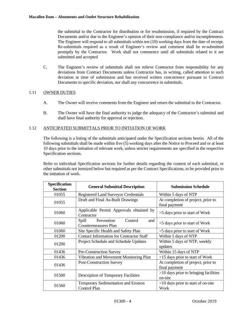
1.12 ANTICIPATED SUBMITTALS PRIOR TO INITIATION OF WORK
The following is a listing of the submittals anticipated under the Specification sections herein. All of thefollowing submittals shall be made within five (5) working days after the Notice to Proceed and or at least10 days prior to the initiation of relevant work, unless stricter requirements are specified in the respectiveSpecification sections.
Refer to individual Specification sections for further details regarding the content of each submittal, orother submittals not itemized below but required as per the Contract Specifications, to be provided prior tothe initiation of work.
SpecificationSection
General Submittal Description Submission Schedule
01055 Registered Land Surveyor Credentials Within 5 days of NTP
01055Draft and Final As-Built Drawings At completion of project, prior to
final payment
01060Applicable Permit Approvals obtained byContractor
>5 days prior to start of Work
01060Spill Prevention Control andCountermeasures Plan
>5 days prior to start of Work
01060 Site Specific Health and Safety Plan >5 days prior to start of Work01200 Contact Information for Contractor Staff Within 5 days of NTP
01200Project Schedule and Schedule Updates Within 5 days of NTP, weekly
updates01436 Pre-Construction Survey Within 15 days of NTP01436 Vibration and Movement Monitoring Plan >15 days prior to start of Work
01436Post-Construction Survey At completion of project, prior to
final payment
01500 Description of Temporary Facilities>10 days prior to bringing facilitieson-site
01560Temporary Sedimentation and ErosionControl Plan
>10 days prior to start of on-siteWork
Macallen Dam – Abutments and Outlet Structure Rehabilitation
01300 - 5 October 2019
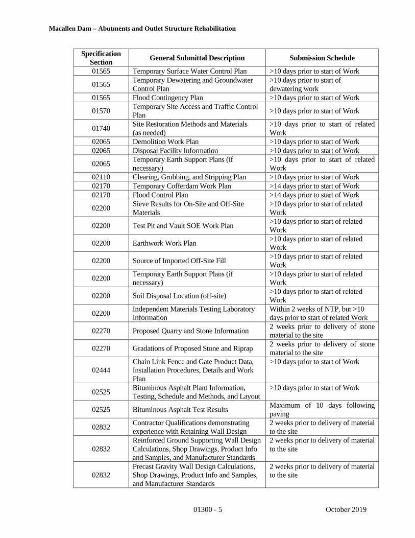
SpecificationSection
General Submittal Description Submission Schedule
01565 Temporary Surface Water Control Plan >10 days prior to start of Work
01565Temporary Dewatering and GroundwaterControl Plan
>10 days prior to start ofdewatering work
01565 Flood Contingency Plan >10 days prior to start of Work
01570Temporary Site Access and Traffic ControlPlan
>10 days prior to start of Work
01740Site Restoration Methods and Materials(as needed)
>10 days prior to start of relatedWork
02065 Demolition Work Plan >10 days prior to start of Work02065 Disposal Facility Information >10 days prior to start of Work
02065Temporary Earth Support Plans (ifnecessary)
>10 days prior to start of relatedWork
02110 Clearing, Grubbing, and Stripping Plan >10 days prior to start of Work02170 Temporary Cofferdam Work Plan >14 days prior to start of Work02170 Flood Control Plan >14 days prior to start of Work
02200Sieve Results for On-Site and Off-SiteMaterials
>10 days prior to start of relatedWork
02200 Test Pit and Vault SOE Work Plan>10 days prior to start of relatedWork
02200 Earthwork Work Plan>10 days prior to start of relatedWork
02200 Source of Imported Off-Site Fill>10 days prior to start of relatedWork
02200Temporary Earth Support Plans (ifnecessary)
>10 days prior to start of relatedWork
02200 Soil Disposal Location (off-site)>10 days prior to start of relatedWork
02200Independent Materials Testing LaboratoryInformation
Within 2 weeks of NTP, but >10days prior to start of related Work
02270 Proposed Quarry and Stone Information2 weeks prior to delivery of stonematerial to the site
02270 Gradations of Proposed Stone and Riprap2 weeks prior to delivery of stonematerial to the site
02444Chain Link Fence and Gate Product Data,Installation Procedures, Details and WorkPlan
>10 days prior to start of Work
02525Bituminous Asphalt Plant Information,Testing, Schedule and Methods, and Layout
>10 days prior to start of Work
02525 Bituminous Asphalt Test ResultsMaximum of 10 days followingpaving
02832Contractor Qualifications demonstratingexperience with Retaining Wall Design
2 weeks prior to delivery of materialto the site
02832Reinforced Ground Supporting Wall DesignCalculations, Shop Drawings, Product Infoand Samples, and Manufacturer Standards
2 weeks prior to delivery of materialto the site
02832Precast Gravity Wall Design Calculations,Shop Drawings, Product Info and Samples,and Manufacturer Standards
2 weeks prior to delivery of materialto the site

Macallen Dam – Abutments and Outlet Structure Rehabilitation
01300 - 6 October 2019
SpecificationSection
General Submittal Description Submission Schedule
02930 Product Information for Revegetation>10 days prior to start of relatedWork
02930Soil Chemistry Test Results for On-Site andOff-Site Loam/Topsoil
>10 days prior to start of relatedWork
03300 Rebar Certifications and Shop Drawings> 14 days prior to beginning orrelevant work
03300Concrete Mix Design, Testing,Certifications, Product Data
> 14 days prior to beginning orrelevant work
03300 Concrete General Procedures2 weeks prior to start of workinvolving concrete
03305Concrete Independent Testing ServiceQualifications, Experience, andCertifications
>10 days prior to start of relatedWork
03346Concrete Finishing, Curing and RepairProduct Data and Procedures
>10 days prior to start of relatedWork
03346Contractor Qualifications demonstratingexperience with Concrete Flatwork Finish
>10 days prior to start of relatedWork
03605Precast Vault Structure Shop Drawings,Product Data, and Materials
>10 days prior to start of fabrication
04510Contractor Qualifications demonstratingexperience with Repointing Masonry
> 10 days prior to beginning orrelevant work
04510 Repointing Masonry Work Plan> 10 days prior to beginning orrelevant work
05730Aluminum Handrail and Railing ProductData, Shop Drawings, and InstallationProcedures
>10 days prior to start of Work
11288
Pneumatic Gate Structural Calculations,Shop Drawings, Anchor Bolt Plan,Installation and Procedure Plan, andManufacturer Warranty
2 weeks prior to final release forfabrication of pneumatic crest gateto manufacturer
14321Portable Crane and Hoist Shop Drawings,Details and Manufacturer’s Product Data
>10 days prior to start of relatedWork
16100Site Electrical Circuit Diagrams and Plans,Shop Drawings, and Product Data,
2 weeks prior to start of work
16100Contractor Qualifications demonstratingexperience with Electrical Design andInstallation
2 weeks prior to start of work
16550 Lighting Product Data and Components >10 days prior to ordering materials
1.13 SUBMITTALS DURING THE PERFORMANCE OF THE WORK
A. During the performance of the Work, the Contractor shall submit progress reports, asrequested by the Owner or Engineer. Progress reports shall be submitted at the beginningof (or before) progress meetings (Section 01200 - Project Coordination and Meetings).Such reports shall contain:
1. A summary of Work activities occurring during the period covered by the report.

Macallen Dam – Abutments and Outlet Structure Rehabilitation
01300 - 7 October 2019
2. The type of materials and/or major equipment being installed by the Contractorand the total number of employees working in each category on that particularday.
3. The names of the subcontractors working and the type of materials and/or majorequipment being installed by each together with the total number of employeesworking for each subcontractor on that particular day.
4. The excavation, compaction, and other equipment being used by the Contractorand each subcontractor.
5. A discussion of problems encountered and corrective actions taken.
1.14 REVIEW OF SHOP DRAWINGS, PRODUCT DATA AND SAMPLES
A. The review of shop drawings, data and samples will be done by the Engineer for generalconformance with the design concept and Contract Documents. They shall not be construed:
1. as permitting any departure from the Contract requirements;
2. as relieving the Contractor of responsibility for any errors, including details, dimensions,and materials;
3. as approving departures from details furnished by the Engineer, except as otherwiseprovided herein.
B. The Contractor remains responsible for details and accuracy, for coordinating the work with allother associated work and trades, for selecting fabrication processes, for techniques of assembly,and for performing work in a safe manner.
C. All Contractor designed components of the project as identified on the Contract Drawings and inthe Specifications shall be reviewed and approved by both the Design Engineer as well as theNHDES – Dam Bureau before being finalized.
D. If the shop drawings, data or samples as submitted describe variations and show a departure fromthe Contract requirements which the Engineer finds to be in the interest of the Owner and to be sominor as not to involve a change in Contract Price or Contract Time, the Engineer may return thereviewed drawings without noting an exception.
E. Submittals will be returned to the Contractor under one of the following codes:
Code 1 – “REVIEWED” – This code is assigned when there are no notations or comments onthe submittal. When returned under this code the Contractor may release theequipment material for manufacture.
Code 2 – “REVIEWED AS NOTED” – This code is assigned when a confirmation of thenotations and comments IS NOT required by the Contractor. The Contractor mayrelease the equipment or material for manufacture; however, all notations andcomments must be incorporated into the final product.
Code 3 – “REVIEWED AS NOTED/RESUBMISSION REQUIRED” - This combination ofcodes is assigned when a confirmation of the notations and comments IS requiredby the Contractor. The Contractor may, at his own risk, release the equipment ormaterial for manufacture; however, all notations and comments must be
Macallen Dam – Abutments and Outlet Structure Rehabilitation
01300 - 8 October 2019
incorporated into the final product. This confirmation shall specifically addresseach omission and nonconforming item that was noted. Confirmation is to bereceived by the Engineer within 15 calendar days of the date of the Engineer’stransmittal requiring the confirmation.
Code 4 – “REVISE AND RESUBMIT” - This combination of codes is assigned when notationsand comments are extensive enough to require a re-submittal of the package. Thisre-submittal is to address all comments, omissions and non-conforming items thatwere noted. Re-submittal is to be received by the Engineer within 15 calendar daysof the date of the Engineer’s transmittal requiring the re-submittal.
Code 5 – “REJECTED”- This code is assigned when the submittal does not meet the intent ofthe Contract Documents. The Contractor must resubmit the entire package revisedto bring the submittal into conformance. It may be necessary to resubmit using adifferent product to meet the intent Contract Documents.
Code 6 – “COMMENTS ATTACHED” – This code is assigned where there are commentsattached to the returned submittal which provide additional data to aid theContractor.
Code 7 – “RECEIPT ACKNOWLEDGED” - This code is assigned to acknowledge receipt ofa submittal that is not subject to the Engineer’s review and approval; and, is beingfiled for informational purposes only.
Codes 1 through 5 designate the status of the reviewed submittal with Code 6 showing therehas been an attachment of additional data.
F. Re-submittals will be handled in the same manner as first submittals. On re-submittals theContractor shall identify all revisions made to the submittals, either in writing on the letter oftransmittal or on the shop drawings by use of revision triangles or other similar methods. The re-submittal shall clearly respond to each comment made by the Engineer on the previous submission.Additionally, the Contractor shall direct specific attention to any revisions made other than thecorrections requested by the Engineer on previous submissions.
G. Partial submittals may not be reviewed at the discretion of the Engineer; the Engineer will be theonly judge as to the completeness of a submittal. Submittals not complete will be returned to theContractor and will be considered "REJECTED" until resubmitted. The Engineer may at his optionprovide a list or mark the submittal directing the Contractor to the areas that are incomplete.
H. Repetitive Review
1. Re-submissions of shop drawings and other submittals will be reviewed no more thanonce at the Owner’s expense. At the Owner’s discretion, all subsequent reviews will beperformed at times convenient to the Engineer and at the Contractor's expense, based onthe Engineer’s then prevailing rates. The Contractor shall reimburse the Owner for allsuch fees invoiced to the by the Engineer. Submittals are required until approved.
2. Any need for more than one resubmission, or any other delay in obtaining Engineer’sreview of submittals, will not entitle Contractor to extension of the Contract Time.

Macallen Dam – Abutments and Outlet Structure Rehabilitation
01300 - 9 October 2019
I. If the Contractor considers any correction indicated on the shop drawings to constitute a changeto the Contract Documents, the Contractor shall give written notice thereof to the Engineer at least7 working days prior to release for manufacture.
J. When the shop drawings have been completed to the satisfaction of the Owner/Engineer, theContractor shall carry out the construction in accordance therewith and shall make no furtherchanges therein except upon written instructions from the Engineer.
1.15 SUBSTITUTIONS
Whenever a product, material or item of equipment is specified or described by using the name of aproprietary product or the name of a particular manufacturer or vendor, followed by the phase “orequivalent” or "or equal," the specific item mentioned shall be the basis upon which bids are to beprepared, and shall be understood as establishing the type, function, dimension, appearance and qualitydesired. Other manufacturer's or vendor's products not named will be considered as substitutions,provided the required information is submitted in the manner set forth in this section and provided thesubstitution will not require substantial revision to the Contract Documents.
A. For Products specified only by reference standard, select product meeting that standard, byany manufacturer.
B. For Products specified by naming several products or manufacturers, select any one ofproducts and manufacturers named which complies with Specifications.
C. For Products specified by naming one or more products or manufacturers and stating “orequivalent” or "or equal," submit a request as for substitutions, for any product ormanufacturer which is not specifically named.
D. For Products specified by naming only one product and manufacturer, there is no option andno substitution will be allowed.
E. Submit separate request for each substitution. Support each request with:
1. Itemized comparison of the proposed substitution with product specified; List significantvariations. Substitution shall not change design intent and shall perform equal to thatspecified.
2. Accurate cost data comparing proposed substitution with product specified.
a. Amount of any net change to Contract Sum.
F. Substitutions will not be considered for acceptance when:
1. They are indicated or implied on shop drawings or product data submittals without aformal request from Contractor.
2. They are requested directly by a subcontractor or supplier.
3. Acceptance will require substantial revision of Contract Documents.
G. In making formal request for substitution, Contractor represents that:
1. He/she has investigated proposed product and has determined that it is equal to orsuperior in all respects to that specified.

Macallen Dam – Abutments and Outlet Structure Rehabilitation
01300 - 10 October 2019
2. He/she will provide same warranties or bonds for substitution as for product specified.
3. He/she will coordinate installation of accepted substitution into the Work and will makesuch changes as may be required for the Work to be complete in all respects.
4. He/she waives claims for additional costs caused by substitution which may subsequentlybecome apparent.
5. Cost data is complete and includes related costs under his Contract, but not:
a. Costs under separate contracts.
b. Engineer's costs for redesign or revision of Contract Documents.
PART 2 – PRODUCTS
This Section Not Used
PART 3 - EXECUTION
This Section Not used.
PART 4 - MEASUREMENT AND PAYMENT
No measurement shall be made of any work performed under this section. No separate payment shall be made forany work performed under this section. The cost of any work done or facilities provided under this section shall beincluded under other pay items within the Contract.
* * * END OF SECTION * * *
J:\170,000-179,999\173346\173346-10.TEM\WORK\Specifications\FINAL\Division 1\01300 - Submittals.docx

Macallen Dam – Abutments and Outlet Structure Rehabilitation
01436-1 October 2019
SECTION 01436VIBRATION AND MOVEMENT LIMITS AND MONITORING
PART 1 - GENERAL
1.01 SCOPE OF WORK
A. The work of this Section includes providing and protecting vibration and movementmonitoring equipment, benchmarks, deformation monitoring points, crack monitors, and othermonitoring equipment that are existing or installed as required by the Contract Documents.Vibration monitoring, crack gauge monitoring and deformation monitoring will be critical inmonitoring the response of the buildings adjacent to the work at 4 Bay Road (Lamprey FallsLLC), 6 Bay Road (Bryant Rock LLC), and 53 Main Street (Durham Book Exchange),monitoring of the underground propane tanks adjacent to the work, and assessing theContractor performance during the rehabilitation work at Macallen Dam.
B. Pre-construction and post-construction inspection surveys of existing conditions of each damsand other existing structures, utilities, and facilities within 150 feet of the proposed Work oras otherwise directed by the Engineer or Owner. Narrated color videos and/or captionedphotographs of existing conditions, performed by an independent specialist specializing insimilar work, shall be incorporated into the pre- and post-construction surveys.
C. The Contractor shall notify the Resident Engineer, Engineer, and the Owner prior toconducting any vibration producing activity and prior to conducting appropriate monitoringat nearby structures in accordance with the plan prepared by the Contractor’s independentspecialist and approved by the Engineer.
D. The Contractor shall engage an independent specialist to provide and install settlement and/ordeformation monitoring points and crack monitors on or in existing structures, including, themanhole rims of the underground propane tanks. The Contractor shall also set upseismographs between the concrete outlet structure work and the 6 Bay Road (Bryant RockLLC) residential structure, the 4 Bay Road (Lamprey Falls LLC) structure, the 53 Main Street(Durham Book Exchange) structure, the underground propane tanks, and any additionalstructures and/or utilities requested by the Resident Engineer, Engineer, and/or Owner.
E. The work specified under this Section includes conducting all activities on the project in sucha manner that damage is prevented to the dam, adjacent structures, facilities, utilities,equipment, property and work; and such that ground vibrations and ground and structuredisplacements are consistently maintained below the maximum levels as specified within thisSection.
1.02 EXISTING CONDITIONS
A. The Contractor’s attention is called to the fact that the project is a dam site. A higher standardof construction practices and quality is required for work on and around a dam. Typicalconstruction practices may require modification or adjustment to meet dam constructionstandards. In addition, additional care is required since the consequences of constructionmishaps could extend beyond the project site were a dam failure to result. Special care andprecautions shall be undertaken to protect the dam, as well as other structures and utilities,within and nearby the Work.

Macallen Dam – Abutments and Outlet Structure Rehabilitation
01436-2 October 2019
B. The Contractor’s attention is called to the fact that 4 Bay Road (Lamprey Falls LLC) and 6Bay Road (Bryant Rock LLC) structures are located adjacent to the existing gate outletstructure, which is to be demolished and reconstructed.
C. The Contractor shall review the historic drawings of the dam to be fully informed on allexisting conditions and limitations as they apply to this work and its relation to otherconstruction work.
D. Cracks in the dam and adjacent structures that require crack gauge monitoring will be mutuallyidentified by the Contractor, Engineer and the Owner during the preconstruction survey.
1.03 RELATED WORK
A. Submittals – Section 01300
B. Site Restoration – Section 01725
C. Saw Cutting, Dismantling, Demolition, and Removal of Existing Structures – Section 02065
D. Earthwork – Section 02200
1.04 SUBMITTALS
A. Pre- and Post-Construction Surveys
1. Within 15 days of Notice to Proceed, submit the qualifications and professionalresumes of the Registered Professional Engineer(s) that will perform the pre- andpost-construction inspection at the site. Include a list of projects that includesproject name; location; date(s); names and current contact information for owner,engineer and general contractor.
2. Submit Draft Reports for the pre- and post-construction surveys to the Owner:
a. Original, plus three (3) copies of the pre-construction survey report for eachbuilding, with captioned photographs and narrated videos shall be submitted.The Contractor shall retain one (1) additional copy for their records.
b. Make any changes or corrections to the Draft Report required by the Owneror the Engineer.
c. Draft pre-construction survey reports shall be submitted 14 days before anyconstruction related activity within one hundred feet (100’) of a structure orfacility designated to be surveyed, but no later than within 60 days of Noticeto Proceed.
3. Submit Final Reports for the pre- and post-construction surveys to the Owner:
a. After review, submit five (5) copies of the approved report; four copies andthe original. The Contractor shall retain one (1) additional copy for theirrecords.
B. Vibration and Movement Monitoring

Macallen Dam – Abutments and Outlet Structure Rehabilitation
01436-3 October 2019
1. No less than 15 days prior to beginning of construction work at Macallen Dam,submit qualifications for the independent specialist whose services have beenselected by the Contractor for performing the vibration and movement monitoringwork demonstrating at least 5 similar assignments completed successfully duringthe last 5 years.
2. Submit a monitoring plan prepared by the independent specialist prior to startingthis work at Macallen Dam. The monitoring plan shall include proposed locationsof deformation monitoring points (DMPs), surface monitoring points (SMPs),crack monitors, and seismographs; reading schedules; threshold and limitingvalues.
3. Shop drawings and manufacturer’s data for the following:
a. Seismographs.
b. Crack monitors, providing material properties including coefficient ofthermal expansion.
c. Epoxy adhesive to be used to install crack monitors.
d. Deformation and Surface Monitoring Points.
4. Submit samples of crack monitor, crack measuring scale, and crack movementrecording form.
5. Within 5 days of installing DMPs, SMPs, and crack gages, provide drawingsshowing plan locations, nearby features and a graphic scale. For crack gages,DMPs, and SMPs on the dam and adjacent structures, provide elevation sketchesshowing distances above existing grades, dam features, descriptions of mountingsurfaces and graphical scales.
6. Submit the results of deformation and surface monitoring, crack monitors, andvibration monitoring in the format and at a frequency as specified herein.
7. Prepare and submit a response plan if Threshold or Limiting values are exceededin a format and at a frequency as specified herein.
8. Submit at least 30 days before instrumentation removal, a detailed step-by-stepprocedure for post-construction instrumentation removal and associatedrestoration.
1.05 QUALITY ASSURANCE
A. Qualifications
1. Vibration monitoring shall be conducted by persons trained in the use of aseismograph and records shall be analyzed and results reported by persons familiarwith analyzing and reporting the frequency content of a seismograph record.Vibration monitoring shall be performed during demolition of the gate outletstructure, installation of the support of excavation components associated with thenew gate operating vault structure, and earthwork along the right embankment and

Macallen Dam – Abutments and Outlet Structure Rehabilitation
01436-4 October 2019
any other construction activities within 150 feet of adjacent structures and theunderground propane tanks.
2. Persons responsible for pre-construction surveys shall be Professional Engineers,registered in the State of New Hampshire, and shall have had a minimum of 5 yearsof professional experience in structural evaluation and conditions surveys.
3. Deformation point survey readings shall be made by a Land Surveyor licensed inthe State of New Hampshire.
1.06 MOVEMENT AND VIBRATION LIMITS
A. The Contractor shall limit vibrations from construction operations to prevent damage tothe existing dam, new work, adjacent structure, facility, utility or other feature near the site.The Contractor or his independent specialist is solely responsible to determine the limitingand maximum vibration values tolerable at each facility.
1. The Threshold maximum peak particle velocities are:
Max. Peak Particle VelocityFrequency (Hz) (inch/sec.)Over 40 1.0
30 to 40 0.75
20 to 30 0.5
Less than 20 0.25
2. The Limiting maximum peak particle velocities are:
Max. Peak Particle VelocityFrequency (Hz) (inch/sec.)Over 40 2.0
30 to 40 1.5
20 to 30 1.0
Less than 20 0.5
B. Maximum movements at DMPs and SMPs installed on the dam, training walls, or adjacentstructures shall not exceed the following as a result of demolition and reconstruction of theoutlet structure, excavation, or other activities of the Contractor:
1. Threshold limit, total maximum displacement of 0.1 inch; and
2. Limiting value, total maximum displacement of 0.15 inch.
C. Maximum new crack width or increase in existing crack width along the dam, trainingwalls, or adjacent structures shall not exceed the following as a result of the constructionactivities of the Contractor:
1. Threshold limit, maximum crack opening of 0.006 inch; and

Macallen Dam – Abutments and Outlet Structure Rehabilitation
01436-5 October 2019
2. Limiting value, maximum crack opening of 0.008 inch.
PART 2 PRODUCTS
2.01 CRACK MONITORS
A. Crack monitors shall consist of two overlapping plexiglass acrylic plates. The bottom plateshall be white with a black two-way measurement grid in millimeters. The upper plateshall be clear with red crosshairs. The measurement grid shall be such that it allowsreadings to the nearest 0.01 inch (0.25 mm) and can accommodate movements of 0.75 inch(20 mm) along the length of the monitor and 0.4 inch (10 mm) across the width.
B. Provide crack monitor with removable tape to hold cross hairs in position centered onmeasurement grid until monitor is securely installed.
C. Provide two component gel-type fast-setting epoxy for installation of crack monitors. Theepoxy shall have a minimum lap shear strength of 2000 psi and shall be formulated for theplacement conditions.
D. Provide a minimum of two crack width scales capable of measuring cracks to the nearest0.10 millimeter (4 mils).
E. Provide recording sheets supplied by the manufacturer and designed to facilitate recordingof movement of the crack monitors.
2.02 DEFORMATION MONITORING POINTS (DMPs) & SURFACE MONITORING POINTS(SMPs)
A. Type 1 monitoring points shall consist of either a 2-inch long “PK” masonry nails withidentification tags or an inscribed marking identified with survey marking paint. Theidentification tags for “PK” nails shall be 1.5 inches in diameter and 3/32-inch-thick witha punched number for identification. Type 1 monitoring points shall typically be installedinto paved surfaces or on manhole rims.
B. Type 2 Monitoring points shall consist of ⅜-inch (0.375”) diameter by minimum two-inch (2”) long, stainless steel, socket head cap screws ASTM A307-UNC with stainless steelwashers, screwed into ⅜-inch (0.375”) machine screw anchors such as Concrete Machine Screw Anchors from Concrete Fastening Systems of Cleveland, Ohio, or an approvedequal. Where removal and patching are not required after construction, the bolts may beinstalled with epoxy or polyester adhesive in lieu of tamp-in screw anchors. Type 2Monitoring points shall typically be installed into vertical surfaces of buildings andstructures.
C. Type 3 Monitoring points shall consist of ⅜-inch (0.375”) diameter by two-inch (2”) long punch-marked stainless-steel round-head bolts screwed into a ⅜-inch (0.375”) machine screw anchors such as a Concrete Machine Screw Anchor from Concrete FasteningSystems of Cleveland, Ohio, or an approved equal. Where removal and patching are notrequired after construction, the bolts may be installed with epoxy or polyester adhesive inlieu of tamp-in screw anchors. Type 3 Monitoring points shall typically be installed intohorizontal surfaces of buildings and structures.

Macallen Dam – Abutments and Outlet Structure Rehabilitation
01436-6 October 2019
2.03 VIBRATION MONITORING INSTRUMENTATION
A. Provide seismographs for full time use on the Macallen Dam during construction operationswhich have been calibrated within the previous 12 months prior to the start of construction, toa standard, which is traceable to the National Bureau of Standards. Required characteristicsof seismographs are listed below:
1. Measure the three mutually perpendicular components of particle velocity indirections vertical, radial and perpendicular to the vibration source.
2. Measure and display the maximum peak particle velocity component.
3. Furnish a permanent record of a velocity/time waveform, on a strip chart or frommagnetic tape.
4. Have a flat velocity frequency response with a minimum broad band of 2 Hz to200 Hz with a tolerance equal to or better than plus or minus 10 percent.
5. Seismographs shall be capable of recording vibration levels from 0.02 to 10 inchesper second.
6. Seismographs shall have the capability for real-time data generation and review.
PART 3 - EXECUTION
3.01 GENERAL
A. In addition to that specified herein, the Contractor may install and monitor instrumentationhe/she deems necessary to ensure performance of the Work in accordance with the ContractDocuments.
B. The intent of the monitoring program is intended to provide pre-construction baseline datafor comparison with construction data and post-construction data to determine whether anyutilities, facilities, or structures have been adversely affected by construction activities, andto provide warning of pending conditions that could require remedial measures oralternative construction approaches.
C. No work shall be conducted by the Contractor that may result in vibrations ordeformation/settlement, as determined by the Owner or Engineer, until all instrumentationhas been installed, initialized, and a series of suitable baseline readings have been recorded.
D. The Contractor shall:
1. Provide components of instrumentation to be installed during construction.
2. Install instruments
3. Collect baseline readings.
Macallen Dam – Abutments and Outlet Structure Rehabilitation
01436-7 October 2019
4. Protect and maintain all instruments, including any existing instruments orbenchmarks shown on the Contract Drawings.
5. Collect, reduce and plot data from both the new instruments installed as part of thiscontract and existing instruments identified on the Contract Drawings.
6. Implement remedial measures based on interpretations of the monitoring programdata by the Engineer, at no additional cost to the Owner, as required.
7. Remove instruments at the end of the construction and restore the site ofinstrumentation locations unless otherwise directed by the Resident Engineer,Engineer or Owner.
E. The Engineer may provide, install and monitor additional instrumentation at the sites as anindependent check of the Contractor’s supplied instrumentation. The Contractor shall notrely upon any instrumentation supplied or installed by the Engineer to satisfy therequirements of this Section. The Contractor shall coordinate their Work with the Engineerand provide safe access by the Engineer at all times.
3.02 PRE-CONSTRUCTION SURVEY
A. Prior to starting work, the Contractor, the Engineer, the Resident Engineer, and the Ownershall make a joint inspection of the existing structures within 150 ft of the work area,specifically portions of the 6 Bay Road (Bryant Rock LLC) residential structure, the 4 BayRoad (Lamprey Falls LLC) structure, and the 53 Main Street (Durham Book Exchange)structure, which fall within the 150 ft of the work area, as well as the underground propanetanks, to examine and document their present conditions.
B. The survey shall consist of a description of interior and exterior conditions. Descriptionsshall locate cracks, damage or other defects existing and shall include information to makeit possible to determine the effect, if any, of the construction operations on the defect.Where significant cracks or damage exists, or for defects too complicated to describe inwords, photographs shall be taken and made part of the record. Photographs shall be takento record any cracks or other evidence of structural distress in the structure. Crack monitorlocations shall be identified during the pre-construction survey.
C. Baseline survey readings of structure elevations, monitoring point plan location, cracklocation documentation, and the placement of crack monitors shall be performed prior tothe start of construction activity. All readings shall be referenced to one benchmark,sufficiently remote as to be unaffected by any construction activity.
D. The Contractor shall prepare a report for each structure documenting all pre-existingconditions, verified by the photographs, and signed by the personnel participating in theinvestigation and, if practicable, by the Owner, whether or not they are present at theexaminations.
3.03 CRACK MONITORING INSTRUMENTATION
A. Crack monitors shall be installed at existing cracks or construction joints at Macallen Damand on existing structure within 150 ft of the work area, specifically portions of the 6 BayRoad (Bryant Rock LLC) residential structure, the 4 Bay Road (Lamprey Falls LLC)
Macallen Dam – Abutments and Outlet Structure Rehabilitation
01436-8 October 2019
structure, and the 53 Main Street (Durham Book Exchange) structure. The actual locationof Crack Monitors will be mutually agreed upon by the Owner, the Contractor, and theEngineer after the Pre-Construction Survey. Additional crack monitors shall be providedby the Contractor at the request of the Resident Engineer during the performance of thework. Installation shall follow the manufacturer’s recommendations and the followingrequirements.
B. Crack gauges shall be installed prior to construction and at least three rounds of baselinereadings shall be obtained prior the start of construction.
C. Install crack monitor parallel with the axis of the member, not perpendicular to the crack.On walls, install the long axis of the crack monitor horizontally. Verify that the redcrosshairs are in the zero position prior to installation.
D. Install crack monitors with epoxy adhesive. Clean the concrete or masonry surface to bareand sound material removing any paint or other substance that may interfere with properbonding of the epoxy adhesive.
E. After the epoxy adhesive has cured the manufacturer’s recommended time period, removethe tape holding the two plates of the monitor in position.
F. Mark each crack monitor with a reference number, in coordination with the Engineer, withpaint or other permanent marking. Record the number and location on a plan of thestructure including the elevation.
G. Record the crack width at the time of crack monitor installation to the nearest 0.10millimeter (4 mils) on the crack monitor sheet. Record the ambient temperature on thecrack monitor sheet.
H. The Contractor must protect the crack gauge during construction. Crack gauges shall bereplaced if damaged.
3.04 VIBRATION MONITORING
A. The Contractor shall monitor peak particle velocities using a minimum of twoseismographs operated by personnel trained in their use during all construction activitieswhere vibrations may be generated having the potential to cause damage to existingstructures or features. Continuous vibration monitoring will be specifically required duringdemolition of the gate outlet structure and earthwork along the right embankment atMacallen Dam. Seismograph locations shall be mutually agreed upon by the Engineer,Resident Engineer and the Contractor.
B. During demolition of the gate outlet structure and installation of the vault SOE, at least oneseismograph shall be located between the work and the structure at 4 Bay Road (LampreyFalls LLC) and at least one seismograph shall be located between the work and theunderground propane tanks while the demolition is occurring. The Contractor shall makeallowances for the seismographs to be moved closer to/away from the existing structure asthe work progresses and the conditions warrant such action.
C. During earthwork and construction along the right abutment, at least one seismograph shallbe located between the work and the structure at 53 Main Street (Durham Book Exchange)

Macallen Dam – Abutments and Outlet Structure Rehabilitation
01436-9 October 2019
while the work is occurring. The Contractor shall make allowances for the seismographsto be moved closer to/away from the existing structure as the work progresses and theconditions warrant such action.
D. The Resident Engineer or the Engineer may direct that additional vibration monitoring beperformed elsewhere at Macallen Dam, during operations other than demolition of the gateoutlet structure (e.g. rock or boulder excavation) if conditions warrant such action.
3.05 DEFORMATION AND SURFACE MONITORING
A. A minimum of ten (10) DMPs (Type 3) shall be provided prior to the start of work at theleft abutment wall. The DMPs shall be installed on the structures at 4 Bay Road (LampreyFalls LLC) and 6 Bay Road (Bryant Rock LLC). Locations shall be proposed by theContractor and approved by the Resident Engineer prior to the start of work.
B. A minimum of ten (10) DMPs (Type 3) shall be provided prior to the start of work at theright abutment wall. The DMPs shall be installed on the structures at 53 Main Street(Durham Book Exchange). Locations shall be proposed by the Contractor and approvedby the Resident Engineer prior to the start of work.
C. A minimum of three (3) SMPs (Type 1) shall be provided prior to the start of work at theleft abutment wall. The SMPs shall be installed on each manhole rim for each undergroundpropane tank, as identified on the Contract Drawings.
D. The Contractor shall document the as-installed location with a scaled sketch showing theinstalled location of each SMP and DMP.
E. Additional SMPs and DMPs may be requested by the Resident Engineer or Engineer.
3.06 MONITORING FREQUENCY
A. Vibration monitoring shall be performed continuously during all demolition andconstruction activities at the Macallen Dam. Continuous monitoring may be automatedprovided that notification alerts are sent electronically to the Owner and Engineer.
B. Deformation, surface, and crack monitoring shall be performed weekly when constructionactivities are outside 100 feet from a monitored structure, and daily when within 100 feetof a monitored structure.
C When construction activities are within 20 feet of a monitored structure, crack monitoringand deformation monitoring may be conducted several times during the day, as directed bythe Engineer and/or Resident Engineer or the Contractors independent specialist.
3.07 REPORTING REQUIRMENTS
A. The Contractor must submit reports of vibration, surface, and deformation monitoring tothe Owner by the end of the next day after monitoring has been performed. Reports shallinclude cumulative data for deformation and crack monitoring readings, in order toillustrate possible trends in data.

Macallen Dam – Abutments and Outlet Structure Rehabilitation
01436-10 October 2019
B. The Contractor shall be notify the Owner and Engineer immediately if any vibration,surface, deformation, or crack monitor readings exceed the Threshold or Limiting valuesspecified herein.
3.08 INSTRUMENTATION RESPONSE ACTIONS
A. If the Threshold limits of vibration, crack width, or movement are exceeded, the Contractorshall alter their activities to prevent the Limiting values from being exceeded. TheContractor shall submit to the Owner, within 24 hours of the exceedance, a submittalindicating the activity causing the exceedance and the steps the Contractor has taken andwill take to prevent further exceedances of the Threshold limit.
B. If the Limiting values of vibration, crack width, or movement are exceeded, all work bythe Contractor in the vicinity of the exceedance shall stop immediately until a meetingtakes place between the Contractor, the Owner and the Engineer to assess the cause of theexceedance. The Contractor shall prepare and submit to the Owner a description of theactivity that caused the exceedance and the steps/modifications the Contractor will take toprevent further exceedances of the Limiting value that was exceeded. No work in thevicinity of the exceedance shall be restarted until the submittal is reviewed and approvedby the Owner and the Engineer.
C. The Contractor shall be completely responsible for repairing all damages resulting fromvibrations and deformation caused due to the construction operations and shall, as aminimum, take whatever measures are necessary to maintain vibrations and deformationswithin the specified limits. Modifications to construction methods required to meet theserequirements shall be undertaken at no additional cost to the Owner.
3.09 POST-CONSTRUCTION SURVEY
A. Within 30 days after completion of all work at Macallen Dam, perform an examinationsimilar to the pre-construction survey. The post-construction survey and inspection shallinclude all areas and items inspected in the pre-construction survey, and shall also includeproperties, buildings, sites, and structures where written or verbal complaints of damagehave been received, or damage claims have been filed. A minimum of 72-hour notice shallbe given to the Owner, Resident Engineer, Engineer and all interested parties so that theymay be present during final examination.
B. The post-construction survey shall include all areas included in the pre-constructionsurvey, with photographs and videos taken from the same viewpoints, plus areas of whereadditional damage or distress is noted or where complaints of such have been received bythe Owner, Engineer or Contractor.
C. Records of the final examination shall be distributed in the same manner as the originalpre-construction survey

Macallen Dam – Abutments and Outlet Structure Rehabilitation
01436-11 October 2019
PART 4 – MEASUREMENT AND PAYMENT
Refer to Section 01950 – Measurement and Payment for the measurement and payment items related tothis Section.
* * * END OF SECTION * * *
J:\170,000-179,999\173346\173346-10.TEM\WORK\Specifications\FINAL\Division 1\01436 - Vibration and Movement Limits andMonitoring.docx

Macallen Dam – Abutments and Outlet Structure Rehabilitation
01500-1 October 2019
SECTION 01500TEMPORARY FACILITIES & CONTROLS
PART 1 - GENERAL
1.01 SCOPE
A. This Section includes requirements for temporary facilities and controls including, but notnecessarily limited to, sanitary facilities, utilities, drinking water, temporary field offices,and working hours.
B. All temporary facilities required by the Contractor as specified herein and elsewhere withinthe Contract Documents shall be furnished by the Contractor, and shall meet all federal,state and local codes and requirements for such temporary installations. All temporaryfacilities shall be provided and maintained so as not to create fire or safety hazards. Costsnecessary to satisfy all requirements specified herein shall be borne by the Contractor. Alltemporary facilities shall be entirely removed upon completion of the work and the siteshall be left in a clean condition to the satisfaction of the Engineer.
C. Possible contractor staging areas are located as shown on the Contract Drawings.Additional supplemental staging areas may be available for use at alternate locations uponwritten request to the Owner. The locations of all temporary facilities described must beapproved by the Owner, Engineer, and Resident Engineer.
D. The Contractor shall be responsible for installing, providing, maintaining, anddecommissioning all utility service to any temporary field offices. The cost of all utilitiesshall be considered incidental to the Unit Cost of this item.
E. The Contractor shall provide the Resident Engineer, Owner, and Engineer with access toand use of all temporary facilities and services provided by the Contractor.
F. The Work of this Section shall also include the fabrication, provision, installation, andremoval of Project Signs (Project Description Sign and any other signage required byregulatory agencies), as specified by the Owner.
1.02 TEMPORARY OFFICES FOR CONTRACTOR AND RESIDENT ENGINEER
A. A temporary field office is not required.
B. The Contractor may place his own temporary field office trailer on the project site, withinthe limits of construction access or at an approved supplemental location. Such a trailermust conform to all applicable local, state, and federal standards.
C. Additional temporary storage in the form of locked box-type containers if/as required shallbe provided by the Contractor. Placement and location of storage containers shall besubject to the approval of the Owner. The Contractor is solely responsible for securing allequipment and materials for use in the work.
1.03 TEMPORARY ELECTRICITY

Macallen Dam – Abutments and Outlet Structure Rehabilitation
01500-2 October 2019
A. The Contractor shall determine the nearest service at each location in relation to obtainingelectrical service required for construction facilities and temporary controls (or for that matterfor use to operate construction equipment necessary to perform the work.)
B. Temporary electricity, with separate meter, for light and power shall be provided andmaintained by the Contractor. Temporary on-site generators may only be used to provideemergency back-up electricity to the Site. Temporary lighting and wiring shall be installed inaccordance with all local, state, and federal regulations.
C. Power Service Characteristics: as required for the Work.
D. The Contractor shall provide power outlets for construction operations, with branch wiringand distribution boxes. Provide flexible power cords as required.
E. The Contractor shall provide main service disconnect and overcurrent protection at convenientlocations.
F. The Contractor shall maintain electrical service, provide routine repairs and inspect electricalservice on a regular basis.
G. Ground fault circuit interrupters shall be required on all electrical equipment.
1.04 TELEPHONE AND INTERNET SERVICE
A. The Contractor is not required to maintain his own temporary “land-line” phone service butmay elect to do so. If telephone service is provided, all applicable local, state, and federalstandards and codes must be obeyed.
B. A working phone connection MUST be maintained by the Contractor at the site such that thesite may be reached at all times during business hours. A cellular phone is acceptable,provided reception is consistent and adequate.
C. The Contractor MUST provide his Superintendent with equipment that allows for e-mails tobe sent and received at the site for the duration of the project.
1.05 TEMPORARY WATER SERVICE
A. The Contractor is responsible for providing all materials equipment, labor and incidentalsnecessary to collect and transport water to work zones as needed in accordance with allapplicable local, state, and federal policies and procedures. Such materials include but are notlimited to water meters, appropriate check valves and flow meters required by the Owner. Allcharges, tariffs, and fees, as applicable, for the use of temporary water service shall be borneby the Contractor at no additional cost to the Owner. The Contractor is responsible forcoordinating with the Owner to arrange for the provision of water from their system, ifavailable.
B. The Contractor shall furnish drinking water with suitable containers and cups for use ofworkers. Drinking water dispensers shall be conveniently located where Work is in progress,but outside of the Work Zones.

Macallen Dam – Abutments and Outlet Structure Rehabilitation
01500-3 October 2019
1.06 TEMPORARY SANITARY FACILITIES
A. The Contractor shall provide temporary sanitary facilities at the site outside of the Work Zoneto be used by the Contractor. The Contractor shall maintain these facilities in a clean andsanitary condition and in such a manner as required or approved by the Engineer. Theseconveniences shall be maintained at all times without nuisance. Upon completion of theWork, the sanitary facilities shall be removed by the Contractor from the premises, leavingthe premises clean.
1.07 TEMPORARY LIGHTING FOR CONSTRUCTION PURPOSES
A. The Contractor may elect to install temporary lighting to illuminate the worksite for work afterdark. However, the Contractor is subject to all local and state work ordinances and must fileappropriate applications and receive acceptance prior to performing work outside of theapproved window. The use of temporary lighting for work after dark shall be only with priorapproval of the Owner and shall NOT result in objectionable conditions for project abutters.
B. Ground circuit interrupters shall be required on all lighting equipment.
C. Provide guard cages or tempered glass enclosures where temporary lighting may be exposedto breakage. Provide exterior fixtures where temporary lighting may be exposed to moisture.
1.08 TEMPORARY BARRIERS, PROTECTION, AND TRAFFIC CONTROL
A. The Contractor shall provide temporary fencing or barriers to prevent unauthorized entry toconstruction, staging, and storage areas, to delineate temporary contractor staging areas, todelineate access from temporary staging areas to the work zones, and to protect the existingdam and appurtenances, adjacent properties and the public from damage from constructionoperations. Additional temporary fencing or barriers may be required on the site, asdetermined by the Owner, Resident Engineer, and/or Engineer, and shall be included in thelump sum price bid for under this Section.
B. Traffic controls or signage on paved public roads shall conform to NHDOT StandardSpecifications for Road and Bridge Construction. Flagmen shall be provided as needed tomaintain traffic on the road. The Contractor shall submit any plan for traffic controls necessaryon paved public roads to the Owner for approval a minimum of 10 days prior to the work. Ata minimum, signs notifying the public of construction activities and/or trucks entering theroadway shall be placed on North Main Street, Penstock Way, and Bay Road approaching thesite.
C. The Contractor shall provide protection for existing infrastructure, roadways, parking areasand existing utilities, and replace those damaged during construction at no additional cost.
D. The Contractor shall protect non-owned vehicular traffic, stored materials, site and structuresfrom damage and shall replace same if damaged during construction at no additional cost.
1.09 SEDIMENTATION AND EROSION CONTROL
A. The Contractor shall provide sedimentation and erosion control in accordance with Section01560.
Macallen Dam – Abutments and Outlet Structure Rehabilitation
01500-4 October 2019
1.10 DUST CONTROL
A. The Contractor shall control dust on the dam, excavation and fill areas, stockpiles, stagingareas and all other areas of the Site. Means of control shall be subject to the approval of theEngineer and be in accordance with local, state and federal permits, policies and procedures.
1.11 PROTECTION OF INSTALLED WORK AND EXCAVATIONS
A. The Contractor shall protect installed work and excavations and provide special protectionwhere necessary.
B. The Contractor shall provide temporary and removable protection for equipment and openexcavations, and control activity in the immediate work area to minimize damage.
1.12 SECURITY
A. The Contractor shall be responsible for providing and maintaining security for protection ofhis work, equipment, supplies and employees and shall be responsible for protecting samefrom unauthorized entry, vandalism, or theft.
1.13 SITE ACCESS AND TRAFFIC
A. Maintain existing roads and driveways accessing the site and thoroughfares to serve existingproperty tenants public rights-of-way, as well as the construction area. Provide for allnecessary temporary traffic control including, but not limited to, temporary signage, barriers,flagmen, and/or police details. Extend and relocate traffic controls as Work progressesproviding detours as necessary for unimpeded traffic flow.
B. At no time shall equipment or materials be operated or stored within public roadways. Shouldthere be an occasion that traffic on nearby roadways has to be temporarily impacted due toongoing work, the Contractor shall employ a police detail or flagman as appropriate and asallowed by the Owner.
D. Provide and maintain access to fire hydrants, free of obstructions.
E. The Contractor is responsible for site area reconnaissance as necessary to determine if thereare any local access, weight or size limitations with respect to specialized constructionequipment to be used in the work.
1.14 PROTECTION OF WORK FROM HEAT AND COLD AND WEATHER RELATED EFFECTS
A. In the event that hot or cold temperatures occur during construction, the Contractor shall takeall measures and provide all necessary items to protect the Work of the project. This includesprovisions for proper curing of concrete, grout and/or mortar (if any).
B. The Contractor shall provide all such temporary facilities needed to protect completed and on-going work and on-site materials from inclement weather, including rain, heat, snow, and cold.This shall include, but not be limited to, the provision of covers, shelters, heaters, etc. The useof rigid barriers for weather protection shall be used as required and as directed by theEngineer.

Macallen Dam – Abutments and Outlet Structure Rehabilitation
01500-5 October 2019
C. Temporary heating units shall have been tested and labeled by UL, FM, or other recognizedassociation related to the type of fuel being used and maintain reasonable temperatures withinthe temporary enclosures.
D. The Contractor shall be responsible for maintaining and/or restoring access and appropriateworking conditions at the site in the event of inclement weather. This shall include, but notbe limited to, providing for plowing and ice removal in the event of snow and freezingtemperatures.
E. The Contractor shall be responsible for all necessary snow and ice removal to allow access toand work at the Site. Snow plowed or removed by the Contractor may not be disposed of inthe Lamprey River or any other waterway or wetland resource area.
1.15 REMOVAL OF TEMPORARY FACILITIES AND CONTROLS
A. The Contractor shall remove temporary equipment, facilities, and materials after completionand acceptance of work at the Site. Lawfully dispose of all waste, trash, and other debrisgenerated during the Work of the Contract.
B. The Contractor shall clean and repair damage caused by installation or use of temporaryfacilities and controls at no additional cost to the Owner.
C. Restore existing and permanent facilities used during construction to original or bettercondition at no additional cost to the Owner.
1.16 TEMPORARY FIRE PROTECTION
A. All operations on respective site premises shall be so performed that no fire hazards are createdor are permitted to exist. If the Contract Work involves a fire hazard, sufficient firefightingequipment with trained, capable operators shall be in the area to contain any fire until the localfire department arrives. The Contractor shall make sure that persons employed directly orindirectly by the Contractor, while on the site premises, comply with all pertinent local, stateand federal fire regulations. The Contractor shall have a procedure for properly addressingany burning activity that begins to get out of control. The Contractor shall be responsible forcompliance by personnel of his organization for their cooperation in fire prevention, firereporting and protective measures to minimize loss.
B. Provide portable UL rated, Class A fire extinguishers for temporary offices and similar spaces.In other locations, provide portable UL rated Class ABC dry chemical extinguishers or acombination of NFPA recommended Classes for the exposure. Comply with NFPA 10 and241for classification, extinguishing agent and size required by location and class of fireexposure.
C. No burning of material shall be allowed.
1.17 MISCELLANEOUS REQUIREMENTS
A. The Contractor shall provide temporary medical and first-aid supplies at the work site,adequately equipped, maintained and located, to serve the needs of the workmen andemployees of the Contractor, subcontractors and assigned contractors.
Macallen Dam – Abutments and Outlet Structure Rehabilitation
01500-6 October 2019
B. The Contractor shall provide all necessary temporary signage around the work site.
1.19 SUBMITTALS
A. No later than ten (10) calendar days prior to bringing the facilities on site, the Contractor shalldevelop and submit a submittal which describes the temporary facilities and services to beprovided to the Owner.
B. No later than ten (10) calendar days prior to bringing the facilities on site, the Contractor shalldevelop and submit a description of the temporary facilities and services to be used by theContractor, including the location of laydown/storage areas, fueling areas, fencing, proposedtemporary office trailer, and any other temporary facilities.
PART 2 - PRODUCTS
2.01 EQUIPMENT
A. The Contractor shall provide all necessary equipment related to the requirements of thisSection such that the work of the Contract can be conducted in accordance with the applicableContract Documents.
B. All temporary equipment, facilities, and controls shall be clean and in good working order.
PART 3 - EXECUTION
3.01 GENERAL
A. The Contractor shall sweep and clean as necessary to maintain neat, orderly work areas.
B. The Contractor shall furnish all materials and perform all work necessary, includingexcavation and backfill. No disturbance will be allowed in areas outside those indicated onthe plans, without prior approval from the Owner. The Contractor will be responsible forrepairing all cuts made for temporary utilities and for the removal of temporary utilities andpost-removal restoration.
3.02 MAINTENANCE AND SERVICING
A. The Contractor shall furnish full maintenance and service for all Temporary Facilities andControls. Trash, garbage and other wastes shall be lawfully, properly, and satisfactorilydisposed of by the Contractor at regular intervals.
PART 4 – MEASUREMENT AND PAYMENT
Refer to Section 01950 – Measurement and Payment for the measurement and payment items related tothis Section.
* * * END OF SECTION * * *

Macallen Dam – Abutments and Outlet Structure Rehabilitation
01500-7 October 2019
J:\170,000-179,999\173346\173346-10.TEM\WORK\Specifications\For Review\Division 1\01500 - Temporary Facilities and Controls.docx

Macallen Dam – Abutments and Outlet Structure Rehabilitation
01560-1 October 2019
SECTION 01560TEMPORARY EROSION AND SEDIMENTATION CONTROLS
PART 1 - GENERAL
1.01 DESCRIPTION
A. The Contractor shall furnish all labor, materials and equipment and shall perform all workrequired to install, maintain, and remove erosion, sedimentation, and siltation controlmeasures to protect the site, and upstream and downstream wetlands, water bodies, streams,and drainage structures from siltation and sedimentation damage and accumulation or damagefrom other byproducts of the work during this Contract, as specified herein and as directed bythe Owner or Engineer.
B. Erosion control measures are used to prevent the displacement of soil. Such measures mayinclude, but not be limited to, grading, erosion control matting, plastic coverings, mulching,temporary seeding, riprap, check dams, cross tracking, and other items intended to stabilizesoil material and/or reduce the erosive potential of water.
C. Sedimentation and siltation control measures are used to prevent the movement and transportof soil particles offsite or into water bodies. Sedimentation and siltation control measures mayinclude, but not be limited to, use of sedimentation basins, filtration dams, siltation sumps, siltfences, turbidity curtains, construction entrances and other items as necessary to containsediment and other deleterious material produced from excavation and filling, dewatering, andrelated contract operations.
D. The Work shall also include all work necessary to continually clean and maintain andpromptly repair/replace all erosion, sedimentation, and siltation measures as needed to sustaintheir intended function and operability.
E. It is the intent of this Section that the Contractor shall be responsible for the use of all BestManagement Practices (BMPs), both structural and operational, to reduce, to the greatestextent possible, the erosion and transport of soil and sediment. The Contractor shall beresponsible for implementing all measures which are both prudent under good constructionpractices and required under local, state, and Federal regulations and law. The Contractorshall also be responsible for all monitoring, maintenance, and repair of all BMPs utilized. Inthe event of the failure of sediment and erosion control BMPs, the Contractor shall beresponsible, at no additional cost to the Owner, for all work necessary to mitigate and correctthe situation, including, but not limited to, the removal of transported sediment.
F. The Contractor shall be responsible for monitoring, maintenance, and repair of BMPs at thesite. The work of this Section shall include sediment and erosion control both upslope anddownslope of the work area, as well as in and around all disturbed areas, including stagingand laydown areas.
G. The Contractor will be required to furnish and operate the required facilities to contain, collect,and treat excess fluid, grout, concrete, etc. associated with the masonry repairs and concretework (Sections 03300, 03346, and 04510). The sedimentation controls for these operations,which are submittal items under each of the cited technical specifications, shall also be
Macallen Dam – Abutments and Outlet Structure Rehabilitation
01560-2 October 2019
included in the Contractor’s overall Temporary Sedimentation and Erosion Control Plan forthe project which is to be submitted under this Section.
1.02 SCOPE OF WORK
A. The scope of the Work of this Section shall include the installation of compost filter socks,turbidity curtains, and sand bags, and other required erosion control measures, as shownon the Contract Drawings, and as needed elsewhere. This work shall also include themonitoring, cleaning, maintenance, and repair/replacement of all installed silt fences,compost tubes, sand bags and other siltation and water control/handling devices as well asproper removal and disposal of same after final stabilization of the site .
B. General work covered and paid for under this Section shall include the installation of all othersediment and erosion control BMPs, as shown on the Contract Drawings, and as neededelsewhere. This work shall also include the monitoring, cleaning, maintenance, and repair ofall installed sediment and erosion control BMPs and disposal of same fencing after finalstabilization of the site. General work covered and paid for under this Section shall alsoinclude all other work, including recordkeeping and reporting, necessary to meet theconditions of the Contract Documents, Permits, Approvals, Licenses issued for the project andall relevant codes, rules, regulations, laws and ordinances applicable to sediment and erosioncontrol.
C. In-water sedimentation controls for this project have been envisioned to consist of turbiditycurtain downstream of the dam. However, the Contractor may use whichever method iscompatible with his or her construction methods and sequence of work. Adequacy of the in-water sedimentation controls shall be judged by the Resident Engineer based on observedperformance and shall be adjusted or supplemented by the Contractor as necessary to achievethe goals of this Section.
1.03 SPECIAL CONDITIONS
A. All work shall comply with all codes, rules, regulations, laws and ordinances and executed inconformance with any permits, licenses etc., as issued by the Town of Newmarket, State ofNew Hampshire Department of Environmental Services (NHDES), the U.S. Army Corps ofEngineers, U.S. Environmental Protection Agency (EPA) and all other authorities havingjurisdiction within the project areas. All work necessary to make site preparation comply withsuch requirements shall be provided without additional cost to the Owner.
B. Copies of all permits and licenses listed under Section 01060 will be forwarded to theContractor prior to the beginning of the work, if not otherwise provided in this Document.The Contractor shall be responsible for conducting his/her work in accordance to allprovisions of said permits.
C. The Contractor shall procure all other required permits and licenses, (except for those to beobtained by the Owner as stated herein), pay all charges, fees and taxes and shall give allnotices necessary and incidental to the due and lawful prosecution of the work under thisContract. The cost thereof shall be included in the prices bid for the various items specifiedherein for the work of this Contract. Copies of all required permits and licenses shall be filedwith the Owner prior to the beginning of the work.

Macallen Dam – Abutments and Outlet Structure Rehabilitation
01560-3 October 2019
D. The disturbance area at the site is likely to be less than one acre in total and therefore not underthe jurisdiction of the NPDES general construction permit process. Regardless of the need fora SWPPP under the NPDES permit, the Contractor shall be responsible for developing a site-specific sediment and erosion control plan which shall be submitted to the Owner. TheContractor’s plan shall incorporate the requirements of this Section and the controls and BMPsshown on the Contract Drawings; however, it shall be understood that these measures calledfor in the specifications and on the plans represent the MINIMUM acceptable level ofsediment and erosion control. The Contractor’s plan shall be designed to account for theanticipated work plan, construction sequence, and anticipated level of disturbance.
E. No work of any type in any area shall commence until sedimentation control measures are inplace to the satisfaction of the Owner, the Engineer and permitting agencies/representativeshaving jurisdiction.
1.04 IMPLEMENTATION
A. The Contractor shall familiarize himself with the nature of work to be performed. TheContractor shall be responsible for scheduling his submittals and/or meetings, if required, withthe applicable regulatory agencies.
B. Measures may include, but not be limited to, the following:
Silt fences and/or turbidity curtains Stabilized construction entrances Sand bags Placement and operation of pumped water filtration bags/Sediment settling tanks Temporary cofferdams Filling and stabilizing of erosion gullies with gravel Application of weed-free straw (or other) mulch Track-roughening of slopes to slow runoff flow Temporary ditches and swales to divert drainage flow Energy dissipaters for pipe, culvert, and hose discharge points
1.05 LOCATION AND STORAGE OF MATERIALS
A. No materials shall be dispersed or stockpiled in any areas beyond authorized the limits ofdisturbance, except in areas specifically designated for spoil disposal. No excavated materialsor materials to be used in backfilling shall be deposited within fifty (50’) of any spillways andrelated areas, watercourses, open water bodies, or wetland areas, or drainage facilities unlessappropriate and approved measures are specifically taken to protect the adjacent resource area.Materials rejected for use in the Work shall be removed and disposed of as soon as practicalto do so. Adequate protective measures shall be taken to prevent the erosion of stockpiledand/or placed materials and resultant sedimentation of adjacent spillways and related areas,watercourses, wetland areas or drainage facilities, during the course of performing the work.These include containing stockpiles using compost filter socks and covering the stockpileswith 20-mil poly plastic sheeting overnight and in advance of forecast rainfall as directed bythe Engineer.
1.06 PROTECTION OF THE IMPOUNDMENT AND RELATED WATER RESOURCES

Macallen Dam – Abutments and Outlet Structure Rehabilitation
01560-4 October 2019
A. The Contractor shall employ Best Management Practices (BMP’s) throughout the conduct ofthe work of this Contract and ensure that impact to Lamprey River Impoundment, Lampreyand Piscassic Rivers, and any surrounding wetlands is minimized.
B. The Contractor shall not store or discharge fuel oil, sewage, septic water or other deleterioussubstances into streams, lakes, reservoirs, groundwater supplies or wetlands areas. Thestorage of fuel oil and refueling of equipment shall be restricted to designated areas withappropriate spill prevention and control measures (Submitted under Section 01060) approvedby the Engineer, the Owner and regulatory agencies. Machinery shall not be refueled orwashed within 100 feet of any resource area. The storage area shall be located on an asphaltpaved surface away from catch basins and other drainage structures. Portable secondarycontainment shall be provided, and sorbent material are to be placed around the perimeter ofthe fueling area.
C. Any spillage of deleterious substance (fuel oil, sewage, septic waste, etc.) shall be reported tothe Resident Engineer, the Owner, and appropriate regulatory agency, by the Contractor andappropriate measures taken, (at costs solely borne by the Contractor) as determined by theregulatory agency, to contain and to clean up the affected areas.
D. Any water that is pumped or bailed from the excavations shall be conveyed by conduit or hoseto approved points of discharge. Water shall be filtered through approved discharge areaerosion controls, sedimentation barriers, and/or pumped water filtration bags, constructed insuch a manner so as to minimize velocities of discharge and to contain silt. Sedimentationbarriers shall be cleaned and/or replaced periodically to ensure effective control and protectionof wetlands and water resource areas.
E. The general sediment control performance standard is outlined in the New Hampshire SurfaceWater Quality Regulations (Env-Wq 1700). The Lamprey River is considered Class B waters.These regulations state the following regarding discharges into freshwater waterways. TheContractor shall ensure that temporary erosion and sediments controls are adequate to ensurecompliance with these regulations, or other more stringent regulations, as needed.
Solids – Class B waters shall contain no slicks, odors, or surface floating solids thatwould impair any existing or designated use, unless naturally occurring.
Color and Turbidity – Class B waters shall contain no color in such concentrationsthat would impair any existing or designated uses, unless naturally occurring. ClassB waters shall not exceed naturally occurring conditions by more than 10 NTUs.
1.07 RELATED WORK SPECIFIED ELSEWHERE
A. The following is a list of related work items that shall be performed or furnished under otherSections of these Specifications as indicated.
1. Regulatory Requirements: Section 01060
2. Submittals: Section 01300
3. Temporary Water Control: Section 01565
4. Site Restoration: Section 01725

Macallen Dam – Abutments and Outlet Structure Rehabilitation
01560-5 October 2019
5. Saw Cutting, Dismantling, Demolition, and Removal of Existing Structures: Section02065.
6. Temporary Cofferdam: Section 02170
7. Earthwork: Section 02200
8. Stone and RipRap: Section 02270
9. Loaming, Seeding and Revegetation: Section 02930
10. Cast-In-Place Concrete: Section 03300
11. Masonry Repair: Section 04400
1.08 SUBMITTALS
The Contractor shall complete and submit to the Owner all of the following submittal items consistentwith submittal requirements prior to beginning any work on the Contract. All submittals shall be madewithin fifteen (15) working days after the Notice of Contract Award and prior to the Start of Workunless otherwise noted.
A. A written plan detailing the methods and layout of BMPs proposed to handle stormwater andcontain sediments, soils, and debris at the Site must be submitted to the Owner for review andapproval prior to proceeding with the Work. If required by Permit, the plan shall also besubmitted to NHDES or the Town of Newmarket.
1. No work shall begin until the pollution, water, and erosion control schedules and planshave been approved by the Owner.
2. If conditions change during construction, the Contractor shall revise the plan and resubmitto the Engineer for review and approval.
B. The methods and materials for proposed construction of individual BMP’s, including compostfilter tubes, sedimentation control barriers shall be submitted to the Engineer for review andapproval prior to proceeding with the work of this Section.
C. The written plan shall detail the phasing of the installation and removal of the proposed BMPs,including which ones are to be left in place.
D. Submit a chemical and oil spill prevention and cleanup plan to be implemented by theContractor in the event of any actual or suspected spill of any chemical, petroleum product, orwaste water.
PART 2 - PRODUCTS
2.01 TEMPORARY GRASS SEED
A. Grass seed for temporary erosion control shall be Annual Ryegrass applied at a minimum rateof 2 pounds per 1,000 SF. Erosion control blankets should be used as required.
2.02 PUMPED WATER FILTER BAG
Macallen Dam – Abutments and Outlet Structure Rehabilitation
01560-6 October 2019
A. Pumped water filter bags used as sedimentation control and filtration of water generatedfrom dewatering activities shall be a Dirtbag® pumped sediment control device(s) (Model53 or 55) as detailed on the Drawings or approved equivalent. The Dirtbag® pumped-siltcontrol system is marketed by ACF Environmental, Inc., Richmond, Virginia.
B. The Dirtbag® shall be a nonwoven geotextile bag which is sewn with a double needlematching using a high strength thread. Seams shall have an average width strength perASTM D-4884 as follows: Dirtbag® 53 ASTM D-4884 60 lb./in, Dirtbag® 55 ASTM D-4884 100 lb./in.
C. Each standard Dirtbag® has a fill spout large enough to accommodate a 4” discharge hose.Attached are straps to secure the hose and prevent pumped water from escaping withoutbeing filtered.
D. The geotextile fabric shall be nonwoven fabric with the following properties:
Properties Test Method Units Nonwoven53 55
Weight ASTM D-3776 Oz/yd. 8 10Grab Tensile ASTM D-4632 Lbs. 203 250Puncture ASTM D-4833 Lbs. 130 165Flow Rate ASTM D-4491 Gal/Min/Ft2 80 70Permittivity ASTM D-4491 Sec.-1 1.5 1.3Mullen Burst ASTM D-3786 Lbs./in2 400 550UV Resistant ASTM D-4355 % 70 70AOS % Retained ASTM D-4751 % 100 100
2.03 HAY BALES / STRAW BALES
A. Neither hay bales nor straw bales shall be used for this work.
2.04 COMPOST FILTER SOCKS
A. Compost filled filter socks for use as a sedimentation control device shall be 24” minimumdiameter by 10 feet long SiltSoxx as manufactured by Filtrexx International, LLC ofGrafton, Ohio, or approved equivalent. The sock shall be designed to provide intimatecontact with the ground surface to prevent blowouts or undermining. At the same time thesock shall allow water to flow through the compost, minimizing overtopping, slowing highwater flow velocities, and intercepting and stopping silt movement.
B. Stakes for affixing compost filter socks in place shall be wooden, 2” square by a minimumof 36” long. Stakes shall be installed in accordance with SiltSoxx manufacturer’sinstructions.
2.05 SILT FENCE
A. If used, siltation fence shall be "Envirofence" as manufactured by Mirafi Inc. Charlotte, NorthCarolina or approved equal. Stakes for anchoring the silt fence shall be one-inch by one-inch

Macallen Dam – Abutments and Outlet Structure Rehabilitation
01560-7 October 2019
(1” x 1”) construction grade timber. If necessary, the Contractor shall provide a backing ofwire mesh to provide stability to the silt fence fabric against blow over or knock down.
2.06 TURBIDITY CURTAIN
A. A pre-assembled medium duty system consisting of a geotextile curtain, flotation system,bottom weight and anchorage or securing mechanism shall be furnished suitable for use inwaters subject to wind, waves, and currents.
1. Downstream turbidity curtain shall be Triton Type 3 Permeable Silt Barrier or approvedequal.
2. Upstream turbidity curtain shall be Triton Type 2 Permeable Silt Barrier or approvedequal.
B. The flotation system shall be closed cell polystyrene and shall be sufficient freeboard toprevent overtopping.
C. Hardware such as stakes, ballast chain, connection bolts, reinforcement, tension cables andother shall be galvanized, stainless steel, aluminum or otherwise corrosion resistant. Theballast chain shall be sufficient to maintain the curtain in a vertical position.
D. The length of turbidity curtain shall be selected to provide no greater than 1-foot of separationbetween the bottom of the channel and the bottom of the curtain.
2.07 SANDBAGS
A. For sandbag product requirements refer to Section 01565.
2.08 SOIL MATERIAL
A. Soil material for use in sediment and erosion control measures shall conform to thespecifications set out in Section 02200 – Earthwork. In general, all soil material must be clean,stable, and free or silt, clay, and organics.
2.09 STABILIZED CONSTRUCTION SITE ENTRANCE
A. A stabilized construction access is defined by a point of entrance/exit to a construction sitethat is stabilized to reduce the tracking of mud and dirt onto public roads by constructionvehicles.
B. Stabilized Construction Entrances shall be as shown on the Contract Drawings, and meetthe minimum requirements of the NHDOT Standard Specifications for StabilizedConstruction Entrances.
C. Construct features to channel runoff away from the road and towards sediment and erosionBMPs.
D. Inspect and clean as needed to maintain efficiency.
E. Remove and properly dispose of all material prior to site stabilization.

Macallen Dam – Abutments and Outlet Structure Rehabilitation
01560-8 October 2019
2.10 OTHER MATERIALS
A. Other materials required for completion of the work in this Section shall be of adequate qualityand construction such that intended performance is satisfied.
PART 3 - EXECUTION
3.01 FLOOD FLOWS
A. The Contractor is advised that flows of the Lamprey River and water levels of the LampreyRiver Reservoir may vary substantially due to climatic and seasonal conditions and they shallbe responsible for controlling and handling ground and/or surface water regardless of thevolume of water and regardless of whether this flow is due to flood waters from storms. Referto Section 01565 for requirements of temporary water control and Section 01566 for additionalinformation on the site’s hydrology.
3.02 SEDIMENTATION, EROSION AND TURBIDITY CONTROL
A. The Contractor shall take every precaution to minimize and control erosion and turbiditywithin the project limits. These precautions shall be subject to approval by the ResidentEngineer who will be at the site to observe critical portions of the work. Sedimentation,erosion and turbidity control precautions shall include, but not necessary be limited to, thefollowing:
1. Stockpiles of excavated materials as well as exposed cut and fill slopes will be keptto minimum gradients whenever possible. If these surfaces are to be exposed formore than two weeks, or are subject to heavy rainfall, they will be treated with straw,mulch, netting, grass seed or combination of the above to slow down the rate ofsurface run-off and to reduce the volume of suspended solids in the runoff water.
2. Compost Filter Socks shall be staked in place down gradient from all exposed borrowareas or materials storage areas in order to reduce the amount of suspended solids inrunoff water as generally depicted on the Drawings. The exact location of the erosionbarriers will be determined in the field, as work progresses.
3. Compost Filter Socks shall be installed with wooden stakes in accordance withmanufacturer’s directions and as shown on the Drawings.
4. The regulatory agencies listed hereinbefore reserve the right to determine theadequacy of the erosion control measures during construction. All inadequatedevices, as determined by these governmental bodies or their agents, shall be replacedwith devices deemed adequate, at the Contractor’s expense.
3.03 GENERAL SEDIMENT AND EROSION CONTROL PLAN AND CONSTRUCTIONSEQUENCE
Creating a project specific construction sequence with respect to proper handling of water, sedimentand erosion control particularly during work at the concrete outlet structure, right and leftabutments, and throughout construction and rehabilitation is of high importance. Final details for

Macallen Dam – Abutments and Outlet Structure Rehabilitation
01560-9 October 2019
such shall be determined by the Contractor as part of their means and methods. However, theContractor responsible for the construction will be contractually obligated to fulfill all applicableprovisions of the all Permits and the Contract Drawings and Specifications.
A Temporary Sediment, Erosion & Water Control Plan has been included as Drawing C-1. Ananticipated construction sequence is included on Drawing G-2 and an anticipated phasedsequencing for temporary water control is included on Drawing C-2. Construction period BestManagement Practices (BMPs) including erosion control barriers shall be used to mitigate againstthe erosion and discharge of on-site sediment.
It is envisioned the right abutment phase of work would begin by installation of a temporarysupersack cofferdam and placing of a crushed stone work pad from the right upstream abutment upto but not including the fish ladder to allow for construction activities including installation ofprotective riprap in front of the right abutment and rehabilitation of the right abutment wall.
It is envisioned the left abutment phase of work (which may be done concurrently with rightabutment phase of work above) would begin by a phased installation of a temporary supersackcofferdam to allow for placement of an upstream concrete apron followed by installation of aPortadam (or other approved cofferdam) from the left edge of the spillway to the left abutment wallencompassing the outlet structure to isolate the work area. A temporary by-pass flow system maybe necessary to be positioned through or around the cofferdam during flood flows.
Once all construction work is complete and permanent water control systems tested andcommissioned, the Contractor shall be required to disassemble all cofferdams and temporary BMPsand begin site restoration, including the conversion of the site access roadway into a permanentgravel access roadway as per the Drawings. The disturbed areas shall be restored and disturbedvegetated areas shall be re-seeded as explained in other specification sections applicable to thatwork.
3.04 INITIAL CONSTRUCTION ACTIVITIES AND PRELIMINARY DRAINAGE CONTROL
A. The Contract Drawings show the deployment of silt fence, compost filter sock/silt fence,sandbag, and construction entrances. The limits of these controls have been established basedon ground conditions, anticipated flow through the spillway area, and expected water surfaceelevation at the start of construction. Prior to the installation of any sedimentation barrier, theContractor, Owner, Resident Engineer, and Engineer shall meet on site to discuss conditions.Any adjustments to the configuration shown on the Contract Drawings shall be discussed atthat time and mutually agreed upon. The Contractor should expect the possibility thatsedimentation controls may be installed and/or removed in the wet.
B. Prior to beginning any dewatering, clearing, stockpiling, excavation or filling, the Contractorshall perform the following sequence of implementation of sedimentation and siltation controlmeasures.
1. Perform all necessary work to install all anticipated sedimentation barriers includingbut not necessarily limited to silt fences, stabilized construction entrances, and otheritems as necessary. Provide all necessary sedimentation and siltation controlmeasures as required by the Resident Engineer, the Owner and regulatory agencies,to minimize sedimentation or siltation from occurring beyond the immediate limitsof work.

Macallen Dam – Abutments and Outlet Structure Rehabilitation
01560-10 October 2019
2. In addition to initial sedimentation and siltation control set-up measures, takeadditional steps as necessary to minimize sedimentation and siltation within workareas and eliminate sedimentation and siltation outside of work areas throughout theconduct of the Work at no additional cost to the Owner.
3. Following initial setup of sediment and erosion controls, the site shall be inspected bythe Owner, Resident Engineer, and Engineer. No work can continue until the Erosioncontrols meet the approval of the Owner and applicable regulatory agencies.
4. Damaged or loose siltation fence or other control measures shall be replaced asnecessary to maintain their function of controlling sedimentation and siltation.
C. Remove any accumulation of silt or soil build-up behind silt fences or sand bags, as it occurs.Remove accumulations of silt and soil build-up from siltation sumps, sedimentation basinsand silt traps as necessary to properly maintain their function.
D. Following periodic cleaning of all sedimentation controls and upon completion of the use ofthe controls, the accumulated sediment shall be allowed to dry prior to transporting to lawfuloff-site upland disposal locations.
E. The Contractor shall repair any damage resulting from sedimentation or siltation during anyoptional subsurface exploration program or related activities and restore property to its priorcondition at no additional cost to the Owner.
3.05 ADDITIONAL EROSION AND SEDIMENTATION CONTROLS
A. The Resident Engineer shall make periodic inspections of the site and shall advise theContractor of the need for additional erosion and sedimentation controls necessary to meet theperformance standards of this Section. Representatives of the Owner and of regulatoryagencies may also make inspections.
B. Additional erosion and sedimentation control necessary to deal with transient conditions onthe sites, such as following the placement of topsoil but prior to the establishment of grasscover, shall be provided by the Contractor as needed and at no additional cost to the Owner.
A. Additional erosion and sedimentation controls may be necessary to deal with the cutting fluids,concrete debris, grout, concrete, and bonding agent required for the concrete surface repairsof the dam and diversion structure.
3.06 INSPECTION AND MAINTENANCE
A. Throughout the entire duration of the Contract (including periods when no actual site work isbeing conducted), the Contractor shall perform weekly inspections of erosion and sedimentcontrol installations. Additional inspections shall be required immediately after each rainevent exceeding one-half (0.5 inch). The Contractor shall develop a checklist to assist withperiodic inspection and maintenance and shall keep completed copies of the checklist for eachinspection on file along with the Sediment and Erosion Control Plan.
B. Throughout the entire duration of the Contract (including periods when no actual site work isbeing conducted), the Contractor shall repair any damage resulting from sedimentation or
Macallen Dam – Abutments and Outlet Structure Rehabilitation
01560-11 October 2019
erosion during construction and/or construction related activities and restore property to itsprior condition at no additional cost to the Owner.
C. Throughout the entire duration of the Contract (including periods when no actual site work isbeing conducted), the Contractor shall take such steps as are necessary to maintain thesediment and erosion controls in good working order, including repair or replacing controlsand cleaning or removing sediment from controls.
D. The site entrance(s) shall be maintained in a condition that will prevent tracking or flow ofmud onto public right-of-way. All materials spilled, dropped, washed, or tracked fromvehicles onto public roadways or into on-site or off-site storm drains must be removedimmediately.
E. In the event of inclement weather, the Contractor shall protect the sites and materials fromdamage or injury from the weather. If, in the opinion of the Owner or its Resident Engineer,any portion of the Work or materials has been damaged by reason of failure on the part of theContractor to so protect the Work, such Work and materials shall be removed and replacedwith new materials and Work to the satisfaction of the Owner. Weather protection shallinclude all activities necessary to prevent the spread of sediment from wind, runoff, erosion,and other causes.
3.07 REMOVAL AND CLEANUP
A. After the sites has been fully stabilized against erosion and upon the approval of the ResidentEngineer, remove sediment control devices and accumulated silt. Legally dispose of off-site(and off-watershed) all accumulated silt and all sedimentation and siltation control devicessuch as, but not limited to siltation fencing, sand bags, and other related products. On-sitedisposal of clean sediments in upland area shall be allowed only with the express approval ofthe Owner.
PART 4 – MEASUREMENT AND PAYMENT
Refer to Section 01950 – Measurement and Payment for the measurement and payment items related tothis Section.
* * * END OF SECTION * * *
J:\170,000-179,999\173346\173346-10.TEM\WORK\Specifications\FINAL\Division 1\01560 - Temporary Sediment and Erosion Control.docx
Macallen Dam – Abutments and Outlet Structure Rehabilitation
01565 - 1 October 2019
SECTION 01565TEMPORARY WATER CONTROL
Part A of this Section describes Temporary Surface Water Control.Part B of this Section describes Temporary Construction Dewatering and Groundwater Control.Temporary Cofferdams are covered under Section 02170.
PART A – TEMPORARY SURFACE WATER CONTROL
PART 1 - GENERAL
1.01 DESCRIPTION
A. This section specifies the removal and control of water in the work area in order to permit allexcavation, construction, installations, and repairs to be performed in the dry. Water controlshall be provided such that the Work of the Contract can proceed unhindered by water andflow into or through the work area. Water control shall also extend to all provisions necessaryto control water in and from the Lamprey River (upstream and downstream) and surfacedrainage from upland areas from flowing into, disrupting, and damaging the work area. Allwork shall be performed in accordance with the plans and specifications and to the satisfactionof the Owner. Water control is of the utmost importance.
B. It should be noted that since the Work involves less than a total of one acre of soildisturbance, clearing, grading and excavation, a Phase II National Pollution EliminationDischarge System (NPDES) construction permit is not expected to be required for thisproject. However, if it is determined that this expectation is incorrect and/or the NHDESStormwater Regulations have undergone a change since the issuance of these ContractDocuments and a NPDES is required after all, securing of such including all supportingdocumentation per NPDES requirements shall be the Contractor’s responsibility.
C. During normal operation conditions, the impoundment of the Lamprey River is controlled bythe fixed crest spillway and the existing concrete outlet structure left of the spillway and alongthe left abutment training wall by three timber slide gates. During normal conditions, the slidegates are left closed and water from the Lamprey River passes over the granite masonryspillway in an uncontrolled manner. During a storm event or for lowering of theimpoundment, the slide gates are opened, and water is allowed to flow through the outletstructure. It is the Contractor’s responsibility for the control of water in and around the workareas, especially during the sequenced installation of temporary cofferdams, rehabilitationwork at the existing outlet structure and installation of new gate structure, masonry andconcrete repairs on left and right abutment training walls and placing of riprap along the rightabutment. The Contractor shall be responsible for requesting in advance that the Town’sauthorized staff be present to operate the slide gates during water control operations. TheTown will attempt to assist the Contractor with water control through its operations of theflood control system; however, in the event of potential flooding, the Contractor shall havean approved Flood Contingency Plan, as described herein.
D. The Contractor shall be responsible for determining the need for and the means and methodsof implementing water control during the work of the Contract, except as specifically statedherein and in other Sections and on the Contract Drawings. The Resident Engineer will

Macallen Dam – Abutments and Outlet Structure Rehabilitation
01565 - 2 October 2019
monitor conditions at the site and the effects of water levels and flows on the Work. If, in theResident Engineer’s opinion, the presence of water has the potential to create a deleteriouseffect on the Work, then the Contractor shall take immediate measures to control such waterto the satisfaction of the Resident Engineer at no additional cost to the Owner.
E. The control of surface water shall consist of installing such provisions, as needed, to divert,reduce, or stop water which may be flowing into, on, or through the work site. The need forcontrol of surface water may change over the course of the project depending on the workunderway, as well as rainfall/runoff conditions encountered, which may change the level ofthe Lamprey River upstream of the dam. Pumping, siphoning, and/or other methods may berequired for certain activities.
F. Temporary cofferdams will be necessary for completion of the Work of this Contract.Temporary water control shall act in concert with the temporary cofferdams. The temporarycofferdams shall be necessary at upstream of the existing outlet structure and upstream of theright abutment wall, as seen on the Contract Drawings. The temporary cofferdams upstreamof the right abutment wall and upstream of the existing outlet structure shall be sand-filled“Supersacks” which (when filled) measure approximately 3-feet-square by 3-feet high, orsimilar approved water control device. Design and implementation of temporary watercontrol cofferdams shall be subject to the Engineer’s approval and shall be in accordance withSection 02170. All cofferdams shall be installed and operated in coordination with the Workof this Section.
G. Temporary construction dewatering systems to control seepage and groundwater will benecessary for completion of the Work of this Contract. The temporary constructiondewatering systems shall be provided and paid for under this Section of the work as discussedin Part B. Temporary surface water control shall act in concert with the temporaryconstruction dewatering systems.
H. The Contractor shall take all necessary precautions during construction to provide andmaintain proper equipment and facilities to remove promptly and dispose of properly, all waterentering work areas and keep work areas dry, as necessary. The Contractor shall implementsuch temporary surface water control measures as necessary to maintain the water level suchthat all work, where judged necessary, proceeds in the dry. Temporary water control workmay include, but shall not be limited to diversion pipes, channels, swales, pumps, siphons,culverts, temporary cofferdams, etc.
I. Water control measures shall be in operation as needed until all work within those areas of thework zone subject to interference by surface water is complete and accepted by the Owner.
J. The Contractor shall remove all channeled, pumped, diverted, or siphoned surface water awayfrom the work area, and provide sedimentation control and recharge in accordance with allapplicable local codes and laws. All water which is discharged by water control measuresshall be passed through appropriate and adequate sediment and/or filtration measures suchthat the effluent meets the standards specified in Section 01560 – Sedimentation and ErosionControl and those provided below. Water diverted or pumped by the Contractor shall bedischarged back into the Lamprey River downstream of temporary cofferdams and shallmaintain water quality standards. Adequate provision for erosion control at the dischargepoint(s) shall be provided as part of the Work of this Section.

Macallen Dam – Abutments and Outlet Structure Rehabilitation
01565 - 3 October 2019
K. All temporary surface water control work shall be coordinated with temporary sedimentationand erosion control work as specified under Section 01560 and temporary cofferdam work asspecified under Section 02170.
L. The Contractor shall prepare and implement a Flood Emergency/Response Plan subject toreview by the Engineer and Owner describing the measures to be implemented in the case ofpotential flooding of the work areas.
1.02 SCOPE
A. The Work of this Section includes the furnishing of all labor, equipment, supplies, materialsand utilities required for the operation, maintenance, and supervision of efforts to controlsurface water on and around the Site such that all construction within this Contract can proceedunhindered by water and flow into or through the work area, including bypass systems (ifnecessary). The Work of this Section further includes the furnishing of all labor, equipment,supplies, materials and utilities required for the operation, maintenance, and supervision ofefforts to maintain the quality of surface water collected and discharged by the surface watercontrol systems.
1.03 ADHERENCE TO REGULATORY CONDITIONS
A. All work shall comply with all codes, rules, regulations, laws and ordinances and executed inconformance with any permits, licenses etc., as issued by the State of New HampshireDepartment of Environmental Services (DES), the U.S. Army Corps of Engineers (USACE),and all other authorities having jurisdiction within the project areas. All work necessary tomake the work site comply with such requirements shall be provided without additional costto the Owner.
B. Copies of all permits and licenses listed under Sections 01060 are included in the ContractDocuments or will be forwarded to the Contractor prior to the beginning of the work. TheContractor shall be responsible for conducting his/her work in accordance to all provisions ofsaid permits.
C. The Contractor shall procure all other required permits and licenses, (except for those to beobtained by the Owner as stated herein), pay all charges, fees and taxes and shall give allnotices necessary and incidental to the due and lawful prosecution of the work under thisContract. The cost thereof shall be included in the prices bid for the various items specifiedherein for the work of this Contract. Copies of all required permits and licenses shall be filedwith the Owner prior to the beginning of the work.
D. The Contractor shall be responsible for complying with all orders and permit conditions ofregulatory agencies for the installation, maintenance, and removal of all erosion andsedimentation control measures.
E. No work of any type in any area shall commence until sedimentation control measures are inplace to the satisfaction of the Owner and its Resident Engineer.
1.04 RELATED WORK

Macallen Dam – Abutments and Outlet Structure Rehabilitation
01565 - 4 October 2019
A. The following is a list of related work items that shall be performed or furnished under othersections of these specifications as indicated:
1. Regulatory Requirements – Section 010602. Temporary Erosion and Sedimentation Control – See Section 015603. Hydrologic and Hydraulic Information – See Section 015664. Subsurface Conditions – See Section 015675. Temporary Cofferdam – Section 02170
1.05 GENERAL DEWATERING AND WATER CONTROL WORK
A. The Contractor shall implement surface water control measures as necessary such that allwork, including excavations, proceeds in the dry.
B. The Contractor shall take such steps as are necessary to control the leakage of water throughthe temporary cofferdams such that said leakage will not interfere with the Work of theContract.
C. The Contractor shall take all reasonable and prudent precautions during construction toprovide and maintain proper equipment and facilities to remove promptly and dispose ofproperly, all water entering work areas and keep such areas dry so as to obtain a satisfactoryundisturbed subgrade condition.
D. Dewatering measures (and cofferdams) shall be in operation until all work below normal riverelevations are complete and accepted by the Owner and Engineer.
E. Shallow sumps may be required for surface water collection. Sumps shall be surrounded bysuitable filter material. Pumping shall be continuous as necessary to maintain the work in thedry.
1.06 SUBMITTALS
A. Not less than ten (10) days prior to the scheduled start of work, the Contractor shall submit hisproposed method of controlling surface water and maintaining dry conditions, to the Ownerfor review. The submittal shall include as a minimum the following items:
1. The Contractor's proposed design, sequence of operation, maintenance andsupervision of the surface water and control systems, as needed for each phase of thework, and coordination with temporary groundwater control and the temporarycofferdams.
2. Design of temporary cofferdams shall be submitted under Section 02170.
3. The Contractor's proposed contingency plan for additional surface water measures forall systems in the event of system failure – monitoring, instrumentation, on-call repair,etc.
4. Scheduling requirements with regard to Sedimentation Control, groundwater control,and temporary cofferdam installation.
Macallen Dam – Abutments and Outlet Structure Rehabilitation
01565 - 5 October 2019
B. Not less than ten (10) days prior to the scheduled start of work, the Contractor shall submit aFlood Contingency Plan for review for potential storm emergency conditions (i.e. anticipatedheavy rainfall). The plan must address the proposed construction sequence and includecontingency plans to respond to a high flow event that could flood the work area andprovisions for emergency demobilization. The submittal shall include as a minimum thefollowing items:
1. A brief description of the water control/by-pass/diversion systems which will beutilized at the site, if any.
2. A description of the sequencing of the work with respect to the Town’s standardprocedures for operating the flood control system.
3. A description of measures for removing equipment and materials from the work areaand stabilizing exposed portions of the embankment or foundation which might besubject to erosion from surface water flow.
4. A description of measures to protect completed and incomplete work.
5. Evaluation of available site hydrology and hydraulics relative to activation of theStorm Emergency/ Response Plan.
6. Monitoring procedures, data sources (USGS and NWS websites), and record keeping.
7. Proposed Action Thresholds (forecast and actual).
8. Potential Contingency Actions (such as sand bags, supersacks, backfilling andpumping, work areas evacuation, etc.)
9. Communication procedures.
10. A brief description on emergency demobilization procedures.
1.07 ANTICIPATED IMPOUNDMENT LEVELS AND INFLOWS
A. The Contractor shall abide by the conditions of all relevant permits issued to the Project whichpertain to Water Control. The Contractor alone shall be responsible for meeting the conditionsof the permits and shall be held accountable for penalties as a result of violations of permitconditions.
B. Lamprey River water surface elevations will be influenced by rainfall, inflows, evaporation,and other climatic conditions beyond the control of Owner. The Owner makes no guaranteesregarding the Lamprey River water surface elevation at the start of construction, nor that theexisting outlet works have sufficient capacity to control the fluctuation of the Lamprey Riverwater level.
C. In the event that dry conditions lead to naturally low levels in the upstream impoundment, theContractor will NOT be required to take steps to raise the water level beyond what wouldoccur naturally.

Macallen Dam – Abutments and Outlet Structure Rehabilitation
01565 - 6 October 2019
D. The Contractor is hereby made aware that the Owner has little if any control over inflows intothe Lamprey River. Major rainfall events may cause the level of the Lamprey River andimpoundment to rise and lead to potential inundation of the work site. In the event ofuncontrolled increases in the Lamprey River level, the Contractor shall undertake measures toprotect existing structures and new work, including but not necessarily limited to by-passing,pumping or siphoning of water upstream of the cofferdams in order to maintain the levelin the Lamprey River Reservoir within specified levels.
E. Historic records available regarding the level in the impoundment and flows in the LampreyRiver are presented in Section 01566 – Hydrologic and Hydraulic Information.
F. Hydrologic and climatological data presented by the Engineer, such as impoundment levelsand river flows are presented in Section 01565. This data is presented FORINFORMATION ONLY. It is the responsibility of the Contractor to make all inferencesand conclusions regarding possible flow rates and lake levels during the Work of this Contract
1.08 MAXIMUM WATER CONTROL DISCHARGE RATE
A. The total flow rate from all Contractor water control operations shall be such that significantdownstream erosion, flooding, or other damage is avoided, in the opinion of the ResidentEngineer, Owner, or regulatory authority. The Contractor’s water control plan shall not leadto an increase in downstream flood impacts.
1.09 BYPASS FLOWS
A. During outlet structure modification or other work, the Contractor has the option to bypasssurface water around or through the coffer- dammed portion of the Site to lower theimpoundment to specified levels and discharge such water downstream of the spillway.
B. The Contractor has the option to install, operate, and maintain a system which withdrawssurface water from the upstream impoundment, pipes it around or through the coffer-dammedportion of the Work area, and discharges the flow downstream of the spillway before thedownstream turbidity curtain. Such a system may use a siphon system, pumps, or othermechanisms to bypass flow around or through the work site. Cutting of open channels shallnot be allowed.
C. Intake for the bypass system shall be from a location where good quality surface water ispresent and no sediment and/or debris will be entrained.
D. The Contractor shall monitor the system daily to ensure flow is continuing and shall keep adaily record of bypass flow discharge rate.
E. If pumps are used, they shall be not create a noise nuisance and they shall be provided withsufficient backup and redundancy to provide adequate protection for the Work.
1.10 DISCHARGE OF WATER
A. Water discharged from any dewatering system in which water is collected and pumped shallbe treated in such a manner as to meet the water quality performance standards listed herein

Macallen Dam – Abutments and Outlet Structure Rehabilitation
01565 - 7 October 2019
and all other water quality standards contained in law, regulations, and permits. In the eventof conflict, the most stringent standard shall apply.
B. The general performance standard for discharge of effluent into state waters is outlined inthe New Hampshire Surface Water Quality Regulations (Env-Wq 1700). The LampreyRiver is considered Class B waters. These regulations state the following regardingdischarges into freshwater waterways. The Contractor shall ensure that discharged water iscompliant with these regulations, or other more stringent regulations, as needed:
Solids –Class B waters shall contain no slicks, odors, or surface floating solids thatwould impair any existing or designated use, unless naturally occurring.
Color and Turbidity –Class B waters shall contain no color in such concentrationsthat would impair any existing or designated uses, unless naturally occurring. ClassB waters shall not exceed naturally occurring conditions by more than 10 NTUs.
The Contractor is reminded to adhere to all provisions and conditions regarding the dischargeof water and general water control contained in all standards, permits, and licenses. Inparticular, specific guidelines (if any) regarding Total Suspended Solids (TSS), Oil andGrease, and pH in discharge water should be adhered to.
C. In the event that any one of these or other water quality standards is violated, discharge fromthe dewatering system shall cease immediately and shall not resume until the issue iscorrected.
1.11 PROTECTION OF WORK FROM FLOOD CONDITIONS
A. The Contractor shall take all such precautions necessary to protect the site and the Works ofthis Contract, either completed or incomplete, from flood waters and flows which would eitherdamage the Work or the site or cause a delay to the Work.
B. In the event of significant natural flooding, the Contractor may need to actively release waterfrom the Lamprey River impoundment via River by-pass through or around the temporarycofferdam, pumping or siphoning depending upon the stage of construction. If extensiveflooding is expected, the Contractor shall implement his/her Flood Contingency Plan inconjunction with the Resident Engineer to release water from the impoundment at themaximum rate allowed to drawdown the impoundment in advance of the storm (within theallowable limits). The release of water shall not exceed the discharge rates described aboveor elsewhere in the contract documents including the related permits. All water releases shallbe coordinated with Resident Engineer.
C. In the event that the Lamprey River level rises such that the work area will become inundateddespite Contractor efforts to actively release water from the impoundment, the Contractorshall implement the emergency demobilization provisions of his/her Flood Contingency Plan.If it is necessary to demobilize from the work area, the Contractor shall cease work in that areaand remove all equipment and materials to the satisfaction of the Owner. The Contractor shallsecure the site and make all efforts to protect completed and incomplete work. Mobilizationback into the work area will be at the direction of the Owner. Such mobilizations anddemobilizations (if required) shall be completed at no additional cost to the Owner.
PART 2 - PRODUCTS

Macallen Dam – Abutments and Outlet Structure Rehabilitation
01565 - 8 October 2019
2.01 DIVERSION BARRIER / MINOR COFFERDAM MATERIALS
A. Temporary Construction Cofferdams at the work site shall be provided as per Section 02170– Temporary Cofferdams. All other diversions barriers and cofferdams shall be provided bythe Contractor, at his discretion, under the Work of this Section.
B. All materials used in the construction of cofferdams or diversion barriers, shall be clean andfree of substances or materials which might lead to contamination of the River, impoundment,wetland resource areas, or other water courses.
C. Loose soil material will NOT be an acceptable material for the construction of cofferdams ordiversion barriers.
2.02 SANDBAGS
A. Sand bags shall be a polypropylene, polyethylene, or polyamide woven material, with aminimum unit weight of four ounces per square yard, a Mullen burst strength exceeding 300psi in conformance with ASTM D3786, and a minimum ultraviolet stability of 70% at 1000hours in conformance with the requirements of ASTM designation D4355. Burlap sand bagsshall not be allowed.
B. Individual sand bags (filled) shall have a length of 18 inches, a width of 12 inches, a thicknessof 3 inches, and a mass of approximately 33 lb. Bag dimensions are nominal and may varybased on locally available materials. Alternative bag sizes, such as “super sacks” shall besubmitted for approval prior to deployment.
C. Sand bags shall be filled with Off-Site Common Fill as set out in Section 02200 - Earthwork.On-site soil sources meeting the requirements of On-Site Common Fill may be used, asappropriate.
D. The Contractor shall make provisions for the sand bags to be UV resistance. Sandbag bermsmay be wrapped in polyethylene sheets to provide additional containment capability and/orUV resistance when used as a part of temporary cofferdam system, under direction of theResident Engineer.
E. All sandbags shall be free of rips or tears which would lead to a loss of sand into the River,channel, or wetland resource areas, and bag openings shall be tied to prevent the same. Brokensandbags shall be removed and replaced.
2.03 PUMPS, HOSES, SIPHONS
A. Pumps, hoses, or siphons used at the site shall be sized appropriately and shall be maintainedin good working order by the Contractor.
B. Pumps shall be sized appropriately by the Contractor and shall operate in a manner which doesnot create a nuisance to abutters (i.e. quietly and without significant exhaust).
C. Secondary containment shall be provided as stipulated in permits for gasoline or diesel-powered pumping equipment. Fueling procedures shall be as per permit conditions.

Macallen Dam – Abutments and Outlet Structure Rehabilitation
01565 - 9 October 2019
2.04 PIPE
Pipes and fittings used for water control and/or diversions shall be sized appropriately and shall be ingood condition without leaks or cracks. Pipe pressure ratings shall be adequate for static head loadingwhen pressure flow is expected. Pipe joints shall be watertight and installed as per the manufacturer’srecommendations.
PART 3 - EXECUTION
3.01 GENERAL SURFACE WATER CONTROLS
A. This section defines the intent of surface water control work, but the Contractor shallultimately be responsible for means and methods and compliance with the specificationand Contract Drawings will be judged on performance criteria. The Contractor shallsubmit a water control plan to the Owner for review and may, at that time, proposealternative water control strategies. The Contractor’s water control plan must howeversatisfy the terms and conditions of all permits issued to the project.
B. It is anticipated that the temporary water control measures necessary to complete the workwill require a phased sequencing. An anticipated construction sequence is included inDrawing G-2 and an anticipated phased sequencing for temporary water control isincluded in Drawing C-2. Creating a project specific construction sequence with respectto water control is of high importance. Final details for such shall be determined by theContractor as a part of their means and methods and shall be submitted for approval by theOwner and Engineer.
C. If pumps or similar equipment is utilized, the Contractor shall maintain immediate accessto back-up electrical generators, fuel, pumps, and related equipment and supplies withoutput capacity sufficient to maintain continuous operation of the water control systems inthe event the original water control equipment or power source(s) which is in use becomesinoperable. The back-up generator, pumps and necessary equipment and supplies shall becapable of rapid deployment for replacement for the inoperable equipment.
D. The Contractor shall take all reasonable and prudent precautions during construction toprovide and maintain proper equipment and facilities to control and divert water. Extravigilance in monitoring any cofferdam structure is vital since dislodgement of such astructure could cause injury to workers within.
E. If necessary, water control systems shall be operated continuously during all constructionspecified herein. The operation time may include breaks, nights, weekends, holidays and othertimes when work is not otherwise being performed on the site.
F. Surface water control in the site area shall account for the range of flow expected in theLamprey River during the course of the Project. If needed, pumps, siphons, pipes, channels,etc. shall be sized appropriately. Any cofferdam / diversion barriers shall be constructed ofsuch materials and to such extent that they will withstand the forces and pressures exerted byflows and depths of a reasonable expected magnitude. The cofferdams / diversion barriersshall be compatible with other dewatering, water control, and sedimentation control

Macallen Dam – Abutments and Outlet Structure Rehabilitation
01565 - 10 October 2019
procedures. Dewatering equipment shall be provided as needed to remove water from theinterior areas of cofferdams / diversion barriers.
G. All cofferdams / diversion barriers constructed by the Contractor shall be completely removedupon the completion of the Project. All material shall be legally disposed of off-site at theContractor’s expense. No material shall be left within the Work area.
H. The Contractor shall make provisions to remove any impediments or obstructions (e.g. debris,material, equipment, etc.) to flow through water conveyance structures expeditiously duringthe entire project period and in the event of a flood event which threatens to overwhelm thewater control system or cause increased water levels which might lead to damage at the Dam,or other property upstream or downstream of the Dam.
I. If deployed by the Contractor, pumps must be operated in such a way as to not disturbabutters (e.g. noise). Pump intakes shall be placed so as to reduce the potential for sedimententrainment and pump discharge points shall make provisions for reducing erosionpotential through energy dissipation, riprap protection, etc.
J. In general, the Contractor shall only work in the dry, unless approved otherwise by theOwner. If the Owner approves the Contractor to work in the wet, the work shall beperformed such that the intent of the Work underway is not violated and the quality of thefinished product is not reduced. The Resident Engineer will monitor conditions at the siteand the effects of water surface levels and flows on the Work. If it is judged that theContractor cannot appropriately complete the Work under the conditions present, theOwner or its Resident Engineer will notify the Contractor and the Contractor shall makeprovision for water control.
K. The Contractor shall install and maintain temporary staff gages and/or measurement points asnecessary to provide for water level measurement during construction. The Contractor shallrecord twice daily (am and pm) impoundment and channel water levels (in elevation based onSite Datum) on a daily basis. Water levels shall be recorded in a log and a copy provided tothe Resident Engineer each day. The Contractor shall install a permanent staff gage adjacentto the water level sensor upstream of the new gate structure. All work and materials describedin this paragraph shall be considered incidental to the Work of this Section.
3.02 SITE SPECIFIC SURFACE WATER CONTROL REQUIREMENTS
A. Water control IS of the utmost importance during the Work of this Contract. The Work ofthis Contract has been designed to allow the upstream area of the existing concrete outletstructure to be isolated from the flow of the Lamprey River. The surface water control planis intended to provide ongoing control throughout the Work of this Contract such that waterlevels upstream of the existing concrete outlet structure are not materially increased nor aredownstream flows materially increased with respect to existing conditions.
B. Direct discharge from the impoundment to the downstream river channel through temporaryopen channels shall NOT be allowed.
C. In general, the Contractor may increase outflows during periods of dewatering and decreaseoutflows during such periods of the Work which require such actions. However, theContractor shall ensure that the drawdown of the impoundment remains in compliance with

Macallen Dam – Abutments and Outlet Structure Rehabilitation
01565 - 11 October 2019
the requirements set forth by New Hampshire Fish and Game Department (NHFG) in thedrawdown letter dated February 22, 2019. NHFG has indicated, as shown in Addendum No.3, that a drawdown of the impoundment would be allowed for a period of six weeks betweenSeptember 1, 2019 and October 15, 2019. If the Contractor determines that a further extensionof the drawdown period is required, they shall coordinate with NHFG and submit theirextension request in writing to the Owner, Engineer and NHFG. The request must be approvedby the NHFG, and if approved, a two week extension of the drawdown period, to October 31,2019, is possible.
D. In the event of pumping or siphoning, flow may be withdrawn from the impoundment untilsuch time as the water surface is within one foot of the bottom of the impoundment. Flowwithdrawn from the volume of water within one foot of the general impoundment bottom /top of sediment must be passed through an appropriate BMP prior to discharge.
3.05 BY-PASS OF SURFACE WATER
A. If surface water is withdrawn from the impoundment upstream of the upstream cofferdam tolower impoundment levels, secure and mark the intake of the system and provide forprotection against damage and entrainment of debris and sediment.
B. Monitor flow during project and maintain proper function. The by-pass system must be in-place and functional prior to dewatering between the cofferdams.
C. Discharge the bypass flow downstream of the downstream cofferdam but upstream of theturbidity curtain.

Macallen Dam – Abutments and Outlet Structure Rehabilitation
01565 - 12 October 2019
PART B – TEMPORARY CONSTRUCTION DEWATERING AND GROUNDWATER CONTROL
PART 1 - GENERAL
1.01 DESCRIPTION
A. This section specifies the removal and control of groundwater and hydrostatic pressures in thework area in order to permit excavation, construction, installations, and repairs to beperformed in the dry. The Contractor shall provide a dewatering system which is capable ofcontrolling of water such that the excavation and/or backfilling operation can proceedunhindered by groundwater and flow into or through the work area. All work shall beperformed in accordance with the plans and specifications and to the satisfaction of the Ownerand its Resident Engineer.
B. The Contractor is required to implement groundwater dewatering and control measures tomaintain the groundwater level such that excavation work proceeds in the dry and subgradesremain stable against heave and boiling.
C. The Contractor shall take all reasonable and prudent precautions during construction toprovide and maintain proper equipment and facilities to remove promptly and dispose ofproperly, all groundwater entering work area and keep such areas dry so as to obtain asatisfactory undisturbed subgrade condition.
D. Shallow sumps may be required to maintain the lowered groundwater level until work hasbeen completed. Sumps shall be surrounded by suitable filter material. Well points may berequired in place of or in addition to other dewatering techniques. Pumping shall becontinuous as necessary to maintain the work in the dry.
E. The Contractor shall remove all pumped water away from the work area, and providesedimentation control and recharge in accordance with all applicable local codes and laws aswell as the Sedimentation & Erosion Control and Surface Water Control Sections of theContract Documents. All water which is discharged by dewatering measures shall be passedthrough appropriate and adequate sediment and/or filtration measures such that the effluentmeets the standards set out in Section 01560 and those provided below. The Contractor shalldischarge all dewatering and groundwater control effluent into the Lamprey River, providedthat the Contractor meets the discharge water quality is appropriate with respect to turbidity,dissolved oxygen, pH, and other characteristics, as stated in any permit or relevant regulation.The Contractor shall be required to monitor discharge water quality and shall be required toprovide the Owner with equipment to independently monitor water quality.
F. Dewatering systems shall act in concert with surface water control systems, noted in Part Aabove, and with any temporary cofferdams erected.
H. The Contractor is specifically informed that dewatering and ground water control efforts maybe necessary for the excavation and installation of the precast concrete gate operator vault forthe new gate.
1.02 SCOPE

Macallen Dam – Abutments and Outlet Structure Rehabilitation
01565 - 13 October 2019
A. The Work of this Section includes the furnishing of all labor, equipment, supplies, materialsand utilities required for the operation, maintenance, and supervision of efforts to controlsurface water on and around the Site such that all construction within this Contract can proceedunhindered by groundwater and seepage flow into or through the work area, including withinexcavations, temporary cofferdams, and foundations. The Work of this Section furtherincludes the furnishing of all labor, equipment, supplies, materials and utilities required forthe operation, maintenance, monitoring, testing, and supervision of efforts to maintain thequality of groundwater collected and discharged by the groundwater control systems.
1.03 ADHERENCE TO REGULATORY CONDITIONS
A. See Part A for Regulatory Conditions.
B. No dewatering work of any type in any area shall commence until sedimentation controlmeasures are in place to the satisfaction of the Owner and its Resident Engineer.
C. A Phase II National Pollution Elimination Discharge System (NPDES) generalconstruction permit is not expected to be required for this project, however all temporarydewatering and water control measures must be installed and maintained in accordance withthe approved Temporary Sediment and Erosion Control Plan as required by Section 01560.
1.04 RELATED WORK
A. See Part A for list of Related Work.
1.05 WATER QUALITY STANDARDS FOR DISCHARGE OF WATER FROM DEWATERINGSYSTEM
A. See Part A for Discharge of Water requirements.
1.06 SUBMITTALS
A. Not less than ten (10) days prior to the scheduled start of work, the Contractor shall submit hisproposed method of dewatering and maintaining dry conditions, to the Owner for review. Thesubmittal shall include as a minimum the following items:
1. The Contractor's proposed design, sequence of operation, maintenance and supervision ofthe dewatering system for the maintenance of groundwater levels as specified herein andas needed for the Contractor’s operations. The submittal shall include a list of allequipment to be provided along with performance characteristics and installationmethodologies.
2. The Contractor's proposed contingency plan for groundwater control measures for allsystems.
3. Scheduling and sequencing requirements with regard to surface Water Control andSedimentation Control.
PART 2 - PRODUCTS
Macallen Dam – Abutments and Outlet Structure Rehabilitation
01565 - 14 October 2019
2.01 PUMPS, HOSES, SIPHONS
A. Pumps, hoses, or siphons used at the site shall be sized appropriately and shall be maintained ingood working order by the Contractor.
B. Pumps shall be sized appropriately by the Contractor and shall operate in a manner which doesnot create a nuisance to abutters (i.e. quietly and without significant exhaust).
C. Secondary containment shall be provided for gasoline or diesel-powered pumping equipment.
2.02 PIPE
Pipes used for water control and/or diversions shall be sized appropriately and shall be in goodcondition without leaks or cracks. Pipe pressure ratings shall be adequate for static head loading whenpressure flow is expected. Pipe joints shall be watertight and installed as per the manufacturer’srecommendations.
2.03 GEOTEXTILES
Geotextiles used as part of the construction dewatering system shall provide for appropriate filtrationcapacity with respect to the site soils.
2.04 INTAKE SUMPS
Intake sumps shall be filtered by crushed stone. Filter fabric may also be used.
2.05 DEWATERING BAGS
Dewatering bags shall be made from permeable non-woven geotextile fabric. Bags shall be sizedappropriately, the apparent opening size of the geotextile shall be suitable for the sediment grain sizedistribution, the bags shall be placed on a gravel bedding, and surrounded by a sediment barrier.
2.06 SOIL MATERIAL
Soil and stone used as part of the construction dewatering system shall provide for appropriate filtrationcapacity with respect to the site soils. All such material shall be clean and free from contaminates andshall meet the requirements of the appropriate Section of these technical specifications.
PART 3 - EXECUTION
3.01 GENERAL GROUNDWATER CONTROLS
A. The Contractor shall provide an on-site back-up electrical generator, pumps and relatedequipment and supplies on-site with output capacity sufficient to maintain continuousoperation of the dewatering systems in the event the original dewatering equipmentbecomes inoperable or power source(s) is interrupted. The back-up generator, pumps andnecessary equipment and supplies shall be connected to the operating system to the greatestdegree possible prior to the start of all dewatering operations in such a manner to allowimmediate replacement of the inoperable equipment. All electrical equipment shall beproperly grounded and shall be provided with GFIs and meet all codes and requirements.
Macallen Dam – Abutments and Outlet Structure Rehabilitation
01565 - 15 October 2019
B. Dewatering systems shall be operated continuously, and groundwater levels monitored andmaintained at specified levels during all construction. The operation time is to include breaks,nights, weekends, holidays and other times (including during storm events) when work is nototherwise being performed on the site. Appropriate alarm systems (autodialer, etc.) shall beprovided to provide alert and notification in the event of water control system failure.
C. Prior to dewatering, all sedimentation controls and dewatering treatment systems shall be in-place and operable. Prior to and during excavation, groundwater levels shall be lowered andmaintained by the dewatering system submitted by the Contractor and approved by theResident Engineer. Groundwater shall be maintained a minimum of one foot below thesubgrade elevation in all work areas. Compliance of the dewatered levels with level specifiedherein shall be determined by visual observation of sumps, subgrades, etc.
D. Where the Contractor proposes to remove groundwater from the bottom of the excavation bysumping as approved by the Resident Engineer, the sump shall be surrounded by a suitablefilter to prevent removal of soil fines. Pumping from sumps which remove fines from the soilshall be immediately terminated and the dewatering method revised accordingly. If cloudydischarge water (i.e. flow containing fines) is observed, then pumping shall ceaseimmediately. The pump discharge point shall be clearly visible to facilitate observation andinspection.
E. Geotextiles and filter soils which are used to control boiling or piping must be sizedappropriately and placed to extent and depths as are necessary to control transport of soil andprevent loss of subgrade material.
F. All pumped water shall be discharged in accordance with Section 01560 and therequirements specified in Part A above as applicable. In the event that discharge water isfound to not meet water quality standards, discharge must immediately cease and maynot resume until the problem is corrected and discharge water may be verified to meetstandards.
G. If applicable, all requirements of relevant regulatory agencies shall be satisfied.
H. The Contractor may stage his dewatering plan such that dewatering and groundwater controlis limited to areas where work is or soon will be occurring. At the request of the Contractor,Groundwater control may cease only when the Owner and Engineer are satisfied thatgroundwater will no longer affect the Work of the Contract or the integrity of the structure inthe area.
I. Groundwater levels in excavations shall be maintained below the working surface so that workcan be conducted “in-the-dry.”
3.02 GENERAL WATER CONTROL METHODOLOGY LIMITATIONS
In order to maintain the quality of dewatering and water control effluent and to prevent the dischargeof unacceptable quantities of sediment, the following minimum restrictions shall be observed:
A. When sumps are required, the intake must be placed within a perforated pipe and the annualspace between the pipe and the sump pit (as well as the bottom of the pit) must be filled with

Macallen Dam – Abutments and Outlet Structure Rehabilitation
01565 - 16 October 2019
crushed stone. Filter fabric may also be used, if necessary. Note that any crushed stoneinstalled for the purpose of dewatering may not be left in place following dewatering activitiesunless specifically approved by the Resident Engineer.
B. Discharge water may be passed through “Silt socks,” “Dirt Bags,” or other appropriatefiltration devices which mitigate turbidity delivered to receiving waters. These devices shouldhave a supplemental perimeter line of turbidity curtains and/or linear sedimentation barriers.
C. Discharge may also be passed through a temporary sedimentation tank sized appropriately forthe flow rate.
PART 4 – MEASUREMENT AND PAYMENT
Refer to Section 01950 – Measurement and Payment for the measurement and payment items related tothis Section.
* * *END OF SECTION* * *
J:\170,000-179,999\173346\173346-10.TEM\WORK\Specifications\FINAL\Division 1\01565 - Temp Water Control.docx

Macallen Dam – Abutments and Outlet Structure Rehabilitation
01566 - 1 October 2019
SECTION 01566HYDRAULIC AND HYDROLOGIC DATA
(for information only)
PART 1 - GENERAL
1.01 PURPOSE AND INTENT OF DATA
The Engineer has compiled the data contained herein regarding certain hydraulic and hydrologicinformation pertaining to the Macallen Dam and its watershed associated with the Project site, along withdata on climate in the area. This information is presented FOR INFORMATION ONLY. Neither theOwner nor the Engineer makes any assurances as to the accuracy of the information depicted in thissection. The Contractor is responsible for making his own assumptions, interpretations, and conclusionsbased on the data presented herein. The Contractor may, at their own expense, make additionalinvestigations to confirm the information presented herein.
1.02 STREAM FLOW DATA FOR MACALLEN DAM
The impoundment associated with the Macallen Dam site reaches approximately 2.5 miles up theLamprey River and approximately 0.75 miles up the Piscassic River. The Lamprey River drainage area atthe Macallen Dam is approximately 211 square miles. The U.S. Geological Survey (USGS) operates agage on the Lamprey River, at the start the dam’s impoundment immediately upstream of Packers Falls,in Durham, NH, which is approximately 2.5 miles upstream of the Macallen Dam site. Data from thisgage may be useful as a surrogate for data regarding the Lamprey River at the dam site, providedappropriate scaling factors are applied. The Contractor shall be aware that the USGS reports the gagedatum to be 38.28 feet above National Geodetic Vertical Datum of 1929 (NGVD29) datum and elevationsherein and specified elsewhere are reported in North American Vertical Datum of 1988 (NAVD88) andappropriate conversions should be applied. The gage number is 01073500, and data from the gage isavailable via the internet at:
https://waterdata.usgs.gov/nwis/inventory?agency_code=USGS&site_no=01073500
The drainage area associated with this gage is approximately 185 square miles. The Piscassic River /Folletts Brook are tributaries to the Lamprey River which meet the river downstream of the gage. Peakflow statistics associated with the gage is here:
https://streamstatsags.cr.usgs.gov/gagepages/html/01073500.htm
The Engineer on behalf of the Owner has, as a part of their studies and analyses, estimated hydrologic andhydraulic characteristics regarding the Lamprey River, watershed, and hydraulic control structures. A portionof this information is summarized below. This hydrologic information is presented for informationalpurposes only. No warranty, expressed or implied, is made on the accuracy of the information herein. TheContractor is responsible for making his or her own interpretation of possible precipitation and/or resultantflow conditions, and responsible for all such decisions which may affect Contractor’s water control andconstruction methods or associated cost of construction. This includes developing hydraulic computations toestimate resultant water surface elevation in the Lamprey River. The information below represents analysisof data using standard statistical methods and are provided for reference only. The Contractor shallindependently verify flow information. The flow duration curve was estimated using water level data fromgage number 01073500 based on years 1934 to 2019. Actual conditions may differ from those presented inTable 1 below.

Macallen Dam – Abutments and Outlet Structure Rehabilitation
01566 - 2 October 2019
Figure 1: Annual Flow Duration Curve of Lamprey River at Macallen Dam*Scaled from USGS Gage 01073500 (1934 to 2019)
Table 1: Statistics of Monthly Mean Streamflow Data(***Not representative of potential flood flows***)
* Estimated monthly flow information presented above was obtained from Table 7.1.1-2 of the FinalFeasibility Report, Dam Feasibility and Impact Analysis, Macallen Dam, Newmarket, NH prepared byGomez and Sullivan Engineers, P.C. dated July 2014
1.03 RAINFALL DATA
The following rainfall data provided below is the monthly average precipitation for Newmarket, NH, as listedon the Weather Channel website:
https://weather.com/weather/monthly/l/USNH0165:1:US
0
200
400
600
800
1000
1200
1400
1600
1800
2000
0% 10% 20% 30% 40% 50% 60% 70% 80% 90% 100%
Flo
w(c
fs)
P ercentExceedance
Jan Feb Mar Apr May Jun Jul Aug Sep Oct Nov DecMean(cfs)
331 360 725 809 427 236 112 86 82 163 316 395
Max.(cfs)
3,224 5,210 7,266 8,572 9,230 5,003 3,606 2,492 3,344 7,346 2,181 2,696
Min.(cfs)
28 36 45 102 51 12 2 2 2 3 10 12

Macallen Dam – Abutments and Outlet Structure Rehabilitation
01566 - 3 October 2019
Table 2: Monthly Average PrecipitationNewmarket, NH
Month Jan Feb Mar Apr May Jun Jul Aug Sep Oct Nov DecPrecip(in) 2.8 3.1 4.1 4.3 4.0 3.9 4.2 3.5 3.8 4.4 4.5 3.4
1.03 FLOOD FLOWS
The information on flows and water surface elevations provided below was obtained from the Gomez andSullivan Engineers (GSE) Final Design Flood Analysis Memorandum, dated August 23, 2016, andapproved by New Hampshire Department of Environmental Services (NHDES). This hydrologicinformation is presented for informational purposed only. No warranty, expressed or implied, is made onthe accuracy of the information herein.
Table 3: Flood Flow Frequency Information at Macallen DamStorm ReturnPeriod (years)
Approximate PeakInflow (cfs)
Source
10-year 4,320 FEMA Preliminary Floor Insurance Study forRockingham County, NH (February 2016)
100-year 9,824 GSE Design Flow Memorandum (August 2016)
1.05 GROUNDWATER LEVEL DATA
Site specific groundwater data is available for the site on the boring and test pit logs provide in Section 01567– Subsurface Explorations Technical Data. The Contractor shall make his/her own assumptions regardinggroundwater levels and flows based on site conditions. The Contractor shall be prepared to manage, handleand control groundwater in accordance with the requirements of Section 01565 – Temporary Dewatering andWater Control.
It should also be noted that fluctuations in groundwater levels will occur due to variations in season, rainfall,site features, and other factors different from those existing at the time of the explorations and measurements.
PART 2 – PRODUCTS
Not Used
PART 3 - EXECUTION
Not Used
Macallen Dam – Abutments and Outlet Structure Rehabilitation
01566 - 4 October 2019
PART 4 - MEASUREMENT AND PAYMENT
No measurement shall be made of any work performed under this section. No separate payment shall bemade for any work performed under this section. The cost of any work done or facilities provided under thissection shall be included under other pay items within the Contract.
* * * END OF SECTION * * *
\\GZANOR\Jobs\170,000-179,999\173346\173346-10.TEM\WORK\Specifications\FINAL\Division 1\01566 - Hydraulic and Hydrologic Data.docx

Macallen Dam – Abutments and Outlet Structure Rehabilitation
01567-1 October 2019
SECTION 01567SUBSURFACE EXPLORATIONS TECHNICAL DATA
(for information only)
PART 1 – GENERAL
1.01 SUBSURFACE INFORMATION
A. The available subsurface information is appended herein to the end of this Section.
1.02 SUBSURFACE INFORMATION LIMITATIONS
A. The Owner has had a limited number of test explorations performed at the site for the purposeof obtaining general knowledge about subsurface conditions.
B. Factual subsurface information in the form of test pit and boring logs within the embankmentsof Macallen Dam and elsewhere within site limits are appended herewith. Contract Drawingsinclude the approximate locations of the borings. The logs describe subsurface conditionsencountered at the exploration locations at the time explorations were made. This informationshould be taken as approximate and conceptual. No warranties, expressed or implied, aremade as to accuracy of subsurface information provided herein.
C. Strata or material between the exploration locations are likely not continuous. Thestratification on the logs represents approximate boundaries between soil types. Actual soiltransitions are more gradual.
D. Water level readings have been observed in the explorations at times and under conditionsstated on the logs. Fluctuations in the level of the groundwater will occur due to variations inreservoir level, rainfall, temperature and season.
E. The boring logs and test pit logs are presented for informational purposes only. TheContractor shall make his own interpretation of subsurface conditions which may affectmethods or cost of construction. Bidders may, and upon approval by the Owner, conductadditional subsurface test borings at the site, at no additional expense to the Owner.
PART 2 - PRODUCTS
This Section Not Used
PART 3 - EXECUTION
This Section Not Used
PART 4 – MEASUREMENT AND PAYMENT
No measurement shall be made of any work performed under this section. No separate payment shall be madefor any work performed under this section. The cost of any work done or facilities provided under this sectionshall be included under other pay items within the Contract.
* * * END OF SECTION * * *
J:\170,000-179,999\173346\173346-10.TEM\WORK\Specifications\FINAL\Division 1\01567 - Subsurface Conditions.docx

Subsurface Conditions
(Historic Boring Information)


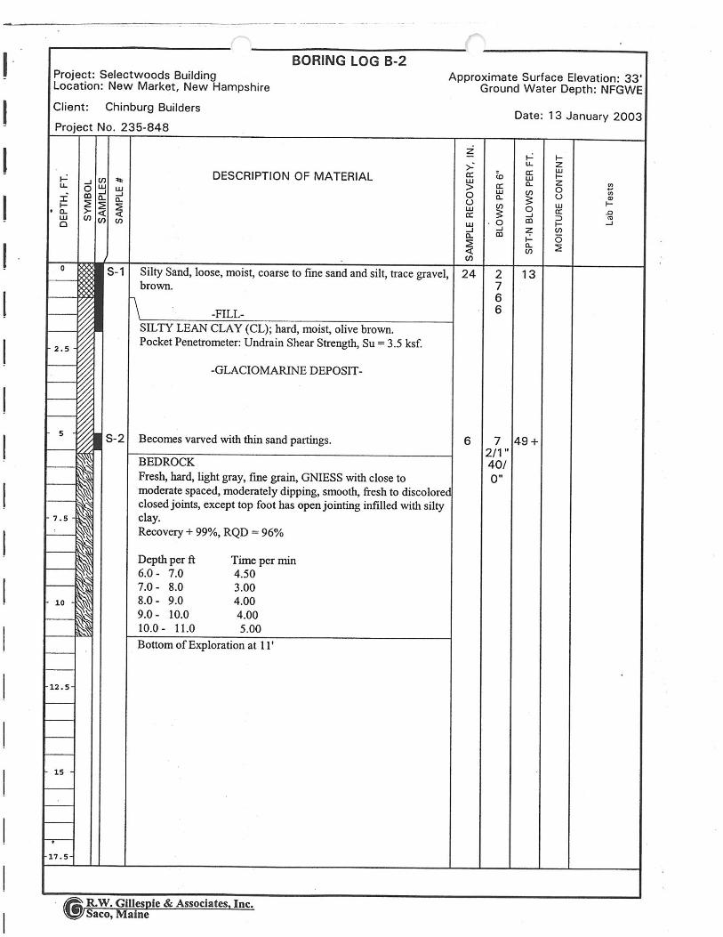


Subsurface Conditions
(2018 GZA Subsurface Exploration)

8
4
3
9
4
14
2 35 4
3 22 3
3 21 3
4 54 3
8 22 5
7 95 5
1
2
3
45
TOPSOIL
CLAYEY SILT (POSSIBLE FILL)
BEDROCK
24
24
24
24
24
24
60
48
29.8'
13.8'
4.8'
S-1
S-2
S-3
S-4
S-5
S-6
C-1
C-2
0-2
2-4
4-6
6-8
8-10
14-16
18-23
23-27
1. Wood fragments stuck in tip of split spoon; possibly part of old shoring.2. Casing and rollerbit refusal at 18 feet below ground surface (bgs).3. Rock casing performed with NX size double tube core barrel. Core rate in units of minutes per foot. RQD = Rock Quality Designation.4. Core C-2 four feet in length. Core barrel jammed at 27 feet bgs.5. Upon completion, boring backfilled with spoils and 1/2 bag of grout and bentonite.
8
12
6
5
8
1
47
45
3
4
2
10
4
5
7
7
6
10
11
9
20
45
40
30
100
4:07
4:01
4:12
4:48
5:05
5:50
4:57
7:11
10:59
2'
18'
27'
S-1: Loose, black, fine to coarse SAND, some Silt, traceClay.
S-2: Medium stiff, brown, Clayey SILT, little fine Sand.
S-3: Soft, brown, Clayey SILT, trace fine Sand.
S-4: Stiff, brown, Clayey SILT, some fine to medium Sand,little Gravel.
S-5A: (Top 1") Medium stiff, brown, Clayey SILT, little fineSand.S-5B: (Bottom 7") Medium stiff, gray, CLAY & SILT, littlefine to coarse Sand, trace Gravel.
S-6: No recovery. (Wood Fragments stuck in tip of spoon.)
C-1: Hard, light to dark gray, fresh to slightly fractured, fineto coarse grained, GNEISS.
C-2: Hard, light to dark gray, fresh to slightly fractured, fineto coarse grained, GNEISS.
Bottom of boring at 27 feet.
30
27
Other:
300
Boring Location:
Logged By:
See Plan
Other:
Split Spoon
Water DepthSampler Hmr Wt (lb):
10/31/2018 - 10/31/2018 V. Datum:Final Boring Depth (ft.):
Sample
HW
Hammer Weight (lb.):
Casing
New England Boring Contractors
Cody Gibb
Groundwater Depth (ft.)
Truck Mounted
Rig Model:Pat SchofieldForeman:
Date Start - Finish:
31.8
Hammer Fall (in.):
Drilling Co.:
Sampler Hmr Fall (in):
1-3/8"/2"
Ground Surface Elev. (ft.):
10/31/18
Drive and Wash
Mobile Drill B-48
NX Core
Type of Rig:
2-1/4"/4" Date
Auger/Casing Type:
824
Time140 1300
NAD83
NAVD88
H. Datum:
I.D/O.D.(in): I.D./O.D. (in.): Stab. Time
Drilling Method:
Auto Trip
Sampler Type:
18
RE
MA
RK
S
Engineers and Scientists
SPTValue
Blows(per 6 in.) R
emar
k
TEST BORING LOG
Depth(ft)
5
10
15
20
25
30
1733
46.1
0 M
AC
ALL
EN
DA
M.G
PJ;
ST
RA
TU
M O
NLY
; 2/2
2/20
19
See Log Key for explanation of sample description and identification procedures. Stratification lines represent approximate boundaries between soil and bedrocktypes. Actual transitions may be gradual. Water level readings have been made at the times and under the conditions stated. Fluctuations of groundwater mayoccur due to other factors than those present at the times the measurements were made.
BORING NO.: GZ-1SHEET: 1 of 1PROJECT NO: 01.0173346.10REVIEWED BY: CBN
GZAGeoEnvironmental, I nc.
StratumDescriptionPen.
(in)
Town of Newmarket, NHMacallen Dam
Newmarket, New Hampshire
Ele
v.(f
t.)
No. Depth(ft.)
Rec.(in)
CasingBlows/CoreRate
Boring No.:GZ-1
FieldTestData D
epth
(ft.)Sample Description and Identification
(Modified Burmister Procedure)

1
234
1. GZ-P1 was drilled as a probe. No samples were taken. The probe was advanced with 4-inch diameter casing and rotary wash drilling methods to refusal.2. Black, fine to coarse Sand and Silt was visually observed in casing spoils.3. Casing refusal at 2.2 feet below ground surface on possible Granite based on visual observation.4. Upon completion, borehole backfilled with spoils and grout.
10
100
Black, fine to coarse SAND and SILT.
Bottom of boring at 2.2 feet.
2.2
Other:
300
Boring Location:
Logged By:
See Plan
Other:
NA
Water DepthSampler Hmr Wt (lb):
10/31/2018 - 10/31/2018 V. Datum:Final Boring Depth (ft.):
Sample
HW
Hammer Weight (lb.):
Casing
New England Boring Contractors
Cody Gibb
Groundwater Depth (ft.)
Truck Mounted
Rig Model:Pat SchofieldForeman:
Date Start - Finish:
32
Hammer Fall (in.):
Drilling Co.:
Sampler Hmr Fall (in):
Ground Surface Elev. (ft.):
Not encountered
Drive and Wash
Mobile Drill B-48
Safety Hammer
Type of Rig:
4" Date
Auger/Casing Type:
24
Time
NAD83
NAVD88
H. Datum:
I.D/O.D.(in): I.D./O.D. (in.): Stab. Time
Drilling Method:
Sampler Type:
RE
MA
RK
S
Engineers and Scientists
SPTValue
Blows(per 6 in.) R
emar
k
TEST BORING LOG
Depth(ft)
5
10
15
20
25
30
1733
46.1
0 M
AC
ALL
EN
DA
M.G
PJ;
ST
RA
TU
M O
NLY
; 2/2
2/20
19
See Log Key for explanation of sample description and identification procedures. Stratification lines represent approximate boundaries between soil and bedrocktypes. Actual transitions may be gradual. Water level readings have been made at the times and under the conditions stated. Fluctuations of groundwater mayoccur due to other factors than those present at the times the measurements were made.
BORING NO.: GZ-P1SHEET: 1 of 1PROJECT NO: 01.0173346.10REVIEWED BY: CBN
GZAGeoEnvironmental, I nc.
StratumDescriptionPen.
(in)
Town of Newmarket, NHMacallen Dam
Newmarket, New Hampshire
Ele
v.(f
t.)
No. Depth(ft.)
Rec.(in)
CasingBlows/CoreRate
Boring No.:GZ-P1
FieldTestData D
epth
(ft.)Sample Description and Identification
(Modified Burmister Procedure)

1
2
3
1. GZ-P2 was drilled as a probe. No samples were taken. The probe was advanced with 4-inch diameter casing and rotary wash drilling methods to refusal.2. Brown, Silty Clay and Sand was observed in wash water.3. Casing and rollerbit refusal on possible Bedrock based on rock fragments in wash water return and core at boring GZ-4.
5
6
5
7
10
10
8
10
20
10
12
12
25
20
30
100
(Blind drill return from approximately 1 to 16'.)Brown, SILT & CLAY, little to trace, fine to coarse Sand.
Bottom of boring at 16 feet.
16
Other:
300
Boring Location:
Logged By:
See Plan
Other:
NA
Water DepthSampler Hmr Wt (lb):
10/31/2018 - 10/31/2018 V. Datum:Final Boring Depth (ft.):
Sample
HW
Hammer Weight (lb.):
Casing
New England Boring Contractors
Cody Gibb
Groundwater Depth (ft.)
Truck Mounted
Rig Model:Pat SchofieldForeman:
Date Start - Finish:
32
Hammer Fall (in.):
Drilling Co.:
Sampler Hmr Fall (in):
Ground Surface Elev. (ft.):
Not encountered
Drive and Wash
Mobile Drill B-48
Safety Hammer
Type of Rig:
4" Date
Auger/Casing Type:
24
Time
NAD83
NAVD88
H. Datum:
I.D/O.D.(in): I.D./O.D. (in.): Stab. Time
Drilling Method:
Sampler Type:
RE
MA
RK
S
Engineers and Scientists
SPTValue
Blows(per 6 in.) R
emar
k
TEST BORING LOG
Depth(ft)
5
10
15
20
25
30
1733
46.1
0 M
AC
ALL
EN
DA
M.G
PJ;
ST
RA
TU
M O
NLY
; 2/2
2/20
19
See Log Key for explanation of sample description and identification procedures. Stratification lines represent approximate boundaries between soil and bedrocktypes. Actual transitions may be gradual. Water level readings have been made at the times and under the conditions stated. Fluctuations of groundwater mayoccur due to other factors than those present at the times the measurements were made.
BORING NO.: GZ-P2SHEET: 1 of 1PROJECT NO: 01.0173346.10REVIEWED BY: CBN
GZAGeoEnvironmental, I nc.
StratumDescriptionPen.
(in)
Town of Newmarket, NHMacallen Dam
Newmarket, New Hampshire
Ele
v.(f
t.)
No. Depth(ft.)
Rec.(in)
CasingBlows/CoreRate
Boring No.:GZ-P2
FieldTestData D
epth
(ft.)Sample Description and Identification
(Modified Burmister Procedure)

Test Pit No.Page No. 1 of 1File No.Checked By:
Excavation EquipmentGZA Rep. Contractor Date
Operator Ground Elev.Weather Make Kubota Model Time Started
Capacity ~0.2c.y. Reach 20 ft. Time Completed
Depth Soil Description Sample PID Boulders:No. Reading Excav. Count/ Note
(ppm) Effort Class No.Dark brown to black SILT, some fine to coarse SAND. [TOPSOIL]Black fine to coarse SAND, some Silt, trace Clay [FILL]
Brown CLAYEY SILT, little fine Sand. [CLAYEY SILT - POSSIBLE FILL]
Bottom of Test Pit at 6 feet.
Notes: 1. Shallow granite block encountered 2-feet 2-inches below ground surface on the northwest side of TP-1. Limit of block extendsapproximately 4-feet from west side and approximately 5-feet from north side of TP-1. See Test Pit Plan.2. Vertical concrete parapet wall is present in upper 5.5-feet, bearing on a granite block wall below. The granite block wall extends about6-feet beyond the concrete section. No apparent batter observed.
Test Pit Plan
8'
10'
NORTH
Volume = 11.5 cu. yd.
E 0
0
11/2/201831± (NAVD88)
08000910
E 0 1
E
0
E 0
E 0 2
E
TP-1
01.0173346.10CBN
Cody Gibb
Rain 40-50° F
Macallen Dam RehabilitationTown of Newmarket
NewmarketNew Hampshire
New England Boring Contractors, Inc.
KX057-4
Boulder ClassLetter Size Range
Designation ClassificationA 6" - 17"B 18" - 36"C 36" and Larger
0
1'
16'
TRACE (TR.)
LITTLE (LI.)
SOME (SO.)
AND
0 - 10%
10 - 20%
20 - 35%
35 - 50%
Excavation EffortE-----EasyM-----ModerateD-----Difficult
AbbreviationsF = FineM = MediumC = CoarseV = VeryF/M = Fine to mediumF/C = Fine to coarseGR = GrayBN = BrownYEL = Yellow
GROUNDWATER
ElapsedTime toReading(Hours)
( ) Encountered( ) Not Encountered
DepthtoGround-water
ProportionsUsed
Stratification lines represent approximate boundaries between soil types, transitions may be gradual. Water level readings have been made at times and under conditions stated.Fluctuations of groundwater may occur due to factors other than those present at the time measurements were made.
GZAGeoEnvironmental, Inc.Engineers/Scientists
2'
15'
14'
13'
12'
11'
10'
3'
9'
6'
4'
5'
7'
8'
Shallow graniteblock

Test Pit No.Page No. 1 of 1File No.Checked By:
Excavation EquipmentGZA Rep. Contractor Date
Operator Ground Elev.Weather Make Kubota Model Time Started
Capacity ~0.2c.y. Reach 20 ft. Time Completed
Depth Soil Description Sample PID Boulders:No. Reading Excav. Count/ Note
(ppm) Effort Class No.Dark brown to black SILT, some f-c SAND. [TOPSOIL]Brown f-c SAND, some Silt, little Clay, trace Cobbles [FILL]
Bottom of Test Pit at 6-feet.
Notes: 1. Wall consists of approximately 4-foot high concrete wall bearing on a larger granite block wall below. The granite block wallextends approximately 5-feet beyond the back of the concrete section. No apparent batter observed at back of masonry wall.
Test Pit Plan
8'
8'
NORTH
Volume = 14.8 cu. yd.
11/2/201828± (NAVD88)
10301200
1E
A/6
E 0
E 0
E 0
E 0
E 0
TP-2
01.0173346.10CBN
Cody Gibb
Rain 40-50° F
Macallen Dam RehabilitationTown of Newmarket
NewmarketNew Hampshire
New England Boring Contractors, Inc.
KX057-4
Boulder ClassLetter Size Range
Designation ClassificationA 6" - 17"B 18" - 36"C 36" and Larger
0
1'
16'
TRACE (TR.)
LITTLE (LI.)
SOME (SO.)
AND
0 - 10%
10 - 20%
20 - 35%
35 - 50%
Excavation EffortE-----EasyM-----ModerateD-----Difficult
AbbreviationsF = FineM = MediumC = CoarseV = VeryF/M = Fine to mediumF/C = Fine to coarseGR = GrayBN = BrownYEL = Yellow
GROUNDWATER
ElapsedTime toReading(Hours)
( ) Encountered( ) Not Encountered
DepthtoGround-water
ProportionsUsed
Stratification lines represent approximate boundaries between soil types, transitions may be gradual. Water level readings have been made at times and under conditions stated.Fluctuations of groundwater may occur due to factors other than those present at the time measurements were made.
GZAGeoEnvironmental, Inc.Engineers/Scientists
2'
15'
14'
13'
12'
11'
10'
3'
9'
6'
4'
5'
7'
8'
Granite block

Test Pit No.Page No. 1 of 1File No.Checked By:
Excavation EquipmentGZA Rep. Contractor Date
Operator Ground Elev.Weather Make Kubota Model Time Started
Capacity ~0.2c.y. Reach 20 ft. Time Completed
Depth Soil Description Sample PID Boulders:No. Reading Excav. Count/ Note
(ppm) Effort Class No.Dark brown to black SILT, some f-c SAND. [TOPSOIL]
Brown f-c SAND, some Gravel, little Silt, little Clay, trace brick debris and other deleterious material[FILL]
Bottom of Test Pit at 8-feet.
Notes: 1. Wall consists of approximately 4-foot high concrete wall bearing on a granite block wall below. The top of the granite block wallextends 2-feet horizontally from the back of the concrete wall.2. Wall observed to step down 2-feet and out 2-feet to a depth of 8-feet below ground surface.3. Top of existing pipe encountered at 6-feet ±0.2-feet below ground surface on the west side of TP-3. Brick observeddirectly overlying pipe.4. Water encountered at 6-feet below ground surface. Observations made below 6-feet based on excavation effort, sound, andoperator experience.
Test Pit Plan
8'
8'
NORTH
Volume = 15.4 cu. yd.
11/2/201828.5± (NAVD88)
12301315
E
E
0
0
E 0
E1,2
0
E 0
E3,4
0
E 0
E 0
TP-3
01.0173346.10CBN
Cody Gibb
Rain 40-50° F
Macallen Dam RehabilitationTown of Newmarket
NewmarketNew Hampshire
New England Boring Contractors, Inc.
KX057-4
Boulder ClassLetter Size Range
Designation ClassificationA 6" - 17"B 18" - 36"C 36" and Larger
0
1'
16'
TRACE (TR.)
LITTLE (LI.)
SOME (SO.)
AND
0 - 10%
10 - 20%
20 - 35%
35 - 50%
Excavation EffortE-----EasyM-----ModerateD-----Difficult
AbbreviationsF = FineM = MediumC = CoarseV = VeryF/M = Fine to mediumF/C = Fine to coarseGR = GrayBN = BrownYEL = Yellow
GROUNDWATER
ElapsedTime toReading(Hours)
( ) Encountered( ) Not Encountered
DepthtoGround-water
ProportionsUsed
Stratification lines represent approximate boundaries between soil types, transitions may be gradual. Water level readings have been made at times and under conditions stated.Fluctuations of groundwater may occur due to factors other than those present at the time measurements were made.
GZAGeoEnvironmental, Inc.Engineers/Scientists
2'
15'
14'
13'
12'
11'
10'
3'
9'
6'
4'
5'
7'
8'
Pipe

Macallen Dam – Abutments and Outlet Structure Rehabilitation
01570-1 October 2019
SECTION 01570TEMPORARY ACCESS AND TRAFFIC CONTROL
PART 1 - GENERAL
1.01 DESCRIPTION
A. The Contractor shall furnish all labor, materials and equipment and shall perform all workrequired to install, maintain, and remove temporary access and traffic control systems at theProject Site, including staging areas, parking areas, and public or private ways accessing thesite.
B. The Contractor shall coordinate with the Project Owner or the owners of properties throughwhich the site will be accessed for the protection of traffic and pedestrians on existing roads,parking areas, and paths, which will be, interfered with by his/her operations. Where trafficis maintained, the work shall be so conducted and guarded so that there will be at all times asafe passageway for all.
C. It is the intent of the Work of this Section that the Contractor shall take such steps as arenecessary to:
Protect the safety of pedestrians and traffic on public or private ways. Protect the safety of personnel accessing the left and right abutments to conduct
repairs, document work or any other construction related activities Exclude the public from the job site for the safety of the public and security of the
Contractor’s work and equipment
D. The Contractor, shall develop a plan to encompass any and all work related to temporarysite access. This plan will act to restrict public access to the site, provide safe access tothe repair areas on the Dam, and allow for Contractor, Resident Engineer, and Owneroperations to be performed safely throughout the entirety of the site. The Contractorshall be responsible for providing and maintain all signage and access controls asnecessary to provide safe access to all areas of the Site and to direct the public away fromwork areas.
E. The Contractor will need to move equipment and material to and from the Project Site. TheContractor shall provide construction traffic control including, but not limited to, temporarysignage, barriers, police detail, as required to protect the public safety. Conform to allrequirements of State of New Hampshire, County, Town, or local laws and requirements fortraffic control. Conformance with contract documents does not relieve the Contractor forresponsibility for public safety. The Contractor is solely responsible for traffic control andfor conformance with all traffic control regulations. Owner access roads to both the left andright abutment are not public ways, therefore it is not anticipated that a police detail will beneeded. However, the Contractor will be responsible to determine the suitability of theseroads for use as access and equipment/material transport. Any damage to access roads by theContractor will be repaired at his/her own expense.
F. The Contractor shall be responsible for obtaining all permits and approvals needed, ifany, from municipal agencies relating to temporary traffic control. The Contractor shall

Macallen Dam – Abutments and Outlet Structure Rehabilitation
01570-2 October 2019
pay all charges, fees and taxes and shall give all notices necessary and incidental to thedue and lawful prosecution of the work under this Contract.
G. Proper signage and additional barriers shall be provided and maintained to provide noticeof restricted areas, to inform the public of possible hazards, to direct the Contractor’sforces to proper access routes, staging areas, and parking areas, and to provide all otherrelevant instructions or notices consistent with the Work of this Section.
1.02 SCOPE OF WORK
A. The scope of the Work of this Section shall include the provision and installation ofTemporary Access Control Fencing, at locations determined by the Contractor and theOwner, and as needed elsewhere. This work shall also include the monitoring, maintenance,and repair of all installed fencing and the proper removal and disposal of fencing aftercompletion of work at the site.
B. General work covered and paid for under this Section shall include the provision andinstallation of all other General Temporary Site Access and Traffic Control Measures, asshown on the Contract Drawings, and as needed elsewhere. This work shall also include allnecessary gates, barriers, locks, scaffolding, staging, matting, etc. needed for site accesscontrol. The Work shall also include the provision of all necessary temporary access andtraffic control signage, including but not limited to signage and miscellaneous site workneeded to establish or maintain site access on existing access roads. General work coveredand paid for under this Section shall also include all other access and traffic control worknecessary to meet the conditions of the Contract Documents, Permits, Approvals, Licensesissued for the project and all relevant codes, rules, regulations, laws and ordinancesapplicable.
1.03 CONSTRUCTION PARKING CONTROL
A. Contractor staging areas are designated on the Contract Drawings. These may be used forparking of construction equipment.
B. The personal vehicles of the Contractor’s personnel shall be parked in areas designatedby the Owner. The Contractor shall not park in parking spaces reserved for residents of 4Bay Road (Lamprey Falls LLC), 6 Bay Road (Bryant Rock, LLC), or 53 Main Street(Durham Book Exchange).
C. Where temporary parking areas are constructed on areas that will be grassed, remove allopen graded shoulder material used for temporary parking areas prior to final landscapegrading for seeding.
D. Control vehicular parking to prevent interference with public traffic and parking, accessby emergency vehicles, Owner’s operations, and any public access parking areas.
1.04 ACCESS CONTROL FENCING
The Contractor shall provide access control fencing to prevent unauthorized entry to constructionareas, to delineate temporary contractor staging areas, and to protect existing facilities, adjacentproperties, and the public from damage from construction operations. Temporary barriers may be

Macallen Dam – Abutments and Outlet Structure Rehabilitation
01570-3 October 2019
required on the site, as determined by the Owner or its Resident Engineer, and shall be provided at noextra cost.
1.05 PROTECTION OF EXISTING FEATURES AND WORK
A. The Contractor shall provide protection for plants, trees, existing structures, and existingutilities, and replace those damaged during construction at no additional cost. It shall bethe Contractor’s sole responsibility to select the location and appropriate construction ofall temporary barriers.
B. The Contractor shall provide all appropriate protection for existing site utilities, overhead, atgrade, and subsurface. The Contractor shall be responsible for repairing or replacing anyutilities damaged during construction at no additional cost to the Owner.
C. The Contractor shall be responsible for providing site security necessary to prevent theft andvandalism from the site, including from stored materials and the Resident Engineer’s trailer.This may include lighting, security cameras, etc.
D. The Contractor shall protect non-Contractor-owned vehicular traffic, stored materials,site and structures from damage and shall replace same if damaged during construction atno additional cost.
1.06 GENERAL ACCESS AND TRAFFIC CONTROL SIGNAGE
The Contractor shall provide all necessary general access and traffic control signage necessary at thesite, including signs indicating the area as a closed to the public, a hardhat area, etc. The Contractorshall also provide a general project information sign stating the project name, the Town, thecontractor information and the Engineer.
1.07 ACCESS AND TRAFFIC CONTROL COORDINATION
A. As part of the general access and traffic control work, the Contractor shall make allnecessary notifications to emergency and public services regarding work which mightinvolve disruption to those services. Coordinate with such agencies and makeaccommodations as necessary.
B. If requested by the Owner, the Contractor shall place a notice in the local newspaperregarding the start of the work, the access road closures, and any detours.
1.08 TEMPORARY SITE ACCESS
A. As part of the general site access control work, the Contractor shall be prepared to provideworking platforms, scaffolding, ladders, ramps, cribbing, shoring, matting, and all otherspecialized support equipment required to ensure safe access of all personnel, equipment,and materials necessary for completion of the work of this Contract in accordance withthe Specifications and Drawings.
B. The Contractor shall specify intended methods for accessing each location for demolition,removal and construction along the existing outlet structure and rehabilitation work alongeach embankment wall as indicated on the Contract Drawings.

Macallen Dam – Abutments and Outlet Structure Rehabilitation
01570-4 October 2019
C. All working platforms, scaffolding, ladders, ramps, cribbing, shoring, matting and any otherspecialized support equipment required for safe temporary site access shall be in compliancewith the most up-to-date Occupational Safety and Health Administration (OSHA)regulations.
1.09 RELATED WORK
A. The following is a list of related work items that shall be performed or furnished under othersections of these specifications as indicated:
1. Regulatory Requirements – Section 01060
2. Temporary Facilities and Controls – Section 01500
3. Site Restoration – Section 01740
4. Mobilization and Demobilization – Section 01900
5. Cast-In-Place Concrete – Section 03300
6. Masonry Repair – Section 04400
1.10 SUBMITTALS
A. Not less than five (5) days prior to the scheduled start of work, the Contractor shall submithis proposed plan for temporary access and traffic control. The submittal shall include as aminimum the following items:
1. General plan for accessing site and controlling traffic.
2. Proposed access route(s) for each side of the dam.
3. Schedule for access road closures or restrictions.
4. Products to be used as signs and barriers.
5. Content and configuration of signs.
6. Means and content of public notification.
7. Layout and location of signs and barriers.
8. Parking plan.
9. Plan for traffic entering/exiting Penstock Way and the parking lot accessed fromBay Road.
10. Approvals from local authorities and railroad (if needed).
11. The general information sign layout and information presented.
12. If requested, newspaper ad text (in local paper) and copy of printed ad.
PART 2 - PRODUCTS
2.01 PLASTIC MESH FENCING
A. Plastic Mesh Fencing, shall be highly visible (orange) extruded plastic flexible safety

Macallen Dam – Abutments and Outlet Structure Rehabilitation
01570-5 October 2019
barricade fencing or equivalent on metal support t-posts installed continuously (i.e., no gaps)around areas as needed and/or directed by the Owner or its Resident Engineer. Such fencingshall be a minimum of four feet high.
2.02 TRAFFIC CONTROL MATERIALS
A. All products used shall be in conformance with the latest edition of the New HampshireDOT (NHDOT) Standard Specifications for Road and Bridge Construction.
B. Temporary Traffic Control devices need not be new but must be in first class condition andacceptable to the Resident Engineer. Temporary Traffic Control devices not up to standardsshall be removed from the site and replace with acceptable products.
C. In the event that traffic controls are needed after dark, appropriate lighted and/or reflectivebarriers, flashers, signals, etc. shall be provided.
2.03 SIGNAGE
A. Temporary traffic control signs on public ways and in parking lots shall conform to therequirements of the latest edition of the NHDOT Standard Specifications for Road andBridge Construction .
B. Other temporary access and traffic control signage shall be commercially printed, all-weather signs on stiff backing. Where appropriate signs shall conform to OSHA guidelines.In general, signs shall be a minimum of 4 square feet in area and shall utilized colors whichare highly visible.
C. All signage shall be firmly affixed to wooden or metal posts at an appropriate height. Signsmay not be affixed to trees in a manner which will result in permanent damage.
2.04 LOCKS AND KEYS
A. The Contractor shall provide the Owner’s Resident Engineer with two sets of keys, each, forany locks installed at the site, excepting the Contractor’s own trailer. Additional sets of keysmay be requested by the Owner in order to provide access to specific areas of the sites, foroperations and maintenance personnel as needed.
PART 3 – EXECUTION
3.01 GENERAL ACCESS CONTROL
A. The Contractor shall be responsible for preparing and executing a Temporary Site Accessand Traffic Control Plan for the work site, access roads, parking lots, and traffic onto the sitein accordance with the needs of the schedule and work plan. The plan shall be approved bythe Owner and all relevant local authorities, as necessary. The Contractor is responsible forall necessary interaction, consultation, and coordination.
B. The Contractor shall be responsible to extend and relocate access staging and traffic controlsas Work progresses by removing or changing signage and barriers at the beginning and endof each work day and removing any and all staging equipment required for the work from

Macallen Dam – Abutments and Outlet Structure Rehabilitation
01570-6 October 2019
the construction areas upon completion, as required by the Plan. The Contractor shall alsomaintain existing roads, driveways, and paths accessing the site as well as the constructionarea.
C. The Contractor shall be responsible for all work and materials, including temporary fill, steelroad plates, etc., required to protect roadways, access roads, parking lots, sidewalks,overhead utilities, and buried underground structures or utilities beneath. Trees near theconstruction staging area shall be protected in accordance with the specifications.Additional tree protection shall be provided as needed at the Contractor’s discretion. Allprotection measures shall be at the Contractor’s sole expense.
D. The Contractor shall provide appropriate safety equipment and training to all personnelassisting with Traffic Control and to all personnel who will drive vehicles onto the site.
E. The Contractor is responsible for site security.
F. The Contractor shall inspect and maintain the signage at the site including signage informingpedestrians of appropriate routes around the site and of areas of no access. Inspections shalltake place at minimum weekly, or as directed by the Owner or Resident Engineer.
G. Once construction has begun, the Contractor shall take all reasonable steps to exclude thepublic from the construction and staging areas, including fences, barriers, signs, etc. TheContractor shall insure that barriers are replaced each night and over weekends so that accessto the site is restricted during non-work hours.
H. The Contractor shall take such steps as are necessary to prevent the spilling of materials andliquids onto the paved surface of the roads and parking lots which extend from the dam. TheContractor shall be responsible for such actions as are necessary, including cleaning,sweeping, etc. as directed by the Resident Engineer, to keep these surfaces clean. Do NOTwash soil, sediment, or other material into surface water bodies, ditches, or storm drains.
I. Upon completion of the work, the Contractor shall remove all items associated with theTemporary Site Access and Traffic Control Plan and restore any disturbed areas.
3.02 POLICE DETAILS AND FLAGGERS
A. The Contractor shall provide such police officers or flaggers, as may be deemed necessary,by the Resident Engineer or by the Owner, for the direction and control of traffic entering,passing through, and leaving the site of the work.
PART 4 – MEASUREMENT AND PAYMENT
Refer to Section 01950 – Measurement and Payment for the measurement and payment items related to thisSection.
* * * END OF SECTION * * *
J:\170,000-179,999\173346\173346-10.TEM\WORK\Specifications\FINAL\Division 1\01570 - Traffic and Access Control.docx

Macallen Dam – Abutments and Outlet Structure Rehabilitation
01740 - 1 October 2019
SECTION 01740SITE RESTORATION
PART 1 - GENERAL
1.01 SCOPE
A. The work under this Section shall consist of all work and operations, including, but notlimited to equipment, supplies, material, personnel, and incidentals to restore areas in andaround the project site to pre-construction conditions.
B. The intent of the Work of this Section is that areas which are disturbed as a result of theoverall Work of this Contract, whether intentionally or unintentionally, planned orunplanned, are restored to at or better than their conditions prior to the start of work. TheScope of Work under this Section shall also include both significant and incidental worknecessary to repair damage to the site beyond those areas shown as disturbed on the ProjectPlans. Areas to be restored shall include, but not be limited to, locations of trailers, laydownareas, construction access roads, adjacent private property used for access, etc. Facilities tobe restored include paving, grassed areas, trees, and utilities, and any other propertydisturbed during Work activities. Additionally, restoration shall include public roadways,sidewalk, or private property areas, if disturbed. Areas of note that shall be restored are asfollow: the landscaped area directly adjacent to the exiting gate structure along the leftabutment and around the new subsurface gate operations vault structure; the flagpoleadjacent to the existing gate structure shall be removed and replaced-in-kind; the 6-inchPVC irrigation intake pipe immediately upstream of the existing gate shall be removedand replaced-in-kind.
C. It is the intent of the Contract that the Contractor avoid and minimize indirect constructionimpact to the maximum extent possible. To this end, the site and surrounding areas shouldbe protected, as needed and as provided for under separate Sections of the Contract.The Contractor should also develop a plan to protect the site and inform and educate theirforces regarding protective measures to be implemented. This Section covers the restorationof damage caused by unavoidable or inadvertent actions by the Contractor’s forces,including all sub-contractors, material deliverers, and others under the Contractor’s employor authority. It is the intent of the Contract that the work of this Section be minimized to theextent possible by the Contractor’s actions to avoid damage to the site and area.
1.02 DOCUMENTATION OF EXISTING CONDITIONS
A. Prior to the start of work, the Contractor shall be responsible for documenting thepre-construction conditions of these and other areas which might be disturbed by theWork of the Contract. Documentation of pre-construction conditions shall becoordinated with the Pre-Construction Survey requirements set forth in Section 01436.This documentation shall be used to determine the extent to which post-construction siterestoration shall be needed.
B. Project Location: Access to the general and immediate project site location is via 6 BayRoad (Bryant Rock LLC.), a private condominium complex off Bay Road (a public pavedroadway), and Penstock Way, a private paved roadway off Main Street (a public paved

Macallen Dam – Abutments and Outlet Structure Rehabilitation
01740 - 2 October 2019
roadway), both located in Newmarket, NH. Utilities may exist under these roadways andthe temporary access roads to the work area.
C. Staging, Laydown and Stockpile Area: The Contract Drawings specifically delineatestaging and lay-down areas for the Contractor, as well as areas not to be disturbed. TheContractor shall be strictly monitored for compliance with these boundaries. Properenvironmental and housekeeping procedures by the Contractor are required. Additionalsupplemental staging, lay-down, or stockpile areas may be available for use at alternatelocations designated by the Owner, however, if the Contractor feels additional staging orlay-down areas are required, the Contractor shall request an extension of the boundaries orrequest supplemental areas to the Owner in writing.
1.03 PROTECTION OF EXISTING FEATURES
The Contractor shall take such steps and measures as are necessary to protect the project site andadjacent areas from damage by construction activities and thereby minimize the extent of work tobe done under this Section. Site protection shall be paid for under the Scope of other Sections.
1.04 RELATED SECTIONS
1. Section 01500 – Temporary Facilities and Controls
2. Section 01565 – Sedimentation and Erosion Controls
3. Section 02200 – Earthwork
4. Section 02930 – Loaming and Seeding
1.05 SUBMITTALS
A. The Contractor shall submit a Pre- and Post-Construction Survey documentation inaccordance with requirements of Section 01436, which shall also include any additionalinformation required herein.
B. The Contractor shall submit information, as needed, on site restoration methods andmaterials to be used in restoring site conditions.
PART 2 – PRODUCTS
A. Products used in Site Restoration shall meet the requirements of the applicable Section of theContract Documents. If work similar to the nature of the necessary site restoration is notspecified elsewhere in the Contract Documents, the applicable section of the State of NewHampshire Department of Transportation Standard Specifications for Road and BridgeConstruction, shall control. Materials for restoration of utilities shall meet with the standardsof the Owner or the utility to be restored.
PART 3 – EXECUTION
3.01 GENERAL

Macallen Dam – Abutments and Outlet Structure Rehabilitation
01740 - 3 October 2019
A. The work required and services for site restoration shall be done in a safe workmanlikemanner and shall conform to any pertinent local or state law, regulation or code. Goodhousekeeping consistent with safety shall be maintained. The Contractor shall be responsiblefor all necessary permits and approvals.
3.02 PRE AND POST-CONSTRUCTION SITE DOCUMENTATION
A. Prior to the start of work at the site, the Contractor shall coordinate with the Owner andEngineer to perform a pre-construction site walk for the purposes of documenting conditionsprior to disturbance by the Contractor’s forces and equipment. A representative from theOwner and/or Engineer shall accompany the Contractor during the site walk, but it shall bethe Contractor’s sole responsibility to properly document existing conditions in all areaswhich might be subject to disturbance. The Contractor shall utilize photographs, video,written descriptions, sketches, and any other means to document pre-construction conditions.If requested, the Contractor shall supply the Owner with one copy each of thedocumentation, including both hard copies and digital files, as appropriate. The Owneralone shall be empowered to make decisions about the pre-construction condition of areasnot covered by the Contractor’s documentation. This pre-construction site documentationshould be coordinated with the pre-construction survey, as defined in Section 01436.
B. At the completion of the work at the site, the Contractor shall coordinate with the Owner andEngineer to perform a post-construction site walk inspecting all areas included in the pre-construction site walk. The post-construction site walk shall be an examination similar tothe pre-construction site walk and shall be coordinated with the post-construction survey, asdefined in Section 01436.
3.03 RESTORATION METHODOLOGY
A. Means of Site Restoration shall meet the requirements of the applicable Section of theContract Documents. If work similar to the nature of the necessary site restoration is notspecified elsewhere in the Contract Documents, the applicable section of the State of NewHampshire Department of Transportation Standard Specifications for Road and BridgeConstruction shall control. Proper sediment, erosion, and water control shall be provided, asneeded, at no additional cost.
3.04 RESTORATION OF ROADS
A. The Contractor shall be required to repair any damage to roadways caused during the courseof construction, in order to return the roads to pre-construction condition or better.
B. Restoration of paved areas shall be done with similar materials and paving characteristics.
C. The Owners shall determine the appropriateness of proposed restorations (e.g. spot patching,full depth repaving, etc.)
3.05 RESTORATION OF STAGING, LAYDOWN AND STOCKPILE AREA
A. The Contractor shall be prepared to repair any damage to the area which will be utilized asthe staging, laydown/storage and stockpile area. These areas shall be restored to their pre-construction condition or better. Restoration is likely to include clean up to remove any/allmaterials, trash and debris resulting from its use during the work, as well as grading of the

Macallen Dam – Abutments and Outlet Structure Rehabilitation
01740 - 4 October 2019
site to smooth out any disturbances made during the work. The Contractor shall be requiredto repair any damage to these areas caused during the course of construction as well as theentrance areas where it meets the existing sidewalk and roadway, in order to return the areato pre-construction condition or better. The cost of restoration of these areas shall befactored into the cost presented for this Section on the Bid Form.
3.06 RESTORATION OF VEGETATED AREAS
A. The Contractor shall be responsible for restoring all vegetated areas beyond the indicatedlimits of work disturbed during the work of this Contract. Restoration shall include, but notbe limited to, loam placement, regrading, seeding, mulching, and maintenance. The intent isto restore damaged areas to pre-construction condition or better. Loaming, seeding, andrevegetation of areas which are shown on the plans as being filled, excavated, or gradedcompleted under Section 02930.
B. The Contractor shall be responsible for restoration of the landscaped area immediatelyadjacent to the existing gate structure along the left abutment, specifically the areas disturbedduring installation of the new concrete gate structure and around the subsurface gateoperations vault.
C. The Contractor shall be responsible for maintenance and care of all restored vegetated areasuntil establishment.
3.07 TREES
A. The Contractor shall be responsible for pruning and other actions necessary to repairconstruction-related damage to trees which are shown to remain in place or are outside of theconstruction areas.
B. The Contractor shall hire a certified arborist to perform restoration work on large trees, ifjudged necessary by the Owner.
C. The Contractor shall protect all trees which might be damaged by the Work of the Contract.Protection shall include physical protection of the trunk and fencing to exclude disturbanceinside the drip line perimeter.
3.06 OTHER AREAS OF NOTE
A. The Contractor shall remove and replace-in-kind the 6-inch PVC irrigation intake pipe,which currently runs immediately upstream of the existing outlet structure. The new PVCirrigation intake shall run upstream of the new pneumatic gate structure and downstream ofthe pneumatic gate’s water level sensor, as described in Section 11288.
B. The Contractor shall remove and replace-in-kind the flagpole and associated footingadjacent to the existing gate structure upon completion of the installation of the new concretegate structure.
C. Additionally, the Contractor shall coordinate with the Owner and Engineer with regard toother items of note which may need removal/replacement-in-kind as a result of disturbanceduring the Work.

Macallen Dam – Abutments and Outlet Structure Rehabilitation
01740 - 5 October 2019
PART 4 – MEASUREMENT AND PAYMENT
Refer to Section 01950 – Measurement and Payment for the measurement and payment items related tothis Section.
* * * END OF SECTION * * *
J:\170,000-179,999\173346\173346-10.TEM\WORK\Specifications\FINAL\Division 1\01740 - Site Restoration.docx
Macallen Dam – Abutments and Outlet Structure Rehabilitation
01900-1 October 2019
SECTION 01900MOBILIZATION/DEMOBILIZATION
PART 1 - GENERAL
1.01 SCOPE
A. The work under this Section shall consist of the Contractor’s preparatory work and operations,including, but not limited to transporting equipment, supplies, personnel and incidentals toand from the work site, and all other operations which must be performed or for costs whichmust be incurred prior to commencement of the work.
B. Work under this Section shall also include all work, services, equipment and other incidentalitems, whether specifically mentioned herein or not, to perform similar tasks at the work siteat the conclusion of the work, in order to restore the site to its intended condition and removeall items which are not a permanent part of the work from the site, and to leave the site in aclean and orderly manner as directed by the Resident Engineer.
C. The work of this Section shall also include any potential work, labor, equipment, materials,labor, and other expenses necessary for emergency protection of, demobilization from, andremobilization to the project site in the event of heavy rains, increased flows, and/or high waterlevels which cause the inundation of the job site or other weather-related conditions whichtemporarily restrict access to the work area.
D. The Work of this Section shall include all efforts and costs to provide general bonds,insurance, and permits required by the Contract and necessary for the Work, except asspecifically noted elsewhere.
E. The Work of this Section shall include all work and operations, including, but not limited toequipment, supplies, material, personnel, and incidentals to restore disturbed areas in andaround the project site to pre-construction conditions, protection of existing structures andfeatures at the site, as well as for site preparation, including dismantling, relocation,demolition, removal, and lawful off-site disposal of certain existing materials and structuresat the site not otherwise covered by other Sections. The Work of the is Section shall alsoinclude the provision, installation, inspection, maintenance, and removal of all temporaryfacilities and controls necessary for the Contractor to successfully complete the Work of thisContract in accordance with the Plans, Specifications, Permits, and all applicable local, state,and Federal laws and regulations.
1.02 DEMOBILIZATION / REMOBILIZATION DUE TO INCLEMENT WEATHER
The Contractor is hereby notified that the Work of this Contract will take place in, on, and aroundMacallen Dam. Portions of this Work will require personnel and equipment to be located on oradjacent to the Dam, the upstream embankments, and in or near other areas typically subject to waterflow. This work may require significant surface water and groundwater control efforts. Certainweather conditions (such as an extended period of heavy rainfall and/or a weather event such as ahurricane) could potentially inhibit proposed work.
Responses to such events are the Contractor’s responsibility and no extra payment shall be madeunless otherwise specified herein. The Contractor shall make provision for contingencies to dealwith inclement weather. In the event of rising waters and increasing flow, the Contractor may be

Macallen Dam – Abutments and Outlet Structure Rehabilitation
01900-2 October 2019
required to act rapidly to protect the structure and the work, including removal of personnel andequipment from potentially affected areas and temporary placement of “super-sack” type sand bags toprevent inflow to the work area. The Contractor may have to demobilize from the potentially affectedareas on a temporary basis. Prior to leaving the area, the Contractor shall take such steps as arenecessary to protect completed work and work in progress and to remove all equipment and materialsfrom potentially inundated areas. The Contractor shall be responsible for any loss or damage to hiswork, equipment, or material. After water levels/flows have receded, the Contractor shallremobilize to the site. Such remobilizations and demobilizations (if required) shall be completedat no additional cost to the Owner, unless otherwise specified herein. Remobilization will includeall effort required to restart the Work.
To reduce the chance of high water levels / flows affecting the Work, the Contractor is urged to payparticular attention to weather forecasts for the area and to schedule work in vulnerable areas forperiods which are anticipated to be relatively dry.
1.03 EXISTING CONDITIONS
Staging areas shall be decided in agreement with the Owner in locations shown on the Plans. TheContractor shall be responsible for marking and maintaining all existing structures and utilitieswithin the staging area(s) and the work area before, during and after the course of work. Contractorresponsibilities shall include notifying Dig Safe and all appropriate Town departments prior tocommencing work.
The Contractor shall be prepared to provide working platforms/ramps, cribbing, shoring, matting,and all other specialized support equipment required to ensure safe access of all personnel,equipment and materials necessary for completion of the work of this Contract in accordance withthe Specifications and Contract Drawings.
1.04 SCHEDULE AND SEQUENCE
A. A suggested construction sequence is shown on the Contract Drawings. The constructionsequence provided is not comprehensive and does not relieve the Contractor fromresponsibility for executing all required work as per the Contract Drawings and Specifications.
B. Certain weather conditions (such as an extended period of very heavy rainfall and/or anabnormal weather event such as a hurricane) could cause a significant rise in the depth ofwater in the river and impoundment areas. Therefore, the Contractor shall establish hismobilization/demobilization bid price accordingly in order to maintain all necessaryequipment to be able to rapidly demobilize from work areas if necessary. In the event ofan emergency demobilization action the Contractor shall take all necessary measures toprotect the work in progress and replace at his own expense all work, materials andequipment lost or damaged as a result of an emergency action.
1.04 RELATED SECTIONS
1. Section 01060 – Regulatory Requirements2. Section 01500 – Temporary Facilities3. Section 01740 – Site Restoration
Site restoration shall be performed and paid for under Section 01740. Site restoration work shallinclude restoration of impacts and damage to the site caused by construction activities.

Macallen Dam – Abutments and Outlet Structure Rehabilitation
01900-3 October 2019
PART 2 – PRODUCTS
This Section Not Used
PART 3 – EXECUTION
3.01 GENERAL
A. The work required and services for mobilization/demobilization shall be done in a safeworkmanlike manner and shall conform to any pertinent local or state law, regulation or code.Good housekeeping consistent with safety shall be maintained.
B. No payment shall be made for any necessary demobilization and remobilization as statedabove.
3.02 PRE-CONSTRUCTION SITE MEETING
A meeting with the Owner, the Engineer, and the Contractor will occur prior to the beginning of anyrehabilitation work at the site, in accordance with Section 01200. During this meeting the Contractor willbecome familiar with the site, including working conditions, existing access road conditions, and accessrestrictions. During this meeting the final location of laydown and spoil disposal areas will be discussed, andconfirmation that the appropriate notifications and clearances (i.e. DIG SAFE and the Owner’s internalclearance as applicable) have been executed.
PART 4 - MEASUREMENT AND PAYMENT
Refer to Section 01950 – Measurement and Payment for the measurement and payment items related tothis Section.
* * * END OF SECTION * * *
\\GZANOR\Jobs\170,000-179,999\173346\173346-10.TEM\WORK\Specifications\FINAL\Division 1\01900 - Mobilization-Demobilization.docx
Macallen Dam – Abutments and Outlet Structure Rehabilitation
01950-1 October 2019
SECTION 01950MEASUREMENT AND PAYMENT
PART 1 - GENERAL
1.01 PAY ITEMS AND UNITS
The payment items for the Work of this contract shall be as shown in this Section. Pay items shallhave the corresponding unit of measurement for the Work of that item, as shown in this Sectionand on the Bid Form. Payment for all pay items shall be at the corresponding price shown on theBid Form.
1.02 GENERAL
The Bid Form has an entry for each item on which payment will be made (i.e. Schedule of Values).No other allowance of any kind will be made unless specifically provided/stipulated in the Contract.
Each unit and lump-sum price stated on the Bid Form shall constitute full compensation as specifiedherein for each item of work complete in accordance with the Contract Drawings andSpecifications. The unit and lump sum prices shall be inclusive of the full scope of the work foreach item, including all labor, tools, materials, transportation, fuel, equipment, incidentals,mobilization/demobilization, and any other costs necessary to complete the work of the Pay Item.
1.03 GUARANTEE AND WARRANTY
The Contractor guarantees all equipment against defective materials and workmanship for a periodof one year from the date of Final Acceptance, unless otherwise specified, and shall provide inhis purchase orders with the suppliers that they agree to guarantee all equipment against defectivematerials and workmanship for a period of one year from the date of Final Acceptance or suchlonger period as may be specified. During the maintenance and guarantee period, the suppliers shallbe responsible to the Contractor to promptly repair, replace, restore, or rebuild, as the Owner maydetermine, any furnished equipment in which defects of materials or workmanship may appear orto which damage may occur because of such defects. The Contractor shall also submit to the Ownera certified copy of the Supplier’s Guarantee for the equipment furnished against defective materialsand workmanship prior to receiving any payment, which Guarantee shall also include the Owneras a guaranteed party.
1.04 RELATED PROVISIONS
A. Payments to Contractor: Refer to Standard General Conditions, Supplemental GeneralConditions, and Form of Agreement.
B. Changes in Contract Price: Standard General Conditions and Supplemental GeneralConditions.
C. Schedule of Values: Refer to General Conditions, Supplementary Conditions, andSchedule of Values.

Macallen Dam – Abutments and Outlet Structure Rehabilitation
01950-2 October 2019
1.05 LUMP SUM QUANTITIES
A. No measurement shall be made of work, materials, or other quantities involved in provisionor construction of Pay Items listed on the Bid Form as being Lump Sum quantities.Payment for the scope of the work specified for each Lump Sum Pay Item shall include alllabor, tools, materials, equipment, fuel, supplies, overhead, profit, and incidentals.
1.06 LUMP SUM CONTRACT ITEMS
The following lump sum contract items shall be included in the Contractor’s total bid for thisContract.
A. Pay Item No. 1 – As-Built Drawings
1. No measurement shall be made for Pay Item No. 1 which has been provided on theBid Form as a Lump Sum.
2. Pay Item No. 1 shall include all measures, including all labor, materials, equipmentand incidentals, to produce and submit any and all As-Built Drawings for the Workperformed at the Project Site. Deliverables for Pay Item No. 1 shall also includeall as-Built markups and a final conditions survey.
3. The work and materials shall be in accordance with Specification Section 01055 –As-Built Drawings.
4. Payment for the scope of the work for As-Build Drawings specified herein shall bepaid for at the applicable lump sum price for Item No. 1 stated on the Bid Form.
B. Pay Item No. 2 – Vibration and Movement Monitoring
1. No measurement shall be made for Pay Item No. 2 which has been provided on theBid Form as a Lump Sum.
2. Pay Item No. 2 shall include all labor, materials, equipment and incidental costs toprovide pre- and post-construction surveys, establish and install monitoring points,crack gauges, and seismographs, provide continuous monitoring, provide periodicreporting and record keeping as specified, and provide notification any remedialactions for threshold exceedances as necessary.
3. The work and materials shall be in accordance with Specification Section 01436 –Vibration and Movement Limits and Monitoring.
4. Payment for the scope of the work specified herein shall be paid for at the applicableLump Sum price for Item No. 2 on the Bid Form.
C. Pay Item No. 3 – Temporary Facilities and Controls
1. No measurement shall be made for Pay Item No. 3 which has been provided on theBid Form as a Lump Sum.

Macallen Dam – Abutments and Outlet Structure Rehabilitation
01950-3 October 2019
2. Pay Item No. 3 shall include Temporary Facilities and Controls including, but notlimited to, sanitary facilities, utilities, drinking water, and temporary field offices.Pay Item No. 3 shall also include all labor, materials, equipment and incidentals andmobilization/demobilization costs to provide, install, maintain, and removeTemporary Facilities and Controls, including tree protection, associated with thework of this Contract.
3. The work and materials shall be in accordance with Specification Section 01500 –Temporary Facilities and Controls and the Contract Drawings.
4. Payment for the scope of the work specified herein, shall be paid for at the applicableLump Sum price for Item No. 3 on the Bid Form. Partial Payment for this itemshall be provided as follows: Sixty percent (60%) of lump sum bid price uponcompletion of installation and approval by the Resident Engineer. Following thesatisfactory completion of work, forty percent (40%) of lump sum bid price willbe paid upon removal and cleanup of the Temporary Facilities and Controls.
D. Pay Item No. 4: Temporary Erosion and Sedimentation Controls
1. No measurement shall be made for Pay Item No. 4 which has been provided on theBid Form as a Lump Sum.
2. Pay Item No. 4 shall include all labor, materials, equipment and incidentals andmobilization/demobilization costs to provide, install, maintain, and removeTemporary Erosion and Sedimentation Control measures and Best ManagementPractices (BMPs), including but not limited to silt fence, turbidity curtains,pumped water filter bags, compost filter socks, and stabilized construction siteentrance. This work shall also include the monitoring, cleaning, maintenance, andrepair/replacement of all installed temporary erosion controls and BMPs; and theirproper removal and disposal at the completion of the Work at the Site. Pay ItemNo. 4 shall also include the development of a Flood Emergency Response Plan.
3. The work and materials shall be in accordance with Specification Section 01560 –Temporary Sediment and Erosion Control and the Contract Drawings.
4. Payment for the scope of the work specified herein shall be paid for at theapplicable unit price for Item No. 4 stated on the Bid Form. Partial Payment forthis item shall be provided as follows: Sixty percent (60%) of lump sum bid priceupon completion of installation and approval by the Engineer and permittingagencies/representatives having jurisdiction. Following the satisfactorycompletion of work, forty percent (40%) of lump sum bid price will be paid uponremoval and cleanup of Temporary Erosion and Sedimentation Controls.
E. Pay Item No. 5: Gate Structure and Left Abutment Temporary Water Control andTemporary Cofferdams
1. No measurement shall be made for Pay Item No. 5 which has been provided on theBid Form as a Lump Sum.
2. Pay Item No. 5 shall include all labor, materials, equipment, testing, monitoring,incidentals and mobilization/demobilization costs to provide Gate Structure and
Macallen Dam – Abutments and Outlet Structure Rehabilitation
01950-4 October 2019
Left Abutment Temporary Water Control and Temporary Cofferdams for allphases of the work. Pay Item No. 5 shall also include all measures utilized totemporarily remove water from within work areas of the left abutment and gatestructure including, but not limited to, pumps, hoses, poly sheeting for sand bags,“Super Sacs” or other temporary cofferdam materials as approved for use by theEngineer, and temporary power for pumps and temporary staff gauges or waterelevation measuring points.
3. The work and materials shall be in accordance with the Contract Drawings,Specification Section 01565 – Temporary Water Control and with SpecificationSection 02170 – Temporary Cofferdams. Treatment of discharge water shall be inaccordance with Specification Section 01560 – Temporary Sediment and ErosionControl.
4. Payment for the scope of the work specified herein, to provide Gate Structure andLeft Abutment Temporary Water Control and Temporary Cofferdams associatedwith the work of this Contract, including temporary surface water control, andtreatment of all discharge water as necessary, shall be paid for at the applicableLump Sum price for Item No. 5 stated on the Bid Form. Payment for this itemshall be on the basis of sixty percent (60%) of the lump sum bid price payable afterinitial deployment of the Gate Structure and Left Abutment Temporary WaterControl and Temporary Cofferdams and forty percent (40%) after substantialcompletion of the work and removal of all temporary materials.
F. Pay Item No. 6: Right Abutment Temporary Water Control and Temporary Cofferdams
1. No measurement shall be made for Pay Item No. 6 which has been provided on theBid Form as a Lump Sum.
2. Pay Item No. 6 shall include all labor, materials, equipment, testing, monitoring,incidentals and mobilization/demobilization costs to provide Right AbutmentTemporary Water Control and Temporary Cofferdams for all phases of the work.Pay Item No. 6 shall also include all measures utilized to temporarily remove waterfrom within work areas of the right abutment including, but not limited to, pumps,hoses, poly sheeting for sand bags, “Super Sacs” or other temporary cofferdammaterials, and temporary power for pumps and temporary staff gauges or waterelevation measuring points.
3. The work and materials shall be in accordance with the Contract Drawings,Specification Section 01565 – Temporary Water Control and with SpecificationSection 02170 – Temporary Cofferdams. Treatment of discharge water shall be inaccordance with Specification Section 01560 – Temporary Sediment and ErosionControl.
4. Payment for the scope of the work specified herein, to provide Right AbutmentTemporary Water Control and Temporary Cofferdams associated with the work ofthis Contract, including temporary surface water control, and treatment of alldischarge water as necessary, shall be paid for at the applicable Lump Sum pricefor Item No. 6 stated on the Bid Form. Payment for this item shall be on the basisof sixty percent (60%) of the lump sum bid price payable after initial deploymentof the Right Abutment Temporary Water Control and Temporary Cofferdams and

Macallen Dam – Abutments and Outlet Structure Rehabilitation
01950-5 October 2019
forty percent (40%) after substantial completion of the work and removal of alltemporary materials.
G. Pay Item No. 7: Temporary Traffic and Access Controls
1. No measurement shall be made for Pay Item No. 7 which has been provided on theBid Form as a Lump Sum.
2. Pay Item No. 7 shall include all labor, materials, equipment, incidentals, andmobilization/demobilization costs to install, maintain, and remove TemporaryAccess and Traffic Controls associated with the work of this Contract, includingstaging areas, parking areas, and public and private ways accessing the site. PayItem No. 7 shall also include all necessary work and materials, such as safety fencing,to delineate and exclude construction work from designated areas to protect aboveand below ground structures, such as the underground storage tanks.
3. The work and materials shall be in accordance with Specification Section 01570 –Temporary Access and Traffic Control.
4. Payment for the scope of the work specified herein shall be paid for at theapplicable Lump Sum price for Item No. 7 stated on the Bid Form.
H. Pay Item No. 8: Site Restoration
1. No measurement shall be made for Pay Item No.8 which has been provided on theBid Form as a Lump Sum.
2. Pay Item No. 8 shall include all labor, materials, equipment, supplies, personnel,incidentals and costs to restore areas in and around the project site to pre-constructionconditions or better, including staging areas, parking areas, and public or private waysaccessing the site and any damage done to abutting properties, as well as asphalt bermcurbing along Penstock Way. Pay Item No. 8 shall also include all labor, equipment,supplies and materials for loaming (on-site topsoil or imported loam), seeding,revegetating, and related items specifically at the right abutment and any otherareas disturbed by the construction. Pay Item No. 8 shall also include the furnishingof all labor, tools, equipment and materials and performance of all operations inconnection with the construction, restoration, and/or repairs of asphalt-paved areaswithin the work area. Reuse of stripped topsoil or loam shall be paid for under PayItem No. 8. Pay Item No. 8 shall also include removal and resetting of the flagpole and base along the left abutment as well as removal and replacement-in-kindof the plaque at the fish ladder along the right abutment. Pay Item No. 8 shall alsoinclude removal (as necessary) and resetting of the irrigation system equipmentalong the left abutment. Pay Item No. 8 shall also include installation of asphaltcurbing along Penstock Way, as well as removal and replacement-in-kind ofgranite curbing along the left abutment.
3. Pay Item No. 8 shall also include all labor, materials, equipment and incidentals toremove, replace-in-kind or furnish and install the Ornamental Aluminum Handrailsand Railings along the left abutment.
Macallen Dam – Abutments and Outlet Structure Rehabilitation
01950-6 October 2019
4. The work and materials shall be in accordance with Specification Section 01740 –Site Restoration, Section 02525 – Bituminous Concrete Paving, Section 02930 –Loaming, Seeding, and Revegetation, Section 05730 – Ornamental AluminumHandrails and Railings, and the Contract Drawings.
5. Payment for the scope of the work specified herein shall be paid for at the applicablelump sum price for Item No. 8 stated on the Bid Form.
I. Pay Item No. 9: Mobilization and Demobilization
1. No measurement shall be made for Pay Item No. 9 which has been provided on theBid Form as a Lump Sum.
2. The work and materials shall be in accordance with Specification Section 01900 –Mobilization/Demobilization.
3. Pay Item No. 9 will include full compensation for Mobilization andDemobilization costs associated with the Work of the Contract, including any costsassociated with emergency demobilization and re-mobilization due to inclementweather or flood conditions. Mobilization/demobilization costs for all work underthe Contract not specifically addressed herein shall be considered incidental, andthe costs for such shall be included as part of the work of that Section (and includedin the respective Bid Form Lump Sum price items) and/or as part of the work ofthis Contract. The bid price for Pay Item No. 9 shall not exceed five percent (5%)of the total contract bid price.
4. Partial payments for Pay Item No. 9 shall be provided as follows: Sixty percent(60%) of lump sum bid price upon completion of mobilization. Following thesatisfactory completion of work, forty percent (40%) of lump sum bid price willbe paid upon completion of demobilization as approved by the Engineer.
5. All costs associated with required bonds, insurances, and permits shall be includedin the lump sum cost for Mobilization and Demobilization.
6. Where the Specifications are silent on Payment for work specified under anindividual specification Section, it is understood that Payment will be made as partof the lump sum price for Pay Item No. 9.
J. Pay Item No. 10: Demolition of Existing Gate Structure and Other Left AbutmentStructures
1. No measurement shall be made for Pay Item No. 10 which has been provided onthe Bid Form as a Lump Sum.
2. Pay Item No. 10 shall include all labor, materials, equipment, supplies, personnel,incidentals, and costs for saw cutting, dismantling, demolition, removal, and lawfuloff-site disposal of the existing gate structure and other left abutment structuresassociated with the Work. Such other left abutment structures include, but are notlimited to, the top courses of granite block along the pier, the existing concrete slababove the granite block wall, and portions of the existing left abutment wall. PayItem No. 10 shall also include all work, materials, labor, and other costs associated

Macallen Dam – Abutments and Outlet Structure Rehabilitation
01950-7 October 2019
with design, installation, and removal of any temporary earth support systems, riggingsystems, containment systems, or other means and methods required duringdismantling, demolition, and/or removal of existing dam features/structuresassociated with the existing gate structure and left abutment work. Pay Item No. 10shall also include salvage and transport of up to three (3) timber slide gates andoperators if directed by the Owner.
3. The work and materials shall be in accordance with Specification Section 02065 –Saw Cutting, Dismantling, Demolition, and Removal of Existing Structure andContract Drawings.
4. Payment for the scope of the work specified herein shall be paid for at the applicablelump sum price for Item No. 10 stated on the Bid Form.
K. Pay Item No. 11: Demolition of Structures at the Right Abutment
1. No measurement shall be made for Pay Item No. 11 which has been provided onthe Bid Form as a Lump Sum.
2. Pay Item No. 11 shall include all labor, materials, equipment, supplies, personnel,incidentals, and costs for saw cutting, dismantling, demolition, removal, and lawfuloff-site disposal of right abutment structures, including the parapet wall anddeteriorated concrete facing along the existing right abutment wall. Pay Item No. 11shall also include all work, materials, labor, and other costs associated with design,installation, and removal of any temporary earth support systems, rigging systems,containment systems, or other means and methods required during dismantling,demolition, and/or removal of the right abutment structures.
3. Pay Item No. 11 shall also include all labor, materials, equipment, supplies,personnel, and incidentals required to inspect the condition of the cast-iron outletconduit at the right abutment and for abandonment with a minimum of a 3-footconcrete plug.
4. The work and materials shall be in accordance with Specification Section 02065 –Saw Cutting, Dismantling, Demolition, and Removal of Existing Structure andContract Drawings.
5. Payment for the scope of the work specified herein shall be paid for at the applicablelump sum price for Item No. 11 stated on the Bid Form.
L. Pay Item No. 12: Right Abutment Chain-link Fence and Gates
1. No measurement shall be made for Pay Item No. 12 which has been provided onthe Bid Form as a Lump Sum.
2. Pay Item No. 19 shall include all labor, materials, equipment and incidentals tofurnish and install the Right Abutment Chain-link Fence and Gates at the site,including gates at access points along Penstock way and at the fish ladder.
3. The work and materials shall be in accordance with Specification Section 02444 –Chain Link Fence and Gates and the Contract Drawings.
Macallen Dam – Abutments and Outlet Structure Rehabilitation
01950-8 October 2019
4. Payment for the scope of the work specified herein shall be paid for at the applicablelump sum price for Item No. 12 stated on the Bid Form.
M. Pay Item No. 13: Pneumatic Crest Gate and Appurtenances
1. No measurement shall be made for Pay Item No. 13 which has been provided onthe Bid Form as a Lump Sum.
2. Pay Item No. 13 shall include all labor, materials, equipment, supplies, personneland incidentals required for the design, procurement, manufacture, delivery, andinstallation of a fully functional pneumatic crest gate system including steel gatepanels, reinforced rubber air bladders, anchor bolts, abutment plates, heaters, seals,clamp casting and associated embeds, air supply pipe, electrical control panel,mechanical control panel, compressed air equipment and motor, gate controls,sensors, sensor housings and cabling, water control systems, and other associatedequipment, supplies, and tools. Pay Item No. 13 shall also include preparation ofall final details, drawings, technical specifications, OEM documentation, andwarranty for the Pneumatic Crest Gate and Appurtenances to be coordinated withthe manufacturer during the procurement process. Pay Item No. 13 shall alsoinclude all labor, materials, equipment and incidentals for testing, commissioningand certification of the Pneumatic Crest Gate and Appurtenances. Pay Item No.13 shall also include the pneumatic crest gate manufacturer’s technical advisor tobe on site during installation and testing as well as to provide operator training tothe Owner. Pay Item No. 13 shall also include all trenching, excavation, andfurnishing, placement, and compaction of trench backfill necessary to run conduitsfrom the pneumatic crest gate to the Subsurface Vault for Gate Controls
3. The work and materials shall be in accordance with Specification Section 11288 –Pneumatic Gate System, Contract Drawings, and Contract Documents to becoordinated with the gate manufacturer during procurement.
4. Payment for the scope of the work specified herein shall be paid for at the applicablelump sum price for Item No. 13 stated on the Bid Form. Partial payments for PayItem No. 13 shall be provided as follows: Forty percent (40%) of lump sum bidprice upon completion of the submittal review and approval process throughprocurement of the pneumatic gate. Upon delivery of the pneumatic gate and allappurtenances to the site, Twenty percent (20%) of lump sum bid price will be paidupon delivery of the pneumatic gate and all appurtenances to the site pendingapproval of the Resident Engineer. Thirty percent (30%) of lump sum bid pricewill be paid upon erection, installation, testing, certification and acceptance by theEngineer and Owner. Ten percent (10%) of lump sum bid price will be paid uponsuccessful completion of the operator training and instruction pending approval bythe Resident Engineer.
N. Pay Item No. 14: Subsurface Vault for Gate Controls
1. No measurement shall be made for Pay Item No. 14 which has been provided onthe Bid Form as a Lump Sum.

Macallen Dam – Abutments and Outlet Structure Rehabilitation
01950-9 October 2019
2. Pay Item No. 14 shall include all labor, materials, equipment, supplies, personneland incidentals required to procure and install the watertight precast concrete vault,hatch cover, frame and lock, ship ladder, interior lighting system, sump and pump,and heater and vent fan. Pay Item No. 14 shall include development of anynecessary conduit openings and installation of water tight seals within the concretevault.
3. The work and materials shall be in accordance with Specification Section 03605 –Precast Concrete Vault and the Contract Drawings.
4. Payment for the scope of the work specified herein shall be paid for at the applicablelump sum price for Item No. 14 stated on the Bid Form.
O. Pay Item No. 15: Support of Excavation for Subsurface Vault for Gate Controls
1. No measurement shall be made for Pay Item No. 15 which has been provided onthe Bid Form as a Lump Sum.
2. Pay Item No. 15 shall include all labor, materials, equipment, supplies, personneland incidentals required to excavate exploratory test pits within the vicinity of theSubsurface Vault for Gate Controls and excavation within and adjacent to thelimits of the support of excavation. Pay Item No. 15 shall also include all labor,materials, equipment, supplies, personnel and incidentals required to install andmaintain a system of supports, including piling, shoring, anchoring, fastening, andplacement of concrete to allow for the installation of the Subsurface Control Vault.Pay Item No. 15 shall also include mobilization/demobilization of a piling drill rig(as necessary). Pay Item No. 15 shall also include all work, labor, materials,equipment, supplies, personnel and incidentals required for the legal disposal ofexcavated material (as necessary) generated by the excavation, disposal of surfacewater and groundwater (as necessary), proper backfilling of the excavation postinstallation of the Subsurface Vault for Gate Controls, protection of adjacentstructures and utilities within the limits of the work, and site restoration within thelimits of the work.
3. The work and materials shall be in accordance with the Contract Drawings, SheetsS-10 and S-11, and Specification Section 02200 – Earthwork.
4. Payment for the scope of the work specified herein shall be paid for at the applicablelump sum price for Item No. 15 stated on the Bid Form.
P. Pay Item No. 16: Cast-in-place Reinforced Concrete for Gate Structure, Slab, and LeftAbutment
1. No measurement shall be made for Pay Item No. 16 which has been provided onthe Bid Form as a Lump Sum.
2. Pay Item No. 16 shall include all labor, materials, equipment, supplies, personneland incidentals required to furnish, place, and finish Cast-in-place ReinforcedConcrete for Gate Structure, Slab, and Left Abutment including, but not limited toconcrete cap/curb on the retaining wall, concrete facing on the granite pier, newconcrete abutment, and downstream slab. Pay Item No. 16 shall also include all

Macallen Dam – Abutments and Outlet Structure Rehabilitation
01950-10 October 2019
labor, materials, equipment, supplies, personnel and incidentals required to furnish,install, and inspect reinforcing steel for the Cast-in-place Reinforced Concrete forGate Structure, Slab, and Left Abutment. Pay Item No. 16 shall also include allcleaning and preparation of existing surfaces, furnishing and placement of bondingagent (as required), and drilling and installation of dowels and anchors. Pay ItemNo. 16 shall also include any quality insurance testing or inspection, required perthe specifications, for the Cast-in-place Reinforced Concrete for Gate Structure,Slab, and Left Abutment.
3. The work and materials shall be in accordance with Specification Section 03300 –Reinforced Cast-In-Place Concrete, Section 03305 – Concrete Testing, Section03346 – Concrete Finishing, Curing, and Repairs, and the Contract Drawings.
4. Payment for the scope of the work specified herein shall be paid for at the applicablelump sum price for Item No. 16 stated on the Bid Form.
Q. Pay Item No. 17: Cast-in-place Reinforced Concrete for Right Abutment Wall
1. No measurement shall be made for Pay Item No. 17 which has been provided onthe Bid Form as a Lump Sum.
2. Pay Item No. 17 shall include all labor, materials, equipment, supplies, personneland incidentals required to furnish, place, and finish Cast-in-place ReinforcedConcrete for Right Abutment Wall, including the stairs for the fish ladder. PayItem No. 17 shall also include all labor, materials, equipment, supplies, personneland incidentals required to furnish, install, and inspect reinforcing steel for theCast-in-place Reinforced Concrete for Right Abutment Wall. Pay Item No. 17shall also include any quality insurance testing or inspection, required per thespecifications, for the Cast-in-place Reinforced Concrete for Right AbutmentWall. Pay Item No. 17 shall also include all excavation for the wall, subgradepreparation, furnishing, placement and compaction of bedding, backfill, anddrainage materials.
3. Pay Item No. 17 shall also include all labor, materials, equipment, supplies,personnel and incidentals required to design, furnish, and install the Contractordesigned Reinforced Ground Supporting Wall behind the cast-in-place wallsection at the davit crane. Pay Item No. 17 shall also include all excavation for theReinforced Ground Supporting Wall, subgrade preparation, furnishing, placementand compaction of bedding, backfill, and drainage materials and geotextiles.
4. The work and materials shall be in accordance with Specification Section 03300 –Reinforced Cast-In-Place Concrete, Section 03305 – Concrete Testing, Section03346 – Concrete Finishing, Curing, and Repairs, and the Contract Drawings.
5. Payment for the scope of the work specified herein shall be paid for at the applicablelump sum price for Item No. 17 stated on the Bid Form.
R. Pay Item No. 18: Precast Concrete Gravity Retaining Wall (Contractor Designed)
1. No measurement shall be made for Pay Item No. 18 which has been provided onthe Bid Form as a Lump Sum.

Macallen Dam – Abutments and Outlet Structure Rehabilitation
01950-11 October 2019
2. Pay Item No. 18 shall include all labor, materials, equipment, supplies, personneland incidentals required to design, furnish, and install the Precast Concrete GravityRetaining Wall (Contractor Designed), including stairs to the alleyway. Pay ItemNo. 18 shall also include all excavation for the wall, subgrade preparation,furnishing, placement and compaction of bedding, backfill, and drainage materials,and furnishing and placement of geotextile materials. This wall is the structurethat runs parallel to the Durham Book Exchange Building (53 Main Street)alleyway.
3. The work and materials shall be in accordance with Specification Section 02832 –Contractor Designed Retaining Walls and the Contract Drawings.
4. Payment for the scope of the work specified herein shall be paid for at the applicablelump sum price for Item No. 18 stated on the Bid Form.
S. Pay Item No. 19: Mechanically Stabilized Earth Wall (Contractor Designed)
1. No measurement shall be made for Pay Item No. 19 which has been provided onthe Bid Form as a Lump Sum.
2. Pay Item No. 19 shall include all labor, materials, equipment, supplies, personneland incidentals required to design, furnish, and install the Mechanically StabilizedEarth Wall (Contractor Designed). Pay Item No. 19 shall also include allexcavation for the wall, subgrade preparation, furnishing, placement andcompaction of bedding, backfill, and drainage materials. Pay Item No. 19 shallalso include furnishing and installing facing panels and geogrid materials. Thiswall is the structure along the eastern edge of the right abutment running northwardfrom the fish ladder upstream.
3. The work and materials shall be in accordance with Specification Section 02832 –Contractor Designed Retaining Walls and the Contract Drawings .
4. Payment for the scope of the work specified herein shall be paid for at the applicablelump sum price for Item No. 19 stated on the Bid Form.
T. Pay Item No. 20: Clearing, Grubbing, Stripping, and Tree Removal
1. No measurement shall be made for Pay Item No. 20 which has been provided onthe Bid Form as a Lump Sum.
2. Pay Item No. 20 shall include all labor, material, tools and equipment to performall operations necessary to cut and clear trees and brush, remove surficial debris,grub up primary roots and surficial stones, clear the designated areas indicated inthe Contract Drawings, and strip and stockpile organic topsoil prior to excavationwork. Pay Item No. 20 shall also include clearing, grubbing, removal, stockpiling,and lawful off-site disposal of all vegetation, roots, and surficial debris fromproposed areas of construction within the Site boundaries. Reuse of strippedtopsoil shall be paid for under Pay Item No. 8 – Site Restoration.

Macallen Dam – Abutments and Outlet Structure Rehabilitation
01950-12 October 2019
3. The work and materials shall be in accordance with Specification Section 02110 –Clearing, Grubbing, and Stripping.
4. Payment for the scope of the work specified herein shall be paid for at the applicablelump sum price for Item No. 20 stated on the Bid Form.
U. Pay Item No. 21: Portable Davit Crane and Cable Winch
1. No measurement shall be made for Pay Item No. 21 which has been provided onthe Bid Form as a Lump Sum.
2. Pay Item No. 21 shall include all labor, materials, equipment, supplies, personnel,attachment hardware, and incidentals required to furnish, install, and test a PortableDavit Crane and Cable Winch system.
3. The work and materials shall be in accordance with Specification Section 14321 –Portable Davit Crane and Cable Winch.
4. Payment for the scope of the work specified herein shall be paid for at the applicablelump sum price for Item No. 21 stated on the Bid Form.
V. Pay Item No. 22: Electric Work – General Provisions
1. No measurement shall be made for Pay Item No. 22 which has been provided onthe Bid Form as a Lump Sum.
2. Pay Item No. 22 shall include all labor, materials, equipment, supplies, personneland incidentals required to design the electrical supply, metering, protection,distribution and other systems necessary to operate the electrical loads. Pay ItemNo. 22 shall also include installation of all electrical supply, metering, protection,distribution and other necessary systems for the pneumatic gate and other systemsand equipment in the Subsurface Control Vault. Pay Item No. 22 shall also includeall coordination with the local utilities and interconnection with utility linesnecessary to complete the work. Pay Item No. 22 shall also include all necessaryelectrical panels, meters and associated appurtenances, as well as electrical supplyand other necessary systems for the Subsurface Vault for Gate Controls. Pay ItemNo. 22 shall also include all trenching, excavation, and furnishing, placement, andcompaction of trench backfill necessary for running conduits from local utilities tothe Subsurface Vault for Gate Controls.
3. The work and materials shall be in accordance with Specification Section 16100 –Electrical Work – General Provisions.
4. Payment for the scope of the work specified herein shall be paid for at the applicablelump sum price for Item No. 22 stated on the Bid Form.
W. Pay Item No. 23: Lighting
1. No measurement shall be made for Pay Item No. 23 which has been provided onthe Bid Form as a Lump Sum.
Macallen Dam – Abutments and Outlet Structure Rehabilitation
01950-13 October 2019
2. Pay Item No. 23 shall include all work, operations, equipment, materials,personnel, and incidentals for removal and replacement-in-kind of the existingdecorative light pole and appurtenant systems adjacent to the work to be conductedalong the left abutment of the dam.
3. The work and materials shall be in accordance with Specification Section 16550 –Lighting.
4. Payment for the scope of the work specified herein shall be paid for at the applicablelump sum price for Item No. 23 stated on the Bid Form.
X. Pay Item No. 24: Dam Instrumentation – Staff Gage & Survey Monument
1. No measurement shall be made for Pay Item No. 24 which has been provided onthe Bid Form as a Lump Sum.
2. Pay Item No. 24 shall include all work, labor, equipment, materials, personnel, andincidentals associated with one (1) Dam Instrumentation – Staff Gage including afull height gage, number plates, and fasteners, and one (1) permanent DamInstrumentation – Survey Monument, including the brass cap and base.
3. The work and materials shall be in accordance with Specification Section 02015 –Dam Instrumentation.
4. Payment for the scope of the work specified herein shall be paid for at the applicablelump sum price for Item No. 24 stated on the Bid Form.
Y. Pay Item No. 25: Furnish and Install Rip-Rap
1. No measurement shall be made for Pay Item No. 25 which has been provided onthe Bid Form as a Lump Sum.
2. Pay Item No. 25 shall include all labor, materials, equipment and incidentals andmobilization/demobilization costs to furnish, store, and place new riprap along theright embankment as indicated on the Contract Drawings.
3. The work and materials shall be in accordance with Specification Section 02270 –Stone and Riprap and the Contract Drawings.
4. Payment for the scope of the work specified herein shall be paid for at the applicablelump sum price for Item No. 25 stated on the Bid Form.
Z. Pay Item No. 26: Furnish, Placement and Compaction of Off-Site Low Permeability Fill
1. No measurement shall be made for Pay Item No. 26 which has been provided onthe Bid Form as a Lump Sum.
2. Pay Item No. 26 shall include all labor, materials, equipment and incidentals,including handling, placement, compaction, shaping, grading, and testing of newOff-Site Low Permeability Fill to raise the right embankment in areas that are notpart of the wall systems outlined in Pay Item Nos. 17, 18, and 19.

Macallen Dam – Abutments and Outlet Structure Rehabilitation
01950-14 October 2019
3. The work and materials shall be in accordance with Specification Section 02200 –Earthwork and the Contract Drawings.
4. Payment for the scope of the work specified herein shall be paid for at the applicablelump sum price for Item No. 26 stated on the Bid Form.
AA. Pay Item No. 27: Alleyway along Durham Book Exchange Building (53 Main Street)
1. No measurement shall be made for Pay Item No. 27 which has been provided onthe Bid Form as a Lump Sum.
2. Pay Item No. 27 shall include all labor, materials, equipment and incidentals tofurnish, place, and compact Pervious Crushed Stone Paving and Crushed Stone forAlleyway along Durham Book Exchange Building (53 Main Street), including anyplacement of geotextiles. Pay Item No. 27 shall also include the all labor,materials, equipment and incidentals to furnish and install drainage and scuppersdown the alleyway. Pay Item No. 27 shall also include resetting the airconditioning units onto a new concrete pad along the alleyway.
3. The work and materials shall be in accordance with Specification Section 02200 –Earthwork and the Contract Drawings.
4. Payment for the scope of the work specified herein shall be paid for at the applicablelump sum price for Item No. 26 stated on the Bid Form.
BB. Pay Item No. 28: Concrete Surface Repair of Right Abutment Wall
1. No measurement shall be made for Pay Item No. 28 which has been provided onthe Bid Form as a Lump Sum.
2. Pay Item No. 28 shall include all labor, materials, equipment, supplies, personneland accessories, weather protection, and all other incidental items required toprovide Concrete Surface Repair of the Right Abutment Wall. Pay Item No. 28shall also include all cleaning and preparation of existing surfaces, furnishing andplacement of bonding agent (as required), drilling and installation of dowels, andforming, placement of concrete.
3. The work and materials shall be in accordance with Specification Section 03300 –Reinforced Cast-In-Place Concrete, Section 03305 – Concrete Testing, Section03346 – Concrete Finishing, Curing, and Repairs, and the Contract Drawings.
4. Payment for the scope of the work specified herein shall be paid for at the applicablelump sum price for Item No. 28 stated on the Bid Form.
CC. Pay Item No. 29: Remote Data Acquisition and Reporting System for the Pneumatic CrestGate
1. No measurement shall be made for Pay Item No. 29 which has been provided onthe Bid Form as a Lump Sum.

Macallen Dam – Abutments and Outlet Structure Rehabilitation
01950-15 October 2019
2. Pay Item No. 29 shall include all labor, materials, equipment, supplies, personneland accessories, and all other incidental items required to provide a Remote DataAcquisition and Reporting System for the Pneumatic Crest Gate.
3. The work and materials shall be in accordance with Specification Section 11288 –Pneumatic Gate System and the Contract Drawings.
4. Payment for the scope of the work specified herein shall be paid for at the applicablelump sum price for Item No. 29 stated on the Bid Form.
DD. Pay Item No. 30: Aesthetic Improvements to the Subsurface Vault for Gate Controls(allowance)
1. No measurement shall be made for Pay Item No. 30 which has been provided onthe Bid Form as a Lump Sum.
2. Pay Item No. 30 shall include all labor, materials, equipment, supplies, personnel,and incidentals required to provide Aesthetic Improvement of the Subsurface Vaultfor Gate Controls as directed by the Resident Engineer and Owner. Suchimprovement may include architectural facing and/or landscaping.
3. The work and materials shall be in accordance with the direction of the ResidentEngineer and Owner.
4. Payment for the scope of the work specified herein shall be paid for at the applicablelump sum price for Item No. 30 stated on the Bid Form.
1.07 UNIT PRICE ITEM QUANTITIES
A. Quantities provided in the Bid Form for unit pay item quantities represent the Owner’s andResident Engineer’s estimate based on available measurements and record drawings.Actual quantities may vary. The Contractor shall be paid on the basis of the actual, in placequantity for each Pay Item.
B. Lengths, areas and volumes shall be computed as per the methodology described.Quantities may be more or less than the estimated quantity shown on the Bid Form.
C. The total price paid for each item listed below may be more or less than the total shown onthe Bid Form based on the measured, in-place quantity and the unit price bid for each itemon the Bid Form. The total price of the project, as listed on the Bid Form, will therefore beincreased or reduced based on the actual, in-place quantities.
1.08 UNIT PRICE CONTRACT ITEMS
The following unit price items shall be included in the total bid for this Contract.
A. Pay Item No. 31: Furnish and Install Additional Riprap

Macallen Dam – Abutments and Outlet Structure Rehabilitation
01950-16 October 2019
1. Under Pay Item No. 31, the Contractor shall furnish and install new riprap at thesite. The work and materials shall be in accordance with Specification Section02270 – Stone and Riprap.
2. Measurement for payment to Furnish and Install Additional Riprap, shall be made onthe basis of actual quantities of new riprap placed measured in Tons in excess of thelump sum quantity from Pay Item No. 31. Certified weight slips shall be submittedto the Resident Engineer for approval and no payment shall be made for quantitiesnot approved and countersigned by the Resident Engineer.
3. Payment for the scope of the work specified herein, including all labor, materials,equipment and incidentals and mobilization/demobilization costs to store andplace riprap, shall be paid for at the applicable unit price for Item No. 31 stated onthe Bid Form.
B. Pay Item No. 32: Crushed Stone Bedding
1. Under Pay Item No. 32, the Contractor shall furnish and install crushed stonebedding beneath new riprap and for use of developing the working pad on the rightabutment as directed by the Resident Engineer. The work and materials shall be inaccordance with Specification Section 02270 – Stone and Riprap.
2. Measurement for payment of Crushed Stone Bedding shall be made on the basis ofactual quantities of crushed stone measured in Tons. Certified weight slips shall besubmitted to the Resident Engineer for approval and no payment shall be made forquantities not approved and countersigned by the Resident Engineer.
3. Payment for the scope of the work specified herein, including all labor, materials,equipment and incidentals and mobilization/demobilization costs to store andplace Crushed Stone Bedding and shall be paid for at the applicable unit price forItem No. 32 stated on the Bid Forms.
C. Pay Item No. 33: Off-Site Disposal of Excess Sediment and Debris
1. Under Pay Item No. 33, the Contractor shall transport and lawfully dispose of allexcess sediment and debris material removed from site in accordance with all state,local, and federal laws if it is determined by the Owner or the Resident Engineerthat the material may not be spread on site. The work and materials shall be inaccordance with Specification Section 02200 – Earthwork.
2. Measurement of the Off-Site Disposal of Excess Sediment and Debris shall be ona basis of the actual volume of sediment removed from the site and disposed of, inaccordance with all state, local, and federal laws, measured in Tons. Measurementshall be made by certified weight slips provided to the Resident Engineer.
3. Payment for the scope of the work specified herein, including all labor, materials,equipment and incidentals and mobilization/demobilization costs for off-site disposalof excess material and shall be paid for at the applicable unit price for Item No. 33stated on the Bid Form.

Macallen Dam – Abutments and Outlet Structure Rehabilitation
01950-17 October 2019
D. Pay Item No. 34: Off-Site Disposal of Excess On-Site Soil
1. Under Pay Item No. 34, the Contractor shall transport and lawfully dispose of allexcess soil (such as Common Fill) removed from site in accordance with all state,local, and federal laws if it is determined by the Owner or the Resident Engineerthat the material may not be re-used on site. This includes disposal of excess soilseparate and in addition to those materials anticipated for removal including at theretaining walls and the subsurface vault. This includes disposal of materialsbeyond the lines and grades shown on the plans. The work and materials shall bein accordance with Specification Section 02200 – Earthwork.
2. Measurement of the Off-Site Disposal of On-Site Soil shall be on a basis of theactual volume of soil removed from the site and disposed of, in accordance withall state, local, and federal laws, measured in Tons. Measurement shall be made bycertified weight slips provided to the Resident Engineer.
3. Payment for the scope of the work specified herein, including all labor, materials,equipment and incidentals and mobilization/demobilization costs for off-site disposalof excess material and shall be paid for at the applicable unit price for Item No. 34stated on the Bid Form.
E. Pay Item No. 35: Repointing Masonry Joints
1. Under Pay Item No. 35, the Contractor shall provide materials, equipment, andlabor necessary to inspect the left upstream granite masonry wall and portions ofthe right existing masonry wall along the north side (as needed). Also, under PayItem No. 35, the Contractor shall provide all labor, materials, equipment andincidentals to clean, re-point and repair the granite masonry joints with cementmortar. Pay Item No. 35 shall also include installation of weepholes, as necessary.The work and materials shall be in accordance with Specification Section 04510 –Repointing Masonry Joints.
2. The quantity of Repointing Masonry Joints, in square feet of wall, to be measuredfor payment under this Item will be the square feet of wall of Repointing MasonryJoints installed and accepted by the Owner and Resident Engineer. Measurementshall be made by taping, or by other methods mutually accepted by the Owner,Resident Engineer and the Contractor. No payment shall be made for quantities notapproved and countersigned by the Resident Engineer. No separate payments shallbe made for mortar or backer materials.
3. Payment for Repointing Masonry Joints shall be made at the Contract unit pricebid per square feet (SF) for Item No. 35. This price shall constitute fullcompensation for providing all labor, equipment, and materials necessary toperform the Work as specified herein.
F. Pay Item No. 36: Unreinforced Concrete for Left Side Mud Mat
1. Under Pay Item No. 36, the Contractor shall furnish, transport, form, install, andplace Unreinforced Concrete for Left Side Mud Mat upstream of the existing gatestructure. The work and materials shall be in accordance with the Contract

Macallen Dam – Abutments and Outlet Structure Rehabilitation
01950-18 October 2019
Drawings, Specification Section 01565 – Temporary Water Control and withSpecification Section 02170 – Temporary Cofferdams.
2. Measurement for payment of Unreinforced Concrete for Left Side Mud Mat shall bemade on the basis of actual quantities of concrete in Cubic Yards. Certified slips ortrip tickets shall be submitted to the Resident Engineer for approval and no paymentshall be made for quantities not approved and countersigned by the ResidentEngineer.
3. Payment for the scope of the work specified herein, including all labor, materials,equipment and incidentals and furnish, transport, form, install, and placeUnreinforced Concrete for Left Side Mud Mat and shall be paid for at the applicableunit price for Item No. 36 stated on the Bid Forms.
G. Pay Item No. 37: Cementitious Concrete or Grout for Void Filling of Right Abutment Wall
1. Under Pay Item No. 37, the Contractor shall furnish, transport, form, install, andplace Cementitious Concrete or Grout for Void Filling of Right Abutment. Thework and materials shall be in accordance with the Contract Drawings andSpecifications.
2. Measurement for payment of Cementitious Concrete or Grout for Void Filling ofRight Abutment Wall shall be made on the basis of actual quantities of cementitiousconcrete or grout in Cubic Yards. Certified slips or trip tickets shall be submitted tothe Resident Engineer for approval and no payment shall be made for quantities notapproved and countersigned by the Resident Engineer.
3. Payment for the scope of the work specified herein, including all labor, materials(including grout bags if necessary), equipment and incidentals and furnish,transport, form, install, and place Cementitious Concrete or Grout for Void Fillingof Right Abutment Wall and shall be paid for at the applicable unit price for Item No.37 stated on the Bid Forms.
H. Pay Item No. 38: Common Excavation (as needed)
1. Under Pay Item No. 38, the Contractor shall provide all labor materials, equipmentand incidentals to excavate soils (as needed) across the site that has not beenanticipated beyond stripping, and excavation associated with each wall system,raising of the embankment, trenching for utilities, or excavation for the SubsurfaceVault for Gate Controls, which have all been under other Pay Items.
2. Measurement for payment of Common Excavation (as needed) shall be on a basis ofthe actual volume of soil excavated, measured in Cubic Yards. Measurement shallbe made by taping, or by other methods mutually accepted by the Owner, ResidentEngineer and the Contractor. No payment shall be made for quantities not approvedand countersigned by the Resident Engineer.
3. Payment for the scope of the work specified herein, including all labor, materials,equipment and incidentals for Common Excavation (as needed) and shall be paidfor at the applicable unit price for Item No. 38 stated on the Bid Forms.

Macallen Dam – Abutments and Outlet Structure Rehabilitation
01950-19 October 2019
I. Pay Item No. 39: Archeological Assistance (as needed)
1. Under Pay Item No. 39, the Contractor shall provide all labor materials, equipmentand incidentals, and mobilization/demobilization costs to provide ArchaeologicalAssistance for inspection of the existing historic timber cribbing and any otherarchaeological oversight deemed necessary by local, state, or Federal entities or asdirected by the Resident Engineer and Owner.
2. Measurement for the work of Archeological Assistance shall be made on the basis oftime spent in this activity, in Days. Each day shall be a standard 8-hour work day.Partial days will be rounded up.
3. Payment for the scope of the work specified herein, including all labor, materials,equipment and incidentals for Archeological Assistance shall be paid for at theapplicable unit price for Item No. 39 stated on the Bid Forms.
1.11 INCIDENTAL WORK
The Contractor shall do all work and pay all costs of cutting, protecting, supporting, maintaining,relocating and restoring all surface, sub-surface, or overhead structures, and all other property,including pipes, conduits, ducts, tubes, channels and appurtenances, public or private, in the vicinityand at the site of the work (except such which by law, franchise, permit, contract, consent oragreement the owner thereof is required to protect, support, maintain, relocate or restore), repairingthe same if damaged and restoring to their original condition all areas disturbed. The Contractorshall do all work and pay all costs of protecting, supporting, maintaining, relocating, replacing, andrestoring all property and equipment owned by the Owner and/or adjacent public and privateproperties, roads, and structures. No measurement or payment shall be made for incidental work.
1.12 PROGRESS PAYMENTS AND RETAINAGE
A. Progress payments will be made as per the Payment Provisions of the Contract.
B. A retainage from each invoice shall be made by the Owner as per the Payment Provisionsof the Contract.
PART 2 – PRODUCTS (NOT USED)
PART 3 - EXECUTION
3.01 MEASUREMENT OF UNIT PRICE ITEMS
A. Payment for quantities based on length, area, or volume shall be made ONLY to the linesand grades shown on the Contract Drawings, unless specifically approved by the Owner.No measurement for payment of work or materials beyond the design lines and grades shallbe made without such additional work being pre-approved by the Owner.
B. Measurements shall be made jointly by the Contractor and the Resident Engineer. TheContractor and Owner’s Engineer shall together make the relative measurements andjointly record the appropriate quantity. In the event of a discrepancy or disagreement, theContractor and the Engineer shall immediately take action to reconcile the quantity
Macallen Dam – Abutments and Outlet Structure Rehabilitation
01950-20 October 2019
measurement. Quantity measurements made in the absence of the Engineer are subject torejection.
C. Linear and area measurements shall be made on a planar basis except in cases when slopesexceed 1 horizontal to 1 vertical, in which case measurement shall be made parallel to thefeature being measured. Volume measurements shall be made with a tape to determine thearea and general height (or depth) of the volume being measured. In the event that a shapeis irregular, “average end” method shall be used to compute the volume.
D. Following the completion of concrete removal to the final depths for each repair area, theContractor, accompanied by the Engineer shall take measurements of the dimensions(length, width, and/or depth as needed) of the prepared area. Measurements shall be madeusing a convenient and accurate method such as tape, level, transit, etc. Concrete repairareas and volumes shall be measured prior to the start of forming and pouring concreterepairs. The computation of a concrete repair volume, when required, shall be determinedby geometrically computing using average end area measurement.
E. In the event of an authorized field modification to the Work or an acknowledged changedcondition, determination of actual dimensions shall be made by the Engineer withassistance from the Contractor, as requested by the Owner. Calculations of quantities fromfield measurements shall be performed by the Engineer using usual and customarymethods. The Contractor may make independent measurements and estimates ofquantities. In such an event, the Contractor shall provide the Owner with all information,data, documentations, and calculations used to compute pay item quantities. In the eventof a discrepancy between the quantity computed by the Contractor and the Engineer, theContractor and the Owner shall meet in an effort to resolve the discrepancy. If noresolution is obtained, the dispute will be handled as per the terms of the Contract.
* * * END OF SECTION * * *
J:\170,000-179,999\173346\173346-10.TEM\WORK\Specifications\FINAL\Division 1\01950 - Measurement Payment.docx

Macallen Dam – Abutments and Outlet Structure Rehabilitation
02015-1 October 2019
SECTION 02015DAM INSTRUMENTATION
PART 1 – GENERAL
1.01 DESCRIPTION
A. The Contractor shall install new permanent instrumentation at the dam, as specifiedbelow and shown on the Project Plans.
B. The Contractor shall install an upstream staff gage to assist the Town in monitoringthe water levels in the impoundment and outlet gate channel.
C. The Contractor shall install a survey monument, which will be embedded on top ofthe dam.
1.02 SCOPE OF WORK
A. Work of this Section shall include the furnishing of all materials, labor, equipment,incidentals, and all else necessary for installing and protecting one (1) new staffgages at the Dam at the following location: the upstream side of the new concretegate left abutment. The exact location shall be determined by the Town. The staffgage shall be of durable material with highly visible marks and numbers. The gageshall be installed so as to indicate water surface elevations using the NAVD88datum. The staff gage shall be incremented in feet and tenths of feet. The staff gageelevations shall be established and verified by the Contractor’s Registered LandSurveyor.
B. Instrumentation shall also include one or more survey monuments which shall beplaced in a location on top of the Dam. The monument will consist of a stable baseand an inscribed brass cap. The location and elevation of the monument shall beestablished by the Contractor’s Registered Land Surveyor.
1.03 SUBMITTALS
A. Five (5) days prior to purchase, Manufacturer’s Cut Sheets on the staff gage.
B. Five (5) days prior to purchase, Manufacturer’s Cut Sheets of the survey monument(Brass cap), including proposed markings.
C. Following installation, stamped documentation of instrumentation location andelevation from a Registered Land Surveyor (may be part of “as-built” plans).

Macallen Dam – Abutments and Outlet Structure Rehabilitation
02015-2 October 2019
1.04 STORAGE OF INSTRUMENTS
A. All instrumentation and related materials, after receipt at the site and prior toinstallation, shall be stored in an indoor, clean, dry and secure storage space.
PART 2 - PRODUCTS
2.01 STAFF GAGE
A. The Staff Gage shall consist of an iron frame coated with backed enamel. Staffsections shall be a minimum of 3.5 inches wide (unnumbered) and graduated withblack marks in feet and tenths of feet. Individual number plates shall be attachedadjacent to the un-numbered graduated gauge. Number plates shall be 2” by 3”enameled plates with black digits. Graduated gage and number plates shall bemechanically attached to the backing structure with stainless steel anchorbolts. Staff gage and figure plates shall be Ben Meadows Style “E” or approvedequal.
B. All fittings and anchors shall be stainless steel. Anchor adhesives shall be anapproved epoxy compound or non-shrink mortar. Other anchor systems such as“Tapcon” concrete screws or equivalent may be acceptable with approval from theDepartment.
2.02 SURVEY MONUMENT
The survey monument shall consist of a standard 4-inch diameter survey brass cap. Thecap shall be securely affixed to an existing concrete structure which has its footings belowthe frost line and is beyond the extent of the proper dam embankment. If no appropriatestructure is available, the Contractor shall provide, at no additional cost, a stable base forthe brass cap consisting of a concrete or stone column embedded a minimum of five feetbelow grade and backfilled with sand. The brass cap shall be stamped with the followinginformation: 1) “Town Survey Monument”; 2) Date; 3) Elevation; 4) “NAVD88 Datum”
PART 3 - EXECUTION
3.01 STAFF GAGE INSTALLATION
A. The Contractor shall install staff gages at the locations shown on the ContractDrawings and as directed by the Town. The Contractor shall consult with theTown and its Engineer prior to finalizing the location of the staff gages. Thelocation shall be selected so as to facilitate visual readings from the left shoreadjacent to the dam.

Macallen Dam – Abutments and Outlet Structure Rehabilitation
02015-3 October 2019
B. The Contractor shall clean and prepare the surface of the concrete and/or masonryas needed prior to attaching the staff gage and numbers. The staff gage andnumbers shall be mechanically attached flush against the headwall using stainlesssteel anchor bolts or concrete screws. Verticality of the gage shall be checked andmaintained and verified by the RLS.
C. The staff gage in the upstream impoundment shall extend from elevation 15.0’ toelevation 33.0’ feet. The Contractor’s Registered Land Surveyor shall establishand verify elevations.
D. The staff gage shall be labeled with elevations at one-foot (1’) increments showingthe actual elevations as per the project datum. The staff gage foot-markers shall beset at even (integer) foot elevations.
3.02 SURVEY MONUMENT INSTALLATION
A. The Contractor shall install survey monuments at the locations shown on theContract Drawings or as directed by the Town. The Contractor shall consult withthe Town and its Engineer prior to finalizing the location of the surveymonuments. The location shall be selected so as to reduce the chance of settlementand disturbance.
B. The Contractor shall prepare a base for the brass cap by either drilling into anexisting structure such than the cap can be affixed with an approved epoxy or byfabricating and embedding a concrete or stone base.
C. The location and elevation of the survey monument shall be established by theContractor’s RLS.
D. The brass cap shall be stamped with the appropriate information and affixed to theapproved base with epoxy.
E. The RLS shall record the location (coordinates) and elevation of the monument onthe As-Built Plans.
PART 4 – MEASUREMENT AND PAYMENT
Refer to Section 01950 – Measurement and Payment for the measurement and payment items related tothis Section.
* * * END OF SECTION * * *
\\GZANOR\Jobs\170,000-179,999\173346\173346-10.TEM\WORK\Specifications\FINAL\Division 2\02015 - Dam Instrumentation.docx
Macallen Dam – Abutments and Outlet Structure Rehabilitation
02065-1 October 2019
SECTION 02065SAW CUTTING, DISMANTLING, DEMOLITION, AND REMOVAL OF EXISTING
STRUCTURES
PART 1 – GENERAL
1.01 DESCRIPTION
A. This Section describes the general parameters and requirements for the saw cutting,dismantling, demolition, removal, and lawful off-site disposal of certain existing materials andstructures at the Work Site.
B. The Work of this Section shall include the demolition and legal off-site disposal of existingdam components, features and structures which are intended to be removed as part of the Workof the Contract.
C. The Work of this Section shall include temporary removal, handling, and storage of existingstructures which may be re-constructed at the same location or elsewhere as part of the finalproject configuration.
D. The Contractor shall obtain all necessary permits, including local, state, and federal permits,coordinate all required inspections with appropriate agencies, and conduct all work inaccordance with all local, state, and federal rules, regulations, and guidance.
E. If necessary, the scope of this item shall also include all work, materials, labor, and other costsassociated with the design, installation, and removal of any temporary earth support systems,rigging systems, containment systems, or other means and methods required duringdismantling, demolition, and/or removal of existing dam features/structures.
1.02 SCOPE OF WORK
A. The general scope of work shall be to prepare the Macallen Dam site for the dam safetyrehabilitation project by removing certain existing structures and materials. Certainidentified structures shall be demolished, dismantled and removed. Demolition,dismantling and removal shall be done in a manner which protects the existing dam,spillway, and abutments walls to remain, as well as adjacent facilities, structures andutilities. Refer to the Contract Drawings for the locations of structures to be demolishedand removed. To achieve the desired improvements to the Dam, major components of theWork will include but not be limited to the following, and as shown on the ContractDrawings:
1. Saw-cutting, removal and legal disposal of deteriorated concrete and parapetsection of the right upstream abutment training wall. Parapet section extends toapproximately Elev. 24.
2. Demolition, removal and legal disposal of the top course of granite block of theexisting stone masonry pier adjacent to the outlet structure to approximatelyElev. 22.8.
3. Demolition, removal and legal disposal of the entire existing gate outlet structure,upstream concrete piers, all associated equipment with the gate outlet, and theexisting gate outlet structure concrete foundation to bedrock.
Macallen Dam – Abutments and Outlet Structure Rehabilitation
02065-2 October 2019
4. Potential salvage of portions of the gate operators and equipment as required bythe Town and transport to a location determined by the Town.
5. Demolition of existing ground level features around the new gate control vault.
6. Demolition of portions of the concrete slab downstream of the slide gates.
7. Removal of existing fencing on both sides. Fencing to be replaced on rightabutment includes safety fence at entrance to the “parcel” and fencing to bereplaced includes hand rail and railing along top left abutment.
8. Miscellaneous removal of debris, sediment and related material that wouldinterfere with other aspects of the work.
9. Work of this Section shall include potential salvage of one or more of the graniteblocks to be removed from the existing stone masonry pier as required by the Townand/or conditions of the permit documents and agreements, and transport to alocation determined by the Town.
1.03 GENERAL
A. Demolition work shall be performed in accordance with all applicable local, state, andfederal regulations. Based on current information, no hazardous materials are anticipatedwithin structures to be demolished or dismantled or sediments to be removed.
B. The removal and lawful disposal of all miscellaneous materials and debris at the job site,including timber, trash, wood chips, mulch, up to five (5) cubic yards of sediment, andother materials such as existing guardrails, handrails, fencing above grade shall beconsidered incidental to the other pay items in this or other Sections of the Work.
1.03 EXISTING CONDITIONS
A. The Contractor’s attention is brought to the fact that the existing spillway (not modified bythis project) and existing gate outlet structure (to be removed and replaced under thisproject) are the only existing usable water control/conveyance structures at the Dam. TheContractor shall not be allowed to utilize the existing fish ladder for water control purposes.As such, water control, sedimentation protection, and dewatering will be important in thedemolition process, as will be the scheduling of the work. The demolition of the existinggate outlet structure must be sequenced with the temporary cofferdam installation,temporary water control, and the construction of the new concrete abutment, slab,apron, and crest gate.
B. The Contractor’s attention is brought to the fact that the 4 Bay Road (Lamprey Falls LLC)structure, 6 Bay Road (Bryant Rock LLC) structure, and a set of three underground propanestorage tanks are located adjacent to the existing gate outlet structure, which is to bedemolished and reconstructed as part of the Work. Special care and precautions shall beundertaken to protect the portions existing dam to remain, as well as other structures andutilities adjacent to the Work. Refer to Section 01436 for additional information andrequirements.
C. The Contractor’s attention is brought to the fact that the Work of this Contract is locatedadjacent to Lamprey River. As such, the adjacent waterbodies and wetland resource areasshall be protected from the entry of demolition debris, dust, etc. into the River and anyother nearby waterbodies and/or wetland resource areas.

Macallen Dam – Abutments and Outlet Structure Rehabilitation
02065-3 October 2019
1.04 DESIGN CRITERIA
A. All excavations shall be performed in accordance with OSHA requirements. If supportstructures are used by the Contractor to support the sides of excavations, the selection,design, and installation of the support system(s) shall be the responsibility of the Contractorwith the exception of the subsurface vault excavation for the gate structure equipment.
B. Debris resulting from demolition activities shall be segregated and recycled to the greatestextent possible. Salvage value accrues to the Contractor, except in cases where material isspecifically reserved by the Owner. Material that the Owner does not specify becomesproperty of the Contractor.
C. Material salvaged for the Owner by the Contractor shall be handled with care so as to notdamage the material, to the extent possible. Material salvaged for the Owner shall betransported and placed in a storage location designated by the Owner, at no additional costto the Owner.
1.05 PROJECT CONDITIONS
A. Explosives: Blasting and use of explosives is not permitted.
B. Burning: Burning on site is not permitted.
C. Protection: The Contractor shall prevent injury to persons and damage to abutting propertyin conjunction with Sections 01436 and 01740. The Contractor shall further provideadequate shoring and bracing to prevent uncontrolled collapse and immediately repairdamaged property to its condition prior to being damaged.
D. The Contractor shall carefully examine the Contract Documents in their entirety forrequirements that affect the work of this Section. Certain construction, systems, orequipment identified in the Contract Documents or by the Owner, Resident Engineer, orEngineer in the field shall remain in-place for future service and shall be protected.
E. The Contractor shall not allow debris to be carried into the impoundment, or any portionof the River.
F. The Contractor shall immediately repair, to the satisfaction of the Owner and ResidentEngineer, any damage directly and indirectly caused by the Contractor’s operations at nocost to the Owner.
G. The Contractor shall remove and legally dispose of all clearing debris, demolition debris,and solid waste from the Site. No on-site disposal shall be allowed. On-site recycling orreuse of demolition debris, including brick, concrete, and asphalt, is not allowed, exceptwhere specifically authorized by the Contract Documents, Owner, or Resident Engineer.
H. The Town may provide an alternate location to dispose of materials to be disposed or tobe salvaged. The Contractor shall coordinate directly with the Town Facilities Manager todetermine if off-site locations may be allowed for use by the Contractor.
1.06 RELATED WORK
Macallen Dam – Abutments and Outlet Structure Rehabilitation
02065-4 October 2019
A. The following is a list of related work items that shall be performed or furnished under otherSections of these Specifications as indicated.
1. Vibration and Deformation Monitoring – Section 01436
2. Temporary Water Control: Section 01565
3. Site Restoration – Section 01740
4. Temporary Cofferdam: Section 02170
5. Earthwork: Section 02200
1.07 SUBMITTALS
A. The Contractor shall submit a plan detailing procedure, equipment, sequences ofoperations, and schedule to perform the saw-cutting, dismantling, demolition, removal, anddisposal activities called for in this Work Item. The Work Plan shall include the name,contact information, and qualifications of any subcontractors assisting with or conductingthe demolition. The submission shall also include procedures for the supporting ofexcavation sidewalls.
B. Documentation of existing conditions shall be submitted under Sections 01436 and 01740.Documentation of the dismantling, removal, storage, and replacement work shall besubmitted to the Owner.
C. The Contractor shall submit information on the facility to which demolition debris will betaken for disposal. The disposal location and license documentation for the facility shall beprovided to the Owner.
PART 2 - PRODUCTS
This Section Not Used.
PART 3 - EXECUTION
3.01 GENERAL
A. No removal or demolition work shall begin until the existing conditions documentationwork has been completed and the documentation package accepted by the Owner andResident Engineer in accordance with Section 01436.
B. No removal or demolition work shall begin until all necessary vibration and deformationmonitoring equipment is in place and accepted by the Owner and Engineer in accordancewith Section 01436.
C. The Contractor shall determine means and methods for all demolition tasks specified andas shown in the Contract Drawings as part of the Work, subject to the restrictions containedin this specification and subject to approval by the Owner and its Engineer.

Macallen Dam – Abutments and Outlet Structure Rehabilitation
02065-5 October 2019
D. Erect, and maintain temporary barriers and security devices including warning signs andlights, and similar measures, for protection of the Owner, Contractor’s employees, allothers, and existing improvements to remain.
E. Protect existing landscaping materials, structures, and utilities not indicated to bedemolished.
F. The Contractor shall be responsible for providing power, water, and any other necessarymaterials or equipment for any saw-cutting activities. Provide appropriate health andsafety protections for workers.
G. Slurry created by demolition and saw-cutting shall be disposed of in an appropriate mannerconsistent with local, state, and federal rules and regulations. Slurry shall not be permittedfrom entering the River.
H. Protect the portions of the concrete apron to remain as well as the adjacent stone and brickmasonry structures that are not to be demolished. Contractor shall be responsible forrepairing damage caused by their work activities and shall receive no additionalcompensation for necessary repairs.
I. Take all steps necessary to prevent movement or settlement of adjacent structures andembankments.
J. The Contractor shall coordinate the demolition of the existing gate outlet structure with theinstallation of the temporary cofferdam, water controls, and construction of the newconcrete abutment wall, concrete slab and apron, and crest gate system. The Contractorshall maintain control of the River level at all times as per the approved water control planas outlined in Section 01565.
K. The Contractor shall lawfully dispose of demolition materials at an approved off-sitelocation. The Town may provide an alternate location to dispose of materials to be disposedor to be salvaged. The Contractor shall coordinate directly with the Town FacilitiesManager to determine if off-site locations may be allowed for use by the Contractor.
PART 4 – MEASUREMENT AND PAYMENT
Refer to Section 01950 – Measurement and Payment for the measurement and payment items related tothis Section.
* * * END OF SECTION * * *
J:\170,000-179,999\173346\173346-10.TEM\WORK\Specifications\FINAL\Division 2\02065 - Demo.docx
Macallen Dam – Abutments and Outlet Structure Rehabilitation
02110-1 October 2019
SECTION 02110CLEARING, GRUBBING, AND STRIPPING
PART 1 - GENERAL
1.01 SCOPE
A. The Contractor shall furnish all labor, material, tools and equipment to perform alloperations necessary to cut and clear trees and brush, remove surficial debris, grub upprimary roots and surficial stones, clear the areas indicated in the Contract Drawings, andstrip and stockpile organic topsoil prior to excavation work.
B. The work shall consist of clearing, grubbing, removal, stockpiling, and lawful off-sitedisposal of all vegetation, roots, and surficial debris from proposed areas of constructionwithin the Site boundaries as shown on the Contract Drawings.
C. The work shall further consist of stripping the topsoil from all areas where excavations willbe made, within the limits of where the grades are to be raised on the right embankment,and from all areas where access roads will be constructed or materials stockpiled and/ordisposed of on-site. The stripped topsoil shall be segregated, stockpiled, and protected forlater reuse at the site as topsoil material. It is the intent of the Contract that stripped topsoilbe re-used on site to the maximum extent possible.
D. The Contractor shall conduct work in a manner that preserves from injury or defacementof all vegetation and objects designated by the Owner or Engineer to remain.
E. Prior to stripping topsoil, the Contractor and Engineer shall survey the areas to be strippedfor the presence of invasive species. If invasive species are found in a particular area,topsoil from that area shall NOT be reused for re-vegetation purposes. Such topsoil maybe disposed of lawfully off-site.
F. Clearing, grubbing, and stripping shall be limited to only those areas inside the limits ofwork absolutely needed by the Contractor for his/her operations. If the implementation ofthe Work of the Contract does not require clearing, or grubbing, or stripping of someportion of the site area, and work can proceed in a neat and orderly fashion without any orall of these operations, then such operations will not be required by the Owner.
1.02 SCOPE OF WORK
The general scope of work under this Section shall be to furnish all labor, material, tools andequipment and perform all operations necessary to execute all work to clear, grub and strip theindicated areas of the Site. The Work shall include all effort necessary to prepare all areas on the sitefor further earthwork (excavation or embankment filling) or other construction. The Contractor shallclear, grub, and strip all areas where construction shall take place as shown on the Contract Drawings,as well as any other areas necessary for the work of the Contract (with approval from the Owner or itsResident Engineer).
Clearing and Grubbing shall encompass all Work necessary to remove all trees, vegetation, stumps,and roots from the dam embankment, upstream right embankment parapet wall, abutment areas,staging areas, and other necessary locations. Trees and vegetation outside the area of disturbance shallNOT be cleared, grubbed, or otherwise disturbed.
Macallen Dam – Abutments and Outlet Structure Rehabilitation
02110-2 October 2019
Stripping shall encompass all Work necessary to remove organic-containing topsoil from indicatedand other necessary locations. The typical minimum depth of stripping shall be six inches (6”).This depth may be varied based on the extent of topsoil and root penetration. In particular, extra depthmay be necessary in local areas within the right embankment area. This work shall include thestockpiling of topsoil as feasible given the site constraints. Stockpiling shall be done in such locationsand in such a manner as minimizes re-handling of excess stripped material. Areas outside the area ofdisturbance shall NOT be stripped or otherwise disturbed.
1.03 REQUIREMENTS
A. All Work of this Section shall comply with all applicable codes, rules, regulations, laws,and ordinances of the Town of Newmarket, Rockingham County, New HampshireDepartment of Environmental Services (NHDES), the U.S. Army Corps of Engineers, U.S.Environmental Protection Agency (EPA) and all other authorities having jurisdiction withinthe project areas.
B. Clearing and Grubbing shall only commence after respective sedimentation and erosioncontrol measures are in place to the satisfaction of the Owner or Resident Engineer inaccordance with Section 01560 of these Specifications. The Contractor remains solelyresponsible for the suitability and adequacy of any of the sedimentation and controlmaterials, methods and procedures. It is recognized that a certain amount of site clearingmay be necessary in order to access portions of the site to install sediment and erosioncontrols. Such clearing shall be acceptable provided steps are taken to limit disturbance ofsoils and generation of sediment.
C. The Contractor shall not burn trees, brush, stumps, and other ignitable materials.
D. Any clearing beyond the boundary limits shall not be permitted without expressedpermission from the Owner or Resident Engineer.
E. The Contractor shall make all arrangements necessary for the disposal of cleared lumber,surficial debris, and other material collected during Site clearing. Debris materials may betemporarily stockpiled at an approved on-site location prior to being lawfully disposed ofoff-site.
F. Timber cleared from the site may be salvaged by the Contractor for any other lawful off-site uses, with expressed permission from the Owner or Resident Engineer.
1.04 RELATED WORK
The following is a list of related work items that shall be performed or furnished under other Sectionsof these Specifications as indicated.
A. Vibration and Movement Limits and Monitoring – Section 01436
B. Temporary Erosion and Sediment Controls – Section 01560
C. Site Restoration – Section 01740
D. Earthwork – Section 02200

Macallen Dam – Abutments and Outlet Structure Rehabilitation
02110-3 October 2019
E. Loaming, Seeding, and Revegetation – Section 02930
1.05 SUBMITTALS
At least ten days prior to the work of this Section, submit to the Owner for review and comment aplan showing the boundaries of all areas to be cleared and grubbed, and showing the locations ofproposed stockpiles. Indicate in the submittal the sediment and erosion control measures which willbe implemented on and around the stockpiles. Indicate means and methods of clearing and grubbingand of accessing areas to be cleared and grubbed. Indicate stockpile areas and means of placementwhich will minimize re-handling. Indicate sequencing, if any. Indicate off-site disposal locations,along with any required permits which the Contractor or disposal facility is required to obtain.
PART 2 - PRODUCTS
This Section Not Used
PART 3 - EXECUTION
3.01 PREPARATION
A. The Contractor shall confirm with the Owner or Resident Engineer those areas to becleared, grubbed, and stripped and the location for the debris stockpiles for materials whichwill be disposed of off-site.
B. The Contractor shall locate, identify and protect sensitive areas (especially wetland areas,protected trees, and any utilities) from damage during work.
C. The Contractor shall coordinate with the Owner or Resident Engineer to identify treeswhich will be cleared from the site. These trees shall be prominently marked.
D. The Contractor shall protect sensitive areas (especially wetland areas, protected trees, ) andthe existing dam features to remain from damage or displacement.
3.02 CLEARING AND GRUBBING
A. The Contractor shall clear, cut, or otherwise remove all trees and vegetation from theindicated areas. Trees and vegetation outside the indicated areas shall be protected.
B. Contractor shall remove all areas from surficial debris, vegetation, roots, and obstructionswhich will affect excavation and repair operations on the Site. This shall include grubbingof all stumps and major subsurface root systems where roots exceed a quarter of an inch indiameter.
C. The Contractor shall place all surficial debris into on-site stockpiles for off-site disposal atan approved disposal location. Transportation and disposal will be performed at theContractors convenience after approval of the material for disposal and location ofdisposal.

Macallen Dam – Abutments and Outlet Structure Rehabilitation
02110-4 October 2019
D. No burning shall be allowed. The Contractor may chip cleared trees or brush to createwood chip mulch. This material can be used on site where approved by the Owner orResident Engineer. The Owner may have use for some portion of the chip mulch materialand shall be allowed to remove quantities not used on-site by the Contractor, upon requestby the Owner. The remaining material not utilized on-site shall be removed and lawfullydisposed of off-site at the Contractor’s sole expense.
E. The Contractor shall screen and/or otherwise treat stripped topsoil which is intended for useas loam. Topsoil to be reused as loam shall meet all requirements and testing for loam setforth in Section 02930 prior to re-use on-site. Excess soil materials from the clearing andstripping processes shall be lawfully disposed of off-site. This work shall be consideredincidental and the cost shall be included in the price bid for this item.
F. No additional payment will be made for moving of stockpiles or re-handling of material.The stockpiles shall be sited, placed, and graded in such a way as to minimize re-handlingnecessary.
3.03 STRIPPING OF TOPSOIL
A. The Contractor shall strip all organic topsoil from all areas of proposed excavation andaccess/stockpile construction locations on the Site. The minimum depth of topsoilstripping shall be six inches (6”).
B. The Contractor shall place all stripped organic topsoil into on-site stockpiles for storageuntil reused in on-site loaming operations. The Contractor shall site the topsoil stockpilesbased on the need to store the material until the final stages of the earthwork at the site.All stockpiles shall be protected against rain and shall have appropriate sediment anderosion controls placed around them. No topsoil shall be stockpiled in any location whichdrains directly into a river, channel, or wetland (other than the borrow area).
PART 4 – MEASUREMENT AND PAYMENT
Refer to Section 01950 – Measurement and Payment for the measurement and payment items related tothis Section.
* * * END OF SECTION * * *
J:\170,000-179,999\173346\173346-10.TEM\WORK\Specifications\FINAL\Division 2\02110 - Clear, Grub, Strip.docx
Macallen Dam – Abutments and Outlet Structure Rehabilitation
02170-1 October 2019
SECTION 02170TEMPORARY COFFERDAMS
PART 1 - GENERAL
1.01 GENERAL
A. In order to facilitate work along the right abutment (Phase 1), the slide gates of thecontrol outlet structure will be opened to allow for temporarily lowering of theimpoundment to between approximately El. 16 and El. 18. This elevation rangecorrelates to approximately 5 to 7 feet below the impoundment water elevation of El.23.3 as measured during the survey conducted in 2018 by Doucet Survey Inc.. Note:water levels vary depending on inflows. The impoundment drawdown shall be incompliance with New Hampshire Fish and Game Department’s (NHFG) drawdown letterdated February 22, 2019. After temporary impoundment lowering is completed, it isenvisioned that remaining water in the impoundment will be prevented from entering thework area via the installation of sand-filled “Super Sacks” which (when filled) measureapproximately 3-feet-square by 3-feet high and an impervious polyethylene liner. “SuperSacks” will be stacked such that total height of the cofferdam will be on the order of aminimum of 6-feet as measured from the top of the installed crushed stone subgradeplaced on the irregular impoundment bottom (refer to Drawing C-1 through C-3 foradditional information on anticipated temporary cofferdam set-up). Additional standardsand bags can be placed atop the “Super Sacks” to provide necessary freeboard behindthe cofferdam as the phased sequential water control progresses and the temporarycofferdam is put into place encompassing the existing outlet structure.
B. It is envisioned that the left abutment Phase 2 work (which may be completedconcurrently with the right abutment Phase 1 work discussed above) would begin by asequenced installation of a temporary cofferdam constructed of sand-filled “SuperSacks”, or approved equivalent, which will be stacked and lined with polyethylene asnecessary such that the top elevation of the temporary cofferdam will be a minimum ofapproximately El. 23. The existing gate structure may be used to lower the impoundmentby allowing for flow through Bay No. 3 of the existing low-level outlet (refer to DrawingC-2 for additional information on the phased approach for temporary cofferdam set-up).A working concrete mud mat shall be placed to El. 16.5 within the enclosed portion ofthe Phase 2 temporary “Super Sack” cofferdam.
C. It is envisioned that Phase 3 of the sequenced installation of the temporary “Super Sack”cofferdam, or approved equivalent, would allow for placement of the remainder of themud mat to El. 16.5 upstream of Bay No. 3. The existing gate structure may be used tolower the impoundment by allowing for flow through Bay No. 1 and No. 2 of the existinglow-level outlet.
D. For Phase 4 work it is envisioned that water in the impoundment will be prevented fromentering the work area via the installation of temporary “Super Sack” cofferdam (orapproved equivalent) encompassing the entire upstream portion of the existing gatestructure and founded on the mud mat placed during previous phases (Phase 2 and Phase3). The temporary cofferdam may be installed in-the-wet and shall have a minimum topelevation of El. 26.5 to allow for depth of flow over the spillway of 3.5+.
Macallen Dam – Abutments and Outlet Structure Rehabilitation
02170-2 October 2019
E. The Contractor shall be prepared to pump, siphon or otherwise provide means to removewater within the temporary cofferdam to ensure work associated with the existing outletstructure is performed “in-the-dry.” The Contractor shall be responsible for requesting inadvance that the Town’s authorized staff be present to operate the existing slide gatesduring water control operations. The Contractor shall also provide means (suitable to theOwner and Resident Engineer) to handle water from upstream of the temporarycofferdam as may be required in order to maintain the water surface to a final drawdownelevation which allows for the minimum freeboard required. No separate payment willbe made for said additional measures. This work shall be performed and paid under theWater Control Item described in the Measurement and Payment section.
1.01 SCOPE
A. The section includes the installation, maintenance, and removal of temporary cofferdamsneeded to prevent water intrusion into the work area and allow work to proceed in the dry.The work under this section includes the furnishing of all labor, equipment, supplies,materials and utilities required for the design, operation, maintenance, supervision andremoval of the temporary cofferdams.
B. The temporary cofferdams are anticipated to be required to facilitate work at the rightupstream abutment and the existing outlet structure to the left of the spillway to the extentshown on the Contract Drawings. Phased sequencing of temporary cofferdam installationand removal will be required as described in this Section and as shown on the ContractDrawings.
C. The temporary cofferdams shall be placed so as not to interfere with the other components ofthe Work. All work shall be performed in accordance with the Contract Documents and tothe satisfaction of the Owner and their Resident Engineer.
E. The temporary cofferdams shall remain in-service until all work along the right abutmentand the existing outlet structure has been completed and accepted by the Owner. Thetemporary turbidity curtains shall remain in place after the temporary cofferdam.
F. Temporary cofferdam systems which would require dumping of earth into the River arespecifically excluded.
G. The Contractor may submit alternative temporary cofferdam configurations, and/orsystems for review and approval by the Owner and Resident Engineer so long as thesystem satisfies the performance requirements for temporary cofferdams and designintents stipulated herein and within the Contract Drawings and Specifications.Alternative systems must be designed by a NH registered professional engineer.
H. The Work of this Section shall be performed in concert with temporary water control effortsas specified in Section 01565. Initial and ongoing dewatering within the cofferdams, as wellas seepage control measures shall be provided under the Work of temporary water controlbut shall be specifically designed and implemented to work with the temporary cofferdamsystems to keep the work area dry and stable. Water control systems shall be sized toaccommodate the anticipated leakage through and seepage under/through the cofferdam.The Contractor shall have sole responsibility for water control within the work area.

Macallen Dam – Abutments and Outlet Structure Rehabilitation
02170-3 October 2019
1.02 RELATED WORK
A. The following is a list of related work items that shall be performed or furnished under othersections of these specifications as indicated:
1. Regulatory Requirements – See Section 010602. Sedimentation and Erosion Control - See Section 01560.3. Temporary Water Control – See Section 015654. Hydraulic and Hydrologic Data – See Section 015665. Subsurface Data - See Section 01567.
1.03 SUBMITTALS
A. Not less than two (2) weeks prior to the scheduled installation of the temporary cofferdams,the Contractor shall submit his proposed method of installing, maintaining and removing thetemporary cofferdams, and emergency procedures, to the Owner for review. The submittalshall include as a minimum the following items:
1. The Contractor's proposed design, layout, sequence of installation, sealing,maintenance, supervision and removal of the temporary cofferdams. Maintenanceand supervision requirements during non-working hours (i.e., nights, holidays andweekends) should be addressed. The work plan should also provide a detaileddescription of the sequence of the installation and removal of the upstream anddownstream cofferdams. The work plan should also describe the phased approachrequired for the spillway construction.
2. All materials to be used for the work of this section.
3. The designer’s, installer’s and supervisor’s qualifications. These individuals shalleach have documented experience on at least five installations of similar temporarycofferdams under similar conditions in ponds, lakes, or reservoirs. Design drawingsshowing the layout in plan and section view of the temporary cofferdaminstallations. The Contractor’s cofferdam submittal and Flood Contingency Plan(see below) shall be stamped by a qualified Professional Engineer registered in thestate of New Hampshire. If the Contractor proposes alternative (non-proprietary)cofferdam configurations or materials, the submittal package shall include designcalculations.
4. Proposed method of initial lowering of water inside temporary cofferdams andsubsequent raising of water levels at the completion of the work, along with siltationcontrol measures for any water that is discharged into the river.
5. The Contractor's proposed Flood Contingency Plan for prevention or control ofpotential flooding of the work area during storm events. The Flood ContingencyPlan should address, but not be limited to: maximum River level under which thetemporary cofferdams may be used, emergency signaling procedures, health andsafety plan, emergency breaching and controlled flooding procedures,leakage/seepage/sand boil control measures, and placement of temporary “SuperSack” and sandbag barrier within embankment excavations for emergencysituations. The temporary cofferdam, “Super Sack” and sand bag barrier shall be

Macallen Dam – Abutments and Outlet Structure Rehabilitation
02170-4 October 2019
coordinated with the Flood Contingency Plan and the Water Control Plan asdescribed in Specification Section 01565.
PART 2 - PRODUCTS
2.01 TEMPORARY COFFERDAM
A. The temporary cofferdam for use in the river upstream of and fully encompassing the workarea around the existing outlet structure shall be constructed of “Super Sacks”, as describedherein, and membrane system for the temporary retention of water, or similar approvedcofferdam system submitted to the Owner and Engineer for approval.
B. The temporary cofferdam shall encircle the work area completely and abut the damembankments and/or abutments.
C. All temporary cofferdam components shall be clean of contaminants and any other materialsthat could adversely impact water quality.
E. Liner shall be impervious, inert, flexible fabric membrane. The bed sealing apron shall beweighted to provide negative buoyancy.
F. System shall be sized and designed in accordance with the foundation bearing capacities,based on anticipated water depth (hydraulic loading). System shall be able toaccommodate river levels coincident with the top of the system.
G. Loose soil material will NOT be an acceptable material for the construction of cofferdams ordiversion barriers or to fill voids between “Super Sacks”.
2.03 SUPER SACK AND SAND BAG BARRIER
A. “Super Sacks” and sand bags shall be a polypropylene, polyethylene, or polyamide wovenmaterial, with a minimum unit weight of four ounces per square yard, a Mullen burststrength exceeding 300 psi in conformance with ASTM D3786, and a minimum ultravioletstability of 70% at 1000 hours in conformance with the requirements of ASTM designationD4355. Burlap sand bags shall not be allowed.
B. Individual “Super Sacks” shall generally be approximately 3 feet by 3 feet by 3 feet.
C. Individual sand bags (filled) shall have a minimum length of 18 inches, minimum width of12 inches and minimum thickness of 3 inches.
D. “Super Sacks” and sandbags shall be free of rips or tears which would lead to a loss of sandinto the Pond, River, or wetlands, and bag openings shall be tied to prevent the same.
E. The polyethylene liner shall be impervious, inert, flexible fabric membrane. The bedsealing apron shall be weighted to provide negative buoyancy. Liner shall be installed asshown on Contract Drawings.
F. All materials used in the construction of the sand bag barrier, shall be clean and free ofsubstances or materials which might lead to contamination of the River, wetlands, or other
Macallen Dam – Abutments and Outlet Structure Rehabilitation
02170-5 October 2019
water courses. Material meeting the material properties for On-site or Off-site Common Fillas set out in Section 02200 shall be suitable material for sand bag or “Super Sack” fillmaterial.
G. Gaps between bags shall not be filled with loose soil material for the construction of the sandbag barrier.
PART 3 - EXECUTION
3.01 GENERAL
A. The Contractor shall be responsible for maintaining a safe, clean and accessible work site atall times. The Contractor shall have full responsibility for the complete and proper diversionof water from the work site at all stages of the project. The Contractor shall, at no additionalcost to the Owner, repair any damage to any equipment, material or work caused by seepage,flood, overtopping, or other failure of the temporary cofferdam system.
B. The Contractor shall take all reasonable and prudent precautions during construction toprovide and maintain the temporary cofferdams and other related equipment. The temporarycofferdams shall be maintained and supervised by the Contractor's personnel qualified to dosuch work.
C. During Phase 1 of the work, a temporary cofferdam shall be installed along the rightupstream abutment extending up to but not including the fish ladder to allow forconstruction activities, as shown on Drawing C-1. The Contractor shall not remove thePhase 1 water control measure until completion and acceptance of the work by the Owner.
D. Phase 2 of the work shall include installation of a temporary cofferdam (which may beconducted concurrently with right abutment Phase 1 work above) upstream of a portion ofthe existing outlet structure, to the extents shown on Drawing C-2, for placement of aconcrete mud mat apron up to El. 16.5. The Contractor shall not remove the Phase 2 watercontrol measure until completion and acceptance of the work by the Owner.
E. During Phase 3 of the work, a temporary cofferdam will be installed along the upstream sideof the existing gate structure for installation of the remainder of the concrete mud mat apronup to El. 16.5, to the extent shown on Drawing C-2. The Contractor shall not remove thePhase 3 water control measure until completion and acceptance of the work by the Owner.
F. During Phase 4 of the work, a temporary “Super Sack” cofferdam system, or similarapproved system, shall be installed subsequent to Owner approval of the placed and curedconcrete mud mat apron installed during previous phases.
G. The Phase 4 water control measures shall remain in place during the demolition andrehabilitation of the outlet structure and installation of the crest gate system. Once the outletstructure work has been completed and approved by the Owner, the temporary cofferdamsshall be removed, and the adjacent areas shall be restored.

Macallen Dam – Abutments and Outlet Structure Rehabilitation
02170-6 October 2019
H. The contractor will need to install water control measures (i.e., supplemental sand bags) onthe stone masonry pier to raise the water control in the vicinity of the pier to the sameelevation as the cofferdam.
I. All OSHA requirements, and all applicable local environmental requirements shall besatisfied.
J. In the case of overtopping of the cofferdam by waves, settlement or high waters, means shallbe provided for controlled flooding of the work area.
K. All pumping and water discharge shall be in accordance with Sections 01060 and 01565.
L. Temporary cofferdam components which settle, tilt or move laterally shall be righted, resetor enlarged as necessary at no additional expense to the Owner.
M. The Contractor shall take all such precautions necessary to protect the site and the Worksof this Contract, either completed or incomplete, from flood waters and flows whichwould either damage the Work or the site or cause delay of the Work.
3.02 DESIGN REQUIREMENTS
A. The temporary cofferdam shall be designed for all expected site-specific conditions,including, but not limited to wind, waves, variations in river level, bottom conditions andsite bathymetry/topography. The top of the cofferdam should extend to at least theminimum specified elevation.
B. The Phase 1 temporary “Super Sack” cofferdam(s) shall be designed/sized such that their topelevation is at a minimum of El. 23 where the Drawings depict the cofferdam is to be placed.It is hereby noted that the bottom of the existing River and impoundment in the area of thePhase 1 work at the right abutment is non-uniform and the Contractor may establish aworking platform of crushed stone up to El. 17. The Contractor shall consider existingconditions and design/arrange the cofferdam to account for said conditions. Refer to theContract Drawings for additional information on temporary cofferdam materials and set-up.
C. The Phase 4 temporary cofferdam, consisting of a “Super Sacks” or similar system, shallbe designed/sized such that its crest elevation is at or above El. 26.5. The total height ofthe cofferdam is expected to be approximately 9.5 feet as measured from the top of theconcrete mud mat placed upstream of the existing outlet structure. Refer to the ContractDrawings for additional information on temporary cofferdam materials and set-up. TheContractor shall make their own evaluation of site conditions, particularly the Riverbottom and contours along the length of the cofferdam and verify the size/height of thecofferdam required to meet the intent of these specifications. Other temporary cofferdamstructures may be presented by the Contractor for review and approval of the Owner andResident Engineer.
D. In the event of the River water level rising higher than the limits of the cofferdam duringthe performance of the Work, the Contractor shall undertake measures to protect existingstructures and new work, in conformance with Section 01565.

Macallen Dam – Abutments and Outlet Structure Rehabilitation
02170-7 October 2019
E. In the event of anticipated flooding, the Contractor shall remove all equipment, erosion-susceptible material items or materials subject to damage from water, and items ormaterials that could adversely impact water quality from areas liable to be inundated orotherwise impacted by flooding. The Contractor shall secure the site and make all effortsto protect completed and incomplete work, in accordance with Section 01565.
F. In the event the cofferdams are expected to be in place when ice will be present, theContractor shall propose and operate an active system (with appropriate backup) toprevent ice formation against the cofferdams (e.g. bubblers, etc.).
3.03 REMOVAL
A. The Owner shall be informed at least 48 hours prior to removal or relocation of any portionof the temporary cofferdam systems. The work inside the temporary cofferdams must beobserved and accepted by the Owner and Resident Engineer prior to removal.
B. The temporary cofferdam structures shall remain in place for a period of at least two (2) daysafter re-flooding of the dewatered area to match existing impoundment water surfaceelevation(s) to allow for containment and settlement of any miscellaneous suspendedparticles. Faster removal may be done with approval from the Engineer. Prior todismantling of the temporary cofferdam, the gate shall be raised to the up (closed position)to prevent migration of sediments downstream during removal of coffer dam.
C. All parts of the temporary cofferdams shall be removed from the site at the end of the work.
3.04 WATER MANAGEMENT
A. The Contractor shall be responsible for the management of water within the areas encircledby the cofferdams and shall be responsible for all necessary bypass flows. Management ofsurface water and groundwater (seepage, etc) shall be accomplished and paid for underseparate Sections of the Contract.
3.05 EMERGENCY CONDITIONS
A. The Contractor shall be responsible for protection of work in the event of an actual orpotential emergency situation, including but not limited to an actual or potential failure ofthe temporary cofferdam and shall submit an emergency plan for approval as a part of theContractor’s Flood Contingency Plan, outlined in Section 01565 – Temporary WaterControl. The contingency plan may include the Contractor placing “Super Sacks” withinthe temporary cofferdam to help protect the work during an emergency or potential failure ofthe temporary cofferdam. The Contractor must maintain the required materials onsite toconstruct the approved emergency measures throughout the entire time the upstreamtemporary cofferdam is in place. This work shall be considered incidental to the temporarywater control work item and will not be paid for as part of the temporary cofferdam.

Macallen Dam – Abutments and Outlet Structure Rehabilitation
02170-8 October 2019
PART 4 – MEASUREMENT AND PAYMENT
Refer to Section 01950 – Measurement and Payment for the measurement and payment items related tothis Section.
* * * END OF SECTION * * *
j:\170,000-179,999\173346\173346-10.tem\work\specifications\final\division 2\02170 - temporary cofferdam.docx

Macallen Dam – Abutments and Outlet Structure Rehabilitation
02200-1 October 2019
SECTION 02200EARTHWORK
PART 1 - GENERAL
1.01 DESCRIPTION
A. The work of this section applies to all operations involving earthwork and/or soil material.This specification generally governs the execution of excavation, fill placement, and all otherearthwork tasks. This specification also generally governs acceptable soil material properties.The provisions of this specification shall apply to all such work and materials unlessspecifically superseded in another specification.
B. When earthwork is included as a fundamental or incidental part of the work of a pay item, theContractor shall provide all equipment, materials, labor, and incidentals and do all worknecessary to complete the earthwork shown on the drawings.
C. Earthwork tasks governed by this Section include, but are not limited to, the following:
1. Excavation of soil, temporary on-site stockpiling, lawful off-site disposal of unsuitableand excess materials (at locations approved by the Owner).
2. Handling and placement of embankment fill and wall backfill materials, in lifts,appropriate grading and compacting to specified densities at specified moistures, offill materials.
3. Supplying of all required on and off-site fills and related backfill materials.4. Grading and compaction of sub-grades.5. Compaction testing by an approved independent laboratory/testing agency.6. Supplying of appropriate fill material.7. Intermediate and temporary grading of slopes and excavations.8. Final grading as per design plans and sections.9. Executing all incidental excavation, filling, and grading for the placement of material
for structures and general site preparation. This work includes, but is not limited to,utility trenching and backfilling, subsurface vault installation, backfilling ofunderground and retaining structures, site drainage, etc.
10. Testing of fill, whether reused from on-site excavations of imported from off-sitesources, for grain size distribution and moisture-density relationship.
11. Design and Construction of excavation support systems other than for the SubsurfaceVault, if applicable.
12. Testing of Off-Site Fill for chemical contamination (as necessary).
D. The Contractor shall coordinate with the Owner, Resident Engineer, and Engineer in regard tofield quality control for all earthwork.
E. Stripping of topsoil shall be performed under Section 02110. Excavation quantities shall becalculated from the ground surface after topsoil material has been stripped.
1.02 SCOPE OF WORK
The general scope of work shall be to perform all earthwork, including excavation, trenching, filling,compaction, and grading, required for the Macallen Dam Rehabilitation Project. Any earthwork not
Macallen Dam – Abutments and Outlet Structure Rehabilitation
02200-2 October 2019
specifically covered under this or other sections of the Contract Documents shall be considered incidental andshall be accomplished at no additional cost to the Owner. Earthwork includes, but is not limited to thefollowing items:
A. Common Excavation after Stripping: Excavation of earthfill material (including bouldersless than 2.0 cubic yards in volume) where required to achieve the work of the Projectboth by machine and hand after topsoil has been stripped. The work shall also includethe provision of all necessary excavation support and other required items to provide forsafe access into the excavation and provide for the location and protection, as needed, ofexisting utilities and structures in, under, and near the excavation. The work of this itemshall also include handling and temporary stockpiling of material. No additional paymentwill be made for any re-handling of the excavated material once it has been removedfrom its original position until such time as it becomes Common Borrow or is designatedas Spoil for Off-Site Disposal.
Excavations shall be made in those areas indicated on the Contract Drawings or asdirected by the Resident Engineer.
B. Placement of Previously Excavated On-Site Common Fill: Handling, placement,compaction, and grading of on-site common soil material which has been previouslyexcavated by the Contractor at the project site under the work of this Contract. The on-site soil material, if judged suitable by the Resident Engineer, shall be used forbackfilling the gatehouse vault, right abutment embankment, or as directed by theResident Engineer.
C. Furnishing and Placement of Embankment Fill from Off-Site Sources: Provision ofmaterials, transport, handling, placement, compaction, and grading of off-siteembankment fill meeting the material specifications. Fill materials from off-site sourcesmeeting the gradation and compaction specifications associated with their respective usesin the work (i.e. Common, Crushed Gravel or Structural) shall be used, as directed by theEngineer, as excavation backfill and backfill to meet final grades when on-site material isfound to be inappropriate or insufficient. Furnishing and Placement of Fill materials forbackfill of the Contractor Designed Retaining Walls (Both the Reinforced GroundSupporting Wall and the Precast Concrete Gravity Wall) shall fall under pay item forSection 02832.
D. Legal Off-Site Disposal of Common or Organic Spoil: Handling, dewatering,transportation, and lawful off-site disposal of excess soil material, common, organic,sediment, or otherwise, excavated from the right embankment or upstream of the existinggate structure and which is judged not needed or not appropriate for use at the projectsite.
E. Boulder Removal: Boulder removal shall hereby be considered as removal and disposal ofboulders greater than 2.0 cubic yards in volume which cannot be readily excavated andremoved by the use of modern small-sized earth excavating equipment (Caterpillar Model307C tracked excavator or equivalent). Boulder Removal does not include loose, weathered,or fragmented bedrock.
F. Furnishing and Placement of Crushed Stone Aggregate from Off-Site Sources: Provisionof materials, transport, handling, placement, compaction, and grading of Crushed Gravelmeeting the material specifications. Crushed Gravel from off-site sources shall be used

Macallen Dam – Abutments and Outlet Structure Rehabilitation
02200-3 October 2019
for the surface treatment of the site access roadway as shown on the Contract Drawingsor as directed by the Resident Engineer.
G. Test Pits: Test pits shall be performed within the project limits for the purpose ofidentifying soil and bedrock conditions when directed by the Owner or ResidentEngineer. At a minimum a test pit(s) will be required in the area of the subsurfaceconcrete vault to determine the status of the adjacent training wall and ramifications (ifany) on installation of the vault. Test pits shall include all excavation of earthfill materialfrom within the project site both by machine and hand for examination and logging of theexcavation by the Owner, its Resident Engineer, and/or Engineer. The work of this itemshall include proper refill and compaction.
1.03 RELATED WORK
A. The following is a list of related work items that shall be performed or furnished under otherSections of these Specifications as indicated:
1. Field Engineering - 010502. Temporary Erosion and Sediment Control - Section 015603. Temporary Water Control – Section 015654. Site Restoration – Section 017405. Saw Cutting, Dismantling, Demolition and Removal of Existing Structures – Section
020656. Clearing, Grubbing, and Stripping – Section 021107. Temporary Cofferdam – Section 021708. Stone and Riprap – Section 022709. Bituminous Concrete Paving – Section 0252510. Contractor Designed Retaining Wall – Section 0283211. Loaming, Seeding, and Revegetation – Section 02930
1.04 FIELD MEASUREMENTS
A. Verify survey benchmarks and intended elevations for the work prior to commencement ofwork in conformance with Section 01050.
B. Verify final grades for conformance with Contract Drawings.
C. Make measurements for determination of pay quantities in cooperation with the ResidentEngineer as per Section 01950 – Measurement and Payment.
1.05 REFERENCE STANDARDS
A. ASTM C 33 - Standard Specification for Concrete Aggregates
B. ASTM D422 - 63(2007) Standard Test Method for Particle-Size Analysis of Soils
C. ASTM D698 – Standard Proctor Density Test for soil material
D. ASTM D1556 - 07 Standard Test Method for Density and Unit Weight of Soil in Place bythe Sand-Cone Method

Macallen Dam – Abutments and Outlet Structure Rehabilitation
02200-4 October 2019
E. ASTM D6938 - 08a Standard Test Method for In-Place Density and Water Content ofSoil and Soil-Aggregate by Nuclear Methods (Shallow Depth)
F. OSHA Regulations, 29 CFR Part 1926 - Excavations, current revisions.
G. New Hampshire Department of Transportation (NHDOT) Standard Specifications forRoad and Bridge Construction, 2016 Edition.
1.06 SUBMITTALS
Submit to the Owner and Engineer for review and comment the following:
A. Within two weeks of the Notice to Proceed but no later than ten (10) days prior to the start ofwork at the site, the Contractor shall submit the name, contact information, qualifications,and certifications of its proposed Independent Materials Testing Laboratory. The Ownerand/or the Resident Engineer shall be the sole judge of the appropriateness of the proposedLaboratory.
B. Submit for review, at least ten (10) days prior to use, representative samples of all fillmaterials to be used, along with laboratory test results for grain size distribution (sieve)and moisture-density (Standard Proctor) test results. Testing shall be performed by theContractor’s Independent Materials Testing Laboratory. Test results shall be submittedfor all fill to be used, whether imported from off-site or re-used from on-site excavations.
a. The Contractor may elect to perform gradation testing in advance of Proctor tests. Ifthis is done, the Contractor shall allow sufficient time for review of separategradation and Proctor test results prior to use on-site.
b. If, in the opinion of the Owner and/or the Resident Engineer, the nature of on- or off-site fill changes during the course of the Work, the Contractor shall resubmit arepresentative sample and the results of new gradation and Proctor testing prior tofurther material usage in the Work. These additional tests shall be at no additionalcost to the Owner
C. Submit for review the Earthwork Work Plan, at least ten (10) days prior to thecommencement of work, containing at minimum the proposed construction schedule,sequence of construction, coordination with temporary site access and traffic controls,methods of construction including equipment to be used, excavation support methods anddetails, and proposed locations of haul roads and staging areas within work limits.
D. If support structures are used by the Contractor to support the sides of excavations orexisting structures, the Contractor shall submit to the Owner, at least ten (10) days prior tothe commencement of the Work, all plans, sections, details, and calculations describing theContractor’s proposed temporary earth support system. The design of the bracing andsupport system shall be certified by a Professional Engineer licensed in the State of NewHampshire.
E. At least ten (10) days prior to use, the Contractor shall submit the identity and location ofeach source of imported off-site fill material. It is hereby noted that the Contractor shall beprepared if requested by the Owner and/or Construction Engineer to submit results ofenvironmental testing performed on a representative sample of each proposed material. If

Macallen Dam – Abutments and Outlet Structure Rehabilitation
02200-5 October 2019
requested testing shall be required for each 500 CY of each type of material from eachsource of material. Environmental testing shall include, but is not necessarily limited to,the following: Total Petroleum Hydrocarbons (TPH) by ASTM D3328/EPA Method 8100,Volatile Organic Compounds (VOCs) by EPA Method Polynuclear AromaticHydrocarbons (PAH) by EPA Method 8270, and metals (RCRA 8) by EPA Methods6010/7471A. Such testing shall be considered incidental to the earthwork items andperformed at no additional cost to the Owner.
Note that the Resident Engineer is amenable to granting partial or full relief regardingenvironmental testing requirements specified hereinabove if proposed materials are fromvirgin sources. Furthermore, with respect to non-virgin sources (and virgin if applicable),the Resident Engineer shall request such testing only if evidence of potential environmentalcontaminates is observed.
F. Within two weeks of the Notice to Proceed but no later than five (5) days prior to the startof work at the site, the Contractor shall submit the name, contact information,qualifications, and certifications of its proposed Independent Materials TestingLaboratory, including the names and credentials of proposed field testing technicians.The Owner and/or the Resident Engineer shall be the sole judge of the appropriateness ofthe proposed Laboratory and personnel.
G. Submit for review and acceptance, in accordance with Section 01300 and at least ten (10)days prior to start of the exploratory test pit(s) and support of excavation installation forthe subsurface vault structure, a plan of work for the installation process which includes,at minimum, the following:
a. Submit overall plan layout of the system, materials, material properties, membersizes, locations, locations of various types of lateral supports. Indicate existing andproposed utilities, structures or other obstructions, location and type ofinstrumentation and monitoring points within the area of influence of the excavation.Work plan shall be in accordance with the Contract Drawings.
b. Provide the overall sequence of excavation, installation of excavation support andbracing, indicating levels to which the work will be carried out before bracing isinstalled. Submit descriptive data and operating procedures for all equipment to beused, which shall include, at a minimum, machinery required to install soldier piles,excavate soil and rock, remove obstructions (if required), and dewatering. TheContractor shall submit the means and methods for each stage of the work and themethods of installation.
c. Submit the Contractor’s and/or subcontractor’s, the Contractor Engineer’s, and fieldsupervisory personnel’s qualifications, including examples of five (5) similar projectsthey have worked on as a person in responsible charge. The qualifications submittalsshall clearly demonstrate a minimum of ten (10) years’ experience with similar typesof excavation support.
H. The Contractor shall submit information on the facility to which excess or unsuitable soilwill be taken for disposal. The disposal location and license documentation for thefacility shall be provided to the Owner along with an necessary testing or paperwork thatmay be required by local, state, or federal agencies.
Macallen Dam – Abutments and Outlet Structure Rehabilitation
02200-6 October 2019
I. Despite review and comment by the Owner or the Resident Engineer, the Contractor shallremain solely responsible for the adequacy and safety of materials and methods used inconstruction
1.07 PROJECT CONDITIONS
A. The Contractor shall be responsible for any damage to existing roadways, buildings, utilities,and other structures caused by construction activities and shall repair any damage to thesatisfaction of the Owner and at no cost to the Owner. As may be necessary, routes used ashaul roads and stockpile areas shall be returned to their original condition or better as shownon the drawings and specified hereinafter, before final acceptance of the project.
B. The Contractor’s attention is called to the fact that the project is a dam site. A higherstandard of earthwork construction practices and quality is required for work on and arounda dam. Typical construction practices may require modification or adjustment to meet damconstruction standards. In addition, additional care is required since the consequences ofconstruction mishaps could extend beyond the project site were a dam failure to result.
C. The Contractor’s attention is called to the fact that the anticipated earthwork is in areasadjacent to existing active residential and commercial structures which must be maintainedand remained undamaged during the Work. The Contractor shall provide all such Work asis required to protect existing structures during excavations and placement and compactionof fill. Special methods may be required in some locations, specifically within the area ofthe existing subsurface propane tanks as shown in the Contract Drawings. Refer to Section01346 for requirements pertaining to pre-construction surveys and monitoring during criticalconstruction activities.
1.08 COORDINATION
A. Contractor shall be responsible for obtaining representative samples of soil materialsproposed to be used and transporting them to the site. Materials shall be delivered to theOwner and/or Resident Engineer sufficiently in advance of the time planned forincorporating them into the work in accordance with these Specifications. Use of proposedmaterials by the Contractor prior to Contractor’s testing and review by the Engineer shall notbe allowed.
1.09 PERMITS AND CODES
A. All work shall conform to the Drawings and Specifications and shall comply with applicablecodes and regulations.
B. Comply with all rules, regulations, laws and ordinances of the State of New Hampshire,Town of Newmarket and of all other federal, state, and local authorities having jurisdiction.All labor, materials, equipment and services necessary to make the work comply with suchrequirements shall be provided without additional cost.
C. Excavation safety and support in accordance and compliance with all applicable OSHA andother regulations shall be the sole responsibility of the Contractor.

Macallen Dam – Abutments and Outlet Structure Rehabilitation
02200-7 October 2019
D. The Contractor shall be responsible for clearing the site with DIGSAFE and with allrelevant entities which may maintain utility structures in and around the site.
1.10 PROTECTION OF EXISTING PROPERTY
A. The work shall be executed in such manner as to prevent any damage to Owner facilities atthe site and adjacent property and any other property and existing improvements, such as butnot limited to the downstream masonry wall of the dam, service utility lines, overhead wires,other structures, monuments, bench marks, and other public or private property. Protectexisting improvements from damage caused by settlement, lateral movements, undermining,washout and other hazards created by earthwork operations.
B. In case of any damage or injury caused in the performance of the work, the Contractor shall,at his own expense, make good such damage or injury to the satisfaction of, and without costto, the Owner. Existing features damaged during the project work shall be repaired orreplaced to their original condition at the commencement of operations. The Contractorshall replace, at their own cost, existing bench marks, monuments and other reference pointswhich are disturbed or destroyed.
C. Buried structures, utility lines, etc., including those which project less than eighteen inches(18") above grade, which are subject to damage from construction equipment shall be clearlymarked by the Contractor to indicate the hazard. Markers shall indicate limits of dangerareas, by means which will be clearly visible to operators of trucks and other constructionequipment and shall be maintained at all times until completion of project. The Contractorshall coordinate with the Owner in locating all buried utilities, but the Contractor shallultimately be responsible for the final location, marking, and protection of all existingunderground facilities. Locations of underground utilities shown on the Contract Drawingsare approximate and may not be complete.
1.11 DRAINAGE
A. The Contractor shall provide, at his own expense, adequate drainage facilities to complete allwork items in an acceptable manner, in accordance with the requirements of Section 01560.Drainage shall be done in a manner so that runoff will not adversely affect constructionproduct, construction procedures, nor cause excessive disturbance of underlying naturalground or exacerbate erosion and sedimentation.
B. The Contractor is advised that groundwater levels within the work area are likely high andthat surface water and groundwater control will be required. Lateral and/or upward seepagethrough existing and proposed slope faces and subgrades is to be expected. The Contractorshall provide, at his own expense, adequate drainage and/or dewatering methods andfacilities such that groundwater seepage will not adversely affect the construction product,procedures, nor cause excessive disturbance of underlying natural ground. These methodsshall include but not necessarily be limited to the minimum dewatering requirements givenin Specification Section 01565.
C. The Contractor shall grade and ditch the staging areas and access roads, as necessary, todirect and control surface runoff in working areas, subject to approval of the Engineer.
D. Water from excavations shall be disposed of in such a manner as will not cause injury topublic health, nor to Lamprey River water quality, nor to public or private property, nor toexisting work, nor to the work completed or in progress, nor to the surface of roads, walks
Macallen Dam – Abutments and Outlet Structure Rehabilitation
02200-8 October 2019
and streets, nor cause any undue interference with the use of the same by the public, exceptin the designated work areas.
1.12 FROST PROTECTION AND SNOW REMOVAL
A. The Contractor shall, at his own expense, keep the operations under this Contract clear andfree of accumulations of snow within the limit of work and on access roads as required tocarry out the work.
B. The Contractor shall protect excavations and the subgrade beneath existing and newstructures and pipes from frost penetration when freezing temperatures are expected.
C. The Contractor shall NOT place fill over frozen soils and shall NOT place frozen fill. Thefrozen soils shall be removed to the satisfaction of the Resident Engineer prior to fillplacement. No payment shall be made for removal of frozen soil nor for replacement withsuitable fill.
1.13 LAYOUT AND GRADES
A. Lay out all lines and grade work at the site in accordance with drawings and specifications.Establish and maintain permanent bench marks. Maintain all established bounds and benchmarks and replace as directed any which are destroyed or disturbed.
B. The word "subgrade" as used herein means the required surface of existing ground, finalprepared ground after excavation, or compacted fill.
1.14 OBSERVATION BY RESIDENT ENGINEER
A. The Owner will employ a Resident Engineer (periodically assisted by the Engineer) toperform full or part-time on-site observation and testing during the earthwork operations.The services of the Resident Engineer may include, but not be limited to, the following:
1. Observation during excavation and dewatering.
2. Observation during subgrade preparation, backfilling andcompaction operations.
3. Laboratory testing and analysis of fill materials specified or proposed for use, asrequired for verification of Contractor submitted analyses.
4. Preparation of test pit logs or documentation of excavation. The Resident Engineermay ask the Contractor to excavate test pits to facilitate the observation anddocument of sub-surface conditions.
5. Visual or other examination of excavated material to judge suitability for reuse ason-site backfill material.
6. Observation of subgrades for all fills and structures.
6. Observation and documentation of performance of compaction methodology andeffort. During the course of construction, the Resident Engineer or the Engineer

Macallen Dam – Abutments and Outlet Structure Rehabilitation
02200-9 October 2019
(Owner’s Consultant) will advise the Owner and Contractor in writing, if at anytime the work does not, in the opinion of the Resident Engineer or Engineer,conform to the Contract Documents.
B. The presence of the Resident Engineer, other representatives of the Owner, or the Engineerdoes not include supervision or direction of the actual work by the Contractor, his/heremployees, or agents. Neither the presence of the Resident Engineer, other representativesof the Owner, or Engineer nor any observations and testing performed by him/her, or anynotice or failure to give notice, shall excuse the Contractor from defects discovered inhis/her work.
PART 2 - PRODUCTS
2.01 FILL MATERIALS
All off-site material brought to the site shall be non-soluble and free of contaminants. TheContractor shall identify the source of the material and provide results of environmental testingperformed on a representative sample of the material from each source. Testing shall be requiredfor each 500 CY of each type of material from each source of material. Environmental testing shallinclude the following: Total Petroleum Hydrocarbons (TPH) by ASTM D3328/EPA Method 8100,Polynuclear Aromatic Hydrocarbons (PAH) by EPA Method 8270, and metals (RCRA 8) by EPAMethods 6010/7471A. Such testing shall be considered incidental to the earthwork items andperformed at no additional cost to the Owner.
Recycled aggregate product (RAP) containing asphalt shall NOT be used as fill material, nor shallany fill contain concrete or former building materials.
A. On-Site Common Fill Material
On-site Common Fill material shall consist of material previously excavated by theContractor from the project site. Excavated material will be examined by the ResidentEngineer to judge its suitability for re-use on the project site as backfill material. Excavatedmaterial shall be judged suitable if it generally meets the standards for Common Fill, being afriable soil, non-soluble, free of rubbish, ice, snow, tree stumps, roots and organic matter,with no less than 15 percent (15%) and no more than thirty percent (30%) passing the No.200 sieve. There shall be no stones greater than 3 inches in size. There shall also be noobservable indications of contamination.
The Resident Engineer shall be the sole judge of the suitability of excavated material for useas on-site backfill. Some or none of the excavated material may be judged to be suitable.Peat or other organics are NOT acceptable for common fill. Excavated boulders or bedrockare NOT acceptable for common fill. The Contractor may, at his own expense, choose tomodify the excavated material (by screening, crushing, mixing, etc.) to attempt to make thematerial more suitable for re-use. Some additional handling of suitable material (drying,mixing, and culling of oversized stones) may be necessary and shall be done at no additionalcost to the Owner.
Material judged to be unsuitable or extra material shall be separated from the rest. Materialunsuitable for use in the embankment may be used elsewhere on site in less critical areas, atthe judgment of the Resident Engineer or may be legally removed from the site by theContractor as directed by the Resident Engineer.

Macallen Dam – Abutments and Outlet Structure Rehabilitation
02200-10 October 2019
B. Off-Site Common Fill Material
The Owner shall approve all Off-site Common Fill material. Off-site material importedfor use as Common Fill for the filling of sand bags or “Super Sacks” shall have the samecharacteristics as stated above under On-Site Common Fill Material, except as follows:The material shall be well graded as per the Unified Soil Classification System and shallnot be gap graded. Atterberg limits must plot above the “A” of the standard plasticitychart and the liquid limit shall not exceed 50.
C. Structural Fill (Low Permeability Fill)
Structural Fill (Low Permeability Fill) for use as embankment backfill to meet new gradeson the right side of the dam below the dam foundation, behind and below wingwall andtraining wall foundations, as well as below and behind control building foundations, belowthe slab and at other locations deemed suitable by the Engineer shall be a well gradedinorganic material, free of rubbish, ice, snow, tree stumps, roots, organic material, or otherdeleterious materials. There shall be no stones greater than three inches in diameter.Material shall be placed within -1% to +3% of its optimum moisture content. It shallconform to the following gradation requirements:
Sieve SizePercent Finer by Weight
Structural Fill
3 inchesNo. 4
No. 40No. 200
10060-10040-7020-40
Soil characteristics shall also conform to the following requirements:
Soil Characteristic Minimum Value Maximum ValuePlasticity Index (PI) 5 20Uniformity Coefficient (Cu) 12 ---Coefficient of Curvature (Cc) 1 3
C. Crushed Stone
Crushed Stone material shall be as specified in Section 02270 – Stone and Riprap. CrushedStone shall be used as Riprap bedding material.
D. Crushed Gravel (NHDOT 304.4)
Crushed Gravel for use to construct the temporary stabilized construction entrance and fordrainage layers behind retaining walls shall generally conform to 304.4 of the NHDOT -Standard Specifications for Road and Bridge Construction (latest edition). The compositematerial shall be free from clay, loam, or other plastic material, and shall conform to thefollowing gradation requirements:
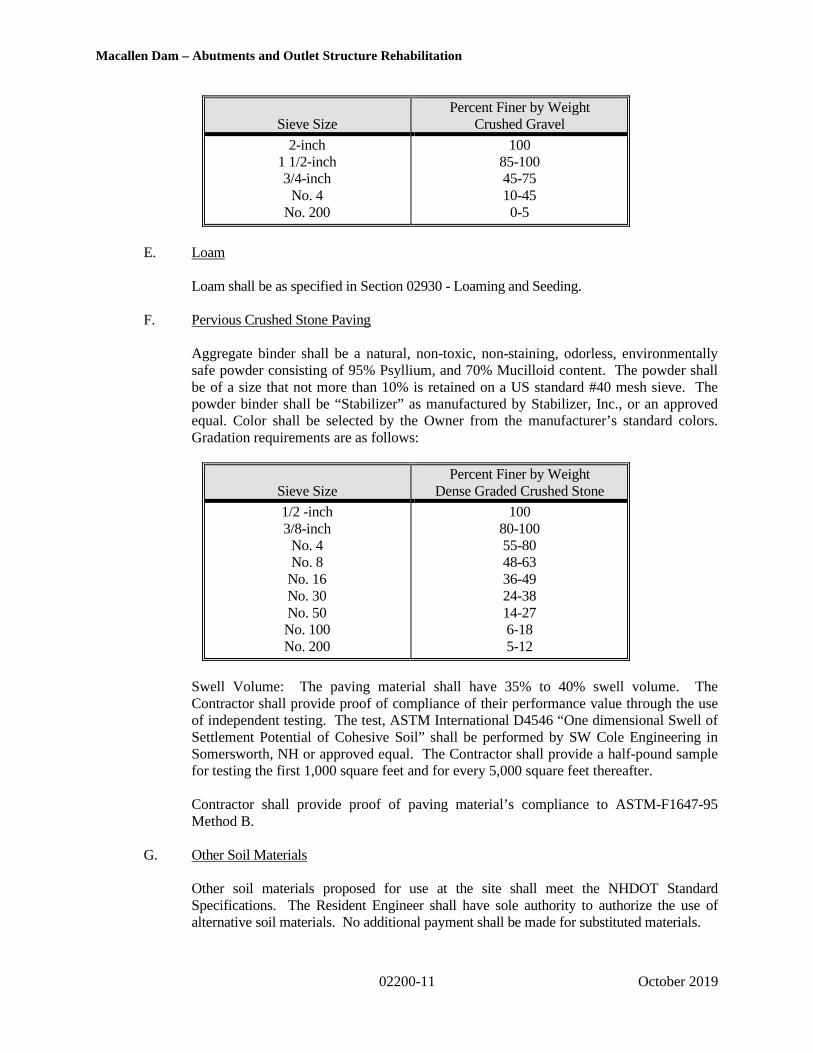
Macallen Dam – Abutments and Outlet Structure Rehabilitation
02200-11 October 2019
Sieve SizePercent Finer by Weight
Crushed Gravel
2-inch1 1/2-inch3/4-inch
No. 4No. 200
10085-10045-7510-450-5
E. Loam
Loam shall be as specified in Section 02930 - Loaming and Seeding.
F. Pervious Crushed Stone Paving
Aggregate binder shall be a natural, non-toxic, non-staining, odorless, environmentallysafe powder consisting of 95% Psyllium, and 70% Mucilloid content. The powder shallbe of a size that not more than 10% is retained on a US standard #40 mesh sieve. Thepowder binder shall be “Stabilizer” as manufactured by Stabilizer, Inc., or an approvedequal. Color shall be selected by the Owner from the manufacturer’s standard colors.Gradation requirements are as follows:
Sieve SizePercent Finer by Weight
Dense Graded Crushed Stone
1/2 -inch3/8-inch
No. 4No. 8
No. 16No. 30No. 50No. 100No. 200
10080-10055-8048-6336-4924-3814-276-185-12
Swell Volume: The paving material shall have 35% to 40% swell volume. TheContractor shall provide proof of compliance of their performance value through the useof independent testing. The test, ASTM International D4546 “One dimensional Swell ofSettlement Potential of Cohesive Soil” shall be performed by SW Cole Engineering inSomersworth, NH or approved equal. The Contractor shall provide a half-pound samplefor testing the first 1,000 square feet and for every 5,000 square feet thereafter.
Contractor shall provide proof of paving material’s compliance to ASTM-F1647-95Method B.
G. Other Soil Materials
Other soil materials proposed for use at the site shall meet the NHDOT StandardSpecifications. The Resident Engineer shall have sole authority to authorize the use ofalternative soil materials. No additional payment shall be made for substituted materials.

Macallen Dam – Abutments and Outlet Structure Rehabilitation
02200-12 October 2019
2.02 NON-WOVEN FILTER FABRIC/GEOTEXTILES
Geotextile Fabric shall be used to prevent soil intrusion into drains, crushed stone or aggregatelayers, and/or assist in stabilizing soil subgrades to be laid on approved soil subgrades prior toplacement of fill materials. Contractor shall use Mirafi 140N or equivalent filter fabric systembetween crushed stone or aggregate and soils or where indicated on the Contract Drawings.Geotextile fabric used beneath placed riprap or crushed stone working mats or bedding layer shallbe as specified in Section 02270 – Stone and RipRap.
2.03 CONTROLLED LOW-STRENGTH MATERIAL (CLSM)/FLOWABLE FILL
Controlled Low-Strength Fill (CLSM) or Flowable Fill Material shall be a cement concretebackfill material that flows like a liquid, supports like a solid when cured, and levels withouttamping or vibrating to reach 100 percent compaction, and shall generally conform to therequirements of Concrete Class F – Flowable Fill as described in the NHDOT - StandardSpecifications for Road and Bridge Construction (latest edition). CLSM/Flowable Fill shall be“excavatable” material and shall be proportioned to yield a 28-day minimum compressivestrength between 60 and 150 psi. The material shall be produced and installed in accordance withACI 229R and ACI 116R and shall generally consist of a two-sack cement/sand mixture type IIPortland cement. The mix formulation shall be approved by the Engineer prior to placement.
PART 3 - EXECUTION
3.01 EXAMINATION AND PREPARATION
Grades, both existing and finished, are indicated on the Drawings. The Owner is not responsible forexisting grades shown on the Drawings. The Contractor shall check all areas wherein grades areshown to satisfy themselves as to actual conditions. The Contractor shall be responsible forestablishing all control points and marks necessary for the work. Precautions shall be taken topreserve the materials outside the lines of the limit of work in the most undisturbed conditionpossible. The Contractor shall:
A. Identify and check all required lines, levels, contours, and datum.
B. Notify the Owner, Resident Engineer, and Engineer in writing of unanticipated subsurfaceconditions and discontinue affected work in area until notified to resume.
C. Protect plant life, grassed areas and other features remaining as a portion of finallandscaping.
D. Verify fill materials to be reused are acceptable.
E. Notify appropriate utility company to remove or relocate utilities, if necessary.
F. Maintain and protect existing utilities remaining which pass through work area.
3.02 TEST PITS
A. Excavation of Test Pits, if needed, shall be performed by the Contractor as directed bythe Owner or Resident Engineer to evaluate subsurface conditions within the project areaand paid under this Section of the Work.
Macallen Dam – Abutments and Outlet Structure Rehabilitation
02200-13 October 2019
Excavation of Test Pits will be required, as shown on the Contract Drawings, in the areaof the subsurface concrete vault prior to installation of the support of excavation system.
Contractor shall assist the Resident Engineer and/or Engineer to all extent practicable inhis duties to log all test pit excavations, at no additional cost. Test Pits specific to theSubsurface Concrete Vault Support of Excavation will be paid under that Section of theWork, as described in Section 01950.
B. Test pits may be up to 6 feet deep, 4 feet wide at the bottom and with a length sufficientto provide stability for the excavation. The actual size of each test pit will be determinedon an individual case basis by the Resident Engineer and/or Engineer.
C. Any test pits excavated shall be properly backfilled in controlled compacted lifts inaccordance with this Section. Backfilled surfaces shall be stabilized in accordance withapproved erosion and sedimentation control plans.
3.03 PROTECTION OF ADJACENT FACILITIES AND PROPERTIES
A. Protect all adjacent facilities which may be damaged by excavation work. All constructioninduced damage shall be repaired by the Contractor at no additional expense to the Owner.Refer to Section 01436 for additional requirements.
B. The work area shall be graded, shaped, and otherwise drained in such a manner as tominimize soil erosion, siltation of drainage channels, damage to existing vegetation andproperty outside the limits of the work area and shall be in accordance with Section 01560.
3.04 DISTURBANCE OF EXCAVATED AND FILLED AREAS DURING CONSTRUCTION
A. The Contractor shall take the necessary steps to avoid disturbance of subgrade duringexcavation and filling operations. Methods of excavation and filling operations shall berevised as necessary to avoid disturbance of the subgrade, including restricting the use ofcertain types of construction equipment and their movement over sensitive or unstablematerials, dewatering and other acceptable control measures. The Contractor shall cooperatewith the Owner or Engineer to modify procedures and protect bearing soils.
B. No payment shall be made for temporary excavations and/or fills to execute construction,beyond those required for the final lines and grades shown on the Contract Drawings.The Contractor shall remove/restore temporary grading at his/her own expense.
3.05 EXCAVATION
A. Perform all work of any nature and description required to accomplish the work as shown onthe Drawings as specified. The work shall include, although not be limited to, earthexcavation; on-site stockpiling of materials; and removal of unsuitable materials todesignated locations.
B. Excavations, unless otherwise required by the Resident Engineer, shall be carried only to theelevations and limits shown on the Drawings. If unauthorized excavation is carried outbelow required subgrade and/or beyond minimum lateral limits shown on Drawings, it shallbe backfilled as specified by the Resident Engineer, at the Contractor's expense.

Macallen Dam – Abutments and Outlet Structure Rehabilitation
02200-14 October 2019
Excavations shall be kept in good condition at all times, and all voids which may endangerexisting structures shall be filled to satisfaction of the Resident Engineer.
C. The Contractor shall lawfully and satisfactorily dispose of, at his own expense, surplusexcavated materials. As necessary, the Contractor will be required to adequately reducethe water content of the spoil material prior to reuse as borrow or offsite disposal. Thedewatering technique may include creation of temporary containment areas within thework area or other method approved by the Owner and shall be in accordance withSection 01560. The Owner shall designate surplus excavated materials as materials fromthe excavations that are unacceptable for use as fill or that are in excess of the fillmaterials required. These materials, if any, which cannot be placed at once in permanentpositions, may be deposited in storage piles at designated locations designated by theResident Engineer. Re-excavation and re-handling from such storage piles shall beincluded in unit prices. Separate stockpiles shall be established for material to be reused andmaterial to be disposed of off-site. Stockpiles shall be labeled with temporary signage.
D. Excavated material which meets the criteria put forth in the specifications shall be reused atthe site after Contractor-performed gradation and moisture-density testing. The Contractoris encouraged to reuse excavated material provided it meets the requirements of the intendedre-use.
E. All excavations shall be performed in accordance with OSHA requirements.
F. The Resident Engineer shall assess the limits of excavation during and after the completionof the work. The Resident Engineer may, at their discretion, reduce or extend the limitsand/or depth of excavations, as judged necessary. It is the intent of this work to remove andreplace all material which may have been subject to internal erosion and loss of structure.
G. All appropriate care shall be taken to avoid damage to existing structures, such as, but notlimited to, the abutment stone masonry wall, the existing subsurface propane tanks, andutilities during excavation. Hand excavation around these and other structures may benecessary and will be performed as required at no additional cost to the Owner.
H. The Contractor shall, at all times during the construction provide and maintain properequipment and facilities to remove all water entering excavations and shall keep suchexcavations dry so as to obtain a satisfactory dry and undisturbed subgrade foundationcondition until the fills or structures to be built thereon have been completed to such extentthat they will not be floated or otherwise damaged by allowing water levels to return tonatural levels.
I. Boulders greater than 1.0 cubic yards in volume may be reduced in size by mechanicalmeans to simplify removal.
J. Subgrade Preparation
1. Following excavation, proof compact the exposed subgrade. Proof-compacting shallbe performed with a minimum of four (4) completed coverages of the full area with avibratory drum roller with a minimum of a 2,000 pound static drum weight andproviding at least 5,000 lbs. of dynamic force. Proof compacting in confined areasmay be accomplished with hand operated vibratory equipment approved by theResident Engineer. Proof compacting shall be conducted in the presence of the

Macallen Dam – Abutments and Outlet Structure Rehabilitation
02200-15 October 2019
Resident Engineer. Subgrade soils which become soft, loose, "quick", or otherwiseunsatisfactory for support of the embankment or structure as a result of inadequateexcavation, dewatering, proof compacting, or other construction methods shall beremoved and replaced with compacted fill or other material satisfactory to theConstruction Engineer at the Contractor's expense.
2. If the bottom of any excavation is taken out below the limits shown on the Drawings,specified, or directed by the Construction Engineer, it shall be refilled/compacted atno additional cost to the Owner with either concrete or Low Permeability Fill asdetermined by the Owner or Construction Engineer.
3. If the Contractor does not care for water properly, through failure to postpone finalexcavation immediately above the subgrade until shortly before placing of the newwork thereon, or other failure or neglect to conduct the excavation work properly sothat the surface of the subgrade is in proper condition when he/she is ready forconstruction, the Contractor shall remove the unsuitable material and replace it withconcrete, Low Permeability Fill, or other approved material at no additional cost tothe Owner so that the condition of the subgrade meets with the approval of theConstruction Engineer before any work is placed thereon.
4. At the conclusion of proof-rolling, and just prior to placement of approved fills, theContractor shall carefully scarify the top 3-inches of the subgrade so as promoteinterlocking of the subsequent fill material.
5. All subgrades shall be approved by the Engineer prior to the placement of any fillmaterials, concrete, geotextile, or any other items.
3.07 EXCAVATION SUPPORT AND PROTECTION
The excavation support system specific to the subsurface vault for the new gate structure shallconform to the requirements of the Contract Drawings. All other excavation support and protectionshall conform to the requirements herein.
A. As necessary, provide shoring, sheeting, and/or bracing of excavations in accordance withapproved submittal as required to assure complete safety against collapse of earth at side ofexcavations. The installation, performance and subsequent removal of any excavationsupport system shall not result in damage or compromise the performance or integrity of thedam.
B. Comply with local safety regulations and/or, in the absence thereof, with the provisions ofthe Occupational Safety and Health Act (OSHA) for trenching and excavation.
C. Remove sheeting and shoring, etc., as backfilling operations progress, taking all necessaryprecautions to prevent collapse of excavation sides. No excavation support elements shall bepermanently left in place within the dam without approval from the Owner or ResidentEngineer.
D. The Contractor shall be fully responsible for furnishing, installing, maintaining, reinforcingand removal of all sheeting and bracing and shall be fully responsible for all damages, lossesand claims involving the use or non-use of sheeting and bracing despite any orders given orany orders failed to be given by the Resident Engineer. The Contractor shall hold harmlessthe Owner and its Engineer from all damages, losses and claims involving the use or non-useof sheeting, shoring and bracing.
Macallen Dam – Abutments and Outlet Structure Rehabilitation
02200-16 October 2019
E. The Contractor shall furnish, put in place, and maintain sheeting and bracing to support thevertical side of excavations, to prevent any movement which could in any way diminish thewidth of the excavation below that necessary for proper construction, and to protect adjacentstructures from disturbance, undermining or other damage.
F. If the Resident Engineer is of the opinion that at any point, sufficient or proper supports havenot been provided, he/she may order additional supports put in at the expense of theContractor, and compliance with such order shall not relieve or release the Contractor fromhis responsibility for the sufficiency of such supports. Care shall be taken to prevent voidsoutside of the sheeting, but if voids are formed, they shall be immediately filled andrammed.
G. The Contractor is responsible for understanding the subsurface and soil conditions in areaswhere excavation support is required. The Contractor shall examine available subsurfacedata and make additional explorations as needed and as approved by the Resident Engineer.
H. No excavation shall be made which will negatively affect the stability of existingstructures or in-place cofferdams.
3.08 FILL PLACEMENT AND COMPACTION
A. Particular care shall be taken in compacting material adjacent to existing structuresincluding, but not limited to, underground utilities and the embankment masonry walls.Compaction of subgrades and fill material within one-foot of existing structures may requirethe use of hand tampers, as required by the Resident Engineer or as judged necessary by theContractor.
B. Fill shall not be placed over wet, frozen or spongy subgrades. In the event these conditionsoccur, the Contractor shall excavate and remove the unsuitable material prior to placingmore fill.
C. The Contractor shall dewater to maintain groundwater levels a minimum of one foot (1’)below bottom of excavations and/or subgrades. All fill is to be placed “in-the-dry.”
D. The Contractor shall bench all existing slopes prior to placing horizontal fill layers onexisting slopes of greater than 6H to 1V.
E. Place and compact materials in continuous horizontal layers not exceeding eight-inch (8”)loose lift thickness. Do not place frozen material.
F. The general standard for compaction for all granular soil materials in non-embankmentareas shall be a firm and stable material which, if tested, would achieve a minimumninety-five percent (95%) of the maximum dry density as determined by ASTM TestD1557 (Modified Proctor Test), with a water content between plus or minus two percent(±2%) of optimum moisture content. If wet fill cannot be adequately compacted, removeand replace with drier fill at no additional cost to the Owner.
G. The general standard for compaction for Structural Fill soil materials for the raising of theright embankment shall be a firm and stable material and when tested achieves a minimumninety-eight percent (98%) of the maximum dry density as determined by ASTM Test D-

Macallen Dam – Abutments and Outlet Structure Rehabilitation
02200-17 October 2019
698 (Standard Proctor Test), with a water content between -1% to +3% of optimum moisturecontent. If wet fill cannot be adequately compacted, remove and replace with drier fill.
H. Fill that is too wet for proper compaction, as determined by testing or the ResidentEngineer’s judgment, shall be disced, harrowed, or otherwise dried to a proper moisturecontent for compaction to the required density, specified herein. If the fill material cannot bedried within forty-eight (48) hours of placement, it shall be removed and replaced with drierfill at no additional cost to the Owner.
I. Fill that is too dry for proper compaction, as determined by testing or the ResidentEngineer’s judgment, shall receive water uniformly applied over the surface of the looselayer. Sufficient water shall be added to allow compaction to the required density.
J. Compaction of fill material shall be done to meet the above stated density criteria, but atminimum six (6) passes of an approved a vibratory drum roller with a minimum of a 2,000pound static drum weight and providing at least 5,000 lbs. of dynamic force. Makeadditional passes as necessary to achieve a degree of compaction of at least 98% for theraised embankment area; 95% elsewhere.
K. When compacting behind or adjacent to structures, place and compact fill in loose layersnot more than eight inches (8") thick. Compact with a powered tamping compactor to thesatisfaction of the Resident Engineer.
L. Fill which becomes disturbed after compaction as a result of the Contractor's operations shallbe removed and replaced or re-compacted to the specified degree of compaction at noadditional cost to the Owner.
L. Placement and compaction of soil material on the embankments shall be in a directionparallel to the top of the embankment, when possible.
M. In cases where prior excavation has not been made, the Contractor shall strip all organictopsoil from along the length and breadth of all areas which are to have fill material placedon top. This work shall be paid for under other Sections of the Contract.
N. Rough and fine grade the surface of embankment and fill as shown on the ContractDrawings. All surfaces shall be appropriately graded to drain and provided with a firm andstable surface which is resistant to erosion.
3.09 FIELD QUALITY CONTROL
A. All field quality control of earthwork shall be provided by the Contractor’s approvedIndependent Testing Laboratory at no additional cost to the Owner. All field and laboratoryquality control work shall be considered incidental to the Work of this Section.
B. The Resident Engineer shall observe the placement of all fill material. The ResidentEngineer shall be provided with the results of tests by the Contractor’s Independent TestingLab or make such observations as are judged necessary to render an opinion as to whetherthe materials used and compaction effort provided are appropriate to meet the intent of thespecifications.

Macallen Dam – Abutments and Outlet Structure Rehabilitation
02200-18 October 2019
C. The Resident Engineer shall judge achievement of the compaction standards by either visualobservation of compaction effort and success or through the Contractor’s IndependentTesting Lab’s use of in-place density tests including, but not be limited to, in-placecompaction (density and moisture) testing performed in accordance with ASTM D1556(sand cone) or ASTM D6938 (nuclear density meter). The frequency of testing shall be atthe Resident Engineer’s sole discretion with a minimum of one test for each lift of materialplaced in a discrete area, at a minimum frequency of one (1) test for every 4,000 square feetof fill and/or one (1) test for every area of less than 4,000 square feet placed in one (1) day.
D. If compaction is judged by the Resident Engineer to be inadequate, the Contractor shallprovide additional compaction or otherwise correct the problem at no additional cost to theOwner.
E. The Contractor shall be responsible for providing to the Resident Engineer and Owner theresults of independent analysis of proposed on-site and off-site fill materials performed inaccordance with ASTM D6913 and ASTM D1557. All the results shall be provided at leastfive (5) days prior to Delivery or placement of material. Test results to be provided are asfollows:
1. Particle size (sieve) analysis for each off-site material.2. Maximum dry densities and optimum moisture contents, as per the Modified Proctor
Test Methodology, for each off-site material.3. New Proctor curves shall be developed whenever the properties of a certain material
are judged by the Engineer to have substantially changed.
F. The Contractor shall be responsible for coordinating fill placement with the ResidentEngineer. No fill shall be placed if the Resident Engineer is not available to observe theWork. Fill placed in the absence of the Resident Engineer may be required to be excavatedand replaced at no additional cost to the Owner.
G. The Contractor shall provide the Owner and the Resident Engineer free and safe access towork at all times, including providing for observation of bottom of excavation and ofbearing surfaces.
3.10 SPOIL DISPOSAL
A. It is the responsibility of the Contractor to lawfully dispose of excess or unsuitable soil atan approved off-site location. The Town may provide an alternate location to dispose ofexcess soils. The Contractor shall coordinate directly with the Town Facilities Managerto determine if off-site locations may be allowed for use by the Contractor. Anynecessary testing or paperwork that may be required by local, state, or federal agenciesshould be provided to the Owner and Engineer at no additional cost.
B. Spoil material may consist of common excavated material, common excavated material withorganics and roots, peat, topsoil, sediment, cobbles, boulders, rock, wet material, or othermaterial which is unsuitable or has been excavated in excess of that quantity needed for fillat the site.

Macallen Dam – Abutments and Outlet Structure Rehabilitation
02200-19 October 2019
C. The Contractor shall be responsible as part of the work of spoil disposal for controlling thewater content of the spoil (i.e. dewatering) such that it is suitable for transport.The Contractor shall not create sanitary problems during the transport of spoil material andshall be responsible for cleaning areas where liquids or solids have leaked.
D. The Contractor shall transport the spoil to an approved spoil disposal area. The Contractorshall use “tight trucks” to minimize leakage of water or spoil.
E. The Contractor shall be responsible to ensure that free liquid is properly transported. “Wetsoils” shall not be loaded for transport. The Contractor shall dewater “wet soils,” andproperly dispose of free liquids in accordance with local, state, and federal regulations. TheContractor shall dispose of any free liquids that may result during transportation at noadditional cost to the Owner and without adverse impacts to nearby water bodies.
3.11 EARTHWORK UNDER OTHER SECTIONS
A. Unless specifically contradicted, all earthwork executed under other Sections of the Contractshall be governed by the Methods specifications detailed in this Section.
3.12 STOCKPLING
A. Stockpile materials on site in such a manner so as to maintain the segregation of differenttypes of material.
B. The Contractor shall provide, at no additional cost, temporary signage which identifies thetype of soil or rock material in each stockpile.
C. Stockpiles should be protected from erosion in accordance with Section 01560.
PART 4 – MEASUREMENT AND PAYMENT
Refer to Section 01950 – Measurement and Payment for the measurement and payment items related to thisSection.
* * * END OF SECTION * * *
\\GZANOR\Jobs\170,000-179,999\173346\173346-10.TEM\WORK\Specifications\FINAL\Division 2\02200 - Earthwork.doc

Macallen Dam – Abutments and Outlet Structure Rehabilitation
02270-1 October 2019
SECTION 02270STONE AND RIPRAP
PART 1 - GENERAL
1.01 DESCRIPTION
A. The Contractor shall furnish all equipment, materials and labor and do all work necessary toplace stone materials, including Crushed Stone and Riprap.
B. Crushed Stone material and Riprap shall be sized as indicated on the Contract Drawings oras indicated in the Specification. The Contractor shall be responsible for all furnishing,processing, transportation, and placement necessary to achieve stone with quality andgradations meeting the specifications.
C. Placement, intermediate grading and final grading of areas of Riprap placement shall beincluded in the Work of this Section at no additional cost to the Owner. Such work mayinvolve handling and placement of individual stones to achieve a stable slope to the lines andgrades shown on the Contract Drawings.
D. Stone, rock, and Riprap material placed by the Contractor shall not exceed the limits shownon the Plans.
E. Adherence to the lines, grades, and slopes shown on the Contract Drawings is critical so asto meet permit requirements and minimize encroachment of stone in front of the fish ladderopening and into resource areas.
F. Stone, rock, and Riprap placed as incidental under this or other Sections shall conform to therequirements of this Section, except as specified elsewhere.
1.02 SCOPE
A. Work involving stone and Riprap shall include, but not be limited to the following:
1. Furnishing and placing Crushed Stone for use as a bedding material for Riprapplaced at the upstream portions of the dam and elsewhere on site.
2. Furnishing and stockpiling of Riprap from off-site sources for use on the rightupstream embankment of the Macallen Dam and immediate surroundings, andelsewhere on site.
3. Placing and grading of Riprap from stockpiles at the site.
4. Furnishing and placing of Chinking Stone for treatment of Riprap surfaces.
1.03 RELATED WORK
A. The following is a list of related work items that shall be performed or furnished under otherSections of these Specifications as indicated:
1. Temporary Erosion and Sedimentation Controls – See Section 015602. Temporary Water Control – See Section 01565

Macallen Dam – Abutments and Outlet Structure Rehabilitation
02270-2 October 2019
3. Temporary Cofferdams – See Section 021704. Earthwork – See Section 02200
1.04 SUBMITTALS
A. Two (2) weeks prior to the delivery of any stone material to the site, the Contractor shallsubmit the name and location of the proposed quarry(s) to be used to supply the stoneproducts. The Contractor shall provide the Owner with information regarding the type andphysical characteristics of the stone, as required below. The Contractor shall also providecopies of any certifications or approvals of the quarries products from other agencies.
B. Two (2) weeks prior to the delivery of any Crushed Stone material, stone, rock, or Riprap tothe site, the Contractor shall submit a description of the material, the source of the material, agradation analysis, density/specific gravity test results, and samples of the materials asrequired by the Engineer. The Contractor shall provide certification of stone source, type,and properties from the quarry.
1.05 PERMITS AND CODES
A. All work shall conform to the Drawings and Specifications and shall comply with applicablecodes and regulations.
B. The Contractor shall comply with all rules, regulations, laws and ordinances of the State ofNew Hampshire, Town of Newmarket and of all other local authorities having jurisdiction atthe site. All labor, materials, equipment and services necessary to make the work complywith such requirements shall be provided without additional cost.
PART 2 - PRODUCTS
2.01 STONE RIPRAP ( NHDOT “Class III”)
A. Stone Riprap shall consist of hard, durable, non-soluble and sound angular stone which isresistant to weathering. Rounded stones, boulders, elongated, thin or flat pieces whosebreadth or thickness is less than one-third its length will not be allowed. The parent rock forrockfill and stone Riprap stones shall be igneous or metamorphic rock. Sedimentary rocktypes such as shale, sandstone, or similar soft stone and soluble limestone and dolomiteshall not be allowed. The stone shall be free of cracks, overburden, spoil, silt, clay, loam,organics and other deleterious matter.
B. Riprap stone shall conform to the suitability requirements of the U.S. Army Corps ofEngineers Engineering Manual (EM) 1110-2-2302, and shall conform to the followingstandards:
Unit Weight Dry unit weight 165 pcf or greaterAbsorption Less than 1 percentSulfate Soundness1 Less than 5 percent lossAbrasion2 Less than 20 percent loss for 500 revolutionsFreezing-Thawing3 Less than 10 percent loss for 12 cyclesDrop Test4 No breakage or crackingWetting and Drying5 Less than 5 percent breakdown after 10 cyclesSolubility6 None (no loss of mass)

Macallen Dam – Abutments and Outlet Structure Rehabilitation
02270-3 October 2019
1) Sulfate Soundness: Stone(s) shall exhibit a less than five percent (5%) loss per theU.S. Army Corps of Engineers standardized method CRD-C 127 for MagnesiumSulfate.
2) Abrasion: Stone(s) shall exhibit a loss of less than 20 percent (20%) for 500revolutions based on the Los Angeles abrasion test per U.S. Army Corps ofEngineers standardized method CRD-C 145.
3) Freezing-Thawing: Stone(s) shall exhibit a loss of less than 10 percent for 12 cyclesbased on the U.S. Army Corps of Engineers standardized method CRD-C 144.
4) Drop Test: The Contractor shall perform a Drop Test on representative samples ofthe stones to evaluate suitability. The test stone(s) shall be dropped from a bucketor cherry picker, or by other means from a height half the average diameter of thestone or a minimum of 2 feet onto a rigid surface or second stone of comparablesize. The stone shall be examined before testing as well as afterward. Stone(s) shallexhibit no breakage or cracking based on the Drop Test. Failure criteria aredevelopment of new cracks, opening of existing cracks, and loss of small piecesfrom the surface of the stone. The Drop Test shall be repeated as directed by theOwner and/or the Resident Engineer.
5) Wetting and Drying: Submerge stone in water for 18 hours, oven dry at 140°F, andcool to complete one cycle.
6) Solubility: Apply 3 M hydrochloric acid (HCl) to the stone to determine if thestone is a carbonate rock (i.e. soluble). The stone is considered soluble if a positivereaction (effervescence) is observed. HCl testing shall be performed in accordancewith the United States Department of Agriculture – Natural Resources ConservationService standardize method “Assessing Carbonates in the Field with a DiluteHydrochloric Acid (HCL) Solution”, Note 5.
It is probable that the Resident Engineer will be able to determine suitability of rockproposed by the Contractor for use as rip rap by visual observation alone and would notrequire that any of the tests above be undertaken. However, if, in the opinion of theOwner or the Resident Engineer, testing of the proposed stone source is warranted, theContractor shall be prepared to provide the results of one or more of the above testsand demonstrate conformance with the specifications at no additional cost to theOwner.
C. Gradations of stone Riprap shall be as specified or, if not stated, then based upon thethickness of the stone Riprap layer as shown on the plans. Stone Riprap layer thickness shallbe defined as the typical (or average) layer thickness as measured perpendicular to theground surface or slope. In all cases, no more than 5 percent by weight shall pass a 2-inchsieve. Diameter refers to the equivalent-volume spherical stone diameter as defined by theUS Army Corps of Engineers in EM 1110-2-1601. No stone dimension shall be greater thanthree (3) times the length of another.
Stone Riprap shall meet the requirements of “Class III”, as defined in Section 583 – Riprapof the State of New Hampshire Department of Transportation – Standard Specifications forRoad and Bridge Construction (latest edition). For “Class III,” the nominal median particle

Macallen Dam – Abutments and Outlet Structure Rehabilitation
02270-4 October 2019
diameter shall be 1 foot. The volume distribution requires that 15 percent of the stone in themass shall be no larger than 0.4 cubic-feet, 15 percent of the stone in the mass shall be nosmaller than 2.5 cubic-feet, and the remaining 70 percent of the stone in the mass shall havea volume between 0.4 cubic-feet and 2.5 cubic-feet with no stone being larger than 6.5cubic-feet.
D. Riprap material shall be well graded as a material without gaps in the gradation curve.The uniformity ratio (D85/D15) should be between 1.5 and 2.5, as defined in the FederalHighway Administration (FHWA) – Hydraulic Engineering Circular No. 23.
E. All Riprap stone furnished and placed at the site shall of the same parent rock from the samequarry and shall be visually similar to the existing Riprap.
F. The Contractor shall provide certification of stone source, type, and properties from thequarry.
G. In companion with Paragraph 2.01.B, control of gradation will be by visual inspection. TheContractor shall provide, prior to Riprap placement, a representative sample of Riprap stonefor inspection. Any difference of opinion between the Resident Engineer and the Contractorshall be resolved by dumping and checking the gradation of two random truckloads of stone.Mechanical equipment, a sorting site, and labor needed to assist in checking gradation shallbe provided by the Contractor at no additional cost, if needed. Further checking at thequarry site to establish the weight distribution of the Riprap material being suppliedmay be required by the Resident Engineer. The Contractor shall provide suchchecking at no additional cost.
H. All Riprap shall be underlain by Crushed Stone material bedding layer and geomembrane asshown on the Contract Drawings.
I. If requested by the Owner, the Contractor shall facilitate and participate in a field visit to thequarry(s) which is the proposed source of the stone material.
2.02 CRUSHED STONE MATERIAL (NHDOT Item 304.5)
A. Crushed Stone material for use as bedding material for Riprap shall consist of aggregate thatis inert material from hard, non-soluble, durable stone and course sand, free from loam, clay,surface coatings, sod, and deleterious or organic materials. Crushed Stone material shallgenerally consist of material similar to ¾-inch Crushed Stone and shall have a gradationmeeting the following requirements:
Sieve Size Percent Finer by Weight
3 ½ -inch 100
3-inch 80-100
1 ½-inch 60-90
¾-inch 40-70
No. 4 15-40
No. 200 0-5

Macallen Dam – Abutments and Outlet Structure Rehabilitation
02270-5 October 2019
This material shall be used for bedding under all Riprap at the Macallen Dam.
B. The thickness of the Crushed Stone material layer below Riprap shall be as indicated on theContract Drawings, but in no case shall the layer thickness be less than 6 inches.
2.02 GEOTEXTILE FABRIC
A. Geotextile Fabric may be used to prevent intrusion of the Crushed Stone bedding materialand/or Riprap into the soil subgrade and/or assist in stabilizing soil subgrades. Contractormay use Mirafi FW700 or equivalent filter fabric system between the soil subgrade andCrushed Stone bedding material or Riprap, where necessary or as directed by the ResidentEngineer. Geotextile fabric used to prevent soil intrusion into drains, Crushed Stone behindretaining walls, or aggregate layers shall be specified in Section 02200.
PART 3 - EXECUTION
3.01 EXAMINATION AND PREPARATION
A. Grades, both existing and finished, are indicated on the Contract Drawings. The Contractorshall check all areas wherein grades are shown to satisfy him/her as to actual conditions.The Contractor shall be responsible for establishing all control points and marks necessaryfor the work. Precautions shall be taken to preserve the materials outside the lines of thelimit of work in the most undisturbed condition possible. The Contractor shall:
1. Identify and check all required lines, levels, contours, and datum.2. Notify the Resident Engineer in writing of unanticipated subsurface conditions and
discontinue affected work in area until notified to resume.3. Verify materials to be reused are acceptable to the Resident Engineer.
3.02 GENERAL RIPRAP PLACEMENT
A. The prepared subgrade in Riprap placement areas shall be cleared of all stones greater than 6inches in diameter, along with any other items that may damage the geotextile (if used). Theprepared surface shall be observed and approved by the Resident Engineer prior toinstallation of the geotextile or placement of the Crushed Stone bedding layer.
B. The geotextile (if used) shall be placed on the prepared subgrade by unrolling directly fromthe rolls in a direction approximately parallel to the slope. Folds and wrinkles in thegeotextile should be avoided. Adjacent rolls or sections of geotextile shall be overlapped aminimum of 3 feet, with the geotextile covering ground of higher elevation overlapping thatwhich covers ground of lower elevation. The geotextile shall be fixed in place so thatslippage does not occur as work continues. If neither a Crushed Stone bedding layer nor ageotextile is shown below the Riprap layer, the Contractor shall place geotextile fabric as ifit had been shown on the plans.
C. Storage and handling of geotextile filter fabric (if used) shall be as per the manufacturer’srecommendations for protection from sunlight, ultraviolet rays, heat, dirt debris, etc. whichcould affect its properties. Uncovered geotextile shall not be left exposed to sunlight, eitheron the roll or in place. Torn, punctured or otherwise damaged fabric shall not be used.Mishandled or damaged material shall be removed from the site and replaced at no

Macallen Dam – Abutments and Outlet Structure Rehabilitation
02270-6 October 2019
additional cost to the Owner.
D. Crushed Stone bedding material shall be placed immediately after the placement of thegeotextile filter fabric (if used). The Crushed Stone bedding layer shall be placed on theprepared subgrade and compacted in layers not exceeding 6 inches. Compaction shall bejudged to be firm and stable to the satisfaction of the Resident Engineer. The Contractorshall grade and shape the final surface to conform to the plans and provide a uniform andacceptable surface for placement of the Riprap.
E. After Crushed Stone layer and/or geotextile placement, the Riprap shall be placed on theslope in uniform fashion to the required thickness. Riprap may be dumped from anexcavator or loader bucket, but from no greater than two feet above the ground. Riprap shallbe dumped directly onto its final location without rolling down the slope. Care shall betaken during placement so as not to damage or disturb the Crushed Stone bedding layer orunderlying geomembrane. Do not dump Riprap directly from truck onto slope or otherRiprap placement area.
F. Riprap shall be placed in such a manner as to produce a reasonably well graded distributionof the various stone sizes, with no localized areas of uniform size material. Each of thelargest stones is to touch adjacent large stones. The smaller size stones shall fill thespaces between the larger stones so as to obtain a minimum practical percent of void space.Dumping from trucks and spreading shall not be allowed. Post-placement manipulation ofthe Riprap shall be performed such that individual stones are in contact with one another,without gaps or spaces between.
G. Riprap shall be compacted and shaped by tamping and manipulation with the bucket of anexcavator, or other means acceptable to the Resident Engineer.
H. It may be necessary to handle and place individual Riprap stones to place the material suchthat it achieves a stable slope conforming to the lines, grades, and slopes shown on theContract Drawings. The Contractor shall be responsible for all efforts necessary to place theRiprap in such a manner which produces a stable slope conforming to the lines, grades, andslopes shown on the Contract Drawings. The Contractor shall not place material beyond thelimits shown.
I. “Chink” the final Riprap surface, manually if necessary, to eliminate any significant gaps inthe Riprap surface. “Chinking” shall involve the placement and setting of smaller stones ingaps between larger stones so as to provide a more uniform coverage across the Riprapsurface. No additional payment shall be made for chinking materials or effort.
J. Riprap placed directly on concrete or bedrock shall not require a Crushed Stone beddinglayer nor a geotextile layer, however, adjacent filter fabric (if used) should be lapped in sucha manner so as to prevent loss of sub-grade or movement of soil along concrete or bedrocksurfaces.
K. Tolerances for placement of stone Riprap shall be within plus or minus six inches (±6”) ofthe dimensions shown on the plans.

Macallen Dam – Abutments and Outlet Structure Rehabilitation
02270-7 October 2019
PART 4 – MEASUREMENT AND PAYMENT
Refer to Section 01950 – Measurement and Payment for the measurement and payment items related to thisSection.
* * * END OF SECTION * * *
J:\170,000-179,999\173346\173346-10.TEM\WORK\Specifications\FINAL\Division 2\02270 - Stone and Riprap.docx

Macallen Dam – Abutments and Outlet Structure Rehabilitation
02444-1 October 2019
SECTION 02444CHAIN LINK FENCE AND GATES
PART 1 - GENERAL
1.01 DESCRIPTION
A. Work Included:
1. Furnish all materials and install chain link fence of the types, sizes and in thelocation(s) shown on the Drawings and specified herein.
B. Related Work Specified Elsewhere:
1. Section 02200 - Earthwork
1.02 QUALITY ASSURANCE
A. Acceptable Manufacturers:
1. USS Cyclone.
2. National Fence Mfg. Co., Inc.
3. Anchor Fence, Inc.
4. Allied Tube & Conduit
5. Or approved equivalent.
1.03 SUBMITTALS
A. Submit satisfactory guarantees by the fence manufacturer covering any faults and defectsin all parts of the fence arising from defective workmanship or materials for a period ofone year from the date of installation.
B. Clearly indicate plan layout, grid, spacing of components, accessories, fitments, andanchorage.
C. Submit manufacturer's installation instructions and procedures.
D. Submit details of fence and gate installation.
PART 2 - PRODUCTS
2.01 FENCE MATERIALS
A. Posts
1. End, Corner, and Gate Posts: 4-inch minimum O.D. galvanized steel pipe.

Macallen Dam – Abutments and Outlet Structure Rehabilitation
02444-2 October 2019
2. All posts shall be of sufficient length to provide a 36-inch minimum setting inconcrete footings, as shown on the plans.
3. All other Posts: 3-inch pull posts.
B. Top/Bottom Rails
1. 1-3/4 inch O.D. galvanized steel pipe.
2. Securely fasten top and bottom rails to the corner posts with heavy galvanizedsteel brace bands and rail end connections.
C. Horizontal Braces
1. Provide horizontal braces (brace rails) at all, pull and corner posts.
2. Securely fasten braces to the corner, line and terminal posts by rail ends andbrace bands.
3. Braces shall be 1-3/4 inch O.D. galvanized steel pipe.
D. Fencing
1. 9-gauge, 0.148 inch diameter galvanized steel wire, of medium high carbonquality, minimum tensile strength of 80,000 pounds per square inch, interwoveninto 2 inch diamond mesh.
2. Top selvage to be twisted and barbed (optional). Bottom selvage to be knuckledunless otherwise specified.
E. Diagonal Braces:
1. Provide diagonal braces (truss rods) from the brace ends on the line posts back tothe bottom of pull, corner or terminal posts and fastened by brace bands.
2. Diagonal braces shall be 3/8 inch diameter galvanized steel rods.
3. Diagonal braces shall be provided with heavy galvanized iron turnbuckles toadjust the tension.
F. Fabric Connections - Securely fasten fabric to:
1. All terminal posts by l/4 inch x l/4 inch galvanized tension bars with ll gaugegalvanized pressed steel bands spaced approximately l4 inches apart.
2. All line posts with 6-gauge galvanized wire clips spaced approximately l4 inchesapart.
3. All top rails with 9-gauge galvanized tie wires spaced approximately 24 inchesapart.
4. The bottom edge of the fabric shall be fastened to a bottom tension wire withwire ties spaced approximately 24 inches apart.
Macallen Dam – Abutments and Outlet Structure Rehabilitation
02444-3 October 2019
2.02 GATE MATERIALS
A. Gate Frames:
1. Fabricate from 4-inch O.D. steel pipe weighing 2.72 pounds per linear foot.
2. All welded construction with malleable iron or pressed steel corner fittings. Allwelds shall be ground smooth to the surface plane of the base metals. Weldingshall be performed prior to galvanizing.
3. Frames shall be rigid enough to be free of twist or sag.
4. Gate leaves shall have truss rods or intermediate braces.
B. Truss Rods:
1. Install 3/8-inch diameter truss rod on each gate.
C. Hinges:
1. Hinges shall be structurally capable of supporting the gate leaf and allow the gateto open and close without binding. The hinges shall be so designed to permit thegate to swing a full 100 degrees.
2. Bottom Hinges: Wraparound adjustable type designed to carry the weight of thegate.
3. Upper Hinges: Wraparound adjustable type.
D. Locking Devices:
1. Positive type latching device with provision for padlocking.
E. Gate Keeper:
1. Install on centerline of double gates.
2. Gate keeper shall be adjusted with gate keeper rod to prevent opening of gatelevers when padlocked.
3. Fabricate from a 1-3/4-inch-wide by 1-3/4-inch-deep galvanized channelwayapproximately 7 inches long.
4. Anchor into a l2 inch by 12 inch by 3 feet deep concrete foundation with a 1-1/2inch O.D. galvanized steel pipe, l8 inches long, welded to the channel way.
5. Slope top edges of channelway from center toward each end.
6. Form concrete foundation to meet tops of channelway sides to prevent itsremoval.
7. Obtain approval from the Engineer prior to installation of the gate keeper.
F. Outer Gate Catches:
1. Material: Galvanized malleable iron or steel.

Macallen Dam – Abutments and Outlet Structure Rehabilitation
02444-4 October 2019
2. Designed to anchor securely into l2 inch diameter by 3.5 feet deep concretefooting.
3. Obtain approval from the Engineer prior to installation of outer gate catches.
2.03 WARNING SIGNS
A. When applicable, provide warning signs.
B. The number of signs, the location, size and wording shall be as shown on the Drawings oras directed by the Engineer.
C. Material:
1. l6 gauge metal with a baked enamel finish.
2.04 VEHICULAR ACCESS GATE
A. Posts
1. End Post: 4-inch minimum O.D. galvanized steel pipe.
2. Rotating Post: 3-inch O.D. galvanized steel pipe set in the concrete footing with a4-inch O.D. galvanized steel pipe placed on top with a free moving hinge.
3. All posts shall be of sufficient length to provide a 36-inch minimum setting inconcrete footings, as shown on the plans.
B. Top/Diagonal Rails
1. 3-inch O.D. galvanized steel pipe.
2. All welded construction for top and diagonal rails to the Rotating post shall bewelded with malleable iron or pressed steel corner fittings. All welds shall beground smooth to the surface plane of the base metals. Welding shall beperformed prior to galvanizing.
C. Locking Plate
1. Locking mechanism shall consist of a 15 inch by 4 inch by 3/8 inch steel platewelded to a 4-inch End Post pipe, with a 5 inch I.D. by 4 ½ inch long steel pipewelded to the steel plate, and a 4 inch by 2 inch by 3/8 inch steel plate welded tothe 4 inch End Post with a ½ inch diameter hole for a lock.

Macallen Dam – Abutments and Outlet Structure Rehabilitation
02444-5 October 2019
2.05 CAST IN PLACE CONCRETE FENCE FOUNDATION
Concrete proportioning shall conform to ACI 318, Chapter 5 except as modified in the table below:
Table 1 - Concrete Class Data
ClassStrength
(f'c)Coarse
Aggregate
% Air±
(1.5%)
Cem.Fac(LB/CY)
Max W/CRatio
Min.-Max. Slump
B 4000 PSI No. 67 (3/4") 6 611 0.45 3 5
A. No additional mix water shall be added to the concrete on site which will increase thewater-cement ratio of the mix. If additional water is to be added on site, it shall be heldback from the specified quantity in the mix design during batching and shall be added on-site for the sole purpose of providing the initial sump as specified prior to adding the highrange water reducer. The amount of water held back from the mix shall be clearlyindicated on the concrete mix delivery slip. The Resident Engineer shall be notified priorto adding the water on site. The addition of a greater quantity of water than that indicatedshall be cause for non-compliance and potential rejection of the concrete truck.
B. Concrete testing shall be performed in accordance with Section 03740 – Concrete SurfaceRepairs.
2.06 NON-SHRINK GROUT
Non-shrink grout shall be as specified in Section 03300 – Reinforced Cast-In-Place Concrete.
PART 3 - EXECUTION
3.01 PREPARATION
A. Galvanizing:
1. Hot dip galvanize all fence and gate materials.
2. Minimum zinc coating shall be 2.0 ounces per square foot of surface per ASTMA123.
3. Galvanize all gate frames after fabrication.
3.02 INSTALLATION
A. Post Spacing:
1. Equidistant in the fence line.
2. Maximum spacing l0 feet on centers.
B. Post Setting:
1. Set all posts plumb with tops aligned.

Macallen Dam – Abutments and Outlet Structure Rehabilitation
02444-6 October 2019
2. Set all posts not less than 36 inches deep in concrete footings. Bottom offootings shall be at least 3.5 feet below finish grade. Slope top of footing to shedwater.
C. Bracing: Brace gate, corner, end and pull posts to the next nearest post with a horizontalbrace (compression member) and a diagonal truss rod and truss tightener (tensionmember).
D. Rails:
1. Install rails before installing chain link fabric.
2. Pass top rail through intermediate post caps.
3. Provide expansion couplings spaced as recommended by manufacturer.
E. Gates:
1. All gates shall open a full 180 degrees.
2. All gates shall open outward unless noted otherwise.
F. Alignment and Grade:
1. Install fencing to the alignment shown on the Drawings or as directed by theEngineer.
2. Changes in alignment of 30 degrees or more shall be considered as corners.
3. Install fencing to follow the general contour of the finished grades, unlessotherwise shown on the Drawings or as directed by the Engineer.
4. Install bottom edge of fence fabric approximately 2 inches above finished grade.
PART 4 – MEASUREMENT AND PAYMENT
Refer to Section 01950 – Measurement and Payment for the measurement and payment items related tothis Section.
***END OF SECTION***
J:\170,000-179,999\173346\173346-10.TEM\WORK\Specifications\FINAL\Division 2\02444 - Chain Link Fence and Gates.doc

Macallen Dam – Abutments and Outlet Structure Rehabilitation
02525-1 October 2019
SECTION 02525BITUMINOUS CONCRETE PAVING
PART 1 - GENERAL
1.01 DESCRIPTION
A. The work of this Section includes the furnishing of all labor, tools, equipment and materialsand performance of all operations in connection with the construction, restoration, and/orrepairs of asphalt-paved areas at Macallen Dam, as well as at 4 Bay Road (Lamprey FallsLLC), 6 Bay Road (Bryant Rock LLC), and 53 Main Street (Durham Book Exchange) ifdetermined necessary by the Owner and/or the Resident Engineer. Work and materialscovered under this Section include, but are not limited to the following:
1. Furnishing, placing, and compacting of Sand-Gravel Base Course material.
2. Furnishing, placing, and compacting of Bituminous Concrete Binder Course
3. Furnishing, placing, and compacting of Bituminous Concrete Surface Top Course
4. All other incidental work for the construction or repair of asphalt pavementassociated with the Work.
B. The Contractor shall provide, at his own expense, and Independent Testing Agency, toperform field quality control for paving operations.
1.02 SCOPE OF WORK
A. Furnishing and Placement of Sand-Gravel Base Course: This work shall encompass allproviding, placing, and compacting the Sand-Gravel Base Course for areas indicated by theOwner and Resident Engineer which need to be repaired. This work of this item shall alsoinclude all necessary grading and shaping.
B. Furnishing and Placement of Bituminous Pavement Materials: This work shall encompassall providing, placing, and compacting the asphalt pavement (base, binder, surface course,and tack coat) for areas indicated by the Owner and Resident Engineer which need to berepaired. Furnishing and placing bituminous tack coat in conjunction with the re-surfacingwork shall be included under this pay item and no separate payment shall be made for tackcoat. This work of this item shall also include all necessary grading and shaping.
C. No payment shall be made for repair of asphalt pavement inadvertently damaged byconstruction activities.
1.03 RELATED WORK
A. Section 01300 – Submittals
B. Section 01560 – Temporary Erosion and Sediment Controls
C. Section 01570 – Temporary Access and Traffic Control

Macallen Dam – Abutments and Outlet Structure Rehabilitation
02525-2 October 2019
D. Section 02200 – Earthwork
1.04 REFERENCE STANDARDS
A. References herein to any technical society, organization, group or body are made inaccordance with the following abbreviations and, unless otherwise noted or specified, allwork under this Section shall conform to the latest edition as applicable:
1. MS-2: Mix Design Methods for Asphalt Concrete and Other Hot-Mix Types—The Asphalt Institute (AI).
2. MS-3: Asphalt Plan Manual—The Asphalt Institute (AI)
3. Hot Mix Asphalt Paving Handbook - US Army Corps of Engineers, UN 13 (CEMP-ET)
4. MS-19: Basic Asphalt Emulsion Manual - The Asphaltic Institute (AI)
5. ASTM D946 Specification for Penetration - Graded Asphalt Cement for use inPavement Construction
1.05 SUBMITTALS
Submit to the Resident Engineer for review and comment the following:
A. Plant Information: The supplier’s current NHDOT Job mix Formula sheet at least eight (8)days prior to intended use.
B. Schedule and Methods: At least eight (8) days prior to the commencement of paving workthe schedule and sequence for completing work, and methods of construction includingequipment to be used.
C. Layout: At least eight (8) days prior to the commencement of paving work a description ofthe areas to be paved.
D. Test Results: At least five (5) days prior to placement, test results on bituminous concretepavement from the Plant. Submit material source, laboratory analytical results, gradation testresults and moisture-density (Proctor) test results for base course in accordance with Section02200. Bituminous pavement material testing shall be conducted as required under Division400 – Pavements, in the NHDOT Standard Specifications for Road and Bridge Constructionlatest revision. New test results shall be submitted when the material source changes or, ifin the opinion of the Resident Engineer, when the nature, characteristics or properties ofthe material change.
E. Quality Control Test Results: Within ten (10) days after paving, submit quality control testresults outlined in Article 3.05 of this Section.
1.06 JOB CONDITIONS
A. Weather Limitations
1. Apply tack coat where indicated on the Drawings or as directed by the Resident Engineerand when ambient temperature is above forty degrees Fahrenheit (40°F), and when

Macallen Dam – Abutments and Outlet Structure Rehabilitation
02525-3 October 2019
temperature has been above 35 degrees Fahrenheit (35°F) for twelve (12) hoursimmediately prior to application. Do not apply when base is wet, contains excess moisture,or during rain.
2. Construct asphaltic concrete paving when atmospheric temperature is above forty degreesFahrenheit (40°F) and when base is dry.
1.07 SUBMITTALS
A. Design Mix: Before any asphaltic concrete liner or pavement is constructed, submit actualdesign mix to the Engineer for review and/or approval.
B. Material Certificates: Submit materials certificate to on-site independent testing laboratorywhich is signed by material producer and Engineer, certifying that materials comply with,or exceed, the requirements herein.
1.08 COORDINATION
A. The Site Contractor shall coordinate with all other trades, especially underground utilitycontractors, in order to prevent covering up unfinished or uninspected work and loss oftime or labor by improper scheduling. Any rework shall be done at no cost to Owner.
PART 2 – PRODUCTS
2.01 BITUMINOUS PAVEMENT MATERIALS
A. All bituminous materials and the plants that supply the materials shall conform to therequirements as specified under Division 400 – Pavements, in the NHDOT StandardSpecifications for Road and Bridge Construction latest revision.
B. Hot-Mix Asphalt shall conform to the requirements as specified under Division 403 – HotBituminous Pavement, in the NHDOT Standard Specifications for Road and BridgeConstruction latest revision.
2.02 SAND-GRAVEL BASE COURSE
A. Sand-Gravel Base Course materials shall conform to the requirements as specified underDivision 300 – Aggregate Base Course, in the NHDOT Standard Specifications for Roadand Bridge Construction latest revision.
PART 3 - EXECUTION
3.01 GENERAL
A. The Contractor shall insure that the existing pavement has been saw cut along a smooth lineand to a neat, even vertical joint. Broken or raveled edges will not be permitted. Only thenmay existing pavement and unsuitable subgrade be excavated. Lawfully dispose of asphaltpavement.
D. Bituminous Concrete Pavement shall be composed of mineral aggregates, mineral filler and

Macallen Dam – Abutments and Outlet Structure Rehabilitation
02525-4 October 2019
bituminous material, plant mixed and hot-laid. The pavement shall be constructed inconformity with the lines and grades shown.
E. If additional cutting and removal of pavement damaged by the Contractor’s operations isrequired, such work shall be performed at no additional cost to the Owner.
3.02 SUBGRADE PREPARATION
A. Proof rolling shall be performed in accordance with Section 02200.
B. The subgrade shall be fine graded as needed to meet required grades and cross-slope (crown).
3.03 SAND-GRAVEL BASE COURSE PLACEMENT AND COMPACTION
A. Place material in loose-lift thickness such that the final layer thickness will be achieved aftercompaction. Fine grade as needed to maintain required grades and cross-slope (crown).
B. The standard for compaction for all materials shall be a firm and stable material which, iftested, would achieve a minimum ninety-five percent (95%) of the maximum dry density asdetermined by ASTM Test D-698 (Standard Proctor Test), with a water content between plusor minus two percent (±2%) of optimum moisture content. If wet fill cannot be adequatelycompacted, remove and replace with drier fill. If material is too dry, apply sufficient wateruniformly to the loose lift. Excavate and replace isolated pockets of unsuitable material at noadditional cost to the Owner.
C. Compaction shall be done to meet the above stated density criteria. However, minimum ofsix (6) passes of an approved compactor shall be required. Make additional passes asnecessary to achieve a degree of compaction of at least 98%. Approved compactors shall bewith a vibratory drum roller with a minimum of a 2,000 pound static drum weight andproviding at least 5,000 lbs. of dynamic force (i.e. a roller commonly used to compactdriveways or small parking areas).
3.04 BITUMINOUS CONCRETE
A. Place binder and surface (Top) course thickness bituminous concrete in layers using amechanical spreader or other means as acceptable to the Resident Engineer. Each layerthickness shall be at minimum as thick as the existing adjacent pavement layer
B. Uniformly compact each layer by rolling with a self-propelled tandem roller as perParagraph 3.03.C above. The roller may be kept moist to prevent adhesion, but excessivewater must not be used. For places inaccessible to this roller, the same compaction shallbe obtained with a hot hand tamper or vibratory plate.
C. Where pavement placed joins an existing pavement, the existing pavement shall be saw cutalong a smooth line and to a neat, even vertical joint. Broken or raveled edges will not bepermitted. Where excavations are made in existing pavement (that is otherwise not to bedisturbed by construction), where noted on the Drawings, and where directed by theResident Engineer, existing pavement shall be saw cut as described above. Contactsurfaces of existing pavement shall be painted with a thin uniform coat of RS-1 Tack Coat,just before the mixture is placed against them. Pavement shall be swept prior to theapplication of the tack coat.

Macallen Dam – Abutments and Outlet Structure Rehabilitation
02525-5 October 2019
D. After the top course has been completed, no vehicular traffic shall be permitted for anappropriate period as judged by the Resident Engineer (minimum 12 hours).
E. If directed by the Resident Engineer, apply a tack coat between the binder course and the topcourse to promote adhesion and bonding. Contact surfaces of existing pavement and adjacentstructures shall be painted with a thin uniform coat of RS-1 Tack Coat, just before the mixtureis placed against them.
E. Particular care shall be paid to have all manhole covers, instrument road boxes, valve covers,etc. set flush with the finished surfaces of the paving, prior to application of the wearingsurface. No depressions or mounds to accommodate these appurtenances will be permitted.
F. The edges of the asphalt mixture adjacent to rigid curb lines, around manholes, drainagegrates, or other solid fixtures, or where no shoulder is constructed, shall be hand tamped beforebeing rolled. Contact surfaces of curbing, gutters, manholes, etc. shall be painted with thinuniform coat of RS-1 Tack Coat, just before the mixture is placed against them.
G. Shape pavement to provide cross drainage as shown on plans. The Resident Engineer shallperform random spot-checks with a contractor-supplied ten-foot straightedge placed parallelto the centerline of the road to verify surface tolerances. The final surface course shall not varymore than 1/4 inch from a ten-foot straightedge and 3/8 inch for all other courses.
H. Seal all joints with an approved bituminous joint sealer.
I. Repair/repave to the satisfaction of the Resident Engineer all other paved areas inside the worklimits are disturbed and/or damaged as a result of work being performed in connection withthis Contract, at no additional expense to the Owner.
3.05 QUALITY CONTROL
A. All quality control of paving operations shall be provided by the Contractor. Quality Controlfor all paving operations, including plant inspection, asphalt compaction, subgrade preparationand subbase course placement, shall be provided by an Independent Testing Agency to beengaged at the Contractor’s own expense. Plant inspections shall include sieve analyses,extraction tests and Marshall tests for each mix delivered to the Site. If the Independent TestingAgency for the paving operation is different than that used in for general earthwork, the nameand qualifications of the Agency shall be submitted for review.
B. The density of paved areas after compaction shall be 95 percent of the density obtained byusing ASTM D1188 or D2726. A calibrated, nuclear asphalt testing device shall be usedfor determining the field density of compacted pavement.
C. All bituminous concrete pavements shall be placed and compacted in the presence of theResident Engineer. The Resident Engineer shall observe placement and compaction methodsand shall indicate to the Contractor if additional effort is necessary. The Resident Engineermust be given 48 hours’ notice prior to pavement repair operations. The Owner must approvethe new pavement.
PART 4 – MEASUREMENT AND PAYMENT

Macallen Dam – Abutments and Outlet Structure Rehabilitation
02525-6 October 2019
No measurement shall be made of any work performed under this section. No separate paymentshall be made for any work performed under this section. The cost of any work done or facilitiesprovided under this section shall be included under other pay items within the Contract.
* * * END OF SECTION * * *
J:\170,000-179,999\173346\173346-10.TEM\WORK\Specifications\FINAL\Division 2\02525 - Bituminous Concrete Paving.docx

Macallen Dam – Abutments and Outlet Structure Rehabilitation
02832-1 October 2019
SECTION 02832CONTRACTOR-DESIGNED RETAINING WALLS
PART 1 - GENERAL
1.01 DESCRIPTION
A. This Section describes contractor design, furnishing and installation of the precast concretegravity block wall required at Macallan Dam for the wall running along the alley way of53 Main Street (Durham Book Exchange) and of the Reinforced Earth Supporting Wallbehind the new cast-in-place concrete retaining wall.
B. Provide all labor, materials, tools, equipment and appurtenant materials, and perform allwork necessary to design, install and backfill the retaining walls at the locations shown onthe Contract Drawings and in accordance with the provisions specified in this Section.Work also includes preparation of wall system foundation subgrade for the approved walltype, furnishing and installing retaining wall foundation leveling pad, and/or other requiredfoundation elements, placing/compacting backfill and drainage material to the lines andgrades designated in the approved proprietary wall system design drawings.
C. The precast gravity block retaining wall along the alley way of 53 Main Street (DurhamBook Exchange) will consist of pre-cast interlocking, large concrete blocks (such as Redi-Rock block retaining walls or equivalent). The blocks shall be stacked on a prepared soilor reinforced concrete leveling pad and backfilled with free-draining material to form agravity retaining wall system.
D. The soil mass behind the reinforced cast-in-place concrete wall, for raising of the rightupstream abutment wall and adjacent to the fish ladder, shall be a Reinforced EarthSupporting Wall from the base of the cast-in-place wall approximately 4 feet tall in totalheight and to the elevation grades shown on the Contract Drawings (approximately El.32.2). Layers of woven geofabric (such as Mirafi HP series or equivalent) wrap aroundthe soil to reinforce and stabilize the soil mass behind the concrete wall. The backfill areafor the Reinforced Earth Supporting Wall will be considered the portion of earth materialplaced within the zone of reinforcement for the wall system.
E. Included in the work shall be the preparation of wall system foundation subgrade forapproved wall, furnishing and installing respective proprietary wall foundation levelingpad, spread footing, foundation slab, and/or other required foundation elements, as well asinstalling required select backfill and drainage material to the lines and grades designatedin the approved proprietary wall system design drawings.
F. The Contractor shall be responsible for the layout of all required lines, and grades notpresently established at the site related to the Contractor-designed retaining walls.
G. The Contractor shall be responsible for protecting the existing abutment walls. Excavationsto construct the new precast concrete block walls shall consider unbalanced loading on theexisting abutment wall. Any bracing, shoring or sloping required to install the walls shallbe including in the Contractor’s price.

Macallen Dam – Abutments and Outlet Structure Rehabilitation
02832-2 October 2019
1.02 QUALITY ASSURANCE
A. Codes and Standards: Comply with all codes, rules, regulations, laws and ordinances of theState of New Hampshire, the Town of Newmarket, and all other governing authoritieshaving jurisdiction. All labor, materials, equipment and services necessary to make thework comply with such requirements shall be provided at no additional cost to the Owner.
1.03 RELATED WORK
A. Carefully examine all of the Contract Documents for requirements, which affect the workin this section. Other specification sections which directly relate to the work of this sectioninclude, but are not limited to, the following:
1. Section 02300 - Earthwork
1.06 REFERENCE STANDARDS
A. Definitions and reference standards which govern the performance of the work in thisSection include, but are not limited to the following:
1. OSHA Regulations, 29 CFR Part 1926 - Including, but not limited to, Trenchingand Excavations, current revisions.
2. ACI Standard Building Code Requirements for Reinforced Concrete (ACI-318).
3. Each manufacturer’s respective Selected Proprietary Wall System’s specificprecast concrete (or other proprietary specific material types) module, bin,segmental block, reference standards and specifications.
4. Each manufacturer’s respective Selected Proprietary Wall System’s specific soilreinforcement reference standards and specifications.
1.07 SUBSURFACE DATA
A. Logs of borings and test pits performed at the site are included with Section 01567 –Subsurface Conditions. Review exploration logs and other pertinent data for the site. Afterobtaining Owner’s permission, take whatever additional subsurface explorations deemednecessary at no expense to the Owner.
B. Aforementioned data are for general information and are accurate only at the particularlocation and time the subsurface explorations were made. It is the Contractor'sresponsibility to make interpretations and draw conclusions on the character of materialsencountered and their impact on the design and construction of the retaining walls(permanent and temporary) based on his/her expert knowledge of the area and of previousrelated experience. The Contractor, subject to the approval of the Owner and at noadditional cost to the Owner, may take whatever additional borings and explorations he/shedeems necessary to provide additional design/construction support.
C. If a potential conflict exists between the subsurface exploration logs and these technicalspecifications, the Contractor shall, immediately upon its discovery, request clarificationfrom the Engineer.

Macallen Dam – Abutments and Outlet Structure Rehabilitation
02832-3 October 2019
D. By submitting a Bid, the Contractor affirms that they have carefully examined the site andall conditions affecting the Work under this Section. No claim for additional costs will beallowed because of lack of full knowledge of existing conditions as indicated in theContract Documents, or obvious from observation at the site.
1.08 SUBMITTALS
Submit to the Owner’s Geotechnical Engineer for review and comment at least 14 days prior todelivery of retaining wall materials to the site and to the start of retaining wall construction(including excavation) the following:
A. Experience
1. Provide at least three (3) examples of similar walls successfully constructed by theContractor. Examples shall be of similar height and length and constructed insimilar soil conditions. Provide Owner’s name and telephone number for eachexample.
2. Provide documentation that Contractor’s Engineer has at least five (5) years’experience designing selected wall types under similar conditions. Providereferences for at least three (3) projects completed over the last five (5) years.
B. Permanent Retaining Wall Systems
1. A complete set of design calculations and shop drawings which shall include, butnot be limited to the following items for each retaining wall and any othercontractor designed project item such as the reinforced earth supporting wall. Allcalculations and drawings shall be approved by the Engineer and the NHDES –Dam Bureau.
a. Legible, complete and organized design computations indicating soilparameters, design criteria, pressure diagrams, allowable stresses, stabilitycomputations and other details necessary to clearly demonstrate therational basis for design.
b. Drawings showing all material specifications and details for the structuralelements and sequences of assembly including backfilling materials andprocedures.
c. Each retaining wall shall be shown in plan, elevation, and section withappropriate elevations and scaling.
d. The elevation and location of any structure or utilities (existing orproposed) affecting or affected by any retaining wall shall be shown inplan and section.
e. Detailed construction procedures and sequencing for the installation of theretaining wall system shall be provided.
f. Details of drainage provided behind wall and connection/routing ofdrainage to discharge endpoints, as appropriate.
g. Drawings and computations shall bear the stamp and signature of aProfessional Engineer who is licensed in the State of New Hampshire and

Macallen Dam – Abutments and Outlet Structure Rehabilitation
02832-4 October 2019
who is experienced in the design of retaining walls of the type proposed.Provide global stability calculations.
h. Where fencing or guardrails are required at the top of wall, provide detailsof fence/rail installation such that it does not negatively impact wall. Wallstability calculations shall include any horizontal or vertical loadings fromthe fence/railing.
i. If temporary earth support is required to construct permanent wall, submittemporary earth support design calculations and drawings in accordancewith Section 02200 – Earthwork.
C. Samples
The Contractor shall submit the following for the proposed permanent retaining wallsystem:
1. Samples in the form of actual specimens and manufacturer’s product literature ofall products used in the work of this Section.
2. Latest edition of manufacturer’s standards and specifications for proposedmaterials, method of installation and list of material proposed for use.
Despite review and comment by the Engineer, the Contractor shall remain solelyresponsible for the adequacy and safety of materials and methods used in construction.
1.09 DELIVERY, STORAGE AND HANDLING OF MATERIALS
A. The Contractor shall check the materials of the retaining wall system materials upondelivery to assure that proper material has been received.
B. The Contractor shall prevent excessive mud, wet cement, epoxy, and like materials whichmay affix themselves, from coming in contact with the materials.
C. The Contractor shall protect the materials from damage at all times. Damaged materialshall not be incorporated into the retaining wall structure.
D. Geogrid/geosynthetic materials shall at all times be stored flat or as recommended by themanufacturer.
PART 2 - PRODUCTS
2.01 PRECAST GRAVITY WALL CONCRETE BLOCKS
A. Precast concrete blocks shall conform to the latest applicable recommendations of the ACIStandard Building Code Requirements for Reinforced Concrete (ACI-318) and theproprietary manufacturer’s standards and specifications.
B. Materials
1. Wall units shall be made with concrete in accordance with ASTM C94. The

Macallen Dam – Abutments and Outlet Structure Rehabilitation
02832-5 October 2019
entrained air content shall be not less than 4.5 percent nor more than 7.5 percent atthe time concrete is deposited in the forms. Coarse aggregate shall consist ofAASHTO-M80 per AASHTO-M43 (No. 67) or ASTM D-448. An abrasion lossof 50 percent in the Los Angeles test will be permitted. The addition of calciumchloride or admixtures containing calcium chloride will not be permitted.Minimum twenty-eight-day compressive strength of the concrete mix shall be3,000 pounds per square inch. The slump shall be between 3.5 and 6.5 inches attime of element fabrication.
2. Reinforcing steel (if required) shall conform to the requirements of ASTM-615.
3. Filter fabric wrapped around specified drainage zone media (if applicable) shall beMirafi 140N, non-woven or approved equivalent.
C. Fabrication
1. The precast concrete elements shall be manufactured in a concrete products plantwith approved facilities. Before proceeding with production, a model of eachapproved precast concrete element shall be provided by the fabricator for theEngineer’s approval to establish a guide and standard for the type of finish to befurnished on the exposed face. Each model shall be kept at the fabricator's plantto be used for comparison purpose during production. Formed surfaces other thanthe exposed face (and wall top) shall not require a special finish.
2. Forms for the elements shall be constructed of steel with dimensional tolerancesthat will assure the production of uniform units.
3. The concrete mix as designed shall be proportioned and mixed in a batch mixer toproduce a homogenous concrete conforming to the requirements. Thetransporting, placement, and compaction of concrete shall be by methods that willprevent segregation of the concrete materials and the displacement of thereinforcement steel from its proper position in the form. Concrete shall becarefully placed in the forms and vibrated sufficiently to produce a surface freefrom imperfections such as honeycomb, segregation, or cracking.
4. All reinforcing steel (if required) for precast elements and other components shallbe fabricated and placed in accordance with details of the approved ShopDrawings. No welding of reinforcing steel will be allowed unless approved by theowner’s engineer.
5. Precast elements shall be cured by a method or combination of methods that willgive satisfactory results in accordance with accepted proprietary practices andstandards. If steam curing is used, it shall be done under a suitable enclosure tocontain the live steam to minimize moisture and heat losses. The initial applicationof the steam shall be from two to four hours after the final placement of theconcrete to allow the initial set of the concrete to take place. If retarders are used,the waiting period before application of the steam shall be increased from four tosix hours. Application of the steam shall not be directly on the concrete.
6. Exposed concrete surfaces shall be acceptable to the Owner.
7. Before shipment, surfaces of all precast elements shall be examined. If the exposedface of an element is below the standard of the approved model, it shall be properlyrepaired to conform to the balance of the work with respect to appearance, strength,and durability or shall be replaced.

Macallen Dam – Abutments and Outlet Structure Rehabilitation
02832-6 October 2019
8. Handling devices, as required, shall be provided in each precast element for thepurpose of handling and placing. Care shall be taken during storage, transporting,hoisting and handling of all elements to prevent cracking or damage. Elementsdamaged by improper storing, transporting, or handling shall be replaced orrepaired to the satisfaction of the Owner.
9. The quality of materials, the process of manufacture, and the finished elementsshall be subject to inspection by the Owner prior to shipment. Precast elementsmay be subject to rejection on account of failure to conform to the Specificationrequirements. Individual units may be rejected because of any of the following:
a. Variations in the exposed face that substantially deviated from theapproved model as to texture in accordance with precast concrete industrystandards.
b. Honeycombed or open texture not properly repaired.
c. Defects which would affect the structural integrity of the element.
2.03 CAST-IN-PLACE CONCRETE WALL GEOSYNTHETICS (for Reinforced Earth SupportingWall)
A. The geogrids shall consist of Tensar UX series structural geogrids, or approved equivalent,which are formed by uniaxially drawing a continuous sheet of select high densitypolyethylene material and shall have aperture geometry and rib and junction cross-sectionssufficient to permit significant mechanical interlock with the material being reinforced.The geogrid shall have high flexural rigidity and high tensile modulus in relation to thematerial being reinforced.
B. The geogrids shall have high resistance to deformation under sustained long-term designload while in service and shall also be resistant to ultraviolet degradation, to damage undernormal construction practices and to all forms of biological and /or chemical degradationnormally encountered in the material being reinforced.
C. The contractor shall check the geogrid upon delivery to ensure that the proper material hasbeen received and is free from defects that may impair its strength and durability. Thegeogrids shall be stored in conditions above -20 degrees F (-29 degrees C) and not greaterthan 140 degrees F (60 degrees C). The contractor shall prevent excessive mud, wetcement, epoxy, and like materials from coming into contact with and affixing to the geogridmaterial. Geogrid rolls may be laid flat or stood on end for storage and as designed anddetermined by the contractor.
D. Geogrids shall be compatible with the right abutment cast-in-place concrete retaining wall.
2.04 EARTH MATERIALS
A. Earth materials shall satisfy the requirements of the proprietary retaining wall systemdesign. At a minimum, permeable backfill consisting of Crushed Gravel wrapped non-woven filter fabric shall be provided for a 4-inch-wide zone behind both the precastconcrete gravity retaining wall and the cast-in-place wall to aid in drainage of both thewalls.

Macallen Dam – Abutments and Outlet Structure Rehabilitation
02832-7 October 2019
B. All backfill, with the exception of the 4-inch-wide drainage zone, behind the PrecastGravity Wall system and cast-in-place wall should be Structural Fill which is non-plasticwith a maximum of 8 percent passing the 200 sieve and should be compacted to at least 95percent of maximum dry density as defined by the Modified Proctor density test, ASTMD-1557 or higher if required by the proprietary retaining wall system design.
C. Crushed Gravel Material shall be as specified in Section 02200 – Earthwork.
D. Geotextile consisting of Non-Woven Filter Fabric shall be as specified in Section 02200 –Earthwork.
E. Geotextile for the Reinforced Earth Supporting Wall shall be Mirafi HP series orequivalent.
PART 3 - EXECUTION
3.01 RESPONSIBILITIES
A. The Contractor is responsible for the production of design and erection drawings and plansfor the Contractor-designed retaining walls. Such drawings and sketches shall bear the sealof a Professional Engineer who is experienced in this type of work and is licensed in theState of New Hampshire. All risks of error or omission shall be assumed by the Contractor.The Owner and/or Engineer shall not be held responsible for the performance and integrityof the retaining walls as designed or constructed.
B. The design and construction criteria indicated herein are minimum criteria. TheContractor's design shall include all measures necessary to insure the stability of theretaining wall and to protect persons and property.
3.02 PURPOSE
A. The purpose of the retaining walls is to provide permanent lateral support of differentialelevations as indicated on the Contract Drawings. The Contractor's design effort shall beperformed in accordance with this goal.
3.03 DESIGN CRITERIA
A. The approved proprietary wall systems and foundations shall be designed to function as aunit with the backfill behind and/or within the structural elements of each of the walls andshall form, when erected, a permanent retaining wall system capable of resisting appliedforces without undergoing deformations or settlements which will unduly affect theperformance or appearance of the walls or result in loss of ground or damage to existingstructures/facilities.
The approved proprietary wall systems shall be designed to resist all of the various (whereapplicable) lateral earth pressures including, but not limited to, conditions of the proposedground surface levels and elevation differences (including sloping backfill), loads fromcompaction equipment, and seismic earthquake pressures per New Hampshire StateBuilding Code requirements. Additionally, the wall shall be designed such that it is stablethroughout the 100-year design flood event during which the water elevation on both sides
Macallen Dam – Abutments and Outlet Structure Rehabilitation
02832-8 October 2019
of the wall (front and back) is as high as 31.2 feet.
B. The loads from compaction equipment include using a vibratory plate compactor weighingless than 300 pounds within 5 feet of back of the walls.
C. The walls shall be designed to support post-construction surcharge loading of 300 poundsper square foot at the ground surface at the top of slope, or construction loadings as requiredby the Contractor's operations, whichever is greater. Stability computations shall be madeneglecting passive earth pressure in front of the retaining walls. The minimum factor ofsafety against overturning shall be 2.0 and the minimum factor of safety against slidingshall be 1.5. The design shall also include an evaluation of global stability.
F. Allowable stress criteria and design and analysis procedures shall be in conformance withlatest edition of the ACI Specification. The wall material shall, as a minimum, be designedto support lateral pressures computed from earth pressure, surcharge loads, compactionequipment and seismic earthquake pressures determined by using the design criteria shownon the Contract Drawings and as specified herein.
F. The approved Precast Concrete Gravity Retaining Wall system and Reinforced EarthSupporting Wall shall be designed to bear on undisturbed, natural inorganic soils, orcompacted Structural Fill place over undisturbed, natural soils. Design net allowablebearing pressure shall not exceed 2 tons per square foot (tsf) for natural, undisturbed soilsand for Structural Fill, place over undisturbed soils.
G. The maximum design friction angle between the soil and the back of the retaining wallshall be 17 degrees.
H. The wall system(s) shall be designed for the following soil parameters:
1. Backfill: Soil required for use as backfill shall be considered to have the followingdesign properties:
a. The design moist unit weight of the backfill shall not be less than125 pounds per cubic foot.
b. The design angle of internal friction of the backfill shall not be more than32 degrees. This 32 degree angle assumes 95 percent degree ofcompaction per ASTM D1557.
c. The cohesive strength of the backfill shall be assumed to be zero.
I. Off-site soils will likely be required as backfill within the geogrid reinforcing zone of thecast-in-place concrete wall system.
3.04 MINIMUM CONSTRUCTION CRITERIA
A. Where the proprietary precast concrete gravity retaining wall and reinforced earthsupporting wall is placed on a prepared soil leveling pad, the wall foundation subgradeshall be observed by the Resident Engineer, who shall determine requirements, if any, foradditional excavation to remove remaining unsuitable materials. In the case that unsuitablebearing materials as determined by the Resident Engineer are encountered at the designsubgrade elevation, the Engineer may direct the removal of the unsuitable material and

Macallen Dam – Abutments and Outlet Structure Rehabilitation
02832-9 October 2019
refill/compact with Structural Fill meeting the applicable requirements of Section 02200 -Earthwork. The Contractor shall take every precaution during final excavation to preventdisturbance of the excavated retaining wall subgrade. Disturbed materials shall beexcavated and replaced with approved compacted Structural Fill. Costs of removal andreplacement/compaction of disturbed material shall be borne by the Contractor.
Prior to beginning wall foundation construction, proof-roll soil subgrade with a minimumof 4 passes of a vibratory plate compactor having a centrifugal force of not less than 3,500lbs., and in conformance with requirements of Section 02200.
B. The proprietary wall system(s) (precast concrete gravity retaining wall, cast-in-placeconcrete wall and reinforced earth supporting wall) shall be erected by personnelexperienced with the system and in accordance with the manufacturer’s recommendeddrawings, construction specifications, installation instructions, procedures and sequences.
C. All approved earth materials used for backfilling the retaining wall systems shall be placedand compacted in accordance with the requirements of the proprietary wall system designplans and specifications and shall be undertaken in conjunction with wall construction inaccordance with the manufacturers recommended installation procedures and sequences.As a minimum, backfill shall be placed in lift thicknesses compatible with the compactionequipment in use and suitable to the Resident Engineer. The minimum acceptable degreeof compaction shall be 95 percent of the respective soil’s maximum dry density asdetermined by ASTM Test 1557.
D. The precast concrete gravity retaining wall and reinforced earth supporting wall shall beconstructed on a prepared leveling pad consisting of a minimum of 6 inches of compactedcrushed stone or as specified by the proprietary retaining wall system design. If theretaining wall subgrade consists of bedrock, the leveling pad shall be at least 12 inchesthick.
E. The cast-in-place concrete wall shall be constructed and placed on a reinforced concreteleveling pad. The reinforced concrete leveling pad shall be placed atop the existingupstream abutment wall at the dimensions and elevations as shown in the ContractDrawings.
F. Free-draining Crushed Stone material wrapped in non-woven filter fabric shall be providedwithin at least 1 foot of the back of the wall systems wrapped in non-woven filter fabric.
G. Contractor shall install each approved proprietary wall system in accordance with therespective manufacturer’s recommendation.
PART 4 – MEASUREMENT AND PAYMENT
Refer to Section 01950 – Measurement and Payment for the measurement and payment items related tothis Section.
* * END OF SECTION * * *
\\GZANOR\Jobs\170,000-179,999\173346\173346-10.TEM\WORK\Specifications\FINAL\Division 2\02832 - Contractor Designed RetWall_Post NHDES 5-23-19.docx
Macallen Dam – Abutments and Outlet Structure Rehabilitation
02930-1 October 2019
SECTION 02930LOAMING, SEEDING, AND REVEGETATION
PART 1 - GENERAL
1.01 DESCRIPTION
A. The work under this Section includes the furnishings of all labor, equipment, supplies andmaterials for loaming (on-site topsoil or imported loam), seeding, revegetating, and relateditems, as indicated on the drawings and/or as specified herein as follows:
1. Topsoil (on site) or Loam (from off-site sources)
2. Seeding
3. Fertilizing (using low phosphate, slow release fertilizer only)
4. Erosion Protection
5. Maintenance
B. The work of this Section covers loaming and seeding operations, as well as priorpreparation and subsequent conditioning (fertilizer and erosion protection) andmaintenance, at all locations where fill is placed, excavations made, or existing vegetationis disturbed.
C. The performance of this work shall be judged by the establishment of appropriate groundcover, as specified, in the indicated areas. The Contractor shall be responsible for thewatering and other proper care of the seeded areas until final acceptance by the Owner.
D. Loaming operations shall utilize reclaimed topsoil previously stripped from on-sitelocations unless specifically directed by the Engineer. On-site topsoil will not be used onlyin the event that it is found to be unsuitable due to its composition, the inclusion of invasiveplant material or seeds, or the presence of undesirable substances.
E. In the event that on-site topsoil is found to be un-usable or the quantities are found to beinadequate, the Contractor shall supply acceptable weed-free loam (i.e. suitable topsoilfrom off-site sources). The Contractor shall be responsible for the determination of thequantities of off-site loam required. Any topsoil created by mixing of different on-site soilsshall be considered as on-site topsoil and paid for accordingly.
F. In general, the work shall consist of all loaming, seeding, and revegetation necessary toprepare all areas on the site for revegetation, placing loam (on-site topsoil and/or off-siteloam), seeding with approved seed mix, conditioning and fertilizing the soil as required,protecting areas without permanent turf reinforcement from erosion through the use ofmulch or biodegradable blankets, and maintaining the seeded areas (watering, etc.) untilthe grass and vegetation is well established.
G. The Contractor shall be responsible for all maintenance and repair of loam and seeded areasuntil final acceptance. The Contractor shall loam, seed, and revegetate all areas whereconstruction shall take place as shown on the Contract Plans, as well as any other areasnecessary for the work of the Contract (with approval from the Owner). The Contractor

Macallen Dam – Abutments and Outlet Structure Rehabilitation
02930-2 October 2019
shall perform ALL necessary loaming, seeding, and revegetation at all locations on the site.
H. It is specifically noted that seeding and revegetation operations may be affected by coldweather. It is possible that project scheduling may require dormant seeding, re-seeding,and resumption of work during more favorable weather conditions. Seeding of frozen soilwill NOT be allowed. It shall be the Contractor’s responsibility to develop a plan to ensureadequate establishment and maintenance of vegetation which considers the schedule andpotential cold weather conditions.
1.02 RELATED WORK
A. The following is a list of related work items that shall be performed or furnished underother Sections of these Specifications as indicated:
1. Temporary Erosion and Sedimentation Control – See Section 01560
2. Clearing, Grubbing and Stripping – See Section 02110
3. Earthwork – See Section 02200
1.03 PROTECTION OF WATERWAYS
Because the project is located adjacent to the Lamprey River, and environmentally sensitivewetland resources, it is critical that no fertilizers or other chemicals be allowed to reach open wateror stream areas.
In accordance with the New Hampshire Shoreland Water Quality Protection Act (NH RSA483-B:9(d), no fertilizer shall be applied to vegetation or soils located within 25 feet of thereference line of any public water. Beyond 25 feet, slow or controlled release fertilizer, asdefined by rules adopted by the department (NHDES), may be used. See Paragraph 2.04.Abelow for additional information on acceptable fertilizer.
DO NOT over-fertilize and take care that runoff containing fertilizer does not enter the pond ordownstream channel. NO herbicides, pesticides, or similar chemicals will be allowed at the site.Fertilizers must be approved prior to application and shall not contain herbicides or pesticides.
1.04 SUBMITTALS
The Contractor shall submit to the Owner for review and approval, the following information aminimum of eight (8) days in advance of starting any loaming, seeding, and revegetation operations:
A. Composition, test data as specified herein, Manufacturer’s information, and/or source offollowing material:
1. Soil Chemistry Test Results (On-site and Off-site sources)
2. Off-site Loam (topsoil) material information
3. Seed (including certification of weed content)
4. Limestone
5. Fertilizer

Macallen Dam – Abutments and Outlet Structure Rehabilitation
02930-3 October 2019
6. Compost
7. Mulch and/or Erosion Protection Blanket material.
PART 2 – PRODUCTS
2.01 TOPSOIL AND LOAM
A. Suitable on-site topsoil shall be used first for all areas to be revegetated. On-site topsoilshall be taken from stockpiles of previously stripped topsoil or directly relocated. Suitablematerial shall generally consist of loose, friable, sandy loam, or loam topsoil, free ofadmixture of subsoil, refuse, stumps, rocks, brush, weeds and other materials which willprevent the formation of a suitable seed bed. No stones in excess of one and one-quarterinch (1-1/4") in diameter will be tolerated. The Contractor shall rake or otherwise sorttopsoil to remove deleterious material.
Muck, peat, or other organic soils resulting from excavation shall not be considered topsoil.Topsoil found to contain unacceptable invasive species shall likewise not be reused.
B. Off-site loam, to be furnished from sources outside of the project limits, shall consist ofloose, friable, sandy loam, or loam topsoil, free of admixture of subsoil, refuse, stumps,rocks, brush, weeds and other materials which will prevent the formation of suitable seedbed. No stones in excess of one and one-quarter inch (1-1/4”) in diameter will be tolerated.The soils shall conform to the following gradation:
Sieve Size Percent Finer by Weight
1-inch 90-100%No. 4 70-95%No. 40 30-85%No. 100 25-50%No. 200 20-40%
(No more than 15 percent of loam shall be clay)
The Contractor shall notify the Owner of the location of the source supply for the loam atleast ten days prior to delivery of the loam to the project site. Any imported materialswhich do not meet the above requirements shall be rejected and removed from the site.
The pH of the material shall be between 5.5 and 7.6. The loam shall contain at least 4%,but not more than 20%, organic material as determined by the loss during ignition of oven-dried samples. Test samples shall be dried to a constant weight at a temperature of 221°F± 5°F. Loam shall not have greater than 500 ppm salt.
C. All topsoil and/or loam shall, at the Contractor’s expense, be subjected to a Standard SoilTest with Organic Matter which shall include reporting of the following parameters:pH, Buffer pH, Extractable Nutrients, Extractable Heavy Metals (e.g. Lead), CationExchange Capacity, Percent Base Saturation, Percent Organic Matter, and Total SoilNitrogen. The laboratory test results shall provide recommendations for nutrient and pHadjustments.

Macallen Dam – Abutments and Outlet Structure Rehabilitation
02930-4 October 2019
A minimum of one test shall be performed on each distinct on-site topsoil or off-site loamsource. A standard soil test shall be performed for every 500 CY of topsoil or loam usedat the site. Soil testing shall be performed at the UMass Soil and Plant Nutrient TestingLaboratory or other approved accredited testing laboratory.
2.02 COMPOST
A. Compost shall be mature and well cured (4-6 months curing after completion ofthermophillic compost process) and moderately screened. It shall have a moisture contentthat results in no visible free water or dust produced when handling the material.
B. Compost shall meet the following criteria:
Minimum MaximumPercent passing 2” 100% --Percent passing 1” 90% 100%Percent passing ¾” 70% 100%Percent passing ¼” 4% 75%
C. Compost pH shall be between 6.0 and 8.5. Manufactured inert material (plastic, metal,etc.) shall be less than 0.5 percent on a dry weight or volume basis, whichever provides theleast amount of foreign material. Minimum organic matter shall by 40 percent dry weightbasis as determined by Loss-On-Ignition Matter Method. Soluble salt contents shall be lessthan 6.0 mmhos/cm. The compost shall be composed of a minimum of 65 percent byvolume recycled plan waste. A maximum of 35 percent by volume of other approvedorganic waste and/or biosolids may be substituted for recycled plant waste. The suppliershall provide written verification of feedstock sources.
D. Compost shall be certified free of herbicides and other harmful chemicals. Compostsgenerated from the decompositions of biosolids shall not be used.
2.03 SEED
A. Seed shall be the commercial product of a reputable grower approved by the Owner andshall be certified to be not more than one (1) year old. Seed mixes provided by NewEngland Wetlands Plants, Inc. (NEWPI) or other approved grower/vendor and optimizedfor the on-site conditions shall be applied where shown on the Contract Drawings.The seed mix proposed for use shall be the New England Erosion Control/Restoration Mixfor Dry Sites or equivalent. Plant species typically provided as follows:
Canada Wild Rye (Elymus Canadensis), Red Fescue (Festuca Rubba), Annual Rye-grass(naturalized)(Lolium multiflorum), Little Bluestem (Schizachyrium scoparium), IndianGrass (Sorgastrum nutans) Upland Bentgrass (Agrostis perennans), Switch Grass (PancuimPerenne), Perennial Ryegrass (naturalized)(Lolium perenne).
B. Other seed mixes may be utilized subject to prior approval by the Owner.
C. The seed shall be furnished and delivered premixed in the proportions specified above. Allseed shall comply with applicable State and Federal seed laws. A grower's certificate ofcompliance with the specifications shall be submitted by the grower with the shipment of

Macallen Dam – Abutments and Outlet Structure Rehabilitation
02930-5 October 2019
the seed. The certificate shall include the guaranteed percentage of purity, weed contentand germination of the seed, and also the net weight and date of shipment. No seed shallbe sown until the Contractor has submitted the certificate to the Owner.
2.04 FERTILIZER
A. Fertilizer shall be furnished in containers plainly marked with chemical analysis of theproduct and showing one of the following compositions by weight. In accordance withNH RSA 438, it shall be a low phosphate, slow release nitrogen guaranteed as indicated onthe label to contain:
a. Not more than 2% Phosphorus; andb. A Nitrogen component which is at least 50% slow release Nitrogen components.
B. No fertilizer except limestone shall be applied within 25 feet of any surface water body.
2.05 LIMESTONE
A. Limestone shall be ground limestone having a minimum total neutralizing value of 88%calcium carbonate equivalence. A minimum of 90% shall pass the No. 20 sieve and aminimum of 60% shall pass the No. 100 sieve.
B. Packaged agricultural limestone packed in the manufacturer's standard containers shallweigh not over 100 lbs each, with the name of the material, net weight of contents and themanufacturer's name and guaranteed analysis appearing on each container.
C. Bulk delivery of limestone shall be accompanied by a certificate providing the names,weight and analysis as specified herein for packaged material.
2.06 EROSION CONTROL BLANKET MATERIAL
A. Erosion control blankets shall be appropriate for use on slopes where mulch is not stable,or where erosion has been observed after loaming and seeding. The erosion protectionblankets shall be for temporary application and shall be biodegradable and non-toxic.Materials such as jute, coir fiber, and mattresses with straw matrices are judged acceptable,provided no other unsuitable material is included. All erosion control products should benew and previously unused and free of weed and other undesirable seeds. The purpose ofthese materials is to provide temporary erosion control during the period of establishmentof the underlying grass. The blankets shall allow for the growth of grass seeded under theblankets.
B. Erosion control blankets anchors shall be compatible with the blanket material and shall beof wooden or other biodegradable material.
2.07 MULCH
A. Straw mulch used in this project shall Straw for mulching shall be stalks of oats, wheat,rye or other similar crops which are free from noxious and invasive species. Straw shallshow no signs of excessive moisture and be visually free of mold or mildew. Hay mulch

Macallen Dam – Abutments and Outlet Structure Rehabilitation
02930-6 October 2019
shall not be allowed.
B. Hydraulically applied wood fiber mulch (Hydro-mulch) shall be manufactured so that thematerials will remain uniformly suspended in water under agitation and will blend withseeds, fertilizer and other additives to form homogeneous slurry. It shall have thecharacteristics which, upon hydraulic application, shall form a blotter-like ground coatingwith moisture absorption and percolation properties and the ability to cover and hold seedsin contact with the soil. Hydro-mulch shall contain no growth or germination inhibitingfactors.
PART 3 – EXECUTION
3.01 PREPARATION
A. The Contractor shall clean all equipment involved in turf establishment to remove plants,seeds and propagules prior to commencement of work. Any work to clean equipment shallbe at no additional cost to the Owner.
B. The Contractor shall rough grade areas to be loamed and seeded in accordance with Section02200 and the lines and grades shown on the Contract Drawings.
3.02 TOPSOIL OR LOAM
A. Topsoil (or Loam) shall be spread on the designated areas so as to form a cover of topsoilto a minimum depth of 3 inches on the left abutment and 6 inches on the right abutmentunless otherwise shown on the drawings or directed by the Engineer. Areas designated forcovering with topsoil shall be scarified or otherwise roughened, just prior to the applicationof topsoil. After the spreading of topsoil all stiff clods, hard lumps, large stones, trash,wood, brush, stumps, roots, or other objectionable material shall be gathered and removedfrom top soiled area. Compaction may be accomplished by the use of a lawn rollercommonly used for this work.
B. Promptly fertilize, seed, mulch, or otherwise cover, and stabilize through tracking withsuitable equipment any topsoil placed on grades steeper than 5 percent.
3.03 FERTILIZING AND LIMING
A. Fertilizing and liming shall be done when the soil is in a moist condition and at least twenty-four (24) hours before the sowing of seed. The fertilizer and lime shall be applied to thesoil at the rates dictated by the laboratory analysis. Spreading may be accomplished bymeans of a mechanical spreader or other approved method capable of maintaining auniform rate of application and shall be thoroughly harrowed, raked or otherwise mixedwith the soil to a depth of not less than 1 inch.
B. The fertilizer and lime shall not be applied together. If the limestone and fertilizer areapplied dry, the limestone shall precede the fertilizer and shall be worked thoroughly intothe soil before the fertilizer is spread. Fertilizer shall be raked to a depth of at least twoinches (2") and the area brought to a smooth surface
C. Extreme care shall be taken by the Contractor so as not to introduce fertilizer into adjacent
Macallen Dam – Abutments and Outlet Structure Rehabilitation
02930-7 October 2019
waterbodies or wetland areas. Over-fertilization will not be allowed.
3.04 SEEDING
A. Grass seed of the required mixture and quality shall be spread by a mechanical seeder orother method which sow the seed uniformly at the required rate over the entire area to beseeded. The mechanical seeder shall be capable of being operated to avoid the growth ofgrass in rows and shall be so operated.
B. The Contractor shall apply the seed mix at a rate of 1 pound of New England ErosionControl/Restoration Mix for Dry Sites per 1,250 square feet of seed area or one and a halftimes the manufacturer’s recommended application rate, whichever is greater.
C. After seeding, all areas shall be lightly raked by hand to mix the seed and topsoil. Seededareas shall be rolled with a lawn roller not to exceed one hundred and twenty pounds (120lbs.) in weight.
D. The recommended seeding periods are from April 1 to June 1, and from August 15 toOctober 1. Dormant seeding after October 1 shall be allowed, however, seed applicationrate shall be doubled. Regardless of the time of seeding, the Contractor shall be responsiblefor a full establishment and growth of vegetation.
3.05 MULCHING
A. Protection of seeded areas shall be either through the application of mulch or theinstallation of temporary erosion control blankets.
B. Areas which have been seeded shall be mulched immediately following seeding. Areaswhich cannot be seeded within the specified seeding periods shall be mulched to providetemporary protection to the soil surface. Mulch shall be spread with a mulch blower or byhand. Mulch shall be immediately anchored with a mulch-anchoring tool (operatedperpendicular to the contour) or by tracking with a tracked vehicle (operated parallel to thecontour). Applying mulch simultaneous to seeding in a hydroseeding operation isacceptable.
C. The Contractor shall perform the initial watering and shall spread straw or wood fiber(hydro) mulch uniformly in a continuous blanket to hide the soil from view.
D. Straw mulch shall be applied to seeded areas at a rate of 10 pounds per 100 square feet.The rate shall be doubled for unseeded areas.
3.06 TEMPORARY EROSION CONTROL BLANKET INSTALLATION
A. Protection of seeded areas shall be either through the installation of temporarybiodegradable erosion control blankets or the application of mulch. Temporary erosioncontrol blankets may be necessary if mulch is found to be ineffective in controlling erosionprior to the establishment of vegetation.
B. Erosion control blankets are anticipated to be necessary for areas of revegetation whereslopes exceed 4H:1V.

Macallen Dam – Abutments and Outlet Structure Rehabilitation
02930-8 October 2019
C. Temporary erosion control blankets shall be installed as per the manufacturer’s instructionsand recommendations. In general, such blankets are installed down (perpendicular to)slopes and are anchored in a trench at the top of the slope.
D. All temporary erosion control blankets must be anchored to the ground by the use of stakes,or stables as per the manufacturer’s instructions and recommendations. In general, stakesshould be placed in staggered rows on 2 to 3-foot centers. Stakes should be long enoughto achieve adequate anchorage.
3.07 MAINTENANCE AND REPAIR
A. The Contractor shall be responsible for the watering and other proper care of the seededareas until final acceptance. If seeded areas have not established by the end of the initialgrowing season, the maintenance period shall extend through the following growingseason.
B. The Contractor shall be responsible for repair of all damage to and erosion of the loamedand seeded areas until final acceptance by the Owner. Repair responsibilities shall include,but not be limited to, repair of eroded areas, reseeding, replacement of erosion controlmeasures, re-grading, etc. The intent is to facilitate the establishment of an adequateground cover over all disturbed areas on the site. If seeded areas have not established bythe end of the initial growing season (September 1), the period during which the Contractoris responsible for repairs shall extend through the following season (June 1 or later).
3.08 ACCEPTANCE
A. Seeded areas shall show no gaps or dead spots at acceptance. The grass growth shall bewidespread and robust with vigorous, healthy root growth.
B. The Contractor is responsible for ensuring that a satisfactory firm stand of grass is obtainedand shall do all necessary re-loaming, re-fertilizing and re-seeding, and make all necessaryrepairs, regardless of cause of damage, to this effect until final acceptance of the project.
C. If seeded areas have not established and been accepted by the end of the initial growingseason (September 1), the Owner will defer evaluation for acceptance until the followingseason (June 1 or later).
PART 4 – MEASUREMENT AND PAYMENT
No measurement shall be made of any work performed under this section. No separate payment shall bemade for any work performed under this section. The cost of any work done or facilities provided under thissection shall be included under other pay items within the Contract.
* * END OF SECTION * * *
\\GZANOR\Jobs\170,000-179,999\173346\173346-10.TEM\WORK\Specifications\FINAL\Division 2\02930 - Loaming & Seeding.docx
Macallen Dam – Abutments and Outlet Structure Rehabilitation
03300-1 October 2019
SECTION 03300REINFORCED CAST-IN-PLACE CONCRETE
PART 1 - GENERAL
1.01 DESCRIPTION
A. The work of this section includes furnishing and placing normal-weight cement concretecomposed of specified proportions of cement, aggregates, and water mixed to form ahomogeneous composition and consolidated in the work as indicated without segregation,under the Resident Engineer’s inspection and approval The Contractor’s proposed concretemix design shall demonstrate the required compressive strengths and densities and besubmitted to the Owner and Engineer.
B. The work of this section includes the furnishing and placement of reinforcing steel within theconcrete structures shown on the Drawings to be so reinforced. All other work incidental tothe construction of the reinforced concrete structures, including waterstops, penetrations,dowels, anchors, etc., is also included in this section.
C. The work of this section includes all formwork, bracing, and temporary construction requiredto build cast-in-place concrete structures as shown on the Contract Drawings.
1.02 SCOPE OF WORK
A. Reinforced concrete structures to be constructed under the Work of this Section shallinclude, but not be limited to, a new concrete slab foundation for new crest gate system, aconcrete cap on existing masonry pier adjacent to spillway, new concrete abutment alongthe left training wall, a concrete facing for a portion of the left upstream retaining wall,new concrete slab cap downstream of the new gate structure. new retaining wall along theright abutment wall, and new concrete facing for portions of the right abutment. The workwill also include miscellaneous concrete placement such as the patching required along theright abutment training wall. Cast-in-place concrete shall also be required at any otherlocations shown on the Contract Drawings. Concrete shall be an air-entrained 4,000 psimix unless otherwise noted. Reinforcing steel shall be uncoated Grade 60 bars unlessotherwise noted. Detailed materials specifications are provided below.
1.03 SPECIAL CONDITIONS
A. The Contractor shall sequence construction, temporary cofferdam and any needed by-passpipe configuration so work at the dam may proceed in the dry. Refer to Section 01565 –Temporary Water Control and the Contract Drawings for additional information andrequirements.
B. Cofferdams, as described in Section 02170 – Temporary Cofferdams, must be installed forcompletion of this Work.
C. The existing gate structure at the location of the proposed Work will be demolished as partof Section 02065 – Saw Cutting, Dismantling, Demolition, Removal of Existing Structures.

Macallen Dam – Abutments and Outlet Structure Rehabilitation
03300-2 October 2019
1.04 QUALITY CONTROL
A. The Contractor shall be required to engage, at his own expense, an independent testing agencyto perform all quality control tests as per Section 03305 of the Specifications.
1.05 REFERENCES
A. ACI 211.1-91 - Standard Practice for Selecting Proportions for Normal Heavyweight, andMass Concrete
B. ACI 301-05 - Standard Specifications for Structural Concrete
C. ACI 302.1R-04 - Guide for Concrete Floor and Slab Construction
D. ACI 304.2R-96 - Placing Concrete by Pumping Methods
E. ACI 305R-99 - Hot Weather Concreting
F. ACI 306.1-90 - Standard Specification for Cold Weather Concreting
G. ACI 308R-01 - Guide to Curing Concrete
H. ACI 308.1-98 - Standard Specification for Curing Concrete
I. ACI 309R-05 - Guide for Consolidation of Concrete
J. ACI 318-08 - Building Code Requirements for Structural Concrete and Commentary
K. ACI 347-04 - Guide to Formwork for Concrete
L. ACI 350-06 - Code Requirements for Environmental Engineering Concrete Structures
M. ASTM A82M-07 - Specification for Steel Wire, Plain, for Concrete Reinforcement
N. ASTM A185M-07 - Specification for Steel Welded Wire Reinforcement, Plain, forConcrete
O. ASTM A615/A615M-07 - Specification for Deformed and Plain Billet - Steel Bars forConcrete Reinforcement
P. ASTM A675/A675M-03e1 - Specification for Steel Bars, Carbon, Hot-Wrought, SpecialQuality, Mechanical Properties
Q. ASTM C33-07 - Specification for Concrete Aggregates
R. ASTM C94/C94M-07 - Specification for Ready Mixed Concrete
S. ASTM C150-07 - Specification for Portland Cement
T. ASTM C260-06 - Specification for Air Entraining Admixtures for Concrete
Macallen Dam – Abutments and Outlet Structure Rehabilitation
03300-3 October 2019
U. ASTM C309-98a - Specification for Liquid Membrane-Forming Compounds for CuringConcrete
V. ASTM C494/C494M-99a - Specification for Chemical Admixtures for Concrete
W. ASTM C595-08 - Specification for Blended Hydraulic Cements
X. ASTM C618-05 - Specification for Coal Fly Ash and Raw or Calcined Natural Pozzolanfor Use in Concrete
Y. ASTM C881/C881M-02 - Specification for Epoxy-Resin-Base Bonding Systems forConcrete
Z. ASTM C989-06 - Specification for Ground Granulated Blast-Furnace Slag for Use inConcrete and Mortars
AA. ASTM C1240-05 - Specification for Silica Fume Used in Cementitious Mixtures
BB. ASTM C1602-04 - Specification for Mixing Water Used in the Production of HydraulicCement Concrete
CC. Concrete Reinforcing Steel Institute - Manual of Standard Practice
DD. Concrete Reinforcing Steel Institute - Placing Reinforcing Bars
1.06 RELATED SECTIONS
A. The following is a list of related work items that shall be performed or furnished under othersections of these specifications as indicated:
1. Sedimentation and Erosion Control - See Section 01560.
2. Temporary Water Control – See Section 01565
3. Demolition – See Section 02060.
4. Temporary Cofferdams – See Section 02170
5. Earthwork - See Section 02200.
6. Concrete Testing – See Section 03305.
7. Concrete Finishing, Curing, and Repairs – See Section 03346.
8. Pneumatic Gate System – See Section 11288.
1.07 SUBMITTALS
The Contractor shall submit, both to the Resident Engineer and Engineer, the following information:
A. Reinforcing Steel
1. Shop Drawings: Indicate bar sizes, spacings, locations, and quantities of

Macallen Dam – Abutments and Outlet Structure Rehabilitation
03300-4 October 2019
reinforcing steel, bending and cutting schedules, and supporting and spacingdevices.
2. Manufacturer's Certificate: Certify that products meet or exceed specifiedrequirements.
3. Submit certified copies of mill test report of reinforcement materials analysis.
4. Field inspection report from Contractor’s Independent Testing Service. The fieldinspection report shall be submitted within 5 days of inspection.
B. Concrete
1. Name, address, qualifications of Contractor’s Independent Testing Service and allother required items as outlined in Section 03305 of the Specifications.
2. Concrete mix design, material test results, and results of strength tests from the trialconcrete mixes by the Concrete supplier
3. Manufacturer’s cement mill test reports for each shipment of cement, regardless ofquantity, prior to incorporation into the work.
4. Product data for proprietary materials and items, including forming accessories,admixtures, curing compounds, non-shrink non-metallic grout and others requestedby the Owner.
5. Field Test Results from Contractor’s Independent Testing Service.
6. Independent Laboratory Test Results as per Section 03305 of the Specifications.
C. General Procedures
1. Two (2) weeks prior to the start of any work involving concrete, the Contractorshall submit a schedule of labor, equipment and methods of concrete placement,curing and protection for approval. As part of this submittal include means andmethods of delivering concrete to placement areas.
2. Two (2) weeks prior to the start of any work involving concrete, the Contractorshall submit the name and qualifications of the independent testing companyengaged to perform field and laboratory testing of the concrete and reinforcingsteel.
3. Two (2) weeks prior to the start of any work involving concrete, the Contractorshall submit the proposed concrete mix design to the Resident Engineer andEngineer for approval.
4. Two (2) weeks prior to the start of any work involving concrete, the Contractorshall submit the proposed reinforcing bar shop drawings to the Resident Engineerand Engineer for approval.
1.08 QUALITY ASSURANCE
A. Reinforcing Steel
1. Do not fabricate reinforcement until shop drawings have been approved by theOwner.

Macallen Dam – Abutments and Outlet Structure Rehabilitation
03300-5 October 2019
2. Perform Work in accordance with CRSI - Manual of Standard Practice, ACI 301,ACI SP-66 and ACI 318. Where contradictions exist, the more stringent code shallgovern.
3. Maintain one copy of each document on site.
4. Replace all reinforcement with bends and kinks not shown on the approvedfabrication shop drawings. Remove from job site all such reinforcement andreplace with new fabricated steel. Field bending of reinforcement is prohibitedwithout prior written approval of the Owner and Engineer.
5. Reinforcing steel must be inspected by the Resident Engineer and the Contractor’sIndependent Testing Service for conformance with Contract Documents andapproved show drawings.
B. Concrete
1. Perform Work in accordance with ACI 301.
2. Maintain one copy of document on site.
3. Acquire cement and aggregate from one source for Work.
4. Materials and installed work may require testing and retesting at any time duringprogress of work. Retesting of rejected materials for installed work shall be doneat the Contractor’s expense.
5. Do not use admixtures which will cause accelerated setting of the cement inconcrete. Use of calcium chloride will not be permitted.
6. Employ an independent accredited testing laboratory, acceptable to the Owner inaccordance with Section 03305.
7. Acceptance of completed concrete work requires conformance with dimensionaltolerances, appearance, and strength as specified and indicated.
PART 2 - PRODUCTS
2.01 CONCRETE
A. Ready-mixed, air-entrained, low-permeability concrete secured from a batch or mixingplant concrete in accordance with ASTM C94. Minimum 28-day compressive strength ofconcrete shall be as specified on the Drawings or 4,000 psi, whichever is greater. Minimum7-day compressive strength shall be 3,000 psi.
B. Cement concrete mix design shall be submitted for review.
C. The normal-weight cement concrete shall be proportioned per ACI 211.1. The low-permeability cement concrete shall conform to the following requirements of ACI 350R aspart of the mix design:
Minimum 28-day compressive strength 4,000 psiMaximum water/cement ratio 0.45Maximum aggregate size ¾ inchMaximum air content 6.0 percent (±1.5 percent)

Macallen Dam – Abutments and Outlet Structure Rehabilitation
03300-6 October 2019
The following table of minimum cement contents for various minimum 28-day compressivestrengths (6”x12” Cylinders) are based on air entrained and water reduced mixtures. The useof approved additives other than air entraining and water reducing admixtures shall not affectthe minimum cement content.
The Contractor shall submit to the Owner, for approval, his/her proposed concrete supplier,source, and type of materials, with current ASTM C-33 aggregate test data, and concrete mixdesigns by an approved laboratory complete with trial mix data. Trial mixtures will bedesigned and tested at the maximum slump and air content for each designated class ofconcrete.
Minimum cement contents may be supplemented by the addition of Slag (GGBFS) or Fly Ashin percentages by weight as stipulated below.
Trial mix 28-day strengths shall be 1,200 psi over required F’c for mixes 4,000 psi and above.
Minimum 28-Day Minimum Cement In placeCompressive Pounds per C.Y. SlumpStrength Maximum Size Coarse Aggregate (inches)
PSI 1 ½” ¾” 3/8”
2000 376 423 470 2-4
2500 423 470 517 2-4
3000 470 517 564 2-4
3500 517 564 611 2-4
4000 564 611 658 2-4
4500 611 658 705 2-4
5000 658 705 752 2-4
PercentAir Content 5.0 6.0 7.5 (all air content ±1.5 percent)
D. Cement shall be Type II or Type I/II normal Portland cement and admixtures. The cementshall conform to the requirements of ASTM C150 for Portland cement, and shall be eitherType II or Type I/II for general use or Type III when high early strength is required. Highearly strength may also be obtained by use of a non-chloride set accelerating admixture asapproved by the Owner and Engineer. The use of type III Portland cement will not be allowedin concrete exposed to seawater, sewerage, or soils containing chlorides. However, only onetype of cement shall be used in a single placement. Cement shall be fresh, sieved, and free oflumps.
Cement shall not exhibit a flash set or cause on abnormal initial rise of temperature uponengaging with water, and it shall maintain its full plasticity and fluidity during the periodrequired for placing the concrete.

Macallen Dam – Abutments and Outlet Structure Rehabilitation
03300-7 October 2019
Cement having a uniform color shall be used in all exposed concrete.
In the event that the proposed cement is not low alkali, the producer shall submit evidence thatthe proposed aggregate is not reactive as per ASTM C1260 or AASHTO T303.
E. Fly ash – Class F may be substituted for cement up to a maximum of 30% by weight of thedesign cement content. Fly ash – Class F or equivalent cementaous produce shall conform tothe requirements of AASHTO M 295 or ASTM C618 – Type F. Fly ash may be used tomitigate Alkali-Silica Reactivity (ASR), however fly ash shall replace no more than 30% byweight of the design cement content and any additional fly ash will be considered fineaggregate. Slag (GGBFS) meeting ASTM C989, Latest Edition, Grade 100 or 120, may beused to replace no more than 40% by weight of the design cement content. Either fly ash orslag may be used, not both.
F. Cement grout and admixtures for use to fill minor depressions below concrete structures(dental concrete) shall be proposed by the Contractor and will be subject to the Owner andEngineer’s review and comment prior to approval for use in the work.
G. Water shall not exhibit any deleterious effects to the required properties of the concrete. Watershall be clean, clear and free from deleterious amounts of oil, acid, alkali, salts and organicmatter and conform to ASTM C94, as well as the following requirements:
1. Acidity 0.1 Normal NaOH 2 c.c. max.*2. Alkalinity 0.1 Normal HC1 10 c.c. max.*
*(to neutralize 200 c.c. sample)3. Total Solids:
a. Organic0.01% max.b. Inorganic 0.10% max.c. Sulphate 0.05% max.
Testing of the water by the Contractor shall be in accordance with AASHTO T26 and the testresults shall be submitted to the Owner and Engineer for approval.
H. Aggregates:
1. Fine Aggregate: Fine aggregate shall consist of natural sand, manufactured sand, ora combination thereof, conforming to the requirements of ASTM C33, Specificationsfor “Concrete Aggregates”, latest edition and the following requirements:
SIEVE NO. PERCENT PASSING
4 95 to 1008 80 to 100
16 50 to 8530 24 to 6050 5 to 30
100 0 to 10
The fineness modulus of the fine aggregate shall be 2.80 plus or minus 0.20 and thepercent passing the #200 sieve shall not exceed 2 percent by dry sieving and 3 percent

Macallen Dam – Abutments and Outlet Structure Rehabilitation
03300-8 October 2019
by wet sieving.
2. Coarse Aggregate: Coarse Aggregate shall consist of washed gravel, crushed gravel,crushed stone, or a combination thereof conforming to ASTM C33, Specifications for“Concrete Aggregates” latest edition and the following:
PERCENT PASSING
SIEVE NO. 67 (3/4”) NO. 57 (1”) NO. 8 (3/8”) NO. 467 (1 ½ ")
1-½ inch -- 100 -- 1001 inch 100 95-100 -- --¾ inch 90-100 -- -- 35-70½ inch -- 25-60 100 --
3/8 inch 20-55 -- 85-100 10-30No. 4 0-10 0-10 10-30 0-5No. 8 0-5 0-5 0-10 --
No. 16 -- -- 0-5 --No. 50 -- -- -- --
. Aggregates for lightweight concrete shall conform to ASTM C330, Specifications for“Lightweight Aggregates for Structural Concrete.”
Select aggregate which is not considered susceptible to Alkali-Silica Reactivity(ASR), in accordance with ASTM C295.
I. Admixtures: Air entraining and water reducing admixtures will be used in all concreteas specified. They shall be used in strict accordance with the manufacturer’srecommendations and added at the batch plant. Admixtures shall be ready-to-use liquidmaterial, and contain no calcium chloride. Set retarding admixtures will be used at thediscretion of the Owner and Engineer when concrete temperatures exceed 80 degrees. Theuse of high range water reducing admixtures will be allowed only with prior approval ofthe Owner and Engineer when circumstances dictate its necessity to facilitate placement.
Air Entraining Admixtures: Shall conform to ASTM C260 Specifications for“Air Entraining Admixtures for Concrete.” Testing for air entrainment shall beas per ASTM C231.
Water Reducing, Retarding, Set Accelerating and High Range Admixtures: Shallconform to ASTM C494 Specifications for “Chemical Admixtures for Concrete.”
Curing Compounds shall conform to ASTM C309
The use of mid and high range water reducing admixtures will be allowed only with priorapproval of the Owner and Engineer when circumstances dictate its necessity to facilitateplacement.
2.02 ACCESSORIES
A. Bonding Agent: Two component modified epoxy resin.

Macallen Dam – Abutments and Outlet Structure Rehabilitation
03300-9 October 2019
B. Epoxy Adhesive: Two component epoxy equivalent to HILTI HY150 or equal. Fastsetting adhesive shall NOT be used without express permission.
C. Cloth, Burlap, Jute or Kenaf. CCC-C-476C
D. Non-Shrink, Non-Metallic Grout: Premixed compound consisting of non-metallicaggregate, cement, water reducing and plasticizing agents; capable of developing minimumcompressive strength of 5000 psi in 48 hours, with zero percent volume change for plasticstate in accordance with ASTM C827, such as Five Star Grout by Five Star Products,Upcon 262 by Emhart Chemical Group or approved equivalent.
E. Surface Finishing / Patching Cement: Premixed fast setting non-shrink patching cementwith integral bonding agent, such are ConproSet or approved equivalent.
F. Fill-Side Waterproofing: Two coats of a cement based waterproofing product applied bybrush or spray and in accordance with the manufacturer’s recommendations. Submitproduct for approval.
G. Joint Filler and Slab Perimeters: J-Joint polyethylene foam with tear off strip for sealantor equivalent; joint filler to be slab thickness in depth less 0.5 inch for sealant.
H. Expansion Joint Filler: Self expanding cork by W.R. Meadows or W.R. Grace orequivalent, size as indicated on the Drawings.
2.03 STEEL CONCRETE REINFORCEMENT
A. Uncoated Reinforcing Steel Bars: ASTM A615, 60 ksi yield Grade 60 deformed billet steel,unless otherwise indicated.
B. Tie Wire: Mild steel or annealed iron, minimum 16 gauge.
C. Splice Devices: Sleeve or coupler type, sized to develop minimum 125 percent of bar yieldstrength.
D. Supports: Provide supports, such as chairs, bolsters, spacers, blocks, hangers, or other devicesto support and position reinforcement, of adequate strength and accepted design to preventdisplacement of reinforcement. Supports of any type coming in contact with form work shallbe plastic or stainless steel.
E. General. After bar list and shop drawings have been accepted, fabricate each unit ofreinforcement to conform to the type, shape, and size indicated on the accepted bar list andshop drawings.
F. Cutting and Bending. Perform cutting and bending of reinforcing bars before shipment to thesite in manner consistent with ASTM and specification CRSI Manual of Practice. Fieldbending of reinforcing steel is not allowed.
G. Dowels: Dowels through construction joints shall be considered a part of the work of thissection. These shall be cast monolithically into the concrete and not drilled in after theconcrete has been placed. These dowels shall be deformed bars, sized as shown, conforming

Macallen Dam – Abutments and Outlet Structure Rehabilitation
03300-10 October 2019
to ASTM A615, Grade 60 unless otherwise indicated. Dowel shall be No. 6 bars unlessotherwise indicated on Contract Drawings.
2.04 DOWEL BAR SPLICERS
A. Thread bars in shop only.
B. Provide plastic plugs in female end at form.
C. Develop 125% of yield strength of specified bar size across joint.
D. Acceptable Manufacturers: Richmond DB-SAE Splicer System, Lenton Form Saver orDayton Superior dowel bar replacement system or equivalent.
E. Submit product data with strength tests.
2.05 MECHANICAL BAR SPLICERS
A. Develop 125% of yield strength of bar across mechanical splice.
B. Use metal filled sleeve type: Richmond DB-SAE Splicer Systems, Dayton Superior D-250 Bar Lock Coupler or equivalent.
2.06 CONCRETE CLASS
A. Reinforced concrete sections greater than 10" thick: Class A
B. Reinforced concrete sections equal to or less than 10" thick: Class B
C. Sand/Cement Slurry: Class A without Coarse Aggregate
2.07 FORM MATERIALS AND ACCESSORIES
A. Plywood Forms:
1. Material: Material shall not be reactive with concrete and shall provide a finishequivalent in smoothness and appearance to plywood conforming to PS-1, ExteriorType Grade B-B. Each panel shall be labeled with grade trademark of APA/EWA.
2. Provide forms which will not deflect beyond finish specified tolerances orindicated on the drawings.
B. Prefabricated Forms
1. Preformed Steel Forms: Matched, tight fitting, stiffened to support weight ofconcrete without deflection detrimental to tolerances and appearance of finishedsurfaces.
2. Form Liners: Smooth, durable, grainless and non-staining hardboard, unlessotherwise shown on Drawings.
3. Framing, Studding and Bracing: Stud or No. 3 structural light framing grade.
Macallen Dam – Abutments and Outlet Structure Rehabilitation
03300-11 October 2019
C. Accessories
1. Form Ties: Provide ties fitted with devices that will form cone shape holes in theconcrete surface not less than 3/8-inch interior diameter or more than 1 ¼ inchexterior surface diameter and at least 1 ½ inches deep such that the portion of theconcrete tie remaining in the concrete will be at least 1 ½ inches back from theconcrete surface.
2. Spreaders: Standard, non-corrosive metal form clamp assembly, of type acting asspreaders and leaving no metal within 1 inch of concrete face. Wire ties, woodspreaders or through bolts are not permitted.
3. Form Anchors and Hangers: Do not use anchors and hangers exposed concreteleaving exposed metal at concrete surface. Symmetrically arrange hangerssupporting forms from structural steel members to minimize twisting or rotationof member. Penetration of structural steel members is not permitted.
4. Form Release Agent: Colorless mineral oil which will not stain concrete, or absorbmoisture.
5. Corners: ¾ inch x ¾ inch triangular fillet type, milled clear straight-grain pine,surfaced each side, or extruded vinyl type, with or without nail flange to form allexposed concrete wall edges.
6. Nails, Spikes, Lag Bolts, Through Bolts, Anchorages: Size, strength and characterto maintain formwork in place while placing concrete.
2.05 WATERSTOPS
A. Waterstops shall contain a continuous fastening system for mechanically attaching each edgeof the waterstop to reinforcing steel or formwork as necessary to prevent displacement duringconcrete placement and consolidation operations. The fastening systems shall include a seriesof one inch (1") continuous galvanized wire loops, 12 per foot both sides and shall have aminimum pull-out strength of 148 pounds per square inch (psi) per wire loop.
B. Water-stops shall be ribbed PVC with dumbbell and centerbulb type placed through allconstruction joints. Approved products include those meeting applicable NHDOTspecifications for Item 541, NH#2).
C. For flat slab construction joints, a polyurethane-based, non-sag elastomeric sealant surfacesealer shall be provided above a backer bar.
D. For waterstops where new concrete is to adjoin existing (i.e. recently poured) concrete,masonry, or other material, waterstops shall consist of bentonite-free preformed swellablewaterstops such as Hydrotite CJ product (or approved equal) and shall be installed permanufacturer’s instructions / recommendations.
E. Other types of waterstops shall be as noted on the drawings.
F. Waterstops shall be placed as per the Contract Drawings or in any location where concretejoints create the potential for water movement through the joint.
Macallen Dam – Abutments and Outlet Structure Rehabilitation
03300-12 October 2019
2.08 PVC DRAINAGE OR VENT PIPES
A. Where called for, PVC drainage pipe for use in the weepholes or other seepage collectionsystems or air vent pipes shall be Type I, Schedule 80 pipe conforming to ASTM D1785-99.Joints shall be made as per ASTM D 2855. The ends shall be covered with a galvanizedmetal fabric. DO NOT INSTALL WEEPHOLES UNLESS SPECIFICALLY CALLEDFOR BY CONTRACT PLANS.
2.09 BACKFILL
A. Backfill material shall be as per the drawings and conform with the material specifications inSection 02200 – Earthwork.
PART 3 - EXECUTION
3.01 METHODS OF PREPARATION AND DELIVERY
See ASTM C94 - Standard Specification for Ready-Mixed Concrete
3.02 CONSTRUCTION METHODS
A. General
1. Reinforced concrete shall be constructed to the dimensions and design indicated onthe Drawing Details, to the lines and grade shown and as directed by the ResidentEngineer, with reinforcement as required, and where necessary, at the direction of theResident Engineer.
2. The work under this section includes setting all reinforcement and inserts furnishedunder this specification section to be embedded in cement concrete including allwater-stops, anchors, and dowels. The concrete after setting and finishing shall betrue to required dimensions and shall be of high quality and exhibit an approved finishand workmanship.
3. The Contractor shall present mix designs for the specified class of concrete. Each ofthe laboratory design mixes shall be varied as directed by the Owner until a mix hasbeen produced that meets the requirements of these Specifications and which receivesthe written approval of the Owner. The approved mix design shall not be varied forthe remainder of the job unless such change is directed by the Owner.
4. No concrete shall be formed or placed until all sediment control, water control,masonry and rock surface preparation, and anchor bar installation work has beencompleted. These tasks are covered under other sections of the Specifications.
5. The Contractor shall provide and maintain all necessary equipment for the control ofsurface, groundwater and seepage within the limits of new concrete areas in order topermit assembly of reinforcement (and related appurtenances), and placement ofconcrete to be conducted in the dry.

Macallen Dam – Abutments and Outlet Structure Rehabilitation
03300-13 October 2019
B. Forms
1. Approved centralizers, spacers and forms shall be provided by the Contractor. Noextra compensation for false work will be allowed, such work being considered a partof the form work. False work shall be set to give the structural sizes indicated on thePlans or as specified, plus allowance for shrinkage or settlement. Forms, except ashereinafter specified, shall be made of planed lumber or form plywood and shallconform to the design of the work.
2. Inserts, anchors and support systems shall be installed by the Contractor, includingreinforcing steel, water-stops, and dowels and such similar items that are required tobe incorporated into the concrete construction. It is the responsibility of theContractor to ensure that all inserts are accurately installed and securely held in placeimmediately prior to placing the concrete, and to ensure that these devices areinspected and approved by the Resident Engineer at least 24 hours before placingconcrete. Concrete placed without such approval of the Resident Engineer may berejected and removed at no additional cost to the Owner.
3. All forms shall be cleaned and repaired as required and oiled prior to each placement.Defective forms with unplugged holes or other defects shall not be used.
4. The sheathing shall be joined tightly to prevent leakage from the mix and it shall beof sufficient strength to hold the concrete without bulging between supports. Formsshall be properly braced and tied so as to maintain correct dimensions. Bolts, rods orapproved form ties shall be used for internal ties. Wire ties will not be permittedexcept when directed or where concrete is not exposed to view.
5. Prior to placing concrete in the forms all foreign matter, lumber and wire ends shallbe removed.
6. The forms shall be true to the lines, satisfactorily supported and firmly secured. Theyshall remain in place as long as directed and shall be replaced by new forms if theylose their proper dimensions or shape.
7. All forms shall be treated with non-staining mineral oil or other approved releaseagent before placing the concrete. The release agent shall be applied before thereinforcing steel is placed. Any material which will adhere to or discolor the concreteshall not be used.
8. Use steel, plywood or lined board forms as forms for “Smooth Finish” Concrete. Useclean and smooth plywood and form liners, uniform in size, and free from surface andedge damage capable of affecting resulting concrete finish. Install form lining withclose-fitting square joints between separate sheets without springing into place. Usefull size sheets of form lines and plywood wherever possible. Tape joints to preventprotrusions in concrete. Use care in forming and stripping wood forms to protectcorners and edges. Level and continue horizontal joints. Keep wood forms wet untilstripped.
9. Provide removable cleanout sections or access panels at bottoms of forms to permitinspection and effective cleaning of loose dirt, debris and waste material. Clean

Macallen Dam – Abutments and Outlet Structure Rehabilitation
03300-14 October 2019
forms and surfaces against which concrete is to be placed. Remove chips, saw dustand other debris. Thoroughly blow out forms with compressed air just beforeconcrete is placed.
C. Handling and Placing Concrete
1. Within ten (10) days from Notice to Proceed, the Contractor shall submit a scheduleof labor, equipment and methods of concrete placement, curing and protection forapproval. As part of this submittal, include means and methods of delivering concreteto placement areas. Failure to submit aforementioned schedule or demonstrateoperation of equipment at the Resident Engineer’s request may be just cause forcancellation of the schedule placement.
2. Aluminum shall not be used in any equipment where it would be in permanent orabrasive contact with fresh concrete.
3. Whenever possible, place concrete during normal working hours. When concreteplacement schedules require concrete placement at times other than normalworking hours, notify the Owner and its Resident Engineer of special conditionsat least 48 hours in advance of placement. Notify Resident Engineer minimum 48hours prior to commencement of concrete placement operations. Include withinthis notification, the quantity of concrete, method and placement location,frequency of trucks, ordered slump and time of initial delivery.
4. Provide a delivery batch ticket to the Resident Engineer, written in ink or computerprinted, with each batch delivered to the discharge location, and as specified inASTM C94 and in addition, state the following:
1. Load number, truck number and driver’s name
2. Volume of Concrete (Cubic Yards)
3. Mix designation number
4. Actual batch weights of cement, fine and coarse aggregate, admixtures,and water
5. Time batched
6. Signature of ready-mix representative
5. Failure to provide this information at delivery will be considered cause forrejection of the load.
6. Additional information which may be required at the discretion of the ResidentEngineer is as follows:
1. Compression strength of concrete
2. Reading of revolution counter at first addition of water
3. Type, brand and amount of cement
4. Type, brand and amount of admixture
5. Information necessary to calculate total mixing water

Macallen Dam – Abutments and Outlet Structure Rehabilitation
03300-15 October 2019
6. Maximum size of aggregate
D. Transportation
1. Order concrete from batching plant so that trucks arrive at discharge locations whenthe concrete is required. Avoid excessive mixing of concrete or delays in placingsuccessive layers of concrete in forms. The concrete supplier shall deliver concreteto discharge locations in watertight agitator or mixer trucks without altering thespecified properties of water-cement ratio, slump, air-entrainment, temperature andhomogeneity. Deliver concrete in order that the contractor can accept delivery within90 minutes after batching or earlier during hot weather concreting as specified. Donot add retempering water, nor exceed the specified water-cement ratio. TheContractor or Resident Engineer shall reject concrete not conforming to specification,unsuitable for placement, exceeding time limitation restraints, and not having acomplete delivery batch ticket.
2. The concrete shall be transported from the mixer and placed in the forms by a methodwhich will permit handling concrete of the slump required without segregation.Buggies and wheelbarrows used for this purpose shall be equipped with pneumatictires. Chutes shall be metal or metal lined, inclined so as to have a slope of between2 and 3 horizontally to 1 vertically. Long chutes shall be provided with reversed flowor re-mixing hoppers in order to correct for segregation.
3. Transportation of concrete by pumping is considered a suitable means for deliveringconcrete. The equipment shall be suitable in kind and adequate in capacity for thework. The equipment and operation shall conform to the requirements of the latestAmerican Concrete Institute (ACI) Specifications for Masonry, Placing Concrete byPumping. The operation shall be such that a continuous stream of concrete withoutair pockets is produced. When pumping is completed, the concrete remaining in thepump-line shall be ejected in such a manner that there will be no contamination of theconcrete or separation of the ingredients.
4. At the conclusion of placement, the entire equipment shall be thoroughly cleaned andall waste and debris shall be legally disposed of off-site in accordance with Federal,State and Local laws, regulations and ordinances. The number and lengths of flexiblelines used for pumping concrete shall be kept to the minimum required for properdistribution. Transition sections for reducing the diameter of the lines shall be ofslick-line material and shall be as long as possible.
E. Placing Concrete
1. Place concrete in accordance with ACI 301. Deposit concrete at its final position informwork, to preserve slump, air content, and homogeneity in accordance with ACI304, and as specified herein. Clean out forms of all soil and debris prior to placement.Wet forms and existing concrete but remove standing water. Concrete shall beproperly distributed in the forms by shoveling. The forms shall be filled in horizontallayers 1½ to 2 feet thick maximum, with each layer extending completely across theforms. Do not allow concrete to fall freely in forms to cause segregation. Do notmove concrete horizontally more than four feet from the point of discharge. Spacepoints of deposit not more than eight feet apart. Care shall be taken to avoid splashingthe forms and reinforcing above the level of the mix. Do not interrupt successive

Macallen Dam – Abutments and Outlet Structure Rehabilitation
03300-16 October 2019
placement; do not permit cold joints to occur. Do not deposit partially hardenedconcrete in forms. Retempering of partially hardened concrete is prohibited. Removeall partially hardened concrete from site at no additional compensation
F. Consolidation
1. Consolidate concrete in accordance with ACI 309. Each layer shall be thoroughlyconsolidated by vibration. The face of the forms shall be carefully spaded to bring adense mortar to the face, and produce a good finish.
2. All concrete, unless otherwise directed, shall be compacted by means of approvedmechanical vibrators operated within the mass of the concrete. The Contractor shallprovide approved methods of vibration to fully consolidate the mix. Vibrators shallbe of internal type, of standard make and approved capacity, and shall be capable oftransmitting vibrations to the concrete at frequencies of not less than 4500 impulsesper minute.
3. Vibration of forms or reinforcing shall not be permitted except where internalvibration is not practical and then only with approval of the Resident Engineer foreach specific application.
4. The vibrator shall be applied directly to the mass at the point and time of deposit andmove throughout the mass continuously from point to point in the mix using care toavoid hitting the forms, over-vibration, causing segregation, over-finished surface andexcess water gain.
5. Vibrators of sufficient number and size shall be provided to obtain proper placing inaccordance with the rate of deposit. At least one spare of each type vibrator requiredshall be on hand at all times.
6. Extreme care shall be taken to prevent penetrating or disturbing previously placedconcrete which has become partially set.
G. Joints
1. Construction Joints
Concrete in structures shall be placed in such a manner that all construction jointsshall be exactly horizontal or vertical, as the case may be, except as otherwisespecified, and that they shall be straight and as inconspicuous as possible.
When construction joints are indicated, all concrete between consecutive joints shallbe placed in a continuous operation.
In order to allow for shrinkage, concrete shall not be placed against the second sideof the construction joints for at least 12 hours after that on the first side has beenplaced.
Approval from the Owner and Engineer in writing must be secured before the placingof any construction joints not indicated in the plans.
Macallen Dam – Abutments and Outlet Structure Rehabilitation
03300-17 October 2019
Unless otherwise indicated, interlocking or keying at construction joints shall beprovided by use of keyways and/or dowels in a manner approved by the Owner andEngineer.
Concrete shall be placed in the order of the sequence of construction. All longitudinaland transverse construction joints shall be formed as described herein and asindicated.
2. Bonding to Concrete Already Set
In all locations where new concrete is going to be placed on or adjacent to existingmasonry, existing concrete, and/or newly placed mass concrete, the surface of the saidmasonry or concrete shall be thoroughly cleaned of all dust, particles and otherwisedeleterious material via high-pressure air or water jetting. A bonding agent shall beapplied, per manufacturer recommendations, prior to placement of new concrete.Roughening or preparing of the existing concrete surface shall be conducted per thebonding agent manufacturers recommendation.
No reinforced concrete may be placed until preparation of all contact surfaces hasbeen approved by the Resident Engineer.
H. Protection
Suitable precautions shall be taken to thoroughly protect the concrete from any damage byweather conditions or otherwise during and after placing.
1. Warm and Dry Weather. During warm or dry weather, and as directed all curingconcrete shall be water-cured throughout the curing period.
2. Rainy Weather. During rainy weather all curing concrete shall be properly covered,as may be necessary to prevent damage. Sufficient approved material for coveringshall be available at the site of the work for immediate use as may be needed.
3. Cold Weather. During cold weather all curing concrete shall be fully protected, bymethods approved by the Owner and Engineer, until properly set and hardened toprevent damage. Cold weather concrete shall be protected at the required minimumtemperature according to ACI 306, as outlined in Section 3.02 (J), specificallyregarding the minimum number of days that temperature protection must bemaintained.
I. Finishing
All concrete shall be finished in accordance with Section 03346 of the Specifications.
J. Curing
All concrete shall be cured in accordance with Section 03346 of the Specifications.
K. Removal of Forms
1. If necessary, the forms for any portion of the structure shall not be removed until the

Macallen Dam – Abutments and Outlet Structure Rehabilitation
03300-18 October 2019
concrete is strong enough, as determined by the Resident Engineer, to avoid possibleinjury from such removal. Forms shall not be removed or disturbed without the priorapproval of the Resident Engineer. Form supports shall be removed in such a manneras to permit the concrete to take the stresses due to its own weight uniformly andgradually.
2. The minimum compressive strength for the type of concrete prior to removing formsor loading the structure shall be not less than seventy-five (75) percent of the designstrength as demonstrated by a concrete cylinder test. In no event shall forms beremoved from concrete less than 3 days following placement.
3. Any defective work discovered after the forms have been removed shall beimmediately removed and replaced. If the surface of the concrete is bulged, unevenor shown excessive voids or form joint marks which cannot be repaired satisfactorily,the entire section shall be removed and replaced. All repairs and renewals due todefective work shall be done at the expense of the Contractor.
L. Loading of Concrete Structures
All concrete structures (footings, slabs, tank walls, elevated slabs, roofs, foundations, etc.)shall not be loaded until the concrete has obtained sufficient strength to resist the loadsimposed. Further, concrete structures or segments thereof shall not be loaded until theconcrete obtains the following design strength.
Loading Required StrengthConcrete loads from above 75%Earth filled, backfilling 100%Equipment Loads 100%
M. Concrete Construction during Cold Weather
All concrete construction during cold weather shall be performed in accordance with Section03346 of the Specifications.
N. Concrete Construction during Hot and Dry Weather
All concrete construction during hot and dry weather shall be performed in accordance withSection 03346 of the Specifications.
O. Waterproofing
1. An approved waterproofing compound shall be applied where indicated. Thewaterproofing compound shall be applied as per the manufacturer’s specifications.When, indicated, all joints shall also be treated with the waterproofing compoundas per the manufacturer’s instructions.
2. Waterproofing shall be applied to all vertical concrete surfaces in direct contactwith backfill unless otherwise specified.
Macallen Dam – Abutments and Outlet Structure Rehabilitation
03300-19 October 2019
3.03 PLACING, SUPPORTING AND SPLICING REINFORCING STEEL
A. Reinforcing steel shall be clean and free of dirt, scale, paint, oil, grease and other foreign matterwhen placed in the work. Metal reinforcement coated with firmly bonded rust, mill scale,or a combination of both shall be considered satisfactory provided the minimumdimensions and weight of a hand wire-brushed test specimen are not less than theapplicable specification requirement. Rust or mill scale which is difficult to remove byvigorous scrubbing with a wire brush shall be considered firmly bonded to the steel.
B. Arrange and place reinforcement as shown on the diagrams, placement plans, and inaccordance with the required tolerances. Concrete shall not be placed in any member untilthe reinforcement steel has been inspected and approved by the Resident Engineer.
C. Support and secure reinforcement together as required in accordance with the followingrequirements:
1. Prevent displacement, by construction loads or by the placing of concretereinforcement and concrete, beyond the required tolerance.
2. Tie or clip bars together securely; weld only where permitted by the ResidentEngineer.
3. Maximum spacing of bar supports: six feet.
D. Minimum concrete protective covering shall be as shown on the Drawings unless otherwisenoted or directed by the Owner or Engineer.
E. Support reinforcing bars imposition by means of accepted spacers, chairs or hangers.
F. Maintain the specified tolerances between reinforcement and the forms by means of stays,blocks, ties, hangers, or other accepted supports.
G. Furnish reinforcing bars in full lengths to the extent practicable. Splices and laps will bepermitted only where shown on the accepted shop drawings or as otherwise permitted by theOwner or Engineer. No splices will be permitted at points where the section does notprovide a minimum distance of 2 inches between splices and the nearest adjacent bar orthe surface of concrete. The bars shall be rigidly clamped or wired at all splices. Sheetsof metal mesh shall overlap each other sufficiently to maintain uniform strength and shallbe securely fastened at the ends of the edges. Splices made with mechanical connectorsshall be as detailed on the Drawings or as permitted and shall develop at least 125% of thespecified yield strength of the reinforcing bar being spliced. The minimum concrete coverover the reinforcing steel as shown on the Drawings shall be maintained at the mechanicalsplice.
3.04 FIELD QUALITY CONTROL AND TESTING
A. Field quality control and testing for concrete shall be performed in accordance with Section03305 of the Specifications.
B. The Contractor shall engage a qualified Independent Testing Service, as defined in Section03305 of the Specifications, to inspect the reinforcing steel for conformance with Contract
Macallen Dam – Abutments and Outlet Structure Rehabilitation
03300-20 October 2019
Documents, approved shop drawings and applicable codes. Reinforcing steel shall beinspected and approved prior to placement of concrete.
C. Perform reinforcing steel quality control inspection with personnel certified as an ACIConcrete Special Inspector according to the American Concrete Institute (ACI).
3.05 WATERSTOPS
Approved waterstops shall be provided at all vertical and horizontal joints.
Install dumbell or centerbulb waterstops as specified herein and as depicted on the Drawings atlocations where new concrete expansion or construction joints are to meet new expansion orconstruction joints. Waterstops shall be cut and spliced in accordance with manufacturer’srecommendations using tools specifically designed for that purpose.
Apply bentonite-free pre-formed swellable water stop at all locations where new concrete is placedagainst existing (i.e. recently poured) concrete, masonry, or other structures. Additionally,Contractor shall be prepared to place bentonite-free pre-formed swellable water stop at locationsdeemed necessary by the Construction Engineer based on conditions observed in the field duringactual construction at no additional cost.
3.06 FAILURE TO MEET STRENGTH REQUIREMENTS
A. The strength of the concrete in place will be considered substandard if any one of thefollowing results occur: Note: A test is defined as the average of two cylinders
1. The arithmetic average of 28-day cylinder tests for any three (3) consecutive testresults are less than the specified strength (f’c).
2. More than 10 percent of the 28-day cylinder tests have strengths less than thespecified strength (f’c).
3. A compressive strength test result falls below the specified strength (f’c) by morethan 500 psi.
B. Concrete which fails to meet the strength requirements as outlined above will be reviewedby the Resident Engineer. The Resident Engineer will determine whether the substandardconcrete will be accepted, rejected or additional tests performed.
C. When Substandard concrete occurs as defined in the above paragraphs A.1 and A.2, theResident Engineer will require corrective measures to be taken immediately in order toincrease the average of subsequent strength tests.
D. When substandard concrete occurs as defined in the above paragraph A.3, the ResidentEngineer may require cores drilled in the area of question in accordance with Specification03305. If the core tests are inconclusive or impractical to obtain, load tests may be requiredand their results evaluated in accordance with ACI 318 Chapter 20. If the average of thethree cores is less than 85% of the specified 28-day strength or if one core is less than 75%of the specified 28-day strength, then that portion of the structure shall be strengthened bya method proposed by the Contractor and no exceptions taken by the Resident Engineer orreplaced by the Contractor at no additional cost to the Owner.

Macallen Dam – Abutments and Outlet Structure Rehabilitation
03300-21 October 2019
3.07 DEFECTIVE CONCRETE
A. Defective concrete is defined as concrete in place which does not conform to strength,shapes, alignments, appearances and/or elevation as shown on the drawings and/or presentsfaulty surface areas.
B. Reinforcing steel size, quantity, strength, position, or arrangement at variance with theDrawings will be considered defective.
C. Concrete which differs from the required dimensions or locations in such a manner as toreduce the strength will be considered defective.
D. Concrete surfaces not finished or not cured in accordance with Section 03346 shall beclassified as defective concrete.
E. Formed surfaces larger or smaller than dimensional tolerances specified in this Divisionmay be rejected. If the Resident Engineer permits the Contractor to correct the error, suchcorrection shall be as directed and in such a manner as to maintain the strength, functionand appearance of the structure.
F. Concrete members cast in the wrong location may be rejected and shall be removed at noadditional cost to the Owner if the strength, appearance or function of the structure isadversely affected.
G. Inaccurately formed surfaces exposed to view may be rejected and shall be repaired orremoved and replaced at no additional cost to the Owner.
H. Concrete exposed to view with defects which adversely affect the appearance of thespecified finish shall be repaired. Excessive honeycomb or embedded debris in concrete isnot acceptable. If, in the opinion of the Resident Engineer, the defects cannot be repaired,the concrete may be accepted or rejected in accordance with the decision of the Engineer.
3.08 DRILLING AND ADHERING DOWELS
A. Use rotary drills and cores (non-percussive) and drill holes into concrete to the depthindicated. Hole size shall be one inch larger in diameter than the dowel diameter unlessotherwise indicated on the Contract Drawings.
B. Scour the dowel hole by thoroughly roughening the sides with a coarse, wire flue brush oruse the appropriate drill bits to provide a roughened surface appropriate for the epoxysystem utilized.
C. Clean hole of dust and debris with a power vacuum.
D. Fill hole with high strength epoxy or non-shrink grout as indicated; insert dowel withtwisting motion; add grout or epoxy as needed.
E. Maintain dowel stationary until grout or epoxy cures.

Macallen Dam – Abutments and Outlet Structure Rehabilitation
03300-22 October 2019
F. If existing reinforcing steel is encountered while drilling, offset the drill hole by amaximum of 2-inches. The new relocated hole shall be in the same line as the line ofdrilled holes. All offset holes shall be a minimum of 4 inches from a free concrete edge.Maintain the original spacing locations of the remaining dowels as indicated on theContract Drawings.
PART 4 - MEASUREMENT AND PAYMENT
Refer to Section 01950 – Measurement and Payment for the measurement and payment items related tothis Section.
* * * END OF SECTION * * *
\\gzanor\jobs\170,000-179,999\173346\173346-10.tem\work\specifications\final\division 3\03300 cast in place concrete.docx

Macallen Dam – Abutments and Outlet Structure Rehabilitation
03305-1 October 2019
SECTION 03305CONCRETE TESTING
PART 1 - GENERAL
1.01 DESCRIPTION
A. This Section describes requirements for quality control testing for cement concrete used inthe construction of cast-in-place concrete structures at the site. Testing shall be done bothon site and in the laboratory on samples collected from the site.
B. The Contractor shall engage a qualified, certified, and approved Independent MaterialsTesting Laboratory to perform all quality control testing for cement concrete placed underthe work of this contract. The Independent Testing Service shall conduct all on-site andlaboratory testing.
C. The Contractor shall be responsible for any and all corrective measures necessary based ontesting results obtained and provided by the Independent Testing Service.
1.02 SCOPE OF WORK
A. The Scope of Work under this Section shall include all work, labor, materials, equipment,and other effort and expenses necessary to engage a qualified, certified, and approvedIndependent Materials Testing Service to perform all quality control testing for cementconcrete placed under the work of this contract. The work shall include all necessary fieldwork, laboratory testing, and reporting by the Independent Testing Service.
1.03 SECTION INCLUDES
A. Concrete Testing
1.04 RELATED SECTIONS
A. Section 01300 – Submittals
B. Section 03300 - Cast-In-Place Concrete
C. Section 03346 - Concrete Finishing, Curing and Repairs
1.05 REFERENCES
A. ASTM C31/C31M-06 - Standard Practice for Making and Curing Concrete TestSpecimens in the Field
B. ASTM C39/C39M-05e1 - Standard Test Method for Compressive Strength of CylindricalConcrete Specimens
C. ASTM C42/C42M-04 - Standard Test Method of Obtaining and Testing Drilled Cores andSawed Beams of Concrete

Macallen Dam – Abutments and Outlet Structure Rehabilitation
03305-2 October 2019
D. ASTM C172-07a - Practice for Sampling Freshly Mixed Concrete
E. ASTM C231-04 - Test Method for Air Content of Freshly Mixed Concrete by the PressureMethod
F. ASTM E329-07a - Specification for Agencies Engaged in the Testing and/or Inspection ofMaterials Used in Construction
G. ASTM C1602/C1602M-06 - Specification for Mixing Water Used in the Production ofHydraulic Cement Concrete
H. ACI 301-05 - Standard Specifications for Structural Concrete
I. ACI 350.1-01/350.1R-01 - Tightness Testing of Environmental Engineering ConcreteStructures
1.07 SUBMITTALS
A. The Contractor shall be responsible for the submittals for review and acceptance by theResident Engineer at no additional cost to the Owner. Submittals shall include IndependentTesting Service’s qualifications, all testing reports, etc.
B. Qualifications, experience, and certifications of each proposed Independent TestingService.
C. Certificates of calibration for testing equipment (if requested).
D. Independent Testing Service will submit one copy each of all test reports to each of thefollowing: Resident Engineer, Engineer, Owner, Contractor and concrete supplier.
E. Independent Testing Service will submit reports within 5 days of testing or inspection.
F. Independent Testing Service will telephone the Resident Engineer within 24 hours if testsindicate deficiencies.
1.06 QUALITY ASSURANCE
A. The responsibility of the Resident Engineer includes the inspection of the test results providedby the Independent Testing Service for compliance with project specifications. Tests shall beconducted by the Contractor’s Independent Testing Service as required below.
B. The Contractor shall be required to engage, at his own expense, a qualified IndependentTesting Service to perform all required quality control tests. The Independent Testing Serviceis subject to approval by the Owner and Engineer.
C. The Independent Testing Service shall have the following general qualifications:
1. Minimum of five years as a firm with the type of testing specified herein.

Macallen Dam – Abutments and Outlet Structure Rehabilitation
03305-3 October 2019
2. Ability to provide timely field testing services to minimize the impact of the testingrequirements on construction progress.
3. Certification to perform the specified services in the State of New Hampshire.
D. Testing services proposed by the Contractor shall be subject to review by the Owner andEngineer. Any testing firm not acceptable to the Owner or Engineer will be rejected.
E. All testing agencies and laboratories must meet the requirements of ASTM E329.
F. Independent Testing Service shall have been in business for a minimum of the last 5 yearsproviding applicable testing services.
G. Testing equipment shall be calibrated at maximum 12-month intervals by devices ofaccuracy traceable to National Bureau of Standards. Submit copy of certificate ofcalibration made by accredited calibration agency.
H. Testing shall be in accordance with applicable codes and regulations referenced inindividual Specification Sections, and with selected standards of the American Society forTesting and Materials.
I. Key personnel for the Independent Testing Service must be qualified and experienced inconcrete quality assurance.
J. Perform concrete field quality control testing with personnel certified as an ACI ConcreteField Testing Technician, Grade 1 according to the American Concrete Institute (ACI).
K. Perform reinforcing steel quality control inspection with personnel certified as an ACIConcrete Special Inspector, according to the American Concrete Institute (ACI).
PART 2 - PRODUCTS
This Section Not Used
PART 3 - EXECUTION
3.01 CAST-IN-PLACE CONCRETE
A. The Contractor shall notify the Independent Testing Service of proposed upcomingconcrete placements as follows.
1. The Contractor shall notify the Independent Testing Service of proposed concreteplacements on a weekly basis.
2. The Contractor shall notify the Independent Testing Service of specific placementsa minimum of 24 hours in advance.
B. Obtain one composite sample for each day’s pour of each concrete mix exceeding 5 CY,but less than 25 CY, plus one set for each additional 50 CY or fraction thereof.Measurements shall be taken not less than once per day. Each composite sample shallconsist of six (6) standard test cylinder samples (6" x 12").
Macallen Dam – Abutments and Outlet Structure Rehabilitation
03305-4 October 2019
C. Perform compressive strength tests per ASTM C39; Test 2 cylinders at 7 days; 2 cylindersat 28 days. Hold one cylinder for later testing. A compressive-strength test shall be theaverage compressive strength from two specimens obtained from same composite sampleand tested at age indicated. One average for lab cured specimens and a separate averagefor field cured specimens. Two remaining cylinders shall be retained until notified by theOwner of approval for disposal.
D. Perform one slump test at the point of placement for each composite sample, but not lessthan one test for each day’s pour of each concrete mix. Perform additional tests whenconcrete consistency appears to change. If applicable, perform slump and air entrainmenttests before addition of High Range Water Reducer (when the high range water reducer isadded on site) and slump and air entrainment tests after addition of High Range WaterReducer (all concrete).
E. Perform one air content test for each composite sample, but not less than one test for eachday’s pour of each concrete mix. Air content test shall be per ASTM C231, pressuremethod, for normal-weight concrete, and per ASTM C173, volumetric method, forstructural lightweight concrete.
F. Sample concrete for testing of air and slump at the discharge end of the truck. Whenconcrete is pumped, concrete taken for test cylinders shall be at the discharge end of thepump hose. All concrete sampled for testing shall be taken from the beginning of theconcrete truck discharge. No concrete shall be placed until the testing is complete.All concrete sampled for casting of cylinders shall be taken from the middle third ofthe concrete truck discharge.
G. Perform Concrete Temperature testing per ASTM C1064; one test hourly when airtemperature is 40° F and below and when 80° F and above, and one test for each compositesample.
H. Perform Unit Weight testing per ASTM C567, fresh unit weight of structural lightweightconcrete; one test for each composite sample, but not less than one test for each day’s pourof each concrete mix.
I. Perform strength, slump and air entrainment tests at other times when directed by theResident Engineer.
J. Additional testing and sampling required as a result of deficient results or improper curingshall be paid for by the Contractor.
K. Contractor shall provide and maintain an insulated, heated concrete cylinder curing box, 4foot square minimum, with a min.-max. thermometer and maintain the temperaturebetween 60F and 80F. Contractor to coordinate the location and specific details of thecuring box with the Resident Engineer and Independent Testing Service and ResidentEngineer.
L. Contractor shall provide access to the site at all times for the Independent Testing ServicePersonnel.
Macallen Dam – Abutments and Outlet Structure Rehabilitation
03305-5 October 2019
M. Test results shall be reported in writing to the Owner, concrete manufacturer, andContractor within 48 hours of testing. Reports of compressive-strength tests shall containProject identification name and number, date of concrete placement, name of concretetesting and inspecting agency, location of concrete batch in Work, design compressivestrength at 28 days, concrete mix proportions and materials, compressive breaking strength,and type of break for both 7-and 28-day tests.
3.02 ADDITIONAL TESTS
A. Independent Testing Service shall provide additional testing of in-place concrete asdirected by Resident Engineer due to non-compliance or consideredsubstandard. Additional tests may consist of non-destructive testing, cores drilled from thearea in question or load tests. Costs of additional testing will be paid by the Contractor.
B. When the concrete strength is substandard as defined in Specification 03300 Section 3.06paragraph A, concrete core specimens shall be obtained and tested from the affected area.
1. Three (3) cores shall be taken for each sample in which the strength requirements werenot met. The drilled cores shall be obtained and tested in conformance with ASTM C42 “Method of Obtaining and Testing Drilled Cores and Sawed Beams of Concrete”.
C. Field cured cylinders may be cast and tested by the Independent Testing Service at therequest of the Contractor. The costs of these tests shall be borne by the Contractor. If thefield cured cylinders are cast and tested prior to 28-days to determine the in-place concretestrength in order to facilitate an accelerated schedule for subsequent concrete placements,or backfilling the following criteria must be met:
1. The Contractor shall notify the Resident Engineer and Independent Testing Service48 hours in advance of the concrete placement. The Resident Engineer willdetermine at that point if the results of the field cured cylinders may be used todetermine the in-place concrete strength. The Contractor shall notify the ResidentEngineer as to when the field cured cylinders will be tested and for what purpose.
2. A minimum of 2 cylinders shall be cast for each separate test the Contractorrequests. A test consisting of at least two cylinders will be required to beconsidered valid.
3. The field cured cylinders shall be left in the field and located such that they areexposed to the identical environmental conditions as the concrete structure. Thecylinders shall remain at this location a minimum of 14 days prior to testing.
4. The Resident Engineer shall determine if the strengths indicated by the field curedcylinder tests are adequate for their intended purpose.
D. The Resident Engineer or Contractor shall reject concrete delivered without a completeconcrete delivery batch ticket as specified. Copies of the signed batch ticket will befurnished by the concrete supplier to the Contractor and the Resident Engineer. TheResident Engineer and Contractor shall inspect the concrete transit truck’s barrel revolutioncounter and gauge for measuring water added to the concrete. The Resident Engineer orContractor shall reject concrete which exceeds the maximum barrel revolution of 300 orwhich has had water added during transit. The Resident Engineer or Contractor shall rejectconcrete exceeding specified time limitations. Concrete not conforming to these

Macallen Dam – Abutments and Outlet Structure Rehabilitation
03305-6 October 2019
Specifications shall be rejected by the Contractor or the Resident Engineer beforedischarging into the forms.
E. Load Testing
Should the compression test of the cores taken from the structure fail to be in compliancewith these Specifications, the Contractor will be directed by the Owner to conduct a loadtest of the structure in conformance with ACI 318 under the direction of the Contractor’slaboratory testing firm. Should the load test fail, the structure shall be removed from thesite and replaced. All tests associated with the load testing and removal and replacementof the structure will be by the Contractor, at no cost to the Owner.
3.03 REINFORCING STEEL INSPECTION
A. Contractor shall notify the Independent Testing Service and Resident Engineer when thereinforcing steel is complete and ready for inspection, at least 48 hours prior to the proposedconcrete placement. Do not cover reinforcing steel with concrete until the installation ofthe reinforcement, including the size, spacing and position of the reinforcement has beeninspected by the Independent Testing Service and by the Resident Engineer. Uponcertification of correct installation of the reinforcing steel by the Independent TestingService and approval by the Resident Engineer, the Contractor may proceed withplacement of concrete. Keep forms open until the Independent Testing Service and theResident Engineer has completed inspection.
PART 4 - MEASUREMENT AND PAYMENT
No measurement shall be made of any work performed under this section. No separate payment shall be madefor any work performed under this section. The cost of any work done or facilities provided under this sectionis incidental to the work shall be included under other pay items within the Contract.
* * * END OF SECTION * * *
J:\170,000-179,999\173346\173346-10.TEM\WORK\Specifications\FINAL\Division 3\03305 Concrete Testing.docx

Macallen Dam – Abutments and Outlet Structure Rehabilitation
03346-1 October 2019
SECTION 03346CONCRETE FINISHING, CURING, AND REPAIRS
PART 1 - GENERAL
1.01 DESCRIPTION
A. This Section describes requirements for finishing, curing, and repairing cast-in-placecement concrete at the site.
B. The intent of the work of this Section is to provide concrete which is durable, neat, andvisually appropriate. Concrete shall be cured so as to provide the required final materialstrength and durability properties of the concrete. Concrete surfaces shall be finished soas to provide durable surfaces which are neat and trim and textured as appropriate for theirlocations.
C. Concrete repairs shall be performed as necessary by the Contractor in all cases whereconcrete is judged by the Owner to be either materially or visually deficient.
1.02 SCOPE OF WORK
A. The Scope of Work under this Section shall include all work, labor, materials, equipment,and other effort and expenses necessary to finish and cure concrete as described below, asrequired under standard ACI guidance, and as directed by the Owner.
B. The Scope of Work under this Section shall include all work, labor, materials, equipment,and other effort and expenses necessary to repair concrete judged to be deficient by theOwner. Repairs shall be implemented as described below, as required under standard ACIguidance, and as directed by the Owner.
1.03 SECTION INCLUDES
A. Concrete Curing
B. Concrete Finishing
C. Concrete Repairs
1.04 RELATED SECTION
A. Section 01300 - Submittals
B. Section 03300 - Cast-in-Place Concrete
C. Section 03305 - Concrete Testing
1.05 REFERENCES
A. ACI 301-05 - Standard Specifications for Structural Concrete

Macallen Dam – Abutments and Outlet Structure Rehabilitation
03346-2 October 2019
B. ACI 302.1R-04 - Guide for Concrete Floor and Slab Construction
C. ACI 305R-99 - Hot Weather Concreting
D. ACI 306.1-90 - Standard Specification for Cold Weather Concreting
E. ACI 308R-01 - Guide to Curing Concrete
F. ACI 350-06 - Code Requirements Environmental Engineering Concrete Structures
G. ASTM C309-07 - Specification for Liquid Membrane - Forming Compounds for CuringConcrete
H. ASTM C1602/C1602M-06 - Specification for Mixing Water Used in the Production ofHydraulic Cement Production
1.06 SUBMITTALS
A. Submit product data and material safety data sheets for curing compounds, floor sealersand hardeners, and repair materials.
B. Submit procedures prior to concrete placements for cold weather protection, hot weatherprotection and curing methods.
C. Submit qualifications of flatwork finisher.
1.07 SAMPLES
A. For each type of wall finish used on the project, the first 100 square feet of finished areashall be observed by the Resident Engineer for acceptance. Sample areas shall be provideduntil no exceptions are taken with the wall finish. The accepted sample area shall serve asa guide for the remainder of the project.
1.08 ENVIRONMENTAL CONDITIONS
A. Environmental Conditions are defined as follows:
1. Cold Weather - When temperature conditions during the concrete placement orduring the 7-day curing period following the placement will fall below 40°F.
2. Hot Weather - When temperature conditions during the concrete placement orduring the 7-day curing period following the placement will rise above 90°F.
1.09 QUALITY ASSURANCE
A. All curing, finishing and repair materials shall meet all Federal and State regulationspertaining to Volatile Organic Compounds (VOC) Compliance.
B. Contractor performing flatwork finishing of concrete slabs shall provide at least one (1)flatwork finisher certified as an ACI Concrete Flatwork finisher.
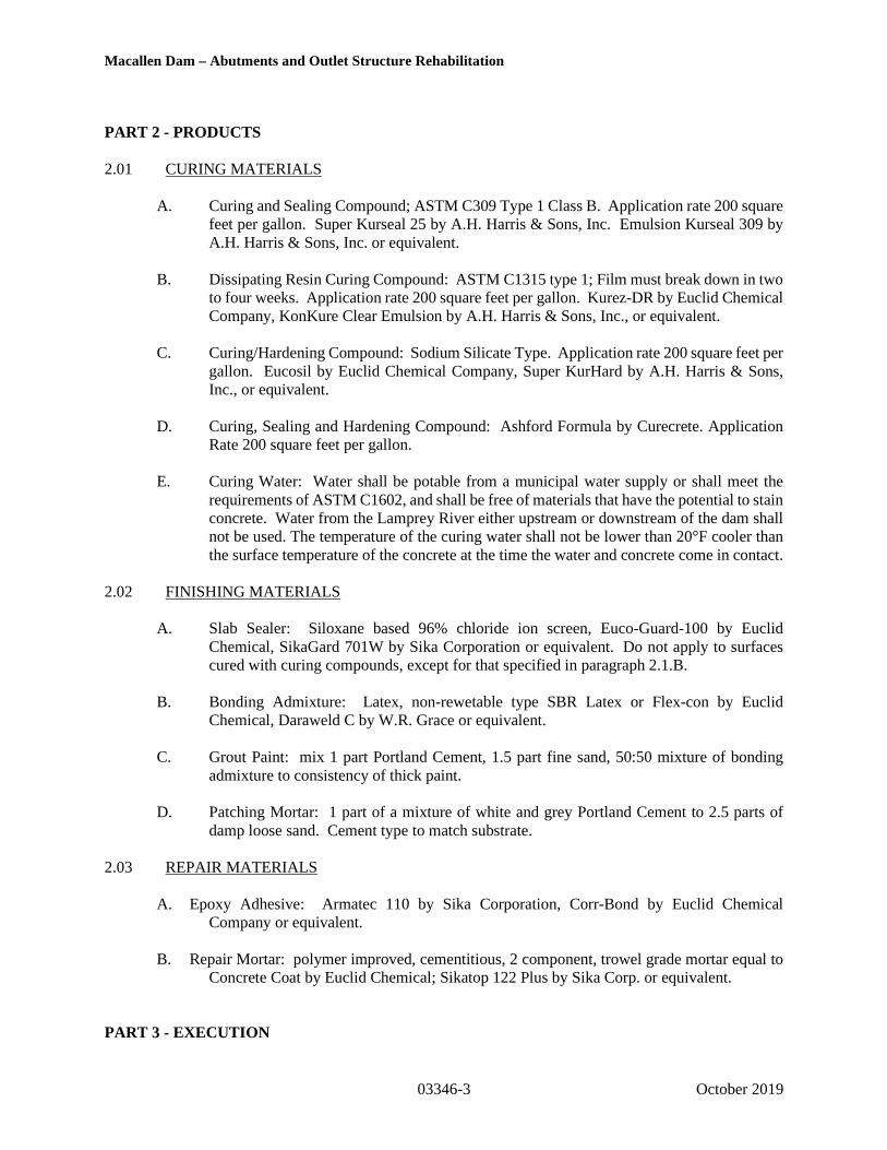
Macallen Dam – Abutments and Outlet Structure Rehabilitation
03346-3 October 2019
PART 2 - PRODUCTS
2.01 CURING MATERIALS
A. Curing and Sealing Compound; ASTM C309 Type 1 Class B. Application rate 200 squarefeet per gallon. Super Kurseal 25 by A.H. Harris & Sons, Inc. Emulsion Kurseal 309 byA.H. Harris & Sons, Inc. or equivalent.
B. Dissipating Resin Curing Compound: ASTM C1315 type 1; Film must break down in twoto four weeks. Application rate 200 square feet per gallon. Kurez-DR by Euclid ChemicalCompany, KonKure Clear Emulsion by A.H. Harris & Sons, Inc., or equivalent.
C. Curing/Hardening Compound: Sodium Silicate Type. Application rate 200 square feet pergallon. Eucosil by Euclid Chemical Company, Super KurHard by A.H. Harris & Sons,Inc., or equivalent.
D. Curing, Sealing and Hardening Compound: Ashford Formula by Curecrete. ApplicationRate 200 square feet per gallon.
E. Curing Water: Water shall be potable from a municipal water supply or shall meet therequirements of ASTM C1602, and shall be free of materials that have the potential to stainconcrete. Water from the Lamprey River either upstream or downstream of the dam shallnot be used. The temperature of the curing water shall not be lower than 20°F cooler thanthe surface temperature of the concrete at the time the water and concrete come in contact.
2.02 FINISHING MATERIALS
A. Slab Sealer: Siloxane based 96% chloride ion screen, Euco-Guard-100 by EuclidChemical, SikaGard 701W by Sika Corporation or equivalent. Do not apply to surfacescured with curing compounds, except for that specified in paragraph 2.1.B.
B. Bonding Admixture: Latex, non-rewetable type SBR Latex or Flex-con by EuclidChemical, Daraweld C by W.R. Grace or equivalent.
C. Grout Paint: mix 1 part Portland Cement, 1.5 part fine sand, 50:50 mixture of bondingadmixture to consistency of thick paint.
D. Patching Mortar: 1 part of a mixture of white and grey Portland Cement to 2.5 parts ofdamp loose sand. Cement type to match substrate.
2.03 REPAIR MATERIALS
A. Epoxy Adhesive: Armatec 110 by Sika Corporation, Corr-Bond by Euclid ChemicalCompany or equivalent.
B. Repair Mortar: polymer improved, cementitious, 2 component, trowel grade mortar equal toConcrete Coat by Euclid Chemical; Sikatop 122 Plus by Sika Corp. or equivalent.
PART 3 - EXECUTION

Macallen Dam – Abutments and Outlet Structure Rehabilitation
03346-4 October 2019
3.01 FINISHES
A. Repair all holes and defects and allow to set prior to finishing concrete.
B. Clean all exposed concrete surfaces and adjoining work stained by leakage of concrete.
C. Finish concrete surfaces as scheduled.
3.02 FINISHING SLABS AND FLATWORK
A. Screed to bring concrete surface to proper contour and elevation.
B. Highway straightedge, bull float or darby float the concrete surface immediately afterscreeding.
C. Allow bleed water to evaporate or remove.
D. (STF) Steel Troweled Finish: Float the surface with magnesium or cast aluminum float orwith a power finishing machine. Steel trowel surface immediately after floating to producesmooth surface. Steel trowel again after concrete has hardened enough so that mortar doesnot adhere to trowel edge. Ringing sound should be apparent when performing secondtroweling due to tilted, compacting motion.
E. (WFF) Wood Float Finish: allow concrete to stiffen; float surface twice or more to auniform sandy texture.
F. (LBF) Light Broom Finish: wood float finish as in E above; while plastic draw a soft-bristled broom, over the concrete in long even strokes with downward pressure. Broomtransverse to traffic or at right angles to the slope of the slab.
G. Finish to receive concrete fill: do not bull float; remove water scum, laitance and looseaggregate from surface after concrete has started to harden with stiff bristle brush topartially expose coarse aggregate. Clean surface with brooms, water jets or airjets. Maintain wet for 12 hours immediately before placing fill concrete. As fill concreteis placed and just ahead of placement, broom in grout paint to the damp concretesurface. Do not allow grout paint to set prior to placement of concrete fill.
H. Flatness and Levelness: All concrete slabs with a steel trowel finish shall be finished toachieve the following "Face Floor Profile Numbers" for composite flatness (FF) andcomposite levelness (FL) in accordance with Section 8.15 of ACI 302.1:
1. Specified Overall Value: FF 20/FL 15.
2. Minimum Local Value: FF 15/FL 10.
3.03 FINISHING VERTICAL SURFACES
A. (RFF) Rough Form Finish: Repair structural defects only and patch tie holes as specifiedin the paragraph titled “STRUCTURAL DEFECTS” in this Section. Fins exceeding 1/4in. in height to be removed by grinding and/or rubbing.

Macallen Dam – Abutments and Outlet Structure Rehabilitation
03346-5 October 2019
B. (SFF) Smooth Form Finish: The concrete surface shall be of uniform color, texture andfree of all irregularities. The arrangement of the facing material shall be orderly andsymmetrical, with the number of seams kept to the minimum. Material with raised grain,torn surfaces, worn edges, patches, dents, or other defects which will impair the texture ofthe concrete surface shall not be used. Remove fins flush by grinding and/orrubbing. Repair surface and structural defects as specified in the paragraphs titled“SURFACE DEFECTS” and “STRUCTURAL DEFECTS” in this Section.
3.04 MISCELLANEOUS CONCRETE SURFACE
A. Curbs: Provide monolithic finish to curbs by stripping forms while concrete is still greenand steel-troweling surfaces to a hard, dense finish with corners, intersections, andterminations chamfered.
3.05 SLAB SEALER
A. Cure concrete for 30 days.
B. Clean surface of oil, grease, dirt, and foreign materials as recommended by themanufacturer.
C. Apply when slab temperature is between 40°F and 80°F.
D. Apply in strict conformance to manufacturers' recommendations.
E. Maximum coverage: 125 square feet per gallon.
3.06 CURING
A. Curing: Curing shall begin immediately following the initial set of concrete or after slabsurface finishing has been completed and shall continue after form removal. All concreteshall be cured to attain strength and durability by one of the following methods for aminimum of seven days after placement regardless of the ambient air temperature: SeeSchedule of Finishes and Curing Requirements in this Section:
1. Moist Curea. Ponding or continuous sprinkling. Intermittent wetting and drying is not
an acceptable curing method.b. Application of absorptive mats of fabric kept continuously wet.
2. Application of concrete curing compounds. If applying slab sealing compounds,use dissipating resin curing compound. Allow dissipating resin curing compoundto chemically break-down, and remove residuals and other foreign material, priorto applying slab sealing compound.
B. Moisture loss from surfaces placed against wooden or metal forms exposed to heating bythe sun shall be minimized by keeping the forms wet until they can be safely removed.After form removal, the concrete shall be cured by one of the methods described above,for the balance of time remaining as specified above.
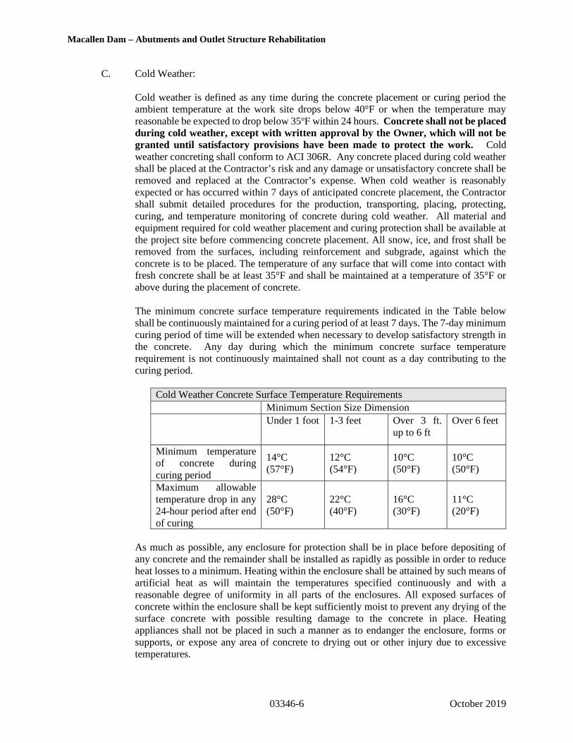
Macallen Dam – Abutments and Outlet Structure Rehabilitation
03346-6 October 2019
C. Cold Weather:
Cold weather is defined as any time during the concrete placement or curing period theambient temperature at the work site drops below 40°F or when the temperature mayreasonable be expected to drop below 35oF within 24 hours. Concrete shall not be placedduring cold weather, except with written approval by the Owner, which will not begranted until satisfactory provisions have been made to protect the work. Coldweather concreting shall conform to ACI 306R. Any concrete placed during cold weathershall be placed at the Contractor’s risk and any damage or unsatisfactory concrete shall beremoved and replaced at the Contractor’s expense. When cold weather is reasonablyexpected or has occurred within 7 days of anticipated concrete placement, the Contractorshall submit detailed procedures for the production, transporting, placing, protecting,curing, and temperature monitoring of concrete during cold weather. All material andequipment required for cold weather placement and curing protection shall be available atthe project site before commencing concrete placement. All snow, ice, and frost shall beremoved from the surfaces, including reinforcement and subgrade, against which theconcrete is to be placed. The temperature of any surface that will come into contact withfresh concrete shall be at least 35°F and shall be maintained at a temperature of 35°F orabove during the placement of concrete.
The minimum concrete surface temperature requirements indicated in the Table belowshall be continuously maintained for a curing period of at least 7 days. The 7-day minimumcuring period of time will be extended when necessary to develop satisfactory strength inthe concrete. Any day during which the minimum concrete surface temperaturerequirement is not continuously maintained shall not count as a day contributing to thecuring period.
Cold Weather Concrete Surface Temperature Requirements
Minimum Section Size Dimension
Under 1 foot 1-3 feet Over 3 ft.up to 6 ft
Over 6 feet
Minimum temperatureof concrete duringcuring period
14°C(57°F)
12°C(54°F)
10°C(50°F)
10°C(50°F)
Maximum allowabletemperature drop in any24-hour period after endof curing
28°C(50°F)
22°C(40°F)
16°C(30°F)
11°C(20°F)
As much as possible, any enclosure for protection shall be in place before depositing ofany concrete and the remainder shall be installed as rapidly as possible in order to reduceheat losses to a minimum. Heating within the enclosure shall be attained by such means ofartificial heat as will maintain the temperatures specified continuously and with areasonable degree of uniformity in all parts of the enclosures. All exposed surfaces ofconcrete within the enclosure shall be kept sufficiently moist to prevent any drying of thesurface concrete with possible resulting damage to the concrete in place. Heatingappliances shall not be placed in such a manner as to endanger the enclosure, forms orsupports, or expose any area of concrete to drying out or other injury due to excessivetemperatures.

Macallen Dam – Abutments and Outlet Structure Rehabilitation
03346-7 October 2019
D. Hot Weather:
Concrete construction during hot weather shall, unless otherwise indicated, conform to ACI305. During hot dry weather, and as directed, all new concrete shall be kept shaded fromthe sun, shielded from the wind and kept wet with water, or protected by other approvedmethods to retain the moisture in the concrete throughout the curing period. Duringconcrete placement operations in hot weather, appropriate measures shall be taken toreduce the hazards of increased rate of cement hydration, flash set, loss of water due toevaporation, high concrete ingredient temperatures, and the increased difficulty of concreteplacing and finishing. The following requirements shall be met during concrete placementoperations in hot weather:
1. Concrete Temperature: The temperature of the concrete at the point of dischargeshall not exceed 26.7°C (80°F). Concrete shall not be placed when the internaltemperature of the concrete is 80oF or above.
2. Cooling Materials: The Contractor may reduce the temperature of the concrete bycooling one or more of several ingredients. The aggregates may be cooled byfogging, or other suitable means that will not result in a high variation of moisturecontent within the stockpile. Chipped or crushed ice may be used in the mix as aportion of the mixing water on a pound for pound basis, provided such measure isdetermined at the time it is placed in the mix. If used, all ice shall be melted beforethe batch is discharged from the mixing unit. Ice shall be added with the approvalof and/or as directed by the Owner. Water may also be cooled by refrigeration orother means that provide a uniform mixing water temperature.
3. Concrete Placing: Immediately before the concrete is placed, the forms andreinforcement steel shall be cooled by spraying with water. In no case shall therebe any standing water in the concrete forms as a result of the spraying procedures.The Contractor shall have sufficient skilled men and adequate equipment to placethe concrete without delays which may cause excessive slump loss and evaporationdue to over-mixing or exposure before it is placed.
Conform to ACI 305R when concreting during hot weather. Alternatively, whenconcrete temperatures exceed 80oF, a set retarding admixture conforming to ASTMC494 type B or D may be added to the concrete mix as directed by the Owner.
4. Finishing: To prevent shrinkage cracking resulting from moisture loss, theContractor may be required to furnish windscreens, to use water fogging, or otherapproved means of supplying moisture. If the use of windscreens is required, thewindscreens shall consist of canvas barriers of suitable height erected on thewindward side of the concrete placement. Finishing operations shall follow asclosely as practicable behind the placing operation so that curing may begin assoon as possible.
3.07 SCHEDULE OF FINISHES AND CURING REQUIREMENTS
A. Provide finishes on concrete surfaces according to the following schedule:

Macallen Dam – Abutments and Outlet Structure Rehabilitation
03346-8 October 2019
SCHEDULE OF FINISHES AND CURING REQUIREMENTS
Location Finish Curing Requirements
Training Walls, Retaining Walls, Allexterior vertical faces S FF
Moist Cure
Vertical faces below grade in contactwith backfill R FF
Moist Cure
All horizontal faces and surfacesS T F
Moist Cure
NOTES:1. When two (2) coats of materials are required as indicated above, second coat shall be applied
perpendicular to the first coat.
3.08 SURFACE DEFECTS
A. As soon as the forms have been stripped and the concrete surfaces exposed, allow theResident Engineer to inspect concrete surfaces. Excessive honeycombing is not consideredacceptable. If approved by the Resident Engineer, repair all surface defects. Surfacedefects include all form tie holes, minor honeycombed areas and surface blemishesincluding air voids and bug holes with a nominal diameter or depth greater than ¼ inch,visible construction joints, fins, burs and other defects. All concrete repair work shall resultin a concrete surface of uniform color and texture, and shall be free of all irregularities.Honeycombed and/or rat holes larger than 50 cubic inches are considered a structuraldefect.
B. Cut out and remove honeycombed areas and rock pockets down to solid concrete, but inno case to a depth less than 1 inch, by means of hand chisels or pneumatic chippinghammers. Saw cut the edges perpendicular to the surface. No feather-edges shall beallowed.
C. Remove all loose aggregate paste and debris and scrub clean; thoroughly wet area to berepaired; brush and scrub grout paint into the substrate of the area to be repaired.
D. Apply a stiff consistency of patching mortar to the area with a trowel; apply prior to the setof grout paint (but after it has cast its water sheen): leave patched surface slightly higherthan surrounding surface; do not finish for 1 hour minimum. Cure in same manner asadjacent concrete.
E. Mix patching mortar using as little water as possible; allow to stand with frequentmanipulation of trowel to achieve stiffest consistency; blend white and gray Portlandcement to achieve color match with surrounding concrete.
F. Form Tie Holes: After cleaned and thoroughly dampened, apply grout paint and fill tieholes solid with patching mortar.
G. Finished Flatwork exceeding specified tolerances:

Macallen Dam – Abutments and Outlet Structure Rehabilitation
03346-9 October 2019
1. High areas shall be repaired by grinding after the concrete has cured 14 days.
2. Low areas shall be repaired by cutting out low areas and replaced with concrete.Finish repair area to match adjacent concrete.
3.09 STRUCTURAL DEFECTS
A. Remove and replace or repair all structural defects. Structural defects includehoneycombed areas and/or rat holes greater than 50 cubic inches, areas which cracking,spalling or other signs of deterioration are present or develop during the initial curing orthereafter until accepted by the Resident Engineer. The Contractor shall propose a specificrepair method, suitable for the situation, and the Resident Engineer will review the methodprior to the repair.
B. Cut out and remove defective concrete, honeycombed areas and rock pockets to soundconcrete by means of hand chisels or pneumatic chipping hammers. Saw cut 1 inchminimum the edges perpendicular to the surfaces. If honeycomb exists aroundreinforcement, chip to provide a clear space at least 1 inch wide all around thereinforcement. Moisten surfaces and allow to dry until damp. Apply bonding agent. Applya polymer-modified cement with 3/8-inch coarse aggregate. Cure as required bymanufacturer.
C. Random Cracks:
1. Random shrinkage or structural cracks shall be repaired utilizing a low viscosity,100% solids, two (2) component epoxy resin system. Remove all dust, debris ordisintegrated material from crack or void by use of oil-free compressed air orvacuuming.
2. Crack or void must be dry at time of application. Cracks saturated with oil orgrease must be chipped out to unsaturated concrete. "Vee" out cracks in horizontalsurfaces slightly.
3. Where cracks extend through members and are accessible, seal bottom of crackwhich is to receive the epoxy. Apply epoxy in strict accordance withmanufacturer's recommendations.
4. Patching of vertical wall or overhead cracks shall be accomplished in the samemanner using a similar epoxy material of higher viscosity as recommended by themanufacturer.
5. Materials shall be as indicated in Part F below.
D. Excessive Cracking:
1. Floor slabs containing an excessive amount of cracks as defined herein, and whichwill remain exposed, shall receive an epoxy mortar topping after sealing of cracksin accordance with the above paragraph.
2. Excessive cracking shall be defined as areas containing racks averaging 1/64th-inchwide or greater, and in excess of 15 linear feet of cracks per 100 square feet of slab.In the event that excessive cracking occurs in isolated areas of a given floor,topping will only be required in the area of the cracks bounded by construction,expansion, or control joints.
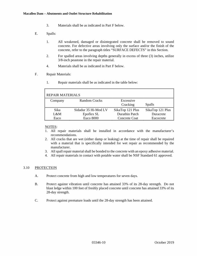
Macallen Dam – Abutments and Outlet Structure Rehabilitation
03346-10 October 2019
3. Materials shall be as indicated in Part F below.
E. Spalls:
1. All weakened, damaged or disintegrated concrete shall be removed to soundconcrete. For defective areas involving only the surface and/or the finish of theconcrete, refer to the paragraph titles “SURFACE DEFECTS” in this Section.
2. For spalled areas involving depths generally in excess of three (3) inches, utilize3/8-inch peastone in the repair material.
4. Materials shall be as indicated in Part F below.
F. Repair Materials:
1. Repair materials shall be as indicated in the table below:
REPAIR MATERIALS
Company Random Cracks ExcessiveCracking Spalls
Sika Sidadur 35 Hi-Mod LV SikaTop 121 Plus SikaTop 121 PlusL&M Epoflex SL Durathin Patch DuracreteEuco Euco 8000 Concrete Coat Eucocrete
NOTES:1. All repair materials shall be installed in accordance with the manufacturer’s
recommendations.2. All cracks that are wet (either damp or leaking) at the time of repair shall be repaired
with a material that is specifically intended for wet repair as recommended by themanufacturer.
3. All spall repair material shall be bonded to the concrete with an epoxy adhesive material.4. All repair materials in contact with potable water shall be NSF Standard 61 approved.
3.10 PROTECTION
A. Protect concrete from high and low temperatures for seven days.
B. Protect against vibration until concrete has attained 33% of its 28-day strength. Do notblast ledge within 100 feet of freshly placed concrete until concrete has attained 33% of its28-day strength.
C. Protect against premature loads until the 28-day strength has been attained.

Macallen Dam – Abutments and Outlet Structure Rehabilitation
03346-11 October 2019
PART 4 - MEASUREMENT AND PAYMENT
No measurement shall be made of any work performed under this section. No separate payment shall be madefor any work performed under this section. The cost of any work done or facilities provided under this sectionis incidental to the work shall be included under other pay items within the Contract.
* * * END OF SECTION * * *
J:\170,000-179,999\173346\173346-10.TEM\WORK\Specifications\FINAL\Division 3\03346 Conc finishing curing and repair.docx
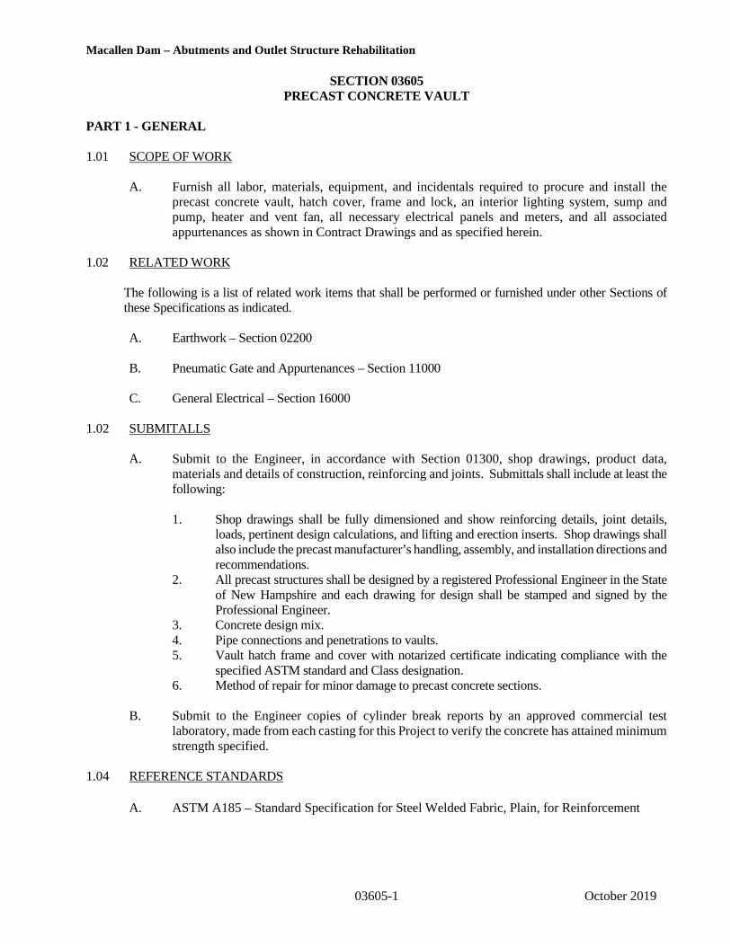
Macallen Dam – Abutments and Outlet Structure Rehabilitation
03605-1 October 2019
SECTION 03605PRECAST CONCRETE VAULT
PART 1 - GENERAL
1.01 SCOPE OF WORK
A. Furnish all labor, materials, equipment, and incidentals required to procure and install theprecast concrete vault, hatch cover, frame and lock, an interior lighting system, sump andpump, heater and vent fan, all necessary electrical panels and meters, and all associatedappurtenances as shown in Contract Drawings and as specified herein.
1.02 RELATED WORK
The following is a list of related work items that shall be performed or furnished under other Sections ofthese Specifications as indicated.
A. Earthwork – Section 02200
B. Pneumatic Gate and Appurtenances – Section 11000
C. General Electrical – Section 16000
1.02 SUBMITALLS
A. Submit to the Engineer, in accordance with Section 01300, shop drawings, product data,materials and details of construction, reinforcing and joints. Submittals shall include at least thefollowing:
1. Shop drawings shall be fully dimensioned and show reinforcing details, joint details,loads, pertinent design calculations, and lifting and erection inserts. Shop drawings shallalso include the precast manufacturer’s handling, assembly, and installation directions andrecommendations.
2. All precast structures shall be designed by a registered Professional Engineer in the Stateof New Hampshire and each drawing for design shall be stamped and signed by theProfessional Engineer.
3. Concrete design mix.4. Pipe connections and penetrations to vaults.5. Vault hatch frame and cover with notarized certificate indicating compliance with the
specified ASTM standard and Class designation.6. Method of repair for minor damage to precast concrete sections.
B. Submit to the Engineer copies of cylinder break reports by an approved commercial testlaboratory, made from each casting for this Project to verify the concrete has attained minimumstrength specified.
1.04 REFERENCE STANDARDS
A. ASTM A185 – Standard Specification for Steel Welded Fabric, Plain, for Reinforcement

Macallen Dam – Abutments and Outlet Structure Rehabilitation
03605-2 October 2019
B. ASTM A615 – Standard Specification for Deformed and Plain Billet Steel Bars for ConcreteReinforcement
C. ASTM A185 – Standard Specification for Steel Welded Fabric, Plain, for Reinforcement
D. ASTM C33 – Standard Specification for Concrete Aggregates
E. ASTM C857 – Practice for Minimum Structural Design Loading for Underground PrecastConcrete Utility Structures
F. ASTM C858 – Standard Specification for Underground Precast Concrete Utility Structures
G. ASTM C877 – Standard Specification for External Sealing Bands for Concrete Pipe, Manholes,and Precast Box Sections
H. ASTM C891 – Practice for Installation of Underground Precast Concrete Utility Structures
I. ASTM C990 – Standard Specification for Joints for Concrete Pipe, Manholes, and Precast BoxSections Using Preformed Flexible Joint Sealants
J. ASTM C1244 – Standard Test Method for Concrete Sewer Manholes by the Negative Air Pressure(Vacuum) Test Prior to Backfill
K. ASTM C1677 – Standard Specification for Joints for Concrete Box, Using Rubber Gaskets
1.05 QUALITY ASSURANCE
A. All material shall be new and unused.
B. Manufacturer and Contractor shall have a minimum of 5 years of experience providing,installing, and finishing precast structures of similar size and complexity.
C. The materials’ quality, manufacturing process, and finished sections are subject to inspectionand acceptance by the Owner, the Resident Engineer, and the Engineer. Inspection may bemade at place of manufacture, at work site following delivery, or both.
D. Materials will be examined for compliance with ASTM standards, this Section, and approvedmanufacturer’s drawings. Additional inspection criteria shall include appearance, dimensions,blisters, cracks and soundness.
E. Repair minor damage to precast concrete sections by approved method, if repair is authorizedby Owner and/or the Resident Engineer. Epoxy mortar may be utilized for repairs subject tothe approval of the Engineer.
1.05 DELIVERY, STORAGE, AND HANDLING
A. Precast concrete vault shall not be transported until concrete has cured to a minimum of 80percent of design strength.

Macallen Dam – Abutments and Outlet Structure Rehabilitation
03605-3 October 2019
B. Store precast concrete vault off ground on wood blocks, pallets, or other appropriate meansaway from brush, and in an area accessible for inspection.
C. Unload and handle precast concrete vault with crane, backhoe, or equipment of adequatecapacity, equipped with appropriate slings and lifting devices to protect material from beingdamaged.
PART 2 – PRODUCTS
2.01 GENERAL
A. Reference to a manufacturer’s name and model or catalog number is for the purpose ofestablishing the standard of quality and general configuration desired.
B. Like items of materials/equipment shall be the end products of one manufacturer in order toprovide standardization for appearance, operation, maintenance, spare parts andmanufacturer’s service.
C. Provide lifting lugs or holes in each precast section for proper handling.
D. Reinforced concrete materials shall generally follow Section 03300. Cement shall conform toASTM C150, Type II or Type I/II cement or equal.
E. Mark date of manufacture, name and trademark of manufacturer on the inside of each precastsection.
2.02 PRECAST CONCRETE VAULT SECTIONS
A. Precast concrete vault sections shall conform to ASTM C858 – Specification for UndergroundPrecast Concrete Utility Structures.
B. Precast concrete vault sections shall have a one pour monolithic reinforced concrete basesection and shall have a keyway type joint between other precast sections.
C. Joint between precast concrete section shall be sealed as recommended by manufacturer andshall be watertight upon completion of joint and shall conform to requirements of ASTM C990for flexible joint sealants or ASTM C1677 for profile rubber gaskets.
D. Provide and install water-tight joint treatment conforming to the requirements of ASTM C877.
E. Provide integrally cast knock-out panels in precast concrete manhole sections at locations andsizes to be coordinated with Pneumatic Gate Drawings and Specifications. Knock-out panelsshall have no steel reinforcing.
F. An OSHA-approved ladder shall be provided for the precast concrete vault section. Holes forladder rungs shall be made during casting of the concrete section. Drilling of holes for manholerungs may be used to accommodate field conditions when approved by the Engineer.
G. Provide a sump assembly along the floor to drain water with the size and location to becoordinated with the Pneumatic Gate manufacturer. The vault floor shall be sloped to draintoward the sump. A minimum 1.5-inch sump pump shall be provided to drain sump. Provide
Macallen Dam – Abutments and Outlet Structure Rehabilitation
03605-4 October 2019
drainage through integrally cast sleeve or knock-out panel and location shall be coordinatedwith manufacturer and Pneumatic Gate manufacturer.
G. Provide an Interior Lighting System which shall consist of two (2) industrial-grade lightfixtures attached to the inside wall within the vault with a light switch accessible from thehatch. Interior Lighting System shall be coordinated with other utilities within the vault andwith the gate manufacturer.
H. If required by the gate manufacturer, provide a heating system for the vault. Heating systemshall be coordinated with the gate manufacturer.
I. Acceptable manufacturers:
1. Oldcastle Infrastructure; 41 Almeida Road, Rehoboth, MA 02769; Tel: (508) 336-7600; Website: https://oldcastleinfrastructure.com/
2. Shea Concrete Products; 160 Old Turnpike Road, Nottingham, NH 03290; Tel: (603)942-5668; Website: https://sheaconcrete.com/
3. Or approved equivalent.
2.03 VAULT FRAME AND COVER
A. Vault frame and covers shall be waterproof, of good quality, strong, tough, free from defectsof any kind which render them unfit for the service for which they are intended. Connection offrame and cover to concrete vault shall be as per manufacturer’s recommendations.
B. Vault frame and cover shall be waterproof and constructed with a lockable double leaf steelchannel frame and shall be Bilco Type JD or approved equivalent.
C. A lock shall be provided for the vault cover.
2.04 PIPE CONNECTION TO VAULT
A. Pipe connections shall be permanent and watertight Connect pipes or conduits to vault in thefollowing ways:
1. Flexible sleeve – Integrally cast sleeve in precast concrete vault section or install sleevein a formed or cored opening. Fasten pipe in sleeve with a stainless-steel clamp(s).Coat stainless steel clamp(s) with bituminous or asphaltic damp proofing material toprotect from corrosion. Flexible sleeve shall be Kor-N-Seal connector; PRX Press-Seal Gasket or approved equivalent.
2. Compression gasket – Integrally cast compression gasket in precast concrete vaultsection. Insert pipe into compression gasket. Compression gasket shall be A-Lok orapproved equivalent.
3. Modular sealing sleeve – Install modular, elastomer sealing system. Insert pipethrough wall penetrating sleeve. Modular sealing sleeve shall be Link Seal or approvedequivalent.
3. At the discretion of the Resident Engineer, the following procedure may be allowed:
Macallen Dam – Abutments and Outlet Structure Rehabilitation
03605-5 October 2019
Grout in place – Precast concrete vault section shall have a formed, tapered circularopening larger than the pipe outside diameter. Grout shall be non-shrink andwaterproof equal to Hallemite, Waterplug, or Embeco. Plastic pipe shall have awaterstop gasket secured to pipe with a stainless-steel clamp prior to grouting.
2.05 WATERPROOFING
A. Two coats of bituminous waterproofing material shall be applied to the below-grade exteriorsurfaces of the precast concrete vault by brush or spray and in accordance with themanufacturer’s recommendations. Waterproofing shall be Hydrocide 648 by SonnebornBuilding Products; Dehydratine 4 by A.C. Horn Inc.; RIW Marine Liquied by Toch Brothersor an approved equivalent.
2.06 NOISE REDUCTION SYSTEM
A. A noise reduction system shall be included with the design and installation of the concretevault. The noise reduction system shall consist of a muffler placed on the exhaust line, orsimilar approved system, to reduce noise emitted from the structure.
PART 3 - EXECUTION
3.01 INSTALLATION
A. Precast concrete vault structures shall be constructed to the dimensions shown on the ContractDrawings, specified herein, and coordinated with the Pneumatic Gate Drawings andSpecifications.
B. The Work for the precast concrete vault structure contained herein shall be coordinated withthe support of excavation protocols provided in Section 02200 – Earthwork. The precastconcrete vault base section will be placed in accordance the Drawing S-10 and S-11, detailsand notes thereon.
C. Precast concrete vault structure shall be free from visible leakage. The structure shall be testedfor leaks and inspected, and all leaks shall be repaired in a manner subject to the Engineer’sapproval.
D. Allow joints to set for 14 hours before backfilling unless the Engineer specifically approves ashorter period.
E. Plug holes in the concrete sections required for handling with a non-shrinking grout or non-shrinking grout in combination with concrete plugs. Finish flush on the inside.
F. Penetrations should be pre-formed into vault. Cut or core holes in precast concrete vaultsections to accommodate pipes and conduits prior to setting the section in place to preventjarring which may loosen the mortar joints.
G. Construct precast concrete vault pipe connections, including pipe stubs, as specified herein.Close or seal pipe stubs for future connections with a gasketed watertight plug.

Macallen Dam – Abutments and Outlet Structure Rehabilitation
03605-6 October 2019
H. Paint outer surface of precast concrete vault with two coats of bituminous waterproofing inaccordance with the manufacturer’s instructions.
I. The precast concrete vault shall be tested to ensure water tightness prior to backfilling andtesting shall be in accordance with ASTM C1244
J. Backfill carefully and evenly around the precast concrete vault structure and in accordance withSection 02200 and the Contract Drawings.
3.02 INSTALLATION OF INTERIOR LIGHTING SYSTEM
A. Coordinate final location of interior light system within the subsurface gate operations vaultwith the Pneumatic Gate manufacturer and the Owner prior to installation.
B. Interior Lighting System shall be affixed to the interior wall of the subsurface gate operationsvault and a switch shall be provided and installed which shall be easily accessible to theentrance hatch.
C. Provide electrical supply to fixtures under separate Sections of the Work. Supply to subsurfacevault must be via underground conduit. Final connection may be via direct burial cable.
D. Ensure proper grounding of the fixture.
PART 4 – MEASUREMENT AND PAYMENT
Refer to Section 01950 – Measurement and Payment for the measurement and payment items related to thisSection.
* * * END OF SECTION * * *
J:\170,000-179,999\173346\173346-10.TEM\WORK\Specifications\FINAL\Division 3\03605 - Precast Vault.docx

Macallen Dam – Abutments and Outlet Structure Rehabilitation
04510-1 October 2019
SECTION 04510REPOINTING MASONRY JOINTS
PART 1 GENERAL
1.01 SCOPE OF WORK
A. All materials, equipment, and labor necessary to inspect the left upstream granitemasonry wall of the Macallen Dam as indicated by the Owner or Resident Engineer andclean, re-point and repair the granite masonry joints with cement mortar, as specifiedherein and as shown on the Contract Drawings.
B. The Contractor is advised of the historical nature of the dam. All masonry joint re-pointingand restoration shall be done with such materials and in such a manner as to create a neat,clean, uniform, and visually attractive appearance for the masonry without damaging thestone masonry. Skilled masons shall be employed for all finishing work.
C. Install weepholes in repointed masonry joints where directed by the Owner or ResidentEngineer, in accordance with the Contract Drawings and this Section.
D. The Contractor shall keep and submit records documenting the repointing details andlocation of repointed masonry joints, including the locations of weepholes.
E. The work of this Section shall specifically include all necessary provisions for safe accessto the work areas, including scaffolding, ropes, and other such methods.
F. Provide measures to protect the Site from dust and debris from the repointing operations.Clean mortar, dust, and debris from the downstream and staging areas after repointing iscompleted. Mortar removed from masonry joints shall be legally disposed of off-site.
1.02 RELATED SECTIONS
A. Section 01565 –Temporary Water Control
B. Section 01740 –Site Restoration
C. Section 02170 –Temporary Cofferdam
1.03 REFERENCES
A. ACI 530 - Building Code Requirements for Masonry Structures.
B. ACI 530.1 - Specifications For Masonry Structures.
C. ASTM C5 - Quicklime for Structural Purposes.
D. ASTM C91 - Masonry Cement.
E. ASTM C94 - Ready-Mixed Concrete.

Macallen Dam – Abutments and Outlet Structure Rehabilitation
04510-2 October 2019
F. ASTM C144 - Aggregate for Masonry Mortar.
G. ASTM C150 - Portland Cement.
H. ASTM C199 - Test Method for Pier Test for Refractory Mortar.
I. ASTM C207 - Hydrated Lime for Masonry Purposes.
J. ASTM C270 - Mortar for Unit Masonry.
K. ASTM C387 - Packaged, Dry, Combined Materials, for Mortar and Concrete.
L. ASTM C595 - Blended Hydraulic Cement.
M. ASTM C780 - Preconstruction and Construction Evaluation of Mortars for Plain andReinforced Unit Masonry.
N. ASTM C1142 - Ready-Mixed Mortar for Unit Masonry.
O. IMIAC (International Masonry Industry All-Weather Council) - Recommended Practicesand Guide Specifications for Cold Weather Masonry Construction.
P. IMIAC (International Masonry Industry All-Weather Council) - Recommended Practicesand Guide Specifications for Hot Weather Masonry Construction.
1.03 QUALITY ASSURANCE
A. The Masons performing the repointing shall have a minimum of five (5) years ofexperience in repointing masonry and shall have performed at least five (5) projectsrepointing masonry structures within the last five years.
B. Obtain mortar mix materials from a single manufacturer for each different product required.
. C. Comply with manufacturers’recommended procedures.
D. Mock-Up: Before starting work, prepare and repoint a sample area of not less than 10 feethigh and 10 feet long using the procedures, proposed colors and texture, finish andworkmanship for approval by the Owner and Resident Engineer.
1.04 SUBMITTALS
A. Provide Company brochures and other information to demostrate that the masonsperforming the repointing operations have the required experience within 30 days followingNotice to Proceed.
B. Not less than ten (10) working days prior to the scheduled start of work, the Contractor shallsubmit a proposed Work Plan for inspecting, cleaning, and re-pointing and containing anddisposal of waste to the Engineer for review. The submittal shall also include the followingitems:
1. Product Data: Manufacturer’s catalog cuts and specifications for all materialsused including masonry cement, backer material, weephole pipes, prepackageddry mortar, admixtures, and cleaning solutions. Include documentation from the

Macallen Dam – Abutments and Outlet Structure Rehabilitation
04510-3 October 2019
manufacturer demonstrating that the materials used will not adversely affect thereservoir water quality.
2. Grain size distribution for mortar aggregate if prepackaged mortar mix is notused.
3. Details of mortar mix including all components and proportions.
4. Samples: Submit two samples of mortar, illustrating mortar color and colorrange.
5. Methods and procedures for removing old mortar from joints, preparing joints forrepointing mortar, and installing repointing mortar.
6. A list and technical description of the specific equipment to be used.
C. Reports: Submit reports on mortar indicating conformance of mortar to propertyrequirements of ASTM C270 and test and evaluation reports to ASTM C780.
D. Within two weeks of completing the work, submit to the Owner and/or Resident Engineera complete record documenting the repointing operations. Include a summary of thework performed, and a drawing showing the approximate work limits, including thelocations of any weepholes installed and dates of completion.
1.05 DELIVERY, STORAGE, AND HANDLING
A. Deliver materials to project site in original unopened containers or bundles with labelsinforming about manufacturer, product name and designation, color, expiration period foruse, pot life, curing time, and mixing instructions for multi-component materials.
B. Store and handle materials in compliance with manufacturers’recommendations to preventtheir deterioration or damage due to moisture, high or low temperatures, contaminants, orother causes.
1.06 PROJECT CONDITIONS
A. Do not proceed with installation of any mortar products when ambient and substratetemperature conditions are outside the limits permitted by mortar/grout manufacturer ofbelow 40 degrees Fahrenheit (4.4 degrees Celsius) for a minimum of 48 hours.
B. Do not proceed with installation of mortar or joint grout until contaminants capable ofinterfering with their adhesion are removed from joint substrate.
1.07 SCHEDULE
A. Coordinate all work at the site with the Owner. Notify the Owner and Resident Engineerat least seventy-two (72) hours prior to starting work.
PART 2 PRODUCTS

Macallen Dam – Abutments and Outlet Structure Rehabilitation
04510-4 October 2019
2.01 PORTLAND CEMENT MORTAR PRODUCTS:
Mortar for use in re-pointing of joints shall be a Portland cement-based material.
A. General Re-Pointing Portland Cement Mortar
Standard Portland Cement Mortar shall be Type N in general conformance with ASTMC270, Specification for Mortar for Unit Masonry. The mortar mix shall be submitted toand approved of by the Engineer. Minimum 28-day compressive strength shall be 750psi as per ASTM C-109 Modified. Materials shall be as follows:
1. Portland cement: ASTM C150 Type I/II or Type II, grey or white as required tomatch original mortar. Fly ash, slag and pozzolans are not permitted assubstitutes for Portland cement.
2. Hydrated Lime: ASTM C207 Type S, incorporated as a finely divided powder inuniform particle size, free of lumps, flakes or other inconsistencies.
3. Mortar Aggregate: ASTM C144 Natural sand blend, rounded to sub-angular inshape, washed, screened and dried, with zero- or near zero-270 crystalline silicacontent. Aggregate to be selected to match the color and texture of the originalmortar aggregates as closely as possible while remaining in compliance withASTM C144 grading and soundness requirements.
4. Mortar Colors: Inorganic mineral oxides meeting the requirements of ASTMC797, at levels not to exceed 10% on cement weight, except for carbon black,which may not exceed 2% on cement weight.
5. Admixtures: NO admixtures shall be used without the express written consent ofthe Engineer and the mortar manufacturer. Calcium chloride is not permitted inany mortar. Admixtures containing more than 0.1% chloride ions are NOTpermitted.
B. General Repair Mortar Products
Products in the SikaRepair line of repair mortars, as manufactured by Sika Corporation,Lyndhurst, New Jersey, are considered to conform to the requirements of the specification.An equivalent product may be used pending approval by the Owner and Engineer.
C. Instant-Setting Portland Cement Water-Stop:
SikaSet Plug, as manufactured by Sika Corporation, Lyndhurst, New Jersey, is considered toconform to the requirements of the specification and have performed satisfactorily for rapidconcrete repairs for a minimum of ten years. This type of mortar shall be used where water ispresent.
1. Properties of the mixed instant-setting Portland cement water-stop:a. Time of Set (ASTM C-403): 15 - 90 seconds.b. Color: concrete gray.
2. Properties of cured instant-setting Portland cement water-stop:a. Compressive Strength (ASTM C-109)

Macallen Dam – Abutments and Outlet Structure Rehabilitation
04510-5 October 2019
i. 1 day: 3600 psi min.ii. 7 day: 5800 psi min.
b. Tensile Strength (ASTM C-496)i. 7 day: 500 psi min.ii 28 day: 600 psi min.
c. Sulfate-Resistance Test (ASTM C-88) no deterioration.i. The material shall not produce a vapor barrier.
2.02 WATER
The water used in the re-pointing/repair work shall be potable, fresh, clean, and free from deleteriousmaterials. Water from the Lamprey River is not considered suitable for use and therefore shall not beused in the repointing work.
2.03 MISCELLANEOUS MATERIALS
A. Provide backer material for modified repointed masonry joints, which prevents three-sided adhesion, and controls sealant depth.
B. Provide material for weepholes, consisting of 3/8”I.D. stainless steel pipe, cut to threeinches (3”) long.
2.04 CLEANING SOLUTIONS
A. Cleaning solutions shall be safe for the enviroment.
PART 3 EXECUTION
3.01 GENERAL
A. Repair any damage to the downstream masonry wall caused by the Contractor’s operationat no additional cost to the Owner.
B. Removal and re-setting of stone masonry blocks is prohibited, unless approved by theOwner.
C. The Contractor shall be responsible for maintaining a safe, clean and accessible work siteat all times.
D. All OSHA requirements, and all applicable local environmental requirements, and OtisConservation Commission Order of Conditions shall be satisfied.

Macallen Dam – Abutments and Outlet Structure Rehabilitation
04510-6 October 2019
3.02 JOINT PREPARATION
A. Clean all vegetation, soil deposits, and loose/unsound grout substrate by mechanicalmeans from all exposed surfaces of stone masonry. Remove mortar using hand or powertools compatible with the stone masonry units. Select equipment and methods that willnot damage or change the appearance of the stone masonry units. Sand blasting or highpressure water blast shall not be allowed.
B. Remove dust, loose particles and debris remaining from cleaning operations byvacuuming or blowing out joints with oil-free compressed air. To allow for mortaradhesion. No chemicals which could pollute the wetland resources areas shall be used incleaning.
C. Barriers shall be constructed as necessary to collect debris and water for disposal and tominimize the effects of infiltration into the waterways, and procedures shall be taken tominimize contamination of these waterways due to cleaning procedures. After cleaning,all masonry should be inspected for previously obscured deficiencies.
3.03 MORTAR MIXING
A. Measure mortar materials to achieve consistent mix proportions, yields, workability, andcolor from batch to batch.
B. Measure sand by volume or equivalent weight; do not measure by shovel.
C. Mix and prehydrate materials in accordance with the appendix to ASTM C270 for tuckpointing mortar.
D. Retemper mortar as needed.
E. Discard unused mortar 2-1/2 hours after initial mixing.
3.04 STANDARD MASONRY JOINT REPOINTING
A. Do not repoint mortar joints unless the ambient air temperature is between 40 and 90 degF and will remain so for at least 48 hours after completion of the work. Protect freshlyplaced mortar from freezing or rapid surface drying.
B. Clean out joints immediately before installing mortar to comply with recommendationsof mortar manufacturers. Dampen joints to be pointed. Allow masonry units to absorbsurface water, and remove standing water from the joints.

Macallen Dam – Abutments and Outlet Structure Rehabilitation
04510-7 October 2019
C. Tightly pack mortar into joints in layers as required to control shrinkage. The joint shallbe a minimum of ¾ -inch thick, placed in maximum ¼ -inch thick layers. Allow eachlayer to become “thumbprint hard”before applying the next layer.
D. After the final layer becomes “thumbprint hard,”tool the joints to match the originaljoints.
3.05 MODIFIED MASONRY JOINT REPOINTING
A. Install modified repointed masonry joints where existing mortar is unsound or non-existent for a depth of two inches from the face of the masonry block, or as directed bythe Resident Engineer.
B. Install appropriate backer material to prevent three sided adhesion and to control sealantdepth.
C. Gun, inject, or pour sealant into joint, tool as required to properly fill joint.
3.06 WEEPHOLES IN MASONRY JOINT REPOINTING
A. Where directed by the Owner and Resident Engineer, weepholes shall be installed injoints where seepage through the masonry wall is actively occuring.
B. Removal of any loose material from within the joint prior to the insertation of the pipe iscritical. The Contractor shall, to the satisfaction of the Owner and Resident Engineer,thoroughly clean out the masonry joint prior to the insertation of the pipe.
C. Weepholes shall be construted using 3/8-inch inside diameter x 3 inch long stainless steelpipes shall be installed within masonry joints where seepage is occuring. The pipe shallbe set in the joint with modified joint with portland cement mortar and instant settingPortland cement water stop mortar joint as shown on the Drawings.
D. The stainless steel weephole pipes shall extend ½ -inch beyond the face of the masonry.
3.07 SITE RESTORATION
A. Clean exposed stone surfaces on completion. Remove mortar droppings, dust, and otherforeign substances from masonry surfaces.
B. Remove equipment, materials, and debris from downstream area. Restore area inaccordance with Section 01740.

Macallen Dam – Abutments and Outlet Structure Rehabilitation
04510-8 October 2019
PART 4 - MEASUREMENT AND PAYMENT
Refer to Section 01950 –Measurement and Payment for the measurement and payment items related tothis Section.
* * * END OF SECTION * * *
J:\170,000-179,999\173346\173346-10.TEM\WORK\Specifications\FINAL\Division 4\04510 Repointing Masonry.doc

Macallen Dam – Abutments and Outlet Structure Rehabilitation
05730-1 October 2019
SECTION 05730ORNAMENTAL ALUMINUM HANDRAILS AND RAILINGS
PART 1 GENERAL
1.01 SCOPE
A. This section specifies the requirements for furnishing and installing an architectural fence(ornamental aluminum railing) system. The work under this section includes the furnishingof all labor, equipment, supplies, materials and utilities required for the removal anddisposal of the existing fence along the left abutment training wall and existing outletstructure, preparation and cleaning of the existing or repaired concrete, masonry, or granitesurfaces, and installation of new ornamental aluminum railing as shown on the ContractDrawings. All work shall be performed in accordance with the plans and specificationsand to the satisfaction of the Engineer.
B. The intent of the Work of this Section is to replace the architectural fence system in-kindwhich matches the existing ornamental railing system along the left abutment training walland existing gate structure after installation of the new gate structure and rehabilitation tothe left abutment wall are completed. The replacement fence shall be submitted for reviewand approval to the owner, and shall generally match the height, style, color, etc., of theexisting system to be replaced.
C. The extents of ornamental aluminum railings along the crest of the left abutment wall to bereplaced-in-kind shall be, at a minimum, from the existing structure at 4 Bay Road to thesouthernmost extent of the downstream apron of the gate structure. The railing shall beconnected to the new underlying concrete by means of anchored base flanges.
D. The ornamental aluminum railings shall perform to all applicable OSHA standards.
1.01 REFERENCES
A. AA DAF-45 - Designation System for Aluminum Finishes; The Aluminum Association.
B. ANSI A1264.1 - Safety Requirements for Workplace Floor and Wall Openings, Stairs, andRailing Systems.
C. ANSI/ASCE 7 - Minimum Design Loads for Buildings and Other Structures.
D. ASTM B 209 - Standard Specification for Aluminum and Aluminum-Alloy Sheet and Plate.
E. ASTM B 211 - Standard Specification for Aluminum and Aluminum-Alloy Rolled or ColdFinished Bar, Rod, and Wire.
F. ASTM B 221 - Standard Specification for Aluminum and Aluminum-Alloy Extruded Bars,Rods, Wire, Profiles, and Tubes.
G. ASTM B 247 - Standard Specification for Aluminum and Aluminum Die Forgings, HandForgings, and Rolled Ring Forgings.

Macallen Dam – Abutments and Outlet Structure Rehabilitation
05730-2 October 2019
H. ASTM B 429 - Standard Specification for Aluminum-Alloy Extruded Structural Pipe andTube.
I. ASTM E 935 - Standard Test Methods for Permanent Metal Railing Systems and Rails forBuildings.
J. 29 CFR 1910.23 - Guarding floor and wall openings; Occupational Safety and HealthAdministration.
K. BOCA National Building Code; Building Officials and Code Administrators International,Inc.
L. ICBO Uniform Building Code; International Conference of Building Officials.
M. SBCCI Standard Building Code; Southern Building Code Congress International, Inc.
1.02 PERFORMANCE REQUIREMENTS
A. Structural Performance: Engineer, fabricate, and install handrails, guardrails, and railingsystems to withstand the structural loading required by applicable codes.
B. Comply with requirements of building authorities having jurisdiction in the Project location.
C. Thermal and Corrosion Control:
1. Allow for thermal action resulting from the maximum range (change) in ambienttemperature in the design, fabrication, and installation of rail systems, to preventopening of joints, buckling, and other detrimental effects, including overstressing ofconnections and components.
2. Prevent galvanic action and other forms of corrosion by isolating dissimilar metals ormaterials, preventing direct contact with each other.
1.03 SUBMITTALS
A. Submit under provisions of Section 01300.
B. Product Data: Manufacturer's specifications and installation instructions for all componentsof each product type specified.
C. Shop Drawings: Prepared specifically for this project.
1. Show complete layout; plan views, elevations, connections, details for fabrication andattachment to other elements, and other installation details. Indicate materials, methods,finishes and types of joinery, fasteners, anchorages and accessory items.

Macallen Dam – Abutments and Outlet Structure Rehabilitation
05730-3 October 2019
1.04 QUALITY ASSURANCE
A. Manufacturer’s Certificates: Certify products meet or exceed specified requirements.
B. Manufacturer/Installer qualifications demonstrating documented experience successfullyexecuting projects with similar scope within the last 3 years.
C. Manufacturer/Installer Qualifications: Provide handrails, guardrails, and railing systems fromone source, produced by a manufacturer and craftsmen having resources to provide consistentquality in appearance and physical properties, without delaying the work.
D. Closeout Submittals: Provide manufacturer’s maintenance instructions that includerecommendations for periodic cleaning and maintenance of all components.
1.5 DELIVERY, STORAGE, AND HANDLING
A. Deliver handrails, guardrails, railing systems, and related components in protective packaging.Inspect materials to ensure that specified products have been received.
B. Store components to avoid damage from moisture, abrasion, and other construction activities.
1.6 SEQUENCING
A. Ensure that products of this Section are supplied to affected trades in time to preventinterruption of construction progress.
1.7 PROJECT CONDITIONS
A. Maintain environmental conditions (temperature, humidity, and ventilation) within limitsrecommended by manufacturer for optimum results. Do not install products underenvironmental conditions outside manufacturer’s absolute limits.
B. Field Measurements: Take measurements of actual dimensions where necessary for fit withoutgaps. Indicate measurements on shop drawings.
PART 2 PRODUCTS
2.01 MANUFACTURERS
A. Acceptable Manufacturers:
1. Ultra Aluminum Manufacturing; 2124 Grand Commerce Drive, Howell, MI48855; Tel: (800) 656-4420, Fax: (800) 643-7429, Website:http://www.ultrafence.com/
2. Master Halco; 3010 Lyndon B Johnson Freeway, Suite 800, Dallas, TX 75234; Tel:(888) 643-3623, Website: https://www.masterhalco.com/
3. Ameristar Fence Products; 1555 N. Mingo Road, Tulsa, OK 74116; Tel: (888) 333-3422, Website: https://www.ameristarfence.com/
B. Alternate systems or manufacturers may be submitted for approval.

Macallen Dam – Abutments and Outlet Structure Rehabilitation
05730-4 October 2019
C. Provide all handrails, guardrails, and railing systems from a single manufacturer.
2.02 MATERIALS
A. General: Provide material free from surface blemishes where exposed to view in the finishedinstallation.
B. Aluminum material for fence framework (i.e., tubular pickets, rails and posts) shall conformto the requirements of ASTM B221. The aluminum extrusions for posts and rails shall beAlloy and Temper Designation 6005-T52. The aluminum extrusions for pickets shall be Alloyand Temper Designation 6063-T52.
C. Pickets shall be 3/4" square x .045" thick. Horizontal rails shall be 1-1/4" x 1-7/16" U- channelwith .060" thick top & internal web wall, and .090" thick side walls and shall be punched toallow picket to pass through the top of the rail. The horizontal rail shall be constructed withan internal web insert providing a raceway for the pickets to be retained with a 1/8” retainingrod. The number of rails shall vary with the style, height and strength as determined bymanufacturer.
D. Accessories: Aluminum castings shall be used for all post caps, scrolls, finials, and othermiscellaneous hardware. Hinges and latches shall be fabricated from aluminum, stainless steelor composite materials.
2.03 FABRICATION
A. Fabricate handrails and railing systems to comply with manufacturer's printed requirements,project design requirements, details, dimensions, finish and member sizes, including postspacing and anchorage, but not less than the structural requirements to support loading.
1. Clearly mark component units for site assembly and installation.2. Use connections that maintain structural capacity of joined members.3. All pipe cuts shall be square and accurate for minimum joint-gap. Cuts shall be clean
and free of chamfer, from deburring, nicks and burrs.
B. Pickets, rails and posts shall be pre-cut to specified lengths. Horizontal rails shall be pre-punched to accept pickets. Grommets shall be inserted into the pre-punched holes in the railsand pickets shall be inserted through the grommets so that pre-drilled picket holes align withthe internal upper raceway of the horizontal rails. Retaining rods shall be inserted into eachhorizontal rail so that they pass through the pre-drilled holes in each picket, thus completingthe panel assembly.
C. If railing is angled horizontally, machine to proper angle into the post.
D. Fabricate railing system to meet step railing requirements; riser and tread dimensions of thesteps.
E. Provide components required for anchorage of framing. Fabricate anchors and relatedcomponents of material and finish as required, or as specifically noted.

Macallen Dam – Abutments and Outlet Structure Rehabilitation
05730-5 October 2019
2.04 FINISHES
A. Contractor shall provide a powder coat finish. Alternate finishes may be proposed for approvalby the Owner. Samples of the finish should be provided.
B. Color to match existing. May require powder coat finish.
PART 3 EXECUTION
3.01 EXAMINATION
A. Examine system components, substrate, and conditions where railing systems are to beinstalled.
B. Do not begin installation until substrates have been properly prepared.
C. Notify Engineer and Owner in writing of unsatisfactory conditions. Do not proceed with thework until unsatisfactory conditions have been corrected.
3.02 PREPARATION
A. Clean surfaces thoroughly prior to installation.
B. Prepare surrounding construction to receive railing system installations to comply withmanufacturer's requirements.
C. Review and coordinate setting drawings, shop drawings, templates, and instructions forassembly and installation of railing system and related items to be embedded in concrete andmasonry.
D. Ensure that adjacent surfaces, structures, and finishes are protected from damage byconstruction activities of this Section.
E. Use wood blocks and padding to prevent damage to railing members and fittings duringerection.
3.03 INSTALLATION
A. Install railing system and related components in strict accordance with manufacturer's printedinstallation instructions and project shop drawings.
B. Separate aluminum which might contact concrete, masonry, or other metals (to include steelanchoring and fasteners), by means of asphaltic or bituminous paint or other approved coatingor method to prevent electrolytic action.
C. Preassemble railing system, including posts, in easy to lift sections whenever possible.
1. Align rails so that variations from level for horizontal members do not exceed 1/4 inchin 12 feet.

Macallen Dam – Abutments and Outlet Structure Rehabilitation
05730-6 October 2019
D. Adjust, level, and securely install railing system components.
1. Avoid springing assembled components of system into place.
E. Keep perimeter lines straight, plumb, and level.
F. Install anchored base flanges onto the top of the existing of rehabilitated wall by means ofapproved stainless-steel anchor bolt system made by Hilti or approved equal.
G. Provide for thermal expansion and contraction by use of expansion joints/gaps in top rails, 40foot (6.096 m) maximum intervals.
1. Strictly adhere to manufacturer's instructions for locations of expansion joints andfastening of expansion sleeves.
2. Attach top rail to posts located at maximum 5 foot (1.524 m) on center spacings.3. Install bottom rails in unspliced lengths between posts.4. Install posts of continuous sections from mounting base to top rail.
H. Provide for water to drain from the railing system hollow sections by drilling weep holes atbottom locations or other approved methods.
3.04 ERECTION TOLERANCES
A. Install railing system plumb and level, securely fastened, with vertical members plumb.
1. Maximum variation from plumb: ¼ inch (6.0 mm).2. Maximum misalignment from true positions: ¼ inch (6.0 mm).3. Maximum misalignment between adjacent separated members: 1/8 inch (3.0 mm).
3.05 CLEANING
A. Immediately upon completion of installation, remove all dust or foreign matter fromcomponents; clean all railing system surfaces using clean water and mild soap or detergentand in accordance with AAMA 609 and AAMA 610-02.
B. Do not use abrasive agent or harsh chemicals.
3.06 PROTECTION
A. Provide adequate protection for all surfaces of completed installations to prevent damageduring remainder of construction activities.
B. Touch-up, repair or replace damaged products before Substantial Completion.

Macallen Dam – Abutments and Outlet Structure Rehabilitation
05730-7 October 2019
PART 4 - MEASUREMENT AND PAYMENT
Refer to Section 01950 – Measurement and Payment for the measurement and payment items related to thisSection.
* * * END OF SECTION* * *
J:\170,000-179,999\173346\173346-10.TEM\WORK\Specifications\FINAL\Division 5\COMMENT_05730 - Aluminum Handrails andRailings.docx
Macallen Dam – Abutments and Outlet Structure Rehabilitation
11288-1 October 2019
SECTION 11288PNEUMATIC GATE SYSTEM
PART 1 - GENERAL
1.01 SUMMARY
A. This section includes the design, manufacture, delivery, and installation of a pneumaticgate system including steel gate panels, reinforced rubber air bladders, anchor bolts,abutment plates, heaters, seals, clamp casting and associated embeds, air supply pipe,electrical control panel, mechanical control panel, compressed air equipment, and otherassociated equipment, supplies, and tools. A technical advisor from the pneumatic gatesupplier shall be at the project location during gate installation and startup tests. The workshall be as specified herein. Reference standards including their date of adoption or revisionshall be as follows and will be referred to hereinafter by their abbreviation. Equivalentinternationally recognized codes are acceptable. All accessories required for satisfactoryinstallation and operation of the equipment shall be furnished and installed whether or notexplicitly mentioned in these Specifications or shown on the Plans.
B. Final details, drawings and technical specifications for the pneumatic gate and requiredappurtenances shall be coordinated by the Contractor with the manufacturer during theprocurement process. The cost of said activities shall be included in the Contractor’s bidprice.
C. There is uncertainty in the internal width of the stone masonry portion of themasonry/concrete pier at the existing gate structure. The width of the stone portion of thepier is approximately 4’-2” ± at the upstream edge and approximately 5’-2” ± at thedownstream edge. The Contractor shall establish actual dimensions of the existingcomponents of the outlet structure and shall work with the engineer to determine the finalgeometry of the gate including the location and width prior to finalizing the gate designand order placement of the gate and associated equipment. This work shall specificallyinclude determining the thickness of the concrete facing on the inside of the masonry piervia drilling through concrete facing or similar methods. Determination that the stone blockportion of the internal section of the pier that is greater than 4’-2” may result in shifting thelocation of the gate structure approximately 1’-1” east and 2’-6” north to allow sufficientwidth for installation of a 23-foot wide gate. Alternatively, and at the Owner’s sole option,the Contractor may coordinate with the engineer to determine if a 22-foot wide gate maybe installed at the location shown on the contract drawings, which may result in a slightlyrevised top of right abutment wall elevation by up to 0.2 feet. In the event that the shortergate and taller abutment wall option is selected, this shall be considered a “no-cost” change.
D. The contractor shall be aware that meeting the strict schedule requirements of the projectis critically dependent on field verification of conditions, including existing gatecomponent locations and widths, prior to final design and ordering of the pneumatic gateand associated equipment.
1.02 RELATED WORK
The following is a list of related work items that shall be performed or furnished under other Sectionsof these Specifications as indicated.

Macallen Dam – Abutments and Outlet Structure Rehabilitation
11288-2 October 2019
A. Saw Cutting, Dismantling, Demolition, and Removal of Existing Structures – Section 03300
B. Temporary Cofferdam – Section 02170
C. Reinforced Cast-in-Place Concrete – Section 03300
D. Precast Concrete Vault – Section 03605
E. General Electric – Section 16000
1.03 REFERENCE STANDARDS
A. ASTM A29/A29M – Standard Specification for General Requirements for Steel Bars,Carbon and Alloy, Hot Wrought and Cold Finished
B. ASTM A36/A36M – Standard Specification for Structural Steel
C. ASTM A53 – Standard Specification for Pipe, Steel, Black and Hot Dipped, Zinc-CoatedWelded and Seamless
D. ASTM A123 – Standard Specification for Zinc (Hot-Dip-Galvanized) Coatings on Iron andSteel Products
E. ASTM A193 – Standard Specification for Alloy Steel and Stainless Steel Bolting Materialsfor High Temperature Service
F. ASTM A312 – Standard Specification for Seamless, Welded, and Heavily Cold WorkedAustenitic Stainless Steel Pipes
G. ASTM A325 – Standard Specification for Structural Bolts, Steel, Heat Treated, 120/105 ksiMinimum Tensile Strength
H. ASTM A403 – Standard Specification for Wrought Austenitic Stainless Steel Piping Fittings
I. ASTM A572 – Standard Specification for High-Strength Low-Alloy Columbium-VanadiumStructural Steel
J. ASTM C501 – Standard Test Method for Relative Resistance to Wear of Unglazed CeramicTile by the Taber Abraser
K. ASTM D751 – Standard Method of Testing Coated Fabrics
L. ASTM D1149 – Standard Test Method for Rubber Deterioration Surface Ozone Cracking ina Chamber (Flat Specimens)
M. ASTM D2000 – Standard Classification System for Rubber Products in AutomotiveApplications
1.04 SUBMITALS

Macallen Dam – Abutments and Outlet Structure Rehabilitation
11288-3 October 2019
A. Submit structural calculations prepared and/or reviewed, and stamped, by a registeredProfessional Structural Engineer for the design of the pneumatic gate system. Indicateprofiles, sizes, spacing, and locations of structural members, connections, attachments,openings, fasteners, gate reactions and anchorage locations, anchor bolt size andembedment lengths.
B. Submit complete shop drawings and descriptive literature showing details of the pneumaticgate design, fabrication, and erection. Include complete dimensioned details, sizes,thicknesses, gauges, material, welding requirements for all joints, finishes, all connectiondetails, abutment plate details, anchorage details to concrete spillway and abutment,actuator support pedestal, operating stem, air vent piping, heater, local/remote controlpanel, heaters, gate position indicator, and all other necessary appurtenances to providecomplete operating pneumatic gate system. Submit shop drawing information onperformance charts, parts list, and factory performance report. Shop drawings formechanical gate and operating systems shall be stamped by a registered ProfessionalMechanical Engineer and shall also be reviewed and approved by the NHDES – DamBureau.
C. Submit anchor bolt setting plan.
D. Submit complete installation and erection drawings, details, and procedures.
E. Submit Manufacturer's Warranty in accordance with Paragraph 1.07 of this Specification.
F. Submit electrical details, wiring diagrams, schematic control diagrams, field instruments,control panel, construction details and dimensional drawings. Project specific wiringinterconnection diagrams showing all field termination points to remote equipment. Allelectrical details shall also be in accordance with Section 16100. Shop drawings forelectrical systems shall be stamped by a registered Professional Electrical Engineer orLicensed Electrician.
G. Submit spare parts list.
H. Submit names and qualifications of professional engineers who will be engaged in thedesign of gate and gate systems.
I. Submit the following supporting information:
1. Operation and Maintenance Manuals: Three sets of operation, maintenance, andparts manuals shall be submitted to the Engineer before final acceptance. Themanuals shall include all information, diagrams, and drawings plus instructions tobe used in operating and maintaining the dams and equipment. All componentsshall be catalogued and described so that replacement parts can be purchased inthe future.
2. Installation Manual: Three sets of installation manuals shall be submitted toEngineer describing in detail installation procedures, testing, and commissioningprocedure of rubber dam and control equipment.

Macallen Dam – Abutments and Outlet Structure Rehabilitation
11288-4 October 2019
1.05 PERFORMANCE CRITERIA
A. The pneumatic gates shall consist of a steel gate panel attached to the reinforced concreteinvert by means of an elastomeric hinge and an air bladder mounted between the hingedgate and the concrete. The hinge shall be anchored using stainless steel anchor bolts. Theelastomeric hinge shall allow the pneumatic crest gate to operate through a range from fullyraised to fully lowered. Rubber wiper type abutment seals shall be provided to allow awater tight seal across the full range of gate motion. Pneumatic air control lines (suppliedby the Installation Contractor) to and from the gates shall be manufactured from stainlesssteel. The pneumatic crest gate system shall be designed to operate in both a fully raisedand a partially raised position for extended periods of overtopping without experiencingsignificant oscillation, adverse flow conditions, or wear. The gates are generally designedfor a minimum of 12-inches of overtopping in the fully closed position at a minimum El.22.8, however overtopping tolerances for final design shall be coordinated with the Ownerand Gate Manufacturer.
B. System Operation:
1. The pneumatic gate shall be operated at a normal internal design pressure less thanor equal to 35 psi. Air shall be supplied by an air compressor; however, voltageand phase power should be coordinated with the manufacturer during procurement.Under normal circumstances, the gate will be used to maintain a constant upstreamwater elevation. A submersible depth transmitter installed at the existing low flowdiversion wet well will monitor water elevation. Location of the depth transmitterwill be coordinated in the field between the Contractor, Owner, Engineer, andResident Engineer. If the upstream water elevation rises above the operator set-point, the electrical control panel will deflate the gate.
2. The control system shall be designed to provide the maximum protection againstupstream flooding. Two (2) independent auto deflation systems shall be provided:1) A fail-safe mechanical valve system that senses the upstream water elevationusing a bubbler (BBS) and 2) an electrical system that utilizes a pilot operatedsolenoid valve that is automatically (or manually) controlled by the electricalcontrol panel. Elevation for placement of the auto deflation systems shall becoordinated in the field between the Contractor, Owner, Engineer, and ResidentEngineer.
3. The BBS automatic deflation elevation will be initially set at an elevationcorresponding to the maximum overtopping condition. If high water actuates theBBS, the BBS will interrupt air flow from the air compressor to the inflate solenoidvalve and will deflate the pneumatic gate. After upstream water elevation recedesto the BBS set-point, the BBS will restore air flow to the inflate solenoid valve andwill allow the Electrical Control System to raise the gate.
C. The piping system shall be designed to minimize the possibility of blockage of the airinflate/deflate lines. The system shall also provide a condensate purge valve for removalof condensation from the piping system. The system shall be designed to require theminimum number of penetrations of the rubber fabric.
D. The anchoring system shall be designed for maximum reliability, air tightness, and ease ofinstallation. The design of the clamping system shall permit easy unclamping and

Macallen Dam – Abutments and Outlet Structure Rehabilitation
11288-5 October 2019
reclamping of the gate without damage to the air bladder body.
E. The rubber fabric shall be designed with a minimum factor of safety of 8.0 when comparingfabric strength to normal operating pressure hoop stress.
F. The anchor bolts shall be designed with a minimum factor of safety of 3 based on normalworking load and the anchor bolt steel yield strength and a minimum factor of safety of 5based on normal working load and the anchor bolt steel tensile strength.
G. Gate panels shall be designed in accordance with The United States Corps of Engineers“Design of Hydraulic Steel Structures” (EM-1110-2-2105, 1993). Other steel memberswill maintain a minimum safety factor of 2.5 based on normal working load and thematerial yield strength and a minimum factor of safety of 5 based on normal working loadand the material tensile strength.
H. The pneumatic gate for this application shall be manufactured to provide a minimumdamming height of 6.2 feet above the invert, however overtopping tolerances for finaldesign shall be coordinated with the Owner and Gate Manufacturer which may increasedamming height. The gate shall span 23 feet between abutment plates.
1.06 TECHNICAL ADVISOR
A. The Contractor shall retain the services of an experienced installation/operation advisorfrom the pneumatic gate manufacturer. The technical advisor shall provide guidance inthe installation and testing of the pneumatic gate and its appurtenant inflation/deflationequipment during periods recommended by the manufacturer. All costs involved inacquiring the services of the technical advisor shall be the responsibility of theContractor. The technical advisor shall be on site for a minimum of 2 days of installationand 1 day for testing of the pneumatic gate and appurtenant equipment.
1.07 WARRANTY
A. The Contractor shall obtain a Certificate of Warranty from the manufacturer and deliverthe Certificate to the Owner and Engineer. The Warranty Certificate shall be made out infavor of the Owner and shall contain all the provisions enumerated in the followingparagraphs:
1. Within two years from the date of initial operation, but not more than two yearsand six months from the date of shipment by Manufacturer of any item of theproduct (s), Purchaser discovers that such item was not as warranted and promptlynotified Manufacturer in writing thereof, Manufacturer shall remedy such non-conformance by, at Manufacturer's option, adjustment or repair or replacement ofthe item or any affected part of the product (s). Purchaser shall assume allresponsibility and expense for removal, reinstallation, and freight in connectionwith the foregoing remedies. The same obligations and conditions shall extend toreplacement parts furnished by Manufacturer thereunder. Manufacturer shall havethe right of disposal of parts replaced by it. The Manufacturer shall not be liablefor any repairs, replacements, or adjustments to the Product (s) or any costs oflabor performed by the Purchaser or others without the Manufacturer's priorwritten approval.
Macallen Dam – Abutments and Outlet Structure Rehabilitation
11288-6 October 2019
2. The purchaser shall not operate the Product (s) which is considered to be defective,without first notifying the Manufacturer in writing of its intention to do so. Anysuch use of the Product (s) will be at the Purchaser's sole risk and liability unlessManufacturer gives Purchaser approval to operate the Product (s). Such approvalwill not be unreasonably withheld.
3. The effects of corrosion, erosion and normal wear and tear are specificallyexcluded from the Manufacturer's warranty.
4. Manufacturer's liability to Purchaser relating to the product (s) whether in contractor in tort arising out of warranties, representations, instructions, installations, ordefects from any cause, shall be limited exclusively to correcting the product (s)and under the conditions as aforesaid.
5. Any separately listed item of the product (s) which is not manufactured by theManufacturer shall be covered only by the express warranty of the manufacturerthereof.
PART 2 – PRODUCTS
2.01 GENERAL
A. Materials shall be new, free from defects and imperfections and shall conform to thespecifications herein.
2.02 PNEUMATIC GATE MATERIALS
A. Air Bladder: The air bladder body shall be a minimum of 2-ply polyester reinforcedrubber. Ozone and ultraviolet protection shall be provided by using Exxon Exxpro TM orequivalent in the outer protective cover. Minimum nominal air bladder wall thickness shallbe 9-mm. The fabricated dam body shall be tested to conform to the following:
6. Tensile breaking strength of the unidirectional polyester reinforcing fabric shall bea minimum of 2320 pounds per linear inch when tested in accordance with ASTM0751.
7. The air bladder shall use unidirectional reinforcing fabric in the inflatableenvelope. The use of square woven reinforcing fabric is not allowed.
8. The adhesion between the polyester reinforcing fabric and the rubber shall betested in accordance with ASTM 0751. The adhesion shall be a minimum of 50pounds per inch before aging and a minimum of 36 pounds per inch after aging in158 degrees Fahrenheit for 96 hours. This requirement also applies to the adhesionof the outer Exxon Exxpro TM cover.
9. The ozone test shall show no abnormality in appearance when subjected to anozone test conducted at 100 mPa, 104 degrees F, 96-hours and 20 percentelongation, in accordance with ASTM D1149.

Macallen Dam – Abutments and Outlet Structure Rehabilitation
11288-7 October 2019
10. An abrasion test using an H18 stone with a 2.2-pound load for 1000 repetitions asmodified from ASTM C501 shall show less than 0.03 cubic inches of abrasion.
11. A means to relieve fabric stress shall be incorporated into the air bladder whereverthe reinforcing fabric changes direction (along the downstream and lateral edgedeflated fold lines). Stress relief size will be determined by manufacturer.
12. The rubber fabric shall be fully vulcanized using a high pressure/heat vulcanizationmethod. Secondary vulcanization cycles or use of post vulcanization bondingagents to seal or otherwise join materials is not permitted.
B. Steel Gate Panel and other Ferrous Parts: A steel gate panel with reinforcing ribs shalloverhand the air bladder through the full range of gate motion. The allowable stress valuewithin the gate panel shall be determined from AISC Allowable Stress Design (1989).
1. The steel gate panels and restraining strap clamps will be manufactured fromASTM A572 grade 50 steel plate or engineering equal.
2. Steel hinge retainers, web retainers, and other non-structural components to bemanufactured from A36 steel or engineering equal.
3. All threaded fasteners including anchor bolts and welded gate studs shall be fromAISI 304/304L stainless steel or approved equal unless otherwise specified.
4. The steel gate panels will be sand blasted in accordance with SSPC-SP 10 andcoated with CeramKote 54 epoxy paint or equivalent in accordance withmanufacturer’s recommendation.
5. Peripheral steel parts to be sand blasted and hot dip galvanized in accordance withASTM A123 and ASTM A153.
C. Abutment Plate: The pneumatic gate system abutment plates will be manufactured fromUHMW polyethylene. The abutment plates will be designed to compensate for differencesin thermal expansion between the concrete and the UHMW polyethylene.
D. Anchor Bolts: The main anchor bolts, restraining strap anchor bolts, abutment plate anchorbolts, and all welded gate studs shall be from AISI 304/304L stainless steel or engineeringequal unless otherwise specified.
E. Air Supply Equipment: The air supply equipment will be sourced from Ingersoll Rand orapproved equivalent supplier. The air compressor system shall nominally comprise an aircompressor, desiccant type air dryer, and dry receiver tank. The system will be designedso that the air dryer does not constantly purge the receiver tank during periods of low airdemand. The compressor and dryer voltage and phase power should be coordinated withthe manufacturer during procurement.
F. Pressure Sensor: The pneumatic gate system shall be supplied with an ASCO, KPSI, orapproved equivalent supplier, air bladder pressure sensor. This sensor shall be supplied bythe gate supplier. The exact model number and catalog sheet shall be submitted with shopdrawings.
Macallen Dam – Abutments and Outlet Structure Rehabilitation
11288-8 October 2019
G. Water Level Sensor: The pneumatic gate system shall be supplied with a Druck, KPSI,approved equivalent supplier, submersible depth transmitter for measuring upstream waterelevation. The sensor shall be supplied by the gate supplier. The exact model number andcatalog sheet shall be submitted with shop drawings. The location of the water level sensorshall be upstream of the 6-inch PVC irrigation intake pipe, as described in Section 01740and shown on the Contract Drawings, and final location shall be determined in the fieldand mutually agreed upon between the Contractor, Owner, and Resident Engineer.
H. Inflate and Deflate Valves: Separate inflate and deflate pilot operated solenoid valves willbe provided by the gate supplier for inflating and deflating the pneumatic gate. The detailsof this equipment shall be submitted with shop drawings.
2.03 CONTROL SYSTEM
A. The pneumatic gate consists of an air bladders and gate panel that spans across a waterway. The pneumatic gate is held in place by anchor bolts that are embedded in the concretefoundation. The gate is inflated to design height when air is supplied through a pilotoperated inflate valve by the air compressor. For gate deflation, air is allowed to exhaustfrom the gate either automatically by a failsafe bubbler back-up system that sensesupstream water elevation, or by a pilot operated exhaust valve which is controlled at thecontrol panel. Inflation or deflation of the gate may be done either manually (push button)or automatically by the electrical control cabinet or manually (manual by-pass valves)through the mechanical cabinet. Modes of operation are as follow:
1. Manual Touchscreen: Inflation/deflation of the pneumatic gate is accomplished byinterfacing with the programmable logic controller (PLC) through the touchscreenlocated on the front of the electrical cabinet.
2. Manual Mechanical: Inflation/deflation of the pneumatic gate is accomplished byphysical operation of % turn manual ball valves located in the mechanical cabinet.
3. Automatic Mode: In automatic mode, inflation/deflation of the pneumatic gate iscontrolled by a PLC in the electrical cabinet. The main purpose of the PLC is tomeasure upstream water elevation using supplied water level transducer, and toinflate or deflate the gate as required in order to maintain a constant upstream waterelevation within +-2-inch.
B. Electrical Control Panel Description:
The primary purpose of the Electrical Control Panel is to control the operation of the inflateand deflate solenoid valves in order to maintain a constant upstream water elevation. Thecontrol panel shall be wall mounted, NEMA 4, metal cabinet suitable for installation on aninterior building wall. Incoming power 110 VAC power shall enter the top of the cabinet.24VDC control wiring shall enter from the bottom of the panel. All equipment shall bemaintained from the front side of the cabinet. A four-way switch for placing the electricalcabinet into MANUAL MODE/AUTOMATIC MODE/REMOTE MODE/OFF and a 5.7"color touchscreen interface (HMI) shall be located on the front of the cabinet:
1. Front Panel Controls:
A. Mode Selection – via four position switch (manual touchscreen,

Macallen Dam – Abutments and Outlet Structure Rehabilitation
11288-9 October 2019
manual mechanical, automatic, remote)
B. Mode Indicator Lights
C. Power Indicator Light
D. Emergency Stop
E. Touch Panel Human Machine Interface
2. Touch Panel Human Machine Interface: A touch panel human machine interfaceshall be used for accessing the PLC and changing system variables and set points.The following screens shall be provided:
A. Upstream water elevation: The upstream water elevation shall beshown in feet and inches as referenced from an engineer approveddatum elevation.
B. Upstream water elevation setpoint: A system variable to be inputby an operator.
C. Raise/Lower/Stop: Used to manually raise and lower the gate.
D. Screen Alarms: Specific pages showing alarm conditions shallinclude:
1. PLC Failure2. Water level sensor signal failure3. Inflate (auto by PLC)4. Deflate (auto by PLC)5. Inflate (manual via touchscreen)6. Deflate (manual via touchscreen)7. Air bladder pressure low8. Air bladder pressure high9. Air compressor run10. Pilot pressure low
3. Electrical Power: The incoming electrical power to the Electrical Control Panelshall be 120VAC. A 24VDC power supply in the Electrical Control Panel willsupply 24VDC to the PLC and to the other electrical control equipment.
4. General Construction: Design and construction shall be of the highest quality andusing good engineering practice and reliable components. All wiring shall beneatly tied and color coded. Terminal strips for control wiring, telemetryinterconnection, and incoming power shall be suitably located in properly labeled.
5. PLC Processor: The PLC Processor shall consist of a Square D M340 PLC, orOwner approved equal.
6. Uninterruptible Power Supply: A Phoenix Uninterruptible Power Supply (UPS)will be mounted inside the Electrical Control Cabinet. The UPS will be sized to

Macallen Dam – Abutments and Outlet Structure Rehabilitation
11288-10 October 2019
provide a minimum 120-minute backup power source for the PLC.
7. Pond Water Level Sensor: The water level sensor shall be a small bore depth sensorand transmitter which shall displace pond water levels on the HMI on the ElectricalControl Panel.
8. Pressure Transducer: The pressure transducer for measuring internal air bladderpressure shall cover the range from 0 to 35 psi gage air pressure. Electrical outputshall be 4 to 20 mA.
C. Mechanical Control Panel Description:
The primary purpose of the Mechanical Control Panel is to house the inflate and deflatesolenoid valves, system set-pressure regulator, manual by-pass valves, and pressure gagesrequired for gate operation. The control panel shall be a floor pad mounted, NEMA 4, metalcabinet. 24 VDC control wiring shall enter the side of the cabinet as shown in the shopdrawings.
D. Mechanical Back-up Control System: The Control System shall include a mechanical back-up control system that provides ability to sense impoundment level and control the airsupply system in order to provide active water level management during periods when thePLC is without power, or is compromised, or there is a malfunction of the primary waterlevel sensor. This system shall be designed and supplied by the manufacturer of thepneumatic gate and control systems. The system is expected not to require electricity andshall provide proportional water level management without the PLC. This system shallutilize a bubbler pipe in the upstream pool to sense water elevation. The mechanical back-up shall use back-pressure on a bubbler pipe to sense water level.
E. Emergency Electrical Input: The gate control system shall be equipped with an externalauxiliary power supply connection to allow for generator-supplied power and a transferswitch to isolate the control vault and control systems from the power grid.
F. The control system shall include a backup power system in the form of a UninterruptablePower Supply to provide power to operate the PLC and water level sensor during periodsof lost grid power. The UPS shall provide sufficient power for control system operationfor up to 12 hours. The back-up power source shall be sufficient to allow for operation ofthe gate but is not required to power the air compressor.
G. The Contractor shall include design and installation of a remote monitoring system capableof providing remote water level monitoring and gate level position in real time to a securewebsite. The Contractor shall coordinate design of such system with the Town to integratewith the Town’s existing monitoring systems. This data system shall be configured toprovide an alert in the event of power loss or other faults in the gate system. It shall beassumed that data transfer shall occur through wireless data. The Contactor shall prepayfor 12 months of data transmission following substantial completion.
PART 3 - EXECUTION
3.01 INSPECTION

Macallen Dam – Abutments and Outlet Structure Rehabilitation
11288-11 October 2019
A. Examine the foundations and the conditions under which work is to be performed andcheck anchor bolt setting for line and grade. Verify foundation and anchor bolt layoutmatches the gate manufacturer's template.
B. Inaccuracies in alignment or levelness of foundation or anchor bolts shall be brought to theattention of the Engineer in writing immediately.
C. Field modifications to the gate to fit the foundation shall not be permitted.
3.02 MANUFACTURING AND INSTALLATION
A. The pneumatic gate supplier shall supply material of high and consistent quality.
B. The gate manufacturer shall prepare a written, detailed procedure for the erection andinstallation of the gate and gate equipment. The installation procedure shall include thesequence of steps necessary for installation, precautions to be taken, description ofadjustments to be made and tolerances to be maintained.
C. Install pneumatic crest gate system in strict accordance with manufacturer's erectiondrawings.
D. Install pneumatic crest gate true to line, plumb, without warping or racking.
E. Material Testing: Material testing shall be recorded and test certificates submitted to theowner.
F. Tolerances: The thickness of the pneumatic air bladders shall be uniform plus minus 15%.No discontinuities of reinforcing fabric will be allowed in the body of the air bladders.
G. Manufacturing: The rubber fabric shall be fully vulcanized using a high pressure/heatvulcanization method. Holes shall be pre-drilled in the hinge flaps at the factory to facilitateease of installation.
H. Tests: Upon completion of the work and adjustment of all equipment, all systems shall betested under the guidance of the technical advisor to demonstrate that all equipmentfurnished and installed and connected under the provisions of these specifications functionsatisfactorily in the manner required, as described below.
I. The removal of the temporary cofferdam, as described in Section 02170, shall not takeplace until near the end of the work after construction of the gate has been completed andthe gate has been tested and accepted by the Engineer and the Owner.
3.03 PNEUMATIC CREST GATE STARTUP
A. Pneumatic crest gate startup "dry operation" shall be defined as the initial placing intooperation of the gate and control systems prior to final grouting of the fixed parts of thegate by representatives of the Contractor, any subcontractors directly responsible for theequipment provided, and the equipment manufacturer.

Macallen Dam – Abutments and Outlet Structure Rehabilitation
11288-12 October 2019
B. Pneumatic crest gate startup shall be performed by a duly authorized representative of themanufacturer who is fully trained in the installation, startup and operation of the equipment.
C. The pneumatic crest gate startup shall be performed prior to crest gate certification testingand Operator Training.
D. The crest gate shall be operated through all modes of operation, testing, all monitoring andcontrol functions and all necessary adjustments made and as part of the startup, theContractor shall:
1. Verify that the equipment is installed properly and in accordance withmanufacturer's requirements and instructions, and as such, it is appropriate to applypower to the units in question.
2. Verify that all manual, automatic and safety control features of the equipmentfunctions properly.
3. Verify that the equipment can operate without excessive noise, vibration,overheating, overloading, jamming, etc., during normal operating conditions.
4. Check amperage draws on all power feeds with equipment running under normaloperating conditions.
E. Any defects disclosed during testing shall be promptly corrected without additional cost tothe Owner and the tests repeated until the gate has satisfactorily passed the tests. Noseparate payment shall be made for testing and adjusting the gate.
F. The manufacturer representative and Contractor shall complete the crest gate startupcertification form included at the end of this Section. Startup will not be consideredcomplete until this form has been provided to the Engineer
3.04 PNEUMATIC CREST GATE CERTIFICATION TESTING
A. Pneumatic crest gate certification testing "wet operation" shall be defined as the formal andscheduled demonstration of operations of the gate and control systems with the water levelat El. 23.3. This formal demonstration shall be performed in the presence of Engineer byrepresentatives of the Contractor, any subcontractors directly responsible for the equipmentprovided and the equipment manufacturer.
B. Pneumatic crest gate certification testing shall be performed after the pneumatic crest gatestartup testing is completed and it has been verified that equipment functions in accordancewith the requirements of the Contract Documents in all aspects. It is required that a dulyauthorized representative of the manufacturer, who is fully trained in the installation,startup and operation of the equipment be in attendance for the pneumatic crest gatecertification testing.
C. Contractor shall provide Owner and Engineer with at least 72 hours’ notice of his desire toperform certified equipment testing.
D. The pneumatic crest gates shall be operated through all modes of operation under the "wetoperation" all monitoring and control functions and all necessary adjustments made.

Macallen Dam – Abutments and Outlet Structure Rehabilitation
11288-13 October 2019
Testing shall be performed in the presence of the Engineer and as part of the certificationtesting, the Contractor shall:
1. Verify that the equipment is installed properly and in accordance withmanufacturer's requirements and instructions, and as such, it is appropriate to applypower to the units in question.
2. Verify that all manual, automatic and safety control features of the equipmentfunctions properly.
3. Verify that the equipment can operate without excessive noise, vibration,overheating, overloading, jamming, etc., during normal operating conditions.
4. Check amperage draws on all power feeds with equipment running under normaloperating conditions.
5. Leakage Criteria: At a minimum water level of El. 23.3, the gate shall exhibit noair leakage and water leakage shall be less than 1-liter/minute/meter of seal length.Overtopping tolerances and final damming height shall be coordinated with theOwner and Gate Manufacturer which may raise the water level for the leakagecriteria.
E. Any defects disclosed during testing shall be promptly corrected without additional cost tothe Owner and the tests repeated until the gate has satisfactorily passed the tests. Noseparate payment shall be made for testing and adjusting the gate.
F. The manufacturer's representative and Contractor shall fill out the pneumatic crest gatecertification form included at the end of this specification. Pneumatic crest gatecertification will not be considered complete until this form has been provided to theEngineer.
3.04 OPERATOR TRAINING
A. Operating training shall generally be defined as the formal and scheduled instruction of theOwner designated representatives in the proper operations of provided equipment, and inthe techniques, methods, schedules, etc., associated with maintenance. This formal trainingshall be performed in the presence of the Engineer by representatives of the Contractor,any subcontractors directly responsible for the equipment provided, and the technicaladvisor of the equipment manufacturer.
B. Operator training shall be performed by a duly authorized representative of themanufacturer who is fully trained in the installation, startup and operation of the equipment.
C. Contractor shall provide Owner and Engineer with at least 72 hours’ notice of his desire toperform operator training.
D. Provide minimum of one day (8-hour days, not including travel time) of combined trainingand operational assistance for the Owner in the proper operations of provided equipmentand in the techniques, methods, schedules, etc., associated with maintenance.

Macallen Dam – Abutments and Outlet Structure Rehabilitation
11288-14 October 2019
E. The manufacturer's representative and Contractor shall fill out the operator trainingcertification form included at the end of this specification. Pneumatic crest gatecertification will not be considered complete until this form has been provided to theEngineer.
PART 4 – MEASUREMENT AND PAYMENT
Refer to Section 01950 – Measurement and Payment for the measurement and payment items related tothis Section.
* * * END OF SECTION * * *
J:\170,000-179,999\173346\173346-10.TEM\WORK\Specifications\Division 11\11288 - Pneumatic Gate System.docx

Macallen Dam – Abutments and Outlet Structure Rehabilitation
11288-15 October 2019
EQUIPMENT START-UP CERTIFICATION
"Dry Operation”
Owner: ______________________________ Date: ________________________
______________________________
Project: _______________________________________________________________________
_______________________________________________________________________
Contractor:
____
Equipment Manufacturer:
Equipment:
As an authorized representative of the equipment manufacturer, the undersigned certifies that theequipment listed above conforms to the requirements of the contract documents. The undersignedauthorized representative of the manufacturer further certifies that the equipment has been installedin accordance with the manufacturer's written instructions, that it is ready for permanent operationand that nothing in the installation will render the manufacturer's warranty null and void.
(Authorized Representative of the Manufacturer) (Date)
(Contractor) (Date)
(Resident Engineer) (Date)

Macallen Dam – Abutments and Outlet Structure Rehabilitation
11288-16 October 2019
EQUIPMENT CERTIFICATION
"Wet Operation"
Owner: ______________________________ Date: ________________________
______________________________
Project:________________________________________________________________________
________________________________________________________________________
Contractor:
Equipment Manufacturer:
Equipment:
This certifies that the entire equipment/system conforms to the requirements of theContract Documents.
(Authorized Representative of the Manufacturer (Date)
(Contractor) (Date)
(Resident Engineer) (Date)

Macallen Dam – Abutments and Outlet Structure Rehabilitation
11288-17 October 2019
OPERATOR TRAINING CERTIFICATION
Owner: _______________________________ Date: ________________________
_______________________________
Project:
________________________________________________________________________
Contractor:
Equipment Manufacturer:
Equipment:
1. I have trained the Owner's personnel in the proper operation and maintenance of the aboveequipment.
(Authorized Representative of the Manufacturer) (Date)
2. The personnel listed below attended the training session.
(Contractor) (Date)
3. Witnessed by:(Resident Engineer) (Date)

Macallen Dam – Abutments and Outlet Structure Rehabilitation
14321-1 October 2019
SECTION 14321PORTABLE DAVIT CRANE AND CABLE WINCH
PART 1 - GENERAL
1.01 DESCRIPTION
A. Work Included: Furnish, install, and test a portable crane and cable winch system alongthe right abutment retaining wall for use at the fish ladder of the Macallen Dam as shownon the Drawings and specified herein.
1.02 SCOPE
A. The Contractor shall provide a davit crane for raising the grates on the fish ladder alongthe right abutment. The davit crane shall be man portable and shall include a manualratchet winch, steel cable, and a hook.
1.02 RELATED WORK
A. Section 01300 –Submittals
B. Section 03300 –Reinforced Cast-In-Place Concrete
1.03 QUALITY ASSURANCE
A. The specifications direct attention to certain required features of the equipment, but donot purport to cover all the details entering into its design and construction. Nevertheless,the Contractors shall furnish the equipment complete in all details and ready foroperation.
B. Acceptable Manufacturers:
1. Thern Inc., Winona, MN.
2. Or equivalent.
1.04 SUBMITTALS
A. Submit shop drawings in accordance with Section 01300.
B. Submit detailed layout Drawings showing all dimensions and support locations anddetails demonstrating coordination with the stoplogs and lifter systems.
C. Submit the Manufacturer’s cut sheet on the davit crane.
D. Davit crane attachment detail and design.

Macallen Dam – Abutments and Outlet Structure Rehabilitation
14321-2 October 2019
PART 2 - MATERIALS
2.01 PRODUCTS
A. A portable davit crane system for placing and/or removing the grates of the fish laddershall be provided. No permanent frame or hoist is proposed.
B. Crane and cable winch assembly shall have a minimum capacity of at least 2000 poundsat the minimum reach and 1000 pounds at the maximum reach with ¼ " cable.
C. Mast and boom:
1. Adjustable boom shall telescope to four different lengths and shall have a reachrange from 27 inches to 82 inches. Boom shall be secured in position byremovable locking pins.
2. Boom shall be pivot mounted to mast top with a hand operated ratchet stylescrew jack attached to the boom and mast to adjust the vertical height of theboom. Boom height shall be adjustable under load.
3. Boom shall have an integral cable sheave with cable guard to prevent the cablefrom jumping off the sheave.
4. Crane shall have swivel boom with full 360ºrotational range with a boom handleto assist with rotation.
5. Crane shall break down for easy storage and transport. The davit crane shall beportable such that it can be carried in a pickup truck and can be moved andinstalled by a single person
6. Material and Finish: Carbon steel with galvanized finish.
D. Mounting base:
1. Design: Raised Pedestal Base
2. Material and Finish: Carbon steel with galvanized finish.
3. Bolts shall be 316 stainless steel and shall be provided by the Contractor.
4. Provide anchor bolt diameter, length, depth of penetration, method of installationand instructions to Contractor in shop drawings and full installation instructionsin the installation, operation and maintenance manuals.
E. Winch:
1. Design: Worm Gear Hand Winch
2. Finish: Corrosion resistant, electrostatic powder coated.
3. Winch shall be top mounted to boom.
4. Winch shall have disc brake handle to give control of the load for lifting andlowering operations.
5. Winch Safe Working Load Rating: Minimum 2000 lbs.
Macallen Dam – Abutments and Outlet Structure Rehabilitation
14321-3 October 2019
F. Winch Cable:
1. Maximum lift distance below floor mounting level shall be 15 feet.
2. Winch shall be provided with a minimum of 60 feet of ¼ " stainless steel cable.
3. Cable Ends:a. Load End: A ¾ ton latching eye hook with stainless steel thimble
compressed to the cable.b. Winch End: A swaged ball for quick connection or disconnection of
cable from winch drum.
4. Cable Safe Working Load Rating: Minimum 2000 lbs.
G. Provide surface preparation and shop coatings in accordance with specification Section09905.
H. Accessories:
1. Crane shall be provided with a plastic base cover that fits in the mast hole toprevent water from collecting inside the base when the crane is removed.
2. Crane shall be provided with an electric 400 rpm drill-motor, 120 VAC with 1-⅛" hex socket to power drive the hand winch. The winch shall also have the capability of being operated manually.
3. Crane shall have a stainless-steel cable spool for storage of the wire rope whendetached from the crane.
4. Cranes shall be provided with a wire rope keeper to hold the free end of the wirerope when detached from the crane.
I. Portable crane and cable winch assembly shall be Thern 5PT20, Commander Series 2000or equivalent.
PART 3 - EXECUTION
3.01 INSTALLATION
A. The Contractor shall verify all dimensions and clearances in the field prior to erection andshall be responsible for the proper fitting and operation of the equipment andcoordination with the stoplogs and lifting system.
B. Contractor to provide and install 316 stainless steel bolts.
C. Install in accordance with manufacturer's instructions.
3.02 FIELD QUALITY CONTROL
A. The cable winch shall be tested at rated load by the Contractor and shall be adjusted tooperate in a manner satisfactory to the Department and Resident Engineer.
3.03 CLEANING

Macallen Dam – Abutments and Outlet Structure Rehabilitation
14321-4 October 2019
A. Thoroughly clean crane and cable winch to remove mill scale, dirt, rust, grease and otherforeign matter and touch up factory finish as required.
PART 4 - MEASUREMENT AND PAYMENT
Refer to Section 01950 –Measurement and Payment for the measurement and payment items related tothis Section.
* * * END OF SECTION * * *
\\GZANOR\Jobs\170,000-179,999\173346\173346-10.TEM\WORK\Specifications\FINAL\Division 14\14321 Portable Crane and_Hoist.doc

Macallen Dam – Abutments and Outlet Structure Rehabilitation
16100-1 October 2019
SECTION 16100ELECTRICAL WORK - GENERAL PROVISIONS
PART 1 GENERAL
1.01 DESCRIPTION
A. Furnish all labor, materials, equipment and incidentals required to design and make readyfor use the complete electrical systems as shown on the Contract Drawings and as specifiedhereinafter to fulfil the intent of the Project and to service all systems and devices procuredand installed under the Contract, specifically the equipment and appurtenances associatedwith the pneumatic gate structure and subsurface gate operations vault.
B. It shall be the responsibility of the Contractor to design the electrical supply, metering,protection, distribution, and other systems necessary to operate the electrical loads installedunder other Sections of this Contract. All such work shall be designed by a ProfessionalElectrical Engineer or Licensed Electrician engaged by the Contractor. All aspects of thesystem shall be designed in accordance with all applicable local, state, and Federal codesand subject to approval by the Owner and Engineer.
C. The Contractor shall be responsible for all local permits for electrical work and forscheduling and passing local electrical code inspections.
D. The loads to be supplied under the Work of this Section shall specifically include, but notbe limited to, the following:
1. Precast Concrete Vault (Section 03605)
2. Pneumatic Gate System (Section 11288)
3. Lighting (Section 16550)
Restoration of electrical systems, fixtures, and appliances which are temporarily disturbedby the Contractor’s work, shall be completed under the performance standards of thisSection and other Sections as applicable (and all applicable local, state, and Federal codes),but shall be paid for under other Sections of the Work.
E. Temporary electrical systems used by the Contractor during construction shall be providedunder other Sections of the Work.
F. The Work of this Section covers all general electrical work necessary for the installation,commissioning, and proper functioning of all electrical systems which are part of the Workof this Contract. The Work of this Section shall include, but not be limited to, thefollowing:
1. Examination and inspection of existing electrical systems
2. Disconnection of existing systems which must be de-energized during construction forsafety reasons.
3. Decommissioning of electrical systems to be removed under the Work of this Contract

Macallen Dam – Abutments and Outlet Structure Rehabilitation
16100-2 October 2019
4. Design, certification, and permitting of electrical systems at the site which are to berepaired, replaced, modified, or installed as part of the Work of this Contract.
5. Provision and installation of all miscellaneous electrical equipment, including, but notlimited to:
i. Transformersii. Breakers and Switches
iii. Outletsiv. Groundingv. Surge protectors and lightning protection
vi. Misc. lightingvii. Wiring and Cables
viii. Racewaysix. Conduits, including reinforced concrete / flowable fill encasementx. Meters, including 3 phase, 480 Volt Cold Sequence Meter in
Gatehouse buildingxi. NEMA boxes
xii. Control boxesxiii. Handholes and Pull Boxesxiv. Bushings
6. All coordination with the electrical utility.
7. All coordination with the pneumatic gate and instrumentation suppliers and installers.
8. All connections to equipment and devices furnished under Division 16 and otherSections of these specifications except as otherwise specified.
9. Testing and commissioning of all electrical systems.
10. All documentation and “as built”drawings.
E. Included in the Work of this Section is the installation of an underground electrical conduitbank to connect the new gate and light to the controls and existing power supply terminals.The Work of this Item includes:
1. All conduits
2. All pull / junction boxes
3. All excavatable flowable fill backfill for the trench
4. All other incidentals not covered under other pay items
Excavation for the trench and replacement of paving and/or landscaping above the trench arepaid for under separate Items.
F. It is the intent of these specifications that the electrical system shall be suitable in every wayfor the service required. All material and all work, which may be reasonably implied as being

Macallen Dam – Abutments and Outlet Structure Rehabilitation
16100-3 October 2019
incidental to the work of this Section shall be furnished at no extra cost to the Owner.
1.02 INTENT
A. The Work included for the Items under this Section is intended cover all labor, materials andequipment required for installation and successful commissioning. The systems shall becomplete and finished in all respects, tested and ready for operation. Work shall includecalibration of equipment with factory settings. All materials, equipment and apparatus shallbe new and of first-class quality.
B. Any apparatus, appliance, material or work not shown on drawings but mentioned in thespecifications, or vice versa, or any incidental accessories necessary to make the workcomplete and perfect in all respects and ready for operation as determined by good tradepractice even if not particularly specified, shall be furnished, delivered and installed undertheir respective Divisions without any additional expense to the Owner.
C. Minor details not usually shown or specified but necessary for proper installation andoperation shall be included in the work as though they were hereinafter shown or specified.
D. Work under each Section shall include giving written notice to the Owner and Engineer ofany materials or apparatus believed inadequate or unsuitable; in violation of laws, ordinances,rules or regulations of authorities having jurisdiction; and any necessary items of workomitted. In the absence of such written notice, it is mutually agreed that work under eachSection has included the cost of all required items for the accepted, satisfactory functioningof the entire system without extra compensation.
E. Location of all existing systems and equipment shown on floor plans is based on the bestavailable information. The Contractor shall verify all dimensions and locations of existingsystems and equipment in the field and adjust as necessary.
F. Certain items of existing equipment may be indicated for removal or relocation. Items notedfor removal shall be disconnected and turned over to the Owner or disposed of by theContractor if the Owner so requests. If instructed to dispose of items, the Contractor shallremove the items from the premises and dispose of them in a safe, legal and responsiblemanner and location. Items noted for relocation are intended for reuse in another location asdesignated on the Contract Drawings. It shall be the responsibility of the Contractor toremove the material from its present location, store the material in a safe place and reinstallthe material in its new location. Questions regarding the suitability of the material orequipment shall be brought to the attention of the Owner and Engineer in writing.
G. Wherever a particular piece of equipment, device or material is specifically indicated on theContract Drawings by model number, type, series or other means, that specification shall takeprecedence over equipment or materials specified herein. For example: If a particular switchis specified on the Contract Drawings, its specification takes precedence over switchspecified herein.

Macallen Dam – Abutments and Outlet Structure Rehabilitation
16100-4 October 2019
1.03 SCOPE
A. The Scope of the Work of this Item shall include, but not be limited to, design, provision andinstallation of the following:
1. Interconnection with existing utility supply as needed to bring electrical service to thenew underground vault and related project components requiring such.
2. All metering, protection, and transformer capacity necessary for electrical service forsystems in the underground vault.
3. Installation and connection of all electrical systems and equipment necessary for thefunction of the new pneumatically operated crest gate.
4. Installation and connection of all data sensors and systems necessary for the functionof the new pneumatically operated crest gate.
5. Provision, installation, and connection of all general electrical systems and equipmentspecified for the underground vault. However, measurement and payment forelectrical equipment within the underground vault will be covered under a separateSection.
6. All aboveground and below ground cabling and conduit, including excavation andbackfill, necessary for all electrical and data systems.
1.04 RELATED WORK
Precast Concrete Vault - Section 03605
Pneumatic Gate System –11288
Lighting –Section 16500
1.05 CODES, INSPECTIONS AND FEES
A. Reference Standard Compliance
1. Where equipment or materials are specified to conform to industry and technicalsociety reference standards of the organizations such as American National StandardsInstitute (ANSI), American Society for Testing and Materials (ASTM), NationalElectrical Manufacturers Association (NEMA), and Underwriters Laboratories Inc.(UL), submit proof of such compliance. The label or listing by the specifiedorganization will be acceptable evidence of compliance.
2. Independent Testing Organization Certificate: In lieu of the label or listing, indicatedabove submit a certificate from an independent testing organization, competent toperform testing, and approved by the engineer. The certificate shall state that the itemhas been tested in accordance with the specified organization's test methods and thatthe item complies with the specified organization's reference standard.
B. The Following Codes and Standards listed below apply to all electrical work. Wherever

Macallen Dam – Abutments and Outlet Structure Rehabilitation
16100-5 October 2019
Codes and/or Standards are mentioned in these Specifications, the latest applicable editionor revision shall be followed:
New Hampshire State Building CodeThe International Building CodeThe International Mechanical CodeThe International Plumbing CodeThe BOCA National Code SupplementThe National Electrical Code (NEC) as amended by the New Hampshire Electrical Code.NFPA 101 Life Safety CodeModel Energy CodeASHRAE 90.1 and International Energy Conservation Code.
C. The following Standards shall be used where referenced by the following abbreviations:
AIA American Institute of ArchitectsANSI American National Standards InstituteASME American Society of Mechanical EngineersASTM American Society of Testing and MaterialsEPA Environmental Protection AgencyFM Factory MutualFSSC Federal SpecificationIEEE Institute of Electrical and Electronics EngineersNBS National Bureau of StandardsNEMA National Electrical Manufacturers AssociationNFPA National Fire Protection AssociationNSC National Safety CouncilOSHA Occupational Safety and Health AdministrationUL Underwriters’Laboratories
D. All materials furnished, and all work installed shall comply with the rules andrecommendations of the NFPA, the requirements of the local utility companies, therecommendations of the fire insurance rating organization having jurisdiction and therequirements of all Governmental departments having jurisdiction.
E. The Electrical Sub-Contractor shall include in the work, without extra cost to the Owner, anylabor, materials, services, apparatus and Drawings in order to comply with all applicablelaws, ordinances, rules and regulations, whether shown on Drawings and/or specified or not.
F. Obtain all necessary permits and pay all fees for permits and inspections.
G. Coordinate with local building departments to schedule and pass all required inspections.
H. The Contractor shall coordinate with the local electrical utility and shall be responsible forpaying all fees associate with utility company work necessary to complete the Scope of thisSection.
1.06 INTERPRETATION OF DRAWINGS
A. The Drawings are not intended to show exact locations of conduit runs.

Macallen Dam – Abutments and Outlet Structure Rehabilitation
16100-6 October 2019
B. Each circuit shall be run in a separate conduit unless otherwise shown on the Drawings orrecommended by the Pneumatic Gate manufacturer.
C. Unless otherwise approved by the Owner, conduit shown exposed shall be installed exposed;conduit shown concealed shall be installed concealed.
D. Where circuits are shown as homeruns, all necessary fittings and boxes shall be provided fora complete raceway installation.
E. Any work installed contrary to or without review by the Owner shall be subject to change asdirected by the Owner, and no extra compensation will be allowed for making these changes.
F. The locations of equipment shown on the drawings are approximate only and exact locationsshould be coordinated with the Pneumatic Gate manufacturer. Exact locations shall be asdetermined by the Owner during construction after coordination with the Pneumatic Gatemanufacturer. Obtain in the field all information relevant to the placing of electrical workand in case of any interference with other work, proceed as directed by the Engineer andfurnish all labor and materials necessary to complete the work in an acceptable manner.
G. Circuit layouts are not intended to show the number of fittings, or other installation details.Furnish all labor and materials necessary to install and place in satisfactory operation allpower, lighting and other electrical systems shown, to include equipment and appurtenancesfor operation of the Pneumatic Gate system. Additional circuits shall be installed whereverneeded to conform to the specific requirements of the equipment.
H. All connections to equipment shall be made as required and in accordance with the approvedshop and setting drawings.
1.07 SUBMITTALS: IN ACCORDANCE WITH REQUIREMENTS OF GENERALSPECIFICATIONS, SUBMIT THE FOLLOWING
A. The Contractor’s professional electrical engineer or licensed electrician shall prepare allnecessary plans, diagrams, and schematics which show the proposed equipment, equipmentlayout, and circuits necessary for providing power, metering, protection, and control to allelectrical loads at the site. This shall include, but not be limited to, one-line circuit diagrams,cabinet outlines and schematics, and other necessary plans. These plans shall be submittedto the Owner and Engineer for approval a minimum of two (2) weeks prior to the start ofelectrical work and shall be coordinated with the Pneumatic Gate manufacturer prior tosubmittal.
B. The Contractor’s professional electrical engineer or licensed electrician shall select andsubmit the manufacturer's name, product designation or catalog number, descriptive literatureand data shall be submitted for all material and equipment to be installed under the Work ofthis Section. This information shall be coordinated with the Pneumatic Gate manufacture toensure compatibility of equipment. This information shall be submitted to the Owner andEngineer for approval a minimum of two (2) weeks prior to the start of electrical work.
C. Prior to submittal, all shop drawings and data shall be checked for accuracy and conformanceto contract requirements and coordinated with the Pneumatic Gate manufacturer. Shopdrawings shall bear the date checked and shall be accompanied by a statement that the shopdrawings have been examined for conformity to the specifications and drawings. This

Macallen Dam – Abutments and Outlet Structure Rehabilitation
16100-7 October 2019
statement shall also list all discrepancies with the specifications and drawings. Shopdrawings not so checked and noted shall be returned. Where required by code, the submittalsshall be certified by a licensed electrician or stamped by an Electrical Engineer, asappropriate.
D. The Owner’s review shall be only for conformance with the design concept of the projectand compliance with the specifications and drawings. The responsibility of, and the necessityof, furnishing materials and workmanship required by the specifications and drawings whichmay not be indicated on the shop drawings is included under the Work of this Section.
E. The responsibility for all dimensions to be confirmed and correlated at the job site and forcoordination of this work with the work of all other trades is also included under the work ofthis section.
PART 2 PRODUCTS
2.01 GENERAL MATERIALS
A. The materials used in all systems shall be new, unused and as hereinafter specified. Allmaterials, where not specified, shall be of the very best of their respective kinds. Samples ofmaterials or manufacturer's specifications shall be submitted for review as required by theOwner.
B. Materials and equipment shall be compatible with the equipment necessary to operate thePneumatic Gate system. All materials and equipment associated with the operation of thePneumatic Gate system shall be coordinated with the Pneumatic Gate manufacturer.
C. Electrical equipment shall at all times during construction be adequately protected againstmechanical injury or damage by water. Electrical equipment shall not be stored outdoors.Electrical equipment shall be stored in dry permanent shelters. If any apparatus has beendamaged, such damage shall be repaired at no additional cost. If any apparatus has beensubject to possible injury by water, it shall be thoroughly dried out and put through suchspecial tests as directed by the Owner or shall be replaced at no additional cost to the Owner.
D. The Contractor's attention is directed to the requirements of the various sections of Division16 for additional product specifications.
2.02 WIRING
A. Conductor Sizes: Standard American wire gauge sizes.
1. Conductors No. 10 and smaller shall be solid copper.
2. Conductors No. 8 and larger shall be stranded copper.
3. Copper shall be soft drawn copper.
B. Instrumentation wire shall be twisted pair construction, multiple pair series with individualand overall shield and PVC jacket. Minimum of 6 pairs AWG size 18 cable, UL listed. In theevent the instrumentation provided will not accommodate AWG size, a smaller than a #18

Macallen Dam – Abutments and Outlet Structure Rehabilitation
16100-8 October 2019
AWG cable can be used.
2.03 CONDUITS
A. Metal Conduit
Above Grade: Provide PVC Coated Steel conduit. Provide PVC coated outlet, pull, andjunction boxes. Provide flush mounting outlet box in finished areas. Provide hingedenclosure for large pull boxes.
B. Non-Metallic Conduit (Underground)
1. Shall be heavy wall high impact strength rigid PVC conforming to the requirementsof:
a. EPC - 80-PVC conduit
b. NEMA TC 2
c. UL listed in accordance with Chapter 3 of NEC for underground use
2. Fittings for EPC-80-PVC conduit shall meet the requirements of NEMA TC 3.
3. The conduit and fittings shall carry a U.L. label on each 10-foot length of conduit andstamped or molded on every fitting.
4. Conduit, fittings and cement shall be produced by the same manufacturer to assuresystem integrity.
C. Liquidtight, Flexible Metal Conduit, Fittings and Couplings
1. Liquidtight, flexible metal conduit shall be LA-LOR as manufactured by Electri-FlexCompany or equal.
2. Fittings used with the flexible metal conduit shall be screw-in type as manufactured byCrouse Hinds Co., Raco or equal.
D. Conduit Mounting Equipment
1. All bons, screws nuts, washers and etc. shall be stainless steel.
2. All wall hangers, clamps and etc. shall be non-metallic. If non-metallic is not availableon certain items, PVC coated hardware will be acceptable field applied PVC coatingsshall not be acceptable.
3. All threaded rod shall be stainless steel and no smaller in diameter than 3/8 inch.
4. Unistrut shall be 1 5/8 inch in width and be hot dipped galvanized.
E. Conduit Seals

Macallen Dam – Abutments and Outlet Structure Rehabilitation
16100-9 October 2019
1. Conduit wall sleeve seals shall be Link-Seal as manufactured by Thunderline Corp orequal.
2. Bolts and nuts shall be stainless steel.
F. Standard Threaded Rigid Steel Conduit for Interior Runs and Exterior Riser
1. Rigid conduit heavy-wall galvanized.
2. Threaded type fittings: "Erickson" couplings where threaded cannot be used.
3. Rigid metal conduit Type RMC per NEC Chapter 3.
4. Follow NEC Chapter 3 for elbows, couplings and associated fittings
5. RMC shall meet the requirements of NEC Chapter 3 for bends, reaming and threading,securing and supporting.
2.04 UNDERGROUND ELECTRICAL PULL/JUNCTION BOXES
A. Pull/junction boxes used as part of the conduit bank shall be precast concrete meeting withwatertight cover rated for AASHTO H-20 loading. Penetrations shall be treated to providewatertightness or the conduits passing through the box shall be sealed watertight. Covershall be securable. Provide boxes at ends, mid-point, and junctions of conduit bank with aminimum of one box every 250 feet.
2.05 MANUFACTURER'S NAMEPLATES
A. All equipment shall have the manufacturer's name, address, model or type designation,serial number and all applicable ratings clearly marked thereon in a location which can bereadily observed after installation. The required information may be die-stamped into thesurface of the equipment or may be marked on durable nameplates permanently fastenedto the equipment.
PART 3 EXECUTION
3.01 INSTALLATION
A. Provide and place all sleeves for conduit penetrations through floors, walls, partitions, etc.,specifically the precast concrete subsurface gate vault. Locate all necessary slots and insertsfor electrical work and place in forms before concrete is poured. Conduit penetrations shallbe coordinated with Section 03605 –Precast Concrete Vault.
B. Provide surge and lightning protection for all circuits.
C. All systems and equipment shall be properly grounded using appropriate permanent, separateconductors in accordance with the NEC and IEEE recommended practices. Inspect and testall grounding systems prior to commissioning of systems and equipment.
D. All equipment, materials, and construction must be suitable for damp environments wherewater may be present.

Macallen Dam – Abutments and Outlet Structure Rehabilitation
16100-10 October 2019
3.02 RECORD DRAWINGS
A. As the work progresses, legibly record (red line) all field changes on a set of projectcontract drawings. Prior to Substantial Completion of the project, record drawings shallbe prepared in accordance with the requirements of Section 01055 –As-Built Drawings.
3.03 TESTS AND ADJUSTMENTS
A. Test all systems furnished under Division 16 and repair or replace all defective work. Makeall necessary adjustments to the systems and equipment and instruct the Owner’s personnelin the proper operation of the systems and equipment. The Owner reserves the right tovideotape the instruction sessions for future use in training.
B. The Contractor's attention is directed to requirements of the various sections of Division 16for additional test specifications.
3.04 GENERAL WORK
A. All Work under this Section shall be performed in accordance with all local, state, andFederal codes.
B. All Work under this Section shall be performed or directly supervised by a licensed masterelectrician.
C. Coordinate with the electrical utility for the site, as needed.
D. Coordinate with the Pneumatic Gate manufacturer, as needed.
3.05 SHUTDOWNS
A. When installation of a new system requires the temporary shutdown of an existing operatingsystem, the connection of the new system shall be performed at such time as designated bythe Owner.
B. The Engineer and the Owner shall be notified in writing of the estimated duration of theshutdown period at least ten (10) days in advance of the date the work is to be performed.
C. Work shall be arranged for continuous performance whenever possible. The Contractor shallprovide all necessary labor, including overtime if required, to assure that existing operatingservices will be shut down only during the time actually required to make necessaryconnections.
3.06 CLEANING AND LABELING
A. The Contractor shall thoroughly clean all equipment of all foreign substances, oils, dust, dirt,etc., inside and out before final acceptance by the Owner.
B. All systems, components, wires, and switches shall be clearly, securely, and permanentlylabeled with all relevant information using a durable and visible labeling system. Labelingshall include nameplates, labels, wire markers, conduit and raceway markers, etc. Color

Macallen Dam – Abutments and Outlet Structure Rehabilitation
16100-11 October 2019
coding shall be as per NEC.
C. Install underground warning tape along length of each underground conduit, raceway, orcable 6 to 8 inches below finished grade, directly above buried conduit, raceway, or cable.
3.07 OPERATING AND MAINTENANCE MANUALS
A. Prepare operating and maintenance manuals in accordance with the requirements of Division1 and as follows. The Contractor shall prepare three (3) copies of a complete maintenanceand operating instructions manual, bound in booklet form. Organize operating andmaintenance data into suitable sets of manageable size. Bind properly indexed data inindividual heavy-duty, 3-ring, vinyl-covered binders, with pocket folders for folded sheetinformation. Mark appropriate identification on front and spine of each binder.
B. Manual shall include the following:
1. Description of function, normal operating characteristics and limitations, performancecurves, engineering data and tests, and complete nomenclature and commercialnumbers of replacement parts.
2. Manufacturer's printed operating procedures to include start-up, break-in, and routineand normal operating instructions; regulation, control, stopping, shutdown, andemergency instructions; and summer and winter operating instructions.
3. Maintenance procedures for routine preventative maintenance and troubleshooting;disassembly, repair, and reassembly; aligning and adjusting instructions.
4. Servicing instructions and lubrication charts and schedules.
5. Emergency instructions.
6. Spare parts list.
7. Copies of warranties.
8. Wiring diagrams.
9. Recommended "turn around" cycles.
10. Inspection procedures.
11. Shop Drawings and Product Data.
12. Equipment start-up reports.
C. Include in the manual, a tabulated equipment schedule for all equipment. Schedule shallinclude pertinent data such as: make, model number, serial number, voltage, normaloperating current, belt size, filter quantities and sizes, bearing number, etc. Schedule shallinclude maintenance to be done and frequency.
D. Maintenance and instruction manuals shall be submitted to the Owner at the same time as the
Macallen Dam – Abutments and Outlet Structure Rehabilitation
16100-12 October 2019
seven (7) day notice is given prior to the instruction period.
3.08 CONDUIT AND RACEWAY INSTALLATION
A. General
1. All non-metallic conduit and fittings shall be solvent cemented in accordance with thewritten manufacturer's instructions.
2. Install in accordance with Chapter 3 of the NEC.
3. No conduit smaller than 1/2-inch electrical trade size shall be used, nor shall any havemore than three 90-degree bends in any one run. Pull boxes shall be provided asrequired or directed.
4. No wire shall be pulled until the conduit system is complete in all details; in the caseof concealed work, until all rough plastering or masonry has been completed; in thecase of exposed work, until the conduit system has been completed in every detail.
5. The ends of all conduits shall be tightly plugged to exclude dust and moisture untilwire is pulled. Immediately after pulling any wire, the box and enclosure covers shallbe installed.
6. Conduit supports shall be spaced:
Rigid non-metallic in compliance with Chapter 3 of the NEC.Rigid metal in compliance with Chapter 3 of the NEC
7. Single conduits shall be supported by one-hole pipe clamps with back plates designedto raise the conduit from the surface. Multiple runs of conduits shall be supported onUnistrut members supported with threaded rod.
8. All conduits on exposed work shall be run at right angles to and parallel with thesurrounding wall. No diagonal runs will be allowed. Bends in parallel conduit runsshall be concentric. All conduits shall be run perfectly straight and true.
9. Conduit terminating in pressed steel boxes shall have double locknuts and insulatedbushings.
10. Conduit terminating in non-metallic boxes shall have terminal adapters (threadedended by socket end).
11. Conduit terminating in gasketed enclosures shall be terminated with conduit hubs.
12. Conduits shall be installed using threaded fittings.
a. Wherever raw metal is exposed on the conduit (cutting of threads), the exposedmetal shall be cleaned and given a coat of ZRC cold galvanizing compound.
13. Liquidtight flexible metal conduit shall be used for all motor terminations and otherequipment where vibration is possible.
Macallen Dam – Abutments and Outlet Structure Rehabilitation
16100-13 October 2019
14. Signal Conduits
a. Signal conduits shall be separated from power conduits by a minimum of four (4)inches where possible runs shall cross each other at right angles.
b. Signal circuits shall not be contained in the same raceway of boxes with power,lighting or control circuits.
c. Signal circuits within equipment enclosures shall be separated from power,lighting or control circuits by containing the signal circuit in metal raceway.
15. Secure continuous grounding by bonding conductor throughout conduit systems.
16. Conduits shall be placed with minimum horizontal direction of travel. Vertical travelis the preferred direction. Conduit shall travel vertical through the ceiling and travelhorizontal along the masonry wall in the ceiling. Plenum conduits shall not be rundiagonally across the top of the ceiling.
17. Conduit travel is restricted in areas that will compromise the architecture structure ofthe building.
18. Provide touch-up compounds for coated raceways. In the event the PVC coated metalis damaged during raceways installation.
19. RMC shall be used for long runs of wire to utilize supports for RMC.
B. Rod and swab embedded conduit after concreting and masonry work have been completed.If obstructions are encountered which cannot be removed, or if any condition exists whichmay result in damage to wires and cables pulled through the conduit, install a new conduitrun at a location approved by the Engineer at no additional cost to the Owner.
C. In each conduit or raceway assigned for the future, or space use, a pulling polyester ornylon pull line that can be left in conduit for future use and that will not rot of mildew.Ends of future or space conduits shall be sealed to prevent all undesired entry, water,animals, or materials.
D. Place conduits in conduit bank trench so as to maintain minimum cover as shown on theplans and minimum separation.
E. Install junction / pull boxes at both ends, mid-point, and all junctions with a minimum ofone every 250 feet.
F. Backfill conduit bank trench with excavatable flowable fill to bottom of overlying pavingmaterial. Flow fill material as per Section 02200 –Earthwork. Cost of flow fill to beincluded in the unit cost of the Conduit Bank.

Macallen Dam – Abutments and Outlet Structure Rehabilitation
16100-14 October 2019
PART 4 MEASUREMENT AND PAYMENT
Refer to Section 01950 –Measurement and Payment for the measurement and payment items related tothis Section.
***END OF SECTION***
J:\170,000-179,999\173346\173346-10.TEM\WORK\Specifications\FINAL\Division 16\COMMENT_16100 - General Electric.docx

Macallen Dam – Abutments and Outlet Structure Rehabilitation
16550-1 October 2019
SECTION 16550LIGHTING
PART 1 GENERAL
1.01 DESCRIPTION
A. The Work of this Section shall include all work, operations, equipment, materials,personnel, and incidentals for removal and replacement-in-kind of the existing decorativelight pole and appurtenant systems adjacent to the work to be conducted along the leftabutment of the dam and as shown on the Contract Drawings. The intent of the work is torestore or replace-in-kind the light pole to the pre-construction condition. The existinglight pole may be re-used provided the condition is deemed acceptable by the Owner andResident Engineer.
1.03 RELATED WORK
The following is a list of related work items that shall be performed or furnished under other Sectionsof these Specifications as indicated.
A. Pneumatic Gate System–Section 11288
B. Electrical Work –16100
1.04 SUBMITTALS:
A. Ten (10) days prior to ordering materials, submit manufacturer's data and descriptiveliterature for all overhead outdoor lighting fixtures and components to be installed as partof the Work of this Contract.
B. Submit information on mast pole and foundation system design for mast pole.
1.05 COORDINATION:
A. Coordinate the work with other Sections to provide for controls and power supply andconnection to the existing light pole.
PART 2 PRODUCTS
2.01 DECORATIVE LIGHT POLE (AS NEEDED)
A. The decorative light pole for use along the left abutment, as shown on the ContractDrawings, and which generally resembles the light poles within the parking lot for 6 BayRoad (Bryant Rock LLC).
B. The light pole base shall provide access to the poles internal wiring.
C. The light pole color shall be black, as directed by the Owner.

Macallen Dam – Abutments and Outlet Structure Rehabilitation
16550-2 October 2019
D. Accessories, including but not limited to attachment and grounding hardware anddecorative scrollwork shall be provided.
E. The associated handhold and accompanying conduit, as shown on the Contract Drawings,shall also be removed and replaced-in-kind.
F. The cost of light pole foundations shall be considered incidental to the price bid for lightpole and fixtures.
PART 3 EXECUTION
3.01 INSTALLATION OR RE-INSTALLATION OF LIGHT POLE
A. Verify location with the Owner prior to installation.
B. Mount fixtures in true vertical and horizontal alignment. Adjust the location of any lightingfixture as required to avoid interferences with existing conditions and of the work of othertrades. All exterior lighting poles shall be grounded as shown on the contract drawings.Adjust as necessary any occupancy sensor for the automatic lighting controls such that allareas in the space being luminated is covered.
B. Each fixture provided shall be a completely finished unit with all components, mountingand/or hanging devices necessary for the proper installation of the particular fixture.
C. Provide electrical supply to the light and handhold box under separate Sections of theWork. Supply to the light pole shall be via underground conduit.
D. All fixture assemblies shall be grounded. Exterior metallic poles shall be grounded byconnecting the equipment ground conductor to each grounding bushing and to the polegrounding terminals.
3.02 COORDINATION
A. Coordinate with the electric utility as necessary.
B. Coordinate with the municipal electrical inspector to schedule and pass all requiredinspections in accordance with the local codes.
PART 4 MEASUREMENT AND PAYMENT
Refer to Section 01950 –Measurement and Payment for the measurement and payment items related tothis Section.
***END OF SECTION***
J:\170,000-179,999\173346\173346-10.TEM\WORK\Specifications\FINAL\Division 16\16550 - Lighting.docx