specifications - AWS
641
eProjects WORK ORDER NO. N40080- -- SPECIFICATION Project Title At the Project Location PREPARED BY: Construction Contract Prime Firm Name Street Address City, State Zip (Contract N40080- -C- ) __________________________________________________________________ Design Manager Signature Date _________________________________________________________________________________ Customer Acceptance (Non Technical) Signature Date _________________________________________________________________________________ CI Team Lead/PMEB Signature Date
-
Upload
khangminh22 -
Category
Documents
-
view
0 -
download
0
Transcript of specifications - AWS

eProjects WORK ORDER NO. N40080- --
SPECIFICATION
Project Title
At the
Project Location
PREPARED BY:
Construction Contract Prime Firm NameStreet AddressCity, State Zip
(Contract N40080- -C- )
__________________________________________________________________Design Manager Signature Date
_________________________________________________________________________________ Customer Acceptance (Non Technical) Signature Date
_________________________________________________________________________________CI Team Lead/PMEB Signature Date
javier.molinari
Typewritten Text

WON 1553030 BUILDING 558 ROOF REPAIR
PROJECT TABLE OF CONTENTS
DIVISION 01 - GENERAL REQUIREMENTS
01 11 00 SUMMARY OF WORKa description of work covered in this contract and is required for use in all projects
01 14 00 WORK RESTRICTIONSwork and site restrictions
01 20 00.00 20 PRICE AND PAYMENT PROCEDURESpayment instruction paragraphs required for use in all projects
01 30 00 ADMINISTRATIVE REQUIREMENTSgeneral administrative and procedural requirements for Contractor management and coordination
01 32 01.00 10 PROJECT SCHEDULEthe preparation and maintenance of the project schedule for construction projects or design-build construction projects
01 32 17.00 20 COST-LOADED NETWORK ANALYSIS SCHEDULES (NAS)preparation and use of Cost-Loaded Network Analysis Schedules (NAS) for construction using Primavera P6
01 33 00 SUBMITTAL PROCEDURESgeneral procedures regarding submittals, data normally submitted for review to establish conformance with the design concept and contract documents
01 35 26 GOVERNMENTAL SAFETY REQUIREMENTSsafety and occupational health requirements for the protection of Contractor and Government personnel, property, and resources
01 42 00 SOURCES FOR REFERENCE PUBLICATIONSlisting of organizations whose publications are referenced in other sections of the specifications.
01 45 00.00 10 QUALITY CONTROLContractor Quality Control for construction projects or design-build construction projects
01 50 00 TEMPORARY CONSTRUCTION FACILITIES AND CONTROLStemporary construction facilities, safety systems, construction traffic provisions, construction signage and controls over contractor operations required for use in all projects.
01 57 19.01 20 SUPPLEMENTAL TEMPORARY ENVIRONMENTAL CONTROLSstate and local environmental protection and for environmental temporary controls. The purpose of this document is to supplement Section 01 57 19 TEMPORARY ENVIRONMENTAL CONTROLS with specific State and Local requirements.
PROJECT TABLE OF CONTENTS Page 1

WON 1553030 BUILDING 558 ROOF REPAIR
01 57 19 TEMPORARY ENVIRONMENTAL CONTROLSenvironmental protection and other environmental temporary controls
01 74 19 CONSTRUCTION AND DEMOLITION WASTE MANAGEMENTthe management of non-hazardous construction and demolition waste materials
01 78 00 CLOSEOUT SUBMITTALScloseout submittals including: revised project documents, warranty management, testing, adjusting and balancing, O & M manuals, and cleanup
DIVISION 02 - EXISTING CONDITIONS
02 41 00 DEMOLITIONdemolition, deconstructon, dismantling, reconditioning and disposal of existing building materials, equipment and utilities as a part of new construction or renovation work
02 82 13.00 10 ASBESTOS ABATEMENTremoval, encapsulation, enclosureencasement, or repair of friable and non-friable asbestos-containing material (ACM) which is encountered during the demolition, alteration, renovation, or maintenance of structures, substrates, equipment or portions thereof that contain asbestos; transportation, disposal, storage, containment of; and housekeeping activities on the site at which these activities are performed
02 82 16.00 20 ENGINEERING CONTROL OF ASBESTOS CONTAINING MATERIALSsafety procedures and requirements for the demolition, removal, encapsulation, and disposal of asbestos containing materials (ACM)
02 82 33.13 20 REMOVAL/CONTROL AND DISPOSAL OF PAINT WITH LEADfor limiting occupational and environmental exposure to lead when removing/controlling lead-based paint or paint with lead (LBP/PWL)
02 83 13.00 20 LEAD IN CONSTRUCTIONprotection of workers, disposal of lead painted material
02 85 00.00 20 MOLD REMEDIATIONthe requirements for the demolition, cleaning, removal, and disposal of mold contaminated materials.
DIVISION 05 - METALS
05 12 00 STRUCTURAL STEELstructural steel used in building construction
05 30 00 STEEL DECKSsteel floor and roof decks, including accessories
05 40 00 COLD-FORMED METAL FRAMING
PROJECT TABLE OF CONTENTS Page 2

WON 1553030 BUILDING 558 ROOF REPAIR
framing components and erection of load-bearing cold-formed metal framing and trusses
05 50 13 MISCELLANEOUS METAL FABRICATIONSmiscellaneous metalwork
05 50 14 STRUCTURAL METAL FABRICATIONSgeneral workmanship applicable to the fabrication, assembly and testing custom fabricated or machined assemblages requiring strict tolerances and specific expertise in detailing, fabrication, and installation
DIVISION 06 - WOOD, PLASTICS, AND COMPOSITES
06 10 00 ROUGH CARPENTRYframing, grounds, nailers, blocking, and sheathing of light wooden structures and includes the use of preassembled components and plastic lumber
06 20 00 FINISH CARPENTRYcovers general exterior and interior finish carpentry in a condensed format and is therefore intended for use on small projects
DIVISION 07 - THERMAL AND MOISTURE PROTECTION
07 22 00 ROOF AND DECK INSULATIONinsulation materials used below built-up roofing and single ply roofing systems
07 53 23 ETHYLENE-PROPYLENE-DIENE-MONOMER ROOFINGethylene propylene diene terpolymer (EPDM) elastomeric sheet roofing, with associated elastomeric sheet flashing, for installations with the insulation below the membrane
07 60 00 FLASHING AND SHEET METALflashing and sheet metal work including gutters and downspouts, scuppers, splash pans, and sheet metal roofing
07 92 00 JOINT SEALANTSsealants for normal building construction
DIVISION 08 - OPENINGS
08 60 45 SKYLIGHTSskylights and translucent panels manufactured from glass-fiber or thermoplastic polycarbonate
DIVISION 09 - FINISHES
09 97 13.00 40 STEEL COATINGScoating systems, materials, surface preparation, and application of protective coatings on carbon steel
PROJECT TABLE OF CONTENTS Page 3
WON 1553030 BUILDING 558 ROOF REPAIR
DIVISION 23 - HEATING, VENTILATING, AND AIR CONDITIONING
23 07 00 THERMAL INSULATION FOR MECHANICAL SYSTEMSfield applied thermal insulation on HVAC and plumbing systems located within, on, under, and adjacent to buildings; above and below ground
DIVISION 26 - ELECTRICAL
26 00 00.00 20 BASIC ELECTRICAL MATERIALS AND METHODSelectrical general requirements, complete
26 05 00.00 40 COMMON WORK RESULTS FOR ELECTRICALcommon to all electrical sections
26 56 00 EXTERIOR LIGHTINGlighting system requirements for exterior installations
26 56 23.00 40 AREA LIGHTINGarea lighting system requirements for exterior installations and recreational areas.
-- End of Project Table of Contents --
PROJECT TABLE OF CONTENTS Page 4
WON 1553030 BUILDING 558 ROOF REPAIR
SECTION TABLE OF CONTENTS
DIVISION 01 - GENERAL REQUIREMENTS
SECTION 01 11 00
SUMMARY OF WORK
08/15
a description of work covered in this contract and is required for use in allprojects
PART 1 GENERAL
1.1 SUBMITTALS 1.2 WORK COVERED BY CONTRACT DOCUMENTS 1.2.1 Project Description 1.2.2 Location 1.3 OCCUPANCY OF PREMISES 1.4 EXISTING WORK 1.5 LOCATION OF UNDERGROUND UTILITIES 1.5.1 Notification Prior to Excavation 1.6 SALVAGE MATERIAL AND EQUIPMENT
PART 2 PRODUCTS
PART 3 EXECUTION
-- End of Section Table of Contents --
SECTION 01 11 00 Page 1
WON 1553030 BUILDING 558 ROOF REPAIR
SECTION 01 11 00
SUMMARY OF WORK08/15
PART 1 GENERAL
1.1 SUBMITTALS
Government approval is required for submittals with a "G" designation; submittals not having a "G" designation are for Contractor Quality Control approval. When used, a designation following the "G" designation identifies the office that will review the submittal for the Government.
1.2 WORK COVERED BY CONTRACT DOCUMENTS
1.2.1 Project Description
This project will repair buidling 558 roof including roof deck and rafters, the exterior soffits including exterior lights, exterior explosion proof light fixtures and conduits.
Building 558 was an Extrusion Plant and Ballistic Building constructed in 1943 - the building is currently uninhabited. The roof frame is made up of lumber rafters, joists and trusses bearing on thick concrete walls and wood studs walls. The roof sheathing is mainly OSB board and plywood. Some areas of the roof are concrete slab and tongue and groove decks. The entire roof is insulated with batt insulation between the joists and covered with black EPDM membrane.
The roof deck and joists have significantly rotten in large areas of the roof.
The soffit is made up of painted asbestos transient board and the entire building is painted with strongly suspected lead paint.
The work includes - for the entire building including the shed-on-roof - demolish roofing including roof sheathing, remove and reinstall rooftop equipment, demolish gutters, downspouts, soffit, exterior lights and conduits; repair roof frames by means of sister-joists and rafters replacement; replace gutters, downspouts, soffit, exterior lights and conduits, rooftop ducting insulation, roof curbs and penetrations, utiltiy lines, and complete all related incidental work for a complete and usable facility.
Prior to commencing of work, the contractor shall complete a survey of the interior and exterior existing condition, provide two digital copies of the photographs taken. The photographs will be used to verify condition of items to remain inside and outside the building, at closeout.All equipment to be removed and reinstalled shall be tested in the presence of the Contracting Officer's representative, to demonstrate functionality or non-functionality, before removal and after reinstallation
Since asbestos is confirmed in the soffit asbestos transient board and strongly suspected in several other building components, and lead is strongly suspected in the interior and exterior building paint, the contractor shall provide lead and asbestos testings prior to commencing of construction, provide lead and abestos abatement plans and building demolition plan in lead and asbestos construction, as applicable.
SECTION 01 11 00 Page 2

WON 1553030 BUILDING 558 ROOF REPAIR
The drawings listed below, and site photographs (available upon request),constitute with these specifications one single document.
New Drawings:G-001 Site location - General NotesS-001 Structural NotesS-101 Partial PlanS-102 Repair PlanSD101 Demolition PlanSD102 Existing Condition PhotosSD103 Existing Condition PhotosSD104 Existing Condition PhotosSD105 Existing Condition PhotosS-103 Partial PlanS-104 Soffit Demolition and New WorkS-105 Roof Decks Fastening PlanS-301 Section and ElevationS-302 Section and ElevationS-303 Section and ElevationS-304 Section and ElevationS-305 Section and ElevationS-501 DetailsA-101 Roof Drainage PatternA-301 Sections and DetailsA-501 Typical DetailsA-502 Typical Details
Existing Drawings:Drawing Number 4129Drawing Number 4129-ADrawing Number 4473Drawing Number 4129-BNAVFAC Drawing Number 1197122NAVFAC Drawing Number 3156562
Site Condition Photos:Available Upon Request
For bidding purposes, for items to be demolished and replaced but not quantifiable with the drawings, the contrator shall assume the following quantities:
Explosion proof lights: 50 unitsArea lights: 8 unitsExterior electrical conduits 1-1/4 inches diameter steel pipes: 1800 feetExterior electrical conduits 3/4 inches diameter steel pipes: 600 feetExteiror electrical conduits 3 inches diameter steel pipes: 800 feet
Exterior utility gas line, pipe with insulation: 150 feet Exterior HVAC ducting (insulation only): 150 feet 1.2.2 Location
The work is located at the site of building #558, on Ballistic Lane - See drawings. . The exact location will be shown by the Contracting Officer.
SECTION 01 11 00 Page 3

WON 1553030 BUILDING 558 ROOF REPAIR
1.3 OCCUPANCY OF PREMISES
Adjacent Building(s) will be occupied during performance of work under this Contract. Construction Notifications will be posted in prominent locations in the work area.
Before work is started, arrange with the Contracting Officer a sequence of procedure, means of access, and space for storage of materials and equipment.
1.4 EXISTING WORK
In addition to "FAR 52.236-9, Protection of Existing Vegetation, Structures, Equipment, Utilities, and Improvements":
a. Remove or alter existing work in such a manner as to prevent injury or damage to any portions of the existing work which remain.
b. Repair or replace portions of existing work which have been altered during construction operations to match existing or adjoining work, as approved by the Contracting Officer. At the completion of operations, existing work must be in a condition equal to or better than that which existed before new work started.
1.5 LOCATION OF UNDERGROUND UTILITIES
Obtain digging permits prior to start of excavation, and comply with Installation requirements for locating and marking underground utilities. Contact local utility locating service a minimum of 5 Work Days prior to excavating, to mark utilities, and within sufficient time required if work occurs on a Monday or after a Holiday. Verify existing utility locations indicated on contract drawings, within area of work.
Identify and mark all other utilities not managed and located by the local utility companies. Scan the construction site with Ground Penetrating Radar (GPR), electromagnetic, or sonic equipment, and mark the surface of the ground or paved surface where existing underground utilities are discovered. Verify the elevations of existing piping, utilities,and any type of underground obstruction not indicated, or specified to be removed, that is indicated or discovered during scanning, in locations where work is to occur , and other work to be conducted or installed. Verify elevations before installing new work closer than nearest manhole or other structure at which an adjustment in grade can be made.
1.5.1 Notification Prior to Excavation
Notify the Contracting Officer at least 15 days prior to starting excavation work.
1.6 SALVAGE MATERIAL AND EQUIPMENT
Items designated by the Contracting Officer to be salvaged remain the property of the Government. Segregate, itemize, deliver and off-load the salvaged property at the Government designated storage area located within _5___ miles of the construction site.
Provide a salvage plan, listing material and equipment to be salvaged, and their storage location. Maintain property control records for material or equipment designated as salvage. Use a system of property control that is approved by the Contracting Officer. Store and protect salvaged materials and equipment until disposition by the Contracting Officer.
SECTION 01 11 00 Page 4

WON 1553030 BUILDING 558 ROOF REPAIR
PART 2 PRODUCTS
Not used.
PART 3 EXECUTION
Not used. -- End of Section --
SECTION 01 11 00 Page 5
WON 1553030 BUILDING 558 ROOF REPAIR
SECTION TABLE OF CONTENTS
DIVISION 01 - GENERAL REQUIREMENTS
SECTION 01 14 00
WORK RESTRICTIONS
11/11
work and site restrictions
PART 1 GENERAL
1.1 SUBMITTALS 1.2 SPECIAL SCHEDULING REQUIREMENTS 1.3 CONTRACTOR ACCESS AND USE OF PREMISES 1.3.1 Activity Regulations 1.3.1.1 Subcontractors and Personnel Contacts 1.3.1.2 Identification Badges and Installation Access 1.3.1.3 Additional Badge Requirements 1.3.1.4 Employee List 1.3.1.5 Personnel Entry Approval 1.3.1.6 No Smoking Policy 1.3.2 Working Hours 1.3.3 Work Outside Regular Hours 1.3.4 Occupied and Existing Buildings 1.3.5 Utility Cutovers and Interruptions 1.4 SECURITY REQUIREMENTS 1.4.1 Naval Surface Warfare Center (NSWC), Indian Head, MD
PART 2 PRODUCTS
PART 3 EXECUTION
-- End of Section Table of Contents --
SECTION 01 14 00 Page 1

WON 1553030 BUILDING 558 ROOF REPAIR
SECTION 01 14 00
WORK RESTRICTIONS11/11
PART 1 GENERAL
1.1 SUBMITTALS
Government approval is required for submittals with a "G" designation; submittals not having a "G" designation are for Contractor Quality Control approval. When used, a designation following the "G" designation identifies the office that will review the submittal for the Government. Submit the following in accordance with Section 01 33 00 SUBMITTAL PROCEDURES:
SD-01 Preconstruction Submittals
Medical Plan; GList of Contact Personnel; G
Personnel List; G
Vehicle List; GStatement of Acknowledgement Form SF 1413; G
1.2 SPECIAL SCHEDULING REQUIREMENTS
a. Contractor must be ready for utility outage and construction as approved by Contracting Officer before work is started on utility outages_____ which would interfere with normal operation.b. Have materials, equipment, and personnel required to perform the work at the site prior to the commencement of the work.c. The ____adjacents facilities_ will remain in operation during the entire construction period. The Contractor must conduct his operations so as to cause the least possible interference with normal operations on the base.Permission to interrupt any Activity roads, railroads, or utility servicemust be requested in writing a minimum of 15work days prior to the desired date of interruption.
1.3 CONTRACTOR ACCESS AND USE OF PREMISES
1.3.1 Activity Regulations
Ensure that Contractor personnel employed on the Activity become familiar with and obey Activity regulations including safety, fire, traffic and security regulations. Keep within the limits of the work and avenues of ingress and egress. Wear hard hats in designated areas. Do not enter any restricted areas unless required to do so and until cleared for such entry. Mark Contractor equipment for identification.
1.3.1.1 Subcontractors and Personnel Contacts
Provide a list of contact personnel of the Contractor and subcontractors including addresses and telephone numbers for use in the event of an emergency. As changes occur and additional information becomes available, correct and change the information contained in previous lists.
SECTION 01 14 00 Page 2
WON 1553030 BUILDING 558 ROOF REPAIR
1.3.1.2 Identification Badges and Installation Access
Application for and use of badges will be as directed. Obtain access tothe installation by participating in the installation DBIDS Access Program,or by obtaining temporary passes from the Base Pass and IdentificationOffice. Temporary passes, issued through the Base Pass and IdentificationOffice, will be furnished without charge for no more than 60 days. Personsrequiring access for greater than 60 days shall be required to participatein the DBIDS Access Program. Immediately report instances of lost orstolen badges to the Contracting Officer.
a. DBIDS Access Program: All contractors working on government contracts at the installation shall be required to participate in the DBIDS Access Program if access to the installation is required for more 60 days. Each company with employees requiring access shall designate a point of contact, and complete and submit Part 1 of the "Naval Support Activity South Potomac DBIDS Access Request" form to their command government contracting office point of contact or sponsor. The government point of contact or sponsor will complete Part 2 of the form and provide the form to the appropriate Naval Support Activity Security point of contact. Part 3 of the form will be complete by the Naval Support Activity South Potomac Security Department for approval processing. The Security Department will contact the company point of contact directly once the access request is approved. The company shall be required to submit a list of Contractor employees requiring access on company letter head directly to the Security Department. SECNAV 5512/1 "Department Of The Navy Local Population ID Card/Base Access Pass Registration" Forms shall also be required to be provided for each Contractor employee that requires current vetting. Upon approval by the NSASP Security Department Contractor employees will be provided with installation access credentials that are valid for up to the as-awarded duration of the contract. The Government will perform background screening and credentialing. Throughout the contract duration the Contractor employee must continue to meet background screening standards. Any time invested for obtaining DBIDS credentials will not be compensated in any way or approved as a direct cost of any contract with the Department of the Navy.
b. Temporary Passes: Participation in the DBIDS Access Program is not mandatory, and if the Contractor chooses to not participate, the Contractor's personnel will have to obtain daily passes, be subject to daily mandatory vehicle inspection, and will have limited access to the installation. The Government will not be responsible for any cost or lost time associated with obtaining daily passes or added vehicle inspections incurred by non-participants in the DBIDS. If the Contractor employees request access for greater than 60 days, the request will be disapproved. Any time invested for obtaining temporary passes will not be compensated in any way or approved as a direct cost of any contract with the Department of the Navy.
1.3.1.3 Additional Badge Requirements
Identification badges will be issued to the Contractor and his employees in accordance with the NSF Indian Head Station Security Regulations. A copy of the security regulations may be obtained from the security office. All badges must be returned or accounted for to the department of Public Safety's Pass and Identification Office upon expiration of the badge or contract, or termination of the employee.
1.3.1.4 Employee List
The Contractor must provide to the Contracting officer, in writing, the names of two designated representatives authorized to request personnel and vehicle passes for employees and subcontractor's employees prior to commencement of work under this contract. The Contractor must adhere to the requirements of "Important Clarifications - Contractors - How to Gain Access," dated 31 October 1995, in obtaining access to NSF Indian Head
SECTION 01 14 00 Page 3
WON 1553030 BUILDING 558 ROOF REPAIR
Station complex for the life of the contract. A copy of these requirements will be provided at the preconstruction meeting.
1.3.1.5 Personnel Entry Approval
Failure to obtain entry approval will not affect the contract price or time of completion.
1.3.1.6 No Smoking Policy
Smoking is prohibited within and outside of all buildings on installation, except in designated smoking areas. This applies to existing buildings, buildings under construction and buildings under renovation. Discarding tobacco materials other than into designated tobacco receptacles is considered littering and is subject to fines. The Contracting Officer will identify designated smoking areas.
1.3.2 Working Hours
Regular working hours must consist of an 8 hour work day periodestablished by the Contractor Officer, between 7 a.m. and 4:00 p.m.Monday through Friday, excluding Government holidays.
1.3.3 Work Outside Regular Hours
Work outside regular working hours requires Contracting Officer approval. Make application 15calendar days prior to such work to allow arrangements to be made by the Government for inspecting the work in progress, giving the specific dates, hours, location, type of work to be performed, contract number and project title. Based on the justification provided, the Contracting Officer may approve work outside regular hours. During periods of darkness, the different parts of the work must be lighted in a manner approved by the Contracting Officer. Make utility cutovers after normal working hours or on Saturdays, Sundays, and Government holidays unless directed otherwise.
1.3.4 Occupied and Existing Buildings
The Contractor shall be working in andaround existing buildingswhich areoccupied.Do not enter the buildings without prior approval of the Contracting Officer.The project's building is unoccupied
The project's building and its contents must be kept secure at all times. Provide temporary closures as required to maintain security as directed by the Contracting Officer.Provide dust covers or protective enclosures to protect existing work that remains and Government material and equipment located in the the building during the construction period.
1.3.5 Utility Cutovers and Interruptions
a. Make utility cutovers and interruptions after normal working hours or on Saturdays, Sundays, and Government holidays. Conform to procedures required paragraph WORK OUTSIDE REGULAR HOURS.
b. Interruption to water, sanitary sewer, storm sewer, telephone service, electric service, air conditioning, heating, fire alarm, compressed air, and all other utilities in the immediate area of construction shall not be permitted. In the event that utility cutovers and interruptions must occur they shall be pursuant to the paragraph WORK
SECTION 01 14 00 Page 4

WON 1553030 BUILDING 558 ROOF REPAIR
OUTSIDE REGULAR HOURS. Such interruptions are further limited to 8 hours for each occurrence. This time limit includes time for deactivation and reactivation.
c. Operation of Station Utilities: The Contractor must not operate nordisturb the setting of control devices in the station utilities system,including water, sewer, electrical, and steam services. The Governmentwill operate the control devices as required for normal conduct of thework. The Contractor must notify the Contracting Officer givingreasonable advance notice when such operation is required.
1.4 SECURITY REQUIREMENTS
Contract Clause "FAR 52.204-2, Security Requirements and Alternate II," "FAC 5252.236-9301, Special Working Conditions and Entry to Work Area"
1.4.1 Naval Support Activity, Indian Head, MD
No employee or representative of the Contractor will be admitted to the work site unless he furnishes satisfactory proof that he is a citizen of the United States or is specifically authorized admittance by the OICC.
a. Identification Badges - A list of all employees to be engaged in the performance of work must be furnished to the Security Department. In the event employees are hired or discharged, a corrected list of employees must be furnished reflecting the change in personnel. Identification badges for the Contractor and his employees must be furnished by the Security Department, Indian Head Division, Naval Support Activity, Indian Head, MD. Immediately report instances of lost or stolen badges to the Contracting Officer. Upon completion of the contract or termination of the service of any employee, the Contractor must return the badges to the Security Pass Office. Compliance with this requirement is mandatory and certification thereof to the Contracting Officer is required prior to submitting final invoices. Failure to return badges will hold up Contractor's final payment.
b. Vehicles and Equipment - In addition to other conditions and requirements set forth hereinbefore, attention is invited to the fact that vehicles and equipment admitted to the Indian Head Division, Naval Support Activity, Indian Head, MD will be required to meet standards established be the Station Safety Department. The vehicular and equipment conditions must satisfactorily meet the following provisions:
(1) Steering mechanism must be satisfactory and safe condition.
(2) Horns and warning devices must be operable.
(3) Windshield wipers must be satisfactory in place, clean and unbroken.
(4) Rearview mirrors must be satisfactory in place, clean and unbroken.
SECTION 01 14 00 Page 5

WON 1553030 BUILDING 558 ROOF REPAIR
(5) General body conditions: Body must be satisfactory tight including fenders, bumpers, doors and latches thereto, and other parts which might become dislocated during travel.
(6) Lights: All lights required by the type of vehicle/equipment in use must be functional with satisfactory bulbs and lenses.
(7) Exhaust Systems: Exhaust systems must be completely functional with no leaks.
(8) Fuel system must be free of leaks and show no evidence of loss of fuel or fumes.
(9) Brakes: All brakes must be functional and give evidence of the ability to halt the loaded vehicles within safe distances.
(10) Tires need not be new but must contain sufficient tread to indicate safety at operating speed with vehicle loaded.
(11) Electric Wiring: All wiring must be completely insulated as required, and in cases considered appropriate, waterproofing of wiring is required.
(12) Motors must be reasonably clean from excess grease, dust, and dirt, and if required must be steam cleaned to the satisfaction of the inspection personnel.
(13) Where applicable, inspection will include other such items as gauges, thermometers, controls, relief valves, piping, mechanical locks, limit switches, connectors, and other safety related devices associated with vehicles and equipment admitted to the Station.
PART 2 PRODUCTS
Not Used
PART 3 EXECUTION
Not Used
-- End of Section --
SECTION 01 14 00 Page 6

WON 1553030 BUILDING 558 ROOF REPAIR
SECTION TABLE OF CONTENTS
DIVISION 01 - GENERAL REQUIREMENTS
SECTION 01 20 00.00 20
PRICE AND PAYMENT PROCEDURES
11/11
payment instruction paragraphs required for use in all projects
PART 1 GENERAL
1.1 REFERENCES 1.2 SUBMITTALS 1.3 SCHEDULE OF PRICES 1.3.1 Data Required 1.3.2 Schedule Instructions 1.3.3 Real Property Assets 1.3.4 Schedule Requirements for HVAC TAB 1.4 CONTRACT MODIFICATIONS 1.5 CONTRACTOR'S INVOICE AND CONTRACT PERFORMANCE STATEMENT 1.5.1 Content of Invoice 1.5.2 Submission of Invoices 1.5.3 Final Invoice 1.6 PAYMENTS TO THE CONTRACTOR 1.6.1 Obligation of Government Payments 1.6.2 Payment for Onsite and Offsite Materials
PART 2 PRODUCTS
PART 3 EXECUTION
-- End of Section Table of Contents --
SECTION 01 20 00.00 20 Page 1

WON 1553030 BUILDING 558 ROOF REPAIR
SECTION 01 20 00.00 20
PRICE AND PAYMENT PROCEDURES11/11
PART 1 GENERAL
1.1 REFERENCESThe publications listed below form a part of this specification to the extent referenced. The publications are referred to within the text by the basic designation only.
U.S. ARMY CORPS OF ENGINEERS (USACE)
EP-1110-1-8 (2009) Construction Equipment Ownership and Operating Expense Schedule
1.2 SUBMITTALS
Government approval is required for submittals with a "G" designation; submittals not having a "G" designation are for Contractor Quality Control approval.. When used, a designation following the "G" designation identifies the office that will review the submittal for the Government. Submit the following in accordance with Section 01 33 00 SUBMITTAL PROCEDURES:SD-01 Preconstruction Submittals
Schedule of Prices; G
1.3 SCHEDULE OF PRICES
1.3.1 Data Required
This contract requires the use of a cost-loaded Network Analysis Schedule (NAS). The information required for the Schedule of Prices will be entered as an integral part of the Network Analysis Schedule. Within 15 calendar days of notice of award, prepare and deliver to the Contracting Officer a Schedule of Prices (construction contract) as directed by the Contracting Officer. Provide a detailed breakdown of the contract price, giving quantities for each of the various kinds of work, unit prices, and extended prices. Costs shall be summarized and totals provided for each construction category.
1.3.2 Schedule Instructions
Payments will not be made until the Schedule of Prices has been submitted to and accepted by the Contracting Officer. 1.3.3 Real Property Assets.
Not used.1.3.4 Schedule Requirements for HVAC TAB.Not used.1.4 CONTRACT MODIFICATIONS
In conjunction with the Contract Clause "DFARS 252.236-7000, Modification Proposals-Price Breakdown," and where actual ownership and operating costs of construction equipment cannot be determined from Contractor accounting records, equipment use rates shall be based upon the applicable provisions of the EP-1110-1-8.
SECTION 01 20 00.00 20 Page 2

WON 1553030 BUILDING 558 ROOF REPAIR
1.5 CONTRACTOR'S INVOICE AND CONTRACT PERFORMANCE STATEMENT
1.5.1 Content of Invoice
Requests for payment will be processed in accordance with the Contract Clause FAR 52.232-27, Prompt Payment Construction Contracts and FAR 52.232-5, Payments Under Fixed-Price Construction Contracts. The requests for payment shall include the documents listed below.
a. The Contractor's invoice, on NAVFAC Form 7300/30 furnished by the Government, showing in summary form, the basis for arriving at the amount of the invoice. Form 7300/30 shall include certification by Contractor and Quality Control (QC) Manager.
b. The Estimate for Voucher/ Contract Performance Statement on NAVFAC Form 4330/54 furnished by the Government showing in detail: the estimated cost, percentage of completion, and value of completed performance for each of the construction categories stated in this contract. Use NAVFAC Form 43300/54 on NAVFAC contracts when a Monthly Estimate for Voucher is required.
c. Updated Project Schedule and reports required by the contract.
d. Contractor Safety Self Evaluation Checklist.
e. Other supporting documents as requested.
f. Updated copy of submittal register.
g. Invoices not completed in accordance with contract requirements will be returned to the Contractor for correction of the deficiencies.
h. Contractor's Monthly Estimate for Voucher and Conractors Certification (NAVFAC Form 4330/54) with Subcontractor and supplier payment certification.
i. Materials on Site.
1.5.2 Submission of Invoices
If DFARS Clause 5252.232-7006 is included in the contract, provide the documents listed in paragraph CONTENT OF INVOICE in their entirety as attachments in Wide Area Work Flow (WAWF) for each invoice submitted. The maximum size of each WAWF attachment is two megabytes, but there are no limits on the number of attachments. If a document cannot be attached in WAWF due to system or size restriction, provide it as instructed by the Contracting Officer.
Monthly invoices and supporting forms for work performed through the anniversary award date of the contract shall be submitted to the Contracting Officer within 5 calendar days of the date of invoice. For example, contract award date is the 7th of the month, the date of each monthly invoice shall be the 7th and the invoice shall be submitted by the 12th of the month.
1.5.3 Final Invoice
a. A final invoice shall be accompanied by the Contractor's Final Release. If the Contractor is incorporated, the Final Release shall contain the
SECTION 01 20 00.00 20 Page 3

WON 1553030 BUILDING 558 ROOF REPAIR
corporate seal. An officer of the corporation shall sign and the corporate secretary shall certify the Final Release.
b. For final invoices being submitted via WAWF, the original Contractor's Final Release Form must be provided directly to the respective Contracting Officer prior to submission of the final invoice. Once receipt of the original Final Release Formhas been confirmed by the Contracting Officer, the Contractor shall then submit final invoice and attach a copy of the Final Release Form in WAWF.
c. Final invoices not accompanied by the Contractor's Final Release will be considered incomplete and will be returned to the Contractor.
1.6 PAYMENTS TO THE CONTRACTOR
Payments will be made on submission of itemized requests by the Contractor which comply with the requirements of this section, and will be subject to reduction for overpayments or increase for underpayments made on previous payments to the Contractor.
1.6.1 Obligation of Government Payments
The obligation of the Government to make payments required under the provisions of this contract will, at the discretion of the Contracting Officer, be subject to reductions and suspensions permitted under the FAR and agency regulations including the following in accordance with FAR 32.503-6:
a. Reasonable deductions due to defects in material or workmanship;
b. Claims which the Government may have against the Contractor under or in connection with this contract;
c. Unless otherwise adjusted, repayment to the Government upon demand for overpayments made to the Contractor; and
d. Failure to provide up to date record drawings not current as stated in Contract Clause "FAC 5252.236-9310, Record Drawings."
1.6.2 Payment for Onsite and Offsite Materials
Progress payments may be made to the contractor for materials delivered on the siteor materials that are in transit to the construction sites under the following conditions:
a. FAR 52.232-5(b) Payments Under Fixed Price Construction Contracts.
b. Materials delivered on the site but not installed, including completed preparatory work, and off-site materials to be considered for progress payment shall be major high cost, long lead, special order, or specialty items, not susceptible to deterioration or physical damage in transit to the construction site. Examples of materials acceptable for payment consideration include, but are not limited to, structural steel, non-magnetic steel, non-magnetic aggregate, equipment, machinery, large pipe and fittings,precast/prestressed concrete products, plastic lumber (e.g., fender piles/curbs), and high-voltage electrical cable. Materials not acceptable for payment include consumable materials such as nails, fasteners, conduits, gypsum board, glass, insulation, and wall coverings.
SECTION 01 20 00.00 20 Page 4
WON 1553030 BUILDING 558 ROOF REPAIR
c. Materials to be considered for progress payment prior to installation shall be specifically and separately identified in the Contractor's estimates of work submitted for the Contracting Officer's approval in accordance with the Schedule of Pricesrequirements of this contract. Requests for progress payment consideration for such items shall be supported by documents establishing their value and that the title requirements of the clause at FAR 52.232-5 have been met.
d. Materials are adequately insured and protected from theft and exposure.
e. Materials to be considered for progress payments prior to installation shall be stored either in Hawaii, Guam, Puerto Rico, or the Continental United States. Other locations are subject to written approval by the Contracting Officer.
PART 2 PRODUCTS
Not Used
PART 3 EXECUTION
Not Used
-- End of Section --
SECTION 01 20 00.00 20 Page 5

WON 1553030 BUILDING 558 ROOF REPAIR
SECTION TABLE OF CONTENTS
DIVISION 01 - GENERAL REQUIREMENTS
SECTION 01 30 00
ADMINISTRATIVE REQUIREMENTS
08/15
general administrative and procedural requirements for Contractor managementand coordination
PART 1 GENERAL
1.1 REFERENCES 1.2 SUBMITTALS 1.3 VIEW LOCATION MAP 1.4 PROGRESS AND COMPLETION PICTURES 1.5 MINIMUM INSURANCE REQUIREMENTS 1.6 FIRST TIER CONTRACTOR REQUIREMENTS FOR ASBESTOS CONTAINING MATERIALS 1.7 SUPERVISION 1.7.1 Minimum Communication Requirements 1.7.2 Superintendent Qualifications 1.7.2.1 Duties 1.7.3 Non-Compliance Actions 1.8 PRECONSTRUCTION MEETING 1.9 FACILITY TURNOVER PLANNING MEETINGS (NAVFAC Red Zone - NRZ) 1.9.1 NRZ Checklist 1.9.2 Meetings 1.10 PARTNERING 1.10.1 Formal Partnering 1.10.2 Informal Partnering 1.11 ELECTRONIC MAIL (E-MAIL) ADDRESS
PART 2 PRODUCTS
PART 3 EXECUTION
-- End of Section Table of Contents --
SECTION 01 30 00 Page 1

WON 1553030 BUILDING 558 ROOF REPAIR
SECTION 01 30 00
ADMINISTRATIVE REQUIREMENTS08/15
PART 1 GENERAL
1.1 REFERENCES
The publications listed below form a part of this specification to the extent referenced. The publications are referred to within the text by the basic designation only.
U.S. ARMY CORPS OF ENGINEERS (USACE)
EM 385-1-1 (2014) Safety and Health Requirements Manual
1.2 SUBMITTALS
Government approval is required for submittals with a "G" designation; submittals not having a "G" designation are for Contractor Quality Control approval.. When used, a designation following the "G" designation identifies the office that will review the submittal for the Government. Submit the following in accordance with Section 01 33 00 SUBMITTAL PROCEDURES:
SD-01 Preconstruction Submittals
View Location Map; G
1.3 VIEW LOCATION MAP
Submit, prior to or with the first digital photograph submittals, a sketch or drawing indicating the required photographic locations. Update as required if the locations are moved.
1.4 PROGRESS AND COMPLETION PICTURES
Not used.
1.5 MINIMUM INSURANCE REQUIREMENTS
Provide the minimum insurance coverage required by FAR 28.307-2 LIABILITY, during the entire period of performance under this contract. Provide other insurance coverage as required by State law.
1.6 FIRST TIER CONTRACTOR REQUIREMENTS FOR ASBESTOS CONTAINING MATERIALS
Accomplish all contract requirements of Section 02 82 16.00 20 ENGINEERING CONTROL OF ASBESTOS CONTAINING MATERIALS, assigned to the Private Qualified Person, directly with a first tier subcontractor.
SECTION 01 30 00 Page 2
WON 1553030 BUILDING 558 ROOF REPAIR
1.7 SUPERVISION
1.7.1 Minimum Communication Requirements
Have at least one qualified superintendent, or competent alternate, capable of reading, writing, and conversing fluently in the English language, on the job-site at all times during the performance of contract work. In addition, if a Quality Control (QC) representative is required on the contract, then that individual must also have fluent English communication skills.
1.7.2 Superintendent Qualifications
The project superintendent must have a minimum of 10 years experience in construction with at least 5 of those years as a superintendent on projects similar in size and complexity. The individual must be familiar with the requirements of EM 385-1-1 and have experience in the areas of hazard identification and safety compliance. The individual must be capable of interpreting a critical path schedule and construction drawings. The qualification requirements for the alternate superintendent are the same as for the project superintendent. The Contracting Officer may request proof of the superintendent's qualifications at any point in the project if the performance of the superintendent is in question.
1.7.2.1 Duties
The project superintendent is primarily responsible for managing and coordinating day-to-day production and schedule adherence on the project. The superintendent is required to attend NAVFAC Red Zone meetings, partnering meetings, and quality control meetings. The superintendent or qualified alternative must be on-site at all times during the performance of this contract until the work is completed and accepted.
1.7.3 Non-Compliance Actions
The Project Superintendent is subject to removal by the Contracting Officer for non-compliance with requirements specified in the contract and for failure to manage the project to insure timely completion. Furthermore, the Contracting Officer may issue an order stopping all or part of the work until satisfactory corrective action has been taken. No part of the time lost due to such stop orders is acceptable as the subject of claim for extension of time for excess costs or damages by the Contractor.
1.8 PRECONSTRUCTION MEETING
After award of the contract but prior to commencement of any work at the site, meet with the Contracting Officer to discuss and develop a mutual understanding relative to the administration of the value engineering and safety program, preparation of the schedule of prices or earned value report, shop drawings, and other submittals, scheduling programming, prosecution of the work, and clear expectations of the "Interim DD Form 1354" Submittal. Major subcontractors who will engage in the work must also attend.
1.9 FACILITY TURNOVER PLANNING MEETINGS (NAVFAC Red Zone - NRZ)
Meet with the Government to identify strategies to ensure the project is
SECTION 01 30 00 Page 3

WON 1553030 BUILDING 558 ROOF REPAIR
carried to expeditious closure and turnover to the Client. Start the turnover process at the Pre-Construction Conference meeting with a discussion of the NAVFAC Red Zone (NRZ) process and convene at regularly scheduled NRZ Meetings. Include the following in the facility Turnover effort:
1.9.1 NRZ Checklist
a. Contracting Officer's Technical Representative (COTR) will provide the Contractor a copy of the NRZ Checklist template prior to 75 percent completion.
b. Prior to 75 percent completion add/delete critical activities to the NRZ Checklist template as necessary to match the project scope, and schedule critical activities and insert planned completion dates in the NRZ checklist for each critical activity. Present the NRZ Checklist to COTR and review during a regularly scheduled QC Meeting.
1.9.2 Meetings
a. Upon Government acceptance of the NRZ Checklist, the Project Superintendent is required to lead regular NRZ Meetings beginning at approximately 75 percent project completion, or three to six months prior to Beneficial Occupancy Date (BOD), whichever comes first.
b. The Contracting Officer will determine the frequency of the meetings, which is expected to increase as the project completion draws nearer.
c. Using the NRZ Checklist as a Plan of Action and Milestones (POAM) and basis for discussion, review upcoming critical activities and strategies to ensure work is completed on time.
d. Coordinate with the COTR any upcoming activities that require Government involvement.
e. Maintain the NRZ Checklist by documenting the actual completion dates as work is completed and update the NRZ Checklist with revised planned completion dates as necessary to match progress. Distribute copies of the current NRZ Checklist to attendees at each NRZ Meeting.
1.10 PARTNERING
To most effectively accomplish this contract, the Government requires the formation of a cohesive partnership within the Project Team whose members are from the Government, the Contractor and their Subcontractors. Key personnel from the Supported Command, the End User (who will occupy the facility), the Government Design and Construction team and Subject Matter Experts, the Installation, the Contractor and Subcontractors, and the Designer of Record will be invited to participate in the Partnering process. The Partnership will draw on the strength of each organization in an effort to achieve a project that is without any safety mishaps, conforms to the Contract, and stays within budget and on schedule.
The Contracting Officer will provide Information on the Partnering Process and a list of key and optional personnel who should attend the Partnering meeting.
SECTION 01 30 00 Page 4

WON 1553030 BUILDING 558 ROOF REPAIR
1.10.1 Formal Partnering
Not used.
1.10.2 Informal Partnering
The Contracting Officer will organize the Partnering Sessions with key personnel of the project team, including Contractor personnel and Government personnel.
The Initial Partnering session should be a part of the Pre-Construction Meeting. Partnering sessions will be held at a location agreed to by the Contracting Officer and the Contractor (typically a conference room provided by the PWD FEAD/ROICC office or the Contractor). The Initial Informal Partnering Session will be conducted and facilitated using electronic media (a video and accompanying forms) provided by the Contracting Officer. The Partners will determine the frequency of the follow-on sessions, at no more than 3 to six month intervals.
1.11 ELECTRONIC MAIL (E-MAIL) ADDRESS
Establish and maintain electronic mail (e-mail) capability along with the capability to open various electronic attachments as text files, pdf files, and other similar formats. Within 10 days after contract award, provide the Contracting Officer a single (only one) e-mail address for electronic communications from the Contracting Officer related to this contract including, but not limited to contract documents, invoice information, request for proposals, and other correspondence. The Contracting Officer may also use email to notify the Contractor of base access conditions when emergency conditions warrant, such as hurricanes or terrorist threats. Multiple email addresses are not allowed.
It is the Contractor's responsibility to make timely distribution of all Contracting Officer initiated e-mail with its own organization including field office(s). Promptly notify the Contracting Officer, in writing, of any changes to this email address.
PART 2 PRODUCTS
Not Used
PART 3 EXECUTION
Not Used
-- End of Section --
SECTION 01 30 00 Page 5

WON 1553030 BUILDING 558 ROOF REPAIR
SECTION TABLE OF CONTENTS
DIVISION 01 - GENERAL REQUIREMENTS
SECTION 01 32 17.00 20
COST-LOADED NETWORK ANALYSIS SCHEDULES (NAS)
02/15
preparation and use of Cost-Loaded Network Analysis Schedules (NAS) forconstruction using Primavera P6
PART 1 GENERAL
1.1 DESCRIPTION 1.2 SUBMITTALS 1.3 SCHEDULE ACCEPTANCE PRIOR TO START OF WORK 1.4 SOFTWARE 1.5 QUALIFICATIONS 1.6 NETWORK SYSTEM FORMAT 1.6.1 Diagrams 1.6.2 Schedule Activity Properties and Level of Detail 1.6.2.1 Activity Categories 1.6.2.1.1 Procurement Activities 1.6.2.1.2 Government Activities 1.6.2.1.3 Quality Management (QM) Activities 1.6.2.1.4 Construction Activities 1.6.2.1.5 Turnover and Closeout Activities 1.6.2.2 Contract Milestones and Constraints 1.6.2.2.1 Project Start Date Milestones 1.6.2.2.2 Facility Turnover Planning Meeting Milestones 1.6.2.2.3 Substantial Completion Milestone 1.6.2.2.4 Projected Completion Milestone 1.6.2.2.5 Contract Completion Date (CCD) Milestone 1.6.2.3 Work Breakdown Structure & Activity Code 1.6.2.3.1 Work Breakdown Structure (WBS) 1.6.2.3.2 Responsibility Code 1.6.2.3.3 Construction Specification Institute (CSI) Masterformat
Code 1.6.2.3.4 Drawing Code 1.6.2.4 Anticipated Weather Lost Work Days 1.6.2.5 Anticipated Restricted Delays 1.6.2.6 Cost Loading 1.6.2.6.1 Cost Loading Activities 1.6.2.6.2 Quantities and Units of Measure 1.6.3 Schedule Software Settings and Restrictions 1.6.4 Required Tabular Reports 1.7 SUBMISSION AND ACCEPTANCE 1.7.1 Monthly Network Analysis Updates 1.7.2 As-Built Schedule 1.8 CONTRACT MODIFICATION 1.8.1 No Reservation of Rights 1.9 PROJECT FLOAT 1.10 THREE-WEEK LOOK AHEAD SCHEDULE
SECTION 01 32 17.00 20 Page 1

WON 1553030 BUILDING 558 ROOF REPAIR
1.11 CORRESPONDENCE AND TEST REPORTS 1.12 ADDITIONAL SCHEDULING REQUIREMENTS
PART 2 PRODUCTS
PART 3 EXECUTION
-- End of Section Table of Contents --
SECTION 01 32 17.00 20 Page 2

WON 1553030 BUILDING 558 ROOF REPAIR
SECTION 01 32 17.00 20
COST-LOADED NETWORK ANALYSIS SCHEDULES (NAS)02/15
PART 1 GENERAL
1.1 DESCRIPTION
The Contractor is responsible for scheduling procurement, Contractor quality control and construction, acceptance testing and training. Refer to Specification Section 01 33 00 SUBMITTAL PROCEDURES to determine if any items require Government approval prior to construction; if any are required, include that submittal review time in the schedule.
The schedule is a tool to manage the project, both for Contractor and Government activities. It will also be used to report progress and evaluate time extensions. The Project NAS must be cost-loaded and will provide the basis for progress payments. Use the Critical Path Method (CPM) and the Precedence Diagram Method (PDM) to satisfy time and cost applications. For consistency, when scheduling software terminology is used in this specification, the terms in Primavera's scheduling programs are used.
1.2 SUBMITTALS
The use of a "G" following a submittal indicates that a Government approval action is required. Submit the following in accordance with Section 01 33 00 SUBMITTAL PROCEDURES.
SD-01 Preconstruction Submittals
Qualifications; G
Baseline Network Analysis Schedule (NAS); G
SD-07 Certificates
Monthly Network Analysis Schedule Update; G
SD-11 Closeout Submittals
1.3 SCHEDULE ACCEPTANCE PRIOR TO START OF WORK
Participate with the Contracting Officer in a preliminary meeting(s) to discuss the proposed schedule and requirements of this section prior to the Contractor preparing the Project Baseline Schedule. Government review comments on the Contractor's schedule(s) do not relieve the Contractor from compliance with requirements of the Contract Documents. Only bonds may be paid prior to acceptance of the Baseline Network Analysis Schedule (NAS) The acceptance of a Baseline NAS is a condition precedent to:
a. The Contractor starting work on the demolition or construction stage(s) of the contract.
SECTION 01 32 17.00 20 Page 3
WON 1553030 BUILDING 558 ROOF REPAIR
b. Processing Contractor's invoices(s) for construction activities/items of work.
c. Review of any schedule updates.
Submittal of the Baseline Network Analysis Schedule, and subsequent schedule updates, is understood to be the Contractor's certification that the submitted schedule meets all of the requirements of the Contract Documents, represents the Contractor's plan on how the work will be accomplished, and accurately reflects the work that has been accomplished and how it was sequenced (as-built logic).
1.4 SOFTWARE
Prepare and maintain project schedules using Primavera P6. Importing data into P6 using data conversion techniques or third party software is cause for rejection of the submitted schedule.
A listing of Primavera P6 settings and parameters which must be used in preparing the Schedules are contained later in this specification section. Deviation from these settings and parameters, without prior consent of the Contracting Officer, is cause for rejection of schedule submission.
1.5 QUALIFICATIONS
The designated Scheduler for the project must have prepared and maintained at least 3 previous schedules of similar size and complexity of this contract using Primavera P3, Primavera SureTrak, or Primavera P6. At least one of the three must be in Primavera P6. Submit a resume outlining the qualifications of the Scheduler. Payment will not be processed until an acceptable Scheduler is provided.
1.6 NETWORK SYSTEM FORMAT
The system must include time-scaled logic diagrams and specified reports.
1.6.1 Diagrams
Provide Time-scaled Logic Diagram printed in color on ANSI D size sheets. The diagram must clearly show activities on the critical path. Include the following information for each activity:
a. Activity ID
b. Activity Description
c. Original Duration in Work Days
d. Remaining duration in Work Days
e. Physical Percent Complete
f. Start Date
g. Finish Date
h. Total Float
SECTION 01 32 17.00 20 Page 4

WON 1553030 BUILDING 558 ROOF REPAIR
1.6.2 Schedule Activity Properties and Level of Detail
The NAS must identify all Government, Construction Quality Management (CQM), Construction activities planned for the project and all other activities that could impact project completion if delayed. Create separate activities for each Phase, Area, Floor Level and Location the activity is occurring. Activity categories included in the schedule are specified below.
With the exception of the Contract Award and Contract Completion Date (CCD) milestone activities, no activity shall be open-ended; each activity must have predecessor and successor ties. No activity must have open start or open finish (dangling) logic. Minimize redundant logic ties. Once an activity exists on the schedule it must not be deleted or renamed to change the scope of the activity and must not be removed from the schedule logic without approval from the Contracting Officer. While an activity cannot be deleted, where said activity is no longer applicable to the schedule but must remain within the logic stream for historical record, it can be changed to a milestone. Document any such change in the milestone's "Notebook", including a date and explanation for the change. The ID number for a deleted activity must not be re-used for another activity. Within the Baseline Schedule no more than 20 percent of the activities shall be critical or near critical. Critical is defined as having zero days of Total Float. "Near Critical" is defined as having Total Float of 1 to 14 days. Contractor activities must be driven by calendars that reflect Saturdays, Sundays and all Federal Holidays as non-work days.
1.6.2.1 Activity Categories
1.6.2.1.1 Procurement Activities
Examples of procurement activities include, but are not limited to; Material/equipment submittal preparation, submittal and approval of material/equipment; material/equipment fabrication and delivery, and material/equipment on-site. As a minimum, separate procurement activities will be provided for critical items, long lead items, items requiring Government approval and material/equipment procurement for which payment will be requested in advance of installation. Show each delivery with relationship tie to the Construction Activity specifically for the delivery.
1.6.2.1.2 Government Activities
Government and other agency activities that could impact progress must be clearly identified. Government activities include, but are not limited to; Government approved submittal reviews, Government conducted inspections/tests, environmental permit approvals by State regulators, utility outages, and delivery of Government Furnished Material/Equipment.
1.6.2.1.3 Quality Management (QM) Activities
The Preparatory Phase and Initial Phase for each Definable Feature of Work identified in the Contractor's Quality Control Plan must be added to each Three-Week Look Ahead Schedule referenced in the paragraph THREE-WEEK LOOK AHEAD SCHEDULE. The Follow-up Phase will be represented by the Construction Activities in the Baseline Schedule and in the schedule updates.
SECTION 01 32 17.00 20 Page 5

WON 1553030 BUILDING 558 ROOF REPAIR
1.6.2.1.4 Construction Activities
No on-site construction activity may have a duration in excess of 20 working days. Contractor activities must be driven by calendars that reflect Saturdays, Sundays and all Federal Holidays as non-work days, unless otherwise defined in this contract.
1.6.2.1.5 Turnover and Closeout Activities
Include activities with all items on the NAVFAC Red Zone Checklist/POAM that are applicable to this project. As a minimum, include all testing, specialized inspection activities, Pre-Final Inspection, Punch List Completion, Final Inspection and Acceptance. Add a milestone for the Facility Turnover Planning Meeting at approximately 75 percent construction contract completion or three to six months prior to Contract Completion Date (CCD), whichever is sooner.
1.6.2.2 Contract Milestones and Constraints
1.6.2.2.1 Project Start Date Milestones
Include as the first activity on the schedule a start milestone titled "Contract Award", which must have a Mandatory Start constraint equal to the Contract Award Date.
1.6.2.2.2 Facility Turnover Planning Meeting Milestones
See paragraph ACTIVITY CATEGORIES above.
1.6.2.2.3 Substantial Completion Milestone
Include an unconstrained finish milestone on the schedule titled "Substantial Completion". Substantial Completion is defined as the point in time the Government would consider the project ready for beneficial occupancy wherein by mutual agreement of the Government and Contractor, Government use of the facility is allowed while construction access continues in order to complete remaining items (e.g. punch list and other close out submittals).
1.6.2.2.4 Projected Completion Milestone
Include an unconstrained finish milestone on the schedule titled "Projected Completion". Projected Completion is defined as the point in time the Government would consider the project complete. This milestone must have the Contract Completion (CCD) milestone as its only successor.
1.6.2.2.5 Contract Completion Date (CCD) Milestone
Include as the last activity on the schedule a finish milestone titled "Contract Completion (CCD)". Calculation of schedule updates must be such that if the finish of the "Projected Completion" milestone falls after the contract completion date, then negative float will be calculated on the longest path and if the finish of the "Projected Completion" milestone falls before the contract completion date, the float calculation must reflect positive float on the longest path.
1.6.2.3 Work Breakdown Structure & Activity Code
At a minimum, the Contractor must establish a Work Breakdown Structure
SECTION 01 32 17.00 20 Page 6

WON 1553030 BUILDING 558 ROOF REPAIR
(WBS) and provide activity codes identified as follows:
1.6.2.3.1 Work Breakdown Structure (WBS)
Group all activities and milestones within appropriate WBS categories including, at a minimum, the following:
a. Project Milestones:
(1) Management Milestones
(2) Project Administrative Meetings
b. Pre-Construction Phase:
(1) Submittals and Reviews
(2) Procurement
c. Construction Phase; Create multiple sub-sections in accordance with project specific categories of work including in WBS descending order as follows:
(1) General Area
(a) Type of Work Item
1. Location
d. Commissioning & Testing:
(1) Specific area/locations of commissioning
(2) Final Testing
(3) Training
e. Project Closeout: Include activity items such as Punchlist, Demobilization, O&M, As-built Drawings, and As-built NAS.
f. Modifications: Create multiple sub-sections as the project progresses identified by modifications issued.
1.6.2.3.2 Responsibility Code
All activities in the project schedule must be identified with the party responsible for completing the task. Activities must not belong to more than one responsible party.
1.6.2.3.3 Construction Specification Institute (CSI) Masterformat Code
Identify all activities in the project schedule with its respective Specification Section number. Activities must not belong to more than one Section number. If an activity does not have an applicable CSI Code (e.g. Mobilize), the code must be "0000".
1.6.2.3.4 Drawing Code
Identify all activities in the project schedule with its respective Drawing
SECTION 01 32 17.00 20 Page 7

WON 1553030 BUILDING 558 ROOF REPAIR
Code. The Drawing Code is the Sheet Number on the primary project drawing which indicates work to be performed. If an activity does not have an applicable Drawing Code (e.g. Mobilize), the code must be "0000".
1.6.2.4 Anticipated Weather Lost Work Days
Use the National Oceanic and Atmospheric Administration's (NOAA) historical monthly averages for days with precipitation, using a nominal 30-year, greater than 0.10 inch amount parameter, as indicated on the Station Report for the NOAA location closest to the project site as the basis for establishing a "Weather Calendar" showing the number of anticipated non-workdays for each month due to adverse weather, in addition to Saturdays, Sundays and all Federal Holidays as non-work days.
MONTHLY ANTICIPATED ADVERSE WEATHER DELAYS
JAN FEB MAR APR MAY JUN JUL AUG SEP OCT NOV DEC
Assign the Weather Calendar to any activity that could be impacted by adverse weather. The Contracting Officer will issue a modification in accordance with the contract clauses, giving the Contractor a time extension for the difference of days between the anticipated and actual adverse weather delay if the number of actual adverse weather delay days exceeds the number of days anticipated for the month in which the delay occurs and the adverse weather delayed activities are critical to contract completion. A lost workday due to weather conditions is defined as a day in which the Contractor cannot work at least 50 percent of the day on the impacted activity.
1.6.2.5 Anticipated Restricted Delays
Unless otherwise noted or defined in Section 01 14 00 WORK RESTRICTIONS, allow in the schedule a total of 5 lost workdays per calendar year for instances where base access is not permitted due to a restriction or closure which causes a delay in the work. A lost workday is defined as a day which the Contractor cannot work at least 50 percent of the day on the closed installation. If the installation is closed for a period longer than 5 lost workdays per calendar year, the Contracting Officer will issue a no cost contract modification as applicable in accordance with the contract clauses extending the contract completion date where the critical path has been impacted.
1.6.2.6 Cost Loading
1.6.2.6.1 Cost Loading Activities
Assign Material and Equipment Costs, for which payment will be requested in advance of installation, to their respective procurement activity (i.e., the material/equipment on-site activity). Assign cost for material/equipment, paid for after installation; labor; and construction equipment to their respective Construction Activities. The value of commissioning, testing and closeout WBS section may not be less than 10 percent of the total costs for Procurement and Construction Activities. Evenly disperse overhead and profit to each activity over the duration of the project.
SECTION 01 32 17.00 20 Page 8

WON 1553030 BUILDING 558 ROOF REPAIR
1.6.2.6.2 Quantities and Units of Measure
Each cost loaded activity must have a detailed quantity breakdown and unit of measure. Lump sum costing is not acceptable.
1.6.3 Schedule Software Settings and Restrictions
a. Activity Constraints: Date/time constraint(s), other than those required by the contract, are not allowed unless accepted by the Contracting Officer. Identify any constraints proposed and provide an explanation for the purpose of the constraint in the Narrative Report as described in paragraph REQUIRED TABULAR REPORTS.
b. Default Progress Data Disallowed: Actual Start and Actual Finish dates on the CPM schedule must match the dates on the Contractor Quality Control and Production Reports.
c. Software Settings: Handle schedule calculations and Out-of-Sequence progress (if applicable) through Retained Logic, not Progress Override. Show all activity durations and float values in days. Show activity progress using Remaining Duration. Set default activity type to "Task Dependent".
d. At a minimum, include the following settings and parameters in Baseline Schedule preparation:
(1) General: Define or establish Calendars and Activity Codes at the "Project" level, not the "Global" level.
(2) Admin Drop-Down Menu, Admin Preferences, Time Periods Tab:
(a) Set time periods for P6 to 8.0 Hours/Day, 40.0 Hours/Week, 172.0 Hours/Month and 2000.0 Hours/Year.
(b) Use assigned calendar to specify the number of work hours for each time period: Must be checked.
(3) Admin Drop-Down Menu, Admin Preferences, Earned Value Tab:
(a) Earned Value Calculation: Use "Budgeted values with current dates".
(4) Project Level, Dates Tab:
(a) Set "Must Finish By" date to "Contract Completion Date".
(5) Project Level, Defaults Tab:
(a) Duration Type: Set to "Fixed Duration & Units".
(b) Percent Complete Type: Set to "Physical".
(c) Activity Type: Set to "Task Dependent".
(d) Calendar: Set to "Standard 5 Day Workweek". Calendar must reflect Saturday, Sunday and all Federal holidays as non-work days. Alternative calendars may be used with Contracting Officer approval.
SECTION 01 32 17.00 20 Page 9

WON 1553030 BUILDING 558 ROOF REPAIR
(6) Project Level, Calculations Tab:
(a) Activity percent complete based on activity steps: Must be Checked.
(b) Reset Remaining Duration and Units to Original: Must be Checked.
(c) Subtract Actual from At Completion: Must be Checked.
(d) Recalculate Actual units and Cost when duration percent(%) complete changes: Must be Checked.
(e) Link Actual to Date and Actual This Period Units and Cost: Must be Checked.
(f) Price/Unit: Set to "$1/h".
(g) Update units when costs change on resource assignments: Must be Unchecked.
(7) Project Level, Settings Tab:
(a) Define Critical Activities: Check "Total Float is less than or equal to" and add "0d".
(8) Work Breakdown Structure Level, Earned Value Tab:
(a) Technique for Computing Performance Percent Complete: "Activity percent complete" is selected.
(b) Technique for Computing Estimate to Complete (ETC): "PF = 1" is selected.
1.6.4 Required Tabular Reports
Include the following reports with the Baseline, Monthly Update and any other required schedule submittals:
a. Log Report: Listing of all changes made between the previous schedule and current updated schedule.
b. Narrative Report: Identify and justify:
(1) Progress made in each area of the project;
(2) Critical Path;
(3) Date/time constraint(s), other than those required by the contract
(4) Changes in the following; added or deleted activities, original and remaining durations for activities that have not started, logic, milestones, planned sequence of operations, critical path, and cost loading;
(5) Any decrease in previously reported activity Earned Amount;
(6) Pending items and status thereof, including permits, changes orders, and time extensions;
SECTION 01 32 17.00 20 Page 10

WON 1553030 BUILDING 558 ROOF REPAIR
(7) Status of Contract Completion Date and interim milestones;
(8) Current and anticipated delays (describe cause of delay and corrective actions(s) and mitigation measures to minimize);
(9) Description of current and future schedule problem areas.
Each entry in the narrative report must cite the respective Activity ID and Activity Description, the date and reason for the change, and description of the change.
c. Earned Value Report: List all activities having a budget amount cost loaded. Compile total earnings on the project from notice to proceed to current progress payment request. Show current budget, previous physical percent complete, to-date physical percent complete, previous earned value, to-date earned value and cost to complete on the report for each activity.
d. Schedule Variance Control (SVC) Diagram: With each schedule submission, provide a SVC diagram showing 1) Cash Flow S-Curves indicating planned project cost based on projected early and late activity finish dates and 2) Earned Value to-date. Revise Cash Flow S-Curves when the contract is modified, or as directed by the Contracting Officer.
e. Daily Reported Production Activity: Submit on a monthly basis, in electronic spreadsheet format, a summary of daily reported production activity for the reporting month in the update schedule. Use the following columns for reporting:
(1) Date
(2) Activity ID
(3) Work Description
(4) Contractor
(5) Billable Hours
1.7 SUBMISSION AND ACCEPTANCE
1.7.1 Monthly Network Analysis Updates
Meet with Government representatives at monthly intervals to review and agree on the information presented in the updated project schedule. The submission of an acceptable, updated schedule to the Government is a condition precedent to the processing of the Contractor's invoice. Submit an acceptable, updated schedule to the Government regardless of whether a Contractor's invoice is submitted for the given period. The Contractor and Government must consent to agree on percentage of payment for each activity progressed during the update period. Monthly update schedules must incorporate as-built events as they occurred and provide ongoing status of anticipated finish dates. As-built events must correspond to contemporaneous records including but not limited to submittals, daily production reports and quality control reports.
Provide the following with each Schedule submittal:
SECTION 01 32 17.00 20 Page 11

WON 1553030 BUILDING 558 ROOF REPAIR
a. Time-Scaled Logic Diagram.
b. Reports listed in paragraph entitled "REQUIRED TABULAR REPORTS."
c. Data disks containing the project schedule. Include the back-up native .xer program files.
1.7.2 As-Built Schedule
As a condition precedent to the release of retention and making final payment, submit an "As-Built Schedule," as the last schedule update showing all activities at 100 percent completion. This schedule must reflect the exact manner in which the project was actually constructed.
1.8 CONTRACT MODIFICATION
Submit a Time Impact Analysis (TIA) with each cost and time proposal for a proposed change. TIA must illustrate the influence of each change or delay on the Contract Completion Date or milestones. No time extensions will be granted nor delay damages paid unless a delay occurs which consumes all available Project Float, and extends the Projected Finish beyond the Contract Completion Date.
a. Each TIA must be in both narrative and schedule form. The narrative must define the scope and conditions of the change; provide start and finish dates of impact, successor and predecessor activity to impact period, responsible party; describe how it originated, and how it impacts the schedule. The schedule submission must consist of three native files:
(1) Fragnet used to define the scope of the changed condition
(2) Most recent accepted schedule update as of the time of the proposal or claim submission that has been updated to show all activity progress as of the time of the impact start date.
(3) The impacted schedule that has the fragnet inserted in the updated schedule and the schedule “run” so that the new completion date is determined.
b. For claimed as-built project delay, the inserted fragnet TIA method must be modified to account for as-built events known to occur after the data date of schedule update used.
c. All TIAs must include any mitigation, and must determine the apportionment of the overall delay assignable to each individual delay. The associated narrative must clearly describe the findings in a chronological listing beginning with the earliest delay event.
(1) Identify types of delays as follows:
(a) Excusable Delay: Force-Majeure (e.g. weather) - Contractor may receive time extension, but time will not be compensable.
(b) Inexcusable Delay: Contractor Responsibility – Contractor will not receive time extension.
(c) Compensable Delay: Government Responsibility – Contractor may
SECTION 01 32 17.00 20 Page 12

WON 1553030 BUILDING 558 ROOF REPAIR
receive compensable time extension.
(2) If a combination of any of the delay types outlined above occurs, it is considered Concurrent Delay, which will require an analysis of the facts to determine compensability and entitlement to any time extension under the applicable contract clauses.
d. Submit Data disks containing the narrative and native schedule files.
e. Unless the Contracting Officer requests otherwise, only add conformed contract modifications into the Project NAS.
1.8.1 No Reservation of Rights
All direct costs, indirect cost, and time extensions will be negotiated and made full, equitable and final at the time of modification issuance.
1.9 PROJECT FLOAT
Project Float is the length of time between the Contractor's Projected Completion Milestone and the Contract Completion Date Milestone. Project Float available in the schedule will not be for the exclusive use of either the Government or the Contractor.
The use of Resource Leveling or other techniques used for the purpose of artificially adjusting activity durations to consume float and influence critical path is prohibited.
1.10 THREE-WEEK LOOK AHEAD SCHEDULE
Prepare and issue a 3-Week Look Ahead schedule to provide a more detailed day-to-day plan of upcoming work identified on the Project Network Analysis Schedule. Key the work plans to NAS activity numbers and update each week to show the planned work for the current and following two-week period. Additionally, include upcoming outages, closures, field evaluation tests, preparatory meetings, and initial meetings. Identify critical path activities on the Three-Week Look Ahead Schedule. The detail work plans are to be bar chart type schedules, derived from but maintained separately from the Project NAS on an electronic spreadsheet program and printed on 8-1/2 by 11 inch sheets as directed by the Contracting Officer. Activities must not exceed 5 working days in duration and have sufficient level of detail to assign crews, tools and equipment required to complete the work. Deliver three hard copies and one electronic file of the 3-Week Look Ahead Schedule to the Contracting Officer no later than 8 a.m. each Monday and review during the weekly CQC Coordination or Production Meeting.
1.11 CORRESPONDENCE AND TEST REPORTS
All correspondence (e.g., letters, Requests for Information (RFIs), e-mails, meeting minute items, Production and QC Daily Reports, material delivery tickets, photographs) must reference Schedule activity IDs that are being addressed. All test reports (e.g., concrete, soil compaction, weld, pressure) must reference schedule activity IDs that are being addressed.
1.12 ADDITIONAL SCHEDULING REQUIREMENTS
Any references to additional scheduling requirements, including systems to
SECTION 01 32 17.00 20 Page 13

WON 1553030 BUILDING 558 ROOF REPAIR
be inspected, tested and commissioned, that are located throughout the remainder of the Contract Documents, are subject to all requirements of this section.
PART 2 PRODUCTS
Not used.
PART 3 EXECUTION
Not used.
-- End of Section --
SECTION 01 32 17.00 20 Page 14
WON 1553030 BUILDING 558 ROOF REPAIR
SECTION TABLE OF CONTENTS
DIVISION 01 - GENERAL REQUIREMENTS
SECTION 01 33 00
SUBMITTAL PROCEDURES
05/11
general procedures regarding submittals, data normally submitted for reviewto establish conformance with the design concept and contract documents
PART 1 GENERAL
1.1 DEFINITIONS 1.1.1 Submittal Descriptions (SD) 1.1.2 Approving Authority 1.1.3 Work 1.2 SUBMITTALS 1.3 SUBMITTAL CLASSIFICATION 1.3.1 Government Approved (G) 1.3.2 Sustainability Reporting Submittals (S) 1.4 FORWARDING SUBMITTALS REQUIRING GOVERNMENT APPROVAL 1.4.1 Submittals Required from the Contractor 1.5 PREPARATION 1.5.1 Transmittal Form 1.5.2 Identifying Submittals 1.5.3 Format for SD-02 Shop Drawings 1.5.4 Format of SD-03 Product Data and SD-08 Manufacturer's
Instructions 1.5.5 Format of SD-04 Samples 1.5.6 Format of SD-05 Design Data and SD-07 Certificates 1.5.7 Format of SD-06 Test Reports and SD-09 Manufacturer's Field
Reports 1.5.8 Format of SD-10 Operation and Maintenance Data (O&M) 1.5.9 Format of SD-01 Preconstruction Submittals and SD-11 Closeout
Submittals 1.5.10 Source Drawings for Shop Drawings 1.5.10.1 Terms and Conditions 1.5.11 Electronic File Format 1.6 QUANTITY OF SUBMITTALS 1.6.1 Number of Copies of SD-02 Shop Drawings 1.6.2 Number of Copies of SD-03 Product Data and SD-08
Manufacturer's Instructions 1.6.3 Number of Samples SD-04 Samples 1.6.4 Number of Copies SD-05 Design Data and SD-07 Certificates 1.6.5 Number of Copies SD-06 Test Reports and SD-09 Manufacturer's
Field Reports 1.6.6 Number of Copies of SD-10 Operation and Maintenance Data 1.6.7 Number of Copies of SD-01 Preconstruction Submittals and SD-11
Closeout Submittals 1.7 INFORMATION ONLY SUBMITTALS 1.8 SUBMITTAL REGISTER 1.8.1 Use of Submittal Register
SECTION 01 33 00 Page 1
WON 1553030 BUILDING 558 ROOF REPAIR
1.8.2 Contractor Use of Submittal Register 1.8.3 Approving Authority Use of Submittal Register 1.8.4 Action Codes 1.8.4.1 Government Review Action Codes 1.8.5 Copies Delivered to the Government 1.9 VARIATIONS 1.9.1 Considering Variations 1.9.2 Proposing Variations 1.9.3 Warranting that Variations are Compatible 1.9.4 Review Schedule Extension 1.10 SCHEDULING 1.10.1 Reviewing, Certifying, Approving Authority 1.10.2 Constraints 1.10.3 QC Organization Responsibilities 1.11 GOVERNMENT APPROVING AUTHORITY 1.11.1 Review Notations 1.12 DISAPPROVED OR REJECTED SUBMITTALS 1.13 APPROVED/ACCEPTED SUBMITTALS 1.14 APPROVED SAMPLES
PART 2 PRODUCTS
PART 3 EXECUTION
-- End of Section Table of Contents --
SECTION 01 33 00 Page 2

WON 1553030 BUILDING 558 ROOF REPAIR
SECTION 01 33 00
SUBMITTAL PROCEDURES05/11
PART 1 GENERAL
1.1 DEFINITIONS
1.1.1 Submittal Descriptions (SD)
Submittals requirements are specified in the technical sections. Submittals are identified by Submittal Description (SD) numbers and titles as follows:
SD-01 Preconstruction Submittals
Submittals which are required prior to commencing work on site.
Certificates of insurance
Surety bonds
List of proposed Subcontractors
List of proposed products
Construction progress schedule
Network Analysis Schedule (NAS)Submittal register
Schedule of prices Health and safety plan
Work plan
Quality Control(QC) plan
Environmental protection plan
SD-02 Shop Drawings
Drawings, diagrams and schedules specifically prepared to illustrate some portion of the work.
Diagrams and instructions from a manufacturer or fabricator for use in producing the product and as aids to the Contractor for integrating the product or system into the project.Drawings prepared by or for the Contractor to show how multiple systems and interdisciplinary work will be coordinated.SD-03 Product Data
Catalog cuts, illustrations, schedules, diagrams, performance charts, instructions and brochures illustrating size, physical appearance and other characteristics of materials, systems or equipment for some portion of the work.
Samples of warranty language when the contract requires extended product warranties.
SECTION 01 33 00 Page 3
WON 1553030 BUILDING 558 ROOF REPAIR
SD-04 Samples
Fabricated or unfabricated physical examples of materials, equipment or workmanship that illustrate functional and aesthetic characteristics of a material or product and establish standards by which the work can be judged.
Color samples from the manufacturer's standard line (or custom color samples if specified) to be used in selecting or approving colors for the project.
Field samples and mock-ups constructed on the project site establish standards by which the ensuring work can be judged. Includes assemblies or portions of assemblies which are to be incorporated into the project and those which will be removed at conclusion of the work.
SD-06 Test Reports
Report signed by authorized official of testing laboratory that a material, product or system identical to the material, product or system to be provided has been tested in accord with specified requirements. Unless specified in another section, testing must have been within three years of date of contract award for the project.
Report which includes findings of a test required to be performed by the Contractor on an actual portion of the work or prototype prepared for the project before shipment to job site.Report which includes finding of a test made at the job site or on sample taken from the job site, on portion of work during or after installation.
Investigation reports.Daily logs and checklists.
Final acceptance test and operational test procedure.
SD-07 Certificates
Statements printed on the manufacturer's letterhead and signed by responsible officials of manufacturer of product, system or material attesting that the product, system, or material meets specification requirements. Must be dated after award of project contract and clearly name the project.
Document required of Contractor, or of a manufacturer, supplier, installer or Subcontractor through Contractor. The document purpose is to further promote the orderly progression of a portion of the work by documenting procedures, acceptability of methods, or personnel qualifications.
Confined space entry permits.
Text of posted operating instructions.SD-08 Manufacturer's Instructions
Preprinted material describing installation of a product, system or material, including special notices and (MSDS)concerning impedances, hazards and safety precautions.SD-10 Operation and Maintenance Data
SECTION 01 33 00 Page 4

WON 1553030 BUILDING 558 ROOF REPAIR
Data that is furnished by the manufacturer, or the system provider, to the equipment operating and maintenance personnel, including manufacturer's help and product line documentation necessary to maintain and install equipment. This data is needed by operating and maintenance personnel for the safe and efficient operation, maintenance and repair of the item.
This data is intended to be incorporated in an operations and maintenance manual or control system.
SD-11 Closeout Submittals
Documentation to record compliance with technical or administrative requirements or to establish an administrative mechanism.
Submittals required for Guiding Principle Validation (GPV) or Third Party Certification (TPC).Special requirements necessary to properly close out a construction contract.
1.1.2 Approving Authority
Office or designated person authorized to approve submittal.
1.1.3 Work
As used in this section, on- and off-site construction required by contract documents, including labor necessary to produce submittals, construction, materials, products, equipment, and systems incorporated or to be incorporated in such construction.
1.2 SUBMITTALS
Government approval is required for submittals with a "G" designation; submittals not having a "G" designation are for Contractor QC approval. When used, a designation following the "G" designation identifies the office that will review the submittal for the Government. Submittals with an "S" are for inclusion in the Sustainability Notebook, in conformance to Section 01 33 29 SUSTAINABILITY REPORTING. Submit the following in accordance with this section.
SD-01 Preconstruction Submittals
Submittal Register; G
1.3 SUBMITTAL CLASSIFICATION
Submittals are classified as follows:
1.3.1 Government Approved (G)
Government approval is required for extensions of design, critical materials, deviations, equipment whose compatibility with the entire system must be checked, and other items as designated by the Contracting Officer. Within the terms of the Contract Clause SPECIFICATIONS AND DRAWINGS FOR CONSTRUCTION, they are considered to be "shop drawings."
SECTION 01 33 00 Page 5

WON 1553030 BUILDING 558 ROOF REPAIR
1.3.2
Sustainability Reporting Submittals (S)
Submittals for Guiding Principle Validation (GPV) or Third Party Certification (TPC) are indicated with an "S" designation. Submit the information required by the technical sections that demonstrates compliance with the sustainable requirement, and for inclusion in the Sustainability Notebook as required by Section 01 33 29 SUSTAINABILITY REPORTING. A full submittal for an item may be provided under another SD; however, for the "S" submittal, only provide that portion of the submittal that demonstrates compliance with the sustainable requirement. If the sustainable submittal does require Government Approval, it may be tagged under another SD with a "G."
Schedule submittals for these items throughout the course of construction as provided; do not wait until closeout.1.4 FORWARDING SUBMITTALS
REQUIRING GOVERNMENT APPROVAL
1.4.1 Submittals Required from the Contractor
As soon as practicable after award of contract, and before procurement of fabrication, forward to NAVFAC , submittals required in the technical sections of this specification, including shop drawings, product data and samples. Forward one copy of the transmittal form for all submittals to the Resident Officer in Charge of Construction.
NAVFAC will review and approve for the Contracting Officer those submittals reserved for Contracting Officer approval to verify submittals comply with the contract requirements.
1.5 PREPARATION
1.5.1 Transmittal Form
Transmit each submittal, except sample installations and sample panels to NAVFAC . Transmit submittals with transmittal form prescribed by Contracting Officer and standard for project. On the transmittal form identify Contractor, indicate date of submittal, and include information prescribed by transmittal form and required in paragraph IDENTIFYING SUBMITTALS. Process transmittal forms to record actions regarding samples installations .
1.5.2 Identifying Submittals
When submittals are provided by a Subcontractor, the Prime Contractor is to prepare, review and stamp with Contractor's approval all specified submittals prior to submitting for Government approval.
Identify submittals, except sample installations and sample panels, with the following information permanently adhered to or noted on each separate component of each submittal and noted on transmittal form. Mark each copy of each submittal identically, with the following:
a. Project title and location.
SECTION 01 33 00 Page 6

WON 1553030 BUILDING 558 ROOF REPAIR
b. Construction contract number.
c. Date of the drawings and revisions.
d. Name, address, and telephone number of subcontractor, supplier, manufacturer and any other subcontractor associated with the submittal.
e. Section number of the specification section by which submittal is required.
f. Submittal description (SD) number of each component of submittal.
g. When a resubmission, add alphabetic suffix on submittal description, for example, submittal 18 would become 18A, to indicate resubmission.
h. Product identification and location in project.
1.5.3 Format for SD-02 Shop Drawings
Shop drawings are not to be less than 8 1/2 by 11 inches nor more than 30 by 42 inches, except for full size patterns or templates. Prepare drawings to accurate size, with scale indicated, unless other form is required. Drawings are to be suitable for reproduction and be of a quality to produce clear, distinct lines and letters with dark lines on a white background.
Present 8 1/2 by 11 inches sized shop drawings as part of the bound volume for submittals required by section. Present larger drawings in sets.
Include on each drawing the drawing title, number, date, and revision numbers and dates, in addition to information required in paragraph IDENTIFYING SUBMITTALS.
Number drawings in a logical sequence. Contractors may use their own number system. Each drawing is to bear the number of the submittal in a uniform location adjacent to the title block. Place the Government contract number in the margin, immediately below the title block, for each drawing.
Reserve a blank space__2__inches on the right hand side of each sheet for the Government disposition stamp.
Dimension drawings, except diagrams and schematic drawings; prepare drawings demonstrating interface with other trades to scale. Use the same unit of measure for shop drawings as indicated on the contract drawings. Identify materials and products for work shown.
Include the nameplate data, size and capacity on drawings. Also include applicable federal, military, industry and technical society publication references.
Submit drawings in PDF format.
1.5.4 Format of SD-03 Product Data and SD-08 Manufacturer's Instructions
Present product data submittals for each section as a complete, bound volume. include table of contents, listing page and catalog item numbers for product data.
SECTION 01 33 00 Page 7

WON 1553030 BUILDING 558 ROOF REPAIR
Indicate, by prominent notation, each product which is being submitted; indicate specification section number and paragraph number to which it pertains.
Supplement product data with material prepared for project to satisfy submittal requirements for which product data does not exist. Identify this material as developed specifically for project, with information and format as required for submission of SD-07 Certificates.Include the manufacturer's name, trade name, place of manufacture, and catalog model or number on product data. Also include applicable federal, military, industry and technical society publication references. Should manufacturer's data require supplemental information for clarification, submit as specified for SD-07 Certificates.
Where equipment or materials are specified to conform to industry and technical society reference standards of the organizations such as American National Standards Institute (ANSI), ASTM International (ASTM), National Electrical Manufacturer's Association (NEMA), Underwriters Laboratories (UL), and Association of Edison Illuminating Companies (AEIC), submit proof of such compliance. The label or listing by the specified organization will be acceptable evidence of compliance. In lieu of the label or listing, submit a certificate from an independent testing organization, competent to perform testing, and approved by the Contracting Officer. State on the certificate that the item has been tested in accordance with the specified organization's test methods and that the item complies with the specified organization's reference standard.
Collect required data submittals for each specific material, product, unit of work, or system into a single submittal and marked for choices, options, and portions applicable to the submittal. Mark each copy of the product data identically. Partial submittals will not be accepted for expedition of construction effort.
Submit manufacturer's instructions prior to installation.
1.5.5 Format of SD-04 Samples
Furnish samples in sizes below, unless otherwise specified or unless the manufacturer has prepackaged samples of approximately same size as specified:
a. Sample of Equipment or Device: Full size.
b. Sample of Materials Less Than 2 by 3 inches: Built up to 8 1/2 by 11 inches.
c. Sample of Materials Exceeding 8 1/2 by 11 inches: Cut down to 8 1/2 by 11 inches and adequate to indicate color, texture, and material variations.
d. Sample of Linear Devices or Materials: 10 inch length or length to be supplied, if less than 10 inches. Examples of linear devices or materials are conduit and handrails.
e. Sample of Non-Solid Materials: Pint. Examples of non-solid materials are sand and paint.
f. Color Selection Samples: 2 by 4 inches. Where samples are specified for selection of color, finish, pattern, or texture, submit the full
SECTION 01 33 00 Page 8

WON 1553030 BUILDING 558 ROOF REPAIR
set of available choices for the material or product specified. Sizes and quantities of samples are to represent their respective standard unit.
g. Sample Panel: 4 by 4 feet.
h. Sample Installation: 100 square feet.
Samples Showing Range of Variation: Where variations in color, finish, pattern, or texture are unavoidable due to nature of the materials, submit sets of samples of not less than three units showing extremes and middle of range. Mark each unit to describe its relation to the range of the variation.
Reusable Samples: Incorporate returned samples into work only if so specified or indicated. Incorporated samples are to be in undamaged condition at time of use.
Recording of Sample Installation: Note and preserve the notation of area constituting sample installation but remove notation at final clean up of project.
When color, texture or pattern is specified by naming a particular manufacturer and style, include one sample of that manufacturer and style, for comparison.1.5.6 Format of SD-05 Design Data and SD-07 Certificates
Provide certificates on 8 1/2 by 11 inches paper. Provide a bound volume for submittals containing numerous pages.
1.5.7 Format of SD-06 Test Reports and SD-09 Manufacturer's Field Reports
Provide reports on 8 1/2 by 11 inches paper in a complete bound volume.Indicate by prominent notation, each report in the submittal. Indicate specification number and paragraph number to which it pertains.
1.5.8 Format of SD-10 Operation and Maintenance Data (O&M)
Comply with the requirements specified in Section 01 78 23 OPERATION AND MAINTENANCE DATA for O&M Data format.
1.5.9 Format of SD-01 Preconstruction Submittals and SD-11 Closeout Submittals
When submittal includes a document which is to be used in project or become part of project record, other than as a submittal, do not apply Contractor's approval stamp to document, but to a separate sheet accompanying document.
1.5.10 Source Drawings for Shop Drawings
Source drawings will not be provided to the contractor.
1.5.10.1 Terms and Conditions
Not used.
SECTION 01 33 00 Page 9

WON 1553030 BUILDING 558 ROOF REPAIR
1.5.11 Electronic File Format
Provide submittals in electronic format, with the exception of material samples required for SD-04 Samples items. In addition to the electronic submittal, provide three hard copies of the submittals. Compile the submittal file as a single, complete document, to include the Transmittal Form described within. Name the electronic submittal file specifically according to its contents, coordinate the file naming convention with the Contracting Officer. Electronic files must be of sufficient quality that all information is legible. Use PDF as the electronic format, unless otherwise specified or directed by the Contracting Officer. Generate PDF files from original documents with bookmarks so that the text included in the PDF file is both searchable and can be copied. If documents are scanned, Optical Character Resolution (OCR) routines are required. Index and bookmark files exceeding 30 pages to allow efficient navigation of the file. When required, the electronic file must include a valid electronic signature, or scan of a signature.
Email electronic submittal documents fewer than 10MB to an email address as directed by the Contracting Officer. Provide electronic documents over 10MB on an optical disc, or through an electronic file sharing system such as the AMRDEC SAFE Web Application located at the following website: https://safe.amrdec.army.mil/safe/.
Provide hard copies of submittals when requested by the Contracting Officer. Up to five additional hard copies of any submittal may be requested at the discretion of the Contracting Officer, at no additional cost to the Government.
1.6 QUANTITY OF SUBMITTALS
1.6.1 Number of Copies of SD-02 Shop Drawings
Submit ___3__ copies of submittals of shop drawings requiring review and approval only by QC organization and three ____ copies of shop drawings requiring review and approval by Contracting Officer.
1.6.2 Number of Copies of SD-03 Product Data and SD-08 Manufacturer's Instructions
Submit in compliance with quantity requirements specified for shop drawings.
1.6.3 Number of Samples SD-04 Samples
a. Submit two samples, or two sets of samples showing range of variation, of each required item. One approved sample or set of samples will be retained by approving authority and one will be returned to Contractor.
b. Submit one sample panel or provide one sample installation where directed. Include components listed in technical section or as directed.
c. Submit one sample installation, where directed.
d. Submit one sample of non-solid materials.
SECTION 01 33 00 Page 10

WON 1553030 BUILDING 558 ROOF REPAIR
1.6.4 Number of Copies SD-05 Design Data and SD-07 Certificates
Submit in compliance with quantity requirements specified for shop drawings.
1.6.5 Number of Copies SD-06 Test Reports and SD-09 Manufacturer's Field Reports
Submit in compliance with quantity and quality requirements specified for shop drawings other than field test results that will be submitted with QC reports.
1.6.6 Number of Copies of SD-10 Operation and Maintenance Data
Submit three copies of O&M Data to the Contracting Officer for review and approval.
1.6.7 Number of Copies of SD-01 Preconstruction Submittals and SD-11 Closeout Submittals
Unless otherwise specified, submit three sets of administrative submittals.
1.7 INFORMATION ONLY SUBMITTALS
Normally submittals for information only will not be returned. Approval of the Contracting Officer is not required on information only submittals. The Government reserves the right to require the Contractor to resubmit any item found not to comply with the contract. This does not relieve the Contractor from the obligation to furnish material conforming to the plans and specifications; will not prevent the Contracting Officer from requiring removal and replacement of nonconforming material incorporated in the work; and does not relieve the Contractor of the requirement to furnish samples for testing by the Government laboratory or for check testing by the Government in those instances where the technical specifications so prescribe.
1.8 SUBMITTAL REGISTER
Prepare and maintain submittal register, as the work progresses. Do not change data which is output in columns (c), (d), (e), and (f) as delivered by Government; retain data which is output in columns (a), (g), (h), and (i) as approved. A submittal register showing items of equipment and materials for which submittals are required by the specifications is provided as an attachment. This list may not be all inclusive and additional submittals may be required. The Government will provide the initial submittal register with the following fields completed, to the extent that will be required by the Government during subsequent usage.
Column (c): Lists specification section in which submittal is required.
Column (d): Lists each submittal description (SD No. and type, e.g. SD-02 Shop Drawings) required in each specification section.
Column (e): Lists one principal paragraph in specification section where a material or product is specified. This listing is only to facilitate locating submitted requirements. Do not consider entries in column (e) as limiting project requirements.
SECTION 01 33 00 Page 11
WON 1553030 BUILDING 558 ROOF REPAIR
Column (f): Indicate approving authority for each submittal.
Thereafter, the Contractor is to track all submittals by maintaining a complete list, including completion of all data columns, including dates on which submittals are received and returned by the Government.
1.8.1 Use of Submittal Register
Submit submittal register. Submit with QC plan and project schedule. Verify that all submittals required for project are listed and add missing submittals. Coordinate and complete the following fields on the register submitted with the QC plan and the project schedule:
Column (a) Activity Number: Activity number from the project schedule.
Column (g) Contractor Submit Date: Scheduled date for approving authority to receive submittals.
Column (h) Contractor Approval Date: Date Contractor needs approval of submittal.
Column (i) Contractor Material: Date that Contractor needs material delivered to Contractor control.
1.8.2 Contractor Use of Submittal Register
Update the following fields in the Government-furnished submittal register program or equivalent fields in program utilized by Contractor with each submittal throughout contract.
Column (b) Transmittal Number: Contractor assigned list of consecutive numbers.
Column (j) Action Code (k): Date of action used to record Contractor's review when forwarding submittals to QC.
Column (l) List date of submittal transmission.
Column (q) List date approval received.
1.8.3 Approving Authority Use of Submittal Register
Update the following fields in the Government-furnished submittal register program or equivalent fields in program utilized by Contractor.
Column (b) Transmittal Number: Contractor assigned list of consecutive numbers.
Column (l) List date of submittal receipt.
Column (m) through (p) List Date related to review actions.
Column (q) List date returned to Contractor.
1.8.4 Action Codes
Entries for columns (j) and (o), are to be used are as follows (others may
SECTION 01 33 00 Page 12

WON 1553030 BUILDING 558 ROOF REPAIR
be prescribed by Transmittal Form):
1.8.4.1 Government Review Action Codes
"A" - "Approved as submitted"; "Completed"
"B" - "Approved, except as noted on drawings"; "Completed"
"C" - "Approved, except as noted on drawings; resubmission required"; "Resubmit"
"D" - "Returned by separate correspondence"; "Completed"
"E" - "Disapproved (See attached)"; "Resubmit"
"F" - "Receipt acknowledged"; "Completed"
"G" - "Other (Specify)"; "Resubmit"
"X" - "Receipt acknowledged, does not comply with contract requirements"; "Resubmit"
1.8.5 Copies Delivered to the Government
Deliver one copy of submittal register updated by Contractor to Government with each invoice request.
1.9 VARIATIONS
Variations from contract requirements require both Designer of Record (DOR) and Government approval pursuant to contract Clause FAR 52.236-21 and will be considered where advantageous to Government.
1.9.1 Considering Variations
Discussion with Contracting Officer prior to submission, after consulting with the DOR, will help ensure functional and quality requirements are met and minimize rejections and re-submittals. When contemplating a variation which results in lower cost, consider submission of the variation as a Value Engineering Change Proposal (VECP).
Specifically point out variations from contract requirements in transmittal letters. Failure to point out deviations may result in the Government requiring rejection and removal of such work at no additional cost to the Government.
1.9.2 Proposing Variations
When proposing variation, deliver written request to the Contracting Officer, with documentation of the nature and features of the variation and why the variation is desirable and beneficial to Government, including the DOR's written analysis and approval. If lower cost is a benefit, also include an estimate of the cost savings. In addition to documentation required for variation, include the submittals required for the item. Clearly mark the proposed variation in all documentation.
1.9.3 Warranting that Variations are Compatible
When delivering a variation for approval, Contractor, including its
SECTION 01 33 00 Page 13

WON 1553030 BUILDING 558 ROOF REPAIR
Designer(s) of Record, warrants that this contract has been reviewed to establish that the variation, if incorporated, will be compatible with other elements of work.
1.9.4 Review Schedule Extension
In addition to normal submittal review period, a period of 10 working days will be allowed for consideration by the Government of submittals with variations.
1.10 SCHEDULING
Schedule and submit concurrently submittals covering component items forming a system or items that are interrelated. Include certifications to be submitted with the pertinent drawings at the same time. No delay damages or time extensions will be allowed for time lost in late submittals.
a. Coordinate scheduling, sequencing, preparing and processing of submittals with performance of work so that work will not be delayed by submittal processing. Allow for potential resubmittal of requirements.
b. Submittals called for by the contract documents will be listed on the register. If a submittal is called for but does not pertain to the contract work, the Contractor is to include the submittal in the register and annotate it "N/A" with a brief explanation. Approval by the Contracting Officer does not relieve the Contractor of supplying submittals required by the contract documents but which have been omitted from the register or marked "N/A."
c. Re-submit register and annotate monthly by the Contractor with actual submission and approval dates. When all items on the register have been fully approved, no further re-submittal is required.
d. Carefully control procurement operations to ensure that each individual submittal is made on or before the Contractor scheduled submittal date shown on the approved "Submittal Register."
e. Except as specified otherwise, allow review period, beginning with receipt by approving authority, that includes at least 15 working days for submittals for QC Manager approval and _15_ working days for submittals for Contracting Officer approval. Period of review for submittals with Contracting Officer approval begins when Government receives submittal from QC organization.
f. For submittals requiring review by fire protection engineer, allow review period, beginning when Government receives submittal from QC organization, of 30 working days for return of submittal to the Contractor.
g. Period of review for each resubmittal is the same as for initial submittal.
1.10.1 Reviewing, Certifying, Approving Authority
The QC organization is responsible for reviewing and certifying that submittals are in compliance with contract requirements. Approving authority on submittals is QC Manager unless otherwise specified for
SECTION 01 33 00 Page 14
WON 1553030 BUILDING 558 ROOF REPAIR
specific submittal. At each "Submittal" paragraph in individual specification sections, a notation "G," following a submittal item, indicates Contracting Officer is approving authority for that submittal item. Use the "S" Classification only in SD-11 Closeout Submittals. An "S" following a submittal item, indicates that the QC Manager is the approving authority, and that a copy of the approved submittal must be provided to the Designer of Record.
1.10.2 Constraints
Conform to provisions of this section, unless explicitly stated otherwise for submittals listed or specified in this contract.
Submit complete submittals for each definable feature of work. Submit at the same time components of definable feature interrelated as a system.
When acceptability of a submittal is dependent on conditions, items, or materials included in separate subsequent submittals, submittal will be returned without review.
Approval of a separate material, product, or component does not imply approval of assembly in which item functions.
1.10.3 QC Organization Responsibilities
a. Note date on which submittal was received from Contractor on each submittal.
b. Review each submittal; and check and coordinate each submittal with requirements of work and contract documents.
c. Review submittals for conformance with project design concepts and compliance with contract documents.
d. Act on submittals, determining appropriate action based on QC organization's review of submittal.
(1) When QC Manager is approving authority, take appropriate action on submittal from the possible actions defined in paragraph APPROVED/ACCEPTED SUBMITTALS.
(2) When Contracting Officer is approving authority or when variation has been proposed, forward submittal to Government with certifying statement or return submittal marked "not reviewed" or "revise and resubmit" as appropriate. The QC organization's review of submittal determines appropriate action.
e. Ensure that material is clearly legible.f. Stamp each sheet of each submittal with QC certifying statement or
approving statement, except that data submitted in bound volume or on one sheet printed on two sides may be stamped on the front of the first sheet only.
(1) When approving authority is Contracting Officer, QC organization will certify submittals forwarded to Contracting Officer with the following certifying statement:
"I hereby certify that the (equipment) (material) (article) shown and marked in this submittal is that proposed to be incorporated with
SECTION 01 33 00 Page 15

WON 1553030 BUILDING 558 ROOF REPAIR
contract Number [_____], is in compliance with the contract drawings and specification, can be installed in the allocated spaces, and is submitted for Government approval.
Certified by Submittal Reviewer _____________________, Date _______(Signature when applicable)
Certified by QC Manager _____________________________, Date ______"(Signature)
(2) When approving authority is QC Manager, QC Manager will use the following approval statement when returning submittals to Contractor as "Approved" or "Approved as Noted."
"I hereby certify that the (material) (equipment) (article) shown and marked in this submittal and proposed to be incorporated with contract Number [_____], is in compliance with the contract drawings and specification, can be installed in the allocated spaces, and is approved for use.
Certified by Submittal Reviewer ______________________, Date ______(Signature when applicable)
Approved by QC Manager _______________________________, Date _____"(Signature)
g. Sign certifying statement or approval statement. The QC organization member designated in the approved QC plan is the person signing certifying statements. The use of original ink for signatures is required. Stamped signatures are not acceptable.
h. Update submittal register as submittal actions occur and maintain the submittal register at project site until final acceptance of all work by Contracting Officer.
i. Retain a copy of approved submittals at project site, including Contractor's copy of approved samples.
j. For "S" submittals, provide a copy of the approved submittal to the Designer of Record.
1.11 GOVERNMENT APPROVING AUTHORITY
When approving authority is Contracting Officer, the Government will:
a. Note date on which submittal was received from QC Manager.
b. Review submittals for approval within scheduling period specified and only for conformance with project design concepts and compliance with contract documents.
c. Identify returned submittals with one of the actions defined in paragraph REVIEW NOTATIONS and with markings appropriate for action indicated.
Upon completion of review of submittals requiring Government approval, stamp and date submittals. Two copies of the submittal will be retained by the Contracting Officer and one copies of the submittal will be returned to the Contractor.
SECTION 01 33 00 Page 16
WON 1553030 BUILDING 558 ROOF REPAIR
1.11.1 Review Notations
Submittals will be returned to the Contractor with the following notations:
a. Submittals marked "approved" or "accepted" authorize the Contractor to proceed with the work covered.
b. Submittals marked "approved as noted" or "approved, except as noted, resubmittal not required," authorize the Contractor to proceed with the work covered provided he takes no exception to the corrections.
c. Submittals marked "not approved" or "disapproved," or "revise and resubmit," indicate noncompliance with the contract requirements or design concept, or that submittal is incomplete. Resubmit with appropriate changes. No work shall proceed for this item until resubmittal is approved.
d. Submittals marked "not reviewed" will indicate submittal has been previously reviewed and approved, is not required, does not have evidence of being reviewed and approved by Contractor, or is not complete. A submittal marked "not reviewed" will be returned with an explanation of the reason it is not reviewed. Resubmit submittals returned for lack of review by Contractor or for being incomplete, with appropriate action, coordination, or change.
1.12 DISAPPROVED OR REJECTED SUBMITTALS
Make corrections required by the Contracting Officer. If the Contractor considers any correction or notation on the returned submittals to constitute a change to the contract drawings or specifications; notice as required under the FAR clause entitled CHANGES, is to be given to the Contracting Officer. Contractor is responsible for the dimensions and design of connection details and construction of work. Failure to point out deviations may result in the Government requiring rejection and removal of such work at the Contractor's expense.
If changes are necessary to submittals, make such revisions and submission of the submittals in accordance with the procedures above. No item of work requiring a submittal change is to be accomplished until the changed submittals are approved.
1.13 APPROVED/ACCEPTED SUBMITTALS
The Contracting Officer's approval or acceptance of submittals is not to be construed as a complete check, and indicates only that the general method of construction, materials, detailing and other information are satisfactory.
Approval or acceptance will not relieve the Contractor of the responsibility for any error which may exist, as the Contractor under the Contractor Quality Control (CQC) requirements of this contract is responsible for dimensions, and the satisfactory construction of all work.
After submittals have been approved or accepted by the Contracting Officer, no resubmittal for the purpose of substituting materials or equipment will be considered unless accompanied by an explanation of why a substitution is
SECTION 01 33 00 Page 17

WON 1553030 BUILDING 558 ROOF REPAIR
necessary.
1.14 APPROVED SAMPLES
Approval of a sample is only for the characteristics or use named in such approval and is not be construed to change or modify any contract requirements. Before submitting samples, the Contractor to assure that the materials or equipment will be available in quantities required in the project. No change or substitution will be permitted after a sample has been approved.
Match the approved samples for materials and equipment incorporated in the work. If requested, approved samples, including those which may be damaged in testing, will be returned to the Contractor, at his expense, upon completion of the contract. Samples not approved will also be returned to the Contractor at its expense, if so requested.
Failure of any materials to pass the specified tests will be sufficient cause for refusal to consider, under this contract, any further samples of the same brand or make of that material. Government reserves the right to disapprove any material or equipment which previously has proved unsatisfactory in service.
Samples of various materials or equipment delivered on the site or in place may be taken by the Contracting Officer for testing. Samples failing to meet contract requirements will automatically void previous approvals. Contractor to replace such materials or equipment to meet contract requirements.
Approval of the Contractor's samples by the Contracting Officer does not relieve the Contractor of his responsibilities under the contract.
PART 2 PRODUCTS
Not Used
PART 3 EXECUTION
Not Used
-- End of Section --
SECTION 01 33 00 Page 18
WON 1553030 BUILDING 558 ROOF REPAIR
SECTION TABLE OF CONTENTS
DIVISION 01 - GENERAL REQUIREMENTS
SECTION 01 35 26
GOVERNMENTAL SAFETY REQUIREMENTS
11/15
safety and occupational health requirements for the protection of Contractorand Government personnel, property, and resources
PART 1 GENERAL
1.1 REFERENCES 1.2 DEFINITIONS 1.2.1 Competent Person (CP) 1.2.2 Competent Person, Confined Space 1.2.3 Competent Person, Cranes and Rigging 1.2.4 Competent Person, Excavation/Trenching 1.2.5 Competent Person, Fall Protection 1.2.6 Competent Person, Scaffolding 1.2.7 Competent Person (CP) Trainer 1.2.8 High Risk Activities 1.2.9 High Visibility Accident 1.2.10 Load Handling Equipment (LHE) 1.2.11 Medical Treatment 1.2.12 Near Miss 1.2.13 Operating Envelope 1.2.14 Qualified Person (QP) 1.2.15 Qualified Person, Fall Protection (QP for FP)) 1.2.16 Recordable Injuries or Illnesses 1.2.17 USACE Property and Equipment 1.2.18 Load Handling Equipment (LHE) Accident or Load Handling
Equipment Mishap 1.3 SUBMITTALS 1.4 CONTRACTOR SAFETY SELF-EVALUATION CHECKLIST 1.5 REGULATORY REQUIREMENTS 1.5.1 Subcontractor Safety Requirements 1.5.1.1 Experience Modification Rate (EMR) 1.5.1.2 OSHA Days Away from Work, Restricted Duty, or Job Transfer
(DART) Rate 1.6 SITE QUALIFICATIONS, DUTIES, AND MEETINGS 1.6.1 Personnel Qualifications 1.6.1.1 Site Safety and Health Officer (SSHO) 1.6.1.2 Contractor Quality Control (QC) Manager: 1.6.1.3 Competent Person Qualifications 1.6.1.3.1 Competent Person for Confined Space Entry 1.6.1.3.2 Competent Person for Scaffolding 1.6.1.3.3 Competent Person for Fall Protection 1.6.1.4 Qualified Trainer Requirements 1.6.1.5 Crane Operators/Riggers 1.6.2 Personnel Duties 1.6.2.1 Duties of the Site Safety and Health Officer (SSHO)
SECTION 01 35 26 Page 1

WON 1553030 BUILDING 558 ROOF REPAIR
1.6.3 Meetings 1.6.3.1 Preconstruction Conference 1.6.3.2 Safety Meetings 1.7 ACCIDENT PREVENTION PLAN (APP) 1.7.1 Names and Qualifications 1.7.2 Plans 1.7.2.1 Confined Space Entry Plan 1.7.2.2 Standard Lift Plan (SLP) 1.7.2.3 Critical Lift Plan - Crane or Load Handling Equipment 1.7.2.4 Fall Protection and Prevention (FP&P) Plan 1.7.2.5 Rescue and Evacuation Plan 1.7.2.6 Hazardous Energy Control Program (HECP) 1.7.2.7 Excavation Plan 1.7.2.8 Occupant Protection Plan 1.7.2.9 Lead Compliance Plan 1.7.2.10 Site Safety and Health Plan 1.7.2.11 Site Demolition Plan 1.8 ACTIVITY HAZARD ANALYSIS (AHA) 1.8.1 AHA Management 1.8.2 AHA Signature Log 1.9 DISPLAY OF SAFETY INFORMATION 1.9.1 Safety Bulletin Board 1.9.2 Safety and Occupational Health (SOH) Deficiency Tracking System 1.10 SITE SAFETY REFERENCE MATERIALS 1.11 EMERGENCY MEDICAL TREATMENT 1.12 NOTIFICATIONS and REPORTS 1.12.1 Mishap Notification 1.12.2 Accident Reports 1.12.3 LHE Inspection Reports 1.12.4 Certificate of Compliance and Pre-lift Plan/Checklist for LHE
and Rigging 1.13 HOT WORK 1.13.1 Permit and Personnel Requirements 1.13.2 Work Around Flammable Materials 1.14 RADIATION SAFETY REQUIREMENTS 1.14.1 Transmitter Requirements 1.15 CONFINED SPACE ENTRY REQUIREMENTS. 1.15.1 Entry Procedures 1.15.2 Forced Air Ventilation 1.15.3 Rescue Procedures and Coordination with Local Emergency
Responders 1.16 SEVERE STORM PLAN
PART 2 PRODUCTS
2.1 CONFINED SPACE SIGNAGE
PART 3 EXECUTION
3.1 CONSTRUCTION AND OTHER WORK 3.1.1 Worksite Communication 3.1.2 Hazardous Material Use 3.1.3 Hazardous Material Exclusions 3.1.4 Unforeseen Hazardous Material 3.2 PRE-OUTAGE COORDINATION MEETING 3.3 CONTROL OF HAZARDOUS ENERGY (LOCKOUT/TAGOUT) 3.4 FALL PROTECTION PROGRAM 3.4.1 Training 3.4.2 Fall Protection Equipment and Systems
SECTION 01 35 26 Page 2

WON 1553030 BUILDING 558 ROOF REPAIR
3.4.2.1 Additional Personal Fall Protection 3.4.2.2 Personal Fall Protection Harnesses 3.4.3 Fall Protection for Roofing Work 3.4.4 Horizontal Lifelines (HLL) 3.4.5 Guardrails and Safety Nets 3.4.6 Rescue andEvacuation Plan and Procedures 3.5 WORK PLATFORMS 3.5.1 Scaffolding 3.5.2 Elevated Aerial Work Platforms (AWPs) 3.6 EQUIPMENT 3.6.1 Material Handling Equipment (MHE) 3.6.2 Load Handling Equipment (LHE) 3.6.3 Machinery and Mechanized Equipment 3.6.4 USE OF EXPLOSIVES 3.7 EXCAVATIONS 3.7.1 Utility Locations 3.7.2 Utility Location Verification 3.7.3 Utilities Within and Under Concrete, Bituminous Asphalt, and
Other Impervious Surfaces 3.8 ELECTRICAL 3.8.1 Conduct of Electrical Work 3.8.2 Qualifications 3.8.3 Arc Flash 3.8.4 Grounding 3.8.5 Testing
-- End of Section Table of Contents --
SECTION 01 35 26 Page 3

WON 1553030 BUILDING 558 ROOF REPAIR
SECTION 01 35 26
GOVERNMENTAL SAFETY REQUIREMENTS11/15
PART 1 GENERAL
1.1 REFERENCES
The publications listed below form a part of this specification to the extent referenced. The publications are referred to within the text by the basic designation only.
AMERICAN SOCIETY OF SAFETY ENGINEERS (ASSE/SAFE)
ASSE/SAFE A10.34 (2001; R 2012) Protection of the Public on or Adjacent to Construction Sites
ASSE/SAFE A10.44 (2014) Control of Energy Sources (Lockout/Tagout) for Construction and Demolition Operations
ASSE/SAFE Z244.1 (2003; R 2014) Control of Hazardous Energy Lockout/Tagout and Alternative Methods
ASSE/SAFE Z359.0 (2012) Definitions and Nomenclature Used for Fall Protection and Fall Arrest
ASSE/SAFE Z359.1 (2007) Safety Requirements for Personal Fall Arrest Systems, Subsystems and Components
ASSE/SAFE Z359.11 (2014) Safety Requirements for Full Body Harnesses
ASSE/SAFE Z359.12 (2009) Connecting Components for Personal Fall Arrest Systems
ASSE/SAFE Z359.13 (2013) Personal Energy Absorbers and Energy Absorbing Lanyards
ASSE/SAFE Z359.14 (2014) Safety Requirements for Self-Retracting Devices for Personal Fall Arrest and Rescue Systems
ASSE/SAFE Z359.15 (2014) Safety Requirements for Single Anchor Lifelines and Fall Arresters for Personal Fall Arrest Systems
ASSE/SAFE Z359.2 (2007) Minimum Requirements for a Comprehensive Managed Fall Protection Program
ASSE/SAFE Z359.3 (2007) Safety Requirements for Positioning and Travel Restraint Systems
ASSE/SAFE Z359.4 (2013) Safety Requirements for
SECTION 01 35 26 Page 4

WON 1553030 BUILDING 558 ROOF REPAIR
Assisted-Rescue and Self-Rescue Systems, Subsystems and Components
ASSE/SAFE Z359.6 (2009) Specifications and Design Requirements for Active Fall Protection Systems
ASSE/SAFE Z359.7 (2011) Qualification and Verification Testing of Fall Protection Products
ASME INTERNATIONAL (ASME)
ASME B30.20 (2013; INT Oct 2010 - May 2012) Below-the-Hook Lifting Devices
ASME B30.22 (2016) Articulating Boom Cranes
ASME B30.26 (2015; INT Jun 2010 - Jun 2014) Rigging Hardware
ASME B30.3 (2016) Tower Cranes
ASME B30.5 (2014) Mobile and Locomotive Cranes
ASME B30.8 (2015) Floating Cranes and Floating Derricks
ASME B30.9 (2014; INT Feb 2011 - Nov 2013) Slings
ASTM INTERNATIONAL (ASTM)
ASTM F855 (2015) Standard Specifications for Temporary Protective Grounds to Be Used on De-energized Electric Power Lines and Equipment
INSTITUTE OF ELECTRICAL AND ELECTRONICS ENGINEERS (IEEE)
IEEE 1048 (2003) Guide for Protective Grounding of Power Lines
IEEE C2 (2017) National Electrical Safety Code
NATIONAL ELECTRICAL MANUFACTURERS ASSOCIATION (NEMA)
NEMA Z535.2 (2011) Environmental and Facility Safety Signs
NATIONAL FIRE PROTECTION ASSOCIATION (NFPA)
NFPA 10 (2013) Standard for Portable Fire Extinguishers
NFPA 241 (2013; Errata 2015) Standard for Safeguarding Construction,Alteration, and Demolition Operations
NFPA 51B (2014) Standard for Fire Prevention During Welding, Cutting, and Other Hot Work
SECTION 01 35 26 Page 5

WON 1553030 BUILDING 558 ROOF REPAIR
NFPA 70 (2017) National Electrical Code
NFPA 70E (2015; ERTA 1 2015) Standard for Electrical Safety in the Workplace
U.S. ARMY CORPS OF ENGINEERS (USACE)
EM 385-1-1 (2014) Safety and Health Requirements Manual
U.S. NATIONAL ARCHIVES AND RECORDS ADMINISTRATION (NARA)
29 CFR 1910 Occupational Safety and Health Standards
29 CFR 1910.146 Permit-required Confined Spaces
29 CFR 1910.147 Control of Hazardous Energy (Lock Out/Tag Out)
29 CFR 1910.333 Selection and Use of Work Practices
29 CFR 1915 Confined and Enclosed Spaces and Other Dangerous Atmospheres in Shipyard Employment
29 CFR 1915.89 Control of Hazardous Energy (Lockout/Tags-Plus)
29 CFR 1926 Safety and Health Regulations for Construction
29 CFR 1926.1400 Cranes and Derricks in Construction
29 CFR 1926.16 Rules of Construction
29 CFR 1926.450 Scaffolds
29 CFR 1926.500 Fall Protection
CPL 2.100 (1995) Application of the Permit-Required Confined Spaces (PRCS) Standards, 29 CFR 1910.146
1.2 DEFINITIONS
1.2.1 Competent Person (CP)
The CP is a person designated in writing, who, through training, knowledge and experience, is capable of identifying, evaluating, and addressing existing and predictable hazards in the working environment or working conditions that are dangerous to personnel, and who has authorization to take prompt corrective measures with regards to such hazards.
1.2.2 Competent Person, Confined Space
The CP, Confined Space, is a person meeting the competent person requirements as defined EM 385-1-1 Appendix Q, with thorough knowledge of
SECTION 01 35 26 Page 6

WON 1553030 BUILDING 558 ROOF REPAIR
OSHA’s Confined Space Standard, 29 CFR 1910.146, and designated in writing to be responsible for the immediate supervision, implementation and monitoring of the confined space program, who through training, knowledge and experience in confined space entry is capable of identifying, evaluating and addressing existing and potential confined space hazards and, who has the authority to take prompt corrective measures with regard to such hazards.
1.2.3 Competent Person, Cranes and Rigging
The CP, Cranes and Rigging, as defined in EM 385-1-1 Appendix Q, is a person meeting the competent person, who has been designated in writing to be responsible for the immediate supervision, implementation and monitoring of the Crane and Rigging Program, who through training, knowledge and experience in crane and rigging is capable of identifying, evaluating and addressing existing and potential hazards and, who has the authority to take prompt corrective measures with regard to such hazards.
1.2.4 Competent Person, Excavation/Trenching
A CP, Excavation/Trenching, is a person meeting the competent person requirements as defined in EM 385-1-1 Appendix Q and 29 CFR 1926, who has been designated in writing to be responsible for the immediate supervision, implementation and monitoring of the excavation/trenching program, who through training, knowledge and experience in excavation/trenching is capable of identifying, evaluating and addressing existing and potential hazards and, who has the authority to take prompt corrective measures with regard to such hazards.
1.2.5 Competent Person, Fall Protection
The CP, Fall Protection, is a person meeting the competent person requirements as defined in EM 385-1-1 Appendix Q and in accordance with ASSE/SAFE Z359.0, who has been designated in writing by the employer to be responsible for immediate supervising, implementing and monitoring of the fall protection program, who through training, knowledge and experience in fall protection and rescue systems and equipment, is capable of identifying, evaluating and addressing existing and potential fall hazards and, who has the authority to take prompt corrective measures with regard to such hazards.
1.2.6 Competent Person, Scaffolding
The CP, Scaffolding is a person meeting the competent person requirements in EM 385-1-1 Appendix Q, and designated in writing by the employer to be responsible for immediate supervising, implementing and monitoring of the scaffolding program. The CP for Scaffolding has enough training, knowledge and experience in scaffolding to correctly identify, evaluate and address existing and potential hazards and also has the authority to take prompt corrective measures with regard to these hazards. CP qualifications must be documented and include experience on the specific scaffolding systems/types being used, assessment of the base material that the scaffold will be erected upon, load calculations for materials and personnel, and erection and dismantling. The CP for scaffolding must have a documented, minimum of 8-hours of scaffold training to include training on the specific type of scaffold being used (e.g. mast-climbing, adjustable, tubular frame), in accordance with EM 385-1-1 Section 22.B.02.
SECTION 01 35 26 Page 7
WON 1553030 BUILDING 558 ROOF REPAIR
1.2.7 Competent Person (CP) Trainer
A competent person trainer as defined in EM 385-1-1 Appendix Q, who is qualified in the material presented, and who possesses a working knowledge of applicable technical regulations, standards, equipment and systems related to the subject matter on which they are training Competent Persons. A competent person trainer must be familiar with the typical hazards and the equipment used in the industry they are instructing. The training provided by the competent person trainer must be appropriate to that specific industry. The competent person trainer must evaluate the knowledge and skills of the competent persons as part of the training process.
1.2.8 High Risk Activities
High Risk Activities are activities that involve work at heights, crane and rigging, excavations and trenching, scaffolding, electrical work, and confined space entry.
1.2.9 High Visibility Accident
A High Visibility Accident is any mishap which may generate publicity or high visibility.1.2.10 Load Handling Equipment (LHE)
LHE is a term used to describe cranes, hoists and all other hoisting equipment (hoisting equipment means equipment, including crane, derricks, hoists and power operated equipment used with rigging to raise, lower or horizontally move a load).
1.2.11 Medical Treatment
Medical Treatment is treatment administered by a physician or by registered professional personnel under the standing orders of a physician. Medical treatment does not include first aid treatment even through provided by a physician or registered personnel.
1.2.12 Near Miss
A Near Miss is a mishap resulting in no personal injury and zero property damage, but given a shift in time or position, damage or injury may have occurred (e.g., a worker falls off a scaffold and is not injured; a crane swings around to move the load and narrowly misses a parked vehicle).
1.2.13 Operating Envelope
The Operating Envelope is the area surrounding any crane or load handling equipment. Inside this "envelope" is the crane, the operator, riggers and crane walkers, other personnel involved in the operation, rigging gear between the hook, the load, the crane's supporting structure (i.e. ground or rail), the load's rigging path, the lift and rigging procedure.
1.2.14 Qualified Person (QP)
The QP is a person designated in writing, who, by possession of a recognized degree, certificate, or professional standing, or extensive knowledge, training, and experience, has successfully demonstrated their ability to solve or resolve problems related to the subject matter, the work, or the project.
SECTION 01 35 26 Page 8

WON 1553030 BUILDING 558 ROOF REPAIR
1.2.15 Qualified Person, Fall Protection (QP for FP))
A QP for FP is a person meeting the requirements of EM 385-1-1 Appendix Q, and ASSE/SAFE Z359.0, with a recognized degree or professional certificate and with extensive knowledge, training and experience in the fall protection and rescue field who is capable of designing, analyzing, and evaluating and specifying fall protection and rescue systems.
1.2.16 Recordable Injuries or Illnesses
Recordable Injuries or Illnesses are any work-related injury or illness that results in:
a. Death, regardless of the time between the injury and death, or the length of the illness;
b. Days away from work (any time lost after day of injury/illness onset);
c. Restricted work;
d. Transfer to another job;
e. Medical treatment beyond first aid;
f. Loss of consciousness; or
g. A significant injury or illness diagnosed by a physician or other licensed health care professional, even if it did not result in (a) through (f) above.
1.2.17 USACE Property and Equipment
Interpret "USACE" property and equipment specified in USACE EM 385-1-1 as Government property and equipment.
1.2.18 Load Handling Equipment (LHE) Accident or Load Handling Equipment Mishap
A LHE accident occurs when any one or more of the eight elements in the operating envelope fails to perform correctly during operation, including operation during maintenance or testing resulting in personnel injury or death; material or equipment damage; dropped load; derailment; two-blocking; overload; or collision, including unplanned contact between the load, crane, or other objects. A dropped load, derailment, two-blocking, overload and collision are considered accidents, even though no material damage or injury occurs. A component failure (e.g., motor burnout, gear tooth failure, bearing failure) is not considered an accident solely due to material or equipment damage unless the component failure results in damage to other components (e.g., dropped boom, dropped load, or roll over). Document any mishap that meets the criteria described in the Contractor Significant Incident Report (CSIR) using the NAVFAC prescribed Navy Crane Center (NCC) form.
1.3 SUBMITTALS
Government approval is required for submittals with a "G" designation; submittals not having a "G" designation are for Contractor Quality Control
SECTION 01 35 26 Page 9
WON 1553030 BUILDING 558 ROOF REPAIR
approval. When used, a designation following the "G" designation identifies the office that will review the submittal for the Government. Submittals with an "S" are for inclusion in the Sustainability Notebook, in conformance with Section 01 33 29 SUSTAINABILITY REPORTING. Submit the following in accordance with Section 01 33 00 SUBMITTAL PROCEDURES:
SD-01 Preconstruction Submittals
Accident Prevention Plan (APP); G
SD-06 Test Reports
Monthly Exposure ReportsNotifications and Reports
Accident Reports; G
LHE Inspection Reports
SD-07 Certificates
Contractor Safety Self-Evaluation Checklist
Crane Operators/RiggersStandard Lift Plan; G
Critical Lift Plan ; G
Activity Hazard Analysis (AHA)
Confined Space Entry PermitHot Work Permit
Certificate of Compliance
1.4 CONTRACTOR SAFETY SELF-EVALUATION CHECKLIST
Contracting Officer will provide a "Contractor Safety Self-Evaluation checklist" to the Contractor at the pre-construction conference. Complete the checklist monthly and submit with each request for payment voucher. An acceptable score of 90 or greater is required. Failure to submit the completed safety self-evaluation checklist or achieve a score of at least 90 may result in retention of up to 10 percent of the voucher.
1.5 REGULATORY REQUIREMENTS
In addition to the detailed requirements included in the provisions of this contract, comply with the most recent edition of USACE EM 385-1-1, and the following federal, state, and local laws, ordinances, criteria, rules and regulations. Submit matters of interpretation of standards to the appropriate administrative agency for resolution before starting work. Where the requirements of this specification, applicable laws, criteria, ordinances, regulations, and referenced documents vary, the most stringent requirements govern.
1.5.1 Subcontractor Safety Requirements
For this contract, neither Contractor nor any subcontractor may enter into
SECTION 01 35 26 Page 10

WON 1553030 BUILDING 558 ROOF REPAIR
contract with any subcontractor that fails to meet the following requirements. The term subcontractor in this and the following paragraphs means any entity holding a contract with the Contractor or with a subcontractor at any tier.
1.5.1.1 Experience Modification Rate (EMR)
Subcontractors on this contract must have an effective EMR less than or equal to 1.10, as computed by the National Council on Compensation Insurance (NCCI) or if not available, as computed by the state agency's rating bureau in the state where the subcontractor is registered, when entering into a subcontract agreement with the Prime Contractor or a subcontractor at any tier. The Prime Contractor may submit a written request for additional consideration to the Contracting Officer where the specified acceptable EMR range cannot be achieved. Relaxation of the EMR range will only be considered for approval on a case-by-case basis for special conditions and must not be anticipated as tacit approval. Contractor's Site Safety and Health Officer (SSHO) must collect and maintain the certified EMR ratings for all subcontractors on the project and make them available to the Government at the Government's request.
1.5.1.2 OSHA Days Away from Work, Restricted Duty, or Job Transfer (DART) Rate
Subcontractors on this contract must have a DART rate, calculated from the most recent, complete calendar year, less than or equal to 3.4 when entering into a subcontract agreement with the Prime Contractor or a subcontractor at any tier. The OSHA Dart Rate is calculated using the following formula:
(N/EH) x 200,000
where:
N = number of injuries and illnesses with days away, restricted work, or job transfer
EH = total hours worked by all employees during most recent, complete calendar year
200,000 = base for 100 full-time equivalent workers (working 40 hours per week, 50 weeks per year)
The Prime Contractor may submit a written request for additional consideration to the Contracting Officer where the specified acceptable OSHA Dart rate range cannot be achieved for a particular subcontractor. Relaxation of the OSHA DART rate range will only be considered for approval on a case-by-case basis for special conditions and must not be anticipated as tacit approval. Contractor's Site Safety and Health Officer (SSHO) must collect and maintain self-certified OSHA DART rates for all subcontractors on the project and make them available to the Government at the Government's request.
1.6 SITE QUALIFICATIONS, DUTIES, AND MEETINGS
1.6.1 Personnel Qualifications
1.6.1.1 Site Safety and Health Officer (SSHO)
Provide an SSHO that meets the requirements of EM 385-1-1 Section 1. The
SECTION 01 35 26 Page 11

WON 1553030 BUILDING 558 ROOF REPAIR
SSHO must ensure that the requirements of 29 CFR 1926.16 are met for the project. Provide a Safety oversight team that includes a minimum of one (1) person at each project site to function as the Site Safety and Health Officer (SSHO). The SSHO or an equally-qualified Alternate SSHO must be at the work site at all times to implement and administer the Contractor's safety program and government-accepted Accident Prevention Plan. The SSHO and Alternate SSHO must have the required training, experience, and qualifications in accordance with EM 385-1-1 Section 01.A.17, and all associated sub-paragraphs.
If the SSHO is off-site for a period longer than 24 hours, an equally-qualified alternate SSHO must be provided and must fulfill the same roles and responsibilities as the primary SSHO. When the SSHO is temporarily (up to 24 hours) off-site, a Designated Representative (DR), as identified in the AHA may be used in lieu of an Alternate SSHO, and must be on the project site at all times when work is being performed. Note that the DR is a collateral duty safety position, with safety duties in addition to their full time occupation.
1.6.1.2 Contractor Quality Control (QC) Manager:
The Contractor Quality Control Manager cannot be the SSHO on this project, even though the QC has safety inspection responsibilities as part of the QC duties.
1.6.1.3 Competent Person Qualifications
Provide Competent Persons in accordance with EM 385-1-1, Appendix Q and herein. Competent Persons for high risk activities include confined space, cranes and rigging, excavation/trenching, fall protection, and electrical work. The CP for these activities must be designated in writing, and meet the requirements for the specific activity (i.e. competent person, fall protection).
The Competent Person identified in the Contractor's Safety and Health Program and accepted Accident Prevention Plan, must be on-site at all times when the work that presents the hazards associated with their professional expertise is being performed. Provide the credentials of the Competent Persons(s) to the the Contracting Officer for information in consultation with the Safety Office.
1.6.1.3.1 Competent Person for Confined Space Entry
Provide a Confined Space (CP) Competent Person who meets the requirements of EM 385-1-1, Appendix Q, and herein. The CP for Confined Space Entry must supervise the entry into each confined space.
1.6.1.3.2 Competent Person for Scaffolding
Provide a Competent Person for Scaffolding who meets the requirements of EM 385-1-1, Section 22.B.02 and herein.
1.6.1.3.3 Competent Person for Fall Protection
Provide a Competent Person for Fall Protection who meets the requirements of EM 385-1-1, Section 21.C.04 and herein.
SECTION 01 35 26 Page 12

WON 1553030 BUILDING 558 ROOF REPAIR
1.6.1.4 Qualified Trainer Requirements
Individuals qualified to instruct the 40 hour contract safety awareness course, or portions thereof, must meet the definition of a Competent Person Trainer, and, at a minimum, possess a working knowledge of the following subject areas: EM 385-1-1, Electrical Standards,Lockout/Tagout, Fall Protection, Confined Space Entry for Construction; Excavation, Trenching and Soil Mechanics, and Scaffolds in accordance with 29 CFR 1926.450, Subpart L.
Instructors are required to:
a. Prepare class presentations that cover construction-related safety requirements.
b. Ensure that all attendees attend all sessions by using a class roster signed daily by each attendee. Maintain copies of the roster for at least five (5) years. This is a certification class and must be attended 100 percent. In cases of emergency where an attendee cannot make it to a session, the attendee can make it up in another class session for the same subject.
c. Update training course materials whenever an update of the EM 385-1-1 becomes available.
d. Provide a written exam of at least 50 questions. Students are required to answer 80 percent correctly to pass.
e. Request, review and incorporate student feedback into a continuous course improvement program.
1.6.1.5 Crane Operators/Riggers
Provide Operators meeting the requirements in EM 385-1-1, Section 15.B for Riggers and Section 16.B for Crane Operators. In addition, for mobile cranes with Original Equipment Manufacturer (OEM) rated capacities of 50,000 pounds or greater, designate crane operators qualified by a source that qualifies crane operators (i.e., union, a government agency, or an organization that tests and qualifies crane operators). Provide proof of current qualification.
1.6.2 Personnel Duties
1.6.2.1 Duties of the Site Safety and Health Officer (SSHO)
The SSHO must:
a. Conduct daily safety and health inspections and maintain a written log which includes area/operation inspected, date of inspection, identified hazards, recommended corrective actions, estimated and actual dates of corrections. Attach safety inspection logs to the Contractors' daily production report.
b. Conduct mishap investigations and complete required accident reports. Report mishaps and near misses.
c. Use and maintain OSHA's Form 300 to log work-related injuries and illnesses occurring on the project site for Prime Contractors and
SECTION 01 35 26 Page 13

WON 1553030 BUILDING 558 ROOF REPAIR
subcontractors, and make available to the Contracting Officer upon request. Post and maintain the Form 300A on the site Safety Bulletin Board.
d. Maintain applicable safety reference material on the job site.
e. Attend the pre-construction conference, pre-work meetings including preparatory meetings, and periodic in-progress meetings.
f. Review the APP and AHAs for compliance with EM 385-1-1, and approve, sign, implement and enforce them.
g. Establish a Safety and Occupational Health (SOH) Deficiency Tracking System that lists and monitors outstanding deficiencies until resolution.
h. Ensure subcontractor compliance with safety and health requirements.
i. Maintain a list of hazardous chemicals on site and their material Safety Data Sheets (SDS).
j. Maintain a weekly list of high hazard activities involving energy, equipment, excavation, entry into confined space, and elevation, and be prepared to discuss details during QC Meetings.
k. Provide and keep a record of site safety orientation and indoctrination for Contractor employees, subcontractor employees, and site visitors.
Superintendent, QC Manager, and SSHO are subject to dismissal if the above duties are not being effectively carried out. If Superintendent, QC Manager, or SSHO are dismissed, project work will be stopped and will not be allowed to resume until a suitable replacement is approved and the above duties are again being effectively carried out.
1.6.3 Meetings
1.6.3.1 Preconstruction Conference
a. Contractor representatives who have a responsibility or significant role in accident prevention on the project must attend the preconstruction conference. This includes the project superintendent, Site Safety and Occupational Health officer, quality control manager, or any other assigned safety and health professionals who participated in the development of the APP (including the Activity Hazard Analyses (AHAs) and special plans, program and procedures associated with it).
b. Discuss the details of the submitted APP to include incorporated plans, programs, procedures and a listing of anticipated AHAs that will be developed and implemented during the performance of the contract. This list of proposed AHAs will be reviewed at the conference and an agreement will be reached between the Contractor and the Contracting Officer as to which phases will require an analysis. In addition, establish a schedule for the preparation, submittal, and Government review of AHAs to preclude project delays.
c. Deficiencies in the submitted APP, identified during the Contracting Officer's review, must be corrected, and the APP re-submitted for review prior to the start of construction. Work is not permitted to begin work until an APP is established that is acceptable to the
SECTION 01 35 26 Page 14
WON 1553030 BUILDING 558 ROOF REPAIR
Contracting Officer.
1.6.3.2 Safety Meetings
Conduct safety meetings to review past activities, plan for new or changed operations, review pertinent aspects of appropriate AHA (by trade), establish safe working procedures for anticipated hazards, and provide pertinent Safety and Occupational Health (SOH) training and motivation. Conduct meetings at least once a month for all supervisors on the project location. The SSHO, supervisors, foremen, or CDSOs must conduct meetings at least once a week for the trade workers. Document meeting minutes to include the date, persons in attendance, subjects discussed, and names of individual(s) who conducted the meeting. Maintain documentation on-site and furnish copies to the Contracting Officer on request. Notify the Contracting Officer of all scheduled meetings 7 calendar days in advance.
1.7 ACCIDENT PREVENTION PLAN (APP)
A qualified person must prepare the written site-specific APP. Prepare the APP in accordance with the format and requirements of EM 385-1-1, Appendix A, and as supplemented herein. Cover all paragraph and subparagraph elements in EM 385-1-1, Appendix A. The APP must be job-specific and address any unusual or unique aspects of the project or activity for which it is written. The APP must interface with the Contractor's overall safety and health program referenced in the APP in the applicable APP element, and made site-specific. Describe the methods to evaluate past safety performance of potential subcontractors in the selection process. Also, describe innovative methods used to ensure and monitor safe work practices of subcontractors. The Government considers the Prime Contractor to be the "controlling authority" for all work site safety and health of the subcontractors. Contractors are responsible for informing their subcontractors of the safety provisions under the terms of the contract and the penalties for noncompliance, coordinating the work to prevent one craft from interfering with or creating hazardous working conditions for other crafts, and inspecting subcontractor operations to ensure that accident prevention responsibilities are being carried out. The APP must be signed by an officer of the firm (Prime Contractor senior person), the individual preparing the APP, the on-site superintendent, the designated SSHO, the Contractor Quality Control Manager, and any designated Certified Safety Professional (CSP) or Certified Health Physicist (CIH). The SSHO must provide and maintain the APP and a log of signatures by each subcontractor foreman, attesting that they have read and understand the APP, and make the APP and log available on-site to the Contracting Officer. If English is not the foreman's primary language, the Prime Contractor must provide an interpreter.
Submit the APP to the Contracting Officer 15 calendar days prior to the date of the preconstruction conference for acceptance. Work cannot proceed without an accepted APP. Once reviewed and accepted by the Contracting Officer, the APP and attachments will be enforced as part of the contract. Disregarding the provisions of this contract or the accepted APP is cause for stopping of work, at the discretion of the Contracting Officer, until the matter has been rectified. Continuously review and amend the APP, as necessary, throughout the life of the contract. Changes to the accepted
SECTION 01 35 26 Page 15

WON 1553030 BUILDING 558 ROOF REPAIR
APP must be made with the knowledge and concurrence of the Contracting Officer, project superintendent, SSHO and Quality Control Manager. Incorporate unusual or high-hazard activities not identified in the original APP as they are discovered. Should any severe hazard exposure (i.e. imminent danger) become evident, stop work in the area, secure the area, and develop a plan to remove the exposure and control the hazard. Notify the Contracting Officer within 24 hours of discovery. Eliminate and remove the hazard. In the interim, take all necessary action to restore and maintain safe working conditions in order to safeguard onsite personnel, visitors, the public (as defined by ASSE/SAFE A10.34), and the environment.
1.7.1 Names and Qualifications
Provide plans in accordance with the requirements outlined in Appendix A of EM 385-1-1, including the following:
a. Names and qualifications (resumes including education, training, experience and certifications) of site safety and health personnel designated to perform work on this project to include the designated Site Safety and Health Officer and other competent and qualified personnel to be used. Specify the duties of each position.
b. Qualifications of competent and of qualified persons. As a minimum, designate and submit qualifications of competent persons for each of the following major areas: excavation; scaffolding; fall protection; hazardous energy; confined space; health hazard recognition, evaluation and control of chemical, physical and biological agents; and personal protective equipment and clothing to include selection, use and maintenance.
1.7.2 Plans
Provide plans in the APP in accordance with the requirements outlined in Appendix A of EM 385-1-1, including the following:
1.7.2.1 Confined Space Entry Plan
Develop a confined or enclosed space entry plan in accordance with EM 385-1-1, applicable OSHA standards 29 CFR 1910, 29 CFR 1915, and 29 CFR 1926, OSHA Directive CPL 2.100, and any other federal, state and local regulatory requirements identified in this contract. Identify the qualified person's name and qualifications, training, and experience. Delineate the qualified person's authority to direct work stoppage in the event of hazardous conditions. Include procedure for rescue by contractor personnel and the coordination with emergency responders. (If there is no confined space work, include a statement that no confined space work exists and none will be created.)
1.7.2.2 Standard Lift Plan (SLP)
Plan lifts to avoid situations where the operator cannot maintain safe control of the lift. Prepare a written SLP in accordance with EM 385-1-1, Section 16.A.03, using Form 16-2 for every lift or series of lifts (if duty cycle or routine lifts are being performed). The SLP must be developed, reviewed and accepted by all personnel involved in the lift in conjunction with the associated AHA. Signature on the AHA constitutes acceptance of the plan. Maintain the SLP on the LHE for the current lift(s) being made.
SECTION 01 35 26 Page 16

WON 1553030 BUILDING 558 ROOF REPAIR
Maintain historical SLPs for a minimum of 3 months.
1.7.2.3 Critical Lift Plan - Crane or Load Handling Equipment
Provide a Critical Lift Plan as required by EM 385-1-1, Section 16.H.01, using Form 16-3. Critical lifts require detailed planning and additional or unusual safety precautions. Develop and submit a critical lift plan to the Contracting Officer 30 calendar days prior to critical lift. Comply with load testing requirements in accordance with EM 385-1-1, Section 16.F.03. In addition to the requirements of EM 385-1-1, Section 16.H.02, the critical lift plan must include the following:
a. For lifts of personnel, demonstrate compliance with the requirements of 29 CFR 1926.1400 and EM 385-1-1, Section 16.T.c. Multi-purpose machines, material handling equipment, and construction equipment used to lift loads that are suspended by rigging gear, require proof of authorization from the machine OEM that the machine is capable of making lifts of loads suspended by rigging equipment. Demonstrate that the operator is properly trained and that the equipment is properly configured to make such lifts and is equipped with a load chart.
1.7.2.4 Fall Protection and Prevention (FP&P) Plan
The plan must comply with the requirements of EM 385-1-1, Section 21.D and ASSE/SAFE Z359.2, be site specific, and address all fall hazards in the work place and during different phases of construction. Address how to protect and prevent workers from falling to lower levels when they are exposed to fall hazards above 6 feet. A competent person or qualified person for fall protection must prepare and sign the plan documentation. Include fall protection and prevention systems, equipment and methods employed for every phase of work, roles and responsibilities, assisted rescue, self-rescue and evacuation procedures, training requirements, and monitoring methods. Review and revise, as necessary, the Fall Protection and Prevention Plan documentation as conditions change, but at a minimum every six months, for lengthy projects, reflecting any changes during the course of construction due to changes in personnel, equipment, systems or work habits. Keep and maintain the accepted Fall Protection and Prevention Plan documentation at the job site for the duration of the project. Include the Fall Protection and Prevention Plan documentation in the Accident Prevention Plan (APP).
1.7.2.5 Rescue and Evacuation Plan
Provide a Rescue and Evacuation Plan in accordance with EM 385-1-1 Section 21.N and ASSE/SAFE Z359.2, and include in the FP&P Plan and as part of the APP. Include a detailed discussion of the following: methods of rescue; methods of self-rescue; equipment used; training requirement; specialized training for the rescuers; procedures for requesting rescue and medical assistance; and transportation routes to a medical facility.
1.7.2.6 Hazardous Energy Control Program (HECP)
Develop a HECP in accordance with EM 385-1-1 Section 12, 29 CFR 1910.147, 29 CFR 1910.333, 29 CFR 1915.89, ASSE/SAFE Z244.1, and ASSE/SAFE A10.44. Submit this HECP as part of the Accident Prevention Plan (APP). Conduct a preparatory meeting and inspection with all effected personnel to coordinate all HECP activities. Document this meeting and inspection in accordance with EM 385-1-1, Section 12.A.02. Ensure that each employee is familiar with and complies with these procedures.
SECTION 01 35 26 Page 17

WON 1553030 BUILDING 558 ROOF REPAIR
1.7.2.7 Excavation Plan
.Not used.
1.7.2.8 Occupant Protection Plan
Not used.
1.7.2.9 Lead Compliance Plan
Identify the safety and health aspects of lead work, and prepare in accordance with Section 02 83 13.00 20 LEAD IN CONSTRUCTION.
1.7.2.10 Site Safety and Health Plan
Identify the safety and health aspects, and prepare in accordance with HEALTH, SAFETY, AND EMERGENCY RESPONSE PROCEDURES FOR CONSTRUCTION SITES.
1.7.2.11 Site Demolition Plan
Identify the safety and health aspects, and prepare in accordance with Section 02 41 00 DEMOLITIONAND DECONSTRUCTION and referenced sources. Include engineering survey as applicable.
1.8 ACTIVITY HAZARD ANALYSIS (AHA)
Before beginning each activity, task or Definable Feature of Work (DFOW) involving a type of work presenting hazards not experienced in previous project operations, or where a new work crew or subcontractor is to perform the work, the Contractor(s) performing that work activity must prepare an AHA. AHAs must be developed by the Prime Contractor, subcontractor, or supplier performing the work, and provided for Prime Contractor review and approval before submitting to the Contracting Officer. AHAs must be signed by the SSHO, Superintendent, QC Manager and the subcontractor Foreman performing the work. Format the AHA in accordance with EM 385-1-1, Section 1 or as directed by the Contracting Officer. Submit the AHA for review at least 15 working days prior to the start of each activity task, or DFOW. The Government reserves the right to require the Contractor to revise and resubmit the AHA if it fails to effectively identify the work sequences, specific anticipated hazards, site conditions, equipment, materials, personnel and the control measures to be implemented.
AHAs must identify competent persons required for phases involving high risk activities, including confined entry, crane and rigging, excavations, trenching, electrical work, fall protection, and scaffolding.
1.8.1 AHA Management
Review the AHA list periodically (at least monthly) at the Contractor supervisory safety meeting, and update as necessary when procedures, scheduling, or hazards change. Use the AHA during daily inspections by the SSHO to ensure the implementation and effectiveness of the required safety and health controls for that work activity.
1.8.2 AHA Signature Log
Each employee performing work as part of an activity, task or DFOW must
SECTION 01 35 26 Page 18
WON 1553030 BUILDING 558 ROOF REPAIR
review the AHA for that work and sign a signature log specifically maintained for that AHA prior to starting work on that activity. The SSHO must maintain a signature log on site for every AHA. Provide employees whose primary language is other than English, with an interpreter to ensure a clear understanding of the AHA and its contents.
1.9 DISPLAY OF SAFETY INFORMATION
1.9.1 Safety Bulletin Board
Within one calendar day(s) after commencement of work, erect a safety bulletin board at the job site. Where size, duration, or logistics of project do not facilitate a bulletin board, an alternative method, acceptable to the Contracting Officer, that is accessible and includes all mandatory information for employee and visitor review, may be deemed as meeting the requirement for a bulletin board. Include and maintain information on safety bulletin board as required by EM 385-1-1, Section 01.A.07. Additional items required to be posted include: Hot work permit.
1.9.2 Safety and Occupational Health (SOH) Deficiency Tracking System
Establish a SOH deficiency tracking system that lists and monitors the status of SOH deficiencies in chronological order. Use the tracking system to evaluate the effectiveness of the APP. A monthly evaluation of the data must be discussed in the QC or SOH meeting with everyone on the project. The list must be posted on the project bulletin board and updated daily, and provide the following information:
a. Date deficiency identified;
b. Description of deficiency;
c. Name of person responsible for correcting deficiency;
d. Projected resolution date;
e. Date actually resolved.
1.10 SITE SAFETY REFERENCE MATERIALS
Maintain safety-related references applicable to the project, including those listed in paragraph REFERENCES. Maintain applicable equipment manufacturer's manuals.
1.11 EMERGENCY MEDICAL TREATMENT
Contractors must arrange for their own emergency medical treatment. Government has no responsibility to provide emergency medical treatment.
1.12 NOTIFICATIONS and REPORTS
1.12.1 Mishap Notification
Notify the Contracting Officer as soon as practical, but no more than twenty-four hours, after any mishaps, including recordable accidents, incidents, and near misses, as defined in EM 385-1-1 Appendix Q, any
SECTION 01 35 26 Page 19

WON 1553030 BUILDING 558 ROOF REPAIR
report of injury, illness, load handling equipment (LHE) or rigging mishaps, or any property damage. The Contractor is responsible for obtaining appropriate medical and emergency assistance and for notifying fire, law enforcement, and regulatory agencies. Immediate reporting is required for electrical mishaps, to include Arc Flash; shock; uncontrolled release of hazardous energy (includes electrical and non-electrical); load handling equipment or rigging; fall from height (any level other than same surface); and underwater diving. These mishaps must be investigated in depth to identify all causes and to recommend hazard control measures.
Within notification include Contractor name; contract title; type of contract; name of activity, installation or location where accident occurred; date and time of accident; names of personnel injured; extent of property damage, if any; extent of injury, if known, and brief description of accident (for example, type of construction equipment used and PPE used). Preserve the conditions and evidence on the accident site until the Government investigation team arrives on-site and Government investigation is conducted. Assist and cooperate fully with the Government's investigation(s) of any mishap.
1.12.2 Accident Reports
a. Conduct an accident investigation for recordable injuries and illnesses, property damage, and near misses as defined in EM 385-1-1, to establish the root cause(s) of the accident. Complete the applicable NAVFAC Contractor Incident Reporting System (CIRS), and electronically submit via the NAVFAC Enterprise Safety Applications Management System (ESAMS).The Contracting Officer will provide copies of any required or special forms.
b. Near Misses: For Navy Projects, complete the applicable documentation in NAVFAC Contractor Incident Reporting System (CIRS), and electronically submit via the NAVFAC Enterprise Safety Applications Management System (ESAMS). Near miss reports are considered positive and proactive Contractor safety management actions.
c. Conduct an accident investigation for any load handling equipment accident (including rigging gear accidents) to establish the root cause(s) of the accident. Complete the LHE Accident Report (Crane and Rigging Gear) form and provide the report to the Contracting Officer within 30 calendar days of the accident. Do not proceed with crane operations until cause is determined and corrective actions have been implemented to the satisfaction of the Contracting Officer. The Contracting Officer will provide a blank copy of the accident report form.
1.12.3 LHE Inspection Reports
Submit LHE inspection reports required in accordance with EM 385-1-1 and as specified herein with Daily Reports of Inspections.
1.12.4 Certificate of Compliance and Pre-lift Plan/Checklist for LHE and Rigging
Provide a FORM 16-1 Certificate of Compliance for LHE entering an activity under this contract and in accordance with EM 385-1-1. Post certifications on the crane.
SECTION 01 35 26 Page 20

WON 1553030 BUILDING 558 ROOF REPAIR
Develop a Standard Lift Plan (SLP) in accordance with EM 385-1-1, Section 16.H.03 using Form 16-2 Standard Pre-Lift Crane Plan/Checklist for each lift planned. Submit SLP to the Contracting Officer for approval within 15 calendar days in advance of planned lift.
1.13 HOT WORK
1.13.1 Permit and Personnel Requirements
Submit and obtain a written permit prior to performing "Hot Work" (i.e. welding or cutting) or operating other flame-producing/spark producing devices, from the Fire Division. A permit is required from the Explosives Safety Office for work in and around where explosives are processed, stored, or handled. CONTRACTORS ARE REQUIRED TO MEET ALL CRITERIA BEFORE A PERMIT IS ISSUED. Provide at least two 20 pound 4A:20 BC rated extinguishers for normal "Hot Work". The extinguishers must be current inspection tagged, and contain an approved safety pin and tamper resistant seal. It is also mandatory to have a designated FIRE WATCH for any "Hot Work" done at this activity. The Fire Watch must be trained in accordance with NFPA 51B and remain on-site for a minimum of one hour after completion of the task or as specified on the hot work permit.
When starting work in the facility, require personnel to familiarize themselves with the location of the nearest fire alarm boxes and place in memory the emergency Fire Division phone number. REPORT ANY FIRE, NO MATTER HOW SMALL, TO THE RESPONSIBLE FIRE DIVISIONIMMEDIATELY.
1.13.2 Work Around Flammable Materials
Obtain services from a NFPA Certified Marine Chemist for "HOT WORK" within or around flammable materials (such as fuel systems or welding/cutting on fuel pipes) or confined spaces (such as sewer wet wells, manholes, or vaults) that have the potential for flammable or explosive atmospheres.
Whenever these materials, except beryllium and chromium (VI), are encountered in indoor operations, local mechanical exhaust ventilation systems that are sufficient to reduce and maintain personal exposures to within acceptable limits must be used and maintained in accordance with manufacturer's instruction and supplemented by exceptions noted in EM 385-1-1, Section 06.H1.14 RADIATION SAFETY REQUIREMENTS
1.14.1 Transmitter Requirements
Adhere to the base policy concerning the use of transmitters, such as radios and cell phones. Obey Emissions control (EMCON) restrictions.
1.15 CONFINED SPACE ENTRY REQUIREMENTS.
Confined space entry must comply with Section 34 of EM 385-1-1, OSHA 29 CFR 1926, OSHA 29 CFR 1910, OSHA 29 CFR 1910.146, and OSHA Directive CPL 2.100. Any potential for a hazard in the confined space requires a permit system to be used.
1.15.1 Entry Procedures
Prohibit entry into a confined space by personnel for any purpose, including hot work, until the qualified person has conducted appropriate tests to ensure the confined or enclosed space is safe for the work
SECTION 01 35 26 Page 21

WON 1553030 BUILDING 558 ROOF REPAIR
intended and that all potential hazards are controlled or eliminated and documented. Comply with EM 385-1-1, Section 34 for entry procedures. Hazards pertaining to the space must be reviewed with each employee during review of the AHA.
1.15.2 Forced Air Ventilation
Forced air ventilation is required for all confined space entry operations and the minimum air exchange requirements must be maintained to ensure exposure to any hazardous atmosphere is kept below its action level.
1.15.3 Rescue Procedures and Coordination with Local Emergency Responders
Develop and implement an on-site rescue and recovery plan and procedures. The rescue plan must not rely on local emergency responders for rescue from a confined space.
1.16 SEVERE STORM PLAN
In the event of a severe storm warning, the Contractor must:
a. Secure outside equipment and materials and place materials that could be damaged in protected areas.
b. Check surrounding area, including roof, for loose material, equipment, debris, and other objects that could be blown away or against existing facilities.
c. Ensure that temporary erosion controls are adequate.
PART 2 PRODUCTS
2.1 CONFINED SPACE SIGNAGE
Provide permanent signs integral to or securely attached to access covers for new permit-required confined spaces. Signs for confined spaces must comply with NEMA Z535.2. Signs wording: "DANGER--PERMIT-REQUIRED CONFINED SPACE, DO NOT ENTER" in bold letters a minimum of one inch in height and constructed to be clearly legible with all paint removed. The signal word "DANGER" must be red and readable from 5 feet.
PART 3 EXECUTION
3.1 CONSTRUCTION AND OTHER WORK
Comply with EM 385-1-1, NFPA 70, NFPA 70E, NFPA 241, the APP, the AHA, Federal and State OSHA regulations, and other related submittals and activity fire and safety regulations. The most stringent standard prevails.
PPE is governed in all areas by the nature of the work the employee is performing. Use personal hearing protection at all times in designated noise hazardous areas or when performing noise hazardous tasks. Safety glasses must be worn or carried/available on each person. Mandatory PPE includes:
a. Hard Hat
SECTION 01 35 26 Page 22

WON 1553030 BUILDING 558 ROOF REPAIR
b. Long Pants
c. Appropriate Safety Shoes
d. Appropriate Class Reflective Vests
3.1.1 Worksite Communication
Employees working alone in a remote location or away from other workers must be provided an effective means of emergency communications (i.e., cellular phone, two-way radios, land-line telephones or other acceptable means). The selected communication must be readily available (easily within the immediate reach) of the employee and must be tested prior to the start of work to verify that it effectively operates in the area/environment. An employee check-in/check-out communication procedure must be developed to ensure employee safety.
3.1.2 Hazardous Material Use
Each hazardous material must receive approval from the Contracting Office or their designated representative prior to being brought onto the job site or prior to any other use in connection with this contract. Allow a minimum of 10 working days for processing of the request for use of a hazardous material.
3.1.3 Hazardous Material Exclusions
Notwithstanding any other hazardous material used in this contract, radioactive materials or instruments capable of producing ionizing/non-ionizing radiation (with the exception of radioactive material and devices used in accordance with EM 385-1-1 such as nuclear density meters for compaction testing and laboratory equipment with radioactive sources) as well as materials which contain asbestos, mercury or polychlorinated biphenyls, di-isocyanates, lead-based paint, and hexavalent chromium, are prohibited. The Contracting Officer, upon written request by the Contractor, may consider exceptions to the use of any of the above excluded materials. Low mercury lamps used within fluorescent lighting fixtures are allowed as an exception without further Contracting Officer approval. Notify the Radiation Safety Officer (RSO) prior to excepted items of radioactive material and devices being brought on base.
3.1.4 Unforeseen Hazardous Material
Contract documents identify materials such as PCB, lead paint, and friable and non-friable asbestos and other OSHA regulated chemicals (i.e. 29 CFR Part 1910.1000). If material(s) that may be hazardous to human health upon disturbance are encountered during construction operations, stop that portion of work and notify the Contracting Officer immediately. Within 14calendar days the Government will determine if the material is hazardous. If material is not hazardous or poses no danger, the Government will direct the Contractor to proceed without change. If material is hazardous and handling of the material is necessary to accomplish the work, the Government will issue a modification pursuant to FAR 52.243-4, "Changes" and FAR 52.236-2, "Differing Site Conditions."
SECTION 01 35 26 Page 23

WON 1553030 BUILDING 558 ROOF REPAIR
3.2 PRE-OUTAGE COORDINATION MEETING
Apply for utility outages at least 15 workingdays in advance. As a minimum, the request must include the location of the outage, utilities being affected, duration of outage and any necessary sketches. Special requirements for electrical outage requests are contained elsewhere in this specification section. Once approved, and prior to beginning work on the utility system requiring shut down, attend a pre-outage coordination meeting with the Contracting Officer to review the scope of work and the lock-out/tag-out procedures for worker protection. No work will be performed on energized electrical circuits unless proof is provided that no other means exist.
3.3 CONTROL OF HAZARDOUS ENERGY (LOCKOUT/TAGOUT)
Provide and operate a Hazardous Energy Control Program (HECP) in accordance with EM 385-1-1 Section 12, 29 CFR 1910.333, 29 CFR 1915.89, and paragraph HAZARDOUS ENERGY CONTROL PROGRAM (HECP).
3.4 FALL PROTECTION PROGRAM
Establish a fall protection program, for the protection of all employees exposed to fall hazards. Within the program include company policy, identify roles and responsibilities, education and training requirements, fall hazard identification, prevention and control measures, inspection, storage, care and maintenance of fall protection equipment and rescue and evacuation procedures in accordance with ASSE/SAFE Z359.2 and EM 385-1-1, Sections 21.A and 21.D.
3.4.1 Training
Institute a fall protection training program. As part of the Fall Protection Program, provide training for each employee who might be exposed to fall hazards. Provide training by a competent person for fall protection in accordance with EM 385-1-1, Section 21.C. Document training and practical application of the competent person in accordance with EM 385-1-1, Section 21.C.04 and ASSE/SAFE Z359.2 in the AHA.
3.4.2 Fall Protection Equipment and Systems
Enforce use of personal fall protection equipment and systems designated (to include fall arrest, restraint, and positioning) for each specific work activity in the Site Specific Fall Protection and Prevention Plan and AHA at all times when an employee is exposed to a fall hazard. Protect employees from fall hazards as specified in EM 385-1-1, Section 21.
Provide personal fall protection equipment, systems, subsystems, and components that comply with EM 385-1-1 Section 21.I, 29 CFR 1926.500 Subpart M,ASSE/SAFE Z359.0, ASSE/SAFE Z359.1, ASSE/SAFE Z359.2, ASSE/SAFE Z359.3, ASSE/SAFE Z359.4, ASSE/SAFE Z359.6, ASSE/SAFE Z359.7, ASSE/SAFE Z359.11, ASSE/SAFE Z359.12, ASSE/SAFE Z359.13, ASSE/SAFE Z359.14, and ASSE/SAFE Z359.15.
SECTION 01 35 26 Page 24

WON 1553030 BUILDING 558 ROOF REPAIR
3.4.2.1 Additional Personal Fall Protection
In addition to the required fall protection systems, other protection such as safety skiffs, personal floatation devices, and life rings, are required when working above or next to water in accordance with EM 385-1-1, Sections 21.O through 21.O.06. Personal fall protection systems and equipment are required when working from an articulating or extendible boom, swing stages, or suspended platform. In addition, personal fall protection systems are required when operating other equipment such as scissor lifts. The need for tying-off in such equipment is to prevent ejection of the employee from the equipment during raising, lowering, travel, or while performing work.
3.4.2.2 Personal Fall Protection Harnesses
Only a full-body harness with a shock-absorbing lanyard or self-retracting lanyard is an acceptable personal fall arrest body support device. The use of body belts is not acceptable. Harnesses must have a fall arrest attachment affixed to the body support (usually a Dorsal D-ring) and specifically designated for attachment to the rest of the system. Snap hooks and carabiners must be self-closing and self-locking, capable of being opened only by at least two consecutive deliberate actions and have a minimum gate strength of 3,600 lbs in all directions. Use webbing, straps, and ropes made of synthetic fiber. The maximum free fall distance when using fall arrest equipment must not exceed 6 feet, unless the proper energy absorbing lanyard is used. Always take into consideration the total fall distance and any swinging of the worker (pendulum-like motion), that can occur during a fall, when attaching a person to a fall arrest system. All full body harnesses must be equipped with Suspension Trauma Preventers such as stirrups, relief steps, or similar in order to provide short-term relief from the effects of orthostatic intolerance in accordance with EM 385-1-1, Section 21.I.06.
3.4.3 Fall Protection for Roofing Work
Implement fall protection controls based on the type of roof being constructed and work being performed. Evaluate the roof area to be accessed for its structural integrity including weight-bearing capabilities for the projected loading.
a. Low Sloped Roofs:
(1) For work within 6 feet of an edge, on a roof having a slope less than or equal to 4:12 (vertical to horizontal), protect personnel from falling by use of personal fall arrest/restraint systems, guardrails, or safety nets. A safety monitoring system is not adequate fall protection and is not authorized. Provide in accordance with 29 CFR 1926.500.
(2) For work greater than 6 feet from an edge, erect and install warning lines in accordance with 29 CFR 1926.500 and EM 385-1-1, Section L.
b. Steep-Sloped Roofs: Work on a roof having a slope greater than 4:12 (vertical to horizontal) requires a personal fall arrest system, guardrails with toe-boards, or safety nets. This requirement also
SECTION 01 35 26 Page 25

WON 1553030 BUILDING 558 ROOF REPAIR
applies to residential or housing type construction.3.4.4 Horizontal Lifelines (HLL)
Provide HLL in accordance with EM 385-1-1, Section 21.I.08.d.2. Commercially manufactured horizontal lifelines (HLL) must be designed, installed, certified and used, under the supervision of a qualified person, for fall protection as part of a complete fall arrest system which maintains a safety factor of 2 (29 CFR 1926.500). The competent person for fall protection may (if deemed appropriate by the qualified person) supervise the assembly, disassembly, use and inspection of the HLL system under the direction of the qualified person. Locally manufactured HLLs are not acceptable unless they are custom designed for limited or site specific applications by a Registered Professional Engineer who is qualified in designing HLL systems.
3.4.5 Guardrails and Safety Nets
Design, install and use guardrails and safety nets in accordance with EM 385-1-1, Section 21.F.01 and 29 CFR 1926 Subpart M.3.4.6 Rescue and
Evacuation Plan and Procedures When personal fall arrest systems are used, ensure that the mishap victim can self-rescue or can be rescued promptly should a fall occur. Prepare a Rescue and Evacuation Plan and include a detailed discussion of the following: methods of rescue; methods of self-rescue or assisted-rescue; equipment used; training requirement; specialized training for the rescuers; procedures for requesting rescue and medical assistance; and transportation routes to a medical facility. Include the Rescue and Evacuation Plan within the Activity Hazard Analysis (AHA) for the phase of work, in the Fall Protection and Prevention (FP&P) Plan, and the Accident Prevention Plan (APP). The plan must comply with the requirements of EM 385-1-1, ASSE/SAFE Z359.2, and ASSE/SAFE Z359.4.
3.5 WORK PLATFORMS
3.5.1 Scaffolding
Provide employees with a safe means of access to the work area on the scaffold. Climbing of any scaffold braces or supports not specifically designed for access is prohibited. Comply with the following requirements:
a. Scaffold platforms greater than 20 feet in height must be accessed by use of a scaffold stair system.
b. Ladders commonly provided by scaffold system manufacturers are
prohibited for accessing scaffold platforms greater than 20 feet maximum in height.
c. An adequate gate is required.
d. Employees performing scaffold erection and dismantling must be qualified.
e. Scaffold must be capable of supporting at least four times the maximum intended load or without appropriate fall protection as delineated in the accepted fall protection and prevention plan.
f. Stationary scaffolds must be attached to structural building components to safeguard against tipping forward or backward.
SECTION 01 35 26 Page 26
WON 1553030 BUILDING 558 ROOF REPAIR
g. Special care must be given to ensure scaffold systems are not overloaded.
h. Side brackets used to extend scaffold platforms on self-supported scaffold systems for the storage of material are prohibited. The first tie-in must be at the height equal to 4 times the width of the smallest dimension of the scaffold base.
i. Scaffolding other than suspended types must bear on base plates upon wood mudsills (2 in x 10 in x 8 in minimum) or other adequate firm foundation.
j. Scaffold or work platform erectors must have fall protection during the erection and dismantling of scaffolding or work platforms that are more than 6 feet.
k. Delineate fall protection requirements when working above 6 feet or above dangerous operations in the Fall Protection and Prevention (FP&P) Plan and Activity Hazard Analysis (AHA) for the phase of work.
3.5.2 Elevated Aerial Work Platforms (AWPs)
Workers must be anchored to the basket or bucket in accordance with manufacturer's specifications and instructions (anchoring to the boom may only be used when allowed by the manufacturer and permitted by the CP). Lanyards used must be sufficiently short to prohibit worker from climbing out of basket. The climbing of rails is prohibited. Lanyards with built-in shock absorbers are acceptable. Self-retracting devices are not acceptable. Tying off to an adjacent pole or structure is not permitted unless a safe device for 100 percent tie-off is used for the transfer.
Use of AWPs must be operated, inspected, and maintained as specified in the operating manual for the equipment and delineated in the AHA. Operators of AWPs must be designated as qualified operators by the Prime Contractor. Maintain proof of qualifications on site for review and include in the AHA.
3.6 EQUIPMENT
3.6.1 Material Handling Equipment (MHE)
a. Material handling equipment such as forklifts must not be modified with work platform attachments for supporting employees unless specifically delineated in the manufacturer's printed operating instructions. Material handling equipment fitted with personnel work platform attachments are prohibited from traveling or positioning while personnel are working on the platform.
b. The use of hooks on equipment for lifting of material must be in accordance with manufacturer's printed instructions. Material Handling Equipment Operators must be trained in accordance with OSHA 29 CFR 1910, Subpart N.
c. Operators of forklifts or power industrial trucks must be licensed in accordance with OSHA.
SECTION 01 35 26 Page 27
WON 1553030 BUILDING 558 ROOF REPAIR
3.6.2 Load Handling Equipment (LHE)
a. Equip cranes and derricks as specified in EM 385-1-1, Section 16.
b. Notify the Contracting Officer 15 working days in advance of any LHE entering the activity, in accordance with EM 385-1-1, Section 16.A.02, so that necessary quality assurance spot checks can be coordinated. Prior to cranes entering federal activities, a Crane Access Permit must be obtained from the Contracting Officer. A copy of the permitting process will be provided at the Preconstruction Conference. Contractor's operator must remain with the crane during the spot check. Rigging gear must comply with OSHA, ASME B30.9 Standards safety standards.
c. Comply with the LHE manufacturer's specifications and limitations for erection and operation of cranes and hoists used in support of the work. Perform erection under the supervision of a designated person (as defined in ASME B30.5). Perform all testing in accordance with the manufacturer's recommended procedures.
d. Comply with ASME B30.5 for mobile and locomotive cranes, ASME B30.22 for articulating boom cranes, ASME B30.3 for construction tower cranes, ASME B30.8 for floating cranes and floating derricks, ASME B30.9 for slings, ASME B30.20 for below the hook lifting devices and ASME B30.26 for rigging hardware.e. Under no circumstance must a Contractor make a lift at or above 90 percent of the cranes rated capacity in any configuration.
f. When operating in the vicinity of overhead transmission lines, operators and riggers must be alert to this special hazard and follow the requirements of EM 385-1-1 Section 11, and ASME B30.5 or ASME B30.22 as applicable.
g. Do not use crane suspended personnel work platforms (baskets) unless the Contractor proves that using any other access to the work location would provide a greater hazard to the workers or is impossible. Do not lift personnel with a line hoist or friction crane. Additionally, submit a specific AHA for this work to the Contracting Officer. Ensure the activity and AHA are thoroughly reviewed by all involved personnel.
h. Inspect, maintain, and recharge portable fire extinguishers as specified in NFPA 10, Standard for Portable Fire Extinguishers.
i. All employees must keep clear of loads about to be lifted and of suspended loads.
j. Use cribbing when performing lifts on outriggers.
k. The crane hook/block must be positioned directly over the load. Side loading of the crane is prohibited.
l. A physical barricade must be positioned to prevent personnel access where accessible areas of the LHE's rotating superstructure poses a risk of striking, pinching or crushing personnel.m. Maintain inspection records in accordance by EM 385-1-1, Section 16.D, including shift, monthly, and annual inspections, the signature of the person performing the inspection, and the serial number or other identifier of the LHE that was inspected. Records must be available for review by the Contracting Officer.
SECTION 01 35 26 Page 28

WON 1553030 BUILDING 558 ROOF REPAIR
n. Maintain written reports of operational and load testing in accordance with EM 385-1-1, Section 16.F, listing the load test procedures used along with any repairs or alterations performed on the LHE. Reports must be available for review by the Contracting Officer.
o. Certify that all LHE operators have been trained in proper use of all safety devices (e.g. anti-two block devices).
p. Take steps to ensure that wind speed does not contribute to loss of control of the load during lifting operations. At wind speeds greater than 20 mph, the operator, rigger and lift supervisor must cease all crane operations, evaluate conditions and determine if the lift may proceed. Base the determination to proceed or not on wind calculations per the manufacturer and a reduction in LHE rated capacity if applicable. Include this maximum wind speed determination as part of the activity hazard analysis plan for that operation.
3.6.3 Machinery and Mechanized Equipment
a. Proof of qualifications for operator must be kept on the project site for review.
b. Manufacture specifications or owner's manual for the equipment must be on-site and reviewed for additional safety precautions or requirements that are sometimes not identified by OSHA or USACE EM 385-1-1. Incorporate such additional safety precautions or requirements into the AHAs.
3.6.4 USE OF EXPLOSIVES
Explosives must not be used or brought to the project site.
3.7 EXCAVATIONS
Soil classification must be performed by a competent person in accordance with 29 CFR 1926 and EM 385-1-1.
3.7.1 Utility Locations
Provide a third party, independent, private utility locating company to positively identify underground utilities in the work area in addition to any station locating service and coordinated with the station utility department.
3.7.2 Utility Location Verification
Physically verify underground utility locations, including utility depth, by hand digging using wood or fiberglass handled tools when any adjacent construction work is expected to come within 3 feet of the underground system.
3.7.3 Utilities Within and Under Concrete, Bituminous Asphalt, and Other Impervious Surfaces
Utilities located within and under concrete slabs or parking areas, and the like, are extremely difficult to identify. Whenever contract work involves
SECTION 01 35 26 Page 29
WON 1553030 BUILDING 558 ROOF REPAIR
chipping, saw cutting, or core drilling through concrete, bituminous asphalt or other impervious surfaces, the existing utility location must be coordinated with station utility departments in addition to location and depth verification by a third party, independent, private locating company. The third party, independent, private locating company must locate utility depth by use of Ground Penetrating Radar (GPR), X-ray, bore scope, or ultrasound prior to the start of demolition and construction. Outages to isolate utility systems must be used in circumstances where utilities are unable to be positively identified. The use of historical drawings does not alleviate the Contractor from meeting this requirement.
3.8 ELECTRICAL
Perform electrical work in accordance with EM 385-1-1, Appendix A, Sections 11 and 12.
3.8.1 Conduct of Electrical Work
As delineated in EM 385-1-1, electrical work is to be conducted in a de-energized state unless there is no alternative method for accomplishing the work. In those cases obtain an energized work permit from the Contracting Officer. The energized work permit application must be accompanied by the AHA and a summary of why the equipment/circuit needs to be worked energized. Underground electrical spaces must be certified safe for entry before entering to conduct work. Cables that will be cut must be positively identified and de-energized prior to performing each cut. Attach temporary grounds in accordance with ASTM F855 and IEEE 1048. Perform all high voltage cable cutting remotely using hydraulic cutting tool. When racking in or live switching of circuit breakers, no additional person other than the switch operator is allowed in the space during the actual operation. Plan so that work near energized parts is minimized to the fullest extent possible. Use of electrical outages clear of any energized electrical sources is the preferred method.
When working in energized substations, only qualified electrical workers are permitted to enter. When work requires work near energized circuits as defined by NFPA 70, high voltage personnel must use personal protective equipment that includes, as a minimum, electrical hard hat, safety shoes, insulating gloves and electrical arc flash protection for personnel as required by NFPA 70E. Insulating blankets, hearing protection, and switching suits may also be required, depending on the specific job and as delineated in the Contractor's AHA. Ensure that each employee is familiar with and complies with these procedures and 29 CFR 1910.147.
3.8.2 Qualifications
Electrical work must be performed by QP personnel with verifiable credentials who are familiar with applicable code requirements. Verifiable credentials consist of State, National and Local Certifications or Licenses that a Master or Journeyman Electrician may hold, depending on work being performed, and must be identified in the appropriate AHA. Journeyman/Apprentice ratio must be in accordance with State requirements applicable to where work is being performed.
3.8.3 Arc Flash
Conduct a hazard analysis/arc flash hazard analysis whenever work on or near energized parts greater than 50 volts is necessary, in accordance with NFPA 70E.
SECTION 01 35 26 Page 30

WON 1553030 BUILDING 558 ROOF REPAIR
All personnel entering the identified arc flash protection boundary must be QPs and properly trained in NFPA 70E requirements and procedures. Unless permitted by NFPA 70E, no Unqualified Person is permitted to approach nearer than the Limited Approach Boundary of energized conductors and circuit parts. Training must be administered by an electrically qualified source and documented.
3.8.4 Grounding
Ground electrical circuits, equipment and enclosures in accordance with NFPA 70 and IEEE C2 to provide a permanent, continuous and effective path to ground unless otherwise noted by EM 385-1-1.
Check grounding circuits to ensure that the circuit between the ground and a grounded power conductor has a resistance low enough to permit sufficient current flow to allow the fuse or circuit breaker to interrupt the current.
3.8.5 Testing
Temporary electrical distribution systems and devices must be inspected, tested and found acceptable for Ground-Fault Circuit Interrupter (GFCI) protection, polarity, ground continuity, and ground resistance before initial use, before use after modification and at least monthly. Monthly inspections and tests must be maintained for each temporary electrical distribution system, and signed by the electrical CP or QP.
-- End of Section --
SECTION 01 35 26 Page 31
WON 1553030 BUILDING 558 ROOF REPAIR
SECTION TABLE OF CONTENTS
DIVISION 01 - GENERAL REQUIREMENTS
SECTION 01 42 00
SOURCES FOR REFERENCE PUBLICATIONS
11/14
listing of organizations whose publications are referenced in other sectionsof the specifications.
PART 1 GENERAL
1.1 REFERENCES 1.2 ORDERING INFORMATION
PART 2 PRODUCTS
PART 3 EXECUTION
-- End of Section Table of Contents --
SECTION 01 42 00 Page 1
WON 1553030 BUILDING 558 ROOF REPAIR
SECTION 01 42 00
SOURCES FOR REFERENCE PUBLICATIONS11/14
PART 1 GENERAL
1.1 REFERENCES
Various publications are referenced in other sections of the specifications to establish requirements for the work. These references are identified in each section by document number, date and title. The document number used in the citation is the number assigned by the standards producing organization (e.g. ASTM B564 Standard Specification for Nickel Alloy Forgings). However, when the standards producing organization has not assigned a number to a document, an identifying number has been assigned for reference purposes.
1.2 ORDERING INFORMATION
The addresses of the standards publishing organizations whose documents are referenced in other sections of these specifications are listed below, and if the source of the publications is different from the address of the sponsoring organization, that information is also provided.
AACE INTERNATIONAL (AACE)1265 Suncrest Towne Centre DriveMorgantown, WV 26505-1876 USAPh: 304-296-8444Fax: 304-291-5728E-mail: [email protected]: http://www.aacei.org
AIR-CONDITIONING, HEATING AND REFRIGERATION INSTITUTE (AHRI)2111 Wilson Blvd, Suite 500Arlington, VA 22201Ph: 703-524-8800Fax: 703-562-1942Internet: http://www.ahrinet.org
ALUMINUM ASSOCIATION (AA)National Headquarters1525 Wilson Boulevard, Suite 600Arlington, VA 22209Ph: 703-358-2960E-Mail: [email protected]: http://www.aluminum.org
AMERICAN ARCHITECTURAL MANUFACTURERS ASSOCIATION (AAMA)1827 Walden Office Square, Suite 550Schaumburg, IL 60173-4268Ph: 847-303-5664Fax: 847-303-5774E-mail: [email protected]: http://www.aamanet.org
SECTION 01 42 00 Page 2

WON 1553030 BUILDING 558 ROOF REPAIR
AMERICAN CONCRETE INSTITUTE INTERNATIONAL (ACI)38800 Country Club DriveFarmington Hills, MI 48331-3439Ph: 248-848-3700Fax: 248-848-3701E-mail: [email protected]: http://www.concrete.org
AMERICAN FOREST FOUNDATION (AFF)American Tree Farm System2000 M Street, NW, Suite 550Washington, DC 20036Ph: 202-765-3660Fax: 202-827-7924Email: [email protected]: https://www.treefarmsystem.org/standards-review
AMERICAN GEAR MANUFACTURERS ASSOCIATION (AGMA)1001 N. Fairfax Street, Suite 500Alexandria, VA 22314-1587Ph: 703-684-0211Fax: 703-684-0242E-mail: [email protected]: http://www.agma.org
AMERICAN HARDBOARD ASSOCIATION (AHA)1210 West Northwest HighwayPalatine, IL 60067Ph: 847-934-8800Fax: 847-934-8803E-mail: [email protected]: http://domensino.com/AHA/
AMERICAN INDUSTRIAL HYGIENE ASSOCIATION (AIHA)3141 Fairview Park Dr, Suite 777Falls Church, VA 22042Tel: 703-849-8888Fax: 703-207-3561E-mail: [email protected] http://www.aiha.org
AMERICAN INSTITUTE OF STEEL CONSTRUCTION (AISC)One East Wacker Drive, Suite 700Chicago, IL 60601-1802Ph: 312-670-2400Fax: 312-670-5403Bookstore: 800-644-2400E-mail: [email protected]: http://www.aisc.org
AMERICAN INSTITUTE OF TIMBER CONSTRUCTION (AITC)7012 South Revere Parkway, Suite 140Centennial, CO 80112Ph: 503-639-0651Fax: 503-684-8928E-mail: [email protected]: http://www.aitc-glulam.org
SECTION 01 42 00 Page 3
WON 1553030 BUILDING 558 ROOF REPAIR
AMERICAN IRON AND STEEL INSTITUTE (AISI)25 Massachusetts Avenue, NW Suite 800Washington, DC 20001Ph: 202-452-7100Internet: http://www.steel.org
AMERICAN LUMBER STANDARDS COMMITTEE (ALSC)P.O. Box 210Germantown, MD 20875-0210Ph: 301-972-1700Fax: 301-540-8004E-mail: [email protected]: http://www.alsc.org
AMERICAN RAILWAY ENGINEERING AND MAINTENANCE-OF-WAY ASSOCIATION (AREMA)4501 Forbes Blvd., Suite 130Lanham, MD 20706Ph: 301-459-3200Fax: 301-459-8077E-mail: [email protected]: http://www.arema.org
AMERICAN SOCIETY OF CIVIL ENGINEERS (ASCE)1801 Alexander Bell DriveReston, VA 20191Ph: 703-295-6300; 800-548-2723E-mail: [email protected]: http://www.asce.org
AMERICAN SOCIETY OF HEATING, REFRIGERATING AND AIR-CONDITIONING ENGINEERS (ASHRAE)1791 Tullie Circle, NEAtlanta, GA 30329Ph: 800-527-4723 or 404-636-8400Fax: 404-321-5478E-mail: [email protected]: http://www.ashrae.org
AMERICAN SOCIETY OF SAFETY ENGINEERS (ASSE/SAFE)1800 East Oakton StreetDes Plaines, IL 60018Ph: 847-699-2929Internet: http://www.asse.org
AMERICAN WATER WORKS ASSOCIATION (AWWA)6666 West Quincy AvenueDenver, CO 80235-3098Ph: 303-794-7711 E-mail: [email protected]: http://www.awwa.org
AMERICAN WELDING SOCIETY (AWS)13301 NW 47 AveMiami, FL 33054
Ph: 888-WELDING, 305-824-1177, 305-826-6192Fax: 305-826-6195
SECTION 01 42 00 Page 4

WON 1553030 BUILDING 558 ROOF REPAIR
E-mail: [email protected]: http://www.aws.org
AMERICAN WOOD COUNCIL (AWC)222 Catoctin Circle SE, Suite 201Leesburg, VA 20175Ph: 800-890-7732Fax: 412-741-0609E-mail: [email protected]: http://www.awc.org
AMERICAN WOOD PROTECTION ASSOCIATION (AWPA)P.O. Box 361784Birmingham, AL 35236-1784Ph: 205-733-4077Fax: 205-733-4075Internet: http://www.awpa.com
APA - THE ENGINEERED WOOD ASSOCIATION (APA)7011 South 19th St.Tacoma, WA 98466-5333Ph: 253-565-6600Fax: 253-565-7265Internet: http://www.apawood.org
ASME INTERNATIONAL (ASME)Two Park Avenue, M/S 10ENew York, NY 10016-5990Ph: 800-843-2763Fax: 973-882-1717E-mail: [email protected]: http://www.asme.org
ASTM INTERNATIONAL (ASTM)100 Barr Harbor Drive, P.O. Box C700West Conshohocken, PA 19428-2959Ph: 877-909-2786Internet: http://www.astm.org
BUILDERS HARDWARE MANUFACTURERS ASSOCIATION (BHMA)355 Lexington Avenue, 15th FloorNew York, NY 10017Ph: 212-297-2122Fax: 212-370-9047Internet: http://www.buildershardware.com
CALIFORNIA AIR RESOURCES BOARD (CARB)1001 I StreetSacramento, CA 95814Ph: 800-242-445-Internet: http://www.arb.ca.gov
CALIFORNIA DEPARTMENT OF PUBLIC HEALTH (CDPH)PO Box 997377, MS 0500Sacramento, CA 95899-7377Ph: 916-558-1784Internet: http://www.cdph.ca.gov
SECTION 01 42 00 Page 5

WON 1553030 BUILDING 558 ROOF REPAIR
CALIFORNIA ENERGY COMMISSION (CEC)Media and Public Communications Office1516 Ninth Street, MS-29Sacramento, CA 95814-5512Ph: 916-654-5106E-mail: [email protected]: http://www.energy.ca.gov/
COMPOSITE PANEL ASSOCIATION (CPA)19465 Deerfield Avenue, Suite 306Leesburg, VA 20176Ph: 703-724-1128Fax: 703-724-1588Internet: http://www.compositepanel.org/
COMPRESSED GAS ASSOCIATION (CGA)14501 George Carter Way, Suite 103Chantilly, VA 20151-1788Ph: 703-788-2700Fax: 703-961-1831E-mail: [email protected]: http://www.cganet.com
CSA GROUP (CSA)178 Rexdale Blvd.Toronto, ON, Canada M9W 1R3Ph: 416-747-4044Fax: 416-747-2510E-mail: [email protected]: http://www.csagroup.org/us/en/home
ELECTRONIC INDUSTRIES ALLIANCE (EIA)EIA has become part of the ELECTRONIC COMPONENTS INDUSTRY ASSOCIATION (ECIA)
FM GLOBAL (FM)270 Central AvenueP.O. Box 7500Johnston, RI 02919-4923Ph: 877-364-6726Fax: 401-275-3029E-mail: [email protected]: http://www.fmglobal.com
FOREST STEWARDSHIP COUNCIL (FSC)212 Third Avenue North Suite 445Minneapolis, MN 55401Ph: 612-353-4511E-mail: [email protected]: https://us.fsc.org/
FOUNDATION FOR CROSS-CONNECTION CONTROL AND HYDRAULIC RESEARCH (FCCCHR)University of South CaliforniaResearch Annex 2193716 South Hope StreetLos Angeles, CA 90089-7700Ph: 213-740-2032 or 866-545-6340
SECTION 01 42 00 Page 6

WON 1553030 BUILDING 558 ROOF REPAIR
Fax: 213-740-8399E-mail: [email protected]: http://www.usc.edu/dept/fccchr
GREEN SEAL (GS)1001 Connecticut Avenue, NWSuite 827Washington, DC 20036-5525Ph: 202-872-6400Fax: 202-872-4324Internet: http://www.greenseal.org
HARDWOOD PLYWOOD AND VENEER ASSOCIATION (HPVA)1825 Michael Faraday Dr.Reston, VA 20190Ph: 703-435-2900Fax: 703-435-2537E-mail: [email protected]: http://www.hpva.org
ICC EVALUATION SERVICE, INC. (ICC-ES)3060 Saturn Street, Suite 100Brea, CA 92821Ph: 800-423-6587 ext. 66546Fax: 562-695-4694E-mail: [email protected]: http://www.icc-es.org
ILLUMINATING ENGINEERING SOCIETY (IES)120 Wall Street, 17th FloorNew York, NY 10005-4001Ph: 212-248-5000Fax: 212-248-5018E-mail: [email protected]: http://www.IES.org
INSTITUTE OF ELECTRICAL AND ELECTRONICS ENGINEERS (IEEE)445 and 501 Hoes LanePiscataway, NJ 08854-4141Ph: 732-981-0060 or 800-701-4333Fax: 732-562-9667E-mail: [email protected]: http://www.ieee.org
INSTITUTE OF INSPECTION, CLEANING, AND RESTORATION CERTIFICATION (IICRC)IICRC Headquarters4317 NE Thurston Way, Suite 200 Vancouver, WA 98662Ph: 360-693-5675Fax: 360-693-4858E-mail: [email protected]: http://www.iicrc.org/home
INTERNATIONAL CODE COUNCIL (ICC)500 New Jersey Avenue, NW 6th Floor, Washington, DC 20001Ph: 800-786-4452 or 888-422-7233E-mail: [email protected]
SECTION 01 42 00 Page 7

WON 1553030 BUILDING 558 ROOF REPAIR
Internet: www.iccsafe.org
INTERNATIONAL ORGANIZATION FOR STANDARDIZATION (ISO)1, ch. de la Voie-CreuseCase Postale 56CP 56 - CH-1211 Geneva 20SwitzerlandPh: 41-22-749-01-11Fax: 41-22-733-34-30E-mail: [email protected]: http://www.iso.org
INTERNATIONAL SAFETY EQUIPMENT ASSOCIATION (ISEA)1901 North Moore StreetArlington, VA 22209-1762Ph: 703-525-1695Fax: 703-528-2148Internet: http://www.safetyequipment.org/
MANUFACTURERS STANDARDIZATION SOCIETY OF THE VALVE AND FITTINGS INDUSTRY (MSS)127 Park Street, NEVienna, VA 22180-4602Ph: 703-281-6613E-mail: [email protected]: http://mss-hq.org/Store/index.cfm
MASTER PAINTERS INSTITUTE (MPI)2800 Ingleton AvenueBurnaby, BC CANADA V5C 6G7Ph: 1-888-674-8937Fax: 1-888-211-8708E-mail: [email protected] or [email protected]: http://www.mpi.net/
MIDWEST INSULATION CONTRACTORS ASSOCIATION (MICA)16712 Elm CircleOmaha, NE 68130Ph: 800-747-6422Fax: 402-330-9702Internet: http://www.micainsulation.org
NATIONAL AIR DUCT CLEANERS ASSOCIATION (NADCA)15000 Commerce Parkway, Suite CMt. Laurel, NJ 08054Toll Free: 855-GO-NADCAPh: (856) 380-6810Fax: (856) 439-0525E-mail: [email protected]: http://www.nadca.com
NATIONAL ELECTRICAL MANUFACTURERS ASSOCIATION (NEMA)1300 North 17th Street, Suite 900Arlington, VA 22209Ph: 703-841-3200Internet: http://www.nema.org/
SECTION 01 42 00 Page 8

WON 1553030 BUILDING 558 ROOF REPAIR
NATIONAL FENESTRATION RATING COUNCIL (NFRC)6305 Ivy Lane, Suite 140Greenbelt, MD 20770Ph: 301-589-1776Fax: 301-589-3884E-Mail: [email protected]: http://www.nfrc.org
NATIONAL FIRE PROTECTION ASSOCIATION (NFPA)1 Batterymarch ParkQuincy, MA 02169-7471Ph: 617-770-3000Fax: 617-770-0700Internet: http://www.nfpa.org
NATIONAL HARDWOOD LUMBER ASSOCIATION (NHLA)6830 Raleigh LaGrange RoadPO Box 34518Memphis, TN 38184Ph: 901-377-1818Store: 901-399-7563Internet: http://www.nhla.org
NATIONAL INSTITUTE FOR OCCUPATIONAL SAFETY AND HEALTH (NIOSH)395 E Street, S.W.Suite 9200Patriots Plaza BuildingWashington, DC 20201Ph: 800-232-4636Fax: 513-533-8347E-mail: [email protected]: http://www.cdc.gov/niosh/
NATIONAL ROOFING CONTRACTORS ASSOCIATION (NRCA)10255 West Higgins Road, Suite 600Rosemont, IL 60018-5607Ph: 866-275-6722 (866-ASK-NRCA)Fax: 847-299-1183E-mail: [email protected]: http://www.nrca.net
NORTHEASTERN LUMBER MANUFACTURERS ASSOCIATION (NELMA)272 Tuttle RoadCumberland, ME 04021Ph: 207-829-6901Fax: 207-829-4293E-mail: [email protected]: http://www.nelma.org
PROGRAMME FOR ENDORSEMENT OF FOREST CERTIFICATION (PEFC)10, Route de l'AeroportCase Postale 6381215 Geneva - SwitzerlandPh: +41 (22) 799-4540Fax: +41 (22) 799-4550Internet: http://www.pefc.org
SECTION 01 42 00 Page 9

WON 1553030 BUILDING 558 ROOF REPAIR
REDWOOD INSPECTION SERVICE (RIS) OF THE CALIFORNIA REDWOOD ASSOCIATION (CRA)818 Grayson Road, Suite 201 Pleasant Hill, CA 94523Ph: 925-935-1499Fax: 925-935-1496E-Mail: [email protected]: http://www.redwoodinspection.com/
SCIENTIFIC CERTIFICATION SYSTEMS (SCS)2000 Powell Street, Suite 600Emeryville, CA 94608Ph: 800-326-3228E-mail: info@SCSglobal services.comInternet: http://www.scsglobalservices.com/
SHEET METAL AND AIR CONDITIONING CONTRACTORS' NATIONAL ASSOCIATION (SMACNA)4201 Lafayette Center DriveChantilly, VA 20151-1219Ph: 703-803-2980Fax: 703-803-3732Internet: http://www.smacna.org
SINGLE PLY ROOFING INDUSTRY (SPRI)411 Waverley Oaks Road, Suite 331BWaltham, MA 02452Ph: 781-647-7026Fax: 781-647-7222E-mail: [email protected]: http://www.spri.org
SOCIETY FOR PROTECTIVE COATINGS (SSPC)40 24th Street, 6th FloorPittsburgh, PA 15222Ph: 412-281-2331Fax: 412-281-9992E-mail: [email protected]: http://www.sspc.org
SOUTH COAST AIR QUALITY MANAGEMENT DISTRICT (SCAQMD)21865 Copley DriveDiamond Bar, CA 91765Ph: 909-396-2000E-mail: [email protected]: http://www.aqmd.gov
SOUTHERN CYPRESS MANUFACTURERS ASSOCIATION (SCMA)665 Rodi Road, Suite 305Pittsburgh, PA 15235Ph: 412-244-0440 Fax: 412-244-9090 E-Mail: [email protected]: http://www.cypressinfo.org
SOUTHERN PINE INSPECTION BUREAU (SPIB)P.O. Box 10915Pensacola, FL 32504-0915Ph: 850-434-2611
SECTION 01 42 00 Page 10

WON 1553030 BUILDING 558 ROOF REPAIR
Fax: 850-433-5594Internet: http://www.spib.org
STATE OF VIRGINIA ADMINISTRATIVE CODE (VAC)201 North 9th StreetGeneral Assembly BuildingRichmond, Virginia 23219E-mail: [email protected]: http://register.dls.virginia.gov
STEEL DECK INSTITUTE (SDI)P.O. Box 426Glenshaw, PA 15116Ph: 412.487.3325Fax: 412.487.3326E-mail: [email protected]: http://www.sdi.org
SUSTAINABLE FOREST INITIATIVE (SFI)2121 K Street NWSuite 750Washington, DC 20037Ph: 202-596-3450Fax: 202-596-3451Internet: http://www.sfiprogram.org
TECHNICAL ASSOCIATION OF THE PULP AND PAPER INDUSTRY (TAPPI)15 Technology Parkway South, Suite 115Peachtree Corners, GA 30092Ph: 800-322-8686 or 770-446-1400Fax: 770-446-6947E-mail: [email protected]: http://www.tappi.org
TRUSS PLATE INSTITUTE (TPI)218 N. Lee Street, Suite 312Alexandria, VA 22314Ph: 703-683-1010Fax: 866-501-4012E-mail: [email protected]: http://www.tpinst.org
U.S. ARMY CORPS OF ENGINEERS (USACE)CRD-C DOCUMENTS available on Internet: http://www.wbdg.org/ccb/browse_cat.php?c=68Order Other Documents from:USACE Publications DepotAttn: CEHEC-IM-PD2803 52nd AvenueHyattsville, MD 20781-1102Ph: 301-394-0081Fax: 301-394-0084E-mail: [email protected]: http://www.publications.usace.army.mil/ or http://www.hnc.usace.army.mil/Missions/Engineering/TECHINFO.aspx
SECTION 01 42 00 Page 11
WON 1553030 BUILDING 558 ROOF REPAIR
U.S. DEFENSE LOGISTICS AGENCY (DLA)
Fort Belvoir, VA
Internet: http://www.dla.mil
U.S. DEPARTMENT OF COMMERCE (DOC)1401 Constitution Avenue, NWWashington, DC 20230Ph: 202-482-2000Internet: http://www.commerce.gov/Order Publications From:National Technical Information Service (NTIS)Alexandria, VA 22312Ph: 703-605-6050 or 800-533-6847E-mail: [email protected]: http://www.ntis.gov
U.S. DEPARTMENT OF DEFENSE (DOD)Order DOD Documents from:Room 3A750-The Pentagon1400 Defense PentagonWashington, DC 20301-1400Ph: 703-571-3343FAX: 215-697-1462E-mail: [email protected]: http://www.ntis.govObtain Military Specifications, Standards and Related Publications from: Acquisition Streamlining and Standardization Information System (ASSIST)Department of Defense Single Stock Point (DODSSP)Document Automation and Production Service (DAPS)Building 4/D700 Robbins AvenuePhiladelphia, PA 19111-5094Ph: 215-697-6396 - for account/password issuesInternet: http://assist.daps.dla.mil/online/start/; account registration requiredObtain Unified Facilities Criteria (UFC) from:Whole Building Design Guide (WBDG)National Institute of Building Sciences (NIBS)1090 Vermont Avenue NW, Suite 700Washington, CD 20005Ph: 202-289-7800Fax: 202-289-1092Internet: http://www.wbdg.org/references/docs_refs.php
U.S. DEPARTMENT OF ENERGY (DOE)1000 Independence Avenue SouthwestWashington, D.C. 20585Internet: www.eere.energy.gov
U.S. DEPARTMENT OF HOUSING AND URBAN DEVELOPMENT (HUD)HUD UserP.O. Box 23268Washington, DC 20026-3268Ph: 800-245-2691 or 202-708-3178TDD: 800-927-7589
SECTION 01 42 00 Page 12

WON 1553030 BUILDING 558 ROOF REPAIR
Fax: 202-708-9981Internet: http://www.huduser.org
U.S. ENVIRONMENTAL PROTECTION AGENCY (EPA)Ariel Rios Building1200 Pennsylvania Avenue, N.W.Washington, DC 20004Ph: 202-272-0167Internet: http://www2.epa.gov/libraries--- Some EPA documents are available only from: National Technical Information Service (NTIS)5301 Shawnee RoadAlexandria, VA 22312Ph: 703-605-6050 or 1-688-584-8332Fax: 703-605-6900E-mail: [email protected]: http://www.ntis.gov
U.S. FEDERAL AVIATION ADMINISTRATION (FAA)Order for sale documents from:Superintendent of DocumentsU.S. Government Printing Office (GPO)710 North Capitol Street, NWWashington, DC 20401Ph: 202-512-1800Fax: 202-512-2104E-mail: [email protected]: http://www.gpoaccess.govOrder free documents from:Federal Aviation AdministrationDepartment of Transportation800 Independence Avenue, SWWashington, DC 20591Ph: 1-866-835-5322Internet: http://www.faa.gov
U.S. FEDERAL HIGHWAY ADMINISTRATION (FHWA)FHWA, Office of Safety 1200 New Jersey Ave., SEWashington, DC 20590Ph: 202-366-4000Internet: http://www.fhwa.dot.govOrder from:Superintendent of DocumentsU. S. Government Printing Office (GPO)710 North Capitol Street, NWWashington, DC 20401Ph: 202-512-1800Fax: 202-512-2104E-mail: [email protected]: http://www.gpoaccess.gov
U.S. GENERAL SERVICES ADMINISTRATION (GSA)General Services Administration1275 First St. NEWashington, DC 20417Ph: 202-501-1231Internet: http://www.gsaelibrary.gsa.gov/ElibMain/home.doObtain documents from:
SECTION 01 42 00 Page 13

WON 1553030 BUILDING 558 ROOF REPAIR
Acquisition Streamlining and Standardization Information System (ASSIST)Internet: https://assist.dla.mil/online/start/; account registration required
U.S. NATIONAL ARCHIVES AND RECORDS ADMINISTRATION (NARA)8601 Adelphi Road College Park, MD 20740-6001Ph: 866-272-6272Fax: 301-837-0483Internet: http://www.archives.govOrder documents from:Superintendent of DocumentsU.S.Government Printing Office (GPO)710 North Capitol Street, NWWashington, DC 20401Ph: 202-512-1800Fax: 202-512-2104E-mail: [email protected]: http://www.gpoaccess.gov
U.S. NAVAL FACILITIES ENGINEERING COMMAND (NAVFAC)1322 Patterson Ave. SE, Suite 1000Washington Navy Yard, DC 20374-5065Ph: 202-685-9387Internet: http://www.navfac.navy.mil
UNDERWRITERS LABORATORIES (UL)2600 N.W. Lake RoadCamas, WA 98607-8542Ph: 877-854-3577E-mail: [email protected]: http://www.ul.com/UL Directories available through IHS at http://www.ihs.com
WEST COAST LUMBER INSPECTION BUREAU (WCLIB)P.O. Box 23145Portland, OR 97281Ph: 503-639-0651Fax: 503-684-8928E-mail: [email protected]: http://www.wclib.org
WESTERN WOOD PRODUCTS ASSOCIATION (WWPA)1500 SW First Ave., Suite 870Portland, OR 97201 Ph: 503-224-3930Fax: 503-224-3934E-mail: [email protected]: http://www.wwpa.org
WINDOW AND DOOR MANUFACTURERS ASSOCIATION (WDMA)330 N Wabash Avenue, Suite 2000Chicago, IL 60611Ph: 312-321-6802E-mail: [email protected]: http://www.wdma.com
SECTION 01 42 00 Page 14

WON 1553030 BUILDING 558 ROOF REPAIR
WOOD MOULDING AND MILLWORK PRODUCERS ASSOCIATION (WMMPA)507 First StreetWoodland, CA 95695Ph: 530-661-9591 or 800-550-7889Fax: 530-661-9586E-mail: [email protected]: http://www.wmmpa.com
PART 2 PRODUCTS
Not used
PART 3 EXECUTION
Not used
-- End of Section --
SECTION 01 42 00 Page 15

WON 1553030 BUILDING 558 ROOF REPAIR
SECTION TABLE OF CONTENTS
DIVISION 01 - GENERAL REQUIREMENTS
SECTION 01 45 00.00 10
QUALITY CONTROL
11/16
Contractor Quality Control for construction projects or design-buildconstruction projects
PART 1 GENERAL
1.1 REFERENCES 1.2 PAYMENT 1.3 SUBMITTALS
PART 2 PRODUCTS
PART 3 EXECUTION
3.1 GENERAL REQUIREMENTS 3.2 CONTRACTOR QUALITY CONTROL (CQC) PLAN 3.2.1 Content of the CQC Plan 3.2.2 Acceptance of Plan 3.2.3 Notification of Changes 3.3 COORDINATION MEETING 3.4 QUALITY CONTROL ORGANIZATION 3.4.1 Personnel Requirements 3.4.2 CQC System Manager 3.4.3 CQC Personnel 3.4.4 Additional Requirement 3.4.5 Organizational Changes 3.5 SUBMITTALS AND DELIVERABLES 3.6 CONTROL 3.6.1 Preparatory Phase 3.6.2 Initial Phase 3.6.3 Follow-up Phase 3.6.4 Additional Preparatory and Initial Phases 3.7 TESTS 3.7.1 Testing Procedure 3.7.2 Testing Laboratories 3.7.2.1 Capability Check 3.7.2.2 Capability Recheck 3.7.3 Onsite Laboratory 3.8 COMPLETION INSPECTION 3.8.1 Punch-Out Inspection 3.8.2 Pre-Final Inspection 3.8.3 Final Acceptance Inspection 3.9 DOCUMENTATION 3.9.1 Quality Control Activities 3.9.2 Verification Statement
SECTION 01 45 00.00 10 Page 1

WON 1553030 BUILDING 558 ROOF REPAIR
3.10 SAMPLE FORMS 3.11 NOTIFICATION OF NONCOMPLIANCE
ATTACHMENTS:
Sample forms
-- End of Section Table of Contents --
SECTION 01 45 00.00 10 Page 2

WON 1553030 BUILDING 558 ROOF REPAIR
SECTION 01 45 00.00 10
QUALITY CONTROL11/16
PART 1 GENERAL
1.1 REFERENCES
The publications listed below form a part of this specification to the extent referenced. The publications are referred to within the text by the basic designation only.
ASTM INTERNATIONAL (ASTM)
ASTM D3740 (2012a) Minimum Requirements for Agencies Engaged in the Testing and/or Inspection of Soil and Rock as Used in Engineering Design and Construction
ASTM E329 (2014a) Standard Specification for Agencies Engaged in the Testing and/or Inspection of Materials Used in Construction
1.2 PAYMENT
Separate payment will not be made for providing and maintaining an effective Quality Control program. Include all associated costs in the applicable Bid Schedule item.
1.3 SUBMITTALS
Government approval is required for submittals with a "G" designation; submittals not having a "G" designation are for Contractor Quality Control approval.. When used, a designation following the "G" designation identifies the office that will review the submittal for the Government. Submit the following in accordance with Section 01 33 00 SUBMITTAL PROCEDURES:
SD-01 Preconstruction Submittals
Contractor Quality Control (CQC) Plan; G
SD-06 Test Reports
Verification Statement
PART 2 PRODUCTS
Not Used
SECTION 01 45 00.00 10 Page 3

WON 1553030 BUILDING 558 ROOF REPAIR
PART 3 EXECUTION
3.1 GENERAL REQUIREMENTS
Establish and maintain an effective quality control (QC) system that complies with the Contract Clause titled "Inspection of Construction." QC consist of plans, procedures, and organization necessary to produce an end product which complies with the Contract requirements. The QC system covers all construction operations, both onsite and offsite, and be keyed to the proposed construction sequence. The project superintendent will be held responsible for the quality of work and is subject to removal by the Contracting Officer for non-compliance with the quality requirements specified in the Contract. In this context the highest level manager responsible for the overall construction activities at the site, including quality and production is the project superintendent. The project superintendent maintains a physical presence at the site at all times and is responsible for all construction and related activities at the site, except as otherwise acceptable to the Contracting Officer.
3.2 CONTRACTOR QUALITY CONTROL (CQC) PLAN
Submit no later than 15 days after receipt of notice to proceed, the Contractor Quality Control (CQC) Plan proposed to implement the requirements of the Contract Clause titled "Inspection of Construction." . Construction will be permitted to begin only after acceptance of the CQC Plan or acceptance of an interim plan applicable to the particular feature of work to be started. Work outside of the accepted interim plan will not be permitted to begin until acceptance of a CQC Plan or another interim plan containing the additional work.
3.2.1 Content of the CQC Plan
Include, as a minimum, the following to cover all construction-operations, both onsite and offsite, including work by subcontractors fabricators, suppliers and purchasing agents:
a. A description of the quality control organization, including a chart showing lines of authority and acknowledgment that the CQC staff will implement the three phase control system for all aspects of the work specified. Include a CQC System Manager that reports to the project superintendent.
b. The name, qualifications (in resume format), duties, responsibilities, and authorities of each person assigned a CQC function.
c. A copy of the letter to the CQC System Manager signed by an authorized official of the firm which describes the responsibilities and delegates sufficient authorities to adequately perform the functions of the CQC System Manager, including authority to stop work which is not in compliance with the Contract. Letters of direction to all other various quality control representatives outlining duties, authorities, and responsibilities will be issued by the CQC System Manager. Furnish copies of these letters to the Contracting Officer.
d. Procedures for scheduling, reviewing, certifying, and managing submittals, including those of subcontractors, offsite fabricators, suppliers, and purchasing agents. These procedures must be in accordance with Section 01 33 00 SUBMITTAL PROCEDURES.
SECTION 01 45 00.00 10 Page 4

WON 1553030 BUILDING 558 ROOF REPAIR
e. Control, verification, and acceptance testing procedures for each specific test to include the test name, specification paragraph requiring test, feature of work to be tested, test frequency, and person responsible for each test. (Laboratory facilities approved by the Contracting Officer are required to be used.)
f. Procedures for tracking preparatory, initial, and follow-up control phases and control, verification, and acceptance tests including documentation.
g. Procedures for tracking construction deficiencies from identification through acceptable corrective action. Establish verification procedures that identified deficiencies have been corrected.
h. Reporting procedures, including proposed reporting formats.
i. A list of the definable features of work. A definable feature of work is a task which is separate and distinct from other tasks, has separate control requirements, and is identified by different trades or disciplines, or it is work by the same trade in a different environment. Although each section of the specifications can generally be considered as a definable feature of work, there are frequently more than one definable features under a particular section. This list will be agreed upon during the coordination meeting.
j. Coordinate scheduled work with Special Inspections required by Section 01 45 35 SPECIAL INSPECTIONS, the Statement of Special Inspections and the Schedule of Special Inspections. Where the applicable Code issue by the International Code Council (ICC) calls for inspections by the Building Official, the Contractor must include the inspections in the Quality Control Plan and must perform the inspections required by the applicable ICC. The Contractor must perform these inspections using independent qualified inspectors. Include the Special Inspection Plan requirements in the QC Plan.
3.2.2 Acceptance of Plan
Acceptance of the Contractor's plan is required prior to the start of construction. Acceptance is conditional and will be predicated on satisfactory performance during the construction. The Government reserves the right to require the Contractor to make changes in the Contractor Quality Control(CQC) Plan and operations including removal of personnel, as necessary, to obtain the quality specified.
3.2.3 Notification of Changes
After acceptance of the CQC Plan, notify the Contracting Officer in writing of any proposed change. Proposed changes are subject to acceptance by the Contracting Officer.
3.3 COORDINATION MEETING
After the Preconstruction Conference, before start of construction, and prior to acceptance by the Government of the CQC Plan, meet with the Contracting Officer and discuss the Contractor's quality control system. Submit the CQC Plan a minimum of __7__ calendar days prior to the Coordination Meeting. During the meeting, a mutual understanding of the system details must be developed, including the forms for recording the CQC operations,, control activities, testing, administration of the system for
SECTION 01 45 00.00 10 Page 5

WON 1553030 BUILDING 558 ROOF REPAIR
both onsite and offsite work, and the interrelationship of Contractor's Management and control with the Government's Quality Assurance. Minutes of the meeting will be prepared by the Government, signed by both the Contractor and the Contracting Officer and will become a part of the contract file. There can be occasions when subsequent conferences will be called by either party to reconfirm mutual understandings and/or address deficiencies in the CQC system or procedures which can require corrective action by the Contractor.
3.4 QUALITY CONTROL ORGANIZATION
3.4.1 Personnel Requirements
The requirements for the CQC organization are a Safety and Health Manager, CQC System Manager, and sufficient number of additional qualified personnel to ensure safety and Contract compliance. The Safety and Health Manager reports directly to a senior project (or corporate) official independent from the CQC System Manager. The Safety and Health Manager will also serve as a member of the CQC Staff Personnel identified in the technical provisions as requiring specialized skills to assure the required work is being performed properly will also be included as part of the CQC organization. The Contractor's CQC staff maintains a presence at the site at all times during progress of the work and have complete authority and responsibility to take any action necessary to ensure Contract compliance. The CQC staff will be subject to acceptance by the Contracting Officer. Provide adequate office space, filing systems and other resources as necessary to maintain an effective and fully functional CQC organization. Promptly complete and furnish all letters, material submittals, shop drawing submittals, schedules and all other project documentation to the CQC organization. The CQC organization is responsible to maintain these documents and records at the site at all times, except as otherwise acceptable to the Contracting Officer.
3.4.2 CQC System Manager
Identify as CQC System Manager an individual within the onsite work organization that is responsible for overall management of CQC and has the authority to act in all CQC matters for the Contractor. The CQC System Manager is required to be a construction person with a minimum of __10___ years in related work. This CQC System Manager is on the site at all times during construction and is employed by the prime Contractor. The CQC System Manager is assigned no other duties. Identify in the plan an alternate to serve in the event of the CQC System Manager's absence. The requirements for the alternate are the same as the CQC System Manager.
3.4.3 CQC Personnel
Not used.3.4.4 Additional Requirement
In addition to the above experience and education requirements, the Contractor Quality Control(CQC) System Manager and Alternate CQC System Manager are required to have completed the Construction Quality Management (CQM) for Contractors course. If the CQC System Manager does not have a current certification, obtain the CQM for Contractors course certification within 90 days of award. This course is periodically offered by the Naval Facilities Engineering Command and the Army Corps of Engineers. Contact the Contracting Officer for information on the next scheduled class.
SECTION 01 45 00.00 10 Page 6
WON 1553030 BUILDING 558 ROOF REPAIR
The Construction Quality Management Training certificate expires after 5 years. If the CQC System Manager's certificate has expired, retake the course to remain current.
3.4.5 Organizational Changes
Maintain the CQC staff at full strength at all times. When it is necessary to make changes to the CQC staff, revise the CQC Plan to reflect the changes and submit the changes to the Contracting Officer for acceptance.
3.5 SUBMITTALS AND DELIVERABLES
Submittals, if needed, have to comply with the requirements in Section 01 33 00SUBMITTAL PROCEDURES. The CQC organization is responsible for certifying that all submittals and deliverables are in compliance with the contract requirements. When Section 01 91 00.15 TOTAL BUILDING COMMISSIONING are included in the contract, the submittals required by those sections have to be coordinated with Section 01 33 00 SUBMITTAL PROCEDURES to ensure adequate time is allowed for each type of submittal required.
3.6 CONTROL
CQC is the means by which the Contractor ensures that the construction, to include that of subcontractors and suppliers, complies with the requirements of the contract. At least three phases of control are required to be conducted by the CQC System Manager for each definable feature of the construction work as follows:
3.6.1 Preparatory Phase
This phase is performed prior to beginning work on each definable feature of work, after all required plans/documents/materials are approved/accepted, and after copies are at the work site. This phase includes:
a. A review of each paragraph of applicable specifications, reference codes, and standards. Make available during the preparatory inspection a copy of those sections of referenced codes and standards applicable to that portion of the work to be accomplished in the field. Maintain and make available in the field for use by Government personnel until final acceptance of the work.
b. Review of the Contract drawings.
c. Check to assure that all materials and/or equipment have been tested, submitted, and approved.
d. Review of provisions that have been made to provide required control inspection and testing.
e. Examination of the work area to assure that all required preliminary work has been completed and is in compliance with the Contract.
f. Examination of required materials, equipment, and sample work to assure that they are on hand, conform to approved shop drawings or submitted data, and are properly stored.
SECTION 01 45 00.00 10 Page 7

WON 1553030 BUILDING 558 ROOF REPAIR
g. Review of the appropriate activity hazard analysis to assure safety requirements are met.
h. Discussion of procedures for controlling quality of the work including repetitive deficiencies. Document construction tolerances and workmanship standards for that feature of work.
i. Check to ensure that the portion of the plan for the work to be performed has been accepted by the Contracting Officer.
j. Discussion of the initial control phase.
k. The Government needs to be notified at least __72___ hours in advance of beginning the preparatory control phase. Include a meeting conducted by the CQC System Manager and attended by the superintendent, other CQC personnel (as applicable), and the foreman responsible for the definable feature. Document the results of the preparatory phase actions by separate minutes prepared by the CQC System Manager and attach to the daily CQC report. Instruct applicable workers as to the acceptable level of workmanship required in order to meet contract specifications.
3.6.2 Initial Phase
This phase is accomplished at the beginning of a definable feature of work. Accomplish the following:
a. Check work to ensure that it is in full compliance with contract requirements. Review minutes of the preparatory meeting.
b. Verify adequacy of controls to ensure full contract compliance. Verify required control inspection and testing are in compliance with the contract.
c. Establish level of workmanship and verify that it meets minimum acceptable workmanship standards. Compare with required sample panels as appropriate.
d. Resolve all differences.
e. Check safety to include compliance with and upgrading of the safety plan and activity hazard analysis. Review the activity analysis with each worker.
f. The Government needs to be notified at least __72___ hours in advance of beginning the initial phase for definable feature of work. Prepare separate minutes of this phase by the CQC System Manager and attach to the daily CQC report. Indicate the exact location of initial phase for definable feature of work for future reference and comparison with follow-up phases.
g. The initial phase for each definable feature of work is repeated for each new crew to work onsite, or any time acceptable specified quality standards are not being met.
3.6.3 Follow-up Phase
Perform daily checks to assure control activities, including control
SECTION 01 45 00.00 10 Page 8

WON 1553030 BUILDING 558 ROOF REPAIR
testing, are providing continued compliance with contract requirements, until completion of the particular feature of work. Record the checks in the CQC documentation. Conduct final follow-up checks and correct all deficiencies prior to the start of additional features of work which may be affected by the deficient work. Do not build upon nor conceal non-conforming work.
3.6.4 Additional Preparatory and Initial Phases
Conduct additional preparatory and initial phases on the same definable features of work if: the quality of on-going work is unacceptable; if there are changes in the applicable CQC staff, onsite production supervision or work crew; if work on a definable feature is resumed after a substantial period of inactivity; or if other problems develop.
3.7 TESTS
3.7.1 Testing Procedure
Perform specified or required tests to verify that control measures are adequate to provide a product which conforms to contract requirements. Upon request, furnish to the Government duplicate samples of test specimens for possible testing by the Government. Testing includes operation and/or acceptance tests when specified. Procure the services of a Corps of Engineers approved testing laboratory or establish an approved testing laboratory at the project site. Perform the following activities and record and provide the following data:
a. Verify that testing procedures comply with contract requirements.
b. Verify that facilities and testing equipment are available and comply with testing standards.
c. Check test instrument calibration data against certified standards.
d. Verify that recording forms and test identification control number system, including all of the test documentation requirements, have been prepared.
e. Record results of all tests taken, both passing and failing on the CQC report for the date taken. Specification paragraph reference, location where tests were taken, and the sequential control number identifying the test. If approved by the Contracting Officer, actual test reports are submitted later with a reference to the test number and date taken. Provide an information copy of tests performed by an offsite or commercial test facility directly to the Contracting Officer. Failure to submit timely test reports as stated results in nonpayment for related work performed and disapproval of the test facility for this Contract.
3.7.2 Testing Laboratories
All testing laboratories must be validated by the USACE Material Testing Center (MTC) for the tests to be performed. Information on the USACE MTC with web-links to both a list of validated testing laboratories and for the laboratory inspection request for can be found at:
SECTION 01 45 00.00 10 Page 9
WON 1553030 BUILDING 558 ROOF REPAIR
3.7.2.1 Capability Check
The Government reserves the right to check laboratory equipment in the proposed laboratory for compliance with the standards set forth in the contract specifications and to check the laboratory technician's testing procedures and techniques. Laboratories utilized for testing soils, concrete, asphalt, and steel is required to meet criteria detailed in ASTM D3740 and ASTM E329.
3.7.2.2 Capability Recheck.Not used.
3.7.3 Onsite Laboratory
The Government reserves the right to utilize the Contractor's control testing laboratory and equipment to make assurance tests, and to check the Contractor's testing procedures, techniques, and test results at no additional cost to the Government.
3.8 COMPLETION INSPECTION
3.8.1 Punch-Out Inspection
Conduct an inspection of the work by the CQC System Manager near the end of the work, or any increment of the work established by a time stated in the SPECIAL CONTRACT REQUIREMENTS Clause, "Commencement, Prosecution, and Completion of Work", or by the specifications. Prepare and include in the CQC documentation a punch list of items which do not conform to the approved drawings and specifications, as required by paragraph DOCUMENTATION. Include within the list of deficiencies the estimated date by which the deficiencies will be corrected. Make a second inspection the CQC System Manager or staff to ascertain that all deficiencies have been corrected. Once this is accomplished, notify the Government that the facility is ready for the Government Pre-Final inspection.
3.8.2 Pre-Final Inspection
The Government will perform the pre-final inspection to verify that the facility is complete and ready to be occupied. A Government Pre-Final Punch List may be developed as a result of this inspection. Ensure that all items on this list have been corrected before notifying the Government, so that a Final inspection with the customer can be scheduled. Correct any items noted on the Pre-Final inspection in a timely manner. These inspections and any deficiency corrections required by this paragraph need to be accomplished within the time slated for completion of the entire work or any particular increment of the work if the project is divided into increments by separate completion dates.
3.8.3 Final Acceptance Inspection
The Contractor's Quality Control Inspection personnel, plus the superintendent or other primary management person, and the Contracting Officer's Representative is required to be in attendance at the final acceptance inspection. Additional Government personnel including, but not limited to, those from Base/Post Civil Facility Engineer user groups, and major commands can also be in attendance. The final acceptance inspection will be formally scheduled by the Contracting Officer based upon results of the Pre-Final inspection. Notify the Contracting Officer at least 14 days prior to the final acceptance inspection and include the Contractor's assurance that all specific items previously identified to the Contractor
SECTION 01 45 00.00 10 Page 10

WON 1553030 BUILDING 558 ROOF REPAIR
as being unacceptable, along with all remaining work performed under the Contract, will be complete and acceptable by the date scheduled for the final acceptance inspection. Failure of the Contractor to have all contract work acceptably complete for this inspection will be cause for the Contracting Officer to bill the Contractor for the Government's additional inspection cost in accordance with the Contract clause titled "Inspection of Construction".
3.9 DOCUMENTATION
3.9.1 Quality Control Activities
Maintain current records providing factual evidence that required quality control activities and/or tests have been performed. Include in these records the work of subcontractors and suppliers on an acceptable form that includes, as a minimum, the following information:
a. The name and area of responsibility of the Contractor/Subcontractor.
b. Operating plant/equipment with hours worked, idle, or down for repair.
c. Work performed each day, giving location, description, and by whom. When Network Analysis (NAS) is used, identify each phase of work performed each day by NAS activity number.
d. Test and/or control activities performed with results and references to specifications/drawings requirements. Identify the control phase (Preparatory, Initial, Follow-up). List of deficiencies noted, along with corrective action.
e. Quantity of materials received at the site with statement as to acceptability, storage, and reference to specifications/drawings requirements.
f. Submittals and deliverables reviewed, with Contract reference, by whom, and action taken.
g. Offsite surveillance activities, including actions taken.
h. Job safety evaluations stating what was checked, results, and instructions or corrective actions.
i. Instructions given/received and conflicts in plans and/or specifications.
3.9.2 Verification Statement
Indicate a description of trades working on the project; the number of personnel working; weather conditions encountered; and any delays encountered. Cover both conforming and deficient features and include a statement that equipment and materials incorporated in the work and workmanship comply with the Contract. Furnish the original and one copy of these records in report form to the Government daily within __72__ hours after the date covered by the report, except that reports need not be submitted for days on which no work is performed. As a minimum, prepare and submit one report for every 7 days of no work and on the last day of a no work period. All calendar days need to be accounted for throughout the life of the contract. The first report following a day of no work will be for that day only. Reports need to be signed and dated by the Contractor
SECTION 01 45 00.00 10 Page 11

WON 1553030 BUILDING 558 ROOF REPAIR
Quality Control(CQC) System Manager. Include copies of test reports and copies of reports prepared by all subordinate quality control personnel within the CQC System Manager Report.
3.10 SAMPLE FORMS
Sample forms enclosed at the end of this section.
3.11 NOTIFICATION OF NONCOMPLIANCE
The Contracting Officer will notify the Contractor of any detected noncompliance with the foregoing requirements. Take immediate corrective action after receipt of such notice. Such notice, when delivered to the Contractor at the work site, will be deemed sufficient for the purpose of notification. If the Contractor fails or refuses to comply promptly, the Contracting Officer can issue an order stopping all or part of the work until satisfactory corrective action has been taken. No part of the time lost due to such stop orders will be made the subject of claim for extension of time or for excess costs or damages by the Contractor.
-- End of Section --
SECTION 01 45 00.00 10 Page 12

WON 1553030 BUILDING 558 ROOF REPAIR
SECTION TABLE OF CONTENTS
DIVISION 01 - GENERAL REQUIREMENTS
SECTION 01 50 00
TEMPORARY CONSTRUCTION FACILITIES AND CONTROLS
08/09
temporary construction facilities, safety systems, construction trafficprovisions, construction signage and controls over contractor operations
required for use in all projects.
PART 1 GENERAL
1.1 REFERENCES 1.2 SUBMITTALS 1.3 CONSTRUCTION SITE PLAN 1.4 BACKFLOW PREVENTERS CERTIFICATE 1.4.1 Backflow Tester Certificate 1.4.2 Backflow Prevention Training Certificate 1.5 HURRICANE CONDITION OF READINESS
PART 2 PRODUCTS
2.1 TEMPORARY SIGNAGE 2.1.1 Bulletin Board 2.1.2 Project and Safety Signs 2.2 TEMPORARY TRAFFIC CONTROL 2.2.1 Haul Roads 2.2.2 Barricades 2.2.3 Fencing 2.2.4 Temporary Wiring 2.2.5 Backflow Preventers
PART 3 EXECUTION
3.1 EMPLOYEE PARKING 3.2 TEMPORARY BULLETIN BOARD 3.3 AVAILABILITY AND USE OF UTILITY SERVICES 3.3.1 Temporary Utilities 3.3.2 Sanitation 3.3.3 Telephone 3.3.4 Obstruction Lighting of Cranes 3.3.5 Fire Protection 3.4 TRAFFIC PROVISIONS 3.4.1 Maintenance of Traffic 3.4.2 Protection of Traffic 3.4.3 Rush Hour Restrictions 3.4.4 Dust Control 3.5 CONTRACTOR'S TEMPORARY FACILITIES 3.5.1 Safety 3.5.2 Administrative Field Offices 3.5.3 Storage Area
SECTION 01 50 00 Page 1

WON 1553030 BUILDING 558 ROOF REPAIR
3.5.4 Supplemental Storage Area 3.5.5 Appearance of Trailers 3.5.6 Trailers or Storage Buildings 3.5.7 Maintenance of Storage Area 3.5.8 Security Provisions 3.5.9 Storage Size and Location 3.5.10 Storage in Existing Buildings 3.5.11 Weather Protection of Temporary Facilities and Stored Materials 3.5.11.1 Building and Site Storm Protection 3.6 GOVERNMENT FIELD OFFICE 3.6.1 Resident Engineer's Office 3.6.2 Quality Control Manager Records and Field Office 3.6.3 Trailer-Type Mobile Office 3.7 TEMPORARY PROJECT SAFETY FENCING 3.8 CLEANUP 3.9 RESTORATION OF STORAGE AREA
-- End of Section Table of Contents --
SECTION 01 50 00 Page 2
WON 1553030 BUILDING 558 ROOF REPAIR
SECTION 01 50 00
TEMPORARY CONSTRUCTION FACILITIES AND CONTROLS08/09
PART 1 GENERAL
1.1 REFERENCES
The publications listed below form a part of this specification to the extent referenced. The publications are referred to within the text by the basic designation only.
AMERICAN WATER WORKS ASSOCIATION (AWWA)
AWWA C511 (2007) Standard for Reduced-Pressure Principle Backflow Prevention Assembly
FOUNDATION FOR CROSS-CONNECTION CONTROL AND HYDRAULIC RESEARCH (FCCCHR)
FCCCHR List (continuously updated) List of Approved Backflow Prevention Assemblies
FCCCHR Manual (10th Edition) Manual of Cross-Connection Control
NATIONAL FIRE PROTECTION ASSOCIATION (NFPA)
NFPA 241 (2013; Errata 2015) Standard for Safeguarding Construction,Alteration, and Demolition Operations
NFPA 70 (2017) National Electrical Code
U.S. FEDERAL AVIATION ADMINISTRATION (FAA)
FAA AC 70/7460-1 (2015; Rev L) Obstruction Marking and Lighting
U.S. FEDERAL HIGHWAY ADMINISTRATION (FHWA)
MUTCD (2009) Manual on Uniform Traffic Control Devices
1.2 SUBMITTALS
Government approval is required for submittals with a "G" designation; submittals not having a "G" designation are for Contractor Quality Control approval. When used, a designation following the "G" designation identifies the office that will review the submittal for the Government. Submittals with an "S" are for inclusion in the Sustainability Notebook, in conformance to Section 01 33 29 SUSTAINABILITY REPORTING. Submit the following in accordance with Section 01 33 00 SUBMITTAL PROCEDURES:
SD-01 Preconstruction Submittals
SECTION 01 50 00 Page 3

WON 1553030 BUILDING 558 ROOF REPAIR
Construction Site Plan; GSD-06 Test Reports
Backflow Preventer TestsSD-07 Certificates
Backflow Tester Certification
Backflow Preventers Certificate of Full Approval
1.3 CONSTRUCTION SITE PLAN
Prior to the start of work, submit a site plan showing the locations and dimensions of temporary facilities (including layouts and details, equipment and material storage area (onsite and offsite), and access and haul routes, avenues of ingress/egress to the fenced area and details of the fence installation. Identify any areas which may have to be graveled to prevent the tracking of mud. Indicate if the use of a supplemental or other staging area is desired. Show locations of safety and construction fences, site trailers, construction entrances, trash dumpsters, temporary sanitary facilities, and worker parking areas.
1.4 BACKFLOW PREVENTERS CERTIFICATE
Certificate of Full Approval from FCCCHR List, University of Southern California, attesting that the design, size and make of each backflow preventer has satisfactorily passed the complete sequence of performance testing and evaluation for the respective level of approval. Certificate of Provisional Approval will not be acceptable.1.4.1 Backflow Tester
Certificate
Prior to testing, submit to the Contracting Officer certification issued by the State or local regulatory agency attesting that the backflow tester has successfully completed a certification course sponsored by the regulatory agency. Tester must not be affiliated with any company participating in any other phase of this Contract.1.4.2 Backflow Prevention Training
Certificate
Submit a certificate recognized by the State or local authority that states the Contractor has completed at least 10 hours of training in backflow preventer installations. The certificate must be current.1.5 HURRICANE
CONDITION OF READINESS
Unless directed otherwise, comply with:
a. Condition FOUR (Sustained winds of 50 knots or greater expected within 72 hours): Normal daily jobsite cleanup and good housekeeping practices. Collect and store in piles or containers scrap lumber, waste material, and rubbish for removal and disposal at the close of each work day. Maintain the construction site including storage areas, free of accumulation of debris. Stack form lumber in neat piles less than 4 feet high. Remove all debris, trash, or objects that could become missile hazards. Contact Contracting Officer for Condition of Readiness (COR) updates and completion of required actions.
b. Condition THREE (Sustained winds of 50 knots or greater expected within 48 hours): Maintain "Condition FOUR" requirements and commence securing operations necessary for "Condition ONE" which cannot be completed within 18 hours. Cease all routine activities which might
SECTION 01 50 00 Page 4

WON 1553030 BUILDING 558 ROOF REPAIR
interfere with securing operations. Commence securing and stow all gear and portable equipment. Make preparations for securing buildings. Review requirements pertaining to "Condition TWO" and continue action as necessary to attain "Condition THREE" readiness. Contact Contracting Officer for weather and COR updates and completion of required actions.
c. Condition TWO (Sustained winds of 50 knots or greater expected within 24 hours): Curtail or cease routine activities until securing operation is complete. Reinforce or remove form work and scaffolding. Secure machinery, tools, equipment, materials, or remove from the jobsite. Expend every effort to clear all missile hazards and loose equipment from general base areas. Contact Contracting Officer for weather and Condition of Readiness (COR) updates and completion of required actions.
d. Condition ONE. (Sustained winds of 50 knots or greater expected within 12 hours): Secure the jobsite, and leave Government premises.
PART 2 PRODUCTS
2.1 TEMPORARY SIGNAGE
2.1.1 Bulletin Board
Immediately upon beginning of work, provide a weatherproof glass-covered bulletin board not less than 36 by 48 inches in size for displaying the Equal Employment Opportunity poster, a copy of the wage decision contained in the contract, Wage Rate Information poster, and other information approved by the Contracting Officer.
2.1.2 Project and Safety Signs
The requirements for the signs, their content, and location are as indicated. Erect signs within 15 days after receipt of the notice to proceed. Correct the data required by the safety sign daily, with light colored metallic or non-metallic numerals.
2.2 TEMPORARY TRAFFIC CONTROL
2.2.1 Haul Roads.Not used.
2.2.2 Barricades
Erect and maintain temporary barricades to limit public access to hazardous areas. Whenever safe public access to paved areas such as roads, parking areas or sidewalks is prevented by construction activities or as otherwise necessary to ensure the safety of both pedestrian and vehicular traffic barricades will be required. Securely place barricades clearly visible with adequate illumination to provide sufficient visual warning of the hazard during both day and night.
2.2.3 Fencing
Provide fencing along the construction site at all open excavations and tunnels to control access by unauthorized people.
SECTION 01 50 00 Page 5

WON 1553030 BUILDING 558 ROOF REPAIR
a. The safety fencing must be a high visibility orange colored, high density polyethylene grid or approved equal, a minimum of 48 inches high and maximum mesh size of 2 inches, supported and tightly secured to steel posts located on maximum 10 foot centers, constructed at the approved location. Install fencing to be able to restrain a force of at least 250 pounds against it.
2.2.4 Temporary Wiring
Provide temporary wiring in accordance with NFPA 241 and NFPA 70. Include frequent inspection of all equipment and apparatus.
2.2.5 Backflow Preventers
Reduced pressure principle type conforming to the applicable requirements AWWA C511. Provide backflow preventers complete with 150 pound flanged cast iron, bronze mounted gate valve and strainer, 304 stainless steel or bronze, internal parts. The particular make, model/design, and size of backflow preventers to be installed must be included in the latest edition of the List of Approved Backflow Prevention Assemblies issued by the FCCCHR List and be accompanied by a Certificate of Full Approval from FCCCHR List. After installation conduct Backflow Preventer Tests and provide test reports verifying that the installation meets the FCCCHR Manual Standards. PART 3 EXECUTION
3.1 EMPLOYEE PARKING
Contractor employees will park privately owned vehicles in an area designated by the Contracting Officer. This area will be within reasonable walking distance of the construction site. Contractor employee parking must not interfere with existing and established parking requirements of the government installation.
3.2 TEMPORARY BULLETIN BOARD
Locate the bulletin board at the project site in a conspicuous place easily accessible to all employees, as approved by the Contracting Officer.
3.3 AVAILABILITY AND USE OF UTILITY SERVICES
3.3.1 Temporary Utilities
Provide temporary utilities required for construction. Materials may be new or used, must be adequate for the required usage, not create unsafe conditions, and not violate applicable codes and standards.3.3.2
Sanitation
a. Provide and maintain within the construction area minimum field-type sanitary facilities approved by the Contracting Officer and periodically empty wastes into a municipal, district, or station sanitary sewage system, or remove waste to a commercial facility. Obtain approval from the system owner prior to discharge into any municipal, district, or commercial sanitary sewer system. Any
SECTION 01 50 00 Page 6

WON 1553030 BUILDING 558 ROOF REPAIR
penalties and / or fines associated with improper discharge will be the responsibility of the Contractor. Coordinate with the Contracting Officer and follow station regulations and procedures when discharging into the station sanitary sewer system. Maintain these conveniences at all times without nuisance. Include provisions for pest control and elimination of odors. Government toilet facilities will not be available to Contractor's personnel.
3.3.3 Telephone
Make arrangements and pay all costs for telephone facilities desired.
3.3.4 Obstruction Lighting of Cranes
Provide a minimum of 2 aviation red or high intensity white obstruction lights on temporary structures (including cranes) over 100 feet above ground level. Light construction and installation must comply with FAA AC 70/7460-1. Lights must be operational during periods of reduced visibility, darkness, and as directed by the Contracting Officer.
3.3.5 Fire Protection
Provide temporary fire protection equipment for the protection of personnel and property during construction. Remove debris and flammable materials daily to minimize potential hazards.
3.4 TRAFFIC PROVISIONS
3.4.1 Maintenance of Traffic
a. Conduct operations in a manner that will not close any thoroughfare or interfere in any way with traffic except with written permission of the Contracting Officer at least 15 calendar days prior to the proposed modification date, and provide a Traffic Control Plan detailing the proposed controls to traffic movement for approval. The plan must be in accordance with State and local regulations and the MUTCD, Part VI.
b. Conduct work so as to minimize obstruction of traffic, and maintain traffic on at least half of the roadway width at all times. Obtain approval from the Contracting Officer prior to starting any activity that will obstruct traffic.
c. Provide, erect, and maintain, at contractors expense, lights, barriers, signals, passageways, detours, and other items, that may be required by the Life Safety Signage, overhead protection authority having jurisdiction.
3.4.2 Protection of Traffic
Maintain and protect traffic on all affected roads during the construction period except as otherwise specifically directed by the Contracting Officer. Measures for the protection and diversion of traffic, including the provision of watchmen and flagmen, erection of barricades, placing of lights around and in front of equipment the work, and the erection and maintenance of adequate warning, danger, and direction signs, will be as required by the State and local authorities having jurisdiction. Protect the traveling public from damage to person and property. Minimize the interference with public traffic on roads selected for hauling material to
SECTION 01 50 00 Page 7

WON 1553030 BUILDING 558 ROOF REPAIR
and from the site. Investigate the adequacy of existing roads and their allowable load limit. Contractor is responsible for the repair of any damage to roads caused by construction operations.
3.4.3 Rush Hour RestrictionsDo not interfere with the peak traffic flows preceding and during normal operations without notification to and approval by the Contracting Officer.
3.4.4 Dust Control
Dust control methods and procedures must be approved by the Contracting Officer. Treat dust abatement on access roads with applications of calcium chloride, water sprinklers, or similar methods or treatment.
3.5 CONTRACTOR'S TEMPORARY FACILITIES
Contractor-owned or -leased trailers must be identified by Government assigned numbers. Size and location of the number must be approved by the contracting officer. Apply the number to the trailer within 14 calendar days of notification, or sooner, if directed by the Government.
3.5.1 Safety
Protect the integrity of any installed safety systems or personnel safety devices. If entrance into systems serving safety devices is required, the Contractor must obtain prior approval from the Contracting Officer. If it is temporarily necessary to remove or disable personnel safety devices in order to accomplish contract requirements, provide alternative means of protection prior to removing or disabling any permanently installed safety devices or equipment and obtain approval from the Contracting Officer.
3.5.2 Administrative Field Offices
Government office and warehouse facilities will not be available to the Contractor's personnel.
3.5.3 Storage Area
Construct a temporary 6 foot high chain link fence around trailers and materials. Include plastic strip inserts, colored greenorbrown, so that visibility through the fence is obstructed. Fence posts may be driven, in lieu of concrete bases, where soil conditions permit. Do not place or store Trailers, materials, or equipment outside the fenced area unless such trailers, materials, or equipment are assigned a separate and distinct storage area by the Contracting Officer away from the vicinity of the construction site but within the installation boundaries. Trailers, equipment, or materials must not be open to public view with the exception of those items which are in support of ongoing work on any given day. Do not stockpile materials outside the fence in preparation for the next day's work. Park mobile equipment, such as tractors, wheeled lifting equipment, cranes, trucks, and like equipment within the fenced area at the end of each work day.
3.5.4 Supplemental Storage Area
Upon Contractor's request, the Contracting Officer will designate another or supplemental area for the Contractor's use and storage of trailers, equipment, and materials. This area may not be in close proximity of the construction site but will be within the installation boundaries. Fencing of materials or equipment will not be required at this site; however, the
SECTION 01 50 00 Page 8

WON 1553030 BUILDING 558 ROOF REPAIR
Contractor is responsible for cleanliness and orderliness of the area used and for the security of any material or equipment stored in this area. Utilities will not be provided to this area by the Government.
3.5.5 Appearance of Trailers
a. Trailers utilized by the Contractor for administrative or material storage purposes must present a clean and neat exterior appearance and be in a state of good repair. Trailers which, in the opinion of the Contracting Officer, require exterior painting or maintenance will not be allowed on installation property.
b. Paint using suitable paint and maintain the temporary facilities. Failure to do so will be sufficient reason to require their removal.
3.5.6 Trailers or Storage Buildings
a. Trailers or storage buildings will be permitted, where space is available, subject to the approval of the Contracting Officer. The trailers or buildings shall be in good condition, free from visible damage rust and deterioration, and meet all applicable safety requirements. Trailers shall be roadworthy and comply with all appropriate state and local vehicle requirements. Failure to maintain storage trailers or buildings to these standards shall result in the removal of non-complying units at the Contractor's expense. A sign not smaller than 24 by 24 inches shall be conspicuously placed on the trailer depicting the company name, business phone number, and emergency phone number. Trailers shall be anchored to resist high winds and must meet applicable state of local standards for anchoring mobile trailers.3.5.7 Maintenance of Storage Area
a. Keep fencing in a state of good repair and proper alignment. Grassed or unpaved areas, which are not established roadways, will be covered with a layer of gravel as necessary to prevent rutting and the tracking of mud onto paved or established roadways, should the Contractor elect to traverse them with construction equipment or other vehicles; gravel gradation will be at the Contractor's discretion. Mow and maintain grass located within the boundaries of the construction site for the duration of the project. Grass and vegetation along fences, buildings, under trailers, and in areas not accessible to mowers will be edged or trimmed neatly.
3.5.8 Security Provisions
Provide adequate outside security lighting at the Contractor's temporary facilities. The Contractor will be responsible for the security of its own equipment; in addition, the Contractor will notify the appropriate law enforcement agency requesting periodic security checks of the temporary project field office.
3.5.9 Storage Size and Location
The open site available for storage must be confined to the indicated operations area or within 1,000 feet of the operations area. The storage area will be as small as possible. The contractor shall provide a sketch to scale of the required storage area if the items to be stored cannot be contained within the limits of disturbance, to the contracting officer.
SECTION 01 50 00 Page 9
WON 1553030 BUILDING 558 ROOF REPAIR
3.5.10 Storage in Existing Buildings
The Contractor will be working in andaround existing buildings; the storage of material will not be allowed in the buildings. Provide 8 foot high security fence with a lockable gate around the storage area. Remove at the completion of work.
3.5.11 Weather Protection of Temporary Facilities and Stored Materials
Take necessary precautions to ensure that roof openings and other critical openings in the building are monitored carefully. Take immediate actions required to seal off such openings when rain or other detrimental weather is imminent, and at the end of each workday. Ensure that the openings are completely sealed off to protect materials and equipment in the building from damage.
3.5.11.1 Building and Site Storm Protection
When a warning of gale force winds is issued, take precautions to minimize danger to persons, and protect the work and nearby Government property. Precautions must include, but are not limited to, closing openings; removing loose materials, tools and equipment from exposed locations; and removing or securing scaffolding and other temporary work. Close openings in the work when storms of lesser intensity pose a threat to the work or any nearby Government property.
3.6 GOVERNMENT FIELD OFFICE3.6.1 Resident Engineer's Office
3.6.2 Quality Control Manager Records and Field Office
Not used.Not used.
3.6.3 Trailer-Type Mobile Office
Not used.3.7 TEMPORARY PROJECT SAFETY FENCING
As soon as practicable, but not later than 15 days after the date established for commencement of work, furnish and erect temporary project safety fencing at the work site. Maintain the safety fencing during the life of the contract and, upon completion and acceptance of the work, will become the property of the Contractor and be removed from the work site.
3.8 CLEANUP
Remove construction debris, waste materials, packaging material and the like from the work site daily. Any dirt or mud which is tracked onto paved or surfaced roadways must be cleaned away. Store any salvageable materials resulting from demolition activities within the fenced area described above or at the supplemental storage area. Neatly stack stored materials not in trailers, whether new or salvaged.
3.9 RESTORATION OF STORAGE AREA
Upon completion of the project remove the bulletin board, signs, barricades, haul roads, and any other temporary products from the site. After removal of trailers, materials, and equipment from within the fenced area, remove the fence that will become the property of the Contractor.
SECTION 01 50 00 Page 10
WON 1553030 BUILDING 558 ROOF REPAIR
Restore areas used by the Contractor for the storage of equipment or material, or other use to the original or better condition. Remove gravel used to traverse grassed areas and restore the area to its original condition, including top soil and seeding as necessary.
-- End of Section --
SECTION 01 50 00 Page 11
WON 1553030 BUILDING 558 ROOF REPAIR
SECTION TABLE OF CONTENTS
DIVISION 01 - GENERAL REQUIREMENTS
SECTION 01 57 19
TEMPORARY ENVIRONMENTAL CONTROLS
11/15
environmental protection and other environmental temporary controls
PART 1 GENERAL
1.1 REFERENCES 1.2 DEFINITIONS 1.2.1 Class I and II Ozone Depleting Substance (ODS) 1.2.2 Contractor Generated Hazardous Waste 1.2.3 Electronics Waste 1.2.4 Environmental Pollution and Damage 1.2.5 Environmental Protection 1.2.6 Hazardous Debris 1.2.7 Hazardous Materials 1.2.8 Hazardous Waste 1.2.9 Land Application 1.2.10 Municipal Separate Storm Sewer System (MS4) Permit 1.2.11 National Pollutant Discharge Elimination System (NPDES) 1.2.12 Oily Waste 1.2.13 Regulated Waste 1.2.14 Sediment 1.2.15 Solid Waste 1.2.15.1 Debris 1.2.15.2 Green Waste 1.2.15.3 Material not regulated as solid waste 1.2.15.4 Non-Hazardous Waste 1.2.15.5 Recyclables 1.2.15.6 Surplus Soil 1.2.15.7 Scrap Metal 1.2.15.8 Wood 1.2.16 Surface Discharge 1.2.17 Wastewater 1.2.17.1 Stormwater 1.2.18 Waters of the United States 1.2.19 Wetlands 1.2.20 Universal Waste 1.3 SUBMITTALS 1.4 ENVIRONMENTAL PROTECTION REQUIREMENTS 1.4.1 Training in Environmental Compliance Assessment Training and
Tracking System (ECATTS) 1.4.1.1 Personnel Requirements 1.4.1.2 Certification 1.4.1.3 Refresher Training 1.4.2 Conformance with the Environmental Management System 1.5 SPECIAL ENVIRONMENTAL REQUIREMENTS 1.6 QUALITY ASSURANCE
SECTION 01 57 19 Page 1

WON 1553030 BUILDING 558 ROOF REPAIR
1.6.1 Preconstruction Survey and Protection of Features 1.6.2 Regulatory Notifications 1.6.3 Environmental Brief 1.6.4 Environmental Manager 1.6.5 Employee Training Records 1.6.6 Non-Compliance Notifications 1.7 ENVIRONMENTAL PROTECTION PLAN 1.7.1 General Overview and Purpose 1.7.1.1 Descriptions 1.7.1.2 Duties 1.7.1.3 Procedures 1.7.1.4 Communications 1.7.1.5 Contact Information 1.7.2 General Site Information 1.7.2.1 Documentation 1.7.3 Management of Natural Resources 1.7.4 Protection of Historical and Archaeological Resources 1.7.5 Stormwater Management and Control 1.7.6 Protection of the Environment from Waste Derived from
Contractor Operations 1.7.7 Prevention of Releases to the Environment 1.7.8 Regulatory Notification and Permits 1.7.9 Clean Air Act Compliance 1.7.9.1 Haul Route 1.7.9.2 Pollution Generating Equipment 1.7.9.3 Stationary Internal Combustion Engines 1.7.9.4 Refrigerants 1.7.9.5 Air Pollution-engineering Processes 1.7.9.6 Compliant Materials 1.8 LICENSES AND PERMITS 1.9 ENVIRONMENTAL RECORDS BINDER 1.10 SOLID WASTE MANAGEMENT PERMIT 1.10.1 Solid Waste Management Report 1.11 FACILITY HAZARDOUS WASTE GENERATOR STATUS
PART 2 PRODUCTS
PART 3 EXECUTION
3.1 PROTECTION OF NATURAL RESOURCES 3.1.1 Flow Ways 3.1.2 Vegetation 3.2 STORMWATER 3.2.1 Construction General Permit 3.2.2 Erosion and Sediment Control Measures 3.2.2.1 Erosion Control 3.2.2.2 Sediment Control Practices 3.2.3 Work Area Limits 3.2.4 Contractor Facilities and Work Areas 3.2.5 Municipal Separate Storm Sewer System (MS4) Management 3.3 SURFACE AND GROUNDWATER 3.3.1 Cofferdams, Diversions and Dewatering 3.4 PROTECTION OF CULTURAL RESOURCES 3.4.1 Archaeological Resources 3.5 AIR RESOURCES 3.5.1 Accidental Venting of Refrigerant 3.5.2 Dust Control 3.5.2.1 Particulates
SECTION 01 57 19 Page 2
WON 1553030 BUILDING 558 ROOF REPAIR
3.5.2.2 Abrasive Blasting 3.5.3 Odors 3.6 WASTE MINIMIZATION 3.6.1 Salvage, Reuse and Recycle 3.6.2 Nonhazardous Solid Waste Diversion Report 3.7 WASTE MANAGEMENT AND DISPOSAL 3.7.1 Waste Determination Documentation 3.7.1.1 Sampling and Analysis of Waste 3.7.1.1.1 Waste Sampling 3.7.1.1.2 Laboratory Analysis 3.7.1.1.3 Analysis Type 3.7.2 Solid Waste Management 3.7.2.1 Solid Waste Management Report 3.7.2.2 Control and Management of Solid Wastes 3.7.3 Control and Management of Hazardous Waste 3.7.3.1 Hazardous Waste/Debris Management 3.7.3.2 Waste Storage/Satellite Accumulation/90 Day Storage Areas 3.7.3.3 Hazardous Waste Disposal 3.7.3.3.1 Responsibilities for Contractor's Disposal 3.7.3.3.1.1 Services 3.7.3.3.1.2 Samples 3.7.3.3.1.3 Analysis 3.7.3.3.1.4 Labeling 3.7.3.3.2 Contractor Disposal Turn-In Requirements 3.7.3.4 Universal Waste Management 3.7.3.5 Electronics End-of-Life Management 3.7.3.6 Disposal Documentation for Hazardous and Regulated Waste 3.7.4 Releases/Spills of Oil and Hazardous Substances 3.7.4.1 Response and Notifications 3.7.4.2 Clean Up 3.7.5 Mercury Materials 3.7.6 Wastewater 3.8 HAZARDOUS MATERIAL MANAGEMENT 3.8.1 Contractor Hazardous Material Inventory Log 3.9 PREVIOUSLY USED EQUIPMENT 3.10 CONTROL AND MANAGEMENT OF ASBESTOS-CONTAINING MATERIAL (ACM) 3.11 CONTROL AND MANAGEMENT OF LEAD-BASED PAINT (LBP) 3.12 CONTROL AND MANAGEMENT OF POLYCHLORINATED BIPHENYLS (PCBS) 3.13 CONTROL AND MANAGEMENT OF LIGHTING BALLAST AND LAMPS CONTAINING
PCBS 3.14 MILITARY MUNITIONS 3.15 INADVERTENT DISCOVERY OF PETROLEUM-CONTAMINATED SOIL OR HAZARDOUS
WASTES 3.16 CHLORDANE 3.17 SOUND INTRUSION 3.18 POST CONSTRUCTION CLEANUP
-- End of Section Table of Contents --
SECTION 01 57 19 Page 3

WON 1553030 BUILDING 558 ROOF REPAIR
SECTION 01 57 19
TEMPORARY ENVIRONMENTAL CONTROLS11/15
PART 1 GENERAL
1.1 REFERENCES
The publications listed below form a part of this specification to the extent referenced. The publications are referred to within the text by the basic designation only.
U.S. ENVIRONMENTAL PROTECTION AGENCY (EPA)
EPA SW-846 (Third Edition; Update IV) Test Methods for Evaluating Solid Waste: Physical/Chemical Methods
U.S. NATIONAL ARCHIVES AND RECORDS ADMINISTRATION (NARA)
29 CFR 1910.120 Hazardous Waste Operations and Emergency Response
40 CFR 122.26 Storm Water Discharges (Applicable to State NPDES Programs, see section 123.25)
40 CFR 241 Guidelines for Disposal of Solid Waste
40 CFR 243 Guidelines for the Storage and Collection of Residential, Commercial, and Institutional Solid Waste
40 CFR 258 Subtitle D Landfill Requirements
40 CFR 260 Hazardous Waste Management System: General
40 CFR 261 Identification and Listing of Hazardous Waste
40 CFR 261.7 Residues of Hazardous Waste in Empty Containers
40 CFR 262 Standards Applicable to Generators of Hazardous Waste
40 CFR 262.31 Standards Applicable to Generators of Hazardous Waste-Labeling
40 CFR 262.34 Standards Applicable to Generators of Hazardous Waste-Accumulation Time
40 CFR 263 Standards Applicable to Transporters of Hazardous Waste
40 CFR 264 Standards for Owners and Operators of
SECTION 01 57 19 Page 4

WON 1553030 BUILDING 558 ROOF REPAIR
Hazardous Waste Treatment, Storage, and Disposal Facilities
40 CFR 265 Interim Status Standards for Owners and Operators of Hazardous Waste Treatment, Storage, and Disposal Facilities
40 CFR 266 Standards for the Management of Specific Hazardous Wastes and Specific Types of Hazardous Waste Management Facilities
40 CFR 268 Land Disposal Restrictions
40 CFR 273 Standards For Universal Waste Management
40 CFR 273.2 Standards for Universal Waste Management - Batteries
40 CFR 273.4 Standards for Universal Waste Management - Mercury Containing Equipment
40 CFR 273.5 Standards for Universal Waste Management - Lamps
40 CFR 279 Standards for the Management of Used Oil
40 CFR 300 National Oil and Hazardous Substances Pollution Contingency Plan
40 CFR 300.125 National Oil and Hazardous Substances Pollution Contingency Plan - Notification and Communications
40 CFR 355 Emergency Planning and Notification
40 CFR 50 National Primary and Secondary Ambient Air Quality Standards
40 CFR 60 Standards of Performance for New Stationary Sources
40 CFR 61 National Emission Standards for Hazardous Air Pollutants
40 CFR 63 National Emission Standards for Hazardous Air Pollutants for Source Categories
40 CFR 64 Compliance Assurance Monitoring
40 CFR 745 Lead-Based Paint Poisoning Prevention in Certain Residential Structures
40 CFR 761 Polychlorinated Biphenyls (PCBs) Manufacturing, Processing, Distribution in Commerce, and Use Prohibitions
49 CFR 171 General Information, Regulations, and Definitions
SECTION 01 57 19 Page 5

WON 1553030 BUILDING 558 ROOF REPAIR
49 CFR 172 Hazardous Materials Table, Special Provisions, Hazardous Materials Communications, Emergency Response Information, and Training Requirements
49 CFR 172.101 Hazardous Material Regulation-Purpose and Use of Hazardous Material Table
49 CFR 173 Shippers - General Requirements for Shipments and Packagings
49 CFR 178 Specifications for Packagings
1.2 DEFINITIONS
1.2.1 Class I and II Ozone Depleting Substance (ODS)
Class I ODS is defined in Section 602(a) of The Clean Air Act. A list of Class I ODS can be found on the EPA website at the following weblink. http://www.epa.gov/ozone/science/ods/classone.html.
Class II ODS is defined in Section 602(s) of The Clean Air Act. A list of Class II ODS can be found on the EPA website at the following weblink. http://www.epa.gov/ozone/science/ods/classtwo.html.
1.2.2 Contractor Generated Hazardous Waste
Contractor generated hazardous waste is materials that, if abandoned or disposed of, may meet the definition of a hazardous waste. These waste streams would typically consist of material brought on site by the Contractor to execute work, but are not fully consumed during the course of construction. Examples include, but are not limited to, excess paint thinners (i.e. methyl ethyl ketone, toluene), waste thinners, excess paints, excess solvents, waste solvents, excess pesticides, and contaminated pesticide equipment rinse water.
1.2.3 Electronics Waste
Electronics waste is discarded electronic devices intended for salvage, recycling, or disposal.
1.2.4 Environmental Pollution and Damage
Environmental pollution and damage is the presence of chemical, physical, or biological elements or agents which adversely affect human health or welfare; unfavorably alter ecological balances of importance to human life; affect other species of importance to humankind; or degrade the environment aesthetically, culturally or historically.1.2.5 Environmental Protection
Environmental protection is the prevention/control of pollution and habitat disruption that may occur to the environment during construction. The control of environmental pollution and damage requires consideration of land, water, and air; biological and cultural resources; and includes management of visual aesthetics; noise; solid, chemical, gaseous, and liquid waste; radiant energy and radioactive material as well as other pollutants.
1.2.6 Hazardous Debris
As defined in paragraph SOLID WASTE, debris that contains listed hazardous
SECTION 01 57 19 Page 6

WON 1553030 BUILDING 558 ROOF REPAIR
waste (either on the debris surface, or in its interstices, such as pore structure) in accordance with 40 CFR 261. Hazardous debris also includes debris that exhibits a characteristic of hazardous waste in accordance with 40 CFR 261.
1.2.7 Hazardous Materials
Hazardous materials as defined in 49 CFR 171 and listed in 49 CFR 172.
Hazardous material is any material that: Is regulated as a hazardous material in accordance with 49 CFR 173; or requires a Safety Data Sheet (SDS) in accordance with 29 CFR 1910.120; or during end use, treatment, handling, packaging, storage, transportation, or disposal meets or has components that meet or have potential to meet the definition of a hazardous waste as defined by 40 CFR 261 Subparts A, B, C, or D. Designation of a material by this definition, when separately regulated or controlled by other sections or directives, does not eliminate the need for adherence to that hazard-specific guidance which takes precedence over this section for "control" purposes. Such material includes ammunition, weapons, explosive actuated devices, propellants, pyrotechnics, chemical and biological warfare materials, medical and pharmaceutical supplies, medical waste and infectious materials, bulk fuels, radioactive materials, and other materials such as asbestos, mercury, and polychlorinated biphenyls (PCBs).
1.2.8 Hazardous Waste
Hazardous Waste is any material that meets the definition of a solid waste and exhibit a hazardous characteristic (ignitability, corrosivity, reactivity, or toxicity) as specified in 40 CFR 261, Subpart C, or contains a listed hazardous waste as identified in 40 CFR 261, Subpart D.
1.2.9 Land Application
Land Application means spreading or spraying discharge water at a rate that allows the water to percolate into the soil. No sheeting action, soil erosion, discharge into storm sewers, discharge into defined drainage areas, or discharge into the "waters of the United States" must occur. Comply with federal, state, and local laws and regulations.
1.2.10 Municipal Separate Storm Sewer System (MS4) Permit
MS4 permits are those held by installations to obtain NPDES permit coverage for their stormwater discharges.
1.2.11 National Pollutant Discharge Elimination System (NPDES)
The NPDES permit program controls water pollution by regulating point sources that discharge pollutants into waters of the United States.
1.2.12 Oily Waste
Oily waste are those materials that are, or were, mixed with Petroleum, Oils, and Lubricants (POLs) and have become separated from that POLs. Oily wastes also means materials, including wastewaters, centrifuge solids, filter residues or sludges, bottom sediments, tank bottoms, and sorbents which have come into contact with and have been contaminated by, POLs and may be appropriately tested and discarded in a manner which is in compliance with other state and local requirements.
SECTION 01 57 19 Page 7

WON 1553030 BUILDING 558 ROOF REPAIR
This definition includes materials such as oily rags, "kitty litter" sorbent clay and organic sorbent material. These materials may be land filled provided that: It is not prohibited in other state regulations or local ordinances; the amount generated is "de minimus" (a small amount); it is the result of minor leaks or spills resulting from normal process operations; and free-flowing oil has been removed to the practicable extent possible. Large quantities of this material, generated as a result of a major spill or in lieu of proper maintenance of the processing equipment, are a solid waste. As a solid waste, perform a hazardous waste determination prior to disposal. As this can be an expensive process, it is recommended that this type of waste be minimized through good housekeeping practices and employee education.1.2.13 Regulated Waste
Regulated waste are solid wastes that have specific additional federal, state, or local controls for handling, storage, or disposal.
1.2.14 Sediment
Sediment is soil and other debris that have eroded and have been transported by runoff water or wind.
1.2.15 Solid Waste
Solid waste is a solid, liquid, semi-solid or contained gaseous waste. A solid waste can be a hazardous waste, non-hazardous waste, or non-Resource Conservation and Recovery Act (RCRA) regulated waste. Types of solid waste typically generated at construction sites may include:
1.2.15.1 Debris
Debris is non-hazardous solid material generated during the construction, demolition, or renovation of a structure that exceeds 2.5-inch particle size that is: a manufactured object; plant or animal matter; or natural geologic material (for example, cobbles and boulders), broken or removed concrete, masonry, and rock asphalt paving; ceramics; roofing paper and shingles. Inert materialsmay notbe reinforced with or contain ferrous wire, rods, accessories and weldments. A mixture of debris and other material such as soil or sludge is also subject to regulation as debris if the mixture is comprised primarily of debris by volume, based on visual inspection.
1.2.15.2 Green Waste
Green waste is the vegetative matter from landscaping, land clearing and grubbing, including, but not limited to, grass, bushes, scrubs, small trees and saplings, tree stumps and plant roots. Marketable trees, grasses and plants that are indicated to remain, be re-located, or be re-used are not included.
1.2.15.3 Material not regulated as solid waste
Material not regulated as solid waste is nuclear source or byproduct materials regulated under the Federal Atomic Energy Act of 1954 as amended; suspended or dissolved materials in domestic sewage effluent or irrigation return flows, or other regulated point source discharges; regulated air emissions; and fluids or wastes associated with natural gas or crude oil
SECTION 01 57 19 Page 8
WON 1553030 BUILDING 558 ROOF REPAIR
exploration or production.1.2.15.4 Non-Hazardous Waste
Non-hazardous waste is waste that is excluded from, or does not meet, hazardous waste criteria in accordance with 40 CFR 263.
1.2.15.5 Recyclables
Recyclables are materials, equipment and assemblies such as doors, windows, door and window frames, plumbing fixtures, glazing and mirrors that are recovered and sold as recyclable, wiring, insulated/non-insulated copper wire cable, wire rope, and structural components. It also includes commercial-grade refrigeration equipment with Freon removed, household appliances where the basic material content is metal, clean polyethylene terephthalate bottles, cooking oil, used fuel oil, textiles, high-grade paper products and corrugated cardboard, stackable pallets in good condition, clean crating material, and clean rubber/vehicle tires. Metal meeting the definition of lead contaminated or lead based paint contaminated maybe included as recyclable if sold to a scrap metal company. Paint cans that meet the definition of empty containers in accordance with 40 CFR 261.7 may be included as recyclable if sold to a scrap metal company.
1.2.15.6 Surplus Soil
Surplus soil is existing soil that is in excess of what is required for this work, including aggregates intended, but not used, for on-site mixing of concrete, mortars, and paving. Contaminated soil meeting the definition of hazardous material or hazardous waste is not included and must be managed in accordance with paragraph HAZARDOUS MATERIAL MANAGEMENT.
1.2.15.7 Scrap Metal
This includes scrap and excess ferrous and non-ferrous metals such as reinforcing steel, structural shapes, pipe, and wire that are recovered or collected and disposed of as scrap. Scrap metal meeting the definition of hazardous material or hazardous waste is not included.
1.2.15.8 Wood
Wood is dimension and non-dimension lumber, plywood, chipboard, hardboard. Treated or painted wood that meets the definition of lead contaminated or lead based contaminated paint is not included. Treated wood includes, but is not limited to, lumber, utility poles, crossties, and other wood products with chemical treatment.
1.2.16 Surface Discharge
Surface discharge means discharge of water into drainage ditches, storm sewers, creeks or "waters of the United States". Surface discharges are discrete, identifiable sources and require a permit from the governing agency. Comply with federal, state, and local laws and regulations.
1.2.17 Wastewater
Wastewater is the used water and solids from a community that flow to a treatment plant.
SECTION 01 57 19 Page 9

WON 1553030 BUILDING 558 ROOF REPAIR
1.2.17.1 Stormwater
Stormwater is any precipitation in an urban or suburban area that does not evaporate or soak into the ground, but instead collects and flows into storm drains, rivers, and streams.
1.2.18 Waters of the United States
Waters of the United States means Federally jurisdictional waters, including wetlands, that are subject to regulation under Section 404 of the Clean Water Act or navigable waters, as defined under the Rivers and Harbors Act.
1.2.19 Wetlands
Wetlands are those areas that are inundated or saturated by surface or groundwater at a frequency and duration sufficient to support, and that under normal circumstances do support, a prevalence of vegetation typically adapted for life in saturated soil conditions.
1.2.20 Universal Waste
The universal waste regulations streamline collection requirements for certain hazardous wastes in the following categories: batteries, pesticides, mercury-containing equipment (for example, thermostats), and lamps (for example, fluorescent bulbs). The rule is designed to reduce hazardous waste in the municipal solid waste (MSW) stream by making it easier for universal waste handlers to collect these items and send them for recycling or proper disposal. These regulations can be found at 40 CFR 273.
1.3 SUBMITTALS
Government approval is required for submittals with a "G" designation; submittals not having a "G" designation are for Contractor Quality Control approval. When used, a designation following the "G" designation identifies the office that will review the submittal for the Government. Submittals with an "S" are for inclusion in the Sustainability Notebook, in conformance with Section 01 33 29 SUSTAINABILITY REPORTING. Submit the following in accordance with Section 01 33 00 SUBMITTAL PROCEDURES:
SD-01 Preconstruction Submittals
Preconstruction Survey
Solid Waste Management Permit; G
Regulatory Notifications; GEnvironmental Protection Plan; G
Stormwater Notice of Intent (for NPDES coverage under the general permit for construction activities); GDirt and Dust Control Plan; G
Employee Training Records; G
Environmental Manager Qualifications; G
SD-06 Test Reports
Laboratory Analysis
SECTION 01 57 19 Page 10

WON 1553030 BUILDING 558 ROOF REPAIR
Inspection ReportsSolid Waste Management Report; G
SD-07 Certificates
Employee Training Records; GECATTS Certificate Of Completion; G
Erosion and Sediment Control Inspector Qualifications
SD-11 Closeout Submittals
Stormwater Pollution Prevention Plan Compliance Notebook; G
Stormwater Notice of Termination (for NPDES coverage under the general permit for construction activities); GWaste Determination Documentation; G
Disposal Documentation for Hazardous and Regulated Waste; G
Assembled Employee Training Records; G
Solid Waste Management Permit; G
Solid Waste Management Report; G
Contractor Hazardous Material Inventory Log; GHazardous Waste/Debris Management; G
Regulatory Notifications; GSales Documentation; G
Contractor Certification
1.4 ENVIRONMENTAL PROTECTION REQUIREMENTS
Provide and maintain, during the life of the contract, environmental protection as defined. Plan for and provide environmental protective measures to control pollution that develops during construction practice. Plan for and provide environmental protective measures required to correct conditions that develop during the construction of permanent or temporary environmental features associated with the project. Protect the environmental resources within the project boundaries and those affected outside the limits of permanent work during the entire duration of this Contract. Comply with federal, state, and local regulations pertaining to the environment, including water, air, solid waste, hazardous waste and substances, oily substances, and noise pollution.
Tests and procedures assessing whether construction operations comply with Applicable Environmental Laws may be required. Analytical work must be performed by qualified laboratories; and where required by law, the laboratories must be certified.
SECTION 01 57 19 Page 11

WON 1553030 BUILDING 558 ROOF REPAIR
1.4.1 Training in Environmental Compliance Assessment Training and Tracking System (ECATTS)
1.4.1.1 Personnel Requirements
The Environmental Manager is responsible for environmental compliance on projects. The Environmental Manager, must complete applicable ECATTS training modules (installation specific or general) prior to starting respective portions of on-site work under this Contract. If personnel changes occur for any of these positions after starting work, replacement personnel must complete applicable ECATTS training within 14 days of assignment to the project.
1.4.1.2 Certification
Submit an ECATTS certificate of completion for personnel who have completed the required ECATTS training. This training is web-based and can be accessed from any computer with Internet access using the following instructions.
Register for NAVFAC Environmental Compliance Training and Tracking System, by logging on to https://environmentaltraining.ecatts.com/. Obtain the password for registration from the Contracting Officer.
1.4.1.3 Refresher Training
This training has been structured to allow contractor personnel to receive credit under this contract and to carry forward credit to future contracts. Ensure the Environmental Manager review their training plans for new modules or updated training requirements prior to beginning work. Some training modules are tailored for specific state regulatory requirements; therefore, Contractors working in multiple states will be required to retake modules tailored to the state where the contract work is being performed.
1.4.2 Conformance with the Environmental Management System
Perform work under this contract consistent with the policy and objectives identified in the installation's Environmental Management System (EMS). Perform work in a manner that conforms to objectives and targets of the environmental programs and operational controls identified by the EMS. Support Government personnel when environmental compliance and EMS audits are conducted by escorting auditors at the Project site, answering questions, and providing proof of records being maintained. Provide monitoring and measurement information as necessary to address environmental performance relative to environmental, energy, and transportation management goals. In the event an EMS nonconformance or environmental noncompliance associated with the contracted services, tasks, or actions occurs, take corrective and preventative actions. In addition, employees must be aware of their roles and responsibilities under the installation EMS and of how these EMS roles and responsibilities affect work performed under the contract.
Coordinate with the installation's EMS coordinator to identify training needs associated with environmental aspects and the EMS, and arrange training or take other action to meet these needs. Provide training documentation to the Contracting Officer. The Installation Environmental Office will retain associated environmental compliance records. Make EMS
SECTION 01 57 19 Page 12

WON 1553030 BUILDING 558 ROOF REPAIR
Awareness training completion certificates available to Government auditors during EMS audits and include the certificates in the Employee Training Records. See paragraph EMPLOYEE TRAINING RECORDS.
1.5 SPECIAL ENVIRONMENTAL REQUIREMENTS
Comply with the special environmental requirements listed here and attached at the end of this section.
1.6 QUALITY ASSURANCE
1.6.1 Preconstruction Survey and Protection of Features
This paragraph supplements the Contract Clause PROTECTION OF EXISTING VEGETATION, STRUCTURES, EQUIPMENT, UTILITIES, AND IMPROVEMENTS. Prior to start of any onsite construction activities, perform a Preconstruction Survey of the project site with the Contracting Officer, and take photographs showing existing environmental conditions in and adjacent to the site. Submit a report for the record. Include in the report a plan describing the features requiring protection under the provisions of the Contract Clauses, which are not specifically identified on the drawings as environmental features requiring protection along with the condition of trees, shrubs and grassed areas immediately adjacent to the site of work and adjacent to the Contractor's assigned storage area and access route(s), as applicable. The Contractor and the Contracting Officer will sign this survey report upon mutual agreement regarding its accuracy and completeness. Protect those environmental features included in the survey report and any indicated on the drawings, regardless of interference that their preservation may cause to the work under the Contract.
1.6.2 Regulatory Notifications
Provide regulatory notification requirements in accordance with federal, state and local regulations. In cases where the Government will also provide public notification (such as stormwater permitting), coordinate with the Contracting Officer. Submit copies of regulatory notifications to the Contracting Officer at least __15__ days prior to commencement of work activities. Typically, regulatory notifications must be provided for the following (this listing is not all-inclusive): demolition, renovation, NPDES defined site work, construction, removal or use of a permitted air emissions source, and remediation of controlled substances (asbestos, hazardous waste, lead paint).
1.6.3 Environmental Brief
Attend an environmental brief to be included in the preconstruction meeting. Provide the following information: types, quantities, and use of hazardous materials that will be brought onto the installation; and types and quantities of wastes/wastewater that may be generated during the Contract. Discuss the results of the Preconstruction Survey at this time.
Prior to initiating any work on site, meet with the Contracting Officer and installation Environmental Office to discuss the proposed Environmental Protection Plan (EPP). Develop a mutual understanding relative to the details of environmental protection, including measures for protecting natural and cultural resources, required reports, required permits, permit requirements (such as mitigation measures), and other measures to be taken.
SECTION 01 57 19 Page 13

WON 1553030 BUILDING 558 ROOF REPAIR
1.6.4 Environmental Manager
Appoint in writing an Environmental Manager for the project site. The Environmental Manager is directly responsible for coordinating contractor compliance with federal, state, local, and installation requirements. The Environmental Manager must ensure compliance with Hazardous Waste Program requirements (including hazardous waste handling, storage, manifesting, and disposal); implement the EPP; ensure environmental permits are obtained, maintained, and closed out; ensure compliance with Stormwater Program requirements; ensure compliance with Hazardous Materials (storage, handling, and reporting) requirements; and coordinate any remediation of regulated substances (lead, asbestos, PCB transformers). This can be a collateral position; however, the person in this position must be trained to adequately accomplish the following duties: ensure waste segregation and storage compatibility requirements are met; inspect and manage Satellite Accumulation areas; ensure only authorized personnel add wastes to containers; ensure Contractor personnel are trained in 40 CFR requirements in accordance with their position requirements; coordinate removal of waste containers; and maintain the Environmental Records binder and required documentation, including environmental permits compliance and close-out. Submit Environmental Manager Qualifications to the Contracting Officer.
1.6.5 Employee Training Records
Prepare and maintain Employee Training Records throughout the term of the contract meeting applicable 40 CFR requirements. Provide Employee Training Records in the Environmental Records Binder. Ensure every employee completes a program of classroom instruction or on-the-job training that teaches them to perform their duties in a way that ensures compliance with federal, state and local regulatory requirements for RCRA Large Quantity Generator. Provide a Position Description for each employee, by subcontractor, based on the Davis-Bacon Wage Rate designation or other equivalent method, evaluating the employee's association with hazardous and regulated wastes. This Position Description will include training requirements as defined in 40 CFR 265 for a Large Quantity Generator facility. Submit these Assembled Employee Training Records to the Contracting Officer at the conclusion of the project, unless otherwise directed.
Train personnel to meet EPA requirements. Conduct environmental protection/pollution control meetings for personnel prior to commencing construction activities. Contact additional meetings for new personnel and when site conditions change. Include in the training and meeting agenda: methods of detecting and avoiding pollution; familiarization with statutory and contractual pollution standards; installation and care of devices, vegetative covers, and instruments required for monitoring purposes to ensure adequate and continuous environmental protection/pollution control; anticipated hazardous or toxic chemicals or wastes, and other regulated contaminants; recognition and protection of archaeological sites, artifacts, waters of the United States, and endangered species and their habitat that are known to be in the area.
1.6.6 Non-Compliance Notifications
The Contracting Officer will notify the Contractor in writing of any observed noncompliance with federal, state or local environmental laws or regulations, permits, and other elements of the Contractor's EPP. After receipt of such notice, inform the Contracting Officer of the proposed
SECTION 01 57 19 Page 14
WON 1553030 BUILDING 558 ROOF REPAIR
corrective action and take such action when approved by the Contracting Officer. The Contracting Officer may issue an order stopping all or part of the work until satisfactory corrective action has been taken. No time extensions will be granted or equitable adjustments allowed for any such suspensions. This is in addition to any other actions the Contracting Officer may take under the contract, or in accordance with the Federal Acquisition Regulation or Federal Law.
1.7 ENVIRONMENTAL PROTECTION PLAN
The purpose of the EPP is to present an overview of known or potential environmental issues that must be considered and addressed during construction. Incorporate construction related objectives and targets from the installation's EMS into the EPP. Include in the EPP measures for protecting natural and cultural resources, required reports, and other measures to be taken. Meet with the Contracting Officer or Contracting Officer Representative to discuss the EPP and develop a mutual understanding relative to the details for environmental protection including measures for protecting natural resources, required reports, and other measures to be taken. Submit the EPP within 15 days after notice to proceed and not less than 10 days before the preconstruction meeting. Revise the EPP throughout the project to include any reporting requirements, changes in site conditions, or contract modifications that change the project scope of work in a way that could have an environmental impact. No requirement in this section will relieve the Contractor of any applicable federal, state, and local environmental protection laws and regulations. During Construction, identify, implement, and submit for approval any additional requirements to be included in the EPP. Maintain the current version onsite.
The EPP includes, but is not limited to, the following elements:
1.7.1 General Overview and Purpose
1.7.1.1 Descriptions
A brief description of each specific plan required by environmental permit or elsewhere in this Contract such as solid waste management plan, air pollution control plan, contaminant prevention plan, traffic control plan Hazardous, Toxic and Radioactive Waste (HTRW) Plan Non-Hazardous Solid Waste Disposal Plan .
1.7.1.2 Duties
The duties and level of authority assigned to the person(s) on the job site who oversee environmental compliance, such as who is responsible for adherence to the EPP, who is responsible for spill cleanup and training personnel on spill response procedures, who is responsible for manifesting hazardous waste to be removed from the site (if applicable), and who is responsible for training the Contractor's environmental protection personnel.
1.7.1.3 Procedures
A copy of any standard or project-specific operating procedures that will be used to effectively manage and protect the environment on the project site.
SECTION 01 57 19 Page 15
WON 1553030 BUILDING 558 ROOF REPAIR
1.7.1.4 Communications
Communication and training procedures that will be used to convey environmental management requirements to Contractor employees and subcontractors.
1.7.1.5 Contact Information
Emergency contact information contact information (office phone number, cell phone number, and e-mail address).1.7.2 General Site Information
1.7.2.1 Documentation
A letter signed by an officer of the firm appointing the Environmental Manager and stating that person is responsible for managing and implementing the Environmental Program as described in this contract. Include in this letter the Environmental Manager's authority to direct the removal and replacement of non-conforming work.
1.7.3 Management of Natural Resources
c.
Not used. 1.7.4 Protection of Historical and Archaeological ResourcesNot used.
1.7.5 Stormwater Management and Control
a. Ground cover
b. Erodible soils
c. Temporary measures
(1) Structural Practices
(2) Temporary and permanent stabilization
1.7.6 Protection of the Environment from Waste Derived from Contractor Operations
Control and disposal of solid and sanitary waste. Control and disposal of hazardous waste.
This item consist of the management procedures for hazardous waste to be generated. The elements of those procedures will coincide with the Installation Hazardous Waste Management Plan. The Contracting Officer will provide a copy of the Installation Hazardous Waste Management Plan. As a minimum, include the following:
a. List of the types of hazardous wastes expected to be generated
b. Procedures to ensure a written waste determination is made for appropriate wastes that are to be generated
c. Sampling/analysis plan, including laboratory method(s) that will be used for waste determinations and copies of relevant laboratory certifications
SECTION 01 57 19 Page 16

WON 1553030 BUILDING 558 ROOF REPAIR
d. Methods and proposed locations for hazardous waste accumulation/storage (that is, in tanks or containers)
e. Management procedures for storage, labeling, transportation, and disposal of waste (treatment of waste is not allowed unless specifically noted)
f. Management procedures and regulatory documentation ensuring disposal of hazardous waste complies with Land Disposal Restrictions (40 CFR 268)
g. Management procedures for recyclable hazardous materials such as lead-acid batteries, used oil, and similar
h. Used oil management procedures in accordance with 40 CFR 279; Hazardous waste minimization procedures
i. Plans for the disposal of hazardous waste by permitted facilities; and Procedures to be employed to ensure required employee training records are maintained.
1.7.7 Prevention of Releases to the Environment
Procedures to prevent releases to the environment
Notifications in the event of a release to the environment
1.7.8 Regulatory Notification and Permits
List what notifications and permit applications must be made. Some permits require up to 180 days to obtain. Demonstrate that those permits have been obtained or applied for by including copies of applicable environmental permits. The EPP will not be approved until the permits have been obtained.
1.7.9 Clean Air Act Compliance
1.7.9.1 Haul Route
Submit truck and material haul routes along with a Dirt and Dust Control Plan for controlling dirt, debris, and dust on Installation roadways. As a minimum, identify in the plan the subcontractor and equipment for cleaning along the haul route and measures to reduce dirt, dust, and debris from roadways.
1.7.9.2 Pollution Generating Equipment
Identify air pollution generating equipment or processes that may require federal, state, or local permits under the Clean Air Act. Determine requirements based on any current installation permits and the impacts of the project. Provide a list of all fixed or mobile equipment, machinery or operations that could generate air emissions during the project to the Installation Environmental Office (Air Program Manager).
1.7.9.3 Stationary Internal Combustion Engines
Identify portable and stationary internal combustion engines that will be supplied, used or serviced. Comply with 40 CFR 60 Subpart IIII, 40 CFR 60
SECTION 01 57 19 Page 17

WON 1553030 BUILDING 558 ROOF REPAIR
Subpart JJJJ, 40 CFR 63 Subpart ZZZZ, and local regulations as applicable. At minimum, include the make, model, serial number, manufacture date, size (engine brake horsepower), and EPA emission certification status of each engine. Maintain applicable records and log hours of operation and fuel use. Logs must include reasons for operation and delineate between emergency and non-emergency operation.
1.7.9.4 Refrigerants
Identify management practices to ensure that heating, ventilation, and air conditioning (HVAC) work involving refrigerants complies with 40 CFR 82 requirements. Technicians must be certified, maintain copies of certification on site, use certified equipment and log work that requires the addition or removal of refrigerant. Any refrigerant reclaimed is the property of the Government, coordinate with the Installation Environmental Office to determine the appropriate turn in location.1.7.9.5 Air
Pollution-engineering Processes
Identify planned air pollution-generating processes and management control measures (including, but not limited to, spray painting, abrasive blasting, demolition, material handling, fugitive dust, and fugitive emissions). Log hours of operations and track quantities of materials used.
1.7.9.6 Compliant Materials
Provide the Government a list of and SDSs for all hazardous materials proposed for use on site. Materials must be compliant with all Clean Air Act regulations for emissions including solvent and volatile organic compound contents, and applicable National Emission Standards for Hazardous Air Pollutants requirements. The Government may alter or limit use of specific materials as needed to meet installation permit requirements for emissions.
1.8 LICENSES AND PERMITS
Obtain licenses and permits required for the construction of the project and in accordance with FAR 52.236-7. Notify the Government of all general use permitted equipment the Contractor plans to use on site. This paragraph supplements the Contractor's responsibility under FAR 52.236-7.
The following have been obtained by the Government:
(1) Comprehensive Work Approval Planning (CWAP)
1.9 ENVIRONMENTAL RECORDS BINDER
Maintain on-site a separate three-ring Environmental Records Binder and submit at the completion of the project. Make separate parts within the binder that correspond to each submittal listed under paragraph CLOSEOUT SUBMITTALS in this section.1.10 SOLID WASTE MANAGEMENT PERMIT
Provide the Contracting Officer with written notification of the quantity of anticipated solid waste or debris that is anticipated or estimated to be generated by construction. Include in the report the locations where various types of waste will be disposed or recycled. Include letters of acceptance from the receiving location or as applicable; submit one copy of the receiving location state and local Solid Waste Management Permit or
SECTION 01 57 19 Page 18
WON 1553030 BUILDING 558 ROOF REPAIR
license showing such agency's approval of the disposal plan before transporting wastes off Government property.
1.10.1 Solid Waste Management Report
Monthly, submit a solid waste disposal report to the Contracting Officer. For each waste, the report will state the classification (using the definitions provided in this section), amount, location, and name of the business receiving the solid waste.
1.11 FACILITY HAZARDOUS WASTE GENERATOR STATUS
Not used.PART 2 PRODUCTS
Not Used
PART 3 EXECUTION
3.1 PROTECTION OF NATURAL RESOURCES
Minimize interference with, disturbance to, and damage to fish, wildlife, and plants, including their habitats. Prior to the commencement of activities, consult with the Installation Environmental Office, regarding rare species or sensitive habitats that need to be protected. The protection of rare, threatened, and endangered animal and plant species identified, including their habitats, is the Contractor's responsibility.Preserve the natural resources within the project boundaries and outside the limits of permanent work. Restore to an equivalent or improved condition upon completion of work that is consistent with the requirements of the Installation Environmental Office or as otherwise specified. Confine construction activities to within the limits of the work indicated or specified.
3.1.1 Flow Ways
Do not alter water flows or otherwise significantly disturb the native habitat adjacent to the project and critical to the survival of fish and wildlife, except as specified and permitted.
3.1.2 Vegetation
Except in areas to be cleared, do not remove, cut, deface, injure, or destroy trees or shrubs without the Contracting Officer's permission. Do not fasten or attach ropes, cables, or guys to existing nearby trees for anchorages unless authorized by the Contracting Officer. Where such use of attached ropes, cables, or guys is authorized, the Contractor is responsible for any resultant damage.
Protect existing trees that are to remain to ensure they are not injured, bruised, defaced, or otherwise damaged by construction operations. Remove displaced rocks from uncleared areas. Coordinate with the Contracting Officer and Installation Environmental Office to determine appropriate action for trees and other landscape features scarred or damaged by equipment operations.
SECTION 01 57 19 Page 19

WON 1553030 BUILDING 558 ROOF REPAIR
3.2 STORMWATER
Do not discharge stormwater from construction sites to the sanitary sewer. If the water is noted or suspected of being contaminated, it may only be released to the storm drain system if the discharge is specifically permitted. Obtain authorization in advance from the Installation Environmental Office for any release of contaminated water.
3.2.1 Construction General Permit
Provide a Construction General Permit as required by 40 CFR 122.26 or EPA General Permit. Under the terms and conditions of the permit, install, inspect, maintain BMPs, prepare stormwater erosion and sediment control inspection reports, and submit SWPPP inspection reports. Maintain construction operations and management in compliance with the terms and conditions of the general permit for stormwater discharges from construction activities.
3.2.2 Erosion and Sediment Control MeasuresNot used.3.2.2.1 Erosion ControlNot used.3.2.2.2 Sediment Control PracticesNot used.
3.2.3 Work Area Limits
Mark the areas that need not be disturbed under this Contract prior to commencing construction activities. Mark or fence isolated areas within the general work area that are not to be disturbed. Protect monuments and markers before construction operations commence. Where construction operations are to be conducted during darkness, any markers must be visible in the dark. Personnel must be knowledgeable of the purpose for marking and protecting particular objects.
3.2.4 Contractor Facilities and Work Areas
Place field offices, staging areas, stockpile storage, and temporary buildings in areas designated on the drawings or as directed by the Contracting Officer. Move or relocate the Contractor facilities only when approved by the Government. Provide erosion and sediment controls for onsite borrow and spoil areas to prevent sediment from entering nearby waters. Control temporary excavation and embankments for plant or work areas to protect adjacent areas.
3.2.5 Municipal Separate Storm Sewer System (MS4) Management
Comply with the Installation's MS4 permit requirements. Comply with requirements of Section 01 57 19.01 20 SUPPLEMENTAL TEMPORARY ENVIRONMENTAL CONTROLS.
3.3 SURFACE AND GROUNDWATER
3.3.1 Cofferdams, Diversions and Dewatering
Not used.
SECTION 01 57 19 Page 20
WON 1553030 BUILDING 558 ROOF REPAIR
3.4 PROTECTION OF CULTURAL RESOURCES
3.4.1 Archaeological Resources
Not used.
3.5 AIR RESOURCES
Equipment operation, activities, or processes will be in accordance with 40 CFR 64 and state air emission and performance laws and standards.
3.5.1 Accidental Venting of Refrigerant
Accidental venting of a refrigerant is a release and must be reported immediately to the Contracting Officer.
3.5.2 Dust Control
Keep dust down at all times, including during nonworking periods. Sprinkle or treat, with dust suppressants, the soil at the siteand other areas disturbed by operations. Dry power brooming will not be permitted. Instead, use vacuuming, wet mopping, wet sweeping, or wet power brooming. Air blowing will be permitted only for cleaning nonparticulate debris such as steel reinforcing bars. Only wet cutting will be permitted for cutting concrete blocks, concrete, and bituminous concrete. Do not unnecessarily shake bags of cement, concrete mortar, or plaster.
3.5.2.1 Particulates
Dust particles, aerosols and gaseous by-products from construction activitiesmust be controlled at all times, including weekends, holidays, and hours when work is not in progress. Maintain excavations, stockpiles, and other work areas within or outside the project boundaries free from particulates that would exceed 40 CFR 50, state, and local air pollution standards or that would cause a hazard or a nuisance. Sprinkling, chemical treatment of an approved type, baghouse, scrubbers, electrostatic precipitators, or other methods will be permitted to control particulates in the work area. Sprinkling, to be efficient, must be repeated to keep the disturbed area damp. Provide sufficient, competent equipment available to accomplish these tasks. Perform particulate control as the work proceeds and whenever a particulate nuisance or hazard occurs. Comply with state and local visibility regulations.
3.5.2.2 Abrasive Blasting
Provide tarpaulin drop cloths and windscreens to confine and collect dust, paint chips, and other debris. Perform work involving removal of hazardous material in accordance with 29 CFR 1910.
3.5.3 Odors
Control odors from construction activities. The odors must be in compliance with state regulations and local ordinances and may not constitute a health hazard.
SECTION 01 57 19 Page 21

WON 1553030 BUILDING 558 ROOF REPAIR
3.6 WASTE MINIMIZATION
Minimize the use of hazardous materials and the generation of waste. Include procedures for pollution prevention/ hazardous waste minimization in the Hazardous Waste Management Section of the EPP. Obtain a copy of the installation's Pollution Prevention/Hazardous Waste Minimization Plan for reference material when preparing this part of the EPP. If no written plan exists, obtain information by contacting the Contracting Officer. Describe the anticipated types of the hazardous materials to be used in the construction when requesting information.
3.6.1 Salvage, Reuse and Recycle
Identify anticipated materials and waste for salvage, reuse, and recycling. Describe actions to promote material reuse, resale or recycling. To the extent practicable, all scrap metal must be sent for reuse or recycling and will not be disposed of in a landfill.
Include the name, physical address, and telephone number of the hauler, if transported by a franchised solid waste hauler. Include the destination and, unless exempted, provide a copy of the state or local permit (cover) or license for recycling.
3.6.2 Nonhazardous Solid Waste Diversion Report
Maintain an inventory of nonhazardous solid waste diversion and disposal of construction and demolition debris. Submit a report to the Contracting Officer on the first working day after each fiscal year quarter, starting the first quarter that nonhazardous solid waste has been generated. Include the following in the report:
Construction and Demolition (C&D) Debris Disposed
cubic yards or tons
C&D Debris Recycled cubic yards or tons
Total C&D Debris Generated cubic yards ortons
Waste Sent to Waste-To-Energy Incineration Plant (This amount should not be included in the recycled amount)
cubic yards ortons
3.7 WASTE MANAGEMENT AND DISPOSAL
3.7.1 Waste Determination Documentation
Complete a Waste Determination form (provided at the pre-construction
SECTION 01 57 19 Page 22

WON 1553030 BUILDING 558 ROOF REPAIR
conference) for Contractor-derived wastes to be generated. All potentially hazardous solid waste streams that are not subject to a specific exclusion or exemption from the hazardous waste regulations (e.g. scrap metal, domestic sewage) or subject to special rules, (lead-acid batteries and precious metals) must be characterized in accordance with the requirements of 40 CFR 261 or corresponding applicable state or local regulations. Base waste determination on user knowledge of the processes and materials used, and analytical data when necessary. Consult with the Installation environmental staff for guidance on specific requirements. Attach support documentation to the Waste Determination form. As a minimum, provide a Waste Determination form for the following waste (this listing is not inclusive): oil- and latex -based painting and caulking products, solvents, adhesives, aerosols, petroleum products, and containers of the original materials.
3.7.1.1 Sampling and Analysis of Waste
Any recyclable metal with lead paint doesn not require removal of that lead paint prior to recycling. The lead paint may remain on the metal parts (stairs, window/door frames, metal siding, crane components, structural supports, etc.) Some of the remaining building materials may contain lead. The entire waste stream for the demolition project will require TCLP testing (Not total lead test) for lead. If the entire waste stream TCLP's positive for lead, review the lead survey and remove all highly leachable lead components from the waste stream, then retest. Consult the NSF Indian Head Environmental Office (John Smallhorn, x2268) for guidance.
Lead paint debris will almost always be hazardous waste and will require a storage site approved by the Environmental Office (John Smallhorn, x2268). Contractor must coordinate storage of any generated hazardous waste with the Environmental Office. Offsite shipments of any hazardous waste remain the responsibility of the contractor and may only be signed by a government employee specifically authorized by the Installation Commanding Officer, coordinated by the Environmental OFfice.
3.7.1.1.1 Waste Sampling
Sample waste in accordance with EPA SW-846. Clearly mark each sampled drum or container with the Contractor's identification number, and cross reference to the chemical analysis performed.
3.7.1.1.2 Laboratory Analysis
Follow the analytical procedure and methods in accordance with the 40 CFR 261. Provide analytical results and reports performed to the Contracting Officer.
3.7.1.1.3 Analysis Type
Identify hazardous waste by analyzing for the following characteristics: ignitability,corrosivity, reactivityand toxicity based on TCLP results.
3.7.2 Solid Waste Management
3.7.2.1 Solid Waste Management Report
Provide copies of the waste handling facilities' weight tickets, receipts,
SECTION 01 57 19 Page 23

WON 1553030 BUILDING 558 ROOF REPAIR
bills of sale, and other sales documentation. In lieu of sales documentation, a statement indicating the disposal location for the solid waste that is signed by an employee authorized to legally obligate or bind the firm may be submitted. The sales documentation must include the receiver's tax identification number and business, EPA or state registration number, along with the receiver's delivery and business addresses and telephone numbers. For each solid waste retained for the Contractor's own use, submit the information previously described in this paragraph on the solid waste disposal report. Prices paid or received do not have to be reported to the Contracting Officer unless required by other provisions or specifications of this Contract or public law.
3.7.2.2 Control and Management of Solid Wastes
Pick up solid wastes, and place in covered containers that are regularly emptied. Do not prepare or cook food on the project site. Prevent contamination of the site or other areas when handling and disposing of wastes. At project completion, leave the areas clean. Employ segregation measures so that no hazardous or toxic waste will become co-mingled with non-hazardous solid waste. Transport solid waste off Government property and dispose of it in compliance with 40 CFR 260, state, and local requirements for solid waste disposal. A Subtitle D RCRA permitted landfill is the minimum acceptable offsite solid waste disposal option. Verify that the selected transporters and disposal facilities have the necessary permits and licenses to operate.Segregate and separate treated wood components disposed at a lined landfill approved to accept this waste in accordance with local and state regulations Solid waste disposal offsite must comply with most stringent local, state, and federal requirements, including 40 CFR 241, 40 CFR 243, and 40 CFR 258.
Manage hazardous material used in construction, including but not limited to, aerosol cans, waste paint, cleaning solvents, contaminated brushes, and used rags, in accordance with 49 CFR 173.
3.7.3 Control and Management of Hazardous Waste
Do not dispose of hazardous waste on Government property. Do not discharge any waste to a sanitary sewer, storm drain, or to surface waters or conduct waste treatment or disposal on Government property without written approval of the Contracting Officer.
3.7.3.1 Hazardous Waste/Debris Management
Identify construction activities that will generate hazardous waste or debris. Provide a documented waste determination for resultant waste streams. Identify, label, handle, store, and dispose of hazardous waste or debris in accordance with federal, state, and local regulations, including 40 CFR 261, 40 CFR 262, 40 CFR 263, 40 CFR 264, 40 CFR 265, 40 CFR 266, and 40 CFR 268.
Manage hazardous waste in accordance with the approved Hazardous Waste Management Section of the EPP. Store hazardous wastes in approved containers in accordance with 49 CFR 173 and 49 CFR 178. Hazardous waste generated within the confines of Government facilities is identified as being generated by the Government. Prior to removal of any hazardous waste from Government property, hazardous waste manifests must be signed by personnel from the Installation Environmental Office. Do not bring hazardous waste onto Government property. Provide the Contracting Officer with a copy of waste determination documentation for any solid waste
SECTION 01 57 19 Page 24

WON 1553030 BUILDING 558 ROOF REPAIR
streams that have any potential to be hazardous waste or contain any chemical constituents listed in 40 CFR 372-SUBPART D.
3.7.3.2 Waste Storage/Satellite Accumulation/90 Day Storage Areas
Accumulate hazardous waste at satellite accumulation points and in compliance with 40 CFR 262.34 and applicable state or local regulations. Individual waste streams will be limited to 55 gallons of accumulation (or 1 quart for acutely hazardous wastes). If the Contractor expects to generate hazardous waste at a rate and quantity that makes satellite accumulation impractical, the Contractor may request a temporary 90 day accumulation point be established. Submit a request in writing to the Contracting Officer and provide the following information (Attach Site Plan to the Request):
Contract Number
Contractor
Haz/Waste or Regulated Waste POC
Phone Number
Type of Waste
Source of Waste
Emergency POC
Phone Number
Location of the Site
Attach a Waste Determination form for the expected waste streams. Allow 10 working days for processing this request. Additional compliance requirements (e.g. training and contingency planning) that may be required are the responsibility of the Contractor. Barricade the designated area where waste is being stored and post a sign identifying as follows:
"DANGER - UNAUTHORIZED PERSONNEL KEEP OUT"
3.7.3.3 Hazardous Waste Disposal
3.7.3.3.1 Responsibilities for Contractor's Disposal
Provide hazardous waste manifest to the Installations Environmental Office for review, approval, and signature prior to shipping waste off Government property.
3.7.3.3.1.1 Services
Provide service necessary for the final treatment or disposal of the hazardous material or waste in accordance with 40 CFR 260, local, and state, laws and regulations, and the terms and conditions of the Contract within 60 days after the materials have been generated. These services include necessary personnel, labor, transportation, packaging, detailed analysis (if required for disposal or transportation, include manifesting or complete waste profile sheets, equipment, and compile documentation).
SECTION 01 57 19 Page 25

WON 1553030 BUILDING 558 ROOF REPAIR
3.7.3.3.1.2 Samples
Obtain a representative sample of the material generated for each job done to provide waste stream determination.
3.7.3.3.1.3 Analysis
Analyze each sample taken and provide analytical results to the Contracting Officer. See paragraph WASTE DETERMINATION DOCUMENTATION.
3.7.3.3.1.4 Labeling
Determine the Department of Transportation's (DOT's) proper shipping names for waste (each container requiring disposal) and demonstrate to the Contracting Officer how this determination is developed and supported by the sampling and analysis requirements contained herein. Label all containers of hazardous waste with the words "Hazardous Waste" or other words to describe the contents of the container in accordance with 40 CFR 262.31 and applicable state or local regulations.
3.7.3.3.2 Contractor Disposal Turn-In Requirements
Hazardous waste generated must be disposed of in accordance with the following conditions to meet installation requirements:
a. Drums must be compatible with waste contents and drums must meet DOT requirements for 49 CFR 173 for transportation of materials.
b. Band drums to wooden pallets.
c. No more than three 55 gallon drums or two 85 gallon over packs are to be banded to a pallet.
d. Band using 1-1/4 inch minimum band on upper third of drum.
e. Provide label in accordance with 49 CFR 172.101.
f. Leave 3 to 5 inches of empty space above volume of material.3.7.3.4 Universal Waste Management
Manage the following categories of universal waste in accordance with federal, state, and local requirements and installation instructions:
a. Batteries as described in 40 CFR 273.2
b. Lamps as described in 40 CFR 273.5
c. Mercury-containing equipment as described in 40 CFR 273.4
d. Section 01 57 19.01 20 SUPPLEMENTAL TEMPORARY ENVIRONMENTAL CONTROLSMercury is prohibited in the construction of this facility, unless specified otherwise, and with the exception of mercury vapor lamps and fluorescent lamps. Dumping of mercury-containing materials and devices such as mercury vapor lamps, fluorescent lamps, and mercury switches, in rubbish containers is prohibited. Remove without breaking, pack to prevent breakage, and transport out of the activity in an unbroken condition for disposal as directed.
SECTION 01 57 19 Page 26

WON 1553030 BUILDING 558 ROOF REPAIR
3.7.3.5 Electronics End-of-Life Management
Recycle or dispose of electronics waste, including, but not limited to, used electronic devices such computers, monitors, hard-copy devices, televisions, mobile devices, in accordance with 40 CFR 260-262, state, and local requirements, and installation instructions.
3.7.3.6 Disposal Documentation for Hazardous and Regulated Waste
Contact the Contracting Officer for the facility RCRA identification number that is to be used on each manifest.
Submit a copy of the applicable EPA and or state permit(s), manifest(s), or license(s) for transportation, treatment, storage, and disposal of hazardous and regulated waste by permitted facilities. Hazardous or toxic waste manifests must be reviewed, signed, and approved by the Contracting Officer before the Contractor may ship waste. To obtain specific disposal instructions, coordinate with the Installation Environmental Office. Refer to Section 01 57 19.01 20 SUPPLEMENTAL TEMPORARY ENVIRONMENTAL CONTROLS for the Installation Point of Contact information.
3.7.4 Releases/Spills of Oil and Hazardous Substances
3.7.4.1 Response and Notifications
Exercise due diligence to prevent, contain, and respond to spills of hazardous material, hazardous substances, hazardous waste, sewage, regulated gas, petroleum, lubrication oil, and other substances regulated in accordance with 40 CFR 300. Maintain spill cleanup equipment and materials at the work site. In the event of a spill, take prompt, effective action to stop, contain, curtail, or otherwise limit the amount, duration, and severity of the spill/release. In the event of any releases of oil and hazardous substances, chemicals, or gases; immediately (within 15 minutes) notify the Installation Fire Department, the Installation Command Duty Officer, the Installation Environmental Office, the Contracting Officer and the state authority.
Submit verbal and written notifications as required by the federal (40 CFR 300.125 and 40 CFR 355), state, local regulations and instructions. Provide copies of the written notification and documentation that a verbal notification was made within 20 days. Spill response must be in accordance with 40 CFR 300 and applicable state and local regulations. Contain and clean up these spills without cost to the Government.
3.7.4.2 Clean Up
Clean up hazardous and non-hazardous waste spills. Reimburse the Government for costs incurred including sample analysis materials, clothing, equipment, and labor if the Government will initiate its own spill cleanup procedures, for Contractor- responsible spills, when: Spill cleanup procedures have not begun within one hour of spill discovery/occurrence; or, in the Government's judgment, spill cleanup is inadequate and the spill remains a threat to human health or the environment.
3.7.5 Mercury Materials
Immediately report to the Environmental Office and the Contracting Officer instances of breakage or mercury spillage. Clean mercury spill area to the
SECTION 01 57 19 Page 27

WON 1553030 BUILDING 558 ROOF REPAIR
satisfaction of the Contracting Officer.
Do not recycle a mercury spill cleanup; manage it as a hazardous waste for disposal.
3.7.6 Wastewater
3.8 HAZARDOUS MATERIAL MANAGEMENT
Include hazardous material control procedures in the Safety Plan, in accordance with Section 01 35 26 GOVERNMENTAL SAFETY REQUIREMENTS. Address procedures and proper handling of hazardous materials, including the appropriate transportation requirements. Do not bring hazardous material onto Government property that does not directly relate to requirements for the performance of this contract. Submit an SDS and estimated quantities to be used for each hazardous material to the Contracting Officer prior to bringing the material on the installation. Typical materials requiring SDS and quantity reporting include, but are not limited to, oil and latex based painting and caulking products, solvents, adhesives, aerosol, and petroleum products. Use hazardous materials in a manner that minimizes the amount of hazardous waste generated. Containers of hazardous materials must have National Fire Protection Association labels or their equivalent. Certify that hazardous materials removed from the site are hazardous materials and do not meet the definition of hazardous waste, in accordance with 40 CFR 261.
3.8.1 Contractor Hazardous Material Inventory Log
Submit the "Contractor Hazardous Material Inventory Log"(found at: http://www.wbdg.org/ccb/NAVGRAPH/graphtoc.pdf), which provides information required by (EPCRA Sections 312 and 313) along with corresponding SDS, to the Contracting Officer at the start and at the end of construction (30 days from final acceptance), and update no later than January 31 of each calendar year during the life of the contract. Keep copies of the SDSs for hazardous materials onsite. At the end of the project, provide the Contracting Officer with copies of the SDSs, and the maximum quantity of each material that was present at the site at any one time, the dates the material was present, the amount of each material that was used during the project, and how the material was used.
The Contracting Officer may request documentation for any spills or releases, environmental reports, or off-site transfers.
3.9 PREVIOUSLY USED EQUIPMENT
Clean previously used construction equipment prior to bringing it onto the project site. Equipment must be free from soil residuals, egg deposits from plant pests, noxious weeds, and plant seeds. Consult with the U.S. Department of Agriculture jurisdictional office for additional cleaning requirements.
3.10 CONTROL AND MANAGEMENT OF ASBESTOS-CONTAINING MATERIAL (ACM)
Manage and dispose of asbestos- containing waste in accordance with 40 CFR 61. Refer to Section 02 82 16.00 20 ENGINEERING CONTROL OF ASBESTOS CONTAINING MATERIALS. Manifest asbestos-containing waste and provide the manifest to the Contracting Officer. Notifications to the state and Installation Air Program Manager are required before starting any asbestos work.3.11 CONTROL AND MANAGEMENT OF LEAD-BASED PAINT (LBP)
Manage and dispose of lead-contaminated waste in accordance with 40 CFR 745
SECTION 01 57 19 Page 28

WON 1553030 BUILDING 558 ROOF REPAIR
and Section 02 83 13.00 20 LEAD IN CONSTRUCTION;. Manifest any lead-contaminated waste and provide the manifest to the Contracting Officer.
3.12 CONTROL AND MANAGEMENT OF POLYCHLORINATED BIPHENYLS (PCBS)
Manage and dispose of PCB-contaminated waste in accordance with 40 CFR 761 and Section 02 84 33 REMOVAL AND DISPOSAL OF POLYCHLORINATED BIPHENYLS (PCBS).3.13 CONTROL AND MANAGEMENT OF LIGHTING BALLAST AND LAMPS
CONTAINING PCBS
Manage and dispose of contaminated waste in accordance with 40 CFR 761. Refer to Section 02 84 16 HANDLING OF LIGHTING BALLASTS AND LAMPS CONTAINING PCBS AND MERCURY.
3.14 MILITARY MUNITIONS
In the event military munitions, as defined in 40 CFR 260, are discovered or uncovered, immediately stop work in that area and immediately inform the Contracting Officer.
3.15 INADVERTENT DISCOVERY OF PETROLEUM-CONTAMINATED SOIL OR HAZARDOUS WASTES
If petroleum-contaminated soil, or suspected hazardous waste is found during construction that was not identified in the Contract documents, immediately notify the Contracting Officer. Do not disturb this material until authorized by the Contracting Officer.
3.16 CHLORDANE
Evaluate excess soils and concrete foundation debris generated during the demolition of housing units or other wooden structures for the presence of chlordane or other pesticides prior to reuse or final disposal.
3.17 SOUND INTRUSION
Make the maximum use of low-noise emission products, as certified by the EPA. Blasting or use of explosives are not permitted without written permission from the Contracting Officer, and then only during the designated times.
Keep construction activities under surveillance and control to minimize environment damage by noise. Comply with the provisions of the State of Maryland rules.
3.18 POST CONSTRUCTION CLEANUP
Clean up areas used for construction in accordance with Contract Clause:
SECTION 01 57 19 Page 29

WON 1553030 BUILDING 558 ROOF REPAIR
"Cleaning Up". Unless otherwise instructed in writing by the Contracting Officer, remove traces of temporary construction facilities such as haul roads, work area, structures, foundations of temporary structures, stockpiles of excess or waste materials, and other vestiges of construction prior to final acceptance of the work. Grade parking area and similar temporarily used areas to conform with surrounding contours.
-- End of Section --
SECTION 01 57 19 Page 30

WON 1553030 BUILDING 558 ROOF REPAIR
SECTION TABLE OF CONTENTS
DIVISION 01 - GENERAL REQUIREMENTS
SECTION 01 74 19
CONSTRUCTION AND DEMOLITION WASTE MANAGEMENT
01/07
the management of non-hazardous construction and demolition waste materials
PART 1 GENERAL
1.1 GOVERNMENT POLICY 1.2 MANAGEMENT 1.3 SUBMITTALS 1.4 MEETINGS 1.5 WASTE MANAGEMENT PLAN 1.6 RECORDS 1.7 COLLECTION 1.7.1 Source Separated Method. 1.7.2 Co-Mingled Method. 1.7.3 Other Methods. 1.8 DISPOSAL 1.8.1 Reuse. 1.8.2 Recycle. 1.8.3 Compost 1.8.4 Waste. 1.8.5 Return
PART 2 PRODUCTS
PART 3 EXECUTION
-- End of Section Table of Contents --
SECTION 01 74 19 Page 1

WON 1553030 BUILDING 558 ROOF REPAIR
SECTION 01 74 19
CONSTRUCTION AND DEMOLITION WASTE MANAGEMENT01/07
PART 1 GENERAL
1.1 GOVERNMENT POLICY
Government policy is to apply sound environmental principles in the design, construction and use of facilities. As part of the implementation of that policy: (1) practice efficient waste management when sizing, cutting, and installing products and materials and (2) use all reasonable means to divert construction and demolition waste from landfills and incinerators and to facilitate their recycling or reuse. Divert a minimum of 60percent by weight of total project solid waste from the landfill.
1.2 MANAGEMENT
Develop and implement a waste management program. Take a pro-active, responsible role in the management of construction and demolition waste and require all subcontractors, vendors, and suppliers to participate in the effort. The Environmental Manager, as specified in Section 01 57 19 TEMPORARY ENVIRONMENTAL CONTROLS, is responsible for instructing workers and overseeing and documenting results of the Waste Management Plan for the project. Construction and demolition waste includes products of demolition or removal, excess or unusable construction materials, packaging materials for construction products, and other materials generated during the construction process but not incorporated into the work. In the management of waste, consider the availability of viable markets, the condition of the material, the ability to provide the material in suitable condition and in a quantity acceptable to available markets, and time constraints imposed by internal project completion mandates. Implement any special programs involving rebates or similar incentives related to recycling of waste. Revenues or other savings obtained for salvage, or recycling accrue to the Contractor. Appropriately permit firms and facilities used for recycling, reuse, and disposal for the intended use to the extent required by federal, state, and local regulations. Also, provide on-site instruction of appropriate separation, handling, recycling, salvage, reuse, and return methods to be used by all parties at the appropriate stages of the project.
1.3 SUBMITTALS
Government approval is required for submittals with a "G" designation; submittals not having a "G" designation are for Contractor Quality Control approval. When used, a designation following the "G" designation identifies the office that will review the submittal for the Government. Submittals with an "S" are for inclusion in the Sustainability Notebook, in conformance to Section 01 33 29 SUSTAINABILITY REPORTING. Submit the following in accordance with Section 01 33 00 SUBMITTAL PROCEDURES:
SD-01 Preconstruction Submittals
Waste Management Plan; G;
SECTION 01 74 19 Page 2
WON 1553030 BUILDING 558 ROOF REPAIR
SD-11 Closeout Submittals
Records;
1.4 MEETINGS
Conduct Construction Waste Management meetings. After award of the Contract and prior to commencement of work, schedule and conduct a meeting with the Contracting Officer to discuss the proposed Waste Management Plan and to develop a mutual understanding relative to the details of waste management. The requirements for this meeting may be fulfilled during the coordination and mutual understanding meeting outlined in Section 01 45 00.00 20 QUALITY CONTROL. At a minimum, discuss environmental and waste management goals and issues at the following additional meetings:
a. Pre-bid meeting.
b. Preconstruction andPre-demolition meeting.
c. Regular QC meetings.
d. Work safety meetings.
1.5 WASTE MANAGEMENT PLAN
Submit a waste management plan within 15 days after notice to proceed and not less than 10 days before the preconstruction meeting. The plan demonstrates how to meet the the project waste diversion goal. Also, include the following in the plan:
a. Name of individuals on the Contractor's staff responsible for waste prevention and management.
b. Actions that will be taken to reduce solid waste generation, including coordination with subcontractors to ensure awareness and participation.
c. Description of the regular meetings to be held to address waste management.
d. Description of the specific approaches to be used in recycling/reuse of the various materials generated, including the areas on site and equipment to be used for processing, sorting, and temporary storage of wastes.
e. Characterization, including estimated types and quantities, of the waste to be generated.
f. Name of landfill and/or incinerator to be used and the estimated costs for use, assuming that there would be no salvage or recycling on the project.
g. Identification of local and regional reuse programs, including non-profit organizations such as schools, local housing agencies, and organizations that accept used materials such as materials exchange networks and Habitat for Humanity. Include the name, location, and phone number for each reuse facility to be used, and provide a copy of the permit or license for each facility.
SECTION 01 74 19 Page 3
WON 1553030 BUILDING 558 ROOF REPAIR
h. List of specific waste materials that will be salvaged for resale, salvaged and reused on the current project, salvaged and stored for reuse on a future project, or recycled. Identify the recycling facilities by name, location, and phone number, including a copy of the permit or license for each facility.
i. Identification of materials that cannot be recycled/reused with an explanation or justification, to be approved by the Contracting Officer.
j. Description of the means by which any waste materials identified in item (h) above will be protected from contamination.
k. Description of the means of transportation of the recyclable materials (whether materials will be site-separated and self-hauled to designated centers, or whether mixed materials will be collected by a waste hauler and removed from the site).
l. Anticipated net cost savings determined by subtracting Contractor program management costs and the cost of disposal from the revenue generated by sale of the materials and the incineration and/or landfill cost avoidance.
Revise and resubmit Plan as required by the Contracting Officer. Approval of Contractor's Plan will not relieve the Contractor of responsibility for compliance with applicable environmental regulations or meeting project cumulative waste diversion requirement. Distribute copies of the Waste Management Plan to each subcontractor, the Quality Control Manager, and the Contracting Officer.
1.6 RECORDS
Maintain records to document the quantity of waste generated; the quantity of waste diverted through sale, reuse, or recycling; and the quantity of waste disposed by landfill or incineration. Quantities may be measured by weight or by volume, but must be consistent throughout. List each type of waste separately noting the disposal or diversion date. Identify the landfill, recycling center, waste processor, or other organization used to process or receive the solid waste. Provide explanations for any waste not recycled or reused. With each application for payment, submit updated documentation for solid waste disposal and diversion, and submit manifests, weight tickets, receipts, and invoices specifically identifying the project and waste material. Make the records available to the Contracting Officer during construction, and deliver to the Contracting Officer upon completion of the construction.
Demolition accomplished by other parties on this project site count toward the project's total waste diversion and should be annotated to indicate that it was accomplished by another party.
SECTION 01 74 19 Page 4

WON 1553030 BUILDING 558 ROOF REPAIR
1.7 COLLECTION
Separate, store, protect, and handle at the site identified recyclable and salvageable waste products in a manner that maximizes recyclability and salvagability of identified materials. Provide the necessary containers, bins and storage areas to facilitate effective waste management and clearly and appropriately identify them. Provide materials for barriers and enclosures around recyclable material storage areas which are nonhazardous and recyclable or reusable. Locate out of the way of construction traffic. Provide adequate space for pick-up and delivery and convenience to subcontractors. Recycling and waste bin areas are to be kept neat and clean, and handle recyclable materials to prevent contamination of materials from incompatible products and materials. Clean contaminated materials prior to placing in collection containers. Use cleaning materials that are nonhazardous and biodegradable. Handle hazardous waste and hazardous materials in accordance with applicable regulations and coordinate with Section 01 57 19 TEMPORARY ENVIRONMENTAL CONTROLS. Metal should be recovered from demolition for recycling to the maximum extent possible. Any recyclable metal with lead paint does not require removal of that lead paint prior to recycling. The lead paint may remain on the metal parts (stairs, window/door frames, metal siding, crane componenents, structural supports, etc.). Separate materials by one of the following methods:
1.7.1 Source Separated Method.
Separate waste products and materials that are recyclable from trash and sorted as described below into appropriately marked separate containers and then transported to the respective recycling facility for further processing. Deliver materials in accordance with recycling or reuse facility requirements (e.g., free of dirt, adhesives, solvents, petroleum contamination, and other substances deleterious to the recycling process). Separate materials into the following category types as appropriate to the project waste and to the available recycling and reuse programs in the project area:
a. Land clearing debris.
b. Asphalt.
c. Concrete and masonry.
d. Metal (e.g. banding, stud trim, ductwork, piping, rebar, roofing, other trim, steel, iron, galvanized, stainless steel, aluminum, copper, zinc, lead brass, bronze).
(1) Ferrous.
(2) Non-ferrous.
e. Wood (nails and staples allowed).
f. Debris.
g. Glass (colored glass allowed).
h. Paper.
SECTION 01 74 19 Page 5

WON 1553030 BUILDING 558 ROOF REPAIR
(1) Bond.
(2) Newsprint.
(3) Cardboard and paper packaging materials.
i. Plastic.
Type
1 Polyethylene Terephthalate (PET, PETE)
2 High Density Polyethylene (HDPE)
3 Vinyl (Polyvinyl Chloride or PVC)
4 Low Density Polyethylene (LDPE)
5 Polypropylene (PP)
6 Polystyrene (PS)
7 Other. Use of this code indicates that the package in question is made with a resin other than the six listed above, or is made of more than one resin listed above, and used in a multi-layer combination.
j. Gypsum.
k. Non-hazardous paint and paint cans.
l. Carpet.
m. Ceiling tiles.
n. Insulation.
o. Beverage containers.
1.7.2 Co-Mingled Method.
Place waste products and recyclable materials into a single container and then transport to a recycling facility where the recyclable materials are sorted and processed.
1.7.3 Other Methods.
Other proposed methods may be used when approved by the Contracting Officer.
1.8 DISPOSAL
Control accumulation of waste materials and trash. Recycle or dispose of collected materials off-site at intervals approved by the Contracting
SECTION 01 74 19 Page 6

WON 1553030 BUILDING 558 ROOF REPAIR
Officer and in compliance with waste management procedures. Except as otherwise specified in other sections of the specifications, dispose of in accordance with the following:
1.8.1 Reuse.
Give first consideration to salvage for reuse since little or no re-processing is necessary for this method, and less pollution is created when items are reused in their original form. Coordinate reuse with the Contracting Officer. Consider sale or donation of waste suitable for reuse.
1.8.2 Recycle.
Recycle waste materials not suitable for reuse, but having value as being recyclable. Recycle all fluorescent lamps, HID lamps, and mercury-containing thermostats removed from the site. Arrange for timely pickups from the site or deliveries to recycling facilities in order to prevent contamination of recyclable materials.
1.8.3 Compost
Consider composting on site if a reasonable amount of compostable material will be available. Compostable materials include plant material, sawdust, and certain food scraps.
1.8.4 Waste.
Dispose of materials with no practical use or economic benefit to waste-to-energy plants where available. As the last choice, dispose of materials at a landfill or incinerator.
1.8.5 Return
Set aside and protect misdelivered and substandard products and materials and return to supplier for credit.
PART 2 PRODUCTS
Not used.
PART 3 EXECUTION
Not used. -- End of Section --
SECTION 01 74 19 Page 7
WON 1553030 BUILDING 558 ROOF REPAIR
SECTION TABLE OF CONTENTS
DIVISION 01 - GENERAL REQUIREMENTS
SECTION 01 78 00
CLOSEOUT SUBMITTALS
08/11
closeout submittals including: revised project documents, warrantymanagement, testing, adjusting and balancing, O & M manuals, and cleanup
PART 1 GENERAL
1.1 REFERENCES 1.2 DEFINITIONS 1.3 SUBMITTALS 1.4 WARRANTY MANAGEMENT 1.4.1 Warranty Management Plan 1.4.2 Performance Bond 1.4.3 Pre-Warranty Conference
PART 2 PRODUCTS
PART 3 EXECUTION
3.1 CLEANUP
-- End of Section Table of Contents --
SECTION 01 78 00 Page 1

WON 1553030 BUILDING 558 ROOF REPAIR
SECTION 01 78 00
CLOSEOUT SUBMITTALS08/11
PART 1 GENERAL
1.1 REFERENCES
The publications listed below form a part of this specification to the extent referenced. The publications are referred to within the text by the basic designation only.
ASTM INTERNATIONAL (ASTM)
ASTM E1971 (2005; R 2011) Standard Guide for Stewardship for the Cleaning of Commercial and Institutional Buildings
GREEN SEAL (GS)
GS-37 (2012) Cleaning Products for Industrial and Institutional Use
1.2 DEFINITIONS
1.3 SUBMITTALS
Government approval is required for submittals with a "G" designation; submittals not having a "G" designation are for Contractor Quality Control approval. When used, a designation following the "G" designation identifies the office that will review the submittal for the Government.. Submit the following in accordance with Section 01 33 00 SUBMITTAL PROCEDURES:
SD-03 Product Data
Warranty Management PlanWarranty TagsFinal CleaningSpare Parts Data
SD-08 Manufacturer's Instructions
Posted Instructions
SD-10 Operation and Maintenance Data
Operation and Maintenance Manuals; GSD-11 Closeout Submittals
Certification of EPA Designated Items; G
SECTION 01 78 00 Page 2

WON 1553030 BUILDING 558 ROOF REPAIR
1.4 WARRANTY MANAGEMENT
1.4.1 Warranty Management Plan
Develop a warranty management plan which contains information relevant to the clause Warranty of Construction . At least 30 days before the planned pre-warranty conference, submit tfour sets of the warranty management plan. Include within the warranty management plan all required actions and documents to assure that the Government receives all warranties to which it is entitled. The plan must be in narrative form and contain sufficient detail to render it suitable for use by future maintenance and repair personnel, whether tradesmen, or of engineering background, not necessarily familiar with this contract. The term "status" as indicated below must include due date and whether item has been submitted or was accomplished. Warranty information made available during the construction phase must be submitted to the Contracting Officer for approval prior to each monthly pay estimate. Assemble approved information in a binder and turn over to the Government upon acceptance of the work. The construction warranty period will begin on the date of project acceptance and continue for the full product warranty period. A joint 4 month and 9 month warranty inspection will be conducted, measured from time of acceptance, by the Contractor, Contracting Officer and the Customer Representative. Include within the warranty management plan , but not limited to, the following:
a. Roles and responsibilities of all personnel associated with the warranty process, including points of contact and telephone numbers within the organizations of the Contractors, subcontractors, manufacturers or suppliers involved.
b. Furnish with each warranty the name, address, and telephone number of each of the guarantor's representatives nearest to the project location.
c. Listing and status of delivery of all Certificates of Warranty for extended warranty items, to include roofs, HVAC balancing, pumps, motors, transformers, and for all commissioned systems such as fire protection and alarm systems, sprinkler systems, lightning protection systems, etc.
d. A list for each warranted equipment, item, feature of construction or system indicating:
(1) Name of item.(2) Model and serial numbers.(3) Location where installed.(4) Name and phone numbers of manufacturers or suppliers.(5) Names, addresses and telephone numbers of sources of spare parts.(6) Warranties and terms of warranty. Include one-year overall
warranty of construction, including the starting date of warranty of construction. Items which have extended warranties must be indicated with separate warranty expiration dates.
(7) Cross-reference to warranty certificates as applicable.(8) Starting point and duration of warranty period.(9) Summary of maintenance procedures required to continue the
warranty in force.(10) Cross-reference to specific pertinent Operation and Maintenance
manuals.(11) Organization, names and phone numbers of persons to call for
warranty service.(12) Typical response time and repair time expected for various
SECTION 01 78 00 Page 3
WON 1553030 BUILDING 558 ROOF REPAIR
warranted equipment.
e. The plans for attendance at the 4 and 9 month post-construction warranty inspections conducted by the Government.
f. Procedure and status of tagging of all equipment covered by extended warranties.
g. Copies of instructions to be posted near selected pieces of equipment where operation is critical for warranty and/or safety reasons.1.4.2
Performance Bond
The Performance Bond must remain effective throughout the construction period.
a. In the event the Contractor fails to commence and diligently pursue any construction warranty work required, the Contracting Officer will have the work performed by others, and after completion of the work, will charge the remaining construction warranty funds of expenses incurred by the Government while performing the work, including, but not limited to administrative expenses.
b. In the event sufficient funds are not available to cover the construction warranty work performed by the Government at the Contractor's expense, the Contracting Officer will have the right to recoup expenses from the bonding company.
c. Following oral or written notification of required construction warranty repair work, respond in a timely manner. Written verification will follow oral instructions. Failure to respond will be cause for the Contracting Officer to proceed against the Contractor.
1.4.3 Pre-Warranty Conference
Prior to contract completion, and at a time designated by the Contracting Officer, meet with the Contracting Officer to develop a mutual understanding with respect to the requirements of this section. Communication procedures for Contractor notification of construction warranty defects, priorities with respect to the type of defect, reasonable time required for Contractor response, and other details deemed necessary by the Contracting Officer for the execution of the construction warranty will be established/reviewed at this meeting. In connection with these requirements and at the time of the Contractor's quality control completion inspection, furnish the name, telephone number and address of a licensed and bonded company which is authorized to initiate and pursue construction warranty work action on behalf of the Contractor. This point of contact will be located within the local service area of the warranted construction, be continuously available, and be responsive to Government inquiry on warranty work action and status. This requirement does not relieve the Contractor of any of its responsibilities in connection with other portions of this provision.
PART 2 PRODUCTS Not Used
PART 3 EXECUTION
3.1 CLEANUP
Provide final cleaning in accordance with ASTM E1971 and submit two copies
SECTION 01 78 00 Page 4

WON 1553030 BUILDING 558 ROOF REPAIR
of the listing of completed final clean-up items. Leave premises "broom clean." Comply with GS-37 for general purpose cleaning and bathroom cleaning. Use only nonhazardous cleaning materials, including natural cleaning materials, in the final cleanup. Clean interior and exterior glass surfaces exposed to view; remove temporary labels, stains and foreign substances; polish transparent and glossy surfaces; vacuum carpeted and soft surfaces. Clean equipment and fixtures to a sanitary condition. Clean filters of operating equipment and comply with the Indoor Air Quality (IAQ) Management Plan. Clean debris from roofs, gutters, downspouts and drainage systems. Sweep paved areas and rake clean landscaped areas. Remove waste and surplus materials, rubbish and construction facilities from the site. Recycle, salvage, and return construction and demolition waste from project in accordance with Section 01 57 19 TEMPORARY ENVIRONMENTAL CONTROLS, and 01 74 19 CONSTRUCTION AND DEMOLITION WASTE MANAGEMENT.
-- End of Section --
SECTION 01 78 00 Page 5

WON 1553030 BUILDING 558 ROOF REPAIR
SECTION TABLE OF CONTENTS
DIVISION 02 - EXISTING CONDITIONS
SECTION 02 41 00
DEMOLITION
05/10
demolition, deconstructon, dismantling, reconditioning and disposal ofexisting building materials, equipment and utilities as a part of new
construction or renovation work
PART 1 GENERAL
1.1 REFERENCES 1.2 PROJECT DESCRIPTION 1.2.1 Demolition/Deconstruction Plan 1.2.2 General Requirements 1.3 ITEMS TO REMAIN IN PLACE 1.3.1 Existing Construction Limits and Protection 1.3.2 Weather Protection 1.3.3 Trees 1.3.4 Utility Service 1.3.5 Facilities 1.4 BURNING 1.5 SUBMITTALS 1.6 QUALITY ASSURANCE 1.6.1 Dust and Debris Control 1.7 PROTECTION 1.7.1 Traffic Control Signs 1.7.2 Protection of Personnel 1.8 RELOCATIONS 1.9 EXISTING CONDITIONS
PART 2 PRODUCTS
2.1 FILL MATERIAL
PART 3 EXECUTION
3.1 EXISTING FACILITIES TO BE REMOVED 3.1.1 Structures 3.1.2 Utilities and Related Equipment 3.1.2.1 General Requirements 3.1.2.2 Disconnecting Existing Utilities 3.1.3 Roofing 3.1.3.1 Temporary Roofing 3.1.3.2 Reroofing 3.1.4 Concrete 3.1.5 Structural Steel 3.1.6 Miscellaneous Metal 3.1.7 Carpentry 3.1.8 Patching
SECTION 02 41 00 Page 1

WON 1553030 BUILDING 558 ROOF REPAIR
3.1.9 Air Conditioning Equipment 3.1.10 Mechanical Equipment and Fixtures 3.1.10.1 Preparation for Storage 3.1.10.2 Piping 3.1.10.3 Ducts 3.1.10.4 Fixtures, Motors and Machines 3.1.11 Electrical Equipment and Fixtures 3.1.11.1 Fixtures 3.1.11.2 Electrical Devices 3.1.11.3 Wiring Ducts or Troughs 3.1.11.4 Conduit and Miscellaneous Items 3.1.12 Items With Unique/Regulated Disposal Requirements 3.2 DISPOSITION OF MATERIAL 3.2.1 Title to Materials 3.2.2 Reuse of Materials and Equipment 3.2.3 Salvaged Materials and Equipment 3.2.4 Disposal of Ozone Depleting Substance (ODS) 3.2.4.1 Special Instructions 3.2.4.2 Fire Suppression Containers 3.2.5 Transportation Guidance 3.2.6 Unsalvageable and Non-Recyclable Material 3.3 CLEANUP 3.4 DISPOSAL OF REMOVED MATERIALS 3.4.1 Regulation of Removed Materials 3.4.2 Burning on Government Property 3.4.3 Removal from Government Property 3.5 REUSE OF SALVAGED ITEMS
-- End of Section Table of Contents --
SECTION 02 41 00 Page 2

WON 1553030 BUILDING 558 ROOF REPAIR
SECTION 02 41 00
DEMOLITION05/10
PART 1 GENERAL
1.1 REFERENCES
The publications listed below form a part of this specification to the extent referenced. The publications are referred to within the text by the basic designation only.
AIR-CONDITIONING, HEATING AND REFRIGERATION INSTITUTE (AHRI)
AHRI Guideline K (2009) Guideline for Containers for Recovered Non-Flammable Fluorocarbon Refrigerants
AMERICAN SOCIETY OF SAFETY ENGINEERS (ASSE/SAFE)
ASSE/SAFE A10.6 (2006) Safety Requirements for Demolition Operations
U.S. ARMY CORPS OF ENGINEERS (USACE)
EM 385-1-1 (2014) Safety and Health Requirements Manual
U.S. DEFENSE LOGISTICS AGENCY (DLA)
DLA 4145.25 (Jun 2000; Reaffirmed Oct 2010) Storage and Handling of Liquefied and Gaseous Compressed Gases and Their Full and Empty Cylinders http://www.aviation.dla.mil/UserWeb/aviationengineering/
U.S. DEPARTMENT OF DEFENSE (DOD)
DOD 4000.25-1-M (2006) MILSTRIP - Military Standard Requisitioning and Issue Procedures
MIL-STD-129 (2014; Rev R) Military Marking for Shipment and Storage
U.S. FEDERAL AVIATION ADMINISTRATION (FAA)
FAA AC 70/7460-1 (2015; Rev L) Obstruction Marking and Lighting
U.S. NATIONAL ARCHIVES AND RECORDS ADMINISTRATION (NARA)
40 CFR 61 National Emission Standards for Hazardous Air Pollutants
SECTION 02 41 00 Page 3

WON 1553030 BUILDING 558 ROOF REPAIR
40 CFR 82 Protection of Stratospheric Ozone
49 CFR 173.301 Shipment of Compressed Gases in Cylinders and Spherical Pressure Vessels
1.2 PROJECT DESCRIPTION
1.2.1 Demolition/Deconstruction Plan
Prepare a Demolition Plan and submit proposed salvage,demolition, and removal procedures for approval before work is started. Include in the plan procedures for careful removal and disposition of materials specified to be salvaged, coordination with other work in progress, a disconnection schedule of utility services, a detailed description of methods and equipment to be used for each operation and of the sequence of operations. Identify components and materials to be salvaged for reuse or recycling with reference to paragraph Existing Facilities to be Removed. Append tracking forms for all removed materials indicating type, quantities, condition, destination, and end use. Coordinate with Waste Management Plan. Include statements affirming Contractor inspection of the existing roof deck and its suitability to perform as a safe working platform or if inspection reveals a safety hazard to workers, state provisions for securing the safety of the workers throughout the performance of the work. Provide procedures for safe conduct of the work in accordance with EM 385-1-1. Plan shall be approved by Structural PE and Contracting Officer prior to work beginning.
1.2.2 General Requirements
Do not begin demolition or deconstruction until authorization is received from the Contracting Officer. The work of this section is to be performed in a manner that maximizes the value derived from the salvage and recycling of materials. Remove rubbish and debris from the project site; do not allow accumulations inside or outside the buildings.The work includes demolition,, salvage of identified items and materials, and removal of resulting rubbish and debris. Remove rubbish and debris from Government property daily, unless otherwise directed. Store materials that cannot be removed daily in areas specified by the Contracting Officer. In the interest of occupational safety and health, perform the work in accordance with EM 385-1-1, Section 23, Demolition, and other applicable Sections.
1.3 ITEMS TO REMAIN IN PLACE
Take necessary precautions to avoid damage to existing items to remain in place, to be reused, or to remain the property of the Government. Repair or replace damaged items as approved by the Contracting Officer. Coordinate the work of this section with all other work indicated. Construct and maintain shoring, bracing, and supports as required. Ensure that structural elements are not overloaded. Increase structural supports or add new supports as may be required as a result of any cutting, removal, deconstruction, or demolition work performed under this contract. Do not overload structural elementsor pavements to remain. Provide new supports and reinforcement for existing construction weakened by demolition, deconstruction, or removal work. Repairs, reinforcement, or structural replacement require approval by the Contracting Officer prior to performing such work.
SECTION 02 41 00 Page 4

WON 1553030 BUILDING 558 ROOF REPAIR
1.3.1 Existing Construction Limits and Protection
Do not disturb existing construction beyond the extent indicated or necessary for installation of new construction. Provide temporary shoring and bracing for support of building components to prevent settlement or other movement. Provide protective measures to control accumulation and migration of dust and dirt in all work areas. Remove snow, dust, dirt, and debris from work areas daily.
1.3.2 Weather Protection
For portions of the building to remain, protect building interior and materials and equipment from the weather at all times. Where removal of existing roofing is necessary to accomplish work, have materials and workmen ready to provide adequate and temporary covering of exposed areas.
1.3.3 Trees
Protect trees within the project site which might be damaged during demolition or deconstruction, and which are indicated to be left in place, by a 6 foot high fence. Erect and secure fence a minimum of 5 feet from the trunk of individual trees or follow the outer perimeter of branches or clumps of trees. Replace any tree designated to remain that is damaged during the work under this contract with like-kind or as approved by the Contracting Officer.
1.3.4 Utility Service
Maintain existing utilities indicated to stay in service and protect against damage during demolition and deconstruction operations. Prior to start of work, utilities serving each area of alteration or removal will be shut off by the Government and disconnected and sealed by the Contractorupon written request from the Contractor.
1.3.5 Facilities
Protect electrical and mechanical services and utilities. Where removal of existing utilities and pavement is specified or indicated, provide approved barricades, temporary covering of exposed areas, and temporary services or connections for electrical and mechanical utilities. Floors, roofs, walls, columns, pilasters, and other structural components that are designed and constructed to stand without lateral support or shoring, and are determined to be in stable condition, must remain standing without additional bracing, shoring, or lateral support until demolished or deconstructed, unless directed otherwise by the Contracting Officer. Ensure that no elements determined to be unstable are left unsupported and place and secure bracing, shoring, or lateral supports as may be required as a result of any cutting, removal, deconstruction, or demolition work performed under this contract.
1.4 BURNING
The use of burning at the project site for the disposal of refuse and debris will not be permitted.
1.5 SUBMITTALS
Government approval is required for submittals with a "G" designation; submittals not having a "G" designation are for Contractor Quality Control
SECTION 02 41 00 Page 5

WON 1553030 BUILDING 558 ROOF REPAIR
approval. When used, a designation following the "G" designation identifies the office that will review the submittal for the Government.. Submit the following in accordance with Section 01 33 00 SUBMITTAL PROCEDURES:
SD-01 Preconstruction Submittals
Demolition Plan; G
Existing Conditions
SD-07 Certificates
Notification; G
SD-11 Closeout Submittals
Receipts
1.6 QUALITY ASSURANCE
Submit timely notification of demolition projects to base personnel. and in accordance with 40 CFR 61, Subpart M. Notify the Contracting Officer in writing 10 working days prior to the commencement of work in accordance with 40 CFR 61, Subpart M. Comply with federal, state, and local hauling and disposal regulations. In addition to the requirements of the "Contract Clauses," conform to the safety requirements contained in ASSE/SAFE A10.6. Comply with COMAR 26.11.06.03 (D) requirements specified. Use of explosives will not be permitted.
1.6.1 Dust and Debris Control
Prevent the spread of dust and debris and avoid the creation of a nuisance or hazard in the surrounding area. Do not use water if it results in hazardous or objectionable conditions such as, but not limited to, ice, flooding, or pollution. Vacuum and dust the work area daily.Sweep pavements as often as necessary to control the spread of debris.
Per COMAR 26.11.06.03 (D): "Particulate matter from materials handling and construction-A person may not cause or permit any material to be handled, transported, or stored, or a building, its appurtenances, or a road to be used, constructed, altered, repaired, or demolished without taking reasonable precautions to prevent particulate matter from becoming airborne. These reasonable precautions shall include, but not be limmited to, the following when appropriate as determined by the control officer:
(1) Use of water or chemicals for control of dust in the demolition of existing buildings or structures, construction operations, the grading of roads, or the clearing of land;
(2) Application of asphalt, oil, water or suitable chemicals on dirt roads, materials stockpiles, and other surfaces which can create airborne dusts;
(3) Installation and use of hoods, fans, and dust collectorsto enclose and vent the handling of dusty materials. Adequate containment methods shall be employed during sandblasting of buildings or other similar operations;
(4) COvering, at all timeswhen in motion, open-bodied vehicles transporting materials likely to create air pollution. Alternate means may be employed to
SECTION 02 41 00 Page 6
WON 1553030 BUILDING 558 ROOF REPAIR
achieve the same results as would covering the vehicles;
(6) The promt removal from paved streets of earth or other material which has been transported there by trucks or earth moving equipment or erosion by water."
1.7 PROTECTION
1.7.1 Traffic Control Signs
Where pedestrian and driversafety is endangered in the area of removal work, use traffic barricades with flashing lights. Anchor barricades in a manner to prevent displacement by wind, jet or prop blast.
Provide a minimum of 2 FAA type L-810 steady burning red obstruction lights on temporary structures (including cranes) over 100 feet, but less than 100 ft, above ground level. The use of LED based obstruction lights are not permitted. For temporary structures (including cranes) over 200 ft above ground level provide obstruction lighting in accordance with FAA AC 70/7460-1. Light construction and installation shall comply with FAA AC 70/7460-1. Lights shall be operational during periods of reduced visibility, darkness, and as directed by the Contracting Officer. Maintain the temporary services during the period of construction and remove only after permanent services have been installed and tested and are in operation.
1.7.2 Protection of Personnel
Before, during and after the demolitionwork continuously evaluate the condition of the structure being demolished and take immediate action to protect all personnel working in and around the project site. No area, section, or component of floors, roofs, walls, columns, pilasters, or other structural element will be allowed to be left standing without sufficient bracing, shoring, or lateral support to prevent collapse or failure while workmen remove debris or perform other work in the immediate area.
1.8 RELOCATIONS
Perform the removal and reinstallation of relocated items as indicated with workmen skilled in the trades involved. Repair or replace items to be relocated which are damaged by the Contractor with new undamaged items as approved by the Contracting Officer.
1.9 EXISTING CONDITIONS
Before beginning any demolition or deconstruction work, survey the site and examine the drawings and specifications to determine the extent of the work. Record existing conditions in the presence of the Contracting Officer showing the condition of structures and other facilities adjacent to areas of alteration or removal. Photographs sized 4 inch will be acceptable as a record of existing conditions. Include in the record the elevation of the top of foundation walls, finish floor elevations, possible conflicting electrical conduits, plumbing lines, alarms systems, the location and extent of existing cracks and other damage and description of surface conditions that exist prior to before starting work. It is the Contractor's responsibility to verify and document all required outages which will be required during the course of work, and to note these outages on the record document. Submit survey results.
SECTION 02 41 00 Page 7

WON 1553030 BUILDING 558 ROOF REPAIR
PART 2 PRODUCTS
2.1 FILL MATERIAL
Not used.
PART 3 EXECUTION
3.1 EXISTING FACILITIES TO BE REMOVED
Inspect and evaluate existing structures onsite for reuse. Existing construction scheduled to be removed for reuse shall be disassembled. Dismantled and removed materials are to be separated, set aside, and prepared as specified, and stored or delivered to a collection point for reuse, remanufacture, recycling, or other disposal, as specified. Materials shall be designated for reuse onsite whenever possible.
3.1.1 Structures
a. Remove existing structures indicated to be removed. .
b. Demolish structures in a systematic manner Remove structural framing members and lower to ground by means of derricks, platforms hoists, or other suitable methods as approved by the Contracting Officer.
c. Locate demolition equipment throughout the structure and remove materials so as to not impose excessive loads to supporting walls, floors, or framing.
c. Building, or the remaining portions thereof, not exceeding 80 feet in height may be demolished by the mechanical method of demolition.
3.1.2 Utilities and Related Equipment
3.1.2.1 General Requirements
Do not interrupt existing utilities serving occupied or used facilities, except when authorized in writing by the Contracting Officer. Do not interrupt existing utilities serving facilities occupied and used by the Government except when approved in writing and then only after temporary utility services have been approved and provided. Do not begin demolition or deconstruction work until all utility disconnections have been made. Shut off and cap utilities for future use, as indicated.
3.1.2.2 Disconnecting Existing Utilities
Remove existing utilities as indicated and terminate in a manner conforming to the nationally recognized code covering the specific utility and approved by the Contracting Officer. When utility lines are encountered but are not indicated on the drawings, notify the Contracting Officer prior to further work in that area. Remove meters and related equipment and deliver to a location in accordance with instructions of the Contracting Officer.
SECTION 02 41 00 Page 8

WON 1553030 BUILDING 558 ROOF REPAIR
3.1.3 Roofing
Remove existing roof system and associated components in their entirety down to existing roof frame.Remove roofing system and insulation . Sequence work to minimize building exposure between demolition or deconstruction and new roof materials installation.
3.1.3.1 Temporary Roofing
Install temporary roofing and flashing as necessary to maintain a watertight condition throughout the course of the work. Remove temporary work prior to installation of permanent roof system materials unless approved otherwise by the Contracting Officer. The existing deckand support structure is deteriorated , such that ability to support foot traffic and construction loads is unknown. Make provisions for worker safety during demolition, deconstruction, and installation of new materials as described in paragraphs entitled "Statements" and "Regulatory and Safety Requirements."
3.1.3.2 Reroofing
When removing the existing roofing system from the roof deck, remove only as much roofing as can be recovered by the end of the work day, unless approved otherwise by the Contracting Officer. Do not attempt to open the roof covering system in threatening weather. Reseal all openings prior to suspension of work the same day.
3.1.4 Concrete
Saw concrete along straight lines to a depth of a minimum 2 inch. Make each cut in walls perpendicular to the face and in alignment with the cut in the opposite face. Break out the remainder of the concrete provided that the broken area is concealed in the finished work, and the remaining concrete is sound. At locations where the broken face cannot be concealed, grind smooth or saw cut entirely through the concrete.
3.1.5 Structural Steel
Dismantle structural steel at field connections and in a manner that will prevent bending or damage. Salvage for recyclingstructural steel, steel joists, girders, angles, plates, columns and shapes. Flame-cutting torches are permitted when other methods of dismantling are not practical. Transport structural steel shapes to a designated area as directed by the Contracting Officer, stacked according to size, type of member and length, and stored off the ground, protected from the weather.
3.1.6 Miscellaneous Metal
Salvage shop-fabricated items such as access doors and frames, steel gratings, metal ladders, wire mesh partitions, metal railings, metal windows and similar items as whole units. Salvage light-gage and cold-formed metal framing, such as steel studs, steel trusses, metal gutters, roofing and siding, metal toilet partitions, toilet accessories and similar items. Scrap metal shall become the Contractor's property. Recycle scrap metal as part of demolition and deconstruction operations. Provide separate containers to collect scrap metal and transport to a scrap metal collection or recycling facility, in accordance with the Waste Management Plan.
SECTION 02 41 00 Page 9

WON 1553030 BUILDING 558 ROOF REPAIR
3.1.7 Carpentry
Salvage for recycling lumber, millwork items, and finished boards, and sort by type and size. Chip or shred and recycle salvaged wood unfit for reuse, except stained, painted, or treated wood.Salvage windows, doors, frames, and cabinets, and similar items as whole units, complete with trim and accessories.
3.1.8 Patching
Where removals leave holes and damaged surfaces exposed in the finished work, patch and repair these holes and damaged surfaces to match adjacent finished surfaces, using on-site materials when available. Where new work is to be applied to existing surfaces, perform removals and patching in a manner to produce surfaces suitable for receiving new work. Finished surfaces of patched area shall be flush with the adjacent existing surface and shall match the existing adjacent surface as closely as possible as to texture and finish. Patching shall be as specified and indicated, and shall include:
a. Concrete and Masonry: Completely fill holes and depressions, left as a result of removals in existing masonry walls to remain, with an approved masonry patching material, applied in accordance with the manufacturer's printed instructions.
b. Where existing partitions have been removed leaving damaged or missing resilient tile flooring, patch to match the existing floor tile.
c. Patch acoustic lay-in ceiling where partitions have been removed. The transition between the different ceiling heights shall be effected by continuing the higher ceiling level over to the first runner on the lower ceiling and closing the vertical opening with a painted sheet metal strip.
3.1.9 Air Conditioning Equipment
Remove air conditioning, refrigeration, and other equipment containing refrigerants without releasing chlorofluorocarbon refrigerants to the atmosphere in accordance with the Clean Air Act Amendment of 1990.
3.1.10 Mechanical Equipment and Fixtures
Disconnect mechanical hardware at the nearest connection to existing services to remain, unless otherwise noted. Disconnect mechanical equipment and fixtures at fittings. Remove service valves attached to the unit. Salvage each item of equipment and fixtures as a whole unit; listed, indexed, tagged, and stored. Salvage each unit with its normal operating auxiliary equipment. Transport salvaged equipment and fixtures, including motors and machines, to a designated storage area as directed by the Contracting Officer. Do not remove equipment until approved. Do not offer low-efficiency equipment for reuse; provide to recycling service for disassembly and recycling of parts.
3.1.10.1 Preparation for Storage
Remove water, dirt, dust, and foreign matter from units; tanks, piping and
SECTION 02 41 00 Page 10
WON 1553030 BUILDING 558 ROOF REPAIR
fixtures shall be drained; Secure motors attached by flexible connections to the unit.
3.1.10.2 Piping
Disconnect piping at unions, flanges and valves, and fittings as required to reduce the pipe into straight lengths for practical storage. Store salvaged piping according to size and type. If the piping that remains can become pressurized due to upstream valve failure, end caps, blind flanges, or other types of plugs or fittings with a pressure gage and bleed valve shall be attached to the open end of the pipe to ensure positive leak control. Carefully dismantle piping that previously contained gas or other dangerous fluids, with precautions taken to prevent injury to persons and property. Store piping outdoors until all fumes and residues are removed. Box prefabricated supports, hangers, plates, valves, and specialty items according to size and type. Wrap sprinkler heads individually in plastic bags before boxing. Classify piping not designated for salvage, or not reusable, as scrap metal.
3.1.10.3 Ducts
Classify removed duct work as scrap metal.
3.1.10.4 Fixtures, Motors and Machines
Remove and salvage fixtures, motors and machines associated with plumbing, heating, air conditioning, refrigeration, and other mechanical system installations. Salvage, box and store auxiliary units and accessories with the main motor and machines. Tag salvaged items for identification, storage, and protection from damage. Classify non-porcelain broken, damaged, or otherwise unserviceable units and not caused to be broken, damaged, or otherwise unserviceable as debris to be disposed of by the Contractor. Salvage and crush porcelain plumbing fixtures unsuitable for reuse.
3.1.11 Electrical Equipment and Fixtures
Salvage motors, motor controllers, and operating and control equipment that are attached to the driven equipment. Salvage wiring systems and components. Box loose items and tag for identification. Disconnect primary, secondary, control, communication, and signal circuits at the point of attachment to their distribution system.
3.1.11.1 Fixtures
Remove and salvage electrical fixtures. Salvage unprotected glassware from the fixture and salvage separately. Salvage incandescent, mercury-vapor, and fluorescent lamps and fluorescent ballasts manufactured prior to 1978, boxed and tagged for identification, and protected from breakage.
3.1.11.2 Electrical Devices
Remove and salvage switches, switchgear, transformers, conductors including wire and nonmetallic sheathed and flexible armored cable, regulators, meters, instruments, plates, circuit breakers, panelboards, outlet boxes, and similar items. Box and tag these items for identification according to type and size.
SECTION 02 41 00 Page 11

WON 1553030 BUILDING 558 ROOF REPAIR
3.1.11.3 Wiring Ducts or Troughs
Remove and salvage wiring ducts or troughs. Dismantle plug-in ducts and wiring troughs into unit lengths. Remove plug-in or disconnecting devices from the busway and store separately.
3.1.11.4 Conduit and Miscellaneous Items
Salvage conduit except where embedded in concrete or masonry. Consider corroded, bent, or damaged conduit as scrap metal. Sort straight and undamaged lengths of conduit according to size and type. Classify supports, knobs, tubes, cleats, and straps as debris to be removed and disposed.
3.1.12 Items With Unique/Regulated Disposal Requirements
Remove and dispose of items with unique or regulated disposal requirements in the manner dictated by law or in the most environmentally responsible manner.
3.2 DISPOSITION OF MATERIAL
3.2.1 Title to Materials
Except for salvaged items specified in related Sections, and for materials or equipment scheduled for salvage, all materials and equipment removed and not reused or salvaged, shall become the property of the Contractor and shall be removed from Government property. Title to materials resulting from demolition and deconstruction, and materials and equipment to be removed, is vested in the Contractor upon approval by the Contracting Officer of the Contractor's demolition, deconstruction, and removal procedures, and authorization by the Contracting Officer to begin demolition and deconstruction. The Government will not be responsible for the condition or loss of, or damage to, such property after contract award. Showing for sale or selling materials and equipment on site is prohibited.
3.2.2 Reuse of Materials and Equipment
Remove and store materials and equipment indicated to be reused, relocated or reinstalled to prevent damage, and reinstall as the work progresses.
3.2.3 Salvaged Materials and Equipment
Remove materials and equipment that are listed in the DemolitionPlanto be removed by the Contractor
a. Salvage items and material to the maximum extent possible.
b. Store all materials salvaged for the Contractor as approved by the Contracting Officer and remove from Government property before completion of the contract. On site sales of salvaged material is prohibited.
c. Remove and capture all Class I ODS refrigerants in accordance with the
SECTION 02 41 00 Page 12

WON 1553030 BUILDING 558 ROOF REPAIR
Clean Air Act Amendment of 1990, and turn in to the Navy by shipping the refrigerant container to the Defense Logistics Agency at the following address:
Defense Depot Richmond VA (DDRV)SW0400Cylinder Operations8000 Jefferson Davis HighwayRichmond, VA 23297-5900
3.2.4 Disposal of Ozone Depleting Substance (ODS)
Class I and Class II ODS are defined in Section, 602(a) and (b), of The Clean Air Act. Prevent discharge of Class I and Class II ODS to the atmosphere. Place recovered ODS in cylinders meeting AHRI Guideline K suitable for the type ODS (filled to no more than 80 percent capacity) and provide appropriate labeling. Recovered ODS shall be removed from Government property and disposed of in accordance with 40 CFR 82. Products, equipment and appliances containing ODS in a sealed, self-contained system shall be disposed of in accordance with 40 CFR 82. Submit Receipts or bills of lading, as specified. Submit a shipping receipt or bill of lading for all containers of ozone depleting substance (ODS) shipped to the Defense Depot, Richmond, Virginia.
3.2.4.1 Special Instructions
No more than one type of ODS is permitted in each container. A warning/hazardous label shall be applied to the containers in accordance with Department of Transportation regulations. All cylinders including but not limited to fire extinguishers, spheres, or canisters containing an ODS shall have a tag with the following information:
a. Activity name and unit identification code
b. Activity point of contact and phone number
c. Type of ODS and pounds of ODS contained
d. Date of shipment
e. National stock number (for information, call (804) 279-4525).
3.2.4.2 Fire Suppression Containers
Deactivate fire suppression system cylinders and canisters with electrical charges or initiators prior to shipment. Also, safety caps must be used to cover exposed actuation mechanisms and discharge ports on these special cylinders.
3.2.5 Transportation Guidance
Ship all ODS containers in accordance with MIL-STD-129, DLA 4145.25 (also referenced one of the following: Army Regulation 700-68, Naval Supply Instruction 4440.128C, Marine Corps Order 10330.2C, and Air Force Regulation 67-12), 49 CFR 173.301, and DOD 4000.25-1-M.
SECTION 02 41 00 Page 13

WON 1553030 BUILDING 558 ROOF REPAIR
3.2.6 Unsalvageable and Non-Recyclable Material
Dispose of unsalvageable and non-recyclable noncombustible materialoff the site.
3.3 CLEANUP
Remove debris and rubbish and transport in a manner that prevents spillage on streets or adjacent areas. Apply local regulations regarding hauling and disposal.
3.4 DISPOSAL OF REMOVED MATERIALS
3.4.1 Regulation of Removed Materials
Dispose of debris, rubbish, scrap, and other nonsalvageable materials resulting from removal operations with all applicable federal, state and local regulations as contractually specified in the Waste Management Plan. Storage of removed materials on the project site is prohibited.
3.4.2 Burning on Government Property
Burning of materials removed from demolished and deconstructed structures will not be permitted on Government propertyTransport combustible materials removed from demolished and deconstructed structures to the areas designated for burning. Comply with Federal, State and local laws regulating the building and maintaining of brush and trash fires.
3.4.3 Removal from Government Property
Transport waste materials removed from demolished and deconstructed structures, except waste soil, from Government property for legal disposal. Dispose of waste soil as directed.
3.5 REUSE OF SALVAGED ITEMS
Recondition salvaged materials and equipment designated for reuse before installation. Replace items damaged during removal and salvage operations or restore them as necessary to usable condition.
-- End of Section --
SECTION 02 41 00 Page 14
WON 1553030 BUILDING 558 ROOF REPAIR
SECTION TABLE OF CONTENTS
DIVISION 02 - EXISTING CONDITIONS
SECTION 02 82 13.00 10
ASBESTOS ABATEMENT
02/10
removal, encapsulation, enclosureencasement, or repair of friable andnon-friable asbestos-containing material (ACM) which is encountered during
the demolition, alteration, renovation, or maintenance of structures,substrates, equipment or portions thereof that contain asbestos;
transportation, disposal, storage, containment of; and housekeepingactivities on the site at which these activities are performed
PART 1 GENERAL
1.1 PAYMENT PROCEDURES 1.2 REFERENCES 1.3 DEFINITIONS 1.3.1 Amended Water 1.3.2 Asbestos-Containing Material (ACM) 1.3.3 Authorized Person 1.3.4 Building Inspector 1.3.5 Class I Asbestos Work 1.3.6 Class II Asbestos Work 1.3.7 Class III Asbestos Work 1.3.8 Class IV Asbestos Work 1.3.9 Clean Room 1.3.10 Competent Person 1.3.11 Contractor/Supervisor 1.3.12 Critical Barrier 1.3.13 Decontamination Area 1.3.14 Demolition 1.3.15 Disposal Bag 1.3.16 Disturbance 1.3.17 Equipment Room or Area 1.3.18 Fiber 1.3.19 Friable ACM 1.3.20 Glovebag 1.3.21 High-Efficiency Particulate Air (HEPA) Filter 1.3.22 Intact 1.3.23 Model Accreditation Plan (MAP) 1.3.24 Negative Initial Exposure Assessment 1.3.25 NESHAP 1.3.26 Nonfriable ACM 1.3.27 Nonfriable ACM (Category I) 1.3.28 Nonfriable ACM (Category II) 1.3.29 Permissible Exposure Limits (PELs) 1.3.29.1 PEL-Time Weighted Average(TWA) 1.3.29.2 PEL-Excursion Limit 1.3.30 Regulated Area 1.3.31 Removal
SECTION 02 82 13.00 10 Page 1
WON 1553030 BUILDING 558 ROOF REPAIR
1.3.32 Repair 1.3.33 Surfacing ACM 1.3.34 Thermal System Insulation (TSI) ACM 1.3.35 Transite 1.3.36 Worker 1.4 SYSTEM DESCRIPTION 1.4.1 Abatement Work Tasks 1.4.2 Unexpected Discovery of Asbestos 1.4.3 Wallboard/Joint Compound 1.5 SUBMITTALS 1.6 QUALITY ASSURANCE 1.6.1 Written Qualifications and Organization Report 1.6.2 Specific Requirements 1.6.3 Federal, State or Local Citations on Previous Projects 1.6.4 Preconstruction Conference 1.7 SAFETY 1.7.1 Asbestos Hazard Abatement Plan Appendix 1.7.2 Activity Hazard Analyses Appendix 1.7.3 Local Exhaust System 1.8 SECURITY 1.8.1 Licenses, Permits and Notifications 1.8.2 Regulated Areas 1.8.3 Warning Signs and Tape 1.8.4 Warning Labels 1.9 MEDICAL SURVEILLANCE REQUIREMENTS 1.9.1 Respiratory Protection Program 1.9.2 Respiratory Fit Testing 1.9.3 Respirator Selection and Use Requirements 1.9.4 Personal Protective Equipment 1.9.5 Whole Body Protection 1.9.5.1 Coveralls 1.9.5.2 Gloves 1.9.5.3 Foot Coverings 1.9.5.4 Head Covering 1.9.5.5 Protective Eye Wear 1.10 HYGIENE 1.10.1 3-Stage Decontamination Area 1.10.2 Load-Out Unit 1.10.3 Single Stage Decontamination Area 1.10.4 Decontamination Area Exit Procedures 1.10.5 Smoking 1.11 TRAINING PROGRAM
PART 2 PRODUCTS
2.1 ENCAPSULANTS 2.2 ENCASEMENT PRODUCTS 2.3 EXPENDABLE SUPPLIES 2.3.1 Glovebag 2.3.2 Duct Tape 2.3.3 Disposal Containers 2.3.4 Sheet Plastic 2.3.4.1 Flame Resistant 2.3.4.2 Reinforced 2.3.5 Mastic Removing Solvent 2.3.6 Leak-tight Wrapping 2.3.7 Viewing Inspection Window 2.3.8 Wetting Agents 2.3.9 Strippable Coating
SECTION 02 82 13.00 10 Page 2

WON 1553030 BUILDING 558 ROOF REPAIR
2.4 EQUIPMENT 2.4.1 Scales 2.4.2 Tools 2.4.3 Rental Equipment 2.4.4 Air Monitoring Equipment
PART 3 EXECUTION
3.1 GENERAL REQUIREMENTS 3.2 PROTECTION OF ADJACENT WORK OR AREAS TO REMAIN 3.3 OBJECTS 3.4 BUILDING VENTILATION SYSTEM AND CRITICAL BARRIERS 3.5 PRECLEANING 3.6 METHODS OF COMPLIANCE 3.6.1 Mandated Practices 3.6.2 Control Methods 3.6.3 Unacceptable Practices 3.6.4 Class I Work Procedures 3.6.5 Specific Control Methods for Class I Work 3.6.5.1 Negative Pressure Enclosure (NPE) System 3.6.5.2 Glovebag Systems 3.6.5.3 Mini-Enclosures 3.6.5.4 Wrap and Cut Operation 3.6.6 Class II Work 3.6.7 Specific Control Methods for Class II Work 3.6.7.1 Roofing Material 3.6.7.2 Cementitious Siding and Shingles or Transite Panels 3.6.7.3 Gaskets 3.6.8 Specific Control Methods for Class III Work 3.6.9 Specific Control Methods for Class IV Work 3.6.10 Methods for Asphaltic Wrap 3.6.11 Class I Asbestos Work Response Action Detail Sheets 3.6.12 Class II Asbestos Work Response Action Detail Sheets 3.6.13 Enclosure of ACM 3.6.14 Encapsulation of ACM 3.6.15 Combined Encapsulation of Acoustical Wall and Ceiling Plaster 3.6.16 Response Action Detail Sheets for Repair of Class I Materials 3.6.17 Response Action Detail Sheets for Repair of Class II Materials 3.6.18 Encasement of ACM 3.6.19 Sealing Contaminated Items Designated for Disposal 3.7 FINAL CLEANING AND VISUAL INSPECTION 3.8 LOCKDOWN 3.9 EXPOSURE ASSESSMENT AND AIR MONITORING 3.9.1 General Requirements 3.9.2 Initial Exposure Assessment 3.9.3 Negative Exposure Assessment 3.9.4 Preabatement Environmental Air Monitoring 3.9.5 Environmental Air Monitoring During Abatement 3.9.6 Final Clearance Air Monitoring 3.9.6.1 Final Clearance Requirements, NIOSH PCM Method 3.9.6.2 Final Clearance Requirements, EPA TEM Method 3.9.6.3 Air Clearance Failure 3.9.7 Air-Monitoring Results and Documentation 3.10 CLEARANCE CERTIFICATION 3.11 CLEANUP AND DISPOSAL 3.11.1 Title to ACM Materials 3.11.2 Collection and Disposal of Asbestos 3.11.3 Records and Management Plan 3.11.3.1 Asbestos Waste Shipment Records
SECTION 02 82 13.00 10 Page 3

WON 1553030 BUILDING 558 ROOF REPAIR
3.11.3.2 Asbestos Management Plan
ATTACHMENTS:
Response Action Detail Sheet
Table 1
"Certificate of Workers Acknowledgment"
Training course completion certificates
Table 3
Table 2
Table 4
-- End of Section Table of Contents --
SECTION 02 82 13.00 10 Page 4

WON 1553030 BUILDING 558 ROOF REPAIR
SECTION 02 82 13.00 10
ASBESTOS ABATEMENT02/10
PART 1 GENERAL
1.1 PAYMENT PROCEDURES
Submit copies of weight bills and delivery tickets for payment to the Contracting Officer during the progress of the work. Furnish scale tickets for each load of ACM weighed and certified. These tickets shall include tare weight; identification mark for each vehicle weighed; and date, time and location of loading and unloading. Tickets shall be furnished at the point and time individual trucks arrive at the worksite. A master log of all vehicle loading shall be furnished for each day of loading operations. Before the final statement is allowed, file with the Contracting Officer certified weigh bills and/or certified tickets and manifests of all ACM actually disposed by the Contractor for this contract.
1.2 REFERENCES
The publications listed below form a part of this specification to the extent referenced. The publications are referred to within the text by the basic designation only.
AMERICAN SOCIETY OF SAFETY ENGINEERS (ASSE/SAFE)
ASSE/SAFE Z9.2 (2012) Fundamentals Governing the Design and Operation of Local Exhaust Ventilation Systems
ASTM INTERNATIONAL (ASTM)
ASTM D4397 (2016) Standard Specification for Polyethylene Sheeting for Construction, Industrial, and Agricultural Applications
ASTM E1368 (2014) Visual Inspection of Asbestos Abatement Projects
COMPRESSED GAS ASSOCIATION (CGA)
CGA G-7 (2014) Compressed Air for Human Respiration; 6th Edition
INTERNATIONAL SAFETY EQUIPMENT ASSOCIATION (ISEA)
ANSI/ISEA Z87.1 (2015) Occupational and Educational Personal Eye and Face Protection Devices
NATIONAL FIRE PROTECTION ASSOCIATION (NFPA)
NFPA 701 (2015) Standard Methods of Fire Tests for Flame Propagation of Textiles and Films
SECTION 02 82 13.00 10 Page 5

WON 1553030 BUILDING 558 ROOF REPAIR
NATIONAL INSTITUTE FOR OCCUPATIONAL SAFETY AND HEALTH (NIOSH)
NIOSH NMAM (2016; 5th Ed) NIOSH Manual of Analytical Methods
U.S. ARMY CORPS OF ENGINEERS (USACE)
EM 385-1-1 (2014) Safety and Health Requirements Manual
EP 1110-1-11 (1992; Change 1 1997) Engineering and Design -- Asbestos Abatement Guideline Detail Sheets
U.S. ENVIRONMENTAL PROTECTION AGENCY (EPA)
EPA 340/1-90/018 (1990) Asbestos/NESHAP Regulated Asbestos Containing Materials Guidance
U.S. NATIONAL ARCHIVES AND RECORDS ADMINISTRATION (NARA)
29 CFR 1910.134 Respiratory Protection
29 CFR 1910.141 Sanitation
29 CFR 1910.147 Control of Hazardous Energy (Lock Out/Tag Out)
29 CFR 1926.1101 Asbestos
29 CFR 1926.32 Safety and Health Regulations for Construction - Definition
40 CFR 61 National Emission Standards for Hazardous Air Pollutants
40 CFR 763 Asbestos
42 CFR 84 Approval of Respiratory Protective Devices
49 CFR 107 Hazardous Materials Program Procedures
49 CFR 171 General Information, Regulations, and Definitions
49 CFR 172 Hazardous Materials Table, Special Provisions, Hazardous Materials Communications, Emergency Response Information, and Training Requirements
49 CFR 173 Shippers - General Requirements for Shipments and Packagings
UNDERWRITERS LABORATORIES (UL)
UL 586 (2009; Reprint Sep 2014) Standard for High-Efficiency Particulate, Air Filter Units
SECTION 02 82 13.00 10 Page 6

WON 1553030 BUILDING 558 ROOF REPAIR
1.3 DEFINITIONS
1.3.1 Amended Water
Water containing a wetting agent or surfactant with a surface tension of at least 29 dynes per square centimeter.
1.3.2 Asbestos-Containing Material (ACM)
Any materials containing more than one percent asbestos.
1.3.3 Authorized Person
Any person authorized by the Contractor and required by work duties to be present in the regulated areas.
1.3.4 Building Inspector
Individual who inspects buildings for asbestos and has EPA Model Accreditation Plan (MAP) "Building Inspector" training; accreditation required by 40 CFR 763, Subpart E, Appendix C, has EPA/State certification/license as a "Building Inspector".
1.3.5 Class I Asbestos Work
Activities defined by OSHA involving the removal of thermal system insulation (TSI) and surfacing ACM.
1.3.6 Class II Asbestos Work
Activities defined by OSHA involving the removal of ACM which is not thermal system insulation or surfacing material. This includes, but is not limited to, the removal of asbestos - containing wallboard, floor tile and sheeting, roofing and siding shingles, and construction mastic. Certain "incidental" roofing materials such as mastic, flashing and cements when they are still intact are excluded from Class II asbestos work. Removal of small amounts of these materials which would fit into a glovebag may be classified as a Class III job.
1.3.7 Class III Asbestos Work
Activities defined by OSHA that involve repair and maintenance operations, where ACM, including TSI and surfacing ACM, is likely to be disturbed. Operations may include drilling, abrading, cutting a hole, cable pulling, crawling through tunnels or attics and spaces above the ceiling, where asbestos is actively disturbed or asbestos-containing debris is actively disturbed.
1.3.8 Class IV Asbestos Work
Maintenance and custodial construction activities during which employees contact but do not disturb ACM and activities to clean-up dust, waste and debris resulting from Class I, II, and III activities. This may include dusting surfaces where ACM waste and debris and accompanying dust exists and cleaning up loose ACM debris from TSI or surfacing ACM following construction
SECTION 02 82 13.00 10 Page 7

WON 1553030 BUILDING 558 ROOF REPAIR
1.3.9 Clean Room
An uncontaminated room having facilities for the storage of employees' street clothing and uncontaminated materials and equipment.
1.3.10 Competent Person
In addition to the definition in 29 CFR 1926.32(f), a person who is capable of identifying existing asbestos hazards as defined in 29 CFR 1926.1101, selecting the appropriate control strategy, has the authority to take prompt corrective measures to eliminate them and has EPA Model Accreditation Plan (MAP) "Contractor/Supervisor" training; has EPA/State certification/license as a "Contractor/Supervisor".
1.3.11 Contractor/Supervisor
Individual who supervises asbestos abatement work and has EPA Model Accreditation Plan "Contractor/Supervisor" training; has EPA/State certification as a "Contractor/Supervisor".
1.3.12 Critical Barrier
One or more layers of plastic sealed over all openings into a regulated area or any other similarly placed physical barrier sufficient to prevent airborne asbestos in a regulated area from migrating to an adjacent area.
1.3.13 Decontamination Area
An enclosed area adjacent and connected to the regulated area and consisting of an equipment room, shower area, and clean room, which is used for the decontamination of workers, materials, and equipment that are contaminated with asbestos.
1.3.14 Demolition
The wrecking or taking out of any load-supporting structural member and any related razing, removing, or stripping of asbestos products.
1.3.15 Disposal Bag
A 6 mil thick, leak-tight plastic bag, pre-labeled in accordance with 29 CFR 1926.1101, used for transporting asbestos waste from containment to disposal site.
1.3.16 Disturbance
Activities that disrupt the matrix of ACM, crumble or pulverize ACM, or generate visible debris from ACM. Disturbance includes cutting away small amounts of ACM, no greater than the amount which can be contained in 1 standard sized glovebag or waste bag, not larger than 60 inches in length and width in order to access a building component.
1.3.17 Equipment Room or Area
An area adjacent to the regulated area used for the decontamination of employees and their equipment.
SECTION 02 82 13.00 10 Page 8
WON 1553030 BUILDING 558 ROOF REPAIR
1.3.18 Fiber
A fibrous particulate, 5 micrometers or longer, with a length to width ratio of at least 3 to 1.
1.3.19 Friable ACM
A term defined in 40 CFR 61, Subpart M and EPA 340/1-90/018 meaning any material which contains more than 1 percent asbestos, as determined using the method specified in 40 CFR 763, Polarized Light Microscopy (PLM), that when dry, can be crumbled, pulverized, or reduced to powder by hand pressure.
1.3.20 Glovebag
Not more than a 60 by 60 inch impervious plastic bag-like enclosure affixed around an asbestos-containing material, with glove-like appendages through which material and tools may be handled.
1.3.21 High-Efficiency Particulate Air (HEPA) Filter
A filter capable of trapping and retaining at least 99.97 percent of all mono-dispersed particles of 0.3 micrometers in diameter.
1.3.22 Intact
ACM which has not crumbled, been pulverized, or otherwise deteriorated so that the asbestos is no longer likely to be bound with its matrix. Removal of "intact" asphaltic, resinous, cementitious products does not render the ACM non-intact simply by being separated into smaller pieces.
1.3.23 Model Accreditation Plan (MAP)
USEPA training accreditation requirements for persons who work with asbestos as specified in 40 CFR 763.
1.3.24 Negative Initial Exposure Assessment
A demonstration by the Contractor to show that employee exposure during an operation is expected to be consistently below the OSHA Permissible Exposure Limits (PELs).
1.3.25 NESHAP
National Emission Standards for Hazardous Air Pollutants. The USEPA NESHAP regulation for asbestos is at 40 CFR 61, Subpart M.
1.3.26 Nonfriable ACM
A NESHAP term defined in 40 CFR 61, Subpart M and EPA 340/1-90/018 meaning any material containing more than 1 percent asbestos that, when dry, cannot be crumbled, pulverized or reduced to powder by hand pressure.
1.3.27 Nonfriable ACM (Category I)
A NESHAP term defined in 40 CFR 61, Subpart E and EPA 340/1-90/018 meaning asbestos-containing packings, gaskets, resilient floor covering, and asphalt roofing products containing more than 1 percent asbestos.
SECTION 02 82 13.00 10 Page 9

WON 1553030 BUILDING 558 ROOF REPAIR
1.3.28 Nonfriable ACM (Category II)
A NESHAP term defined in 40 CFR 61, Subpart E and EPA 340/1-90/018 meaning any material, excluding Category I nonfriable ACM, containing more than 1 percent asbestos.
1.3.29 Permissible Exposure Limits (PELs)
1.3.29.1 PEL-Time Weighted Average(TWA)
Concentration of asbestos not in excess of 0.1 fibers per cubic centimeter of air (f/cc) as an 8 hour time weighted average (TWA).
1.3.29.2 PEL-Excursion Limit
An airborne concentration of asbestos not in excess of 1.0 f/cc of air as averaged over a sampling period of 30 minutes.
1.3.30 Regulated Area
An OSHA term defined in 29 CFR 1926.1101 meaning an area established by the Contractor to demarcate areas where Class I, II, and III asbestos work is conducted; also any adjoining area where debris and waste from such asbestos work accumulate; and an area within which airborne concentrations of asbestos exceed, or there is a reasonable possibility they may exceed, the permissible exposure limit.
1.3.31 Removal
All operations where ACM is taken out or stripped from structures or substrates, and includes demolition operations.
1.3.32 Repair
Overhauling, rebuilding, reconstructing, or reconditioning of structures or substrates, including encapsulation or other repair of ACM attached to structures or substrates.
1.3.33 Surfacing ACM
Asbestos-containing material which contains more than 1 percent asbestos and is sprayed-on, troweled-on, or otherwise applied to surfaces, such as acoustical plaster on ceilings and fireproofing materials on structural members, or other materials on surfaces for acoustical, fireproofing, or other purposes.
1.3.34 Thermal System Insulation (TSI) ACM
ACM which contains more than 1 percent asbestos and is applied to pipes, fittings, boilers, breeching, tanks, ducts, or other interior structural components to prevent heat loss or gain or water condensation.
1.3.35 Transite
A generic name for asbestos cement wallboard and pipe.
1.3.36 Worker
Individual (not designated as the Competent Person or a supervisor) who
SECTION 02 82 13.00 10 Page 10
WON 1553030 BUILDING 558 ROOF REPAIR
performs asbestos work and has completed asbestos worker training required by 29 CFR 1926.1101, to include EPA Model Accreditation Plan (MAP) "Worker" training; accreditation if required by the OSHA Class of work to be performed or by the state where the work is to be performed.
1.4 SYSTEM DESCRIPTION
This section covers all operations in which asbestos-containing materials (ACM) are encountered. These procedures and equipment are required to protect workers and building occupants from airborne asbestos fibers and ACM dust and debris. Activities include OSHA Class I,Class II,Class III andClass IV work operations. This section also includes containment, storage, transportation and disposal of the generated ACM wastes. Submit Detailed Drawings in accordance with EP 1110-1-11 and containing descriptions, and site layout to include worksite containment area(s), local exhaust systems locations, decontamination units and load-out units, other temporary waste storage facility, access tunnels, location of temporary utilities (electrical, water, sewer) and boundaries of each regulated area. When the detail sheets are not attached to this specification, the Contractor can get them from the web at: http://www.publications.usace.army.mil/Portals/76/Publications/EngineerPamphlets/EP_1110
1.4.1 Abatement Work Tasks
A summary for each work task including the appropriate RESPONSE ACTION DETAIL SHEET (item to be abated and methods to be used) and SET-UP DETAIL SHEETS (containment techniques to include safety precautions and methods) is included in Table 1, "Individual Work Task Data Elements" at the end of this section.
1.4.2 Unexpected Discovery of Asbestos
For any previously untested building components suspected to contain asbestos and located in areas impacted by the work, notify the Contracting Officer (CO) who will have the option of ordering up to __10___ bulk samples to be obtained at the Contractor's expense and delivered to a laboratory accredited under the National Institute of Standards and Technology (NIST) "National Voluntary Laboratory Accreditation Program (NVLAP)" and analyzed by PLM. If the asbestos content is less than 10 percent, as determined by a method other than point counting, the asbestos content shall be verified by point counting. Any additional components identified as ACM that have been approved by the CO for removal shall be removed and will be paid for by an equitable adjustment to the contract price under the CONTRACT CLAUSE titled "changes". Sampling shall be conducted by personnel who have successfully completed the EPA Model Accreditation Plan (MAP) "Building Inspector" training course and is EPA/State certified/licensed as a "Building Inspector".
1.4.3 Wallboard/Joint Compound
Discrete samples of the joint compound were tested and found to contain greater than one percent asbestos.
1.5 SUBMITTALS
Government approval is required for submittals with a "G" designation; submittals not having a "G" designation are for Contractor Quality Control approval.. When used, a designation following the "G" designation identifies the office that will review the submittal for the Government.
SECTION 02 82 13.00 10 Page 11
WON 1553030 BUILDING 558 ROOF REPAIR
Submittals with an "S" are for inclusion in the Sustainability eNotebook, in conformance to Section 01 33 29 SUSTAINABILITY REPORTING. Submit the following in accordance with Section 01 33 00 SUBMITTAL PROCEDURES:
SD-03 Product Data
Asbestos Waste Shipment Records; G
Weight Bills and Delivery Tickets
Encapsulants; G
Respiratory Protection Program; G
Cleanup and Disposal; G
Qualifications; G
Training Program
Licenses, Permits and Notifications
Asbestos Management Plan; G
SD-06 Test Reports
Exposure Assessment and Air Monitoring
Local Exhaust System
SD-07 Certificates
Local Exhaust System
Encapsulants; G
Medical Surveillance Requirements
1.6 QUALITY ASSURANCE
In addition to detailed requirements of this specification, work performed under this contract shall comply with EM 385-1-1, applicable federal, state, and local laws, ordinances, criteria, rules and regulations regarding handling, storing, transporting, and disposing of asbestos waste materials. Matters of interpretation of standards shall be submitted to the appropriate administrative agency for resolution before starting work. Where the requirements of this specification, applicable laws, criteria, ordinances, regulations, and referenced documents vary, the most stringent requirements shall apply.
1.6.1 Written Qualifications and Organization Report
Submit a written qualifications and organization report providing evidence of qualifications of the Contractor, Contractor's Project Supervisor, Designated Competent Person, supervisors and workers; Designated IH; independent testing laboratory; all subcontractors to be used including disposal transportation and disposal facility firms, subcontractor
SECTION 02 82 13.00 10 Page 12
WON 1553030 BUILDING 558 ROOF REPAIR
supervisors, subcontractor workers; and any others assigned to perform asbestos abatement and support activities. Include in the report an organization chart showing the Contractor's staff organization chain of command and reporting relationship with all subcontractors. The report shall be signed by the Contractor, the Contractor's onsite project manager, Designated Competent Person, Designated IH, designated testing laboratory and the principals of all subcontractors to be used. Include the following statement in the report: "By signing this report I certify that the personnel I am responsible for during the course of this project fully understand the contents of 29 CFR 1926.1101, 40 CFR 61, Subpart M, and the federal, state and local requirements for those asbestos abatement activities that they will be involved in."
1.6.2 Specific Requirements
Designate in writing, personnel meeting the following qualifications:
a. Asbestos Abatement Contractor: Certified/licensed by applicable state agencies to perform asbestos-related activities.
b. Designated Competent Person: Qualified in accordance with 29 CFR 1926.32 and 29 CFR 1926.1101, has EPA MAP "Contractor/Supervisor" training accreditation, has EPA/State certification/license as a "Contractor/Supervisor" and is experienced in the administration and supervision of asbestos abatement projects, including exposure assessment and monitoring, work practices, abatement methods, protective measures for personnel, setting up and inspecting asbestos abatement work areas, evaluating the integrity of containment barriers, placement and operation of local exhaust systems, ACM generated waste containment and disposal procedures, decontamination units installation and maintenance requirements, site safety and health requirements, notification of other employees onsite, etc. The Designated Competent Person shall be responsible for compliance with applicable federal, state and local requirements, the Contractor's Accident Prevention Plan (APP) and Asbestos Hazard Abatement Plan (AHAP). Submit the "Contractor/Supervisor" course completion certificate and the most recent certificate for required refresher training, EPA/State certification/license with the employee "Certificate of Worker Acknowledgment". Submit evidence that this person has a minimum of 2 years of on-the-job asbestos abatement experience relevant to OSHA competent person requirements. The Designated Competent Person shall be onsite at all times during the conduct of this project.
c. Project and Other Supervisors: Have EPA MAP "Contractor/Supervisor" training accreditation. Submit the "Contractor/Supervisor" course completion certificate and the most recent certificate for required refresher training, EPA/State certification/license with the employee "Certificate of Worker Acknowledgment". Also submit evidence that the Project Supervisor has a minimum of 2 years of on-the-job asbestos abatement experience relevant to project supervisor responsibilities and the other supervisors have a minimum of 1 year on-the-job asbestos abatement experience commensurate with the responsibilities they will have on this project.
d. Designated Industrial Hygienist: Resume for the Industrial Hygienist (IH) selected to prepare the Contractor's AHAP, prepare and perform training, direct air monitoring and assist the Contractor's Competent Person in implementing and ensuring that safety and health requirements are complied with during the performance of all required work. The
SECTION 02 82 13.00 10 Page 13

WON 1553030 BUILDING 558 ROOF REPAIR
Designated IH shall be a person who is board certified in the practice of industrial hygiene or board eligible (meets all education and experience requirements) as determined and documented by the American Board of Industrial Hygiene (ABIH), has EPA MAP "Contractor/Supervisor" training accreditation, has EPA/State certification/license, and has a minimum of 2 years of comprehensive experience in planning and overseeing asbestos abatement activities. Submit the "Contractor/Supervisor" course completion certificate and the most recent certificate for required refresher training and EPA/State certification/license with the employee "Certificate of Worker Acknowledgment". The Designated IH shall be completely independent from the Contractor according to federal, state, or local regulations; that is, shall not be a Contractor's employee or be an employee or principal of a firm in a business relationship with the Contractor negating such independent status. A copy of the Designated IH's current valid ABIH certification shall be included. The Designated IH shall visit the site at least __1___ per week for the duration of asbestos activities and shall be available for emergencies. In addition, submit resumes of additional IH's and industrial hygiene technicians (IHT) who will be assisting the Designated IH in performing onsite tasks. IHs and IHTs supporting the Designated IH shall have a minimum of 2 years of practical onsite asbestos abatement experience. Indicate the formal reporting relationship between the Designated IH and the support IHs and IHTs, the Designated Competent Person, and the Contractor.
e. Asbestos Abatement Workers: Meet the requirements contained in 29 CFR 1926.1101, 40 CFR 61, Subpart M, and other applicable federal, state and local requirements. Worker training documentation shall be provided as required on the "Certificate of Workers Acknowledgment". Training documentation is required for each employee who will perform OSHA Class I, Class II, Class III, or Class IV asbestos abatement operations. Such documentation shall be submitted on a Contractor generated form titled "Certificate of Workers Acknowledgment", to be completed for each employee in the same format and containing the same information as the example certificate at the end of this section. Training course completion certificates (initial and most recent update refresher) required by the information checked on the form shall be attached.
f. Physician: Resume of the physician who will or has performed the medical examinations and evaluations of the persons who will conduct the asbestos abatement work tasks. The physician shall be currently licensed by the state where the workers will be or have been examined, have expertise in pneumoconiosis and shall be responsible for the determination of medical surveillance protocols and for review of examination/test results performed in compliance with 29 CFR 1926.1101. The physician shall be familiar with the site's hazards and the scope of this project.
g. Independent Testing Laboratory: identify the independent testing laboratory selected to perform the sample analyses and report the results. The testing laboratory shall be completely independent from the Contractor as recognized by federal, state or local regulations. Written verification of the following criteria, signed by the testing laboratory principal and the Contractor, shall be submitted:
(1) Phase contrast microscopy (PCM): The laboratory is fully equipped and proficient in conducting PCM of airborne samples
SECTION 02 82 13.00 10 Page 14
WON 1553030 BUILDING 558 ROOF REPAIR
using the methods specified by 29 CFR 1926.1101, OSHA method ID-160, the most current version of NIOSH NMAM Method 7400 as shown in Table 3 at the end of this Section. The laboratory shall be currently judged proficient (classified as acceptable) in counting airborne asbestos samples by PCM by successful participation in each of the last 4 rounds in the American Industrial Hygiene Association (AIHA) Proficiency Analytical Testing (PAT) Program or by participating in the AIHA PAT Program, and being judged proficient in counting samples.
(2) Polarized light microscopy (PLM): The laboratory is fully equipped and proficient in conducting PLM analyses of suspect ACM bulk samples in accordance with 40 CFR 763, Subpart E, Appendix E; the laboratory is currently accredited by NIST under the NVLAP for bulk asbestos analysis and will use analysts with demonstrated proficiency to conduct PLM analyses.
(3) Transmission electron microscopy (TEM): The laboratory is fully equipped and proficient in conducting TEM analysis of airborne samples using the mandatory method specified by 40 CFR 763, Subpart E, Appendix E; the laboratory is currently accredited by NIST under the NVLAP for airborne sample analysis of asbestos by TEM; the laboratory will use analysts with demonstrated proficiency under NVLAP.
(4) PCM/TEM: The laboratory is fully equipped and each analyst is proficient in conducting PCM and TEM analysis of airborne samples using NIOSH NMAM Method 7400 PCM and NIOSH NMAM Method 7402 (TEM confirmation of asbestos content of PCM results) from the same filter.
h. Disposal Facility, Transporter: Written evidence that the landfill to be used is approved for asbestos disposal by the USEPA andstate and local regulatory agencies. Copies of signed agreements between the Contractor (including subcontractors and transporters) and the asbestos waste disposal facility to accept and dispose of all asbestos containing waste shall be provided. The Contractor and transporters shall meet the DOT requirements of 49 CFR 171, 49 CFR 172, and 49 CFR 173 as well as registration requirements of 49 CFR 107 and other applicable state or local requirements. The disposal facility shall meet the requirements of 40 CFR 61, Sections .154 or .155, as required in 40 CFR 61 150(b), and other applicable state or local requirements.
1.6.3 Federal, State or Local Citations on Previous Projects
The Contractor and all subcontractors shall submit a statement, signed by an officer of the company, containing a record of any citations issued by Federal, State or local regulatory agencies relating to asbestos activities (including projects, dates, and resolutions); a list of penalties incurred through non-compliance with asbestos project specifications, including liquidated damages, overruns in scheduled time limitations and resolutions; and situations in which an asbestos-related contract has been terminated (including projects, dates, and reasons for terminations). If there are none, a negative declaration signed by an officer of the company shall be provided.
1.6.4 Preconstruction Conference
The Contractor and the Contractor's Designated Competent Person, Project
SECTION 02 82 13.00 10 Page 15

WON 1553030 BUILDING 558 ROOF REPAIR
Supervisor, and Designated IH shall meet with the Contracting Officer (CO) prior to beginning work at a safety preconstruction conference to discuss the details of the Contractor's submitted APP to include the AHAP and AHAs appendices. Deficiencies in the APP will be discussed. Onsite work shall not begin until the APP has been accepted.
1.7 SAFETY
Prepare a written comprehensive site-specific Accident Prevention Plan (APP) at least 30 days prior to the preconstruction conference. The APP shall be in accordance with the format and requirements in Appendix A of EM 385-1-1. The APP shall incorporate an Asbestos Hazard Abatement Plan (AHAP), and Activity Hazard Analyses (AHAs) as separate appendices into one site-specific document. The APP shall take into consideration all the individual asbestos abatement work tasks identified in Table 1. See Section 01 35 26 GOVERNMENT SAFETY REQUIREMENTS for additional requirements.
1.7.1 Asbestos Hazard Abatement Plan Appendix
The AHAP shall include, but not be limited to, the following:
a. The personal protective equipment to be used;
b. The location and description of regulated areas including clean and dirty areas,access tunnels, and decontamination unit (clean room, shower room, equipment room, storage areas such as load-out unit);
c. Initial exposure assessment in accordance with 29 CFR 1926.1101;
d. Level of supervision;
e. Method of notification of other employers at the worksite;
f. Abatement method to include containment and control procedures;
g. Interface of trades;
h. Sequencing of asbestos related work;
i. Storage and disposal procedures and plan;
j. Type of wetting agent and asbestos encapsulant;
k. Location of local exhaust equipment;
l. Air monitoring methods (personal, environmental and clearance);
m. Bulk sampling and analytical methods (if required);
n. A detailed description of the method to be employed in order to control the spread of ACM wastes and airborne fiber;
o. Fire and medical emergency response procedures;
p. The security procedures to be used for all regulated areas.
1.7.2 Activity Hazard Analyses Appendix
AHAs for each major phase of work, shall be submitted and updated during
SECTION 02 82 13.00 10 Page 16
WON 1553030 BUILDING 558 ROOF REPAIR
the project. The AHAs format shall be in accordance with Figure 1-1 of EM 385-1-1. The analysis shall define the activities to be performed for a major phase of work, identify the sequence of work, the specific hazards anticipated, and the control measures to be implemented to eliminate or reduce each hazard to an acceptable level. Work shall not proceed on that phase until the AHA has been accepted and a preparatory meeting has been conducted by the Contractor to discuss its contents with everyone engaged in the activities, including the onsite Government representatives. The AHAs shall be continuously reviewed and, when appropriate, modified to address changing site conditions or operations.
1.7.3 Local Exhaust System
Local exhaust units shall conform to ASSE/SAFE Z9.2 and 29 CFR 1926.1101. Filters on local exhaust system equipment shall conform to ASSE/SAFE Z9.2 and UL 586. Filter shall be UL labeled. Submit pressure differential recordings and Manufacturer's certifications showing compliance with ASSE/SAFE Z9.2 for:a. Vacuums.b. Water filtration equipment.c. Ventilation equipment.d. Other equipment required to contain airborne asbestos fibers.
1.8 SECURITY
Fenced and locked security area shall be provided for each regulated area. A log book shall be kept documenting entry into and out of the regulated area. Entry into regulated areas shall only be by personnel authorized by the Contractor and the CO. Personnel authorized to enter regulated areas shall be trained, medically evaluated, and wear the required personal protective equipment.
1.8.1 Licenses, Permits and Notifications
Obtain necessary licenses, permits and notifications in conjunction with the project's asbestos abatement, transportation and disposal actions and timely notification furnished of such actions as required by federal, state, regional, and local authorities. Notify the Regional Office of the USEPA or state's environmental protection agency responsible for asbestos air emissions, local air pollution control district/agency, state OSHA program ,and the CO in writing, at least 10 days prior to the commencement of work, in accordance with 40 CFR 61, Subpart M, and state and local requirements to include the mandatory "Notification of Demolition and Renovation Record" form and other required notification documents. Notify by Certified Mail, Return Receipt Requested. Furnish copies of the receipts to the CO, in writing, prior to the commencement of work. Notify the local fire department 3 days before fireproofing material is removed from a building and the notice shall specify whether or not the material contains asbestos. The associated fees/costs for licenses, permits, and notifications are is contract.
1.8.2 Regulated Areas
All Class I, II, and III asbestos work shall be conducted within regulated areas. The regulated area shall be demarcated to minimize the number of persons within the area and to protect persons outside the area from exposure to airborne asbestos. Control access to regulated areas, ensure that only authorized personnel enter, and verify that Contractor required medical surveillance, training and respiratory protection program
SECTION 02 82 13.00 10 Page 17

WON 1553030 BUILDING 558 ROOF REPAIR
requirements are met prior to allowing entrance.
1.8.3 Warning Signs and Tape
Warning signs and tape printed in Englishand shall be provided at the regulated boundaries and entrances to regulated areas. Signs shall be located to allow personnel to read the signs and take the necessary protective steps required before entering the area. Warning signs, as shown and described in DETAIL SHEET 11, and displaying the following legend in the lower panel:
DANGERASBESTOS
CANCER AND LUNG DISEASE HAZARDAUTHORIZED PERSONNEL ONLY
RESPIRATORS AND PROTECTIVE CLOTHING ARE REQUIRED IN THIS AREA
See DETAIL SHEET 11 and DETAIL SHEET 15.Decontamination unit signage shall be as shown and described on DETAILED SHEET 15.
1.8.4 Warning Labels
Warning labels shall be affixed to all asbestos disposal containers, asbestos materials, scrap, waste debris, and other products contaminated with asbestos. Containers with preprinted warning labels conforming to requirements are acceptable. See DETAIL SHEET 14,
1.9 MEDICAL SURVEILLANCE REQUIREMENTS
Medical surveillance requirements shall conform to 29 CFR 1926.1101. Asbestos workers shall be enrolled in a medical surveillance program that meets 29 CFR 1926.1101 (m) requirements and other pertinent state or local requirements. This requirement shall have been satisfied within the last 12 months. Submit required medical certification and the Physician's written opinion.
1.9.1 Respiratory Protection Program
The Contractor's Designated IH shall establish in writing, and implement a respiratory protection program in accordance with 29 CFR 1926.1101 and 29 CFR 1910.134. The Contractor's Designated IH shall establish minimum respiratory protection requirements based on measured or anticipated levels of airborne asbestos fiber concentrations.
1.9.2 Respiratory Fit Testing
The Contractor's Designated IH shall conduct a qualitative or quantitative fit test conforming to Appendix A of 29 CFR 1910.134 for each worker required to wear a respirator, and any authorized visitors who enter a regulated area where respirators are required to be worn. A respirator fit test shall be performed prior to initially wearing a respirator and every 12 months thereafter. If physical changes develop that will affect the fit, a new fit test shall be performed. Functional fit checks shall be performed each time a respirator is put on and in accordance with the manufacturer's recommendation.
SECTION 02 82 13.00 10 Page 18

WON 1553030 BUILDING 558 ROOF REPAIR
1.9.3 Respirator Selection and Use Requirements
Provide respirators, and ensure that they are used as required by 29 CFR 1926.1101 and in accordance with CGA G-7 and the manufacturer's recommendations. Respirators shall be approved by the National Institute for Occupational Safety and Health NIOSH, under the provisions of 42 CFR 84, for use in environments containing airborne asbestos fibers. For air-purifying respirators, the particulate filter shall be high-efficiency particulate air (HEPA)/(N-,R-,P-100). The initial respirator selection and the decisions regarding the upgrading or downgrading of respirator type shall be made by the Contractor's Designated IH based on the measured or anticipated airborne asbestos fiber concentrations to be encountered.
1.9.4 Personal Protective Equipment
Three complete sets of personal protective equipment shall be made available to the CO and authorized visitors for entry to the regulated area. The CO and authorized visitors shall be provided with training equivalent to that provided to Contractor employees in the selection, fitting, and use of personal protective equipment and the site safety and health requirements. Provide workers with personal protective clothing and equipment and ensure that it is worn properly. The Designated IH and Designated Competent Person shall select and approve all the required personal protective clothing and equipment.
1.9.5 Whole Body Protection
Personnel exposed to or having the potential to be exposed to airborne concentrations of asbestos that exceed the PELs, or for all OSHA Classes of work for which a required negative exposure assessment is not produced, shall be provided with whole body protection and such protection shall be worn properly. Disposable whole body protection shall be disposed of as asbestos contaminated waste upon exiting from the regulated area. Reusable whole body protection worn shall be either disposed of as asbestos contaminated waste upon exiting from the regulated area or be properly laundered in accordance with 29 CFR 1926.1101. The Contractor's Designated Competent Person, in consultation with the Designated IH, has the authority to take immediate action to upgrade or downgrade whole body protection when there is an immediate danger to the health and safety of the wearer.
1.9.5.1 Coveralls
Disposable-impermeable coveralls with a zipper front shall be provided. Sleeves shall be secured at the wrists, and foot coverings secured at the ankles. See DETAIL SHEET 13.
1.9.5.2 Gloves
Gloves shall be provided to protect the hands where there is the potential for hand injuries (i.e., scrapes, punctures, cuts, etc.).
1.9.5.3 Foot Coverings
Cloth socks shall be provided and worn next to the skin. Footwear, as required by OSHA and EM 385-1-1, that is appropriate for safety and health hazards in the area shall be worn. Reusable footwear removed from the regulated area shall be thoroughly decontaminated or disposed of as ACM waste.
SECTION 02 82 13.00 10 Page 19

WON 1553030 BUILDING 558 ROOF REPAIR
1.9.5.4 Head Covering
Hood type disposable head covering shall be provided. In addition, protective head gear (hard hats) shall be provided as required. Hard hats shall only be removed from the regulated area after being thoroughly decontaminated.
1.9.5.5 Protective Eye Wear
Eye protection shall be provided, when operations present a potential eye injury hazard, and shall meet the requirements of ANSI/ISEA Z87.1.
1.10 HYGIENE
Establish a decontamination area for the decontamination of employees, material and equipment. Ensure that employees enter and exit the regulated area through the decontamination area.
1.10.1 3-Stage Decontamination Area
A temporary negative pressure decontamination unit that is adjacent and attached in a leak-tight manner to the regulated area shall be provided as described in SET-UP DETAIL SHEET Numbers 22 and 23. The decontamination unit shall have an equipment room and a clean room separated by a shower that complies with 29 CFR 1910.141, unless the Contractor can demonstrate that such facilities are not feasible. Equipment and surfaces of containers filled with ACM shall be cleaned prior to removing them from the equipment room or area. Two separate lockers shall be provided for each asbestos worker, one in the equipment room and one in the clean room. Provide a minimum of 2 showers. Wastewater shall be collected and filtered to remove asbestos contamination. Filters and residue shall be disposed of as asbestos contaminated material, in accordance with DETAIL SHEETS 9 and 14. Wastewater filters shall be installed in series with the first stage pore size of 20 microns and the second stage pore size of 5 microns. The floor of the decontamination unit's clean room shall be kept dry and clean at all times. Proper housekeeping and hygiene requirements shall be maintained. Soap and towels shall be provided for showering, washing and drying. Any cloth towels provided shall be disposed of as ACM waste or shall be laundered in accordance with 29 CFR 1926.1101.
1.10.2 Load-Out Unit
A temporary load-out unit that is adjacent and connected to the regulated area and access tunnel shall be provided as described in DETAIL SHEET Number 20 . The load-out unit shall be attached in a leak-tight manner to each regulated area.
1.10.3 Single Stage Decontamination Area
A decontamination area (equipment room/area) shall be provided for Class I work involving less than 25 feet or 10 square feet of TSI or surfacing ACM, and for Class II and Class III asbestos work operations where exposures exceed the PELs or where there is no negative exposure assessment. The equipment room or area shall be adjacent to the regulated area for the decontamination of employees, material, and their equipment which could be contaminated with asbestos. The area shall be covered by an impermeable drop cloth on the floor or horizontal working surface. The area must be of sufficient size to accommodate cleaning of equipment and removing personal protective equipment without spreading contamination beyond the area.
SECTION 02 82 13.00 10 Page 20

WON 1553030 BUILDING 558 ROOF REPAIR
1.10.4 Decontamination Area Exit Procedures
Ensure that the following procedures are followed:
a. Before leaving the regulated area, remove all gross contamination and debris from work clothing using a HEPA vacuum.
b. Employees shall remove their protective clothing in the equipment room and deposit the clothing in labeled impermeable bags or containers (see Detail Sheets 9A and 14) for disposal and/or laundering.
c. Employees shall not remove their respirators until showering.
d. Employees shall shower prior to entering the clean room. If a shower has not been located between the equipment room and the clean room or the work is performed outdoors, ensure that employees engaged in Class I asbestos jobs: a) Remove asbestos contamination from their work suits in the equipment room or decontamination area using a HEPA vacuum before proceeding to a shower that is not adjacent to the work area; or b) Remove their contaminated work suits in the equipment room, without cleaning worksuits, and proceed to a shower that is not adjacent to the work area.
1.10.5 Smoking
Smoking, if allowed by the Contractor, shall only be permitted in designated areas approved by the CO.
1.11 TRAINING PROGRAM
Establish and submit a training program as specified by EPA MAP, training requirements at 40 CFR 763, OSHA requirements at 29 CFR 1926.1101 (k)(9). Contractor employees shall complete the required training for the type of work they are to perform and such training shall be documented and provided to the CO.
a. Class I and II operations 32 hours Asbestos Worker Trainingb. Class II generic removal 8 hour Asbestos Worker Trainingc. Class III operations 16 hour O & M Trainingd. Class IV operations 2 hour Awareness Training
Prior to commencement of work the Contractor's Designated IH and Competent Person shall instruct each worker about:
a. The hazards and health effects of the specific types of ACM to be abated; and
b. The content and requirements of the Contractor's APP to include the AHAP and AHAs and site-specific safety and health precautions.
PART 2 PRODUCTS
2.1 ENCAPSULANTS
Encapsulants shall conform to USEPA requirements, shall contain no toxic or hazardous substances and no solvent. Submit certificates stating that encapsulants meet the applicable specified performance requirements.
SECTION 02 82 13.00 10 Page 21

WON 1553030 BUILDING 558 ROOF REPAIR
2.2 ENCASEMENT PRODUCTS
Encasement shall consist of primary cellular polymer coat, polymer finish coat, and any other finish coat as approved by the CO.
2.3 EXPENDABLE SUPPLIES
2.3.1 Glovebag
Glovebags shall be provided as described in 29 CFR 1926.1101 and SET-UP DETAIL SHEET 10. The glovebag assembly shall be 6 mil thick plastic, prefabricated and seamless at the bottom with preprinted OSHA warning label.
2.3.2 Duct Tape
Industrial grade duct tape of appropriate widths suitable for bonding sheet plastic and disposal container.
2.3.3 Disposal Containers
Leak-tight (defined as solids, liquids, or dust that cannot escape or spill out) disposal containers shall be provided for ACM wastes as required by 29 CFR 1926.1101 and DETAIL SHEETS 9A, 9B, 9C and 14. Disposal containers can be in the form of:
a. Disposal Bags
b. Fiberboard Drums
c. Cardboard Boxes
2.3.4 Sheet Plastic
Sheet plastic shall be polyethylene of 6 mil minimum thickness and shall be provided in the largest sheet size necessary to minimize seams ,[as indicated on the project drawings]. Film shall be [clear] [frosted] [or] [black] and conform to ASTM D4397, except as specified below:
2.3.4.1 Flame Resistant
Where a potential for fire exists, flame-resistant sheets shall be provided. Film shall be frosted or black and shall conform to the requirements of NFPA 701.
2.3.4.2 Reinforced
Reinforced sheets shall be provided where high skin strength is required, such as where it constitutes the only barrier between the regulated area and the outdoor environment. The sheet stock shall consist of translucent, nylon-reinforced or woven-polyethylene thread laminated between 2 layers of polyethylene film. Film shall meet flame resistant standards of NFPA 701.
2.3.5 Mastic Removing Solvent
Mastic removing solvent shall be nonflammable and shall not contain methylene chloride, glycol ether, or halogenated hydrocarbons. Solvents used onsite shall have a flash point greater than 140 degrees F.
SECTION 02 82 13.00 10 Page 22

WON 1553030 BUILDING 558 ROOF REPAIR
2.3.6 Leak-tight Wrapping
Two layers of 6 mil minimum thick polyethylene sheet stock shall be used for the containment of removed asbestos-containing components or materials such as reactor vessels, large tanks, boilers, insulated pipe segments and other materials too large to be placed in disposal bags as described in DETAIL SHEET 9B. Upon placement of the ACM component or material, each layer shall be individually leak-tight sealed with duct tape.
2.3.7 Viewing Inspection Window
Where feasible, a minimum of 1 clear, 1/8 inch thick, acrylic sheet, 18 by 24 inches, shall be installed as a viewing inspection window at eye level on a wall in each containment enclosure. The windows shall be sealed leak-tight with industrial grade duct tape.
2.3.8 Wetting Agents
Removal encapsulant (a penetrating encapsulant) shall be provided when conducting removal abatement activities that require a longer removal time or are subject to rapid evaporation of amended water. The removal encapsulant shall be capable of wetting the ACM and retarding fiber release during disturbance of the ACM greater than or equal to that provided by amended water. Performance requirements for penetrating encapsulants are specified in paragraph ENCAPSULANTS above.
2.3.9 Strippable Coating
Strippable coating in aerosol cans shall be used to adhere to surfaces and to be removed cleanly by stripping, at the completion of work.
2.4 EQUIPMENT
2.4.1 Scales
Scales used for measurement shall be public scales. Weighing shall be at a point nearest the work at which a public scale is available. Scales shall be standard truck scales of the beam type; scales shall be equipped with the type registering beam and an "over and under" indicator; and shall be capable of accommodating the entire vehicle. Scales shall be tested, approved and sealed by an inspector of the State of __Maryland___. Scales shall be calibrated and resealed as often as necessary and at least once every three months to ensure continuous accuracy. Vehicles used for hauling ACM shall be weighed empty daily at such time as directed and each vehicle shall bear a plainly legible identification mark.
2.4.2 Tools
Vacuums shall be equipped with HEPA filters, of sufficient capacity and necessary capture velocity at the nozzle or nozzle attachment to efficiently collect, transport and retain the ACM waste material. Power tools shall not be used to remove ACM unless the tool is equipped with effective, integral HEPA filtered exhaust ventilation capture and collection system. Reusable tools shall be thoroughly decontaminated prior to being removed from regulated areas.
2.4.3 Rental Equipment
If rental equipment is to be used, written notification shall be provided
SECTION 02 82 13.00 10 Page 23

WON 1553030 BUILDING 558 ROOF REPAIR
to the rental agency, concerning the intended use of the equipment, the possibility of asbestos contamination of the equipment and the steps that will be taken to decontaminate such equipment.
2.4.4 Air Monitoring Equipment
The Contractor's Designated IH shall approve air monitoring equipment. The equipment shall include, but shall not be limited to:
a. High-volume sampling pumps that can be calibrated and operated at a constant airflow up to 16 liters per minute.
b. Low-volume, battery powered, body-attachable, portable personal pumps that can be calibrated to a constant airflow up to approximately 3.5 liters per minute, and a self-contained rechargeable power pack capable of sustaining the calibrated flow rate for a minimum of 10 hours. The pumps shall also be equipped with an automatic flow control unit which shall maintain a constant flow, even as filter resistance increases due to accumulation of fiber and debris on the filter surface.
c. Single use standard 25 mm diameter cassette, open face, 0.8 micron pore size, mixed cellulose ester membrane filters and cassettes with 50 mm electrically conductive extension cowl, and shrink bands for personal air sampling.
e. A flow calibrator capable of calibration to within plus or minus 2 percent of reading over a temperature range of minus 4 to plus 140 degrees F and traceable to a NIST primary standard.
PART 3 EXECUTION
3.1 GENERAL REQUIREMENTS
Use the engineering controls and work practices required in 29 CFR 1926.1101(g) in all operations regardless of the levels of exposure. Personnel shall wear and utilize protective clothing and equipment. Do not permit eating, smoking, drinking, chewing or applying cosmetics in the regulated area. Personnel of other trades, shall not be exposed at any time to airborne concentrations of asbestos unless all the administrative and personal protective provisions of the Contractor's APP are complied with. Power to the regulated area shall be locked-out and tagged in accordance with 29 CFR 1910.147, and temporary electrical service with ground fault circuit interrupters shall be provided as needed. Temporary electrical service shall be disconnected when necessary for wet removal. Stop abatement work in the regulated area immediately when the airborne total fiber concentration: (1) equals or exceeds 0.01 f/cc, or the pre-abatement concentration, whichever is greater, outside the regulated area; or (2) equals or exceeds 1.0 f/cc inside the regulated area. Correct the condition to the satisfaction of the CO, including visual inspection and air sampling. Work shall resume only upon notification by the CO. Corrective actions shall be documented.
3.2 PROTECTION OF ADJACENT WORK OR AREAS TO REMAIN
Perform asbestos abatement without damage to or contamination of adjacent work or area. Where such work or area is damaged or contaminated, it shall be restored to its original condition or decontaminated at no expense to the Government. When spills occur, work shall stop in all effected areas immediately and the spill shall be cleaned. When satisfactory visual
SECTION 02 82 13.00 10 Page 24

WON 1553030 BUILDING 558 ROOF REPAIR
inspection and air sampling analysis results are obtained and have been evaluated by the Contractor's Designated IH and the CO, work shall proceed.
3.3 OBJECTS
3.4 BUILDING VENTILATION SYSTEM AND CRITICAL BARRIERS
Building ventilation system supply and return air ducts in a regulated area shall be shut down and isolated by lockable switch or other positive means in accordance with 29 CFR 1910.147. The airtight seals shall consist of air-tight rigid covers for building ventilation supply and exhaust grills where the ventilation system is required to remain in service during abatement . Edges to wall, ceiling and floor surfaces shall be sealed with industrial grade duct tape.
3.5 PRECLEANING
Surfaces shall be cleaned by HEPA vacuum and adequately wet wiped prior to establishment of containment.
3.6 METHODS OF COMPLIANCE
3.6.1 Mandated Practices
The specific abatement techniques and items identified shall be detailed in the Contractor's AHAP. Use the following engineering controls and work practices in all operations, regardless of the levels of exposure:
a. Vacuum cleaners equipped with HEPA filters.
b. Wet methods or wetting agents except where it can be demonstrated that the use of wet methods is unfeasible due to the creation of electrical hazards, equipment malfunction, and in roofing.
c. Prompt clean-up and disposal.
d. Inspection and repair of polyethylene.
e. Cleaning of equipment and surfaces of containers prior to removing them from the equipment room or area.
3.6.2 Control Methods
Use the following control methods:
a. Local exhaust ventilation equipped with HEPA filter;
b. Enclosure or isolation of processes producing asbestos dust;
c. Where the feasible engineering and work practice controls are not sufficient to reduce employee exposure to or below the PELs, use them to reduce employee exposure to the lowest levels attainable and shall supplement them by the use of respiratory protection.
3.6.3 Unacceptable Practices
The following work practices shall not be used:
a. High-speed abrasive disc saws that are not equipped with point of cut
SECTION 02 82 13.00 10 Page 25
WON 1553030 BUILDING 558 ROOF REPAIR
ventilator or enclosures with HEPA filtered exhaust air.
b. Compressed air used to remove asbestos containing materials, unless the compressed air is used in conjunction with an enclosed ventilation system designed to capture the dust cloud created by the compressed air.
c. Dry sweeping, shoveling, or other dry clean up.
d. Employee rotation as a means of reducing employee exposure to asbestos.
3.6.4 Class I Work Procedures
In addition to requirements of paragraphs Mandated Practices and Control Methods, the following engineering controls and work practices shall be used:
a. A Competent Person shall supervise the installation and operation of the control methods.
b. For jobs involving the removal of more than 25 feet or 10 square feet of TSI or surfacing material, place critical barriers over all openings to the regulated area.
c. HVAC systems shall be isolated in the regulated area by sealing with a double layer of plastic or air-tight rigid covers.
d. Impermeable dropcloths ( 6 mil or greater thickness) shall be placed on surfaces beneath all removal activity.
e. Where a negative exposure assessment has not been provided or where exposure monitoring shows the PEL was exceeded, the regulated area shall be ventilated with a HEPA unit and employees must use PPE.
3.6.5 Specific Control Methods for Class I Work
3.6.5.1 Negative Pressure Enclosure (NPE) System
The NPE system shall be as shown in SETUP DETAIL. The system shall provide at least 4 air changes per hour inside the containment. The local exhaust unit equipment shall be operated 24 hours per day until the containment is removed. The NPE shall be smoke tested for leaks at the beginning of each shift and be sufficient to maintain a minimum pressure differential of minus 0.02 inch of water column relative to adjacent, unsealed areas. Pressure differential shall be monitored continuously, 24 hours per day, with an automatic manometric recording instrument and Records shall be provided daily on the same day collected to the CO. The CO shall be notified immediately if the pressure differential falls below the prescribed minimum. The building ventilation system shall not be used as the local exhaust system for the regulated area. The NPE shall terminate outdoors unless an alternate arrangement is allowed by the CO. All filters used shall be new at the beginning of the project and shall be periodically changed as necessary and disposed of as ACM waste.
3.6.5.2 Glovebag Systems
Glovebag systems shall be as shown in SETUP DETAIL SHEET 10. Glovebags shall be used without modification, smoke-tested for leaks, and completely cover the circumference of pipe or other structures where the work is to be done. Glovebags shall be used only once and shall not be moved. Glovebags
SECTION 02 82 13.00 10 Page 26

WON 1553030 BUILDING 558 ROOF REPAIR
shall not be used on surfaces that have temperatures exceeding 150 degrees F. Prior to disposal, glovebags shall be collapsed using a HEPA vacuum. Before beginning the operation, loose and friable material adjacent to the glovebag operation shall be wrapped and sealed in 2 layers of plastic or otherwise rendered intact. At least 2 persons shall perform glovebag removal. Asbestos regulated work areas shall be established for glovebag abatement. Designated boundary limits for the asbestos work shall be established with rope or other continuous barriers and all other requirements for asbestos control areas shall be maintained, including area signage and boundary warning tape as specified in SET-UP DETAIL SHEET 11.
a. Attach HEPA vacuum systems to the bag to prevent collapse during removal of ACM.
b. The negative pressure glove boxes shall be fitted with gloved apertures and a bagging outlet and constructed with rigid sides from metal or other material which can withstand the weight of the ACM and water used during removal. A negative pressure shall be created in the system using a HEPA filtration system. The box shall be smoke tested for leaks prior to each use.
3.6.5.3 Mini-Enclosures
Mini-containment (small walk-in enclosure) to accommodate no more than 2 persons, may be used if the disturbance or removal can be completely contained by the enclosure. The mini-enclosure shall be inspected for leaks and smoke tested before each use. Air movement shall be directed away from the employee's breathing zone within the mini-enclosure.
3.6.5.4 Wrap and Cut Operation
Wrap and cut operations shall be as shown in SETUP DETAIL SHEET 9B and 10. Prior to cutting pipe, the asbestos-containing insulation shall be wrapped with polyethylene and securely sealed with duct tape to prevent asbestos becoming airborne as a result of the cutting process. The following steps shall be taken: install glovebag, strip back sections to be cut 6 inches from point of cut, and cut pipe into manageable sections.
3.6.6 Class II Work
In addition to the requirements of paragraphs Mandated Practices and Control Methods, the following engineering controls and work practices shall be used:
a. A Competent Person shall supervise the work.
b. For indoor work, critical barriers shall be placed over all openings to the regulated area.
c. Impermeable dropcloths shall be placed on surfaces beneath all removal activity.
3.6.7 Specific Control Methods for Class II Work
3.6.7.1 Roofing Material
When removing roofing materials which contain ACM as described in 29 CFR 1926.1101(g)(8)(ii), use the practices as shown in RESPONSE ACTION DETAIL SHEETS . Roofing material shall be removed in an intact state. Wet
SECTION 02 82 13.00 10 Page 27
WON 1553030 BUILDING 558 ROOF REPAIR
methods shall be used to remove roofing materials that are not intact, or that will be rendered not intact during removal, unless such wet methods are not feasible or will create safety hazards. When removing built-up roofs, with asbestos-containing roofing felts and an aggregate surface, using a power roof cutter, all dust resulting from the cutting operations shall be collected by a HEPA dust collector, or shall be HEPA vacuumed by vacuuming along the cut line. Asbestos-containing roofing material shall not be dropped or thrown to the ground, but shall be lowered to the ground via covered, dust-tight chute, crane, hoist or other method approved by the CO. Any ACM that is not intact shall be lowered to the ground as soon as practicable, but not later than the end of the work shift. While the material remains on the roof it shall be kept wet or placed in an impermeable waste bag or wrapped in plastic sheeting. Intact ACM shall be lowered to the ground as soon as practicable, but not later than the end of the work shift. Unwrapped material shall be transferred to a closed receptacle. Critical barriers shall be placed over roof level heating and ventilation air intakes.
3.6.7.2 Cementitious Siding and Shingles or Transite Panels
When removing cementitious asbestos-containing siding, shingles or transite panels use the following work practices shown in RESPONSE ACTION DETAIL SHEET 81, 82 and 83. Intentionally cutting, abrading or breaking is prohibited. Each panel or shingle shall be sprayed with amended water prior to removal. Nails shall be cut with flat, sharp instruments. Unwrapped or unbagged panels or shingles shall be immediately lowered to the ground via covered dust-tight chute, crane or hoist, or placed in an impervious waste bag or wrapped in plastic sheeting and lowered to the ground no later than the end of the work shift.
3.6.7.3 Gaskets
Gaskets shall be thoroughly wetted with amended water prior to removal and immediately placed in a disposal container. If a gasket is visibly deteriorated and unlikely to be removed intact, removal shall be undertaken within a glovebag. Any scraping to remove residue shall be performed wet.
3.6.8 Specific Control Methods for Class III Work
Class III asbestos work shall be conducted using engineering and work practice controls which minimize the exposure to employees performing the asbestos work. The work shall be performed using wet methods and, to the extent feasible, using local exhaust. Use impermeable drop cloths and shall isolate the operation, using mini-enclosures or glovebag systems, where the disturbance involves drilling, cutting, abrading, sanding, chipping, breaking, or sawing of TSI or surfacing material.
3.6.9 Specific Control Methods for Class IV Work
Class IV jobs shall be conducted using wet methods and HEPA vacuums. Employees cleaning up debris and waste in a regulated area where respirators are required shall wear the selected respirators.
3.6.10 Methods for Asphaltic Wrap
Removal or disturbance of pipeline asphaltic wrap shall be performed using wet methods.
SECTION 02 82 13.00 10 Page 28
WON 1553030 BUILDING 558 ROOF REPAIR
3.6.11 Class I Asbestos Work Response Action Detail Sheets
The following Class I Asbestos Work Response Action Detail Sheet is specified on Table 1 for each individual work task to be performed:
a. Troweled Wall Plaster on Masonry: See Sheet 32
b. Troweled Wall Plaster on Stud Wall: See Sheet 33
c. Troweled Ceiling Plaster on Structural Substrate: See Sheet 35
d. Troweled Ceiling Plaster on Hung Ceiling: See Sheet 36
e. Acoustical Wall Plaster on Masonry: See Sheet 42
f. Acoustical Ceiling Plaster (Non-Asbestos Substrate): See Sheet 44
g. Asbestos Decorative Paint on Plaster: See Sheet 46
h. Asbestos-contaminated Masonry for Masonry Chimney: See Sheet 50
i. Asbestos-contaminated Masonry Wall or Thermal Insulation: See Sheet 51
j. Fireproofing or Thermal Surface Insulation: See Sheet 68
k. Acoustical Ceiling Insulation: See Sheet 70
l. Exterior Asbestos Stucco: See Sheet 79
m. Duct Insulation: Air circulation is not permitted in ductwork while abatement work is in progress. See Sheet 101. The HVAC system shall be isolated or inoperative and locked out of service prior to removal of duct insulation. Air circulation is not permitted in ductwork during abatement work.
n. Pipe Insulation (Using a Glovebag): See Sheet 87
o. Horizontal Pipe Insulation (Using a Containment Area): See Sheet 88
p. Pipe Insulation (Using a Mini-Containment Area): See Sheet 89
q. Storage Tank and Boiler Breeching Insulation: See Sheet 93. Storage tanks and boilers shall be valved off an allowed a sufficient amount of time to cool down prior to abatement work. Insulation shall be sprayed with a mist of amended water or removal encapsulant. Amended water or removal encapsulant shall be allowed to saturate material to substrate. Cover jackets shall be slit at seams, and sections removed and hand-placed in a polyethylene disposable bag. Exposed surfaces shall be continuously sprayed with amended water to minimize airborne dust. Insulation on tanks and boiler breeching shall not be allowed to drop to the floor. Lagging on piping and insulation on fittings shall be removed. A penetrating encapsulant shall be sprayed on all exposed tank, boiler and boiler breeching surfaces.
r. Troweled Wall Plaster on Studs: See Sheet 30
s. Troweled Ceiling or Wall Plaster on Masonry: See Sheet 31
t. Acoustical Ceiling on Wall Plaster: See Sheet 41
SECTION 02 82 13.00 10 Page 29

WON 1553030 BUILDING 558 ROOF REPAIR
u. Interior Stucco: See Sheet 78
v. Exterior Stucco: See Sheet 80
w. Pipe and Fitting Insulation (using Glovebag): See Sheet 86
x. Storage Tank and Boiler Breeching: See Sheet 92
y. Duct Insulation: See Sheet 100.
3.6.12 Class II Asbestos Work Response Action Detail Sheets
The following Class II Asbestos Work Response Action Detail Sheet is specified on Table 1 for each individual work task to be performed:
a. Light Curtain: See Sheet 47
b. Interior Asbestos Cement, Fiberboard and Drywall Panels: See Sheet 48
c. Suspended Asbestos Cement Ceiling Tile: See Sheet 52
d. Asbestos Cement Architectural Products: See Sheet 53
e. Glued-on Acoustical Ceiling and Wall Tile: See Sheet 55
f. Suspended Acoustical Ceiling Tile: See Sheet 54
g. Vinyl or Vinyl Asbestos Tile Adhered to Concrete Floor System by Asbestos-Containing Adhesive: See Sheet 56
h. Vinyl or Vinyl Asbestos Tile Adhered to Wood Floor System by Asbestos Containing Adhesive: See Sheet 60
i. Vinyl Asbestos Tile Adhered to Concrete Floor System by Asbestos Containing Adhesive: See Sheet 57
j. Vinyl Asbestos Tile Adhered to Concrete Floor System by Asbestos Free Adhesive: See Sheet 58
k. Vinyl Asbestos Tile and Chemical Dissolution of Asbestos-Containing Adhesives on Concrete Floor System: See Sheet 59
l. Vinyl Asbestos Tile Adhered to Wood Floor System by Asbestos-Containing Adhesive: See Sheet 61
m. Vinyl Asbestos Tile Adhered to Wood Floor System by Asbestos Free Adhesive: See Sheet 62
n. Sheet Flooring Adhered Wood Floor System: See Sheet 63
o. Asbestos-Containing Sheet Flooring Adhered to Concrete Floor System by Asbestos-Containing Adhesive: See Sheet 64
p. Carpeting (Asbestos-Containing or Contaminated): See Sheet 65
q. Miscellaneous Asbestos-Containing Materials: See Sheet 45
r. Built-Up Roofing and Flashing: See Sheet 74
SECTION 02 82 13.00 10 Page 30

WON 1553030 BUILDING 558 ROOF REPAIR
s. Roof, Shingles and Underlayment: See Sheet 75
t. Asbestos Cement Siding: See Sheet 81
u. Asbestos Cement Roofing: See Sheet 82
v. Asbestos-Containing Walkway Cover: See Sheet 83
w. Asbestos-Contaminated Metal Siding: See Sheet 84
x. Asbestos Cement Sunscreen Louvers: See Sheet 85
y. Electrical Wiring and Fixtures: See Sheet 95
z. Asbestos Insulated Electrical Fixture: See Sheet 96
aa. Boiler Firebox Insulation: Firebox lining shall be removed from out-of-service boilers before the boiler is dismantled: See Sheet 97.
3.6.13 Enclosure of ACM
Isolation of ACM by construction of a permanent enclosure shall be conducted as specified in Section 02 82 16.00 20 ENGINEERING CONTROL OF ASBESTOS CONTAINING MATERIALS. Enclosures shall be as follows:
a. Enclosure of Acoustical Wall Plaster on Masonry Wall: See Detail Sheet 37
b. Enclosure of Asbestos Contaminated Soil: See Detail Sheet 71
c. Enclosure of Acoustical Ceiling Plaster, Spray-on Fireproofing and Thermal Insulation Plaster: See Detail Sheet 43.
3.6.14 Encapsulation of ACM
Prior to applying any encapsulant, the entire surface area shall be inspected for loose, or damaged asbestos material:
a. Penetrating Encapsulation: Before penetrating encapsulation is applied, asbestos removal work in the area shall be complete. Substrate shall be evaluated before application to ensure that the encapsulant will not cause the substrate to fail in any way. Plug samples shall be taken to determine if full penetration has been achieved. If full penetration has not been achieved, surfaces shall be recoated while the matrix is still wet, until full penetration is achieved: See Detail Sheet 39.
b. Bridging Encapsulation: The surface shall be encapsulated in sections of 1000 square feet or less as recommended by the encapsulant manufacturer. Upon completion of each section, the dry thickness of the bridging encapsulation shall be measured. Additional bridging encapsulant shall be applied to obtain the desired encapsulant thickness. Additional coats shall blend with the original bridging encapsulant. Bridging encapsulation shall include:
(1) Troweled Wall Plaster: See Detail Sheet 29(2) Troweled Ceiling Plaster: See Detail Sheet 34(3) Acoustical Wall Plaster: See Detail Sheet 38
SECTION 02 82 13.00 10 Page 31
WON 1553030 BUILDING 558 ROOF REPAIR
(4) Acoustical Ceiling Plaster: See Detail Sheet 34(5) Asbestos Cement Wall, Fiberboard and Drywall Panels: See Detail
Sheet 49(6) Exterior Asbestos Stucco: See Detail Sheet 76(7) Interior Asbestos Stucco: See Detail Sheet 77(8) Storage Tank and Boiler Breeching: See Detail Sheet 91(9) Boiler and Piping Gasket: See Detail Sheet 98.
3.6.15 Combined Encapsulation of Acoustical Wall and Ceiling Plaster
The combination penetrating/bridging encapsulation system shall be installed by first applying the penetrating encapsulant and then the bridging encapsulant: See Detail Sheet 40.
3.6.16 Response Action Detail Sheets for Repair of Class I Materials
a. Troweled Wall Plaster on Studs: See Detail Sheet 30
b. Troweled Ceiling or Wall Plaster on Masonry: See Detail Sheet 31
c. Acoustical Ceiling on Wall Plaster: See Detail Sheet 41
d. Interior Stucco: See Detail Sheet 78
e. Exterior Stucco: See Detail Sheet 80
f. Pipe and Fitting Insulation (using Glovebag): See Detail Sheet 86
g. Storage Tank and Boiler Breeching: See Detail Sheet 92
h. Duct Insulation: See Detail Sheet 100
i. Exposed Pipe Insulation Edges: Asbestos insulation to remain shall have exposed edges contained. Wet and cut the rough ends true and square with sharp tools and then encapsulate the edges with a 1/4 inch thick layer of non-asbestos-containing insulating cement troweled to a smooth finish; when cement is dry, lag the end with a layer of non-asbestos lagging cloth, overlapping the existing ends by 4 inches.
3.6.17 Response Action Detail Sheets for Repair of Class II Materials
a. Vinyl or Vinyl Asbestos Tile Adhered to Concrete Floor System by Asbestos-Containing Adhesive: See Detail Sheet 56
b. Vinyl or Vinyl Asbestos Tile Adhered to Wood Floor System by Asbestos Containing Adhesive: See Detail Sheet 60.
3.6.18 Encasement of ACM
Prior to applying the first layer of the polymer system, the structural stability of the ACM shall be verified. Encasement materials shall not be applied until all removal work within the regulated area has been completed and materials to be encased have been decontaminated. The asbestos substrate shall be completely encased. A polymer finish containing fiberglass shall be applied over the low density cellular foam to a thickness of 1 inch. All system components shall be applied according to the system manufacturer's instructions and data. Encasement shall be applied to:
SECTION 02 82 13.00 10 Page 32

WON 1553030 BUILDING 558 ROOF REPAIR
a. Beams and Decking: See Detail Sheet 66
b. Columns: See Detail Sheet 67
c. Acoustical Ceiling Insulation: See Detail Sheet 69
d. Storage Tank and Boiler Breeching: See Detail Sheet 90.
3.6.19 Sealing Contaminated Items Designated for Disposal
Contaminated items designated for removal shall be coated with an asbestos lockdown encapsulant before being removed from the asbestos control area. The asbestos lockdown encapsulant shall be tinted a contrasting color and shall be spray applied by airless method. Thoroughness of sealing operation shall be visually gauged by the extent of colored coating on exposed surfaces.
3.7 FINAL CLEANING AND VISUAL INSPECTION
After completion of all asbestos removal work and the gross amounts of asbestos have been removed from every surface, any remaining visible accumulations of asbestos shall be collected. For all classes of indoor asbestos abatement projects a final cleaning shall be performed using HEPA vacuum and wet cleaning of all exposed surfaces and objects in the regulated area. Upon completion of the cleaning, conduct a visual pre-inspection of the cleaned area in preparation for a final inspection before final air clearance monitoring. The Contractor and the CO shall conduct a final visual inspection of the cleaned regulated area in accordance with ASTM E1368 and document the results on the Final Cleaning and Visual Inspection as specified on the SET-UP DETAIL SHEET 19. If the CO rejects the clean regulated area as not meeting final cleaning requirements, reclean as necessary and have a follow-on inspection conducted with the CO. Recleaning and follow-up reinspection shall be at the Contractor's expense.
3.8 LOCKDOWN
Prior to removal of plastic barriers and after final visual inspection, a (lockdown) encapsulant shall be spray applied to ceiling, walls, floors, and other surfaces in the regulated area.
3.9 EXPOSURE ASSESSMENT AND AIR MONITORING
3.9.1 General Requirements
a. Exposure assessment, air monitoring and analysis of airborne concentration of asbestos fibers shall be performed in accordance with 29 CFR 1926.1101, and the Contractor's air monitoring plan. Results of breathing zone samples shall be posted at the job site and made available to the CO. Submit all documentation regarding initial exposure assessments, negative exposure assessments, and air-monitoring results.
b. Worker Exposure.
(1) The Contractor's Designated IH shall collect samples representative of the exposure of each employee who is assigned to work within a regulated area. Breathing zone samples shall be taken for at least 25 percent of the workers in each shift, or a
SECTION 02 82 13.00 10 Page 33

WON 1553030 BUILDING 558 ROOF REPAIR
minimum of 2, whichever is greater. Air monitoring results at the 95 percent confidence level shall be calculated as shown in Table 2 at the end of this section.
(2) Provide an onsite independent testing laboratory with qualified analysts and appropriate equipment to conduct sample analyses of air samples using the methods prescribed in 29 CFR 1926.1101, to include NIOSH NMAM Method 7400.
(3) Workers shall not be exposed to an airborne fiber concentration in excess of 1.0 f/cc, as averaged over a sampling period of 30 minutes. Should a personal excursion concentration of 1.0 f/cc expressed as a 30-minute sample occur inside a regulated work area, stop work immediately, notify the Contracting Officer, and implement additional engineering controls and work practice controls to reduce airborne fiber levels below prescribed limits in the work area. Do not restart work until authorized by the CO.
c. Environmental Exposure
(1) All environmental air monitoring shall be performed by the Contractor's Designated IH .
(2) Environmental and final clearance air monitoring shall be performed using NIOSH NMAM Method 7400 (PCM) with optional confirmation of results by OSHA or EPA TEM.
(3) For environmental and final clearance, air monitoring shall be conducted at a sufficient velocity and duration to establish the limit of detection of the method used at 0.005 f/cc.
(4) When confirming asbestos fiber concentrations (asbestos f/cc) from environmental and final clearance samples, use TEM in accordance with NIOSH NMAM Method 7402. When such confirmation is conducted, it shall be from the same sample filter used for the NIOSH NMAM Method 7400 PCM analysis. All confirmation of asbestos fiber concentrations, using NIOSH NMAM Method 7402, shall be at the Contractor's expense.
(5) Monitoring may be duplicated by the Government at the discretion of the CO and at the Government's expense.
(6) Maintain a fiber concentration inside a regulated area less than or equal to 0.1 f/cc expressed as an 8 hour, time-weighted average (TWA) during the conduct of the asbestos abatement.
(7) At the discretion of the Contracting Officer, fiber concentration may exceed 0.1 f/cc but shall not exceed 1.0 f/cc expressed as an 8-hour TWA. Should an environmental concentration of 1.0 f/cc expressed as an 8-hour TWA occur inside a regulated work area, stop work immediately, notify the Contracting Officer, and implement additional engineering controls and work practice controls to reduce airborne fiber levels below prescribed limits in the work area. Work shall not restart until authorized by the CO.
3.9.2 Initial Exposure Assessment
The Contractor's Designated IH shall conduct an exposure assessment
SECTION 02 82 13.00 10 Page 34
WON 1553030 BUILDING 558 ROOF REPAIR
immediately before or at the initiation of an asbestos abatement operation to ascertain expected exposures during that operation. The assessment shall be completed in time to comply with the requirements, which are triggered by exposure data or the lack of a negative exposure assessment, and to provide information necessary to assure that all control systems planned are appropriate for that operation. The assessment shall take into consideration both the monitoring results and all observations, information or calculations which indicate employee exposure to asbestos, including any previous monitoring conducted in the workplace, or of the operations of the Contractor which indicate the levels of airborne asbestos likely to be encountered on the job. For Class I asbestos work, until the employer conducts exposure monitoring and documents that employees on that job will not be exposed in excess of PELs, or otherwise makes a negative exposure assessment, presume that employees are exposed in excess of the PEL-TWA and PEL-Excursion Limit.
3.9.3 Negative Exposure Assessment
Provide a negative exposure assessment for the specific asbestos job which will be performed after initiation of the project and conform to the following criteria:
a. Objective Data: Objective data demonstrating that the product or material containing asbestos minerals or the activity involving such product or material cannot release airborne fibers in concentrations exceeding the PEL-TWA and PEL-Excursion Limit under those work conditions having the greatest potential for releasing asbestos.
b. Prior Asbestos Jobs: Where the Contractor has monitored prior asbestos jobs for the PEL and the PEL-Excursion Limit within 12 months of the current job, the monitoring and analysis were performed in compliance with asbestos standard in effect; the data were obtained during work operations conducted under workplace conditions closely resembling the processes, type of material, control methods, work practices, and environmental conditions used and prevailing in the Contractor's current operations; the operations were conducted by employees whose training and experience are no more extensive than that of employees performing the current job; and these data show that under the conditions prevailing and which will prevail in the current workplace, there is a high degree of certainty that the monitoring covered exposure from employee exposures will not exceed the PEL-TWA and PEL-Excursion Limit.
c. Initial Exposure Monitoring: The results of initial exposure monitoring of the current job, made from breathing zone air samples that are representative of the 8-hour PEL-TWA and 30-minute short-term exposures of each employee. The monitoring covered exposure from operations which are most likely during the performance of the entire asbestos job to result in exposures over the PELs.
3.9.4 Preabatement Environmental Air Monitoring
Preabatement environmental air monitoring shall be established 1 day prior to the masking and sealing operations for each regulated area to determine background concentrations before abatement work begins. As a minimum, preabatement air samples shall be collected using NIOSH NMAM Method 7400, PCM at these locations: outside the building; inside the building, but outside the regulated area perimeter; and inside each regulated work area. One sample shall be collected for every 2000 square feet of floor space.
SECTION 02 82 13.00 10 Page 35

WON 1553030 BUILDING 558 ROOF REPAIR
At least 2 samples shall be collected outside the building: at the exhaust of the HEPA unit; and downwind from the abatement site. The PCM samples shall be analyzed within 24 hours; and if any result in fiber concentration greater than 0.01 f/cc, asbestos fiber concentration shall be confirmed using NIOSH NMAM Method 7402 (TEM).
3.9.5 Environmental Air Monitoring During Abatement
Until an exposure assessment is provided to the CO, environmental air monitoring shall be conducted at locations and frequencies that will accurately characterize any evolving airborne asbestos fiber concentrations. The assessment shall demonstrate that the product or material containing asbestos minerals, or the abatement involving such product or material, cannot release airborne asbestos fibers in concentrations exceeding 0.01 f/cc as a TWA under those work conditions having the greatest potential for releasing asbestos. The monitoring shall be at least once per shift at locations including, but not limited to, close to the work inside a regulated area; preabatement sampling locations; outside entrances to a regulated area; close to glovebag operations; representative locations outside of the perimeter of a regulated area; inside clean room; and at the exhaust discharge point of local exhaust system ducted to the outside of a containment (if used). If the sampling outside regulated area shows airborne fiber levels have exceeded background or 0.01 f/cc, whichever is greater, work shall be stopped immediately, and the Contracting Officer notified. The condition causing the increase shall be corrected. Work shall not restart until authorized by the CO.
3.9.6 Final Clearance Air Monitoring
The Contractor's Designated IH shall conduct final clearance air monitoring using aggressive air sampling techniques as defined in 40 CFR 763, Subpart E, Appendix A, Unit III, TEM Method B.7(d-f) and Table 4 of this section for all indoor asbestos abatement projects. Clearance air monitoring is not required for outside work or for soil cleanups.
3.9.6.1 Final Clearance Requirements, NIOSH PCM Method
For PCM sampling and analysis using NIOSH NMAM Method 7400, the fiber concentration inside the abated regulated area, for each airborne sample, shall be less than 0.01 f/cc. The abatement inside the regulated area is considered complete when every PCM final clearance sample is below the clearance limit. If any sample result is greater than 0.01 total f/cc, the asbestos fiber concentration (asbestos f/cc) shall be confirmed from that same filter using NIOSH NMAM Method 7402 (TEM) at Contractor's expense. If any confirmation sample result is greater than 0.01 asbestos f/cc, abatement is incomplete and cleaning shall be repeated. Upon completion of any required recleaning, resampling with results to meet the above clearance criteria shall be done.
3.9.6.2 Final Clearance Requirements, EPA TEM Method
For EPA TEM sampling and analysis, using the EPA Method specified in 40 CFR 763, abatement inside the regulated area is considered complete when the arithmetic mean asbestos concentration of the 5 inside samples is less than or equal to 70 structures per square millimeter (70 S/mm). When the arithmetic mean is greater than 70 S/mm, the 3 blank samples shall be analyzed. If the 3 blank samples are greater than 70 S/mm, resampling shall be done. If less than 70 S/mm, the 5 outside samples shall be analyzed and a Z-test analysis performed. When the Z-test results are less
SECTION 02 82 13.00 10 Page 36

WON 1553030 BUILDING 558 ROOF REPAIR
than 1.65, the decontamination shall be considered complete. If the Z-test results are more than 1.65, the abatement is incomplete and cleaning shall be repeated. Upon completion of any required recleaning, resampling with results to meet the above clearance criteria shall be done.
3.9.6.3 Air Clearance Failure
If clearance sampling results fail to meet the final clearance requirements, pay all costs associated with the required recleaning, resampling, and analysis, until final clearance requirements are met.
3.9.7 Air-Monitoring Results and Documentation
Air sample fiber counting shall be completed and results provided within 24 hours (breathing zone samples), and __24__ hours (environmental/clearance monitoring) after completion of a sampling period. The CO shall be notified immediately of any airborne levels of asbestos fibers in excess of established requirements. Written sampling results shall be provided within 5 working days of the date of collection. The written results shall be signed by testing laboratory analyst, testing laboratory principal and the Contractor's Designated IH. The air sampling results shall be documented on a Contractor's daily air monitoring log. The daily air monitoring log shall contain the following information for each sample:
a. Sampling and analytical method used;
b. Date sample collected;
c. Sample number;
d. Sample type: BZ = Breathing Zone (Personal), P = Preabatement, E = Environmental, C = Abatement Clearance;
e. Location/activity/name where sample collected;
f. Sampling pump manufacturer, model and serial number, beginning flow rate, end flow rate, average flow rate (L/min);
g. Calibration date, time, method, location, name of calibrator, signature;
h. Sample period (start time, stop time, elapsed time (minutes);
i. Total air volume sampled (liters);
j. Sample results (f/cc and S/mm square) if EPA methods are required for final clearance;
k. Laboratory name, location, analytical method, analyst, confidence level. In addition, the printed name and a signature and date block for the Industrial Hygienist who conducted the sampling and for the Industrial Hygienist who reviewed the daily air monitoring log verifying the accuracy of the information.
3.10 CLEARANCE CERTIFICATION
When asbestos abatement is complete, ACM waste is removed from the regulated areas, and final clean-up is completed, the CO will allow the warning signs and boundary warning tape to be removed. After final clean-up and acceptable airborne concentrations are attained, but before
SECTION 02 82 13.00 10 Page 37

WON 1553030 BUILDING 558 ROOF REPAIR
the HEPA unit is turned off and the containment removed, the Contractor shall Government will remove all pre-filters on the building HVAC system and provide new pre-filters. Dispose of such filters as asbestos contaminated materials. HVAC, mechanical, and electrical systems shall be re-established in proper working order. The Contractor and the CO shall visually inspect all surfaces within the containment for residual material or accumulated debris. Reclean all areas showing dust or residual materials. The CO will certify in writing that the area is safe before unrestricted entry is permitted. The Government will have the option to perform monitoring to certify the areas are safe before entry is permitted.
3.11 CLEANUP AND DISPOSAL
3.11.1 Title to ACM Materials
ACM material resulting from abatement work, except as specified otherwise, shall become the property of the Contractor and shall be disposed of as specified and in accordance with applicable federal, state and local regulations.
3.11.2 Collection and Disposal of Asbestos
All ACM waste shall be collected including contaminated wastewater filters, scrap, debris, bags, containers, equipment, and asbestos contaminated clothing and placed in leak-tight containers. Waste within the containers shall be wetted in case the container is breeched. Asbestos-containing waste shall be disposed of at an EPA, state and local approved asbestos landfill . For temporary storage, sealed impermeable containers shall be stored in an asbestos waste load-out unit or in a storage/transportation conveyance (i.e., dumpster, roll-off waste boxes, etc.) in a manner acceptable to and in an area assigned by the CO. Procedure for hauling and disposal shall comply with 40 CFR 61, Subpart M, state, regional, and local standards. Submit manufacturer's catalog data for all materials and equipment to be used, including brand name, model, capacity, performance characteristics and any other pertinent information. Test results and certificates from the manufacturer of encapsulants substantiating compliance with performance requirements of this specification. Material Safety Data Sheets for all chemicals to be used onsite in the same format as implemented in the Contractor's HAZARD COMMUNICATION PROGRAM. Data shall include, but shall not be limited to, the following items:
a. High Efficiency Filtered Air (HEPA) local exhaust equipment
b. Vacuum cleaning equipment
c. Pressure differential monitor for HEPA local exhaust equipment
d. Air monitoring equipment
e. Respirators
f. Personal protective clothing and equipment
g. Glovebags. Written manufacturer's proof that glovebags will not break down under expected temperatures and conditions.
h. Duct Tape
i. Disposal Containers
SECTION 02 82 13.00 10 Page 38

WON 1553030 BUILDING 558 ROOF REPAIR
j. Sheet Plastic
k. Wetting Agent
l. Strippable Coating
m. Prefabricated Decontamination Unit
n. Material Safety Data Sheets (for all chemicals proposed)
3.11.3 Records and Management Plan
3.11.3.1 Asbestos Waste Shipment Records
Complete and provide the CO final completed copies of the Waste Shipment Record for all shipments of waste material as specified in 40 CFR 61, Subpart M and other required state waste manifest shipment records, within 3 days of delivery to the landfill. Each Waste Shipment Record shall be signed and dated by the Contractor , the waste transporter and disposal facility operator.
3.11.3.2 Asbestos Management Plan
Provide a summary, in electronic form, of site activities (bulk samples, asbestos removed, repaired, encased, etc.) for updating the installation Asbestos Management Plan.
SECTION 02 82 13.00 10 Page 39

WON 1553030 BUILDING 558 ROOF REPAIR
TABLE 1
INDIVIDUAL WORK TASK DATA ELEMENTS
Sheet_____ of _____ There is a separate data sheet for each individual work task.
1. WORK TASK DESIGNATION NUMBER _______ 2. LOCATION OF WORK TASK__________________________________________ _______________________________________________________________ 3. BRIEF DESCRIPTION OF MATERIAL TO BE ABATED:____________________ _______________________________________________________________
a. Type of Asbestos _____________________________ b. Percent asbestos content ____________________
4. ABATEMENT TECHNIQUE TO BE USED_________________________________ 5. OSHA ASBESTOS CLASS DESIGNATION FOR WORK TASK__________________ 6. EPA NESHAP FRIABILITY DESIGNATION FOR WORK TASK Friable _____ Non-friable Category I _____ Non-friable Category II_____ 7. FORM _____ and CONDITION OF ACM: GOOD_____ FAIR_____ POOR_____ 8. QUANTITY: METERS__________________, SQUARE METERS_____________ 8a. QUANTITY: LINEAR FT.______________, SQUARE FT._______________ 9. RESPONSE ACTION DETAIL SHEET NUMBER FOR WORK TASK______________ 10. SET-UP DETAIL SHEET NUMBERS FOR WORK TASK __________, __________, __________, __________, __________, __________, __________, __________.
NOTES: (1) Numeric sequence of individual work tasks (1,2,3,4, etc.) for each regulated area. Each category of EPA friability/OSHA class has a separate task. (2) Specific location of work (building, floor, area, e.g., Building 1421, 2nd Floor, Rm 201) (3) A description of material to be abated (example: horizontal pipe, cement wall panels, tile, stucco, etc.) type of asbestos (chrysotile, amosite, crocidolite, etc.); and percent asbestos content. (4) Technique to be used: Removal = REM; Encapsulation = ENCAP; Encasement = ENCAS; Enclosure = ENCL; Repair = REP. (5) Class designation: Class I, II, III, or IV (OSHA designation). (6) Friability of materials: Check the applicable EPA NESHAP friability designation. (7) Form: Interior or Exterior Architectural = IA or EA; Mechanical/Electrical = ME. Condition: Good = G; Fair = F; Poor = P. (8) Quantity of ACM for each work task in meters or square meters. (8a) Quantity of ACM for each work task in linear feet or square feet. (9) Response Action Detail Sheet specifies the material to be abated and the methods to be used. There is only one Response Action Detail Sheet for each abatement task. (10) Set-up Detail Sheets indicate containment and control methods used in support of the response action (referenced in the selected Response Action Detail Sheet).
SECTION 02 82 13.00 10 Page 40

WON 1553030 BUILDING 558 ROOF REPAIR
TABLE 2
FORMULA FOR CALCULATION OF THE 95 PERCENT CONFIDENCE LEVEL(Reference: NIOSH 7400)
_______________________________________________________________________
Fibers/cc(01.95 percent CL) = X + [(X) * (1.645) * (CV)]
Where: X = ((E)(AC))/((V)(1000))
E = ((F/Nf) - (B/Nb))/Af
CV = The precision value; 0.45 shall be used unless the analytical laboratory provides the Contracting Officer with documentation (Round Robin Program participation and results) that the laboratory's precision is better.
AC = Effective collection area of the filter in square millimeters
V = Air volume sampled in liters
E = Fiber density on the filter in fibers per square millimeter
F/Nf = Total fiber count per graticule field
B/Nb = Mean field blank count per graticule field
Af = Graticule field area in square millimeters
TWA = C1/T1 + C2/T2 = Cn/Tn
Where: C = Concentration of contaminant
T = Time sampled.
SECTION 02 82 13.00 10 Page 41

WON 1553030 BUILDING 558 ROOF REPAIR
TABLE 3NIOSH METHOD 7400
PCM ENVIRONMENTAL AIR SAMPLING PROTOCOL (NON-PERSONAL)
Sample Location
Minimum No. of Samples
Filter Pore Size (Note 1)
Min. Vol. (Note 2) (Liters)
Sampling Rate (liters/min.
Inside Abatement Area
0.5/140 Square Meters (Notes 3 & 4)
0.45 microns 3850 2-16
Each Room in 1 Abatement Area Less than 140 Square meters
0.45 microns 3850 2-16
Field Blank 2 0.45 microns 0 0
Laboratory Blank
1 0.45 microns 0 0
Notes:1. Type of filter is Mixed Cellulose Ester.2. Ensure detection limit for PCM analysis is established at 0.005 fibers/cc.3. One sample shall be added for each additional 140 square meters.(The corresponding I-P units are 5/1500 square feet).4. A minimum of 5 samples are to be taken per abatement area, plus 2 field blanks.
SECTION 02 82 13.00 10 Page 42

WON 1553030 BUILDING 558 ROOF REPAIR
TABLE 4EPA AHERA METHOD: TEM AIR SAMPLING PROTOCOL
Location Sampled
MinimumNo. ofSamples
Filter Pore Size
Min. Vol.(Liters)
Sampling Rate(liters/min.)
Inside Abatement Area
5 0.45 microns 1500 2-16
Outside Abatement Area
5 0.45 microns 1500 2-16
Field Blank 2 0.45 microns 0 0
Laboratory Blank
1 0.45 microns 0 0
Notes:1. Type of filter is Mixed Cellulose Ester.2. The detection limit for TEM analysis is 70 structures/square mm.
SECTION 02 82 13.00 10 Page 43

WON 1553030 BUILDING 558 ROOF REPAIR
CERTIFICATE OF WORKER'S ACKNOWLEDGMENT
PROJECT NAME _________________________ CONTRACT NO. ______________________PROJECT ADDRESS __________________________________________________________CONTRACTOR FIRM NAME _____________________________________________________EMPLOYEE'S NAME _________________________,_______________,______, (Print) (Last) (First) (MI)
Social Security Number: _______-_______-________,__(Optional)
WORKING WITH ASBESTOS CAN BE DANGEROUS. INHALING ASBESTOS FIBERS HAS BEEN LINKED WITH TYPES OF LUNG DISEASE AND CANCER. IF YOU SMOKE AND INHALE ASBESTOS FIBERS, THE CHANCE THAT YOU WILL DEVELOP LUNG CANCER IS GREATER THAN THAT OF THE NONSMOKING PUBLIC.
Your employer's contract for the above project requires that you be provided and you complete formal asbestos training specific to the type of work you will perform and project specific training; that you be supplied with proper personal protective equipment including a respirator, that you be trained in its use; and that you receive a medical examination to evaluate your physical capacity to perform your assigned work tasks, under the environmental conditions expected, while wearing the required personal protective equipment. These things are to be done at no cost to you. By signing this certification, you are acknowledging that your employer has met these obligations to you. The Contractor's Designated Industrial Hygienist will check the block(s) for the type of formal training you have completed. Review the checked blocks prior to signing this certification.
FORMAL TRAINING:_____ a. For Competent Persons and Supervisors: I have completed EPA's Model Accreditation Program (MAP) training course, "Contractor/Supervisor", that meets this State's requirements.
b. For Workers:_____ (1) For OSHA Class I work: I have completed EPA's MAP training course, "Worker", that meets this State's requirements._____ (2) For OSHA Class II work (where there will be abatement of more than one type of Class II materials, i.e., roofing, siding, floor tile, etc.): I have completed EPA's MAP training course, "Worker", that meets this State's requirements. (3) For OSHA Class II work (there will only be abatement of one type of Class II material):_____ (a) I have completed an 8-hour training class on the elements of 29 CFR 1926.1101(k)(9)(viii), in addition to the specific work practices and engineering controls of 29 CFR 1926.1101(g) and hands-on training._____ (b) I have completed EPA's MAP training course, "Worker", that meets this State's requirements._____ (4) For OSHA Class III work: I have completed at least a 16-hour course consistent with EPA requirements for training of local education agency maintenance and custodial staff at 40 CFR 763, Section .92(a)(2) and the elements of 29 CFR 1926.1101(k)(9)(viii), in addition to the specific work practices and engineering controls at 29 CFR 1926.1101, and hands-on training.
SECTION 02 82 13.00 10 Page 44

WON 1553030 BUILDING 558 ROOF REPAIR
CERTIFICATE OF WORKER'S ACKNOWLEDGMENT
_____ (5) For OSHA Class IV work: I have completed at least a 2-hr course consistent with EPA requirements for training of local education agency maintenance and custodial staff at 40 CFR 763, (a)(1), and the elements of 29 CFR 1926.1101(k)(9)(viii), in addition to the specific work practices and engineering controls at 29 CFR 1926.1101(g) and hands-on training.
_____ c. Workers, Supervisors and the Designated Competent Person: I have completed annual refresher training as required by EPA's MAP that meets this State's requirements.
PROJECT SPECIFIC TRAINING:_____ I have been provided and have completed the project specific training required by this Contract. My employer's Designated Industrial Hygienist and Designated Competent Person conducted the training.
RESPIRATORY PROTECTION:_____ I have been trained in accordance with the criteria in the Contractor's Respiratory Protection program. I have been trained in the dangers of handling and breathing asbestos dust and in the proper work procedures and use and limitations of the respirator(s) I will wear. I have been trained in and will abide by the facial hair and contact lens use policy of my employer.
RESPIRATOR FIT-TEST TRAINING:_____ I have been trained in the proper selection, fit, use, care, cleaning, maintenance, and storage of the respirator(s) that I will wear. I have been fit-tested in accordance with the criteria in the Contractor's Respiratory Program and have received a satisfactory fit. I have been assigned my individual respirator. I have been taught how to properly perform positive and negative pressure fit-check upon donning negative pressure respirators each time.
EPA/STATE CERTIFICATION/LICENSE
I have an EPA/[_____] certification/license as: Building Inspector/Management Planner; Certification #______ Contractor/Supervisor, Certification # _____________________ Project Designer, Certification # __________________________ Worker, Certification # ____________________________________
MEDICAL EXAMINATION:_____ I have had a medical examination within the last twelve months which was paid for by my employer. The examination included: health history, pulmonary function tests, and may have included an evaluation of a chest x-ray. A physician made a determination regarding my physical capacity to perform work tasks on the project while wearing personal protective equipment including a respirator. I was personally provided a copy and informed of the results of that examination. My employer's Industrial Hygienist evaluated the medical certification provided by the physician and checked the appropriate blank below. The physician determined that there:
_____ were no limitations to performing the required work tasks._____ were identified physical limitations to performing the required work tasks.
SECTION 02 82 13.00 10 Page 45

WON 1553030 BUILDING 558 ROOF REPAIR
CERTIFICATE OF WORKER'S ACKNOWLEDGMENTDate of the medical examination __________________
Employee Signature ______________________________________ date ___________Contractor's IndustrialHygienist Signature _____________________________________ date ___________
-- End of Section --
SECTION 02 82 13.00 10 Page 46

WON 1553030 BUILDING 558 ROOF REPAIR
SECTION TABLE OF CONTENTS
DIVISION 02 - EXISTING CONDITIONS
SECTION 02 82 16.00 20
ENGINEERING CONTROL OF ASBESTOS CONTAINING MATERIALS
08/11
safety procedures and requirements for the demolition, removal,encapsulation, and disposal of asbestos containing materials (ACM)
PART 1 GENERAL
1.1 REFERENCES 1.2 DEFINITIONS 1.2.1 ACM 1.2.2 Amended Water 1.2.3 Area Sampling 1.2.4 Asbestos 1.2.5 Asbestos Control Area 1.2.6 Asbestos Fibers 1.2.7 Asbestos Permissible Exposure Limit 1.2.8 Background 1.2.9 Contractor 1.2.10 Competent Person 1.2.11 Encapsulation 1.2.12 Encapsulants 1.2.13 Friable Asbestos Material 1.2.14 Glovebag Technique 1.2.15 HEPA Filter Equipment 1.2.16 Navy Consultant (NC) 1.2.17 Negative Pressure Enclosure (NPE) 1.2.18 Nonfriable Asbestos Material 1.2.19 Personal Sampling 1.2.20 Private Qualified Person (PQP) 1.2.21 Qualified Person (QP) 1.2.22 TEM 1.2.23 Time Weighted Average (TWA) 1.2.24 Wetting Agent 1.3 REQUIREMENTS 1.3.1 Description of Work 1.3.1.1 Wallboard/Joint Compound 1.3.2 Medical Requirements 1.3.2.1 Medical Examinations 1.3.2.2 Medical Records 1.3.3 Employee Training 1.3.4 Permits , Licenses, and Notifications 1.3.5 Environment, Safety and Health Compliance 1.3.6 Respiratory Protection Program 1.3.6.1 Respirator Program Records 1.3.7 Asbestos Hazard Control Supervisor 1.3.8 Hazard Communication 1.3.9 Asbestos Hazard Abatement Plan
SECTION 02 82 16.00 20 Page 1

WON 1553030 BUILDING 558 ROOF REPAIR
1.3.10 Testing Laboratory 1.3.11 Landfill Approval 1.3.12 Medical Certification 1.4 SUBMITTALS 1.5 QUALITY ASSURANCE 1.5.1 Private Qualified Person Documentation 1.5.2 Competent Person Documentation 1.5.3 Worker's License 1.5.4 Contractor's License 1.5.5 Air Sampling Results 1.5.6 Pressure Differential Recordings for Local Exhaust System 1.5.7 Protective Clothing Decontamination Quality Control Records 1.5.8 Protective Clothing Decontamination Facility Notification 1.6 EQUIPMENT 1.6.1 Rental Equipment
PART 2 PRODUCTS
2.1 ENCAPSULANTS 2.1.1 Removal Encapsulants 2.1.2 Bridging Encapsulant 2.1.3 Penetrating Encapsulant 2.1.4 Lock-down Encapsulant
PART 3 EXECUTION
3.1 EQUIPMENT 3.1.1 Respirators 3.1.1.1 Respirators for Handling Asbestos 3.1.2 Exterior Whole Body Protection 3.1.2.1 Outer Protective Clothing 3.1.2.2 Work Clothing 3.1.2.3 Personal Decontamination Unit 3.1.2.4 Decontamination of Reusable Outer Protective Clothing 3.1.2.5 Eye Protection 3.1.3 Warning Signs and Labels 3.1.3.1 Warning Sign 3.1.3.2 Warning Labels 3.1.4 Local Exhaust System 3.1.5 Tools 3.1.6 Rental Equipment 3.1.7 Glovebags 3.2 WORK PROCEDURE 3.2.1 Protection of Existing Work to Remain 3.2.2 Furnishings 3.2.3 Precleaning 3.2.4 Asbestos Control Area Requirements 3.2.4.1 Negative Pressure Enclosure 3.2.4.2 Glovebag 3.2.5 Removal Procedures 3.2.5.1 Sealing Contaminated Items Designated for Disposal 3.2.5.2 Exposed Pipe Insulation Edges 3.2.6 Encapsulation Procedures 3.2.6.1 Preparation of Test Patches 3.2.6.2 Field Testing 3.2.6.3 Large-Scale Application 3.2.7 Air Sampling 3.2.7.1 Sampling Prior to Asbestos Work 3.2.7.2 Sampling During Asbestos Work
SECTION 02 82 16.00 20 Page 2

WON 1553030 BUILDING 558 ROOF REPAIR
3.2.7.3 Sampling After Final Clean-Up (Clearance Sampling) 3.2.8 Lock-Down 3.2.9 Site Inspection 3.3 CLEAN-UP AND DISPOSAL 3.3.1 Housekeeping 3.3.2 Title to Materials 3.3.3 Disposal of Asbestos 3.3.3.1 Procedure for Disposal 3.3.3.2 Asbestos Disposal Quantity Report
-- End of Section Table of Contents --
SECTION 02 82 16.00 20 Page 3

WON 1553030 BUILDING 558 ROOF REPAIR
SECTION 02 82 16.00 20
ENGINEERING CONTROL OF ASBESTOS CONTAINING MATERIALS08/11
PART 1 GENERAL
1.1 REFERENCES
The publications listed below form a part of this specification to the extent referenced. The publications are referred to within the text by the basic designation only.
AMERICAN INDUSTRIAL HYGIENE ASSOCIATION (AIHA)
AIHA Z88.6 (2006) Respiratory Protection - Respirator Use-Physical Qualifications for Personnel
AMERICAN SOCIETY OF SAFETY ENGINEERS (ASSE/SAFE)
ASSE/SAFE Z9.2 (2012) Fundamentals Governing the Design and Operation of Local Exhaust Ventilation Systems
ASTM INTERNATIONAL (ASTM)
ASTM C732 (2006; R 2012) Aging Effects of Artificial Weathering on Latex Sealants
ASTM D2794 (1993; R 2010) Resistance of Organic Coatings to the Effects of Rapid Deformation (Impact)
ASTM D522/D522M (2014) Mandrel Bend Test of Attached Organic Coatings
ASTM E119 (2016a) Standard Test Methods for Fire Tests of Building Construction and Materials
ASTM E1368 (2014) Visual Inspection of Asbestos Abatement Projects
ASTM E1494 (2012) Encapsulants for Spray- or Trowel-Applied Friable Asbestos-Containing Building Materials
ASTM E736 (2000; R 2011) Cohesion/Adhesion of Sprayed Fire-Resistive Materials Applied to Structural Members
ASTM E84 (2016) Standard Test Method for Surface Burning Characteristics of Building Materials
ASTM E96/E96M (2016) Standard Test Methods for Water Vapor Transmission of Materials
SECTION 02 82 16.00 20 Page 4

WON 1553030 BUILDING 558 ROOF REPAIR
STATE OF VIRGINIA ADMINISTRATIVE CODE (VAC)
16 VAC 25-20-30 Title 16, Agency 25, Chapter 20, Section 30: Notification and Permit Fee
U.S. NATIONAL ARCHIVES AND RECORDS ADMINISTRATION (NARA)
29 CFR 1926.103 Respiratory Protection
29 CFR 1926.1101 Asbestos
29 CFR 1926.200 Accident Prevention Signs and Tags
29 CFR 1926.51 Sanitation
29 CFR 1926.59 Hazard Communication
40 CFR 61-SUBPART A General Provisions
40 CFR 61-SUBPART M National Emission Standard for Asbestos
40 CFR 763 Asbestos
U.S. NAVAL FACILITIES ENGINEERING COMMAND (NAVFAC)
ND OPNAVINST 5100.23 (2005; Rev G) Navy Occupational Safety and Health (NAVOSH) Program Manual
UNDERWRITERS LABORATORIES (UL)
UL 586 (2009; Reprint Sep 2014) Standard for High-Efficiency Particulate, Air Filter Units
1.2 DEFINITIONS
1.2.1 ACM
Asbestos Containing Materials.
1.2.2 Amended Water
Water containing a wetting agent or surfactant with a maximum surface tension of 0.00042 psi.
1.2.3 Area Sampling
Sampling of asbestos fiber concentrations which approximates the concentrations of asbestos in the theoretical breathing zone but is not actually collected in the breathing zone of an employee.
1.2.4 Asbestos
The term asbestos includes chrysotile, amosite, crocidolite, tremolite asbestos, anthophyllite asbestos, and actinolite asbestos and any of these minerals that has been chemically treated or altered. Materials are considered to contain asbestos if the asbestos content of the material is determined to be at least one percent.
SECTION 02 82 16.00 20 Page 5

WON 1553030 BUILDING 558 ROOF REPAIR
1.2.5 Asbestos Control Area
That area where asbestos removal operations are performed which is isolated by physical boundaries which assist in the prevention of the uncontrolled release of asbestos dust, fibers, or debris.
1.2.6 Asbestos Fibers
Those fibers having an aspect ratio of at least 3:1 and longer than 5 micrometers as determined by National Institute for Occupational Safety and Health (NIOSH) Method 7400.
1.2.7 Asbestos Permissible Exposure Limit
0.1 fibers per cubic centimeter of air as an 8-hour time weighted average measured in the breathing zone as defined by 29 CFR 1926.1101 or other Federal legislation having legal jurisdiction for the protection of workers health.
1.2.8 Background
The ambient airborne asbestos concentration in an uncontaminated area as measured prior to any asbestos hazard abatement efforts. Background concentrations for other (contaminated) areas are measured in similar but asbestos free locations.
1.2.9 Contractor
The Contractor is that individual, or entity under contract to the Navy to perform the herein listed work.
1.2.10 Competent Person
A person meeting the requirements for competent person as specified in 29 CFR 1926.1101 including a person capable of identifying existing asbestos hazards in the workplace and selecting the appropriate control strategy for asbestos exposure, who has the authority to take prompt corrective measures to eliminate them, and is specifically trained in a training course which meet the criteria of EPA's Model Accreditation Plan (40 CFR 763) for project designer or supervisor, or its equivalent. The competent person shall have a current State of _Maryland asbestos contractors or supervisors license.
1.2.11 Encapsulation
The abatement of an asbestos hazard through the appropriate use of chemical encapsulants.
1.2.12 Encapsulants
Specific materials in various forms used to chemically or physically entrap asbestos fibers in various configurations to prevent these fibers from becoming airborne. There are four types of encapsulants as follows which must comply with performance requirements as specified herein.
a. Removal Encapsulant (can be used as a wetting agent)
b. Bridging Encapsulant (used to provide a tough, durable surface coating
SECTION 02 82 16.00 20 Page 6

WON 1553030 BUILDING 558 ROOF REPAIR
to asbestos containing material)
c. Penetrating Encapsulant (used to penetrate the asbestos containing material encapsulating all asbestos fibers and preventing fiber release due to routine mechanical damage)
d. Lock-Down Encapsulant (used to seal off or "lock-down" minute asbestos fibers left on surfaces from which asbestos containing material has been removed).
1.2.13 Friable Asbestos Material
One percent asbestos containing material that can be crumbled, pulverized, or reduced to powder by hand pressure when dry.
1.2.14 Glovebag Technique
Those asbestos removal and control techniques put forth in 29 CFR 1926.1101 Appendix G.
1.2.15 HEPA Filter Equipment
High efficiency particulate air (HEPA) filtered vacuum and/or exhaust ventilation equipment with a filter system capable of collecting and retaining asbestos fibers. Filters shall retain 99.97 percent of particles 0.3 microns or larger as indicated in UL 586.
1.2.16 Navy Consultant (NC)
That qualified person employed directly by the Government to monitor, sample, inspect the work or in some other way advise the Contracting Officer. The NC is normally a private consultant, but can be an employee of the Government.
1.2.17 Negative Pressure Enclosure (NPE)
That engineering control technique described as a negative pressure enclosure in 29 CFR 1926.1101.
1.2.18 Nonfriable Asbestos Material
Material that contains asbestos in which the fibers have been immobilized by a bonding agent, coating, binder, or other material so that the asbestos is well bound and will not normally release asbestos fibers during any appropriate use, handling, storage or transportation. It is understood that asbestos fibers may be released under other conditions such as demolition, removal, or mishap.
1.2.19 Personal Sampling
Air sampling which is performed to determine asbestos fiber concentrations within the breathing zone of a specific employee, as performed in accordance with 29 CFR 1926.1101.
1.2.20 Private Qualified Person (PQP)
That qualified person hired by the Contractor to perform the herein listed tasks.
SECTION 02 82 16.00 20 Page 7
WON 1553030 BUILDING 558 ROOF REPAIR
1.2.21 Qualified Person (QP)
A Registered Architect, Professional Engineer, Certified Industrial Hygienist, consultant or other qualified person who has successfully completed training and is therefore accredited under a legitimate State Model Accreditation Plan as described in 40 CFR 763 as a Building Inspector, Contractor/Supervisor Abatement Worker, and Asbestos Project Designer; and has successfully completed the National Institute of Occupational Safety and Health (NIOSH) 582 course "Sampling and Evaluating Airborne Asbestos Dust" or equivalent. The QP must be qualified to perform visual inspections as indicated in ASTM E1368. The QP shall be appropriately licensed in the State of Maryland.
1.2.22 TEM
Refers to Transmission Electron Microscopy.
1.2.23 Time Weighted Average (TWA)
The TWA is an 8-hour time weighted average airborne concentration of asbestos fibers.
1.2.24 Wetting Agent
A chemical added to water to reduce the water's surface tension thereby increasing the water's ability to soak into the material to which it is applied. An equivalent wetting agent must have a surface tension of at most 0.00042 psi.
1.3 REQUIREMENTS
1.3.1 Description of Work
The work covered by this section includes the handling and control of asbestos containing materials and describes some of the resultant procedures and equipment required to protect workers, the environment and occupants of the building or area, or both, from contact with airborne asbestos fibers. The work also includes the disposal of any asbestos containing materials generated by the work. More specific operational procedures shall be outlined in the Asbestos Hazard Abatement Plan called for elsewhere in this specification. The asbestos work includes the demolition and removal of the Abestos Hazard located which is governed by 40 CFR 763. Under normal conditions non-friable or chemically bound materials containing asbestos would not be considered hazardous; however, this material may release airborne asbestos fibers during demolition and removal and therefore must be handled in accordance with the removal and disposal procedures as specified herein. Provide negative pressure enclosure techniques as outlined in this specification. The Navy will evacuate the buildingor work area during the asbestos abatement work. All asbestos removal work shall be supervised by a competent person as specified herein.
1.3.1.1 Wallboard/Joint Compound
Discrete samples of the joint compound were tested and found to contain greater than one percent asbestos.
SECTION 02 82 16.00 20 Page 8

WON 1553030 BUILDING 558 ROOF REPAIR
1.3.2 Medical Requirements
Provide medical requirements including but not limited to medical surveillance and medical record keeping as listed in 29 CFR 1926.1101.
1.3.2.1 Medical Examinations
Before exposure to airborne asbestos fibers, provide workers with a comprehensive medical examination as required by 29 CFR 1926.1101 or other pertinent State or local directives. This requirement must have been satisfied within the 12 months prior to the start of work on this contract. The same medical examination shall be given on an annual basis to employees engaged in an occupation involving asbestos and within 30 calendar days before or after the termination of employment in such occupation. Specifically identify x-ray films of asbestos workers to the consulting radiologist and mark medical record jackets with the word "ASBESTOS."
1.3.2.2 Medical Records
Maintain complete and accurate records of employees' medical examinations, medical records, and exposure data for a period of 50 years after termination of employment and make records of the required medical examinations and exposure data available for inspection and copying to: The Assistant Secretary of Labor for Occupational Safety and Health (OSHA), or authorized representatives of them, and an employee's physician upon the request of the employee or former employee.
1.3.3 Employee Training
Submit certificates, prior to the start of work but after the main abatement submittal, signed by each employee indicating that the employee has received training in the proper handling of materials and wastes that contain asbestos in accordance with 40 CFR 763; understands the health implications and risks involved, including the illnesses possible from exposure to airborne asbestos fibers; understands the use and limits of the respiratory equipment to be used; and understands the results of monitoring of airborne quantities of asbestos as related to health and respiratory equipment as indicated in 29 CFR 1926.1101 on an initial and annual basis. Certificates shall be organized by individual worker, not grouped by type of certification. Post appropriate evidence of compliance with the training requirements of 40 CFR 763. Train all personnel involved in the asbestos control work in accordance with United States Environmental Protection Agency (USEPA) Asbestos Hazard Emergency Response Act (AHERA) training criteria or State training criteria whichever is more stringent. The Contractor shall document the training by providing: dates of training, training entity, course outline, names of instructors, and qualifications of instructors upon request by the Contracting Officer. Furnish each employee with respirator training and fit testing administered by the PQP as required by 29 CFR 1926.1101. Fully cover engineering and other hazard control techniques and procedures. All asbestos workers shall have a current State of Maryland asbestos worker's license.
1.3.4 Permits , Licenses, and Notifications
Obtain necessary permits and licenses in conjunction with asbestos removal, encapsulation, hauling, and disposition, and furnish notification of such actions required by Federal, State, regional, and local authorities prior to the start of work. Notify the Regional Office of the United States
SECTION 02 82 16.00 20 Page 9

WON 1553030 BUILDING 558 ROOF REPAIR
Environmental Protection Agency (USEPA), State's environmental protection agency, local air pollution control district/agency and the Contracting Officer in writing 20 working days prior to commencement of work in accordance with 40 CFR 61-SUBPART M and 16 VAC 25-20-30. Notify the Contracting Officer and other appropriate Government agencies in writing 20 working days prior to the start of asbestos work as indicated in applicable laws, ordinances, criteria, rules, and regulations. Submit copies of all Notifications to the Contracting Officer. Notify the local fire department 3 days prior to removing fire-proofing material from the building including notice that the material contains asbestos.
1.3.5 Environment, Safety and Health Compliance
In addition to detailed requirements of this specification, comply with those applicable laws, ordinances, criteria, rules, and regulations of Federal, State, regional, and local authorities regarding handling, storing, transporting, and disposing of asbestos waste materials. Comply with the applicable requirements of the current issue of 29 CFR 1926.1101, 40 CFR 61-SUBPART A, 40 CFR 61-SUBPART M, and ND OPNAVINST 5100.23. Submit matters of interpretation of standards to the appropriate administrative agency for resolution before starting the work. Where the requirements of this specification, applicable laws, rules, criteria, ordinances, regulations, and referenced documents vary, the most stringent requirement as defined by the Government shall apply.
1.3.6 Respiratory Protection Program
Establish and implement a respirator program as required by AIHA Z88.6, 29 CFR 1926.1101, and 29 CFR 1926.103. Submit a written description of the program to the Contracting Officer. Submit a written program manual or operating procedure including methods of compliance with regulatory statutes.
1.3.6.1 Respirator Program Records
Submit records of the respirator program as required by AIHA Z88.6, 29 CFR 1926.103, and 29 CFR 1926.1101.
1.3.7 Asbestos Hazard Control Supervisor
The Contractor shall be represented on site by a supervisor, trained using the model Contractor accreditation plan as indicated in the Federal statutes for all portions of the herein listed work.
1.3.8 Hazard Communication
Adhere to all parts of 29 CFR 1926.59 and provide the Contracting Officer with a copy of the Material Safety Data Sheets (MSDS) for all materials brought to the site.
1.3.9 Asbestos Hazard Abatement Plan
Submit a detailed plan of the safety precautions such as lockout, tagout, tryout, fall protection, and confined space entry procedures and equipment and work procedures to be used in the removal and demolition of materials containing asbestos. The plan, not to be combined with other hazard abatement plans, shall be prepared, signed, and sealed by the PQP. Provide a Table of Contents for each abatement submittal, which shall follow the sequence of requirements in the contract. Such plan shall include but not
SECTION 02 82 16.00 20 Page 10

WON 1553030 BUILDING 558 ROOF REPAIR
be limited to the precise personal protective equipment to be used including, but not limited to, respiratory protection, type of whole-body protection and if reusable coveralls are to be employed decontamination methods (operations and quality control plan), the location of asbestos control areas including clean and dirty areas, buffer zones, showers, storage areas, change rooms, removal method, interface of trades involved in the construction, sequencing of asbestos related work, disposal plan, type of wetting agent and asbestos sealer to be used, locations of local exhaust equipment, planned air monitoring strategies, and a detailed description of the method to be employed in order to control environmental pollution. The plan shall also include (both fire and medical emergency) response plans. The Asbestos Hazard Abatement Plan must be approved in writing prior to starting any asbestos work. The Contractor, Asbestos Hazard Control Supervisor, and PQP shall meet with the Contracting Officer prior to beginning work, to discuss in detail the Asbestos Hazard Abatement Plan, including work procedures and safety precautions. Once approved by the Contracting Officer, the plan will be enforced as if an addition to the specification. Any changes required in the specification as a result of the plan shall be identified specifically in the plan to allow for free discussion and approval by the Contracting Officer prior to starting work.
1.3.10 Testing Laboratory
Submit the name, address, and telephone number of each testing laboratory selected for the sampling, analysis, and reporting of airborne concentrations of asbestos fibers along with evidence that each laboratory selected holds the appropriate State license and/or permits and certification that each laboratory is American Industrial Hygiene Association (AIHA) accredited and that persons counting the samples have been judged proficient by current inclusion on the AIHA Asbestos Analysis Registry (AAR) and successful participation of the laboratory in the Proficiency Analytical Testing (PAT) Program. Where analysis to determine asbestos content in bulk materials or transmission electron microscopy is required, submit evidence that the laboratory is accredited by the National Institute of Science and Technology (NIST) under National Voluntary Laboratory Accreditation Program (NVLAP) for asbestos analysis. The testing laboratory firm shall be independent of the asbestos contractor and shall have no employee or employer relationship which could constitute a conflict of interest.
1.3.11 Landfill Approval
Submit written evidence that the landfill is for asbestos disposal by the U.S. Environmental Protection Agency, Region 3, Air Enforcement Section (38W12), and local regulatory agencies. Within 3 working days after delivery, submit detailed delivery tickets, prepared, signed, and dated by an agent of the landfill, certifying the amount of asbestos materials delivered to the landfill. Submit a copy of the waste shipment records within 1 day of the shipment leaving the project site.
1.3.12 Medical Certification
Provide a written certification for each worker and supervisor, signed by a licensed physician indicating that the worker and supervisor has met or exceeded all of the medical prerequisites listed herein and in 29 CFR 1926.1101 and 29 CFR 1926.103 as prescribed by law. Submit certificates prior to the start of work but after the main abatement submittal.
SECTION 02 82 16.00 20 Page 11
WON 1553030 BUILDING 558 ROOF REPAIR
1.4 SUBMITTALS
Government approval is required for submittals with a "G" designation; submittals not having a "G" designation are for Contractor Quality Control approval. When used, a designation following the "G" designation identifies the office that will review the submittal for the Government. . Submit the following in accordance with Section 01 33 00 SUBMITTAL PROCEDURES:
SD-03 Product Data
Local Exhaust Equipment; G
Vacuums; G
Respirators; G
Pressure Differential Automatic Recording Instrument; G
Amended Water; G
Glovebags; G
Material Safety Data Sheets (Msds) for all materials proposed for transport to the project site; G
SD-06 Test Reports
Air Sampling Results; G
Pressure Differential Recordings For Local Exhaust System; G
Asbestos Disposal Quantity Report; G
Clearance Sampling; G
SD-07 Certificates
Asbestos Hazard Abatement Plan; G
Testing Laboratory; G
Private Qualified Person Documentation; G
Contractor's License; G
Competent Person documentation; G
Worker's License; G
Landfill Approval; G
Employee Training; G
Medical Certification requirements; G
SECTION 02 82 16.00 20 Page 12

WON 1553030 BUILDING 558 ROOF REPAIR
Waste Shipment Records and if applicable exemption report; G
Respiratory Protection Program; G
Delivery Tickets; G
Vacuums; G
Water Filtration Equipment; G
Ventilation Systems; G
Other Equipment Used To Contain Airborne Asbestos Fibers; G
Notifications
Show compliance with ASSE/SAFE Z9.2 by providing manufacturers' certifications.
SD-11 Closeout Submittals
Notifications; G
Rental Equipment; G
Respirator Program Records; G
Permits and Licenses; G
Protective Clothing Decontamination Quality Control Records; G
Protective Clothing Decontamination Facility Notification; G
1.5 QUALITY ASSURANCE
1.5.1 Private Qualified Person DocumentationSubmit the name, address, and telephone number of the Private Qualified Person (PQP) selected to prepare the Asbestos Hazard Abatement Plan, direct monitoring and training, and documented evidence that the PQP has successfully completed training in and is accredited and where required is certified as, a Building Inspector, Contractor/Supervisor Abatement Worker, and Asbestos Project Designer as described by 40 CFR 763 and has successfully completed the National Institute of Occupational Safety and Health (NIOSH) 582 course "Sampling and Evaluating Airborne Asbestos Dust" or equivalent. The PQP shall be appropriately licensed in the State of Maryland. The PQP and the asbestos contractor shall not have an employee/employer relationship or financial relationship which could constitute a conflict of interest. The PQP shall be a first tier subcontractor.
1.5.2 Competent Person Documentation
Submit training certification and a current State of Maryland Asbestos Contractor's and Supervisor's License.
SECTION 02 82 16.00 20 Page 13

WON 1553030 BUILDING 558 ROOF REPAIR
1.5.3 Worker's License
Submit documentation that requires all workers have a current State of Maryland Asbestos Workers License.
1.5.4 Contractor's License
Contractor shall have current Maryland asbestos contractor's license. Submit a copy of the asbestos contractor's license issued by the State of Maryland.
1.5.5 Air Sampling Results
Complete fiber counting and provide results to the PQP and NC for review within 16 hours of the "time off" of the sample pump. Notify the Contracting Officer immediately of any airborne levels of asbestos fibers in excess of the acceptable limits. Submit sampling results to the Contracting Officer and the affected Contractor employees where required by law within 3 working days, signed by the testing laboratory employee performing air sampling, the employee that analyzed the sample, and the PQP and NC. Notify the Contractor and the Contracting Officer immediately of any variance in the pressure differential which could cause adjacent unsealed areas to have asbestos fiber concentrations in excess of 0.01 fibers per cubic centimeter or background whichever is higher. In no circumstance shall levels exceed 0.1 fibers per cubic centimeter.
1.5.6 Pressure Differential Recordings for Local Exhaust System
Provide a local exhaust system that creates a negative pressure of at least 0.02 inches of water relative to the pressure external to the enclosure and operate it continuously, 24 hours a day, until the temporary enclosure of the asbestos control area is removed. Submit pressure differential recordings for each work day to the PQP and NC for review and to the Contracting Officer within 24 hours from the end of each work day.
1.5.7 Protective Clothing Decontamination Quality Control Records
Provide all records that document quality control for the decontamination of reusable outer protective clothing.
1.5.8 Protective Clothing Decontamination Facility Notification
Submit written evidence that persons who decontaminate, store, or transport asbestos contaminated clothing used in the performance of this contract were duly notified in accordance with 29 CFR 1926.1101.
1.6 EQUIPMENT
1.6.1 Rental Equipment
Provide a copy of the written notification to the rental company concerning the intended use of the equipment and the possibility of asbestos contamination of the equipment.
PART 2 PRODUCTS
2.1 ENCAPSULANTS
Shall conform to current USEPA requirements, shall contain no toxic or
SECTION 02 82 16.00 20 Page 14
WON 1553030 BUILDING 558 ROOF REPAIR
hazardous substances as defined in 29 CFR 1926.59, and shall conform to the following performance requirements.
2.1.1 Removal Encapsulants
Requirement Test Standard
Flame Spread - 25, Smoke Emission - 50 ASTM E84
Life Expectancy - 20 years ASTM C732 Accelerated Aging Test
Permeability - Minimum 0.4 perms ASTM E96/E96M
Fire Resistance - Negligible affect on fire resistance rating over 3 hour test (Classified by UL for use over fibrous and cementitious sprayed fireproofing)
ASTM E119
Impact Resistance - Minimum 43 in/lb ASTM D2794 Gardner Impact Test
Flexibility - no rupture or cracking ASTM D522/D522M Mandrel Bend Test
2.1.2 Bridging Encapsulant
Requirement Test Standard
Flame Spread - 25, Smoke Emission - 50 ASTM E84
Life Expectancy - 20 years ASTM C732 Accelerated Aging Test
Permeability - Minimum 0.4 perms ASTM E96/E96M
Fire Resistance - Negligible affect on fire resistance rating over 3 hour test (Classified by UL for use over fibrous and cementitious sprayed fireproofing)
ASTM E119
Impact Resistance - Minimum 43 in/lb ASTM D2794 Gardner Impact Test
Flexibility - no rupture or cracking ASTM D522/D522M Mandrel Bend Test
SECTION 02 82 16.00 20 Page 15

WON 1553030 BUILDING 558 ROOF REPAIR
2.1.3 Penetrating Encapsulant
Requirement Test Standard
Flame Spread - 25, Smoke Emission - 50 ASTM E84
Life Expectancy - 20 years ASTM C732 Accelerated Aging Test
Permeability - Minimum 0.4 perms ASTM E96/E96M
Cohesion/Adhesion Test - 50 pounds of force/foot
ASTM E119
Fire Resistance - Negligible affect on fire resistance rating over 3 hour test (Classified by UL for use over fibrous and cementitious sprayed fireproofing)
ASTM E119
Impact Resistance - Minimum 43 in/lb ASTM D2794 Gardner Impact Test
Flexibility - no rupture or cracking ASTM D522/D522M Mandrel Bend Test
2.1.4 Lock-down Encapsulant
Requirement Test Standard
Flame Spread - 25, Smoke Emission - 50 ASTM E84
Life Expectancy - 20 years ASTM C732 Accelerated Aging Test
Permeability - Minimum 0.4 perms ASTM E96/E96M
Fire Resistance - Negligible affect on fire resistance rating over 3 hour test (Tested with fireproofing over encapsulant applied directly to steel member)
ASTM E119
Bond Strength: 100 pounds of force/foot
ASTM E736
(Tests compatibility with cementitious and fibrous fireproofing)
SECTION 02 82 16.00 20 Page 16
WON 1553030 BUILDING 558 ROOF REPAIR
PART 3 EXECUTION
3.1 EQUIPMENT
At all times, provide the Contracting Officer or the Contracting Officer's Representative, with at least two complete sets of personal protective equipment including decontaminating reusable coveralls as required for entry to and inspection of the asbestos control area. Provide equivalent training to the Contracting Officer or a designated representative as provided to Contractor employees in the use of the required personal protective equipment. Provide manufacturer's certificate of compliance for all equipment used to contain airborne asbestos fibers.
3.1.1 Respirators
Select respirators from those approved by the National Institute for Occupational Safety and Health (NIOSH), Department of Health and Human Services.
3.1.1.1 Respirators for Handling Asbestos
Provide personnel engaged in pre-cleaning, cleanup, handling, encapsulation removal and or demolition of asbestos materials with respiratory protection as indicated in 29 CFR 1926.1101 and 29 CFR 1926.103.
3.1.2 Exterior Whole Body Protection
3.1.2.1 Outer Protective Clothing
Provide personnel exposed to asbestos with disposable "non-breathable," or reusable "non-breathable" whole body outer protective clothing, head coverings, gloves, and foot coverings. Provide disposable plastic or rubber gloves to protect hands. Cloth gloves may be worn inside the plastic or rubber gloves for comfort, but shall not be used alone. Make sleeves secure at the wrists, make foot coverings secure at the ankles, and make clothing secure at the neck by the use of tape. Reusable whole body outer protective clothing shall be either disposed of as asbestos contaminated waste upon exiting from the asbestos regulated work area or be properly decontaminated.
3.1.2.2 Work Clothing
Provide cloth work clothes for wear under the outer protective clothing and foot coverings and either dispose of or properly decontaminate them as recommended by the NC PQP after each use.
3.1.2.3 Personal Decontamination Unit
Provide a temporary, negative pressure unit with a separate decontamination locker room and clean locker room with a shower that complies with 29 CFR 1926.51(f)(4)(ii) through (V) in between for personnel required to wear whole body protective clothing. Provide two separate lockers for each asbestos worker, one in each locker room. Keep street clothing and street shoes in the clean locker. HEPA vacuum and remove asbestos contaminated disposable protective clothing while still wearing respirators at the boundary of the asbestos work area and seal in impermeable bags or containers for disposal. HEPA vacuum and remove asbestos contaminated reusable protective clothing while still wearing respirators at the boundary of the asbestos work area, seal in two impermeable bags, label
SECTION 02 82 16.00 20 Page 17

WON 1553030 BUILDING 558 ROOF REPAIR
outer bag as asbestos contaminated waste, and transport for decontamination. Do not wear work clothing between home and work. Locate showers between the decontamination locker room and the clean locker room and require that all employees shower before changing into street clothes. Collect used shower water and filter with approved water filtration equipment to remove asbestos contamination. Dispose of filters and residue as asbestos waste. Discharge clean water to the sanitary system. Dispose of asbestos contaminated work clothing as asbestos contaminated waste or properly decontaminate as specified in the Contractor's Asbestos Hazard Abatement Plan. Decontamination units shall be physically attached to the asbestos control area. Build both a personnel decontamination unit and an equipment decontamination unit onto and integral with each asbestos control area.
3.1.2.4 Decontamination of Reusable Outer Protective Clothing
When reusable outer protective clothing is used, transport the double bagged clothing to a previously notified commercial/industrial decontamination facility for decontamination. Perform non-destructive testing to determine the effectiveness of asbestos decontamination. If representative sampling is used, ensure the statistical validity of the sampling results. If representative sampling is used, reject any entire batch in which any of the pieces exceed 40 fibers per square millimeter. Inspect reusable protective clothing prior to use to ensure that it will provide adequate protection and is not or is not about to become ripped, torn, deteriorated, or damaged, and that it is not visibly contaminated. Notify, in writing, all personnel involved in the decontamination of reusable outer protective clothing as indicated in 29 CFR 1926.1101.
3.1.2.5 Eye Protection
Provide goggles to personnel engaged in asbestos abatement operations when the use of a full face respirator is not required.
3.1.3 Warning Signs and Labels
Provide warning signs printed in English at all approaches to asbestos control areas. Locate signs at such a distance that personnel may read the sign and take the necessary protective steps required before entering the area. Provide labels and affix to all asbestos materials, scrap, waste, debris, and other products contaminated with asbestos.
3.1.3.1 Warning Sign
Provide vertical format conforming to 29 CFR 1926.200, and 29 CFR 1926.1101 minimum 20 by 14 inches displaying the following legend in the lower panel:
Legend Notation
Danger one inch Sans Serif Gothic or Block
Asbestos one inch Sans Serif Gothic or Block
Cancer and Lung Disease Hazard 1/4 inch Sans Serif Gothic or Block
SECTION 02 82 16.00 20 Page 18

WON 1553030 BUILDING 558 ROOF REPAIR
Legend Notation
Authorized Personnel Only 1/4 inch Sans Serif Gothic or Block
Respirators and Protective Clothing are Required in this Area
1/4 inch Sans Serif Gothic or Block
Spacing between lines shall be at least equal to the height of the upper of any two lines.
3.1.3.2 Warning Labels
Provide labels conforming to 29 CFR 1926.1101 of sufficient size to be clearly legible, displaying the following legend:
DANGER
CONTAINS ASBESTOS FIBERS
MAY CAUSE CANCER
CAUSES DAMAGE TO LUNGS
DO NOT BREATHE DUST AVOID CREATING DUST
3.1.4 Local Exhaust System
Provide a local exhaust system in the asbestos control area in accordance with ASSE/SAFE Z9.2 and 29 CFR 1926.1101 that will provide at least four air changes per hour inside of the negative pressure enclosure. Local exhaust equipment shall be operated 24 hours per day, until the asbestos control area is removed and shall be leak proof to the filter and equipped with HEPA filters. Maintain a minimum pressure differential in the control area of minus 0.02 inch of water column relative to adjacent, unsealed areas. Provide continuous 24-hour per day monitoring of the pressure differential with a pressure differential automatic recording instrument. In no case shall the building ventilation system be used as the local exhaust system for the asbestos control area. Filters on exhaust equipment shall conform to ASSE/SAFE Z9.2 and UL 586. The local exhaust system shall terminate out of doors and remote from any public access or ventilation system intakes.
3.1.5 Tools
Vacuums shall be leak proof to the filter and equipped with HEPA filters. Filters on vacuums shall conform to ASSE/SAFE Z9.2 and UL 586. Do not use power tools to remove asbestos containing materials unless the tool is equipped with effective, integral HEPA filtered exhaust ventilation systems. Remove all residual asbestos from reusable tools prior to storage or reuse.
3.1.6 Rental Equipment
If rental equipment is to be used, furnish written notification to the rental agency concerning the intended use of the equipment and the
SECTION 02 82 16.00 20 Page 19

WON 1553030 BUILDING 558 ROOF REPAIR
possibility of asbestos contamination of the equipment.
3.1.7 Glovebags
Submit written manufacturers proof that glovebags will not break down under expected temperatures and conditions.
3.2 WORK PROCEDURE
Perform asbestos related work in accordance with 29 CFR 1926.1101, 40 CFR 61-SUBPART M, and as specified herein. Use wet or if given prior EPA approval, dry removal procedures and negative pressure enclosure techniques. Personnel shall wear and utilize protective clothing and equipment as specified herein. Eating, smoking, drinking, chewing gum, tobacco, or applying cosmetics shall not be permitted in the asbestos work or control areas. Personnel of other trades not engaged in the removal and demolition of asbestos containing material shall not be exposed at any time to airborne concentrations of asbestos unless all the personnel protection and training provisions of this specification are complied with by the trade personnel. Seal all roof top penetrations, except plumbing vents, prior to asbestos roofing work. Shut down the building heating, ventilating, and air conditioning system, cap the openings to the system, prior to the commencement of asbestos work. Disconnect electrical service when wet removal is performed and provide temporary electrical service with verifiable ground fault circuit interrupter (GFCI) protection prior to the use of any water . If an asbestos fiber release or spill occurs outside of the asbestos control area, stop work immediately, correct the condition to the satisfaction of the Contracting Officer including clearance sampling, prior to resumption of work.
3.2.1 Protection of Existing Work to Remain
Perform work without damage or contamination of adjacent work. Where such work is damaged or contaminated as verified by the Contracting Officer using visual inspection or sample analysis, it shall be restored to its original condition or decontaminated by the Contractor at no expense to the Government as deemed appropriate by the Contracting Officer. This includes inadvertent spill of dirt, dust, or debris in which it is reasonable to conclude that asbestos may exist. When these spills occur, stop work immediately. Then clean up the spill. When satisfactory visual inspection and air sampling results are obtained from the PQP NC work may proceed at the discretion of the Contracting Officer.
3.2.2 Furnishings
if equipment will remain in the building. Cover and seal with 6-mil plastic sheet or remove from the work area and store in a location on site approved by the Contracting Officer.
3.2.3 Precleaning
Wet wipe and HEPA vacuum all surfaces potentially contaminated with asbestos prior to establishment of an enclosure.
SECTION 02 82 16.00 20 Page 20

WON 1553030 BUILDING 558 ROOF REPAIR
3.2.4 Asbestos Control Area Requirements
3.2.4.1 Negative Pressure Enclosure
Block and seal openings in areas where the release of airborne asbestos fibers can be expected. Establish an asbestos negative pressure enclosure with the use of curtains, portable partitions, or other enclosures in order to prevent the escape of asbestos fibers from the contaminated asbestos work area. Negative pressure enclosure development shall include protective covering of uncontaminated walls, and ceilings with a continuous membrane of two layers of minimum 6-mil plastic sheet sealed with tape to prevent water or other damage. Provide two layers of 6-mil plastic sheet over floors and extend a minimum of 12 inches up walls. Seal all joints with tape. Provide local exhaust system in the asbestos control area. Openings will be allowed in enclosures of asbestos control areas for personnel and equipment entry and exit, the supply and exhaust of air for the local exhaust system and the removal of properly containerized asbestos containing materials. Replace local exhaust system filters as required to maintain the efficiency of the system.
3.2.4.2 Glovebag
The construction of a negative pressure enclosure is infeasible for the removal of asbestos containing material,use alternate techniques as indicated in 29 CFR 1926.1101. Establish designated limits for the asbestos regulated area with the use of rope or other continuous barriers, and maintain all other requirements for asbestos control areas. The PQP shall conduct personal samples of each worker engaged in asbestos handling (removal, disposal, transport and other associated work) throughout the duration of the project. If the quantity of airborne asbestos fibers monitored at the breathing zone of the workers at any time exceeds background or 0.01 fibers per cubic centimeter whichever is greater, stop work, evacuate personnel in adjacent areas or provide personnel with approved protective equipment at the discretion of the Contracting Officer. This sampling may be duplicated by the Government at the discretion of the Contracting Officer. If the air sampling results obtained by the Government differ from those obtained by the Contractor, the Government will determine which results predominate. If adjacent areas are contaminated as determined by the Contracting Officer, clean the contaminated areas, monitor, and visually inspect the area as specified herein.
3.2.5 Removal Procedures
Wet asbestos material with a fine spray of amended water a specific wetting agent such as light oil during removal, cutting, or other handling so as to reduce the emission of airborne fibers. Remove material and immediately place in 6 mil plastic disposal bags. Remove asbestos containing material in a gradual manner, with continuous application of the amended water or wetting agent in such a manner that no asbestos material is disturbed prior to being adequately wetted. Where unusual circumstances prohibit the use of 6 mil plastic bags, submit an alternate proposal for containment of asbestos fibers to the Contracting Officer for approval. For example, in the case where both piping and insulation are to be removed, the Contractor may elect to wet the insulation, wrap the pipes and insulation in plastic and remove the pipe by sections. Asbestos containing material shall be containerized while wet. At no time shall asbestos material be allowed to accumulate or become dry. Lower and otherwise handle asbestos containing material as indicated in 40 CFR 61-SUBPART M.
SECTION 02 82 16.00 20 Page 21

WON 1553030 BUILDING 558 ROOF REPAIR
3.2.5.1 Sealing Contaminated Items Designated for Disposal
Remove contaminated architectural, mechanical, and electrical appurtenances such as venetian blinds, full-height partitions, carpeting, duct work, pipes and fittings, radiators, light fixtures, conduit, panels, and other contaminated items designated for removal by completely coating the items with an asbestos lock-down encapsulant at the demolition site before removing the items from the asbestos control area. These items need not be vacuumed. The asbestos lock-down encapsulant shall be tinted a contrasting color. It shall be spray-applied by airless method. Thoroughness of sealing operation shall be visually gauged by the extent of colored coating on exposed surfaces. Lock-down encapsulants shall comply with the performance requirements specified herein.
3.2.5.2 Exposed Pipe Insulation Edges
Contain edges of asbestos insulation to remain that are exposed by a removal operation. Wet and cut the rough ends true and square with sharp tools and then encapsulate the edges with a 1/4 inch thick layer of non-asbestos containing insulating cement troweled to a smooth hard finish. When cement is dry, lag the end with a layer of non-asbestos lagging cloth, overlapping the existing ends by at least 4 inches. When insulating cement and cloth is an impractical method of sealing a raw edge of asbestos, take appropriate steps to seal the raw edges as approved by the Contracting Officer.
3.2.6 Encapsulation Procedures
3.2.6.1 Preparation of Test Patches
Install three test patches of encapsulant in amended water or specific wetting agent such as light oil, as indicated. Use airless spray at the lowest pressure and as recommended by the encapsulant manufacturer. Follow exactly the manufacturer's instructions for thinning recommendations, application procedures and rates. Curing time shall be not less than five days or that recommended by the manufacturer, whichever is more. A test patch shall be 9 square feet in size.
3.2.6.2 Field Testing
Field test the encapsulation test patches in accordance with ASTM E1494, paragraph "Required Field Test," in the presence of the Contracting Officer. Keep a written record of the testing procedures and test results. Upon successful testing of the encapsulant, submit a signed statement to the Contracting Officer certifying that the encapsulant is suitable for installation on the particular asbestos containing material.
3.2.6.3 Large-Scale Application
Apply encapsulant using the same equipment and procedures as employed for the test patches. Keep the encapsulant material stirred to prevent settling. Keep a clean work area. Change pre-filters in the ventilation equipment as soon as they appear clogged by encapsulant aerosol or pressure differential drops below 0.02 Hg.
3.2.7 Air Sampling
Sampling of airborne concentrations of asbestos fibers shall be performed
SECTION 02 82 16.00 20 Page 22

WON 1553030 BUILDING 558 ROOF REPAIR
in accordance with 29 CFR 1926.1101 and as specified herein. Sampling performed in accordance with 29 CFR 1926.1101 shall be performed by the PQP. Sampling performed for environmental and quality control reasons shall be performed by the PQP NC. Unless otherwise specified, use NIOSH Method 7400 for sampling and analysis. Monitoring may be duplicated by the Government at the discretion of the Contracting Officer. If the air sampling results obtained by the Government differ from those results obtained by the Contractor, the Government will determine which results predominate.
3.2.7.1 Sampling Prior to Asbestos Work
Provide area air sampling and establish the baseline one day prior to the masking and sealing operations for each demolition removal encapsulation site. Establish the background by performing area sampling in similar but uncontaminated sites in the building.
3.2.7.2 Sampling During Asbestos Work
The PQP shall provide personal and area sampling as indicated in 29 CFR 1926.1101 and governing environmental regulations. In addition, provided the same type of work is being performed, provide area sampling at least once every work shift close to the work inside the enclosure, outside the clean room entrance to the enclosure, and at the exhaust opening of the local exhaust system. If sampling outside the enclosure shows airborne levels have exceeded background or 0.01 fibers per cubic centimeter, whichever is greater, stop all work, correct the condition(s) causing the increase, and notify the Contracting Officer immediately. Where alternate methods are used, perform personal and area air sampling at locations and frequencies that will accurately characterize the evolving airborne asbestos levels.
3.2.7.3 Sampling After Final Clean-Up (Clearance Sampling)
Provide area sampling of asbestos fibers and establish an airborne asbestos concentration of less than 0.01 fibers per cubic centimeter after final clean-up but before removal of the enclosure or the asbestos work control area. After final cleanup and the asbestos control area is dry but prior to clearance sampling, the PQP and NC shall perform a visual inspection in accordance with ASTM E1368 to ensure that the asbestos control and work area is free of any accumulations of dirt, dust, or debris. Prepare a written report signed and dated by the PQP documenting that the asbestos control area is free of dust, dirt, and debris and all waste has been removed. The asbestos fiber counts from these samples shall be less than 0.01 fibers per cubic centimeter or be not greater than the background, whichever is greater. Should any of the final samples indicate a higher value, the Contractor shall take appropriate actions to re-clean the area and shall repeat the sampling and TEM analysis at the Contractor's expense.
3.2.8 Lock-Down
Prior to removal of plastic barriers and after pre-clearance clean up of gross contamination, the PQPor NC shall conduct a visual inspection of all areas affected by the removal in accordance with ASTM E1368. Inspect for any visible fibers , and to ensure that encapsulants were applied evenly and appropriately. A post removal (lock-down) encapsulant shall then be
SECTION 02 82 16.00 20 Page 23

WON 1553030 BUILDING 558 ROOF REPAIR
spray applied to ceiling, walls, floors and other areas exposed in the removal area. The exposed area shall include but not be limited to plastic barriers, furnishings and articles to be discarded as well as dirty change room, air locks for bag removal and decontamination chambers.
3.2.9 Site Inspection
While performing asbestos engineering control work, the Contractor shall be subject to on-site inspection by the Contracting Officer who may be assisted by or represented by safety or industrial hygiene personnel. If the work is found to be in violation of this specification, the Contracting Officer or his representative will issue a stop work order to be in effect immediately and until the violation is resolved. All related costs including standby time required to resolve the violation shall be at the Contractor's expense.
3.3 CLEAN-UP AND DISPOSAL
3.3.1 Housekeeping
Essential parts of asbestos dust control are housekeeping and clean-up procedures. Maintain surfaces of the asbestos control area free of accumulations of asbestos fibers. Give meticulous attention to restricting the spread of dust and debris; keep waste from being distributed over the general area. Use HEPA filtered vacuum cleaners. DO NOT BLOW DOWN THE SPACE WITH COMPRESSED AIR. When asbestos removal is complete, all asbestos waste is removed from the work-site, and final clean-up is completed, the Contracting Officer will attest that the area is safe before the signs can be removed. After final clean-up and acceptable airborne concentrations are attained but before the HEPA unit is turned off and the enclosure removed, remove all pre-filters on the building HVAC system and provide new pre-filters. Dispose of filters as asbestos contaminated materials. Reestablish HVAC mechanical, and electrical systems in proper working order. The Contracting Officer will visually inspect all surfaces within the enclosure for residual material or accumulated dust or debris. The Contractor shall re-clean all areas showing dust or residual materials. If re-cleaning is required, air sample and establish an acceptable asbestos airborne concentration after re-cleaning. The Contracting Officer must agree that the area is safe in writing before unrestricted entry will be permitted. The Government shall have the option to perform monitoring to determine if the areas are safe before entry is permitted.
3.3.2 Title to Materials
All waste materials, except as specified otherwise, shall become the property of the Contractor and shall be disposed of as specified in applicable local, State, and Federal regulations and herein.
3.3.3 Disposal of Asbestos
3.3.3.1 Procedure for Disposal
Collect asbestos waste, asbestos contaminated water, scrap, debris, bags, containers, equipment, and asbestos contaminated clothing which may produce airborne concentrations of asbestos fibers and place in sealed fiber-proof, waterproof, non-returnable containers (e.g. double plastic bags 6 mils thick, cartons, drums or cans). Wastes within the containers must be adequately wet in accordance with 40 CFR 61-SUBPART M. Affix a warning and Department of Transportation (DOT) label to each container including the
SECTION 02 82 16.00 20 Page 24

WON 1553030 BUILDING 558 ROOF REPAIR
bags or use at least 6 mils thick bags with the approved warnings and DOT labeling preprinted on the bag. The name of the waste generator and the location at which the waste was generated shall be clearly indicated on the outside of each container. Prevent contamination of the transport vehicle (especially if the transport vehicle is a rented truck likely to be used in the future for non-asbestos purposes). These precautions include lining the vehicle cargo area with plastic sheeting (similar to work area enclosure) and thorough cleaning of the cargo area after transport and unloading of asbestos debris is complete. Dispose of waste asbestos material at an Environmental Protection Agency (EPA) or State-approved asbestos landfill off Government property. For temporary storage, store sealed impermeable bags in asbestos waste drums or skids. An area for interim storage of asbestos waste-containing drums or skids will be assigned by the Contracting Officer or his authorized representative. Procedure for hauling and disposal shall comply with 40 CFR 61-SUBPART M, State, regional, and local standards. Sealed plastic bags may be dumped from drums into the burial site unless the bags have been broken or damaged. Damaged bags shall remain in the drum and the entire contaminated drum shall be buried. Uncontaminated drums may be recycled. Workers unloading the sealed drums shall wear appropriate respirators and personal protective equipment when handling asbestos materials at the disposal site.
3.3.3.2 Asbestos Disposal Quantity Report
Direct the PQP to record and report, to the Contracting Officer, the amount of asbestos containing material removed and released for disposal. Deliver the report for the previous day at the beginning of each day shift with amounts of material removed during the previous day reported in linear feet or square feet as described initially in this specification and in cubic feet for the amount of asbestos containing material released for disposal.
Allow the NC to inspect, record and report the amount of asbestos containing material removed and released for disposal on a daily basis.
-- End of Section --
SECTION 02 82 16.00 20 Page 25

WON 1553030 BUILDING 558 ROOF REPAIR
SECTION TABLE OF CONTENTS
DIVISION 02 - EXISTING CONDITIONS
SECTION 02 82 33.13 20
REMOVAL/CONTROL AND DISPOSAL OF PAINT WITH LEAD
08/11
for limiting occupational and environmental exposure to lead whenremoving/controlling lead-based paint or paint with lead (LBP/PWL)
PART 1 GENERAL
1.1 REFERENCES 1.2 DEFINITIONS 1.2.1 Abatement 1.2.2 Action Level 1.2.3 Area Sampling 1.2.4 Child Occupied Facility 1.2.5 Competent Person (CP) 1.2.6 Contaminated Room 1.2.7 Decontamination Shower Facility 1.2.8 Deleading 1.2.9 Eight-Hour Time Weighted Average (TWA) 1.2.10 High Efficiency Particulate Air (HEPA) Filter Equipment 1.2.11 Lead 1.2.12 Lead-Based Paint (LBP) 1.2.13 Lead-Based Paint Activities 1.2.14 Lead-Based Paint Hazard (LBP Hazard) 1.2.15 Paint with Lead (PWL) 1.2.16 Lead Control Area 1.2.17 Lead Permissible Exposure Limit (PEL) 1.2.18 Personal Sampling 1.2.19 Physical Boundary 1.2.20 Target Housing 1.3 DESCRIPTION 1.3.1 Description of Work 1.3.2 Coordination with Other Work 1.4 SUBMITTALS 1.5 QUALITY ASSURANCE 1.5.1 Qualifications 1.5.1.1 Qualifications of CP 1.5.1.2 Training Certification 1.5.1.3 Testing Laboratory 1.5.1.4 Third Party Consultant Qualifications 1.5.2 Requirements 1.5.2.1 Competent Person (CP) Responsibilities 1.5.2.2 Lead-Based Paint/Paint with Lead Removal/Control Plan
(LBP/PWL R/CP) 1.5.2.3 Occupational and Environmental Assessment Data Report 1.5.2.4 Medical Examinations 1.5.2.5 Training 1.5.2.6 Respiratory Protection Program
SECTION 02 82 33.13 20 Page 1

WON 1553030 BUILDING 558 ROOF REPAIR
1.5.2.7 Hazard Communication Program 1.5.2.8 Lead Waste Management 1.5.2.9 Environmental, Safety and Health Compliance 1.5.3 Pre-Construction Conference 1.6 EQUIPMENT 1.6.1 Respirators 1.6.2 Special Protective Clothing 1.6.3 Rental Equipment Notification 1.6.4 Vacuum Filters 1.6.5 Equipment for Government Personnel 1.7 PROJECT/SITE CONDITIONS 1.7.1 Protection of Existing Work to Remain
PART 2 PRODUCTS
PART 3 EXECUTION
3.1 PREPARATION 3.1.1 Protection 3.1.1.1 Notification 3.1.1.2 Boundary Requirements 3.1.1.3 Furnishings 3.1.1.4 Heating, Ventilating and Air Conditioning (HVAC) Systems 3.1.1.5 Decontamination Shower Facility 3.1.1.6 Eye Wash Station 3.1.1.7 Mechanical Ventilation System 3.1.1.8 Personnel Protection 3.2 ERECTION 3.2.1 Lead Control Area Requirements 3.3 APPLICATION 3.3.1 Work Procedures 3.3.2 Lead-Based Paint Removal/Control/Deleading 3.3.2.1 Indoor Paint Removal 3.3.2.2 Outdoor Paint Removal 3.3.3 Personnel Exiting Procedures 3.4 FIELD QUALITY CONTROL 3.4.1 Tests 3.4.1.1 Air and Wipe Sampling 3.4.1.2 Air Sampling During Paint Removal Work 3.4.1.3 Sampling After Paint Removal/Control 3.4.1.4 Testing of Removed Paint and Used Abrasive 3.5 CLEANING AND DISPOSAL 3.5.1 Cleanup 3.5.1.1 Clearance Certification 3.5.2 Disposal 3.5.2.1 Disposal Documentation 3.5.3 Payment for Hazardous Waste
-- End of Section Table of Contents --
SECTION 02 82 33.13 20 Page 2

WON 1553030 BUILDING 558 ROOF REPAIR
SECTION 02 82 33.13 20
REMOVAL/CONTROL AND DISPOSAL OF PAINT WITH LEAD08/11
PART 1 GENERAL
1.1 REFERENCES
The publications listed below form a part of this specification to the extent referenced. The publications are referred to within the text by the basic designation only.
AMERICAN INDUSTRIAL HYGIENE ASSOCIATION (AIHA)
AIHA Z88.6 (2006) Respiratory Protection - Respirator Use-Physical Qualifications for Personnel
U.S. DEPARTMENT OF HOUSING AND URBAN DEVELOPMENT (HUD)
HUD 6780 (1995; Errata Aug 1996;Rev Ch. 7 - 1997) Guidelines for the Evaluation and Control of Lead-Based Paint Hazards in Housing
U.S. NATIONAL ARCHIVES AND RECORDS ADMINISTRATION (NARA)
29 CFR 1926.103 Respiratory Protection
29 CFR 1926.21 Safety Training and Education
29 CFR 1926.33 Access to Employee Exposure and Medical Records
29 CFR 1926.55 Gases, Vapors, Fumes, Dusts, and Mists
29 CFR 1926.59 Hazard Communication
29 CFR 1926.62 Lead
29 CFR 1926.65 Hazardous Waste Operations and Emergency Response
40 CFR 260 Hazardous Waste Management System: General
40 CFR 261 Identification and Listing of Hazardous Waste
40 CFR 262 Standards Applicable to Generators of Hazardous Waste
40 CFR 263 Standards Applicable to Transporters of Hazardous Waste
40 CFR 264 Standards for Owners and Operators of Hazardous Waste Treatment, Storage, and Disposal Facilities
SECTION 02 82 33.13 20 Page 3

WON 1553030 BUILDING 558 ROOF REPAIR
40 CFR 265 Interim Status Standards for Owners and Operators of Hazardous Waste Treatment, Storage, and Disposal Facilities
40 CFR 268 Land Disposal Restrictions
40 CFR 745 Lead-Based Paint Poisoning Prevention in Certain Residential Structures
49 CFR 172 Hazardous Materials Table, Special Provisions, Hazardous Materials Communications, Emergency Response Information, and Training Requirements
49 CFR 178 Specifications for Packagings
UNDERWRITERS LABORATORIES (UL)
UL 586 (2009; Reprint Sep 2014) Standard for High-Efficiency Particulate, Air Filter Units
1.2 DEFINITIONS
1.2.1 Abatement
As applied to target housing and child occupied facilities, "abatement" means any set of measures designed to permanently eliminate lead-based paint hazards in accordance with standards established by appropriate Federal agencies. Such term includes:
a. The removal of lead-based paint and lead-contaminated dust, the permanent containment or encapsulation of lead-based paint, the replacement of lead-painted surfaces or fixtures, and the removal or covering of lead contaminated soil; and
b. All preparation, cleanup, disposal, and post-abatement clearance testing activities associated with such measures.
1.2.2 Action Level
Employee exposure, without regard to use of respirators, to an airborne concentration of lead of 30 micrograms per cubic meter of air averaged over an 8 hour period in a work environment.
1.2.3 Area Sampling
Sampling of lead concentrations within the lead control area and inside the physical boundaries, which is representative of the airborne lead concentrations but is not collected in the breathing zone of personnel.
1.2.4 Child Occupied Facility
A building or portion of a building constructed prior to 1978 visited regularly by the same child, 6 years of age or under, on a least two different days within any week, provided each days visit last at least 3 hours and the combined weekly visit last at least 6 hours and the combined annual visit last at least 60 hours. Child occupied facilities may include, but are not limited to day-care centers, preschools and
SECTION 02 82 33.13 20 Page 4

WON 1553030 BUILDING 558 ROOF REPAIR
kindergarten classrooms.
1.2.5 Competent Person (CP)
As used in this section, refers to a person employed by the Contractor who is trained in the recognition and control of lead hazards in accordance with current federal, State, and local regulations. A Certified Industrial Hygienist (CIH) certified for comprehensive practice by the American Board of Industrial Hygiene or a Certified Safety Professional (CSP) certified by the Board of Certified Safety Professionals is the best choice.
1.2.6 Contaminated Room
Refers to a room for removal of contaminated personal protective equipment (PPE).
1.2.7 Decontamination Shower Facility
That facility that encompasses a clean clothing storage room, and a contaminated clothing storage and disposal rooms, with a shower facility in between.
1.2.8 Deleading
Activities conducted by a person who offers to eliminate lead-based paint or lead-based paint hazards or to plan such activities in commercial buildings, bridges or other structures.
1.2.9 Eight-Hour Time Weighted Average (TWA)
Airborne concentration of lead to which an employee is exposed, averaged over an 8 hour workday as indicated in 29 CFR 1926.62.
1.2.10 High Efficiency Particulate Air (HEPA) Filter Equipment
HEPA filtered vacuuming equipment with a UL 586 filter system capable of collecting and retaining lead-contaminated paint dust. A high efficiency particulate filter means 99.97 percent efficient against 0.3 micron or larger size particles.
1.2.11 Lead
Metallic lead, inorganic lead compounds, and organic lead soaps.
1.2.12 Lead-Based Paint (LBP)
Paint or other surface coating that contains lead in excess of 1.0 milligrams per centimeter squared or 0.5 percent by weight.
1.2.13 Lead-Based Paint Activities
In the case of target housing or child occupied facilities, lead-based paint activities include; a lead-based paint inspection, a risk assessment, or abatement of lead-based paint hazards.
1.2.14 Lead-Based Paint Hazard (LBP Hazard)
Any condition that causes exposure to lead from lead-contaminated dust, lead-contaminated soil, lead-based paint that is deteriorated or present in
SECTION 02 82 33.13 20 Page 5
WON 1553030 BUILDING 558 ROOF REPAIR
accessible surfaces, friction surfaces, or impact surfaces that would result in adverse human health effects.
1.2.15 Paint with Lead (PWL)
Any paint that contains lead as determined by the testing laboratory using a valid test method. The requirements of this section does not apply if no detectable levels of lead are found using a quantitative method for analyzing paint using laboratory instruments with specified limits of detection (usually 0.01 percent). An X-Ray Fluorescence (XRF) instrument is not considered a valid test method.
1.2.16 Lead Control Area
A system of control methods to prevent the spread of lead dust, paint chips or debris to adjacent areas that may include temporary containment, floor or ground cover protection, physical boundaries, and warning signs to prevent unauthorized entry of personnel. HEPA filtered local exhaust equipment may be used as engineering controls to further reduce personnel exposures or building/outdoor environmental contamination.
1.2.17 Lead Permissible Exposure Limit (PEL)
Fifty micrograms per cubic meter of air as an 8 hour time weighted average as determined by 29 CFR 1926.62. If an employee is exposed for more than eight hours in a workday, the PEL shall be determined by the following formula:
PEL (micrograms/cubic meter of air) = 400/No. hrs worked per day
1.2.18 Personal Sampling
Sampling of airborne lead concentrations within the breathing zone of an employee to determine the 8 hour time weighted average concentration in accordance with 29 CFR 1926.62. Samples shall be representative of the employees' work tasks. Breathing zone shall be considered an area within a hemisphere, forward of the shoulders, with a radius of 6 to 9 inches and centered at the nose or mouth of an employee.
1.2.19 Physical Boundary
Area physically roped or partitioned off around an enclosed lead control area to limit unauthorized entry of personnel. As used in this section, "inside boundary" shall mean the same as "outside lead control area but inside the physical boundary."
1.2.20 Target Housing
Housing constructed prior to 1978. It does not include housing for the elderly, or persons with disabilities unless any one or more children age 6 years and younger resides or is expected to reside in such housing.
1.3 DESCRIPTION
1.3.1 Description of Work
Remove/control lead-based / paint with lead in unstable condition assumed
SECTION 02 82 33.13 20 Page 6

WON 1553030 BUILDING 558 ROOF REPAIR
to be present or indicated by previous lead surveys or as indicated on the drawings.
1.3.2 Coordination with Other Work
The contractor shall coordinate with work being performed in adjacent areas. Coordination procedures shall be explained in the Removal/Control Plan and shall describe how the Contractor will prevent lead exposure to other contractors and/or Government personnel performing work unrelated to lead activities.
1.4 SUBMITTALS
Government approval is required for submittals with a "G" designation; submittals not having a "G" designation are for Contractor Quality Control approval.. When used, a designation following the "G" designation identifies the office that will review the submittal for the Government. Submit the following in accordance with Section 01 33 00 SUBMITTAL PROCEDURES:
SD-03 Product Data
Vacuum Filters; G
Respirators; G
SD-06 Test Reports
Sampling Results; G
Occupational and Environmental Assessment Data Report; G
SD-07 Certificates
Qualifications of CP; G
Testing Laboratory qualifications; G
Occupant Notification; G
Training Certification of workers and supervisors; G
Notification of the Commencement of LBP Hazard Abatement; GThird Party Consultant Qualifications; G
lead-based paint/paint with lead removal/control plan including CP approval (signature, date, and certification number); G
Rental equipment notification; G
Respiratory Protection Program; G
Hazard Communication Program; G
EPA or State approved hazardous waste treatment, storage, or disposal facility for lead disposal; G
Lead Waste Management Plan; G
SECTION 02 82 33.13 20 Page 7

WON 1553030 BUILDING 558 ROOF REPAIR
Vacuum filters; G
Clearance Certification; G
SD-11 Closeout Submittals
Completed and Signed Hazardous Waste Manifest from Treatment or Disposal Facility; G
Certification of Medical Examinations; G
Employee Training Certification; G
Waste Turn-In Documents or Weight Tickets for Non-Hazardous Wastes that are Disposed of at Sanitary or Construction and Demolition Landfills; G
1.5 QUALITY ASSURANCE
1.5.1 Qualifications
1.5.1.1 Qualifications of CP
Submit name, address, and telephone number of the CP selected to perform responsibilities specified in paragraph entitled "Competent Person (CP) Responsibilities." Provide previous experience of the CP. Submit proper documentation that the CP is trained and licensed and certified in accordance with Federal, State, and local laws.
1.5.1.2 Training Certification
Submit a certificate for each employee and supervisor, signed and dated by the authorized training provider meeting 40 CFR 745 (Subpart L) requirements, stating that the employee or supervisor has received the required lead training and is certified to perform or supervise deleading or lead removal. Submit proof the work will be performed by a certified firm.
1.5.1.3 Testing Laboratory
Submit the name, address, and telephone number of the testing laboratory selected to perform the air and wipe sampling, testing, and reporting of airborne concentrations of lead. Use a laboratory accredited under the EPA National Lead Laboratory Accreditation Program (NLLAP) by either the American Association for Laboratory Accreditation (A2LA) or the American Industrial Hygiene Association (AIHA) and that is successfully participating in the Environmental Lead Proficiency Analytical Testing (ELPAT) program to perform sample analysis. Laboratories selected to perform blood lead analysis shall be OSHA approved.
1.5.1.4 Third Party Consultant Qualifications
Submit the name, address, and telephone number of the third party consultant selected to perform the wipe sampling for determining concentrations of lead in dust or soil sampling. Submit proper documentation that the consultant is trained and certified as an inspector technician or inspector/risk assessor by the USEPA authorized State (or local) certification and accreditation program.
SECTION 02 82 33.13 20 Page 8
WON 1553030 BUILDING 558 ROOF REPAIR
1.5.2 Requirements
1.5.2.1 Competent Person (CP) Responsibilities
a. Verify training meets all federal, State, and local requirements.
b. Review and approve lead-based paint/paint with lead removal/control plan for conformance to the applicable standards. Ensure work is performed in strict accordance with specifications at all times.
c. Continuously inspect lead-based paint removal/control work for conformance with the approved plan.
d. Perform air and wipe sampling.
e. Control work to prevent hazardous exposure to human beings and to the environment at all times.
f. Certify the conditions of the work as called for elsewhere in this specification.
1.5.2.2 Lead-Based Paint/Paint with Lead Removal/Control Plan (LBP/PWL R/CP)
Submit a detailed job-specific plan of the work procedures to be used in the removal/control of LBP/PWL. The plan shall include a sketch showing the location, size, and details of lead control areas, location and details of decontamination facilities, viewing ports, and mechanical ventilation system. Include a description of equipment and materials, controls and job responsibilities for each activity from which lead is emitted. Include in the plan, eating, drinking, smoking and sanitary procedures, interface of trades, sequencing of lead related work, collected waste water and paint debris disposal plan, air sampling plan, respirators, personal protective equipment, and a detailed description of the method of containment of the operation to ensure that lead is not released outside the lead control area. Include site preparation, cleanup and clearance procedures. Include occupational and environmental sampling, training, sampling methodology, frequency, duration of sampling, and qualifications of sampling personnel in the air sampling portion of the plan. Include a description of arrangements made among contractors on multi-contractor worksites to inform affected employees and to clarify responsibilities to control exposures.
The Removal/Control Plan shall be developed by a certified planner/project designer.
In occupied buildings, the Removal/Control Plan shall also include an occupant protection program that describes the measures that will be taken during the work to protect the building occupants.
1.5.2.3 Occupational and Environmental Assessment Data Report
If initial monitoring is necessary, submit occupational and environmental sampling results to the Contracting Officer within three working days of collection, signed by the testing laboratory employee performing the analysis, the employee that performed the sampling, and the CP.
In order to reduce the full implementation of 29 CFR 1926.62, the Contractor shall provide documentation. Submit a report that supports the
SECTION 02 82 33.13 20 Page 9

WON 1553030 BUILDING 558 ROOF REPAIR
determination to reduce full implementation of the requirements of 29 CFR 1926.62 and supporting the Lead Removal/Control Plan.
a. The initial monitoring shall represent each job classification, or if working conditions are similar to previous jobs by the same employer, provide previously collected exposure data that can be used to estimate worker exposures per 29 CFR 1926.62. The data shall represent the worker's regular daily exposure to lead for stated work.
b. Submit worker exposure data gathered during the task based trigger operations of 29 CFR 1926.62 with a complete process description. This includes manual demolition, manual scraping, manual sanding, heat gun, power tool cleaning, rivet busting, cleanup of dry expendable abrasives, abrasive blast enclosure removal, abrasive blasting, welding, cutting and torch burning where lead containing coatings are present.
c. The initial assessment shall determine the requirement for further monitoring and the need to fully implement the control and protective requirements including the lead compliance plan per 29 CFR 1926.62.
1.5.2.4 Medical Examinations
Initial medical surveillance as required by 29 CFR 1926.62 shall be made available to all employees exposed to lead at any time (1 day) above the action level. Full medical surveillance shall be made available to all employees on an annual basis who are or may be exposed to lead in excess of the action level for more than 30 days a year or as required by 29 CFR 1926.62. Adequate records shall show that employees meet the medical surveillance requirements of 29 CFR 1926.33, 29 CFR 1926.62, and 29 CFR 1926.103. Maintain complete and accurate medical records of employees for a period of at least 30 years or for the duration of employment plus 30 years, whichever is longer.
1.5.2.5 Training
Train each employee performing paint removal, disposal, and air sampling operations prior to the time of initial job assignment and annually thereafter, in accordance with 29 CFR 1926.21, 29 CFR 1926.62, and State and local regulations where appropriate.
1.5.2.6 Respiratory Protection Program
a. Provide each employee required to wear a respirator a respirator fit test at the time of initial fitting and at least annually thereafter as required by 29 CFR 1926.62.
b. Establish and implement a respiratory protection program as required by AIHA Z88.6, 29 CFR 1926.103, 29 CFR 1926.62, and 29 CFR 1926.55.
1.5.2.7 Hazard Communication Program
Establish and implement a Hazard Communication Program as required by 29CFR 1926.59.
SECTION 02 82 33.13 20 Page 10
WON 1553030 BUILDING 558 ROOF REPAIR
1.5.2.8 Lead Waste Management
The Lead Waste Management Plan shall comply with applicable requirements of federal, State, and local hazardous waste regulations and address:
a. Identification and classification of hazardous wastes associated with the work.
b. Estimated quantities of wastes to be generated and disposed of.
c. Names and qualifications of each contractor that will be transporting, storing, treating, and disposing of the wastes. Include the facility location and a 24-hour point of contact. Furnish two copies of proof of EPA State and local hazardous waste permit applications permits manifests and [EPA Identification numbers,Transporter Number.
d. Names and qualifications (experience and training) of personnel who will be working on-site with hazardous wastes.
e. List of waste handling equipment to be used in performing the work, to include cleaning, volume reduction, and transport equipment.
f. Spill prevention, containment, and cleanup contingency measures including a health and safety plan to be implemented in accordance with 29 CFR 1926.65.
g. Work plan and schedule for waste containment, removal and disposal. Wastes shall be cleaned up and containerized daily. Proper containment of the waste includes using acceptable waste containers (e.g., 55-gallon drums) as well as proper marking/labeling of the containers.
h. Unit cost for waste disposal according to this plan.
1.5.2.9 Environmental, Safety and Health Compliance
In addition to the detailed requirements of this specification, comply with laws, ordinances, rules, and regulations of Federal, State, and local authorities regarding removing, handling, storing, transporting, and disposing of lead waste materials. Comply with the applicable requirements of the current issue of 29 CFR 1926.62. Submit matters regarding interpretation of standards to the Contracting Officer for resolution before starting work. Where specification requirements and the referenced documents vary, the most stringent requirement shall apply. Licensing and certification in the State of Maryland is required.
1.5.3 Pre-Construction Conference
Along with the CP, meet with the Contracting Officer to discuss in detail the lead waste management plan and the lead-based paint/paint with lead removal/control plan, including work procedures and precautions for the removal plan.
1.6 EQUIPMENT
1.6.1 Respirators
Furnish appropriate respirators approved by the National Institute for
SECTION 02 82 33.13 20 Page 11

WON 1553030 BUILDING 558 ROOF REPAIR
Occupational Safety and Health (NIOSH), Department of Health and Human Services, for use in atmospheres containing lead dust. Respirators shall comply with the requirements of 29 CFR 1926.62.
1.6.2 Special Protective Clothing
Furnish personnel who will be exposed to lead-contaminated dust with proper disposable, or uncontaminated, reusable protective whole body clothing, head covering, gloves, and foot coverings as required by 29 CFR 1926.62. Furnish proper disposable plastic or rubber gloves to protect hands. Reduce the level of protection only after obtaining approval from the CP.
1.6.3 Rental Equipment Notification
If rental equipment is to be used during lead-based paint handling and disposal, notify the rental agency in writing concerning the intended use of the equipment. Furnish a copy of the written notification to the Contracting Officer.
1.6.4 Vacuum Filters
UL 586 labeled HEPA filters.
1.6.5 Equipment for Government Personnel
Furnish the Contracting Officer with two complete sets of personal protective equipment (PPE) daily, as required herein, for entry into and inspection of the paint removal work within the lead controlled area. Personal protective equipment shall include disposable whole body covering, including appropriate foot, head, and hand protection. PPE shall remain the property of the Contractor. The Government will provide respiratory protection for the Contracting Officer.
1.7 PROJECT/SITE CONDITIONS
1.7.1 Protection of Existing Work to Remain
Perform paint removal work without damage or contamination of adjacent areas. Where existing work is damaged or contaminated, restore work to its original condition or better.
PART 2 PRODUCTS
Section 01 35 26 GOVERNMENTAL SAFETY REQUIREMENTS.
PART 3 EXECUTION
3.1 PREPARATION
3.1.1 Protection
3.1.1.1 Notification
a. Notify the Contracting Officer 20 days prior to the start of any paint removal work.
b. Occupant Notification
SECTION 02 82 33.13 20 Page 12

WON 1553030 BUILDING 558 ROOF REPAIR
Submit occupant written acknowledgment of the delivery of lead hazard information pamphlet (EPA 747-K-99-001 "Protect Your Family From Lead in Your Home") prior to commencing the renovation work for each affected unit per 40 CFR 745 Subpart E.
c. Notification of the Commencement of LBP Hazard Abatement
Submit a copy of the notification of the commencement of LBP hazard abatement to the contracting officer.
3.1.1.2 Boundary Requirements
a. Provide physical boundaries around the lead control area by roping off the area designated in the work plan or providing curtains, portable partitions or other enclosures to ensure that lead will not escape outside the lead control area.
b. Warning Signs - Provide warning signs at approaches to lead control areas. Locate signs at such a distance that personnel may read the sign and take the necessary precautions before entering the area. Signs shall comply with the requirements of 29 CFR 1926.62.
3.1.1.3 Furnishings
The contractor shall protect the furniture and equipment likely to be contaminated from the building before lead-based paint removal work begins.
3.1.1.4 Heating, Ventilating and Air Conditioning (HVAC) Systems
Shut down, lock out, and isolate HVAC systems that supply, exhaust, or pass through the lead control areas. Seal intake and exhaust vents in the lead control area with 6 mil plastic sheet and tape. Seal seams in HVAC components that pass through the lead control area. Provide temporary HVAC system for areas in which HVAC has been shut down outside the lead control area.
3.1.1.5 Decontamination Shower Facility
Provide clean and contaminated change rooms and shower facilities in accordance with this specification and 29 CFR 1926.62.
3.1.1.6 Eye Wash Station
Where eyes may be exposed to injurious corrosive materials, suitable facilities for quick drenching or flushing of the eyes shall be provided within the work area.
3.1.1.7 Mechanical Ventilation System
a. Use adequate ventilation to control personnel exposure to lead in accordance with 29 CFR 1926.62.
b. To the extent feasible, use local exhaust ventilation connected to HEPA filters or other collection systems, approved by the CP. Local exhaust ventilation systems shall be evaluated and maintained in accordance with 29 CFR 1926.62.
SECTION 02 82 33.13 20 Page 13

WON 1553030 BUILDING 558 ROOF REPAIR
c. Vent local exhaust outside the building only and away from building ventilation intakes.
d. Use locally exhausted, power actuated, paint removal tools.
3.1.1.8 Personnel Protection
Personnel shall wear and use protective clothing and equipment as specified herein. Eating, smoking, or drinking or application of cosmetics is not permitted in the lead control area. No one will be permitted in the lead control area unless they have been appropriately trained and provided with protective equipment.
3.2 ERECTION
3.2.1 Lead Control Area Requirements
Establish a lead control area by situating critical barriers and physical boundaries around the area or structure where LBP/PWL removal/control operations will be performed.
Full containment - Contain removal operations by the use of critical barriers and HEPA filtered exhaust or a negative pressure enclosure system with decontamination facilities and with HEPA filtered exhaust if required by the CP. For containment areas larger than 1,000 square feet install a minimum of two 18 inch square viewing ports. Locate ports to provide a view of the required work from the exterior of the enclosed contaminated area. Glaze ports with laminated safety glass.
3.3 APPLICATION
3.3.1 Work Procedures
Perform removal of lead-based paint in accordance with approved lead-based paint/paint with lead removal/control plan. Use procedures and equipment required to limit occupational and environmental exposure to lead when lead-based paint is removed in accordance with 29 CFR 1926.62. Dispose of removed paint chips and associated waste in compliance with Environmental Protection Agency (EPA), State, and local requirements.
3.3.2 Lead-Based Paint Removal/Control/Deleading
Manual or power sanding of interior and exterior surfaces is not permitted unless tools are equipped with HEPA attachments or wet methods. The dry sanding or grinding of surfaces that contain lead is prohibited Provide methodology for LBP removal/control in work plan. Remove paint within the areas designated on the drawings in order to completely expose the substrate. Take whatever precautions necessary to minimize damage to the underlying substrate.
Avoid deterioration of the substrate. Provide surface preparations for painting in accord with Section 09 90 00 PAINTS AND COATINGS.
Provide methodology for LBP/PWL removaland abatement/control and processes to minimize contamination of work areas outside the control area with lead-contaminated dust or other lead-contaminated debris/waste and to ensure that unprotected personnel are not exposed to hazardous concentrations of lead. Describe this LBP/PWL removal/control process in
SECTION 02 82 33.13 20 Page 14

WON 1553030 BUILDING 558 ROOF REPAIR
the LBP/PWL R/CP.
3.3.2.1 Indoor Paint Removal
No indoor paint removal.
3.3.2.2 Outdoor Paint Removal
Perform outdoor removal as indicated in federal, State, and local regulations and in the LBP/CPR/CP. The worksite preparation (barriers or containments) shall be job dependent and presented in the LBP/PWL R/CP.
3.3.3 Personnel Exiting Procedures
Whenever personnel exit the lead-controlled area, they shall perform the following procedures and shall not leave the work place wearing any clothing or equipment worn during the work day:
a. Vacuum themselves off.
b. Remove protective clothing in the contaminated change room, and place them in an approved impermeable disposal bag.
c. Shower (prefered method).
c. Wash hands and face at the site, don appropriate disposable or uncontaminated reusable clothing; move to an appropriate facility; shower.
d. Change to clean clothes prior to leaving the physical boundary designated around the lead control area.
3.4 FIELD QUALITY CONTROL
3.4.1 Tests
3.4.1.1 Air and Wipe Sampling
Air sample for lead in accordance with 29 CFR 1926.62 and as specified herein. Air and wipe sampling shall be directed or performed by the CP.
a. The CP shall be on the job site directing the air and non-clearance wipe sampling and inspecting the lead-based paint removal/control work to ensure that the requirements of the contract have been satisfied during the entire lead-based paint removal operation.
b. Collect personal air samples on employees who are expected to have the greatest risk of exposure as determined by the CP. In addition, collect air samples on at least 25 percent of the work crew or a minimum of two employees, whichever is greater, during each work shift.
c. Submit results of air samples, within 72 hours after the air samples are taken.
d. Before any work begins, a third party consultant shall collect and analyze baseline wipe samples in accordance with methods defined in federal, State, and local standards inside and outside of the physical boundary to assess the degree of dust contamination in the facility prior to lead-based paint removal/control.
SECTION 02 82 33.13 20 Page 15
WON 1553030 BUILDING 558 ROOF REPAIR
e. Collect surface wipe samples at a location no greater than 10 feet outside the lead control area at a frequency of once per day while lead removal work is conducted. Surface wipe results shall meet criteria in paragraph "Clearance Certification."
3.4.1.2 Air Sampling During Paint Removal Work
Conduct area air sampling daily, on each shift in which lead-based paint removal operations are performed, in areas immediately adjacent to the lead control area. Sufficient area monitoring shall be conducted to ensure unprotected personnel are not exposed at or above 30 micrograms per cubic meter of air. If 30 micrograms per cubic meter of air is reached or exceeded, stop work, correct the conditions(s) causing the increased levels. Notify the Contracting Officer immediately. Determine if condition(s) require any further change in work methods. Removal work shall resume only after the CP and the Contracting Officer give approval. For outdoor operations, at least one sample on each shift shall be taken on the downwind side of the lead control area.
3.4.1.3 Sampling After Paint Removal/Control
After the visual inspection, collect wipe samples according to the HUD protocol contained in HUD 6780 to determine the lead content of settled dust and dirt in micrograms per square meter foot of surface area .
3.4.1.4 Testing of Removed Paint and Used Abrasive
Test removed paint and used abrasive in accordance with 40 CFR 261 for hazardous waste.
3.5 CLEANING AND DISPOSAL
3.5.1 Cleanup
Maintain surfaces of the lead control area free of accumulations of paint chips and dust. Restrict the spread of dust and debris; keep waste from being distributed over the work area. Do not dry sweep or use compressed air to clean up the area. At the end of each shift and when the paint removal operation has been completed, clean the area of visible lead paint contamination by vacuuming with a HEPA filtered vacuum cleaner, wet mopping the area and wet wiping the area as indicated by the CP. Reclean areas showing dust or residual paint chips or debris. After visible dust, chips and debris is removed, wet wipe and HEPA vacuum all surfaces in the work area. If adjacent areas become contaminated at any time during the work, clean, visually inspect, and then wipe sample all contaminated areas. The CP shall then certify in writing that the area has been cleaned of lead contamination before restarting work.
3.5.1.1 Clearance Certification
The CP shall certify in writing that air samples collected outside the lead control area during paint removal operations are less than 30 micrograms per cubic meter of air; the respiratory protection used for the employees was adequate; the work procedures were performed in accordance with 29 CFR 1926.62 and 40 CFR 745; and that there were no visible accumulations of material and dust containing lead left in the work site. Do not remove the lead control area or roped off boundary and warning signs prior to the Contracting Officer's acknowledgement of receipt of the CP certification.
SECTION 02 82 33.13 20 Page 16

WON 1553030 BUILDING 558 ROOF REPAIR
The third party consultant shall certify surface wipe sample results collected inside and outside the work area are less than 200 micrograms per square foot on floors or horizontal surfaces.
Certify surface wipe samples are not significantly greater than the initial surface loading determined prior to work.
Clear the lead control area in industrial facilities of all visible dust and debris.
For lead-based paint hazard abatement work, surface wipe and soil sampling shall be conducted and clearance determinations made according to the work practice standards presented in 40 CFR 745.227.
3.5.2 Disposal
a. Collect lead-contaminated waste, scrap, debris, bags, containers, equipment, and lead-contaminated clothing that may produce airborne concentrations of lead particles. Label the containers in accordance with 29 CFR 1926.62 and 40 CFR 262. Dispose of lead-contaminated waste material at an EPA or State approved hazardous waste treatment, storage, or disposal facility off Government property.
b. Place waste materials in U.S. Department of Transportation (49 CFR 178) approved 55 gallon drums. Properly label each drum to identify the type of waste (49 CFR 172) and the date the drum was filled. For hazardous waste, the collection drum requires marking/labeling in accordance with 40 CFR 262 during the accumulation/collection timeframe. The Contracting Officer or an authorized representative will assign an area for interim storage of waste-containing drums. Do not store hazardous waste drums in interim storage longer than 90 calendar days from the date affixed to each drum.
c. Handle, transport, and dispose lead or lead-contaminated material classified as hazardous waste in accordance with 40 CFR 260, 40 CFR 261, 40 CFR 262, 40 CFR 263, 40 CFR 264, and 40 CFR 265. Comply with land disposal restriction notification requirements as required by 40 CFR 268.
d. All material, whether hazardous or non-hazardous shall be disposed in accordance with laws and provisions and Federal, State, or local regulations. Ensure waste is properly characterized. The result of each waste characterization (TCLP for RCRA materials) will dictate disposal requirements.
3.5.2.1 Disposal Documentation
Submit written evidence to demonstrate the hazardous waste treatment, storage, or disposal facility (TSD) is approved for lead disposal by the EPA, State or local regulatory agencies. Submit one copy of the completed hazardous waste manifest, signed and dated by the initial transporter in accordance with 40 CFR 262. Contractor shall provide a certificate that the waste was accepted by the disposal facility. Provide turn-in documents
SECTION 02 82 33.13 20 Page 17

WON 1553030 BUILDING 558 ROOF REPAIR
or weight tickets for non-hazardous waste disposal.
3.5.3 Payment for Hazardous Waste
Payment for disposal of hazardous and non-hazardous waste will not be made until a signed copy of the manifest from the treatment or disposal facility certifying the amount of lead-containing materials or non-hazardous waste delivered is returned and a copy is furnished to the Government.
-- End of Section --
SECTION 02 82 33.13 20 Page 18

WON 1553030 BUILDING 558 ROOF REPAIR
SECTION TABLE OF CONTENTS
DIVISION 02 - EXISTING CONDITIONS
SECTION 02 83 13.00 20
LEAD IN CONSTRUCTION
08/11
protection of workers, disposal of lead painted material
PART 1 GENERAL
1.1 REFERENCES 1.2 DEFINITIONS 1.2.1 Action Level 1.2.2 Area Sampling 1.2.3 Competent Person (CP) 1.2.4 Contaminated Room 1.2.5 Decontamination Shower Facility 1.2.6 High Efficiency Particulate Arrestor (HEPA) Filter Equipment 1.2.7 Lead 1.2.8 Lead Control Area 1.2.9 Lead Permissible Exposure Limit (PEL) 1.2.10 Material Containing Lead/Paint with Lead (MCL/PWL) 1.2.11 Personal Sampling 1.2.12 Physical Boundary 1.3 DESCRIPTION 1.3.1 Description of Work 1.3.2 Coordination with Other Work 1.4 SUBMITTALS 1.5 QUALITY ASSURANCE 1.5.1 Qualifications 1.5.1.1 Competent Person (CP) 1.5.1.2 Training Certification 1.5.1.3 Testing Laboratory 1.5.1.4 Third Party Consultant Qualifications 1.5.2 Requirements 1.5.2.1 Competent Person (CP) Responsibilities 1.5.2.2 Lead Compliance Plan 1.5.2.3 Occupational and Environmental Assessment Data Report 1.5.2.4 Training 1.5.2.5 Respiratory Protection Program 1.5.2.6 Hazard Communication Program 1.5.2.7 Lead Waste Management 1.5.2.8 Environmental, Safety and Health Compliance 1.5.3 Pre-Construction Conference 1.6 EQUIPMENT 1.6.1 Respirators 1.6.2 Special Protective Clothing 1.6.3 Rental Equipment Notification 1.6.4 Vacuum Filters 1.6.5 Equipment for Government Personnel 1.7 PROJECT/SITE CONDITIONS
SECTION 02 83 13.00 20 Page 1

WON 1553030 BUILDING 558 ROOF REPAIR
1.7.1 Protection of Existing Work to Remain
PART 2 PRODUCTS
PART 3 EXECUTION
3.1 PREPARATION 3.1.1 Protection 3.1.1.1 Notification 3.1.1.2 Lead Control Area 3.1.1.3 Furnishings 3.1.1.4 Decontamination Shower Facility 3.1.1.5 Eye Wash Station 3.1.1.6 Mechanical Ventilation System 3.1.1.7 Personnel Protection 3.2 ERECTION 3.2.1 Lead Control Area Requirements 3.3 APPLICATION 3.3.1 Lead Work 3.3.2 Paint with Lead or Material Containing Lead Removal 3.3.2.1 Paint with Lead or Material Containing Lead - Outdoor
Removal 3.3.3 Personnel Exiting Procedures 3.4 FIELD QUALITY CONTROL 3.4.1 Tests 3.4.1.1 Air and Wipe Sampling 3.4.1.2 Sampling After Removal 3.4.1.3 Testing of Material Containing Lead Residue 3.5 CLEANING AND DISPOSAL 3.5.1 Cleanup 3.5.1.1 Clearance Certification 3.5.2 Disposal 3.5.2.1 Disposal Documentation 3.5.2.2 Payment for Hazardous Waste
-- End of Section Table of Contents --
SECTION 02 83 13.00 20 Page 2

WON 1553030 BUILDING 558 ROOF REPAIR
SECTION 02 83 13.00 20
LEAD IN CONSTRUCTION08/11
PART 1 GENERAL
1.1 REFERENCES
The publications listed below form a part of this specification to the extent referenced. The publications are referred to within the text by the basic designation only.
AMERICAN INDUSTRIAL HYGIENE ASSOCIATION (AIHA)
AIHA Z88.6 (2006) Respiratory Protection - Respirator Use-Physical Qualifications for Personnel
STATE OF VIRGINIA ADMINISTRATIVE CODE (VAC)
18 VAC 15-30 Title 18, Agency 15, Chapter 30: Virginia Lead-Based Paint Activities Regulations
U.S. DEPARTMENT OF HOUSING AND URBAN DEVELOPMENT (HUD)
HUD 6780 (1995; Errata Aug 1996;Rev Ch. 7 - 1997) Guidelines for the Evaluation and Control of Lead-Based Paint Hazards in Housing
U.S. NATIONAL ARCHIVES AND RECORDS ADMINISTRATION (NARA)
29 CFR 1926.103 Respiratory Protection
29 CFR 1926.21 Safety Training and Education
29 CFR 1926.55 Gases, Vapors, Fumes, Dusts, and Mists
29 CFR 1926.59 Hazard Communication
29 CFR 1926.62 Lead
29 CFR 1926.65 Hazardous Waste Operations and Emergency Response
40 CFR 260 Hazardous Waste Management System: General
40 CFR 261 Identification and Listing of Hazardous Waste
40 CFR 262 Standards Applicable to Generators of Hazardous Waste
40 CFR 263 Standards Applicable to Transporters of Hazardous Waste
40 CFR 264 Standards for Owners and Operators of Hazardous Waste Treatment, Storage, and
SECTION 02 83 13.00 20 Page 3

WON 1553030 BUILDING 558 ROOF REPAIR
Disposal Facilities
40 CFR 265 Interim Status Standards for Owners and Operators of Hazardous Waste Treatment, Storage, and Disposal Facilities
40 CFR 268 Land Disposal Restrictions
40 CFR 745 Lead-Based Paint Poisoning Prevention in Certain Residential Structures
49 CFR 172 Hazardous Materials Table, Special Provisions, Hazardous Materials Communications, Emergency Response Information, and Training Requirements
49 CFR 178 Specifications for Packagings
UNDERWRITERS LABORATORIES (UL)
UL 586 (2009; Reprint Sep 2014) Standard for High-Efficiency Particulate, Air Filter Units
1.2 DEFINITIONS
1.2.1 Action Level
Employee exposure, without regard to use of respirators, to an airborne concentration of lead of 30 micrograms per cubic meter of air averaged over an 8 hour period.
1.2.2 Area Sampling
Sampling of lead concentrations within the lead control area and inside the physical boundaries which is representative of the airborne lead concentrations but is not collected in the breathing zone of personnel (approximately 5 to 6 feet above the floor).
1.2.3 Competent Person (CP)
As used in this section, refers to a person employed by the Contractor who is trained in the recognition and control of lead hazards in accordance with current federal, State, and local regulations and has the authority to take prompt corrective actions to control the lead hazard. A Certified Industrial Hygienist (CIH) certified by the American Board of Industrial Hygiene or a Certified Safety Professional (CSP) certified by the Board of Certified Safety Professionals is the best choice.
1.2.4 Contaminated Room
Refers to a room for removal of contaminated personal protective equipment (PPE).
SECTION 02 83 13.00 20 Page 4
WON 1553030 BUILDING 558 ROOF REPAIR
1.2.5 Decontamination Shower Facility
That facility that encompasses a clean clothing storage room, and a contaminated clothing storage and disposal rooms, with a shower facility in between.
1.2.6 High Efficiency Particulate Arrestor (HEPA) Filter Equipment
HEPA filtered vacuuming equipment with a UL 586 filter system capable of collecting and retaining lead-contaminated particulate. A high efficiency particulate filter demonstrates at least 99.97 percent efficiency against 0.3 micron or larger size particles.
1.2.7 Lead
Metallic lead, inorganic lead compounds, and organic lead soaps. Excludes other forms of organic lead compounds.
1.2.8 Lead Control Area
A system of control methods to prevent the spread of lead dust, paint chips or debris to adjacent areas that may include temporary containment, floor or ground cover protection, physical boundaries, and warning signs to prevent unauthorized entry of personnel. HEPA filtered local exhaust equipment may be used as engineering controls to further reduce personnel exposures or building/outdoor environmental contamination.
1.2.9 Lead Permissible Exposure Limit (PEL)
Fifty micrograms per cubic meter of air as an 8 hour time weighted average as determined by 29 CFR 1926.62. If an employee is exposed for more than eight hours in a work day, the PEL shall be determined by the following formula:
PEL (micrograms/cubic meter of air) = 400/No. hrs worked per day
1.2.10 Material Containing Lead/Paint with Lead (MCL/PWL)
Any material, including paint, which contains lead as determined by the testing laboratory using a valid test method. The requirements of this section does not apply if no detectable levels of lead are found using a quantitative method for analyzing paint or MCL using laboratory instruments with specified limits of detection (usually 0.01 percent). An X-Ray Fluorescence (XRF) instrument is not considered a valid test method.
1.2.11 Personal Sampling
Sampling of airborne lead concentrations within the breathing zone of an employee to determine the 8 hour time weighted average concentration in accordance with 29 CFR 1926.62. Samples shall be representative of the employees' work tasks. Breathing zone shall be considered an area within a hemisphere, forward of the shoulders, with a radius of 6 to 9 inches and centered at the nose or mouth of an employee.
1.2.12 Physical Boundary
Area physically roped or partitioned off around lead control area to limit unauthorized entry of personnel.
SECTION 02 83 13.00 20 Page 5

WON 1553030 BUILDING 558 ROOF REPAIR
1.3 DESCRIPTION
1.3.1 Description of Work
Construction activities impacting PWL or material containing lead which are covered by this specification include the demolition and/or removal of painted metal which contains lead , located outside the building and as indicated on the drawings.
1.3.2 Coordination with Other Work
The contractor shall coordinate with work being performed in adjacent areas. Coordination procedures shall be explained in the Plan and shall describe how the Contractor will prevent lead exposure to other contractors and/or Government personnel performing work unrelated to lead activities. Also, refer to Demolition Plan for coordination.
1.4 SUBMITTALS
Government approval is required for submittals with a "G" designation; submittals not having a "G" designation are for Contractor Quality Control approval. When used, a designation following the "G" designation identifies the office that will review the submittal for the Government.. Submit the following in accordance with Section 01 33 00 SUBMITTAL PROCEDURES:
Occupational and Environmental Assessment Data Report (if objective data is used to justify excluding the initial occupational exposure assessment); G
Lead Compliance Plan Including CP Approval(signature, date, and certification number); G
Competent Person Qualifications; G
Training Certification of Workers and Supervisors; G
Lead Waste Management Plan; G
Written Evidence That Tsd Is Approved For Lead Disposal; G
SD-06 Test Reports
Sampling Results; G
Occupational and Environmental Assessment Data Report; G
SD-07 Certificates
Testing Laboratory Qualifications; G
Third party consultant qualifications; G
SD-11 Closeout Submittals
SECTION 02 83 13.00 20 Page 6

WON 1553030 BUILDING 558 ROOF REPAIR
Completed and signed hazardous waste manifest from treatment or disposal facility; G
Waste turn-in documents or weight tickets for non-hazardous wastes that are disposed of at sanitary or construction and demolition landfills; G
1.5 QUALITY ASSURANCE
1.5.1 Qualifications
1.5.1.1 Competent Person (CP)
Submit name, address, and telephone number of the CP selected to perform responsibilities specified in paragraph entitled "Competent Person (CP)Responsibilities." Provide documented construction project-related experience with implementation of OSHA's Lead in Construction standard (29 CFR 1926.62) which shows ability to assess occupational and environmental exposure to lead, experience with the use of respirators, personal protective equipment and other exposure reduction methods to protect employee health. Submit proper documentation that the CP is trained, licensedand certified in accordance with federal, State (18 VAC 15-30) and local laws. The competent person shall be a licensed lead-based paint abatement Supervisor/Project Designer in the State of Maryland .
1.5.1.2 Training Certification
Submit a certificate for each worker and supervisor, signed and dated by the accredited training provider, stating that the employee has received the required lead training specified in 29 CFR 1926.62(l)and is certified to perform or supervise deleading, lead removal or demolition activities in the state of Maryland .
1.5.1.3 Testing Laboratory
Submit the name, address, and telephone number of the testing laboratory selected to perform the air and wipeanalysis, testing, and reporting of airborne concentrations of lead. Use a laboratory participating in the EPANational Lead Laboratory Accreditation Program (NLLAP) by being accredited by either the American Association for Laboratory Accreditation (A2LA) or the American Industrial Hygiene Association (AIHA) and that is successfully participating in the Environmental Lead Proficiency Analytical Testing (ELPAT) program to perform sample analysis. Laboratories selected to perform blood lead analysis shall be OSHA approved.
1.5.1.4 Third Party Consultant Qualifications
Submit the name, address and telephone number of the third party consultant selected to perform the wipe sampling for determining concentrations of lead in dust. Submit proper documentation that the consultant is trained and certified as an inspector technician or inspector/risk assessor by the USEPA authorized State (or local) certification and accreditation program.
SECTION 02 83 13.00 20 Page 7
WON 1553030 BUILDING 558 ROOF REPAIR
1.5.2 Requirements
1.5.2.1 Competent Person (CP) Responsibilities
a. Verify training meets all federal, State, and local requirements.
b. Review and approve Lead Compliance Plan for conformance to the applicable referenced standards.
c. Continuously inspect PWL or MCL work for conformance with the approved plan.
d. Perform (or oversee performance of) air sampling. Recommend upgrades or downgrades (whichever is appropriate based on exposure) on the use of PPE (respirators included) and engineering controls.
e. Ensure work is performed in strict accordance with specifications at all times.
f. Control work to prevent hazardous exposure to human beings and to the environment at all times.
g. Supervise final cleaning of the lead control area, take clearance wipe samples if necessary; review clearance sample results and make recommendations for further cleaning.
h. Certify the conditions of the work as called for elsewhere in this specification.
1.5.2.2 Lead Compliance Plan
Submit a detailed job-specific plan of the work procedures to be used in the disturbance of PWL or MCL. The plan shall include a sketch showing the location, size, and details of lead control areas, critical barriers, physical boundaries, location and details of decontamination facilities, viewing ports, and mechanical ventilation system. Include a description of equipment and materials, work practices, controls and job responsibilities for each activity from which lead is emitted. Include in the plan, eating, drinking, smoking, hygiene facilities and sanitary procedures, interface of trades, sequencing of lead related work, collected waste water and dust containing lead and debris, air sampling, respirators, personal protective equipment, and a detailed description of the method of containment of the operation to ensure that lead is not released outside of the lead control area. Include site preparation, cleanup and clearance procedures. Include occupational and environmental sampling, training and strategy, sampling and analysis strategy and methodology, frequency of sampling, duration of sampling, and qualifications of sampling personnel in the air sampling portion of the plan. Include a description of arrangements made among contractors on multicontractor worksites to inform affected employees and to clarify responsibilities to control exposures.
1.5.2.3 Occupational and Environmental Assessment Data Report
If initial monitoring is necessary, submit occupational and environmental sampling results to the Contracting Officer within three working days of collection, signed by the testing laboratory employee performing the analysis, the employee that performed the sampling, and the CP.
In order to reduce the full implementation of 29 CFR 1926.62, the
SECTION 02 83 13.00 20 Page 8

WON 1553030 BUILDING 558 ROOF REPAIR
Contractor shall provide documentation. Submit a report that supports the determination to reduce full implementation of the requirements of 29 CFR 1926.62 and supporting the Lead Compliance Plan.
a. The initial monitoring shall represent each job classification, or if working conditions are similar to previous jobs by the same employer, provide previously collected exposure data that can be used to estimate worker exposures per 29 CFR 1926.62. The data shall represent the worker's regular daily exposure to lead for stated work.
b. Submit worker exposure data gathered during the task based trigger operations of 29 CFR 1926.62 with a complete process description. This includes manual demolition, manual scraping, manual sanding, heat gun, power tool cleaning, rivet busting, cleanup of dry expendable abrasives, abrasive blast enclosure removal, abrasive blasting, welding, cutting and torch burning where lead containing coatings are present.
c. The initial assessment shall determine the requirement for further monitoring and the need to fully implement the control and protective requirements including the lead compliance plan per 29 CFR 1926.62.
1.5.2.4 Training
Train each employee performing work that disturbs lead, who performs MCL/PWL disposal, and air sampling operations prior to the time of initial job assignment and annually thereafter, in accordance with 29 CFR 1926.21, 29 CFR 1926.62, and State and local regulations where appropriate.
1.5.2.5 Respiratory Protection Program
a. Provide each employee required to wear a respirator a respirator fit test at the time of initial fitting and at least annually thereafter as required by 29 CFR 1926.62.
b. Establish and implement a respiratory protection program as required by AIHA Z88.6, 29 CFR 1926.103, 29 CFR 1926.62, and 29 CFR 1926.55.
1.5.2.6 Hazard Communication Program
Establish and implement a Hazard Communication Program as required by 29CFR 1926.59.
1.5.2.7 Lead Waste Management
The Lead Waste Management Plan shall comply with applicable requirements of federal, State, and local hazardous waste regulations. and address:
a. Identification and classification of wastes associated with the work.
b. Estimated quantities of wastes to be generated and disposed of.
c. Names and qualifications of each contractor that will be transporting, storing, treating, and disposing of the wastes. Include the facility
SECTION 02 83 13.00 20 Page 9

WON 1553030 BUILDING 558 ROOF REPAIR
location and operator and a 24-hour point of contact. Furnish two copies of State permits.
d. Names and qualifications (experience and training) of personnel who will be working on-site with hazardous wastes.
e. List of waste handling equipment to be used in performing the work, to include cleaning, volume reduction, and transport equipment.
f. Spill prevention, containment, and cleanup contingency measures including a health and safety plan to be implemented in accordance with 29 CFR 1926.65.
g. Work plan and schedule for waste containment, removal and disposal. Proper containment of the waste includes using acceptable waste containers (e.g., 55-gallon drums) as well as proper marking/labeling of the containers. Wastes shall be cleaned up and containerized daily.
h. Include any process that may alter or treat waste rendering a hazardous waste non hazardous.
i. Unit cost for hazardous waste disposal according to this plan.
1.5.2.8 Environmental, Safety and Health Compliance
In addition to the detailed requirements of this specification, comply with laws, ordinances, rules, and regulations of federal, State, and local authorities regarding lead. Comply with the applicable requirements of the current issue of 29 CFR 1926.62. Submit matters regarding interpretation of standards to the Contracting Officer for resolution before starting work. Where specification requirements and the referenced documents vary, the most stringent requirement shall apply.
Licensingand certificationin the state of Maryland is required.
1.5.3 Pre-Construction Conference
Along with the CP, meet with the Contracting Officer to discuss in detail the Lead Waste Management Plan and the Lead Compliance Plan, including procedures and precautions for the work.
1.6 EQUIPMENT
1.6.1 Respirators
Furnish appropriate respirators approved by the National Institute forOccupational Safety and Health (NIOSH), Department of Health and HumanServices, for use in atmospheres containing lead dust, fume and mist.Respirators shall comply with the requirements of 29 CFR 1926.62.
1.6.2 Special Protective Clothing
Furnish personnel who will be exposed to lead-contaminated dust with proper disposableprotective whole body clothing, head covering, gloves, eye, and
SECTION 02 83 13.00 20 Page 10

WON 1553030 BUILDING 558 ROOF REPAIR
foot coverings as required by 29 CFR 1926.62. Furnish proper disposable plastic or rubber gloves to protect hands. Reduce the level of protection only after obtaining approval from the CP.
1.6.3 Rental Equipment Notification
If rental equipment is to be used during PWL or MCL handling and disposal, notify the rental agency in writing concerning the intended use of the equipment.
1.6.4 Vacuum Filters
UL 586 labeled HEPA filters.
1.6.5 Equipment for Government Personnel
Furnish the Contracting Officer with two complete sets ofpersonal protective equipment (PPE) daily, as required herein, for entryinto and inspection of the lead removal work within the lead controlledarea. Personal protective equipment shall include disposable whole bodycovering, including appropriate foot, head, eye, and hand protection. PPEshall remain the property of the Contractor. The Government will providerespiratory protection for the Contracting Officer.
1.7 PROJECT/SITE CONDITIONS
1.7.1 Protection of Existing Work to Remain
Perform work without damage or contamination of adjacent areas. Where existing work is damaged or contaminated, restore work to its original condition or better as determined by the Contracting Officer.
PART 2 PRODUCTS
Not used.
PART 3 EXECUTION
3.1 PREPARATION
3.1.1 Protection
3.1.1.1 Notification
a. Notify the Contracting Officer 20 days prior to the start of any lead work.
3.1.1.2 Lead Control Area
a. Physical Boundary - Provide physical boundaries around the lead control area by roping off the area designated in the work plan or providing curtains, portable partitions or other enclosures to ensure that lead
SECTION 02 83 13.00 20 Page 11

WON 1553030 BUILDING 558 ROOF REPAIR
will not escape outside of the lead control area.
b. Warning Signs - Provide warning signs at approaches to lead control areas. Locate signs at such a distance that personnel may read the sign and take the necessary precautions before entering the area. Signs shall comply with the requirements of 29 CFR 1926.62.
3.1.1.3 FurnishingsFurniture and equipment likely to be lead contaminated shall be protected and decontaminated.3.1.1.4 Decontamination Shower
Facility
Provide clean and contaminated change rooms and shower facilities in accordance with this specification and 29 CFR 1926.62.
3.1.1.5 Eye Wash Station
Where eyes may be exposed to injurious corrosive materials, suitable facilities for quick drenching or flushing of the eyes shall be provided within the work area.
3.1.1.6 Mechanical Ventilation Systema. Vent local exhaust outside the building and away from building ventilation intakes or ensure system is connected to HEPA filters.
3.1.1.7 Personnel Protection
Personnel shall wear and use protective clothing and equipment as specified herein. Eating, smoking, or drinking or application of cosmetics is not permitted in the lead control area. No one will be permitted in the lead control area unless they have been appropriately trained and provided with protective equipment.
3.2 ERECTION
3.2.1 Lead Control Area Requirements
Full containment - Contain removal operations by the use of barriersand HEPA filtered exhaustwith decontamination facilities and with HEPA filtered exhaust if required by the CP
3.3 APPLICATION
3.3.1 Lead Work
Perform lead work in accordance with approved Lead Compliance Plan. Use procedures and equipment required to limit occupational exposure and environmental contamination with lead when the work is performed in accordance with 29 CFR 1926.62 or 40 CFR 745, and as specified herein. Dispose of all PWL or MCL and associated waste in compliance with federal, State, and local requirements.
SECTION 02 83 13.00 20 Page 12

WON 1553030 BUILDING 558 ROOF REPAIR
3.3.2 Paint with Lead or Material Containing Lead Removal
Provide methodology for removing lead in the Lead Compliance Plan. Select lead removal processes to minimize contamination of work areas outside the control area with lead-contaminated dust or other lead-contaminated debris or waste and to ensure that unprotected personnel are not exposed to hazardous concentrations of lead. Describe this removal process in the Lead Compliance Plan.
3.3.2.1 Paint with Lead or Material Containing Lead - Outdoor Removal
Perform outdoor removal as indicated in federal, State, and local regulations and in the Lead Compliance Plan. The worksite preparation (barriers or containments) shall be job dependent and presented in the Lead Compliance Plan.
3.3.3 Personnel Exiting Procedures
Whenever personnel exit the lead-controlled area, they shall perform the following procedures and shall not leave the work place wearing any clothing or equipment worn in the control area:
a. Vacuum all clothing before entering the contaminated change room.
b. Remove protective clothing in the contaminated change room, and place them in an approved impermeable disposal bag.
c. Shower.d. Wash hands and face at the site, don appropriate disposable or
uncontaminated reusable clothing, move to an appropriate shower facility, shower.
e. Change to clean clothes prior to leaving the clean clothes storage area.
3.4 FIELD QUALITY CONTROL
3.4.1 Tests
3.4.1.1 Air and Wipe Sampling
Conduct sampling for lead in accordance with 29 CFR 1926.62 and as specified herein. Air and wipe sampling shall be directed or performed by the CP.
a. The CP shall be on the job site directing the air and wipe sampling and inspecting the PWL or MCL removal work to ensure that the requirements of the contract have been satisfied during the entire PWL or MCL operation.
b. Collect personal air samples on employees who are anticipated to have the greatest risk of exposure as determined by the CP. In addition, collect air samples on at least twenty-five percent of the work crew or a minimum of two employees, whichever is greater, during each work shift.
c. Submit results of air samples, signed by the CP, within 72 hours after the air samples are taken.
SECTION 02 83 13.00 20 Page 13

WON 1553030 BUILDING 558 ROOF REPAIR
d. Conduct area air sampling daily, on each shift in which lead-based paint removal operations are performed, in areas immediately adjacent to the lead control area. Sufficient area monitoring shall be conducted to ensure unprotected personnel are not exposed at or above 30 micrograms per cubic meter of air. If 30 micrograms per cubic meter of air is reached or exceeded, stop work, correct the conditions(s) causing the increased levels. Notify the Contracting Officer immediately. Determine if condition(s) require any further change in work methods. Removal work shall resume only after the CP and the Contracting Officer give approval.
e. Before any work begins,a third party consultant shall collect and analyze baseline wipe samples in accordance with methods defined by federal, State, and local standards inside and outside of the physical boundary to assess the degree of dust contamination in the facility prior to lead disturbance or removal.
f. Surface Wipe Samples - Collect surface wipe samples on floors at a location no greater than 10 feet outside the lead control area at a frequency of once per day while lead removal work is conducted in occupied buildings. Surface wipe results shall meet criteria in paragraph "Clearance Certification.
3.4.1.2 Sampling After Removal
After the visual inspection, conduct soil sampling if bare soil is present during external removal operations and collect wipe and soil samples according to the HUD protocol contained in HUD 6780 to determine the lead content of settled dust in micrograms per square meter foot of surface area.
3.4.1.3 Testing of Material Containing Lead Residue
Test residue in accordance with 40 CFR 261 for hazardous waste.
3.5 CLEANING AND DISPOSAL
3.5.1 Cleanup
Maintain surfaces of the lead control area free of accumulations of dust and debris. Restrict the spread of dust and debris; keep waste from being distributed over the work area. Do not dry sweep or use pressurized air to clean up the area. At the end of each shift and when the lead operation has been completed, clean the controlled area of visible contamination by vacuuming with a HEPA filtered vacuum cleaner, wet mopping the area and wet wiping the area as indicated by the Lead Compliance Plan. Reclean areas showing dust or debris. After visible dust and debris is removed, wet wipe and HEPA vacuum all surfaces in the controlled area. If adjacent areas become contaminated at any time during the work, clean, visually inspect, and then wipe sample all contaminated areas. The CP shall then certify in writing that the area has been cleaned of lead contamination before clearance testing.
3.5.1.1 Clearance Certification
The CP shall certify in writing that air samples collected outside the lead control area during paint removal operations are less than 30 micrograms per cubic meter of air; the respiratory protection used for the employees was adequate; the work procedures were performed in accordance with
SECTION 02 83 13.00 20 Page 14
WON 1553030 BUILDING 558 ROOF REPAIR
29 CFR 1926.62; and that there were no visible accumulations of material and dust containing lead left in the work site. Do not remove the lead control area or roped off boundary and warning signs prior to the Contracting Officer's acknowledgement of receipt of the CP certification.
The third party consultant shall certify surface wipe sample results collected inside and outside the work area are not significantly greater than the initial surface loading determined prior to work.
The third party consultant shall certify surface wipe sample results collected inside and outside the work area are less than 200 micrograms per square foot on floors or horizontal surfaces.
For exterior work, soil samples taken at the exterior of the work site shall be used to determine if soil lead levels had increased at a statistically significant level (significant at the 95 percent confidence limit) from the soil lead levels prior to the operation. If soil lead levels either show a statistically significant increase above soil lead levels prior to work or soil lead levels above any applicable federal or state standard for lead in soil, the soil shall be remediated.
3.5.2 Disposal
a. All material, whether hazardous or non-hazardous shall be disposed in accordance with all laws and provisions and all federal, State or local regulations. Ensure all waste is properly characterized. The result of each waste characterization (TCLP for RCRA materials) will dictate disposal requirements.
b. Contractor is responsible for segregation of waste. Collect lead-contaminated waste, scrap, debris, bags, containers, equipment, and lead-contaminated clothing that may produce airborne concentrations of lead particles. Label the containers in accordance with 29 CFR 1926.62 and 40 CFR 261.
c. Dispose of lead-contaminated material classified as hazardous waste at an State approved hazardous waste treatment, storage, or disposal facility off Government property.
d. Store waste materials in U.S. Department of Transportation (49 CFR 178) approved 55 gallon drums. Properly label each drum to identify the type of waste (49 CFR 172) and the date the drum was filled. For hazardous waste, the collection drum requires marking/labeling in accordance with 40 CFR 262 during the accumulation/collection timeframe. The Contracting Officer or an authorized representative will assign an area for interim storage of waste-containing drums. Do not store hazardous waste drums in interim storage longer than 90 calendar days from the date affixed to each drum.
e. Handle, store, transport, and dispose lead or lead-contaminated waste in accordance with 40 CFR 260, 40 CFR 261, 40 CFR 262, 40 CFR 263, 40 CFR 264, and 40 CFR 265. Comply with land disposal restriction notification requirements as required by 40 CFR 268.
SECTION 02 83 13.00 20 Page 15

WON 1553030 BUILDING 558 ROOF REPAIR
3.5.2.1 Disposal Documentation
Submit written evidence to demonstrate the hazardous waste treatment, storage, or disposal facility (TSD) is approved for lead disposal by the EPA, State or local regulatory agencies. Submit one copy of the completed hazardous waste manifest, signed and dated by the initial transporter in accordance with 40 CFR 262. Contractor shall provide a certificate that the waste was accepted by the disposal facility. Provide turn-in documents or weight tickets for non-hazardous waste disposal.
3.5.2.2 Payment for Hazardous Waste
Payment for disposal of hazardous and non-hazardous waste will not be made until a signed copy of the manifest from the treatment or disposal facility certifying the amount of lead-containing materials or non-hazardous waste delivered is returned and a copy is furnished to the Government.
-- End of Section --
SECTION 02 83 13.00 20 Page 16

WON 1553030 BUILDING 558 ROOF REPAIR
SECTION TABLE OF CONTENTS
DIVISION 02 - EXISTING CONDITIONS
SECTION 02 85 00.00 20
MOLD REMEDIATION
05/11
the requirements for the demolition, cleaning, removal, and disposal of moldcontaminated materials.
PART 1 GENERAL
1.1 REFERENCES 1.2 DEFINITIONS 1.2.1 AIHA 1.2.2 AFU 1.2.3 Categories of Water 1.2.4 Certified Industrial Hygienist (CIH) 1.2.5 Complete Interior Building Demolition (Complete Gut) 1.2.6 Containment 1.2.6.1 Source Containment 1.2.6.2 Limited Containment 1.2.6.3 Full Containment 1.2.6.4 Unoccupied Building Containment 1.2.6.5 Cleaning Containment 1.2.7 Decontamination Unit (Airlock) 1.2.8 Dehumidifier 1.2.9 Detergent 1.2.10 Disinfectants or Biocide Sanitizing Solutions 1.2.11 EPA 1.2.12 Fungicidal Agents, (EPA) 1.2.13 HEPA Filter 1.2.14 HVAC 1.2.15 Industrial Hygienist (IH) 1.2.16 Microbial Remediation Supervisor 1.2.17 Non-Porous Material 1.2.18 Occupied Spaces (Areas) 1.2.19 Personal Protective Equipment (PPE) 1.2.20 Poly 1.2.21 Porous Material 1.2.22 Pressure Differential Measuring Instrument 1.2.23 Semi-porous Material 1.2.24 Ventilation System Mold Remediator Qualifications (VSMR) 1.2.25 Work Area 1.3 REQUIREMENTS 1.3.1 Description of Work 1.3.2 Security Requirements 1.4 SUBMITTALS 1.4.1 Preconstruction Submittals 1.4.1.1 Preliminary Visual Assessment Report 1.4.1.2 Microbial Remediation Plan 1.4.1.3 Respiratory Protection Program
SECTION 02 85 00.00 20 Page 1
WON 1553030 BUILDING 558 ROOF REPAIR
1.4.1.4 Worker Records 1.4.1.5 Certified Industrial Hygienist (CIH)/Industrial Hygienist
(IH) Qualifications 1.4.1.6 Microbial Remediation Supervisor Qualifications 1.4.2 Product Data 1.4.3 Daily Reports 1.4.4 Submittals at Completion of Remediation Work 1.5 RECORD KEEPING 1.5.1 Daily Log
PART 2 PRODUCTS
2.1 DISINFECTANTS, BIOCIDES, SANITIZING SOLUTIONS AND FUNGICIDAL AGENTS, (EPA)
PART 3 EXECUTION
3.1 EQUIPMENT 3.1.1 Respirators 3.1.2 Protective Clothing 3.1.3 Warning Signs and Labels 3.1.4 Dehumidifiers 3.1.5 Air Filtration Units (AFU) 3.1.6 Vacuum Cleaners Equipped with HEPA Filters 3.2 GENERAL REQUIREMENTS 3.2.1 Pre-Microbial Remediation Work Conference 3.2.2 Containment Entry / Exit Procedure 3.3 REMOVAL PROCEDURES 3.3.1 Protection of Existing Work Areas 3.3.2 Remediation of Fungally Contaminated Building Materials 3.3.3 Remediation Procedures 3.3.3.1 Remediation of Non-Porous Materials 3.3.3.2 Semi-Porous Materials (Unfinished Wood) 3.3.3.3 Semi-Porous Materials 3.3.3.4 Porous Materials 3.4 DETAILED SEQUENCE OF WORK FOR MOLD REMOVAL UNDER CONTAINMENT 3.4.1 Preparation for Remediation Work 3.4.2 Demolition 3.4.3 Post-Demolition Inspection 3.4.4 Cleaning after Demolition, and Cleaning of Settled Spores from
Porous / Non-Porous Materials 3.5 DUCT AND HVAC SYSTEM CLEANING 3.5.1 Contractor Qualifications 3.5.2 Inspection 3.6 FIRE PROTECTION 3.7 CONSTRUCTION BARRIERS 3.8 QUALITY ASSURANCE / QUALITY CONTROL REQUIREMENTS 3.8.1 Contractor Qualifications 3.8.2 Waste Management and Removal 3.8.3 Post-Remediation Inspection 3.8.3.1 Clearance 3.9 CLEAN-UP AND DISPOSAL 3.9.1 Disposal of Material 3.9.2 Material Packaging 3.9.3 Building Exit (Waste Disposal) 3.9.4 Hazardous Material 3.10 APPENDICES
ATTACHMENTS:
SECTION 02 85 00.00 20 Page 2
WON 1553030 BUILDING 558 ROOF REPAIR
Microbial Assessment Visual Field Report Form
-- End of Section Table of Contents --
SECTION 02 85 00.00 20 Page 3

WON 1553030 BUILDING 558 ROOF REPAIR
SECTION 02 85 00.00 20
MOLD REMEDIATION05/11
PART 1 GENERAL
1.1 REFERENCES
The publications listed below form a part of this specification to the extent referenced. The publications are referred to within the text by the basic designation only.
AMERICAN INDUSTRIAL HYGIENE ASSOCIATION (AIHA)
AIHA IMOM08-679 (2008) Recognition, Evaluation, and Control of Indoor Mold
AMERICAN SOCIETY OF SAFETY ENGINEERS (ASSE/SAFE)
ASSE/SAFE Z9.2 (2012) Fundamentals Governing the Design and Operation of Local Exhaust Ventilation Systems
INSTITUTE OF INSPECTION, CLEANING, AND RESTORATION CERTIFICATION (IICRC)
IICRC S100 (2002) Standard Reference Guide for Professional Carpet Cleaning
IICRC S500 (2006) Standard and Reference Guide for Professional Water Damage Restoration
NATIONAL AIR DUCT CLEANERS ASSOCIATION (NADCA)
ACR (2013) Standard for Assessment, Cleaning, and Restoration of HVAC Systems
U.S. NATIONAL ARCHIVES AND RECORDS ADMINISTRATION (NARA)
29 CFR 1910.134 Respiratory Protection
29 CFR 1926.1101 Asbestos
UNDERWRITERS LABORATORIES (UL)
UL 586 (2009; Reprint Sep 2014) Standard for High-Efficiency Particulate, Air Filter Units
1.2 DEFINITIONS
1.2.1 AIHA
American Industrial Hygiene Association.
SECTION 02 85 00.00 20 Page 4

WON 1553030 BUILDING 558 ROOF REPAIR
1.2.2 AFU
Air filtration unit with High Efficiency particulate air (HEPA) filtered vacuum and / or exhaust ventilation equipment with a filter system capable of collecting and retaining microbial contamination ASSE/SAFE Z9.2. Filters shall retain 99.97 percent of particles 1.2 by 10-6 inch or larger as indicated in UL 586.
1.2.3 Categories of Water
(IICRC S500) Category 1 Water: Water originating from a source that does not pose substantial harm to humans. Also referred to as "clean water."
Category 2 Water: Water containing a significant degree of chemical, biological and/or physical contamination and having the potential to cause discomfort or sickness if consumed by or exposed to humans. Also referred to as "gray water."
Category 3 Water: Grossly unsanitary water, containing pathogenic agents, arising from sewage or other contaminated water sources and having the likelihood of causing discomfort or sickness if consumed by or exposed to humans. This category includes all forms of seawater, ground surface water and rising water from rivers or streams. Also referred to as "black water."
1.2.4 Certified Industrial Hygienist (CIH)
A Certified Industrial Hygienist refers to an individual that has been certified by the American Board of Industrial Hygiene (ABIH), with professional qualifications and experience as required for an industrial hygienist, as presented in the definition of "Industrial Hygienist."
1.2.5 Complete Interior Building Demolition (Complete Gut)
Interior finishes of the building have been removed to expose basic structural elements.
1.2.6 Containment
Physical separation and engineering controls required to prevent contamination of undamaged materials and occupied areas. The level of containment varies depending on the extent of the contamination.
1.2.6.1 Source Containment
Use when the contaminated surface area is less than 10 square feet, in non-residential buildings only. At a minimum, source containment shall include the following:
a. Isolation of Work Areas. Install polyethylene barriers to isolate the areas or material to be demolished / remediated from non-remediation areas.
b. Floor protection. Maintain protection for finished floors through all construction activities.
c. HEPA vacuum to control dust created during the demolition. Hold HEPA vac intake at source of dust.
SECTION 02 85 00.00 20 Page 5

WON 1553030 BUILDING 558 ROOF REPAIR
1.2.6.2 Limited Containment
Use when contaminated surface area is between 10 square feet and 100 square feet per room in non-residential buildings and contaminated surface area less than 100 square feet per room in residential buildings. At a minimum, limited containment shall include the following:
a. Containment. For residential buildings, a containment shall include the entire room where work is being performed. The containment shall not extend past the extents of the room unless there are instances of contamination extending from one room to the next. For non-residential buildings, the containment shall include the area to be remediated, plus enough additional area to allow for all equipment and work activities.
b. Isolation of Work Areas. Install polyethylene barriers to isolate the areas to be demolished / remediated.
c. Floor protection. Maintain protection for finished floors through all construction activities.
d. Air Filtration / Pressurization Control. Install AFUs with HEPA filters in the containment. Configure the AFUs with splitters / diverters to allow some of the air to recirculate within the containment. Discharge the remainder of the air directly to the outside to maintain an overall negative pressure in the containment of 0.02 inch water column minimum to 0.04 inch water column maximum relative to the outside and other adjacent spaces not undergoing remediation. AFUs shall filter a minimum of four air changes per hour and a maximum of six air changes per hour.
e. Protection for all items remaining in the containment. Protective devices shall prevent physical damage (e.g., scratches and dents) and shall provide a positive seal to prevent dust from settling in or on the items.
f. Containment Entrance. Install a triple-flap poly "door" to be used during demolition to minimize egress and provide a good separation between containment and occupied areas of the house / building.
1.2.6.3 Full Containment
Use when contaminated surface area is greater than 100 square feet in both residential and nonresidential buildings. At a minimum, full containment shall include the following:
a. Containment. For residential buildings, a containment shall include the entire room where work is being performed. The containment shall not extend past the extents of the room unless there are instances of contamination extending from one room to the next. For non-residential buildings, the containment shall include the area to be remediated, plus enough additional area to allow for all equipment and work activities.
b. Isolation of Work Areas. Construct polyethylene barriers to isolate the areas to be demolished / remediated.
c. Floor protection. Maintain protection for finished floors through all construction activities.
SECTION 02 85 00.00 20 Page 6

WON 1553030 BUILDING 558 ROOF REPAIR
d. Air Filtration / Pressurization Control. Install AFUs with HEPA filters in the containment. Configure the AFUs with splitters / diverters to allow some of the air to recirculate within the containment. Discharge the remainder of the air directly to the outside to maintain an overall negative pressure in the containment of 0.02 inch water column minimum to 0.04 inch water column maximum relative to the outside and other adjacent spaces not undergoing remediation. AFUs shall filter a minimum of four air changes per hour and a maximum of six air changes per hour.
e. Protection for all items remaining in the containment. Protective devices shall prevent physical damage (e.g., scratches and dents) and shall provide a positive seal to prevent dust from settling in or on the items.
f. Decontamination. Construct a decontamination airlock for entry into and exit from the work area. The airlock shall be used to HEPA vacuum the sealed bags of contaminated debris. When possible, the decontamination airlock shall be located so that the sealed bags can be passed directly from the airlock to the outside, through a door or window.
g. Containment Entrance. Install a triple-flap poly "door" at the entrance to the airlock, and between the airlock and the work area during demolition to minimize egress and provide a good separation between containment and occupied areas of the house / building.
1.2.6.4 Unoccupied Building Containment
Use when a building is unoccupied and large amounts of mold growth are present throughout the building:
a. Containment. The containment consists of the entire building. Install AFUs with HEPA filters in the building. Configure the AFUs to recirculate within the active remediation area. AFUs shall filter a minimum of four air changes per hour and a maximum of six air changes per hour based on the size of the area undergoing active remediation.
b. Isolation of Work Areas. Install polyethylene barriers to isolate the areas where remediation is not required. AFU discharge may be used to positively pressurize non-remediation areas from areas undergoing remediation to prevent the movement of spores into "clean" areas.
c. Floor Protection. Maintain protection for finished floors through all construction activities.
d. Protection for all items remaining in the containment. Protective devices shall prevent physical damage (e.g., scratches and dents) and shall provide a positive seal to prevent dust from settling in or on the items.
e. Decontamination. Construct a decontamination airlock for entry into and exit from the building.
f. Containment Entrance. A triple-flap poly "door" shall be used at the entrance to the work area during demolition to minimize egress.
SECTION 02 85 00.00 20 Page 7

WON 1553030 BUILDING 558 ROOF REPAIR
1.2.6.5 Cleaning Containment
A temporary containment structure set up to clean items removed from the containment. At a minimum, the cleaning area shall contain:
a. Two chambers. Construct walls with polyethylene. Items will be cleaned in the first chamber. The clean items shall be stored in the second chamber.
b. Air Filtration / Pressurization Control Cleaning Chamber. Install AFUs with HEPA filters in the cleaning chamber. Configure the AFUs with splitters / diverters to allow some of the air to recirculate within the containment. Discharge the remainder of the air directly to the outside to maintain an overall negative pressure in the containment of 0.02 inch water column minimum to 0.04 inch water column (maximum) relative to the storage chamber.
c. Air Filtration, Storage Chamber. Install AFUs with HEPA filters in the storage chamber. The AFUs shall be configured to allow air to recirculate within the chamber. AFUs shall filter a minimum of four air changes per hour and a maximum of six air changes per hour.
d. Containment Entrance. Install a triple-flap poly "door" at the entrance to the cleaning chamber, between the cleaning and storage chambers, and at the exit of the storage chamber to minimize egress and provide a good separation between the chambers.
1.2.7 Decontamination Unit (Airlock)
An enclosed area adjacent to, and connected to, a regulated work area. It consists of various rooms that are used for the decontamination of workers, equipment, and materials.
1.2.8 Dehumidifier
Mechanism or machine to remove moisture from the air.
1.2.9 Detergent
A cleaning agent. The term refers to a prepared compound that may include surfactants, builders, dry solvents, softeners, etc, but does not include true soap.
1.2.10 Disinfectants or Biocide Sanitizing Solutions
One of three groups of antimicrobials registered by the EPA for public health uses. The EPA considers an antimicrobial to be a disinfectant when it destroys or irreversibly inactivates infectious or other undesirable organisms, but not necessarily their spores.
1.2.11 EPA
U.S. Environmental Protection Agency.
1.2.12 Fungicidal Agents, (EPA)
A coating material that contains an EPA registered fungicide that inhibits the spread and growth of mold with the ability to withstand moist and humid conditions.
SECTION 02 85 00.00 20 Page 8

WON 1553030 BUILDING 558 ROOF REPAIR
1.2.13 HEPA Filter
A High Efficiency Particulate Air (HEPA) filter capable of trapping and retaining 99.97 percent of all particulate larger than 1.2 by 10-6 inch.
1.2.14 HVAC
Heating, Ventilating, and Air Conditioning (System).
1.2.15 Industrial Hygienist (IH)
Industrial Hygienist (IH) refers to an individual designated and provided by the Contractor that is a professional qualified by education, training, and experience to anticipate, recognize, evaluate, and develop controls for occupational and indoor air quality hazards. Education must include a minimum 12 semester hours or quarter hour equivalent of chemistry and 18 additional semester hours or quarter hour equivalent of courses in any combination of chemistry, physics, engineering, health physics, environmental health, biostatistics, biology, physiology, toxicology, epidemiology, or industrial hygiene. The Industrial Hygienist shall be under the supervision of a Certified Industrial Hygienist.
1.2.16 Microbial Remediation Supervisor Individual responsible for the execution of the microbial remediation work as defined by the scope of work. This individual shall have documented training in microbial remediation and have at least three years experience in microbial remediation work. Remediation contractor's on-site supervisor shall have one of the following certifications: Council-Certified Mold Remediator (CMR), or Council-Certified Mold Remediation Supervisor (CMRS) as certified by the American Council for Accredited Certification, or Applied Microbial Remediation Specialist (AMRS), Institute of Inspection, Cleaning, and Restoration Certification (IICRC) or Contracting Officer approved equivalent.
1.2.17 Non-Porous Material
A material that does not absorb nor is easily penetrated by liquids, especially water. Generally, non-porous materials have a permeable factor of less than 1. Some examples are metal, glass, plastic, ceramic tile, etc.
1.2.18 Occupied Spaces (Areas)
The phrase "occupied space" within this specification refers to spaces that are occupied by unprotected non-remediation personnel while work is in progress. It also refers to areas adjacent to work areas that are not currently undergoing remediation.
1.2.19 Personal Protective Equipment (PPE)
Any material or device worn to protect a worker from exposure to, or contact with, any harmful material or force. PPE must be cleaned or disposed of prior to removal from the remediation work area.
1.2.20 Poly
Polyethylene sheet with a minimum thickness of 6 mils.
SECTION 02 85 00.00 20 Page 9
WON 1553030 BUILDING 558 ROOF REPAIR
1.2.21 Porous Material
Permeable materials having the physical properties that allow liquids or gasses to pass through. These materials include but are not limited to the following: gypsum wall board, insulation, wallpaper, ceiling material, carpet, padding, paper goods (i.e., cardboard boxes, loose paper, books, etc.), stuffed furniture, wicker, fabrics, etc.
1.2.22 Pressure Differential Measuring Instrument
Device used to measure the relative pressure difference between the work area and areas outside the work area. For mold remediation, the device must measure accurately in the 0 to 0.04 inch range.
1.2.23 Semi-porous Material
A material that can absorb liquids if exposed over long periods of time. These materials include but are not limited to wood, concrete, linoleum, vinyl wall covering, wooden or hardboard furniture, plaster, etc.
1.2.24 Ventilation System Mold Remediator Qualifications (VSMR)
An individual certified by the North American Duct Cleaning Association (NADCA) to clean HVAC systems.
1.2.25 Work Area
The area where remediation operations are actively performed and controlled to prevent the spread of dust / spores and entry by unauthorized personnel. A work area is the space, group of spaces, or the building, as defined by the Microbial Assessment Survey.
1.3 REQUIREMENTS
1.3.1 Description of Work
The Contracting Officer will furnish the Contractor, in the contract documents, an initial Microbial Assessment Survey with containment categories and remediation methods specified for each work area and material within the work area.
The Contracting Officer's initial Microbial Assessment Survey specified below shall be furnished and certified by a qualified assessor authorized by the Contracting Officer to do such work. The initial survey is included in the solicitation documents at the end of this specification section.
Provide mold remediation work including the handling and control of mold contaminated materials and the resultant procedures and equipment required to protect workers, the environment and occupants of the building or area, or both, from contact with mold products and spores. The work also includes the disposal of any mold contaminated materials generated by the work. Provide containment and engineering control techniques as outlined in this specification. All mold contaminated material removal work shall be supervised by a microbial remediation supervisor as specified herein.
No work in this specification section shall be provided by any person, contractor, or contracting entity involved in the preparation of the contract documents of which this specification section is a part.
SECTION 02 85 00.00 20 Page 10

WON 1553030 BUILDING 558 ROOF REPAIR
The following microbial remediation specifications apply to the cleaning / removal and disposal of fungally-contaminated porous, semi-porous and non-porous surfaces within various types of structures. The level of containment and requirements for cleaning and remediation of materials will depend on the condition of the space and materials being remediated.
Immediately after award of the contract, prepare a preliminary visual assessment report using the standard microbial assessment form (Appendix A) to document the differences in the pre-remediation condition of the work areas as compared to the government provided Microbial Assessment Survey. Only address the differences between the pre-remediation condition of the work areas and the government provided Microbial Assessment Survey. If required to indicate the differences, include the HVAC systems inspection required elsewhere in this specification section. Submit this written pre-remediation condition report to the Contracting Officer for approval and instructions to proceed.
After approval of the preliminary visual assessment report and having instructions from the Contracting Officer to proceed, prepare a microbial remediation plan for approval by the Contractor's Certified Industrial Hygienist. Microbial remediation plan shall include an assessment of the risk for people to occupy areas adjoining the remediation area while remediation work is occurring. Upon the Contractor's CIH approval of the plan, submit the plan to the Contracting Officer for approval.
The Contractor's CIH or IH shall monitor the site on a daily basis while remediation work is in progress, identifying work and/or work practices that are not in compliance with the approved microbial remediation plan, and performing all inspections required by this specification. The Contracting Officer may require the removal of any individual for non-compliance with quality requirements specified in the contract.
This specification section includes the protocol regarding proper disposal of the removed building material components from within the work site.
Use proper cleaning procedures, engineering controls, and apply best management practices to remove microbial growth and spore fallout from all surfaces and building materials to minimize the further release of microbial spores. Address semi-porous and nonporous surfaces within the facility in each cleaning phase of the project. Damp wipe and HEPA vacuum all surfaces, at a minimum. Remove and dispose of porous building materials that are supporting microbial growth.
1.3.2 Security Requirements
Prior to granting access to any work area (i.e., building, area, room, or space) for mold remediation work, a determination must be made by the government agency whether classified or controlled unclassified information (paper material and / or electronic media) or equipment is contained in the work area(s).
If Contractor personnel require access to classified information or spaces to perform mold remediation work, the Government must issue the Contractor facility a DD Form 254 (Contract Security Classification Specification) prior to the initiation of the work under the contract. If the Contractor facility does not possess a valid DD Form 254 issued by the Defense Security Service (DSS), the Government will be required to submit a sponsorship request to DSS requesting that the Contractor be processed for and issued a current DD Form 254 at the appropriate level.
SECTION 02 85 00.00 20 Page 11

WON 1553030 BUILDING 558 ROOF REPAIR
Access to classified information (paper material, electronic media, and equipment) must only be granted to authorized and appropriately cleared government and U.S. contractor personnel that possess a personnel security clearance commensurate with the level of information contained in the work area that requires a mold remediation effort.
Access to Controlled Unclassified information (i.e., For Official Use Only, Sensitive but Unclassified, Privacy Act Information, Export Controlled unclassified, etc.) can be granted to DOD cleared contractors, consultants and grantees that are conducting official business for the DOD or DON. Non-cleared U.S. contractor personnel who only require access to controlled unclassified information can be granted access if they get a favorable trustworthiness determination on an individual Facility Access Determination National Agency Check (FADNAC) submitted on their behalf by the government agency issuing the contract.
Classified information and controlled unclassified information must be safeguarded / secured, reproduced, and destroyed in accordance with SECNAV M-5510.36.
1.4 SUBMITTALS
Government approval is required for submittals with a "G" designation; submittals not having a "G" designation are for Contractor Quality Control approval. When used, a designation following the "G" designation identifies the office that will review the submittal for the Government. Submit the following in accordance with Section 01 33 00 SUBMITTAL PROCEDURES:
SD-01 Preconstruction Submittals
Preliminary Visual Assessment Report; G
Microbial Remediation Plan; G
Worker Records;
Respiratory Protection Program; G
Certified Industrial Hygienist (CIH)/Industrial Hygienist (IH) Qualifications; G
Microbial Remediation Supervisor Qualifications; G
Ventilation System Mold Remediator Qualifications (VSMR); G
SD-03 Product Data
Personal Protective Equipment (PPE); G
Air Filtration Units;
Dehumidifiers;
Pressure Differential Measuring Instrument;
Fungicidal Agents, (EPA); G
SECTION 02 85 00.00 20 Page 12

WON 1553030 BUILDING 558 ROOF REPAIR
Disinfectants or Biocide Sanitizing Solutions; G
SD-06 Test Reports
Daily Reports; G
SD-11 Closeout Submittals
Submittals at Completion of Remediation Work; G
1.4.1 Preconstruction Submittals
Within ten (10) days from the award of the contract and prior to the start of the work, submit to the Contracting Officer six copies of the following items for review and permanent file.
1.4.1.1 Preliminary Visual Assessment Report
A written report to document the pre-remediation condition of the work areas compared to the government provided Microbial Assessment Survey and the results of the HVAC systems inspection.
1.4.1.2 Microbial Remediation Plan
Submit a job-specific, detailed plan Approved by the Contractor's CIH to the Contracting Officer for final approval prior to start of work. The plan shall address the following items at a minimum:
a. Description of materials to be remediated, providing location and quantities (map if available), and methods to be used for remediation.
b. Types of biocides and fungicidal agents, (EPA).
c. Containment procedures to include description and locations of engineering controls and decontamination unit to include entry and exit procedures (provide sketch of floor plan showing location of containment barriers and decontamination units). Plan shall include locations of AFUs and AFU discharges to the outside.
d. Description of personal protective equipment to be used during the remediation.
e. Construction barricades and barriers in occupied areas.
f. HVAC Shut down and start-up procedures.
g. HVAC Evaluation and remediation procedures.
h. Moisture and relative humidity control procedures and equipment.
i. Packaging and disposal procedures.
j. Safety Precautions to include lockout / tag-out, fall protection, confined space entry procedures, and fire protection.
k. Description of the method to be employed to control cross contamination of areas not in the work area. This shall include a risk assessment related to the suitability of people to occupy areas adjoin the
SECTION 02 85 00.00 20 Page 13

WON 1553030 BUILDING 558 ROOF REPAIR
remediation area while remediation activities are ongoing.
l. IH Quality Control procedures to include visual inspection.
m. Procedures to control, abate, and dispose of Asbestos Containing Materials (ACM) and Lead Based Paint (LBP) coincident with microbial remediation. Before work in areas containing ACM and PACM is begun; Contractor shall identify the presence, location, and quantity of ACM, and/or PACM therein pursuant to paragraph (k)(1) of 29 CFR 1926.1101.
1.4.1.3 Respiratory Protection Program
Provide written copy of Contractor's Respiratory Protection program.
1.4.1.4 Worker Records
Provide the following documents for all workers, including supervisory personnel. If new workers are added to the crew, provide the same documentation for them.
Employee Instruction and Release Form: Provide documentation showing that each employee has been instructed on the following items:
a. Use and fit of respirators (for employees entering and working in the containment).
b. Protective clothing.
c. Protective measures.
d. Safety and Emergency Egress Procedures.
e. Site specific fall protection plan and training.
f. Microbial remediation hazards and practices including engineering controls and isolation. Training should include "hands on" training for microbial remediation supervisors.
g. Workers' release forms stating the potential hazards involved with the scope of the work.
Worker Training Certification: Submit copies of training certificates for each employee indicating that the employee has received training at the appropriate level for the work prescribed in the description of work.
1.4.1.5 Certified Industrial Hygienist (CIH)/Industrial Hygienist (IH) Qualifications
Submit the name, address, and telephone number of the Certified Industrial Hygienist (CIH) and Industrial Hygienist (IH). Provide copies of board certificates, resume to document field experience, and evidence that the CIH and IH have successfully completed training in microbial investigation and remediation.
1.4.1.6 Microbial Remediation Supervisor Qualifications
Onsite supervisor shall have one of the following certifications: Certified Mold Remediator (CMR), Certified Mold Remediation Supervisor
SECTION 02 85 00.00 20 Page 14
WON 1553030 BUILDING 558 ROOF REPAIR
(CMRS), or Applied Microbial Remediation Specialist (AMRS). Submit copies of supervisory training certificates.
1.4.2 Product Data
Within 10 days of contract award, submit product data for items identified for use in Microbial Remediation Plan.
1.4.3 Daily Reports
Prepare a written report for each day that microbial remediation work is being accomplished. Submit this report to the Contracting Officer by 1000 hours of the following day, attached to the Contractor Quality Control Report. Referred to collectively as the IH Daily Report, the report at a minimum shall include measurements of differential pressure and temperature and relative humidity in work areas, and detail any non-compliance issues observed.
1.4.4 Submittals at Completion of Remediation Work
Within 14 days of completion, provide the following information:
a. Supervisor Logs.
b. IH Daily Reports.
c. Photographic Logs.
d. Contractor's Industrial Hygienist Report certifying the microbial remediation is complete.
1.5 RECORD KEEPING
A Daily Project Log shall form a permanent record of the project. Secure and maintain these logs and any other required documentation as part of the permanent project file.
1.5.1 Daily Log
The Microbial Remediation Supervisor shall maintain a Daily Project Log. The Daily Project Log shall be used each day of the project to document the following information.
a. Date.
b. Name of Microbial Remediation Supervisor.
c. Name of Industrial Hygienist monitoring work area.
d. Number of workers on site.
e. Equipment utilized.
f. Brief description of daily work activities.
g. Listing of any non-compliance noted, emergencies, stop work orders (with detailed explanation), exhaust system pressure differential recordings and descriptions of any other significant events.
SECTION 02 85 00.00 20 Page 15
WON 1553030 BUILDING 558 ROOF REPAIR
PART 2 PRODUCTS
2.1 DISINFECTANTS, BIOCIDES, SANITIZING SOLUTIONS AND FUNGICIDAL AGENTS, (EPA)
Shall be approved by EPA for the use detailed in the Microbial Remediation Plan and used in accordance with the manufacturer's specifications.
PART 3 EXECUTION
3.1 EQUIPMENT
Provide protective clothing and respirators as required by the Microbial Remediation Plan for use by any authorized visitors. Provide manufacturer's certificate of compliance for all equipment used to contain the microbial contamination. Contractor shall not be required to certify that visitors entering work areas be capable of wearing respirators.
3.1.1 Respirators
Select respirators from those approved by the National Institute for Occupational Safety and Health (NIOSH), Department of Health and Human Services. Provide personnel engaged in set-up, pre-cleaning, cleanup, handling, and removal of contaminated materials with the appropriate respiratory protection as specified in 29 CFR 1910.134. Microbial remediation plan shall consider Table 17.1 in AIHA IMOM08-679 "Recognition, Evaluation, and Control of Indoor Mold", which lists the minimum levels of respiratory protection based on the activity and size of the remediated area.
3.1.2 Protective Clothing
Provide all workers with protective clothing as appropriate for the work being accomplished, as required by the Microbial Remediation Plan.
Do not permit any person to enter the work area without the appropriate protective clothing and equipment.
3.1.3 Warning Signs and Labels
Provide bilingual warning signs printed in English and Spanish at all approaches to the work areas. Locate signs at such a distance that personnel may read the sign and take the necessary protective steps required before entering the area. Warning signs may be in the form of continuous plastic tape. The warning signs shall have black characters on a yellow background.
WARNING DO NOT ENTER MICROBIAL REMEDIATION WORK IN PROGRESS
Alternate wording for the warning signs will be approved by the Contracting Officer.
3.1.4 Dehumidifiers
Install and use dehumidifiers as needed during the remediation to maintain relative humidity below 60 percent in the work area. Drain the condensate water to a permanent drain, or empty as needed to prevent water overflowing
SECTION 02 85 00.00 20 Page 16

WON 1553030 BUILDING 558 ROOF REPAIR
from the dehumidifiers.
3.1.5 Air Filtration Units (AFU)
Install and use AFUs with HEPA filters, and manufacturer specified pre-filters, as part of the exhaust ventilation system to develop and maintain the specified desired air pressure differential inside the enclosed work area relative to the outside areas. The Contractor shall be responsible for acquiring and paying for any licenses needed for use of any equipment, including but not limited to, air pressure differential systems and air filtration systems.
Replace HEPA filters and pre-filters for AFUs as required to maintain pressurization performance requirements during demolition and cleaning. Do not reuse filters. Bag used filters at a minimum in clear 6 mil polyethylene bags within the containment and disposed as contaminated waste.
Discharge air from any AFUs located in the work area containment to the outside environment when creating a negative pressure containment to create a negative pressure relative to occupied areas of 0.02 inch H2O to 0.04 inch H20. Discharge air in excess of that required for creating the proper negative pressure to the work area. The AFUs shall provide four to six air changes per hour in the work area. Under no circumstances may air from AFUs discharge to an occupied area. Coordinate location of window sashes or doors required for discharge openings with the Contracting Officer. Seal around openings used for discharge of exhaust air airtight. Exhaust discharge openings may be constructed of plywood.
Seal all exhaust and intake openings in AFUs with one layer of 6 mil polyethylene sheeting when not in use.
3.1.6 Vacuum Cleaners Equipped with HEPA Filters
Provide vacuum cleaners equipped with HEPA filters designed for continuous operation to perform the work in a timely and efficient manner.
Provide nozzle attachments as required to adequately remove all dust. As a minimum, nozzle attachments shall include crevice and extended bristle brush nozzles. Any vacuum that is not equipped with a HEPA filter shall not be used at anytime.
Provide sufficient vacuum cleaners equipped with HEPA filters designed for continuous operation in the work area during microbial remediation inside the containment area.
Provide additional vacuum cleaners equipped with HEPA filters in the enclosed work area during remediation or cleaning work as required by the size (area) of the containment and to maintain timely progress of the work.
3.2 GENERAL REQUIREMENTS
3.2.1 Pre-Microbial Remediation Work Conference
Meet with the Contracting Officer prior to beginning work to discuss in detail the Microbial Remediation Plan, including work procedures and safety precautions. Once approved by the Contracting Officer, the plan shall be enforced as if a part of this specification. Any variances to the specification as a result of the plan shall be specifically identified to allow for free discussion and approved by the Contracting Officer in
SECTION 02 85 00.00 20 Page 17
WON 1553030 BUILDING 558 ROOF REPAIR
writing prior to starting work. Before work in areas containing Asbestos Containing Material (ACM) and Presumed Asbestos Containing Materials (PACM) and Lead is begun, Contractor shall identify the presence, location, and quantity of ACM, PACM and Lead. Ensure proper notification of regulatory authorities. Contractor shall consult with Contracting Officer to obtain facility ACM / LBP surveys.
3.2.2 Containment Entry / Exit Procedure
Ensure that each worker and authorized visitor follows entry and exit procedures detailed in the Microbial Remediation Plan.
3.3 REMOVAL PROCEDURES
3.3.1 Protection of Existing Work Areas
Perform work in a manner to minimize the damage or contamination to areas outside or directly adjacent to the work area. Contractor is required to inspect areas inside and outside proposed work areas to identify existing damage and notify Contracting Officer prior to start of work.
Where materials outside work area are damaged or contaminated as a result of the Contractors work efforts as verified by the Contracting Officer using visual inspection or sample analysis, it shall be restored to its original condition or decontaminated by the Contractor at no expense to the Government as deemed appropriate by the Contracting officer. Should adjacent or outside areas become contaminated as a result of the Contractors work efforts the work shall stop immediately. The newly contaminated areas shall be cleaned and verified by visual inspection by the IH. The work may proceed at the discretion of the Contracting Officer once the area has been verified as restored.
3.3.2 Remediation of Fungally Contaminated Building Materials
The removal of contaminated materials shall follow in general the listed sequence of work. The Contractor may make changes to improve work flow with the approval of the Contracting Officer.
a. Provide level of containment and PPE required by the Microbial Remediation Plan.
b. Disable all HVAC units and exhaust fans in the area to be remediated.
c. Protect materials to remain in work area. Where possible, all materials to be salvaged should be cleaned in place to prevent possible cross-contamination created by moving materials through non-remediation areas.
d. Remove undamaged items and materials to be cleaned and salvaged from the work area. Materials shall be stored in an area with relative humidity maintained below 60 percent and where temperatures will not damage the material. Notify Contracting Officer of existing damage to items prior to removal.
e. Set up containments, including protection of materials remaining within the containment and AFUs. Notify Contracting Officer that the area is prepared for remediation activities.
f. Pre-demolition inspection by the Contracting Officer.
SECTION 02 85 00.00 20 Page 18

WON 1553030 BUILDING 558 ROOF REPAIR
g. Demolition and removal / cleaning of contaminated materials.
h. Post-remediation inspection by the Contracting Officer.
i. Perform final cleaning in the containment.
j. Clean carpet in the containment.
k. Clearance inspection by the Contracting Officer.
l. Duct and HVAC cleaning, if necessary.
m. Deconstruction of containment, removal of AFUs.
n. Clean previously removed items prior to returning to occupied area.
3.3.3 Remediation Procedures
Procedures for remediation depend on the amount of mold growth and the type of material with fungal growth.
3.3.3.1 Remediation of Non-Porous Materials
The method of remediating non-porous items shall be:
a. HEPA vacuum all surfaces.
b. Damp wipe all surfaces using clean water or a detergent solution.
3.3.3.2 Semi-Porous Materials (Unfinished Wood)
The method of remediating unfinished wood-based items, including wood and wood framing in wall cavities, shall be:
a. Cleaning
(1) HEPA vacuum all surfaces.
(2) Scrub surfaces with a brush and detergent to remove mold.
(3) HEPA vacuum all surfaces to remove dust.
(4) Repair finishes as required to match original.
b. Removal
Where unfinished wood product has been structurally damaged, remove and replace with an equivalent product. This shall include wall studs and sheathing, such as OSB used in flooring, wall, or roof construction.
3.3.3.3 Semi-Porous Materials
The method of surface cleaning semi-porous materials such as concrete, vinyl wall covering, linoleum, leather furniture, and finished wood products shall be:
a. HEPA vacuum all surfaces.
SECTION 02 85 00.00 20 Page 19

WON 1553030 BUILDING 558 ROOF REPAIR
b. Damp wipe surfaces with using clean water or a detergent solution. Avoid over-wetting the material.
3.3.3.4 Porous Materials
a. Carpet
(1) Removal: Replace carpet that has remained wet for 48 hours or longer.
(2) Cleaning: Use a dry absorbent compound cleaning method as designated by IICRC S100. This method uses an absorbent compound to dissolve, suspend and absorb carpet soils. It does not add moisture back into the carpet.
b. Gypsum Wallboard (GWB)
(1) Removal: Replace Gypsum Wallboard that has remained wet for 48 hours or longer, or has visible mold growth. Where removal of GWB exposes insulation, remove and replace the insulation with an insulation having equal characteristics for insulating value and permeability.
(2) Surface Cleaning: Where GWB has a small amount of surface mold growth and the GWB is structurally sound, a surface cleaning method may be used with the permission of the Contracting Officer. The method of surface cleaning GWB shall be HEPA vacuum all surfaces. Surface cleaning shall not be used where mold growth penetrates wallboard substrate.
c. Ceiling Tile
(1) Removal: Replace ceiling tile that has remained wet for 48 hours or longer, or has visible mold growth.
(2) Surface Cleaning: Where settled dust on ceiling tiles contains mold spores and the ceiling tile is structurally sound, is not sagging, and has not been wet, a surface cleaning method may be used with the permission of the Contracting Officer. The method of surface cleaning ceiling tile shall be HEPA vacuum all surfaces. Surface cleaning shall not be used where mold growth is occurring on ceiling tiles.
d. Paper Materials
Contractor personnel cannot be granted access to classified information and / or Controlled Unclassified Information until they have met the security requirements stated in the paragraph SECURITY REQUIREMENTS.
(1) Removal: Discard paper materials that have remained wet for 48 hours or longer, or that have visible mold growth. Classified and Controlled Unclassified Information must be destroyed by appropriately cleared contractor personnel using an approved DOD destruction method that is authorized for the specific level of information.
(2) Containment: Where paper materials, such as personnel records must be retained, the following containment methods may be used with the permission of the Contracting Officer. The method of
SECTION 02 85 00.00 20 Page 20

WON 1553030 BUILDING 558 ROOF REPAIR
containment for paper products shall be:
(a) Thoroughly dry the paper material. Classified and Controlled Unclassified Information must be safeguarded at all times in a GSA approved security container, restricted area, vault, or under the direct physical control of appropriately cleared contractor personnel.
(b) Where routine access to the material is required, a copy shall be made. Contractor personnel shall not reproduce copies of classified information or controlled unclassified information without the prior written approval of the Contracting Officer and the NAVFAC LANT security department. If approval is obtained, only appropriately cleared Contractor personnel shall be authorized to reproduce the information and they must use only DOD authorized reproduction equipment.
(c) When not in use, the classified and controlled unclassified information must be secured in an approved GSA security container, restricted area, or vault. Limit access to the container to only appropriately cleared Contractor personnel. Implement an access procedure involving opening the container in a secure area with provision for capturing mold spores and respiratory protection for workers opening the container for these materials. Store the container in an area where the relative humidity is maintained below 60 percent to prevent further mold growth.
e. Textiles
(1) Discard textiles with visible mold growth.
(2) Clean textile based items, including clothing, linens, and toys that do not have visible mold growth, but have been wet, in standard commercial or residential washing machines with standard washing machine detergent.
(3) Dry all items completely before returning to the building / house.
(a) When possible, use dryers to dry items.
(b) If dryers will cause irreversible harm to the item, hang the item on a drying rack in a temperature and humidity controlled space. Discard items not dry within 48 hours.
f. Upholstered Furniture
(1) Removal: Discard upholstered furniture that has remained wet for 48 hours or longer, or that have visible mold growth.
(2) Cleaning: Clean upholstered furniture that has been exposed to mold spores but does not have visible mold growth by HEPA vacuuming upholstery and wood or metal structure, followed by a damp wipe of semi-porous or non-porous portions of the furniture.
3.4 DETAILED SEQUENCE OF WORK FOR MOLD REMOVAL UNDER CONTAINMENT
3.4.1 Preparation for Remediation Work
a. Provide level of containment and PPE required for the remediation based
SECTION 02 85 00.00 20 Page 21

WON 1553030 BUILDING 558 ROOF REPAIR
on the Microbial Remediation Plan.
b. Disable all HVAC units and exhaust fans in the area to be remediated.
c. Remove undamaged materials from the work area if they are to be salvaged but cannot be cleaned in place. Store materials in an area with relative humidity maintained below 60 percent and where temperatures will not damage the material. Notify Contracting Officer of existing damage to items prior to removal. Clean materials using procedures detailed in Remediation Procedures.
d. Remove supply diffusers, return grilles and exhaust grilles. Clean diffusers and grilles using procedures detailed in Remediation Procedures.
e. Construct containment barriers. Existing walls can be used as a portion of the containment barriers if existing openings in walls (such as doors, wall openings, vents, etc.) are sealed using polyethylene.
f. Install the AFUs and dehumidifiers.
g. Seal supply, return, and exhaust openings with polyethylene sheeting and protect intakes to air handling units. Air handling units shall remain off.
h. Install all equipment needed for removal work in the containment area to minimize egress during demolition.
i. The Contracting Officer will inspect the containment to verify that the containment is properly constructed and the containment area has an overall negative pressure of 0.02 to 0.04 inch water column relative to the outside and adjacent work areas not undergoing active remediation, prior to beginning demolition work.
3.4.2 Demolition
a. Remove mold contaminated materials to be discarded, such as paper, and furniture. Double bag material in 6 mil poly bags. Seal poly bags using duct tape inside the containment. HEPA vacuum bags before removing them from the containment or airlock. When possible, pass the bags directly from the containment or airlock to the outside. Transport bags to a dumpster. Do not leave the bags at the building / house.
b. Remove contaminated gypsum wallboard (GWB) at the preliminary limits of demolition specified in the Microbial Remediation Plan. Inspect back side of removed GWB. If mold is observed on the back side of the GWB, report this condition to the Contracting Officer. After obtaining Contracting Officer approval, continue removing GWB until no mold is observed. If hidden mold is discovered that will extend past the extents of the containment, stop work immediately and reconstruct the containment to extend past the suspected contamination. Re-evaluate level of containment and PPE. Continue to operate AFUs during reconfiguring of containment.
c. Remove drywall by cutting in pieces as large as possible to minimize aerosolization of fungal spores. Drywall screws can either be backed out during removal or later during cleanup.
SECTION 02 85 00.00 20 Page 22
WON 1553030 BUILDING 558 ROOF REPAIR
d. Use dust collection attachments on all power tools, such as sanders, saws, etc., to capture dust created when using the tools. Outlet of dust collector should discharge into inlet of AFU.
e. Remove fiberglass insulation behind removed gypsum board.
f. If wood studs are contaminated, scrub them with a brush and detergent to remove mold. Replace wood studs with damage severe enough to reduce the structural capacity of the member. Prior to removal of any structural member consult with the Contracting Officer.
g. Clean all metal framing with a dilute detergent solution. Clean metal framing with light rust using steel wool and coat with a rust inhibiting paint. Replace metal framing with rust damage severe enough to reduce the structural capacity of the member. Prior to removal of any structural material, consult with the Contracting Officer.
h. Remove contaminated carpet scheduled for removal.
i. Place removed gypsum board, insulation, carpet and remaining debris in two layers of 6 mil poly bags. Seal poly bags using duct tape inside the containment. HEPA vacuum bags before removing them from the containment or airlock. When possible pass the bags directly from the containment or airlock to the outside. Transport bags to a dumpster. Do not leave the bags at the building / house. Remediation workers shall HEPA vacuum their PPE, then remove them within the airlock chamber. Discard disposable coverall suits into a 6 mil poly bag.
3.4.3 Post-Demolition Inspection
a. The Contracting Officer will inspect the containment area to verify that all contaminated materials have been removed.
b. Allow a minimum of 12 hours after completion of removal work, with AFUs operating, for airborne dust in the containment to settle and / or be removed by the AFUs.
3.4.4 Cleaning after Demolition, and Cleaning of Settled Spores from Porous / Non-Porous Materials
a. Continue to operate AFUs during cleaning.
b. Clean exposed surfaces.
(1) HEPA vacuum all surfaces.
(2) Damp wipe all non-porous exposed surfaces including polyethylene sheets used to protect materials, external surfaces of ductwork, studs, and floors with clean rag and clean potable water or detergent solution.
(3) Remove poly sheeting inside the containment.
(4) HEPA vacuum all surfaces protected by poly sheeting.
(5) Damp wipe non-porous surfaces protected by poly sheeting with clean water or a detergent solution.
(6) Clean carpet using procedures in Remediation of Fungally
SECTION 02 85 00.00 20 Page 23

WON 1553030 BUILDING 558 ROOF REPAIR
Contaminated Building Materials.
c. Final clearance inspection will be conducted by Contracting Officer. Clearance inspections will be performed using the procedures detailed in Post-Remediation Inspection. Maintain containments in place until spaces are inspected and accepted by the Government as being fully remediated. The Government will determine whether the Contractor shall conduct additional cleaning and repeat the clearance process.
3.5 DUCT AND HVAC SYSTEM CLEANING
3.5.1 Contractor Qualifications
a. The HVAC cleaning contractor shall be a certified member of NADCA.
b. The HVAC cleaning contractor shall have at least one individual with Ventilation System Mold Remediator Qualifications certified by NADCA onsite during duct and HVAC system cleaning.
3.5.2 Inspection
IH shall visually inspect the HVAC system serving all work areas (or as required in the initial Microbial Assessment Survey performed by the Government), and determine if additional remediation is needed to clean the HVAC system, thus preventing re-contamination. Notify the Contracting Officer of the inspection results. The Contractor must receive written approval from the Contracting Officer before proceeding with HVAC microbial remediation.
a. Follow requirements of the NADCA ACR "Standard for Assessment, Cleaning, and Restoration of HVAC Systems".
b. Using a "gassing" or "fogging" method of cleaning with gaseous chlorine dioxide or ozone will not be allowed.
c. Disable all HVAC equipment prior to cleaning any component of the system.
d. The method of cleaning the air handling units, terminal units, blowers and exhaust fans shall be:
(1) Construct a limited containment around equipment to be cleaned. Provide appropriate PPE for workers.
(2) Remove filters. Seal filters in 6 mil poly bags for disposal.
(3) Disassemble units as necessary to clean components. Contractor is responsible for reassembling equipment after cleaning.
(4) Clean disassembled components within the containment or in a separate two chamber cleaning containment. Seal disassembled components in 6 mil poly bags for transport out of building / house.
(5) HEPA vacuum all surfaces.
(6) Damp wipe all non-porous surfaces and components with clean water or a detergent solution.
SECTION 02 85 00.00 20 Page 24

WON 1553030 BUILDING 558 ROOF REPAIR
e. The method of cleaning HVAC coils shall be:
(1) Clean coils using a method which will render the coil visibly clean. Coil cleaners shall be non-acidic / alkaline, detergent based. Clean condensate drain pans. The drain for the condensate drain pan shall be operational during the cleaning.
(2) Rinse coils and drain pans with clean water to remove any latent residues.
(3) Cleaning methods shall not cause damage to the coil surface or fins.
(4) Cleaning must restore the coil pressure drop to within 10 percent of the pressure drop measured when the coil was first installed. If the original pressure drop is not known, the coil shall be considered clean only if the coil is free of foreign matter and chemical residue.
f. The method of cleaning the duct system shall be:
(1) During cleaning, connect a vacuum collection system to the downstream end of the section being cleaned. The vacuum collection device must be of sufficient power to render all areas of duct being cleaned under negative pressure relative to rooms and areas of duct not being cleaned. Negative pressure must be verified at the furthest point from the collection system with a micromanometer and verification measurements included in the Daily Report.
(2) Equip the vacuum collection systems with HEPA filters. Exhaust the vacuum collection systems directly to the outside.
(3) Use mechanical agitation devices to dislodge debris adhered to the ductwork, such that debris may be safely conveyed to vacuum collection devices. Cleaning methods shall not damage the integrity of the ductwork, nor damage porous surface materials such as liners inside the ductwork.
(4) HEPA vacuum duct surfaces.
(5) When possible, damp wipe metal duct surfaces with clean water or detergent solution. Do not wet fibrous glass thermal or acoustical insulation.
(6) Identify areas where there is evidence of damage to or uncleanable mold in duct insulation. The Contracting Officer will make the decision to discard the insulation, if necessary.
g. Final clearance of HVAC and duct system will be based on a visual assessment (no visible dust, no visible mold) by Contracting Officer.
3.6 FIRE PROTECTION
The Contractor shall provide portable fire extinguishers within the containment area and outside the decontamination unit. Fire extinguishers shall be rated for the class of fire hazards in the work area and shall be sized for coverage of the areas within the containment. At a minimum, one 10 pound ABC fire extinguisher for every 1,000 square feet shall be
SECTION 02 85 00.00 20 Page 25

WON 1553030 BUILDING 558 ROOF REPAIR
strategically placed around the containment. Personnel shall be trained for emergency egress and the use of fire extinguishers. Notify fire officials of work activities as required.
3.7 CONSTRUCTION BARRIERS
a. Provide interior shoring, bracing, or support to prevent movement, settlement, or collapse of structure or element to be demolished and adjacent facilities or work to remain. Shoring, bracing or support will be necessary when structural wood studs or metal framing need to be removed and replaced when they cannot be cleaned.
b. Do not disturb microbial-contaminated building materials while isolating work areas. This precaution prevents the release of microbial spores.
c. Workers shall wear respirators and other PPE as outlined in the microbial remediation plan when installing critical barriers where microbial contaminated surfaces (walls or surfaces with visible settled dusts) are likely to be disturbed. Operate an AFU if disturbance is likely during setup.
d. Monitor the air pressure differential across work area containments. The monitoring system shall be in place before the start of remedial activities. Verification by the Industrial Hygienist is required prior to the start of the microbial remediation.
3.8 QUALITY ASSURANCE / QUALITY CONTROL REQUIREMENTS
3.8.1 Contractor Qualifications
Work shall be performed by a qualified remediation contractor. Contractor shall carry insurance that specifically covers mold remediation.
Remediation contractor's on-site supervisor shall have one of the following certifications: Certified Mold Remediator (CMR), Certified Mold Remediation Supervisor (CMRS), or Applied Microbial Remediation Specialist (AMRS). Qualified supervisor shall be onsite whenever active remediation is being performed. Set-up activities may be performed without supervisor present; qualified supervisor shall review set-up prior to start of work.
Mold remediation workers shall be given training in PPE and mold remediation activities as required for their particular job. Microbial remediation plan shall provide details of worker training.
3.8.2 Waste Management and Removal
Keep the site and work area free from accumulations of dust, waste materials, or rubbish caused by Contractor operations and free from any flammable materials or other sources of fire hazard. Remove all waste materials and rubbish from and about the work site in strict accordance with the specifications and applicable codes and regulations.
3.8.3 Post-Remediation Inspection
Clean up all debris and dust in interior spaces outside the work area resulting from the Contractor's remediation work.
After all visible accumulations of material and debris are removed from the
SECTION 02 85 00.00 20 Page 26
WON 1553030 BUILDING 558 ROOF REPAIR
containment, provide the Contracting Officer a 24-hour notice for a final clearance visual inspection. The Contracting Officer and Contractor's Industrial Hygienist shall conduct a thorough visual inspection of the work area. If during this inspection any visible debris and/or microbial contamination are observed, the Contractor shall re-clean the work area without additional cost to the Government.
3.8.3.1 Clearance
a. Clearance Criteria
Clearance will be based on visual assessment (all visible mold removed, all visible dust removed, based on a "white glove" test) by Contracting Officer. "White glove" test shall consist of wiping the surface with a clean cloth of color suitable to reveal expected type of dust. For most surfaces, a white cloth is suitable. For GWB dust, a dark cloth may be more appropriate.
b. Failed remediation areas will be recleaned and the AFUs kept in operation another 12 hours, followed by another visual assessment. Subsequent failures will follow the same routine until a pass condition is secured.
3.9 CLEAN-UP AND DISPOSAL
3.9.1 Disposal of Material
Dispose of contaminated bagged waste materials removed during this remediation as general construction debris. Follow all applicable local, State, and Federal requirements for the disposal of this material.
3.9.2 Material Packaging
Place waste, as waste is removed, into a disposal container promptly. Disposal containers shall consist of at a minimum, two layers of clear 6 mil polyethylene bags. Tape bags in a gooseneck fashion to form an airtight seal and label appropriately. Bag waste from vacuums equipped with HEPA filters in 6 mil polyethylene bags.
3.9.3 Building Exit (Waste Disposal)
HEPA vacuum and damp wipe bags of contaminated waste material prior to removal from the building.
3.9.4 Hazardous Material
Should the Contractor encounter any hazardous materials, notify the Contracting Officer immediately for direction.
3.10 APPENDICES
Appendix A - Microbial Assessment Visual Field Report FormAppendix B - Sample Mold Remediation Clearance Criteria
For Buildings Housing Sensitive Populations
Appendix A
Microbial Assessment Visual Field Report Form
SECTION 02 85 00.00 20 Page 27
WON 1553030 BUILDING 558 ROOF REPAIR
TO DOWNLOAD THIS FORM, SEE UFGS GRAPHICSGo to http://www.wbdg.org/FFC/NAVGRAPH/graphtoc.pdf.
Appendix B
Sample Mold Remediation Clearance CriteriaFor Buildings Housing Sensitive Populations
-- End of Section --
SECTION 02 85 00.00 20 Page 28
WON 1553030 BUILDING 558 ROOF REPAIR
SECTION TABLE OF CONTENTS
DIVISION 05 - METALS
SECTION 05 12 00
STRUCTURAL STEEL
05/14
structural steel used in building construction
PART 1 GENERAL
1.1 REFERENCES 1.2 SUBMITTALS 1.3 AISC QUALITY CERTIFICATION 1.4 SEISMIC PROVISIONS 1.5 QUALITY ASSURANCE 1.5.1 Preconstruction Submittals 1.5.1.1 Erection Drawings 1.5.2 Fabrication Drawing Requirements
PART 2 PRODUCTS
2.1 SYSTEM DESCRIPTION 2.2 STEEL 2.2.1 Structural Steel 2.2.2 Structural Steel Tubing 2.2.3 Steel Pipe 2.3 BOLTS, NUTS, AND WASHERS 2.3.1 Common Grade Bolts 2.3.1.1 Bolts 2.3.1.2 Nuts 2.3.1.3 Washers 2.3.2 High-Strength Bolts 2.3.2.1 Bolts 2.3.2.2 Nuts 2.3.2.3 Direct Tension Indicator Washers 2.3.2.4 Washers 2.3.3 Tension Control Bolts 2.3.4 Foundation Anchorage 2.3.4.1 Anchor Rods 2.3.4.2 Anchor Nuts 2.3.4.3 Anchor Washers 2.3.4.4 Anchor Plate Washers 2.4 STRUCTURAL STEEL ACCESSORIES 2.4.1 Welding Electrodes and Rods 2.4.2 Non-Shrink Grout 2.4.3 Welded Shear Stud Connectors 2.5 GALVANIZING 2.6 FABRICATION 2.6.1 Markings 2.6.2 Shop Primer 2.6.2.1 Cleaning
SECTION 05 12 00 Page 1

WON 1553030 BUILDING 558 ROOF REPAIR
2.6.3 Surface Finishes 2.7 DRAINAGE HOLES
PART 3 EXECUTION
3.1 ERECTION 3.1.1 STORAGE 3.2 CONNECTIONS 3.2.1 Common Grade Bolts 3.2.2 High-Strength Bolts 3.2.2.1 Installation of Direct Tension Indicator Washers (DTIW) 3.2.3 Tension Control Bolts 3.3 GAS CUTTING 3.4 WELDING 3.4.1 Removal of Temporary Welds, Run-Off Plates, and Backing Strips 3.5 SHOP PRIMER REPAIR 3.5.1 Field Priming 3.6 GALVANIZING REPAIR 3.7 FIELD QUALITY CONTROL 3.7.1 Direct Tension Indicator Washers 3.7.1.1 Direct Tension Indicator Washer Compression 3.7.1.2 Direct Tension Indicator Gaps 3.7.2 Testing for Embrittlement
-- End of Section Table of Contents --
SECTION 05 12 00 Page 2

WON 1553030 BUILDING 558 ROOF REPAIR
SECTION 05 12 00
STRUCTURAL STEEL05/14
PART 1 GENERAL
1.1 REFERENCES
The publications listed below form a part of this specification to the extent referenced. The publications are referred to within the text by the basic designation only.
AMERICAN INSTITUTE OF STEEL CONSTRUCTION (AISC)
AISC 201 (2006) AISC Certification Program for Structural Steel Fabricators
AISC 303 (2016) Code of Standard Practice for Steel Buildings and Bridges
AISC 325 (2011) Steel Construction Manual
AISC 326 (2009) Detailing for Steel Construction
AISC 341 (2012) Seismic Provisions for Structural Steel Buildings
AISC 360 (2010) Specification for Structural Steel Buildings
AISC DESIGN GUIDE 10 (1997) Erection Bracing of Low-Rise Structural Steel Buildings
AMERICAN WELDING SOCIETY (AWS)
AWS A2.4 (2012) Standard Symbols for Welding, Brazing and Nondestructive Examination
AWS D1.1/D1.1M (2015; Errata 1 2015; Errata 2 2016) Structural Welding Code - Steel
AWS D1.8/D1.8M (2009) Structural Welding Code—Seismic Supplement
ASME INTERNATIONAL (ASME)
ASME B46.1 (2009) Surface Texture, Surface Roughness, Waviness and Lay
ASTM INTERNATIONAL (ASTM)
ASTM A123/A123M (2015) Standard Specification for Zinc (Hot-Dip Galvanized) Coatings on Iron and Steel Products
ASTM A143/A143M (2007; R 2014) Standard Practice for
SECTION 05 12 00 Page 3

WON 1553030 BUILDING 558 ROOF REPAIR
Safeguarding Against Embrittlement of Hot-Dip Galvanized Structural Steel Products and Procedure for Detecting Embrittlement
ASTM A29/A29M (2016) Standard Specification for General Requirements for Steel Bars, Carbon and Alloy, Hot-Wrought
ASTM A307 (2014) Standard Specification for Carbon Steel Bolts and Studs, 60 000 PSI Tensile Strength
ASTM A325 (2014) Standard Specification for Structural Bolts, Steel, Heat Treated, 120/105 ksi Minimum Tensile Strength
ASTM A36/A36M (2014) Standard Specification for Carbon Structural Steel
ASTM A490 (2014a) Standard Specification for Structural Bolts, Alloy Steel, Heat Treated, 150 ksi Minimum Tensile Strength
ASTM A500/A500M (2013) Standard Specification for Cold-Formed Welded and Seamless Carbon Steel Structural Tubing in Rounds and Shapes
ASTM A53/A53M (2012) Standard Specification for Pipe, Steel, Black and Hot-Dipped, Zinc-Coated, Welded and Seamless
ASTM A563 (2015) Standard Specification for Carbon and Alloy Steel Nuts
ASTM A563M (2007; R 2013) Standard Specification for Carbon and Alloy Steel Nuts (Metric)
ASTM A6/A6M (2016a) Standard Specification for General Requirements for Rolled Structural Steel Bars, Plates, Shapes, and Sheet Piling
ASTM A780/A780M (2009; R 2015) Standard Practice for Repair of Damaged and Uncoated Areas of Hot-Dip Galvanized Coatings
ASTM A992/A992M (2011) Standard Specification for Structural Steel Shapes
ASTM B695 (2004; R 2016) Standard Specification for Coatings of Zinc Mechanically Deposited on Iron and Steel
ASTM C1107/C1107M (2014a) Standard Specification for Packaged Dry, Hydraulic-Cement Grout (Nonshrink)
ASTM C827/C827M (2016) Standard Test Method for Change in
SECTION 05 12 00 Page 4

WON 1553030 BUILDING 558 ROOF REPAIR
Height at Early Ages of Cylindrical Specimens of Cementitious Mixtures
ASTM F1554 (2015; E 2016) Standard Specification for Anchor Bolts, Steel, 36, 55, and 105-ksi Yield Strength
ASTM F1852 (2014) Standard Specification for "Twist Off" Type Tension Control Structural Bolt/Nut/Washer Assemblies, Steel, Heat Treated, 120/105 ksi Minimum Tensile Strength
ASTM F2280 (2014) Standard Specification for “Twist Off” Type Tension Control Structural Bolt/Nut/Washer Assemblies, Steel, Heat Treated, 150 ksi Minimum Tensile Strength
ASTM F2329 (2013) Zinc Coating, Hot-Dip, Requirements for Application to Carbon and Alloy Steel Bolts, Screws, Washers, Nuts, and Special Threaded Fasteners
ASTM F436 (2011) Hardened Steel Washers
ASTM F844 (2007a; R 2013) Washers, Steel, Plain (Flat), Unhardened for General Use
ASTM F959 (2013) Compressible-Washer-Type Direct Tension Indicators for Use with Structural Fasteners
SOCIETY FOR PROTECTIVE COATINGS (SSPC)
SSPC PA 1 (2016) Shop, Field, and Maintenance Coating of Metals
SSPC Paint 20 (2002; E 2004) Zinc-Rich Primers (Type I, Inorganic, and Type II, Organic)
SSPC Paint 29 (2002; E 2004) Zinc Dust Sacrificial Primer, Performance-Based
SSPC SP 3 (1982; E 2004) Power Tool Cleaning
SSPC SP 6/NACE No.3 (2007) Commercial Blast Cleaning
U.S. DEPARTMENT OF DEFENSE (DOD)
UFC 3-301-01 (2013; with Change 1) Structural Engineering
UFC 3-310-04 (2013) Seismic Design for Buildings
1.2 SUBMITTALS
Government approval is required for submittals with a "G" designation; submittals not having a "G" designation are for Contractor Quality Control approval. When used, a designation following the "G" designation
SECTION 05 12 00 Page 5

WON 1553030 BUILDING 558 ROOF REPAIR
identifies the office that will review the submittal for the Government. . Submit the following in accordance with Section 01 33 00 SUBMITTAL PROCEDURES:
SD-01 Preconstruction Submittals
Erection Drawings; G
SD-02 Shop Drawings
Fabrication Drawings Including Description of Connections; G
SD-03 Product Data
Shop Primer
Direct Tension Indicator Washers
Non-Shrink Grout
SD-06 Test Reports
Class B Coating
Bolts, Nuts, and Washers
SD-07 Certificates
Steel
Bolts, Nuts, and Washers
Galvanizing
1.3 AISC QUALITY CERTIFICATION
Work must be fabricated in an AISC Certified Fabrication Plant, Category Std.
Work must be erected by an AISC Certified Erector, Category ASCE.
1.4 SEISMIC PROVISIONS
The structural steel system must be provided in accordance with AISC 341, Chapter J as amended by UFC 3-310-04.
SECTION 05 12 00 Page 6

WON 1553030 BUILDING 558 ROOF REPAIR
1.5 QUALITY ASSURANCE
1.5.1 Preconstruction Submittals
1.5.1.1 Erection Drawings
Submit for record purposes. Indicate the sequence of erection, temporary shoring and bracing. The erection drawings must conform to AISC 303. Erection drawings must be reviewed, stamped and sealed by a registered professional engineer.
1.5.2 Fabrication Drawing Requirements
Submit fabrication drawings for approval prior to fabrication. Prepare in accordance with AISC 326 and AISC 325. Fabrication drawings must not be reproductions of contract drawings. Include complete information for the fabrication and erection of the structure's components, including the location, type, and size of bolts, welds, member sizes and lengths, connection details, blocks, copes, and cuts. Use AWS A2.4 standard welding symbols. Any deviations from the details shown on the contract drawings must be clearly highlighted on the fabrication drawings. Explain the reasons for any deviations from the contract drawings.
PART 2 PRODUCTS
2.1 SYSTEM DESCRIPTION
Provide the structural steel system, including shop primer galvanizing, complete and ready for use. Structural steel systems including design, materials, installation, workmanship, fabrication, assembly, erection, inspection, quality control, and testing must be provided in accordance with AISC 360, AISC 341, UFC 3-301-01 and UFC 3-310-04 except as modified in this contract.
2.2 STEEL
2.2.1 Structural Steel
Wide flange and WT shapes, ASTM A992/A992M. Angles, Channels and Plates, ASTM A36/A36M.
2.2.2 Structural Steel Tubing
ASTM A500/A500M, Grade C.
2.2.3 Steel Pipe
ASTM A53/A53M, Type E or S, Grade B, weight class STD (Standard).
2.3 BOLTS, NUTS, AND WASHERS
Submit the certified manufacturer's mill reports which clearly show the applicable ASTM mechanical and chemical requirements together with the actual test results for the supplied fasteners.
SECTION 05 12 00 Page 7

WON 1553030 BUILDING 558 ROOF REPAIR
2.3.1 Common Grade Bolts
2.3.1.1 Bolts
ASTM A307, Grade A. The bolt heads and the nuts of the supplied fasteners must be marked with the manufacturer's identification mark, the strength grade and type specified by ASTM specifications.
2.3.1.2 Nuts
ASTM A563M, Grade A, heavy hex style.
2.3.1.3 Washers
ASTM F844.
2.3.2 High-Strength Bolts
2.3.2.1 Bolts
ASTM A325, Type 1 ASTM A490, Type 1 or 2.
2.3.2.2 Nuts
ASTM A563, Grade and Style as specified in the applicable ASTM bolt standard.
2.3.2.3 Direct Tension Indicator Washers
ASTM F959. Provide ASTM B695, Class 50, Type 1 galvanizing.
2.3.2.4 Washers
ASTM F436, plain carbon steel.
2.3.3 Tension Control Bolts
ASTM F1852 ASTM F2280, Type 1, heavy-hexround head assemblies consisting of steel structural bolts with splined ends, heavy-hex carbon steel nuts, and hardened carbon steel washers. Assembly finish must be mechanically deposited zinc coating.
2.3.4 Foundation Anchorage
2.3.4.1 Anchor Rods
ASTM F1554 Gr 36 55] 105, Class 1A .
2.3.4.2 Anchor Nuts
ASTM A563, Grade A, hex style.
2.3.4.3 Anchor Washers
ASTM F844.
2.3.4.4 Anchor Plate Washers
ASTM A36/A36M
SECTION 05 12 00 Page 8
WON 1553030 BUILDING 558 ROOF REPAIR
2.4 STRUCTURAL STEEL ACCESSORIES
2.4.1 Welding Electrodes and Rods
AWS D1.1/D1.1M and AWS D1.8/D1.8M.
2.4.2 Non-Shrink Grout
ASTM C1107/C1107M, with no ASTM C827/C827M shrinkage.
2.4.3 Welded Shear Stud Connectors
ASTM A29/A29M, Type B. AWS D1.1/D1.1M.
2.5 GALVANIZING
ASTM F2329 for threaded parts or ASTM A123/A123M for structural steel members, as applicable, unless specified otherwise galvanize after fabrication where practicable.
2.6 FABRICATION
Fabrication must be in accordance with the applicable provisions of AISC 325. Fabrication and assembly must be done in the shop to the greatest extent possible. Punch, subpunch and ream, or drill bolt and pin holes perpendicular to the surface of the member.
Compression joints depending on contact bearing must have a surface roughness not in excess of 500 micro inch as determined by ASME B46.1, and ends must be square within the tolerances for milled ends specified in ASTM A6/A6M.
Shop splices of members between field splices will be permitted only where indicated on the Contract Drawings. Splices not indicated require the approval of the Contracting Officer.
2.6.1 Markings
Prior to erection, members must be identified by a painted erection mark. Connecting parts assembled in the shop for reaming holes in field connections must be match marked with scratch and notch marks. Do not locate erection markings on areas to be welded. Do not locate match markings in areas that will decrease member strength or cause stress concentrations.
2.6.2 Shop Primer
SSPC Paint 20 or SSPC Paint 29, (zinc rich primer). Shop prime structural steel, except as modified herein, in accordance with SSPC PA 1. Do not prime steel surfaces embedded in concrete, galvanized surfaces, or surfaces within 0.5 inch of the toe of the welds prior to welding (except surfaces on which metal decking is to be welded). If flash rusting occurs, re-clean the surface prior to application of primer. Apply primer in accordance with endorsement "P1""P2""P3" of AISC 201to a minimum dry film thickness of 2.0 mil.
Slip critical surfaces must be primed with a Class B coating in accordance with AISC 325. Submit test report for Class B coating.
SECTION 05 12 00 Page 9
WON 1553030 BUILDING 558 ROOF REPAIR
Prior to assembly, prime surfaces which will be concealed or inaccessible after assembly. Do not apply primer in foggy or rainy weather; when the ambient temperature is below 45 degrees F or over 95 degrees F; or when the primer may be exposed to temperatures below 40 degrees F within 48 hours after application, unless approved otherwise by the Contracting Officer. Repair damaged primed surfaces with an additional coat of primer.
2.6.2.1 Cleaning
SSPC SP 6/NACE No.3, except steel exposed in spaces above ceilings, attic spaces, furred spaces, and chases that will be hidden to view in finished construction may be cleaned to SSPC SP 3 when recommended by the shop primer manufacturer. Maintain steel surfaces free from rust, dirt, oil, grease, and other contaminants through final assembly.
2.6.3 Surface Finishes
ASME B46.1 maximum surface roughness of 125 for pin, pinholes, and sliding bearings, unless indicated otherwise.
2.7 DRAINAGE HOLES
Adequate drainage holes must be drilled to eliminate water traps. Hole diameter must be 1/2 inch and location must be indicated on the detail drawings. Hole size and location must not affect the structural integrity.
PART 3 EXECUTION
3.1 ERECTION
a. Erection of structural steel, except as indicated in item b. below, must be in accordance with the applicable provisions of AISC 325.
b. For low-rise structural steel buildings ( 60 feet tall or less and a maximum of 2 stories), the structure must be erected in accordance with AISC DESIGN GUIDE 10.
After final positioning of steel members, provide full bearing under base plates and bearing plates using nonshrink grout. Place nonshrink grout in accordance with the manufacturer's instructions.
3.1.1 STORAGE
Material must be stored out of contact with the ground in such manner and location as will minimize deterioration.
3.2 CONNECTIONS
Except as modified in this section, connections not detailed must be designed in accordance with AISC 360. Build connections into existing work. Do not tighten anchor bolts set in concrete with impact torque wrenches. Holes must not be cut or enlarged by burning. Bolts, nuts, and washers must be clean of dirt and rust, and lubricated immediately prior to installation.
3.2.1 Common Grade Bolts
ASTM A307 bolts must be tightened to a "snug tight" fit. "Snug tight" is
SECTION 05 12 00 Page 10

WON 1553030 BUILDING 558 ROOF REPAIR
the tightness that exists when plies in a joint are in firm contact. If firm contact of joint plies cannot be obtained with a few impacts of an impact wrench, or the full effort of a man using a spud wrench, contact the Contracting Officer for further instructions.
3.2.2 High-Strength Bolts
Provide direct tension indicator washers in all ASTM A325 and ASTM A490 bolted connections. Bolts must be installed in connection holes and initially brought to a snug tight fit. After the initial tightening procedure, bolts must then be fully tensioned, progressing from the most rigid part of a connection to the free edges.
3.2.2.1 Installation of Direct Tension Indicator Washers (DTIW)
Where possible, the DTIW must be installed under the bolt head and the nut must be tightened. If the DTIW is installed adjacent to the turned element, provide a flat washer between the DTIW and nut when the nut is turned for tightening, and between the DTIW and bolt head when the bolt head is turned for tightening. In addition to the LIW, provide flat washers under both the bolt head and nut when ASTM A490 bolts are used.
3.2.3 Tension Control Bolts
Bolts must be installed in connection holes and initially brought to a snug tight fit. After the initial tightening procedure, bolts must then be fully tensioned, progressing from the most rigid part of a connection to the free edges.
3.3 GAS CUTTING
Use of gas-cutting torch in the field for correcting fabrication errors will not be permitted on any major member in the structural framing. Use of a gas cutting torch will be permitted on minor members not under stress only after approval has been obtained from the Contracting Officer.
3.4 WELDING
Welding must be in accordance with AWS D1.1/D1.1M. Provide AWS D1.1/D1.1M qualified welders, welding operators, and tackers.
Develop and submit the Welding Procedure Specifications (WPS) for all welding, including welding done using prequalified procedures. Prequalified procedures may be submitted for information only; however, procedures that are not prequalified must be submitted for approval.
3.4.1 Removal of Temporary Welds, Run-Off Plates, and Backing Strips
Remove only from finished areas. Remove backing strips from bottom flange of moment connections, backgouge the root pass to sound weld metal and reinforce with a 5/16 inch fillet weld minimum.
3.5 SHOP PRIMER REPAIR
Repair shop primer in accordance with the paint manufacturer's recommendation for surfaces damaged by handling, transporting, cutting, welding, or bolting.
SECTION 05 12 00 Page 11

WON 1553030 BUILDING 558 ROOF REPAIR
3.5.1 Field Priming
Steel exposed to the weather, or located in building areas without HVAC for control of relative humidity must be field primed. After erection, the field bolt heads and nuts, field welds, and any abrasions in the shop coat must be cleaned and primed with paint of the same quality as that used for the shop coat.
3.6 GALVANIZING REPAIR
Repair damage to galvanized coatings using ASTM A780/A780M zinc rich paint for galvanizing damaged by handling, transporting, cutting, welding, or bolting. Do not heat surfaces to which repair paint has been applied.
3.7 FIELD QUALITY CONTROL
Perform field tests, and provide labor, equipment, and incidentals required for testing. The Contracting Officer must be notified in writing of defective welds, bolts, nuts, and washers within 7 working days of the date of the inspection.
3.7.1 Direct Tension Indicator Washers
3.7.1.1 Direct Tension Indicator Washer Compression
Direct tension indicator washers must be tested in place to verify that they have been compressed sufficiently to provide the 0.015 inch gap when the direct tension indicator washer is placed under the bolt head and the nut is tightened, and to provide the 0.005 inch gap when the direct tension indicator washer is placed under the turned element, as required by ASTM F959. Submit direct tension indicator washer inspection reports.
3.7.1.2 Direct Tension Indicator Gaps
In addition to the above testing, an independent testing agency as approved by the Contracting Officer, must test in place the direct tension indicator gaps on 20 percent of the installed direct tension indicator washers to verify that the ASTM F959 direct tension indicator gaps have been achieved. If more than 10 percent of the direct tension indicators tested have not been compressed sufficiently to provide the average gaps required by ASTM F959, then all in place direct tension indicator washers shall be tested to verify that the ASTM F959 direct tension indicator gaps have been achieved. Test locations must be selected by the Contracting Officer.
3.7.2 Testing for Embrittlement
ASTM A143/A143M for steel products hot-dip galvanized after fabrication. Submit embrittlement test reports.
-- End of Section --
SECTION 05 12 00 Page 12

WON 1553030 BUILDING 558 ROOF REPAIR
SECTION TABLE OF CONTENTS
DIVISION 05 - METALS
SECTION 05 30 00
STEEL DECKS
05/15
steel floor and roof decks, including accessories
PART 1 GENERAL
1.1 REFERENCES 1.2 SUBMITTALS 1.3 QUALITY ASSURANCE 1.3.1 Deck Units 1.3.2 Certification of Powder-Actuated Tool Operator 1.3.3 Qualifications for Welding Work 1.3.4 Regulatory Requirements 1.3.4.1 Fire Safety 1.3.4.2 Wind Storm Resistance 1.3.5 Fabrication Drawings 1.4 DELIVERY, STORAGE, AND HANDLING 1.5 DESIGN REQUIREMENTS FOR ROOF DECKS 1.5.1 Properties of Sections 1.5.2 Allowable Loads
PART 2 PRODUCTS
2.1 DECK UNITS 2.1.1 Roof Deck 2.1.2 Length of Deck Units 2.1.3 Shop Priming 2.1.4 Touch-Up Paint 2.2 ACCESSORIES 2.2.1 Adjusting Plates 2.2.2 End Closures 2.2.3 Partition Closures 2.2.4 Flexible Closure Strips for Roof Decks 2.2.5 Closure Plates for Composite Deck 2.2.6 Sheet Metal Collar 2.2.7 Cover Plates 2.2.8 Roof Sump Pans 2.2.9 Column Closures 2.2.10 Access Hole Covers 2.2.11 Hanger 2.2.12 Shear Connectors 2.2.13 Cant Strips for Roof Decks 2.2.14 Ridge and Valley Plates for Roof Decks 2.2.15 Metal Closure Strips for Roof Decks 2.2.16 Galvanized Steel Angles for Roof Decks 2.2.17 Sound Absorbing Material 2.2.18 Mechanical Fasteners
SECTION 05 30 00 Page 1

WON 1553030 BUILDING 558 ROOF REPAIR
2.2.19 Miscellaneous Accessories
PART 3 EXECUTION
3.1 EXAMINATION 3.2 INSTALLATION 3.2.1 Attachment 3.2.1.1 Mechanical Fastening 3.2.1.2 Sidelap Fastening 3.2.2 Openings 3.2.3 Deck Damage 3.2.4 Touch-Up Paint 3.2.4.1 Roof Deck 3.2.4.2 Floor Deck 3.2.5 Accessory Installation 3.2.5.1 Adjusting Plates 3.2.5.2 End Closures 3.2.5.3 Closures Above Partitions 3.2.5.4 Hangers 3.2.6 Preparation of Fire-Proofed Surfaces 3.3 ROOF SUMP PANS 3.4 CANT STRIPS FOR ROOF DECKS 3.5 RIDGE AND VALLEY PLATES FOR ROOF DECKS 3.6 CLOSURE STRIPS FOR ROOF DECKS 3.7 ROOF INSULATION SUPPORT FOR ROOF DECKS 3.8 CLEANING AND PROTECTION FOR ROOF DECKS 3.9 FIELD QUALITY CONTROL 3.9.1 Headed Stud Inspection 3.9.2 Deck Weld Inspection 3.9.3 Decks Not Receiving Concrete
-- End of Section Table of Contents --
SECTION 05 30 00 Page 2
WON 1553030 BUILDING 558 ROOF REPAIR
SECTION 05 30 00
STEEL DECKS05/15
PART 1 GENERAL
1.1 REFERENCES
The publications listed below form a part of this specification to the extent referenced. The publications are referred to within the text by the basic designation only.
AMERICAN IRON AND STEEL INSTITUTE (AISI)
AISI D100 (1991; R 2008) Cold-Formed Steel Design Manual
AMERICAN WELDING SOCIETY (AWS)
AWS D1.1/D1.1M (2015; Errata 1 2015; Errata 2 2016) Structural Welding Code - Steel
AWS D1.3/D1.3M (2008; Errata 2008) Structural Welding Code - Sheet Steel
ASTM INTERNATIONAL (ASTM)
ASTM A1008/A1008M (2016) Standard Specification for Steel, Sheet, Cold-Rolled, Carbon, Structural, High-Strength Low-Alloy, High-Strength Low-Alloy with Improved Formability, Solution Hardened, and Bake Hardenable
ASTM A123/A123M (2015) Standard Specification for Zinc (Hot-Dip Galvanized) Coatings on Iron and Steel Products
ASTM A36/A36M (2014) Standard Specification for Carbon Structural Steel
ASTM A780/A780M (2009; R 2015) Standard Practice for Repair of Damaged and Uncoated Areas of Hot-Dip Galvanized Coatings
ASTM A792/A792M (2010) Standard Specification for Steel Sheet, 55% Aluminum-Zinc Alloy-Coated by the Hot-Dip Process
ASTM D1056 (2014) Standard Specification for Flexible Cellular Materials - Sponge or Expanded Rubber
ASTM D1149 (2007; R 2012) Standard Test Method for Rubber Deterioration - Surface Ozone Cracking in a Chamber
SECTION 05 30 00 Page 3

WON 1553030 BUILDING 558 ROOF REPAIR
ASTM D746 (2014) Standard Test Method for Brittleness Temperature of Plastics and Elastomers by Impact
ASTM E84 (2016) Standard Test Method for Surface Burning Characteristics of Building Materials
FM GLOBAL (FM)
FM APP GUIDE (updated on-line) Approval Guide http://www.approvalguide.com/
FM DS 1-28R (1998) Data Sheet: Roof Systems
SOCIETY FOR PROTECTIVE COATINGS (SSPC)
SSPC Paint 20 (2002; E 2004) Zinc-Rich Primers (Type I, Inorganic, and Type II, Organic)
STEEL DECK INSTITUTE (SDI)
ANSI/SDI C (2011; Int 1 2012; Errata 1 2012) Standard for Composite Steel Floor Deck - Slabs
ANSI/SDI NC (2010) Standard for Non-Composite Steel Floor Deck
ANSI/SDI QA/QC (2011) Standard for Quality Control and Quality Assurance for Installation of Steel Deck
ANSI/SDI RD (2010) Standard for Steel Roof Deck
SDI DDP (1987; R 2000) Deck Damage and Penetrations
SDI MOC2 (2006) Manual of Construction with Steel Deck
U.S. DEPARTMENT OF DEFENSE (DOD)
UFC 3-301-01 (2013; with Change 1) Structural Engineering
U.S. NATIONAL ARCHIVES AND RECORDS ADMINISTRATION (NARA)
29 CFR 1926 Safety and Health Regulations for Construction
UNDERWRITERS LABORATORIES (UL)
UL 580 (2006; Reprint Oct 2013) Tests for Uplift Resistance of Roof Assemblies
UL Fire Resistance (2014) Fire Resistance Directory
1.2 SUBMITTALS
Government approval is required for submittals with a "G" designation;
SECTION 05 30 00 Page 4

WON 1553030 BUILDING 558 ROOF REPAIR
submittals not having a "G" designation are for Contractor QC approval.. When used, a designation following the "G" designation identifies the office that will review the submittal for the Government. Submit the following in accordance with Section 01 33 00 SUBMITTAL PROCEDURES:
SD-02 Shop Drawings
Fabrication Drawings; G
SD-03 Product Data
Accessories
Deck Units
Galvanizing Repair Paint
Mechanical Fasteners
Touch-Up Paint
Sound Absorbing Materials
Welding Equipment
Welding Rods and Accessories
SD-04 Samples
Metal Roof Deck Units
Cellular Metal Floor Deck Units
Flexible Closure Strips
Acoustical Material
SD-05 Design Data
Deck Units; G
SD-07 Certificates
Powder-Actuated Tool Operator
Welder Qualifications
Welding Procedures
Fire Safety
Wind Storm Resistance
Manufacturer's Certificate
Stud Manufacture's Certification
Stud Manufacture's Test Reports
SECTION 05 30 00 Page 5
WON 1553030 BUILDING 558 ROOF REPAIR
1.3 QUALITY ASSURANCE
1.3.1 Deck Units
Furnish deck units and accessory products from a manufacturer regularly engaged in manufacture of steel decking. Provide manufacturer's certificates attesting that the decking material meets the specified requirements.
1.3.2 Certification of Powder-Actuated Tool Operator
Provide manufacturer's certificate attesting that the operators are authorized to use the low velocity powder-actuated tool.
1.3.3 Qualifications for Welding Work
Follow Welding Procedures of AWS D1.3/D1.3M for sheet steel and AWS D1.1/D1.1M for stud welding.Submit qualified Welder Qualifications in accordance with AWS D1.3/D1.3M for sheet steel and AWS D1.1/D1.1M for stud welding, or under an equivalent approved qualification test. Perform tests on test pieces in positions and with clearances equivalent to those actually encountered. If a test weld fails to meet requirements, perform an immediate retest of two test welds until each test weld passes. Failure in the immediate retest will require the welder be retested after further practice or training, performing a complete set of test welds.
Submit manufacturer's catalog data for Welding Equipment and Welding Rods and Accessories.
1.3.4 Regulatory Requirements
1.3.4.1 Fire Safety
Test roof deck as a part of a roof deck construction assembly of the type used for this project, listing as fire classified in the UL Fire Resistance, or listing as Class I construction in the FM APP GUIDE, and so labeled.
1.3.4.2 Wind Storm Resistance
Provide roof construction assembly capable of withstanding a nominal uplift pressure of 90 pounds per square foot when tested in accordance with the uplift pressure test described in the FM DS 1-28R or as described in UL 580 and in general compliance with UFC 3-301-01.
1.3.5 Fabrication Drawings
Show type and location of units, location and sequence of connections, bearing on supports, methods of anchoring, attachment of accessories, adjusting plate details, cant strips, ridge and valley plates, metal closure strips, size and location of holes to be cut and reinforcement to be provided, the manufacturer's erection instructions and other pertinent details.
1.4 DELIVERY, STORAGE, AND HANDLING
Deliver deck units to the site in a dry and undamaged condition. Store and handle steel deck in a manner to protect it from corrosion, deformation, and other types of damage. Do not use decking for storage or as working
SECTION 05 30 00 Page 6
WON 1553030 BUILDING 558 ROOF REPAIR
platform until units have been fastened into position. Exercise care not to damage material or overload decking during construction. The maximum uniform distributed storage load must not exceed the design live load. Stack decking on platforms or pallets and cover with weathertight ventilated covering. Elevate one end during storage to provide drainage. Maintain deck finish at all times to prevent formation of rust. Repair deck finish using touch-up paint. Replace damaged material.
1.5 DESIGN REQUIREMENTS FOR ROOF DECKS
1.5.1 Properties of Sections
Properties of metal roof deck sections must comply with engineering design width as limited by the provisions of AISI D100.
1.5.2 Allowable Loads
Indicate total uniform dead and live load for detailing purposes.
PART 2 PRODUCTS
2.1 DECK UNITS
Submit manufacturer's design calculations, or applicable published literature for the structural properties of the proposed deck units.
Recycled content of steel products: provide products with an averagerecycled content of steel products so postconsumer recycled content plus one half of preconsumer recycled content not less than 25 percent.
2.1.1 Roof Deck
Conform to ASTM A792/A792M or ASTM A1008/A1008M for deck used in conjunction with insulation and built-up roofing. Fabricate roof deck units of the steel design thickness required by the design drawings and galvanized . Furnish sample of Metal Roof Deck Units used to illustrate actual cross section dimensions and configurations.
2.1.2 Length of Deck Units
Provide deck units of sufficient length to span three or more spacings where possible.
2.1.3 Shop Priming
Shop prime accessories and underside of deck at the factory after coating. Clean surfaces in accordance with the manufacturer's standard procedure followed by a spray, dip or roller coat of rust-inhibitive primer, oven cured.
2.1.4 Touch-Up Paint
Provide a high zinc-dust content paint for regalvanizing welds in galvanized steel conforming to ASTM A780/A780M.
Provide touch-up paint for shop-painted units of the same type used for the shop painting, and touch-up paint for zinc-coated units of an approved galvanizing repair paint with a high-zinc dust content. Touch-up welds with paint conforming to SSPC Paint 20 in accordance with ASTM A780/A780M. Maintain finish of deck units and accessories by using touch-up paint
SECTION 05 30 00 Page 7

WON 1553030 BUILDING 558 ROOF REPAIR
whenever necessary to prevent the formation of rust.
2.2 ACCESSORIES
Provide accessories of same material as deck, unless specified otherwise. Provide manufacturer's standard type accessories, as specified.
2.2.1 Adjusting Plates
Provide adjusting plates, or segments of deck units, of same thickness and configuration as deck units in locations too narrow to accommodate full size units. Provide factory cut plates of predetermined size where possible.
2.2.2 End Closures
Fabricated of sheet metal by the deck manufacturer. Provide end closures minimum 0.0295 inch thick to close open ends at eaves, and openings through deck.
2.2.3 Partition Closures
Provide closures for closing voids above interior walls and partitions that are perpendicular to the direction of the configurations. Provide sheet steel closures above fire-resistant interior walls and partitions located on both sides of wall or partition.Provide glass fiber blanket insulation in the space between pairs of closures at acoustical partitions.
2.2.4 Flexible Closure Strips for Roof Decks
Provide strips made of vulcanized, closed-cell, synthetic rubber material specified and premolded to the configuration required to provide tight-fitting closures at open ends and sides of steel roof decking.
Conforming to ASTM D1056, Grade 2A1, with the following additional properties:
Brittleness temperature of minus 40 degrees F when tested in accordance with ASTM D746.
Flammability resistance with a flame spread rating of less than 25 when tested in accordance with ASTM E84.
Resistance to ozone must be "no cracks" after exposure of a sample kept under a surface tensile strain of 25 percent to an ozone concentration of 100 parts per million of air by volume in air for 100 hours at 104 degrees F and tested in accordance with ASTM D1149.
Provide a elastomeric type adhesive as recommended by the manufacturer of the flexible closure strips.
2.2.5 Closure Plates for Composite Deck
Support and retain concrete at each floor level. Provide edge closures at all edges of the slab of sufficient strength and stiffness to support the wet concrete. Provide metal closures for all openings in composite steel deck 1/4 inch and over.
SECTION 05 30 00 Page 8
WON 1553030 BUILDING 558 ROOF REPAIR
2.2.6 Sheet Metal Collar
Where deck is cut for passage of pipes, ducts, columns, etc., and deck is to remain exposed, provide a neatly cut sheet metal collar to cover edges of deck. Do not cut deck until after installation of supplemental supports.
2.2.7 Cover Plates
Sheet metal to close panel edge and end conditions, and where panels change direction or butt. Polyethylene-coated, self-adhesive, 2 inch wide joint tape may be provided in lieu of cover plates on flat-surfaced decking butt joints.
Fabricate cover plates for abutting floor deck units from the specified structural-quality steel sheets not less than nominal 18 gagethick before galvanizing. Provide 6 inch wide cover plates and form to match the contour of the floor deck units.
2.2.8 Roof Sump Pans
Sump pans must be provided for roof drains and must be minimum 0.075 inch thick steel, recessed type. Shape sump pans to meet roof slope by the supplier or by a sheet metal specialist. Provide bearing flanges of sump pans to overlap steel deck a minimum of 3 inch. Shape, size, and reinforce the opening in bottom of the sump pan to receive roof drain.
2.2.9 Column Closures
Sheet metal, minimum 0.0358 inch thick or metal rib lath.
2.2.10 Access Hole Covers
Sheet metal, minimum 0.0474 inch thick.
2.2.11 Hanger
Provide clips or loops for utility systems of one or more of the following types:
a. Lip tabs or integral tabs where noncellular decking or flat plate of cellular section is 0.0474 inch thick or more, and a structural concrete fill is used over deck.
b. Slots or holes punched in decking for installation of pigtails.
c. Tabs driven from top side of decking and arranged so as not to pierce electrical cells.
d. Decking manufacturer's standard as approved by the Contracting Officer.
2.2.12 Shear Connectors
Provide shear connectors in accordance with AWS D1.1/D1.1M headed stud Type B. Submit stud manufacture's certification that the studs delivered conform to the material requirements. Submit stud manufacture's test reports for the last completed in-plant quality control mechanical tests.
SECTION 05 30 00 Page 9

WON 1553030 BUILDING 558 ROOF REPAIR
2.2.13 Cant Strips for Roof Decks
Fabricate cant strips from the specified commercial-quality steel sheets not less than nominal 0.0358 inch thick before galvanizing. Bend strips to form a 45-degree cant not less than 5 inch wide, with top and bottom flanges a minimum 3 inch wide. Length of strips 10 feet.
2.2.14 Ridge and Valley Plates for Roof Decks
Fabricate plates from the specified structural-quality steel sheets, not less than nominal 0.0358 inch thick before galvanizing. Provide plates of minimum 4-1/2 inch wide and bent to provide tight fitting closures at ridges and valleys. Provide a minimum length of ridge and valley plates of 10 feet.
2.2.15 Metal Closure Strips for Roof Decks
Fabricate strips from the specified commercial-quality steel sheets not less than nominal 0.0358 inch thick before galvanizing. Provide strips from the configuration required to provide tight-fitting closures at open ends and sides of steel roof decking.
2.2.16 Galvanized Steel Angles for Roof Decks
Provide hot-rolled carbon steel angles conforming to ASTM A36/A36M, and hot-dip galvanized in accordance with ASTM A123/A123M.
2.2.17 Sound Absorbing Material
Provide glass fiber rigid strip for acoustical cellular steel deck in accordance with the manufacturer's standards. Provide a sample of acoustical material to be used.
2.2.18 Mechanical Fasteners
Provide mechanical fasteners, such as powder actuated fasteners, pneumatically driven fasteners or self-drilling screws, for anchoring the deck to structural supports and adjoining units as indicated that are designed to meet the loads indicated.
2.2.19 Miscellaneous AccessoriesFurnish the manufacturer's standard accessories to complete the deck installation. Furnish metal accessories of the same material as the deck and with the minimum design thickness as follows: saddles, 0.0474 inch welding washers, 0.0598 inch other metal accessories, 0.0358 inch unless otherwise indicated.
PART 3 EXECUTION
3.1 EXAMINATION
Prior to installation of decking units and accessories, examine worksite to verify that as-built structure will permit installation of decking system without modification.
3.2 INSTALLATION
Install steel deck units in accordance with 29 CFR 1926, Subpart R – Steel Erection, ANSI/SDI QA/QC, and approved shop drawings. Place units on
SECTION 05 30 00 Page 10

WON 1553030 BUILDING 558 ROOF REPAIR
structural supports, properly adjusted, leveled, and aligned at right angles to supports before permanently securing in place. Damaged deck and accessories including material which is permanently stained or contaminated, deformed, or with burned holes shall not be installed. Extend deck units over three or more supports unless absolutely impractical. Report inaccuracies in alignment or leveling to the Contracting Officer and make necessary corrections before permanently anchoring deck units. Locate deck ends over supports only. Lap 2 inch deck ends. Do not use unanchored deck units as a work or storage platform. Permanently anchor units placed by the end of each working day. Do not support suspended ceilings, light fixtures, ducts, utilities, or other loads by steel deck unless indicated. Distribute loads by appropriate means to prevent damage.
3.2.1 Attachment
Immediately after placement and alignment, and after correcting inaccuracies, permanently fasten steel deck units to structural supports and to adjacent deck units , fastened with screws, powder-actuated fasteners, or pneumatically driven fasteners as indicated on the design drawings and in accordance with manufacturer's recommended procedure and ANSI/SDI C, ANSI/SDI NC or ANSI/SDI RD. Clamp or weight deck units to provide firm contact between deck units and structural supports while performing fastening. Attachment of adjacent deck units by button-punching is prohibited.
3.2.1.1 Mechanical Fastening
Anchor deck to structural supports and adjoining units with mechanical fasteners. Drive the powder-actuated fasteners with a low-velocity piston tool by an operator authorized by the manufacturer of the powder-actuated tool. Drive pneumatically fasteners with a low-velocity fastening tool and comply with the manufacturer's recommendations. Drive screws to properly clamp desk to supporting structural members.
3.2.1.2 Sidelap Fastening
Lock sidelaps between adjacent floor deck units together by welding or screws as indicated.
3.2.2 Openings
Cut or drill all holes and openings required and be coordinated with the drawings, specifications, and other trades. Frame and reinforce openings through the deck in conformance with SDI DDP. Reinforce holes and openings 6 to 12 inch across by 0.0474 inch thick steel sheet at least 12 inch wider and longer than the opening and be fastened to the steel deck at each corner of the sheet and at a maximum of 6 inch on center. Reinforce holes and openings larger than 12 inch by steel channels or angles installed perpendicular to the steel joists and supported by the adjacent steel joists. Install steel channels or angles perpendicular to the deck ribs and fasten to the channels or angles perpendicular to the steel joists. Openings must not interfere with seismic members such as chords and drag struts.
3.2.3 Deck Damage
SDI MOC2, for repair of deck damage.
SECTION 05 30 00 Page 11
WON 1553030 BUILDING 558 ROOF REPAIR
3.2.4 Touch-Up Paint
3.2.4.1 Roof Deck
After roof decking installation, wire brush, clean, and touchup paint the scarred areas on top and bottom surfaces of metal roof decking. The scarred areas include welds, weld scars, bruises, and rust spots. Touchup galvanized surfaces with galvanizing repair paint. Touchup painted surfaces with repair paint of painted surfaces.
3.2.4.2 Floor Deck
For floor decking installation, wire brush, clean, and touchup paint the scarred areas on the top and bottom surfaces of the metal floor decking and on the surface of supporting steel members. Include welds, weld scars, bruises, and rust spots for scarred areas. Touched up the galvanized surfaces with galvanizing repair paint. Touch up the painted surfaces with paint for the repair of painted surfaces.
3.2.5 Accessory Installation
3.2.5.1 Adjusting Plates
Provide in locations too narrow to accommodate full-size deck units and install as shown on shop drawings.
3.2.5.2 End Closures
Provide end closure to close open ends of cells at columns, walls, and openings in deck.
3.2.5.3 Closures Above Partitions
Provide for closing voids between cells over partitions that are perpendicular to direction of cells. Provide a one-piece closure strip for partitions 4 inch nominal or less in thickness and two-piece closure strips for wider partitions. Provide sheet metal closures above fire-rated partitions at both sides of partition with space between filled with fiberglass insulation.
3.2.5.4 Hangers
Provide as indicated to support utility system . Space devices as to provide one device per 6.25 square feet or as required by the manufacturer.
3.2.6 Preparation of Fire-Proofed Surfaces
Provide deck surfaces, both composite and noncomposite, which are to receive sprayed-on fireproofing, galvanized and free of all grease, mill oil, paraffin, dirt, salt, and other contaminants which impair adhesion of the fireproofing. Complete any required cleaning prior to steel deck installation using a cleaning method that is compatible with the sprayed-on fireproofing.
3.3 ROOF SUMP PANS
Place sump pans over openings in roof decking and fusion welded to top surface of roof decking. Do not exceed spacing of welds of 12 inch with not less than one weld at each corner. Field cut opening in the bottom of
SECTION 05 30 00 Page 12

WON 1553030 BUILDING 558 ROOF REPAIR
each roof sump pan to receive the roof drain as part of the work of this section.
3.4 CANT STRIPS FOR ROOF DECKS
Provide strips to be fusion welded to surface of roof decking, secured to wood nailers by galvanized screws or to steel framing by galvanized self-tapping screws or welds. Do not exceed spacing of welds and fasteners of 12 inch. Lap end joints a minimum 3 inch and secure with galvanized sheet metal screws spaced a maximum 4 inch on center.
3.5 RIDGE AND VALLEY PLATES FOR ROOF DECKS
Provide plates to be fusion welded to top surface of roof decking. Lap end joints a minimum 3 inch. For valley plates, provide endlaps to be in the direction of water flow.
3.6 CLOSURE STRIPS FOR ROOF DECKS
Provide closure strips at open, uncovered ends and edges of the roof decking and in voids between roof decking and top of walls and partitions where indicated. Install closure strips in position in a manner to provide a weathertight installation.
3.7 ROOF INSULATION SUPPORT FOR ROOF DECKS
Provide metal closure strips for support of roof insulation where rib openings in top surface of metal roof decking occur adjacent to edges and openings. Weld metal closure strips in position.
3.8 CLEANING AND PROTECTION FOR ROOF DECKS
Upon completion of the deck, sweep surfaces clean and prepare for installation of the roofing.
3.9 FIELD QUALITY CONTROL
3.9.1 Headed Stud Inspection
In addition to visual inspection, test and inspect shop-welded shear connectors according to requirements in AWS D1.1/D1.1M for stud welding and as follows:
a. Perform bend tests if visual inspections reveal either a less-than-continuous 360-degree flash or welding repairs to any shear connector.
b. Conduct tests according to requirements in AWS D1.1/D1.1M on additional shear connectors if weld fracture occurs on shear connectors already tested.
3.9.2 Deck Weld Inspection
Visual inspect welds in accordance with AWS D1.3/D1.3M.
3.9.3 Decks Not Receiving Concrete
Inspect the decking top surface for distortion after installation. For roof decks not receiving concrete, verify distortion by placing a straight
SECTION 05 30 00 Page 13
WON 1553030 BUILDING 558 ROOF REPAIR
edge across three adjacent top flanges. The maximum allowable gap between the straight edge and the top flanges should not exceed manufacturing and construction tolerances of supporting members. When gap is more than the allowable, provide corrective measures or replacement. Reinspect decking after performing corrective measures or replacement.
-- End of Section --
SECTION 05 30 00 Page 14
WON 1553030 BUILDING 558 ROOF REPAIR
SECTION TABLE OF CONTENTS
DIVISION 05 - METALS
SECTION 05 40 00
COLD-FORMED METAL FRAMING
05/15
framing components and erection of load-bearing cold-formed metal framing andtrusses
PART 1 GENERAL
1.1 REFERENCES 1.2 SUBMITTALS 1.3 DELIVERY, STORAGE, AND HANDLING 1.4 LOAD-BEARING COLD-FORMED METAL FRAMING 1.5 MAXIMUM DEFLECTION 1.6 QUALITY ASSURANCE 1.6.1 Drawing Requirements
PART 2 PRODUCTS
2.1 STEEL STUDS, JOISTS, TRACKS, BRACING, BRIDGING AND ACCESSORIES 2.1.1 Studs and Joists of 54 mils (0.054 Inch) and Heavier 2.1.2 Studs and Joists of 43 mils (0.043 Inch) and Lighter 2.1.3 Sizes, Thickness, Section Modulus, and Other Structural
Properties 2.2 MARKINGS 2.3 CONNECTIONS 2.3.1 Steel-To-Concrete Connections 2.3.2 Steel-To-Steel Connections 2.4 PLASTIC GROMMETS 2.5 SEALER GASKET
PART 3 EXECUTION
3.1 TRUSS FABRICATION 3.2 FASTENING 3.2.1 Screws 3.2.2 Anchors 3.2.3 Powder-Actuated Fasteners 3.3 INSTALLATION 3.3.1 Tracks 3.3.2 Joists and Trusses 3.3.3 Erection Tolerances
-- End of Section Table of Contents --
SECTION 05 40 00 Page 1
WON 1553030 BUILDING 558 ROOF REPAIR
SECTION 05 40 00
COLD-FORMED METAL FRAMING05/15
PART 1 GENERAL
1.1 REFERENCES
The publications listed below form a part of this specification to the extent referenced. The publications are referred to within the text by the basic designation only.
AMERICAN CONCRETE INSTITUTE INTERNATIONAL (ACI)
ACI 318 (2014; Errata 1-2 2014; Errata 3-5 2015; Errata 6 2016) Building Code Requirements for Structural Concrete and Commentary
AMERICAN IRON AND STEEL INSTITUTE (AISI)
AISI S100 (2012) North American Specification for the Design of Cold-Formed Steel Structural Members
AISI S110 (2007; Suppl 1; Reaffirmed 2012) Standard for Seismic Design of Cold-Formed Steel Structural Systems - Special Bolted Moment Frames
AISI S200 (2007) North American Standard for Cold-Formed Steel Framing - General Provision
AISI S201 (2007) North American Standard for Cold-Formed Steel Framing - Product Data
AISI S202 (2011) Code of Standard Practice for Cold-formed Steel Structural Framing
AISI S211 (2007) North American Standard for Cold-Formed Steel Framing - Wall Stud Design
AISI S212 (2007) North American Standard for Cold-Formed Steel Framing - Header Design
AISI S213 (2007; Suppl 1 2009) North American Standard for Cold-Formed Steel Framing - Lateral Design
AISI S214 (2012) North American Standard for Cold-Formed Steel Framing – Truss Design
AMERICAN WELDING SOCIETY (AWS)
AWS D1.1/D1.1M (2015; Errata 1 2015; Errata 2 2016)
SECTION 05 40 00 Page 2

WON 1553030 BUILDING 558 ROOF REPAIR
Structural Welding Code - Steel
AWS D1.3/D1.3M (2008; Errata 2008) Structural Welding Code - Sheet Steel
ASTM INTERNATIONAL (ASTM)
ASTM A1003/A1003M (2015) Standard Specification for Steel Sheet, Carbon, Metallic- and Nonmetallic-Coated for Cold-Formed Framing Members
ASTM A123/A123M (2015) Standard Specification for Zinc (Hot-Dip Galvanized) Coatings on Iron and Steel Products
ASTM A153/A153M (2016) Standard Specification for Zinc Coating (Hot-Dip) on Iron and Steel Hardware
ASTM A307 (2014) Standard Specification for Carbon Steel Bolts and Studs, 60 000 PSI Tensile Strength
ASTM A370 (2016) Standard Test Methods and Definitions for Mechanical Testing of Steel Products
ASTM A653/A653M (2015; E 2016) Standard Specification for Steel Sheet, Zinc-Coated (Galvanized) or Zinc-Iron Alloy-Coated (Galvannealed) by the Hot-Dip Process
ASTM C1007 (2011a) Standard Specification for Installation of Load Bearing (Transverse and Axial) Steel Studs and Related Accessories
ASTM C1513 (2013) Standard Specification for Steel Tapping Screws for Cold-Formed Steel Framing Connections
ASTM C955 (2015; E2015) Load-Bearing (Transverse and Axial) Steel Studs, Runners (Tracks), and Bracing or Bridging for Screw Application of Gypsum Panel Products and Metal Plaster Bases
ASTM E119 (2016a) Standard Test Methods for Fire Tests of Building Construction and Materials
ASTM E329 (2014a) Standard Specification for Agencies Engaged in the Testing and/or Inspection of Materials Used in Construction
ASTM E488/E488M (2015) Standard Test Methods for Strength of Anchors in Concrete and Masonry Elements
SECTION 05 40 00 Page 3

WON 1553030 BUILDING 558 ROOF REPAIR
ASTM F1554 (2015; E 2016) Standard Specification for Anchor Bolts, Steel, 36, 55, and 105-ksi Yield Strength
ASTM F1941 (2010) Standard Specification for Electrodeposited Coatings on Threaded Fasteners (Unified Inch Screw Threads (UN/UNR))
ASTM F2329 (2013) Zinc Coating, Hot-Dip, Requirements for Application to Carbon and Alloy Steel Bolts, Screws, Washers, Nuts, and Special Threaded Fasteners
INTERNATIONAL CODE COUNCIL (ICC)
ICC IBC (2015) International Building Code
U.S. DEPARTMENT OF DEFENSE (DOD)
UFC 3-301-01 (2013; with Change 1) Structural Engineering
1.2 SUBMITTALS
Government approval is required for submittals with a "G" designation; submittals not having a "G" designation are for Contractor QC approval. When used, a designation following the "G" designation identifies the office that will review the submittal for the Government. . Submit the following in accordance with Section 01 33 00 SUBMITTAL PROCEDURES:
SD-02 Shop Drawings
Framing Components; G
SD-03 Product Data
Steel Studs, Joists, Tracks, Bracing, Bridging and Accessories
SD-07 Certificates
Load-Bearing Cold-Formed Metal Framing
Welds
1.3 DELIVERY, STORAGE, AND HANDLING
Steel framing and related accessories shall be stored and handled in accordance with the AISI S202, "Code of Standard Practice for Cold-Formed Steel Structural Framing".
1.4 LOAD-BEARING COLD-FORMED METAL FRAMING
Include top and bottom tracks, bracing, fastenings, and other accessories necessary for complete installation. Framing members shall have the
SECTION 05 40 00 Page 4

WON 1553030 BUILDING 558 ROOF REPAIR
structural properties indicated. Where physical structural properties are not indicated, they shall be as necessary to withstand all imposed loads.
Submit mill certificates or test reports from independent testing agency, qualified in accordance with ASTM E329, showing that the steel sheet used in the manufacture of each cold-formed component complies with the minimum yield strengths and uncoated steel thickness specified. Test reports shall be based on the results of three coupon tests in accordance with ASTM A370.
1.5 MAXIMUM DEFLECTION
Deflections of structural members shall not exceed the more restrictive of the limitations of ICC IBC and UFC 3-301-01.
1.6 QUALITY ASSURANCE
a. Engineering Responsibility: Preparation of Shop Drawings, design calculations, and other structural data by a registered professional engineer.
b. Testing Agency Qualifications: An independent testing agency, acceptable to authorities having jurisdiction, qualified according to ASTM E329 for testing indicated.
c. Product Tests: Mill certificates or data from a qualified independent testing agency, indicating steel sheet complies with requirements, including base-metal thickness, yield strength, tensile strength, total elongation, chemical requirements, and metallic-coating thickness.
d. Welding Qualifications: Qualify procedures and personnel according to the following:
(1) AWS D1.1/D1.1M, "Structural Welding Code - Steel".
(2) AWS D1.3/D1.3M, "Structural Welding Code - Sheet Steel".
e. Fire-Test-Response Characteristics: Where indicated, provide cold-formed metal framing identical to that of assemblies tested for fire resistance per ASTM E119 by, and displaying a classification label from, a testing and inspecting agency acceptable to authorities having jurisdiction.
f. AISI Specifications and Standards: Comply with:
(1) AISI S100, "North American Specification for the Design of Cold-Formed Steel Structural Members".
(2) AISI S110, "Standard for Seismic Design of Cold-Formed Steel Structural Systems - Special Bolted Moment Frames".
(3) AISI S200, "North American Standard for Cold-Formed Steel Framing - General Provision".
(4) AISI S201, "North American Standard for Cold-Formed Steel Framing - Product Data".
(5) AISI S202, "Code of Standard Practice for Cold-Formed Steel
SECTION 05 40 00 Page 5

WON 1553030 BUILDING 558 ROOF REPAIR
Structural Framing".
(6) AISI S211, "North American Standard for Cold-Formed Steel Framing - Wall Stud Design".
(7) AISI S212, "North American Standard for Cold-Formed Steel Framing - Header Design".
(8) AISI S213, "North American Standard for Cold-Formed Steel Framing - Lateral Design".
(9) AISI S214, "North American Standard for Cold-Formed Steel Framing - Truss Design".
1.6.1 Drawing Requirements
Submit framing components to show sizes, thicknesses, layout, material designations, methods of installation, and accessories including the following:
a. Cross sections, plans, and/or elevations showing component types and locations for each framing application; including shop coatings and material thicknesses for each framing component.
b. Connection details showing fastener type, quantity, location, and other information to assure proper installation.
c. Drawings depicting panel configuration, dimensions, components, locations, and construction sequence if the Contractor elects to install prefabricated/prefinished frames.
PART 2 PRODUCTS
2.1 STEEL STUDS, JOISTS, TRACKS, BRACING, BRIDGING AND ACCESSORIES
Framing components shall comply with ASTM C955 and the following.
a. Recycled Content of Steel Products: Provide products with an average recycled content of steel products so postconsumer recycled content plus one half of preconsumer recycled content not less than 25 percent.
b. Steel Sheet: ASTM A1003/A1003M, Structural Grade, Type H, metallic coated, of grade and coating weight as follows:
(1) Grade: ST50H (ST340H)
(2) Coating: G90 (Z275).
c. Steel Studs: Manufacturer's standard C-shaped steel studs, of web depths indicated, punched, with stiffened flanges, and as follows:
(1) Minimum Base-Metal Thickness: 0.0677 inch.
(2) Flange Width: 2 inches
d. Steel Track: Manufacturer's standard U-shaped steel track, of web depths indicated, unpunched, with straight flanges, and as follows:
SECTION 05 40 00 Page 6

WON 1553030 BUILDING 558 ROOF REPAIR
(1) Minimum Base-Metal Thickness: Matching steel studs.
(2) Flange Width: 1-1/4 inches.
2.1.1 Studs and Joists of 54 mils (0.054 Inch) and Heavier
Galvanized steel, ASTM A653/A653M and ASTM A1003/A1003M, SS Grade 50, G90.
2.1.2 Studs and Joists of 43 mils (0.043 Inch) and Lighter
Studs and Joists of 43 mils (0.043 Inch) and Lighter, Track, and Accessories (All thicknesses): Galvanized steel, ASTM A653/A653M and ASTM A1003/A1003M, SS, Grade 33 33,000 psi G60.
2.1.3 Sizes, Thickness, Section Modulus, and Other Structural Properties
Size and thickness as indicated.
2.2 MARKINGS
Studs and track shall have product markings stamped on the web of the section. The markings shall be repeated throughout the length of the member at a maximum spacing of 4 feet on center and shall be legible and easily read. The product marking shall include the following:
a. An ICC number.
b. Manufacturer's identification.
c. Minimum delivered uncoated steel thickness.
d. Protective coating designator.
e. Minimum yield strength.
2.3 CONNECTIONS
2.3.1 Steel-To-Concrete Connections
a. Anchor Rods: ASTM F1554, Grade 36; galvanized per ASTM A153/A153M.
b. Post-Installed Concrete Anchors: Adhesive or expansion anchors fabricated from corrosion-resistant materials with allowable load capacities in accordance with ICC-ES AC193 and ACI 318 greater than or equal to the design load as determined by testing per ASTM E488/E488M conducted by a qualified testing agency.
c. Power-Actuated Fasteners: Fabricated from corrosion-resistant materials with allowable load capacities in accordance with ICC-ES AC 70 greater than or equal to the design load as determined by testing per ASTM E1190 conducted by a qualified testing agency
2.3.2 Steel-To-Steel Connections
a. Screws: ASTM C1513, corrosion-resistant-coated, self-drilling, self-tapping steel screws of the type and size indicated. Provide
SECTION 05 40 00 Page 7

WON 1553030 BUILDING 558 ROOF REPAIR
low-profile head beneath sheathing and manufacturer's standard elsewhere. Electroplated to a minimum of 5 micron zinc coating per ASTM F1941 or hot-dipped galvanized per ASTM A123/A123M or ASTM A153/A153M.
b. Bolts: ASTM A307 coated by hot-dip process per ASTM F2329 or zinc-coated by mechanical-deposition process per ASTM B695, Class 55.
c. Welding Electrodes: Comply with AWS standards.
2.4 PLASTIC GROMMETS
Supply plastic grommets for stud webs as recommended by stud manufacturer, to protect electrical wires and plumbing piping. Prevent metal-to-metal contact between wiring/piping and studs.
2.5 SEALER GASKET
Closed-cell neoprene foam, 1/4-inch thick, selected from manufacturer's standard widths to match width of bottom track on concrete slab or foundation.
PART 3 EXECUTION
3.1 TRUSS FABRICATION
a. Fabricate cold-formed steel trusses and accessories plumb, square, and true to line, and with connections securely fastened, according to referenced AISI's specifications and standards, manufacturer's written instructions, and requirements in this Section.
b. Truss must be fabricated either on site or off site prior to erection.
c. Fabricate trusses using jigs or templates.
d. Splices can only occur at joints.
e. Cut truss members by sawing or shearing: do not torch cut.
f. Fasten cold-formed steel truss members by welding, screw fastening, clinch fastening, pneumatic pin fastening, or riveting as standard with fabricator.
g. Fasten other materials to cold-formed steel trusses by welding, bolting, pneumatic pin fastening, or screw fastening, according to Shop Drawings.
h. Reinforce, stiffen, and brace trusses to withstand handling, delivery, and erection stresses. Lift fabricated trusses to prevent damage or permanent distortion.
3.2 FASTENING
Fasten framing members together by welding or by using self-drilling, self-tapping screws. Electrodes and screw connections shall be as required and indicated in the design calculations.
SECTION 05 40 00 Page 8

WON 1553030 BUILDING 558 ROOF REPAIR
3.2.1 Screws
Screws shall be of the self-drilling self-tapping type, size, and location as required. Screw penetration through joined materials shall not be less than three exposed threads. Minimum spacings and edge distances for screws shall be as specified in AISI S100. Screws covered by sheathing materials shall have low profile heads.
3.2.2 Anchors
Anchors shall be of the type, size, and location as required.
3.2.3 Powder-Actuated Fasteners
Powder-actuated fasteners shall be of the type, size, and location as required.
3.3 INSTALLATION
Install cold-formed framing in accordance with ASTM C1007 and AISI S200.
Install cold-formed steel framing according to AISI S202 and to manufacturer's written instructions unless more stringent requirements are indicated.
3.3.1 Tracks
Provide accurately aligned runners at top and bottom of studs. Install sealer gasket under bottom of track on concrete slab or foundation. Anchor tracks as indicated in design calculations. Butt weld joints in tracks or splice with stud inserts. Fasteners shall be at least 3 inches from the edge of concrete slabs.
3.3.2 Joists and Trusses
a. Provide a stud directly under each joist or truss. The maximum spacing of studs as indicated shall be maintained.
b. Install, bridge, and brace cold-formed steel trusses according to AISI S200, AISI S214, AISI's "Code of Standard Practice for Cold-Formed Steel Structural Framing," and manufacturer's written instructions unless more stringent requirements are indicated.
c. Install temporary bracing and supports. Maintain braces and supports in place, undisturbed, until entire integrated supporting structure has been completed and permanent connections to framing are secured.
d. Do not alter, cut, or remove framing members or connections of trusses.
3.3.3 Erection Tolerances
a. Framing members which will be covered by finishes such as wallboard, plaster, or ceramic tile set in a mortar setting bed, shall be within the following limits:
(1) Layout of walls and partitions: 1/4 inch from intended position;
(2) Plates and runners: 1/4 inch in 8 feet from a straight line;
SECTION 05 40 00 Page 9

WON 1553030 BUILDING 558 ROOF REPAIR
(3) Studs: 1/4 inch in 8 feet out of plumb, not cumulative; and
(4) Face of framing members: 1/4 inch in 8 feet from a true plane.
b. Framing members which will be covered by ceramic tile set in dry-set mortar, latex-portland cement mortar, or organic adhesive shall be within the following limits:
(1) Layout of walls and partitions: 1/4 inch from intended position;
(2) Plates and runners: 1/8 inch in 8 feet from a straight line;
(3) Studs: 1/8 inch in 8 feet out of plumb, not cumulative; and
(4) Face of framing members: 1/8 inch in 8 feet from a true plane.
-- End of Section --
SECTION 05 40 00 Page 10

WON 1553030 BUILDING 558 ROOF REPAIR
SECTION TABLE OF CONTENTS
DIVISION 05 - METALS
SECTION 05 50 13
MISCELLANEOUS METAL FABRICATIONS
05/17
miscellaneous metalwork
PART 1 GENERAL
1.1 REFERENCES 1.2 SUBMITTALS 1.3 QUALIFICATION OF WELDERS 1.4 DELIVERY, STORAGE, AND PROTECTION 1.5 MISCELLANEOUS REQUIREMENTS 1.5.1 Fabrication Drawings 1.5.2 Installation Drawings
PART 2 PRODUCTS
2.1 RECYCLED CONTENT 2.2 MATERIALS 2.2.1 Structural Carbon Steel 2.2.2 Structural Tubing 2.2.3 Steel Pipe 2.2.4 Fittings for Steel Pipe 2.2.5 Anchor Bolts 2.2.5.1 Adhesive Anchors 2.2.5.2 Lag Screws and Bolts 2.2.5.3 Toggle Bolts 2.2.5.4 Bolts, Nuts, Studs and Rivets 2.2.5.5 Powder Actuated Fasteners 2.2.5.6 Screws 2.2.5.7 Washers 2.2.5.8 Welded Headed Shear Studs 2.2.6 Aluminum Alloy Products 2.3 FABRICATION FINISHES 2.3.1 Galvanizing 2.3.2 Galvanize 2.3.3 Repair of Zinc-Coated Surfaces 2.3.4 Shop Cleaning and Painting 2.3.4.1 Surface Preparation 2.3.4.2 Pretreatment, Priming and Painting 2.3.5 Nonferrous Metal Surfaces 2.3.6 Aluminum Surfaces 2.3.6.1 Surface Condition 2.3.6.2 Aluminum Finishes 2.4 CORNER GUARDS 2.5 COVER PLATES AND FRAMES 2.6 EXPANSION JOINT COVERS 2.7 MISCELLANEOUS PLATES AND SHAPES
SECTION 05 50 13 Page 1

WON 1553030 BUILDING 558 ROOF REPAIR
2.8 SAFETY CHAINS 2.9 SECURITY GRILLES 2.10 CHIMNEYS, VENTS, AND SMOKESTACKS
PART 3 EXECUTION
3.1 GENERAL INSTALLATION REQUIREMENTS 3.2 WORKMANSHIP 3.3 ANCHORAGE, FASTENINGS, AND CONNECTIONS 3.4 BUILT-IN WORK 3.5 WELDING 3.6 DISSIMILAR METALS 3.7 PREPARATION 3.7.1 Material Coatings and Surfaces 3.7.2 Environmental Conditions 3.8 EXPANSION JOINT COVERS 3.9 COVER PLATES AND FRAMES 3.10 WHEEL GUARDS 3.11 ROOF HATCH (SCUTTLES) 3.12 INSTALLATION OF CHIMNEYS, VENTS, AND SMOKESTACKS 3.13 DOOR GUARD FRAME 3.14 INSTALLATION OF BOLLARDS/PIPE GUARDS 3.15 INSTALLATION OF DOWNSPOUT TERMINATIONS
-- End of Section Table of Contents --
SECTION 05 50 13 Page 2

WON 1553030 BUILDING 558 ROOF REPAIR
SECTION 05 50 13
MISCELLANEOUS METAL FABRICATIONS05/17
PART 1 GENERAL
1.1 REFERENCES
The publications listed below form a part of this specification to the extent referenced. The publications are referred to within the text by the basic designation only.
ALUMINUM ASSOCIATION (AA)
AA DAF45 (2003; Reaffirmed 2009) Designation System for Aluminum Finishes
AMERICAN INSTITUTE OF STEEL CONSTRUCTION (AISC)
AISC 303 (2016) Code of Standard Practice for Steel Buildings and Bridges
AMERICAN SOCIETY OF CIVIL ENGINEERS (ASCE)
ASCE 7 (2010; Errata 2011; Supp 1 2013) Minimum Design Loads for Buildings and Other Structures
AMERICAN SOCIETY OF SAFETY ENGINEERS (ASSE/SAFE)
ASSE/SAFE A10.3 (2013) Operations - Safety Requirements for Powder Actuated Fastening Systems
AMERICAN WELDING SOCIETY (AWS)
AWS D1.1/D1.1M (2015; Errata 1 2015; Errata 2 2016) Structural Welding Code - Steel
ASME INTERNATIONAL (ASME)
ASME B18.2.1 (2012; Errata 2013) Square and Hex Bolts and Screws (Inch Series)
ASME B18.2.2 (2015) Nuts for General Applications: Machine Screw Nuts, Hex, Square, Hex Flange, and Coupling Nuts (Inch Series)
ASME B18.21.1 (2009; R 2016) Washers: Helical Spring-Lock, Tooth Lock, and Plain Washers (Inch Series)
ASME B18.21.2M (1999; R 2014) Lock Washers (Metric Series)
ASME B18.22M (1981; R 2010) Metric Plain Washers
ASME B18.6.2 (1998; R 2010) Slotted Head Cap Screws,
SECTION 05 50 13 Page 3
WON 1553030 BUILDING 558 ROOF REPAIR
Square Head Set Screws, and Slotted Headless Set Screws: Inch Series
ASME B18.6.3 (2013) Machine Screws, Tapping Screws, and Machine Drive Screws (Inch Series)
ASTM INTERNATIONAL (ASTM)
ASTM A108 (2013) Standard Specification for Steel Bar, Carbon and Alloy, Cold-Finished
ASTM A123/A123M (2015) Standard Specification for Zinc (Hot-Dip Galvanized) Coatings on Iron and Steel Products
ASTM A153/A153M (2016) Standard Specification for Zinc Coating (Hot-Dip) on Iron and Steel Hardware
ASTM A29/A29M (2016) Standard Specification for General Requirements for Steel Bars, Carbon and Alloy, Hot-Wrought
ASTM A307 (2014) Standard Specification for Carbon Steel Bolts and Studs, 60 000 PSI Tensile Strength
ASTM A36/A36M (2014) Standard Specification for Carbon Structural Steel
ASTM A467/A467M (2007; R 2012) Standard Specification for Machine Coil Chain
ASTM A47/A47M (1999; R 2014) Standard Specification for Ferritic Malleable Iron Castings
ASTM A500/A500M (2013) Standard Specification for Cold-Formed Welded and Seamless Carbon Steel Structural Tubing in Rounds and Shapes
ASTM A53/A53M (2012) Standard Specification for Pipe, Steel, Black and Hot-Dipped, Zinc-Coated, Welded and Seamless
ASTM A653/A653M (2015; E 2016) Standard Specification for Steel Sheet, Zinc-Coated (Galvanized) or Zinc-Iron Alloy-Coated (Galvannealed) by the Hot-Dip Process
ASTM A780/A780M (2009; R 2015) Standard Practice for Repair of Damaged and Uncoated Areas of Hot-Dip Galvanized Coatings
ASTM A924/A924M (2016a) Standard Specification for General Requirements for Steel Sheet, Metallic-Coated by the Hot-Dip Process
ASTM B108/B108M (2015) Standard Specification for
SECTION 05 50 13 Page 4
WON 1553030 BUILDING 558 ROOF REPAIR
Aluminum-Alloy Permanent Mold Castings
ASTM B209 (2014) Standard Specification for Aluminum and Aluminum-Alloy Sheet and Plate
ASTM B209M (2014) Standard Specification for Aluminum and Aluminum-Alloy Sheet and Plate (Metric)
ASTM B221 (2014) Standard Specification for Aluminum and Aluminum-Alloy Extruded Bars, Rods, Wire, Profiles, and Tubes
ASTM B221M (2013) Standard Specification for Aluminum and Aluminum-Alloy Extruded Bars, Rods, Wire, Profiles, and Tubes (Metric)
ASTM B26/B26M (2014; E 2015) Standard Specification for Aluminum-Alloy Sand Castings
ASTM C1513 (2013) Standard Specification for Steel Tapping Screws for Cold-Formed Steel Framing Connections
ASTM D1187/D1187M (1997; E 2011; R 2011) Asphalt-Base Emulsions for Use as Protective Coatings for Metal
ASTM E488/E488M (2015) Standard Test Methods for Strength of Anchors in Concrete and Masonry Elements
MASTER PAINTERS INSTITUTE (MPI)
MPI 79 (Oct 2009) Alkyd Anti-Corrosive Metal Primer
NATIONAL FIRE PROTECTION ASSOCIATION (NFPA)
NFPA 211 (2016) Standard for Chimneys, Fireplaces, Vents, and Solid Fuel-Burning Appliances
SOCIETY FOR PROTECTIVE COATINGS (SSPC)
SSPC SP 3 (1982; E 2004) Power Tool Cleaning
SSPC SP 6/NACE No.3 (2007) Commercial Blast Cleaning
U.S. ARMY CORPS OF ENGINEERS (USACE)
EM 385-1-1 (2014) Safety and Health Requirements Manual
1.2 SUBMITTALS
Government approval is required for submittals with a "G" designation; submittals not having a "G" designation are for Contractor Quality Control approval. When used, a designation following the "G" designation identifies the office that will review the submittal for the Government. . Submit the following in accordance with Section 01 33 00 SUBMITTAL PROCEDURES:
SECTION 05 50 13 Page 5

WON 1553030 BUILDING 558 ROOF REPAIR
SD-02 Shop Drawings
Structural Steel Door Frames, fabrication drawings; G
Cover Plates and Frames, Installation Drawings; G
Expansion Joint Covers, Installation Drawings; G
Roof Hatches, Installation Drawings; G
SD-03 Product Data
Cover Plates and Frames; G
Expansion Joint Covers; G
Roof Hatches; G
Each Downspout Terminations Type; G
SD-04 Samples
Expansion Joint Covers
SD-07 Certificates
Certificates of Compliance; G
Certified Mill Test Reports for Chemistry and Mechanical Properties; G
SECTION 05 50 13 Page 6

WON 1553030 BUILDING 558 ROOF REPAIR
1.3 QUALIFICATION OF WELDERS
Qualify welders in accordance with AWS D1.1/D1.1M. Use procedures, materials, and equipment of the type required for the work.
1.4 DELIVERY, STORAGE, AND PROTECTION
Protect from corrosion, deformation, and other types of damage. Store items in an enclosed area free from contact with soil and weather. Remove and replace damaged items with new items.
1.5 MISCELLANEOUS REQUIREMENTS
1.5.1 Fabrication Drawings
Submit fabrication drawings showing layout(s), connections to structural system, and anchoring details as specified in AISC 303.
1.5.2 Installation Drawings
Submit templates, erection, and installation drawings indicating thickness, type, grade, class of metal, and dimensions. Show construction details, reinforcement, anchorage, and installation in relation to the building construction.
PART 2 PRODUCTS
2.1 RECYCLED CONTENT
Provide products with recycled content and provide certificates of compliance in accordance with Section 01 33 29 SUSTAINABILITY REPORTING.
2.2 MATERIALS
Provide exposed fastenings of compatible materials (avoid contact of dissimilar metals). Coordinate color and finish with the material to which fastenings are applied. Submit the manufacturer's certified mill reports which clearly show the applicable ASTM mechanical and chemical requirements together with the actual test results for the supplied materials.
2.2.1 Structural Carbon Steel
Provide in accordance with ASTM A36/A36M.
2.2.2 Structural Tubing
Provide in accordance with ASTM A500/A500M.
2.2.3 Steel Pipe
Provide in accordance with ASTM A53/A53M, Type E or S, Grade B.
2.2.4 Fittings for Steel Pipe
Provide standard malleable iron fittings in accordance with ASTM A47/A47M.
2.2.5 Anchor Bolts
Provide in accordance with ASTM A307. Where exposed, provide anchor bolts
SECTION 05 50 13 Page 7

WON 1553030 BUILDING 558 ROOF REPAIR
of the same material, color, and finish as the metal to which they are applied.
2.2.5.1 Adhesive Anchors
Provide adhesive anchors. Minimum concreteandmasonry embedment of __6___in. Design values listed are as tested in accordance with ASTM E488/E488M.
2.2.5.2 Lag Screws and Bolts
Provide in accordance with ASME B18.2.1, type and grade best suited for the purpose.
2.2.5.3 Toggle Bolts
Provide in accordance with ASME B18.2.1.
2.2.5.4 Bolts, Nuts, Studs and Rivets
Provide in accordance with ASME B18.2.2 or ASTM A307.
2.2.5.5 Powder Actuated Fasteners
Follow safety provisions in accordance with ASSE/SAFE A10.3.
2.2.5.6 Screws
Provide in accordance with ASME B18.2.1, ASME B18.6.2, ASME B18.6.3 and ASTM C1513.
2.2.5.7 Washers
Provide plain washers in accordance with ASME B18.22M, ASME B18.21.1. Provide beveled washers for American Standard beams and channels, square or rectangular, tapered in thickness, and smooth. Provide lock washers in accordance with ASME B18.21.2M, ASME B18.21.1.
2.2.5.8 Welded Headed Shear Studs
Provide in accordance with ASTM A108 or ASTM A29/A29M-12.
2.2.6 Aluminum Alloy Products
Provide in accordance with ASTM B209M, ASTM B209 for sheet plate, ASTM B221M, ASTM B221M, ASTM B221 for extrusions and ASTM B26/B26M or ASTM B108/B108M for castings. Provide aluminum extrusions at least 1/8 inch thick and aluminum plate or sheet at least 0.050 inch thick.
2.3 FABRICATION FINISHES
2.3.1 Galvanizing
Hot-dip galvanize items specified to be zinc-coated, after fabrication where practicable. Provide galvanizing in accordance with ASTM A123/A123M, ASTM A153/A153M, ASTM A653/A653M or ASTM A924/A924M, Z275 G90.
SECTION 05 50 13 Page 8

WON 1553030 BUILDING 558 ROOF REPAIR
2.3.2 Galvanize
Anchor bolts, grating fasteners, washers, and parts or devices necessary for proper installation, unless indicated otherwise.
2.3.3 Repair of Zinc-Coated Surfaces
Repair damaged surfaces with galvanizing repair method and paint in accordance with ASTM A780/A780M or by application of stick or thick paste material specifically designed for repair of galvanizing, as approved by Contracting Officer. Clean areas to be repaired and remove slag from welds. Heat, with a torch, surfaces to which stick or paste material will be applied. Heat to a temperature sufficient to melt the metals in the stick or paste. Spread molten material uniformly over surfaces to be coated and wipe off excess material.
2.3.4 Shop Cleaning and Painting
2.3.4.1 Surface Preparation
Blast clean surfaces in accordance with SSPC SP 6/NACE No.3. Surfaces that will be exposed in spaces above ceiling or in attic spaces, crawl spaces, furred spaces, and chases may be cleaned in accordance with SSPC SP 3 in lieu of being blast cleaned. Wash cleaned surfaces which become contaminated with rust, dirt, oil, grease, or other contaminants with solvents until thoroughly clean. Steel to be embedded in concrete must be free of dirt and grease prior to embed. Do not paint or galvanize bearing surfaces, including contact surfaces within slip critical joints. Shop coat these surfaces with rust prevention.
2.3.4.2 Pretreatment, Priming and Painting
Apply pre-treatment, primer, and paint in accordance with manufacturer's printed instructions. On surfaces concealed in the finished construction or not accessible for finish painting, apply an additional prime coat to a minimum dry film thickness of 1.0 mil. Tint additional prime coat with a small amount of tinting pigment.
2.3.5 Nonferrous Metal Surfaces
Protect by plating, anodic, or organic coatings.
2.3.6 Aluminum Surfaces
2.3.6.1 Surface Condition
Before finishes are applied, remove roll marks, scratches, rolled-in scratches, kinks, stains, pits, orange peel, die marks, structural streaks, and other defects which will affect uniform appearance of finished surfaces.
2.3.6.2 Aluminum Finishes
Unexposed sheet, plate and extrusions may have mill finish as fabricated. Sandblast castings' finish, medium, AA DAF45. Unless otherwise specified, provide all other aluminum items with a standard mill finish. Provide a coating thickness not less than that specified for protective and decorative type finishes for items used in interior locations or architectural Class I type finish for items used in exterior locations. Provide in accordance with AA DAF45. Provide a polished satin finish on
SECTION 05 50 13 Page 9

WON 1553030 BUILDING 558 ROOF REPAIR
items to be anodized.
2.4 CORNER GUARDS
For jambs and sills of openings and edges of platforms provide steel shapes and plates anchored in masonry or concrete with welded steel straps or end-weld stud anchors. Form corner guards for use with glazed or ceramic tile finish on walls with 0.0625 inch thick corrosion-resisting steel with polished or satin finish, extend 5 feet above the top of cove base or to the top of the wainscot, whichever is less, and securely anchor to the supporting wall. Provide galvanized corner guards on exterior.
2.5 COVER PLATES AND FRAMES
Fabricate cover plates of 1/4 inch thick rolled steel weighing not more than 100 pounds per plate with a selected raised pattern nonslip top surface. Provide galvanizedshop painted plate. Reinforce to sustain a live load of __90 pounds per square foot. Provide structural steel shapes and plates for frames, securely fastened to the structure as indicated. Miter and weld all corners. Butt joint straight runs. Allow for expansion on straight runs over 15 feet. Provide holes for lifting tools. Provide flush drop handles for removal where indicated; form from 1/4 inch round stock. Provide holes and openings with 1/2 inch clearance for pipes and equipment. Remove sharp edges and burrs from cover plates and exposed edges of frames. Weld all connections and grind top surface smooth. Weld bar stops every six inches. Provide 1/8 inch clearance at edges and between cover plates.
2.6 EXPANSION JOINT COVERS
Provide expansion joint covers constructed of extruded aluminum with anodized satin aluminum finish for walls and ceilings and standard mill finish for floor covers and exterior covers. Furnish plates, backup angles, expansion filler strips and anchors as indicated.
2.7 MISCELLANEOUS PLATES AND SHAPES
Provide items that do not form a part of the structural steel framework, such as lintels, sill angles, miscellaneous mountings and frames. Provide with connections and fasteners.
Provide angles and plates in accordance with ASTM A36/A36M, for embedment as indicated. Galvanize embedded items exposed to the elements in accordance with ASTM A123/A123M.
2.8 SAFETY CHAINS
Construct safety chains of galvanized steel, straight link type, minimum 3/16 inch diameter, with a minimum of twelve links per one foot, and snap hooks on each end. Test safety chain in accordance with ASTM A467/A467M, Class CS. Provide boat type snap hooks. Provide galvanized 3/8 inch bolt with 3/4 inch eye diameter for attachment of chain, anchored as indicated. Supply two chains, 4 inches longer than the anchorage spacing, for each guarded area.
2.9 SECURITY GRILLES
Fabricate of channel frames with not less than two masonry anchors at each jamb and 1/2 inch hardened steel bars spaced not over 4 inches both ways
SECTION 05 50 13 Page 10

WON 1553030 BUILDING 558 ROOF REPAIR
and welded to frame. Provide 18 by 16 mesh screen and two layers of 1/4 inch hardware cloth clamped to frame.
2.10 CHIMNEYS, VENTS, AND SMOKESTACKS
Provide chimneys and vents in accordance with NFPA 211. Form chimney connectors of minimum 20 gauge galvanized steel. Design and construct stacks to withstand a wind velocity of __115__ mph in accordance with ASCE 7. Construct unlined stacks of black-steel plates not less than 3/16 inch thick in accordance with ASTM A36/A36M. Weld seams and joints. Provide angle flanges for connections to boilers, other equipment, and stack supports.
PART 3 EXECUTION
3.1 GENERAL INSTALLATION REQUIREMENTS
Install items at locations indicated in accordance with manufacturer's instructions. Verify all field dimensions prior to fabrication. Include materials and parts necessary to complete each assembly, whether indicated or not. Miss-alignment and miss-sizing of holes for fasteners is cause for rejection. Conceal fastenings where practicable. Joints exposed to weather must be watertight.
3.2 WORKMANSHIP
Provide miscellaneous metalwork that is true and accurate in shape, size, and profile. Make angles and lines continuous and straight. Make curves consistent, smooth and unfaceted. Provide continuous welding along the entire area of contact except where tack welding is permitted. Do not tack weld exposed connections. Unless otherwise indicated and approved, provide a smooth finish on exposed surfaces. Provide countersuck rivets where exposed. Provide coped and mitered corner joints aligned flush and without gaps.
3.3 ANCHORAGE, FASTENINGS, AND CONNECTIONS
Provide anchorage as necessary, whether indicated or not, for fastening miscellaneous metal items securely in place. Include slotted inserts, expansion shields, powder-driven fasteners, toggle bolts (when approved for concrete), through bolts for masonry, headed shear studs, machine and carriage bolts for steel, through bolts, lag bolts, and screws for wood. Do not use wood plugs. Provide non-ferrous attachments for non-ferrous metal. Provide exposed fastenings of compatible materials (avoid contact of dissimilar metals), that generally match in color and finish the surfaces to which they are applied. Conceal fastenings where practicable. Provide all fasteners flush with the surfaces they fasten, unless indicated otherwise.
3.4 BUILT-IN WORK
Where necessary and not otherwise indicated, form built-in metal work for anchorage with concrete or masonry. Provide built-in metal work in ample time for securing in place as the work progresses.
3.5 WELDING
Perform welding, welding inspection, and corrective welding in accordance with AWS D1.1/D1.1M. Use continuous welds on all exposed connections.
SECTION 05 50 13 Page 11

WON 1553030 BUILDING 558 ROOF REPAIR
Grind visible welds smooth in the finished installation. Provide welded headed shear studs in accordance with AWS D1.1/D1.1M, Clause 7, except as otherwise specified. Provide in accordance with the safety requirements of EM 385-1-1.
3.6 DISSIMILAR METALS
Where dissimilar metals are in contact, protect surfaces with a coating in accordance with MPI 79 to prevent galvanic or corrosive action. Where aluminum is in contact with concrete, plaster, mortar, masonry, wood, or absorptive materials subject to wetting, protect in accordance with ASTM D1187/D1187M, asphalt-base emulsion. Clean surfaces with metal shavings from installation at the end of each work day.
3.7 PREPARATION
3.7.1 Material Coatings and Surfaces
Remove rust preventive coating just prior to field erection, using a remover approved by the metal manufacturer. Surfaces, when assembled, must be free of rust, grease, dirt and other foreign matter.
3.7.2 Environmental Conditions
Do not clean or paint surfaces when damp or exposed to foggy or rainy weather, when metallic surface temperature is less than minus 5 degrees F above the dew point of the surrounding air, or when surface temperature is below 45 degrees F or over 95 degrees F, unless approved by the Contracting Officer. Metal surfaces to be painted must be dry for a minimum of 48 hours prior to the application of primer or paint.
3.8 EXPANSION JOINT COVERS
Provide in accordance with manufacturer's written instructions and with seismic requirements indicated. Verify installation allows specified movement prior to completion of work
3.9 COVER PLATES AND FRAMES
Provide tops of cover plates and frames flush with finished surface. Test for trip hazards and adjust for any encountered lippage.
3.10 WHEEL GUARDS
Anchor guards to concrete or masonry in accordance with manufacturer's instructions. Fill hollow cores solid with concrete with minimum compressive strength of 2500 psi.
3.11 ROOF HATCH (SCUTTLES)
Construction and accessories as follows:
a. Provide insulated cover and curb with mounting flanges for securing to roof deck. Provide curbs with integral metal cap flashing of the same gage and metal as the curb, fully welded and ground at corners for weather tightness.
b. Provide hatches completely assembled, with pintle hinges, compression spring operators enclosed in telescopic tubes, positive snap latches
SECTION 05 50 13 Page 12

WON 1553030 BUILDING 558 ROOF REPAIR
with turn handles on inside and outside, and neoprene draft seals. Provide fasteners for padlocking from the inside. Provide covers with automatic hold-open arms complete with grip handle to permit one hand release. Cover action must be smooth through its entire range of motion with an operating pressure of approximately 30 pounds.
3.12 INSTALLATION OF CHIMNEYS, VENTS, AND SMOKESTACKS
Install chimneys and vents in accordance with NFPA 211. Provide cleanout openings with a tight-fitting, hinged, cast-iron door and frame at the base of each smokestack. Provide a top band on stacks for attachment of painter's rigging in accordance with structural requirements. Provide roof housing, rain cap, downdraft diverter, fire damper, and other accessories required for a complete installation. Join sections of prefabricated lined stacks with acid-resisting high temperature cement and steel draw bands. Flash as necessary to prevent accumulation of water in the smokestack.
3.13 DOOR GUARD FRAME
Mount door guard frames over glazed openings using 1/4 inch lag bolts on the interiors of wood doors or tamperproof through bolts on the interiors of metal doors.
3.14 INSTALLATION OF BOLLARDS/PIPE GUARDS
Set bollards/pipe guards vertically in concrete piers. Fill hollow cores with concrete having a compressive strength of 3000 psi.
3.15 INSTALLATION OF DOWNSPOUT TERMINATIONS
Secure downspouts terminations to downspouts and substrate per manufacturer's instructions.
-- End of Section --
SECTION 05 50 13 Page 13

WON 1553030 BUILDING 558 ROOF REPAIR
SECTION TABLE OF CONTENTS
DIVISION 05 - METALS
SECTION 05 50 14
STRUCTURAL METAL FABRICATIONS
05/14
general workmanship applicable to the fabrication, assembly and testingcustom fabricated or machined assemblages requiring strict tolerances and
specific expertise in detailing, fabrication, and installation
PART 1 GENERAL
1.1 REFERENCES 1.2 SUBMITTALS
PART 2 PRODUCTS
2.1 FABRICATION 2.1.1 Structural Fabrication 2.1.1.1 Dimensional Tolerances for Structural Work 2.1.1.2 Structural Steel Fabrication 2.1.1.3 Structural Aluminum Fabrication 2.1.2 Bolted Connections 2.1.2.1 Bolted Structural Steel Connections 2.1.2.2 Bolted Aluminum Connections 2.1.3 Riveted Aluminum Connections 2.1.4 Patterns 2.1.5 Machine Work 2.1.5.1 Finished Surfaces 2.1.5.2 Unfinished Surfaces 2.1.5.3 Pin Holes 2.1.5.4 Gears 2.1.5.5 Shafting 2.1.5.6 Bearings 2.1.6 Miscellaneous Provisions 2.1.6.1 Metallic Coatings 2.1.6.2 Cleaning of Corrosion-Resisting Steel 2.1.6.3 Lubrication 2.2 TESTS, INSPECTIONS, AND VERIFICATIONS 2.2.1 Nondestructive Testing 2.2.2 Tests of Machinery and Structural Units 2.2.3 Inspection of Structural Steel Welding 2.2.3.1 Visual Examination 2.2.3.2 Nondestructive Testing 2.2.3.2.1 Testing Agency 2.2.3.2.2 Examination Procedures 2.2.3.2.2.1 Ultrasonic Testing 2.2.3.2.2.2 Magnetic Particle Inspection 2.2.3.2.2.3 Dye Penetrant Inspection 2.2.3.2.3 Acceptability of Welds 2.2.3.3 Test Coupons
SECTION 05 50 14 Page 1
WON 1553030 BUILDING 558 ROOF REPAIR
2.2.3.4 Supplemental Examination 2.2.4 Structural Steel Welding Repairs 2.2.5 Inspection and Testing of Steel Stud Welding
PART 3 EXECUTION
3.1 INSTALLATION 3.1.1 Alignment and Setting 3.1.2 Blocking and Wedges 3.1.3 Foundations and Grouting 3.2 TESTS 3.2.1 Workmanship 3.2.2 Production Welding 3.3 PROTECTION OF FINISHED WORK 3.3.1 Machined Surfaces 3.3.2 Lubrication After Assembly 3.3.3 Aluminum
-- End of Section Table of Contents --
SECTION 05 50 14 Page 2

WON 1553030 BUILDING 558 ROOF REPAIR
SECTION 05 50 14
STRUCTURAL METAL FABRICATIONS05/14
PART 1 GENERAL
1.1 REFERENCES
The publications listed below form a part of this specification to the extent referenced. The publications are referred to within the text by the basic designation only.
ALUMINUM ASSOCIATION (AA)
AA ADM (2015) Aluminum Design Manual
AMERICAN GEAR MANUFACTURERS ASSOCIATION (AGMA)
AGMA ISO 22849-A12 (2012) Design Recommendations for Bevel Gears
AGMA ISO 23509-A08 (2008) Bevel and Hypoid Gear Geometry
ANSI/AGMA 6001 (2008E; R 2014) Design and Selection of Components for Enclosed Gear Drives
AMERICAN WELDING SOCIETY (AWS)
AWS D1.1/D1.1M (2015; Errata 1 2015; Errata 2 2016) Structural Welding Code - Steel
AWS D1.2/D1.2M (2014) Structural Welding Code - Aluminum
ASME INTERNATIONAL (ASME)
ASME B4.1 (1967; R 2009) Preferred Limits and Fits for Cylindrical Parts
ASME B46.1 (2009) Surface Texture, Surface Roughness, Waviness and Lay
ASTM INTERNATIONAL (ASTM)
ASTM A123/A123M (2015) Standard Specification for Zinc (Hot-Dip Galvanized) Coatings on Iron and Steel Products
ASTM A325 (2014) Standard Specification for Structural Bolts, Steel, Heat Treated, 120/105 ksi Minimum Tensile Strength
ASTM A380/A380M (2013) Standard Practice for Cleaning, Descaling, and Passivation of Stainless Steel Parts, Equipment, and Systems
SECTION 05 50 14 Page 3

WON 1553030 BUILDING 558 ROOF REPAIR
ASTM A490 (2014a) Standard Specification for Structural Bolts, Alloy Steel, Heat Treated, 150 ksi Minimum Tensile Strength
ASTM A514/A514M (2014) Standard Specification for High-Yield-Strength, Quenched and Tempered Alloy Steel Plate, Suitable for Welding
ASTM A780/A780M (2009; R 2015) Standard Practice for Repair of Damaged and Uncoated Areas of Hot-Dip Galvanized Coatings
ASTM B177/B177M (2011) Standard Guide for Engineering Chromium Electroplating
ASTM B766 (1986; R 2015) Standard Specification for Electrodeposited Coatings of Cadmium
ASTM D962 (1981; R 2014) Aluminum Powder and Paste Pigments for Paints
ASTM E165/E165M (2012) Standard Practice for Liquid Penetrant Examination for General Industry
ASTM E709 (2015) Standard Guide for Magnetic Particle Examination
1.2 SUBMITTALS
Government approval is required for submittals with a "G" designation; submittals not having a "G" designation are for Contractor Quality Control approval. When used, a designation following the "G" designation identifies the office that will review the submittal for the Government. Submit the following in accordance with Section 01 33 00 SUBMITTAL PROCEDURES:
SD-03 Product Data
Filler MetalLubricant
PART 2 PRODUCTS
2.1 FABRICATION
2.1.1 Structural Fabrication
Material must be straight before being laid off or worked. Perform straightening, if necessary, by methods that will not impair the metal. Sharp kinks or bends will be cause for rejection of the material. Material with welds will not be accepted except where welding is definitely specified, indicated or otherwise approved. Make bends using approved dies, press brakes or bending rolls. Where heating is required, take precautions to avoid overheating the metal and allow it to cool in a manner that will not impair the original properties of the metal. Proposed flame
SECTION 05 50 14 Page 4
WON 1553030 BUILDING 558 ROOF REPAIR
cutting of material, other than structural steel, is subject to approval and must be indicated on detail drawings. Shearing shall be accurate and all portions of the work neatly finished. Make corners square and true unless otherwise shown. Fillet re-entrant cuts to a minimum radius of 3/4 inch unless otherwise approved. Provide finished members free of twists, bends and open joints. Tighten bolts, nuts and screws.
2.1.1.1 Dimensional Tolerances for Structural Work
Measure dimensions using an approved calibrated steel tape of approximately the same temperature as the material being measured. The overall dimensions of an assembled structural unit must be within the tolerances indicated on the drawings or as specified in the particular section of these specifications for the item of work. Where tolerances are not specified in other sections of these specifications or shown, an allowable variation of 1/32 inch is permissible in the overall length of component members with both ends milled; component members without milled ends must not deviate from the dimensions shown by more than 1/16 inch for members 30 feet or less in length, and by more than 1/8 inch for members over 30 feet in length.
2.1.1.2 Structural Steel Fabrication
Structural steel may be cut by mechanically guided or hand-guided torches, provided an accurate profile with a surface that is smooth and free from cracks and notches is obtained. Prepare surfaces and edges in accordance with AWS D1.1/D1.1M, Subclause 3.2. Where structural steel is not to be welded, chipping or grinding will not be required except as necessary to remove slag and sharp edges of mechanically guided or hand-guided cuts not exposed to view. Chip, grind or machine to sound metal hand-guided cuts which are to be exposed or visible.
2.1.1.3 Structural Aluminum Fabrication
Lay out and cut aluminum in accordance with the AA ADM, Section 6.
2.1.2 Bolted Connections
2.1.2.1 Bolted Structural Steel Connections
Provide bolts, nuts and washers of the type specified or indicated. Equip all nuts with washers except for high strength bolts. Use beveled washers where bearing faces have a slope of more than 1:20 with respect to a plane normal to the bolt axis. Where the use of high strength bolts is specified or indicated, the materials, conform workmanship and installation to the applicable provisions of ASTM A325 or ASTM A490.
a. Accurately locate bolt holes, smooth, perpendicular to the member and cylindrical.
b. Dril or subdrill holes for regular bolts and ream in the shop and not more than 1/16 inch larger than the diameter of the bolt.
c. Match-ream or drill holes for fitted bolts in the shop. Remove burrs resulting from reaming. Keep bolt threads entirely outside of the holes. The body diameter of bolts must have tolerances as recommended by ASME B4.1for the class of fit specified. Place fitted bolts in reamed holes by selective assembly to provide an LN-2 fit.
SECTION 05 50 14 Page 5

WON 1553030 BUILDING 558 ROOF REPAIR
d. Holes for high strength bolts must not have diameters more than 1/16 inch larger than bolt diameters. If the thickness of the material is not greater than the diameter of the bolts, the holes may be punched. If the thickness of the material is greater than the diameter of the bolts the holes may be drilled full size or subpunched or subdrilled at least 1/8 inch smaller than the diameter of the bolts and then reamed to full size. Poor matching of holes will be cause for rejection. Drifting occurring during assembly cannot distort the metal or enlarge the holes. Reaming to a larger diameter of the next standard size bolt will be allowed for slight mismatching.
2.1.2.2 Bolted Aluminum Connections
Conform to the requirements of AA ADM, Section 6 for punching, drilling, reaming and bolting for bolted aluminum connections.
2.1.3 Riveted Aluminum Connections
Conform to the requirements of AA ADM, Section 6 for punching, drilling, reaming and riveting for riveted aluminum connections.
2.1.4 Patterns
Take care to avoid sharp corners or abrupt changes in cross section; ample fillets are to be used in the construction of patterns. Add, as required, draft and increases in pattern thicknesses to conform to the standard foundry practice applied and as necessary to ensure that all metal thicknesses of the finished castings conform to the dimensions shown and are within the tolerances specified in paragraph INSPECTION OF STEEL CASTINGS. All patterns , except those loaned to the Contractor by the Government, will remain the property of the Contractor.
2.1.5 Machine Work
Tolerances, allowances and gauges for metal fits between plain, non-threaded, cylindrical parts conform to ASME B4.1 for the class of fit shown or required unless otherwise shown on approved detail drawings. Where fits are not shown they will be suitable as approved. Tolerances for machine-finished surfaces designated by non-decimal dimensions must be within 1/64 inch. Sufficient machining stock will be allowed on placing pads to ensure true surfaces of solid material. Provide finished contact or bearing surfaces true and exact to secure full contact. Polish journal surfaces and finish all surfaces with sufficient smoothness and accuracy to ensure proper operation when assembled. Accurately machine parts entering any machine and all like parts be interchangeable except that parts assembled together for drilling or reaming of holes or machining will not be required to be interchangeable with like parts. Accurately locate all drilled holes bolts.
2.1.5.1 Finished Surfaces
Provide surface finishes, indicated or specified, in accordance with ASME B46.1. Values of required roughness heights are arithmetical average deviations expressed in microinches. These values are maximum. Lesser degrees will be satisfactory unless otherwise indicated. Compliance with surface requirements is determined by sense of feel and visual inspection of the work compared to Roughness Comparison Specimens in accordance with the provisions of ASME B46.1. Values of roughness width and waviness height must be consistent with the general type of finish specified by
SECTION 05 50 14 Page 6

WON 1553030 BUILDING 558 ROOF REPAIR
roughness height. Where the finish is not indicated or specified use that which is most suitable for the particular surface, provide the class of fit required and be indicated on the detail drawings by a symbol which conforms to ASME B46.1 when machine finishing is provided. Flaws such as scratches, ridges, holes, peaks, cracks or checks which will make the part unsuitable for the intended use will be cause for rejection.
2.1.5.2 Unfinished Surfaces
Lay out all work to secure proper matching of adjoining unfinished surfaces unless otherwise directed. Where there is a large discrepancy between adjoining unfinished surfaces chip and grind smooth or machine to secure proper alignment. Unfinished surfaces must be true to the lines and dimensions shown and be chipped or ground free of all projections and rough spots. Fill in depressions or holes not affecting the strength or usefulness of the parts in an approved manner.
2.1.5.3 Pin Holes
Pin holes are to be bored true to gauges, smooth, straight and at right angles to the axis of the member. Do the boring after the member is securely fastened in position.
2.1.5.4 Gears
Provide gears that have machine cut teeth of a form conforming to applicable design requirements of AGMA ISO 22849-A12, AGMA ISO 23509-A08 and ANSI/AGMA 6001 unless otherwise specified or shown.
2.1.5.5 Shafting
Turn or grind shafting with hot-rolled or cold-rolled steel, as required, unless otherwise specified or authorized. Provide fillets where changes in section occur. Cold-finished shafting may be used where keyseating is the only machine work required.
2.1.5.6 Bearings
Bearings may be lined with babbit or bronze unless otherwise specified or shown. Where the bearing pressure is in excess of 200 psi, line bearings with bronze. Anti-friction bearings of approved types and of sizes not less than those recommended by the bearing manufacturer for the duty intended will be permitted subject to approval. Properly align all bearings provided with a suitable means of lubrication. Install anti-friction bearings as required to provide for retention of the lubricant and to exclude dirt and grit.
2.1.6 Miscellaneous Provisions
2.1.6.1 Metallic Coatings
a. Zinc Coatings - Apply zinc coatings in a manner and of a thickness and quality conforming to ASTM A123/A123M. Where zinc coatings are destroyed by cutting, welding or other causes regalvanize the affected areas. Regalvanize coatings 2 ounces or heavier with a suitable low-melting zinc base alloy similar to the recommendations of the American Hot-Dip Galvanizers Association to the thickness and quality specified for the original zinc coating. Repair coatings less than 2 ounces in accordance with ASTM A780/A780M.
SECTION 05 50 14 Page 7

WON 1553030 BUILDING 558 ROOF REPAIR
b. Cadmium Coatings - Provide cadmium coatings of a quality and thickness conforming to the requirements of ASTM B766 and inspections conforming to the requirements of ASTM E165/E165M.
c. Chromium Coatings - Apply chromium coatings for engineering in conformance with ASTM B177/B177M.
2.1.6.2 Cleaning of Corrosion-Resisting Steel
Remove oil, paint and other foreign substances from corrosion-resisting steel surfaces after fabrication. Perform cleaning by vapor degreasing or by the use of cleaners of the alkaline, emulsion or solvent type. After the surfaces have been cleaned give a final rinsing with clean water followed by a 24 hour period during which the surfaces are intermittently wet with clean water and then allowed to dry for the purpose of inspecting the clean surfaces. Visually inspect the surfaces for evidence of paint, oil, grease, welding slag, heat treatment scale, iron rust or other forms of contamination. If evidence of foreign substance is found, clean again in accordance with the applicable provisions of ASTM A380/A380M. Furnish the proposed method of treatment for approval. Visually reinspect after treatment. Use only stainless steel or nonmetallic bristle brushes to remove foreign substances. Remove any contamination occurring subsequent to the initial cleaning by one or more of the methods indicated above.
2.1.6.3 Lubrication
Provide the arrangement and details for lubrication as indicated. Thoroughly clean and lubricate, with an appropriate lubricant, all bearing surfaces before erection or assembly. Prior to use of the lubricant submit for approval product data supporting its use in the assembly that includes the following lubricating properties as they apply, temperature range, protection against corrosion, ability to remain in bearing, ability to seal out contaminants, cooling and friction.
2.2 TESTS, INSPECTIONS, AND VERIFICATIONS
Perform material tests and analyses certified by an approved laboratory to demonstrate that materials are in conformity with the specifications. These tests and analyses shall be performed and certified at the Contractor's expense. Perform tests, inspections, and verifications conforming to the requirements of the particular sections of these specifications for the respective items of work unless otherwise specified or authorized. Conduct tests in the presence of the Contracting Officer if so required. Furnish specimens and samples for additional independent tests and analyses upon request by the Contracting Officer. Properly label specimens and samples and prepare for shipment. Submit certified test reports for materials with all materials delivered to the site.
2.2.1 Nondestructive Testing
When doubt exists as to the soundness of any material part, such part may be subjected to any form of nondestructive testing determined by the Contracting Officer. This may include ultrasonic, magnaflux, dye penetrant, x-ray, gamma ray or any other test that will thoroughly investigate the part in question. The cost of such investigation will be borne by the Government. Any defects will be cause for rejection; replace and retest rejected parts at the Contractor's expense.
SECTION 05 50 14 Page 8

WON 1553030 BUILDING 558 ROOF REPAIR
2.2.2 Tests of Machinery and Structural Units
The details for tests of machinery and structural units must conform to the requirements of the particular sections of these specifications covering these items. Assemble each complete machinery and structural unit and test them in the shop, in the presence of the Contracting Officer, unless otherwise directed. Waiving of tests will not relieve the Contractor of responsibility for any fault in operation, workmanship or material that occurs before the completion of the contract or guarantee. After being installed at the site, operate each complete machinery or structural unit through a sufficient number of complete cycles to demonstrate to the satisfaction of the Contracting Officer that it meets the specified operational requirements in all respects.
2.2.3 Inspection of Structural Steel Welding
Nondestructive testing of designated welds will be required. Supplemental examination of any joint or coupon cut from any location in any joint may be required.
2.2.3.1 Visual Examination
For all visual examination of completed welds clean and carefully examine for insufficient throat or leg sizes, cracks, undercutting, overlap, excessive convexity or reinforcement and other surface defects to ensure compliance with the requirements of AWS D1.1/D1.1M, Clause 6, Subclause 6.9, Part C.
2.2.3.2 Nondestructive Testing
Perform as designated or described in the sections of these specifications, the nondestructive testing of shop and field welds covering the particular items of work.
2.2.3.2.1 Testing Agency
The nondestructive testing of welds and the evaluation of tests as to the acceptability of the welds must be performed by a testing agency adequately equipped and competent to perform such services or by the Contractor using suitable equipment and qualified personnel. In either case, written approval of the examination procedures is required and perform the examination tests in the presence of the Contracting Officer. The evaluation of tests are subject to the approval and all records become the property of the Government.
2.2.3.2.2 Examination Procedures
Conform to the following requirements.
2.2.3.2.2.1 Ultrasonic Testing
Make, evaluate and report ultrasonic testing of welds in conform to the requirements of AWS D1.1/D1.1M, Clause 6, Part C. Provide ultrasonic equipment capable of making a permanent record of the test indications. Make a record of each weld tested.
2.2.3.2.2.2 Magnetic Particle Inspection
Conform magnetic particle inspection of welds to the applicable provisions
SECTION 05 50 14 Page 9

WON 1553030 BUILDING 558 ROOF REPAIR
of ASTM E709.
2.2.3.2.2.3 Dye Penetrant Inspection
Perform dye penetrant inspection of welds conforming to the applicable provisions of ASTM E165/E165M.
2.2.3.2.3 Acceptability of Welds
Welds will be unacceptable if shown to have defects prohibited by AWS D1.1/D1.1M, or possess any degree of incomplete fusion, inadequate penetration or undercutting.
2.2.3.3 Test Coupons
The Government reserves the right to require the Contractor to remove coupons from completed work when doubt as to soundness cannot be resolved by nondestructive testing. Should tests of any two coupons cut from the work of any welder show strengths less than that specified for the base metal it will be considered evidence of negligence or incompetence and such welder will be removed from the work. When coupons are removed from any part of a structure, repair the members cut in a neat manner with joints of the proper type to develop the full strength of the members. Peen repaired joints as approved or directed to relieve residual stress. The expense for removing and testing coupons, repairing cut members and the nondestructive testing of repairs is borne by the Government or the Contractor in accordance with the Contract Clauses INSPECTION AND ACCEPTANCE.
2.2.3.4 Supplemental Examination
When the soundness of any weld is suspected of being deficient due to faulty welding or stresses that might occur during shipment or erection, the Government reserves the right to perform nondestructive supplemental examinations before final acceptance. The cost of such inspection will be borne by the Government.
2.2.4 Structural Steel Welding Repairs
Repair defective welds in the structural steel welding repairs in accordance with AWS D1.1/D1.1M, Subclause 3.7. Remove defective weld metal to sound metal by use of air carbon-arc or oxygen gouging. Do not use oxygen gouging on ASTM A514/A514M steel. Thoroughly clean surfaces before welding. Retest welds that have been repaired by the same methods used in the original inspection. Except for the repair of members cut to remove test coupons and found to have acceptable welds costs of repairs and retesting will be borne by the Contractor. Submit welding repair plans for steel, prior to making repairs.
2.2.5 Inspection and Testing of Steel Stud Welding
Perform fabrication and verification inspection and testing of steel stud welding conforming to the requirements of AWS D1.1/D1.1M, Subclause 7.8 except as otherwise specified. The Contracting Officer will serve as the verification inspector. Bend or torque test one stud in every 100 and studs that do not show a full 360 degree weld flash, have been repaired by welding or whose reduction in length due to welding is less than normal as required by AWS D1.1/D1.1M, Subclause 7.8. If any of these studs fail, bend or torque test two additional studs. If either of the two additional studs fails, all of the studs represented by the tests will be rejected.
SECTION 05 50 14 Page 10
WON 1553030 BUILDING 558 ROOF REPAIR
Studs that crack under testing in either the weld, base metal or shank will be rejected and replaced by the Contractor at no additional cost.
PART 3 EXECUTION
3.1 INSTALLATION
Thoroughly clean all parts to be installed. Remove packing compounds, rust, dirt, grit and other foreign matter. Clean holes and grooves for lubrication. Examine enclosed chambers or passages to make sure that they are free from damaging materials. Where units or items are shipped as assemblies they will be inspected prior to installation. Disassembly, cleaning and lubrication will not be required except where necessary to place the assembly in a clean and properly lubricated condition. Do not use pipe wrenches, cold chisels or other tools likely to cause damage to the surfaces of rods, nuts or other parts used for assembling and tightening parts. Tighten bolts and screws firmly and uniformly but take care not to overstress the threads. When a half nut is used for locking a full nut place the half nut first followed by the full nut. Lubricate threads of all bolts except high strength bolts, nuts and screws with an appropriate lubricant before assembly. Coat threads of corrosion-resisting steel bolts and nuts with an approved antigalling compound. Driving and drifting bolts or keys will not be permitted.
3.1.1 Alignment and Setting
Accurately align each machinery or structural unit by the use of steel shims or other approved methods so that no binding in any moving parts or distortion of any member occurs before it is fastened in place. The alignment of all parts with respect to each other must be true within the respective tolerances required. Set true machines to the elevations shown.
3.1.2 Blocking and Wedges
Remove all blocking and wedges used during installation for the support of parts to be grouted in foundations before final grouting unless otherwise directed. Blocking and wedges left in the foundations with approval must be of steel or iron.
3.1.3 Foundations and Grouting
Concrete subbases and frames and final grout under parts of machines in accordance with the procedures as specified in Section 03 30 53 MISCELLANEOUS CAST-IN-PLACE CONCRETE.
3.2 TESTS
3.2.1 Workmanship
Workmanship must be of the highest grade and in accordance with the best modern practices to conform with the specifications for the item of work being furnished.
3.2.2 Production Welding
Perform production welding conforming to the requirements of AWS D1.1/D1.1M or AWS D1.2/D1.2M, as applicable. Studs, on which pre-production testing is to be performed, must be welded in the same general position as required on production items (flat, vertical, overhead or sloping). Test and
SECTION 05 50 14 Page 11

WON 1553030 BUILDING 558 ROOF REPAIR
production stud welding will be subjected to visual examination or inspection. If the reduction of the length of studs becomes less than normal as they are welded, stop welding immediately and do not resume until the cause has been corrected.
3.3 PROTECTION OF FINISHED WORK
3.3.1 Machined Surfaces
Thoroughly clean foreign matter off machined surfaces. Protect all finished surfaces. Oil and wrap unassembled pins and bolts with moisture resistant paper or protect them by other approved means. Wash finished surfaces of ferrous metals to be in bolted contact, with an approved rust inhibitor and coat them with an approved rust resisting compound for temporary protection during fabrication, shipping and storage periods. Paint finished surfaces of metals which will be exposed after installation, except corrosion resisting steel or nonferrous metals as specified in Section 09 97 02 PAINTING: HYDRAULIC STRUCTURES.
3.3.2 Lubrication After Assembly
After assembly fill all lubricating systems with the appropriate lubricant and apply additional lubricant at intervals as required to maintain the equipment in satisfactory condition until acceptance of the work.
3.3.3 Aluminum
Protect aluminum that will be in contact with grout or concrete from galvanic or corrosive action, with a coat of zinc-chromate primer and a coat of aluminum paint. Protect aluminum in contact with structural steel against galvanic or corrosive action with a coat of zinc-chromate primer and a coat of aluminum paint. Provide aluminum paint consisting of a aluminum paste conforming to ASTM D962, spar varnish and thinner compatible with the varnish. Field mix the aluminum paint in proportion of 2 pounds of paste, not more than one gallon of spar varnish and not more than one pint of thinner.
-- End of Section --
SECTION 05 50 14 Page 12

WON 1553030 BUILDING 558 ROOF REPAIR
SECTION TABLE OF CONTENTS
DIVISION 06 - WOOD, PLASTICS, AND COMPOSITES
SECTION 06 10 00
ROUGH CARPENTRY
08/16
framing, grounds, nailers, blocking, and sheathing of light wooden structuresand includes the use of preassembled components and plastic lumber
PART 1 GENERAL
1.1 REFERENCES 1.2 SUBMITTALS 1.3 DELIVERY AND STORAGE 1.4 GRADING AND MARKING 1.4.1 Lumber 1.4.2 Structural Glued Laminated Timber 1.4.3 Plywood 1.4.4 Structural-Use and OSB Panels 1.4.5 Preservative-Treated Lumber and Plywood 1.4.6 Fire-Retardant Treated Lumber 1.4.7 Hardboard, Gypsum Board, and Fiberboard 1.4.8 Plastic Lumber 1.5 SIZES AND SURFACING 1.6 MOISTURE CONTENT 1.7 PRESERVATIVE TREATMENT 1.7.1 Existing Structures 1.7.2 New Construction 1.8 FIRE-RETARDANT TREATMENT 1.9 QUALITY ASSURANCE 1.9.1 Drawing Requirements 1.9.2 Data Required 1.9.3 Humidity Requirements 1.9.4 Plastic Lumber Performance 1.10 ENVIRONMENTAL REQUIREMENTS 1.11 CERTIFICATIONS 1.11.1 Certified Wood Grades 1.11.2 Indoor Air Quality Certifications 1.11.2.1 Adhesives and Sealants 1.11.2.2 Composite Wood, Wood Structural Panel and Agrifiber
Products
PART 2 PRODUCTS
2.1 PRODUCT SUSTAINABILITY CRITERIA 2.1.1 Certified Sustainably Harvested Wood 2.2 MATERIALS 2.2.1 Virgin Lumber 2.2.2 Salvaged Lumber 2.2.3 Recovered Lumber 2.2.4 Natural Decay- and Insect-Resistant Wood
SECTION 06 10 00 Page 1
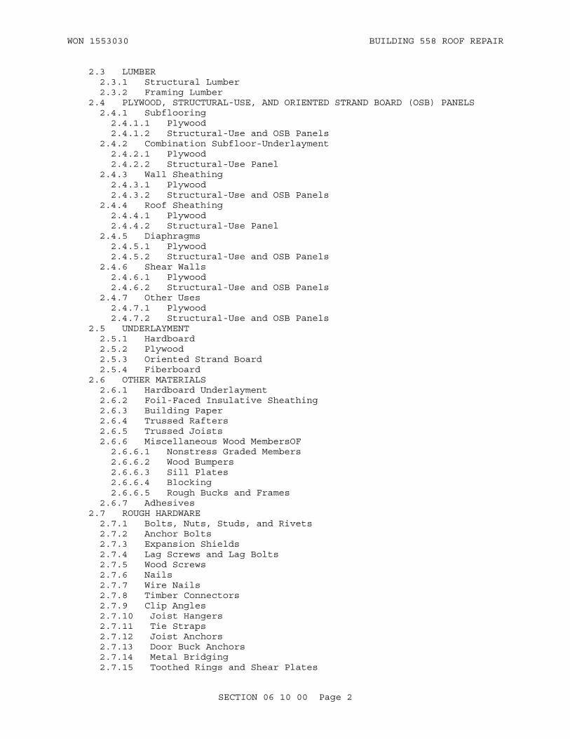
WON 1553030 BUILDING 558 ROOF REPAIR
2.3 LUMBER 2.3.1 Structural Lumber 2.3.2 Framing Lumber 2.4 PLYWOOD, STRUCTURAL-USE, AND ORIENTED STRAND BOARD (OSB) PANELS 2.4.1 Subflooring 2.4.1.1 Plywood 2.4.1.2 Structural-Use and OSB Panels 2.4.2 Combination Subfloor-Underlayment 2.4.2.1 Plywood 2.4.2.2 Structural-Use Panel 2.4.3 Wall Sheathing 2.4.3.1 Plywood 2.4.3.2 Structural-Use and OSB Panels 2.4.4 Roof Sheathing 2.4.4.1 Plywood 2.4.4.2 Structural-Use Panel 2.4.5 Diaphragms 2.4.5.1 Plywood 2.4.5.2 Structural-Use and OSB Panels 2.4.6 Shear Walls 2.4.6.1 Plywood 2.4.6.2 Structural-Use and OSB Panels 2.4.7 Other Uses 2.4.7.1 Plywood 2.4.7.2 Structural-Use and OSB Panels 2.5 UNDERLAYMENT 2.5.1 Hardboard 2.5.2 Plywood 2.5.3 Oriented Strand Board 2.5.4 Fiberboard 2.6 OTHER MATERIALS 2.6.1 Hardboard Underlayment 2.6.2 Foil-Faced Insulative Sheathing 2.6.3 Building Paper 2.6.4 Trussed Rafters 2.6.5 Trussed Joists 2.6.6 Miscellaneous Wood MembersOF 2.6.6.1 Nonstress Graded Members 2.6.6.2 Wood Bumpers 2.6.6.3 Sill Plates 2.6.6.4 Blocking 2.6.6.5 Rough Bucks and Frames 2.6.7 Adhesives 2.7 ROUGH HARDWARE 2.7.1 Bolts, Nuts, Studs, and Rivets 2.7.2 Anchor Bolts 2.7.3 Expansion Shields 2.7.4 Lag Screws and Lag Bolts 2.7.5 Wood Screws 2.7.6 Nails 2.7.7 Wire Nails 2.7.8 Timber Connectors 2.7.9 Clip Angles 2.7.10 Joist Hangers 2.7.11 Tie Straps 2.7.12 Joist Anchors 2.7.13 Door Buck Anchors 2.7.14 Metal Bridging 2.7.15 Toothed Rings and Shear Plates
SECTION 06 10 00 Page 2

WON 1553030 BUILDING 558 ROOF REPAIR
2.7.16 Beam Anchors 2.7.17 Metal Framing Anchors 2.7.18 Panel Edge Clips 2.8 AIR INFILTRATION BARRIER
PART 3 EXECUTION
3.1 INSTALLATION 3.1.1 Sills 3.1.1.1 Anchors in Masonry 3.1.1.2 Anchors in Concrete 3.1.2 Beams and Girders 3.1.3 Roof Framing or Rafters 3.1.4 Joists 3.1.4.1 Floor (Ceiling) Framing 3.1.4.2 Doubled Joists 3.1.4.3 Tie Straps 3.1.4.4 Joist Anchors 3.1.5 Bridging 3.1.5.1 Wood Cross-Bridging 3.1.5.2 Metal Cross-Bridging 3.1.6 Columns and Posts 3.1.7 Wall Framing 3.1.7.1 Studs 3.1.7.2 Plates 3.1.7.3 Firestops 3.1.7.4 Diagonal Bracing 3.1.8 Wall Sheathing 3.1.8.1 Plywood, Structural-Use, and OSB Panel Wall Sheathing 3.1.8.2 Fiberboard Wall Sheathing 3.1.8.3 Gypsum Sheathing Board 3.1.8.4 Foil-Faced Insulative Sheathing 3.1.8.5 Particleboard 3.1.8.6 Cellulose Honeycomb Panels 3.1.9 Wood Sheathing 3.1.10 Building Paper 3.1.11 Ceiling Joists 3.1.12 Metal Framing Anchors 3.1.13 Trusses 3.1.14 Structural Glued Laminated Timber Members 3.1.15 Plywood and Structural-Use Panel Roof Sheathing 3.1.16 Stair Framing 3.1.17 Plastic Lumber 3.2 MISCELLANEOUS 3.2.1 Wood Roof Nailers, Edge Strips, Crickets, Curbs, and Cants 3.2.1.1 Roof Nailing Strips 3.2.1.2 Roof Edge Strips and Nailers 3.2.1.3 Crickets, Cants, and Curbs 3.2.2 Rough Wood Bucks 3.2.3 Wood Blocking 3.2.4 Wood Grounds 3.2.5 Wood Furring 3.2.6 Wood Bumpers 3.2.7 Temporary Closures 3.2.8 Wood Sleepers 3.2.9 Diaphragms 3.2.10 Bridging 3.2.11 Corner Bracing 3.2.12 Sill Plates
SECTION 06 10 00 Page 3

WON 1553030 BUILDING 558 ROOF REPAIR
3.3 INSTALLATION OF TIMBER CONNECTORS 3.4 ERECTION TOLERANCES 3.5 SPECIAL INSPECTION AND TESTING FOR SEISMIC-RESISTING SYSTEMS 3.6 WASTE MANAGEMENT OF WOOD PRODUCTS
-- End of Section Table of Contents --
SECTION 06 10 00 Page 4

WON 1553030 BUILDING 558 ROOF REPAIR
SECTION 06 10 00
ROUGH CARPENTRY08/16
PART 1 GENERAL
1.1 REFERENCES
The publications listed below form a part of this specification to the extent referenced. The publications are referred to within the text by the basic designation only.
AMERICAN HARDBOARD ASSOCIATION (AHA)
AHA A135.4 (1995; R 2004) Basic Hardboard
AMERICAN INSTITUTE OF TIMBER CONSTRUCTION (AITC)
AITC TCM (2012) Timber Construction Manual, 5th Edition
ANSI/AITC A190.1 (2007) American National Standard, Structural Glued Laminated Timber
AMERICAN LUMBER STANDARDS COMMITTEE (ALSC)
ALSC PS 20 (2015) American Softwood Lumber Standard
AMERICAN RAILWAY ENGINEERING AND MAINTENANCE-OF-WAY ASSOCIATION (AREMA)
AREMA Eng Man (2015) Manual for Railway Engineering
AMERICAN WOOD COUNCIL (AWC)
AWC NDS (2015) National Design Specification (NDS) for Wood Construction
AWC WFCM (2012) Wood Frame Construction Manual for One- and Two-Family Dwellings
AMERICAN WOOD PROTECTION ASSOCIATION (AWPA)
AWPA BOOK (2015) AWPA Book of Standards
AWPA M2 (2016) Standard for the Inspection of Preservative Treated Wood Products for Industrial Use
AWPA M6 (2013) Brands Used on Preservative Treated Materials
AWPA P18 (2014) Nonpressure Preservatives
AWPA P49 (2015) Standard for Fire Retardant FR-1
SECTION 06 10 00 Page 5

WON 1553030 BUILDING 558 ROOF REPAIR
AWPA P5 (2015) Standard for Waterborne Preservatives
AWPA T1 (2016) Use Category System: Processing and Treatment Standard
AWPA U1 (2016) Use Category System: User Specification for Treated Wood
APA - THE ENGINEERED WOOD ASSOCIATION (APA)
APA E30 (2016) Engineered Wood Construction Guide
APA E445 (2002) Performance Standards and Qualification Policy for Structural-Use Panels (APA PRP-108)
APA EWS T300 (2007) Technical Note: Glulam Connection Details
APA F405 (19) Product Guide: Performance Rated Panels
APA L870 (2010) Voluntary Product Standard, PS 1-09, Structural Plywood
APA S350 (2014) PS 2-10, Performance Standard for Wood-Based Structural-Use Panels
ASME INTERNATIONAL (ASME)
ASME B18.2.1 (2012; Errata 2013) Square and Hex Bolts and Screws (Inch Series)
ASME B18.2.2 (2015) Nuts for General Applications: Machine Screw Nuts, Hex, Square, Hex Flange, and Coupling Nuts (Inch Series)
ASME B18.5.2.1M (2006; R 2011) Metric Round Head Short Square Neck Bolts
ASME B18.5.2.2M (1982; R 2010) Metric Round Head Square Neck Bolts
ASME B18.6.1 (2016) Wood Screws (Inch Series)
ASTM INTERNATIONAL (ASTM)
ASTM A153/A153M (2016) Standard Specification for Zinc Coating (Hot-Dip) on Iron and Steel Hardware
ASTM A307 (2014) Standard Specification for Carbon Steel Bolts and Studs, 60 000 PSI Tensile Strength
ASTM A653/A653M (2015; E 2016) Standard Specification for Steel Sheet, Zinc-Coated (Galvanized) or Zinc-Iron Alloy-Coated (Galvannealed) by
SECTION 06 10 00 Page 6

WON 1553030 BUILDING 558 ROOF REPAIR
the Hot-Dip Process
ASTM C1136 (2012) Standard Specification for Flexible, Low Permeance Vapor Retarders for Thermal Insulation
ASTM D1435 (2013) Standard Practice for Outdoor Weathering of Plastics
ASTM D1972 (1997; R 2005) Standard Practice for Generic Marking of Plastic Products
ASTM D2898 (2010) Accelerated Weathering of Fire-Retardant-Treated Wood for Fire Testing
ASTM E96/E96M (2016) Standard Test Methods for Water Vapor Transmission of Materials
ASTM F1667 (2013) Driven Fasteners: Nails, Spikes, and Staples
ASTM F547 (2006; R 2012) Nails for Use with Wood and Wood-Base Materials
CALIFORNIA AIR RESOURCES BOARD (CARB)
CARB 93120 (2007) Airborne Toxic Control Measure (ATCM) to Reduce Formaldehyde Emissions from Composite Wood Products
CALIFORNIA DEPARTMENT OF PUBLIC HEALTH (CDPH)
CDPH SECTION 01350 (2004; Add 2004-01) Standard Practice for the Testing Of Volatile Organic Emissions from Various Sources Using Small-Scale Environmental Chambers
FM GLOBAL (FM)
FM 4435 (2013) Roof Perimeter Flashing
GREEN SEAL (GS)
GS-36 (2011) Commercial Adhesives
INTERNATIONAL CODE COUNCIL (ICC)
ICC IBC (2015) International Building Code
NATIONAL HARDWOOD LUMBER ASSOCIATION (NHLA)
NHLA Rules (2011) Rules for the Measurement & Inspection of Hardwood & Cypress
NORTHEASTERN LUMBER MANUFACTURERS ASSOCIATION (NELMA)
NELMA Grading Rules (2013) Standard Grading Rules for Northeastern Lumber
SECTION 06 10 00 Page 7
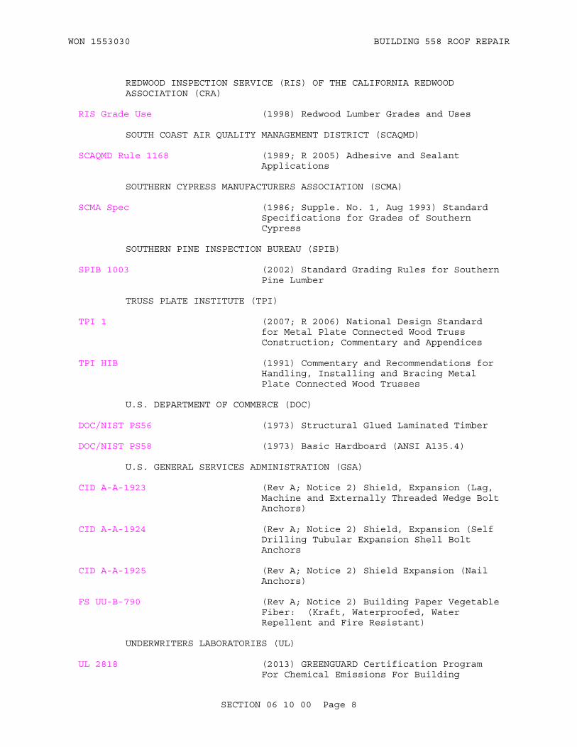
WON 1553030 BUILDING 558 ROOF REPAIR
REDWOOD INSPECTION SERVICE (RIS) OF THE CALIFORNIA REDWOOD ASSOCIATION (CRA)
RIS Grade Use (1998) Redwood Lumber Grades and Uses
SOUTH COAST AIR QUALITY MANAGEMENT DISTRICT (SCAQMD)
SCAQMD Rule 1168 (1989; R 2005) Adhesive and Sealant Applications
SOUTHERN CYPRESS MANUFACTURERS ASSOCIATION (SCMA)
SCMA Spec (1986; Supple. No. 1, Aug 1993) Standard Specifications for Grades of Southern Cypress
SOUTHERN PINE INSPECTION BUREAU (SPIB)
SPIB 1003 (2002) Standard Grading Rules for Southern Pine Lumber
TRUSS PLATE INSTITUTE (TPI)
TPI 1 (2007; R 2006) National Design Standard for Metal Plate Connected Wood Truss Construction; Commentary and Appendices
TPI HIB (1991) Commentary and Recommendations for Handling, Installing and Bracing Metal Plate Connected Wood Trusses
U.S. DEPARTMENT OF COMMERCE (DOC)
DOC/NIST PS56 (1973) Structural Glued Laminated Timber
DOC/NIST PS58 (1973) Basic Hardboard (ANSI A135.4)
U.S. GENERAL SERVICES ADMINISTRATION (GSA)
CID A-A-1923 (Rev A; Notice 2) Shield, Expansion (Lag, Machine and Externally Threaded Wedge Bolt Anchors)
CID A-A-1924 (Rev A; Notice 2) Shield, Expansion (Self Drilling Tubular Expansion Shell Bolt Anchors
CID A-A-1925 (Rev A; Notice 2) Shield Expansion (Nail Anchors)
FS UU-B-790 (Rev A; Notice 2) Building Paper Vegetable Fiber: (Kraft, Waterproofed, Water Repellent and Fire Resistant)
UNDERWRITERS LABORATORIES (UL)
UL 2818 (2013) GREENGUARD Certification Program For Chemical Emissions For Building
SECTION 06 10 00 Page 8

WON 1553030 BUILDING 558 ROOF REPAIR
Materials, Finishes And Furnishings
WEST COAST LUMBER INSPECTION BUREAU (WCLIB)
WCLIB 17 (2004) Standard Grading Rules
WESTERN WOOD PRODUCTS ASSOCIATION (WWPA)
WWPA G-5 (2011) Western Lumber Grading Rules
1.2 SUBMITTALS
Government approval is required for submittals with a "G" designation; submittals not having a "G" designation are for Contractor Quality Control approval. When used, a designation following the "G" designation identifies the office that will review the submittal for the Government. Submit the following in accordance with Section 01 33 00 SUBMITTAL PROCEDURES:
Nailers and Nailing Strips; G
Drawings of field erection details, including materials and methods of fastening nailers in conformance with Factory Mutual wind uplift rated systems specified in other Sections of these specifications.
SD-03 Product Data
Salvaged Lumber
Recovered Lumber
Underlayment
Structural-use and OSB Panels
Oriented Strand Board
Adhesives
SD-06 Test Reports
Preservative-treated Lumber and Plywood
SD-07 Certificates
Certificates of Grade
Certified Sustainably Harvested Wood; G
Preservative Treatment
SECTION 06 10 00 Page 9
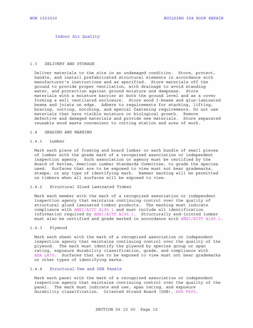
WON 1553030 BUILDING 558 ROOF REPAIR
Indoor Air Quality
1.3 DELIVERY AND STORAGE
Deliver materials to the site in an undamaged condition. Store, protect, handle, and install prefabricated structural elements in accordance with manufacturer's instructions and as specified. Store materials off the ground to provide proper ventilation, with drainage to avoid standing water, and protection against ground moisture and dampness. Store materials with a moisture barrier at both the ground level and as a cover forming a well ventilated enclosure. Store wood I-beams and glue-laminated beams and joists on edge. Adhere to requirements for stacking, lifting, bracing, cutting, notching, and special fastening requirements. Do not use materials that have visible moisture or biological growth. Remove defective and damaged materials and provide new materials. Store separated reusable wood waste convenient to cutting station and area of work.
1.4 GRADING AND MARKING
1.4.1 Lumber
Mark each piece of framing and board lumber or each bundle of small pieces of lumber with the grade mark of a recognized association or independent inspection agency. Such association or agency must be certified by the Board of Review, American Lumber Standards Committee, to grade the species used. Surfaces that are to be exposed to view must not bear grademarks, stamps, or any type of identifying mark. Hammer marking will be permitted on timbers when all surfaces will be exposed to view.
1.4.2 Structural Glued Laminated Timber
Mark each member with the mark of a recognized association or independent inspection agency that maintains continuing control over the quality of structural glued laminated timber products. The marking must indicate compliance with ANSI/AITC A190.1 and must include all identification information required by ANSI/AITC A190.1. Structurally end-jointed lumber must also be certified and grade marked in accordance with ANSI/AITC A190.1.
1.4.3 Plywood
Mark each sheet with the mark of a recognized association or independent inspection agency that maintains continuing control over the quality of the plywood. The mark must identify the plywood by species group or span rating, exposure durability classification, grade, and compliance with APA L870. Surfaces that are to be exposed to view must not bear grademarks or other types of identifying marks.
1.4.4 Structural-Use and OSB Panels
Mark each panel with the mark of a recognized association or independent inspection agency that maintains continuing control over the quality of the panel. The mark must indicate end use, span rating, and exposure durability classification. Oriented Strand Board (OSB), APA F405.
SECTION 06 10 00 Page 10

WON 1553030 BUILDING 558 ROOF REPAIR
1.4.5 Preservative-Treated Lumber and Plywood
The Contractor is responsible for the quality of treated wood products. Each treated piece must be inspected in accordance with AWPA M2 and permanently marked or branded, by the producer, in accordance with AWPA M6. The Contractor must provide Contracting Officer's Representative (COR) with the inspection report of an approved independent inspection agency that offered products comply with applicable AWPA Standards. The appropriate Quality Mark on each piece will be accepted, in lieu of inspection reports, as evidence of compliance with applicable AWPA treatment standards.
1.4.6 Fire-Retardant Treated Lumber
Mark each piece in accordance with AWPA M6, except pieces that are to be natural or transparent finished. In addition, exterior fire-retardant lumber must be distinguished by a permanent penetrating blue stain. Labels of a nationally recognized independent testing agency will be accepted as evidence of conformance to the fire-retardant requirements of AWPA M6.
1.4.7 Hardboard, Gypsum Board, and Fiberboard
Mark each sheet or bundle to identify the standard under which the material is produced and the producer.
1.4.8 Plastic Lumber
Label plastic products to be incorporated into the project in accordance with ASTM D1972, or provide product data indicating polymeric information in the Operation and Maintenance Manual.
a. Type 1: Polyethylene Terephthalate (PET, PETE).b. Type 2: High Density Polyethylene (HDPE).c. Type 3: Vinyl (Polyvinyl Chloride or PVC).d. Type 4: Low Density Polyethylene (LDPE).e. Type 5: Polypropylene (PP).f. Type 6: Polystyrene (PS).g. Type 7: Other. Use of this code indicates that the package in
question. is made with a resin other than the six listed above, or is made of more than one resin listed above, and used in a multi-layer combination.
1.5 SIZES AND SURFACING
ALSC PS 20 for dressed sizes of yard and structural lumber. Lumber must be surfaced four sides. Size references, unless otherwise specified, are nominal sizes, and actual sizes must be within manufacturing tolerances allowed by the standard under which the product is produced. Other measurements are IP or SI standard.
1.6 MOISTURE CONTENT
Air-dry or kiln-dry lumber. Kiln-dry treated lumber after treatment. Maximum moisture content of wood products must be as follows at the time of delivery to the job site:
a. Framing lumber and board, 19 percent maximum
b. Timbers 5 inches and thicker, 25 percent maximum
SECTION 06 10 00 Page 11

WON 1553030 BUILDING 558 ROOF REPAIR
c . Materials other than lumber; moisture content must be in accordance with standard under which the product is produced
1.7 PRESERVATIVE TREATMENT
Treat wood products with waterborne wood preservatives conforming to AWPA P5. Pressure treatment of wood products must conform to the requirements of AWPA BOOK Use Category System Standards U1 and T1. Pressure-treated wood products must not contain arsenic, chromium, or other agents classified as carcinogenic, probably carcinogenic, or possibly carcinogenic to humans (compounds in Groups 1, 2A, or 2B) by the International Agency for Research on Cancer (IARC), Lyon, France. Pressure-treated wood products must not exceed the limits of the U.S. EPA's Toxic Characteristic Leaching Procedure (TCLP), and must not be classified as hazardous waste. Submit certification from treating plant stating chemicals and process used and net amount of preservatives retained are in conformance with specified standards. In accordance with AWPA U1 provide non-copper preservative treatment such as EL2, PTI or SBX,DOT for products in direct contact with sheet metal.
a. 0.25 pcf intended for above ground use.
b. 0.40 pcf intended for ground contact and fresh water use. 0.60 pcf intended for Ammoniacal Copper Quaternary Compound (ACQ)-treated foundations. 0.80 to 1.00 pcf intended for ACQ-treated pilings. All wood must be air or kiln dried after treatment. Specific treatments must be verified by the report of an approved independent inspection agency, or the AWPA Quality Mark on each piece. Do not incise surfaces of lumber that will be exposed. Minimize cutting and avoid breathing sawdust. Brush coat areas that are cut or drilled after treatment with either the same preservative used in the treatment or with a 2 percent copper naphthenate solution. Plastic lumber must not be preservative treated. The following items must be preservative treated:
(1) Wood framing, woodwork, and plywood up to and including the subflooring at the first-floor level of structures having crawl spaces when the bottoms of such items are 24 inches or less from the earth underneath.
(2) Wood members that are in contact with water.
(3) Exterior wood steps, platforms, and railings; and all wood framing of open, roofed structures.
(4) Wood sills, soles, plates, furring, and sleepers that are less than 24 inches from the ground, furring and nailers that are set into or in contact with concrete or masonry.
(5) Nailers, edge strips, crickets, curbs, and cants for roof decks.
1.7.1 Existing Structures
Use borate, permathrin, or a sodium silicate wood mineralization process to treat wood. Use borate for interior applications only.
SECTION 06 10 00 Page 12

WON 1553030 BUILDING 558 ROOF REPAIR
1.7.2 New Construction
Use a boron-based preservative conforming to AWPA P18, sodium silicate wood mineralization process, or Ammoniacal Copper Quaternary Compound to treat wood. Use boron-based preservatives for above-ground applications only.
1.8 FIRE-RETARDANT TREATMENT
Fire-retardant treated wood must be pressure treated with fire retardants conforming to AWPA P49. Fire retardant treatment of wood products must conform to the requirements of AWPA U1, Commodity Specification H and AWPA T1, Section H. Treatment and performance inspection must be by an independent and qualified testing agency that establishes performance ratings. Each piece or bundle of treated material must bear identification of the testing agency to indicate performance in accordance with such rating. Treated materials to be exposed to rain wetting must be subjected to an accelerated weathering technique in accordance with ASTM D2898 prior to being tested. Such items which will not be inside a building, and such items which will be exposed to heat or high humidity, must receive exterior fire-retardant treatment. Fire-retardant-treated wood products must be free of halogens, sulfates, ammonium phosphate, and formaldehyde.
1.9 QUALITY ASSURANCE
1.9.1 Drawing Requirements
For fabricated structural members, trusses, qlu-lam members, indicate materials, details of construction, methods of fastening, and erection details. Include reference to design criteria used and manufacturers design calculations. Submit drawings for all proposed modifications of structural members. Do not proceed with modifications until the submittal has been approved.
1.9.2 Data Required
Submit calculations and drawings for all proposed modifications of structural members. Do not proceed with modifications until the submittal has been approved.
1.9.3 Humidity Requirements
Sequence work to minimize use of temporary HVAC to dry out building and control humidity.
1.9.4 Plastic Lumber Performance
Plastic lumber intended for use in exterior applications must have no fading or discoloration and no change in dimensional stability as tested in accordance with ASTM D1435 for a period of 3 years.
1.10 ENVIRONMENTAL REQUIREMENTS
During and immediately after installation of treated wood, engineered wood products, and laminated wood products at interior spaces, provide temporary ventilation.
SECTION 06 10 00 Page 13

WON 1553030 BUILDING 558 ROOF REPAIR
1.11 CERTIFICATIONS
1.11.1 Certified Wood Grades
Provide certificates of grade from the grading agency on graded but unmarked lumber or plywood attesting that materials meet the grade requirements specified herein.
1.11.2 Indoor Air Quality Certifications
Submit required indoor air quality certifications in one submittal package.1.11.2.1 Adhesives and Sealants
Provide products certified to meet indoor air quality requirements byUL 2818 (Greenguard) Gold, SCS Global Services Indoor Advantage Gold or provide validation by other third-party program that products meet the requirements of this paragraph. Sealants and non-aerosol adhesive products used on the interior of the building (defined as inside of the weatherproofing system) must meet either emissions requirements of CDPH SECTION 01350 (limit requirements for either office or classroom spaces regardless of space type) or VOC content requirements of SCAQMD Rule 1168. Aerosol adhesives used on the interior of the building must meet either emissions requirements of CDPH SECTION 01350 (limit requirements for either office or classroom spaces regardless of space type) or VOC content requirements of GS-36. Provide current product certification documentation from certification body.
1.11.2.2 Composite Wood, Wood Structural Panel and Agrifiber Products
For purposes of this specification, composite wood and agrifiber products include particleboard, medium density fiberboard (MDF), wheatboard, strawboard, panel substrates, and door cores. Products must contain no added urea-formaldehyde resins. Provide products certified to meet emissions requirements of either CARB 93120 or CDPH SECTION 01350 (limit requirements for either office or classroom spaces regardless of space type). Provide current product certification documentation from certification body.
PART 2 PRODUCTS
2.1 PRODUCT SUSTAINABILITY CRITERIA
For products in this section, where applicable and to extent allowed by performance criteria, provide and document the following:
2.1.1 Certified Sustainably Harvested Wood
Certified sustainably harvested wood is identified for some products in this section; provide documentation in accordance with Section 01 33 29 SUSTAINABILITY REPORTING paragraph BIOBASED PRODUCTS. Other products listed in this section may be available as certified sustainably harvested wood; identify those products that meet project requirements for certified sustainably harvested wood, and provide documentation in accordance with Section 01 33 29 SUSTAINABILITY REPORTING paragraph BIOBASED PRODUCTS.
SECTION 06 10 00 Page 14

WON 1553030 BUILDING 558 ROOF REPAIR
2.2 MATERIALS
2.2.1 Virgin Lumber
Lumber fabricated from old growth timber is not permitted. Avoid companies who buy, sell, or use old growth timber in their operations, when possible.
2.2.2 Salvaged Lumber
Provide salvaged lumber where specified. Unless otherwise noted, salvaged lumber must be delivered clean, denailed, and free of paint, finish materials, and other contamination. Lumber must meet the other criteria within this section. Provide documentation certifying products are from salvaged lumber sources.
2.2.3 Recovered Lumber
Use recovered lumber where practical. Unless otherwise noted, recovered lumber must be delivered clean and free of contamination. Provide grading certificates for any recovered wood materials used in structural applications. Lumber must meet the other criteria within this section. Provide documentation certifying products are from recovered lumber sources.
2.2.4 Natural Decay- and Insect-Resistant Wood
Naturally durable wood must be certified sustainably harvested natural-decay and insect-resistant wood. An occasional piece with corner sapwood is permitted if 90 percent or more of the width of each side on which the sapwood occurs is heartwood.
2.3 LUMBER
2.3.1 Structural Lumber
Except where a specific grade is indicated or specified, Any of the species and grades listed in AWC NDS that have allowable unit stresses in pounds per square inch (psi) not less than _1,500___ Fb, 700_____ Ft, 780____ Fc, with 1,200,000 E allowable unit stresses indicated. Use for joists, rafters, headers, trusses, beams (except collar beams), columns, posts, stair stringers, girders, and all other members indicated to be stress rated. Design of members and fastenings must conform to AITC TCM. Other stress graded or dimensioned items such as blocking, carriages, and studs must be standard or No. 2 grade except that studs may be Stud grade.
2.3.2 Framing Lumber
Framing lumber such as studs, plates, caps, collar beams, cant strips, bucks, sleepers, nailing strips, and nailers and board lumber such as subflooring and wall and roof sheathing must be one of the species listed in the table below. Minimum grade of species must be as listed. Finger-jointed lumber may be used in the same applications as solid lumber of an equivalent species and grade, provided the finger-jointed lumber meets all the requirements of the certification and the quality control programs of the rules writing agency having jurisdiction and all applicable requirements of DOC/NIST PS56.
SECTION 06 10 00 Page 15

WON 1553030 BUILDING 558 ROOF REPAIR
Table of Grades for Framing and Board Lumber
Grading Rules Species Framing Board Lumber
WWPA G-5 standard grading rules
Aspen, Douglas Fir-Larch, Douglas Fir South, Engelmann Spruce-Lodgepole Pine, Engelmann Spruce, Hem-Fir, Idaho White Pine, Lodgepole Pine, Mountain Hemlock, Mountain Hemlock-Hem-Fir, Ponderosa Pine-Sugar Pine, Ponderosa Pine-Lodgepole Pine, Subalpine Fir, White Woods, Western Woods, Western Cedars, Western Hemlock
All Species: Standard Light Framing or No. 3 Structural Light Framing (Stud Grade for 2x4 nominal size, 10 feet and shorter)
All Species: No. 3 Common
WCLIB 17 standard grading rules
Douglas Fir-Larch, Hem-Fir, Mountain Hemlock, Sitka Spruce, Western Cedars, Western Hemlock
All Species: Standard Light Framing or No. 3 Structural Light Framing (Stud Grade for 2x4 nominal size, 10 feet and shorter)
All Species: Standard
SECTION 06 10 00 Page 16
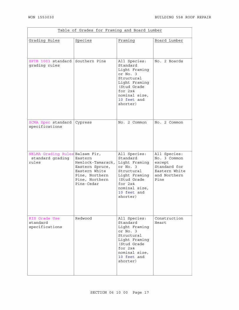
WON 1553030 BUILDING 558 ROOF REPAIR
Table of Grades for Framing and Board Lumber
Grading Rules Species Framing Board Lumber
SPIB 1003 standard grading rules
Southern Pine All Species: Standard Light Framing or No. 3 Structural Light Framing (Stud Grade for 2x4 nominal size, 10 feet and shorter)
No. 2 Boards
SCMA Spec standard specifications
Cypress No. 2 Common No. 2 Common
NELMA Grading Rules standard grading rules
Balsam Fir, Eastern Hemlock-Tamarack, Eastern Spruce, Eastern White Pine, Northern Pine, Northern Pine-Cedar
All Species: Standard Light Framing or No. 3 Structural Light Framing (Stud Grade for 2x4 nominal size, 10 feet and shorter)
All Species: No. 3 Common except Standard for Eastern White and Northern Pine
RIS Grade Use standard specifications
Redwood All Species: Standard Light Framing or No. 3 Structural Light Framing (Stud Grade for 2x4 nominal size, 10 feet and shorter)
Construction Heart
SECTION 06 10 00 Page 17
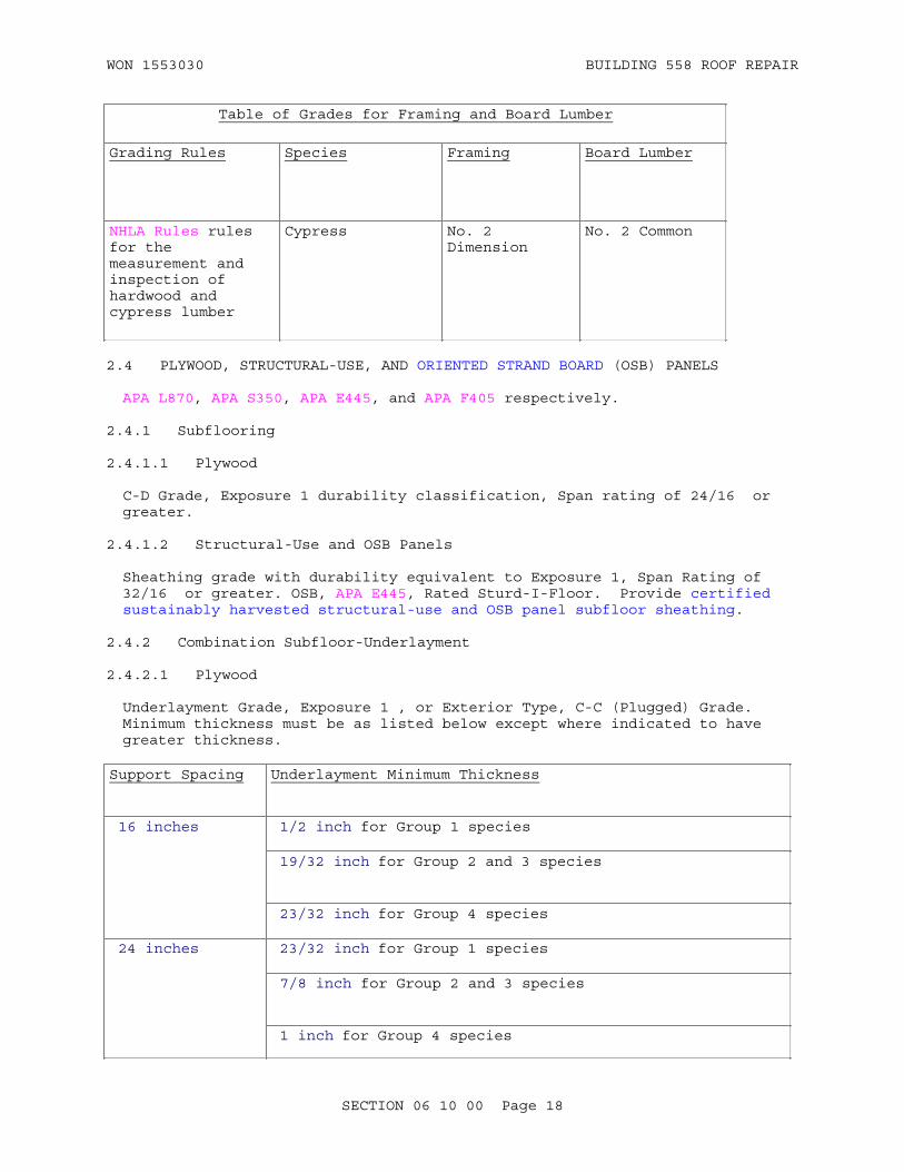
WON 1553030 BUILDING 558 ROOF REPAIR
Table of Grades for Framing and Board Lumber
Grading Rules Species Framing Board Lumber
NHLA Rules rules for the measurement and inspection of hardwood and cypress lumber
Cypress No. 2 Dimension
No. 2 Common
2.4 PLYWOOD, STRUCTURAL-USE, AND ORIENTED STRAND BOARD (OSB) PANELS
APA L870, APA S350, APA E445, and APA F405 respectively.
2.4.1 Subflooring
2.4.1.1 Plywood
C-D Grade, Exposure 1 durability classification, Span rating of 24/16 or greater.
2.4.1.2 Structural-Use and OSB Panels
Sheathing grade with durability equivalent to Exposure 1, Span Rating of 32/16 or greater. OSB, APA E445, Rated Sturd-I-Floor. Provide certified sustainably harvested structural-use and OSB panel subfloor sheathing.
2.4.2 Combination Subfloor-Underlayment
2.4.2.1 Plywood
Underlayment Grade, Exposure 1 , or Exterior Type, C-C (Plugged) Grade. Minimum thickness must be as listed below except where indicated to have greater thickness.
Support Spacing Underlayment Minimum Thickness
16 inches 1/2 inch for Group 1 species
19/32 inch for Group 2 and 3 species
23/32 inch for Group 4 species
24 inches 23/32 inch for Group 1 species
7/8 inch for Group 2 and 3 species
1 inch for Group 4 species
SECTION 06 10 00 Page 18

WON 1553030 BUILDING 558 ROOF REPAIR
2.4.2.2 Structural-Use Panel
Combination subfloor-underlayment grade with durability equivalent to Exterior plywood, Span Rating of 16 or greater.
2.4.3 Wall Sheathing
2.4.3.1 Plywood
C-D Grade, Exposure 1, and a minimum thickness of 1/2 inch , except where indicated to have greater thickness. Provide exterior grade material with phenol resin for interior and exterior applications.
2.4.3.2 Structural-Use and OSB Panels
Sheathing grade with durability equivalent to Exposure 1, Span Rating of 16/0 or greater. OSB, APA Rated Sheathing. OSB must be a phenolic-glued board.
2.4.4 Roof Sheathing
2.4.4.1 Plywood
C-D Grade, Exposure 1, with an Identification Index of not less than _16/0___. Provide exterior grade material with phenol resin for all applications.
2.4.4.2 Structural-Use Panel
Sheathing grade with durability equivalent to Exposure 1, Span Rating of _16/0____ or greater.
2.4.5 Diaphragms
2.4.5.1 Plywood
Structural I, C-D grade, Exposure 1, and a minimum thickness of _5/8____ inch.
2.4.5.2 Structural-Use and OSB Panels
Sheathing grade with durability equivalent to Exposure 1 and a minimum thickness of __5/8___ inch.
2.4.6 Shear Walls
2.4.6.1 Plywood
Structural I , C-D Grade and a minimum thickness of _5/8____ inch.
2.4.6.2 Structural-Use and OSB Panels
Sheathing grade with durability equivalent to Interior plywood with Exterior glue (Exposure 1) and a minimum thickness of __5/8___ inch.
SECTION 06 10 00 Page 19

WON 1553030 BUILDING 558 ROOF REPAIR
2.4.7 Other Uses
2.4.7.1 Plywood
Plywood for __other use, as indicated in the drawings: C-D Grade, Exposure 1.
2.4.7.2 Structural-Use and OSB Panels
Structural-use and OSB panels for _other uses as indicated in the drawings. Sheathing grade with durability equivalent to Exposure 1 and a minimum thickness of __5/8__ inch.
2.5 UNDERLAYMENT
Underlayment must conform to one of the following:
2.5.1 Hardboard
AHA A135.4 service class, sanded one side, 1/4 inch thick, 4 feet wide.
2.5.2 Plywood
Plywood must conform to APA L870, underlayment grade with exterior glue, or C-C (Plugged) exterior grade 11/32 inch thick, 4 feet wide.
2.5.3 Oriented Strand Board
OSB underlayment grade 0.225 inch.
2.5.4 Fiberboard
Use structural fiberboard, minimum 100 percent recycled newspaper. gypsum fiberboard, minimum 15 percent post-consumer newspaper. Provide data identifying percentage of recycled content for fiberboard underlayment. For products located on the interior of the building (inside of the weatherproofing system), provide certification of indoor air quality for fiberboard underlayment.
2.6 OTHER MATERIALS
2.6.1 Hardboard Underlayment
DOC/NIST PS58, service class, sanded on one side, 1/4 inch thick 4 feet wide.
2.6.2 Foil-Faced Insulative Sheathing
Wood fiber core, chemically treated for water resistance, with aluminum foil laminated under pressure to both sides with water-resistant adhesive; 48 inches or 48 3/4 inches wide; 0.078 inch thick when used with corner bracing, 0.115 inch thick with studs up to 16 inches o.c. without corner bracing, or 0.137 inch thick with studs up to 24 inches o.c. without corner bracing. The sheathing and installation must have been accepted by ICC as conforming to ICC IBC. The sheathing alone must have a thermal resistance value (R value) of not less than 0.20.
SECTION 06 10 00 Page 20

WON 1553030 BUILDING 558 ROOF REPAIR
2.6.3 Building Paper
FS UU-B-790, Type I, Grade D, Style 1.
2.6.4 Trussed Rafters
Metal plate connected trusses designed in accordance with TPI 1 and TPI HIB and fabricated in accordance with TPI 1.
2.6.5 Trussed Joists
Metal plate connected parallel chord wood trusses designed and fabricated in accordance with TPI 1.
2.6.6 Miscellaneous Wood MembersOF
2.6.6.1 Nonstress Graded Members
Members must include bridging, corner bracing, furring, grounds, and nailing strips. Members must be in accordance with TABLE I for the species used. Sizes must be as follows unless otherwise shown:
Member Size inch
Bridging 1 x 3 or 1 x 4 for use between members 2 x 12 and smaller; 2 x 4 for use between members larger than 2 x 12.
Corner bracing 1 x 4.
Furring 1 x 2
Grounds Plaster thickness by 38.
Nailing strips 1 x 3 or 1 x 4 when used as shingle base or interior finish, otherwise 2 inch stock.
2.6.6.2 Wood Bumpers
AREMA Eng Man, Industrial grade cross ties
2.6.6.3 Sill Plates
Sill plates must be standard or number 2 grade.
2.6.6.4 Blocking
Blocking must be standard or number 2 grade.
2.6.6.5 Rough Bucks and Frames
Rough bucks and frames must be straight standard or number 2 grade.
2.6.7 Adhesives
Comply with applicable regulations regarding toxic and hazardous materials
SECTION 06 10 00 Page 21

WON 1553030 BUILDING 558 ROOF REPAIR
and as specified. Provide certification of indoor air quality for non-aerosol adhesives applied on the interior of the building (inside of the weatherproofing system). Provide certification of indoor air quality for aerosol adhesives used on the interior of the building (inside of the weatherproofing system).
2.7 ROUGH HARDWARE
Unless otherwise indicated or specified, rough hardware must be of the type and size necessary for the project requirements. Sizes, types, and spacing of fastenings of manufactured building materials UST be as recommended by the product manufacturer unless otherwise indicated or specified. Rough hardware exposed to the weather or embedded in or in contact with preservative treated wood, exterior masonry, or concrete walls or slabs must be hot-dip zinc-coated in accordance with ASTM A153/A153M. Nails and fastenings for fire-retardant treated lumber and woodwork exposed to the weather must be copper alloy or hot-dipped galvanized fasteners as recommended by the treated wood manufacturer.
2.7.1 Bolts, Nuts, Studs, and Rivets
ASME B18.2.1, ASME B18.5.2.1M, ASME B18.5.2.2M and ASME B18.2.2.
2.7.2 Anchor Bolts
ASTM A307, size as indicated, complete with nuts and washers.
2.7.3 Expansion Shields
CID A-A-1923, CID A-A-1924, and CID A-A-1925. Except as shown otherwise, maximum size of devices must be 3/8 inch.
2.7.4 Lag Screws and Lag Bolts
ASME B18.2.1.
2.7.5 Wood Screws
ASME B18.6.1.
2.7.6 Nails
ASTM F547, size and type best suited for purpose; staples must be as recommended by the manufacturer of the materials to be joined. For sheathing and subflooring, length of nails must be sufficient to extend 1 inch into supports. In general, 8-penny or larger nails must be used for nailing through 1 inch thick lumber and for toe nailing 2 inch thick lumber; 16-penny or larger nails must be used for nailing through 2 inch thick lumber. Nails used with treated lumber and sheathing must be hot-dipped galvanized in accordance with ASTM A153/A153M. Nailing must be in accordance with the recommended nailing schedule contained in AWC WFCM. Where detailed nailing requirements are not specified, nail size and spacing must be sufficient to develop an adequate strength for the connection. The connection's strength must be verified against the nail capacity tables in AWC NDS. Reasonable judgment backed by experience must ensure that the designed connection will not cause the wood to split. If a load situation exceeds a reasonable limit for nails, a specialized connector must be used.
SECTION 06 10 00 Page 22

WON 1553030 BUILDING 558 ROOF REPAIR
2.7.7 Wire Nails
ASTM F1667.
2.7.8 Timber Connectors
Unless otherwise specified, timber connectors must be in accordance with TPI 1, APA EWS T300 or AITC TCM.
2.7.9 Clip Angles
Steel, 3/16 inch thick, size as indicated; or zinc-coated steel or iron commercial clips designed for connecting wood members.
2.7.10 Joist Hangers
Steel or iron, zinc coated, sized to fit the supported member, of sufficient strength to develop the full strength of the supported member in accordance with ICC IBC, and furnished complete with any special nails required.
2.7.11 Tie Straps
For joists supported by the lower flange of steel beams, provide 1/8 by 1-1/2 inch steel strap, 2 feet long , except as indicated otherwise.
2.7.12 Joist Anchors
For joists supported by masonry walls, provide anchors 3/16 by 1 1/2 inch steel tee or strap, bent and of length to provide 4 inches embedment into wall and 12 inches along joist except as indicated otherwise. For joists parallel to masonry or concrete walls, provide anchors 1/4 by 1-1/4 inch minimum cross-sectional area, steel strap, length as necessary to extend over top of first three joists and into wall 4 inches, and with wall end of bend or pin type , except as indicated otherwise.
2.7.13 Door Buck Anchors
Metal anchors, 1/8 by 1-1/4 inch steel, 12 inches long, with ends bent 2 inches , except as indicated otherwise. Anchors must be screwed to the backs of bucks and built into masonry or concrete. Locate 8 inches above sills and below heads and not more than 24 inches intermediately between. Anchorage of bucks to steel framing must be as indicated
2.7.14 Metal Bridging
Where not indicated or specified otherwise, No. 16 U.S. Standard gage, cadmium-plated or zinc-coated.
2.7.15 Toothed Rings and Shear Plates
AWC NDS.
2.7.16 Beam Anchors
Steel U-shaped strap anchors 1/4 inch thick by 1-1/2 inches wide , except as indicated otherwise.
SECTION 06 10 00 Page 23
WON 1553030 BUILDING 558 ROOF REPAIR
2.7.17 Metal Framing Anchors
Construct anchors to the configuration shown using hot dip zinc-coated steel conforming to ASTM A653/A653M, G90. Except where otherwise shown, Steel must be not lighter than 18 gage. Special nails supplied by the manufacturer must be used for all nailing.
2.7.18 Panel Edge Clips
Extruded aluminum or galvanized steel, H-shaped clips to prevent differential deflection of roof sheathing.
2.8 AIR INFILTRATION BARRIER
Air infiltration barrier must be building paper meeting the requirements of ASTM C1136, Type IV, style optional or a tear and puncture resistant olefin building wrap (polyethylene or polypropylene) with a moisture vapor transmission rate of 125 g per square meter per 24 hours in accordance with ASTM E96/E96M, Desiccant Method at 23 degrees C or with a moisture vapor transmission rate of 670 g per square meter per 24 hours in accordance with ASTM E96/E96M, Water Method at 23 degrees C.
PART 3 EXECUTION
3.1 INSTALLATION
Do not install building construction materials that show visual evidence of biological growth.
Conform to AWC WFCM and install in accordance with the National Association of Home Builders (NAHB) Advanced Framing Techniques: Optimum Value Engineering, unless otherwise indicated or specified. Select lumber sizes to minimize waste. Fit framing lumber and other rough carpentry, set accurately to the required lines and levels, and secure in place in a rigid manner. Space plastic lumber boards as necessary to allow for lengthwise expansion and contraction. Do not splice framing members between bearing points. Set joists, rafters, and purlins with their crown edge up. Frame members for the passage of pipes, conduits, and ducts. Provide adequate support as appropriate to the application, climate, and modulus of elasticity of the product. Do not cut or bore structural members for the passage of ducts or pipes without approval. Reinforce all members damaged by such cutting or boring by means of specially formed and approved sheet metal or bar steel shapes, or remove and provide new, as approved. Provide as necessary for the proper completion of the work all framing members not indicated or specified. Spiking and nailing not indicated or specified otherwise must be in accordance with the Nailing Schedule contained in ICC IBC; perform bolting in an approved manner. Spikes, nails, and bolts must be drawn up tight. Install plastic lumber with screws or bolts; if nails are used, use ring shank or spiral shank nails. Timber connections and fastenings must conform to AWC NDS. Provide 2 inch minimum clearance between chimneys and wood framing; provide 4 inch minimum clearance at fireplaces. Fill the spaces with strips of approved noncombustible material. Use slate or steel shims when leveling joists, beams, and girders on masonry or concrete. Do not use shimming on wood or metal bearings. When joists, beams, and girders are placed on masonry or concrete, a wood base plate must be positioned and leveled with grout. The joist, beam, or girder must then be placed on the plate. When joists, beams, and girders are set into masonry or concrete, a pocket must be formed into the wall. The joist, beam, or girder must then be placed into
SECTION 06 10 00 Page 24

WON 1553030 BUILDING 558 ROOF REPAIR
the pocket and leveled with a steel shim.
3.1.1 Sills
Set sills level and square and wedge with steel or slate shims; point or grout with non-shrinking cement mortar to provide continuous and solid bearing. Anchor sills to the foundations as indicated. Where sizes and spacing of anchor bolts are not indicated, provide not less than 5/8 inch diameter bolts at all corners and splices and space at a maximum of 6 feet o.c. between corner bolts. Provide at least two bolts for each sill member. Lap and splice sills at corners and bolt through the laps or butt the ends and through-bolt not more than 6 inches from the ends. Provide bolts with plate washers and nuts. Bolts in exterior walls must be zinc-coated.
3.1.1.1 Anchors in Masonry
Except where indicated otherwise, Embed anchor bolts not less than 15 inches in masonry unit walls and provide each with a nut and a 2 inch diameter washer at bottom end. Fully grout bolts with mortar.
3.1.1.2 Anchors in Concrete
Except where indicated otherwise, Embed anchor bolts not less than 8 inches in poured concrete walls and provide each with a nut and a 2 inch diameter washer at bottom end. A bent end may be substituted for the nut and washer; bend must be not less than 90 degrees. Powder-actuated fasteners spaced 3 feet o.c. may be provided in lieu of bolts for single thickness plates on concrete.
3.1.2 Beams and Girders
Set beams and girders level and in alignment and anchor to bearing walls, piers, or supports with U-shaped steel strap anchors. Embed anchors in concrete or masonry at each bearing and through-bolt to the beams or girders with not less than two bolts. Provide bolts not less than 1/2 inch in diameter and with plate washers under heads and nuts. Install beams and girders not indicated otherwise with 8 inch minimum end bearing on walls or supports. Install beams and girders into walls with 1/2 inch clearance at the top, end, and sides or standard steel wall-bearing boxes. Provide joints and splices over bearings only and bolt or spike together.
3.1.3 Roof Framing or Rafters
Tops of supports or rafters must form a true plane. Valley, ridge, and hip members must be of depth equal to cut on rafters where practicable, but in no case less than depth of rafters and nominally 2 inches thick. Rafters must have full and solid bearing on plates. Valleys, hips, and ridges must be straight and true intersections of roof planes. Necessary crickets and watersheds must be formed. Rafters, except hip and valley rafters, must be spiked to wall plate and to ceiling joists with no less than four 8-penny nails or bolted by angles. Rafters must be toe-nailed to ridge, valley, or hip members with at least four 8-penny nails. Rafters must be braced to prevent movement until permanent bracing, decking or sheathing is installed. Hip and valley rafters must be secured to wall plates by clip angles. Openings in roof must be framed with headers and trimmers. Unless otherwise indicated, headers carrying more than two rafters and trimmers supporting headers carrying more than one rafter must be double. Hip rafters longer than the available lumber must be butt jointed and scabbed.
SECTION 06 10 00 Page 25
WON 1553030 BUILDING 558 ROOF REPAIR
Valley rafters longer than the available lumber must be double, with pieces lapped not less than 4 feet and well spiked together. Install trussed rafters in accordance with TPI HIB. Install engineered wood joists in accordance with distributor's instructions.
3.1.4 Joists
Provide joists of the sizes and spacing indicated, accurately and in alignment, and of uniform width. Joists must have full bearing on sills, plates, beams, girders, and trusses; provide laps over bearing only and spike. Where joists are of insufficient length to produce a 12 inch lap, butt joists over bearing and provide wood scabs 2 nominal inches thick by depth of joists by 24 inches long or metal straps 1/4 by 1 1/2 inch by not less than 18 inches long nailed to each joist with not less than four 10-penny nails, or approved sheet metal connectors installed in accordance with the manufacturer's recommendations. . Provide metal hangers for joists framing into the side of headers, beams, or girders and beam-ledgers. When a portion of the joist extends above the top flange of a steel beam or girder, provide a 3/8 inch space between the top flange and the extended portion of the joists to allow for shrinkage of joists. The minimum joist end bearing must be 4 inches, and joists built into concrete or masonry must have a 1/2 inch minimum clearance at the top, end, and sides. For joists approved to be bored for the passage of pipes or conduits, bore through the neutral axis of the joist. Provide steel joist hangers of proper size and type to receive the ends of all framed joists.
3.1.4.1 Floor (Ceiling) Framing
Except where otherwise indicated joists must have bearings not less than 4 inches on concrete or masonry and 1-1/2 inches on wood or metal. Joists, trimmers, headers, and beams framing into carrying members at the same relative levels must be carried on joist hangers. Joists must be lapped and spiked together at bearings or butted end-to-end with scab ties at joint and spiked to plates. Openings in floors must be framed with headers and trimmers. Headers carrying more than two tail joists and trimmers supporting headers carrying more than one tail joist must be doubled, unless otherwise indicated. . Install engineered wood joists in accordance with distributor's instructions.
3.1.4.2 Doubled Joists
Provide under bearing walls and partitions running parallel with the floor joists, around stairways, chimneys, fireplaces, and at other openings where joists are cut and framed. Double, space for clearance, block apart 4 feet on center, rigidly frame, and spike together joists under partitions that are to receive ducts, pipes, and conduits.
3.1.4.3 Tie Straps
For joists supported by the lower flange of steel beams, provide straps at every fourth joist and the corresponding fourth joist on the opposite side. Tie joists across the top of the steel beam with a steel strap. Form straps to lie flat across the top of the beam and twist at the ends to provide flat contact with the side of each joist. Nail each strap at each end with three 10-penny nails spaced 2 inches o.c.
3.1.4.4 Joist Anchors
Provide anchors for each fourth joist supported by a masonry wall. Build
SECTION 06 10 00 Page 26

WON 1553030 BUILDING 558 ROOF REPAIR
wall end of anchors into the wall. Nail anchor to the joist with three 10-penny nails spaced 2 inches o.c. Anchor the first three joists parallel to concrete or masonry walls at bridging points, but not less than 8 feet o.c. from end walls. Let anchors into the tops of each joist and spike to the top of joist with one 10-penny nail. Extend anchors at least 4 inches into the wall.
3.1.5 Bridging
Provide bridging for floor and ceiling joists and for roof rafters having slopes of less than 1/3. Locate bridging as indicated and as specified herein. Provide bridging for spans greater than 6 feet, but do not exceed 8 feet maximum spacing between rows of bridging. Install rows of bridging uniformly. Provide metal or wood cross-bridging, except where solid bridging is indicated. Do not nail the bottom end of cross-bridging until the subfloor has been laid.
3.1.5.1 Wood Cross-Bridging
Provide wood cross-bridging not less than 2 by 3 nominal size. Nail wood cross-bridging at each end with two 8-penny nails for one by thick material and three 8-penny nails for 2 by thick material.
3.1.5.2 Metal Cross-Bridging
Must be the manufacturer's standard product, not less than 16 gage before forming and coating. Metal bridging must be the compression type, lodged into or nailed to the wide faces of opposite joists at points diagonally across from each other near the bottoms and tops of joists.
3.1.6 Columns and Posts
Set columns and posts, plumb, in alignment, and with full and uniform bearing. Do not embed the bottom and bearing surfaces of posts columns in concrete or set in direct contact with concrete slabs on grade. Provide post and beam construction with steel post caps in such a manner that the post above will tier directly over the one below; fabricate the assembly in a rigid and substantial manner using bolts or lag screws.
3.1.7 Wall Framing
3.1.7.1 Studs
Select studs for straightness and set plumb, true, and in alignment. In walls and partitions more than 8 feet tall, provide horizontal bridging at not more than 8 feet o.c. using nominal 2 inch material of the same width as the studs; install the bridging flat. Sizes and spacing of studs must be as indicated. Double studs at jambs and heads of openings and triple at corners to form corner posts. Frame corner posts to receive sheathing, lath, and interior finish. Truss over openings exceeding 4 feet in width or use a header of sufficient depth. Toe-nail studs to sills or sole plates with four 8-penny nails or fasten with metal nailing clips or connectors. Anchor studs abutting concrete or masonry walls thereto near the top and bottom and at midheight of each story using expansion bolts or powder-actuated drive studs.
3.1.7.2 Plates
Use plates for walls and partitions of the same width as the studs to form
SECTION 06 10 00 Page 27

WON 1553030 BUILDING 558 ROOF REPAIR
continuous horizontal ties. Splice single plates; stagger the ends of double plates. Double top plates in walls and bearing partitions, built up of two nominal 2 inch thick members. Top plates for nonbearing partitions must be single or double plates of the same size as the studs. Nail lower members of double top plates and single top plates to each stud and corner post with two 16-penny nails. Nail the upper members of double plates to the lower members with 10-penny nails, two near each end, and stagger 16 inches o.c. intermediately between. Nail sole plates on wood construction through the subfloor to each joist and header; stagger nails. Anchor sole plates on concrete with expansion bolts, one near each end and at not more than 6 feet o.c., or with powder-actuated fasteners, one near each end and at not more than 3 feet o.c. Provide plates cut for the passage of pipes or ducts with a steel angle as a tie for the plate and bearing for joist.
3.1.7.3 Firestops
Provide firestops for wood framed walls and partitions and for furred spaces of concrete or masonry walls at each floor level and at the ceiling line in the top story. Where firestops are not automatically provided by the framing system used, they must be formed of closely fitted wood blocks of nominal 2 inch thick material of the same width as the studs and joists.
3.1.7.4 Diagonal Bracing
Provide diagonal bracing at all external corners and internal angles and at maximum 40 foot centers in stud walls, except that bracing may be omitted where diagonally applied wood sheathing, plywood or structural-use panel sheathing, 4 by 8 foot fiberboard sheathing, or gypsum board sheathing is used. Bracing must be of 1 by 6 material, let into the exterior face of studs. Extend bracing from top plates to sill at an angle of approximately 45 degrees and double nail at each stud. When openings occur near corners, provide diagonal knee braces extending from the corner post above headers to top plates and from below window sills to the main sill. Nail bracing at each bearing with two 8-penny nails.
3.1.8 Wall Sheathing
3.1.8.1 Plywood, Structural-Use, and OSB Panel Wall Sheathing
Apply horizontally or vertically. Extend sheathing over and nail to sill and top plate. Abut sheathing edges over centerlines of supports. Allow 1/8 inch spacing between panels and 1/8 inch at windows and doors. If sheathing is applied horizontally, stagger vertical end joints. Nail panels with 6-penny nails spaced 6 inches o.c. along edges of the panel and 12 inches o.c. over intermediate supports. Keep nails 3/8 inches away from panel ledges. Provide 2 by 4 blocking for horizontal edges not otherwise supported.
3.1.8.2 Fiberboard Wall Sheathing
Apply fiberboard wall sheathing allowing a 1/8 inch joint at edges to permit expansion, except at frames and openings where sheathing must be fitted snugly. Pre-expand sheathing before application, allowing sheathing to condition for humidity as recommended by the sheathing manufacturer. Provide 2 by 4 blocking for horizontal edges not otherwise supported.
a. Fiberboard wall sheathing used with diagonal-braced framing must be either 2 or 4 feet wide. Sheathing 2 feet wide must have T&G or shiplapped edges and must be applied horizontally with vertical joints
SECTION 06 10 00 Page 28

WON 1553030 BUILDING 558 ROOF REPAIR
staggered. Apply sheathing with tongued edge up and nail at edges and intermediate bearings with 1-3/4 inch long, zinc-coated steel roofing nails spaced on maximum 4-1/2 inch centers. Apply sheathing 4 feet wide either horizontally or vertically. Nail sheathing with 1-3/4 inch long, zinc-coated steel roofing nails spaced 4 inches maximum o.c. at edges and 8 inches maximum o.c. at intermediate bearings.
b. Fiberboard wall sheathing used with unbraced framing must be 4 feet wide. Apply sheathing vertically. Extend sheathing over and nail to sill and top plates. Locate joints over centerlines of supports. Nail sheathing with 1-1/2 inch long, zinc-coated steel roofing nails with 3/8 inch diameter heads. Space nails 3 inches o.c. at edges and ends and 6 inches o.c. at intermediate bearings.
3.1.8.3 Gypsum Sheathing Board
Apply gypsum sheathing board either horizontally or vertically. Butt joints and locate over the centerlines of supports. Horizontally applied sheathing must be T&G, applied with tongued edge up. Stagger vertical joints and abut sheet closely to frames of openings. Nail sheathing with 11 gage, 3/8 inch head, zinc-coated nails 1-1/2 inches long for 1/2 inch sheathing and 1-3/4 inches long for 5/8 inch sheathing, spaced 3/8 inch minimum from edges. Provide 2 by 4 blocking for horizontal edges of 4 foot wide panels not otherwise supported.
a. Gypsum Sheathing Board Used with Diagonal-Braced Framing: Sheathing must be either 2 or 4 feet wide. Apply sheathing 2 feet wide horizontally. Nail 4 inches maximum o.c. at edges and over intermediate bearings. Apply sheathing 4 feet wide either horizontally or vertically. Nail 4 inches maximum o.c. at edges and 8 inches maximum o.c. at intermediate bearings.
b. Gypsum Sheathing Board Used with Unbraced Frames: Sheathing must be 4 feet wide and applied vertically. Extend sheathing over and nail to both sill and top plates. Nail 4 inches maximum o.c. at edges and 8 inches maximum o.c. at intermediate bearings.
3.1.8.4 Foil-Faced Insulative Sheathing
Apply sheathing vertically. Butt or overlap joints and locate over centerline of supports. Attach sheathing to framing with 1-1/4 inch, large, flat-head, 11 gage, galvanized roofing nails or 16 gage, 7/16 inch minimum crown, galvanized staples with 1-1/4 inch legs. For nonstructural application (with corner bracing), space fasteners 6 inches o.c. on all panel edges and 12 inches o.c. on intermediate supports, regardless of sheathing thickness, for studs not more than 24 inches o.c. For structural application (without corner bracing), for studs not more than 16 inches o.c., space fasteners 3 inches o.c. on all edges and 6 inches o.c. on intermediate members using minimum 0.115 inch thickness; for studs up to 24 inches o.c., space fasteners 3 inches o.c. on all edges and 3 inches o.c. on intermediate supports using minimum 0.137 inch thickness.
3.1.8.5 Particleboard
Install according to manufacturer's instructions and accepted industry standards.
SECTION 06 10 00 Page 29

WON 1553030 BUILDING 558 ROOF REPAIR
3.1.8.6 Cellulose Honeycomb Panels
Install according to manufacturer's instructions and accepted industry standards.
3.1.9 Wood Sheathing
Sheathing end joints must be made over framing members and so alternated that there will be at least two boards between joints on the same support. Each board must bear on at least three supports. Boards must be nailed at each support using two nails for boards 6 inches and less in width and three nails for boards more than 6 inches in width. Roof sheathing must not be installed where roof decking is installed.
3.1.10 Building Paper
Provide building paper where indicated and on wood board sheathing for all types of exterior siding. Apply paper shingle fashion, horizontally, beginning at the bottom of the wall. Lap edges 4 inches, and nail with one inch, zinc-coated roofing nails, spaced 12 inches o.c. and driven through tin discs.
3.1.11 Ceiling Joists
Size as indicated and set accurately and in alignment. Toe-nail joists to all plates with not less than three 10-penny nails. Frame openings in ceilings with headers and trimmers.
3.1.12 Metal Framing Anchors
Provide framing anchors at every rafter or trussed rafter to fasten rafter or trussed rafter to plates and studs against uplift movement and forces as indicated. Anchors must be punched and formed for nailing so that nails will be stressed in shear only. Nails must be zinc-coated; drive a nail in each nail hole provided in the anchor.
3.1.13 Trusses
Metal plate connected wood trusses must be handled, erected, and braced in accordance with TPI HIB and as indicated.
3.1.14 Structural Glued Laminated Timber Members
Brace members before erection. Align members and complete all connections before removal of bracing. Unwrap individually wrapped members only after adequate protection by a roof or other cover has been provided. Treat scratches and abrasions of factory applied sealer with two brush coats of the same sealer used at the factory.
3.1.15 Plywood and Structural-Use Panel Roof Sheathing
Install with the grain of the outer plies or long dimension at right angles to supports. Stagger end joints and locate over the centerlines of supports. Allow 1/8 inch spacing at panel ends and 1/4 inch at panel edges. Nail panels with 8-penny common nails or 6-penny annular rings or screw-type nails spaced 6 inches o.c. at supported edges and 12 inches o.c. at intermediate bearings. Do not use staples in roof sheathing. Where the support spacing exceeds the maximum span for an unsupported edge, provide adequate blocking, tongue-and-groove edges, or panel edge clips, in
SECTION 06 10 00 Page 30
WON 1553030 BUILDING 558 ROOF REPAIR
accordance with APA E30.
3.1.16 Stair Framing
Cut carriages to exact shape required to receive treads and risers, with risers of uniform height and treads of uniform width. Provide trimmers, nailers, and blocking as required to support finish materials.
3.1.17 Plastic Lumber
In conjunction with above requirements, follow manufacturer's recommendations for plastic lumber installation, including requirements for structural support, thermal movement, working, fastening, and finishing. Use standard woodworking tools, including carbide tips, coarse saw blades, and routers with aggressive cutters. Follow manufacturer's recommendations for repair by melting.
3.2 MISCELLANEOUS
3.2.1 Wood Roof Nailers, Edge Strips, Crickets, Curbs, and Cants
Provide sizes and configurations indicated or specified and anchored securely to continuous construction.
3.2.1.1 Roof Nailing Strips
Provide roof nailing strips for roof decks as specified herein. Apply nailing strips in straight parallel rows in the direction and spacing indicated. Strips must be surface applied.
a. Surface-Applied Nailers: Must be 3 inches wide and of thickness to finish flush with the top of the insulation. Anchor strips securely to the roof deck with powder actuated fastening devices or expansion shields and bolts, spaced not more than 24 inches o.c. On decks with slopes of one inch or more, provide surface applied wood nailers for securing insulation and for nailing of roofing felts.
b. Embedded Nailers: Must be nominal 2 by 3 with 2 inch sides beveled. Set and anchor nailers to finish flush with the roof deck surface.
3.2.1.2 Roof Edge Strips and Nailers
Provide at perimeter of roof, around openings through roof, and where roofs abut walls, curbs, and other vertical surfaces. Except where indicated otherwise, nailers must be 6 inches wide and the same thickness as the insulation. Anchor nailers securely to underlying construction. Anchor perimeter nailers in accordance with FM 4435.
3.2.1.3 Crickets, Cants, and Curbs
Provide wood saddles or crickets, cant strips, curbs for scuttles and ventilators, and wood nailers bolted to tops of concrete or masonry curbsand at expansion joints, as indicated, specified, or necessary and of lumber .
3.2.2 Rough Wood Bucks
Size as indicated 2 inch nominal thickness. Set wood bucks true and plumb. Anchor bucks to concrete or masonry with steel straps extending
SECTION 06 10 00 Page 31
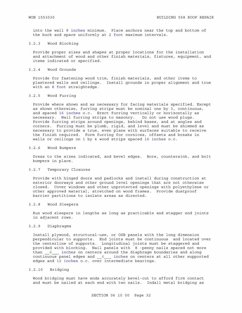
WON 1553030 BUILDING 558 ROOF REPAIR
into the wall 8 inches minimum. Place anchors near the top and bottom of the buck and space uniformly at 2 foot maximum intervals.
3.2.3 Wood Blocking
Provide proper sizes and shapes at proper locations for the installation and attachment of wood and other finish materials, fixtures, equipment, and items indicated or specified.
3.2.4 Wood Grounds
Provide for fastening wood trim, finish materials, and other items to plastered walls and ceilings. Install grounds in proper alignment and true with an 8 foot straightedge.
3.2.5 Wood Furring
Provide where shown and as necessary for facing materials specified. Except as shown otherwise, furring strips must be nominal one by 3, continuous, and spaced 16 inches o.c. Erect furring vertically or horizontally as necessary. Nail furring strips to masonry. Do not use wood plugs. Provide furring strips around openings, behind bases, and at angles and corners. Furring must be plumb, rigid, and level and must be shimmed as necessary to provide a true, even plane with surfaces suitable to receive the finish required. Form furring for cornices, offsets and breaks in walls or ceilings on 1 by 4 wood strips spaced 16 inches o.c.
3.2.6 Wood Bumpers
Dress to the sizes indicated, and bevel edges. Bore, countersink, and bolt bumpers in place.
3.2.7 Temporary Closures
Provide with hinged doors and padlocks and install during construction at exterior doorways and other ground level openings that are not otherwise closed. Cover windows and other unprotected openings with polyethylene or other approved material, stretched on wood frames. Provide dustproof barrier partitions to isolate areas as directed.
3.2.8 Wood Sleepers
Run wood sleepers in lengths as long as practicable and stagger end joints in adjacent rows.
3.2.9 Diaphragms
Install plywood, structural-use, or OSB panels with the long dimension perpendicular to supports. End joints must be continuous and located over the centerline of supports. Longitudinal joints must be staggered and provided with blocking. Nail panels with 8 -penny nails spaced not more than __6___ inches on centers around the diaphragm boundaries and along continuous panel edges and __6___ inches on centers at all other supported edges and 12 inches o.c. over intermediate bearings.
3.2.10 Bridging
Wood bridging must have ends accurately bevel-cut to afford firm contact and must be nailed at each end with two nails. Indall metal bridging as
SECTION 06 10 00 Page 32

WON 1553030 BUILDING 558 ROOF REPAIR
recommended by the manufacturer. The lower ends of bridging must be driven up tight and secured after subflooring or roof sheathing has been laid and partition framing installed.
3.2.11 Corner Bracing
Indatall corner bracing when required by type of sheathing used or when siding, other than panel siding, is applied directly to studs. Corner bracing must be let into the exterior surfaces of the studs at an angle of approximately 45 degrees, must extend completely over wall plates, and must be secured at each bearing with two nails.
3.2.12 Sill Plates
Sill plates must be set level and square and anchor bolted at not more than 6 feet on centers and not more than 12 inches from end of each piece. A minimum of two anchors must be used for each piece.
3.3 INSTALLATION OF TIMBER CONNECTORS
Install timber connectors in conformance with requirements of AWC NDS.
3.4 ERECTION TOLERANCES
a. Framing members which will be covered by finishes such as wallboard, plaster, or ceramic tile set in a mortar setting bed, must be within the following limits:
(1) Layout of walls and partitions: 1/4 inch from intended position;
(2) Plates and runners: 1/4 inch in 8 feet from a straight line;
(3) Studs: 1/4 inch in 8 feet out of plumb, not cumulative; and
(4) Face of framing members: 1/4 inch in 8 feet from a true plane.
b. Framing members which will be covered by ceramic tile set in dry-set mortar, latex-portland cement mortar, or organic adhesive must be within the following limits:
(1) Layout of walls and partitions: 1/4 inch from intended position;
(2) Plates and runners: 1/8 inch in 8 feet from a straight line;
(3) Studs: 1/8 inch in 8 feet out of plumb, not cumulative; and
(4) Face of framing members: 1/8 in 8 feet from a true plane.
3.5 SPECIAL INSPECTION AND TESTING FOR SEISMIC-RESISTING SYSTEMS
Special inspections and testing for seismic-resisting systems and components must be done in accordance with Section 01 45 35 SPECIAL INSPECTIONS.
3.6 WASTE MANAGEMENT OF WOOD PRODUCTS
In accordance with the Waste Management Plan and as specified. Clearly separate damaged wood and other scrap lumber for acceptable alternative uses on site, including bracing, blocking, cripples, ties, and shims.
SECTION 06 10 00 Page 33
WON 1553030 BUILDING 558 ROOF REPAIR
Separate treated, stained, painted, and contaminated wood and place in designated area for hazardous materials. Dispose of according to local regulations. Prevent sawdust and wood shavings from entering the storm drainage system.Do not burn scrap lumber that has been pressure treated, or lumber that is less than one year old.
-- End of Section --
SECTION 06 10 00 Page 34

WON 1553030 BUILDING 558 ROOF REPAIR
SECTION TABLE OF CONTENTS
DIVISION 06 - WOOD, PLASTICS, AND COMPOSITES
SECTION 06 20 00
FINISH CARPENTRY
08/16
covers general exterior and interior finish carpentry in a condensed formatand is therefore intended for use on small projects
PART 1 GENERAL
1.1 REFERENCES 1.2 SUBMITTALS 1.3 DETAIL DRAWINGS 1.4 PRODUCT DATA 1.5 SAMPLES 1.6 DELIVERY, STORAGE, AND HANDLING 1.7 QUALITY ASSURANCE 1.7.1 Certifications 1.7.1.1 Certified Wood Grades 1.7.1.2 Certified Sustainably Harvested Wood 1.7.1.3 Indoor Air Quality Certifications 1.7.1.3.1 Adhesives and Sealants 1.7.2 Lumber 1.7.3 Plywood 1.7.4 Hardboard 1.7.5 Pressure Treated Lumber and Plywood 1.7.6 Non-Pressure Treated Woodwork and Millwork 1.7.7 Fire-Retardant Treated Lumber
PART 2 PRODUCTS
2.1 PRODUCT SUSTAINABILITY CRITERIA 2.1.1 Certified Sustainably Harvested Wood 2.1.2 Reduce Volatile Organic Compounds (VOC) (Low-Emitting
Materials) for Products 2.2 WOOD PRODUCTS 2.2.1 Sizes and Patterns of Wood Products 2.2.2 Species and Grades 2.2.3 Trim, Finish, and Frames 2.2.4 Utility Shelving 2.2.5 Softwood Plywood 2.2.6 Hardwood Plywood 2.2.7 Hardboard 2.2.8 Medium Density Fiberboard (MDF) and Particleboard 2.2.9 Stairs 2.2.10 Shoe Mould 2.2.11 Wood Seats 2.2.12 Wood Bumpers 2.2.13 Catwalks 2.3 SOFFITS
SECTION 06 20 00 Page 1

WON 1553030 BUILDING 558 ROOF REPAIR
2.3.1 Hardboard and Plywood 2.4 FASCIAS AND TRIM 2.4.1 Wood 2.5 MOISTURE CONTENT OF WOOD PRODUCTS 2.6 PRESERVATIVE TREATMENT OF WOOD PRODUCTS 2.6.1 Non-Pressure Treatment 2.6.2 Pressure Treatment 2.7 FIRE-RETARDANT TREATMENT 2.7.1 Wood Products 2.8 HARDWARE AND ACCESSORIES 2.8.1 Wood Screws 2.8.2 Bolts, Nuts, Lag Screws, and Studs 2.8.3 Nails 2.8.4 Adjustable Shelf Standards 2.8.5 Vertical Slotted Shelf Standards 2.8.6 Closet Hanger Rods
PART 3 EXECUTION
3.1 FINISH WORK 3.1.1 Exterior Finish Work 3.1.2 Interior Finish Work 3.1.3 Door Frames 3.1.4 Thresholds 3.1.5 Window Stools and Aprons 3.1.6 Bases 3.1.7 Finish Stair Work 3.2 SOFFITS 3.2.1 Wood 3.3 FASCIAE AND EXTERIOR TRIM 3.4 MOULDING AND INTERIOR TRIM
-- End of Section Table of Contents --
SECTION 06 20 00 Page 2

WON 1553030 BUILDING 558 ROOF REPAIR
SECTION 06 20 00
FINISH CARPENTRY08/16
PART 1 GENERAL
1.1 REFERENCES
The publications listed below form a part of this specification to the extent referenced. The publications are referred to within the text by the basic designation only.
AMERICAN FOREST FOUNDATION (AFF)
ATFS STANDARDS (2015) American Tree Farm System Standards of Sustainability 2015-2020
AMERICAN HARDBOARD ASSOCIATION (AHA)
AHA A135.4 (1995; R 2004) Basic Hardboard
AMERICAN LUMBER STANDARDS COMMITTEE (ALSC)
ALSC PS 20 (2015) American Softwood Lumber Standard
AMERICAN WOOD PROTECTION ASSOCIATION (AWPA)
AWPA M4 (2015) Standard for the Care of Preservative-Treated Wood Products
AWPA U1 (2016) Use Category System: User Specification for Treated Wood
APA - THE ENGINEERED WOOD ASSOCIATION (APA)
APA L870 (2010) Voluntary Product Standard, PS 1-09, Structural Plywood
ASME INTERNATIONAL (ASME)
ASME B18.2.1 (2012; Errata 2013) Square and Hex Bolts and Screws (Inch Series)
ASME B18.2.2 (2015) Nuts for General Applications: Machine Screw Nuts, Hex, Square, Hex Flange, and Coupling Nuts (Inch Series)
ASME B18.6.1 (2016) Wood Screws (Inch Series)
ASTM INTERNATIONAL (ASTM)
ASTM D2898 (2010) Accelerated Weathering of Fire-Retardant-Treated Wood for Fire Testing
ASTM F547 (2006; R 2012) Nails for Use with Wood and
SECTION 06 20 00 Page 3

WON 1553030 BUILDING 558 ROOF REPAIR
Wood-Base Materials
BUILDERS HARDWARE MANUFACTURERS ASSOCIATION (BHMA)
ANSI/BHMA A156.9 (2015) Cabinet Hardware
CALIFORNIA DEPARTMENT OF PUBLIC HEALTH (CDPH)
CDPH SECTION 01350 (2004; Add 2004-01) Standard Practice for the Testing Of Volatile Organic Emissions from Various Sources Using Small-Scale Environmental Chambers
COMPOSITE PANEL ASSOCIATION (CPA)
CPA A208.1 (2016) Particleboard
CSA GROUP (CSA)
CSA Z809-08 (R2013) Sustainable Forest Management
FOREST STEWARDSHIP COUNCIL (FSC)
FSC STD 01 001 (2000) Principles and Criteria for Forest Stewardship
GREEN SEAL (GS)
GS-36 (2011) Commercial Adhesives
HARDWOOD PLYWOOD AND VENEER ASSOCIATION (HPVA)
HPVA HP-1 (2016) American National Standard for Hardwood and Decorative Plywood
NATIONAL HARDWOOD LUMBER ASSOCIATION (NHLA)
NHLA Rules (2011) Rules for the Measurement & Inspection of Hardwood & Cypress
NORTHEASTERN LUMBER MANUFACTURERS ASSOCIATION (NELMA)
NELMA Grading Rules (2013) Standard Grading Rules for Northeastern Lumber
PROGRAMME FOR ENDORSEMENT OF FOREST CERTIFICATION (PEFC)
PEFC ST 2002:2013 (2015) PEFC International Standard Chain of Custody of Forest Based Products Requirements
REDWOOD INSPECTION SERVICE (RIS) OF THE CALIFORNIA REDWOOD ASSOCIATION (CRA)
RIS Grade Use (1998) Redwood Lumber Grades and Uses
SOUTH COAST AIR QUALITY MANAGEMENT DISTRICT (SCAQMD)
SCAQMD Rule 1168 (1989; R 2005) Adhesive and Sealant
SECTION 06 20 00 Page 4

WON 1553030 BUILDING 558 ROOF REPAIR
Applications
SOUTHERN PINE INSPECTION BUREAU (SPIB)
SPIB 1003 (2002) Standard Grading Rules for Southern Pine Lumber
SUSTAINABLE FOREST INITIATIVE (SFI)
SFI 2015-2019 (2015) Standards, Rules for Label Use, Procedures and Guidance
UNDERWRITERS LABORATORIES (UL)
UL 2818 (2013) GREENGUARD Certification Program For Chemical Emissions For Building Materials, Finishes And Furnishings
WEST COAST LUMBER INSPECTION BUREAU (WCLIB)
WCLIB 17 (2004) Standard Grading Rules
WESTERN WOOD PRODUCTS ASSOCIATION (WWPA)
WWPA G-5 (2011) Western Lumber Grading Rules
WINDOW AND DOOR MANUFACTURERS ASSOCIATION (WDMA)
WDMA I.S.4 (2013) Preservative Treatment for Millwork
WOOD MOULDING AND MILLWORK PRODUCERS ASSOCIATION (WMMPA)
WMMPA WM 6 (1987) Industry Standard for Non-Pressure Treating of Wood Millwork
1.2 SUBMITTALS
Government approval is required for submittals with a "G" designation; submittals not having a "G" designation are for Contractor Quality Control approval. When used, a designation following the "G" designation identifies the office that will review the submittal for the Government. Submit the following in accordance with Section 01 33 00 SUBMITTAL PROCEDURES:
SD-02 Shop Drawings
Detail Drawings Indicating All Wood Assemblies; G
SD-03 Product Data
Wood Products; G
Treated Wood Products; G
Soffits; G
Fascias and Trim; G
SECTION 06 20 00 Page 5
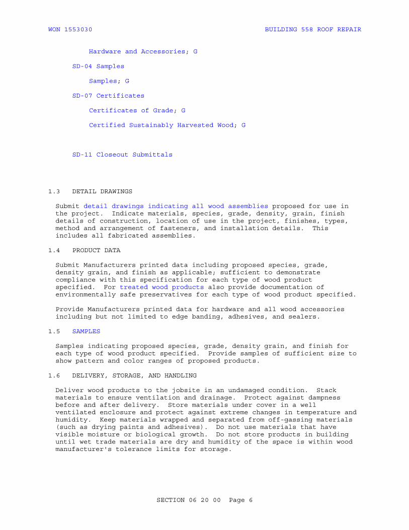
WON 1553030 BUILDING 558 ROOF REPAIR
Hardware and Accessories; G
SD-04 Samples
Samples; G
SD-07 Certificates
Certificates of Grade; G
Certified Sustainably Harvested Wood; G
SD-11 Closeout Submittals
1.3 DETAIL DRAWINGS
Submit detail drawings indicating all wood assemblies proposed for use in the project. Indicate materials, species, grade, density, grain, finish details of construction, location of use in the project, finishes, types, method and arrangement of fasteners, and installation details. This includes all fabricated assemblies.
1.4 PRODUCT DATA
Submit Manufacturers printed data including proposed species, grade, density grain, and finish as applicable; sufficient to demonstrate compliance with this specification for each type of wood product specified. For treated wood products also provide documentation of environmentally safe preservatives for each type of wood product specified.
Provide Manufacturers printed data for hardware and all wood accessories including but not limited to edge banding, adhesives, and sealers.
1.5 SAMPLES
Samples indicating proposed species, grade, density grain, and finish for each type of wood product specified. Provide samples of sufficient size to show pattern and color ranges of proposed products.
1.6 DELIVERY, STORAGE, AND HANDLING
Deliver wood products to the jobsite in an undamaged condition. Stack materials to ensure ventilation and drainage. Protect against dampness before and after delivery. Store materials under cover in a well ventilated enclosure and protect against extreme changes in temperature and humidity. Keep materials wrapped and separated from off-gassing materials (such as drying paints and adhesives). Do not use materials that have visible moisture or biological growth. Do not store products in building until wet trade materials are dry and humidity of the space is within wood manufacturer's tolerance limits for storage.
SECTION 06 20 00 Page 6

WON 1553030 BUILDING 558 ROOF REPAIR
1.7 QUALITY ASSURANCE
1.7.1 Certifications
1.7.1.1 Certified Wood Grades
Provide certificates of grade from the grading agency on graded but unmarked lumber or plywood attesting that materials meet the grade requirements specified herein.
1.7.1.2 Certified Sustainably Harvested Wood
Provide wood certified as sustainably harvested by FSC STD 01 001, ATFS STANDARDS, CSA Z809-08, SFI 2015-2019, or other third party program certified by PEFC ST 2002:2013. Provide a letter of Certification of Sustainably Harvested Wood signed by the wood supplier. Identify certifying organization and their third party program name and indicate compliance with chain-of-custody program requirements. Submit sustainable wood certification data; identify each certified product on a line item basis. Submit copies of invoices bearing certification numbers.
1.7.1.3 Indoor Air Quality Certifications
1.7.1.3.1 Adhesives and Sealants
Provide products certified to meet indoor air quality requirements by UL 2818 (Greenguard) Gold, SCS Global Services Indoor Advantage Gold or provide validation by other third-party program that products meet the requirements of this paragraph. Sealants and non-aerosol adhesive products used on the interior of the building (defined as inside of the weatherproofing system) must meet either emissions requirements of CDPH SECTION 01350 (limit requirements for either office or classroom spaces regardless of space type) or VOC content requirements of SCAQMD Rule 1168. Aerosol adhesives used on the interior of the building must meet either emissions requirements of CDPH SECTION 01350 (limit requirements for either office or classroom spaces regardless of space type) or VOC content requirements of GS-36. Provide current product certification documentation from certification body.
1.7.2 Lumber
Identify each piece or each bundle of lumber, millwork, and trim by the grade mark of a recognized association or independent inspection agency certified by the Board of Review of the ALSC to grade the species.
1.7.3 Plywood
Provide each sheet of plywood with the mark of a recognized association or independent inspection agency that maintains continuing control over the quality of the plywood. Marks must identify plywood by species group or span rating, exposure durability classification, grade, and compliance with APA L870.
1.7.4 Hardboard
Provide materials marks or written documentation identifying the producer and the applicable standard.
SECTION 06 20 00 Page 7

WON 1553030 BUILDING 558 ROOF REPAIR
1.7.5 Pressure Treated Lumber and Plywood
Inspect each treated piece in accordance with AWPA U1.
1.7.6 Non-Pressure Treated Woodwork and Millwork
Mark, stamp, or label to indicate compliance with WDMA I.S.4.
1.7.7 Fire-Retardant Treated Lumber
Each piece must bear an Underwriters Laboratories fire resistance label or comparable label of another nationally recognized independent fire retardant materials testing laboratory.
PART 2 PRODUCTS
2.1 PRODUCT SUSTAINABILITY CRITERIA
For products in this section, where applicable and to extent allowed by performance criteria, provide and document the following:
2.1.1 Certified Sustainably Harvested Wood
Certified sustainably harvested wood is identified for some products in this section; provide documentation in accordance with Section 01 33 29 SUSTAINABILITY REPORTING paragraph BIOBASED PRODUCTS. Other products listed in this section may be available as certified sustainably harvested wood; identify those products that meet project requirements for certified sustainably harvested wood, and provide documentation in accordance with Section 01 33 29 SUSTAINABILITY REPORTING paragraph BIOBASED PRODUCTS.
2.1.2 Reduce Volatile Organic Compounds (VOC) (Low-Emitting Materials) for Products
Reduced VOC content is identified for some products in this section; provide documentation in accordance with Section 01 33 29 SUSTAINABILITY REPORTING paragraph REDUCE VOLATILE ORGANIC COMPOUNDS (VOC) (LOW-EMITTING MATERIALS). Other products listed in this section may be available with reduced VOC content; identify those products that meet project requirements for reduced VOC content, and provide documentation in accordance with Section 01 33 29 SUSTAINABILITY REPORTING paragraph REDUCE VOLATILE ORGANIC COMPOUNDS (VOC) (LOW-EMITTING MATERIALS).
2.2 WOOD PRODUCTS
2.2.1 Sizes and Patterns of Wood Products
Provide yard and board lumber sizes in accordance with ALSC PS 20. Provide shaped lumber and millwork in the patterns indicated and in standard patterns of the association covering the species. Size references, unless otherwise specified, are nominal sizes. Provide actual sizes within manufacturing tolerances allowed by the applicable standard.
2.2.2 Species and Grades
Provide in accordance with AWPA U1 Use Category System Tables unless otherwise specified herein.
SECTION 06 20 00 Page 8
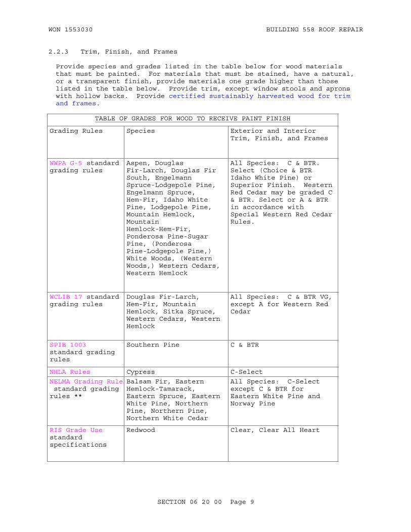
WON 1553030 BUILDING 558 ROOF REPAIR
2.2.3 Trim, Finish, and Frames
Provide species and grades listed in the table below for wood materials that must be painted. For materials that must be stained, have a natural, or a transparent finish, provide materials one grade higher than those listed in the table below. Provide trim, except window stools and aprons with hollow backs. Provide certified sustainably harvested wood for trim and frames.
TABLE OF GRADES FOR WOOD TO RECEIVE PAINT FINISH
Grading Rules Species Exterior and Interior Trim, Finish, and Frames
WWPA G-5 standard grading rules
Aspen, Douglas Fir-Larch, Douglas Fir South, Engelmann Spruce-Lodgepole Pine, Engelmann Spruce, Hem-Fir, Idaho White Pine, Lodgepole Pine, Mountain Hemlock, Mountain Hemlock-Hem-Fir, Ponderosa Pine-Sugar Pine, (Ponderosa Pine-Lodgepole Pine,) White Woods, (Western Woods,) Western Cedars, Western Hemlock
All Species: C & BTR. Select (Choice & BTR Idaho White Pine) or Superior Finish. Western Red Cedar may be graded C & BTR. Select or A & BTR in accordance with Special Western Red Cedar Rules.
WCLIB 17 standard grading rules
Douglas Fir-Larch, Hem-Fir, Mountain Hemlock, Sitka Spruce, Western Cedars, Western Hemlock
All Species: C & BTR VG, except A for Western Red Cedar
SPIB 1003 standard grading rules
Southern Pine C & BTR
NHLA Rules Cypress C-Select
NELMA Grading Rules standard grading rules **
Balsam Fir, Eastern Hemlock-Tamarack, Eastern Spruce, Eastern White Pine, Northern Pine, Northern Pine, Northern White Cedar
All Species: C-Select except C & BTR for Eastern White Pine and Norway Pine
RIS Grade Use standard specifications
Redwood Clear, Clear All Heart
SECTION 06 20 00 Page 9

WON 1553030 BUILDING 558 ROOF REPAIR
TABLE OF GRADES FOR WOOD TO RECEIVE PAINT FINISH
Grading Rules Species Exterior and Interior Trim, Finish, and Frames
NHLA Rules Cypress B Finish
Red Gum, Soft Elm, Birch Select or BTR (for interior use only)
Note: ** http://www.nelma.org/library/2013-standard-grading-rules-for-northeastern-lumber/
2.2.4 Utility Shelving
Provide utility shelving in a suitable species equal to or exceeding the requirements of No. 3 common white fir under WWPA G-5, 1 inch thick; or plywood, interior type, Grade A-B, 1/2 inch thick, any species group.
2.2.5 Softwood Plywood
Provide in accordance with APA L870. When located on the interior of buildings, provide products with no added urea-formaldehyde resins. Provide data identifying VOC content for softwood plywood.
a. Plywood for Soffits: Exterior type, B-B medium density overlay.
2.2.6 Hardwood Plywood
HPVA HP-1, Type Technical (Exterior) I (Exterior) Grade, lumber core construction, , of thickness indicated. When located on the interior of buildings, provide products with no added urea-formaldehyde resins. Provide data identifying VOC content for hardwood plywood.
2.2.7 Hardboard
AHA A135.4, standard type, 1/4 inch thick.
2.2.8 Medium Density Fiberboard (MDF) and Particleboard
CPA A208.1, Grade 1-M-2 or 2-M-2 or better.
Provide products with pre-consumer recycled content of 85 percent. Provide data identifying percentage of recycled content for MDF/particleboard.
2.2.9 Stairs
Treads 1-1/4 inches thickness, clear red or white oak. Risers 1 inch nominal finish lumber.
2.2.10 Shoe Mould
Clear red or white oak, 1/2 by 5/8 inch unless otherwise indicated.
SECTION 06 20 00 Page 10
WON 1553030 BUILDING 558 ROOF REPAIR
2.2.11 Wood Seats
Clear maple, oak, or other suitable hardwood, not less than 1-5/8 inches thick, with rounded edges. Provide stainless steel stanchions or brackets.
2.2.12 Wood Bumpers
Clear oak, maple , or birch , dressed to size indicated and with outer edges beveled.
2.2.13 Catwalks
Boards, 1 by 6 inches nominal, species and grade equal to or exceeding 3 Common Hem-Fir under WWPA G-5.
2.3 SOFFITS
2.3.1 Hardboard and Plywood
Provide hardboard and plywood soffits in siding grade hardboard, 3/8 or 7/16 inch thick; plywood, APA L870, exterior type, plywood panel siding ,11/32 inch thick for 24 inches on center maximum span with all edges supported.
2.4 FASCIAS AND TRIM
2.4.1 Wood
Provide species and grades for all fasciae and trim, including exterior door and window casings, in accordance with AWPA U1 Use Category System Tables. Provide sizes indicated. Metal corners may be provided in lieu of wood corner boards for horizontal siding. If metal corners are used, provide galvanized steel or aluminum, completely coated with primer compatible for the specific metal substrate.
2.5 MOISTURE CONTENT OF WOOD PRODUCTS
Air dry or kiln dry lumber. Kiln dry treated lumber after treatment. Maximum moisture content of wood products at time of delivery to the jobsite, and when installed, must be as follows:
a. Interior Paneling: 6 percent.
b. Interior Finish Lumber, Trim, and Millwork: 1-1/4 Inches Nominal or Less in Thickness: 6 percent on 85 percent of the pieces and 8 percent on remainder.
c. Exterior Treated and Untreated Finish Lumber and Trim: 4 inches Nominal or Less in Thickness: 19 percent.
d. Exterior Wood Siding: 15 percent.
e. Provide moisture content of other materials in accordance with the applicable standards.
SECTION 06 20 00 Page 11

WON 1553030 BUILDING 558 ROOF REPAIR
2.6 PRESERVATIVE TREATMENT OF WOOD PRODUCTS
2.6.1 Non-Pressure Treatment
Treat woodwork and millwork, such as exterior trim, door trim, and window trim, in accordance with WDMA I.S.4, with either 2 percent copper napthenate, 3 percent zinc napthenate, or 1.8 percent copper-8-quinolinolate. Provide a liberal brush coat of preservative treatment to field cuts and holes.
2.6.2 Pressure Treatment
Treat lumber and plywood used on the exterior of buildings or in contact with masonry or concrete with a waterborne preservative listed in AWPA U1 (P series is included therein by reference) as applicable, and inspected in accordance with AWPA U1. Identify treatment on each piece of material by the quality mark of an agency accredited by the Board of Review of the American Lumber Standards Committee. Provide treated plywood to a reflection level as follows:
Preservative treat exterior wood moulding and millwork that will be within 18 inches of soil or in contact with water or concrete in accordance with WMMPA WM 6. Provide a field treatment in accordance with AWPA M4 of exposed areas of treated wood that have been cut or drilled. Items of all-heart material of cedar, cypress, or redwood do not require preservative treatment except when in direct contact with soil.
2.7 FIRE-RETARDANT TREATMENT
2.7.1 Wood Products
Pressure treat fire-retardant treated lumber and plywood in accordance with AWPA U1. Comply with material use as defined in AWPA U1 for Interior Type A and B and Exterior Type. Treatment and performance inspection must be conducted by a qualified independent testing agency that establishes performance ratings. Each piece or bundle of treated material must bear identification of the testing agency to indicate performance with such rating. Subject treated materials that will be exposed to rain wetting to an accelerated weathering technique in accordance with ASTM D2898, Method A, prior to being tested for compliance with AWPA U1.
2.8 HARDWARE AND ACCESSORIES
Provide sizes, types, and spacings of hardware and accessories as recommended in writing by the wood product manufacturer, except as otherwise specified.
2.8.1 Wood Screws
ASME B18.6.1.
2.8.2 Bolts, Nuts, Lag Screws, and Studs
ASME B18.2.1 and ASME B18.2.2.
SECTION 06 20 00 Page 12

WON 1553030 BUILDING 558 ROOF REPAIR
2.8.3 Nails
Use nails of a size and type best suited for each application and in accordance with ASTM F547. Use hot-dipped galvanized or aluminum nails for exterior applications. For siding, provide nails of sufficient length to extend 1-1/2 inches into supports, including wood sheathing over framing. Where nailing is impractical, provide screws of a size and type best suited for each application.
2.8.4 Adjustable Shelf Standards
ANSI/BHMA A156.9 .
2.8.5 Vertical Slotted Shelf Standards
ANSI/BHMA A156.9 .
2.8.6 Closet Hanger Rods
Chromium plated steel rods, not less than 1 inch diameter by 18 gage. Rods may be adjustable with integral mounting brackets if smaller tube is 1 inch by 18 gage. Provide intermediate support brackets for rods more than 48 inches long.
PART 3 EXECUTION
Do not install building construction materials that show visual evidence of biological growth.
3.1 FINISH WORK
Apply primer to finish work before installing. Where practicable, shop assemble and finish millwork items. Construct joints tight and in a manner to conceal shrinkage but to avoid cupping, twisting and warping after installation. Miter trim and mouldings at exterior angles; cope at interior angles and at returns. Provide millwork and trim in maximum practical lengths. Fasten finish work with finish nails. Provide blind nailing where practicable. Set face nails for putty stopping.
3.1.1 Exterior Finish Work
Machine sand exposed flat members and square edges. Machine finish semi-exposed surfaces. Construct joints to exclude water. In addition to nailing, glue joints with waterproof glue as necessary for weather resistant construction. Evenly distribute end joints in built-up members. Provide shoulder joints in flat work. Reinforce backs of wide-faced miters with metal rings and waterproof glue. Unless otherwise indicated, provide fasciae and other flat members 3/4 inch thick minimum. Provide door and window trim in single lengths. Provide braced, blocked, and rigidly anchored cornices for support and protection of vertical joints. Provide soffits in largest practical size. Align joints of plywood over centerlines of supports. Fasten soffits with aluminum or stainless steel nails. Back prime all concealed surfaces of exterior trim.
3.1.2 Interior Finish Work
After installation, sand exposed surfaces smooth. Provide window and door trim in single lengths.
SECTION 06 20 00 Page 13
WON 1553030 BUILDING 558 ROOF REPAIR
3.1.3 Door Frames
Set plumb and square. Provide solid blocking at not more than 16 inches on center for each jamb. Position blocking to occur behind hinges and lock strikes. Double wedge frames and fasten with finish nails. Set nails for putty stopping.
3.1.4 Thresholds
Unless otherwise indicated, provide thresholds 5/8 inch thick by 2-5/8 inches wide with beveled sides and cut to fit at jambs. Fasten thresholds with casing nails. Set nails for putty stopping.
3.1.5 Window Stools and Aprons
Provide stools with rabbets over window sills. Provide aprons with returns cut accurately to profile of member.
3.1.6 Bases
Provide flat member with a moulded top and oak shoe mould. Fasten base to framing or to grounds. Nail shoe mould to base. Set shoe mould after finish flooring is in place.
3.1.7 Finish Stair Work
Fit, nail, screw, bolt, and glue stair work together to form a strong, rigid structure without squeaks or vibrations. Anchor newels and posts securely to stair framing. Cut newels, posts, and drops accurately around floor construction to make a tight fit. Embed balusters into treads and landings and secure with glue. Provide railings with straight runs that follow the slope of the stairs and have smooth curved turns. Return railing profile at ends and secure joints with bolts and nuts in accordance with structural load requirements for railings. Secure railing to posts and newels with concealed anchors. Support wall rails on metal brackets spaced near ends and at not more than 5 feet on center.
3.2 SOFFITS
3.2.1 Wood
Provide panels with edges at joints spaced in accordance with manufacturer's written instructions and with all edges backed by framing members. Nail panels 3/8 inch from edges at 6 inches on center and at intermediate supports at 12 inches on center. Provide panels in maximum practicable lengths.
3.3 FASCIAE AND EXTERIOR TRIM
Construct, caulk, and machine sand exposed surfaces and edges to exclude water. In addition to nailing, glue joints as necessary for weather resistance. Evenly distribute end joints in built-up members. Shoulder joints in flat work. Reinforce backs of wide-faced miters with metal rings and glue. Provide fasciae and other flat members in maximum practicable lengths. Braced, block, and rigidly anchor cornices for support and protection of vertical joints.
SECTION 06 20 00 Page 14

WON 1553030 BUILDING 558 ROOF REPAIR
3.4 MOULDING AND INTERIOR TRIM
Install mouldings and interior trim straight, plumb, level and with closely fitted joints. Provide exposed surfaces machine sanded at the shop. Cope returns and interior angles at moulded items and miter external corners. Shoulder intersections of flatwork to ease any inherent changes in plane. Provide window and door trim in single lengths. Blind nail to the extent practicable. Set and stop face nailing with a nonstaining putty to match the applied finish. Use screws for attachment to metal; set and stop screws in accordance with the same quality requirements for nails.
-- End of Section --
SECTION 06 20 00 Page 15

WON 1553030 BUILDING 558 ROOF REPAIR
SECTION TABLE OF CONTENTS
DIVISION 07 - THERMAL AND MOISTURE PROTECTION
SECTION 07 22 00
ROOF AND DECK INSULATION
02/16
insulation materials used below built-up roofing and single ply roofingsystems
PART 1 GENERAL
1.1 REFERENCES 1.2 SUBMITTALS 1.3 SHOP DRAWINGS 1.4 PRODUCT DATA 1.5 MANUFACTURER'S INSTRUCTIONS 1.6 QUALITY CONTROL 1.7 FM APPROVAL REQUIREMENTS 1.8 FIRE PERFORMANCE REQUIREMENTS 1.8.1 Insulation in Roof Systems 1.8.2 Thermal Barrier Requirements 1.8.3 Fire Resistance Ratings for Roofs 1.9 CERTIFICATIONS 1.10 DELIVERY, STORAGE, AND HANDLING 1.10.1 Delivery 1.10.2 Storage and Handling 1.11 ENVIRONMENTAL CONDITIONS 1.12 PROTECTION 1.12.1 Flame Heated Equipment 1.12.1.1 Fire Protection 1.12.1.2 Operational Requirements 1.12.2 Special Protection 1.12.3 Drippage of Bitumen 1.12.4 Completed Work
PART 2 PRODUCTS
2.1 PRODUCT SUSTAINABILITY CRITERIA 2.1.1 Reduce Volatile Organic Compounds (VOC) Contents 2.1.2 Recycled Content 2.2 INSULATION 2.2.1 Insulation Types 2.2.2 Mineral Fiber Insulation Board 2.2.3 Recycled Materials 2.2.4 Insulation Thickness 2.2.5 Tapered Roof Insulation 2.2.6 Cants and Tapered Edge Strips 2.3 COVER BOARD 2.3.1 Glass Mat Gypsum Roof Board 2.3.2 High Density Wood Fiber 2.4 BITUMENS
SECTION 07 22 00 Page 1

WON 1553030 BUILDING 558 ROOF REPAIR
2.4.1 Asphalt Primer 2.4.2 Asphalt 2.4.3 Asphalt Roof Cement 2.5 SHEATHING PAPER FOR WOOD DECKS 2.6 MOISTURE CONTROL 2.6.1 Vapor Retarder 2.6.1.1 Asphalt Saturated Felt Base Sheet for Single Layer
Application 2.6.1.2 Asphalt-Coated Glass Felt 2.7 FASTENERS 2.7.1 Roofing Nails for Wood Decks 2.7.2 Fasteners for Plywood Decks 2.7.3 Fasteners for Steel Decks 2.8 WOOD NAILERS
PART 3 EXECUTION
3.1 EXAMINATION AND PREPARATION 3.1.1 Surface Inspection 3.1.2 Surface Preparation 3.2 INSTALLATION OF VAPOR RETARDER 3.2.1 Vapor Retarder on Poured Concrete Decks 3.2.2 Vapor Retarder on Precast Concrete Decks 3.2.3 Vapor Retarder on Wood Decks 3.2.4 Vapor Retarder on Steel Decks 3.2.5 Over Gypsum Insulating Concrete or Lightweight Insulating
Concrete 3.2.6 Over Concrete Decks and First Layer of Insulation on Steel Decks 3.2.7 Over Structural Concrete on Non-Venting Support 3.3 INSULATION INSTALLATION 3.3.1 Installation Using Asphalt 3.3.2 Installation Using Asphalt on Steel Decks 3.3.3 Installation of Protection for Asphalt Work 3.3.4 Installation Using Only Mechanical Fasteners 3.3.5 Special Precautions for Installation of Foam Insulation 3.3.5.1 Polyisocyanurate Insulation 3.3.5.2 Polystyrene Insulation 3.3.6 Cant Strips 3.3.7 Tapered Edge Strips 3.4 PROTECTION 3.4.1 Protection of Applied Insulation 3.4.2 Damaged Work and Materials 3.5 INSPECTION
-- End of Section Table of Contents --
SECTION 07 22 00 Page 2

WON 1553030 BUILDING 558 ROOF REPAIR
SECTION 07 22 00
ROOF AND DECK INSULATION02/16
PART 1 GENERAL
1.1 REFERENCES
The publications listed below form a part of this specification to the extent referenced. The publications are referred to within the text by the basic designation only.
ASTM INTERNATIONAL (ASTM)
ASTM C1177/C1177M (2013) Standard Specification for Glass Mat Gypsum Substrate for Use as Sheathing
ASTM C1289 (2016a) Standard Specification for Faced Rigid Cellular Polyisocyanurate Thermal Insulation Board
ASTM C208 (2012) Cellulosic Fiber Insulating Board
ASTM C552 (2016a) Standard Specification for Cellular Glass Thermal Insulation
ASTM C578 (2016) Standard Specification for Rigid, Cellular Polystyrene Thermal Insulation
ASTM C726 (2012) Mineral Fiber Roof Insulation Board
ASTM C728 (2016) Perlite Thermal Insulation Board
ASTM D2178/D2178M (2015a) Asphalt Glass Felt Used in Roofing and Waterproofing
ASTM D312 (2000; R 2006) Standard Specification for Asphalt Used in Roofing
ASTM D41/D41M (2011; R 2016) Standard Specification for Asphalt Primer Used in Roofing, Dampproofing, and Waterproofing
ASTM D4263 (1983; R 2012) Indicating Moisture in Concrete by the Plastic Sheet Method
ASTM D4586/D4586M (2007; E 2012; R 2012) Asphalt Roof Cement, Asbestos-Free
ASTM D4601/D4601M (2004; R 2012) Asphalt-Coated Glass Fiber Base Sheet Used in Roofing
ASTM E84 (2016) Standard Test Method for Surface Burning Characteristics of Building Materials
SECTION 07 22 00 Page 3

WON 1553030 BUILDING 558 ROOF REPAIR
FM GLOBAL (FM)
FM 4450 (1989) Approval Standard for Class 1 Insulated Steel Deck Roofs
FM 4470 (2010) Single-Ply, Polymer-Modified Bitumen Sheet, Built-up Roof (BUR), and Liquid Applied Roof Assemblies for Use in Class 1 and Noncombustible Roof Deck Construction
FM APP GUIDE (updated on-line) Approval Guide http://www.approvalguide.com/
INTERNATIONAL CODE COUNCIL (ICC)
ICC IBC (2015) International Building Code
NATIONAL FIRE PROTECTION ASSOCIATION (NFPA)
NFPA 1 (2015; ERTA 2015) Fire Code
SCIENTIFIC CERTIFICATION SYSTEMS (SCS)
SCS SCS Global Services (SCS)Indoor Advantage
UNDERWRITERS LABORATORIES (UL)
UL 1256 (2002; Reprint Jul 2013) Fire Test of Roof Deck Constructions
UL 2818 (2013) GREENGUARD Certification Program For Chemical Emissions For Building Materials, Finishes And Furnishings
1.2 SUBMITTALS
Government approval is required for submittals with a "G" designation; submittals not having a "G" designation are for Contractor Quality Control approval.. When used, a designation following the "G" designation identifies the office that will review the submittal for the Government. Submit the following in accordance with Section 01 33 00 SUBMITTAL PROCEDURES:
SD-02 Shop Drawings
Insulation Board Layout and Attachment; G
Verification of Existing Conditions; G
SD-03 Product Data
Insulation; G
Cover Board; G
Fasteners; G
Sheathing Paper; G
SECTION 07 22 00 Page 4

WON 1553030 BUILDING 558 ROOF REPAIR
Moisture Control; G
Asphalt Products; G
SD-06 Test Reports
Flame Spread Rating; G
SD-07 Certificates
Volatile Organic Compounds (VOC) Content; G
Installer Qualifications; G
Certificates Of Compliance For Felt Materials; G
SD-08 Manufacturer's Instructions
Nails and Fasteners; G
Roof Insulation; G
1.3 SHOP DRAWINGS
Submit insulation board layout and attachment indicating methods of attachment and spacing, transitions, tapered components, thicknesses of materials, and closure and termination conditions. Show locations of ridges, valleys, crickets, interface with, and slope to, roof drains. Base shop drawings on verified field measurements and include verification of existing conditions. Show wood nailers.Show location and spacing of wood nailers required for securing of insulation and backnailing of roofing felts.
1.4 PRODUCT DATA
Include data for material descriptions, recommendations for product shelf life, requirements for cover board or coatings, and precautions for flammability and toxicity. Include data to verify compatibility of sealants with insulation.
1.5 MANUFACTURER'S INSTRUCTIONS
Include field of roof and perimeter attachment requirements.
Provide a complete description of installation sequencing for each phase of the roofing system. Include weatherproofing procedures.
1.6 QUALITY CONTROL
Provide certification of installer qualifications from the insulation manufacturer confirming the specific installer has the required qualifications for installing the specific roof insulation system(s) indicated.
Provide certificates of compliance for felt materials.
SECTION 07 22 00 Page 5

WON 1553030 BUILDING 558 ROOF REPAIR
1.7 FM APPROVAL REQUIREMENTS
Provide fastening patterns in accordance with FM 1-90 for insulation on steel decks.
1.8 FIRE PERFORMANCE REQUIREMENTS
1.8.1 Insulation in Roof Systems
Comply with the requirements of ICC IBC or UL 1256or FM 4450or FM 4470. Roof insulation to have a flame spread rating of 75 or less when tested in accordance with ASTM E84. Additional documentation of compliance with flame spread rating is not required when insulation of the type used for this project as part of the specific roof assembly is listed and labeled as FM Class 1 approved.
1.8.2 Thermal Barrier Requirements
Separate polyurethane or polystyrene insulation from a steel deck with a thermal barrier of glass mat gypsum roof board or other approved barrier material in accordance with the requirements of the ICC IBC or FM 4450 or FM 4470or UL 1256.
1.8.3 Fire Resistance Ratings for Roofs
Provide in accordance with ICC IBC Chapter 7 and Table 721.1(3) Min Fire and Smoke Protection For Floor and Roof Systems.
1.9 CERTIFICATIONS
Provide products that are third party certified for low Volatile Organic Compounds (VOC) Content in accordance with UL 2818 Greenguard Gold, SCS Scientific Certification Systems Indoor Advantage Gold or approved equal.(http://www.scsglobalservices.com/indoor-air-quality-certification)
1.10 DELIVERY, STORAGE, AND HANDLING
1.10.1 Delivery
Deliver materials to the project site in manufacturer's unopened and undamaged standard commercial containers bearing the following legible information:
a. Name of manufacturer
b. Brand designation
c. Specification number, type, and class, as applicable, where materials are covered by a referenced specification
d. Asphalt flashpoint (FP), equiviscous temperature (EVT), and finished blowing temperature (FBT).
Deliver materials in sufficient quantity to allow continuity of the work.
1.10.2 Storage and Handling
Store and handle materials in accordance with manufacturer's printed instructions. Protect from damage, exposure to open flame or other
SECTION 07 22 00 Page 6

WON 1553030 BUILDING 558 ROOF REPAIR
ignition sources, wetting, condensation, and moisture absorption. Keep materials wrapped and separated from off-gassing materials (such as drying paints and adhesives). Do not use materials that have visible moisture or biological growth. Store in an enclosed building or trailer that provides a dry, adequately ventilated environment. Store felt rolls on ends. For the 24 hours immediately before application of felts, store felts in an area maintained at a temperature no lower than 50 degrees F above grade and having ventilation on all sides. Replace damaged material with new material.
1.11 ENVIRONMENTAL CONDITIONS
Do not install roof insulation during inclement weather or when air temperature is below 40 degrees F and interior humidity is 45 percent or greater, or when there is visible ice, frost, or moisture on the roof deck.
1.12 PROTECTION
1.12.1 Flame Heated Equipment
1.12.1.1 Fire Protection
Locate melt kettles no closer than 25 feet from buildings or combustible materials. Provide and maintain two approved 4-A:40-B:C fire extinguishers within 25 feet of each operating kettle. Fire extinguishers, operations and locations must comply with NFPA 1 Section Tar Kettles. Equip asphalt (tar) kettles with tight fitting lids.
1.12.1.2 Operational Requirements
Equip kettles with automatic thermostatic control capable of maintaining asphalt temperature. Calibrate and maintain controls in working order for the duration of the work. Equip kettles with means of agitation and ensure they are operating as necessary to produce a controlled uniform temperature throughout kettle contents to prevent spot heating. Do not heat contents above flash point. Do not place flame heated equipment on the roof.
1.12.2 Special Protection
Provide special protection as approved by the insulation manufacturer.
1.12.3 Drippage of Bitumen
Seal joints in and at edges of deck as necessary to prevent drippage of asphalt into the building or onto adjacent surfaces.
1.12.4 Completed Work
Cover completed work with cover board for the duration of construction. Avoid traffic on completed work particularly when ambient temperature is above 80 degrees F. Replace crushed or damaged insulation prior to roof surface installation.
SECTION 07 22 00 Page 7

WON 1553030 BUILDING 558 ROOF REPAIR
PART 2 PRODUCTS
2.1 PRODUCT SUSTAINABILITY CRITERIA
Where allowed by performance criteria:
2.1.1 Reduce Volatile Organic Compounds (VOC) Contents
Provide products with reduced VOC content and provide documentation in accordance with Section 01 33 29 SUSTAINABILITY REPORTING paragraph REDUCE VOLATILE ORGANIC COMPOUNDS.
2.1.2 Recycled Content
Provide products with recycled content and provide documentation in accordance with Section 01 33 29 SUSTAINABILITY REPORTING paragraph RECYCLED CONTENT.
2.2 INSULATION
2.2.1 Insulation Types
Provide one, or an assembly of a maximum of three, of the following roof insulation materials. Provide roof insulation that is compatible with attachment methods for the specified insulation and roof membrane.a. Expanded Perlite Board: Provide in accordance with ASTM C728. Minimum
3/4 inch thick when both top and bottom surfaces must be in contact with asphalt.
b. Polyisocyanurate Board: Provide in accordance with ASTM C1289 REV A Type I, foil faced both sides or Type II, fibrous felt or glass mat membrane both sides, except minimum compressive strength of 20 pounds per square inch (psi).
c. Composite Boards: Provide in accordance with ASTM C1289 REV A, Type III, perlite insulation board faced on one side with fibrous felt or glass fiber mat membrane on opposite side.Type V, oriented strand board or waferboard on one side and fibrous felt or glass fiber mat membrane or aluminum foil on opposite side (Polyisocyanurate-perlite).
d. Cellular Glass Boards: ASTM C552, Type IV.
e. Polystyrene Board: In accordance with ASTM C578 REV A, Type II, IV, or X.
f. Wood Fiberboard: In accordance with ASTM C208, high density, except 4 by 4 feet maximum board size.
ASTM C208 Type II, Grade 1 or 2, roof insulating board, treated with sizing, wax or bituminous impregnation. Limit bituminous impregnation to 4 percent by weight when used over steel decks. Maximum board size: 4 feet by 4 feet.
2.2.2 Mineral Fiber Insulation Board
Provide in accordance with ASTM C726.
SECTION 07 22 00 Page 8

WON 1553030 BUILDING 558 ROOF REPAIR
2.2.3 Recycled Materials
Provide thermal insulation materials containing recycled content in accordance with paragraph PRODUCT SUSTAINABILITY CRITERIA. Unless specified otherwise, the minimum required recycled content for listed materials are:
Perlite Composition Board: 75 percent postconsumer paper
Polyisocyanurate/polyurethane: 9 percent recovered material
Wood Fiberboard: 100 percent recovered material
Cellular Glass Insulation: 75 percent recovered content
Structural Fiberboard: 100 percent recovered content
Fiberglass Insulation: 25 percent recovered content
Fiber (felt) or Fiber composite: 75 percent recovered content
Rubber: 90 percent recovered content
Plastic or Plastic/Rubber composite:
90 percent recovered content
Wood/Plastic Composite: 90 percent total recovered content
2.2.4 Insulation Thickness
As necessary to provide the thermal resistance (R-value) indicated for average thickness of tapered system. Base calculation on the R-value for aged insulation. For insulation over steel decks, satisfy both specified R-value and minimum thickness for width of rib opening recommended in insulation manufacturer's published literature.
2.2.5 Tapered Roof Insulation
One layer of the tapered roof insulation assembly must be factory tapered to a slope of not less than 1/2 inch per foot. Factory fabricate mitered joints from two diagonally cut boards or one board shaped to provide required slopes.
2.2.6 Cants and Tapered Edge Strips
Provide preformed cants and tapered edge strips of the same material as the roof insulation. When unavailable, provide pressure-preservative treated wood, wood fiberboard, or rigid perlite board cants and edge strips as recommended by the roofing manufacturer for the specific application, unless otherwise indicated. Face of cant strips to incline at 45 degrees with a minimum vertical height of 4 inches. Taper edge strips at a rate of one to 1 1/2 inch per foot down to approximately 1/8 inch thick.
2.3 COVER BOARD
For use as a thermal barrier (underlayment), fire barrier (overlayment), or cover board for hot-mopped, torched-down, or adhesive-applied roofing membrane over roof insulation.
SECTION 07 22 00 Page 9
WON 1553030 BUILDING 558 ROOF REPAIR
2.3.1 Glass Mat Gypsum Roof Board
ASTM C1177/C1177M, 0 Flame Spread and 0 Smoke Developed when tested in accordance with ASTM E84, 500 psi, Class A, non-combustible, 5/8 inch thick, 4 by 8 feet board size.
2.3.2 High Density Wood Fiber
Provide high density fiber board, Grade 2 in accordance with ASTM C208 with a transverse load of 12 lbf.
2.4 BITUMENS
2.4.1 Asphalt Primer
Provide in accordance with ASTM D41/D41M.
2.4.2 Asphalt
Provide in accordance with ASTM D312, Type III or IV. Asphalt flash point, finished blowing temperature, and equiviscous temperature (EVT) for mop and mechanical spreader application must be indicated on each container.
2.4.3 Asphalt Roof Cement
Provide in accordance with ASTM D4586/D4586M, Type I, for horizontal surfaces and surfaces sloped from 0 to 3 inches per foot. Type II for vertical and surfaces sloped more than 3 inches per foot.
2.5 SHEATHING PAPER FOR WOOD DECKS
Rosin-sized building paper or unsaturated felt weighing not less than 5 pounds per 100 square feet.
2.6 MOISTURE CONTROL
2.6.1 Vapor Retarder
2.6.1.1 Asphalt Saturated Felt Base Sheet for Single Layer Application
Provide in accordance with ASTM D4601/D4601M, weighing not less than 35 pounds per 100 square feet.
2.6.1.2 Asphalt-Coated Glass Felt
Provide in accordance with ASTM D2178/D2178M, Type IV.
2.7 FASTENERS
Provide flush-driven fasteners through flat round or hexagonal steel or plastic plates. Provide zinc-coated steel plates, flat round not less than 1 3/8 inch diameter, hexagonal not less than 28 gage. Provide high-density plastic plates, molded thermoplastic with smooth top surface, reinforcing ribs and not less than 3 inches in diameter. Fully recess fastener head into plastic plate after it is driven. Form plates to prevent dishing. Do not use bell or cup shaped plates. Provide fasteners in accordance with insulation manufacturer's recommendations for holding power when driven, or a minimum of 40 pounds each in steel deck, whichever is the higher
SECTION 07 22 00 Page 10

WON 1553030 BUILDING 558 ROOF REPAIR
minimum. Provide fasteners for steel or concrete decks in accordance with FM APP GUIDE (http://www.approvalguide.com/) for Class I roof deck construction, and spaced to withstand uplift pressure of 90 pounds per square foot.
2.7.1 Roofing Nails for Wood Decks
Barbed 11 gage, zinc-coated nails with 7/16 to 5/8 inch diameter heads or annular ring shank, square head, one piece composite nails. Provide nails long enough to penetrate wood deck at least 5/8 inch without protruding through underside of decking.
2.7.2 Fasteners for Plywood Decks
Annular ring shank, square head, one piece composite nails long enough to penetrate into plywood decks approximately 1/2 inch without protruding through underside of decking.
2.7.3 Fasteners for Steel Decks
Approved hardened penetrating fasteners or screws in accordance with FM 4450 and listed in FM APP GUIDE for Class I roof deck construction. Quantity and placement to withstand a minimum uplift pressure of 90 psf in accordance with FM APP GUIDE.
2.8 WOOD NAILERS
Pressure-preservative treated as specified in Section 06 10 00 ROUGH CARPENTRY.
PART 3 EXECUTION
3.1 EXAMINATION AND PREPARATION
3.1.1 Surface Inspection
Ensure surfaces are clean, smooth, and dry prior to application. Ensure surfaces receiving vapor retarder are free of projections that might puncture the vapor retarder. Check roof deck surfaces, including surfaces sloped to roof drains and outlets, for defects before starting work.
The Contractor must inspect and approve the surfaces immediately before starting installation. Prior to installing vapor retarderand insulation, perform the following:
a. Examine wood decks to ascertain that deck boards have been properly nailed and that exposed nail heads have been set.
b. Examine steel decks to ensure that panels are properly secured to structural members and to each other and that surfaces of top flanges are flat or slightly convex.
c. Examine precast concrete decks to ensure that joints between precast units are properly grouted and leveled to provide suitable surfaces for installation of vapor retarder and insulation.
c d. In the presence of the Contracting Officer perform the following surface dryness test on concrete substrates:
(1) Foaming: When poured on the deck, one pint of asphalt when heated
SECTION 07 22 00 Page 11
WON 1553030 BUILDING 558 ROOF REPAIR
in the range of 350 to 400 degrees F, does not foam upon contact.
(2) Strippability: After asphalt used in the foaming test application has cooled to ambient temperatures, test coating for adherence. Should a portion of the sample be readily stripped clean from surface, do not consider surface to be dry and do not start application. Should rain occur during application, stop work and do not resume until surface has been re-tested by method above and found dry.
e. Prior to installing any roof system on a concrete deck, moisture test the deck in accordance with ASTM D4263. The deck is acceptable for roof system application when there is no visible moisture on underside of plastic sheet after 24 hours.
3.1.2 Surface Preparation
Correct defects and inaccuracies in roof deck surface to eliminate poor drainage from hollow or low spots, perform the following:
a. Provide wood nailers of the same thickness as the insulation at eaves, edges, curbs, walls, and roof openings for securing of cant strips, gravel stops, gutters, and flashing flanges. On decks with slopes of one in 12 (1 inch per foot) or more, install wood nailers perpendicular to slope for securing insulation and for backnailing of roofing felts. Space nailers in accordance with approved shop drawings.
b. Fill or cover cracks or knot holes larger than 1/2 inch in diameter in wood decks as necessary to form an unyielding surface.
c. Cover wood decks with a layer of rosin-sized building paper or unsaturated felt. Lap sides and ends not less than 3 inches. Nail sufficiently to prevent tearing or buckling during installation.
d. Cover steel decks with a layer of insulation board of sufficient width to span the width of a deck rib opening, and in accordance with fire safety requirements. Secure with piercing or self-drilling, self-tapping fasteners of quantity and placement in accordance with FM APP GUIDE. Locate insulation joints parallel to ribs of deck on solid bearing surfaces only, not over open ribs.
e. Solidly apply asphalt primer to concrete decks at the rate of 1 gallon per 100 square feet of roof surface , stopping approximately 4 inches from joints between precast concrete units. Allow primer to dry thoroughly. Place felt strips, 4 inches or more in width, over joints, 2 inches on each side, between precast concrete units in a heavy coating of cold-applied asphalt roof cement.
3.2 INSTALLATION OF VAPOR RETARDER
Install vapor retarder in direct contact with roof deck surface . Unless otherwise specified, vapor retarder to consist of either two plies of No. 15 asphalt-saturated felt, two plies of asphalt-coated glass felt , or one layer of asphalt-saturated felt base sheet. Lay vapor retarder at right angles to direction of slope. Install first ply of felt or base sheet as specified herein for the specific deck. Apply second ply of 2-ply vapor retarder system using asphalt at rate of 20 to 35 lbs per 100 square feet, applied within plus or minus 25 degrees F of EVT. Do not heat asphalt above asphalt's FBT or 525 degrees F, whichever is less. Use thermometers
SECTION 07 22 00 Page 12
WON 1553030 BUILDING 558 ROOF REPAIR
to check temperatures during heating and application. Completely seal side and end laps. Asphalt must be visible beyond all edges of each ply as it is being installed. Lay plies free of wrinkles, buckles, creases or fishmouths. Do not walk on mopped surfaces while asphalt is sticky. Press out air bubbles to obtain complete adhesion between surfaces. At walls, eaves, rakes, and other vertical surfaces, extend vapor retarder organic felts or separate plies 9 inches, with not less than 9 inches on the substrate, and the extended portion turned back and mopped in over the top of the insulation. At roof penetrations other than walls, eaves and rakes, and vertical surfaces, extend vapor retarder or separate plies 9 inches to form a lap folded back over the edge of the insulation. Provide asphalt roof cement under the vapor retarder for at least 9 inches from walls, eaves, rakes and other penetrations.
3.2.1 Vapor Retarder on Poured Concrete Decks
Evenly mop primed substrate with asphalt at a rate of 20 to 35 lbs per 100 square feet before installing vapor retarder. Lay first ply of two-ply system with each sheet lapping 19 inches over the preceding sheet. Lap ends not less than 4 inches. Stagger laps a minimum of 12 inches. For a vapor retarder consisting of one layer of asphalt base sheet, provide side and end laps not less than 4 inches. Stagger laps a minimum of 12 inches. Cement base sheets together with a solid mopping of asphalt.
3.2.2 Vapor Retarder on Precast Concrete Decks
Evenly mop primed substrate with asphalt at a rate of 20 to 35 lbs per 100 square feet before installing vapor retarder. Lay first ply of two-ply system with each sheet lapping 19 inches over preceding sheet. Lap ends not less than 4 inches. Stagger laps a minimum of 12 inches. For vapor retarder consisting of one layer of asphalt base sheet, provide side and end laps not less than 4 inches and stagger laps a minimum of 12 inches. Cement base sheets together with a solid mopping of asphalt.
3.2.3 Vapor Retarder on Wood Decks
Lay first ply of two-ply system dry with each sheet lapping 2 inches over the preceding sheet. Lap ends not less than 4 inches. Stagger laps a minimum of 12 inches. Nail felt at 6 inch intervals along side laps and install two rows of nails approximately 11 inchesapart down longitudinal center of each sheet, with nails staggered at 18 inches on center. For vapor retarder consisting of one layer of asphalt base sheet, lap each sheet 4 inches over the preceding sheet. Provide end laps not less than 4 inches and stagger laps a minimum of 12 inches. Cement side and end laps together with solid mopping of asphalt or heavy coat of asphalt roof cement. Nail side laps at 6 inch intervals. Apply asphalt mopping at a rate of 20 to 35 lbs per 100 square feet. Install two rows of nails approximately 11 inches apart down longitudinal center of each sheet, with nails staggered at 18 inches on center.
3.2.4 Vapor Retarder on Steel Decks
Even mop the mechanically secured insulation surface with asphalt before installing vapor retarder. For a two-ply vapor retarder, install each sheet lapping 19 inches over the preceding sheet. Lap ends not less than 4 inches. Stagger the laps a minimum of 12 inches. Cement felts together with solid mopping of asphalt. Apply asphalt moppings at rate of 20 to 35 lbs per 100 square feet. For a vapor retarder consisting of one layer of asphalt base sheet, lap each sheet 4 inches over preceding sheet. Lap ends
SECTION 07 22 00 Page 13

WON 1553030 BUILDING 558 ROOF REPAIR
not less than 4 inches, and stagger laps a minimum of 12 inches. Cement base sheets together with solid mopping of asphalt.
3.2.5 Over Gypsum Insulating Concrete or Lightweight Insulating Concrete
Lay one ply of venting inorganic base sheet, without mopping, at a right angle to the slope with 4 inch side laps and 6 inch end laps. Bond laps with hot asphalt. Stagger end laps. Attach to the concrete deck in accordance with uplift requirements. Apply 2-ply vapor retarder over the base sheet as specified above.
3.2.6 Over Concrete Decks and First Layer of Insulation on Steel Decks
Apply 2-ply vapor retarder as specified above except delete the venting inorganic base sheet.
3.2.7 Over Structural Concrete on Non-Venting Support
Lay one ply of venting inorganic base sheet with mopping holes at a right angle to the slope with 4 inch side laps and 6 inch end laps then apply the vapor retarder as specified.
3.3 INSULATION INSTALLATION
Apply insulation in two layers with staggered joints when total required thickness of insulation exceeds 1/2 inch. Lay insulation so that continuous longitudinal joints are perpendicular to direction of felts for the built-up roofing, and end joints of each course are staggered with those of adjoining courses. When using multiple layers of insulation, provide joints of each succeeding layer that are parallel and offset in both directions with respect to the layer below. Keep insulation 1/2 inch clear of vertical surfaces penetrating and projecting from roof surface. Verify required slopes to each roof drain.
3.3.1 Installation Using Asphalt
Firmly embed each layer in solid asphalt mopping; mop only sufficient area to provide complete embedment of one board at a time. Provide 20 to 35 lbs of asphalt per 100 square feet of roof deck for each layer of insulation. Apply asphalt when temperature is within plus or minus 25 degrees F of EVT. Do not heat asphalt above asphalt's FBT or 525 degrees F, whichever is less, for longer than 4 consecutive hours. Use thermometers to check temperatures during heating and application.
3.3.2 Installation Using Asphalt on Steel Decks
Secure first layer of insulation and thermal barrier to deck with piercing or self-drilling, self-tapping fasteners. Engage fasteners by driving them through insulation into top flange of steel deck. Use driving method prescribed by fastener manufacturer. Locate insulation joints parallel to ribs of deck on solid bearing surfaces only, not over open ribs. Secure succeeding layers with solid asphalt moppings. Where insulation is applied over steel deck, locate long edge joints so that they bear continuously on the steel deck. Insulation that can be readily lifted after installation is not considered adequately secured. Apply insulation only in quantities that can be entirely waterproofed the same day. Phased construction is not permitted. Apply impermeable faced insulation without damage to the facing.
SECTION 07 22 00 Page 14

WON 1553030 BUILDING 558 ROOF REPAIR
3.3.3 Installation of Protection for Asphalt Work
Before starting asphalt work, protect surrounding areas and surfaces from spillage and migration of asphalt onto other work. Provide non-combustible protective coverings at surfaces adjacent to hoists and kettles. Lap protective coverings at least 6 inches, secure against wind, and vent to prevent collection of moisture on covered surfaces. Keep protective coverings in place for the duration of asphalt work.
3.3.4 Installation Using Only Mechanical Fasteners
Secure total thickness of insulation with penetrating type fasteners.
3.3.5 Special Precautions for Installation of Foam Insulation
3.3.5.1 Polyisocyanurate Insulation
Where polyisocyanurate foam board insulation is provided, install 1/2 inch thick wood fiberboard, glass mat gypsum roof board, or 3/4 inch thick expanded perlite board insulation over top surface of foam board insulation. Stagger joints of insulation with respect to foam board insulation below.
3.3.5.2 Polystyrene Insulation
a. Over the top surface of non-composite polystyrene board, install 1/2 inch thick high density wood fiberboard, 3/4 inch thick expanded perlite board, glass mat gypsum roof board, or other overlayment approved by roofing sheet manufacturer. Tightly butt and stagger joints of field applied overlayment board at least 6 inches with respect to the polystyrene board below. Apply 6 inch wide glass fiber roofing tape centered over joints and edges of overlayment board.
b. Where composite boards consisting of polystyrene insulation are provided, apply 6 inch wide glass fiber roofing tape centered over joints and edges of composite board. Apply joint strips as recommended by roofing sheet manufacturer.
3.3.6 Cant Strips
Where indicated, provide cant strips at intersections of roof with walls, parapets, and curbs extending above roof. Wood cant strips must bear on and be anchored to wood blocking. Fit cant strips flush to vertical surfaces. Where possible, nail cant strips to adjoining surfaces. Where cant strips are installed against non-nailable materials, install in an approved adhesive.
3.3.7 Tapered Edge Strips
Where indicated, provide edge strips in the right angle formed by the juncture of roof and wood nailing strips that extend above the level of the roof. Install edge strips flush to vertical surfaces of wood nailing strips. Where possible, nail edge strips to adjoining surfaces. Where installed against non-nailable materials, install in an approved adhesive.
SECTION 07 22 00 Page 15
WON 1553030 BUILDING 558 ROOF REPAIR
3.4 PROTECTION
3.4.1 Protection of Applied Insulation
Completely cover each day's installation of insulation with finished roofing on same day. Phased construction is not permitted. Protect open spaces between insulation and parapets or other walls and spaces at curbs, scuttles, and expansion joints, until permanent roofing and flashing are applied. Storing, walking, wheeling, or trucking directly on insulation or on roofed surfaces is not permitted. Provide smooth, clean board or plank walkways, runways, and platforms near supports, as necessary, to distribute weight in accordance with indicated live load limits of roof construction. Protect exposed edges of insulation with cutoffs at the end of each work day or whenever precipitation is imminent. Cutoffs must be two layers of bituminous-saturated felt set in plastic bituminous cement or EPDM membrane set in roof cement. Fill all profile voids in cutoffs to prevent trapping moisture below the membrane. Remove cutoffs when work resumes.
3.4.2 Damaged Work and Materials
Restore work and materials that become damaged during construction to original condition or replace with new materials.
3.5 INSPECTION
Establish and maintain inspection procedures to assure compliance of the installed roof insulation with contract requirements. Remove, replace, correct in an approved manner, any work found not in compliance. Quality control must include, but is not limited to, the following:
a. Observation of environmental conditions; number and skill level of insulation workers; start and end time of work.
b. Verification of certification, listing or label compliance with FM Data Sheets. (https://www.fmglobal.com/fmglobalregistration/Downloads.aspx)
c. Verification of proper storage and handling of insulation and vapor retarder materials before, during, and after installation.
d. Inspection of vapor retarder application, including edge envelopes and mechanical fastening.
e. Inspection of mechanical fasteners; type, number, length, and spacing.
f. Coordination with other materials, cants, sleepers, and nailing strips.
g. Inspection of insulation joint orientation and laps between layers, joint width and bearing of edges of insulation on deck.
h. Installation of cutoffs and proper joining of work on subsequent days.
i. Continuation of complete roofing system installation to cover insulation installed same day.
j. Verification of required slope to each roof drain.
-- End of Section --
SECTION 07 22 00 Page 16

WON 1553030 BUILDING 558 ROOF REPAIR
SECTION TABLE OF CONTENTS
DIVISION 07 - THERMAL AND MOISTURE PROTECTION
SECTION 07 53 23
ETHYLENE-PROPYLENE-DIENE-MONOMER ROOFING
05/12
ethylene propylene diene terpolymer (EPDM) elastomeric sheet roofing, withassociated elastomeric sheet flashing, for installations with the insulation
below the membrane
PART 1 GENERAL
1.1 REFERENCES 1.2 DESCRIPTION OF ROOF MEMBRANE SYSTEMS 1.3 SUBMITTALS 1.3.1 Shop Drawings 1.4 QUALITY ASSURANCE 1.4.1 Qualification of Manufacturer 1.4.2 Qualification of Applicator 1.4.3 Qualifications of Photovoltaics (PV) Rooftop Applicator 1.4.4 Fire Resistance 1.4.5 Wind Uplift Resistance 1.4.6 Preroofing Conference 1.5 DELIVERY, STORAGE, AND HANDLING 1.5.1 Delivery 1.5.2 Storage 1.5.3 Handling 1.6 ENVIRONMENTAL REQUIREMENTS 1.7 SEQUENCING 1.8 WARRANTY 1.8.1 Roof Membrane Manufacturer Warranty 1.8.2 Roofing System Installer Warranty 1.8.3 Continuance of Warranty 1.9 CONFORMANCE AND COMPATIBILITY 1.10 ELIMINATION, PREVENTION OF FALL HAZARDS 1.10.1 Fall Protection
PART 2 PRODUCTS
2.1 MATERIALS 2.1.1 EPDM Sheet 2.1.2 Seam Tape 2.1.3 Lap Splice Adhesive 2.1.4 Bonding Adhesive 2.1.5 Lap Cleaner, Lap Sealant, and Edge Treatment 2.1.6 Water Cutoff Mastic/Water Block 2.1.7 Membrane Flashings and Flashing Accessories 2.1.7.1 Flashing Tape 2.1.8 Membrane Fasteners and Plates 2.1.8.1 Stress Plates for Fasteners 2.1.8.2 Auxiliary Fasteners
SECTION 07 53 23 Page 1
WON 1553030 BUILDING 558 ROOF REPAIR
2.1.8.3 Powder-Driven Fasteners 2.1.8.4 Metal Disks 2.1.9 Protection Mat / Slip Sheet 2.1.10 Pre-Manufactured Accessories 2.1.10.1 Pre-fabricated Curbs 2.1.11 Roof Insulation Below EPDM Sheet 2.1.12 Photovoltaic (PV) Systems - Rack Mounted Systems 2.1.13 Wood Products 2.1.14 Membrane Liner 2.2 FLASHING CEMENT
PART 3 EXECUTION
3.1 EXAMINATION 3.2 APPLICATION 3.2.1 Special Precautions 3.2.2 EPDM Sheet Roofing 3.2.3 Application Method 3.2.3.1 Fully Adhered Membrane Application 3.2.4 Tape Seams / Lap Splices 3.2.5 Adhesive Seams / Lap Splices 3.2.6 Perimeter Attachment 3.2.7 Securement at Base Tie-In Conditions 3.3 FLASHINGS 3.3.1 General 3.3.2 Membrane Flashing 3.3.3 Flashing at Roof Drain 3.3.4 PRE-FABRICATED CURBS 3.3.5 Set-On Accessories 3.3.6 Lightning Protection 3.4 CORRECTION OF DEFICIENCIES 3.5 CLEAN UP 3.6 PROTECTION OF APPLIED ROOFING 3.6.1 Water Cutoffs 3.6.2 Temporary Flashing for Permanent Roofing 3.6.3 Temporary Walkways, Runways, and Platforms 3.7 FIELD QUALITY CONTROL 3.7.1 Construction Monitoring 3.7.2 Manufacturer's Inspection 3.7.3 Roof Drain Test 3.8 INSTRUCTIONS TO GOVERNMENT PERSONNEL 3.9 INFORMATION CARD
-- End of Section Table of Contents --
SECTION 07 53 23 Page 2

WON 1553030 BUILDING 558 ROOF REPAIR
SECTION 07 53 23
ETHYLENE-PROPYLENE-DIENE-MONOMER ROOFING05/12
PART 1 GENERAL
1.1 REFERENCES
The publications listed below form a part of this specification to the extent referenced. The publications are referred to within the text by the basic designation only.
AMERICAN SOCIETY OF CIVIL ENGINEERS (ASCE)
ASCE 7 (2010; Errata 2011; Supp 1 2013) Minimum Design Loads for Buildings and Other Structures
ASTM INTERNATIONAL (ASTM)
ASTM D4637/D4637M (2015) EPDM Sheet Used in Single-Ply Roof Membrane
ASTM D4811/D4811M (2016) Standard Specification for Nonvulcanized (Uncured) Rubber Sheet Used as Roof Flashing
ASTM D6369 (1999; R 2006) Design of Standard Flashing Details for EPDM Roof Membranes
ASTM E108 (2011) Fire Tests of Roof Coverings
FM GLOBAL (FM)
FM 4470 (2010) Single-Ply, Polymer-Modified Bitumen Sheet, Built-up Roof (BUR), and Liquid Applied Roof Assemblies for Use in Class 1 and Noncombustible Roof Deck Construction
FM APP GUIDE (updated on-line) Approval Guide http://www.approvalguide.com/
NATIONAL ROOFING CONTRACTORS ASSOCIATION (NRCA)
NRCA RoofMan (2011 thru 2014) The NRCA Roofing Manual
SINGLE PLY ROOFING INDUSTRY (SPRI)
ANSI/SPRI RD-1 (2009) Performance Standard for Retrofit Drains
UNDERWRITERS LABORATORIES (UL)
UL 790 (2004; Reprint Jul 2014) Standard Test Methods for Fire Tests of Roof Coverings
SECTION 07 53 23 Page 3

WON 1553030 BUILDING 558 ROOF REPAIR
UL RMSD (2012) Roofing Materials and Systems Directory
1.2 DESCRIPTION OF ROOF MEMBRANE SYSTEMS
Fully adhered EPDM roof membrane system applied over insulation substrate.
1.3 SUBMITTALS
Government approval is required for submittals with a "G" designation; submittals not having a "G" designation are for Contractor Quality Control approval. When used, a designation following the "G" designation identifies the office that will review the submittal for the Government. Submit the following in accordance with Section 01 33 00 SUBMITTAL PROCEDURES:
SD-02 Shop Drawings
Roof Plan Drawing
Wind Load Calculations
Boundaries of Enhanced Perimeter
Corner Attachments of Roof System Components
Location of Perimeter Half-Sheets
Spacing of Perimeter, Corner, and Infield Fasteners
Slopes and Drain Locations
SD-03 Product Data
Cement
EPDM Sheet; G
Seam Tape
Bonding Adhesive
Lap Splice Adhesive
Water Cutoff Mastic/Water Block
Lap Cleaner, Lap Sealant, and Edge Treatment
Flashings
Flashing Accessories
Flashing Tape
Fasteners and Plates
SECTION 07 53 23 Page 4

WON 1553030 BUILDING 558 ROOF REPAIR
Roof Insulation
Pre-Manufactured Accessories
Sample warranty certificate; G
Submit all data required together with requirements of this section. Include a written acceptance by the roof membrane manufacturer of the insulation and other products and accessories to be provided. List products in the applicable wind uplift and fire rating classification listings, unless approved otherwise by the Contracting Officer.
SD-07 Certificates
Qualification of Manufacturer
Certify that the manufacturer of the roof membrane meets requirements specified under paragraph entitled "Qualification of Manufacturer."
Qualification of Applicator
Certify that the applicator meets requirements specified under paragraph entitled "Qualification of Applicator."
Wind Uplift Resistance classification, as applicable; G
Fire Resistance classification; G
Submit the roof system assembly wind uplift and fire rating classification listings.
SD-08 Manufacturer's Instructions
Application; G
Application Method; G, including pattern and frequency of mechanical attachments required in the field of roof, corners, and perimeters to provide for the specified wind resistance
Membrane Flashing; G
Seam Tape
Tape Seams / Lap Splices
Adhesive Seams / Lap Splices
Perimeter Attachment
Primer
SECTION 07 53 23 Page 5

WON 1553030 BUILDING 558 ROOF REPAIR
Fasteners
Pavers
Protection Mat
Pre-Manufactured Accessories
Cold Weather Installation; G
Include detailed application instructions and standard manufacturer drawings altered as required by these specifications. Explicitly identify in writing, differences between manufacturer's printed instructions and the specified requirements.
SD-11 Closeout Submittals
Warranty
Information Card
Instructions To Government Personnel
Include copies of Material Safety Data Sheets for maintenance/repair materials.
1.3.1 Shop Drawings
Roof plan drawing depicting wind load calculations and boundaries of enhanced perimeter and corner attachments of roof system components, location of perimeter half-sheets, spacing of perimeter, corner, and infield fasteners, as applicable. The drawing must reflect the project roof plan of each roof level and conditions indicated. Provide all slopes and drain locations.
1.4 QUALITY ASSURANCE
1.4.1 Qualification of Manufacturer
EPDM sheet roofing membrane manufacturer must have at least 5 years experience in manufacturing EPDM roofing products.
1.4.2 Qualification of Applicator
Roofing system applicator must be approved, authorized, or licensed in writing by the roof membrane manufacturer and must have a minimum of three years experience as an approved, authorized, or licensed applicator with that manufacturer and be approved at a level capable of providing the specified warranty. The applicator must supply the names, locations and client contact information of 5 projects of similar size and scope that the applicator has constructed using the manufacturer's roofing products submitted for this project within the previous three years.
1.4.3 Qualifications of Photovoltaics (PV) Rooftop Applicator
The PV rooftop applicator must be approved, authorized, or certified by a Roof Integrated Solar Energy (RISE) Certified Solar Roofing Professional (CSRP), and comply with applicable codes, standards, and regulatory requirements to maintain the weatherproofing abilities of both the
SECTION 07 53 23 Page 6

WON 1553030 BUILDING 558 ROOF REPAIR
integrated roof system and photovoltaic system.
1.4.4 Fire Resistance
Complete roof covering assembly must:
a. Be Class A rated in accordance with ASTM E108, FM 4470, or UL 790; and
b. Be listed as part of Fire-Classified roof deck construction in the UL RMSD or Class I roof deck construction in the FM APP GUIDE.
FM or UL approved components of the roof covering assembly must bear the appropriate FM or UL label.
1.4.5 Wind Uplift Resistance
The complete roof system assembly shall be rated and installed to resist wind loads indicated and validated by uplift resistance testing in accordance with Factory Mutual (FM) test procedures. Do not installnon-rated systems except as approved by the Contracting Officer. Submit licensed engineer's wind uplift calculations and substantiating data to validate any non-rated roof system. Base wind uplift measurements based on a design wind speed of __115___ mph in accordance with ASCE 7 and/or other applicable building code requirements
1.4.6 Preroofing Conference
After approval of submittals and before performing roofing and insulation system installation work, hold a preroofing conference to review the following:
a. Drawings, specifications and submittals related to the roof work;
b. Roof system components installation;
c. Procedure for the roof manufacturer's technical representative's onsite inspection and acceptance of the roofing substrate, the name of the manufacturer's technical representatives, the frequency of the onsite visits, distribution of copies of the inspection reports from the manufacturer's technical representative;
d. Contractor's plan for coordination of the work of the various trades involved in providing the roofing system and other components secured to the roofing; and
e. Quality control plan for the roof system installation;
f. Safety requirements.
Coordinate preroofing conference scheduling with the Contracting Officer. The conference must be attended by the Contractor, the Contracting Officer's designated personnel, personnel directly responsible for the installation of roofing and insulation, flashing and sheet metal work, mechanical and electrical work, other trades interfacing with the roof work, and representative of the roofing materials manufacturer. Before beginning roofing work, provide a copy of meeting notes and action items to all attending parties. Note action items requiring resolution prior to start of roof work.
SECTION 07 53 23 Page 7
WON 1553030 BUILDING 558 ROOF REPAIR
1.5 DELIVERY, STORAGE, AND HANDLING
1.5.1 Delivery
Deliver materials in their original, unopened containers or wrappings with labels intact and legible. Where materials are covered by a referenced specification number, the labels must bear the specification number, type, class, and shelf life expiration date where applicable. Deliver materials in sufficient quantity to allow continuity of work.
1.5.2 Storage
Store and protect materials from damage and weather in accordance with manufacturer's printed instructions, except as specified otherwise. Keep materials clean and dry. Store and maintain adhesives, sealants, primers and other liquid materials above 60 degrees F. Insulated hot boxes or other enclosed warming devices must be required in cold weather. Mark and remove damaged materials from the site. Use pallets to support and canvas tarpaulins to completely cover material materials stored outdoors. Do not use polyethylene as a covering. Locate materials temporarily stored on the roof in approved areas, and distribute the load to stay within the live load limits of the roof construction. Remove unused materials from the roof at the end of each days work.
1.5.3 Handling
Prevent damage to edges and ends of roll materials. Do not install damaged materials in the work. Select and operate material handling equipment so as not to damage materials or applied roofing. Do not use materials contaminated by exposure or moisture. Remove contaminated materials from the site. When hazardous materials are involved, adhere to the special precautions of the manufacturer. Adhesives may contain petroleum distillates and may be extremely flammable; prevent personnel from breathing vapors, and do not use near sparks or open flame.
1.6 ENVIRONMENTAL REQUIREMENTS
Do not install EPDM sheet roofing during high winds or inclement weather, or when there is ice, frost, moisture, or visible dampness on the substrate surface, or when condensation develops on surfaces during application. Unless recommended otherwise by the EPDM sheet manufacturer and approved by the Contracting Officer, do not install EPDM sheet when air temperature is below 40 degrees F or within 5 degrees F of the dewpoint. Follow manufacturer's printed instructions for installation during cold weather conditions.
1.7 SEQUENCING
Coordinate the work with other trades to ensure that components which are to be secured to or stripped into the roofing system are available and that permanent flashing and counterflashing are installed as the work progresses. Ensure temporary protection measures are in place to preclude moisture intrusion or damage to installed materials. Application of roofing must immediately follow application of insulation as a continuous operation. Coordinate roofing operations with insulation work so that all roof insulation applied each day is covered with roof membrane installation the same day.
SECTION 07 53 23 Page 8

WON 1553030 BUILDING 558 ROOF REPAIR
1.8 WARRANTY
Provide roof system material and workmanship warranties meeting specified requirements. Provide revision or amendment to standard membrane manufacturer warranty as required to comply with the specified requirements. Minimum manufacturer warranty shall have no dollar limit, cover full system water-tightness, and shall have a minimum duration of 20 years.
1.8.1 Roof Membrane Manufacturer Warranty
Furnish the roof membrane manufacturer's 20 year no dollar limit roof system materials and installation workmanship warranty, including flashing, insulation, and accessories necessary for a watertight roof system construction. The warranty must run directly to the Government and commence at time of Government's acceptance of the roof work. The warranty must state that:
a. If within the warranty period the roof system, as installed for its intended use in the normal climatic and environmental conditions of the facility, becomes non-watertight, shows evidence of moisture intrusion within the assembly, splits, tears, cracks, delaminates, separates at the seams, shrinks to the point of bridging or tenting membrane at transitions, or shows evidence of excessive weathering due to defective materials or installation workmanship, the repair or replacement of the defective and damaged materials of the roof system assembly and correction of defective workmanship must be the responsibility of the roof membrane manufacturer. The roof membrane manufacturer is responsible for all costs associated with the repair or replacement work.
b. When the manufacturer or his approved applicator fail to perform the repairs within 72 hours of notification, emergency temporary repairs performed by others does not void the warranty.
1.8.2 Roofing System Installer Warranty
The roof system installer must warrant for a period of two years that the roof system, as installed, is free from defects in installation workmanship, to include the roof membrane, flashing, insulation, accessories, attachments, and sheet metal installation integral to a complete watertight roof system assembly. Write the warranty directly to the Government. The roof system installer is responsible for correction of defective workmanship and replacement of damaged or affected materials. The roof system installer is responsible for all costs associated with the repair or replacement work.
1.8.3 Continuance of Warranty
Approve repair or replacement work that becomes necessary within the warranty period and accomplish in a manner so as to restore the integrity of the roof system assembly and validity of the roof membrane manufacturer warranty for the remainder of the manufacturer warranty period.
1.9 CONFORMANCE AND COMPATIBILITY
The entire roofing and flashing system must be in accordance with specified and indicated requirements, including fire and wind resistance requirements. Work not specifically addressed and any deviation from
SECTION 07 53 23 Page 9

WON 1553030 BUILDING 558 ROOF REPAIR
specified requirements must be in general accordance with recommendations of the NRCA RoofMan, membrane manufacturer published recommendations and details, ASTM D6369, and compatible with surrounding components and construction. Submit any deviation from specified or indicated requirements to the Contracting Officer for approval prior to installation.
1.10 ELIMINATION, PREVENTION OF FALL HAZARDS
1.10.1 Fall Protection
See 01 35 26 Government Safety Requirements
PART 2 PRODUCTS
2.1 MATERIALS
Coordinate with other specification sections related to the roof work. Furnish a combination of specified materials that comprise a roof system acceptable to the roof membrane manufacturer and meeting specified requirements. Protect materials provided from defects and make suitable for the service and climatic conditions of the installation.
2.1.1 EPDM Sheet
Ethylene Propylene Diene Terpolymer (EPDM), ASTM D4637/D4637M, Type I, non-reinforced, 0.090 inch nominal thickness for fully adhered, application. The minimum thickness must not be less than minus 10 percent of the specified thickness value. EPDM membrane thickness specified is exclusive of backing material on the EPDM membrane. Principal polymer used in manufacture of the membrane sheet must be greater than 95 percent EPDM. Width and length of sheet must be as recommended by the manufacturer.maximum width attainable as recommended by the manufacturer to minimize field formed seams in the field of the roof.
2.1.2 Seam Tape
Double-sided synthetic rubber tape, minimum 0.03 inch thick, minimum 3 inch wide. The roof membrane manufacturer must supply seam tape recommended by the manufacturer's printed data for forming watertight bond of EPDM sheet materials to each other for the application specified and conditions encountered. 6 inch wide tape is required for seam seals along lines of mechanical attachment of membrane.
2.1.3 Lap Splice Adhesive
Low volatile organic compound (VOC) synthetic rubber adhesive as supplied by roof membrane manufacturer and recommended by the manufacturer's printed data for forming watertight bond of EPDM sheet membrane materials to each other in areas of membrane flashing. Do not use splice adhesive to form membrane seams in field of roof or at standard base flashing conditions.
2.1.4 Bonding Adhesive
Low volatile organic compound (VOC) synthetic rubber adhesive as supplied by roof membrane manufacturer and recommended by the manufacturer's printed data for bonding EPDM membrane materials to insulation, wood, metal, concrete or other substrate materials. Do not use bonding adhesive to bond membrane materials to each other.
SECTION 07 53 23 Page 10
WON 1553030 BUILDING 558 ROOF REPAIR
2.1.5 Lap Cleaner, Lap Sealant, and Edge Treatment
As supplied by the roof membrane manufacturer and recommended by the manufacturer's printed data.
2.1.6 Water Cutoff Mastic/Water Block
As supplied by the roof membrane manufacturer and recommended by the manufacturer's printed data.
2.1.7 Membrane Flashings and Flashing Accessories
Membrane flashing, including self-adhering membrane flashing, perimeter flashing, flashing around roof penetrations, and prefabricated pipe seals, must be minimum 0.045 inch minimum cured EPDM, as recommended by the roof membrane manufacturer or minimum 0.055 inch thick uncured EPDM sheet in compliance with ASTM D4811/D4811M, Type I. Use cured EPDM membrane to the maximum extent recommended by the roof membrane manufacturer. Limit uncured flashing material to reinforcing inside and outside corners and angle changes in plane of membrane, and to flash scuppers, pourable sealer pockets, and other formed penetrations or unusually shaped conditions as recommended by the roof membrane manufacturer where the use of cured material is impractical.
2.1.7.1 Flashing Tape
EPDM-backed synthetic rubber tape, minimum 6 inch wide as supplied by the roof membrane manufacturer and recommended by the manufacturer's printed data.
2.1.8 Membrane Fasteners and Plates
Coated, corrosion-resistant fasteners as recommended by the roof membrane manufacturer and meeting the requirements of FM 4470 and FM APP GUIDE for Class I roof deck construction and the wind uplift resistance specified. As supplied and warranted for the substrate type(s) by EPDM sheet manufacturer and recommended by EPDM sheet manufacturer's printed data.
2.1.8.1 Stress Plates for Fasteners
Flat corrosion-resistant round stress plates as recommended by the roof membrane manufacturer's printed instructions and meeting the requirements of FM 4470; not less than 2 inch in diameter. Provide pre-formed discs to prevent dishing or cupping.
2.1.8.2 Auxiliary Fasteners
Corrosion resistance screws, nails, or anchors suitable for intended attachment purpose and as recommended by the roof membrane manufacturer.
2.1.8.3 Powder-Driven Fasteners
Powder-driven fasteners may be used only when approved in writing.
2.1.8.4 Metal Disks
Provide flat metal disks of minimum 1 inch in diameter. Metal disks must be of nonferrous material compatible with the nails or fasteners.
SECTION 07 53 23 Page 11
WON 1553030 BUILDING 558 ROOF REPAIR
2.1.9 Protection Mat / Slip Sheet
Minimum 4.5 ounce per square yard 6 ounce per square yard ultraviolet resistant polypropylene, non-woven, needle punched fabric for use as protection mat under ballast system and as recommended by the roof membrane manufacturer.
2.1.10 Pre-Manufactured Accessories
Pre-manufactured accessories must be manufacturer's standard for intended purpose, comply with applicable specification section, compatible with the membrane roof system and approved for use by the roof membrane manufacturer.
2.1.10.1 Pre-fabricated Curbs
Provide _16____ gauge G90 galvanized,AZ55 galvalume curbs with minimum 4 inch flange for attachment to roof nailers. Provide minimum height of 10 inch above the finished roof membrane surface.
2.1.11 Roof Insulation Below EPDM Sheet
Insulation system and facer material must be compatible with membrane application specified and as approved by the roof membrane manufacturer.
2.1.12 Photovoltaic (PV) Systems - Rack Mounted Systems
The Contractor shall adhere to the following guidelines:
a. Building Owners Guide to Roof-mounted PV Systems, published by NRCA.
b. Guidelines for Roof-Mounted PV Systems, published by NRCA.
2.1.13 Wood Products
Do not allow fire retardant treated materials be in contact with EPDM membrane or EPDM accessory products, unless approved by the membrane manufacturer and the Contracting Officer.
2.1.14 Membrane Liner
Self-adhering EPDM membrane liner conforming to ASTM D4637/D4637M, or other waterproof membrane liner material as approved by the roof membrane manufacturer and the Contracting Officer.
2.2 FLASHING CEMENT
Provide a self-vulcanizing butyl compound flashing cement for splicing laps and for flashings workable at 20 degrees F. Obtain a recommendation for such flashing cement from the roofing membrane manufacturer.
PART 3 EXECUTION
3.1 EXAMINATION
Ensure that the following conditions exist prior to application of the roofing materials:
a. Drains, curbs, control joints, expansion joints, perimeter walls, roof penetrating components, and equipment supports are in place.
SECTION 07 53 23 Page 12
WON 1553030 BUILDING 558 ROOF REPAIR
b. Surfaces are rigid, clean, dry, smooth, and free from cracks, holes, and sharp changes in elevation.
c. The plane of the substrate does not vary more than 1/4 inch within an area 10 by 10 feet when checked with a 10 foot straight edge placed anywhere on the substrate.
d. Substrate is sloped to provide positive drainage.
e. Walls and vertical surfaces are constructed to receive counterflashing, and will permit mechanical fastening of the base flashing materials.
f. Treated wood nailers are in place on non-nailable surfaces, to permit nailing of base flashing at minimum height of 8 inch above finished roofing surface.
g. Pressure-preservative treated wood nailers are fastened in place at eaves, gable ends, openings, and intersections with vertical surfaces for securing of membrane, edging strips, attachment flanges of sheet metal, and roof fixtures. Embedded nailers are flush with deck surfaces. Surface-applied nailers are the same thickness as the roof insulation.
h. Avoid contact of EPDM materials with fire retardant treated wood, except as approved by the roof membrane manufacturer and Contracting Officer.
i. Cants are securely fastened in place in the angles formed by walls and other vertical surfaces. The angle of the cant is 45 degrees and the height of the vertical leg is not less than 3-1/2 inch.
j. Venting is provided in accordance with the following:
(1) Edge Venting: Perimeter nailers are kerfed across the width of the nailers to permit escape of gaseous pressure at roof edges.
(2) Underside Venting: Vent openings are provided in steel form decking for cast-in-place concrete substrate.
(3) Vapor pressure relief vents: Holes equal to the outside diameter of vents are provided through the insulation where vents are required. Space vents in accordance with membrane manufacturer's recommendations.
k. Exposed nail heads in wood substrates are properly set. Warped and split boards and sheets have been replaced. There are no cracks or end joints 1/4 inch in width or greater. Joints in plywood substrates are taped or otherwise sealed to prevent air leakage from the underside.
l. Insulation boards are installed smoothly and evenly, and are not broken, cracked, or curled. There are no gaps in insulation board joints exceeding 1/4 inch in width. Insulation is being roofed over on the same day the insulation is installed.
3.2 APPLICATION
Apply entire EPDM sheet utilizing fully adhered . Apply roofing materials as specified herein unless approved otherwise by the Contracting Officer.
SECTION 07 53 23 Page 13

WON 1553030 BUILDING 558 ROOF REPAIR
3.2.1 Special Precautions
a. Do not dilute coatings or sealants unless specifically recommended by the materials manufacturer's printed application instructions. Do not thin liquid materials with cleaners used for cleaning EPDM sheet.
b. Keep liquids in airtight containers, and keep containers closed except when removing materials.
c. Use liquid components, including adhesives, within their shelf life period. Store adhesives at 60 to 80 degrees F prior to use. Avoid excessive adhesive application and adhesive spills, as they can be destructive to some elastomeric sheets and insulations; follow adhesive manufacturer's printed application instructions. Mix and use liquid components in accordance with label directions and manufacturer's printed instructions.
d. Provide clean, dry cloths or pads for applying membrane cleaners and cleaning of membrane
e. Do not use heat guns or open flame to expedite drying of adhesives or primers.
f. Require workmen and others who walk on the membrane to wear clean, soft-soled shoes to avoid damage to roofing materials.
g. Do not use equipment with sharp edges which could puncture the EPDM sheet.
h. Shut down air intakes and any related mechanical systems and seal open vents and air intakes when applying solvent-based materials in the area of the opening or intake. Coordinate shutdowns with the Contracting Officer.
3.2.2 EPDM Sheet Roofing
Provide a watertight roof membrane sheet free of contaminants and defects that might affect serviceability. Provide a uniform, straight, and flat edge. Unroll EPDM sheet roofing in position without stretching membrane. Inspect for holes. Remove sections of EPDM sheet roofing that are damaged. Allow sheets to relax minimum 30 minutes before seaming. Lap sheets as specified, to shed water, and as recommended by the roof membrane manufacturer's published installation instructions for the application required but not less than 3 inch in any case.
3.2.3 Application Method
3.2.3.1 Fully Adhered Membrane Application
Layout membrane and side lap adjoining sheets in accordance with membrane manufacturer's printed installation instructions. Allow for sufficient membrane to form proper membrane terminations. Remove dusting agents and dirt from membrane and substrate areas where bonding adhesives are to be applied. Apply specified adhesive evenly and continuously to substrate and underside of sheets at rates recommended by the roof membrane manufacturer's printed application instructions. When adhesive is spray applied, roll with a paint roller to ensure proper contact and coverage. Do not apply bonding adhesive to surfaces of membrane in seam or lap areas.
SECTION 07 53 23 Page 14
WON 1553030 BUILDING 558 ROOF REPAIR
Allow adhesive to flash off or dry to consistency prescribed by manufacturer before adhering sheets to the substrate. Roll each sheet into adhesive slowly and evenly to avoid wrinkles; broom or roll the membrane to remove air pockets and fishmouths and to ensure full, continuous bonding of sheet to substrate. Form field lap splices or seams as specified. Check all seams and ensure full lap seal. Apply lap sealant to all adhesive formed seams and all cut edges of reinforced membrane materials.
3.2.4 Tape Seams / Lap Splices
Field form seams, or lap splices, with seam tape in accordance with membrane manufacturer's printed instructions and as specified. Clean and prime mating surfaces in the seam area. After primer has dried or set in accordance with membrane manufacturer's instructions, apply seam tape to bottom membrane and roll with a 3 inch to 4 inch wide smooth silicone or steel hand roller, or other manufacturer approved rolling device, to ensure full contact and adhesion of tape to bottom membrane. Tape end laps must be minimum 1 inch. Roll top membrane into position to check for proper overlap and alignment. Remove release paper from top of seam tape and form seam splice. Ensure top membrane contact with seam tape as release paper is removed. Roll the closed seam with a smooth silicone or steel hand roller, rolling first across the width of the seam then along the entire length, being careful not to damage the membrane. Apply minimum 9 inch long strip of membrane-backed flashing tape over T-intersections of roof membrane. Roll tape to ensure full adhesion and seal over T-joint.
3.2.5 Adhesive Seams / Lap Splices
Use only field-applied adhesive formed seams in flashing areas where approved by the membrane manufacturer and the Contracting Officer. Do not use adhesive formed seams for field of roof membrane seaming, except as approved by the membrane manufacturer and the Contracting Officer. Thoroughly and completely clean mating surfaces of materials throughout the lap area. Remove all dirt, dust, and contaminants and allow to dry.
Apply primer as recommended by the membrane manufacturer. Apply splice adhesive with a 3 inch to 4 inch wide, 1/2 inch thick, solvent-resistant brush in a smooth, even coat with long brush strokes. Bleed out brush marks. Do not apply adhesive in a circular motion. Simultaneously apply adhesive to both mating surfaces in an approximate 0.025 to 0.030 inch wet film thickness, or other thickness as recommended by the roof membrane manufacturer's printed instructions.
Allow the splice adhesive to set-up in accordance with membrane manufacturer's printed instructions. Perform manufacturer recommended field check to test for adhesive readiness prior to closing seam. Apply a 1/8 inch to 1/4 inch bead of in-seam sealant approximately 1/2 inch from the inside edge of the lower membrane sheet prior to closing the seam. Ensure the in-seam sealant does not extend onto the splice adhesive. Maintain the full adhered seam width required. Roll the top membrane onto the mating surface. Roll the seam area with a 2 inch to 3 inch wide, smooth silicone or steel hand roller. A minimum of 2 hours after joining sheets and when the lap edge is dry, clean the lap edge with membrane manufacturer's recommended cleaner and apply a 1/4 inch to 3/8 inch bead of lap sealant centered on the seam edge. With a feathering tool, immediately feather the lap sealant to completely cover the splice edge, leaving a mound of sealant over the seam edge. Apply lap sealant to all adhesive formed seams.
SECTION 07 53 23 Page 15
WON 1553030 BUILDING 558 ROOF REPAIR
3.2.6 Perimeter Attachment
Adhesive bond or mechanically secure roof membrane sheet at roof perimeter in a manner to comply with wind resistance requirements and in accordance with membrane manufacturer's printed application instructions. When adhesively bonding a mechanically fastened system in perimeter areas, the perimeter boundary of the adhesive bond must be the same as the boundary required for additional perimeter mechanical fastening to meet wind resistance requirements.
3.2.7 Securement at Base Tie-In Conditions
Mechanically fasten the roof membrane at penetrations, at base of curbs and walls, and at all locations where the membrane turns and angle greater than 4 degrees (1:12). Space fasteners a maximum of 12 inch on center, except where more frequent attachment is required to meet specified wind resistance or where recommended by the roof membrane manufacturer. Flash over fasteners with a fully adhered layer of material as recommended by the roof membrane manufacturer's printed data.
3.3 FLASHINGS
3.3.1 General
Provide flashings in the angles formed at walls and other vertical surfaces and where required to make the work watertight, except where metal flashings are indicated.
Provide a one-ply flashing membrane, as specified for the system used, and install immediately after the roofing membrane is placed and prior to finish coating where a finish coating is required. Flashings must be stepped where vertical surfaces abut sloped roof surfaces. Provide sheet metal reglet in which sheet metal cap flashings are installed of not more than 16 inch nor less than 8 inch above the roofing surfaces. Exposed joints and end laps of flashing membrane must be made and sealed in the manner required for roofing membrane.
3.3.2 Membrane Flashing
Install flashing and flashing accessories as the roof membrane is installed. Apply flashing to cleaned surfaces and as recommended by the roof membrane manufacturer and as specified. Utilize cured EPDM membrane flashing and prefabricated accessory flashings to the maximum extent recommended by the roof membrane manufacturer. Limit uncured flashing material to reinforcing inside and outside corners and angle changes in plane of membrane, and to flashing scuppers, pourable sealer pockets, and other formed penetrations or unusually shaped conditions as recommended by the roof membrane manufacturer where the use of cured material is impractical. Extend base flashing not less than 8 inch above roofing surface and as necessary to provide for seaming overlap on roof membrane as recommended by the roof membrane manufacturer.
Seal flashing membrane for a minimum of 3 inch on each side of fastening device used to anchor roof membrane to nailers. Completely adhere flashing sheets in place. Seam flashing membrane in the same manner as roof membrane, except as otherwise recommended by the membrane manufacturer's printed instructions and approved by the Contracting Officer. Reinforce all corners and angle transitions by applying uncured membrane to the area in accordance with roof membrane manufacturer recommendations.
SECTION 07 53 23 Page 16

WON 1553030 BUILDING 558 ROOF REPAIR
Mechanically fasten top edge of base flashing with manufacturer recommended termination bar fastened at maximum 12 inch on center. Install sheet metal flashing over the termination bar in the completed work. Mechanically fasten top edge of base flashing for all other terminations in a manner recommended by the roof membrane manufacturer. Apply membrane liner over top of exposed nailers and blocking and to overlap top edge of base flashing installation at curbs, parapet walls, expansion joints and as otherwise indicated to serve as waterproof lining under sheet metal flashing components.
3.3.3 Flashing at Roof Drain
Provide a tapered insulation sump into the drain bowl area. Do not exceed tapered slope of 18 degrees for unreinforced membrane and 5 degrees for reinforced membrane. Provide tapered insulation with surface suitable for adhering membrane in the drain sump area. Avoid field seams running through or within 24 inch of roof drain, or as otherwise recommended by the roof membrane manufacturer. Adhere the membrane to the tapered in the drain sump area. Apply water block mastic and extend membrane sheets over edge of drain bowl opening at the roof drain deck flange in accordance with membrane manufacturer's printed application instructions. Insure membrane free of wrinkles and folds in the drain area. Securely clamp membrane in the flashing clamping ring. Ensure membrane is cut to within 3/4 inch of inside rim of clamping ring to maintain drainage capacity. Do not cut back to bolt holes. Retrofit roof drains must conform to ANSI/SPRI RD-1.
3.3.4 PRE-FABRICATED CURBS
Securely anchor prefabricated curbs to nailer or other base substrate andflashed with EPDM membrane flashing materials.
3.3.5 Set-On Accessories
Where pipe or conduit blocking, supports and similar roof accessories, or isolated paver block, are set on the membrane, adhere reinforced membrane or walkpad material, as recommended by the roof membrane manufacturer, to bottom of accessories prior to setting on roofing membrane. Specific method of installing set-on accessories must permit normal movement due to expansion, contraction, vibration, and similar occurrences without damaging roofing membrane. Do not mechanically secure set-on accessories through roofing membrane into roof deck substrate.
3.3.6 Lightning Protection
Flash lightning protection system components or attach to the roof membrane in a manner acceptable to the roof membrane manufacturer.
3.4 CORRECTION OF DEFICIENCIES
Where any form of deficiency is found, additional measures must be taken as deemed necessary by the Contracting Officer to determine the extent of the deficiency and corrective actions must be as directed by the Contracting Officer.
3.5 CLEAN UP
Remove debris, scraps, containers and other rubbish and trash resulting from installation of the roofing system from job site each day.
SECTION 07 53 23 Page 17

WON 1553030 BUILDING 558 ROOF REPAIR
3.6 PROTECTION OF APPLIED ROOFING
At the end of the day's work and when precipitation is imminent, protect applied membrane roofing system from water intrusion.
3.6.1 Water Cutoffs
Straighten insulation line using loose-laid cut insulation sheets and seal the terminated edge of the roof membrane system in an effective manner. [Seal off flutes in metal decking along the cutoff edge.] Remove the water cut-offs to expose the insulation when resuming work, and remove the insulation sheets used for fill-in.
3.6.2 Temporary Flashing for Permanent Roofing
Provide temporary flashing at drains, curbs, walls and other penetrations and terminations of roofing sheets until permanent flashings can be applied. Remove temporary flashing before applying permanent flashing.
3.6.3 Temporary Walkways, Runways, and Platforms
Do not permit storing, walking, wheeling, and trucking directly on applied roofing materials. Provide temporary walkways, runways, and platforms of smooth clean boards, mats or planks as necessary to avoid damage to applied roofing materials, and to distribute weight to conform to live load limits of roof construction. Use rubber-tired equipment for roofing work.
3.7 FIELD QUALITY CONTROL
3.7.1 Construction Monitoring
During progress of the roof work, Contractor must make visual inspections as necessary to ensure compliance with specified parameters. Additionally, verify the following:
a. Equipment is in working order. Metering devices are accurate.
b. Materials are not installed in adverse weather conditions.
c. Substrates are in acceptable condition, in compliance with specification, prior to application of subsequent materials.
Nailers and blocking are provided where and as needed.
Insulation substrate is smooth, properly secured to its substrate, and without excessive gaps prior to membrane application.
The proper number, type, and spacing of fasteners are installed.
Materials comply with the specified requirements.
All materials are properly stored, handled and protected from moisture or other damages. Liquid components are properly mixed prior to application.
Membrane is allowed to relax prior to seaming. Adhesives are applied uniformly to both mating surfaces and checked for proper set prior to bonding mating materials. Mechanical attachments are spaced as required, including additional fastening of membrane in corner and
SECTION 07 53 23 Page 18

WON 1553030 BUILDING 558 ROOF REPAIR
perimeter areas as required.
Membrane is properly overlapped.
Membrane seaming is as specified and seams are hand rolled to ensure full adhesion and bond width. In-seam sealant is applied when adhesive seams are used in the field of the roof. All seams are checked at the end of each work day.
Applied membrane is inspected and repaired as necessary prior to ballast installation.
Membrane is fully adhered without ridges, wrinkles, kinks, fishmouths.
Installer adheres to specified and detailed application parameters.
Associated flashings and sheet metal are installed in a timely manner in accord with the specified requirements.
Ballast is within the specified weight range.
Temporary protection measures are in place at the end of each work shift.
3.7.2 Manufacturer's Inspection
Manufacturer's technical representative must visit the site a minimum of three times once per week during the installation for purposes of reviewing materials installation practices and adequacy of work in place. Inspections must occur during the first 20 squares of membrane installation, at mid-point of the installation, and at substantial completion, at a minimum. Do not exceed additional inspections one for each 100 squares of total roof area with the exception that follow-up inspections of previously noted deficiencies or application errors must be performed as requested by the Contracting Officer. After each inspection, submit a report signed by the manufacturer's technical representative to the Contracting Officer within 3 working days. Note overall quality of work, deficiencies and any other concerns, and recommended corrective action.
3.7.3 Roof Drain Test
After completing roofing but prior to Government acceptance, perform the following test for watertightness. Plug roof drains and fill with water to edge of drain sump for 8 hours. Retrofit roof drains must conform to ANSI/SPRI RD-1. Do not plug secondary overflow drains at the same time as adjacent primary drain. To ensure some drainage from roof, do not test all drains at same time. Measure water at beginning and end of the test period. When precipitation occurs during test period, repeat test. When water level falls, remove water, thoroughly dry, and inspect installation; repair or replace roofing at drain to provide for a properly installed watertight flashing seal. Repeat test until there is no water leakage.
3.8 INSTRUCTIONS TO GOVERNMENT PERSONNEL
Furnish written and verbal instructions on proper maintenance procedures to designated Government personnel. Furnish instructions by a competent representative of the roof membrane manufacturer and include a minimum of 4 hours on maintenance and emergency repair of the membrane. Include a
SECTION 07 53 23 Page 19
WON 1553030 BUILDING 558 ROOF REPAIR
demonstration of membrane repair, and give sources of required special tools. Furnish information on safety requirements during maintenance and emergency repair operations.
3.9 INFORMATION CARD
For each roof, furnish a typewritten information card for facility records anda photoengraved 0.032 inch thick aluminum card for exterior display. Card must be 8-1/2 by 11 inch minimum. Information card must identify facility name and number; location; contract number; approximate roof area; detailed roof system description, including deck type, membrane, number of plies, method of application, manufacturer, insulation and cover board system and thickness; presence of tapered insulation for primary drainage, presence of vapor retarder; date of completion; installing contractor identification and contact information; membrane manufacturer warranty expiration, warranty reference number, and contact information. Install card at roof top or access location as directed by the Contracting Officer and provide a paper copy to the Contracting Officer.
-- End of Section --
SECTION 07 53 23 Page 20

WON 1553030 BUILDING 558 ROOF REPAIR
SECTION TABLE OF CONTENTS
DIVISION 07 - THERMAL AND MOISTURE PROTECTION
SECTION 07 60 00
FLASHING AND SHEET METAL
05/17
flashing and sheet metal work including gutters and downspouts, scuppers,splash pans, and sheet metal roofing
PART 1 GENERAL
1.1 REFERENCES 1.2 GENERAL REQUIREMENTS 1.3 SUBMITTALS 1.4 MISCELLANEOUS REQUIREMENTS 1.4.1 Product Data 1.4.2 Finish Samples 1.4.3 Operation and Maintenance Data 1.5 DELIVERY, HANDLING, AND STORAGE
PART 2 PRODUCTS
2.1 RECYCLED CONTENT 2.2 MATERIALS 2.2.1 Exposed Sheet Metal Items 2.2.2 Drainage 2.2.3 Copper, Sheet and Strip 2.2.4 Lead-Coated Copper Sheet 2.2.5 Lead Sheet 2.2.6 Steel Sheet, Zinc-Coated (Galvanized) 2.2.7 Zinc Sheet and Strip 2.2.8 Stainless Steel 2.2.9 Terne-Coated Steel 2.2.10 Aluminum Alloy Sheet and Plate 2.2.10.1 Alclad 2.2.11 Finishes 2.2.12 Aluminum Alloy, Extruded Bars, Rods, Shapes, and Tubes 2.2.13 Solder 2.2.14 Reglets 2.2.14.1 Polyvinyl Chloride Reglets 2.2.14.2 Metal Reglets 2.2.14.2.1 Caulked Reglets 2.2.14.2.2 Friction Reglets 2.2.15 Scuppers 2.2.16 Conductor Heads 2.2.17 Splash Pans 2.2.18 Copings 2.2.19 Bituminous Plastic Cement 2.2.20 Roofing Felt 2.2.21 Asphalt Primer 2.2.22 Fasteners
SECTION 07 60 00 Page 1
WON 1553030 BUILDING 558 ROOF REPAIR
PART 3 EXECUTION
3.1 INSTALLATION 3.1.1 Metal Roofing 3.1.1.1 Flat Copper, Zinc, Terne-coated Steel Roofing 3.1.2 Workmanship 3.1.3 Nailing 3.1.4 Cleats 3.1.5 Bolts, Rivets, and Screws 3.1.6 Seams 3.1.6.1 Flat-lock Seams 3.1.6.2 Lap Seams 3.1.6.3 Loose-Lock Expansion Seams 3.1.6.4 Standing Seams 3.1.6.5 Flat Seams 3.1.7 Soldering 3.1.7.1 Edges 3.1.8 Welding and Mechanical Fastening 3.1.8.1 Welding of Aluminum 3.1.8.2 Mechanical Fastening of Aluminum 3.1.9 Protection from Contact with Dissimilar Materials 3.1.9.1 Copper or Copper-bearing Alloys 3.1.9.2 Aluminum 3.1.9.3 Metal Surfaces 3.1.9.4 Wood or Other Absorptive Materials 3.1.10 Expansion and Contraction 3.1.11 Base Flashing 3.1.12 Counterflashing 3.1.13 Metal Reglets 3.1.13.1 Caulked Reglets 3.1.13.2 Friction Reglets 3.1.14 Polyvinyl Chloride Reglets for Temporary Construction 3.1.15 Gravel Stops and Fasciae 3.1.15.1 Edge Strip 3.1.15.2 Joints 3.1.16 Metal Drip Edges 3.1.17 Gutters 3.1.18 Downspouts 3.1.18.1 Terminations 3.1.19 Flashing for Roof Drains 3.1.20 Scuppers 3.1.21 Conductor Heads 3.1.22 Splash Pans 3.1.23 Open Valley Flashing 3.1.24 Eave Flashing 3.1.25 Sheet Metal Covering on Flat, Sloped, or Curved Surfaces 3.1.26 Expansion Joints 3.1.26.1 Roof Expansion Joints 3.1.26.2 Floor and Wall Expansion Joints 3.1.27 Flashing at Roof Penetrations and Equipment Supports 3.1.28 Single Pipe Vents 3.1.29 Stepped Flashing 3.1.30 Copings 3.2 PAINTING 3.2.1 Aluminum Surfaces 3.3 CLEANING 3.4 REPAIRS TO FINISH 3.5 FIELD QUALITY CONTROL
SECTION 07 60 00 Page 2

WON 1553030 BUILDING 558 ROOF REPAIR
3.5.1 Procedure
ATTACHMENTS:
Table I
Table II
-- End of Section Table of Contents --
SECTION 07 60 00 Page 3

WON 1553030 BUILDING 558 ROOF REPAIR
SECTION 07 60 00
FLASHING AND SHEET METAL05/17
PART 1 GENERAL
1.1 REFERENCES
The publications listed below form a part of this specification to the extent referenced. The publications are referred to within the text by the basic designation only.
AMERICAN WELDING SOCIETY (AWS)
AWS D1.2/D1.2M (2014) Structural Welding Code - Aluminum
ASTM INTERNATIONAL (ASTM)
ASTM A308/A308M (2010) Standard Specification for Steel Sheet, Terne (Lead-Tin Alloy) Coated by the Hot Dip Process
ASTM A480/A480M (2016) Standard Specification for General Requirements for Flat-Rolled Stainless and Heat-Resisting Steel Plate, Sheet, and Strip
ASTM A653/A653M (2015; E 2016) Standard Specification for Steel Sheet, Zinc-Coated (Galvanized) or Zinc-Iron Alloy-Coated (Galvannealed) by the Hot-Dip Process
ASTM B101 (2012) Standard Specification for Lead-Coated Copper Sheet and Strip for Building Construction
ASTM B209 (2014) Standard Specification for Aluminum and Aluminum-Alloy Sheet and Plate
ASTM B221 (2014) Standard Specification for Aluminum and Aluminum-Alloy Extruded Bars, Rods, Wire, Profiles, and Tubes
ASTM B32 (2008; R 2014) Standard Specification for Solder Metal
ASTM B370 (2012) Standard Specification for Copper Sheet and Strip for Building Construction
ASTM B69 (2013) Standard Specification for Rolled Zinc
ASTM D1784 (2011) Standard Specification for Rigid Poly(Vinyl Chloride) (PVC) Compounds and Chlorinated Poly(Vinyl Chloride) (CPVC) Compounds
SECTION 07 60 00 Page 4

WON 1553030 BUILDING 558 ROOF REPAIR
ASTM D226/D226M (2009) Standard Specification for Asphalt-Saturated Organic Felt Used in Roofing and Waterproofing
ASTM D41/D41M (2011; R 2016) Standard Specification for Asphalt Primer Used in Roofing, Dampproofing, and Waterproofing
ASTM D4586/D4586M (2007; E 2012; R 2012) Asphalt Roof Cement, Asbestos-Free
SHEET METAL AND AIR CONDITIONING CONTRACTORS' NATIONAL ASSOCIATION (SMACNA)
SMACNA 1793 (2012) Architectural Sheet Metal Manual, 7th Edition
SINGLE PLY ROOFING INDUSTRY (SPRI)
ANSI/SPRI RD-1 (2009) Performance Standard for Retrofit Drains
1.2 GENERAL REQUIREMENTS
Finished sheet metal assemblies must form a weathertight enclosure without waves, warps, buckles, fastening stresses or distortion, while allowing for expansion and contraction without damage to the system. The sheet metal installer is responsible for cutting, fitting, drilling, and other operations in connection with sheet metal modifications required to accommodate the work of other trades. Coordinate installation of sheet metal items used in conjunction with roofing with roofing work to permit continuous, uninterrupted roofing operations.
1.3 SUBMITTALS
Government approval is required for submittals with a "G" designation; submittals not having a "G" designation are for Contractor Quality Control approval.. When used, a designation following the "G" designation identifies the office that will review the submittal for the Government. Submit the following in accordance with Section 01 33 00 SUBMITTAL PROCEDURES:
SD-02 Shop Drawings
Exposed Sheet Metal Coverings; G
Gutters; G
Downspouts; G
Expansion Joints; G
Gravel Stops and Fasciae; G
Splash Pans; G
Flashing for Roof Drains; G
SECTION 07 60 00 Page 5

WON 1553030 BUILDING 558 ROOF REPAIR
Base Flashing; G
Counterflashing; G
Flashing at Roof Penetrations and Equipment Supports; G
Reglets; G
Scuppers; G
Copings; G
Drip Edges; G
Conductor Heads; G
Open Valley Flashing; G
Eave Flashing; G
SD-03 Product Data
Cool Roof Data; G
SD-04 Samples
Finish Samples; G
SD-07 Certificates
Certificates of Compliance; G
SD-08 Manufacturer's Instructions
Instructions for Installation; G
Quality Control Plan; G
SD-10 Operation and Maintenance Data
Cleaning and Maintenance; G
SD-11 Closeout Submittals
1.4 MISCELLANEOUS REQUIREMENTS
1.4.1 Product Data
Indicate thicknesses, dimensions, fastenings, anchoring methods, expansion joints, and other provisions necessary for thermal expansion and contraction. Scaled manufacturer's catalog data may be submitted for factory fabricated items.
1.4.2 Finish Samples
Submit two color charts and two finish sample chips from manufacturer's standard color and finish options for each type of finish indicated.
SECTION 07 60 00 Page 6

WON 1553030 BUILDING 558 ROOF REPAIR
1.4.3 Operation and Maintenance Data
Submit detailed instructions for installation and quality control during installation, cleaning and maintenance, for each type of assembly indicated.
1.5 DELIVERY, HANDLING, AND STORAGE
Package and protect materials during shipment. Uncrate and inspect materials for damage, dampness, and wet-storage stains upon delivery to the job site. Remove from the site and replace damaged materials that cannot be restored to like-new condition. Handle sheet metal items to avoid damage to surfaces, edges, and ends. Store materials in dry, weather-tight, ventilated areas until installation.
PART 2 PRODUCTS
2.1 RECYCLED CONTENT
Provide products with recycled content .
2.2 MATERIALS
Do not use lead, lead-coated metal, or galvanized steel. Use any metal listed by SMACNA 1793 for a particular item, unless otherwise indicated. Provide materials, thicknesses, and configurations in accordance with SMACNA 1793 for each material. Different items need not be of the same metal, except that if copper is selected for any exposed item, all exposed items must be copper, and that contact between dissimilar metals must be avoided.
Furnish sheet metal items in 8 to 10 foot lengths. Single pieces less than 8 feet long may be used to connect to factory-fabricated inside and outside corners, and at ends of runs. Factory fabricate corner pieces with minimum 12 inch legs. Provide accessories and other items essential to complete the sheet metal installation. Provide accessories made of the same or compatible materials as the items to which they are applied. Fabricate sheet metal items of the materials specified below and to the gage, thickness, or weight shown in Table I at the end of this section. Provide sheet metal items with mill finish unless specified otherwise. Where more than one material is listed for a particular item in Table I, each is acceptable and may be used, except as follows:
2.2.1 Exposed Sheet Metal Items
Must be of the same material. Consider the following as exposed sheet metal: gutters, including hangers; downspouts; gravel stops and fasciae; cap, valley, steeped, base, and eave flashings and related accessories.
2.2.2 Drainage
Do not use copper for an exposed item if drainage from that item will pass over exposed masonry, stonework or other metal surfaces. In addition to the metals listed in Table I, lead-coated copper may be used for such items.
2.2.3 Copper, Sheet and Strip
Provide in accordance with ASTM B370, cold-rolled temper, H 00 (standard).
SECTION 07 60 00 Page 7
WON 1553030 BUILDING 558 ROOF REPAIR
2.2.4 Lead-Coated Copper Sheet
Provide in accordance with ASTM B101.
2.2.5 Lead Sheet
Provide in a minimum weight of 4 pounds per square foot.
2.2.6 Steel Sheet, Zinc-Coated (Galvanized)
Provide in accordance with ASTM A653/A653M.
2.2.7 Zinc Sheet and Strip
Provide in accordance with ASTM B69, Type I, a minimum of 0.024 inch thick.
2.2.8 Stainless Steel
Provide in accordance with ASTM A480/A480M, Type 302 or 304, 2D Finish, fully annealed, dead-soft temper.
2.2.9 Terne-Coated Steel
Provide in accordance with ASTM A308/A308M, a minimum of 14 by 20 inch with minimum of 40 pound coating per double base box. ASTM A308/A308M.
2.2.10 Aluminum Alloy Sheet and Plate
Provide in accordance with ASTM B209 anodized clear color form alloy, and temper appropriate for use.
2.2.10.1 Alclad
When fabricated of aluminum, fabricate the following items with Alclad 3003, Alclad 3004, or Alclad 3005, clad on both sides unless otherwise indicated.
a. Gutters, downspouts, and hangers
b. Gravel stops and fasciae
c. Flashing
2.2.11 Finishes
Provide exposed exterior sheet metal and aluminum with a baked on, factory applied color coating of polyvinylidene fluoride (PVF2) or approved equal fluorocarbon coating. Dry film thickness of coatings must be 0.8 to 1.3 mils. Color to be selected from manufacturer's standard range of color choices. Field applications of color coatings are prohibited and will be rejected.
2.2.12 Aluminum Alloy, Extruded Bars, Rods, Shapes, and Tubes
ASTM B221.
2.2.13 Solder
Provide in accordance with ASTM B32, 95-5 tin-antimony.
SECTION 07 60 00 Page 8

WON 1553030 BUILDING 558 ROOF REPAIR
2.2.14 Reglets
2.2.14.1 Polyvinyl Chloride Reglets
Provide in accordance with ASTM D1784, Type II, Grade 1, Class 14333-D, 0.075 inch minimum thickness.
2.2.14.2 Metal Reglets
Provide factory fabricated caulked type or friction type reglets with a minimum opening of 1/4 inch and a depth of 1-1/4 inch, as approved.
2.2.14.2.1 Caulked Reglets
Provide with rounded edges, temporary reinforcing cores, and accessories as required for securing to adjacent construction. Provide built-up mitered corner pieces for inside and outside corners.
2.2.14.2.2 Friction Reglets
Provide with flashing receiving slots not less than 5/8 inch deep, one inch jointing tongues, and upper and lower anchoring flanges installed at 24 inch maximum snap-lock type receiver.
2.2.15 Scuppers
Line interiors of scupper openings with sheet metal. Provide a drip edge at bottom edges with returns of not less than one inch against the face of the outside wall at the top and sides. Provide the perimeter of the lining approximately 1/2 inch less than the perimeter of the scupper.
2.2.16 Conductor Heads
Provide conductor heads and screens in the same material as downspouts. Provide outlet tubes not less than 4 inches long.
2.2.17 Splash Pans
Provide splash pans where downspouts discharge onto roof surfaces and at locations indicated. Unless otherwise indicated, provide pans not less than 24 inches long by 18 inches wide with metal ribs across bottoms of pans. Provide sides of pans with vertical baffles not less than one inch high in the front, and 4 inches high in the back.
2.2.18 Copings
Unless otherwise indicated, provide copings in copper sheets, 8 or 10 feet long, joined by a 3/4 inch locked and soldered seam.
2.2.19 Bituminous Plastic Cement
Provide in accordance with ASTM D4586/D4586M, Type I.
2.2.20 Roofing Felt
Provide in accordance with ASTM D226/D226M Type Ior Type II.
SECTION 07 60 00 Page 9

WON 1553030 BUILDING 558 ROOF REPAIR
2.2.21 Asphalt Primer
Provide in accordance with ASTM D41/D41M.
2.2.22 Fasteners
Use the same metal as, or a metal compatible with the item fastened. Use stainless steel fasteners to fasten. Confirm compatibility of fasteners and items to be fastened to avoid galvanic corrosion due to dissimilar materials.
PART 3 EXECUTION
3.1 INSTALLATION
3.1.1 Metal Roofing
3.1.1.1 Flat Copper, Zinc, Terne-coated Steel Roofing
Before applying roofing, cover deck with rosin-sized roofing felt. Lap 2 inch at joints and secure in place with roofing nails. Using solder of equal parts tin and lead, solder slowly with well-heated irons to thoroughly heat sheet and completely sweat solder through full width of seam. Tin edges of copper to be soldered at least 3/4 inch before sheets are locked. Use stainless nails in terne-coated steel; in copper, use solid copper or bronze roofing nails, in zinc, use zinc-coated roofing nails. Where roof decks abut vertical surfaces, turn metal roofing up vertical surfaces about 8 inch where practicable; where vertical surfaces are covered with applied materials, turn up roofing behind applied materials. Use standing-seam method for roofs having rise of more than 3 inch per foot, and use flat-seam method when rise is 3 inch per foot or less. Walking not permitted directly on metal roofs; provide approved walkways.
3.1.2 Workmanship
Make lines and angles sharp and true. Free exposed surfaces from visible wave, warp, buckle, and tool marks. Fold back exposed edges neatly to form a 1/2 inch hem on the concealed side. Make sheet metal exposed to the weather watertight with provisions for expansion and contraction.
Make surfaces to receive sheet metal plumb and true, clean, even, smooth, dry, and free of defects and projections. For installation of items not shown in detail or not covered by specifications conform to the applicable requirements of SMACNA 1793, Architectural Sheet Metal Manual. Provide sheet metal flashing in the angles formed where roof decks abut walls, curbs, ventilators, pipes, or other vertical surfaces and wherever indicated and necessary to make the work watertight. Join sheet metal items together as shown in Table II.
3.1.3 Nailing
Confine nailing of sheet metal generally to sheet metal having a maximum width of 18 inches. Confine nailing of flashing to one edge only. Space nails evenly not over 3 inch on center and approximately 1/2 inch from edge unless otherwise specified or indicated. Face nailing will not be permitted. Where sheet metal is applied to other than wood surfaces, include in shop drawings, the locations for sleepers and nailing strips required to secure the work.
SECTION 07 60 00 Page 10

WON 1553030 BUILDING 558 ROOF REPAIR
3.1.4 Cleats
Provide cleats for sheet metal 18 inches and over in width. Space cleats evenly not over 12 inches on center unless otherwise specified or indicated. Unless otherwise specified, provide cleats of 2 inches wide by 3 inches long and of the same material and thickness as the sheet metal being installed. Secure one end of the cleat with two nails and the cleat folded back over the nailheads. Lock the other end into the seam. Where the fastening is to be made to concrete or masonry, use screws and drive in expansion shields set in concrete or masonry. Pre-tin cleats for soldered seams.
3.1.5 Bolts, Rivets, and Screws
Install bolts, rivets, and screws where indicated or required. Provide compatible washers where required to protect surface of sheet metal and to provide a watertight connection. Provide mechanically formed joints in aluminum sheets 0.040 inches or less in thickness.
3.1.6 Seams
Straight and uniform in width and height with no solder showing on the face.
3.1.6.1 Flat-lock Seams
Finish not less than 3/4 inch wide.
3.1.6.2 Lap Seams
Finish soldered seams not less than one inch wide. Overlap seams not soldered, not less than 3 inches.
3.1.6.3 Loose-Lock Expansion Seams
Not less than 3 inches wide; provide minimum one inch movement within the joint. Completely fill the joints with the specified sealant, applied at not less than 1/8 inch thick bed.
3.1.6.4 Standing Seams
Not less than one inch high, double locked without solder.
3.1.6.5 Flat Seams
Make seams in the direction of the flow.
3.1.7 Soldering
Where soldering is specified, apply to copper, terne-coated stainless steel, zinc-coated steel, and stainless steel items. Pre-tin edges of sheet metal before soldering is begun. Seal the joints in aluminum sheets of 0.040 inch or less in thickness with specified sealants. Do not solder aluminum.
3.1.7.1 Edges
Scrape or wire-brush the edges of lead-coated material to be soldered to produce a bright surface. Flux brush the seams in before soldering. Treat
SECTION 07 60 00 Page 11

WON 1553030 BUILDING 558 ROOF REPAIR
with soldering acid flux the edges of stainless steel to be pre-tinned. Seal the joints in aluminum sheets of 0.040 inch or less in thickness with specified sealants. Do not solder aluminum.
3.1.8 Welding and Mechanical Fastening
Use welding for aluminum of thickness greater than 0.040 inch. Aluminum 0.040 inch or less in thickness must be butted and the space backed with formed flashing plate; or lock joined, mechanically fastened, and filled with sealant as recommended by the aluminum manufacturer.
3.1.8.1 Welding of Aluminum
Use welding of the inert gas, shield-arc type. For procedures, appearance and quality of welds, and the methods used in correcting welding work, conform to AWS D1.2/D1.2M.
3.1.8.2 Mechanical Fastening of Aluminum
Use No. 12, aluminum alloy, sheet metal screws or other suitable aluminum alloy or stainless steel fasteners. Drive fasteners in holes made with a No. 26 drill in securing side laps, end laps, and flashings. Space fasteners 12 inches maximum on center. Where end lap fasteners are required to improve closure, locate the end lap fasteners not more than 2 inches from the end of the overlapping sheet.
3.1.9 Protection from Contact with Dissimilar Materials
3.1.9.1 Copper or Copper-bearing Alloys
Paint with heavy-bodied bituminous paint surfaces in contact with dissimilar metal, or separate the surfaces by means of moistureproof building felts.
3.1.9.2 Aluminum
Do not allow aluminum surfaces in direct contact with other metals except stainless steel, zinc, or zinc coating. Where aluminum contacts another metal, paint the dissimilar metal with a primer followed by two coats of aluminum paint. Where drainage from a dissimilar metal passes over aluminum, paint the dissimilar metal with a non-lead pigmented paint.
3.1.9.3 Metal Surfaces
Paint surfaces in contact with mortar, concrete, or other masonry materials with alkali-resistant coatings such as heavy-bodied bituminous paint.
3.1.9.4 Wood or Other Absorptive Materials
Paint surfaces that may become repeatedly wet and in contact with metal with two coats of aluminum paint or a coat of heavy-bodied bituminous paint.
3.1.10 Expansion and Contraction
Provide expansion and contraction joints at not more than 32 foot intervals for aluminum and at not more than 40 foot intervals for other metals. Provide an additional joint where the distance between the last expansion joint and the end of the continuous run is more than half the required interval. Space joints evenly. Join extruded aluminum gravel stops and
SECTION 07 60 00 Page 12

WON 1553030 BUILDING 558 ROOF REPAIR
fasciae by expansion and contraction joints spaced not more than 12 feet apart.
3.1.11 Base Flashing
Lay the base flashings with each course of the roof covering, shingle fashion, where practicable, where sloped roofs abut chimneys, curbs, walls, or other vertical surfaces. Extend up vertical surfaces of the flashing not less than 8 inches and not less than 4 inches under the roof covering. Where finish wall coverings form a counterflashing, extend the vertical leg of the flashing up behind the applied wall covering not less than 6 inches. Overlap the flashing strips or shingles with the previously laid flashing not less than 3 inches. Fasten the strips or shingles at their upper edge to the deck. Horizontal flashing at vertical surfaces must extend vertically above the roof surface and fastened at their upper edge to the deck a minimum of 6 inches on center with large headed aluminum roofing nailsor hex headed, galvanized shielded screws a minimum of 2 inch lap of any surface. Solder end laps and provide for expansion and contraction. Extend the metal flashing over crickets at the up-slope side of chimneys, curbs, and similar vertical surfaces extending through sloping roofs, the metal flashings. Extend the metal flashings onto the roof covering not less than 4.5 inches at the lower side of dormer walls, chimneys, and similar vertical surfaces extending through the roof decks. Install and fit the flashings so as to be completely weathertight. Provide factory-fabricated base flashing for interior and exterior corners. Do not use metal base flashing on built-up roofing.
3.1.12 Counterflashing
Except where indicated or specified otherwise, insert counterflashing in reglets located from 9 to 10 inches above roof decks, extend down vertical surfaces over upturned vertical leg of base flashings not less than 3 inches. Fold the exposed edges of counterflashings 1/2 inch. Where stepped counterflashings are required, they may be installed in short lengths a minimum 8 inches by 8 inches or may be of the preformed single piece type. Provide end laps in counterflashings not less than 3 inches and make it weathertight with plastic cement. Do not make lengths of metal counterflashings exceed 10 feet. Form flashings to the required shapes before installation. Factory form corners not less than 12 inches from the angle. Secure the flashings in the reglets with lead wedges and space not more than 18 inches apart; on chimneys and stair/elevator towers short runs, place wedges closer together. Fill caulked-type reglets or raked joints which receive counterflashing with caulking compound. Turn up the concealed edge of counterflashings built into masonry or concrete walls not less than 1/4 inch and extend not less than 2 inches into the walls. Install counterflashing to provide a spring action against base flashing. Where bituminous base flashings are provided, extend down the counter flashing as close as practicable to the top of the cant strip. Factory form counter flashing to provide spring action against the base flashing.
3.1.13 Metal Reglets
Keep temporary cores in place during installation. Ensure factory fabricated caulked type or friction type, reglets have a minimum opening of 1/4 inch and a minimum depth of 1-1/4 inch, when installed.
3.1.13.1 Caulked Reglets
Wedge flashing in reglets with lead wedges every 18 inches, caulked full
SECTION 07 60 00 Page 13

WON 1553030 BUILDING 558 ROOF REPAIR
and solid with an approved compound.
3.1.13.2 Friction Reglets
Install flashing snap lock receivers at 24 inches on center maximum. When flashing has been inserted the full depth of the slot, caulk the slot, lock with wedges, and fill with sealant.
3.1.14 Polyvinyl Chloride Reglets for Temporary Construction
Rigid polyvinyl chloride reglets may be provided in lieu of metal reglets for temporary construction.
3.1.15 Gravel Stops and Fasciae
Prefabricate in the shapes and sizes indicated and in lengths not less than 8 feet. Extend flange at least 4 inches onto roofing. Provide prefabricated, mitered corners internal and external corners. Install gravel stops and fasciae after all plies of the roofing membrane have been applied, but before the flood coat of bitumen is applied. Prime roof flange of gravel stops and fasciae on both sides with an asphalt primer. After primer has dried, set flange on roofing membrane and strip-in. Nail flange securely to wood nailer with large-head, barbed-shank roofing nails 1.5 inch long spaced not more than 3 inches on center, in two staggered rows.
3.1.15.1 Edge Strip
Hook the lower edge of fasciae at least 3/4 inch over a continuous strip of the same material bent outward at an angle not more than 45 degrees to form a drip. Nail hook strip to a wood nailer at 6 inches maximum on center. Where fastening is made to concrete or masonry, use screws spaced 12 inches on center driven in expansion shields set in the concrete or masonry. Where horizontal wood nailers are slotted to provide for insulation venting, install strips to prevent obstruction of vent slots. Where necessary, install strips over 1/16 inch thick compatible spacer or washers.
3.1.15.2 Joints
Leave open the section ends of gravel stops and fasciae 1/4 inch and backed with a formed flashing plate, mechanically fastened in place and lapping each section end a minimum of 4 inches set laps in plastic cement. Face nailing will not be permitted. Install prefabricated aluminum gravel stops and fasciae in accordance with the manufacturer's printed instructions and details.
3.1.16 Metal Drip Edges
Provide a metal drip edge, designed to allow water run-off to drip free of underlying construction, at eaves and rakes prior to the application of roofing shingles. Apply directly on the wood deck at the eaves and over the underlay along the rakes. Extend back from the edge of the deck not more than 3 inches and secure with compatible nails spaced not more than 10 inches on center along upper edge.
3.1.17 Gutters
The hung type of shape indicated and supported on underside by brackets that permit free thermal movement of the gutter. Provide gutters in sizes
SECTION 07 60 00 Page 14

WON 1553030 BUILDING 558 ROOF REPAIR
indicated complete with mitered corners, end caps, outlets, brackets, and other accessories necessary for installation. Bead with hemmed edge or reinforce the outer edge of gutter with a stiffening bar not less than 3/4 by 3/16 inch of material compatible with gutter. Fabricate gutters in sections not less than 8 feet. Lap the sections a minimum of one inch in the direction of flow or provide with concealed splice plate 6 inches minimum. Join the gutters, other than aluminum, by riveted and soldered joints. Join aluminum gutters with riveted sealed joints. Provide expansion-type slip joints midway between outlets. Install gutters below slope line of the roof so that snow and ice can slide clear. Support gutters on adjustable hangers spaced not more than 30 inches on center by continuous cleats and or by cleats spaced not less than 36 inches apart. Adjust gutters to slope uniformly to outlets, with high points occurring midway between outlets. Fabricate hangers and fastenings from compatible metals.
3.1.18 Downspouts
Space supports for downspouts according to the manufacturer's recommendation for the wood, masonry, or steel substrate. Types, shapes and sizes are indicated. Provide complete including elbows and offsets. Provide downspouts in approximately 10 foot lengths. Provide end joints to telescope not less than 1/2 inch and lock longitudinal joints. Provide gutter outlets with wire ball strainers for each outlet. Provide strainers to fit tightly into outlets and be of the same material used for gutters. Keep downspouts not less than one inch away from walls. Fasten to the walls at top, bottom, and at an intermediate point not to exceed 5 feet on center with leader straps or concealed rack-and-pin type fasteners. Form straps and fasteners of metal compatible with the downspouts.
3.1.18.1 Terminations
Neatly fit into the drainage connection the downspouts terminating in drainage lines and fill the joints with a portland cement mortar cap sloped away from the downspout. Provide downspouts terminating in splash blocks with elbow-type fittings. Provide splash pans as specified.
3.1.19 Flashing for Roof Drains
Provide a 30 inches square sheet indicated. Taper insulation to drain from 24 inches out. Set flashing on finished felts in a full bed of asphalt roof cement, ASTM D4586/D4586M. Heavily coat the drain flashing ring with asphalt roof cement. Clamp the roof membrane, flashing sheet, and stripping felt in the drain clamping ring. Secure clamps so that felts and drain flashing are free of wrinkles and folds. Retrofit roof drains must conform to ANSI/SPRI RD-1.
3.1.20 Scuppers
Extend the scupper liner through and project outside of, the wall it penetrates to form a bottom drip edge against the face of the wall. Fold outside edges under 1/2 inch on all sides. Join the top and sides of the lining on the roof deck side to a closure flange by a locked and soldered joint. Join the bottom edge by a locked and soldered joint to the closure flange, where required, form with a ridge to act as a gravel stop around the scupper inlet. Provide surfaces to receive the scupper lining and coat with bituminous plastic cement.
SECTION 07 60 00 Page 15

WON 1553030 BUILDING 558 ROOF REPAIR
3.1.21 Conductor Heads
Set the depth of the top opening equal to two-thirds of the width or the conductor head. Flat-lock solder seams. Where conductor heads are used in conjunction with scuppers, set the conductor a minimum of 2 inches wider than the scupper. Attach conductor heads to the wall with masonry fasteners. Securely fasten screens to heads.
3.1.22 Splash Pans
Install splash pans lapped with horizontal roof flanges not less than 4 inches wide to form a continuous surface. Bend the rear flange of the pan to contour of can't strip and extend up 6 inches under the side wall covering or to height of base flashing under counterflashing. Bed the pans and roof flanges in plastic bituminous cement and strip-flash as specified.
3.1.23 Open Valley Flashing
Provide valley flashing free of longitudinal seams, of width sufficient to extend not less than 6 inches under the roof covering on each side. Provide a 1/2 inch fold on each side of the valley flashing. Lap the sheets not less than 6 inches in the direction of flow and secure to roofing construction with cleats attached to the fold on each side. Nail the tops of sheets to roof sheathing. Space the cleats not more than 12 inches on center. Provide exposed flashing not less than 4 inches in width at the top and increase one inch in width for each additional 8 feet in length. Where the slope of the valley is 4.5 inches or less per foot, or the intersecting roofs are on different slopes, provide an inverted V-joint, one inch high, along the centerline of the valley; and extend the edge of the valley sheets 8 inches under the roof covering on each side.
Valley flashing for asphalt shingle roofs is specified in Section 07 31 13 ASPHALT SHINGLES.
3.1.24 Eave Flashing
One piece in width, applied in 8 to 10 foot lengths with expansion joints spaced as specified in paragraph EXPANSION AND CONTRACTION. Provide a 3/4 inch continuous fold in the upper edge of the sheet to engage cleats spaced not more than 10 inches on center. Locate the upper edge of flashing not less than 18 inches from the outside face of the building, measured along the roof slope. Fold lower edge of the flashing over and loose-lock into a continuous edge strip on the fascia. Where eave flashing intersects metal valley flashing, secure with one inch flat locked joints with cleats that are 10 inches on center.
3.1.25 Sheet Metal Covering on Flat, Sloped, or Curved Surfaces
Except as specified or indicated otherwise, cover and flash all minor flat, sloped, or curved surfaces such as crickets, bulkheads, dormers and small decks with metal sheets of the material used for flashing; maximum size of sheets, 16 by 18 inches. Fasten sheets to sheathing with metal cleats. Lock seams and solder. Lock aluminum seams as recommended by aluminum manufacturer. Provide an underlayment of roofing felt for all sheet metal covering.
3.1.26 Expansion Joints
. Provide expansion joints in continuous sheet metal at 40 foot
SECTION 07 60 00 Page 16

WON 1553030 BUILDING 558 ROOF REPAIR
intervals for copper and stainless steel and at 32 foot intervals for aluminum, aluminum gravel stops and fasciae which must have expansion joints at not more than 12 foot spacing. Provide evenly spaced joints. Provide an additional joint where the distance between the last expansion joint and the end of the continuous run is more than half the required interval spacing. Conform to the requirements of Table I.
3.1.26.1 Roof Expansion Joints
Consist of curb with wood nailing members on each side of joint, bituminous base flashing, metal counterflashing, and metal joint cover. Bituminous base flashing is specified in Roofing Section. Provide counterflashing as specified in paragraph COUNTERFLASHING, except as follows: Provide counterflashing with vertical leg of suitable depth to enable forming into a horizontal continuous cleat. Secure the inner edge to the nailing member. Make the outer edge projection not less than one inch for flashing on one side of the expansion joint and be less than the width of the expansion joint plus one inch for flashing on the other side of the joint. Hook the expansion joint cover over the projecting outer edges of counterflashing. Provide roof joint with a joint cover of the width indicated. Hook and lock one edge of the joint cover over the shorter projecting flange of the continuous cleat, and the other edge hooked over and loose locked with the longer projecting flange. Joints are specified in Table II.
3.1.26.2 Floor and Wall Expansion Joints
Provide U-shape with extended flanges for expansion joints in concrete and masonry walls and in floor slabs.
3.1.27 Flashing at Roof Penetrations and Equipment Supports
Provide metal flashing for all pipes, ducts, and conduits projecting through the roof surface and for equipment supports, guy wire anchors, and similar items supported by or attached to the roof deck. Goose-necks, rain hoods, power roof ventilators, are specified in 23 03 00 General Mechanical Requirements.
3.1.28 Single Pipe Vents
See Table I, footnote (d). Set flange of sleeve in bituminous plastic cement and nail 3 inches on center. Bend the top of sleeve over and extend down into the vent pipe a minimum of 2 inches. For long runs or long rises above the deck, where it is impractical to cover the vent pipe with lead, use a two-piece formed metal housing. Set metal housing with a metal sleeve having a 4 inches roof flange in bituminous plastic cement and nailed 3 inches on center. Extend sleeve a minimum of 8 inches above the roof deck and lapped a minimum of 3 inches by a metal hood secured to the vent pipe by a draw band. Seal the area of hood in contact with vent pipe with an approved sealant.
3.1.29 Stepped Flashing
Provide stepped flashing where sloping roofs surfaced with shingles abut vertical surfaces. Place separate pieces of base flashing in alternate shingle courses.
SECTION 07 60 00 Page 17

WON 1553030 BUILDING 558 ROOF REPAIR
3.1.30 Copings
Provide coping with locked and soldered seam. Terminate outer edges in edge strips. Install with sealed lap joints,cover plate joints,orstanding seam joints as indicated.
3.2 PAINTING
Touch ups in the field may be applied only after metal substrates have been cleaned and pretreated in accordance with manufacturer's written instructions and products.
Field-paint sheet metal for separation of dissimilar materials.
3.2.1 Aluminum Surfaces
Clean with solvent and apply one coat of zinc-molybdate primer and one coat of aluminum paint.
3.3 CLEANING
Clean exposed sheet metal work at completion of installation. Remove grease and oil films, handling marks, contamination from steel wool, fittings and drilling debris, and scrub-clean. Free the exposed metal surfaces of dents, creases, waves, scratch marks, and solder or weld marks.
3.4 REPAIRS TO FINISH
Scratches, abrasions, and minor surface defects of finish may be repaired in accordance with the manufacturer's printed instructions and as approved. Repair damaged surfaces caused by scratches, blemishes, and variations of color and surface texture. Replace items which cannot be repaired.
3.5 FIELD QUALITY CONTROL
Establish and maintain a Quality Control Plan for sheet metal used in conjunction with roofing to assure compliance of the installed sheet metalwork with the contract requirements. Remove work that is not in compliance with the contract and replace or correct. Include quality control, but not be limited to, the following:
a. Observation of environmental conditions; number and skill level of sheet metal workers; condition of substrate.
b. Verification that specified material is provided and installed.
c. Inspection of sheet metalwork, for proper size(s) and thickness(es), fastening and joining, and proper installation.
3.5.1 Procedure
Submit for approval prior to start of roofing work. Include a checklist of points to be observed. Document the actual quality control observations and inspections. Furnish a copy of the documentation to the Contracting Officer at the end of each day.
SECTION 07 60 00 Page 18

WON 1553030 BUILDING 558 ROOF REPAIR
TABLE I. SHEET METAL WEIGHTS, THICKNESSES, AND GAGES
Sheet Metal Items
[Copper kilogramsper square foot]
[Aluminum,inch]
[Stainless Steel, inch]
[Terne-Coated Stainless Steel, inch]
[Zinc-Coated Steel, U.S. Std. Gage]
[Building Expansion Joints]
[Cover] 16 .032 .015 .015 24
[Waterstop-bellowor flanged, U-type.]
16 - .015 .015 -
[Covering on minor flat, pitched or curved surfaces]
20 .040 .018 .018 -
[Downspouts and leaders]
16 .032 .015 .015 24
[Downspout clips and anchors]
- .040 clip.125 anchor
- - -
[Downspout straps, 2-inch]
48 (a) .060 .050 - -
[Conductor heads]
16 .032 .015 .015 -
[Scupper lining] 20 .032 .015 .015 -
[Strainers, wire diameter or gage]
No. 9 gage
.144 diameter
.109 diameter
-
[Flashings:]
[Base] 20 .040 .018 .018 24
[Cap (Counter-flashing
16 .032 .015 .015 26
[Eave] 16 - .015 .015 24
[Spandrel beam] 10 - .010 .010 -
[Bond barrier] 16 - .015 .015 -
[Stepped] 16 .032 .015 .015 -
[Valley] 16 .032 .015 .015 -
SECTION 07 60 00 Page 19

WON 1553030 BUILDING 558 ROOF REPAIR
TABLE I. SHEET METAL WEIGHTS, THICKNESSES, AND GAGES
Sheet Metal Items
[Copper kilogramsper square foot]
[Aluminum,inch]
[Stainless Steel, inch]
[Terne-Coated Stainless Steel, inch]
[Zinc-Coated Steel, U.S. Std. Gage]
[Roof drain] 16 (b)
[Pipe vent sleave (d)]
[Coping] 16 - - - -
[Gravel stops and fasciae:]
[Extrusions] - .075 - - -
[Sheets, corrugated]
16 .032 .015 .015 -
[Sheets, smooth] 20 .050 .018 .018 24
[Edge strip] 24 .050 .025 - -
[Gutters:]
[Gutter section] 16 .032 .015 .015 24
[Continuous cleat]
16 .032 .015 .015 24
[Hangers, dimensions]
1 inch by 1/8 inch (a)
1 inch by .080 inch (c)
1 inch by inch
- -
[Joint Cover plates (See Table II)]
16 .032 .015 .015 24
[Reglets (c)] 10 - .010 .010 -
[Splash pans] 16 .040 .018 .018 -
(a) Brass.
(b) May be lead weighing 4 pounds per square foot.
(c) May be polyvinyl chloride.
SECTION 07 60 00 Page 20

WON 1553030 BUILDING 558 ROOF REPAIR
TABLE I. SHEET METAL WEIGHTS, THICKNESSES, AND GAGES
Sheet Metal Items
[Copper kilogramsper square foot]
[Aluminum,inch]
[Stainless Steel, inch]
[Terne-Coated Stainless Steel, inch]
[Zinc-Coated Steel, U.S. Std. Gage]
(d) 2.5 pound minimum lead sleeve with 4 inch flange. Where lead sleeve is impractical, refer to paragraph SINGLE PIPE VENTS for optional material.
TABLE II. SHEET METAL JOINTS
TYPE OF JOINT
Item Designation Copper, Terne-Coated Stainless Steel, Zinc-Coated Steel and Stainless Steel
Aluminum Remarks
Joint cap for building expansion seam, cleated joint at roof
1.25 inch single lock, standing seam, cleated
1.25 inch single lock, standing
--
Flashings
Base One inch3 inch lap for expansion joint
One inch flat locked, soldered; sealed; 3 inch lap for expansion joint
Aluminum manufacturer's recommended hard setting sealant for locked aluminum joints. Fill each metal expansion joint with a joint sealing compound.
Cap-in reglet 3 inch lap 3 inch lap Seal groove with joint sealing compound.
SECTION 07 60 00 Page 21

WON 1553030 BUILDING 558 ROOF REPAIR
TABLE II. SHEET METAL JOINTS
TYPE OF JOINT
Item Designation Copper, Terne-Coated Stainless Steel, Zinc-Coated Steel and Stainless Steel
Aluminum Remarks
Reglets Butt joint -- Seal reglet groove with joint sealing compound.
Eave One inch flat locked, cleated. One inch loose locked, sealed expansion joint, cleated.
One inch flat locked, locked, cleated one inch loose locked, sealed expansion joints, cleated
Same as base flashing.
Stepped 3 inch lap 3 inch lap --
Valley 6 inch lap cleated 6 inch lap cleated
--
Edge strip Butt Butt --
Gravel stops:
Extrusions -- Butt with 1/2 inch space
Use sheet flashing beneath and a cover plate
Sheet, smooth Butt with 1/4 inch space
Butt with 1/4 inch space
Use sheet flashing backup plate.
Sheet, corrugated
Butt with 1/4 inch space
Butt with 1/4 inch space
Use sheet flashing beneath and a cover plate or a combination unit
Gutters 1.5 inch lap, riveted and soldered
One inch flat locked riveted and sealed
Aluminum producers recommended hard setting sealant for locked aluminum joints.
(a) Provide a 3 inch lap elastomeric flashing with manufacturer's recommended sealant.
(b) Seal Polyvinyl chloride reglet with manufacturer's recommended sealant.
-- End of Section --
SECTION 07 60 00 Page 22
WON 1553030 BUILDING 558 ROOF REPAIR
SECTION TABLE OF CONTENTS
DIVISION 07 - THERMAL AND MOISTURE PROTECTION
SECTION 07 92 00
JOINT SEALANTS
08/16
sealants for normal building construction
PART 1 GENERAL
1.1 REFERENCES 1.2 SUBMITTALS 1.3 PRODUCT DATA 1.4 CERTIFICATIONS 1.4.1 Indoor Air Quality Certifications 1.4.1.1 Adhesives and Sealants 1.5 ENVIRONMENTAL CONDITIONS 1.6 DELIVERY AND STORAGE 1.7 QUALITY ASSURANCE 1.7.1 Compatibility with Substrate 1.7.2 Joint Tolerance 1.7.3 Mock-Up 1.7.4 Adhesion
PART 2 PRODUCTS
2.1 PRODUCT SUSTAINABILITY CRITERIA 2.1.1 Reduce Volatile Organic Compounds (VOC) (Low-Emitting
Materials) for Products 2.2 SEALANTS 2.2.1 Interior Sealants 2.2.2 Exterior Sealants 2.2.3 Floor Joint Sealants 2.2.4 Acoustical Sealants 2.2.5 Preformed Sealants 2.2.5.1 Tape 2.2.5.2 Bead 2.2.5.3 Foam Strip 2.3 PRIMERS 2.4 BOND BREAKERS 2.5 BACKSTOPS 2.5.1 Rubber 2.5.2 PVC 2.5.3 Synthetic Rubber 2.5.4 Neoprene 2.5.5 Butyl Rubber Based 2.5.6 Silicone Rubber Base 2.6 CAULKING 2.7 CLEANING SOLVENTS
PART 3 EXECUTION
SECTION 07 92 00 Page 1
WON 1553030 BUILDING 558 ROOF REPAIR
3.1 FIELD QUALITY CONTROL 3.2 SURFACE PREPARATION 3.2.1 Steel Surfaces 3.2.2 Aluminum or Bronze Surfaces 3.2.3 Concrete and Masonry Surfaces 3.2.4 Wood Surfaces 3.2.5 Removing Existing Hazardous Sealants 3.3 SEALANT PREPARATION 3.4 APPLICATION 3.4.1 Joint Width-To-Depth Ratios 3.4.2 Unacceptable Sealant Use 3.4.3 Masking Tape 3.4.4 Backstops 3.4.5 Primer 3.4.6 Bond Breaker 3.4.7 Sealants 3.5 PROTECTION AND CLEANING 3.5.1 Protection 3.5.2 Final Cleaning
-- End of Section Table of Contents --
SECTION 07 92 00 Page 2

WON 1553030 BUILDING 558 ROOF REPAIR
SECTION 07 92 00
JOINT SEALANTS08/16
PART 1 GENERAL
1.1 REFERENCES
The publications listed below form a part of this specification to the extent referenced. The publications are referred to within the text by the basic designation only.
ASTM INTERNATIONAL (ASTM)
ASTM C1193 (2013) Standard Guide for Use of Joint Sealants
ASTM C1311 (2014) Standard Specification for Solvent Release Agents
ASTM C1521 (2013) Standard Practice for Evaluating Adhesion of Installed Weatherproofing Sealant Joints
ASTM C509 (2006; R 2015) Elastomeric Cellular Preformed Gasket and Sealing Material
ASTM C734 (2015) Low-Temperature Flexibility of Latex Sealants After Artificial Weathering
ASTM C834 (2014) Latex Sealants
ASTM C919 (2012) Use of Sealants in Acoustical Applications
ASTM C920 (2014a) Standard Specification for Elastomeric Joint Sealants
ASTM D1056 (2014) Standard Specification for Flexible Cellular Materials - Sponge or Expanded Rubber
ASTM D1667 (2005; R 2011) Flexible Cellular Materials - Poly (Vinyl Chloride) Foam (Closed-Cell)
ASTM D217 (2016) Standard Test Methods for Cone Penetration of Lubricating Grease
ASTM D2452 (2015) Standard Test Method for Extrudability of Oil- and Resin-Base Caulking Compounds
ASTM D2453 (2015) Standard Test Method for Shrinkage and Tenacity of Oil- and Resin-Base Caulking Compounds
SECTION 07 92 00 Page 3

WON 1553030 BUILDING 558 ROOF REPAIR
ASTM E84 (2016) Standard Test Method for Surface Burning Characteristics of Building Materials
CALIFORNIA DEPARTMENT OF PUBLIC HEALTH (CDPH)
CDPH SECTION 01350 (2004; Add 2004-01) Standard Practice for the Testing Of Volatile Organic Emissions from Various Sources Using Small-Scale Environmental Chambers
SCIENTIFIC CERTIFICATION SYSTEMS (SCS)
SCS SCS Global Services (SCS)Indoor Advantage
SOUTH COAST AIR QUALITY MANAGEMENT DISTRICT (SCAQMD)
SCAQMD Rule 1168 (1989; R 2005) Adhesive and Sealant Applications
UNDERWRITERS LABORATORIES (UL)
UL 2818 (2013) GREENGUARD Certification Program For Chemical Emissions For Building Materials, Finishes And Furnishings
1.2 SUBMITTALS
Government approval is required for submittals with a "G" designation; submittals not having a "G" designation are for Contractor Quality Control approval.. When used, a designation following the "G" designation identifies the office that will review the submittal for the Government. Submit the following in accordance with Section 01 33 00 SUBMITTAL PROCEDURES:
SD-03 Product Data
Sealants; G
Primers; G
Bond Breakers; G
Backstops; G
SD-06 Test Reports
Field Adhesion; G
SD-07 Certificates
Indoor Air Quality; G
1.3 PRODUCT DATA
Include storage requirements, shelf life, curing time, instructions for mixing and application, and accessories. Provide manufacturer's Material Safety Data Sheet (MSDS) for each solvent, primer and sealant material
SECTION 07 92 00 Page 4

WON 1553030 BUILDING 558 ROOF REPAIR
proposed.
1.4 CERTIFICATIONS
1.4.1 Indoor Air Quality Certifications
Submit required indoor air quality certifications in one submittal package.
1.4.1.1 Adhesives and Sealants
Provide products certified to meet indoor air quality requirements by UL 2818 (Greenguard) Gold, SCS Global Services Indoor Advantage Gold or provide validation by other third-party program that products meet the requirements of this paragraph. Sealants and non-aerosol adhesive products used on the interior of the building (defined as inside of the weatherproofing system) must meet either emissions requirements of CDPH SECTION 01350 (limit requirements for either office or classroom spaces regardless of space type) or VOC content requirements of SCAQMD Rule 1168. Provide current product certification documentation from certification body.
1.5 ENVIRONMENTAL CONDITIONS
Apply sealant when the ambient temperature is between 40 and 90 degrees F.
1.6 DELIVERY AND STORAGE
Deliver materials to the jobsite in unopened manufacturers' sealed shipping containers, with brand name, date of manufacture, color, and material designation clearly marked thereon. Label elastomeric sealant containers to identify type, class, grade, and use. Handle and store materials in accordance with manufacturer's printed instructions. Prevent exposure to foreign materials or subjection to sustained temperatures exceeding 90 degrees F or lower than 0 degrees F. Keep materials and containers closed and separated from absorptive materials such as wood and insulation.
1.7 QUALITY ASSURANCE
1.7.1 Compatibility with Substrate
Verify that each sealant is compatible for use with each joint substrate in accordance with sealant manufacturer's printed recommendations for each application.
1.7.2 Joint Tolerance
Provide joint tolerances in accordance with manufacturer's printed instructions.
1.7.3 Mock-Up
Provide a mock-up of each type of sealant using materials, colors, and techniques approved for use on the project. Approved mock-ups may be incorporated into the Work.
1.7.4 Adhesion
Provide in accordance with ASTM C1193 or ASTM C1521.
SECTION 07 92 00 Page 5

WON 1553030 BUILDING 558 ROOF REPAIR
PART 2 PRODUCTS
2.1 PRODUCT SUSTAINABILITY CRITERIA
For products in this section, where applicable and to extent allowed by performance criteria, provide and document the following:
2.1.1 Reduce Volatile Organic Compounds (VOC) (Low-Emitting Materials) for Products
Reduced VOC content is identified for some products in this section . Other products listed in this section may be available with reduced VOC content; identify those products that meet project requirements for reduced VOC content.
2.2 SEALANTS
Provide sealant products that have been tested, found suitable, and documented as such by the manufacturer for the particular substrates to which they will be applied.
2.2.1 Interior Sealants
Provide ASTM C834,ASTM C920, Type S or M, Grade NS, Class 12.5, Use NT. Provide certification of indoor air quality for interior sealants. Location(s) and color(s) of sealant for the following. Note, color "as selected" refers to manufacturer's full range of color options
LOCATION COLOR
a. Small voids between walls or partitions and adjacent lockers, casework, shelving, door frames, built-in or surface mounted equipment and fixtures, and similar items.
Match adjacent surface color
b. Perimeter of frames at doors, windows, and access panels which adjoin exposed interior concrete and masonry surfaces.
Match adjacent surface color
c. Joints of interior masonry walls and partitions which adjoin columns, pilasters, concrete walls, and exterior walls unless otherwise detailed.
Match adjacent surface color
d. Joints between edge members for acoustical tile and adjoining vertical surfaces.
Match adjacent surface color
e. Interior locations, not otherwise indicated or specified, where small voids exist between materials specified to be painted.
Match adjacent surface color
f. Joints between bathtubs and ceramic tile; joints between shower receptors and ceramic tile; joints formed where non-planar tile surfaces meet.
Match adjacent surface color
g. Joints formed between tile floors and tile base cove; joints between tile and dissimilar materials; joints occurring where substrates change.
Match adjacent surface color
SECTION 07 92 00 Page 6

WON 1553030 BUILDING 558 ROOF REPAIR
LOCATION COLOR
h. Behind escutcheon plates at valve pipe penetrations and showerheads in showers.
Match adjacent surface color
2.2.2 Exterior Sealants
For joints in vertical surfaces, provide ASTM C920, Type S or M, Grade NS, Class 25, Use NT. For joints in horizontal surfaces, provide ASTM C920, Type S or M, Grade P, Class 25, Use T. Provide location(s) and color(s) of sealant as follows. Note, color "as selected" refers to manufacturer's full range of color options:
LOCATION COLOR
a. Joints and recesses formed where frames and subsills of windows, doors, louvers, and vents adjoin masonry, concrete, or metal frames. Use sealant at both exterior and interior surfaces of exterior wall penetrations.
Match adjacent surface color
b. Joints between new and existing exterior masonry walls.
Match adjacent surface color
c. Masonry joints where shelf angles occur.
Match adjacent surface color
d. Joints in wash surfaces of stonework.
Match adjacent surface color
e. Expansion and control joints. Match adjacent surface color
f. Interior face of expansion joints in exterior concrete or masonry walls where metal expansion joint covers are not required.
Match adjacent surface color
g. Voids where items pass through exterior walls.
Match adjacent surface color
h. Metal reglets, where flashing is inserted into masonry joints, and where flashing is penetrated by coping dowels.
Match adjacent surface color
i. Metal-to-metal joints where sealant is indicated or specified.
Match adjacent surface color
SECTION 07 92 00 Page 7

WON 1553030 BUILDING 558 ROOF REPAIR
LOCATION COLOR
j. Joints between ends of gravel stops, fasciae, copings, and adjacent walls.
Match adjacent surface color
2.2.3 Floor Joint Sealants
ASTM C920, Type S or M, Grade P, Class 25, Use T. Provide certification of indoor air quality for interior floor joint sealants. Provide location(s) and color(s) of sealant as follows. Note, color "as selected" refers to manufacturer's full range of color options:
LOCATION COLOR
a. Seats of metal thresholds for exterior doors.
b. Control and expansion joints in floors, slabs, ceramic tile, and walkways.
2.2.4 Acoustical Sealants
Rubber or polymer based acoustical sealant in accordance with ASTM C919 to have a flame spread of 25 or less and a smoke developed rating of 50 or less when tested in accordance with ASTM E84. Provide non-staining acoustical sealant with a consistency of 250 to 310 when tested in accordance with ASTM D217. Acoustical sealant must remain flexible and adhesive after 500 hours of accelerated weathering as specified in ASTM C734. Provide certification of indoor air quality for interior acoustical sealants.
2.2.5 Preformed Sealants
Provide preformed sealants of polybutylene or isoprene-butylene based pressure sensitive weather resistant tape or bead sealants capable of sealing out moisture, air and dust when installed as recommended by the manufacturer. At temperatures from minus 30 to plus 160 degrees F, sealants must be non-bleeding and have no loss of adhesion.
2.2.5.1 Tape
Tape sealant: Provide cross section dimensions per manufacturer's recommendation for the the joint width.
2.2.5.2 Bead
Bead sealant: Provide cross section dimensions per manufacturer's recommendation for the joint width.
2.2.5.3 Foam Strip
Provide foam strip of polyurethane foam. coordinate cross section dimensions and appropriateness of application with the manufacturer. .
SECTION 07 92 00 Page 8
WON 1553030 BUILDING 558 ROOF REPAIR
Provide foam strip capable of sealing out moisture, air, and dust when installed and compressed in accordance with manufacturer's printed instructions. Service temperature must be minus 40 to plus 275 degrees F. Furnish untreated strips with adhesive to hold them in place. Do not allow adhesive to stain or bleed onto adjacent finishes. Saturate treated strips with butylene waterproofing or impregnate with asphalt.
2.3 PRIMERS
Non-staining, quick drying type and consistency as recommended by the sealant manufacturer for the particular application. Provide primers for interior applications that meet the indoor air quality requirements of the paragraph SEALANTS above.
2.4 BOND BREAKERS Type and consistency as recommended by the sealant manufacturer to prevent adhesion of the sealant to the backing or to the bottom of the joint. Provide bond breakers for interior applications that meet the indoor air quality requirements of the paragraph SEALANTS above.
2.5 BACKSTOPS
Provide glass fiber roving, neoprene, butyl, polyurethane, or polyethylene foams free from oil or other staining elements as recommended by sealant manufacturer. Provide 25 to 33 percent oversized backing for closed cell and 40 to 50 percent oversized backing for open cell material, unless otherwise indicated. Provide backstop material that is compatible with sealant. Do not use oakum or other types of absorptive materials as backstops.
2.5.1 Rubber
Provide in accordance with ASTM D1056, Type 1, open cell, or Type 2, closed cell, Class A,B or D, Grade to be confirmed with manufacturer for appropriateness to job-specific condition, , round cross section for cellular rubber sponge backing.
2.5.2 PVC
Provide in accordance with ASTM D1667, Grade VO 12, open-cell foam, round cross section for polyvinyl chloride (PVC) backing.
2.5.3 Synthetic Rubber
Provide in accordance with ASTM C509, Option I,II, Type I,II preformed rods or tubes for synthetic rubber backing.
2.5.4 Neoprene
Provide in accordance with ASTM D1056, closed cell expanded neoprene cord Type 2, Class C, Grade 2C2or open cell neoprene sponge Type 1, Class C, Grade 1C3 for neoprene backing.
2.5.5 Butyl Rubber Based
Provide in accordance with ASTM C1311, from a single component, with solvent release. color as selected from manufacturer's full range of color choices.
SECTION 07 92 00 Page 9

WON 1553030 BUILDING 558 ROOF REPAIR
2.5.6 Silicone Rubber Base
Provide in accordance with ASTM C920, from a single component, with solvent release, Non-sag, Type andand Grade to be coordinated with manufacturer's recommended product for job specific application, , Class 25. Color as selected from manufacturer's full range of color choices.
2.6 CAULKING
For interior use and only where there is little or no anticipated joint movement. Provide in accordance with ASTM D2452 and ASTM D2453, for oil and resin-based caulking. Provide certification of indoor air quality for interior caulking.
2.7 CLEANING SOLVENTS
Provide type(s) recommended by the sealant manufacturer and in accordance with environmental requirements herein. Protect adjacent aluminum and bronze surfaces from solvents. Provide solvents for interior applications that meet the indoor air quality requirements of the paragraph SEALANTS above.
PART 3 EXECUTION
3.1 FIELD QUALITY CONTROL
Perform a field adhesion test in accordance with manufacturer's instructions and ASTM C1193, Method A or ASTM C1521, Method A, Tail Procedure. Remove sealants that fail adhesion testing; clean substrates, reapply sealants, and re-test. Test sealants adjacent to failed sealants. Submit field adhesion test report indicating tests, locations, dates, results, and remedial actions taken.
3.2 SURFACE PREPARATION
Prepare surfaces according to manufacturer's printed installation instructions. Clean surfaces from dirt, frost, moisture, grease, oil, wax, lacquer, paint, or other foreign matter that would destroy or impair adhesion. Remove oil and grease with solvent; thoroughly remove solvents prior to sealant installation. Wipe surfaces dry with clean cloths. When resealing an existing joint, remove existing caulk or sealant prior to applying new sealant. For surface types not listed below, provide in accordance with sealant manufacturer's printed instructions for each specific surface.
3.2.1 Steel Surfaces
Remove loose mill scale by sandblasting or, if sandblasting is impractical or would damage finished work, scraping and wire brushing. Remove protective coatings by sandblasting or using a residue free solvent. Remove resulting debris and solvent residue prior to sealant installation.
3.2.2 Aluminum or Bronze Surfaces
Remove temporary protective coatings from surfaces that will be in contact with sealant. When masking tape is used as a protective coating, remove tape and any residual adhesive prior to sealant application. For removing protective coatings and final cleaning, use non-staining solvents
SECTION 07 92 00 Page 10

WON 1553030 BUILDING 558 ROOF REPAIR
recommended by the manufacturer of the item(s) containing aluminum or bronze surfaces.
3.2.3 Concrete and Masonry Surfaces
Where surfaces have been treated with curing compounds, oil, or other such materials, remove materials by sandblasting or wire brushing. Remove laitance, efflorescence and loose mortar from the joint cavity. Remove resulting debris prior to sealant installation.
3.2.4 Wood Surfaces
Ensure wood surfaces that will be in contact with sealants are free of splinters, sawdust and other loose particles.
3.2.5 Removing Existing Hazardous Sealants
For sealants applied prior to 1979, or that have been tested and found to contain polychlorinated biphenyls (PCBs), remove and dispose of these sealants in accordance with Section 02 84 33 REMOVAL AND DISPOSAL OF POLYCHLORINATED BIPHENYLS (PCBs).
3.3 SEALANT PREPARATION
Do not add liquids, solvents, or powders to sealants. Mix multicomponent elastomeric sealants in accordance with manufacturer's printed instructions.
3.4 APPLICATION
3.4.1 Joint Width-To-Depth Ratios
Acceptable Ratios:
JOINT WIDTH JOINT DEPTH
Minimum Maximum
For metal, glass, or other nonporous surfaces:
1/4 inch (minimum) 1/4 inch 1/4 inch
over 1/4 inch 1/2 of width Equal to width
For wood, concrete, masonry, stone :
1/4 inch (minimum) 1/4 inch 1/4 inch
over 1/4 inch to 1/2 inch
1/4 inch Equal to width
over 1/2 inch to 1 inch 1/2 inch 5/8 inch
Over 1 inch prohibited
Unacceptable Ratios: Where joints of acceptable width-to-depth ratios have not been provided, clean out joints to acceptable depths and grind or cut to acceptable widths without damage to the adjoining work. Grinding is prohibited at metal surfaces.
SECTION 07 92 00 Page 11

WON 1553030 BUILDING 558 ROOF REPAIR
3.4.2 Unacceptable Sealant Use
Do not install sealants in lieu of other required building enclosure weatherproofing components such as flashing, drainage components, and joint closure accessories, or to close gaps between walls, floors, roofs, windows, and doors, that exceed acceptable installation tolerances. Remove sealants that have been used in an unacceptable manner and correct building enclosure deficiencies to comply with contract documents requirements.
3.4.3 Masking Tape
Place masking tape on the finished surface on one or both sides of joint cavities to protect adjacent finished surfaces from primer or sealant smears. Remove masking tape within 10 minutes of joint filling and tooling.
3.4.4 Backstops
Provide backstops dry and free of tears or holes. Tightly pack the back or bottom of joint cavities with backstop material to provide joints in specified depths. Provide backstops where indicated and where backstops are not indicated but joint cavities exceed the acceptable maximum depths specified in JOINT WIDTH-TO-DEPTH RATIOS Table.
3.4.5 Primer
Clean out loose particles from joints immediately prior to application of. Apply primer to joints in concrete masonry units, wood, and other porous surfaces in accordance with sealant manufacturer's printed instructions. Do not apply primer to exposed finished surfaces.
3.4.6 Bond Breaker
Provide bond breakers to surfaces not intended to bond in accordance with, sealant manufacturer's printed instructions for each type of surface and sealant combination specified.
3.4.7 Sealants
Provide sealants compatible with the material(s) to which they are applied. Do not use a sealant that has exceeded its shelf life or has jelled and cannot be discharged in a continuous flow from the sealant gun. Apply sealants in accordance with the manufacturer's printed instructions with a gun having a nozzle that fits the joint width. Work sealant into joints so as to fill the joints solidly without air pockets. Tool sealant after application to ensure adhesion. Apply sealant uniformly smooth and free of wrinkles. Upon completion of sealant application, roughen partially filled or unfilled joints, apply additional sealant, and tool smooth as specified. Apply sealer over sealants in accordance with the sealant manufacturer's printed instructions.
3.5 PROTECTION AND CLEANING
3.5.1 Protection
Protect areas adjacent to joints from sealant smears. Masking tape may be used for this purpose if removed 5 to 10 minutes after the joint is filled and no residual tape marks remain.
SECTION 07 92 00 Page 12

WON 1553030 BUILDING 558 ROOF REPAIR
3.5.2 Final Cleaning
Upon completion of sealant application, remove remaining smears and stains and leave the work in a clean and neat condition.
a. Masonry and Other Porous Surfaces: Immediately remove fresh sealant that has been smeared on adjacent masonry, rub clean with a solvent, and remove solvent residue, in accordance with sealant manufacturer's printed instructions. Allow excess sealant to cure for 24 hour then remove by wire brushing or sanding. Remove resulting debris.
b. Metal and Other Non-Porous Surfaces: Remove excess sealant with a solvent moistened cloth. Remove solvent residue in accordance with solvent manufacturer's printed instructions.
-- End of Section --
SECTION 07 92 00 Page 13

WON 1553030 BUILDING 558 ROOF REPAIR
SECTION TABLE OF CONTENTS
DIVISION 08 - OPENINGS
SECTION 08 60 45
SKYLIGHTS
02/12
skylights and translucent panels manufactured from glass-fiber orthermoplastic polycarbonate
PART 1 GENERAL
1.1 SUMMARY 1.2 REFERENCES 1.3 SUBMITTALS 1.4 QUALITY ASSURANCE 1.5 DELIVERY, STORAGE, AND HANDLING 1.6 WARRANTY
PART 2 PRODUCTS
2.1 SKYLIGHTS 2.2 GLASS-FIBER PANELS 2.2.1 Weatherability 2.2.2 Non Combustible Grid Core 2.2.3 Adhesive 2.2.4 Panel Construction 2.3 THERMOPLASTIC POLYCARBONATE PANELS 2.4 COMMON PANEL REQUIREMENTS 2.4.1 Appearance 2.4.2 Panel Fabrication 2.4.3 Thermal Performance 2.4.4 Condensation Index Rating 2.5 SKYLIGHT SYSTEMS 2.5.1 Glass Glazed Skylights and Roof Windows 2.5.1.1 Fixed Skylight 2.5.1.2 Emergency Escape and Rescue Roof Window 2.5.1.3 Balcony Roof Window Featuring Dual-Sash Operation 2.5.2 Plastic Glazed Unit Skylight 2.5.2.1 Dome 2.5.2.2 Pyramid 2.5.2.3 Vault 2.5.3 Framed Skylights 2.6 FLEXIBLE SEALING TAPE
PART 3 EXECUTION
3.1 EXAMINATION 3.2 ERECTION
-- End of Section Table of Contents --
SECTION 08 60 45 Page 1

WON 1553030 BUILDING 558 ROOF REPAIR
SECTION 08 60 45
SKYLIGHTS02/12
PART 1 GENERAL
1.1 SUMMARY
Provide commercially available roof windows, unit skylights flat glass and domed , metal or wood framed skylights which satisfy all requirements contained in this section and have been verified by load testing and independent design analyses (if required) to meet specified design requirements. Provide environmentally preferable products and work practices, applicable to skylights, considering raw materials acquisition, production, manufacturing, packaging, distribution, reuse, operation, maintenance, and/or disposal of the products or services used in the skylights. Provide UV-stabilized, shatterproof and energy efficient skylight systems. Provide light transmitting plastics in the manufacturing of skylights for daylighting applications. Systems must meet requirements of UFC 4-010-01.
1.2 REFERENCES
The publications listed below form a part of this specification to the extent referenced. The publications are referred to within the text by the basic designation only.
ALUMINUM ASSOCIATION (AA)
AA DAF45 (2003; Reaffirmed 2009) Designation System for Aluminum Finishes
AMERICAN ARCHITECTURAL MANUFACTURERS ASSOCIATION (AAMA)
AAMA 2603 (2015) Voluntary Specification, Performance Requirements and Test Procedures for Pigmented Organic Coatings on Aluminum Extrusions and Panels
AAMA 2605 (2013) Voluntary Specification, Performance Requirements and Test Procedures for Superior Performing Organic Coatings on Aluminum Extrusions and Panels
AAMA 611 (2014) Voluntary Specification for Anodized Architectural Aluminum
AAMA/WDMA/CSA 101/I.S.2/A440 (2011; Update 1 2014) North American Fenestration Standard/Specification for Windows, Doors, and Skylights
ASTM INTERNATIONAL (ASTM)
ASTM C297/C297M (2016) Flatwise Tensile Strength of Sandwich Constructions
SECTION 08 60 45 Page 2
WON 1553030 BUILDING 558 ROOF REPAIR
ASTM D1002 (2010) Apparent Shear Strength of Single-Lap-Joint Adhesively Bonded Metal Specimens by Tension Loading (Metal-to-Metal)
ASTM D1003 (2013) Haze and Luminous Transmittance of Transparent Plastics
ASTM D1037 (2012) Evaluating Properties of Wood-Base Fiber and Particle Panel Materials
ASTM D1929 (2016) Standard Test Method for Determining Ignition Temperature of Plastics
ASTM D2244 (2016) Standard Practice for Calculation of Color Tolerances and Color Differences from Instrumentally Measured Color Coordinates
ASTM D2843 (2016) Standard Test Method for Density of Smoke from the Burning or Decomposition of Plastics
ASTM D3841 (2016) Standard Specification for Glass Fiber-Reinforced Polyester Plastic Panels
ASTM D572 (2004; R 2010) Rubber Deterioration by Heat and Oxygen
ASTM D635 (2014) Standard Test Method for Rate of Burning and/or Extent and Time of Burning of Self-Supporting Plastics in a Horizontal Position
ASTM E108 (2011) Fire Tests of Roof Coverings
ASTM E283 (2004; R 2012) Determining the Rate of Air Leakage Through Exterior Windows, Curtain Walls, and Doors Under Specified Pressure Differences Across the Specimen
ASTM E330/E330M (2014) Structural Performance of Exterior Windows, Doors, Skylights and Curtain Walls by Uniform Static Air Pressure Difference
ASTM E331 (2000; R 2016) Standard Test Method for Water Penetration of Exterior Windows, Skylights, Doors, and Curtain Walls by Uniform Static Air Pressure Difference
ASTM E661 (2003;R 2015; E 2015) Standard Test Method for Performance of Wood and Wood-Based Floor and Roof Sheathing Under Concentrated Static and Impact Loads
ASTM E695 (2003; R 2015; E 2015) Measuring Relative
SECTION 08 60 45 Page 3

WON 1553030 BUILDING 558 ROOF REPAIR
Resistance of Wall, Floor, and Roof Construction to Impact Loading
ASTM E72 (2015) Conducting Strength Tests of Panels for Building Construction
ASTM E84 (2016) Standard Test Method for Surface Burning Characteristics of Building Materials
ICC EVALUATION SERVICE, INC. (ICC-ES)
ICC-ES AC04 (2012) Acceptance Criteria for Sandwich Panels
INTERNATIONAL CODE COUNCIL (ICC)
ICC IBC (2015) International Building Code
NATIONAL FENESTRATION RATING COUNCIL (NFRC)
NFRC 100 (2014) Procedure for Determining Fenestration Product U-Factors
NFRC 200 (2014) Procedure for Determining Fenestration Product Solar Heat Gain Coefficient and Visible Transmittance at Normal Incidence
U.S. DEPARTMENT OF DEFENSE (DOD)
UFC 4-010-01 (2012; with Change 1) DoD Minimum Antiterrorism Standards for Buildings
U.S. NATIONAL ARCHIVES AND RECORDS ADMINISTRATION (NARA)
29 CFR 1910.23 Guarding Floor and Wall Openings and Holes
UNDERWRITERS LABORATORIES (UL)
UL 972 (2006; Reprint Dec 2015) Standard for Burglary Resisting Glazing Material Type
1.3 SUBMITTALS
Government approval is required for submittals with a "G" designation; submittals not having a "G" designation are for Contractor Quality Control approval. When used, a designation following the "G" designation identifies the office that will review the submittal for the Government. Submit the following in accordance with Section 01 33 00 SUBMITTAL PROCEDURES:
SD-02 Shop Drawings
Shop Drawings; G
SD-03 Product Data
Skylights; G
SECTION 08 60 45 Page 4

WON 1553030 BUILDING 558 ROOF REPAIR
Warranty
SD-06 Test Reports
Test Reports
SD-07 Certificates
SystemsQualifications
1.4 QUALITY ASSURANCE
a. Provide documentation of Qualifications for the following: The manufacturer is a company specializing in the manufacture of the specified products with a minimum of 5 years documented experience. The installer has documented experience of 5 years minimum performing the work specified.
b. Before fabrication, provide a full service mock-up of each type of skylight, one skylight unit complete with glass and AAMA certification label for structural purposes and NFRC temporary and Permanent Label for certification of thermal performance rating for review of skylight construction and quality of hardware operation. Glass and glaze in conformance with the applicable requirements of Section 08 81 00 GLAZING.
1.5 DELIVERY, STORAGE, AND HANDLING
Provide factory assembled system modules to the greatest extent possible. Ship panels to the jobsite in rugged shipping units, ready for erection. Affix conspicuous decals on all skylights warning individuals against sitting or stepping on the units. Store skylight panels on the long edge, several inches above the ground, blocked and under cover to prevent warping. Deliver unit skylights in manufacturer's original containers, dry, undamaged, with seals and labels intact. Deliver, store and protect all products in accordance with manufacturer's recommendations.
1.6 WARRANTY
Provide the manufacturer's complete warranty for materials, workmanship, and installation. The warranty is for 5 years from the time of project completion and with no proration. The warranty must guarantee, but not be limited to, the following:
a. No change in light transmission and color of the panels after exposure to heat of 300 degrees F for 25 minutes. In accordance with ASTM D2244, panels do not darken more than 3.0 Delta E units after 5 years of outdoor weathering in South Florida at 45 degrees facing south. Document compliance with this requirement in submitted Test Reports.
b. There is no delamination of the panel affecting appearance, performance, weatherability or structural integrity of the panels or the completed system.
c. There is no fiberbloom on the panel face.
d. Change in light transmission of no more than 6 percent in accordance
SECTION 08 60 45 Page 5

WON 1553030 BUILDING 558 ROOF REPAIR
with ASTM D1003, and in color (yellowing index) no more than 10 points in comparison to the original specified value over a 10 year period.
e. Provide a single source warranty for the glazing panels and the framing system. Third party warranty for the glazing panels will not be accepted.
PART 2 PRODUCTS
2.1 SKYLIGHTS
Fabricate skylight panels of glass-fiber reinforced polyester or extruded cellular thermoplastic polycarbonate panels conforming to the specified requirements and other appropriate lab test specified criteria, weighing not less than 8 ounces/square foot. Submit certified Test Reports from independent testing laboratory for each type and class of panel system. Reports must verify that the material meets specified performance requirements. Previously completed test reports will be acceptable if they are current and indicative of products used on this project. Where a Class A, B or C roof is part of the project, provide a listing certificate for roof covering systems category certifying that the product complies with the safety standards of ASTM E108 and ICC IBC. Size and color of skylight panels as indicated.
2.2 GLASS-FIBER PANELS
Provide glass-fiber reinforced polyester panels conforming to ASTM D3841, Class __A___ and to the requirements of AAMA/WDMA/CSA 101/I.S.2/A440.
2.2.1 Weatherability
Provide the exposed faces of fiberglass sandwich type panels with a permanent glass veil erosion barrier embedded integrally to provide maximum long term resistance to reinforcing fiber exposure. The exterior face sheet must be uniform in strength and resistant to penetration by pencil point.
2.2.2 Non Combustible Grid Core
Use 6063-T6 aluminum I-beams with provisions for mechanical interlocking of muntin-mullion and perimeter to prevent high and low intersections which do not allow full bonding surface to contact with face material. I-beam width no less than 7/16 inch. Machine I-beam grid to tolerances of not greater than plus or minus 0.002 inch for flat panels. Panels must withstand 1200 degrees F fire for a minimum of one hour without collapse or exterior flaming.
2.2.3 Adhesive
Use heat and pressure resin-type laminate adhesive engineered for structural sandwich panel use; which passes testing requirements specified by the International Conference of Building Officials' "Acceptance Criteria for Sandwich Panel Adhesive". Provide with the following minimum strength:
a. Tensile Strength of 750 psi in accordance with ASTM C297/C297M after two exposures to six cycles each of the aging conditions prescribed in ASTM D1037.
b. Shear Strength, after exposure to five separate aging conditions in
SECTION 08 60 45 Page 6

WON 1553030 BUILDING 558 ROOF REPAIR
accordance with ASTM D1002:
(1) 540 psi at 50 percent relative humidity and 73 degrees F.
(2) 800 psi under accelerated aging in accordance with ASTM D1037 at room temperature.
(3) 250 psi under accelerated aging in accordance with ASTM D1037 at 182 degrees F.
(4) 1400 psi after 500 hour Oxygen Bomb in accordance with ASTM D572.
(5) 100 psi at 182 degrees F.
2.2.4 Panel Construction
Provide panels consisting of fiberglass faces laminated to an aluminum I-beam grid core and deflecting no more than 1.9 inches at 30 psf in 10 feet in accordance with ASTM E72, without a supporting frame. Include manufacturing facilities, sandwich panel components and production sandwich panels in the quality control inspections and required testing, conducted at least once each year, for conformance with ICC-ES AC04 or equivalent.
2.3 THERMOPLASTIC POLYCARBONATE PANELS
Manufacture systems from translucent polycarbonate panels designed for architectural applications. Provide panels consisting of a polycarbonate resin with a permanent, co-extruded, ultra-violet protective layer; co-extruded by the manufacturer during the original extrusion of the panel a permanent part of the exterior and interior layers. Pot-applied coatings or films of dissimilar materials are unacceptable. Provide panel width not to exceed 2 feet to ensure best performance for wind uplift, vibration, oil canning and visual appearance. Meet the following manufacturing requirements:
a. Extruded in one single formable length. Transverse sections are unacceptable. Manufacture the panels with upstands which are integral to the unit, and with the upstands 90 degrees to the panel face (standing seam dry glazed concept). Welding or gluing of upstands or standing seam is unacceptable.
b. Provide dry glazed profiles mullions, using no sealant, welding, adhesives or gaskets; thermally break mullions continuous for panel length.
c. For structural performance, the use of adhesives, plastic or sonic welding or sealant is not allowed.
d. For longevity, the minimum ratio of panel weight to thickness must be 0.91 psf for 2.2, 3, and 4 inch double glazed thick panel.
e. Extruded panel includes integral extruded multi-cells, and truss-like structural core for resistance to buckling. Interconnect the panel's exterior skins and space apart by supporting ribs, perpendicular to the skins, at a spacing not to exceed 0.16 inches (truss-like construction). In addition, divide the space between the two exterior skins in a cross section by multiple parallel intermediate surfaces, at a spacing not to exceed 0.16 inches.
SECTION 08 60 45 Page 7

WON 1553030 BUILDING 558 ROOF REPAIR
f. Interior flame spread classification is Class Ior II in accordance with ASTM E84.
g. Smoke density no greater than 70 in accordance with ASTM D2843.
h. The exterior and interior faces must be an approved light transmitting panel with a CC1 fire rating classification in accordance with ASTM D635.
i. Self-ignition greater than 1058 degrees F in accordance with ASTM D1929.
j. Fire rated roof assembly translucent panels must be successfully evaluated for fire from exterior exposure per ASTM E108 to meet Class A rating. Provide panel listed by an independent recognized listing laboratory.
2.4 COMMON PANEL REQUIREMENTS
2.4.1 Appearance
Provide face sheets uniform in color to prevent splotchy appearance and completely free of ridges and wrinkles which prevent proper surface contact. Clusters of air bubbles/pinholes which collect moisture and dirt are not acceptable.
2.4.2 Panel Fabrication
Panel construction msut meet the following requirements:
a. Light transmission _90%____ percent before any desire tinting; color to be coordinated with contracting officer.
2.4.3 Thermal Performance
Provide non-residential skylights (including frames and glass) certified by the National Fenestration Rating Council with a whole-unit Solar Heat Gain Coefficient (SHGC) maximum of _0.55 Btu/hr-ft^2-F____ determined according to NFRC 200 procedures and a U-factor maximum of _0.45 Btu/fr-ft^2-F____Btu/hr-ft2-F in accordance with NFRC 100.
2.4.4 Condensation Index Rating
The condensation index rating must be as determined using National Fenestration Rating Council approved software THERM.
2.5 SKYLIGHT SYSTEMS
Submit manufacturer's certificate that the systems meet or exceed specified requirements. Provide systems evaluated and listed (the whole skylight as a unit, not just a glazing material in the unit) by the recognized building code authorities: ICC and SBCCI-Public Safety Testing and Evaluation Services Inc. Product ratings determined using NFRC 100 and NFRC 200 must be authorized for certification and properly labeled by the manufacturer. Provide skylight systems meeting the following requirements:
a. Integral perimeter framing system assembly by the manufacturer.
b. Exterior panel faces crystalor white in color. Interior panel faces crystalor white in color.
SECTION 08 60 45 Page 8

WON 1553030 BUILDING 558 ROOF REPAIR
c. Air infiltration at 1.57 psf less than 0.04 cfm/ft2 and at 6.24 psf
less than 0.1 cfm/ft2 in accordance with ASTM E283.
d. Water penetration at test pressure of 15 psf equals zero in accordance with ASTM E331.
e. Manufacturer is responsible for maximum system deflection, in accordance with the applicable building code, and without damage to system performance. Calculate deflection in accordance with engineering principles.
f. Incorporate weepage elements within the perimeter framework of the glazing system for drainage of any condensation or water penetration.
g. System must accommodate movement within the system; movement between the system and perimeter framing components; dynamic loading and release of loads; and deflection of supporting members. Achieve this without damage to system or components, deterioration of weather seals and fenestration properties specified.
h. The exterior panel face must repel an impact of 50 foot-pounds without fracture or tear when impacted by a 3.25 inch diameter, 5 pound free falling ball dropped from a vertical distance of 10 feet, 200 foot-pounds without fracture or tear when impacted by a 3.25 inch diameter, 5 pound free falling ball dropped from a vertical distance of 40 feet when tested in accordance with UL 972.
i. Provide system meeting the fall through requirements of 29 CFR 1910.23 as demonstrated by testing in accordance with ASTM E661 or ASTM E695, thereby not requiring supplemental screens or railings.
j. Exposed aluminum color must be selected from the manufacturer's standard range. Provide corrosion resistant oven dried Kynar 500, 70 percent fluoropolymer, two coat superior-performance organic finish in accordance with AAMA 2605 finish, baked-on enamel coating in accordance with AAMA 2603 with a total dry film thickness not less than 0.8 milanodized finish complying with AA DAF45 and AAMA 611 must be Architectural Class I (0.7 mil or thicker), designation AA-M10-C22-A41, clear (natural) or A42, integral color anodized.
k. Provide a system requiring no scheduled recoating to maintain its performance or for UV resistance.
l. Design criteria:
(1) Wind Load __90psf___; snow load _25 psf___.
(2) Frame Blast Loads: Design framing to resist 50 pounds per square foot blast load at L/160 deflection.
(3) Anchor Blast Loads: Design anchors to resist 100 pounds per square foot blast load.
m. Use 6063-T6 and 6063-T5 extruded aluminum; all fasteners of stainless steel or cadmium plated steel.
SECTION 08 60 45 Page 9
WON 1553030 BUILDING 558 ROOF REPAIR
2.5.1 Glass Glazed Skylights and Roof Windows
Provide roof windows to withstand dead and live loads caused by pressure and uplift of wind acting normal to the plane of roof and tested by an ICC listed, independent testing and quality control inspection agency to an allowable downward pressure of 12-182 psf and an uplift pressure of 22-105 psf measured in accordance with ASTM E330/E330M, as recommended by the manufacturer for the type of window tested.
2.5.1.1 Fixed Skylight
Fixed skylight featuring a select wood frame, mortise and tenon joints, gaskets to drain any condensation to the outside, a choice of tempered clear, laminated, insulated daylight area. Provide aluminum protective exterior cladding for protection and low profile appearance. The skylight must have a ventilating panel and insect screen with an operator hook that allows easy opening and closing, with control rods, for out-of-reach installations or smooth-turning handle for within-reach installation.
2.5.1.2 Emergency Escape and Rescue Roof Window
Emergency escape and rescue roof window which opens 45 degrees to satisfy egress requirements for emergency escape. When the unit is closed, a ventilation flap can be opened to allow in fresh air. For easy cleaning from inside the room, the sash rotates completely inward. Insect screen and sunscreen accessories are available.
2.5.1.3 Balcony Roof Window Featuring Dual-Sash Operation
The top sash opens for maximum ventilation and also pivots completely inward for easy cleaning from inside the room; the bottom sash opens outward to create a roof balcony. When the window is closed, a ventilation flap allows fresh air circulation. Insect screen and sunscreen accessories are available.
2.5.2 Plastic Glazed Unit Skylight
2.5.2.1 Dome
Provide factory assembled dome skylight units each consisting of sealed double or triple domes with 0.06 inch extruded aluminum frame with a polyurethane thermal break to prevent condensation on the interior portion of the frame and 0.07 inch extruded aluminum retainer cap. Submit Manufacturer's descriptive data, catalog cuts and certificate stating that products meet or exceed specified requirements. Provide the skylight with an integral condensation gutter with weep hole slots to provide sufficient drainage to the outside; and clear or white dome. Use the manufacturer's standard for self-flashing domes, the curbs, treated wood nailer, and insulation. Uniform design load capacity of composite dome and frame must meet or exceed 40 psf snow load. Insulated curbs with PVC thermal barriers connecting the top and bottom of the inner and outer walls are available.
2.5.2.2 Pyramid
Pyramid skylights are, for all practical purposes, just a configuration alternative to the dome skylights; the requirements specified above for the domes also apply to the pyramids. Pyramid skylight units are available from 4 to 20 foot square and can be used for both self-flashing or curb mount installations; 22 and 40 degrees are standard. The maximum horizontal
SECTION 08 60 45 Page 10

WON 1553030 BUILDING 558 ROOF REPAIR
thrust load on the pyramid curb is 410 to 730 lbs (2 panels per side) depending on size. Pyramids are available in grid and tandem models.
2.5.2.3 Vault
Provide double glazed vault skylights; barrel vault height, for low rise vaults, at 10 percent of the vault width, and 50 percent of the vault width for half round vaults; provide outside curbs in accordance with the manufacturer's details. Vaults must support a 30 or 40 psf roof snow or live load, and a negative 25 psf wind load plus dead load; rafter spacing is determined by load requirements but must not exceed 36 inches on center for 40 psf and 48 inches on center for 30 psf. Provide sill members that are factory slotted at anchors for thermal movement, and weep water infiltration and condensation. Use EPDM gaskets. Ship all units over 87 inches unassembled for access to anchors from roof level.
2.5.3 Framed Skylights
Framed skylights must be designed to span up to 12 feet in a single pitch and up to 20 feet in a double pitch configuration; determine rafter and purlin spacing by loading requirements. Skylights manufactured in prefabricated sections easy to install are available in a wide range of standardized pitches. Provide tubular framing members; deflection of rafters not to exceed L/180 of the rafter span. A registered professional engineer must size all framing members and design all structural connections; submit a copy of the calculations. Framing includes a primary gutter system with secondary gutters to control water infiltration and condensation runoff from the underside of the glazing material and channel it to the exterior. Design skylight structural members for a live load of __20___ psf and wind load of __90___ psf; do not induce objectionable distortion or stress in fastenings and joinery due to expansion and contraction when subjected to a 100 degree F temperature change.
2.6 FLEXIBLE SEALING TAPE
Provide manufacturer's standard pre-applied sealing tape to closure system at the factory under controlled conditions.
PART 3 EXECUTION
3.1 EXAMINATION
Field verify all submitted opening sizes, dimensions and tolerances; preparation of openings includes isolating dissimilar materials from aluminum system to avoid damage by electrolysis. The installer must examine area of installation to verify readiness of site conditions and to notify the Contractor about any defects requiring correction. Verify when structural support is ready to receive all specified work and to convene a pre-installation conference, if approved by the Contracting Officer, including the Contractor, skylight installer and all parties directly affecting and affected by the specified work. Do not install any materials that show visual evidence of biological growth due to the presence of moisture. Do not commence work until conditions are satisfactory.
3.2 ERECTION
Erect translucent skylight system in accordance with the approved shop drawings supplied by the manufacturer. Submit drawings showing fabrication details, materials, dimensions, installation methods, anchors, and
SECTION 08 60 45 Page 11

WON 1553030 BUILDING 558 ROOF REPAIR
relationship to adjacent construction. Fasten and seal in accordance with the manufacturer's shop drawings. Remove all panel, after other trades have completed work on adjacent materials. Carefully inspect and adjust panel installation as necessary to ensure proper installation and weather-tight conditions. provide all staging, lifts and hoists required for the complete installation and field measuring. Install system clean of dirt, debris or staining and thoroughly examined for removal of all protective material prior to final inspection of the designated work area. Do not use snow rakes on roof windows or skylights.
-- End of Section --
SECTION 08 60 45 Page 12
WON 1553030 BUILDING 558 ROOF REPAIR
SECTION TABLE OF CONTENTS
DIVISION 09 - FINISHES
SECTION 09 97 13.00 40
STEEL COATINGS
11/14
coating systems, materials, surface preparation, and application ofprotective coatings on carbon steel
PART 1 GENERAL
1.1 REFERENCES 1.2 SUBMITTALS 1.3 QUALITY CONTROL 1.4 DELIVERY, STORAGE, AND HANDLING 1.5 WARRANTY
PART 2 PRODUCTS
2.1 MATERIALS 2.1.1 Abrasive Blasting Material 2.1.2 Sealant Compound 2.1.3 Protective Coatings 2.1.3.1 Coating Systems
PART 3 EXECUTION
3.1 PREPARATION 3.1.1 Coating Hazards 3.1.2 Surface Preparation 3.1.3 Abrasive Blasting (AB) 3.1.4 Mechanical Cleaning (MC) 3.2 APPLICATION 3.2.1 General Requirements 3.2.2 Mixing and Application Procedures 3.2.3 Dry-Film Thickness (DFT) 3.2.4 Touch-Up 3.2.5 Sealant Compound Application 3.3 FIELD QUALITY CONTROL 3.3.1 Inspection 3.3.2 Inspection Forms 3.4 SCHEDULES 3.4.1 Coating Schedule
-- End of Section Table of Contents --
SECTION 09 97 13.00 40 Page 1

WON 1553030 BUILDING 558 ROOF REPAIR
SECTION 09 97 13.00 40
STEEL COATINGS11/14
PART 1 GENERAL
1.1 REFERENCES
The publications listed below form a part of this specification to the extent referenced. The publications are referred to within the text by the basic designation only.
ASTM INTERNATIONAL (ASTM)
ASTM C920 (2014a) Standard Specification for Elastomeric Joint Sealants
SOCIETY FOR PROTECTIVE COATINGS (SSPC)
SSPC AB 1 (2015; E 2016) Mineral and Slag Abrasives
SSPC Painting Manual (2002) Good Painting Practice, Steel Structures Painting Manual, Volume 1
SSPC SP 1 (2015) Solvent Cleaning
SSPC SP 10/NACE No. 2 (2007) Near-White Blast Cleaning
SSPC SP 3 (1982; E 2004) Power Tool Cleaning
U.S. NATIONAL ARCHIVES AND RECORDS ADMINISTRATION (NARA)
29 CFR 1910.1000 Air Contaminants
29 CFR 1910.134 Respiratory Protection
1.2 SUBMITTALS
Government approval is required for submittals with a "G" designation; submittals not having a "G" designation are for Contractor Quality Control approval. When used, a designation following the "G" designation identifies the office that will review the submittal for the Government. Submit the following in accordance with Section 01 33 00 SUBMITTAL PROCEDURES:
SD-01 Preconstruction Submittals
Material, Equipment, and Fixture Lists; G
A Safety Plan; G
SD-03 Product Data
Abrasive Blasting Material; G
Sealant Compound; G
SECTION 09 97 13.00 40 Page 2

WON 1553030 BUILDING 558 ROOF REPAIR
Inorganic Zinc; G
Inhibitive Polyamide Epoxy; G
Aliphatic Polyurethane; G
SD-04 Samples
Manufacturer's Standard Color Charts; G
Inspection Forms; G
SD-05 Design Data
Mix Designs
Inorganic Zinc
Inhibitive Polyamide Epoxy
Aliphatic Polyurethane
SD-06 Test Reports
Inspection Reports
Test Reports
SD-07 Certificates
Abrasive Blasting Material; G
Sealant Compound; G
Inorganic Zinc Coating; G
Inhibitive Polyamide Epoxy; G
Aliphatic Polyurethane; G
SD-08 Manufacturer's Instructions
Protective Coatings; G
SD-11 Closeout Submittals
Warranty; G
1.3 QUALITY CONTROL
Submit a safety plan for protective coating systems in accordance with OSHA regulations.
Submit manufacturer's standard color charts showing manufacturer's standard finish colors.
SECTION 09 97 13.00 40 Page 3
WON 1553030 BUILDING 558 ROOF REPAIR
1.4 DELIVERY, STORAGE, AND HANDLING
Deliver materials in their original, unopened containers bearing the manufacturer's name, shelf-life, product identification, and batch number.
Store coatings, thinners, and cleaners in tightly closed containers in a covered, well-ventilated area; protected from exposure to extreme cold or heat, sparks, flame, direct sunlight, or rainfall. Follow manufacturer's instructions for storage limitations.
1.5 WARRANTY
Provide a Manufactures' warranty for each coating used.
PART 2 PRODUCTS
Submit a material, equipment, and fixture lists for manufacturer's style or catalog numbers, specification and drawing reference numbers and warranty information for the protective coatings systems fabrication site.
2.1 MATERIALS
2.1.1 Abrasive Blasting Material
Ensure abrasive blasting materials conforms to SSPC Painting Manual, Chapter 2.4, and SSPC AB 1.
2.1.2 Sealant Compound
Sealant is a self-curing, single component, polysulfide-rubber type conforming to ASTM C920. Provide a sealant gray in color and capable of being applied into the joint with a caulking gun.
2.1.3 Protective Coatings
Submit mix designs for each type of protective coating including a complete list of ingredients and admixtures. Submit applicable test reports verifying that the mix has been successfully tested and meets design requirements.
2.1.3.1 Coating Systems
The following two coating systems definitions are to be specified for use on the surfaces listed in the Coating Schedule, of this section, and as directed.
Coating System No. 1 consists of inorganic zinc only , no top coat unless specified. Select inorganic zinc from the following listing. Ensure coatings, thinners, and cleaners are the product of one manufacturer.
Coating System No. 2 consists of an inorganic zinc first coat, inhibitive polyamide epoxy intermediate coat, and aliphatic polyurethane finish coat. Select coatings from the following listing. Ensure all coatings, thinners, and cleaners are the product of the same manufacturer. Ensure each successive coating is a contrasting color to provide a visual assurance of complete coverage.
Coating System No. 3
SECTION 09 97 13.00 40 Page 4

WON 1553030 BUILDING 558 ROOF REPAIR
COATING SYSTEMS
INORGANIC ZINCINHIBITIVE
POLYAMIDE EPOXYALIPHATIC
POLYURETHANE MANUFACTURER
Dimetcote 9 Amercoat 370 Amercoat 450HS PPG One PPG PlacePittsburgh, PA 15272412/434-3131
CarboZinc 11 Carboguard 893 Carbothane 134HG
Carboline Company350 HanleyIndustrial CourtSt. Louis, MO 63144800/848-4645 Ext. 2557
Catha-Coat 304V Devran 201H Devthane 359 ICI-DEVOE925 Euclid Ave.Cleveland, OH44115216/344-8798
Ganicin 3.4 IOZ Corlar 3.2 PR orCorlar 2.1PR
Imron 3.5 HG DuPont CompanyDuPont Building1007 Market StreetWilmington, DE 19898800/441-7515
Porter Zinc 3200 Porter Glaze 4400 High Build
Porterthane 9000 Gloss Urethane
Porter Paint Company400 South 13th StreetLouisville, KY 40203800/332-6270
PART 3 EXECUTION
3.1 PREPARATION
3.1.1 Coating Hazards
Ensure that employees are trained in all aspects of the safety plan. Specified coatings may have potential health hazards if ingested or improperly handled. Follow the coating manufacturer's written safety precautions throughout mixing, application, and curing of the coatings. During all cleaning, cleanup, surface preparation, and paint application phases, ensure that employees are protected from toxic and hazardous chemical agents which exceed concentrations in 29 CFR 1910.1000. Comply with respiratory protection requirements in 29 CFR 1910.134.
3.1.2 Surface Preparation
For faying surfaces that become inaccessible after installation, abrasive blast and coat with inorganic zinc only, prior to installation.
Surfaces that are part of slip-critical joints are abrasive blasted
SECTION 09 97 13.00 40 Page 5

WON 1553030 BUILDING 558 ROOF REPAIR
mechanically cleaned coated with inorganic zinc prior to installation.
Leave surfaces to be welded uncoated. Welded areas are then masked and touched up.
Coat prepared surfaces within 6 hours after completion of surface preparation and before rusting or recontamination occurs. Re-prepare surfaces not coated within 6 hours or which show rusting or contamination, regardless of the length of time after preparation.
Sequence surface preparation and coating operations so that freshly applied coatings are not contaminated by dust or foreign matter.
Inspect and degrease surfaces as required prior to subsequent surface preparation and the application of protective coatings. Degreasing is by solvent cleaning, detergent washing, or steam cleaning. SSPC SP 1 applies for solvent cleaning.
3.1.3 Abrasive Blasting (AB)
Ensure abrasive blasting conforms to SSPC SP 10/NACE No. 2 and SSPC Painting Manual.
Ensure compressed air used for abrasive blasting is free of moisture and oil.
Surfaces not to be blasted are:
a. Galvanized steel and prefinished surfaces except when specified to be blast-cleaned in the coating schedule
b. Piston rods and bearing surfaces
Maintain a minimum nozzle pressure of 90 pounds per square inch.
Remove weld slag, weld spatter, and foreign matter from surfaces to be coated prior to abrasive blasting using mechanical methods as specified.
Ensure blast cleaning achieves a 1-to 2-mil anchor profile as indicated by a surface profile comparator, replica tape, or similar device.
Remove rust and corrosion from pits and depressions.
Do not reuse abrasive blast aggregate.
Remove all traces of abrasive residue and dust from the surface, leaving it clean and dry.
3.1.4 Mechanical Cleaning (MC)
Where mechanical cleaning is specified in the coating schedule for existing surfaces and AB is prohibited, use needle scalers or abrasive disks or wheels in accordance with SSPC SP 3, leaving the surface cleanliness equivalent to near-white metal (SSPC SP 10/NACE No. 2).
SECTION 09 97 13.00 40 Page 6
WON 1553030 BUILDING 558 ROOF REPAIR
3.2 APPLICATION
3.2.1 General Requirements
Manufacturer's instructions for thinning, mixing, handling, and applying products are considered a part of this specification. In the event of conflict between the requirements of this specification and the manufacturer's recommendations, this specification takes precedence.
Ensure compressed air used for spraying coatings remains free of moisture and oil.
Ensure each coat of material applied is free from runs; sags; blisters; bubbles; mud cracking; variations in color, gloss, and texture; holidays (missed areas); excessive film build; foreign contaminants; and dry overspray.
Do not apply coating when rain is imminent or when the temperature or humidity is outside the limits recommended by the coating manufacturer.
Ensure the surface temperature is at least 5 degrees F above the dew point.
Work coatings thoroughly into all joints, crevices, and open spaces. Pay special attention to welds, cutouts, sharp edges, rivets, crevices, and bolts to ensure proper coverage and thickness.
Protect newly coated surfaces from damage.
Apply coatings by airless or conventional spray. Use airless spraying for uniform large surface areas. Use conventional spraying for small areas of intricate configuration and for touchup. During application of inorganic zinc coating, maintain uniform suspension.
3.2.2 Mixing and Application Procedures
Stir material thoroughly using an instrument that does not induce air into coating.
Strain mixed material through a 30- to 60-mesh screen.
Provide continuous slow agitation of the material during application of inorganic zinc coating, maintain uniform suspension. Avoid continuous rapid agitation.
Thin material for workability and improved spray characteristics only.
Apply material in even, parallel passes, overlapping 50 percent. Pay special attention to welds, cutouts, sharp edges, rivets, crevices, and bolts to ensure proper coverage and thickness.
3.2.3 Dry-Film Thickness (DFT)
Apply coatings to the following dry-film thicknesses:
Coating System No. 1:
a. Inorganic primer zinc: 3 to 6 mils, inorganic zinc, as specified in Coating Schedule.
SECTION 09 97 13.00 40 Page 7

WON 1553030 BUILDING 558 ROOF REPAIR
b. Inhibitive polyamide epoxy, second coat: 2 to 4 mils. Top coat 2 to 4 mils.
c. Aliphatic polyurethane, third coat: 2 to 4 mils, but sufficient to hide previous coat Second coat, inorganic zinc, 2 to 4 mils.
Coating System No. 3: When thoroughly dry (dry to handle), check the film thickness with a calibrated nondestructive dry-film thickness gage. If less than specified thickness, apply additional material as required. Obtain proper DFT for the inorganic zinc coating in a single application which may consist of multiple passes, while coating is still wet.
3.2.4 Touch-Up
Touch-up abrasions that occurred during shipment or erection as follows:
a. Ensure surface preparation and coating application conforms to the manufacturer's instructions.
b. Use inorganic zinc for touch-up and repair of inorganic zinc and hot-dip galvanizing.
c. Use inhibitive polyamide epoxy and aliphatic polyurethane for touch-up and repair of coating system No. 2.
3.2.5 Sealant Compound Application
For Coating System No. 1, accomplish caulking after application and cure of inorganic zinc coating.
For Coating System No. 2, accomplish caulking after application and cure of inhibitive epoxy coat and prior to aliphatic polyurethane coat.
Caulk exterior joints, including, but not limited to, the following:
a. Perimeter of faying and bearing surfaces of structural members
b. Joints in members between intermittent welds
c. Perimeter of bearing surfaces between floor plates and supporting members (inside, outside, top, and bottom)
d. Stair treads, where joined to channel stringers
e. Openings of 1/2 inch or smaller (Use foam filler backup as required.)
f. Hot-dipped galvanized vent holes
3.3 FIELD QUALITY CONTROL
3.3.1 Inspection
On-site work as described herein is inspected for compliance with this specification by a NACE (National Association of Corrosion Engineers) Certified Coating Inspector provided by the Contractor.
For all protective coatings applied off-site locations, provide full inspection by NACE Certified Coating Inspector. Ensure the inspector is present at the pre-work conference to address necessary clarification of
SECTION 09 97 13.00 40 Page 8

WON 1553030 BUILDING 558 ROOF REPAIR
inspection and specification requirements. Report immediately any apparent deviation from the specified requirements or any out of tolerance condition to the Contracting Officer for determination of corrective action. Submit the inspection reports performed by the Coating Inspector.
3.3.2 Inspection Forms
Submit inspection forms at the pre-work conference which are used by the Coating Inspector and forwarded to the Contracting Officer prior to delivery of the coated work to the job site.
3.4 SCHEDULES
3.4.1 Coating Schedule
SURFACE DESCRIPTION
SURFACE PREPARATION
COATING SYSTEM
FINISH COLOR FOR COATING SYSTEM NO. 2
DRY FILM THICKNESS, PRIMERCOAT, MILS
1 red
4-6
-- End of Section --
SECTION 09 97 13.00 40 Page 9

WON 1553030 BUILDING 558 ROOF REPAIR
SECTION TABLE OF CONTENTS
DIVISION 23 - HEATING, VENTILATING, AND AIR CONDITIONING
SECTION 23 07 00
THERMAL INSULATION FOR MECHANICAL SYSTEMS
02/13
field applied thermal insulation on HVAC and plumbing systems located within,on, under, and adjacent to buildings; above and below ground
PART 1 GENERAL
1.1 REFERENCES 1.2 SYSTEM DESCRIPTION 1.2.1 General 1.2.2 Recycled Materials 1.3 SUBMITTALS 1.4 QUALITY ASSURANCE 1.4.1 Installer Qualification 1.5 DELIVERY, STORAGE, AND HANDLING
PART 2 PRODUCTS
2.1 PRODUCT SUSTAINABILITY CRITERIA 2.1.1 Reduce Volatile Organic Compounds (VOC) for Caulking, Sealant
and Adhesive Materials 2.1.2 Recycled Content for Pipe and Ductwork Insulation Materials 2.2 STANDARD PRODUCTS 2.2.1 Insulation System 2.2.2 Surface Burning Characteristics 2.3 MATERIALS 2.3.1 Adhesives 2.3.1.1 Acoustical Lining Insulation Adhesive 2.3.1.2 Mineral Fiber Insulation Cement 2.3.1.3 Lagging Adhesive 2.3.1.4 Contact Adhesive 2.3.2 Caulking 2.3.3 Corner Angles 2.3.4 Fittings 2.3.5 Finishing Cement 2.3.6 Fibrous Glass Cloth and Glass Tape 2.3.7 Staples 2.3.8 Jackets 2.3.8.1 Aluminum Jackets 2.3.8.2 Polyvinyl Chloride (PVC) Jackets 2.3.8.3 Vapor Barrier/Weatherproofing Jacket 2.3.8.4 Vapor Barrier/Vapor Retarder 2.3.9 Vapor Retarder Required 2.3.9.1 White Vapor Retarder All Service Jacket (ASJ) 2.3.9.2 Vapor Retarder/Vapor Barrier Mastic Coatings 2.3.9.2.1 Vapor Barrier 2.3.9.2.2 Vapor Retarder
SECTION 23 07 00 Page 1

WON 1553030 BUILDING 558 ROOF REPAIR
2.3.9.3 Laminated Film Vapor Retarder 2.3.9.4 Polyvinylidene Chloride (PVDC) Film Vapor Retarder 2.3.9.5 Polyvinylidene Chloride Vapor Retarder Adhesive Tape 2.3.9.6 Vapor Barrier/Weather Barrier 2.3.10 Vapor Retarder Not Required 2.3.11 Wire 2.3.12 Insulation Bands 2.3.13 Sealants 2.4 PIPE INSULATION SYSTEMS 2.4.1 Aboveground Cold Pipeline ( -30 to 60 deg. F) 2.4.1.1 Cellular Glass 2.4.1.2 Flexible Elastomeric Cellular Insulation 2.4.1.3 Mineral Fiber Insulation with Integral Wicking Material
(MFIWM) 2.4.2 Aboveground Hot Pipeline (Above 60 deg. F) 2.4.2.1 Mineral Fiber 2.4.2.2 Calcium Silicate 2.4.2.3 Cellular Glass 2.4.2.4 Flexible Elastomeric Cellular Insulation 2.4.2.5 Phenolic Insulation 2.4.2.6 Perlite Insulation 2.4.3 Aboveground Dual Temperature Pipeline 2.4.4 Below-ground Pipeline Insulation 2.5 DUCT INSULATION SYSTEMS 2.5.1 Factory Applied Insulation 2.5.1.1 Rigid Insulation 2.5.1.2 Blanket Insulation 2.5.2 Acoustical Duct Lining 2.5.2.1 General 2.5.2.2 Duct Liner 2.5.3 Duct Insulation Jackets 2.5.3.1 All-Purpose Jacket 2.5.3.2 Metal Jackets 2.5.3.2.1 Aluminum Jackets 2.5.3.2.2 Stainless Steel Jackets 2.5.3.3 Vapor Barrier/Weatherproofing Jacket 2.5.4 Weatherproof Duct Insulation 2.6 EQUIPMENT INSULATION SYSTEMS
PART 3 EXECUTION
3.1 APPLICATION - GENERAL 3.1.1 Display Samples 3.1.1.1 Pipe Insulation Display Sections 3.1.1.2 Duct Insulation Display Sections 3.1.2 Installation 3.1.3 Firestopping 3.1.4 Painting and Finishing 3.1.5 Installation of Flexible Elastomeric Cellular Insulation 3.1.5.1 Adhesive Application 3.1.5.2 Adhesive Safety Precautions 3.1.6 Welding 3.1.7 Pipes/Ducts/Equipment That Require Insulation 3.2 PIPE INSULATION SYSTEMS INSTALLATION 3.2.1 Pipe Insulation 3.2.1.1 General 3.2.1.2 Pipes Passing Through Walls, Roofs, and Floors 3.2.1.2.1 Penetrate Interior Walls 3.2.1.2.2 Penetrating Floors
SECTION 23 07 00 Page 2

WON 1553030 BUILDING 558 ROOF REPAIR
3.2.1.2.3 Penetrating Waterproofed Floors 3.2.1.2.4 Penetrating Exterior Walls 3.2.1.2.5 Penetrating Roofs 3.2.1.2.6 Hot Water Pipes Supplying Lavatories or Other Similar
Heated Service 3.2.1.2.7 Domestic Cold Water Pipes Supplying Lavatories or Other
Similar Cooling Service 3.2.1.3 Pipes Passing Through Hangers 3.2.1.3.1 Horizontal Pipes Larger Than 2 Inches at 16 Degrees C
60 Degrees F and Above 3.2.1.3.2 Horizontal Pipes Larger Than 2 Inches and Below 16
Degrees C 60 Degrees F 3.2.1.3.3 Vertical Pipes 3.2.1.3.4 Inserts 3.2.1.4 Flexible Elastomeric Cellular Pipe Insulation 3.2.1.5 Pipes in high abuse areas. 3.2.1.6 Pipe Insulation Material and Thickness 3.2.2 Aboveground Cold Pipelines 3.2.2.1 Insulation Material and Thickness 3.2.2.2 Factory or Field applied Jacket 3.2.2.3 Installing Insulation for Straight Runs Hot and Cold Pipe 3.2.2.3.1 Longitudinal Laps of the Jacket Material 3.2.2.3.2 Laps and Butt Strips 3.2.2.3.3 Factory Self-Sealing Lap Systems 3.2.2.3.4 Staples 3.2.2.3.5 Breaks and Punctures in the Jacket Material 3.2.2.3.6 Penetrations Such as Thermometers 3.2.2.3.7 Flexible Elastomeric Cellular Pipe Insulation 3.2.2.4 Insulation for Fittings and Accessories 3.2.2.5 Optional PVC Fitting Covers 3.2.3 Aboveground Hot Pipelines 3.2.3.1 General Requirements 3.2.3.2 Insulation for Fittings and Accessories 3.2.3.2.1 Precut or Preformed 3.2.3.2.2 Rigid Preformed 3.2.4 Piping Exposed to Weather 3.2.4.1 Aluminum Jacket 3.2.4.2 Insulation for Fittings 3.2.4.3 PVC Jacket 3.2.5 Below Ground Pipe Insulation 3.2.5.1 Type of Insulation 3.2.5.2 Installation of Below ground Pipe Insulation 3.3 DUCT INSULATION SYSTEMS INSTALLATION 3.3.1 Duct Insulation Minimum Thickness 3.3.2 Insulation and Vapor Retarder/Vapor Barrier for Cold Air Duct 3.3.2.1 Installation on Concealed Duct 3.3.2.2 Installation on Exposed Duct Work 3.3.3 Insulation for Warm Air Duct 3.3.3.1 Installation on Concealed Duct 3.3.3.2 Installation on Exposed Duct 3.3.4 Ducts Handling Air for Dual Purpose 3.3.5 Insulation for Evaporative Cooling Duct 3.3.6 Duct Test Holes 3.3.7 Duct Exposed to Weather 3.3.7.1 Installation 3.3.7.2 Round Duct 3.3.7.3 Fittings 3.3.7.4 Rectangular Ducts 3.4 EQUIPMENT INSULATION SYSTEMS INSTALLATION
SECTION 23 07 00 Page 3

WON 1553030 BUILDING 558 ROOF REPAIR
3.4.1 General 3.4.2 Insulation for Cold Equipment 3.4.2.1 Insulation Type 3.4.2.2 Pump Insulation 3.4.2.3 Other Equipment 3.4.2.4 Vapor Retarder/Vapor Barrier 3.4.3 Insulation for Hot Equipment 3.4.3.1 Insulation 3.4.3.2 Insulation of Boiler Stack and Diesel Engine Exhaust Pipe 3.4.3.3 Insulation of Pumps 3.4.3.4 Other Equipment 3.4.4 Equipment Handling Dual Temperature Media 3.4.5 Equipment Exposed to Weather 3.4.5.1 Installation 3.4.5.2 Optional Panels
-- End of Section Table of Contents --
SECTION 23 07 00 Page 4
WON 1553030 BUILDING 558 ROOF REPAIR
SECTION 23 07 00
THERMAL INSULATION FOR MECHANICAL SYSTEMS02/13
PART 1 GENERAL
1.1 REFERENCES
The publications listed below form a part of this specification to the extent referenced. The publications are referred to within the text by the basic designation only. At the discretion of the Government, the manufacturer of any material supplied will be required to furnish test reports pertaining to any of the tests necessary to assure compliance with the standard or standards referenced in this specification.
AMERICAN SOCIETY OF HEATING, REFRIGERATING AND AIR-CONDITIONING ENGINEERS (ASHRAE)
ASHRAE 90.1 - IP (2016) Energy Standard for Buildings Except Low-Rise Residential Buildings
ASHRAE 90.2 (2007; Addendum B 2010) Energy Efficient Design of Low-Rise Residential Buildings
ASTM INTERNATIONAL (ASTM)
ASTM A167 (2011) Standard Specification for Stainless and Heat-Resisting Chromium-Nickel Steel Plate, Sheet, and Strip
ASTM A240/A240M (2016) Standard Specification for Chromium and Chromium-Nickel Stainless Steel Plate, Sheet, and Strip for Pressure Vessels and for General Applications
ASTM A580/A580M (2016) Standard Specification for Stainless Steel Wire
ASTM B209 (2014) Standard Specification for Aluminum and Aluminum-Alloy Sheet and Plate
ASTM C1126 (2014) Standard Specification for Faced or Unfaced Rigid Cellular Phenolic Thermal Insulation
ASTM C1136 (2012) Standard Specification for Flexible, Low Permeance Vapor Retarders for Thermal Insulation
ASTM C1710 (2011) Standard Guide for Installation of Flexible Closed Cell Preformed Insulation in Tube and Sheet Form
ASTM C195 (2007; R 2013) Standard Specification for
SECTION 23 07 00 Page 5

WON 1553030 BUILDING 558 ROOF REPAIR
Mineral Fiber Thermal Insulating Cement
ASTM C450 (2008) Standard Practice for Fabrication of Thermal Insulating Fitting Covers for NPS Piping, and Vessel Lagging
ASTM C533 (2013) Standard Specification for Calcium Silicate Block and Pipe Thermal Insulation
ASTM C534/C534M (2016) Standard Specification for Preformed Flexible Elastomeric Cellular Thermal Insulation in Sheet and Tubular Form
ASTM C547 (2015) Standard Specification for Mineral Fiber Pipe Insulation
ASTM C552 (2016a) Standard Specification for Cellular Glass Thermal Insulation
ASTM C585 (2010) Standard Practice for Inner and Outer Diameters of Thermal Insulation for Nominal Sizes of Pipe and Tubing
ASTM C592 (2016) Standard Specification for Mineral Fiber Blanket Insulation and Blanket-Type Pipe Insulation (Metal-Mesh Covered) (Industrial Type)
ASTM C610 (2015) Standard Specification for Molded Expanded Perlite Block and Pipe Thermal Insulation
ASTM C612 (2014) Mineral Fiber Block and Board Thermal Insulation
ASTM C647 (2008; R 2013) Properties and Tests of Mastics and Coating Finishes for Thermal Insulation
ASTM C795 (2008; R 2013) Standard Specification for Thermal Insulation for Use in Contact with Austenitic Stainless Steel
ASTM C916 (2014) Standard Specification for Adhesives for Duct Thermal Insulation
ASTM C920 (2014a) Standard Specification for Elastomeric Joint Sealants
ASTM C921 (2010) Standard Practice for Determining the Properties of Jacketing Materials for Thermal Insulation
ASTM D2863 (2013) Measuring the Minimum Oxygen Concentration to Support Candle-Like Combustion of Plastics (Oxygen Index)
ASTM D5590 (2000; R 2010; E 2012) Standard Test
SECTION 23 07 00 Page 6

WON 1553030 BUILDING 558 ROOF REPAIR
Method for Determining the Resistance of Paint Films and Related Coatings to Fungal Defacement by Accelerated Four-Week Agar Plate Assay
ASTM D882 (2012) Tensile Properties of Thin Plastic Sheeting
ASTM E2231 (2015) Specimen Preparation and Mounting of Pipe and Duct Insulation Materials to Assess Surface Burning Characteristics
ASTM E84 (2016) Standard Test Method for Surface Burning Characteristics of Building Materials
ASTM E96/E96M (2016) Standard Test Methods for Water Vapor Transmission of Materials
FM GLOBAL (FM)
FM APP GUIDE (updated on-line) Approval Guide http://www.approvalguide.com/
INTERNATIONAL ORGANIZATION FOR STANDARDIZATION (ISO)
ISO 2758 (2014) Paper - Determination of Bursting Strength
MANUFACTURERS STANDARDIZATION SOCIETY OF THE VALVE AND FITTINGS INDUSTRY (MSS)
MSS SP-58 (1993; Reaffirmed 2010) Pipe Hangers and Supports - Materials, Design and Manufacture, Selection, Application, and Installation
MIDWEST INSULATION CONTRACTORS ASSOCIATION (MICA)
MICA Insulation Stds (1999) National Commercial & Industrial Insulation Standards
NATIONAL FIRE PROTECTION ASSOCIATION (NFPA)
NFPA 90A (2015) Standard for the Installation of Air Conditioning and Ventilating Systems
NFPA 90B (2015) Standard for the Installation of Warm Air Heating and Air Conditioning Systems
TECHNICAL ASSOCIATION OF THE PULP AND PAPER INDUSTRY (TAPPI)
TAPPI T403 OM (2010) Bursting Strength of Paper
U.S. DEPARTMENT OF DEFENSE (DOD)
MIL-A-24179 (1969; Rev A; Am 2 1980; Notice 1 1987) Adhesive, Flexible Unicellular-Plastic
SECTION 23 07 00 Page 7

WON 1553030 BUILDING 558 ROOF REPAIR
Thermal Insulation
MIL-A-3316 (1987; Rev C; Am 2 1990) Adhesives, Fire-Resistant, Thermal Insulation
MIL-PRF-19565 (1988; Rev C) Coating Compounds, Thermal Insulation, Fire- and Water-Resistant, Vapor-Barrier
UNDERWRITERS LABORATORIES (UL)
UL 723 (2008; Reprint Aug 2013) Test for Surface Burning Characteristics of Building Materials
UL 94 (2013; Reprint Mar 2016) UL Standard for Safety Tests for Flammability of Plastic Materials for Parts in Devices and Appliances
1.2 SYSTEM DESCRIPTION
1.2.1 General
Provide field-applied insulation and accessories on mechanical systems as specified herein; factory-applied insulation is specified under the piping, duct or equipment to be insulated. Field applied insulation materials required for use on Government-furnished items as listed in the SPECIAL CONTRACT REQUIREMENTS shall be furnished and installed by the Contractor.
1.2.2 Recycled Materials
Provide thermal insulation containing recycled materials to the extent practicable, provided that the materials meet all other requirements of this section. The minimum recycled material content of the following insulation are:
Rock Wool 75 percent slag of weight
Fiberglass 20-25 percent glass cullet by weight
Rigid Foam 9 percent recovered material
1.3 SUBMITTALS
Government approval is required for submittals with a "G" designation; submittals not having a "G" designation are for Contractor Quality Control approval. When used, a designation following the "G" designation identifies the office that will review the submittal for the Government. Submit the following in accordance with Section 01 33 00 SUBMITTAL PROCEDURES:
Submit the three SD types, SD-02 Shop Drawings, SD-03 Product Data, and SD-08 Manufacturer's Instructions at the same time for each system.
SD-02 Shop Drawings
MICA Plates; G
SECTION 23 07 00 Page 8
WON 1553030 BUILDING 558 ROOF REPAIR
Pipe Insulation Systems and Associated AccessoriesDuct Insulation Systems and Associated AccessoriesEquipment Insulation Systems and Associated Accessories
SD-03 Product Data
Pipe Insulation Systems; GDuct Insulation Systems; GEquipment Insulation Systems; G
SD-04 Samples
Thermal Insulation; GDisplay Samples; G
SD-08 Manufacturer's Instructions
Pipe Insulation Systems; GDuct Insulation Systems; GEquipment Insulation Systems; G
1.4 QUALITY ASSURANCE
1.4.1 Installer Qualification
Qualified installers shall have successfully completed three or more similar type jobs within the last 5 years.
1.5 DELIVERY, STORAGE, AND HANDLING
Materials shall be delivered in the manufacturer's unopened containers. Materials delivered and placed in storage shall be provided with protection from weather, humidity, dirt, dust and other contaminants. The Contracting Officer may reject insulation material and supplies that become dirty, dusty, wet, or contaminated by some other means. Packages or standard containers of insulation, jacket material, cements, adhesives, and coatings delivered for use, and samples required for approval shall have manufacturer's stamp or label attached giving the name of the manufacturer and brand, and a description of the material, date codes, and approximate shelf life (if applicable). Insulation packages and containers shall be asbestos free.
PART 2 PRODUCTS
2.1 PRODUCT SUSTAINABILITY CRITERIA
For products in this section, where applicable and to extent allowed by performance criteria, provide and document the following:
2.1.1 Reduce Volatile Organic Compounds (VOC) for Caulking, Sealant and Adhesive Materials
For interior applications, provide caulking, sealant and adhesive materials meeting the reduced VOC requirements as stated within Section 01 33 29 SUSTAINABILITY REPORTING paragraph REDUCE VOLATILE ORGANIC COMPOUNDS (VOC).
SECTION 23 07 00 Page 9

WON 1553030 BUILDING 558 ROOF REPAIR
2.1.2 Recycled Content for Pipe and Ductwork Insulation Materials
Provide documentation in conformance with Section 01 33 29 SUSTAINABILITY REPORTING that the following products meet the recycled content requirements as outlined in this section:
a. Pipe Insulation Systemsb. Duct Insulation Systems
2.2 STANDARD PRODUCTS
Provide materials which are the standard products of manufacturers regularly engaged in the manufacture of such products and that essentially duplicate items that have been in satisfactory use for at least 2 years prior to bid opening. Submit a complete list of materials, including manufacturer's descriptive technical literature, performance data, catalog cuts, and installation instructions. The product number, k-value, thickness and furnished accessories including adhesives, sealants and jackets for each mechanical system requiring insulation shall be included. The product data must be copyrighted, have an identifying or publication number, and shall have been published prior to the issuance date of this solicitation. Materials furnished under this section shall be submitted together in a booklet.
2.2.1 Insulation System
Provide insulation systems in accordance with the approved MICA National Insulation Standards plates as supplemented by this specification. Provide field-applied insulation for heating, ventilating, and cooling (HVAC) air distribution systems and piping systems that are located within, on, under, and adjacent to buildings; and for plumbing systems. Provide CFC and HCFC free insulation.
2.2.2 Surface Burning Characteristics
Unless otherwise specified, insulation must have a maximum flame spreadindex of 25 and a maximum smoke developed index of 50 when tested inaccordance with ASTM E84. Flame spread, and smoke developed indexes,shall be determined by ASTM E84 or UL 723. Test insulation inthe same density and installed thickness as the material to be used in theactual construction. Prepare and mount test specimens according to ASTM E2231.
2.3 MATERIALS
Provide insulation that meets or exceed the requirements of ASHRAE 90.1 - IP, orASHRAE 90.2. Insulation exterior shall be cleanable, grease resistant, non-flaking and non-peeling. Materials shall be compatible and shall not contribute to corrosion, soften, or otherwise attack surfaces to which applied in either wet or dry state. Materials to be used on stainless steel surfaces shall meet ASTM C795 requirements. Calcium silicate shall not be used on chilled or cold water systems. Materials shall be asbestos free. Provide product recognized under UL 94 (if containing plastic) and listed in FM APP GUIDE.
SECTION 23 07 00 Page 10

WON 1553030 BUILDING 558 ROOF REPAIR
2.3.1 Adhesives
2.3.1.1 Acoustical Lining Insulation Adhesive
Adhesive shall be a nonflammable, fire-resistant adhesive conforming to ASTM C916, Type I.
2.3.1.2 Mineral Fiber Insulation Cement
Cement shall be in accordance with ASTM C195.
2.3.1.3 Lagging Adhesive
Lagging is the material used for thermal insulation, especially around a cylindrical object. This may include the insulation as well as the cloth/material covering the insulation. To resist mold/mildew, lagging adhesive shall meet ASTM D5590 with 0 growth rating. Lagging adhesives shall be nonflammable and fire-resistant and shall have a maximum flame spread index of 25 and a maximum smoke developed index of 50 when tested in accordance with ASTM E84. Adhesive shall be MIL-A-3316, Class 1, pigmented whiteor red and be suitable for bonding fibrous glass cloth to faced and unfaced fibrous glass insulation board; for bonding cotton brattice cloth to faced and unfaced fibrous glass insulation board; for sealing edges of and bonding glass tape to joints of fibrous glass board; for bonding lagging cloth to thermal insulation; or Class 2 for attaching fibrous glass insulation to metal surfaces. Lagging adhesives shall be applied in strict accordance with the manufacturer's recommendations for pipe and duct insulation.
2.3.1.4 Contact Adhesive
Adhesives may be any of, but not limited to, the neoprene based, rubber based, or elastomeric type that have a maximum flame spread index of 25 and a maximum smoke developed index of 50 when tested in accordance with ASTM E84. The adhesive shall not adversely affect, initially or in service, the insulation to which it is applied, nor shall it cause any corrosive effect on metal to which it is applied. Any solvent dispersing medium or volatile component of the adhesive shall have no objectionable odor and shall not contain any benzene or carbon tetrachloride. The dried adhesive shall not emit nauseous, irritating, or toxic volatile matters or aerosols when the adhesive is heated to any temperature up to 212 degrees F. The dried adhesive shall be nonflammable and fire resistant. Flexible Elastomeric Adhesive: Comply with MIL-A-24179, Type II, Class I. Provide product listed in FM APP GUIDE.
2.3.2 Caulking
ASTM C920, Type S, Grade NS, Class 25, Use A.
2.3.3 Corner Angles
Nominal 0.016 inch aluminum 1 by 1 inch with factory applied kraft backing. Aluminum shall be ASTM B209, Alloy 3003, 3105, or 5005.
2.3.4 Fittings
Fabricated Fittings are the prefabricated fittings for flexible elastomeric pipe insulation systems in accordance with ASTM C1710. Together with the flexible elastomeric tubes, they provide complete system integrity for
SECTION 23 07 00 Page 11

WON 1553030 BUILDING 558 ROOF REPAIR
retarding heat gain and controlling condensation drip from chilled-water and refrigeration systems. Flexible elastomeric, fabricated fittings provide thermal protection (0.25 k) and condensation resistance (0.05 Water Vapor Transmission factor). For satisfactory performance, properly installed protective vapor retarder/barriers and vapor stops shall be used on high relative humidity and below ambient temperature applications to reduce movement of moisture through or around the insulation to the colder interior surface.
2.3.5 Finishing Cement
ASTM C450: Mineral fiber hydraulic-setting thermal insulating and finishing cement. All cements that may come in contact with Austenitic stainless steel must comply with ASTM C795.
2.3.6 Fibrous Glass Cloth and Glass Tape
Fibrous glass cloth, with 20X20 maximum mesh size, and glass tape shall have maximum flame spread index of 25 and a maximum smoke developed index of 50 when tested in accordance with ASTM E84. Tape shall be 4 inch wide rolls. Class 3 tape shall be 4.5 ounces/square yard. Elastomeric Foam Tape: Black vapor-retarder foam tape with acrylic adhesive containing an anti-microbial additive.
2.3.7 Staples
Outward clinching type ASTM A167, Type 304 or 316 stainless steel.
2.3.8 Jackets
2.3.8.1 Aluminum Jackets
Aluminum jackets shall be corrugated, embossed or smooth sheet, 0.016 inch nominal thickness; ASTM B209, Temper H14, Temper H16, Alloy 3003, 5005, or 3105. Corrugated aluminum jacket shall not be used outdoors. Aluminum jacket securing bands shall be Type 304 stainless steel, 0.015 inch thick, 1/2 inch wide for pipe under 12 inch diameter and 3/4 inch wide for pipe over 12 inch and larger diameter. Aluminum jacket circumferential seam bands shall be 2 by 0.016 inch aluminum matching jacket material. Bands for insulation below ground shall be 3/4 by 0.020 inch thick stainless steel, or fiberglass reinforced tape. The jacket may, at the option of the Contractor, be provided with a factory fabricated Pittsburgh or "Z" type longitudinal joint. When the "Z" joint is used, the bands at the circumferential joints shall be designed by the manufacturer to seal the joints and hold the jacket in place.
2.3.8.2 Polyvinyl Chloride (PVC) Jackets
Polyvinyl chloride (PVC) jacket and fitting covers shall have high impact strength, ultraviolet (UV) resistant rating or treatment and moderate chemical resistance with minimum thickness 0.030 inch.
2.3.8.3 Vapor Barrier/Weatherproofing Jacket
Vapor barrier/weatherproofing jacket shall be laminated self-adhesive, greater than 3 plies standard grade, silver, white, black and embossed or greater than 8 ply (minimum 2.9 mils adhesive); with 0.0000 permeability when tested in accordance with ASTM E96/E96M, using the water transmission rate test method; heavy duty, white or natural; and UV resistant. Flexible
SECTION 23 07 00 Page 12
WON 1553030 BUILDING 558 ROOF REPAIR
Elastomeric exterior foam with factory applied, UV Jacket made with a cold weather acrylic adhesive. Construction of laminate designed to provide UV resistance, high puncture, tear resistance and excellent Water Vapor Transmission (WVT) rate.
2.3.8.4 Vapor Barrier/Vapor Retarder
Apply the following criteria to determine which system is required.
a. On ducts, piping and equipment located outside shall be equipped with a vapor barrier.
agraph VAPOR RETARDER REQUIRED.
2.3.9 Vapor Retarder Required
ASTM C921, Type I, minimum puncture resistance 50 Beach units on all surfaces except concealed ductwork, where a minimum puncture resistance of 25 Beach units is acceptable. Minimum tensile strength, 35 pounds/inch width. ASTM C921, Type II, minimum puncture resistance 25 Beach units, tensile strength minimum 20 pounds/inch width. Jackets used on insulation exposed in finished areas shall have white finish suitable for painting without sizing. Based on the application, insulation materials that require manufacturer or fabricator applied pipe insulation jackets are cellular glass, when all joints are sealed with a vapor barrier mastic, and mineral fiber. All non-metallic jackets shall have a maximum flame spread index of 25 and a maximum smoke developed index of 50 when tested in accordance with ASTM E84. Flexible elastomerics require (in addition to vapor barrier skin) vapor retarder jacketing for high relative humidity and below ambient temperature applications.
2.3.9.1 White Vapor Retarder All Service Jacket (ASJ)
ASJ is for use on hot/cold pipes, ducts, or equipment indoors or outdoors if covered by a suitable protective jacket. The product shall meet all physical property and performance requirements of ASTM C1136, Type I, except the burst strength shall be a minimum of 85 psi. ASTM D2863 Limited Oxygen Index (LOI) shall be a minimum of 31.
In addition, neither the outer exposed surface nor the inner-most surface contacting the insulation shall be paper or other moisture-sensitive material. The outer exposed surface shall be white and have an emittance of not less than 0.80. The outer exposed surface shall be paintable.
2.3.9.2 Vapor Retarder/Vapor Barrier Mastic Coatings
2.3.9.2.1 Vapor Barrier
The vapor barrier shall be self adhesive (minimum 2 mils adhesive, 3 mils embossed) greater than 3 plies standard grade, silver, white, black and embossed white jacket for use on hot/cold pipes. Permeability shall be less than 0.02 when tested in accordance with ASTM E96/E96M. Products shall meet UL 723 or ASTM E84 flame and smoke requirements and shall be UV resistant.
2.3.9.2.2 Vapor Retarder
The vapor retarder coating shall be fire and water resistant and appropriately selected for either outdoor or indoor service. Color shall
SECTION 23 07 00 Page 13

WON 1553030 BUILDING 558 ROOF REPAIR
be white. The water vapor permeance of the compound shall be 0.013 perms or less at 43 mils dry film thickness as determined according to procedure B of ASTM E96/E96M utilizing apparatus described in ASTM E96/E96M. The coating shall be nonflammable, fire resistant type. To resist mold/mildew, coating shall meet ASTM D5590 with 0 growth rating. Coating shall meet MIL-PRF-19565 Type II (if selected for indoor service) and be Qualified Products Database listed. All other application and service properties shall be in accordance with ASTM C647.
2.3.9.3 Laminated Film Vapor Retarder
ASTM C1136, Type I, maximum moisture vapor transmission 0.02 perms, minimum puncture resistance 50 Beach units on all surfaces except concealed ductwork; where Type II, maximum moisture vapor transmission 0.02 perms, a minimum puncture resistance of 25 Beach units is acceptable. Vapor retarder shall have a maximum flame spread index of 25 and a maximum smoke developed index of 50 when tested in accordance with ASTM E84. Flexible Elastomeric exterior foam with factory applied UV Jacket. Construction of laminate designed to provide UV resistance, high puncture, tear resistance and an excellent WVT rate.
2.3.9.4 Polyvinylidene Chloride (PVDC) Film Vapor Retarder
The PVDC film vapor retarder shall have a maximum moisture vapor transmission of 0.02 perms, minimum puncture resistance of 150 Beach units, a minimum tensile strength in any direction of 30 lb/inch when tested in accordance with ASTM D882, and a maximum flame spread index of 25 and a maximum smoke developed index of 50 when tested in accordance with ASTM E84.
2.3.9.5 Polyvinylidene Chloride Vapor Retarder Adhesive Tape
Requirements must meet the same as specified for Laminated Film Vapor Retarder above.
2.3.9.6 Vapor Barrier/Weather Barrier
The vapor barrier shall be greater than 3 ply self adhesive laminate -white vapor barrier jacket- superior performance (less than 0.0000 permeability when tested in accordance with ASTM E96/E96M). Vapor barrier shall meet UL 723 or ASTM E84 25 flame and 50 smoke requirements; and UV resistant. Minimum burst strength 185 psi in accordance with TAPPI T403 OM, orISO 2758. Tensile strength 68 lb/inch width (PSTC-1000). Tape shall be as specified for laminated film vapor barrier above.
2.3.10 Vapor Retarder Not Required
ASTM C921, Type II, Class D, minimum puncture resistance 50 Beach units on all surfaces except ductwork, where Type IV, maximum moisture vapor transmission 0.10, a minimum puncture resistance of 25 Beach units is acceptable. Jacket shall have a maximum flame spread index of 25 and a maximum smoke developed index of 50 when tested in accordance with ASTM E84.
2.3.11 Wire
Soft annealed ASTM A580/A580M Type 302, 304 or 316 stainless steel, 16 or 18 gauge.
SECTION 23 07 00 Page 14

WON 1553030 BUILDING 558 ROOF REPAIR
2.3.12 Insulation Bands
Insulation bands shall be 1/2 inch wide; 26 gauge stainless steel.
2.3.13 Sealants
Sealants shall be chosen from the butyl polymer type, the styrene-butadiene rubber type, or the butyl type of sealants. Sealants shall have a maximum permeance of 0.02 perms based on Procedure B for ASTM E96/E96M, and a maximum flame spread index of 25 and a maximum smoke developed index of 50 when tested in accordance with ASTM E84.
2.4 PIPE INSULATION SYSTEMS
Conform insulation materials to Table 1 and minimum insulation thickness as listed in Table 2 and meet or exceed the requirements of ASHRAE 90.1 - IP, or ASHRAE 90.2. Comply with EPA requirements for material with recycled content in accordance with Section 01 33 29 SUSTAINABILITY REPORTING, paragraph RECYCLED CONTENT. Limit pipe insulation materials to those listed herein and meeting the following requirements:
2.4.1 Aboveground Cold Pipeline ( -30 to 60 deg. F)
Insulation for outdoor, indoor, exposed or concealed applications, shall be as follows:
2.4.1.1 Cellular Glass
ASTM C552, Type II, and Type III. Supply the insulation from the fabricator with (paragraph WHITE VAPOR RETARDER ALL SERVICE JACKET (ASJ)) ASJ vapor retarder and installed with all longitudinal overlaps sealed and all circumferential joints ASJ taped or supply the insulation unfaced from the fabricator and install with all longitudinal and circumferential joints sealed with vapor barrier mastic.
2.4.1.2 Flexible Elastomeric Cellular Insulation
Closed-cell, foam- or expanded-rubber materials containing anti-microbial additive, complying with ASTM C534/C534M, Grade 1, Type I or II. Type I, Grade 1 for tubular materials. Type II, Grade 1, for sheet materials. Type I and II shall have vapor retarder/vapor barrier skin on one or both sides of the insulation, and require an additional exterior vapor retarder covering for high relative humidity and below ambient temperature applications.
2.4.1.3 Mineral Fiber Insulation with Integral Wicking Material (MFIWM)
ASTM C547. Install in accordance with manufacturer's instructions. Do not use in applications exposed to outdoor ambient conditions in climatic zones 1 through 4.
2.4.2 Aboveground Hot Pipeline (Above 60 deg. F)
Insulation for outdoor, indoor, exposed or concealed applications shall meet the following requirements. Supply the insulation with manufacturer's recommended factory-applied jacket/vapor barrier.
SECTION 23 07 00 Page 15

WON 1553030 BUILDING 558 ROOF REPAIR
2.4.2.1 Mineral Fiber
ASTM C547, Types I, II or III, supply the insulation with manufacturer's recommended factory-applied jacket.
2.4.2.2 Calcium Silicate
ASTM C533, Type I indoor only, or outdoors above 250 degrees F pipe temperature. Supply insulation with the manufacturer's recommended factory-applied jacket/vapor barrier.
2.4.2.3 Cellular Glass
ASTM C552, Type II and Type III. Supply the insulation with manufacturer's recommended factory-applied jacket.
2.4.2.4 Flexible Elastomeric Cellular Insulation
Closed-cell, foam- or expanded-rubber materials containing anti-microbial additive, complying with ASTM C534/C534M, Grade 1, Type I or II to 220 degrees F service. Type I for tubular materials. Type II for sheet materials.
2.4.2.5 Phenolic Insulation
ASTM C1126 Type III to 250 degrees F service shall comply with ASTM C795. Supply the insulation with manufacturer's recommended factory-applied jacket/vapor barrier.
2.4.2.6 Perlite Insulation
ASTM C610
2.4.3 Aboveground Dual Temperature Pipeline
Selection of insulation for use over a dual temperature pipeline system (Outdoor, Indoor - Exposed or Concealed) shall be in accordance with the most limiting/restrictive case. Find an allowable material from paragraph PIPE INSULATION MATERIALS and determine the required thickness from the most restrictive case. Use the thickness listed in paragraphs INSULATION THICKNESS for cold & hot pipe applications.
2.4.4 Below-ground Pipeline Insulation
For below-ground pipeline insulation, use cellular glass, ASTM C552, type II.
2.5 DUCT INSULATION SYSTEMS
2.5.1 Factory Applied Insulation
Provide factory-applied ASTM C534/C534M Grade 1, Type II, flexible elastomeric closed cell insulation according to manufacturer's recommendations for insulation with insulation manufacturer's standard reinforced fire-retardant vapor barrier, with identification of installed thermal resistance (R) value and out-of-package R value.
SECTION 23 07 00 Page 16

WON 1553030 BUILDING 558 ROOF REPAIR
2.5.1.1 Rigid Insulation
Calculate the minimum thickness in accordance with ASHRAE 90.2, orASHRAE 90.1 - IP.
2.5.1.2 Blanket Insulation
Calculate minimum thickness in accordance with ASHRAE 90.2, orASHRAE 90.1 - IP.
2.5.2 Acoustical Duct Lining
2.5.2.1 General
For ductwork indicated or specified in Section 23 00 00 AIR SUPPLY, DISTRIBUTION, VENTILATION, AND EXHAUST SYSTEM to be acoustically lined, provide external insulation in accordance with this specification section and in addition to the acoustical duct lining. Do not use acoustical lining in place of duct wrap or rigid board insulation (insulation on the exterior of the duct).
2.5.2.2 Duct Liner
Flexible Elastomeric Acoustical and Conformable Duct Liner Materials: Flexible Elastomeric Thermal, Acoustical and Conformable Insulation Compliance with ASTM C534/C534M Grade 1, Type II; and NFPA 90A or NFPA 90B as applicable.
2.5.3 Duct Insulation Jackets
2.5.3.1 All-Purpose Jacket
Provide insulation with insulation manufacturer's standard reinforced fire-retardant jacket with or without integral vapor barrier as required by the service. In exposed locations, provide jacket with a white surface suitable for field painting.
2.5.3.2 Metal Jackets
2.5.3.2.1 Aluminum Jackets
ASTM B209, Temper H14, minimum thickness of 27 gauge ( 0.016 inch), with factory-applied polyethylene and kraft paper moisture barrier on inside surface. Provide smooth surface jackets for jacket outside dimension 8 inches and larger. Provide corrugated surface jackets for jacket outside dimension 8 inches and larger. Provide stainless steel bands, minimum width of 1/2 inch.
2.5.3.2.2 Stainless Steel Jackets
ASTM A167 or ASTM A240/A240M; Type 304, minimum thickness of 33 gauge ( 0.010 inch), smooth surface with factory-applied polyethylene and kraft paper moisture barrier on inside surface. Provide stainless steel bands, minimum width of 1/2 inch.
2.5.3.3 Vapor Barrier/Weatherproofing Jacket
Vapor barrier/weatherproofing jacket shall be laminated self-adhesive (minimum 2 mils adhesive, 3 mils embossed) less than 0.0000 permeability,
SECTION 23 07 00 Page 17
WON 1553030 BUILDING 558 ROOF REPAIR
(greater than 3 ply, standard grade, silver, white, black and embossed or greater than 8 ply (minimum 2.9 mils adhesive), heavy duty white or natural).
2.5.4 Weatherproof Duct Insulation
Provide ASTM C552, cellular glass thermal insulation, or ASTM C534/C534M Grade 1, Type II, flexible elastomeric cellular insulation, and weatherproofing as specified in manufacturer's instruction. Multi-ply, Polymeric Blend Laminate Jacketing: Construction of laminate designed to provide UV resistance, high puncture, tear resistance and an excellent WVT rate.
2.6 EQUIPMENT INSULATION SYSTEMS
Insulate equipment and accessories as specified in Tables 5 and 6. In outside locations, provide insulation 1/2 inch thicker than specified. Increase the specified insulation thickness for equipment where necessary to equal the thickness of angles or other structural members to make a smooth, exterior surface. Submit a booklet containing manufacturer's published installation instructions for the insulation systems. The instructions must be copyrighted, have an identifying or publication number, and shall have been published prior to the issuance date of this solicitation. A booklet is also required by paragraphs titled: Pipe Insulation Systems and Duct Insulation Systems.
PART 3 EXECUTION
3.1 APPLICATION - GENERAL
Insulation shall only be applied to unheated and uncooled piping and equipment. Flexible elastomeric cellular insulation shall not be compressed at joists, studs, columns, ducts, hangers, etc. The insulation shall not pull apart after a one hour period; any insulation found to pull apart after one hour, shall be replaced.
3.1.1 Display Samples
Submit and display, after approval of materials, actual sections of installed systems, properly insulated in accordance with the specification requirements. Such actual sections must remain accessible to inspection throughout the job and will be reviewed from time to time for controlling the quality of the work throughout the construction site. Each material used shall be identified, by indicating on an attached sheet the specification requirement for the material and the material by each manufacturer intended to meet the requirement. The Contracting Officer will inspect display sample sections at the jobsite. Approved display sample sections shall remain on display at the jobsite during the construction period. Upon completion of construction, the display sample sections will be closed and sealed.
3.1.1.1 Pipe Insulation Display Sections
Display sample sections shall include as a minimum an elbow or tee, a valve, dielectric waterways and flanges, a hanger with protection shield and insulation insert, or dowel as required, at support point, method of fastening and sealing insulation at longitudinal lap, circumferential lap, butt joints at fittings and on pipe runs, and terminating points for each type of pipe insulation used on the job, and for hot pipelines and cold
SECTION 23 07 00 Page 18

WON 1553030 BUILDING 558 ROOF REPAIR
pipelines, both interior and exterior, even when the same type of insulation is used for these services.
3.1.1.2 Duct Insulation Display Sections
Display sample sections for rigid and flexible duct insulation used on the job. Use a temporary covering to enclose and protect display sections for duct insulation exposed to weather
3.1.2 Installation
Except as otherwise specified, material shall be installed in accordance with the manufacturer's written instructions. Insulation materials shall not be applied until tests and heat tracing specified in other sections of this specification are completed. Material such as rust, scale, dirt and moisture shall be removed from surfaces to receive insulation. Insulation shall be kept clean and dry. Insulation shall not be removed from its shipping containers until the day it is ready to use and shall be returned to like containers or equally protected from dirt and moisture at the end of each workday. Insulation that becomes dirty shall be thoroughly cleaned prior to use. If insulation becomes wet or if cleaning does not restore the surfaces to like new condition, the insulation will be rejected, and shall be immediately removed from the jobsite. Joints shall be staggered on multi layer insulation. Mineral fiber thermal insulating cement shall be mixed with demineralized water when used on stainless steel surfaces. Insulation, jacketing and accessories shall be installed in accordance with MICA Insulation Stds plates except where modified herein or on the drawings.
3.1.3 Firestopping
Where pipes and ducts pass through fire walls, fire partitions, above grade floors, and fire rated chase walls, the penetration shall be sealed with fire stopping materials as specified in Section 07 84 00 FIRESTOPPING. The protection of ducts at point of passage through firewalls must be in accordance with NFPA 90A and/or NFPA 90B. All other penetrations, such as piping, conduit, and wiring, through firewalls must be protected with a material or system of the same hourly rating that is listed by UL, FM, or a NRTL.
3.1.4 Painting and Finishing
Painting shall be as specified in Section 09 90 00 PAINTS AND COATINGS.
3.1.5 Installation of Flexible Elastomeric Cellular Insulation
Install flexible elastomeric cellular insulation with seams and joints sealed with rubberized contact adhesive. Flexible elastomeric cellular insulation shall not be used on surfaces greater than 220 degrees F. Stagger seams when applying multiple layers of insulation. Protect insulation exposed to weather and not shown to have vapor barrier weatherproof jacketing with two coats of UV resistant finish or PVC or metal jacketing as recommended by the manufacturer after the adhesive is dry and cured.
3.1.5.1 Adhesive Application
Apply a brush coating of adhesive to both butt ends to be joined and to both slit surfaces to be sealed. Allow the adhesive to set until dry to touch but tacky under slight pressure before joining the surfaces.
SECTION 23 07 00 Page 19

WON 1553030 BUILDING 558 ROOF REPAIR
Insulation seals at seams and joints shall not be capable of being pulled apart one hour after application. Insulation that can be pulled apart one hour after installation shall be replaced.
3.1.5.2 Adhesive Safety Precautions
Use natural cross-ventilation, local (mechanical) pickup, and/or general area (mechanical) ventilation to prevent an accumulation of solvent vapors, keeping in mind the ventilation pattern must remove any heavier-than-air solvent vapors from lower levels of the workspaces. Gloves and spectacle-type safety glasses are recommended in accordance with safe installation practices.
3.1.6 Welding
No welding shall be done on piping, duct or equipment without written approval of the Contracting Officer. The capacitor discharge welding process may be used for securing metal fasteners to duct.
3.1.7 Pipes/Ducts/Equipment That Require Insulation
Insulation is required on all pipes, ducts, or equipment, except for omitted items as specified.
3.2 PIPE INSULATION SYSTEMS INSTALLATION
3.2.1 Pipe Insulation
3.2.1.1 General
Pipe insulation shall be installed on aboveground hot and cold pipeline systems as specified below to form a continuous thermal retarder/barrier, including straight runs, fittings and appurtenances unless specified otherwise. Installation shall be with full length units of insulation and using a single cut piece to complete a run. Cut pieces or scraps abutting each other shall not be used. Pipe insulation shall be omitted on the following:
a. Pipe used solely for fire protection.
b. Chromium plated pipe to plumbing fixtures. However, fixtures for use by the physically handicapped shall have the hot water supply and drain, including the trap, insulated where exposed.
c. Sanitary drain lines.
d. Air chambers.
e. Adjacent insulation.
f. ASME stamps.
g. Access plates of fan housings.
h. Cleanouts or handholes.
SECTION 23 07 00 Page 20

WON 1553030 BUILDING 558 ROOF REPAIR
3.2.1.2 Pipes Passing Through Walls, Roofs, and Floors
Pipe insulation shall be continuous through the sleeve.
Provide an aluminum jacket or vapor barrier/weatherproofing self adhesive jacket (minimum 2 mils adhesive, 3 mils embossed) less than 0.0000 permeability, greater than 3 ply standard grade, silver, white, black and embossed with factory applied moisture retarder over the insulation wherever penetrations require sealing.
3.2.1.2.1 Penetrate Interior Walls
The aluminum jacket or vapor barrier/weatherproofing - self adhesive jacket (minimum 2 mils adhesive, 3 mils embossed) less than 0.0000 permeability, greater than 3 plies standard grade, silver, white, black and embossed shall extend 2 inches beyond either side of the wall and shall be secured on each end with a band.
3.2.1.2.2 Penetrating Floors
Extend the aluminum jacket from a point below the backup material to a point 10 inches above the floor with one band at the floor and one not more than 1 inch from the end of the aluminum jacket.
3.2.1.2.3 Penetrating Waterproofed Floors
Extend the aluminum jacket rom below the backup material to a point 2 inches above the flashing with a band 1 inch from the end of the aluminum jacket.
3.2.1.2.4 Penetrating Exterior Walls
Continue the aluminum jacket required for pipe exposed to weather through the sleeve to a point 2 inches beyond the interior surface of the wall.
3.2.1.2.5 Penetrating Roofs
Insulate pipe as required for interior service to a point flush with the top of the flashing and sealed with flashing sealant. Tightly butt the insulation for exterior application to the top of flashing and interior insulation. Extend the exterior aluminum jacket 2 inches down beyond the end of the insulation to form a counter flashing. Seal the flashing and counter flashing underneath with metal jacketing/flashing sealant.
3.2.1.2.6 Hot Water Pipes Supplying Lavatories or Other Similar Heated Service
Terminate the insulation on the backside of the finished wall. Protect the insulation termination with two coats of vapor barrier coating with a minimum total thickness of 1/16 inch applied with glass tape embedded between coats (if applicable). Extend the coating out onto the insulation 2 inches and seal the end of the insulation. Overlap glass tape seams 1 inch. Caulk the annular space between the pipe and wall penetration with approved fire stop material. Cover the pipe and wall penetration with a properly sized (well fitting) escutcheon plate. The escutcheon plate shall overlap the wall penetration at least 3/8 inches.
SECTION 23 07 00 Page 21
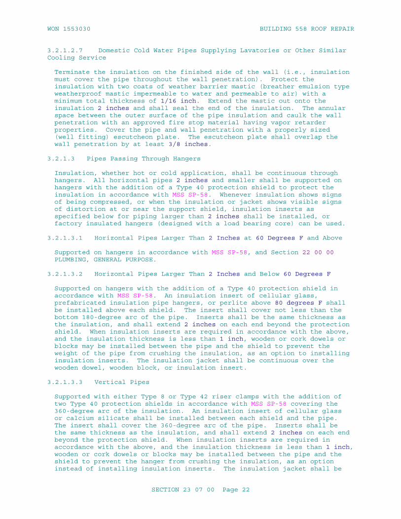
WON 1553030 BUILDING 558 ROOF REPAIR
3.2.1.2.7 Domestic Cold Water Pipes Supplying Lavatories or Other Similar Cooling Service
Terminate the insulation on the finished side of the wall (i.e., insulation must cover the pipe throughout the wall penetration). Protect the insulation with two coats of weather barrier mastic (breather emulsion type weatherproof mastic impermeable to water and permeable to air) with a minimum total thickness of 1/16 inch. Extend the mastic out onto the insulation 2 inches and shall seal the end of the insulation. The annular space between the outer surface of the pipe insulation and caulk the wall penetration with an approved fire stop material having vapor retarder properties. Cover the pipe and wall penetration with a properly sized (well fitting) escutcheon plate. The escutcheon plate shall overlap the wall penetration by at least 3/8 inches.
3.2.1.3 Pipes Passing Through Hangers
Insulation, whether hot or cold application, shall be continuous through hangers. All horizontal pipes 2 inches and smaller shall be supported on hangers with the addition of a Type 40 protection shield to protect the insulation in accordance with MSS SP-58. Whenever insulation shows signs of being compressed, or when the insulation or jacket shows visible signs of distortion at or near the support shield, insulation inserts as specified below for piping larger than 2 inches shall be installed, or factory insulated hangers (designed with a load bearing core) can be used.
3.2.1.3.1 Horizontal Pipes Larger Than 2 Inches at 60 Degrees F and Above
Supported on hangers in accordance with MSS SP-58, and Section 22 00 00 PLUMBING, GENERAL PURPOSE.
3.2.1.3.2 Horizontal Pipes Larger Than 2 Inches and Below 60 Degrees F
Supported on hangers with the addition of a Type 40 protection shield in accordance with MSS SP-58. An insulation insert of cellular glass, prefabricated insulation pipe hangers, or perlite above 80 degrees F shall be installed above each shield. The insert shall cover not less than the bottom 180-degree arc of the pipe. Inserts shall be the same thickness as the insulation, and shall extend 2 inches on each end beyond the protection shield. When insulation inserts are required in accordance with the above, and the insulation thickness is less than 1 inch, wooden or cork dowels or blocks may be installed between the pipe and the shield to prevent the weight of the pipe from crushing the insulation, as an option to installing insulation inserts. The insulation jacket shall be continuous over the wooden dowel, wooden block, or insulation insert.
3.2.1.3.3 Vertical Pipes
Supported with either Type 8 or Type 42 riser clamps with the addition of two Type 40 protection shields in accordance with MSS SP-58 covering the 360-degree arc of the insulation. An insulation insert of cellular glass or calcium silicate shall be installed between each shield and the pipe. The insert shall cover the 360-degree arc of the pipe. Inserts shall be the same thickness as the insulation, and shall extend 2 inches on each end beyond the protection shield. When insulation inserts are required in accordance with the above, and the insulation thickness is less than 1 inch, wooden or cork dowels or blocks may be installed between the pipe and the shield to prevent the hanger from crushing the insulation, as an option instead of installing insulation inserts. The insulation jacket shall be
SECTION 23 07 00 Page 22
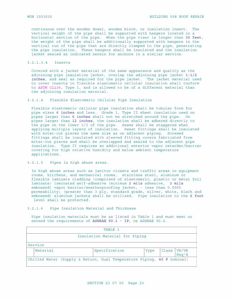
WON 1553030 BUILDING 558 ROOF REPAIR
continuous over the wooden dowel, wooden block, or insulation insert. The vertical weight of the pipe shall be supported with hangers located in a horizontal section of the pipe. When the pipe riser is longer than 30 feet, the weight of the pipe shall be additionally supported with hangers in the vertical run of the pipe that are directly clamped to the pipe, penetrating the pipe insulation. These hangers shall be insulated and the insulation jacket sealed as indicated herein for anchors in a similar service.
3.2.1.3.4 Inserts
Covered with a jacket material of the same appearance and quality as the adjoining pipe insulation jacket, overlap the adjoining pipe jacket 1-1/2 inches, and seal as required for the pipe jacket. The jacket material used to cover inserts in flexible elastomeric cellular insulation shall conform to ASTM C1136, Type 1, and is allowed to be of a different material than the adjoining insulation material.
3.2.1.4 Flexible Elastomeric Cellular Pipe Insulation
Flexible elastomeric cellular pipe insulation shall be tubular form for pipe sizes 6 inches and less. Grade 1, Type II sheet insulation used on pipes larger than 6 inches shall not be stretched around the pipe. On pipes larger than 12 inches, the insulation shall be adhered directly to the pipe on the lower 1/3 of the pipe. Seams shall be staggered when applying multiple layers of insulation. Sweat fittings shall be insulated with miter-cut pieces the same size as on adjacent piping. Screwed fittings shall be insulated with sleeved fitting covers fabricated from miter-cut pieces and shall be overlapped and sealed to the adjacent pipe insulation. Type II requires an additional exterior vapor retarder/barrier covering for high relative humidity and below ambient temperature applications.
3.2.1.5 Pipes in high abuse areas.
In high abuse areas such as janitor closets and traffic areas in equipment rooms, kitchens, and mechanical rooms, stainless steel, aluminum or flexible laminate cladding (comprised of elastomeric, plastic or metal foil laminate) laminated self-adhesive (minimum 2 mils adhesive, 3 mils embossed) vapor barrier/weatherproofing jacket, - less than 0.0000 permeability; (greater than 3 ply, standard grade, silver, white, black and embossed) aluminum jackets shall be utilized. Pipe insulation to the 6 foot level shall be protected.
3.2.1.6 Pipe Insulation Material and Thickness
Pipe insulation materials must be as listed in Table 1 and must meet or exceed the requirements of ASHRAE 90.1 - IP, or ASHRAE 90.2.
TABLE 1
Insulation Material for Piping
Service
Material Specification Type Class VR/VB Req'd
Chilled Water (Supply & Return, Dual Temperature Piping, 40 F nominal)
SECTION 23 07 00 Page 23

WON 1553030 BUILDING 558 ROOF REPAIR
TABLE 1
Insulation Material for Piping
Service
Material Specification Type Class VR/VB Req'd
Cellular Glass ASTM C552 II 2 Yes
Flexible Elastomeric Cellular
ASTM C534/C534M I Yes
[Mineral Fiber with Wicking Material][Do not use in applications exposed to outdoor ambient conditions in climatic zones 1 through 4.]
[ASTM C547] [I] [Yes]
Heating Hot Water Supply & Return, Heated Oil (Max 250 F)
Mineral Fiber ASTM C547 I 1 No
Calcium Silicate ASTM C533 I No
Cellular Glass ASTM C552 II 2 No
Faced Phenolic Foam ASTM C1126 III Yes
Perlite ASTM C610 No
Flexible Elastomeric Cellular
ASTM C534/C534M I 2 No
Cold Domestic Water Piping, Makeup Water & Drinking Fountain Drain Piping
Cellular Glass ASTM C552 II 2 NoFlexible Elastomeric Cellular
ASTM C534/C534M I No
Hot Domestic Water Supply & Recirculating Piping (Max 200 F)
Mineral Fiber ASTM C547 I 1 No
Cellular Glass ASTM C552 II 2 No
Flexible Elastomeric Cellular
ASTM C534/C534M I No
Faced Phenolic Foam ASTM C1126 III Yes
Refrigerant Suction Piping (35 degrees F nominal)
Flexible Elastomeric Cellular
ASTM C534/C534M I No
Cellular Glass ASTM C552 II 1 Yes
Compressed Air Discharge, Steam and Condensate Return (201 to 250 Degrees F
Cellular Glass ASTM C552 II No
Mineral Fiber ASTM C547 I 1 No
SECTION 23 07 00 Page 24

WON 1553030 BUILDING 558 ROOF REPAIR
TABLE 1
Insulation Material for Piping
Service
Material Specification Type Class VR/VB Req'd
Calcium Silicate ASTM C533 I No
Faced Phenolic Foam ASTM C1126 III Yes
Perlite ASTM C610 No
Flexible Elastomeric Cellular
ASTM C534/C534M I 2 No
Exposed Lavatory Drains, Exposed Domestic Water Piping & Drains to Areas for Handicapped Personnel
Flexible Elastomeric Cellular
ASTM C534/C534M I No
Horizontal Roof Drain Leaders (Including Underside of Roof Drain Fittings)
Flexible Elastomeric Cellular
ASTM C534/C534M I No
Faced Phenolic Foam ASTM C1126 III Yes
Cellular Glass ASTM C552 III Yes
Condensate Drain Located Inside Building
Cellular Glass ASTM C552 II 2 NoFlexible Elastomeric Cellular
ASTM C534/C534M I No
Medium Temperature Hot Water, Steam and Condensate (251 to 350 Degrees F)
Mineral Fiber ASTM C547 I 1 No
Calcium Silicate ASTM C533 I No
Cellular Glass ASTM C552 I or II
No
Perlite ASTM C610 No
Flexible Elastomeric Cellular
ASTM C534/C534M I 2 No
High Temperature Hot Water & Steam (351 to 700 Degrees F)
Mineral Fiber ASTM C547 I 2 No
Calcium Silicate ASTM C533 I NoPerlite ASTM C610 No
Cellular Glass ASTM C552 No
Brine Systems Cryogenics (-30 to 0 Degrees F)
Cellular Glass ASTM C552 II 2 No
SECTION 23 07 00 Page 25

WON 1553030 BUILDING 558 ROOF REPAIR
TABLE 1
Insulation Material for Piping
Service
Material Specification Type Class VR/VB Req'd
Flexible Elastomeric Cellular
ASTM C534/C534M I No
Brine Systems Cryogenics (0 to 34 Degrees F)
Cellular Glass ASTM C552 II 2 No
Flexible Elastomeric Cellular
ASTM C534/C534M I No
Note: VR/VB = Vapor Retarder/Vapor Barrier
TABLE 2
Piping Insulation Thickness (inch) Do not use integral wicking material in Chilled water applicationsexposed to outdoor ambient conditions in climatic zones 1 through 4.
Service
Material Tube And Pipe Size (inch)
<1 1-<1.5 1.5-<4 4-<8 > or = >8
[Chilled Water (Supply & Return, Dual Temperature Piping, 40 Degrees F nominal)]
Cellular Glass 1.5 2 2 2.5 3
Mineral Fiber with Wicking Material
1 1.5 1.5 2 2
Flexible Elastomeric Cellular
1 1 1 N/A N/A
[Chilled Water (Supply & Return, Dual Temperature Piping, 40 Degrees F nominal)]
Cellular Glass 1.5 1.5 1.5 1.5 2
Flexible Elastomeric Cellular
1 1 1 N/A N/A
Mineral Fiber with Wicking Material
1 1.5 1.5 2 2
Heating Hot Water Supply & Return, Heated Oil (Max 250 F)
Mineral Fiber 1.5 1.5 2 2 2
SECTION 23 07 00 Page 26

WON 1553030 BUILDING 558 ROOF REPAIR
TABLE 2
Calcium Silicate 2.5 2.5 3 3 3
Cellular Glass 2 2.5 3 3 3
Perlite 2.5 2.5 3 3 3
Flexible Elastomeric Cellular
1 1 1 N/A N/A
Cold Domestic Water Piping, Makeup Water & Drinking Fountain Drain Piping
Cellular Glass 1.5 1.5 1.5 1.5 1.5
Flexible Elastomeric Cellular
1 1 1 N/A N/A
Hot Domestic Water Supply & Recirculating Piping (Max 200 F)
Mineral Fiber 1 1 1 1.5 1.5
Cellular Glass 1.5 1.5 1.5 2 2
Flexible Elastomeric Cellular
1 1 1 N/A N/A
Refrigerant Suction Piping (35 degrees F nominal)
Flexible Elastomeric Cellular
1 1 1 N/A N/A
Cellular Glass 1.5 1.5 1.5 1.5 1.5
Compressed Air Discharge, Steam and Condensate Return (201 to 250 Degrees F
Mineral Fiber 1.5 1.5 2 2 2
1.5* 2* 2.5* 3* 3.5*
Calcium Silicate 2.5 3 4 4 4.5
Cellular Glass 2 2.5 3 3 3
Perlite 2.5 3 4 4 4.5
Flexible Elastomeric Cellular
1 1 1 N/A N/A
Exposed Lavatory Drains, Exposed Domestic Water Piping & Drains to Areas for Handicapped Personnel
Flexible Elastomeric Cellular
0.5 0.5 0.5 0.5 0.5
Horizontal Roof Drain Leaders (Including Underside of Roof Drain Fittings)
Cellular Glass 1.5 1.5 1.5 1.5 1.5
Flexible Elastomeric Cellular
1 1 1 N/A N/A
SECTION 23 07 00 Page 27

WON 1553030 BUILDING 558 ROOF REPAIR
TABLE 2
Faced Phenolic Foam 1 1 1 1 1
Condensate Drain Located Inside Building
Cellular Glass 1.5 1.5 1.5 1.5 1.5
Flexible Elastomeric Cellular
1 1 1 N/A N/A
Medium Temperature Hot Water, Steam and Condensate (251 to 350 Degrees F)
Mineral Fiber 1.5 3 3 4 4
2.5* * 3.5*
Calcium Silicate 2.5 3.5 4.5 4.5 5
Perlite 2.5 3.5 4.5 4.5 5
Flexible Elastomeric Cellular
1 1 1 N/A N/A
High Temperature Hot Water & Steam (351 to 700 Degrees F)
Mineral Fiber 2.5 3 3 4 4
Calcium Silicate 4 4.5 6 6 6
Perlite 4 4.5 6 6 6
Brine Systems Cryogenics (-30 to 0 Degrees F)
Cellular Glass 2.5 2.5 3 3 3.5
Flexible Elastomeric Cellular
1 1 N/A N/A N/A
Brine Systems Cryogenics (0 to 34 Degrees F)
Cellular Glass 2 2 2 2.5 3
Flexible Elastomeric Cellular
1 1 1 N/A N/A
3.2.2 Aboveground Cold Pipelines
The following cold pipelines for minus 30 to plus 60 degrees F, shall be insulated in accordance with Table 2 except those piping listed in subparagraph Pipe Insulation in PART 3 as to be omitted. This includes but is not limited to the following:
a. Make-up water.
b. Horizontal and vertical portions of interior roof drains.
c. Refrigerant suction lines.
SECTION 23 07 00 Page 28
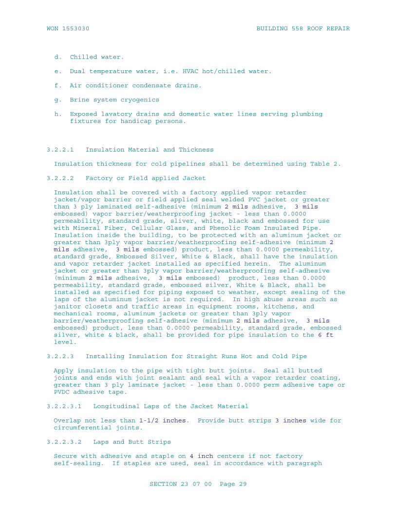
WON 1553030 BUILDING 558 ROOF REPAIR
d. Chilled water.
e. Dual temperature water, i.e. HVAC hot/chilled water.
f. Air conditioner condensate drains.
g. Brine system cryogenics
h. Exposed lavatory drains and domestic water lines serving plumbing fixtures for handicap persons.
3.2.2.1 Insulation Material and Thickness
Insulation thickness for cold pipelines shall be determined using Table 2.
3.2.2.2 Factory or Field applied Jacket
Insulation shall be covered with a factory applied vapor retarder jacket/vapor barrier or field applied seal welded PVC jacket or greater than 3 ply laminated self-adhesive (minimum 2 mils adhesive, 3 mils embossed) vapor barrier/weatherproofing jacket - less than 0.0000 permeability, standard grade, sliver, white, black and embossed for use with Mineral Fiber, Cellular Glass, and Phenolic Foam Insulated Pipe. Insulation inside the building, to be protected with an aluminum jacket or greater than 3ply vapor barrier/weatherproofing self-adhesive (minimum 2 mils adhesive, 3 mils embossed) product, less than 0.0000 permeability, standard grade, Embossed Silver, White & Black, shall have the insulation and vapor retarder jacket installed as specified herein. The aluminum jacket or greater than 3ply vapor barrier/weatherproofing self-adhesive (minimum 2 mils adhesive, 3 mils embossed) product, less than 0.0000 permeability, standard grade, embossed silver, White & Black, shall be installed as specified for piping exposed to weather, except sealing of the laps of the aluminum jacket is not required. In high abuse areas such as janitor closets and traffic areas in equipment rooms, kitchens, and mechanical rooms, aluminum jackets or greater than 3ply vapor barrier/weatherproofing self-adhesive (minimum 2 mils adhesive, 3 mils embossed) product, less than 0.0000 permeability, standard grade, embossed silver, white & black, shall be provided for pipe insulation to the 6 ft level.
3.2.2.3 Installing Insulation for Straight Runs Hot and Cold Pipe
Apply insulation to the pipe with tight butt joints. Seal all butted joints and ends with joint sealant and seal with a vapor retarder coating, greater than 3 ply laminate jacket - less than 0.0000 perm adhesive tape or PVDC adhesive tape.
3.2.2.3.1 Longitudinal Laps of the Jacket Material
Overlap not less than 1-1/2 inches. Provide butt strips 3 inches wide for circumferential joints.
3.2.2.3.2 Laps and Butt Strips
Secure with adhesive and staple on 4 inch centers if not factory self-sealing. If staples are used, seal in accordance with paragraph
SECTION 23 07 00 Page 29

WON 1553030 BUILDING 558 ROOF REPAIR
STAPLES below. Note that staples are not required with cellular glass systems.
3.2.2.3.3 Factory Self-Sealing Lap Systems
May be used when the ambient temperature is between 40 and 120 degrees F during installation. Install the lap system in accordance with manufacturer's recommendations. Use a stapler only if specifically recommended by the manufacturer. Where gaps occur, replace the section or repair the gap by applying adhesive under the lap and then stapling.
3.2.2.3.4 Staples
Coat all staples, including those used to repair factory self-seal lap systems, with a vapor retarder coating or PVDC adhesive tape or greater than 3 ply laminate jacket - less than 0.0000 perm adhesive tape. Coat all seams, except those on factory self-seal systems, with vapor retarder coating or PVDC adhesive tape or greater than 3 ply laminate jacket - less than 0.0000 perm adhesive tape.
3.2.2.3.5 Breaks and Punctures in the Jacket Material
Patch by wrapping a strip of jacket material around the pipe and secure it with adhesive, staple, and coat with vapor retarder coating or PVDC adhesive tape or greater than 3 ply laminate jacket - less than 0.0000 perm adhesive tape. Extend the patch not less than 1-1/2 inches past the break.
3.2.2.3.6 Penetrations Such as Thermometers
Fill the voids in the insulation and seal with vapor retarder coating or PVDC adhesive tape or greater than 3 ply laminate jacket - less than 0.0000 perm adhesive tape.
3.2.2.3.7 Flexible Elastomeric Cellular Pipe Insulation
Install by slitting the tubular sections and applying them onto the piping or tubing. Alternately, whenever possible slide un-slit sections over the open ends of piping or tubing. Secure all seams and butt joints and seal with adhesive. When using self seal products only the butt joints shall be secured with adhesive. Push insulation on the pipe, never pulled. Stretching of insulation may result in open seams and joints. Clean cut all edges. Rough or jagged edges of the insulation are not be permitted. Use proper tools such as sharp knives. Do not stretch Grade 1, Type II sheet insulation around the pipe when used on pipe larger than 6 inches. On pipes larger than 12 inches, adhere sheet insulation directly to the pipe on the lower 1/3 of the pipe.
3.2.2.4 Insulation for Fittings and Accessories
a. Pipe insulation shall be tightly butted to the insulation of the fittings and accessories. The butted joints and ends shall be sealed with joint sealant and sealed with a vapor retarder coating or PVDC adhesive tape or greater than 3 ply laminate jacket - less than 0.0000 perm adhesive tape.
b. Precut or preformed insulation shall be placed around all fittings and accessories and shall conform to MICA plates except as modified herein: 5 for anchors; 10, 11, and 13 for fittings; 14 for valves; and 17 for flanges and unions. Insulation shall be the same insulation as
SECTION 23 07 00 Page 30

WON 1553030 BUILDING 558 ROOF REPAIR
the pipe insulation, including same density, thickness, and thermal conductivity. Where precut/preformed is unavailable, rigid preformed pipe insulation sections may be segmented into the shape required. Insulation of the same thickness and conductivity as the adjoining pipe insulation shall be used. If nesting size insulation is used, the insulation shall be overlapped 2 inches or one pipe diameter. Elbows insulated using segments shall conform to MICA Tables 12.20 "Mitered Insulation Elbow'. Submit a booklet containing completed MICA Insulation Stds plates detailing each insulating system for each pipe, duct, or equipment insulating system, after approval of materials and prior to applying insulation.
(1) The MICA plates shall detail the materials to be installed and the specific insulation application. Submit all MICA plates required showing the entire insulating system, including plates required to show insulation penetrations, vessel bottom and top heads, legs, and skirt insulation as applicable. The MICA plates shall present all variations of insulation systems including locations, materials, vaporproofing, jackets and insulation accessories.
(2) If the Contractor elects to submit detailed drawings instead of edited MICA Plates, the detail drawings shall be technically equivalent to the edited MICA Plate submittal.
c. Upon completion of insulation installation on flanges, unions, valves, anchors, fittings and accessories, terminations, seams, joints and insulation not protected by factory vapor retarder jackets or PVC fitting covers shall be protected with PVDC or greater than 3 ply laminate jacket - less than 0.0000 perm adhesive tape or two coats of vapor retarder coating with a minimum total thickness of 1/16 inch, applied with glass tape embedded between coats. Tape seams shall overlap 1 inch. The coating shall extend out onto the adjoining pipe insulation 2 inches. Fabricated insulation with a factory vapor retarder jacket shall be protected with either greater than 3 ply laminate jacket - less than 0.0000 perm adhesive tape, standard grade, silver, white, black and embossed or PVDC adhesive tape or two coats of vapor retarder coating with a minimum thickness of 1/16 inch and with a 2 inch wide glass tape embedded between coats. Where fitting insulation butts to pipe insulation, the joints shall be sealed with a vapor retarder coating and a 4 inch wide ASJ tape which matches the jacket of the pipe insulation.
d. Anchors attached directly to the pipe shall be insulated for a sufficient distance to prevent condensation but not less than 6 inches from the insulation surface.
e. Insulation shall be marked showing the location of unions, strainers, and check valves.
3.2.2.5 Optional PVC Fitting Covers
At the option of the Contractor, premolded, one or two piece PVC fitting covers may be used in lieu of the vapor retarder and embedded glass tape. Factory precut or premolded insulation segments shall be used under the fitting covers for elbows. Insulation segments shall be the same insulation as the pipe insulation including same density, thickness, and thermal conductivity. The covers shall be secured by PVC vapor retarder tape, adhesive, seal welding or with tacks made for securing PVC covers.
SECTION 23 07 00 Page 31

WON 1553030 BUILDING 558 ROOF REPAIR
Seams in the cover, and tacks and laps to adjoining pipe insulation jacket, shall be sealed with vapor retarder tape to ensure that the assembly has a continuous vapor seal.
3.2.3 Aboveground Hot Pipelines
3.2.3.1 General Requirements
All hot pipe lines above 60 degrees F, except those piping listed in subparagraph Pipe Insulation in PART 3 as to be omitted, shall be insulated in accordance with Table 2. This includes but is not limited to the following:
a. Domestic hot water supply & re-circulating system.
b. Steam.
c. Condensate & compressed air discharge.
d. Hot water heating.
e. Heated oil.
f. Water defrost lines in refrigerated rooms.
Insulation shall be covered, in accordance with manufacturer's recommendations, with a factory applied Type I jacket or field applied aluminum where required or seal welded PVC.
3.2.3.2 Insulation for Fittings and Accessories
Pipe insulation shall be tightly butted to the insulation of the fittings and accessories. The butted joints and ends shall be sealed with joint sealant. Insulation shall be marked showing the location of unions, strainers, check valves and other components that would otherwise be hidden from view by the insulation.
3.2.3.2.1 Precut or Preformed
Place precut or preformed insulation around all fittings and accessories. Insulation shall be the same insulation as the pipe insulation, including same density, thickness, and thermal conductivity.
3.2.3.2.2 Rigid Preformed
Where precut/preformed is unavailable, rigid preformed pipe insulation sections may be segmented into the shape required. Insulation of the same thickness and conductivity as the adjoining pipe insulation shall be used. If nesting size insulation is used, the insulation shall be overlapped 2 inches or one pipe diameter. Elbows insulated using segments shall conform to MICA Tables 12.20 "Mitered Insulation Elbow".
3.2.4 Piping Exposed to Weather
Piping exposed to weather shall be insulated and jacketed as specified for the applicable service inside the building. After this procedure, a laminated self-adhesive (minimum 2 mils adhesive, 3 mils embossed) vapor barrier/weatherproofing jacket - less than 0.0000 permeability (greater than 3 ply, standard grade, silver, white, black and embossed aluminum
SECTION 23 07 00 Page 32

WON 1553030 BUILDING 558 ROOF REPAIR
jacket or PVC jacket shall be applied. PVC jacketing requires no factory-applied jacket beneath it, however an all service jacket shall be applied if factory applied jacketing is not furnished. Flexible elastomeric cellular insulation exposed to weather shall be treated in accordance with paragraph INSTALLATION OF FLEXIBLE ELASTOMERIC CELLULAR INSULATION in PART 3.
3.2.4.1 Aluminum Jacket
The jacket for hot piping may be factory applied. The jacket shall overlap not less than 2 inches at longitudinal and circumferential joints and shall be secured with bands at not more than 12 inch centers. Longitudinal joints shall be overlapped down to shed water and located at 4 or 8 o'clock positions. Joints on piping 60 degrees F and below shall be sealed with metal jacketing/flashing sealant while overlapping to prevent moisture penetration. Where jacketing on piping 60 degrees F and below abuts an un-insulated surface, joints shall be caulked to prevent moisture penetration. Joints on piping above 60 degrees F shall be sealed with a moisture retarder.
3.2.4.2 Insulation for Fittings
Flanges, unions, valves, fittings, and accessories shall be insulated and finished as specified for the applicable service. Two coats of breather emulsion type weatherproof mastic (impermeable to water, permeable to air) recommended by the insulation manufacturer shall be applied with glass tape embedded between coats. Tape overlaps shall be not less than 1 inch and the adjoining aluminum jacket not less than 2 inches. Factory preformed aluminum jackets may be used in lieu of the above. Molded PVC fitting covers shall be provided when PVC jackets are used for straight runs of pipe. PVC fitting covers shall have adhesive welded joints and shall be weatherproof laminated self-adhesive (minimum 2 mils adhesive, 3 mils embossed) vapor barrier/weatherproofing jacket - less than 0.0000 permeability, (greater than 3 ply, standard grade, silver, white, black and embossed, and UV resistant.
3.2.4.3 PVC Jacket
PVC jacket shall be ultraviolet resistant and adhesive welded weather tight with manufacturer's recommended adhesive. Installation shall include provision for thermal expansion.
3.2.5 Below Ground Pipe Insulation
Below ground pipes shall be insulated in accordance with Table 2, except as precluded in subparagraph Pipe Insulation in PART 3. This includes, but is not limited to the following:
a. Heated oil.
b. Domestic hot water.
c. Heating hot water.
d. Dual temperature water.
e. Steam.
f. Condensate.
SECTION 23 07 00 Page 33

WON 1553030 BUILDING 558 ROOF REPAIR
3.2.5.1 Type of Insulation
Below ground pipe shall be insulated with Cellular Glass insulation, in accordance with manufacturer's instructions for application with thickness as determined from Table 2 (whichever is the most restrictive).
3.2.5.2 Installation of Below ground Pipe Insulation
a. Bore surfaces of the insulation shall be coated with a thin coat of gypsum cement of a type recommended by the insulation manufacturer. Coating thickness shall be sufficient to fill surface cells of insulation. Mastic type materials shall not be used for this coating. Note that unless this is for a cyclic application (i.e., one that fluctuates between high and low temperature on a daily process basis) there is no need to bore coat the material.
b. Stainless steel bands, 3/4 inch wide by 0.020 inch thick shall be used to secure insulation in place. A minimum of two bands per section of insulation shall be applied. As an alternate, fiberglass reinforced tape may be used to secure insulation on piping up to 12 inches in diameter. A minimum of two bands per section of insulation shall be applied.
c. Insulation shall terminate at anchor blocks but shall be continuous through sleeves and manholes.
d. At point of entry to buildings, underground insulation shall be terminated 2 inches inside the wall or floor, shall butt tightly against the aboveground insulation and the butt joint shall be sealed with high temperature silicone sealant and covered with fibrous glass tape.
e. Provision for expansion and contraction of the insulation system shall be made in accordance with the insulation manufacturer's recommendations.
f. Flanges, couplings, valves, and fittings shall be insulated with factory pre-molded, prefabricated, or field-fabricated sections of insulation of the same material and thickness as the adjoining pipe insulation. Insulation sections shall be secured as recommended by the manufacturer.
g. Insulation, including fittings, shall be finished with three coats of asphaltic mastic, with 6 by 5.5 mesh synthetic reinforcing fabric embedded between coats. Fabric shall be overlapped a minimum of 2 inches at joints. Total film thickness shall be a minimum of 3/16 inch. As an alternate, a prefabricated bituminous laminated jacket, reinforced with internal reinforcement mesh, shall be applied to the insulation. Jacketing material and application procedures shall match manufacturer's written instructions. Vapor barrier - less than 0.0000 permeability self adhesive (minimum 2 mils adhesive, 3 mils embossed) jacket greater than 3 ply, standard grade, silver, white, black and embossed or greater than 8 ply (minimum 2.9 mils adhesive), heavy duty, white or natural). Application procedures shall match the manufacturer's written instructions.
h. At termination points, other than building entrances, the mastic and cloth or tape shall cover the ends of insulation and extend 2 inches
SECTION 23 07 00 Page 34

WON 1553030 BUILDING 558 ROOF REPAIR
along the bare pipe.
3.3 DUCT INSULATION SYSTEMS INSTALLATION
Except for oven hood exhaust duct insulation, corner angles shall be installed on external corners of insulation on ductwork in exposed finished spaces before covering with jacket. Duct insulation shall be omitted on exposed supply and return ducts in air conditioned spaces where the difference between supply air temperature and room air temperature is less than 15 degrees F unless otherwise shown. Air conditioned spaces shall be defined as those spaces directly supplied with cooled conditioned air (or provided with a cooling device such as a fan-coil unit) and heated conditioned air (or provided with a heating device such as a unit heater, radiator or convector).
3.3.1 Duct Insulation Minimum Thickness
Duct insulation minimum thickness in accordance with Table 4.
Table 4 - Minimum Duct Insulation (inches)
Cold Air Ducts 2.0
Relief Ducts 1.5
Fresh Air Intake Ducts 1.5
Warm Air Ducts 2.0
Relief Ducts 1.5
Fresh Air Intake Ducts 1.5
3.3.2 Insulation and Vapor Retarder/Vapor Barrier for Cold Air Duct
Insulation and vapor retarder/vapor barrier shall be provided for the following cold air ducts and associated equipment.
a. Supply ducts.
b. Return air ducts.
c. Relief ducts.
d. Flexible run-outs (field-insulated).
e. Plenums.
f. Duct-mounted coil casings.
g. Coil headers and return bends.
h. Coil casings.
i. Fresh air intake ducts.
SECTION 23 07 00 Page 35
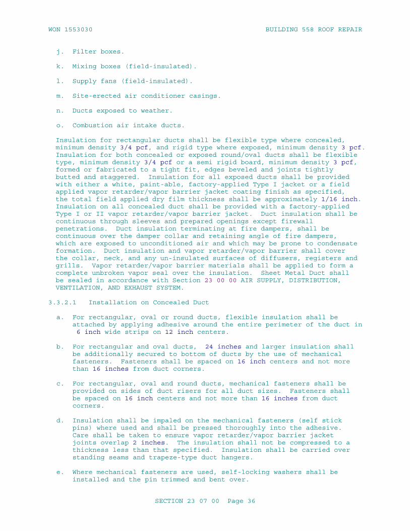
WON 1553030 BUILDING 558 ROOF REPAIR
j. Filter boxes.
k. Mixing boxes (field-insulated).
l. Supply fans (field-insulated).
m. Site-erected air conditioner casings.
n. Ducts exposed to weather.
o. Combustion air intake ducts.
Insulation for rectangular ducts shall be flexible type where concealed, minimum density 3/4 pcf, and rigid type where exposed, minimum density 3 pcf. Insulation for both concealed or exposed round/oval ducts shall be flexible type, minimum density 3/4 pcf or a semi rigid board, minimum density 3 pcf, formed or fabricated to a tight fit, edges beveled and joints tightly butted and staggered. Insulation for all exposed ducts shall be provided with either a white, paint-able, factory-applied Type I jacket or a field applied vapor retarder/vapor barrier jacket coating finish as specified, the total field applied dry film thickness shall be approximately 1/16 inch. Insulation on all concealed duct shall be provided with a factory-applied Type I or II vapor retarder/vapor barrier jacket. Duct insulation shall be continuous through sleeves and prepared openings except firewall penetrations. Duct insulation terminating at fire dampers, shall be continuous over the damper collar and retaining angle of fire dampers, which are exposed to unconditioned air and which may be prone to condensate formation. Duct insulation and vapor retarder/vapor barrier shall cover the collar, neck, and any un-insulated surfaces of diffusers, registers and grills. Vapor retarder/vapor barrier materials shall be applied to form a complete unbroken vapor seal over the insulation. Sheet Metal Duct shall be sealed in accordance with Section 23 00 00 AIR SUPPLY, DISTRIBUTION, VENTILATION, AND EXHAUST SYSTEM.
3.3.2.1 Installation on Concealed Duct
a. For rectangular, oval or round ducts, flexible insulation shall be attached by applying adhesive around the entire perimeter of the duct in 6 inch wide strips on 12 inch centers.
b. For rectangular and oval ducts, 24 inches and larger insulation shall be additionally secured to bottom of ducts by the use of mechanical fasteners. Fasteners shall be spaced on 16 inch centers and not more than 16 inches from duct corners.
c. For rectangular, oval and round ducts, mechanical fasteners shall be provided on sides of duct risers for all duct sizes. Fasteners shall be spaced on 16 inch centers and not more than 16 inches from duct corners.
d. Insulation shall be impaled on the mechanical fasteners (self stick pins) where used and shall be pressed thoroughly into the adhesive. Care shall be taken to ensure vapor retarder/vapor barrier jacket joints overlap 2 inches. The insulation shall not be compressed to a thickness less than that specified. Insulation shall be carried over standing seams and trapeze-type duct hangers.
e. Where mechanical fasteners are used, self-locking washers shall be installed and the pin trimmed and bent over.
SECTION 23 07 00 Page 36

WON 1553030 BUILDING 558 ROOF REPAIR
f. Jacket overlaps shall be secured with staples and tape as necessary to ensure a secure seal. Staples, tape and seams shall be coated with a brush coat of vapor retarder coating or PVDC adhesive tape or greater than 3 ply laminate (minimum 2 mils adhesive, 3 mils embossed) - less than 0.0000 perm adhesive tape.
g. Breaks in the jacket material shall be covered with patches of the same material as the vapor retarder jacket. The patches shall extend not less than 2 inches beyond the break or penetration in all directions and shall be secured with tape and staples. Staples and tape joints shall be sealed with a brush coat of vapor retarder coating or PVDC adhesive tape or greater than 3 ply laminate (minimum 2 mils adhesive, 3 mils embossed) - less than 0.0000 perm adhesive tape.
h. At jacket penetrations such as hangers, thermometers, and damper operating rods, voids in the insulation shall be filled and the penetration sealed with a brush coat of vapor retarder coating or PVDC adhesive tape greater than 3 ply laminate (minimum 2 mils adhesive, 3 mils embossed) - less than 0.0000 perm adhesive tape.
i. Insulation terminations and pin punctures shall be sealed and flashed with a reinforced vapor retarder coating finish or tape with a brush coat of vapor retarder coating.. The coating shall overlap the adjoining insulation and un-insulated surface 2 inches. Pin puncture coatings shall extend 2 inches from the puncture in all directions.
j. Where insulation standoff brackets occur, insulation shall be extended under the bracket and the jacket terminated at the bracket.
3.3.2.2 Installation on Exposed Duct Work
a. For rectangular ducts, rigid insulation shall be secured to the duct by mechanical fasteners on all four sides of the duct, spaced not more than 12 inches apart and not more than 3 inches from the edges of the insulation joints. A minimum of two rows of fasteners shall be provided for each side of duct 12 inches and larger. One row shall be provided for each side of duct less than 12 inches. Mechanical fasteners shall be as corrosion resistant as G60 coated galvanized steel, and shall indefinitely sustain a 50 lb tensile dead load test perpendicular to the duct wall.
b. Form duct insulation with minimum jacket seams. Fasten each piece of rigid insulation to the duct using mechanical fasteners. When the height of projections is less than the insulation thickness, insulation shall be brought up to standing seams, reinforcing, and other vertical projections and shall not be carried over. Vapor retarder/barrier jacket shall be continuous across seams, reinforcing, and projections. When height of projections is greater than the insulation thickness, insulation and jacket shall be carried over. Apply insulation with joints tightly butted. Neatly bevel insulation around name plates and access plates and doors.
c. Impale insulation on the fasteners; self-locking washers shall be installed and the pin trimmed and bent over.
d. Seal joints in the insulation jacket with a 4 inch wide strip of tape. Seal taped seams with a brush coat of vapor retarder coating.
SECTION 23 07 00 Page 37

WON 1553030 BUILDING 558 ROOF REPAIR
e. Breaks and ribs or standing seam penetrations in the jacket material shall be covered with a patch of the same material as the jacket. Patches shall extend not less than 2 inches beyond the break or penetration and shall be secured with tape and stapled. Staples and joints shall be sealed with a brush coat of vapor retarder coating.
f. At jacket penetrations such as hangers, thermometers, and damper operating rods, the voids in the insulation shall be filled and the penetrations sealed with a flashing sealant.
g. Insulation terminations and pin punctures shall be sealed and flashed with a reinforced vapor retarder coating finish. The coating shall overlap the adjoining insulation and un-insulated surface 2 inches. Pin puncture coatings shall extend 2 inches from the puncture in all directions.
h. Oval and round ducts, flexible type, shall be insulated with factory Type I jacket insulation with minimum density of 3/4 pcf, attached as in accordance with MICA standards.
3.3.3 Insulation for Warm Air Duct
Insulation and vapor barrier shall be provided for the following warm air ducts and associated equipment:.
a. Supply ducts.
b. Return air ducts.
c. Relief air ducts
d. Flexible run-outs (field insulated).
e. Plenums.
f. Duct-mounted coil casings.
g. Coil-headers and return bends.
h. Coil casings.
i. Fresh air intake ducts.
j. Filter boxes.
k. Mixing boxes.
l. Supply fans.
m. Site-erected air conditioner casings.
n. Ducts exposed to weather.
Insulation for rectangular ducts shall be flexible type where concealed, and rigid type where exposed. Insulation on exposed ducts shall be provided with a white, paint-able, factory-applied Type II jacket, or finished with adhesive finish. Flexible type insulation shall be used for round ducts, with a factory-applied Type II jacket. Insulation on concealed duct shall be provided with a factory-applied Type II jacket.
SECTION 23 07 00 Page 38

WON 1553030 BUILDING 558 ROOF REPAIR
Adhesive finish where indicated to be used shall be accomplished by applying two coats of adhesive with a layer of glass cloth embedded between the coats. The total dry film thickness shall be approximately 1/16 inch. Duct insulation shall be continuous through sleeves and prepared openings. Duct insulation shall terminate at fire dampers and flexible connections.
3.3.3.1 Installation on Concealed Duct
a. For rectangular, oval and round ducts, insulation shall be attached by applying adhesive around the entire perimeter of the duct in 6 inch wide strips on 12 inch centers.
b. For rectangular and oval ducts 24 inches and larger, insulation shall be secured to the bottom of ducts by the use of mechanical fasteners. Fasteners shall be spaced on 18 inch centers and not more than 18 inches from duct corner.
c. For rectangular, oval and round ducts, mechanical fasteners shall be provided on sides of duct risers for all duct sizes. Fasteners shall be spaced on 18 inch centers and not more than 18 inches from duct corners.
d. The insulation shall be impaled on the mechanical fasteners where used. The insulation shall not be compressed to a thickness less than that specified. Insulation shall be carried over standing seams and trapeze-type hangers.
e. Self-locking washers shall be installed where mechanical fasteners are used and the pin trimmed and bent over.
f. Insulation jacket shall overlap not less than 2 inches at joints and the lap shall be secured and stapled on 4 inch centers.
3.3.3.2 Installation on Exposed Duct
a. For rectangular ducts, the rigid insulation shall be secured to the duct by the use of mechanical fasteners on all four sides of the duct, spaced not more than 16 inches apart and not more than 6 inches from the edges of the insulation joints. A minimum of two rows of fasteners shall be provided for each side of duct 12 inches and larger and a minimum of one row for each side of duct less than 12 inches.
b. Duct insulation with factory-applied jacket shall be formed with minimum jacket seams, and each piece of rigid insulation shall be fastened to the duct using mechanical fasteners. When the height of projection is less than the insulation thickness, insulation shall be brought up to standing seams, reinforcing, and other vertical projections and shall not be carried over the projection. Jacket shall be continuous across seams, reinforcing, and projections. Where the height of projections is greater than the insulation thickness, insulation and jacket shall be carried over the projection.
c. Insulation shall be impaled on the fasteners; self-locking washers shall be installed and pin trimmed and bent over.
d. Joints on jacketed insulation shall be sealed with a 4 inch wide strip of tape and brushed with vapor retarder coating.
e. Breaks and penetrations in the jacket material shall be covered with a
SECTION 23 07 00 Page 39

WON 1553030 BUILDING 558 ROOF REPAIR
patch of the same material as the jacket. Patches shall extend not less than 2 inches beyond the break or penetration and shall be secured with adhesive and stapled.
f. Insulation terminations and pin punctures shall be sealed with tape and brushed with vapor retarder coating.
g. Oval and round ducts, flexible type, shall be insulated with factory Type I jacket insulation, minimum density of 3/4 pcf attached by staples spaced not more than 16 inches and not more than 6 inches from the degrees of joints. Joints shall be sealed in accordance with item "d." above.
3.3.4 Ducts Handling Air for Dual Purpose
For air handling ducts for dual purpose below and above 60 degrees F, ducts shall be insulated as specified for cold air duct.
3.3.5 Insulation for Evaporative Cooling Duct
Evaporative cooling supply duct located in spaces not evaporatively cooled, shall be insulated. Material and installation requirements shall be as specified for duct insulation for warm air duct.
3.3.6 Duct Test Holes
After duct systems have been tested, adjusted, and balanced, breaks in the insulation and jacket shall be repaired in accordance with the applicable section of this specification for the type of duct insulation to be repaired.
3.3.7 Duct Exposed to Weather
3.3.7.1 Installation
Ducts exposed to weather shall be insulated and finished as specified for the applicable service for exposed duct inside the building. After the above is accomplished, the insulation shall then be further finished as detailed in the following subparagraphs.
3.3.7.2 Round Duct
Laminated self-adhesive (minimum 2 mils adhesive, 3 mils embossed) vapor barrier/weatherproofing jacket - Less than 0.0000 permeability, (greater than 3 ply, standard grade, silver, white, black and embossed or greater than 8 ply, heavy duty, white and natural) membrane shall be applied overlapping material by 3 inches no bands or caulking needed - see manufacturer's recommended installation instructions. Aluminum jacket with factory applied moisture retarder shall be applied with the joints lapped not less than 3 inches and secured with bands located at circumferential laps and at not more than 12 inch intervals throughout. Horizontal joints shall lap down to shed water and located at 4 or 8 o'clock position. Joints shall be sealed with metal jacketing sealant to prevent moisture penetration. Where jacketing abuts an un-insulated surface, joints shall be sealed with metal jacketing sealant.
3.3.7.3 Fittings
Fittings and other irregular shapes shall be finished as specified for
SECTION 23 07 00 Page 40

WON 1553030 BUILDING 558 ROOF REPAIR
rectangular ducts.
3.3.7.4 Rectangular Ducts
Two coats of weather barrier mastic reinforced with fabric or mesh for outdoor application shall be applied to the entire surface. Each coat of weatherproof mastic shall be 1/16 inch minimum thickness. The exterior shall be a metal jacketing applied for mechanical abuse and weather protection, and secured with screws or vapor barrier/weatherproofing jacket less than 0.0000 permeability greater than 3 ply, standard grade, silver, white, black, and embossed or greater than 8 ply, heavy duty white and natural. Membrane shall be applied overlapping material by 3 inches. No bands or caulking needed-see manufacturing recommend installation instructions.
3.4 EQUIPMENT INSULATION SYSTEMS INSTALLATION
3.4.1 General
Removable insulation sections shall be provided to cover parts of equipment that must be opened periodically for maintenance including vessel covers, fasteners, flanges and accessories. Equipment insulation shall be omitted on the following:
a. Hand-holes.
b. Boiler manholes.
c. Cleanouts.
d. ASME stamps.
e. Manufacturer's nameplates.
f. Duct Test/Balance Test Holes.
3.4.2 Insulation for Cold Equipment
Cold equipment below 60 degrees F: Insulation shall be furnished on equipment handling media below 60 degrees F including the following:
a. Pumps.
b. Refrigeration equipment parts that are not factory insulated.
c. Drip pans under chilled equipment.
d. Cold water storage tanks.
e. Water softeners.
f. Duct mounted coils.
g. Cold and chilled water pumps.
h. Pneumatic water tanks.
i. Roof drain bodies.
SECTION 23 07 00 Page 41

WON 1553030 BUILDING 558 ROOF REPAIR
j. Air handling equipment parts that are not factory insulated.
k. Expansion and air separation tanks.
3.4.2.1 Insulation Type
Insulation shall be suitable for the temperature encountered. Material and thicknesses shall be as shown in Table 5:
TABLE 5
Insulation Thickness for Cold Equipment (inches)
Equipment handling media at indicated temperature
Material Thickness (inches)
35 to 60 degrees F
Cellular Glass 1.5
Flexible Elastomeric Cellular 1
1 to 34 degrees F
Cellular Glass 3
Flexible Elastomeric Cellular 1.5
Minus 30 to 0 degrees F
Cellular Glass 3.5
Flexible Elastomeric Cellular 1.75
3.4.2.2 Pump Insulation
a. Insulate pumps by forming a box around the pump housing. The box shall be constructed by forming the bottom and sides using joints that do not leave raw ends of insulation exposed. Joints between sides and between sides and bottom shall be joined by adhesive with lap strips for rigid mineral fiber and contact adhesive for flexible elastomeric cellular insulation. The box shall conform to the requirements of MICA Insulation Stds plate No. 49 when using flexible elastomeric cellular insulation. Joints between top cover and sides shall fit tightly forming a female shiplap joint on the side pieces and a male joint on the top cover, thus making the top cover removable.
b. Exposed insulation corners shall be protected with corner angles.
c. Upon completion of installation of the insulation, including removable sections, two coats of vapor retarder coating shall be applied with a layer of glass cloth embedded between the coats. The total dry thickness of the finish shall be 1/16 inch. A parting line shall be provided between the box and the removable sections allowing the removable sections to be removed without disturbing the insulation coating. Flashing sealant shall be applied to parting line, between
SECTION 23 07 00 Page 42

WON 1553030 BUILDING 558 ROOF REPAIR
equipment and removable section insulation, and at all penetrations.
3.4.2.3 Other Equipment
a. Insulation shall be formed or fabricated to fit the equipment. To ensure a tight fit on round equipment, edges shall be beveled and joints shall be tightly butted and staggered.
b. Insulation shall be secured in place with bands or wires at intervals as recommended by the manufacturer but not more than 12 inch centers except flexible elastomeric cellular which shall be adhered with contact adhesive. Insulation corners shall be protected under wires and bands with suitable corner angles.
c. Cellular glass shall be installed in accordance with manufacturer's instructions. Joints and ends shall be sealed with joint sealant, and sealed with a vapor retarder coating.
d. Insulation on heads of heat exchangers shall be removable. Removable section joints shall be fabricated using a male-female shiplap type joint. The entire surface of the removable section shall be finished by applying two coats of vapor retarder coating with a layer of glass cloth embedded between the coats. The total dry thickness of the finish shall be 1/16 inch.
e. Exposed insulation corners shall be protected with corner angles.
f. Insulation on equipment with ribs shall be applied over 6 by 6 inches by 12 gauge welded wire fabric which has been cinched in place, or if approved by the Contracting Officer, spot welded to the equipment over the ribs. Insulation shall be secured to the fabric with J-hooks and 2 by 2 inches washers or shall be securely banded or wired in place on 12 inch centers.
3.4.2.4 Vapor Retarder/Vapor Barrier
Upon completion of installation of insulation, penetrations shall be caulked. Two coats of vapor retarder coating or vapor barrier jacket shall be applied over insulation, including removable sections, with a layer of open mesh synthetic fabric embedded between the coats. The total dry thickness of the finish shall be 1/16 inch. Flashing sealant or vapor barrier tape shall be applied to parting line between equipment and removable section insulation.
3.4.3 Insulation for Hot Equipment
Insulation shall be furnished on equipment handling media above 60 degrees F including the following:
a. Converters.
b. Heat exchangers.
c. Hot water generators.
d. Water heaters.
e. Pumps handling media above 130 degrees F.
SECTION 23 07 00 Page 43
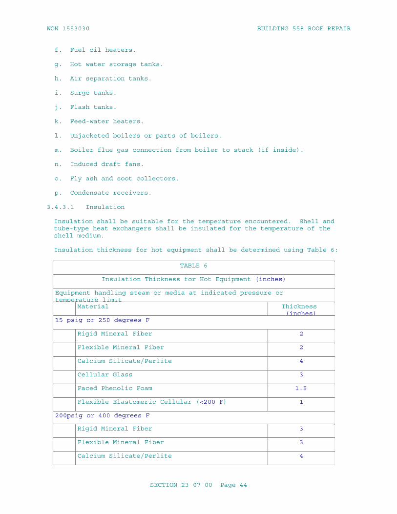
WON 1553030 BUILDING 558 ROOF REPAIR
f. Fuel oil heaters.
g. Hot water storage tanks.
h. Air separation tanks.
i. Surge tanks.
j. Flash tanks.
k. Feed-water heaters.
l. Unjacketed boilers or parts of boilers.
m. Boiler flue gas connection from boiler to stack (if inside).
n. Induced draft fans.
o. Fly ash and soot collectors.
p. Condensate receivers.
3.4.3.1 Insulation
Insulation shall be suitable for the temperature encountered. Shell and tube-type heat exchangers shall be insulated for the temperature of the shell medium.
Insulation thickness for hot equipment shall be determined using Table 6:
TABLE 6
Insulation Thickness for Hot Equipment (inches)
Equipment handling steam or media at indicated pressure or temperature limit
Material Thickness (inches)
15 psig or 250 degrees F
Rigid Mineral Fiber 2
Flexible Mineral Fiber 2
Calcium Silicate/Perlite 4
Cellular Glass 3
Faced Phenolic Foam 1.5
Flexible Elastomeric Cellular (<200 F) 1
200psig or 400 degrees F
Rigid Mineral Fiber 3
Flexible Mineral Fiber 3
Calcium Silicate/Perlite 4
SECTION 23 07 00 Page 44

WON 1553030 BUILDING 558 ROOF REPAIR
TABLE 6
Insulation Thickness for Hot Equipment (inches)
Equipment handling steam or media at indicated pressure or temperature limit
Material Thickness (inches)
Cellular Glass 4
600 degrees F
Rigid Mineral Fiber 5
Flexible Mineral Fiber 6
Calcium Silicate/Perlite 6
Cellular Glass 6
600 degrees F: Thickness necessary to limit the external temperature of the insulation to 120 F. Heat transfer calculations shall be submitted to substantiate insulation and thickness selection.
3.4.3.2 Insulation of Boiler Stack and Diesel Engine Exhaust Pipe
Inside [boiler House] [mechanical Room], bevel insulation neatly around openings and provide sheet metal insulation stop strips around such openings. Apply a skim coat of hydraulic setting cement directly to insulation. Apply a flooding coat of adhesive over hydraulic setting cement, and while still wet, press a layer of glass cloth or tape into adhesive and seal laps and edges with adhesive. Coat glass cloth with adhesive. When dry, apply a finish coat of adhesive at can-consistency so that when dry no glass weave shall be observed. Provide metal jackets for [stacks] [and] [exhaust pipes] that are located above finished floor and spaces outside [boiler house] [mechanical room]. Apply metal jackets directly over insulation and secure with 3/4 inch wide metal bands spaced on 18 inch centers. Do not insulate name plates. Insulation type and thickness shall be in accordance with the following Table 7.
TABLE 7
Insulation and Thickness forBoiler Stack and Diesel Engine Exhaust Pipe
Service & Surface Temperature Range (Degrees F)
Material Outside Diameter (Inches)
SECTION 23 07 00 Page 45

WON 1553030 BUILDING 558 ROOF REPAIR
TABLE 7
0.25 -1.25
1 -1.67
3.5-5 6 - 10 > or = 11 - 36
Boiler Stack (Up to 400 degrees F)
Mineral FiberASTM C585 Class B-3,ASTM C547 Class 1, orASTM C612 Class 1
N/A N/A 3 3.5 4
Calcium SilicateASTM C533, Type 1
N/A N/A 3 3.5 4
Cellular GlassASTM C552, Type II
1.5 1.5 1.5 2 2.5
Boiler Stack (401 to 600 degrees F)
Mineral FiberASTM C547 Class 2,ASTM C592 Class 1, orASTM C612 Class 3
N/A N/A 4 4 5
Calcium SilicateASTM C533, Type I or II
N/A N/A 4 4 4
Mineral Fiber/Cellular Glass Composite:
Mineral FiberASTM C547 Class 2,ASTM C592 Class 1, orASTM C612 Class 3
1 1 1 1 2
Cellular GlassASTM C552, Type II
2 2 2 2 2
Boiler Stack (601 to 800 degrees F)
Mineral FiberASTM C547 Class 3,ASTM C592 Class 1, orASTM C612 Class 3
N/A N/A 4 4 6
SECTION 23 07 00 Page 46

WON 1553030 BUILDING 558 ROOF REPAIR
TABLE 7
Calcium SilicateASTM C533, Type I or II
N/A N/A 4 4 6
Mineral Fiber/Cellular Glass Composite:
Mineral FiberASTM C547 Class 2,ASTM C592 Class 1, orASTM C612 Class 3
2 2 2 3 3
Cellular GlassASTM C552, Type II
2 2 2 2 2
Diesel Engine Exhaust (Up to 700 degrees F)
Calcium SilicateASTM C533, Type I or II
3 3.5 4 4 4
Cellular GlassASTM C552, Type II
2.5 3.5 4 4.5 6
3.4.3.3 Insulation of Pumps
Insulate pumps by forming a box around the pump housing. The box shall be constructed by forming the bottom and sides using joints that do not leave raw ends of insulation exposed. Bottom and sides shall be banded to form a rigid housing that does not rest on the pump. Joints between top cover and sides shall fit tightly. The top cover shall have a joint forming a female shiplap joint on the side pieces and a male joint on the top cover, making the top cover removable. Two coats of Class I adhesive shall be applied over insulation, including removable sections, with a layer of glass cloth embedded between the coats. A parting line shall be provided between the box and the removable sections allowing the removable sections to be removed without disturbing the insulation coating. The total dry thickness of the finish shall be 1/16 inch. Caulking shall be applied to parting line of the removable sections and penetrations.
3.4.3.4 Other Equipment
a. Insulation shall be formed or fabricated to fit the equipment. To ensure a tight fit on round equipment, edges shall be beveled and joints shall be tightly butted and staggered.
b. Insulation shall be secured in place with bands or wires at intervals as recommended by the manufacturer but not greater than 12 inch centers except flexible elastomeric cellular which shall be adhered. Insulation corners shall be protected under wires and bands with suitable corner angles.
SECTION 23 07 00 Page 47

WON 1553030 BUILDING 558 ROOF REPAIR
c. On high vibration equipment, cellular glass insulation shall be set in a coating of bedding compound as recommended by the manufacturer, and joints shall be sealed with bedding compound. Mineral fiber joints shall be filled with finishing cement.
d. Insulation on heads of heat exchangers shall be removable. The removable section joint shall be fabricated using a male-female shiplap type joint. Entire surface of the removable section shall be finished as specified.
e. Exposed insulation corners shall be protected with corner angles.
f. On equipment with ribs, such as boiler flue gas connection, draft fans, and fly ash or soot collectors, insulation shall be applied over 6 by 6 inch by 12 gauge welded wire fabric which has been cinched in place, or if approved by the Contracting Officer, spot welded to the equipment over the ribs. Insulation shall be secured to the fabric with J-hooks and 2 by 2 inch washers or shall be securely banded or wired in place on 12 inch (maximum) centers.
g. On equipment handling media above 600 degrees F, insulation shall be applied in two or more layers with joints staggered.
h. Upon completion of installation of insulation, penetrations shall be caulked. Two coats of adhesive shall be applied over insulation, including removable sections, with a layer of glass cloth embedded between the coats. The total dry thickness of the finish shall be 1/16 inch. Caulking shall be applied to parting line between equipment and removable section insulation.
3.4.4 Equipment Handling Dual Temperature Media
Below and above 60 degrees F: equipment handling dual temperature media shall be insulated as specified for cold equipment.
3.4.5 Equipment Exposed to Weather
3.4.5.1 Installation
Equipment exposed to weather shall be insulated and finished in accordance with the requirements for ducts exposed to weather in paragraph DUCT INSULATION INSTALLATION.
3.4.5.2 Optional Panels
At the option of the Contractor, prefabricated metal insulation panels may be used in lieu of the insulation and finish previously specified. Thermal performance shall be equal to or better than that specified for field applied insulation. Panels shall be the standard catalog product of a manufacturer of metal insulation panels. Fastenings, flashing, and support system shall conform to published recommendations of the manufacturer for weatherproof installation and shall prevent moisture from entering the insulation. Panels shall be designed to accommodate thermal expansion and to support a 250 pound walking load without permanent deformation or permanent damage to the insulation. Exterior metal cover sheet shall be aluminum and exposed fastenings shall be stainless steel or aluminum.
-- End of Section --
SECTION 23 07 00 Page 48

WON 1553030 BUILDING 558 ROOF REPAIR
SECTION 23 07 00 Page 49

WON 1553030 BUILDING 558 ROOF REPAIR
SECTION TABLE OF CONTENTS
DIVISION 26 - ELECTRICAL
SECTION 26 00 00.00 20
BASIC ELECTRICAL MATERIALS AND METHODS
07/06
electrical general requirements, complete
PART 1 GENERAL
1.1 REFERENCES 1.2 RELATED REQUIREMENTS 1.3 DEFINITIONS 1.4 ELECTRICAL CHARACTERISTICS 1.5 ADDITIONAL SUBMITTALS INFORMATION 1.5.1 Shop Drawings (SD-02) 1.5.2 Product Data (SD-03) 1.6 QUALITY ASSURANCE 1.6.1 Regulatory Requirements 1.6.2 Standard Products 1.6.2.1 Alternative Qualifications 1.6.2.2 Material and Equipment Manufacturing Date 1.7 WARRANTY 1.8 POSTED OPERATING INSTRUCTIONS 1.9 MANUFACTURER'S NAMEPLATE 1.10 FIELD FABRICATED NAMEPLATES 1.11 WARNING SIGNS 1.12 ELECTRICAL REQUIREMENTS 1.13 INSTRUCTION TO GOVERNMENT PERSONNEL
PART 2 PRODUCTS
2.1 FACTORY APPLIED FINISH
PART 3 EXECUTION
3.1 FIELD APPLIED PAINTING 3.2 FIELD FABRICATED NAMEPLATE MOUNTING 3.3 WARNING SIGN MOUNTING
-- End of Section Table of Contents --
SECTION 26 00 00.00 20 Page 1
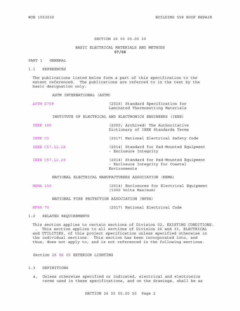
WON 1553030 BUILDING 558 ROOF REPAIR
SECTION 26 00 00.00 20
BASIC ELECTRICAL MATERIALS AND METHODS07/06
PART 1 GENERAL
1.1 REFERENCES
The publications listed below form a part of this specification to the extent referenced. The publications are referred to in the text by the basic designation only.
ASTM INTERNATIONAL (ASTM)
ASTM D709 (2016) Standard Specification for Laminated Thermosetting Materials
INSTITUTE OF ELECTRICAL AND ELECTRONICS ENGINEERS (IEEE)
IEEE 100 (2000; Archived) The Authoritative Dictionary of IEEE Standards Terms
IEEE C2 (2017) National Electrical Safety Code
IEEE C57.12.28 (2014) Standard for Pad-Mounted Equipment - Enclosure Integrity
IEEE C57.12.29 (2014) Standard for Pad-Mounted Equipment - Enclosure Integrity for Coastal Environments
NATIONAL ELECTRICAL MANUFACTURERS ASSOCIATION (NEMA)
NEMA 250 (2014) Enclosures for Electrical Equipment (1000 Volts Maximum)
NATIONAL FIRE PROTECTION ASSOCIATION (NFPA)
NFPA 70 (2017) National Electrical Code
1.2 RELATED REQUIREMENTS
This section applies to certain sections of Division 02, EXISTING CONDITIONS, . This section applies to all sections of Division 26 and 33, ELECTRICAL and UTILITIES, of this project specification unless specified otherwise in the individual sections. This section has been incorporated into, and thus, does not apply to, and is not referenced in the following sections.
Section 26 56 00 EXTERIOR LIGHTING
1.3 DEFINITIONS
a. Unless otherwise specified or indicated, electrical and electronics terms used in these specifications, and on the drawings, shall be as
SECTION 26 00 00.00 20 Page 2

WON 1553030 BUILDING 558 ROOF REPAIR
defined in IEEE 100.
b. The technical sections referred to herein are those specification sections that describe products, installation procedures, and equipment operations and that refer to this section for detailed description of submittal types.
c. The technical paragraphs referred to herein are those paragraphs in PART 2 - PRODUCTS and PART 3 - EXECUTION of the technical sections that describe products, systems, installation procedures, equipment, and test methods.
1.4 ELECTRICAL CHARACTERISTICS
Electrical characteristics for this project shall be as established by existing condition.
1.5 ADDITIONAL SUBMITTALS INFORMATION
Submittals required in other sections that refer to this section must conform to the following additional requirements as applicable.
1.5.1 Shop Drawings (SD-02)
Include wiring diagrams and installation details of equipment indicating proposed location, layout and arrangement, control panels, accessories, piping, ductwork, and other items that must be shown to ensure a coordinated installation. Wiring diagrams shall identify circuit terminals and indicate the internal wiring for each item of equipment and the interconnection between each item of equipment. Drawings shall indicate adequate clearance for operation, maintenance, and replacement of operating equipment devices.
1.5.2 Product Data (SD-03)
Submittal shall include performance and characteristic curves.
1.6 QUALITY ASSURANCE
1.6.1 Regulatory Requirements
In each of the publications referred to herein, consider the advisory provisions to be mandatory, as though the word, "shall" had been substituted for "should" wherever it appears. Interpret references in these publications to the "authority having jurisdiction," or words of similar meaning, to mean the Contracting Officer. Equipment, materials, installation, and workmanship shall be in accordance with the mandatory and advisory provisions of NFPA 70 unless more stringent requirements are specified or indicated.
1.6.2 Standard Products
Provide materials and equipment that are products of manufacturers regularly engaged in the production of such products which are of equal material, design and workmanship. Products shall have been in satisfactory commercial or industrial use for 2 years prior to bid opening. The 2-year period shall include applications of equipment and materials under similar circumstances and of similar size. The product shall have been on sale on the commercial market through advertisements, manufacturers' catalogs, or
SECTION 26 00 00.00 20 Page 3
WON 1553030 BUILDING 558 ROOF REPAIR
brochures during the 2-year period. Where two or more items of the same class of equipment are required, these items shall be products of a single manufacturer; however, the component parts of the item need not be the products of the same manufacturer unless stated in the technical section.
1.6.2.1 Alternative Qualifications
Products having less than a 2-year field service record will be acceptable if a certified record of satisfactory field operation for not less than 6000 hours, exclusive of the manufacturers' factory or laboratory tests, is furnished.
1.6.2.2 Material and Equipment Manufacturing Date
Products manufactured more than 3 years prior to date of delivery to site shall not be used, unless specified otherwise.
1.7 WARRANTY
The equipment items shall be supported by service organizations which are reasonably convenient to the equipment installation in order to render satisfactory service to the equipment on a regular and emergency basis during the warranty period of the contract.
1.8 POSTED OPERATING INSTRUCTIONS
Provide for each system and principal item of equipment as specified in the technical sections for use by operation and maintenance personnel. The operating instructions shall include the following:
a. Wiring diagrams, control diagrams, and control sequence for each principal system and item of equipment.
b. Start up, proper adjustment, operating, lubrication, and shutdown procedures.
c. Safety precautions.
d. The procedure in the event of equipment failure.
e. Other items of instruction as recommended by the manufacturer of each system or item of equipment.
Print or engrave operating instructions and frame under glass or in approved laminated plastic. Post instructions where directed. For operating instructions exposed to the weather, provide weather-resistant materials or weatherproof enclosures. Operating instructions shall not fade when exposed to sunlight and shall be secured to prevent easy removal or peeling.
1.9 MANUFACTURER'S NAMEPLATE
Each item of equipment shall have a nameplate bearing the manufacturer's name, address, model number, and serial number securely affixed in a conspicuous place; the nameplate of the distributing agent will not be acceptable.
SECTION 26 00 00.00 20 Page 4

WON 1553030 BUILDING 558 ROOF REPAIR
1.10 FIELD FABRICATED NAMEPLATES
ASTM D709. Provide laminated plastic nameplates for each equipment enclosure, relay, switch, and device; as specified in the technical sections or as indicated on the drawings. Each nameplate inscription shall identify the function and, when applicable, the position. Nameplates shall be melamine plastic, 0.125 inch thick, white with black center core. Surface shall be matte finish. Corners shall be square. Accurately align lettering and engrave into the core. Minimum size of nameplates shall be one by 2.5 inches. Lettering shall be a minimum of 0.25 inch high normal block style.
1.11 WARNING SIGNS
Provide warning signs for the enclosures of electrical equipment including substations, pad-mounted transformers, pad-mounted switches, generators, and switchgear having a nominal rating exceeding 600 volts.
a. When the enclosure integrity of such equipment is specified to be in accordance with IEEE C57.12.28 or IEEE C57.12.29, such as for pad-mounted transformers and pad-mounted SF6 switches, provide self-adhesive warning signs on the outside of the high voltage compartment door(s). Sign shall be a decal and shall have nominal dimensions of 7 by 10 inches with the legend "DANGER HIGH VOLTAGE" printed in two lines of nominal 2 inch high letters. The word "DANGER" shall be in white letters on a red background and the words "HIGH VOLTAGE" shall be in black letters on a white background. Decal shall be Panduit No. PPSO710D72 or approved equal.
b. When such equipment is guarded by a fence, mount signs on the fence. Provide metal signs having nominal dimensions of 14 by 10 inches with the legend "DANGER HIGH VOLTAGE KEEP OUT" printed in three lines of nominal 3 inch high white letters on a red and black field.
1.12 ELECTRICAL REQUIREMENTS
Electrical installations shall conform to IEEE C2, NFPA 70, and requirements specified herein.
1.13 INSTRUCTION TO GOVERNMENT PERSONNEL
Where specified in the technical sections, furnish the services of competent instructors to give full instruction to designated Government personnel in the adjustment, operation, and maintenance of the specified systems and equipment, including pertinent safety requirements as required. Instructors shall be thoroughly familiar with all parts of the installation and shall be trained in operating theory as well as practical operation and maintenance work. Instruction shall be given during the first regular work week after the equipment or system has been accepted and turned over to the Government for regular operation. The number of man-days (8 hours per day) of instruction furnished shall be as specified in the individual section. When more than 4 man-days of instruction are specified, use approximately half of the time for classroom instruction. Use other time for instruction with equipment or system. When significant changes or modifications in the equipment or system are made under the terms of the contract, provide additional instructions to acquaint the operating personnel with the changes or modifications.
SECTION 26 00 00.00 20 Page 5

WON 1553030 BUILDING 558 ROOF REPAIR
PART 2 PRODUCTS
2.1 FACTORY APPLIED FINISH
Electrical equipment shall have factory-applied painting systems which shall, as a minimum, meet the requirements of NEMA 250 corrosion-resistance test[ and the additional requirements specified in the technical sections].
PART 3 EXECUTION
3.1 FIELD APPLIED PAINTING
Paint electrical equipment as required to match finish of adjacent surfaces or to meet the indicated or specified safety criteria. Painting shall be as specified in Section 09 90 00 PAINTS AND COATINGS and the section specifying the associated electrical equipment.
3.2 FIELD FABRICATED NAMEPLATE MOUNTING
Provide number, location, and letter designation of nameplates as indicated. Fasten nameplates to the device with a minimum of two sheet-metal screws or two rivets.
3.3 WARNING SIGN MOUNTING
Provide the number of signs required to be readable from each accessible side, but space the signs a maximum of 30 feet apart.
-- End of Section --
SECTION 26 00 00.00 20 Page 6
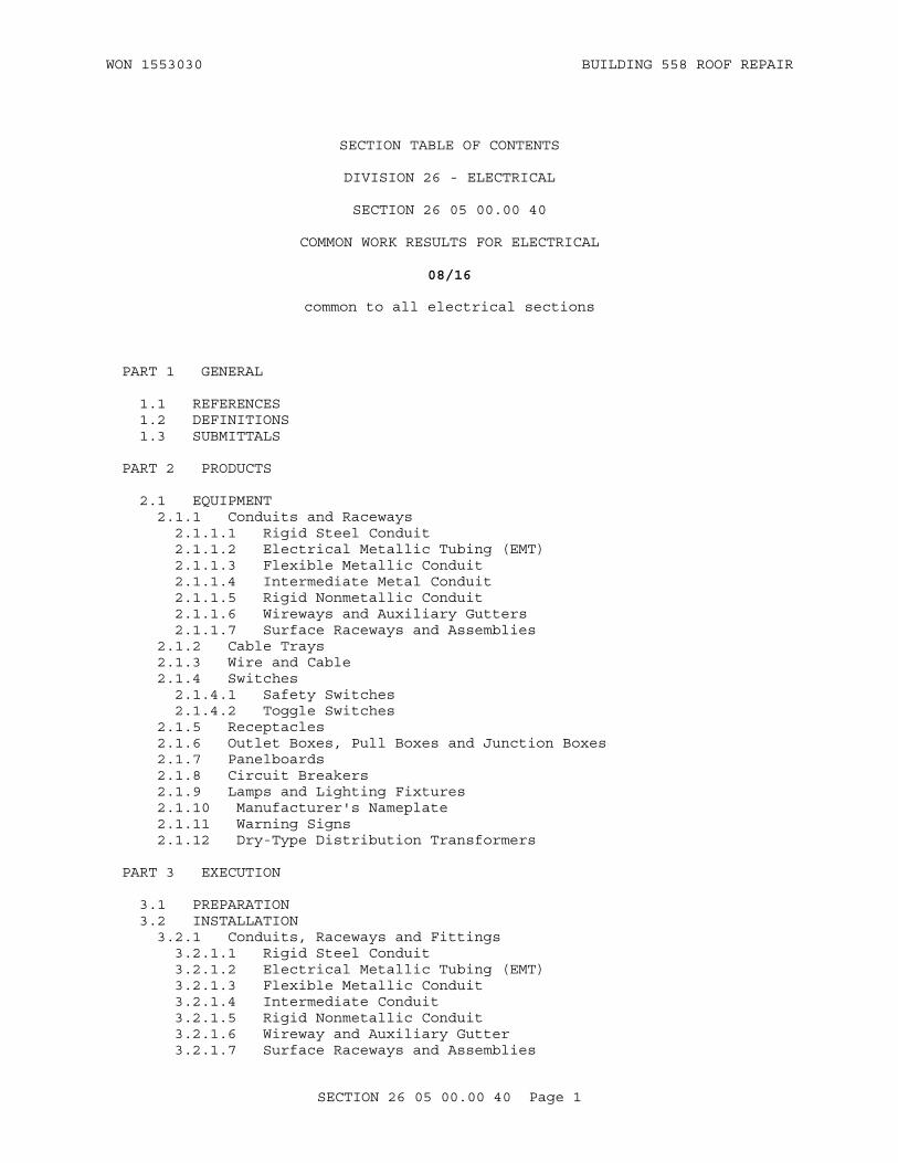
WON 1553030 BUILDING 558 ROOF REPAIR
SECTION TABLE OF CONTENTS
DIVISION 26 - ELECTRICAL
SECTION 26 05 00.00 40
COMMON WORK RESULTS FOR ELECTRICAL
08/16
common to all electrical sections
PART 1 GENERAL
1.1 REFERENCES 1.2 DEFINITIONS 1.3 SUBMITTALS
PART 2 PRODUCTS
2.1 EQUIPMENT 2.1.1 Conduits and Raceways 2.1.1.1 Rigid Steel Conduit 2.1.1.2 Electrical Metallic Tubing (EMT) 2.1.1.3 Flexible Metallic Conduit 2.1.1.4 Intermediate Metal Conduit 2.1.1.5 Rigid Nonmetallic Conduit 2.1.1.6 Wireways and Auxiliary Gutters 2.1.1.7 Surface Raceways and Assemblies 2.1.2 Cable Trays 2.1.3 Wire and Cable 2.1.4 Switches 2.1.4.1 Safety Switches 2.1.4.2 Toggle Switches 2.1.5 Receptacles 2.1.6 Outlet Boxes, Pull Boxes and Junction Boxes 2.1.7 Panelboards 2.1.8 Circuit Breakers 2.1.9 Lamps and Lighting Fixtures 2.1.10 Manufacturer's Nameplate 2.1.11 Warning Signs 2.1.12 Dry-Type Distribution Transformers
PART 3 EXECUTION
3.1 PREPARATION 3.2 INSTALLATION 3.2.1 Conduits, Raceways and Fittings 3.2.1.1 Rigid Steel Conduit 3.2.1.2 Electrical Metallic Tubing (EMT) 3.2.1.3 Flexible Metallic Conduit 3.2.1.4 Intermediate Conduit 3.2.1.5 Rigid Nonmetallic Conduit 3.2.1.6 Wireway and Auxiliary Gutter 3.2.1.7 Surface Raceways and Assemblies
SECTION 26 05 00.00 40 Page 1

WON 1553030 BUILDING 558 ROOF REPAIR
3.2.1.8 Cable Trays 3.2.1.9 Splices and Connectors 3.2.2 Wiring 3.2.3 Safety Switches 3.2.4 Wiring Devices 3.2.4.1 Wall Switches and Receptacles 3.2.4.2 Device Plates 3.2.5 Boxes and Fittings 3.2.6 Lamps and Lighting Fixtures 3.2.7 Panelboards 3.2.8 Dry-Type Distribution Transformers 3.2.9 Field Fabricated Nameplates 3.2.10 Identification Plates and Warnings 3.2.11 Posted Operating Instructions 3.3 FIELD QUALITY CONTROL
-- End of Section Table of Contents --
SECTION 26 05 00.00 40 Page 2

WON 1553030 BUILDING 558 ROOF REPAIR
SECTION 26 05 00.00 40
COMMON WORK RESULTS FOR ELECTRICAL08/16
PART 1 GENERAL
1.1 REFERENCES
The publications listed below form a part of this specification to the extent referenced. The publications are referred to within the text by the basic designation only.
AMERICAN SOCIETY OF CIVIL ENGINEERS (ASCE)
ASCE 7 (2010; Errata 2011; Supp 1 2013) Minimum Design Loads for Buildings and Other Structures
ASTM INTERNATIONAL (ASTM)
ASTM D709 (2016) Standard Specification for Laminated Thermosetting Materials
ELECTRONIC INDUSTRIES ALLIANCE (EIA)
EIA 480 (1981) Toggle Switches
INSTITUTE OF ELECTRICAL AND ELECTRONICS ENGINEERS (IEEE)
IEEE C57.12.28 (2014) Standard for Pad-Mounted Equipment - Enclosure Integrity
IEEE C57.12.29 (2014) Standard for Pad-Mounted Equipment - Enclosure Integrity for Coastal Environments
IEEE Stds Dictionary (2009) IEEE Standards Dictionary: Glossary of Terms & Definitions
INTERNATIONAL CODE COUNCIL (ICC)
ICC/ANSI A117.1 (2009) Accessible and Usable Buildings and Facilities
NATIONAL ELECTRICAL MANUFACTURERS ASSOCIATION (NEMA)
ANSI Z535.1 (2006; R 2011) American National Standard for Safety--Color Code
ANSI/NEMA OS 1 (2013) Sheet-Steel Outlet Boxes, Device Boxes, Covers, and Box Supports
NEMA 250 (2014) Enclosures for Electrical Equipment (1000 Volts Maximum)
NEMA FB 1 (2014) Standard for Fittings, Cast Metal
SECTION 26 05 00.00 40 Page 3

WON 1553030 BUILDING 558 ROOF REPAIR
Boxes, and Conduit Bodies for Conduit, Electrical Metallic Tubing, and Cable
NEMA KS 1 (2013) Enclosed and Miscellaneous Distribution Equipment Switches (600 V Maximum)
NEMA PB 1 (2011) Panelboards
NEMA RN 1 (2005; R 2013) Polyvinyl-Chloride (PVC) Externally Coated Galvanized Rigid Steel Conduit and Intermediate Metal Conduit
NEMA TC 2 (2013) Standard for Electrical Polyvinyl Chloride (PVC) Conduit
NEMA TC 3 (2015) Standard for Polyvinyl Chloride (PVC) Fittings for Use With Rigid PVC Conduit and Tubing
NEMA VE 1 (2009) Standard for Metal Cable Tray Systems
NEMA WD 1 (1999; R 2015) Standard for General Color Requirements for Wiring Devices
NEMA WD 6 (2016) Wiring Devices Dimensions Specifications
NATIONAL FIRE PROTECTION ASSOCIATION (NFPA)
NFPA 70 (2017) National Electrical Code
UNDERWRITERS LABORATORIES (UL)
UL 1 (2005; Reprint Jul 2012) Standard for Flexible Metal Conduit
UL 1242 (2006; Reprint Mar 2014) Standard for Electrical Intermediate Metal Conduit -- Steel
UL 489 (2016) UL Standard for Safety Molded-Case Circuit Breakers, Molded-Case Switches and Circuit-Breaker Enclosures
UL 506 (2008; Reprint Oct 2013) Specialty Transformers
UL 6 (2007; Reprint Nov 2014) Electrical Rigid Metal Conduit-Steel
UL 797 (2007; Reprint Dec 2012) Electrical Metallic Tubing -- Steel
UL 870 (2016) UL Standard for Safety Wireways, Auxiliary Gutters, and Associated Fittings
SECTION 26 05 00.00 40 Page 4

WON 1553030 BUILDING 558 ROOF REPAIR
1.2 DEFINITIONS
a. Unless otherwise specified or indicated, electrical and electronics terms used in these specifications, and on the drawings, are as defined in IEEE Stds Dictionary.
b. The technical sections referred to herein are those specification sections that describe products, installation procedures, and equipment operations and that refer to this section for detailed description of submittal types.
c. Vertical assembly: A vertical assembly is a pole, tower or other such support, mounting hardware, arms, brackets and the load. Load can be a luminaire, siren, loudspeaker or other device. All components of a vertical assembly will be rated by the manufacturer to withstand 150 mph wind loading in accordance with ASCE 7.
1.3 SUBMITTALS
Government approval is required for submittals with a "G" designation; submittals not having a "G" designation are for Contractor Quality Control approval. When used, a designation following the "G" designation identifies the office that will review the submittal for the Government. Submit the following in accordance with Section 01 33 00 SUBMITTAL PROCEDURES:
SD-01 Preconstruction Submittals
Material, Equipment, and Fixture Lists
SD-03 Product Data
Conduits and Raceways; G
Wire and Cable; G
Splices and Connectors; G
Switches; G
Receptacles; G
Outlet Boxes, Pull Boxes and Junction Boxes; G
Circuit Breakers; G
Panelboards; G
Lamps and Lighting Fixtures; G
Dry-Type Distribution Transformers; G
SD-06 Test Reports
Continuity Test; G
Phase-Rotation Tests; G
Insulation Resistance Test; G
SECTION 26 05 00.00 40 Page 5
WON 1553030 BUILDING 558 ROOF REPAIR
SD-08 Manufacturer's Instructions
Manufacturer's Instructions
PART 2 PRODUCTS
2.1 EQUIPMENT
Provide the standard cataloged materials and equipment of manufacturers regularly engaged in the manufacture of the products. For material, equipment, and fixture lists submittals, show manufacturer's style or catalog numbers, specification and drawing reference numbers, warranty information, and fabrication site.
2.1.1 Conduits and Raceways
2.1.1.1 Rigid Steel Conduit
Provide hot dipped galvanized rigid steel conduit complying with UL 6. Except where installed underground, or in corrosive areas, provide polyvinylchloride (PVC), or painted with bitumastic coated rigid steel conduit in accordance with NEMA RN 1.
Use threaded fittings for rigid steel conduit.
Use solid gaskets. Ensure conduit fittings with blank covers have gaskets, except in clean, dry areas or at the lowest point of a conduit run where drainage is required.
Provide covers with captive screws and are accessible after the work has been completed.
2.1.1.2 Electrical Metallic Tubing (EMT)
Ensure EMT is in accordance with UL 797 and is zinc coated steel. Provide zinc-coated couplings and connectors that are raintight, gland compression type with insulation throat. Crimp, spring, or setscrew type fittings are not acceptable.
2.1.1.3 Flexible Metallic Conduit
Ensure flexible metallic conduit is galvanized steel and complies with UL 1.
Ensure fittings for flexible metallic conduit are specifically designed for such conduit.
Provide liquidtight flexible metallic conduit with a protective jacket of PVC extruded over a flexible interlocked galvanized steel core to protect wiring against moisture, oil, chemicals, and corrosive fumes.
Ensure fittings for liquidtight flexible metallic conduit are specifically designed for such conduit.
2.1.1.4 Intermediate Metal Conduit
Ensure intermediate metal conduit is galvanized steel and complies with UL 1242.
SECTION 26 05 00.00 40 Page 6

WON 1553030 BUILDING 558 ROOF REPAIR
2.1.1.5 Rigid Nonmetallic Conduit
Ensure rigid nonmetallic conduit complies with NEMA TC 2 and NEMA TC 3 with a wall thickness not less than Schedule 40.
2.1.1.6 Wireways and Auxiliary Gutters
Ensure wireways and auxiliary gutters are a minimum 4 by 4-inch trade size conforming to UL 870.
2.1.1.7 Surface Raceways and Assemblies
Ensure surface metal raceways and multi-outlet assemblies conform to NFPA 70, and have receptacles conforming to NEMA WD 1, Type 5-20R.
2.1.2 Cable Trays
Provide ladder type cable trays conforming to NEMA VE 1.
2.1.3 Wire and Cable
Use copper 600-volt type THHN, THWN,and XHHW for conductors installed in conduit. Ensure all conductors AWG No. 8 and larger, are stranded. All conductors smaller than AWG No. 8 are solid.
Ensure flexible cable is Type SO and contains a grounding conductor with green insulation.
Ensure conductors installed in plenums are marked plenum rated.
2.1.4 Switches
2.1.4.1 Safety Switches
Ensure safety switches comply with NEMA KS 1, and are the heavy-duty type with enclosure, voltage, current rating, number of poles, and fusing as indicated on the drawings. Ensure switch construction is such that, when the switch handle in the "ON" position, the cover or door cannot be opened. Cover release device is coinproof and so constructed that an external tool is used to open the cover. Make provisions to lock the handle in the "OFF" position. Ensure the switch is not capable of being locked in the "ON" position.
Provide switches of the quick-make, quick-break type and terminal lugs for use with copper conductors.
Ensure safety color coding for identification of safety switches conforms to ANSI Z535.1.
2.1.4.2 Toggle Switches
Ensure toggle switches comply with EIA 480, control incandescent, mercury, and fluorescent lighting fixtures and are the heavy duty, general purpose, noninterchangeable flush-type.
Provide commercial grade toggle switches, single -pole, three -way two-position devices rated 20 amperes at 277 volts, 60 hertz alternating current (ac) only.
SECTION 26 05 00.00 40 Page 7
WON 1553030 BUILDING 558 ROOF REPAIR
Ensure all toggle switches are products of the same manufacturer.
2.1.5 Receptacles
Provide commercial grade, NEMA 5-20R receptacles, 20A, 125 VAC, 2-pole, 3-wire duplex conforming to NEMA WD 6.
2.1.6 Outlet Boxes, Pull Boxes and Junction Boxes
Ensure outlet boxes for use with conduit systems are in accordance with NEMA FB 1 and ANSI/NEMA OS 1 and are not less than 1-1/2 inches deep. Furnish all pull and junction boxes with screw-fastened covers.
2.1.7 Panelboards
Provide circuit breaker type lighting and appliance branch circuit panelboards in accordance with NEMA PB 1. Bolt circuit breakers to the bus. Plug-in circuit breakers are not acceptable. Provide copper buses of the rating indicated on the drawings, with main lugs or main circuit breaker. Provide all panelboards for use on grounded ac systems with a full-capacity isolated neutral bus and a separate grounding bus bonded to the panelboard enclosure. Ensure panelboard enclosures are NEMA 250, Type 1, in accordance with NEMA PB 1. Provide enclosure fronts with latchable hinged doors.
2.1.8 Circuit Breakers
Ensure circuit breaker interrupting rating is not less than those indicated and in no event less than 10,000 amperes root-mean-square (rms) symmetrical at 208 and 240 volts, respectively. Provide multipole circuit breakers of the common-trip type with a single handle. Molded case circuit breakers are bolt-on type conforming to UL 489.
2.1.9 Lamps and Lighting Fixtures
Manufacturers and catalog numbers shown on the drawings are indicative of the general type desired and are not intended to restrict the selection to fixtures of any particular manufacturer. Fixtures with the same salient features and equivalent light distribution and brightness characteristics, of equal finish and quality, are acceptable. Provide lamps of the proper type and wattage for each fixture.
Ensure ballasts have a high power factor and are energy efficient. Provide ballasts with a Class P terminal protective device for 120-volt operation as indicated and are rapid-start fluorescent. Use ballasts that are "A" sound rated. Provide standard reduced wattage type fluorescent lamps.
Provide high intensity discharge (HID) lighting fixtures that have prewired integral ballasts and cast aluminum housings complete with tempered glass lenses suitable for installation in damp or wet locations. Provide fixtures and lamps.
2.1.10 Manufacturer's Nameplate
Ensure each item of equipment has a nameplate bearing the manufacturer's name, address, model number, and serial number securely affixed in a conspicuous place; the nameplate of the distributing agent is not acceptable.
SECTION 26 05 00.00 40 Page 8
WON 1553030 BUILDING 558 ROOF REPAIR
2.1.11 Warning Signs
Provide warning signs for the enclosures of electrical equipment including substations, pad-mounted transformers, pad-mounted switches, generators, and switchgear having a nominal rating exceeding 600 volts.
a. Enclosure integrity to conform with IEEE C57.12.28 and IEEE C57.12.29, such as for pad-mounted transformers[ and pad-mounted SF6 switches]. Provide self-adhesive warning signs on the outside of the high voltage compartment door(s). Provide decal signs with nominal dimensions of 7 by 10 inches. Print the legend "DANGER HIGH VOLTAGE" in two lines of nominal 2 inch high letters. Show the word "DANGER" in white letters on a red background and the words "HIGH VOLTAGE" in black letters on a white background. Use Panduit decal No. PPSO710D72 or approved equal.
b. When such equipment is guarded by a fence, mount signs on the fence. Provide metal signs having nominal dimensions of 14 by 10 inches with the legend "DANGER HIGH VOLTAGE KEEP OUT" printed in three lines of nominal 3-inch high white letters on a red and black field.
2.1.12 Dry-Type Distribution Transformers
Ensure that general purpose dry-type transformers with windings 600 volts or less are two-winding, 60 hertz, and self-cooled in accordance with UL 506. Ensure windings have a minimum of two 2-1/2-percent taps above and below nominal voltage.
PART 3 EXECUTION
3.1 PREPARATION
Submit manufacturer's instructions including special provisions required to install equipment components and system packages. Special provisions include impedances, hazards and safety precautions.
Clean and paint conduit, supports, fittings, cabinets, pull boxes, and racks as specified in Section 09 90 00 PAINTS AND COATINGS and Section 09 96 00 HIGH-PERFORMANCE COATINGS.
Protect metallic materials against corrosion. Provide equipment enclosures with the standard finish by the manufacturer when used for most indoor installations. For harsh indoor environments (any area subjected to chemical and abrasive action), and all outdoor installations, refer to Section 09 96 00 HIGH-PERFORMANCE COATINGS. Do not use aluminum when in contact with earth or concrete and, where connected to dissimilar metal, protect by using approved fittings and treatment. Except where other equivalent protective treatment is specifically approved in writing, provide hot-dip galvanized ferrous metals for items such as, anchors, bolts, braces, boxes, bodies, clamps, fittings, guards, nuts, pins, rods, shims, thimbles, washers, and miscellaneous items not made of corrosion-resistant steel.
3.2 INSTALLATION
3.2.1 Conduits, Raceways and Fittings
Ensure that conduit runs between outlet and outlet, between fitting and fitting, or between outlet and fitting does not contain more than the equivalent of three 90-degree bends, including those bends located
SECTION 26 05 00.00 40 Page 9

WON 1553030 BUILDING 558 ROOF REPAIR
immediately at the outlet or fitting.
Do not install crushed or deformed conduit. Avoid trapped conduit runs where possible. Take care to prevent the lodgment of foreign material in the conduit, boxes, fittings, and equipment during the course of construction. Clear any clogged conduit of obstructions or replace conduit.
Conduit and raceway runs concealed in or behind walls, above ceilings, or exposed on walls and ceilings 5 feet or more above finished floors and not subject to mechanical damage may be electrical metallic tubing (EMT).
3.2.1.1 Rigid Steel Conduit
Make field-made bends and offsets with approved Hickey bending tool or conduit bending machine. Use long radius conduit for elbows larger than 2-1/2 inches.
Provide a flush coupling for all conduit stubbed-up through concrete floors for connections to free-standing equipment with the exception of motor-control centers, cubicles, and other such items of equipment, when the floor slab is of sufficient thickness. Otherwise, provide a floor box set flush with the finished floor. For conduits installed for future use, terminate with a coupling and plug; set flush with the floor.
3.2.1.2 Electrical Metallic Tubing (EMT)
Ground EMT in accordance with NFPA 70, using pressure grounding connectors especially designed for EMT.
3.2.1.3 Flexible Metallic Conduit
Use flexible metallic conduit to connect recessed fixtures from outlet boxes in ceilings, transformers, and other approved assemblies.
Use bonding wires in flexible conduit as specified in NFPA 70, for all circuits. Flexible conduit is not considered a ground conductor.
Make electrical connections to vibration-isolated equipment with flexible metallic conduit.
Use liquidtight flexible metallic conduit in wet and oily locations and to complete the connection to motor-driven equipment.
3.2.1.4 Intermediate Conduit
Make all field-made bends and offsets with approved Hickey bending tool or conduit bending machine. Use intermediate metal conduit only for indoor installations.
3.2.1.5 Rigid Nonmetallic Conduit
Ensure rigid PVC conduit is direct buried.
Install a green insulated copper grounding conductor in conduit with conductors and solidly connect to ground at each end. Size grounding wires in accordance with NFPA 70.
SECTION 26 05 00.00 40 Page 10

WON 1553030 BUILDING 558 ROOF REPAIR
3.2.1.6 Wireway and Auxiliary Gutter
Bolt together straight sections and fittings to provide a rigid, mechanical connection and electrical continuity. Close dead ends of wireways and auxiliary gutters. Plug all unused conduit openings.
Support wireways for overhead distribution and control circuits at maximum 5-foot intervals.
Ensure auxiliary gutters used to supplement wiring spaces for equipment not contained in a single enclosure contains no switches, overcurrent devices, appliances, or apparatus and is not more than 30 feet long.
3.2.1.7 Surface Raceways and Assemblies
Mount surface raceways plumb and level, with the base and cover secured. Minimum circuit run is three-wire, with one wire designated as ground.
3.2.1.8 Cable Trays
Support cable trays from ceiling hangers, equipment bays, or floor or wall supports. Cable trays may be mounted on equipment racks. Provide support when the free end extends beyond 3 feet. Maximum support spacing is 6 feet. Support trays 10-inches wide or less by one hanger. Support trays greater than 10 inches wide by two hangers. Bond cable trays at splices.
3.2.1.9 Splices and Connectors
Make all splices in AWG No. 8 and smaller with approved indentor crimp-type connectors and compression tools.
Make all splices in AWG No. 6 and larger with indentor crimp-type connectors and compression tools or bolted clamp-type connectors. Wrap joints with an insulating tape that has an insulation and temperature rating equivalent to that of the conductor.
3.2.2 Wiring
Color code feeder and branch circuit conductors as follows:
CONDUCTOR COLOR AC 240/120 COLOR AC 480/277
Phase A Black_____ Orange
Phase B Red_____ Yellow
Phase C Blue_____ Brown
Neutral White
EquipmentGrounds
Green or Bare
Use conductors up to and including AWG No. 2 that are manufactured with colored insulating materials. For conductors larger than AWG No. 2, have ends identified with color plastic tape in outlet, pull, or junction boxes.
Splice in accordance with the NFPA 70. Provide conductor identification
SECTION 26 05 00.00 40 Page 11

WON 1553030 BUILDING 558 ROOF REPAIR
within each enclosure where a tap, splice, or termination is made and at the equipment terminal of each conductor. Match terminal and conductor identification as indicated.
Where several feeders pass through a common pullbox, tag the feeders to clearly indicate the electrical characteristics, circuit number, and panel designation.
3.2.3 Safety Switches
Securely fasten switches to the supporting structure or wall, utilizing a minimum of four 1/4 inch bolts. Do not use sheet metal screws and small machine screws for mounting. Do not mount switches in an inaccessible location or where the passageway to the switch may become obstructed. Mounting height 5 feet above floor level, when possible.
3.2.4 Wiring Devices
3.2.4.1 Wall Switches and Receptacles
Install wall switches and receptacles so that when device plates are applied, the plates are aligned vertically to within 1/16 inch.
Bond ground terminal of each flush-mounted receptacle to the outlet box with an approved green bonding jumper when used with dry wall type construction.
3.2.4.2 Device Plates
Ensure device plates for switches are suitably engraved with a description of the loads when not within sight of the loads controlled.
Mark device plates and receptacle cover plates for receptacles other than 125-volt, single-phase, duplex, convenience outlets. Show the circuit number, voltage, frequency, phasing, and amperage available at the receptacle. Use self-adhesive labels having 1/4 inch embossed letters.
Similarly mark device plates for convenience outlets indicating the supply panel and circuit number.
3.2.5 Boxes and Fittings
Provide pullboxes where necessary in the conduit system to facilitate conductor installation. For conduit runs longer than 100 feet or with more than three right-angle bends, install a pullbox at a convenient intermediate location.
Securely mount boxes and enclosures to the building structure using supports that are independent of the conduit entering or leaving the boxes.
Select the mounting height of wall-mounted outlet and switch boxes, as measured between the bottom of the box and the finished floor, in accordance with ICC/ANSI A117.1 and as follows:
LOCATION MOUNTING HEIGHT(inches)
Receptacles in offices 18
SECTION 26 05 00.00 40 Page 12
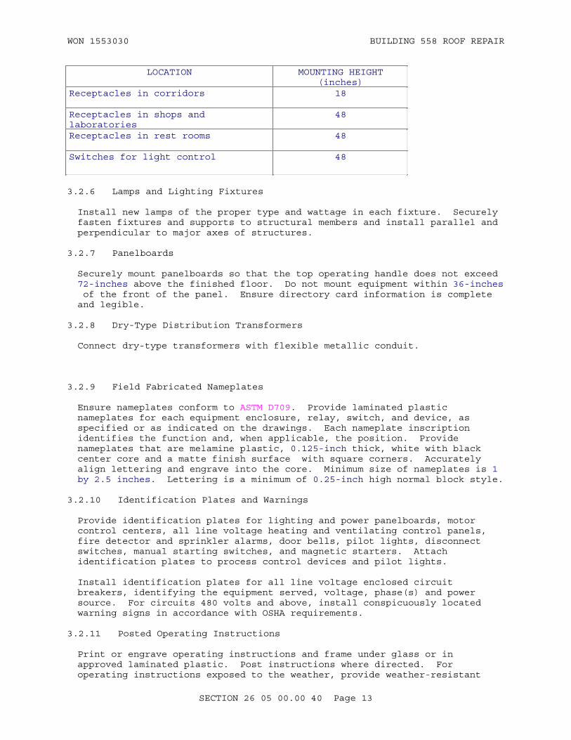
WON 1553030 BUILDING 558 ROOF REPAIR
LOCATION MOUNTING HEIGHT(inches)
Receptacles in corridors 18
Receptacles in shops and laboratories
48
Receptacles in rest rooms 48
Switches for light control 48
3.2.6 Lamps and Lighting Fixtures
Install new lamps of the proper type and wattage in each fixture. Securely fasten fixtures and supports to structural members and install parallel and perpendicular to major axes of structures.
3.2.7 Panelboards
Securely mount panelboards so that the top operating handle does not exceed 72-inches above the finished floor. Do not mount equipment within 36-inches of the front of the panel. Ensure directory card information is complete and legible.
3.2.8 Dry-Type Distribution Transformers
Connect dry-type transformers with flexible metallic conduit.
3.2.9 Field Fabricated Nameplates
Ensure nameplates conform to ASTM D709. Provide laminated plastic nameplates for each equipment enclosure, relay, switch, and device, as specified or as indicated on the drawings. Each nameplate inscription identifies the function and, when applicable, the position. Provide nameplates that are melamine plastic, 0.125-inch thick, white with black center core and a matte finish surface with square corners. Accurately align lettering and engrave into the core. Minimum size of nameplates is 1 by 2.5 inches. Lettering is a minimum of 0.25-inch high normal block style.
3.2.10 Identification Plates and Warnings
Provide identification plates for lighting and power panelboards, motor control centers, all line voltage heating and ventilating control panels, fire detector and sprinkler alarms, door bells, pilot lights, disconnect switches, manual starting switches, and magnetic starters. Attach identification plates to process control devices and pilot lights.
Install identification plates for all line voltage enclosed circuit breakers, identifying the equipment served, voltage, phase(s) and power source. For circuits 480 volts and above, install conspicuously located warning signs in accordance with OSHA requirements.
3.2.11 Posted Operating Instructions
Print or engrave operating instructions and frame under glass or in approved laminated plastic. Post instructions where directed. For operating instructions exposed to the weather, provide weather-resistant
SECTION 26 05 00.00 40 Page 13

WON 1553030 BUILDING 558 ROOF REPAIR
materials or weatherproof enclosures. Ensure operating instructions do not fade when exposed to sunlight. Secure instructions to prevent easy removal or peeling.
Ensure each system and principal item of equipment is as specified in the technical sections for use by operation and maintenance personnel. Include the following information with the operating instructions:
a. Wiring diagrams, control diagrams, and control sequence for each principal system and item of equipment.
b. Start up, proper adjustment, operating, lubrication, and shutdown procedures.
c. Safety precautions.
d. The procedure in the event of equipment failure.
e. Other items of instruction as recommended by the manufacturer.
3.3 FIELD QUALITY CONTROL
After completion of the installation and splicing, and prior to energizing the conductors, perform wire and cable continuity and insulation tests as herein specified before the conductors are energized.
Provide all necessary test equipment, labor, and personnel to perform the tests, as herein specified.
Isolate completely all wire and cable from all extraneous electrical connections at cable terminations and joints. Use substation and switchboard feeder breakers, disconnects in combination motor starters, circuit breakers in panel boards, and other disconnecting devices to isolate the circuits under test.
Perform insulation-resistance test on each field-installed conductor with respect to ground and adjacent conductors. Applied potential is 500 volts dc for 300 volt rated cable and 1000 volts dc for 600 volt rated cable. Take readings after 1 minute and until the reading is constant for 15 seconds. Minimum insulation-resistance values is not less than 25 Megohms for 300 volt rated cable and 100 Megohms for 600 volt rated cable. For circuits with conductor sizes AWG No. 8 and smaller insulation resistance testing is not required.
Perform continuity test to insure correct cable connection end-to-end (i.e correct phase conductor, grounded conductor, and grounding conductor wiring). Repair and verify any damages to existing or new electrical equipment resulting from mis-wiring. Receive approval for all repairs from the Contracting Officer prior to commencement of the repair.
Conduct phase-rotation tests on all three-phase circuits using a phase-rotation indicating instrument. Perform phase rotation of electrical connections to connected equipment in a clockwise direction, facing the source.
Submit test reports in accordance with referenced standards in this section.
SECTION 26 05 00.00 40 Page 14
WON 1553030 BUILDING 558 ROOF REPAIR
Final acceptance requires the successful performance of wire and cable under test. Do not energize any conductor until the final test reports are reviewed and approved by the Contracting Officer.
-- End of Section --
SECTION 26 05 00.00 40 Page 15

WON 1553030 BUILDING 558 ROOF REPAIR
SECTION TABLE OF CONTENTS
DIVISION 26 - ELECTRICAL
SECTION 26 56 00
EXTERIOR LIGHTING
05/13
lighting system requirements for exterior installations
PART 1 GENERAL
1.1 REFERENCES 1.2 RELATED REQUIREMENTS 1.3 DEFINITIONS 1.4 SUBMITTALS 1.5 QUALITY ASSURANCE 1.5.1 Design Data for Luminaires 1.5.2 LED Luminaire - IES LM-79 Test Report 1.5.3 LED Light Source - IES LM-80 Test Report 1.5.3.1 Test Laboratories 1.5.4 Regulatory Requirements 1.5.5 Standard Products 1.5.5.1 Alternative Qualifications 1.5.5.2 Material and Equipment Manufacturing Date 1.6 WARRANTY 1.6.1 LED Luminaire Warranty 1.6.2 Electronic Ballast Warranty 1.7 OPERATIONAL SERVICE
PART 2 PRODUCTS
2.1 PRODUCT COORDINATION 2.2 HID LPS, FLUORESCENT, INDUCTION AND LED LUMINAIRES 2.2.1 General Requirements 2.2.2 Luminaire Light Sources 2.2.2.1 High Pressure Sodium (HPS) Light Sources 2.2.2.2 Metal Halide (MH) Light Sources 2.2.2.3 LED Light Sources 2.2.3 Luminaire Ballasts, Generators and Power Supply Units (Drivers) 2.2.3.1 HID Ballasts 2.2.3.1.1 Electronic HID Ballasts 2.2.3.1.2 Magnetic HID and LPS Ballasts 2.2.3.2 Induction Generators 2.2.3.3 LED Power Supply Units (Drivers) 2.2.4 LED Luminaire Surge Protection 2.3 EXTERIOR LUMINAIRE CONTROLS 2.3.1 Photocell 2.3.2 Timeswitch 2.3.3 Lighting Contactor 2.3.4 Lighting Control Relay Panel 2.3.5 Motion Sensor 2.3.6 Bi-level HID Controller
SECTION 26 56 00 Page 1
WON 1553030 BUILDING 558 ROOF REPAIR
2.4 BRACKETS AND SUPPORTS 2.5 EQUIPMENT IDENTIFICATION 2.5.1 Manufacturer's Nameplate 2.5.2 Labels 2.6 FACTORY APPLIED FINISH
PART 3 EXECUTION
3.1 INSTALLATION 3.1.1 Wood Poles 3.1.2 Photocell Switch Aiming 3.1.3 GROUNDING 3.1.4 FIELD APPLIED PAINTING 3.2 FIELD QUALITY CONTROL
-- End of Section Table of Contents --
SECTION 26 56 00 Page 2

WON 1553030 BUILDING 558 ROOF REPAIR
SECTION 26 56 00
EXTERIOR LIGHTING05/13
PART 1 GENERAL
1.1 REFERENCES
The publications listed below form a part of this specification to the extent referenced. The publications are referred to in the text by the basic designation only.
AMERICAN SOCIETY OF HEATING, REFRIGERATING AND AIR-CONDITIONING ENGINEERS (ASHRAE)
ASHRAE 90.1 - IP (2016) Energy Standard for Buildings Except Low-Rise Residential Buildings
ASTM INTERNATIONAL (ASTM)
ASTM B117 (2016) Standard Practice for Operating Salt Spray (Fog) Apparatus
CALIFORNIA ENERGY COMMISSION (CEC)
CEC Title 24 (2008; Effective Jan 2010) California's Energy Efficiency Standards for Residential and Nonresidential Buildings
ILLUMINATING ENGINEERING SOCIETY (IES)
IES HB-10 (2011; Errata 2015) IES Lighting Handbook
IES LM-79 (2008) Electrical and Photometric Measurements of Solid-State Lighting Products
IES LM-80 (2015) Measuring Lumen Maintenance of LED Light Sources
IES RP-16 (2010; Addendum A 2008; Addenda B 2009; Addendum C 2016) Nomenclature and Definitions for Illuminating Engineering
IES RP-8 (2014) Roadway Lighting
IES TM-15 (2011) Luminaire Classification System for Outdoor Luminaires
IES TM-21 (2011; Addendum B 2015) Projecting Long Term Lumen Maintenance of LED Light Sources
INSTITUTE OF ELECTRICAL AND ELECTRONICS ENGINEERS (IEEE)
IEEE 100 (2000; Archived) The Authoritative Dictionary of IEEE Standards Terms
SECTION 26 56 00 Page 3

WON 1553030 BUILDING 558 ROOF REPAIR
IEEE C2 (2017) National Electrical Safety Code
IEEE C62.41 (1991; R 1995) Recommended Practice on Surge Voltages in Low-Voltage AC Power Circuits
IEEE C62.41.2 (2002) Recommended Practice on Characterization of Surges in Low-Voltage (1000 V and Less) AC Power Circuits
NATIONAL ELECTRICAL MANUFACTURERS ASSOCIATION (NEMA)
ANSI ANSLG C78.42 (2009; R 2016) For Electric Lamps: High-Pressure Sodium Lamps
ANSI C136.13 (2004; R 2009) American National Standard for Roadway Lighting Equipment, Metal Brackets for Wood Poles
ANSI C136.21 (2014) American National Standard for Roadway and Area Lighting Equipment - Vertical Tenons Used with Post-Top-Mounted Luminaires
ANSI C136.3 (2014) American National Standard for Roadway and Area Lighting Equipment Luminaire Attachments
ANSI C78.1381 (1998) American National Standard for Electric Lamps - 250-Watt, 70 Watt, M85 Metal-Halide Lamps
ANSI C82.4 (2002) American National Standard for Ballasts for High-Intensity-Discharge and Low-Pressure Sodium (LPS) Lamps (Multiple-Supply Type)
ANSI/ANSLG C78.43 (2013) American National Standard for Electric Lamps - Single-Ended Metal-Halide Lamps
NEMA 250 (2014) Enclosures for Electrical Equipment (1000 Volts Maximum)
NEMA ANSLG C78.377 (2015) American National Standard for Electric Lamps— Specifications for the Chromaticity of Solid State Lighting Products
NEMA ANSLG C78.380 (2007) Electric Lamps - High Intensity Discharge Lamps, Method of Designation
NEMA ANSLG C78.44 (2008) For Electric Lamps - Double-Ended Metal Halide Lamps
NEMA ANSLG C82.14 (2006) Lamp Ballasts Low-Frequency Square Wave Electronic Ballasts -- for Metal Halide Lamps
SECTION 26 56 00 Page 4

WON 1553030 BUILDING 558 ROOF REPAIR
NEMA C136.10 (2010) American National Standard for Roadway and Area Lighting Equipment-Locking-Type Photocontrol Devices and Mating Receptacles--Physical and Electrical Interchangeability and Testing
NEMA C136.31 (2010) American National for Roadway and Area Lighting Equipment - Luminaire Vibration
NEMA C78.LL 3 (2003; R 2015) Electric Lamps - Procedures for High Intensity Discharge Lamp Sample Preparation and the Toxicity Characteristic Leaching Procedure
NEMA C82.77 (2002) Harmonic Emission Limits - Related Power Quality Requirements for Lighting Equipment
NEMA ICS 2 (2000; R 2005; Errata 2008) Industrial Control and Systems Controllers, Contactors, and Overload Relays Rated 600 V
NEMA ICS 6 (1993; R 2011) Industrial Control and Systems: Enclosures
NEMA IEC 60529 (2004) Degrees of Protection Provided by Enclosures (IP Code)
NEMA WD 7 (2011; R 2016) Occupancy Motion Sensors Standard
NATIONAL FIRE PROTECTION ASSOCIATION (NFPA)
NFPA 70 (2017) National Electrical Code
U.S. NATIONAL ARCHIVES AND RECORDS ADMINISTRATION (NARA)
47 CFR 15 Radio Frequency Devices
47 CFR 18 (2011) Industrial, Scientific, and Medical Equipment
UNDERWRITERS LABORATORIES (UL)
UL 1029 (1994; Reprint Dec 2013) High-Intensity-Discharge Lamp Ballasts
UL 1310 (2011; Reprint Dec 2014) UL Standard for Safety Class 2 Power Units
UL 1598 (2008; Reprint Oct 2012) Luminaires
UL 773 (1995; Reprint Jul 2015) Standard for Plug-In, Locking Type Photocontrols for Use with Area Lighting
SECTION 26 56 00 Page 5
WON 1553030 BUILDING 558 ROOF REPAIR
UL 773A (2016) Standard for Nonindustrial Photoelectric Switches for Lighting Control
UL 8750 (2015; Reprint Nov 2016) UL Standard for Safety Light Emitting Diode (LED) Equipment for Use in Lighting Products
UL 916 (2007; Reprint Aug 2014) Standard for Energy Management Equipment
1.2 RELATED REQUIREMENTS
Materials not considered to be luminaires or lighting equipment are specified in Section(s) 33 71 02 UNDERGROUND ELECTRICAL DISTRIBUTION.
1.3 DEFINITIONS
a. Unless otherwise specified or indicated, electrical and electronics terms used in these specifications, and on the drawings shall be as defined in IEEE 100 and IES RP-16.
b. For HID, fluorescent, and induction luminaire light sources, "Average Rated Life" is the time after which 50 percent of a large group of light sources will have failed and 50 percent will have survived under normal operating conditions.
c. For LED luminaire light sources, "Useful Life" is the operating hours before reaching 70 percent of the initial rated lumen output (L70) with no catastrophic failures under normal operating conditions. This is also known as 70 percent "Rated Lumen Maintenance Life" as defined in IES LM-80.
d. The "Groundline Section" of wood poles is that portion of the pole between one foot above, and 2 feet below the groundline.
1.4 SUBMITTALS
Government approval is required for submittals with a "G" designation; submittals not having a "G" designation are for Contractor Quality Control approval When used, a designation following the "G" designation identifies the office that will review the submittal for the Government. Submit the following in accordance with Section 01 33 00 SUBMITTAL PROCEDURES:
SD-01 Preconstruction Submittals
Photometric Plan; G
LED Luminaire Warranty; G
SD-03 Product Data
HID, LPS, Fluorescent, Induction and LED Luminaires; G
Luminaire Light Sources; G
SECTION 26 56 00 Page 6

WON 1553030 BUILDING 558 ROOF REPAIR
Lighting contactor; G
Time switch; G
Lighting Control Relay Panel; G
Motion Sensor; G
Bi-level HID Controller; G
Photocell; G
Brackets
Obstruction Marker Luminaires; G
SD-04 Samples
HID, LPS, Fluorescent, Induction and LED Luminaires; G
Submit one sample of each luminaire type, complete with light source and ballast, generator or power supply unit. Sample will be returned to the Contractor for installation in the project work.
SD-06 Test Reports
LED Luminaire - IES LM-79 Test Report; G
LED Light Source - IES LM-80 Test Report; G
Operating test
Submit operating test results as stated in paragraph entitled "Field Quality Control."
SD-07 Certificates
Luminaire Useful Life Certificate; G
Submit certification from the manufacturer indicating the expected useful life of the luminaires provided. The useful life shall be directly correlated from the IES LM-80 test data using procedures outlined in IES TM-21. Thermal properties of the specific luminaire and local ambient operating temperature and conditions shall be taken into consideration.
SD-10 Operation and Maintenance Data
Electronic Ballast Warranty
Operational Service
Submit documentation that includes contact information, summary of procedures, and the limitations and conditions applicable to the
SECTION 26 56 00 Page 7

WON 1553030 BUILDING 558 ROOF REPAIR
project. Indicate manufacturer's commitment to reclaim materials for recycling and/or reuse.
1.5 QUALITY ASSURANCE
1.5.1 Design Data for Luminaires
a. Provide distribution data according to IES classification type as defined in IES HB-10.
b. Shielding as defined by IES RP-8 or B.U.G. rating for the installed position as defined by IES TM-15.
c. Provide safety certification and file number for the luminaire family. Include listing, labeling and identification per NFPA 70 (NEC). Applicable testing bodies are determined by the US Occupational Safety Health Administration (OSHA) as Nationally Recognized Testing Laboratories (NRTL) and include: CSA (Canadian Standards Association), ETL (Edison Testing Laboratory), and UL (Underwriters Laboratories).
d. Provide long term lumen maintenance projections for each LED luminaire in accordance with IES TM-21. Data used for projections shall be obtained from testing in accordance with IES LM-80.
e. Provide wind loading calculations for luminaires mounted on poles. Weight and effective projected area (EPA) of luminaires and mounting brackets shall not exceed maximum rating of pole as installed in particular wind zone area.
1.5.2 LED Luminaire - IES LM-79 Test Report
Submit test report on manufacturer's standard production model luminaire. Submittal shall include all photometric and electrical measurements, as well as all other pertinent data outlined under "14.0 Test Report" in IES LM-79.
1.5.3 LED Light Source - IES LM-80 Test Report
Submit report on manufacturer's standard production LED package, array, or module. Submittal shall include:
a. Testing agency, report number, date, type of equipment, and LED light source being tested.
b. All data required by IES LM-80.
1.5.3.1 Test Laboratories
Test laboratories for the IES LM-79 and IES LM-80 test reports shall be one of the following:
a. National Voluntary Laboratory Accreditation Program (NVLAP) accredited for solid-state lighting testing as part of the Energy-Efficient Lighting Products laboratory accreditation program.
b. One of the qualified labs listed on the Department of Energy - Energy Efficiency & Renewable Energy, Solid-State Lighting web site.
c. A manufacturer's in-house lab that meets the following criteria:
SECTION 26 56 00 Page 8

WON 1553030 BUILDING 558 ROOF REPAIR
1. Manufacturer has been regularly engaged in the design and production of high intensity discharge roadway and area luminaires and the manufacturer's lab has been successfully certifying these fixtures for a minimum of 15 years.
2. Annual equipment calibration including photometer calibration in accordance with National Institute of Standards and Technology.
1.5.4 Regulatory Requirements
In each of the publications referred to herein, consider the advisory provisions to be mandatory, as though the word, "shall" had been substituted for "should" wherever it appears. Interpret references in these publications to the "authority having jurisdiction," or words of similar meaning, to mean the Contracting Officer. Equipment, materials, installation, and workmanship shall be in accordance with the mandatory and advisory provisions of NFPA 70 unless more stringent requirements are specified or indicated.
1.5.5 Standard Products
Provide materials and equipment that are products of manufacturers regularly engaged in the production of such products which are of equal material, design and workmanship. Products shall have been in satisfactory commercial or industrial use for 2 years prior to bid opening. The 2-year period shall include applications of equipment and materials under similar circumstances and of similar size. The product shall have been on sale on the commercial market through advertisements, manufacturers' catalogs, or brochures during the 2-year period. Where two or more items of the same class of equipment are required, these items shall be products of a single manufacturer; however, the component parts of the item need not be the products of the same manufacturer unless stated in this section.
1.5.5.1 Alternative Qualifications
Products having less than a 2-year field service record will be acceptable if the manufacturer has been regularly engaged in the design and production of high intensity discharge roadway and area luminaires for a minimum of 15 years. Products shall have been in satisfactory commercial or industrial use for 15 years prior to bid opening. The product shall have been on sale on the commercial market through advertisements, manufacturers' catalogs, or brochures during the 15-year period.
1.5.5.2 Material and Equipment Manufacturing Date
Products manufactured more than 1 year prior to date of delivery to site shall not be used, unless specified otherwise.
1.6 WARRANTY
The equipment items shall be supported by service organizations which are reasonably convenient to the equipment installation in order to render satisfactory service to the equipment on a regular and emergency basis during the warranty period of the contract.
1.6.1 LED Luminaire Warranty
Provide Luminaire Useful Life Certificate.
SECTION 26 56 00 Page 9
WON 1553030 BUILDING 558 ROOF REPAIR
The equipment items shall be supported by service organizations which are reasonably convenient to the equipment installation in order to render satisfactory service to the equipment on a regular and emergency basis during the warranty period of the contract.
a. Provide a written five year on-site replacement warranty for material, fixture finish, and workmanship. On-site replacement includes transportation, removal, and installation of new products.
1. Finish warranty shall include warranty against failure and against substantial deterioration such as blistering, cracking, peeling, chalking, or fading.
2. Material warranty shall include:
(a) All power supply units (drivers).
(b) Replacement when more than 10 percent of LED sources in any lightbar or subassembly(s) are defective or non-starting.
b. Warranty period must begin on date of beneficial occupancy. Contractor shall provide the Contracting Officer signed warranty certificates prior to final payment.
1.6.2 Electronic Ballast Warranty
Furnish the electronic ballasts manufacturer's warranty. The warranty period shall not be less than five (5) years from the date of manufacture. Ballast assembly in the lighting fixture, transportation, and on-site storage shall not exceed twelve (12) months, thereby permitting four (4) years of the five (5) year warranty to be in service and energized. The warranty shall state that the malfunctioning ballast shall be exchanged by the manufacturer and promptly shipped to the using Government facility. The replacement ballast shall be identical to, or an improvement upon, the original design of the malfunctioning ballast.
1.7 OPERATIONAL SERVICE
Collect information from the manufacturer about maintenance agreement options, and submit to Contracting Officer. Services shall reclaim materials for recycling and/or reuse. Services shall not deposit materials in landfills or burn reclaimed materials. Indicate procedures for compliance with regulations governing disposal of mercury. When such a service is not available, local recyclers shall be sought after to reclaim the materials.
PART 2 PRODUCTS
2.1 PRODUCT COORDINATION
Products and materials not considered to be luminaires, equipment or accessories are specified inSection 26 20 00 INTERIOR DISTRIBUTION SYSTEM. Luminaires and associated equipment and accessories for interior applications are specified in Section 26 51 00 INTERIOR LIGHTING.
SECTION 26 56 00 Page 10

WON 1553030 BUILDING 558 ROOF REPAIR
2.2 HID LPS, FLUORESCENT, INDUCTION AND LED LUMINAIRES
UL 1598, NEMA C82.77 and UL 8750. Provide luminaires as indicated in luminaire schedule and XL plates or details on project plans. Provide luminaires complete with light sources of quantity, type, and wattage indicated. All luminaires of the same type shall be provided by the same manufacturer.
2.2.1 General Requirements
a. LED luminaire housings shall be die cast or extruded aluminum. Housings for luminaires other than LED shall be die cast, extruded, or fabricated aluminum. Fabricated aluminum housings shall have all seams and corners internally welded to resist weathering, moisture and dust.
b. LED luminaires shall be rated for operation within an ambient temperature range of minus 22 degrees F to 122 degrees F.
c. Luminaires shall be UL listed for wet locations per UL 1598. Optical compartment for LED luminaires shall be sealed and rated a minimum of IP65 per NEMA IEC 60529.
d. LED luminaires shall produce a minimum efficacy as shown in the following table, tested per IES LM-79. Theoretical models of initial raw LED lumens per watt are not acceptable.
Application Luminaire Efficacy in Lumens per Watt
Exterior Pole/Arm-Mounted Area and Roadway Luminaires
65
Exterior Pole/Arm-Mounted Decorative Luminaires
65
Exterior Wall-Mounted Area Luminaires 60
Bollards 35
Parking Garage Luminaires 70
e. Luminaires shall have IES distribution and NEMA field angle classifications as indicated in luminaire schedule on project plans per IES HB-10.
f. Housing finish shall be baked-on enamel, anodized, or baked-on powder coat paint. Finish shall be capable of surviving ASTM B117 salt fog environment testing for 2500 hours minimum without blistering or peeling.
g. Luminaires shall not exceed the following IES TM-15 Backlight, Uplight and Glare (B.U.G.) ratings:
1. Maximum Backlight (B) rating shall be determined by lighting zone in which luminaire is placed.
SECTION 26 56 00 Page 11
WON 1553030 BUILDING 558 ROOF REPAIR
2. Maximum Uplight (U) rating shall be U0.
3. Maximum Glare (G) rating shall be determined by lighting zone in which luminaire is placed.
h. Luminaires shall be fully assembled and electrically tested prior to shipment from factory.
i. The finish color shall be as indicated in the luminaire schedule or detail on the project plans.
j. Luminaire arm bolts shall be 304 stainless steel or zinc-plated steel.
k. Luminaire lenses shall be constructed of clearor frosted tempered glass or UV-resistant acrylic. Provide polycarbonate vandal-resistant lenses as indicated.
l. The wiring compartment on pole-mounted, street and area luminaires must be accessible without the use of hand tools to manipulate small screws, bolts, or hardware.
m. Incorporate modular electrical connections, and construct luminaires to allow replacement of all or any part of the optics, heat sinks, power supply units, ballasts, surge suppressors and other electrical components using only a simple tool, such as a manual or cordless electric screwdriver.
n. Luminaires shall have a nameplate bearing the manufacturer's name, address, model number, date of manufacture, and serial number securely affixed in a conspicuous place. The nameplate of the distributing agent will not be acceptable.
o. Roadway and area luminaires shall have an integral tilt adjustment of plus or minus 5 degrees to allow the unit to be leveled in accordance with ANSI C136.3.
p. Luminaire must pass 3G vibration testing in accordance with NEMA C136.31.
q. All factory electrical connections shall be made using crimp, locking, or latching style connectors. Twist-style wire nuts are not acceptable.
2.2.2 Luminaire Light Sources
2.2.2.1 High Pressure Sodium (HPS) Light Sources
ANSI ANSLG C78.42 and NEMA ANSLG C78.380. HPS light sources shall have a minimum average rated life of 24,000 hours, minimum color rendering index (CRI) of 21, and a minimum correlated color temperature (CCT) of 1900 degrees K. Provide type and wattage as indicated in luminaire schedule on project plans. Light sources shall be compliant with the most current TCLP test procedure per NEMA C78.LL 3 at the time of manufacture.
2.2.2.2 Metal Halide (MH) Light Sources
ANSI/ANSLG C78.43, NEMA ANSLG C78.44, ANSI C78.1381, and NEMA ANSLG C78.380. Provide type and wattage as indicated in luminaire schedule on project
SECTION 26 56 00 Page 12

WON 1553030 BUILDING 558 ROOF REPAIR
plans. Open fixtures are prohibited unless provided with a mechanism to utilize only Type O light sources and prohibit the use of Type E or S light sources. Light sources shall be specifically suited to operate in the burning position which they are installed, and shall be compliant with the most current TCLP test procedure per NEMA C78.LL 3 at the time of manufacture.
2.2.2.3 LED Light Sources
a. Correlated Color Temperature (CCT) shall be in accordance with NEMA ANSLG C78.377:
Nominal CCT: 4000 degrees K: 3985 plus or minus 275 degrees K
b. Color Rendering Index (CRI) shall be:
Greater than or equal to 70 for 4000 degrees K light sources.
c. Color Consistency:
Manufacturer shall utilize a maximum 4-step MacAdam ellipse binning tolerance for color consistency of LEDs used in luminaires.
2.2.3 Luminaire Ballasts, Generators and Power Supply Units (Drivers)
2.2.3.1 HID Ballasts
2.2.3.1.1 Electronic HID Ballasts
NEMA ANSLG C82.14, IEEE C62.41, 47 CFR 18 and shall meet the following requirements:
a. Minimum power factor shall be greater than 90 percent.
b. Input voltage shall be 120-277 volts plus or minus 10 percent.
c. Shall have end of life circuitry to prevent ballast from operating if light source is inoperable.
d. Shall have a sound rating of A and a lamp current crest factor less than 1.5.
e. Input current total harmonic distortion shall be less than 15 percent.
f. Minimum starting temperature shall be minus 22 degrees F.
g. Shall be thermally protected to prevent overheating.
h. Shall be UL listed and RoHS compliant.
2.2.3.1.2 Magnetic HID and LPS Ballasts
ANSI C82.4. Pulse-start constant wattage autotransformer (CWA) type shall be used when available. Probe-start constant wattage autotransformer
SECTION 26 56 00 Page 13
WON 1553030 BUILDING 558 ROOF REPAIR
(CWA), high reactance/high power factor (HX-HPF) or regulator type shall be used for metal halide light sources when pulse-start is not available, and for high and low pressure sodium light sources. Ballasts shall meet the following requirements:
a. Shall have minimum Class "H" insulation rating.
b. Shall be designed for 60,000 hours of operation at maximum rated temperature.
c. Shall have minimum starting temperature for high and low pressure sodium shall be minus 40 degrees F, and for metal halide minus 22 degrees F.
d. Nominal ballast factor shall be 1.0.
e. Capacitors shall have a self-contained bleeder resistor as required by UL 1029.
f. Oil-filled capacitors shall be housed in an aluminum or corrosion-resistant steel can and be provided with 0.25 in quick disconnect terminals.
g. Capacitor maximum case temperature shall be 194 degrees F for oil-filled and 221 degrees F for dry film type.
h. Starter/igniter shall provide six months of light source open circuit operation without failure and be designed to withstand 10,000 hours of continuous pulsing (not applicable for LPS).
2.2.3.2 Induction Generators
Generator shall be connected to, and operate in conjunction with, an inductive power coupler or coil(s). These in turn activate a glass light source enclosure from either inside or outside of the enclosure. The generator shall be solid-state, high-frequency (200kHz - 2.67MHz) type, with a power factor greater than 0.9, a Class A sound rating, a maximum input current THD of 15 percent, an operating voltage of 120-277V and a minimum starting temperature of minus 40 degrees F. Generator shall be dimmable to 50 percent of lumen output and be UL, CSA, and RoHS compliant.
2.2.3.3 LED Power Supply Units (Drivers)
UL 1310. LED Power Supply Units (Drivers) shall meet the following requirements:
a. Minimum efficiency shall be 85 percent.
b. Drive current to each individual LED shall not exceed 600 mA, plus or minus 10 percent.
c. Shall be rated to operate between ambient temperatures of minus 22 degrees F and 122 degrees F.
d. Shall be designed to operate on the voltage system to which they are connected, typically ranging from 120 V to 480 V nominal.
e. Operating frequency shall be: 50 or 60 Hz.
SECTION 26 56 00 Page 14
WON 1553030 BUILDING 558 ROOF REPAIR
f. Power Factor (PF) shall be greater than or equal to 0.90.
g. Total Harmonic Distortion (THD) current shall be less than or equal to 20 percent.
h. Shall meet requirements of 47 CFR 15, Class B.
i. Shall be RoHS-compliant.
j. Shall be mounted integral to luminaire. Remote mounting of power supply is not allowed.
k. Power supplies in luminaires mounted under a covered structure, such as a canopy, or where otherwise appropriate shall be UL listed with a sound rating of A.
l. Shall be dimmable, and compatible with a standard dimming control circuit of 0 - 10V or other approved dimming system.
m. Shall be equipped with over-temperature protection circuit that turns light source off until normal operating temperature is achieved.
2.2.4 LED Luminaire Surge Protection
Provide surge protection integral to luminaire to meet C Low waveforms as defined by IEEE C62.41.2, Scenario 1, Location Category C.
2.3 EXTERIOR LUMINAIRE CONTROLS
Controls shall comply with Section 9 of ASHRAE 90.1 - IP . Provide a control system interface within each luminaire that is compatible with the energy management or control system used by the utility department in charge of the project area for control of site lighting.
2.3.1 Photocell
UL 773 or UL 773A. Photocells shall be hermetically sealed, silicon diode light sensor type, rated at watts, volts, 50/60 Hz with single-pole, single-throw contacts. Photocell shall be designed to fail to the ON position. Housing shall be constructed of die cast aluminum , rated to operate within a temperature range of minus 40 to 158 degrees F. Photocell shall have a 1/2 in threaded base for mounting to a junction box or conduit. Provide swivel base type housing.Photocell shall be twist-lock receptacle type conforming to NEMA C136.10. Provide with solid brass prongs and voltage markings and color coding on exterior of housing. Photocell shall turn on at 1-3 footcandles and turn off at 3 to 15 footcandles. A time delay shall prevent accidental switching from transient light sources. Provide a directional lens in front of the cell to prevent fixed light sources from creating a turnoff condition.
2.3.2 Timeswitch
Timeswitch shall be electromechanical type with a astronomic dial that changes on/off settings according to seasonal variations of sunset and sunrise. Switch shall be powered by an enclosed synchronous motor with a maximum 3 watt operating rating. Timeswitch contacts shall be rated for 40 amps at 120-277 VAC resistive load in a SPST normally open (NO) configuration. Switch shall have an automatic spring mechanism to maintain
SECTION 26 56 00 Page 15
WON 1553030 BUILDING 558 ROOF REPAIR
accurate time for up to 16 hours during a power failure. Provide switch with manual bypass or remote override control.
Timeswitch shall be housed in a surface-mounted, lockable NEMA 3R enclosure constructed of painted steel or plastic polymer conforming to NEMA ICS 6.
2.3.3 Lighting Contactor
NEMA ICS 2. Provide a mechanically-held lighting contactor housed in a NEMA 3R enclosure conforming to NEMA ICS 6. Contactor shall have 4 poles, configured as normally open (NO). Contacts shall be rated 600 volts, 30 amperes for a resistive load. Coil operating voltage shall be 120 volts. Contactor shall have silver cadmium oxide double-break contacts and coil clearing contacts for mechanically held contactors and shall require no arcing contacts. Provide contactor with hand-off-automatic on-off selector switch.Provide contactor as specified above along with disconnect switch in integral NEMA 3R enclosure with flange-mounted handle to satisfy requirement for a "combination lighting contactor" when specified.
2.3.4 Lighting Control Relay Panel
Panel shall consist of a single NEMA 3R surface-mounted enclosure with two separate interior sections; one for Class 1 (branch circuit) and one for Class 2 (low voltage) wiring. Provide panel with 16 relays. Panel shall be designed as a stand alone type. The Class 1 section shall contain the load side of all relays and the incoming branch circuit wiring. The Class 2 section shall contain the control power transformer (24 volt output), relays, relay control modules, and control wiring, and native BACnetLONworks field-programmable application controller for panels connected to the facility automated control system. Panel enclosure shall be constructed of 14 gauge cold-rolled steel with baked-on enamel finish. Panel shall meet requirements of UL 916, ASHRAE 90.1 - IP, CEC Title 24 and 47 CFR 15.
Relays shall be 2-pole, rated at 20 amperes 480 VAC with rated life of 120,000 mechanical operations minimum.
Relay control module shall be 24 volt, electronic type and control up to 16 separate relays (16 channel) or programmed groups of relays. Provide with inputs for signals from devices such as photocells, timeclocks, and motion sensors. Relay control module with integral timeclock function shall be 24 volt, electronic type with LCD display and control up to 8 separate relays (8 channel).
2.3.5 Motion Sensor
NEMA WD 7, UL 773A. Provide dual technology passive infrared/microwave type sensors with 270 degree coverage, time delay that can be adjusted from 15 seconds to 15 minutes, and "fail to ON position" default state. Sensors shall be located to achieve coverage of areas as indicated on project plans. Coverage patterns shall be derated as recommended by manufacturer based on mounting height of sensor and any obstructions such as trees. Do not use gross rated coverage in manufacturer's product literature. Sensors installed integral to the luminaire must be provided by the luminaire manufacturer. Sensors shall have an integral light level sensor that does not allow luminaires to operate during daylight hours and shall be designed to operate on a voltage of 120/277 VAC. Provide sensors to operate in
SECTION 26 56 00 Page 16

WON 1553030 BUILDING 558 ROOF REPAIR
conjunction with bi-level controllers that lower HID or LED luminaires to a 50 percent output. Sensor shall be equipped with a threaded base for mounting to a weatherproof junction box.
2.3.6 Bi-level HID Controller
UL 1598. Provide device to switch full lumen output of HID luminaires to 50 percent output upon receiving 24 VDC signal from motion sensor, photocell or control system circuit. Device shall be compatible with constant wattage autotransformer (CWA) ballasts only and have maximum load rating of 1000 watts. Provide controller in a weatherproof housing and mount adjacent to luminaire on pole or luminaire mounting structure. Controller requires separate bi-level capacitor, supplied with luminaire, supplied with controller to operate.
2.4 BRACKETS AND SUPPORTS
ANSI C136.3, ANSI C136.13, and ANSI C136.21, as applicable. Pole brackets shall be not less than 1 1/4 inch galvanized steel pipe secured to pole. Slip-fitter or pipe-threaded brackets may be used, but brackets shall be coordinated to luminaires provided, and brackets for use with one type of luminaire shall be identical. Brackets for pole-mounted street lights shall correctly position luminaire no lower than mounting height indicated. Mount brackets not less than 24 feet above street. Special mountings or brackets shall be as indicated and shall be of metal which will not promote galvanic reaction with luminaire head.
2.5 EQUIPMENT IDENTIFICATION
2.5.1 Manufacturer's Nameplate
Each item of equipment shall have a nameplate bearing the manufacturer's name, address, model number, and serial number securely affixed in a conspicuous place; the nameplate of the distributing agent will not be acceptable.
2.5.2 Labels
Provide labeled luminaires in accordance with UL 1598 requirements. Luminaires shall be clearly marked for operation of specific light sources and ballasts according to proper light source type. The following light source characteristics shall be noted in the format "Use Only _____":
a. Light source tube diameter code (e.g. T-5, T-8), tube quantity configuration (e.g. twin, quad, triple), base type (e.g. G24q-2, GX 24 q-4), and nominal wattage for fluorescent and compact fluorescent luminaires.
b. Light source type, wattage, bulb type (e.g. ED17, BD56) and coating (clear or coated) for HID luminaires.
c. Start type (e.g. programmed-start, rapid-start, instant-start) for fluorescent and compact fluorescent luminaires.
d. ANSI ballast type (e.g. M98, M57) for HID luminaires.
e. Correlated color temperature (CCT) and color rendering index (CRI) for all luminaires.
SECTION 26 56 00 Page 17

WON 1553030 BUILDING 558 ROOF REPAIR
Markings related to lamp type shall be clear and located to be readily visible to service personnel, but unseen from normal viewing angles when lamps are in place. Ballasts shall have clear markings indicating multi-level outputs and indicate proper terminals for the various outputs.
2.6 FACTORY APPLIED FINISH
Electrical equipment shall have factory-applied painting systems which shall, as a minimum, meet the requirements of NEMA 250 corrosion-resistance test.
PART 3 EXECUTION
3.1 INSTALLATION
Electrical installations shall conform to IEEE C2, NFPA 70, and to the requirements specified herein.
3.1.1 Wood Poles
Pole holes shall be at least as large at the top as at the bottom and shall be large enough to provide 4 inches of clearance between the pole and the side of the hole.
a. Setting depth: Pole setting depths shall be as follows:
Length of Pole (feet) Setting in Soil (feet)
20 5.0
25 5.5
30 5.5
35 6.0
40 6.0
45 6.5
50 7.0
55 7.5
60 8.0
b. Soil setting: "Setting in Soil" depths shall apply where pole holes are in soil, sand, or gravel or any combination of these. At corners, dead ends and other points of extra strain, poles 40 feet long or more shall be set 6 inches deeper.
c. Setting on sloping ground: On sloping ground, measure the depth of the hole from the low side of the hole.
d. Backfill: Tamp pole backfill for the full depth of the hole and mound the excess fill around the pole.
SECTION 26 56 00 Page 18

WON 1553030 BUILDING 558 ROOF REPAIR
3.1.2 Photocell Switch Aiming
Aim switch according to manufacturer's recommendations. Mount switch on or beside each luminaire when switch is provided in cast weatherproof aluminum housing with swivel arm. Set adjustable window slide for footcandles photocell turn-on.
3.1.3 GROUNDING
Ground noncurrent-carrying parts of equipment including metal poles, luminaires, mounting arms, brackets, and metallic enclosures as specified in Section 33 71 02 UNDERGROUND ELECTRICAL DISTRIBUTION. Where copper grounding conductor is connected to a metal other than copper, provide specially treated or lined connectors suitable for this purpose.
3.1.4 FIELD APPLIED PAINTING
Paint electrical equipment as required to match finish of adjacent surfaces or to meet the indicated or specified safety criteria. Painting shall be as specified in Section 09 90 00 PAINTS AND COATINGS.
3.2 FIELD QUALITY CONTROL
Upon completion of installation, verify that equipment is properly installed, connected, and adjusted. Conduct an operating test after 100 hours of burn-in time to show that the equipment operates in accordance with the requirements of this section.
-- End of Section --
SECTION 26 56 00 Page 19

WON 1553030 BUILDING 558 ROOF REPAIR
SECTION TABLE OF CONTENTS
DIVISION 26 - ELECTRICAL
SECTION 26 56 23.00 40
AREA LIGHTING
11/08
area lighting system requirements for exterior installations and recreationalareas.
PART 1 GENERAL
1.1 REFERENCES 1.2 DEFINITIONS 1.3 SUBMITTALS 1.4 QUALITY ASSURANCE 1.4.1 Drawing Requirements 1.4.1.1 Luminaire Drawings 1.4.2 Design Data for Luminaires 1.4.3 Regulatory Requirements 1.4.4 Standard Products 1.4.4.1 Alternative Qualifications 1.4.4.2 Material and Equipment Manufacturing Date 1.5 DELIVERY, STORAGE, AND HANDLING 1.6 SUSTAINABLE DESIGN REQUIREMENTS 1.6.1 Local/Regional Materials 1.6.2 Energy Efficiency 1.7 WARRANTY 1.8 OPERATIONAL SERVICE
PART 2 PRODUCTS
2.1 PRODUCT COORDINATION 2.2 LUMINAIRES 2.2.1 Lamps 2.2.1.1 High-Pressure Sodium (HPS) Lamps 2.2.1.2 Standby HPS Lamps 2.2.1.3 Low-Pressure Sodium (LPS) Lamps 2.2.1.4 Metal-Halide Lamps 2.2.2 Ballasts for High-Intensity-Discharge (HID) Luminaires 2.3 AUXILIARY INSTANT-ON QUARTZ SYSTEM 2.4 EQUIPMENT IDENTIFICATION 2.4.1 Manufacturer's Nameplate 2.4.2 Labels 2.5 FACTORY APPLIED FINISH
PART 3 EXECUTION
3.1 INSTALLATION 3.1.1 Photocell Switch Aiming 3.1.2 GROUNDING 3.1.3 FIELD APPLIED PAINTING
SECTION 26 56 23.00 40 Page 1
WON 1553030 BUILDING 558 ROOF REPAIR
3.2 FIELD QUALITY CONTROL
-- End of Section Table of Contents --
SECTION 26 56 23.00 40 Page 2

WON 1553030 BUILDING 558 ROOF REPAIR
SECTION 26 56 23.00 40
AREA LIGHTING11/08
PART 1 GENERAL
1.1 REFERENCES
The publications listed below form a part of this specification to the extent referenced. The publications are referred to in the text by the basic designation only.
ILLUMINATING ENGINEERING SOCIETY (IES)
IES HB-10 (2011; Errata 2015) IES Lighting Handbook
INSTITUTE OF ELECTRICAL AND ELECTRONICS ENGINEERS (IEEE)
IEEE C2 (2017) National Electrical Safety Code
IEEE Stds Dictionary (2009) IEEE Standards Dictionary: Glossary of Terms & Definitions
NATIONAL ELECTRICAL MANUFACTURERS ASSOCIATION (NEMA)
ANSI ANSLG C78.41 (2006) For Electric Lamps--Guidelines for Low-Pressure Sodium Lamps
ANSI ANSLG C78.42 (2009; R 2016) For Electric Lamps: High-Pressure Sodium Lamps
ANSI C78.1381 (1998) American National Standard for Electric Lamps - 250-Watt, 70 Watt, M85 Metal-Halide Lamps
ANSI C82.4 (2002) American National Standard for Ballasts for High-Intensity-Discharge and Low-Pressure Sodium (LPS) Lamps (Multiple-Supply Type)
ANSI/ANSLG C78.43 (2013) American National Standard for Electric Lamps - Single-Ended Metal-Halide Lamps
NEMA 250 (2014) Enclosures for Electrical Equipment (1000 Volts Maximum)
NATIONAL FIRE PROTECTION ASSOCIATION (NFPA)
NFPA 70 (2017) National Electrical Code
U.S. DEPARTMENT OF ENERGY (DOE)
Energy Star (1992; R 2006) Energy Star Energy Efficiency Labeling System (FEMP)
SECTION 26 56 23.00 40 Page 3

WON 1553030 BUILDING 558 ROOF REPAIR
UNDERWRITERS LABORATORIES (UL)
UL 1029 (1994; Reprint Dec 2013) High-Intensity-Discharge Lamp Ballasts
UL 1598 (2008; Reprint Oct 2012) Luminaires
1.2 DEFINITIONS
Unless otherwise specified or indicated, electrical and electronics terms used in these specifications, and on the drawings, are as defined in IEEE Stds Dictionary.
Average life is the time after which 50 percent will have failed and 50 percent will have survived under normal conditions.
1.3 SUBMITTALS
Government approval is required for submittals with a "G" designation; submittals not having a "G" designation are for information only or as otherwise designated. When used, a designation following the "G" designation identifies the office that will review the submittal for the Government. Submit the following in accordance with Section 01 33 00 SUBMITTAL PROCEDURES:
SD-02 Shop Drawings
Luminaire drawings; G
SD-03 Product Data
Local/Regional Materials; G
Submit documentation indicating distance between manufacturing facility and the project site. Indicate distance of raw material origin from the project site. Indicate relative dollar value of local/regional materials to total dollar value of products included in project.
Energy Efficiency; G
Luminaires; G
Lamps; G
Ballasts; G
Submit operating test results as stated in paragraph FIELD QUALITY CONTROL.
SD-08 Manufacturer's Instructions
SECTION 26 56 23.00 40 Page 4

WON 1553030 BUILDING 558 ROOF REPAIR
Mounting Details;
Submit instructions prior to installation.
SD-10 Operation and Maintenance Data
Operational Service; G
Submit documentation that includes contact information, summary of procedures, and the limitations and conditions applicable to the project. Indicate manufacturer's commitment to reclaim materials for recycling and/or reuse.
1.4 QUALITY ASSURANCE
1.4.1 Drawing Requirements
1.4.1.1 Luminaire Drawings
Include dimensions, effective projected area (EPA), accessories, and installation and construction details. Accompany shop drawings with photometric data, including zonal lumen data, average and minimum ratio, aiming diagram, and computerized candlepower distribution data.
1.4.2 Design Data for Luminaires
a. Distribution data according to IES classification type as defined in IES HB-10.
b. Computerized horizontal illumination levels in footcandles at ground level, taken every 20 feet. Include average maintained footcandle level and maximum and minimum ratio.
c. Amount of shielding on luminaires.
1.4.3 Regulatory Requirements
In each of the publications referred to herein, consider the advisory provisions to be mandatory,for "should" wherever it appears. Interpret references in these publications to the "authority having jurisdiction," or words of similar meaning, to mean the Contracting Officer. Provide equipment, materials, installation, and workmanship in accordance with the mandatory and advisory provisions of NFPA 70 unless more stringent requirements are specified or indicated.
1.4.4 Standard Products
Provide materials and equipment that are products of manufacturers regularly engaged in the production of such products which are of equal material, design and workmanship, which have been in satisfactory commercial or industrial use for 2 years prior to bid opening under similar circumstances and of similar size. The product is to have been on sale on the commercial market through advertisements, manufacturers' catalogs, or brochures during the 2-year period. Where two or more items of the same class of equipment are required, provide products of a single manufacturer; however, the component parts of the item need not be the products of the same manufacturer unless stated in this section.
SECTION 26 56 23.00 40 Page 5

WON 1553030 BUILDING 558 ROOF REPAIR
1.4.4.1 Alternative Qualifications
Products having less than a 2-year field service record will be acceptable if a certified record of satisfactory field operation for not less than 6000 hours, exclusive of the manufacturers' factory or laboratory tests, is furnished.
1.4.4.2 Material and Equipment Manufacturing Date
Products manufactured more than 3 years prior to date of delivery to site are not allowed, unless specified otherwise.
1.5 DELIVERY, STORAGE, AND HANDLING
Deliver, store, and handle fixtures, lamps, and all related accessories and other manufactured items in a manner to prevent damage or deformation.
1.6 SUSTAINABLE DESIGN REQUIREMENTS
1.6.1 Local/Regional Materials
Use materials or products extracted, harvested, or recovered, as well as manufactured, within a 500 mile radius from the project site, if available from a minimum of three sources.
1.6.2 Energy Efficiency
Comply with National Energy Policy Act and Energy Star requirements for lighting products. Submit data indicating lumens per watt efficiency and color rendition index of light source.
1.7 WARRANTY
Provide support for the equipment items by service organizations which are reasonably convenient to the equipment installation in order to render satisfactory service to the equipment on a regular and emergency basis during the warranty period of the contract.
1.8 OPERATIONAL SERVICE
Collect information from the manufacturer about maintenance agreement options, and submit to the Contracting Officer. Maintenance agreement for services to reclaim materials for recycling and/or reuse may not be used for landfill or burned. Indicate procedures for compliance with regulations governing disposal of mercury. When such a service is not available, seek local recyclers to reclaim the materials.
PART 2 PRODUCTS
2.1 PRODUCT COORDINATION
Products and materials not considered to be lighting equipment or lighting fixture accessories are specified in Lighting fixtures and accessories mounted on exterior surfaces of buildings are specified in Section 26 51 00 INTERIOR LIGHTING.
2.2 LUMINAIRES
Provide luminaires conforming to UL 1598 as indicated. Provide luminaires
SECTION 26 56 23.00 40 Page 6
WON 1553030 BUILDING 558 ROOF REPAIR
complete with lamps of number, type, and wattage indicated. Details, shapes, and dimensions are indicative of the general type desired, but are not intended to restrict selection to luminaires of a particular manufacturer. Luminaires of similar designs, light distribution and brightness characteristics, and of equal finish and quality will be acceptable as approved. Include copies of manufacturer's mounting details for each type of system.
2.2.1 Lamps
2.2.1.1 High-Pressure Sodium (HPS) Lamps
ANSI ANSLG C78.42. Wattage as indicated. Provide HPS lamps having an average rated life of 16,000 hours (minimum) for 35 watt lamps and 24,000 hours (minimum) for all higher wattage lamps. Provide 150 watt lamps, if required, as 55 volt lamps. Provide lamps with Luminaire Efficiency Ratings (LER) as follows:
a. Upward efficiency of 0 percent
1. 150-399 watts: minimum 58 LER for closed fixture; minimum 68 for open fixture
2. 400-999 watts: minimum 63 LER for closed fixture; minimum 84 for open fixture
b. Upward efficiency of 1 percent-10 percent
1. 150-399 watts: minimum 64 LER for closed fixture; minimum 63 for open fixture
2. 400-999 watts: minimum 82 LER for closed fixture; minimum 89 for open fixture
3. 1000+ watts: minimum 109 LER for open fixture
c. Upward efficiency of 11 percent to 20 percent
1. 150-399 watts: minimum 78 LER for open fixture
2. 400-999 watts: minimum 94 for open fixture
d. Upward efficiency greater than 20 percent
1. 150-399 watts: minimum 75 LER for closed fixture; minimum 77 for open fixture
2.2.1.2 Standby HPS Lamps
ANSI ANSLG C78.42. Wattage as indicated. Provide standby HPS lamps having two arc tubes and an average rated life of 40,000 hours (minimum), with hot restart instant lumen output of 8 percent, minimum, of total light output. Provide 150 watt lamps, if required, 55 volt type.
2.2.1.3 Low-Pressure Sodium (LPS) Lamps
ANSI ANSLG C78.41.
SECTION 26 56 23.00 40 Page 7

WON 1553030 BUILDING 558 ROOF REPAIR
2.2.1.4 Metal-Halide Lamps
Provide luminaires with tempered glass lens.
a. Double-ended, 70 watt, conforming to ANSI C78.1381
b. Single-ended, wattage as indicated, conforming to ANSI/ANSLG C78.43
Provide lamps with Luminaire Efficiency Ratings (LER) as follows:
a. Upward efficiency of 0 percent
1. 150-399 watts: minimum 41 LER for closed fixture
2. 400-999 watts: minimum 53 LER for closed fixture; minimum 59 for open fixture
3. 1000+ watts: minimum 77 LER for closed fixture
b. Upward efficiency of 1 percent-10 percent
1. 150-399 watts: minimum 56 LER for closed fixture
2. 400-999 watts: minimum 62 LER for closed fixture; minimum 64 for open fixture
3. 1000+ watts: minimum 88 LER for open fixture
c. Upward efficiency greater than 20 percent
1. 150-399 watts: minimum 62 LER for closed fixture; minimum 77 for open fixture
2. 400-999 watts: minimum 65 LER for closed fixture
2.2.2 Ballasts for High-Intensity-Discharge (HID) Luminaires
Provide ballasts conforming to UL 1029 and ANSI C82.4, with constant wattage autotransformer (CWA) or regulator, high power-factor type (minimum 90 percent). Provide single-lamp ballasts which have a minimum starting temperature of minus 30 degrees C. Provide ballasts:
a. designed to operate on voltage system to which they are connected.
b. constructed so that open circuit operation will not reduce the average life.
Provide HID ballasts with a solid-state igniter/starter with an average life in the pulsing mode of 10,000 hours at the intended ambient temperature. Igniter case temperature is not to exceed 90 degrees C.
2.3 AUXILIARY INSTANT-ON QUARTZ SYSTEM
Provide UL listed, automatically switched instant-on 250-wattquartz lamp, with quartz lamp which comes on when the luminaire is initially energized and immediately after a momentary power outage, and remains on until HID lamp reaches approximately 60 percent light output. Quartz lamp wiring is to be internal to ballast and independent of incoming line voltage to the ballast.
SECTION 26 56 23.00 40 Page 8
WON 1553030 BUILDING 558 ROOF REPAIR
2.4 EQUIPMENT IDENTIFICATION
2.4.1 Manufacturer's Nameplate
Provide each item of equipment with a nameplate bearing the manufacturer's name, address, model number, and serial number securely affixed in a conspicuous place; the nameplate of the distributing agent is not acceptable.
2.4.2 Labels
Provide labeled luminaires in accordance with UL 1598 requirements, clearly marked for operation of specific lamps and ballasts according to proper lamp type. Note the following lamp characteristics in the format "Use Only ":
a. Lamp diameter code (T-4, T-5, T-8, T-12), tube configuration (twin, quad, triple), base type, and nominal wattage for fluorescent and compact fluorescent luminaires.
b. Lamp type, wattage, bulb type (ED17, BD56, etc.) and coating (clear or coated) for HID luminaires.
c. Start type (preheat, rapid start, instant start) for fluorescent and compact fluorescent luminaires.
d. ANSI ballast type (M98, M57, etc.) for HID luminaires.
e. Correlated color temperature (CCT) and color rendering index (CRI) for all luminaires.
Make markings related to lamp type clear and locate to be readily visible to service personnel, but unseen from normal viewing angles when lamps are in place. Provide ballasts with clear markings indicating multi-level outputs and indicate proper terminals for the various outputs.
2.5 FACTORY APPLIED FINISH
Factory apply painting system to electrical equipment which as a minimum, meets the requirements of NEMA 250 corrosion-resistance test.
PART 3 EXECUTION
3.1 INSTALLATION
Provide electrical installations conforming to IEEE C2, NFPA 70, and to the requirements specified herein.
3.1.1 Photocell Switch Aiming
Aim switch according to manufacturer's recommendations. Mount switch on or beside each luminaire when switch is provided in cast weatherproof aluminum housing with swivel arm. Set adjustable window slide for footcandles photocell turn-on.
3.1.2 GROUNDING
Ground noncurrent-carrying parts of equipment including metal poles,
SECTION 26 56 23.00 40 Page 9

WON 1553030 BUILDING 558 ROOF REPAIR
luminaires, mounting arms, brackets, and metallic enclosures as specified . Where copper grounding conductor is connected to a metal other than copper, provide specially treated or lined connectors suitable for this purpose.
3.1.3 FIELD APPLIED PAINTING
Paint electrical equipment as required to match finish of adjacent surfaces or to meet the indicated or specified safety criteria. Painting is as specified in Section 09 90 00 PAINTS AND COATINGS.
3.2 FIELD QUALITY CONTROL
Upon completion of installation, verify that equipment is properly installed, connected, and adjusted. Conduct an operating test in the presence of the Contracting Officer to show that the equipment operates in accordance with the requirements of this section.
-- End of Section --
SECTION 26 56 23.00 40 Page 10

SUBMITTAL FORM,Jan 96 PREVIOUS EDITION IS OBSOLETE PAGE 1 OF 24 PAGES
Demo Ex. Magazine
01 14 00 SD-01 Preconstruction SubmittalsGMedical Plan
1.3.1.1 GList of Contact PersonnelGPersonnel ListGVehicle ListGStatement of Acknowledgement
Form SF 141301 20 00.00 20 SD-01 Preconstruction Submittals
1.3 GSchedule of Prices01 30 00 SD-01 Preconstruction Submittals
1.3 GView Location Map01 32 01.00 10 SD-01 Preconstruction Submittals
1.3 GProject Scheduler Qualifications3.4.1 GPreliminary Project Schedule3.4.2 GInitial Project Schedule3.6.2 GPeriodic Schedule Update
01 32 17.00 20 SD-01 Preconstruction Submittals1.5 GQualifications1.3 GBaseline Network Analysis
ScheduleSD-07 Certificates
1.7.1 GMonthly Network Analysis01 33 00 SD-01 Preconstruction Submittals
1.8 GSubmittal Register01 35 26 SD-01 Preconstruction Submittals
1.7 GAccident Prevention Plan (APP)
SUBMITTAL REGISTERCONTRACT NO.
TITLE AND LOCATION CONTRACTOR
CONTRACTOR:SCHEDULE DATES
CONTRACTORACTION
APPROVING AUTHORITY
ACTIVITY NO
TRANSMITTAL NO
SPEC SECT
DESCRIPTION
ITEM SUBMITTED
PARAGRAPH
#
CLASSIFICATION
GOVT OR A/E REVWR SUBMIT
APPROVALNEEDED
BY
MATERIALNEEDED
BY
ACTION CODE
DATEOF
ACTION
DATE FWDTO APPR
AUTH/
DATE RCDFROM
CONTR
DATE FWDTO OTHERREVIEWER
DATE RCDFROM OTHREVIEWER
ACTION CODE
DATEOF
ACTION
MAILEDTO
CONTR/
DATE RCDFRM APPR
AUTH REMARKS
(a) (b) (c) (d) (e) (f) (g) (h) (i) (j) (k) (l) (m) (n) (o) (p) (q) (r)

SUBMITTAL FORM,Jan 96 PREVIOUS EDITION IS OBSOLETE PAGE 2 OF 24 PAGES
Demo Ex. Magazine
01 35 26 SD-06 Test ReportsMonthly Exposure Reports
1.12Notifications and Reports1.12.2 GAccident Reports1.12.3LHE Inspection Reports
SD-07 Certificates1.4Contractor Safety Self-Evaluation
Checklist1.6.1.5Crane Operators/Riggers1.7.2.2 GStandard Lift Plan1.7.2.3 GCritical Lift Plan1.8Activity Hazard Analysis (AHA)
Confined Space Entry Permit1.9.1Hot Work Permit1.12.4Certificate of Compliance
01 45 00.00 10 SD-01 Preconstruction Submittals3.2 GContractor Quality Control (CQC)
PlanSD-06 Test Reports
3.9.2Verification Statement01 50 00 SD-01 Preconstruction Submittals
1.3 GConstruction Site PlanSD-06 Test Reports
2.2.5Backflow Preventer TestsSD-07 Certificates
1.4.1Backflow Tester
SUBMITTAL REGISTERCONTRACT NO.
TITLE AND LOCATION CONTRACTOR
CONTRACTOR:SCHEDULE DATES
CONTRACTORACTION
APPROVING AUTHORITY
ACTIVITY NO
TRANSMITTAL NO
SPEC SECT
DESCRIPTION
ITEM SUBMITTED
PARAGRAPH
#
CLASSIFICATION
GOVT OR A/E REVWR SUBMIT
APPROVALNEEDED
BY
MATERIALNEEDED
BY
ACTION CODE
DATEOF
ACTION
DATE FWDTO APPR
AUTH/
DATE RCDFROM
CONTR
DATE FWDTO OTHERREVIEWER
DATE RCDFROM OTHREVIEWER
ACTION CODE
DATEOF
ACTION
MAILEDTO
CONTR/
DATE RCDFRM APPR
AUTH REMARKS
(a) (b) (c) (d) (e) (f) (g) (h) (i) (j) (k) (l) (m) (n) (o) (p) (q) (r)

SUBMITTAL FORM,Jan 96 PREVIOUS EDITION IS OBSOLETE PAGE 3 OF 24 PAGES
Demo Ex. Magazine
01 50 00 1.4Backflow Preventers01 57 19 SD-01 Preconstruction Submittals
1.6.1Preconstruction Survey1.10 GSolid Waste Management Permit1.6.2 GRegulatory Notifications1.7 GEnvironmental Protection Plan
GStormwater Notice of Intent1.7.9.1 GDirt and Dust Control Plan1.6.5 GEmployee Training Records1.6.4 GEnvironmental Manager
QualificationsSD-06 Test Reports
3.7.1.1.2Laboratory AnalysisInspection Reports
3.7.2.1 GSolid Waste Management ReportSD-07 Certificates
1.6.5 GEmployee Training Records1.4.1.2 GECATTS Certificate Of
CompletionErosion and Sediment ControlInspector
SD-11 Closeout SubmittalsGStormwater Pollution Prevention
Plan Compliance NotebookGStormwater Notice of Termination
SUBMITTAL REGISTERCONTRACT NO.
TITLE AND LOCATION CONTRACTOR
CONTRACTOR:SCHEDULE DATES
CONTRACTORACTION
APPROVING AUTHORITY
ACTIVITY NO
TRANSMITTAL NO
SPEC SECT
DESCRIPTION
ITEM SUBMITTED
PARAGRAPH
#
CLASSIFICATION
GOVT OR A/E REVWR SUBMIT
APPROVALNEEDED
BY
MATERIALNEEDED
BY
ACTION CODE
DATEOF
ACTION
DATE FWDTO APPR
AUTH/
DATE RCDFROM
CONTR
DATE FWDTO OTHERREVIEWER
DATE RCDFROM OTHREVIEWER
ACTION CODE
DATEOF
ACTION
MAILEDTO
CONTR/
DATE RCDFRM APPR
AUTH REMARKS
(a) (b) (c) (d) (e) (f) (g) (h) (i) (j) (k) (l) (m) (n) (o) (p) (q) (r)

SUBMITTAL FORM,Jan 96 PREVIOUS EDITION IS OBSOLETE PAGE 4 OF 24 PAGES
Demo Ex. Magazine
01 57 19 3.7.1 GWaste DeterminationDocumentation
3.7.3.6 GDisposal Documentation forHazardous and Regulated Waste
1.6.5 GAssembled Employee TrainingRecords
1.10 GSolid Waste Management Permit3.7.2.1 GSolid Waste Management Report3.8.1 GContractor Hazardous Material
Inventory Log3.7.3.1 GHazardous Waste/Debris
Management1.6.2 GRegulatory Notifications3.7.2.1 GSales Documentation
Contractor Certification01 74 19 SD-01 Preconstruction Submittals
1.5 GWaste Management PlanSD-11 Closeout Submittals
1.6Records01 78 00 SD-03 Product Data
1.4.1Warranty Management PlanWarranty Tags
3.1Final CleaningSpare Parts Data
SD-08 Manufacturer’s Instructions1.4.1Instructions
SUBMITTAL REGISTERCONTRACT NO.
TITLE AND LOCATION CONTRACTOR
CONTRACTOR:SCHEDULE DATES
CONTRACTORACTION
APPROVING AUTHORITY
ACTIVITY NO
TRANSMITTAL NO
SPEC SECT
DESCRIPTION
ITEM SUBMITTED
PARAGRAPH
#
CLASSIFICATION
GOVT OR A/E REVWR SUBMIT
APPROVALNEEDED
BY
MATERIALNEEDED
BY
ACTION CODE
DATEOF
ACTION
DATE FWDTO APPR
AUTH/
DATE RCDFROM
CONTR
DATE FWDTO OTHERREVIEWER
DATE RCDFROM OTHREVIEWER
ACTION CODE
DATEOF
ACTION
MAILEDTO
CONTR/
DATE RCDFRM APPR
AUTH REMARKS
(a) (b) (c) (d) (e) (f) (g) (h) (i) (j) (k) (l) (m) (n) (o) (p) (q) (r)

SUBMITTAL FORM,Jan 96 PREVIOUS EDITION IS OBSOLETE PAGE 5 OF 24 PAGES
Demo Ex. Magazine
01 78 00 SD-10 Operation and MaintenanceData
GOperation and MaintenanceManuals
SD-11 Closeout SubmittalsGCertification of EPA Designated
Items02 41 00 SD-01 Preconstruction Submittals
1.2.1 GDemolition Plan1.9Existing Conditions
SD-07 Certificates1.6 GNotification
SD-11 Closeout Submittals3.2.4Receipts
02 82 13.00 10 SD-03 Product Data3.11.3.1 GAsbestos Waste Shipment
Records1.1Weight Bills and Delivery Tickets2.1 GEncapsulants1.9.1 GRespiratory Protection Program3.11 GCleanup and Disposal1.6.1 GQualifications1.11Training Program1.8.1Licenses, Permits and
Notifications3.11.3.2 GAsbestos Management Plan
SUBMITTAL REGISTERCONTRACT NO.
TITLE AND LOCATION CONTRACTOR
CONTRACTOR:SCHEDULE DATES
CONTRACTORACTION
APPROVING AUTHORITY
ACTIVITY NO
TRANSMITTAL NO
SPEC SECT
DESCRIPTION
ITEM SUBMITTED
PARAGRAPH
#
CLASSIFICATION
GOVT OR A/E REVWR SUBMIT
APPROVALNEEDED
BY
MATERIALNEEDED
BY
ACTION CODE
DATEOF
ACTION
DATE FWDTO APPR
AUTH/
DATE RCDFROM
CONTR
DATE FWDTO OTHERREVIEWER
DATE RCDFROM OTHREVIEWER
ACTION CODE
DATEOF
ACTION
MAILEDTO
CONTR/
DATE RCDFRM APPR
AUTH REMARKS
(a) (b) (c) (d) (e) (f) (g) (h) (i) (j) (k) (l) (m) (n) (o) (p) (q) (r)
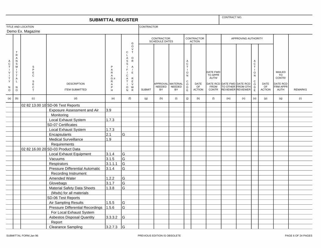
SUBMITTAL FORM,Jan 96 PREVIOUS EDITION IS OBSOLETE PAGE 6 OF 24 PAGES
Demo Ex. Magazine
02 82 13.00 10 SD-06 Test Reports3.9Exposure Assessment and Air
Monitoring1.7.3Local Exhaust System
SD-07 Certificates1.7.3Local Exhaust System2.1 GEncapsulants1.9Medical Surveillance
Requirements02 82 16.00 20 SD-03 Product Data
3.1.4 GLocal Exhaust Equipment3.1.5 GVacuums3.1.1.1 GRespirators3.1.4 GPressure Differential Automatic
Recording Instrument1.2.2 GAmended Water3.1.7 GGlovebags1.3.8 GMaterial Safety Data Sheets
(Msds) for all materialsSD-06 Test Reports
1.5.5 GAir Sampling Results1.5.6 GPressure Differential Recordings
For Local Exhaust System3.3.3.2 GAsbestos Disposal Quantity
Report3.2.7.3 GClearance Sampling
SUBMITTAL REGISTERCONTRACT NO.
TITLE AND LOCATION CONTRACTOR
CONTRACTOR:SCHEDULE DATES
CONTRACTORACTION
APPROVING AUTHORITY
ACTIVITY NO
TRANSMITTAL NO
SPEC SECT
DESCRIPTION
ITEM SUBMITTED
PARAGRAPH
#
CLASSIFICATION
GOVT OR A/E REVWR SUBMIT
APPROVALNEEDED
BY
MATERIALNEEDED
BY
ACTION CODE
DATEOF
ACTION
DATE FWDTO APPR
AUTH/
DATE RCDFROM
CONTR
DATE FWDTO OTHERREVIEWER
DATE RCDFROM OTHREVIEWER
ACTION CODE
DATEOF
ACTION
MAILEDTO
CONTR/
DATE RCDFRM APPR
AUTH REMARKS
(a) (b) (c) (d) (e) (f) (g) (h) (i) (j) (k) (l) (m) (n) (o) (p) (q) (r)

SUBMITTAL FORM,Jan 96 PREVIOUS EDITION IS OBSOLETE PAGE 7 OF 24 PAGES
Demo Ex. Magazine
02 82 16.00 20 SD-07 Certificates1.3.9 GAsbestos Hazard Abatement
Plan1.3.10 GTesting Laboratory1.5.1 GPrivate Qualified Person
Documentation1.5.4 GContractor's License1.5.2 GCompetent Person1.5.3 GWorker's License1.3.11 GLandfill Approval1.3.3 GEmployee Training1.3.12 GMedical Certification1.3.11 GWaste Shipment Records1.3.6 GRespiratory Protection Program1.3.11 GDelivery Tickets3.1.5 GVacuums3.1.2.3 GWater Filtration Equipment3.1.5 GVentilation Systems3.1 GEquipment Used To Contain
Airborne Asbestos Fibers1.3.4Notifications
SD-11 Closeout Submittals1.3.4 GNotifications1.6.1 GRental Equipment1.3.6.1 GRespirator Program Records1.3.4 GPermits and Licenses
SUBMITTAL REGISTERCONTRACT NO.
TITLE AND LOCATION CONTRACTOR
CONTRACTOR:SCHEDULE DATES
CONTRACTORACTION
APPROVING AUTHORITY
ACTIVITY NO
TRANSMITTAL NO
SPEC SECT
DESCRIPTION
ITEM SUBMITTED
PARAGRAPH
#
CLASSIFICATION
GOVT OR A/E REVWR SUBMIT
APPROVALNEEDED
BY
MATERIALNEEDED
BY
ACTION CODE
DATEOF
ACTION
DATE FWDTO APPR
AUTH/
DATE RCDFROM
CONTR
DATE FWDTO OTHERREVIEWER
DATE RCDFROM OTHREVIEWER
ACTION CODE
DATEOF
ACTION
MAILEDTO
CONTR/
DATE RCDFRM APPR
AUTH REMARKS
(a) (b) (c) (d) (e) (f) (g) (h) (i) (j) (k) (l) (m) (n) (o) (p) (q) (r)
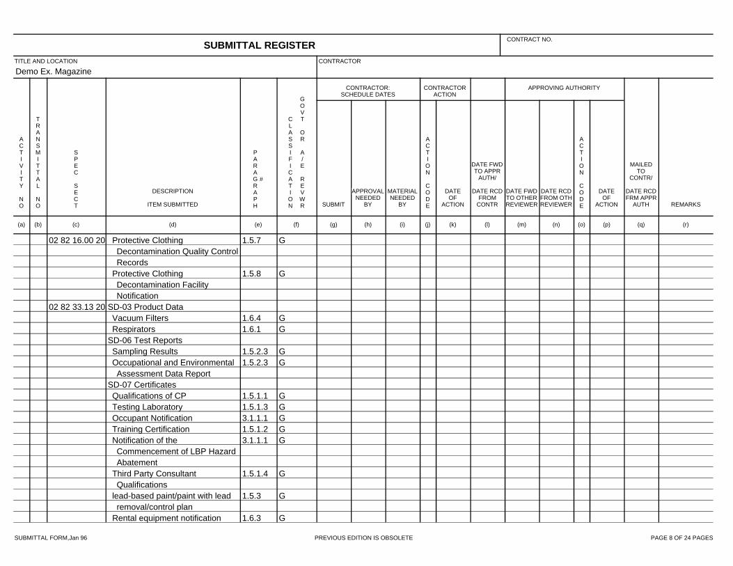
SUBMITTAL FORM,Jan 96 PREVIOUS EDITION IS OBSOLETE PAGE 8 OF 24 PAGES
Demo Ex. Magazine
02 82 16.00 20 1.5.7 GProtective ClothingDecontamination Quality ControlRecords
1.5.8 GProtective ClothingDecontamination FacilityNotification
02 82 33.13 20 SD-03 Product Data1.6.4 GVacuum Filters1.6.1 GRespirators
SD-06 Test Reports1.5.2.3 GSampling Results1.5.2.3 GOccupational and Environmental
Assessment Data ReportSD-07 Certificates
1.5.1.1 GQualifications of CP1.5.1.3 GTesting Laboratory3.1.1.1 GOccupant Notification1.5.1.2 GTraining Certification3.1.1.1 GNotification of the
Commencement of LBP HazardAbatement
1.5.1.4 GThird Party ConsultantQualifications
1.5.3 Glead-based paint/paint with leadremoval/control plan
1.6.3 GRental equipment notification
SUBMITTAL REGISTERCONTRACT NO.
TITLE AND LOCATION CONTRACTOR
CONTRACTOR:SCHEDULE DATES
CONTRACTORACTION
APPROVING AUTHORITY
ACTIVITY NO
TRANSMITTAL NO
SPEC SECT
DESCRIPTION
ITEM SUBMITTED
PARAGRAPH
#
CLASSIFICATION
GOVT OR A/E REVWR SUBMIT
APPROVALNEEDED
BY
MATERIALNEEDED
BY
ACTION CODE
DATEOF
ACTION
DATE FWDTO APPR
AUTH/
DATE RCDFROM
CONTR
DATE FWDTO OTHERREVIEWER
DATE RCDFROM OTHREVIEWER
ACTION CODE
DATEOF
ACTION
MAILEDTO
CONTR/
DATE RCDFRM APPR
AUTH REMARKS
(a) (b) (c) (d) (e) (f) (g) (h) (i) (j) (k) (l) (m) (n) (o) (p) (q) (r)

SUBMITTAL FORM,Jan 96 PREVIOUS EDITION IS OBSOLETE PAGE 9 OF 24 PAGES
Demo Ex. Magazine
02 82 33.13 20 1.5.2.6 GRespiratory Protection Program1.5.2.7 GHazard Communication Program3.5.2 GEPA or State approved
hazardous waste treatment,storage, or disposal facility
1.5.2.8 GLead Waste Management Plan1.6.4 GVacuum filters3.5.1.1 GClearance Certification
SD-11 Closeout Submittals3.5.2.1 GHazardous Waste Manifest1.5.2.4 GMedical Examinations1.5.1.2 GTraining Certification3.5.2.1 GTurn-In Documents or Weight
Tickets02 83 13.00 20 SD-06 Test Reports
1.5.2.3 GSampling ResultsGOccupational and Environmental
Assessment Data Report1.5.2.3 GOccupational and Environmental
Assessment Data ReportSD-07 Certificates
1.5.1.3 GTesting Laboratory1.5.1.4 GThird party consultant
qualificationsSD-11 Closeout Submittals
3.5.2.1 Ghazardous waste manifest
SUBMITTAL REGISTERCONTRACT NO.
TITLE AND LOCATION CONTRACTOR
CONTRACTOR:SCHEDULE DATES
CONTRACTORACTION
APPROVING AUTHORITY
ACTIVITY NO
TRANSMITTAL NO
SPEC SECT
DESCRIPTION
ITEM SUBMITTED
PARAGRAPH
#
CLASSIFICATION
GOVT OR A/E REVWR SUBMIT
APPROVALNEEDED
BY
MATERIALNEEDED
BY
ACTION CODE
DATEOF
ACTION
DATE FWDTO APPR
AUTH/
DATE RCDFROM
CONTR
DATE FWDTO OTHERREVIEWER
DATE RCDFROM OTHREVIEWER
ACTION CODE
DATEOF
ACTION
MAILEDTO
CONTR/
DATE RCDFRM APPR
AUTH REMARKS
(a) (b) (c) (d) (e) (f) (g) (h) (i) (j) (k) (l) (m) (n) (o) (p) (q) (r)
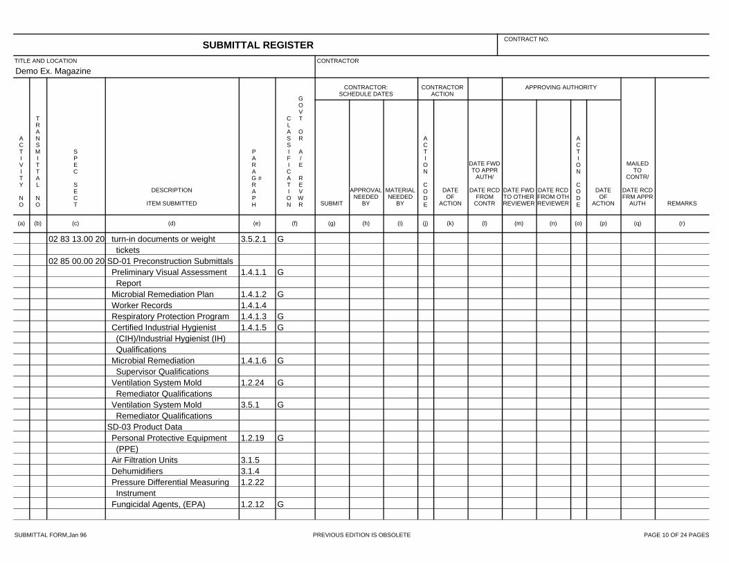
SUBMITTAL FORM,Jan 96 PREVIOUS EDITION IS OBSOLETE PAGE 10 OF 24 PAGES
Demo Ex. Magazine
02 83 13.00 20 3.5.2.1 Gturn-in documents or weighttickets
02 85 00.00 20 SD-01 Preconstruction Submittals1.4.1.1 GPreliminary Visual Assessment
Report1.4.1.2 GMicrobial Remediation Plan1.4.1.4Worker Records1.4.1.3 GRespiratory Protection Program1.4.1.5 GCertified Industrial Hygienist
(CIH)/Industrial Hygienist (IH)Qualifications
1.4.1.6 GMicrobial RemediationSupervisor Qualifications
1.2.24 GVentilation System MoldRemediator Qualifications
3.5.1 GVentilation System MoldRemediator Qualifications
SD-03 Product Data1.2.19 GPersonal Protective Equipment
(PPE)3.1.5Air Filtration Units3.1.4Dehumidifiers1.2.22Pressure Differential Measuring
Instrument1.2.12 GFungicidal Agents, (EPA)
SUBMITTAL REGISTERCONTRACT NO.
TITLE AND LOCATION CONTRACTOR
CONTRACTOR:SCHEDULE DATES
CONTRACTORACTION
APPROVING AUTHORITY
ACTIVITY NO
TRANSMITTAL NO
SPEC SECT
DESCRIPTION
ITEM SUBMITTED
PARAGRAPH
#
CLASSIFICATION
GOVT OR A/E REVWR SUBMIT
APPROVALNEEDED
BY
MATERIALNEEDED
BY
ACTION CODE
DATEOF
ACTION
DATE FWDTO APPR
AUTH/
DATE RCDFROM
CONTR
DATE FWDTO OTHERREVIEWER
DATE RCDFROM OTHREVIEWER
ACTION CODE
DATEOF
ACTION
MAILEDTO
CONTR/
DATE RCDFRM APPR
AUTH REMARKS
(a) (b) (c) (d) (e) (f) (g) (h) (i) (j) (k) (l) (m) (n) (o) (p) (q) (r)

SUBMITTAL FORM,Jan 96 PREVIOUS EDITION IS OBSOLETE PAGE 11 OF 24 PAGES
Demo Ex. Magazine
02 85 00.00 20 1.2.10 GDisinfectants or BiocideSanitizing Solutions
SD-06 Test Reports1.4.3 GDaily Reports
SD-11 Closeout Submittals1.4.4 GSubmittals at Completion of
Remediation Work05 12 00 SD-01 Preconstruction Submittals
1.5.1.1 GErection DrawingsSD-02 Shop Drawings
1.5.2 GFabrication DrawingsSD-03 Product Data
2.6.2Shop Primer2.3.2.3Direct Tension Indicator Washers2.4.2Non-Shrink Grout
SD-06 Test Reports2.6.2Class B Coating2.3Bolts, Nuts, and Washers
SD-07 Certificates2.2Steel2.3Bolts, Nuts, and Washers2.5Galvanizing
05 30 00 SD-02 Shop Drawings1.3.5 GFabrication Drawings
SD-03 Product Data2.2Accessories
SUBMITTAL REGISTERCONTRACT NO.
TITLE AND LOCATION CONTRACTOR
CONTRACTOR:SCHEDULE DATES
CONTRACTORACTION
APPROVING AUTHORITY
ACTIVITY NO
TRANSMITTAL NO
SPEC SECT
DESCRIPTION
ITEM SUBMITTED
PARAGRAPH
#
CLASSIFICATION
GOVT OR A/E REVWR SUBMIT
APPROVALNEEDED
BY
MATERIALNEEDED
BY
ACTION CODE
DATEOF
ACTION
DATE FWDTO APPR
AUTH/
DATE RCDFROM
CONTR
DATE FWDTO OTHERREVIEWER
DATE RCDFROM OTHREVIEWER
ACTION CODE
DATEOF
ACTION
MAILEDTO
CONTR/
DATE RCDFRM APPR
AUTH REMARKS
(a) (b) (c) (d) (e) (f) (g) (h) (i) (j) (k) (l) (m) (n) (o) (p) (q) (r)

SUBMITTAL FORM,Jan 96 PREVIOUS EDITION IS OBSOLETE PAGE 12 OF 24 PAGES
Demo Ex. Magazine
05 30 00 2.1Deck Units2.1.4Galvanizing Repair Paint2.2.18Mechanical Fasteners2.1.4Touch-Up Paint
Sound Absorbing Materials1.3.3Welding Equipment1.3.3Welding Rods and Accessories
SD-04 Samples2.1.1Metal Roof Deck Units
Cellular Metal Floor Deck Units2.2.4Flexible Closure Strips2.2.17Acoustical Material
SD-05 Design Data2.1 GDeck Units
SD-07 Certificates1.3.2Powder-Actuated Tool Operator1.3.3Welder Qualifications1.3.3Welding Procedures1.3.4.1Fire Safety1.3.4.2Wind Storm Resistance1.3.1Manufacturer's Certificate2.2.12Stud Manufacture's Certification2.2.12Stud Manufacture's Test Reports
05 40 00 SD-02 Shop Drawings1.6.1 GFraming Components
SD-03 Product Data
SUBMITTAL REGISTERCONTRACT NO.
TITLE AND LOCATION CONTRACTOR
CONTRACTOR:SCHEDULE DATES
CONTRACTORACTION
APPROVING AUTHORITY
ACTIVITY NO
TRANSMITTAL NO
SPEC SECT
DESCRIPTION
ITEM SUBMITTED
PARAGRAPH
#
CLASSIFICATION
GOVT OR A/E REVWR SUBMIT
APPROVALNEEDED
BY
MATERIALNEEDED
BY
ACTION CODE
DATEOF
ACTION
DATE FWDTO APPR
AUTH/
DATE RCDFROM
CONTR
DATE FWDTO OTHERREVIEWER
DATE RCDFROM OTHREVIEWER
ACTION CODE
DATEOF
ACTION
MAILEDTO
CONTR/
DATE RCDFRM APPR
AUTH REMARKS
(a) (b) (c) (d) (e) (f) (g) (h) (i) (j) (k) (l) (m) (n) (o) (p) (q) (r)
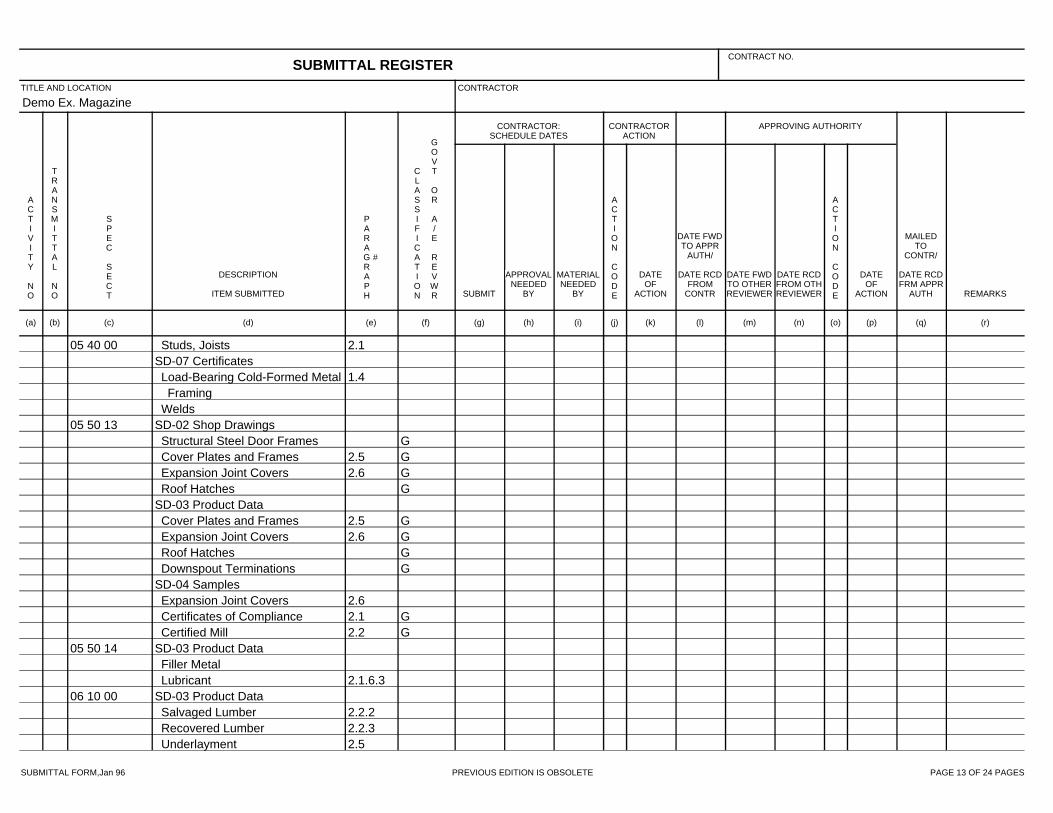
SUBMITTAL FORM,Jan 96 PREVIOUS EDITION IS OBSOLETE PAGE 13 OF 24 PAGES
Demo Ex. Magazine
05 40 00 2.1Studs, JoistsSD-07 Certificates
1.4Load-Bearing Cold-Formed MetalFraming
Welds05 50 13 SD-02 Shop Drawings
GStructural Steel Door Frames2.5 GCover Plates and Frames2.6 GExpansion Joint Covers
GRoof HatchesSD-03 Product Data
2.5 GCover Plates and Frames2.6 GExpansion Joint Covers
GRoof HatchesGDownspout Terminations
SD-04 Samples2.6Expansion Joint Covers2.1 GCertificates of Compliance2.2 GCertified Mill
05 50 14 SD-03 Product DataFiller Metal
2.1.6.3Lubricant06 10 00 SD-03 Product Data
2.2.2Salvaged Lumber2.2.3Recovered Lumber2.5Underlayment
SUBMITTAL REGISTERCONTRACT NO.
TITLE AND LOCATION CONTRACTOR
CONTRACTOR:SCHEDULE DATES
CONTRACTORACTION
APPROVING AUTHORITY
ACTIVITY NO
TRANSMITTAL NO
SPEC SECT
DESCRIPTION
ITEM SUBMITTED
PARAGRAPH
#
CLASSIFICATION
GOVT OR A/E REVWR SUBMIT
APPROVALNEEDED
BY
MATERIALNEEDED
BY
ACTION CODE
DATEOF
ACTION
DATE FWDTO APPR
AUTH/
DATE RCDFROM
CONTR
DATE FWDTO OTHERREVIEWER
DATE RCDFROM OTHREVIEWER
ACTION CODE
DATEOF
ACTION
MAILEDTO
CONTR/
DATE RCDFRM APPR
AUTH REMARKS
(a) (b) (c) (d) (e) (f) (g) (h) (i) (j) (k) (l) (m) (n) (o) (p) (q) (r)

SUBMITTAL FORM,Jan 96 PREVIOUS EDITION IS OBSOLETE PAGE 14 OF 24 PAGES
Demo Ex. Magazine
06 10 00 1.4.4Structural-use and OSB Panels2.4.3.2Structural-use and OSB Panels2.4Oriented Strand Board2.6.7Adhesives
SD-06 Test Reports1.4.5Preservative-treated
SD-07 Certificates1.11.1Certificates of Grade
GCertified Sustainably HarvestedWood
1.7Preservative Treatment1.11.2Indoor Air Quality
06 20 00 SD-02 Shop Drawings1.3 GDetail Drawings Indicating All
Wood AssembliesSD-03 Product Data
2.2 GWood Products1.4 GTreated Wood Products2.3 GSoffits2.4 GFascias and Trim2.8 GHardware and Accessories
SD-04 Samples1.5 GSamples
SD-07 Certificates1.7.1.1 GCertificates of Grade
SUBMITTAL REGISTERCONTRACT NO.
TITLE AND LOCATION CONTRACTOR
CONTRACTOR:SCHEDULE DATES
CONTRACTORACTION
APPROVING AUTHORITY
ACTIVITY NO
TRANSMITTAL NO
SPEC SECT
DESCRIPTION
ITEM SUBMITTED
PARAGRAPH
#
CLASSIFICATION
GOVT OR A/E REVWR SUBMIT
APPROVALNEEDED
BY
MATERIALNEEDED
BY
ACTION CODE
DATEOF
ACTION
DATE FWDTO APPR
AUTH/
DATE RCDFROM
CONTR
DATE FWDTO OTHERREVIEWER
DATE RCDFROM OTHREVIEWER
ACTION CODE
DATEOF
ACTION
MAILEDTO
CONTR/
DATE RCDFRM APPR
AUTH REMARKS
(a) (b) (c) (d) (e) (f) (g) (h) (i) (j) (k) (l) (m) (n) (o) (p) (q) (r)

SUBMITTAL FORM,Jan 96 PREVIOUS EDITION IS OBSOLETE PAGE 15 OF 24 PAGES
Demo Ex. Magazine
06 20 00 1.7.1.2 GCertified Sustainably HarvestedWood
07 22 00 SD-02 Shop Drawings1.3 GInsulation Board Layout1.3 GVerification of Existing Conditions
SD-03 Product Data2.2 GInsulation1.4 GCover Board2.7 GFasteners2.5 GSheathing Paper2.6 GMoisture Control1.10.1 GAsphalt2.4.3 GAsphalt
SD-06 Test Reports1.8.1 GFlame Spread Rating
SD-07 Certificates1.9 GVolatile Organic Compounds
(VOC) Content1.6 GInstaller Qualifications1.6 GCertificates Of Compliance For
Felt MaterialsSD-08 Manufacturer’s Instructions
2.7 GFasteners2.2 GInsulation
07 53 23 SD-02 Shop Drawings1.3.1Roof Plan Drawing
SUBMITTAL REGISTERCONTRACT NO.
TITLE AND LOCATION CONTRACTOR
CONTRACTOR:SCHEDULE DATES
CONTRACTORACTION
APPROVING AUTHORITY
ACTIVITY NO
TRANSMITTAL NO
SPEC SECT
DESCRIPTION
ITEM SUBMITTED
PARAGRAPH
#
CLASSIFICATION
GOVT OR A/E REVWR SUBMIT
APPROVALNEEDED
BY
MATERIALNEEDED
BY
ACTION CODE
DATEOF
ACTION
DATE FWDTO APPR
AUTH/
DATE RCDFROM
CONTR
DATE FWDTO OTHERREVIEWER
DATE RCDFROM OTHREVIEWER
ACTION CODE
DATEOF
ACTION
MAILEDTO
CONTR/
DATE RCDFRM APPR
AUTH REMARKS
(a) (b) (c) (d) (e) (f) (g) (h) (i) (j) (k) (l) (m) (n) (o) (p) (q) (r)

SUBMITTAL FORM,Jan 96 PREVIOUS EDITION IS OBSOLETE PAGE 16 OF 24 PAGES
Demo Ex. Magazine
07 53 23 1.3.1Wind Load Calculations1.3.1Boundaries of Enhanced
Perimeter1.3.1Corner Attachments of Roof
System Components1.3.1Location of Perimeter
Half-Sheets1.3.1Spacing of Perimeter, Corner,
and Infield Fasteners1.3.1Slopes and Drain Locations
SD-03 Product Data2.2Cement2.1.1 GEPDM Sheet2.1.2Seam Tape2.1.4Bonding Adhesive2.1.3Lap Splice Adhesive2.1.6Water Cutoff Mastic/Water Block2.1.5Lap Cleaner, Lap Sealant, and
Edge Treatment3.3Flashings2.1.7Flashing Accessories2.1.7.1Flashing Tape2.1.8Fasteners and Plates2.1.11Roof Insulation2.1.10Pre-Manufactured Accessories1.8 Gwarranty
SUBMITTAL REGISTERCONTRACT NO.
TITLE AND LOCATION CONTRACTOR
CONTRACTOR:SCHEDULE DATES
CONTRACTORACTION
APPROVING AUTHORITY
ACTIVITY NO
TRANSMITTAL NO
SPEC SECT
DESCRIPTION
ITEM SUBMITTED
PARAGRAPH
#
CLASSIFICATION
GOVT OR A/E REVWR SUBMIT
APPROVALNEEDED
BY
MATERIALNEEDED
BY
ACTION CODE
DATEOF
ACTION
DATE FWDTO APPR
AUTH/
DATE RCDFROM
CONTR
DATE FWDTO OTHERREVIEWER
DATE RCDFROM OTHREVIEWER
ACTION CODE
DATEOF
ACTION
MAILEDTO
CONTR/
DATE RCDFRM APPR
AUTH REMARKS
(a) (b) (c) (d) (e) (f) (g) (h) (i) (j) (k) (l) (m) (n) (o) (p) (q) (r)

SUBMITTAL FORM,Jan 96 PREVIOUS EDITION IS OBSOLETE PAGE 17 OF 24 PAGES
Demo Ex. Magazine
07 53 23 SD-07 Certificates1.4.1Qualification of Manufacturer1.4.2Qualification of Applicator1.4.5 GWind Uplift Resistance1.4.4 GFire Resistance
SD-08 Manufacturer’s Instructions3.2 GApplication3.2.3 GApplication Method3.3.2 GMembrane Flashing2.1.2Seam Tape3.2.4Tape Seams / Lap Splices3.2.5Adhesive Seams / Lap Splices3.2.6Perimeter Attachment3.2.4Primer3.2.7Fasteners
Pavers2.1.9Protection Mat2.1.10Pre-Manufactured Accessories1.6 GCold Weather
SD-11 Closeout Submittals1.8Warranty3.9Information Card3.8Instructions To Government
Personnel07 60 00 SD-02 Shop Drawings
2.2.1 GExposed Sheet Metal
SUBMITTAL REGISTERCONTRACT NO.
TITLE AND LOCATION CONTRACTOR
CONTRACTOR:SCHEDULE DATES
CONTRACTORACTION
APPROVING AUTHORITY
ACTIVITY NO
TRANSMITTAL NO
SPEC SECT
DESCRIPTION
ITEM SUBMITTED
PARAGRAPH
#
CLASSIFICATION
GOVT OR A/E REVWR SUBMIT
APPROVALNEEDED
BY
MATERIALNEEDED
BY
ACTION CODE
DATEOF
ACTION
DATE FWDTO APPR
AUTH/
DATE RCDFROM
CONTR
DATE FWDTO OTHERREVIEWER
DATE RCDFROM OTHREVIEWER
ACTION CODE
DATEOF
ACTION
MAILEDTO
CONTR/
DATE RCDFRM APPR
AUTH REMARKS
(a) (b) (c) (d) (e) (f) (g) (h) (i) (j) (k) (l) (m) (n) (o) (p) (q) (r)
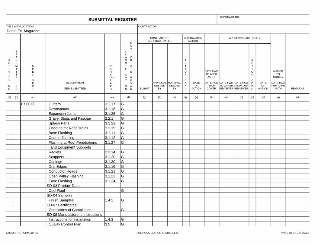
SUBMITTAL FORM,Jan 96 PREVIOUS EDITION IS OBSOLETE PAGE 18 OF 24 PAGES
Demo Ex. Magazine
07 60 00 3.1.17 GGutters3.1.18 GDownspouts3.1.26 GExpansion Joints2.2.1 GGravel Stops and Fasciae3.1.22 GSplash Pans3.1.19 GFlashing for Roof Drains3.1.11 GBase Flashing3.1.12 GCounterflashing3.1.27 GFlashing at Roof Penetrations
and Equipment Supports2.2.14 GReglets3.1.20 GScuppers3.1.30 GCopings3.1.16 GDrip Edges3.1.21 GConductor Heads3.1.23 GOpen Valley Flashing3.1.24 GEave Flashing
SD-03 Product DataGCool Roof
SD-04 Samples1.4.2 GFinish Samples
SD-07 CertificatesGCertificates of Compliance
SD-08 Manufacturer’s Instructions1.4.3 GInstructions for Installation3.5 GQuality Control Plan
SUBMITTAL REGISTERCONTRACT NO.
TITLE AND LOCATION CONTRACTOR
CONTRACTOR:SCHEDULE DATES
CONTRACTORACTION
APPROVING AUTHORITY
ACTIVITY NO
TRANSMITTAL NO
SPEC SECT
DESCRIPTION
ITEM SUBMITTED
PARAGRAPH
#
CLASSIFICATION
GOVT OR A/E REVWR SUBMIT
APPROVALNEEDED
BY
MATERIALNEEDED
BY
ACTION CODE
DATEOF
ACTION
DATE FWDTO APPR
AUTH/
DATE RCDFROM
CONTR
DATE FWDTO OTHERREVIEWER
DATE RCDFROM OTHREVIEWER
ACTION CODE
DATEOF
ACTION
MAILEDTO
CONTR/
DATE RCDFRM APPR
AUTH REMARKS
(a) (b) (c) (d) (e) (f) (g) (h) (i) (j) (k) (l) (m) (n) (o) (p) (q) (r)

SUBMITTAL FORM,Jan 96 PREVIOUS EDITION IS OBSOLETE PAGE 19 OF 24 PAGES
Demo Ex. Magazine
07 60 00 SD-10 Operation and MaintenanceData
1.4.3 GCleaning and Maintenance07 92 00 SD-03 Product Data
2.2 GSealants2.3 GPrimers2.4 GBond Breakers2.5 GBackstops3.1 GField Adhesion
SD-07 Certificates1.4.1 GIndoor Air Quality
08 60 45 SD-02 Shop Drawings3.2 GShop Drawings
SD-03 Product Data2.1 GSkylights1.6Warranty
SD-06 Test Reports2.1Test Reports
SD-07 Certificates2.5Systems1.4Qualifications
09 97 13.00 40 SD-01 Preconstruction SubmittalsPart 2 GMaterial, Equipment, and Fixture
Lists1.3 GSafety Plan
SD-03 Product Data
SUBMITTAL REGISTERCONTRACT NO.
TITLE AND LOCATION CONTRACTOR
CONTRACTOR:SCHEDULE DATES
CONTRACTORACTION
APPROVING AUTHORITY
ACTIVITY NO
TRANSMITTAL NO
SPEC SECT
DESCRIPTION
ITEM SUBMITTED
PARAGRAPH
#
CLASSIFICATION
GOVT OR A/E REVWR SUBMIT
APPROVALNEEDED
BY
MATERIALNEEDED
BY
ACTION CODE
DATEOF
ACTION
DATE FWDTO APPR
AUTH/
DATE RCDFROM
CONTR
DATE FWDTO OTHERREVIEWER
DATE RCDFROM OTHREVIEWER
ACTION CODE
DATEOF
ACTION
MAILEDTO
CONTR/
DATE RCDFRM APPR
AUTH REMARKS
(a) (b) (c) (d) (e) (f) (g) (h) (i) (j) (k) (l) (m) (n) (o) (p) (q) (r)
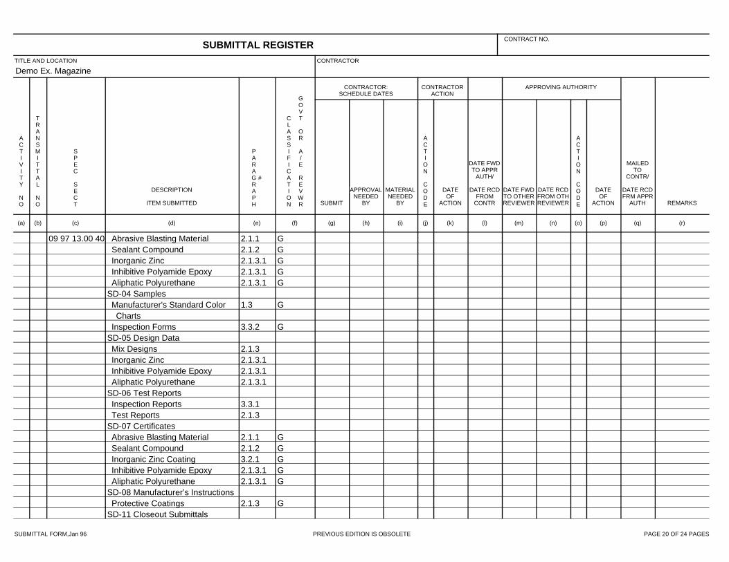
SUBMITTAL FORM,Jan 96 PREVIOUS EDITION IS OBSOLETE PAGE 20 OF 24 PAGES
Demo Ex. Magazine
09 97 13.00 40 2.1.1 GAbrasive Blasting Material2.1.2 GSealant Compound2.1.3.1 GInorganic Zinc2.1.3.1 GInhibitive Polyamide Epoxy2.1.3.1 GAliphatic Polyurethane
SD-04 Samples1.3 GManufacturer's Standard Color
Charts3.3.2 GInspection Forms
SD-05 Design Data2.1.3Mix Designs2.1.3.1Inorganic Zinc2.1.3.1Inhibitive Polyamide Epoxy2.1.3.1Aliphatic Polyurethane
SD-06 Test Reports3.3.1Inspection Reports2.1.3Test Reports
SD-07 Certificates2.1.1 GAbrasive Blasting Material2.1.2 GSealant Compound3.2.1 GInorganic Zinc Coating2.1.3.1 GInhibitive Polyamide Epoxy2.1.3.1 GAliphatic Polyurethane
SD-08 Manufacturer’s Instructions2.1.3 GProtective Coatings
SD-11 Closeout Submittals
SUBMITTAL REGISTERCONTRACT NO.
TITLE AND LOCATION CONTRACTOR
CONTRACTOR:SCHEDULE DATES
CONTRACTORACTION
APPROVING AUTHORITY
ACTIVITY NO
TRANSMITTAL NO
SPEC SECT
DESCRIPTION
ITEM SUBMITTED
PARAGRAPH
#
CLASSIFICATION
GOVT OR A/E REVWR SUBMIT
APPROVALNEEDED
BY
MATERIALNEEDED
BY
ACTION CODE
DATEOF
ACTION
DATE FWDTO APPR
AUTH/
DATE RCDFROM
CONTR
DATE FWDTO OTHERREVIEWER
DATE RCDFROM OTHREVIEWER
ACTION CODE
DATEOF
ACTION
MAILEDTO
CONTR/
DATE RCDFRM APPR
AUTH REMARKS
(a) (b) (c) (d) (e) (f) (g) (h) (i) (j) (k) (l) (m) (n) (o) (p) (q) (r)

SUBMITTAL FORM,Jan 96 PREVIOUS EDITION IS OBSOLETE PAGE 21 OF 24 PAGES
Demo Ex. Magazine
09 97 13.00 40 1.5 GWarranty23 07 00 SD-02 Shop Drawings
3.2.2.4 GMICA Plates2.4Pipe Insulation Systems3.2Pipe Insulation Systems3.3Duct Insulation Systems3.4Equipment Insulation Systems
SD-03 Product Data2.4 GPipe Insulation Systems3.2 GPipe Insulation Systems3.3 GDuct Insulation Systems3.4 GEquipment Insulation Systems
SD-04 Samples2.3.1.3 GThermal Insulation3.1.1 GDisplay Samples
SD-08 Manufacturer’s Instructions2.4 GPipe Insulation Systems3.2 GPipe Insulation Systems3.3 GDuct Insulation Systems3.4 GEquipment Insulation Systems
26 05 00.00 40 SD-01 Preconstruction Submittals2.1Material, Equipment, and Fixture
ListsSD-03 Product Data
2.1.1 GConduits and Raceways2.1.3 GWire and Cable
SUBMITTAL REGISTERCONTRACT NO.
TITLE AND LOCATION CONTRACTOR
CONTRACTOR:SCHEDULE DATES
CONTRACTORACTION
APPROVING AUTHORITY
ACTIVITY NO
TRANSMITTAL NO
SPEC SECT
DESCRIPTION
ITEM SUBMITTED
PARAGRAPH
#
CLASSIFICATION
GOVT OR A/E REVWR SUBMIT
APPROVALNEEDED
BY
MATERIALNEEDED
BY
ACTION CODE
DATEOF
ACTION
DATE FWDTO APPR
AUTH/
DATE RCDFROM
CONTR
DATE FWDTO OTHERREVIEWER
DATE RCDFROM OTHREVIEWER
ACTION CODE
DATEOF
ACTION
MAILEDTO
CONTR/
DATE RCDFRM APPR
AUTH REMARKS
(a) (b) (c) (d) (e) (f) (g) (h) (i) (j) (k) (l) (m) (n) (o) (p) (q) (r)
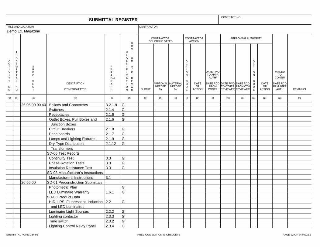
SUBMITTAL FORM,Jan 96 PREVIOUS EDITION IS OBSOLETE PAGE 22 OF 24 PAGES
Demo Ex. Magazine
26 05 00.00 40 3.2.1.9 GSplices and Connectors2.1.4 GSwitches2.1.5 GReceptacles2.1.6 GOutlet Boxes, Pull Boxes and
Junction Boxes2.1.8 GCircuit Breakers2.1.7 GPanelboards2.1.9 GLamps and Lighting Fixtures2.1.12 GDry-Type Distribution
TransformersSD-06 Test Reports
3.3 GContinuity Test3.3 GPhase-Rotation Tests3.3 GInsulation Resistance Test
SD-08 Manufacturer’s Instructions3.1Manufacturer's Instructions
26 56 00 SD-01 Preconstruction SubmittalsGPhotometric Plan
1.6.1 GLED Luminaire WarrantySD-03 Product Data
2.2 GHID, LPS, Fluorescent, Inductionand LED Luminaires
2.2.2 GLuminaire Light Sources2.3.3 GLighting contactor2.3.2 GTime switch2.3.4 GLighting Control Relay Panel
SUBMITTAL REGISTERCONTRACT NO.
TITLE AND LOCATION CONTRACTOR
CONTRACTOR:SCHEDULE DATES
CONTRACTORACTION
APPROVING AUTHORITY
ACTIVITY NO
TRANSMITTAL NO
SPEC SECT
DESCRIPTION
ITEM SUBMITTED
PARAGRAPH
#
CLASSIFICATION
GOVT OR A/E REVWR SUBMIT
APPROVALNEEDED
BY
MATERIALNEEDED
BY
ACTION CODE
DATEOF
ACTION
DATE FWDTO APPR
AUTH/
DATE RCDFROM
CONTR
DATE FWDTO OTHERREVIEWER
DATE RCDFROM OTHREVIEWER
ACTION CODE
DATEOF
ACTION
MAILEDTO
CONTR/
DATE RCDFRM APPR
AUTH REMARKS
(a) (b) (c) (d) (e) (f) (g) (h) (i) (j) (k) (l) (m) (n) (o) (p) (q) (r)

SUBMITTAL FORM,Jan 96 PREVIOUS EDITION IS OBSOLETE PAGE 23 OF 24 PAGES
Demo Ex. Magazine
26 56 00 2.3.5 GMotion Sensor2.3.6 GBi-level HID Controller2.3.1 GPhotocell2.4Brackets
GObstruction Marker LuminairesSD-04 Samples
2.2 GHID, LPS, Fluorescent, Inductionand LED Luminaires
SD-06 Test Reports1.5.2 GLED Luminaire - IES LM-79 Test
Report1.5.3 GLED Light Source - IES LM-80
Test Report3.2Operating test
SD-07 Certificates1.6.1 GLuminaire Useful Life Certificate
SD-10 Operation and MaintenanceData
1.6.2Electronic Ballast Warranty1.7Operational Service
26 56 23.00 40 SD-02 Shop Drawings1.4.1.1 GLuminaire drawings
SD-03 Product Data1.6.1 GLocal/Regional Materials1.6.2 GEnergy Efficiency2.2 GLuminaires
SUBMITTAL REGISTERCONTRACT NO.
TITLE AND LOCATION CONTRACTOR
CONTRACTOR:SCHEDULE DATES
CONTRACTORACTION
APPROVING AUTHORITY
ACTIVITY NO
TRANSMITTAL NO
SPEC SECT
DESCRIPTION
ITEM SUBMITTED
PARAGRAPH
#
CLASSIFICATION
GOVT OR A/E REVWR SUBMIT
APPROVALNEEDED
BY
MATERIALNEEDED
BY
ACTION CODE
DATEOF
ACTION
DATE FWDTO APPR
AUTH/
DATE RCDFROM
CONTR
DATE FWDTO OTHERREVIEWER
DATE RCDFROM OTHREVIEWER
ACTION CODE
DATEOF
ACTION
MAILEDTO
CONTR/
DATE RCDFRM APPR
AUTH REMARKS
(a) (b) (c) (d) (e) (f) (g) (h) (i) (j) (k) (l) (m) (n) (o) (p) (q) (r)

SUBMITTAL FORM,Jan 96 PREVIOUS EDITION IS OBSOLETE PAGE 24 OF 24 PAGES
Demo Ex. Magazine
26 56 23.00 40 2.2.1 GLamps2.2.2 GBallasts
SD-08 Manufacturer’s Instructions2.2Mounting Details
SD-10 Operation and MaintenanceData
1.8 GOperational Service
SUBMITTAL REGISTERCONTRACT NO.
TITLE AND LOCATION CONTRACTOR
CONTRACTOR:SCHEDULE DATES
CONTRACTORACTION
APPROVING AUTHORITY
ACTIVITY NO
TRANSMITTAL NO
SPEC SECT
DESCRIPTION
ITEM SUBMITTED
PARAGRAPH
#
CLASSIFICATION
GOVT OR A/E REVWR SUBMIT
APPROVALNEEDED
BY
MATERIALNEEDED
BY
ACTION CODE
DATEOF
ACTION
DATE FWDTO APPR
AUTH/
DATE RCDFROM
CONTR
DATE FWDTO OTHERREVIEWER
DATE RCDFROM OTHREVIEWER
ACTION CODE
DATEOF
ACTION
MAILEDTO
CONTR/
DATE RCDFRM APPR
AUTH REMARKS
(a) (b) (c) (d) (e) (f) (g) (h) (i) (j) (k) (l) (m) (n) (o) (p) (q) (r)