CONTRACT SPECIFICATIONS - Yakima County
670
CONTRACT SPECIFICATIONS For The Construction Of: Terrace Heights Landfill Scale Plaza Upgrades SP-3600G Yakima County Public Services Project
-
Upload
khangminh22 -
Category
Documents
-
view
0 -
download
0
Transcript of CONTRACT SPECIFICATIONS - Yakima County
CONTRACT
SPECIFICATIONS
For The Construction Of:
Terrace Heights Landfill
Scale Plaza Upgrades
SP-3600G
Yakima County Public Services Project
Terrace Heights Landfill
Scale Plaza Upgrades 1 Informational Bid Documents
TITLE PAGE
PROJECT NO. SP-3600G
Terrace Heights Landfill Scale Plaza Upgrades
Issued for Bid
Issued by: Yakima County Prepared by: HDR Engineering, Inc.
Department of Public Services Seattle, Washington
Solid Waste Division
Yakima, Washington
August 2016
Terrace Heights Landfill
Scale Plaza Upgrades 2 Informational Bid Documents
CERTIFICATION PAGE
PROJECT NO. SP-3600G
Terrace Heights Landfill Scale Plaza Upgrades
Yakima County Department of Public Services
Solid Waste Division
Yakima, Washington
The engineering material and data contained in the Contract Drawings and Specifications were
prepared under the supervision and direction of the undersigned, whose seal as a registered
professional engineer is affixed below.
I hereby certify that the portion of this technical submission described below was
prepared by me or under my direct supervision and that I am a duly registered
Professional Engineer under the laws of the State of Washington.
Daniel Moore
Pages or sheets covered by this seal:
Divisions 02 and 13 (Section 13600 only)
I hereby certify that the portion of this technical submission described below was
prepared by me or under my direct supervision and that I am a duly registered
Professional Engineer under the laws of the State of Washington.
David L. Zahller
Pages or sheets covered by this seal:
Divisions 03 and 06
I hereby certify that the portion of this technical submission described below was
prepared by me or under my direct supervision and that I am a duly registered
Professional Architect under the laws of the State of Washington.
Donn Hogan
Pages or sheets covered by this seal:
Divisions 05, 06, 07, 08, 09, 10, 11, and 12
Terrace Heights Landfill
Scale Plaza Upgrades 3 Informational Bid Documents
I hereby certify that the portion of this technical submission described below was
prepared by me or under my direct supervision and that I am a duly registered
Professional Engineer under the laws of the State of Washington.
Debra Frye
Pages or sheets covered by this seal:
Division 15
I hereby certify that the portion of this technical submission described below was
prepared by me or under my direct supervision and that I am a duly registered
Professional Engineer under the laws of the State of Washington.
Isabel Rincon
Pages or sheets covered by this seal:
Divisions 13 (Section 13700 only) and 16
Terrace Heights Landfill
Scale Plaza Upgrades 4 Informational Bid Documents
TABLE OF CONTENTS
PROJECT NO. SP-3600G
Terrace Heights Landfill Scale Plaza Upgrades
Yakima County Department of Public Services
Solid Waste Division
Yakima, Washington
SECTION CONTENTS
TITLE PAGE
CERTIFICATION PAGE
TABLE OF CONTENTS
INFORMATIONAL BID DOCUMENTS
INSTRUCTIONS TO BIDDERS -------------------------------------------------------------------------- 8
PROPOSAL -------------------------------------------------------------------------------------------------- 9
SUBCONTRACTORS ------------------------------------------------------------------------------------ 12
LETTER OF RESPONSIBILITY ----------------------------------------------------------------------- 13
NON-COLLUSION DECLARATION ----------------------------------------------------------------- 14
NOTICE TO ALL BIDDERS ---------------------------------------------------------------------------- 14
CERTIFICATION REGARDING DEBARMENT, ETC. -------------------------------------------- 15
CONTRACT (INFORMATIONAL) -------------------------------------------------------------------- 16
PERFORMANCE BOND (INFORMATIONAL) ----------------------------------------------------- 18
DIVISION 0 – GENERAL INFORMATION
00700 STANDARD GENERAL CONDITIONS OF THE CONSTRUCTION CONTRACT
00800 SUPPLEMENTARY CONDITIONS
00810 GENERAL CONDITIONS MODIFICATIONS
00830 PREVAILING WAGES
DIVISION 1 – GENERAL REQUIREMENTS
01060 SPECIAL CONDITIONS
01070 STANDARD ABBREVIATIONS AND SYMBOLS
01095 REFERENCE STANDARDS
01100 SUMMARY OF WORK
01200 PAYMENT PROCEDURE
01210 EXECUTION PROCEDURES
01300 ADMINISTRATIVE REQUIREMENTS
01320 CONSTRUCTION PROGRESS SCHEDULE
01340 SUBMITTALS
01350 HEALTH AND SAFETY
01370 MEASUREMENT AND PAYMENT
01410 REGULATORY REQUIREMENTS
Terrace Heights Landfill
Scale Plaza Upgrades 5 Informational Bid Documents
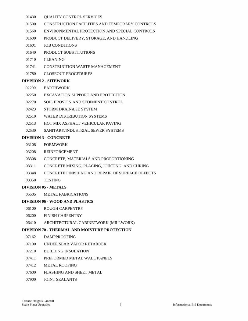
01430 QUALITY CONTROL SERVICES
01500 CONSTRUCTION FACILITIES AND TEMPORARY CONTROLS
01560 ENVIRONMENTAL PROTECTION AND SPECIAL CONTROLS
01600 PRODUCT DELIVERY, STORAGE, AND HANDLING
01601 JOB CONDITIONS
01640 PRODUCT SUBSTITUTIONS
01710 CLEANING
01741 CONSTRUCTION WASTE MANAGEMENT
01780 CLOSEOUT PROCEDURES
DIVISION 2 - SITEWORK
02200 EARTHWORK
02250 EXCAVATION SUPPORT AND PROTECTION
02270 SOIL EROSION AND SEDIMENT CONTROL
02423 STORM DRAINAGE SYSTEM
02510 WATER DISTRIBUTION SYSTEMS
02513 HOT MIX ASPHALT VEHICULAR PAVING
02530 SANITARY/INDUSTRIAL SEWER SYSTEMS
DIVISION 3 - CONCRETE
03108 FORMWORK
03208 REINFORCEMENT
03308 CONCRETE, MATERIALS AND PROPORTIONING
03311 CONCRETE MIXING, PLACING, JOINTING, AND CURING
03348 CONCRETE FINISHING AND REPAIR OF SURFACE DEFECTS
03350 TESTING
DIVISION 05 - METALS
05505 METAL FABRICATIONS
DIVISION 06 - WOOD AND PLASTICS
06100 ROUGH CARPENTRY
06200 FINISH CARPENTRY
06410 ARCHITECTURAL CABINETWORK (MILLWORK)
DIVISION 70 - THERMAL AND MOISTURE PROTECTION
07162 DAMPPROOFING
07190 UNDER SLAB VAPOR RETARDER
07210 BUILDING INSULATION
07411 PREFORMED METAL WALL PANELS
07412 METAL ROOFING
07600 FLASHING AND SHEET METAL
07900 JOINT SEALANTS
Terrace Heights Landfill
Scale Plaza Upgrades 6 Informational Bid Documents
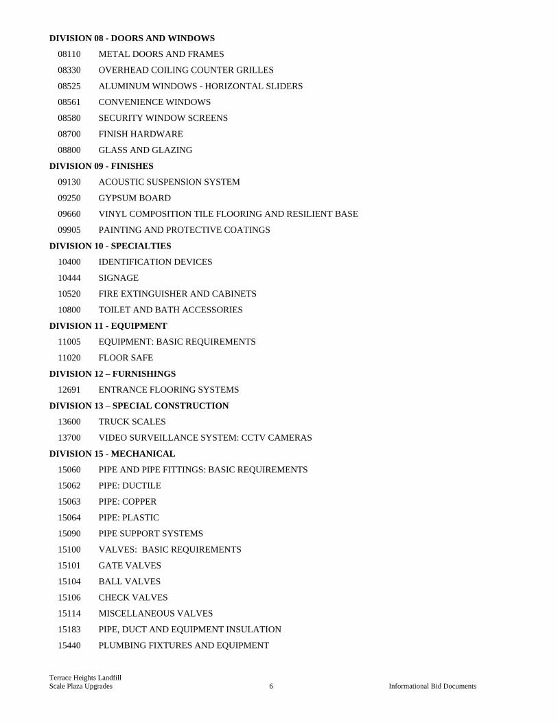
DIVISION 08 - DOORS AND WINDOWS
08110 METAL DOORS AND FRAMES
08330 OVERHEAD COILING COUNTER GRILLES
08525 ALUMINUM WINDOWS - HORIZONTAL SLIDERS
08561 CONVENIENCE WINDOWS
08580 SECURITY WINDOW SCREENS
08700 FINISH HARDWARE
08800 GLASS AND GLAZING
DIVISION 09 - FINISHES
09130 ACOUSTIC SUSPENSION SYSTEM
09250 GYPSUM BOARD
09660 VINYL COMPOSITION TILE FLOORING AND RESILIENT BASE
09905 PAINTING AND PROTECTIVE COATINGS
DIVISION 10 - SPECIALTIES
10400 IDENTIFICATION DEVICES
10444 SIGNAGE
10520 FIRE EXTINGUISHER AND CABINETS
10800 TOILET AND BATH ACCESSORIES
DIVISION 11 - EQUIPMENT
11005 EQUIPMENT: BASIC REQUIREMENTS
11020 FLOOR SAFE
DIVISION 12 – FURNISHINGS
12691 ENTRANCE FLOORING SYSTEMS
DIVISION 13 – SPECIAL CONSTRUCTION
13600 TRUCK SCALES
13700 VIDEO SURVEILLANCE SYSTEM: CCTV CAMERAS
DIVISION 15 - MECHANICAL
15060 PIPE AND PIPE FITTINGS: BASIC REQUIREMENTS
15062 PIPE: DUCTILE
15063 PIPE: COPPER
15064 PIPE: PLASTIC
15090 PIPE SUPPORT SYSTEMS
15100 VALVES: BASIC REQUIREMENTS
15101 GATE VALVES
15104 BALL VALVES
15106 CHECK VALVES
15114 MISCELLANEOUS VALVES
15183 PIPE, DUCT AND EQUIPMENT INSULATION
15440 PLUMBING FIXTURES AND EQUIPMENT

Terrace Heights Landfill
Scale Plaza Upgrades 7 Informational Bid Documents
15605 HVAC: EQUIPMENT
15890 HVAC: DUCTWORK
15970 INSTRUMENTATION AND CONTROL FOR HVAC SYSTEMS
15990 HVAC SYSTEMS: BALANCING AND TESTING
DIVISION 16 - ELECTRICAL
16010 ELECTRICAL: BASIC REQUIREMENTS
16120 WIRE AND CABLE: 600 VOLT AND BELOW
16125 HEAT TRACING CABLE
16130 RACEWAYS AND BOXES
16135 ELECTRICAL: EXTERIOR UNDERGROUND
16140 WIRING DEVICES
16410 SAFETY SWITCHES
16411 TRANSFER SWITCHES
16441 PANELBOARDS
16490 OVERCURRENT AND SHORT CIRCUIT PROTECTIVE DEVICES
16491 LOW VOLTAGE SURGE PROTECTION DEVICES (SPD)
16493 CONTROL EQUIPMENT ACCESSORIES
16500 INTERIOR AND EXTERIOR LIGHTING
16711 PASSIVE TELECOMMUNICATION SYSTEM
APPENDICES
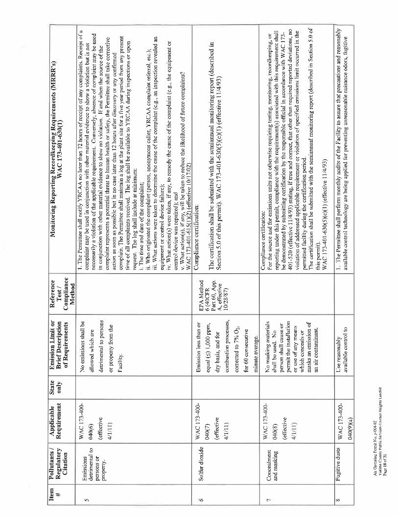
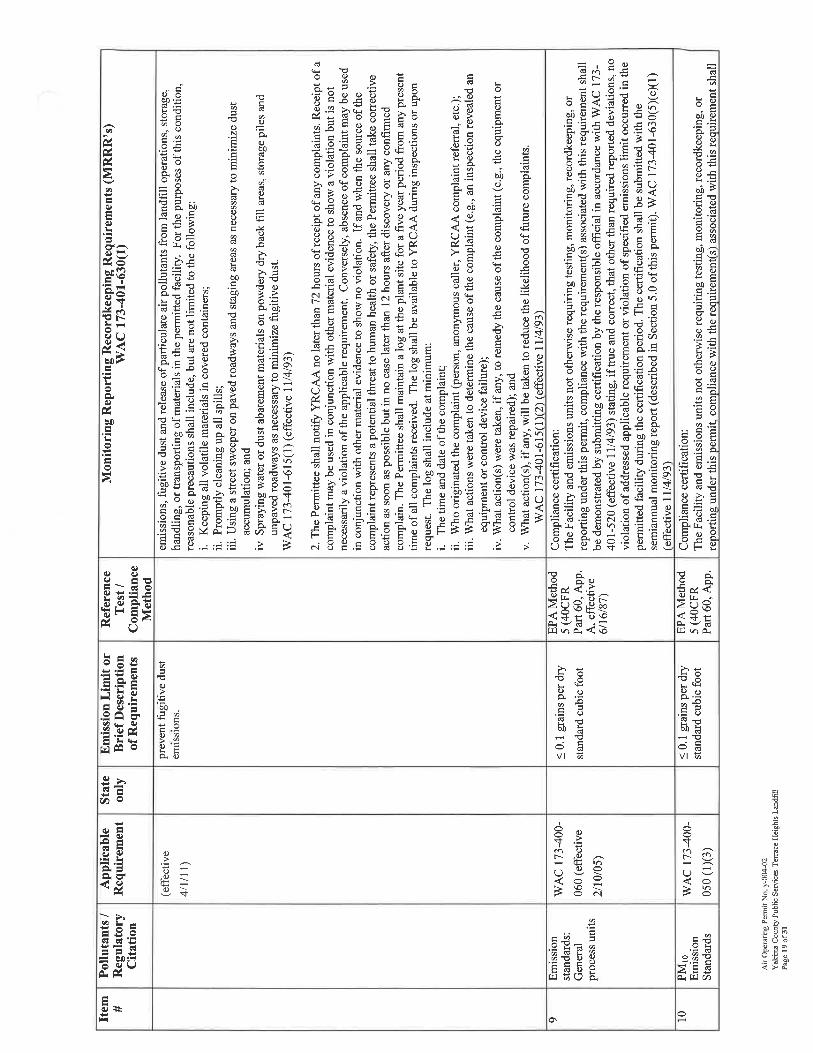
APPENDIX A – TERRACE HEIGHTS LANDFILL TITLE V DUST CONTROL REQUIREMENTS
Terrace Heights Landfill Scale Plaza Upgrades 8 Informational Bid Documents
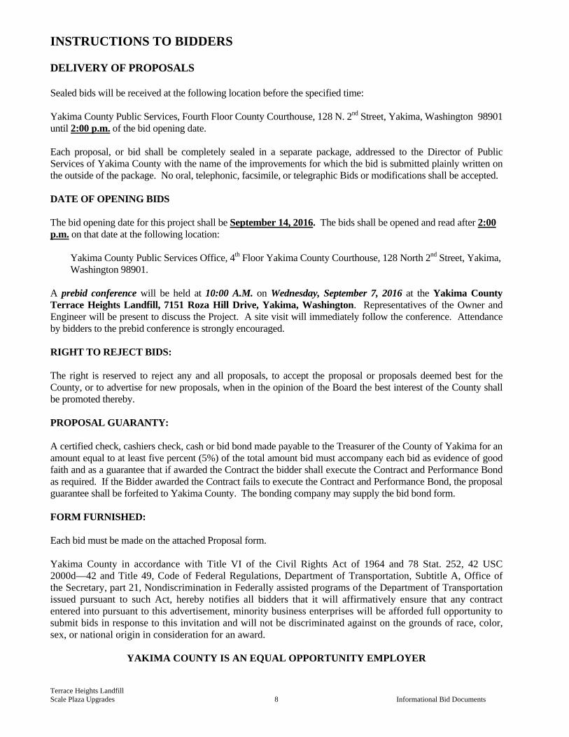
INSTRUCTIONS TO BIDDERS DELIVERY OF PROPOSALS Sealed bids will be received at the following location before the specified time: Yakima County Public Services, Fourth Floor County Courthouse, 128 N. 2nd Street, Yakima, Washington 98901 until 2:00 p.m. of the bid opening date. Each proposal, or bid shall be completely sealed in a separate package, addressed to the Director of Public Services of Yakima County with the name of the improvements for which the bid is submitted plainly written on the outside of the package. No oral, telephonic, facsimile, or telegraphic Bids or modifications shall be accepted. DATE OF OPENING BIDS The bid opening date for this project shall be September 14, 2016. The bids shall be opened and read after 2:00 p.m. on that date at the following location:
Yakima County Public Services Office, 4th Floor Yakima County Courthouse, 128 North 2nd Street, Yakima, Washington 98901.
A prebid conference will be held at 10:00 A.M. on Wednesday, September 7, 2016 at the Yakima County Terrace Heights Landfill, 7151 Roza Hill Drive, Yakima, Washington. Representatives of the Owner and Engineer will be present to discuss the Project. A site visit will immediately follow the conference. Attendance by bidders to the prebid conference is strongly encouraged. RIGHT TO REJECT BIDS: The right is reserved to reject any and all proposals, to accept the proposal or proposals deemed best for the County, or to advertise for new proposals, when in the opinion of the Board the best interest of the County shall be promoted thereby. PROPOSAL GUARANTY: A certified check, cashiers check, cash or bid bond made payable to the Treasurer of the County of Yakima for an amount equal to at least five percent (5%) of the total amount bid must accompany each bid as evidence of good faith and as a guarantee that if awarded the Contract the bidder shall execute the Contract and Performance Bond as required. If the Bidder awarded the Contract fails to execute the Contract and Performance Bond, the proposal guarantee shall be forfeited to Yakima County. The bonding company may supply the bid bond form. FORM FURNISHED: Each bid must be made on the attached Proposal form. Yakima County in accordance with Title VI of the Civil Rights Act of 1964 and 78 Stat. 252, 42 USC 2000d—42 and Title 49, Code of Federal Regulations, Department of Transportation, Subtitle A, Office of the Secretary, part 21, Nondiscrimination in Federally assisted programs of the Department of Transportation issued pursuant to such Act, hereby notifies all bidders that it will affirmatively ensure that any contract entered into pursuant to this advertisement, minority business enterprises will be afforded full opportunity to submit bids in response to this invitation and will not be discriminated against on the grounds of race, color, sex, or national origin in consideration for an award.
YAKIMA COUNTY IS AN EQUAL OPPORTUNITY EMPLOYER
Terrace Heights Landfill
Scale Plaza Upgrades 9 Informational Bid Documents
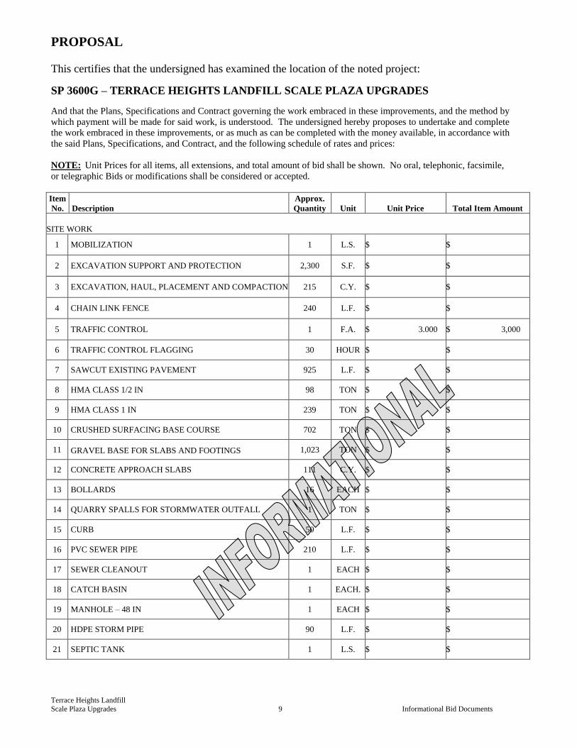
PROPOSAL
This certifies that the undersigned has examined the location of the noted project:
SP 3600G – TERRACE HEIGHTS LANDFILL SCALE PLAZA UPGRADES
And that the Plans, Specifications and Contract governing the work embraced in these improvements, and the method by
which payment will be made for said work, is understood. The undersigned hereby proposes to undertake and complete
the work embraced in these improvements, or as much as can be completed with the money available, in accordance with
the said Plans, Specifications, and Contract, and the following schedule of rates and prices:
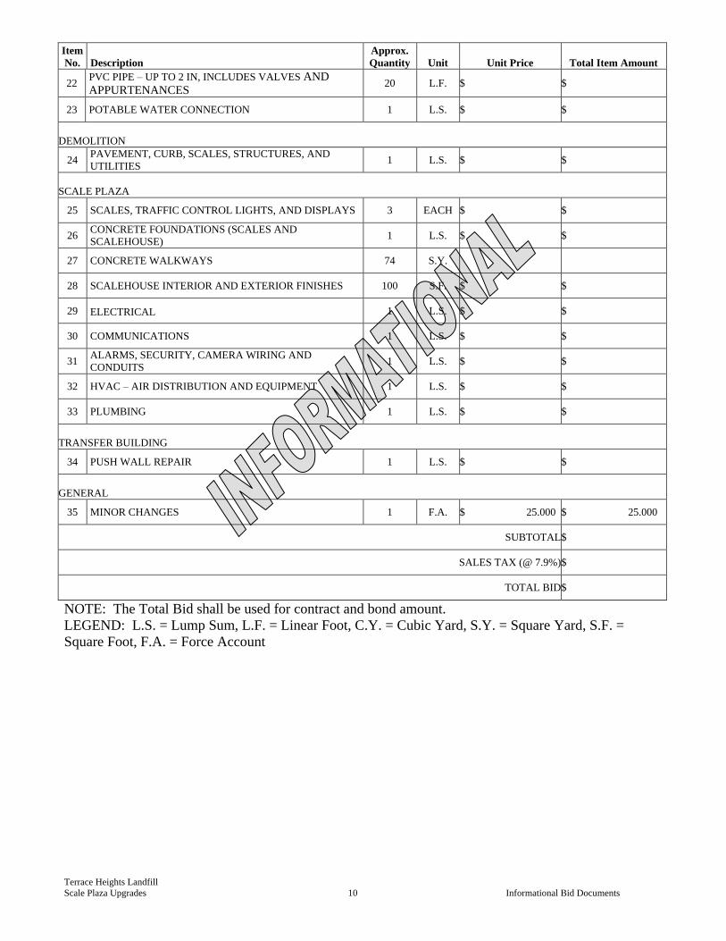
NOTE: Unit Prices for all items, all extensions, and total amount of bid shall be shown. No oral, telephonic, facsimile,
or telegraphic Bids or modifications shall be considered or accepted.
Item
No. Description
Approx.
Quantity Unit Unit Price Total Item Amount
SITE WORK
1 MOBILIZATION 1 L.S. $ $
2 EXCAVATION SUPPORT AND PROTECTION 2,300 S.F. $ $
3 EXCAVATION, HAUL, PLACEMENT AND COMPACTION 215 C.Y. $ $
4 CHAIN LINK FENCE 240 L.F. $ $
5 TRAFFIC CONTROL 1 F.A. $ 3.000 $ 3,000
6 TRAFFIC CONTROL FLAGGING 30 HOUR $ $
7 SAWCUT EXISTING PAVEMENT 925 L.F. $ $
8 HMA CLASS 1/2 IN 98 TON $ $
9 HMA CLASS 1 IN 239 TON $ $
10 CRUSHED SURFACING BASE COURSE 702 TON $ $
11 GRAVEL BASE FOR SLABS AND FOOTINGS 1,023 TON $ $
12 CONCRETE APPROACH SLABS 111 C.Y. $ $
13 BOLLARDS 16 EACH $ $
14 QUARRY SPALLS FOR STORMWATER OUTFALL 1 TON $ $
15 CURB 50 L.F. $ $
16 PVC SEWER PIPE 210 L.F. $ $
17 SEWER CLEANOUT 1 EACH $ $
18 CATCH BASIN 1 EACH. $ $
19 MANHOLE – 48 IN 1 EACH $ $
20 HDPE STORM PIPE 90 L.F. $ $
21 SEPTIC TANK 1 L.S. $ $
Terrace Heights Landfill
Scale Plaza Upgrades 10 Informational Bid Documents
Item
No. Description
Approx.
Quantity Unit Unit Price Total Item Amount
22 PVC PIPE – UP TO 2 IN, INCLUDES VALVES AND
APPURTENANCES 20 L.F. $ $
23 POTABLE WATER CONNECTION 1 L.S. $ $
DEMOLITION
24 PAVEMENT, CURB, SCALES, STRUCTURES, AND
UTILITIES 1 L.S. $ $
SCALE PLAZA
25 SCALES, TRAFFIC CONTROL LIGHTS, AND DISPLAYS 3 EACH $ $
26 CONCRETE FOUNDATIONS (SCALES AND
SCALEHOUSE) 1 L.S. $ $
27 CONCRETE WALKWAYS 74 S.Y.
28 SCALEHOUSE INTERIOR AND EXTERIOR FINISHES 100 S.F. $ $
29 ELECTRICAL 1 L.S. $ $
30 COMMUNICATIONS 1 L.S. $ $
31 ALARMS, SECURITY, CAMERA WIRING AND
CONDUITS 1 L.S. $ $
32 HVAC – AIR DISTRIBUTION AND EQUIPMENT 1 L.S. $ $
33 PLUMBING 1 L.S. $ $
TRANSFER BUILDING
34 PUSH WALL REPAIR 1 L.S. $ $
GENERAL
35 MINOR CHANGES 1 F.A. $ 25.000 $ 25.000
SUBTOTAL $
SALES TAX (@ 7.9%) $
TOTAL BID $
NOTE: The Total Bid shall be used for contract and bond amount.
LEGEND: L.S. = Lump Sum, L.F. = Linear Foot, C.Y. = Cubic Yard, S.Y. = Square Yard, S.F. =
Square Foot, F.A. = Force Account
Terrace Heights Landfill
Scale Plaza Upgrades 11 Informational Bid Documents
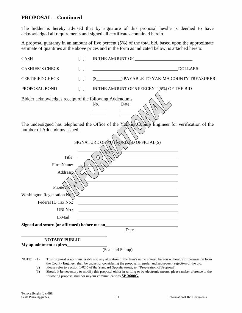
PROPOSAL – Continued
The bidder is hereby advised that by signature of this proposal he/she is deemed to have
acknowledged all requirements and signed all certificates contained herein.
A proposal guaranty in an amount of five percent (5%) of the total bid, based upon the approximate
estimate of quantities at the above prices and in the form as indicated below, is attached hereto:
CASH [ ] IN THE AMOUNT OF
CASHIER’S CHECK [ ] DOLLARS
CERTIFIED CHECK [ ] ($ ) PAYABLE TO YAKIMA COUNTY TREASURER
PROPOSAL BOND [ ] IN THE AMOUNT OF 5 PERCENT (5%) OF THE BID
Bidder acknowledges receipt of the following Addendums: No. Date
The undersigned has telephoned the Office of the Yakima County Engineer for verification of the
number of Addendums issued.
SIGNATURE OF AUTHORIZED OFFICIAL(S)
Title:
Firm Name:
Address:
Phone No.:
Washington Registration No.:
Federal ID Tax No.:
UBI No.:
E-Mail:
Signed and sworn (or affirmed) before me on
Date
NOTARY PUBLIC
My appointment expires
(Seal and Stamp)
NOTE: (1) This proposal is not transferable and any alteration of the firm’s name entered hereon without prior permission from
the County Engineer shall be cause for considering the proposal irregular and subsequent rejection of the bid.
(2) Please refer to Section 1-02.6 of the Standard Specifications, re: “Preparation of Proposal”
(3) Should it be necessary to modify this proposal either in writing or by electronic means, please make reference to the
following proposal number in your communications SP 3600G.
Terrace Heights Landfill
Scale Plaza Upgrades 12 Informational Bid Documents
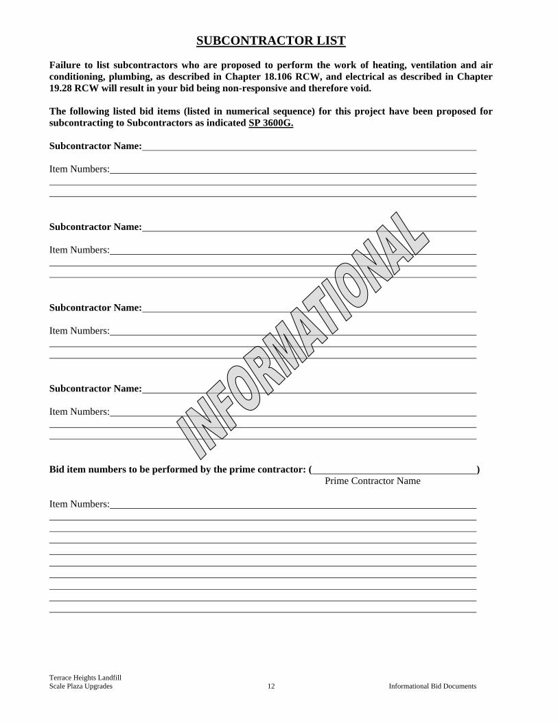
SUBCONTRACTOR LIST
Failure to list subcontractors who are proposed to perform the work of heating, ventilation and air
conditioning, plumbing, as described in Chapter 18.106 RCW, and electrical as described in Chapter
19.28 RCW will result in your bid being non-responsive and therefore void.
The following listed bid items (listed in numerical sequence) for this project have been proposed for
subcontracting to Subcontractors as indicated SP 3600G.
Subcontractor Name:
Item Numbers:
Subcontractor Name:
Item Numbers:
Subcontractor Name:
Item Numbers:
Subcontractor Name:
Item Numbers:
Bid item numbers to be performed by the prime contractor: ( )
Prime Contractor Name
Item Numbers:
Terrace Heights Landfill
Scale Plaza Upgrades 13 Informational Bid Documents
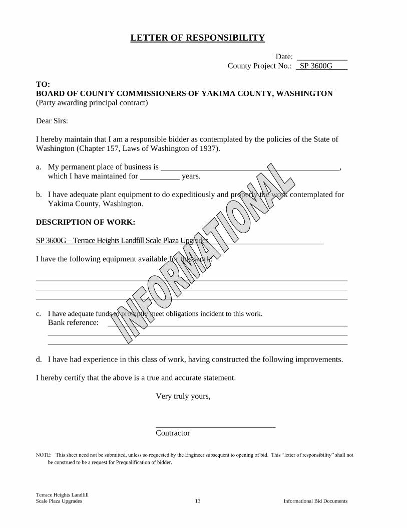
LETTER OF RESPONSIBILITY
Date:
County Project No.: SP 3600G
TO:
BOARD OF COUNTY COMMISSIONERS OF YAKIMA COUNTY, WASHINGTON
(Party awarding principal contract)
Dear Sirs:
I hereby maintain that I am a responsible bidder as contemplated by the policies of the State of
Washington (Chapter 157, Laws of Washington of 1937).
a. My permanent place of business is ,
which I have maintained for years.
b. I have adequate plant equipment to do expeditiously and properly the work contemplated for
Yakima County, Washington.
DESCRIPTION OF WORK:
SP 3600G – Terrace Heights Landfill Scale Plaza Upgrades
I have the following equipment available for this work:
c. I have adequate funds to promptly meet obligations incident to this work.
Bank reference:
d. I have had experience in this class of work, having constructed the following improvements.
I hereby certify that the above is a true and accurate statement.
Very truly yours,
Contractor
NOTE: This sheet need not be submitted, unless so requested by the Engineer subsequent to opening of bid. This “letter of responsibility” shall not
be construed to be a request for Prequalification of bidder.
Terrace Heights Landfill
Scale Plaza Upgrades 14 Informational Bid Documents
NON-COLLUSION DECLARATION
I, by signing the proposal, hereby declare, under penalty of perjury under the laws of the
United States that the following statements are true and correct:
1. That the undersigned person(s), firm, association or corporation has (have) not, either
directly or indirectly, entered into any agreement, participated in any collusion, or
otherwise taken any action in restraint of free competitive bidding in connection with
the project for which this proposal is submitted.
2. That by signing the signature page of this proposal, I am deemed to have signed and
have agreed to the provisions of this declaration.
NOTICE TO ALL BIDDERS
To report bid rigging activities call:
1-800-424-9071
The United States Department of Transportation (USDOT) operates the above toll-free “hotline”
Monday through Friday, 8:00 a.m. to 5:00 p.m., Eastern Time. Anyone with knowledge of possible
bid rigging, bidder collusion, or other fraudulent activities should use the “hotline” to report such
activities.
The “hotline” is part of USDOT’s continuing effort to identify and investigate highway construction
contract fraud and abuse and is operated under the direction of the USDOT Inspector General. All
information will be treated confidentially and caller anonymity will be respected.
Terrace Heights Landfill
Scale Plaza Upgrades 15 Informational Bid Documents
Certification Regarding
Debarment, Suspension, Ineligibility and Voluntary Exclusion
Lower Tier Covered Transactions
This certification is required by the regulations implementing Executive Order 12549, Debarment
and Suspension, 29 CFR Part 98, Section 98.510, Participant’s responsibilities. The regulations
were published as Part VII of the May 26, 1998 Federal Register (pages 19160-19211).
(BEFORE COMPLETING CERTIFICATION, READ ATTACHED INSTRUCTIONS
WHICH ARE AN INTEGRAL PART OF THE CERTIFICATION)
(1) The prospective recipient of federal assistance funds certifies, by submission of this proposal,
that neither it nor its principals are presently debarred, suspended, proposed for debarment,
declared ineligible, or voluntarily excluded from participation in this transaction by any federal
department or agency.
(2) Where the prospective recipient of federal assistance funds is unable to certify to any of the
statements in this certification, such prospective participant shall attach an explanation to this
proposal.
Name and Title of Authorized Representative
Signature Date
Terrace Heights Landfill
Scale Plaza Upgrades 16 Informational Bid Documents
CONTRACT
THIS AGREEMENT is made and entered into between Yakima County, acting under and by virtue of Titles 36 and 39 RCW, hereinafter called the “COUNTY” and ., hereinafter called the “CONTRACTOR”.
That in consideration of the terms and conditions contained herein and attached and made a part of this agreement, the parties hereto covenant and agree as follows:
I. The CONTRACTOR shall do all work and furnish all tools and equipment for SP 3600G; TERRACE HEIGHTS LANDFILL SCALE PLAZA UPGRADES and shall perform any changes in the work in accordance with the Contract Documents, which include the Contract Form, Bidder’s completed Proposal Form, Scope of Work, Contract Plans, Contract Provisions, Standard Specifications, Standard Plans, Addenda, various certifications and affidavits, supplemental agreements, and any change orders—all of which are incorporated by reference and made a part of this agreement. In the event of any conflict between terms or provisions contained in the following with those provided in the incorporated documents, the explicit provisions contained here shall control over those provided in incorporated documents.
II. The CONTRACTOR shall provide and bear the expense of all equipment, material and labor of any sort whatsoever that may be required for the transfer of materials and for constructing and completing the work provided for in the Contract Documents except those items mentioned therein to be furnished by Yakima County.
III. The COUNTY hereby promises and agrees to pay the CONTRACTOR according to the conditions stated in the Contract Documents.
IV. The CONTRACTOR for itself, and for its heirs, executors, administrators, successors and assigns does hereby agree to the full performance of all the covenants herein contained upon the part of the CONTRACTOR.
V. It is further provided that no liability shall attach to the COUNTY by reason of entering into this Contract, except as expressly provided herein.
VI. The parties agree that, for the purpose of this agreement, the CONTRACTOR is an independent contractor and neither the CONTRACTOR nor any employee of the CONTRACTOR is an employee of the COUNTY. Neither the CONTRACTOR nor any employee of the CONTRACTOR is entitled to any benefits that the COUNTY provides its employees. The CONTRACTOR is solely responsible for payment of any statutory workers compensation or employer’s liability insurance as required by state law.
VII. If any provision of this Agreement or any provision of any document incorporated by reference shall be held invalid, such invalidity shall not affect the other provisions of this Agreement, which can be given effect without the invalid provision if such remainder conforms to the requirements of applicable law and the fundamental purpose of this agreement, and to this end the provisions of this Agreement are declared to be severable.
VIII. In the event that either party shall be required to bring any action to enforce any of the provisions of this Agreement, or shall be required to defend any action brought by the other party with respect to this Agreement, and in the further event that one party shall prevail in such action, the losing party shall, in addition to all other payments required therein, pay all of the prevailing party’s actual costs in connection with such action, including such sums as the court or courts may adjudge reasonable as attorneys’ fees in the trial court and in any appellate courts.
Terrace Heights Landfill
Scale Plaza Upgrades 17 Informational Bid Documents
IN WITNESS WHEREOF, the CONTRACTOR has executed this instrument, on the date indicated below and Yakima County has caused this instrument to be executed in the name of said COUNTY by and through the Board of Yakima County Commissioners on the date indicated below.
CONTRACTOR: BOARD OF YAKIMA COUNTY COMMISSIONERS Signed: ___________________, 2016 Signed:___________________, 2016 Michael D. Leita, Chairman Signature for Kevin J. Bouchey, Commissioner
Print or Type Name of Person Signing J. Rand Elliott, Commissioner Title Constituting the Board of County Commissioners
For Yakima County, Washington
ATTEST: Clerk of the Board Foregoing Contract approved and ratified , 2016 Tiera Girard _____________________________ Approved as to form: Surety _____________________________ Attorney in fact Deputy Prosecuting Attorney
Terrace Heights Landfill
Scale Plaza Upgrades 18 Informational Bid Documents
PERFORMANCE BOND
(RCW 39.08)
KNOW ALL MEN BY THESE PRESENTS, That , as “PRINCIPAL”, and
, a corporation authorized to do business in the State of
Washington, as “SURETY”, are jointly and severally held and bound unto Yakima County, Washington in the penal sum of
Dollars ($ ) for the payment of
which by these presents we jointly and severally bind ourselves, our heirs, executors, administrators, assigns, and successors.
THE CONDITION of this bond is such that WHEREAS, on , 2015, the PRINCIPAL executed
a certain Contract with the County, by the terms of which PRINCIPAL agrees to furnish all material and labor and will undertake and
complete the construction of SP 3600G; TERRACE HEIGHTS LANDFILL SCALE PLAZA UPGRADES according to
the maps, plans and specifications made a part of said Contract, which Contract is attached hereto and by this reference is incorporated
herein and made a part hereof. FURTHER, the SURETY agrees to be bound by the laws of the State of Washington and subjected to
the jurisdiction of the State of Washington.
NOW, THEREFORE, if the PRINCIPAL shall faithfully perform all the provisions of such contract and pay all laborers,
mechanics, subcontractors and materialmen, and all persons who supply such persons or subcontractors with provisions or supplies for
the carrying on of such work, then this obligation to be void, otherwise to remain in full force and effect.
Dated this day of , 2015.
APPROVED: YAKIMA COUNTY
PRINCIPAL
By: By:
Chair of the Board of
Title: Yakima County Commissioners
Date: , 20
SURETY
By: Approved as to form:
Attorney-in-Fact
Deputy Prosecuting Attorney
Name of Local Office of Agent
Address of Local Office Agent
BOND NUMBER YAKIMA COUNTY CONTRACT NUMBER

002-267618-003 Yakima County Public Services Terrace Heights Scale Plaza Upgrades - GENERAL CONDITIONS - FLY SHEETGENERAL CONDITIONS - FLY SHEET 00700 - 1
SECTION 00700
STANDARD GENERAL CONDITIONS OF
THE CONSTRUCTION CONTRACT
(EJCDC C-700, 2013 EDITION)
END OF SECTION 00700

002-267618-003 Yakima County Public Services Terrace Heights Scale Plaza Upgrades - GENERAL CONDITIONS - FLY SHEETGENERAL CONDITIONS - FLY SHEET 00700 - 2
EJCDC® C-700 (Rev. 1), Standard General Conditions of the Construction Contract. Copyright © 2013 National Society of Professional Engineers, American Council of Engineering Companies,
and American Society of Civil Engineers. All rights reserved.
This document has important legal consequences; consultation with an attorney is encouraged with respect to its use or modification. This document should be adapted to the particular circumstances of the contemplated Project and the controlling Laws and Regulations.
STANDARD GENERAL CONDITIONS OF THE CONSTRUCTION CONTRACT
EJCDC® C-700 (Rev. 1), Standard General Conditions of the Construction Contract. Copyright © 2013 National Society of Professional Engineers, American Council of Engineering Companies,
and American Society of Civil Engineers. All rights reserved.
These General Conditions have been prepared for use with the Agreement Between Owner and Contractor for Construction Contract (EJCDC® C-520, Stipulated Sum, or C-525, Cost-Plus, 2013 Editions). Their provisions are interrelated and a change in one may necessitate a change in the other.
To prepare supplementary conditions that are coordinated with the General Conditions, use EJCDC’s Guide to the Preparation of Supplementary Conditions (EJCDC® C-800, 2013 Edition). The full EJCDC Construction series of documents is discussed in the Commentary on the 2013 EJCDC Construction Documents (EJCDC® C-001, 2013 Edition).
Copyright © 2013:
National Society of Professional Engineers
1420 King Street, Alexandria, VA 22314-2794
(703) 684-2882
www.nspe.org
American Council of Engineering Companies
1015 15th Street N.W., Washington, DC 20005
(202) 347-7474
www.acec.org
American Society of Civil Engineers
1801 Alexander Bell Drive, Reston, VA 20191-4400
(800) 548-2723
www.asce.org
The copyright for this document is owned jointly by the three sponsoring organizations listed above. The National Society of Professional Engineers is the Copyright Administrator for the EJCDC documents; please direct all inquiries regarding EJCDC copyrights to NSPE.
NOTE: EJCDC publications may be purchased at www.ejcdc.org, or from any of the sponsoring organizations above.
EJCDC® C-700 (Rev. 1), Standard General Conditions of the Construction Contract. Copyright © 2013 National Society of Professional Engineers, American Council of Engineering Companies,
and American Society of Civil Engineers. All rights reserved. Page i
STANDARD GENERAL CONDITIONS OF THE CONSTRUCTION CONTRACT
TABLE OF CONTENTS
Page Article 1 – Definitions and Terminology ......................................................................................... 1
1.01 Defined Terms ........................................................................................................................ 1
1.02 Terminology ........................................................................................................................... 5
Article 2 – Preliminary Matters ....................................................................................................... 6
2.01 Delivery of Bonds and Evidence of Insurance ........................................................................ 6
2.02 Copies of Documents ............................................................................................................. 6
2.03 Before Starting Construction ................................................................................................. 6
2.04 Preconstruction Conference; Designation of Authorized Representatives ........................... 7
2.05 Initial Acceptance of Schedules ............................................................................................. 7
2.06 Electronic Transmittals ........................................................................................................... 7
Article 3 – Documents: Intent, Requirements, Reuse .................................................................... 8
3.01 Intent ...................................................................................................................................... 8
3.02 Reference Standards .............................................................................................................. 8
3.03 Reporting and Resolving Discrepancies ................................................................................. 8
3.04 Requirements of the Contract Documents ............................................................................ 9
3.05 Reuse of Documents ............................................................................................................ 10
Article 4 – Commencement and Progress of the Work ................................................................ 10
4.01 Commencement of Contract Times; Notice to Proceed ...................................................... 10
4.02 Starting the Work ................................................................................................................. 10
4.03 Reference Points .................................................................................................................. 10
4.04 Progress Schedule ................................................................................................................ 10
4.05 Delays in Contractor’s Progress ........................................................................................... 11
Article 5 – Availability of Lands; Subsurface and Physical Conditions; Hazardous Environmental Conditions ..................................................................................................................................... 12
5.01 Availability of Lands ............................................................................................................. 12
5.02 Use of Site and Other Areas ................................................................................................. 12
5.03 Subsurface and Physical Conditions ..................................................................................... 13
5.04 Differing Subsurface or Physical Conditions ........................................................................ 14
5.05 Underground Facilities ......................................................................................................... 15
EJCDC® C-700 (Rev. 1), Standard General Conditions of the Construction Contract. Copyright © 2013 National Society of Professional Engineers, American Council of Engineering Companies,
and American Society of Civil Engineers. All rights reserved. Page ii
5.06 Hazardous Environmental Conditions at Site....................................................................... 17
Article 6 – Bonds and Insurance ................................................................................................... 19
6.01 Performance, Payment, and Other Bonds ........................................................................... 19
6.02 Insurance—General Provisions ............................................................................................ 19
6.03 Contractor’s Insurance ......................................................................................................... 20
6.04 Owner’s Liability Insurance .................................................................................................. 23
6.05 Property Insurance ............................................................................................................... 23
6.06 Waiver of Rights ................................................................................................................... 25
6.07 Receipt and Application of Property Insurance Proceeds ................................................... 25
Article 7 – Contractor’s Responsibilities ....................................................................................... 26
7.01 Supervision and Superintendence ....................................................................................... 26
7.02 Labor; Working Hours .......................................................................................................... 26
7.03 Services, Materials, and Equipment ..................................................................................... 26
7.04 “Or Equals” ........................................................................................................................... 27
7.05 Substitutes ........................................................................................................................... 28
7.06 Concerning Subcontractors, Suppliers, and Others ............................................................. 29
7.07 Patent Fees and Royalties .................................................................................................... 31
7.08 Permits ................................................................................................................................. 31
7.09 Taxes .................................................................................................................................... 32
7.10 Laws and Regulations ........................................................................................................... 32
7.11 Record Documents ............................................................................................................... 32
7.12 Safety and Protection ........................................................................................................... 32
7.13 Safety Representative .......................................................................................................... 33
7.14 Hazard Communication Programs ....................................................................................... 33
7.15 Emergencies ......................................................................................................................... 34
7.16 Shop Drawings, Samples, and Other Submittals .................................................................. 34
7.17 Contractor’s General Warranty and Guarantee................................................................... 36
7.18 Indemnification .................................................................................................................... 37
7.19 Delegation of Professional Design Services ......................................................................... 37
Article 8 – Other Work at the Site ................................................................................................ 38
8.01 Other Work .......................................................................................................................... 38
8.02 Coordination ........................................................................................................................ 39
8.03 Legal Relationships ............................................................................................................... 39
EJCDC® C-700 (Rev. 1), Standard General Conditions of the Construction Contract. Copyright © 2013 National Society of Professional Engineers, American Council of Engineering Companies,
and American Society of Civil Engineers. All rights reserved. Page iii
Article 9 – Owner’s Responsibilities .............................................................................................. 40
9.01 Communications to Contractor ............................................................................................ 40
9.02 Replacement of Engineer ..................................................................................................... 40
9.03 Furnish Data ......................................................................................................................... 40
9.04 Pay When Due ...................................................................................................................... 40
9.05 Lands and Easements; Reports, Tests, and Drawings .......................................................... 40
9.06 Insurance .............................................................................................................................. 40
9.07 Change Orders ...................................................................................................................... 40
9.08 Inspections, Tests, and Approvals ........................................................................................ 41
9.09 Limitations on Owner’s Responsibilities .............................................................................. 41
9.10 Undisclosed Hazardous Environmental Condition ............................................................... 41
9.11 Evidence of Financial Arrangements .................................................................................... 41
9.12 Safety Programs ................................................................................................................... 41
Article 10 – Engineer’s Status During Construction ...................................................................... 41
10.01 Owner’s Representative ....................................................................................................... 41
10.02 Visits to Site .......................................................................................................................... 41
10.03 Project Representative ......................................................................................................... 42
10.04 Rejecting Defective Work ..................................................................................................... 42
10.05 Shop Drawings, Change Orders and Payments .................................................................... 42
10.06 Determinations for Unit Price Work .................................................................................... 42
10.07 Decisions on Requirements of Contract Documents and Acceptability of Work ................ 42
10.08 Limitations on Engineer’s Authority and Responsibilities .................................................... 42
10.09 Compliance with Safety Program ......................................................................................... 43
Article 11 – Amending the Contract Documents; Changes in the Work ...................................... 43
11.01 Amending and Supplementing Contract Documents .......................................................... 43
11.02 Owner-Authorized Changes in the Work ............................................................................. 44
11.03 Unauthorized Changes in the Work ..................................................................................... 44
11.04 Change of Contract Price ..................................................................................................... 44
11.05 Change of Contract Times .................................................................................................... 45
11.06 Change Proposals ................................................................................................................. 45
11.07 Execution of Change Orders ................................................................................................. 46
11.08 Notification to Surety ........................................................................................................... 47
Article 12 – Claims ......................................................................................................................... 47
EJCDC® C-700 (Rev. 1), Standard General Conditions of the Construction Contract. Copyright © 2013 National Society of Professional Engineers, American Council of Engineering Companies,
and American Society of Civil Engineers. All rights reserved. Page iv
12.01 Claims ................................................................................................................................... 47
Article 13 – Cost of the Work; Allowances; Unit Price Work ........................................................ 48
13.01 Cost of the Work .................................................................................................................. 48
13.02 Allowances ........................................................................................................................... 50
13.03 Unit Price Work .................................................................................................................... 51
Article 14 – Tests and Inspections; Correction, Removal or Acceptance of Defective Work ....... 52
14.01 Access to Work ..................................................................................................................... 52
14.02 Tests, Inspections, and Approvals ........................................................................................ 52
14.03 Defective Work..................................................................................................................... 53
14.04 Acceptance of Defective Work ............................................................................................. 53
14.05 Uncovering Work ................................................................................................................. 53
14.06 Owner May Stop the Work .................................................................................................. 54
14.07 Owner May Correct Defective Work .................................................................................... 54
Article 15 – Payments to Contractor; Set-Offs; Completion; Correction Period .......................... 55
15.01 Progress Payments ............................................................................................................... 55
15.02 Contractor’s Warranty of Title ............................................................................................. 58
15.03 Substantial Completion ........................................................................................................ 58
15.04 Partial Use or Occupancy ..................................................................................................... 59
15.05 Final Inspection .................................................................................................................... 59
15.06 Final Payment ....................................................................................................................... 59
15.07 Waiver of Claims .................................................................................................................. 61
15.08 Correction Period ................................................................................................................. 61
Article 16 – Suspension of Work and Termination ....................................................................... 62
16.01 Owner May Suspend Work .................................................................................................. 62
16.02 Owner May Terminate for Cause ......................................................................................... 62
16.03 Owner May Terminate For Convenience ............................................................................. 63
16.04 Contractor May Stop Work or Terminate ............................................................................ 63
Article 17 – Final Resolution of Disputes ...................................................................................... 64
17.01 Methods and Procedures ..................................................................................................... 64
Article 18 – Miscellaneous ............................................................................................................ 64
18.01 Giving Notice ........................................................................................................................ 64
18.02 Computation of Times .......................................................................................................... 64
18.03 Cumulative Remedies .......................................................................................................... 64
EJCDC® C-700 (Rev. 1), Standard General Conditions of the Construction Contract. Copyright © 2013 National Society of Professional Engineers, American Council of Engineering Companies,
and American Society of Civil Engineers. All rights reserved. Page v
18.04 Limitation of Damages ......................................................................................................... 65
18.05 No Waiver ............................................................................................................................ 65
18.06 Survival of Obligations ......................................................................................................... 65
18.07 Controlling Law .................................................................................................................... 65
18.08 Headings ............................................................................................................................... 65
EJCDC® C-700 (Rev. 1), Standard General Conditions of the Construction Contract. Copyright © 2013 National Society of Professional Engineers, American Council of Engineering Companies,
and American Society of Civil Engineers. All rights reserved. Page 1 of 65
ARTICLE 1 – DEFINITIONS AND TERMINOLOGY
1.01 Defined Terms
A. Wherever used in the Bidding Requirements or Contract Documents, a term printed with initial capital letters, including the term’s singular and plural forms, will have the meaning indicated in the definitions below. In addition to terms specifically defined, terms with initial capital letters in the Contract Documents include references to identified articles and paragraphs, and the titles of other documents or forms.
1. Addenda—Written or graphic instruments issued prior to the opening of Bids which clarify, correct, or change the Bidding Requirements or the proposed Contract Documents.
2. Agreement—The written instrument, executed by Owner and Contractor, that sets forth the Contract Price and Contract Times, identifies the parties and the Engineer, and designates the specific items that are Contract Documents.
3. Application for Payment—The form acceptable to Engineer which is to be used by Contractor during the course of the Work in requesting progress or final payments and which is to be accompanied by such supporting documentation as is required by the Contract Documents.
4. Bid—The offer of a Bidder submitted on the prescribed form setting forth the prices for the Work to be performed.
5. Bidder—An individual or entity that submits a Bid to Owner.
6. Bidding Documents—The Bidding Requirements, the proposed Contract Documents, and all Addenda.
7. Bidding Requirements—The advertisement or invitation to bid, Instructions to Bidders, Bid Bond or other Bid security, if any, the Bid Form, and the Bid with any attachments.
8. Change Order—A document which is signed by Contractor and Owner and authorizes an addition, deletion, or revision in the Work or an adjustment in the Contract Price or the Contract Times, or other revision to the Contract, issued on or after the Effective Date of the Contract.
9. Change Proposal—A written request by Contractor, duly submitted in compliance with the procedural requirements set forth herein, seeking an adjustment in Contract Price or Contract Times, or both; contesting an initial decision by Engineer concerning the requirements of the Contract Documents or the acceptability of Work under the Contract Documents; challenging a set-off against payments due; or seeking other relief with respect to the terms of the Contract.
10. Claim—(a) A demand or assertion by Owner directly to Contractor, duly submitted in compliance with the procedural requirements set forth herein: seeking an adjustment of Contract Price or Contract Times, or both; contesting an initial decision by Engineer concerning the requirements of the Contract Documents or the acceptability of Work under the Contract Documents; contesting Engineer’s decision regarding a Change Proposal; seeking resolution of a contractual issue that Engineer has declined to address; or seeking other relief with respect to the terms of the Contract; or (b) a demand or assertion by Contractor directly to Owner, duly submitted in compliance with the procedural requirements set forth herein, contesting Engineer’s decision regarding a Change Proposal; or seeking resolution of a contractual issue that Engineer
EJCDC® C-700 (Rev. 1), Standard General Conditions of the Construction Contract. Copyright © 2013 National Society of Professional Engineers, American Council of Engineering Companies,
and American Society of Civil Engineers. All rights reserved. Page 2 of 65
has declined to address. A demand for money or services by a third party is not a Claim.
11. Constituent of Concern—Asbestos, petroleum, radioactive materials, polychlorinated biphenyls (PCBs), hazardous waste, and any substance, product, waste, or other material of any nature whatsoever that is or becomes listed, regulated, or addressed pursuant to (a) the Comprehensive Environmental Response, Compensation and Liability Act, 42 U.S.C. §§9601 et seq. (“CERCLA”); (b) the Hazardous Materials Transportation Act, 49 U.S.C. §§5101 et seq.; (c) the Resource Conservation and Recovery Act, 42 U.S.C. §§6901 et seq. (“RCRA”); (d) the Toxic Substances Control Act, 15 U.S.C. §§2601 et seq.; (e) the Clean Water Act, 33 U.S.C. §§1251 et seq.; (f) the Clean Air Act, 42 U.S.C. §§7401 et seq.; or (g) any other federal, state, or local statute, law, rule, regulation, ordinance, resolution, code, order, or decree regulating, relating to, or imposing liability or standards of conduct concerning, any hazardous, toxic, or dangerous waste, substance, or material.
12. Contract—The entire and integrated written contract between the Owner and Contractor concerning the Work.
13. Contract Documents—Those items so designated in the Agreement, and which together comprise the Contract.
14. Contract Price—The money that Owner has agreed to pay Contractor for completion of the Work in accordance with the Contract Documents. .
15. Contract Times—The number of days or the dates by which Contractor shall: (a) achieve Milestones, if any; (b) achieve Substantial Completion; and (c) complete the Work.
16. Contractor—The individual or entity with which Owner has contracted for performance of the Work.
17. Cost of the Work—See Paragraph 13.01 for definition.
18. Drawings—The part of the Contract that graphically shows the scope, extent, and character of the Work to be performed by Contractor.
19. Effective Date of the Contract—The date, indicated in the Agreement, on which the Contract becomes effective.
20. Engineer—The individual or entity named as such in the Agreement.
21. Field Order—A written order issued by Engineer which requires minor changes in the Work but does not change the Contract Price or the Contract Times.
22. Hazardous Environmental Condition—The presence at the Site of Constituents of Concern in such quantities or circumstances that may present a danger to persons or property exposed thereto. The presence at the Site of materials that are necessary for the execution of the Work, or that are to be incorporated in the Work, and that are controlled and contained pursuant to industry practices, Laws and Regulations, and the requirements of the Contract, does not establish a Hazardous Environmental Condition.
23. Laws and Regulations; Laws or Regulations—Any and all applicable laws, statutes, rules, regulations, ordinances, codes, and orders of any and all governmental bodies, agencies, authorities, and courts having jurisdiction.
EJCDC® C-700 (Rev. 1), Standard General Conditions of the Construction Contract. Copyright © 2013 National Society of Professional Engineers, American Council of Engineering Companies,
and American Society of Civil Engineers. All rights reserved. Page 3 of 65
24. Liens—Charges, security interests, or encumbrances upon Contract-related funds, real property, or personal property.
25. Milestone—A principal event in the performance of the Work that the Contract requires Contractor to achieve by an intermediate completion date or by a time prior to Substantial Completion of all the Work.
26. Notice of Award—The written notice by Owner to a Bidder of Owner’s acceptance of the Bid.
27. Notice to Proceed—A written notice by Owner to Contractor fixing the date on which the Contract Times will commence to run and on which Contractor shall start to perform the Work.
28. Owner—The individual or entity with which Contractor has contracted regarding the Work, and which has agreed to pay Contractor for the performance of the Work, pursuant to the terms of the Contract.
29. Progress Schedule—A schedule, prepared and maintained by Contractor, describing the sequence and duration of the activities comprising the Contractor’s plan to accomplish the Work within the Contract Times.
30. Project—The total undertaking to be accomplished for Owner by engineers, contractors, and others, including planning, study, design, construction, testing, commissioning, and start-up, and of which the Work to be performed under the Contract Documents is a part.
31. Project Manual—The written documents prepared for, or made available for, procuring and constructing the Work, including but not limited to the Bidding Documents or other construction procurement documents, geotechnical and existing conditions information, the Agreement, bond forms, General Conditions, Supplementary Conditions, and Specifications. The contents of the Project Manual may be bound in one or more volumes.
32. Resident Project Representative—The authorized representative of Engineer assigned to assist Engineer at the Site. As used herein, the term Resident Project Representative or “RPR” includes any assistants or field staff of Resident Project Representative.
33. Samples—Physical examples of materials, equipment, or workmanship that are representative of some portion of the Work and that establish the standards by which such portion of the Work will be judged.
34. Schedule of Submittals—A schedule, prepared and maintained by Contractor, of required submittals and the time requirements for Engineer’s review of the submittals and the performance of related construction activities.
35. Schedule of Values—A schedule, prepared and maintained by Contractor, allocating portions of the Contract Price to various portions of the Work and used as the basis for reviewing Contractor’s Applications for Payment.
36. Shop Drawings—All drawings, diagrams, illustrations, schedules, and other data or information that are specifically prepared or assembled by or for Contractor and submitted by Contractor to illustrate some portion of the Work. Shop Drawings, whether approved or not, are not Drawings and are not Contract Documents.
EJCDC® C-700 (Rev. 1), Standard General Conditions of the Construction Contract. Copyright © 2013 National Society of Professional Engineers, American Council of Engineering Companies,
and American Society of Civil Engineers. All rights reserved. Page 4 of 65
37. Site—Lands or areas indicated in the Contract Documents as being furnished by Owner upon which the Work is to be performed, including rights-of-way and easements, and such other lands furnished by Owner which are designated for the use of Contractor.
38. Specifications—The part of the Contract that consists of written requirements for materials, equipment, systems, standards, and workmanship as applied to the Work, and certain administrative requirements and procedural matters applicable to the Work.
39. Subcontractor—An individual or entity having a direct contract with Contractor or with any other Subcontractor for the performance of a part of the Work.
40. Substantial Completion—The time at which the Work (or a specified part thereof) has progressed to the point where, in the opinion of Engineer, the Work (or a specified part thereof) is sufficiently complete, in accordance with the Contract Documents, so that the Work (or a specified part thereof) can be utilized for the purposes for which it is intended. The terms “substantially complete” and “substantially completed” as applied to all or part of the Work refer to Substantial Completion thereof.
41. Successful Bidder—The Bidder whose Bid the Owner accepts, and to which the Owner makes an award of contract, subject to stated conditions.
42. Supplementary Conditions—The part of the Contract that amends or supplements these General Conditions.
43. Supplier—A manufacturer, fabricator, supplier, distributor, materialman, or vendor having a direct contract with Contractor or with any Subcontractor to furnish materials or equipment to be incorporated in the Work by Contractor or a Subcontractor.
44. Technical Data—Those items expressly identified as Technical Data in the Supplementary Conditions, with respect to either (a) subsurface conditions at the Site, or physical conditions relating to existing surface or subsurface structures at the Site (except Underground Facilities) or (b) Hazardous Environmental Conditions at the Site. If no such express identifications of Technical Data have been made with respect to conditions at the Site, then the data contained in boring logs, recorded measurements of subsurface water levels, laboratory test results, and other factual, objective information regarding conditions at the Site that are set forth in any geotechnical or environmental report prepared for the Project and made available to Contractor are hereby defined as Technical Data with respect to conditions at the Site under Paragraphs 5.03, 5.04, and 5.06.
45. Underground Facilities—All underground pipelines, conduits, ducts, cables, wires, manholes, vaults, tanks, tunnels, or other such facilities or attachments, and any encasements containing such facilities, including but not limited to those that convey electricity, gases, steam, liquid petroleum products, telephone or other communications, fiber optic transmissions, cable television, water, wastewater, storm water, other liquids or chemicals, or traffic or other control systems.
46. Unit Price Work—Work to be paid for on the basis of unit prices.
47. Work—The entire construction or the various separately identifiable parts thereof required to be provided under the Contract Documents. Work includes and is the result of performing or providing all labor, services, and documentation necessary to produce such construction; furnishing, installing, and incorporating all materials and equipment into such construction; and may include related services such as testing, start-up, and commissioning, all as required by the Contract Documents.
EJCDC® C-700 (Rev. 1), Standard General Conditions of the Construction Contract. Copyright © 2013 National Society of Professional Engineers, American Council of Engineering Companies,
and American Society of Civil Engineers. All rights reserved. Page 5 of 65
48. Work Change Directive—A written directive to Contractor issued on or after the Effective Date of the Contract, signed by Owner and recommended by Engineer, ordering an addition, deletion, or revision in the Work.
1.02 Terminology
A. The words and terms discussed in the following paragraphs are not defined but, when used in the Bidding Requirements or Contract Documents, have the indicated meaning.
B. Intent of Certain Terms or Adjectives:
1. The Contract Documents include the terms “as allowed,” “as approved,” “as ordered,” “as directed” or terms of like effect or import to authorize an exercise of professional judgment by Engineer. In addition, the adjectives “reasonable,” “suitable,” “acceptable,” “proper,” “satisfactory,” or adjectives of like effect or import are used to describe an action or determination of Engineer as to the Work. It is intended that such exercise of professional judgment, action, or determination will be solely to evaluate, in general, the Work for compliance with the information in the Contract Documents and with the design concept of the Project as a functioning whole as shown or indicated in the Contract Documents (unless there is a specific statement indicating otherwise). The use of any such term or adjective is not intended to and shall not be effective to assign to Engineer any duty or authority to supervise or direct the performance of the Work, or any duty or authority to undertake responsibility contrary to the provisions of Article 10 or any other provision of the Contract Documents.
C. Day:
1. The word “day” means a calendar day of 24 hours measured from midnight to the next midnight.
D. Defective:
1. The word “defective,” when modifying the word “Work,” refers to Work that is unsatisfactory, faulty, or deficient in that it:
a. does not conform to the Contract Documents; or
b. does not meet the requirements of any applicable inspection, reference standard, test, or approval referred to in the Contract Documents; or
c. has been damaged prior to Engineer’s recommendation of final payment (unless responsibility for the protection thereof has been assumed by Owner at Substantial Completion in accordance with Paragraph 15.03 or 15.04).
E. Furnish, Install, Perform, Provide:
1. The word “furnish,” when used in connection with services, materials, or equipment, shall mean to supply and deliver said services, materials, or equipment to the Site (or some other specified location) ready for use or installation and in usable or operable condition.
2. The word “install,” when used in connection with services, materials, or equipment, shall mean to put into use or place in final position said services, materials, or equipment complete and ready for intended use.
EJCDC® C-700 (Rev. 1), Standard General Conditions of the Construction Contract. Copyright © 2013 National Society of Professional Engineers, American Council of Engineering Companies,
and American Society of Civil Engineers. All rights reserved. Page 6 of 65
3. The words “perform” or “provide,” when used in connection with services, materials, or equipment, shall mean to furnish and install said services, materials, or equipment complete and ready for intended use.
4. If the Contract Documents establish an obligation of Contractor with respect to specific services, materials, or equipment, but do not expressly use any of the four words “furnish,” “install,” “perform,” or “provide,” then Contractor shall furnish and install said services, materials, or equipment complete and ready for intended use.
F. Unless stated otherwise in the Contract Documents, words or phrases that have a well-known technical or construction industry or trade meaning are used in the Contract Documents in accordance with such recognized meaning.
ARTICLE 2 – PRELIMINARY MATTERS
2.01 Delivery of Bonds and Evidence of Insurance
A. Bonds: When Contractor delivers the executed counterparts of the Agreement to Owner, Contractor shall also deliver to Owner such bonds as Contractor may be required to furnish.
B. Evidence of Contractor’s Insurance: When Contractor delivers the executed counterparts of the Agreement to Owner, Contractor shall also deliver to Owner, with copies to each named insured and additional insured (as identified in the Supplementary Conditions or elsewhere in the Contract), the certificates and other evidence of insurance required to be provided by Contractor in accordance with Article 6.
C. Evidence of Owner’s Insurance: After receipt of the executed counterparts of the Agreement and all required bonds and insurance documentation, Owner shall promptly deliver to Contractor, with copies to each named insured and additional insured (as identified in the Supplementary Conditions or otherwise), the certificates and other evidence of insurance required to be provided by Owner under Article 6.
2.02 Copies of Documents
A. Owner shall furnish to Contractor four printed copies of the Contract (including one fully executed counterpart of the Agreement), and one copy in electronic portable document format (PDF). Additional printed copies will be furnished upon request at the cost of reproduction.
B. Owner shall maintain and safeguard at least one original printed record version of the Contract, including Drawings and Specifications signed and sealed by Engineer and other design professionals. Owner shall make such original printed record version of the Contract available to Contractor for review. Owner may delegate the responsibilities under this provision to Engineer.
2.03 Before Starting Construction
A. Preliminary Schedules: Within 10 days after the Effective Date of the Contract (or as otherwise specifically required by the Contract Documents), Contractor shall submit to Engineer for timely review:
1. a preliminary Progress Schedule indicating the times (numbers of days or dates) for starting and completing the various stages of the Work, including any Milestones specified in the Contract;
2. a preliminary Schedule of Submittals; and
EJCDC® C-700 (Rev. 1), Standard General Conditions of the Construction Contract. Copyright © 2013 National Society of Professional Engineers, American Council of Engineering Companies,
and American Society of Civil Engineers. All rights reserved. Page 7 of 65
3. a preliminary Schedule of Values for all of the Work which includes quantities and prices of items which when added together equal the Contract Price and subdivides the Work into component parts in sufficient detail to serve as the basis for progress payments during performance of the Work. Such prices will include an appropriate amount of overhead and profit applicable to each item of Work.
2.04 Preconstruction Conference; Designation of Authorized Representatives
A. Before any Work at the Site is started, a conference attended by Owner, Contractor, Engineer, and others as appropriate will be held to establish a working understanding among the parties as to the Work and to discuss the schedules referred to in Paragraph 2.03.A, procedures for handling Shop Drawings, Samples, and other submittals, processing Applications for Payment, electronic or digital transmittals, and maintaining required records.
B. At this conference Owner and Contractor each shall designate, in writing, a specific individual to act as its authorized representative with respect to the services and responsibilities under the Contract. Such individuals shall have the authority to transmit and receive information, render decisions relative to the Contract, and otherwise act on behalf of each respective party.
2.05 Initial Acceptance of Schedules
A. At least 10 days before submission of the first Application for Payment a conference, attended by Contractor, Engineer, and others as appropriate, will be held to review for acceptability to Engineer as provided below the schedules submitted in accordance with Paragraph 2.03.A. Contractor shall have an additional 10 days to make corrections and adjustments and to complete and resubmit the schedules. No progress payment shall be made to Contractor until acceptable schedules are submitted to Engineer.
1. The Progress Schedule will be acceptable to Engineer if it provides an orderly progression of the Work to completion within the Contract Times. Such acceptance will not impose on Engineer responsibility for the Progress Schedule, for sequencing, scheduling, or progress of the Work, nor interfere with or relieve Contractor from Contractor’s full responsibility therefor.
2. Contractor’s Schedule of Submittals will be acceptable to Engineer if it provides a workable arrangement for reviewing and processing the required submittals.
3. Contractor’s Schedule of Values will be acceptable to Engineer as to form and substance if it provides a reasonable allocation of the Contract Price to the component parts of the Work.
2.06 Electronic Transmittals
A. Except as otherwise stated elsewhere in the Contract, the Owner, Engineer, and Contractor may transmit, and shall accept, Project-related correspondence, text, data, documents, drawings, information, and graphics, including but not limited to Shop Drawings and other submittals, in electronic media or digital format, either directly, or through access to a secure Project website.
B. If the Contract does not establish protocols for electronic or digital transmittals, then Owner, Engineer, and Contractor shall jointly develop such protocols.
C. When transmitting items in electronic media or digital format, the transmitting party makes no representations as to long term compatibility, usability, or readability of the items resulting from the recipient’s use of software application packages, operating systems, or
EJCDC® C-700 (Rev. 1), Standard General Conditions of the Construction Contract. Copyright © 2013 National Society of Professional Engineers, American Council of Engineering Companies,
and American Society of Civil Engineers. All rights reserved. Page 8 of 65
computer hardware differing from those used in the drafting or transmittal of the items, or from those established in applicable transmittal protocols.
ARTICLE 3 – DOCUMENTS: INTENT, REQUIREMENTS, REUSE
3.01 Intent
A. The Contract Documents are complementary; what is required by one is as binding as if required by all.
B. It is the intent of the Contract Documents to describe a functionally complete project (or part thereof) to be constructed in accordance with the Contract Documents.
C. Unless otherwise stated in the Contract Documents, if there is a discrepancy between the electronic or digital versions of the Contract Documents (including any printed copies derived from such electronic or digital versions) and the printed record version, the printed record version shall govern.
D. The Contract supersedes prior negotiations, representations, and agreements, whether written or oral.
E. Engineer will issue clarifications and interpretations of the Contract Documents as provided herein.
3.02 Reference Standards
A. Standards Specifications, Codes, Laws and Regulations
1. Reference in the Contract Documents to standard specifications, manuals, reference standards, or codes of any technical society, organization, or association, or to Laws or Regulations, whether such reference be specific or by implication, shall mean the standard specification, manual, reference standard, code, or Laws or Regulations in effect at the time of opening of Bids (or on the Effective Date of the Contract if there were no Bids), except as may be otherwise specifically stated in the Contract Documents.
2. No provision of any such standard specification, manual, reference standard, or code, or any instruction of a Supplier, shall be effective to change the duties or responsibilities of Owner, Contractor, or Engineer, or any of their subcontractors, consultants, agents, or employees, from those set forth in the part of the Contract Documents prepared by or for Engineer. No such provision or instruction shall be effective to assign to Owner, Engineer, or any of their officers, directors, members, partners, employees, agents, consultants, or subcontractors, any duty or authority to supervise or direct the performance of the Work or any duty or authority to undertake responsibility inconsistent with the provisions of the part of the Contract Documents prepared by or for Engineer.
3.03 Reporting and Resolving Discrepancies
A. Reporting Discrepancies:
1. Contractor’s Verification of Figures and Field Measurements: Before undertaking each part of the Work, Contractor shall carefully study the Contract Documents, and check and verify pertinent figures and dimensions therein, particularly with respect to applicable field measurements. Contractor shall promptly report in writing to Engineer any conflict, error, ambiguity, or discrepancy that Contractor discovers, or has actual knowledge of, and shall not proceed with any Work affected thereby until the conflict,
EJCDC® C-700 (Rev. 1), Standard General Conditions of the Construction Contract. Copyright © 2013 National Society of Professional Engineers, American Council of Engineering Companies,
and American Society of Civil Engineers. All rights reserved. Page 9 of 65
error, ambiguity, or discrepancy is resolved, by a clarification or interpretation by Engineer, or by an amendment or supplement to the Contract Documents issued pursuant to Paragraph 11.01.
2. Contractor’s Review of Contract Documents: If, before or during the performance of the Work, Contractor discovers any conflict, error, ambiguity, or discrepancy within the Contract Documents, or between the Contract Documents and (a) any applicable Law or Regulation, (b) actual field conditions, (c) any standard specification, manual, reference standard, or code, or (d) any instruction of any Supplier, then Contractor shall promptly report it to Engineer in writing. Contractor shall not proceed with the Work affected thereby (except in an emergency as required by Paragraph 7.15) until the conflict, error, ambiguity, or discrepancy is resolved, by a clarification or interpretation by Engineer, or by an amendment or supplement to the Contract Documents issued pursuant to Paragraph 11.01.
3. Contractor shall not be liable to Owner or Engineer for failure to report any conflict, error, ambiguity, or discrepancy in the Contract Documents unless Contractor had actual knowledge thereof.
B. Resolving Discrepancies:
1. Except as may be otherwise specifically stated in the Contract Documents, the provisions of the part of the Contract Documents prepared by or for Engineer shall take precedence in resolving any conflict, error, ambiguity, or discrepancy between such provisions of the Contract Documents and:
a. the provisions of any standard specification, manual, reference standard, or code, or the instruction of any Supplier (whether or not specifically incorporated by reference as a Contract Document); or
b. the provisions of any Laws or Regulations applicable to the performance of the Work (unless such an interpretation of the provisions of the Contract Documents would result in violation of such Law or Regulation).
3.04 Requirements of the Contract Documents
A. During the performance of the Work and until final payment, Contractor and Owner shall submit to the Engineer all matters in question concerning the requirements of the Contract Documents (sometimes referred to as requests for information or interpretation—RFIs), or relating to the acceptability of the Work under the Contract Documents, as soon as possible after such matters arise. Engineer will be the initial interpreter of the requirements of the Contract Documents, and judge of the acceptability of the Work thereunder.
B. Engineer will, with reasonable promptness, render a written clarification, interpretation, or decision on the issue submitted, or initiate an amendment or supplement to the Contract Documents. Engineer’s written clarification, interpretation, or decision will be final and binding on Contractor, unless it appeals by submitting a Change Proposal, and on Owner, unless it appeals by filing a Claim.
C. If a submitted matter in question concerns terms and conditions of the Contract Documents that do not involve (1) the performance or acceptability of the Work under the Contract Documents, (2) the design (as set forth in the Drawings, Specifications, or otherwise), or (3) other engineering or technical matters, then Engineer will promptly give written notice to Owner and Contractor that Engineer is unable to provide a decision or interpretation. If Owner and Contractor are unable to agree on resolution of such a matter in question, either party may pursue resolution as provided in Article 12.
EJCDC® C-700 (Rev. 1), Standard General Conditions of the Construction Contract. Copyright © 2013 National Society of Professional Engineers, American Council of Engineering Companies,
and American Society of Civil Engineers. All rights reserved. Page 10 of 65
3.05 Reuse of Documents
A. Contractor and its Subcontractors and Suppliers shall not:
1. have or acquire any title to or ownership rights in any of the Drawings, Specifications, or other documents (or copies of any thereof) prepared by or bearing the seal of Engineer or its consultants, including electronic media editions, or reuse any such Drawings, Specifications, other documents, or copies thereof on extensions of the Project or any other project without written consent of Owner and Engineer and specific written verification or adaptation by Engineer; or
2. have or acquire any title or ownership rights in any other Contract Documents, reuse any such Contract Documents for any purpose without Owner’s express written consent, or violate any copyrights pertaining to such Contract Documents.
B. The prohibitions of this Paragraph 3.05 will survive final payment, or termination of the Contract. Nothing herein shall preclude Contractor from retaining copies of the Contract Documents for record purposes.
ARTICLE 4 – COMMENCEMENT AND PROGRESS OF THE WORK
4.01 Commencement of Contract Times; Notice to Proceed
A. The Contract Times will commence to run on the thirtieth day after the Effective Date of the Contract or, if a Notice to Proceed is given, on the day indicated in the Notice to Proceed. A Notice to Proceed may be given at any time within 30 days after the Effective Date of the Contract. In no event will the Contract Times commence to run later than the sixtieth day after the day of Bid opening or the thirtieth day after the Effective Date of the Contract, whichever date is earlier.
4.02 Starting the Work
A. Contractor shall start to perform the Work on the date when the Contract Times commence to run. No Work shall be done at the Site prior to such date.
4.03 Reference Points
A. Owner shall provide engineering surveys to establish reference points for construction which in Engineer’s judgment are necessary to enable Contractor to proceed with the Work. Contractor shall be responsible for laying out the Work, shall protect and preserve the established reference points and property monuments, and shall make no changes or relocations without the prior written approval of Owner. Contractor shall report to Engineer whenever any reference point or property monument is lost or destroyed or requires relocation because of necessary changes in grades or locations, and shall be responsible for the accurate replacement or relocation of such reference points or property monuments by professionally qualified personnel.
4.04 Progress Schedule
A. Contractor shall adhere to the Progress Schedule established in accordance with Paragraph 2.05 as it may be adjusted from time to time as provided below.
1. Contractor shall submit to Engineer for acceptance (to the extent indicated in Paragraph 2.05) proposed adjustments in the Progress Schedule that will not result in changing the Contract Times.
EJCDC® C-700 (Rev. 1), Standard General Conditions of the Construction Contract. Copyright © 2013 National Society of Professional Engineers, American Council of Engineering Companies,
and American Society of Civil Engineers. All rights reserved. Page 11 of 65
2. Proposed adjustments in the Progress Schedule that will change the Contract Times shall be submitted in accordance with the requirements of Article 11.
B. Contractor shall carry on the Work and adhere to the Progress Schedule during all disputes or disagreements with Owner. No Work shall be delayed or postponed pending resolution of any disputes or disagreements, or during any appeal process, except as permitted by Paragraph 16.04, or as Owner and Contractor may otherwise agree in writing.
4.05 Delays in Contractor’s Progress
A. If Owner, Engineer, or anyone for whom Owner is responsible, delays, disrupts, or interferes with the performance or progress of the Work, then Contractor shall be entitled to an equitable adjustment in the Contract Times and Contract Price. Contractor’s entitlement to an adjustment of the Contract Times is conditioned on such adjustment being essential to Contractor’s ability to complete the Work within the Contract Times.
B. Contractor shall not be entitled to an adjustment in Contract Price or Contract Times for delay, disruption, or interference caused by or within the control of Contractor. Delay, disruption, and interference attributable to and within the control of a Subcontractor or Supplier shall be deemed to be within the control of Contractor.
C. If Contractor’s performance or progress is delayed, disrupted, or interfered with by unanticipated causes not the fault of and beyond the control of Owner, Contractor, and those for which they are responsible, then Contractor shall be entitled to an equitable adjustment in Contract Times. Contractor’s entitlement to an adjustment of the Contract Times is conditioned on such adjustment being essential to Contractor’s ability to complete the Work within the Contract Times. Such an adjustment shall be Contractor’s sole and exclusive remedy for the delays, disruption, and interference described in this paragraph. Causes of delay, disruption, or interference that may give rise to an adjustment in Contract Times under this paragraph include but are not limited to the following:
1. severe and unavoidable natural catastrophes such as fires, floods, epidemics, and earthquakes;
2. abnormal weather conditions;
3. acts or failures to act of utility owners (other than those performing other work at or adjacent to the Site by arrangement with the Owner, as contemplated in Article 8); and
4. acts of war or terrorism.
D. Delays, disruption, and interference to the performance or progress of the Work resulting from the existence of a differing subsurface or physical condition, an Underground Facility that was not shown or indicated by the Contract Documents, or not shown or indicated with reasonable accuracy, and those resulting from Hazardous Environmental Conditions, are governed by Article 5.
E. Paragraph 8.03 governs delays, disruption, and interference to the performance or progress of the Work resulting from the performance of certain other work at or adjacent to the Site.
F. Contractor shall not be entitled to an adjustment in Contract Price or Contract Times for any delay, disruption, or interference if such delay is concurrent with a delay, disruption, or interference caused by or within the control of Contractor.
EJCDC® C-700 (Rev. 1), Standard General Conditions of the Construction Contract. Copyright © 2013 National Society of Professional Engineers, American Council of Engineering Companies,
and American Society of Civil Engineers. All rights reserved. Page 12 of 65
G. Contractor must submit any Change Proposal seeking an adjustment in Contract Price or Contract Times under this paragraph within 30 days of the commencement of the delaying, disrupting, or interfering event.
ARTICLE 5 – AVAILABILITY OF LANDS; SUBSURFACE AND PHYSICAL CONDITIONS; HAZARDOUS ENVIRONMENTAL CONDITIONS
5.01 Availability of Lands
A. Owner shall furnish the Site. Owner shall notify Contractor of any encumbrances or restrictions not of general application but specifically related to use of the Site with which Contractor must comply in performing the Work.
B. Upon reasonable written request, Owner shall furnish Contractor with a current statement of record legal title and legal description of the lands upon which permanent improvements are to be made and Owner’s interest therein as necessary for giving notice of or filing a mechanic’s or construction lien against such lands in accordance with applicable Laws and Regulations.
C. Contractor shall provide for all additional lands and access thereto that may be required for temporary construction facilities or storage of materials and equipment.
5.02 Use of Site and Other Areas
A. Limitation on Use of Site and Other Areas:
1. Contractor shall confine construction equipment, temporary construction facilities, the storage of materials and equipment, and the operations of workers to the Site, adjacent areas that Contractor has arranged to use through construction easements or otherwise, and other adjacent areas permitted by Laws and Regulations, and shall not unreasonably encumber the Site and such other adjacent areas with construction equipment or other materials or equipment. Contractor shall assume full responsibility for (a) damage to the Site; (b) damage to any such other adjacent areas used for Contractor’s operations; (c) damage to any other adjacent land or areas; and (d) for injuries and losses sustained by the owners or occupants of any such land or areas; provided that such damage or injuries result from the performance of the Work or from other actions or conduct of the Contractor or those for which Contractor is responsible.
2. If a damage or injury claim is made by the owner or occupant of any such land or area because of the performance of the Work, or because of other actions or conduct of the Contractor or those for which Contractor is responsible, Contractor shall (a) take immediate corrective or remedial action as required by Paragraph 7.12, or otherwise; (b) promptly attempt to settle the claim as to all parties through negotiations with such owner or occupant, or otherwise resolve the claim by arbitration or other dispute resolution proceeding, or at law; and (c) to the fullest extent permitted by Laws and Regulations, indemnify and hold harmless Owner and Engineer, and the officers, directors, members, partners, employees, agents, consultants and subcontractors of each and any of them from and against any such claim, and against all costs, losses, and damages (including but not limited to all fees and charges of engineers, architects, attorneys, and other professionals and all court or arbitration or other dispute resolution costs) arising out of or relating to any claim or action, legal or equitable, brought by any such owner or occupant against Owner, Engineer, or any other party indemnified hereunder to the extent caused directly or indirectly, in whole or in part
EJCDC® C-700 (Rev. 1), Standard General Conditions of the Construction Contract. Copyright © 2013 National Society of Professional Engineers, American Council of Engineering Companies,
and American Society of Civil Engineers. All rights reserved. Page 13 of 65
by, or based upon, Contractor’s performance of the Work, or because of other actions or conduct of the Contractor or those for which Contractor is responsible.
B. Removal of Debris During Performance of the Work: During the progress of the Work the Contractor shall keep the Site and other adjacent areas free from accumulations of waste materials, rubbish, and other debris. Removal and disposal of such waste materials, rubbish, and other debris shall conform to applicable Laws and Regulations.
C. Cleaning: Prior to Substantial Completion of the Work Contractor shall clean the Site and the Work and make it ready for utilization by Owner. At the completion of the Work Contractor shall remove from the Site and adjacent areas all tools, appliances, construction equipment and machinery, and surplus materials and shall restore to original condition all property not designated for alteration by the Contract Documents.
D. Loading of Structures: Contractor shall not load nor permit any part of any structure to be loaded in any manner that will endanger the structure, nor shall Contractor subject any part of the Work or adjacent structures or land to stresses or pressures that will endanger them.
5.03 Subsurface and Physical Conditions
A. Reports and Drawings: The Supplementary Conditions identify:
1. those reports known to Owner of explorations and tests of subsurface conditions at or adjacent to the Site;
2. those drawings known to Owner of physical conditions relating to existing surface or subsurface structures at the Site (except Underground Facilities); and
3. Technical Data contained in such reports and drawings.
B. Reliance by Contractor on Technical Data Authorized: Contractor may rely upon the accuracy of the Technical Data expressly identified in the Supplementary Conditions with respect to such reports and drawings, but such reports and drawings are not Contract Documents. If no such express identification has been made, then Contractor may rely upon the accuracy of the Technical Data (as defined in Article 1) contained in any geotechnical or environmental report prepared for the Project and made available to Contractor. Except for such reliance on Technical Data, Contractor may not rely upon or make any claim against Owner or Engineer, or any of their officers, directors, members, partners, employees, agents, consultants, or subcontractors, with respect to:
1. the completeness of such reports and drawings for Contractor’s purposes, including, but not limited to, any aspects of the means, methods, techniques, sequences, and procedures of construction to be employed by Contractor, and safety precautions and programs incident thereto; or
2. other data, interpretations, opinions, and information contained in such reports or shown or indicated in such drawings; or
3. any Contractor interpretation of or conclusion drawn from any Technical Data or any such other data, interpretations, opinions, or information.
EJCDC® C-700 (Rev. 1), Standard General Conditions of the Construction Contract. Copyright © 2013 National Society of Professional Engineers, American Council of Engineering Companies,
and American Society of Civil Engineers. All rights reserved. Page 14 of 65
5.04 Differing Subsurface or Physical Conditions
A. Notice by Contractor: If Contractor believes that any subsurface or physical condition that is uncovered or revealed at the Site either:
1. is of such a nature as to establish that any Technical Data on which Contractor is entitled to rely as provided in Paragraph 5.03 is materially inaccurate; or
2. is of such a nature as to require a change in the Drawings or Specifications; or
3. differs materially from that shown or indicated in the Contract Documents; or
4. is of an unusual nature, and differs materially from conditions ordinarily encountered and generally recognized as inherent in work of the character provided for in the Contract Documents;
then Contractor shall, promptly after becoming aware thereof and before further disturbing the subsurface or physical conditions or performing any Work in connection therewith (except in an emergency as required by Paragraph 7.15), notify Owner and Engineer in writing about such condition. Contractor shall not further disturb such condition or perform any Work in connection therewith (except with respect to an emergency) until receipt of a written statement permitting Contractor to do so.
B. Engineer’s Review: After receipt of written notice as required by the preceding paragraph, Engineer will promptly review the subsurface or physical condition in question; determine the necessity of Owner’s obtaining additional exploration or tests with respect to the condition; conclude whether the condition falls within any one or more of the differing site condition categories in Paragraph 5.04.A above; obtain any pertinent cost or schedule information from Contractor; prepare recommendations to Owner regarding the Contractor’s resumption of Work in connection with the subsurface or physical condition in question and the need for any change in the Drawings or Specifications; and advise Owner in writing of Engineer’s findings, conclusions, and recommendations.
C. Owner’s Statement to Contractor Regarding Site Condition: After receipt of Engineer’s written findings, conclusions, and recommendations, Owner shall issue a written statement to Contractor (with a copy to Engineer) regarding the subsurface or physical condition in question, addressing the resumption of Work in connection with such condition, indicating whether any change in the Drawings or Specifications will be made, and adopting or rejecting Engineer’s written findings, conclusions, and recommendations, in whole or in part.
D. Possible Price and Times Adjustments:
1. Contractor shall be entitled to an equitable adjustment in Contract Price or Contract Times, or both, to the extent that the existence of a differing subsurface or physical condition, or any related delay, disruption, or interference, causes an increase or decrease in Contractor’s cost of, or time required for, performance of the Work; subject, however, to the following:
a. such condition must fall within any one or more of the categories described in Paragraph 5.04.A;
b. with respect to Work that is paid for on a unit price basis, any adjustment in Contract Price will be subject to the provisions of Paragraph 13.03; and,
EJCDC® C-700 (Rev. 1), Standard General Conditions of the Construction Contract. Copyright © 2013 National Society of Professional Engineers, American Council of Engineering Companies,
and American Society of Civil Engineers. All rights reserved. Page 15 of 65
c. Contractor’s entitlement to an adjustment of the Contract Times is conditioned on such adjustment being essential to Contractor’s ability to complete the Work within the Contract Times.
2. Contractor shall not be entitled to any adjustment in the Contract Price or Contract Times with respect to a subsurface or physical condition if:
a. Contractor knew of the existence of such condition at the time Contractor made a commitment to Owner with respect to Contract Price and Contract Times by the submission of a Bid or becoming bound under a negotiated contract, or otherwise; or
b. the existence of such condition reasonably could have been discovered or revealed as a result of any examination, investigation, exploration, test, or study of the Site and contiguous areas expressly required by the Bidding Requirements or Contract Documents to be conducted by or for Contractor prior to Contractor’s making such commitment; or
c. Contractor failed to give the written notice as required by Paragraph 5.04.A.
3. If Owner and Contractor agree regarding Contractor’s entitlement to and the amount or extent of any adjustment in the Contract Price or Contract Times, or both, then any such adjustment shall be set forth in a Change Order.
4. Contractor may submit a Change Proposal regarding its entitlement to or the amount or extent of any adjustment in the Contract Price or Contract Times, or both, no later than 30 days after Owner’s issuance of the Owner’s written statement to Contractor regarding the subsurface or physical condition in question.
5.05 Underground Facilities
A. Contractor’s Responsibilities: The information and data shown or indicated in the Contract Documents with respect to existing Underground Facilities at or adjacent to the Site is based on information and data furnished to Owner or Engineer by the owners of such Underground Facilities, including Owner, or by others. Unless it is otherwise expressly provided in the Supplementary Conditions:
1. Owner and Engineer do not warrant or guarantee the accuracy or completeness of any such information or data provided by others; and
2. the cost of all of the following will be included in the Contract Price, and Contractor shall have full responsibility for:
a. reviewing and checking all information and data regarding existing Underground Facilities at the Site;
b. locating all Underground Facilities shown or indicated in the Contract Documents as being at the Site;
c. coordination of the Work with the owners (including Owner) of such Underground Facilities, during construction; and
d. the safety and protection of all existing Underground Facilities at the Site, and repairing any damage thereto resulting from the Work.
B. Notice by Contractor: If Contractor believes that an Underground Facility that is uncovered or revealed at the Site was not shown or indicated in the Contract Documents, or was not shown or indicated with reasonable accuracy, then Contractor shall, promptly after
EJCDC® C-700 (Rev. 1), Standard General Conditions of the Construction Contract. Copyright © 2013 National Society of Professional Engineers, American Council of Engineering Companies,
and American Society of Civil Engineers. All rights reserved. Page 16 of 65
becoming aware thereof and before further disturbing conditions affected thereby or performing any Work in connection therewith (except in an emergency as required by Paragraph 7.15), identify the owner of such Underground Facility and give written notice to that owner and to Owner and Engineer.
C. Engineer’s Review: Engineer will promptly review the Underground Facility and conclude whether such Underground Facility was not shown or indicated in the Contract Documents, or was not shown or indicated with reasonable accuracy; obtain any pertinent cost or schedule information from Contractor; prepare recommendations to Owner regarding the Contractor’s resumption of Work in connection with the Underground Facility in question; determine the extent, if any, to which a change is required in the Drawings or Specifications to reflect and document the consequences of the existence or location of the Underground Facility; and advise Owner in writing of Engineer’s findings, conclusions, and recommendations. During such time, Contractor shall be responsible for the safety and protection of such Underground Facility.
D. Owner’s Statement to Contractor Regarding Underground Facility: After receipt of Engineer’s written findings, conclusions, and recommendations, Owner shall issue a written statement to Contractor (with a copy to Engineer) regarding the Underground Facility in question, addressing the resumption of Work in connection with such Underground Facility, indicating whether any change in the Drawings or Specifications will be made, and adopting or rejecting Engineer’s written findings, conclusions, and recommendations in whole or in part.
E. Possible Price and Times Adjustments:
1. Contractor shall be entitled to an equitable adjustment in the Contract Price or Contract Times, or both, to the extent that any existing Underground Facility at the Site that was not shown or indicated in the Contract Documents, or was not shown or indicated with reasonable accuracy, or any related delay, disruption, or interference, causes an increase or decrease in Contractor’s cost of, or time required for, performance of the Work; subject, however, to the following:
a. Contractor did not know of and could not reasonably have been expected to be aware of or to have anticipated the existence or actual location of the Underground Facility in question;
b. With respect to Work that is paid for on a unit price basis, any adjustment in Contract Price will be subject to the provisions of Paragraph 13.03;
c. Contractor’s entitlement to an adjustment of the Contract Times is conditioned on such adjustment being essential to Contractor’s ability to complete the Work within the Contract Times; and
d. Contractor gave the notice required in Paragraph 5.05.B.
2. If Owner and Contractor agree regarding Contractor’s entitlement to and the amount or extent of any adjustment in the Contract Price or Contract Times, or both, then any such adjustment shall be set forth in a Change Order.
3. Contractor may submit a Change Proposal regarding its entitlement to or the amount or extent of any adjustment in the Contract Price or Contract Times, or both, no later than 30 days after Owner’s issuance of the Owner’s written statement to Contractor regarding the Underground Facility in question.
EJCDC® C-700 (Rev. 1), Standard General Conditions of the Construction Contract. Copyright © 2013 National Society of Professional Engineers, American Council of Engineering Companies,
and American Society of Civil Engineers. All rights reserved. Page 17 of 65
5.06 Hazardous Environmental Conditions at Site
A. Reports and Drawings: The Supplementary Conditions identify:
1. those reports and drawings known to Owner relating to Hazardous Environmental Conditions that have been identified at or adjacent to the Site; and
2. Technical Data contained in such reports and drawings.
B. Reliance by Contractor on Technical Data Authorized: Contractor may rely upon the accuracy of the Technical Data expressly identified in the Supplementary Conditions with respect to such reports and drawings, but such reports and drawings are not Contract Documents. If no such express identification has been made, then Contractor may rely on the accuracy of the Technical Data (as defined in Article 1) contained in any geotechnical or environmental report prepared for the Project and made available to Contractor. Except for such reliance on Technical Data, Contractor may not rely upon or make any claim against Owner or Engineer, or any of their officers, directors, members, partners, employees, agents, consultants, or subcontractors with respect to:
1. the completeness of such reports and drawings for Contractor’s purposes, including, but not limited to, any aspects of the means, methods, techniques, sequences and procedures of construction to be employed by Contractor and safety precautions and programs incident thereto; or
2. other data, interpretations, opinions and information contained in such reports or shown or indicated in such drawings; or
3. any Contractor interpretation of or conclusion drawn from any Technical Data or any such other data, interpretations, opinions or information.
C. Contractor shall not be responsible for removing or remediating any Hazardous Environmental Condition encountered, uncovered, or revealed at the Site unless such removal or remediation is expressly identified in the Contract Documents to be within the scope of the Work.
D. Contractor shall be responsible for controlling, containing, and duly removing all Constituents of Concern brought to the Site by Contractor, Subcontractors, Suppliers, or anyone else for whom Contractor is responsible, and for any associated costs; and for the costs of removing and remediating any Hazardous Environmental Condition created by the presence of any such Constituents of Concern.
E. If Contractor encounters, uncovers, or reveals a Hazardous Environmental Condition whose removal or remediation is not expressly identified in the Contract Documents as being within the scope of the Work, or if Contractor or anyone for whom Contractor is responsible creates a Hazardous Environmental Condition, then Contractor shall immediately: (1) secure or otherwise isolate such condition; (2) stop all Work in connection with such condition and in any area affected thereby (except in an emergency as required by Paragraph 7.15); and (3) notify Owner and Engineer (and promptly thereafter confirm such notice in writing). Owner shall promptly consult with Engineer concerning the necessity for Owner to retain a qualified expert to evaluate such condition or take corrective action, if any. Promptly after consulting with Engineer, Owner shall take such actions as are necessary to permit Owner to timely obtain required permits and provide Contractor the written notice required by Paragraph 5.06.F. If Contractor or anyone for whom Contractor is responsible created the Hazardous Environmental Condition in question, then Owner may remove and remediate the Hazardous Environmental Condition, and impose a set-off against payments to account for the associated costs.
EJCDC® C-700 (Rev. 1), Standard General Conditions of the Construction Contract. Copyright © 2013 National Society of Professional Engineers, American Council of Engineering Companies,
and American Society of Civil Engineers. All rights reserved. Page 18 of 65
F. Contractor shall not resume Work in connection with such Hazardous Environmental Condition or in any affected area until after Owner has obtained any required permits related thereto, and delivered written notice to Contractor either (1) specifying that such condition and any affected area is or has been rendered safe for the resumption of Work, or (2) specifying any special conditions under which such Work may be resumed safely.
G. If Owner and Contractor cannot agree as to entitlement to or on the amount or extent, if any, of any adjustment in Contract Price or Contract Times, or both, as a result of such Work stoppage or such special conditions under which Work is agreed to be resumed by Contractor, then within 30 days of Owner’s written notice regarding the resumption of Work, Contractor may submit a Change Proposal, or Owner may impose a set-off.
H. If after receipt of such written notice Contractor does not agree to resume such Work based on a reasonable belief it is unsafe, or does not agree to resume such Work under such special conditions, then Owner may order the portion of the Work that is in the area affected by such condition to be deleted from the Work, following the contractual change procedures in Article 11. Owner may have such deleted portion of the Work performed by Owner’s own forces or others in accordance with Article 8.
I. To the fullest extent permitted by Laws and Regulations, Owner shall indemnify and hold harmless Contractor, Subcontractors, and Engineer, and the officers, directors, members, partners, employees, agents, consultants, and subcontractors of each and any of them from and against all claims, costs, losses, and damages (including but not limited to all fees and charges of engineers, architects, attorneys, and other professionals and all court or arbitration or other dispute resolution costs) arising out of or relating to a Hazardous Environmental Condition, provided that such Hazardous Environmental Condition (1) was not shown or indicated in the Drawings, Specifications, or other Contract Documents, identified as Technical Data entitled to limited reliance pursuant to Paragraph 5.06.B, or identified in the Contract Documents to be included within the scope of the Work, and (2) was not created by Contractor or by anyone for whom Contractor is responsible. Nothing in this Paragraph 5.06.I shall obligate Owner to indemnify any individual or entity from and against the consequences of that individual’s or entity’s own negligence.
J. To the fullest extent permitted by Laws and Regulations, Contractor shall indemnify and hold harmless Owner and Engineer, and the officers, directors, members, partners, employees, agents, consultants, and subcontractors of each and any of them from and against all claims, costs, losses, and damages (including but not limited to all fees and charges of engineers, architects, attorneys, and other professionals and all court or arbitration or other dispute resolution costs) arising out of or relating to the failure to control, contain, or remove a Constituent of Concern brought to the Site by Contractor or by anyone for whom Contractor is responsible, or to a Hazardous Environmental Condition created by Contractor or by anyone for whom Contractor is responsible. Nothing in this Paragraph 5.06.J shall obligate Contractor to indemnify any individual or entity from and against the consequences of that individual’s or entity’s own negligence.
K. The provisions of Paragraphs 5.03, 5.04, and 5.05 do not apply to the presence of Constituents of Concern or to a Hazardous Environmental Condition uncovered or revealed at the Site.
EJCDC® C-700 (Rev. 1), Standard General Conditions of the Construction Contract. Copyright © 2013 National Society of Professional Engineers, American Council of Engineering Companies,
and American Society of Civil Engineers. All rights reserved. Page 19 of 65
ARTICLE 6 – BONDS AND INSURANCE
6.01 Performance, Payment, and Other Bonds
A. Contractor shall furnish a performance bond and a payment bond, each in an amount at least equal to the Contract Price, as security for the faithful performance and payment of all of Contractor’s obligations under the Contract. These bonds shall remain in effect until one year after the date when final payment becomes due or until completion of the correction period specified in Paragraph 15.08, whichever is later, except as provided otherwise by Laws or Regulations, the Supplementary Conditions, or other specific provisions of the Contract. Contractor shall also furnish such other bonds as are required by the Supplementary Conditions or other specific provisions of the Contract.
B. All bonds shall be in the form prescribed by the Contract except as provided otherwise by Laws or Regulations, and shall be executed by such sureties as are named in “Companies Holding Certificates of Authority as Acceptable Sureties on Federal Bonds and as Acceptable Reinsuring Companies” as published in Circular 570 (as amended and supplemented) by the Financial Management Service, Surety Bond Branch, U.S. Department of the Treasury. A bond signed by an agent or attorney-in-fact must be accompanied by a certified copy of that individual’s authority to bind the surety. The evidence of authority shall show that it is effective on the date the agent or attorney-in-fact signed the accompanying bond.
C. Contractor shall obtain the required bonds from surety companies that are duly licensed or authorized in the jurisdiction in which the Project is located to issue bonds in the required amounts.
D. If the surety on a bond furnished by Contractor is declared bankrupt or becomes insolvent, or its right to do business is terminated in any state or jurisdiction where any part of the Project is located, or the surety ceases to meet the requirements above, then Contractor shall promptly notify Owner and Engineer and shall, within 20 days after the event giving rise to such notification, provide another bond and surety, both of which shall comply with the bond and surety requirements above.
E. If Contractor has failed to obtain a required bond, Owner may exclude the Contractor from the Site and exercise Owner’s termination rights under Article 16.
F. Upon request, Owner shall provide a copy of the payment bond to any Subcontractor, Supplier, or other person or entity claiming to have furnished labor or materials used in the performance of the Work.
6.02 Insurance—General Provisions
A. Owner and Contractor shall obtain and maintain insurance as required in this Article and in the Supplementary Conditions.
B. All insurance required by the Contract to be purchased and maintained by Owner or Contractor shall be obtained from insurance companies that are duly licensed or authorized, in the state or jurisdiction in which the Project is located, to issue insurance policies for the required limits and coverages. Unless a different standard is indicated in the Supplementary Conditions, all companies that provide insurance policies required under this Contract shall have an A.M. Best rating of A-VII or better.
C. Contractor shall deliver to Owner, with copies to each named insured and additional insured (as identified in this Article, in the Supplementary Conditions, or elsewhere in the Contract), certificates of insurance establishing that Contractor has obtained and is
EJCDC® C-700 (Rev. 1), Standard General Conditions of the Construction Contract. Copyright © 2013 National Society of Professional Engineers, American Council of Engineering Companies,
and American Society of Civil Engineers. All rights reserved. Page 20 of 65
maintaining the policies, coverages, and endorsements required by the Contract. Upon request by Owner or any other insured, Contractor shall also furnish other evidence of such required insurance, including but not limited to copies of policies and endorsements, and documentation of applicable self-insured retentions and deductibles. Contractor may block out (redact) any confidential premium or pricing information contained in any policy or endorsement furnished under this provision.
D. Owner shall deliver to Contractor, with copies to each named insured and additional insured (as identified in this Article, the Supplementary Conditions, or elsewhere in the Contract), certificates of insurance establishing that Owner has obtained and is maintaining the policies, coverages, and endorsements required of Owner by the Contract (if any). Upon request by Contractor or any other insured, Owner shall also provide other evidence of such required insurance (if any), including but not limited to copies of policies and endorsements, and documentation of applicable self-insured retentions and deductibles. Owner may block out (redact) any confidential premium or pricing information contained in any policy or endorsement furnished under this provision.
E. Failure of Owner or Contractor to demand such certificates or other evidence of the other party’s full compliance with these insurance requirements, or failure of Owner or Contractor to identify a deficiency in compliance from the evidence provided, shall not be construed as a waiver of the other party’s obligation to obtain and maintain such insurance.
F. If either party does not purchase or maintain all of the insurance required of such party by the Contract, such party shall notify the other party in writing of such failure to purchase prior to the start of the Work, or of such failure to maintain prior to any change in the required coverage.
G. If Contractor has failed to obtain and maintain required insurance, Owner may exclude the Contractor from the Site, impose an appropriate set-off against payment, and exercise Owner’s termination rights under Article 16.
H. Without prejudice to any other right or remedy, if a party has failed to obtain required insurance, the other party may elect to obtain equivalent insurance to protect such other party’s interests at the expense of the party who was required to provide such coverage, and the Contract Price shall be adjusted accordingly.
I. Owner does not represent that insurance coverage and limits established in this Contract necessarily will be adequate to protect Contractor or Contractor’s interests.
J. The insurance and insurance limits required herein shall not be deemed as a limitation on Contractor’s liability under the indemnities granted to Owner and other individuals and entities in the Contract.
6.03 Contractor’s Insurance
A. Workers’ Compensation: Contractor shall purchase and maintain workers’ compensation and employer’s liability insurance for:
1. claims under workers’ compensation, disability benefits, and other similar employee benefit acts.
2. United States Longshoreman and Harbor Workers’ Compensation Act and Jones Act coverage (if applicable).
3. claims for damages because of bodily injury, occupational sickness or disease, or death of Contractor’s employees (by stop-gap endorsement in monopolist worker’s compensation states).
EJCDC® C-700 (Rev. 1), Standard General Conditions of the Construction Contract. Copyright © 2013 National Society of Professional Engineers, American Council of Engineering Companies,
and American Society of Civil Engineers. All rights reserved. Page 21 of 65
4. Foreign voluntary worker compensation (if applicable).
B. Commercial General Liability—Claims Covered: Contractor shall purchase and maintain commercial general liability insurance, covering all operations by or on behalf of Contractor, on an occurrence basis, against:
1. claims for damages because of bodily injury, sickness or disease, or death of any person other than Contractor’s employees.
2. claims for damages insured by reasonably available personal injury liability coverage.
3. claims for damages, other than to the Work itself, because of injury to or destruction of tangible property wherever located, including loss of use resulting therefrom.
C. Commercial General Liability—Form and Content: Contractor’s commercial liability policy shall be written on a 1996 (or later) ISO commercial general liability form (occurrence form) and include the following coverages and endorsements:
1. Products and completed operations coverage:
a. Such insurance shall be maintained for three years after final payment.
b. Contractor shall furnish Owner and each other additional insured (as identified in the Supplementary Conditions or elsewhere in the Contract) evidence of continuation of such insurance at final payment and three years thereafter.
2. Blanket contractual liability coverage, to the extent permitted by law, including but not limited to coverage of Contractor’s contractual indemnity obligations in Paragraph 7.18.
3. Broad form property damage coverage.
4. Severability of interest.
5. Underground, explosion, and collapse coverage.
6. Personal injury coverage.
7. Additional insured endorsements that include both ongoing operations and products and completed operations coverage through ISO Endorsements CG 20 10 10 01 and CG 20 37 10 01 (together); or CG 20 10 07 04 and CG 20 37 07 04 (together); or their equivalent.
8. For design professional additional insureds, ISO Endorsement CG 20 32 07 04, “Additional Insured—Engineers, Architects or Surveyors Not Engaged by the Named Insured” or its equivalent.
D. Automobile liability: Contractor shall purchase and maintain automobile liability insurance against claims for damages because of bodily injury or death of any person or property damage arising out of the ownership, maintenance, or use of any motor vehicle. The automobile liability policy shall be written on an occurrence basis.
E. Umbrella or excess liability: Contractor shall purchase and maintain umbrella or excess liability insurance written over the underlying employer’s liability, commercial general liability, and automobile liability insurance described in the paragraphs above. Subject to industry-standard exclusions, the coverage afforded shall follow form as to each and every one of the underlying policies.
F. Contractor’s pollution liability insurance: Contractor shall purchase and maintain a policy covering third-party injury and property damage claims, including clean-up costs, as a result
EJCDC® C-700 (Rev. 1), Standard General Conditions of the Construction Contract. Copyright © 2013 National Society of Professional Engineers, American Council of Engineering Companies,
and American Society of Civil Engineers. All rights reserved. Page 22 of 65
of pollution conditions arising from Contractor’s operations and completed operations. This insurance shall be maintained for no less than three years after final completion.
G. Additional insureds: The Contractor’s commercial general liability, automobile liability, umbrella or excess, and pollution liability policies shall include and list as additional insureds Owner and Engineer, and any individuals or entities identified in the Supplementary Conditions; include coverage for the respective officers, directors, members, partners, employees, agents, consultants, and subcontractors of each and any of all such additional insureds; and the insurance afforded to these additional insureds shall provide primary coverage for all claims covered thereby (including as applicable those arising from both ongoing and completed operations) on a non-contributory basis. Contractor shall obtain all necessary endorsements to support these requirements.
H. Contractor’s professional liability insurance: If Contractor will provide or furnish professional services under this Contract, through a delegation of professional design services or otherwise, then Contractor shall be responsible for purchasing and maintaining applicable professional liability insurance. This insurance shall provide protection against claims arising out of performance of professional design or related services, and caused by a negligent error, omission, or act for which the insured party is legally liable. It shall be maintained throughout the duration of the Contract and for a minimum of two years after Substantial Completion. If such professional design services are performed by a Subcontractor, and not by Contractor itself, then the requirements of this paragraph may be satisfied through the purchasing and maintenance of such insurance by such Subcontractor.
I. General provisions: The policies of insurance required by this Paragraph 6.03 shall:
1. include at least the specific coverages provided in this Article.
2. be written for not less than the limits of liability provided in this Article and in the Supplementary Conditions, or required by Laws or Regulations, whichever is greater.
3. contain a provision or endorsement that the coverage afforded will not be canceled, materially changed, or renewal refused until at least 10 days prior written notice has been given to Contractor. Within three days of receipt of any such written notice, Contractor shall provide a copy of the notice to Owner, Engineer, and each other insured under the policy.
4. remain in effect at least until final payment (and longer if expressly required in this Article) and at all times thereafter when Contractor may be correcting, removing, or replacing defective Work as a warranty or correction obligation, or otherwise, or returning to the Site to conduct other tasks arising from the Contract Documents.
5. be appropriate for the Work being performed and provide protection from claims that may arise out of or result from Contractor’s performance of the Work and Contractor’s other obligations under the Contract Documents, whether it is to be performed by Contractor, any Subcontractor or Supplier, or by anyone directly or indirectly employed by any of them to perform any of the Work, or by anyone for whose acts any of them may be liable.
J. The coverage requirements for specific policies of insurance must be met by such policies, and not by reference to excess or umbrella insurance provided in other policies.
EJCDC® C-700 (Rev. 1), Standard General Conditions of the Construction Contract. Copyright © 2013 National Society of Professional Engineers, American Council of Engineering Companies,
and American Society of Civil Engineers. All rights reserved. Page 23 of 65
6.04 Owner’s Liability Insurance
A. In addition to the insurance required to be provided by Contractor under Paragraph 6.03, Owner, at Owner’s option, may purchase and maintain at Owner’s expense Owner’s own liability insurance as will protect Owner against claims which may arise from operations under the Contract Documents.
B. Owner’s liability policies, if any, operate separately and independently from policies required to be provided by Contractor, and Contractor cannot rely upon Owner’s liability policies for any of Contractor’s obligations to the Owner, Engineer, or third parties.
6.05 Property Insurance
A. Builder’s Risk: Unless otherwise provided in the Supplementary Conditions, Contractor shall purchase and maintain builder’s risk insurance upon the Work on a completed value basis, in the amount of the full insurable replacement cost thereof (subject to such deductible amounts as may be provided in the Supplementary Conditions or required by Laws and Regulations). This insurance shall:
1. include the Owner and Contractor as named insureds, and all Subcontractors, and any individuals or entities required by the Supplementary Conditions to be insured under such builder’s risk policy, as insureds or named insureds. For purposes of the remainder of this Paragraph 6.05, Paragraphs 6.06 and 6.07, and any corresponding Supplementary Conditions, the parties required to be insured shall collectively be referred to as “insureds.”
2. be written on a builder’s risk “all risk” policy form that shall at least include insurance for physical loss or damage to the Work, temporary buildings, falsework, and materials and equipment in transit, and shall insure against at least the following perils or causes of loss: fire; lightning; windstorm; riot; civil commotion; terrorism; vehicle impact; aircraft; smoke; theft; vandalism and malicious mischief; mechanical breakdown, boiler explosion, and artificially generated electric current; earthquake; volcanic activity, and other earth movement; flood; collapse; explosion; debris removal; demolition occasioned by enforcement of Laws and Regulations; water damage (other than that caused by flood); and such other perils or causes of loss as may be specifically required by the Supplementary Conditions. If insurance against mechanical breakdown, boiler explosion, and artificially generated electric current; earthquake; volcanic activity, and other earth movement; or flood, are not commercially available under builder’s risk policies, by endorsement or otherwise, such insurance may be provided through other insurance policies acceptable to Owner and Contractor.
3. cover, as insured property, at least the following: (a) the Work and all materials, supplies, machinery, apparatus, equipment, fixtures, and other property of a similar nature that are to be incorporated into or used in the preparation, fabrication, construction, erection, or completion of the Work, including Owner-furnished or assigned property; (b) spare parts inventory required within the scope of the Contract; and (c) temporary works which are not intended to form part of the permanent constructed Work but which are intended to provide working access to the Site, or to the Work under construction, or which are intended to provide temporary support for the Work under construction, including scaffolding, form work, fences, shoring, falsework, and temporary structures.
4. cover expenses incurred in the repair or replacement of any insured property (including but not limited to fees and charges of engineers and architects).
EJCDC® C-700 (Rev. 1), Standard General Conditions of the Construction Contract. Copyright © 2013 National Society of Professional Engineers, American Council of Engineering Companies,
and American Society of Civil Engineers. All rights reserved. Page 24 of 65
5. extend to cover damage or loss to insured property while in temporary storage at the Site or in a storage location outside the Site (but not including property stored at the premises of a manufacturer or Supplier).
6. extend to cover damage or loss to insured property while in transit.
7. allow for partial occupation or use of the Work by Owner, such that those portions of the Work that are not yet occupied or used by Owner shall remain covered by the builder’s risk insurance.
8. allow for the waiver of the insurer’s subrogation rights, as set forth below.
9. provide primary coverage for all losses and damages caused by the perils or causes of loss covered.
10. not include a co-insurance clause.
11. include an exception for ensuing losses from physical damage or loss with respect to any defective workmanship, design, or materials exclusions.
12. include performance/hot testing and start-up.
13. be maintained in effect, subject to the provisions herein regarding Substantial Completion and partial occupancy or use of the Work by Owner, until the Work is complete.
B. Notice of Cancellation or Change: All the policies of insurance (and the certificates or other evidence thereof) required to be purchased and maintained in accordance with this Paragraph 6.05 will contain a provision or endorsement that the coverage afforded will not be canceled or materially changed or renewal refused until at least 10 days prior written notice has been given to the purchasing policyholder. Within three days of receipt of any such written notice, the purchasing policyholder shall provide a copy of the notice to each other insured.
C. Deductibles: The purchaser of any required builder’s risk or property insurance shall pay for costs not covered because of the application of a policy deductible.
D. Partial Occupancy or Use by Owner: If Owner will occupy or use a portion or portions of the Work prior to Substantial Completion of all the Work as provided in Paragraph 15.04, then Owner (directly, if it is the purchaser of the builder’s risk policy, or through Contractor) will provide notice of such occupancy or use to the builder’s risk insurer. The builder’s risk insurance shall not be canceled or permitted to lapse on account of any such partial use or occupancy; rather, those portions of the Work that are occupied or used by Owner may come off the builder’s risk policy, while those portions of the Work not yet occupied or used by Owner shall remain covered by the builder’s risk insurance.
E. Additional Insurance: If Contractor elects to obtain other special insurance to be included in or supplement the builder’s risk or property insurance policies provided under this Paragraph 6.05, it may do so at Contractor’s expense.
F. Insurance of Other Property: If the express insurance provisions of the Contract do not require or address the insurance of a property item or interest, such as tools, construction equipment, or other personal property owned by Contractor, a Subcontractor, or an employee of Contractor or a Subcontractor, then the entity or individual owning such property item will be responsible for deciding whether to insure it, and if so in what amount.
EJCDC® C-700 (Rev. 1), Standard General Conditions of the Construction Contract. Copyright © 2013 National Society of Professional Engineers, American Council of Engineering Companies,
and American Society of Civil Engineers. All rights reserved. Page 25 of 65
6.06 Waiver of Rights
A. All policies purchased in accordance with Paragraph 6.05, expressly including the builder’s risk policy, shall contain provisions to the effect that in the event of payment of any loss or damage the insurers will have no rights of recovery against any insureds thereunder, or against Engineer or its consultants, or their officers, directors, members, partners, employees, agents, consultants, or subcontractors. Owner and Contractor waive all rights against each other and the respective officers, directors, members, partners, employees, agents, consultants, and subcontractors of each and any of them, for all losses and damages caused by, arising out of, or resulting from any of the perils or causes of loss covered by such policies and any other property insurance applicable to the Work; and, in addition, waive all such rights against Engineer, its consultants, all Subcontractors, all individuals or entities identified in the Supplementary Conditions as insureds, and the officers, directors, members, partners, employees, agents, consultants, and subcontractors of each and any of them, under such policies for losses and damages so caused. None of the above waivers shall extend to the rights that any party making such waiver may have to the proceeds of insurance held by Owner or Contractor as trustee or fiduciary, or otherwise payable under any policy so issued.
B. Owner waives all rights against Contractor, Subcontractors, and Engineer, and the officers, directors, members, partners, employees, agents, consultants and subcontractors of each and any of them, for:
1. loss due to business interruption, loss of use, or other consequential loss extending beyond direct physical loss or damage to Owner’s property or the Work caused by, arising out of, or resulting from fire or other perils whether or not insured by Owner; and
2. loss or damage to the completed Project or part thereof caused by, arising out of, or resulting from fire or other insured peril or cause of loss covered by any property insurance maintained on the completed Project or part thereof by Owner during partial occupancy or use pursuant to Paragraph 15.04, after Substantial Completion pursuant to Paragraph 15.03, or after final payment pursuant to Paragraph 15.06.
C. Any insurance policy maintained by Owner covering any loss, damage or consequential loss referred to in Paragraph 6.06.B shall contain provisions to the effect that in the event of payment of any such loss, damage, or consequential loss, the insurers will have no rights of recovery against Contractor, Subcontractors, or Engineer, or the officers, directors, members, partners, employees, agents, consultants, or subcontractors of each and any of them.
D. Contractor shall be responsible for assuring that the agreement under which a Subcontractor performs a portion of the Work contains provisions whereby the Subcontractor waives all rights against Owner, Contractor, all individuals or entities identified in the Supplementary Conditions as insureds, the Engineer and its consultants, and the officers, directors, members, partners, employees, agents, consultants, and subcontractors of each and any of them, for all losses and damages caused by, arising out of, relating to, or resulting from any of the perils or causes of loss covered by builder’s risk insurance and any other property insurance applicable to the Work.
6.07 Receipt and Application of Property Insurance Proceeds
A. Any insured loss under the builder’s risk and other policies of insurance required by Paragraph 6.05 will be adjusted and settled with the named insured that purchased the
EJCDC® C-700 (Rev. 1), Standard General Conditions of the Construction Contract. Copyright © 2013 National Society of Professional Engineers, American Council of Engineering Companies,
and American Society of Civil Engineers. All rights reserved. Page 26 of 65
policy. Such named insured shall act as fiduciary for the other insureds, and give notice to such other insureds that adjustment and settlement of a claim is in progress. Any other insured may state its position regarding a claim for insured loss in writing within 15 days after notice of such claim.
B. Proceeds for such insured losses may be made payable by the insurer either jointly to multiple insureds, or to the named insured that purchased the policy in its own right and as fiduciary for other insureds, subject to the requirements of any applicable mortgage clause. A named insured receiving insurance proceeds under the builder’s risk and other policies of insurance required by Paragraph 6.05 shall distribute such proceeds in accordance with such agreement as the parties in interest may reach, or as otherwise required under the dispute resolution provisions of this Contract or applicable Laws and Regulations.
C. If no other special agreement is reached, the damaged Work shall be repaired or replaced, the money so received applied on account thereof, and the Work and the cost thereof covered by Change Order, if needed.
ARTICLE 7 – CONTRACTOR’S RESPONSIBILITIES
7.01 Supervision and Superintendence
A. Contractor shall supervise, inspect, and direct the Work competently and efficiently, devoting such attention thereto and applying such skills and expertise as may be necessary to perform the Work in accordance with the Contract Documents. Contractor shall be solely responsible for the means, methods, techniques, sequences, and procedures of construction.
B. At all times during the progress of the Work, Contractor shall assign a competent resident superintendent who shall not be replaced without written notice to Owner and Engineer except under extraordinary circumstances.
7.02 Labor; Working Hours
A. Contractor shall provide competent, suitably qualified personnel to survey and lay out the Work and perform construction as required by the Contract Documents. Contractor shall at all times maintain good discipline and order at the Site.
B. Except as otherwise required for the safety or protection of persons or the Work or property at the Site or adjacent thereto, and except as otherwise stated in the Contract Documents, all Work at the Site shall be performed during regular working hours, Monday through Friday. Contractor will not perform Work on a Saturday, Sunday, or any legal holiday. Contractor may perform Work outside regular working hours or on Saturdays, Sundays, or legal holidays only with Owner’s written consent, which will not be unreasonably withheld.
7.03 Services, Materials, and Equipment
A. Unless otherwise specified in the Contract Documents, Contractor shall provide and assume full responsibility for all services, materials, equipment, labor, transportation, construction equipment and machinery, tools, appliances, fuel, power, light, heat, telephone, water, sanitary facilities, temporary facilities, and all other facilities and incidentals necessary for the performance, testing, start up, and completion of the Work, whether or not such items are specifically called for in the Contract Documents.
B. All materials and equipment incorporated into the Work shall be of good quality and new, except as otherwise provided in the Contract Documents. All special warranties and
EJCDC® C-700 (Rev. 1), Standard General Conditions of the Construction Contract. Copyright © 2013 National Society of Professional Engineers, American Council of Engineering Companies,
and American Society of Civil Engineers. All rights reserved. Page 27 of 65
guarantees required by the Specifications shall expressly run to the benefit of Owner. If required by Engineer, Contractor shall furnish satisfactory evidence (including reports of required tests) as to the source, kind, and quality of materials and equipment.
C. All materials and equipment shall be stored, applied, installed, connected, erected, protected, used, cleaned, and conditioned in accordance with instructions of the applicable Supplier, except as otherwise may be provided in the Contract Documents.
7.04 “Or Equals”
A. Whenever an item of material or equipment is specified or described in the Contract Documents by using the name of a proprietary item or the name of a particular Supplier, the Contract Price has been based upon Contractor furnishing such item as specified. The specification or description of such an item is intended to establish the type, function, appearance, and quality required. Unless the specification or description contains or is followed by words reading that no like, equivalent, or “or equal” item is permitted, Contractor may request that Engineer authorize the use of other items of material or equipment, or items from other proposed suppliers under the circumstances described below.
1. If Engineer in its sole discretion determines that an item of material or equipment proposed by Contractor is functionally equal to that named and sufficiently similar so that no change in related Work will be required, Engineer shall deem it an “or equal” item. For the purposes of this paragraph, a proposed item of material or equipment will be considered functionally equal to an item so named if:
a. in the exercise of reasonable judgment Engineer determines that:
1) it is at least equal in materials of construction, quality, durability, appearance, strength, and design characteristics;
2) it will reliably perform at least equally well the function and achieve the results imposed by the design concept of the completed Project as a functioning whole;
3) it has a proven record of performance and availability of responsive service; and
4) it is not objectionable to Owner.
b. Contractor certifies that, if approved and incorporated into the Work:
1) there will be no increase in cost to the Owner or increase in Contract Times; and
2) it will conform substantially to the detailed requirements of the item named in the Contract Documents.
B. Contractor’s Expense: Contractor shall provide all data in support of any proposed “or equal” item at Contractor’s expense.
C. Engineer’s Evaluation and Determination: Engineer will be allowed a reasonable time to evaluate each “or-equal” request. Engineer may require Contractor to furnish additional data about the proposed “or-equal” item. Engineer will be the sole judge of acceptability. No “or-equal” item will be ordered, furnished, installed, or utilized until Engineer’s review is complete and Engineer determines that the proposed item is an “or-equal”, which will be evidenced by an approved Shop Drawing or other written communication. Engineer will advise Contractor in writing of any negative determination.
EJCDC® C-700 (Rev. 1), Standard General Conditions of the Construction Contract. Copyright © 2013 National Society of Professional Engineers, American Council of Engineering Companies,
and American Society of Civil Engineers. All rights reserved. Page 28 of 65
D. Effect of Engineer’s Determination: Neither approval nor denial of an “or-equal” request shall result in any change in Contract Price. The Engineer’s denial of an “or-equal” request shall be final and binding, and may not be reversed through an appeal under any provision of the Contract Documents.
E. Treatment as a Substitution Request: If Engineer determines that an item of material or equipment proposed by Contractor does not qualify as an “or-equal” item, Contractor may request that Engineer considered the proposed item as a substitute pursuant to Paragraph 7.05.
7.05 Substitutes
A. Unless the specification or description of an item of material or equipment required to be furnished under the Contract Documents contains or is followed by words reading that no substitution is permitted, Contractor may request that Engineer authorize the use of other items of material or equipment under the circumstances described below. To the extent possible such requests shall be made before commencement of related construction at the Site.
1. Contractor shall submit sufficient information as provided below to allow Engineer to determine if the item of material or equipment proposed is functionally equivalent to that named and an acceptable substitute therefor. Engineer will not accept requests for review of proposed substitute items of material or equipment from anyone other than Contractor.
2. The requirements for review by Engineer will be as set forth in Paragraph 7.05.B, as supplemented by the Specifications, and as Engineer may decide is appropriate under the circumstances.
3. Contractor shall make written application to Engineer for review of a proposed substitute item of material or equipment that Contractor seeks to furnish or use. The application:
a. shall certify that the proposed substitute item will:
1) perform adequately the functions and achieve the results called for by the general design,
2) be similar in substance to that specified, and
3) be suited to the same use as that specified.
b. will state:
1) the extent, if any, to which the use of the proposed substitute item will necessitate a change in Contract Times,
2) whether use of the proposed substitute item in the Work will require a change in any of the Contract Documents (or in the provisions of any other direct contract with Owner for other work on the Project) to adapt the design to the proposed substitute item, and
3) whether incorporation or use of the proposed substitute item in connection with the Work is subject to payment of any license fee or royalty.
c. will identify:
1) all variations of the proposed substitute item from that specified, and
EJCDC® C-700 (Rev. 1), Standard General Conditions of the Construction Contract. Copyright © 2013 National Society of Professional Engineers, American Council of Engineering Companies,
and American Society of Civil Engineers. All rights reserved. Page 29 of 65
2) available engineering, sales, maintenance, repair, and replacement services.
d. shall contain an itemized estimate of all costs or credits that will result directly or indirectly from use of such substitute item, including but not limited to changes in Contract Price, shared savings, costs of redesign, and claims of other contractors affected by any resulting change.
B. Engineer’s Evaluation and Determination: Engineer will be allowed a reasonable time to evaluate each substitute request, and to obtain comments and direction from Owner. Engineer may require Contractor to furnish additional data about the proposed substitute item. Engineer will be the sole judge of acceptability. No substitute will be ordered, furnished, installed, or utilized until Engineer’s review is complete and Engineer determines that the proposed item is an acceptable substitute. Engineer’s determination will be evidenced by a Field Order or a proposed Change Order accounting for the substitution itself and all related impacts, including changes in Contract Price or Contract Times. Engineer will advise Contractor in writing of any negative determination.
C. Special Guarantee: Owner may require Contractor to furnish at Contractor’s expense a special performance guarantee or other surety with respect to any substitute.
D. Reimbursement of Engineer’s Cost: Engineer will record Engineer’s costs in evaluating a substitute proposed or submitted by Contractor. Whether or not Engineer approves a substitute so proposed or submitted by Contractor, Contractor shall reimburse Owner for the reasonable charges of Engineer for evaluating each such proposed substitute. Contractor shall also reimburse Owner for the reasonable charges of Engineer for making changes in the Contract Documents (or in the provisions of any other direct contract with Owner) resulting from the acceptance of each proposed substitute.
E. Contractor’s Expense: Contractor shall provide all data in support of any proposed substitute at Contractor’s expense.
F. Effect of Engineer’s Determination: If Engineer approves the substitution request, Contractor shall execute the proposed Change Order and proceed with the substitution. The Engineer’s denial of a substitution request shall be final and binding, and may not be reversed through an appeal under any provision of the Contract Documents. Contractor may challenge the scope of reimbursement costs imposed under Paragraph 7.05.D, by timely submittal of a Change Proposal.
7.06 Concerning Subcontractors, Suppliers, and Others
A. Contractor may retain Subcontractors and Suppliers for the performance of parts of the Work. Such Subcontractors and Suppliers must be acceptable to Owner.
B. Contractor shall retain specific Subcontractors, Suppliers, or other individuals or entities for the performance of designated parts of the Work if required by the Contract to do so.
C. Subsequent to the submittal of Contractor’s Bid or final negotiation of the terms of the Contract, Owner may not require Contractor to retain any Subcontractor, Supplier, or other individual or entity to furnish or perform any of the Work against which Contractor has reasonable objection.
D. Prior to entry into any binding subcontract or purchase order, Contractor shall submit to Owner the identity of the proposed Subcontractor or Supplier (unless Owner has already deemed such proposed Subcontractor or Supplier acceptable, during the bidding process or otherwise). Such proposed Subcontractor or Supplier shall be deemed acceptable to Owner unless Owner raises a substantive, reasonable objection within five days.
EJCDC® C-700 (Rev. 1), Standard General Conditions of the Construction Contract. Copyright © 2013 National Society of Professional Engineers, American Council of Engineering Companies,
and American Society of Civil Engineers. All rights reserved. Page 30 of 65
E. Owner may require the replacement of any Subcontractor, Supplier, or other individual or entity retained by Contractor to perform any part of the Work. Owner also may require Contractor to retain specific replacements; provided, however, that Owner may not require a replacement to which Contractor has a reasonable objection. If Contractor has submitted the identity of certain Subcontractors, Suppliers, or other individuals or entities for acceptance by Owner, and Owner has accepted it (either in writing or by failing to make written objection thereto), then Owner may subsequently revoke the acceptance of any such Subcontractor, Supplier, or other individual or entity so identified solely on the basis of substantive, reasonable objection after due investigation. Contractor shall submit an acceptable replacement for the rejected Subcontractor, Supplier, or other individual or entity.
F. If Owner requires the replacement of any Subcontractor, Supplier, or other individual or entity retained by Contractor to perform any part of the Work, then Contractor shall be entitled to an adjustment in Contract Price or Contract Times, or both, with respect to the replacement; and Contractor shall initiate a Change Proposal for such adjustment within 30 days of Owner’s requirement of replacement.
G. No acceptance by Owner of any such Subcontractor, Supplier, or other individual or entity, whether initially or as a replacement, shall constitute a waiver of the right of Owner to the completion of the Work in accordance with the Contract Documents.
H. On a monthly basis Contractor shall submit to Engineer a complete list of all Subcontractors and Suppliers having a direct contract with Contractor, and of all other Subcontractors and Suppliers known to Contractor at the time of submittal.
I. Contractor shall be fully responsible to Owner and Engineer for all acts and omissions of the Subcontractors, Suppliers, and other individuals or entities performing or furnishing any of the Work just as Contractor is responsible for Contractor’s own acts and omissions.
J. Contractor shall be solely responsible for scheduling and coordinating the work of Subcontractors, Suppliers, and all other individuals or entities performing or furnishing any of the Work.
K. Contractor shall restrict all Subcontractors, Suppliers, and such other individuals or entities performing or furnishing any of the Work from communicating with Engineer or Owner, except through Contractor or in case of an emergency, or as otherwise expressly allowed herein.
L. The divisions and sections of the Specifications and the identifications of any Drawings shall not control Contractor in dividing the Work among Subcontractors or Suppliers or delineating the Work to be performed by any specific trade.
M. All Work performed for Contractor by a Subcontractor or Supplier shall be pursuant to an appropriate contractual agreement that specifically binds the Subcontractor or Supplier to the applicable terms and conditions of the Contract Documents for the benefit of Owner and Engineer.
N. Owner may furnish to any Subcontractor or Supplier, to the extent practicable, information about amounts paid to Contractor on account of Work performed for Contractor by the particular Subcontractor or Supplier.
EJCDC® C-700 (Rev. 1), Standard General Conditions of the Construction Contract. Copyright © 2013 National Society of Professional Engineers, American Council of Engineering Companies,
and American Society of Civil Engineers. All rights reserved. Page 31 of 65
O. Nothing in the Contract Documents:
1. shall create for the benefit of any such Subcontractor, Supplier, or other individual or entity any contractual relationship between Owner or Engineer and any such Subcontractor, Supplier, or other individual or entity; nor
2. shall create any obligation on the part of Owner or Engineer to pay or to see to the payment of any money due any such Subcontractor, Supplier, or other individual or entity except as may otherwise be required by Laws and Regulations.
7.07 Patent Fees and Royalties
A. Contractor shall pay all license fees and royalties and assume all costs incident to the use in the performance of the Work or the incorporation in the Work of any invention, design, process, product, or device which is the subject of patent rights or copyrights held by others. If a particular invention, design, process, product, or device is specified in the Contract Documents for use in the performance of the Work and if, to the actual knowledge of Owner or Engineer, its use is subject to patent rights or copyrights calling for the payment of any license fee or royalty to others, the existence of such rights shall be disclosed by Owner in the Contract Documents.
B. To the fullest extent permitted by Laws and Regulations, Owner shall indemnify and hold harmless Contractor, and its officers, directors, members, partners, employees, agents, consultants, and subcontractors from and against all claims, costs, losses, and damages (including but not limited to all fees and charges of engineers, architects, attorneys, and other professionals, and all court or arbitration or other dispute resolution costs) arising out of or relating to any infringement of patent rights or copyrights incident to the use in the performance of the Work or resulting from the incorporation in the Work of any invention, design, process, product, or device specified in the Contract Documents, but not identified as being subject to payment of any license fee or royalty to others required by patent rights or copyrights.
C. To the fullest extent permitted by Laws and Regulations, Contractor shall indemnify and hold harmless Owner and Engineer, and the officers, directors, members, partners, employees, agents, consultants and subcontractors of each and any of them from and against all claims, costs, losses, and damages (including but not limited to all fees and charges of engineers, architects, attorneys, and other professionals and all court or arbitration or other dispute resolution costs) arising out of or relating to any infringement of patent rights or copyrights incident to the use in the performance of the Work or resulting from the incorporation in the Work of any invention, design, process, product, or device not specified in the Contract Documents.
7.08 Permits
A. Unless otherwise provided in the Contract Documents, Contractor shall obtain and pay for all construction permits and licenses. Owner shall assist Contractor, when necessary, in obtaining such permits and licenses. Contractor shall pay all governmental charges and inspection fees necessary for the prosecution of the Work which are applicable at the time of the submission of Contractor’s Bid (or when Contractor became bound under a negotiated contract). Owner shall pay all charges of utility owners for connections for providing permanent service to the Work
EJCDC® C-700 (Rev. 1), Standard General Conditions of the Construction Contract. Copyright © 2013 National Society of Professional Engineers, American Council of Engineering Companies,
and American Society of Civil Engineers. All rights reserved. Page 32 of 65
7.09 Taxes
A. Contractor shall pay all sales, consumer, use, and other similar taxes required to be paid by Contractor in accordance with the Laws and Regulations of the place of the Project which are applicable during the performance of the Work.
7.10 Laws and Regulations
A. Contractor shall give all notices required by and shall comply with all Laws and Regulations applicable to the performance of the Work. Except where otherwise expressly required by applicable Laws and Regulations, neither Owner nor Engineer shall be responsible for monitoring Contractor’s compliance with any Laws or Regulations.
B. If Contractor performs any Work or takes any other action knowing or having reason to know that it is contrary to Laws or Regulations, Contractor shall bear all resulting costs and losses, and shall indemnify and hold harmless Owner and Engineer, and the officers, directors, members, partners, employees, agents, consultants, and subcontractors of each and any of them from and against all claims, costs, losses, and damages (including but not limited to all fees and charges of engineers, architects, attorneys, and other professionals and all court or arbitration or other dispute resolution costs) arising out of or relating to such Work or other action. It shall not be Contractor’s responsibility to make certain that the Work described in the Contract Documents is in accordance with Laws and Regulations, but this shall not relieve Contractor of Contractor’s obligations under Paragraph 3.03.
C. Owner or Contractor may give notice to the other party of any changes after the submission of Contractor’s Bid (or after the date when Contractor became bound under a negotiated contract) in Laws or Regulations having an effect on the cost or time of performance of the Work, including but not limited to changes in Laws or Regulations having an effect on procuring permits and on sales, use, value-added, consumption, and other similar taxes. If Owner and Contractor are unable to agree on entitlement to or on the amount or extent, if any, of any adjustment in Contract Price or Contract Times resulting from such changes, then within 30 days of such notice Contractor may submit a Change Proposal, or Owner may initiate a Claim.
7.11 Record Documents
A. Contractor shall maintain in a safe place at the Site one printed record copy of all Drawings, Specifications, Addenda, Change Orders, Work Change Directives, Field Orders, written interpretations and clarifications, and approved Shop Drawings. Contractor shall keep such record documents in good order and annotate them to show changes made during construction. These record documents, together with all approved Samples, will be available to Engineer for reference. Upon completion of the Work, Contractor shall deliver these record documents to Engineer.
7.12 Safety and Protection
A. Contractor shall be solely responsible for initiating, maintaining, and supervising all safety precautions and programs in connection with the Work. Such responsibility does not relieve Subcontractors of their responsibility for the safety of persons or property in the performance of their work, nor for compliance with applicable safety Laws and Regulations. Contractor shall take all necessary precautions for the safety of, and shall provide the necessary protection to prevent damage, injury, or loss to:
1. all persons on the Site or who may be affected by the Work;
EJCDC® C-700 (Rev. 1), Standard General Conditions of the Construction Contract. Copyright © 2013 National Society of Professional Engineers, American Council of Engineering Companies,
and American Society of Civil Engineers. All rights reserved. Page 33 of 65
2. all the Work and materials and equipment to be incorporated therein, whether in storage on or off the Site; and
3. other property at the Site or adjacent thereto, including trees, shrubs, lawns, walks, pavements, roadways, structures, other work in progress, utilities, and Underground Facilities not designated for removal, relocation, or replacement in the course of construction.
B. Contractor shall comply with all applicable Laws and Regulations relating to the safety of persons or property, or to the protection of persons or property from damage, injury, or loss; and shall erect and maintain all necessary safeguards for such safety and protection. Contractor shall notify Owner; the owners of adjacent property, Underground Facilities, and other utilities; and other contractors and utility owners performing work at or adjacent to the Site, when prosecution of the Work may affect them, and shall cooperate with them in the protection, removal, relocation, and replacement of their property or work in progress.
C. Contractor shall comply with the applicable requirements of Owner’s safety programs, if any. The Supplementary Conditions identify any Owner’s safety programs that are applicable to the Work.
D. Contractor shall inform Owner and Engineer of the specific requirements of Contractor’s safety program with which Owner’s and Engineer’s employees and representatives must comply while at the Site.
E. All damage, injury, or loss to any property referred to in Paragraph 7.12.A.2 or 7.12.A.3 caused, directly or indirectly, in whole or in part, by Contractor, any Subcontractor, Supplier, or any other individual or entity directly or indirectly employed by any of them to perform any of the Work, or anyone for whose acts any of them may be liable, shall be remedied by Contractor at its expense (except damage or loss attributable to the fault of Drawings or Specifications or to the acts or omissions of Owner or Engineer or anyone employed by any of them, or anyone for whose acts any of them may be liable, and not attributable, directly or indirectly, in whole or in part, to the fault or negligence of Contractor or any Subcontractor, Supplier, or other individual or entity directly or indirectly employed by any of them).
F. Contractor’s duties and responsibilities for safety and protection shall continue until such time as all the Work is completed and Engineer has issued a notice to Owner and Contractor in accordance with Paragraph 15.06.B that the Work is acceptable (except as otherwise expressly provided in connection with Substantial Completion).
G. Contractor’s duties and responsibilities for safety and protection shall resume whenever Contractor or any Subcontractor or Supplier returns to the Site to fulfill warranty or correction obligations, or to conduct other tasks arising from the Contract Documents.
7.13 Safety Representative
A. Contractor shall designate a qualified and experienced safety representative at the Site whose duties and responsibilities shall be the prevention of accidents and the maintaining and supervising of safety precautions and programs.
7.14 Hazard Communication Programs
A. Contractor shall be responsible for coordinating any exchange of material safety data sheets or other hazard communication information required to be made available to or
EJCDC® C-700 (Rev. 1), Standard General Conditions of the Construction Contract. Copyright © 2013 National Society of Professional Engineers, American Council of Engineering Companies,
and American Society of Civil Engineers. All rights reserved. Page 34 of 65
exchanged between or among employers at the Site in accordance with Laws or Regulations.
7.15 Emergencies
A. In emergencies affecting the safety or protection of persons or the Work or property at the Site or adjacent thereto, Contractor is obligated to act to prevent threatened damage, injury, or loss. Contractor shall give Engineer prompt written notice if Contractor believes that any significant changes in the Work or variations from the Contract Documents have been caused thereby or are required as a result thereof. If Engineer determines that a change in the Contract Documents is required because of the action taken by Contractor in response to such an emergency, a Work Change Directive or Change Order will be issued.
7.16 Shop Drawings, Samples, and Other Submittals
A. Shop Drawing and Sample Submittal Requirements:
1. Before submitting a Shop Drawing or Sample, Contractor shall have:
a. reviewed and coordinated the Shop Drawing or Sample with other Shop Drawings and Samples and with the requirements of the Work and the Contract Documents;
b. determined and verified all field measurements, quantities, dimensions, specified performance and design criteria, installation requirements, materials, catalog numbers, and similar information with respect thereto;
c. determined and verified the suitability of all materials and equipment offered with respect to the indicated application, fabrication, shipping, handling, storage, assembly, and installation pertaining to the performance of the Work; and
d. determined and verified all information relative to Contractor’s responsibilities for means, methods, techniques, sequences, and procedures of construction, and safety precautions and programs incident thereto.
2. Each submittal shall bear a stamp or specific written certification that Contractor has satisfied Contractor’s obligations under the Contract Documents with respect to Contractor’s review of that submittal, and that Contractor approves the submittal.
3. With each submittal, Contractor shall give Engineer specific written notice of any variations that the Shop Drawing or Sample may have from the requirements of the Contract Documents. This notice shall be set forth in a written communication separate from the Shop Drawings or Sample submittal; and, in addition, in the case of Shop Drawings by a specific notation made on each Shop Drawing submitted to Engineer for review and approval of each such variation.
B. Submittal Procedures for Shop Drawings and Samples: Contractor shall submit Shop Drawings and Samples to Engineer for review and approval in accordance with the accepted Schedule of Submittals. Each submittal will be identified as Engineer may require.
1. Shop Drawings:
a. Contractor shall submit the number of copies required in the Specifications.
b. Data shown on the Shop Drawings will be complete with respect to quantities, dimensions, specified performance and design criteria, materials, and similar data to show Engineer the services, materials, and equipment Contractor proposes to
EJCDC® C-700 (Rev. 1), Standard General Conditions of the Construction Contract. Copyright © 2013 National Society of Professional Engineers, American Council of Engineering Companies,
and American Society of Civil Engineers. All rights reserved. Page 35 of 65
provide and to enable Engineer to review the information for the limited purposes required by Paragraph 7.16.D.
2. Samples:
a. Contractor shall submit the number of Samples required in the Specifications.
b. Contractor shall clearly identify each Sample as to material, Supplier, pertinent data such as catalog numbers, the use for which intended and other data as Engineer may require to enable Engineer to review the submittal for the limited purposes required by Paragraph 7.16.D.
3. Where a Shop Drawing or Sample is required by the Contract Documents or the Schedule of Submittals, any related Work performed prior to Engineer’s review and approval of the pertinent submittal will be at the sole expense and responsibility of Contractor.
C. Other Submittals: Contractor shall submit other submittals to Engineer in accordance with the accepted Schedule of Submittals, and pursuant to the applicable terms of the Specifications.
D. Engineer’s Review:
1. Engineer will provide timely review of Shop Drawings and Samples in accordance with the Schedule of Submittals acceptable to Engineer. Engineer’s review and approval will be only to determine if the items covered by the submittals will, after installation or incorporation in the Work, conform to the information given in the Contract Documents and be compatible with the design concept of the completed Project as a functioning whole as indicated by the Contract Documents.
2. Engineer’s review and approval will not extend to means, methods, techniques, sequences, or procedures of construction or to safety precautions or programs incident thereto.
3. Engineer’s review and approval of a separate item as such will not indicate approval of the assembly in which the item functions.
4. Engineer’s review and approval of a Shop Drawing or Sample shall not relieve Contractor from responsibility for any variation from the requirements of the Contract Documents unless Contractor has complied with the requirements of Paragraph 7.16.A.3 and Engineer has given written approval of each such variation by specific written notation thereof incorporated in or accompanying the Shop Drawing or Sample. Engineer will document any such approved variation from the requirements of the Contract Documents in a Field Order.
5. Engineer’s review and approval of a Shop Drawing or Sample shall not relieve Contractor from responsibility for complying with the requirements of Paragraph 7.16.A and B.
6. Engineer’s review and approval of a Shop Drawing or Sample, or of a variation from the requirements of the Contract Documents, shall not, under any circumstances, change the Contract Times or Contract Price, unless such changes are included in a Change Order.
7. Neither Engineer’s receipt, review, acceptance or approval of a Shop Drawing, Sample, or other submittal shall result in such item becoming a Contract Document.
EJCDC® C-700 (Rev. 1), Standard General Conditions of the Construction Contract. Copyright © 2013 National Society of Professional Engineers, American Council of Engineering Companies,
and American Society of Civil Engineers. All rights reserved. Page 36 of 65
8. Contractor shall perform the Work in compliance with the requirements and commitments set forth in approved Shop Drawings and Samples, subject to the provisions of Paragraph 7.16.D.4.
E. Resubmittal Procedures:
1. Contractor shall make corrections required by Engineer and shall return the required number of corrected copies of Shop Drawings and submit, as required, new Samples for review and approval. Contractor shall direct specific attention in writing to revisions other than the corrections called for by Engineer on previous submittals.
2. Contractor shall furnish required submittals with sufficient information and accuracy to obtain required approval of an item with no more than three submittals. Engineer will record Engineer’s time for reviewing a fourth or subsequent submittal of a Shop Drawings, sample, or other item requiring approval, and Contractor shall be responsible for Engineer’s charges to Owner for such time. Owner may impose a set-off against payments due to Contractor to secure reimbursement for such charges.
3. If Contractor requests a change of a previously approved submittal item, Contractor shall be responsible for Engineer’s charges to Owner for its review time, and Owner may impose a set-off against payments due to Contractor to secure reimbursement for such charges, unless the need for such change is beyond the control of Contractor.
7.17 Contractor’s General Warranty and Guarantee
A. Contractor warrants and guarantees to Owner that all Work will be in accordance with the Contract Documents and will not be defective. Engineer and its officers, directors, members, partners, employees, agents, consultants, and subcontractors shall be entitled to rely on Contractor’s warranty and guarantee.
B. Contractor’s warranty and guarantee hereunder excludes defects or damage caused by:
1. abuse, modification, or improper maintenance or operation by persons other than Contractor, Subcontractors, Suppliers, or any other individual or entity for whom Contractor is responsible; or
2. normal wear and tear under normal usage.
C. Contractor’s obligation to perform and complete the Work in accordance with the Contract Documents shall be absolute. None of the following will constitute an acceptance of Work that is not in accordance with the Contract Documents or a release of Contractor’s obligation to perform the Work in accordance with the Contract Documents:
1. observations by Engineer;
2. recommendation by Engineer or payment by Owner of any progress or final payment;
3. the issuance of a certificate of Substantial Completion by Engineer or any payment related thereto by Owner;
4. use or occupancy of the Work or any part thereof by Owner;
5. any review and approval of a Shop Drawing or Sample submittal;
6. the issuance of a notice of acceptability by Engineer;
7. any inspection, test, or approval by others; or
8. any correction of defective Work by Owner.
EJCDC® C-700 (Rev. 1), Standard General Conditions of the Construction Contract. Copyright © 2013 National Society of Professional Engineers, American Council of Engineering Companies,
and American Society of Civil Engineers. All rights reserved. Page 37 of 65
D. If the Contract requires the Contractor to accept the assignment of a contract entered into by Owner, then the specific warranties, guarantees, and correction obligations contained in the assigned contract shall govern with respect to Contractor’s performance obligations to Owner for the Work described in the assigned contract.
7.18 Indemnification
A. To the fullest extent permitted by Laws and Regulations, and in addition to any other obligations of Contractor under the Contract or otherwise, Contractor shall indemnify and hold harmless Owner and Engineer, and the officers, directors, members, partners, employees, agents, consultants and subcontractors of each and any of them from and against all claims, costs, losses, and damages (including but not limited to all fees and charges of engineers, architects, attorneys, and other professionals and all court or arbitration or other dispute resolution costs) arising out of or relating to the performance of the Work, provided that any such claim, cost, loss, or damage is attributable to bodily injury, sickness, disease, or death, or to injury to or destruction of tangible property (other than the Work itself), including the loss of use resulting therefrom but only to the extent caused by any negligent act or omission of Contractor, any Subcontractor, any Supplier, or any individual or entity directly or indirectly employed by any of them to perform any of the Work or anyone for whose acts any of them may be liable.
B. In any and all claims against Owner or Engineer or any of their officers, directors, members, partners, employees, agents, consultants, or subcontractors by any employee (or the survivor or personal representative of such employee) of Contractor, any Subcontractor, any Supplier, or any individual or entity directly or indirectly employed by any of them to perform any of the Work, or anyone for whose acts any of them may be liable, the indemnification obligation under Paragraph 7.18.A shall not be limited in any way by any limitation on the amount or type of damages, compensation, or benefits payable by or for Contractor or any such Subcontractor, Supplier, or other individual or entity under workers’ compensation acts, disability benefit acts, or other employee benefit acts.
C. The indemnification obligations of Contractor under Paragraph 7.18.A shall not extend to the liability of Engineer and Engineer’s officers, directors, members, partners, employees, agents, consultants and subcontractors arising out of:
1. the preparation or approval of, or the failure to prepare or approve maps, Drawings, opinions, reports, surveys, Change Orders, designs, or Specifications; or
2. giving directions or instructions, or failing to give them, if that is the primary cause of the injury or damage.
7.19 Delegation of Professional Design Services
A. Contractor will not be required to provide professional design services unless such services are specifically required by the Contract Documents for a portion of the Work or unless such services are required to carry out Contractor’s responsibilities for construction means, methods, techniques, sequences and procedures. Contractor shall not be required to provide professional services in violation of applicable Laws and Regulations.
B. If professional design services or certifications by a design professional related to systems, materials, or equipment are specifically required of Contractor by the Contract Documents, Owner and Engineer will specify all performance and design criteria that such services must satisfy. Contractor shall cause such services or certifications to be provided by a properly licensed professional, whose signature and seal shall appear on all drawings, calculations, specifications, certifications, and other submittals prepared by such professional. Shop
EJCDC® C-700 (Rev. 1), Standard General Conditions of the Construction Contract. Copyright © 2013 National Society of Professional Engineers, American Council of Engineering Companies,
and American Society of Civil Engineers. All rights reserved. Page 38 of 65
Drawings and other submittals related to the Work designed or certified by such professional, if prepared by others, shall bear such professional’s written approval when submitted to Engineer.
C. Owner and Engineer shall be entitled to rely upon the adequacy, accuracy, and completeness of the services, certifications, or approvals performed by such design professionals, provided Owner and Engineer have specified to Contractor all performance and design criteria that such services must satisfy.
D. Pursuant to this paragraph, Engineer’s review and approval of design calculations and design drawings will be only for the limited purpose of checking for conformance with performance and design criteria given and the design concept expressed in the Contract Documents. Engineer’s review and approval of Shop Drawings and other submittals (except design calculations and design drawings) will be only for the purpose stated in Paragraph 7.16.D.1.
E. Contractor shall not be responsible for the adequacy of the performance or design criteria specified by Owner or Engineer.
ARTICLE 8 – OTHER WORK AT THE SITE
8.01 Other Work
A. In addition to and apart from the Work under the Contract Documents, the Owner may perform other work at or adjacent to the Site. Such other work may be performed by Owner’s employees, or through contracts between the Owner and third parties. Owner may also arrange to have third-party utility owners perform work on their utilities and facilities at or adjacent to the Site.
B. If Owner performs other work at or adjacent to the Site with Owner’s employees, or through contracts for such other work, then Owner shall give Contractor written notice thereof prior to starting any such other work. If Owner has advance information regarding the start of any utility work at or adjacent to the Site, Owner shall provide such information to Contractor.
C. Contractor shall afford each other contractor that performs such other work, each utility owner performing other work, and Owner, if Owner is performing other work with Owner’s employees, proper and safe access to the Site, and provide a reasonable opportunity for the introduction and storage of materials and equipment and the execution of such other work. Contractor shall do all cutting, fitting, and patching of the Work that may be required to properly connect or otherwise make its several parts come together and properly integrate with such other work. Contractor shall not endanger any work of others by cutting, excavating, or otherwise altering such work; provided, however, that Contractor may cut or alter others' work with the written consent of Engineer and the others whose work will be affected.
D. If the proper execution or results of any part of Contractor’s Work depends upon work performed by others under this Article 8, Contractor shall inspect such other work and promptly report to Engineer in writing any delays, defects, or deficiencies in such other work that render it unavailable or unsuitable for the proper execution and results of Contractor’s Work. Contractor’s failure to so report will constitute an acceptance of such other work as fit and proper for integration with Contractor’s Work except for latent defects and deficiencies in such other work.
EJCDC® C-700 (Rev. 1), Standard General Conditions of the Construction Contract. Copyright © 2013 National Society of Professional Engineers, American Council of Engineering Companies,
and American Society of Civil Engineers. All rights reserved. Page 39 of 65
8.02 Coordination
A. If Owner intends to contract with others for the performance of other work at or adjacent to the Site, to perform other work at or adjacent to the Site with Owner’s employees, or to arrange to have utility owners perform work at or adjacent to the Site, the following will be set forth in the Supplementary Conditions or provided to Contractor prior to the start of any such other work:
1. the identity of the individual or entity that will have authority and responsibility for coordination of the activities among the various contractors;
2. an itemization of the specific matters to be covered by such authority and responsibility; and
3. the extent of such authority and responsibilities.
B. Unless otherwise provided in the Supplementary Conditions, Owner shall have sole authority and responsibility for such coordination.
8.03 Legal Relationships
A. If, in the course of performing other work at or adjacent to the Site for Owner, the Owner’s employees, any other contractor working for Owner, or any utility owner for whom the Owner is responsible causes damage to the Work or to the property of Contractor or its Subcontractors, or delays, disrupts, interferes with, or increases the scope or cost of the performance of the Work, through actions or inaction, then Contractor shall be entitled to an equitable adjustment in the Contract Price or the Contract Times, or both. Contractor must submit any Change Proposal seeking an equitable adjustment in the Contract Price or the Contract Times under this paragraph within 30 days of the damaging, delaying, disrupting, or interfering event. The entitlement to, and extent of, any such equitable adjustment shall take into account information (if any) regarding such other work that was provided to Contractor in the Contract Documents prior to the submittal of the Bid or the final negotiation of the terms of the Contract. When applicable, any such equitable adjustment in Contract Price shall be conditioned on Contractor assigning to Owner all Contractor’s rights against such other contractor or utility owner with respect to the damage, delay, disruption, or interference that is the subject of the adjustment. Contractor’s entitlement to an adjustment of the Contract Times is conditioned on such adjustment being essential to Contractor’s ability to complete the Work within the Contract Times.
B. Contractor shall take reasonable and customary measures to avoid damaging, delaying, disrupting, or interfering with the work of Owner, any other contractor, or any utility owner performing other work at or adjacent to the Site. If Contractor fails to take such measures and as a result damages, delays, disrupts, or interferes with the work of any such other contractor or utility owner, then Owner may impose a set-off against payments due to Contractor, and assign to such other contractor or utility owner the Owner’s contractual rights against Contractor with respect to the breach of the obligations set forth in this paragraph.
C. When Owner is performing other work at or adjacent to the Site with Owner’s employees, Contractor shall be liable to Owner for damage to such other work, and for the reasonable direct delay, disruption, and interference costs incurred by Owner as a result of Contractor’s failure to take reasonable and customary measures with respect to Owner’s other work. In response to such damage, delay, disruption, or interference, Owner may impose a set-off against payments due to Contractor.
EJCDC® C-700 (Rev. 1), Standard General Conditions of the Construction Contract. Copyright © 2013 National Society of Professional Engineers, American Council of Engineering Companies,
and American Society of Civil Engineers. All rights reserved. Page 40 of 65
D. If Contractor damages, delays, disrupts, or interferes with the work of any other contractor, or any utility owner performing other work at or adjacent to the Site, through Contractor’s failure to take reasonable and customary measures to avoid such impacts, or if any claim arising out of Contractor’s actions, inactions, or negligence in performance of the Work at or adjacent to the Site is made by any such other contractor or utility owner against Contractor, Owner, or Engineer, then Contractor shall (1) promptly attempt to settle the claim as to all parties through negotiations with such other contractor or utility owner, or otherwise resolve the claim by arbitration or other dispute resolution proceeding or at law, and (2) indemnify and hold harmless Owner and Engineer, and the officers, directors, members, partners, employees, agents, consultants and subcontractors of each and any of them from and against any such claims, and against all costs, losses, and damages (including but not limited to all fees and charges of engineers, architects, attorneys, and other professionals and all court or arbitration or other dispute resolution costs) arising out of or relating to such damage, delay, disruption, or interference.
ARTICLE 9 – OWNER’S RESPONSIBILITIES
9.01 Communications to Contractor
A. Except as otherwise provided in these General Conditions, Owner shall issue all communications to Contractor through Engineer.
9.02 Replacement of Engineer
A. Owner may at its discretion appoint an engineer to replace Engineer, provided Contractor makes no reasonable objection to the replacement engineer. The replacement engineer’s status under the Contract Documents shall be that of the former Engineer.
9.03 Furnish Data
A. Owner shall promptly furnish the data required of Owner under the Contract Documents.
9.04 Pay When Due
A. Owner shall make payments to Contractor when they are due as provided in the Agreement.
9.05 Lands and Easements; Reports, Tests, and Drawings
A. Owner’s duties with respect to providing lands and easements are set forth in Paragraph 5.01.
B. Owner’s duties with respect to providing engineering surveys to establish reference points are set forth in Paragraph 4.03.
C. Article 5 refers to Owner’s identifying and making available to Contractor copies of reports of explorations and tests of conditions at the Site, and drawings of physical conditions relating to existing surface or subsurface structures at the Site.
9.06 Insurance
A. Owner’s responsibilities, if any, with respect to purchasing and maintaining liability and property insurance are set forth in Article 6.
9.07 Change Orders
A. Owner’s responsibilities with respect to Change Orders are set forth in Article 11.
EJCDC® C-700 (Rev. 1), Standard General Conditions of the Construction Contract. Copyright © 2013 National Society of Professional Engineers, American Council of Engineering Companies,
and American Society of Civil Engineers. All rights reserved. Page 41 of 65
9.08 Inspections, Tests, and Approvals
A. Owner’s responsibility with respect to certain inspections, tests, and approvals is set forth in Paragraph 14.02.B.
9.09 Limitations on Owner’s Responsibilities
A. The Owner shall not supervise, direct, or have control or authority over, nor be responsible for, Contractor’s means, methods, techniques, sequences, or procedures of construction, or the safety precautions and programs incident thereto, or for any failure of Contractor to comply with Laws and Regulations applicable to the performance of the Work. Owner will not be responsible for Contractor’s failure to perform the Work in accordance with the Contract Documents.
9.10 Undisclosed Hazardous Environmental Condition
A. Owner’s responsibility in respect to an undisclosed Hazardous Environmental Condition is set forth in Paragraph 5.06.
9.11 Evidence of Financial Arrangements
A. Upon request of Contractor, Owner shall furnish Contractor reasonable evidence that financial arrangements have been made to satisfy Owner’s obligations under the Contract Documents (including obligations under proposed changes in the Work).
9.12 Safety Programs
A. While at the Site, Owner’s employees and representatives shall comply with the specific applicable requirements of Contractor’s safety programs of which Owner has been informed.
B. Owner shall furnish copies of any applicable Owner safety programs to Contractor.
ARTICLE 10 – ENGINEER’S STATUS DURING CONSTRUCTION
10.01 Owner’s Representative
A. Engineer will be Owner’s representative during the construction period. The duties and responsibilities and the limitations of authority of Engineer as Owner’s representative during construction are set forth in the Contract.
10.02 Visits to Site
A. Engineer will make visits to the Site at intervals appropriate to the various stages of construction as Engineer deems necessary in order to observe as an experienced and qualified design professional the progress that has been made and the quality of the various aspects of Contractor’s executed Work. Based on information obtained during such visits and observations, Engineer, for the benefit of Owner, will determine, in general, if the Work is proceeding in accordance with the Contract Documents. Engineer will not be required to make exhaustive or continuous inspections on the Site to check the quality or quantity of the Work. Engineer’s efforts will be directed toward providing for Owner a greater degree of confidence that the completed Work will conform generally to the Contract Documents. On the basis of such visits and observations, Engineer will keep Owner informed of the progress of the Work and will endeavor to guard Owner against defective Work.
B. Engineer’s visits and observations are subject to all the limitations on Engineer’s authority and responsibility set forth in Paragraph 10.08. Particularly, but without limitation, during
EJCDC® C-700 (Rev. 1), Standard General Conditions of the Construction Contract. Copyright © 2013 National Society of Professional Engineers, American Council of Engineering Companies,
and American Society of Civil Engineers. All rights reserved. Page 42 of 65
or as a result of Engineer’s visits or observations of Contractor’s Work, Engineer will not supervise, direct, control, or have authority over or be responsible for Contractor’s means, methods, techniques, sequences, or procedures of construction, or the safety precautions and programs incident thereto, or for any failure of Contractor to comply with Laws and Regulations applicable to the performance of the Work.
10.03 Project Representative
A. If Owner and Engineer have agreed that Engineer will furnish a Resident Project Representative to represent Engineer at the Site and assist Engineer in observing the progress and quality of the Work, then the authority and responsibilities of any such Resident Project Representative will be as provided in the Supplementary Conditions, and limitations on the responsibilities thereof will be as provided in Paragraph 10.08. If Owner designates another representative or agent to represent Owner at the Site who is not Engineer’s consultant, agent, or employee, the responsibilities and authority and limitations thereon of such other individual or entity will be as provided in the Supplementary Conditions.
10.04 Rejecting Defective Work
A. Engineer has the authority to reject Work in accordance with Article 14.
10.05 Shop Drawings, Change Orders and Payments
A. Engineer’s authority, and limitations thereof, as to Shop Drawings and Samples, are set forth in Paragraph 7.16.
B. Engineer’s authority, and limitations thereof, as to design calculations and design drawings submitted in response to a delegation of professional design services, if any, are set forth in Paragraph 7.19.
C. Engineer’s authority as to Change Orders is set forth in Article 11.
D. Engineer’s authority as to Applications for Payment is set forth in Article 15.
10.06 Determinations for Unit Price Work
A. Engineer will determine the actual quantities and classifications of Unit Price Work performed by Contractor as set forth in Paragraph 13.03.
10.07 Decisions on Requirements of Contract Documents and Acceptability of Work
A. Engineer will render decisions regarding the requirements of the Contract Documents, and judge the acceptability of the Work, pursuant to the specific procedures set forth herein for initial interpretations, Change Proposals, and acceptance of the Work. In rendering such decisions and judgments, Engineer will not show partiality to Owner or Contractor, and will not be liable to Owner, Contractor, or others in connection with any proceedings, interpretations, decisions, or judgments conducted or rendered in good faith.
10.08 Limitations on Engineer’s Authority and Responsibilities
A. Neither Engineer’s authority or responsibility under this Article 10 or under any other provision of the Contract, nor any decision made by Engineer in good faith either to exercise or not exercise such authority or responsibility or the undertaking, exercise, or performance of any authority or responsibility by Engineer, shall create, impose, or give rise to any duty in contract, tort, or otherwise owed by Engineer to Contractor, any Subcontractor, any Supplier, any other individual or entity, or to any surety for or employee or agent of any of them.
EJCDC® C-700 (Rev. 1), Standard General Conditions of the Construction Contract. Copyright © 2013 National Society of Professional Engineers, American Council of Engineering Companies,
and American Society of Civil Engineers. All rights reserved. Page 43 of 65
B. Engineer will not supervise, direct, control, or have authority over or be responsible for Contractor’s means, methods, techniques, sequences, or procedures of construction, or the safety precautions and programs incident thereto, or for any failure of Contractor to comply with Laws and Regulations applicable to the performance of the Work. Engineer will not be responsible for Contractor’s failure to perform the Work in accordance with the Contract Documents.
C. Engineer will not be responsible for the acts or omissions of Contractor or of any Subcontractor, any Supplier, or of any other individual or entity performing any of the Work.
D. Engineer’s review of the final Application for Payment and accompanying documentation and all maintenance and operating instructions, schedules, guarantees, bonds, certificates of inspection, tests and approvals, and other documentation required to be delivered by Paragraph 15.06.A will only be to determine generally that their content complies with the requirements of, and in the case of certificates of inspections, tests, and approvals, that the results certified indicate compliance with the Contract Documents.
E. The limitations upon authority and responsibility set forth in this Paragraph 10.08 shall also apply to the Resident Project Representative, if any.
10.09 Compliance with Safety Program
A. While at the Site, Engineer’s employees and representatives will comply with the specific applicable requirements of Owner’s and Contractor’s safety programs (if any) of which Engineer has been informed.
ARTICLE 11 – AMENDING THE CONTRACT DOCUMENTS; CHANGES IN THE WORK
11.01 Amending and Supplementing Contract Documents
A. The Contract Documents may be amended or supplemented by a Change Order, a Work Change Directive, or a Field Order.
1. Change Orders:
a. If an amendment or supplement to the Contract Documents includes a change in the Contract Price or the Contract Times, such amendment or supplement must be set forth in a Change Order. A Change Order also may be used to establish amendments and supplements of the Contract Documents that do not affect the Contract Price or Contract Times.
b. Owner and Contractor may amend those terms and conditions of the Contract Documents that do not involve (1) the performance or acceptability of the Work, (2) the design (as set forth in the Drawings, Specifications, or otherwise), or (3) other engineering or technical matters, without the recommendation of the Engineer. Such an amendment shall be set forth in a Change Order.
2. Work Change Directives: A Work Change Directive will not change the Contract Price or the Contract Times but is evidence that the parties expect that the modification ordered or documented by a Work Change Directive will be incorporated in a subsequently issued Change Order, following negotiations by the parties as to the Work Change Directive’s effect, if any, on the Contract Price and Contract Times; or, if negotiations are unsuccessful, by a determination under the terms of the Contract Documents governing adjustments, expressly including Paragraph 11.04 regarding change of Contract Price. Contractor must submit any Change Proposal seeking an
EJCDC® C-700 (Rev. 1), Standard General Conditions of the Construction Contract. Copyright © 2013 National Society of Professional Engineers, American Council of Engineering Companies,
and American Society of Civil Engineers. All rights reserved. Page 44 of 65
adjustment of the Contract Price or the Contract Times, or both, no later than 30 days after the completion of the Work set out in the Work Change Directive. Owner must submit any Claim seeking an adjustment of the Contract Price or the Contract Times, or both, no later than 60 days after issuance of the Work Change Directive.
3. Field Orders: Engineer may authorize minor changes in the Work if the changes do not involve an adjustment in the Contract Price or the Contract Times and are compatible with the design concept of the completed Project as a functioning whole as indicated by the Contract Documents. Such changes will be accomplished by a Field Order and will be binding on Owner and also on Contractor, which shall perform the Work involved promptly. If Contractor believes that a Field Order justifies an adjustment in the Contract Price or Contract Times, or both, then before proceeding with the Work at issue, Contractor shall submit a Change Proposal as provided herein.
11.02 Owner-Authorized Changes in the Work
A. Without invalidating the Contract and without notice to any surety, Owner may, at any time or from time to time, order additions, deletions, or revisions in the Work. Such changes shall be supported by Engineer’s recommendation, to the extent the change involves the design (as set forth in the Drawings, Specifications, or otherwise), or other engineering or technical matters. Such changes may be accomplished by a Change Order, if Owner and Contractor have agreed as to the effect, if any, of the changes on Contract Times or Contract Price; or by a Work Change Directive. Upon receipt of any such document, Contractor shall promptly proceed with the Work involved; or, in the case of a deletion in the Work, promptly cease construction activities with respect to such deleted Work. Added or revised Work shall be performed under the applicable conditions of the Contract Documents. Nothing in this paragraph shall obligate Contractor to undertake work that Contractor reasonably concludes cannot be performed in a manner consistent with Contractor’s safety obligations under the Contract Documents or Laws and Regulations.
11.03 Unauthorized Changes in the Work
A. Contractor shall not be entitled to an increase in the Contract Price or an extension of the Contract Times with respect to any work performed that is not required by the Contract Documents, as amended, modified, or supplemented, except in the case of an emergency as provided in Paragraph 7.15 or in the case of uncovering Work as provided in Paragraph 14.05.
11.04 Change of Contract Price
A. The Contract Price may only be changed by a Change Order. Any Change Proposal for an adjustment in the Contract Price shall comply with the provisions of Paragraph 11.06. Any Claim for an adjustment of Contract Price shall comply with the provisions of Article 12.
B. An adjustment in the Contract Price will be determined as follows:
1. where the Work involved is covered by unit prices contained in the Contract Documents, then by application of such unit prices to the quantities of the items involved (subject to the provisions of Paragraph 13.03); or
2. where the Work involved is not covered by unit prices contained in the Contract Documents, then by a mutually agreed lump sum (which may include an allowance for overhead and profit not necessarily in accordance with Paragraph 11.04.C.2); or
3. where the Work involved is not covered by unit prices contained in the Contract Documents and the parties do not reach mutual agreement to a lump sum, then on
EJCDC® C-700 (Rev. 1), Standard General Conditions of the Construction Contract. Copyright © 2013 National Society of Professional Engineers, American Council of Engineering Companies,
and American Society of Civil Engineers. All rights reserved. Page 45 of 65
the basis of the Cost of the Work (determined as provided in Paragraph 13.01) plus a Contractor’s fee for overhead and profit (determined as provided in Paragraph 11.04.C).
C. Contractor’s Fee: When applicable, the Contractor’s fee for overhead and profit shall be determined as follows:
1. a mutually acceptable fixed fee; or
2. if a fixed fee is not agreed upon, then a fee based on the following percentages of the various portions of the Cost of the Work:
a. for costs incurred under Paragraphs 13.01.B.1 and 13.01.B.2, the Contractor’s fee shall be 15 percent;
b. for costs incurred under Paragraph 13.01.B.3, the Contractor’s fee shall be five percent;
c. where one or more tiers of subcontracts are on the basis of Cost of the Work plus a fee and no fixed fee is agreed upon, the intent of Paragraphs 11.04.C.2.a and 11.04.C.2.b is that the Contractor’s fee shall be based on: (1) a fee of 15 percent of the costs incurred under Paragraphs 13.01.A.1 and 13.01.A.2 by the Subcontractor that actually performs the Work, at whatever tier, and (2) with respect to Contractor itself and to any Subcontractors of a tier higher than that of the Subcontractor that actually performs the Work, a fee of five percent of the amount (fee plus underlying costs incurred) attributable to the next lower tier Subcontractor; provided, however, that for any such subcontracted work the maximum total fee to be paid by Owner shall be no greater than 27 percent of the costs incurred by the Subcontractor that actually performs the work;
d. no fee shall be payable on the basis of costs itemized under Paragraphs 13.01.B.4, 13.01.B.5, and 13.01.C;
e. the amount of credit to be allowed by Contractor to Owner for any change which results in a net decrease in cost will be the amount of the actual net decrease in cost plus a deduction in Contractor’s fee by an amount equal to five percent of such net decrease; and
f. when both additions and credits are involved in any one change, the adjustment in Contractor’s fee shall be computed on the basis of the net change in accordance with Paragraphs 11.04.C.2.a through 11.04.C.2.e, inclusive.
11.05 Change of Contract Times
A. The Contract Times may only be changed by a Change Order. Any Change Proposal for an adjustment in the Contract Times shall comply with the provisions of Paragraph 11.06. Any Claim for an adjustment in the Contract Times shall comply with the provisions of Article 12.
B. An adjustment of the Contract Times shall be subject to the limitations set forth in Paragraph 4.05, concerning delays in Contractor’s progress.
11.06 Change Proposals
A. Contractor shall submit a Change Proposal to Engineer to request an adjustment in the Contract Times or Contract Price; appeal an initial decision by Engineer concerning the requirements of the Contract Documents or relating to the acceptability of the Work under the Contract Documents; contest a set-off against payment due; or seek other relief under
EJCDC® C-700 (Rev. 1), Standard General Conditions of the Construction Contract. Copyright © 2013 National Society of Professional Engineers, American Council of Engineering Companies,
and American Society of Civil Engineers. All rights reserved. Page 46 of 65
the Contract. The Change Proposal shall specify any proposed change in Contract Times or Contract Price, or both, or other proposed relief, and explain the reason for the proposed change, with citations to any governing or applicable provisions of the Contract Documents.
1. Procedures: Contractor shall submit each Change Proposal to Engineer promptly (but in no event later than 30 days) after the start of the event giving rise thereto, or after such initial decision. The Contractor shall submit supporting data, including the proposed change in Contract Price or Contract Time (if any), to the Engineer and Owner within 15 days after the submittal of the Change Proposal. The supporting data shall be accompanied by a written statement that the supporting data are accurate and complete, and that any requested time or price adjustment is the entire adjustment to which Contractor believes it is entitled as a result of said event. Engineer will advise Owner regarding the Change Proposal, and consider any comments or response from Owner regarding the Change Proposal.
2. Engineer’s Action: Engineer will review each Change Proposal and, within 30 days after receipt of the Contractor’s supporting data, either deny the Change Proposal in whole, approve it in whole, or deny it in part and approve it in part. Such actions shall be in writing, with a copy provided to Owner and Contractor. If Engineer does not take action on the Change Proposal within 30 days, then either Owner or Contractor may at any time thereafter submit a letter to the other party indicating that as a result of Engineer’s inaction the Change Proposal is deemed denied, thereby commencing the time for appeal of the denial under Article 12.
3. Binding Decision: Engineer’s decision will be final and binding upon Owner and Contractor, unless Owner or Contractor appeals the decision by filing a Claim under Article 12.
B. Resolution of Certain Change Proposals: If the Change Proposal does not involve the design (as set forth in the Drawings, Specifications, or otherwise), the acceptability of the Work, or other engineering or technical matters, then Engineer will notify the parties that the Engineer is unable to resolve the Change Proposal. For purposes of further resolution of such a Change Proposal, such notice shall be deemed a denial, and Contractor may choose to seek resolution under the terms of Article 12.
11.07 Execution of Change Orders
A. Owner and Contractor shall execute appropriate Change Orders covering:
1. changes in the Contract Price or Contract Times which are agreed to by the parties, including any undisputed sum or amount of time for Work actually performed in accordance with a Work Change Directive;
2. changes in Contract Price resulting from an Owner set-off, unless Contractor has duly contested such set-off;
3. changes in the Work which are: (a) ordered by Owner pursuant to Paragraph 11.02, (b) required because of Owner’s acceptance of defective Work under Paragraph 14.04 or Owner’s correction of defective Work under Paragraph 14.07, or (c) agreed to by the parties, subject to the need for Engineer’s recommendation if the change in the Work involves the design (as set forth in the Drawings, Specifications, or otherwise), or other engineering or technical matters; and
4. changes in the Contract Price or Contract Times, or other changes, which embody the substance of any final and binding results under Paragraph 11.06, or Article 12.
EJCDC® C-700 (Rev. 1), Standard General Conditions of the Construction Contract. Copyright © 2013 National Society of Professional Engineers, American Council of Engineering Companies,
and American Society of Civil Engineers. All rights reserved. Page 47 of 65
B. If Owner or Contractor refuses to execute a Change Order that is required to be executed under the terms of this Paragraph 11.07, it shall be deemed to be of full force and effect, as if fully executed.
11.08 Notification to Surety
A. If the provisions of any bond require notice to be given to a surety of any change affecting the general scope of the Work or the provisions of the Contract Documents (including, but not limited to, Contract Price or Contract Times), the giving of any such notice will be Contractor’s responsibility. The amount of each applicable bond will be adjusted to reflect the effect of any such change.
ARTICLE 12 – CLAIMS
12.01 Claims
A. Claims Process: The following disputes between Owner and Contractor shall be submitted to the Claims process set forth in this Article:
1. Appeals by Owner or Contractor of Engineer’s decisions regarding Change Proposals;
2. Owner demands for adjustments in the Contract Price or Contract Times, or other relief under the Contract Documents; and
3. Disputes that Engineer has been unable to address because they do not involve the design (as set forth in the Drawings, Specifications, or otherwise), the acceptability of the Work, or other engineering or technical matters.
B. Submittal of Claim: The party submitting a Claim shall deliver it directly to the other party to the Contract promptly (but in no event later than 30 days) after the start of the event giving rise thereto; in the case of appeals regarding Change Proposals within 30 days of the decision under appeal. The party submitting the Claim shall also furnish a copy to the Engineer, for its information only. The responsibility to substantiate a Claim shall rest with the party making the Claim. In the case of a Claim by Contractor seeking an increase in the Contract Times or Contract Price, or both, Contractor shall certify that the Claim is made in good faith, that the supporting data are accurate and complete, and that to the best of Contractor’s knowledge and belief the amount of time or money requested accurately reflects the full amount to which Contractor is entitled.
C. Review and Resolution: The party receiving a Claim shall review it thoroughly, giving full consideration to its merits. The two parties shall seek to resolve the Claim through the exchange of information and direct negotiations. The parties may extend the time for resolving the Claim by mutual agreement. All actions taken on a Claim shall be stated in writing and submitted to the other party, with a copy to Engineer.
D. Mediation:
1. At any time after initiation of a Claim, Owner and Contractor may mutually agree to mediation of the underlying dispute. The agreement to mediate shall stay the Claim submittal and response process.
2. If Owner and Contractor agree to mediation, then after 60 days from such agreement, either Owner or Contractor may unilaterally terminate the mediation process, and the Claim submittal and decision process shall resume as of the date of the termination. If the mediation proceeds but is unsuccessful in resolving the dispute, the Claim
EJCDC® C-700 (Rev. 1), Standard General Conditions of the Construction Contract. Copyright © 2013 National Society of Professional Engineers, American Council of Engineering Companies,
and American Society of Civil Engineers. All rights reserved. Page 48 of 65
submittal and decision process shall resume as of the date of the conclusion of the mediation, as determined by the mediator.
3. Owner and Contractor shall each pay one-half of the mediator’s fees and costs.
E. Partial Approval: If the party receiving a Claim approves the Claim in part and denies it in part, such action shall be final and binding unless within 30 days of such action the other party invokes the procedure set forth in Article 17 for final resolution of disputes.
F. Denial of Claim: If efforts to resolve a Claim are not successful, the party receiving the Claim may deny it by giving written notice of denial to the other party. If the receiving party does not take action on the Claim within 90 days, then either Owner or Contractor may at any time thereafter submit a letter to the other party indicating that as a result of the inaction, the Claim is deemed denied, thereby commencing the time for appeal of the denial. A denial of the Claim shall be final and binding unless within 30 days of the denial the other party invokes the procedure set forth in Article 17 for the final resolution of disputes.
G. Final and Binding Results: If the parties reach a mutual agreement regarding a Claim, whether through approval of the Claim, direct negotiations, mediation, or otherwise; or if a Claim is approved in part and denied in part, or denied in full, and such actions become final and binding; then the results of the agreement or action on the Claim shall be incorporated in a Change Order to the extent they affect the Contract, including the Work, the Contract Times, or the Contract Price.
ARTICLE 13 – COST OF THE WORK; ALLOWANCES; UNIT PRICE WORK
13.01 Cost of the Work
A. Purposes for Determination of Cost of the Work: The term Cost of the Work means the sum of all costs necessary for the proper performance of the Work at issue, as further defined below. The provisions of this Paragraph 13.01 are used for two distinct purposes:
1. To determine Cost of the Work when Cost of the Work is a component of the Contract Price, under cost-plus-fee, time-and-materials, or other cost-based terms; or
2. To determine the value of a Change Order, Change Proposal, Claim, set-off, or other adjustment in Contract Price. When the value of any such adjustment is determined on the basis of Cost of the Work, Contractor is entitled only to those additional or incremental costs required because of the change in the Work or because of the event giving rise to the adjustment.
B. Costs Included: Except as otherwise may be agreed to in writing by Owner, costs included in the Cost of the Work shall be in amounts no higher than those prevailing in the locality of the Project, shall not include any of the costs itemized in Paragraph 13.01.C, and shall include only the following items:
1. Payroll costs for employees in the direct employ of Contractor in the performance of the Work under schedules of job classifications agreed upon by Owner and Contractor. Such employees shall include, without limitation, superintendents, foremen, and other personnel employed full time on the Work. Payroll costs for employees not employed full time on the Work shall be apportioned on the basis of their time spent on the Work. Payroll costs shall include, but not be limited to, salaries and wages plus the cost of fringe benefits, which shall include social security contributions, unemployment, excise, and payroll taxes, workers’ compensation, health and retirement benefits, bonuses, sick leave, and vacation and holiday pay applicable
EJCDC® C-700 (Rev. 1), Standard General Conditions of the Construction Contract. Copyright © 2013 National Society of Professional Engineers, American Council of Engineering Companies,
and American Society of Civil Engineers. All rights reserved. Page 49 of 65
thereto. The expenses of performing Work outside of regular working hours, on Saturday, Sunday, or legal holidays, shall be included in the above to the extent authorized by Owner.
2. Cost of all materials and equipment furnished and incorporated in the Work, including costs of transportation and storage thereof, and Suppliers’ field services required in connection therewith. All cash discounts shall accrue to Contractor unless Owner deposits funds with Contractor with which to make payments, in which case the cash discounts shall accrue to Owner. All trade discounts, rebates, and refunds and returns from sale of surplus materials and equipment shall accrue to Owner, and Contractor shall make provisions so that they may be obtained.
3. Payments made by Contractor to Subcontractors for Work performed by Subcontractors. If required by Owner, Contractor shall obtain competitive bids from subcontractors acceptable to Owner and Contractor and shall deliver such bids to Owner, who will then determine, with the advice of Engineer, which bids, if any, will be acceptable. If any subcontract provides that the Subcontractor is to be paid on the basis of Cost of the Work plus a fee, the Subcontractor’s Cost of the Work and fee shall be determined in the same manner as Contractor’s Cost of the Work and fee as provided in this Paragraph 13.01.
4. Costs of special consultants (including but not limited to engineers, architects, testing laboratories, surveyors, attorneys, and accountants) employed for services specifically related to the Work.
5. Supplemental costs including the following:
a. The proportion of necessary transportation, travel, and subsistence expenses of Contractor’s employees incurred in discharge of duties connected with the Work.
b. Cost, including transportation and maintenance, of all materials, supplies, equipment, machinery, appliances, office, and temporary facilities at the Site, and hand tools not owned by the workers, which are consumed in the performance of the Work, and cost, less market value, of such items used but not consumed which remain the property of Contractor.
c. Rentals of all construction equipment and machinery, and the parts thereof, whether rented from Contractor or others in accordance with rental agreements approved by Owner with the advice of Engineer, and the costs of transportation, loading, unloading, assembly, dismantling, and removal thereof. All such costs shall be in accordance with the terms of said rental agreements. The rental of any such equipment, machinery, or parts shall cease when the use thereof is no longer necessary for the Work.
d. Sales, consumer, use, and other similar taxes related to the Work, and for which Contractor is liable, as imposed by Laws and Regulations.
e. Deposits lost for causes other than negligence of Contractor, any Subcontractor, or anyone directly or indirectly employed by any of them or for whose acts any of them may be liable, and royalty payments and fees for permits and licenses.
f. Losses and damages (and related expenses) caused by damage to the Work, not compensated by insurance or otherwise, sustained by Contractor in connection with the performance of the Work (except losses and damages within the deductible amounts of property insurance established in accordance with Paragraph 6.05), provided such losses and damages have resulted from causes
EJCDC® C-700 (Rev. 1), Standard General Conditions of the Construction Contract. Copyright © 2013 National Society of Professional Engineers, American Council of Engineering Companies,
and American Society of Civil Engineers. All rights reserved. Page 50 of 65
other than the negligence of Contractor, any Subcontractor, or anyone directly or indirectly employed by any of them or for whose acts any of them may be liable. Such losses shall include settlements made with the written consent and approval of Owner. No such losses, damages, and expenses shall be included in the Cost of the Work for the purpose of determining Contractor’s fee.
g. The cost of utilities, fuel, and sanitary facilities at the Site.
h. Minor expenses such as communication service at the Site, express and courier services, and similar petty cash items in connection with the Work.
i. The costs of premiums for all bonds and insurance that Contractor is required by the Contract Documents to purchase and maintain.
C. Costs Excluded: The term Cost of the Work shall not include any of the following items:
1. Payroll costs and other compensation of Contractor’s officers, executives, principals (of partnerships and sole proprietorships), general managers, safety managers, engineers, architects, estimators, attorneys, auditors, accountants, purchasing and contracting agents, expediters, timekeepers, clerks, and other personnel employed by Contractor, whether at the Site or in Contractor’s principal or branch office for general administration of the Work and not specifically included in the agreed upon schedule of job classifications referred to in Paragraph 13.01.B.1 or specifically covered by Paragraph 13.01.B.4. The payroll costs and other compensation excluded here are to be considered administrative costs covered by the Contractor’s fee.
2. Expenses of Contractor’s principal and branch offices other than Contractor’s office at the Site.
3. Any part of Contractor’s capital expenses, including interest on Contractor’s capital employed for the Work and charges against Contractor for delinquent payments.
4. Costs due to the negligence of Contractor, any Subcontractor, or anyone directly or indirectly employed by any of them or for whose acts any of them may be liable, including but not limited to, the correction of defective Work, disposal of materials or equipment wrongly supplied, and making good any damage to property.
5. Other overhead or general expense costs of any kind and the costs of any item not specifically and expressly included in Paragraph 13.01.B.
D. Contractor’s Fee: When the Work as a whole is performed on the basis of cost-plus, Contractor’s fee shall be determined as set forth in the Agreement. When the value of any Work covered by a Change Order, Change Proposal, Claim, set-off, or other adjustment in Contract Price is determined on the basis of Cost of the Work, Contractor’s fee shall be determined as set forth in Paragraph 11.04.C.
E. Documentation: Whenever the Cost of the Work for any purpose is to be determined pursuant to this Article 13, Contractor will establish and maintain records thereof in accordance with generally accepted accounting practices and submit in a form acceptable to Engineer an itemized cost breakdown together with supporting data.
13.02 Allowances
A. It is understood that Contractor has included in the Contract Price all allowances so named in the Contract Documents and shall cause the Work so covered to be performed for such sums and by such persons or entities as may be acceptable to Owner and Engineer.
EJCDC® C-700 (Rev. 1), Standard General Conditions of the Construction Contract. Copyright © 2013 National Society of Professional Engineers, American Council of Engineering Companies,
and American Society of Civil Engineers. All rights reserved. Page 51 of 65
B. Cash Allowances: Contractor agrees that:
1. the cash allowances include the cost to Contractor (less any applicable trade discounts) of materials and equipment required by the allowances to be delivered at the Site, and all applicable taxes; and
2. Contractor’s costs for unloading and handling on the Site, labor, installation, overhead, profit, and other expenses contemplated for the cash allowances have been included in the Contract Price and not in the allowances, and no demand for additional payment on account of any of the foregoing will be valid.
C. Contingency Allowance: Contractor agrees that a contingency allowance, if any, is for the sole use of Owner to cover unanticipated costs.
D. Prior to final payment, an appropriate Change Order will be issued as recommended by Engineer to reflect actual amounts due Contractor on account of Work covered by allowances, and the Contract Price shall be correspondingly adjusted.
13.03 Unit Price Work
A. Where the Contract Documents provide that all or part of the Work is to be Unit Price Work, initially the Contract Price will be deemed to include for all Unit Price Work an amount equal to the sum of the unit price for each separately identified item of Unit Price Work times the estimated quantity of each item as indicated in the Agreement.
B. The estimated quantities of items of Unit Price Work are not guaranteed and are solely for the purpose of comparison of Bids and determining an initial Contract Price. Payments to Contractor for Unit Price Work will be based on actual quantities.
C. Each unit price will be deemed to include an amount considered by Contractor to be adequate to cover Contractor’s overhead and profit for each separately identified item.
D. Engineer will determine the actual quantities and classifications of Unit Price Work performed by Contractor. Engineer will review with Contractor the Engineer’s preliminary determinations on such matters before rendering a written decision thereon (by recommendation of an Application for Payment or otherwise). Engineer’s written decision thereon will be final and binding (except as modified by Engineer to reflect changed factual conditions or more accurate data) upon Owner and Contractor, subject to the provisions of the following paragraph.
E. Within 30 days of Engineer’s written decision under the preceding paragraph, Contractor may submit a Change Proposal, or Owner may file a Claim, seeking an adjustment in the Contract Price if:
1. the quantity of any item of Unit Price Work performed by Contractor differs materially and significantly from the estimated quantity of such item indicated in the Agreement;
2. there is no corresponding adjustment with respect to any other item of Work; and
3. Contractor believes that it is entitled to an increase in Contract Price as a result of having incurred additional expense or Owner believes that Owner is entitled to a decrease in Contract Price, and the parties are unable to agree as to the amount of any such increase or decrease.
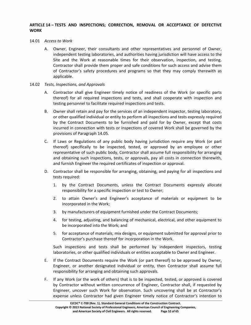
EJCDC® C-700 (Rev. 1), Standard General Conditions of the Construction Contract. Copyright © 2013 National Society of Professional Engineers, American Council of Engineering Companies,
and American Society of Civil Engineers. All rights reserved. Page 52 of 65
ARTICLE 14 – TESTS AND INSPECTIONS; CORRECTION, REMOVAL OR ACCEPTANCE OF DEFECTIVE WORK
14.01 Access to Work
A. Owner, Engineer, their consultants and other representatives and personnel of Owner, independent testing laboratories, and authorities having jurisdiction will have access to the Site and the Work at reasonable times for their observation, inspection, and testing. Contractor shall provide them proper and safe conditions for such access and advise them of Contractor’s safety procedures and programs so that they may comply therewith as applicable.
14.02 Tests, Inspections, and Approvals
A. Contractor shall give Engineer timely notice of readiness of the Work (or specific parts thereof) for all required inspections and tests, and shall cooperate with inspection and testing personnel to facilitate required inspections and tests.
B. Owner shall retain and pay for the services of an independent inspector, testing laboratory, or other qualified individual or entity to perform all inspections and tests expressly required by the Contract Documents to be furnished and paid for by Owner, except that costs incurred in connection with tests or inspections of covered Work shall be governed by the provisions of Paragraph 14.05.
C. If Laws or Regulations of any public body having jurisdiction require any Work (or part thereof) specifically to be inspected, tested, or approved by an employee or other representative of such public body, Contractor shall assume full responsibility for arranging and obtaining such inspections, tests, or approvals, pay all costs in connection therewith, and furnish Engineer the required certificates of inspection or approval.
D. Contractor shall be responsible for arranging, obtaining, and paying for all inspections and tests required:
1. by the Contract Documents, unless the Contract Documents expressly allocate responsibility for a specific inspection or test to Owner;
2. to attain Owner’s and Engineer’s acceptance of materials or equipment to be incorporated in the Work;
3. by manufacturers of equipment furnished under the Contract Documents;
4. for testing, adjusting, and balancing of mechanical, electrical, and other equipment to be incorporated into the Work; and
5. for acceptance of materials, mix designs, or equipment submitted for approval prior to Contractor’s purchase thereof for incorporation in the Work.
Such inspections and tests shall be performed by independent inspectors, testing laboratories, or other qualified individuals or entities acceptable to Owner and Engineer.
E. If the Contract Documents require the Work (or part thereof) to be approved by Owner, Engineer, or another designated individual or entity, then Contractor shall assume full responsibility for arranging and obtaining such approvals.
F. If any Work (or the work of others) that is to be inspected, tested, or approved is covered by Contractor without written concurrence of Engineer, Contractor shall, if requested by Engineer, uncover such Work for observation. Such uncovering shall be at Contractor’s expense unless Contractor had given Engineer timely notice of Contractor’s intention to
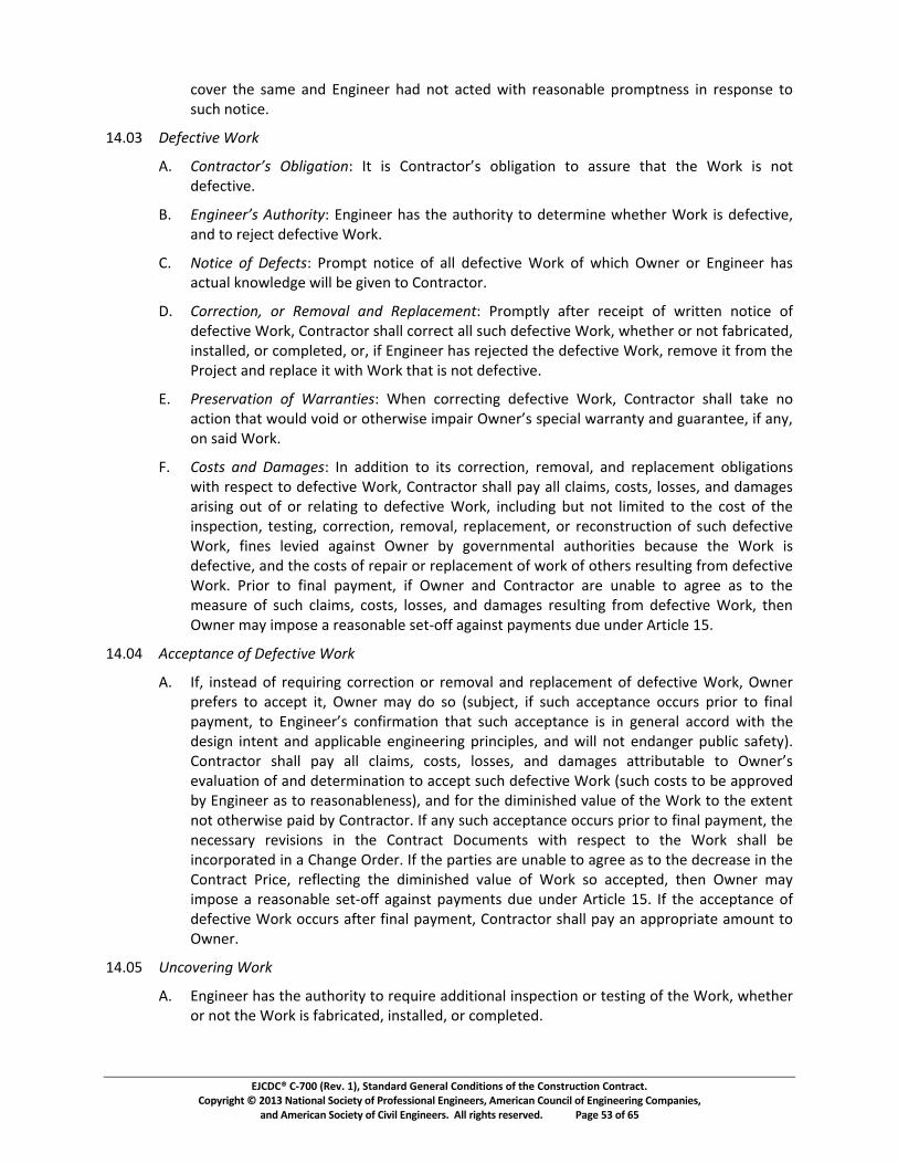
EJCDC® C-700 (Rev. 1), Standard General Conditions of the Construction Contract. Copyright © 2013 National Society of Professional Engineers, American Council of Engineering Companies,
and American Society of Civil Engineers. All rights reserved. Page 53 of 65
cover the same and Engineer had not acted with reasonable promptness in response to such notice.
14.03 Defective Work
A. Contractor’s Obligation: It is Contractor’s obligation to assure that the Work is not defective.
B. Engineer’s Authority: Engineer has the authority to determine whether Work is defective, and to reject defective Work.
C. Notice of Defects: Prompt notice of all defective Work of which Owner or Engineer has actual knowledge will be given to Contractor.
D. Correction, or Removal and Replacement: Promptly after receipt of written notice of defective Work, Contractor shall correct all such defective Work, whether or not fabricated, installed, or completed, or, if Engineer has rejected the defective Work, remove it from the Project and replace it with Work that is not defective.
E. Preservation of Warranties: When correcting defective Work, Contractor shall take no action that would void or otherwise impair Owner’s special warranty and guarantee, if any, on said Work.
F. Costs and Damages: In addition to its correction, removal, and replacement obligations with respect to defective Work, Contractor shall pay all claims, costs, losses, and damages arising out of or relating to defective Work, including but not limited to the cost of the inspection, testing, correction, removal, replacement, or reconstruction of such defective Work, fines levied against Owner by governmental authorities because the Work is defective, and the costs of repair or replacement of work of others resulting from defective Work. Prior to final payment, if Owner and Contractor are unable to agree as to the measure of such claims, costs, losses, and damages resulting from defective Work, then Owner may impose a reasonable set-off against payments due under Article 15.
14.04 Acceptance of Defective Work
A. If, instead of requiring correction or removal and replacement of defective Work, Owner prefers to accept it, Owner may do so (subject, if such acceptance occurs prior to final payment, to Engineer’s confirmation that such acceptance is in general accord with the design intent and applicable engineering principles, and will not endanger public safety). Contractor shall pay all claims, costs, losses, and damages attributable to Owner’s evaluation of and determination to accept such defective Work (such costs to be approved by Engineer as to reasonableness), and for the diminished value of the Work to the extent not otherwise paid by Contractor. If any such acceptance occurs prior to final payment, the necessary revisions in the Contract Documents with respect to the Work shall be incorporated in a Change Order. If the parties are unable to agree as to the decrease in the Contract Price, reflecting the diminished value of Work so accepted, then Owner may impose a reasonable set-off against payments due under Article 15. If the acceptance of defective Work occurs after final payment, Contractor shall pay an appropriate amount to Owner.
14.05 Uncovering Work
A. Engineer has the authority to require additional inspection or testing of the Work, whether or not the Work is fabricated, installed, or completed.
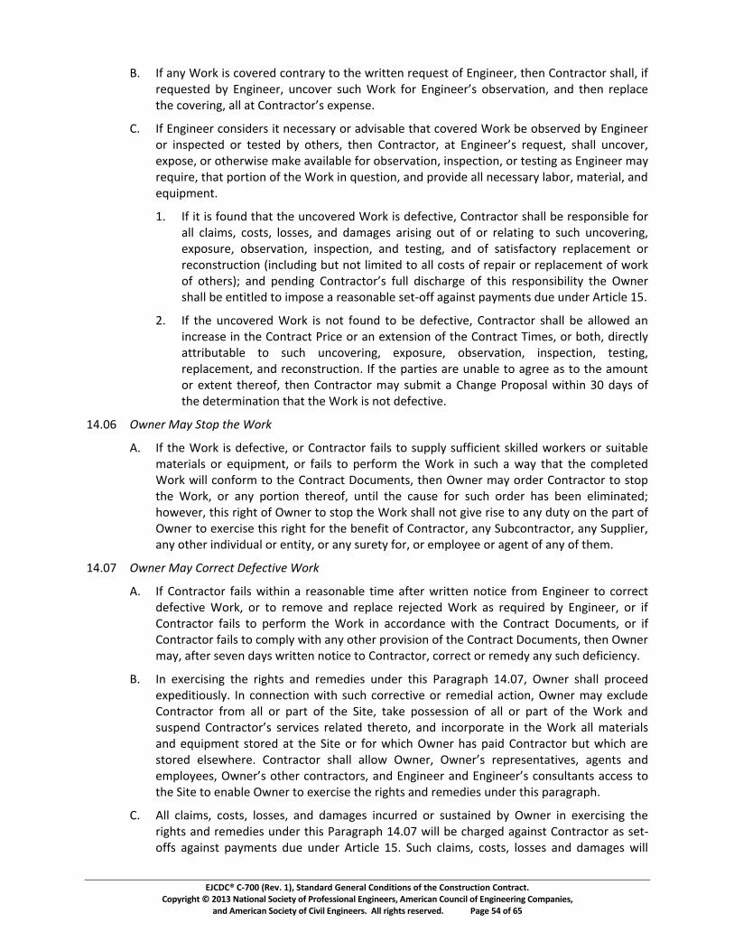
EJCDC® C-700 (Rev. 1), Standard General Conditions of the Construction Contract. Copyright © 2013 National Society of Professional Engineers, American Council of Engineering Companies,
and American Society of Civil Engineers. All rights reserved. Page 54 of 65
B. If any Work is covered contrary to the written request of Engineer, then Contractor shall, if requested by Engineer, uncover such Work for Engineer’s observation, and then replace the covering, all at Contractor’s expense.
C. If Engineer considers it necessary or advisable that covered Work be observed by Engineer or inspected or tested by others, then Contractor, at Engineer’s request, shall uncover, expose, or otherwise make available for observation, inspection, or testing as Engineer may require, that portion of the Work in question, and provide all necessary labor, material, and equipment.
1. If it is found that the uncovered Work is defective, Contractor shall be responsible for all claims, costs, losses, and damages arising out of or relating to such uncovering, exposure, observation, inspection, and testing, and of satisfactory replacement or reconstruction (including but not limited to all costs of repair or replacement of work of others); and pending Contractor’s full discharge of this responsibility the Owner shall be entitled to impose a reasonable set-off against payments due under Article 15.
2. If the uncovered Work is not found to be defective, Contractor shall be allowed an increase in the Contract Price or an extension of the Contract Times, or both, directly attributable to such uncovering, exposure, observation, inspection, testing, replacement, and reconstruction. If the parties are unable to agree as to the amount or extent thereof, then Contractor may submit a Change Proposal within 30 days of the determination that the Work is not defective.
14.06 Owner May Stop the Work
A. If the Work is defective, or Contractor fails to supply sufficient skilled workers or suitable materials or equipment, or fails to perform the Work in such a way that the completed Work will conform to the Contract Documents, then Owner may order Contractor to stop the Work, or any portion thereof, until the cause for such order has been eliminated; however, this right of Owner to stop the Work shall not give rise to any duty on the part of Owner to exercise this right for the benefit of Contractor, any Subcontractor, any Supplier, any other individual or entity, or any surety for, or employee or agent of any of them.
14.07 Owner May Correct Defective Work
A. If Contractor fails within a reasonable time after written notice from Engineer to correct defective Work, or to remove and replace rejected Work as required by Engineer, or if Contractor fails to perform the Work in accordance with the Contract Documents, or if Contractor fails to comply with any other provision of the Contract Documents, then Owner may, after seven days written notice to Contractor, correct or remedy any such deficiency.
B. In exercising the rights and remedies under this Paragraph 14.07, Owner shall proceed expeditiously. In connection with such corrective or remedial action, Owner may exclude Contractor from all or part of the Site, take possession of all or part of the Work and suspend Contractor’s services related thereto, and incorporate in the Work all materials and equipment stored at the Site or for which Owner has paid Contractor but which are stored elsewhere. Contractor shall allow Owner, Owner’s representatives, agents and employees, Owner’s other contractors, and Engineer and Engineer’s consultants access to the Site to enable Owner to exercise the rights and remedies under this paragraph.
C. All claims, costs, losses, and damages incurred or sustained by Owner in exercising the rights and remedies under this Paragraph 14.07 will be charged against Contractor as set-offs against payments due under Article 15. Such claims, costs, losses and damages will
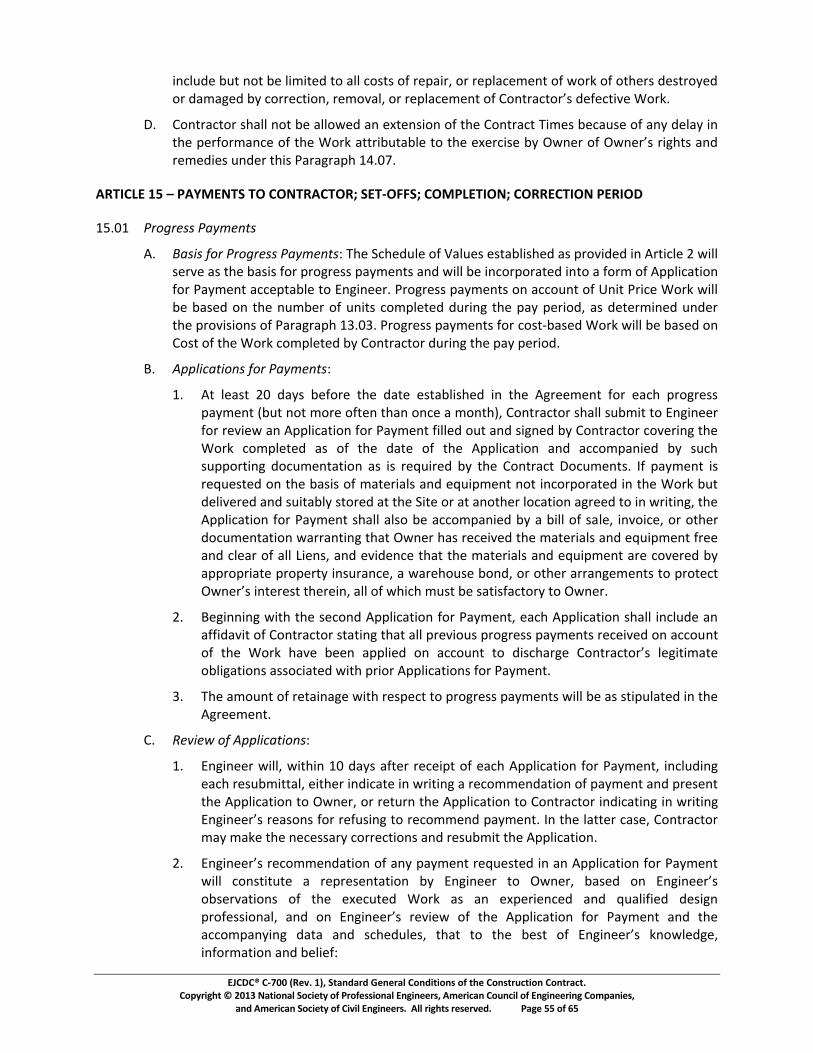
EJCDC® C-700 (Rev. 1), Standard General Conditions of the Construction Contract. Copyright © 2013 National Society of Professional Engineers, American Council of Engineering Companies,
and American Society of Civil Engineers. All rights reserved. Page 55 of 65
include but not be limited to all costs of repair, or replacement of work of others destroyed or damaged by correction, removal, or replacement of Contractor’s defective Work.
D. Contractor shall not be allowed an extension of the Contract Times because of any delay in the performance of the Work attributable to the exercise by Owner of Owner’s rights and remedies under this Paragraph 14.07.
ARTICLE 15 – PAYMENTS TO CONTRACTOR; SET-OFFS; COMPLETION; CORRECTION PERIOD
15.01 Progress Payments
A. Basis for Progress Payments: The Schedule of Values established as provided in Article 2 will serve as the basis for progress payments and will be incorporated into a form of Application for Payment acceptable to Engineer. Progress payments on account of Unit Price Work will be based on the number of units completed during the pay period, as determined under the provisions of Paragraph 13.03. Progress payments for cost-based Work will be based on Cost of the Work completed by Contractor during the pay period.
B. Applications for Payments:
1. At least 20 days before the date established in the Agreement for each progress payment (but not more often than once a month), Contractor shall submit to Engineer for review an Application for Payment filled out and signed by Contractor covering the Work completed as of the date of the Application and accompanied by such supporting documentation as is required by the Contract Documents. If payment is requested on the basis of materials and equipment not incorporated in the Work but delivered and suitably stored at the Site or at another location agreed to in writing, the Application for Payment shall also be accompanied by a bill of sale, invoice, or other documentation warranting that Owner has received the materials and equipment free and clear of all Liens, and evidence that the materials and equipment are covered by appropriate property insurance, a warehouse bond, or other arrangements to protect Owner’s interest therein, all of which must be satisfactory to Owner.
2. Beginning with the second Application for Payment, each Application shall include an affidavit of Contractor stating that all previous progress payments received on account of the Work have been applied on account to discharge Contractor’s legitimate obligations associated with prior Applications for Payment.
3. The amount of retainage with respect to progress payments will be as stipulated in the Agreement.
C. Review of Applications:
1. Engineer will, within 10 days after receipt of each Application for Payment, including each resubmittal, either indicate in writing a recommendation of payment and present the Application to Owner, or return the Application to Contractor indicating in writing Engineer’s reasons for refusing to recommend payment. In the latter case, Contractor may make the necessary corrections and resubmit the Application.
2. Engineer’s recommendation of any payment requested in an Application for Payment will constitute a representation by Engineer to Owner, based on Engineer’s observations of the executed Work as an experienced and qualified design professional, and on Engineer’s review of the Application for Payment and the accompanying data and schedules, that to the best of Engineer’s knowledge, information and belief:
EJCDC® C-700 (Rev. 1), Standard General Conditions of the Construction Contract. Copyright © 2013 National Society of Professional Engineers, American Council of Engineering Companies,
and American Society of Civil Engineers. All rights reserved. Page 56 of 65
a. the Work has progressed to the point indicated;
b. the quality of the Work is generally in accordance with the Contract Documents (subject to an evaluation of the Work as a functioning whole prior to or upon Substantial Completion, the results of any subsequent tests called for in the Contract Documents, a final determination of quantities and classifications for Unit Price Work under Paragraph 13.03, and any other qualifications stated in the recommendation); and
c. the conditions precedent to Contractor’s being entitled to such payment appear to have been fulfilled in so far as it is Engineer’s responsibility to observe the Work.
3. By recommending any such payment Engineer will not thereby be deemed to have represented that:
a. inspections made to check the quality or the quantity of the Work as it has been performed have been exhaustive, extended to every aspect of the Work in progress, or involved detailed inspections of the Work beyond the responsibilities specifically assigned to Engineer in the Contract; or
b. there may not be other matters or issues between the parties that might entitle Contractor to be paid additionally by Owner or entitle Owner to withhold payment to Contractor.
4. Neither Engineer’s review of Contractor’s Work for the purposes of recommending payments nor Engineer’s recommendation of any payment, including final payment, will impose responsibility on Engineer:
a. to supervise, direct, or control the Work, or
b. for the means, methods, techniques, sequences, or procedures of construction, or the safety precautions and programs incident thereto, or
c. for Contractor’s failure to comply with Laws and Regulations applicable to Contractor’s performance of the Work, or
d. to make any examination to ascertain how or for what purposes Contractor has used the money paid on account of the Contract Price, or
e. to determine that title to any of the Work, materials, or equipment has passed to Owner free and clear of any Liens.
5. Engineer may refuse to recommend the whole or any part of any payment if, in Engineer’s opinion, it would be incorrect to make the representations to Owner stated in Paragraph 15.01.C.2.
6. Engineer will recommend reductions in payment (set-offs) necessary in Engineer’s opinion to protect Owner from loss because:
a. the Work is defective, requiring correction or replacement;
b. the Contract Price has been reduced by Change Orders;
c. Owner has been required to correct defective Work in accordance with Paragraph 14.07, or has accepted defective Work pursuant to Paragraph 14.04;
d. Owner has been required to remove or remediate a Hazardous Environmental Condition for which Contractor is responsible; or
EJCDC® C-700 (Rev. 1), Standard General Conditions of the Construction Contract. Copyright © 2013 National Society of Professional Engineers, American Council of Engineering Companies,
and American Society of Civil Engineers. All rights reserved. Page 57 of 65
e. Engineer has actual knowledge of the occurrence of any of the events that would constitute a default by Contractor and therefore justify termination for cause under the Contract Documents.
D. Payment Becomes Due:
1. Ten days after presentation of the Application for Payment to Owner with Engineer’s recommendation, the amount recommended (subject to any Owner set-offs) will become due, and when due will be paid by Owner to Contractor.
E. Reductions in Payment by Owner:
1. In addition to any reductions in payment (set-offs) recommended by Engineer, Owner is entitled to impose a set-off against payment based on any of the following:
a. claims have been made against Owner on account of Contractor’s conduct in the performance or furnishing of the Work, or Owner has incurred costs, losses, or damages on account of Contractor’s conduct in the performance or furnishing of the Work, including but not limited to claims, costs, losses, or damages from workplace injuries, adjacent property damage, non-compliance with Laws and Regulations, and patent infringement;
b. Contractor has failed to take reasonable and customary measures to avoid damage, delay, disruption, and interference with other work at or adjacent to the Site;
c. Contractor has failed to provide and maintain required bonds or insurance;
d. Owner has been required to remove or remediate a Hazardous Environmental Condition for which Contractor is responsible;
e. Owner has incurred extra charges or engineering costs related to submittal reviews, evaluations of proposed substitutes, tests and inspections, or return visits to manufacturing or assembly facilities;
f. the Work is defective, requiring correction or replacement;
g. Owner has been required to correct defective Work in accordance with Paragraph 14.07, or has accepted defective Work pursuant to Paragraph 14.04;
h. the Contract Price has been reduced by Change Orders;
i. an event that would constitute a default by Contractor and therefore justify a termination for cause has occurred;
j. liquidated damages have accrued as a result of Contractor’s failure to achieve Milestones, Substantial Completion, or final completion of the Work;
k. Liens have been filed in connection with the Work, except where Contractor has delivered a specific bond satisfactory to Owner to secure the satisfaction and discharge of such Liens;
l. there are other items entitling Owner to a set off against the amount recommended.
2. If Owner imposes any set-off against payment, whether based on its own knowledge or on the written recommendations of Engineer, Owner will give Contractor immediate written notice (with a copy to Engineer) stating the reasons for such action and the specific amount of the reduction, and promptly pay Contractor any amount
EJCDC® C-700 (Rev. 1), Standard General Conditions of the Construction Contract. Copyright © 2013 National Society of Professional Engineers, American Council of Engineering Companies,
and American Society of Civil Engineers. All rights reserved. Page 58 of 65
remaining after deduction of the amount so withheld. Owner shall promptly pay Contractor the amount so withheld, or any adjustment thereto agreed to by Owner and Contractor, if Contractor remedies the reasons for such action. The reduction imposed shall be binding on Contractor unless it duly submits a Change Proposal contesting the reduction.
3. Upon a subsequent determination that Owner’s refusal of payment was not justified, the amount wrongfully withheld shall be treated as an amount due as determined by Paragraph 15.01.C.1 and subject to interest as provided in the Agreement.
15.02 Contractor’s Warranty of Title
A. Contractor warrants and guarantees that title to all Work, materials, and equipment furnished under the Contract will pass to Owner free and clear of (1) all Liens and other title defects, and (2) all patent, licensing, copyright, or royalty obligations, no later than seven days after the time of payment by Owner.
15.03 Substantial Completion
A. When Contractor considers the entire Work ready for its intended use Contractor shall notify Owner and Engineer in writing that the entire Work is substantially complete and request that Engineer issue a certificate of Substantial Completion. Contractor shall at the same time submit to Owner and Engineer an initial draft of punch list items to be completed or corrected before final payment.
B. Promptly after Contractor’s notification, Owner, Contractor, and Engineer shall make an inspection of the Work to determine the status of completion. If Engineer does not consider the Work substantially complete, Engineer will notify Contractor in writing giving the reasons therefor.
C. If Engineer considers the Work substantially complete, Engineer will deliver to Owner a preliminary certificate of Substantial Completion which shall fix the date of Substantial Completion. Engineer shall attach to the certificate a punch list of items to be completed or corrected before final payment. Owner shall have seven days after receipt of the preliminary certificate during which to make written objection to Engineer as to any provisions of the certificate or attached punch list. If, after considering the objections to the provisions of the preliminary certificate, Engineer concludes that the Work is not substantially complete, Engineer will, within 14 days after submission of the preliminary certificate to Owner, notify Contractor in writing that the Work is not substantially complete, stating the reasons therefor. If Owner does not object to the provisions of the certificate, or if despite consideration of Owner’s objections Engineer concludes that the Work is substantially complete, then Engineer will, within said 14 days, execute and deliver to Owner and Contractor a final certificate of Substantial Completion (with a revised punch list of items to be completed or corrected) reflecting such changes from the preliminary certificate as Engineer believes justified after consideration of any objections from Owner.
D. At the time of receipt of the preliminary certificate of Substantial Completion, Owner and Contractor will confer regarding Owner’s use or occupancy of the Work following Substantial Completion, review the builder’s risk insurance policy with respect to the end of the builder’s risk coverage, and confirm the transition to coverage of the Work under a permanent property insurance policy held by Owner. Unless Owner and Contractor agree otherwise in writing, Owner shall bear responsibility for security, operation, protection of the Work, property insurance, maintenance, heat, and utilities upon Owner’s use or occupancy of the Work.
EJCDC® C-700 (Rev. 1), Standard General Conditions of the Construction Contract. Copyright © 2013 National Society of Professional Engineers, American Council of Engineering Companies,
and American Society of Civil Engineers. All rights reserved. Page 59 of 65
E. After Substantial Completion the Contractor shall promptly begin work on the punch list of items to be completed or corrected prior to final payment. In appropriate cases Contractor may submit monthly Applications for Payment for completed punch list items, following the progress payment procedures set forth above.
F. Owner shall have the right to exclude Contractor from the Site after the date of Substantial Completion subject to allowing Contractor reasonable access to remove its property and complete or correct items on the punch list.
15.04 Partial Use or Occupancy
A. Prior to Substantial Completion of all the Work, Owner may use or occupy any substantially completed part of the Work which has specifically been identified in the Contract Documents, or which Owner, Engineer, and Contractor agree constitutes a separately functioning and usable part of the Work that can be used by Owner for its intended purpose without significant interference with Contractor’s performance of the remainder of the Work, subject to the following conditions:
1. At any time Owner may request in writing that Contractor permit Owner to use or occupy any such part of the Work that Owner believes to be substantially complete. If and when Contractor agrees that such part of the Work is substantially complete, Contractor, Owner, and Engineer will follow the procedures of Paragraph 15.03.A through E for that part of the Work.
2. At any time Contractor may notify Owner and Engineer in writing that Contractor considers any such part of the Work substantially complete and request Engineer to issue a certificate of Substantial Completion for that part of the Work.
3. Within a reasonable time after either such request, Owner, Contractor, and Engineer shall make an inspection of that part of the Work to determine its status of completion. If Engineer does not consider that part of the Work to be substantially complete, Engineer will notify Owner and Contractor in writing giving the reasons therefor. If Engineer considers that part of the Work to be substantially complete, the provisions of Paragraph 15.03 will apply with respect to certification of Substantial Completion of that part of the Work and the division of responsibility in respect thereof and access thereto.
4. No use or occupancy or separate operation of part of the Work may occur prior to compliance with the requirements of Paragraph 6.05 regarding builder’s risk or other property insurance.
15.05 Final Inspection
A. Upon written notice from Contractor that the entire Work or an agreed portion thereof is complete, Engineer will promptly make a final inspection with Owner and Contractor and will notify Contractor in writing of all particulars in which this inspection reveals that the Work, or agreed portion thereof, is incomplete or defective. Contractor shall immediately take such measures as are necessary to complete such Work or remedy such deficiencies.
15.06 Final Payment
A. Application for Payment:
1. After Contractor has, in the opinion of Engineer, satisfactorily completed all corrections identified during the final inspection and has delivered, in accordance with the Contract Documents, all maintenance and operating instructions, schedules, guarantees, bonds, certificates or other evidence of insurance, certificates of
EJCDC® C-700 (Rev. 1), Standard General Conditions of the Construction Contract. Copyright © 2013 National Society of Professional Engineers, American Council of Engineering Companies,
and American Society of Civil Engineers. All rights reserved. Page 60 of 65
inspection, annotated record documents (as provided in Paragraph 7.11), and other documents, Contractor may make application for final payment.
2. The final Application for Payment shall be accompanied (except as previously delivered) by:
a. all documentation called for in the Contract Documents;
b. consent of the surety, if any, to final payment;
c. satisfactory evidence that all title issues have been resolved such that title to all Work, materials, and equipment has passed to Owner free and clear of any Liens or other title defects, or will so pass upon final payment.
d. a list of all disputes that Contractor believes are unsettled; and
e. complete and legally effective releases or waivers (satisfactory to Owner) of all Lien rights arising out of the Work, and of Liens filed in connection with the Work.
3. In lieu of the releases or waivers of Liens specified in Paragraph 15.06.A.2 and as approved by Owner, Contractor may furnish receipts or releases in full and an affidavit of Contractor that: (a) the releases and receipts include all labor, services, material, and equipment for which a Lien could be filed; and (b) all payrolls, material and equipment bills, and other indebtedness connected with the Work for which Owner might in any way be responsible, or which might in any way result in liens or other burdens on Owner's property, have been paid or otherwise satisfied. If any Subcontractor or Supplier fails to furnish such a release or receipt in full, Contractor may furnish a bond or other collateral satisfactory to Owner to indemnify Owner against any Lien, or Owner at its option may issue joint checks payable to Contractor and specified Subcontractors and Suppliers.
B. Engineer’s Review of Application and Acceptance:
1. If, on the basis of Engineer’s observation of the Work during construction and final inspection, and Engineer’s review of the final Application for Payment and accompanying documentation as required by the Contract Documents, Engineer is satisfied that the Work has been completed and Contractor’s other obligations under the Contract have been fulfilled, Engineer will, within ten days after receipt of the final Application for Payment, indicate in writing Engineer’s recommendation of final payment and present the Application for Payment to Owner for payment. Such recommendation shall account for any set-offs against payment that are necessary in Engineer’s opinion to protect Owner from loss for the reasons stated above with respect to progress payments. At the same time Engineer will also give written notice to Owner and Contractor that the Work is acceptable, subject to the provisions of Paragraph 15.07. Otherwise, Engineer will return the Application for Payment to Contractor, indicating in writing the reasons for refusing to recommend final payment, in which case Contractor shall make the necessary corrections and resubmit the Application for Payment.
C. Completion of Work: The Work is complete (subject to surviving obligations) when it is ready for final payment as established by the Engineer’s written recommendation of final payment.
D. Payment Becomes Due: Thirty days after the presentation to Owner of the final Application for Payment and accompanying documentation, the amount recommended by Engineer (less any further sum Owner is entitled to set off against Engineer’s recommendation,
EJCDC® C-700 (Rev. 1), Standard General Conditions of the Construction Contract. Copyright © 2013 National Society of Professional Engineers, American Council of Engineering Companies,
and American Society of Civil Engineers. All rights reserved. Page 61 of 65
including but not limited to set-offs for liquidated damages and set-offs allowed under the provisions above with respect to progress payments) will become due and shall be paid by Owner to Contractor.
15.07 Waiver of Claims
A. The making of final payment will not constitute a waiver by Owner of claims or rights against Contractor. Owner expressly reserves claims and rights arising from unsettled Liens, from defective Work appearing after final inspection pursuant to Paragraph 15.05, from Contractor’s failure to comply with the Contract Documents or the terms of any special guarantees specified therein, from outstanding Claims by Owner, or from Contractor’s continuing obligations under the Contract Documents.
B. The acceptance of final payment by Contractor will constitute a waiver by Contractor of all claims and rights against Owner other than those pending matters that have been duly submitted or appealed under the provisions of Article 17.
15.08 Correction Period
A. If within one year after the date of Substantial Completion (or such longer period of time as may be prescribed by the terms of any applicable special guarantee required by the Contract Documents, or by any specific provision of the Contract Documents), any Work is found to be defective, or if the repair of any damages to the Site, adjacent areas that Contractor has arranged to use through construction easements or otherwise, and other adjacent areas used by Contractor as permitted by Laws and Regulations, is found to be defective, then Contractor shall promptly, without cost to Owner and in accordance with Owner’s written instructions:
1. correct the defective repairs to the Site or such other adjacent areas;
2. correct such defective Work;
3. if the defective Work has been rejected by Owner, remove it from the Project and replace it with Work that is not defective, and
4. satisfactorily correct or repair or remove and replace any damage to other Work, to the work of others, or to other land or areas resulting therefrom.
B. If Contractor does not promptly comply with the terms of Owner’s written instructions, or in an emergency where delay would cause serious risk of loss or damage, Owner may have the defective Work corrected or repaired or may have the rejected Work removed and replaced. Contractor shall pay all claims, costs, losses, and damages (including but not limited to all fees and charges of engineers, architects, attorneys, and other professionals and all court or arbitration or other dispute resolution costs) arising out of or relating to such correction or repair or such removal and replacement (including but not limited to all costs of repair or replacement of work of others).
C. In special circumstances where a particular item of equipment is placed in continuous service before Substantial Completion of all the Work, the correction period for that item may start to run from an earlier date if so provided in the Specifications.
D. Where defective Work (and damage to other Work resulting therefrom) has been corrected or removed and replaced under this paragraph, the correction period hereunder with respect to such Work will be extended for an additional period of one year after such correction or removal and replacement has been satisfactorily completed.
EJCDC® C-700 (Rev. 1), Standard General Conditions of the Construction Contract. Copyright © 2013 National Society of Professional Engineers, American Council of Engineering Companies,
and American Society of Civil Engineers. All rights reserved. Page 62 of 65
E. Contractor’s obligations under this paragraph are in addition to all other obligations and warranties. The provisions of this paragraph shall not be construed as a substitute for, or a waiver of, the provisions of any applicable statute of limitation or repose.
ARTICLE 16 – SUSPENSION OF WORK AND TERMINATION
16.01 Owner May Suspend Work
A. At any time and without cause, Owner may suspend the Work or any portion thereof for a period of not more than 90 consecutive days by written notice to Contractor and Engineer. Such notice will fix the date on which Work will be resumed. Contractor shall resume the Work on the date so fixed. Contractor shall be entitled to an adjustment in the Contract Price or an extension of the Contract Times, or both, directly attributable to any such suspension. Any Change Proposal seeking such adjustments shall be submitted no later than 30 days after the date fixed for resumption of Work.
16.02 Owner May Terminate for Cause
A. The occurrence of any one or more of the following events will constitute a default by Contractor and justify termination for cause:
1. Contractor’s persistent failure to perform the Work in accordance with the Contract Documents (including, but not limited to, failure to supply sufficient skilled workers or suitable materials or equipment or failure to adhere to the Progress Schedule);
2. Failure of Contractor to perform or otherwise to comply with a material term of the Contract Documents;
3. Contractor’s disregard of Laws or Regulations of any public body having jurisdiction; or
4. Contractor’s repeated disregard of the authority of Owner or Engineer.
B. If one or more of the events identified in Paragraph 16.02.A occurs, then after giving Contractor (and any surety) ten days written notice that Owner is considering a declaration that Contractor is in default and termination of the contract, Owner may proceed to:
1. declare Contractor to be in default, and give Contractor (and any surety) notice that the Contract is terminated; and
2. enforce the rights available to Owner under any applicable performance bond.
C. Subject to the terms and operation of any applicable performance bond, if Owner has terminated the Contract for cause, Owner may exclude Contractor from the Site, take possession of the Work, incorporate in the Work all materials and equipment stored at the Site or for which Owner has paid Contractor but which are stored elsewhere, and complete the Work as Owner may deem expedient.
D. Owner may not proceed with termination of the Contract under Paragraph 16.02.B if Contractor within seven days of receipt of notice of intent to terminate begins to correct its failure to perform and proceeds diligently to cure such failure.
E. If Owner proceeds as provided in Paragraph 16.02.B, Contractor shall not be entitled to receive any further payment until the Work is completed. If the unpaid balance of the Contract Price exceeds the cost to complete the Work, including all related claims, costs, losses, and damages (including but not limited to all fees and charges of engineers, architects, attorneys, and other professionals) sustained by Owner, such excess will be paid to Contractor. If the cost to complete the Work including such related claims, costs, losses,
EJCDC® C-700 (Rev. 1), Standard General Conditions of the Construction Contract. Copyright © 2013 National Society of Professional Engineers, American Council of Engineering Companies,
and American Society of Civil Engineers. All rights reserved. Page 63 of 65
and damages exceeds such unpaid balance, Contractor shall pay the difference to Owner. Such claims, costs, losses, and damages incurred by Owner will be reviewed by Engineer as to their reasonableness and, when so approved by Engineer, incorporated in a Change Order. When exercising any rights or remedies under this paragraph, Owner shall not be required to obtain the lowest price for the Work performed.
F. Where Contractor’s services have been so terminated by Owner, the termination will not affect any rights or remedies of Owner against Contractor then existing or which may thereafter accrue, or any rights or remedies of Owner against Contractor or any surety under any payment bond or performance bond. Any retention or payment of money due Contractor by Owner will not release Contractor from liability.
G. If and to the extent that Contractor has provided a performance bond under the provisions of Paragraph 6.01.A, the provisions of that bond shall govern over any inconsistent provisions of Paragraphs 16.02.B and 16.02.D.
16.03 Owner May Terminate For Convenience
A. Upon seven days written notice to Contractor and Engineer, Owner may, without cause and without prejudice to any other right or remedy of Owner, terminate the Contract. In such case, Contractor shall be paid for (without duplication of any items):
1. completed and acceptable Work executed in accordance with the Contract Documents prior to the effective date of termination, including fair and reasonable sums for overhead and profit on such Work;
2. expenses sustained prior to the effective date of termination in performing services and furnishing labor, materials, or equipment as required by the Contract Documents in connection with uncompleted Work, plus fair and reasonable sums for overhead and profit on such expenses; and
3. other reasonable expenses directly attributable to termination, including costs incurred to prepare a termination for convenience cost proposal.
B. Contractor shall not be paid on account of loss of anticipated overhead, profits, or revenue, or other economic loss arising out of or resulting from such termination.
16.04 Contractor May Stop Work or Terminate
A. If, through no act or fault of Contractor, (1) the Work is suspended for more than 90 consecutive days by Owner or under an order of court or other public authority, or (2) Engineer fails to act on any Application for Payment within 30 days after it is submitted, or (3) Owner fails for 30 days to pay Contractor any sum finally determined to be due, then Contractor may, upon seven days written notice to Owner and Engineer, and provided Owner or Engineer do not remedy such suspension or failure within that time, terminate the contract and recover from Owner payment on the same terms as provided in Paragraph 16.03.
B. In lieu of terminating the Contract and without prejudice to any other right or remedy, if Engineer has failed to act on an Application for Payment within 30 days after it is submitted, or Owner has failed for 30 days to pay Contractor any sum finally determined to be due, Contractor may, seven days after written notice to Owner and Engineer, stop the Work until payment is made of all such amounts due Contractor, including interest thereon. The provisions of this paragraph are not intended to preclude Contractor from submitting a Change Proposal for an adjustment in Contract Price or Contract Times or otherwise for
EJCDC® C-700 (Rev. 1), Standard General Conditions of the Construction Contract. Copyright © 2013 National Society of Professional Engineers, American Council of Engineering Companies,
and American Society of Civil Engineers. All rights reserved. Page 64 of 65
expenses or damage directly attributable to Contractor’s stopping the Work as permitted by this paragraph.
ARTICLE 17 – FINAL RESOLUTION OF DISPUTES
17.01 Methods and Procedures
A. Disputes Subject to Final Resolution: The following disputed matters are subject to final resolution under the provisions of this Article:
1. A timely appeal of an approval in part and denial in part of a Claim, or of a denial in full; and
2. Disputes between Owner and Contractor concerning the Work or obligations under the Contract Documents, and arising after final payment has been made.
B. Final Resolution of Disputes: For any dispute subject to resolution under this Article, Owner or Contractor may:
1. elect in writing to invoke the dispute resolution process provided for in the Supplementary Conditions; or
2. agree with the other party to submit the dispute to another dispute resolution process; or
3. if no dispute resolution process is provided for in the Supplementary Conditions or mutually agreed to, give written notice to the other party of the intent to submit the dispute to a court of competent jurisdiction.
ARTICLE 18 – MISCELLANEOUS
18.01 Giving Notice
A. Whenever any provision of the Contract Documents requires the giving of written notice, it will be deemed to have been validly given if:
1. delivered in person, by a commercial courier service or otherwise, to the individual or to a member of the firm or to an officer of the corporation for which it is intended; or
2. delivered at or sent by registered or certified mail, postage prepaid, to the last business address known to the sender of the notice.
18.02 Computation of Times
A. When any period of time is referred to in the Contract by days, it will be computed to exclude the first and include the last day of such period. If the last day of any such period falls on a Saturday or Sunday or on a day made a legal holiday by the law of the applicable jurisdiction, such day will be omitted from the computation.
18.03 Cumulative Remedies
A. The duties and obligations imposed by these General Conditions and the rights and remedies available hereunder to the parties hereto are in addition to, and are not to be construed in any way as a limitation of, any rights and remedies available to any or all of them which are otherwise imposed or available by Laws or Regulations, by special warranty or guarantee, or by other provisions of the Contract. The provisions of this paragraph will be as effective as if repeated specifically in the Contract Documents in connection with each particular duty, obligation, right, and remedy to which they apply.
EJCDC® C-700 (Rev. 1), Standard General Conditions of the Construction Contract. Copyright © 2013 National Society of Professional Engineers, American Council of Engineering Companies,
and American Society of Civil Engineers. All rights reserved. Page 65 of 65
18.04 Limitation of Damages
A. With respect to any and all Change Proposals, Claims, disputes subject to final resolution, and other matters at issue, neither Owner nor Engineer, nor any of their officers, directors, members, partners, employees, agents, consultants, or subcontractors, shall be liable to Contractor for any claims, costs, losses, or damages sustained by Contractor on or in connection with any other project or anticipated project.
18.05 No Waiver
A. A party’s non-enforcement of any provision shall not constitute a waiver of that provision, nor shall it affect the enforceability of that provision or of the remainder of this Contract.
18.06 Survival of Obligations
A. All representations, indemnifications, warranties, and guarantees made in, required by, or given in accordance with the Contract, as well as all continuing obligations indicated in the Contract, will survive final payment, completion, and acceptance of the Work or termination or completion of the Contract or termination of the services of Contractor.
18.07 Controlling Law
A. This Contract is to be governed by the law of the state in which the Project is located.
18.08 Headings
A. Article and paragraph headings are inserted for convenience only and do not constitute parts of these General Conditions.
Terrace Heights Landfill 00800-1 SUPPLEMENTARY CONDITIONS
Scale Plaza Upgrades Issued for Bid – August, 2016
SECTION 00800
SUPPLEMENTARY CONDITIONS
These Supplementary Conditions amend or supplement the Standard General Conditions of the
Construction Contract as indicated below. All provisions which are not so amended or
supplemented remain in full force and effect.
Section 00810 – Modifications to General Conditions
SC-1.01 Defined Terms
SC-3.01 Intent
SC-4.02 Subsurface and Physical Conditions
SC-4.03 Differing Subsurface and Physical Conditions
SC-5.03 Certificates of Insurance
SC-5.04 CONTRACTOR’s Liability Insurance
SC-5.05 OWNER’s Liability Insurance
SC-5.06 Property Insurance
SC-5.07 Waiver of Rights
SC-5.08 Receipt and Application of Insurance Proceeds
SC-5.09 Acceptance of Bonds and Insurance; Option to Replace
SC-5.10 Partial Utilization, Acknowledgement of Property Insurer
SC-5.11 Insurance Requirements
SC-6.03 Services, Materials and Equipment
SC-6.04 Progress Schedule
SC-6.06 Concerning Subcontractors, Suppliers and Others
SC-6.10 Taxes
SC-6.17 Shop Drawings and Samples
SC-6.20 Indemnification
SC-7.01 Related Work at the Site
SC-9.03 Project Representative
SC-9.09 Limitation on ENGINEER’s Authority and Responsibilities
SC-11.01 Cost of the Work
SC-11.03 Unit Price Work
SC-14.02 Progress Payments
SC-14.07 Final Payment
SC-15.05 Suspension of Work and Termination
SC-16.01 Dispute Resolution
SC-17.07 Prevailing Wage Rates
Section 00830 – Wage Determination Schedule
END OF SECTION 00800


Terrace Heights Landfill 00810-1 GENERAL CONDITIONS MODIFICATIONS
Scale Plaza Upgrades Issued for Bid
SECTION 00810
GENERAL CONDITIONS MODIFICATIONS
SC-1.01 Defined Terms
The terms used in these Supplementary Conditions which are defined in the Standard General
Conditions of the Construction Contract have the meanings assigned to them in the General
Conditions.
Add the following language at the end of paragraph 1.01.A.19 of the General Conditions:
ENGINEER shall be HDR Engineering, Inc.
Add the following language at the end of paragraph 1.01.A.30 of the General Conditions:
OWNER shall be Yakima County Department of Public Services Solid Waste Division.
Modify paragraph 1.01.A.36 of the General Conditions by replacing the term ENGINEER with
the term OWNER.
Add the following new paragraphs to Article 1.01.A of the General Conditions:
52. ENGINEER’s Project Manager – The authorized partner, officer, agent or employee
of the ENGINEER, designated by the ENGINEER, to represent the ENGINEER in
performing the ENGINEER’s duties related to the Work.
53. OWNER’s Field Representative – The authorized representative of the OWNER who
may be assigned to the Site or any part thereof.
54. Minor Changes – Changes made in the field by the OWNER or OWNER’s field
representative that may affect the cost of the work.
55. Standard Specifications – The 2016 Standard Specifications for Road, Bridge and
Municipal Construction, as published by the Washington State Department of
Transportation.
SC-3.01 Intent
Add new paragraphs 3.01.D and 3.01.E immediately after paragraph 3.01.C of the General
Conditions, which are to read as follows:
F. The Specifications utilize the pre 2004 Construction Specifications Institute (CSI)
16 Division format. Sections of Division 1 – General Requirements govern
sections in all divisions of the Specifications.
G. The Specifications contained in Divisions 1 to 16, inclusive, are directed to
CONTRACTOR unless specifically noted otherwise. The words “shall be” are
included by inference where a colon (:) is used within sentences or phrases of
sections within these divisions.
SC-4.04 Progress Schedule
Add a new paragraph immediately after paragraph 4.04.A.2 of the General Conditions, which is
to read as follows:
Terrace Heights Landfill 00810-2 GENERAL CONDITIONS MODIFICATIONS
Scale Plaza Upgrades Issued for Bid
3. If, in the opinion of the ENGINEER, the CONTRACTOR falls
behind the project schedule, the CONTRACTOR shall take such steps as
may be necessary to improve progress. The ENGINEER may require the
Work to be accelerated to regain the schedule, such as increase the number
of shifts or overtime operations, days of work, amount of construction
personnel or equipment, or any combination of these measures.
CONTRACTOR shall submit to the Engineer for review and approval the
proposed measures and such supplementary schedule as deemed necessary
to demonstrate the manner in which the schedule or the agreed rate of
progress will be regained, all without additional cost to the OWNER.
Failure of the CONTRACTOR to comply will be grounds
for determination by the ENGINEER that the CONTRACTOR is not
prosecuting the Work with such diligence as will ensure completion within
the time specified. Upon such determination, the ENGINEER may
recommend that the OWNER terminate the CONTRACTOR’s right to
proceed with the Work, or any separable part thereof, in accordance with
determination for default or with other provisions provided in the Contract
Documents.
SC-5.03 Subsurface and Physical Conditions
Add new paragraph 5.03. C. to the General Conditions, which is to read as follows:
C. In the preparation of the Contract Documents, the ENGINEER has relied upon:
1. The following drawings of physical conditions in or
relating to existing surface or subsurface structures at or contiguous to the
Site (except Underground Facilities):
Record Drawings dated February, 11 1998 prepared by SCS Engineers for
Yakima County Public Works Department.
Design Drawings dated April 5, 2005 prepared by R.W. Beck, Inc. for
Yakima County Public Works Department.
Final Geotechnical Report – Phase II dated March 30, 2004 by HWA
Geosciences, Inc. for R.W. Beck, Inc.
2. Technical Data:
Unless expressly revised in SC-04.02.C.1, “technical data”
shall be limited to facts, measurements, field observations, and similar
data. “Technical data” shall not include opinions regarding suitability of
material and other opinions or professional judgments.
SC-5.04 Differing Subsurface and Physical Conditions
Delete paragraph 5.04.A, 5.04.B, and 5.04.C of the General Conditions in their entirety and
insert the following in their place:
A. CONTRACTOR shall promptly, and before the conditions are disturbed
(except in an emergency as permitted by paragraph 6.16.A), give a written notice
to the OWNER of (1) subsurface or latent physical conditions at the site which
Terrace Heights Landfill 00810-3 GENERAL CONDITIONS MODIFICATIONS
Scale Plaza Upgrades Issued for Bid
differ materially from those indicated in the Contract Documents, or (2) unknown
physical conditions at the site, of an unusual nature, which differ materially from
those ordinarily encountered and generally recognized as inherent in work of the
character provided for in the Contract Documents.
B. OWNER shall investigate the site conditions promptly after receiving the
notice. If the conditions do materially so differ and cause an increase or decrease
in the OWNER’s cost of, or the time required for, performing any part of the
work, whether or not changed as a result of the conditions, and equitable
adjustment shall be made under this clause and the contract documents modified
in writing accordingly.
C. No request by CONTRACTOR for an equitable adjustment to the Contract
Documents under this clause shall be allowed, unless CONTRACTOR has given
the written notice required; provided, that the time prescribed in paragraph 4.03.A
above for giving written notice may be extended by OWNER.
D. No request by CONTRACTOR for an equitable adjustment to the Contract
for differing site conditions shall be allowed if made after final payment under the
Contract Documents.
SC-6.01 Performance Payment, and Other Bonds
Delete paragraph 6.01 of the General Conditions in its entirety.
SC-6.02 Insurance – General Provisions
Delete paragraph 6.02 of the General Conditions in its entirety.
SC-6.03 Contractor’s Insurance
Delete paragraph 6.03 of the General Conditions in its entirety.
SC-6.04 OWNER’s Liability Insurance
Delete paragraph 6.04 of the General Conditions in its entirety.
SC-6.05 Property Insurance
Delete paragraph 5.06 of the General Conditions in its entirety.
SC-6.06 Waiver of Rights
Delete paragraph 5.07.A of the General Conditions in its entirety.
SC-6.07 Receipt and Application of Insurance Proceeds
Delete paragraph 5.08.B of the General Conditions in its entirety.
Terrace Heights Landfill 00810-4 GENERAL CONDITIONS MODIFICATIONS
Scale Plaza Upgrades Issued for Bid
SC-6.08 Insurance Requirements
Add the following new paragraph 6.08 to the General Conditions, which is to read as follows:
A. General Requirements:
The Contractor shall procure and maintain the insurance described in all
subsections of section SC-6.08 of these Special Provisions, from insurers with a
current A. M. Best rating of not less than A-: VII and licensed to do business in
the State of Washington. The Contracting Agency reserves the right to approve or
reject the insurance provided, based on the insurer’s financial condition.
The Contractor shall keep this insurance in force without interruption from the
commencement of the Contractor’s Work through the term of the Contract and for
thirty (30) days after the Physical Completion date, unless otherwise indicated
below.
If any insurance policy is written on a claims made form, its retroactive date, and
that of all subsequent renewals, shall be no later than the effective date of this
Contract. The policy shall state that coverage is claims made, and state the
retroactive date. Claims-made form coverage shall be maintained by the
Contractor for a minimum of 36 months following the Completion Date or earlier
termination of this Contract, and the Contractor shall annually provide the
Contracting Agency with proof of renewal. If renewal of the claims made form of
coverage becomes unavailable, or economically prohibitive, the Contractor shall
purchase an extended reporting period (“tail”) or execute another form of
guarantee acceptable to the Contracting Agency to assure financial responsibility
for liability for services performed.
The Contractor’s Automobile Liability, Commercial General Liability and Excess
or Umbrella Liability insurance policies shall be primary and non-contributory
insurance as respects the Contracting Agency’s insurance, self-insurance, or self-
insured pool coverage. Any insurance, self-insurance, or self-insured pool
coverage maintained by the Contracting Agency shall be excess of the
Contractor’s insurance and shall not contribute with it.
The Contractor shall provide the Contracting Agency and all additional insureds
with written notice of any policy cancellation, within two business days of their
receipt of such notice.
The Contractor shall not begin work under the Contract until the required
insurance has been obtained and approved by the Contracting Agency.
Failure on the part of the Contractor to maintain the insurance as required shall
constitute a material breach of contract, upon which the Contracting Agency may,
after giving five business days’ notice to the Contractor to correct the breach,
immediately terminate the Contract or, at its discretion, procure or renew such
insurance and pay any and all premiums in connection therewith, with any sums
so expended to be repaid to the Contracting Agency on demand, or at the sole
discretion of the Contracting Agency, offset against funds due the Contractor
from the Contracting Agency.
All costs for insurance shall be incidental to and included in the unit or lump sum
prices of the Contract and no additional payment will be made.
Terrace Heights Landfill 00810-5 GENERAL CONDITIONS MODIFICATIONS
Scale Plaza Upgrades Issued for Bid
B. Additional Insured
All insurance policies, with the exception of Workers Compensation, and of
Professional Liability and Builder’s Risk (if required by this Contract) shall name
the following listed entities as additional insured(s) using the forms or
endorsements required herein: Yakima County, its officials, employees, and
agents. Coverage provided is primary and non-contributory to any insurance that
such additional insureds may have.
The above-listed entities shall be additional insured(s) for the full available limits
of liability maintained by the Contractor, irrespective of whether such limits
maintained by the Contractor are greater than those required by this Contract, and
irrespective of whether the Certificate of Insurance provided by the Contractor
pursuant to Verification of Coverage describes limits lower than those maintained
by the Contractor.
For Commercial General Liability insurance coverage, the required additional
insured endorsements shall be at least as broad as ISO forms CG 20 10 10 01 for
ongoing operations and CG 20 37 10 01 for completed operations.
C. Subcontractors:
The Contractor shall cause each Subcontractor of every tier to provide insurance
coverage that complies with all applicable requirements of the Contractor-
provided insurance as set forth herein, except the Contractor shall have sole
responsibility for determining the limits of coverage required to be obtained by
Subcontractors.
The Contractor shall ensure that all Subcontractors of every tier add all entities
listed in Additional Insured as additional insureds, and provide proof of such on
the policies as required by that section as detailed in Additional Insured using an
endorsement as least as broad as ISO CG 20 10 10 01 for ongoing operations and
CG 20 37 10 01 for completed operations.
Upon request by the Contracting Agency, the Contractor shall forward to the
Contracting Agency evidence of insurance and copies of the additional insured
endorsements of each Subcontractor of every tier as required in Verification of
Coverage.
D. Verification of Coverage:
The Contractor shall deliver to the Contracting Agency a Certificate(s) of
Insurance and endorsements for each policy of insurance meeting the
requirements set forth herein when the Contractor delivers the signed Contract for
the work. Failure of Contracting Agency to demand such verification of coverage
with these insurance requirements or failure of Contracting Agency to identify a
deficiency from the insurance documentation provided shall not be construed as a
waiver of Contractor’s obligation to maintain such insurance.
Verification of coverage shall include:
1. An ACORD certificate or a form determined by the Contracting Agency
to be equivalent.
Terrace Heights Landfill 00810-6 GENERAL CONDITIONS MODIFICATIONS
Scale Plaza Upgrades Issued for Bid
2. Copies of all endorsements naming Contracting Agency and all other
entities listed in Additional Insured, showing the policy number. The
Contractor may submit a copy of any blanket additional insured clause
from its policies instead of a separate endorsement.
3. Any other amendatory endorsements to show the coverage required
herein.
4. A notation of coverage enhancements on the Certificate of Insurance shall
not satisfy these requirements – actual endorsements must be submitted.
Upon request by the Contracting Agency, the Contractor shall forward to the
Contracting Agency a full and certified copy of the insurance policy(s). If
Builders Risk insurance is required on this Project, a full and certified copy of that
policy is required when the Contractor delivers the signed Contract for the work.
E. Coverages and Limits:
The insurance shall provide the minimum coverages and limits set forth below.
Contractor’s maintenance of insurance, its scope of coverage, and limits as
required herein shall not be construed to limit the liability of the Contractor to the
coverage provided by such insurance, or otherwise limit the Contracting Agency’s
recourse to any remedy available at law or in equity.
All deductibles and self-insured retentions must be disclosed and are subject to
approval by the Contracting Agency. The cost of any claim payments falling
within the deductible or self-insured retention shall be the responsibility of the
Contractor. In the event an additional insured incurs a liability subject to any
policy’s deductibles or self-insured retention, said deductibles or self-insured
retention shall be the responsibility of the Contractor.
1. Commercial General Liability:
Commercial General Liability insurance shall be written on coverage
forms at least as broad as ISO occurrence form CG 00 01, including but
not limited to liability arising from premises, operations, stop gap liability,
independent contractors, products-completed operations, personal and
advertising injury, and liability assumed under an insured contract. There
shall be no exclusion for liability arising from explosion, collapse or
underground property damage.
The Commercial General Liability insurance shall be endorsed to provide
a per project general aggregate limit, using ISO form CG 25 03 05 09 or
an equivalent endorsement.
Contractor shall maintain Commercial General Liability Insurance arising
out of the Contractor’s completed operations for at least three years
following Substantial Completion of the Work.
Such policy must provide the following minimum limits:
$1,000,000 Each Occurrence
$2,000,000 General Aggregate
$2,000,000 Products & Completed Operations Aggregate
$1,000,000 Personal & Advertising Injury each offence
Terrace Heights Landfill 00810-7 GENERAL CONDITIONS MODIFICATIONS
Scale Plaza Upgrades Issued for Bid
$1,000,000 Stop Gap / Employers’ Liability each accident
2. Automobile Liability:
Automobile Liability shall cover owned, non-owned, hired, and leased
vehicles; and shall be written on a coverage form at least as broad as ISO
form CA 00 01. If the work involves the transport of pollutants, the
automobile liability policy shall include MCS 90 and CA 99 48
endorsements.
Such policy must provide the following minimum limit:
$1,000,000 Combined single limit each accident
3. Worker’s Compensation:
The Contractor shall comply with Workers’ Compensation coverage as
required by the Industrial Insurance laws of the State of Washington.
SC-7.03 Services, Materials, and Equipment
Add the following new paragraph 7.03.D to the General Conditions, which is to read as follows:
D. No provision of any instructions, warranties or guarantees will be effective to
assign to ENGINEER, or any of ENGINEER’s Consultants, agents or employees,
any duty or authority to supervise or direct the furnishing or performance of the
Work or any duty or authority to undertake responsibility contrary to the
provisions of paragraph 9.10.
SC-7.06 Concerning Subcontractors, Suppliers, and Others
Add new paragraphs 6.06.C., 6.06.D., and 6.06.E. to the General Conditions immediately
following paragraph 6.06.B, which are to read as follows:
P. The names of all subcontractors with more than 10% of the bid price for contract
bids in excess of $250,000 shall be listed as part of the bid or within one hour of
the bid submittal time as provided in the Bid Submittal Forms. Failure to comply
with this requirement may be cause for rejection of the bid as non-responsive.
Q. The subcontractors, suppliers, other persons and organizations to be employed to
perform portions of the Work shall be identified by CONTRACTOR in
Informational Bid Documents.
R. CONTRACTOR shall perform with its own organization not less than one-quarter
of Contract Price and shall not sublet to one Subcontractor more than one-half of
Contract Price without previous written consent of OWNER. After the Effective
Date of the Agreement and prior to beginning of operations of a subcontract,
CONTRACTOR may, if approved by OWNER through a Change Order, employ
a different subcontractor than was identified by the CONTRACTOR in Section
00430 of the Bidding Documents. In this event, Contract Price shall be reduced
by an amount equal to the reduction, if any, in the cost to CONTRACTOR as a
result of the change of Subcontractor.
Terrace Heights Landfill 00810-8 GENERAL CONDITIONS MODIFICATIONS
Scale Plaza Upgrades Issued for Bid
SC-7.16 Shop Drawings, Samples, and Other Submittals
Add a new paragraph 7.16.E.4 immediately after paragraph 7.16.E.3 of the General Conditions,
which is to read as follows:
4. It is expected that not more than one resubmittal of any shop drawing or
sample will be required to satisfactorily revise an original submittal.
Charges for extra work incurred by OWNER to review resubmittals after
the first resubmittal, including but not limited to work by ENGINEER,
may be deducted by OWNER from amounts payable to CONTRACTOR.
SC-7.18 Indemnification
Delete paragraph 7.18 of the General Conditions in its entirety and replace as follows.
A. To the fullest extent permitted by Laws and Regulations, CONTRACTOR shall
defend, indemnify and hold harmless OWNER, ENGINEER, and the officers,
directors, employees, agents, and other consultants of each and any of them from
and against all claims, costs, losses, and damages (including, but not limited to, all
fees and charges if engineers, architects, attorneys, and other professionals) and
all court or arbitration or the performance of the Work, provided that any such
claim, cost, loss, or damage: (I) is attributable to bodily injury, sickness, disease,
or death, or including the loss of use resulting therefrom, and (ii) to the extent is
caused by any negligent act or omission of CONTRACTOR.
B. In any and all claims against OWNER or ENGINEER or any of their respective
consultants, agents, officers, directors, or employees by any employee (or the
survivor or personal representative of such employee) of CONTRACTOR, any
subcontractor, any supplier, any person or organization directly or indirectly
employed by any of them to perform or furnish any of the Work, or anyone for
whose acts any of them may be liable, the indemnification obligation under
Paragraph 6.31. shall not be limited in any way by any limitation on the amount
of type of damages, compensation, or other person or organization under worker’s
compensation acts, disability benefit acts, or other employee benefit acts
(including, but not limited to, the industrial insurance laws, Title 51 of the
Revised Code of Washington), it being clearly agreed and understood by the
parties hereto that the CONTRACTOR expressly waives any immunity the
CONTRACTOR might have had under such laws. By executing the Agreement,
the CONTRACTOR acknowledges that the foregoing waiver has been mutually
negotiated by the parties.
C. The indemnification of CONTRACTOR under Paragraph 6.20.A shall not extend
to the liability of ENGINEER, officers, directors, employees, or agents arising out
of the preparation or approval of maps, drawings, opinions, reports, surveys,
designs, or specifications caused by the professional negligence, errors, or
omissions of any of them.
Terrace Heights Landfill 00810-9 GENERAL CONDITIONS MODIFICATIONS
Scale Plaza Upgrades Issued for Bid
SC-8.01 Other Work at Site
Add a new paragraph immediately after paragraph 8.01.A. of the General Conditions which is to
read as follows:
1. Work to be performed at the site by the OWNER or others is described in
detail in Section 01100 of the General Requirements.
SC-10.03 Owner’s Representative
Add new paragraph 10.03.A.1 immediately after paragraph 10.03.A of the General Conditions,
which are to read as follows:
1. OWNER will designate a Resident Project Representative prior to the pre-
construction conference. The responsibilities and authority of such
representative shall be:
a. To inspect the Work for compliance with the Contract Documents;
b. To monitor construction progress;
c. To issue Field Orders (that do not effect changes in Contract Time
or Contract Price); and
d. To respond to CONTRACTOR’s design clarification/verification
requests.
2. In addition, the Resident Project Representative shall have the same
limitations on authority and responsibility as defined for ENGINEER in
paragraph SC-9.09.F.
SC-10.08 Limitation on ENGINEER’s Authority and Responsibilities
Add a new paragraph 10.08.F to the General Conditions, which is to read as follows:
F. ENGINEER will have no responsibility or authority to:
1. Order changes in construction that will result in additional costs or which
will require extensions of time;
2. Suspend all or any portion of CONTRACTOR’s operations;
3. Terminate all or any portion of the Work;
4. Make final acceptance of all or any portion of the Work; and
5. Operate or maintain any portion of the Work.
SC-13.01 Cost of the Work
Delete paragraph 13.01.B.5.c of the General Conditions in its entirety and insert the following in
its place:
c. Rentals of construction equipment and machinery and the parts
thereof whether rented from CONTRACTOR or others in accordance with
rates published in current edition of the Rental Rate Blue Book for
Construction Equipment published by DataQuest Incorporated, San Jose,
California. When contractor-owned equipment is ordered by OWNER,
Terrace Heights Landfill 00810-10 GENERAL CONDITIONS MODIFICATIONS
Scale Plaza Upgrades Issued for Bid
ENGINEER to be held at standby, equipment rental rates shall be 50% of
normal rate. Rental or standby shall not include time that equipment is
inoperative because of malfunction or breakdown and shall cease when the
use thereof is no longer necessary for the work. Additional costs may
include necessary mobilization and demobilization for equipment.
SC-13.03 Unit Price Work
Add a new paragraph 11.03.F to the General Conditions, which is to read as follows:
F. A material and significant difference in an estimated quantity shall be a quantity
which is plus or minus 25% of either the estimated quantity included in the
Agreement or the adjusted quantity resulting from any change to the Contract.
SC-15.01 Progress Payments
Delete paragraph 15.01 of the General Conditions in its entirety and insert the following in its
place:
A. Owner will prepare Applications for Payment on a monthly basis.
B. The basis of payment will be the actual quantities of Work performed according
to the Contract and as specified for payment.
C. The Contractor shall submit a breakdown of the cost of lump sum bid items at the
Preconstruction Conference, to enable the Owner to determine the Work
performed on a monthly basis. A breakdown is not required for lump sum items
that include a basis for incremental payments as part of the respective
Specification. Absent a lump sum breakdown, the Owner will make a
determination based on information available. The Owner's determination of the
cost of work shall be final.
D. Progress payments for completed work and material on hand will be based upon
progress estimates prepared by the Owner. A progress estimate cutoff date will
be established at the Preconstruction Conference.
E. The initial progress estimate will be made not later than 30 days after the
Contractor commences the Work, and successive progress estimates will be made
every month thereafter until the Completion Date. Progress estimates made
during progress of the work are tentative, and made only for the purpose of
determining progress payments. The progress estimates are subject to change at
any time prior to the calculation of the final payment.
F. The value of the progress estimate will be the sum of the following:
1. Unit Price Items in the Bid Form-the approximate quantity of acceptable units
of work completed multiplied by the unit price.
2. Lump Sum Items in the Bid Form-based on the approved Contractor's lump
sum breakdown for that item, or absent such a breakdown, based on the
Owner's determination.
3. Materials on Hand-100 percent of invoiced cost of material delivered to Job
site or other storage area approved by the Owner.
Terrace Heights Landfill 00810-11 GENERAL CONDITIONS MODIFICATIONS
Scale Plaza Upgrades Issued for Bid
4. Change Orders-entitlement for approved extra cost or completed extra work as
determined by the Owner.
G. Progress payments will be made in accordance with the progress estimate less:
1. Retainage.
2. The amount of progress payments previously made; and
3. Funds withheld by the Contracting Agency for disbursement in accordance
with the Contract Documents.
H. Progress payments for work performed shall not be evidence of acceptable
performance or an admission by the Owner that any work has been satisfactorily
completed.
Add new paragraph 16.05 immediately after paragraph 16.04 of the General Conditions, which is
to read as follows:
SC-16.05 Environmental Litigation
A. If the performance of all or any part of the Work is suspended, delayed, or
interrupted due to an order of a court of competent jurisdiction as a result of
environmental litigation, as defined below, the OWNER, at the request of the
CONTRACTOR, shall determine whether the order is due in any part to the acts
or omissions of the CONTRACTOR or a Subcontractor at any tier not required by
the terms of this Contract. If it is determined that the order is not due in any part
to acts or omissions of the CONTRACTOR or a Subcontractor at any tier other
than as required by the terms of this Contract, such suspension, delay, or
interruption shall be considered as if ordered by the OWNER in the
administration of this Contract under the terms of Article 15 except that it will not
be possible for the OWNER to fix the date for resumption of the Work.
B. The term “environmental litigation”, as used herein, means a lawsuit
alleging that the Work will have an adverse effect on the environment or that the
OWNER has not duly considered, either substantively or procedurally, the effect
of the Work on the environment.
SC-17.01 Methods and Procedures
Add a new paragraph 17.01.C to the General Conditions, which is to read as follows:
C. In any action or proceeding to enforce or interpret any contractual
provision or to resolve any conflict or dispute relating to or arising from the
Contract, the prevailing party shall be entitled to recover, as part of its claim,
award or judgement, reasonable attorneys’ fees and associated costs and expense,
including expenses of engineering, claims and other consultants.
Add new paragraph 18.09 immediately after paragraph 18.08 of the General Conditions
SC-18.09 Prevailing Wage Rates
A. The CONTRACTOR shall pay the state minimum prevailing rates.
B. In accordance with the laws of the State of Washington, Chapter 39.12 RCW, the
hourly wage to be paid to laborers, workmen, or mechanics upon all public works
Terrace Heights Landfill 00810-12 GENERAL CONDITIONS MODIFICATIONS
Scale Plaza Upgrades Issued for Bid
of this State and upon the Work contemplated in this Contract shall not be less
than the prevailing rate of wage for an hour’s work in the same trade or
occupation in the locality within the State where such labor is performed.
C. All laborers, workmen, or mechanics shall be paid not less than the minimum
hourly rate of wage as determined by the State Industrial Statistician, which rates
shall be incorporated into this Contract by reference; PROVIDED, however,
nothing herein contained shall be construed to prohibit the CONTRACTOR,
subcontractor, or other person doing or contracting to do the whole or any part of
the Work under this Contract from paying any such laborers, workers, or
mechanics wages in excess of the hourly minimum rate above specified.
D. The CONTRACTOR, on or before the date of commencement of the Work, shall
file a Statement of Intent to Pay Prevailing Wages with the OWNER and with the
Director of Labor an Industries certifying the rate of hourly wage, including
fringe benefits, paid and to be paid each classification of laborers, workers, or
mechanics employed upon the Work by the CONTRACTOR or subcontractor that
shall be filed in accordance with the practices and procedures required by the
Department of Labor and Industries.
E. Wage rates so filed will be checked against prevailing wage rates determined by
the Industrial Statistician of the Department of Labor and Industries. If the wage
rates are correct, the Department will issue an acknowledgement of approval to
the CONTRACTOR with a copy to the OWNER. If any incorrect wage rates are
included, the CONTRACTOR will be notified of the correct rates by the
Department, and approval will be withheld until a correct statement is received.
F. Forms for filing a Statement of Intent are available from the Supervisor of
Industrial Relations, Department of Labor and Industries, General Administration
Building, Olympia, Washington.
G. Each request submitted by the CONTRACTOR for a progress payment on a
Project estimate shall state that the prevailing wages have been paid in accordance
with the profiled Statement of Intent to pay prevailing wages on file with the
Department of Labor and Industries and approved by the Department.
H. Certified wage affidavit listing all classifications and applicable wages paid will
not be required for each progress estimate payment, other than the above
statement.
I. At the conclusion of the Project, the CONTRACTOR and its subcontractors shall
submit affidavits of wages paid to the Industrial Relations Division, Department
of Labor and Industries, General Administration Building, Olympia, Washington,
98504, for certification. Form “Affidavit of Wages Paid on Public Works
Contract” or a similarly constructed form shall be filed to secure the certification
of the Director of the Department of Labor and Industries of the State of
Washington.
J. Final payment on the Contract will be withheld until the OWNER has received
certification by the Director that the prevailing wage requirements of the law have
been satisfied.
Terrace Heights Landfill 00810-13 GENERAL CONDITIONS MODIFICATIONS
Scale Plaza Upgrades Issued for Bid
K. The prevailing rate of wages to be paid to all workers, laborers or mechanics
employed in the performance of any part of this Contract shall be in accordance
with the provisions of Chapter 39.12 RCW as amended. The rules and
regulations of the Sate of Washington Department of Labor and Industries and the
schedule of prevailing wage rates for the locality or localities where this Contract
will be performed as determined by the Industrial Statistician of the State of
Washington Department of Labor and Industries are by reference made a part of
this Contract as though fully set forth herein.
L. In as much as the CONTRACTOR will be held responsible for paying the
prevailing wages, it is imperative that all contractors familiarize themselves with
the current wage rates before submitting proposals based on these Contract
Documents.
M. In case any dispute arises as to what are the prevailing rates of wages for work of
a similar nature and such dispute cannot be adjusted by the parties of interest,
including labor and management representatives, the matter shall be referred for
arbitration to the Director of the Department of Labor and Industries of the State
of Washington, and his decision shall be final and conclusive and binding on all
parties involved in the dispute as provided for by RCW 39.12.060 as amended.
N Current prevailing wage data can be obtained from the Industrial Statistician upon
request. Contact the Industrial Relations Division, Department of Labor and
Industries, Olympia, Washington, 98504, (360) 902-5799.
END OF SECTION 00810

Terrace Heights Landfill 00810-14 GENERAL CONDITIONS MODIFICATIONS
Scale Plaza Upgrades Issued for Bid
Terrace Heights Landfill 00830-1 WAGE DETERMINATION SCHEDULES Issued for Bid
SECTION 00830
WAGE DETERMINATION SCHEDULES
Prevailing Wage Rates for Public Works Contracts, Chapter 39.12 RCW.
END OF SECTION 00830


D I V I S I O N 0 1 GENERAL REQUIREMENTS

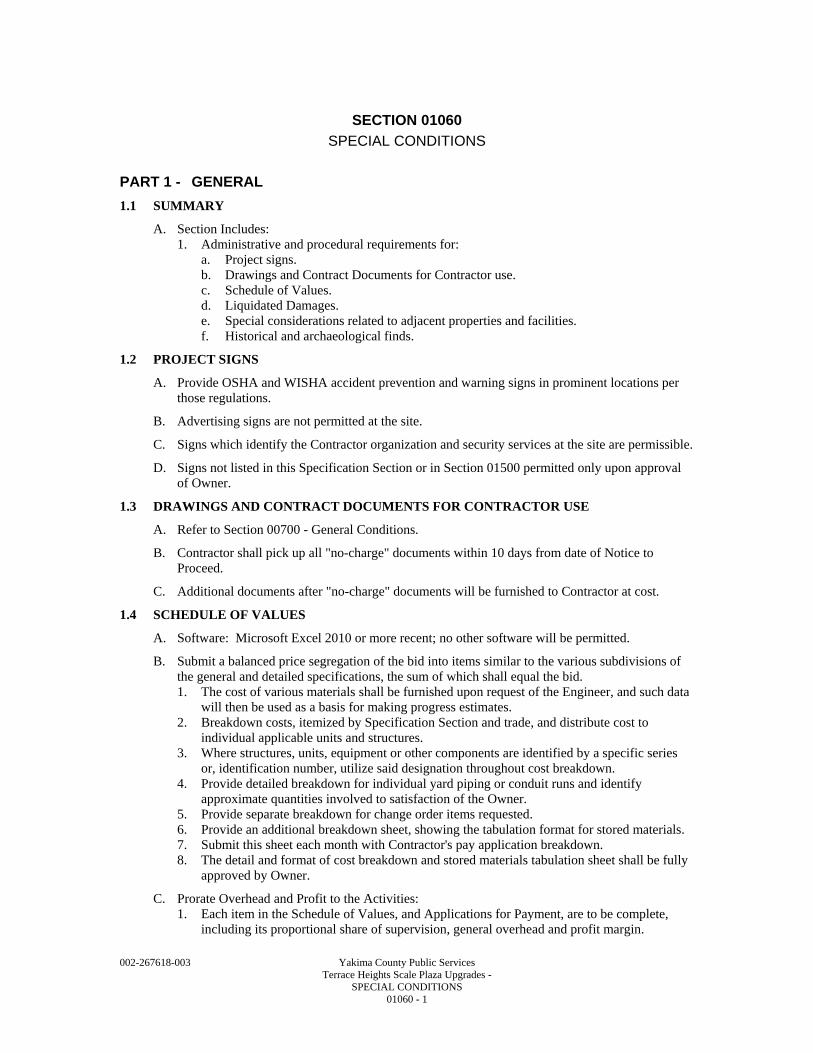
002-267618-003 Yakima County Public Services Terrace Heights Scale Plaza Upgrades - SPECIAL CONDITIONS 01060 - 1
SECTION 01060
SPECIAL CONDITIONS
PART 1 - GENERAL
1.1 SUMMARY
A. Section Includes: 1. Administrative and procedural requirements for:
a. Project signs. b. Drawings and Contract Documents for Contractor use. c. Schedule of Values. d. Liquidated Damages. e. Special considerations related to adjacent properties and facilities. f. Historical and archaeological finds.
1.2 PROJECT SIGNS
A. Provide OSHA and WISHA accident prevention and warning signs in prominent locations per those regulations.
B. Advertising signs are not permitted at the site.
C. Signs which identify the Contractor organization and security services at the site are permissible.
D. Signs not listed in this Specification Section or in Section 01500 permitted only upon approval of Owner.
1.3 DRAWINGS AND CONTRACT DOCUMENTS FOR CONTRACTOR USE
A. Refer to Section 00700 - General Conditions.
B. Contractor shall pick up all "no-charge" documents within 10 days from date of Notice to Proceed.
C. Additional documents after "no-charge" documents will be furnished to Contractor at cost.
1.4 SCHEDULE OF VALUES
A. Software: Microsoft Excel 2010 or more recent; no other software will be permitted.
B. Submit a balanced price segregation of the bid into items similar to the various subdivisions of the general and detailed specifications, the sum of which shall equal the bid. 1. The cost of various materials shall be furnished upon request of the Engineer, and such data
will then be used as a basis for making progress estimates. 2. Breakdown costs, itemized by Specification Section and trade, and distribute cost to
individual applicable units and structures. 3. Where structures, units, equipment or other components are identified by a specific series
or, identification number, utilize said designation throughout cost breakdown. 4. Provide detailed breakdown for individual yard piping or conduit runs and identify
approximate quantities involved to satisfaction of the Owner. 5. Provide separate breakdown for change order items requested. 6. Provide an additional breakdown sheet, showing the tabulation format for stored materials. 7. Submit this sheet each month with Contractor's pay application breakdown. 8. The detail and format of cost breakdown and stored materials tabulation sheet shall be fully
approved by Owner.
C. Prorate Overhead and Profit to the Activities: 1. Each item in the Schedule of Values, and Applications for Payment, are to be complete,
including its proportional share of supervision, general overhead and profit margin.
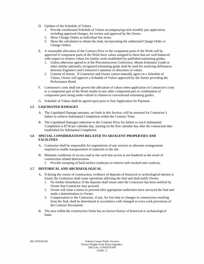
002-267618-003 Yakima County Public Services Terrace Heights Scale Plaza Upgrades - SPECIAL CONDITIONS 01060 - 2
D. Updates of the Schedule of Values: 1. Provide coordinated Schedule of Values accompanying each monthly pay application,
including approved changes, for review and approval by the Owner. 2. Show Change Orders as individual line items. 3. Show the calculation to obtain the total, incorporating the authorized Change Order or
Change Orders.
E. A reasonable allocation of the Contract Price to the component parts of the Work will be approved if component parts of the Work have values assigned to them that are well-balanced with respect to relative values for similar work established by published estimating guides. 1. Unless otherwise agreed to at the Preconstruction Conference, Means Estimator Guide or
other similar nationally recognized estimating guide shall be used for resolving differences between Engineer's and Contractor's opinions of allocation of values.
2. Consent of Surety: If Contractor and Owner cannot mutually agree on a Schedule of Values, Owner will approve a Schedule of Values approved by the Surety providing the Performance Bond.
F. Contractor's costs shall not govern the allocation of values when application of Contractor's costs to a component part of the Work results in any other component part or combination of component parts being under-valued in relation to conventional estimating guides.
G. Schedule of Values shall be agreed upon prior to first Application for Payment.
1.5 LIQUIDATED DAMAGES
A. The Liquidated Damage amounts, set forth in this Section, will be assessed for Contractor’s failure to achieve Substantial Completion within the Contract Time.
B. The Liquidated Damages reduction to the Contract Price for failure to reach Substantial Completion is $750 per calendar day, starting on the first calendar day after the contractual date established for Substantial Completion.
1.6 SPECIAL CONSIDERATIONS RELATED TO ADJACENT PROPERTIES AND FACILITIES
A. Contractor shall be responsible for negotiations of any waivers or alternate arrangements required to enable transportation of materials to the site.
B. Maintain conditions of access road to site such that access is not hindered as the result of construction related deterioration. 1. Provide sweeping of hard-surface roadways to remove soils tracked onto roadway.
1.7 HISTORICAL AND ARCHAEOLOGICAL
A. If during the course of construction, evidence of deposits of historical or archeological interest is found, the Contractor shall cease operations affecting the find and shall notify Owner. 1. No further disturbance of the deposits shall ensue until the Contractor has been notified by
Owner that Contractor may proceed. 2. Owner will issue a notice to proceed after appropriate authorities have surveyed the find and
made a determination to Owner. 3. Compensation to the Contractor, if any, for lost time or changes in construction resulting
from the find, shall be determined in accordance with changed or extra work provisions of the Contract Documents.
B. The area within the construction limits has no known history of historical or archaeological finds.
002-267618-003 Yakima County Public Services Terrace Heights Scale Plaza Upgrades - SPECIAL CONDITIONS 01060 - 3
PART 2 - PRODUCTS - (NOT APPLICABLE TO THIS SECTION)
PART 3 - EXECUTION - (NOT APPLICABLE TO THIS SECTION)
END OF SECTION

002-267618-003 Yakima County Public Services Terrace Heights Scale Plaza Upgrades - SPECIAL CONDITIONS 01060 - 4
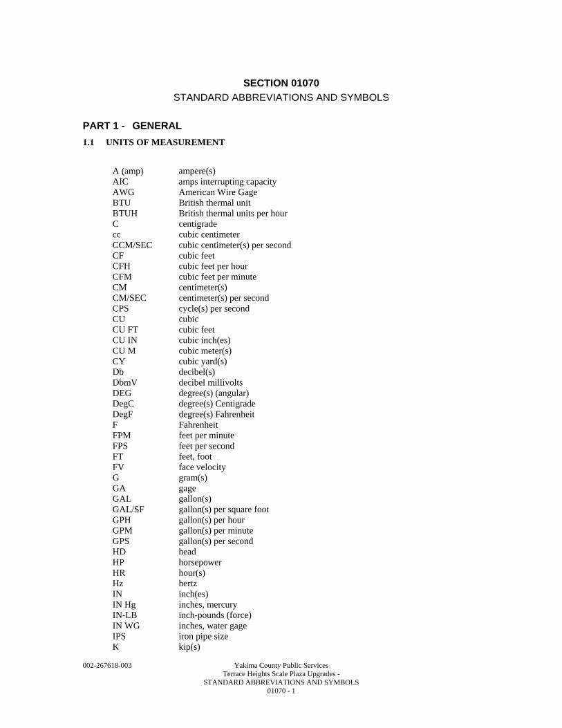
002-267618-003 Yakima County Public Services Terrace Heights Scale Plaza Upgrades - STANDARD ABBREVIATIONS AND SYMBOLS 01070 - 1
SECTION 01070
STANDARD ABBREVIATIONS AND SYMBOLS
PART 1 - GENERAL
1.1 UNITS OF MEASUREMENT
A (amp) ampere(s) AIC amps interrupting capacity AWG American Wire Gage BTU British thermal unit BTUH British thermal units per hour C centigrade cc cubic centimeter CCM/SEC cubic centimeter(s) per second CF cubic feet CFH cubic feet per hour CFM cubic feet per minute CM centimeter(s) CM/SEC centimeter(s) per second CPS cycle(s) per second CU cubic CU FT cubic feet CU IN cubic inch(es) CU M cubic meter(s) CY cubic yard(s) Db decibel(s) DbmV decibel millivolts DEG degree(s) (angular) DegC degree(s) Centigrade DegF degree(s) Fahrenheit F Fahrenheit FPM feet per minute FPS feet per second FT feet, foot FV face velocity G gram(s) GA gage GAL gallon(s) GAL/SF gallon(s) per square foot GPH gallon(s) per hour GPM gallon(s) per minute GPS gallon(s) per second HD head HP horsepower HR hour(s) Hz hertz IN inch(es) IN Hg inches, mercury IN-LB inch-pounds (force) IN WG inches, water gage IPS iron pipe size K kip(s)
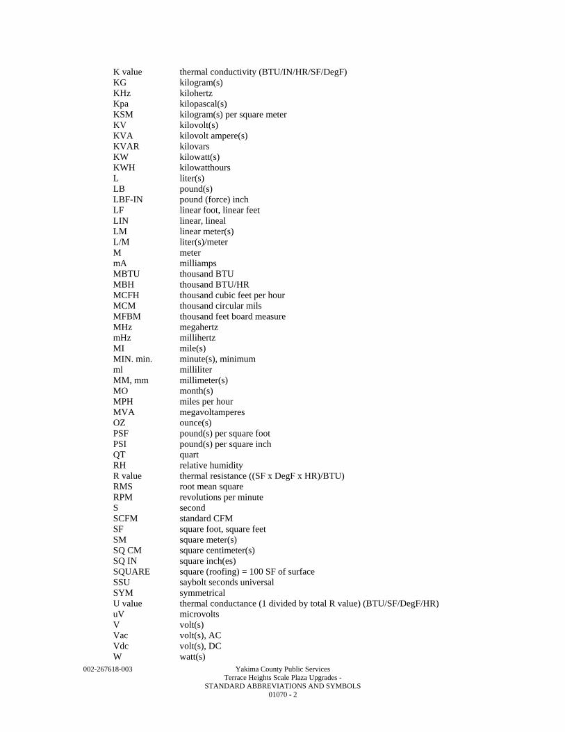
002-267618-003 Yakima County Public Services Terrace Heights Scale Plaza Upgrades - STANDARD ABBREVIATIONS AND SYMBOLS 01070 - 2
K value thermal conductivity (BTU/IN/HR/SF/DegF) KG kilogram(s) KHz kilohertz Kpa kilopascal(s) KSM kilogram(s) per square meter KV kilovolt(s) KVA kilovolt ampere(s) KVAR kilovars KW kilowatt(s) KWH kilowatthours L liter(s) LB pound(s) LBF-IN pound (force) inch LF linear foot, linear feet LIN linear, lineal LM linear meter(s) L/M liter(s)/meter M meter mA milliamps MBTU thousand BTU MBH thousand BTU/HR MCFH thousand cubic feet per hour MCM thousand circular mils MFBM thousand feet board measure MHz megahertz mHz millihertz MI mile(s) MIN. min. minute(s), minimum ml milliliter MM, mm millimeter(s) MO month(s) MPH miles per hour MVA megavoltamperes OZ ounce(s) PSF pound(s) per square foot PSI pound(s) per square inch QT quart RH relative humidity R value thermal resistance ((SF x DegF x HR)/BTU) RMS root mean square RPM revolutions per minute S second SCFM standard CFM SF square foot, square feet SM square meter(s) SQ CM square centimeter(s) SQ IN square inch(es) SQUARE square (roofing) = 100 SF of surface SSU saybolt seconds universal SYM symmetrical U value thermal conductance (1 divided by total R value) (BTU/SF/DegF/HR) uV microvolts V volt(s) Vac volt(s), AC Vdc volt(s), DC W watt(s)
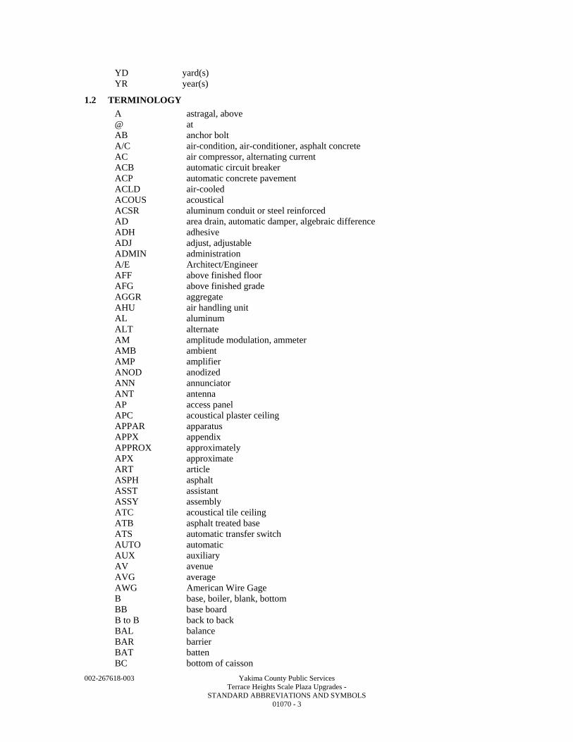
002-267618-003 Yakima County Public Services Terrace Heights Scale Plaza Upgrades - STANDARD ABBREVIATIONS AND SYMBOLS 01070 - 3
YD yard(s) YR year(s)
1.2 TERMINOLOGY
A astragal, above @ at AB anchor bolt A/C air-condition, air-conditioner, asphalt concrete AC air compressor, alternating current ACB automatic circuit breaker ACP automatic concrete pavement ACLD air-cooled ACOUS acoustical ACSR aluminum conduit or steel reinforced AD area drain, automatic damper, algebraic difference ADH adhesive ADJ adjust, adjustable ADMIN administration A/E Architect/Engineer AFF above finished floor AFG above finished grade AGGR aggregate AHU air handling unit AL aluminum ALT alternate AM amplitude modulation, ammeter AMB ambient AMP amplifier ANOD anodized ANN annunciator ANT antenna AP access panel APC acoustical plaster ceiling APPAR apparatus APPX appendix APPROX approximately APX approximate ART article ASPH asphalt ASST assistant ASSY assembly ATC acoustical tile ceiling ATB asphalt treated base ATS automatic transfer switch AUTO automatic AUX auxiliary AV avenue AVG average AWG American Wire Gage B base, boiler, blank, bottom BB base board B to B back to back BAL balance BAR barrier BAT batten BC bottom of caisson
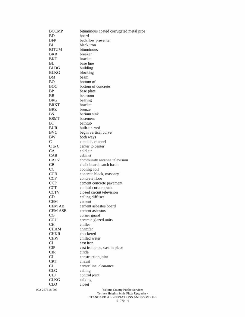
002-267618-003 Yakima County Public Services Terrace Heights Scale Plaza Upgrades - STANDARD ABBREVIATIONS AND SYMBOLS 01070 - 4
BCCMP bituminous coated corrugated metal pipe BD board BFP backflow preventer BI black iron BITUM bituminous BKR breaker BKT bracket BL base line BLDG building BLKG blocking BM beam BO bottom of BOC bottom of concrete BP base plate BR bedroom BRG bearing BRKT bracket BRZ bronze BS barium sink BSMT basement BT bathtub BUR built-up roof BVC begin vertical curve BW both ways C conduit, channel C to C center to center CA cold air CAB cabinet CATV community antenna television CB chalk board, catch basin CC cooling coil CCB concrete block, masonry CCF concrete floor CCP cement concrete pavement CCT cubical curtain track CCTV closed circuit television CD ceiling diffuser CEM cement CEM AB cement asbestos board CEM ASB cement asbestos CG corner guard CGU ceramic glazed units CH chiller CHAM chamfer CHKR checkered CHW chilled water CI cast iron CIP cast iron pipe, cast in place CIR circle CJ construction joint CKT circuit CL center line, clearance CLG ceiling CLJ control joint CLKG calking CLO closet
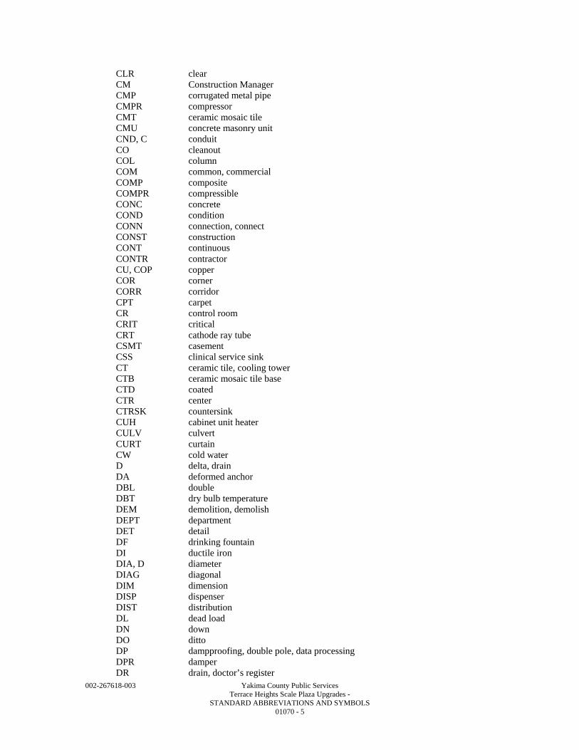
002-267618-003 Yakima County Public Services Terrace Heights Scale Plaza Upgrades - STANDARD ABBREVIATIONS AND SYMBOLS 01070 - 5
CLR clear CM Construction Manager CMP corrugated metal pipe CMPR compressor CMT ceramic mosaic tile CMU concrete masonry unit CND, C conduit CO cleanout COL column COM common, commercial COMP composite COMPR compressible CONC concrete COND condition CONN connection, connect CONST construction CONT continuous CONTR contractor CU, COP copper COR corner CORR corridor CPT carpet CR control room CRIT critical CRT cathode ray tube CSMT casement CSS clinical service sink CT ceramic tile, cooling tower CTB ceramic mosaic tile base CTD coated CTR center CTRSK countersink CUH cabinet unit heater CULV culvert CURT curtain CW cold water D delta, drain DA deformed anchor DBL double DBT dry bulb temperature DEM demolition, demolish DEPT department DET detail DF drinking fountain DI ductile iron DIA, D diameter DIAG diagonal DIM dimension DISP dispenser DIST distribution DL dead load DN down DO ditto DP dampproofing, double pole, data processing DPR damper DR drain, doctor’s register
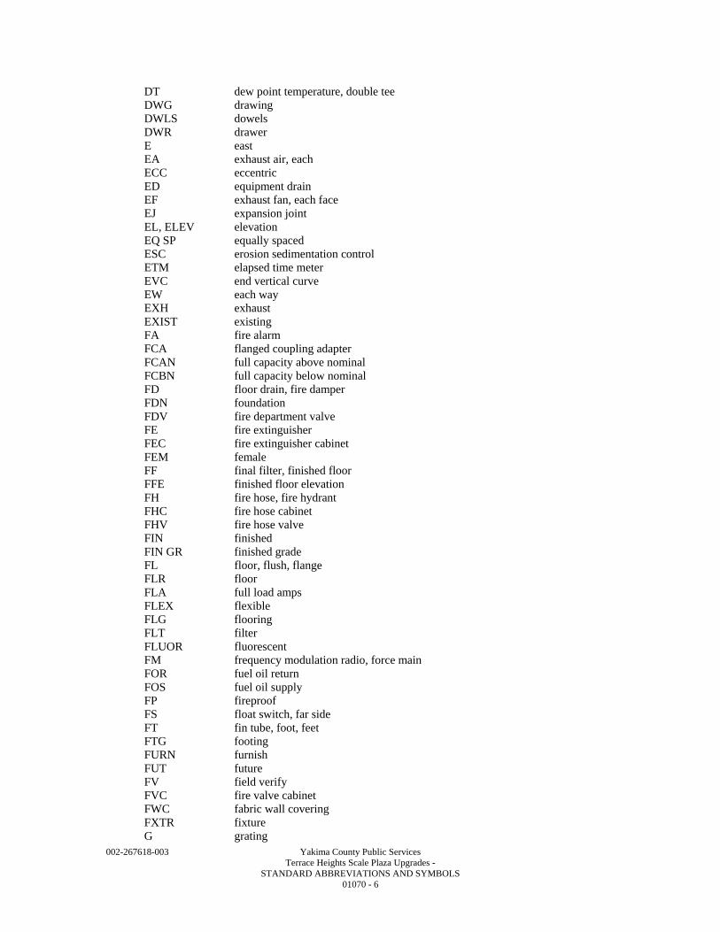
002-267618-003 Yakima County Public Services Terrace Heights Scale Plaza Upgrades - STANDARD ABBREVIATIONS AND SYMBOLS 01070 - 6
DT dew point temperature, double tee DWG drawing DWLS dowels DWR drawer E east EA exhaust air, each ECC eccentric ED equipment drain EF exhaust fan, each face EJ expansion joint EL, ELEV elevation EQ SP equally spaced ESC erosion sedimentation control ETM elapsed time meter EVC end vertical curve EW each way EXH exhaust EXIST existing FA fire alarm FCA flanged coupling adapter FCAN full capacity above nominal FCBN full capacity below nominal FD floor drain, fire damper FDN foundation FDV fire department valve FE fire extinguisher FEC fire extinguisher cabinet FEM female FF final filter, finished floor FFE finished floor elevation FH fire hose, fire hydrant FHC fire hose cabinet FHV fire hose valve FIN finished FIN GR finished grade FL floor, flush, flange FLR floor FLA full load amps FLEX flexible FLG flooring FLT filter FLUOR fluorescent FM frequency modulation radio, force main FOR fuel oil return FOS fuel oil supply FP fireproof FS float switch, far side FT fin tube, foot, feet FTG footing FURN furnish FUT future FV field verify FVC fire valve cabinet FWC fabric wall covering FXTR fixture G grating
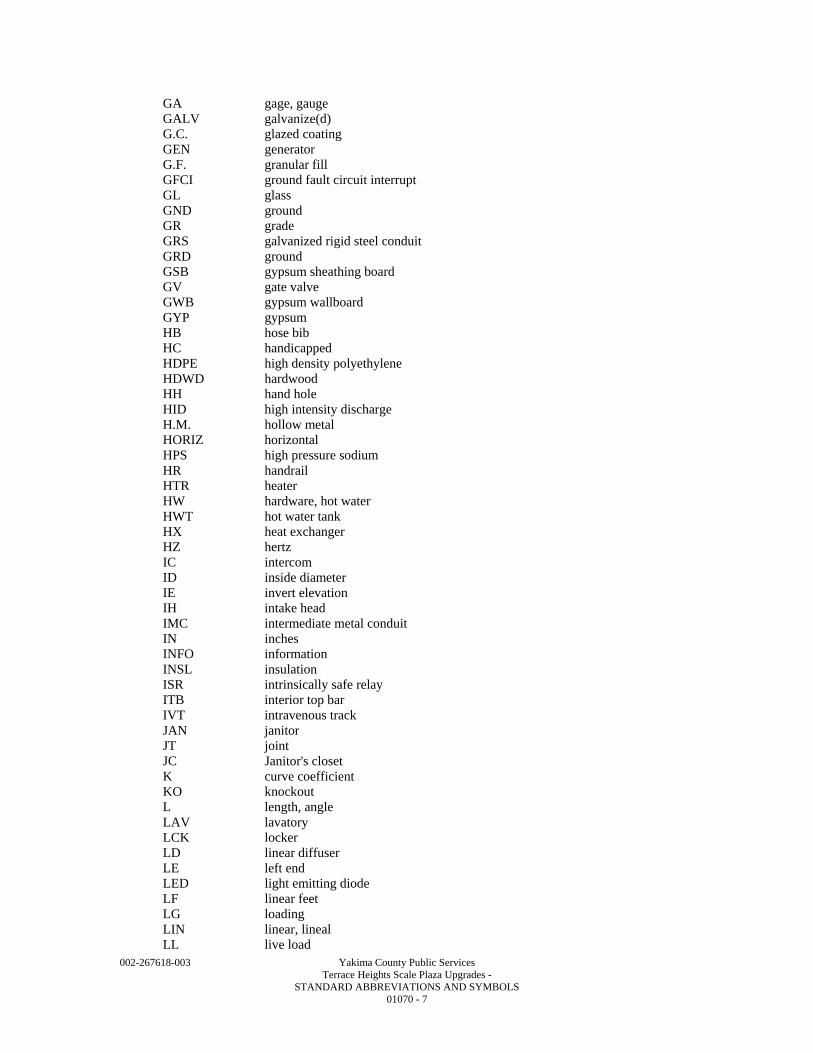
002-267618-003 Yakima County Public Services Terrace Heights Scale Plaza Upgrades - STANDARD ABBREVIATIONS AND SYMBOLS 01070 - 7
GA gage, gauge GALV galvanize(d) G.C. glazed coating GEN generator G.F. granular fill GFCI ground fault circuit interrupt GL glass GND ground GR grade GRS galvanized rigid steel conduit GRD ground GSB gypsum sheathing board GV gate valve GWB gypsum wallboard GYP gypsum HB hose bib HC handicapped HDPE high density polyethylene HDWD hardwood HH hand hole HID high intensity discharge H.M. hollow metal HORIZ horizontal HPS high pressure sodium HR handrail HTR heater HW hardware, hot water HWT hot water tank HX heat exchanger HZ hertz IC intercom ID inside diameter IE invert elevation IH intake head IMC intermediate metal conduit IN inches INFO information INSL insulation ISR intrinsically safe relay ITB interior top bar IVT intravenous track JAN janitor JT joint JC Janitor's closet K curve coefficient KO knockout L length, angle LAV lavatory LCK locker LD linear diffuser LE left end LED light emitting diode LF linear feet LG loading LIN linear, lineal LL live load
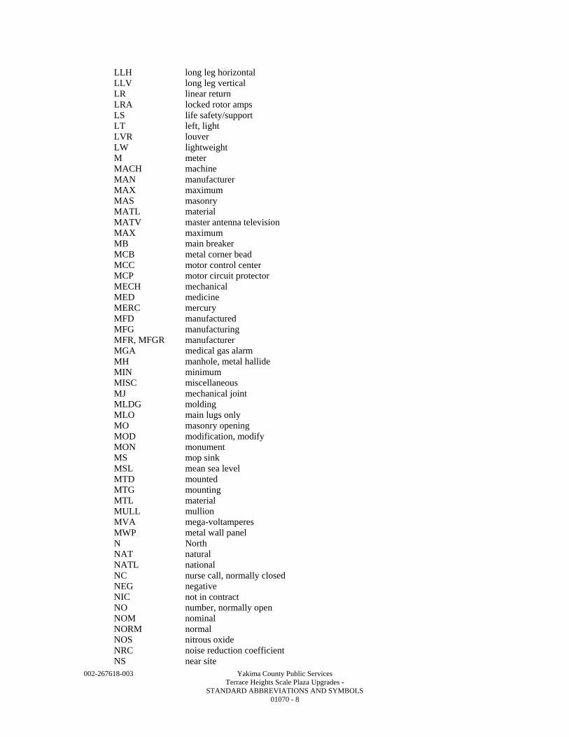
002-267618-003 Yakima County Public Services Terrace Heights Scale Plaza Upgrades - STANDARD ABBREVIATIONS AND SYMBOLS 01070 - 8
LLH long leg horizontal LLV long leg vertical LR linear return LRA locked rotor amps LS life safety/support LT left, light LVR louver LW lightweight M meter MACH machine MAN manufacturer MAX maximum MAS masonry MATL material MATV master antenna television MAX maximum MB main breaker MCB metal corner bead MCC motor control center MCP motor circuit protector MECH mechanical MED medicine MERC mercury MFD manufactured MFG manufacturing MFR, MFGR manufacturer MGA medical gas alarm MH manhole, metal hallide MIN minimum MISC miscellaneous MJ mechanical joint MLDG molding MLO main lugs only MO masonry opening MOD modification, modify MON monument MS mop sink MSL mean sea level MTD mounted MTG mounting MTL material MULL mullion MVA mega-voltamperes MWP metal wall panel N North NAT natural NATL national NC nurse call, normally closed NEG negative NIC not in contract NO number, normally open NOM nominal NORM normal NOS nitrous oxide NRC noise reduction coefficient NS near site
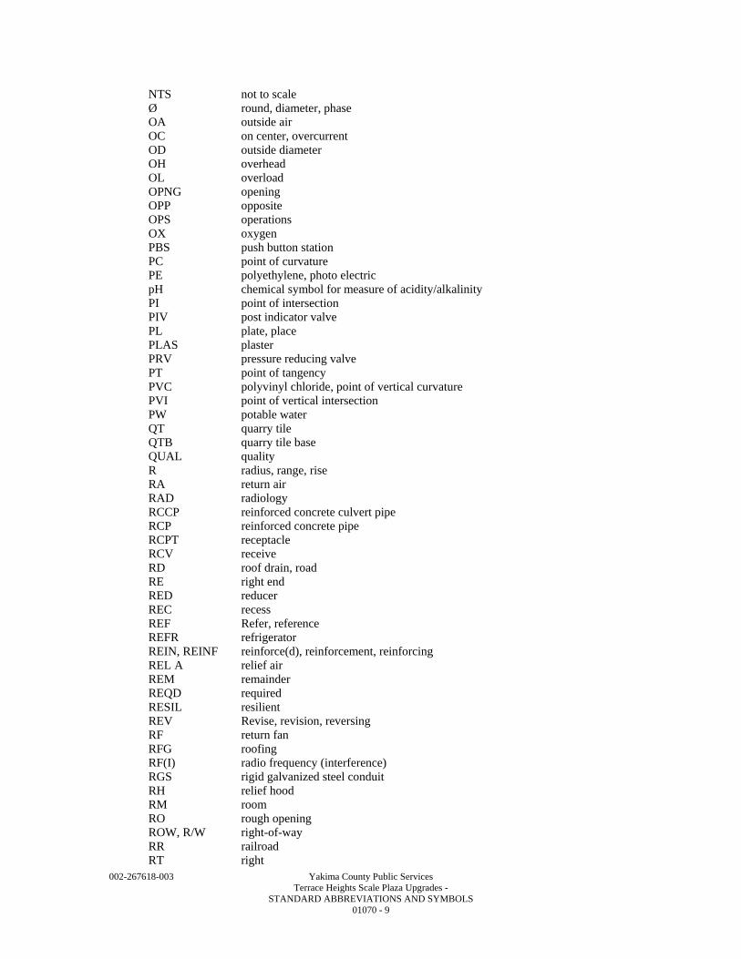
002-267618-003 Yakima County Public Services Terrace Heights Scale Plaza Upgrades - STANDARD ABBREVIATIONS AND SYMBOLS 01070 - 9
NTS not to scale Ø round, diameter, phase OA outside air OC on center, overcurrent OD outside diameter OH overhead OL overload OPNG opening OPP opposite OPS operations OX oxygen PBS push button station PC point of curvature PE polyethylene, photo electric pH chemical symbol for measure of acidity/alkalinity PI point of intersection PIV post indicator valve PL plate, place PLAS plaster PRV pressure reducing valve PT point of tangency PVC polyvinyl chloride, point of vertical curvature PVI point of vertical intersection PW potable water QT quarry tile QTB quarry tile base QUAL quality R radius, range, rise RA return air RAD radiology RCCP reinforced concrete culvert pipe RCP reinforced concrete pipe RCPT receptacle RCV receive RD roof drain, road RE right end RED reducer REC recess REF Refer, reference REFR refrigerator REIN, REINF reinforce(d), reinforcement, reinforcing REL A relief air REM remainder REQD required RESIL resilient REV Revise, revision, reversing RF return fan RFG roofing RF(I) radio frequency (interference) RGS rigid galvanized steel conduit RH relief hood RM room RO rough opening ROW, R/W right-of-way RR railroad RT right
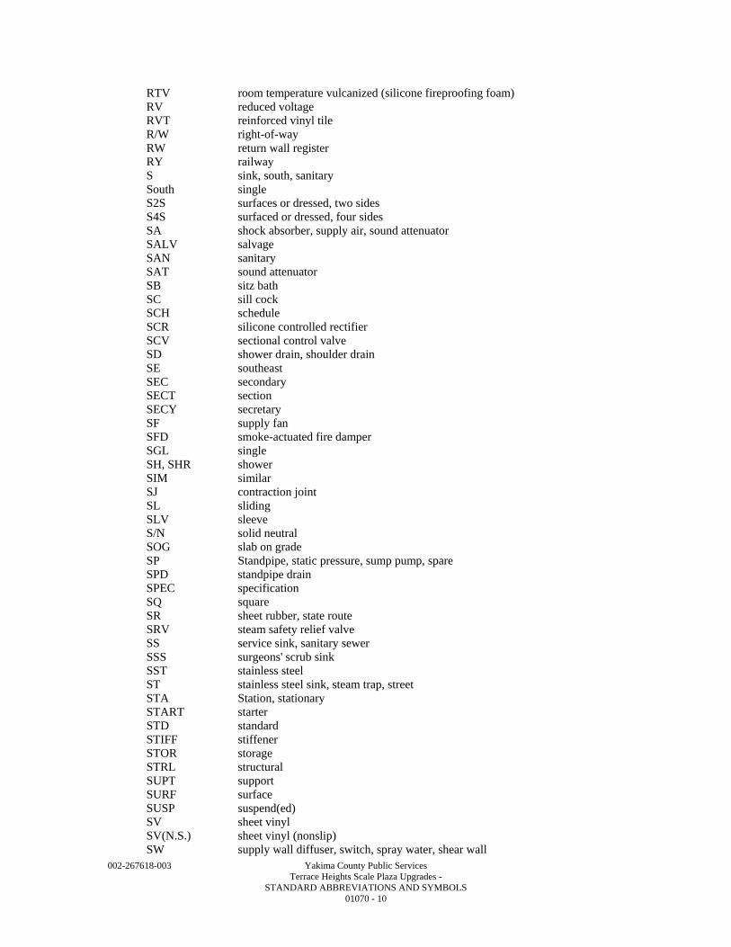
002-267618-003 Yakima County Public Services Terrace Heights Scale Plaza Upgrades - STANDARD ABBREVIATIONS AND SYMBOLS 01070 - 10
RTV room temperature vulcanized (silicone fireproofing foam) RV reduced voltage RVT reinforced vinyl tile R/W right-of-way RW return wall register RY railway S sink, south, sanitary South single S2S surfaces or dressed, two sides S4S surfaced or dressed, four sides SA shock absorber, supply air, sound attenuator SALV salvage SAN sanitary SAT sound attenuator SB sitz bath SC sill cock SCH schedule SCR silicone controlled rectifier SCV sectional control valve SD shower drain, shoulder drain SE southeast SEC secondary SECT section SECY secretary SF supply fan SFD smoke-actuated fire damper SGL single SH, SHR shower SIM similar SJ contraction joint SL sliding SLV sleeve S/N solid neutral SOG slab on grade SP Standpipe, static pressure, sump pump, spare SPD standpipe drain SPEC specification SQ square SR sheet rubber, state route SRV steam safety relief valve SS service sink, sanitary sewer SSS surgeons' scrub sink SST stainless steel ST stainless steel sink, steam trap, street STA Station, stationary START starter STD standard STIFF stiffener STOR storage STRL structural SUPT support SURF surface SUSP suspend(ed) SV sheet vinyl SV(N.S.) sheet vinyl (nonslip) SW supply wall diffuser, switch, spray water, shear wall
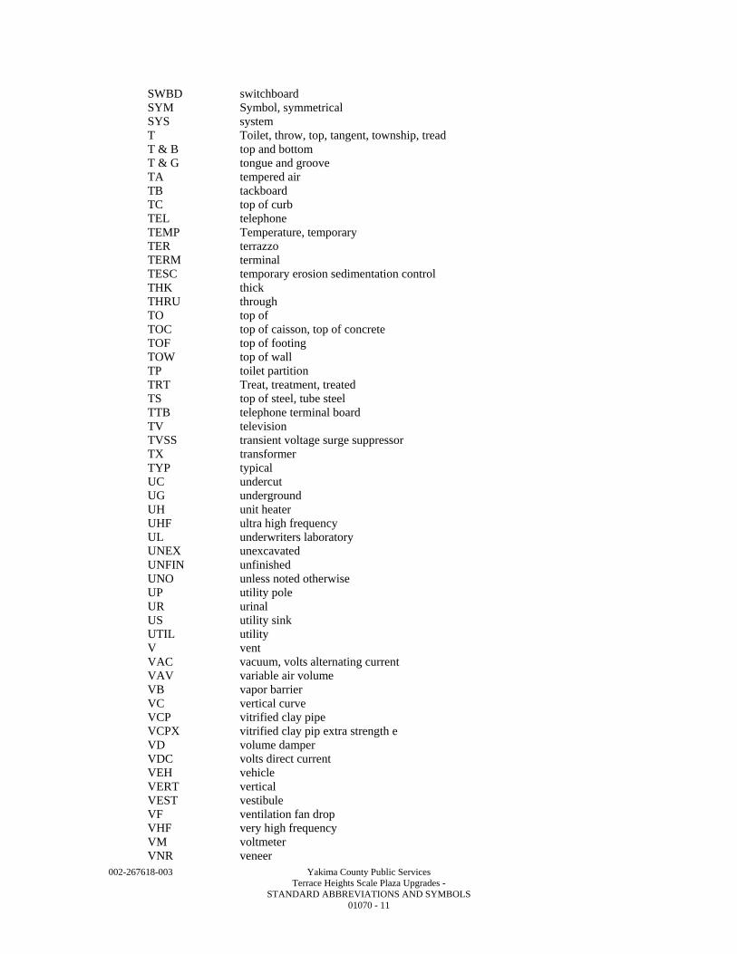
002-267618-003 Yakima County Public Services Terrace Heights Scale Plaza Upgrades - STANDARD ABBREVIATIONS AND SYMBOLS 01070 - 11
SWBD switchboard SYM Symbol, symmetrical SYS system T Toilet, throw, top, tangent, township, tread T & B top and bottom T & G tongue and groove TA tempered air TB tackboard TC top of curb TEL telephone TEMP Temperature, temporary TER terrazzo TERM terminal TESC temporary erosion sedimentation control THK thick THRU through TO top of TOC top of caisson, top of concrete TOF top of footing TOW top of wall TP toilet partition TRT Treat, treatment, treated TS top of steel, tube steel TTB telephone terminal board TV television TVSS transient voltage surge suppressor TX transformer TYP typical UC undercut UG underground UH unit heater UHF ultra high frequency UL underwriters laboratory UNEX unexcavated UNFIN unfinished UNO unless noted otherwise UP utility pole UR urinal US utility sink UTIL utility V vent VAC vacuum, volts alternating current VAV variable air volume VB vapor barrier VC vertical curve VCP vitrified clay pipe VCPX vitrified clay pip extra strength e VD volume damper VDC volts direct current VEH vehicle VERT vertical VEST vestibule VF ventilation fan drop VHF very high frequency VM voltmeter VNR veneer
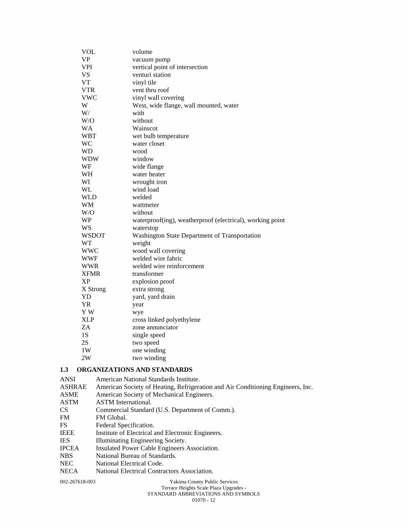
002-267618-003 Yakima County Public Services Terrace Heights Scale Plaza Upgrades - STANDARD ABBREVIATIONS AND SYMBOLS 01070 - 12
VOL volume VP vacuum pump VPI vertical point of intersection VS venturi station VT vinyl tile VTR vent thru roof VWC vinyl wall covering W West, wide flange, wall mounted, water W/ with W/O without WA Wainscot WBT wet bulb temperature WC water closet WD wood WDW window WF wide flange WH water heater WI wrought iron WL wind load WLD welded WM wattmeter W/O without WP waterproof(ing), weatherproof (electrical), working point WS waterstop WSDOT Washington State Department of Transportation WT weight WWC wood wall covering WWF welded wire fabric WWR welded wire reinforcement XFMR transformer XP explosion proof X Strong extra strong YD yard, yard drain YR year Y W wye XLP cross linked polyethylene ZA zone annunciator 1S single speed 2S two speed 1W one winding 2W two winding
1.3 ORGANIZATIONS AND STANDARDS
ANSI American National Standards Institute. ASHRAE American Society of Heating, Refrigeration and Air Conditioning Engineers, Inc. ASME American Society of Mechanical Engineers. ASTM ASTM International. CS Commercial Standard (U.S. Department of Comm.). FM FM Global. FS Federal Specification. IEEE Institute of Electrical and Electronic Engineers. IES Illuminating Engineering Society. IPCEA Insulated Power Cable Engineers Association. NBS National Bureau of Standards. NEC National Electrical Code. NECA National Electrical Contractors Association.
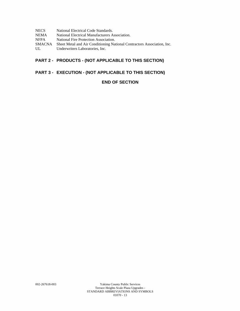
002-267618-003 Yakima County Public Services Terrace Heights Scale Plaza Upgrades - STANDARD ABBREVIATIONS AND SYMBOLS 01070 - 13
NECS National Electrical Code Standards. NEMA National Electrical Manufacturers Association. NFPA National Fire Protection Association. SMACNA Sheet Metal and Air Conditioning National Contractors Association, Inc. UL Underwriters Laboratories, Inc.
PART 2 - PRODUCTS - (NOT APPLICABLE TO THIS SECTION)
PART 3 - EXECUTION - (NOT APPLICABLE TO THIS SECTION)
END OF SECTION

002-267618-003 Yakima County Public Services Terrace Heights Scale Plaza Upgrades - STANDARD ABBREVIATIONS AND SYMBOLS 01070 - 14
002-267618-003 Yakima County Public Services Terrace Heights Scale Plaza Upgrades - REFERENCE STANDARDS 01095 - 1
SECTION 01095
REFERENCE STANDARDS
PART 1 - GENERAL
1.1 SUMMARY
A. Selection includes: 1. Specification Format and Content Explanation. 2. Industry Standards. 3. Governing Regulations and Authorities.
1.2 SPECIFICATION FORMAT AND CONTENT EXPLANATION
A. Specification Format: These Specifications are organized into Divisions and Sections based on the Construction Specifications Institute’s 16 Division format and MASTERFORMAT numbering system.
B. Specification Content: This Specification uses certain conventions in the use of language and the intended meaning of certain terms, words, and phrases when used in particular situations or circumstances. These conventions are explained as follows: 1. Abbreviated Language: Language used in Specifications and other Contract Documents are
the abbreviated type. Words and meanings shall be interpreted as appropriate. Words that are implied, but not stated shall be interpolated, as the sense required. Singular words will be interpreted as plural and plural words interpreted as singular where applicable and the context of the Contract Documents so indicates.
2. Imperative and streamlined language is used generally in the Specifications. Requirements expressed in the imperative mood are to be performed by the Contractor. At certain locations in the text, for clarity, subjective language is used to describe responsibilities that must be fulfilled indirectly by the Contractor or by others when so noted. a. The words “shall be” shall be included by inference wherever a colon (:) is used within
a sentence or phrase.
1.3 INDUSTRY STANDARDS
A. Applicability of Standards: Except where the Contract Documents include more stringent requirements, applicable construction industry standards have the same force and effect as if bound or copied directly into the Contract Documents to the extent referenced. Such standards are made a part of the Contract Documents by reference.
B. Publication Dates: Comply with the standard in effect as of the date of the Contract Documents.
C. Conflicting Requirements: Where compliance with two or more industry standards is specified, and the industry standards establish different or conflicting requirements for minimum quantities or quality levels, refer requirements that are different, but apparently equal, and uncertainties to the Owner for a decision before proceeding. 1. Minimum Quantity or Quality Levels: The quantity or quality level shown or specified
shall be the minimum provided or performed. The actual installation may comply exactly with the minimum quantity or quality specified, or it may exceed the minimum within reasonable limits. In complying with these requirements, indicated numeric values are minimum or maximum, as appropriate for the context of the requirements. Refer uncertainties to the Owner for a decision before proceeding.
D. Copies of Standards: Each entity engaged in construction on the Project is required to be familiar with industry standards applicable to that entity’s construction activity. Copies of applicable standards are not bound with the Contract Documents. 1. Where copies of standards are needed for performance of a required construction activity,
the Contractor shall obtain copies directly from the publication source.
002-267618-003 Yakima County Public Services Terrace Heights Scale Plaza Upgrades - REFERENCE STANDARDS 01095 - 2
E. Abbreviations and Names: Trade association names and titles of general standards are frequently abbreviated. The following acronyms or abbreviations, as referenced in Contract Documents, are defined to mean the associated names. Names and addresses are subject to change and are believed to be, but are not assured to be, accurate and up to date as of date of the Contract Documents.
AASHTO American Association of State Highway & Transportation Officials 444 North Capitol Street, Suite 225 Washington, DC 20001 (202) 624-5800 ACI American Concrete Institute 38800 Country Club Dr. Farmington Hills, MI 48331 (248) 848-3700 AI Asphalt Institute 2696 Research Park Drive Lexington, KY 40511-8480 40512-4052 (859) 288-4960 A.I.A. American Insurance Associates
513 Wilcox St. Suite 200 Castle Rock, CO 80104 (303) 663-1555
AIHA American Industrial Hygiene Association 2700 Prosperity Ave., Suite 250 Fairfax, VA 22031 (703) 849-8888 AISC American Institute of Steel Construction One East Wacker Drive, Suite 700 Chicago, IL 60601-1802 (312) 670-2400 AISI American Iron and Steel Institute 1133 Fifteenth Street NW Washington, DC 20005 (202) 452-7100 AITC American Institute of Timber Construction 7012 S. Revere Parkway Suite 140 Centennial, CO 80112 (303) 792-9559 ANSI American National Standards Institute 25 W 43rd Street, 4th Floor New York, NY, 10036 (212) 642-4980 APA American Plywood Association 7011 S. 19th Street Tacoma, WA 98466-5333 (253) 565-6600 API American Petroleum Institute
1220 L Street, NW Washington, DC 20005-4070 (202) 682-8000
ASC Adhesive and Sealant Council 7101 Wisconsin Avenue, Suite 990 Bethesda, MD 20814 (301) 986-9700 ASPE American Society of Plumbing Engineers 2980 S River Rd Des Plaines, IL 60018 (847) 296-0002 ASTM American Society for Testing and Materials PO Box C700 West Conshohocken, PA, 19428-2959 (610) 832-9500 AWS American Welding Society 550 N.W. LeJeune Road Miami, Florida 33126 (305) 443-9353 AWWA American Water Works Association 6666 W. Quincy Avenue
002-267618-003 Yakima County Public Services Terrace Heights Scale Plaza Upgrades - REFERENCE STANDARDS 01095 - 3
Denver, CO 80235 (303) 794-7711 CRSI Concrete Reinforcing Steel Institute 933 North Plum Grove Road Schaumburg, IL 60173 (847) 517-1200 FM Factory Mutual Research Organization PO BOX 7500 Johnston, RI 02919-4923 (401) 275-3000 ICEA Insulated Cable Engineers Association, Inc. PO Box 1568 Carrollton, GA 30112 (303) 397-7956 IEC International Electrotechnical Commission ANSI 25 West 43rd Street, 4th Floor New York, NY 10036 (212) 642-4900 IEEE Institute of Electrical and Electronic Engineers 3 Park Avenue, 17th Floor New York, NY 10016-5997 (212) 419-7900 IESNA Illuminating Engineering Society of North America
120 Wall Street, Floor 17 New York, NY 10005-4001 (212) 248-5000 IMSA International Municipal Signal Association PO Box 539 Newark, NY 14513-0539 (315) 331-2182 LPI Lightning Protection Institute P.O. Box 99 Maryville, MO 64468 (800) 488-6864 NAPA National Asphalt Pavement Association 5100 Forbes Blvd. Lanham, MD 20706-4407 (301) 731-4748 NCMA National Concrete Masonry Association 13750 Sunrise Valley Drive Herndon, VA 20171-4622 (703) 713-1900 NEC National Electric Code (from NFPA)
National Fire Protection Association 1 Batterymarch park Quincy, MA 02269 (617) 770-3000
NECA National Electrical Contractors Association 3 Bethesda Metro Center, Suite 1100
Bethesda, MD 20814 (301) 657-3110 NEMA National Electrical Manufacturers Association
1300 North 17th Street, Suite 1752 Rosslyn, Virginia 22209 (703) 841-3200
NFPA National Fire Protection Association 1 Batterymarch Park Quincy, MA 02269-9101 (617) 770-3000 NPCA National Paint and Coatings Association 1500 Rhode Island Avenue NW Washington, DC 20005 (202) 462-6272 NSF National Sanitation Foundation P.O. Box 130140 Ann Arbor, MI 48113-0140 (734) 769-8010 PCA Portland Cement Association 5420 Old Orchard Road Skokie, IL 60077 (847) 966-6200 PCI Prestressed Concrete Institute 200 W. Adams St. #2100
002-267618-003 Yakima County Public Services Terrace Heights Scale Plaza Upgrades - REFERENCE STANDARDS 01095 - 4
Chicago, IL 60606 (312) 786-0300 PDI Plumbing and Drainage Institute 800 Turnpike Street, Suite 300 North Andover, MA 01845 (978) 557-0720 SSPC The Society for Protective Coatings 40 24th Street, 6th Floor Pittsburgh, PA 15222 (412) 281-2331 UL Underwriters Laboratories 2600 N.W. Lake Rd. Camas, WA 98607-8542 (877) 854-3577 WRI Wire Reinforcement Institute 942 Main Street, Suite 300 Hartford, CT 06103 (800) 552-4974 WSC Water Systems Council 1101 30th Street, N.W., Suite 500 Washington, DC 2000 (202) 625-4387 W.W.P.A. Woven Wire Products Association P.O. Box 610280 Birmingham, Alabama 35261-0280 (800) 529-6691 Federal Government Agencies: Names and titles of federal government standard or Specification producing agencies are often abbreviated. The following acronyms or abbreviations referenced in the Contract Documents indicate names of standard or Specification producing agencies of the federal government. Names and addresses are subject to change but are believed to be, but are not assured to be, accurate and up to date as of the date of the Contract Documents. COE Corps of Engineers 441 G. Street, NW Washington, DC 20314-1000 (202) 761-0099 CFR Code of Federal Regulations Available from the Government Printing Office 732 N. Capitol Street, NW Washington, DC 20401 (202) 512-1800 (Material is usually first published in the “Federal Register”) NIST National Institute of Standards and Technology (U.S. Department of Commerce) 100 Bureau Drive, Stop 1070 Gaithersburg, MD 20899-1070 (301) 975-6478 DOT Department of Transportation 1200 New Jersey Ave, SE Washington, DC 20590 (202) 366-4000 EPA Environmental Protection Agency Ariel Rios Building 1200 Pennsylvania Avenue, N.W. Washington, DC 20460 (202) 272-0167 FS Federal Specification (from GSA) http://apps.fas.gsa.gov/pub/fedspecs/ OSHA Occupational Safety and Health Administration (U.S. Department of Labor) 200 Constitution Avenue Washington, D.C. 20210 (800) 321-6742 USDA U.S. Department of Agriculture 1400 Independence Ave., S.W. Washington, DC 20250 (202) 720-4581
002-267618-003 Yakima County Public Services Terrace Heights Scale Plaza Upgrades - REFERENCE STANDARDS 01095 - 5
State Government Agencies: Names and titles of state government standard or Specification producing agencies are often abbreviated. The following acronyms or abbreviations referenced in the Contract Documents indicate names of standard or Specification producing agencies of the federal government. Names and addresses are subject to change but are believed to be, but are not assured to be, accurate and up to date as of the date of the Contract Documents. WSDOT Washington State Department of Transportation P.O. Box 47300 Olympia, WA 98504-7300 (360) 705-7000
1.4 GOVERNING AUTHORITIES/STANDARDS
A. The Engineer has contacted authorities having jurisdiction where necessary to obtain information necessary for preparation of Contract Documents. Contact authorities having jurisdiction directly for information and decisions having a bearing on the work.
B. Portions of the work, where indicated in these Specifications, shall be in accordance with the referenced sections of the “2016 Standard Specifications for Road, Bridge, and Municipal Construction” and the “Standard Plans for Road, Bridge, and Municipal Construction” published by the Washington State Department of Transportation and the Washington State Chapter of American Public Works Association, hereafter referred to as the “Standard Specifications” and “Standard Plans”, respectively. 1. References to Engineer, department, secretary, State or other similar terms in the Standard
Specifications shall mean Owner. 2. All references to measurement and payment are deleted.
C. Work shall conform to the 2012 edition of the International Building Code and the State of Washington Building Code amendments hereafter referred to as the “IBC”.
1.5 SUBMITTALS
A. Permits, Licenses, and Certificates: For the Owner’s records, submit copies of permits, licenses, certifications, inspection reports, releases, jurisdictional settlements, notices, receipts for fee payments, judgments, and similar documents, correspondence, and records established in conjunction with compliance with standards and regulations bearing upon performance of the work.
PART 2 - PRODUCTS- (NOT APPLICABLE TO THIS SECTION)
PART 3 - EXECUTION- (NOT APPLICABLE TO THIS SECTION)
END OF SECTION

002-267618-003 Yakima County Public Services Terrace Heights Scale Plaza Upgrades - REFERENCE STANDARDS 01095 - 6
002-267618-003 Yakima County Public Services Terrace Heights Scale Plaza Upgrades - SUMMARY OF WORK 01100 - 1
SECTION 01100
SUMMARY OF WORK
PART 1 - GENERAL
1.1 SUMMARY
A. Section includes: 1. Definitions. 2. Project description. 3. Permits. 4. Contractor’s use of the site. 5. Work by others. 6. Contractor’s work progress. 7. Drawings.
1.2 DEFINITIONS
A. "Contractor" means the entity with responsibility for the construction of the Work as described in the Contract Documents.
1.3 PROJECT DESCRIPTION
A. Existing Conditions: 1. The Yakima County Public Service Solid Waste Division (Owner) is upgrading the Terrace
Heights Scale Plaza at the existing Terrace Heights Landfill site located at 7151 Roza Hill Drive in unincorporated Yakima County, Washington 98901.
2. The Project Site is located on the Yakima County Solid Waste Division owned property. 3. Existing Scale Plaza Facilities:
a. The existing Scale Plaza consists of concrete approach slabs, three scales, a main scalehouse and a smaller satellite scalehouse.
b. Existing site utility services include potable water and septic systems, electrical, communications, and security.
4. The Terrace Heights Landfill, including recycling activities and transfer station, operates seven days per week, year round (except New Year’s Day, Easter Sunday, Memorial Day, Fourth of July, Labor Day, Thanksgiving, and Christmas), and is open to customers on the following schedule: a. Monday through Friday from 7:00 a.m. to 5:00 p.m. b. Saturday and Sunday from 9:00 a.m. to 5:00 p.m.
B. Project Development: 1. The Scale Facility will include a new satellite scale house and three new 80 FT long truck
scales (to weigh incoming and outgoing customers). The new satellite scale house will include a waste weighing and data collection system, areas for clerical and record-keeping activities, an electrical room, and restroom. a. A minimum of one operational scale house is required at all times. b. Access to a minimum of one outbound and one inbound operational scales is required at
all times. 2. Ancillary facilities include, but are not limited to, the following:
a. Site utility service connections, replacements and expansions/extensions for water, sewer systems, electrical, communications and security.
b. Stormwater systems. 3. Sitework:
a. Earthwork including: general and structural excavation and backfill, and final site grading.
b. Temporary erosion and sediment control.
002-267618-003 Yakima County Public Services Terrace Heights Scale Plaza Upgrades - SUMMARY OF WORK 01100 - 2
c. Site utilities, including: water systems, sanitary sewer systems, storm drainage system, drainage, and site electrical distribution, and site communications systems.
d. Construction of new pavement areas, including base course and hot mix asphaltic paving.
e. Road channelization. f. Peripheral equipment for scale systems including traffic control lights, point-of-sale
displays, digital weight indicators, and interconnecting conduit and cabling. g. Conduits and wires for security system and cameras.
1.4 PERMITS
A. Owner has or will obtain the following permits and approvals: 1. General Application for Construction – Excavating & Grading, Demolition, Mechanical,
Plumbing, and Building Permits. 2. Applicable Washington State Energy Code forms.
B. Contractor shall comply with all permit requirements and conditions, including posting onsite as required by individual permits. If necessary, Owner intends to delay issuing the Notice to Proceed until all Owner-furnished permits necessary for the start of construction have been obtained.
C. Contractor shall apply for and obtain all other permits and approvals required for the work, including payment of any applicable fees and charges including, but not limited to the following: 1. Washington Department of Labor and Industries electrical permits. 2. Highway use permits, as applicable. 3. Sewage tank certifications in compliance with WAC 246-272C-0130.
1.5 CONTRACTOR’S USE OF THE SITE
A. Perform construction and limit use of the Site to the areas identified on the Drawings.
B. Allow unimpaired, continuous public access to and use of the site for existing household hazardous waste, transfer station, landfill, and recycling operations. Maintain two-way traffic on Site and along Roza Hill Drive at all times. Flaggers may delay, but not prohibit, access.
C. Working hours will be in accordance with the requirements of the Yakima County Code, Chapter 6.28 – Noise Control.
1.6 WORK SEQUENCE RESTRICTIONS
A. Contractor is responsible to plan the sequence of construction to accommodate all Contract requirements, including the following limitations and restrictions. 1. The anticipated construction phasing will be as follows:
a. Demolish existing satellite scalehouse and existing scale furthest to the North. b. Construct new outbound and inbound scales and new satellite scalehouse. c. Transition period for Yakima County IT Department to get communications and
transaction computers operational at new satellite scalehouse. Contractor to assume this transaction period is fifteen 15 work days. Yakima County to transfer operations from existing main scalehouse to new satellite scalehouse.
d. Demolish reversible scale. e. Construct new outbound scale at existing main scalehouse.
B. Contractor shall maintain communications, power, sewer, and water to scalehouse in operation during days and hours listed in Article 1.3.
1.7 WORK BY OTHERS
A. Except as noted below and elsewhere in these Contract Documents, none of the construction work required will be performed by other Contractors, utility companies and agencies, or the Owner.
002-267618-003 Yakima County Public Services Terrace Heights Scale Plaza Upgrades - SUMMARY OF WORK 01100 - 3
B. Owner Will Perform the Following Work: 1. Furnish and install computers, computer switches, printers, and copiers for Scale House and
cabling from wall outlets to each piece of hardware. 2. Furnish and install computer software. 3. Furnish and install first aid cabinets. 4. Furnish and install office furniture and office equipment and supplies. 5. Furnish and install traffic striping and signage. 6. Perform concrete strength, slump, air content, and temperature testing, refer to Section
03350 - Testing. 7. Perform survey.
a. Surveying necessary to perform the construction of Work. b. Locate and flag/stake the Construction Limits. c. Locate and layout site improvements, including but not limited to pavements, grade
stakes, grading, fill placement, utility slopes, cut slopes, and invert elevations. d. Locate and layout batter boards for structures, control lines, and levels. e. Check layout to confirm correct and accurate placement of materials. f. Record information on a regular basis as a condition for payment. g. Survey the completed work.
8. Furnish and install Communication Equipment Rack and Transaction Event Recording System Housing Enclosure.
9. Furnish and install cameras. a. Includes video display equipment and monitor(s). b. Includes camera housings and mounts.
10. Operate the facility following Substantial Completion.
1.8 CONTRACTOR’S WORK PROGRESS
A. The Owner considers the Contractor’s schedule and construction sequencing to be paramount for this project to ensure that the work is properly planned, coordinated and executed in accordance with the Contract Documents, and that the Owner’s needs are maintained.
B. If Contractor’s actual work progress fails to meet the progress indicated in the Contractor’s latest progress schedule, as reviewed and accepted by Owner, Contractor shall increase its work force, equipment, work hours, and efforts as required to bring actual progress into conformance with planned progress at no additional cost to Owner.
1.9 DRAWINGS
A. The Drawings are listed in the drawing index on Drawing Cover Sheet G-01 and are part of the Contract Documents.
PART 2 - PRODUCTS - (NOT APPLICABLE TO THIS SECTION)
PART 3 - EXECUTION - (NOT APPLICABLE TO THIS SECTION)
END OF SECTION

002-267618-003 Yakima County Public Services Terrace Heights Scale Plaza Upgrades - SUMMARY OF WORK 01100 - 4
002-267618-003 Yakima County Public Services Terrace Heights Scale Plaza Upgrades - PAYMENT PROCEDURE 01200 - 1
SECTION 01200
PAYMENT PROCEDURE
PART 1 - GENERAL
1.1 SUMMARY
A. Section includes procedures for Applications for Payment.
1.2 FORMAT
A. Application for Payment form: On Owner’s form to be signed by the Contractor.
1.3 PREPARATION AND PROCEDURES OF APPLICATIONS
A. Owner will prepare required information in typewritten form.
B. Owner will prepare one Application for Payment per month.
C. Owner will use data on the Bid Form and provide dollar value in each column for each line item for portion of work performed.
D. Owner will list each authorized Change Order as an extension on continuation sheet, listing Change Order number and dollar amount as for an original item of Work.
E. Owner will provide three copies of each Application for Payment to the Contractor.
1.4 SUBMITTAL PROCEDURES
A. Return each signed Application for Payment with an updated progress schedule and any proposed Change Orders. Refer to Section 01320.
B. Return each signed Application for Payment with an updated submittal schedule. Refer to Section 01340.
1.5 SUBSTANTIATING DATA
A. When Owner requires substantiating information, submit data justifying dollar amounts in question.
B. Provide one copy of data with cover letter for each copy. Show Application for Payment number and date, and reference line item by number and description.
PART 2 - PRODUCTS - (NOT APPLICABLE TO THIS SECTION)
PART 3 - EXECUTION - (NOT APPLICABLE TO THIS SECTION)
END OF SECTION

002-267618-003 Yakima County Public Services Terrace Heights Scale Plaza Upgrades - PAYMENT PROCEDURE 01200 - 2
002-267618-003 Yakima County Public Services Terrace Heights Scale Plaza Upgrades - EXECUTION PROCEDURES 01210 - 1
SECTION 01210
EXECUTION PROCEDURES
PART 1 - GENERAL
1.1 SUMMARY
A. Section includes the following: 1. Examination. 2. Installation. 3. Construction. 4. Tolerances. 5. Site Restoration. 6. Cleaning. 7. Protection.
1.2 REFERENCES
A. Comply with the requirements of Section 01095 – Reference Standards and as listed herein.
PART 2 - PRODUCTS – (NOT APPLICABLE TO THIS SECTION)
PART 3 - EXECUTION
3.1 EXAMINATION
A. The Contractor shall require the subcontractors, suppliers, and installers of each element of the Work to perform a detailed inspection of work conditions prior to its performance of Work. 1. Inspect substrates, quality of work, conditions of the work area, and Owner activities
associated with the Project Site. 2. Review all Contract Documents, Request for Information (RFI) responses, Changes to the
Work, Shop Drawing reviews. 3. Contractor and its subcontractors, suppliers, and installers shall not proceed with Work until
unsatisfactory conditions are remedied. 4. Beginning work constitutes acceptance of conditions.
B. Contractor Responsibilities for Existing Underground Conditions, Utilities, and Improvements: 1. Certain Available Information and Contract Drawings provided by the Owner indicate
existence of underground conditions, obstructions, utilities, and improvements known to the Owner prior to execution of the Contract, which are within the Construction Limits. a. Review Available Information and Contract Drawings prior to performing Work
adjacent, above or otherwise potentially affecting underground conditions, obstructions, utilities, and improvements.
b. Immediately notify the Owner of conditions which are not as indicated within the Reference Documents and Contract Drawings.
2. Coordinate efforts to locate existing underground utilities, follow procedures of Chapter 19.122 RCW.
3. Examine, mark and record location of existing utilities and improvements prior to commencing other Work activities.
4. Repair or replace any utilities and improvements which are damaged or destroyed or rendered unusable by actions caused by or arising from the performance of Work by the Contractor or its subcontractors in accordance Section 00700, General Conditions.
C. Contractor Responsibilities for Existing Above-Grade Utilities: 1. The Contractor shall be responsible to coordinate its work activities around existing above-
grade utilities, e.g., electrical lines, transformers, communications.

002-267618-003 Yakima County Public Services Terrace Heights Scale Plaza Upgrades - EXECUTION PROCEDURES 01210 - 2
2. In the event the Contractor elects to adjust, move or relocate existing above-grade utilities, the Contractor shall obtain the approval of the Owner, and furnish information necessary, ten (10) working days prior to making such adjustments or relocations.
3. The Contactor shall be responsible for costs associated with its decision to adjust, move, or relocate existing above-grade utilities.
4. No additional costs shall be paid by the Owner if the Contractor elects to make such adjustments or relocations.
3.2 INSTALLATION
A. General: 1. Provide all attachments, connection devices, and accessory components necessary for the
completion and physical attachment and support of the Work. 2. Comply with requirements of regulatory agencies and authorities having jurisdiction for
bracing, restraints, supports, and attachments.
B. Install equipment, products, coatings, materials, and finishes in accordance with the Contract Documents and Manufacturer’s written installation instructions. 1. In the event there is a conflict or inconsistency between the Contract Documents and
Manufacturer’s written installation instructions, promptly inform the Owner of such issue through a RFI.
C. Work Results: 1. Install components, products, materials, equipment, and other items, and assemblies, only
during appropriate weather conditions for that Work. 2. Coordinate installation activities such that these activities do not subject unfinished Work to
adverse weather, cold temperatures, or other conditions detrimental to the Work.
3.3 CONSTRUCTION
A. All construction means and methods, and any specialized techniques, employed or selected by the Contractor in the performance of the Work are the sole responsibility of the Contractor.
B. The Contractor’s work shall be coordinated to correctly interface, fit and come together with adjacent surfaces and utility structures, roadway surfaces, and grades.
3.4 TOLERANCES
A. General: Tolerances shall comply with the following, unless noted otherwise.
B. Preconstruction Conditions: 1. Variation from Owner-provided survey elevations as indicated on the Drawings: Plus or
minus three (3) IN. 2. Variation from Owner-provided survey horizontal locations as indicated on the Drawings:
Three (3) IN in any direction. 3. Variations of preconstruction conditions from Owner-provided survey elevations and
horizontal locations less than the stated three (3) IN tolerances shall not entitle the Contractor to an adjustment in Contract Price.
C. Substantial Completion Conditions: 1. Earthwork and Paving:
a. Conform to the grades and contours indicated on the Drawings. b. Deviation from Scheduled Compacted Thickness: Plus or minus one-half (1/2) IN. c. Variation from Design Elevation: Plus or minus one (1) IN.
1) Refer to Section 02513 for tolerance requirements of new to old asphalt paving. d. Variation from Design Horizontal Location: One (1) IN in any direction.
2. Buildings: a. Deviation from Design Elevation: Plus or minus one-half (1/2) IN. b. Variation from Design Horizontal Location: One-half (1/2) IN in any direction. c. Variation in Plumb: Two-tenths (2/10) of one (1) percent.
002-267618-003 Yakima County Public Services Terrace Heights Scale Plaza Upgrades - EXECUTION PROCEDURES 01210 - 3
3. Anchor Bolts, Base Plates and Concrete Embeds: a. Deviation from Design Elevation: Plus or minus one-half (1/2) IN. b. Variation from Design Horizontal Location: One-sixteenth (1/16) of an IN in any
direction. 4. Utility Systems:
a. Deviation from Design Elevation: Plus or minus one-half (1/2) IN. b. Deviation from Design Horizontal Position: Plus or minus one (1) IN. c. Deviation from Design Pipe Slope (gravity lines only): Plus one-half (1/2) or minus
zero (0) IN/FT. 5. Review other Sections for additional tolerance information. More stringent tolerances in
other Sections or required by Manufacturers of products and equipment being supplied on the project shall supersede the tolerances above.
3.5 SITE RESTORATION
A. All areas, items, utilities or structures damaged or destroyed by the Contractor or its subcontractors and suppliers during the construction project, whether inside or outside of the Construction Limits, shall be restored by the Contractor to the satisfaction of the Engineer, and in accordance with the requirements of this Section, prior to the Certificate of Substantial Completion.
3.6 CLEANING
A. Maintain the Site in a neat and orderly condition, removing empty containers and rubbish daily.
B. Before leaving the Site, all vehicles and equipment shall be free of dust, mud, rocks, debris, and soils.
C. Street Cleaning: 1. All Site roadways used by Contractor’s trucks and equipment shall be kept clean by the
Contractor. a. Contractor shall keep public roadways clean of dust, dirt, and debris. Any associated
costs shall be paid at no additional cost to the Owner. 2. Damage to roadway surfaces from the direct or indirect result of the Contractor’s operation
shall be repaired by the Contractor to the satisfaction Owner at no additional cost to the Owner.
D. Remove rocks, dirt, debris, trash, shavings, filings, and surface dust from limited access spaces, equipment vaults, manholes and similar spaces.
E. Clean Project Site, Yard, and Grounds: 1. Clean areas within the Construction Limits. 2. Sweep paved surfaces to a broom-clean condition. 3. Remove stains, petrochemical spills, and other foreign deposits.
3.7 PROTECTION
A. Temporary Protective Coverings: 1. Refer to Section 02270 – Soil Erosion and Sediment Control for requirements. 2. Temporary protective coverings shall include sheet plastic, matting, and accessories as
identified in the Contract Documents. 3. Apply temporary protective coverings when, where, and to the degree required by the
Contract Documents to ensure continuous protection from damage, deterioration, and prohibited exposures until Substantial Completion is achieved.
4. Apply temporary protective coverings appropriate to the installation. 5. Removal:
a. Remove temporary protection devices and facilities when requested by the Owner. b. Do not remove protection when subsequent work activities including corrective work
could damage surfaces.
002-267618-003 Yakima County Public Services Terrace Heights Scale Plaza Upgrades - EXECUTION PROCEDURES 01210 - 4
B. Limitation of Exposures: 1. Supervise and coordinate construction activities to ensure no part of the construction
completed, or in progress, is subject to deleterious exposure during the construction period. 2. Protect against the following exposures:
a. Excessive loading, including static and dynamic forces. b. Excessive pressures. c. Excessive high and low temperatures. d. Air contamination, pollution, solvents, chemicals, volatile organic compounds in
concentrations greater than necessary in accordance with the Contract Documents. e. Construction traffic. f. Soiling, staining. g. Mold, mildew, bacteria, and other organic processes. h. Excessive electrical current or load. i. Inadequate separation and/or isolation between dissimilar materials. j. Improper shipping, handling, packing. k. Unprotected, improper, insufficient storage.
END OF SECTION

002-267618-003 Yakima County Public Services Terrace Heights Scale Plaza Upgrades - ADMINISTRATIVE REQUIREMENTS 01300 - 1
SECTION 01300
ADMINISTRATIVE REQUIREMENTS
PART 1 - GENERAL
1.1 SUMMARY
A. Section includes the following: 1. Project coordination. 2. Preconstruction meeting. 3. Pre-installation meetings. 4. Weekly project meetings. 5. RFI (Request for Information) meetings. 6. Schedule for forms.
1.2 PROJECT COORDINATION
A. General: Coordinate construction activities to assure efficient and orderly performance of the Work and avoidance of interference with Owner’s transfer station operations.
B. Utilities: 1. Coordinate construction activities with utility service providers required for performance of
the Work.
C. Be responsible for completion, and administration of required forms. 1. The Owner will provide required and suggested forms and formats during and after the
Preconstruction Meeting.
D. Forms not prescribed by the Owner may be of the Contractor’s own design, subject to the following. 1. Contractor-designed forms shall use Arial typeface, eleven (11) point type size, and shall be
double-sided printed. 2. Submit draft forms for review and approval by the Owner.
1.3 PRECONSTRUCTION MEETING
A. A preconstruction conference shall be held at the Yakima County Public Services Maintenance Building located at 1216 South 18th Street in Yakima, Washington after award of Contract.
B. Schedule: 1. The Owner will schedule the Preconstruction Meeting.
a. Owner will notify the Contractor as to the date and time of the conference two (2) weeks in advance of the proposed date.
b. Notice to Proceed is anticipated to be provided at the Preconstruction Meeting with the effective date being the date of the Preconstruction Meeting.
C. Purpose: 1. Establish lines of communication at the project working level. 2. Discuss and review administrative requirements of the Contract. 3. Review forms required to be used by the Contractor in administration of the Work. 4. Review and discuss design intent, user and concurrent operations issues, and permitting
issues including requirements of authorities having jurisdiction (AHJ). 5. Definition of and interpretation of roles and responsibilities in performance of the Contract. 6. Discuss invoice format, schedule, critical submittals, and submittal review. 7. Review and discuss Contract Documents including Drawings, and Specifications. 8. Review and discuss facility and site access, flagging activities, security, and procedural
issues. 9. Coordinate safety activities, including performance of the required Contractor’s Health and
Safety Plan.
002-267618-003 Yakima County Public Services Terrace Heights Scale Plaza Upgrades - ADMINISTRATIVE REQUIREMENTS 01300 - 2
10. Coordinate mobilization activities.
D. Required Attendees: 1. Construction Manager. 2. Yakima County Construction Inspector(s). 3. Engineer. 4. Landfill Operations Representative(s). 5. Contractor, including its project manager, superintendent, and the safety officer. 6. Significant subcontractors pertinent to the agenda.
E. Meeting Minutes: The Owner will prepare and distribute the minutes from the Preconstruction Meeting.
F. Authorities having jurisdiction may require their own preconstruction meeting with the Contractor and the Owner. 1. Refer to individual permits for preconstruction meeting requirements. 2. Contractor is responsible for arranging for these meetings.
1.4 PRE-INSTALLATION MEETINGS
A. Pre-installation meetings will be scheduled for various portions of the Work as the Work progresses.
B. The agenda of each pre-installation meeting shall include the following: 1. Project conditions, including anticipated temperature and weather conditions, readiness of
the substrate for installation; and project-specific issues affecting the Work of this Section. 2. Installation schedule, sequencing, and coordination with Work of other trades. 3. Installation procedures. 4. Quality assurance procedures; specifically Contractor accommodation of Engineer
inspections of the Work of the relevant Section and other quality expectations.
C. The following is a partial list of structures, assemblies and products for which pre-installation meetings are required: 1. Scale house, and 2. Scales.
1.5 EVERY OTHER WEEK PROJECT MEETINGS
A. Every other week Project Meetings will be directed, and led by the Owner.
B. The Owner will prepare, coordinate, convene, and arrange Project Meetings.
C. Purpose: 1. Maintain and improve lines of communication. 2. Demonstrate performance of administrative requirements of the Contract. 3. Complete and maintain forms required to be used by the Contractor in administration of the
Work. 4. Review and discuss the Look Ahead Schedule. 5. Review and discuss design intent, user and concurrent operations issues, work quality
issues, and permitting issues including requirements of authorities having jurisdiction. 6. Review and discuss specific Contract Documents including Drawings, and Specifications. 7. Maintain and improve facility and site access, security, and procedural issues. 8. Review and improve ongoing safety activities including performance of the required Health
and Safety Plan.
D. Attend Project Meetings; be prepared to discuss the agenda items identified in this Section.
E. Follow the direction of the Owner in preparation for Project Meetings, including: 1. Ensure that the Contractor’s project manager, superintendent, safety officer, representatives
of subcontractors, and others are present in accordance with provisions of this Section. 2. Ensure that required attendees are prepared, and familiar with the Project and the Project
Schedule.
002-267618-003 Yakima County Public Services Terrace Heights Scale Plaza Upgrades - ADMINISTRATIVE REQUIREMENTS 01300 - 3
3. Coordinate the time and place of the Project Meetings with the Owner. 4. Ensure the Owner has been consulted in advance of the meeting with respect to the
proposed attendees, and their relationship to the Project. 5. Submit the Look Ahead Schedule during the meeting. 6. Submit Weekly Reports:
a. Include a narrative describing the Work accomplished the preceding two weeks. b. Identify the completion of milestones, and work activities. c. Indicate problems and resolution of problems occurring during the past two weeks.
F. Attendance at Project Meetings: 1. Construction Manager. 2. Yakima County Inspector(s) 3. Engineer(s). 4. Yakima County Operations Representative(s). 5. Contractor, including its project manager, superintendent, safety officer, and others as
requested by the Owner. 6. Subcontractors and vendors pertinent to the agenda.
G. Agenda for Project Meetings: 1. Be prepared to discuss the following, to the extent deemed appropriate by the Owner:
a. Review and approve minutes or record of previous meeting. b. Safety Report by the Contractor-designated safety representative. c. Review safety measures, including compliance with the required Health and Safety
Plan, and cooperation with governmental agencies, and authorities having jurisdiction. d. Weekend work request, if any is requested by the Contractor for the coming two week. e. Review work progress during the preceding two weeks. f. Note field observations, problems and decisions. g. Identify problems that impede planned progress. h. Coordinate activities to the Engineer’s satisfaction, to permit the Project Schedule to be
maintained, or improved. i. Review off-site fabrication processes, and status. j. Develop corrective measures, and procedures to maintain or improve the Project
Schedule. k. Discuss progress of preparation and maintenance of administrative documents required
in accordance with this Section. l. Discuss updates to the Monthly Update Schedule in accordance with Section 01320 –
Construction Progress Schedule. m. Review planned work identified in the Look-Ahead Rolling Schedule in accordance
with Section 01320 – Construction Progress Schedule. n. Review impacts of Changes on the Project Schedule. o. Discuss status, and action related to Changes. p. Discuss additional scope, costs, schedule impacts, deviations, substitutions and other
Changes. q. Review Apprenticeship and Subcontractor Opportunities. r. Maintenance and improvement of quality, work standards, and competence. s. Resolution of construction non-conformities. t. Review of status logs of submittals, Requests for Information (RFIs), and Change
Orders.
H. Meeting Minutes: The Owner will prepare and distribute minutes from each Project Meeting.
1.6 RFI MEETINGS
A. RFI Meetings will be held on an as needed basis when required by the Contractor or Engineer and will be conducted via conference call.
B. RFI Meetings will be led by the Engineer. 1. RFI responses are prepared by the Engineer only, and in writing and are binding.
002-267618-003 Yakima County Public Services Terrace Heights Scale Plaza Upgrades - ADMINISTRATIVE REQUIREMENTS 01300 - 4
2. Verbal responses and discussions about RFIs are unofficial, non-final, and non-binding on the parties.
C. Purpose: 1. Maintain and improve lines of communication about Contractor-initiated questions, and
questions from subcontractors. 2. Review and discuss specific Contract Documents including Drawings, and Specifications
related to the RFI in question.
D. Follow the direction of the Engineer in preparation for RFI meetings, including: 1. Ensure that the persons responsible for preparation of RFIs are present. 2. Ensure that required attendees are prepared to discuss the RFIs with the Designer, in detail.
E. Attendance: 1. Engineer. 2. Owner, as needed. 3. Contractor. 4. Subcontractor that initiated RFI, if applicable.
F. Agenda: 1. Review and discussion of RFI and proposed responses by the Engineer.
G. Meeting Minutes: The Engineer will prepare and distribute minutes from each RFI Meeting if such minutes are deemed necessary.
1.7 DOCUMENTS
A. The Owner requires an original signed copy of every piece of written communication and submittals used in the Project. 1. Hardcopy documents are required. 2. Provide the hardcopy signed documents regardless of the document management system
capabilities. 3. Provide the signed hardcopy documents to the Owner.
B. For documents created by the Contractor and/or its subcontractors: 1. Text: Submit electronically in Microsoft Word, compatible with current version. 2. Tables: Submit electronically in Microsoft Excel, compatible with current version. 3. Schedules: Submit electronically in Microsoft Project, or Approved Equal. 4. Figures and pictures: Submit electronically as PDF or JPG files. 5. Cut sheets from catalogs, and similar items: Scan, and submit as Adobe PDFs. 6. Drawings: Submit as PDF files, except:
a. Provide AutoCAD version of files when requested by the Engineer. 7. Obtain prior approval from the Owner to submit an electronic version in a format other than
those specified here.
C. Security and Reliability: 1. The Contractor is required to provide its own back up of electronic files that have been
submitted. 2. The Contractor is required to keep a current paper copy of every document used or created
for the Project.
1.8 SUBMITTALS
A. General: Submit the following in accordance Section 01340 – Submittals:
B. Contractor Staffing and Organization Chart: 1. Submit an Organization Chart showing the Contractor personnel and key points of contact
with the Owner within two (2) weeks following Notice to Proceed. 2. Submit a list of Contractor’s personnel and Subcontractors, to include their responsibilities
and contact information within two (2) weeks following Notice to Proceed. a. Include the project superintendent, safety officer, and contractor project manager.
002-267618-003 Yakima County Public Services Terrace Heights Scale Plaza Upgrades - ADMINISTRATIVE REQUIREMENTS 01300 - 5
b. Provide telephone numbers with voice mail service, and email addresses monitored daily for each designee of the Contractor.
c. Indicate emergency and after-hours contacts, and the means of reaching these people. d. Post copies of the list in the construction trailers. e. Revise the list as approved by the Owner whenever changes in staffing may occur.
PART 2 - PRODUCTS – (NOT APPLICABLE TO THIS SECTION)
PART 3 - EXECUTION
3.1 UTILITY AND AGENCY CONTACT INFORMATION
UTILITY/AGENCY TELEPHONE
NUMBER
PACIFIC POWER & LIGHT (866) 870-3419
EAST VALLEY FIRE DIVISION (509) 457-8615
WASHINGTON LABOR AND INDUSTRIES
(800) 647-0982
END OF SECTION

002-267618-003 Yakima County Public Services Terrace Heights Scale Plaza Upgrades - ADMINISTRATIVE REQUIREMENTS 01300 - 6
002-267618-003 Yakima County Public Services Terrace Heights Scale Plaza Upgrades - CONSTRUCTION PROGRESS SCHEDULE 01320 - 1
SECTION 01320
CONSTRUCTION PROGRESS SCHEDULE
PART 1 - GENERAL
1.1 SUMMARY
A. Section Includes: 1. Specific requirements for the preparation, submittal, updating, status reporting and
management of the construction Progress Schedule.
1.2 QUALITY ASSURANCE
A. The person preparing and revising the construction Progress Schedule shall be experienced in the preparation of schedules of similar complexity.
B. Within five (5) days from the Effective Date of the Agreement, Contractor shall submit to Owner the name of the person responsible for the preparation, maintenance, updating and revision of all schedules. 1. Qualifications necessary:
a. At least five (5) years verifiable experience in the preparation and updating of complex construction schedules for projects of similar type, size and complexity.
b. Proficient in the use of Primavera P6 or Microsoft Project.
1.3 DEFINITIONS
A. The following definitions shall apply to this Specification Section: 1. Baseline Schedule: The initial as-bid, detailed, cost and resource loaded Progress Schedule
prepared by the Contractor to define its plan for constructing the Project as required by the Contract Documents, and accepted by the Owner as meeting the requirements of the Contract Documents for specified constraints, sequences, milestones and completion dates.
2. Monthly Record Schedule: The initially accepted Baseline Schedule updated each month to reflect actual start and finish dates of schedule activities, approved changes, and all time impact events whether caused by Contractor or Owner or factors beyond the control of either party.
3. Float Time: Time between the earliest start date, and the latest start date of and activity, or succession of dependent activities.
4. Weekly Look-Ahead Rolling Schedule: Annotated, detailed version of the Monthly Record Schedule.
5. Substantial Completion: Substantial Completion is defined as completion of all work on the Site, including completion of punch list items by the Owner. Owner intends to occupy and begin use of the facility on the date of Substantial Completion.
6. Final Completion: Final Completion is defined as all work complete and ready for final acceptance as evidenced by the Owner’s verification that all work is complete. Final Completion shall occur not later than 20 working days following the achievement of Substantial Completion.
1.4 MILESTONES
A. Milestone 1 – Substantial Completion of one new inbound and outbound scale and new satellite scalehouse and associated sitework and utilities: 1. Milestone 1 shall be completed not later than 70 working days following the start date
specified in the Milestone 1 Notice to Proceed.
B. Transition period between Substantial Completion of Milestones 1 and Notice to Proceed on Milestone 2 shall be assumed to be 15 working days. 1. During transition period Yakima County will be completing its work inside the scalehouse
to make it operational for use during Milestone 2.
002-267618-003 Yakima County Public Services Terrace Heights Scale Plaza Upgrades - CONSTRUCTION PROGRESS SCHEDULE 01320 - 2
C. Milestone 2 – Substantial Completion of one new outbound scale at existing main scalehouse and associated sitework and utilities: 1. Milestone 2 shall be completed not later than 40 working days following the start date
specified in the Milestone 2 Notice to Proceed.
1.5 SUBMITTALS
A. See Specification Section 01340 for requirements for the mechanics and administration of the submittal process. 1. Scheduler qualifications. 2. Baseline Schedule: Submitted within (14) days after Notice to Proceed. 3. Monthly Record Schedules: Submitted with signed Application for Payment. 4. Look-Ahead Schedules: Submitted at every weekly construction meeting.
1.6 PRESCRIBED WORK HOURS
A. Within the Construction Limits indicated on the Drawings, no restriction except as noted below: 1. Contractor work hours shall comply with all ordinances and permits. Any modification to
prescribed work hours will require the Contractor to obtain written approval from the Owner, at no additional cost to the Owner. a. Work is permitted Monday through Friday within the daily hours of 7:00 a.m. to 6:00
p.m. b. Work is permitted on Saturday between the hours of 8:30 a.m. to 5:30 p.m. c. Work is not permitted on Sunday without prior written approval by Yakima County.
Request for work on Sunday must include description of work to be completed and anticipated duration of activities. Work request shall be submitted a minimum of ten (10) days in advance of anticipated Sunday work.
d. Work is not permitted on holidays recognized by Yakima County. 2. Contractor shall develop a Baseline Schedule so as not to require weekend work or work
outside of the above hours. 3. A minimum of one (1) week notice to Owner is required for work on Saturdays.
B. Work activities that require inspection by Yakima County and any other agencies, shall be scheduled and coordinated through the Owner for the hours between 8:00 a.m. and 4:00 p.m. on weekdays, unless prior approval from the affected agency is obtained in advance.
1.7 GENERAL REQUIREMENTS
A. Contractor shall prepare and submit Baseline and Monthly Record Schedules and updates and revisions to them as specified herein. 1. All scheduling to be preformed in Primavera P6 or Microsoft Project. 2. The Baseline and Monthly Record Schedules shall be a working day-based, Critical Path
Method (CPM) network diagram with supporting data.
B. Disallowed Scheduling Software Features: 1. The following specific features are not allowed to be applied in the Baseline and Record
Schedules: a. Resource leveling. b. Activity or event constraints, other than those specified by the Contract Documents. c. Leads and lags:
1) Create specific activities with specific durations in-lieu-of leads and lags. 2) Durations shall have positive values.
d. Default progress data: 1) Start and finish dates shall not be automatically updated. 2) Update with actual start and finish dates documented from field reports. 3) Work activities shall be updated by actual Work progression, not cash flow driven. 4) Updating of activity percent complete and remaining duration shall be independent
functions, not one parameter calculated from the other.
002-267618-003 Yakima County Public Services Terrace Heights Scale Plaza Upgrades - CONSTRUCTION PROGRESS SCHEDULE 01320 - 3
5) Out-of-sequence progress shall be accounted for through retained logic, not a default option of progress override.
e. Multiple calendars. 2. Any float suppression techniques or other software features that corrupts the pure
mathematical model calculating the critical path. a. The following CPM schedule outputs will be rejected without further review:
1) Schedules indicating the start of the critical path at a date point or activity beyond the date of Notice to Proceed, or schedules indicating a discontinuous critical path from Notice to Proceed to Contract completion.
2) Schedules defining critical activities as those on a path or paths having some minimum value of float.
3) Schedules with multiple critical paths. 4) Schedules indicating a completion date beyond the contractual completion date.
3. Contractor, at Contractor's sole discretion, may employ the disallowed scheduling software features for Contractor's exclusive use in preparing a Working Schedule.
C. Float Time: 1. Neither the Owner nor the Contractor owns the float; the project owns the float. 2. As such, liability for delay of the project completion date rests with the party actually
causing delay to the project completion date.
D. By preparing and submitting the Baseline Schedule, the Contractor represents that it can and intends to execute the Work and portions thereof within the specified times and constraints and that its bid covers the costs associated with the execution of the Work in accordance with the Construction Documents.
E. Contractor shall provide an electronic copy of the Baseline Schedule and Monthly Record Schedules. 1. Electronic submittal shall be in a format compatible with Primavera or Microsoft Project
and in PDF format.
1.8 SUBMITTAL PACKAGES
A. Baseline Schedule: 1. CPM time-scaled network diagram:
a. Maximum sheet size: 11 by 17 IN. 2. Supporting data:
a. List of project activities including the following: 1) Holidays that will be observed during construction. 2) Number of planned working days and shifts per week.
B. Monthly Updated Record Schedule that include the following: 1. Narrative Schedule Report. 2. Revised Baseline Schedule as appropriate.
a. Update to reflect approved Change Orders occurring since the prior update. b. If no new approved Change Orders since prior update, provide a narrative report
indicating such, and acknowledging the pertinence of the previously approved Baseline Schedule.
3. Explanation of changes in logic, duration of activities.
C. Look-Ahead Rolling Schedule: 1. A three-week rolling schedule shall be provided by the Contractor at each every other week
progress meeting. a. The schedule shall provide an accurate representation of the work performed the
previous two (2) weeks and work planned for the current week and subsequent three (3) weeks.
2. The schedule shall be provided in a tabular format with bars representing work duration. a. The schedule shall refer to activity ID numbers on the Baseline and Record Schedules.
002-267618-003 Yakima County Public Services Terrace Heights Scale Plaza Upgrades - CONSTRUCTION PROGRESS SCHEDULE 01320 - 4
b. Activities that are on the critical path and activities that are behind schedule shall be noted by color, highlight, or underscore.
3. Derived from the Working Schedule, if applicable.
D. Narrative Schedule Report: 1. Schedule reports for Initial Baseline and Revised Baseline Schedules shall include the
following minimum data for each activity: a. Preceding and succeeding activities. b. Activity description and number. c. Durations of activities:
1) Original durations. 2) Remaining durations.
d. Earliest start date (by calendar date). e. Earliest finish date (by calendar date). f. Actual start date (by calendar date). g. Actual finish date (by calendar date). h. Latest start date (by calendar date). i. Latest finish date (by calendar date). j. Float. k. Percentage of activity completed. l. Activity constraints specified by the Contract Documents. m. Type of Tabulation (Initial or Updated). n. Project Duration. o. Project Contractual Completion Date. p. The date of commencement of the Work as stated in the Notice to Proceed. q. If an updated (revised) schedule, cite the new project completion date and project status
and date of revision. 2. Shall be organized in the following sequence with all applicable documents included:
a. Contractor's transmittal letter. b. Work completed during the period. c. Identification of unusual conditions or restrictions regarding labor, equipment or
material. d. Include multiple shifts, six day work weeks, specified overtime or work at times other
than between 7:00 a.m. and 6:00 p.m. on weekdays. e. Description of the current critical path. f. Changes to the critical path and scheduled completion date since the last schedule
submittal. g. Description of problem areas. h. Current and anticipated delays:
1) Cause of delay. 2) Impact of delay on other activities, milestones and completion dates. 3) Corrective action and schedule adjustments to correct the delay.
i. Pending items and status thereof: 1) Permits. 2) Change orders. 3) Time adjustments. 4) Non-compliance notices.
j. Reasons for an early or late scheduled completion date in comparison to the contract completion date.
1.9 START-UP, DEMONSTRATION, TRAINING, AND FINAL COMPLETION
A. The Baseline Schedule must include broad-based activities for start-up, operator training, and final completion. 1. The Baseline Schedule may not necessarily contain sufficient detail on all activities listed in
Specification Section 01780 for start-up and demonstration.
002-267618-003 Yakima County Public Services Terrace Heights Scale Plaza Upgrades - CONSTRUCTION PROGRESS SCHEDULE 01320 - 5
2. At least 30 days prior to any activities, submit a detailed schedule in conformance with the requirements of Specification Section 01780: a. Identify task for the substantial completion notification. b. Pre-demonstration period:
1) Identify equipment start-up for all major equipment. 2) Identify all operator trainings required by individual Specification Sections. 3) Complete submission of all required submittals.
c. Demonstration period: Identify the demonstration period for each project classified system.
1.10 PRE-CONSTRUCTION SCHEDULING CONFERENCE
A. Contractor shall schedule and Owner will conduct a pre-construction scheduling conference with Contractor's project manager and construction scheduler. 1. Owner will review the requirements of this Specification Section and other specified
scheduling and sequencing requirements with Contractor.
B. Contractor shall submit a general time-scaled logic diagram displaying the major activities and sequence of planned operations. 1. Contractor shall be prepared to discuss the proposed work plan and schedule methodology
that comply with the Contract requirements. 2. If Contractor proposes deviations to specified construction phases of the project, then the
general time-scaled logic diagram shall also display the deviations and resulting time impacts.
3. Contractor shall be prepared to discuss the proposal.
C. Contractor shall additionally submit the alphanumeric coding structure and the activity identification system for labeling the work activities. 1. Each activity description shall indicate its associated scope or location of work by including
terms, such as the following: a. Specification Section. b. Type of work. c. Building name. d. Station to station; column lines or wall line numbers; levels or elevations; etc.
D. Contractor shall provide the Preliminary Schedule of Values for the work to be performed. 1. This document must match the total quantities and costs associated with the scheduled tasks.
E. Owner will review the logic diagram, coding structure, and activity identification system, and provide required Baseline Schedule changes to Contractor for implementation within three (3) days following the Conference.
F. Scheduling Conferences are required on a weekly basis until agreement to the Baseline Schedule is reached. 1. Contractor to provide copies of the revised schedule. 2. Contractor to address specific comments from the previous meeting. 3. Contractor to revise the narrative as required.
1.11 BASELINE SCHEDULE
A. Schedule shall include, but not be limited to, activities that show the following that are applicable to the project: 1. Project characteristics, salient features, or interfaces, including those with outside entities
that could affect time of completion. 2. Project start date, scheduled completion date and other milestones. 3. Work performed by Contractor, subcontractors and suppliers. 4. Submittal development, delivery, review and approval, including those from Contractor,
subcontractors and suppliers. 5. Procurement, delivery, installation and testing of materials, plants and equipment. 6. Testing and settlement periods.
002-267618-003 Yakima County Public Services Terrace Heights Scale Plaza Upgrades - CONSTRUCTION PROGRESS SCHEDULE 01320 - 6
7. Utility notification and relocation. 8. Erection and removal of falsework and shoring. 9. Finish work and final cleanup. 10. Project float as the predecessor activity to the scheduled completion date.
B. Schedule shall have not less than 50 and not more than 200 activities, unless otherwise authorized by the Owner. 1. The number of activities shall be sufficient to assure adequate planning of the project, to
permit monitoring and evaluation of progress, and to do an analysis of time impacts. 2. Schedule activities shall include the following:
a. A clear and legible description. b. Start and finish dates. c. A duration of not less than one (1) working day, except for event activities, and not
more than (30) days, unless otherwise authorized by the Owner. d. At least one (1) predecessor and one (1) successor activity, except for project start and
finish milestones. e. Required constraints: Only contractually required constraints may be inserted into the
Baseline Schedule. f. Codes for responsibility, stage, work shifts, location and contract pay item numbers.
C. Early Completion Time: 1. Contractor may show early completion time on any schedule provided that the requirements
of the contract are met. 2. Contractor may increase early completion time by improving production, reallocating
resources to be more efficient, performing sequential activities concurrently or by completing activities earlier than planned.
D. Working durations shall be planned to incorporate the effects of normal weather impacts.
1.12 MONTHLY RECORD SCHEDULE
A. Develop Record Schedule based on approved Baseline and Revised Baseline Schedules. 1. All restrictions on use of constraints, leads and lags, resource leveling, etc., shall also apply
to Monthly Record Schedules.
B. The Record Schedule will be updated once per month for monitoring progress. 1. Contractor may submit one (1) additional update per month for its own convenience.
C. Indicate progress by making entries on the most recently accepted version of the network diagram and supporting data to show: 1. Activities completed. 2. Activities started. 3. Remaining duration for each activity started but not yet completed. 4. Percent complete based on value of work in place and value of equipment or material
delivered and properly stored. 5. Status of activity due to be completed by the next scheduled progress meeting.
D. Computerized Monthly Record Schedule and percent completion of Work shall be used to verify Contractor's payment requests. 1. Progress payments will not be processed by the Owner unless the updated Monthly Record
Schedule has been submitted concurrently with a pay request and found acceptable by the Owner.
1.13 REVISIONS TO RECORD SCHEDULE
A. Contractor shall submit data for a revised Record Schedule within five (5) days of the occurrence of any of the following: 1. When contractor-caused delay in completion of any activity or group of activities indicates
an overrun of the Contract Time or Control Dates by (10) days or (10) percent of the remaining duration, whichever is less.
002-267618-003 Yakima County Public Services Terrace Heights Scale Plaza Upgrades - CONSTRUCTION PROGRESS SCHEDULE 01320 - 7
2. When delays in submittals, deliveries, or work stoppages are encountered making necessary the replanning or rescheduling of the Work.
3. When the schedule does not represent the actual progress of the Work. 4. When a change order affects the contract completion date by more than ten (10) days.
B. Show changes on the network diagram and supporting data including: 1. New activities and their duration. 2. Modifications to existing activities.
C. Provide written narrative report as needed to define: 1. Problem areas, anticipated delays, and impact on the current schedule. 2. Corrective action recommended, and its effect. 3. Mitigation measures to avoid falling behind schedule on future activities. 4. Major changes in scope. 5. Revised projections of progress and completion.
D. Except as provided in the following subparagraphs 1 and 2, the cost of revisions to the Record Schedule resulting from changes in the Work shall be included in the cost for the change in the Work, and shall be based on the complexity of the revision or Change Order, man-hours expended in analyzing the change, and the total cost of the change. 1. The cost of revision to the Construction Schedule not resulting from authorized changes in
the Work shall be the responsibility of the Contractor. 2. The cost of revision to the Construction Schedule for the Contractor's convenience shall be
the responsibility of the Contractor.
E. The revised network diagram and supporting data for the Record Schedule shall be submitted to the Owner upon completion of the revisions, but not later than the next progress meeting.
F. Revisions to the Record Schedule for the Contractor's convenience must be approved by the Owner before Contractor changes the sequence of Work.
1.14 TIME IMPACT ANALYSIS (TIA)
A. The accepted initial Baseline Schedule shall be used for TIA.
B. Contractor shall submit a written TIA to the Owner with each request for adjustment of Contract Time, or when Contractor or Owner consider that an approved or anticipated change may impact the critical path or contract progress. 1. The TIA must be attached to any change order prior to approval of any change to time or
cost.
C. The TIA shall illustrate the impacts of each change or delay on the current scheduled completion date or internal milestone, as appropriate. 1. The analysis shall use the Baseline Schedule. 2. If the Owner determines that the accepted Baseline Schedule used does not appropriately
represent the conditions prior to the event, the accepted Baseline Schedule shall be updated to the day before the event being analyzed.
3. The TIA shall include an impact schedule developed from incorporating the event into the accepted Baseline Schedule by adding or deleting activities, or by changing durations or logic of existing activities as appropriate to the nature of the change event.
4. If the impact schedule shows that incorporating the event modifies the critical path and scheduled completion date of the accepted Baseline Schedule, the difference between scheduled completion dates of the two (2) schedules shall be equal to the adjustment of Contract Time.
D. Contractor shall submit a TIA in duplicate within 15 working days of receiving a written request for a TIA from the Owner. 1. Contractor shall allow the Owner two (2) weeks after receipt to approve or reject the
submitted TIA.
002-267618-003 Yakima County Public Services Terrace Heights Scale Plaza Upgrades - CONSTRUCTION PROGRESS SCHEDULE 01320 - 8
2. All approved TIA schedule changes shall be shown on the next Monthly Record Schedule update.
E. In the event of a TIA rejection: 1. If a TIA submitted by the Contractor is rejected by the Owner, the Contractor shall meet
with the Owner to discuss and resolve issues related to the TIA. 2. If agreement is not reached, the Contractor will be allowed 15 days from the meeting with
the Owner to give notice. 3. Contractor shall only show actual as-built work, not unapproved changes related to the TIA,
in subsequent update schedules. 4. If agreement is reached at a later date, approved TIA schedule changes shall be shown on
the next update schedule. 5. Owner will withhold remaining payment on the schedule contract item if a TIA is requested
by Owner and not submitted by Contractor within 15 working days. 6. The schedule item payment will resume on the next estimate after the requested TIA is
submitted. a. No other contract payment will be retained regarding TIA submittals.
F. Contractor shall also submit a narrative report with each updated analysis which shall include but not be limited to, a description of current and anticipated problem areas, delaying factors and their impact, and an explanation of corrective actions taken or proposed.
PART 2 - PRODUCTS - (NOT APPLICABLE TO THIS SECTION)
PART 3 - EXECUTION - (NOT APPLICABLE TO THIS SECTION)
END OF SECTION
002-267618-003 Yakima County Public Services Terrace Heights Scale Plaza Upgrades - SUBMITTALS 01340 - 1
SECTION 01340
SUBMITTALS
PART 1 - GENERAL
1.1 SUMMARY
A. Section Includes: 1. Mechanics and administration of the submittal process for:
a. Shop Drawings. b. Samples. c. Miscellaneous submittals. d. Operation and Maintenance (O&M) Manuals.
2. General content requirements for submittals.
B. Related Sections are Sections in Division 2 through 16 identifying required submittals.
1.2 DEFINITIONS
A. Shop Drawings and Samples: 1. See General Conditions Article 1.01.
B. O&M Manuals: 1. Contain the information required for proper installation and maintenance of building
materials and finishes. 2. Contain the technical information required for proper installation, operation and
maintenance of process, electrical and mechanical equipment and systems.
C. Miscellaneous Submittals: 1. Submittals other than Samples, Shop Drawings and O&M Manuals. 2. Representative types of miscellaneous submittal items include but are not limited to:
a. Product Data. b. Construction schedules. c. Pressure test reports. d. HVAC test and balance reports. e. Installed equipment and systems performance test reports. f. Manufacturer's installation certification letters. g. Instrumentation and control commissioning reports. h. Warranties. i. Service agreements. j. Construction photographs. k. Cost breakdown (Schedule of Values). l. Health and Safety Plan.
1.3 SUBMITTAL SCHEDULE
A. Submittal Schedule 1. Submitted and approved within 20 days of receipt of Notice to Proceed. 2. Prepare a Submittal Schedule, which provides columns for the following information in
tabular format: a. Unique submittal number, numbered sequentially. b. Submittal description. c. Applicable Section and/or Article. d. Planned submittal date. e. Actual submittal date. f. Required submittal approval date. g. Actual submittal return date. h. Disposition.
002-267618-003 Yakima County Public Services Terrace Heights Scale Plaza Upgrades - SUBMITTALS 01340 - 2
i. Notes or comments. 3. Provide an electronic copy of the Submittal Schedule in Microsoft Excel format. 4. Submittals requiring further action or re-submittal will be added to the register and tracked
by the Contractor. Resubmittals are to have the original number with an alphabetic suffix. 5. Submit an updated Submittal Schedule monthly with each signed Application for Payment. 6. In the event of a discrepancy between the Contract Documents and the Submittal Schedule,
the Contract Documents shall take precedence.
1.4 REQUIRED SUBMITTAL DATES
A. In general, unless otherwise noted, submittals shall be transmitted to the Owner so the review and return time is adequate for the product, material, assembly, system or other element of the Work covered by the submittal to be ordered so that it is delivered to the Project Site when needed in accordance with the Contractor’s schedule.
B. Review and Return Time: 1. Submittals will be reviewed and returned to the Contractor within fifteen (15) working days
after receipt of each submittal, or re-submittal. 2. In the event a large number of submittals are submitted within a limited timeframe, that may
not provide sufficient review time by the Owner, coordinate the priority of each submittal with the Owner.
C. Require that each subcontractor provide its respective submittal packages in advance of the submittal date, and with sufficient time to permit the Contractor to review the submittals for completeness prior to distribution to the Owner.
1.5 PREPARATION OF SUBMITTALS
A. General: 1. All submittals and all pages of all copies of a submittal shall be completely legible. 2. Submittals which, in the Owner’s sole opinion, are illegible will be returned without review.
B. Submit at least three copies of each required submittal plus the number of copies Contractor requires back. The Owner will process and distribute the submittals as described for Shop Drawings.
C. Shop Drawings: 1. Scope of any submittal:
a. Do not submit under any Specification Section entitled (in part) "Basic Requirements" unless the product or material submitted is specified, in total, in a “Basic Requirements” Section.
2. Numbering: a. Include as prefix to the Specification Section number a series number, "xx-", beginning
with "01" and increasing sequentially with each additional submittal. 3. Describing submittal contents:
a. Provide listing of each component or item in submittal capable of receiving an independent review action.
b. Identify for each item, as applicable: 1) Manufacturer and Manufacturer's Drawing or data number. 2) Contract Drawing or detail number. 3) Specification Article or Paragraph number. 4) Unique page numbers for each page of each separate item.
c. When submitting "or-equal" items that are not the products of named manufacturers, include the words "or-equal" in the item description.
4. Contractor stamping: a. General:
1) Contractor's review and approval stamp shall be applied to a separate sheet preceding each independent item in the submittal. a) Contractor's signature and date shall be wet ink signature.
002-267618-003 Yakima County Public Services Terrace Heights Scale Plaza Upgrades - SUBMITTALS 01340 - 3
b) Shop Drawing submittal stamp shall read "(Contractor's Name) has satisfied Contractor's obligations under the Contract Documents."
2) Submittals containing multiple independent items shall be prepared with an index sheet for each item listing the discrete page numbers for each page of that item, which shall be stamped with the Contractor's review and approval stamp. a) Individual pages or sheets of independent items shall be numbered in a manner
that permits Contractor's review and approval stamp to be associated with the entire contents of a particular item.
b. Electronic stamps: 1) Contractor may electronically embed Contractor's review and approval stamp to a
separate index sheet preceding each independent item in the submittal. 2) Contractor's signature and date on electronically applied stamps shall be wet ink
signature. 5. Resubmittals:
a. Number with original root number and a suffix letter starting with "A" on a (new) duplicate transmittal form.
b. Do not increase the scope of any prior transmittal. c. Account for all components of prior transmittal.
1) If items in prior transmittal received "A" or "B" Action code, list them and indicate "A" or "B" as appropriate. a) Do not include submittal information for items listed with prior "A" or "B"
Action in resubmittal. 2) Indicate "Outstanding-To Be Resubmitted At a Later Date" for any prior "C" or
"D" Action item not included in resubmittal. a) Obtain Owner's approval to exclude items.
6. Contractor shall not use red color for marks on submittals. a. Duplicate all marks on all copies transmitted, and ensure marks are photocopy
reproducible. b. Outline Contractor marks on reproducible transparencies with a rectangular box.
7. Transmittal contents: a. Coordinate and identify Shop Drawing contents so that all items can be easily verified
by the Owner. b. Identify equipment or material use, tag number, Drawing detail reference, weight, and
other Project specific information. c. Provide sufficient information together with technical cuts and technical data to allow
an evaluation to be made to determine that the item submitted is in compliance with the Contract Documents.
d. Submit items such as equipment brochures, cuts of fixtures, product data sheets or catalog sheets on 8-1/2 by 11 IN pages. 1) Indicate exact item or model and all options proposed.
e. When a Shop Drawing submittal is called for in any Specification Section, include as appropriate, scaled details, sizes, dimensions, performance characteristics, capacities, test data, anchoring details, installation instructions, storage and handling instructions, color charts, layout Drawings, rough-in diagrams, wiring diagrams, controls, weights and other pertinent data in addition to information specifically stipulated in the Specification Section. 1) Arrange data and performance information in format similar to that provided in
Contract Documents. 2) Provide, at minimum, the detail specified in the Contract Documents.
f. If proposed equipment or materials deviate from the Contract Drawings or Specifications in any way, clearly note the deviation and justify the said deviation in detail in a separate letter immediately following transmittal sheet.
002-267618-003 Yakima County Public Services Terrace Heights Scale Plaza Upgrades - SUBMITTALS 01340 - 4
8. Samples: a. Identification:
1) Identify sample as to transmittal number, manufacturer, item, use, type, project designation, tag number, standard Specification Section or Drawing detail reference, color, range, texture, finish and other pertinent data.
2) If identifying information cannot be marked directly on sample without defacing or adversely altering samples, provide a durable tag with identifying information securely attached to the sample.
b. Include application specific brochures, and installation instructions. c. Provide Contractor's stamp of approval on samples or transmittal form as indication of
Contractor's checking and verification of dimensions and coordination with interrelated work.
d. Resubmit samples of rejected items.
D. Miscellaneous Submittals: 1. Prepare in the format and detail specified in Specification requiring the miscellaneous
submittal.
E. O&M Manuals: 1. Owner's use of manufacturer's O&M materials:
a. Materials are provided for Owner's use, reproduction and distribution as training and reference materials within Owner's organization. 1) Applicable to hard copy or electronic media. 2) Applicable to materials containing copyright notice as well as those with no
copyright notice. b. Notify manufacturer of this intended use of materials provided under the Contract.
2. Submit prior to Milestone 1 Substantial Completion. 3. Submittal format:
a. Draft submittals: 1) Submit electronic copy in Portable Document Format (PDF). 2) Do not password protect and/or lock the PDF document. 3) Scanning to be used only where actual file conversion is not possible.
b. Within 30 days of receipt of approval of draft submittal, submit four (4) paper copies and one (1) electronic copy (PDF).Final submittals: 1) Paper copies shall be bound in a series of D-ring binders with durable plastic
covers. Manuals shall be 8-1/2 by 11 IN in size except for oversize Drawings, which shall be bound in fold-out fashion or folded and placed inside a bound-in envelope. Multiple, thinner binders are preferred to extra large and bulky binders where subdivisions of the contents permit. Volumes shall not exceed 3 IN in thickness. Internally subdivide the binder contents with permanent page dividers, logically organized as described below; with tab titling clearly printed under reinforced laminated plastic tabs. Equipment operating instructions and test reports shall be bound in front of maintenance instructions and other materials. Provide the following in each binder: a) Plastic sheet lifters prior to first page and following last page. b) A title indicating its contents permanently labeled on the outside of the binder. c) A cover sheet identifying equipment with the process or assembly in which it
is used according to (1) location, (2) Specification Section number and title, and (3) Contract Document Drawing number.
d) Table of Contents for each volume, with material, equipment, or system description identified, typed on white paper. Each volume shall have a complete Table of Contents showing the volume divisions and other information.
e) Use plastic-coated dividers to tab each section of each manual per the manual’s Table of Contents for easy reference.
002-267618-003 Yakima County Public Services Terrace Heights Scale Plaza Upgrades - SUBMITTALS 01340 - 5
2) Electronic copies will be reviewed for conformance with the paper copy and the electronic copy (PDF) requirements of this Specification.
3) Non-conforming PDFs will be rejected with comments. a) Provide final PDFs within 30 days of receipt of comments.
c. Rotate pages that must be viewed in landscape to the appropriate position for easy reading.
d. Images only shall be scanned at a resolution of 300 dpi or greater. 1) Perform Optical Character Recognition (OCR) capture on all images. 2) Achieve OCR with the "original image with hidden text" option. 3) Word searches of the PDF document must operate successfully to demonstrate
OCR compliance. e. Create bookmarks in the navigation frame, for each entry in the Table of
Contents/Index. 1) Normally three (3) levels deep (i.e., "Chapter," "Section," "Sub-section").
f. Thumbnails must be generated for each PDF file. g. Set the opening view for PDF files as follows:
1) Initial view: Bookmarks and Page. 2) Magnification: Fit in Window. 3) Page layout: Single page. 4) Set the file to open to the cover page of the manual with bookmarks to the left, and
the first bookmark linked to the cover page. h. All PDF documents shall be set with the option "Fast Web View" to open the first
pages of the document for the viewer while the rest of the document continues to load. i. File naming conventions:
1) File names shall use a "ten dot three" convention (XXXXX-YY-Z.PDF) where XXXXX is the Specification Section number, YY is the Shop Drawing Root number and Z is an ID number used to designate the associated volume. a) Example 1:
(1) Two (2) pumps submitted as separate Shop Drawings under the same Specification Section: (a) Pump 1 = 11061-01-1.pdf. (b) Pump 2 = 11061-02-1.pdf.
b) Example 2: (1) Control system submitted as one (1) Shop Drawing but separated into two
(2) O&M volumes: (a) Volume 1 = 13440-01-1.pdf. (b) Volume 2 = 13440-01-2.pdf.
1.6 TRANSMITTAL OF SUBMITTALS
A. Samples and O&M Manuals to: 1. Wendy Mifflin
Yakima County Public Services – Solid Waste Division 7151 Roza Hill Drive Yakima, WA 98901
2. Utilize two (2) copies of Owner provided transmittal for all submittals. 3. All submittals must be from Contractor.
a. Submittals will not be received from or returned to subcontractors. b. O&M Manual submittal stamp may be Contractor's standard approval stamp.
4. Provide submittal information defining specific equipment or materials utilized on the Project. a. Generalized product information, not clearly defining specific equipment or materials
to be provided, will be rejected.
B. Miscellaneous Submittals and Shop Drawings: 1. Transmit under Contractor's standard letter of transmittal or letterhead. 2. Submit in triplicate or as specified in individual Specification Section.
002-267618-003 Yakima County Public Services Terrace Heights Scale Plaza Upgrades - SUBMITTALS 01340 - 6
3. Transmit to: Wendy Mifflin Yakima County Public Services 128 North 2nd Street, Fourth Floor Courthouse Yakima, WA 98901
C. Expedited Return Delivery: 1. Include prepaid express envelope or airbill in submittal transmittal package for any samples
Contractor expects or requires express return mail. 2. Inclusion of prepaid express envelope or airbill does not obligate Owner to conduct
expedited review of submittal.
D. Fax Transmittals will not be accepted.
1.7 OWNER'S REVIEW ACTION
A. Shop Drawings, Miscellaneous Submittals, and Samples: 1. Items within transmittals will be reviewed for overall design intent and will receive one of
the following actions: a. A - FURNISH AS SUBMITTED. b. B - FURNISH AS NOTED (BY OWNER). c. C - REVISE AND RESUBMIT. d. D- REJECTED. e. E - OWNER'S REVIEW NOT REQUIRED.
2. Submittals received will be initially reviewed to ascertain inclusion of Contractor's approval stamp. a. Submittals not stamped by the Contractor or stamped with a stamp containing language
other than that specified herein will not be reviewed for technical content and will be returned without any action.
3. In relying on the representation on the Contractor’s review and approval stamp, Owner reserves the right to review and process poorly organized and poorly described submittals as follows: a. Submittals transmitted with a description identifying a single item and found to contain
multiple independent items: 1) Review and approval will be limited to the single item described on the transmittal
letter. 2) Other items identified in the submittal will:
a) Not be logged as received by the Owner. b) Not be reviewed by Owner for coordination, description and stamping. c) Be submitted by the Contractor as a new series number, not as a re-submittal
number. b. Owner, at Owner’s discretion, may revise the submittal item list and descriptions, and
conduct review. 1) Unless Contractor notifies Owner in writing that the Owner’s revision of the
submittal item list and descriptions was in error, Contractor’s review and approval stamp will be deemed to have applied to the entire contents of the submittal package.
4. Submittals returned with Action "A" or "B" are considered ready for fabrication and installation. a. If for any reason a submittal that has an "A" or "B" Action is resubmitted, it must be
accompanied by a letter defining the changes that have been made and the reason for the resubmittal.
b. Destroy or conspicuously mark "SUPERSEDED" all documents having previously received "A" or "B" Action that are superseded by a resubmittal.
002-267618-003 Yakima County Public Services Terrace Heights Scale Plaza Upgrades - SUBMITTALS 01340 - 7
5. Submittals with Action "A" or "B" combined with Action "C" (Revise and Resubmit) or "D" (Rejected) will be individually analyzed giving consideration as follows: a. The portion of the submittal given "C" or "D" will not be distributed (unless previously
agreed to otherwise at the Preconstruction Conference). 1) The "C" or "D" Drawings will be marked up and returned to the Contractor.
a) Correct and resubmit items so marked. b. Items marked "A" or "B" will be fully distributed. c. If a portion of the items or system proposed are acceptable, however, the major part of
the individual Drawings or documents are incomplete or require revision, the entire submittal may be given "C" or "D" Action. 1) This is at the sole discretion of the Owner. 2) In this case, some Drawings may contain relatively few or no comments or the
statement, "Resubmit to maintain a complete package." 3) Distribution to the Owner and field will not be made (unless previously agreed to
otherwise). 6. Failure to include any specific information specified under the submittal paragraphs of the
Specifications will result in the submittal being returned to the Contractor with "C" or "D" Action.
7. Calculations required in individual Specification Sections will be received for information purposes only, as evidence calculations have been performed by individuals meeting specified qualifications, and will be returned stamped "E. Owner's Review Not Required" to acknowledge receipt.
8. All costs associated with the review of any Shop Drawing resubmitted more than once shall be borne by the Contractor with said costs being deducted from the Contract Price. Costs shall be based on same billing rates used by Engineer for billing Owner for Services during Construction.
9. Transmittals of submittals which the Owner considers as "Not Required" submittal information, which is supplemental to but not essential to prior submitted information, or items of information in a transmittal which have been reviewed and received "A" or "B" Action in a prior submittal, will be returned with Action "E. Owner's Review Not Required."
10. Samples may be retained for comparison purposes. a. Remove samples when directed. b. Include in bid all costs of furnishing and removing samples.
11. Approved samples submitted or constructed, constitute criteria for judging completed work. a. Finished work or items not equal to samples will be rejected.
B. O&M Manuals: 1. Owner will review and indicate one of the following review actions:
a. A - ACCEPTABLE. b. C - REVISE AND RESUBMIT.
2. Acceptable paper copy submittals will be retained with the transmittal form returned with a request for one (1) additional paper copy and two (2) electronic copies on CD-ROM.
3. Deficient submittals (paper copy and/or electronic copy) will be returned along with the transmittal form which will be marked to indicate deficient areas.
PART 2 - PRODUCTS
2.1 OPERATION AND MAINTENANCE MANUALS
A. Coordinate, assemble, and submit four sets of O&M manuals that include information for each piece of equipment or equipment assembly specified in the Contract Documents as noted below. All manufacturers’ literature in each manual shall be original, not copies.

002-267618-003 Yakima County Public Services Terrace Heights Scale Plaza Upgrades - SUBMITTALS 01340 - 8
Item Description Specification Section
1 Septic Tank 02530 2 Concrete Finishing and Repair of Surface Defects 03348 3 Metal Roofing 07412 4 Overhead Coiling Counter Grilles 08330 5 Vinyl Composition Tile Flooring and Resilient Base 09660 6 Fire Extinguishers and Cabinets 10520 8 Toilet and Bath Accessories 10800 9 Equipment – Basic Requirements 11005 10 Floor Safe 11020 11 Truck Scales 13600 12 Pipe and Pipe Fittings: Basic Requirements 15060 13 Valves: Basic Requirements 15100 14 Gate Valves 15101 15 Ball Valves 15104 16 Check Valves 15106 17 Miscellaneous Valves 15114 18 Plumbing Fixtures and Equipment 15440 19 HVAC Equipment 15605 20 HVAC Ductwork 15890 21 Instrumentation and Control for HVAC System 15970 22 Electrical Basic Requirements 16010 23 Heat Tracing Cable 16125 24 Safety Switches 16410 25 Transfer Switches 16411 26 Panelboards 16441 27 Overcurrent and Short Circuit Protective Devices 16490 28 Low Voltage Surge Protection Devices 16491 29 Control Equipment Accessories 16493 Include any additional listed equipment in the specifications.
PART 3 - EXECUTION – (NOT APPLICABLE TO THIS SECTION)
END OF SECTION
002-267618-003 Yakima County Public Services Terrace Heights Scale Plaza Upgrades - HEALTH AND SAFETY 01350 - 1
SECTION 01350
HEALTH AND SAFETY
PART 1 - GENERAL
1.1 SUMMARY
A. Section includes the following: 1. Special Project procedures. 2. Governmental safety requirements. 3. Health, safety, and emergency response procedures. 4. Requirements for Contractor’s Health and Safety Plan.
B. Related Sections. 1. Section 02200 – Earthwork. 2. Section 02250 –Excavation Support and Protection.
1.2 REFERENCES
A. Comply with the requirements of Section 01095 – Reference Standards and as listed herein. The following is a list of standards referenced in this Section: 1. CERCLA. 2. Federal Water Pollution Control Act. 3. HAZWOPER - 29 CFR 1910.120. 4. NIOSH/OSHA/USCG/EPA: Occupational Safety and Health Guidance Publication 85-115:
Manual for Hazardous Waste Site Activities, October 1985. 5. Yakima Regional Clean Air Agency Regulations. 6. Revised Code of Washington (RCW):
a. RCW 49.17 – Washington Industrial Safety and Health Act. b. RCW 70.105 - Hazardous Waste Disposal Act. c. RCW 70.105D - Hazardous Waste Cleanup-Model Toxic Control Act.
7. Toxic Substance Control Act. 8. Washington Administrative Code (WAC).
a. Chapter 173-303 WAC: Dangerous Waste Regulations. b. Chapter 296-24 WAC: Safety Standards for General Safety and Health. c. Chapter 296-62 WAC: General Occupational Health Standards. d. Chapter 296-155 WAC: Safety Standards for Construction Work.
1.3 DEFINITIONS
A. Dangerous Waste: Those solid wastes designated in WAC 173-303-070 through 173-303-100 as dangerous, or extremely hazardous or mixed waste. As used in this chapter, the words "dangerous waste" will refer to the full universe of wastes regulated by WAC 173-303.
B. Hazardous Material: All of the following apply: 1. Hazardous Waste as defined in Section 00700 –Conditions of Contract, Article 1.0 –
Definitions and Terminology as Constituent of Concern. 2. A solid waste, or combination of solid wastes, which because of its quantity, concentration,
or physical, chemical, or infectious characteristics may (1) cause or significantly contribute to an increase in mortality or increase in serious, irreversible, or incapacitating reversible illness; or (2) pose substantial present or potential hazard to human health or the environment when improperly treated, stored, transported, or disposed or otherwise managed.
3. Asbestos material. 4. Hazardous Material excludes Refuse, and includes material that may have been
contaminated with petroleum products and other chemicals in quantity or character not typical of Refuse.
002-267618-003 Yakima County Public Services Terrace Heights Scale Plaza Upgrades - HEALTH AND SAFETY 01350 - 2
C. Health Safety Supervisor: 1. The person assigned by the Contractor, and responsible for implementation of the
Contractor’s Health and Safety Plan. 2. The Health Safety Supervisor can be the same person as the project superintendent. 3. The Health Safety Supervisor can be the same person as the Site Safety and Health Officer.
D. MSDS: Material safety data sheets.
E. Notice of Deficiency: Written instruction from regulatory agencies, jurisdictions, and the Owner which identify required changes to the Contractor-prepared plans and programs identified as work of this Section.
F. Permit-Required Confined Space: 1. It contains or has potential to contain a hazardous atmosphere. 2. It contains material that has potential for engulfing an entrant. 3. It is shaped inside such that someone entering could be trapped or asphyxiated. 4. It contains other recognized serious safety or health hazards. 5. Storm and sewer conveyance systems (manholes, tanks, pipes, etc.) shall be considered as
permit-required confined spaces.
G. Site Safety and Health Officer: 1. The person assigned by the Contractor, and thoroughly trained in rescue procedures, the use
of safety equipment, and the use of gas detectors. 2. The Site Safety and Health Officer can be the same person as the Project Superintendent. 3. The Site Safety and Health Officer can be the same person as the Health Safety Supervisor.
1.4 PERFORMANCE
A. Prepare and implement the Health and Safety Plan. 1. Contractor personnel performing Work are to comply with the federal Occupational Safety
and Health Act of 1970 (OSHA), including revisions, amendments, and regulations issued since the legislation was enacted.
2. Contractor personnel performing Work are to comply with the Washington Industrial Safety Act of 1973 (WISHA), including revisions, amendments, and regulations issued since the legislation was enacted.
3. Applicable safety standards include but are not limited to the following: a. NIOSH/OSHA/USCG/EPA: Occupational Safety and Health Guidance Publication 85-
115: Manual for Hazardous Waste Site Activities, October 1985. b. Chapter 296-24 WAC: Safety Standards for General Safety and Health. c. Chapter 296-62 WAC: General Occupational Health Standards. d. Chapter 296-155 WAC: Safety Standards for Construction Work. e. Chapter 173-303 WAC: Dangerous Waste Regulations.
4. Ascertain the extent to which applicable regulations affect Work. a. In the case of conflict or inconsistency between the regulations, the more stringent
regulation or requirement applies. b. There is no acceptable deviation from the regulations.
B. Prepare and implement the Accident Prevention Program.
C. The Contractor may encounter suspect Dangerous Wastes and/or potentially Hazardous Material. 1. In the event suspect Dangerous Wastes are encountered, the Contractor shall have
previously planned for and shall implement sufficient supervision, equipment, and trained workforce to be able to continue the Work on the Project Site without delay, and to be able to continue Work on other areas of the Project Site without any additional cost incurred to the Owner. a. Persons involved in the handling, cleaning up, and corrective actions associated with
Dangerous Waste are to be currently certified, at a minimum, to the 40 hour HAZWOPER level – 29 CFR 1910.120
002-267618-003 Yakima County Public Services Terrace Heights Scale Plaza Upgrades - HEALTH AND SAFETY 01350 - 3
2. In the event potentially Hazardous Materials are encountered, the Contractor shall have previously planned for and shall implement sufficient supervision, equipment, and trained workforce, including specialty subcontracted workforces as applicable to be able to continue the Work in other areas of the Project Site without delay, and to be able to continue Work on other areas of the Project Site without any additional cost incurred to the Owner. a. Further, the Contractor shall have available, with a maximum response time of twenty-
four (24) HRS, sufficient equipment, trained workforce, and planning to appropriately remove and temporarily store the potentially Hazardous Material while samples are tested and disposal determinations are made by the Engineer.
b. Persons involved with the handling, cleaning up, and corrective actions associated with Hazardous Material shall be currently certified per regulations to perform the required work in accordance with all applicable safety and material handling requirements.
3. Other personnel not directly involved in the handling, cleaning up, and corrective actions associated with Dangerous Waste, including suspect Dangerous Waste, but that may be exposed to such conditions consistent with the description of occasional site workers, are to be trained, at a minimum, to the 24 HR HAZWOPER level – 29 CFR 1910.210.
4. Refer to Paragraph 1.6 of Section 02200 – Earthwork for classification procedures.
1.5 SUBMITTALS
A. General: Submit the following in accordance with Section 01340 – Submittals.
B. Health and Safety Plan: 1. Provide a Health and Safety Plan within fourteen (14) days following the Notice to Proceed.
a. Address all earthwork, below grade construction such as utility construction, fill, proof-rolling, surveying, building construction, and all other aspects of the Work through all phases of the Work.
b. The plan shall be specific to the Project. c. The Site Safety and Health Officer shall participate in the development of the plan. d. Include MSDS for chemical materials stored, used, or otherwise required for the Work. e. Include a map and directions to hospitals and urgent care facilities.
2. Include training for specific work conditions associated with the Work. 3. Provide a system of informing workers and others about the health and safety conditions of
the Work. 4. Identify responsible parties to implement the Health and Safety Plan. 5. Include coordination with the Owner regarding the shutdown and safety tagout/lockout of
electrical, mechanical, etc., systems, and other equipment and utilities. 6. Include good housekeeping procedures in accordance with Chapter 296-155-020 WAC.
C. Accident Prevention Program: 1. Prepare within fourteen (14) days following the Notice to Proceed and administer in
accordance with federal, state, and local jurisdictional requirements, including WAC 296-24-040, and 296-155-110.
2. The program must be specific to the Work, and the Project Site. 3. Outline the anticipated hazards and safety controls necessary to safeguard the Contractor’s
employees, the public, and Owner staff and representatives. 4. Include the name and telephone number of the Health Safety Supervisor responsible for
implementation of the plan.
D. Revisions to the Health and Safety Plan and Accident Prevention Program: 1. Revise the Health and Safety Plan and Accident Prevention Program prior to the start of
Work and as necessary to accommodate changes requested by the Owner, regulatory agencies, and jurisdictions having authority.
2. Revise the Health and Safety Plan and Accident Prevention Program as necessary to accommodate changes in site conditions.

002-267618-003 Yakima County Public Services Terrace Heights Scale Plaza Upgrades - HEALTH AND SAFETY 01350 - 4
E. Injury Summary Report: 1. Submit a completed Injury Summary Report, as attached, to the Project Representative the
first weekday of each month.
F. Identify all personnel, including subcontractor personnel, responsible for handling suspect Hazardous Material and provide current copies of the HAZWOPER certification prior to personnel performing work on the Project Site.
G. Accident Notification Report: 1. Provide a written report to the Project Representative within three (3) working days of the
occurrence of an accident.
1.6 QUALITY CONTROL
A. Ensure that subcontractors receive a copy of this Section.
B. Post copies of the Health and Safety Plan, Accident Prevention Program, and all other applicable documents at the Contractor’s job site office, and at each of the subcontractors’ offices.
1.7 ADDITIONAL REQUIREMENTS
A. Excavations: 1. Refer to Section 02250 – Excavation Support and Protection.
B. Gas Mitigation: 1. Provide for the protection of employees, and all others, from risk of fire, explosion, and
asphyxiation resulting from any work, and especially those risks associated with: a. Toxic, flammable, or explosive gases encountered during excavation. b. Gases encountered during work associated with existing wastewater systems.
C. Perform whatever work is necessary for safety; be solely and completely responsible for conditions of the job site, including safety of all persons, and property continuously, twenty-four (24) hours per day, seven (7) days per week, during the construction period.
D. Accident Notifications: 1. Report immediately to the Owner any accidents causing death, injuries, or property damage. 2. Written Report:
a. Provide a written report to the Owner within three (3) working days of the occurrence of an accident.
b. Provide full details, witness statements, and corrective actions being taken.
E. Chemicals Labeling and Identification: 1. Take steps to ensure containers of chemical materials at the Project Site are labeled and
managed in accordance with the regulations. a. Comply with Chapter 296-62 WAC.
2. Maintain copies of MSDS for chemical materials stored, used, or otherwise necessary for the Work. a. Include MSDS in the Health and Safety Plan as indicated in this Section.
PART 2 - PRODUCTS – (NOT APPLICABLE TO THIS SECTION)
PART 3 - EXECUTION
3.1 PREPARATION
A. Health Safety Supervisor: 1. Train, or administer training for all personnel in use of appropriate safety equipment utilized
in the course of their work responsibilities. 2. Monitor personnel, and implement corrective actions to ensure that personnel are correctly
implementing requirements and procedures of the Health and Safety Plan.
002-267618-003 Yakima County Public Services Terrace Heights Scale Plaza Upgrades - HEALTH AND SAFETY 01350 - 5
3. Advise the Site Safety and Health Officer.
B. Site Safety and Health Officer: 1. Delegate authority to the Site Safety and Health Officer to direct any person, or personnel to
follow the safety rules. 2. Administer recommendations, and instructions made by the Health Safety Supervisor. 3. Train, or administer training for all personnel in use of appropriate safety equipment utilized
in the course of their work responsibilities. 4. Monitor personnel, and implement corrective actions to ensure that personnel are correctly
implementing requirements and procedures of the Accident Prevention Program. 5. Prepare and submit Injury Summary Reports in accordance with provisions of this Section. 6. Equipment Management: Ensure availability and suitability of necessary air-monitoring,
ventilation equipment, protective clothing, and other supplies and equipment identified in the Contractor-prepared plans.
3.2 FIELD QUALITY CONTROL
1. Utilities: Take appropriate precautions in working on or near utilities, and Dangerous Systems.
2. Failure to Perform Duties of this Section: The Owner may stop the Work in response to the Contractor’s failure to administer, revise and implement the required Health and Safety Plan, and the Accident Prevention Program. a. The Contractor will not be granted schedule extensions or compensation arising from
violations of health and safety on the Project. 3. Compliance Monitoring: The Owner will continuously review the Contractor’s
performance of the Work of this Section.
3.3 REPORTS - SEE FOLLOWING PAGE
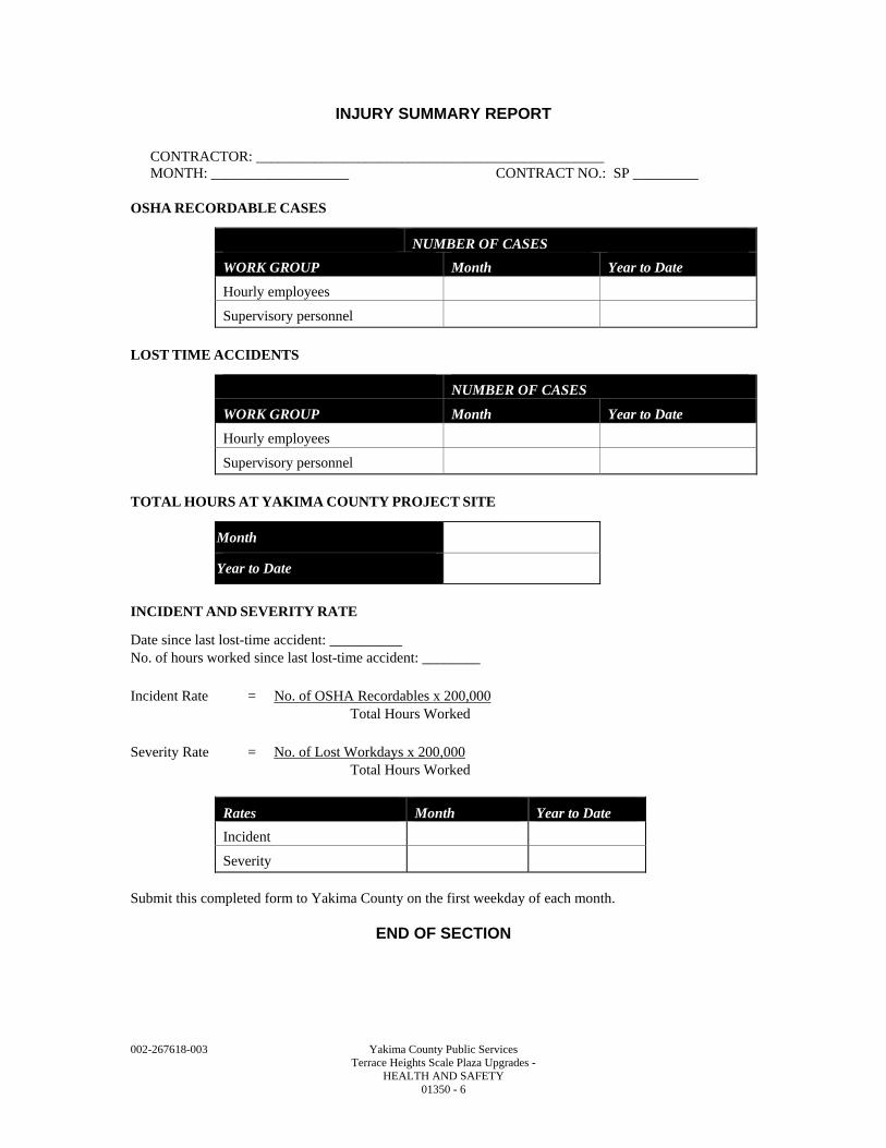
002-267618-003 Yakima County Public Services Terrace Heights Scale Plaza Upgrades - HEALTH AND SAFETY 01350 - 6
INJURY SUMMARY REPORT
CONTRACTOR: ________________________________________________ MONTH: ___________________ CONTRACT NO.: SP _________
OSHA RECORDABLE CASES
NUMBER OF CASES WORK GROUP Month Year to Date Hourly employees
Supervisory personnel
LOST TIME ACCIDENTS
NUMBER OF CASES WORK GROUP Month Year to Date Hourly employees
Supervisory personnel
TOTAL HOURS AT YAKIMA COUNTY PROJECT SITE
Month
Year to Date
INCIDENT AND SEVERITY RATE
Date since last lost-time accident: __________ No. of hours worked since last lost-time accident: ________
Incident Rate = No. of OSHA Recordables x 200,000 Total Hours Worked
Severity Rate = No. of Lost Workdays x 200,000 Total Hours Worked
Rates Month Year to Date Incident
Severity
Submit this completed form to Yakima County on the first weekday of each month.
END OF SECTION
002-267618-003 Yakima County Public Services Terrace Heights Scale Plaza Upgrades - MEASUREMENT AND PAYMENT 01370 - 1
SECTION 01370
MEASUREMENT AND PAYMENT
PART 1 - GENERAL
1.1 SUMMARY
A. Procedures for measurement and payment for Contract bid items. 1. Related Section:
a. Section 01200 – Payment Procedure. 2. Reference Standard:
a. Washington State Department of Transportation Standard Specification 2016 (Standard Specifications).
1.2 FORMAT AND CONTENT
A. Format: Bid items shall be considered categories of work. 1. Round amounts off to the nearest whole dollar; the total shall equal the Contract Sum.
1.3 MARGINS OF COST
A. Each item in the Applications for Payment shall be complete including its total cost and proportionate share of site supervision, general overhead and profit margin.
1.4 MEASUREMENT
A. All measurement shall be performed according to United States Standard units of measure and in accordance with the Contract Documents. 1. All measurements shall be based on actual units installed or neat line dimensions of Work
completed as stipulated by the Contract Documents. 2. Measurements of Area: Quantities shall be measured based on the horizontal plane area.
Quantities shall be computed, in accordance with the unit of measure shown on the Form of Bid, to either the nearest tenth of the nearest square yard or the nearest square foot. No adjustments shall be made for overlap of materials, penetrations, repairs, wasted materials, or grade/slope. Quantities shall be measured to the lines shown on the Drawings unless otherwise specified.
3. Measurements of Volume by Calculation: Quantities shall be measured based on the measured area and depth and calculated to determine volume. Quantities shall be computed, in accordance with the unit of measure shown on the Form of Bid, to the nearest cubic yard. Quantities shall be measured to the limits shown on the Drawings unless otherwise specified.
4. Measurements of Length: Quantities shall be measured based on survey length along the alignment of the feature being measured. Quantities shall be computed from the end points defined by the Specification to the nearest foot. Ditch quantities shall be computed along the centerline between the end points defined by the Drawings.
5. Measurements by Weight: Quantities shall be measured based on weight tickets received by the Owner. Quantities shall be computed, in accordance with the unit of measure shown on the Bid Form, to the nearest tenth of a ton. Weight tickets must document: the vehicle identification number, date and time of delivery; tar weight of the vehicle, gross weight of the vehicle, as measured by a certified scale.
6. Measurement by Each: The per each contract price shall constitute full payment for furnishing all labor, equipment, materials, permits and agreements and performing all operations required to complete the work as defined in the Contract Documents. Notwithstanding the omission or mention of any incidental Work, the unit price shall also constitute full compensation for all Work incidentals to the completion of each item, unless such work is otherwise specifically mentioned for separate payment under another bid items.
002-267618-003 Yakima County Public Services Terrace Heights Scale Plaza Upgrades - MEASUREMENT AND PAYMENT 01370 - 2
7. Measurement by Lump Sum: The lump sum contract price shall constitute full payment for furnishing all labor, equipment, materials, permits and agreements and performing all operations required to complete the Work as defined in the Contract Documents. Notwithstanding the omission or mention of any incidental Work, the lump sum contract price shall also constitute full compensation for all Work incidentals to completion of the item, unless such Work is otherwise specifically mentioned for separate payment under another bid item.
8. Measurement by Time and Materials: Payment by Time and Materials shall be measured based on the labor hours, materials and equipment charged to work by detailed time cards or logs completed on a daily basis before the close of business each working day. Present the time card and/or log at the close of business each day to the Owner so they may review and initial each time card/log. Perform all Work in accordance with this provision as efficiently as possible. Maintain all records of the work, including all records of the Subcontractor, Supplier, and Material men, as applicable, and make such records available for inspection. a. The Labor Rate is the actual reasonable wage paid to the individual plus the actual
reasonable costs incurred by the Contractor to cover costs associated with Federal Insurance Compensation Act (FICA), Federal Unemployment Tax Act (FUTA), State Unemployment Tax Act (SUCA), industrial insurance, fringe benefits, and benefits paid on behalf of labor by the Contractor. The applicable Labor Rates shall be multiplied by the number of hours reasonably expended in each labor classification because of the event or condition to arrive at a total cost of labor.
b. The cost of materials shall be paid the actual invoice cost of materials including actual freight and express charges and applicable taxes less all available discounts, rebates, and back-charges, notwithstanding the fact that they may not have been taken by the Contractor. This method shall be considered only to the extent the Contractor’s invoice costs are reasonable and the Contractor provides copies of vendor invoices, freight and express bills, and other evidence of cost accounting and payment satisfactory to the Owner. As to materials furnished from the Contractor’s stocks for which an invoice is not available, the Contractor shall furnish an affidavit certifying its actual cost of such materials and such other information as the Owner may reasonably require.
c. The additional cost, if any, of machine-power tools and equipment usage shall be calculated by the Contractor’s own charge rates may be used if verified and approved by the Owner and based on the Contractor’s actual ownership and operating cost experience. Rental rates contained in published rate guides may be used if their cost formulas and rate factors are identifiable, reflect the Contractor’s historical acquisition costs, utilization, and useful life, and do not include replacement cost, escalation contingency reserves, general and administrative expense, or profit. Rates shall be based on the Contractor’s actual allowable costs incurred.
1.5 PAYMENT
A. Payment shall be made in accordance with unit prices shown on the Contractor’s schedule of values and on the Bid Form.
B. Payment for all items includes all costs for overhead and profit and for supplying materials, labor, equipment, tools and any other incidentals necessary to complete the Work in accordance with the Contract Documents. Payment for bid item work also includes all costs for Division 0 and Division 1 requirements.
C. Payment for any item of work for which there is no specific bid item shall be considered incidental to the construction and shall be included in the costs of other items of work involved in the project.
002-267618-003 Yakima County Public Services Terrace Heights Scale Plaza Upgrades - MEASUREMENT AND PAYMENT 01370 - 3
D. The unit or lump sum contract prices shall constitute full compensation for furnishing all labor, equipment, and materials, and performing all operations required to complete the Work as required. Notwithstanding the omission or mention of any incident or incidental Work, the contract price and payment shall also constitute full compensation for all Work incident or incidental to completion of the item, unless such Work is otherwise specifically mentioned for separate payment under another item. 1. Mobilization:
a. Measurement shall be based on lump sum for mobilizing to perform Work, temporary facilities, demobilizing, and cleaning within Construction Limits shown on Drawings.
b. The lump sum price for Mobilization shall constitute full compensation for all labor, equipment, and materials required to complete the Work described in Section 01500 – Construction Facilities and Temporary Controls and Section 01780 – Closeout Procedures. The price shall include, but not be limited to, field trailer and all specified equipment, supplies and temporary utilities used while on site.
c. Based on the lump sum price for Mobilization, partial payments will be made as follows: 1) When 5 percent of the original contract amount is earned from other contract items,
50 percent of the amount bid for Mobilization, or 5 percent of the total original contract amount, whichever is the least, will be paid.
2) When 10 percent of the total original contract amount is earned from other contract items, 90 percent of the amount bid for Mobilization, or 10 percent of the total original contract amount, whichever is the least, will be paid.
3) When the Substantial Completion requirements have been met for the project, payment of any remaining amount bid for Mobilization will be paid.
2. Excavation Support and Protection: a. Excavation Support and Protection shall be measured in place. Quantities shall be
computed based on Area covered by the square foot. b. The unit contract price per square foot for Excavation Support and Protection shall
include all labor, materials, and equipment required to furnish, install the work in accordance with the Contract Documents.
3. Excavation, Haul, Placement and Compaction: a. Measurement for Excavation Haul, Placement and Compaction shall be by the cubic
yard of material removed. b. The unit rate for Excavation Haul, Placement and Compaction shall be full pay for all
work as specified, including, but not limited to, all labor and equipment to excavate in-place soils, regardless of their nature, to the finished elevations and grades indicated on the Drawings, proof rolling and compaction of the exposed subgrade, loading, hauling, final placement and compaction, processing as required, and any other activities necessary to accomplish this Work, in accordance with Section 02200 – Earthwork.
c. Erosion and sediment controls required to protect work are incidental to this item. 4. Chain Link Fence:
a. Measurement shall be by the linear foot. b. The unit rate shall be for all work as specified, including, but not limited to, all labor,
materials and equipment to install 6 FT Chain Link Fence and any other activities necessary to accomplish this Work.
5. Traffic Control: a. Measurement shall be based on Time and Materials and paid via a Force Account. b. Payment for Traffic Control shall be full compensation for labor and materials required
to complete the Work, in accordance with Section 01500 – Construction Facilities and Temporary Controls.
6. Traffic Control Flagging: a. Traffic Control Flagging shall be based on Time and Materials by the Hour. b. The unit contract price per Hour for Traffic Control Flagging shall be full compensation
for all labor and materials required to complete the Work, in accordance with Section 01500 – Construction Facilities and Temporary Controls.
002-267618-003 Yakima County Public Services Terrace Heights Scale Plaza Upgrades - MEASUREMENT AND PAYMENT 01370 - 4
7. Sawcut Existing Asphalt Pavement: a. Measurement for Sawcut and Removal of Existing Asphalt Pavement shall be by the
linear foot. b. The unit rate for Sawcut Existing Asphalt Pavement shall be full pay for all work as
specified, including, but not limited to, all labor and equipment to cut asphalt and any other activities necessary to accomplish this Work.
8. HMA, Class 1/2 IN: a. Measurement for HMA, Class 1/2 IN will be by the ton installed in the Work.
Measurement will be by the certified weight tickets delivered to the Owner for each truck load supplied to the project.
b. The unit rate per ton for HMA, Class 1/2 IN for HMA Paving shall constitute full payment for all labor, equipment and materials to complete the work in accordance with the Contract Documents.
9. HMA, Class 1 IN: a. Measurement for HMA, Class 1 IN will be by the ton installed in the Work.
Measurement will be by the certified weight tickets delivered to the Owner for each truck load supplied to the project.
b. The unit rate per ton for HMA, Class 1 IN for HMA Paving shall constitute full payment for all labor, equipment and materials to complete the work in accordance with the Contract Documents.
10. Crushed Surfacing Base Course: a. Measurement for Crushed Surfacing Base Course will be by the ton installed in the
Work. Measurement will be by the certified weight tickets delivered to the Owner for each truck load supplied to the project.
b. The unit rate per ton for Crushed Surfacing Base Course for HMA Paving shall constitute full payment for all labor, equipment and materials to complete the work in accordance with the Contract Documents.
11. Gravel Base for Slabs and Footings: a. Measurement for Gravel Base for Slabs and Footings will be by the ton installed in the
Work. Measurement will be by the certified weight tickets delivered to the Owner for each truck load supplied to the project.
b. The unit rate per ton for Gravel Base for Slabs and Footings shall constitute full payment for all labor, equipment and materials to complete the work in accordance with the Contract Documents.
12. Bollards: a. Bollards shall be measured in place, per each. b. The unit rate per each Bollard shall include all costs for labor, materials, and equipment
required to furnish and install the work in accordance with the Contract Documents. 13. Quarry Spalls for Stormwater Outfall:
a. Quarry Spalls for Stormwater Outfall shall be measured by the ton installed in the Work. Measurement will be by the certified weight tickets delivered to the Owner for each truck load supplied to the project. Quarry Spalls for Stormwater Outfall shall be included in this bid item. Geotextile included for this Work shall be considered incidental to this item. Quarry Spalls used elsewhere in the Work shall be incidental to those bid items.
b. The unit contract price per ton for Quarry Spalls shall constitute full compensation for labor, equipment, and materials, required to complete the Work, in accordance with Section 02200 – Earthwork.
14. Curb: a. Curb shall be measured in place. Quantities shall be calculated based on Length. b. The unit rate per linear foot of Curb shall include all costs for labor, materials, and
equipment required to furnish and install the work in accordance with the Contract Documents.
15. PVC Sewer Pipe: a. PVC Sewer Pipe shall be measured in-place per linear foot installed. Quantities shall
be computed based on Length from end to end, measured along the invert of the pipe.
002-267618-003 Yakima County Public Services Terrace Heights Scale Plaza Upgrades - MEASUREMENT AND PAYMENT 01370 - 5
b. The unit contract price per linear foot for PVC Sewer Pipe shall be full payment for all labor, equipment, and materials required to complete the installation, furnishing and installing pipe and fittings, pipe bedding, backfill and compaction up to the existing ground surface, cleaning and testing.
c. Erosion and sediment control required for installation shall be incidental to this item. 16. Sewer Cleanout:
a. Sewer Cleanout shall be measured in place, per each. b. The unit rate per each Cleanout shall include all costs for labor, materials, and
equipment required to furnish and install the work in accordance with the Contract Documents.
17. Catch Basin: a. Catch Basin shall be measured in place, per each. b. The unit rate per each Catch Basin shall include all costs for labor, materials, and
equipment required to furnish and install the work in accordance with the Contract Documents.
18. Manhole – 48 IN: a. Manhole - 48 IN shall be measured in place, per each. b. The unit rate per each Manhole - 48 IN shall include all costs for labor, materials, and
equipment required to furnish and install the work in accordance with the Contract Documents.
19. HDPE Storm Pipe: a. HDPE Storm Pipe shall be measured in-place per linear foot installed. Quantities shall
be computed based on Length from end to end, measured along the invert of the pipe. b. The unit contract price per linear foot for HDPE Storm Pipe shall be full payment for
all labor, equipment, and materials required to complete the installation, furnishing and installing HDPE Storm Pipe and fittings, beveled end sections to match soil slope, pipe bedding, backfill and compaction up to the existing ground surface, cleaning and testing.
c. Erosion and sediment control required for installation shall be incidental to this item. 20. Septic Tank:
a. Measurement shall be based on lump sum. b. The unit rate per each Septic Tank shall include all costs for labor, materials, and
equipment required to furnish and install the work, including vents, floats, and risers in accordance with the Contract Documents..
21. PVC Pipe - Up to 2 IN Including Valves and Appurtenances: a. PVC Pipe Up - 2 IN Including Valves and Appurtenances shall be measured in-place
per linear foot installed. Quantities shall be computed based on Length from end to end, measured along the invert of the pipe.
b. The unit contract price per linear foot for PVC Pipe - Up to 2 IN Including Valves and Appurtenances shall be full payment for all labor, equipment, and materials required to complete the installation, furnishing and installing pipe and fittings, pipe bedding, backfill and compaction up to the existing ground surface, cleaning and testing.
22. Potable Water Connection: a. Measurement shall be based on lump sum. b. The contract price shall include connection, shut offs required, disinfection, testing and
other incidental work to complete the potable water connection. c. Based on the lump sum price for Potable Water Connection partial payments will be
made based on percent complete. 23. Demolition:
a. Measurement shall be based on lump sum. b. Based on the lump sum price for Demolition payments will be made based on percent
complete for all work required to remove and dispose of structures, scales, pavement, curb, and utilities.
24. Scales, Traffic Control Lights, and Displays: a. Scales shall be measured in place, per each.
002-267618-003 Yakima County Public Services Terrace Heights Scale Plaza Upgrades - MEASUREMENT AND PAYMENT 01370 - 6
b. The unit rate per each Scale Traffic Control Lights, and Displays shall include all costs for labor, materials, and equipment, required to furnish and install the work in accordance with the Contract Documents.
25. Concrete Foundations and Scale Approaches: a. Measurement shall be based on lump sum. b. Based on the lump sum price for Concrete Foundations and Scale Approaches
payments will be made based on percent complete. 26. Concrete Walkways
a. Walkways shall be measured in place. Quantities shall be computed based on Area covered by the square foot.
b. The unit contract price per square foot for Sidewalk shall include all labor, materials, and equipment required to furnish, install the work in accordance with the Contract Documents.
27. Scalehouse Interior and Exterior Finishes: a. Measurement shall be based on lump sum. b. Based on the lump sum price for Scalehouse Interior and Exterior Finishes payments
will be made based on percent complete. 28. Electrical:
a. Measurement shall be based on lump sum. b. Based on the lump sum price for Electrical payments will be made based on percent
complete. 29. Communications:
a. Measurement shall be based on lump sum. b. Based on the lump sum price for Communications payments will be made based on
percent complete. 30. Alarms, Security and Camera Wiring and Conduit:
a. Measurement shall be based on lump sum. b. Based on the lump sum price for Alarms, Security and Cameras Wiring and Conduits
payments will be made based on percent complete. 31. HVAC – Air Distribution & Equipment:
a. Measurement shall be based on lump sum. b. Based on the lump sum price for HVAC – Air Distribution & Equipment payments will
be made based on percent complete. 32. Plumbing:
a. Measurement shall be based on lump sum. b. Based on the lump sum price for Plumbing payments will be made based on percent
complete. 33. Push Wall Repair:
a. Measurement shall be based on lump sum. b. The unit contract price shall include all labor, materials, and equipment required to
complete the work in accordance with the Contract Documents. c. Based on the lump sum price for Push Wall Repair payments will be made based on
percent complete. 34. Minor Changes:
a. Payments or credits for changes amounting to $25,000.00 or less may be made under the Bid Item “Minor Changes”. At the discretion of the Owner, this procedure for Minor Changes may be used in lieu of the more formal procedure as outlined in Section 1-04.4(1) of the Standard Specifications.
b. The Contractor will be provided a copy of the completed order for Minor Change. The agreement for the Minor Change will be documented by signature of the Contractor, or notation of verbal agreement. If the Contractor is in disagreement with anything required by the order for Minor Change, the Contractor may protest the order as provided in Section 1-04.4(1) of the Standard Specifications.
002-267618-003 Yakima County Public Services Terrace Heights Scale Plaza Upgrades - MEASUREMENT AND PAYMENT 01370 - 7
c. Payments or credits will be determined in accordance with Section 1-09.6 of the Standard Specifications. For the purpose of providing a common Proposal for all Bidders, the Contracting Agent has entered an amount for “Minor Changes” in the Proposal to become a part of the total Bid by the Contractor.
35. All incidental work not included above shall be included in lump sum contract prices and paid per percentage complete.
36. The Owner may require up to 50 percent difference in quantities indicated in Informational Bid Documents. The Contractor shall not be entitled to an adjustment in any contract price without significant difference in an estimated quantity, which is in excess of plus or minus 50 percent of either the estimated quantity included in the Agreement or the adjusted quantity resulting from any change to the Contract.
PART 2 - PRODUCTS - (NOT APPLICABLE TO THIS SECTION)
PART 3 - EXECUTION - (NOT APPLICABLE TO THIS SECTION)
END OF SECTION

002-267618-003 Yakima County Public Services Terrace Heights Scale Plaza Upgrades - MEASUREMENT AND PAYMENT 01370 - 8
002-267618-003 Yakima County Public Services Terrace Heights Scale Plaza Upgrades - REGULATORY REQUIREMENTS 01410 - 1
SECTION 01410
REGULATORY REQUIREMENTS
PART 1 - GENERAL
1.1 SUMMARY
A. Section includes the following: 1. Compliance with codes, laws, regulations and rules. 2. Fees. 3. Permits.
1.2 REFERENCES
A. The following is a partial list of Codes and Regulations central to the Project: 1. Yakima County Zoning Code. 2. Yakima County Regional Stormwater Manual. Yakima County, Washington. 2010. 3. 2004 Department of Ecology Stormwater Management Manual for Eastern Washington. 4. 2012 International Building Code, including the following amendments:
a. Washington State Amendments. 5. RCRA – Resource Conservation and Recovery Act.
1.3 PERFORMANCE
A. Be fully informed of regulations which impact the Work.
B. In event of conflict between standards, codes, and regulations, inform the Owner at the earliest opportunity. 1. The Owner will determine the appropriate direction and communicate with the Contractor.
C. Permits by Contractor: 1. Permit Milestones: Coordinate permit responsibilities and tasks with preparation and
maintenance of schedules and other administrative activities in accordance with Section 01300 – Administrative Requirements.
2. Provide and pay for the following permits and certifications: a. Washington Department of Labor and Industries electrical permits. b. All necessary street use permits in connection with Contractor’s operations. c. Any permits required for temporary facilities or utilities. d. Sewage tank certifications in compliance with WAC 246-272C-0130.
3. Fulfill the obligations and conditions on each permit affecting the Work. 4. Bring conflicting requirements to the attention of the Owner, who will arrange for a
determination to be made.
D. Permits Paid For and Obtained by Owner from Yakima County, Washington: 1. The following permits are pending approval:
a. General Application for Construction – Excavating & Grading, Demolition, Mechanical, Plumbing, and Building permits.
b. Applicable Washington State Energy Code forms.
1.4 SUBMITTALS
A. General: Submit the following in accordance with Section 01340 – Submittals:
B. Permits: 1. Provide copies of permits to the Owner within three (3) days of the date of issuance by the
permitting agencies. 2. Provide copies of permit cards that include progress notations made by inspectors
acknowledging completeness of Work, for those permits requiring several inspections. 3. Provide copies of permit approvals to the Owner, when these become available.
002-267618-003 Yakima County Public Services Terrace Heights Scale Plaza Upgrades - REGULATORY REQUIREMENTS 01410 - 2
1.5 ADDITIONAL REQUIREMENTS
A. Work performed under permits must be inspected by the authority having jurisdiction prior to being considered part of the Work.
B. Contractor shall be responsible for satisfactory completion of all Work required to obtain regulatory approval and sign off of permits applied to this Contract.
C. Permit Posting: 1. Post all permits at the site in a protected location. 2. Use clear plastic pockets mounted on a wood panelboard for storage. 3. Post project permits in one (1) location. 4. Do not post permits in unprotected or exterior locations.
PART 2 - PRODUCTS –- (NOT APPLICABLE TO THIS SECTION)
PART 3 - EXECUTION –- (NOT APPLICABLE TO THIS SECTION)
END OF SECTION
002-267618-003 Yakima County Public Services Terrace Heights Scale Plaza Upgrades - QUALITY CONTROL SERVICES 01430 - 1
SECTION 01430
QUALITY CONTROL SERVICES
PART 1 - GENERAL
1.1 SUMMARY
A. Section specifies administrative and procedural requirements for quality control services.
B. Quality control services include inspections and tests and related actions including reports, performed by independent agencies, governing authorities, and the Contractor. They do not include Contract enforcement activities performed by the Owner.
C. Inspection and testing services are required to verify compliance with requirements specified or indicated. These services do not relieve the Contractor of responsibility for compliance with Contract Document requirements.
D. Specific quality control requirements for individual construction activities are specified in the Sections that specify those activities.
E. Inspections, test and related actions specified are not intended to limit the Contractor’s quality control procedures that facilitate compliance with Contract Document requirements.
F. Requirements for the Contractor to provide quality control services required by the Owner, or authorities having jurisdiction are not limited by provisions of this Section.
1.2 RESPONSIBILITIES
A. Contractor Responsibilities: Provide inspections, tests and similar quality control services to ensure that all work meets the requirements of the Contract Documents, including quality control services specified in individual Specification Sections and required by governing authorities, except where they are specifically indicated to be solely the Owner’s responsibility, or are provided by another identified entity. 1. The Contractor shall employ an independent agency to perform specified quality control
services. 2. The Contractor shall comply with the Yakima Health District Septic System Permit
installation requirements. 3. The Contractor shall cooperate with Owner and agencies performing required inspections,
tests and similar services and provide reasonable auxiliary services as requested. Auxiliary services required include but are not limited to: a. Providing access to the Work and furnishing incidental labor and facilities necessary to
facilitate inspections and tests. b. Taking adequate quantities of representative samples of materials that require testing or
assisting the agency in taking samples. c. Providing facilities for storage and curing of test samples, and delivery of samples to
testing laboratories. d. Security and protection of samples and test equipment at the Project site.
B. Owner Responsibilities: The Owner will perform inspections and tests specified as the Owner’s responsibility.
C. Duties of the Owner: The Owner will perform inspections, sampling and testing of materials and construction specified in individual Specification Sections and shall cooperate with Contractor in performance of its duties, and shall provide qualified personnel to perform required inspections and tests. 1. The Owner shall notify the Contractor promptly of irregularities or deficiencies observed in
the work during performance of its services. 2. The Owner shall not perform any duties of the Contractor.
002-267618-003 Yakima County Public Services Terrace Heights Scale Plaza Upgrades - QUALITY CONTROL SERVICES 01430 - 2
D. Coordination: The Contractor, Owner, and each agency engaged to perform inspections, tests and similar services shall coordinate the sequence of activities to accommodate required services with a minimum of delay. In addition to Contractor, Owner, and each agency shall coordinate activities to avoid the necessity of removing and replacing construction to accommodate inspections and tests. 1. The Contractor is responsible for scheduling times for inspections, tests, taking samples and
similar activities.
1.3 SUBMITTALS
A. The Owner and its independent testing agency shall submit a certified written report of each inspection, test or similar service, to the Contractor.
B. If the Contractor is responsible for the service, submit a certified written report of each inspection to Owner. 1. Submit additional copies of each written report directly to the governing authority, when the
authority so directs. 2. Report Data: Written reports of each inspection, test or similar service shall include, but not
be limited to: a. Date of issue. b. Project title and number. c. Name, address and telephone number of testing agency. d. Dates and locations of samples and tests or inspections. e. Names of individuals making the inspection or test. f. Designation of the work and test method. g. Identification of product and Specification Section. h. Complete inspection or test data. i. Test results and an interpretation of test results. j. Ambient conditions at the time of sample-taking and testing. k. Comments or professional opinion as to whether inspected or tested Work complies
with Contract Document requirements. l. Name and signature of laboratory inspector. m. Recommendations on retesting.
1.4 QUALITY ASSURANCE
A. Qualification for Service Agencies: Contractor shall engage inspection and testing service agencies, including independent testing laboratories, which are prequalified as complying with “Recommended Requirements for Independent Laboratory Qualification” by the American Council of Independent Laboratories, and which specialize in the types of inspections and tests to be performed. 1. Each independent inspection and testing agency engaged on the Project shall be authorized
by authorities having jurisdiction to operate in the State of Washington.
PART 2 - PRODUCTS- (NOT APPLICABLE TO THIS SECTION)
PART 3 - EXECUTION
3.1 REPAIR AND PROTECTION
A. Upon completion of inspection, testing, sample-taking and similar services, repair damaged construction and restore substrates and finishes to eliminate deficiencies, including deficiencies in visual qualities of exposed finishes.
B. Protect construction exposed by or for quality control service activities, and protect repaired construction.
002-267618-003 Yakima County Public Services Terrace Heights Scale Plaza Upgrades - QUALITY CONTROL SERVICES 01430 - 3
C. Repair and protection is the Contractor’s responsibility, regardless of the assignment of responsibility for inspection, testing or similar services.
END OF SECTION

002-267618-003 Yakima County Public Services Terrace Heights Scale Plaza Upgrades - QUALITY CONTROL SERVICES 01430 - 4
002-267618-003 Yakima County Public Services Terrace Heights Scale Plaza Upgrades - CONSTRUCTION FACILITIES AND TEMPORARY CONTROLS 01500 - 1
SECTION 01500
CONSTRUCTION FACILITIES AND TEMPORARY CONTROLS
PART 1 - GENERAL
1.1 SUMMARY
A. Section includes requirements for temporary services and facilities, including utilities, construction and support facilities, site security and protection.
B. Temporary utilities required include, but are not limited to: 1. Temporary electricity. 2. Temporary Heating, Cooling and Ventilation (HVAC). 3. Temporary communications service. 4. Temporary sanitary facilities. 5. Temporary water service.
C. Temporary construction and support facilities required include, but are not limited to: 1. Barriers. 2. Protection of installed work. 3. Access roads and parking. 4. Contractor’s field offices and storage. 5. Owner's field office. 6. Progress cleaning. 7. Contractor's staging and stockpile area(s).
D. Temporary controls and security include, but are not limited to: 1. Dust control. 2. Noise control. 3. Pollution control. 4. Traffic control. 5. Site security. 6. Temporary fire protection.
E. Removal of utilities, facilities, and controls.
F. Related Sections: 1. Section 02270 - Soil Erosion and Sedimentation Control.
1.2 REFERENCES
A. Comply with the requirements of Section 01095 – Reference Standards and as listed herein. The following is a list of standards referenced in this Section: 1. American Traffic Safety Services Association – Quality Guidelines for Work Zone Traffic
Control Devices. 2. USDOT Federal Highway Administration – NCHRP 350 Report – Recommended
Procedures for the Safety Performance Evaluation of Highway Features. 3. USDOT Federal Highway Administration – Manual on Uniform Traffic Control Devices
(MUTCD) 2003 Edition with Revisions 1 and 2 and including Washington State modifications.
4. Washington State Department of Transportation Standard Plans Manual.
002-267618-003 Yakima County Public Services Terrace Heights Scale Plaza Upgrades - CONSTRUCTION FACILITIES AND TEMPORARY CONTROLS 01500 - 2
1.3 SUBMITTALS
A. Submit a written Project Control Plan (Control Plan) within fifteen (15) days after the date of the Notice to Proceed outlining Contractor's plans and methods for complying with the requirements for temporary controls, regulation, security and protection. The plan shall separately address each of the areas outlined in Paragraph 1.1 above and shall include specific substantive details of the procedures, methods, resources (facilities, staff, and equipment) to be employed, instruction and training, and standards to be met and maintained. 1. The pollution control section of the Control Plan shall include a narrative description of
practices that will be followed to reduce the threat of pollutants from construction-related materials and equipment that are stored on-site, including an inventory of construction materials (including waste materials), storage practices to minimize exposure of these materials to storm water, and spill prevention. The Control Plan shall outline responsive actions in the event of a spill or release and shall identify notification and reporting procedures. The Control Plan shall also outline Contractor management elements such as personnel responsibilities, project site security, site inspections and training.
2. The Control Plan shall outline what measures the Contractor shall take to prevent the release or spread of the following: a. Any hazardous material found on site and encountered during construction but not
identified in Contract Documents. b. Any hazardous materials that the Contractor stores, uses, or generates on the
construction site during construction activities. These items include, but are not limited, gasoline, oils and chemicals.
3. The Control Plan shall also address, at a minimum, the following project-specific information: a. Introduction. b. Stormwater Pollution Prevention Plan Elements. c. Site Information. d. Management Approval. e. Site Description. f. Planning and Recognition. g. Spill Prevention and Containment. h. Spill Response. i. Reporting. j. Program Management. k. Attachments:
1) Emergency Action Plan. 2) Site Plan. 3) Inspection and Incident Report Forms.
4. The traffic regulation section of the Control Plan shall include a general discussion (overview) of the Contractor's planned approach to maintaining public traffic Roza Hill Drive and customer and operations traffic within the site. A separate detailed Traffic Control Plan submittal is required and is described under paragraph 1.19 Traffic Regulation below.
B. Traffic Control Plan: 1. Traffic Control Plan will at a minimum show temporary warning signage, flaggers, work
zones, detours, and include notes defining specific control procedures and constraints. 2. State of Washington traffic flagger certification cards.
C. Submit a written plan describing the temporary construction facilities and temporary utilities within ten (10) days after the date of the Notice to Proceed and prior to site mobilization.
1.4 QUALITY ASSURANCE
A. Regulations: Comply with industry standards and applicable laws and regulations of authorities having jurisdiction, including but not limited to: 1. Building Code requirements.
002-267618-003 Yakima County Public Services Terrace Heights Scale Plaza Upgrades - CONSTRUCTION FACILITIES AND TEMPORARY CONTROLS 01500 - 3
2. Health and safety regulations. 3. Utility Company regulations. 4. Police, Fire Department and Emergency Response rules. 5. Environmental protection regulations. 6. Yakima County ordinances and regulations.
B. Standards: Comply with NFPA Code 241, “Building Construction and Demolition Operations”, ANSI-A10 Series standards for “Safety Requirements for Construction and Demolition”, and NECA Electrical Design Library “Temporary Electrical Facilities.” 1. Refer to “Guidelines for Bid Conditions for Temporary Job Utilities and Services”, prepared
jointly by AGC and ASC, for industry recommendations. 2. Electrical Service: Comply with NEMA, NECA, and UL standards and regulations for
Temporary electrical service. Install service in compliance with National Electrical Code (NFPA 70).
C. Inspections: If required by local ordinance or code, arrange for authorities having jurisdiction to inspect and test each temporary utility before use. Obtain required certifications and permits.
1.5 PROJECT CONDITIONS
A. Existing Conditions: Contractor is responsible for arranging for, and making connections to, existing utilities and obtaining permits, providing potable drinking water supply, maintaining non-potable water supply, and sanitary facilities.
B. Conditions of Use: Keep temporary services and facilities clean and in fully functional condition. Operate temporary facilities in a safe and efficient manner. Take necessary fire prevention measures. Do not overload facilities and utility services, or permit inadequate support services to interfere with work progress. Do not allow hazardous, dangerous or unsanitary conditions, or public nuisances to develop or persist on the site.
1.6 TEMPORARY ELECTRICITY
A. Furnish and pay for power service or generation for Contractor’s use.
1.7 TEMPORARY COMMUNICATIONS SERVICE
A. Install, maintain and pay for communications service to field office(s) at time of project mobilization. Service shall support telephone and internet communications services to the Contractor's field staff and to the Owner's field office. 1. Provide separate dedicated lines for phone and internet communications.
1.8 TEMPORARY SANITARY FACILITIES
A. Provide temporary self-contained toilets, wash facilities and drinking water fixtures, as necessary. Comply with regulations and health codes for the type, number, location, operation and maintenance of fixtures and facilities. 1. Provide toilet tissue, paper towels, paper cups and similar disposable materials for each
facility. Provide covered waste containers for used materials. 2. Provide containerized tap-dispenser bottled-water type drinking water units, including paper
cup supply.
B. Maintain in clean and sanitary condition.
1.9 TEMPORARY CONSTRUCTION WATER SERVICE
A. Water for Contractor’s operations necessary for construction of the facilities is available from the onsite groundwater well. 1. Coordinate with Owner for training on operation of the existing truck fill station. 2. Based on Owner’s experience, improper operation of the existing truck fill station may
cause impacts to the existing onsite facilities. 3. Damage to the existing truck fill station by the Contractor will be repaired at no cost to the
Owner.
002-267618-003 Yakima County Public Services Terrace Heights Scale Plaza Upgrades - CONSTRUCTION FACILITIES AND TEMPORARY CONTROLS 01500 - 4
4. Contractor may use a maximum of 2,000 GAL of water a day from the onsite groundwater well. If Contractor’s needs exceed 2,000 GAL of water on any given day, then water shall be obtained from a potable source offsite at no additional cost to the Owner.
B. Do not waste water.
1.10 BARRIERS
A. Furnish fencing, barriers, and warning signs to prevent unauthorized entry to construction areas, to protect existing facilities and adjacent properties from damage from construction operations and to protect the public from injury.
B. Protect non-owned vehicular traffic, stored materials, site and structures from damage.
C. Provide barricades at all open excavation to prevent public entry and as required by governing authorities.
1.11 PROTECTION OF INSTALLED WORK
A. Protect installed work and provide special protection where specified in individual Specification Sections. 1. Protect all bare soil areas on site and adjacent to Roza Hill Drive, regardless of the slope, as
specified in Section 02250.
B. Furnish temporary and removable protection for installed products.
C. Provide security and facilities to protect work from unauthorized entry, vandalism, or theft.
D. Prohibit traffic from landscaped areas.
E. Contractor shall be liable for all repair, replacement costs, and environmental remediation costs due to damage caused by the Contractor’s operations.
1.12 ACCESS ROADS AND PARKING
A. Maintain roads accessing public thoroughfares to serve construction area. Control dust and water.
B. Provide means of removing mud from vehicle wheels before entering public thoroughfares as further described in Section 02270.
C. Maintain traffic areas in a sound condition free of excavated material, construction equipment, and products.
D. Maintain existing traffic areas used for construction; promptly repair potholes, low areas, standing water, and other deficiencies, to its original or specified condition.
E. Repair existing facilities damaged to original condition.
F. Construction equipment and vehicles may use on-site asphalt-paved access roads if the gross vehicle weight does not exceed legal highway limits, or 80,000 LBS.
1.13 FIELD OFFICES AND SHEDS
A. General: 1. Owner’s field office shall be separate from Contractor’s field office. 2. Install office spaces ready for occupancy within five (5) days of initial mobilization of
equipment. 3. At completion of work, remove buildings, foundations, utility services, and debris. Restore
areas to original condition. 4. Provide and pay for facilities through Substantial Completion. 5. Pay for installation and monthly service charges for all utilities, including connections,
through Substantial Completion. 6. Provide and pay for equipment service contracts for all furnished equipment through
Substantial Completion.
002-267618-003 Yakima County Public Services Terrace Heights Scale Plaza Upgrades - CONSTRUCTION FACILITIES AND TEMPORARY CONTROLS 01500 - 5
B. Environmental Control: 1. HVAC for Offices: Automatic equipment to maintain comfort conditions within 68 to 80
DegF. 2. Freeze protect and insulate all piping.
C. Electrical System: 1. All fixtures, outlets, and wiring of Underwriters Laboratories, Inc. (UL) approved devices. 2. All circuits protected by circuit breakers; fuses are not acceptable. 3. Electrical system shall meet requirements of the latest NFPA 70, National Electric Code
(NEC). 4. System suitable for 220 V, 3 PH service. 5. Any transformers or other devices required to match this supply to the mobile office shall be
provided and connected. 6. Provide a circuit breaker for the incoming service. 7. Each interior room, shall have at least four (4) 110 V duplex electrical convenience outlets.
D. Construction: 1. New or reconditioned portable or mobile building, or building constructed with floors raised
above ground, securely fixed to foundations, with steps and landings at entrance doors. 2. Construction: Structurally sound, secure, weather-tight enclosures for office and storage
spaces. Maintain during progress of work; remove at completion of work. 3. Temperature Transmission Resistance of Floors, Walls, and Ceilings: Compatible with
locale, occupancy, and storage requirements. 4. Exterior Materials: Weather-resistant; finished. 5. Interior Materials in Offices: Sheet type materials for walls and ceilings, pre-finished or
painted; resilient floors and bases. 6. Lighting for Offices: 100 candle-feet at desktop height, exterior lighting at entrance doors.
Ample ceiling fixtures provided to ensure adequate lighting throughout. 7. Minimum two (2) combination screen windows per room, excepting washroom if included,
with one (1) each on opposing walls equipped with horizontal louver blinds on each window.
8. First Aid Supplies: Supply wall-mounted first aid kit(s) in the Owner’s and Contractor’s Field Offices. Replace first aid supplies as necessary. Comply with governing regulations.
9. Fire Extinguishers: Provide hand-carried, portable, UL-rated, Class A fire extinguishers for temporary offices and similar spaces. In other locations provide hand-carried, portable, UL-rated Class ABC dry chemical extinguishers, or a combination of extinguishers of NFPA recommended classes for the exposures. Comply with NFPA 10 and 241 for classification, extinguishing agent and size required by location and class of fire exposure.
E. Contractor’s Office and Facilities: 1. Size: As required for Contractor's needs and to provide space for project meetings. 2. Communications: As required for Contractor’s needs including separate lines for phone
communications and internet service. 3. Furnishings in Meeting Area: Conference table and chairs to seat at least eight (8) persons;
racks and files for Contract Documents, submittals, and Project Record Documents. 4. Other Furnishings: Contractor’s option. 5. Equipment: Six adjustable band protective helmets and six orange safety vests for visitors.
F. Owner’s Office and Facilities: 1. A drawing of interior configuration will be submitted to the Owner. 2. The Owner’s Office will be used to house Owner and Construction Manager personnel. 3. Provide a weather-tight, insulated, modular trailer field office building of not less than 160-
square feet for use by Owner. Furnish office with a minimum of one (1) exterior door with cylinder locks and six (6) sets of keys. Include exterior intrusion/burglar prevention guards over all windows. Provide metal or wood steps and exterior landing at each entrance door with suitable handrail system. Equip each landing with boot scraper/brush.
002-267618-003 Yakima County Public Services Terrace Heights Scale Plaza Upgrades - CONSTRUCTION FACILITIES AND TEMPORARY CONTROLS 01500 - 6
4. Provide office with heat, air conditioning, electric lights, electric outlets, communications, bottled water, and janitorial service. a. Communications include a minimum of two (2) lines serving the Owner’s Office for
exclusive use by Owner as follows: 1) One (1) dedicated line for telephone with voice mail service. 2) One (1) line for cable internet of 10Mbps or greater. 3) Coordinate service providers to be used with the Owner.
5. Furnish office with the following furniture and equipment, assembled and ready for Owner’s use: a. One (1) desk with locking drawers, 36 by 60 IN. b. One (1) desk chair. c. Four (4) standard office chairs. d. One (1) plan table at drafting board height, 42 by 60 IN. e. One (1) drafting stool. f. One (1) four (4)-drawer, standard size file cabinet. g. One (1) wastebasket and one (1) recycling bin. h. Provide one (1) plan rack for 24 by 36 IN size Drawings, accommodating not less than
six (6) sets of plans. i. Provide one (1) meeting table with dimensions four (4) FT square, with folding, locking
legs. j. Provide one (1) refrigerator with freezer with minimum size of three (3) CF. k. Provide one (1) refrigerated water cooler with water delivery service using bottled
water. l. One (1) 48 by 60 IN liquid marking board with minimum four-color set of compatible
markers. m. One (1) 48 by 60 IN cork bulletin board. n. One (1) bookcase a minimum of 3 FT high, composed of three (3) shelves 36 IN long
and 12 IN wide. o. One (1) three-hole punch. p. One (1) stapler. q. One (1) electric pencil sharpener. r. One (1) tape dispenser.
6. Provide one (1) multifunction copier with print, copy scan, and fax functions installed and connection to Owner supplied computer. Copier shall have the following capabilities. a. Support color impressions and scanning. b. Support SMB and FTP scanning protocols. c. Minimum of paper sizes letter, legal, and eleven inch by seventeen (11x17) IN. d. Minimum speed for automatic document feeder shall be thirty-five (35) pages per
minute. e. Minimum speed for printing, copying, and scanning shall be thirty-five (35) pages per
minute. f. Finishing with stapling and collating.
G. Maintenance: 1. Contractor shall provide all maintenance and upkeep of trailer and equipment. 2. Equipment breakdowns shall be repaired promptly by Contractor.
H. Provide janitorial service through Substantial Completion, as follows: 1. On a weekly basis trash removal service, cleaning, vacuuming or sweeping, including ample
supply of drinking water, toilet paper, paper towels, disposable toilet seat covers, liquid soap, and toilet tissue.
2. On a monthly basis wash windows and clean window blinds. 3. Maintain and provide uninterrupted stocking of all these materials and in sufficient quantity
and replenishment such that all products are continuously available.
002-267618-003 Yakima County Public Services Terrace Heights Scale Plaza Upgrades - CONSTRUCTION FACILITIES AND TEMPORARY CONTROLS 01500 - 7
1.14 PROGRESS CLEANING AND WASTE REMOVAL
A. Maintain areas free of waste materials, debris, and rubbish at all times. Maintain site in a clean and orderly condition.
B. Remove waste materials, debris, and rubbish from site and dispose at a minimum weekly.
C. Maintain approaches to Field Offices free of mud and water.
1.15 CONTRACTOR STAGING AND STOCKPILE AREA
A. The Contractor's staging area is shown on the Drawings.
B. Construct stockpiles as specified in Section 02200. 1. Maintain temporary cover measures over stockpiled soils to prevent erosion and air-blown
dust. Replace covers removed for access to stored materials immediately following finish of work requiring access or at the end of the day which ever comes first.
1.16 NOISE CONTROL
A. Provide methods, means, and facilities to minimize noise from construction operations. Do not exceed local Yakima County noise ordinance limits (65 dBA) on construction noise levels outside the ordinance-exempted work hours.
B. Maintain all motorized equipment, including exhaust noise mufflers and silencing equipment in good working order.
1.17 POLLUTION CONTROL
A. Provide methods, means, and facilities to prevent contamination of soil, water, and atmosphere from discharge of noxious, toxic substances, and pollutants produced by construction operations.
B. Water Pollution Control: 1. Implement the measures defined in the Stormwater Pollution Prevention Plan (SWPPP)
described in Section 02270. 2. Minimize non-sediment stormwater pollution by following applicable guidance of the
Stormwater Management Manual for Eastern Washington (Washington State Department of Ecology, September 2004). The SWPPP shall direct workers to call 911 in the case of a fuel or hazardous materials spill that cannot be contained with materials or equipment on-site. Personnel at 911 will route the call to the appropriate Emergency Management Agency which is trained and equipped to respond.
3. Assure that sediment, debris, petroleums, chemicals, or other contaminants will not enter existing drainage facilities and channels. Use construction methods that will prevent entrance of pollutants and wastes into existing streams, rivers, lakes, and flowing and dry watercourses.
4. Obtain legal disposal sites and dispose of pollutants and wastes in a legal manner. 5. Respond immediately to emergencies as directed when water quality of existing streams,
rivers, lakes and flowing and dry watercourses is threatened. Take corrective action to remove or contain pollutants until a permanent solution is determined.
C. Air Pollution Control: 1. Equipment and vehicles that exhibit excessive exhausts emissions due to poor engine
adjustments or inefficient operation will not be permitted to operate until corrective repairs or adjustments are made.
2. Burning of combustible construction materials, and rubbish will not be allowed.
1.18 TRAFFIC CONTROL
A. Keep all roads, sidewalks, and parking areas, that are not part of this Project, usable at all times.
B. Control and maintain traffic within the project area.
002-267618-003 Yakima County Public Services Terrace Heights Scale Plaza Upgrades - CONSTRUCTION FACILITIES AND TEMPORARY CONTROLS 01500 - 8
C. Provide and maintain traffic control devices, informational signs, flaggers, warning devices, and construction signs at a minimum to alert traffic of construction activities within the project site and to warn traffic accessing the scale plaza, HHW building, and recycling areas of construction traffic entering and exiting adjacent portions of the construction site. 1. The Contractor shall coordinate all work to avoid conflict with the County’s operations.
The Contractor shall supply all equipment and labor necessary to achieve this.
D. Use of traffic control and maintenance devices shall be in accordance with the current edition of the “Manual on Uniform Traffic Control Devices for Street and Highways” as prepared by the National Joint Committee on Uniform Traffic Control Devices, and other applicable codes and standards.
E. Operate devices 24 HRS per day, as required.
F. Ingress and Egress to Construction Limits: 1. Accomplish ingress and egress with as little disruption to traffic as possible. 2. Yield right of way to the public and County vehicles.
G. Contractor’s Duties: 1. Expeditiously correct any deficiency, and or shortage of resources, when directed by the
Owner to do so, at no additional cost to the Owner. a. Upon failure of the Contractor to immediately provide flaggers; erect, maintain, and
remove signs; or provide, erect, maintain, and remove other traffic control devices when ordered to do so by the Owner, the Owner may, without further notice to the Contractor, perform any of the above and deduct all of the costs from the Contractor’s payments.
2. Assure that all persons performing traffic management have current certification (flagging card) acceptable to the State Department of Labor and Industries (WAC 296-155-305).
3. Maintain copies of the following references, readily accessible during performance of work activities: a. Copies of the latest edition of the MUTCD, including Washington State modifications. b. A copy of the latest edition of “Quality Guidelines for Work Zone Traffic Control
Devices.” 4. Inspect traffic control devices, lighting, and signage for proper location, installation,
message, cleanliness, and effect on the public, users, and others. a. Flaggers:
1) All flaggers working on this project shall have completed an approved instructional course in flagging procedures conducted by the Washington Department of Transportation or other approved course by a government entity within Washington as evidenced by a valid flaggers certification card.
2) Supply each flagger with an orange vest and a hard hat. This equipment shall be reflectorized. Flags shall be not less than 24IN square, made of a good grade of red material securely fastened to a staff approximately 3 FT in length. The free edge of flags shall be weighted to ensure that they hang vertically in heavy winds. Sign paddles may be used in lieu of red flags. Paddles shall be at least 24 IN wide, with 6 IN series "C" letters and have a rigid, fixed handle.
3) To increase visibility during hours of darkness, flaggers shall wear either white coveralls (dry weather) or yellow raingear (wet weather) as appropriate for weather conditions.
4) Flagging performed in darkness shall be accompanied by sufficient lighting illumination for the flagging stations. Contractor is responsible for sufficient lighting illumination.
5) Flaggers shall carry two-way radios, with batteries and range compatible with the Project, and shall have continuous and direct contact with the Contractor.
6) Provide safe, protected locations for flaggers to work from, and in accordance with the Health and Safety Plan.
002-267618-003 Yakima County Public Services Terrace Heights Scale Plaza Upgrades - CONSTRUCTION FACILITIES AND TEMPORARY CONTROLS 01500 - 9
H. Install traffic control devices oriented in the direction of traffic flow. 1. At all times during performance of the Work, the Contractor shall manage traffic control
activities with its own staff actively involved in the planning and management of the Work. 2. Provide adequate labor, sufficient signs and traffic control devices required to perform the
traffic control for protection of the public, the Owner’s property, and the Work.
I. Additional Personnel: In addition to the personnel set forth above, Contractor shall add additional personnel which it believes is necessary to provide traffic safety at no additional cost to the Owner.
J. Traffic control measures deemed inadequate and or not in conformance with the requirements as interpreted by the Owner shall be corrected by the Contractor within twelve (12) HRS, at no additional cost to the Owner.
K. The Contractor shall be responsible to monitor and maintain traffic control measures, including but not limited to: 1. Resetting traffic cones and mislocated devices. 2. Assuring visibility of all devices. 3. Cleaning and repairing devices. 4. Maintaining equipment. 5. Replacing batteries and lamps. 6. Adjusting devices to suit conditions. 7. Accommodating vehicle queue conditions and lengths.
L. Submit a Traffic Control Plan to Owner for review fourteen (14) days of Notice to Proceed. Control Plan shall clearly describe the sequencing of all construction work, traffic control devices including flaggers, signage, warning devices, and for each sequence shall show how traffic will be accommodated. Special consideration will be given to accommodating the peak customer traffic occurring on Saturdays. Show the location and type of signage that will be used as part of the traffic control plan. Show measures that will be used to protect the safety of the public and operations staff. 1. Maintain two-way traffic on Roza Hill Drive and on all site access roads at all times. Refer
to Section 01100, 1.5 for additional requirements related to maintenance of access through the site.
M. Provide for unimpeded access by emergency traffic, such as police, fire, and disaster units at all times. Contractor shall be liable for damages resulting from failure to provide such access.
1.19 TEMPORARY LIGHTING
A. Provide temporary lighting as necessary to support work activities and insure worker safety.
1.20 SITE SECURITY
A. If necessary to protect work site, provide temporary fencing.
B. Coordinate with local police and emergency services so that site is accessible to their vehicles and on foot at all times.
C. Provide periodic security surveillance of site after hours as necessary to protect work from damage due to vandalism and from theft.
1.21 TEMPORARY FIRE PROTECTION
A. Install and maintain temporary fire protection facilities of the types needed to protect against reasonably predictable and controllable fire losses. Comply with NFPA 10 “Standard for Portable Fire Extinguishers”, and NFPA 241 “Standard for Safeguarding Construction, Alternations and Demolition Operations.” 1. Locate fire extinguishers where convenient and effective for their intended purpose. 2. Store combustible materials in containers in fire-safe locations. 3. Maintain unobstructed access to fire extinguishers, fire hydrants, and access routes for
fighting fires. Prohibit smoking in hazardous fire exposure areas.
002-267618-003 Yakima County Public Services Terrace Heights Scale Plaza Upgrades - CONSTRUCTION FACILITIES AND TEMPORARY CONTROLS 01500 - 10
4. Provide supervision of welding operations, combustion-type temporary heating units, and similar sources of fire ignition.
1.22 REMOVAL OF UTILITIES, FACILITIES, AND CONTROLS
A. Remove temporary utilities, equipment, and facilities before Substantial Completion inspection unless otherwise approved by Owner.
B. Remove temporary underground installations and grade site as indicated. Clean and repair damage caused by installation or use of temporary utilities, facilities, and controls.
C. Restore existing facilities used during construction to original condition. Restore permanent facilities used during construction to specified condition.
PART 2 - PRODUCTS
2.1 MATERIALS AND EQUIPMENT
A. Construction Signs: At a minimum, provide where required to safely control, direct, and maintain traffic within the project area.
B. Barricades: Where barricades are used, the only acceptable means of weighting shall be with bags of sand that will rupture upon impact, weighing forty (40) LBS or less, and positioned not more than one (1) FT above the ground surface.
C. Traffic Drums: Shall be used or new, weighted to resist overturning, and of consistent configuration and profile to promote visual recognition in variable lighting and weather conditions.
D. Jersey Barrier: Shall be in accordance with Standard Plans C-8.
E. Traffic Cones: Where employed, stack multiple cones together to resist relocation and upset by wind.
F. Warning Lights and Flashers: Provide where necessary to avoid accident or injury and ensure safety.
G. Provide Category 1 and 2 work-zone devices including equipment fitter with approved devices in accordance with MUTCD. 1. Category 1: Small, lightweight, channelizing and delineating devices are required for this
Project. 2. Category 2: Barricades, portable sign supports, signs, and vertical panels; all meeting
NCHRP 350 are required for this Project.
H. Categories 3 and 4 hardware and equipment are not part of this Project.
PART 3 - EXECUTION - (NOT APPLICABLE TO THIS SECTION)
END OF SECTION
002-267618-003 Yakima County Public Services Terrace Heights Scale Plaza Upgrades - ENVIRONMENTAL PROTECTION AND SPECIAL CONTROLS 01560 - 1
SECTION 01560
ENVIRONMENTAL PROTECTION AND SPECIAL CONTROLS
PART 1 - GENERAL
1.1 SUMMARY
A. Section Addresses: 1. Minimizing the pollution of air, water, or land; control of noise, the disposal of solid waste
materials, and protection of deposits of historical or archaeological interest.
B. Related Sections include but are not necessarily limited to: 1. Section 02270 - Soil Erosion and Sedimentation Control.
1.2 QUALITY ASSURANCE
A. Comply with the requirements specified herein and applicable Federal and State, and County permits, licenses, and authorizations including but not limited to: 1. Chapter 7 of the Stormwater Management Manual for Eastern Washington, Washington
State Department of Ecology, September 2004. 2. Uniform Building Code, latest edition.
1.3 REFERENCED STANDARDS:
A. Stormwater Management Manual for Eastern Washington, Washington State Department of Ecology, September 2004.
PART 2 - PRODUCTS - (NOT APPLICABLE TO THIS SECTION)
PART 3 - EXECUTION
3.1 INSTALLATION
A. Employ and utilize environmental protection methods, obtain all necessary permits, and fully observe all local, state, and federal regulations.
B. Land Protection: 1. Except for any work or storage area and access routes specifically assigned for the use of
the Contractor, the land areas outside the limits of construction shall be preserved in their present condition. Contractor shall confine his construction activities to areas defined for work within the Contract Documents.
2. Manage and control all borrow areas, work and storage areas, access routes and embankments to prevent sediment from entering nearby water or land adjacent to the work site.
3. Restore all disturbed areas including stockpile and haul areas and establish permanent vegetative cover.
4. Unless earthwork is immediately paved or surfaced, protect all side slopes and backslopes immediately upon completion of final grading.
5. Plan and execute earthwork in a manner to minimize duration of exposure of unprotected soils.
6. Except for areas designated by the Contract Documents to be cleared and grubbed, the Contractor shall not deface, injure or destroy vegetation, without approval of the Owner. Any damage caused by the Contractor's equipment or operations shall be restored as nearly as possible to its original condition at the Contractor's expense.
002-267618-003 Yakima County Public Services Terrace Heights Scale Plaza Upgrades - ENVIRONMENTAL PROTECTION AND SPECIAL CONTROLS 01560 - 2
C. Surface Water Protection: 1. Utilize, as necessary, erosion control methods to protect side and backslopes, minimize and
the discharge of sediment to the surface water leaving the construction site as soon as rough grading is complete. These controls shall be maintained until the site is ready for final grading and landscaping or until they are no longer warranted and concurrence is received from the Engineer. Physically retard the rate and volume of run-on and runoff by: a. Implementing structural practices such as diversion swales, terraces, straw bales, silt
fences, berms, storm drain inlet protection, rocked outlet protection, sediment traps and temporary basins.
b. Implementing vegetative practices such as mulching, vegetative buffers, anchored erosion control blankets, or a combination of these methods.
c. Providing Construction sites with graveled or rocked access entrance and exit drives and parking areas to reduce the tracking of sediment onto public or private roads.
2. Discharges from the construction site shall not contain pollutants at concentrations that produce objectionable films, colors, turbidity, deposits or noxious odors.
D. Solid Waste Disposal: 1. Collect solid waste on a daily basis. 2. Contractor shall be responsible for all waste hauling and disposal. 3. Dispose of non-degradable solid waste at Terrace Heights Landfill in a manner approved by
Engineer. The Contractor must weigh in and out through the existing scale plaza facility, but will not be charged disposal fees.
4. No building materials wastes or unused building materials shall be buried, dumped, or disposed of within the construction limits.
E. Fuel and Chemical Handling: 1. Store and dispose of chemical wastes in a manner approved by regulatory agencies. 2. Take special measures to prevent chemicals, fuels, oils, greases, herbicides, and insecticides
from entering drainage ways. 3. Do not allow water used in onsite material processing, concrete curing, cleanup, and other
waste waters to enter Racehorse Canyon. 4. The Contractor shall provide containment around fueling and chemical storage areas to
ensure that spills in these areas do not reach waters of the state.
F. Control of Dust: 1. The control of dust shall mean that no construction activity shall take place without
applying all such reasonable measures as may be required to prevent particulate matter from becoming airborne so that it remains visible beyond the limits of construction. Reasonable measures may include paving, frequent road cleaning, groundcover, application of water or application of chemical dust suppressants.
2. The Owner will determine the effectiveness of the dust control program and may request the Contractor to provide additional measures, at no additional cost to Owner.
3. Comply with approved dust control plan, see Appendix A.
G. Burning: 1. Do not burn material on the site. If the Contractor elects to dispose of waste materials by
burning, make arrangements for an off-site burning area and conform to all agency regulations.
H. Control of Noise: Control noise by fitting equipment with appropriate mufflers.
I. Completion of Work: 1. Upon completion of work, leave area in a clean, natural looking condition. 2. Ensure all signs of temporary construction and activities incidental to construction of
required permanent work are removed.
002-267618-003 Yakima County Public Services Terrace Heights Scale Plaza Upgrades - ENVIRONMENTAL PROTECTION AND SPECIAL CONTROLS 01560 - 3
J. Historical Protection: 1. If during the course of construction, evidence of deposits of historical or archaeological
interests is found, cease work affecting find and notify Owner. Do not disturb deposits until written notice from Owner is given to proceed.
2. The Contractor will be compensated for lost time or changes in construction to avoid the find based upon normal change order procedures.
END OF SECTION

002-267618-003 Yakima County Public Services Terrace Heights Scale Plaza Upgrades - ENVIRONMENTAL PROTECTION AND SPECIAL CONTROLS 01560 - 4
002-267618-003 Yakima County Public Services Terrace Heights Scale Plaza Upgrades - PRODUCT DELIVERY, STORAGE, AND HANDLING 01600 - 1
SECTION 01600
PRODUCT DELIVERY, STORAGE, AND HANDLING
PART 1 - GENERAL
1.1 SUMMARY
A. Section Includes: 1. Scheduling of product delivery. 2. Packaging of products for delivery. 3. Protection of products against damage from:
a. Handling. b. Exposure to elements or harsh environments.
B. Payment: 1. No payment will be made to Contractor for equipment or materials not properly stored and
insured or without approved Shop Drawings. a. Previous payments for items will be deducted from subsequent progress estimate(s) if
proper storage procedures are not observed.
1.2 DEFINITIONS
A. Products: Items purchased for incorporation in the work, whether purchased for the project or taken from previously purchased stock. The term "product" includes the terms "material", "equipment", "system", and terms of similar intent. 1. Named Products: Items identified by manufacturer's product name, including make or
model designation, indicated in the manufacturer's published product literature, that is current as of the date of the Contract Documents.
B. Materials: Products that are substantially mined, extracted, shaped, cut, worked, mixed, finished, refined, or otherwise fabricated, processed, or installed to form a part of the work.
1.3 DELIVERY, STORAGE AND HANDLING
A. Scheduling: Schedule delivery of products or equipment as required to allow timely installation and to avoid prolonged storage.
B. Packaging: Deliver products or equipment in manufacturer's original unbroken cartons or other containers designed and constructed to protect the contents from physical or environmental damage.
C. Identification: Clearly and fully mark and identify as to manufacturer, item, and installation location.
D. Deliver, store and handle products in accordance with the manufacturer's written recommendations, using means and methods that will prevent damage, deterioration and loss, including theft.
E. Schedule delivery to minimize long-term storage at the site, to prevent overcrowding of construction spaces, and to ensure minimum holding time for items that are easily damaged or sensitive to deterioration, theft, or other losses.
F. Store products at the site in a manner that will facilitate inspection and measurement of quantity or counting of units.
G. Inspect products upon delivery to ensure compliance with the Contract Documents and consistency with the approved submittals for those products.
H. Protect products that are sensitive to deterioration or damage by the elements.
002-267618-003 Yakima County Public Services Terrace Heights Scale Plaza Upgrades - PRODUCT DELIVERY, STORAGE, AND HANDLING 01600 - 2
1.4 SUBMITTALS
A. Submit to Owner manufacturer's instructions for storage and handling.
1.5 QUALITY ASSURANCE
A. Source Limitations: To the fullest extent possible, provide products of the same kind, from a single source.
PART 2 - PRODUCTS - (NOT APPLICABLE TO THIS SECTION)
PART 3 - EXECUTION
3.1 PRODUCT SELECTION
A. Product Selection Procedures: Product selection is governed by the Contract Documents and governing regulations, not by previous project experience. Procedures governing product selection include the following: 1. Proprietary Specification Requirements: Where only a single product or manufacturer is
named, provide the product indicated. No substitutions will be permitted. 2. Semi-proprietary Specification Requirements: Where products or manufacturers are
specified by name, accompanied by the term "or equal", or "or approved equal" comply with the Contract Document provisions concerning "substitutions" to obtain approval for use of an unnamed product.
3. Non-proprietary Specifications: When the Specifications list products or manufacturers that are available and may be incorporated in the work, but do not restrict the Contractor to use of these products only, the Contractor may propose any available product that complies with Contract requirements. Comply with Contract Document provisions concerning "substitutions" to obtain approval for use of an unnamed product.
4. Compliance with Standards, Codes and Regulations: Where the Specifications only require compliance with an imposed code, standard, or regulation, select a product that complies with the code, standard, or regulation specified.
5. Descriptive Specification Requirements: Where Specifications describe a product or assembly listing exact characteristics required, with or without use of brand or trade name, provide a product or assembly that provides the characteristics and otherwise complies with Contract requirements.
6. Performance Specification Requirements: Where Specifications require compliance with performance requirements, provide products that comply with these requirements and are recommended by the manufacturer for the application indicated. General overall performance of a product is implied where the product is specified for a specific application. a. Manufacturer's recommendations may be contained in published product literature or
by the manufacturer's certification of performance.
3.2 USE OF RECYCLED MATERIALS
A. Owner's Preference: Whenever the option exists for selection of materials and products that meet Project Specifications and that consist wholly or in part of recycled constituents versus materials or products that consist wholly of new, virgin, or previously unused constituents, and materials and products are competitively priced, Owner prefers Contractor to select the materials or products that contain recycled constituents. Final decision to use materials or products with recycled constituents is Contractor's. Examples of these materials and products may include: 1. Recycled Portland cement concrete rubble used for, or blended with, crushed surfacing top
and base course. 2. Recycled glass blended with crushed surfacing base course. 3. Composted organics blended with topsoil. 4. Recycled old newspaper and corrugated cardboard used as part of mulch. 5. Recycled asphalt pavement in new asphalt pavement.
002-267618-003 Yakima County Public Services Terrace Heights Scale Plaza Upgrades - PRODUCT DELIVERY, STORAGE, AND HANDLING 01600 - 3
B. Specifications may stipulate certain materials and products that must be produced from, or contain a portion that consists of, recycled materials. For these materials and products, Contractor must comply with the requirement for recycled materials.
3.3 FIELD QUALITY CONTROL
A. Inspect Deliveries: 1. Inspect all products or equipment delivered to the site prior to unloading.
a. Reject all products or equipment that are damaged, used, or in any other way unsatisfactory for use on Project.
B. Monitor Storage Area: Monitor storage area to ensure suitable temperature and moisture conditions are maintained as required by manufacturer or as appropriate for particular items.
END OF SECTION

002-267618-003 Yakima County Public Services Terrace Heights Scale Plaza Upgrades - PRODUCT DELIVERY, STORAGE, AND HANDLING 01600 - 4
002-267618-003 Yakima County Public Services Terrace Heights Scale Plaza Upgrades - JOB CONDITIONS 01601 - 1
SECTION 01601
JOB CONDITIONS
PART 1 - GENERAL
1.1 SUMMARY
A. Section Includes: Job conditions.
1.2 PROJECT CONDITIONS
A. Prior to installation of material, equipment and other work, verify with subcontractors, material or equipment manufacturers, and installers that the substrate or surface to which those materials attach is acceptable for installation of those materials or equipment (Substrate is defined as building surfaces to which materials or equipment is attached to i.e., floors, walls, ceilings, etc.).
B. Correct unacceptable substrate until acceptable for installation of equipment or materials.
C. Project Site is located at 7151 Roza Hill Drive in Yakima, WA.
D. Surface Water is controlled by existing ditches and infiltration ponds.
E. Climate: 1. The Project Site is characterized as arid to semi-arid sagebrush steppe with low
precipitation. The seasonal cycle is one of cool, moderately rainy and snowy winters; wet springs; hot, dry summers; and predominantly dry, mild autumns.
2. Precipitation averages less than 10 IN per year, most of which falls as snow. 3. In winter, low temperatures are severe, dropping below freezing. During summer, daytime
temperatures can top 100 DegF.
F. Maintaining Facility Operations: 1. Site is currently operating as a Solid Waste Division administration location, landfill,
transfer station, household hazardous waste collection site, and has various yard waste and recyclables collections areas. Ensure construction activities do not interfere with Owner's operation of site or customer’s usage of facilities.
2. No facility shut-downs are permitted. 3. Contractor traffic shall yield right-of-way to all Yakima County traffic and customers. 4. Construction shall not at any time disrupt customer access. If at any time Yakima County
operations are disrupted due to construction activities, in the opinion of Yakima County or the Engineer, the Contractor shall revise the construction approach or staging at no additional cost to the Owner.
5. The Contractor shall not block access to Yakima County’s buildings, monitoring wells, water tanks, diesel tank, or landfill gas probes.
PART 2 - PRODUCTS – (NOT APPLICABLE TO THIS SECTION)
PART 3 - EXECUTION – (NOT APPLICABLE TO THIS SECTION)
END OF SECTION

002-267618-003 Yakima County Public Services Terrace Heights Scale Plaza Upgrades - JOB CONDITIONS 01601 - 2
002-267618-003 Yakima County Public Services Terrace Heights Scale Plaza Upgrades - PRODUCT SUBSTITUTIONS 01640 - 1
SECTION 01640
PRODUCT SUBSTITUTIONS
PART 1 - GENERAL
1.1 SUMMARY
A. Section Includes: 1. The procedure for requesting the approval of substitution of a product that is not equivalent
to a product which is specified by descriptive or performance criteria or defined by reference to one or more of the following: a. Name of manufacturer. b. Name of vendor. c. Trade name. d. Catalog number.
2. Substitutions are not "or-equals".
B. Request for Substitution - General: 1. Base all bids on materials, equipment, and procedures specified. 2. Certain types of equipment and kinds of material are described in specifications by means of
references to names of manufacturers and vendors, trade names, or catalog numbers. a. When this method of specifying is used, it is not intended to exclude from consideration
other products bearing other manufacturer's or vendor's names, trade names, or catalog numbers, provided said products are "or-equals," as determined by Engineer.
3. Other types of equipment and kinds of material may be acceptable substitutions under the following conditions: a. Or-equals are unavailable due to strike, discontinued production of products meeting
specified requirements, or other factors beyond control of Contractor; or, b. Contractor proposes a cost and/or time reduction incentive to the Owner.
1.2 QUALITY ASSURANCE
A. In making request for substitution or in using an approved product, Contractor represents Contractor: 1. Has investigated proposed product, and has determined that it is adequate or superior in all
respects to that specified, and that it will perform function for which it is intended. 2. Will provide same guarantee for substitute item as for product specified. 3. Will coordinate installation of accepted substitution into Work, to include building
modifications if necessary, making such changes as may be required for Work to be complete in all respects.
4. Waives all claims for additional costs related to substitution which subsequently arise.
1.3 DEFINITIONS
A. Products: Items purchased for incorporation in the work, whether purchased for the project or taken from previously purchased stock. The term "product" includes the terms "material", "equipment", "system", and terms of similar intent. 1. Named Products: Items identified by manufacturer's product name, including make or
model designation, indicated in the manufacturer's published product literature, that is current as of the date of the Contract Documents.
1.4 PROCEDURE FOR REQUESTING SUBSTITUTION
A. Substitution shall be considered only: 1. After award of Contract. 2. Under the conditions stated herein.
B. Written request through Contractor only.
002-267618-003 Yakima County Public Services Terrace Heights Scale Plaza Upgrades - PRODUCT SUBSTITUTIONS 01640 - 2
C. Transmittal Mechanics: 1. Follow the transmittal mechanics prescribed for Submittals in Section 01340.
a. Describe deviation and justifications on the transmittal form. 1) Include in the transmittal letter, either directly or as a clearly marked attachment,
the items listed in Paragraph D below.
D. Transmittal Contents: 1. Product identification:
a. Manufacturer's name. b. Telephone number and representative contact name. c. Specification Section or Drawing reference of originally specified product, including
discrete name or tag number assigned to original product in the Contract Documents. 2. Manufacturer's literature clearly marked to show compliance of proposed product with
Contract Documents. 3. Itemized comparison of original and proposed product addressing product characteristics
including but not necessarily limited to: a. Size. b. Composition or materials of construction. c. Weight. d. Electrical or mechanical requirements.
4. Product experience: a. Location of past projects utilizing product. b. Name and telephone number of persons associated with referenced projects
knowledgeable concerning proposed product. c. Available field data and reports associated with proposed product.
5. Data relating to changes in construction schedule. 6. Data relating to changes in cost. 7. Samples:
a. At request of Owner. b. Full size if requested by Owner. c. Owner not responsible for loss or damage to samples.
1.5 APPROVAL OR REJECTION
A. Written approval or rejection of substitution given by the Owner.
B. Owner reserves the right to require proposed product to comply with color and pattern of specified product if necessary to secure design intent.
C. In the event the substitution is approved, the resulting cost and/or time reduction will be documented by Change Order in accordance with the General Conditions.
D. Substitution will be rejected if: 1. Submittal is not through the Contractor with his stamp of approval. 2. Request is not made in accordance with this Specification Section. 3. In the Owner's opinion, acceptance will require substantial revision of the original design. 4. In the Owner's opinion, substitution will not perform adequately the function consistent with
the design intent.
E. Contractor shall reimburse Owner for the cost of evaluation whether or not substitution is approved.
PART 2 - PRODUCTS - (NOT APPLICABLE TO THIS SECTION)
PART 3 - EXECUTION - (NOT APPLICABLE TO THIS SECTION)
END OF SECTION
002-267618-003 Yakima County Public Services Terrace Heights Scale Plaza Upgrades - CLEANING 01710 - 1
SECTION 01710
CLEANING
PART 1 - GENERAL
1.1 SUMMARY
A. Section Includes: 1. Intermediate and final cleaning of Work not including special cleaning of closed systems
specified elsewhere.
1.2 STORAGE AND HANDLING
A. Store cleaning products and cleaning wastes in containers specifically designed for those materials.
1.3 SCHEDULING
A. Schedule cleaning operations so that dust and other contaminants disturbed by cleaning process will not fall on newly painted surfaces.
PART 2 - PRODUCTS
2.1 MATERIALS
A. Cleaning Agents: 1. Compatible with surface being cleaned. 2. New and uncontaminated. 3. For Manufactured Surfaces: Material recommended by manufacturer.
PART 3 - EXECUTION
3.1 CLEANING - GENERAL
A. Prevent accumulation of wastes that create hazardous conditions.
B. Conduct cleaning and disposal operations to comply with laws and safety orders of governing authorities.
C. Do not dispose of volatile wastes such as mineral spirits, oil, or paint thinner in storm or sanitary drains or sewers.
D. Dispose of degradable debris at the yard waste collection area near the transfer station. Coordinate with the Owner a minimum of two (2) days in advance of disposal.
E. Dispose of nondegradable debris at Terrace Heights Landfill in a manner approved by Owner. The Contractor must weigh in and out through the existing scale facility but will not be charged disposal fees by Yakima County.
F. Handle materials in a controlled manner with as few handlings as possible.
G. Do not drop or throw materials from heights greater than 4 FT or less than 4 FT if conditions warrant greater care.
H. On completion of work, leave area in a clean, natural looking condition. 1. Remove all signs of temporary construction and activities incidental to construction of
required permanent Work.
I. Do not burn onsite.
002-267618-003 Yakima County Public Services Terrace Heights Scale Plaza Upgrades - CLEANING 01710 - 2
3.2 INTERIOR CLEANING
A. Cleaning During Construction: 1. Keep work areas clean so as not to hinder health, safety or convenience of personnel in
existing facility operations. 2. At maximum weekly intervals, dispose of waste materials, debris, and rubbish. 3. Vacuum clean interior areas when ready to receive finish painting.
a. Continue vacuum cleaning on an as-needed basis, until substantial completion.
3.3 EXTERIOR (SITE) CLEANING
A. Cleaning During Construction: 1. Construction Waste:
a. Confine in strategically located container(s): 1) Cover to prevent blowing by wind. 2) Dispose minimum once a week.
b. Remove from work area to container daily. 2. Soils, sand, and gravel deposited on paved areas and walks:
a. Remove as required to prevent muddy or dusty conditions. b. Do not flush into storm sewer system.
3.4 FIELD QUALITY CONTROL
A. The Owner will determine the effectiveness of the cleaning program and may request the Contractor to provide additional measures, at no additional cost to Owner.
END OF SECTION
002-267618-003 Yakima County Public Services Terrace Heights Scale Plaza Upgrades - CONSTRUCTION WASTE MANAGEMENT 01741 - 1
SECTION 01741
CONSTRUCTION WASTE MANAGEMENT
PART 1 - GENERAL
1.1 SUMMARY
A. Owner desires that this project shall generate the least amount of waste possible and that processes that ensure the generation of as little waste as possible due to error, poor planning, breakage, mishandling, contamination, or other factors shall be employed.
B. Of the inevitable waste that is generated, as many of the waste materials as economically feasible shall be reused, salvaged, or recycled. This is consistent with the intent of RCW 39.04.135 and is mandated whenever practicable.
1.2 CONTRACTOR'S RESPONSIBILITY
A. Contractor may dispose of construction debris not suitable for reuse, salvage or recycling at the Terrace Heights Landfill for no disposal fee. 1. Contractor shall be responsible for hauling. 2. Contractor shall weigh in and out at existing scale plaza facility. 3. Contractor shall be responsible for ensuring legal disposal, and all associated costs, for
materials not permitted for disposal in the landfill.
B. Contractor shall be responsible for all hauling and costs associated with recoverable materials.
PART 2 - PART 2 – PRODUCTS – (NOT APPLICABLE TO THIS SECTION)
PART 3 - PART 3 – EXECUTION – (NOT APPLICABLE TO THIS SECTION)
END OF SECTION

002-267618-003 Yakima County Public Services Terrace Heights Scale Plaza Upgrades - CONSTRUCTION WASTE MANAGEMENT 01741 - 2
002-267618-003 Yakima County Public Services Terrace Heights Scale Plaza Upgrades - CLOSEOUT PROCEDURES 01780 - 1
SECTION 01780
CLOSEOUT PROCEDURES
PART 1 - GENERAL
1.1 SUMMARY
A. Section specifies administrative and procedural requirements for project closeout, including but not limited to: 1. Inspection procedures. 2. Project record documents. 3. Warranties. 4. Final cleaning.
1.2 DEFINITIONS
A. Pre-Demonstration Period: The period of time, of unspecified duration after initial construction and installation activities during which Contractor, with assistance from manufacturer's representatives, performs in the following sequence: 1. Finishing type construction work to ensure the Project has reached a state of Substantial
Completion. 2. Equipment start-up. 3. Personnel training.
B. Demonstration Period: A period of time, of specified duration, following the Pre-Demonstration Period, during which the Contractor starts up and operates the facility, without exceeding specified downtime limitations, to prove the functional integrity of the mechanical and electrical equipment and components and the control interfaces of the respective equipment and components comprising the facility as evidence of Substantial Completion.
C. Substantial Completion: See Section 00700 - General Conditions, Article 15.03.
1.3 SUBMITTALS
A. See Section 01340 for requirements for the mechanics and administration of the submittal process.
B. Submit in the chronological order listed below prior to the completion of the Pre-Demonstration Period. 1. Master O&M training schedule:
a. Submit thirty (30) days (minimum) prior to first training session for Owner's personnel. b. Schedule to include:
1) Target date and time for Owner witnessing of each system initial start-up. 2) Target date and time for O&M training for each system, both field and classroom. 3) Target date for initiation of Demonstration Period.
c. Submit for review and approval by Owner. d. Include holidays observed by Owner. e. Attend a schedule planning and coordination meeting thirty (30) working days prior to
first anticipated training session. 1) Provide a status report and schedule-to-complete for requirements prerequisite to
manufacturer's training. 2) Identify initial target dates for individual manufacturer's training sessions.
f. Owner reserves the right to insist on a minimum five (5) working days' notice of rescheduled training session not conducted on master schedule target date for any reason.
g. Schedule to be resubmitted until approved. 2. Substantial Completion Submittal:
a. File Contractor's Notice of Substantial Completion and Request for Inspection.
002-267618-003 Yakima County Public Services Terrace Heights Scale Plaza Upgrades - CLOSEOUT PROCEDURES 01780 - 2
b. Approved O&M manual received by Owner minimum one (1) week prior to scheduled training.
c. Written request for Owner to witness each system pre-demonstration start-up. Request to be received by Owner minimum one (1) week before scheduled training of Owner's personnel on that system.
d. Equipment installation and pre-demonstration start-up certifications. e. Letter verifying completion of all pre-demonstration start-up activities including receipt
of all specified items from manufacturers or suppliers as final item prior to initiation of Demonstration Period.
1.4 SUBSTANTIAL COMPLETION INSPECTION
A. Preliminary Procedures: Before requesting inspection for certification of Substantial Completion, complete the following. 1. In the Application for Payment that coincides with, or first follows, the date Substantial
Completion is claimed, show 100 percent completion for the portion of the work claimed as substantially complete. Include supporting documents for completion as indicated in these Contract Documents and a statement showing an accounting of changes to the Contract Sum. a. If 100 percent completion cannot be shown, include a list of incomplete items, the value
of incomplete construction, and reasons the Work is not complete. 2. Complete final clean up requirements, including touch-up painting. Touch-up and
otherwise repair and restore marred exposed finishes.
B. Inspection Procedures: On receipt of a request for inspection, the Owner and Engineer will either proceed with inspection or advise the Contractor of unfilled requirements. The Owner will prepare the Certificate of Substantial Completion following inspection, or advise the Contractor of construction that must be completed or corrected before the certificate will be issued. 1. The Owner will repeat inspection when requested and assured that the work has been
substantially completed. 2. Results of the completed inspection will form the basis of requirements for final acceptance.
1.5 FINAL COMPLETION INSPECTION
A. Preliminary Procedures: Before requesting final inspection for certification of Final Completion and final payment, complete the following (list exceptions in the request). 1. Submit the final payment request with releases and supporting documentation not
previously submitted and accepted. Include certificates of insurance for products and completed operations where required.
2. Submit a certified copy of the final inspection list of items, stating that each item has been completed or otherwise resolved for acceptance and the list has been endorsed and dated by the Owner and Engineer.
3. Submit consent of surety to final payment. 4. Submit a final liquidated damages settlement statement. 5. Submit evidence of final continuing insurance coverage complying with insurance
requirements.
B. Reinspection Procedure: The Owner will reinspect the work upon receipt of notice that the work, including inspection list items from earlier inspections, has been completed, except items whose completion has been delayed because of circumstances acceptable to the Owner. 1. Upon completion of reinspection, the Owner will prepare a certificate of final acceptance, or
advise the Contractor of work that is incomplete or of obligations that have not been fulfilled but are required for final acceptance.
2. If necessary, reinspection will be repeated.
002-267618-003 Yakima County Public Services Terrace Heights Scale Plaza Upgrades - CLOSEOUT PROCEDURES 01780 - 3
1.6 RECORD DOCUMENT SUBMITTALS
A. General: 1. Do not use Record Documents for construction purposes; protect from deterioration and loss
in a secure, fire-resistive location; provide access to Record Documents for the Owner’s reference during normal working hours.
2. Upon completion of the Work, submit Record Documents to the Owner.
B. Record Drawings: Maintain a clean, undamaged set of black line white-prints of Contract Drawings and Shop Drawings. Mark the set to show the actual installation where the installation varies substantially from the Work as originally shown. Substantial variation shall be understood to include variations of more than 0.1 FT in elevation and more than 0.2 FT in horizontal location as well as other physical changes in the completed work. Mark whichever drawing is most capable of showing conditions fully and accurately; where Shop Drawings are used, record a cross-reference at the corresponding location on the Contract Drawings. Give particular attention to concealed elements that would be difficult to measure and record at a later date. 1. Mark record sets with red erasable pencil to show changes to the work and green erasable
pencil to show items of work deleted or removed; use other colors to distinguish between variations in separate categories of the Work.
2. Mark new information that is important to the Owner but was not shown on Contract Drawings or Shop Drawings.
3. Note related Change Order numbers where applicable. 4. Organize record drawing sheets into manageable sets, bind with durable paper cover sheets,
and print suitable titles, dates and other identification on the cover of each set. 5. Mark measured horizontal and vertical locations of underground utilities and appurtenances,
referenced to permanent surface improvements. 6. Mark measured locations of utilities and appurtenances concealed in construction,
referenced to visible and accessible features of the work. 7. Mark dimensions and detail of field changes.
C. Record Specifications: Maintain one complete copy of the Project Specifications, including addenda, and one copy of other written Construction Documents such as Change Orders and modifications issued in printed form during construction. Mark these documents to show substantial variations in actual Work performed in comparison with the text of the Specifications and modifications. Give particular attention to substitutions, selection of options and similar information on elements that are concealed or cannot otherwise be readily discerned later by direct observation. Note related Record Drawing information and Product Data.
D. Record Product Data: Maintain one copy of each Product Data submittal. Mark these documents to show significant variations in the actual Work performed in comparison with information submitted. Include variations in products delivered to the site, and from the manufacturer’s installation instructions and recommendations. Give particular attention to concealed products and portions of the Work which cannot otherwise be readily discerned later by direct observation. Note related Change Orders and mark-up of Record Drawings and Specifications.
E. Miscellaneous Record Submittals: Refer to other Specification Sections for requirements of miscellaneous record keeping and submittals in connection with actual performance of the work. Immediately prior to the date of Substantial Completion, complete miscellaneous records and place in good order, properly identified and bound or filed, ready for continued use and reference.
002-267618-003 Yakima County Public Services Terrace Heights Scale Plaza Upgrades - CLOSEOUT PROCEDURES 01780 - 4
PART 2 - PRODUCTS - (NOT APPLICABLE TO THIS SECTION)
PART 3 - EXECUTION
3.1 GENERAL
A. Facility Start-up Divided into Two Periods: 1. Pre-Demonstration Period including:
a. Completion of construction work to bring Project to a state of Substantial Completion. b. Start-up of Equipment. c. Training of Personnel. d. Completion of the filing of all required submittals. e. Filing of Contractor's Notice of Substantial Completion and Request for Inspection.
2. Demonstration Period including: a. Demonstration of functional integrity of facility.
3.2 PRE-DEMONSTRATION PERIOD
A. Completion of Construction Work: 1. Complete the work to bring the Project to a state of substantial completion.
B. Equipment Start-up: 1. Requirements for individual items of equipment are included in Division 2 through 16
Specification Sections. 2. Prepare the equipment so it will operate properly and safely and be ready to demonstrate
functional integrity during the Demonstration Period. 3. Procedures include but are not necessarily limited to the following:
a. Test or check and correct deficiencies of: 1) Power, control, and monitoring circuits for continuity prior to connection to power
source. 2) Voltage of all circuits. 3) Phase sequence. 4) Cleanliness of connecting piping systems. 5) Alignment of connected machinery. 6) Vacuum and pressure of all closed systems. 7) Lubrication. 8) Valve orientation and position status for manual operating mode. 9) Tankage for integrity using clean water. 10) Pumping equipment using clean water. 11) Tagging and identification systems. 12) All equipment: Proper connections, alignment, calibration and adjustment.
b. Calibrate all safety equipment. c. Manually rotate or move moving parts to assure freedom of movement. d. "Bump" start electric motors to verify proper rotation. e. Perform other tests, checks, and activities required to make the equipment ready for
Demonstration Period. f. Documentation:
1) Prepare a log showing each equipment item subject to this paragraph and listing what is to be accomplished during Equipment Start-up. Provide a place for the Contractor to record date and person accomplishing required work. Submit completed document before requesting inspection for Substantial Completion certification.
4. Obtain certifications, without restrictions or qualifications, and deliver to Owner: a. Manufacturer's equipment installation check letters. b. Instrumentation Supplier's Instrumentation Installation Certificate.
C. Personnel Training: 1. See individual equipment Specification Sections.
002-267618-003 Yakima County Public Services Terrace Heights Scale Plaza Upgrades - CLOSEOUT PROCEDURES 01780 - 5
2. Conduct all personnel training after completion of Equipment Start-up for the equipment for which training is being conducted. a. Personnel training on individual equipment or systems will not be considered
completed unless: 1) All pretraining deliverables are received and approved before commencement of
training on the individual equipment or system. 2) No system malfunctions occur during training. 3) All provisions of field training specifications are met.
b. Training not in compliance with the above will be performed again in its entirety by the manufacturer at no additional cost to Owner.
3. Field training requirements: a. Hold training onsite. b. Notify each manufacturer specified for onsite training that the Owner reserves the right
to video record any or all training sessions. Organize each training session in a format compatible with video recording.
c. Training instructor: Factory trained and familiar with giving both classroom and "hands-on" instructions.
d. Training instructors: Be on time. Session beginning and ending times to be coordinated with the Owner and indicated on the master schedule. Normal time lengths for training can vary, but brief rest breaks should be scheduled and taken for training anticipated to be more than two (2) HRS.
e. Organize training sessions into maintenance verses operation topics and identify on schedule.
f. Plan for minimum class attendance of four (4) and a maximum class attendance of eight (8) people at each session and provide sufficient materials, samples, and handouts for those in attendance.
g. Instructors to have a typed agenda and well prepared instructional material. Deliver agendas to the Owner a minimum of seven (7) days prior to the training.
h. If the use of visual aids, e.g., films, pictures, and slides is required, coordinate with the Owner a minimum of ten (10) days prior to training. Provide equipment required for presentation of films, slides, and other visual aids.
i. In the onsite training sessions, cover the information required in the Operation and Maintenance manuals submitted according to Section 01340 and the following areas. 1) Operation of equipment. 2) Lubrication of equipment. 3) Maintenance and repair of equipment. 4) Troubleshooting of equipment. 5) Preventive maintenance procedures. 6) Adjustments to equipment. 7) Inventory of spare parts. 8) Optimizing equipment performance. 9) Capabilities. 10) Operational safety. 11) Emergency situation response. 12) Takedown procedures (disassembly and assembly).
j. Maintain a log of training provided including: Instructors, topics, dates, time, and attendance.
D. Complete the filing of all required submittals: 1. Shop Drawings. 2. O&M Manual. 3. Training material.
E. Filing of Contractor's Notice of Substantial Completion and Request for Inspection of Project: 1. File the notice when the following have been completed:
a. Construction work (brought to state of Substantial Completion).
002-267618-003 Yakima County Public Services Terrace Heights Scale Plaza Upgrades - CLOSEOUT PROCEDURES 01780 - 6
b. Equipment Start-up. c. Personnel Training. d. Submittal of required documents.
2. Engineer will review required submittals for completeness within five (5) days of Contractor's notice. If complete, Engineer will complete inspection of the Work, within ten (10) days of Contractor's notice.
3. Engineer will inform Contractor in writing of the status of the Work reviewed, within fourteen (14) days of Contractor's notice. a. Work determined not meeting state of Substantial Completion:
1) Contractor: Correct deficiencies noted or submit plan of action for correction within five (5) days of Engineer's determination.
2) Owner: Re-inspect work within five (5) days of Contractor's notice of correction of deficiencies.
3) If more than one re-inspection is required, costs incurred by Owner will deduct them from final payment due Contractor.
b. Work determined to be in state of tentative Substantial Completion: Owner to prepare tentative "Certificate of Substantial Completion."
c. Certificate of Substantial Completion: 1) Certificate tentatively issued subject to successful Demonstration of functional
integrity. 2) Issued subject to completion or correction of items cited in the certificate (punch
list). 3) Issued with responsibilities of Owner and Contractor cited. 4) Executed by Owner. 5) Accepted by Owner. 6) Accepted by Contractor.
d. Upon successful completion of Demonstration Period, Engineer will endorse certificate attesting to the successful demonstration, and citing the hour and date of ending the successful Demonstration Period of functional integrity as the effective date of Substantial Completion.
3.3 DEMONSTRATION PERIOD
A. General: 1. Demonstrate the functional integrity of the mechanical, electrical, and control interfaces of
the respective equipment and components comprising the facility as evidence of Substantial Completion.
2. Duration of Demonstration Period: One (1) consecutive week. 3. If, during the Demonstration Period, the aggregate amount of time used for repair,
alteration, or unscheduled adjustments to any equipment or systems that render the affected equipment or system inoperative exceed 10 percent of the Demonstration Period, the demonstration of functional integrity will be deemed to have failed. In the event of failure, a new Demonstration Period will recommence after correction of the cause of failure. The new Demonstration Period shall have the same requirements and duration as the Demonstration Period previously conducted.
4. Conduct the demonstration of functional integrity under full operational conditions. 5. Perform all functions including but not limited to equipment operation and maintenance
until successful completion of the Demonstration Period. 6. Owner reserves the right to simulate operational variables, equipment failures, routine
maintenance scenarios, etc., to verify the functional integrity of automatic and manual backup systems and alternate operating modes.
7. Time of beginning and ending any Demonstration Period shall be agreed upon by Contractor, Owner, and Engineer in advance of initiating Demonstration Period.
002-267618-003 Yakima County Public Services Terrace Heights Scale Plaza Upgrades - CLOSEOUT PROCEDURES 01780 - 7
8. Throughout the Demonstration Period, provide knowledgeable personnel to answer Owner's questions, provide final field instruction on select systems and to respond to any system problems or failures which may occur. a. Provide final field instruction on the following systems:
1) Truck scales and related appurtenances. 2) All rotating and reciprocating equipment. 3) Electrical equipment. 4) Video surveillance system. 5) HVAC systems and related appurtenances.
9. Provide all labor, supervision, utilities, chemicals, maintenance, equipment, vehicles or any other item necessary to operate and demonstrate all systems being demonstrated.
3.4 FINAL CLEANING
A. General: General cleaning during construction is required by the General Conditions and included in Section 01500 – Construction Facilities and Temporary Controls and Section 01710 – Cleaning.
B. Complete immediately prior to Demonstration Period.
C. Final Cleaning: Complete the following cleaning operations before requesting inspection for Certification of Substantial Completion.
a. Remove labels that are not permanent labels. b. Remove grease, mastic, adhesives, dust, dirt, stains, fingerprints, and other foreign
materials from sight-exposed surfaces. c. Wipe all lighting fixture reflectors, lenses, lamps and trims clean. d. Wash and shine glazing and mirrors. e. Polish glossy surfaces to a clear shine. f. Mop scalehouse floors. g. Replace all burned out lamps. h. Clean exposed exterior and interior hard-surfaced finishes to a dust-free condition, free
of stains, films and similar foreign substances. i. Restore reflective surfaces to their original reflective condition. j. Leave concrete floors broom clean. k. Ventilating systems:
1) Clean permanent filters and replace disposable filters if units were operated during construction.
2) Clean ducts, blowers and coils if units were operated without filters during construction.
l. Dispose of trash and remove debris containers from site. 1) Seed areas disturbed by location of trash and debris containers.
m. Clean paved roadways.
D. Removal of Protection: Remove temporary protection and facilities installed for protection of the Work during construction.
E. Compliance: Comply with regulations of authorities having jurisdiction and safety standards for cleaning. Do not burn waste materials. Do not discharge volatile, harmful or dangerous materials into drainage systems. Remove waste materials from within the construction limits and dispose of in a lawful manner. 1. Where extra materials of value remaining after completion of associated work have become
the Owner’s property, arrange for disposition of these materials as directed.
3.5 FIELD QUALITY CONTROL
A. Immediately prior to Demonstration Period, conduct an inspection with Engineer to verify cleaned condition of all Work areas.
END OF SECTION

002-267618-003 Yakima County Public Services Terrace Heights Scale Plaza Upgrades - CLOSEOUT PROCEDURES 01780 - 8

002-267618-003 Yakima County Public Services Terrace Heights Scale Plaza Upgrades - CLOSEOUT PROCEDURES 01780 - 9

D I V I S I O N 0 2 SITE WORK

002-267618-003 Yakima County Public Services Terrace Heights Scale Plaza Upgrades - EARTHWORK 02200 - 1
SECTION 02200
EARTHWORK
PART 1 - GENERAL
1.1 SUMMARY
A. Section includes: 1. Sequencing of work with stormwater drainage system construction and temporary erosion
and sedimentation control (TESC) measures. 2. Excavation, fill, compaction, and grading to establish the required elevations and grades
shown on the Drawings. 3. Subgrade preparation (proof rolling and compaction). 4. Excavating, filling, backfilling, and compaction for structures. 5. Excavating, bedding, backfilling, and compaction for utilities. 6. Placing and compacting crushed surfacing base course in preparation for roadway paving. 7. Stockpiling excavation material temporarily at locations within the staging area. 8. Owner’s and Contractor’s quality control testing.
B. Related Sections include but are not necessarily limited to: 1. Section 02250 – Excavation Support and Protection. 2. Section 02270 – Soil Erosion and Sediment Control. 3. Section 07190 - Under Slab Vapor Retarder.
C. See the Terrace Heights Geotechnical Report available for review at 7151 Roza Hill Drive, Yakima, WA for description of existing soil conditions and types. Contractor shall inform and satisfy itself as to the character, quantity, and distribution of all material to be excavated. 1. Test pit and boring logs are provided to the Contractor for information only. The Owner
will not be responsible for interpretations or conclusions drawn from this data by Contractor.
2. Contractor may perform additional test borings and other exploratory operations, at the Contractor’s option and expense; however, no change in the Contract Price will be authorized for such additional exploration.
1.2 DEFINITIONS
A. Excavation consists of removal of material of whatever nature, including boulders and rock, encountered to subgrade, trench bottom elevations, or structural foundation depths indicated on the drawings and subsequent stockpiling or reuse of materials removed.
B. Unauthorized Excavation consists of removal of materials beyond indicated subgrade and trench bottom elevations or dimensions without specific direction of Owner.
C. Overexcavation consists of excavation, as defined above, below finished grade in areas and to depths indicated on the Drawings, proof-rolling and compaction of the exposed subgrade, and replacement of the removed material with the material meeting the Specification requirements taken from onsite stockpiles or taken directly from excavated areas of the site, including placement and compaction.
D. Subgrade: The undisturbed earth or the compacted soil layer defined on the Drawings as the finished constructed grade or upon which embankment, structural foundations or pavement materials are subsequently placed, or the exposed soil layer at the bottom of overexcavation areas and utility trenches.
E. Structure: Buildings, foundations, slabs, walls, tank, or other man-made stationary features occurring above or below ground surface.
002-267618-003 Yakima County Public Services Terrace Heights Scale Plaza Upgrades - EARTHWORK 02200 - 2
F. Grading: Redistribution of soils, primarily through the use of motorized construction equipment such as bulldozers, scrapers, graders, loaders and the like, as well as hand work, to create the finished surface elevations and grades indicated on the Drawings.
G. Subbase: Fill/backfill material placed and compacted over subgrade and under roadways as part of road construction.
H. Embankment: Fill material taken directly from onsite excavation or Contractor’s temporary stockpiles, or imported fill placed and compacted in areas of the site to bring existing grades up to final design grades and elevations.
I. Acceptable Material: Material that meets the requirements of Soil Materials defined herein.
J. Unsuitable Material: Material below the limits of excavation that is determined by the Owner or Owner to be not stable enough or otherwise unsuitable for design loads or the intended usage of the completed project. Unsuitable material may include mud, highly organic material, silts, clays, boulders, rocks, debris, or organic/woody debris.
1.3 QUALITY ASSURANCE
A. Codes and Standards: Contractor shall perform Work in compliance with applicable requirements of governing authorities having jurisdiction and referenced most recent codes and standards, and bear sole responsibility for penalties imposed for noncompliance.
B. Referenced Standards: 1. ASTM International (ASTM):
a. C33, Standard Specification for Concrete Aggregates. b. D698, Standard Test Methods for Laboratory Compaction Characteristics of Soil Using
Standard Effort (12,400 ft-lbf/ft3). c. D1557, Standard Test Methods for Laboratory Compaction Characteristics of Soil
Using Modified Effort (56,000 ft-lbf/ft3). d. D3786, Standard Test Method for Bursting Strength of Textile Fabrics--Diaphragm
Bursting Strength Tester Method. e. D4253, Standard Test Methods for Maximum Index Density and Unit Weight of Soils
Using a Vibratory Table. f. D4254, Standard Test Methods for Minimum Index Density and Unit Weight of Soils
and Calculation of Relative Density. g. D4632, Standard Test Method for Grab Breaking Load and Elongation of Geotextiles.
1.4 SUBMITTALS
A. See Section 01340 for requirements for the mechanics and administration of the submittal process.
B. Qualifications of Contractor’s soils testing and inspection service.
C. Sieve analysis and other test results performed by Contractor’s testing service as required to show conformance of proposed imported materials with Specifications.
D. Samples: 1. Submit 30 LB samples in air tight containers of each type of fill and source of proposed
earthwork materials to be used in the construction for use by Owner. Samples shall be provided a minimum of fourteen (14) days in advance of when Contractor anticipates delivery of materials to the Project Site. The types of fill are as follows: a. Embankment. b. Pipe and Vault Bedding. c. Crushed Surfacing Base Course (CSBC). d. Gravel Base for Slabs and Footings.
2. Allow Owner and Owner’s testing laboratory to sample materials at source if requested. 3. Samples will be used as comparison to actual material delivered to the site and maximum
density testing.
002-267618-003 Yakima County Public Services Terrace Heights Scale Plaza Upgrades - EARTHWORK 02200 - 3
4. Submit samples in sufficient frequency as determined by the Owner.
1.5 DELIVERY, STORAGE, AND HANDLING:
A. Obtain all permits and licenses required by authorities having jurisdiction for the legal transport of all material to and from the Project Site.
B. Documentation: Provide certified waybills and delivery tickets of Import Material as follows: 1. Provide certified waybills, delivery tickets and bills of lading paperwork to the Owner on a
daily basis, 2. Documentation shall contain the following information, complete and accurately recorded:
a. Date and the time that the material entered or departed the Project Site. b. Driver identification. c. Vehicle identification, configuration, tare weight. d. Material classification. e. Material weight in tons to the nearest one-hundredth (1/100) of a ton (20 LBS).
1.6 DISPOSITION OF EXCAVATION MATERIALS
A. The Work requires a continuous classification and quality control testing process by the Owner to determine disposition of Excavation materials to appropriate use as one of the following: 1. Embankment from native soil. 2. Hazardous Material in accordance with Section 01350 – Health and Safety.
B. Cooperate with the Owner to assist and coordinate continuous material classification (observation/monitoring) processes performed by the Owner.
C. If the classification process identifies potentially Hazardous Materials or Dangerous Waste, the suspect material shall be separated by the Contractor and tested by the Owner.
D. Delays or slowdown of excavation operations due to material classification processes shall not be cause for adjustment in Contract Time or in Contract Price.
1.7 PROJECT SITE CONDITIONS
A. Weather Limitations: Construct only when the weather conditions do not detrimentally affect the quality of the finished work. Earthwork may not be conducted at temperatures below 35 DegF. Any portion of stockpiles, excavations, or subgrade that are damaged by the effects of rain, wind, or other weather conditions during any phase of the construction shall be aerated if excessively wet, moistened if excessively dry, reshaped and recompacted to conform to the requirements of the specifications without additional cost to the Owner.
B. Settlement or washing that may occur from the action of the elements or any other cause, prior to acceptance of the work shall be repaired and grades reestablished to the elevations and slopes shown on the Drawings without additional cost to the Owner.
C. Existing Utilities: Call for utility locates by calling the Utilities Underground Location Center (1-800-424-5555) a minimum of two days before digging. If utilities are indicated to remain in place, provide adequate means of support and protection during earthwork operations. 1. Should uncharted or incorrectly located piping or other utilities be encountered during
excavation, consult Owner immediately for direction. Cooperate with Owner and utility companies in keeping respective services and facilities in operation. Repair damaged utilities to satisfaction of Owner and utility owner. The Contractor is alerted to the existence of Title 19 RCW 122 – Underground Utilities. Any cost to the Contractor incurred as a result of this regulation shall be at the Contractor’s expense.
2. Do not interrupt existing utilities serving facilities occupied by Owner or others, during occupied hours, except when permitted in writing by Owner, and then only after acceptable temporary utility services have been provided as required by Owner. a. Provide minimum 48 HR notice to Owner and utility owner, and receive written
approval to proceed before interrupting any utility. b. Contractor must provide lock out tag out signage.
002-267618-003 Yakima County Public Services Terrace Heights Scale Plaza Upgrades - EARTHWORK 02200 - 4
3. Coordinate with utility companies for shutoff of services if lines are active.
D. Temporary drains and drainage ditches shall be installed to intercept or direct surface water that may affect the condition of the work.
E. The general project site is an active municipal solid waste disposal facility. The project work is not anticipated to be in areas of waste placement, however, there is the potential for exposure to refuse, leachate, and landfill gas. Contractor shall take necessary precautions to ensure the safety of workers.
PART 2 - PRODUCTS
2.1 MATERIALS
A. Native Soil (Embankment): Soil material obtained at the project site directly from excavation that is free of organic contaminants, perishable material, and rocks and lumps greater than 6 IN in maximum dimension. Generally, such material meeting the USCS classification criteria for sand (SP, SP-SM, or SM) and gravels (GP, GP-GM, or upon approval GM) are suitable for use as embankment (fill), backfill of overexcavation, and replacement of excavated unsuitable materials, provided it can be appropriately moisture conditioned for compaction. Materials meeting the USCS classification criteria for silt (ML and MH) and clay (CL) may be used as trench backfill to within 1.0 FT of top of the trench. These materials shall not be used as structural fill within the upper 2 FT of planned finish road grade or within 1 FT beneath planned of structural foundations. 1. The Owner shall be the final authority in determining the suitability of the material to be
used as Native Soil.
B. Pipe and Vault Bedding: Material meeting the requirements for Gravel Backfill for Pipe Zone Bedding as described in Section 9-03.12(3) of the Standard Specifications.
C. Compacted Granular Fill under Pavement shall be CSBC as described in Section 9-03.9(3) of the Standard Specifications.
D. Gravel Base for Slabs and Footings: Material meeting the requirements of Section 9-03.10 of the Standard Specifications.
E. Recycled Concrete Rubble: Recycled concrete rubble may be used as, or blended with Crushed Surfacing Base Course or Top Course in accordance with Section 9-03.21 of the Standard Specifications. Aggregate shall consist of recycled concrete rubble and meet gradation requirements subject to the material being replaced. Submit Los Angeles Wear tests, required results, after 500 revolutions of 33 percent loss maximum, and a minimum degradation factor of 25 percent.
F. Quarry Spalls: Material meeting the requirements for Quarry Spalls as described in Section 9-13.1(5) of the Standard Specifications.
G. Geotextile Filter Fabric: 1. Nonwoven type. 2. Apparent opening size: No. 30 maximum (U.S. Standard Sieve). 3. Permittivity: 0.02/sec minimum. 4. Grab tensile strength, in machine and x-machine direction: 160 LBS minimum. 5. Grab failure strain, in machine and x-machine direction: Greater than or equal to 50
percent. 6. Seam breaking strength: 140 LBS minimum. 7. Puncture Resistance: 310 LBS minimum. 8. Tear Strength, in machine and x-machine direction: 50 LBS minimum. 9. Ultraviolet (UV) radiation stability: 50 percent strength retained minimum after 500 HRS in
xenon arc device.
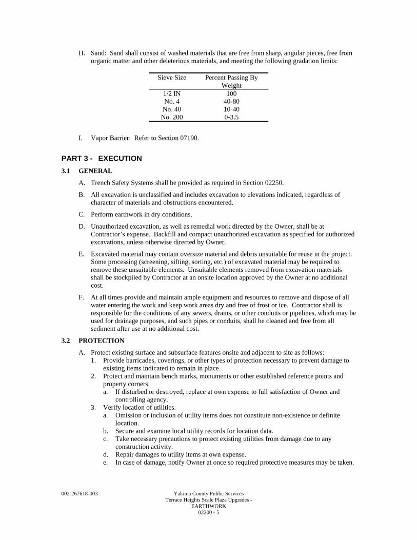
002-267618-003 Yakima County Public Services Terrace Heights Scale Plaza Upgrades - EARTHWORK 02200 - 5
H. Sand: Sand shall consist of washed materials that are free from sharp, angular pieces, free from organic matter and other deleterious materials, and meeting the following gradation limits:
Sieve Size Percent Passing By
Weight 1/2 IN No. 4
No. 40 No. 200
100 40-80 10-40 0-3.5
I. Vapor Barrier: Refer to Section 07190.
PART 3 - EXECUTION
3.1 GENERAL
A. Trench Safety Systems shall be provided as required in Section 02250.
B. All excavation is unclassified and includes excavation to elevations indicated, regardless of character of materials and obstructions encountered.
C. Perform earthwork in dry conditions.
D. Unauthorized excavation, as well as remedial work directed by the Owner, shall be at Contractor’s expense. Backfill and compact unauthorized excavation as specified for authorized excavations, unless otherwise directed by Owner.
E. Excavated material may contain oversize material and debris unsuitable for reuse in the project. Some processing (screening, sifting, sorting, etc.) of excavated material may be required to remove these unsuitable elements. Unsuitable elements removed from excavation materials shall be stockpiled by Contractor at an onsite location approved by the Owner at no additional cost.
F. At all times provide and maintain ample equipment and resources to remove and dispose of all water entering the work and keep work areas dry and free of frost or ice. Contractor shall is responsible for the conditions of any sewers, drains, or other conduits or pipelines, which may be used for drainage purposes, and such pipes or conduits, shall be cleaned and free from all sediment after use at no additional cost.
3.2 PROTECTION
A. Protect existing surface and subsurface features onsite and adjacent to site as follows: 1. Provide barricades, coverings, or other types of protection necessary to prevent damage to
existing items indicated to remain in place. 2. Protect and maintain bench marks, monuments or other established reference points and
property corners. a. If disturbed or destroyed, replace at own expense to full satisfaction of Owner and
controlling agency. 3. Verify location of utilities.
a. Omission or inclusion of utility items does not constitute non-existence or definite location.
b. Secure and examine local utility records for location data. c. Take necessary precautions to protect existing utilities from damage due to any
construction activity. d. Repair damages to utility items at own expense. e. In case of damage, notify Owner at once so required protective measures may be taken.
002-267618-003 Yakima County Public Services Terrace Heights Scale Plaza Upgrades - EARTHWORK 02200 - 6
4. Maintain free of damage, monitoring wells, landfill gas probes, and pavement, not indicated to be removed. a. Any item known or unknown or not properly located that is inadvertently damaged
shall be repaired to original condition. b. All repairs to be made and paid for by Contractor.
5. Provide full access to public and private premises, fire hydrants, street crossings, and other points as designated by Owner to prevent serious interruption of travel.
6. Maintain stockpiles and excavations in such a manner to prevent inconvenience or damage to structures onsite or on adjoining property.
7. Avoid surcharge or excavation procedures which can result in heaving, caving, or slides.
B. Dispose of refuse materials at the Terrace Heights Landfill per Section 01741 – Construction Waste Management. 1. Burning, as a means of waste disposal, is not permitted.
3.3 SITE EXCAVATION AND GRADING
A. The work includes all operations in connection with excavation, borrow, construction of fills and embankments, rough grading, and disposal of excess materials in connection with the preparation of the site(s) for construction of the proposed facilities.
B. The Contractor shall understand the character, quantity and distribution of all material to be excavated. Should the Contractor excavate below the designated lines and grades without prior written permission from the Owner, Contractor shall replace such excavation with suitable materials, in a satisfactory manner and condition, without additional cost to the Owner.
C. The Owner will have control over utilization of all excavated material and shall be the final authority in determining the suitability of excavated material to be used as embankment, backfill, or hauled to stockpile onsite as unsuitable material.
D. Conditions of excessive moisture will require that operations be temporarily suspended until drying weather permits use of the material or the materials are drained or aerated to optimum moisture content.
E. Excavation of Unsuitable Materials: In cases where unstable material such as mud, muck, or highly organic material is encountered within the limits of the Work, the Owner may direct the subgrade to be excavated below the grade shown on the Drawings and replaced with suitable material. Excavation and replacement with suitable materials shall only be performed where directed in writing by the Owner.
F. Excavation by drilling and blasting, or other similar techniques, will not be permitted.
G. Excavation and Grading: Perform as required by the Contract Drawings. 1. Contract Drawings indicate both existing grade and finished grade required for construction
of Project. a. Mark all structures, piping, and roads and establish their elevations. b. Perform other layout work required.
2. Protection of finish grade: a. During construction, shape and drain embankments and excavations. b. Maintain ditches and drains to provide drainage at all times. c. Protect graded areas against natural or man made disturbance when final grade has been
established. Repair of any damage to subgrade caused by Contractor’s construction operations shall be the responsibility of the Contractor. Such damage includes deforming, rutting, softening or otherwise destabilizing the subgrade caused by hauling vehicles or other operations, failure to maintain TESC measures, or failure to construct and maintain temporary drainage system features. Contractor shall repair damaged subgrade areas to the satisfaction of the Owner. Such repair may include removal and replacement of unstable material.
d. Embankment that is damaged or becomes unstable due to Contractor’s continued use of haul equipment shall be repaired at Contractor’s expense.
002-267618-003 Yakima County Public Services Terrace Heights Scale Plaza Upgrades - EARTHWORK 02200 - 7
e. Reestablish grade where settlement or erosion occurs by backfilling with compacted fill material.
H. Borrow: 1. Provide necessary amount of approved fill compacted to density equal to that indicated in
this Specification. 2. Include cost of all borrow material in original proposal. 3. Fill material to be approved by Owner prior to placement.
I. Construct embankments and fills as required by the Contract Drawings: 1. Construct embankments and fills at locations and to lines of grade indicated.
a. Completed fill shall correspond to shape of typical cross section or contour indicated regardless of method used to show shape, size, and extent of line and grade of completed work.
b. Construct fills and embankments at the locations and to the lines and grades indicated on the Drawings using Native Soil.
c. Compact in accordance with Section 2-03.3(14)C of the Standard Specifications, using Method C except that the minimum acceptable degree of compaction shall be not less than 95 percent of the given material’s laboratory maximum density as determined per ASTM D1557.
d. Grading shall produce uniform grades or slopes between spot elevations or contours shown on the Drawings. Blend graded areas into existing contours.
e. As directed by Owner, provide additional compaction or remove unsuitable subgrade materials and replace with Native Soil. Unsuitable Material shall be stockpiled within the landfill property.
f. Embankment shall be moisture conditioned and placed in maximum 8 IN loose lifts. Compact to the specified density with sheepsfoot, pneumatic rollers, vibrators, or by other equipment as required to obtain specified density. Within 2 FT of structures, compact by hand operated vibratory equipment. Thinner lifts may be required to achieve compaction requirements in these areas.
3.4 OVEREXCAVATION
A. Excavate and remove soil below finished subgrade elevations and grades where unsuitable conditions dictate in all areas required to complete the work as indicated on the Drawings.
B. Unless otherwise directed by the owner, backfill overexcavated areas with fill material places as Embankment.
3.5 STOCKPILE
A. Contractor may create temporary stockpile areas onsite within the Staging Area to facilitate Contractor's work sequence. Such temporary stockpiles shall not exceed 12 FT in height, with side slopes less than the safe angle of repose for the stockpiled soils (in no case greater that 1 horizontal to 1 vertical), and shall be protected from erosion using specified temporary erosion and sediment control measures specified in Section 02270. Locate temporary stockpile areas so as not to interfere or impede stormwater drainage.
3.6 UTILITY TRENCHING AND BACKFILLING
A. Perform trench excavation by open cut. In areas, which allow reuse of native material for backfill, temporarily stockpile material in an orderly manner a distance, at least the depth of the trench from the trench edge. Excess materials that will not be used for backfilling shall be hauled to onsite Owner-designated stockpile areas.
B. Comply with regulatory requirements for trench safety as specified in Section 02250.
C. Excavate the bottom of the trench to the lines and grades shown with allowance for pipe thickness and bedding. Minimum trench width shall be as shown on the Drawings.
D. Remove boulders and cobbles larger than 3 IN in maximum dimension from the trench bottom.
002-267618-003 Yakima County Public Services Terrace Heights Scale Plaza Upgrades - EARTHWORK 02200 - 8
E. Where in the opinion of the Owner, the undisturbed condition of the trench bottom is not adequate for support of the utility, stabilize the trench bottom as directed. Stabilization shall consist of removal and replacement of unsuitable material. Payment will not be made for inadequate foundation conditions that are caused by Contractor’s failure to provide adequate protection for trench foundations.
F. Place bedding on approved trench foundation to a depth shown on the Drawings. Place bedding before pipe or conduit is installed. Spread bedding so that the pipe is uniformly supported along the barrel. This includes digging for support of pipe bells. Do not use blocking to adjust the pipe to grade.
G. Compact bedding to specified density.
H. After pipe or conduit has been properly laid and inspected, place and compact bedding around pipe to spring line. Bring lifts up together on both sides of pipe or conduit and work the initial backfill under the haunches by means of a shovel, haunch tool, vibration, or other approved method.
I. Continue placing bedding to a depth over the pipe shown on the Drawing. Place in lifts not exceeding 8 IN loose depth. Compact with hand held vibratory compactors to the specified density.
J. Subsequent backfill shall be specified material. Place in a maximum of 8 IN loose lifts and compact to the specified density. Use hand held vibratory compactors for depths less than 2 FT clear over the pipe.
3.7 CRUSHED SURFACING
A. Crushed Surfacing shall be placed and compacted in accordance with Standard Specifications Sections 4-04.3(4) through 4-04.3(9).
B. Grade and proof-roll existing surfaces such as areas to be paved. Grade as shown on the Drawings. Proof rolling shall be accomplished by driving a fully loaded dump truck (10 CY minimum) or a smooth-wheeled roller over the surface. Unstable areas shall be repaired as directed by the Owner. Repair may include additional compaction effort or removal and replacement of material.
3.8 QUARRY SPALLS
A. In areas to receive quarry spalls complete subgrade to elevations and grades shown on the Drawings.
B. Place specified quarry spalls in a single 12 IN lift.
C. Place in such a manner that all relatively large stones are essentially in contact with each other and voids are filled with the finer materials to provide a well graded compact mass. The finished surface shall be free from irregularities.
D. Place on slopes in a manner that will ensure the placed materials attain its specified thickness in one operation.
E. Care shall be used to avoid damaging the underlying material.
F. Placement on slopes shall start at the bottom of the slope and work toward the top. Do not place at the top of the slope and allow to roll down the surface. Placement in ditches shall be started from the bottom of the ditch, and work towards edges.
002-267618-003 Yakima County Public Services Terrace Heights Scale Plaza Upgrades - EARTHWORK 02200 - 9
G. Quarry spalls shall not be dropped on geotextile from a height greater than one (1) FT, unless approved by the Owner. If approved, the Contractor must provide a cushioning layer of sand on top of the geotextile before dumping of stone. The Contractor shall demonstrate to the satisfaction of the Owner that the proposed combination of drop height and sand cushion layer thickness will prevent puncture or damage to the geotextile. No measurement or separate payment shall be made for a sand cushion layer placed for the purpose of allowing an increased drop height of stones.
H. Geotextile damaged during placement of quarry spalls shall be repaired at the Contractor’s expense.
3.9 DISPOSAL OF EXCESS SOIL AND WASTE MATERIALS
A. All excess soil and waste earthwork material shall be disposed of onsite at Owner-approved onsite stockpile locations.
3.10 USE OF EXPLOSIVES
A. Blasting with any type of explosive is prohibited.
3.11 FIELD QUALITY CONTROL
A. Contractor shall have ultimate responsibility for quality control of the work, including quality control at the source of imported materials, to insure that the materials comply with the gradations and material specifications described hereinafter and that placement and compaction comply with all requirements. Contractor shall employ a qualified testing and inspection service to provide the necessary quality control testing at the source, and, at Contractor's option, in the field. All tests shall be by the most recent standards and methods for the designated tests. Contractor shall maintain and submit accurate records of all source and field quality control testing.
B. Owner will perform soils testing and inspection service during earthwork operations. 1. Such testing will be the primary source of information for Owner's verification that
Contractor is meeting all design requirements. Allow Owner to sample materials for gradation and density tests and perform field tests of placed materials.
2. Allow sufficient reasonable time in work schedule for results of Contractor's and Owner's testing services to be reported before proceeding on with subsequent work.
3. Give advance notice of at least one working day to the Owner when ready for compaction or subgrade testing and inspection.
C. Moisture density relationships, to be established by the Owner required for all materials to be compacted.
D. Extent of compaction testing will be as necessary to assure compliance with Specifications and in accordance with standard Geotechnical practice.
E. Give minimum of 24 HR advance notice to Owner when ready for compaction or subgrade testing and inspection.
F. Should any compaction density test or subgrade inspection fail to meet Specification requirements, perform corrective work as necessary.
3.12 COMPACTION DENSITY REQUIREMENTS
A. Obtain approval from Owner with regard to compaction suitability of soils and acceptable subgrade prior to subsequent operations.
B. Provide dewatering system necessary to successfully complete compaction and construction requirements.
C. Remove loose, wet, or soft material and replace with approved material as directed by Owner.
D. Stabilize subgrade with well graded granular materials as directed by Owner.
002-267618-003 Yakima County Public Services Terrace Heights Scale Plaza Upgrades - EARTHWORK 02200 - 10
E. Earthwork material compaction shall meet the following criteria. All compaction densities are based on maximum density as determined by ASTM D1557 (Modified Proctor). 1. Subgrade and overexcavation areas: Proof-roll all areas; recompact as directed by the
Owner to 90 percent minimum compaction. 2. Backfill of overexcavation areas: 95 percent for the full depth of the backfill. 3. Embankment using Native Soil, borrow, or fill: 95 percent. 4. Gravel Backfill: 95 percent within 5 FT of structures and foundations and 92 percent closer
than 5 FT to avoid damage by heavy equipment loading. 5. Crushed Surfacing: 95 percent. 6. Utility Trench and Vault Bedding and Backfill: 95 percent.
3.13 SAND
A. Place as required for under slabs as vapor retardant.
3.14 EXCAVATION, FILLING, AND BACKFILLING FOR STRUCTURES
A. General: 1. In general, work includes, but is not necessarily limited to, excavation for structures,
removal of underground obstructions and undesirable material, backfilling, filling, and fill, backfill, and subgrade compaction.
2. Obtain fill and backfill material necessary to produce grades required. a. Materials and source to be approved by Owner. b. Native Fill material approved by Owner may also be used for fill and backfill.
3. In this Section, the word "foundations" includes footings, base slabs, foundation walls, mat foundations, grade beams, and any other support placed directly on soil.
4. In the paragraphs of this Section, the word "soil" also includes any type of rock subgrade that may be present at or below existing subgrade levels.
B. Excavation Requirements for Structures: 1. General:
a. Do not commence excavation for foundations for structures until Owner approves: 1) Density and moisture content of site area compacted fill material meets
requirements of Specifications. b. Owner grants approval to begin excavations.
2. Dimensions: a. Excavate to elevations and dimensions indicated or specified. b. Allow additional space as required for construction operations and inspection of
foundations. 3. Removal of obstructions and undesirable materials in excavation includes, but is not
necessarily limited to, removal of old foundations, existing construction, unsuitable subgrade soils, expansive type soils, and any other materials which may be concealed beneath present grade, as required to execute work indicated on Contract Drawings. a. If undesirable material and obstructions are encountered during excavation, remove
material and replace as directed by Owner. 4. Level off bottoms of excavations to receive foundations, floor slabs, equipment support
pads, or compacted fill. a. Remove loose materials and bring excavations into approved condition to receive
concrete or fill material. b. Where compacted fill material must be placed to bring subgrade elevation up to
underside of construction, scarify existing subgrade upon which fill material is to be placed to a depth of 6 IN and then compact to density stated in this Specification Section before fill material can be placed thereon.
c. Do not carry excavations lower than shown for foundations except as directed by Owner.
002-267618-003 Yakima County Public Services Terrace Heights Scale Plaza Upgrades - EARTHWORK 02200 - 11
d. If any part of excavations is carried below required depth without authorization, maintain excavation and start foundation from excavated level with concrete of same strength as required for superimposed foundation, and no extra compensation will be made to Contractor therefore.
5. Make excavations large enough for working space, forms, dampproofing, waterproofing, and inspection.
6. Notify Owner as soon as excavation is completed in order that subgrades may be inspected. a. Do not commence further construction until subgrade under compacted fill material,
under foundations, under floor slabs-on-grade, under equipment support pads, and under retaining wall footings has been inspected and approved by the Owner as being free of undesirable material, being of compaction density required by this specification, and being capable of supporting the allowable foundation design bearing pressures and superimposed foundation, fill, and building loads to be placed thereon.
b. Owner shall be given the opportunity to inspect subgrade below fill material both prior to and after subgrade compaction.
c. Place fill material, foundations, floor slabs-on-grade, and equipment support pads as soon as weather conditions permit after excavation is completed, inspected, and approved and after forms and reinforcing are inspected and approved.
d. Before concrete or fill material is placed, protect approved subgrade from becoming loose, frozen, or soft due to weather, construction operations, or other reasons.
7. Subgrade stabilization: a. If subgrade under foundations, fill material, floor slabs-on-grade, or equipment support
pads is in a loose, wet, or soft condition before construction is placed thereon, remove loose, wet, or soft material and replace with approved compacted material as directed by Owner.
b. Provide compaction density of replacement material as stated in this Specification Section.
c. Loose, wet, or soft materials, when approved by Owner, may be stabilized by a compacted working mat of well graded crushed stone.
d. Compact stone mat thoroughly into subgrade to avoid future migration of fines into the stone voids.
e. Remove and replace frozen materials as directed by Owner. f. Method of stabilization shall be performed as directed by Owner. g. Do not place further construction on the repaired subgrades, until the subgrades have
been approved by the Owner. 8. Do not place floor slabs-on-grade including equipment support pads until subgrade below
has been approved, piping has been tested and approved, reinforcement placement has been approved, and Contractor receives approval to commence slab construction. a. Do not place building floor slabs-on-grade including equipment support pads when
temperature of air surrounding the slab and pads is or is expected to be below 40 DegF before structure is completed and heated to a temperature of at least 50 DegF.
9. Protection of structures: a. Prevent new and existing structures from becoming damaged due to construction
operations or other reasons. b. Prevent subgrade under new and existing foundations from becoming wet and
undermined during construction due to presence of surface or subsurface water or due to construction operations.
10. Shoring: a. Shore, sheet pile, slope, or brace excavations as required to prevent them from
collapsing. b. Remove shoring as backfilling progresses but only when banks are stable and safe from
caving or collapse. 11. Drainage:
a. Control grading around structures so that ground is pitched to prevent water from running into excavated areas or damaging structures.
002-267618-003 Yakima County Public Services Terrace Heights Scale Plaza Upgrades - EARTHWORK 02200 - 12
b. Maintain excavations where foundations, floor slabs, equipment support pads or fill material are to be placed free of water.
c. Provide pumping to keep excavated spaces clear of water during construction. d. Should any water be encountered in the excavation, notify Owner. e. Provide free discharge of water by trenches, pumps, wells, well points, or other means
as necessary and drain to point of disposal that will not damage existing or new construction or interfere with construction operations.
12. Frost protection: a. Do not place foundations, slabs-on-grade, equipment support pads, or fill material on
frozen ground. b. When freezing temperatures may be expected, do not excavate to full depth indicated,
unless foundations, floor slabs, equipment support pads, or fill material can be placed immediately after excavation has been completed and approved.
c. Protect excavation from frost if placing of concrete or fill is delayed. d. Where a concrete slab is a base slab-on-grade located under and within a structure that
will not be heated, protect subgrade under the slab from becoming frozen until final acceptance of the Project by the Owner.
e. Protect subgrade under foundations of a structure from becoming frozen until structure is completed and heated to a temperature of at least 50 DegF.
C. Fill and Backfill Inside of Structure and Below Foundations, Base Slabs, Floor Slabs, Equipment Support Pads and Piping: 1. General:
a. Subgrade to receive fill or backfill shall be free of undesirable material as determined by Owner and scarified to a depth of 6 IN and compacted to density specified herein.
b. Surface may be stepped by at not more than 12 IN per step or may be sloped at not more than 2 percent.
c. Do not place any fill or backfill material until subgrade under fill or backfill has been inspected and approved by Owner as being free of undesirable material and compacted to specified density.
2. Obtain approval of fill and backfill material and source from Owner prior to placing the material.
3. Granular fill under floor slabs-on-grade: Place all floor slabs-on-grade on a minimum of 6 IN of granular fill unless otherwise indicated.
4. Vapor barrier: Install a continuous vapor barrier under floor slabs-on-grade as required by Section 07190 and shown on Contract Drawings.
5. Fill and backfill placement: a. Prior to placing fill and backfill material, optimum moisture and maximum density
properties for proposed material shall be obtained from Owner. b. Place fill and backfill material in thin lifts as necessary to obtain required compaction
density. c. Compact material by means of equipment of sufficient size and proper type to obtain
specified density. d. Use hand operated equipment for filling and backfilling next to walls. e. Do not place fill and backfill when the temperature is less than 35 DegF and when
subgrade to receive fill and backfill material is frozen, wet, loose, or soft. f. Use vibratory equipment to compact granular material; do not use water.
6. Where fill material is required below foundations, place fill material, conforming to the required density and moisture content, outside the exterior limits of foundations located around perimeter of structure the following horizontal distance whichever is greater: a. As required to provide fill material to indicated finished grade. b. 5 FT. c. Distance equal to depth of compacted fill below bottom of foundations. d. As directed by Owner.
002-267618-003 Yakima County Public Services Terrace Heights Scale Plaza Upgrades - EARTHWORK 02200 - 13
D. Filling and Backfilling Outside of Structures: 1. This paragraph of this Specification applies to fill and backfill placed outside of structures
above bottom level of both foundations and piping but not under paving. 2. Provide material as approved by Owner for filling and backfilling outside of structures. 3. Fill and backfill placement:
a. Prior to placing fill and backfill material, obtain optimum moisture and maximum density properties for proposed material from Owner.
b. Place fill and backfill material in thin lifts as necessary to obtain required compaction density.
c. Compact material with equipment of proper type and size to obtain density specified. d. Use only hand operated equipment for filling and backfilling next to walls and retaining
walls. e. Do not place fill or backfill material when temperature is less than 40 DegF and when
subgrade to receive material is frozen, wet, loose, or soft. f. Use vibratory equipment for compacting granular material; do not use water.
4. Backfilling against walls: a. Do not backfill around any part of structures until each part has reached specified 28-
day compressive strength and backfill material has been approved. b. Do not start backfilling until concrete forms have been removed, trash removed from
excavations, pointing of masonry work, concrete finishing, dampproofing and waterproofing have been completed.
c. Do not place fills against walls until floor slabs at top, bottom, and at intermediate levels of walls are in place and have reached 28-day required compressive strength to prevent wall movement.
d. Bring backfill and fill up uniformly around the structures and individual walls, piers, or columns.
E. Backfilling Outside of Structures under Piping or Paving: 1. When backfilling outside of structures requires placing backfill material under piping or
paving, the material shall be placed from bottom of excavation to underside of piping or paving at the density required for fill under piping or paving as indicated in this Section.
2. This compacted material shall extend transversely to the centerline of piping or paving a horizontal distance each side of the exterior edges of piping or paving equal to the depth of backfill measured from bottom of excavation to underside of piping or paving.
3. Provide special compacted bedding or compacted subgrade material under piping or paving as required by other sections of these Specifications.
END OF SECTION

002-267618-003 Yakima County Public Services Terrace Heights Scale Plaza Upgrades - EARTHWORK 02200 - 14
002-267618-003 Yakima County Public Services Terrace Heights Scale Plaza Upgrades - EXCAVATION SUPPORT AND PROTECTION 02250 - 1
SECTION 02250
EXCAVATION SUPPORT AND PROTECTION
PART 1 - GENERAL
1.1 SUMMARY
A. Section includes but is not limited to: 1. Furnishing, placing, maintaining and, except as otherwise shown or specified, the removal
of shoring necessary to protect the Construction, existing improvements and to provide safe working conditions in excavations in accordance with applicable local, state, and federal safety codes.
B. Related Sections; coordinate related work specified in other parts of the Contract Documents, including but not limited to the following: 1. Section 02200 – Earthwork. 2. Section 02423 – Storm Drainage System. 3. Section 02530 – Sanitary/Industrial Sewer Systems.
1.2 REFERENCES
A. Chapter 39.04.180 RCW (Revised Code of Washington), Trench Excavations - Safety Systems Required.
B. Chapter 49.17 RCW, Washington Industrial Safety and Health Act (WISHA).
C. Chapter 296-155 WAC (Washington Administrative Code), Safety Standards for Construction Work.
D. Section 4.9.2 in the Terrace Heights Geotechnical Report available for review at 7151 Roza Hill Drive, Yakima, WA.
1.3 SYSTEM REQUIREMENTS
A. All cribbing, sheeting, and shoring shall be designed by a State of Washington Licensed Professional Engineer and meet the requirements of Chapter 296-155 WAC.
B. The sheeting and shoring for trench work shall be in strict conformance with Section 7-08.3(1)B of the Standard Specifications. The Contractor is responsible for meeting all of the appropriate federal, state and local restrictions when operating in the trench or other onsite excavation.
1.4 SUBMITTALS
A. General: Submit in accordance with the Conditions of Contract and Section 01340.
B. A shoring plan for each location where shoring is required.
PART 2 - PRODUCTS- (NOT APPLICABLE TO THIS SECTION)
PART 3 - EXECUTION
3.1 GENERAL
A. All trenches and excavations shall safely lay back in accordance with the recommendations in the Terrace Heights Geotechnical Report and/or shored in compliance with applicable Federal and State regulations. Shoring shall be required to protect existing foundations. Providing sheeting, shoring, cribbing, cofferdams, and all aspects involved therein shall be the sole responsibility of the Contractor.
002-267618-003 Yakima County Public Services Terrace Heights Scale Plaza Upgrades - EXCAVATION SUPPORT AND PROTECTION 02250 - 2
B. Trench/excavation protection shall comply with the requirements of Section 2-09 of the Standard Specifications, Chapter 49.17 RCW of the Washington Industrial Safety and Health Act, and Part N - Excavation, Trenching, and Shoring of Chapter 296-155 WAC.
C. Install and maintain sheeting, shoring, cribbing, cofferdams, and sloping necessary to support the sides of any excavation to prevent any movement that may damage adjacent facilities, delay the work, or endanger life and health.
D. The method of shoring shall be according to the Contractor's design. The design, planning, installation and removal, if required, of sheeting and bracing shall be accomplished in such a manner as to maintain the required excavation or trench section and to maintain the undisturbed state of soils below and adjacent to the excavation.
E. Use any combination of shoring and over-excavation, tunneling, boring, sliding trench shield, or other method allowed by the applicable local, state, and federal safety codes. Submit an excavation/shoring plan for each location where shoring or over-excavation is required.
F. Damages resulting from improper support or from failure to support excavations shall be the sole responsibility of the Contractor.
G. In trenching operations, the use of horizontal strutting below the barrel of pipe or the use of pipe as support for trench bracing will not be permitted.
H. Sheet piling and timbers in trench excavations shall be withdrawn in a manner so as to prevent subsequent settlement of the pipe or additional backfill loading that might overload the pipe.
I. That portion of cribbing or sheeting extending below the springline of pipe, shall be left in place unless satisfactory means of reconsolidating bedding or side support, disturbed by cribbing or sheeting removal, can be demonstrated.
J. If a movable box is used in lieu of cribbing or sheeting, and the bottom cannot be kept above the springline of the pipe, the bedding or side support shall be carefully reconsolidated behind the movable box prior to placing initial backfill.
K. When the construction sequence of structures requires the transfer of bracing to the completed portions of any structure, the Contractor shall secure written approval of the Engineer prior to the installation of such bracing.
L. Where removal of sheeting would result in damage to adjacent utilities or other property, the Engineer may order all or a portion of sheeting to be cut off and left in place.
M. Do not use the pipe or vault as support for trench bracing.
N. Damages resulting from improper shoring and failure to shore shall be the sole responsibility of the Contractor.
3.2 STABILITY OF EXCAVATIONS
A. Comply with all codes, ordinances, and requirements of agencies having jurisdiction.
B. The requirements of the Occupational Safety and Health Act and WISHA shall apply to all excavation, trenching, and ditching operations on this project. All trenches over 4 FT in depth shall be shored or laid back in compliance with the applicable Federal and State regulations.
C. Side slopes of temporary excavations shall comply with the Geotechnical Report recommendations and all codes, ordinances and authorities having jurisdiction. Shore and brace where sloping is not possible because of space restrictions or stability of material excavated. Maintain sides and slopes of excavations in a safe condition until completion of backfilling.
D. Shoring and Bracing: Provide materials for shoring and bracing in good, serviceable condition. Maintain shoring and bracing in excavations regardless of time period excavations will be open. Extend shoring and bracing as excavation progresses.
END OF SECTION
002-267618-003 Yakima County Public Services Terrace Heights Scale Plaza Upgrades - SOIL EROSION AND SEDIMENT CONTROL 02270 - 1
SECTION 02270
SOIL EROSION AND SEDIMENT CONTROL
PART 1 - GENERAL
1.1 SUMMARY
A. Section includes providing, installing, operating, maintaining and removing the Temporary Erosion and Sediment Control (TESC) system. Section includes but is not limited to the following: 1. Construction Limits survey and flagging. 2. Construction Limits fencing. 3. Orange safety fence. 4. Temporary silt fence. 5. Temporary mulch covers. 6. Temporary plastic cover measures. 7. Dust control measures.
B. Related Sections include but are not necessarily limited to: 1. Section 02200 – Earthwork. 2. Section 02423 – Storm Drainage System.
1.2 QUALITY ASSURANCE
A. Referenced Standards: 1. Stormwater Management Manual for Eastern Washington, Washington State Department of
Ecology, September 2004 (Ecology Manual).
B. Comply with the requirements specified herein and applicable Federal and State, and County permits, licenses, and authorizations including but not limited to: 1. Chapter 7 of the Ecology Manual. 2. International Building Code, latest edition.
1.3 SUBMITTALS
A. General: Submit the following in accordance with Conditions of Contract and Section 01340 - Submittals.
B. Manufacturer’s catalog and product data for temporary silt fencing, orange safety fence, and temporary plastic covers prior to using on site.
C. Submit construction Stormwater Pollution Prevention Plan (SWPPP) in accordance to the Ecology Manual for approval within ten (10) days after the Notice to Proceed, including all BMP sizing calculations. The SWPPP shall demonstrate consideration of all twelve (12) elements outlined in the Ecology Manual, including: 1. Marking clearing limits. 2. Establishing construction access. 3. Installing sediment controls. 4. Protecting drain inlets. 5. Stabilizing channels and outlets. 6. Controlling pollutants. 7. Controlling dewatering. 8. Maintaining BMPs. 9. Managing the project.
002-267618-003 Yakima County Public Services Terrace Heights Scale Plaza Upgrades - SOIL EROSION AND SEDIMENT CONTROL 02270 - 2
D. Submit a project specific Spill Prevention Control and Countermeasure (SPCC) Plan to be used for the duration of the project. The plan shall be submitted to the Owner prior to the commencement of any on site construction activities. The Contractor shall maintain a copy of the plan at the Work site, including any required updates as the Work progresses. 1. The SPCC plan shall be prepared per the requirements of Section 1-07.15(1) of the Standard
Specifications.
E. Submit detailed TESC plan within 10 days from the Notice to Proceed.
1.4 PROJECT CONDITIONS
A. Contractor shall be solely responsible for the TESC system, including maintenance, achieving the performance requirements, and removal and disposal of TESC measures at project completion.
B. The TESC measures are the minimum requirements for anticipated site condition. During the construction period, the TESC system shall be maintained and upgraded if required to reduce erosion and sedimentation.
C. The use of temporary covers will be a key measure to controlling erosion. Optional cover systems include temporary plastic cover, and temporary mulch cover. Contractor shall select appropriate cover system for conditions and notify Owner for approval.
PART 2 - PRODUCTS
2.1 TEMPORARY SILT FENCE
A. Filter fabric fence shall meet the requirements of Section 9-33.2(1) of the Standard Specifications.
B. Posts: 2 by 2 IN wood posts, standard or better; or steel fence posts.
C. Backfill with Native Soil per Section 02200 – Earthwork.
2.2 PLASTIC SHEETING
A. Plastic sheeting shall be minimum 6-mil thick, polyethylene film meeting the requirements of the UBS Voluntary Product Standard, PS 17-69.
2.3 MULCH
A. The Contractor shall obtain mulch from the on site chipped yard waste stockpile. Coordinate with the Owner a minimum of two (2) days in advance for removal of material from this stockpile.
2.4 ORANGE SAFETY FENCE
A. Fence material shall be composed of high-density polyethylene material with a tensile strength of 360 LBS/FT using ASTM D4595 testing method.
B. The fence color shall be high visibility orange.
C. Posts shall be 2 by 2 IN wood posts, standard or better, or metal fence posts.
PART 3 - EXECUTION
3.1 GENERAL
A. Marking construction limit: Install Construction Limits flagging or pavement markings along the construction limit. Maintain for the duration of the construction and re-establish when disturbed.
B. Install sediment controls: Prior to releasing the runoff shall pass through appropriate BMPs such as silt fence.
002-267618-003 Yakima County Public Services Terrace Heights Scale Plaza Upgrades - SOIL EROSION AND SEDIMENT CONTROL 02270 - 3
C. Stabilize exposed soil with Temporary Cover Measures. The Contractor shall stabilize exposed areas and temporary soil stockpiles.
D. Exposed and unworked soil shall be temporarily and permanently stabilized as soon as practicable within 30 days during dry season (April 1 through October 31) and 15 days during the wet season (November 1 through March 31). Contractor shall initiate soil stabilization measures on inactive area and soil stockpiles as soon as practicable but in no case more than 10 days after the construction activity has temporarily or permanently ceased. Upon determining a risk of erosion, immediately apply Temporary Cover Measures regardless of any previous established deadline. Temporary Cover Measures shall include, but are not limited to, plastic covering, or mulch covering. Review the type of Temporary Cover Measure to be employed with the Owner, who shall have the right to select the type to be employed.
E. Direct discharges from dewatering devices to the existing onsite stormwater retention pond following approval by the Owner.
F. Inspect the erosion and sedimentation control facilities weekly or after a runoff-producing storm event. Maintain as necessary to ensure their continued functioning.
G. Remove and dispose of accumulated sediment at TESC facilities at the completion of the erosion control period. Material may be disposed of in an onsite stockpile location directed by the owner.
H. Disturbed soil resulting from removal of BMPs or vegetation shall be permanently stabilized.
3.2 DURING CONSTRUCTION PERIOD
A. Do not disturb existing vegetation to remain (grass and trees).
B. Storm drain inlets operable during construction shall be protected so that stormwater runoff does not enter the conveyance system without first being filtered or treated to remove sediment.
C. All pollutants, including waste materials and demolition debris, that occur onsite shall be handled and disposed of in a manner that does not cause contamination of stormwater in accordance with all applicable local, State, and Federal laws. 1. Cover, containment, and protection from vandalism shall be provided for all chemicals,
liquid products, petroleum products, and non-inert wastes present at the site. 2. Contaminated surfaces shall be cleaned immediately following any discharge or spill
incident. Emergency repairs of any heavy equipment or vehicles may be performed onsite using temporary plastic sheeting placed beneath, and if raining, over the heavy equipment or vehicle.
3.3 ORANGE SAFETY FENCING
A. Install orange safety fencing to define the construction limits and staging area. Fencing shall be at least four feet in height. Posts for the fencing shall be steel or wood and placed every 6 FT OC maximum or as needed to ensure rigidity. The fencing shall be fastened to the post every 6 IN with a polyethylene tie. On long continuous lengths of fence, a tension wire or rope shall be used as a top stringer to prevent sagging between posts.
3.4 TEMPORARY SILT FENCE
A. Install temporary silt fences as indicated on the Contract Drawings.
B. Purchase filter fabric in continuous roll cut to the length of the barrier to avoid use of joints. When joints are necessary, splice filter fabric together only at a support post, with a minimum 6 IN overlap, and both ends securely fastened to the fence post.
C. Install temporary silt fence to follow ground contours perpendicular to surface water runoff, where feasible, except at ends where the fence shall be turned uphill such that the silt fence prevents runoff from flowing around the ends of the fence. Space fence posts a maximum of 6 FT apart and drive securely into the ground a minimum of 30 IN.
002-267618-003 Yakima County Public Services Terrace Heights Scale Plaza Upgrades - SOIL EROSION AND SEDIMENT CONTROL 02270 - 4
D. Excavate a trench, approximately 8 IN wide and 12 IN deep, upslope and adjacent to the fence post to allow the filter fabric to be buried. Side casting of spoils on the downhill side will not be allowed.
E. Inspect immediately after each rainfall and at least daily during prolonged rainfall. Make any required repairs immediately.
F. Accumulated sediment shall be removed or stabilized on site.
G. Upon completion of project or when directed by the Owner, remove and dispose of filter fabric fences.
3.5 MULCH
A. Use mulch to control erosion as directed by the Owner. The mulch shall be spread a minimum of 2 IN thick, 4 IN thick during wet season construction (November 1 through March 31). Hand methods may be used to place the mulch.
B. Use only on areas that require cover measures for less than 30 days.
3.6 PLASTIC COVER
A. Use plastic sheeting to control erosion as directed by the Owner. Covering shall be installed and maintained tightly in place by using sandbags or tires on ropes with a maximum 10 FT grid spacing in all directions.
B. All seams shall be taped or weighted down full length and have at least a 2 FT overlap.
C. Check regularly for rips and places where the plastic may be dislodged. Maintain contact between the plastic and the ground. Air bubbles should be removed immediately to prevent ripping during winds.
D. Re-anchor and replace plastic as necessary.
3.7 DUST CONTROL
A. Execute work by methods to minimize raising dust from construction operations.
B. Minimize the period of soil exposure by implementing temporary cover measures.
C. Provide positive means to prevent air-borne dust, both on and off the site.
D. Utilize watering trucks, when directed by the Owner, to dampen dry soil materials to control dust.
E. Spray exposed soil areas with a dust palliative. Do not use oil-based sprays or calcium-based spreads for dust control.
F. Eliminate off-site tracking of dirt, mud and sediments. Use vacuum street sweepers with dust suppressants daily to remove dirt and foreign objects from the road unless directed otherwise by the owner.
G. Dust control shall continue, if necessary, until such time as the areas have been restored.
H. The Contractor shall comply with the requirements of the Terrace Heights Landfill Title V Permit dust control requirements, attached as Appendix A.
END OF SECTION
002-267618-003 Yakima County Public Services Terrace Heights Scale Plaza Upgrades - STORM DRAINAGE SYSTEM 02423 - 1
SECTION 02423
STORM DRAINAGE SYSTEM
PART 1 - GENERAL
1.1 SUMMARY
A. Section Includes: 1. Storm drainage systems. 2. Storm drainage pipe. 3. Outlets.
B. Related Sections include but are not necessarily limited to: 1. Section 02200 – Earthwork. 2. Section 02270 – Soil Erosion and Sediment Control.
1.2 QUALITY ASSURANCE
A. Referenced Standards: 1. Washington State Department of Transportation (WSDOT) Standard Specification 2016
(Standard Specifications).
1.3 SUBMITTALS
A. General 1. See Section 01340 for requirements for the mechanics and administration of the submittal
process.
B. Approval Submittals: 1. Layout Drawings in a scale of 1 IN = 20 FT. 2. Product technical data including:
a. Acknowledgement that products submitted meet requirements of standards referenced. 3. Catch Basin. 4. Certifications. 5. Test reports. 6. Submit all tests and certification in a single coordinated submittal. Partial submittals will
not be accepted.
1.4 SEQUENCING AND SCHEDULING
A. Coordinate with grading plan and other utility work.
PART 2 - PRODUCTS
2.1 MATERIALS
A. Culvert: 1. High Density Polyethylene Pipe (HDPE) Pipe shall be per Standard Specifications Section
9-05.23.
B. Rock-Lined Outlets: 1. Quarry spalls supplied for ditch construction shall conform to Section 02200 - Earthwork. 2. Geotextile supplied for ditch construction shall conform to Section 02200 - Earthwork.
C. Catch Basin per Yakima County Public Services Standard Plan D-1 and Standard Specifications Section 7-05 except as modified by the Contract Documents. 1. Catch Basin shall be precast concrete sections with either a cast in place base, or a precast
base made from minimum 4,000 PSI structural concrete.
002-267618-003 Yakima County Public Services Terrace Heights Scale Plaza Upgrades - STORM DRAINAGE SYSTEM 02423 - 2
2. Frame and cover shall be ductile iron, and H-20 rated. a. Rectangular Frame shall be per WSDOT Standard Plan B-30.10-01. b. Rectangular Grate shall be per WSDOT Standard Plan B-30-50-01. c. Castings shall be free of porosity, shrink cavities, cold shuts or cracks, or any surface
defects which would impair serviceability. d. Repair of defects by welding, or by the use of “smooth-on” or similar material, will not
be permitted. Frames and covers shall be machine finished or ground on seating surfaces so as to assure non-rocking fit in any position and interchangeability of covers.
e. Cast iron shall conform to ASTM Designation A48 Class 30 and ductile iron to ASTM Designation A526 Grade 80-55-06. Strength requirements for Federal Specification RR-F-621D apply.
f. Block lettering “DRAIN” in 1/2 IN letters shall be cast into the top surfaces of grates. g. Grate shall be secured with five-eighths (5/8) IN Stainless Steel Socket Head Cap
Screws.
PART 3 - EXECUTION
3.1 CULVERT INSTALLATION
A. Install products in accordance with manufacturer's instructions.
B. Install culvert per Standard Specifications Sections 7-02 and 7-08, except as modified by these Contract Documents.
C. Culvert shall employ outlet protection. 1. Outlet protection shall be composed of a minimum one foot thick quarry spalls protection,
underlain with geotextile. The horizontal dimension of the protections shall be at least 2.5 times the culvert diameter and extend to the bottom of a ditch, 3 FT beyond the culvert outlet.
3.2 CATCH BASIN
A. Install in accordance with Standard Specifications Section 7-05.
B. The catch basin grating shall not be grouted to final grade until the final elevation of the concrete in which it is to be placed has been established, and until permission thereafter is given by the Owner to grout the cover or grating in place.
3.3 FIELD QUALITY CONTROL
A. Verify and coordinate installation.
B. Clean pipe interior of dirt and other superfluous material as work progresses.
C. Maintain swab or drag in piping and pull past each joint as it is completed.
D. Place plugs in ends of uncompleted pipe at end of day or whenever work stops.
E. In case of conflict, do not relocate piping without prior approval from the Owner.
3.4 CLEANING
A. At completion of work, clean and remove silt and debris from permanent surface water facilities, including ditches, check dams, and pipes.
END OF SECTION
002-267618-003 Yakima County Public Services Terrace Heights Scale Plaza Upgrades - WATER DISTRIBUTION SYSTEMS 02510 - 1
SECTION 02510
WATER DISTRIBUTION SYSTEMS
PART 1 - GENERAL
1.1 SUMMARY
A. Section Includes: 1. Coordination and interface with existing facilities and utilities. 2. Water distribution piping. 3. Fittings. 4. Testing, flushing and disinfection.
B. Related Sections include but are not necessarily limited to: 1. Section 02200 – Earthwork. 2. Section 02250 – Excavation Support and Protection. 3. Section 15060 - Pipe and Pipe Fittings: Basic Requirements. 4. Section 15100 - Valves: Basic Requirements. 5. Section 15101 - Gate Valves.
1.2 QUALITY ASSURANCE
A. Referenced Standards: 1. Washington State Standard Specifications for Road, Bridge and Municipal Construction,
2016 (Standard Specifications). 2. Yakima County Public Services Water Standard Details and Special Provisions. 3. American Water Work Association (AWWA):
a. B300, Standard for Hypochlorites. b. B301, Standard for Liquid Chlorine. c. C651, Standard for Disinfecting Water Lines.
B. Environmental Compliance: Comply with applicable portions of local environmental agency regulations pertaining to water distribution systems, including Yakima County Health District.
C. All work shall be in accordance with Sections 7-09 Pipe and Fittings for Water Mains; 7-09 Water Mains; 7-12 Valves for Water Mains; 7-14 Hydrants; and 7-15 Service Connections of the Standard Specifications except as modified herein.
D. Contractor shall coordinate with the Owner for all necessary inspections and approval of the portion of the completed system that involves piping larger than 3 IN DIA.
1.3 SUBMITTALS
A. Submit results of the leakage tests, identifying the specific length of pipe tested, the test pressure, the duration of test and the amount of leakage.
B. Submit satisfactory bacteriological test reports on disinfection requirements.
C. Submit Certification of Washington State Health Department approved laboratory for water system purity tests to be used for demonstration on acceptable disinfection processes.
PART 2 - PRODUCTS
2.1 MATERIALS
A. Pipe: Refer to Section 15060, Section 15062, and Section 15064.
B. In-Line Valves: 1. Refer to Section 15100, Section 15101, Section 15104, and Section 15106. 2. Provide adjustable valve boxes. Include price of valve boxes in price of PVC piping.
002-267618-003 Yakima County Public Services Terrace Heights Scale Plaza Upgrades - WATER DISTRIBUTION SYSTEMS 02510 - 2
PART 3 - EXECUTION
3.1 INSTALLATION
A. Install water lines per the Contract Drawings.
B. Field Verify Depth of Utilities that will be Crossed: 1. Adjust water line elevations as required during construction. 2. No separate payment will be made for field verification or adjustment of main depths as
required.
C. Contractor will restore all existing structures or services damaged by Contractor's operations at no cost to Owner.
3.2 INTERRUPTION OF SERVICE
A. Interruption of service to the Owner shall not exceed two (2) HRS without providing temporary toilet facilities at the existing scalehouse. Notify property owners of interruption a minimum of two (2) working days in advance.
3.3 UNDERGROUND SERVICES
A. Notify Utility Representative and the Owner prior to construction to obtain available information on location of existing utilities. The Contractor shall be responsible for locating all utilities.
B. Damage to existing water service to be repaired, using the same size as existing service.
3.4 GRAVEL SURFACED DRIVES AND ROADWAYS
A. The Contractor shall restore all damaged gravel surfaced drives and roadways to a condition equal to or better than original. Payment to be incidental to the bid unit price for this item. 1. Replacement gravel gradation to be the same as original.
3.5 PROTECTION OF EXISTING UTILITIES
A. Contractor is to verify the location of all underground utilities. Omission from, or the inclusion of utility locations on the plans is not to be considered as the nonexistence of or a definite location of existing underground utilities.
B. A Representative of the underground utilities shall be notified 2 working days in advance of crossings.
3.6 SEWER CROSSINGS
A. Water pipes crossing storm sewers or sanitary sewers shall be laid to provide a vertical separation of at least 18 IN between the bottom of the water main and the top of the sewer, whenever possible. A water main may be laid closer than 10 FT if the crown of the sewer is at least 18 IN below the water main invert. In the event 18 IN of vertical separation cannot be provided at a sewer crossing, the sewer shall be removed for a distance of 10 FT on each side of the water main and replaced with one 20 FT length of ductile iron pipe of the same size.
B. Concrete collars shall be provided at each end of the ductile iron pipe to connect to the existing sewer pipe as shown on the Drawings.
C. Payment for crossings shall be included in the bid unit price of the water distribution system.
3.7 FENCES AND SIGNS
A. Restore all damaged fences and, signs to their original conditions. No separate payment will be made for these items.
END OF SECTION
002-267618-003 Yakima County Public Services Terrace Heights Scale Plaza Upgrades - HOT MIX ASPHALT VEHICULAR PAVING 02513 - 1
SECTION 02513
HOT MIX ASPHALT VEHICULAR PAVING
PART 1 - GENERAL
1.1 SUMMARY
A. Section Includes: Hot Mix Asphalt (HMA) paving.
B. Related Sections include but are not necessarily limited to: 1. Section 02200 - Earthwork.
1.2 QUALITY ASSURANCE
A. Referenced Standards: 1. Washington State Department of Transportation (WSDOT), Standard Specifications 2016
(Standard Specifications).
B. Miscellaneous: 1. Should conflicts arise between standard specifications of government agencies mentioned
herein and Contract Documents, Contract Documents shall govern.
1.3 SUBMITTALS
A. Submittals: 1. See Section 01340 for requirements for the mechanics and administration of the submittal
process. 2. Product technical data including:
a. Acknowledgement that products submitted meet requirements of standards referenced. b. Asphalt design mix.
PART 2 - PRODUCTS
2.1 MATERIALS
A. HMA: Class 1/2 IN as specified in Standard Specifications Section 5-04.2.
B. Hot Mix Asphalt Binder: PG 64-28 in accordance with Standard Specifications Section 9-02.1(4).
C. Aggregates: As specified in Standard Specifications Section 9-03.8: 1/2 IN.
D. Tack Coat: CSS-1 Emulsified asphalt in accordance with Standard Specifications Section 9-02.1(6).
PART 3 - EXECUTION
3.1 SURFACE PREPARATION – NEW PAVEMENT
A. Construct to line, grade and section as shown on Contract Drawings.
B. Check prepared subbase surface for unstable areas and areas requiring additional compaction.
C. Do not begin paving work until deficient subbase areas have been corrected and are ready to receive paving as approved by the Owner.
D. Tolerance of Finished Grade: Plus or minus one (1) IN from required elevations. 1. Joints of old and new asphalt paving shall be smooth.
002-267618-003 Yakima County Public Services Terrace Heights Scale Plaza Upgrades - HOT MIX ASPHALT VEHICULAR PAVING 02513 - 2
3.2 TACK COAT
A. Tack Coat: 1. Apply to contact surfaces of previously constructed asphalt or Portland cement concrete and
surfaces abutting or projecting into hot-mixed asphalt pavement. 2. Distribute at rate of 0.05 to 0.15 GAL/SY of surface.
B. Allow to dry until at proper condition to receive paving.
C. Exercise care in applying bituminous materials to avoid smearing of adjoining concrete surfaces. Remove and clean damaged surfaces.
3.3 PLACING MIX
A. Place each course to compacted thickness indicated on Contract Drawings.
B. Patching: 1. Remove and replace paving areas mixed with foreign materials and defective areas. 2. Cut out such areas, tack edges and fill with fresh, asphaltic concrete paving. 3. Compact to specified density and smoothness. 4. Join old and new work into smooth, unbroken surfaces, conforming to existing slopes. 5. Seal joints with hot bituminous application.
C. Protection: 1. Do not permit vehicular traffic on pavement until it has cooled and hardened. 2. Protect paving from traffic until mixture has cooled enough not to become marked.
3.4 FIELD QUALITY CONTROL
A. General: Testing in-place HMA paving courses for compliance with requirements for compaction, thickness and surface smoothness will be done by Owner’s testing laboratory. Repair or remove and replace unacceptable paving as directed by Owner.
B. Compaction: Compact each lift of HMA to a minimum of 91 percent of the materials maximum theoretical specific gravity (Rice Density) as determined by ASTM D2041.
C. Thickness: In-place compacted thickness tested in accordance with ASTM D3549 will not be acceptable if variations are greater than plus or minus 1/4 IN.
D. Surface Smoothness: Test finished surface of each HMA paving course for smoothness, in accordance with Standard Specifications 5-04.3(13). 1. Transition between existing and new HMA pavement must be smooth.
END OF SECTION
002-267618-003 Yakima County Public Services Terrace Heights Scale Plaza Upgrades - SANITARY/INDUSTRIAL SEWER SYSTEMS 02530 - 1
SECTION 02530
SANITARY/INDUSTRIAL SEWER SYSTEMS
PART 1 - GENERAL
1.1 SUMMARY
A. Section includes but is not limited to septic system design requirements, sanitary/industrial sewer wastewater piping, fittings, equipment, manholes, tanks, cleanouts, and appurtenances.
B. All work specified in this section is subject to inspection, witness of testing, and approval of the Yakima County Health District.
C. Related Sections; coordinate related work specified in other parts of the Contract Documents, including but not limited to the following: 1. Section 02250 – Excavation Support and Protection. 2. Section 02200 – Earthwork. 3. Section 02270 – Temporary Erosion and Sedimentation Control. 4. Section 02513 – Asphalt Concrete Vehicular Paving. 5. Section 03308 – Concrete, Materials and Proportioning. 6. Section 15440 – Plumbing Fixtures and Equipment.
1.2 REFERENCE STANDARDS
A. Washington State Department of Transportation Standard Specifications for Road, Bridge and Municipal Construction, 2016 (Standard Specifications).
B. Yakima County Public Services Wastewater Standard Details and Special Provisions.
C. Washington Administrative Code (WAC): 1. WAC 246-272C-0200 through WAC 246-272C-0250, as applicable.
D. International Code Council (ICC): 1. International Plumbing Code (IPC).
1.3 SUBMITTALS
A. General: 1. Submit in accordance with the Conditions of Contract and Section 01340. 2. Manufacturer’s product data for:
a. Septic Tank. b. Sanitary/industrial sewer piping and fittings. c. Cleanouts. d. Manhole. e. System appurtenances.
3. Septic Tank: a. Refer to Drawings for general layout, dimensions and required volume of tank. b. Sealed Drawings showing plan and section views of structure; structural reinforcing;
manhole and access port locations and detailing; vent detailing. c. Sealed engineering calculations.
4. Maintenance data for inclusion in Operating and Maintenance Manuals. Submit in accordance with Section 01340 requirements.
5. Record Drawings at project closeout of installed sanitary/industrial sewer piping and equipment including septic system components.
1.4 QUALITY ASSURANCE
A. Environmental Compliance: 1. Comply with applicable portions of local environmental agency regulations pertaining to
sanitary sewer systems, including Yakima County Health District.
002-267618-003 Yakima County Public Services Terrace Heights Scale Plaza Upgrades - SANITARY/INDUSTRIAL SEWER SYSTEMS 02530 - 2
2. All work shall be in accordance with Sections 7-05 Manholes, Inlets, Catch Basins, and Drywells and 7-17 Sanitary Sewers of the Standard Specifications, latest edition, except as modified herein.
3. Contractor shall coordinate with Yakima County Health District for all necessary inspections and approval of the completed system.
1.5 SEQUENCING AND SCHEDULING
A. See Section 01100 - Summary of Work for sequencing and coordination requirements.
B. Coordinate with grading plan and installation of Temporary Erosion and Sedimentation Control (TESC) Plan.
C. Coordinate with other utility work.
1.6 SEPTIC SYSTEMS REQUIREMENTS
A. General Locations and Arrangements: 1. Drawings (plans) indicate the general location and arrangement of the existing septic system
and new septic tank.
PART 2 - PRODUCTS
2.1 SANITARY/INDUSTRIAL SEWER PIPE AND FITTINGS
A. General: 1. All materials shall be in accordance with Standard Specifications. 2. Sewer pipe shall be PVC. 3. PVC Pipe and Fittings:
a. The PVC pipe shall be a minimum Class SDR 35 and be manufactured in accordance with ASTM D3034. The pipe and fittings shall be furnished with bells and spigots which are integral with the pipe wall. Pipe joints shall use flexible elastomeric gaskets conforming to ASTM D3212. Nominal laying lengths shall be thirteen (13) FT.
2.2 SEPTIC TANK
A. General: 1. Tanks may be supplied using the following materials, in accordance with WAC 246-272C-
0210 and Yakima County Standard Details & Special Provisions: a. Fiberglass. b. Polyethylene. c. Precast concrete. d. Cast-in-place concrete.
2. Volume requirements:
Tank Location Minimum Volume (GAL) Scale House 500
C. Vehicular loads on tank top slab and manhole covers: HS-20.
2.3 MANHOLE
A. Sanitary Sewer Manhole shall be minimum 48-inch inside diameter in accordance with Yakima County Standard Plan SS-3.
B. Nonpressure Type Frames and Cover: 1. Cast iron frame and covers: ASTM A48, Class 35 (minimum). 2. Use only cast iron of best quality, free from of porosity, shrink cavities, cold shuts or cracks,
or any surface defects or imperfections which would impair serviceability. Castings shall be free repair of defects by welding or by the use of “smooth-on” or similar material will not be permitted.
002-267618-003 Yakima County Public Services Terrace Heights Scale Plaza Upgrades - SANITARY/INDUSTRIAL SEWER SYSTEMS 02530 - 3
3. Machine all horizontal surfaces so as to assure non-rocking fit in any position and interchangeability of covers.
4. Furnish unit with solid non-ventilated lid with concealed pick holes. 5. Furnish unit with letters "SEWER". 6. Ensure minimum clear opening of 24 IN DIA.
C. Manhole steps shall be polypropylene by Lane International Corporation or equal. Manhole ladder shall be polypropylene, Lane International Corporation or equal, and shall be compatible with the steps.
D. Special Coatings and Joint Treatment 1. Joints of precast sections:
a. Black mastic compound: ASTM D4022. b. Resilient O-ring gaskets manufactured from natural or synthetic materials complying
with ASTM C923, of suitable cross section and size to meet specified infiltration or exfiltration requirements.
2. Vertical wall surfaces: a. Emulsified fibrated asphalt compound meeting ASTM D1227 Type I for all exterior
vertical wall surfaces.
2.4 CLEANOUTS
A. General: 1. Provide cast-iron ferrule and countersunk brass cleanout plug, with round cast-iron access
frame and heavy-duty, secured, cast-iron cover.
2.5 PIPE WALL PENETRATION SEALS
A. Kor-N-Seal flexible connector as manufactured by NPC Systems, Inc. or approved equal.
2.6 NONSHRINK GROUT
A. Nonshrink, Nonmetallic Grout: Premixed, factory-packaged nonstaining, noncorrosive, nongaseous grout complying with CD CRD C 621. Provide grout specifically recommended by manufacturer for interior and exterior applications of type specified in this Section.
B. Available Products: Subject to compliance with requirements, products that may be incorporated in the Work include, but are not limited to, the following: 1. Nonshrink Nonmetallic Grouts:
a. “Sure Grip Grout”; Dayton Superior. b. “Euco N-S Grout”; Euclid Chemical Co. c. “Masterflow 713”; Master Builders. d. “Set Non-Shrink, Set Products, Inc.” e. “Five Star Grout”; U.D. Group Corp.
PART 3 - EXECUTION
3.1 PREPARATION OF FOUNDATION FOR BURIED SANITARY SEWERAGE SYSTEMS
A. Grade trench bottom to provide a smooth, firm, stable, and rock-free foundation, throughout the length of the pipe.
B. Remove unstable, soft, and unsuitable materials at the surface upon which pipes are to be laid, and backfill as specified in Section 02200 - Earthwork.
C. Shape bottom of trench to fit bottom of pipe. Fill unevenness with tamped sand backfill. Dig bell holes at each pipe joint to relieve the bells of all loads and to ensure continuous bearing of the pipe barrel on the foundation.
3.2 SANITARY/INDUSTRIAL SEWER PIPE AND FITTINGS
A. Install sanitary/industrial sewers in accordance with Standards Specifications.
002-267618-003 Yakima County Public Services Terrace Heights Scale Plaza Upgrades - SANITARY/INDUSTRIAL SEWER SYSTEMS 02530 - 4
B. General Locations and Arrangements: Drawings (plans and details) indicate the general location and arrangement of the underground sanitary sewerage system piping. Location and arrangement of piping layout take into account many design considerations. Install the piping as indicated, to the extent practical.
C. Install piping beginning at low point of systems, true to grades and alignment indicated with unbroken continuity of invert. Place bell ends of piping facing upstream. Install gaskets, seals, sleeves, and couplings in accordance with manufacturer’s recommendations for use of lubricants, cements, and other installation requirements. Maintain swab or drag in line and pull past each joint as it is completed. When pipe laying is not in progress, the forward end of the pipe shall be kept tightly closed with an approved temporary plug. Wherever movable shoring (steel box) is used in the ditch, pipe shall be restrained by use of a winch mounted in the downstream manhole and a line of sufficient strength threaded through the pipe and set tight before each move. Any indication that joints are not being held shall be sufficient reason for the Owner to require restraints, whether or not movable shoring is being used.
D. All gravity sewer pipe shall be laid in straight lines and at uniform rate of grade and shall maintain a minimum slope of 0.5 percent (6 IN of fall in 100 FT). Any corrections required in line and grade shall be reviewed with the Owner and the repairs shall be made at the expense of the Contractor.
E. Pipe handling after the gasket has been affixed shall be carefully controlled to avoid disturbing the gasket and knocking it out of position, or fouling the gasket with dirt or other foreign material. Any gaskets so disturbed shall be removed, cleaned, re-lubricated if required, and replaced before the rejoining is attempted.
F. Care shall be taken to properly align the pipe before joints are forced entirely home. During insertion of the tongue or spigot, the pipe shall be partially supported by hand, sling or crane to minimize unequal lateral pressure on the gasket and thereby maintain concentricity until the gasket is properly positioned. Since most flexible gasketed joints tend to creep apart when the end pipe is deflected and straightened, such movement shall be held to a minimum once the joint is home.
G. Sufficient pressure shall be applied in making the joint to assure that it is home, as described in the installation instructions provided by the pipe manufacturer. Sufficient restraint shall be applied to the line to assure that joints once home are held so, until fill material under and alongside the pipe has been sufficiently compacted. At the end of the workday, the last pipe laid shall be blocked in an effective way to prevent creep during “down time.”
H. All gravity sewer pipe shall be bedded with material in accordance with Section 02200 - Earthwork. The PVC pipe shall be bedded from a depth of 4 IN below the pipe to 12 IN above the pipe and ductile iron gravity sewer pipe shall be bedded from a depth of 4 IN below the pipe to the springline of the pipe. The bedding material shall extend across the full width of the trench and shall be compacted under the haunches of the pipe.
I. Use proper size increasers, reducers, and couplings, where different size or material of pipes and fittings are connected. Reduction of the size of piping in the direction of flow is prohibited.
J. Extend sanitary sewerage system piping to connect to building sanitary drains, of sizes and in locations indicated.
K. Survey line and grade control hubs in a manner consistent with accepted practices. Constantly check line and grade and, in the event they do not meet specified limits described herein, the work shall be immediately stopped, the Engineer notified and the cause remedied before proceeding with the work. Do not place sewer pipe until the trench has been dewatered and the foundation and/or bedding has been prepared in accordance with the Section 02200.
L. Provide a full length section of pipe (with joints located a minimum of 10 FT from water line measured along length of sewer line) at locations where sewer passes above water line or passes less than 12 IN below a water line perpendicular to it.
002-267618-003 Yakima County Public Services Terrace Heights Scale Plaza Upgrades - SANITARY/INDUSTRIAL SEWER SYSTEMS 02530 - 5
3.3 PIPE JOINT CONSTRUCTION AND INSTALLATION
A. Join and install PVC /CPVC pipe as follows: 1. Solvent cement joint pipe and fittings, joining with solvent cement in accordance with
ASTM D2855 and ASTM F402. 2. Pipe and gasketed fittings, joining with elastomeric seals in accordance with ASTM D3212. 3. Installation in accordance with ASTM D2321.
3.4 SEPTIC TANK
A. Excavate for holding tank, shoring and dewatering excavation as necessary. Compact subgrade as specified in Section 02200-Earthwork for structures.
B. Install tank in accordance with manufacturers’ installation instructions.
C. Following inspections required by Sewage Disposal Permits, backfill around tank in lifts with pea gravel and fill tank with water to counter balance the loads created by the backfill and compaction equipment.
D. Connect 8 IN fill line to tank. Run 4 IN vent piping to the adjacent unpaved area as shown on the Drawings.
E. Fill tank completely after installation and all pipe connections are complete, and before placing concrete cover slab. Leave tank full for 24 HRS to verify that there are no leaks. There shall be no drop in the water level in 24 HRS. Locate and correct any leaks. Drain tank completely after satisfactory leak test results are obtained.
F. After tank is drained inspect interior of tank with Owner and verify that there is no deformation of the tank due to soil loading.
3.5 MANHOLE
A. General: 1. Manhole sections shall be placed and aligned so as to provide vertical sides and vertical
alignment of the ladder steps. The completed manhole shall be rigid, true to dimension, and be watertight. Rough, uneven surfaces will not be permitted.
2. Each manhole shall be provided with not less than twelve (12) inches or more than twenty-four (24) inches of grade adjustment between the top of the cone and the top of the manhole frame.
3. Make inverts with a semi-circular bottom conforming to the inside contour of the adjacent sewer sections.
4. Shape inverts accurately and steel trowel finish. a. For changes in direction of the sewer, make a circular curve in the manhole invert using
as large a radius as manhole inside diameter will permit. b. Pour base slab integral with bottom barrel section.
B. Build to elevations shown on plans so pipe sections built into wall of manhole will be true extensions of line of pipe.
C. For all horizontal mating surfaces between concrete and concrete or concrete and metal, trowel apply to clean surface black mastic joint compound to a minimum wet thickness of ¼-inch immediately prior to mating the surfaces.
D. Seal all pipe penetrations in manhole. 1. Form pipe openings smooth and well shaped. 2. After installation, seal cracks with, non shrink grout. 3. After grout cures, wire brush smooth and apply two coats emulsified fibrated asphalt
compound to minimum wet thickness of 1/8-inch to ensure complete seal.
E. Set and adjust frame and cover final 6-inch (minimum) to 18-inch (maximum) to match finished pavement elevation using precast adjuster rings.
002-267618-003 Yakima County Public Services Terrace Heights Scale Plaza Upgrades - SANITARY/INDUSTRIAL SEWER SYSTEMS 02530 - 6
F. All lift holes shall be completely filled with expanding mortar, smoothed both inside and outside, to insure water tightness. All steel loops shall be removed, flush with the manhole wall. The stubs shall be covered with mortar and smoothed. Rough, uneven surfaces will not be permitted.
3.6 CLEANOUTS
A. Install cleanouts and extension from pipe to cleanout at grade as indicated in the drawings. Set top of cleanout frame and cover flush with pavement grade.
3.7 TESTING GRAVITY SEWERS
A. Furnish all facilities and personnel for conducting tests under the observation of the Owner. Methods other than low pressure air test shall be subject to the approval of the Owner.
B. Preparation for Testing for Leakage: 1. Before any leakage test is performed, clean and flush all gravity sewer lines with an
approved rodding method or with a cleaning ball and clean water prior to testing. The inflatable diagonally ribbed rubber ball shall be of a size that will inflate to fit snugly into the pipe to be tested. After completion of backfill and cleaning, the completed gravity sewer, including side sewer stubs, shall be televised inspected. This will be permitted prior to paving. If the television inspection reveals excess debris, clean and televise again at the contractor’s expense. The sewer shall then be tested by the low pressure air test method but only after all utilities are installed and the project paved. Except, however, that in certain conditions an exfiltration test may be required by the Owner.
2. All debris flushed out of the line shall be removed at the first manhole where its presence is noted. In the event cemented or wedged debris or a damaged pipe shall stop the cleaning operation, remove the obstruction, and/or repair any damaged pipe. All visible leaks showing flowing water in pipelines or manholes shall be stopped even if the test results fall within the allowable leakage. The cleaning shall be carried out in such a manner as to not infiltrate water into existing facilities. Precautions shall be taken to prevent any damage caused by cleaning and testing. Any damage resulting shall be repaired by the Contractor at its own expense. The manner and time of testing shall be subject to approval of the Owner.
C. Low Pressure Air Test: 1. The sewer pipe shall be tested for leaks through the use of air per method as specified in
Standard Specifications 7-17.3(2)F and Section 15060. 2. If the pipe installation fails to meet these requirements, determine the source or sources of
leakage, and repair (if the extent and type of repairs proposed by the Contractor appear reasonable to the Owner) or replace all defective materials or workmanship at the expense of the Contractor. The completed pipe installation shall meet the requirements of this low pressure air test or the alternative water exfiltration test before being considered for acceptance.
3. Plugs used to close the sewer pipe for the air test shall be securely braced to prevent the unintentional release of a plug which can become a high velocity projectile. Gauges, air piping manifolds and valves shall be located at the top of the ground. No one shall be permitted to enter a manhole where a plugged pipe is under pressure. Air testing apparatus shall be equipped with a pressure release device such as a rupture disk or a pressure relief valve designed to relieve pressure on the pipe under test at 6 psi.
3.8 FIELD QUALITY CONTROL
A. Testing: 1. Perform testing of completed piping after trench compaction has been completed on the
length of the pipe to be tested. Complete testing by the low pressure air method as specified in Standard Specifications 7-17.3(2)F or water exfiltration test as specified in Standard Specifications 7-17.3(2)B. Test thermoplastic pipe for deflection in accordance with Standard Specifications 7-17.3(2)G.
002-267618-003 Yakima County Public Services Terrace Heights Scale Plaza Upgrades - SANITARY/INDUSTRIAL SEWER SYSTEMS 02530 - 7
B. Cleaning: 1. Clear interior of piping and structures of dirt and other superfluous material as work
progresses. Maintain swab or drag in piping and pull past each joint as it is completed. a. Place plugs in ends of uncompleted pipe at end of day or whenever work stops. b. Flush piping between manholes, if required by local authority, to remove collected
debris.
C. Interior Inspection: 1. Inspect piping to determine whether line displacement or other damage has occurred.
a. If inspection indicates poor alignment, debris, displaced pipe, infiltration or other defects, correct such defects, and reinspect.
END OF SECTION

002-267618-003 Yakima County Public Services Terrace Heights Scale Plaza Upgrades - SANITARY/INDUSTRIAL SEWER SYSTEMS 02530 - 8

D I V I S I O N 0 3 CONCRETE

002-267618-003 Yakima County Public Services Terrace Heights Scale Plaza Upgrades - FORMWORK 03108 - 1
SECTION 03108
FORMWORK
PART 1 - GENERAL
1.1 SUMMARY
A. Section Includes: Formwork requirements for concrete construction.
B. Related Sections include but are not necessarily limited to: 1. Section 03311 - Concrete Mixing, Placing, Jointing, and Curing.
1.2 QUALITY ASSURANCE
A. Referenced Standards: 1. American Concrete Institute (ACI):
a. 116R, Cement and Concrete Terminology. b. 347, Guide to Formwork for Concrete.
2. Building Code: a. International Code Council (ICC):
1) International Building Code and associated standards, 2012 Edition including all amendments, referred to herein as Building Code.
B. Miscellaneous: 1. Design of formwork, shoring and reshoring as well as its construction is the responsibility of
the Contractor. 2. Design requirements:
a. Design formwork for loads, lateral pressures and allowable stresses outlined in ACI 347 and for design considerations, wind loads, allowable stresses and other applicable requirements of the controlling local Building Code. 1) Where conflicts occur between the above two (2) standards, the more stringent
requirements shall govern. b. Design formwork to limit maximum deflection of form facing materials reflected in
concrete surfaces exposed to view to 1/240 of span between structural members.
1.3 DEFINITIONS
A. Words and terms used in these Specifications are defined in ACI 116R.
1.4 SUBMITTALS
A. See Section 01340 for the requirements for the mechanics and administration of the submittal process.
B. Product technical data including: 1. Acknowledgement that products submitted meet requirements of standards referenced. 2. Manufacturer's installation instructions. 3. Manufacturer and type of proposed form materials. 4. Manufacturer and type of proposed form ties. 5. Manufacturer and type of proposed form coating material.
PART 2 - PRODUCTS
2.1 MATERIALS
A. Forms for Surfaces Exposed to View: 1. Wood forms:
a. New 5/8 or 3/4 IN, 5-ply structural plywood of concrete form grade. b. Built-in-place or prefabricated type panel.
002-267618-003 Yakima County Public Services Terrace Heights Scale Plaza Upgrades - FORMWORK 03108 - 2
c. 4 by 8 FT sheets for built-in-place type except where smaller pieces will cover entire area.
d. When approved, plywood may be reused. 2. Metal forms:
a. Metal forms excluding aluminum may be used. b. Forms to be tight to prevent leakage, free of rust and straight without dents to provide
members of uniform thickness.
B. Forms for Surfaces Not Exposed to View: 1. Wood or metal sufficiently tight to prevent leakage. 2. Do not use aluminum forms.
2.2 ACCESSORIES
A. Form Ties: 1. Commercially fabricated for use in form construction.
a. Do not use wire ties. 2. Constructed so that ends or end fasteners can be removed without causing spalling at
surfaces of the concrete. 3. 3/4 IN minimum to 1 IN maximum diameter cones on both ends. 4. Embedded portion of ties to be not less than 1-1/2 IN from face of concrete after ends have
been removed. 5. Capable of resisting moisture with no loss of load carrying strength or change in depth or
configuration.
PART 3 - EXECUTION
3.1 PREPARATION
A. Form Surface Treatment: 1. Before placing of either reinforcing steel or concrete, cover surfaces of forms with an
approved coating material that will effectively prevent absorption of moisture and prevent bond with concrete, will not stain concrete or prevent bonding of future finishes. a. A field applied form release agent or sealer of approved type or a factory applied
nonabsorptive liner may be used. 2. Do not allow excess form coating material to stand in puddles in forms nor in contact with
hardened concrete against which fresh concrete is to be placed.
B. Provide temporary openings at base of column and wall forms and at other points where necessary to facilitate cleaning and observation immediately before concrete is placed, and to limit height of free fall of concrete to prevent aggregate segregation. 1. Temporary openings to limit height of free fall of concrete shall be spaced no more than 8
FT apart.
C. Clean surfaces of forms, reinforcing steel and other embedded materials of any accumulated mortar or grout from previous concreting and of all other foreign material before concrete is placed.
3.2 ERECTION
A. Install products in accordance with manufacturer's instructions.
B. Tolerances: 1. Variation from plumb:
a. In lines and surfaces of piers and walls. 1) Maximum in any 10 FT of height: 1/4 IN. 2) Maximum for entire height: 1/2 IN.
b. For exposed corner columns, control-joint grooves, and other exposed to view lines: 1) Maximum in any 20 FT length: 1/4 IN. 2) Maximum for entire length: 1/2 IN.
002-267618-003 Yakima County Public Services Terrace Heights Scale Plaza Upgrades - FORMWORK 03108 - 3
2. Variation of linear structure lines from established position in plan and related position of piers and walls: a. Maximum in any bay: 1/2 IN. b. Maximum in any 20 FT of length: 1/2 IN. c. Maximum for entire length: 1 IN.
3. Variation in sizes and location of sleeves, floor openings, and wall openings: Maximum of + 1/2 IN.
4. Variation in horizontal plan location of piers and wall centerlines from required location: Maximum of + 1/2 IN.
5. Variation in cross sectional dimensions of piers and beams, and in thickness of slabs and walls: Maximum of -1/4 IN, +1/2 IN.
6. Footings and foundations: a. Variations in concrete dimensions in plan: -1/2 IN, +2 IN. b. Misplacement or eccentricity:
1) 2 percent of footing width in direction of misplacement but not more than 2 IN. c. Thickness:
1) Decrease in specified thickness: 5 percent. 2) Increase in specified thickness: No limit except that which may interfere with
other construction. 7. Establish and maintain in an undisturbed condition and until final completion and
acceptance of Project, sufficient control points and bench marks to be used for reference purposes to check tolerances.
8. Regardless of tolerances listed allow no portion of structure to extend beyond legal boundary of Project.
9. To maintain specified tolerances, camber formwork to compensate for anticipated deflections in formwork prior to hardening of concrete.
C. Make forms sufficiently tight to prevent loss of mortar from concrete.
D. Place 3/4 IN chamfer strips in exposed to view corners of forms to produce 3/4 IN wide beveled edges.
E. At construction joints, overlap contact surface of form sheathing for flush surfaces exposed to view over hardened concrete in previous placement by at least 1 IN. 1. Hold forms against hardened concrete to prevent offsets or loss of mortar at construction
joint and to maintain a true surface. 2. Where possible, locate juncture of built-in-place wood or metal forms at architectural lines,
control joints or at construction joints.
F. Construct wood forms for wall openings to facilitate loosening, if necessary, to counteract swelling.
G. Anchor formwork to shores or other supporting surfaces or members so that movement of any part of formwork system is prevented during concrete placement.
H. Provide positive means of adjustment (wedges or jacks) of shores and struts and take up all settlement during concrete placing operation. 1. Securely brace forms against lateral deflection. 2. Fasten wedges used for final adjustment of forms prior to concrete placement in position
after final check.
3.3 REMOVAL OF FORMS
A. No construction loads shall be supported on, nor any shoring removed from, any part of the structure under construction except when that portion of the structure in combination with remaining forming and shoring system has sufficient strength to safely support its weight and loads places thereon.
002-267618-003 Yakima County Public Services Terrace Heights Scale Plaza Upgrades - FORMWORK 03108 - 4
B. When required for concrete curing in hot weather, required for repair of surface defects or when finishing is required at an early age, remove forms as soon as concrete has hardened sufficiently to resist damage from removal operations or lack of support.
C. Loosen wood forms for wall openings as soon as this can be accomplished without damage to concrete.
D. Formwork for piers, walls and other parts not supporting weight of concrete may be removed as soon as concrete has hardened sufficiently to resist damage from removal.
E. Leave forms and shoring used to support weight of concrete in place until concrete has attained its specified 28 day compressive strength.
F. When shores and other vertical supports are so arranged that non-load-carrying form facing material may be removed without loosening or disturbing shores and supports, facing material may be removed when concrete has sufficiently hardened to resist damage from removal.
END OF SECTION
002-267618-003 Yakima County Public Services Terrace Heights Scale Plaza Upgrades - REINFORCEMENT 03208 - 1
SECTION 03208
REINFORCEMENT
PART 1 - GENERAL
1.1 SUMMARY
A. Section Includes: Reinforcing bar requirements for concrete construction.
1.2 QUALITY ASSURANCE
A. Referenced Standards: 1. American Concrete Institute (ACI):
a. SP 66, ACI Detailing Manual. b. 318, Building Code Requirements for Structural Concrete.
2. ASTM International (ASTM): a. A615, Standard Specification for Deformed and Plain Carbon-Steel Bars for Concrete
Reinforcement. 3. Concrete Reinforcing Steel Institute (CRSI):
a. Manual of Standard Practice.
1.3 SUBMITTALS
A. General: See Specification Section 01340 for requirements for the mechanics and administration of the submittal process.
B. Shop Drawings: 1. Product technical data including:
a. Acknowledgement that products submitted meet requirements of standards referenced. b. Manufacturer's installation instructions. c. Mill certificates for all reinforcing. d. Manufacturer and type of rebar adhesive anchor including installation instructions.
2. Rebar number, sizes, spacing, dimensions, configurations, locations, mark numbers, lap splice lengths and locations, concrete cover and rebar supports.
3. Sufficient rebar details to permit installation of reinforcing. 4. Rebar details in accordance with ACI SP 66. 5. Shop Drawings shall be in sufficient detail to permit installation of reinforcing without
reference to Contract Drawings. a. Shop Drawings shall not be prepared by reproducing the plans and details indicated on
the Contract Drawings but shall consist of completely redrawn plans and details as necessary to indicate complete fabrication and installation of all reinforcing steel.
1.4 DELIVERY, STORAGE, AND HANDLING
A. Support and store all reinforcing above ground.
B. Ship to jobsite with attached plastic or metal tags with permanent mark numbers which match the Shop Drawing mark numbers.
PART 2 - PRODUCTS
2.1 ACCEPTABLE MANUFACTURES
A. Subject to compliance with the Contract Documents, the following manufacturers are acceptable: 1. Rebar adhesive anchors:
a. HIT-RE-500 V3 System by Hilti Fastening Systems, Inc.
B. Submit request for substitution in accordance with Specification Section 01640.
002-267618-003 Yakima County Public Services Terrace Heights Scale Plaza Upgrades - REINFORCEMENT 03208 - 2
2.2 MATERIALS
A. Reinforcing Bars: ASTM A615, grade 60, deformed.
B. Smooth Dowel Bars: ASTM A615, grade 60 with metal end cap to allow longitudinal movement equal to joint width plus 1 IN.
C. Rebar Adhesive Anchors: 1. Manufactured for the specific purpose of embedding and developing 125 percent of the
yield strength of rebars in hardened concrete.
2.3 ACCESSORIES
A. Metal Chairs, Runners, Bolsters, Spacers, Hangers, and Other Rebar Supports: 1. For slabs-on-grade, use supports with sand plates or horizontal runners where base material
will not support chair legs. 2. Plastic-coated tips in contact with forms. Plastic coating meeting requirements of CRSI
(Class 1) Manual of Standard Practice.
2.4 FABRICATION
A. Tolerances: 1. Sheared lengths: +1 IN. 2. Overall dimensions of stirrups, ties and spirals: +1/2 IN. 3. All other bends: +0, -1/2 IN.
B. Minimum diameter of bends measured on the inside of the rebar to be as indicated in ACI 318 Paragraph 7.2.
C. Ship rebars to jobsite with attached plastic or metal tags. 1. Place on each tag the mark number of the rebar corresponding to the mark number indicated
on the Shop Drawing. 2. Mark numbers on tags to be so placed that the numbers cannot be removed.
PART 3 - EXECUTION
3.1 INSTALLATION
A. Tolerances: 1. Rebar placement:
a. Clear distance to formed surfaces: +1/4 IN. b. Minimum spacing between bars: -1/4 IN. c. Top bars in slabs and beams:
1) Members 8 IN deep or less: +1/4 IN. 2) Members between 8 IN and 2 FT deep: -1/4 IN, +1/2 IN. 3) Members more than 2 FT deep: -1/4 IN, +1 IN.
d. Crosswise of members: Spaced evenly within +1 IN. e. Lengthwise of members: +2 IN.
2. Minimum clear distances between rebars: a. Walls and slabs: Distance equal to rebar diameter or 1-1/2 IN, whichever is greater. b. Columns: Distance equal to 1-1/2 times the rebar diameter or 1-1/2 IN, whichever is
greater. c. Slab rebars shall be threaded through the column vertical rebars without displacing the
column vertical rebars and still maintaining the clear distances required for slab rebars.
B. Minimum concrete protective covering for reinforcement: As shown on Drawings.
C. Unless indicated otherwise on Drawings, provide splice lengths for reinforcing as follows: 1. For rebars: Class B splice meeting the requirements of Paragraph 12.15 of ACI 318. 2. Provide splices of reinforcing not specifically indicated or specified subject to approval of
Owner.
002-267618-003 Yakima County Public Services Terrace Heights Scale Plaza Upgrades - REINFORCEMENT 03208 - 3
D. Placing Rebars: 1. Assure that reinforcement at time concrete is placed is free of mud, oil or other materials
that may affect or reduce bond. 2. Reinforcement with rust, mill scale or a combination of both will be accepted as being
satisfactory without cleaning or brushing provided dimensions and weights including heights of deformations on a cleaned sample is not less than required by applicable ASTM specification that governs for the rebar supplied.
3. Rebar support: a. Uncoated rebar:
1) Support rebars and fasten together to prevent displacement by construction loads or placing of concrete. a) Locate and support reinforcement with bar supports to maintain minimum
concrete cover. b) Set wire ties with ends directed into concrete, not toward exposed concrete
surfaces. 2) On ground, provide supporting concrete blocks or metal bar supports with bottom
plate. a) Do not use concrete blocks to support slab-on-grade reinforcing.
3) Over formwork, provide plastic-coated metal chairs, runners, bolsters, spacers, hangers and other rebar support. a) Only tips in contact with the forms need to be plastic coated.
4. Extend reinforcement to within 2 IN of concrete perimeter edges. a. If perimeter edge is formed by earth or stay-in-place forms, extend reinforcement to
within 3 IN of the edge. 5. To assure proper placement, furnish templates for all column vertical bars and dowels. 6. Do not bend reinforcement after embedding in hardened concrete unless approved by
Owner. a. Do not bend reinforcing by means of heat.
7. Do not tack weld reinforcing. 8. Embed rebars into hardened concrete utilizing adhesive anchor system specifically
manufactured for such installation: a. Drill hole in concrete with diameter and depth as required to develop 125 percent of the
yield strength of the bar according to manufacturer's requirements. b. Clean holes per manufacturer's recommendations. c. Place adhesive in drilled hole. d. Insert rebar into hole and adhesive in accordance with manufacturer's instructions.
3.2 FIELD QUALITY CONTROL
A. Reinforcement Congestion and Interferences: 1. Notify Owner whenever the specified clearances between rebars cannot be met. 2. Do not place any concrete until the Owner submits a solution to rebar congestion problem. 3. Rebars may be moved as necessary to avoid interference with other reinforcing steel,
conduits, or embedded items. 4. If rebars are moved more than one bar diameter, obtain Owner's approval of resulting
arrangement of rebars. 5. No cutting of rebars shall be done without written approval of Owner.
END OF SECTION

002-267618-003 Yakima County Public Services Terrace Heights Scale Plaza Upgrades - REINFORCEMENT 03208 - 4
002-267618-003 Yakima County Public Services Terrace Heights Scale Plaza Upgrades - CONCRETE, MATERIALS AND PROPORTIONING 03308 - 1
SECTION 03308
CONCRETE, MATERIALS AND PROPORTIONING
PART 1 - GENERAL
1.1 SUMMARY
A. Section Includes: 1. Concrete materials, strengths and proportioning for concrete work. 2. Grouting:
a. Base plates for columns and equipment. b. Dowels and anchors into concrete. c. Patching cavities in concrete. d. As specified and indicated in the Contract Document.
B. Related Specification Sections include but are not necessarily limited to: 1. Section 02200 – Earthwork. 2. Section 03350 - Testing.
1.2 QUALITY ASSURANCE
A. Referenced Standards: 1. American Concrete Institute (ACI):
a. 116R, Cement and Concrete Terminology. b. 211.1, Standard Practice for Selecting Proportions for Normal, Heavyweight, and Mass
Concrete.
c. 212.3R, Chemical Admixtures for Concrete. d. 301 Specifications for Structural Concrete e. 318, Building Code Requirements for Structural Concrete.
2. ASTM International (ASTM): a. C33, Standard Specification for Concrete Aggregates. b. C39, Standard Test Method for Compressive Strength of Cylindrical Concrete
Specimens. c. C94, Standard Specification for Ready-Mixed Concrete. d. C150, Standard Specification for Portland Cement. e. C192, Standard Practice for Making and Curing Concrete Test Specimens in the
Laboratory. f. C260, Standard Specification for Air-Entraining Admixtures for Concrete. g. C330, Standard Specification for Lightweight Aggregates for Structural Concrete. h. C494, Standard Specification for Chemical Admixtures for Concrete. i. C496, Standard Test Method for Splitting Tensile Strength of Cylindrical Concrete
Specimens.
j. C618, Standard Specification for Coal Fly Ash and Raw or Calcined Natural Pozzolan for Use in Concrete.
3. Corps of Owners (COE): a. CRD-C621, Standard Specification for Packaged, Dry, Hydraulic-Cement Grout
(NonShrink). 4. Washington State Department of Transportation (WSDOT).
1.3 DEFINITIONS
A. Words and terms used in these Specifications are defined in ACI 116R.
002-267618-003 Yakima County Public Services Terrace Heights Scale Plaza Upgrades - CONCRETE, MATERIALS AND PROPORTIONING 03308 - 2
1.4 SUBMITTALS
A. General: See Specification Section 01340 for requirements for the mechanics and administration of the submittal process.
B. Shop Drawings: 1. Product technical data including:
a. Acknowledgement that products submitted meet requirements of standards referenced. b. Manufacturer's instructions. c. Concrete mix designs as required by Specification Section 03350. d. Manufacturer and type of proposed admixtures. e. Manufacturer and type of proposed non-shrink grout and grout cure/seal compound.
2. Certifications: a. Certification of standard deviation value in psi for ready mix plant supplying the
concrete. b. Certification that the fly ash meets the quality requirements stated in this Specification
Section if fly ash is used. c. Fly ash supplier's certified test reports for each shipment of fly ash delivered to concrete
supplier, if fly ash is used. d. Certification that all fly ash supplied in concrete delivered to the site is from the same
source, if fly ash is used. e. Certification that the class of coarse aggregate meets the requirements of ASTM C33
for type and location of concrete construction and project requirements. A minimum of 70 percent of the coarse aggregate not passing a 3/8 IN sieve shall be crushed stone aggregate.
f. Certification of aggregate gradation. g. Certification of percent of coarse aggregate not passing a 3/8 IN sieve that is crushed
stone. 3. Test reports:
a. Cement mill reports for all cement to be supplied. b. Compressive tests per Section 03350. c. Percent of crushed coarse aggregate not passing a 3/8 IN sieve.
4. Certification that the aggregates to be supplied for the project are from the same location as the aggregates represented in the following concrete mix design submittal documents: a. Compressive strength test reports. b. Certification document for the class of coarse aggregate meeting the requirements of
ASTM C33 and project requirements for type and location of concrete construction c. Shrinkage test reports. d. Certification document for the aggregate gradation. e. Certification document for the percent of crushed stone coarse aggregate not passing a
3/8 IN sieve.
1.5 DELIVERY, STORAGE AND HANDLING
A. Storage of Materials: 1. Store cement and pozzolan in weathertight buildings, bins, or silos which will exclude
moisture and contaminants. 2. Arrange aggregate stockpiles and use in a manner to avoid excessive segregation and to
prevent contamination with other materials or with other sizes of like aggregates. 3. Allow natural sand to drain until it has reached relatively uniform moisture content before
use. 4. Store admixtures in such a manner as to avoid contamination, evaporation, or damage.
a. For those used in form of suspensions or non-stable solutions, provide agitating equipment to assure thorough distribution of ingredients.
b. Protect liquid admixtures from freezing and temperature changes which would adversely affect their characteristics and performance.
002-267618-003 Yakima County Public Services Terrace Heights Scale Plaza Upgrades - CONCRETE, MATERIALS AND PROPORTIONING 03308 - 3
PART 2 - PRODUCTS
2.1 ACCEPTABLE MANUFACTURERS
A. Subject to compliance with the Contract Documents, the manufacturers listed in the applicable Articles below are acceptable. 1. Non-shrink grout:
a. BASF Admixtures, Inc. b. Euclid Chemical Corporation. c. U. S. Grout. d. Upco. e. Set Products, Inc. f. L & M Construction Chemicals, Inc. g. Sika Corporation.
2. Epoxy grout: a. Ceilcote. b. Exxon Chemical Company. c. Sika Corporation. d. Dayton Superior. e. Euclid Chemical Corporation.
3. Cementitious Epoxy Patch: a. SikaCorporation. b. Euclid Chemical Corporation.
4. Epoxy Bonding Adhesive: a. Sika Corporation. b. Euclid Chemical Corporation.
5. Bonding Agent: a. Euclid Chemical Corporation. b. BASF Admixtures, Inc. c. L & M Construction Chemicals, Inc. d. Thoro System Products.
6. Anti-Corrosion Bonding Agent. a. Sika Corporation. b. Euclid Chemical Corporation.
B. Submit request for substitution in accordance with Specification Section 01640.
2.2 MATERIALS
A. Cement: 1. Portland cement: ASTM C150, Type II. 2. Cement type used shall correspond to that upon which selection of concrete proportions was
based in the mix design. 3. Use one brand of cement throughout project unless otherwise acceptable to Owner.
B. Fly Ash: 1. ASTM C618, Class F. 2. Non-staining. 3. Suited to provide hardened concrete of uniform light gray color. 4. Maximum loss on ignition: 4 percent. 5. Compatible with other concrete ingredients and having no deleterious effects on the
hardened concrete. 6. Cement and fly ash type used shall correspond to that upon which selection of concrete
proportions was based in the mix design.
C. Admixtures: 1. Air entraining: ASTM C260. 2. Water reducing, retarding, and accelerating: Conform to ASTM C494, Types A through E,
and provisions of ACI 212.3R.
002-267618-003 Yakima County Public Services Terrace Heights Scale Plaza Upgrades - CONCRETE, MATERIALS AND PROPORTIONING 03308 - 4
3. High range water reducers (superplasticizers): Conform to ASTM C494, Types F or G. 4. Admixtures to be chloride free.
a. Do not use calcium chloride. 5. Provide admixtures of same type, manufacturer and quantity as used in establishing required
concrete proportions in the mix design.
D. Water: 1. Potable. 2. Free of oils, acids and organic matter. 3. Meeting the requirements of ASTM C94.
E. Aggregates for Normal Weight Concrete: 1. ASTM C33. 2. Fine and coarse aggregates to be regarded as separate ingredients. 3. Fine aggregates to be natural, not manufactured. 4. Coarse aggregate sieve analysis:
a. For foundations, footings, walls, floor slabs, exterior slabs and pavement which have a minimum dimension of 10 IN or greater, truck scale decks, and all other concrete construction except as otherwise noted: ASTM C33, size number 467 (maximum 1-1/2 IN).
b. For lean concrete: ASTM C33, size number 7 (maximum 1/2 IN). c. For walls, footings and slabs 8 IN or less in minimum dimension and Transfer Building
beams: ASTM C33, size number 57 (maximum 1 IN). 5. Pozzolan or other additives shall not be used to compensate for alkali reactivity of
aggregates.
F. Maximum total chloride ion content for concrete mix including all ingredients measured as a weight percent of cement: 1. All concrete: 0.10.
G. Sand Cement Grout: 1. Approximately three (3) parts sand, one (1) part Portland cement, 6 +1 percent entrained air
and water to produce a slump which allows grout to completely fill required areas and surround adjacent reinforcing. a. Provide sand in accordance with requirements for fine aggregate for concrete.
2. Minimum 28 day compressive strength: 3,000 psi.
H. Non-shrink Grout: 1. Non-shrink, non-metallic, non-corrosive, and non-staining. 2. Premixed with only water to be added in accordance with manufacturer's instructions at
jobsite. 3. Grout to produce a positive but controlled expansion.
a. Mass expansion shall not be created by gas liberation or by other means. 4. Minimum 28 day compressive strength: 6500 psi. 5. Acceptable manufacturers:
a. BASF Admixtures, Inc. Masterflow, 713 Plus. b. Euclid Chemical NS Grout. c. Sauereisen Cements F-100 Level Fill Grout. d. U.S. Grout Five Star Grout. e. Set Products, Inc. Set Non-Shrink Grout. f. The Upco Corporation Upcon. g. L&M Crystex. h. Sika Corporation Sika Grout 212.
6. In accordance with COE CRD-C621.
I. Epoxy Grout: 1. Three-component epoxy resin system:
a. Two (2) liquid epoxy components.
002-267618-003 Yakima County Public Services Terrace Heights Scale Plaza Upgrades - CONCRETE, MATERIALS AND PROPORTIONING 03308 - 5
b. One (1) inert aggregate filler component. 2. Adhesive acceptable manufacturers:
a. BASF Masterflow 648 CP. b. Exxon Chemical Company Escoweld 2505. c. Sika Sikadur Hi-Mod. d. U.S. Grout Five Start Epoxy Grout. e. Euclid Chemical E3-G. f. Or approved equal.
3. Aggregate acceptable manufacturers: a. BASF Masterflow 648 CP. b. Exxon Chemical Company Escoweld 2510. c. Sika aggregate. d. U.S. Grout aggregate. e. Euclid Chemical Euclid aggregate. f. Or approved equal.
4. Aggregate manufacturer shall be the same as the adhesive manufacturer. 5. The aggregate shall be compatible with the adhesive. 6. Each component furnished in separate package for mixing at jobsite.
2.3 MIXES
A. General: 1. Provide concrete capable of being placed without aggregate segregation and, when cured, of
developing all properties specified. 2. Ready-mixed concrete shall conform to ASTM C94. 3. All concrete to be normal weight concrete, weighing approximately 145 to 150 LBS/CF at
28 days after placement.
B. Prepare design mixes for each type and strength of concrete by either laboratory trial batch or field experience methods as specified in ACI 301. If trial batch method used, use an independent testing facility acceptable to Owner for preparing and reporting proposed mix designs. The testing facility shall not be the same as used for field quality control testing.
C. Submit written reports to Owner of each proposed mix for each class of concrete at least 15 days prior to start of work. Do not begin concrete production until Owner has reviewed proposed mix designs.
D. Design mixes to provide normal weight concrete with the following properties, as indicated below or per the drawings and schedules: 1. Minimum 28 Day Compressive Strengths:
Normal weight lean concrete 3000 psi Normal weight all other concrete 4500 psi
2. Location of concrete use:
a. Normal Weight Lean Concrete 3000 psi: For curbs and gutters, light pole bases, and embedment of fence posts and bollards.
b. Normal Weight Concrete 4500 psi. 1) 1-1/2 IN nominal maximum size aggregate: For foundations, footings, walls, floor
slabs, exterior slabs and pavement which have a minimum dimension of 10 IN or greater, truck scale decks, and all other concrete construction except as otherwise noted.
2) 1 IN nominal maximum size aggregate: For walls, footings and slabs 8-inches or less in minimum dimension
002-267618-003 Yakima County Public Services Terrace Heights Scale Plaza Upgrades - CONCRETE, MATERIALS AND PROPORTIONING 03308 - 6
E. Air Entrainment: 1. Provide air entrainment in all concrete resulting in a total air content percent by volume as
follows: a. 1-1/2 IN maximum aggregate size: 4-1/2 to 6-1/2 percent total air content. b. 1 IN maximum aggregate size: 5 to 7 percent total air content. c. 1/2 IN maximum aggregate size: 5 1/2 to 8 percent total air content. d. Interior slabs and mats with power trowel finish: Maximum 3 percent total air content.
F. Slump: 1. 4 IN maximum, 1 IN minimum measured at point of discharge for piers, columns, and
walls: 2. 3 IN maximum, 1 IN minimum measured at the point of discharge into all other concrete
construction. 3. Concrete of lower than minimum slump may be used provided it can be properly placed and
consolidated. 4. 8 IN maximum after addition of superplasticizer. 5. Provide additional water or water reducing admixture at ready mix plant for concrete that is
to be pumped to allow for slump loss due to pumping. a. Provide only enough additional water so that slump of concrete at discharge end of
pump hose does not exceed maximum slump specified.
G. Proportioning: 1. General:
a. Proportion ingredients to produce a mixture which will work readily into corners and angles of forms and around reinforcement by methods of placement and consolidation employed without permitting materials to segregate or excessive free water to collect on surface.
b. Proportion ingredients to produce proper placability, durability, strength and other required properties.
2. Normal weight concrete minimum cement contents and maximum water cement ratios:
SPECIFIED STRENGTH
(PSI)
MIN. CEMENT CONTENT
(SACKS/CY)
MINIMUM CEMENT (LBS/CY)
MAXIMUM WATER CEMENT RATIO BY
WEIGHT 3000 5.5 517 0.48 4500 6 564* 0.42 (0.40 if
Superplasticizer used) *The weight of fly ash plus weight of Portland cement shall equal these values.
3. Fly ash:
a. A maximum of 20 percent by weight of Portland cement content per cubic yard may be replaced with fly ash at a rate of 1 pound fly ash for 1 LB cement.
b. If fly ash is used, the water to fly ash plus cement ratio not to exceed the maximum water cement ratio specified in this Specification Section.
4. Water reducing, retarding, and accelerating admixtures: a. Use in accordance with manufacturer's instructions. b. Do not use unless required by these specifications or approved for use by Owner.
5. High range water reducers (superplasticizers): a. Use in accordance with manufacturer's instructions. b. Maximum concrete slump before addition of admixture to be 3 IN maximum slump
after addition to be 8 IN. c. Maximum water-content ratio of the concrete mix containing a high range water
reducer to be 0.40.
002-267618-003 Yakima County Public Services Terrace Heights Scale Plaza Upgrades - CONCRETE, MATERIALS AND PROPORTIONING 03308 - 7
6. Concrete mix proportioning methods for normal weight concrete: a. Method 1:
1) Used when combination of materials proposed is to be evaluated and proportions selected to be on a basis of trial mixes.
2) Produce mixes having suitable proportions and consistencies based on ACI 211.1, using at least three (3) different water cement ratios or cement contents which will produce a range of compressive strengths encompassing the required average strength.
3) Design trial mixes to produce a slump within 0.75 IN of maximum specified, and for air entrained concrete, air content within 0.5 percent specified.
4) For each water cement ratio or cement content, make at least three (3) compression test cylinders for specified test age, and cure in accordance with ASTM C192. a) Test for strength at 28 days in accordance with ASTM C39.
5) From results of these tests, plot a curve showing relationship between water cement ratio or cement content and compressive strength.
6) From this curve select water cement ratio or cement content to be used to produce required average strength.
7) Use cement content and mixture proportions such that maximum water cement ratio is not exceeded when slump is maximum specified.
8) Base field control on maintenance of proper cement content, slump, air content and water cement ratio.
9) See paragraph hereafter for definition of required average strength. b. Method 2:
1) In lieu of trial mixes, field test records for concrete made with similar ingredients may be used.
2) Use of proposed concrete mix proportions based on field test records subject to approval by Owner based on information contained in field test records and demonstrated ability to provide the required average strength.
3) Field test records to represent materials, proportions and conditions similar to those specified. a) Changes in the materials, proportions and conditions within the test records
shall have not been more restricted than those for the proposed concrete mix. b) Field test records shall meet the requirements of ACI 318 Paragraph 5.3.1.
4) Required concrete proportions may be established by interpolation between the strengths and proportions of two (2) or more test records each of which meets the requirements of this Specification Section.
7. Required average strength to exceed the specified 28 day compressive strength by the amount determined or calculated in accordance with Paragraph 5.3 of ACI 318 using the standard deviation of the proposed concrete production facility as described in Paragraphs 5.3.1 and 2 of ACI 318.
2.4 SOURCE QUALITY CONTROL
A. To assure stockpiles are not contaminated or materials are segregated, perform any test for determining conformance to requirements for cleanness and grading on samples secured from aggregates at point of batching.
B. Do not use frozen or partially frozen aggregates.
002-267618-003 Yakima County Public Services Terrace Heights Scale Plaza Upgrades - CONCRETE, MATERIALS AND PROPORTIONING 03308 - 8
PART 3 - EXECUTION
3.1 FIELD QUALITY CONTROL
A. Perform concrete tests per Specification Section 03350.
B. Perform strength test on any concrete to which water has been added at the jobsite.
END OF SECTION
002-267618-003 Yakima County Public Services Terrace Heights Scale Plaza Upgrades - CONCRETE MIXING, PLACING, JOINTING, AND CURING 03311 - 1
SECTION 03311
CONCRETE MIXING, PLACING, JOINTING, AND CURING
PART 1 - GENERAL
1.1 SUMMARY
A. Section Includes: 1. Mixing, placing, jointing, and curing of concrete construction.
B. Related Specification Sections include but are not necessarily limited to: 1. Section 03108 - Formwork. 2. Section 03208 - Reinforcement. 3. Section 03308 - Concrete, Materials and Proportioning. 4. Section 03348 - Concrete Finishing and Repair of Surface Defects. 5. Section 03350 - Testing. 6. Section 07190 - Under Slab Vapor Retarder. 7. Section 07900 - Joint Sealants.
1.2 QUALITY ASSURANCE
A. Referenced Standards: 1. American Concrete Institute (ACI):
a. 116R, Cement and Concrete Terminology. b. 304R, Guide for Measuring, Mixing, Transporting and Placing Concrete. c. 304.2R, Placing Concrete by Pumping Methods. d. 305R, Hot Weather Concreting. e. 306R, Cold Weather Concreting. f. 308R, Guide to Curing Concrete. g. 309R, Guide for Consolidation of Concrete.
2. ASTM International (ASTM): a. C94, Standard Specification for Ready-Mixed Concrete. b. C171, Standard Specification for Sheet Materials for Curing Concrete. c. C309, Standard Specification for Liquid Membrane-Forming Compounds for Curing
Concrete. d. D994, Standard Specification for Preformed Expansion Joint Filler for Concrete
(Bituminous Type). e. D1056, Standard Specification for Flexible Cellular Materials-Sponge or Expanded
Rubber. 3. National Ready Mixed Concrete Association (NRMCA):
a. Checklist for Certification of Ready Mixed Concrete Production Facilities.
B. Qualifications: 1. Ready Mixed Concrete Batch Plant: Certified by NRMCA.
C. Pre-Installation Conference: 1. Coordinate and schedule a meeting to review the detailed requirements of the Contractor's
approved concrete design mixes, to determine the procedures for producing proper concrete construction, and to clarify the roles of the parties involved. a. Schedule the meeting to occur no later than five (5) days in advance of the first
scheduled date of concrete placement. b. The Owner shall be notified no less than seven (7) days prior to the date of the
conference. 2. All parties involved in the concrete work shall attend the conference, including:
a. Contractor's representative. b. Testing laboratory representative/inspectors. c. Concrete subcontractor, if any.
002-267618-003 Yakima County Public Services Terrace Heights Scale Plaza Upgrades - CONCRETE MIXING, PLACING, JOINTING, AND CURING 03311 - 2
d. Reinforcing steel subcontractor, if any, and detailer. e. Concrete supplier. f. Admixture manufacturer's representative. g. Owner. h. Owner.
3. The agenda shall include but not be limited to the following: a. Scheduling, sequence and notification of concrete placements. b. Delivery time from batch plant and maximum waiting period prior to placing concrete. c. Review of approved design mix including the limits of water that can be added and who
is authorized to add water, if water has been withheld at the plant. d. Review and discuss Field Quality Control requirements. e. Additional test cylinders for structural elements the Contract intends to subject to live
loads earlier than 28 days. f. Authority of testing agency. g. Curing procedures. h. Temperature/weather issues. i. Test cylinder storage and protection. j. Approval and rejection of work.
1.3 DEFINITIONS
A. Words and terms used in this Specification Section are defined in ACI 116R.
1.4 SUBMITTALS
A. General: See Specification Section 01340 for requirements for the mechanics and administration of the submittal process.
B. Shop Drawings: 1. Drawings showing all proposed construction slab joint layouts and any proposed wall joints
not shown on the Drawings for approval by the Owner prior to constructing. 2. Product technical data including:
a. Acknowledgement that products submitted meet requirements of standards referenced. b. Manufacturer's installation instructions.
1) Procedure for adding high-range water reducer at the jobsite. c. Scaled (minimum 1/8 IN/FT) Drawings showing proposed locations of construction
joints and joint keyway dimensions. d. Manufacturers and types:
1) Joint fillers. 2) Curing agents. 3) Construction joint bonding adhesive.
3. Certifications: Ready mix concrete plant certification.
C. Miscellaneous: Copies of concrete delivery tickets.
1.5 DELIVERY, STORAGE, AND HANDLING
A. Delivery: 1. Concrete:
a. Prepare a delivery ticket for each load of ready mixed concrete. b. Truck operator shall hand ticket to Contractor at the time of delivery. c. Ticket to show:
1) Mix identification. 2) Quantity delivered. 3) Amount of material in each batch. 4) Outdoor temperature in the shade. 5) Time at which cement was added. 6) Time of delivery. 7) Time of discharge.
002-267618-003 Yakima County Public Services Terrace Heights Scale Plaza Upgrades - CONCRETE MIXING, PLACING, JOINTING, AND CURING 03311 - 3
8) Amount of water that may be added at the site without exceeding the specified water-cement ratio.
9) Amount of water added at the site.
PART 2 - PRODUCTS
2.1 ACCEPTABLE MANUFACTURERS
A. Subject to compliance with the Contract Documents, the manufacturers listed in the applicable Articles below are acceptable.
B. Submit request for substitution in accordance with Specification Section 01640.
2.2 COMPONENTS
A. Neoprene Expansion Joint Fillers: 1. Acceptable manufacturers:
a. Permaglaze. b. Rubatex. c. Williams Products.
2. Materials: a. Closed cell neoprene. b. ASTM D1056, Class SC. c. Compression deflection: As required to limit deflection to 50 percent of joint thickness
under pressure from concrete pour height.
B. Asphalt Expansion Joint Fillers: 1. Acceptable manufacturers:
a. W R Meadows. b. J and P Petroleum Products.
2. Materials: ASTM D994.
C. Bonding Agent: 1. Available Products: Subject to compliance with requirements, products that may be
incorporated in the work include, but are not limited to, the following: a. Polyvinyl Acetate (Interior Only):
1) Superior Concrete Bonder (J-41), Dayton Superior Corporation. 2) Euco Weld, Euclid Chemical Company. 3) Everweld, L&M Construction Chemicals, Inc. 4) PVA Bonder, The Burke Co.
b. Acrylic or Styrene Butadiene: 1) “Acrylic Bondcrete,” The Burke Company. 2) “Strongbond,” Conspec Marketing and Mfg. Company. 3) “Day-Chem Ad Bond,” Dayton Superior Corporation. 4) “SBR Latex,” Euclid Chemical Company. 5) “Daraweld C,” W.R. Grace & Company. 6) “Hornweld,” A.C. Horn, Inc.
D. Vapor Retarder: See Specification Section 07190.
E. Sand cement grout, non-shrink grout and epoxy grout: See Specification Section 03308.
PART 3 - EXECUTION
3.1 PREPARATION
A. General: 1. Complete formwork.
a. See Specification Section 03108.
002-267618-003 Yakima County Public Services Terrace Heights Scale Plaza Upgrades - CONCRETE MIXING, PLACING, JOINTING, AND CURING 03311 - 4
2. Remove earth, snow, ice, water, and other foreign materials from areas that will receive concrete.
3. Secure reinforcement in place. a. See Specification Section 03208.
4. Position expansion joint material, anchors and other embedded items. 5. Obtain approval of reinforcement erection and placement prior to placing concrete. 6. Do not place concrete during rain, sleet, or snow, unless adequate protection is provided and
approval is obtained. a. Plan size of crews with due regard for effects of concrete temperature and atmospheric
conditions on rate of hardening of concrete as required to obtain good surfaces and avoid unplanned cold joints.
b. Do not allow rainwater to increase mixing water nor to damage surface finish. 7. Prepare all construction joints for proper bond per Paragraph 3.4C. of this Specification
Section. 8. Coat all construction joints with an approved bonding material, before new concrete is
placed. a. Apply proprietary bonding adhesive in accordance with manufacturer's instructions.
9. Remove hardened concrete and foreign materials from inner surfaces of conveying equipment and formwork.
10. Provide slabs and beams of minimum indicated required depth when sloping structural foundation base slabs and elevated slabs to drains. a. For floor slabs on grade, slope top of subgrade to provide slab of required uniform
thickness.
B. Preparation of Subgrade for Slabs on Ground: 1. Subgrade drained and of adequate and uniform load-bearing nature. 2. Obtain approval of subgrade compaction density prior to placing slabs on ground. 3. Maintain subgrade at a temperature above 32 DegF before concrete placing begins for a
sufficient amount of time to remove frost. 4. Moisten subgrade to eliminate absorption.
a. Keep subgrade moist at time of concreting. b. Allow no free-standing water on subgrade or soft or muddy spots when concrete is
placed.
C. Edge Forms and Screeds: 1. Set accurately to produce designated elevations and contours of finished surface. 2. Sufficiently strong to support vibrating screeds or roller pipe screeds, if required. 3. Use strike off templates, or approved vibrating type screeds, to align concrete surfaces to
contours of screed strips.
3.2 CONCRETE MIXING
A. General: 1. Provide all concrete from a central plant conforming to Checklist for Certification of Ready
Mixed Concrete Production Facilities of the NRMCA. 2. Batch, mix, and transport in accordance with ASTM C94.
B. Control of Admixtures: 1. Charge admixtures into mixer as solutions.
a. Measure by means of an approved mechanical dispensing device. b. Liquid considered a part of mixing water. c. Admixtures that cannot be added in solution may be weighed or measured by volume if
so recommended by manufacturer. 2. Add separately, when two or more admixtures are used in concrete, to avoid possible
interaction that might interfere with efficiency of either admixture, or adversely affect concrete.
002-267618-003 Yakima County Public Services Terrace Heights Scale Plaza Upgrades - CONCRETE MIXING, PLACING, JOINTING, AND CURING 03311 - 5
3. Complete addition of retarding admixtures within one minute after addition of water to cement has been completed, or prior to beginning of last three quarters of required mixing, whichever occurs first.
C. Tempering and Control of Mixing Water: 1. Mix concrete only in quantities for immediate use. 2. Discard concrete which has set. 3. Discharge concrete from ready mix trucks within time limit and drum revolutions stated in
ASTM C94. 4. Addition of water at the jobsite:
a. See Specification Section 03308 for specified water cement ratio and slump. b. Do not exceed maximum specified water cement ratio or slump. c. Incorporate water by additional mixing equal to at least half of total mixing required. d. Perform strength test on any concrete to which water has been added at the jobsite.
1) See Specification Section 03350.
3.3 PLACING OF CONCRETE
A. General: 1. Comply with ACI 304R and ACI 304.2R. 2. Deposit concrete:
a. Continuously to avoid cold joints. b. In layers of 12 to 18 IN.
3. Locate construction joints at locations approved by Owner. a. Plan size of crews with due regard for effects of concrete temperature and atmosphere
conditions to avoid unplanned cold joints. 4. Place concrete at such a rate that concrete, which is being integrated with fresh concrete, is
still workable. 5. Do not deposit concrete which has partially hardened or has been contaminated by foreign
materials. 6. Spreaders:
a. Temporary: Remove as soon as concrete placing renders their function unnecessary. b. Embedded:
1) Obtain approval of Owner. 2) Materials: Concrete or metal. 3) Ends of metal spreaders coated with plastic coating 2 IN from each end.
7. Deposit concrete as nearly as practicable in its final position to avoid segregation. a. Maximum free fall: 4 FT. b. Free fall exceeding 4 FT: Place concrete by means of hopper, elephant trunk or tremie
pipe extending down to within 4 FT of surface placed upon. 8. Perform the following operations before bleeding water has an opportunity to collect on
surface: a. Spread. b. Consolidate. c. Straightedge. d. Darby or bull float.
B. Admixtures: 1. All admixtures to be introduced at the batch plant in accordance with manufacturer's
recommendations.
C. Cold Weather Concrete Placement: 1. Comply with ACI 306R. 2. Do not place concrete on substrates that are below 32 DegF or contain frozen material. 3. Maintain all materials, forms, reinforcement, subgrade and any other items which concrete
will come in contact with free of frost, ice or snow at time of concrete placement.
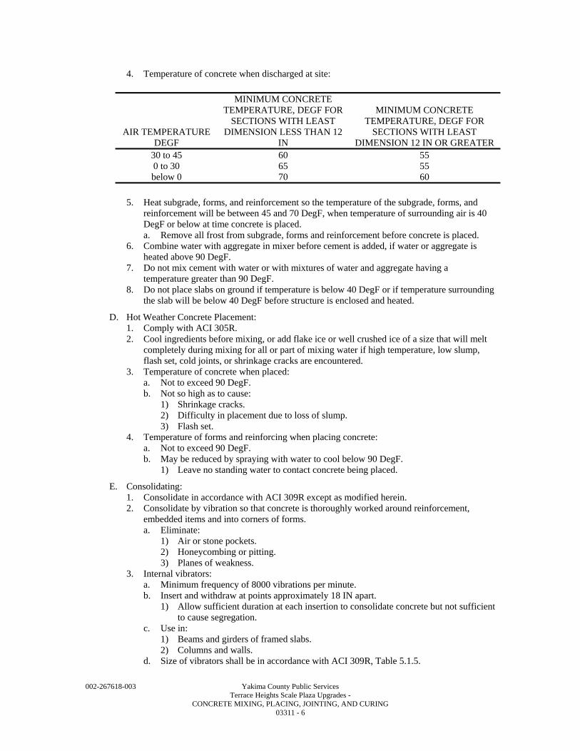
002-267618-003 Yakima County Public Services Terrace Heights Scale Plaza Upgrades - CONCRETE MIXING, PLACING, JOINTING, AND CURING 03311 - 6
4. Temperature of concrete when discharged at site:
AIR TEMPERATURE DEGF
MINIMUM CONCRETE TEMPERATURE, DEGF FOR
SECTIONS WITH LEAST DIMENSION LESS THAN 12
IN
MINIMUM CONCRETE TEMPERATURE, DEGF FOR
SECTIONS WITH LEAST DIMENSION 12 IN OR GREATER
30 to 45 60 55 0 to 30 65 55 below 0 70 60
5. Heat subgrade, forms, and reinforcement so the temperature of the subgrade, forms, and
reinforcement will be between 45 and 70 DegF, when temperature of surrounding air is 40 DegF or below at time concrete is placed. a. Remove all frost from subgrade, forms and reinforcement before concrete is placed.
6. Combine water with aggregate in mixer before cement is added, if water or aggregate is heated above 90 DegF.
7. Do not mix cement with water or with mixtures of water and aggregate having a temperature greater than 90 DegF.
8. Do not place slabs on ground if temperature is below 40 DegF or if temperature surrounding the slab will be below 40 DegF before structure is enclosed and heated.
D. Hot Weather Concrete Placement: 1. Comply with ACI 305R. 2. Cool ingredients before mixing, or add flake ice or well crushed ice of a size that will melt
completely during mixing for all or part of mixing water if high temperature, low slump, flash set, cold joints, or shrinkage cracks are encountered.
3. Temperature of concrete when placed: a. Not to exceed 90 DegF. b. Not so high as to cause:
1) Shrinkage cracks. 2) Difficulty in placement due to loss of slump. 3) Flash set.
4. Temperature of forms and reinforcing when placing concrete: a. Not to exceed 90 DegF. b. May be reduced by spraying with water to cool below 90 DegF.
1) Leave no standing water to contact concrete being placed.
E. Consolidating: 1. Consolidate in accordance with ACI 309R except as modified herein. 2. Consolidate by vibration so that concrete is thoroughly worked around reinforcement,
embedded items and into corners of forms. a. Eliminate:
1) Air or stone pockets. 2) Honeycombing or pitting. 3) Planes of weakness.
3. Internal vibrators: a. Minimum frequency of 8000 vibrations per minute. b. Insert and withdraw at points approximately 18 IN apart.
1) Allow sufficient duration at each insertion to consolidate concrete but not sufficient to cause segregation.
c. Use in: 1) Beams and girders of framed slabs. 2) Columns and walls.
d. Size of vibrators shall be in accordance with ACI 309R, Table 5.1.5.
002-267618-003 Yakima County Public Services Terrace Heights Scale Plaza Upgrades - CONCRETE MIXING, PLACING, JOINTING, AND CURING 03311 - 7
4. Obtain consolidation of slabs with internal vibrators, vibrating screeds, roller pipe screeds, or other approved means.
5. Do not use vibrators to transport concrete within forms. 6. Provide spare vibrators on jobsite during all concrete placing operations. 7. Bring a full surface of mortar against form by vibration supplemented if necessary by
spading to work coarse aggregate back from formed surface, where concrete is to have an as-cast finish.
8. Use suitable form vibrators located just below top surface of concrete, where internal vibrators cannot be used in areas of congested reinforcing.
9. Prevent construction equipment, construction operations, and personnel from introducing vibrations into freshly placed concrete after the concrete has been placed and consolidated.
F. Handle concrete from mixer to place of final deposit by methods which will prevent segregation or loss of ingredients and in a manner which will assure that required quality of concrete is maintained. 1. Use truck mixers, agitators, and non-agitating units in accordance with ASTM C94. 2. Horizontal belt conveyors:
a. Mount at a slope which will not cause segregation or loss of ingredients. b. Protect concrete against undue drying or rise in temperature. c. Use an arrangement at discharge end to prevent segregation. d. Do not allow mortar to adhere to return length of belt. e. Discharge conveyor runs into equipment specially designed for spreading concrete.
3. Metal or metal lined chutes: a. Slope not exceeding 1 vertical to 2 horizontal and not less than 1 vertical to 3
horizontal. b. Chutes more than 20 FT long and chutes not meeting slope requirements may be used
provided they discharge into a hopper before distribution. c. Provide end of each chute with a device to prevent segregation.
4. Pumping or pneumatic conveying equipment: a. Designed for concrete application and having adequate pumping capacity. b. Control pneumatic placement so segregation is avoided in discharged concrete. c. Loss of slump in pumping or pneumatic conveying equipment shall not exceed 1-1/2
IN. d. Do not convey concrete through pipe made of aluminum or aluminum alloy. e. Provide pumping equipment without Y sections.
3.4 JOINTS AND EMBEDDED ITEMS
A. Construction Joints - General: 1. Locate joints as indicated on Contract Drawings or as shown on approved Shop Drawings.
a. Where construction joint spacing shown on Drawings exceeds the joint spacing indicated in Paragraph B. below, submit proposed construction joint location in conformance with this Specification Section.
2. Unplanned construction joints will not be allowed. a. If concrete cannot be completely placed between planned construction joints, then it
must be removed. 3. Locate joints in walls and columns at underside of floors, and at tops of foundations or floor
slabs, unless shown otherwise. 4. Make joints perpendicular to main reinforcement with all reinforcement continuous across
joints. 5. Provide roughened construction joints at all construction joints unless indicated otherwise
on Drawings. a. Clean the previously hardened concrete interface and remove all laitance. b. Intentionally roughen the interface to a full amplitude of 1/4 IN.
6. Provide continuous keyways only where indicated on Drawings. a. Construction joint keyways shall have the following dimensions, unless shown
otherwise on Drawings or directed otherwise by Owner.
002-267618-003 Yakima County Public Services Terrace Heights Scale Plaza Upgrades - CONCRETE MIXING, PLACING, JOINTING, AND CURING 03311 - 8
b. Construction joint keyways in walls: 1) Keyway width, not less than 1/3 and not more than 1/2 the wall thickness measured
perpendicular to wall faces. 2) Keyway depth to be not less than 1-1/2 IN. 3) Place keyway in wall center unless shown otherwise on Drawings.
c. Construction joint keyways in footings, foundations, base slabs, and structural or elevated slabs: 1) Keyway height not less than 1/3 and not more than 1/2 the footing or slab
thickness. 2) Keyway depth not less than 1-1/2 IN. 3) Keyway in footing or slab center unless shown otherwise on Drawings.
7. Allow a minimum of 48 HRS before placement of adjoining concrete construction.
B. Construction Joints - Spacing: 1. General - Structures not intended to contain liquid:
a. Wall vertical construction joints: 1) 60 FT maximum centers. 2) At wall intersections, 30 FT maximum from corner.
b. Base slab construction joints: 1) Placements to be approximately square and not to exceed 3500 SF. 2) Maximum side dimension of a slab pour to be less than:
a) Twice the length of the short side. b) 80 FT.
C. Construction Joints - Bonding: 1. Obtain bond between concrete pours at construction joints by thoroughly cleaning and
removing all laitance from construction joints. a. Before new concrete is placed, all construction joints shall be coated with cement grout,
or dampened. 1) General: Use cement grout or dampening for all construction joints.
2. Roughened construction joints: a. Roughen the surface of the concrete to expose the aggregate uniformly b. Remove laitance, loosened particles of aggregate or damaged concrete at the surface, or
at the Contractor's option, use an approved chemical retarder which delays but does not prevent setting of the surface of the mortar in accordance with the manufacturer's recommendations. 1) Retarded mortar shall be removed within 24 HRS after placing to produce a clean
exposed aggregate bonding surface. c. Cover the hardened concrete of horizontal joints with a coat of cement grout of similar
proportions to the concrete, except substitute fine aggregate for coarse aggregate. d. Place 1-inch layer of grout in bottoms of wall or column lifts immediately before
placing concrete. 1) Vibrate grout and first layer of concrete simultaneously.
e. Place fresh concrete before the grout has attained its initial set. 3. Other keyed construction joints:
a. Thoroughly clean construction joints and remove all laitance. b. Dampen the hardened concrete (but do not saturate) immediately prior to placing of
fresh concrete.
D. Locate control joints in slabs on grade as indicated on Drawings. 1. Time cutting properly with set of concrete, if saw cut joints are required or permitted.
a. Start cutting as soon as concrete has hardened sufficiently to prevent aggregates being dislodged by saw.
b. Complete before shrinkage stresses become sufficient to produce cracking.
002-267618-003 Yakima County Public Services Terrace Heights Scale Plaza Upgrades - CONCRETE MIXING, PLACING, JOINTING, AND CURING 03311 - 9
E. Expansion Joints: 1. Do not permit reinforcement or other embedded metal items bonded to concrete (except
smooth dowels bonded on only one side of joint) to extend continuously through an expansion joint.
2. Use neoprene expansion joint fillers, unless noted otherwise on Drawings. 3. Seal expansion joints as shown on Drawings.
a. See Specification Section 07900 for requirements.
F. General: Set and build into work anchorage devices and other embedded items required for other work that is attached to or supported by cast-in-place concrete. Use setting Drawings, diagrams, templates, instructions, and directions provided by suppliers of items to be attached thereto: 1. Place sleeves, inserts, anchors, and embedded items required for adjoining work or for its
support, prior to initiating concreting. 2. Do not place electrical conduit, drains, or pipes in or thru concrete slabs, walls, columns,
foundations, beams or other structural members unless approved by Owner.
G. Placing Embedded Items: 1. Position expansion joint material and other embedded items accurately. 2. Support against displacement. 3. Fill voids in sleeves, inserts and anchor slots temporarily with readily removable material to
prevent entry of concrete into voids.
3.5 FINISHING
A. See Specification Section 03348.
B. Coordinate mixing and placing with finishing.
3.6 INSTALLATION OF GROUT
A. Grout Schedule of Use: 1. Sand cement grout:
a. Fill keyways if precast HCU. b. General use.
2. Non-shrinking non-metallic grout: a. Filling form tie holes. b. Under column and beam base plates. c. Other uses indicated on the Drawings.
3. Epoxy grout: a. Patching cavities in concrete. b. Grouting of dowels and anchor bolts into existing concrete. c. Grouting of equipment base plates where driving motor is 500 HP and above. d. Other uses indicated on the Drawings.
B. Grout Installation: 1. Non-shrink non-metallic grout:
a. Clean concrete surface to receive grout. b. Saturate concrete with water for 24 HRS prior to grouting. c. Mix in a mechanical mixer. d. Use no more water than necessary to produce flowable grout. e. Place in accordance with manufacturer's instructions. f. Provide under equipment base plates, and in other locations indicated on the Drawings. g. Completely fill all spaces and cavities below the top of base plates. h. Provide forms where base plates and bed plates do not confine grout. i. Where exposed to view, finish grout edges smooth. j. Except where a slope is indicated on the Drawings, finish edges flush at the base plate,
bed plate, member or piece of equipment.
002-267618-003 Yakima County Public Services Terrace Heights Scale Plaza Upgrades - CONCRETE MIXING, PLACING, JOINTING, AND CURING 03311 - 10
k. Coat exposed edges of grout with cure or seal compound recommended by the grout manufacturer.
2. Epoxy grout: a. Mix and place in accordance with manufacturer's instructions. b. Apply only to clean, dry, sound surface. c. Completely fill all cavities and spaces around dowels and anchors without voids. d. Grout base and bed plates as specified for non-shrinking, non-metallic grout. e. Obtain manufacturer's field technical assistance as required to assure proper placement.
3.7 CURING AND PROTECTION
A. Protect concrete from premature drying, excessively hot or cold temperatures, and mechanical injury immediately after placement, and maintain with minimal moisture loss at relatively constant temperature for period necessary for hydration of cement, hardening, and compressive strength gain. 1. Follow recommendations of ACI 308 except as modified herein. 2. Use Confilm by BASF to reduce surface moisture evaporation of slabs during concrete
placement. Strict adherence to the manufacturer’s instructions of use are essential for intended results.
B. Apply one of the following moist curing procedures immediately after completion of placement and finishing, for concrete surfaces not in contact with forms. 1. Ponding or continuous sprinkling. 2. Application of absorptive mats or fabric kept continuously wet. 3. Application of sand kept continuously wet. 4. Continuous application of steam (not exceeding 150 DegF) or mist spray. 5. Ponding and Sprinkling in conjunction with application of waterproof sheet materials,
conforming to ASTM C171 and only with a program as approved by the Owner that will keep the surface continuously wet.
6. Ponding and Sprinkling in conjunction with application of other moisture retaining covering as approved and only with a program as approved by the Owner that will keep the surface continuously wet.
C. After 7 full days of moist curing application of a curing compound conforming to ASTM C309 may be substituted for moist curing. 1. Apply curing compound in accordance with manufacturer's recommendations immediately
after any water sheen which may develop during moist curing has disappeared from concrete surface.
2. Do not use on any surface against which additional concrete or other material is to be bonded unless it is proven that curing compound will not prevent bond.
3. Where a vertical surface is cured with a curing compound, the vertical surface shall be covered with a minimum of two (2) coats of the curing compound, 30 mils thick each coat. a. Apply the first coat of curing compound to a vertical surface immediately after form
removal and before the surface displays water loss. Apply in one direction only, covering uniformly to a minimum thickness of 30 mils.
b. The vertical concrete surface at the time of receiving the first coat shall be damp with no free water on the surface.
c. Allow the preceding coat to completely dry prior to applying the next coat. d. Apply second coat in direction perpendicular to the first coat application direction,
covering uniformly to a minimum thickness of 30 mils. e. A vertical surface: Any surface steeper than 1 vertical to 4 horizontal.
D. Curing Concrete In Contact with Forms: 1. Minimize moisture loss of concrete placed in forms by keeping forms wet and cool until
they can be safely removed. 2. Moist cure the top surface of concrete placed in forms according to paragraph 03311-3.7B. 3. After form removal, cure concrete until end of time prescribed.
a. Use one of methods listed above.
002-267618-003 Yakima County Public Services Terrace Heights Scale Plaza Upgrades - CONCRETE MIXING, PLACING, JOINTING, AND CURING 03311 - 11
b. When approved by the Owner, placement of the second pour at joints may occur prior to the end of the curing period.
4. Forms left in place shall not be used as a method of curing in hot weather. 5. The term "hot weather," where used in these Specifications, is defined in ACI 305R. 6. In hot weather, remove forms from vertical surfaces as soon as concrete has gained
sufficient strength so that the formwork is no longer required to support the concrete and commence moist curing according to paragraph 03311-3.7B.
E. Continue curing for at least fourteen (14) days for all water bearing concrete except high early strength concrete for which period shall be at least three (7) days.
F. Continue curing for at least seven 7 days for all non- water bearing concrete except high early strength concrete for which period shall be at least three (3) days. 1. If one of curing procedures indicated above is used initially, it may be replaced by one of
other procedures indicated any time after concrete is 7 days old, provided concrete is not permitted to become surface dry during transition.
G. Cold Weather: 1. Follow recommendations of ACI 306R. 2. Maintain temperature of concrete between 50 and 70 DegF for required curing period, when
outdoor temperature is 40 DegF, or less. 3. Use heating, covering, insulating, or housing of the concrete work to maintain required
temperature without injury due to concentration of heat. 4. Do not use combustion heaters unless precautions are taken to prevent exposure of concrete
to exhaust gases which contain carbon dioxide. 5. Interior slabs in areas intended to be heated shall be adequately protected so that frost does
not develop in the supporting subgrade.
H. Hot Weather: 1. Follow recommendations of ACI 305R. 2. Make provision for cooling forms, reinforcement and concrete, windbreaks, shading, fog
spraying, sprinkling, ponding, or wet covering with a light colored material. 3. Provide protective measures as quickly as concrete hardening and finishing operations will
allow.
I. Rate of Temperature Change: 1. Keep changes in temperature of air immediately adjacent to concrete as uniform as possible,
during and immediately following curing period. 2. Do not exceed a temperature change of 5 DegF in any 1 HR or 50 DegF in any 24 HR
period.
J. Protection from Mechanical Injury: 1. Protect concrete from damaging mechanical disturbances, such as load stresses, heavy
shock, and excessive vibration. 2. Protect finished concrete surfaces from damage by construction equipment, materials, or
methods, and by rain or running water. 3. Do not load self supporting structures in such a way as to overstress concrete.
3.8 FIELD QUALITY CONTROL
A. Tests in accordance with Specification Section 03350. 1. Perform a strength test on all concrete to which water or superplasticizer, above the amount
stated in the approved concrete mix design, has been added. a. Perform sampling after water or superplasticizer has been added and additional mixing
has been performed.
END OF SECTION

002-267618-003 Yakima County Public Services Terrace Heights Scale Plaza Upgrades - CONCRETE MIXING, PLACING, JOINTING, AND CURING 03311 - 12
002-267618-003 Yakima County Public Services Terrace Heights Scale Plaza Upgrades - CONCRETE FINISHING AND REPAIR OF SURFACE DEFECTS 03348 - 1
SECTION 03348
CONCRETE FINISHING AND REPAIR OF SURFACE DEFECTS
PART 1 - GENERAL
1.1 SUMMARY
A. Section Includes: 1. Concrete finishing and repair of surface defects. 2. Hardener applied to surface of concrete slabs.
B. Related Specification Sections include but are not necessarily limited to: 1. Section 03108 - Formwork. 2. Section 03308 - Concrete, Materials and Proportioning. 3. Section 03311 - Concrete Mixing, Placing, Jointing and Curing. 4. Section 09905 - Painting and Protective Coatings.
1.2 QUALITY ASSURANCE
A. Referenced Standards: 1. American Concrete Institute (ACI):
a. 116R, Cement and Concrete Terminology. b. 117 Tolerances for Concrete Construction. c. 303R, Guide to Cast-in-Place Architectural Concrete Practice.
2. ASTM International (ASTM): a. C94 Standard Specification for Ready-Mixed Concrete. b. C150, Standard Specification for Portland Cement. c. C309, Standard Specification for Liquid Membrane-Forming Compounds for Curing
Concrete. d. C1315, Standard Specification for Liquid Membrane-Forming Compounds Having
Special Properties for Curing and Sealing Concrete. e. D4258, Standard Practice for Surface Cleaning Concrete for Coating. f. D4259, Standard Practice for Abrading Concrete.
3. The Society for Protective Coatings/NACE International (SSPC/NACE): a. SP 13/NACE No. 6, Surface Preparation of Concrete.
B. Qualifications: 1. Applicator of acrylics epoxy products and surfacer/fillers must be approved, in writing, by
manufacturer. 2. Manufacturer of acrylics epoxy products and surfacer/fillers shall have minimum of ten (10)
years experience in manufacturing of same with documented performance history for similar installations.
3. Installer/applicator of acrylics epoxy products and surfacer/fillers shall have minimum of ten (10) years experience installing similar coatings and shall be licensed or approved in writing by manufacturer to install/apply this product.
4. Applicator of concrete sealers, hardener, densifier shall be factory trained and approved, in writing, by the manufacturer to apply the product. a. Applicator shall have a minimum of ten (10) years experience successfully applying
materials specified. Provide references for minimum of three (3) different projects completed in last five (5) years with similar scope of work.
b. Include name and address of project, size of project in value (product application) and contact person.
002-267618-003 Yakima County Public Services Terrace Heights Scale Plaza Upgrades - CONCRETE FINISHING AND REPAIR OF SURFACE DEFECTS 03348 - 2
1.3 DEFINITIONS
A. Vertical Surface Defects: 1. Any void in the face of the concrete deeper than 1/8-inch, such as:
a. Tie holes. b. Air pockets (bug holes). c. Honeycombs. d. Rock holes.
2. Scabbing: a. Scabbing is defect in which parts of the form face, including release agent, adhere to
concrete. 3. Foreign material embedded in face of concrete. 4. Fins 1/16 IN or more in height.
B. Installer or Applicator: 1. Installer or applicator is the person actually installing or applying the product in the field at
the Project site. 2. Installer and applicator are synonymous.
C. Other words and terms used in this Specification Section are defined in ACI 116R.
1.4 SUBMITTALS
A. General: See Specification Section 01340 for requirements for the mechanics and administration of the submittal process.
B. Product technical data including: 1. Acknowledgement that products submitted meet requirements of standards referenced. 2. Manufacturer's installation instructions.
C. Certifications: 1. Certification of aggregate gradation. 2. Certification that products being used will not interfere with bonding of future floor or wall
finishes. 3. Certification of installer qualifications for application of epoxy, surfacer/filler, and concrete
sealer and hardener. a. References substantiating specialty experience.
D. Operation and Maintenance Manuals: 1. See Specification Section 01340 - Operation and Maintenance Manuals.
1.5 DELIVERY, STORAGE, AND HANDLING
A. Comply with manufacturer's recommendations and requirements for materials used.
1.6 WARRANTY
A. Provide warranty equal to specified manufacturer's standard warranty for all products used.
PART 2 - PRODUCTS
2.1 ACCEPTABLE MANUFACTURERS
A. Subject to compliance with the Contract Documents, the following manufacturers are acceptable: 1. Chemical Hardener/Sealer: One part penetrating water based hardener, dustproofer and
sealer. Subject to compliance with requirements, products that may be incorporated in the work include, but are not limited to, the following: a. Titan Hard, The Burke Company. b. Euco Diamond Hard, The Euclid Chemical Company. c. Day-Chem Sure Hard (J-17), Dayton Superior. d. Seal Hard, L & M Construction Chemicals, Inc.
002-267618-003 Yakima County Public Services Terrace Heights Scale Plaza Upgrades - CONCRETE FINISHING AND REPAIR OF SURFACE DEFECTS 03348 - 3
2. Chemical floor sealer (CS-1): a. L&M Construction Chemicals, Inc. b. Euclid Chemical Co. c. Dayton Superior.
3. Bonding agents: a. Euclid Chemical Co. b. BASF Admixtures, Inc. c. L&M Construction Chemicals, Inc.
B. Submit request for substitution in accordance with Specification Section 01640.
2.2 MATERIALS
A. Chemical Floor Sealer CS-1: 1. Colorless low VOC water-based solution containing acrylic copolymers.
a. ASTM C1315, Class B, minimum 30 percent solids. b. ASTM C309, Type 1. c. Non-yellowing UV resistant. d. Capable of being painted after cured.
2. L&M Construction Chemicals, Inc. Dress and Seal WB 30.
B. Bonding Agent: 1. For use only on concrete surfaces not receiving liquid water repellent coating:
a. High solids acrylic latex base liquid for interior or exterior application as a bonding agent to improve adhesion and mechanical properties of concrete patching mortars.
b. Euclid Chemical Co. "Flex-Con." c. BASF Admixtures, Inc. "Acryl-Set." d. L&M Construction Chemicals, Inc. "Everbond." e. Thoro System Products "Acryl 60."
2. For use only on concrete surface receiving liquid water repellent: a. Non-acrylic base liquid for interior or exterior application as a bonding agent to
improve adhesion and mechanical properties of concrete patching mortars.
C. Cement: ASTM C150, Type II Portland.
D. Aggregate: 1. Sand: Maximum size #30 mesh sieve.
E. Water: 1. Clean and free from deleterious substances. 2. Free of oils, acids and organic matter. 3. Meeting the requirements of ASTM C94.
F. Non-Shrink Grout: See Specification Section 03308 and Specification Section 03311.
2.3 MIXES
A. Bonding Grout: One (1) part cement to one (1) part aggregate.
B. Patching Mortar: 1. One (1) part cement to two and one-half (2-1/2) parts aggregate by damp loose volume.
a. Substitute white Portland cement for a part of gray Portland cement to produce color matching surrounding concrete.
PART 3 - EXECUTION
3.1 PREPARATION
A. For methods of curing, see Specification Section 03311.
B. Preparation of Bonding Grout Mixture: 1. Mix cement and aggregate.
002-267618-003 Yakima County Public Services Terrace Heights Scale Plaza Upgrades - CONCRETE FINISHING AND REPAIR OF SURFACE DEFECTS 03348 - 4
2. Mix bonding agent and water together in separate container in accordance with manufacturer's instructions.
3. Add bonding agent/water mixture to cement/aggregate mixture. 4. Mix to consistency of thick cream. 5. Bonding agent itself may be used as bonding grout if approved by manufacturer and Owner.
C. Preparation of Patching Mortar Mixture: 1. Mix cement and aggregate. 2. Mix bonding agent and water together in separate container in accordance with
manufacturer's instructions. 3. Add only enough bonding agent/water mixture to cement/aggregate mixture to allow
handling and placing. 4. Let stand with frequent manipulation with a trowel, until mix has reached stiffest
consistency to allow placement.
D. Clean surfaces in accordance with ASTM D4258 to remove dust, dirt, form oil, grease, or other contaminants prior to abrasive blasting, chipping, grinding or wire brushing. 1. Abrasive blast surfaces in accordance with ASTM D4259 and SSPC SP 13/NACE No. 6 to
completely open defects down to sound concrete and remove laitance. a. If additional chipping or wire brushing is necessary, make edges perpendicular to
surface or slightly undercut. b. No featheredges will be permitted.
2. Rinse surface with clean water and allow surface water to evaporate prior to repairing surface defects.
E. Repairing Surface Defects: 1. This method of repairing surface defects is to be used only on vertical concrete surfaces, in
tanks containing water, surfaces to receive liquid water repellent and exterior surfaces. 2. Fill and repair using patching mortar mix specified in Article 2.3.
a. Use non-shrink grout to fill tieholes as outlined in this Specification Section. 3. If required by bonding agent manufacturer, etch surfaces with a muriatic acid solution
followed by a thorough rinse with clean water. a. Test concrete to determine pH level and continue flushing with clean water until
surface pH is within acceptable limits. 4. Dampen area to be patched and an area at least 6 inches wide surrounding it prior to
application of bonding grout. 5. Brush bonding grout into the surface after the surface water has evaporated. 6. Allow bonding grout to set for period of time required by bonding agent manufacturer
before applying premixed patching mortar. 7. Fill tie holes with non-shrink non-metallic grout.
a. Where exposed to view and scheduled to receive concrete Finish #2 or #5, hold grout below surface of concrete and fill with patching mortar to match surrounding concrete.
8. Fill all other defects with patching mortar. a. Match color of surrounding wall. b. Do not use acrylic bonding agent in patching mortar for filling defects in surfaces to be
treated with liquid water repellent. 9. Consolidate grout or mortar into place and strike off so as to leave patch slightly higher than
surrounding surface. 10. Leave undisturbed for at least 60 minutes before finishing level with surrounding surface.
a. Do not use metal tools in finishing a patch in a formed wall which will be exposed or coated with other materials.
11. Keep areas damp in accordance with grout manufacturer or bonding agent manufacturer's directions.
12. Repairing Surface Defects - Interior Concrete Surfaces Only: a. Does not include exterior concrete surfaces, surfaces exposed to water, or surfaces to
receive liquid water repellent.
002-267618-003 Yakima County Public Services Terrace Heights Scale Plaza Upgrades - CONCRETE FINISHING AND REPAIR OF SURFACE DEFECTS 03348 - 5
b. Clean surfaces in accordance with ASTM D4258 to remove dirt, dust, form oil, grease or other contaminants prior to abrasive blasting, chipping, grinding or wire brushing.
c. Abrasive blast concrete in accordance with ASTM D4259 and SSPC SP 13/NACE No. 6 to completely open defects down to sound concrete and remove laitance.
d. If additional chipping or wire brushing is necessary, make edges perpendicular to surface or slightly undercut.
e. No feather edges will be permitted. f. Rinse surface with clean water and allow surface water to evaporate prior to repairing
surface defects. g. Fill tie holes with non-shrink, non-metallic grout.
13. Preparation - Surfacer/Filler: a. Allow concrete to cure for minimum 28 days. b. Verify that surfaces have been cleaned in accordance with ASTM D4258 to remove
dust, dirt, form oil, grease and other contaminants, and that surface has been abrasive blasted to completely open all defects down to sound concrete and remove all laitance.
c. Bring surface within manufacturer's recommended moisture content. d. Test as recommended by surfacer/filler manufacturer. e. Blend and mix individual components of prepackaged surfacer/filler system in strict
accordance with manufacturer's instructions. f. Provide primer when required by conditions and/or as recommended by manufacturer
or as specified. g. Apply by trowel or hydraulic pumping equipment. h. If applied by hydraulic pumping equipment, material shall be finished by hand
troweling. i. Force material into all voids and surface irregularities. j. Provide a uniform, continuous, void free, smooth film surface. k. Thickness:
1) Minimum: 1/16 IN. 2) Maximum: 1/8 IN.
l. Uniform. m. Remove all trowel marks and leave ready for topcoats of high performance industrial
coatings. n. See Specification Section 09905 for high performance industrial coatings. o. Install concrete slab toppings within tolerances indicated in Article 3.2. p. Clean surfaces in accordance with ASTM D4258 to remove form oils, grease, dirt,
laitance, and other contaminants which will affect finish or topping material.
3.2 INSTALLATION AND APPLICATION
A. Do not repair surface defects or apply wall or floor finishes when temperature is or is expected to be below 50 DegF. 1. If necessary, enclose and heat area to between 50 and 70 DegF during repair of surface
defects and curing of patching material. a. Use only clean fuel, indirect fired heating apparatus.
B. Chemical Floor Sealer (CS-1) Application: 1. Apply to floor areas indicated on the Drawings in accordance with manufacturer's
recommendations. 2. Apply at rate recommended by manufacturer. 3. After final coat of material is applied, remove surplus in accordance with manufacturer's
recommendations. 4. Do not apply sealer to floors scheduled to receive epoxy floor finish.
002-267618-003 Yakima County Public Services Terrace Heights Scale Plaza Upgrades - CONCRETE FINISHING AND REPAIR OF SURFACE DEFECTS 03348 - 6
C. Chemical Hardener/Dustproofer/Sealer: 1. Apply in accordance with manufacturer's written recommendations in a two-coat process at
not less than 200 SF/GAL for the first coat and 400 SF/GAL for the second coat. Do not allow the concrete surface to dry between applications. Utilize mechanical scrubbers to improve effectiveness of applications.
2. Comply with manufacturer's recommendations regarding minimum temperature requirements during application.
3.3 FINISH OF FORMED SURFACES
A. Rough Form Finish: This is the concrete surface having texture imparted by form-facing material used, with tie holes and defective areas repaired and patched and fins and other projections exceeding 1/4 IN in height rubbed down or chipped off. Repair bug holes larger than 1 IN in maximum dimension.
B. Smooth Rubbed Finish: This finish is applied to a smooth form finish. Not later than one day after form removal moisten concrete surfaces and rub with carborundum brick or other abrasive until a uniform color and texture is produced. Do not apply cement grout other than that created by the rubbing process.
C. Grout-Cleaned Finish (sack-rubbed finish): This finish consists of rubbing a grout onto a smooth form finish. The grout consists of one part Portland cement to 1-1/2 parts fine sand by volume, and a 50:50 mixture of acrylic or styrene butadiene-based bonding admixture and water to consistency of thick paint. Blend standard Portland cement and white Portland cement, amounts determined by trial patches, so that final color of dry grout will match adjacent surfaces. Following repair of any defects, the concrete surface is saturated with water and kept wet at least 1 HR before finishing. The grout is applied uniformly by brush, plasterer’s trowel, or rubber float to completely fill air bubbles, holes, and minor surface irregularities. The surface is then vigorously floated with a wood, sponge rubber, or cork float. The grout remaining on the surface is allowed to stand undisturbed until it loses some of its plasticity but not its damp appearance. The surface is then rubbed with a clean, dry, burlap to remove all excess grout. All bug holes should remain filled, but no visible film of grout should remain after rubbing. Keep damp by fog spray for at least 36 HRS after rubbing.
D. Form Finish for Architectural Finishes: Surfaces to receive architectural finishes such as water proofing shall meet the finish requirements of the product manufacturer, or the specified finish, which ever is more stringent.
E. Related Unformed Surfaces: At tops of walls, horizontal offsets, and similar unformed surfaces occurring adjacent to formed surfaces, strike-off smooth and finish with a texture matching adjacent formed surfaces. Continue final surface treatment of formed surfaces uniformly across adjacent unformed surfaces unless otherwise indicated.
3.4 SLAB FINISHES
A. Scratched Finish: Place, consolidate, strike off, and level concrete, eliminating high spots and low spots. Roughen the surface with a stiff brushes or rakes before final set.
B. Floated Finish: Place, consolidate, strike off, and level concrete, eliminating high spots and low spots. Do not work concrete further until it is ready for floating. Begin floating with a hand float, a bladed power float equipped with float shoes, or a powered disk float when the bleed water sheen has disappeared and the surface has stiffened sufficiently to permit the operation. Produce a finish that will meet tolerance requirements and then refloat the slab immediately to a uniform texture.
C. Float and Nonslip Broom Finish: Immediately after float finishing, slightly roughen concrete surface by brooming with fiber-bristle broom perpendicular to main traffic route. Coordinate required final finish with Owner before application. Prepare a control sample area and obtain Owner’s approval.
002-267618-003 Yakima County Public Services Terrace Heights Scale Plaza Upgrades - CONCRETE FINISHING AND REPAIR OF SURFACE DEFECTS 03348 - 7
D. Trowel Finish: After floating, begin first trowel finish operation using a power-driven trowel. Begin final troweling when surface produces a ringing sound as trowel is moved over surface. Consolidate concrete surface by final hand-troweling operation, free of trowel marks, uniform in texture and appearance.
E. Trowel and Nonslip Broom Finish: Immediately after trowel finishing, as specified, slightly roughen concrete surface by brooming with fiber-bristle broom perpendicular to main traffic route. Coordinate required final finish with Owner before application. Prepare a control sample area and obtain Owner’s approval.
F. Floor Covering Finish: Surfaces to receive architectural finishes such as moisture sensitive floor coverings shall meet the finish requirements of the product manufacturer.
3.5 CONCRETE FINISH SCHEDULE
A. Formed Finish: 1. Rough Form Finish: All formed concrete surfaces not exposed to view in the finished work. 2. Smooth Form Finish: All formed concrete surfaces exposed to view except those exposed
to view surfaces specified below to receive a smooth rubbed finish. Exposed to view surfaces are those surfaces that are not hidden by backfill or by other permanent construction cover such as furring and drywall, plywood, metal siding, suspended ceiling, or similar covering.
3. Smooth Rubbed Finish: All Transfer Building push walls, side facing building interior (above armor plate).
B. Slab Finishes: 1. Trowel Finish: All interior slab surfaces exposed to view unless otherwise noted. 2. Trowel and Nonslip Medium Broom Finish: All interior floor slabs, landings, steps, and
ramps, not scheduled to receive a subsequent floor covering and to all truck and platform scale decks.
3. Float and Nonslip Medium Broom Finish: All exterior concrete paving slabs, approach slabs, platforms, steps and ramps.
C. Floated finish: 1. The finish shall be applied to Transfer Station floor. DO NOT POWER TROWEL THIS
AREA. Use only hand trowels to harden the finish. DO NOT OVERWORK finishing in this area.
2. After concrete has been placed, consolidated, struck off, and leveled, do no further work until ready for floating.
3. Being floating when water sheen has disappeared and surface has stiffened sufficiently to permit operations. Use wood or cork float.
4. During or after first floating, check planeness of entire surface with a 10 FT straightedge applied at not less than two different angles.
5. Cut down all high spots and fill all low spots to produce a surface with Class B tolerance throughout.
6. Refloat slab immediately to a uniform texture.
3.6 CONCRETE TREATMENT SCHEDULE
A. Chemical Hardener/Sealer: Apply on the following areas: 1. Concrete deck of truck scale and concrete approach slabs to truck scale.
B. Chemical Floor Sealer (CS-1): Apply to the following areas: 1. Where noted on plans.
C. Water-Based Acrylic Membrane Cure/Seal/Dustproofer: Apply on the following areas: 1. All interior and exterior concrete floors, paving slabs, landings, stairs and other walking
surfaces not scheduled to receive one of the other treatments or floor covering. 2. In 18 to 24 IN wide bands centered on each of the control joints in the tipping floor of the
Transfer Building.
002-267618-003 Yakima County Public Services Terrace Heights Scale Plaza Upgrades - CONCRETE FINISHING AND REPAIR OF SURFACE DEFECTS 03348 - 8
3.7 CONCRETE FINISH TOLERANCES
A. General concrete finish tolerances shall meet the requirements of ACI 117, “Standard Specifications for Tolerances for Concrete Construction and Materials.”
B. ACI 117, Section 4.5.4, regarding offset between adjacent pieces of formwork facing material, the class of surface for smooth form, smooth rubbed, or grout cleaned finishes shall be Class B. For rough form finish, the class of surface shall be Class C.
C. In addition to ACI 117, 4.5.3 and 4.5.4, smooth form, smooth rubbed, or grout cleaned finishes shall meet tolerances as measured by placing a 10 FT straightedge anywhere on the surface and allowing it to rest upon two high spots. The gap at any point between the straightedge and surface shall not exceed 1/2 IN.
D. Floor finish tolerances shall be based on ACI 117,4.5.7, classification straight edged. This tolerance is measured by placing a 10 FT straightedge anywhere on the slab and allowing it to rest upon two high spots. The gap at any point between the straightedge and the floor shall not exceed 5/16 IN.
3.8 CONCRETE SURFACE REPAIRS
A. Repair of Formed Surfaces: 1. Repair and patch defective areas with specified patching repair mortar or approved equal.
Chip out defective areas such as honeycomb and rock pockets down to solid concrete but in no case to a depth of less than 1/2 IN. Saw cut edges of repair a minimum depth of 1/2 IN to create a neat line repair. Make edges of cuts perpendicular or slightly undercut to the concrete surface. Thoroughly clean, dampen with water, and brush-coat the area to be patched with specified bonding agent. Place patching repair mortar before bonding compound has dried. Finish patch with procedure similar to that required for grout cleaned finish. Moist cure repair a minimum of 48 HRS.
2. Repair spalled areas by patching with patching repair mortar in accordance with manufacturer’s instructions.
3. Remove and replace concrete having defective surfaces if defects cannot be repaired to satisfaction of Owner. Surface defects, as such, include color and texture irregularities, cracks, spalls, air bubbles, honeycomb, rock pockets, fins and other projections on surface, out of tolerance surfaces, and stains and other discolorations that cannot be removed by cleaning.
B. Repair of Unformed Surfaces: 1. Test unformed surfaces for smoothness and verify surface plane to tolerances specified.
Correct low and high areas as herein specified. 2. Correct high areas in unformed surfaces by grinding after concrete has cured at least 14
days. 3. Correct low areas in unformed surfaces by saw cutting boundary of low area a minimum of
1/4 IN depth. Chip or otherwise remove concrete in the low area to provide a minimum repair mortar depth of 1/4 IN. Areas already below this 1/4 IN depth shall be cleaned and roughened by high pressure water blasting, bush hammering, or other approved method to provide a surface roughness of 1/8 IN amplitude. Place repair mortar and finish to match adjacent concrete. Cure patch by moist curing for a minimum of 24 HRS.
4. Repair finished unformed surfaces that contain defects that affect durability of concrete. Surface defects, as such, include crazing and cracks in excess of 0.01 IN wide or that penetrate to reinforcement or completely through nonreinforced sections regardless of width, spalling, popouts, honeycomb, rock pockets, and other objectionable conditions.
002-267618-003 Yakima County Public Services Terrace Heights Scale Plaza Upgrades - CONCRETE FINISHING AND REPAIR OF SURFACE DEFECTS 03348 - 9
5. Repair defective areas, except random cracks and single holes not exceeding 1 IN in diameter, by cutting out and replacing with fresh concrete. Remove defective areas to sound concrete with clean, square cuts and expose reinforcing steel with at least 3/4 IN clearance all around. Dampen concrete surfaces in contact with patching concrete and apply bonding compound. Mix patching concrete of same materials to provide concrete of same type or class as original concrete. Place, compact, and finish to blend with adjacent finished concrete. Cure in same manner as adjacent concrete.
6. Perform structural repairs with prior approval of Owner for method and procedure, using specified epoxy adhesive and mortar.
7. Repair methods not specified above may be used, subject to acceptance of Owner.
3.9 CRACK REPAIRS
A. Crack Repair: Cracks which can be attributed to Contractor construction means and methods shall be repaired at the expense of the Contractor. Cracks attributed to construction can be caused by, but not limited to, out of specification soil compaction resulting in settlement, improper curing, placing concrete not meeting the specification requirements, or improper placement of reinforcement. Method of repair of such cracks shall be proposed by Contractor and approved by Owner. In general, cracks shall be repaired with the following methods: 1. Slab on grade cracks: Gravity feed Sika Pronto 19 or equivalent product to fill and seal
crack. 2. Wall cracks: Epoxy injection of cracks which compromise the integrity of the structure.
Urethane injection of cracks which do not compromise structural integrity but may continue to move in the future. Surface seal cracks which do not compromise structural integrity and will not continue to move.
3.10 FIELD QUALITY CONTROL
A. Horizontal slab finishes will be accepted provided: 1. Applicable specification requirements are satisfied. 2. Water does not pond in areas sloped to drain. 3. Gap between a 10 FT straightedge placed anywhere and the finished surface does not
exceed: a. Class A tolerance: 1/8 IN. b. Class B tolerance: 1/4 IN. c. Class C tolerance: 1/2 IN.
4. Accumulated deviation from intended true plane of finished surface does not exceed 1/2 IN. 5. Accuracy of floor finish does not adversely affect installation and operation of movable
equipment, floor supported items, or items fitted to floor (doors, tracks, etc.).
B. Unacceptable finishes shall be replaced or, if approved in writing by Owner, may be corrected provided strength and appearance are not adversely affected. 1. High spots to be removed by grinding and/or low spots filled with a patching compound or
other remedial measures to match adjacent surfaces.
3.11 PROTECTION
A. All horizontal slab surfaces receiving chemical floor sealer or hardener shall be kept free of traffic and loads for minimum of 72 HRS following installation of sealer or hardener.
END OF SECTION

002-267618-003 Yakima County Public Services Terrace Heights Scale Plaza Upgrades - CONCRETE FINISHING AND REPAIR OF SURFACE DEFECTS 03348 - 10
002-267618-003 Yakima County Public Services Terrace Heights Scale Plaza Upgrades - TESTING 03350 - 1
SECTION 03350
TESTING
PART 1 - GENERAL
1.1 SUMMARY
A. Section Includes: 1. Contractor requirements for testing of concrete and grout. 2. Owner provided testing and requirements. 3. Acceptance criteria for concrete.
B. Related Specification Sections include but are not necessarily limited to: 1. Division 0 - Bidding Requirements, Contract Forms, and Conditions of the Contract. 2. Division 1 - General Requirements. 3. Section 03208 - Reinforcement. 4. Section 03308 - Concrete, Materials and Proportioning.
1.2 RESPONSIBILITY AND PAYMENT
A. Owner will perform the following testing and inspection. 1. Testing and inspection of concrete and grout produced for incorporation into the work
during the construction of the Project for compliance with the Contract Documents. 2. Additional testing or retesting of materials occasioned by their failure, by test or inspection,
to meet requirements of the Contract Documents. 3. Strength testing on concrete required by the Engineer or Special Inspector when the water-
cement ratio exceeds the water-cement ratio of the typical test cylinders. 4. In-place testing of concrete as may be required by Engineer when strength of structure is
considered potentially deficient. 5. Other testing services needed or required by Contractor such as field curing of test
specimens and testing of additional specimens for determining when forms, form shoring or reshoring may re removed.
6. Owner will pay for services defined in Paragraph 1.2A.1.
B. Owner to perform the following testing. 1. Testing of materials and mixes proposed by the Contractor for compliance with the Contract
Documents and retesting in the event of changes. 2. Additional testing and inspection required because of changes in materials or proportions
requested by Contractor. 3. Owner shall pay for services defined in Paragraphs 1.2B.1. and 1.2B.2.
C. Duties and Authorities of Owner: 1. Owner shall inform the Contractor and Engineer regarding acceptability of or deficiencies in
the work including materials furnished and work performed by Contractor that fails to fulfill requirements of the Contract Documents.
2. Owner to submit test reports and inspection reports to Engineer and Contractor immediately after they are performed. a. All test reports to include exact location in the work at which batch represented by a
test was deposited. b. Reports of strength tests to include detailed information on storage and curing of
specimens prior to testing. 3. Owner retains the responsibility for ultimate rejection or approval of any portion of the
Work.
002-267618-003 Yakima County Public Services Terrace Heights Scale Plaza Upgrades - TESTING 03350 - 2
1.3 QUALITY ASSURANCE
A. Referenced Standards: 1. American Association of State Highway and Transportation Officials (AASHTO):
a. T260, Standard Method of Test for Sampling and Testing for Chloride Ion in Concrete and Concrete Raw Materials.
2. American Concrete Institute (ACI): a. 318, Building Code Requirements for Structural Concrete.
3. ASTM International (ASTM): a. C31, Standard Practice for Making and Curing Concrete Test Specimens in the Field. b. C39, Standard Test Method for Compressive Strength of Cylindrical Concrete
Specimens. c. C42, Standard Test Method for Obtaining and Testing Drilled Cores and Sawed Beams
of Concrete. d. C138, Standard Test Method for Density (Unit Weight), Yield, and Air Content
(Gravimetric) of Concrete. e. C143, Standard Test Method for Slump of Hydraulic-Cement Concrete. f. C172, Standard Practice for Sampling Freshly Mixed Concrete. g. C173, Standard Test Method for Air Content of Freshly Mixed Concrete by the
Volumetric Method. h. C231, Standard Test Method for Air Content of Freshly Mixed Concrete by the
Pressure Method. i. C567, Standard Test Method for Determining Density of Structural Lightweight
Concrete. j. E329, Standard Specification for Agencies Engaged in Construction Inspection and/or
Testing. 4. National Bureau of Standards (NBS):
a. Cement and Concrete Reference Laboratory (CCRL).
B. Qualifications: 1. Owner provided testing:
a. Meeting requirements of ASTM E329. b. Provide evidence of recent inspection by CCRL of NBS, and correction of deficiencies
noted.
C. Approval by Owner of proposed concrete mix design shall in no way relieve Contractor of responsibility to furnish materials and construction in full compliance with Contract Documents.
1.4 SUBMITTALS
A. General: See Specification Section 01340 for requirements for the mechanics and administration of the submittal process.
B. Product technical data including: 1. Concrete materials and concrete mix designs proposed for use.
a. Include results of all testing performed to qualify materials and to establish mix designs.
b. Place no concrete until approval of mix designs has been received in writing. c. Submittal for each concrete mix design to include:
1) Sieve analysis and source of fine and coarse aggregates. 2) Test for aggregate organic impurities. 3) Proportioning of all materials. 4) Type of cement with mill certificate for the cement. 5) Brand, quantity and class of fly ash proposed for use along with other submittal
data as required for fly ash by Specification Section 03308. 6) Unit weight of fresh and dry lightweight concrete. 7) Slump. 8) Splitting tensile strength for proposed lightweight concrete mix.
002-267618-003 Yakima County Public Services Terrace Heights Scale Plaza Upgrades - TESTING 03350 - 3
9) Brand, type and quantity of air entrainment and any other proposed admixtures. 10) Shrinkage test results. 11) Total chloride ion content per cubic yard of concrete determined in accordance
with AASHTO T260. 12) 28-day compression test results and any other data required by Specification
Section 03308 to establish concrete mix design.
PART 2 - PRODUCTS - (NOT APPLICABLE TO THIS SECTION)
PART 3 - EXECUTION
3.1 TESTING SERVICES TO BE PERFORMED BY OWNER
A. The following concrete testing will be performed by the Owner: 1. Concrete strength testing:
a. Secure concrete samples in accordance with ASTM C172. 1) Obtain each sample from a different batch of concrete on a random basis, avoiding
selection of test batch other than by a number selected at random before commencement of concrete placement.
b. For each strength test mold and cure four (4) cylinders from each sample in accordance with ASTM C31. 1) Record any deviations from requirements on test report. 2) Cylinder size: Per ASTM C31.
c. Field cure one cylinder for the seven (7) day test. 1) Laboratory cure the remaining.
d. Test cylinders in accordance with ASTM C39. 1) Test two (2) cylinders at 28 days for strength test result and one (1) at seven (7)
days for information. 2) Hold remaining cylinder in reserve.
e. Strength test result: 1) Average of strengths of two (2) cylinders from the same sample tested at 28 days. 2) If one (1) cylinder in a test manifests evidence of improper sampling, molding,
handling, curing, or testing, discard and test reserve cylinder; average strength of remaining cylinders shall be considered strength test result.
3) Should all cylinders in a test show any of above defects, discard entire test. f. Frequency of tests:
1) Concrete sand cement grout: One (1) strength test for each 4 HR period of grout placement or fraction thereof.
2) Concrete topping, concrete fill and lean concrete: One (1) strength test for each 10 CY of each type of concrete or fraction thereof placed.
3) All other concrete: a) One (1) strength test consisting to be taken not less than once a day, nor less
than once for each 60 CY or fraction thereof placed in any one (1) day. b) If total volume of concrete on Project is such that frequency of testing required
in above paragraph will provide less than five (5) strength tests for each concrete mix, tests shall then be made from at least five (5) randomly selected batches or from each batch if fewer than five (5) batches are provided.
2. Slump testing: a. Determine slump of concrete sample for each strength test.
1) Determine slump in accordance with ASTM C143. b. If consistency of concrete appears to vary, the Engineer shall be authorized to require a
slump test for each concrete truck. 1) This practice shall continue until the Engineer deems it no longer necessary.
3. Air content testing: Determine air content of concrete sample for each strength test in accordance with either ASTM C231, ASTM C173, or ASTM C138.
002-267618-003 Yakima County Public Services Terrace Heights Scale Plaza Upgrades - TESTING 03350 - 4
4. Temperature testing: Determine temperature of concrete sample for each strength test. 5. Determine unit weight of fresh and dry lightweight concrete for each strength test in
accordance with ASTM C567. 6. In-place concrete testing (if required).
3.2 SAMPLING ASSISTANCE AND NOTIFICATION FOR OWNER
A. To facilitate testing and inspection, perform the following: 1. Furnish any necessary labor to assist Owner in obtaining and handling samples at site. 2. Provide and maintain for sole use of Owner adequate facilities for safe storage and proper
curing of test specimens on site for first 24 HRS as required by ASTM C31.
B. Notify Engineer sufficiently in advance of operations (minimum of 24 HRS) to allow completion of quality tests for assignment of personnel and for scheduled completion of quality tests.
3.3 ACCEPTANCE
A. Completed concrete work which meets applicable requirements will be accepted without qualification.
B. Completed concrete work which fails to meet one or more requirements but which has been repaired to bring it into compliance will be accepted without qualification.
C. Completed concrete work which fails to meet one or more requirements and which cannot be brought into compliance may be accepted or rejected as provided in these Contract Documents. 1. In this event, modifications may be required to assure that concrete work complies with
requirements. 2. Modifications, as directed by Engineer, to be made at no additional cost to Owner.
D. Dimensional Tolerances: 1. Formed surfaces resulting in concrete outlines smaller than permitted by tolerances shall be
considered potentially deficient in strength and subject to modifications required by Engineer.
2. Formed surfaces resulting in concrete outlines larger than permitted by tolerances may be rejected and excess material subject to removal. a. If removal of excess material is permitted, accomplish in such a manner as to maintain
strength of section and to meet all other applicable requirements of function and appearance.
3. Concrete members cast in wrong location may be rejected if strength, appearance or function of structure is adversely affected or misplaced items interfere with other construction.
4. Inaccurately formed concrete surfaces exceeding limits of tolerances and which are exposed to view, may be rejected. a. Repair or remove and replace if required.
5. Finished slabs exceeding tolerances may be required to be repaired provided that strength or appearance is not adversely affected. a. High spots may be removed with a grinder, low spots filled with a patching compound,
or other remedial measures performed as permitted or required.
E. Appearance: 1. Concrete surfaces exposed to view with defects which, in opinion of Owner, adversely
affect appearance as required by specified finish shall be repaired by approved methods. 2. Concrete not exposed to view is not subject to rejection for defective appearance unless, in
the opinion of the Owner, the defects impair the strength or function of the member.
F. High Water-Cement Ratio: 1. Concrete with water in excess of the specified maximum water-cement ratio will be
considered potentially deficient in durability.
002-267618-003 Yakima County Public Services Terrace Heights Scale Plaza Upgrades - TESTING 03350 - 5
2. Remove and replace concrete with high water-cement ratio or make other corrections as directed by Engineer.
G. Strength of Structure: 1. Strength of structure in place will be considered potentially deficient if it fails to comply
with any requirements which control strength of structure, including but not necessarily limited to following: a. Low concrete strength:
1) Test results for standard molded and cured test cylinders to be evaluated separately for each mix design. a) Such evaluation shall be valid only if tests have been conducted in accordance
with specified quality standards. b) For evaluation of potential strength and uniformity, each mix design shall be
represented by at least three (3) strength tests. c) A strength test shall be the average of two (2) cylinders from the same sample
tested at 28 days. 2) Acceptance:
a) Strength level of each specified compressive strength shall be considered satisfactory if both of the following requirements are met: (1) Average of all sets of three (3) consecutive strength tests equal or exceed
the required specified 28 day compressive strength. (2) No individual strength test falls below the required specified 28 day
compressive strength by more than 500 psi. b. Reinforcing steel size, configuration, quantity, strength, position, or arrangement at
variance with requirements in Specification Section 03208 or requirements of the Contract Drawings or approved Shop Drawings.
c. Concrete which differs from required dimensions or location in such a manner as to reduce strength.
d. Curing time and procedure not meeting requirements of this Specification Section. e. Inadequate protection of concrete from extremes of temperature during early stages of
hardening and strength development. f. Mechanical injury, construction fires, accidents or premature removal of formwork
likely to result in deficient strength. g. Concrete defects such as voids, honeycomb, cold joints, spalling, cracking, etc., likely
to result in deficient strength or durability. 2. Structural analysis and/or additional testing may be required when strength of structure is
considered potentially deficient. 3. In-place testing of concrete may be required when strength of concrete in place is
considered potentially deficient. a. Testing by impact hammer, sonoscope, or other nondestructive device may be
permitted by Engineer to determine relative strengths at various locations in the structure or for selecting areas to be cored. 1) Such tests shall not be used as a basis for acceptance or rejection.
b. Core tests: 1) Where required, test cores will be obtained in accordance with ASTM C42.
a) If concrete in structure will be dry under service conditions, air dry cores (temperature 60 to 80 DegF, relative humidity less than 60 percent) for seven (7) days before test then test dry.
b) If concrete in structure will be wet or subjected to high moisture atmosphere under service conditions, test cores after immersion in water for at least 40 HRS and test wet.
c) Testing wet or dry to be determined by Engineer. 2) Three (3) representative cores may be taken from each member or area of concrete
in place that is considered potentially deficient. a) Location of cores shall be determined by Engineer so as least to impair
strength of structure.
002-267618-003 Yakima County Public Services Terrace Heights Scale Plaza Upgrades - TESTING 03350 - 6
b) If, before testing, one (1) or more of cores shows evidence of having been damaged subsequent to or during removal from structure, damaged core shall be replaced.
3) Concrete in area represented by a core test will be considered adequate if average strength of three (3) cores is equal to at least 85 percent of specified strength and no single core is less than 75 percent of specified strength.
4) Fill core holes with nonshrink grout and finish to match surrounding surface when exposed in a finished area.
4. If core tests are inconclusive or impractical to obtain or if structural analysis does not confirm safety of structure, load tests may be required and their results evaluated in accordance with ACI 318, Chapter 20.
5. Correct or replace concrete work judged inadequate by structural analysis or by results of core tests or load tests with additional construction, as directed by Owner, at Contractor's expense.
6. Contractor to pay all costs incurred in providing additional testing and/or structural analysis required.
END OF SECTION

D I V I S I O N 0 5 METALS

002-267618-003 Yakima County Public Services Terrace Heights Scale Plaza Upgrades - METAL FABRICATIONS 05505 - 1
SECTION 05505
METAL FABRICATIONS
PART 1 - GENERAL
1.1 SUMMARY
A. Section Includes: 1. Custom fabricated metal items and certain manufactured units not otherwise indicated to be
supplied under work of other Specification Sections. 2. Design of all temporary bracing not indicated on Drawings.
B. Related Specification Sections include but are not necessarily limited to: 1. Section 03308 - Concrete, Materials and Proportioning. 2. Section 09905 - Painting and Protective Coatings.
1.2 QUALITY ASSURANCE
A. Referenced Standards: 1. American Institute of Steel Construction (AISC):
a. 325, Manual of Steel Construction - Allowable Stress Design (ASD). b. 360, Specifications for Structural Steel Buildings (referred to herein as AISC
Specification). 2. American National Standards Institute (ANSI):
a. A14.3, Ladders - Fixed - Safety Requirements. 3. ASTM International (ASTM):
a. A36, Standard Specification for Carbon Structural Steel.
b. A53, Standard Specification for Pipe, Steel, Black and Hot-Dipped, Zinc-Coated, Welded and Seamless.
c. A123, Standard Specification for Zinc (Hot-Dip Galvanized) Coatings on Iron and Steel Products.
d. A153, Standard Specification for Zinc Coating (Hot-Dip) on Iron and Steel Hardware. e. A307, Standard Specification for Carbon Steel Bolts and Studs, 60,000 PSI Tensile
Strength. f. A325, Standard Specification for Structural Bolts, Steel, Heat Treated, 120/105 ksi
Minimum Tensile Strength. g. A780, Standard Practice for Repair of Damaged and Uncoated Areas of Hot-Dip
Galvanized Coatings. h. F593, Standard Specification for Stainless Steel Bolts, Hex Cap Screws, and Studs. i. F1554, Standard Specification for Anchor Bolts, Steel, 36, 55, and 105-ksi Yield
Strength. 4. American Welding Society (AWS):
a. A5.1, Specification for Carbon Steel Electrodes for Shielded Metal Arc Welding. b. D1.1, Structural Welding Code - Steel. c. D1.2, Structural Welding Code - Aluminum.
5. National Association of Architectural Metal Manufacturers (NAAMM): a. AMP 510, Metal Stairs Manual. b. MBG 531, Metal Bar Grating Manual.
6. NACE International (NACE). 7. Occupational Safety and Health Administration (OSHA):
a. 29 CFR 1910, Occupational Safety and Health Standards, referred to herein as OSHA Standards.
8. Research Council on Structural Connections (RCSC): a. Specification for Structural Joints Using ASTM A325 or A490 Bolts, referred to herein
as Specification for Structural Joints.
002-267618-003 Yakima County Public Services Terrace Heights Scale Plaza Upgrades - METAL FABRICATIONS 05505 - 2
9. Building Code: a. International Code Council (ICC):
1) International Building Code and associated standards, 2012 Edition including all amendments, referred to herein as Building Code.
B. Qualifications: 1. Qualify welding procedures and welding operators in accordance with AWS. 2. Fabricator shall have minimum of 10 years experience in fabrication of metal items
specified. 3. Owner for contractor-designed systems and components: Professional structural Owner
licensed in the State of Washington. 4. NACE certified inspector shall have minimum of two (2) years experience performing
inspections as indicated.
1.3 DEFINITIONS
A. Installer or Applicator: 1. Installer or applicator is the person actually installing or applying the product in the field at
the Project site. 2. Installer and applicator are synonymous.
B. Hardware: As defined in ASTM A153.
C. Galvanizing: Hot-dip galvanizing per ASTM A123 or ASTM A153 with minimum coating of 2.0 OZ of zinc per square foot of metal (average of specimens) unless noted otherwise or dictated by standard.
1.4 SUBMITTALS
A. General: See Specification Section 01340 for requirements for the mechanics and administration of the submittal process.
B. Fabrication and/or layout Drawings and details: 1. Submit Drawings for all fabrications and assemblies.
a. Include erection Drawings, plans, sections, details and connection details. 2. Identify materials of construction, shop coatings and third party accessories.
C. Product technical data including: 1. Acknowledgement that products submitted meet requirements of standards referenced. 2. Manufacturer's installation instructions. 3. Provide manufacturer's standard allowable load tables for the following:
a. Expansion anchor bolts. b. Adhesive anchor bolts. c. Castings, trench covers and accessories.
D. Miscellaneous Submittals: 1. See Specification Section 01340 for requirements for the mechanics and administration of
the submittal process. 2. Certification of welders and welding processes.
a. Indicate compliance with AWS. b. NACE inspector qualifications. c. NACE certification of surface preparation. d. NACE certification of paint application.
1.5 DELIVERY, STORAGE, AND HANDLING
A. Deliver and handle fabrications to avoid damage.
B. Store above ground on skids or other supports to keep items free of dirt and other foreign debris and to protect against corrosion.
002-267618-003 Yakima County Public Services Terrace Heights Scale Plaza Upgrades - METAL FABRICATIONS 05505 - 3
PART 2 - PRODUCTS
2.1 ACCEPTABLE MANUFACTURERS
A. Subject to compliance with the Contract Documents, the following manufacturers are acceptable: 1. Expansion anchor bolts:
a. Hilti Inc. b. ITW Ramset/Red Head. c. Simpson Strongtie.
2. Epoxy adhesive anchor bolts: a. Hilti Inc. b. ITW Ramset/Red Head. c. Simpson Strongtie.
3. Castings, trench covers and accessories: a. Neenah Foundry Co. b. Deeter Foundry Co. c. Barry Craft Construction Casting Co. d. McKinley Iron Works.
4. Galvanizing repair paint: a. Clearco Products Co., Inc. b. ZRC Products.
B. Submit request for substitution in accordance with Specification Section 01640.
2.2 MATERIALS
A. Steel: 1. Angles: ASTM A36. 2. Structural tubing: ASTM A500, Grade B (46 ksi minimum yield). 3. Bolts, nuts and washers, high strength:
a. ASTM A325. b. Galvanized, ASTM A153 where noted on Drawings. c. Provide two (2) washers with all bolts.
4. Bolts and nuts: a. ASTM A307, Grade A. b. Galvanized, ASTM A153 where noted on Drawings.
5. Welding electrodes: AWS D1.1, E70 Series. 6. Steel forgings: ASTM A668.
B. Washers: Same material and alloy as found in accompanying bolts and nuts.
C. Embedded Anchor Bolts: 1. Building anchor bolts: ASTM D1554, Grade 36 2. All other anchor bolts: Type 304 or 316 stainless steel with matching nut and washer.
D. Expansion Anchor Bolts and Adhesive Anchor Bolts: 1. ASTM D1554 Grade 36. 2. Provide minimum edge distance cover and spacing as recommended by manufacturer, or as
indicated on Drawings whichever is larger. a. Minimum embedment as recommended by manufacturer or eight (8) diameters of bolt,
whichever is larger. b. Notify Owner if required depth of embedment cannot be achieved at a particular anchor
bolt location.
E. Expansion Anchor Bolts: 1. Kwik Bolt by Hilti, Inc. 2. Trubolt by ITW Ramset/Red Head. 3. Wedge-All by Simpson Strong-Tie.
002-267618-003 Yakima County Public Services Terrace Heights Scale Plaza Upgrades - METAL FABRICATIONS 05505 - 4
F. Adhesive Anchor Bolts: 1. HIT-RE100 by Hilti. 2. C6+ by ITW Ramset. 3. SET-XP By Simpson.
G. Galvanizing Repair Paint: 1. High zinc dust content paint for regalvanizing welds and abrasions. 2. ASTM A780. 3. Zinc content: Minimum 92 percent in dry film. 4. ZRC "ZRC Cold Galvanizing" or Clearco "High Performance Zinc Spray." 5. VOC: 0 LBS/GAL.
H. Dissimilar Materials Protection: See Specification Section 09905.
2.3 MANUFACTURED UNITS
A. Bollards: 1. 8 IN DIA extra strength steel pipe, ASTM A53.
a. Galvanized. b. See Specification Section 09905 for painting requirements.
2. Minimum 48 IN projection above ground. 3. Minimum 48 IN embedment in concrete.
B. Steel Grating: 1. NAAMM MBG 531. 2. Bearing bars:
a. Rectangular 1-1/2 x 3/16 IN unless shown otherwise on Drawings. b. Maximum 1-3/16 IN OC spacing.
3. Cross bars: a. Welded, swagged or pressure locked to bearing bars. b. Maximum 4 IN OC spacing.
4. Top edges of bars: Serrated or grooved. 5. Removable grating sections: Not wider than 3 FT and not more than 100 LBS. 6. Finish:
a. Galvanized. b. Clips and bolts: Galvanized. c. Seat angles: Galvanized steel.
7. Ends and perimeter edges: Banded. 8. Openings through grating: Reinforced to provide required load carrying capacity and
banded with 4 IN high toe plate. 9. Provide joints at openings between individual grating sections.
2.4 FABRICATION
A. Verify field conditions and dimensions prior to fabrication.
B. Form materials to shapes indicated with straight lines, true angles, and smooth curves. 1. Grind smooth all rough welds and sharp edges.
a. Round all corners to approximately 1/32 - 1/16 IN nominal radius.
C. Provide drilled or punched holes with smooth edges. 1. Punch or drill for field connections and for attachment of work by other trades.
D. Conceal fastenings where practicable.
E. Fabricate work in shop in as large assemblies as is practicable.
F. Tolerances: 1. Rolling:
a. ASTM A6.
002-267618-003 Yakima County Public Services Terrace Heights Scale Plaza Upgrades - METAL FABRICATIONS 05505 - 5
b. When material received from the mill does not satisfy ASTM A6 tolerances for camber, profile, flatness, or sweep, the Contractor is permitted to perform corrective work by the use of controlled heating and mechanical straightening, subject to the limitations of the AISC Specifications.
2. Fabrication tolerance: a. Member length:
1) Both ends finished for contact bearing: 1/32 IN. 2) Framed members:
a) 30 FT or less: 1/16 IN. b) Over 30 FT: 1/8 IN.
b. Member straightness: 1) Compression members: 1/1000 of axial length between points laterally supported. 2) Non-compression members: ASTM A6 tolerance for wide flange shapes.
c. Specified member camber (except compression members): 1) 50 FT or less: Minus 0/plus 1/2 IN. 2) Over 50 FT: Minus 0/plus 1/2 IN (plus 1/8 IN per 10 FT over 50 FT). 3) Members received from mill with 75 percent of specified camber require no further
cambering. 4) Beams/trusses without specified camber shall be fabricated so after erection,
camber is upward. 5) Camber shall be measured in fabrication shop in unstressed condition.
d. At bolted splices, depth deviation shall be taken up by filler plates. 1) At welded joints, adjust weld profile to conform to variation in depth. 2) Slope weld surface per AWS requirements.
e. Finished members shall be free from twists, bends and open joints. 1) Sharp kinks, bends and deviation from above tolerances are cause for rejection of
material.
G. Fabricate grating, checkered plate, stairs, ladders and accessories using galvanized steel unless shown otherwise on Drawings. 1. Finish:
a. Aluminum: Mill finished unless scheduled or otherwise specified or, if approved by Owner, finished in manufacturer's standard.
b. Coat surfaces in contact with dissimilar materials. 1) See Specification Section 09905. 2) Coat surfaces in contact with dissimilar material.
a) 5 mils DFT. b) Tnemec Series N69.
2. See Specification Section 09905 for preparation and painting of ferrous metals and other surfaces.
H. Maximum tolerance for difference in depth between checkered plate or grating depth and seat or support angle depth: 1/8 IN.
I. Distance between edge of grating or checkered plate and face of embedded seat angle or face of wall or other structural member shall be 1/4 IN. 1. Tolerance per NAAMM MBG 531.
J. Passivate stainless steel items and stainless steel welds after they have been ground smooth, where indicated on Drawings. 1. ASTM A967.
2.5 SOURCE QUALITY CONTROL
A. Surface Preparation: 1. Refer to Specification Section 09905 for surface preparation requirements.
B. Shop Applied Paint Coating Application: 1. Refer to Specification Section 09905 for painting requirements.
002-267618-003 Yakima County Public Services Terrace Heights Scale Plaza Upgrades - METAL FABRICATIONS 05505 - 6
C. Owner will employ and pay for services of an independent testing agency to inspect and test structural steel shop and field work for compliance with this Specification Section.
D. Contractor responsible for testing to qualify shop and field welders and as needed for Contractor's own quality control to ensure compliance with Contract Documents.
E. Contractor provides sufficient notification and access so inspection and testing can be accomplished.
F. Contractor pays for retesting of failed tests and for additional testing required when defects are discovered.
G. Responsibilities of Testing Agency: 1. Inspect shop and field welding in accordance with AWS Code, Section 6 including the
following non-destructive testing: 2. Visually inspect all welds. 3. In addition to visual inspection, test 50 percent of full penetration welds and 20 percent of
fillet welds with liquid dye penetrant. 4. Test 20 percent of liquid dye penetrant tested full penetration welds with ultrasonic or
radiographic testing. 5. Inspect high-strength bolting in accordance with the RCSC Specification for Structural
Joints, Section 9. 6. Verify direct tension indicator gaps. 7. Inspect structural steel which has been erected. 8. Inspect stud welding in accordance with AWS Code, Article 7.8. 9. Prepare and submit inspection and test reports to Owner. 10. Assist Owner to determine corrective measures necessary for defective work.
PART 3 - EXECUTION
3.1 PREPARATION
A. Provide items to be built into other construction in time to allow their installation. 1. If such items are not provided in time for installation, cut in and install.
B. Prior to installation, inspect and verify condition of substrate.
C. Correct surface defects or conditions which may interfere with or prevent a satisfactory installation. 1. Field welding aluminum is not permitted unless approved in writing by Owner.
3.2 INSTALLATION
A. Set metal work level, true to line, plumb. 1. Shim and grout as necessary.
B. Meet structural requirements of Specification Section 01210 regarding tolerances for erecting items of structural nature.
C. Contractor is solely responsible for safety. 1. Construction means and methods and sequencing of work is the prerogative of the
Contractor. 2. Examine work-in-place on which specified work is in any way dependent to ensure that
conditions are satisfactory for the installation of the work. 3. Report defects in work-in-place which may influence satisfactory completion of the work. 4. Absence of such notification will be construed as acceptance of work-in-place.
D. Field Measurement: 1. Take field measurements as necessary to verify or supplement dimensions indicated on the
Drawings. 2. Contractor responsible for the accurate fit of the work.
002-267618-003 Yakima County Public Services Terrace Heights Scale Plaza Upgrades - METAL FABRICATIONS 05505 - 7
3. Check the elevations of all finished footings or foundations and the location and alignment of all anchor bolts before starting erection.
4. Use surveyor's level. 5. Notify Owner of any errors or deviations found by such checking. 6. Framing member location tolerances after erection shall not exceed the frame tolerances
listed in Article 3.3. 7. Erect plumb and level; introduce temporary bracing required to support erection loads. 8. Use light drifting necessary to draw holes together. 9. Drifting to match unfair holes is not allowed.
E. Welding: 1. Conform to AWS D1.1. 2. When joining two (2) sections of steel of different ASTM designations, welding techniques
shall be in accordance with a qualified AWS D1.1 procedure. 3. Shore existing members when unbolting of common connections is required. 4. Use new bolts for rebolting connections. 5. Clean stored material of all foreign matter accumulated during erection period.
F. Bolt Field Connections: Where practicable, conceal fastenings.
G. Grind welds smooth where field welding is required.
H. Field cutting grating or checkered plate to correct fabrication errors is not acceptable. 1. Replace entire section.
I. Remove all burrs and radius all sharp edges and corners of miscellaneous plates, angles, framing system elements, etc.
J. Unless noted or specified otherwise: 1. Provide washers for all bolted connections. 2. Where exposed, bolts shall extend a maximum of 3/4 IN and a minimum of 1/2 IN above
the top nut. a. If bolts are cut off to required maximum height, threads must be dressed to allow nuts
to be removed without damage to the bolt or the nuts.
K. Install and tighten ASTM A325 high-strength bolts in accordance with the AISC 325, Allowable Stress Design (ASD). 1. Provide hardened washers for all ASTM A325 bolts.
a. Provide the hardened washer under the element (nut or bolt head) turned in tightening. b. Provide bearing type connection.
L. After bolts are tightened, upset threads of ASTM A307 unfinished bolts or anchor bolts to prevent nuts from backing off.
M. Secure metal to wood with lag screws of adequate size with appropriate washers.
N. Do not field splice fabricated items unless said items exceed standard shipping length or change of direction requires splicing. 1. Provide full penetration welded splices where continuity is required.
O. Provide each fabricated item complete with attachment devices as indicated or required to install.
P. Anchor such that work will not be distorted nor fasteners overstressed from expansion and contraction.
Q. Tie anchor bolts in position to embedded reinforcing steel using wire. 1. Tack welding prohibited.
a. Coat bolt threads and nuts with heavy coat of clean grease. 2. Anchor bolt location tolerance:
a. 1/16 IN. b. Provide steel templates for all column anchor bolts.
002-267618-003 Yakima County Public Services Terrace Heights Scale Plaza Upgrades - METAL FABRICATIONS 05505 - 8
R. Install bollards in concrete as detailed. 1. Fill pipe with concrete and round off at top.
S. Accurately locate and place frames for openings before casting into floor slab so top of plate is flush with surface of finished floor. 1. Keep screw holes clean and ready to receive screws.
T. Attach grating to end and intermediate supports with grating saddle clips and bolts. 1. Maximum spacing: 2 FT OC with minimum of two (2) per side. 2. Attach individual units of aluminum grating together with clips at 2 FT OC maximum with
a minimum of two (2) clips per side.
U. Repair damaged galvanized surfaces in accordance with ASTM A780. 1. Prepare damaged surfaces by abrasive blasting or power sanding. 2. Apply galvanizing repair paint to minimum 6 mils DFT in accordance with manufacturer's
instructions.
3.3 CLEANING
A. After erection, installation or application, clean all miscellaneous metal fabrication surfaces of all dirt, weld slag and other foreign matter.
B. Provide surface acceptable to receive field applied paint coatings specified in Specification Section 09905.
END OF SECTION
D I V I S I O N 0 6 WOOD AND PLASTICS

002-267618-003 Yakima County Public Services Terrace Heights Scale Plaza Upgrades - ROUGH CARPENTRY 06100 - 1
SECTION 06100
ROUGH CARPENTRY
PART 1 - GENERAL
1.1 SUMMARY
A. Section Includes: 1. Rough carpentry. 2. Roof sheathing. 3. Wall sheathing.
B. Related Specification Sections include but are not necessarily limited to: 1. Section 05505 - Metal Fabrications. 2. Section 06200 - Finish Carpentry. 3. Section 07900 - Joint Sealants.
1.2 QUALITY ASSURANCE
A. Referenced Standards: 1. American Forest and Paper Association (AF&PA):
a. NDS, National Design Specification for Wood Construction. 2. APA - The Engineered Wood Association (APA):
a. PRP-108, Performance Standards and Qualification Policy for Structural Use Panels. b. U450E, Storage and Handling of APA Trademarked Panels. c. Y510T, Plywood Design Specification.
3. ASTM International (ASTM): a. D2898, Standard Practice for Accelerated Weathering of Fire-Retardant-Treated Wood
for Fire Testing. b. D4442, Standard Test Methods for Direct Moisture Content Measurement of Wood and
Wood-Base Materials. c. D4444, Standard Test Method for Laboratory Standardization and Calibration of Hand-
Held Moisture Meters. d. E84, Standard Test Method for Surface Burning Characteristics of Building Materials. e. F1667, Standard Specification for Driven Fasteners: Nails, Spikes and Staples.
4. American Wood Protection Association (AWPA): a. Book of Standards. b. M4: Standard for the Care of Preservative-treated Wood Products. c. U1: Use Category System.
5. Environmental Protection Agency (EPA). 6. National Institute of Standards and Technology (NIST):
a. PS-1, Construction and Industrial Plywood. b. PS-2, Performance Standard for Wood-Based Structural-Use Panels. c. PS-20, American Softwood Lumber Standard.
7. Underwriters Laboratories, Inc. (UL): a. 723, Standard for Test for Surface Burning Characteristics of Building Materials.
8. Building Code: a. International Code Council (ICC):
1) International Building Code and associated standards, 2009 Edition including all amendments, referred to herein as Building Code.
B. Qualifications: 1. Wood Treatment Plant: AWPA M3. 2. Treated Wood Inspection: AWPA M2.
002-267618-003 Yakima County Public Services Terrace Heights Scale Plaza Upgrades - ROUGH CARPENTRY 06100 - 2
C. Miscellaneous: 1. Factory marking:
a. Lumber: 1) Identify type, grade, moisture content, inspection service, producing mill, and other
qualities specified. 2) Marking may be omitted, as allowed by Building Code, if certificate of inspection
is provided for each shipment.
1.3 SUBMITTALS
A. See Specification Section 01340 for requirements for the mechanics and administration of the submittal process.
B. Fabrication Drawings of all fabricated items.
C. Product technical data including: 1. Acknowledgement that products submitted meet requirements of standards referenced. 2. Manufacturer's installation instructions for all products specified.
D. Certifications: 1. Chemicals used in treatment process are registered with and approved by EPA. 2. Moisture content of material prior to treatment: 25 percent maximum. 3. Material has been kiln-dried after treatment (KDAT) to the moisture content specified.
E. Documentation of treatment of preservative treated material in accordance with standards referenced.
F. Samples: 1. Manufacturer's complete line of material colors and patterns. 2. Roof underlayment.
1.4 DELIVERY AND STORAGE
A. Delivery, storage and handling of untreated wood products: 1. Lumber: As recommended by the grading agency indicated on the grade stamp. 2. Plywood: APA U450E.
B. Delivery, storage, handling and disposal of treated wood products: AWPA M4.
PART 2 - PRODUCTS
2.1 ACCEPTABLE MANUFACTURERS
A. Subject to compliance with the Contract Documents, the following manufacturers are acceptable: 1. Wood connectors:
a. Simpson Strong-Tie Company, Inc.
B. Subject to compliance with the Contract Documents, the manufacturers listed in the applicable Articles below are acceptable.
C. Submit request for substitution in accordance with Specification Section 01640.
2.2 MATERIALS
A. General: 1. Lumber (for framing, blocking, nailers, furring, grounds and similar members):
a. NIST PS-20. b. Species:
1) Treated material: As indicated in the appropriate AWPA Standard. 2) Untreated material:
a) Douglas Fir (DF).
002-267618-003 Yakima County Public Services Terrace Heights Scale Plaza Upgrades - ROUGH CARPENTRY 06100 - 3
c. Grade: 1) For wall studs, blocking and plates: Visually graded stud and better. 2) For all other lumber (4x nominal and smaller): Visually graded #2 and better. 3) For all timber (5x nominal and larger): Visually graded #1 and better.
2. Structural plywood: a. Structural I Rated Sheathing: b. Exposure EXP 1. c. Span rating: 24/16.
3. Moisture content: a. Kiln-dry, ASTM D4442 and ASTM D4444. b. Lumber, 19 percent maximum. c. Wood structural panels, 15 percent maximum.
B. Preservative Treated (PT) Material: 1. Moisture content:
a. Prior to treatment: 25 percent. b. Kiln-dry after treatment (KDAT), ASTM D4442 and ASTM D4444:
1) Lumber: 19 percent maximum. 2) Plywood: 18 percent maximum.
2. Preservative: a. Waterborne, AWPA P5. b. As indicated in the appropriate AWPA commodity standards.
3. Pressure-treat material in accordance with AWPA C1 and the following: 4. Wherever practicable, material to be treated shall be manufactured in its final form prior to
treatment.
C. Fire-Retardant Treated Material (FRTM): 1. Acceptable manufacturer:
a. Hoover Treated Wood Products, Inc.: 1) Interior: "Pyro-Guard". 2) Exterior: "Exterior Fire-X".
2. Maximum moisture content: a. Prior to treatment: 25 percent. b. Kiln-dry after treatment (KDAT), ASTM D4442 and ASTM D4444:
1) Lumber: 19 percent (KDAT). 2) Plywood: 15 percent (KD-15).
3. Fire-retardant preservative: a. Provide protection against decay:
1) EPA registered for use as a wood preservative. b. Shall not bleed-through or adversely affect bond of any finish.
4. Pressure-treat material in accordance with AWPA C1 and the following: a. Lumber: C20. b. Plywood: C27.
5. UL Classified: a. FR-S, UL 723. b. Exterior: No increase in classification when subjected to the Standard Rain Test,
ASTM D2898. c. Provide UL mark on each piece of FRTM.
6. Maximum flame spread rating: 25, ASTM E84. 7. Wherever practicable, material to be treated shall be manufactured in its final form prior to
treatment.
D. Fasteners and Anchors: 1. Proper type, size, material, and finish for application. 2. Nuts, bolts and washers: See Specification Section 05505. 3. Expansion anchors: See Specification Section 05505. 4. Adhesive anchors: See Specification Section 05505.
002-267618-003 Yakima County Public Services Terrace Heights Scale Plaza Upgrades - ROUGH CARPENTRY 06100 - 4
5. Nails: a. Nails shall meet ASTM F1667. b. Nails shall be “Common” nails, unless noted otherwise.
6. Fastener coating: a. Fasteners in contact with PT wood shall be zinc-coated galvanized steel.
1) Fasteners other than nails, timber rivets, wood screws and lag screws shall have coating weights shall be in accordance with ASTM B695, Class 55 minimum.
2) Nails shall be hot-dipped galvanized. 3) Fasteners and connectors in contact with preservative-treated wood shall have
coating in accordance with the treated wood or connector manufacturer’s recommendation, with a minimum of ASTM A653 type G185 zinc-coated galvanized steel, or equivalent.
b. Fasteners in contact with fire-retardant-treated wood in wet or damp locations shall be zinc-coated galvanized steel. 1) Fasteners other than nails, timber rivets, wood screws and lag screws shall have
coating weights shall be in accordance with ASTM A695, Class 55 minimum. 2) Nails shall be hot-dipped galvanized.
c. Fasteners in contact with fire-retardant-treated wood in interior locations shall be per manufacturer’s recommendation
d. Fasteners in contact with PT and FRTM wood shall conform with the coating requirements of both PT wood and FRTM wood. 1) Coating weights shall be in accordance with ASTM A153.
E. Roof Sheathing: 1. Water and moisture-resistant treated core. 2. Glass mat facing front and back. 3. Resists mold growth. 4. Class 'A' fire rated per UL 790. 5. Flame spread 15 and smoke developed 0 when tested in accordance with ASTM E84 or
UL 723. 6. Thickness: 19/32 IN. 7. Compatible with roofing vapor retarder specified and adhesives being used for direct
adhered roofing system.
F. Exterior Wall Sheathing: 1. Plywood sheathing:
a. Acceptable manufacturer: 1) Hoover Treated Wood Products "Exterior Fire-X." 2) Or equal.
b. Fire retardant treated plywood, UL classified FR-S, UL 723. c. Thickness as shown on the Drawings. d. Provide minimum B/C face with "B" face installed on the exterior side.
G. Fascia Board and Miscellaneous Exterior Wood Trim: S4S clear redwood.
H. Aluminum Soffit Vents: 1. 8 IN x 16 IN louvered vent. 2. Screen: Corrosion resistant wire screen or hardware cloth. 3. Minimum net free area of 49 SQ IN per linear foot. 4. Color: White.
I. Roof Underlayment: 1. Acceptable manufacturers:
1) Carlisle: "QSC-707". 2) GAF "WEATHERWATCH". 3) Owens Corning "WeatherLock".
2. Nominal 40 mil thick composite sheet of rubberized asphalt and polyethylene film. 3. Permeance: 0.05 perms maximum.
002-267618-003 Yakima County Public Services Terrace Heights Scale Plaza Upgrades - ROUGH CARPENTRY 06100 - 5
4. Elongation: Minimum 250 percent. 5. Tensile Strength: Minimum 250 psi. 6. Pliability: Material shall be unaffected by temperature down to -25 DegF. 7. Manufactured to meet ASTM D1970. 8. Non-slip surface.
PART 3 - EXECUTION
3.1 PREPARATION
A. Verify measurements, dimensions, and shop drawing details before proceeding.
B. Coordinate location of studs, nailers, blocking, grounds and similar supports for attached work.
C. Eliminate sharp projections which would puncture roofing, flashing or underlayment material.
3.2 ERECTION AND INSTALLATION
A. General: 1. Provide treated material in accordance with appropriate AWPA standard for intended end
use. 2. Provide preservative treated material for all wood used:
a. Exposed to weather. b. Placed against earth, water or concrete.
3. Provide fire-retardant treated material for all wood used: a. Fire rated partition indicated in Drawings.
B. Attach work securely by anchoring and fastening as indicated or required to support applied loading. 1. Provide washers under bolt heads and nuts. 2. Fasten plywood in accordance with APA recommendations.
a. Nail panels so that nail head is flush with surface. Panels with overdriven nails shall be removed and replaced.
3. Use galvanized nails as noted in Part 2. a. When anchoring treated wood material use appropriately treated fasteners for corrosion
protection against the chemicals used in the wood treatment process. 4. Use fasteners of size that will not penetrate members where opposite side will be exposed to
view or receive finish materials. 5. Install fasteners without splitting of wood; predrill as required. 6. Do not drive threaded friction type fasteners. 7. Tighten bolts and lag screws at installation and retighten as required.
C. Set work to required levels and lines, plumb, true. 1. Shim as required. 2. Cut and fit accurately.
D. Provide wood grounds, nailers, or blocking where required for attachment of other work and surface applied items. 1. Form to shapes indicated or required.
a. Field treat cuts and holes in preservative and fire-retardant treated material in accordance with AWPA M4 and manufacturer's published recommendations. 1) FRTM lumber:
a) Do not rip or mill. b) Cross-cutting and drilling are allowable in accordance with manufacturer's
recommendations and UL requirements. c) Resurfacing, planing or fabrication of special shapes or profiles shall be done
prior to treatment.
002-267618-003 Yakima County Public Services Terrace Heights Scale Plaza Upgrades - ROUGH CARPENTRY 06100 - 6
2) FRTM plywood: a) Cross-cutting, ripping and drilling are allowable in accordance with
manufacturer's recommendations and UL requirements. 3) Light sanding as permitted by UL to remove raised grain or prepare for finishing is
allowable. 2. Grounds:
a. Dressed, key beveled lumber minimum 1-1/2 IN wide of thickness required to bring face of ground even with finish material.
b. Remove temporary grounds when no longer required.
E. Install wood furring plumb and level with closure strips at all edges and openings.
F. When wood has been exposed to moisture allow to completely dry out prior to covering with additional wood or another material.
G. Correct or replace wood which shows bowing, warping or twisting to provide a straight, plumb and level substrate for applications of other materials.
H. Roof Sheathing Installation: 1. Install sheathing in accordance with manufacturer's installation guidelines and fastening rate
for uplift rating specified. 2. Install sheathing with low-permeability coating face down on the metal deck.
a. Verify that coating will not be affected by adhesives used for adhering sheathing to roof deck where applicable.
3. Install with edge joints located on and parallel to deck ribs. a. Stagger end joints of adjacent panels.
4. Install only as much sheathing as can be covered by the roof membrane system in the same work day. a. Provide weatherproof protection when required to maintain sheathing in dry conditions
until roof membrane has covered installed sheathing.
I. Exterior Wall Sheathing Installation: 1. Install sheathing in accordance with manufacturer's installation guidelines and fastening
requirements for loading requirements noted in the Contract Documents. 2. Install sheathing with "gold side" out. 3. Use maximum lengths possible. 4. DO NOT TAPE JOINTS BETWEEN PANELS. 5. If sheathing surface varies more than 1/8 IN from any one panel to an adjoining panel,
remove the panels and reset. a. If the condition persists, remove the panels and correct subframing as required so
panels align properly. 6. Drive fasteners to bear tight against and flush with surface of sheathing.
a. Do not countersink, fracture core or puncture facers with head of fastener.
J. Install soffit vents per manufacturer's recommendations.
K. Install roofing underlayment at all valleys, ridges and eaves in accordance with manufacturer's recommendations.
END OF SECTION
002-267618-003 Yakima County Public Services Terrace Heights Scale Plaza Upgrades - FINISH CARPENTRY 06200 - 1
SECTION 06200
FINISH CARPENTRY
PART 1 - GENERAL
1.1 SUMMARY
A. Section Includes: Finish carpentry.
B. Related Sections include but are not necessarily limited to: 1. Section 06100 - Rough Carpentry. 2. Section 06410 - Architectural Cabinetwork (Millwork). 3. Section 09905 - Painting and Protective Coatings.
1.2 QUALITY ASSURANCE
A. Referenced Standards: 1. American National Standards Institute (ANSI):
a. A161.2, Decorative Laminate Countertops, Performance Standards for Fabricated High Pressure.
b. A208.1, Particleboard. 2. Architectural Woodwork Institute (AWI):
a. Architectural Woodwork Quality Standards: 1) Section 200, Panel Products and Overlays. 2) Section 300, Standing and Running Trim.
B. Qualifications: Workmanship and materials shall meet AWI custom grade standards.
1.3 SUBMITTALS
A. See Section 01340 for requirements for the mechanics and administration of the submittal process.
B. Fabrication Drawings of all fabricated items.
C. Product technical data including: 1. Acknowledgement that products submitted meet requirements of standards referenced. 2. Manufacturer's installation instructions.
PART 2 - PRODUCTS
2.1 ACCEPTABLE MANUFACTURERS
A. Subject to compliance with the Contract Documents, the following manufacturers are acceptable: 1. Shelf standards and supports:
a. KV Manufacturing. b. Stanley Hardware.
2. Shelf and rod supports: a. KV Manufacturing. b. Stanley.
3. Stain and varnish: a. Pratt and Lambert. b. Cabot. c. PPG/Rez.
B. Submit request for substitution in accordance with Specification Section 01640.
002-267618-003 Yakima County Public Services Terrace Heights Scale Plaza Upgrades - FINISH CARPENTRY 06200 - 2
2.2 MATERIALS
A. Plywood: 1. General: 2. Custom grade.
a. Veneer or particle core, AWI Section 200. 3. Veneer:
a. Hardwood: Red oak or Birch. 1) AWI Section 200-S-7, Grade AA, for exposed faces.
b. Softwood: Douglas Fir. 1) AWI Section 200-S-9, Grade A, for exposed faces.
4. Cut: AWI Section 200-G-8. a. Hardwood veneer: Rotary.
B. Hardwood Trim: Solid, S4S: 1. AWI Section 300 custom grade, Grade II, for exposed surfaces. 2. Exposed: Species to match veneer plywood unless noted otherwise on Drawings. 3. Other locations: Any hardwood.
C. Particleboard: Three ply, medium density, industrial particleboard. 1. ANSI A208.1: Grade M-2 or M-3. 2. Density: 45 pcf minimum. 3. Particleboard used for countertops:
a. ANSI A161.2. b. Moisture resistant.
4. Shelf supports (for wall-mounted shelves): a. Standards: Slotted steel.
1) KV 87. b. Shelf brackets: Boltless, steel for shelf depths indicated.
1) 187. c. Finish:
1) Electroplated. 2) Color: Anochrome.
5. Clothes rod, heavy duty rated: a. Chrome plated steel. b. Minimum 1 IN OD. c. 660 stainless steel. d. End supports: KV 734/735. e. Intermediate supports: KV 1195.
1) Finish: Powder coated. 2) Color: White.
6. Semi-Exposed Shelves: a. Grade A. b. Veneer or particle core softwood veneer plywood. c. Minimum 1/4 IN thick solid hardwood edges.
D. Fabrication 1. Window Countertops: 2. Single piece construction unless recommended otherwise by manufacturer. 3. 1/2 IN thick build-up to 1-1/4 IN at all exposed edges. 4. Ease all exposed edges. 5. Radius corners. 6. Provide feature strip as detailed on Drawings. 7. Seal perimeter joint where abuts vertical surface. 8. Sealant per Section 07900. 9. 4 IN high x 1/2 IN backsplash.
002-267618-003 Yakima County Public Services Terrace Heights Scale Plaza Upgrades - FINISH CARPENTRY 06200 - 3
PART 3 - EXECUTION
3.1 INSTALLATION
A. Set items in proper location, assemble, level, neatly fit and secure in place.
B. Finish panel edges to match exterior surfaces.
C. Assemble using concealed fasteners.
D. Provide access panels if installed work covers mechanical, electrical or other items requiring access.
E. Provide intermediate supports for shelving exceeding 42 IN in length.
F. Dado and glue hardwood edging in place. 1. Remove all excess glue prior to finishing.
G. Set all nails.
H. Fill holes.
I. Sand smooth before application of finishes.
J. Finishing Hardwood: 1. Apply all materials in accordance with manufacturer's recommendations. 2. Set all nails. 3. Sand smooth. 4. Apply stain. 5. Apply one coat of gloss varnish specified cut 10 percent with paint thinner recommended by
manufacturer. 6. Sand and dust. 7. Fill all nail holes, manufacturing defects, etc., with wood filler which has been tinted to
match color of stain. 8. Apply one coat gloss varnish specified at full strength. 9. Sand and dust. 10. Apply final coat of gloss varnish specified at full strength.
END OF SECTION

002-267618-003 Yakima County Public Services Terrace Heights Scale Plaza Upgrades - FINISH CARPENTRY 06200 - 4
002-267618-003 Yakima County Public Services Terrace Heights Scale Plaza Upgrades - ARCHITECTURAL CABINETWORK (MILLWORK) 06410 - 1
SECTION 06410
ARCHITECTURAL CABINETWORK (MILLWORK)
PART 1 - GENERAL
1.1 SUMMARY
A. Section Includes: Architectural cabinetwork.
B. Related Specification Sections include but are not necessarily limited to: 1. Section 06200 - Finish Carpentry. 2. Section 07900 - Joint Sealants.
1.2 QUALITY ASSURANCE
A. Referenced Standards: 1. Americans with Disability Act (ADA):
a. Accessibility Guidelines for Buildings and Facilities (ADAAG). 2. American National Standards Institute (ANSI):
a. A161.2, Decorative Laminate Countertops, Performance Standards for Fabricated High Pressure.
b. A208.1, Particleboard. c. A208.2, Medium Density Fiberboard.
3. American National Standards Institute/American Hardboard Association (ANSI/AHA): a. A135.4, Basic Hardboard.
4. ASTM International (ASTM): a. D4442, Standard Test Methods for Direct Moisture Content Measurement of Wood and
Wood-Base Materials. b. D4444, Standard Test Method for Laboratory Standardization and Calibration of Hand-
Held Moisture Meters. 5. Architectural Woodwork Institute (AWI):
a. Architectural Woodwork Quality Standards: 1) Section 300, Standing and Running Trim.
6. American Wood Protection Association (AWPA): a. Book of Standards. b. Use Category System.
7. Hardwood Plywood and Veneer Association (HPVA): a. HP-1, Standard for Hardwood and Decorative Plywood.
8. National Electrical Manufacturers Association (NEMA): a. LD 3, High-Pressure Decorative Laminates (HPDL).
B. Qualifications: 1. Fabricator shall have minimum of 10 years experience in design and fabrication of
architectural cabinetwork with minimum of three (3) successfully completed projects with similar scope in the last two (2) years.
C. Miscellaneous: 1. Construction details, fastening, tolerances and workmanship: AWI custom grade standards
with exceptions indicated.
1.3 DEFINITIONS
A. Architectural Cabinetwork: Millwork.
B. Exposed Surfaces: 1. All surfaces visible when doors and drawers are closed, inside of doors, and:
a. Door and drawer fronts and their edges. b. Exposed end.
002-267618-003 Yakima County Public Services Terrace Heights Scale Plaza Upgrades - ARCHITECTURAL CABINETWORK (MILLWORK) 06410 - 2
c. Countertop and backsplash and their exposed edges. d. Face frame (if used). e. Interior of open cabinets. f. Toe strip not to be covered by separate base. g. Bottom of wall case over 4 FT above floor.
C. Concealed Surfaces: 1. Surfaces not visible after installation. 2. Web frames. 3. Dust panels.
D. Semi-Exposed Surfaces: All other surfaces not exposed or concealed.
1.4 SYSTEM DESCRIPTION
A. Fabricated cabinets including all hardware, countertops, and finishing thereof.
1.5 SUBMITTALS
A. See Section 01340 for requirements for the mechanics and administration of the submittal process.
B. Product technical data including: 1. Acknowledgement that products submitted meet requirements of standards referenced. 2. Manufacturer's installation instructions.
C. Fabrication Drawings and details showing compliance with this Specification.
D. Samples: 1. Plastic laminate color and finish samples for Engineer's selection. 2. PVC edging: Manufacturer's complete line of color samples.
E. Miscellaneous Submittals: 1. Millwork fabricator experience qualifications. 2. Listing of millwork fabricators projects within last two (2) years with similar scope.
1.6 DELIVERY, STORAGE, AND HANDLING
A. Deliver all millwork items to the Project Site and store in the area in which items will be installed. 1. Building areas to receive millwork items shall be enclosed, weathertight and conditioned to
a relative humidity between 25 percent and 55 percent before, during and after installation. 2. Remove any plastic packaging or wrapping from millwork upon delivery to Project Site. 3. Protect stored items from damage with vapor-permeable covering during storage. 4. Allow material to acclimate to the surrounding environment a minimum of 96 HRS prior to
installation.
PART 2 - PRODUCTS
2.1 ACCEPTABLE MANUFACTURERS
A. Subject to compliance with the Contract Documents, the following manufacturers are acceptable: 1. Plastic laminate:
a. Formica Corp. b. Nevamar Corp. c. Wilsonart International.
2. Plastic overlay panel products: a. Simpson Timber Co. b. Sel-Ply Division/Medford Corp. c. Willamette Industries. d. Formica Corporation.
002-267618-003 Yakima County Public Services Terrace Heights Scale Plaza Upgrades - ARCHITECTURAL CABINETWORK (MILLWORK) 06410 - 3
3. Cabinet hardware: a. Epco. b. Faultless. c. Grant. d. Ives. e. Knape & Vogt. f. McKinney. g. National Lock Co. h. Rockford Process Control, Inc. i. Stanley. j. Stylmark. k. Webber-Knapp.
4. Sealants: See Section 07900.
B. Submit request for substitution in accordance with Specification Section 01640.
2.2 MATERIALS
A. Plastic Laminate: 1. NEMA LD 3 high-pressure laminate, matte finish. 2. Countertops and backsplashes and their edges: Grade GP50, 0.050 IN thick. 3. All other exposed surfaces: Grade GP28, 0.028 IN thick. 4. Semi-exposed backer sheet: Grade CL20, 0.020 IN thick; color to match plastic overlay. 5. Concealed backer sheet: Grade BK20, 0.020 IN thick.
B. Plastic Overlay: 1. Resin impregnated paper overlay hot press cured onto substrates with backer/balance sheet. 2. Conform to NEMA requirements for "general purpose" decorative board (not "light duty"
liner type). 3. Satin finish: Opaque color. 4. Resin: Polyester; phenolic resin may be used on concealed surfaces. 5. Color: White.
C. Particleboard: 1. Three-ply, medium density industrial particleboard. 2. ANSI A208.1: Grade M-2 or M-3. 3. Density: 45 pcf minimum. 4. Particleboard used for countertops:
a. ANSI A161.2. b. Moisture resistant.
D. Fiberboard: 1. Medium density wood fiberboard. 2. ANSI A208.2: Interior Grade M.
E. Hardboard: 1. Tempered, smooth on both sides. 2. ANSI/AHA A135.4: Class 1, S2S.
F. Hardwood Plywood: 1. Species: White oak. 2. Rotary sliced. 3. Veneer or particle core. 4. HPVA HP-1, Grade A. 5. Hardwood plywood for drawer boxes:
a. Species: Alder or Birch. b. HPVA HP-1, Grade A. c. States Industries "Appleply".
G. Plywood: Softwood plywood, A grade.
002-267618-003 Yakima County Public Services Terrace Heights Scale Plaza Upgrades - ARCHITECTURAL CABINETWORK (MILLWORK) 06410 - 4
H. Hardwood: 1. Solid, S4S. 2. AWI Section 300 custom grade, Grade II, for exposed surfaces. 3. Exposed: Species to match veneer plywood unless noted otherwise on Drawings. 4. Other locations: Any hardwood.
I. PVC Edging: 1. Polyvinyl chloride edge banding, machine applied and trimmed:
a. Hot melt glue per PVC manufacturer's recommendations. b. T-edging will not be allowed.
J. Preservative Treated Lumber: 1. Preservative: Waterborne, AWPA P5. 2. Moisture content:
a. Prior to treatment: 25 percent. b. Kiln-dry after treatment (KDAT), ASTM D4442, ASTM D4444: 19 percent maximum.
3. Pressure treat material in accordance with AWPA C1, C2, C15 and C31.
K. Sealant: Silicone. 1. See Section 07900.
2.3 FABRICATION
A. General: 1. Cabinetwork: Custom shop or factory built casework, complete with all hardware,
accessories, countertops and bases in sizes and configurations indicated. 2. Style: Reveal overlay doors and drawer fronts overlapping case body with uniform reveal at
all edges. 3. Case body:
a. All joints glued. b. Top and bottom (and fixed horizontals):
1) Lock jointed and screwed. 2) Dadoed or rabbeted into ends/dividers. 3) Doweled at approximately 2-1/2 IN OC.
c. Back: Dadoed into top, sides, and bottom. d. Fixed small compartment dividers: Dadoed.
4. Drawers (with subfront): a. All joints glued. b. All corners:
1) Dovetailed or doweled. 2) Front corners dovetailed and back corners lock jointed. 3) Sides dadoed for front and back and all joints nailed, stapled or screwed.
c. Bottom: Dadoed into all four sides. d. Front: Screwed onto subfront. e. Top edges of drawer box rounded.
5. Drawers (without subfront): a. All joints glued. b. Front corners dovetailed or doweled. c. Back corners:
1) Dovetailed, doweled, or lock jointed. 2) Sides dadoed for back and corner nailed or screwed.
d. Bottom: Dadoed into all four sides. e. Top edges of drawer sides and back rounded.
6. Plastic laminate countertops: a. Use maximum size sheet of laminate to eliminate joints in laminate. b. Backsplash: Glued and screwed onto top, with edges scribed. c. If joints in plastic laminate are required locate not closer than 24 IN to sinks. d. Joints in counter length: Factory fitted, splined, glued, and mechanically fastened.
002-267618-003 Yakima County Public Services Terrace Heights Scale Plaza Upgrades - ARCHITECTURAL CABINETWORK (MILLWORK) 06410 - 5
e. Apply laminate front edge before top laminate. f. 3/4 IN thick, built up to 1-1/4 IN at edges. g. Allow for two (2) different countertop colors. h. Colors:
1) Color of laminate on edges: Same as top. 7. PVC edging:
a. Thickness: 1) Case body: 1 mm. 2) Door and drawer edges: 1 mm.
b. Color: 1) 1 mm thick: Match adjacent plastic laminate. 2) 3 mm thick: Accent color to be selected by Engineer from manufacturer's
complete line of color samples. 8. Use no blocking or fasteners in exposed or semi-exposed locations. 9. Allow for two (2) different cabinet face colors.
B. Hardware: 1. General:
a. Provide handles, pulls, latches, locks, and other operating devices in accordance with the ADAAG.
2. Hardware for hinged doors: a. Hinges:
1) Five (5) knuckle, wraparound type with hospital type tips. 2) Not less than 2-1/2 IN long. 3) Minimum three (3) screws each leaf. 4) For doors up to 48 IN high: Two (2) hinges. 5) For doors over 48 IN high: Three (3) hinges. 6) Finish:
a) Powder coated. b) Color: Chrome.
7) Hinge: Rockford Process Control "Overlay." b. Catch:
1) Heavy duty, roller catch. 2) Case and strike: Wrought steel. 3) Roller: Rubber. 4) Ives 338. 5) Finish: Bright nickel plated, clear coated.
3. Hardware for drawers: a. Slides: KV 8400 series; 100 LB capacity, precision steel ball bearings, positive closing
and pull out stops, drawer removable without use of tools; telescoping full extension slides, epoxy-coated with white finish.
b. Lock: Provide where indicated. c. For file drawers: Label holder and file hanger frame.
4. Pulls: a. Steel wire. b. 4 IN centers. c. 5/16 IN (8 mm) DIA. d. Provide two (2) on drawers over 18 IN wide. e. Finish:
1) Powder coated. 2) Color: Chrome.
5. Locks: a. Pin tumbler cylinder cam locks. b. Material: Brass. c. Finish: Chrome plated, US 26D. d. National C8100 series.
002-267618-003 Yakima County Public Services Terrace Heights Scale Plaza Upgrades - ARCHITECTURAL CABINETWORK (MILLWORK) 06410 - 6
e. Provide two (2) keys for each lock. f. Master key as directed.
6. Shelf supports (drilled hole type): a. 5 mm holes drilled at 32 mm OC. b. Shelf clips:
1) Injection molded plastic. 2) Two (2) 5 mm pins to interface with drilled holes. 3) Anti-tip feature: Designed to retain either 3/4 IN or 1 IN thick shelf. 4) Color: White. 5) KV 339/340.
7. Countertop support brackets: a. Custom fabricated steel brackets as shown on Drawings. b. Finish:
1) Powder coated. 2) Color: Black.
C. Plastic Laminate Casework Fabrication: 1. Finishes for non-fire-rated cabinets:
a. All exposed surfaces: Plastic laminate. b. All semi-exposed surfaces not covered with plastic laminate backer sheet (except
hardwood): Plastic overlay. 2. Edges:
a. Edges of case body members: 1 mm PVC. b. All other exposed and semi-exposed edges: 3 mm PVC.
3. Case body members (except backs not exposed): a. Minimum 3/4 IN thick particleboard. b. Base unit top:
1) Use either full subtop or web frame. 2) Web frames: Hardwood.
c. Provide drawer lock rails at all drawers. d. Provide backs on all cabinets.
4. Unexposed case back: a. Tempered hardboard. b. Minimum 1/4 IN thick. c. Full bound: Capture and glue back panel in dado at top, sides and bottom of case.
5. Shelves: a. Minimum 3/4 IN thick particleboard. b. 1 IN thick if over 36 IN between supports.
6. Doors: a. Particleboard:
1) Up to 26 IN wide or 48 IN high: 3/4 IN thick. 7. Drawers:
a. Fronts: 3/4 IN thick particleboard. b. Subfront, sides and back: 1/2 IN thick hardwood plywood. c. Bottom:
1) Minimum 1/4 IN thick hardboard, captured four (4) sides with 3/8 IN standing shoulder.
2) Over 18 IN wide provide intermediate reinforcing rails. 8. Case base:
a. Separate ladder style base. b. Preservative treated lumber. c. Provide concealed fastening of cabinet body to base.
1) Fasteners through bottom of casework will not be accepted. 9. Small compartment dividers and dust panels: 1/4 IN thick hardboard. 10. Filler panels and scribe pieces: Particleboard; provide as required to fit standard size units
to space.
002-267618-003 Yakima County Public Services Terrace Heights Scale Plaza Upgrades - ARCHITECTURAL CABINETWORK (MILLWORK) 06410 - 7
D. Case Configuration: 1. Similar reveal, approximately 1/4 IN at all sides, top and bottom of doors and drawer fronts,
and between doors and drawer fronts in same unit. 2. Double door units: No vertical rail or divider between doors unless called for or unless
locks are called for. 3. Toe space:
a. 4 IN high by approximately 3 IN deep. b. Provide on front of each base unit unless otherwise noted.
4. Pairs of sliding doors: Equal width; overlap 1 IN. 5. Countertop: Overhang front and exposed ends 1 IN. 6. Hardware mounting:
a. Drawers: Center pull in front, horizontally. b. Drawers with two pulls: Set pulls at 1/4 points. c. Swinging doors:
1) Set pull in swing side corner: a) Base units: Horizontally at top of door. b) Wall units: Vertically at bottom of door. c) Tall units: Vertically, centered at 40 IN above finished floor.
7. Adjustable shelves: a. Use drilled hole supports. b. Depth: 1/2 IN less than inside cabinet depth. c. Width: 1/8 IN, maximum, less than inside cabinet width.
PART 3 - EXECUTION
3.1 PREPARATION
A. Verify dimensions at site.
B. Verify locations of items furnished in other sections.
3.2 INSTALLATION
A. Install products in accordance with manufacturer's instructions.
B. Install products in accordance with the ADAAG. 1. Provide sizes, heights and clearances required for accessibility compliance.
C. Provide balanced construction on each plastic laminated item.
D. Use manufacturer's printed instructions or drawings in all cases where items or details are not indicated.
E. Provide all trim, fillers, closures, stands, supports, sleeves, collars, escutcheons, brackets, braces or other miscellaneous items required for complete installation.
F. Test and adjust for satisfactory operation.
G. Seal components with silicone sealants in accordance with AWI Standards and as recommended by Solid Surface Materials manufacturer. 1. Seal joints in plastic laminate countertops before assembly. 2. Seal joints between backsplashes and endsplashes and countertops. 3. Seal joints where backsplashes and endsplashes meet adjoining surfaces.
H. Adjust hinges so doors hang straight.
END OF SECTION

002-267618-003 Yakima County Public Services Terrace Heights Scale Plaza Upgrades - ARCHITECTURAL CABINETWORK (MILLWORK) 06410 - 8
D I V I S I O N 0 7 THERMAL AND MOISTURE PROTECTION

002-267618-003 Yakima County Public Services Terrace Heights Scale Plaza Upgrades - DAMPPROOFING 07162 - 1
SECTION 07162
DAMPPROOFING
PART 1 - GENERAL
1.1 SUMMARY
A. Section Includes: Dampproofing.
B. Related Sections include but are not necessarily limited to those in Division 3 - Concrete.
1.2 QUALITY ASSURANCE
A. Referenced Standards: 1. ASTM International (ASTM):
a. D1227, Standard Specification for Emulsified Asphalt Used As a Protective Coating for Roofing.
B. Qualifications: Licensed or approved in writing by coating manufacturer.
1.3 DEFINITIONS
A. Installer or Applicator: 1. Installer or applicator is the person actually installing or applying the product in the field at
the Project site. 2. Installer and applicator are synonymous.
1.4 SUBMITTALS
A. See Section 01340 for requirements for the mechanics and administration of the submittal process.
B. Product technical data including: 1. Acknowledgement that products submitted meet requirements of standards referenced. 2. Manufacturer's installation instructions.
C. Warranty.
D. Miscellaneous Submittals: 1. See Section 01340 for requirements for the mechanics and administration of the submittal
process. 2. Applicator qualifications.
1.5 WARRANTY
A. Provide written warranty signed jointly by applicator and manufacturer.
B. Warranty for period of five (5) years from date of acceptance by Owner.
PART 2 - PRODUCTS
2.1 ACCEPTABLE MANUFACTURERS
A. Subject to compliance with the Contract Documents, the following manufacturers are acceptable: 1. Dampproofing system:
a. Karnak 83 or 86 - Karnak Chemical Corporation. b. Hydrocide 700 or 700B - Sonneborn. c. Sealmastic Type 2 or 3 - W. R. Meadows Inc.
B. Submit request for substitution in accordance with Specification Section 01640.
002-267618-003 Yakima County Public Services Terrace Heights Scale Plaza Upgrades - DAMPPROOFING 07162 - 2
2.2 MATERIALS
A. Dampproofing: 1. Fibrated asphalt emulsion coating for trowel, spray or brush application. 2. Primer as recommended by coating manufacturer. 3. ASTM D1227, Type 1.
PART 3 - EXECUTION
3.1 PREPARATION
A. Allow masonry and/or concrete to cure per manufacturer's recommendations.
3.2 APPLICATION
A. Install products in accordance with manufacturer's instructions.
B. Apply dampproofing to exterior face of exterior walls below grade where indicated as "DAMPPROOFING." Extend coating to finished grade line.
C. Apply two (2) coats each at manufacturer's recommended coverage rates.
D. Do not backfill for 48 HRS; however, backfilling is to be completed within seven (7) days of coating application.
E. Provide protection for coating during backfilling operation.
F. Repair any damage to coating caused prior to or during backfilling.
G. Remove coating from adjacent surfaces as required.
3.3 FIELD QUALITY CONTROL
A. Test wet film thickness and comply with listed manufacturer's recommended coverage rates. 1. Apply additional material as required.
END OF SECTION
002-267618-003 Yakima County Public Services Terrace Heights Scale Plaza Upgrades - UNDER SLAB VAPOR RETARDER 07190 - 1
SECTION 07190
UNDER SLAB VAPOR RETARDER
PART 1 - GENERAL
1.1 SUMMARY
A. Section Includes: Under slab vapor retarder.
B. Related Sections include but are not necessarily limited to Section 02200 - Earthwork.
1.2 QUALITY ASSURANCE
A. Referenced Standards: 1. ASTM International (ASTM):
a. D882, Standard Test Method for Tensile Properties of Thin Plastic Sheeting. b. D1709, Standard Test Methods for Impact Resistance of Plastic Film by the Free-
Falling Dart Method. c. E96, Standard Test Methods for Water Vapor Transmission of Materials. d. E1643, Standard Practice for Installation of Water Vapor Retarders Used in Contact
with Earth or Granular Fill Under Concrete Slabs. e. E1745, Standard Specification for Water Vapor Retarders Used in Contact with Soil or
Granular Fill under Concrete Slabs.
1.3 SUBMITTALS
A. See Section 01340 for requirements for the mechanics and administration of the submittal process.
B. Product technical data including: 1. Acknowledgement that products submitted meet requirements of standards referenced. 2. Manufacturer's installation instructions.
C. Miscellaneous Submittals: Manufacturer's recommendation on vapor retarder tape.
D. Samples: Provide 6 IN x 6 IN sample of vapor retarder material and vapor retarder tape.
PART 2 - PRODUCTS
2.1 ACCEPTABLE MANUFACTURERS
A. Subject to compliance with the Contract Documents, the following manufacturers are acceptable: 1. Vapor retarder:
a. Fortifiber Corporation. b. Raven. c. WR Meadows, Inc.
B. Submit request for substitution in accordance with Specification Section 01640.
2.2 MATERIALS
A. Vapor Retarder: Polyolefin film or reinforced polyethylene or new generation resin.
B. Vapor Retarder Tape: As recommended by vapor retarder manufacturers.
2.3 ACCESSORIES
A. Pipe Boots: Manufacturer's standard boot fabricated to maintain the integrity of the vapor retarder system.
002-267618-003 Yakima County Public Services Terrace Heights Scale Plaza Upgrades - UNDER SLAB VAPOR RETARDER 07190 - 2
2.4 FABRICATION
A. Vapor Retarder: 1. ASTM E1745, Class A, minimum 15 mil thickness. 2. Water vapor permeance: 0.03 maximum per ASTM E96. 3. Puncture resistance: ASTM D1709, Method B, 2200 grams. 4. Minimum tensile strength: 45 LBS/IN, ASTM D882.
B. Vapor Retarder Tape: As recommended by vapor retarder manufacturer.
PART 3 - EXECUTION
3.1 INSTALLATION
A. Install products in accordance with manufacturer's instructions and ASTM E1643.
B. Place continuous vapor retarder above granular fill subgrade material under the full extent of all internal (inside the enclosed building) slabs-on-grade. 1. Included under this specification are:
a. All slab-on-grade portions of the Scalehouse Facility. b. Vapor retarder shall extend to the building footing on the north, east, west and south
sides. 2. Place a 2 IN layer of sand (see Section 02200) between the vapor barrier and the underside
of the slab.
C. Lap vapor retarder 3 IN at ends and edges of sheets and seal with tape.
D. Extend to extremities of area, turn up at perimeter to form bond breaker between slab and wall. 1. Tape in place. 2. Do not turn up at perimeter if slab is keyed into perimeter wall.
E. Provide pipe boot for all pipes penetrating the floor slab.
F. Trim off excess material even with top of slab after slab is placed.
3.2 FIELD QUALITY CONTROL
A. Ensure proper precautions are implemented to prevent damage to installed vapor retarder membrane prior to and during pouring of concrete floor slab.
B. Patch all punctures, tears, holes, etc., with additional layer of vapor retarder and seal entire patch with vapor retarder tape.
END OF SECTION
002-267618-003 Yakima County Public Services Terrace Heights Scale Plaza Upgrades - BUILDING INSULATION 07210 - 1
SECTION 07210
BUILDING INSULATION
PART 1 - GENERAL
1.1 SUMMARY
A. Section Includes: Building insulation.
B. Related Specification Sections include but are not necessarily limited to Section 09250 - Gypsum Board.
1.2 QUALITY ASSURANCE
A. Referenced Standards: 1. ASTM International (ASTM):
a. C578, Standard Specification for Rigid, Cellular Polystyrene Thermal Insulation. b. C665, Standard Specification for Mineral-Fiber Blanket Thermal Insulation for Light
Frame Construction and Manufactured Housing. c. C1289, Standard Specification for Faced Rigid Cellular Polyisocyanurate Thermal
Insulation Board. d. E96, Standard Test Methods for Water Vapor Transmission of Materials.
2. Underwriters Laboratories, Inc. (UL): a. Building Materials Directory.
1.3 SUBMITTALS
A. See Specification Section 01340 for requirements for the mechanics and administration of the submittal process.
B. Product technical data including: 1. Acknowledgement that products submitted meet requirements of standards referenced. 2. Manufacturer's installation instructions. 3. Manufacturer's recommendations on sealants, tapes and mastics.
C. Miscellaneous Submittals: 1. Certification from insulation manufacturer stating that insulation proposed is acceptable for
intended use per the Drawings.
1.4 SITE CONDITIONS
A. For purposes of this Specification Section, design frost line for this Project is 24 IN below grade.
PART 2 - PRODUCTS
2.1 ACCEPTABLE MANUFACTURERS
A. Subject to compliance with the Contact Documents, the following manufacturers are acceptable: 1. Rigid polyisocyanurate foam board insulation.
a. Dyplast Products. b. Other manufacturers meeting the requirements of this Specification.
2. Vapor retarder: a. Raven Industries. b. Reef Industries. c. Fortifiber Corp. d. Alumiseal.
B. Submit request for substitution in accordance with Specification Section 01640.
002-267618-003 Yakima County Public Services Terrace Heights Scale Plaza Upgrades - BUILDING INSULATION 07210 - 2
2.2 MATERIALS
A. Rigid Polyisocyanurate Foam Board Insulation: 1. ASTM C1289, Type 1 Class 1. 2. CFC and HCFC free. 3. Compressive strength: 25 psi minimum. 4. Density: Nominal 2.0 pcf minimum. 5. Water vapor transmission: ASTM E96, less than 1 perm IN. 6. Thermal resistance (R value): 6.5 per IN minimum. 7. Water absorbtion: Less than 1 percent by volume. 8. Provide insulation designed for intended use.
B. Sealant and Mastic (for setting polyisocyanurate insulation board): Manufacturer's recommended standard. 1. Minimum thickness as noted on Drawings.
C. Vapor Retarder: 1. Fire rated, reinforced, 3 ply, Class 1 material. 2. Perm rating: Not exceeding 0.035 grains/HR-FT2-IN-Hg when determined in accordance
with ASTM E96. 3. Griffolyn "TX-1200FR."
D. Vapor Retarder Tape: As recommended by vapor retarder manufacturer.
PART 3 - EXECUTION
3.1 INSTALLATION
A. Install products in accordance with manufacturer's instructions.
B. General: 1. Insulate full thickness over surfaces to be insulated. 2. Fit tightly around obstructions, fill voids. 3. Cover all penetrations (electrical junction boxes, switch boxes, piping, conduits, etc.) with
insulation, taking care not to compromise the workings of the device. 4. Seal all joints with sealant or tape as applicable. 5. Seal or tape to abutting materials to maintain vapor retarder integrity. 6. Fit butted joints of batt or blanket insulations tightly together. 7. Apply single or double layer to achieve total thickness.
a. If double layer is provided stagger all joints minimum 12 IN. 8. Do not use broken or torn pieces of insulation. 9. Install so that completed installation is vapor tight. 10. If vapor retarder tape fails to adhere to any surface, apply sprayed-on adhesive as
recommended by tape manufacturer to promote adhesion. a. Install between wall furring strips. Cut to fit tightly to furring member. b. Set solidly in mastic. c. Make all joints tight. d. Cut and fit insulation at corners, and at penetrations, connections, etc. e. Seal all joints with sealant applied continuously to edges of pieces before installation or
apply sealant bead continuously to joint after installation. f. Cover penetrations or connections which remain exposed after insulation is in place and
seal with expanding foam sealant for a distance of 6 IN on each side. g. If no covering is indicated on Drawings, cover entire exposed surface with 1/2 IN thick
gypsum board. h. Provide support for gypsum board at minimum 24 IN OC.
C. Polyisocyanurate Insulation at Perimeter Below Grade and Under Slab: 1. Provide insulation manufactured specifically for use in below grade applications. 2. Install insulation below grade outside foundation walls.
002-267618-003 Yakima County Public Services Terrace Heights Scale Plaza Upgrades - BUILDING INSULATION 07210 - 3
3. Install in mastic with tight joints. 4. Where footings are located below the design frost line, extend insulation down to the design
frost line or, if so indicated on the Drawings, beyond the design frost line. 5. Where footings are located at the design frost line, extend insulation down to top of footing
or as indicated on Drawings. 6. Protect from damage and/or displacement during backfilling and/or pouring of floor slab.
3.2 FIELD QUALITY CONTROL
A. Repair or replace damaged insulation as directed by Owner.
END OF SECTION

002-267618-003 Yakima County Public Services Terrace Heights Scale Plaza Upgrades - BUILDING INSULATION 07210 - 4
002-267618-003 Yakima County Public Services Terrace Heights Scale Plaza Upgrades - PREFORMED METAL WALL PANELS 07411 - 1
SECTION 07411
PREFORMED METAL WALL PANELS
PART 1 - GENERAL
1.1 SUMMARY
A. Section Includes: Preformed metal wall panels.
B. Related Sections include but are not necessarily limited to Section 07210 - Building Insulation.
1.2 QUALITY ASSURANCE
A. Referenced Standards: 1. American Society of Civil Owners (ASCE):
a. 7, Minimum Design Loads for Buildings and Other Structures. 2. ASTM International (ASTM):
a. A653, Standard Specification for Steel Sheet, Zinc-Coated (Galvanized) or Zinc-Iron Alloy-Coated (Galvannealed) by the Hot-Dip Process.
b. A924, Standard Specification for General Requirements for Steel Sheet, Metallic-Coated by the Hot-Dip Process.
c. E84, Standard Test Method for Surface Burning Characteristics of Building Materials. d. E283, Standard Test Method for Determining the Rate of Air Leakage Through
Exterior Windows, Curtain Walls, and Doors Under Specified Pressure Differences Across the Specimen.
e. E331, Standard Test Method for Water Penetration of Exterior Windows, Skylights, Doors, and Curtain Walls by Uniform Static Air Pressure Difference.
3. Underwriters Laboratories, Inc. (UL): a. Building Materials Directory. b. Fire Resistance Directory.
4. Building Code: a. International Code Council (ICC):
1) International Building Code and associated standards, 2009 Edition including all amendments, referred to herein as Building Code.
B. Qualifications: 1. Installer shall be licensed or approved in writing by manufacturer. 2. Installer shall have minimum of 10 years experience in the installation of metal wall panel
systems similar to system specified. 3. Installer shall have successfully completed two (2) projects of similar size, scope and
complexity within past three (3) years.
1.3 DEFINITIONS
A. Installer or Applicator: 1. Installer or applicator is the person actually installing or applying the product in the field at
the Project site. 2. Installer and applicator are synonymous.
1.4 SYSTEM DESCRIPTION
A. Metal wall panel system consisting of exterior corrugated panel.
1.5 SUBMITTALS
A. See Section 01340 for requirements for the mechanics and administration of the submittal process.
B. Fabrication and/or layout Drawings: Drawings, prepared by manufacturer, showing anchorage, flashing, jointing and any special detailing different from or not indicated on the Drawings.
002-267618-003 Yakima County Public Services Terrace Heights Scale Plaza Upgrades - PREFORMED METAL WALL PANELS 07411 - 2
C. Product Technical Data Including: 1. Acknowledgement that products submitted meet requirements of standards referenced. 2. Manufacturer's complete installation and erection instructions and details showing all
accessories required.
D. Miscellaneous Submittals: 1. Installer qualifications and listing of projects completed in past three (3) years. 2. Letter of acceptance of Installer from manufacturer. 3. Instructions on proper cleaning methods and materials for Owner reference. 4. Warranty. 5. Product data on insulation for field-insulated panels. 6. Test data:
a. Certification that all tests identified under Article 2.4 have been performed on panel being provided and that panel has passed minimum requirements of those tests.
E. Samples: 1. For initial color selection, provide 2 x 3 IN panel samples for each color offered by
manufacturer for Owner's color selection.
1.6 WARRANTY
A. Provide listed manufacturer's standard 20 year warranty on panel finish against fading, chipping, cracking and peeling.
PART 2 - PRODUCTS
2.1 ACCEPTABLE MANUFACTURER
A. Subject to compliance with the Contract Documents, the following manufacturers are acceptable: 1. Field insulated and assembled concealed fastener metal wall panels:
a. AEP Span. b. CENTRIA. c. Merchant and Evans. d. Reynolds Metals Company. e. ASC Pacific.
2. PVDF coating: a. PPG - DURANAR. b. Valspar - Fluropon. c. Atofina Chemicals - KYNAR 500. d. Solvay Solexis - HYLAR 5000.
B. Submit request for substitution in accordance with Specification Section 01640.
2.2 MATERIALS
A. Wall Panels: 1. General:
a. Steel, ASTM A653, Structural Quality. b. Galvanized per ASTM A924 with G90 (1.25 OZ) coating.
B. Perimeter Trim Pieces and Flashing: Same material as wall panels.
C. Fasteners: 300 Series stainless steel.
D. Intermediate support items: 1. Steel, galvanized per ASTM A924 with G90 (1.25 OZ) coating. 2. Minimum 18 GA. 3. Panel manufacturer shall design subgirt for loading conditions specified.
E. Sealant: Manufacturer's standard.
002-267618-003 Yakima County Public Services Terrace Heights Scale Plaza Upgrades - PREFORMED METAL WALL PANELS 07411 - 3
2.3 FABRICATION
A. General: 1. Fabricate to shapes indicated on Drawings.
a. Provide custom fabricated trim pieces as required. 2. Completely fabricate in shop and label all items for field assembly or, if approved in writing
by Owner, fabricate on-site using same equipment used in the fabrication shop. 3. System shall be designed for wind loading in accordance with ASCE 7 and the Building
Code.
B. Panels: 1. Exterior panel:
a. Profile: Similar to AEP Span, Super-span corrugated metal panels. b. Gage: 22 GA. c. Width: 36 IN. d. Finish: PVDF having minimum 70 percent resin content. e. Finish:
1) Three-coat system having minimum 0.8 mil primer coat on both sides of panel with a 0.8 mil 70 percent KYNAR 500 or HYLAR 5000 resin color coat and a 0.8 mil 70 percent KYNAR 500 to HYLAR 5000 clear top coat on the exterior.
2) Smooth finish. 3) Color: To be selected from manufacturer’s full range of standard colors.
a) Color shall be similar to that of existing main scalehouse. f. Fasteners: Painted to match wall panel.
2. Length of exterior panels shall be sufficient to cover minimum 40 FT without horizontal joints.
2.4 SOURCE QUALITY CONTROL
A. Air infiltration: 1. When tested per ASTM E283 at a positive pressure differential of 1.57 psf, air infiltration
shall not exceed 0.06 cfm/SF of wall area. 2. Does not apply to liner panels.
B. Water infiltration: 1. When tested per ASTM E331 at a pressure differential of 6.24 psf or 20 percent of the
design wind pressure, whichever is greater, there shall be no uncontrolled leakage through the panel joints.
2. Does not apply to liner panels.
C. Fire tests: 1. Panels shall be qualified by laboratory scale and/or full scale fire tests for acceptance by
Building Code and insurance authorities for use when non-load-bearing non-combustible wall construction is permitted, based on fire performance.
2. Evidence of fire performance shall be submitted and include the following: a. UL classification for "Surface Burning Characteristics" per ASTM E84.
2.5 MAINTENANCE MATERIALS
A. Extra Materials: 1. Provide Owner with following extra materials:
a. Eight (8) OZ of touch-up paint for each color and each different finish specified.
PART 3 - EXECUTION
3.1 EXAMINATION
A. Examine alignment of structural steel and/or panel support system prior to installation and do not proceed until all defects are corrected.
002-267618-003 Yakima County Public Services Terrace Heights Scale Plaza Upgrades - PREFORMED METAL WALL PANELS 07411 - 4
3.2 ERECTION AND INSTALLATION
A. Provide all closures, trim, angles, plates, caulking, gaskets, fasteners, washers, etc., as required for complete water and air tight installation.
B. Install products in accordance with manufacturer's instructions.
C. Remove all strippable coating and provide a dry wipe-down cleaning of the panels as they are erected.
D. Provide prefinished fasteners to match finish of panels where fasteners must be exposed.
E. Touch up all damaged surfaces with paint supplied by panel manufacturer.
F. Seal all joints using sealant recommended by panel manufacturer for water- and air-tight installation.
G. Wall panel manufacturers shall be responsible for designing and installing necessary expansion joints in wall panel system.
END OF SECTION
002-267618-003 Yakima County Public Services Terrace Heights Scale Plaza Upgrades - METAL ROOFING 07412 - 1
SECTION 07412
METAL ROOFING
PART 1 - GENERAL
1.1 SUMMARY
A. Section Includes: 1. Standing seam metal roofing. 2. Prefinished gutters and downspouts.
B. Related Specification Sections include but are not necessarily limited to: 1. Section 06100 - Rough Carpentry.
1.2 QUALITY ASSURANCE
A. Referenced Standards: 1. American Architectural Manufacturers Association (AAMA):
a. 621, Voluntary Specifications for High Performance Organic Coatings on Coil Coated Architectural Hot Dipped Galvanized (HDG) and Zinc-Aluminum Coated Steel Substrates.
2. ASTM International (ASTM): a. A653, Standard Specification for Steel Sheet, Zinc-Coated (Galvanized) or Zinc-Iron
Alloy-Coated (Galvannealed) by the Hot-Dip Process. b. C209, Standard Test Methods for Cellulosic Fiber Insulating Board. c. C1289, Standard Specification for Faced Rigid Cellular Polyisocyanurate Thermal
Insulation Board. d. E96, Standard Test Methods for Water Vapor Transmission of Materials. e. E1592, Standard Test Method for Structural Performance of Sheet Metal Roof and
Siding Systems by Uniform Static Air Pressure Difference. f. E1646, Standard Test Method for Water Penetration of Exterior Metal Roof Panel
Systems by Uniform Static Air Pressure Difference. g. E1680, Standard Test Method for Rate of Air Leakage Through Exterior Metal Roof
Panel Systems. h. F593, Standard Specification for Stainless Steel Bolts, Hex Cap Screws, and Studs.
3. Sheet Metal and Air Conditioning Contractors' National Association (SMACNA): a. Architectural Sheet Metal Manual, Sixth Edition, 2003.
4. Underwriters Laboratories, Inc. (UL): a. Building Materials Directory. b. Fire Resistance Directory. c. 580, Standard for Tests for Uplift Resistance of Roof Assemblies.
5. Building Code: a. International Code Council (ICC):
1) International Building Code and associated standards, 2009 Edition including all amendments, referred to herein as Building Code.
B. Qualifications: 1. Manufacturer shall have minimum of 10 years experience in the production of structural
standing seam metal roofing. a. All structural components of the roof system shall be designed and sealed by Registered
Professional Structural Engineer licensed in the State of Washington. 2. Installing Contractor shall be licensed or approved in writing by manufacturer. 3. Contractor and installer shall have minimum of seven (7) years experience in the installation
of structural standing seam metal roof systems similar to system specified. 4. Contractor and installer shall have successfully completed two (2) projects of similar size,
scope and complexity within past two (2) years.
002-267618-003 Yakima County Public Services Terrace Heights Scale Plaza Upgrades - METAL ROOFING 07412 - 2
5. All roll forming performed on-site shall be supervised by personnel trained and employed by the roofing manufacturer. a. Roofing manufacturer shall have been engaged in field roll forming for a minimum of
15 years with experience in roll forming long panels similar to panels being used.
C. Completed roof system to be inspected by roof manufacturer's authorized factory trained representative prior to issuance of roof warranty.
1.3 DEFINITIONS
A. Installer or Applicator: 1. Installer or applicator is the person actually installing or applying the product in the field at
the Project site. 2. Installer and applicator are synonymous.
B. Low Slope: Having a pitch less than 3:12 but greater than 1/4:12.
C. PVDF: Polyvinylidene fluoride.
1.4 SYSTEM DESCRIPTION
A. Prefinished steel gutters and downspouts, prefinished aluminum soffit panels, standing seam fascia system and field-insulated standing seam roof system consisting of exterior panel, roofing underlayment, field installed insulation over sheathing. 1. Roof panel support and attachment system to be determined by standing seam roof
manufacturer.
B. System also includes all metal flashing, counterflashing, snow retention system, and miscellaneous trim required for a complete water and airtight system.
1.5 SUBMITTALS
A. See Specification Section 01340 for requirements for the mechanics and administration of the submittal process.
B. Fabrication and/or layout Drawings: 1. Manufacturer prepared computer generated Drawings showing anchorage, flashing, jointing
and all other accessories required and all special detailing required by the system. a. Minimum plan scale: 1 IN = 8 FT. b. Minimum detail scale: 1-1/2 IN = 1 FT.
2. Provide complete erection plan for each building structure with all details and sections referenced, all penetrations shown, expansion joints shown, detailed and referenced, and all special conditions identified, referenced and detailed.
3. Erection plan to identify limits of each different substrate material (decking). 4. Provide distinction between factory and field assembled work.
C. Product technical data including: 1. Manufacturer data sheets on each component, including masonry reglets used in the roof
system. 2. Acknowledgement that products submitted meet requirements of standards referenced.
a. Certification by manufacturer that roofing assembly being supplied has been successfully tested under UL 580 procedures and has achieved a Class 90 rating.
D. Test results: 1. UL 580, Class 90 test data. 2. ASTM E1592 test results.
a. Provide results of tests conducted in accordance with ASTM E1592 for panel size and gage and clip type and spacing similar to panels and clips being used.
3. ASTM E1646 and ASTM E1680 test results. 4. Concentrated load test data.
a. Load test to be conducted on panel size, gage and with clip spacing as required.
002-267618-003 Yakima County Public Services Terrace Heights Scale Plaza Upgrades - METAL ROOFING 07412 - 3
E. Qualifications: 1. Manufacturer: Provide structural engineer qualifications. 2. Contractor:
a. Certification of approval or license to install product from manufacturer. b. Certification of experience. c. Listing of projects completed in the past two (2) years. d. Completed projects information to include, square footage of roofing installed, dollar
value of roofing installed, manufacturer and type of roofing installed and contact name and telephone number of building Owner.
3. Installer: Provide qualifications of all personnel expected to be working on the Project.
F. Roofing manufacturer's letter of approval for insulation proposed for use.
G. Warranty: Sample language of manufacturer's warranty to be provided on this Project.
H. Structural Engineer's sealed and signed calculations certifying that system structural components meet the requirements for lateral, upward and downward loads specified.
I. Samples: 1. General: Tag, identify and provide statement regarding use for all fasteners, anchor clips,
closures and sealants. 2. Roof panel:
a. Two (2) samples, full width, 24 IN long. b. Provide color selected or specified when possible.
3. Fasteners. 4. Anchor clips. 5. Closures, (both metal and non-metallic). 6. Masonry reglet. 7. Factory and field applied sealants. 8. Color samples:
a. For initial preliminary color selection, provide manufacturer's color chart showing all colors available.
b. For final color selection, provide two (2) 2 IN x 3 IN colored metal samples, for each color selected during the initial color selection.
J. Operation and Maintenance Manuals: 1. See Specification Section 01340 for requirements for the content of Operation and
Maintenance Manuals.
K. Miscellaneous Submittals: Warranty.
1.6 WARRANTY
A. Provide 10 year complete system warranty, for air and weather tightness of entire roof assembly signed by manufacturer. 1. Warranty limits shall meet the minimum load capacity requirements of ASTM E1592.
B. Provide manufacturer's 20 year warranty on panel finish against fading, chipping, cracking and peeling of the panel exterior finish and/or erosion of substrate metal. 1. Repair of panel finish shall be done using material, color and application method to match
surrounding panel finish.
PART 2 - PRODUCTS
2.1 ACCEPTABLE MANUFACTURERS
A. Metal roofing and fascia products specified are manufactured by AEP Span.
B. Manufacturers listed and other manufacturers not listed, but capable of meeting these specifications are expected to provide a system with similar profile, standing seam height, spacing, construction and factory applied finish.
002-267618-003 Yakima County Public Services Terrace Heights Scale Plaza Upgrades - METAL ROOFING 07412 - 4
C. Subject to compliance with the Contract Documents, the following manufacturers are acceptable: 1. Metal roofing and fascia:
a. AEP Span b. Centria. c. Merchant and Evans - Zip Rib. d. Other manufacturers capable of providing structural standing seam system and profiles
similar to that specified will be considered. 2. PVDF resin:
a. PPG - DURANAR. b. Valspar - Fluropon. c. Arkema Inc. - KYNAR 500. d. Solvay Solexis - HYLAR 5000.
D. Submit request for substitution in accordance with Specification Section 01640.
2.2 MATERIALS
A. Roof and Fascia Panels: 1. General:
a. Steel, ASTM A653, SQ, Grade 37. 1) Galvanized G90 coating.
B. Insulation: 1. Rigid polyisocyanurate.
a. Approved by roofing manufacturer.
C. Perimeter Trim, Panel Closures, Flashing and Counterflashing: Material and factory applied finish to match roof panels.
D. Fasteners: 300 series stainless steel, ASTM F593.
E. Intermediate Support System: 1. Galvanized steel: ASTM A653, SQ, Grade 50, G90 coating.
F. Sealant: Manufacturer's standard.
G. Sheathing: See Specification Section 06100.
2.3 ACCESSORIES
A. Foam and metal closure, caulking, gaskets, fasteners, washers, clips, angles, and all miscellaneous trim shall be provided by roof manufacturer, fabricated for the specific condition as required. 1. Fascia metal: 22 GA to match gutter material, finish and color. 2. Roof Insulation:
a. Rigid polyisocyanurate foam board.
B. Roof Penetration Flashing: 1. Round penetrations:
a. Premolded EPDM boot with metal collar. b. Buildex "DEK-TITE."
C. Flashing Curb: 1. Provided by metal roofing manufacturer.
a. One-piece completely seal welded prefabricated roof curb, including vertical flashing, and counter flashing, cricket on high side of penetration and flat pan fabricated to replace standing seam metal roof panel.
b. Size as required for penetration. c. Bottom sloped to match roof. d. Level on top. e. Minimum 16 GA galvanized metal finished to match roof panel.
002-267618-003 Yakima County Public Services Terrace Heights Scale Plaza Upgrades - METAL ROOFING 07412 - 5
D. Snow Retention System: 1. Mechanical non-penetrating system for sloped metal roof systems to prevent ice and snow
from sliding off roof. 2. Snow retention system shall consist of aluminum extrusion secured to the standing seam
with non-penetrating stainless steel set screws having rounded points. 3. Snow/Ice clips:
a. Aluminum or stainless steel. b. Provide with rubber foot on end that sits on the metal roof pan.
2.4 FABRICATION
A. General: 1. Fabricate with square, true corners, mitered and welded. 2. Fabricate trim, flashings and closure pieces to match panel profile and finish. 3. Hem all edges. 4. Fabricate panels in full length with no end laps.
a. Any roll-forming of panels at the jobsite must be performed with industrial type rolling mill having at least 10 stands to gradually shape the sheet metal, maintaining flatness and strict tolerances.
B. Standing Seam Metal Roof Panels: 1. Profile: AEP Span "Span-Lok" System. 2. Height of standing seam: 2-1/2 IN. 3. Gage: Minimum 24. 4. Width: 16 IN.
a. Longitudinal stiffening elements to minimize oil canning. 5. System shall be designed as a true structural standing seam shape. 6. Finish:
a. PVDF based with minimum 70 percent resin. b. Three-coat system having minimum 0.8 mil epoxy primer coat on both sides of panel
with a 0.8 mil PVDF resin color coat and a 0.8 mil PVDF resin clear top coat on the exterior side of the panel.
c. Meet or exceed requirements of AAMA 621. d. Smooth finish. e. Color: To be selected from manufacturer’s full range of standard colors.
1) Color shall be similar to that of existing main scalehouse. 7. Concealed fasteners:
a. Provide concealed fasteners in all locations. b. If exposed fasteners are required by the roof panel manufacturer, because of location,
constructability issues or other critical design requirement, finish of fastener shall match roof panel finish. 1) Exposed fasteners are to be approved by Engineer.
c. The use of deflection limiter devices is not allowed.
C. Intermediate Support System: 1. Roof panel anchor clips:
a. Manufacturer's standard one-piece clip suitable for condition. 1) Two-piece clips are acceptable if required by roofing manufacturer.
b. Minimum 16 GA. c. ASTM A653, hot-dipped galvanized, with minimum 2.0 OZ zinc/SF coating.
2. Roof panel manufacturer shall be responsible for designing and providing all necessary intermediate "Z" or "hat-shaped" or other miscellaneous support members as required to transfer roof panel loads into building roof framing members. a. Design in accordance with Building Code and loads specified.
3. Bearing plates: a. Galvanized steel sized by roofing manufacturer for roof loading indicated. b. Minimum 16 GA.
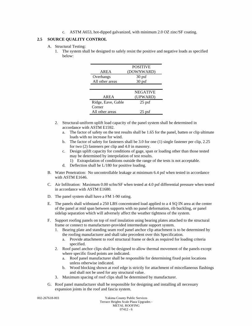
002-267618-003 Yakima County Public Services Terrace Heights Scale Plaza Upgrades - METAL ROOFING 07412 - 6
c. ASTM A653, hot-dipped galvanized, with minimum 2.0 OZ zinc/SF coating.
2.5 SOURCE QUALITY CONTROL
A. Structural Testing: 1. The system shall be designed to safely resist the positive and negative loads as specified
below:
AREA POSITIVE
(DOWNWARD) Overhangs 30 psf All other areas 30 psf
AREA NEGATIVE (UPWARD)
Ridge, Eave, Gable 25 psf Corner All other areas 25 psf
2. Structural-uniform uplift load capacity of the panel system shall be determined in
accordance with ASTM E1592. a. The factor of safety on the test results shall be 1.65 for the panel, batten or clip ultimate
loads with no increase for wind. b. The factor of safety for fasteners shall be 3.0 for one (1) single fastener per clip, 2.25
for two (2) fasteners per clip and 4.0 in masonry. c. Design uplift capacity for conditions of gage, span or loading other than those tested
may be determined by interpolation of test results. 1) Extrapolation of conditions outside the range of the tests is not acceptable.
d. Deflection shall be L/180 for positive loading.
B. Water Penetration: No uncontrollable leakage at minimum 6.4 psf when tested in accordance with ASTM E1646.
C. Air Infiltration: Maximum 0.00 scfm/SF when tested at 4.0 psf differential pressure when tested in accordance with ASTM E1680.
D. The panel system shall have a FM 1-90 rating.
E. The panels shall withstand a 250 LBS concentrated load applied to a 4 SQ IN area at the center of the panel at mid span between supports with no panel deformation, rib buckling, or panel sidelap separation which will adversely affect the weather tightness of the system.
F. Support roofing panels on top of roof insulation using bearing plates attached to the structural frame or connect to manufacturer-provided intermediate support system. 1. Bearing plate and standing seam roof panel anchor clip attachment is to be determined by
the roofing manufacturer and shall take precedent over this Specification. a. Provide attachment to roof structural frame or deck as required for loading criteria
specified. 2. Roof panel anchor clips shall be designed to allow thermal movement of the panels except
where specific fixed points are indicated. a. Roof panel manufacturer shall be responsible for determining fixed point locations
unless otherwise indicated. b. Wood blocking shown at roof edge is strictly for attachment of miscellaneous flashings
and shall not be used for any structural value. 3. Maximum spacing of roof clips shall be determined by manufacturer.
G. Roof panel manufacturer shall be responsible for designing and installing all necessary expansion joints in the roof and fascia system.
002-267618-003 Yakima County Public Services Terrace Heights Scale Plaza Upgrades - METAL ROOFING 07412 - 7
2.6 MAINTENANCE MATERIALS
A. Provide Owner with 4 OZ of touch-up paint to match each different color used in the system.
PART 3 - EXECUTION
3.1 INSTALLATION
A. Provide all closures, trim, angles, plates, calking, gaskets, fasteners, washers, etc., as required for a complete water and air tight installation.
B. Install all soffit panels in accordance with manufacturer's recommendations using concealed fasteners when possible. 1. Exposed fasteners to be painted to match soffit finish.
C. Install products in accordance with manufacturer's instructions, SMACNA (where referenced) and details shown on Drawings.
D. Attachments shall allow for thermal expansion and contraction.
E. Seal all joints as required for watertight installation.
F. Install panels in one (1) continuous length from ridge to eave.
G. Touch-up paint all damaged surfaces.
END OF SECTION

002-267618-003 Yakima County Public Services Terrace Heights Scale Plaza Upgrades - METAL ROOFING 07412 - 8
002-267618-003 Yakima County Public Services Terrace Heights Scale Plaza Upgrades - FLASHING AND SHEET METAL 07600 - 1
SECTION 07600
FLASHING AND SHEET METAL
PART 1 - GENERAL
1.1 SUMMARY
A. Section Includes: Architectural flashing and sheet metal work.
B. Related Specification Sections include but are not necessarily limited to: 1. Section 07900 - Joint Sealants. 2. Section 09905 - Painting and Protective Coatings.
1.2 QUALITY ASSURANCE
A. Referenced Standards: 1. ASTM International (ASTM): 2. Sheet Metal and Air Conditioning Contractors' National Association (SMACNA):
a. Architectural Sheet Metal Manual, Sixth Edition, 2003.
B. Qualifications: 1. Sheet metal fabricator shall have minimum 10 years experience in fabrication of sheet metal
items similar to items specified. 2. Sheet metal installer shall have minimum five (5) years experience installing sheet metal
items specified.
1.3 DEFINITIONS
A. Installer or Applicator: 1. Installer or applicator is the person actually installing or applying the product in the field at
the Project site. 2. Installer and applicator are synonymous.
1.4 SUBMITTALS
A. See Specification Section 01340 for requirements for the mechanics and administration of the submittal process.
B. Product technical data including: 1. Acknowledgement that products submitted meet requirements of standards referenced. 2. Manufacturer's installation instructions.
C. Fabrication and/or layout drawings. 1. Scaled drawing showing expansion joint locations, special conditions, profile, fastening and
jointing details. a. Minimum plan scale: 1/8 IN = 1 FT. b. Minimum detail scale: 1-1/2 IN = 1 FT.
D. Fabricator qualifications.
E. Installer qualifications.
F. Samples: 1. Finish and color samples for each product specified for Engineer preliminary color
selection. 2. For final color selection, provide two (2) 2 IN x 3 IN colored metal samples for each color
selected during the preliminary color selection.
G. Miscellaneous Submittals: 1. Warranty: Manufacturer's sample warranty language.
002-267618-003 Yakima County Public Services Terrace Heights Scale Plaza Upgrades - FLASHING AND SHEET METAL 07600 - 2
1.5 WARRANTY
A. Furnish five (5) year warranty on sheet metal work, signed jointly by Contractor and sheet metal installer. 1. Agree to repair or replace work which leaks water or, where applicable, air or deteriorates
excessively, including color failure, or otherwise fails to perform as watertight and, where appropriate, airtight flashing.
PART 2 - PRODUCTS
2.1 ACCEPTABLE MANUFACTURERS
A. Subject to compliance with the Contract Documents, the following manufacturers are acceptable: 1. Clad steel fabrications:
a. Vincent Metal Goods. b. Peterson Aluminum Corp.
2. PVDF resin: a. PPG - DURANAR. b. Valspar - Fluropon. c. Arkema Inc. - KYNAR 500. d. Solvay Solexis - HYLAR 5000.
B. Submit request for substitution in accordance with Specification Section 01640.
2.2 MATERIALS
A. Sheet Metal: Steel, galvanized per ASTM A653.
B. Sheet Metal: Stainless steel, ASTM A167 or ASTM A176.
C. Fasteners: Non-ferrous compatible with sheet metal.
D. Retainer Clips and Continuous Cleats: Galvanized steel or stainless steel.
E. Solder: ASTM B32.
F. Dissimilar Metal Protection: Comply with Specification Section 09905.
2.3 ACCESSORIES
A. Accessories as required to form a complete water and airtight system.
B. Gutters: 1. Style 'F' gutter per SMACNA Figure 1-2. 2. Size as indicated on Drawings. 3. Clad steel. 4. Seamless construction fabricated in longest practical lengths.
C. Downspouts: 1. Round. 2. Materials to match gutters. 3. Seamless construction fabricated in longest practical lengths.
2.4 FABRICATION
A. Sheet Metal (Steel): 1. Minimum 24 GA galvanized steel; G60 coating. 2. Match gage of surrounding sheet metal.
B. Sheet Metal (Stainless Steel): Minimum 24 GA with #4 finish.
002-267618-003 Yakima County Public Services Terrace Heights Scale Plaza Upgrades - FLASHING AND SHEET METAL 07600 - 3
C. Retainer Clips and Continuous Cleats: 1. Use 16 GA galvanized steel, G60 coating minimum with ferrous steel flashing, coping and
counterflashing and standing seam metal roofing wall trim. 2. Use 0.050 IN stainless steel with aluminum or stainless steel.
D. Shop fabricate items to maximum extent possible. 1. Fabricate true and sharp to profiles and sizes indicated on Drawings.
a. Shop fabricate and weld or solder all corners.
PART 3 - EXECUTION
3.1 PREPARATION
A. Provide items to be built into other construction to Contractor in time to allow their installation.
3.2 INSTALLATION
A. Install products in accordance with manufacturer's instructions, SMACNA, and as indicated on Drawings.
B. Solder steel and weld aluminum to achieve weathertight joints and required details; do not solder or weld slip joints and prefinished items.
C. Set top edges of membrane flashing and sheet metal flashing into reglets.
D. Fasten materials at intervals recommended by SMACNA.
E. Install slip joints to allow for thermal movement as recommended by SMACNA and manufacturer. 1. Maximum spacing: 10 FT OC. 2. Provide slip joint 24 IN from corners. 3. Provide slip joint at each vertical expansion joint location in wall.
a. Provide break in continuous cleat at each vertical expansion joint. b. The above expansion joints do not include brick veneer expansion joints.
F. Caulk slip joints with two (2) beads of sealant on each side of slip joint overlap. 1. Refer to Specification Section 07900 for sealant.
G. Caulk all exposed joints of coping with sealant to match color of metal being sealed.
H. Form flashings to provide spring action with exposed edges hemmed or folded to create tight junctures.
I. Provide dissimilar metals and materials protection where dissimilar metals come in contact or where sheet metal contacts mortar, concrete masonry or concrete. 1. Refer to Specification Section 09905 for dissimilar metals protection.
J. Provide all components necessary to create watertight junctures between roofing and sheet metal work.
K. Provide all miscellaneous sheet metal items not specifically covered elsewhere, as indicated or required to provide a weathertight installation.
END OF SECTION

002-267618-003 Yakima County Public Services Terrace Heights Scale Plaza Upgrades - FLASHING AND SHEET METAL 07600 - 4
002-267618-003 Yakima County Public Services Terrace Heights Scale Plaza Upgrades - JOINT SEALANTS 07900 - 1
SECTION 07900
JOINT SEALANTS
PART 1 - GENERAL
1.1 SUMMARY
A. Section Includes: Sealant work.
B. Related Specification Sections include but are not necessarily limited to Section 09905 - Painting and Protective Coatings.
C. Work included consists of but is not necessarily limited to: 1. Sealing all joints which will permit penetration of dust, air or moisture, unless sealing work
is specifically required under other Specification Sections. a. Work may include the following:
1) Flashing reglets and retainers. 2) Exterior wall joints. 3) Flooring joints. 4) Isolation joints. 5) Joints between paving and building. 6) Concrete construction, control and expansion joints, exterior and interior. 7) Sawed joints in interior concrete slabs. 8) Joints between precast roof units, between precast roof units and walls, and all
exterior and interior joints between precast wall panels. 9) Joints at penetrations of walls, floors and decks by piping and other services and
equipment. 10) Exterior and interior perimeters of exterior and interior door and window frames,
louvers, grilles, etc. 11) Thresholds at exterior doors. 12) Sealing of plumbing fixtures to floor or wall. 13) Sealing around piping, duct or conduit penetrations through roof, floors, interior
and exterior walls. 14) Sealing perimeter and penetrations of sound insulated walls. 15) Other joints where sealant, expanding foam sealant or compressible sealant is
indicated.
1.2 QUALITY ASSURANCE
A. Referenced Standards: 1. American Concrete Institute (ACI):
a. 302.1R, Guide for Concrete Floor and Slab Construction. 2. ASTM International (ASTM):
a. C834, Standard Specification for Latex Sealants. b. C920, Standard Specification for Elastomeric Joint Sealants. c. C1521, Standard Practice for Evaluating Adhesion of Installed Weatherproofing
Sealant Joints. 3. NSF International (NSF):
a. 61, Drinking Water System Components - Health Effects. 4. Underwriters Laboratories, Inc. (UL).
B. Qualifications: Sealant applicator shall have minimum five (5) years experience using products specified on projects with similar scope.
002-267618-003 Yakima County Public Services Terrace Heights Scale Plaza Upgrades - JOINT SEALANTS 07900 - 2
C. Mock-Ups: 1. Before sealant work is started, a mock-up of each type of joint shall be sealed where
directed by the Engineer. a. The approved mock-ups shall show the workmanship, bond, and color of sealant
materials as specified or selected for the work and shall be the minimum standard of quality on the entire project.
b. Each sample shall cure for a minimum of seven (7) days at which time the sealant manufacturer's authorized factory representative shall perform adhesion tests on each sample joint. 1) Perform adhesion tests per ASTM C1521. 2) If mock-up is not acceptable or if adhesion test fails, provide additional mock-up
and adhesion testing as required until acceptable to Engineer.
1.3 DEFINITIONS
A. “Caulk(ing),” “calk(ing),”, and “sealant”: Joint sealant work.
B. Defect(ive): Failure of watertightness or airtightness.
C. Finish sealant: Sealant material per this specification applied over face of compressible sealant or expanding foam sealant specified, to provide a finished, colored sealant joint.
D. Installer or Applicator: 1. Installer or applicator is the person actually installing or applying the product in the field at
the Project site. 2. Installer and applicator are synonymous.
1.4 SUBMITTALS
A. See Specification Section 01340 for requirements for the mechanics and administration of the submittal process.
B. Product technical data including: 1. Acknowledgement that products submitted meet requirements of standards referenced. 2. Manufacturer's installation instructions. 3. Manufacturer's recommendations for joint cleaner, primer, backer rod, tooling and bond
breaker.
C. Certification from sealant manufacturer stating product being used is recommended for and is best suited for joint in which it is being applied.
D. Certification of applicator qualification.
E. Samples: 1. Cured sample of each color for Engineer's color selection. 2. Color chart not acceptable.
F. Test Results: 1. Provide adhesion test results for each sealant sample including adhesion results compared to
adhesion requirements. 2. Manufacturer's authorized factory representative recommended remedial measures for all
failing tests.
1.5 DELIVERY, STORAGE, AND HANDLING
A. Deliver material in manufacturer's original unopened containers with labels intact: Labels shall indicate contents and expiration date on material.
002-267618-003 Yakima County Public Services Terrace Heights Scale Plaza Upgrades - JOINT SEALANTS 07900 - 3
PART 2 - PRODUCTS
2.1 ACCEPTABLE MANUFACTURERS
A. Subject to compliance with the Contract Documents, the following manufacturers are acceptable: 1. Compressible sealant:
a. Polytite Manufacturing Corporation. b. Emseal. c. Norton. d. Sandell.
2. Expanding foam sealant: a. Macklanburg Duncan. b. Convenience Products. c. FAI International, Inc.
3. Polyether sealants: a. BASF Sonneborn. b. ChemLink, Inc.
4. Polysulfide rubber sealant: a. Pecora. b. BASF Sonneborn. c. PolySpec.
5. Polyurea joint filler: a. Dayton Superior Specialty Chemical Corporation. b. Euclid Chemical Co. c. L&M Construction Chemicals, Inc. d. BASF Sonneborn.
6. Polyurethane sealants: a. Pecora. b. Sika Chemical Corp. c. BASF Sonneborn. d. Tremco.
7. Silicone sealants: a. ChemLink. b. GE Construction Sealants. c. Dow Corning. d. Tremco.
8. Backer rod, compressible filler, primer, joint cleaners, bond breaker: As recommended by sealant manufacturer.
B. Submit request for substitution in accordance with Specification Section 01640.
2.2 MATERIALS
A. Sealants - General: 1. Provide colors matching materials being sealed. 2. Where compound is not exposed to view in finished work, provide manufacturer's color
which has best performance. 3. Nonsagging sealant for vertical and overhead horizontal joints. 4. Sealants for horizontal joints: Self-leveling pedestrian/traffic grade. 5. Joint cleaner, primer, bond breaker: As recommended by sealant manufacturer. 6. Sealant backer rod and/or compressible filler:
a. Closed cell polyethylene, polyethylene jacketed polyurethane foam, or other flexible, nonabsorbent, non-bituminous material recommended by sealant manufacturer to: 1) Control joint depth. 2) Break bond of sealant at bottom of joint. 3) Provide proper shape of sealant bead. 4) Serve as expansion joint filler.
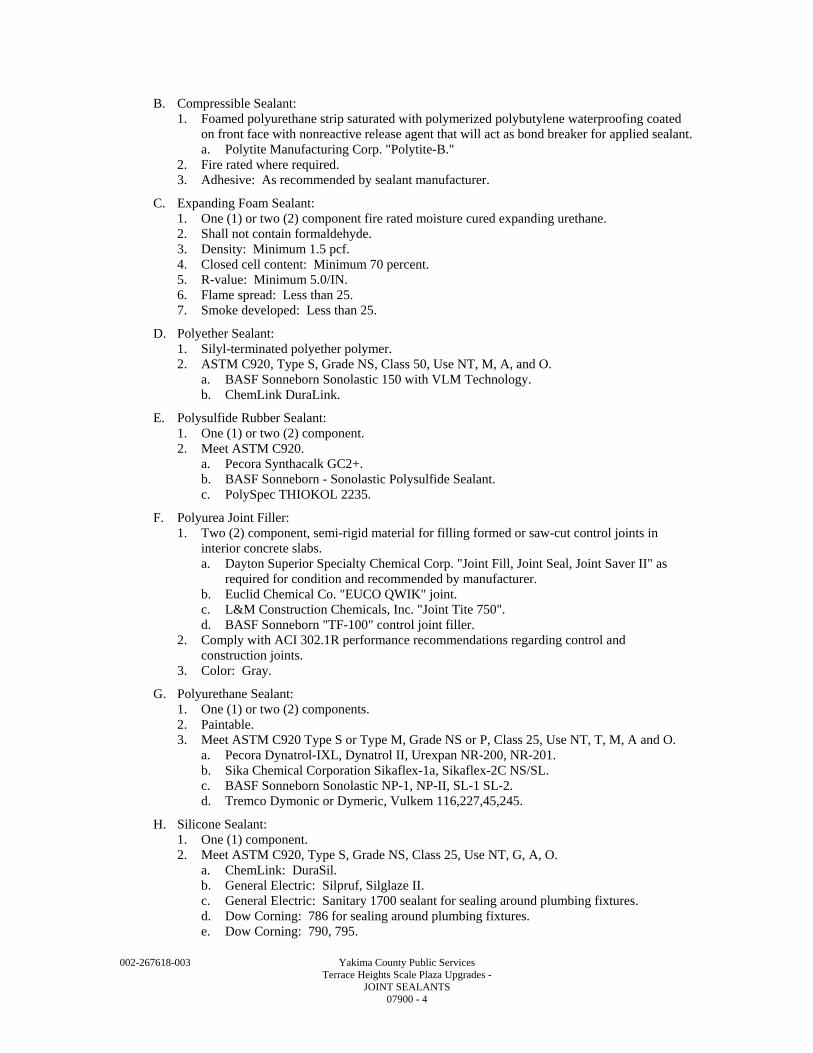
002-267618-003 Yakima County Public Services Terrace Heights Scale Plaza Upgrades - JOINT SEALANTS 07900 - 4
B. Compressible Sealant: 1. Foamed polyurethane strip saturated with polymerized polybutylene waterproofing coated
on front face with nonreactive release agent that will act as bond breaker for applied sealant. a. Polytite Manufacturing Corp. "Polytite-B."
2. Fire rated where required. 3. Adhesive: As recommended by sealant manufacturer.
C. Expanding Foam Sealant: 1. One (1) or two (2) component fire rated moisture cured expanding urethane. 2. Shall not contain formaldehyde. 3. Density: Minimum 1.5 pcf. 4. Closed cell content: Minimum 70 percent. 5. R-value: Minimum 5.0/IN. 6. Flame spread: Less than 25. 7. Smoke developed: Less than 25.
D. Polyether Sealant: 1. Silyl-terminated polyether polymer. 2. ASTM C920, Type S, Grade NS, Class 50, Use NT, M, A, and O.
a. BASF Sonneborn Sonolastic 150 with VLM Technology. b. ChemLink DuraLink.
E. Polysulfide Rubber Sealant: 1. One (1) or two (2) component. 2. Meet ASTM C920.
a. Pecora Synthacalk GC2+. b. BASF Sonneborn - Sonolastic Polysulfide Sealant. c. PolySpec THIOKOL 2235.
F. Polyurea Joint Filler: 1. Two (2) component, semi-rigid material for filling formed or saw-cut control joints in
interior concrete slabs. a. Dayton Superior Specialty Chemical Corp. "Joint Fill, Joint Seal, Joint Saver II" as
required for condition and recommended by manufacturer. b. Euclid Chemical Co. "EUCO QWIK" joint. c. L&M Construction Chemicals, Inc. "Joint Tite 750". d. BASF Sonneborn "TF-100" control joint filler.
2. Comply with ACI 302.1R performance recommendations regarding control and construction joints.
3. Color: Gray.
G. Polyurethane Sealant: 1. One (1) or two (2) components. 2. Paintable. 3. Meet ASTM C920 Type S or Type M, Grade NS or P, Class 25, Use NT, T, M, A and O.
a. Pecora Dynatrol-IXL, Dynatrol II, Urexpan NR-200, NR-201. b. Sika Chemical Corporation Sikaflex-1a, Sikaflex-2C NS/SL. c. BASF Sonneborn Sonolastic NP-1, NP-II, SL-1 SL-2. d. Tremco Dymonic or Dymeric, Vulkem 116,227,45,245.
H. Silicone Sealant: 1. One (1) component. 2. Meet ASTM C920, Type S, Grade NS, Class 25, Use NT, G, A, O.
a. ChemLink: DuraSil. b. General Electric: Silpruf, Silglaze II. c. General Electric: Sanitary 1700 sealant for sealing around plumbing fixtures. d. Dow Corning: 786 for sealing around plumbing fixtures. e. Dow Corning: 790, 795.
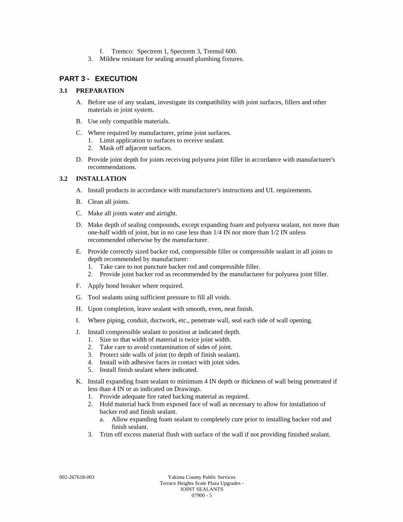
002-267618-003 Yakima County Public Services Terrace Heights Scale Plaza Upgrades - JOINT SEALANTS 07900 - 5
f. Tremco: Spectrem 1, Spectrem 3, Tremsil 600. 3. Mildew resistant for sealing around plumbing fixtures.
PART 3 - EXECUTION
3.1 PREPARATION
A. Before use of any sealant, investigate its compatibility with joint surfaces, fillers and other materials in joint system.
B. Use only compatible materials.
C. Where required by manufacturer, prime joint surfaces. 1. Limit application to surfaces to receive sealant. 2. Mask off adjacent surfaces.
D. Provide joint depth for joints receiving polyurea joint filler in accordance with manufacturer's recommendations.
3.2 INSTALLATION
A. Install products in accordance with manufacturer's instructions and UL requirements.
B. Clean all joints.
C. Make all joints water and airtight.
D. Make depth of sealing compounds, except expanding foam and polyurea sealant, not more than one-half width of joint, but in no case less than 1/4 IN nor more than 1/2 IN unless recommended otherwise by the manufacturer.
E. Provide correctly sized backer rod, compressible filler or compressible sealant in all joints to depth recommended by manufacturer: 1. Take care to not puncture backer rod and compressible filler. 2. Provide joint backer rod as recommended by the manufacturer for polyurea joint filler.
F. Apply bond breaker where required.
G. Tool sealants using sufficient pressure to fill all voids.
H. Upon completion, leave sealant with smooth, even, neat finish.
I. Where piping, conduit, ductwork, etc., penetrate wall, seal each side of wall opening.
J. Install compressible sealant to position at indicated depth. 1. Size so that width of material is twice joint width. 2. Take care to avoid contamination of sides of joint. 3. Protect side walls of joint (to depth of finish sealant). 4. Install with adhesive faces in contact with joint sides. 5. Install finish sealant where indicated.
K. Install expanding foam sealant to minimum 4 IN depth or thickness of wall being penetrated if less than 4 IN or as indicated on Drawings. 1. Provide adequate fire rated backing material as required. 2. Hold material back from exposed face of wall as necessary to allow for installation of
backer rod and finish sealant. a. Allow expanding foam sealant to completely cure prior to installing backer rod and
finish sealant. 3. Trim off excess material flush with surface of the wall if not providing finished sealant.
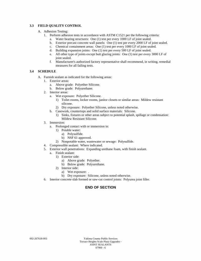
002-267618-003 Yakima County Public Services Terrace Heights Scale Plaza Upgrades - JOINT SEALANTS 07900 - 6
3.3 FIELD QUALITY CONTROL
A. Adhesion Testing: 1. Perform adhesion tests in accordance with ASTM C1521 per the following criteria:
a. Water bearing structures: One (1) test per every 1000 LF of joint sealed. b. Exterior precast concrete wall panels: One (1) test per every 2000 LF of joint sealed. c. Chemical containment areas: One (1) test per every 1000 LF of joint sealed. d. Building expansion joints: One (1) test per every 500 LF of joint sealed. e. All other type of joints except butt glazing joints: One (1) test per every 3000 LF of
joint sealed. f. Manufacturer's authorized factory representative shall recommend, in writing, remedial
measures for all failing tests.
3.4 SCHEDULE
A. Furnish sealant as indicated for the following areas: 1. Exterior areas:
a. Above grade: Polyether Silicone. b. Below grade: Polyurethane.
2. Interior areas: a. Wet exposure: Polyether Silicone.
1) Toilet rooms, locker rooms, janitor closets or similar areas: Mildew resistant silicone.
2) Dry exposure: Polyether Silicone, unless noted otherwise. b. Casework, countertops and solid surface materials: Silicone.
1) Sinks, fixtures or other areas subject to potential splash, spillage or condensation: Mildew Resistant Silicone.
3. Immersion: a. Prolonged contact with or immersion in:
1) Potable water: a) Polysulfide. b) NSF 61 approved.
2) Nonpotable water, wastewater or sewage: Polysulfide. 4. Compressible sealant: Where indicated. 5. Exterior wall penetrations: Expanding urethane foam, with finish sealant.
a. Finish sealant: 1) Exterior side:
a) Above grade: Polyether. b) Below grade: Polyurethane.
2) Interior side: a) Wet exposure: . b) Dry exposure: Silicone, unless noted otherwise.
6. Interior concrete slab formed or saw-cut control joints: Polyurea joint filler.
END OF SECTION

D I V I S I O N 0 8 DOORS AND WINDOWS

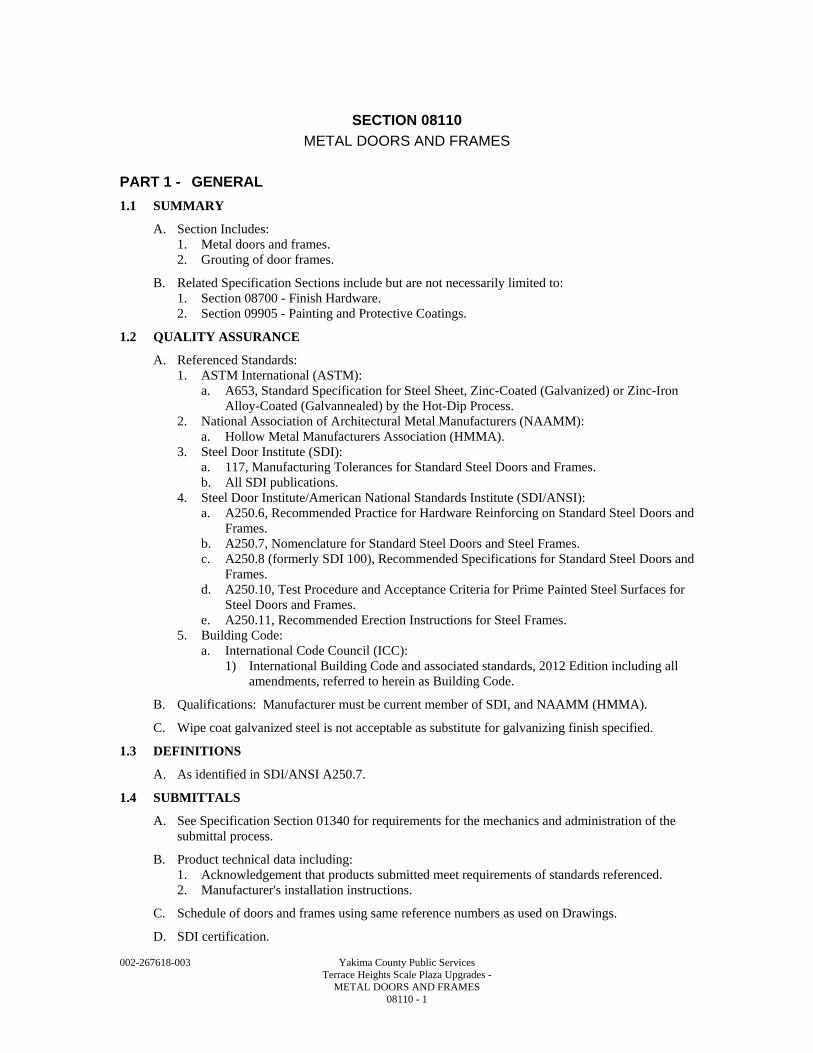
002-267618-003 Yakima County Public Services Terrace Heights Scale Plaza Upgrades - METAL DOORS AND FRAMES 08110 - 1
SECTION 08110
METAL DOORS AND FRAMES
PART 1 - GENERAL
1.1 SUMMARY
A. Section Includes: 1. Metal doors and frames. 2. Grouting of door frames.
B. Related Specification Sections include but are not necessarily limited to: 1. Section 08700 - Finish Hardware. 2. Section 09905 - Painting and Protective Coatings.
1.2 QUALITY ASSURANCE
A. Referenced Standards: 1. ASTM International (ASTM):
a. A653, Standard Specification for Steel Sheet, Zinc-Coated (Galvanized) or Zinc-Iron Alloy-Coated (Galvannealed) by the Hot-Dip Process.
2. National Association of Architectural Metal Manufacturers (NAAMM): a. Hollow Metal Manufacturers Association (HMMA).
3. Steel Door Institute (SDI): a. 117, Manufacturing Tolerances for Standard Steel Doors and Frames. b. All SDI publications.
4. Steel Door Institute/American National Standards Institute (SDI/ANSI): a. A250.6, Recommended Practice for Hardware Reinforcing on Standard Steel Doors and
Frames. b. A250.7, Nomenclature for Standard Steel Doors and Steel Frames. c. A250.8 (formerly SDI 100), Recommended Specifications for Standard Steel Doors and
Frames. d. A250.10, Test Procedure and Acceptance Criteria for Prime Painted Steel Surfaces for
Steel Doors and Frames. e. A250.11, Recommended Erection Instructions for Steel Frames.
5. Building Code: a. International Code Council (ICC):
1) International Building Code and associated standards, 2012 Edition including all amendments, referred to herein as Building Code.
B. Qualifications: Manufacturer must be current member of SDI, and NAAMM (HMMA).
C. Wipe coat galvanized steel is not acceptable as substitute for galvanizing finish specified.
1.3 DEFINITIONS
A. As identified in SDI/ANSI A250.7.
1.4 SUBMITTALS
A. See Specification Section 01340 for requirements for the mechanics and administration of the submittal process.
B. Product technical data including: 1. Acknowledgement that products submitted meet requirements of standards referenced. 2. Manufacturer's installation instructions.
C. Schedule of doors and frames using same reference numbers as used on Drawings.
D. SDI certification.
002-267618-003 Yakima County Public Services Terrace Heights Scale Plaza Upgrades - METAL DOORS AND FRAMES 08110 - 2
1.5 DELIVERY, STORAGE, AND HANDLING
A. Store doors and frames in accordance with SDI/ANSI A250.11.
PART 2 - PRODUCTS
2.1 ACCEPTABLE MANUFACTURERS
A. Subject to compliance with the Contract Documents, the following manufacturers are acceptable: 1. Metal doors and frames:
a. CECO Corporation. b. Steelcraft Manufacturing Co. c. Curries Company.
B. Submit request for substitution in accordance with Specification Section 01640.
2.2 MATERIALS
A. Steel Sheet: Hot-dipped galvannealed steel, ASTM A653, A60 coating.
B. Frames: Hot-dipped galvannealed steel, ASTM A653, A60 coating.
C. Supports and Reinforcing: Hot-dipped galvannealed steel, ASTM A653, A60 coating.
D. Inserts, Bolts and Fasteners: Manufacturer's standard.
E. Primer: Manufacturer's standard coating meeting SDI/ANSI A250.10.
F. Galvannealed Coating Repair: See Specification Section 09905.
G. Thermal Insulation: Polyurethane, CFC free.
H. Sound Insulation: Fiberglass batt insulation or impregnated Kraft honeycomb.
2.3 ACCESSORIES
A. Frame Anchors: 1. Jamb anchors:
a. Masonry wire anchors: Minimum 0.1875 IN wire, galvanized. b. Existing wall anchor: Minimum 18 GA, galvanized. c. Stud partition and base anchors: Minimum 18 GA, galvanized.
2.4 FABRICATION
A. General: 1. SDI/ANSI A250.8. 2. Fabricate rigid, neat in appearance and free from defects. 3. Form to sizes and profiles indicated on Drawings.
a. Beveled edge. 4. Fit and assemble in shop wherever practical. 5. Mark work that cannot be fully assembled in shop to assure proper assembly at site. 6. Continuously wire weld all joints, dress exposed joints smooth and flush. 7. Fabricate doors and frames to tolerance requirements of SDI 117. 8. Fit doors to SDI clearances. 9. All doors shall be handed. 10. Hinge cut-out depth and size on doors and frames shall match hinge specified in
Specification Section 08700. 11. Design and fabricate doors to requirements of the Building Code.
B. Hollow Metal Doors: 1. General:
a. 1-3/4 IN thick.
002-267618-003 Yakima County Public Services Terrace Heights Scale Plaza Upgrades - METAL DOORS AND FRAMES 08110 - 3
b. Fabricate with flush top caps. 1) Thickness and material to match door face. 2) On exterior doors, seal weld top cap to door face and grind smooth and flush. 3) On interior doors, attach top cap to door with concealed fasteners or by welding.
a) Factory seal if attached with fasteners. b) No exposed fasteners will be accepted.
c. Continuously wire weld all joints and dress, smooth and flush. d. Galvannealed per ASTM A653, A60 coating.
2. Exterior: a. Doors 48 IN wide, or less: SDI/ANSI A250.8, Level 3, and physical performance level
A, Model 2. 1) Face sheet minimum thickness: 16 GA. 2) Insulated: Minimum R10.
3. Interior: a. Doors 48 IN wide, or less: SDI/ANSI A250.8, Level 2, and physical performance level
"B", Model 2. 1) Face sheet minimum thickness: 18 GA.
b. Sound insulated, minimum STC-35.
C. Hollow Metal Frames: 1. Door frames:
a. Provide 2 IN face at all heads, jambs and mullions for frames in stud walls. b. Provide 4 IN face at head where noted on Drawings or required by wall construction. c. 26 GA galvannealed steel boxes welded to frame at back of all hardware cutouts. d. Steel plate reinforcement welded to frame for hinge, strikes, closers and surface-
mounted hardware reinforcing. 1) All plate reinforcement shall meet size and thickness requirements of
SDI/ANSI A250.8. 2) Galvannealed per ASTM A653, minimum A60.
e. Split type frames not acceptable. 1) All horizontal and vertical mullions and transom bars shall be welded to adjacent
members. f. Conceal all fasteners. g. Frames shall be set up, all face joints continuously wire welded and dressed smooth. h. Exterior (up to 4 FT wide): 16 GA steel galvannealed per ASTM A653, A60. i. Interior: 16 GA steel galvannealed per ASTM A653, A60. j. Provide removable spreaders at bottom of frame.
D. Prepare for finish hardware in accordance with hardware schedule, templates provided by hardware supplier, and SDI/ANSI A250.6. 1. Locate finish hardware in accordance with SDI/ANSI A250.8. 2. See Specification Section 08700 for hardware. 3. Prepare doors for swing direction indicated.
a. Preparing doors for non-handed hinges is not acceptable.
E. After fabrication, clean off mill scale and foreign materials, repair damaged galvannealed surfaces, and treat and prime with rust inhibiting primer.
PART 3 - EXECUTION
3.1 INSTALLATION
A. Install doors and frames in accordance with SDI/ANSI A250.11, the Building Code and manufacturer's instructions.
B. Where applicable, place frames prior to construction of enclosing walls and ceilings.
C. Plumb, align, and brace securely until permanently anchored.
002-267618-003 Yakima County Public Services Terrace Heights Scale Plaza Upgrades - METAL DOORS AND FRAMES 08110 - 4
D. After completion of walls, remove temporary braces and spreaders.
E. Use plastic plugs to keep silencer holes clear during construction.
F. Immediately after erection, sand smooth rusted or damaged areas of prime and galvannealed coating.
G. Touch-up prime and galvannealed coating in accordance with Specification Section 09905.
H. Where indicated to be painted leave finish smooth for finish painting.
I. Install three (3) silencers on strike jamb of single door frame and two (2) on head of double door frame.
J. Number and location of anchors shall be in accordance with frame manufacturer's recommendation with minimum of three (3) anchors per jamb.
K. Protect doors and frames during construction.
END OF SECTION
002-267618-003 Yakima County Public Services Terrace Heights Scale Plaza Upgrades - OVERHEAD COILING COUNTER GRILLES 08330 - 1
SECTION 08330
OVERHEAD COILING COUNTER GRILLES
PART 1 - GENERAL
1.1 SUMMARY
A. Section includes custom overhead coiling counter grilles as indicated on the Drawings.
B. Related Sections: Coordinate related work specified in other parts of the Contract Documents, including but not limited to the following: 1. Section 06100 – Rough Carpentry. 2. Section 09250 – Gypsum Board.
1.2 REFERENCES
A. Comply with the requirements of Section 01095.
1.3 SYSTEM DESCRIPTION
A. Door Operation: Manual, push-up type.
1.4 SUBMITTALS
A. General: Submit in accordance with the Conditions of Contract and Section 01340.
B. Shop Drawings: 1. Show complete details of construction and installation, including materials, dimensions,
fastenings, finishes, hardware, connections and other information. 2. Indicate placement, including elevations, walls on which materials are installed,
identification information, etc.
C. Maintenance Data: Provide in ‘Project Operation and Maintenance Manual’ required in accordance with Section 01340.
1.5 QUALITY ASSURANCE
A. Installer: Installers must be an authorized distributor of the manufacturer of products identified in this Section.
B. Duty Rating: Products of this Section are to be rated by the manufacturer to a standard of 25 cycles per day and an operational life of 50,000 cycles.
C. Source Limitations: Provide manufactured products identified in this Section from a single manufacturer.
1.6 DELIVERY, STORAGE AND HANDLING
A. Deliver products to site under provisions of Section 01600.
B. Store and protect products under provisions of Section 01600.
C. Store in original protective packaging until time of installation.
PART 2 - PRODUCTS
2.1 MANUFACTURERS
A. Subject to compliance with requirements, manufacturers offering products that may be incorporated in the work include, but are not limited to, the following: 1. The Cookson Company. 2. Alumatek. 3. Dynamic Closures.
002-267618-003 Yakima County Public Services Terrace Heights Scale Plaza Upgrades - OVERHEAD COILING COUNTER GRILLES 08330 - 2
4. Or approved other.
2.2 MATERIALS
A. Aluminum.
2.3 MANUFACTURED UNITS
A. Grille: Interlocking Aluminum Construction. 1. Vertical Elements: 1/8 IN thickness; 5/8 IN wide; 3 3/4 IN high, hinged vertical connecting
links. 2. Horizontal Elements: 5/16 IN DIA rods on 2 IN centers. 3. Finish: Mill.
B. Bottom Bar: 1. Rectangular section mill finish aluminum. 2. Foot: Coordinate the foot profile with the sill indicated on the Drawings. 3. Provide two (2) vinyl loop type astragals for contact with the sill. 4. Finish: Mill.
C. Guides: 1. Continuous, vertical mounted, fastened directly to structure as indicated on the Drawings. 2. Wear Strips: Nylon. Continuous the full length of both guides. 3. Finish: Mill. Steel is not acceptable.
D. Counterbalance: 1. Steel pipe designed to carry the weight of the grille without measurable deflection. 2. Springs: Adjustable oil tempered helical torsion type.
E. Hood Enclosure: None, in accordance with ‘above the ceiling’ installation indicated on the Drawings.
F. Hardware: 1. Lock Mechanism:
a. Deadbolt/Deadlatch: Adams Rite: “MS 1847-02.” b. Cylinder Lock: Provide per Section 08700.
PART 3 - EXECUTION
3.1 INSTALLATION
A. Manufacturer’s Instructions: 1. Comply with manufacturer’s instructions, including technical bulletins and product catalog
data. 2. Retain manufacturer’s written installation instructions at the project site.
3.2 ADJUSTING
A. Adjust for unencumbered, smooth operation and verify mechanisms function properly. 1. Adjust grilles to operate with a maximum of 20 LBS of effort pulling up or pushing down.
B. Replace damaged or defective items.
3.3 CLEANING
A. Clean work of this Section in accordance with provisions of Section 01710.
B. Remove temporary labels and protective coverings.
C. Clean exposed surfaces according to manufacturer’s written instructions.

002-267618-003 Yakima County Public Services Terrace Heights Scale Plaza Upgrades - OVERHEAD COILING COUNTER GRILLES 08330 - 3
3.4 PROTECTION
A. Protect work of this Section from damage and deterioration until completion and acceptance by Owner.
END OF SECTION

002-267618-003 Yakima County Public Services Terrace Heights Scale Plaza Upgrades - OVERHEAD COILING COUNTER GRILLES 08330 - 4
002-267618-003 Yakima County Public Services Terrace Heights Scale Plaza Upgrades - ALUMINUM WINDOWS - HORIZONTAL SLIDERS 08525 - 1
SECTION 08525
ALUMINUM WINDOWS - HORIZONTAL SLIDERS
PART 1 - GENERAL
1.1 SUMMARY
A. Furnish all labor, materials, tools, equipment, and services for all Aluminum Windows – Horizontal Slide, as indicated, in accordance with provisions of Contract Documents.
B. Completely coordinate with work of other trades.
1.2 QUALITY ASSURANCE
A. Window standard: ANSI/AAMA-101 Standard Specification for Windows, Doors and Unit Skylights.
1.3 TEST REQUIREMENTS
A. Work Includes: 1. Provide independent laboratory test report. 2. Submit following test data, performed on Test Unit, with shop drawings, prior to installation
of windows. 3. Manufacturers requesting approval submit test data with request. 4. Condensation Resistance, Thermal, and Temperature Exposure Tests may be performed on
Alternate Test Units. 5. Perform tests for submittal on "Test Units" as specified. 6. Use of certifiable units larger than tested is allowed provided calculated deflection does not
exceed maximum listed when using effective moment(s) of inertia and section properties of window elements obtained from test of smaller unit and applying them to exact dimensions and conditions of larger project unit.
7. Test air infiltration first, water resistance second and other tests in any order.
B. Test Unit: 1. Largest size window unit for project or minimum 5 x 7 FT unit, either fixed or with single
operating dual sash, unless otherwise noted. 2. Completely assembled and glazed as specified. 3. Install in test chamber to simulate and be in accord with installation details to be used on
project. 4. Test data on vertical pivot windows will be accepted for fixed windows for Condensation
Resistance, Thermal, Temperature Exposure and Acoustical Tests provided fixed windows are same as vertical windows tested in following respects: a. Same frame section (or same family of extrusions). b. Same basic metal mass inside and outside. c. Identical thermal break. d. Same type of glazing.
C. Alternate Test Unit: Same as Test Unit except as follows: 1. Window unit as required by AAMA. 2. Unit need not be identical to project unit but must comply as follows:
a. Same thickness of frame section (front to back). b. Identical thermal break. c. Same basic metal mass on outside. d. Same type of glazing.
3. Submit information necessary to prove that Alternate Test Unit complies in above respects.
D. Air Infiltration Test: 1. With sash and ventilator closed and locked, test in accord with ASTM-E283.

002-267618-003 Yakima County Public Services Terrace Heights Scale Plaza Upgrades - ALUMINUM WINDOWS - HORIZONTAL SLIDERS 08525 - 2
2. Air infiltration, in CFM/FT of crack length, at pressure differential of 6.24 psf as follows: a. Operable windows: Maximum 0.10. b. Fixed windows: Maximum 0.06.
E. Water Resistance Test: 1. Mount glazed unit in its vertical position, continuously supported around outside perimeter
with sash and ventilators closed and locked. 2. Test in accord with ASTM E331. 3. No uncontrolled leakage allowed, with pressure differential of 6.24 psf.
F. Uniform Load Deflection Test: 1. Test in accord with ASTM E330. 2. Subject unit to load of 25 psf applied to outside of window and 25 psf applied to inside of
window. 3. Maximum allowable deflection of unsupported span: L/175. 4. No glass breakage, permanent damage to fasteners, hardware parts, support arms or
activating mechanisms, or other damage which would cause window to be inoperable.
G. Uniform Load Structural Test: 1. Test in accord with ASTM E330. 2. Subject unit to loads indicated below. 3. Stabilize pressure and maintain it for minimum period of ten seconds. 4. No glass breakage, permanent damage to fasteners, hardware parts, support arms or
activating mechanisms or other damage which would cause window to be inoperable allowed.
5. Maximum permanent deformation of main frame, sash or ventilator member: 0.4 percent of its span.
6. After performing Uniform Load Structural Test: Increase loads 1-1/2 times and perform Safety Test.
7. No glass breakage, permanent damage to fasteners, hardware parts, activating mechanisms or other damage which would cause window to be inoperable.
8. Design unit to withstand design pressures as required by applicable building codes.
1.4 SUBMITTALS
A. Elevations, sections and details for review of support system to building frame.
B. Samples: Range samples of aluminum finishes.
C. Certified independent laboratory test reports verifying requirements.
D. Contract Closeout Information: Warranty.
1.5 WARRANTY
A. Written five (5) year warranty signed jointly by manufacturer and installer, agreeing to repair or replace work performed under this Section which fails. 1. Failure includes but not limited to, defects in materials, workmanship, water tightness of
assembly, caulking, glazing or other defect which affects its ability to perform as a weathertight envelope.
PART 2 - PRODUCTS
2.1 ACCEPTABLE MANUFACTURERS
A. Windows: 1. Base:
a. TRACO, a division of Kawneer. b. Peerless Products. c. EFCO.
002-267618-003 Yakima County Public Services Terrace Heights Scale Plaza Upgrades - ALUMINUM WINDOWS - HORIZONTAL SLIDERS 08525 - 3
B. Submit request for substitution in accordance with Specification Section 01640.
2.2 MATERIALS
A. Model: 1. TRACO NX-6400 Single Slide Thermal Aluminum Windows. 2. KAWNEER TR 7100 Heavy Commercial Thermal Aluminum Windows.
B. Aluminum Extrusions: 1. Alloy 6063-T5 or T6 as recommended by manufacturer. 2. Tensile strength: Minimum 22,000 psi. 3. Main frame and sash members: Minimum 0.062 IN thick.
C. Hardware and Fasteners: 1. Combination pull and latch, which prevents removal of sash when latched. 2. One aluminum automatic handle/lock with finish to match window color and performance
on the interior stile of the exterior secondary sash to engage the frame in the closed position. 3. Avoid use of exposed fasteners. 4. Where exposed fasteners cannot be avoided, use Phillips flat head screws.
D. Weatherstripping: 1. Double row of weatherstripping at horizontal rails and meeting and jamb rails. 2. Rigid PVC weatherseal in one side of the horizontal sash rails, and pile conforming to
AAMA 701/702 with polypropylene center fin in remaining locations.
E. Sealants (within fabricated window units): Type warranted by window manufacturer for joint size and movement conforming to AAMA 800.
F. Sealants (at window perimeter): See Section 07900.
G. Glazing: See Section 08800.
H. General: 1. Color consistency range: 5 delta E’s. 2. Anodic Finish complying with AAMA 611
I. Clear Anodic finish (Class I): 1. Architectural Class I per AAMA 611.
a. 2-step electrolytic. 2. Minimum Coating Thickness: 0.7 mils. 3. Color: “#14”, Clear, AA-M12C22-A41.
2.3 FABRICATION
A. Wherever possible verify actual window openings by accurate field measurement before fabrication. 1. Indicate measurements on final Shop Drawings. 2. Coordinate fabrication schedule with construction progress to avoid delay of work. 3. Where necessary, proceed with fabrication without field measurements, and coordinate
installation tolerances to ensure proper fit.
B. Construct frames with thermal break between inner and outer frame to allow no through metal contact.
C. Fabricate units with corners and intersections either mitered or mortised, welded, with hairline joints and exposed surfaces dressed smooth.
D. Provide means for drainage of water or condensation.
E. Provide units complete with polyvinyl chloride channel glazing gaskets correctly fitted to sash.
002-267618-003 Yakima County Public Services Terrace Heights Scale Plaza Upgrades - ALUMINUM WINDOWS - HORIZONTAL SLIDERS 08525 - 4
PART 3 - EXECUTION
3.1 INSTALLATION
A. Comply with manufacturer's installation recommendations.
B. Set Units Plumb and True. 1. Anchor securely in place. 2. Separate aluminum and other corrodible metal surfaces from sources of corrosion or
electrolytic action.
C. Set frame members in sealant bed, joint fillers or gaskets to provide weathertight construction.
D. Adjust operating sash and hardware to provide tight fit for smooth operation and weathertight closure.
E. Clean aluminum surfaces promptly after installation.
F. Remove excess sealant, dirt and other substances.
G. Lubricate hardware and other moving parts.
H. Provide protection to ensure that units are without damage at time of acceptance by Owner.
3.2 FIELD QUALITY CONTROL
A. Field Tests - General: 1. Owner shall select Aluminum Windows to be tested when representative portion of
Aluminum Windows have been installed, glazed, perimeter caulked and cured. 2. Test for water penetration in accordance with AAMA 501.2-03, Quality Assurance and
Diagnostic Water Leakage Field Check of Installed Storefronts, Curtain Walls, and Sloped Glazing Systems.
3. Where test results do not meet requirements: Correct deficiencies, and implement improved installation procedures for completing balance of Storefront.
3.3 ADJUST AND CLEAN
A. After completion of project, adjust windows for proper operation; recheck installation, weathersealing, sealants and other items of complete installation.
B. Completely clean glass and metal surfaces and remove labels before final acceptance.
END OF SECTION
002-267618-003 Yakima County Public Services Terrace Heights Scale Plaza Upgrades - CONVENIENCE WINDOWS 08561 - 1
SECTION 08561
CONVENIENCE WINDOWS
PART 1 - GENERAL
1.1 SUMMARY
A. Section Includes: Automatic drive-thru service windows.
1.2 REFERENCES
A. General: Standards listed by reference, including revisions by issuing authority, form a part of this Specification Section to the extent indicated. 1. Standards subsequently referred to herein are referred to by an authority abbreviation and a
basic designation.
B. American Society for Testing and Materials (ASTM): 1. B221, Specification for Aluminum-Alloy Extruded Bars, Rods, Wire, Shapes and Tubes. 2. C1036, Specification for Flat Glass. 3. C1048, Specification for Heat Treated Flat Glass - Kind HS, Kind FT Coated and Uncoated
Glass.
C. The Aluminum Association (AA): 1. Aluminum Finishes Manual.
D. American Architectural Manufacturer's Association (AAMA): 1. ANSI/AAMA 101: Voluntary Specification for Aluminum and Poly Vinyl Chloride Prime
Windows and Glass Doors.
E. Underwriters Laboratory, Inc. (UL) and Underwriters Laboratory of Canada (ULC): 1. 325, Electrical Door, Drapery, Gate, Louver, and Window Operators and Systems. 2. 752, Ballistic Resistance Standard, Levels 1-4.
F. American National Standards Institute (ANSI): 1. Z97.1: Safety Glazing Materials Used in Buildings - Safety Performance Specs & Methods
of Test.
1.3 SYSTEM DESCRIPTION
A. Performance Requirements: 1. Provide automatic aluminum windows which have been manufactured, fabricated and
installed to maintain performance criteria stated by manufacturer without defects, damage or failure.
1.4 SUBMITTALS
A. General: Submit listed submittals in accordance with Conditions of the Contract and Section 01340.
B. Product Data: Submit manufacturer's product data and standard details for automatic windows.
C. Submit Shop Drawings showing layout, profiles, product components including anchorage, accessories, finish and glazing details.
D. Quality Assurance Submittals and Closeout Submittals: 1. Submit the following:
a. Manufacturer's Installation instructions and Operation and Maintenance Data. b. Warranty document as specified herein.
002-267618-003 Yakima County Public Services Terrace Heights Scale Plaza Upgrades - CONVENIENCE WINDOWS 08561 - 2
1.5 QUALITY ASSURANCE
A. Installers Qualifications: 1. Installer experienced (as determined by Contractor) to perform work this Section who has
specialized in the installation of work similar to that required for this Project and who is acceptable to product manufacturer.
1.6 DELIVERY, STORAGE AND HANDLING
A. General: Comply with Division 1 Product Requirements Sections.
B. Delivery: Deliver items in factory's original, unopened, undamaged containers with identification labels intact.
C. Storage/Protection: Storage to provide protection from exposure to harmful weather conditions and vandalism.
1.7 PROJECT CONDITIONS
A. Field Measurements: 1. Verify actual dimensions/openings by field measurements before fabrication and record on
Shop Drawings. 2. Coordinate with fabrication and construction schedule to avoid construction delays.
1.8 WARRANTIES
A. Manufacturer's Warranty: 1. Submit, for owner's acceptance, manufacturer's standard warranty document executed by
authorized Horton Automatics company official. a. Manufacturer's warranty is in addition to, and not a limitation of, other rights Owner may
have under the Contract Documents. b. Warranty Period:
1) One year warranty shall be provided commencing on Date of Substantial Completion.
B. Distributor's Warranty: 1. The installing distributor shall provide a one-year warranty covering the labor and
transportation charges for defective parts replacement.
PART 2 - PRODUCTS
2.1 MANUFACTURER
A. Horton Automatics, a division of Overhead Door Corporation. Contact Eastern Door Service, Inc. at (800) 390-5521, www.edsdoors.com.
2.2 EQUIPMENT
A. Window Unit Components: 1. Header: Aluminum, 4 IN (102 mm) deep by 6 IN (152 mm) high with removable face plate. 2. Track: Aluminum, 1/4 IN (6 mm) wide, nylon covered, replaceable. 3. Rollers: Steel, high quality ball bearing wheels 1-1/4 IN (32 mm) in diameter. 4. Sliding panel(s) and fixed panel(s): Aluminum and glass. 5. Concealed guides: To stabilize bottom of sliding panel. 6. Anti-derailing means: A continuous aluminum extrusion full length of travel of slide panel. 7. Mohair weather-strip: On all strike rails as well as on adjoining vertical rails. 8. Jambs: Aluminum, 1-3/4 IN (44 mm) by 4 IN (102 mm). 9. Glass: Thickness and glazing as per unit type. 10. Electromechanical Operator, controls, and control switches for automatic units.

002-267618-003 Yakima County Public Services Terrace Heights Scale Plaza Upgrades - CONVENIENCE WINDOWS 08561 - 3
11. Hardware: a. Manual Locks:
1) Single slide units equipped with Adams Rite® maximum security MS1850 lock, 1-5/32 IN (29 mm) cylinder, 6410 standard thumbturn and keeper. a) Keycylinder optional. b) Biparting units equipped with Adams Rite® MS1847-06 lock, escutcheon,
spindle and lock knob, and keeper. b. Autolock:
1) All units equipped with automatic locking mechanism that securely locks the window every time it closes. a) It unlocks only if window unit is activated or if lock release is depressed.
c. Manual Recessed Pull: On interior side of strike rails of manual units.
B. Operator Components/Features for Automatic Units: 1. 1/2 IN threadless shaft constructed of induction hardened steel. 2. Linear travel block utilizing six aircraft quality ball bearings with integral clutch and rod
lubrication. 3. 1/8 HP DC permanent magnet motor, 1800 RPM. 4. Electronic control module. 5. Fully and independently adjustable open speed, close speed and close check. 6. Adjustable time delay from 1 to 20 seconds. 7. Adjustable reversing circuit enabling operator to reopen window unit if closing path is
obstructed. 8. Circuit breaker (0.5 Amp) for current overload protection.
C. Manufactured Window Unit Types: a. Series 8100TS (O-X-X-O):
1) Flush-mount, automatic biparting, unit with thin stile rails and 1/4 IN (6 mm) glass. a) Option: 1 IN (25 mm) prep without glass.
2.3 RELATED EQUIPMENT AND REQUIREMENTS
A. Control Switches for Automatic Units: Each of the following is 24 V AC, Class 2 circuit: 1. Activation is initiated and maintained by foot petal pushbutton so staff opens the window
when customers are on the scale. 2. C521 Pushbutton:
a. Momentary contact switch serves as mode of actuation for window. Factory wired and installed as foot pedal.
B. Switches for Automatic Units: 1. Partial-Open Cut-off:
a. Consult with factory for desired opening. b. Factory wired and installed.
2. Latch Relay Module: a. Actuation button must be pressed once to open then again to close. b. Factory wired and installed.
3. Fly Fan Switch: a. Magnetic reed switch factory installed in automatic or manual units for actuation of
fly/insect suction fan when window is open. b. Fan and wiring by Electrical Contractor.
C. Electrical Requirements: 1. General or electrical contractor shall furnish all wiring to operator. 2. 120 VAC, 60 cycle,1 phase, 15 amp service shall be provided. 3. Actual amperage drawn per operator is less than 2 amps (average).
002-267618-003 Yakima County Public Services Terrace Heights Scale Plaza Upgrades - CONVENIENCE WINDOWS 08561 - 4
2.4 GLASS AND GLAZING
A. General: 1. Glass and glazing provided by manufacturer in thickness and type recommended for
particular unit type; otherwise, General Contractor to coordinate acquisition of glass in thickness and type in accordance with manufacturer's recommendations for prescribed design (manufacturer to provide corresponding glass stops for field glazing).
B. Glass Materials: See Section 08800.
2.5 MATERIALS - STRUCTURAL WINDOW SECTIONS
A. Extruded Aluminum with Safety Radius Corners: 1. ASTM B221, 6063-T5 alloy and temper, anodized:
a. Structural Header Sections: Minimum 3/16 IN (5 mm) thickness. b. Structural Frame Sections: Minimum 1/8 IN (3 mm) thickness. c. Structural Panel Sections: Commercial grade.
2.6 FABRICATION
A. Panel Construction: 1. Mortise and tenon type joints, neatly and mechanically secured. 2. Sash consists of snap-in glass stops, snap-in glazing beads and vinyl gaskets.
B. Frame Construction: 1. Butt joints, neatly and mechanically secured by means of screws and formed aluminum
corner brackets.
C. Operator for Automatic Units: Electromechanical, modular type construction.
2.7 ACCESSORIES
A. Fasteners: Manufacturer's standard fasteners and anchors.
2.8 FINISHES
A. Architectural Class 1 Anodized Coating, Clear, AA-MI2C22-A41.
PART 3 - EXECUTION
3.1 MANUFACTURER'S INSTRUCTIONS
A. Compliance: Comply with factory product data, technical bulletins, and installation and carton instructions.
3.2 EXAMINATION
A. Site Verification of Conditions: 1. Installer must verify that base conditions previously installed under other Sections are
acceptable for product installation according to with manufacturer's instructions. 2. Notify the Contractor in writing of conditions detrimental to the proper and timely completion
of work. 3. Do not start work until all negative conditions are corrected in a manner acceptable to the
installer and manufacturer.
3.3 INSTALLATION
A. General: 1. Install window units plumb, level and true to line, without warp or rack of frames or sash with
manufacturer's prescribed tolerances. a. Provide support and anchor in place.
002-267618-003 Yakima County Public Services Terrace Heights Scale Plaza Upgrades - CONVENIENCE WINDOWS 08561 - 5
2. Dissimilar Materials: a. Comply with AAMA 101, Appendix Dissimilar Materials by separating aluminum
materials and other corrodible surfaces from sources of corrosion or electrolytic action contact points.
3. Weather-tight Construction: a. Install sill and other members in a bed of sealant or with joint filler or gaskets. b. Coordinate installation with wall flashings and other components of construction. Refer
to the following Sections: 1) Section 07210 - Building Insulation. 2) Section 07900 - Joint Sealants. 3) Section 08800 - Glass and Glazing.
4. Electrical: a. Electrical Subcontractor to install all wiring to operator. b. Refer to Division 16, Electrical, applicable Sections.
3.4 FIELD QUALITY CONTROL
A. Installation in accordance to manufacturer's instructions.
3.5 CLEANING, ADJUSTMENT AND PROTECTION
A. Cleaning: 1. After installation, complete the following steps:
a. Remove temporary coverings and protection of adjacent work areas. b. Repair or replace damaged installed products. c. Clean product surfaces and lubricate operating equipment per manufacturer’s
instructions.
B. Adjustment: Installer to meet with Owner for minimum of two hours to provide the following: 1. Adjust operator and controls to meet Owner needs. 2. Provide training for operation, maintenance and safety.
C. Protect work through the remainder of the construction period, to ensure that windows will be without damage at the time of substantial completion.
END OF SECTION

002-267618-003 Yakima County Public Services Terrace Heights Scale Plaza Upgrades - CONVENIENCE WINDOWS 08561 - 6
002-267618-003 Yakima County Public Services Terrace Heights Scale Plaza Upgrades - SECURITY WINDOW SCREENS 08580 - 1
SECTION 08580
SECURITY WINDOW SCREENS
PART 1 - GENERAL
1.1 SUMMARY
A. Section includes the following: 1. Shop fabricated aluminum security window screens are required on fixed aluminum
windows.
B. Related Sections; coordinate related work specified in other parts of the Contract Documents, including but not limited to the following: 1. Section 06200 – Rough Carpentry. 2. Section 07411 – Preformed Metal Wall Panels. 3. Section 08525 – Aluminum Windows – Horizontal Sliders.
1.2 REFERENCES
A. Comply with the requirements of Section 01095 and as listed herein. The following is a list of standards referenced in this Section: 1. AAMA CW-10 - Care and Handling of Architectural Aluminum From Shop to Site;
American Architectural Manufacturers Association; 1997. 2. AA DAF-45 - Designation System for Aluminum Finishes; The Aluminum Association,
Inc.; 2003. 3. AAMA 661 – Voluntary Specifications for Anodized Architectural Aluminum; American
Architectural Manufacturers Association; 1998. 4. ASTM B 209 - Standard Specification for Aluminum and Aluminum-Alloy Sheet and Plate;
2002a. 5. ASTM B 210M - Standard Specification for Aluminum and Aluminum-Alloy Drawn
Seamless Tubes (Metric); 2002. 6. ASTM B221 – Standard Specifications for Aluminum and Aluminum-Alloy Extruded Bars.
Rods, Wire, Profiles, and Tubes; 2002.
1.3 SUBMITTALS
A. General: Submit in accordance with the Conditions of Contract and Section 01340.
B. Shop Drawings: 1. Show complete details of construction and installation, including materials, dimensions,
fastenings, finishes, hardware, connections and other information. 2. Indicate placement, including elevations, walls on which materials are installed, etc.
C. Samples: Submit samples of products including accessory items and fasteners. Obtain approval before proceeding.
1.4 QUALITY ASSURANCE
A. Regulatory Requirements: See referenced codes, regulations - Section 01410.
1.5 DELIVERY, STORAGE AND HANDLING
A. Deliver products to site under provisions of Section 01600.
B. Store and protect products under provisions of Section 01600.
002-267618-003 Yakima County Public Services Terrace Heights Scale Plaza Upgrades - SECURITY WINDOW SCREENS 08580 - 2
PART 2 - PRODUCTS
2.1 MATERIALS
A. Rectangular Stock: ASTM B221, 6063 alloy, T6 temper, Dimensions as indicated on the Drawings.
B. Ornamental Grille Material: 1. Aluminum: 6063-T5 or T6. 2. Design Pattern: Flattened expanded metal, minimum thickness 0.125 IN.
a. Thickness: Minimum 0.125 IN stock. b. ‘Short Way Opening’ (SWO): Approximately 11/16 IN. c. ‘Long Way Opening’ (LWO): Approximately 1-11/16 IN. d. Open Area: Minimum 68 percent.
C. Hinges: 1. Configuration:
a. As detailed on Drawings, minimum two per frame. 2. Fasteners: 1/2 IN DIA x 6 IN long stainless steel lag screws, with heads finished to match
color selected by the Architect.
D. Silencers: 3/8 IN thickness neoprene washers, spaced and fastened as indicated on the Drawings.
E. Welding Materials: AWS D1.1; type required for materials being welded.
F. Bolts, Screws, Nuts, and Washers: Stainless steel.
2.2 FABRICATION
A. Fit and shop assemble items in largest practical sections, for delivery to site.
B. Fabricate items with joints tightly fitted and secured.
C. Grind exposed joints flush and smooth with adjacent finish surface. Make exposed joints butt tight, flush, and hairline. Ease exposed edges to small uniform radius.
D. Prepare surfaces in accordance with written instructions provided by the aluminum producer manufacturer.
E. Supply components required for anchorage of fabrications. Fabricate anchors and related components of same material and finish as fabrication, except where specifically noted otherwise.
F. Sequence the finishing of materials in a predetermined manner to minimize color, sheen and texture differences between adjacent members.
G. Finish: Factory applied Kynar/Duranar 70 percent polyvinyldiene finish with electrolytically deposited color in accordance with the Aluminum Association designation number AA-M12-C10-R1X. 1. Color: As selected by Owner to coordinate with adjacent metal wall panel.
2.3 FABRICATION TOLERANCES
A. Squareness: 1/8 IN maximum difference in diagonal measurements.
B. Maximum Misalignment of Adjacent Members: 1/16 IN (1.5 mm).
C. Maximum Deviation from Plane: 1/16 IN (1.5 mm) in 48 IN (1.2 m).
002-267618-003 Yakima County Public Services Terrace Heights Scale Plaza Upgrades - SECURITY WINDOW SCREENS 08580 - 3
PART 3 - EXECUTION
3.1 INSTALLERS
A. Installer is required to be experienced in work of the scope and quality indicated, with a record of successful in-service performance.
3.2 EXAMINATION
A. Verify conditions are satisfactory to receive work of this Section. Do not commence work until unsatisfactory conditions have been corrected.
B. Beginning work constitutes acceptance of conditions.
3.3 PREPARATION
A. Field Measurements: Verify on job before beginning work.
B. Protect surrounding areas and surfaces from damage prior to beginning work of this Section.
3.4 INSTALLATION
A. Install items plumb and level, accurately fitted, free from distortion or defects.
B. Provide for erection loads, and for sufficient temporary bracing to maintain true alignment until completion of erection and installation of permanent attachments.
C. Obtain approval prior to site cutting or making adjustments not scheduled.
3.5 ADJUSTING
A. Adjust for unencumbered, smooth operation and verify mechanisms function properly. Replace damaged or defective items.
END OF SECTION

002-267618-003 Yakima County Public Services Terrace Heights Scale Plaza Upgrades - SECURITY WINDOW SCREENS 08580 - 4
002-267618-003 Yakima County Public Services Terrace Heights Scale Plaza Upgrades - FINISH HARDWARE 08700 - 1
SECTION 08700
FINISH HARDWARE
PART 1 - GENERAL
1.1 SUMMARY
A. Section Includes: Finish hardware.
B. Related Specification Sections include but are not necessarily limited to: 1. Section 08110 - Metal Doors and Frames. 2. Section 08525 – Aluminum Windows. 3. Section 08561 – Convenience Windows. 4. Division 16 - Electrical.
1.2 QUALITY ASSURANCE
A. All door hardware shall be provided by the same hardware supplier. 1. Hardware required by doors specified in Section 08110, Section 08525, and Section 08561
is to be provided under this Section unless noted otherwise.
B. Referenced Standards: 1. Americans with Disabilities Act (ADA):
a. Accessibility Guidelines for Buildings and Facilities (ADAAG). 2. American National Standards Institute/Builders Hardware Manufacturers Association
(ANSI/BHMA): a. A156.1, Butts and Hinges. b. A156.3, Exit Devices. c. A156.4, Door Controls -Closers. d. A156.6, Architectural Door Trim. e. A156.8, Door Controls - Overhead Stops and Holders. f. A156.13, Mortise Locks and Latches Series 1000. g. A156.16, Auxiliary Hardware. h. A156.18, Materials and Finishes. i. A156.21, Thresholds.
3. National Fire Protection Association (NFPA): a. 80, Standard for Fire Doors and Other Opening Protectives.
4. Steel Door Institute (SDI). 5. Underwriters Laboratories, Inc. (UL):
a. Building Materials Directory. 6. Building Code:
a. International Code Council (ICC): 1) International Building Code and associated standards, 2012 Edition including all
amendments, referred to herein as Building Code.
C. Qualifications: 1. Installation shall be performed or inspected by Certified Architectural Hardware Consultant
(AHC).
1.3 DEFINITIONS
A. Installer or Applicator: 1. Installer or applicator is the person actually installing or applying the product in the field at
the Project site. 2. Installer and applicator are synonymous.
B. All weather: Capable of operation from -50 to +120 DegF.
002-267618-003 Yakima County Public Services Terrace Heights Scale Plaza Upgrades - FINISH HARDWARE 08700 - 2
C. Active Leaf: Right-hand leaf when facing door from keyed side unless noted otherwise on Drawings.
D. FRP: Fiberglass reinforced plastic.
1.4 SUBMITTALS
A. See Specification Section 01340 for requirements for the mechanics and administration of the submittal process.
B. Product technical data including: 1. Acknowledgement that products submitted meet requirements of standards referenced. 2. Manufacturer's installation instructions.
C. Schedule of all hardware being used on each door. 1. Number hardware sets and door references same as those indicated on Drawings.
D. Technical data sheets on each hardware item proposed for use.
E. Warranty information for all hardware devices having extended warranties.
F. Certified AHC Qualifications.
G. Letter from Certified AHC stating all door hardware has been provided per approved submittals, has been inspected, has been installed in accordance with manufacturer's recommended installation instructions and is in proper working order.
1.5 WARRANTY
A. Provide all individual manufacturer's extended warranties as advertised.
PART 2 - PRODUCTS
2.1 ACCEPTABLE MANUFACTURERS
A. Subject to compliance with the Drawings, the following manufacturers are acceptable: 1. Locksets and latchsets:
a. Corbin/Russwin. b. Best Access Systems.
2. Closers: a. LCN. b. Norton. c. Corbin/Russwin.
3. Hinges: a. Stanley Works. b. Hager Hinge Co. c. McKinney Manufacturing Co.
4. Door stops and holders: a. Trimco. b. Rockwood. c. Ives.
5. Overhead stops: a. Glynn-Johnson Corp. b. Rockwood. c. Trimco d. Rixson.
6. Weatherstripping and thresholds: a. Pemko Manufacturing Co. b. Reese Enterprises, Inc. c. Zero Weatherstripping, Inc. d. National Guard Products, Inc.
002-267618-003 Yakima County Public Services Terrace Heights Scale Plaza Upgrades - FINISH HARDWARE 08700 - 3
7. Door bolts, coordinators and strikes: a. Ives. b. Trimco. c. Hager. d. Rockwood. e. Dorma.
8. Other materials: As noted.
B. Submit request for substitution in accordance with Specification Section 01640.
2.2 MATERIALS
A. Fasteners: Stainless steel or aluminum.
B. Locking, Latching and Retracting Mechanism and Lock Case: 1. Manufacturer's standard.
C. Closers: 1. Shell: Aluminum or cast iron. 2. Arms and piston: Forged steel.
D. Kickplates: 1. Stainless steel. 2. FRP.
E. Thresholds: Aluminum.
F. Overhead Stops and Wall Stops: Stainless steel or aluminum.
G. Keys: Brass or bronze.
H. Weatherstripping and Smoke Seals: Polypropylene, neoprene, or EPDM.
I. Pulls and Push Plates: Stainless steel.
2.3 ACCESSORIES
A. Closer Mechanism Covers: 1. Match finish of adjacent hardware. 2. Full cover. 3. Manufacturer's standard plastic cover.
B. Arms, Brackets, and Plates: As required for complete installation of closers.
C. Strikes: 1. Stainless steel, 630 finish. 2. Provide with curved lips. 3. Extended lips when required. 4. Furnish strike boxes. 5. Appropriate for function and hardware listed.
2.4 FABRICATION
A. Hardware - General: 1. Generally prepare for Phillips head machine screw installation. 2. Exposed screws to match hardware finish or, if exposed in surfaces of other work, to match
finish of other work as closely as possible. 3. For mineral core doors use screws which thread to head to apply butts. 4. Provide concealed fasteners unless thru bolted. 5. Through bolt closers on all doors. 6. Furnish items of hardware for proper door swing. 7. Furnish lock devices which allow door to be opened from inside room without a key or any
special knowledge.
002-267618-003 Yakima County Public Services Terrace Heights Scale Plaza Upgrades - FINISH HARDWARE 08700 - 4
B. Hardware: 1. Fabricate hardware for fire rated openings in compliance with UL and NFPA 80.
a. This requirement takes precedence over other requirements for such hardware. b. Provide only hardware which has been tested and listed by UL for types and sizes of
doors. 2. Provide integral serrated knurling on lever for all doors on this Project(grit covered tape
applied to lever is not acceptable). 3. Provide stainless steel dustproof strikes for all doors with automatic or manual flush bolts or
other bolts into floor. 4. Provide following ANSI/BHMA A156.18 finishes:
a. Locks: 630. b. Door pulls, push bars, push plates: 630. c. Kickplates:
1) 630 (if metal kickplates are specified). d. Exit devices: 630 or 626. e. Butts: 630. f. Door stops, dead locks, mortise bolts, and miscellaneous hardware: 630 if available,
626 if 630 not available. g. Door overhead stops: 630. h. All parts of closers (other than corrosion resistant closers): Provide special rust
inhibiting pretreatment.
C. Mortise Locks and Latches: 1. ANSI/BHMA A156.13, Series 1000, Operational Grade 1, Security Grade 1.
a. Meet requirements of ADA. 2. Antifriction two-piece mechanical latchbolt with stainless steel anti-friction insert.
a. One-piece stainless steel deadbolt, minimum 1-1/4 IN x 9/16 IN thick with 1 IN throw. b. 2-3/4 IN backset. c. Cylinder: Brass, 6 pin, with interchangeable core. d. ADA compliant thumb turn lever. e. Corbin/Russwin:
1) Trim design "NSP" for all doors. f. Functions as indicated in following table in accordance with ANSI/BHMA A156.13.
1) All electric lock hardware to be 24 Vdc.
MORTISE LOCK NUMBERS ANSI FUNCTION CORBIN/RUSSWIN
F07 Electrical Room ML2057
F13 Entrance or Office ML2065
D. Door Closers: 1. ANSI/BHMA A156.4, Grade 1. 2. Size door closers to comply with ANSI recommendations for door size and location. 3. Fabricate all closers with integral back check.
a. Provide all weather fluid for all closers used in exterior doors 4. Closers (other than corrosion resistant closers): LCN 4040 Series or Norton 7500 Series or
Corbin-Russwin DC6200 Series. 5. Provide manufacturer's standard 10 year warranty.
E. Butts and Hinges: 1. ANSI/BHMA A156.1. 2. Hinge numbers:
HAGER STANLEY Type 1 (Typical butts) BB1199 FBB199
002-267618-003 Yakima County Public Services Terrace Heights Scale Plaza Upgrades - FINISH HARDWARE 08700 - 5
3. Flat button tips on all butts. 4. Butt types:
a. Type 1: Provide NRP (non-removable pin) on all exterior doors and where noted in the Schedule.
b. All other doors: Type 1. 5. Butt quantities:
a. Doors 61-90 IN in height: Three (3) butts. b. Doors 91-114 IN in height: Four (4) butts. c. Doors 115-144 IN in height: Five (5) butts.
6. Butt sizes: a. 1.75 IN doors: 4.5 x 4.5 IN for all doors up to and including 46 IN wide.
F. Door Stops: 1. ANSI/BHMA A156.16.
a. Wall stops: Ives WS406-CVX or WS406-CCV.
G. Kickplates: 1. ANSI/BHMA A156.6. 2. 8 IN high x 2 IN less than door width. 3. Beveled on all edges. 4. 0.050 IN thick for all doors except FRP.
H. Thresholds: 1. ANSI/BHMA A156.21. 2. One-piece unit:
a. Maximum 1/2 IN high. b. Meet requirements of ADA.
3. Provide required bolt cutouts.
I. Astragal: UL listed for labeled doors.
J. Weatherstripping: 1. Weather seal at jambs and head: Self-adhesive strip Reese #797B. 2. Sweep at bottom of doors: Reese 701C. 3. Weather seal astragal at meeting edges of pairs of doors: Reese 92C each leaf.
K. Keying: 1. Establish keying with Owner.
a. Provide and set up complete visible card indexed system with key tags and control slips.
b. Tag and identify keys. c. Provide two (2) keys for each lock or cylinder. d. Master key and key in groups as directed. e. Provide construction master keys for all exterior doors.
L. Bolts: 1. ANSI/BHMAA 156.16. 2. Surface bolts: Ives SB1630 Series with top and bottom strikes.
PART 3 - EXECUTION
3.1 INSTALLATION
A. Install products in accordance with manufacturer's installation instructions, supervised or inspected by an AHC.
B. Fit hardware before final door finishing.
C. Permanently install hardware after door finishing operations are complete.
D. Use SDI mounting heights for hardware.
002-267618-003 Yakima County Public Services Terrace Heights Scale Plaza Upgrades - FINISH HARDWARE 08700 - 6
E. Mount closers on push side of doors unless noted otherwise. 1. Provide extended arms and brackets as required. 2. Provide full cover for each closer. 3. Mount closers on pull side of the door for the following doors:
F. Install closers with integral stop at all doors scheduled to receive closer unless noted otherwise. 1. Do not install integral stop on closers mounted on pull side of door.
G. Provide appropriate overhead stop when corrosion resistant closer is specified.
H. Where interior doors swing more than 105 degrees without encountering a wall and which do not have a closer scheduled, provide overhead stop. 1. Provide concealed overhead stop on doors scheduled to receive closer mounted on pull side
of door.
I. Provide hold-open feature when required by Hardware Schedule.
J. Provide coordinator when required by hardware specified.
K. Wall Mount Door Stops: 1. Provide at all doors unless noted to receive overhead stop, closer with integral stop or as
noted otherwise on Hardware Schedule. 2. Floor mounted stops are not acceptable unless noted otherwise in this Specification Section.
L. Install overhead stop at all inactive leafs of pairs of doors unless provided with closer.
M. Install astragal on all pairs of UL labeled fire doors.
N. Provide weather seal, door sweep and threshold at all exterior doors and where scheduled on interior doors. 1. Set thresholds in a full bed of sealant. 2. Mount door sweeps on exterior face of door. 3. Mount weather seal astragal at meeting edges of pairs of doors on the exterior face of the
doors.
O. Mount kickplates on push side of doors.
3.2 FIELD QUALITY CONTROL
A. Adjust and check each operating item of hardware to assure proper operation or function. 1. Lubricate moving parts with lubricant recommended by manufacturer.
B. During week prior to startup, make a final check and adjustment of all hardware items. 1. Clean and lubricate as necessary to assure proper function and operation. 2. Adjust door control devices to compensate for operation of heating and ventilating
equipment.
3.3 SCHEDULES
A. Hardware Schedule: HW-3: Butts, Lockset F19, Stop Kickplate Closer. HW-16: Butts, Closer Lockset F13Kickplate.
END OF SECTION
002-267618-003 Yakima County Public Services Terrace Heights Scale Plaza Upgrades - GLASS AND GLAZING 08800 - 1
SECTION 08800
GLASS AND GLAZING
PART 1 - GENERAL
1.1 SUMMARY
A. Section Includes: Glass and glazing.
B. Related Specification Sections include but are not necessarily limited to: 1. Section 07900 - Joint Sealants. 2. Section 08110 - Metal Doors and Frames. 3. Section 08525 - Aluminum Windows. 4. Section 08561 – Convenience Windows.
1.2 QUALITY ASSURANCE
A. Referenced Standards: 1. American National Standards Institute (ANSI):
a. Z97.1, Glazing Materials Used in Buildings - Safety Performance Specifications and Methods of Test.
2. ASTM International (ASTM): a. C1036, Standard Specification for Flat Glass. b. C1048, Standard Specification for Heat-Treated Flat Glass-Kind HS, Kind FT Coated
and Uncoated Glass. c. E2190, Standard Specification for Insulating Glass Unit Performance and Evaluation.
3. Code of Federal Regulations (CFR): a. Title 16 - Commercial Practices, Chapter ii - Consumer Product Safety Commission
(CPSC), Subchapter B - Consumer Product Safety Act Regulations: 1) 16 CFR 1201, Safety Standard for Architectural Glazing Materials.
4. Glass Association of North America (GANA): a. Glazing Manual.
5. Insulating Glass Certification Council (IGCC). 6. Insulating Glass Manufacturers Alliance (IGMA):
a. TM-3000, North American Glazing Guidelines for Sealed Insulating Glass Units for Commercial and Residential Use.
7. National Fire Protection Association (NFPA). 8. Building Code:
a. International Code Council (ICC): 1) International Building Code and associated standards, 2012 Edition including all
amendments, referred to herein as Building Code.
B. Safety glazing shall be provided in all locations where required by the Building Code and CPSC 16 CFR 1201.
1.3 DEFINITIONS
A. Installer or Applicator: 1. Installer or applicator is the person actually installing or applying the product in the field at
the Project site. 2. Installer and applicator are synonymous.
1.4 SUBMITTALS
A. See Specification Section 01340 for requirements for the mechanics and administration of the submittal process.
B. Product technical data including: 1. Acknowledgement that products submitted meet requirements of standards referenced.
002-267618-003 Yakima County Public Services Terrace Heights Scale Plaza Upgrades - GLASS AND GLAZING 08800 - 2
2. Manufacturer's installation instructions. 3. Certification that glass has been tested and approved for use in fire rated doors or walls.
a. Copies of all test criterion. 4. Certification that insulated glass units meet requirements of IGCC and are certified by
IGCC to ASTM E2190.
C. Samples: 1. 12 x 12 IN sample of each type, color, and thickness specified except clear glass (glass Type
1 and 2).
D. Miscellaneous Submittals: Warranty.
1.5 WARRANTY
A. Written five (5) year warranty signed by installer to cover air and weathertightness of installation.
B. Written five (5) year warranty signed by manufacturer or fabricator of insulating glass units against failure of integrity of air space.
PART 2 - PRODUCTS
2.1 ACCEPTABLE MANUFACTURERS
A. Subject to compliance with the Contract Documents, the following manufacturers are acceptable: 1. Insulated Low E glass units:
a. Libbey-Owens-Ford. b. PPG. c. Viracon. d. Visteon.
2. Laminated safety glass: a. Libbey-Owens-Ford. b. PPG. c. Viracon. d. Visteon.
3. Gaskets, glazing compounds, setting blocks, spacers, sealant, sealant tape, etc., as recommended by glass manufacturer, glass unit fabricator, or as required by NFPA.
B. Submit request for substitution in accordance with Specification Section 01640.
2.2 MATERIALS
A. Clear Float Glass: 1. 1/4 IN thick. 2. ASTM C1036. 3. Clear glass:
a. Type I, Class I, Quality q3.
B. Laminated Safety Glass: 1. 1/4 IN thick. 2. ASTM C1172. 3. ANSI Z97.1. 4. Tinted. 5. Interlayer shall be 0.030 IN thick clear plastic manufactured specifically for use in
laminated glass.
C. Insulated Low Emissivity Glass Units: 1. Viracon "Solarscreen 85."
a. Color: Gray, VE3-85.
002-267618-003 Yakima County Public Services Terrace Heights Scale Plaza Upgrades - GLASS AND GLAZING 08800 - 3
2. Two (2) sheets of 1/4 IN glass sealed together at edges with spacers and sealant. a. Coating applied to second third face.
3. 1/2 IN air space. 4. Visible light transmittance: 38 percent. 5. Visible light reflectance outside: 7 percent. 6. Solar energy transmittance: 25 percent. 7. U value summer/winter: 0.29/0.31. 8. Shading coefficient: 0.38.
D. Sealant Tape: Butyl rubber sealant tape or ribbon having a continuous neoprene shim.
E. Gaskets: 1. Flexible polyvinyl chloride or neoprene.
a. Provide gaskets which will not be affected by chemicals stored in rooms where gaskets are used.
2. Extruded of profile and hardness required to receive glass and provide a watertight installation.
3. Provide gaskets in accordance with NFPA in fire rated glazing.
F. Setting Blocks and Spacers: 1. Neoprene or EPDM, compatible with sealants used. 2. Setting blocks: 70-90 Durometer. 3. Spacers: 40-50 Durometer.
G. Compressible Filler Stock: Closed-cell jacketed rod stock of synthetic rubber or plastic foam.
H. Shims, Clips, Springs, Angles, Beads, Attachment Screws and Other Miscellaneous Items: As required by condition.
PART 3 - EXECUTION
3.1 INSTALLATION
A. Install in accordance with recommendations of manufacturer, GANA Glazing Manual and IGMA TM-3000.
B. Install setting blocks in adhesive or sealant.
C. Install spacers inside and out, of proper size and spacing, for all glass sizes larger than 50 united inches, except where gaskets are used for glazing.
D. Provide 1/8 IN minimum bite of spacers on glass.
E. Spacer thickness to equal sealant width.
F. Prevent sealant exudation from glazing channels of insulating glass which is more than 1/2 IN thick; colored, heat absorbing, coated or laminated glass sizes larger than 75 united inches; and other glass more than 9/32 IN thick or larger than 125 united inches. 1. Leave void at heel (or install filler) at jambs and head. 2. Do not leave void (or install filler) at sill.
G. Miter cut and bond gasket ends together at corners.
H. Immediately after installation, attach crossed streamers to framing held away from glass.
I. Use polysulfide-based glazing sealants in window assembly and as perimeter sealant around frames in areas which may be exposed to chlorine gas or chlorine liquid splash or spillage. 1. See Specification Section 07900 for sealants.
3.2 FIELD QUALITY CONTROL
A. Do not install glass with edge damage.
002-267618-003 Yakima County Public Services Terrace Heights Scale Plaza Upgrades - GLASS AND GLAZING 08800 - 4
B. Do not apply anything to surfaces of glass.
C. Remove and replace damaged glass.
3.3 CLEANING
A. Maintain glass reasonably clean during construction, so that it will not be damaged by corrosive action and will not contribute to deterioration of other materials.
B. Wash and polish glass on both faces not more than seven (7) days prior to acceptance of work in each area. 1. Comply with glass manufacturer's recommendations.
3.4 SCHEDULES
A. Glass Type 1: Clear float glass.
B. Glass Type 3: Tinted float glass. 1. Solargray.
C. Glass Type 9: Insulated Low E glass units. 1. Exterior glass: Type 3. 2. Interior glass: Type 1.
D. Glass Type 11: Laminated safety glass. 1. Tinted: Color: Selected by Owner.
END OF SECTION

D I V I S I O N 0 9 FINISHES

002-267618-003 Yakima County Public Services Terrace Heights Scale Plaza Upgrades - ACOUSTIC SUSPENSION SYSTEM 09130 - 1
SECTION 09130
ACOUSTIC SUSPENSION SYSTEM
PART 1 - GENERAL
1.1 SUMMARY
A. Section Includes: Metal acoustic suspension systems.
1.2 RELATED SECTIONS
A. Section 06100 – Rough Carpentry.
B. Section 09250 – Gypsum Wall Board.
C. Division 15 - Mchanical penetrations.
D. Division 16 - Lighting fixtures, smoke detectors, exit signs and lights, and related systems.
1.3 QUALITY ASSURANCE
A. Referenced Standards: 1. ASTM International (ASTM):
a. C635, Standard Specification for the Manufacture, Performance, and Testing of Metal Suspension Systems for Acoustical Tile and Lay-In Panel Ceilings.
b. C636, Standard Practice for Installation of Metal Ceiling Suspension Systems for Acoustical Tile and Lay-In Panels.
c. E580, Standard Practice for Application of Ceiling Suspension Systems for Acoustical Tile and Lay-in Panels in Areas Requiring Seismic Restraint.
d. E1264 – Standard Classification for Acoustical Ceiling Products. 2. Manufacturer’s Acceptance: Provide written acceptance of installer responsible for work of
this Section. 3. Regulatory Requirements:
a. Seismic Sway Bracing: Provide sway bracing in accordance with UBC Standard 25-2 and ASTM E 580, Horizontal Force Factor ‘CP’.
b. Suspension system components shall be designed to support the ceiling assembly indicated on project drawings with maximum deflection of 1/360 of the span.
c. System Design shall allow for appropriate load-carrying capacity for acoustical panels, light fixtures, and HVAC elements plus an appropriate safety factor.
d. Fire rated systems where indicated on the Drawings must be classified by Underwriters Laboratories (UL).
4. Source Limitations: Obtain suspension system from one source with resources to provide products of consistent quality in appearance and physical properties without delaying the Work.
1.4 SUBMITTALS
A. See Section 01340 for requirements for the mechanics and administration of the submittal process.
B. Product technical data including: 1. Acknowledgement that products submitted meet requirements of standards referenced. 2. Manufacturer's installation instructions.
C. Samples: 1. Three samples of each product being used minimum 6 IN long in color specified. 2. Three samples, each 3 IN square, of the specified acoustical ceiling tile.
002-267618-003 Yakima County Public Services Terrace Heights Scale Plaza Upgrades - ACOUSTIC SUSPENSION SYSTEM 09130 - 2
D. Shop Drawings: 1. Submit reflected ceiling plans indicating layout based on actual field conditions. Show
items to be supported by the ceiling system. 2. Provide details indicating hanger spacing and fastenings, splicing method for main runners
and cross tees, seismic sway bracing, perimeter attachment. 3. Indicate conditions requiring special trims. 4. Attachments to Structure: Identify each type of eye screw, threaded insert or other hardware
proposed for work of this Section.
PART 2 - PRODUCTS
2.1 ACCEPTABLE MANUFACTURERS
A. Subject to compliance with the Contract Documents, the following manufacturers are acceptable: 1. Acoustical suspension systems (steel):
a. Armstrong World Industries. b. Donn.
2. Acoustical Ceiling Tile: Subject to compliance with the requirements, furnish products of one of the following manufacturers. a. Donn “Fissured SLT.” b. Armstrong “Cortega Second Look II.”
B. Submit request for substitution in accordance with Specification Section 01640.
2.2 COMPONENTS
A. Acoustical Suspension Systems - General: 1. Heavy duty rated systems, ASTM C635. 2. Main runner jointing by spliced, interlocking ends, tab locks, pin locks, or other suitable
connections. 3. Cross runners interlocking with main runners.
B. Hangers: 1. Galvanized, soft annealed steel wire for general use. 2. Soft stainless steel wire for use with aluminum systems and in wet areas.
C. Non-Rated Exposed Grid System: 1. Direct hung. 2. Electrogalvanized double-web steel main and cross runners. 3. Finish on exposed surfaces: Smooth, flat white. 4. Chicago Metallic "SNAP-GRID 200" or "FIRE FRONT 1250."
D. Acoustical Ceiling Tile: 1. Classification: ASTM E1264, Type III, Form 2, Pattern CDK. 2. Material: Wet formed mineral fiber. 3. Type: 9/16 IN, angled tegular edge. 4. Fire Rated Applications: Underwriters Laboratory (UL) Listed Class A. 5. Flame Spread: 25. 6. Smoke Developed: 10. 7. Recycled Content: Minimum 35 percent. 8. Surface Finish: Factory applied vinyl latex paint. 9. Color: White.
2.3 MAINTENANCE MATERIALS
A. Extra Material: 1. Provide Owner with 8 LF of main runner and 8 LF of cross runner of each different finish
and type of grid specified. 2. Supply minimum 2 OZ of touch-up paint for each color of grid used.
002-267618-003 Yakima County Public Services Terrace Heights Scale Plaza Upgrades - ACOUSTIC SUSPENSION SYSTEM 09130 - 3
3. Provide Owner with extra tile material equal to 5 percent of the material supplied.
PART 3 - EXECUTION
3.1 PREPARATION
A. Field Measurements: Measure each ceiling area prior to attempting installation.
B. Lay out suspension system balancing perimeter tile dimensions in both directions. Do not proceed with layouts that result in perimeter tiles less than 50 percent of the original width and/or length. Comply with lay outs indicated on the approved Shop Drawings.
C. Verify and coordinate ceiling lay outs with mechanical and electrical items prior to beginning installation.
D. Do not begin installation until major above ceiling work is complete.
3.2 INSTALLATION
A. Install in accordance with ASTM C636 and ASTM E580 and manufacturer's instructions.
B. Provide all hangers and inserts necessary to support acoustical ceilings. 1. Where placement of ducts or other obstructions limits hanging wires, provide additional
supporting members. 2. Provide supplementary rough suspension system and trapezing where necessary to support
acoustical ceilings beneath pipes, ducts, equipment, etc. 3. Do not suspend any part of rough suspension system or acoustical ceilings from ducts,
pipes, conduit, equipment, etc. 4. Provide structural members sized as required to span ducts, etc.
C. Hang suspension systems from structural supporting and framing members, floor deck, or rough suspension system. 1. Locate hangers to avoid contact with insulation covering ducts and pipes. 2. Splay hangers only where obstructions or other conditions preclude plumb, vertical
installation. 3. Offset horizontal forces of splayed hangers by countersplaying, bracing or other approved
methods.
D. Space hangers to prevent loads from items in or on ceiling from causing eccentric deflection and rotation of main runners exceeding limits specified in manufacturer's technical data. 1. Provide additional hangers at each corner of recessed light fixture. 2. Provide hangers not more than 6 IN from ends of main runners. 3. Support main runners directly from hangers. 4. Space main runners to support ceiling units and other work resting in or on ceiling.
E. Install moldings where ceilings meet walls, partitions, other vertical elements, and other types of ceilings. 1. Support runners and border units on moldings. 2. Secure moldings to wall construction by fastening through holes drilled in web. 3. Space holes not more than 3 IN from each end and not more than 16 IN on center. 4. Draw up fasteners for tight set against vertical surfaces. 5. Miter cut inside and outside corners. 6. Level to tolerances in accordance with ASTM C636. 7. Install moldings with exposed leg supporting bottom flange of exposed runners. 8. Where ceiling mounted fixtures have integral flange trim, no additional trim is required.

002-267618-003 Yakima County Public Services Terrace Heights Scale Plaza Upgrades - ACOUSTIC SUSPENSION SYSTEM 09130 - 4
F. Leave suspension system ready to accept installation of acoustic materials.
G. Install tiles in accordance with applicable codes and regulations, and manufacturer’s written instructions.
END OF SECTION
002-267618-003 Yakima County Public Services Terrace Heights Scale Plaza Upgrades - GYPSUM BOARD 09250 - 1
SECTION 09250
GYPSUM BOARD
PART 1 - GENERAL
1.1 SUMMARY
A. Section Includes: Gypsum board work.
B. Related Specification Sections include but are not necessarily limited to: 1. Section 07210 - Building Insulation. 2. Section 07900 - Joint Sealants. 3. Section 09130 - Acoustic Suspension System. 4. Section 09905 - Painting and Protective Coatings.
1.2 QUALITY ASSURANCE
A. Referenced Standards: 1. American National Standards Institute (ANSI):
a. A108.11, Specification for Interior Installations of Cementitious Backer Units. 2. ASTM International (ASTM):
a. A653, Standard Specification for Steel Sheet, Zinc-Coated (Galvanized) or Zinc-Iron Alloy-Coated (Galvannealed) by the Hot-Dip Process.
b. C475, Standard Specification for Joint Compound and Joint Tape for Finishing Gypsum Board.
c. C840, Standard Specification for Application and Finishing of Gypsum Board. d. C1396, Standard Specification for Gypsum Board.
3. Gypsum Association (GA): a. GA-214, Recommended Levels of Gypsum Board Finish.
4. Underwriters Laboratories, Inc. (UL): a. Building Materials Directory. b. Fire Resistance Directory.
1.3 DEFINITIONS
A. Wet Area: Toilets.
1.4 SUBMITTALS
A. See Specification Section 01340 for requirements for the mechanics and administration of the submittal process.
B. Drawings of unusual conditions. 1. Control joint layout.
C. Product technical data including: 1. Acknowledgement that products submitted meet requirements of standards referenced. 2. Manufacturer's installation instructions.
D. Manufacturer's adhesive, sealer, joint treatment compound and tape recommendations.
PART 2 - PRODUCTS
2.1 ACCEPTABLE MANUFACTURERS
A. Subject to compliance with the Contract Documents, the following manufacturers are acceptable: 1. Gypsum board and accessories:
a. Georgia - Pacific.
002-267618-003 Yakima County Public Services Terrace Heights Scale Plaza Upgrades - GYPSUM BOARD 09250 - 2
b. National Gypsum. c. U.S. Gypsum Co.
2. Cement board and accessories: a. U.S. Gypsum Co. b. National Gypsum.
3. Gypsum board suspension system: a. Chicago Metallic Corp.
B. Submit request for substitution in accordance with Specification Section 01640.
2.2 MATERIALS
A. Gypsum Board (GB): 1. ASTM C1396. 2. Furnish in lengths as long as practicable with tapered edges. 3. Regular board: 5/8 IN thick.
B. Cement Backer Board: 1. UL listed. 2. 5/8 IN thickness. 3. Water durable, mold resistant, non-combustible cement backer board for ceramic tile.
a. Rot, warp and delaminate resistant. b. For use on walls or floors. c. U.S. Gypsum Co. "DUROCK - NEXT GENERATION."
C. Water-Resistant (WR) Gypsum Board: 1. ASTM C1396. 2. 5/8 IN thick.
D. Adhesive: As recommended by board manufacturer.
E. Sealers for Water Resistant Board: Recommended by board manufacturer.
F. Joint Treatment Compound: 1. ASTM C475. 2. Recommended by manufacturer for specified board type and location. 3. Do not use self-adhesive fiber mesh tape.
G. Joint Tape: 1. ASTM C475. 2. Recommended by manufacturer for specified board type and location.
2.3 ACCESSORIES
A. General: ASTM A653, galvanized G90.
B. Corner Bead: Standard type with perforated flanges.
C. Casing and Trim Bead: Manufacturer's standard product.
D. Control and Expansion Joints: Manufacturer's standard product.
E. Fasteners: 1. Gypsum board:
a. Self-drilling Type S, corrosion-resistant bugle head screws. b. Provide stainless steel fasteners in wet areas.
2. Cement backer board: a. Self-drilling, corrosion resistant wafer head screws with strip-out prevention ribs. b. Do not use drywall screws.
F. Foam Tape: PVC, 1/2 IN x 1/4 IN pressure sensitive.
G. Tie Wire and Suspension Wire: 1. Galvanized, soft annealed 12 GA minimum.
002-267618-003 Yakima County Public Services Terrace Heights Scale Plaza Upgrades - GYPSUM BOARD 09250 - 3
2. Use soft stainless steel wire of same gage in all wet areas and/or exterior areas.
H. Gypsum Board Suspension System: 1. Direct hung factory fabricated heavy duty rated, single web system. 2. Electro-galvanized. 3. Fire rated system, UL listed. 4. Chicago Metallic "Fire Front 650 Drywall Furring System."
PART 3 - EXECUTION
3.1 INSTALLATION
A. General: 1. Install board in fire-rated walls in accordance with UL requirements.
a. Self-adhesive applied fire rated tape is not acceptable for use on board joints in fire rated walls.
b. Tape all joints using conventional fire rated joint tape and joint treatment compound. 2. Erect all board vertically with edges over supporting members. 3. Secure to each support or framing member with screws. 4. In areas having gypsum board ceilings and walls, install ceiling first. 5. Bring boards into contact, but do not force into place. 6. Fit neatly and carefully. 7. Stagger edge joints on opposite side of a partition so they occur on different framing
members. 8. Hold board in firm contact with support while fasteners are being driven. 9. Proceed with attachment from center of board toward ends and edges. 10. Scribe board prior to cutting. 11. Seal ends, cutouts and screw penetrations with W/R sealant where type WR board is used.
B. Application: 1. Gypsum board:
a. Use 5/8 IN thick board for general and fire-rated construction. b. Use non-rated gypsum board unless noted otherwise.
2. Cement backer board: a. Install in accordance with ANSI A108.11 and manufacturer's recommendations. b. Use in areas where ceramic or quarry tile is final wall finish. c. Provide fire-rated board in fire-rated walls.
3. Water-resistant (WR) gypsum board: a. Use in wet locations (toilet rooms). b. Provide fire-rated board in fire-rated walls.
4. Gypsum liner panel: a. Use WR boards in walls common to wet areas.
5. Casing and trim bead: a. Where bead abuts exterior window or other metal components, separate from other
material using foam tape. 6. Fasteners:
a. Provide fasteners of sufficient length to penetrate framing member or stud not less than 3/8 IN.
C. Installation (Single-Layer System): 1. Set fasteners between 3/8 and 1/2 IN from edges and 2 IN in from board corner.
a. Space maximum of 12 IN OC at edges and in field of board. b. Where board butts at wall/ceiling juncture, hold fasteners back 6 IN from edges. c. Space fasteners closer if required by UL.
2. Install fasteners, in gypsum board, so that head rests in a slight dimple without cutting face paper or fracturing core or as recommended by board/panel manufacturer.
002-267618-003 Yakima County Public Services Terrace Heights Scale Plaza Upgrades - GYPSUM BOARD 09250 - 4
3. Install screws, in cement backer board, flush with board surface. a. Do not countersink screws.
D. Control Joints: 1. Install prefabricated control joints to provide following maximum unjointed lengths or
areas: a. Control joints: #093 zinc coated control joint. b. Partitions: 30 FT, maximum straight run, and at lock side of jamb from head of each
door opening to top of partition. c. Ceilings: 50 FT maximum in one (1) direction, and at change of direction or irregular
shapes. d. Ceiling area: 2500 SF, maximum.
2. Calk control joints. a. Use color to match wall or ceiling color as closely as possible.
3. Where control or expansion joints occur in fire or sound rated assemblies, install suitable backing material to maintain required rating.
4. Where a partition or ceiling abuts a structural element or dissimilar wall or ceiling, install corner bead, casing bead or other trim as required.
E. Board Finishing: 1. Securely attach continuous corner beads to all external corners in accordance with
manufacturer's recommendations. 2. Provide the following minimum levels of gypsum board finish in accordance with GA-214.
a. Areas exposed to view: 1) Surfaces to receive painted finish: Level #4.
b. Areas not exposed to view: 1) Fire rated partitions: Level #2 unless a higher grade of finish is required by UL. 2) Non-fire rated partitions: Level #2.
c. Provide additional coats of joint compound as required to completely conceal joints, fasteners and accessories. 1) Joint photographing will not be acceptable.
3. Sand each coat to remove excess joint compound. a. Avoid roughing paper facing on board.
4. Finish surface shall be smooth and free of tool marks and ridges. 5. After primer has been applied to wall surface in accordance with Specification
Section 09905, repair and refinish all areas which show defects. 6. Refer to ASTM C840 for additional finishing requirements.
END OF SECTION
002-267618-003 Yakima County Public Services Terrace Heights Scale Plaza Upgrades - VINYL COMPOSITION TILE FLOORING AND RESILIENT BASE 09660 - 1
SECTION 09660
VINYL COMPOSITION TILE FLOORING AND RESILIENT BASE
PART 1 - GENERAL
1.1 SUMMARY
A. Section Includes: 1. Vinyl composition tile (VCT). 2. Resilient base (RB).
1.2 QUALITY ASSURANCE
A. Referenced Standards: 1. Americans with Disabilities Act (ADA):
a. Accessibility Guidelines for Buildings and Facilities (ADAAG). 2. ASTM International (ASTM):
a. E648, Standard Test Method for Critical Radiant Flux of Floor-Covering Systems Using a Radiant Heat Energy Source.
b. F710, Standard Practice for Preparing Concrete Floors to Receive Resilient Flooring. c. F1066, Standard Specification for Vinyl Composition Floor Tile. d. F1861, Standard Specification for Resilient Wall Base. e. F2034, Standard Specification for Sheet Linoleum Floor Covering.
1.3 SUBMITTALS
A. See Specification Section 01340 for requirements for the mechanics and administration of the submittal process.
B. Product technical data including: 1. Acknowledgement that products submitted meet requirements of standards referenced. 2. Manufacturer's installation instructions. 3. Recommendations on adhesives, primers and leveling and patching compounds.
C. Samples: 1. Full range of colors and patterns for Engineer's color selection of each component specified.
D. Operation and Maintenance Manuals: 1. See Specification Section 01340 for the content of Operation and Maintenance Manuals.
PART 2 - PRODUCTS
2.1 ACCEPTABLE MANUFACTURERS
A. Subject to compliance with the Contract Documents, the following manufacturers are acceptable: 1. Vinyl composition tile (VCT):
a. Armstrong. b. Azrock. c. Congoleum. d. Mannington Commercial. e. Tarkett Inc.
2. Resilient base: a. Armstrong. b. Burke Flooring. c. Flexco. d. Johnsonite. e. Roppe.
002-267618-003 Yakima County Public Services Terrace Heights Scale Plaza Upgrades - VINYL COMPOSITION TILE FLOORING AND RESILIENT BASE 09660 - 2
f. VPI. 3. Edging strips, reducers and joiners:
a. Burke Flooring. b. Flexco. c. Johnsonite. d. Roppe.
B. Submit request for substitution in accordance with Specification Section 01640.
2.2 MANUFACTURED UNITS
A. Vinyl Composition Tile (VCT): 1. 12 IN SQ x 1/8 IN. 2. ASTM F1066, Comp 1, Class 2.
B. Resilient Base (RB): 1. Rubber or vinyl, ASTM F1861.
a. Group 1, solid through-color. b. Style B, coved. c. 1/8 by 4 IN.
2. Factory-formed outside corners. 3. Continuous rolls, minimum 95 FT long.
C. Leveling compound as recommended by manufacturer compatible with adhesives.
D. Adhesives and primers as recommended by manufacturer.
E. Sheet Vinyl Accent Stripes: 1/8 x 1 IN plain color homogeneous vinyl with backing.
F. Edging Strips, Reducers and Joiners: 1. Thermoplastic vinyl.
a. ASTM E648, Class 1 Fire Rated.
2.3 MAINTENANCE MATERIALS
A. Extra Materials: 1. Furnish Owner the following extra material:
a. One (1) carton of each type and color of vinyl composition tile. b. Minimum 12 LF of resilient linoleum sheet flooring and enough welding rod to install
all 12 LF of material. c. Remaining portion of one (1) partially used roll of resilient base material with a
minimum of 10 LF of each height, color and type. 2. Package and label extra materials to protect material during storage.
PART 3 - EXECUTION
3.1 PREPARATION
A. Prepare surfaces in accordance with manufacturer's recommendations and ASTM F710.
B. Acclimate tile to area in which it is to be installed for minimum 72 HRS at 68 DegF prior to installation. 1. Provide manufacturer's recommended relative humidity levels.
C. Fill cracks, joints (except specified expansion joints), etc., in floors with a water-resistant noncrumbling patching and leveling compound. 1. Trowel level. 2. Verify moisture content in concrete substrate is within acceptable limits per the floor
covering manufacturer. a. Conduct one (1) test for every 1000 SF of flooring per room or area in accordance with
manufacturer's recommendation.
002-267618-003 Yakima County Public Services Terrace Heights Scale Plaza Upgrades - VINYL COMPOSITION TILE FLOORING AND RESILIENT BASE 09660 - 3
b. Provide necessary measures to dry out the substrate in accordance with flooring manufacturer's recommendations and retest until acceptable moisture levels are obtained.
D. Where tile flooring abuts other finish flooring materials and finished surfaces do not align, install and feather leveling compound for approximately 6 IN so that finished surfaces will align.
3.2 INSTALLATION
A. Install products in accordance with manufacturer's instructions.
B. Floors to be free of all dust, paint, grease, oils, solvents, curing and hardening compounds, sealers and any other deleterious material which may affect the bonding of the adhesive used to install the floor coverings.
C. Ensure recommended minimum installation temperatures are maintained before, during and after installation as required by the manufacturer.
D. General: 1. Apply primer and adhesive as recommended by manufacturer. 2. Maintain minimum temperature of 68 DegF for a minimum of 72 HRS prior to, during and
after installation.
E. Vinyl Composition Tile: 1. Lay in pattern selected by Engineer. 2. Bond tile to floor, flush, tight, and in true alignment with adjacent tiles and with finished
surface. 3. Fit neatly into breaks and recesses, against walls, around pipes, and other obstructions. 4. Install edging strips where tile edge is exposed or where flooring terminates. 5. Lay out tile to avoid less than one-half tile at permanent perimeter walls. 6. Perform any cutting or drilling of tile as required. 7. Install accent strips in all door openings directly under door when in closed position. 8. Roll entire floor. 9. Immediately after application and rolling, remove surplus adhesive.
F. Resilient Base: 1. Install base after wall material has thoroughly dried out. 2. Provide base at intersections of floor and all vertical surfaces in areas scheduled to receive
base, where intersection is exposed to view. 3. Set base straight and true. 4. Fit into breaks and recesses. 5. Provide factory-formed outside corners; miter inside corners.
a. Make joints tight. b. Where door frames are inset in opening, provide factory formed outside corner returned
to frame; trim flush with face of frame. 6. Install with top level and bottom edge in firm contact with floor.
G. Edging Strips, Reducers and Joiners: 1. Provide edging, reducers and transitions as necessary for terminating flooring or
transitioning to adjacent flooring materials. a. Profiles shall be ADA compliant.
3.3 CLEANING
A. Clean floors in accordance with manufacturer's recommendations.
B. Prior to final acceptance, wash, wax and buff floors. 1. After thorough cleaning, apply two (2) coats of wax recommended by flooring
manufacturer. 2. After each coat, buff floor.
002-267618-003 Yakima County Public Services Terrace Heights Scale Plaza Upgrades - VINYL COMPOSITION TILE FLOORING AND RESILIENT BASE 09660 - 4
3.4 PROTECTION
A. Protect with nonstaining, nonsticking building paper as may be necessary to prevent dirt and damage.
B. Protect traffic areas with fiberboard or plywood laid over nonstaining, nonsticking building paper.
END OF SECTION
002-267618-003 Yakima County Public Services Terrace Heights Scale Plaza Upgrades - PAINTING AND PROTECTIVE COATINGS 09905 - 1
SECTION 09905
PAINTING AND PROTECTIVE COATINGS
PART 1 - GENERAL
1.1 SUMMARY
A. Section includes surface preparation, painting, and finishing of exposed interior and exterior items and surfaces. 1. Surface preparation, priming, and finish coats specified in this section are in addition to
shop priming and surface treatment specified under other sections, unless otherwise noted. 2. Surfaces to be painted with paint systems referenced in this Specification Section are called
out on the Plans, including but not limited to, the architectural finish and door schedule, and Structural Detail Drawings. Specification Section 05505 also calls out coating requirements for miscellaneous metals. Painting requirements for equipment and products are called out in the Specification sections for these products.
3. Paint exposed surfaces whether or not colors are designated in "schedules," except where a surface or material is specifically indicated not to be painted or is to remain natural. Where an item or surface is not specifically mentioned, paint the same as similar adjacent materials or surfaces. If color or finish is not designated, the Owner will select from standard colors or finishes available. a. Painting is not required for exposed bare pipes, pipe hangers, pipe supports, and
exposed steel and iron work supporting piping. See Section 10400 for piping identification labels.
4. Painting is not required on prefinished items, finished metal surfaces, concealed surfaces, operating parts, and labels. a. Prefinished items not to be painted include the following factory-finished components:
1) Toilet compartments/partitions. 2) Acoustic ceiling and wall materials. 3) Finished mechanical and electrical equipment. 4) Ornamental fence and gates. 5) Metal siding and roofing panels and trim. 6) Light fixtures. 7) Switchgear. 8) Electrical distribution and control cabinets and panels. 9) Pre-painted primary structural framing system of the Transfer Building.
b. Finished metal surfaces not to be painted include: 1) Anodized aluminum. 2) Mill finished aluminum. 3) Stainless steel. 4) Chromium plate. 5) Copper. 6) Bronze. 7) Brass. 8) Aluminized and galvanized chain link fabric fence and gates. 9) Galvanized finished cold-formed metal framing exposed to view in the finished
construction. 10) Galvanized sheet metal ductwork. 11) Galvanized secondary framing system of the metal building that comprises the
Transfer and Employee Buildings. c. Operating parts not to be painted include moving parts of operating equipment such as
the following: 1) Valve and damper operators. 2) Linkages.
002-267618-003 Yakima County Public Services Terrace Heights Scale Plaza Upgrades - PAINTING AND PROTECTIVE COATINGS 09905 - 2
3) Sensing devices. 4) Motor and fan shafts.
d. Labels: Do not paint over Underwriter's Laboratories, Factory Mutual or other code-required labels or equipment name, identification, performance rating, or nomenclature plates.
5. Painting is not required on the following exterior and interior surfaces. a. All exposed exterior concrete. b. All exposed interior concrete and concrete masonry except where specified otherwise
or shown in the finish schedules. 6. Related Sections; coordinate related work specified in other parts of the Contract
Documents, including but not limited to the following: a. Section 05505 – Metal Fabrications. b. Section 06200 – Finish Carpentry. c. Section 07162 – Dampproofing. d. Section 08110 – Metal Doors and Frames. e. Section 15060 – Pipe and Pipe Fittings: Basic Requirements.
1.2 DEFINITIONS
A. "Paint" includes coating systems materials, primers, emulsions, enamels, stains, sealers and fillers, and other applied materials whether used as prime, intermediate, or finish coats.
1.3 SUBMITTALS
A. General: Submit in accordance with Conditions of Contract and Section 01300.
B. Product Data: Manufacturer's technical information, label analysis, and application instructions for each material proposed for use. 1. List each material and cross-reference the specific coating and finish system and
application. Identify each material by the manufacturer's catalog number and general classification.
C. Samples for initial color selection in the form of manufacturer's color charts. 1. After color selection, the Owner will furnish color chips for surfaces to be coated.
D. Samples for verification purposes: Provide samples of each color and material to be applied, with texture to simulate actual conditions, on representative samples of the actual substrate. Define each separate coat, including block fillers and primers. Use representative colors when preparing samples for review. Resubmit until required sheen, color, and texture are achieved. 1. Provide a list of material and application for each coat of each sample. Label each sample
as to location and application. 2. Submit samples on the following substrates for the Owner’s review of color and texture
only: a. Gypsum Board: Provide three 12 IN SQ samples for each color and finish. b. Painted Wood: Provide three 4 by 8 IN samples of painted wood finish on actual wood
surfaces. c. Stained or Natural Wood: Provide three 4 by 8 IN samples of natural and stained wood
finish on actual wood surfaces. d. Ferrous Metal: Provide two 4 IN SQ samples of flat metal for each color and finish.
1.4 QUALITY ASSURANCE
A. Single-Source Responsibility: Provide primers and undercoat paint produced by the same manufacturer as the finish coats.
B. Coordination of Work: Review other sections in which primers are provided to ensure compatibility of the total systems for various substrates. On request, furnish information on characteristics of finish materials to ensure use of compatible primers. 1. Notify the Owner of problems anticipated using the materials specified.
002-267618-003 Yakima County Public Services Terrace Heights Scale Plaza Upgrades - PAINTING AND PROTECTIVE COATINGS 09905 - 3
C. Material Quality: Provide the manufacturer's best quality trade sale paint material of the various coating types specified. Paint material containers not displaying manufacturer's product identification will not be acceptable. 1. Proprietary names used to designate colors or materials are not intended to imply that
products named are required or to exclude equal products of other manufacturers. 2. Federal Specifications, when referenced, establish a minimum quality level for paint
materials, except where other product identification is used. Provide written certification from the manufacturer that materials provided meet or exceed these criteria.
3. Products that comply with qualitative requirements of applicable Federal Specifications, yet differ in quantitative requirements, may be considered for use when acceptable to the Owner. Furnish material data and manufacturer's certificate of performance to Owner for proposed substitutions.
1.5 DELIVERY, STORAGE, AND HANDLING
A. Deliver materials to the job site in the manufacturer's original, unopened packages and containers bearing manufacturer's name and label and the following information: 1. Product name or title of material. 2. Product description (generic classification or binder type). 3. Manufacturer's stock number and date of manufacture. 4. Contents by volume, for pigment and vehicle constituents. 5. Thinning instructions. 6. Application instructions. 7. Color name and number.
B. Store materials not in use in tightly covered containers in a well-ventilated area at a minimum ambient temperature of 45 DegF. Maintain containers used in storage in a clean condition, free of foreign materials and residue. 1. Protect from freezing. Keep storage area neat and orderly. Remove oily rags and waste
daily. Take necessary measures to ensure that workers and work areas are protected from fire and health hazards resulting from handling, mixing, and application.
1.6 JOB CONDITIONS
A. Apply water-based paints only when the temperature of surfaces to be painted and surrounding air temperatures are between 50 DegF and 90 DegF.
B. Apply solvent-thinned paints only when the temperature of surfaces to be painted and surrounding air temperatures are between 45 DegF and 95 DegF.
C. Do not apply paint in snow, rain, fog, or mist, when the relative humidity exceeds 85 percent, at temperatures less than 5 DegF above the dew point, or to damp or wet surfaces. 1. Painting may continue during inclement weather if surfaces and areas to be painted are
enclosed and heated within temperature limits specified by the manufacturer during application and drying periods.
PART 2 - PRODUCTS
2.1 MANUFACTURERS
A. Available Manufacturers: Subject to compliance with requirements, manufacturers offering products that may be incorporated in the work include but are not limited to the following: 1. Devoe and Raynolds Co. (Devoe). 2. The Glidden Company (Glidden). 3. Benjamin Moore and Co. (Moore). 4. PPG Industries, Pittsburgh Paints (Pittsburgh). 5. Pratt and Lambert (P & L). 6. The Sherwin-Williams Company (S-W). 7. Tnemec Company Inc. (Tnemec).
002-267618-003 Yakima County Public Services Terrace Heights Scale Plaza Upgrades - PAINTING AND PROTECTIVE COATINGS 09905 - 4
B. Products and systems listed below are based on the Sherwin Williams Company product line unless noted otherwise. Equivalent type and performance products from the other listed manufacturers may be substituted subject to Owner's review and approval of product submittals.
2.2 PAINT SYSTEMS
A. Gypsum Board: Latex, Eggshell Finish. 1. 1st Coat: PrepRite 200 Latex Primer, B28W200 (4 mils wet, 1.2 mils dry). 2. 2nd Coat: ProMar 200 Latex Eg-Shel, B20W200 Series (4 mils wet, 1.6 mils dry). 3. 3rd Coat: ProMar 200 Latex Eg-Shel, B20W200 Series (4 mils wet, 1.6 mils dry).
B. Wood Trim: Alkyd, Semi-Gloss Finish. 1. 1st Coat: PreRite Wall & Wood Oil Primer/Undercoater, B49 (4 mils wet, 2 mils dry). 2. 2nd Coat: ProMar Alkyd Semi-Gloss, B34WZ1101 Series (4 mils wet, 2 mils dry). 3. 3rd Coat: ProMar Alkyd Semi-Gloss, B34WZ1101 Series (4 mils wet, 2 mils dry).
C. Metal (Galvanized): Urethane, Gloss Finish. 1. 1st Coat: Tnemec Series 161, 3-5 mils dry, (Tnemec). 2. 2nd Coat: Tnemec Series 73, 3-5 mils dry, (Tnemec).
D. Metal, Interior (Non-Galvanized, Unprimed and Factory Primed): Epoxy, Satin Finish. 1. 1st Coat: Tnemec-Zinc 90-97, 2.5 to 3.5 mils dry (Tnemec). 2. 2nd Coat: Tenemec Hi Build Epoxoline II, Series N69, 6 to 8 mils dry (Tnemec).
E. Metal, Exterior (Non-Galvanized, Unprimed and Factory Primed): Epoxy, Satin Finish. 1. 1st Coat: Tnemec-Zinc 90-97, 2.5 to 3.5 mils dry (Tnemec). 2. 2nd Coat: Tenemec Hi Build Epoxoline II, Series N69, 3 to 5 mils dry (Tnemec). 3. 3rd Coat: Tnemec Endura-Shield, Series 73, 3 to 5 mils dry (Tnemec).
PART 3 - EXECUTION
3.1 EXAMINATION
A. Examine substrates and conditions under which painting will be performed for compliance with requirements for application of paint. Do not begin paint application until unsatisfactory conditions have been corrected. 1. Start of painting will be construed as the Applicator's acceptance of surfaces and conditions
within a particular area.
3.2 PREPARATION
A. General Procedures: Remove hardware and hardware accessories, plates, machined surfaces, lighting fixtures, and similar items in place that are not to be painted, or provide surface-applied protection prior to surface preparation and painting. Remove these items if necessary for complete painting of the items and adjacent surfaces. Following completion of painting operations in each space or area, have items reinstalled by workers skilled in the trades involved. 1. Clean surfaces before applying paint or surface treatments. Remove oil and grease prior to
cleaning. Schedule cleaning and painting so that dust and other contaminants from the cleaning process will not fall on wet, newly painted surfaces.
B. Surface Preparation: Clean and prepare surfaces to be painted in accordance with the manufacturer's instructions for each particular substrate condition and as specified. 1. Provide barrier coats over incompatible primers or remove and reprime. Notify Owner in
writing of problems anticipated with using the specified finish-coat material with substrates primed by others.
2. Cementitious Materials: Prepare concrete surfaces to be painted. Remove efflorescence, chalk, dust, dirt, grease, oils, and release agents. Roughen as required to remove glaze. If hardeners or sealers have been used to improve curing, use mechanical methods of surface preparation. a. Use abrasive blast-cleaning methods if recommended by the paint manufacturer.
002-267618-003 Yakima County Public Services Terrace Heights Scale Plaza Upgrades - PAINTING AND PROTECTIVE COATINGS 09905 - 5
b. Determine alkalinity and moisture content of surfaces by performing appropriate tests. If surfaces are sufficiently alkaline to cause blistering and burning of finish paint, correct this condition before application. Do not paint surfaces where moisture content exceeds that permitted in manufacturer's printed directions.
c. Clean areas of concrete floors to be painted (traffic/parking markings) with a 5 percent solution of muriatic acid or other etching cleaner. Flush the floor with clean water to remove acid, neutralize with ammonia, and rinse; allow to dry and vacuum before painting.
3. Wood: Clean surfaces of dirt, oil, and other foreign substances with scrapers, mineral spirits, and sandpaper, as required. Sand surfaces exposed to view smooth and dust off. a. Scrape and clean small, dry, seasoned knots and apply a thin coat of white shellac or
other recommended knot sealer before application of primer. After priming, fill holes and imperfections in finish surfaces with putty or plastic wood filler. Sand smooth when dried.
b. Prime, stain, or seal wood to be painted immediately upon delivery. Prime edges, ends, faces, undersides, and backsides of wood, including cabinets, counters, cases, and paneling.
c. When transparent finish is required, back prime with spar varnish. d. Seal tops, bottoms, and cutouts of unprimed wood doors with a heavy coat of varnish or
sealer immediately upon delivery. 4. Ferrous Metals: Shop prime coat metals with specified paint system. Hold back shop coat
at areas which will be field welded, or field grind coating prior to welding. Minimum shop or field surface preparation for prime coat shall be SP6 – Commercial Blast Cleaning. Surface preparation for over coats shall be as recommended by the paint manufacturer.
5. Galvanized Surfaces: Clean galvanized surfaces with non-petroleum-based solvents so that the surface is free of oil and surface contaminants. Remove pretreatment from galvanized sheet metal fabricated from coil stock by mechanical methods.
C. Materials Preparation: Carefully mix and prepare paint materials in accordance with manufacturer's directions. 1. Maintain containers used in mixing and application of paint in a clean condition, free of
foreign materials and residue. 2. Stir material before application to produce a mixture of uniform density; stir as required
during application. Do not stir surface film into material. Remove film and, if necessary, strain material before using.
3. Use only thinners approved by the paint manufacturer, and only within recommended limits.
3.3 APPLICATION
A. Apply paint in accordance with manufacturer's directions. Use applicators and techniques best suited for substrate and type of material being applied.
B. Do not paint over dirt, rust, scale, grease, moisture, scuffed surfaces, or conditions detrimental to formation of a durable paint film. 1. Paint colors, surface treatments, and finishes are indicated in "schedules." 2. Provide finish coats that are compatible with primers used. 3. The number of coats and film thickness required is the same regardless of the application
method. Do not apply succeeding coats until the previous coat has cured as recommended by the manufacturer. Sand between applications where sanding is required to produce an even smooth surface in accordance with the manufacturer's directions.
4. Apply additional coats when undercoats, stains, or other conditions show through final coat of paint until paint film is of uniform finish, color, and appearance. Give special attention to ensure that surfaces, including edges, corners, crevices, welds, and exposed fasteners, receive a dry film thickness equivalent to that of flat surfaces.
5. The term "exposed surfaces" includes areas visible when permanent or built-in fixtures, grilles, and similar components are in place. Extend coatings in these areas as required to maintain the system integrity and provide desired protection.
002-267618-003 Yakima County Public Services Terrace Heights Scale Plaza Upgrades - PAINTING AND PROTECTIVE COATINGS 09905 - 6
6. Paint surfaces behind movable equipment and furniture same as similar exposed surfaces. Paint surfaces behind permanently fixed equipment or furniture with prime coat only before final installation of equipment.
7. Paint back sides of access panels and removable or hinged covers to match exposed surfaces.
8. Finish exterior doors on tops, bottoms, and side edges same as exterior faces. 9. Sand lightly between each succeeding enamel or varnish coat. 10. Omit primer on metal surfaces that have been shop-primed and touch up painted.
C. Scheduling Painting: Apply first coat to surfaces that have been cleaned, pretreated, or otherwise prepared for painting as soon as practicable after preparation and before subsequent surface deterioration. 1. Allow sufficient time between successive coats to permit proper drying. Do not recoat until
paint has dried to where it feels firm, and does not deform or feel sticky under moderate thumb pressure and where application of another coat of paint does not cause lifting or loss of adhesion of the undercoat.
D. Minimum Coating Thickness: Apply materials at not less than the manufacturer's recommended spreading rate. Provide a total dry film thickness of the entire system as recommended by the manufacturer.
E. Mechanical and Electrical Work: Painting mechanical and electrical work is limited to items exposed in mechanical equipment rooms, occupied spaces, and exposed on or above roofs. 1. Mechanical items to be painted include but are not limited to:
a. Equipment supports. 2. Electrical items to be painted include but are not limited to:
a. Conduit and fittings only in rooms and spaces which have painted walls and/or ceilings above roofs.
F. Block Fillers: Apply block fillers to concrete masonry block at a rate to ensure complete coverage with pores filled.
G. Prime Coats: Before application of finish coats, apply a prime coat of material as recommended by the manufacturer to material that is required to be painted or finished including factory primed metal. Recoat primed and sealed surfaces where evidence of suction spots or unsealed areas in first coat appears, to assure a finish coat with no burn through or other defects due to insufficient sealing.
H. Pigmented (Opaque) Finishes: Completely cover to provide an opaque, smooth surface of uniform finish, color, appearance, and coverage. Cloudiness, spotting, holidays, laps, brush marks, runs, sags, ropiness, or other surface imperfections will not be acceptable.
I. Transparent (Clear) Finishes: Use multiple coats to produce a glass-smooth surface film of even luster. Provide a finish free of laps, cloudiness, color irregularity, runs, brush marks, orange peel, nail holes, or other surface imperfections. 1. Provide satin finish for final coats.
J. Completed Work: Match approved samples for color, texture, and coverage. Remove, refinish, or repaint work not in compliance with specified requirements.
3.4 CLEANING
A. Cleanup: At the end of each work day, remove empty cans, rags, rubbish, and other discarded paint materials from the site.
B. Upon completion of painting, clean glass and paint-spattered surfaces. Remove spattered paint by washing and scraping, using care not to scratch or damage adjacent finished surfaces.
3.5 PROTECTION
A. Protect work of other trades, whether to be painted or not, against damage by painting. Correct damage by cleaning, repairing or replacing, and repainting, as acceptable to Owner.
002-267618-003 Yakima County Public Services Terrace Heights Scale Plaza Upgrades - PAINTING AND PROTECTIVE COATINGS 09905 - 7
B. Provide "wet paint" signs to protect newly painted finishes. Remove temporary protective wrappings provided by others for protection of their work after completion of painting operations. 1. At completion of construction activities of other trades, touch up and restore damaged or
defaced painted surfaces.
END OF SECTION

002-267618-003 Yakima County Public Services Terrace Heights Scale Plaza Upgrades - PAINTING AND PROTECTIVE COATINGS 09905 - 8

D I V I S I O N 1 0 SPECIALTIES

002-267618-003 Yakima County Public Services Terrace Heights Scale Plaza Upgrades - IDENTIFICATION DEVICES 10400 - 1
SECTION 10400
IDENTIFICATION DEVICES
PART 1 - GENERAL
1.1 SUMMARY
A. Section Includes: 1. Tag, tape and stenciling systems for equipment, piping, valves, pumps, ductwork and
similar items, and hazard and safety signs.
1.2 QUALITY ASSURANCE
A. Referenced Standards: 1. American Society of Mechanical Engineers (ASME):
a. A13.1, Scheme for the Identification of Piping Systems. 2. Instrumentation, Systems, and Automation Society (ISA). 3. National Electrical Manufacturers Association/American National Standards Institute
(NEMA/ANSI): a. Z535.1, Safety Color Code. b. Z535.2, Environmental and Facility Safety Signs. c. Z535.3, Criteria for Safety Symbols. d. Z535.4, Product Safety Signs and Labels.
4. National Fire Protection Association (NFPA): a. 70, National Electrical Code (NEC).
5. Occupational Safety and Health Administration (OSHA): a. 29 CFR 1910.145, Specification for Accident Prevention Signs and Tags.
1.3 SUBMITTALS
A. See Specification Section 01340 for requirements for the mechanics and administration of the submittal process.
B. Product technical data including: 1. Catalog information for all identification systems. 2. Acknowledgement that products submitted meet requirements of standards referenced.
C. Identification register, listing all items in PART 3 of this Specification Section to be identified, type of identification system to be used, lettering, location and color.
PART 2 - PRODUCTS
2.1 ACCEPTABLE MANUFACTURERS
A. Subject to compliance with the Contract Documents, the following manufacturers are acceptable: 1. W.H. Brady Co. 2. Panduit. 3. Seton. 4. National Band and Tag Co. 5. Carlton Industries, Inc.
B. Submit request for substitution in accordance with Specification Section 01640.
2.2 MANUFACTURED UNITS
A. Type A1 - Round Metal Tags: 1. Materials:
a. Aluminum or stainless steel.
002-267618-003 Yakima County Public Services Terrace Heights Scale Plaza Upgrades - IDENTIFICATION DEVICES 10400 - 2
b. Stainless steel shall be used in corrosive environments. 2. Size:
a. Diameter: 1-1/2 IN minimum. b. Thickness: 0.035 IN (20 GA) minimum.
3. Fabrication: a. 3/16 IN minimum mounting hole. b. Legend: Stamped and filled with black coloring.
4. Color: Natural.
B. Type A2 - Rectangle Metal Tags: 1. Materials: Stainless steel. 2. Size:
a. 3-1/2 IN x 1-1/2 IN minimum. b. Thickness: 0.036 IN (20 GA) minimum.
3. Fabrication: a. 3/16 IN minimum mounting hole. b. Legend: Stamped and filled with black coloring.
4. Color: Natural.
C. Type A3 - Metal Tape Tags: 1. Materials: Aluminum or stainless steel. 2. Size:
a. Width 1/2 IN minimum. b. Length as required by text.
3. Fabrication: a. 3/16 IN minimum mounting hole. b. Legend: Embossed.
4. Color: Natural.
D. Type B1- Square Non-Metallic Tags: 1. Materials: Fiberglass reinforced plastic. 2. Size:
a. Surface: 2 x 2 IN minimum. b. Thickness: 100 mils.
3. Fabrication: a. 3/16 IN mounting hole with metal eyelet. b. Legend: Preprinted and permanently embedded and fade resistant.
4. Color: a. Background: Manufacturer standard or as specified. b. Lettering: Black.
E. Type B2 - Non-Metallic Signs: 1. Materials: Fiberglass reinforced or durable plastic. 2. Size:
a. Surface: As required by text. b. Thickness: 60 mils minimum.
3. Fabrication: a. Rounded corners. b. Drilled holes in corners with grommets. c. Legend: Preprinted, permanently embedded and fade resistant for a 10 year minimum
outdoor durability. 4. Color:
a. Background: Manufacturer standard or as specified. b. Lettering: Black.
5. Standards for OSHA signs: NEMA/ANSI Z535.1, NEMA/ANSI Z535.2, NEMA/ANSI Z535.3, NEMA/ANSI Z535.4, OSHA 29 CFR 1910.145.
002-267618-003 Yakima County Public Services Terrace Heights Scale Plaza Upgrades - IDENTIFICATION DEVICES 10400 - 3
F. Type C - Phenolic Name Plates: 1. Materials: Phenolic. 2. Size:
a. Surface: As required by text. b. Thickness: 1/16 IN.
3. Fabrication: a. Two (2) layers laminated. b. Legend: Engraved through top lamination into bottom lamination. c. Two (2) drilled side holes, for screw mounting.
4. Color: Black top surface, white core, unless otherwise indicated.
G. Type D - Self-Adhesive Tape Tags and Signs: 1. Materials: Vinyl tape or vinyl cloth. 2. Size:
a. Surface: As required by text. b. Thickness: 5 mils minimum.
3. Fabrication: a. Indoor/Outdoor grade. b. Weather and UV resistant inks. c. Permanent adhesive. d. Legend: Preprinted. e. Wire markers to be self-laminating.
4. Color: White with black lettering or as specified. 5. Standards for OSHA signs: NEMA/ANSI Z535.1, NEMA/ANSI Z535.2, NEMA/ANSI
Z535.3, NEMA/ANSI Z535.4, OSHA 29 CFR 1910.145.
H. Type F - Underground Warning Tape: 1. Materials: Polyethylene. 2. Size:
a. 6 IN wide (minimum). b. Thickness: 3.5 mils.
3. Fabrication: a. Legend: Preprinted and permanently imbedded. b. Message continuous printed. c. Tensile strength: 1750 psi.
4. Color: As specified.
I. Type G - Stenciling System: 1. Materials:
a. Exterior type stenciling enamel. b. Either brushing grade or pressurized spray can form and grade.
2. Size: As required. 3. Fabrication:
a. Legend: As required. 4. Color: Black or white for best contrast.
2.3 ACCESSORIES
A. Fasteners: 1. Bead chain: #6 brass, aluminum or stainless steel. 2. Plastic strap: Nylon, urethane or polypropylene. 3. Screws: Self-tapping, stainless steel. 4. Adhesive, solvent activated.
2.4 MAINTENANCE MATERIALS
A. Where stenciled markers are provided, clean and retain stencils after completion and include in extra stock, along with required stock of paints and applicators.
002-267618-003 Yakima County Public Services Terrace Heights Scale Plaza Upgrades - IDENTIFICATION DEVICES 10400 - 4
PART 3 - EXECUTION
3.1 GENERAL INSTALLATION
A. Install identification devices at specified locations.
B. All identification devices to be printed by mechanical process, hand printing is not acceptable.
C. Attach tags to equipment with sufficient surface or body area with solvent activated adhesive applied to back of each tag.
D. Attach tags with 1/8 IN round or flat head screws to equipment without sufficient surface or body area, or porous surfaces. 1. Where attachment with screws should not or cannot penetrate substrate, attach with plastic
strap.
E. Single items of equipment enclosed in a housing or compartment to be tagged on outside of housing. 1. Several items of equipment mounted in housing to be individually tagged inside the
compartment.
F. Tracer Wire: 1. Attach to pipe at a maximum of 10 FT intervals with tape or tie-wraps. 2. Continuous pass from each valve box and above grade at each structure. 3. Coil enough wire at each valve box to extend wire 1 FT above the ground surface. 4. 1,000 FT maximum spacing between valve boxes. 5. If split bolts are used for splicing, wrap with electrical tape. 6. If wire nuts are used for splicing, knot wire at each splice point leaving 6 IN of wire for
splicing. 7. Use continuous strand of wire between valve box where possible.
a. Continuous length shall be no shorter than 100 FT.
3.2 SCHEDULES
A. Process Systems: 1. General:
a. Provide arrows and markers on piping. 1) At 20 FT maximum centers along continuous lines. 2) At changes in direction (route) or obstructions. 3) At valves, risers, "T" joints, machinery or equipment. 4) Where pipes pass through floors, walls, ceilings, cladding assemblies and like
obstructions provide markers on both sides. b. Position markers on both sides of pipe with arrow markers pointing in flow direction.
1) If flow is in both directions use double headed arrow markers. c. Apply tapes and stenciling in uniform manner parallel to piping.
2. Trenches with piping: a. Tag type: Type F - Underground Warning Tape. b. Location: Halfway between top of piping and finished grade. c. Letter height: 1-1/4 IN minimum. d. Potable water:
1) Color: Blue with black letters. 2) Legend:
a) First line: “CAUTION CAUTION CAUTION” b) Second line: “BURIED WATER LINE BELOW”
e. Storm and sanitary sewer lines: 1) Color: Green with black letters. 2) Legend:
a) First line: “CAUTION CAUTION CAUTION” b) Second line: “BURIED SEWER LINE BELOW”
002-267618-003 Yakima County Public Services Terrace Heights Scale Plaza Upgrades - IDENTIFICATION DEVICES 10400 - 5
f. (Nonpotable) water piping, except 3 IN and smaller irrigation pipe: 1) Color: Green with black letters. 2) Legend:
a) First line: “CAUTION CAUTION CAUTION” b) Second line: “BURIED NONPOTABLE WATER LINE BELOW”
3. Yard valves, buried, with valve box and concrete pad: a. Tag type: Type A2 - Rectangle Metal Tags. b. Fastener: 3/16 IN x 7/8 IN plastic screw anchor with 1 IN #6 stainless steel pan head
screw. c. Legend:
1) Letter height: 1/4 IN minimum. 2) Valve designation as indicated on the Drawings (e.g., “V-xxx”).
4. Valves and slide gates: a. Tag type:
1) Outdoor locations: Type B1 - Square Non-Metallic Tags. 2) Indoor non-corrosive:
a) Type A1 - Round Metal Tags. b) Type B1 - Square Non-Metallic Tags.
3) Indoor corrosive: a) Stainless steel Type A1 - Round Metal Tags. b) Type B1 - Square Non-Metallic Tags.
b. Fastener: 1) Type A1: Chain of the same material. 2) Type B1: Stainless steel chain.
c. Color: Per ASME A13.1 corresponding to the piping system. d. Legend:
1) Letter height: 1/4 IN minimum. 2) Valve designation as indicated on the Drawings (e.g., “V-xxx”).
5. Piping systems: a. Tag type:
1) Outdoor locations: Type G - Stenciling System. 2) Indoor locations:
a) Type D - Self-Adhesive Tape Tags and Signs. b) Type G - Stenciling System.
b. Fastener: Self. c. Color: Per ASME A13.1. d. Legend:
1) Letter height: Manufacturers standard for the pipe diameter. 2) Mark piping in accordance with ASME A13.1. 3) Use piping designation as indicated on the Drawings. 4) Arrow: Single arrow.
B. HVAC Systems: 1. General:
a. Provide arrows and markers on ducts. 1) At 20 FT maximum centers along continuous lines. 2) At changes in direction (route) or obstructions. 3) At dampers, risers, branches, machinery or equipment. 4) Where ducts pass through floors, walls, ceilings, cladding assemblies and like
obstructions provide markers on both sides. b. Position markers on both sides of duct with arrow markers pointing in flow direction.
1) If flow is in both directions use double headed arrow markers. c. Apply tapes and stenciling in uniform manner parallel to ducts.
2. HVAC Equipment (e.g., unit heaters, exhaust fans, air handlers, etc.): a. Tag type:
1) Type B2 - Non-Metallic Signs.
002-267618-003 Yakima County Public Services Terrace Heights Scale Plaza Upgrades - IDENTIFICATION DEVICES 10400 - 6
2) Type C - Phenolic Name Plates. b. Fastener: Screws. c. Legend:
1) Letter height: 1 IN minimum. 2) Equipment designation as indicated on the Drawings (e.g., "EF-xxx").
3. Ductwork: a. Tag type:
1) Type D - Self-Adhesive Tape Tags and Signs. 2) Type G - Stenciling System.
b. Fastener: Self. c. Legend:
1) Letter height: 1 IN minimum. 2) Description of ductwork, (e.g., “AIR SUPPLY”). 3) Arrows: Single arrow.
4. Enclosure for instrumentation and control equipment, (e.g., fan control panels, etc.): a. Tag type: Type C - Phenolic Name Plates. b. Fastener: Screws. c. Legend:
1) Letter height: 1/2 IN minimum. 2) Equipment designation as indicated on the Drawings (e.g., "FAN CONTROL
PANEL FCP-xxx"). 5. Wall mounted thermostats:
a. Tag type: Type D - Self-Adhesive Tape Tags and Signs. b. Fastener: Self. c. Legend:
1) Letter height: 3/16 IN minimum. 2) Description of equipment controlled (e.g., "UH-xxx" or AHU-xxx").
6. Components inside equipment enclosure, (e.g., controller’s, control relays, contactors, and timers): a. Tag type: Type D - Self-Adhesive Tape Tags and Signs. b. Fastener: Self. c. Legend:
1) Letter height: 3/16 IN minimum. 2) Description or function of component (e.g., "CR-xxx").
7. Through enclosure door mounted equipment (e.g., selector switches, controller digital displays, etc.): a. Tag type: Type C - Phenolic Name Plates. b. Fastener: Screws. c. Legend:
1) Letter height: 1/4 IN minimum. 2) Component tag number as indicated on the Drawings or as defined by contractor
(e.g., “HS-xxx”).
C. Electrical Systems: 1. Trenches with ductbanks, direct-buried conduit, or direct-buried wire and cable.
a. Tag type: Type F - Underground Warning Tape. b. Letter height: 1-1/4 IN minimum. c. Location:
1) Where trench is 12 IN or more below finished grade: In trench 6 IN below finished grade.
2) Where trench is less than 12 IN below finished grade: In trench 3 IN below finished grade.
d. Electrical power (e.g., low and medium voltage): 1) Color: Red with black letters. 2) Legend:
a) First line: “CAUTION CAUTION CAUTION”.
002-267618-003 Yakima County Public Services Terrace Heights Scale Plaza Upgrades - IDENTIFICATION DEVICES 10400 - 7
b) Second line: “BURIED ELECTRIC LINE BELOW”. e. Communications (e.g., telephone, instrumentation, LAN, SCADA):
1) Color: Orange with black letters. 2) Legend:
a) First line: “CAUTION CAUTION CAUTION”. b) Second line: “BURIED COMMUNICATION LINE BELOW”.
2. Panelboards and transformers: a. Tag type: Type C - Phenolic Name Plates. b. Fastener: Screws. c. Legend:
1) Letter height: a) First line: 3/8 IN minimum. b) Subsequent lines: 3/16 IN minimum.
2) First line: Equipment name (e.g., "PANELBOARD LPxxx" or "TRANSFORMER Txxx").
3) Second line (panelboards only): System voltage and phase (e.g., “208/120V, 3PH”).
4) Third line: a) Source of power (e.g., "FED FROM MCCxxx LOCATED IN ROOM xxx"). b) The source of power room number is only required when there are multiple
electrical rooms, if the source is in another building, the building name or number shall be used.
3. Transfer switches: a. Tag type: Type C - Phenolic Name Plates. b. Fastener: Screws. c. Legend:
1) Letter height: a) First line: 3/8 IN minimum. b) Subsequent lines: 3/16 IN minimum.
2) First line: Equipment name (e.g., "AUTOMATIC TRANSFER SWITCH ATSxxx").
3) Second line: Normal source of power (e.g., "NORMAL SOURCE FED FROM MCCxxx").
4) Third line: Emergency source of power (e.g., "EMERGENCY SOURCE FED FROM SGENxxx").
4. Safety switches, separately mounted circuit breakers and motor starters, VFD’s, etc.: a. Tag type: Type C - Phenolic Name Plates. b. Fastener: Screws. c. Legend:
1) Letter height: 1/4 IN minimum. 2) First line: Description of load equipment is connected to (e.g., "PUMP Pxxx"). 3) Second line:
a) Source of power (e.g., "FED FROM MCCxxx LOCATED IN ROOM xxx"). b) The source of power room number is only required when there are multiple
electrical rooms, if the source is in another building, the building name or number shall be used.
5. Enclosure for instrumentation and control equipment, (e.g., lighting control panels, etc.): a. Tag type: Type C - Phenolic Name Plates. b. Fastener: Screws. c. Legend:
1) Letter height: 1/2 IN minimum. 2) Equipment name (e.g., "LIGHTING CONTROL PANEL LCPxxx").
6. Components inside equipment enclosures (e.g., circuit breakers, fuses, control power transformers, control relays, contactors, timers, etc.): a. Tag type: Type D - Self-Adhesive Tape Tags and Signs. b. Fastener: Self.
002-267618-003 Yakima County Public Services Terrace Heights Scale Plaza Upgrades - IDENTIFICATION DEVICES 10400 - 8
c. Legend: 1) Letter height: 3/16 IN minimum. 2) Description or function of component (e.g., "M-xxx”, “CR-xxx” or “TR-xxx").
7. Through enclosure door mounted equipment (e.g., selector switches, controller digital displays, etc.): a. Tag type: Type C - Phenolic Name Plates. b. Fastener: Screws. c. Legend:
1) Letter height: 1/4 IN minimum. 2) Component tag number as indicated on the Drawings or as defined by contractor
(e.g., “HS-xxx”). 8. Conductors in control panels and in pull or junction boxes where multiple circuits exist.
a. Tag type: Type D - Self-Adhesive Tape Tags. b. Fastener: Self. c. Tag conductor at both ends. d. Legend:
1) Letter height: 1/8 IN minimum. 2) Circuit number or wire number as scheduled on the Drawings or as furnished with
the equipment. 9. Conductors in handholes and manholes.
a. Tag type: Type A3 - Metal Tape Tags. b. Fastener: Nylon strap. c. Tag conductor at both ends. d. Legend:
1) Letter height: 1/8 IN minimum. 2) Circuit number or wire number as scheduled on the Drawings.
10. Grounding conductors associated with grounding electrode system in accordance with the following: a. Tag type: Type D - Self-Adhesive Tape Tags. b. Fastener: Self. c. Legend:
1) Letter height: 1/8 IN minimum. 2) Function of conductor (e.g., "MAIN BONDING JUMPER", "TO GROUND
RING", "TO MAIN WATER PIPE"). 11. Arc Flash Hazard Label for switchboards, panelboards, industrial control panels and motor
control centers: a. Tag type: Type D - Self-Adhesive Tape Signs. b. Fastener: Self. c. Legend: Per NFPA 70.
12. Poles: a. Tag type: Type D - Self-Adhesive Tape Tags and Signs. b. Fastener:
1) Wood pole: a) Self mount tag on aluminum utility panel. b) Panel thickness: 20 mils. c) Two (2) mounting holes. d) Screw or nail panel to pole.
2) Color: Yellow with black letters. 3) Legend:
a) Letter height: 1 IN minimum. b) Pole number as scheduled on the Drawings.
13. Equipment where more than one (1) voltage source is present: a. Tag type:
1) Type B2 - Non-Metallic Signs. 2) Type D - Self-Adhesive Tape Signs.
002-267618-003 Yakima County Public Services Terrace Heights Scale Plaza Upgrades - IDENTIFICATION DEVICES 10400 - 9
b. Fastener: 1) Screw or adhesive. 2) Self.
c. Size: 1-3/4 IN x 2-1/2 IN. d. Location: Exterior face of enclosure or cubical. e. Legend:
1) OSHA Danger Sign. 2) Description of Danger: “MULTIPLE VOLTAGE SOURCES”.
3.3 HAZARD AND SAFETY SIGNS
A. Provide 25 Hazard and Safety Signs: 1. Type B2. 2. Locate in plain sight of entrance to each hazardous location (i.e. Household Hazardous
Waste Canopy, Wastewater Holding Tank(s), portable gasoline generator storage room). 3. Inscription as directed by Owner.
END OF SECTION

002-267618-003 Yakima County Public Services Terrace Heights Scale Plaza Upgrades - IDENTIFICATION DEVICES 10400 - 10
002-267618-003 Yakima County Public Services Terrace Heights Scale Plaza Upgrades - SIGNAGE 10444 - 1
SECTION 10444
SIGNAGE
PART 1 - GENERAL
1.1 SUMMARY
A. Section Includes: 1. Room identification signs. 2. Site signs.
1.2 REFERENCE STANDARDS
A. Comply with the requirements of Section 01095 – Reference Standards and as listed herein. The following is a list of standards referenced in this Section: 1. Americans with Disabilities Act (ADA) – The ADA Accessibility Guidelines for Buildings
and Facilities. 2. American Society for Testing and Materials (ASTM):
a. A53, Standard Specification for Pipe, Steel, Black and Hot-Dipped, Zinc-Coated, Welded and Seamless.
b. A276, Standard Specification for Stainless Steel Bars and Shapes. c. A500, Standard Specification for Cold-Formed Welded and Seamless carbon Steel
Structural Tubing in Rounds and Shapes. d. B209, Standard Specification for Aluminum and Aluminum-Alloy Sheet and Plate. e. B221, Standard Specification for Aluminum and Aluminum-Alloy Extruded Bars,
Rods, Wire, Profiles, and Tubes. f. D4956, Standard Specification for Retroreflective Sheeting for Traffic Control.
B. American Wood Preservers Association (AWPA): www.awpa.com. 1. U-1 (2007) Use Category System: User Specification for Treated Wood. 2. T-1 (2007) Use category System: Processing and Treatment Standard.
1.3 SUBMITTALS
A. General: Submit the following in accordance with the Conditions of Contract and Section 01340 – Submittal Procedures.
B. Product Data Sheets. 1. Acknowledgement that products submitted meet requirements of standards referenced. 2. Manufacturer's installation instructions. 3. Color charts for Owner's color selection.
a. Color selection shall be made from manufacturer's complete color line including all premium and special colors.
C. Manufacturer’s written installation instructions.
D. Schedule of all signs indicating text and graphics.
E. Layout of room, fire wall and/or smoke barrier identification signs, and exterior building signs, site signs, signs showing finish, size, letter style, text, and installation detail.
F. Samples: 1. Sample of room, fire wall and/or smoke barrier identification signs, and exterior building
signs, site signs, sign finish.
1.4 QUALITY CONTROL
A. Comply with provisions of Section 01430 - Quality Assurance and Control and the requirements of this Section.
002-267618-003 Yakima County Public Services Terrace Heights Scale Plaza Upgrades - SIGNAGE 10444 - 2
B. Manufacturer’s Qualifications: Manufacturer shall: 1. Have been regularly engaged in the production of specialty commercial signs for at least
three (3) years. 2. Submit a list of installations.
C. Sign Maker Qualifications: Sign Maker shall: 1. Be skilled in the art of letter making, letter spacing, and composition. 2. Be able to perform accurate, consistent, and well finished signs with letter spacing that is
optically correct.
1.5 DELIVERY, STORAGE, AND HANDLING
A. Comply with Section 01600 - Product Delivery, Storage, and Handling.
B. Deliver signs to the Project Site, store and install to ensure against scratching, distortion, staining, or other physical damage.
PART 2 - PRODUCTS
2.1 GENERAL
A. Signage installation details and inventory table shown in Drawings specify sign type, quantity, material, verbiage, and mounting method.
B. Fabricate sign plate of size and thickness indicated, or if not indicated, as selected by Owner from manufacturer’s standards.
C. Letters, numbers, and symbols shall be of the size and style indicated, or if not indicated, as selected by Owner from manufacturer’s standards.
2.2 ACCEPTABLE MANUFACTURERS
A. Subject to compliance with the Contract Documents, the following manufacturers are acceptable: 1. Room identification signs:
a. Andco. b. ASE - Architectural Signs and Engraving. c. ASI Sign Systems. d. Best Sign Systems, Inc. e. Mohawk Engraving Co., Inc. f. Nelson-Harkins. g. Southwell. h. The Supersine Co.
B. Site Signs: 1. ASI Sign Systems. 2. The Supersine Co. 3. Best Manufacturing. 4. Aluminum logo graphics. 5. Any manufacturer capable of meeting Specifications.
C. Submit request for substitution in accordance with Specification Section 01640.
2.3 MATERIALS
A. Room Identification Signs: 1. Interior: Melamine plastic suitable for raised lettering and Braille. 2. Exterior: Aluminum or fiberglass suitable for raised lettering and Braille.
B. All post supported Site Sign Posts shall be imbedded into a cast-in-place concrete base.
002-267618-003 Yakima County Public Services Terrace Heights Scale Plaza Upgrades - SIGNAGE 10444 - 3
2.4 ANCILLARY MATERIALS
A. Fasteners: Stainless steel screws or bolts of appropriate size.
B. U-bolts ASTM A276 Type 304 Stainless Steel.
C. Steel Banding, Buckles and Brackets: 1. ASTM A276 Type 316 uncoated stainless steel bands: 5/8 IN by 0.030 IN, IDEX Corp
(www.BAND-IT-IDEX.com) “BAND-IT Band” (Part No. C40599) or Approved Equal. 2. Buckle, stainless steel: IDEX Corp (WWW.BAND-IT-IDEX.com) “EAR-Lokt Buckle”
(Part No. C45599) or Approved Equal. 3. Single bolt, flared leg stainless steel mounting bracket and bolt: IDEX Corp (www.BAND-
IT-IDEX.com) “Bracket-It” (Part No. D02189) or Approved Equal. 4. Site Signs: Aluminum.
2.5 FABRICATION
A. Room Identification Signs: 1. General:
a. Raised text, border and graphics. 1) Minimum 1/32 IN height. 2) Provide international graphic symbology for all toilet, locker and shower rooms or
combinations thereof, and for unisex toilet rooms and stairs. 3) Provide handicap symbol on all signs for rooms meeting handicap requirements.
b. Grade 2 Braille. c. Finish: Eggshell.
1) Color: To be selected. d. Text: Minimum 3/4 IN high. e. Text as indicated in the SCHEDULES Article in PART 3 of this Specification Section. f. Exterior signs shall be rated for exterior use. g. All signs shall comply with requirements of ADA.
B. Site Signs: 1. All aluminum construction:
a. Panel size as required by text indicated in the schedules Article in PART 3 of this Specification Section.
b. Finish: Baked enamel: 1) Color white. 2) Color: ASI Sign Systems Modulex Colors.
2. Tubing: 2 IN square steel. 3. Center justified.
a. Text as indicated in the schedules Article in PART 3 of this Specification Section. 4. Signs: ASI Modulex "Compass Modular Exterior System" with individual styles as noted in
the schedules Article in PART 3 of this Specification Section.
2.6 MAINTENANCE MATERIALS
A. Where stenciled markers are provided, clean and retain stencils after completion and include in extra stock, along with required stock of paints and applicators.
PART 3 - EXECUTION
3.1 GENERAL
A. Coordinate with other work for installation of signs to finish surfaces and surrounding work.
B. Sequence sign installation with work sequence and milestones required in Section 01100 – Summary of Work.
002-267618-003 Yakima County Public Services Terrace Heights Scale Plaza Upgrades - SIGNAGE 10444 - 4
3.2 INSTALLERS
A. Installer is required to be experienced in work of the scope and quality indicated, with a record of successful in-service performance.
3.3 EXAMINATION
A. Verify conditions are satisfactory to receive work of this Section.
B. Do not commence work until unsatisfactory conditions have been corrected.
C. Beginning work constitutes acceptance of conditions.
3.4 PREPARATION
A. Protect surrounding areas and surfaces from damage prior to beginning work of this Section.
3.5 INSTALLATION
A. Room Identification Signs: 1. Install signs on walls adjacent to the latch side of doors using foam tape for interior signs
and stainless steel screws (minimum of two (2)) for exterior signs. a. Stainless steel screws shall be painted to match sign color.
2. Where no adjacent wall space is available, mount signs on nearest adjacent wall. a. Mounting of signs shall be such that a person may approach to within 3 IN of sign
without encountering any protruding objects or standing in swing of door travel. 3. Mount 60 IN above finish floor to centerline of sign.
3.6 CLEANING
A. Remove foreign materials including dust and dirt, and excess adhesive using materials and methods in accordance with manufacturer’s written instructions.
B. Remove temporary labels and protective coverings.
3.7 PROTECTION
A. Protect work of this Section from damage and deterioration until completion and acceptance by Owner.
B. Repair damage to signs damaged during construction and move-in activities.
C. Restore finishes so there is no evidence of corrective and repair work.
D. Site Signs: Set posts in concrete minimum 18 IN into earth or as recommended by manufacturer.
E. Return items which cannot be repaired to the shop. 1. Repair items where appropriate. 2. Fabricate new items to replace items that cannot be repaired.
3.8 SCHEDULES
A. Room Identification Signs: 1. AUTHORIZED PERSONNEL ONLY 2. ELECTRICAL EQUIPMENT 3. UNISEX TOILET
B. Site Signs: 1. NO SMOKING 2. EMPLOYEE PARKING
END OF SECTION
002-267618-003 Yakima County Public Services Terrace Heights Scale Plaza Upgrades - FIRE EXTINGUISHER AND CABINETS 10520 - 1
SECTION 10520
FIRE EXTINGUISHER AND CABINETS
PART 1 - GENERAL
1.1 SUMMARY
A. Section Includes: Fire extinguishers, and cabinets and blankets.
1.2 QUALITY ASSURANCE
A. Referenced Standards: 1. Americans with Disabilities Act (ADA):
a. Accessibility Guidelines for Buildings and Facilities (ADAAG). 2. National Fire Protection Association (NFPA):
a. 10, Standard for Portable Fire Extinguishers. 3. Underwriters Laboratories, Inc. (UL):
a. Building Materials Directory. 4. Warnock Hersey (WH).
B. All cabinets must meet projection limitations per ADA.
1.3 SUBMITTALS
A. See Section 01340 for requirements for the mechanics and administration of the submittal process.
B. Product technical data including: 1. Acknowledgement that products submitted meet requirements of standards referenced. 2. Manufacturer's installation instructions.
C. Operation and Maintenance Manuals: 1. See Section 01340 for requirements for the content of Operation and Maintenance Manuals.
1.4 DELIVERY, STORAGE, AND HANDLING
A. Deliver and install filled and charged extinguishers just prior to building occupancy.
PART 2 - PRODUCTS
2.1 ACCEPTABLE MANUFACTURERS
A. Subject to compliance with the Contract Documents, the following manufacturers are acceptable: 1. Fire extinguishers:
a. Amerex Corporation. b. Ansul Fire Protection. c. Walter Kidde. d. Potter - Roemer Inc.
2. Fire extinguisher signs: a. Seton.
B. Submit request for substitution in accordance with Specification Section 01640.
2.2 MANUFACTURED UNITS
A. Wall Brackets: 1. Bracket type to fit specified extinguisher, with correct mounting accessories to fit substrate. 2. Furnish bracket for each extinguisher not in cabinet. 3. Bracket to be finished in red or black enamel.
002-267618-003 Yakima County Public Services Terrace Heights Scale Plaza Upgrades - FIRE EXTINGUISHER AND CABINETS 10520 - 2
B. Fire Extinguisher (FEXT): 1. Steel bodied, all metal top (head) and valves. 2. Multi-purpose dry chemical, UL rated 20A-120 BC. 3. Provide hose and horn on each. 4. Furnish one extinguisher for each fire extinguisher (FEXT) location. 5. Finish: Red with epoxy finish coat. 6. Provide "FIRE EXTINGUISHER" sign for each extinguisher location.
a. SETON #21999 for single face and #22001 for double-faced signs. 7. Meeting NFPA 10.
PART 3 - EXECUTION
3.1 INSTALLATION
A. Install products in accordance with manufacturer's instructions.
B. Install units with extinguisher top not over 48 IN above floor.
C. Install FEC with top of unit at 60 IN above floor.
D. Fire extinguisher locations shown on Drawings are approximate locations. Verify all extinguisher mounting locations with local Fire Marshal.
E. Mount "FIRE EXTINGUISHER" sign above or adjacent to each extinguisher as directed by the Engineer.
END OF SECTION
002-267618-003 Yakima County Public Services Terrace Heights Scale Plaza Upgrades - TOILET AND BATH ACCESSORIES 10800 - 1
SECTION 10800
TOILET AND BATH ACCESSORIES
PART 1 - GENERAL
1.1 SUMMARY
A. Section Includes: Toilet and bath accessories.
1.2 QUALITY ASSURANCE
A. Referenced Standards: 1. Americans with Disabilities Act (ADA):
a. Accessibility Guidelines for Buildings and Facilities (ADAAG). 2. ASTM International (ASTM):
a. A269, Standard Specification for Seamless and Welded Austenitic Stainless Steel Tubing for General Service.
b. A480, Standard Specification for General Requirements for Flat-Rolled Stainless and Heat-Resisting Steel Plate, Sheet, and Strip.
1.3 SUBMITTALS
A. See Section 01340 for requirements for the mechanics and administration of the submittal process.
B. Product technical data including: 1. Acknowledgement that products submitted meet requirements of standards referenced. 2. Manufacturer's installation instructions. 3. Manufacturer's recommendation on fasteners.
C. Schedule of items being provided for each room. Reference rooms using room number designated on Drawings.
D. Catalog cut sheet of each item proposed.
E. Operation and Maintenance Manuals: 1. See Section 01340 for requirements for the content of Operation and Maintenance Manuals.
PART 2 - PRODUCTS
2.1 ACCEPTABLE MANUFACTURERS
A. Product numbers scheduled are manufactured by Bobrick.
B. Subject to compliance with the Contract Documents, the following manufacturers are acceptable: 1. American Specialties, Inc. 2. Bobrick. 3. Bradley Corp.
C. Provide equipment from one manufacturer.
D. Submit request for substitution in accordance with specification Section 01640.
2.2 MATERIALS
A. Toilet Accessories: 1. General: ASTM A480, stainless steel. 2. Grab bars: ASTM A269, stainless steel.
B. Anchoring Devices: Manufacturer's standard.
002-267618-003 Yakima County Public Services Terrace Heights Scale Plaza Upgrades - TOILET AND BATH ACCESSORIES 10800 - 2
2.3 FABRICATION
A. Toilet Accessories: 1. General:
a. Satin finish. b. Items shall meet design requirements of ADA.
2. Grab bars: a. Concealed mounting. b. 3 IN DIA flange. c. 1-1/2 IN OD.
B. Anchoring Devices: 1. Designed to withstand minimum concentrated load of 250 LBS applied at any point on grab
bar.
PART 3 - EXECUTION
3.1 PREPARATION
A. Verify adequate backing has been provided in wall.
3.2 INSTALLATION
A. Install in accordance with manufacturer's instruction and in accordance with ADA.
B. Mount all items with manufacturer's standard anchorage devices.
C. Install in locations indicated on Drawings.
3.3 SCHEDULE
A. See Drawings for locations. 1. TA-1: Robe Hook - B-6727. 2. TA-2: Toilet Tissue Dispenser (double non-controlled) - B-2740. 3. TA-4: Feminine Napkin-Tampon Dispenser - B-282. 4. TA-5: Feminine Napkin Disposal - B-270. 5. TA-6: Paper Towel Dispenser - B-262. 6. TA-8: Liquid Soap Dispenser - B-2112. 7. TA-9: Mop and Broom Rack - B-223 x 36 IN. 8. TA-12: Mirror - B-290 x size indicated on Drawings. 9. TA-18: Grab Bar - B-6806.99 x length indicated on Drawings. 10. TA-19: Grab Bar - B-6893.99 (52 IN horizontal). 11. TA-21: Waste Receptacle - B-261.
END OF SECTION

D I V I S I O N 1 1 EQUIPMENT

002-267618-003 Yakima County Public Services Terrace Heights Scale Plaza Upgrades - EQUIPMENT: BASIC REQUIREMENTS 11005 - 1
SECTION 11005
EQUIPMENT: BASIC REQUIREMENTS
PART 1 - GENERAL
1.1 SUMMARY
A. Section Includes: 1. Requirements of this Specification Section apply to all equipment provided on the Project
including those found in other Divisions even if not specifically referenced in individual "Equipment" Articles of those Specification Sections.
B. Related Specification Sections include but are not necessarily limited to: 1. Section 03308 - Concrete, Materials and Proportioning. 2. Section 05505 - Metal Fabrications. 3. Section 07900 - Joint Sealants. 4. Section 09905 - Painting and Protective Coatings. 5. Section 11020 – Floor Safe. 6. Section 12691 – Entrance Flooring Systems. 7. Section 13600 – Truck Scales. 8. Section 15060 - Pipe and Pipe Fittings: Basic Requirements. 9. Division 16 - Electrical.
1.2 QUALITY ASSURANCE
A. Referenced Standards: 1. American Bearing Manufacturers Association (ABMA). 2. American Gear Manufacturers Association (AGMA). 3. ASTM International (ASTM):
a. E1934, Standard Guide for Examining Electrical and Mechanical Equipment with Infrared Thermography.
b. F593, Standard Specification for Stainless Steel Bolts, Hex Cap Screws, and Studs. 4. Hydraulic Institute (HI):
a. 9.6.4, Centrifugal and Vertical Pumps for Vibration Measurements and Allowable Valves.
5. International Electrotechnical Commission (IEC). 6. Institute of Electrical and Electronics Engineers, Inc. (IEEE). 7. Instrumentation, Systems, and Automation Society (ISA). 8. International Organization for Standardization (ISO):
a. 1940, Mechanical Vibration - Balance Quality Requirements for Rotors in a Constant (Rigid) State - Part 1: Specification and Verification of Balance Tolerances.
9. National Electrical Manufacturers Association (NEMA): a. 250, Enclosures for Electrical Equipment (1000 Volts Maximum). b. ICS 6, Enclosures for Industrial Control and System. c. MG 1, Motors and Generators.
10. InterNational Electrical Testing Association (NETA): a. ATS, Acceptance Testing Specification for Electrical Power Distribution Equipment
and Systems. 11. National Fire Protection Association (NFPA):
a. 70, National Electrical Code (NEC): 1) Article 430, Motors, Motor Circuits, and Controllers.
12. National Institute for Certification in Engineering Technologies (NICET). 13. National Institute of Standards and Technology (NIST). 14. Occupational Safety and Health Administration (OSHA):
a. 29 CFR 1910, Occupational Safety and Health Standards, referred to herein as OSHA Standards.
002-267618-003 Yakima County Public Services Terrace Heights Scale Plaza Upgrades - EQUIPMENT: BASIC REQUIREMENTS 11005 - 2
15. Underwriters Laboratories, Inc. (UL). a. 508, Standard for Safety Industrial Control Equipment. b. 508A, Standard for Safety Industrial Control Panels.
B. Electrical Equipment and Connections Testing Program: 1. Testing firm:
a. An independent firm performing, as the sole or principal part of its business for a minimum of 10 years, the inspection, testing, calibration , and adjusting of systems.
b. Must have an established monitoring and testing equipment calibration program with accuracy traceable in an unbroken chain, according to NIST.
2. Field personnel: a. Minimum of one (1) year field experience covering all phases of electrical equipment
inspection, testing, and calibration. b. Relay test technician having previous experience with testing and calibration of relays
of the same manufacturer and type used on project and proficient in setting and testing the types of protection elements used.
c. Supervisor certified by NETA or NICET. 3. Analysis personnel:
a. Minimum three (3) years combined field testing and data analysis experience. b. Supervisor certified by NETA or NICET.
C. Miscellaneous: 1. A single manufacturer of a "product" to be selected and utilized uniformly throughout
Project even though: a. More than one (1) manufacturer is listed for a given "product" in Specifications. b. No manufacturer is listed.
2. Equipment, electrical assemblies, related electrical wiring, instrumentation, controls, and system components shall fully comply with specific NEC requirements related to area classification and to NEMA 250 and NEMA ICS 6 designations shown on Electrical Power Drawings and defined in Division 16.
3. Variable speed equipment applications: The driven equipment manufacturer shall have single source responsibility for coordination of the equipment and VFD system and sure their compatibility.
1.3 DEFINITIONS
A. Product: Manufactured materials and equipment.
B. Equipment: 1. One (1) or more assemblies capable of performing a complete function. 2. Mechanical, electrical, instrumentation or other devices requiring an electrical, pneumatic,
electronic or hydraulic connection. 3. Not limited to items specifically referenced in "Equipment" articles within individual
Specifications.
C. Installer or Applicator: 1. Installer or applicator is the person actually installing or applying the product in the field at
the Project site. 2. Installer and applicator are synonymous.
1.4 SUBMITTALS
A. General for all equipment: 1. See Specification Section 01340 for requirements for the mechanics and administration of
the submittal process. 2. Data sheets that include manufacturer's name and complete product model number.
a. Clearly identify all optional accessories that are included. 3. Acknowledgement that products submitted comply with the requirements of the standards
referenced.
002-267618-003 Yakima County Public Services Terrace Heights Scale Plaza Upgrades - EQUIPMENT: BASIC REQUIREMENTS 11005 - 3
4. Manufacturer's delivery, storage, handling, and installation instructions. 5. Equipment identification utilizing numbering system and name utilized in Drawings. 6. Equipment installation details:
a. Location of anchorage. b. Type, size, and materials of construction of anchorage. c. Anchorage setting templates. d. Manufacturer's installation instructions.
7. Equipment area classification rating. 8. Shipping and operating weight. 9. Equipment physical characteristics:
a. Dimensions (both horizontal and vertical). b. Materials of construction and construction details.
10. Equipment factory primer and paint data. 11. Manufacturer's recommended spare parts list. 12. Equipment lining and coatings. 13. Equipment utility requirements include air, electricity, and water. 14. Mechanical and process equipment:
a. Operating characteristics: 1) Technical information including applicable performance curves showing specified
equipment capacity, rangeability, and efficiencies. 2) Brake horsepower requirements. 3) Copies of equipment data plates.
b. Piping and duct connection size, type and location. c. Equipment bearing life certification. d. Equipment foundation data:
1) Equipment center of gravity. 2) Criteria for designing vibration, special or unbalanced forces resulting from
equipment operation. 15. Electric motor:
a. Motor manufacturer and model number. b. Complete motor nameplate data. c. Weight. d. NEMA design type. e. Enclosure type. f. Frame size. g. Winding insulation class and temperature rise. h. Starts per hour. i. Performance data:
1) Motor speed-torque curve superimposed over driven machine speed-torque curve during start-up acceleration and at rated terminal voltage a minimum permissible or specified terminal voltage for all motors over 15 HP.
2) Time-current plots with acceleration versus current and thermal damage curves at the operating and ambient temperatures and at rated terminal voltage and minimum permissible or specified terminal voltage for all motors over 15 HP.
3) Guaranteed minimum efficiencies at 100 percent, 75 percent, and 50 percent of full load
4) Guaranteed minimum power factor at 100 percent, 75 percent, and 50 percent of full load.
5) Locked rotor and full load current at rated terminal voltage and minimum permissible or specified terminal voltage.
6) Starting, full load, and breakdown torque at rated terminal voltage and minimum permissible or specified terminal voltage.
j. Bearing data and lubrication system. k. Thermal protection system including recommended alarm and trip settings for winding
and bearing RTD’s.
002-267618-003 Yakima County Public Services Terrace Heights Scale Plaza Upgrades - EQUIPMENT: BASIC REQUIREMENTS 11005 - 4
l. Recommended size of power factor correction capacitors to improve power factor to 0.95 lagging when operated at full load.
m. Fabrication and/or layout Drawings: 1) Dimensioned outlined Drawing. 2) Connection diagrams including accessories (strip heaters, thermal protection, etc.).
n. Certifications: 1) When utilized with a reduced voltage starter, certify that motor and driven
equipment are compatible. 2) When utilized with a variable frequency controller, certify motor is inverter duty
and the controller and motor are compatible. a) Include minimum speed at which the motor may be operated for the driven
machinery. o. Electrical gear:
1) Unless specified in a narrow-scope Specification Section, provide the following: a) Equipment ratings: Voltage, continuous current, kVa, watts, short circuit with
stand, etc., as applicable. 2) Control panels:
a) Panel construction. b) Point-to-point ladder diagrams. c) Scaled panel face and subpanel layout. d) Technical product data on panel components. e) Panel and subpanel dimensions and weights. f) Panel access openings. g) Nameplate schedule. h) Panel anchorage.
16. Provide system schematics where required in system specifications. a. Acknowledge all system components being supplied as part of the system. b. Utilize equipment, instrument and valving tag numbers defined in the Contract
Documents for all components. c. Provide technical data for each system component showing compliance with the
Contract Document requirements. d. For piping components, identify all utility connections, vents and drains which will be
included as part of the system. 17. For factory painted equipment, provide paint submittals in accordance with Specification
Section 09905. 18. Qualifications for Electrical equipment and connections testing firm and personnel. 19. Testing plans, in accordance with PART 3 of this Specification Section for electrical
equipment and connection testing.
B. Operation and Maintenance Manuals: 1. See Specification Section 01340 for content of Operation and Maintenance Manuals.
C. Miscellaneous Submittals: 1. Sample form letter for equipment field certification. 2. Certification that equipment has been installed properly, has been initially started up, has
been calibrated and/or adjusted as required, and is ready for operation. 3. Certification for major equipment supports that equipment foundation design loads shown
on the Drawings or specified have been compared to actual loads exhibited by equipment provided for this Project and that said design loadings are equal to or greater than the loads produced by the equipment provided.
4. Field noise testing reports if such testing is specified in narrow-scope Specification Sections.
5. Notification, at least one (1) week in advance, that motor testing will be conducted at factory.
002-267618-003 Yakima County Public Services Terrace Heights Scale Plaza Upgrades - EQUIPMENT: BASIC REQUIREMENTS 11005 - 5
6. Certification from equipment manufacturer that all manufacturer-supplied control panels that interface in any way with other controls or panels have been submitted to and coordinated with the supplier/installer of those interfacing systems.
7. Motor test reports. 8. Certification prior to Project closeout that electrical panel drawings for manufacturer-
supplied control panels truly represent panel wiring including any field-made modifications. 9. Provide three (3) bound final written reports documenting vibration monitoring and testing
for specified equipment. a. Include the acceptance criteria of all equipment tested. b. Provide individual tabbed sections for information associated with each piece of tested
equipment. 10. Preliminary field quality control testing format to be used as a basis for final field quality
control reporting. 11. Testing and monitoring reports in accordance with PART 3 of this Specification Section. 12. Certification that driven equipment and VFD are compatible.
PART 2 - PRODUCTS
2.1 ACCEPTABLE MANUFACTURERS
A. Subject to compliance with the Contract Documents, the following manufacturers are acceptable: 1. Motors:
a. Baldor. b. General Electric. c. Marathon Electric. d. Reliance Electric. e. Siemens. f. Teco-Westinghouse. g. U.S. Motors. h. WEG.
2. Mechanical variable speed drives: a. Reeves. b. U.S. Motors (VariDrive).
B. Submit request for substitution in accordance with Specification Section 01640.
2.2 MANUFACTURED UNITS
A. General: 1. Furnished equipment manufacturer’s field quality control services and testing as specified in
the individual equipment Specification Sections. 2. Execute pre-demonstration requirements in accordance with Specification Section 01780. 3. Perform and report on all tests required by the equipment manufacturer’s Operation and
Maintenance Manual. 4. Provide testing of electrical equipment and connections in accordance with Division 16. 5. Equip testing and analysis personnel with all appropriate project related reference material
required to perform tests, analyze results, and provide documentation including, but not limited to: a. Contract Drawings and Specifications. b. Related construction change documentation. c. Approved Shop Drawings. d. Approved Operation and Maintenance Manuals. e. Other pertinent information as required.
B. Equipment Monitoring and Testing Plans: 1. Approved in accordance with Shop Drawing submittal schedule.
002-267618-003 Yakima County Public Services Terrace Heights Scale Plaza Upgrades - EQUIPMENT: BASIC REQUIREMENTS 11005 - 6
2. Included as a minimum: a. Qualifications of firm, field personnel, and analysis personnel doing the Work. b. List and description of testing and analysis equipment to be utilized. c. List of all equipment to be testing, including:
1) Name and tag numbers identified in the Contract Documents. 2) Manufacturer’s serial numbers. 3) Other pertinent manufacturer identification.
C. Instruments Used in Equipment and Connections Quality Control Testing: 1. Minimum calibration frequency:
a. Field analog instruments: Not more than 6 months. b. Field digital instruments: Not more than 12 months. c. Laboratory instruments: Not more than 12 months. d. If instrument manufacturer’s calibration requirements are more stringent, those
requirements shall govern. 2. Carry current calibration status and labels on all testing instruments. 3. See individual testing programs for additional instrumentation compliance requirements.
D. Testing and Monitoring Program Documentation: 1. Provide reports with tabbed sections for each piece of equipment tested. 2. Include all testing results associated with each piece of equipment under that equipment’s
tabbed section. a. Include legible copies of all forms used to record field test information.
3. Prior to start of testing, submit one (1) copy of preliminary report format for Engineer review and comment. a. Include data gathering and sample test report forms that will be utilized.
4. In the final report, include as a minimum, the following information for all equipment tested: a. Equipment identification, including:
1) Name and tag numbers identified in the Contract Documents. 2) Manufacturer’s serial numbers. 3) Other pertinent manufacturer identification,
b. Date and time of each test. c. Ambient conditions including temperature, humidity, and precipitation. d. Visual inspection report. e. Description of test and referenced standards, if any, followed while conducting tests. f. Results of initial and all retesting. g. Acceptance criteria. h. “As found” and “as left” conditions. i. Corrective action, if required, taken to meet acceptance. j. Verification of corrective action signed by the Contractor, equipment supplier, and
Owner’s representative. k. Instrument calibration dates of all instruments used in testing.
5. Provide three (3) bound final reports prior to Project final completion. 6. Additional requirements for testing equipment:
a. Frequency response: 0.18 Hz to 25 kHz. b. Resolution: 6400 lines. c. Amplitude range: 18 bit for 96 dB dynamic range. d. Supports measurements of acceleration, velocity, displacement, envelope demodulation
for bearing defect detection. e. Capable of two-place computer balancing. f. Requirements for vibration sensor:
1) Sensitivity: +/- 5 percent at 25 DegC = 100 mV/g. 2) Acceleration range: 80 g peak. 3) Amplitude nonlinearity: 1 percent.
002-267618-003 Yakima County Public Services Terrace Heights Scale Plaza Upgrades - EQUIPMENT: BASIC REQUIREMENTS 11005 - 7
4) Frequency response: a) +/- 5 percent = 3-5000 Hz. b) +/- 10 percent = 1-9000 Hz.
5) Permanently attach vibration test and monitoring mounting pads to mechanical equipment at location recommended by the equipment manufacturer or as recommended by the testing firm.
6) Acceptability of equipment conditions, except pumps, based on ISO 1940-1 Balance Quality Grade G2.5 criteria.
7) Acceptability of pumping equipment to be based on HI 9.6.4 criteria. 8) Repair or replace equipment shown to be out of range of the acceptable tolerance
until the equipment meets or exceeds acceptability standards.
E. Electrical Equipment and Connections Testing Program: 1. Perform testing on Division 16 equipment and connections in accordance with Division 16
requirements. 2. Testing of motors:
a. After installation and prior to energizing the motor, perform inspections and tests per NETA ATS 7.15 for all motors 10 HP or above.
b. Bump motor to check for correct rotation. 3. Repair or replace equipment shown to be out of range of the acceptable tolerance until the
equipment meets or exceeds acceptability standards.
F. Other Testing: 1. Perform tests and inspections not specifically listed but required to assure equipment is safe
to energize and operate. 2. Subbase that supports the equipment base and that is made in the form of a cast iron or steel
structure that has supporting beams, legs, and cross members that are cast, welded, or bolted shall be tested for a natural frequency of vibration after equipment is mounted. a. The ratio of the natural frequency of the structure to the frequency of the disturbing
force shall not be between 0.5 and 1.5.
G. Electric Motors: 1. Where used in conjunction with adjustable speed AC or DC drives, provide motors that are
fully compatible with the speed controllers. 2. Design for frequent starting duty equivalent to duty service required by driven equipment. 3. Design for full voltage starting. 4. Design bearing life based upon actual operating load conditions imposed by driven
equipment. 5. Size for altitude of Project. 6. Furnish with stainless steel nameplates which include all data required by NEC Article 430. 7. Use of manufacturer's standard motor will be permitted on integrally constructed motor
driven equipment specified by model number in which a redesign of the complete unit would be required in order to provide a motor with features specified.
8. AC electric motors less than 1/3 HP: a. Single phase, 60 Hz, designed for the supply voltage shown on the Drawings. b. Permanently lubricated sealed bearings conforming to ABMA standards. c. Built-in manual reset thermal protector or integrally mounted manual motor starter with
thermal overload element with stainless steel enclosure. 9. AC electric motors 1/3 to 1 HP:
a. Single or 3 PH, 60 Hz, designed for the supply voltage shown on the Drawings. b. Permanently lubricated sealed bearings conforming to ABMA standards.
1) For single phase motors, provide built-in manual reset thermal protector or integrally mounted manual motor starter with thermal overload element.
10. AC electric motors 1-1/2 to 10 HP: a. Single or 3 PH, 60 Hz, designed for the supply voltage shown on the Drawings. b. Permanently lubricated sealed bearings conforming to ABMA standards.
002-267618-003 Yakima County Public Services Terrace Heights Scale Plaza Upgrades - EQUIPMENT: BASIC REQUIREMENTS 11005 - 8
c. For vertical motors provide 15 year, average-life thrust bearings conforming to ABMA standards.
11. AC electric motors greater than 10 HP: a. Single or 3 PH, 60 Hz, designed for the supply voltage shown on the Drawings. b. Oil or grease lubricated antifriction bearings conforming to ABMA standards.
1) Design bearing life for 90 percent survival rating at 50,000 HRS of operation for motors up to and including 100 HP.
2) For motors greater than 100 HP, design bearing life for 90 percent survival rating at 100,000 HRS of operation.
c. For vertical motors provide 15 year, average-life thrust bearings conforming to ABMA standards.
d. Thermal protection: 1) For motors 50 HP and above controlled from a variable frequency drive and for all
other motors 100 HP and above, provide integral thermal detectors with normally closed contacts that will open on overtemperature or resistance type temperature detector (RTD) complete with monitor and alarm panel having a normally closed contact that will open on overtemperature. a) Two (2) thermal sensing devices per phase in each phase hot-spot location. b) Monitor and alarm panel:
(1) For constant speed motors, install panel in and energize from the motor starter equipment.
(2) For variable speed motors, install panel in and energize from the variable speed drive equipment.
12. Severe duty motor to have the following minimum features: a. All cast iron construction. b. Gasketed conduit box. c. Epoxy finish for corrosion protection. d. Hydroscopic varnish on windings for corrosion protection. e. Drain plug and breather.
H. NEMA Design Squirrel Cage Induction Motors: 1. Provide motors designed and applied in compliance with NEMA and IEEE for the specific
duty imposed by the driven equipment. 2. Motors to meet NEMA MG 1 (NEMA Premium) efficiencies. 3. Do not provide motors having a locked rotor kVA per HP exceeding the NEMA standard
for the assigned NEMA code letter. 4. For use on variable frequency type adjustable speed drives, provide induction motors that
are in compliance with NEMA MG 1, Part 31. 5. Design motor insulation in accordance with NEMA standards for Class F insulation with
Class B temperature rise above a 40 DegC ambient. 6. Design motors for continuous duty. 7. Size motors having a 1.0 service factor so that nameplate HP is a minimum of 15 percent
greater than the maximum HP requirements of the driven equipment over its entire operating range. a. As an alternative, furnish motors with a 1.15 service factor and size so that nameplate
HP is at least equal to the maximum HP requirements of the driven equipment over its entire operating range.
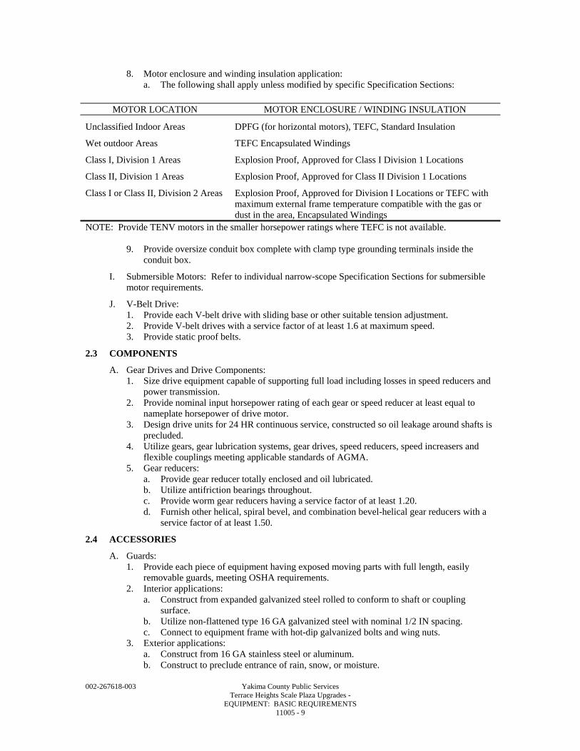
002-267618-003 Yakima County Public Services Terrace Heights Scale Plaza Upgrades - EQUIPMENT: BASIC REQUIREMENTS 11005 - 9
8. Motor enclosure and winding insulation application: a. The following shall apply unless modified by specific Specification Sections:
MOTOR LOCATION MOTOR ENCLOSURE / WINDING INSULATION
Unclassified Indoor Areas DPFG (for horizontal motors), TEFC, Standard Insulation
Wet outdoor Areas TEFC Encapsulated Windings
Class I, Division 1 Areas Explosion Proof, Approved for Class I Division 1 Locations
Class II, Division 1 Areas Explosion Proof, Approved for Class II Division 1 Locations
Class I or Class II, Division 2 Areas Explosion Proof, Approved for Division I Locations or TEFC with maximum external frame temperature compatible with the gas or dust in the area, Encapsulated Windings
NOTE: Provide TENV motors in the smaller horsepower ratings where TEFC is not available.
9. Provide oversize conduit box complete with clamp type grounding terminals inside the conduit box.
I. Submersible Motors: Refer to individual narrow-scope Specification Sections for submersible motor requirements.
J. V-Belt Drive: 1. Provide each V-belt drive with sliding base or other suitable tension adjustment. 2. Provide V-belt drives with a service factor of at least 1.6 at maximum speed. 3. Provide static proof belts.
2.3 COMPONENTS
A. Gear Drives and Drive Components: 1. Size drive equipment capable of supporting full load including losses in speed reducers and
power transmission. 2. Provide nominal input horsepower rating of each gear or speed reducer at least equal to
nameplate horsepower of drive motor. 3. Design drive units for 24 HR continuous service, constructed so oil leakage around shafts is
precluded. 4. Utilize gears, gear lubrication systems, gear drives, speed reducers, speed increasers and
flexible couplings meeting applicable standards of AGMA. 5. Gear reducers:
a. Provide gear reducer totally enclosed and oil lubricated. b. Utilize antifriction bearings throughout. c. Provide worm gear reducers having a service factor of at least 1.20. d. Furnish other helical, spiral bevel, and combination bevel-helical gear reducers with a
service factor of at least 1.50.
2.4 ACCESSORIES
A. Guards: 1. Provide each piece of equipment having exposed moving parts with full length, easily
removable guards, meeting OSHA requirements. 2. Interior applications:
a. Construct from expanded galvanized steel rolled to conform to shaft or coupling surface.
b. Utilize non-flattened type 16 GA galvanized steel with nominal 1/2 IN spacing. c. Connect to equipment frame with hot-dip galvanized bolts and wing nuts.
3. Exterior applications: a. Construct from 16 GA stainless steel or aluminum. b. Construct to preclude entrance of rain, snow, or moisture.
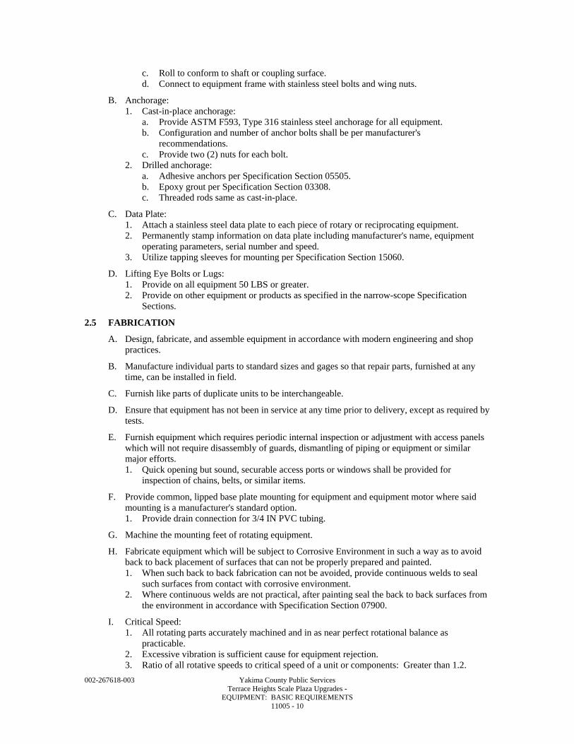
002-267618-003 Yakima County Public Services Terrace Heights Scale Plaza Upgrades - EQUIPMENT: BASIC REQUIREMENTS 11005 - 10
c. Roll to conform to shaft or coupling surface. d. Connect to equipment frame with stainless steel bolts and wing nuts.
B. Anchorage: 1. Cast-in-place anchorage:
a. Provide ASTM F593, Type 316 stainless steel anchorage for all equipment. b. Configuration and number of anchor bolts shall be per manufacturer's
recommendations. c. Provide two (2) nuts for each bolt.
2. Drilled anchorage: a. Adhesive anchors per Specification Section 05505. b. Epoxy grout per Specification Section 03308. c. Threaded rods same as cast-in-place.
C. Data Plate: 1. Attach a stainless steel data plate to each piece of rotary or reciprocating equipment. 2. Permanently stamp information on data plate including manufacturer's name, equipment
operating parameters, serial number and speed. 3. Utilize tapping sleeves for mounting per Specification Section 15060.
D. Lifting Eye Bolts or Lugs: 1. Provide on all equipment 50 LBS or greater. 2. Provide on other equipment or products as specified in the narrow-scope Specification
Sections.
2.5 FABRICATION
A. Design, fabricate, and assemble equipment in accordance with modern engineering and shop practices.
B. Manufacture individual parts to standard sizes and gages so that repair parts, furnished at any time, can be installed in field.
C. Furnish like parts of duplicate units to be interchangeable.
D. Ensure that equipment has not been in service at any time prior to delivery, except as required by tests.
E. Furnish equipment which requires periodic internal inspection or adjustment with access panels which will not require disassembly of guards, dismantling of piping or equipment or similar major efforts. 1. Quick opening but sound, securable access ports or windows shall be provided for
inspection of chains, belts, or similar items.
F. Provide common, lipped base plate mounting for equipment and equipment motor where said mounting is a manufacturer's standard option. 1. Provide drain connection for 3/4 IN PVC tubing.
G. Machine the mounting feet of rotating equipment.
H. Fabricate equipment which will be subject to Corrosive Environment in such a way as to avoid back to back placement of surfaces that can not be properly prepared and painted. 1. When such back to back fabrication can not be avoided, provide continuous welds to seal
such surfaces from contact with corrosive environment. 2. Where continuous welds are not practical, after painting seal the back to back surfaces from
the environment in accordance with Specification Section 07900.
I. Critical Speed: 1. All rotating parts accurately machined and in as near perfect rotational balance as
practicable. 2. Excessive vibration is sufficient cause for equipment rejection. 3. Ratio of all rotative speeds to critical speed of a unit or components: Greater than 1.2.
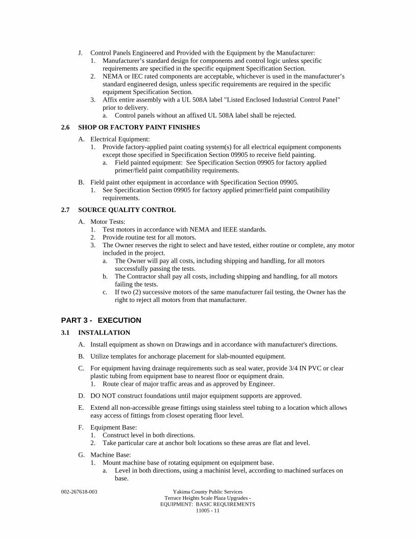
002-267618-003 Yakima County Public Services Terrace Heights Scale Plaza Upgrades - EQUIPMENT: BASIC REQUIREMENTS 11005 - 11
J. Control Panels Engineered and Provided with the Equipment by the Manufacturer: 1. Manufacturer’s standard design for components and control logic unless specific
requirements are specified in the specific equipment Specification Section. 2. NEMA or IEC rated components are acceptable, whichever is used in the manufacturer’s
standard engineered design, unless specific requirements are required in the specific equipment Specification Section.
3. Affix entire assembly with a UL 508A label "Listed Enclosed Industrial Control Panel" prior to delivery. a. Control panels without an affixed UL 508A label shall be rejected.
2.6 SHOP OR FACTORY PAINT FINISHES
A. Electrical Equipment: 1. Provide factory-applied paint coating system(s) for all electrical equipment components
except those specified in Specification Section 09905 to receive field painting. a. Field painted equipment: See Specification Section 09905 for factory applied
primer/field paint compatibility requirements.
B. Field paint other equipment in accordance with Specification Section 09905. 1. See Specification Section 09905 for factory applied primer/field paint compatibility
requirements.
2.7 SOURCE QUALITY CONTROL
A. Motor Tests: 1. Test motors in accordance with NEMA and IEEE standards. 2. Provide routine test for all motors. 3. The Owner reserves the right to select and have tested, either routine or complete, any motor
included in the project. a. The Owner will pay all costs, including shipping and handling, for all motors
successfully passing the tests. b. The Contractor shall pay all costs, including shipping and handling, for all motors
failing the tests. c. If two (2) successive motors of the same manufacturer fail testing, the Owner has the
right to reject all motors from that manufacturer.
PART 3 - EXECUTION
3.1 INSTALLATION
A. Install equipment as shown on Drawings and in accordance with manufacturer's directions.
B. Utilize templates for anchorage placement for slab-mounted equipment.
C. For equipment having drainage requirements such as seal water, provide 3/4 IN PVC or clear plastic tubing from equipment base to nearest floor or equipment drain. 1. Route clear of major traffic areas and as approved by Engineer.
D. DO NOT construct foundations until major equipment supports are approved.
E. Extend all non-accessible grease fittings using stainless steel tubing to a location which allows easy access of fittings from closest operating floor level.
F. Equipment Base: 1. Construct level in both directions. 2. Take particular care at anchor bolt locations so these areas are flat and level.
G. Machine Base: 1. Mount machine base of rotating equipment on equipment base.
a. Level in both directions, using a machinist level, according to machined surfaces on base.
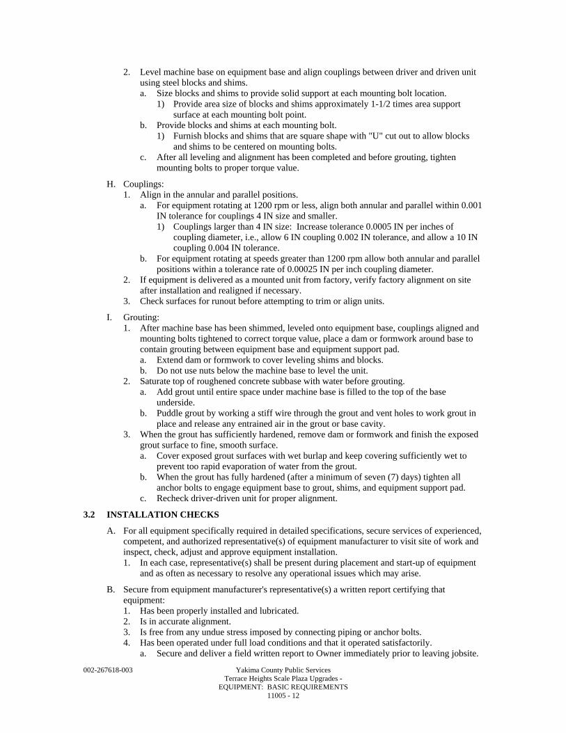
002-267618-003 Yakima County Public Services Terrace Heights Scale Plaza Upgrades - EQUIPMENT: BASIC REQUIREMENTS 11005 - 12
2. Level machine base on equipment base and align couplings between driver and driven unit using steel blocks and shims. a. Size blocks and shims to provide solid support at each mounting bolt location.
1) Provide area size of blocks and shims approximately 1-1/2 times area support surface at each mounting bolt point.
b. Provide blocks and shims at each mounting bolt. 1) Furnish blocks and shims that are square shape with "U" cut out to allow blocks
and shims to be centered on mounting bolts. c. After all leveling and alignment has been completed and before grouting, tighten
mounting bolts to proper torque value.
H. Couplings: 1. Align in the annular and parallel positions.
a. For equipment rotating at 1200 rpm or less, align both annular and parallel within 0.001 IN tolerance for couplings 4 IN size and smaller. 1) Couplings larger than 4 IN size: Increase tolerance 0.0005 IN per inches of
coupling diameter, i.e., allow 6 IN coupling 0.002 IN tolerance, and allow a 10 IN coupling 0.004 IN tolerance.
b. For equipment rotating at speeds greater than 1200 rpm allow both annular and parallel positions within a tolerance rate of 0.00025 IN per inch coupling diameter.
2. If equipment is delivered as a mounted unit from factory, verify factory alignment on site after installation and realigned if necessary.
3. Check surfaces for runout before attempting to trim or align units.
I. Grouting: 1. After machine base has been shimmed, leveled onto equipment base, couplings aligned and
mounting bolts tightened to correct torque value, place a dam or formwork around base to contain grouting between equipment base and equipment support pad. a. Extend dam or formwork to cover leveling shims and blocks. b. Do not use nuts below the machine base to level the unit.
2. Saturate top of roughened concrete subbase with water before grouting. a. Add grout until entire space under machine base is filled to the top of the base
underside. b. Puddle grout by working a stiff wire through the grout and vent holes to work grout in
place and release any entrained air in the grout or base cavity. 3. When the grout has sufficiently hardened, remove dam or formwork and finish the exposed
grout surface to fine, smooth surface. a. Cover exposed grout surfaces with wet burlap and keep covering sufficiently wet to
prevent too rapid evaporation of water from the grout. b. When the grout has fully hardened (after a minimum of seven (7) days) tighten all
anchor bolts to engage equipment base to grout, shims, and equipment support pad. c. Recheck driver-driven unit for proper alignment.
3.2 INSTALLATION CHECKS
A. For all equipment specifically required in detailed specifications, secure services of experienced, competent, and authorized representative(s) of equipment manufacturer to visit site of work and inspect, check, adjust and approve equipment installation. 1. In each case, representative(s) shall be present during placement and start-up of equipment
and as often as necessary to resolve any operational issues which may arise.
B. Secure from equipment manufacturer's representative(s) a written report certifying that equipment: 1. Has been properly installed and lubricated. 2. Is in accurate alignment. 3. Is free from any undue stress imposed by connecting piping or anchor bolts. 4. Has been operated under full load conditions and that it operated satisfactorily.
a. Secure and deliver a field written report to Owner immediately prior to leaving jobsite.
002-267618-003 Yakima County Public Services Terrace Heights Scale Plaza Upgrades - EQUIPMENT: BASIC REQUIREMENTS 11005 - 13
C. No separate payment shall be made for installation checks. 1. All or any time expended during installation check does not qualify as Operation and
Maintenance training or instruction time when specified.
3.3 IDENTIFICATION OF EQUIPMENT AND HAZARD WARNING SIGNS
A. Identify equipment and install hazard warning signs in accordance with Specification Section 10400.
3.4 FIELD PAINTING AND PROTECTIVE COATINGS
A. For required field painting and protective coatings, comply with Specification Section 09905.
3.5 WIRING CONNECTIONS AND TERMINATION
A. Clean wires before installing lugs and connectors.
B. Coat connection with oxidation eliminating compound for aluminum wire.
C. Terminate motor circuit conductors with copper lugs bolted to motor leads.
D. Tape stripped ends of conductors and associated connectors with electrical tape. 1. Wrapping thickness shall be 150 percent of the conductor insulation thickness.
E. Connections to carry full ampacity of conductors without temperature rise.
F. Terminate spare conductors with electrical tape.
3.6 FIELD QUALITY CONTROL
A. Furnish equipment manufacturer services as specified in the individual equipment Specifications.
B. Inspect wire and connections for physical damage and proper connection.
C. After installation and prior to energizing the motor, provide insulation resistance test of all motors 1 HP and above. 1. Conduct test with 500 or 1000 Vdc megger. 2. Test each phase separately. 3. Disconnect all extraneous leads to the motor. 4. Comply with NEMA MG 1 safety requirements and test procedures.
D. Bump motor to check for correct rotation: 1. Ensure motor has been lubricated. 2. Check prior to connection to driven equipment.
E. Subbase that supports the equipment base and that is made in the form of a cast iron or steel structure that has supporting beams, legs and cross member that are cast welded or bolted, shall be tested for a natural frequency of vibration after equipment is mounted. 1. Keep the ratio of the natural frequency of the structure to the frequency of the disturbing
force out of the range from 0.5 to 1.5.
F. Equipment Vibration Monitoring and Testing: 1. Utilize an Engineer approved testing agency to perform vibration monitoring and testing on
equipment defined in the schedule at the end of this Section. 2. Permanently attach vibration test and monitoring mounting pads to the equipment at
locations recommended by the equipment manufacturer or as recommended by the vibration testing agency.
3. Utilize mounting pads suitable for permanent installation and for incorporation into a predictable maintenance program.
4. For variable speed equipment provide vibration testing at 1 Hz increments throughout entire operating range.
5. Diagnosis to include, but is not limited to the following: a. Unbalance.
002-267618-003 Yakima County Public Services Terrace Heights Scale Plaza Upgrades - EQUIPMENT: BASIC REQUIREMENTS 11005 - 14
b. Misalignment. c. Bent shaft. d. Journal bearing related problems. e. Rolling contract bearing problems. f. Mechanical looseness. g. Resonance. h. Foundation flexibility. i. Electrically induced problems. j. Pump problems. k. Fan problems. l. Coupling problems. m. Drive belt problems. n. Gear problems. o. Centrifugal compressor problems. p. Electric motor induced vibration from VFD or VFD carrier frequency.
6. Provide machinery condition diagnosis based on an acceptable machinery vibration severity guide or machinery fault guide analysis provided by the testing agency, ISO 1940 Balance Quality Grade 6.3 as a minimum.
7. Tolerances for pumping equipment shall be per HI published standards. 8. Repair or replace equipment shown to be out of range of the specified tolerance until the
equipment meets the specified normal operation range required in the machinery fault guide analysis.
9. Document testing with written report. a. Report to include initial testing results, acceptance criteria, corrective action taken to
meet acceptance, verification of corrective action and acceptance report and baseline.
END OF SECTION
002-267618-003 Yakima County Public Services Terrace Heights Scale Plaza Upgrades - FLOOR SAFE 11020 - 1
SECTION 11020
FLOOR SAFE
PART 1 - GENERAL
1.1 SUMMARY
A. Section includes supply and installation of one floor safe in the new Scale House.
B. Related Sections; coordinate related work specified in other parts of the Contract Documents, including but not limited to the following: 1. Section 03308 – Concrete, Materials and Proportioning.
1.2 SUBMITTALS
A. General: Submit in accordance with the Conditions of Contract and Section 01340.
B. Manufacturer’s product and catalog data.
C. Manufacturer’s installation instructions.
D. Operation and Maintenance Manuals: 1. See Section 01340 for requirements for the content of Operation and Maintenance Manuals.
PART 2 - PRODUCTS
2.1 GENERAL
A. The safe system shall be designed to operate satisfactorily and reliably over the full range of weather conditions and conditions of service experienced at the project site.
2.2 MANUFACTURERS
A. Subject to compliance with requirements, manufacturers offering truck scales that may be incorporated in the work include the following: 1. American Security Products Company, 909-685-9680 www.amsecusa.com 2. Or approved equal.
B. The specifications are based on American Security Products Company product. Similar equipment offered by other manufacturers will be considered.
2.3 SAFE
A. Steel floor safe for in-floor installation with door on top, designed to meet the requirements of the Insurance Offices Manual of Burglary Insurance. “B+” rated, 3/4 IN solid steel door. American Security Products Company Model Super Brute, B3800.
B. Approximate Size/Weight: 1. Inside: 12-5/8 IN by 18 IN by 17 IN deep. 2. Outside: 12-3/4 IN by 18-3/4 IN by 21-3/8 IN deep. 3. Door Opening: 10-3/4 IN by 11-1/8 IN. 4. Weight: Approximately 135 LBS.
C. Body: 1. Constructed of 3/16 IN steel plate. 2. Oversize floor plate.
D. Door: Constructed of 1/2 IN steel plate.
E. Locking System: 1. Handle activated locking mechanism consisting of five 3/4 IN DIA long throw, chrome
plated steel locking bolts.
002-267618-003 Yakima County Public Services Terrace Heights Scale Plaza Upgrades - FLOOR SAFE 11020 - 2
2. UL listed Group 2 three wheel key change combination lock with relock and not less than 1 million combinations.
F. Finish: 1. Black textured baked-on enamel finish. 2. Lexan escutcheon plate cover for entire door surface.
PART 3 - EXECUTION
3.1 INSTALLATION, GENERAL
A. The concrete foundation and floor system shall be constructed in accordance with the applicable sections of Divisions 3.
B. Touchup and repair all damaged areas of factory applied paint finish after installation.
C. Set top to safe flush with finished floor.
3.2 COORDINATION
A. Coordinate the installation of the safe with the surrounding concrete construction and interior finishes.
END OF SECTION
D I V I S I O N 1 2 FURNISHINGS

002-267618-003 Yakima County Public Services Terrace Heights Scale Plaza Upgrades - ENTRANCE FLOORING SYSTEMS 12691 - 1
SECTION 12691
ENTRANCE FLOORING SYSTEMS
PART 1 - GENERAL
1.1 SUMMARY
A. Section includes roll-up foot mats.
1.2 SUBMITTALS
A. See Section 01340 for requirements for the mechanics and administration of the submittal process.
B. Product technical data including: 1. Acknowledgement that products submitted meet requirements of standards referenced. 2. Manufacturer's installation instructions. 3. Product data sheet on each component included in the system.
C. Samples: 1. Manufacturer's full range of colors, textures, finishes, and patterns available. 2. Minimum 6 IN long sample of each color and type selected.
PART 2 - PRODUCTS
2.1 ACCEPTABLE MANUFACTURERS
A. Subject to compliance with the Contract Documents, the following manufacturers are acceptable: 1. Arden. 2. Balco. 3. The Construction Specialties. 4. J. L. Industries. 5. Pawling. 6. Reese.
B. Submit request for substitution in accordance with Specification Section 01640.
2.2 MANUFACTURED UNITS
A. Roll-Up Surface Mounted Foot Mat: 1. Tread rail: Aluminum. 2. Hinge rail connector: Extruded aluminum. 3. Tread inserts: Carpet.
a. Replaceable. b. Color: As selected from manufacturer’s standard colors.
4. Cushioned for noise reduction. 5. Tread spacing: 2 IN. 6. Depth: Maximum 1/2 IN. 7. Rollable. 8. Perimeter frame: Tapered aluminum. 9. Structural loading: All grid and frame sections shall be capable of supporting a minimum
300 LBS rolling load per wheel.
002-267618-003 Yakima County Public Services Terrace Heights Scale Plaza Upgrades - ENTRANCE FLOORING SYSTEMS 12691 - 2
PART 3 - EXECUTION
3.1 PREPARATION
A. Verify substrate and correct all unsatisfactory conditions. 1. Installation of unit indicates acceptance of substrate.
3.2 INSTALLATION
A. Follow manufacturer's printed instruction for installation.
B. Provide all trim, fillers, inserts, anchors or other miscellaneous items required for complete installation.
C. Protect installed unit from damage until acceptance by Owner.
END OF SECTION

D I V I S I O N 1 3 SPECIAL CONSTRUCTION

002-267618-003 Yakima County Public Services Terrace Heights Scale Plaza Upgrades - TRUCK SCALES 13600 - 1
SECTION 13600
TRUCK SCALES
PART 1 - GENERAL
1.1 SUMMARY
A. Section includes the following: 1. Design, fabrication and installation of three 11 FT wide x 80 FT long, minimum 100 ton
capacity, low-profile orthotropic, above-grade type all-electronic truck scale, with concrete deck, curbing system, scale appurtenances, and traffic control equipment.
2. Weighbridges shall be 11 FT wide with a concentrated point-load capacity of 50 tons. 3. The weighbridge shall consist of a maximum of four sections supported by a maximum of
10 load cells. Drawings show arrangement and foundations based on a scale system using four sections. Contractor is responsible for cost of providing all concrete foundations to suit the scale equipment proposed. Load cells must be available to the Owner’s current scale maintenance contractor, Western Scales.
4. Furnish and install components of the data management and traffic control systems including: a. There are no summing boards in this system. Truck Scale manufacturer digital
communication cable connects all of the load cells in series and terminate at the indicator. System shall not require the use of summing boards or junction boxes.
b. The Terminal is the device that provides the interface to the scales and converts the signal from the load cells to a weight. Provide three Terminals, one per scale, two located in the new satellite scalehouse and one located in the existing main scalehouse.
c. The scoreboards, provide one on each scale, two located outside the satellite new scalehouse, and one located outside the existing main scalehouse.
d. Traffic control lights (6), one each at the entrance and exit of the new scales. Connection to traffic control lights shall be a standard USB connection.
e. Coordinate work furnished under other specification sections including: Cast-in-place concrete scale foundations and approach slabs.
5. Embedded steel copings and checks for the scale platform end foundations.
B. Related Sections; coordinate related work specified in other parts of the Contract Documents, including but not limited to the following: 1. Section 02423 – Storm Drainage System. 2. Section 03311 – Concrete Mixing, Placing, Jointing, and Curing. 3. Section 05505 – Metal Fabrications.
1.2 DESCRIPTION OF SYSTEM
A. The scale system includes, but is not necessarily be limited to, the following major items: 1. Steel orthotropic weighbridge with 10 IN, site-cast, steel and fiber reinforced concrete
platform (deck). 2. Cast-in-place concrete scale foundations and abutments, and approach slabs (furnished
under other sections but coordinated by scale manufacturer). 3. Electronic load cells. 4. Embedded steel bumper stops for platforms and steel plates and anchor bolts for load cells. 5. Embedded steel channels and copings. 6. Voltage surge protection system. 7. Weight Scale Terminals (3). 8. Scoreboards (3). 9. RS232 serial interface for each scale with data management system equipment. 10. Traffic control lights (6): Red/green in a single lens unit, post-mounted with controls as
necessary for automatic control through the computer system. 11. Outside point of sale displays (6).
002-267618-003 Yakima County Public Services Terrace Heights Scale Plaza Upgrades - TRUCK SCALES 13600 - 2
12. Galvanized rigid steel conduits mounted on scale platforms and PVC embedded conduits located in the concrete deck and stainless steel-sheathed cabling. Any conduit locations requiring flexibility shall include liquid-tight flexible conduits.
13. Installation and testing of all the furnished system equipment. 14. Obtaining a seal of accuracy and acceptance from the State of Washington Office of
Weights and Measures. 15. Instruction for operating personnel.
1.3 WORK BY OTHERS
A. Owner will furnish and install the proprietary data management hardware (computers, printers, Ethernet switches and interconnecting exposed cabling) and software (Paradigm) following Contractor’s installation of the scale equipment and before final startup and checkout of the system by the Contractor.
1.4 QUALITY ASSURANCE
A. Qualifications of Manufacturer: The manufacturer shall have been in the business of design and manufacturer of similar truck scales for at least 10 years and shall have been represented in the State of Washington by a complete sales and service organization for at least the preceding five years. The manufacturer shall have a minimum of 25 similar truck scale installations in place within a radius of 350 miles of the project site. The manufacturer shall be capable of providing a local source of parts and service on a 24-hour per day, seven-day per week basis. Service call response time shall be not more than 4 HRS. Submit evidence verifying these qualifications with other submittals. Parts must be available universally to all truck scale service companies. The manufacturer’s scale design shall be such that service can be provided by any reputable scale service company.
1.5 REFERENCE STANDARDS
A. United States Department of Commerce, National Bureau of Standards, Handbook 44.
B. Uniform Building Code (UBC-1997).
1.6 SUBMITTALS
A. General: See Section 01340 for requirements for the mechanics and administration of the submittal process.
B. Scale system general arrangement Drawings showing for each size scale the scale platform and scale foundation in plan and section and showing arrangement of load cells, load cell support pads, anchor bolts, platform, access covers for load cells, conduit and accessories.
C. The scale system foundations shown on the Drawings are based on a representative manufacturer’s standard layout and are provided for bidding purposes only, and may not be fully suitable for construction. Manufacturer shall determine if the design depicted on the Drawings is suitable for its scale equipment and submit all information necessary to modify the Drawings to suit scale manufacturer's equipment. 1. If proposed scale system requires different or additional foundations and/or load cell
supports beyond those shown on the Drawings, the Owner will revised the Drawings to reflect the structural changes needed. Any additional construction cost associated with these changes shall be the responsibility of the Contractor.
D. Manufacturer’s product and catalog data for: 1. Load cells. 2. Scoreboards. 3. Point of sale displays. 4. Traffic control lights. 5. Paint system.
002-267618-003 Yakima County Public Services Terrace Heights Scale Plaza Upgrades - TRUCK SCALES 13600 - 3
E. Provide complete schematic wiring diagram showing all interconnecting cabling from scales to terminal, scoreboards and to transaction software PLC, and all Contractor-furnished peripheral equipment.
F. Provide guidance to electrical subcontractor for location and routing of all embedded and built-in conduit runs for the interconnecting cabling.
G. Provide Shop Drawings and mounting details for peripheral equipment mounting posts and for each permanently mounted piece of equipment.
H. Standard finish: Medium gray color. 1. All exterior surfaces of the scale shall have a two component, high build epoxy finish,
impregnated with aluminum flake for increased corrosion resistance and UV protection, providing total Dry Film Thickness of 5-7 mils; International/Akzo Nobel Intergard 7562 or equivalent.
I. Operation and Maintenance Manual including as a minimum of the following type of information: 1. Description and data for each component or product including manufacturer’s printed data,
standard catalog cuts, parts lists and illustrations. 2. Complete operating instructions. 3. Complete maintenance procedures, including routine maintenance, cleaning procedures,
guide to trouble shooting, disassembly, repair and reassembly instructions and alignment, adjusting and checking procedures.
4. Full set of all submitted and approved Drawings.
J. Evidence of manufacturer’s experience and qualifications as specified in Article 1.4 above.
1.7 WARRANTY
A. Furnish the Scale manufacturers and installing subcontractor’s jointly-issued written warranty for a period of ten (10) year after the date of substantial completion.
B. This manufacturer’s warranty shall be in addition to and run concurrent with the one-year warranty on all work specified in the Conditions of contract, and no a limitation of other rights the Owner may have against the Contractor under the Contract Documents.
C. Warranties shall cover and include the cost of removal of defective materials, products, equipment, and systems, installation of new replacement materials, products, equipment, and systems or repair and reinstallation of materials, products, equipment, and systems at Owner’s discretion, and repair and replacement of any adjoining construction, including finishes, that are damaged as a result of the failure of the warranted materials, products, equipment, and systems.
PART 2 - PRODUCTS
2.1 GENERAL
A. The scales shall conform to the specifications, tolerances and other requirements for motor vehicle scales as published in the latest edition of the United States Department of Commerce, National Bureau of Standards Handbook 44, and shall have National Type Evaluation Program (NTEP) certification. 1. The scale shall be calibrated to a minimum of 120,000 LBS by 20 LB increments and not to
exceed 200,000 LBS. System configurations with increments greater than 20 LB increments will not be accepted; therefore scales with gross capacities in excess of 200,000 LBS will not be acceptable in order for the scale to meet NTEP Legal For Trade regulatory requirements.
B. The scale system shall be designed to operate satisfactorily and reliably over the full range of weather conditions and conditions of service experienced at the project site.
002-267618-003 Yakima County Public Services Terrace Heights Scale Plaza Upgrades - TRUCK SCALES 13600 - 4
C. All Contractor-furnished equipment supports and mounting hardware for the scale system exterior equipment shall be hot dip galvanized and/or stainless steel.
2.2 MANUFACTURERS
A. Mettler Toledo Model Number VTC 221 truck scales that may be incorporated in the work.
2.3 WEIGHBRIDGE
A. The steel weighbridge shall be constructed from members conforming to ASTM A36, and shall be designed to be free from excessive deflection and capable of safely handling a concentrated load of 80,000 LBS dual tandem axle rating at any location on the weighbridge.
B. Weighbridge modules must be factory assembled and welded. No bolt together weighbridges or bolt-on cross members will be accepted. The weighbridge shall include continuous heavy-duty steel curbs along both sides, with the top of the curbs not less than 6 IN above the concrete deck surface. The curbs could be part of integral structural side beams or they could be fabricated as secondary members attached to the steel deck pan and framing. The curbs shall include adequate provisions for surface water runoff from the deck so that there is no ponded water on the deck at any location.
C. The weighbridge shall be designed with a 10 IN thick reinforced, site-cast concrete deck. Concrete shall be 6,000 psi, fiber-reinforced, finished with a medium-broom finish and chemical hardener/sealer.
D. There shall be galvanized adjustable bumper checks at each end of the weighbridge that shall be capable of limiting weighbridge longitudinal motion to 1/8 IN. The weighbridge shall be designed to withstand sudden truck stops.
E. After fabrication all steel members of the weighbridge shall be prepared (SSPC-SP 6, Commercial Blast Cleaning) and painted with a multi-coat two-part epoxy finish with a dry film thickness of 6 to 8 mils. The finish color shall be medium gray, exact color as selected by Owner from submitted color chips.
2.4 LOAD CELLS
A. Electronic: Powercell PDX 50,000 LBS, rocker column or double-ended, center-loaded shear beam load cells meeting the requirements by NIST Handbook 44 for Class IIIL devices. Load cells shall be stainless, hermetically sealed, with a minimum NEMA 6P (submersible) rating. Electrical supply voltage 24 VDC.
B. The scale shall have not more than ten load cells, daisy chained (connected in series) and utilizing the CAN bus industrial communications protocol. Load cell covers shall be provided and shall be sized and arranged to accommodate the adjacent construction. Modify standard covers, if necessary, to make them and the load cells accessible and removable, considering the adjacent construction.
2.5 CONDUIT
A. All concrete-embedded conduit supplied with scales shall be PVC Schedule 40. All exposed conduit shall be galvanized rigid steel. All conduit shall not be less than 1 IN DIA.
2.6 VOLTAGE SURGE PROTECTION
A. Electronic components require integral surge suppression as well as lightning protection tested to withstand a minimum of 80,000 amps.
002-267618-003 Yakima County Public Services Terrace Heights Scale Plaza Upgrades - TRUCK SCALES 13600 - 5
2.7 TRAFFIC CONTROL LIGHTS
A. Single polycarbonate lens light emitting diode, 120 volt signal light providing an 8 IN red ball and an 8 IN green ball. Axial luminous intensity of 504 candelas. Industrial Traffic Solutions Inc. (480-951-1150/www.lanecontrols.com), RM-8. Furnish each unit with a post cap adaptor (Pelco Products Inc., 405-340-3434 or approved) suitable for mounting on a nominal 4 IN DIA galvanized Schedule 40 steel pipe. Connection(s) for control of traffic control lights shall be a standard USB connection.
2.8 DIGITAL READOUTS AND CUSTOMER DISPLAYS
A. Interior Digital Readouts: Mettler Toledo IND560 PDX scoreboards (aka digital weight indicators).
B. Exterior Customer Transaction Displays manufactured by Pacific Northwest Technologies: 2-line, 20-column digital point-of-sale customer display with characters not less than 0.7 IN high, RS-232 serial interface, vacuum fluorescent display, 115 V, with adaptors and mounting hardware suitable for mounting units to the exterior face of the scalehouse wall. Provide each display with a stainless steel weather hood as shown on the Drawings with mounting hardware to provide three-sided weather protection. Hood top and sides should extend approximately 2 IN beyond the face of the display. 1. The inbound scale display shall indicate weight. 2. The outbound scale display shall indicate weight and transaction amount.
PART 3 - EXECUTION
3.1 INSTALLATION, GENERAL
A. The manufacturer shall provide factory trained, skilled mechanics to install, adjust and test the scale system and its peripheral devices and components.
B. The concrete foundation system and deck shall be constructed in accordance with the applicable Sections of Divisions 3 and 5.
C. Touchup and repair all damaged areas of factory applied paint finish after installation.
3.2 COORDINATION
A. Scale manufacturer shall be responsible to coordinate the installation of the scale equipment package including those items furnished under other Specification Sections and furnished by Owner.
B. A pre-installation coordination meeting shall be held at the site including the scale manufacturer, the Owner's Site Representative, Owner's installing technicians, and other trades involved in the work. 1. The meeting shall be held no later than 15 days prior to the start of the scale equipment
manufacturer's installation work.
3.3 TESTING/CERTIFICATION
A. Following installation each scale shall be tested and calibrated with not less than 20,000 LBS of certified weights.
B. After successful testing obtain a seal of accuracy and acceptance of the system by the State of Washington Office of Weights and Measures.
3.4 INSTRUCTION
A. Provide Owner's operating personnel with not less than 8 HRS of on-site instruction in the use and maintenance of the equipment furnished.
END OF SECTION

002-267618-003 Yakima County Public Services Terrace Heights Scale Plaza Upgrades - TRUCK SCALES 13600 - 6

002-267618-003 Yakima County Public Services Terrace Heights Scale Plaza Upgrades - TRUCK SCALES 13600 - 7
002-267618-003 Yakima County Public Services Terrace Heights Scale Plaza Upgrades - VIDEO SURVEILLANCE SYSTEM: CCTV CAMERAS 13700 - 1
SECTION 13700
VIDEO SURVEILLANCE SYSTEM: CCTV CAMERAS
PART 1 - GENERAL
1.1 DESCRIPTION
A. County security system, transaction recording system, and CCTV cameras single system supplier, integrator and installer shall be E3 Solutions, Inc., Attn. Rick Woods, Ph 509-452-0240, Email Address: [email protected], Physical Address: 410 South 3rd Street, Yakima WA 98901.
B. Provide and install a complete: Security System, Transaction Recording System (TRS) and Video Surveillance System (VSS), herein refer to as the System.
C. This Section includes video surveillance system consisting of cameras, data transmission wiring, and a control station with its associated equipment.
D. Cameras shall be compatible with the Paradigm software system and County Technology Services standards. Contact information: Chris Holmes, Paradigm Software, L.L.C., PH: 410-329-1300, E-Mail: [email protected]
E. Transaction Recording System: DRX50-16-CO-1000 / DVDRW dual layer, which supports 16 cameras.
1.2 RELATED WORK
A. Related Specification Sections include but are not necessarily limited to: 1. Section 10444 - Signage. 2. Section 16010 - Electrical: Basic Requirements. 3. Section 16120 – Wire and Cable: 600 Volt and Below. 4. Section 16130 – Raceways and Boxes. 5. Section 16135 – Electrical: Exterior Underground. 6. Section 16140 – Wiring Devices. 7. Section 16711 – Passive Telecommunication System.
1.3 DEFINITIONS
A. AGC: Automatic gain control.
B. B/W: Black and white.
C. CCD: Charge-coupled device.
D. CIF: Common Intermediate Format CIF images are 352 pixels wide and 88/240 (PAL/NTSC) pixels tall (352 x 288/240).
E. 4CIF: Resolution is 704 pixels wide and 576/480 (PAL/NTSC) pixels tall (704 x 576/480).
F. H.264 (also known as MPEG4 Part 10): An encoding format that compresses video much more effectively than older (MPEG4) standards.
G. IPS: Images per second.
H. MPEG: Moving picture experts group.
I. MPEG4: A video encoding and compression standard that uses inter-frame encoding to significantly reduce the size of the video stream being transmitted.
J. NTSC: National Television System Committee.
K. UPS: Uninterruptible power supply.
002-267618-003 Yakima County Public Services Terrace Heights Scale Plaza Upgrades - VIDEO SURVEILLANCE SYSTEM: CCTV CAMERAS 13700 - 2
L. PTZ: Refers to a movable camera that has the ability to pan left and right, tilt up and down, and zoom or magnify a scene.
1.4 QUALITY ASSURANCE
A. The Contractor shall be responsible for designing, providing, installing, and the operation of a complete and functional: Security System, Transaction Recording System and Video Surveillance System. The Contractor shall also provide certification as required.
B. The security system shall be installed and tested to ensure all components are fully compatible as a system and can be integrated with all associated security subsystems, whether the security system is stand-alone or a part of a complete security data network.
C. The Security Contractor shall be E3 Solutions, Inc., Attn. Rick Woods, Ph 509-452-0240, Email Address: [email protected], Physical Address: 410 South 3rd Street, Yakima WA 98901.
1.5 SUBMITTALS
A. Submit below items in conjunction with Shop Drawings, Product Data, and Samples.
B. Provide certificates of compliance with Section 1.4, Quality Assurance.
C. Provide manufacturer security system product cut-sheets. Submit for approval at least 30 days prior to commencement of formal testing, a Security System and Transaction Recording System Operational Test Plan. Include procedures for operational testing of each component and security subsystem, to include performance of an integrated system test.
D. Submit manufacture’s certification of Underwriters Laboratories, Inc. (UL) listing as specified. Provide all maintenance and operating manuals.
E. Operation and Maintenance Manuals: 1. See Section 01340 for requirements for the content of Operation and Maintenance Manuals.
1.6 APPLICABLE PUBLICATIONS
A. The publications listed below (including amendments, addenda, revisions, supplement, and errata) form a part of this Specification to the extent referenced. The publications are referenced in the text by the basic designation only.
B. American National Standards Institute (ANSI)/Electronic Industries Alliance (EIA): 1. 330-09, Electrical Performance Standards for CCTV Cameras. 2. 375A-76, Electrical Performance Standards for CCTV Monitors.
C. Institute of Electrical and Electronics Engineers (IEEE): 1. C62.41-02, IEEE Recommended Practice on Surge Voltages in Low-Voltage AC Power
Circuits. 2. 802.3af-08, Power over Ethernet Standard.
D. Federal Communications Commission (FCC): 1. (47 CFR 15) Part 15, Limitations on the Use of Wireless Equipment/Systems.
E. National Electrical Contractors Association (NECA): 1. 303-2005, Installing Closed Circuit Television (CCTV) Systems.
F. National Fire Protection Association (NFPA): 1. 70-08, Article 780-National Electrical Code.
G. Underwriters Laboratories, Inc. (UL): 1. 983-06, Standard for Surveillance Camera Units. 2. 044-01, Standard for Surveillance Closed Circuit Television Equipment.

002-267618-003 Yakima County Public Services Terrace Heights Scale Plaza Upgrades - VIDEO SURVEILLANCE SYSTEM: CCTV CAMERAS 13700 - 3
1.7 COORDINATION
A. Coordinate arrangement, mounting, and support of video surveillance equipment: 1. To allow maximum possible headroom unless specific mounting heights that reduce
headroom are indicated. 2. To provide for ease of disconnecting the equipment with minimum interference to other
installations. 3. To allow right of way for piping and conduit installed at required slope. 4. So connecting raceways, cables, wireways, cable trays, and busways will be clear of
obstructions and of the working and access space of other equipment.
B. Coordinate installation of required supporting devices and set sleeves in cast-in-place concrete, masonry walls, and other structural components as they are constructed.
C. Coordinate location of access panels and doors for video surveillance items that are behind finished surfaces or otherwise concealed.
1.8 WARRANTY OF CONSTRUCTION
A. Demonstration and training shall be performed prior to system acceptance.
PART 2 - PRODUCTS
2.1 GENERAL
A. Video signal format shall comply with the NTSC standard composite video, interlaced. Composite video signal termination shall be 75 ohms.
B. Surge Protection: Protect components from voltage surges originating external to equipment housing and entering through power, communication, signal, control, or sensing leads. Include surge protection for external wiring of each conductor entry connection to components.
C. Power Connections: As recommended by manufacturer for type of line being protected.
D. Tamper Protection: Tamper switches on enclosures, control units, pull boxes, junction boxes, cabinets, and other system components shall initiate a tamper-alarm signal when unit is opened or partially disassembled. Control-station, control-unit alarm display shall identify tamper alarms and indicate locations.
2.2 SECURITY SYSTEM
A. Existing security panel is currently covering the Hazardous Waste, Administration and, the existing Scale House buildings and is located in the Hazardous Waste building. Upgrade that panel to the newest version and make upgrades to the keypads and input modules in the Administration Building and Hazardous Waste Building in order to bring them up to standard. Maintain all buildings on one system to only require 1 monitoring account and keep monthly reoccurring costs to a minimum. Keep the general configuration but upgrade to a current panel.
B. Security Panel: To view system status, silence alarms, turn system on/off, monitor doors, windows, control functions as lighting and heating. Programmed for fire alarm verification.
C. Keypad with sounder that emits eight warning tones: Fire Alarm, Burglary Alarm, Trouble Alarm, Exit Delay, Entry Delay, Error, OK, Watch.
D. PIR Motion Sensor includes Tamper Switch to cover an area of 35 x 35 FT.
E. Steel Door Contact: Recessed 1 IN magnetic door contacts (Scalehouse outside doors).
F. Smoke detectors will provide audible alarm and input signal to Security Panel.
G. Carbon Monoxide High concentration level will provide audible alarm and input signal to Security Panel.
002-267618-003 Yakima County Public Services Terrace Heights Scale Plaza Upgrades - VIDEO SURVEILLANCE SYSTEM: CCTV CAMERAS 13700 - 4
2.3 CAMERAS (WORK BY OTHERS)
A. Network Cameras: 1. Samsung IP CCTV Cameras compatible with DVR furnished by County. High Resolution,
True Day & Night, Weather-Resistant Cameras. 2. Or Engineer approved equal.
B. All Cameras will be EIA 330 and UL 1.Minimum Protection for Power Connections 120 V. Minimum Protection for Communication, Signal, Control, and Low-Voltage 983 compliant as well as: 1. Will be charge coupled device (CCD cameras and shall conform to National Television
System Committee (NTSC) formatting. 2. Fixed cameras shall be color and the primary choice for monitoring following the activities
described below. 3. Shall be powered by either 12 volts direct current (VDC) or 24 volts alternate current
(VAC). Power supplies shall be Class 2 and UL compliant and have a back-up power source to ensure cameras are still operational in the event of loss of primary power to the System.
4. Shall be powered over Ethernet. Network switches supporting PoE cameras shall have a back-up power source to ensure cameras are still operational in the event of loss of primary power to the System.
5. Shall be rated for continuous operation under the environmental conditions listed in Part 1, Project Conditions.
6. Will be home run to a monitoring and recording device via a controlling device such as network server and monitored on a 24 HR basis at a designated Security Management System location.
7. Each function and activity shall be addressed within the system by a unique user defined name, with minimum of twenty (20) characters. The use of codes or mnemonics identifying the System action shall not be accepted.
8. Shall come with built-in video motion detection that shall automatically monitor and process information from each camera. The camera motion detection shall detect motion within the camera's field of view and provide automatic visual, remote alarms as a result of detected motion.
9. Shall be programmed to digitally flip from color to black and white at dusk and vice versa at low light conditions.
10. Will be fitted with AI/DC lenses to ensure the image quality under different light conditions. 11. Dummy or fake cameras will not be utilized at any time. 12. Appropriate signage shall be designed, provided, and posted that notifies people that an area
is under camera surveillance.
2.4 VIDEO DISPLAY EQUIPMENT
A. Video Display Equipment: 1. Will consist of color monitors and shall be EIA 375A compliant. 2. Shall be able to display analog, digital, and other images in either NTSC or MPEG format
associated with the operation of the Security Management System (SMS). 3. Shall:
a. Have front panel controls that provide for power on/off, horizontal and vertical hold, brightness, and contrast.
b. Accept multiple inputs, either directly or indirectly. c. Have the capabilities to observe and program the System. d. Be installed in a manner that they cannot be witnessed by the general public.
002-267618-003 Yakima County Public Services Terrace Heights Scale Plaza Upgrades - VIDEO SURVEILLANCE SYSTEM: CCTV CAMERAS 13700 - 5
B. Color Video Monitors Technical Characteristics:
Sync Format PAL/NTSC Display Tube 90 Degree deflection angle Horizontal Resolution 250 TVL minimum, 300 TVL typical Video Input 1.0 Vp-p, 75 Ohm Front Panel Controls Volume, Contrast, Brightness, Color Connectors BNC
C. Liquid Crystal Display (LCD) Flat Panel Display Monitor.
D. Color LCD monitor shall have a flat screen and consists of an LCD panel, bezel, and stand.
E. The monitor shall meet or exceed the following Specifications: 1. The monitor shall incorporate an active matrix TFT LCD panel.
a. The pixel pitch of the monitor’s LCD panel shall be 0.264 mm horizontal and 0.264 mm vertical.
b. The monitor shall have a minimum resolution of 1080 pixels. c. The contrast ratio shall be 500:1. d. The typical brightness shall be 250 cd/m². e. The monitor shall display at least 16.7 million colors. f. The light source for the LCD panel shall have a lifetime of 50,000 HRS. g. The scan frequency horizontal shall be 30 K to 80 KHz and the scan frequency vertical
shall be 56 to 75 Hz. h. The viewing angle for the monitor shall be 170 degrees horizontal and 170 degrees
vertical. 2. The monitor shall have automatic NTSC or PAL recognition. 3. The monitor shall have a picture-in-picture function. 4. The monitor shall use the following signal connectors:
a. Video 1.0 V peak-to-peak at 75 ohms. b. BNC in/out. c. Y/C (S-video) in/out. d. Audio in/out. e. VGA 15-pin D-Sub.
5. The monitor shall have audio speaker(s). a. The speaker shall be 0.5 W minimum.
6. The monitor shall have the following front control panel buttons: a. Power on/off. b. LED indicator. c. Mode. d. Increase (volume). e. Decrease (volume). f. Up (contrast adjustment). g. Down (brightness adjustment). h. Menu. i. Auto.
7. The monitor shall have the following options for adjustment in an onscreen display menu: a. Color: b. Tint:
1) NTSC mode only: a) Brightness. b) Contrast. c) Sharpness. d) Volume. e) Language. f) Scan.
002-267618-003 Yakima County Public Services Terrace Heights Scale Plaza Upgrades - VIDEO SURVEILLANCE SYSTEM: CCTV CAMERAS 13700 - 6
g) Color Temp. h) H-Position. i) Recall.
F. The electrical specifications for the monitor shall be as follows: 1. Input voltage shall be 12 VDC/3 A. 2. Power consumption shall be 50 W maximum.
G. The environmental specifications for the monitor shall be as follows: 1. Operating temperature shall be 32 to 104 DegF or 0 to 40 DegC. 2. Operating humidity shall be 10 to 85 percent.
H. The monitor shall conform to these compliance standards: 1. FCC. 2. CE (EMC/LVD). 3. UL.
2.5 MEGAPIXEL HIGH DEFINITION INTEGRATED DIGITAL NETWORK CAMERA (WORK BY OTHERS)
A. The network camera shall offer dual video streams with 2 megapixel resolution in 1080 progressive scan format.
B. An alarm input and relay output shall be built in for integration with hard wired external sensors.
C. The network camera shall be capable of firmware upgrades through a network using a software-based device utility.
D. The network camera shall offer auto back focus (ABF) functionality through a push button on the camera. ABF parameters shall also be configurable through a standard Web browser interface.
E. The network camera shall offer a video output port providing an NTSC/PAL analog video output signal for adjusting field of view and focus at the camera.
F. The network camera shall provide advanced low-light capabilities for color and day/night models.
G. The network camera shall have removable IR cut filter mechanism for increased sensitivity in low-light installations. The sensitivity of IR cut filter removal shall be configurable through a Web browser.
H. The network camera shall support two simultaneous, configurable video streams. H.264 and MJPEG compression formats shall be available for primary and secondary streams with selectable unicast and multicast protocols. The streams shall be configurable in a variety of frame rates and bit rates.
I. The network camera shall support industry standard Power over Ethernet (PoE).
J. IEEE 802.3af to supply power to the camera over the network. The network camera shall also offer a 24 VAC power input for optional use.
K. The network camera shall use a standard Web browser interface for remote administration and configuration of camera parameters.
L. The network camera shall have a window blanking feature to conceal user-defined privacy areas that cannot be viewed by an Operator. The network camera shall support up to four blanked windows. A blanked area shall appear on the screen as a solid gray window.
M. The network camera shall support standard IT protocols.
N. The network camera shall support open architecture best practices with a published API available to third-party network video recording and management systems.
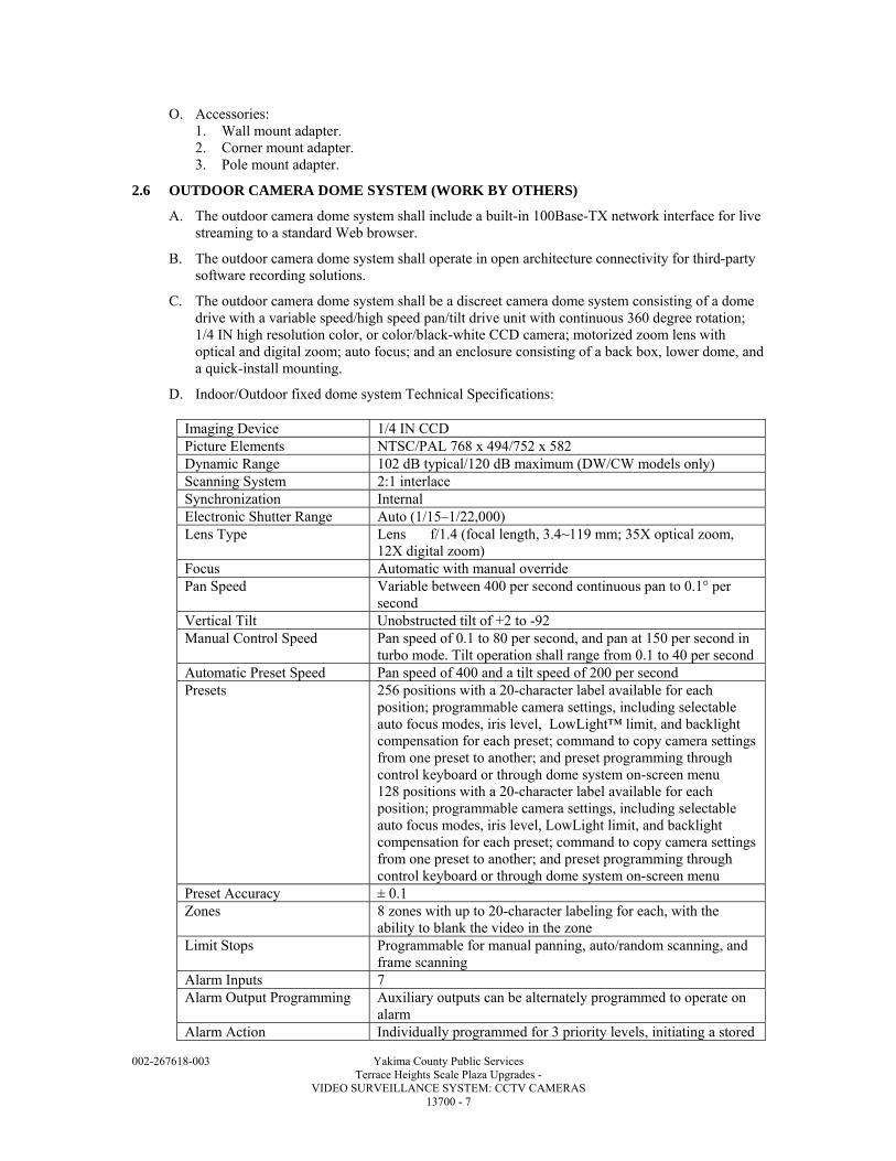
002-267618-003 Yakima County Public Services Terrace Heights Scale Plaza Upgrades - VIDEO SURVEILLANCE SYSTEM: CCTV CAMERAS 13700 - 7
O. Accessories: 1. Wall mount adapter. 2. Corner mount adapter. 3. Pole mount adapter.
2.6 OUTDOOR CAMERA DOME SYSTEM (WORK BY OTHERS)
A. The outdoor camera dome system shall include a built-in 100Base-TX network interface for live streaming to a standard Web browser.
B. The outdoor camera dome system shall operate in open architecture connectivity for third-party software recording solutions.
C. The outdoor camera dome system shall be a discreet camera dome system consisting of a dome drive with a variable speed/high speed pan/tilt drive unit with continuous 360 degree rotation; 1/4 IN high resolution color, or color/black-white CCD camera; motorized zoom lens with optical and digital zoom; auto focus; and an enclosure consisting of a back box, lower dome, and a quick-install mounting.
D. Indoor/Outdoor fixed dome system Technical Specifications:
Imaging Device 1/4 IN CCD Picture Elements NTSC/PAL 768 x 494/752 x 582 Dynamic Range 102 dB typical/120 dB maximum (DW/CW models only) Scanning System 2:1 interlace Synchronization Internal Electronic Shutter Range Auto (1/15–1/22,000) Lens Type Lens f/1.4 (focal length, 3.4~119 mm; 35X optical zoom,
12X digital zoom) Focus Automatic with manual override Pan Speed Variable between 400 per second continuous pan to 0.1° per
second Vertical Tilt Unobstructed tilt of +2 to -92 Manual Control Speed Pan speed of 0.1 to 80 per second, and pan at 150 per second in
turbo mode. Tilt operation shall range from 0.1 to 40 per second Automatic Preset Speed Pan speed of 400 and a tilt speed of 200 per second Presets 256 positions with a 20-character label available for each
position; programmable camera settings, including selectable auto focus modes, iris level, LowLight™ limit, and backlight compensation for each preset; command to copy camera settings from one preset to another; and preset programming through control keyboard or through dome system on-screen menu 128 positions with a 20-character label available for each position; programmable camera settings, including selectable auto focus modes, iris level, LowLight limit, and backlight compensation for each preset; command to copy camera settings from one preset to another; and preset programming through control keyboard or through dome system on-screen menu
Preset Accuracy ± 0.1 Zones 8 zones with up to 20-character labeling for each, with the
ability to blank the video in the zone Limit Stops Programmable for manual panning, auto/random scanning, and
frame scanning Alarm Inputs 7 Alarm Output Programming Auxiliary outputs can be alternately programmed to operate on
alarm Alarm Action Individually programmed for 3 priority levels, initiating a stored
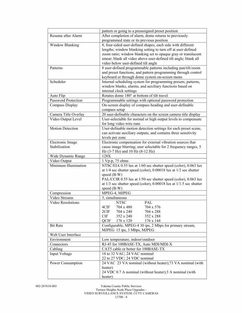
002-267618-003 Yakima County Public Services Terrace Heights Scale Plaza Upgrades - VIDEO SURVEILLANCE SYSTEM: CCTV CAMERAS 13700 - 8
pattern or going to a preassigned preset position Resume after Alarm After completion of alarm, dome returns to previously
programmed state or its previous position Window Blanking 8, four-sided user-defined shapes, each side with different
lengths; window blanking setting to turn off at user-defined zoom ratio; window blanking set to opaque gray or translucent smear; blank all video above user-defined tilt angle; blank all video below user-defined tilt angle
Patterns 8 user-defined programmable patterns including pan/tilt/zoom and preset functions, and pattern programming through control keyboard or through dome system on-screen menu
Scheduler Internal scheduling system for programming presets, patterns, window blanks, alarms, and auxiliary functions based on internal clock settings
Auto Flip Rotates dome 180° at bottom of tilt travel Password Protection Programmable settings with optional password protection Compass Display On-screen display of compass heading and user-definable
compass setup Camera Title Overlay 20 user-definable characters on the screen camera title display Video Output Level User-selectable for normal or high output levels to compensate
for long video wire runs Motion Detection User-definable motion detection settings for each preset scene,
can activate auxiliary outputs, and contains three sensitivity levels per zone
Electronic Image Stabilization
Electronic compensation for external vibration sources that cause image blurring; user selectable for 2 frequency ranges, 5 Hz (3-7 Hz) and 10 Hz (8-12 Hz)
Wide Dynamic Range 128X Video Output 1 Vp-p, 75 ohms Minimum Illumination NTSC/EIA 0.55 lux at 1/60 sec shutter speed (color), 0.063 lux
at 1/4 sec shutter speed (color), 0.00018 lux at 1/2 sec shutter speed (B-W) PAL/CCIR 0.55 lux at 1/50 sec shutter speed (color), 0.063 lux at 1/3 sec shutter speed (color), 0.00018 lux at 1/1.5 sec shutter speed (B-W)
Compression MPEG-4, MJPEG Video Streams 3, simultaneous Video Resolutions NTSC PAL
4CIF 704 x 480 704 x 576 2CIF 704 x 240 704 x 288 CIF 352 x 240 352 x 288 QCIF 176 x 120 176 x 144
Bit Rate Configurable, MPEG-4 30 ips, 2 Mbps for primary stream, MJPEG 15 ips, 3 Mbps, MJPEG
Web User Interface Environment Low temperature, indoor/outdoor Connectors RJ-45 for 100BASE-TX, Auto MDI/MDI-X Cabling CAT5 cable or better for 100BASE-TX Input Voltage 18 to 32 VAC; 24 VAC nominal
22 to 27 VDC; 24 VDC nominal Power Consumption 24 VAC 23 VA nominal (without heater);73 VA nominal (with
heater) 24 VDC 0.7 A nominal (without heater);3 A nominal (with heater)
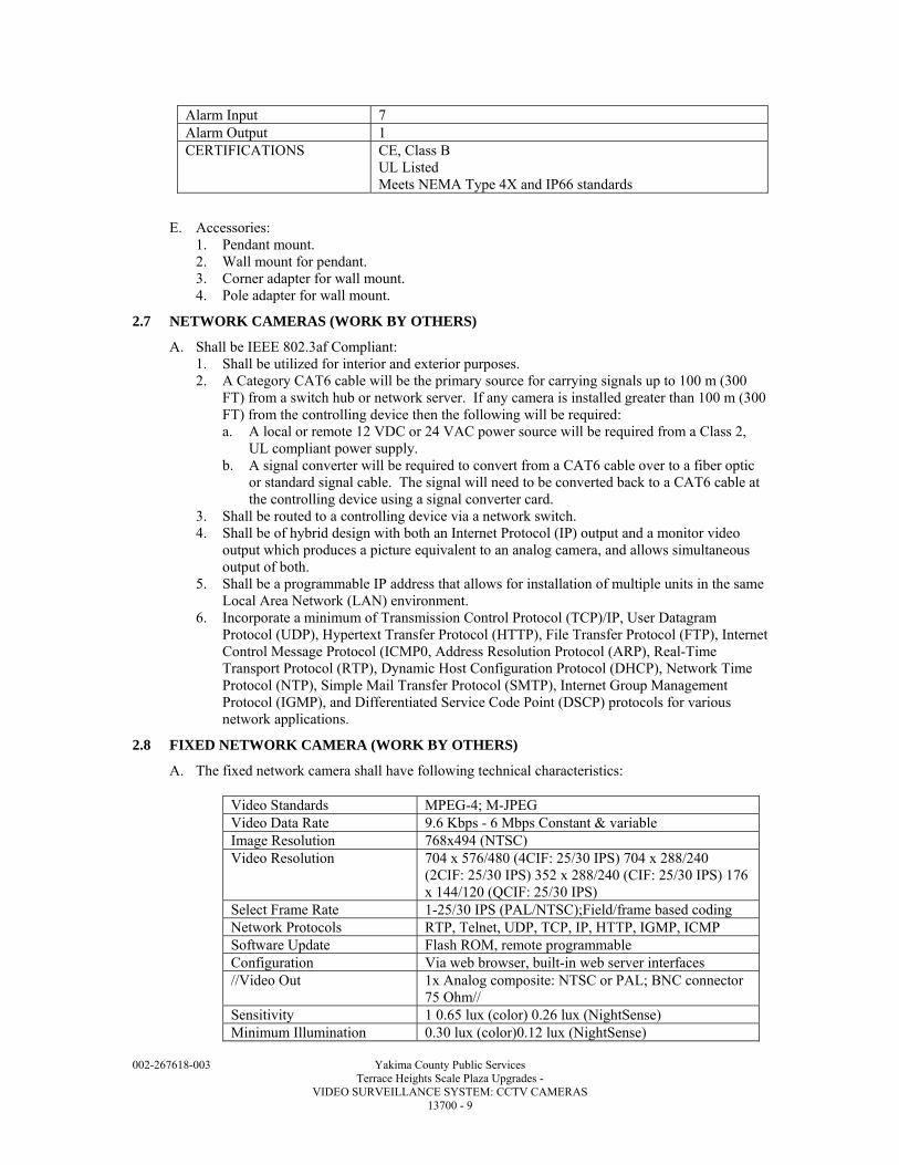
002-267618-003 Yakima County Public Services Terrace Heights Scale Plaza Upgrades - VIDEO SURVEILLANCE SYSTEM: CCTV CAMERAS 13700 - 9
Alarm Input 7 Alarm Output 1 CERTIFICATIONS CE, Class B
UL Listed Meets NEMA Type 4X and IP66 standards
E. Accessories: 1. Pendant mount. 2. Wall mount for pendant. 3. Corner adapter for wall mount. 4. Pole adapter for wall mount.
2.7 NETWORK CAMERAS (WORK BY OTHERS)
A. Shall be IEEE 802.3af Compliant: 1. Shall be utilized for interior and exterior purposes. 2. A Category CAT6 cable will be the primary source for carrying signals up to 100 m (300
FT) from a switch hub or network server. If any camera is installed greater than 100 m (300 FT) from the controlling device then the following will be required: a. A local or remote 12 VDC or 24 VAC power source will be required from a Class 2,
UL compliant power supply. b. A signal converter will be required to convert from a CAT6 cable over to a fiber optic
or standard signal cable. The signal will need to be converted back to a CAT6 cable at the controlling device using a signal converter card.
3. Shall be routed to a controlling device via a network switch. 4. Shall be of hybrid design with both an Internet Protocol (IP) output and a monitor video
output which produces a picture equivalent to an analog camera, and allows simultaneous output of both.
5. Shall be a programmable IP address that allows for installation of multiple units in the same Local Area Network (LAN) environment.
6. Incorporate a minimum of Transmission Control Protocol (TCP)/IP, User Datagram Protocol (UDP), Hypertext Transfer Protocol (HTTP), File Transfer Protocol (FTP), Internet Control Message Protocol (ICMP0, Address Resolution Protocol (ARP), Real-Time Transport Protocol (RTP), Dynamic Host Configuration Protocol (DHCP), Network Time Protocol (NTP), Simple Mail Transfer Protocol (SMTP), Internet Group Management Protocol (IGMP), and Differentiated Service Code Point (DSCP) protocols for various network applications.
2.8 FIXED NETWORK CAMERA (WORK BY OTHERS)
A. The fixed network camera shall have following technical characteristics:
Video Standards MPEG-4; M-JPEG Video Data Rate 9.6 Kbps - 6 Mbps Constant & variable Image Resolution 768x494 (NTSC) Video Resolution 704 x 576/480 (4CIF: 25/30 IPS) 704 x 288/240
(2CIF: 25/30 IPS) 352 x 288/240 (CIF: 25/30 IPS) 176 x 144/120 (QCIF: 25/30 IPS)
Select Frame Rate 1-25/30 IPS (PAL/NTSC);Field/frame based coding Network Protocols RTP, Telnet, UDP, TCP, IP, HTTP, IGMP, ICMP Software Update Flash ROM, remote programmable Configuration Via web browser, built-in web server interfaces //Video Out 1x Analog composite: NTSC or PAL; BNC connector
75 Ohm// Sensitivity 1 0.65 lux (color) 0.26 lux (NightSense) Minimum Illumination 0.30 lux (color)0.12 lux (NightSense)
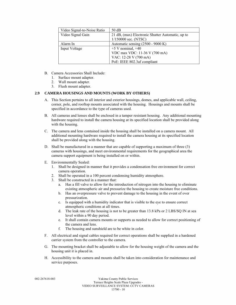
002-267618-003 Yakima County Public Services Terrace Heights Scale Plaza Upgrades - VIDEO SURVEILLANCE SYSTEM: CCTV CAMERAS 13700 - 10
Video Signal-to-Noise Ratio 50 dB Video Signal Gain 21 dB, (max) Electronic Shutter Automatic, up to
1/150000 sec. (NTSC) Alarm In Automatic sensing (2500 - 9000 K) Input Voltage +5 V nominal, +40
VDC max VDC: 11-36 V (700 mA) VAC: 12-28 V (700 mA) PoE: IEEE 802.3af compliant
B. Camera Accessories Shall Include: 1. Surface mount adapter. 2. Wall mount adapter. 3. Flush mount adapter.
2.9 CAMERA HOUSINGS AND MOUNTS (WORK BY OTHERS)
A. This Section pertains to all interior and exterior housings, domes, and applicable wall, ceiling, corner, pole, and rooftop mounts associated with the housing. Housings and mounts shall be specified in accordance to the type of cameras used.
B. All cameras and lenses shall be enclosed in a tamper resistant housing. Any additional mounting hardware required to install the camera housing at its specified location shall be provided along with the housing.
C. The camera and lens contained inside the housing shall be installed on a camera mount. All additional mounting hardware required to install the camera housing at its specified location shall be provided along with the housing.
D. Shall be manufactured in a manner that are capable of supporting a maximum of three (3) cameras with housings, and meet environmental requirements for the geographical area the camera support equipment is being installed on or within.
E. Environmentally Sealed: 1. Shall be designed in manner that it provides a condensation free environment for correct
camera operation. 2. Shall be operated in a 100 percent condensing humidity atmosphere. 3. Shall be constructed in a manner that:
a. Has a fill valve to allow for the introduction of nitrogen into the housing to eliminate existing atmospheric air and pressurize the housing to create moisture free conditions.
b. Has an overpressure valve to prevent damage to the housing in the event of over pressurization.
c. Is equipped with a humidity indicator that is visible to the eye to ensure correct atmospheric conditions at all times.
d. The leak rate of the housing is not to be greater than 13.8 kPa or 2 LBS/SQ IN at sea level within a 90 day period.
e. It shall contain camera mounts or supports as needed to allow for correct positioning of the camera and lens.
f. The housing and sunshield are to be white in color.
F. All electrical and signal cables required for correct operations shall be supplied in a hardened carrier system from the controller to the camera.
G. The mounting bracket shall be adjustable to allow for the housing weight of the camera and the housing unit it is placed in.
H. Accessibility to the camera and mounts shall be taken into consideration for maintenance and service purposes.
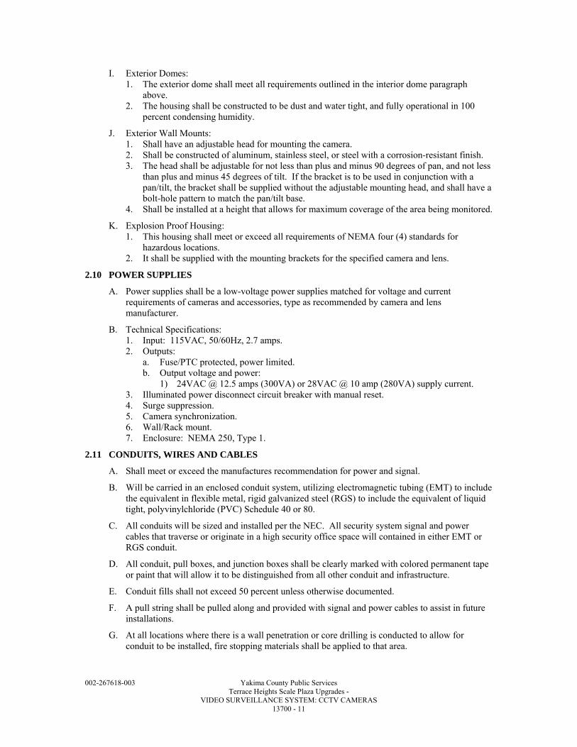
002-267618-003 Yakima County Public Services Terrace Heights Scale Plaza Upgrades - VIDEO SURVEILLANCE SYSTEM: CCTV CAMERAS 13700 - 11
I. Exterior Domes: 1. The exterior dome shall meet all requirements outlined in the interior dome paragraph
above. 2. The housing shall be constructed to be dust and water tight, and fully operational in 100
percent condensing humidity.
J. Exterior Wall Mounts: 1. Shall have an adjustable head for mounting the camera. 2. Shall be constructed of aluminum, stainless steel, or steel with a corrosion-resistant finish. 3. The head shall be adjustable for not less than plus and minus 90 degrees of pan, and not less
than plus and minus 45 degrees of tilt. If the bracket is to be used in conjunction with a pan/tilt, the bracket shall be supplied without the adjustable mounting head, and shall have a bolt-hole pattern to match the pan/tilt base.
4. Shall be installed at a height that allows for maximum coverage of the area being monitored.
K. Explosion Proof Housing: 1. This housing shall meet or exceed all requirements of NEMA four (4) standards for
hazardous locations. 2. It shall be supplied with the mounting brackets for the specified camera and lens.
2.10 POWER SUPPLIES
A. Power supplies shall be a low-voltage power supplies matched for voltage and current requirements of cameras and accessories, type as recommended by camera and lens manufacturer.
B. Technical Specifications: 1. Input: 115VAC, 50/60Hz, 2.7 amps. 2. Outputs:
a. Fuse/PTC protected, power limited. b. Output voltage and power:
1) 24VAC @ 12.5 amps (300VA) or 28VAC @ 10 amp (280VA) supply current. 3. Illuminated power disconnect circuit breaker with manual reset. 4. Surge suppression. 5. Camera synchronization. 6. Wall/Rack mount. 7. Enclosure: NEMA 250, Type 1.
2.11 CONDUITS, WIRES AND CABLES
A. Shall meet or exceed the manufactures recommendation for power and signal.
B. Will be carried in an enclosed conduit system, utilizing electromagnetic tubing (EMT) to include the equivalent in flexible metal, rigid galvanized steel (RGS) to include the equivalent of liquid tight, polyvinylchloride (PVC) Schedule 40 or 80.
C. All conduits will be sized and installed per the NEC. All security system signal and power cables that traverse or originate in a high security office space will contained in either EMT or RGS conduit.
D. All conduit, pull boxes, and junction boxes shall be clearly marked with colored permanent tape or paint that will allow it to be distinguished from all other conduit and infrastructure.
E. Conduit fills shall not exceed 50 percent unless otherwise documented.
F. A pull string shall be pulled along and provided with signal and power cables to assist in future installations.
G. At all locations where there is a wall penetration or core drilling is conducted to allow for conduit to be installed, fire stopping materials shall be applied to that area.
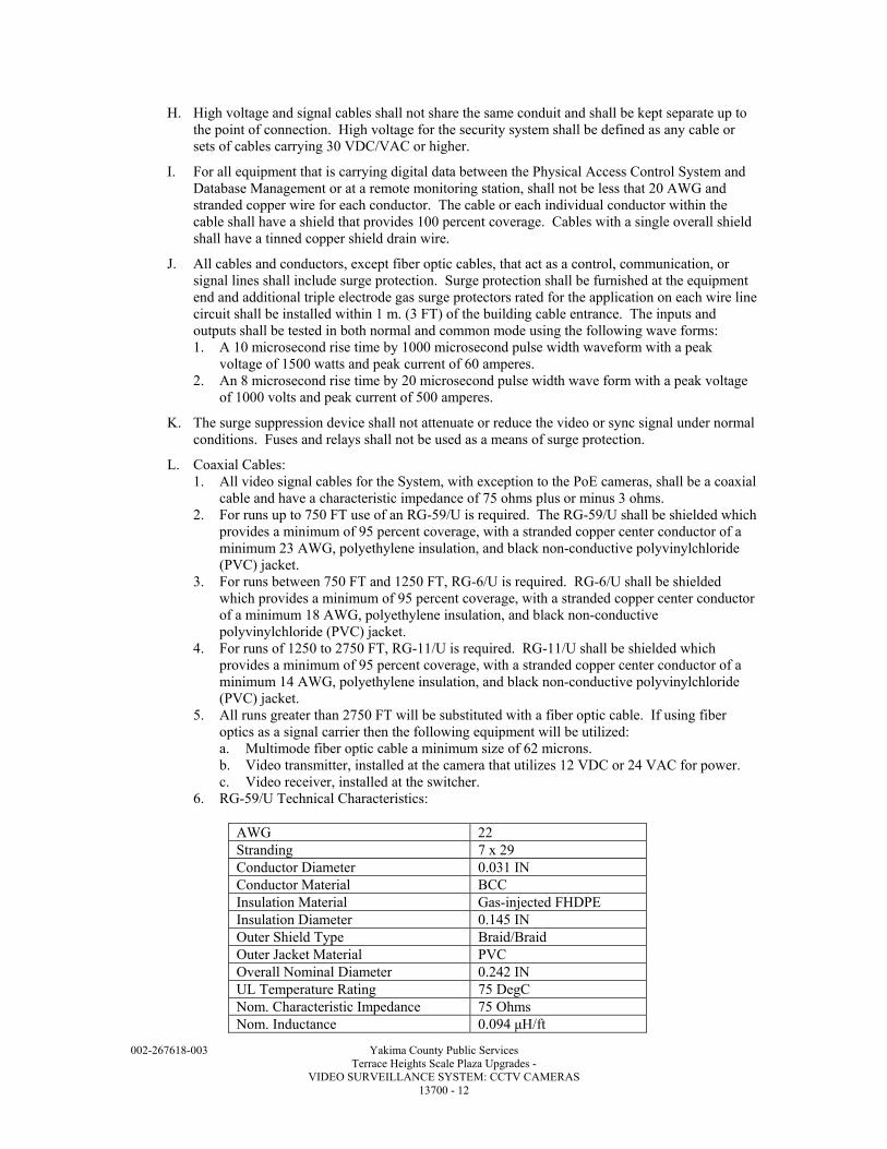
002-267618-003 Yakima County Public Services Terrace Heights Scale Plaza Upgrades - VIDEO SURVEILLANCE SYSTEM: CCTV CAMERAS 13700 - 12
H. High voltage and signal cables shall not share the same conduit and shall be kept separate up to the point of connection. High voltage for the security system shall be defined as any cable or sets of cables carrying 30 VDC/VAC or higher.
I. For all equipment that is carrying digital data between the Physical Access Control System and Database Management or at a remote monitoring station, shall not be less that 20 AWG and stranded copper wire for each conductor. The cable or each individual conductor within the cable shall have a shield that provides 100 percent coverage. Cables with a single overall shield shall have a tinned copper shield drain wire.
J. All cables and conductors, except fiber optic cables, that act as a control, communication, or signal lines shall include surge protection. Surge protection shall be furnished at the equipment end and additional triple electrode gas surge protectors rated for the application on each wire line circuit shall be installed within 1 m. (3 FT) of the building cable entrance. The inputs and outputs shall be tested in both normal and common mode using the following wave forms: 1. A 10 microsecond rise time by 1000 microsecond pulse width waveform with a peak
voltage of 1500 watts and peak current of 60 amperes. 2. An 8 microsecond rise time by 20 microsecond pulse width wave form with a peak voltage
of 1000 volts and peak current of 500 amperes.
K. The surge suppression device shall not attenuate or reduce the video or sync signal under normal conditions. Fuses and relays shall not be used as a means of surge protection.
L. Coaxial Cables: 1. All video signal cables for the System, with exception to the PoE cameras, shall be a coaxial
cable and have a characteristic impedance of 75 ohms plus or minus 3 ohms. 2. For runs up to 750 FT use of an RG-59/U is required. The RG-59/U shall be shielded which
provides a minimum of 95 percent coverage, with a stranded copper center conductor of a minimum 23 AWG, polyethylene insulation, and black non-conductive polyvinylchloride (PVC) jacket.
3. For runs between 750 FT and 1250 FT, RG-6/U is required. RG-6/U shall be shielded which provides a minimum of 95 percent coverage, with a stranded copper center conductor of a minimum 18 AWG, polyethylene insulation, and black non-conductive polyvinylchloride (PVC) jacket.
4. For runs of 1250 to 2750 FT, RG-11/U is required. RG-11/U shall be shielded which provides a minimum of 95 percent coverage, with a stranded copper center conductor of a minimum 14 AWG, polyethylene insulation, and black non-conductive polyvinylchloride (PVC) jacket.
5. All runs greater than 2750 FT will be substituted with a fiber optic cable. If using fiber optics as a signal carrier then the following equipment will be utilized: a. Multimode fiber optic cable a minimum size of 62 microns. b. Video transmitter, installed at the camera that utilizes 12 VDC or 24 VAC for power. c. Video receiver, installed at the switcher.
6. RG-59/U Technical Characteristics:
AWG 22 Stranding 7 x 29 Conductor Diameter 0.031 IN Conductor Material BCC Insulation Material Gas-injected FHDPE Insulation Diameter 0.145 IN Outer Shield Type Braid/Braid Outer Jacket Material PVC Overall Nominal Diameter 0.242 IN UL Temperature Rating 75 DegC Nom. Characteristic Impedance 75 Ohms Nom. Inductance 0.094 μH/ft
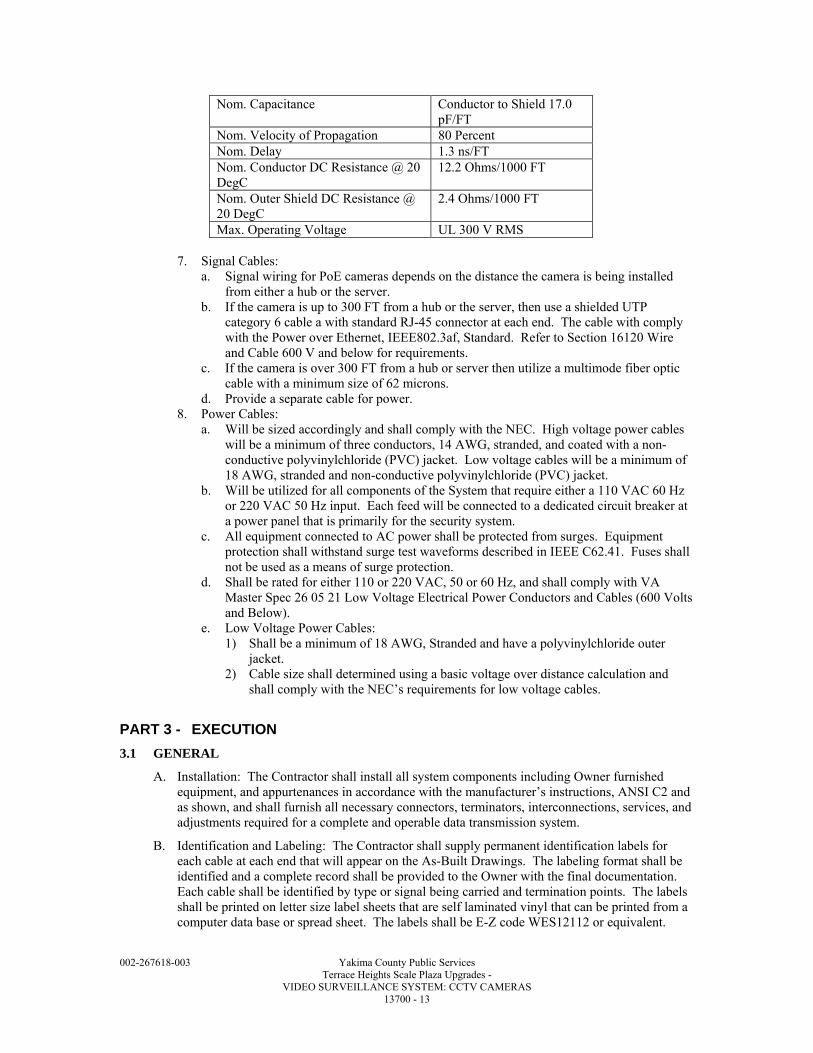
002-267618-003 Yakima County Public Services Terrace Heights Scale Plaza Upgrades - VIDEO SURVEILLANCE SYSTEM: CCTV CAMERAS 13700 - 13
Nom. Capacitance Conductor to Shield 17.0 pF/FT
Nom. Velocity of Propagation 80 Percent Nom. Delay 1.3 ns/FT Nom. Conductor DC Resistance @ 20 DegC
12.2 Ohms/1000 FT
Nom. Outer Shield DC Resistance @ 20 DegC
2.4 Ohms/1000 FT
Max. Operating Voltage UL 300 V RMS
7. Signal Cables: a. Signal wiring for PoE cameras depends on the distance the camera is being installed
from either a hub or the server. b. If the camera is up to 300 FT from a hub or the server, then use a shielded UTP
category 6 cable a with standard RJ-45 connector at each end. The cable with comply with the Power over Ethernet, IEEE802.3af, Standard. Refer to Section 16120 Wire and Cable 600 V and below for requirements.
c. If the camera is over 300 FT from a hub or server then utilize a multimode fiber optic cable with a minimum size of 62 microns.
d. Provide a separate cable for power. 8. Power Cables:
a. Will be sized accordingly and shall comply with the NEC. High voltage power cables will be a minimum of three conductors, 14 AWG, stranded, and coated with a non-conductive polyvinylchloride (PVC) jacket. Low voltage cables will be a minimum of 18 AWG, stranded and non-conductive polyvinylchloride (PVC) jacket.
b. Will be utilized for all components of the System that require either a 110 VAC 60 Hz or 220 VAC 50 Hz input. Each feed will be connected to a dedicated circuit breaker at a power panel that is primarily for the security system.
c. All equipment connected to AC power shall be protected from surges. Equipment protection shall withstand surge test waveforms described in IEEE C62.41. Fuses shall not be used as a means of surge protection.
d. Shall be rated for either 110 or 220 VAC, 50 or 60 Hz, and shall comply with VA Master Spec 26 05 21 Low Voltage Electrical Power Conductors and Cables (600 Volts and Below).
e. Low Voltage Power Cables: 1) Shall be a minimum of 18 AWG, Stranded and have a polyvinylchloride outer
jacket. 2) Cable size shall determined using a basic voltage over distance calculation and
shall comply with the NEC’s requirements for low voltage cables.
PART 3 - EXECUTION
3.1 GENERAL
A. Installation: The Contractor shall install all system components including Owner furnished equipment, and appurtenances in accordance with the manufacturer’s instructions, ANSI C2 and as shown, and shall furnish all necessary connectors, terminators, interconnections, services, and adjustments required for a complete and operable data transmission system.
B. Identification and Labeling: The Contractor shall supply permanent identification labels for each cable at each end that will appear on the As-Built Drawings. The labeling format shall be identified and a complete record shall be provided to the Owner with the final documentation. Each cable shall be identified by type or signal being carried and termination points. The labels shall be printed on letter size label sheets that are self laminated vinyl that can be printed from a computer data base or spread sheet. The labels shall be E-Z code WES12112 or equivalent.
002-267618-003 Yakima County Public Services Terrace Heights Scale Plaza Upgrades - VIDEO SURVEILLANCE SYSTEM: CCTV CAMERAS 13700 - 14
1. The Contractor shall provide all personnel, equipment, instrumentation, and supplies necessary to perform all testing.
C. Transient Voltage Surge Suppressors (TVSS): The Contractor shall mount TVSS within 118 IN of equipment to be protected inside terminal cabinets or suitable NEMA 1 enclosures. Terminate off-premise conductors on input side of device. Connect the output side of the device to the equipment to be protected. Connect ground lug to a low impedance earth ground (less than 10 ohms) via Number 12 AWG insulated, stranded copper conductor.
D. Contractor’s Field Test: The Contractor shall verify the complete operation of the data transmission system during the Contractor’s Field Testing. Field test shall include a bit error rate test. The Contractor shall perform the test by sending a minimum of 1,000,000 bits of data on each DTM circuit and measuring the bit error rate. The bit error rate shall not be greater than one (1) bit out of each 100,000 bits sent for each dial-up DTM circuit, and one (1) bit out of 1,000,000 bits sent for each leased or private DTM circuit. The Contractor shall submit a report containing results of the field test.
E. Acceptance Test and Endurance Test: The wire line data transmission system shall be tested as a part of the completed IDS and EECS during the Acceptance test and Endurance Test as specified.
F. Identification and Labeling: The Contractor shall supply identification tags or labels for each cable. Cable shall be labeled at both end points and at intermediate hand holes, manholes, and junction boxes. The labeling format shall be identified and a complete record shall be provided to the Owner with the final documentation. Each cable shall be identified with type of signal being carried and termination points.
3.2 INSTALLATION
A. System installation shall be in accordance with NECA 303, manufacturer and related documents and references, for each type of security subsystem designed, engineered and installed.
B. The Contractor shall install all system components including County furnished equipment, and appurtenances in accordance with the manufacturer's instructions, and shall furnish all necessary connectors, terminators, interconnections, services, and adjustments required for a complete and operable system.
C. Contractor will be design, engineer, install, and test Security and Video Surveillance System to ensure all components are fully compatible as a system and can be integrated with all associated security subsystems, whether the system is a stand alone or a complete network.
D. For programming purposes refer to the manufacturers requirements for correct system operations. Ensure computers being utilized for system integration meet or exceed the minimum system requirements outlined on the systems software packages.
E. A complete System shall be comprised of, but not limited to, the following components: 1. Cameras. 2. Lenses. 3. Video Display Equipment. 4. Camera Housings and Mounts. 5. Controlling Equipment. 6. Recording Devices. 7. Conduits, Wiring and Cables.
F. Enclosure Penetrations: All enclosure penetrations shall be from the bottom of the enclosure unless the system design requires penetrations from other directions. Penetrations of interior enclosures involving transitions of conduit from interior to exterior, and all penetrations on exterior enclosures shall be sealed with rubber silicone sealant to preclude the entry of water. The conduit riser shall terminate in a hot-dipped galvanized metal cable terminator. The terminator shall be filled with an approved sealant as recommended by the cable manufacturer and in such a manner that the cable is not damaged.
002-267618-003 Yakima County Public Services Terrace Heights Scale Plaza Upgrades - VIDEO SURVEILLANCE SYSTEM: CCTV CAMERAS 13700 - 15
G. Cold Galvanizing: All field welds and brazing on factory galvanized boxes, enclosures, and conduits shall be coated with a cold galvanized paint containing at least 95 percent zinc by weight.
H. Interconnection of Console Video Equipment: The Contractor shall connect signal paths between video equipment as specified. Cables shall be as short as practicable for each signal path without causing strain at the connectors. Rack mounted equipment on slide mounts shall have cables of sufficient length to allow full extension of the slide rails from the rack.
I. Cameras: 1. Install the cameras with the focal length lens as indicated for each zone. 2. Connect power and signal lines to the camera. 3. Aim camera to give field of view as needed to cover the alarm zone. 4. Aim fixed mounted cameras installed outdoors facing the rising or setting sun sufficiently
below the horizon to preclude the camera looking directly at the sun. 5. Focus the lens to give a sharp picture (to include checking for day and night focus and
image quality) over the entire field of view. 6. Synchronize all cameras so the picture does not roll on the monitor when cameras are
selected.
J. Monitors: 1. Install the monitors as shown and specified in design and Construction Documents. 2. Connect all signal inputs and outputs as shown and specified. 3. Terminate video input signals as required. 4. Connect the monitor to AC power.
K. Switcher: 1. Install the switcher as shown in the design and construction documents, and according to
manufacturer recommendations. 2. Connect all subassemblies as specified by the manufacturer and as shown. 3. Connect video signal inputs and outputs as shown and specified; terminate video inputs as
required. 4. Connect alarm signal inputs and outputs as shown and specified; connect control signal
inputs and outputs for ancillary equipment or secondary control/monitoring sites as specified by the manufacturer and as shown.
5. Connect the switcher CPU and switcher subassemblies to AC power. 6. Load all software as specified and required for an operational System configured for the site
and building requirements, including data bases, operational parameters, and system, command, and application programs.
7. Provide the original and 2 backup copies for all accepted software upon successful completion of the endurance test.
8. Program the video annotation for each camera.
L. Video Encoder/Decoder: 1. Install the Video Encoder/Decoder per design and construction documents, and as specified
by manufacturer. 2. Connect analog camera inputs to video encoder. 3. Connect network camera to video decoder. 4. Connect video encoder to System network. 5. Connect video decoder to video matrix, DVR, monitor etc. 6. Connect unit to AC power (UPS). 7. Configure the video encoder/decoder per manufacturer’s recommendation and project
requirements.
M. Video Workstation: 1. Install the video workstation per design and construction documents, and as specified by
manufacturer. 2. Connect video workstation to AC power (UPS).
002-267618-003 Yakima County Public Services Terrace Heights Scale Plaza Upgrades - VIDEO SURVEILLANCE SYSTEM: CCTV CAMERAS 13700 - 16
3. Connect to System network. 4. Install operating system and application software. 5. Provide application software programming per VA guidance and the requirements provided
by the Owner. Programming shall include: a. Screen views. b. Graphical User Interface (GUI) maps, views, icons and actions. c. Alarm outputs. d. Reports.
N. Network Switch: 1. Install the network switch per design and construction documents, and as specified by
manufacturer. 2. Connect network switch to AC power (UPS). 3. Connect network cameras to network switch. 4. Configure the network switch per manufacturer’s recommendation and project
requirements.
O. Video Recording Equipment: 1. Install the video recording equipment as shown in the design and construction documents,
and as specified by manufacturer. 2. Connect video signal inputs and outputs as shown and specified. 3. Connect alarm signal inputs and outputs as shown and specified. 4. Connect video recording equipment to AC power. 5. Program the video recording equipment:
a. Recording schedules. b. Camera caption.
P. Video Signal Equipment: 1. Install the video signal equipment as shown in the design and construction documents, and
as specified by manufacturer. 2. Connect video or signal inputs and outputs as shown and specified. 3. Terminate video inputs as required. 4. Connect alarm signal inputs and outputs as required. 5. Connect control signal inputs and outputs as required. 6. Connect electrically powered equipment to AC power.
Q. Camera Housings, Mounts, and Poles: 1. Install the camera housings and mounts as specified by the manufacturer and as shown,
provide mounting hardware sized appropriately to secure each camera, housing and mount with maximum wind and ice loading encountered at the site.
2. Provide a foundation for each camera pole as specified and shown. 3. Provide a ground rod for each camera pole and connect the camera pole to the ground rod. 4. Provide electrical and signal transmission cabling to the mount location via a hardened
carrier system to the device. 5. Connect signal lines and AC power to the housing interfaces. 6. Connect pole wiring harness to camera.
3.3 SYSTEM START-UP
A. The Contractor shall not apply power to the System until the following items have been completed: 1. System equipment items have been set up in accordance with manufacturer's instructions. 2. A visual inspection of the System has been conducted to ensure that defective equipment
items have not been installed and that there are no loose connections. 3. System wiring has been tested and verified as correctly connected as indicated. 4. All system grounding and transient protection systems have been verified as installed and
connected as indicated.
002-267618-003 Yakima County Public Services Terrace Heights Scale Plaza Upgrades - VIDEO SURVEILLANCE SYSTEM: CCTV CAMERAS 13700 - 17
5. Power supplies to be connected to the System have been verified as the correct voltage, phasing, and frequency as indicated.
B. The Owner/Engineer will observe startup and Contractor testing of selected equipment. Coordinate the startup and contractor testing schedules with the Owner. Provide a minimum of 7 days prior notice.
C. Satisfaction of the above requirements shall not relieve the Contractor of responsibility for incorrect installation, defective equipment items, or collateral damage as a result of Contractor work efforts.
3.4 SUPPLEMENTAL CONTRACTOR QUALITY CONTROL
A. The Contractor shall provide the services of technical representatives who are familiar with all components and installation procedures of the installed System; and are approved by the Contracting Officer.
B. The Contractor will be present on the job site during the preparatory and initial phases of quality control to provide technical assistance.
C. The Contractor shall also be available on an as needed basis to provide assistance with follow-up phases of quality control.
D. The Contractor shall participate in the testing and validation of the system and shall provide certification that the system installed is fully operational as all construction document requirements have been fulfilled.
3.5 COMMISSIONING
A. Provide commissioning documentation in accordance with the requirements for all inspection, start up, and contractor testing required above.
3.6 DEMONSTRATION AND TRAINING
A. Provide services of manufacturer’s technical representative for four hours to instruct personnel in operation and maintenance of units.
END OF SECTION

002-267618-003 Yakima County Public Services Terrace Heights Scale Plaza Upgrades - VIDEO SURVEILLANCE SYSTEM: CCTV CAMERAS 13700 - 18

D I V I S I O N 1 5 MECHANICAL

002-267618-003 Yakima County Public Services Terrace Heights Scale Plaza Upgrades - PIPE AND PIPE FITTINGS: BASIC REQUIREMENTS 15060 - 1
SECTION 15060
PIPE AND PIPE FITTINGS: BASIC REQUIREMENTS
PART 1 - GENERAL
1.1 SUMMARY
A. Section Includes: 1. Process piping systems. 2. Utility piping systems. 3. Plumbing piping systems.
B. Related Specification Sections include but are not necessarily limited to: 1. Section 02423 – Storm Drainage System. 2. Section 02530 – Sanitary Industrial Sewer Systems. 3. Section 09905 - Painting and Protective Coatings. 4. Section 11005 - Equipment: Basic Requirements. 5. Section 15090 - Pipe Support Systems. 6. Section 15100 - Valves: Basic Requirements. 7. Section 15183 - Pipe, Duct and Equipment Insulation. 8. Section 16125 - Heat Tracing Cable.
1.2 QUALITY ASSURANCE
A. Referenced Standards: 1. American Association of State Highway and Transportation Officials (AASHTO):
a. M36, Corrugated Steel Pipe, Metallic-Coated, for Sewers and Drains (Equivalent ASTM A760).
b. M190, Standard Specification for Bituminous Coated Corrugated Metal Culvert Pipe and Pipe Arches.
c. M252, Standard Specification for Corrugated Polyethylene Drainage Tubing. d. M294, Interim Specification for Corrugated Polyethylene Pipe 12 to 24 Inch Diameter.
2. American Iron and Steel Institute (AISI). 3. American Society of Mechanical Engineers (ASME):
a. B16.3, Malleable Iron Threaded Fittings. b. B16.5, Pipe Flanges and Flanged Fittings. c. B16.9, Factory-Made Wrought Steel Butt-Welding Fittings. d. B16.22, Wrought Copper and Bronze Solder - Joint Pressure Fittings. e. B16.26, Cast Copper Alloy Fittings for Flared Copper Tubes. f. B36.19, Stainless Steel Pipe. g. B40.100, Pressure Gauges and Gauge Attachments.
4. ASTM International (ASTM): a. A53, Standard Specification for Pipe, Steel, Black and Hot-Dipped, Zinc-Coated,
Welded and Seamless. b. A74, Standard Specification for Cast Iron Soil Pipe and Fittings. c. A106, Standard Specification for Seamless Carbon Steel Pipe for High-Temperature
Service. d. A126, Standard Specification for Gray Iron Castings for Valves, Flanges, and Pipe
Fittings. e. A182, Standard Specification for Forged or Rolled Alloy-Steel Pipe Flanges, Forged
Fittings, and Valves and Parts for High-Temperature Service. f. A197, Standard Specification for Cupola Malleable Iron. g. A234, Standard Specification for Pipe Fittings of Wrought Carbon Steel and Alloy
Steel for Moderate and High Temperature Service. h. A269, Standard Specification for Seamless and Welded Austenitic Stainless Steel
Tubing for General Service.
002-267618-003 Yakima County Public Services Terrace Heights Scale Plaza Upgrades - PIPE AND PIPE FITTINGS: BASIC REQUIREMENTS 15060 - 2
i. A312, Standard Specification for Seamless, Welded, and Heavily Cold Worked Austenitic Stainless Steel Pipes.
j. A518, Standard Specification for Corrosion-Resistant High-Silicon Iron Castings. k. A536, Standard Specification for Ductile Iron Castings. l. A587, Standard Specification for Electric-Resistance-Welded Low-Carbon Steel Pipe
for the Chemical Industry. m. A760, Standard Specification for Corrugated Steel Pipe, Metallic-Coated for Sewers
and Drains. n. A774, Standard Specification for As-Welded Wrought Austenitic Stainless Steel
Fittings for General Corrosive Service at Low and Moderate Temperatures. o. A778, Standard Specification for Welded, Unannealed Austenitic Stainless Steel
Tubular Products. p. B88, Standard Specification for Seamless Copper Water Tube. q. C14, Standard Specification for Concrete Sewer, Storm Drain, and Culvert Pipe. r. C76, Standard Specification for Reinforced Concrete Culvert, Storm Drain, and Sewer
Pipe. s. C425, Standard Specification for Compression Joints for Vitrified Clay Pipe and
Fittings. t. C443, Standard Specification for Joints for Concrete Pipe and Manholes, Using Rubber
Gaskets. u. C564, Standard Specification for Rubber Gaskets for Cast Iron Soil Pipe and Fittings. v. C700, Standard Specification for Vitrified Clay Pipe, Extra Strength, Standard Strength
and Perforated. w. D1785, Standard Specification for Poly(Vinyl Chloride) (PVC) Plastic Pipe, Schedules
40, 80, and 120. x. D2466, Standard Specification for Poly(Vinyl Chloride) (PVC) Plastic Pipe Fittings,
Schedule 40. y. D2467, Standard Specification for Poly (Vinyl Chloride) (PVC) Plastic Pipe Fittings,
Schedule 80. z. D4101, Standard Specification for Polypropylene Plastic Injection and Extrusion
Materials. aa. F439, Standard Specification for Chlorinated Poly (Vinyl Chloride) (CPVC) Plastic
Pipe Fittings, Schedule 80. bb. F441, Standard Specification for Chlorinated Poly (Vinyl Chloride) (CPVC) Plastic
Pipe, Schedules 40 and 80. 5. American Water Works Association (AWWA):
a. B300, Standard for Hypochlorites. b. C200, Standard for Steel Water Pipe - 6 IN and Larger. c. C207, Standard for Steel Pipe Flanges for Waterworks Service - Sizes 4 IN through 144
IN. d. C208, Standard for Dimensions for Fabricated Steel Water Pipe Fittings. e. C606, Standard for Grooved and Shouldered Joints. f. C651, Standard for Disinfecting Water Mains. g. C800, Standard for Underground Service Line Valves and Fittings.
6. American Water Works Association/American National Standards Institute (AWWA/ANSI): a. C110/A21.10, Standard for Ductile-Iron and Gray-Iron Fittings. b. C111/A21.11, Standard for Rubber-Gasket Joints for Ductile-Iron Pressure Pipe and
Fittings. c. C115/A21.15, Standard for Flanged Ductile-Iron Pipe with Ductile-Iron or Gray-Iron
Threaded Flanges. d. C151/A21.51, Standard for Ductile-Iron Pipe, Centrifugally Cast, for Water. e. C153/A21.53, Standard for Ductile-Iron Compact Fittings for Water Service.
7. Chlorine Institute, Inc. (CI): a. Pamphlet 6, Piping Systems for Dry Chlorine.

002-267618-003 Yakima County Public Services Terrace Heights Scale Plaza Upgrades - PIPE AND PIPE FITTINGS: BASIC REQUIREMENTS 15060 - 3
8. Cast Iron Soil Pipe Institute (CISPI): a. 301, Standard Specification for Hubless Cast Iron Soil Pipe and Fittings for Sanitary
and Storm Drain, Waste, and Vent Piping Applications. 9. International Plumbing Code (IPC). 10. National Fire Protection Association (NFPA):
a. 54, National Fuel Gas Code. b. 69, Standard on Explosion Prevention Systems.
11. Underwriters Laboratories, Inc. (UL).
B. Coordinate flange dimensions and drillings between piping, valves, and equipment.
1.3 SYSTEM DESCRIPTION
A. Piping Systems Organization and Definition: 1. Piping services are grouped into designated systems according to the chemical and physical
properties of the fluid conveyed, system pressure, piping size and system materials of construction.
2. See PIPING SPECIFICATION SCHEDULES in PART 3.
1.4 SUBMITTALS
A. See Specification Section 01340 for requirements for the mechanics and administration of the submittal process.
B. Product technical data including: 1. Acknowledgement that products submitted meet requirements of standards referenced. 2. Copies of manufacturer's written directions regarding material handling, delivery, storage
and installation. 3. Separate schedule sheet for each piping system scheduled in this Specification Section
showing compliance of all system components. a. Attach technical product data on gaskets, pipe, fittings, and other components.
C. Fabrication and/or layout Drawings: 1. Exterior yard piping Drawings (minimum scale 1 IN equals 10 FT) with information
including: a. Dimensions of piping lengths. b. Invert or centerline elevations of piping crossings. c. Acknowledgement of bury depth requirements. d. Details of fittings, tapping locations, thrust blocks, restrained joint segments, harnessed
joint segments, hydrants, and related appurtenances. e. Acknowledge designated valve or gate tag numbers, manhole numbers, instrument tag
numbers, pipe and line numbers. f. Line slopes and vents.
2. Interior piping drawings (minimum scale 1/8 IN equals 1 FT) with information including: a. Dimensions of piping from column lines or wall surfaces. b. Invert dimensions of piping. c. Centerline elevation and size of intersecting ductwork, conduit/conduit racks, or other
potential interferences requiring coordination. d. Location and type of pipe supports and anchors. e. Locations of valves and valve actuator type. f. Details of fittings, tapping locations, equipment connections, flexible expansion joints,
connections to equipment, and related appurtenances. g. Acknowledgement of valve, equipment and instrument tag numbers. h. Provisions for expansion and contraction. i. Line slopes and air release vents. j. Rough-in data for plumbing fixtures.
3. Schedule of interconnections to existing piping and method of connection.
002-267618-003 Yakima County Public Services Terrace Heights Scale Plaza Upgrades - PIPE AND PIPE FITTINGS: BASIC REQUIREMENTS 15060 - 4
D. Operation and Maintenance Manuals: 1. See Specification Section 01340 for requirements for the content of Operation and
Maintenance Manuals.
E. Miscellaneous Submittals: 1. Qualifications of lab performing disinfection analysis on water systems. 2. Test reports:
a. Copies of pressure test results on all piping systems. b. Disinfection test report. c. Notification of time and date of piping pressure tests.
1.5 DELIVERY, STORAGE, AND HANDLING
A. Protect pipe coating during handling using methods recommended by manufacturer. 1. Use of bare cables, chains, hooks, metal bars or narrow skids in contact with coated pipe is
not permitted.
B. Prevent damage to pipe during transit. 1. Repair abrasions, scars, and blemishes. 2. If repair of satisfactory quality cannot be achieved, replace damaged material immediately.
PART 2 - PRODUCTS
2.1 ACCEPTABLE MANUFACTURERS
A. Subject to compliance with the Contract Documents, the following manufacturers are acceptable: 1. Dirt strainers (Y type):
a. Mueller (#351). b. Sarco. c. Armstrong.
2. Dry disconnect couplings: a. Kamlock.
B. Submit request for substitution in accordance with Specification Section 01640.
2.2 PIPING SPECIFICATION SCHEDULES
A. Piping system materials, fittings and appurtenances are subject to requirements of specific piping specification schedules located at the end of PART 3 of this Section.
2.3 COMPONENTS AND ACCESSORIES
A. Dirt Strainers: 1. Y-type. 2. Composition bronze. 3. Rated for test pressure and temperature of system in which they are installed. 4. 20 mesh Monel screen. 5. Threaded bronze plug in the blowoff outlet. 6. Threaded NPT end connections.
B. Reducers: 1. Furnish appropriate size reducers and reducing fittings to mate pipe to equipment
connections. 2. Connection size requirements may change from those shown on Drawings depending on
equipment furnished.
C. Protective Coating and Lining: 1. Include pipe, fittings, and appurtenances where coatings, linings, paint, tests and other items
are specified. 2. Field paint pipe in accordance with Specification Section 09905.
002-267618-003 Yakima County Public Services Terrace Heights Scale Plaza Upgrades - PIPE AND PIPE FITTINGS: BASIC REQUIREMENTS 15060 - 5
D. Dry Disconnect Couplings: 1. Adapters:
a. Male adapters: Size shown on Drawings. b. Adapters:
1) Female NPT end connection for sludge and flush applications. 2) Male NPT end connection for chemical applications.
c. Construct adapters for sludge applications from cast iron or steel. d. Construct adapters for chemical and PVC system applications 3 IN and below from
polypropylene. 1) Above 3 IN size, provide stainless steel units.
2. Couplers: a. Built-in valve and spring loaded poppet which close automatically when disconnected. b. Designed to remain with only one (1) arm locked in closed position. c. Construct couplers for sludge applications fabricated from material utilized for
adapters. d. Construct couplers for chemical and PVC system applications 3 IN and less from
polypropylene with stainless steel arms and pins. 1) Above 3 IN, provide stainless steel units.
e. Gasket: Compatible with conveyed liquid. 3. Dust caps: For all adapters.
E. Valves: 1. See schematics and details for definition of manual valves used in each system under 4 IN
in size. a. See Specification Section 15100 schedule for valve types 4 IN and above and for
automatic valves used in each system. 2. See Specification Section 15100.
PART 3 - EXECUTION
3.1 EXTERIOR BURIED PIPING INSTALLATION
A. Unless otherwise shown on the Drawings, provide a minimum of 4 FT and maximum of 8 FT earth cover over exterior buried piping systems and appurtenances conveying water, fluids, or solutions subject to freezing.
B. Enter and exit through structure walls, floors, and ceilings by using penetrations and seals and as shown on Drawings.
C. When entering or leaving structures with buried mechanical joint piping, install joint within 2 FT of point where pipe enters or leaves structure. 1. Install second joint not more than 6 FT nor less than 4 FT from first joint.
D. Install expansion devices as necessary to allow expansion and contraction movement.
E. Laying Pipe in Trench: 1. Clean each pipe length thoroughly and inspect for compliance to specifications. 2. Grade trench bottom and excavate for pipe bell and lay pipe on trench bottom. 3. Install gasket or joint material according to manufacturer's directions after joints have been
thoroughly cleaned and examined. 4. Except for first two (2) joints, before making final connections of joints, install two (2) full
sections of pipe with earth tamped along side of pipe or final with bedding material placed. 5. Lay pipe in only suitable weather with good trench conditions.
a. Never lay pipe in water except where approved by Engineer. 6. Seal open end of line with watertight plug if pipe laying stopped. 7. Remove water in trench before removal of plug.
F. Lining Up Push-On Joint Piping: 1. Lay piping on route lines shown on Drawings.
002-267618-003 Yakima County Public Services Terrace Heights Scale Plaza Upgrades - PIPE AND PIPE FITTINGS: BASIC REQUIREMENTS 15060 - 6
2. Deflect from straight alignments or grades by vertical or horizontal curves or offsets. 3. Observe maximum deflection values stated in manufacturer's written literature. 4. Provide special bends when specified or where required alignment exceeds allowable
deflections stipulated. 5. Install shorter lengths of pipe in such length and number that angular deflection of any joint,
as represented by specified maximum deflection, is not exceeded.
G. Anchorage and Blocking: 1. Provide reaction blocking, anchors, joint harnesses, or other acceptable means for
preventing movement of piping caused by forces in or on buried piping tees, wye branches, plugs, or bends.
2. Place concrete blocking so that it extends from fitting into solid undisturbed earth wall. a. Concrete blocks shall not cover pipe joints.
3. Provide bearing area of concrete in accordance with Drawing detail.
H. Install underground hazard warning tape per Specification Section 10400.
I. Install insulating components where dissimilar metals are joined together.
3.2 INTERIOR AND EXPOSED EXTERIOR PIPING INSTALLATION
A. Install piping in vertical and horizontal alignment as shown on Drawings.
B. Alignment of piping smaller than 4 IN may not be shown; however, install according to Drawing intent and with clearance and allowance for: 1. Expansion and contraction. 2. Operation and access to equipment, doors, windows, hoists, moving equipment. 3. Headroom and walking space for working areas and aisles. 4. System drainage and air removal.
C. Install vertical piping runs plumb and horizontal piping runs parallel with structure walls.
D. Pipe Support: 1. Use methods of piping support as shown on Drawings and as required in Specification
Section 15090. 2. Where pipes run parallel and at same elevation or grade, they may be grouped and
supported from common trapeze-type hanger, provided hanger rods are increased in size as specified for total supported weight. a. The pipe in the group requiring the least maximum distance between supports shall set
the distance between trapeze hangers. 3. Size pipe supports with consideration to specific gravity of liquid being piped.
E. Locate and size sleeves and castings required for piping system. 1. Arrange for chases, recesses, inserts or anchors at proper elevation and location.
F. Use reducing fittings throughout piping systems. 1. Bushings will not be allowed unless specifically approved.
G. Unions: 1. Install in position which will permit valve or equipment to be removed without dismantling
adjacent piping. 2. Mechanical type couplings may serve as unions. 3. Additional flange unions are not required at flanged connections.
H. Install expansion devices as necessary to allow expansion/contraction movement.
I. Provide full face gaskets on all systems.
J. Anchorage and Blocking: 1. Block, anchor, or harness exposed piping subjected to forces in which joints are installed to
prevent separation of joints and transmission of stress into equipment or structural components not designed to resist those stresses.
002-267618-003 Yakima County Public Services Terrace Heights Scale Plaza Upgrades - PIPE AND PIPE FITTINGS: BASIC REQUIREMENTS 15060 - 7
K. Equipment Pipe Connections: 1. Equipment - General:
a. Exercise care in bolting flanged joints so that there is no restraint on the opposite end of pipe or fitting which would prevent uniform gasket pressure at connection or would cause unnecessary stresses to be transmitted to equipment flanges.
b. Where push-on joints are used in conjunction with flanged joints, final positioning of push-on joints shall not be made until flange joints have been tightened without strain.
c. Tighten flange bolts at uniform rate which will result in uniform gasket compression over entire area of joint. 1) Provide tightening torque in accordance with manufacturer's recommendations.
d. Support and match flange faces to uniform contact over their entire face area prior to installation of any bolt between the piping flange and equipment connecting flange.
e. Permit piping connected to equipment to freely move in directions parallel to longitudinal centerline when and while bolts in connection flange are tightened.
f. Align, level, and wedge equipment into place during fitting and alignment of connecting piping.
g. Grout equipment into place prior to final bolting of piping but not before initial fitting and alignment.
h. To provide maximum flexibility and ease of alignment, assemble connecting piping with gaskets in place and minimum of four (4) bolts per joint installed and tightened. 1) Test alignment by loosening flange bolts to see if there is any change in
relationship of piping flange with equipment connecting flange. 2) Realign as necessary, install flange bolts and make equipment connection.
i. Provide utility connections to equipment shown on Drawings, scheduled or specified. 2. Plumbing and HVAC equipment:
a. Make piping connections to plumbing and HVAC equipment, including but not limited to installation of fittings, strainers, pressure reducing valves, flow control valves and relief valves provided with or as integral part of equipment.
b. Furnish and install sinks, fittings, strainers, pressure reducing valves, flow control valves, pressure relief valves, and shock absorbers which are not specified to be provided with or as integral part of equipment.
c. For each water supply piping connection to equipment, furnish and install union and gate or angle valve. 1) Provide wheel handle stop valve at each laboratory sink water supply. 2) Minimum size: 1/2 IN.
d. Furnish and install "P" trap for each waste piping connection to equipment if waste is connected directly to building sewer system. 1) Size trap as required by IPC.
e. Stub piping for equipment, sinks, lavatories, supply and drain fittings, key stops, "P" traps, miscellaneous traps and miscellaneous brass through wall or floor and cap and protect until such time when later installation is performed.
L. Provide insulating components where dissimilar metals are joined together.
3.3 CONNECTIONS WITH EXISTING PIPING
A. Where connection between new work and existing work is made, use suitable and proper fittings to suit conditions encountered.
B. Perform connections with existing piping at time and under conditions which will least interfere with service to customers affected by such operation.
C. Undertake connections in fashion which will disturb system as little as possible.
D. Provide suitable equipment and facilities to dewater, drain, and dispose of liquid removed without damage to adjacent property.
E. Where connections to existing systems necessitate employment of past installation methods not currently part of trade practice, utilize necessary special piping components.
002-267618-003 Yakima County Public Services Terrace Heights Scale Plaza Upgrades - PIPE AND PIPE FITTINGS: BASIC REQUIREMENTS 15060 - 8
F. Where connection involves potable water systems, provide disinfection methods as prescribed in this Specification Section.
G. Once tie-in to each existing system is initiated, continue work continuously until tie-in is made and tested.
3.4 ACCESS PROVISIONS
A. Provide access doors or panels in walls, floors, and ceilings to permit access to valves, piping and piping appurtenances requiring service.
B. Size of access panels to allow inspection and removal of items served, minimum 10 x 14 IN size.
C. Fabricate door and frame of minimum 14 GA, stretcher leveled stock, cadmium plated or galvanized after fabrication and fitted with screw driver lock of cam type.
D. Provide with key locks, keyed alike, in public use areas.
E. Furnish panels with prime coat of paint.
F. Style and type as required for material in which door installed.
G. Where door is installed in fire-rated construction, provide door bearing UL label required for condition.
3.5 CATHODIC PROTECTION
A. Isolate, dielectrically, all piping from all other metals including reinforcing bars in concrete slabs, other pipe lines, and miscellaneous metal.
3.6 HEAT TRACING
A. See Specification Section 16125 - Heat Tracing Cable.
3.7 FIELD QUALITY CONTROL
A. Pipe Testing - General: 1. Test piping systems as follows:
a. Test exposed, non-insulated piping systems upon completion of system. b. Test exposed, insulated piping systems upon completion of system but prior to
application of insulation. c. Test concealed interior piping systems prior to concealment and, if system is insulated,
prior to application of insulation. d. Test buried piping (insulated and non-insulated) prior to backfilling and, if insulated,
prior to application of insulation. 2. Utilize pressures, media and pressure test durations as specified in Piping Specification
Schedules. 3. Isolate equipment which may be damaged by the specified pressure test conditions. 4. Perform pressure test using calibrated pressure gages and calibrated volumetric measuring
equipment to determine leakage rates. a. Select each gage so that the specified test pressure falls within the upper half of the
gage's range. b. Notify the Owner 24 HRS prior to each test.
5. Completely assemble and test new piping systems prior to connection to existing pipe systems.
6. Acknowledge satisfactory performance of tests and inspections in writing to Engineer prior to final acceptance.
7. Bear the cost of all testing and inspecting, locating and remedying of leaks and any necessary retesting and re-examination.
002-267618-003 Yakima County Public Services Terrace Heights Scale Plaza Upgrades - PIPE AND PIPE FITTINGS: BASIC REQUIREMENTS 15060 - 9
B. Pressure Testing: 1. Testing medium: Unless otherwise specified in the Piping Specification Schedules, utilize
the following test media.
PIPE LINE SIZE (DIA) GRAVITY
OR PUMPED SPECIFIED TEST
PRESSURE TESTING MEDIUM
Up to and including 48 IN Gravity 25 psig or less Water
2. Allowable leakage rates:
a. All exposed piping systems, all pressure piping systems and all buried, insulated piping systems which are hydrostatically pressure tested shall have zero leakage at the specified test pressure throughout the duration of the test.
b. Hydrostatic exfiltration and infiltration for sanitary and stormwater sewers (groundwater level is below the top of pipe): 1) Leakage rate: 200 GAL per inch diameter per mile of pipe per day at average head
on test section of 3 FT. 2) Average head is defined from groundwater elevation to average pipe crown. 3) Acceptable test head leakage rate for heads greater than 3 FT: Acceptable leakage
rate (gallons per inch diameter per mile per day) = 115 x (actual test head to the 1/2 power).
3. Hydrostatic pressure testing methodology: a. General:
1) All joints, including welds, are to be left exposed for examination during the test. 2) Provide additional temporary supports for piping systems designed for vapor or gas
to support the weight of the test water. 3) Provide temporary restraints for expansion joints for additional pressure load under
test. 4) Isolate equipment in piping system with rated pressure lower than pipe test
pressure. 5) Do not paint or insulate exposed piping until successful performance of pressure
test. b. Soil, waste, drain and vent systems:
1) Test at completion of installation of each stack or section of piping by filling system with water and checking joints and fittings for leaks.
2) Eliminate leaks before proceeding with work or concealing piping. 3) Minimum test heights shall be 10 FT above highest stack inlet.
3.8 CLEANING, DISINFECTION AND PURGING
A. Cleaning: 1. Clean interior of piping systems thoroughly before installing. 2. Maintain pipe in clean condition during installation. 3. Before jointing piping, thoroughly clean and wipe joint contact surfaces and then properly
dress and make joint. 4. Immediately prior to pressure testing, clean and remove grease, metal cuttings, dirt, or other
foreign materials which may have entered the system. 5. At completion of work and prior to Final Acceptance, thoroughly clean work installed under
these Specifications. a. Clean equipment, fixtures, pipe, valves, and fittings of grease, metal cuttings, and
sludge which may have accumulated by operation of system, from testing, or from other causes.
b. Repair any stoppage or discoloration or other damage to parts of building, its finish, or furnishings, due to failure to properly clean piping system, without cost to Owner.
002-267618-003 Yakima County Public Services Terrace Heights Scale Plaza Upgrades - PIPE AND PIPE FITTINGS: BASIC REQUIREMENTS 15060 - 10
B. Disinfection of Water Systems: 1. After favorable performance of pressure test and prior to Final Acceptance, thoroughly flush
entire water piping system including supply, source and any appurtenant devices and perform disinfection as prescribed.
2. Perform work, including preventative measures during construction, in full compliance with AWWA C651.
3. Perform disinfection using sodium hypochlorite complying with AWWA B300. 4. Flush each segment of system to provide flushing velocity of not less than 2.5 FT per
second. 5. Drain flushing water to sewer.
a. Do not drain flushing water to receiving stream. 6. Use continuous feed method of application.
a. Tag system during disinfection procedure to prevent use. 7. After required contact period, flush system to remove traces of heavily chlorinated water. 8. After final flushing and before placing potable water in service, obtain an independent
laboratory approved by the Owner to collect samples and test for bacteriological quality. a. Repeat entire disinfection procedures until satisfactory results are obtained.
9. Secure and deliver to Owner, satisfactory bacteriological reports on samples taken from system. a. Ensure sampling and testing procedures are in full compliance to AWWA C651, local
water purveyor and applicable requirements of State of Washington.
3.9 LOCATION OF BURIED OBSTACLES
A. Furnish exact location and description of buried utilities encountered and thrust block placement.
B. Reference items to definitive reference point locations such as found property corners, entrances to buildings, existing structure lines, fire hydrants and related fixed structures.
C. Include such information as location, elevation, coverage, supports and additional pertinent information.
D. Incorporate information on "As-Recorded" Drawings.
3.10 PIPE INSULATION
A. Insulate pipe and pipe fittings in accordance with Specification Section 15183.
3.11 SCHEDULES
002-267618-003 Yakima County Public Services Terrace Heights Scale Plaza Upgrades - PIPE AND PIPE FITTINGS: BASIC REQUIREMENTS 15060 - 11
A. SPECIFICATION SCHEDULE - SYSTEM 10 1. General:
a. Piping symbol and service: 1) PWC - Potable Water Cold. 2) PWH – Potable Water Hot.
b. Test requirements: 1) Test medium: Water. 2) Pressure: 125 psig. 3) Duration: 6 HRS.
c. Gaskets and O-rings: 1) O-rings: Neoprene or rubber. 2) Flanged, push-on and mechanical joints (ductile iron): Rubber,
AWWA/ANSI C111/A21.11. 3) Flanged joints (steel): Rubber, AWWA C207. 4) Grooved coupling joints (ductile and steel): Rubber, AWWA C606.
2. System components: a. Pipe size to 3 IN:
1) Exposed service: a) Material: Copper tubing, Type L. b) Solder: Cadmium and lead-free solder compatible with tubing and fittings
materials. c) Reference: ASTM B88. d) Lining: None. e) Coating: Paint. f) Fittings: Wrought copper or bronze fittings meeting ASME B16.22. g) Joints: Soldered or brazed with unions at valves and equipment.
2) Buried service: a) Material: Copper tubing, Type K. b) Reference: ASTM B88. c) Lining: None. d) Coating: None. e) Fittings: AWWA C800. f) Joints: Flared.
b. Pipe size 3 IN through 24 IN: 1) Exposed service:
a) Materials: (1) Flanged: Ductile iron. (2) Grooved type joint system: Use pipe thickness per AWWA C606. (3) With both systems, provide screwed on flanges at equipment, valves and
structural penetrations. b) Reference: AWWA/ANSI C115/A21.15. c) Lining: Cement. d) Coating: Paint. e) Fittings: Either AWWA/ANSI C110/A21.10 ductile or gray iron. f) Joints:
(1) Flanged or grooved type mechanical coupling (AWWA C606) joints. (2) With both systems, provide screwed-on flanges at valves, equipment, and
structure penetration. 2) Buried service:
a) Materials: PVC. 3. Install drain tees with capped nipples of IPS brass 3 IN long at low points.
a. If low point occurs in concealed piping, provide approved flush access panel. b. These drains are not shown on Drawings.
4. Slope water lines down to drain points not less than 1 IN in 60 FT.
002-267618-003 Yakima County Public Services Terrace Heights Scale Plaza Upgrades - PIPE AND PIPE FITTINGS: BASIC REQUIREMENTS 15060 - 12
5. Install all threaded piping with clean-cut tapered threads and with ends thoroughly reamed after cutting to remove burrs. a. Pipe joint cement permitted only on external threads.
6. For screwed nipples for connections to flush valves, lavatory supplies, and other equipment with threaded connections use iron, copper, or brass pipe.
7. Install ball, butterfly and plug valves where indicated or required to adequately service all parts of system and equipment. a. Install valves on each branch serving restroom. b. Install valves on inlet and outlet connections of heat exchangers and on other
equipment connected to water lines. 8. Install unions between valves and connections to each piece of equipment, and install
sufficient number of unions throughout piping system to facilitate installation and servicing. a. On copper pipe lines, install wrought, solder-joint, copper to copper unions for lines
2 IN and smaller and, for lines 2-1/2 IN and over install brass flange unions. 9. Construct and equip plumbing fixtures and equipment with anti-siphon devices as to entirely
eliminate any danger of siphoning waste material into potable water supply system. 10. Where exposed pipes 6 IN in size and smaller pass through floors, finished walls, or
finished ceilings, fit with nickel or chrome-plated plates large enough to completely close hole around pipes. a. Secure plates to pipe by set screw in approved manner.
11. Size supply branches to individual fixtures as scheduled or indicated on Drawings. 12. Install piping so as to be free to expand with proper loops, anchors and joints without injury
to system or structure. 13. Provide branches to wall hydrants or hose bibbs in exterior locations with interior shutoff
and drain valves. 14. Provide approved type vacuum breaker and backflow preventer installations indicated or as
required by Code. 15. Install concealed in finished structures such as administration and office facilities and at
locations shown on Drawings.
002-267618-003 Yakima County Public Services Terrace Heights Scale Plaza Upgrades - PIPE AND PIPE FITTINGS: BASIC REQUIREMENTS 15060 - 13
B. SPECIFICATION SCHEDULE - SYSTEM 15 1. General:
a. Piping symbol and service: 1) SW - Stormwater.
b. Test requirements: 1) See Article 3.8.
c. Gaskets: 1) Push-on joints: Rubber, ASTM C443.
2. System components: a. Pipe size 4 IN to 36 IN:
1) Buried service. a) Material: PVC.
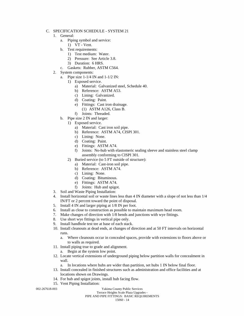
002-267618-003 Yakima County Public Services Terrace Heights Scale Plaza Upgrades - PIPE AND PIPE FITTINGS: BASIC REQUIREMENTS 15060 - 14
C. SPECIFICATION SCHEDULE - SYSTEM 21 1. General:
a. Piping symbol and service: 1) VT - Vent.
b. Test requirements: 1) Test medium: Water. 2) Pressure: See Article 3.8. 3) Duration: 6 HRS.
c. Gaskets: Rubber, ASTM C564. 2. System components:
a. Pipe size 1-1/4 IN and 1-1/2 IN: 1) Exposed service.
a) Material: Galvanized steel, Schedule 40. b) Reference: ASTM A53. c) Lining: Galvanized. d) Coating: Paint. e) Fittings: Cast iron drainage.
(1) ASTM A126, Class B. f) Joints: Threaded.
b. Pipe size 2 IN and larger: 1) Exposed service.
a) Material: Cast iron soil pipe. b) Reference: ASTM A74, CISPI 301. c) Lining: None. d) Coating: Paint. e) Fittings: ASTM A74. f) Joints: No-hub with elastomeric sealing sleeve and stainless steel clamp
assembly conforming to CISPI 301. 2) Buried service (to 5 FT outside of structure):
a) Material: Cast-iron soil pipe. b) Reference: ASTM A74. c) Lining: None. d) Coating: Bituminous. e) Fittings: ASTM A74. f) Joints: Hub and spigot.
3. Soil and Waste Piping Installation: 4. Install horizontal soil or waste lines less than 4 IN diameter with a slope of not less than 1/4
IN/FT or 2 percent toward the point of disposal. 5. Install 4 IN and larger piping at 1/8 IN per foot. 6. Install as close to construction as possible to maintain maximum head room. 7. Make changes of direction with 1/8 bends and junctions with wye fittings. 8. Use short wye fittings in vertical pipe only. 9. Install handhole test tee at base of each stack. 10. Install cleanouts at dead ends, at changes of direction and at 50 FT intervals on horizontal
runs. a. Where cleanouts occur in concealed spaces, provide with extensions to floors above or
to walls as required. 11. Install piping true to grade and alignment.
a. Begin at the system low point. 12. Locate vertical extensions of underground piping below partition walls for concealment in
wall. a. In locations where hubs are wider than partition, set hubs 1 IN below final floor.
13. Install concealed in finished structures such as administration and office facilities and at locations shown on Drawings.
14. For hub and spigot joints, install hub facing flow. 15. Vent Piping Installation:
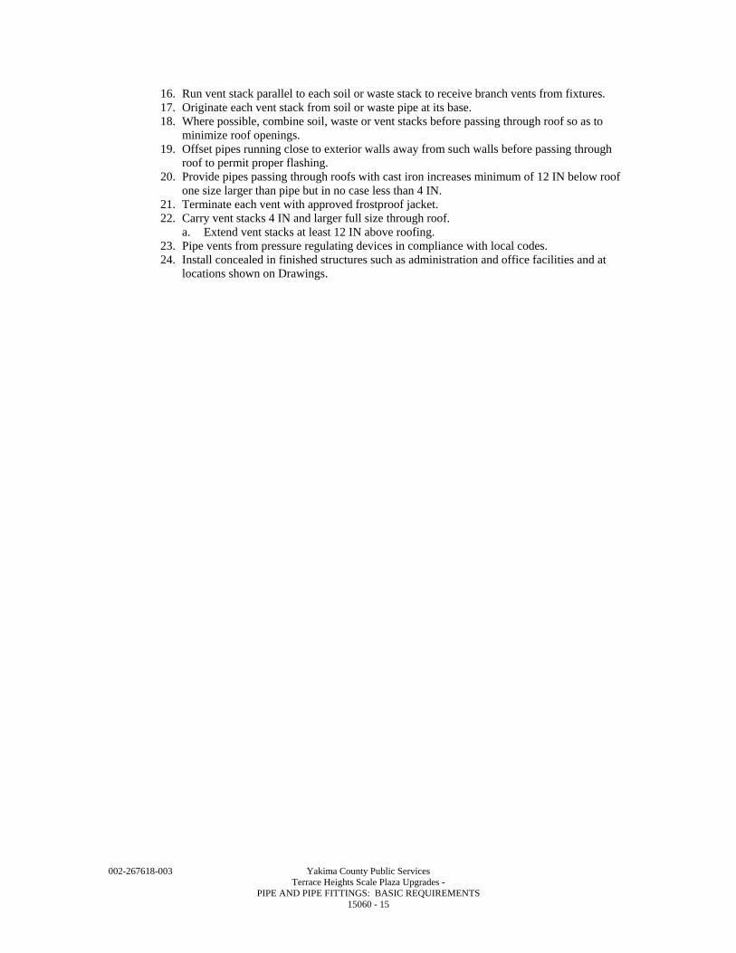
002-267618-003 Yakima County Public Services Terrace Heights Scale Plaza Upgrades - PIPE AND PIPE FITTINGS: BASIC REQUIREMENTS 15060 - 15
16. Run vent stack parallel to each soil or waste stack to receive branch vents from fixtures. 17. Originate each vent stack from soil or waste pipe at its base. 18. Where possible, combine soil, waste or vent stacks before passing through roof so as to
minimize roof openings. 19. Offset pipes running close to exterior walls away from such walls before passing through
roof to permit proper flashing. 20. Provide pipes passing through roofs with cast iron increases minimum of 12 IN below roof
one size larger than pipe but in no case less than 4 IN. 21. Terminate each vent with approved frostproof jacket. 22. Carry vent stacks 4 IN and larger full size through roof.
a. Extend vent stacks at least 12 IN above roofing. 23. Pipe vents from pressure regulating devices in compliance with local codes. 24. Install concealed in finished structures such as administration and office facilities and at
locations shown on Drawings.
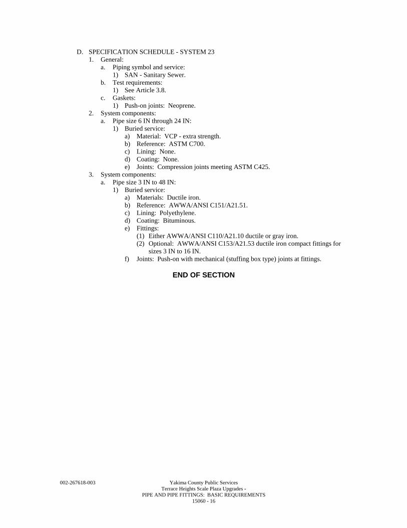
002-267618-003 Yakima County Public Services Terrace Heights Scale Plaza Upgrades - PIPE AND PIPE FITTINGS: BASIC REQUIREMENTS 15060 - 16
D. SPECIFICATION SCHEDULE - SYSTEM 23 1. General:
a. Piping symbol and service: 1) SAN - Sanitary Sewer.
b. Test requirements: 1) See Article 3.8.
c. Gaskets: 1) Push-on joints: Neoprene.
2. System components: a. Pipe size 6 IN through 24 IN:
1) Buried service: a) Material: VCP - extra strength. b) Reference: ASTM C700. c) Lining: None. d) Coating: None. e) Joints: Compression joints meeting ASTM C425.
3. System components: a. Pipe size 3 IN to 48 IN:
1) Buried service: a) Materials: Ductile iron. b) Reference: AWWA/ANSI C151/A21.51. c) Lining: Polyethylene. d) Coating: Bituminous. e) Fittings:
(1) Either AWWA/ANSI C110/A21.10 ductile or gray iron. (2) Optional: AWWA/ANSI C153/A21.53 ductile iron compact fittings for
sizes 3 IN to 16 IN. f) Joints: Push-on with mechanical (stuffing box type) joints at fittings.
END OF SECTION
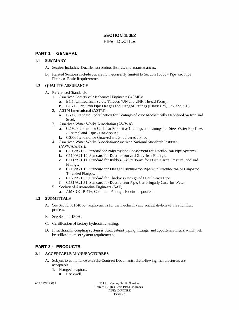
002-267618-003 Yakima County Public Services Terrace Heights Scale Plaza Upgrades - PIPE: DUCTILE 15062 - 1
SECTION 15062
PIPE: DUCTILE
PART 1 - GENERAL
1.1 SUMMARY
A. Section Includes: Ductile iron piping, fittings, and appurtenances.
B. Related Sections include but are not necessarily limited to Section 15060 - Pipe and Pipe Fittings: Basic Requirements.
1.2 QUALITY ASSURANCE
A. Referenced Standards: 1. American Society of Mechanical Engineers (ASME):
a. B1.1, Unified Inch Screw Threads (UN and UNR Thread Form). b. B16.1, Gray Iron Pipe Flanges and Flanged Fittings (Classes 25, 125, and 250).
2. ASTM International (ASTM): a. B695, Standard Specification for Coatings of Zinc Mechanically Deposited on Iron and
Steel. 3. American Water Works Association (AWWA):
a. C203, Standard for Coal-Tar Protective Coatings and Linings for Steel Water Pipelines - Enamel and Tape - Hot Applied.
b. C606, Standard for Grooved and Shouldered Joints. 4. American Water Works Association/American National Standards Institute
(AWWA/ANSI): a. C105/A21.5, Standard for Polyethylene Encasement for Ductile-Iron Pipe Systems. b. C110/A21.10, Standard for Ductile-Iron and Gray-Iron Fittings. c. C111/A21.11, Standard for Rubber-Gasket Joints for Ductile-Iron Pressure Pipe and
Fittings. d. C115/A21.15, Standard for Flanged Ductile-Iron Pipe with Ductile-Iron or Gray-Iron
Threaded Flanges. e. C150/A21.50, Standard for Thickness Design of Ductile-Iron Pipe. f. C151/A21.51, Standard for Ductile-Iron Pipe, Centrifugally Cast, for Water.
5. Society of Automotive Engineers (SAE): a. AMS-QQ-P-416, Cadmium Plating - Electro-deposited.
1.3 SUBMITTALS
A. See Section 01340 for requirements for the mechanics and administration of the submittal process.
B. See Section 15060.
C. Certification of factory hydrostatic testing.
D. If mechanical coupling system is used, submit piping, fittings, and appurtenant items which will be utilized to meet system requirements.
PART 2 - PRODUCTS
2.1 ACCEPTABLE MANUFACTURERS
A. Subject to compliance with the Contract Documents, the following manufacturers are acceptable: 1. Flanged adaptors:
a. Rockwell.
002-267618-003 Yakima County Public Services Terrace Heights Scale Plaza Upgrades - PIPE: DUCTILE 15062 - 2
b. Dresser. 2. Compression sleeve coupling:
a. Rockwell. b. Dresser.
3. Mechanical coupling: a. Victaulic (Style 31). b. Tyler.
4. Insulating couplings: a. Rockwell (Style 416). b. Dresser (Style 39).
5. Reducing couplings: a. Rockwell (Style 415). b. Dresser (Style 62).
6. Transition coupling: a. Rockwell (Style 413). b. Dresser (Style 62).
7. Polyethylene encasement tape: a. Chase (Chasekote 750). b. Kendall (Polyken 900). c. 3 M (Scotchrap 50).
8. Restrained joints: a. American (Lock Fast) - 12 IN and below. b. U.S. Pipe (TR-Flex) - 4 IN to 54 IN.
B. Submit request for substitution in accordance with Specification Section 01640.
2.2 MATERIALS
A. Ductile Iron Pipe: 1. AWWA/ANSI C115/A21.15. 2. AWWA/ANSI C150/A21.50. 3. AWWA/ANSI C151/A21.51.
B. Fittings and Flanges: 1. AWWA/ANSI C110/A21.10. 2. AWWA/ANSI C115/A21.15. 3. Flanges drilled and faced per ASME B16.1 for both 125 and 250 psi applications.
C. Nuts and Bolts: 1. Buried: Cadmium-plated meeting SAE AMS-QQ-P-416, Type 1, Class 2 (Cor-Ten) for
buried application. 2. Exposed: Mechanical galvanized ASTM B695, Class 40. 3. Heads and dimensions per ASME B1.1. 4. Threaded per ASME B1.1. 5. Project ends 1/4 to 1/2 IN beyond nuts.
D. Gaskets: See individual piping system requirements in Section 15060.
E. If mechanical coupling system is used, utilize pipe thickness and grade in accordance with AWWA C606.
F. Polyethylene Encasement: See AWWA/ANSI C105/A21.5.
G. See Piping Schedules in Section 15060.
2.3 MANUFACTURED UNITS
A. Couplings: 1. Flanged adaptors:
a. Unit consisting of steel or carbon steel body sleeve, flange, followers, Grade 30 rubber gaskets.
002-267618-003 Yakima County Public Services Terrace Heights Scale Plaza Upgrades - PIPE: DUCTILE 15062 - 3
b. Provide units specified in Article 2.1. c. Supply flanges meeting standards of adjoining flanges. d. Rate entire assembly for test pressure specified on piping schedule for each respective
application. 2. Compression sleeve coupling:
a. Unit consisting of steel sleeve, followers, Grade 30 rubber gaskets. b. Provide units specified in Article 2.1. c. Supply flanges meeting standards of adjoining flanges. d. Entire assembly to be rated for test pressure specified on piping schedule for each
respective application. e. Provide field coating for buried couplings per AWWA C203.
3. Mechanical couplings: a. Use of mechanical couplings and fittings in lieu of flanged joints is acceptable where
specifically specified in Section 15060. b. Utilize units defined in Article 2.1.
2.4 FABRICATION
A. Furnish and install without outside coatings of bituminous material any exposed pipe scheduled to be painted.
B. Furnish cast parts with lacquer finish compatible with finish coat.
2.5 LININGS AND COATINGS
A. Where specified in piping schedule, provide linings to a minimum thickness of 40 mils. 1. Polyethylene, "Polybond" by American Pipe. 2. Polyurethane, "Polythane" by U.S. Pipe. 3. Ceramic epoxy, "Protecto 401" by U.S. Pipe. 4. Calcium aluminate, "Sewper Coat" by Griffin Pipe.
2.6 SOURCE QUALITY CONTROL
A. Factory Test: 1. Subject pipe to hydrostatic test of not less than 500 psi with the pipe under the full test
pressure for at least 10 seconds.
PART 3 - EXECUTION
3.1 INSTALLATION
A. Joining Method - Push-On Mechanical (Gland-Type) Joints: 1. Install in accordance with AWWA/ANSI C111/A21.11. 2. Assemble mechanical joints carefully according to manufacturer's recommendations. 3. If effective sealing is not obtained, disassemble, thoroughly clean, and reassemble the joint. 4. Do not overstress bolts. 5. Where piping utilizes mechanical joints with tie rods, align joint holes to permit installation
of harness bolts.
B. Joining Method - Push-On Joints: 1. Install in accordance with AWWA/ANSI C151/A21.51. 2. Assemble push-on joints in accordance with manufacturer's directions. 3. Bevel and lubricate spigot end of pipe to facilitate assembly without damage to gasket.
a. Use lubricant that is non-toxic, does not support the growth of bacteria, has no deteriorating effects on the gasket material, and imparts no taste or odor to water in pipe.
4. Assure the gasket groove is thoroughly clean. 5. For cold weather installation, warm gasket prior to placement in bell. 6. Taper of bevel shall be approximately 30 degrees with centerline of pipe and approximately
1/4 IN back.
002-267618-003 Yakima County Public Services Terrace Heights Scale Plaza Upgrades - PIPE: DUCTILE 15062 - 4
C. Joining Method - Flanged Joints: 1. Install in accordance with AWWA/ANSI C115/A21.15. 2. Extend pipe completely through screwed-on flanged and machine flange face and pipe in
single operation. 3. Make flange faces flat and perpendicular to pipe centerline. 4. When bolting flange joints, exercise extreme care to ensure that there is no restraint on
opposite end of pipe or fitting which would prevent uniform gasket compression or would cause unnecessary stress, bending or torsional strains to be applied to cast flanges or flanged fittings.
5. Allow one (1) flange free movement in any direction while bolts are being tightened. 6. Do not assemble adjoining flexible joints until flanged joints in piping system have been
tightened. 7. Gradually tighten flange bolts uniformly to permit even gasket compression.
D. Joining Method - Mechanical Coupling Joint: 1. Arrange piping so that pipe ends are in full contact. 2. Groove and shoulder ends of piping in accordance with manufacturer's recommendations. 3. Provide coupling and grooving technique assuring a connection which passes pressure
testing requirements.
E. Flange Adaptors 12 IN and Less: 1. Locate and drill holes for anchor studs after pipe is in place and bolted tight. 2. Drill holes not more than 1/8 IN larger than diameter of stud projection.
F. Cutting: 1. Do not damage interior lining material during cutting. 2. Use abrasive wheel cutters or saws. 3. Make square cuts. 4. Bevel and free cut ends of sharp edges after cutting.
G. Support exposed pipe in accordance with Section 15060.
H. Install buried piping in accordance with Section 15060.
I. Install restrained joint systems where specified in Section 15060 under specific piping system.
3.2 FIELD QUALITY CONTROL
A. Test piping systems in accordance with Section 15060.
END OF SECTION
002-267618-003 Yakima County Public Services Terrace Heights Scale Plaza Upgrades - PIPE: COPPER 15063 - 1
SECTION 15063
PIPE: COPPER
PART 1 - GENERAL
1.1 SUMMARY
A. Section Includes: Copper piping, fittings, and appurtenances.
B. Related Sections include but are not necessarily limited to: 1. Section 15060 - Pipe and Pipe Fittings: Basic Requirements. 2. Section 15090 - Pipe Support Systems.
1.2 QUALITY ASSURANCE
A. Referenced Standards: 1. American Society of Mechanical Engineers (ASME):
a. B16.22, Wrought Copper and Bronze Solder - Joint Pressure Fittings. b. B16.23, Cast Bronze Solder Joint Drainage Fittings - DWV. c. B16.26, Cast Bronze Alloy Fittings for Flared Copper Tubes.
2. ASTM International (ASTM): a. B32, Standard Specification for Solder Metal. b. B42, Standard Specification for Seamless Copper Pipe, Standard Sizes. c. B88, Standard Specification for Seamless Copper Water Tube. d. B306, Standard Specification for Copper Drainage Tube (DWV).
3. American Welding Society (AWS): a. A5.8, Specification for Filler Metals for Brazing and Braze Welding.
1.3 SUBMITTALS
A. See Section 01340 for requirements for the mechanics and administration of the submittal process.
B. See Section 15060.
PART 2 - PRODUCTS
2.1 MATERIALS
A. Copper Tubing: 1. Pressure non-buried: ASTM B88, Type L hard. 2. Pressure buried: ASTM B88, Type K. 3. Non-pressure: ASTM B306.
B. Copper Pipe: ASTM B42, regular strength.
C. Fittings: 1. Pressure non-buried: ASME B16.22. 2. Pressure buried: ASME B16.22 or ASME B16.26. 3. Non-pressure: ASME B16.23
D. Soldering and Brazing: 1. Non-buried:
a. ASTM B32 solder with a tin/antimony ratio of 95/5 and non-corrosive flux up to 180 DegF water temperature.
b. At 180 DegF and above, use brazing alloy with melting temperature above 1000 DegF and suitable flux.
2. Buried: Silver solder per AWS A5.8.
002-267618-003 Yakima County Public Services Terrace Heights Scale Plaza Upgrades - PIPE: COPPER 15063 - 2
E. See Piping Schedules in Section 15060.
F. Unions: 1. Pipe sizes 2 IN and smaller: Copper, ground joint. 2. Pipe sizes 2-1/2 IN and larger: Brass flanged unions.
PART 3 - EXECUTION
3.1 INSTALLATION
A. Comply with Section 15060.
3.2 FIELD QUALITY CONTROL
A. Test piping systems in accordance with Section 15060.
B. Utilize only annealed (soft) type tubing where flared joints are used and drawn temper (hard) type tubing where soldered or brazed joints are used.
C. Support exposed piping in accordance with Section 15060 and Section 15090.
END OF SECTION
002-267618-003 Yakima County Public Services Terrace Heights Scale Plaza Upgrades - PIPE: PLASTIC 15064 - 1
SECTION 15064
PIPE: PLASTIC
PART 1 - GENERAL
1.1 SUMMARY
A. Section Includes: Plastic pipe.
B. Related Sections include but are not necessarily limited to Section 15060 - Pipe and Pipe Fittings: Basic Requirements.
1.2 QUALITY ASSURANCE
A. See Section 15060.
B. Referenced Standards: 1. ASTM International (ASTM):
a. PVC (polyvinyl chloride) materials: 1) D1784, Standard Specification for Rigid Poly(Vinyl Chloride) (PVC) Compounds
and Chlorinated Poly(Vinyl Chloride) (CPVC) Compounds. 2) D1785, Standard Specification for Poly(Vinyl Chloride) PVC Plastic Pipe,
Schedules 40, 80 and 120. 3) D2467, Standard Specification for Poly(Vinyl Chloride) (PVC) Plastic Pipe
Fittings, Schedule 80. 4) D3034, Standard Specification for Type PSM Poly(Vinyl Chloride) (PVC) Sewer
Pipe and Fittings. 5) D3139, Standard Specification for Joints for Plastic Pressure Pipes Using Flexible
Elastomeric Seals. 6) D3212, Standard Specification for Joints for Drain and Sewer Plastic Pipes Using
Flexible Elastomeric Seals. 7) F593, Standard Specification for Stainless Steel Bolts, Hex Cap Screws, and Studs. 8) F679, Standard Specification for Poly(Vinyl Chloride) (PVC) Large-Diameter
Plastic Gravity Sewer Pipe and Fittings. 9) F794, Standard Specification for Poly(Vinyl Chloride) (PVC) Profile Gravity
Sewer Pipe and Fittings Based on Controlled Inside Diameter. 10) F949, Standard Specification for Poly(Vinyl Chloride) (PVC) Corrugated Sewer
Pipe with a Smooth Interior and Fittings. b. Installation:
1) D2321, Standard Practice for Underground Installation of Thermosplastic Pipe for Sewers and Other Gravity-Flow Applications.
2. American Water Works Association (AWWA): a. PVC (polyvinyl chloride) materials:
1) C900, Standard for Polyvinyl Chloride (PVC) Pressure Pipe and Fabricated Fittings, 4 IN Through 12 IN, for Water Distribution.
2) C905, Standard for Polyvinyl Chloride (PVC) Pressure Pipe and Fabricated Fittings, 14 IN through 48 IN, for Water Transmission and Distribution.
b. Polyethylene (PE) materials: 1) C901, Standard for Polyethylene (PE) Pressure Pipe and Tubing, 1/2 IN through
3 IN, for Water Service. 3. NSF International (NSF).
1.3 SUBMITTALS
A. See Section 01340 for requirements for the mechanics and administration of the submittal process.
B. See Section 15060.
002-267618-003 Yakima County Public Services Terrace Heights Scale Plaza Upgrades - PIPE: PLASTIC 15064 - 2
PART 2 - PRODUCTS
2.1 PVC PRESSURE PIPING (EXPOSED)
A. General: 1. Provide Schedule 80 pipe with Schedule 80 fittings and appurtenances to locations shown
on Drawings. 2. Furnish materials in full compliance to following material specifications:
a. Manufacture pipe, fittings and appurtenances from polyvinyl chloride (PVC) compound which meets the requirements of Type 1, Grade 1 (12454-B) Polyvinyl Chloride as outlined in ASTM D1784.
b. Manufacture pipe, fittings and valves from materials that have been tested and approved for conveying potable water by the NSF.
B. Pipe: 1. Furnish pipe meeting requirements of ASTM D1785. 2. Pipe 2 IN and less to be solvent welded. 3. Pipe larger than 2 IN may be either flanged or solvent welded unless shown otherwise on
Drawings.
C. Fittings: Provide ASTM D2467 PVC socket type fittings having the same pressure and temperature rating as the pipe.
D. Flanges/Unions: 1. Furnish flanges and unions at locations shown on Drawings. 2. Provide either flanges or unions at valves, penetrations through structures and equipment
connections. 3. For pipe larger than 2 IN, provide 150 LBS socket type PVC flange. 4. For pipe 2 IN and less, provide socket type PVC union with Buna O-rings. 5. Use flat, full faced natural rubber gaskets at flanged connections.
a. Furnish heavy hex head bolts, each with one (1) heavy hex nut, ASTM F593 Type 316 stainless steel.
6. Use spacers supplied by pipe manufacturer when mating raised-faced flanges to other flanges.
E. Installation: 1. Field threading PVC will not be permitted.
a. Perform required threaded connections or attachments by the use of factory molded socket by threaded adapters.
b. Female adapters are not acceptable. 2. Employ installation and pipe support practices and solvent welding all in compliance to the
manufacturer's printed recommendation. a. Continuously support PVC piping at liquid operating temperatures in excess of 100
DegF. b. For vertical piping, band the pipe at intervals to rigidly support load of twice vertical
load. c. Support riser clamps on spring hangers. d. Do not clamp PVC tightly or restrict movement for expansion and contraction.
2.2 PRESSURE PIPING (UNDERGROUND)
A. Materials: Furnish materials in full compliance with following requirements: 1. 1/2-3 IN: AWWA C901 PE with Pressure Class of 125 psi per Table A3, AWWA C901. 2. Joints for polyethylene pipe shall be fusion type in accordance with AWWA C901. 3. Joints for PVC pipe shall be the elastomeric-gasket type with a pressure rating not less than
pipe pressure rating meeting performance requirements of ASTM D3139.
B. Installation: 1. Field threading of PVC pipe will not be permitted.
002-267618-003 Yakima County Public Services Terrace Heights Scale Plaza Upgrades - PIPE: PLASTIC 15064 - 3
2. Perform installation procedures, handling, thrust blocking, connections, and other appurtenant operations in full compliance to the manufacturer's printed recommendations and in full observance to plan details when more stringent.
2.3 PVC DRAINAGE AND SEWER PIPING
A. Materials: 1. Furnish materials in full compliance to the following material specification. 2. PVC pipe shall be rigid, unplasticized PVC made of PVC plastic having a cell classification
of 12454-B or 12454-C as described in specification ASTM D1784. 3. The requirements of this Specification are intended to provide for pipe and fittings suitable
for non-pressure drainage of wastewater and surface water. 4. Joining systems shall consist of an elastomeric gasket joint meeting requirements of
ASTM D3212. 5. Supply to the Engineer all information and sample of joining method for his evaluation.
a. Only jointing methods acceptable to the Engineer will be permitted. 6. Provide pipe and fittings meeting or exceeding the following requirements:
a. 4-27 IN DIA: ASTM D3034 and ASTM F679, SDR 35. b. 8-30 IN DIA: ASTM F794. c. 4-18 IN DIA: ASTM F949.
7. Ensure impact strengths and pipe stiffnesses in full compliance to these Specifications.
B. Installation: Install pipe and fittings in accordance with ASTM D2321 and as recommended by the manufacturer. 1. Provide for a maximum deflection of not more than 5 percent.
C. Infiltration and Exfiltration: 1. The maximum allowable infiltration measured by test shall not exceed 100 GAL per inch of
pipe diameter per mile per 24 HRS. 2. Observe full instructions of the Owner for carrying of testing procedures.
a. Perform tests only during presence of the Engineer or his authorized representative. 3. Should any test on any section of pipe line disclose either infiltration rates greater than
allowed or disclose air loss rate greater than that permitted, locate and repair the defective joints or pipes at no cost to Owner and retest until requirements stated are met.
D. Deflection: 1. After backfilling, each section of pipe shall be checked for deflection by pulling a mandrel
through the pipe. 2. Pipe with deflection exceeding 5 percent of the inside diameter shall have backfill removed
and replaced to provide a deflection of less than 5 percent. 3. Any repaired pipe shall be retested.
2.4 PVC TUBING
A. General: Provide nylon tubing with fittings and appurtenances as shown on Drawings.
B. Materials: 1. Furnish clear outer braided tubing with braid outside the walls. 2. Have tubing manufactured of nylon with working temperatures from 5 to 180 DegF. 3. Design tubing with a minimum safety factor of 4 to 1 ratio of burst pressure to working
pressure at maximum temperature. 4. Provide tubing with working pressure of 75 psi at 180 DegF. 5. Ensure that tubing is self-extinguishing and fire resistant.
C. Fittings: 1. Install tubing with nylon fittings and connectors. 2. Use barbed type adapters with stainless steel clamps. 3. Provide fittings capable of withstanding temperatures from a -70 to 250 DegF. 4. Ensure fittings have the same pressure and temperature rating as the tubing.
002-267618-003 Yakima County Public Services Terrace Heights Scale Plaza Upgrades - PIPE: PLASTIC 15064 - 4
PART 3 - EXECUTION
3.1 IDENTIFICATION
A. Identify each length of pipe clearly at intervals of 5 FT or less. 1. Include manufacturer's name and trademark. 2. Nominal size of pipe, appurtenant information regarding polymer cell classification and
critical identifications regarding performance specifications and NSF approvals when applicable.
3.2 PRESSURE PIPING (UNDERGROUND)
A. Installation: 1. Field threading of PVC pipe will not be permitted. 2. Perform installation procedures, handling, thrust blocking, connections, and other
appurtenant operations in full compliance to the manufacturer's printed recommendations and in full observance to plan details when more stringent.
3.3 PVC DRAINAGE AND SEWER PIPING
A. Installation: Install pipe and fittings in accordance with ASTM D2321 and as recommended by the manufacturer. 1. Provide for a maximum deflection of not more than 5 percent.
B. Infiltration and Exfiltration: 1. The maximum allowable infiltration measured by test shall not exceed 100 GAL per inch of
pipe diameter per mile per 24 HRS. 2. For exfiltration, all the pipe and fittings shall exceed performance requirements by an air
test procedure as specified in Section 15060. 3. Observe full instructions of the Engineer for carrying of testing procedures.
a. Perform tests only during presence of the Engineer or his authorized representative. 4. Should any test on any section of pipe line disclose either infiltration rates greater than
allowed or disclose air loss rate greater than that permitted, locate and repair the defective joints or pipes at no cost to Owner and retest until requirements stated are met.
C. Deflection: 1. After backfilling, each section of pipe shall be checked for deflection by pulling a mandrel
through the pipe. 2. Pipe with deflection exceeding 5 percent of the inside diameter shall have backfill removed
and replaced to provide a deflection of less than 5 percent. 3. Any repaired pipe shall be retested.
3.4 PVC TUBING
A. Fittings: 1. Install tubing with nylon fittings and connectors. 2. Use barbed type adapters with stainless steel clamps. 3. Provide fittings capable of withstanding temperatures from a -70 to 250 DegF. 4. Ensure fittings have the same pressure and temperature rating as the tubing.
END OF SECTION
002-267618-003 Yakima County Public Services Terrace Heights Scale Plaza Upgrades - PIPE SUPPORT SYSTEMS 15090 - 1
SECTION 15090
PIPE SUPPORT SYSTEMS
PART 1 - GENERAL
1.1 SUMMARY
A. Section Includes: Pipe support and anchor systems.
B. Related Sections include but are not necessarily limited to Section 09905 - Painting and Protective Coatings.
1.2 QUALITY ASSURANCE
A. Referenced Standards: 1. ANVIL International (ANVIL). 2. American Society of Mechanical Engineers (ASME):
a. B31.1, Power Piping. b. B31.3, Process Piping.
3. ASTM International (ASTM): a. A36, Standard Specification for Carbon Structural Steel. b. A510, Standard Specification for General Requirements for Wire Rods and Coarse
Round Wire, Carbon Steel. c. A575, Standard Specification for Steel Bars, Carbon, Merchant Quality, M-Grades. d. A576, Standard Specification for Steel Bars, Carbon, Hot-Wrought, Special Quality.
4. American Welding Society (AWS): a. D1.1, Structural Welding Code - Steel.
5. Manufacturers Standardization Society of the Valve and Fittings Industry Inc. (MSS): a. SP-58, Pipe Hangers and Supports - Materials, Design and Manufacture. b. SP-69, Pipe Hangers and Supports - Selection and Application.
1.3 SUBMITTALS
A. See Section 01340 for requirements for the mechanics and administration of the submittal process.
B. Product technical data including: 1. Acknowledgement that products submitted meet requirements of standards referenced. 2. Manufacturer's installation instructions. 3. Itemized list of wall sleeves, anchors, support devices and all other items related to pipe
support system. 4. Scale Drawings showing guides, hangers, supports, anchors, structural members and
appurtenances to describe the pipe support system.
PART 2 - PRODUCTS
2.1 ACCEPTABLE MANUFACTURERS
A. Subject to compliance with the Contract Documents, the manufacturers listed in the applicable Articles below are acceptable.
B. Submit request for substitution in accordance with Specification Section 01640.
2.2 MANUFACTURED UNITS
A. Hanger Rods: 1. Material:
a. ASTM A36. b. ASTM A510, Grade 1020.
002-267618-003 Yakima County Public Services Terrace Heights Scale Plaza Upgrades - PIPE SUPPORT SYSTEMS 15090 - 2
c. ASTM A575, Grade M1020. d. ASTM A576, Grade 1020. e. Minimum allowable tensile stress of 12,000 psi at 650 DegF per MSS SP-58.
2. Continuously threaded. 3. Electro-galvanized or cadmium plated after threads are cut. 4. Load limit:
NOMINAL ROD DIAMETER MAXIMUM SAFE LOAD, (LBS)
3/8 IN DIA (min) 610 1/2 IN DIA 1,130 5/8 IN DIA 1,810 3/4 IN DIA 2,710 7/8 IN DIA 3,770 1 IN DIA 4,960
B. Hangers: 1. Hangers for use directly on copper pipe: Copper or cadmium plated. 2. Hangers for use other than directly on copper pipe: Cadmium plated or galvanized. 3. Hanger type schedule:
APPLICATION PIPE SIZE HANGER TYPE
All except noted 4 IN and less ANVIL Figure 108 with Figure 114 All except noted Over 4 IN ANVIL Figure 590 Steam, condensate and hot water All ANVIL Figure 181, Figure 82
C. Concrete Inserts for Hanger Rods: 1. Continuous slots: Unistrut #P1000. 2. Individual inserts: ANVIL Figure 281. 3. Self-drilling expansion anchors: Phillips flush-end or snap-off end type.
D. Beam Clamps for Hanger Rods: 1. Heavy duty. 2. ANVIL Figure 134.
E. Trapeze Hangers for Suspended Piping: 1. Material: Steel. 2. Galvanized. 3. Angles, channels, or other structural shapes. 4. Curved roller surfaces at support point corresponding with type of hanger required.
F. Vertical Pipe Supports: 1. At base of riser. 2. Lateral movement:
a. Clamps or brackets: 1) ANVIL.
G. Expanding Pipe Supports: 1. Spring hanger type. 2. MSS SP-58.
H. Pipe Support Saddle: 1. For pipe located 3 FT or less from floor elevation, except as otherwise indicated on
Drawings. 2. ANVIL Figure 264.
002-267618-003 Yakima County Public Services Terrace Heights Scale Plaza Upgrades - PIPE SUPPORT SYSTEMS 15090 - 3
I. Pipe Support Risers: 1. Schedule 40 pipe. 2. Galvanized. 3. As recommended by saddle manufacturer.
J. Pipe Support Base Plate: 1. 4 IN larger than support. 2. Collar 3/16 IN thickness, circular in shape, and sleeve type connection to pipe. 3. Collar fitted over outside of support pipe and extended 2 IN from floor plate. 4. Collar welded to floor plate. 5. Edges ground smooth. 6. Assembly hot dipped galvanized after fabrication.
K. Pipe Covering Protection Saddle: 1. For insulated pipe at point of support. 2. ANVIL Figure 167, Type B.
L. Wall Brackets: 1. For pipe located near walls and 8 FT or more above floor elevation or as otherwise indicated
on the Drawings. 2. ANVIL Figure 199.
M. Pipe Anchors: 1. For locations shown on the Drawings. 2. 1/4 IN steel plate construction. 3. Hot dipped galvanized after fabrication. 4. Designed to prevent movement of pipe at point of attachment.
N. Pipe Guides: 1. For locations on both sides on each expansion joint or loop. 2. To ensure proper alignment of expanding or contracting pipe. 3. ANVIL Figure 256.
2.3 DESIGN REQUIREMENTS
A. Supports capable of supporting the pipe for all service and testing conditions. 1. Provide 5 to 1 safety factor.
B. Allow free expansion and contraction of the piping to prevent excessive stress resulting from service and testing conditions or from weight transferred from the piping or attached equipment.
C. Design supports and hangers to allow for proper pitch of pipes.
D. For hot and cold water piping, design, materials of construction and installation of pipe hangers, supports, guides, restraints, and anchors: 1. ASME B31.1. 2. MSS SP-58 and MSS SP-69.
E. Check all physical clearances between piping, support system and structure. 1. Provide for vertical adjustment after erection.
F. Support vertical pipe runs in pipe chases at base of riser. 1. Support pipes for lateral movement with clamps or brackets.
G. Place hangers on outside of pipe insulation. 1. Use a pipe covering protection saddle for insulated pipe at support point. 2. Insulated piping 1-1/2 IN and less: Provide a 9 IN length of 9 LB density fiberglass
insulation at saddle. 3. Insulated piping over 1-1/2 IN: Provide a 12 IN length of 9 LB density fiberglass insulation
on saddle.
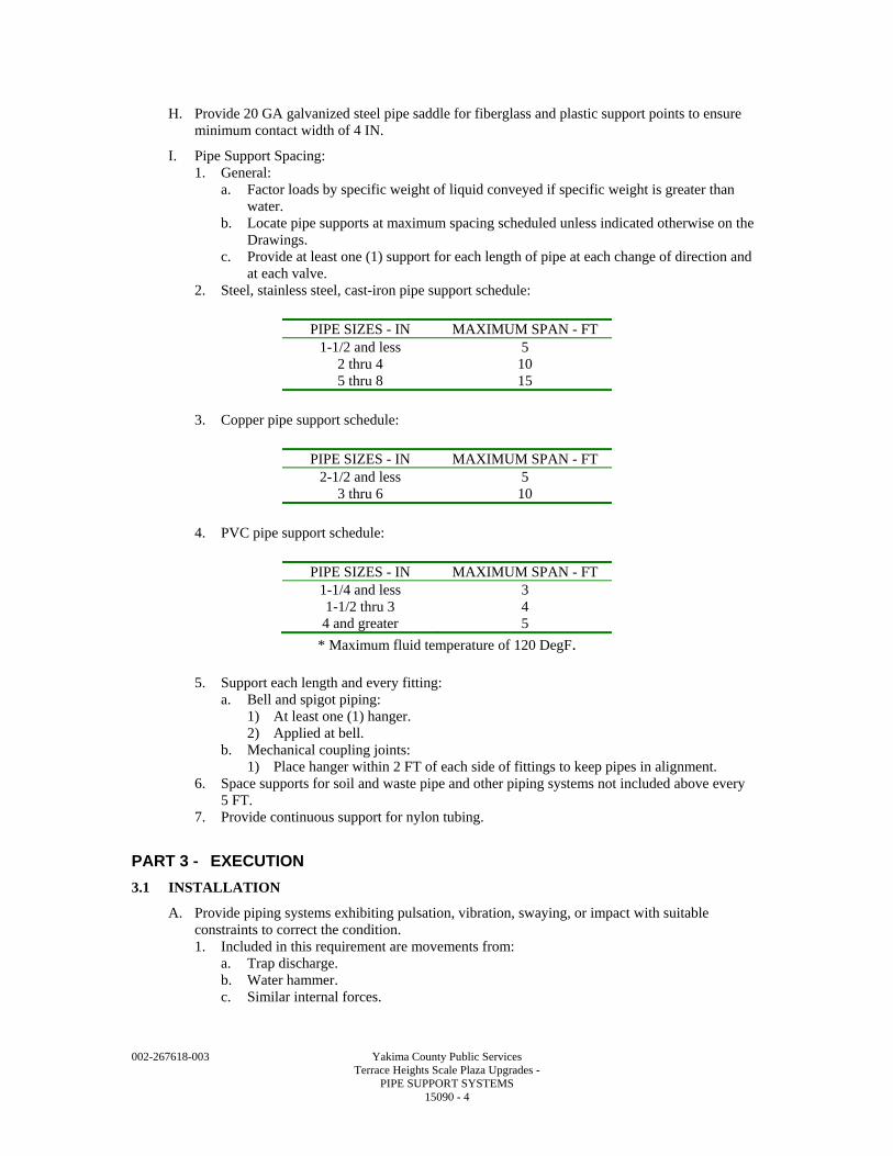
002-267618-003 Yakima County Public Services Terrace Heights Scale Plaza Upgrades - PIPE SUPPORT SYSTEMS 15090 - 4
H. Provide 20 GA galvanized steel pipe saddle for fiberglass and plastic support points to ensure minimum contact width of 4 IN.
I. Pipe Support Spacing: 1. General:
a. Factor loads by specific weight of liquid conveyed if specific weight is greater than water.
b. Locate pipe supports at maximum spacing scheduled unless indicated otherwise on the Drawings.
c. Provide at least one (1) support for each length of pipe at each change of direction and at each valve.
2. Steel, stainless steel, cast-iron pipe support schedule:
PIPE SIZES - IN MAXIMUM SPAN - FT 1-1/2 and less 5
2 thru 4 10 5 thru 8 15
3. Copper pipe support schedule:
PIPE SIZES - IN MAXIMUM SPAN - FT
2-1/2 and less 5 3 thru 6 10
4. PVC pipe support schedule:
PIPE SIZES - IN MAXIMUM SPAN - FT
1-1/4 and less 3 1-1/2 thru 3 4 4 and greater 5
* Maximum fluid temperature of 120 DegF.
5. Support each length and every fitting: a. Bell and spigot piping:
1) At least one (1) hanger. 2) Applied at bell.
b. Mechanical coupling joints: 1) Place hanger within 2 FT of each side of fittings to keep pipes in alignment.
6. Space supports for soil and waste pipe and other piping systems not included above every 5 FT.
7. Provide continuous support for nylon tubing.
PART 3 - EXECUTION
3.1 INSTALLATION
A. Provide piping systems exhibiting pulsation, vibration, swaying, or impact with suitable constraints to correct the condition. 1. Included in this requirement are movements from:
a. Trap discharge. b. Water hammer. c. Similar internal forces.
002-267618-003 Yakima County Public Services Terrace Heights Scale Plaza Upgrades - PIPE SUPPORT SYSTEMS 15090 - 5
B. Weld Supports: 1. AWS D1.1. 2. Weld anchors to pipe in accordance with ASME B31.3.
C. Locate piping and pipe supports as to not interfere with open accesses, walkways, platforms, and with maintenance or disassembly of equipment.
D. Inspect hangers for: 1. Design offset. 2. Adequacy of clearance for piping and supports in the hot and cold positions. 3. Guides to permit movement without binding. 4. Adequacy of anchors.
E. Inspect hangers after erection of piping systems and prior to pipe testing and flushing.
F. Install individual or continuous slot concrete inserts for use with hangers for piping and equipment. 1. Install concrete inserts as concrete forms are installed.
G. Welding: 1. Welding rods: ASTM and AWS standards. 2. Integral attachments:
a. Include welded-on ears, shoes, plates and angle clips. b. Ensure material for integral attachments is of good weldable quality.
3. Preheating, welding and postheat treating: ASME B31.3, Chapter V.
H. Field Painting: Comply with Section 09905.
END OF SECTION

002-267618-003 Yakima County Public Services Terrace Heights Scale Plaza Upgrades - PIPE SUPPORT SYSTEMS 15090 - 6
002-267618-003 Yakima County Public Services Terrace Heights Scale Plaza Upgrades - VALVES: BASIC REQUIREMENTS 15100 - 1
SECTION 15100
VALVES: BASIC REQUIREMENTS
PART 1 - GENERAL
1.1 SUMMARY
A. Section Includes: Valving, actuators, and valving appurtenances.
B. Related Specification Sections include but are not necessarily limited to: 1. Section 09905 - Painting and Protective Coatings. 2. Section 11005 - Equipment: Basic Requirements. 3. Section 15060 - Pipe and Pipe Fittings: Basic Requirements. 4. Section 15101 - Gate Valves. 5. Section 15104 - Ball Valves. 6. Section 15114 - Miscellaneous Valves.
1.2 QUALITY ASSURANCE
A. Referenced Standards: 1. American Society of Mechanical Engineers (ASME):
a. B1.20.1, Pipe Threads, General Purpose. b. B16.1,Grayt Iron Pipe Flanges and Flanged Fittings (Classes 25, 125, and 250). c. B16.18, Cast Copper Alloy Solder Joint Pressure Fittings.
2. ASTM International (ASTM): a. A126, Standard Specification for Gray Iron Castings for Valves, Flanges, and Pipe
Fittings. b. D256, Standard Test Methods for Determining the Izod Pendulum Impact Resistance of
Plastics. c. D638, Standard Test Method for Tensile Properties of Plastics. d. D648, Standard Test Method for Deflection Temperature of Plastics Under Flexural
Load in the Edgewise Position. e. D695, Standard Test Method for Compressive Properties of Rigid Plastics. f. D2240, Standard Test Method for Rubber Property-Durometer Hardness.
3. American Water Works Association (AWWA): a. C207, Standard for Steel Pipe Flanges for Waterworks Service - Sizes 4 IN through
144 IN. b. C500, Standard for Metal-Seated Gate Valves for Water Supply Service. c. C504, Standard for Rubber-Seated Butterfly Valves. d. C507, Standard for Ball Valves, 6 IN through 48 IN (150 MM through 1200 MM). e. C509, Standard for Resilient-Seated Gate Valves for Water Supply Service. f. C541, Standard for Hydraulic and Pneumatic Cylinder and Vane-Type Actuators for
Valves and Slide Gates. g. C542, Standard for Electric Motor Actuators for Valves and Slide Gates. h. C550, Standard for Protective Coatings for Valves and Hydrants. i. C606, Standard for Grooved and Shouldered Joints.
4. American Water Works Association/American National Standards Institute (AWWA/ANSI): a. C111/A21.11, Standard for Rubber-Gasket Joints for Ductile-Iron Pressure Pipe and
Fittings. 5. National Electrical Manufacturers Association (NEMA):
a. 250, Enclosures for Electrical Equipment (1000 Volts Maximum). b. MG 1, Motors and Generators.
002-267618-003 Yakima County Public Services Terrace Heights Scale Plaza Upgrades - VALVES: BASIC REQUIREMENTS 15100 - 2
1.3 DEFINITIONS
A. The following are definitions of abbreviations used in this Specification Section or one (1) of the individual valve sections: 1. CWP: Cold water working pressure. 2. WWP: Water working pressure.
1.4 SUBMITTALS
A. See Specification Section 01340 for requirements for the mechanics and administration of the submittal process.
B. Product technical data including: 1. Acknowledgement that products submitted meet requirements of standards referenced. 2. Manufacturer's installation instructions. 3. Valve pressure and temperature rating. 4. Valve material of construction. 5. Special linings. 6. Valve dimensions and weight. 7. Valve flow coefficient. 8. Wiring and control diagrams for electric or cylinder actuators.
C. Test reports.
D. Operation and Maintenance Manuals: 1. See Specification Section 01340 for requirements for the content of Operation and
Maintenance Manuals.
E. Verification from valve actuator manufacturer that actuators have been installed properly, that all limit switches and position potentiometers have been properly adjusted, and that the valve actuator responds correctly to the valve position command.
PART 2 - PRODUCTS
2.1 ACCEPTABLE MANUFACTURERS
A. Subject to compliance with the Contract Documents, refer to individual valve Specification Sections for acceptable manufacturers.
2.2 MATERIALS
A. Refer to individual valve Specification Sections.
2.3 FABRICATION
A. End Connections: 1. Provide the type of end connections for valves as required in the Piping Schedules presented
in Specification Section 15060 or as shown on the Drawings. 2. Comply with the following standards:
a. Threaded: ASME B1.20.1. b. Flanged: ASME B16.1 Class 125 unless otherwise noted or AWWA C207. c. Bell and spigot or mechanical (gland) type: AWWA/ANSI C111/A21.11. d. Soldered: ASME B16.18. e. Grooved: Rigid joints per Table 5 of AWWA C606.
B. Refer to individual valve Specification Sections for specifications of each type of valve used on Project.
C. Nuts, Bolts, and Washers: 1. Wetted or internal to be bronze or stainless steel.
a. Exposed to be zinc or cadmium plated.
002-267618-003 Yakima County Public Services Terrace Heights Scale Plaza Upgrades - VALVES: BASIC REQUIREMENTS 15100 - 3
D. On Insulated Piping: Provide valves with extended stems to permit proper insulation application without interference from handle.
E. Epoxy Interior Coating: Provide epoxy interior coating for all ferrous surfaces in accordance with AWWA C550.
PART 3 - EXECUTION
3.1 INSTALLATION
A. Install products in accordance with manufacturer's instructions.
B. Painting Requirements: Comply with Specification Section 09905 for painting and protective coatings.
C. Setting Buried Valves: 1. Locate valves installed in pipe trenches where buried pipe indicated on Drawings. 2. Set valves and valve boxes plumb. 3. Place valve boxes directly over valves with top of box being brought to surface of finished
grade. 4. Install in closed position. 5. Place valve on firm footing in trench to prevent settling and excessive strain on connection
to pipe. 6. After installation, backfill up to top of box for a minimum distance of 4 FT on each side of
box.
D. Support exposed valves and piping adjacent to valves independently to eliminate pipe loads being transferred to valve and valve loads being transferred to the piping.
E. For grooved coupling valves, install rigid type couplings.
F. For threaded valves, provide union on one (1) side within 2 FT of valve to allow valve removal.
G. Install valves accessible for operation, inspection, and maintenance.
3.2 ADJUSTMENT
A. Adjust valves and appurtenant equipment to comply with operation of valve, open and close at system pressures.
END OF SECTION

002-267618-003 Yakima County Public Services Terrace Heights Scale Plaza Upgrades - VALVES: BASIC REQUIREMENTS 15100 - 4
002-267618-003 Yakima County Public Services Terrace Heights Scale Plaza Upgrades - GATE VALVES 15101 - 1
SECTION 15101
GATE VALVES
PART 1 - GENERAL
1.1 SUMMARY
A. Section Includes: Gate valves.
B. Related Specification Sections include but are not necessarily limited to Section 15100 - Valves: Basic Requirements.
1.2 QUALITY ASSURANCE
A. Referenced Standards: 1. ASTM International (ASTM):
a. A126, Standard Specification for Gray Iron Castings for Valves, Flanges, and Pipe Fittings.
2. American Water Works Association (AWWA): a. C500, Standard for Metal-Seated Gate Valves for Water Supply Service. b. C504, Standard for Rubber-Seated Butterfly Valves. c. C509, Standard for Resilient-Seated Gate Valves for Water Supply Service. d. C515, Standards for Reduced-Wall, Resilient-Seated Gate Valves for Water Supply
Systems. e. C550, Standard for Protective Epoxy Interior Coatings for Valves and Hydrants.
3. Manufacturers Standardization Society of the Valve and Fittings Industry Inc. (MSS): a. SP-9, Spot Facing for Bronze, Iron and Steel Flanges. b. SP-70, Cast Iron Gate Valves, Flanged and Threaded Ends. c. SP-80, Bronze Gate, Globe, Angle and Check Valves.
1.3 DEFINITIONS
A. OS&Y: Outside Screw and Yoke.
B. NRS: Non-rising Stem.
C. RS: Rising Stem.
1.4 SUBMITTALS
A. See Specification Section 01340 for requirements for the mechanics and administration of the submittal process.
B. See Specification Section 15100.
C. Operation and Maintenance Manuals: 1. See Specification Section 01340 for requirements for the content of Operation and
Maintenance Manuals.
PART 2 - PRODUCTS
2.1 ACCEPTABLE MANUFACTURERS
A. Subject to compliance with the Contract Documents, the manufacturers listed in the applicable Articles below are acceptable.
B. Submit request for substitution in accordance with Specification Section 01640.
2.2 VALVES: WATER, 2-1/2 IN AND SMALLER
A. Class 125 bronze gate valve.
002-267618-003 Yakima County Public Services Terrace Heights Scale Plaza Upgrades - GATE VALVES 15101 - 2
B. Comply with MSS SP-80.
C. Materials: 1. Body, bonnet, wedge: Bronze. 2. Stem: Silicon bronze. 3. Packing: Aramid fibers with graphite (Kevlar®).
D. Design Requirements: 1. 200 psi nonshock WOG. 2. Screw in bonnet, non-rising stem, solid wedge.
E. Acceptable Manufacturers: 1. Nibco. 2. Stockham.
2.3 VALVES: WATER (HOT, COLD, POTABLE, NON-POTABLE, AND WASTEWATER)
A. Double Disc Gate Valve, 3 to 12 IN (Water Application): 1. Comply with AWWA C500. 2. Materials:
a. Seating surfaces, stems, stem nut: Bronze. b. Body, disc: Cast iron.
3. Design requirements: a. 200 psi working pressure. b. Buried: NRS, O-ring stem seal, 2 IN operation nut. c. Exposed: NRS, O-ring stem seal, handwheel.
4. Acceptable manufacturers: a. American Flow Control. b. Clow. c. M&H. d. Mueller.
B. Resilient Wedge Gate Valves, 2 to 8 IN (Water, Wastewater Application): 1. Comply with AWWA C509. 2. Materials:
a. Stem and stem nut: Bronze. 1) Wetted bronze parts in low zinc bronze. 2) Aluminum bronze components: Heat treated per AWWA C504.
b. Body, gate: Ductile iron. c. Resilient wedge: Fully encapsulated rubber wedge. Styrene Butadiene Rubber (SBR).
3. Design requirements: a. Minimum 200 psi working pressure. b. Buried: NRS, O-ring stem seal, 2 IN square operating nut. c. Exposed: OS&Y, stuffing box stem seal, handwheel. d. Counter clockwise open rotation. e. Fusion bonded epoxy coating interior and exterior except stainless steel and bearing
surfaces. 1) Comply with AWWA C550. 2) Wetted bronze parts in low zinc bronze. 3) Aluminum bronze components: Heat treated per AWWA C504.
4. Acceptable manufacturers: a. Clow. b. Mueller. c. American Flow Control. d. M & H.
2.4 FABRICATION
A. General: Provide valves with clear waterways the full diameter of the valve.
002-267618-003 Yakima County Public Services Terrace Heights Scale Plaza Upgrades - GATE VALVES 15101 - 3
B. Spot valves in accordance with MSS SP-9.
PART 3 - EXECUTION
3.1 INSTALLATION
A. See Specification Section 15100.
B. Where larger buried valves utilize smaller bypass valves, provide a second valve box installed over the bypass valve operating nut.
C. Do not install gate valves inverted or with the stems sloped more than 45 degrees from the upright unless the valve was ordered and manufactured specifically for this orientation.
END OF SECTION

002-267618-003 Yakima County Public Services Terrace Heights Scale Plaza Upgrades - GATE VALVES 15101 - 4
002-267618-003 Yakima County Public Services Terrace Heights Scale Plaza Upgrades - BALL VALVES 15104 - 1
SECTION 15104
BALL VALVES
PART 1 - GENERAL
1.1 SUMMARY
A. Section Includes: Ball valves.
B. Related Sections include but are not necessarily limited to Section 15100 - Valves: Basic Requirements.
1.2 QUALITY ASSURANCE
A. Referenced Standards: 1. ASTM International (ASTM):
a. A48, Standard Specification for Gray Iron Castings. b. A126, Standard Specification for Gray Iron Castings for Valves, Flanges, and Pipe
Fittings. c. D1784, Standard Specification for Rigid Poly(Vinyl Chloride) (PVC) Compounds and
Chlorinated Poly(Vinyl Chloride) (CPVC) Compounds. 2. American Water Works Association (AWWA):
a. C507, Standard for Ball Valves, 6 IN through 48 IN. 3. Federal Specification (FS):
a. WW-V-35C, Valve, Ball. 4. Manufacturers Standardization Society of the Valve and Fittings Industry Inc. (MSS):
a. SP-72, Ball Valves with Flanged or Butt-Welding Ends for General Service. b. SP-110, Ball Valves; Threaded, Socket-Welding, Solder Joint, Grooved and Flared
Ends.
1.3 SUBMITTALS
A. See Section 01340 for requirements for the mechanics and administration of the submittal process.
B. See Section 15100.
C. Test results for AWWA valves.
D. Operation and Maintenance Manuals: 1. See Section 01340 for requirements for the content of Operation and Maintenance Manuals.
PART 2 - PRODUCTS
2.1 ACCEPTABLE MANUFACTURERS
A. Subject to compliance with the Contract Documents, the manufacturers listed in the applicable Articles below are acceptable.
B. Submit request for substitution in accordance with Specification Section 01640.
2.2 METALLIC BALL VALVES 1/4 TO 3 IN DIA
A. Comply with FS WW-V-35C Type II, Class A.
B. Acceptable Manufacturers: 1. Apollo. 2. Jamesbury. 3. Watts. 4. Stockham.
002-267618-003 Yakima County Public Services Terrace Heights Scale Plaza Upgrades - BALL VALVES 15104 - 2
5. Nibco.
C. Materials: 1. Body: Bronze. 2. Stem, stem gland nut: Brass. 3. Ball: Brass, chrome plated. 4. Seats, stuffing box ring, and thrust washer: Reinforced Teflon. 5. Handle: Vinyl coated or zinc- or cadmium-plated steel.
D. Design Requirements: 1. Rated for 400 psi and 250 DegF, WOG for threaded end applications and 285 psi WOG and
150 psi saturated steam service for flanged end applications. 2. Handles showing direction of opening. 3. Stuffing boxes capable of being repacked under pressure and adjustable for wear. 4. Stem with reinforced Teflon stuffing box ring and blowout-proof design. 5. Renewable reinforced Teflon seats. 6. Ball design which does not allow media contact with stem. 7. Balancing stop for all applications. 8. Bodies with mounting pad for applications requiring actuators.
2.3 PLASTIC BALL VALVES: 1/2 IN TO 4 IN DIA
A. Acceptable Manufacturers: 1. Chemtrol. 2. Spears. 3. ASAHI/America.
B. Materials: 1. Body, stem, ball, handle, end connectors:
a. PVC ASTM D1784-12454B. 2. Ball Seat: Teflon. 3. O-rings: Viton.
C. Design Requirements: 1. Rated at 150 psi at 75 DegF. 2. Double or "true union" design. 3. Blocks both directions, upstream and downstream. 4. Union nut capable of compensating for seat wear. 5. Body with mounting pad for actuators where required. 6. Capable of being disconnected at downstream end under full line pressure. 7. Sodium hypochlorite service:
a. Provide "vented" ball valves for all service with greater than 5 percent concentrated sodium hypochlorite.
2.4 AWWA C507 BALL VALVES: 6 IN TO 48 IN DIA
A. Comply with AWWA C507.
B. Acceptable Manufacturers: 1. Willamette. 2. Pratt.
C. Materials: 1. Body:
a. Cast iron ASTM A126, Class B (P). b. Cast iron ASTM A48, Class 35 (W).
2. Ball: a. Cast iron ASTM A48, Class 40 (P). b. Cast iron ASTM A48, Class 35 (W).
002-267618-003 Yakima County Public Services Terrace Heights Scale Plaza Upgrades - BALL VALVES 15104 - 3
3. Shaft: a. Stainless steel 18-8 Type 304 (P). b. Forged steel, chrome plated at seal tensile yield 82,000 psi (W).
4. Bearings, sleeve type, non-metallic: a. Teflon lined (P). b. Sleeve type, bronze (W).
5. Ball seat: Stainless steel Type 304 (P and W). 6. Body seat:
a. Buna-N (P). b. Monel (W).
D. Design Requirements: 1. Design pressure: 150 psi. 2. Flanges: Class 125. 3. Ball shall provide one (1) direction seal or closure. 4. Provide pipe tap for body drain and air vent and legs or base for support. 5. Ball and body seats: Field adjustable and replaceable.
2.5 SOURCE QUALITY CONTROL
A. Shop test AWWA C507 ball valves in accordance with AWWA C507.
B. Furnish record of test.
PART 3 - EXECUTION
3.1 INSTALLATION
A. See Section 15100.
3.2 FIELD QUALITY CONTROL
A. For AWWA C507 ball valves, employ and pay for services of equipment manufacturer's field service representative(s) to: 1. Inspect equipment covered by these Specifications. 2. Supervise adjustments and installation checks. 3. Provide test equipment, tools, and instruments necessary to accomplish equipment testing. 4. Conduct startup of equipment and perform operational checks. 5. Provide Owner with a written statement that manufacturer's equipment has been installed
properly, has been started up, and is ready for operation by Owner's personnel.
END OF SECTION

002-267618-003 Yakima County Public Services Terrace Heights Scale Plaza Upgrades - BALL VALVES 15104 - 4
002-267618-003 Yakima County Public Services Terrace Heights Scale Plaza Upgrades - CHECK VALVES 15106 - 1
SECTION 15106
CHECK VALVES
PART 1 - GENERAL
1.1 SUMMARY
A. Section Includes: Check valves.
B. Related Specification Sections include but are not necessarily limited to Section 15100 - Valves: Basic Requirements.
1.2 QUALITY ASSURANCE
A. Referenced Standards: 1. American Society of Mechanical Engineers (ASME):
a. B16.1, Gray Iron Pipe Flanges and Flanged Fittings (Classes 25, 125, and 250). 2. American Water Works Association (AWWA):
a. C508, Standard for Swing-Check Valves for Waterworks Service, 2 IN through 24 IN NPS.
3. Manufacturers Standardization Society of the Valve and Fittings Industry Inc. (MSS): a. SP-71, Cast Iron Swing Check Valves, Flanged and Threaded Ends. b. SP-80, Bronze Gate, Globe, Angle and Check Valves.
1.3 SUBMITTALS
A. See Specification Section 01340 for requirements for the mechanics and administration of the submittal process.
B. See Specification Section 15100.
C. Operation and Maintenance Manuals: 1. See Specification Section 01340 for requirements for the content of Operation and
Maintenance Manuals.
PART 2 - PRODUCTS
2.1 ACCEPTABLE MANUFACTURERS
A. Subject to compliance with the Contract Documents, manufacturers listed under the valve with types are acceptable.
B. Submit request for substitution in accordance with Specification Section 01640.
2.2 CHECK VALVES: 2.5 IN AND SMALLER
A. Class 125 Bronze Swing Check Valves (Water, Wastewater): 1. Comply with MSS SP-80. 2. Acceptable manufacturers:
a. Nibco T413-Y. b. Stockham B-319Y.
3. Materials: a. Body, bonnet, disc: Bronze.
4. Design requirements: a. 125 psi steam to 406 DegF, 200 psi WOG. b. Horizontal swing, renewable disc.
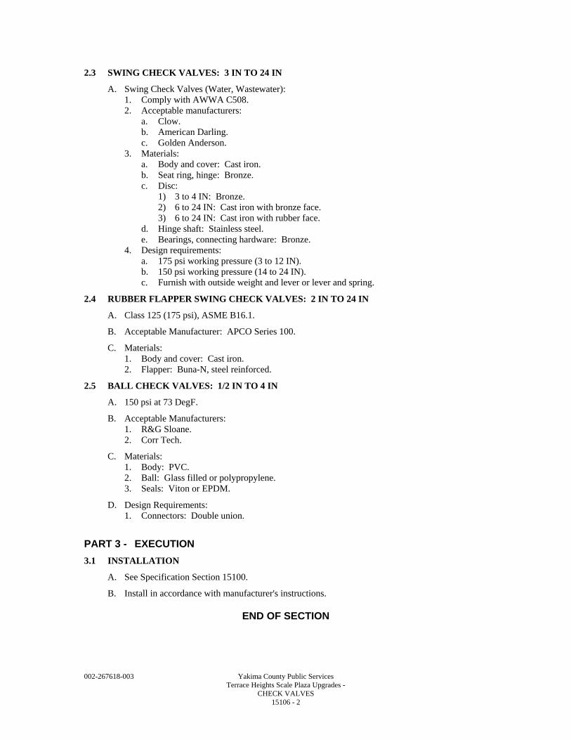
002-267618-003 Yakima County Public Services Terrace Heights Scale Plaza Upgrades - CHECK VALVES 15106 - 2
2.3 SWING CHECK VALVES: 3 IN TO 24 IN
A. Swing Check Valves (Water, Wastewater): 1. Comply with AWWA C508. 2. Acceptable manufacturers:
a. Clow. b. American Darling. c. Golden Anderson.
3. Materials: a. Body and cover: Cast iron. b. Seat ring, hinge: Bronze. c. Disc:
1) 3 to 4 IN: Bronze. 2) 6 to 24 IN: Cast iron with bronze face. 3) 6 to 24 IN: Cast iron with rubber face.
d. Hinge shaft: Stainless steel. e. Bearings, connecting hardware: Bronze.
4. Design requirements: a. 175 psi working pressure (3 to 12 IN). b. 150 psi working pressure (14 to 24 IN). c. Furnish with outside weight and lever or lever and spring.
2.4 RUBBER FLAPPER SWING CHECK VALVES: 2 IN TO 24 IN
A. Class 125 (175 psi), ASME B16.1.
B. Acceptable Manufacturer: APCO Series 100.
C. Materials: 1. Body and cover: Cast iron. 2. Flapper: Buna-N, steel reinforced.
2.5 BALL CHECK VALVES: 1/2 IN TO 4 IN
A. 150 psi at 73 DegF.
B. Acceptable Manufacturers: 1. R&G Sloane. 2. Corr Tech.
C. Materials: 1. Body: PVC. 2. Ball: Glass filled or polypropylene. 3. Seals: Viton or EPDM.
D. Design Requirements: 1. Connectors: Double union.
PART 3 - EXECUTION
3.1 INSTALLATION
A. See Specification Section 15100.
B. Install in accordance with manufacturer's instructions.
END OF SECTION
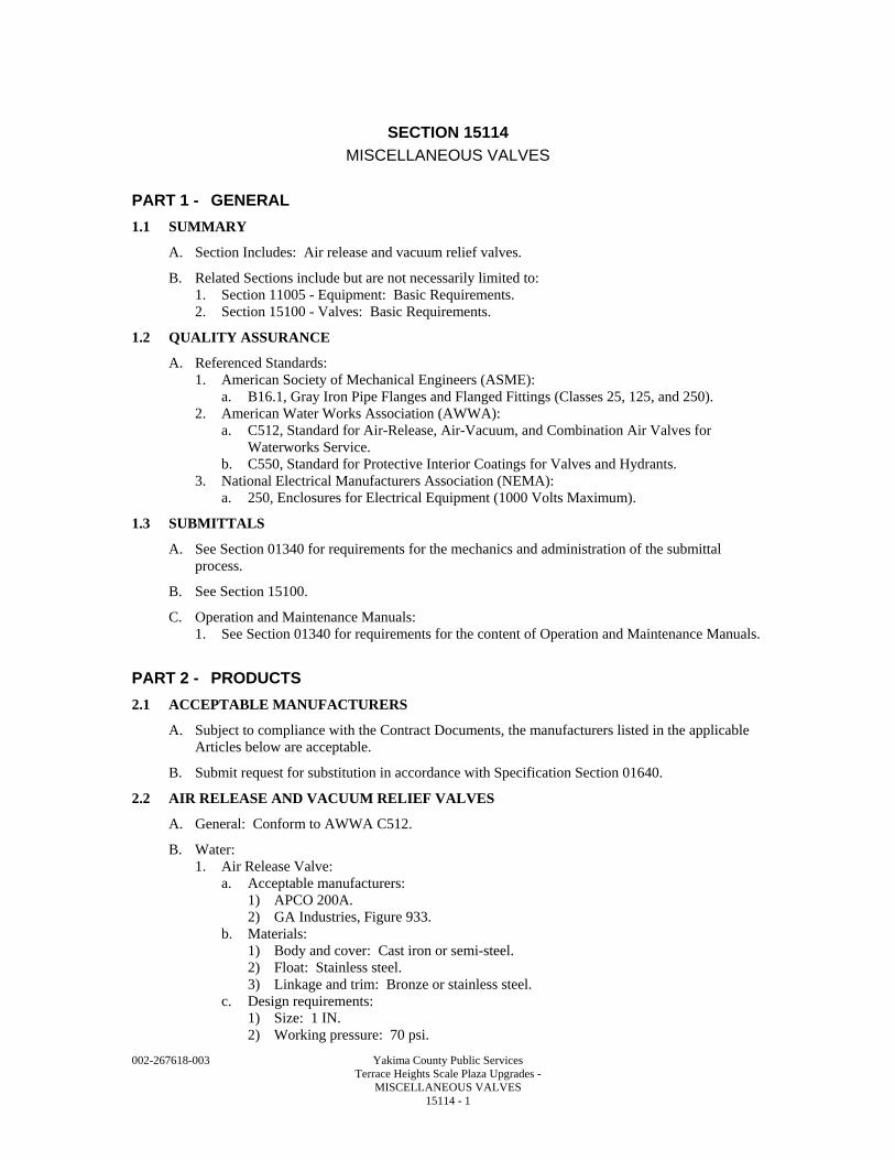
002-267618-003 Yakima County Public Services Terrace Heights Scale Plaza Upgrades - MISCELLANEOUS VALVES 15114 - 1
SECTION 15114
MISCELLANEOUS VALVES
PART 1 - GENERAL
1.1 SUMMARY
A. Section Includes: Air release and vacuum relief valves.
B. Related Sections include but are not necessarily limited to: 1. Section 11005 - Equipment: Basic Requirements. 2. Section 15100 - Valves: Basic Requirements.
1.2 QUALITY ASSURANCE
A. Referenced Standards: 1. American Society of Mechanical Engineers (ASME):
a. B16.1, Gray Iron Pipe Flanges and Flanged Fittings (Classes 25, 125, and 250). 2. American Water Works Association (AWWA):
a. C512, Standard for Air-Release, Air-Vacuum, and Combination Air Valves for Waterworks Service.
b. C550, Standard for Protective Interior Coatings for Valves and Hydrants. 3. National Electrical Manufacturers Association (NEMA):
a. 250, Enclosures for Electrical Equipment (1000 Volts Maximum).
1.3 SUBMITTALS
A. See Section 01340 for requirements for the mechanics and administration of the submittal process.
B. See Section 15100.
C. Operation and Maintenance Manuals: 1. See Section 01340 for requirements for the content of Operation and Maintenance Manuals.
PART 2 - PRODUCTS
2.1 ACCEPTABLE MANUFACTURERS
A. Subject to compliance with the Contract Documents, the manufacturers listed in the applicable Articles below are acceptable.
B. Submit request for substitution in accordance with Specification Section 01640.
2.2 AIR RELEASE AND VACUUM RELIEF VALVES
A. General: Conform to AWWA C512.
B. Water: 1. Air Release Valve:
a. Acceptable manufacturers: 1) APCO 200A. 2) GA Industries, Figure 933.
b. Materials: 1) Body and cover: Cast iron or semi-steel. 2) Float: Stainless steel. 3) Linkage and trim: Bronze or stainless steel.
c. Design requirements: 1) Size: 1 IN. 2) Working pressure: 70 psi.
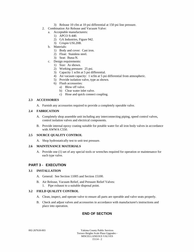
002-267618-003 Yakima County Public Services Terrace Heights Scale Plaza Upgrades - MISCELLANEOUS VALVES 15114 - 2
3) Release 10 cfm at 10 psi differential at 150 psi line pressure. 2. Combination Air Release and Vacuum Valve:
a. Acceptable manufacturers: 1) APCO S-440. 2) GA Industries, Figure 942. 3) Crispin USL20B.
b. Materials: 1) Body and cover: Cast iron. 2) Float: Stainless steel. 3) Seat: Buna-N.
c. Design requirements: 1) Size: As shown. 2) Working pressure: 25 psi. 3) Capacity 1 scfm at 5 psi differential. 4) Air vacuum capacity: 1 scfm at 5 psi differential from atmospheric. 5) Provide isolation valve, type as shown. 6) Flush accessories:
a) Blow off valve. b) Clear water inlet valve. c) Hose and quick connect coupling.
2.3 ACCESSORIES
A. Furnish any accessories required to provide a completely operable valve.
2.4 FABRICATION
A. Completely shop assemble unit including any interconnecting piping, speed control valves, control isolation valves and electrical components.
B. Provide internal epoxy coating suitable for potable water for all iron body valves in accordance with AWWA C550.
2.5 SOURCE QUALITY CONTROL
A. Shop hydrostatically test to unit test pressure.
2.6 MAINTENANCE MATERIALS
A. Provide one (1) set of any special tools or wrenches required for operation or maintenance for each type valve.
PART 3 - EXECUTION
3.1 INSTALLATION
A. General: See Section 11005 and Section 15100.
B. Air Release, Vacuum Relief, and Pressure Relief Valves: 1. Pipe exhaust to a suitable disposal point.
3.2 FIELD QUALITY CONTROL
A. Clean, inspect, and operate valve to ensure all parts are operable and valve seats properly.
B. Check and adjust valves and accessories in accordance with manufacturer's instructions and place into operation.
END OF SECTION
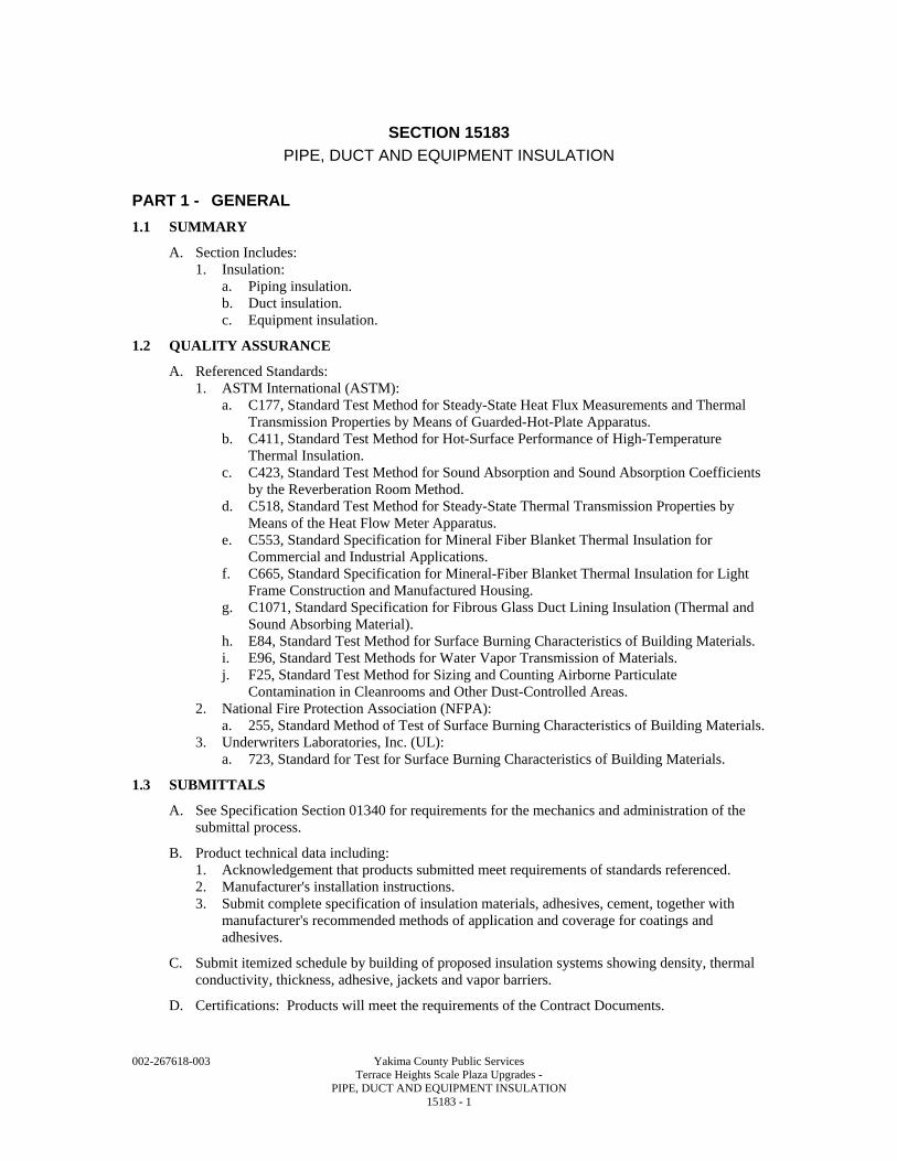
002-267618-003 Yakima County Public Services Terrace Heights Scale Plaza Upgrades - PIPE, DUCT AND EQUIPMENT INSULATION 15183 - 1
SECTION 15183
PIPE, DUCT AND EQUIPMENT INSULATION
PART 1 - GENERAL
1.1 SUMMARY
A. Section Includes: 1. Insulation:
a. Piping insulation. b. Duct insulation. c. Equipment insulation.
1.2 QUALITY ASSURANCE
A. Referenced Standards: 1. ASTM International (ASTM):
a. C177, Standard Test Method for Steady-State Heat Flux Measurements and Thermal Transmission Properties by Means of Guarded-Hot-Plate Apparatus.
b. C411, Standard Test Method for Hot-Surface Performance of High-Temperature Thermal Insulation.
c. C423, Standard Test Method for Sound Absorption and Sound Absorption Coefficients by the Reverberation Room Method.
d. C518, Standard Test Method for Steady-State Thermal Transmission Properties by Means of the Heat Flow Meter Apparatus.
e. C553, Standard Specification for Mineral Fiber Blanket Thermal Insulation for Commercial and Industrial Applications.
f. C665, Standard Specification for Mineral-Fiber Blanket Thermal Insulation for Light Frame Construction and Manufactured Housing.
g. C1071, Standard Specification for Fibrous Glass Duct Lining Insulation (Thermal and Sound Absorbing Material).
h. E84, Standard Test Method for Surface Burning Characteristics of Building Materials. i. E96, Standard Test Methods for Water Vapor Transmission of Materials. j. F25, Standard Test Method for Sizing and Counting Airborne Particulate
Contamination in Cleanrooms and Other Dust-Controlled Areas. 2. National Fire Protection Association (NFPA):
a. 255, Standard Method of Test of Surface Burning Characteristics of Building Materials. 3. Underwriters Laboratories, Inc. (UL):
a. 723, Standard for Test for Surface Burning Characteristics of Building Materials.
1.3 SUBMITTALS
A. See Specification Section 01340 for requirements for the mechanics and administration of the submittal process.
B. Product technical data including: 1. Acknowledgement that products submitted meet requirements of standards referenced. 2. Manufacturer's installation instructions. 3. Submit complete specification of insulation materials, adhesives, cement, together with
manufacturer's recommended methods of application and coverage for coatings and adhesives.
C. Submit itemized schedule by building of proposed insulation systems showing density, thermal conductivity, thickness, adhesive, jackets and vapor barriers.
D. Certifications: Products will meet the requirements of the Contract Documents.
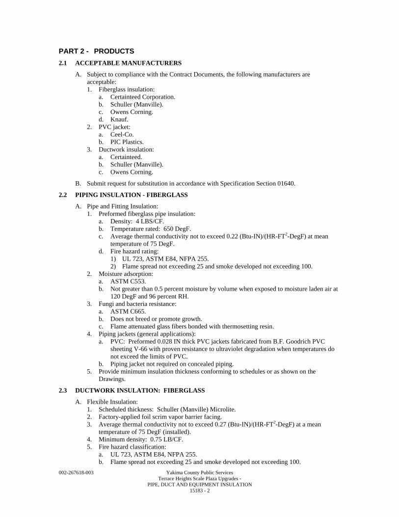
002-267618-003 Yakima County Public Services Terrace Heights Scale Plaza Upgrades - PIPE, DUCT AND EQUIPMENT INSULATION 15183 - 2
PART 2 - PRODUCTS
2.1 ACCEPTABLE MANUFACTURERS
A. Subject to compliance with the Contract Documents, the following manufacturers are acceptable: 1. Fiberglass insulation:
a. Certainteed Corporation. b. Schuller (Manville). c. Owens Corning. d. Knauf.
2. PVC jacket: a. Ceel-Co. b. PIC Plastics.
3. Ductwork insulation: a. Certainteed. b. Schuller (Manville). c. Owens Corning.
B. Submit request for substitution in accordance with Specification Section 01640.
2.2 PIPING INSULATION - FIBERGLASS
A. Pipe and Fitting Insulation: 1. Preformed fiberglass pipe insulation:
a. Density: 4 LBS/CF. b. Temperature rated: 650 DegF. c. Average thermal conductivity not to exceed 0.22 (Btu-IN)/(HR-FT2-DegF) at mean
temperature of 75 DegF. d. Fire hazard rating:
1) UL 723, ASTM E84, NFPA 255. 2) Flame spread not exceeding 25 and smoke developed not exceeding 100.
2. Moisture adsorption: a. ASTM C553. b. Not greater than 0.5 percent moisture by volume when exposed to moisture laden air at
120 DegF and 96 percent RH. 3. Fungi and bacteria resistance:
a. ASTM C665. b. Does not breed or promote growth. c. Flame attenuated glass fibers bonded with thermosetting resin.
4. Piping jackets (general applications): a. PVC: Preformed 0.028 IN thick PVC jackets fabricated from B.F. Goodrich PVC
sheeting V-66 with proven resistance to ultraviolet degradation when temperatures do not exceed the limits of PVC.
b. Piping jacket not required on concealed piping. 5. Provide minimum insulation thickness conforming to schedules or as shown on the
Drawings.
2.3 DUCTWORK INSULATION: FIBERGLASS
A. Flexible Insulation: 1. Scheduled thickness: Schuller (Manville) Microlite. 2. Factory-applied foil scrim vapor barrier facing. 3. Average thermal conductivity not to exceed 0.27 (Btu-IN)/(HR-FT2-DegF) at a mean
temperature of 75 DegF (installed). 4. Minimum density: 0.75 LB/CF. 5. Fire hazard classification:
a. UL 723, ASTM E84, NFPA 255. b. Flame spread not exceeding 25 and smoke developed not exceeding 100.
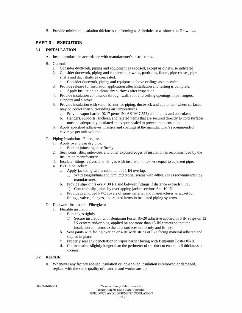
002-267618-003 Yakima County Public Services Terrace Heights Scale Plaza Upgrades - PIPE, DUCT AND EQUIPMENT INSULATION 15183 - 3
B. Provide minimum insulation thickness conforming to Schedule, or as shown on Drawings.
PART 3 - EXECUTION
3.1 INSTALLATION
A. Install products in accordance with manufacturer's instructions.
B. General: 1. Consider ductwork, piping and equipment as exposed, except as otherwise indicated. 2. Consider ductwork, piping and equipment in walls, partitions, floors, pipe chases, pipe
shafts and duct shafts as concealed. a. Consider ductwork, piping and equipment above ceilings as concealed.
3. Provide release for insulation application after installation and testing is complete. a. Apply insulation on clean, dry surfaces after inspection.
4. Provide insulation continuous through wall, roof and ceiling openings, pipe hangers, supports and sleeves.
5. Provide insulation with vapor barrier for piping, ductwork and equipment where surfaces may be cooler than surrounding air temperatures. a. Provide vapor barrier (0.17 perm-IN; ASTM C553) continuous and unbroken. b. Hangers, supports, anchors, and related items that are secured directly to cold surfaces
must be adequately insulated and vapor-sealed to prevent condensation. 6. Apply specified adhesives, mastics and coatings at the manufacturer's recommended
coverage per unit volume.
C. Piping Insulation - Fiberglass: 1. Apply over clean dry pipe.
a. Butt all joints together firmly. 2. Seal joints, slits, miter-cuts and other exposed edges of insulation as recommended by the
insulation manufacturer. 3. Insulate fittings, valves, and flanges with insulation thickness equal to adjacent pipe. 4. PVC pipe jacket:
a. Apply jacketing with a minimum of 1 IN overlap. 1) Weld longitudinal and circumferential seams with adhesives as recommended by
manufacturer. b. Provide slip-joints every 30 FT and between fittings if distance exceeds 8 FT.
1) Construct slip-joints by overlapping jacket sections 6 to 10 IN. c. Provide premolded PVC covers of same material and manufacturer as jacket for
fittings, valves, flanges, and related items in insulated piping systems.
D. Ductwork Insulation - Fiberglass: 1. Flexible insulation:
a. Butt edges tightly. 1) Secure insulation with Benjamin Foster 85-20 adhesive applied in 6 IN strips on 12
IN centers and/or pins, applied on not more than 18 IN centers so that the insulation conforms to the duct surfaces uniformly and firmly.
b. Seal joints with facing overlap or 4 IN wide strips of like facing material adhered and stapled in place.
c. Properly seal any penetration in vapor barrier facing with Benjamin Foster 85-20. d. Cut insulation slightly longer than the perimeter of the duct to ensure full thickness at
corners.
3.2 REPAIR
A. Whenever any factory applied insulation or job-applied insulation is removed or damaged, replace with the same quality of material and workmanship.
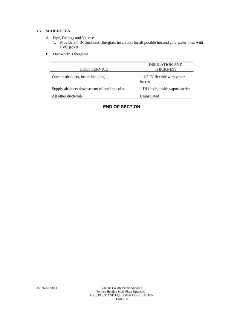
002-267618-003 Yakima County Public Services Terrace Heights Scale Plaza Upgrades - PIPE, DUCT AND EQUIPMENT INSULATION 15183 - 4
3.3 SCHEDULES
A. Pipe, Fittings and Valves: 1. Provide 3/4 IN thickness fiberglass insulation for all potable hot and cold water lines with
PVC jacket.
B. Ductwork: Fiberglass.
DUCT SERVICE INSULATION AND
THICKNESS
Outside air ducts, inside building 1-1/2 IN flexible with vapor barrier
Supply air ducts downstream of cooling coils 1 IN flexible with vapor barrier
All other ductwork Uninsulated
END OF SECTION
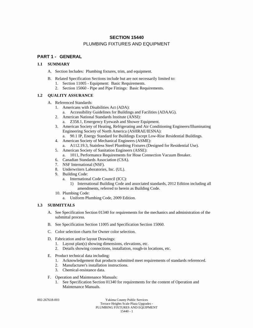
002-267618-003 Yakima County Public Services Terrace Heights Scale Plaza Upgrades - PLUMBING FIXTURES AND EQUIPMENT 15440 - 1
SECTION 15440
PLUMBING FIXTURES AND EQUIPMENT
PART 1 - GENERAL
1.1 SUMMARY
A. Section Includes: Plumbing fixtures, trim, and equipment.
B. Related Specification Sections include but are not necessarily limited to: 1. Section 11005 - Equipment: Basic Requirements. 2. Section 15060 - Pipe and Pipe Fittings: Basic Requirements.
1.2 QUALITY ASSURANCE
A. Referenced Standards: 1. Americans with Disabilities Act (ADA):
a. Accessibility Guidelines for Buildings and Facilities (ADAAG). 2. American National Standards Institute (ANSI):
a. Z358.1, Emergency Eyewash and Shower Equipment. 3. American Society of Heating, Refrigerating and Air Conditioning Engineers/Illuminating
Engineering Society of North America (ASHRAE/IESNA): a. 90.1 IP, Energy Standard for Buildings Except Low-Rise Residential Buildings.
4. American Society of Mechanical Engineers (ASME): a. A112.19.3, Stainless Steel Plumbing Fixtures (Designed for Residential Use).
5. American Society of Sanitation Engineers (ASSE): a. 1011, Performance Requirements for Hose Connection Vacuum Breaker.
6. Canadian Standards Association (CSA). 7. NSF International (NSF). 8. Underwriters Laboratories, Inc. (UL). 9. Building Code:
a. International Code Council (ICC): 1) International Building Code and associated standards, 2012 Edition including all
amendments, referred to herein as Building Code. 10. Plumbing Code:
a. Uniform Plumbing Code, 2009 Edition.
1.3 SUBMITTALS
A. See Specification Section 01340 for requirements for the mechanics and administration of the submittal process.
B. See Specification Section 11005 and Specification Section 15060.
C. Color selection charts for Owner color selection.
D. Fabrication and/or layout Drawings: 1. Layout plan(s) showing dimensions, elevations, etc. 2. Details showing connections, installation, rough-in locations, etc.
E. Product technical data including: 1. Acknowledgement that products submitted meet requirements of standards referenced. 2. Manufacturer's installation instructions. 3. Chemical-resistance data.
F. Operation and Maintenance Manuals: 1. See Specification Section 01340 for requirements for the content of Operation and
Maintenance Manuals.
002-267618-003 Yakima County Public Services Terrace Heights Scale Plaza Upgrades - PLUMBING FIXTURES AND EQUIPMENT 15440 - 2
PART 2 - PRODUCTS
2.1 ACCEPTABLE MANUFACTURERS
A. Subject to compliance with the Contract Documents, the following manufacturers are acceptable: 1. Plumbing fixtures (vitreous china):
a. American Standard. b. Crane. c. Kohler. d. Eljer.
2. Water closet seats: a. Church. b. Beneke.
3. Lavatory fittings: a. American Standard. b. Chicago Faucets. c. Kohler. d. Sloan.
4. Drains, roof drains, carriers, and shock absorbers: a. Wade. b. Josam. c. Zurn. d. Smith.
5. Domestic water heater: a. A. O. Smith. b. EEMax. c. Ruud. d. Rheem. e. State.
6. Reduced pressure backflow preventer: a. Watts. b. Febco. c. Clayton.
B. Submit request for substitution in accordance with Specification Section 01640.
2.2 MANUFACTURED UNITS
A. Plumbing Fixtures (Vitreous China): 1. Water closet (WC):
a. White. b. 1.6 GAL per flush. c. Siphon jet. d. Elongated bowl. e. 1-1/2 IN top spud or close coupled tank. f. Bolt caps. g. Type:
1) WC-1 (handicapped floor-mounted tank type) American Standard "Cadet" 2333.100.
2. Lavatory (L): a. White. b. Front overflow. c. Type:
1) L-1 (wall hung 20 x 18 IN) American Standard "Lucerne" 0356.015.
002-267618-003 Yakima County Public Services Terrace Heights Scale Plaza Upgrades - PLUMBING FIXTURES AND EQUIPMENT 15440 - 3
B. Toilet Seat: 1. Molded plastic. 2. Open front. 3. No cover. 4. Stainless steel hinge with check. 5. For elongated bowl.
C. Lavatory Fittings: 1. Lavatory faucets:
a. Lever handles. b. Renewable washer. c. Renewable seats. d. Aerator. e. Stopper and 1-1/4 IN tail piece. f. Coupling nuts. g. Chrome plated.
2. Handicapped lavatory faucets: a. Chrome-plated wrist handles. b. Chrome-plated gooseneck. c. Aerator. d. Renewable seat.
D. Drains: 1. Floor drain (FD):
a. Bottom outlet. b. Clamping seepage flange. c. Seepage openings. d. Size as shown on Drawings. e. Type: Cast iron body.
1) FD-1 (finished area) adjustable satin nickel bronze strainer: Wade W-1100. f. Type: Polypropylene.
1) FD-3 R&G Sloane "FUSEAL II."
E. Traps: 1. Floor and equipment drains:
a. Same material and coating as the piping system. b. 3 IN minimum seal.
2. Fixture drains: a. 2 IN minimum seal. b. Cast brass. c. Chrome plated. d. Size as required.
3. Ventilation housing drains: Extra-deep seal sufficient to maintain seal against static pressure maintained in fan housing.
F. Cleanouts (CO): 1. Cleanouts for cast iron pipe:
a. Tapped extra heavy cast iron ferrule. b. Calked into cast iron fittings. c. Extra heavy brass neoprene seal screw plug with solid hexagonal nut.
2. Cleanouts for steel pipe: Extra heavy brass screw plug in drainage fittings. 3. Access housing with adjustable anchor flange and secured scoriated cast: Wade W-3800-
MF.
002-267618-003 Yakima County Public Services Terrace Heights Scale Plaza Upgrades - PLUMBING FIXTURES AND EQUIPMENT 15440 - 4
4. Cleanouts turning out through walls and up through floor shall be made by long sweep ells or "y" and 1/8 bends with plugs and face or deck plates to conform to architectural finish in room. a. Where definite finish is not indicated, wall plates shall be chrome-plated cast-brass and
floor plates polished brass. 5. Code:
a. Provide cleanouts of same size as pipe up to 4 IN and not less than 4 IN for larger pipes.
b. Close access openings for concealed cleanouts with flush floor or flush wall cover plates or flush ceiling access panels.
c. Provide wall plates with chrome plated cast-brass round cleanout cover with flanged ring.
d. Provide screws which match cover plate material. 6. Cleanouts installed in floor with a resilient tile finish: Wade W-6000-TS. 7. Cleanouts installed in floor with ceramic tile, concrete, or Terrazzo finish: Wade W-6000-
U. 8. Cleanouts installed in finished rooms flush with wall: Wade W-8480-S stainless steel.
G. Domestic Water Heater (DWH): 1. Electric tankless type:
a. Capacity as scheduled. b. UL listed. c. Cover: Enameled steel, white finish. d. Dual glass reinforced heater bodies with NiChrome elements.
1) Microprocessing temperature control +/- 1 DegF, adjustable range, and high temperature cutoff.
e. Warranty against corrosion for five (5) year period. f. Provide water heaters meeting ASHRAE 90.1 IP for energy efficiencies.
PART 3 - EXECUTION
3.1 INSTALLATION
A. Cross Connection: Do not install any plumbing components that will provide a cross connection between potable and non-potable or drainage systems.
B. Fixtures: 1. Install fixtures at locations indicated on Drawings and in compliance with local Codes. 2. Connect plumbing supply, drain and vent line sizes as shown on Drawings. 3. Set proper grounds to form secure base for each fixture and rigid setting. 4. Install fixtures except water closets with water supply above rim and with Code approved
backflow preventers. 5. Seal fixture joints abutting walls and floors with silicone sealant. 6. Connect exposed traps and supply pipes for fixtures and equipment to rough piping systems
at wall, unless otherwise specified. 7. Install emergency fixtures in accordance with ANSI Z358.1.
C. Drains: 1. Install drains at locations indicated on Drawings and in compliance with local Codes. 2. In uncovered concrete slabs:
a. Install at the low points of surface areas to be drained or as indicated. b. Set tops of drains flush with the finished floor. c. Install drain flashing collar or a flange so that no leakage occurs between the drain and
the adjoining surfaces. d. Maintain the integrity of waterproof membranes, where penetrated.
002-267618-003 Yakima County Public Services Terrace Heights Scale Plaza Upgrades - PLUMBING FIXTURES AND EQUIPMENT 15440 - 5
D. Shock Absorbers: 1. Install on hot and cold water lines adjacent to each battery of fixtures or other equipment
where indicated on Drawings. 2. Size as recommended by manufacturer for length of pipe served. 3. Locations having two (2) fixtures or less, install capped air chamber 12 IN long on hot and
cold water runouts to each fixture, same size as runout. 4. Runouts to hose bibbs and wall hydrants do not require air chambers. 5. Install units vertically on top of pipe or as detailed on the Drawings.
E. Cleanouts: 1. Install cleanouts:
a. Above floor in each vertical riser that connects to horizontal branch below floor. b. At test tee to receive proper test plugs in each vertical riser at least every other floor. c. As required by local Code.
F. Wall Plates and Escutcheons: Install as specified in Specification Section 15060 or this Specification Section.
G. Water Heater: 1. Install all water heaters in accordance with details, manufacturer's recommendations, and
applicable Codes. 2. Connect hot and cold water piping to the unit with line-size, isolation valves and dielectric
unions. 3. Start up the unit and adjust all controls for proper temperature control and maximum
efficiency. 4. Where indicated, install instantaneous electric water heaters in enclosure rated for area
classification. a. Silicone seal all piping and wiring penetrations.
H. Reduce Pressure Backflow Preventer: Install on water lines as required by Code.
3.2 FIELD QUALITY CONTROL
A. Test piping and fixtures for leaks per Specification Section 15060.
END OF SECTION

002-267618-003 Yakima County Public Services Terrace Heights Scale Plaza Upgrades - PLUMBING FIXTURES AND EQUIPMENT 15440 - 6
002-267618-003 Yakima County Public Services Terrace Heights Scale Plaza Upgrades - HVAC: EQUIPMENT 15605 - 1
SECTION 15605
HVAC: EQUIPMENT
PART 1 - GENERAL
1.1 SUMMARY
A. Section Includes: Heating, ventilating, carbon monoxide sensor, and cooling equipment.
B. Related Specification Sections include but are not necessarily limited to: 1. Section 11005 - Equipment: Basic Requirements. 2. Section 15890 - HVAC: Ductwork. 3. Section 15970 - Instrumentation and Control for HVAC Systems. 4. Section 15990 - HVAC Systems: Balancing and Testing.
1.2 QUALITY ASSURANCE
A. Referenced Standards: 1. Air Movement and Control Association (AMCA). 2. Air Conditioning and Refrigeration Institute (ARI). 3. American Society of Heating, Refrigerating and Air Conditioning Engineers (ASHRAE):
a. HVAC Applications Handbook, Chapter entitled "Sound and Vibration Control." b. 20, Methods of Testing for Rating Remote Mechanical-Draft Air-Cooled Refrigerant
Condensers. c. 52.2, Method of Testing General Ventilation Air-Cleaning Devices for Removal
Efficiency by Particle Size. 4. Canadian Standards Association (CSA). 5. National Electrical Manufacturers Association (NEMA):
a. 250, Enclosures for Electrical Equipment (1000 Volts Maximum). 6. National Fire Protection Association (NFPA):
a. 70, National Electrical Code (NEC). 7. National Roofing Contractors Association (NRCA). 8. Underwriters Laboratories, Inc. (UL):
a. 507, Standard for Electric Fans. 9. Building Code:
a. International Code Council (ICC): 1) International Building Code and associated standards, 2009 Edition including all
amendments, referred to herein as Building Code.
B. Miscellaneous: 1. Gage thickness specified herein shall be manufacturer's standard gage for steel and Brown
and Sharpe gage for non-ferrous metals. 2. Corrosion protection of equipment to be as specified herein.
1.3 SUBMITTALS
A. See Specification Section 01340 for requirements for the mechanics and administration of the submittal process.
B. Fabrication and/or layout Drawings.
C. Product technical data including: 1. Acknowledgement that products submitted meet requirements of standards referenced. 2. Manufacturer's installation instructions. 3. Wiring diagrams. 4. Control diagrams. 5. Manufacturer's catalog cuts and technical data. 6. Corrosion-protection information.
002-267618-003 Yakima County Public Services Terrace Heights Scale Plaza Upgrades - HVAC: EQUIPMENT 15605 - 2
7. Fan curves. 8. Sound data. 9. Vibration isolation. 10. Control description. 11. Performance data on all equipment.
D. Certifications: Provide certification of thickness of corrosion-protection coating.
E. Operation and Maintenance Manuals: 1. See Specification Section 01340 for requirements for the content of Operation and
Maintenance Manuals.
PART 2 - PRODUCTS
2.1 ACCEPTABLE MANUFACTURERS
A. Subject to compliance with the Contract Documents, the following manufacturers are acceptable: 1. Cooling coils - direct expansion:
a. Carrier. b. McQuay.
2. Heating coil - electric: a. Carrier. b. McQuay.
3. Fan coils: a. Carrier. b. McQuay.
4. Baseboard heater - electric: a. Q Mark. b. Berko.
5. Toilet room exhaust fans: a. Penn Ventilator Co., Inc. b. Loren Cook.
6. Unitary split system heat pump: a. Carrier. b. Lennox. c. Bryant.
7. Carbon Monoxide Sensor: a. Dynagard AutoCal
B. Submit request for substitution in accordance with Specification Section 01640.
2.2 GENERAL
A. All Manufactured Units: 1. Comply with Specification Section 11005. 2. Factory wired and assembled. 3. Use fasteners made of same material as unit.
2.3 MANUFACTURED UNITS
A. Equipment Coils: 1. Cooling coils - direct expansion:
a. ARI certified. b. Material:
1) Aluminum. 2) Copper with aluminum fins for use in administration units only.
c. Fin spacing: Minimum 80 fins per foot. d. Minimum standard operating limit: 250 psi.
002-267618-003 Yakima County Public Services Terrace Heights Scale Plaza Upgrades - HVAC: EQUIPMENT 15605 - 3
e. Size and capacity as scheduled. 2. Heating coil - electric:
a. ARI certified. b. 80-percent nickel, 20-percent chromium elements. c. Maximum heating density: 35 watts/SQ IN. d. Built-in thermal protection. e. Airflow switch. f. Built-in circuit fusing. g. Control voltage transformer. h. Terminal block. i. Magnetic contactor. j. Fused disconnect switch. k. Step controller as required by instrumentation. l. Single point electrical connection. m. Size and capacity as scheduled on Drawings.
B. Fan Coils: 1. ARI certified. 2. Coils: See paragraph(s) in Article 2.3, Equipment Coils. 3. Blower:
a. Fan wheels: Centrifugal forward-curved, double width. b. Fan housing: Galvanized steel. c. Statically and dynamically balanced. d. Motor:
1) See Specification Section 11005. 2) Integral overload protection.
4. Cabinet: a. Material: Galvanized steel, 18 GA minimum. b. Exposed units equipped with hinged access panel, intake and discharge grilles. c. Concealed units equipped with return plenum, filter section and discharge duct collar.
5. Drain pans: a. Material: Galvanized steel. b. Equip with drain connection. c. Insulated.
6. Filters: See Specification Section 15890. 7. Controls:
a. Provide with 7-day programmable thermostat capable of carrying out all control sequences listed in Section 15970.
8. Size and capacity as scheduled on Drawings.
C. Baseboard Heater - Electric: 1. UL listed. 2. Material:
a. Cabinet: 0.028 galvanized steel. b. Front cover: 18 GA galvanized steel. c. Heating element: 80 percent nickel, 20 percent chromium. d. Fins: Aluminum.
3. Built-in thermostat. 4. Size and capacity as scheduled on Drawings.
D. Toilet Room Exhaust Fans: 1. AMCA certified. 2. UL listed. 3. Materials: Galvanized steel. 4. Centrifugal wheels. 5. Permanently lubricated motor. 6. Acoustically insulated housing.
002-267618-003 Yakima County Public Services Terrace Heights Scale Plaza Upgrades - HVAC: EQUIPMENT 15605 - 4
7. Resilient rubber-in-shear vibration isolation. 8. Fan, motor, and wheel assembly removable from housing. 9. Duct flanged outlet. 10. Integral backdraft damper. 11. Minimum 85-percent free open area face grill. 12. Accessories:
a. Roof jack. b. Wall cap.
13. Size and capacity as scheduled on Drawings.
E. Unitary Split System Heat Pump: 1. Casing and frame:
a. Material: Heavy gage galvanized steel. b. Insulation: 1 IN thick neoprene-coated glass fiber. c. Installation: Base equipped with lifting brackets with lifting holes. d. Removable end panel for access to components and connections.
2. Compressors: a. Heavy duty, reciprocating, semi-hermetic type. b. Positive displacement oil pump. c. Suction and discharge service valves. d. Crankcase heater. e. Thermal overload protection.
3. Refrigeration circuit: a. Sight glass. b. Filter dryer. c. Manual shut-off valve. d. High pressure relief valve.
4. Compressor isolators. 5. Condenser coils:
a. Nominal 3/8 IN OD seamless copper mechanically bonded to corrugated aluminum fins.
b. Factory leak tested at 315 psig under water. 6. Condenser fans:
a. Direct drive: See Specification Section 11005. b. Propeller type.
7. Condenser fan motors: a. Heavy duty, inherently protected, non-reversing. b. Permanently lubricated bearings. c. Integral rain shield.
8. Defrost control: Defrost cycles at a preselected time interval when the outdoor coil is below a preset initiation temperature.
9. Expansion valve: Designed and sized specifically for heat pump service. 10. Reversing valve: Four-way interchange reversing valve, operates on pressure differential
between the outdoor unit and indoor unit.
F. Carbon Monoxide Sensor: 1. Single point gas monitor. 2. 115 VAC power supply. 3. Two adjustable alarm points, one fault for local connection. 4. Detection range of 0-500 ppm.
PART 3 - EXECUTION
3.1 INSTALLATION
A. Install in accordance with Specification Section 11005.
002-267618-003 Yakima County Public Services Terrace Heights Scale Plaza Upgrades - HVAC: EQUIPMENT 15605 - 5
B. Install fixed pitched drive sheave after sheave has been sized based on accepted test and balance report.
C. Carbon Monoxide Sensor: 1. Mount sensor on wall near transaction window 3-5 FT AFF. Coordinate the mounting
location with the Owner. 2. Carbon Monoxide alarm set points to be 50 ppm and 100 ppm.
3.2 FIELD QUALITY CONTROL
A. Comply with Specification Section 15990.
3.3 ADJUSTING
A. Install new filters on units which have been running prior to acceptance of Project.
END OF SECTION

002-267618-003 Yakima County Public Services Terrace Heights Scale Plaza Upgrades - HVAC: EQUIPMENT 15605 - 6
002-267618-003 Yakima County Public Services Terrace Heights Scale Plaza Upgrades - HVAC: DUCTWORK 15890 - 1
SECTION 15890
HVAC: DUCTWORK
PART 1 - GENERAL
1.1 SUMMARY
A. Section Includes: HVAC ductwork and accessories.
B. Related Specification Sections include but are not necessarily limited to: 1. Section 09905 - Painting and Protective Coatings. 2. Section 11005 - Equipment: Basic Requirements. 3. Section 15970 - Instrumentation and Control for HVAC Systems.
1.2 QUALITY ASSURANCE
A. Referenced Standards: 1. Aluminum Association (AA):
a. DAF 45, Designation System for Aluminum Finishes. 2. American Architectural Manufacturers Association (AAMA):
a. 2605, Voluntary Specification, Performance Requirements and Test Procedures for Superior Performing Organic Coatings on Aluminum Extrusions and Panels.
3. American Society of Heating, Refrigerating and Air Conditioning Engineers (ASHRAE): a. 52, Method of Testing Air Conditioning Devices Used in General Ventilation for
Removing Particulate Matter. 4. ASTM International (ASTM):
a. B221, Standard Specification for Aluminum and Aluminum-Alloy Extruded Bars, Rods, Wire, Profiles, and Tubes.
5. National Fire Protection Association (NFPA). 6. Sheet Metal and Air Conditioning Contractors' National Association (SMACNA):
a. Ducted Electric Heat Guide for Air Handling Systems. b. HVAC Duct Construction Standards - Metal and Flexible.
7. Underwriters Laboratory, Inc. (UL): a. 555, Standard for Safety Fire Damper and Ceiling Fire Damper. b. 555S, Standard for Safety Leakage Rated Dampers for Use in Smoke Control Systems. c. Building Materials Directory.
8. Building Code: a. International Code Council (ICC):
1) International Building Code and associated standards, 2012 Edition including all amendments, referred to herein as Building Code.
B. Qualifications: 1. Fabricator: Firms regularly engaged in the manufacture of the specific product, of type, size
required, whose products have been in use in similar service for not less than three (3) years. 2. Installers: Firm with at least five (5) years installation experience on products similar to that
required for this Project.
1.3 DEFINITIONS
A. Installer or Applicator: 1. Installer or applicator is the person actually installing or applying the product in the field at
the Project site. 2. Installer and applicator are synonymous.
1.4 SUBMITTALS
A. See Specification Section 01340 for requirements for the mechanics and administration of the submittal process.
002-267618-003 Yakima County Public Services Terrace Heights Scale Plaza Upgrades - HVAC: DUCTWORK 15890 - 2
B. See Specification Section 11005.
C. Efficiency ratings per ASHRAE 52 for factory built and assembled filter units.
D. Scaled ductwork Drawings (1/4 IN equals 1 FT) showing duct and accessory layout and support.
E. Operation and Maintenance Manuals: 1. See Specification Section 01340 for requirements for the content of Operation and
Maintenance Manuals.
F. Miscellaneous Submittal: 1. Documentation of qualifications for fabricators and installers.
PART 2 - PRODUCTS
2.1 ACCEPTABLE MANUFACTURERS
A. Subject to compliance with the Contract Documents, the following manufacturers are acceptable: 1. Transverse joints (factory fabricated aluminum):
a. Ductmate Industries, Inc. 2. Flexible ducts:
a. Thermaflex. b. Condu-flex. c. Glass-flex.
3. Turning vanes: a. Ductmate. b. Barber - Colman. c. Tuttle and Bailey.
4. Flexible duct connections: a. Vent Fabrics. b. Duro-Dyne.
5. Flexible connector thrust restraint: a. Mason WB.
6. Ceiling diffusers: a. Anemostat. b. Carnes. c. Titus.
7. Grilles and registers: a. Anemostat. b. Carnes. c. Titus.
8. Air filters: a. American Air Filter. b. Farr. c. Continental.
9. Manual (volume) dampers: a. Air Balance. b. Ruskin. c. American Warming.
10. Duct sealers: a. Chicago Mastic. b. 3M Co. c. Permatex. d. Benjamin Foster.
B. Submit request for substitution in accordance with Specification Section 01640.
002-267618-003 Yakima County Public Services Terrace Heights Scale Plaza Upgrades - HVAC: DUCTWORK 15890 - 3
2.2 COMPONENTS
A. Duct and Fittings (Galvanized Steel): 1. Material: Galvanized steel sheets. 2. Fabrication: Rectangular ductwork.
a. Minimum material thickness: 20 GA. b. Meet SMACNA HVAC duct standards for minimum of 2 IN WG static pressure. c. Joints:
1) Galvanized "S" slips. 2) Galvanized drive slips. 3) Seal joints for zero leakage.
3. Fabrication: Round ductwork: a. Minimum material thickness: Meeting ASTM A653 b. Minimum duct thickness:
1) 3 to 14.5 IN DIA: 26 GA. 2) 15 to 26 IN DIA: 24 GA. 3) 27 to 36 IN DIA: 22 GA. 4) 37 to 50 IN DIA: 20 GA.
c. Construction: Spiral lockseam. d. Minimum fitting material thickness:
1) 3 to 14.5 IN DIA: 24 GA. 2) 15 to 26 IN DIA: 22 GA. 3) 27 to 36 IN DIA: 20 GA.
e. Fittings: 1) Continuous welds all seams. 2) All divided flow fittings are to be manufactured as separate fittings, not as tap
collars welded into spiral duct sections. f. Joints: Slip joints with screws or pop rivets.
B. Supports and Hangers: 1. Materials:
a. Support angles: Aluminum or stainless steel. b. Hanger rods: Stainless steel. c. Anchors: Stainless steel wedge type.
2. Fabrication: Trapeze type units.
C. Turning Vanes: 1. Materials: Same as duct. 2. Fabrication:
a. Fabricate double vane units. b. Pressure drop through elbows: Maximum 20 percent of velocity pressure.
D. Flexible Connections: 1. Materials: Hypalon, double coated closely woven glass fabric. 2. Fabrication: Withstand 4.5 IN water column, positive and negative pressure.
E. Flexible Duct: 1. Material: Continuous steel supporting spiral covered with 100 percent continuous filament
fiberglass with nonporous fiberglass/vinyl liner and reinforced Mylar/neoprene outer cover. 2. UL listed, Class 1 with flame spread of 25 or less and smoke development rating not to
exceed 50.
F. Drain Pan: 1. Materials: Aluminum. 2. Fabrication: 0.080 IN.
G. Diffusers: 1. Materials:
a. Body: Extruded aluminum.
002-267618-003 Yakima County Public Services Terrace Heights Scale Plaza Upgrades - HVAC: DUCTWORK 15890 - 4
b. Ceiling diffuser gaskets: Sponge rubber. 2. Fabrication:
a. Type: Square or rectangular with removable core. b. Key operated opposed blade damper mounted in neck except where indicated on
Drawings to be omitted. 1) Dampers to be housed in round to square adapters.
c. Linear supply diffusers: 1) Internal pattern control vanes which also function as volume control dampers,
adjustable through slots. 2) Mounting: Hanger inside ductwork. 3) Clear anodized face. 4) Length: As indicated on Drawings. 5) Number of slots, size, location, and throw: See Drawings.
d. Finish: 1) Circular diffusers: Clear satin anodized. 2) Interior of perforated supply and return diffusers: Flat black paint.
H. Air Grille and Register Assembly: 1. Materials:
a. Assembly: Extruded aluminum. b. Gaskets: Sponge rubber.
2. Fabrication: a. Supply registers: Two (2) sets individually adjustable louvers. b. Exhaust and return registers: 45-degree deflection front blades. c. Dampers: Key-operated opposed blade. d. Screws, duct collars, and transitions as required. e. Finish for units installed in finish areas where ductwork is concealed: Prime painted
with primer compatible with paint specified in Specification Section 09905.
I. Roof-Mounted Intake Hood: 1. Materials:
a. Hood: Aluminum. b. Screen: Expanded aluminum.
2. Fabrication: a. Type indicated on Drawings. b. 0.080 IN thick material. c. Insulated. d. 85 percent free area bird screen. e. Design to withstand 30 LBS/SF snow load and 100 mph winds.
J. Air Filter Enclosure: 1. Housing:
a. Factory fabricated. b. 16 GA galvanized steel. c. Bracing to eliminate racking. d. Two-side access doors.
K. Air Filters: 1. Materials:
a. Holding frame: Aluminum. 2. Fabrication:
a. Factory built and assembled unit. b. Efficiency rating as per ASHRAE 52. c. 2 IN thickness minimum. d. Efficiency: 20 percent. e. Air velocity: 450 FPM maximum. f. Clean pressure drop: 0.2 IN WG maximum.
002-267618-003 Yakima County Public Services Terrace Heights Scale Plaza Upgrades - HVAC: DUCTWORK 15890 - 5
g. Size, capacity, and type: As indicated on Drawings.
2.3 MAINTENANCE MATERIALS
A. Extra Materials: 1. Furnish Owner with the following extra materials:
a. Twelve complete filter media changes for each filter unit. b. Filter media used during construction is in addition to this requirement.
PART 3 - EXECUTION
3.1 INSTALLATION
A. See Specification Section 11005.
B. Metal Ductwork: 1. Install with longitudinal seams sealed for zero leakage.
a. Welded seams may be used upon acceptance of welded seam samples by Engineer. 2. Install gaskets at each transverse joint and fasten sections together with bolts.
a. Tighten for zero leakage. 3. Install supports and hangers with anchors in accordance with SMACNA HVAC Duct
Construction Standards. 4. Install turning vanes in square elbows:
a. Unsupported vane length not to exceed 48 IN. b. Position vanes at proper angle to meet specified pressure drop.
5. Install flexible connections at fans: a. Locate as close as possible to fan. b. Allow 1 IN of slack to prevent vibration transmission. c. Install thrust restraints across connectors.
C. Flexible Ductwork: 1. Install in concealed areas between: low velocity duct work and diffusers, return air grilles
or exhaust outlets and ducts. 2. Use low loss fittings for connection to duct. 3. Connect to metal duct collars by means of non-combustible synthetic rubber sealing
compound and stainless steel drawband.
D. Drain Pans: 1. Install at fan coil cooling coils, control valves above finished ceilings and at other sources of
moisture. 2. Install metal tubing at drain and terminate above floor drain, equipment drain and as shown
on Drawings.
E. Diffusers: 1. Install where shown on Drawings of size and capacities scheduled on Drawings. 2. Install painted lay-in type in lay-in ceilings. 3. Install prime painted diffusers in areas where duct work is concealed. 4. Install anodized diffusers in exposed duct work.
F. Air Grille and Register Assemblies: 1. Install where shown on Drawings of size and capacities scheduled on Drawings. 2. Install prime painted grilles and registers in areas where duct work is concealed.
a. Field paint to match adjacent surface finish.
G. Roof-mounted Intake Hoods: Install where shown on Drawings.
002-267618-003 Yakima County Public Services Terrace Heights Scale Plaza Upgrades - HVAC: DUCTWORK 15890 - 6
H. Air Filters: 1. Install where shown on Drawings of size and capacity scheduled on Drawings. 2. Do not operate equipment during construction without filters.
END OF SECTION
002-267618-003 Yakima County Public Services Terrace Heights Scale Plaza Upgrades - INSTRUMENTATION AND CONTROL FOR HVAC SYSTEMS 15970 - 1
SECTION 15970
INSTRUMENTATION AND CONTROL FOR HVAC SYSTEMS
PART 1 - GENERAL
1.1 SUMMARY
A. Section Includes: 1. Instrumentation and control for HVAC systems. 2. Temperature control. 3. Ventilation control.
B. Related Specification Sections include but are not necessarily limited to: 1. Section 11005 - Equipment: Basic Requirements. 2. Section 15605 - HVAC: Equipment. 3. Section 15890 - HVAC: Ductwork. 4. Division 16 - Electrical.
1.2 QUALITY ASSURANCE
A. See Specification Section 11005.
B. Referenced Standards: 1. ASTM International (ASTM):
a. D1693, Standard Test Method for Environmental Stress-Cracking of Ethylene Plastics. 2. Instrumentation, Systems, and Automation Society (ISA):
a. S5.1, Instrumentation Symbols and Identification. b. S5.4, Standard Instrument Loop Diagrams.
3. National Electrical Manufacturers Association (NEMA): a. 250, Enclosures for Electrical Equipment (1000 Volts Maximum).
4. National Fire Protection Association (NFPA): a. 70, National Electrical Code (NEC).
5. Underwriters Laboratories, Inc. (UL).
1.3 SYSTEM DESCRIPTION
A. Work shall be provided as an integrated operating system.
B. Provide a complete system of automatic temperature control, thermostats, relays, valves, damper operators and other associated controls and appurtenances required to maintain minimum conditions described in detail herein and on Drawings, together with thermometers, gages and other accessory equipment. 1. Assemble control system with complete system of wiring and air piping to fulfill
requirements of the Contract Documents.
C. Install system using competent mechanics under direct supervision of control manufacturer.
D. Controls, as set out in "Sequence of Operation," are designed to illustrate operating functions only. 1. Control sequence shall be considered supplementary to "Sequence of Operation." 2. These minimum specified items, and any additional controls, not indicated but required to
meet performance as outlined in the Contract Documents, shall be furnished and installed at no additional cost to Owner to make a complete system.
E. Sequence of Operation - General: 1. Sequence of operation indicated illustrates basic operating functions only. 2. Contractor shall review Drawings and submit complete installation data, including minor
details, to provide proper operation in his proposal.
002-267618-003 Yakima County Public Services Terrace Heights Scale Plaza Upgrades - INSTRUMENTATION AND CONTROL FOR HVAC SYSTEMS 15970 - 2
3. Where an item differs from specifications, control manufacturer shall submit manufacturer's recommendations subject to Engineer's approval.
F. Sequence of Operation – Specific: 1. Heat Pump and Fan Coil (HP-01 and FC-01):
a. Thermostat shall be by heat pump/fan coil unit manufacturer. 1) 7-day programmability. 2) Scheduled fan control. 3) Setback control. 4) Automatic heating/cooling changeover with deadband.
b. Supply fan shall run continuously during occupied hours. c. Refrigerant circuit shall energize as required to maintain heating or cooling set point. d. On a further call for heat, internal electric coil shall be energized to maintain heating set
point. e. Supply fan and refrigerant circuit shall cycle with call for heating or cooling during
unoccupied hours to satisfy thermostat set back set points. 2. Exhaust Fan (EF-01):
a. Exhaust fan shall be energized by a wall mounted switch.
1.4 SUBMITTALS
A. See Specification Section 01340 for requirements for the mechanics and administration of the submittal process.
PART 2 - PRODUCTS
2.1 ACCEPTABLE MANUFACTURERS
A. Subject to compliance with the Contract Documents, the following manufacturers are acceptable: 1. Manufacturer's catalog numbers hereinafter are for reference to type, style, dimension,
related items and to establish a standard of quality. a. Reference to a manufacturer's number hereinafter does not imply full compliance to
these Specifications. 2. Instrumentation and control systems:
a. Honeywell. b. Johnson Control Co.
2.2 EQUIPMENT – AUXILIARIES
A. Relays: 1. Acceptable manufacturers:
a. Idec. b. Potter & Brumsfield. c. Allen-Bradley.
2. Design and fabrication: a. Plug-in general purpose relay. b. Blade connector type. c. Switching capacity: 10 A. d. Contact material: Silver cadmium oxide. e. Provide relays with a minimum of 3 SPDT contacts. f. Coil voltage: 120 Vac or 24 Vdc. g. Relay sockets are DIN rail mounted. h. Internal neon or LED indicator is lit when coil is energized. i. Clear polycarbonate dust cover with clip fastener. j. Check button. k. Temperature rise:
1) Coil: 85 DegF maximum.
002-267618-003 Yakima County Public Services Terrace Heights Scale Plaza Upgrades - INSTRUMENTATION AND CONTROL FOR HVAC SYSTEMS 15970 - 3
2) Contact: 65 DegF maximum. l. Insulation resistance: 100 Meg minimum. m. Frequency response: 1800 operations/hour. n. Operating temperature: -20 to +150 DegF. o. Life expectancy:
1) Electrical: 500,000 operations or more. 2) Mechanical: 50,000,000 operations or more.
p. UL listed or recognized.
B. Selector Switches: 1. Acceptable manufacturers:
a. Cutler Hammer. b. Allen-Bradley.
2. Design and fabrication: a. Heavy-duty type. b. NEMA 4X. c. Rotary cam units conforming to NEMA ICS 2-216.22. d. Supply switches having number of positions required with contact blocks to fulfill
functions shown and specified. e. UL listed. f. Maintained contact type. g. Knob type operators. h. Black colored operators. i. Designed with cam and contact block with approximate area of 2 IN SQ. j. Legend plate marked per Contract Documents. k. Contact block requirements:
1) Dry and indoor locations: Standard contact blocks rated for 10 A continuous current.
2) Wet or outside locations: Hermetically sealed contact blocks.
C. Alarm Horns: 1. Acceptable manufacturers:
a. Edwards Signaling and Security Systems. b. General Electric.
2. Design and fabrication: a. Creates audible alarm when energized. b. Panel mounted. c. Anechoic chamber. d. Output volume: 90 dB at 10 FT. e. Input voltage: 24 VAC. f. Current draw: 20 mA. g. UL listed.
D. Power Supplies: 1. Acceptable manufacturers:
a. Sola Hevi-Duty. b. Phoenix Contact. c. Rockwell Automation.
2. Design and fabrication: a. Converts 120 Vac input to DC power at required voltage. b. DIN rail mount with enclosure (i.e., not open frame). c. Switching type. d. AC input: 120 Vac ±15 percent, nominal 60 Hz. e. Efficiency: Minimum 86 percent. f. Rated mean time between failure (MTBF): 500,000 HRS. g. Voltage regulation:
1) Static: Less than 1.0 percent Vout.
002-267618-003 Yakima County Public Services Terrace Heights Scale Plaza Upgrades - INSTRUMENTATION AND CONTROL FOR HVAC SYSTEMS 15970 - 4
2) Dynamic: ±2 percent Vout overall. h. Output ripple/noise: Less than 100 mV peak to peak (20 MHz). i. Overload, short circuit and open circuit protection. j. Temperature rating: 0 to 60 DegC full rated, derated linearly to 50 percent at 70 DegC. k. Humidity rating: Up to 90 percent, non-condensing. l. LED status indication for DC power.
E. Transformers: 1. Acceptable manufacturers:
a. Topaz Noise Suppressor Noise Isolator. b. MGE UPS Systems, Topaz T1. c. Or equal;
2. Design and fabrication: a. Protects sensitive electronic equipment from electrical noise. b. Common-mode noise attenuation: 146 dB at 0.0005 pF coupling capacitance. c. Normal-mode attenuation: 60 dB. d. Input voltage range: ±10 percent of rated. e. Regulation: 3.5 percent or less from full-load to no-load. f. Dielectric strength: 2,500 Vac minimum. g. Harmonic distortion: 1 percent maximum. h. Electromagnetic interference: 0-1 gauss maximum at 18 IN. i. UL listed.
2.3 EQUIPMENT – PRIMARY ELEMENTS
A. Mechanical Dampers (all except zone control dampers): 1. Refer to Specification Section 15890.
B. Mechanical Damper Operators (all except zone control damper operators): 1. Provide operators of proper size and number to secure true throttling or two-position action
as required. 2. Furnish damper operators for installation inside ductwork and attached to frame of damper,
or installed outside ductwork and connected to extended shaft as required. 3. Provide operators for outside air, spring-loaded with sufficient power to assure tight closing
of dampers on fan shutdown or in the fail safe position indicated by "Sequence of Controls." 4. Electric operators:
a. Provide operators: 1) Fully immersed in oil gear train. 2) Enclosed in closed cast aluminum housing.
b. As an alternate to 4.a.: Provide operators in NEMA 4X enclosure, Belimo ZS-300 or equal.
c. Provide damper operators with integral spring return motor springs to make controls fail safe in position specified under "Sequence of Controls."
d. Provide fully modulating operators from proportional electric controllers. e. Provide end switches or proportioning controllers permitting simultaneous operation or
interlocking with other equipment. f. Provide separate electrical circuits for damper operators with no more than four (4)
operators on a circuit. 5. Coordinate with dampers provided:
a. Provide damper operators that are rated for the required torque. b. If single damper operator can not meet torque requirement, provide sectional dampers
to match operator torque. 6. Ensure coordination to provide for the installation of tight closing dampers low leakage type
(6 cfm per square foot at 4 IN WC pressure across damper) with compatible dampers, damper operators and related controls.
002-267618-003 Yakima County Public Services Terrace Heights Scale Plaza Upgrades - INSTRUMENTATION AND CONTROL FOR HVAC SYSTEMS 15970 - 5
7. Ensure power supply from fan control panel is adequate for all dampers and losses through long line lengths are not excessive. a. Power supply for damper operators to be installed, routed, provided by Temperature
Controls Contractor.
C. Thermostats: 1. For unit heaters:
a. Provided by unit heater manufacturer. 2. For temperature controlled fans:
a. Line-voltage thermostat: 1) Fully proportioning type. 2) Adjustable throttling range (45-90 DegF). 3) Digital or red-mercury type temperature readout external
3. For spaces under control of rooftop unit temperature control zones: a. One temperature sensor for each zone controller provided in the HVAC system control
package. b. Digital readout. c. 2 HR occupancy override button. d. Adjustable heating and cooling set points.
2.4 ENCLOSURES AND PANELS
A. Acceptable Manufacturers: a. Hoffman Engineering Co. b. Rittal. c. Hammond Manufacturing. d. Millbank Mfg. Co.
B. General: 1. Fabricate panels with panel face arrangements identified in the Contract Documents. 2. Panel shall be sized to accommodate necessary internal equipment and wiring. 3. Provide panel(s) with the required enclosure rating per NEMA 250 to meet classifications of
the space. 4. Devices installed in panel openings shall have a NEMA enclosure rating at least equal to the
panel enclosure rating. a. Devices that cannot be obtained with an adequate NEMA rating shall be installed
behind a transparent viewing window. b. The window shall maintain the required NEMA rating of the enclosure.
5. Panel(s) shall be completely assembled at the Contractor’s factory. a. No fabrication other than correction of minor defects or minor transit damage shall be
performed on panels at the jobsite. 6. Construction:
a. Panels shall be fabricated from stainless steel, aluminum, or fiberglass. 7. Finish opening edges of panel cutouts to smooth and true surface conditions. 8. Panel shall meet all requirements of UL 508A.
a. If more than one (1) disconnect switch is required to disconnect all power within a panel or enclosure, provide a cautionary marking with the word "CAUTION" and the following or equivalent, "Risk of Electric Shock-More than one (1) disconnect switch required to de-energize the equipment before servicing."
9. Provide control panel in accordance with NEC Article 409 - Industrial Control Panels. a. In the event of any conflict between NEC Article 409 and UL 508A, the more stringent
requirement shall apply.
C. Wall Mounted Panels: 1. Seams continuously welded and ground smooth. 2. Rolled lip around all sides of enclosure door opening. 3. Gasketed dust tight. 4. Door clamps and hasp/staple for padlocking.
002-267618-003 Yakima County Public Services Terrace Heights Scale Plaza Upgrades - INSTRUMENTATION AND CONTROL FOR HVAC SYSTEMS 15970 - 6
5. Key doors alike. 6. Continuous heavy GA hinge pin on doors.
a. Hinges rated for 1.5 times door plus instrument weight. 7. Front full opening door. 8. Brackets for wall mounting.
D. Internal Panel Wiring: 1. Panel wire duct shall be installed between each row of components, and adjacent to each
terminal strip. a. Route wiring within the panel in wire-duct neatly tied and bundled with tie wraps. b. Follow wire-duct manufacturers recommended fill limits. c. Wire-duct shall have removable snap-on covers and perforated walls for easy wire
entrance. d. Wire-duct shall be constructed of nonmetallic materials with rating in excess of the
maximum voltage carried therein. 2. Wiring shall be installed such that if wires are removed from one (1) device, source of
power will not be disrupted to other devices. 3. Splicing and tapping of wires permitted only at terminal blocks. 4. Arrange wiring neatly, cut to proper length, with surplus wire removed.
a. Arrange wiring with sufficient clearance. b. Provide abrasion protection for wire bundles that pass through openings or across edges
of sheet metal. 5. Provide at least 6 IN of separation between intrinsically safe devices and circuits and non-
intrinsically safe devices and circuits. 6. Conductors for AC and DC circuits shall be type MTW stranded copper listed for operation
with 600 V at 90 DegC. a. Conductor size shall be as required for load and 16 AWG minimum. b. Internal panel wiring color code:
1) AC circuits: a) Power wiring: Black. b) Control interconnections: Yellow. c) Neutral: White. d) Ground: Green.
2) Low voltage DC circuits: a) Power wiring: Blue. b) Control interconnections: Violet.
3) Foreign voltage circuits: Pink. 4) Annunciator circuits: Red. 5) Intrinsically safe circuits: Orange.
7. Analog signal cables shall be of 600 V insulation, stranded copper, twisted-shielded pairs. a. Conductor size: 18 AWG minimum. b. Terminate shield drain conductors to ground only at one (1) end of the cable.
8. Wire and cable identification: a. Wire and cables numbered and tagged at each termination. b. Wire tags:
1) Slip-on, PVC wire sleeves with legible, machine-printed markings. 2) Adhesive, snap-on, or adhesive type labels are not acceptable.
c. Markings as identified in the Shop Drawings.
E. Grounding Requirements: 1. Equipment grounding conductors shall be separated from incoming power conductors at the
point of entry. 2. Minimize grounding conductor length within the enclosure by locating the ground reference
point as close as practical to the incoming power point of entry.
002-267618-003 Yakima County Public Services Terrace Heights Scale Plaza Upgrades - INSTRUMENTATION AND CONTROL FOR HVAC SYSTEMS 15970 - 7
3. Bond electrical racks, chassis and machine elements to a central ground bus. a. Nonconductive materials, such as paint, shall be removed from the area where the
equipment contacts the enclosure. 4. Bond the enclosure to the ground bus.
a. It is imperative that good electrical connections are made at the point of contact between the ground bus and enclosure.
5. Panel-mounted devices shall be bonded to the panel enclosure or the panel grounding system by means of locknuts or pressure mounting methods.
6. Sub-panels and doors shall be bonded to ground.
F. Termination Requirements: 1. Wiring to circuits external to the panel connected to interposing terminal blocks. 2. Terminal blocks rigidly mounted on DIN rail mounting channels. 3. Terminal strips located to provide adequate space for entrance and termination of the field
conductors. 4. One (1) side of each strip of terminal blocks reserved exclusively for the termination of field
conductors. 5. Terminal block markings:
a. Marking shall be the same as associated wire marking. b. Legible, machine-printed markings. c. Markings as identified in the Shop Drawings.
6. Terminal block mechanical characteristics, and electrical characteristics shall be in accordance with NEMA ICS 4.
7. Terminal blocks with continuous marking strips. a. Each terminal block shall be identified with machine printed labels.
8. Terminals shall facilitate wire sizes as follows: a. 120 Vac applications: Conductor size 12 AWG minimum. b. Other: Conductor size 14 AWG minimum.
9. Analog signal cable shield drain conductors shall be individually terminated. 10. Install minimum of 20 percent spare terminals. 11. Bladed, knife switch, isolating type terminal blocks where control voltages enter or leave
the panel. 12. Fused terminal blocks shall be used in the following circuits:
a. Control voltage is used to energize a solenoid valve. b. DC power is connected to 2-wire, loop-powered instruments.
13. Fused terminal blocks shall be provided with blown fuse indicators. 14. DIN rail mounting channels shall be installed along full length of the terminal strip areas to
facilitate future expansion. 15. Connections to devices with screw type terminals shall be made using spade-tongue,
insulated, compression terminators.
G. Component Mounting and Placement: 1. Components shall be installed per manufacturer instructions. 2. Control relays and other control auxiliaries shall be mounted on DIN rail mounting channels
where practical. 3. Front panel devices shall be mounted within a range of 40 to 70 IN above the finished floor,
unless otherwise shown in the Contract Documents. 4. Locate power supplies with sufficient spacing for circulation of air. 5. Where components such as magnetic starters, contactors, relays, and other electromagnetic
devices are installed within the same enclosure as the PLC/RTU system components, provide a barrier of at least 6 IN of separation between the “power area containing the electromagnetic devices” and the “control area.”
6. Components mounted in the panel interior shall be fastened to an interior sub-panel using machine screws. a. Fastening devices shall not project through the outer surface of the panel enclosure.
002-267618-003 Yakima County Public Services Terrace Heights Scale Plaza Upgrades - INSTRUMENTATION AND CONTROL FOR HVAC SYSTEMS 15970 - 8
7. Components installed on sub-panels shall be provides with a minimum spacing between component and wire duct of 1 IN. a. Minimum of 2 IN separation between terminal strips and wire ducts.
H. Power Distribution: 1. Main incoming power circuits shall be protected with a thermal magnetic circuit breaker.
a. Limit load to maximum of 80 percent of circuit breaker rating. 2. Components shall be individually fused so that they may be individually de-energized for
maintenance. 3. Equip each panel with necessary power supplies with ratings required for installed
equipment and with minimum 25 percent spare capacity. 4. Constant voltage transformers, balancing potentiometers, and rectifiers as necessary for
specific instrument requirements. 5. Provide stainless steel sensing elements type thermostats with liquid filled, compensated
thermal systems so that equally spaced dial graduations are possible over entire range.
PART 3 - EXECUTION
3.1 INSTALLATION
A. Install products in accordance with manufacturer's instructions.
B. Comply with requirements of Specification Section 16120 and Specification Section 16130.
C. Identification: See Specification Section 10400.
END OF SECTION
002-267618-003 Yakima County Public Services Terrace Heights Scale Plaza Upgrades - HVAC SYSTEMS: BALANCING AND TESTING 15990 - 1
SECTION 15990
HVAC SYSTEMS: BALANCING AND TESTING
PART 1 - GENERAL
1.1 SUMMARY
A. Section Includes: 1. Adjusting, balancing, and testing of all heating, ventilating and air conditioning (HVAC)
systems, including the following systems: a. Air distribution and exhaust systems. b. Circulating water systems, including pumps.
B. Related Sections include but are not necessarily limited to: 1. Section 15605 - HVAC: Equipment. 2. Section 15890 - HVAC: Ductwork. 3. Section 15970 - Instrumentation and Control for HVAC Systems.
1.2 QUALITY ASSURANCE
A. Referenced Standards: 1. Associated Air Balance Council (AABC):
a. National Standards for Total System Balance. 2. American Industrial Hygiene Association (AIHA):
a. Z9.5, Laboratory Ventilation. 3. American Society of Heating, Refrigerating and Air Conditioning Engineers (ASHRAE):
a. HVAC Applications Handbook, Chapter entitled "Laboratories." b. HVAC Systems and Equipment Handbook, Chapter entitled "Testing, Adjusting, and
Balancing." 4. National Environmental Balancing Bureau (NEBB):
a. Procedural Standards for Testing Adjusting Balancing of Environmental Systems.
B. Qualifications: 1. Work of this Section to be accomplished by an independent testing and balancing firm
certified by one (1) of the following: a. Associated Air Balance Council (AABC). b. National Environmental Balancing Bureau (NEBB). c. Other certification entity approved by Engineer.
2. The independent firm shall not be the same firm as the firm installing the HVAC equipment, nor under contract to the firm installing the equipment.
1.3 SUBMITTALS
A. See Section 01340 for requirements for the mechanics and administration of the submittal process.
B. Certifications: 1. Letter stating the name and qualifications of the firm proposed. 2. Evidence that relevant subcontractors have been notified of the requirement to coordinate
balance and test elements in the work with the testing and balancing firm.
C. Report forms: 1. Procedures and forms to be used in calibrating of test instruments, balancing systems, and
recording and reporting test data.
002-267618-003 Yakima County Public Services Terrace Heights Scale Plaza Upgrades - HVAC SYSTEMS: BALANCING AND TESTING 15990 - 2
D. Miscellaneous Submittals: 1. Completed test reports and data forms upon completion of installation, balance and testing
of HVAC systems. a. Insert recorded information on report forms required by specifications and approved for
use on project. b. Additional written verification and other related information clearly identifying project,
date and specifics of verification. c. Utilize report forms similar to those shown in Section V of AABC Standard. d. Provide forms typed and signed by the testing and balancing firm.
PART 2 - PRODUCTS - (NOT APPLICABLE TO THIS SECTION)
PART 3 - EXECUTION
3.1 PREPARATION
A. Secure approved Shop Drawings of all HVAC equipment.
B. Procedures and Forms: 1. Submit procedures and forms to be used in calibration of test instruments, balancing
systems, and recording and reporting test data. 2. Obtain approval before beginning balancing and testing.
C. Do not begin balancing and testing until HVAC systems are complete and in full working order. 1. Place HVAC systems into full operation and continue their operation during each working
day of balancing and testing.
D. Provide qualified heating and ventilating Engineer(s) to supervise and perform balancing and testing.
E. Review design Drawings, specifications, approved Shop Drawings and other related items to become thoroughly acquainted with the design of HVAC systems.
F. Check all installed systems against Contract Drawings, Specifications and Shop Drawings to see that system is installed as required. 1. Report deficiencies to the Engineer. 2. Report deficiencies to Contractor for remedial action including providing corrective
measures required in the function of any part of system to complete balancing.
G. Make necessary adjustments as required to balance the systems.
3.2 FIELD QUALITY CONTROL
A. Balance and Test Air Systems: 1. Adjust equipment RPM to design requirements. 2. Report motor full load amperes. 3. Obtain design CFM at fans.
a. Make pitot tube traverse of main supply and exhaust ducts within 5 percent. 4. Test and record system static pressures, suction and discharge. 5. Obtain design CFM for recirculated air. 6. Obtain design CFM outside air. 7. Test and record entering air temperatures, (DB, heating and cooling). 8. Test and record leaving air temperatures, (DB, heating and cooling). 9. Test and record leaving air temperatures, (WB, cooling). 10. Adjust dampers in supply, exhaust and return air ducts to design CFM. 11. Test diffusers, grilles, and registers as follows:
a. Adjust to comply with design requirements within 10 percent. b. Identify location and area of each.
002-267618-003 Yakima County Public Services Terrace Heights Scale Plaza Upgrades - HVAC SYSTEMS: BALANCING AND TESTING 15990 - 3
c. Adjust face velocity to establish required CFM. 1) Retest after initial adjustments.
d. Adjust to minimize drafts and to ensure uniform air distribution in all areas. 12. Identify and list size, type and manufacturer of diffusers, grilles, registers, and HVAC
equipment. a. Use manufacturer's ratings on equipment to make required calculations.
13. Adjust and assure that the operation of automatically operated dampers are as specified. a. Check and calibrate controls.
14. Prepare and submit reports.
END OF SECTION

002-267618-003 Yakima County Public Services Terrace Heights Scale Plaza Upgrades - HVAC SYSTEMS: BALANCING AND TESTING 15990 - 4

D I V I S I O N 1 6 ELECTRICAL

002-267618-003 Yakima County Public Services Terrace Heights Scale Plaza Upgrades - ELECTRICAL: BASIC REQUIREMENTS 16010 - 1
SECTION 16010
ELECTRICAL: BASIC REQUIREMENTS
PART 1 - GENERAL
1.1 SUMMARY
A. Section Includes: Basic requirements for electrical systems.
B. Related Specification Sections include but are not necessarily limited to: 1. Section 05505 - Metal Fabrications. 2. Section 11005 - Equipment: Basic Requirements. 3. Section 16120 - Wire and Cable - 600 Volt and Below. 4. Section 16130 - Raceways and Boxes.
1.2 INTENT
A. The Contractor is Responsible for Providing a Complete and Operating Facility. 1. The intention of the Contract Documents is to include all labor and materials, equipment,
and transportation necessary or reasonably inferable as being necessary for the execution of the work.
2. Contractor represents it has made a thorough examination of the site, of the work and existing conditions and limitations, and that he has examined the Contract Documents in complete detail and has determined beyond doubt that the Drawings, Specifications, and existing conditions are sufficient, adequate, and satisfactory for the construction of the work under the Contract.
3. Where minor adjustments of the work are necessary for purposes of fabrication or installation of items or resolution of conflicts between items within the intent of the Contract Documents, the Contractor shall make such adjustments at no added expense to the Owner.
4. Where such adjustments affect functional or aesthetic design of the work, they shall first be submitted to the Owner for review and approval.
5. Indiscriminate changes of design by the Contractor are not acceptable.
B. Modify supplied conduit and cable schedules as required for actual equipment provided at facility. 1. Connect systems and actual equipment provided to enable complete operating systems. 2. Provide final conduit and cable connections and documented for the equipment provided. 3. Provide plan, schematic, and wiring diagrams for the final equipment for review by the
Engineer prior to installation.
C. Provide temporary conduit and cable connections for interim checkout and startup period to maintain existing facility operations while new Scale Plaza and Truck Scales go through construction. 1. Provide plan, schematic, and wiring diagrams for the temporary connections for review by
the Engineer prior to installation.
D. Discrepancies: 1. Bring to the Owner’s attention any discrepancies within the Contract Documents or between
the Contract Documents and field conditions, and any design and layout changes required due to specific equipment selection, etc., prior to equipment and material purchasing and installation.
2. Corrective work necessitated by discrepancies after purchasing and installation shall be at the Contractor's expense.
002-267618-003 Yakima County Public Services Terrace Heights Scale Plaza Upgrades - ELECTRICAL: BASIC REQUIREMENTS 16010 - 2
1.3 SYSTEM DESCRIPTION
A. Contractor is responsible for protecting existing utilities, not all existing utilities shown on Drawings. 1. Field investigate presence of utilities prior to start construction work.
B. Contractor to provide a complete interior and exterior electrical system (interior and interior power/control/digital network/telecommunication/analog wiring and conduit), including start-up and commissioning for this project in the following areas: 1. Owner furnished equipment (all areas). 2. New Scale Plaza. 3. Site Electrical.
1.4 DRAWINGS
A. The Electrical Drawings are diagrammatic and are not intended to show all raceway, wiring, exact locations of equipment, terminations, or number or types of fittings required by the electrical system. 1. Provide all related electrical work which is specified herein, diagrammed or scheduled on
the Electrical Drawings, required by code enforcing agencies and as indicated on other details or elevations for complete and operating electrical systems.
2. Since the Drawings of floor, wall, and ceiling installation are made at a small scale, outlets, devices, equipment, etc. are indicated only in their approximate location unless dimensioned or otherwise indicated.
3. Locate outlets and apparatus symmetrically on floors, walls and ceilings where not dimensioned and coordinate such locations with the work of other trades to prevent interferences.
4. Verify all dimensions on the job. 5. Do not scale the Electrical Drawings.
B. Branch Circuit Wiring: 1. Duplex receptacles and miscellaneous power wiring are shown diagrammatically.
a. In general, the panel and circuit numbers are shown adjacent to the device or equipment connection.
2. Provide all conduit, wire, and junction boxes in accordance with all applicable code and standards. a. Home runs are not to exceed three current carrying conductors, unless specifically
indicated on Drawings.
1.5 QUALITY ASSURANCE
A. Referenced Standards: 1. American Iron and Steel Institute (AISI). 2. ASTM International (ASTM):
a. A123, Standard Specification for Zinc (Hot-Dip Galvanized) Coatings on Iron and Steel Products.
b. A153, Standard Specification for Zinc Coating (Hot-Dip) on Iron and Steel Hardware. 3. ETL Testing Laboratories (ETL). 4. Institute of Electrical and Electronics Engineers, Inc. (IEEE):
a. C2, National Electrical Safety Code (NESC). 5. National Electrical Manufacturers Association (NEMA):
a. 250, Enclosures for Electrical Equipment (1000 Volts Maximum). 6. National Fire Protection Association (NFPA):
a. 70, National Electrical Code (NEC). 7. Underwriters Laboratories, Inc. (UL).
B. Where UL test procedures have been established for the product type, use UL or ETL approved electrical equipment and provide with the UL or ETL label.
002-267618-003 Yakima County Public Services Terrace Heights Scale Plaza Upgrades - ELECTRICAL: BASIC REQUIREMENTS 16010 - 3
1.6 DEFINITIONS AND ABBREVIATIONS
A. For the purposes of providing materials and installing electrical work the following definitions shall be used. 1. Outdoor area: Exterior locations where the equipment is normally exposed to the weather
and including below grade structures, such as vaults, manholes, handholes and in-ground pump stations.
2. Architecturally finished interior area: Scalehouse Control Room, offices, laboratories, conference rooms, restrooms, corridors and other similar occupied spaces.
3. Non-architecturally finished interior area: Pump, chemical, mechanical, electrical rooms and other similar process type rooms.
4. Highly corrosive and corrosive area: Areas identified on the Drawings where there is a varying degree of spillage or splashing of corrosive materials such as: Transfer Station Tipping Floor, water, wastewater or chemical solutions; or chronic exposure to corrosive, caustic or acidic agents, chemicals, chemical fumes or chemical mixtures.
5. Hazardous areas: Class I, II or III areas as defined in NFPA 70. 6. Shop fabricated: Manufactured or assembled equipment for which a UL test procedure has
not been established.
B. Definitions: 1. Provide: Furnish and install. 2. Contractor: Electrical Contractor. 3. As Directed: As directed by the Owner's Representative. 4. As Shown: As shown on the Drawings. 5. Concealed: Built into the construction and not exposed to view. 6. Hot-Dip Galvanized: Galvanized after fabrication by hot-dip process. 7. Per: According to; in accordance with. 8. Engineer: Engineer responsible for electrical Contract Documents.
C. Abbreviations: 1. ANSI American National Standards Institute. 2. ASTM American Society for Testing and Materials. 3. ETL Electrical Testing Laboratories. 4. FM Factory Mutual. 5. IBC International Building Code (2009 edition). 6. IEEE Institute of Electrical and Electronics Engineers. 7. IMC International Mechanical Code. 8. IPC International Plumbing Code. 9. NEC National Electrical Code. 10. NECA National Electrical Contractors Association. 11. NEMA National Electrical Manufacturers Association. 12. NETA National Electrical Testing Association. 13. NFPA National Fire Protection Association. 14. UL Underwriters Laboratories, Inc. 15. ISA, Instrument Society of America.
1.7 CODES AND STANDARDS
A. Comply with the National Electrical Code, NFPA regulations, and all other applicable national, state, and local codes and ordinances.
B. Workmanship shall comply with NECA “Standard for Installation.”
1.8 SAFETY AND PROTECTION
A. Safety Measures to be taken: 1. The Engineer has not been retained or compensated to provide design and construction
review services relating to the Contractor's safety precautions or to means, methods, techniques, sequences or procedures required for the Contractor to perform his work.
002-267618-003 Yakima County Public Services Terrace Heights Scale Plaza Upgrades - ELECTRICAL: BASIC REQUIREMENTS 16010 - 4
2. The Contractor will be solely and completely responsible for conditions of the job site, including safety of all persons and property during performance of the work.
3. This requirement will apply continuously and not be limited to normal working hours. 4. The Owner’s observations of the Contractor’s performance are not intended to include
review of the adequacy of the Contractor's safety measures, in, on or near the construction site.
5. It shall be the Contractor's responsibility to comply with “Safety and Health Regulations for Construction,” Volume 36, No. 75, Part II of the Federal Register by the U.S. Department of Labor.
6. Contractor shall be responsible for providing all such safety measures and shall consult with the State or Federal Safety Inspector for interpretation whenever in doubt as to whether safe conditions do or do not exist or whether he is or is not in compliance with state or federal regulations.
1.9 SYSTEM DESCRIPTION
A. Single Electrical Subcontractor: 1. Furnish and coordinate electrical system through a single electrical system subcontractor.
B. The electrical subcontractor shall be responsible for functional operation, supervision of installation, final connections, and Power System Studies: short circuit, protective device coordination and Arc Flash Hazard report, programming and settings of intelligent electronic devices included in electrical panels, preparation of Drawings and Operation and Maintenance Manuals, start-up, training, demonstration of substantial completion and all other aspects of the electrical system.
C. Coordinate electrical system with other work to ensure that necessary manual transfer switch, electrical panels, wiring, conduits, contacts, relays, converters, and incidentals are provided in order to power, transmit, receive, and control signals for the equipment and devices in this Contract.
D. Prior to Shop Drawing preparation, the Electrical Subcontractor shall secure record drawings, inspect the Owner's furnished, Contractor to install equipment, existing equipment and as-constructed electrical documentation so as to be able to fully coordinate the interface of new and existing electrical system, instrumentation and controls.
E. All costs associated with this Work shall be incorporated into the original bid.
F. Although such Work is not specifically indicated, furnish and install all supplementary or miscellaneous items, appurtenances and devices incidental to or necessary for a sound, secure, complete and compatible installation.
G. Under no circumstances shall equipment be taken out of service without the Owner's permission. 1. Comply with requirements of Specification Section 01060.
1.10 SUBMITTALS
A. Electrical Subcontractor Qualifications: 1. Have a valid industrial electrical contractor license valid in the State of Washington. 2. Prior, demonstrable experience of ten years as a minimum with solid waste landfill and
industrial electrical systems installation, commissioning and testing. 3. The electrical construction experience shall include installing and maintaining electrical
wires and equipment that are used for light, heat, or power and installing and maintaining remote control, signaling, power limited, or communication circuits or systems.
4. Crew: a. Master General Journey Level Electrician - Certified as a general journey level
electrician by L&I for at least 4 years. Have a valid electrician certificate to work in the electrical construction trade in Washington State.
002-267618-003 Yakima County Public Services Terrace Heights Scale Plaza Upgrades - ELECTRICAL: BASIC REQUIREMENTS 16010 - 5
b. Master specialty categories: Certified by L&I in that specialty, for at least 2 years. Have a valid electrician certificate to work in the electrical construction trade in Washington State.
B. See Specification Section 01340 for requirements for the mechanics and administration of submittal process.
C. See Specification Section 11005 and individual Specification Sections for submittal requirements for products defined as equipment.
D. General requirements: 1. Provide manufacturer's technical information on products to be used, including product
descriptive bulletin. 2. Include data sheets with manufacturer's name and product model number.
a. Clearly identify all optional accessories. 3. Acknowledgement that products are UL or ETL listed or are constructed utilizing UL or
ETL recognized components. 4. Manufacturer's delivery, storage, handling and installation instructions. 5. Product installation details. 6. See individual Specification Sections for any additional requirements.
E. Operation and Maintenance Manuals: 1. See Specification Section 01340 for requirements for the content process of Operation and
Maintenance Manuals.
F. When a Specification Section includes products specified in another Specification Section, each Specification Section shall have the required Shop Drawing transmittal form per Specification Section 01340 and all Specification Sections shall be submitted simultaneously.
1.11 DELIVERY, STORAGE, AND HANDLING
A. See Specification Section 01600.
B. Protect nameplates on electrical equipment to prevent defacing.
1.12 AREA DESIGNATIONS
A. Designation of an area will determine the NEMA rating of the electrical equipment enclosures, types of conduits and installation methods to be used in that area. 1. Outdoor areas:
a. Wet. b. Also, corrosive and/or hazardous when specifically designated on the Drawings or in
the Specifications. 2. Indoor areas:
a. Dry. b. Also, wet, corrosive and/or hazardous when specifically designated on the Drawings or
in the Specifications.
PART 2 - PRODUCTS
2.1 ACCEPTABLE MANUFACTURERS
A. Subject to compliance with the Contract Documents, refer to specific Division 16 Specification Sections and specific material paragraphs below for acceptable manufacturers.
B. Submit request for substitution in accordance with Specification Section 01640.
C. Provide all components of a similar type by one (1) manufacturer.
002-267618-003 Yakima County Public Services Terrace Heights Scale Plaza Upgrades - ELECTRICAL: BASIC REQUIREMENTS 16010 - 6
2.2 MATERIALS
A. Electrical Equipment Support Pedestals and/or Racks: 1. Approved manufacturers:
a. Modular strut: 1) Unistrut Building Systems. 2) B-Line. 3) Globe Strut.
2. Material requirements: a. Modular strut:
1) Galvanized steel: ASTM A123 or ASTM A153. 2) Stainless steel: AISI Type 316. 3) PVC coated galvanized steel: ASTM A123 or ASTM A153 and 20 mil PVC
coating. b. Mounting hardware:
1) Galvanized steel. 2) Stainless steel.
c. Anchorage per Specification Section 05505.
B. Field touch-up of galvanized surfaces. 1. Zinc-rich primer.
a. One (1) coat, 3.0 mils, ZRC by ZRC Products.
PART 3 - EXECUTION
3.1 INSTALLATION
A. Install and wire all equipment, including pre-purchased equipment, and perform all tests necessary to assure conformance to the Drawings and Specification Sections and ensure that equipment is ready and safe for energization.
B. Install equipment in accordance with the requirements of: 1. NFPA 70. 2. IEEE C2. 3. The manufacturer's instructions.
C. In general, conduit routing is not shown on the Drawings. 1. The Contractor is responsible for routing all conduits including those shown on one-line and
control block diagrams and home runs shown on floor plans. 2. Conduit routings and stub-up locations that are shown are approximate; exact routing to be
as required for equipment furnished and field conditions.
D. When complete branch circuiting is not shown on the Drawings: 1. A homerun indicating panelboard name and circuit number will be shown and the circuit
number will be shown adjacent to the additional devices (e.g., light fixture and receptacles) on the same circuit.
2. The Contractor is to furnish and install all conduit and conductors required for proper operation of the circuit.
3. The indicated home run conduit and conductor size shall be used for the entire branch circuit.
4. See Specification Section 16120 for combining multiple branch circuits in a common conduit.
E. Do not use equipment that exceed dimensions or reduce clearances indicated on the Drawings or as required by the NFPA 70.
F. Install equipment plumb, square and true with construction features and securely fastened.
G. Install electrical equipment, including pull and junction boxes, minimum of 6 IN from process, gas, air and water piping and equipment.
002-267618-003 Yakima County Public Services Terrace Heights Scale Plaza Upgrades - ELECTRICAL: BASIC REQUIREMENTS 16010 - 7
H. Install equipment so it is readily accessible for operation and maintenance, is not blocked or concealed and does not interfere with normal operating and maintenance requirements of other equipment.
I. Device Mounting Schedule: 1. Unless indicated otherwise on the Drawings, mounting heights are as indicated below:
a. Light switch (to center): 48 IN. b. Receptacle in architecturally finished areas (to center): 18 IN. c. Receptacle on exterior wall of building (to center): 18 IN. d. Receptacle in non-architecturally finished areas (to center): 48 IN. e. Telephone outlet in architecturally finished areas (to center): 18 IN. f. Telephone outlet for wall-mounted phone (to center): 54 IN. g. Safety switch (to center of operating handle): 54 IN. h. Separately mounted motor starter (to center of operating handle): 54 IN. i. Pushbutton or selector switch control station (to center): 48 IN. j. Panelboard (to top): 72 IN.
J. Avoid interference of electrical equipment operation and maintenance with structural members, building features and equipment of other trades. 1. When it is necessary to adjust the intended location of electrical equipment, unless
specifically dimensioned or detailed, the Contractor may make adjustments in equipment locations in accordance with the following without obtaining the Engineer's approval: a. 6 IN at grade, floor and roof level in any direction in the horizontal plane. b. 6 IN for equipment other than lighting at ceiling level in any direction in the horizontal
plane. c. No change in location of lighting fixtures is permitted. d. 6 IN on walls in a horizontal direction within the vertical plane. e. Changes in equipment location exceeding those defined above require the Engineer's
approval.
K. Provide electrical equipment support system per the following area designations: 1. Dry areas:
a. Galvanized system consisting of galvanized steel channels and fittings, nuts and hardware.
b. Field touch-up cut ends and scratches of galvanized components with the specified primer during the installation, before rust appears.
2. Wet areas: a. Galvanized system consisting of galvanized steel channels and fittings, nuts and
hardware. b. Field touch-up cut ends and scratches of galvanized components with the specified
primer during the installation, before rust appears. 3. Corrosive areas:
a. Aluminum system consisting of aluminum channels and fittings with stainless steel nuts and hardware.
4. Highly corrosive areas: a. PVC coated steel system consisting of PVC coated steel channels and fittings with
stainless steel nuts and hardware.
L. Provide all necessary anchoring devices and supports rated for the equipment load based on dimensions and weights verified from approved submittals, or as recommended by the manufacturer. 1. See Specification Section 05505. 2. Do not cut, or weld to, building structural members. 3. Do not mount safety switches or other equipment to equipment enclosures, unless enclosure
mounting surface is properly braced to accept mounting of external equipment.
002-267618-003 Yakima County Public Services Terrace Heights Scale Plaza Upgrades - ELECTRICAL: BASIC REQUIREMENTS 16010 - 8
M. Provide corrosion resistant spacers to maintain 1/4 IN separation between metallic equipment and/or metallic equipment supports and mounting surface in wet areas, on below grade walls and on walls of liquid containment or processing areas such as Basins, Clarifiers, Digesters, Reservoirs, etc.
N. Do not place equipment fabricated from aluminum in direct contact with earth or concrete.
O. Screen or seal all openings into equipment mounted outdoors to prevent the entrance of rodents and insects.
P. Do not use materials that may cause the walls or roof of a building to discolor or rust.
Q. Identify electrical equipment and components in accordance with Specification Section 10400.
3.2 FIELD QUALITY CONTROL
A. Verify exact rough-in location and dimensions for connection to electrified equipment, provided by others.
B. Replace equipment and systems found inoperative or defective and re-test.
C. Cleaning: See Specification Section 01710.
D. The protective coating integrity of support structures and equipment enclosures shall be maintained. 1. Repair galvanized components utilizing a zinc rich paint. 2. Repair painted components utilizing touch up paint provided by or approved by the
manufacturer. 3. Repair PVC coated components utilizing a patching compound, of the same material as the
coating, provided by the manufacturer of the component. 4. Repair surfaces which will be inaccessible after installation prior to installation. 5. See Specification Section 16130 for requirements for conduits and associated accessories.
E. Replace nameplates damaged during installation.
3.3 DEMONSTRATION
A. Demonstrate equipment in accordance with Specification Section 01780.
END OF SECTION
002-267618-003 Yakima County Public Services Terrace Heights Scale Plaza Upgrades - WIRE AND CABLE: 600 VOLT AND BELOW 16120 - 1
SECTION 16120
WIRE AND CABLE: 600 VOLT AND BELOW
PART 1 - GENERAL
1.1 SUMMARY
A. Section Includes: 1. Material and installation requirements for:
a. Building wire. b. Power cable. c. Shielded VFD cable. d. Control cable. e. Instrumentation cable. f. Wire connectors. g. Insulating tape. h. Pulling lubricant.
B. Related Specification Sections include but are not necessarily limited to Section 16010 - Electrical: Basic Requirements.
1.2 QUALITY ASSURANCE
A. Referenced Standards: 1. Canadian Standards Association (CSA):
a. Test Methods for Electrical Wires and Cables (FT-4 Vertical Cable Tray Test). 2. Institute of Electrical and Electronics Engineers, Inc. (IEEE):
a. 1202, Standard for Flame-Propagation Testing of Wire and Cable. 3. National Electrical Manufacturers Association (NEMA):
a. ICS 4, Industrial Control and Systems: Terminal Blocks. 4. National Electrical Manufacturers Association/Insulated Cable Engineers Association
(NEMA/ICEA): a. WC 57/S-73-532, Standard for Control Cables. b. WC 70/S-95-658, Non-Shielded Power Cables Rated 2000 Volts or Less for the
Distribution of Electrical Energy. 5. National Fire Protection Association (NFPA):
a. 70, National Electrical Code (NEC). 6. Underwriters Laboratories, Inc. (UL):
a. 44, Standard for Safety Thermoset-Insulated Wires and Cables. b. 83, Standard for Safety Thermoplastic-Insulated Wires and Cables. c. 467, Standard for Safety Grounding and Bonding Equipment. d. 486A, Standard for Safety Wire Connectors and Soldering Lugs for use with Copper
Conductors. e. 486C, Standard for Safety Splicing Wire Connections. f. 510, Standard for Safety Polyvinyl Chloride, Polyethylene and Rubber Insulating Tape. g. 1277, Standard for Safety Electrical Power and Control Tray Cables with Optional
Optical-Fiber Members. h. 1581, Standard for Safety Reference Standard for Electrical Wires, Cables, and Flexible
Cords. i. 2250, Standard for Safety Instrumentation Tray Cable.
1.3 DEFINITIONS
A. Cable: Multi-conductor, insulated, with outer sheath containing either building wire or instrumentation wire.
002-267618-003 Yakima County Public Services Terrace Heights Scale Plaza Upgrades - WIRE AND CABLE: 600 VOLT AND BELOW 16120 - 2
B. Instrumentation Cable: 1. Multiple conductor, insulated, twisted or untwisted, with outer sheath. 2. The following are specific types of instrumentation cables:
a. Analog signal cable: 1) Used for the transmission of low current (e.g., 4-20mA DC) or low voltage (e.g., 0-
10 Vdc) signals, using No. 16 AWG and smaller conductors. 2) Commonly used types are defined in the following:
a) TSP: Twisted shielded pair. b) TST: Twisted shielded triad.
b. Digital signal cable: Used for the transmission of digital signals between computers, PLC's, RTU's, etc.
C. Power Cable: Multi-conductor, insulated, with outer sheath containing building wire, No. 8 AWG and larger.
D. Shielded VFD cable: Multi-conductor, insulated, with shield, drain wire and building wires, No. 12 and larger.
E. Control Cable: Multi-conductor, insulated, with outer sheath containing building wires, No. 14, No. 12 or No. 10 AWG.
F. Building Wire: Single conductor, insulated, with or without outer jacket depending upon type.
1.4 SUBMITTALS
A. See Specification Section 01340 for requirements for the mechanics and administration of the submittal process.
B. Product technical data: 1. Provide submittal data for all products specified in Part 2 of this specification except:
a. Wire connectors. b. Insulating tape. c. Cable lubricant.
2. See Specification Section 16010 for additional requirements.
1.5 DELIVERY, STORAGE, AND HANDLING
A. See Specification Section 16010.
PART 2 - PRODUCTS
2.1 ACCEPTABLE MANUFACTURERS
A. Subject to compliance with the Contract Documents, the following manufacturers are acceptable: 1. Building wire, power and control cable:
a. American Insulated Wire Corporation. b. General Cable. c. Manhattan/CDT. d. Southwire Company.
2. Instrumentation cable: a. Analog cable:
1) Alpha Wire Corporation. 2) American Insulated Wire Corporation. 3) Belden CDT Inc. 4) General Cable. 5) Manhattan/CDT.
3. Wire connectors: a. Burndy Corporation. b. Buchanan.
002-267618-003 Yakima County Public Services Terrace Heights Scale Plaza Upgrades - WIRE AND CABLE: 600 VOLT AND BELOW 16120 - 3
c. Ideal. d. Ilsco. e. 3M Co. f. Teledyne Penn Union. g. Thomas and Betts. h. Phoenix Contact.
4. Insulating and color coding tape: a. 3M Co. b. Plymouth Bishop Tapes. c. Red Seal Electric Co.
5. Shielded VFD cable: a. Belden b. Lapp USA, Olflex.
B. Submit request for substitution in accordance with Specification Section 01640.
2.2 MANUFACTURED UNITS
A. Building Wire: 1. Conductor shall be copper with 600 V rated insulation. 2. Conductors shall be stranded, except for conductors used in lighting and receptacle circuits
which may be stranded or solid. 3. Surface mark with manufacturer's name or trademark, conductor size, insulation type and
UL label. 4. Conform to NEMA/ICEA WC 70/S-95-658 and UL 83 for type THHN/THWN and
THHN/THWN-2 insulation. 5. Conform to NEMA/ICEA WC 70/S-95-658 and UL 44 for type XHHW-2 insulation.
B. Power Cable: 1. Conductor shall be copper with 600 V rated insulation. 2. Surface mark with manufacturer's name or trademark, conductor size, insulation type and
UL label. 3. Conform to NEMA/ICEA WC 70/S-95-658 and UL 83 and UL 1277 for type
THHN/THWN insulation with an overall PVC jacket. 4. Number of conductors as required, including a bare ground conductor. 5. Individual conductor color coding:
a. ICEA Method 4. b. See PART 3 of this Specification Section for additional requirements.
6. Conform to NFPA 70 Type TC.
C. Control Cable: 1. Conductor shall be copper with 600 V rated insulation. 2. Surface mark with manufacturer's name or trademark, conductor size, insulation type and
UL label. 3. Conform to NEMA/ICEA WC 57/S-73-532 and UL 83 and UL 1277 for type
THHN/THWN insulation with an overall PVC jacket. 4. Number of conductors as required, provided with or without bare ground conductor of the
same AWG size. a. When a bare ground conductor is not provided, an additional insulated conductor shall
be provided and used as the ground conductor (e.g., 6/c No. 14 w/g and 7/c No. 14 are equal).
5. Individual conductor color coding: a. NEMA/ICEA Method 1, Table E-2. b. See Part 3 of this Specification for additional requirements.
6. Conform to NFPA 70 Type TC
D. Electrical Equipment Control Wire: 1. Conductor shall be copper with 600 V rated insulation.
002-267618-003 Yakima County Public Services Terrace Heights Scale Plaza Upgrades - WIRE AND CABLE: 600 VOLT AND BELOW 16120 - 4
2. Conductors shall be stranded. 3. Surface mark with manufacturer's name or trademark, conductor size, insulation type and
UL label. 4. Conform to UL 44 for Type SIS insulation. 5. Conform to UL 83 for Type MTW insulation.
E. Shielded VFD Cable: 1. Conductor shall be copper, stranded with 600 V rated insulation. 2. Surface mark with manufacturer's name or trademark, conductor size, insulation type and
UL label. 3. Cables No. 12 through 750 kcmil:
a. Conform to NEMA/ICEA WC 70/S-95-658 and UL 44 type XHHW-2 insulation. b. Shielding: 5 mil copper tape, longitudinally applied with a minimum overlap of 15
percent. c. Number of conductors: 3 PH and 3 equally spaced ground conductors.
4. Individual conductor color coding: a. ICEA Method 4. b. See PART 3 of this Specification Section for additional requirements.
5. When installed exposed outdoors, UL listed and marked as sunlight resistant. 6. Conform to NFPA 70, Type TC.
F. Instrumentation Cable: 1. Surface mark with manufacturer's name or trademark, conductor size, insulation type and
UL label. 2. Analog cable:
a. Tinned copper conductors. b. 600 V PVC insulation with PVC jacket. c. Twisted with 100 percent foil shield coverage with drain wire. d. Six (6) twists per foot minimum. e. Individual conductor color coding: ICEA Method 1, Table K-2. f. Conform to UL 2250, UL 1581 and NFPA 70 Type ITC.
3. Digital cable: a. As recommended by equipment (e.g., PLC, RTU) manufacturer. b. Horizontal voice and data cable:
1) Category 6 per TIA/EIA/ANSI 568. 2) Cable shall be label-verified. 3) Cable jacket shall be factory marked at regular intervals indicating verifying
organization and performance level. 4) Conductors: No. 24 AWG solid untinned copper. 5) Rated CMP per NFPA 70.
c. Conform to NFPA 70 Type ITC.
G. Wire Connectors: 1. Twist/screw on type:
a. Insulated pressure or spring type solderless connector. b. 600 V rated. c. Ground conductors: Conform to UL 486C and/or UL 467 when required by local
codes. d. Phase and neutral conductors: Conform to UL 486C.
2. Compression and mechanical screw type: a. 600 V rated. b. Ground conductors: Conform to UL 467. c. Phase and neutral conductors: Conform to UL 486A.
3. Terminal block type: a. High density, screw-post barrier-type with white center marker strip. b. 600 V and ampere rating as required, for power circuits. c. 600 V, 20 ampere rated for control circuits.
002-267618-003 Yakima County Public Services Terrace Heights Scale Plaza Upgrades - WIRE AND CABLE: 600 VOLT AND BELOW 16120 - 5
d. 300 V, 15 ampere rated for instrumentation circuits. e. Conform to NEMA ICS 4 and UL 486A.
H. Insulating and Color Coding Tape: 1. Pressure sensitive vinyl. 2. Premium grade. 3. Heat, cold, moisture, and sunlight resistant. 4. Thickness, depending on use conditions: 7, 8.5, or 10 mil. 5. For cold weather or outdoor location, tape must also be all-weather. 6. Color:
a. Insulating tape: Black. b. Color coding tape: Fade-resistant color as specified herein.
7. Comply with UL 510.
I. Pulling Lubricant: Cable manufacturer's standard containing no petroleum or other products which will deteriorate insulation.
PART 3 - EXECUTION
3.1 INSTALLATION
A. Permitted Usage of Insulation Types: 1. Type XHHW-2:
a. Building wire and power and control cable in architectural and non-architectural finished areas.
b. Building wire and power and control cable in conduit below grade. 2. Type THHN/THWN and THHN/THWN-2:
a. Building wire and power and control cable No. 8 AWG and smaller in architectural and non-architectural finished areas.
3. Type SIS and MTW: a. For the wiring of control equipment within control panels and field wiring of control
equipment within switchgear, switchboards, motor control centers. 4. Shielded VFD Cable:
a. For wiring between VFD and motor b. Where specifically shown on Drawings, power input wiring to VFD.
B. Conductor Size Limitations: 1. Feeder and branch power conductors shall not be smaller than No. 12 AWG unless
otherwise indicated on the Drawings. 2. Control conductors shall not be smaller than No. 14 AWG unless otherwise indicated on the
Drawings. 3. Instrumentation conductors shall not be smaller than No. 18 AWG unless otherwise
indicated on the Drawings.
C. Color Code All Wiring as Follows: 1. Building wire:
240 V, 208 V, 240/120 V,
208/120 V 480 V, 480/277 V Phase 1 Black Brown Phase 2 Red * Orange Phase 3 Blue Yellow Neutral White White or Gray Ground Green Green
* Orange when it is a high leg of a 120/240 V Delta system.
002-267618-003 Yakima County Public Services Terrace Heights Scale Plaza Upgrades - WIRE AND CABLE: 600 VOLT AND BELOW 16120 - 6
a. Conductors No. 6 AWG and smaller: Insulated phase, neutral and ground conductors shall be identified by a continuous colored outer finish along its entire length.
b. Conductors larger than No. 6 AWG: 1) Insulated phase and neutral conductors shall be identified by one (1) of the
following methods: a) Continuous colored outer finish along its entire length. b) 3 IN of colored tape applied at the termination.
2) Insulated grounding conductor shall be identified by one (1) of the following methods: a) Continuous green outer finish along its entire length. b) Stripping the insulation from the entire exposed length. c) Using green tape to cover the entire exposed length.
3) The color coding shall be applied at all accessible locations, including but not limited to: Junction and pull boxes, wireways, manholes and handholes.
2. Power cables ICEA Method 4 with: a. Phase and neutral conductors identified with 3 IN of colored tape, per the Table herein,
applied at the terminations. b. Ground conductor: Bare.
3. Control cables NEMA/ICEA Method 1, Table E-2: a. When a bare ground is not provided, one (1) of the colored insulated conductors shall
be re-identified by stripping the insulation from the entire exposed length or using green tape to cover the entire exposed length.
b. When used in power applications the colored insulated conductors used as phase and neutral conductors may have to be re-identified with 3 IN of colored tape, per the Table herein, applied at the terminations.
D. Install all wiring in raceway unless otherwise indicated on the Drawings.
E. Feeder, branch, control and instrumentation circuits shall not be combined in a raceway, cable tray, junction or pull box, except as permitted in the following: 1. Where specifically indicated on the Drawings. 2. Where field conditions dictate and written permission is obtained from the Engineer. 3. Control circuits shall be isolated from feeder and branch power and instrumentation circuits
but combining of control circuits is permitted. a. The combinations shall comply with the following:
1) 12 Vdc, 24 Vdc and 48 Vdc may be combined. 2) 125 Vdc shall be isolated from all other AC and DC circuits. 3) AC control circuits shall be isolated from all DC circuits.
4. Instrumentation circuits shall be isolated from feeder and branch power and control circuits but combining of instrumentation circuits is permitted. a. The combinations shall comply with the following:
1) Analog signal circuits may be combined. 2) Digital signal circuits may be combined but isolated from analog signal circuits.
5. Multiple branch circuits for lighting, receptacle and other 120 Vac circuits are allowed to be combined into a common raceway. a. Contractor is responsible for making the required adjustments in conductor and
raceway size, in accordance with all requirements of the NFPA 70, including but not limited to: 1) Up sizing conductor size for required ampacity de-ratings for the number of current
carrying conductors in the raceway. 2) The neutral conductors may not be shared. 3) Up sizing raceway size for the size and quantity of conductors.
F. Ground the drain wire of shielded instrumentation cables at one (1) end only. 1. The preferred grounding location is at the load (e.g., control panel), not at the source (e.g.,
field mounted instrument).
002-267618-003 Yakima County Public Services Terrace Heights Scale Plaza Upgrades - WIRE AND CABLE: 600 VOLT AND BELOW 16120 - 7
G. Splices and terminations for the following circuit types shall be made in the indicated enclosure type using the indicated method. 1. Feeder and branch power circuits:
a. Device outlet boxes: 1) Twist/screw on type connectors.
b. Junction and pull boxes and wireways: 1) Twist/screw on type connectors for use on No. 8 and smaller wire. 2) Compression, mechanical screw or terminal block or terminal strip type connectors
for use on No. 6 AWG and larger wire. c. Motor terminal boxes:
1) Twist/screw on type connectors for use on No. 10 AWG and smaller wire. 2) Insulated mechanical screw type connectors for use on No. 8 AWG and larger
wire. d. Manholes or handholes:
1) Twist/screw on type connectors pre-filled with epoxy for use on No. 8 AWG and smaller wire.
2) Watertight compression or mechanical screw type connectors for use on No. 6 AWG and larger wire.
2. Control circuits: a. Junction and pull boxes: Terminal block type connector. b. Manholes or handholes: Twist/screw on type connectors pre-filled with epoxy. c. Control panels and motor control centers: Terminal block or strips provided within the
equipment or field installed within the equipment by the Contractor. 3. Instrumentation circuits can be spliced where field conditions dictate and written permission
is obtained from the Engineer. a. Maintain electrical continuity of the shield when splicing twisted shielded conductors. b. Junction and pull boxes: Terminal block type connector. c. Control panels and motor control centers: Terminal block or strip provided within the
equipment or field installed within the equipment by the Contractor. 4. Non-insulated compression and mechanical screw type connectors shall be insulated with
tape or hot or cold shrink type insulation to the insulation level of the conductors.
H. Insulating Tape Usage: 1. For insulating connections of No. 8 AWG wire and smaller: 7 mil vinyl tape. 2. For insulating splices and taps of No. 6 AWG wire or larger: 10 mil vinyl tape. 3. For insulating connections made in cold weather or in outdoor locations: 8.5 mil, all
weather vinyl tape.
I. Color Coding Tape Usage: For color coding of conductors.
J. Fiber Optic Cable: 1. Unless indicated otherwise, install all fiber optic cable in conduit.
END OF SECTION

002-267618-003 Yakima County Public Services Terrace Heights Scale Plaza Upgrades - WIRE AND CABLE: 600 VOLT AND BELOW 16120 - 8
002-267618-003 Yakima County Public Services Terrace Heights Scale Plaza Upgrades - HEAT TRACING CABLE 16125 - 1
SECTION 16125
HEAT TRACING CABLE
PART 1 - GENERAL
1.1 SUMMARY
A. Section Includes: 1. Heat tracing cable as required for heat tracing of outdoor pipes and as indicated on the
Drawings.
B. Related Sections include but are not necessarily limited to: 1. Division 15 - Mechanical.
a. Section 15183 - Pipe, Duct, and Equipment Insulation. 2. Section 16010 - Electrical: Basic Requirements.
1.2 QUALITY ASSURANCE
A. Referenced Standards: 1. National Electrical Manufacturers Association (NEMA):
a. 250, Enclosures for Electrical Equipment (1000 Volts Maximum).
1.3 SUBMITTALS
A. See Section 01340 for requirements for the mechanics and administration of the submittal process.
B. Product technical data: 1. Power requirements for each circuit based upon actual length of heat trace and maintained
temperature. 2. Circuit breaker rating based upon inrush current at minimum expected start-up temperature. 3. Length of heat tape for each pipe size and run. 4. Coordinate and verify length and Watts/FT of heat tape required based upon pipe size and
insulation thickness. a. Include the calculations to support the heat tape output.
5. See Section 16010 for additional requirements.
C. Fabrication and/or layout Drawings: 1. Wiring diagrams showing physical locations of thermostats and heat trace power supply.
D. Operation and Maintenance Manual: 1. See Section 01340 for requirements for:
a. The mechanics and administration of the submittal process. b. The content of Operation and Maintenance Manuals.
E. Test reports: Megger test results.
1.4 DELIVERY, STORAGE, AND HANDLING
A. Shall be stored such that they are not exposed to sunlight or other UV rays.
PART 2 - PRODUCTS
2.1 ACCEPTABLE MANUFACTURERS
A. Subject to compliance with the Contract Documents, the following Manufacturers are acceptable: 1. Thermon. 2. Chemelex Division; Raychem Corp. 3. Chromalox.
002-267618-003 Yakima County Public Services Terrace Heights Scale Plaza Upgrades - HEAT TRACING CABLE 16125 - 2
B. Submit request for substitution in accordance with Specification Section 01640.
2.2 HEAT TRACING
A. Design Parameters: 1. Pipe diameter, length and material: See Drawings and Division 15 Specifications. 2. Flange, valve, pipe support size: See Drawings and Division 15 Specifications. 3. Pipe insulation type and thickness: See Drawings and Division 15 Specifications. 4. Temperatures requirements:
a. Low ambient temperature for the specific location: 0 DegF. b. Start-up temperature (alarm thermostat set point):
1) Water/wastewater lines: 40 DegF. c. Maintain temperature (power thermostat set point):
1) Water/wastewater lines: 40 DegF. d. High temperature exposure with power off: 185 DegF.
5. Wind factor for the specific location: 10 MPH. 6. Electrical requirements:
a. Voltage: 120 V. b. Circuit breaker: Field coordinate if other than 20A GFEPCI type.
7. Safety factor: 10 percent.
B. Self-regulating or power-limiting parallel circuit construction consisting of an inner core of conductive material between parallel copper bus wires, with inverse temperature - conductivity characteristics with metal overbraid.
C. Thermostats adjustable between 35 and 200 DegF minimum with maximum differential range of 9 DegF, furnished complete with NEMA 4 enclosures in all areas, stainless steel temperature bulb and capillary.
D. All necessary or required components and accessories, such as power connection boxes, end seals, straps, tape and fitting brackets.
E. In non-corrosive and non-hazardous locations, insulation shall be Polyolefin.
F. In corrosive, hazardous and hydrocarbon locations insulation shall be Fluoropolymer (Teflon).
PART 3 - EXECUTION
3.1 PREPARATION
A. Install materials after piping has been tested and approved.
3.2 INSTALLATION
A. Insulate and heat trace wet pipe systems as indicated on Drawings.
B. Install materials in accordance with manufacturer's instructions. 1. Each circuit shall not exceed the manufacturer's recommended maximum length.
C. For metallic piping: 1. Heat tracing shall be installed completely wired. 2. Cut heat trace to lengths as required and secure to pipe with glass or polyester fiber tape.
D. For non-metallic piping: 1. Allow for extra heat trace output because non-metallic pipe has a lower heat transfer.
a. Heat tracing shall be installed completely wired. 2. Cut heat trace to lengths as required and secure to pipe with aluminum tape through out the
length of the trace.
002-267618-003 Yakima County Public Services Terrace Heights Scale Plaza Upgrades - HEAT TRACING CABLE 16125 - 3
E. Protection and Control Requirements: 1. Protection by a GFEPCI circuit breaker.
a. Breaker amperage rating shall be coordinated with Contractor when different than the Contract Drawings.
2. Provide an ambient sensing thermostat for power.
3.3 TESTING
A. Megger the cables at the manufacturers recommended voltage level three (3) times. 1. Before installation. 2. After attachment to pipe but before insulation is installed. 3. After pipe insulation is installed but before energization.
END OF SECTION

002-267618-003 Yakima County Public Services Terrace Heights Scale Plaza Upgrades - HEAT TRACING CABLE 16125 - 4
002-267618-003 Yakima County Public Services Terrace Heights Scale Plaza Upgrades - RACEWAYS AND BOXES 16130 - 1
SECTION 16130
RACEWAYS AND BOXES
PART 1 - GENERAL
1.1 SUMMARY
A. Section Includes: 1. Material and installation requirements for:
a. Conduits. b. Conduit fittings. c. Conduit supports. d. Wireways. e. Outlet boxes. f. Pull and junction boxes.
B. Related Specification Sections include but are not necessarily limited to: 1. Section 16010 - Electrical: Basic Requirements. 2. Section 16135 - Electrical: Exterior Underground. 3. Section 16140 - Wiring Devices.
1.2 QUALITY ASSURANCE
A. Referenced Standards: 1. American Iron and Steel Institute (AISI). 2. ASTM International (ASTM):
a. A123, Standard Specification for Zinc (Hot-Dip Galvanized) Coatings on Iron and Steel Products.
b. A153, Standard Specification for Zinc Coating (Hot-Dip) on Iron and Steel Hardware. c. D2564, Standard Specification for Solvent Cements for Poly (Vinyl Chloride) (PVC)
Plastic Piping Systems. 3. National Electrical Manufacturers Association (NEMA):
a. 250, Enclosures for Electrical Equipment (1000 Volts Maximum). b. RN 1, Polyvinyl Chloride (PVC) Externally Coated Galvanized Rigid Steel Conduit
and Intermediate Metal Conduit (IMC). c. TC 2, Electrical Polyvinyl Chloride (PVC) Tubing and Conduit. d. TC 3, Polyvinyl Chloride (PVC) Fittings for Use with Rigid PVC Conduit and Tubing.
4. National Electrical Manufacturers Association/American National Standards Institute (NEMA/ANSI): a. C80.1, Electric Rigid Steel Conduit (ERSC). b. C80.3, Steel Electrical Metallic Tubing (EMT). c. OS 1, Sheet-Steel Outlet Boxes, Device Boxes, Covers, and Box Supports.
5. National Fire Protection Association (NFPA): a. 70, National Electrical Code (NEC).
6. Underwriters Laboratories, Inc. (UL): a. 1, Standard for Flexible Metal Conduit. b. 6, Standard for Electrical Rigid Metal Conduit - Steel. c. 50, Enclosures for Electrical Equipment, Non-Environmental Considerations. d. 360, Standard for Liquid-Tight Flexible Steel Conduit. e. 467, Grounding and Bonding Equipment. f. 514A, Metallic Outlet Boxes. g. 514B, Conduit, Tubing, and Cable Fittings. h. 651, Standard for Schedule 40 and 80 Rigid PVC Conduit and Fittings. i. 797, Electrical Metallic Tubing - Steel. j. 870, Standard for Wireways, Auxiliary Gutters, and Associated Fittings.
002-267618-003 Yakima County Public Services Terrace Heights Scale Plaza Upgrades - RACEWAYS AND BOXES 16130 - 2
k. 886, Standard for Outlet Boxes and Fittings for Use in Hazardous (Classified) Locations.
1.3 SUBMITTALS
A. See Specification Section 01340 for requirements for the mechanics and administration of the submittal process.
B. Product technical data: 1. Provide submittal data for all products specified in PART 2 of this Specification Section
except: a. Conduit fittings. b. Support systems.
2. See Specification Section 16010 for additional requirements.
C. Fabrication and/or layout Drawings: 1. Identify dimensional size of pull and junction boxes to be used.
1.4 DELIVERY, STORAGE, AND HANDLING
A. See Specification Section 16010.
PART 2 - PRODUCTS
2.1 ACCEPTABLE MANUFACTURERS
A. Subject to compliance with the Contract Documents, the following manufacturers are acceptable: 1. Rigid metallic conduits:
a. Allied Tube and Conduit Corporation. b. Triangle PWC Inc. c. Western Tube and Conduit Corporation. d. Wheatland Tube Company. e. LTV Steel Company.
2. PVC coated rigid metallic conduits and repair kits: a. Occidental Coating Company. b. Perma-Cote. c. Rob-Roy Ind. d. Raychem "GelTek" tape.
3. Rigid non-metallic conduit: a. Carlon. b. Cantex. c. Osburn Associates.
4. Flexible conduit: a. AFC Cable Systems. b. Anamet, Inc. c. Electri-Flex. d. Flexible Metal Hose Company. e. International Metal Hose Company. f. Triangle PWC Inc. g. LTV Steel Company.
5. Wireway: a. Hoffman Engineering Company. b. Wiegmann. c. Square D.
6. Conduit fittings and accessories: a. Appleton. b. Carlon. c. Cantex.
002-267618-003 Yakima County Public Services Terrace Heights Scale Plaza Upgrades - RACEWAYS AND BOXES 16130 - 3
d. Crouse-Hinds. e. Killark. f. Osburn Associates. g. OZ Gedney Company. h. RACO. i. Steel City. j. Thomas and Betts.
7. Support systems: a. Unistrut Building Systems. b. B-Line Systems Inc. c. Kindorf. d. Minerallac Fastening Systems. e. Caddy.
8. Outlet, pull and junction boxes: a. Appleton Electric Co. b. Crouse-Hinds. c. Killark. d. O-Z/Gedney. e. Steel City. f. Raco. g. Bell. h. Hoffman Engineering Co. i. Wiegmann. j. B-Line Circle AW. k. Adalet. l. Rittal.
B. Submit request for substitution in accordance with Specification Section 01640.
2.2 RIGID METALLIC CONDUITS
A. Rigid Galvanized Steel Conduit (RGS): 1. Mild steel with continuous welded seam. 2. Metallic zinc applied by hot-dip galvanizing or electro-galvanizing. 3. Threads galvanized after cutting. 4. Internal coating: Baked lacquer, varnish or enamel for a smooth surface. 5. Standards: NEMA/ANSI C80.1, UL 6.
B. PVC-Coated Rigid Steel Conduit (PVC-RGS): 1. Nominal 40 mil Polyvinyl Chloride Exterior Coating:
a. Coating: Bonded to hot-dipped galvanized rigid steel conduit conforming to NEMA/ANSI C80.1.
b. The bond between the PVC coating and the conduit surface: Greater than the tensile strength of the coating.
2. Nominal 2 mil, minimum, urethane interior coating. 3. Urethane coating on threads. 4. Conduit: Epoxy prime coated prior to application of PVC and urethane coatings. 5. Female Ends:
a. Have a plastic sleeve extending a minimum of 1 pipe diameter or 2 IN, whichever is less beyond the opening.
b. The inside diameter of the sleeve shall be the same as the outside diameter of the conduit to be used with it.
6. Standards: NEMA/ANSI C80.1, UL 6, NEMA RN 1.
C. Electrical Metallic Tubing (EMT): 1. Mild steel with continuous welded seam. 2. Metallic zinc applied by hot-dip galvanizing or electro-galvanizing. 3. Internal coating: Baked lacquer, varnish, or enamel for a smooth surface.
002-267618-003 Yakima County Public Services Terrace Heights Scale Plaza Upgrades - RACEWAYS AND BOXES 16130 - 4
4. Standards: NEMA/ANSI C80.3, UL 797.
2.3 RIGID NON-METALLIC CONDUIT
A. Schedules 40 (PVC-40) and 80 (PVC-80): 1. Polyvinyl-chloride (PVC) plastic compound which includes inert modifiers to improve
weatherability and heat distribution. 2. Rated for direct sunlight exposure. 3. Fire retardant and low smoke emission. 4. Shall be suitable for use with 90 DegC wire and shall be marked "maximum 90 DegC." 5. Standards: NEMA TC 2, UL 651.
2.4 FLEXIBLE CONDUIT
A. Flexible Galvanized Steel Conduit (FLEX): 1. Formed of continuous, spiral wound, hot-dip galvanized steel strip with successive
convolutions securely interlocked. 2. Standard: UL 1.
B. PVC-Coated Flexible Galvanized Steel (liquid-tight) Conduit (FLEX-LT): 1. Core formed of continuous, spiral wound, hot-dip galvanized steel strip with successive
convolutions securely interlocked. 2. Extruded PVC outer jacket positively locked to the steel core. 3. Liquid and vaportight. 4. Standard: UL 360.
2.5 WIREWAY
A. General: 1. Suitable for lay-in conductors. 2. Designed for continuous grounding. 3. Covers:
a. Hinged or removable in accessible areas. b. Non-removable when passing through partitions.
4. Finish: Rust inhibiting primer and manufacturers standard paint inside and out except for stainless steel type.
5. Standards: UL 870, NEMA 250.
B. General Purpose (NEMA 1 rated) Wireway: 1. 14 or 16 gage steel without knockouts. 2. Cover: Solid, non-gasketed and held in place by captive screws.
C. Raintight (NEMA 3R) Wiring Trough: 1. 14 or 16 GA galvanized steel without knockouts. 2. Cover: Non-gasketed and held in place by captive screws.
D. Watertight (NEMA 4X rated) Wireway: 1. 14 GA Type 304 or 316 stainless steel bodies and covers without knockouts and 10 GA
stainless steel flanges. 2. Cover: Fully gasketed and held in place with captive clamp type latches. 3. Flanges: Fully gasketed and bolted.
E. Dusttight (NEMA 12 rated) Wireway: 1. 14 GA steel bodies and covers without knockouts and 10 GA steel flanges. 2. Cover: Fully gasketed and held in place with captive clamp type latches. 3. Flanges: Fully gasketed and bolted.
2.6 CONDUIT FITTINGS AND ACCESSORIES
A. Fittings for Use with RGS: 1. General:
a. In hazardous locations listed for use in Class I, Groups C and D locations.
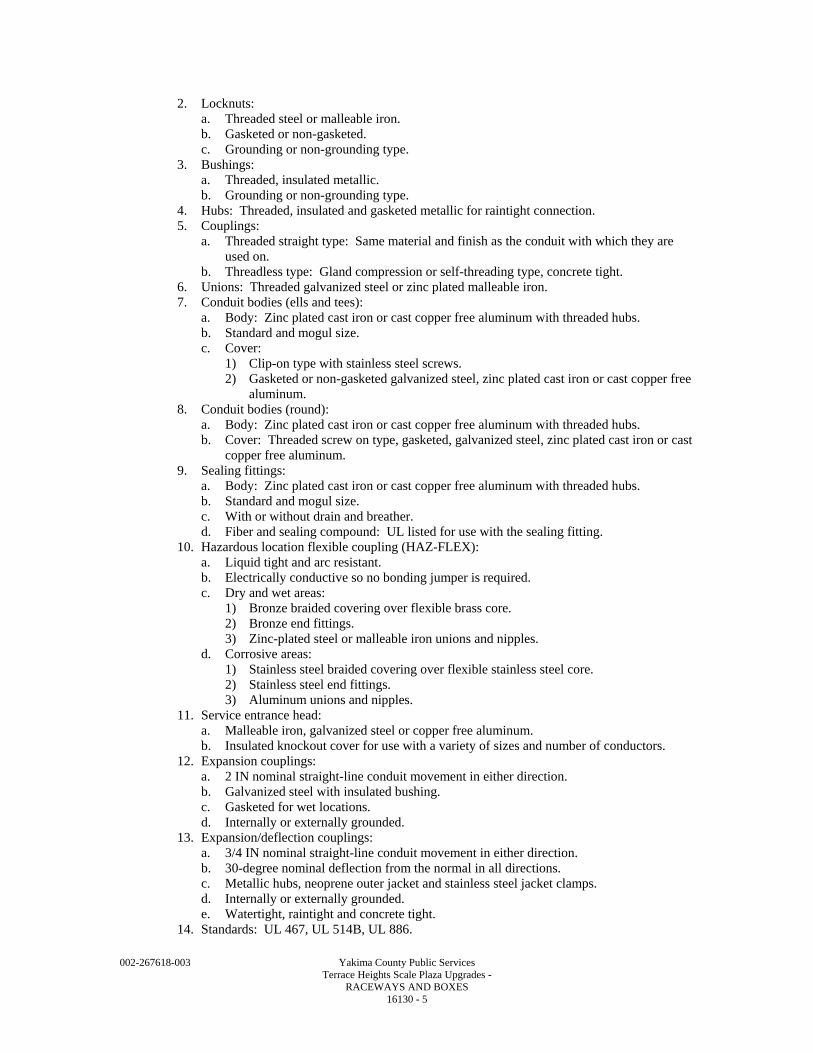
002-267618-003 Yakima County Public Services Terrace Heights Scale Plaza Upgrades - RACEWAYS AND BOXES 16130 - 5
2. Locknuts: a. Threaded steel or malleable iron. b. Gasketed or non-gasketed. c. Grounding or non-grounding type.
3. Bushings: a. Threaded, insulated metallic. b. Grounding or non-grounding type.
4. Hubs: Threaded, insulated and gasketed metallic for raintight connection. 5. Couplings:
a. Threaded straight type: Same material and finish as the conduit with which they are used on.
b. Threadless type: Gland compression or self-threading type, concrete tight. 6. Unions: Threaded galvanized steel or zinc plated malleable iron. 7. Conduit bodies (ells and tees):
a. Body: Zinc plated cast iron or cast copper free aluminum with threaded hubs. b. Standard and mogul size. c. Cover:
1) Clip-on type with stainless steel screws. 2) Gasketed or non-gasketed galvanized steel, zinc plated cast iron or cast copper free
aluminum. 8. Conduit bodies (round):
a. Body: Zinc plated cast iron or cast copper free aluminum with threaded hubs. b. Cover: Threaded screw on type, gasketed, galvanized steel, zinc plated cast iron or cast
copper free aluminum. 9. Sealing fittings:
a. Body: Zinc plated cast iron or cast copper free aluminum with threaded hubs. b. Standard and mogul size. c. With or without drain and breather. d. Fiber and sealing compound: UL listed for use with the sealing fitting.
10. Hazardous location flexible coupling (HAZ-FLEX): a. Liquid tight and arc resistant. b. Electrically conductive so no bonding jumper is required. c. Dry and wet areas:
1) Bronze braided covering over flexible brass core. 2) Bronze end fittings. 3) Zinc-plated steel or malleable iron unions and nipples.
d. Corrosive areas: 1) Stainless steel braided covering over flexible stainless steel core. 2) Stainless steel end fittings. 3) Aluminum unions and nipples.
11. Service entrance head: a. Malleable iron, galvanized steel or copper free aluminum. b. Insulated knockout cover for use with a variety of sizes and number of conductors.
12. Expansion couplings: a. 2 IN nominal straight-line conduit movement in either direction. b. Galvanized steel with insulated bushing. c. Gasketed for wet locations. d. Internally or externally grounded.
13. Expansion/deflection couplings: a. 3/4 IN nominal straight-line conduit movement in either direction. b. 30-degree nominal deflection from the normal in all directions. c. Metallic hubs, neoprene outer jacket and stainless steel jacket clamps. d. Internally or externally grounded. e. Watertight, raintight and concrete tight.
14. Standards: UL 467, UL 514B, UL 886.
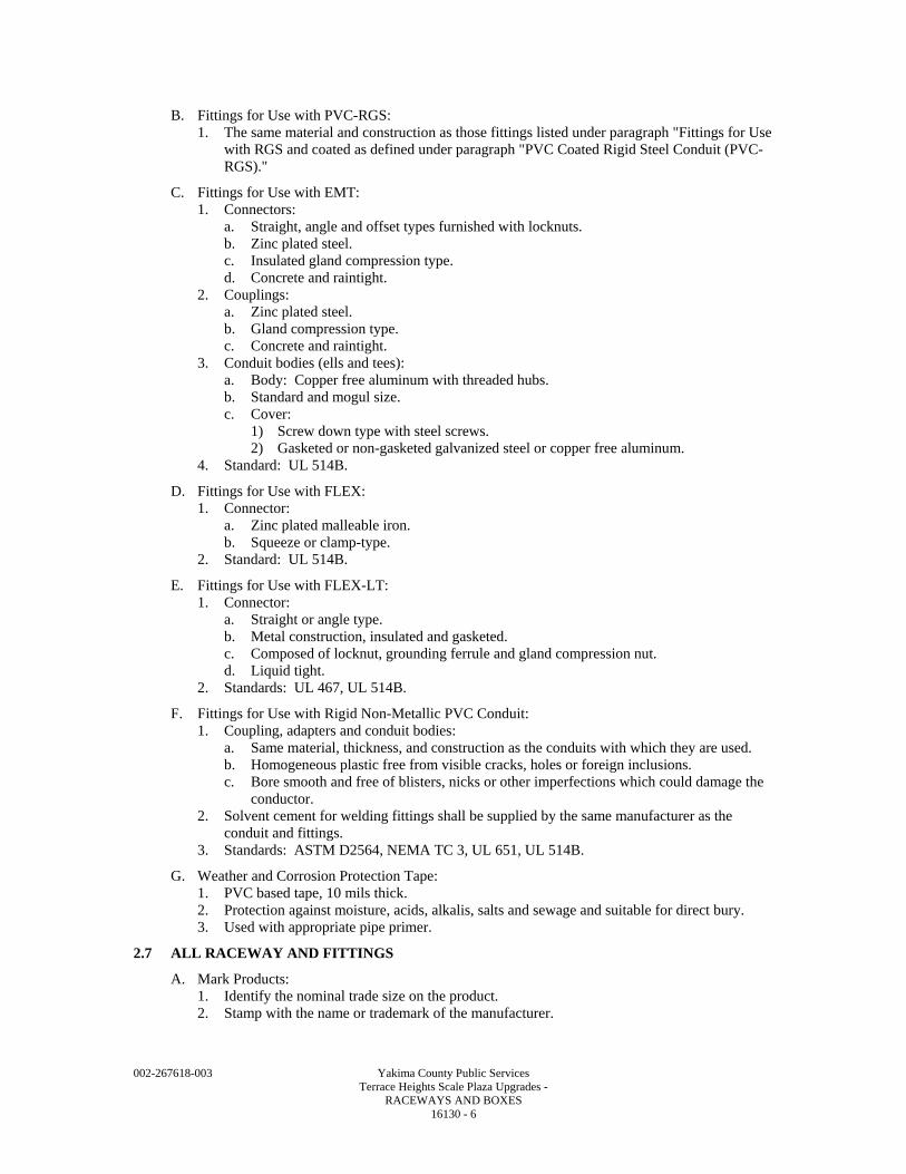
002-267618-003 Yakima County Public Services Terrace Heights Scale Plaza Upgrades - RACEWAYS AND BOXES 16130 - 6
B. Fittings for Use with PVC-RGS: 1. The same material and construction as those fittings listed under paragraph "Fittings for Use
with RGS and coated as defined under paragraph "PVC Coated Rigid Steel Conduit (PVC-RGS)."
C. Fittings for Use with EMT: 1. Connectors:
a. Straight, angle and offset types furnished with locknuts. b. Zinc plated steel. c. Insulated gland compression type. d. Concrete and raintight.
2. Couplings: a. Zinc plated steel. b. Gland compression type. c. Concrete and raintight.
3. Conduit bodies (ells and tees): a. Body: Copper free aluminum with threaded hubs. b. Standard and mogul size. c. Cover:
1) Screw down type with steel screws. 2) Gasketed or non-gasketed galvanized steel or copper free aluminum.
4. Standard: UL 514B.
D. Fittings for Use with FLEX: 1. Connector:
a. Zinc plated malleable iron. b. Squeeze or clamp-type.
2. Standard: UL 514B.
E. Fittings for Use with FLEX-LT: 1. Connector:
a. Straight or angle type. b. Metal construction, insulated and gasketed. c. Composed of locknut, grounding ferrule and gland compression nut. d. Liquid tight.
2. Standards: UL 467, UL 514B.
F. Fittings for Use with Rigid Non-Metallic PVC Conduit: 1. Coupling, adapters and conduit bodies:
a. Same material, thickness, and construction as the conduits with which they are used. b. Homogeneous plastic free from visible cracks, holes or foreign inclusions. c. Bore smooth and free of blisters, nicks or other imperfections which could damage the
conductor. 2. Solvent cement for welding fittings shall be supplied by the same manufacturer as the
conduit and fittings. 3. Standards: ASTM D2564, NEMA TC 3, UL 651, UL 514B.
G. Weather and Corrosion Protection Tape: 1. PVC based tape, 10 mils thick. 2. Protection against moisture, acids, alkalis, salts and sewage and suitable for direct bury. 3. Used with appropriate pipe primer.
2.7 ALL RACEWAY AND FITTINGS
A. Mark Products: 1. Identify the nominal trade size on the product. 2. Stamp with the name or trademark of the manufacturer.
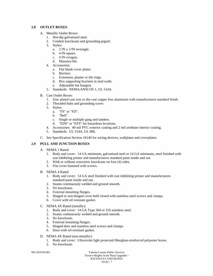
002-267618-003 Yakima County Public Services Terrace Heights Scale Plaza Upgrades - RACEWAYS AND BOXES 16130 - 7
2.8 OUTLET BOXES
A. Metallic Outlet Boxes: 1. Hot-dip galvanized steel. 2. Conduit knockouts and grounding pigtail. 3. Styles:
a. 2 IN x 3 IN rectangle. b. 4 IN square. c. 4 IN octagon. d. Masonry/tile.
4. Accessories: a. Flat blank cover plates. b. Barriers. c. Extension, plaster or tile rings. d. Box supporting brackets in stud walls. e. Adjustable bar hangers.
5. Standards: NEMA/ANSI OS 1, UL 514A.
B. Cast Outlet Boxes: 1. Zinc plated cast iron or die-cast copper free aluminum with manufacturers standard finish. 2. Threaded hubs and grounding screw. 3. Styles:
a. "FS" or "FD". b. "Bell". c. Single or multiple gang and tandem. d. "EDS" or "EFS" for hazardous locations.
4. Accessories: 40 mil PVC exterior coating and 2 mil urethane interior coating. 5. Standards: UL 514A, UL 886.
C. See Specification Section 16140 for wiring devices, wallplates and coverplates.
2.9 PULL AND JUNCTION BOXES
A. NEMA 1 Rated: 1. Body and cover: 14 GA minimum, galvanized steel or 14 GA minimum, steel finished with
rust inhibiting primer and manufacturers standard paint inside and out. 2. With or without concentric knockouts on four (4) sides. 3. Flat cover fastened with screws.
B. NEMA 4 Rated: 1. Body and cover: 14 GA steel finished with rust inhibiting primer and manufacturers
standard paint inside and out. 2. Seams continuously welded and ground smooth. 3. No knockouts. 4. External mounting flanges. 5. Hinged or non-hinged cover held closed with stainless steel screws and clamps. 6. Cover with oil resistant gasket.
C. NEMA 4X Rated (metallic): 1. Body and cover: 14 GA Type 304 or 316 stainless steel. 2. Seams continuously welded and ground smooth. 3. No knockouts. 4. External mounting flanges. 5. Hinged door and stainless steel screws and clamps. 6. Door with oil-resistant gasket.
D. NEMA 4X Rated (non-metallic): 1. Body and cover: Ultraviolet light protected fiberglass-reinforced polyester boxes. 2. No knockouts.
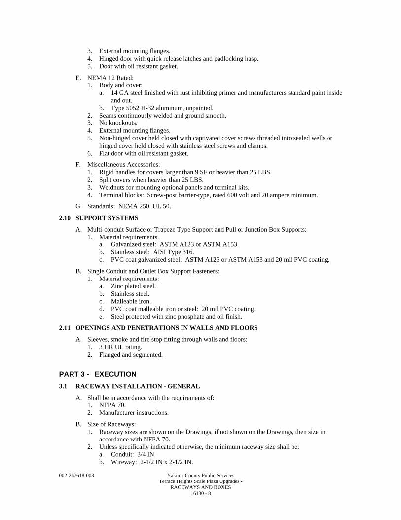
002-267618-003 Yakima County Public Services Terrace Heights Scale Plaza Upgrades - RACEWAYS AND BOXES 16130 - 8
3. External mounting flanges. 4. Hinged door with quick release latches and padlocking hasp. 5. Door with oil resistant gasket.
E. NEMA 12 Rated: 1. Body and cover:
a. 14 GA steel finished with rust inhibiting primer and manufacturers standard paint inside and out.
b. Type 5052 H-32 aluminum, unpainted. 2. Seams continuously welded and ground smooth. 3. No knockouts. 4. External mounting flanges. 5. Non-hinged cover held closed with captivated cover screws threaded into sealed wells or
hinged cover held closed with stainless steel screws and clamps. 6. Flat door with oil resistant gasket.
F. Miscellaneous Accessories: 1. Rigid handles for covers larger than 9 SF or heavier than 25 LBS. 2. Split covers when heavier than 25 LBS. 3. Weldnuts for mounting optional panels and terminal kits. 4. Terminal blocks: Screw-post barrier-type, rated 600 volt and 20 ampere minimum.
G. Standards: NEMA 250, UL 50.
2.10 SUPPORT SYSTEMS
A. Multi-conduit Surface or Trapeze Type Support and Pull or Junction Box Supports: 1. Material requirements.
a. Galvanized steel: ASTM A123 or ASTM A153. b. Stainless steel: AISI Type 316. c. PVC coat galvanized steel: ASTM A123 or ASTM A153 and 20 mil PVC coating.
B. Single Conduit and Outlet Box Support Fasteners: 1. Material requirements:
a. Zinc plated steel. b. Stainless steel. c. Malleable iron. d. PVC coat malleable iron or steel: 20 mil PVC coating. e. Steel protected with zinc phosphate and oil finish.
2.11 OPENINGS AND PENETRATIONS IN WALLS AND FLOORS
A. Sleeves, smoke and fire stop fitting through walls and floors: 1. 3 HR UL rating. 2. Flanged and segmented.
PART 3 - EXECUTION
3.1 RACEWAY INSTALLATION - GENERAL
A. Shall be in accordance with the requirements of: 1. NFPA 70. 2. Manufacturer instructions.
B. Size of Raceways: 1. Raceway sizes are shown on the Drawings, if not shown on the Drawings, then size in
accordance with NFPA 70. 2. Unless specifically indicated otherwise, the minimum raceway size shall be:
a. Conduit: 3/4 IN. b. Wireway: 2-1/2 IN x 2-1/2 IN.
002-267618-003 Yakima County Public Services Terrace Heights Scale Plaza Upgrades - RACEWAYS AND BOXES 16130 - 9
C. Field Bending and Cutting of Conduits: 1. Utilize tools and equipment recommended by the manufacturer of the conduit, designed for
the purpose and the conduit material to make all field bends and cuts. 2. Do not reduce the internal diameter of the conduit when making conduit bends. 3. Prepare tools and equipment to prevent damage to the PVC coating. 4. Degrease threads after threading and apply a zinc rich paint. 5. Debur interior and exterior after cutting.
D. Male threads of conduit systems shall be coated with an electrically conductive anti-seize compound.
E. The protective coating integrity of conduits, fittings, outlet, pull and junction boxes and accessories shall be maintained. 1. Repair galvanized components utilizing a zinc rich paint. 2. Repair painted components utilizing touch up paint provided by or approved by the
manufacturer. 3. Repair PVC coated components utilizing a patching compound, of the same material as the
coating, provided by the manufacturer of the conduit; or a self-adhesive, highly conformable, cross-linked silicone composition strip, followed by a protective coating of vinyl tape. a. Total nominal thickness: 40 mil.
4. Repair surfaces which will be inaccessible after installation prior to installation.
F. Remove moisture and debris from conduit before wire is pulled into place. 1. Pull mandrel with diameter nominally 1/4 IN smaller than the interior of the conduit, to
remove obstructions. 2. Swab conduit by pulling a clean, tight-fitting rag through the conduit. 3. Tightly plug ends of conduit with tapered wood plugs or plastic inserts until wire is pulled.
G. Only nylon or polyethylene rope shall be used to pull wire and cable in conduit systems.
H. Where portions of a raceway are subject to different temperatures and where condensation is known to be a problem, as in cold storage areas of buildings or where passing from the interior to the exterior of a building, the raceway shall be sealed to prevent circulation of warm air to colder section of the raceway.
I. Fill openings in walls, floors, and ceilings and finish flush with surface.
3.2 RACEWAY ROUTING
A. Raceways shall be routed in the field unless otherwise indicated. 1. Conduit and fittings shall be installed, as required, for a complete system that has a neat
appearance and is in compliance with all applicable codes. 2. Run in straight lines parallel to or at right angles to building lines. 3. Do not route conduits:
a. Through areas of high ambient temperature or radiant heat. b. In suspended concrete slabs.
4. Conduit shall not interfere with, or prevent access to, piping, valves, ductwork, or other equipment for operation, maintenance and repair.
5. Provide pull boxes or conduit bodies as needed so that there is a maximum of 360 degrees of bends in the conduit run or in long straight runs to limit pulling tensions.
B. All rigid conduits within a structure shall be installed exposed except as follows: 1. As indicated on the Drawings. 2. Concealed above gypsum wall board or acoustical tile suspended ceilings. 3. Concealed within stud frame, poured concrete, concrete block and brick walls of an
architecturally finished area. 4. Embedded in floor slabs or buried under floor serving equipment in non-architecturally
finished areas that are not located on or near a wall or column and the ceiling height is greater than 12 FT.
002-267618-003 Yakima County Public Services Terrace Heights Scale Plaza Upgrades - RACEWAYS AND BOXES 16130 - 10
5. Embedded in floor slabs or buried under floor slabs where shown on the Contract Drawings or with the Engineer's permission.
C. Maintain minimum spacing between parallel conduit and piping runs in accordance with the following when the runs are greater than 30 FT: 1. Between instrumentation and telecommunication: 1 IN. 2. Between instrumentation and 125 V, 48 V and 24 Vdc: 2 IN. 3. Between instrumentation and 600 V and less AC power or control: 6 IN. 4. Between instrumentation and greater than 600 Vac power: 12 IN. 5. Between telecommunication and 125 V, 48 V and 24 Vdc: 2 IN. 6. Between telecommunication and 600 V and less AC power or control: 6 IN. 7. Between telecommunication and greater than 600 Vac power: 12 IN. 8. Between 125 V, 48 V and 24 Vdc and 600 V and less AC power or control: 2 IN. 9. Between 125 V, 48 V and 24 Vdc and greater than 600 Vac power: 2 IN. 10. Between 600 V and less AC and greater than 600 Vac: 2 IN. 11. Between process, gas, air and water pipes: 6 IN.
D. Conduits shall be installed to eliminate moisture pockets. 1. Where water cannot drain to openings, provide drain fittings in the low spots of the conduit
run.
E. Conduit shall not be routed on the exterior of structures except as specifically indicated on the Drawings.
F. Where sufficient room exists within the housing of roof-mounted equipment, the conduit shall be stubbed up inside the housing.
G. Provide all required openings in walls, floors, and ceilings for conduit penetration.
3.3 RACEWAY APPLICATIONS
A. Permitted Raceway Types per Wire or Cable Types: 1. Power wire or cables: All raceway types. 2. Control wire or cables: All raceway types. 3. Instrumentation cables: Metallic raceway except non-metallic may be used underground. 4. Motor leads from a VFD: RGS, RAC or shielded VFD cables in all other raceways. 5. Telecommunication cables: All raceway types.
B. Permitted Raceway Types Per Area Designations: 1. Dry areas:
a. RGS. 2. Wet areas:
a. RGS. b. PVC-RGS.
3. Corrosive areas: a. PVC-RGS. b. Fiberglass.
4. NFPA 70 hazardous areas: a. RGS.
C. Permitted Raceway Types Per Routing Locations: 1. In stud framed walls:
a. EMT. 2. In concrete block or brick walls:
a. PVC-40. 3. Above acoustical tile ceilings:
a. EMT. b. NEMA 1 rated wireway.
4. Embedded in poured concrete walls and floors: a. PVC-40.
002-267618-003 Yakima County Public Services Terrace Heights Scale Plaza Upgrades - RACEWAYS AND BOXES 16130 - 11
b. Fiberglass. c. Fiberglass when emerging from concrete into areas designated as wet, corrosive. d. PVC-RGS when emerging from concrete into areas designated as wet, corrosive.
5. Beneath floor slab-on-grade: a. PVC-40. b. Fiberglass.
6. Through floor penetrations: a. Fiberglass in areas designated as wet. b. PVC-RGS in areas designated as wet.
7. Direct buried conduits and ductbanks: a. PVC-80. b. Fiberglass. c. 90 degree elbows for transitions to above grade:
1) PVC-RGS. 2) Fiberglass.
d. Long sweeping bends greater than 15 degrees: 1) PVC-RGS. 2) Fiberglass.
8. Concrete encased ductbanks: a. PVC-40. b. 90 degree elbows for transitions to above grade:
1) PVC-RGS. c. Long sweeping bends greater than 15 degrees:
1) RGS for sizes 2 IN and larger.
D. FLEX conduits shall be installed for connections to light fixtures, HVAC equipment and other similar devices above the ceilings. 1. The maximum length shall not exceed:
a. 6 FT to light fixtures. b. 3 FT to all other equipment.
E. FLEX-LT conduits shall be install as the final conduit connection to light fixtures, dry type transformers, motors, electrically operated valves, instrumentation primary elements, and other electrical equipment that is liable to vibrate. 1. The maximum length shall not exceed:
a. 6 FT to light fixtures. b. 3 FT to motors. c. 2 FT to all other equipment.
F. HAZ-FLEX coupling shall be installed as the final conduit to motors, electrically operated valves, instrumentation primary elements and electrical equipment that is liable to vibrate. 1. The maximum length shall not exceed:
a. 3 FT to motors. b. 2 FT to all other equipment.
G. NEMA 1 Rated Wireway: 1. Surface mounted in electrical rooms. 2. Surface mounted above removable ceilings tiles of an architecturally finished area.
H. NEMA 3R Wiring Trough: 1. Surface mounted in exterior locations.
I. NEMA 4X Rated Wireway: 1. Surface mounted in areas designated as wet and or corrosive.
J. NEMA 12 Rated Wireway: 1. Surface mounted in areas designated as dry in architecturally and non-architecturally
finished areas.
002-267618-003 Yakima County Public Services Terrace Heights Scale Plaza Upgrades - RACEWAYS AND BOXES 16130 - 12
K. Underground Conduit: See Specification Section 16135.
3.4 CONDUIT FITTINGS AND ACCESSORIES
A. Conduit Seals: 1. Installed in conduit systems located in hazardous areas as required by the NFPA 70.
B. Rigid non-metallic conduit and fittings shall be joined utilizing solvent cement. 1. Immediately after installation of conduit and fitting, the fitting or conduit shall be rotated
1/4 turn to provide uniform contact.
C. Install Expansion Fittings: 1. Where conduits are exposed to the sun and conduit run is greater than 200 FT. 2. Elsewhere as identified on the Drawings.
D. Install Expansion/Deflection Fittings: 1. Where conduits enter a structure.
a. Except electrical manholes and handholes. b. Except where the ductbank is tied to the structure with rebar.
2. Where conduits span structural expansions joints. 3. Elsewhere as identified on the Drawings.
E. Threaded connections shall be made wrench-tight.
F. Conduit joints shall be watertight: 1. Where subjected to possible submersion. 2. In areas classified as wet. 3. Underground.
G. Terminate Conduits: 1. In metallic outlet boxes:
a. RGS: 1) Conduit hub and locknut. 2) Insulated bushing and two (2) locknuts. 3) Use grounding type locknut or bushing when required by NFPA 70.
b. EMT: Compression type connector and locknut. 2. In NEMA 1 rated enclosures:
a. RGS: 1) Conduit hub and locknut. 2) Insulated bushing and two (2) locknuts. 3) Use grounding type locknut or bushing when required by NFPA 70.
b. EMT: Compression type connector and locknut. 3. In NEMA 12 rated enclosures:
a. Watertight, insulated and gasketed hub and locknut. b. Use grounding type locknut or bushing when required by NFPA 70.
4. In NEMA 4 and NEMA 4X rated enclosures: a. Watertight, insulated and gasketed hub and locknut.
5. In NEMA 7 and NEMA 9 rated enclosures: a. Into an integral threaded hub.
6. When stubbed up through the floor into floor mount equipment: a. With an insulated grounding bushing on metallic conduits. b. With end bells on non-metallic conduits.
H. Threadless couplings shall only be used to join new conduit to existing conduit when the existing conduit end is not threaded and it is not practical or possible to cut threads on the existing conduit with a pipe threader.
002-267618-003 Yakima County Public Services Terrace Heights Scale Plaza Upgrades - RACEWAYS AND BOXES 16130 - 13
3.5 CONDUIT SUPPORT
A. Permitted multi-conduit surface or trapeze type support system per area designations and conduit types: 1. Dry or wet and/or hazardous areas:
a. Galvanized system consisting of: Galvanized steel channels and fittings, nuts and hardware and conduit clamps.
b. Aluminum system consisting of: Aluminum channels, fittings and condit clamps with stainless steel nuts and hardware.
2. Corrosive areas: a. Aluminum system consisting of: Aluminum channels, fittings and conduit clamps with
stainless steel nuts and hardware. b. PVC coated steel system consisting of: PVC coated galvanized steel channels and
fittings and conduit clamps with stainless steel nuts and hardware. 3. Conduit type shall be compatible with the support system material.
a. Galvanized steel system may be used with RGS. b. Stainless steel system may be used with RGS and PVC-RGS. c. PVC coated galvanized steel system may be used with PVC-RGS, PVC-40 and PVC-
80. d. Aluminum system may be used with PVC-RGS. e. Fiberglass system may be used with PVC-40 and PVC-80 and PVC-RGS.
B. Permitted single conduit support fasteners per area designations and conduit types: 1. Architecturally finished areas:
a. Material: Zinc plated steel, or steel protected with zinc phosphate and oil finish. b. Types of fasteners: Spring type hangers and clips, straps, hangers with bolts, clamps
with bolts and bolt on beam clamps. c. Provide anti-rattle conduit supports when conduits are routed through metal studs.
2. Dry or wet and/or hazardous areas: a. Material: Zinc plated steel, stainless steel and malleable iron. b. Types of fasteners: Straps, hangers with bolts, clamps with bolts and bolt on beam
clamps. 3. Corrosive areas:
a. Material: Stainless steel and PVC coat malleable iron or steel. b. Types of fasteners: Straps, hangers with bolts, clamps with bolts and bolt on beam
clamps. 4. Conduit type shall be compatible with the support fastener material.
a. Zinc plated steel, steel protected with zinc phosphate and oil finish and malleable iron fasteners may be used with RGS.
b. Stainless steel system may be used with RGS and PVC-RGS. c. PVC coated fasteners may be used with PVC-RGS and PVC-40 and PVC-80. d. Non-metallic fasteners may be used with PVC-40, PVC-80.
C. Conduit Support General Requirements: 1. Maximum spacing between conduit supports per NFPA 70. 2. Support conduit from the building structure. 3. Do not support conduit from process, gas, air or water piping; or from other conduits. 4. Provide hangers and brackets to limit the maximum uniform load on a single support to
25 LBS or to the maximum uniform load recommended by the manufacturer if the support is rated less than 25 LBS. a. Do not exceed maximum concentrated load recommended by the manufacturer on any
support. b. Conduit hangers:
1) Continuous threaded rods combined with struts or conduit clamps: Do not use perforated strap hangers and iron bailing wire.
c. Do not use suspended ceiling support systems to support raceways.
002-267618-003 Yakima County Public Services Terrace Heights Scale Plaza Upgrades - RACEWAYS AND BOXES 16130 - 14
d. Hangers in metal roof decks: 1) Utilize fender washers. 2) Not extend above top of ribs. 3) Not interfere with vapor barrier, insulation, or roofing.
5. Conduit support system fasteners: a. Use sleeve-type expansion anchors as fasteners in masonry wall construction. b. Do not use concrete nails and powder-driven fasteners.
3.6 OUTLET, PULL AND JUNCTION BOX INSTALLATION
A. General: 1. Install products in accordance with manufacturer's instructions. 2. See Specification Section 16010 and the Drawings for area classifications. 3. Fill unused punched-out, tapped, or threaded hub openings with insert plugs. 4. Size boxes to accommodate quantity of conductors enclosed and quantity of conduits
connected to the box.
B. Outlet Boxes: 1. Permitted uses of metallic outlet boxes:
a. Housing of wiring devices: 1) Recessed in all stud framed walls and ceilings. 2) Recessed in poured concrete, concrete block and brick walls of architecturally
finished areas and exterior building walls. b. Pull or junction box:
1) Above gypsum wall board or acoustical tile ceilings. 2) Above 10 FT in an architecturally finished area where there is no ceiling.
2. Permitted uses of cast outlet boxes: a. Housing of wiring devices surface mounted in non-architecturally finished dry, wet,
corrosive areas. b. Pull and junction box surface mounted in non-architecturally finished dry, wet,
corrosive areas. 3. Mount device outlet boxes where indicated on the Drawings and at heights as scheduled in
Specification Section 16010. 4. Set device outlet boxes plumb and vertical to the floor. 5. Outlet boxes recessed in walls:
a. Install with appropriate stud wall support brackets or adjustable bar hangers so that they are flush with the face of the wall.
b. Locate in ungrouted cell of concrete block with bottom edge of box flush with bottom edge of block and flush with the face of the block.
6. Place barriers between switches in boxes with 277 V switches on opposite phases. 7. Back-to-back are not permitted. 8. When an outlet box is connected to a PVC coated conduit, the box shall also be PVC coated.
C. Pull and Junction Boxes: 1. Install pull or junction boxes in conduit runs where indicated or required to facilitate pulling
of wires or making connections. a. Make covers of boxes accessible.
2. Permitted uses of NEMA 1 enclosure: a. Pull or junction box surface mounted above removable ceiling tiles of an architecturally
finished area. 3. Permitted uses of NEMA 4 enclosure:
a. Pull or junction box surface mounted in areas designated as wet. 4. Permitted uses of NEMA 4X metallic enclosure:
a. Pull or junction box surface mounted in areas designated as wet and/or corrosive.
002-267618-003 Yakima County Public Services Terrace Heights Scale Plaza Upgrades - RACEWAYS AND BOXES 16130 - 15
5. Permitted uses of NEMA 12 enclosure: a. Pull or junction box surface mounted in areas designated as dry.
END OF SECTION

002-267618-003 Yakima County Public Services Terrace Heights Scale Plaza Upgrades - RACEWAYS AND BOXES 16130 - 16
002-267618-003 Yakima County Public Services Terrace Heights Scale Plaza Upgrades - ELECTRICAL: EXTERIOR UNDERGROUND 16135 - 1
SECTION 16135
ELECTRICAL: EXTERIOR UNDERGROUND
PART 1 - GENERAL
1.1 SUMMARY
A. Section Includes: 1. Material and installation requirements for:
a. Handhole. b. Underground conduits and ductbanks.
B. Related Specification Sections include but are not necessarily limited to: 1. Division 3 - Concrete. 2. Section 10400 - Identification Devices. 3. Section 16130 - Raceways and Boxes.
1.2 QUALITY ASSURANCE
A. Referenced Standards: 1. American Association of State Highway and Transportation Officials (AASHTO):
a. HB, Standard Specifications for Highway Bridges. 2. ASTM International (ASTM):
a. A536, Standard Specification for Ductile Iron Castings. 3. National Fire Protection Association (NFPA):
a. 70, National Electrical Code (NEC). 4. Society of Cable Telecommunications Engineers (SCTE):
a. 77, Specification for Underground Enclosure Integrity.
1.3 DEFINITIONS
A. Direct-Buried Conduit(s): 1. Individual (single) underground conduit. 2. Multiple underground conduits, arranged in one or more planes, in a common trench.
B. Concrete Encased Ductbank: An individual (single) or multiple conduit(s), arranged in one or more planes, encased in a common concrete envelope.
1.4 SUBMITTALS
A. See Specification Section 01340 for requirements for the mechanics and administration of the submittal process.
B. Product Technical Data: 1. Provide submittal data for all products specified in PART 2 of this Specification Section.
C. Fabrication and/or layout Drawings.
PART 2 - PRODUCTS
2.1 ACCEPTABLE MANUFACTURERS
A. Subject to compliance with the Contract Documents, the following manufacturers are acceptable: 1. Prefabricated composite handholes:
a. Quazite Composolite. b. Armorcast Products Company. c. Synertech.
002-267618-003 Yakima County Public Services Terrace Heights Scale Plaza Upgrades - ELECTRICAL: EXTERIOR UNDERGROUND 16135 - 2
2. Precast handholes: a. Utility Vault Co. b. Oldcastle Precast, Inc. c. Lister Industries.
3. Handhole and ductbank accessories: a. Neenah. b. Unistrut. c. Condux International, Inc. d. Underground Devices, Inc.
B. Submit request for substitution in accordance with Specification Section 01640.
2.2 HANDHOLES
A. Prefabricated Composite Material Handholes: 1. Handhole body and cover: Fiberglass reinforced polymer concrete conforming to all test
provisions of SCTE 77. 2. Minimum load ratings: SCTE 77 Tier 5. 3. Open bottom. Solid bottom is shown in Drawings. 4. Stackable design as required for specified depth. 5. Cover:
a. Engraved legend of "ELECTRIC" or "COMMUNICATIONS." b. Non-gasketed bolt down with stainless steel penta head bolts. c. Lay-in non-bolt down, when cover is over 100 LBS. d. One or multiple sections so the maximum weight of a section is 125 LBS.
6. Cover lifting hook: 24 IN minimum in length.
B. Precast Handholes: 1. Fiberglass reinforced polymer concrete or steel reinforced cement concrete structures: 2. AASHTO live load rating: H-20 for full deliberate vehicle traffic. 3. Mating edges: Tongue and groove type. 4. Gasketed removable top slab with lifting eyes and cast in frame for cover. 5. Cover extension rings as required. 6. Cable pulling eyes opposite all conduit entrances.
a. Coordinate exact location with installation contractor.
2.3 CONCRETE HANDHOLE ACCESSORIES
A. Cover and Frame: 1. Cast ductile iron: ASTM A536. 2. AASHTO live load rating: H-20. 3. Diameter: 30 IN. 4. Cast the legend "ELECTRICAL" or "COMMUNICATIONS" into handhole covers.
B. Cable Racks and Hooks: 1. Material: Heavy-duty non-metallic (glass reinforced nylon). 2. Hook loading capacity: 400 LBS minimum. 3. Rack loading capacity: Four (4) hooks maximum. 4. Hook deflection: 0.25 IN maximum. 5. Hooks: Length, as required, with positive locking device to prevent upward movement. 6. Mounding hardware: Stainless steel.
C. Cable Pulling Irons: 1. 7/8 IN DIA hot-dipped galvanized steel. 2. 6000 LB minimum pulling load.
2.4 UNDERGROUND CONDUIT AND ACCESSORIES
A. Concrete: Comply with Division 3 Specifications Specification Section 03108, Specification Section 03208, Specification Section 03308 and Specification Section 03348.
002-267618-003 Yakima County Public Services Terrace Heights Scale Plaza Upgrades - ELECTRICAL: EXTERIOR UNDERGROUND 16135 - 3
B. Conduit: See Specification Section 16130.
C. Duct Spacers/Supports: 1. High density polyethylene or high impact polystyrene. 2. Interlocking. 3. Provide 2 IN minimum spacing between conduits. 4. Accessories, as required:
a. Hold down bars. b. Ductbank strapping.
PART 3 - EXECUTION
3.1 GENERAL
A. Drawings indicate the intended location of handholes and routing of ductbanks and direct buried conduit. 1. Field conditions may affect actual routing.
B. Handhole Locations: 1. Approximately where shown on the Drawings. 2. As required for pulling distances. 3. As required to keep pulling tensions under allowable cable tensions. 4. As required for number of bends in ductbank routing. 5. Shall not be installed in a swale or ditch. 6. Determine the exact locations after careful consideration has been given to the location of
other utilities, grading, and paving. 7. Locations are to be approved by the Owner prior to excavation and placement or
construction of handholes.
C. Install products in accordance with manufacturer's instructions.
D. Install handholes in conduit runs where indicated or as required to facilitate pulling of wires or making connections.
3.2 HANDHOLES
A. Prefabricated Composite Material Handholes: 1. For use in areas subjected to occasional non-deliberate vehicular traffic. 2. Place handhole on a foundation of compacted 1/4 to 1/2 IN crushed rock or gravel a
minimum of 8 IN thick and 6 IN larger than handholes footprint on all sides. 3. Provide concrete encasement ring around handhole per manufacturers installation
instructions (minimum of 10 IN wide x 12 IN deep). 4. Install so that the surrounding grade is 1 IN lower than the top of the handhole. 5. Size: As indicated on the Drawings or as required for the number and size of conduits. 6. Provide cable rails and pulling eyes as needed.
B. Precast Handholes: 1. For use in vehicular and non-vehicular traffic areas. 2. Construction:
a. Grout or seal all joints, per manufacturer's instructions. b. Support cables on walls by cable racks:
1) Provide a minimum of two (2) racks, install symmetrically on each wall of handholes. a) Provide additional cable racks, as required, so that both ends of cable splices
will be supported horizontally. 2) Equip cable racks with adjustable hooks: Quantity of cable hooks as required by
the number of conductors to be supported.
002-267618-003 Yakima County Public Services Terrace Heights Scale Plaza Upgrades - ELECTRICAL: EXTERIOR UNDERGROUND 16135 - 4
c. In each handhole, drive 3/4 IN x 10 FT long copper clad ground rod into the earth with approximately 6 IN exposed above finished floor. 1) Drill opening in floor for ground rod. 2) Connect all metallic components to ground rod by means of #8 AWG minimum
copper wire and approved grounding clamps. 3) Utilize a ground bar in the handhole if the quantity of ground wires exceeds 3.
a) Connect ground bar to ground rod with a #2/0 AWG minimum copper wire. 3. Place handhole on a foundation of compacted 1/4 to 1/2 IN crushed rock or gravel a
minimum of 8 IN thick and 6 IN larger than handholes footprint on all sides. 4. Install so that the top of cover is 1 IN above finished grade.
a. Where existing grades are higher than finished grades, install sufficient number of courses of curved segmented concrete block between top of handhole frame to temporarily elevate cover to existing grade level.
5. After installation is complete, backfill and compact soil around handholes. 6. Handhole size:
a. As indicated on the Drawings or as required for the number and size of conduits entering or as indicated on the Drawings.
b. Minimum floor dimension of 2 FT x 3 FT and minimum depth of 3 FT.
3.3 UNDERGROUND CONDUITS
A. General Installation Requirements: 1. Ductbank types per location:
a. Reinforced concrete ductbank: 1) Under aircraft pavement. 2) Under railroads. 3) As indicated in the Ductbank Schedule.
b. Concrete encased ductbank: 1) Under roads. 2) Conduits containing medium voltage cables. 3) Pad mounted transformer secondaries. 4) Facility process equipment feeders and controls. 5) As indicated in the Ductbank Schedule.
c. Direct-buried conduit(s): 1) Area/Roadway lighting. 2) As indicated in the Ductbank Schedule.
2. Do not place concrete or soil until conduits have been observed by the Owner. 3. Ductbanks shall be sloped a minimum of 4 IN per 100 FT or as detailed on the Drawings.
a. Low points shall be at handholes. 4. During construction and after conduit installation is complete, plug the ends of all conduits. 5. Provide conduit supports and spacers.
a. Place supports and spacers for rigid nonmetallic conduit on maximum centers as indicated for the following trade sizes: 1) 1 IN and less: 3 FT. 2) 1-1/4 to 3 IN: 5 FT. 3) 3-1/2 to 6 IN: 7 FT.
b. Place supports and spacers for rigid steel conduit on maximum centers as indicated for the following trade sizes: 1) 1 IN and less: 10 FT. 2) 1-1/4 to 2-1/2 IN: 14 FT. 3) 3 IN and larger: 20 FT.
c. Securely anchor conduits to supports and spacers to prevent movement during placement of concrete or soil.
6. Stagger conduit joints at intervals of 6 IN vertically. 7. Make conduit joints watertight and in accordance with manufacturer's recommendations.

002-267618-003 Yakima County Public Services Terrace Heights Scale Plaza Upgrades - ELECTRICAL: EXTERIOR UNDERGROUND 16135 - 5
8. Accomplish changes in direction of runs exceeding a total of 15 degrees by long sweep bends having a minimum radius of 25 FT. a. Sweep bends may be made up of one or more curved or straight sections or
combinations thereof. 9. Furnish manufactured bends at end of runs.
a. Minimum radius of 18 IN for conduits less than 3 IN trade size and 36 IN for conduits 3 IN trade size and larger.
10. Field cuts requiring tapers shall be made with the proper tools and shall match factory tapers.
11. After the conduit run has been completed: a. Prove joint integrity and test for out-of-round duct by pulling a test mandrel through
each conduit. 1) Test mandrel:
a) Length: Not less than 12 IN. b) Diameter: Approximately 1/4 IN less than the inside diameter of the conduit.
b. Clean the conduit by pulling a heavy duty wire brush mandrel followed by a rubber duct swab through each conduit.
12. Pneumatic rodding may be used to draw in lead wire. a. Install a heavy nylon cord free of kinks and splices in all unused new ducts. b. Extend cord 3 FT beyond ends of conduit.
13. Transition from rigid non-metallic conduit to rigid metallic conduit, per Specification Section 16130, prior to entering a structure or going above ground. a. Except rigid non-metallic conduit may be extended directly to handholes, pad mounted
transformer boxes and other exterior pad mounted electrical equipment where the conduit is concealed within the enclosure.
b. Terminate rigid PVC conduits with end bells. c. Terminate steel conduits with insulated bushings.
14. Place warning tape in trench directly over ductbanks, direct-buried conduit, and direct-buried wire and cable in accordance with Specification Section 10400.
15. Placement of conduits stubbing into handholes shall be located to allow for proper bending radiuses of the cables.
B. Concrete Encased Ductbank: 1. Ductbank system consists of conduits completely encased in minimum 2 IN of concrete and
with separations between different cabling types as required in Specification Section 16130 or as detailed on the Drawings.
2. Install so that top of concrete encased duct, at any point: a. Is not less than 24 IN below grade. b. Is below pavement sub-grading.
3. Where identified and for a distance 10 FT either side of the area, the concrete shall be reinforced. a. The reinforcement shall consist of #4 bars and #4 ties placed 12 IN on center, in
accordance with Division 3 Specification Sections or as detailed on the Drawings. 4. Conduit supports shall provide a uniform minimum clearance of 2 IN between the bottom of
the trench and the bottom row of conduit. 5. Conduit separators shall provide a uniform minimum clearance of 2 IN between conduits or
as required in Specification Section 16130 for different cabling types.
C. Direct-Buried Conduit(s): 1. Install so that the top of the uppermost conduit, at any point:
a. Is not less than 30 IN below grade. b. Is below pavement sub-grading.
002-267618-003 Yakima County Public Services Terrace Heights Scale Plaza Upgrades - ELECTRICAL: EXTERIOR UNDERGROUND 16135 - 6
2. Provide a uniform minimum clearance of 2 IN between conduits or as required in Specification Section 16130 for different cabling types. a. Maintain the separation of multiple planes of conduits by one of the following methods:
1) Install multilevel conduits with the use of conduit supports and separators to maintain the required separations, and backfill with flowable fill (100 psi).
2) Install the multilevel conduits one level at a time. a) Each level is backfilled with the appropriate amount of soil and compaction, to
maintain the required separations.
END OF SECTION
002-267618-003 Yakima County Public Services Terrace Heights Scale Plaza Upgrades - WIRING DEVICES 16140 - 1
SECTION 16140
WIRING DEVICES
PART 1 - GENERAL
1.1 SUMMARY
A. Section Includes: 1. Material and installation requirements for:
a. Light switches. b. Receptacles. c. Device wallplates and coverplates. d. Plug-in strips. e. Occupancy sensors.
B. Related Specification Sections include but are not necessarily limited to: 1. Section 16010 - Electrical: Basic Requirements. 2. Section 16130 - Raceways and Boxes.
1.2 QUALITY ASSURANCE
A. Referenced Standards: 1. National Electrical Manufacturers Association (NEMA):
a. 250, Enclosures for Electrical Equipment (1000 Volts Maximum). b. WD 1, General Color Requirements for Wiring Devices. c. WD 6, Wiring Devices - Dimensional Requirements.
2. Underwriters Laboratories, Inc. (UL): a. 20, General-Use Snap Switches. b. 498, Standard for Attachment Plugs and Receptacles. c. 514A, Metallic Outlet Boxes. d. 894, Standard for Switches for Use in Hazardous (Classified) Locations. e. 943, Ground-Fault Circuit-Interrupters. f. 1010, Standard for Receptacle-Plug Combinations for Use in Hazardous (Classified)
Locations.
1.3 SUBMITTALS
A. See Specification Section 01340 for requirement for the mechanics and administration of the submittal process.
B. Product technical data: a. Provide submittal data for all products specified in PART 2 of this Specification Section. b. See Specification Section 16010 for additional requirements.
PART 2 - PRODUCTS
2.1 ACCEPTABLE MANUFACTURERS
A. Subject to compliance with the Contract Documents, the following manufacturers are acceptable: 1. Light switches and receptacles:
a. Bryant. b. Cooper Wiring Devices. c. Hubbell. d. Leviton. e. Pass & Seymour. f. Crouse-Hinds.
002-267618-003 Yakima County Public Services Terrace Heights Scale Plaza Upgrades - WIRING DEVICES 16140 - 2
g. Appleton Electric Co. h. Killark. i. Plug-in strip:
1) Wiremold. 2) Walker.
j. Occupancy sensors: 1) Cooper Controls. 2) Lighting Design and Control (LD&C). 3) Watt Stopper.
B. Submit request for substitution in accordance with Specification Section 01640.
2.2 LIGHT SWITCHES
A. General requirements unless modified in specific requirements paragraph of switches per designated areas or types: 1. Toggle type, quiet action, Industrial Specification Grade. 2. Self grounding with grounding terminal. 3. Back and side wired. 4. Solid silver cadmium oxide contacts. 5. Rugged urea housing and one-piece switch arm. 6. Rated 20 A, 120/277 Vac. 7. Switch handle color: White. 8. Types as indicated on the Drawings:
a. Single-pole. b. Double-pole. c. 3-way. d. 4-way.
9. Standards: UL 20, UL 514A, NEMA WD 6.
B. Architecturally Finished Areas: 1. Wallplate:
a. White colored high impact thermoplastic or nylon. b. Single or multiple gang as required.
C. Dry Non-architecturally Finished Areas: 1. Coverplate:
a. Zinc plated malleable iron or galvanized steel. b. Single or multiple gang as required.
D. Wet Non-architecturally Finished Areas: 1. Coverplate:
a. Gasketed zinc plated malleable iron or aluminum with stainless steel screws utilizing rocker, front mounted toggle or pull type switch.
b. Single or multiple gang as required.
2.3 RECEPTACLES
A. General requirements unless modified in specific requirements paragraph of receptacles per designated areas: 1. Straight blade, Industrial Specification Grade. 2. Brass triple wipe line contacts. 3. One-piece grounding system with double wipe brass grounding contacts and self grounding
strap. 4. Back and side wired. 5. Rated 20 A, 125 Vac. 6. High impact nylon body. 7. Receptacle body color:
a. Normal power: White.

002-267618-003 Yakima County Public Services Terrace Heights Scale Plaza Upgrades - WIRING DEVICES 16140 - 3
b. Generator or UPS power: Red. 8. Types as indicated on the Drawings:
a. Normal: Self grounding with grounding terminal. b. Ground fault circuit interrupter: Feed-through type with test and reset buttons.
9. Duplex or simplex as indicated on the Drawings. 10. Configuration: NEMA 5-20R. 11. Standards: UL 498, UL 514A, UL 943, NEMA WD 1, NEMA WD 6.
B. Ground Fault Circuit Interrupter (GFCI): 1. Specification Grade. 2. Class A protection. 3. Feed through type. 4. Test and reset buttons. 5. Self-testing. 6. Visual indicator light. 7. Weather-resistant when located in exterior locations or interior damp or wet areas as
indicated on the Drawings. 8. Identification: Letters “WR” on face of receptacle. 9. Tamper resistant (TR) when indicated on the Drawings. 10. Additional standards: UL 943
C. Architecturally Finished Areas: 1. Wallplate: White colored high impact thermoplastic or nylon.
D. Dry Non-Architecturally Finished Areas: 1. Coverplate:
a. Zinc plated malleable iron or galvanized steel. b. Single or multiple gang as required.
E. Wet Non-Architecturally Finished Areas: 1. Coverplate: Weatherproof (NEMA 3R) while in use, gasketed, copper-free aluminum, 2.5
IN minimum cover depth.
F. Exterior Locations: 1. Coverplate: Weatherproof (NEMA 3R) while in use, gasketed, copper-free aluminum, 2.5
IN minimum cover depth.
G. Special Purpose Receptacles: Portable Generator Plug-in (Scalehouse Exterior Wall): 1. Outdoor rated (waterproof, dustproof). 2. As recommended by generator manufacturer. 3. NEMA configuration as indicated on the Drawings. 4. Coverplate: See requirements per area designations herein.
2.4 MISCELLANEOUS WIRING DEVICES
A. Manual Motor Starters: Horsepower rated with or without thermal overloads.
B. Plug-In Strip: 1. Surface steel raceway plug-in strip with single 15 A, 125 V, 3-wire grounding-type
receptacles spaced 18 IN OC. 2. Prewired with two (2) #12 TW and one (1) #12 TW green insulated ground. 3. Minimum 1-1/4 IN wide x 3/4 IN deep. 4. Suitable fittings and snap-in cover. 5. Finish: Stainless steel.
2.5 OCCUPANCY SENSORS
A. Low Voltage Passive Infrared Ceiling Sensor (Type OC) per the Drawings: 1. Detection of changes in the infrared energy: Sensor to respond only to those signals caused
by human motion. 2. Analog and digital processing to provide immunity to RFI and EMI.
002-267618-003 Yakima County Public Services Terrace Heights Scale Plaza Upgrades - WIRING DEVICES 16140 - 4
3. Temperature compensated, dual element sensor and a multi-element lens with a minimum field of view of 110 degrees.
4. Daylight filter or compensation for short wavelength infrared wave from the sun. 5. Cover up to 300 SF at normal mounting heights. 6. System voltage: 24 Vdc through power pack. 7. Load ON-OFF control through power pack. 8. Adjustable time delay set at 30 minutes. 9. Adjustable sensitivity set at maximum. 10. Adjustments and mounting hardware under a removable cover. 11. Parallel wiring of multiple sensors to allow coverage of large areas.
B. Passive Infrared Wall Switch: 1. Self contained control system that replaces a standard toggle switch.
a. Latching air gap relay switching mechanism, compatible with electronic ballasts, compact fluorescent and inductive loads.
2. Detection of changes in the infrared energy: Sensor to respond only to those signals caused by human motion.
3. Analog and digital processing to provide immunity to RFI and EMI. 4. Temperature compensated, dual element sensor and a multi-element Fresnel lens. 5. Cover up to 300 SF for walking motion, with a field of view of 180 degrees. 6. System voltage: 120 Vac or 277 Vac. 7. No minimum load.
a. 0 to 500 watts incandescent, 0 to 800 watts fluorescent or 1/6 HP at 120 Vac, 60 Hz. b. 0 to 1200 watts fluorescent or 1/3 HP at 277 Vac, 60 Hz.
8. DIP switch to control the following functions: a. Built-in light level feature adjustable from 8 to 180 foot candles. b. AUTOMATIC-ON or MANUAL-ON operation. c. Time delay adjustable from 30 seconds to 30 minutes. d. High/low sensitivity adjustments.
9. Adjustments and mounting hardware under a removable, tamper resistant cover. 10. Normal operation: OFF and AUTO.
C. Ultrasonic Ceiling Sensor: 1. Detection of Doppler shifts in transmitted ultrasound. 2. Ultrasonic sensing is volumetric in coverage with a frequency of 32 kHz and automatically
adjust the detection threshold dynamically to compensate for constantly changing levels of activity and air flow throughout controlled areas.
3. Temperature and humidity resistant, 32 kHz tuned ultrasonic receivers. a. Receivers have less than a 6 dB shift in the humidity range of 10 percent to 90 percent
and less than a 10 dB shift in the temperature range of -20 to 60 DegC. 4. DIP switch to control the following functions:
a. Override-ON function for use in the event of failure. b. Time delay adjustable from 15 seconds to 30 minutes. c. High/low sensitivity adjustments.
5. Cover 360 degrees and hallway and corridor sensors shall cover up to 90 linear feet. 6. Additional single-pole, double-throw isolated relay with normally open, normally closed,
and common outputs rated at 1 amp for 24 Vdc. a. The isolated relay is for use with HVAC control, data logging and other control options.
D. Power Pack: 1. Self contained transformer and relay module. 2. Dry contacts capable of switching:
a. 20 amp ballast load, 13 amp incandescent, 1 HP at 120 Vac, 60 Hz. b. 20 amp ballast at 277 Vac, 60 Hz.
3. 24 Vdc, 100 mA output. 4. Capable of parallel wiring without regard to AC phases on primary. 5. Used as a stand alone, low voltage switch or wired to sensor for auto control.
002-267618-003 Yakima County Public Services Terrace Heights Scale Plaza Upgrades - WIRING DEVICES 16140 - 5
6. Low voltage Teflon coated leads, rated for 300 V, suitable for use in plenum applications.
PART 3 - EXECUTION
3.1 INSTALLATION
A. Install products in accordance with manufacturer's instructions.
B. Mount devices where indicated on the Drawings and as scheduled in Specification Section 16010.
C. See Specification Section 16130 for device outlet box requirements.
D. Where more than one (1) receptacle is installed in a room, they shall be symmetrically arranged.
E. Provide blank plates for empty outlets.
F. Occupancy Sensors: 1. Locations and quantity of sensors shown on the Drawings are diagrammatic and indicate
only the rooms and spaces to be provided with sensors. 2. Verify sensor type, quantity, location, aiming and sensitivity with manufacturer's
recommendations. 3. All controlled spaces shall be tested to insure 90 to 100 percent coverage of the controlled
space. a. If test fails, adjust sensitivity, re-aim, relocate, and/or add sensor(s) as required at no
cost to Owner.
END OF SECTION

002-267618-003 Yakima County Public Services Terrace Heights Scale Plaza Upgrades - WIRING DEVICES 16140 - 6
002-267618-003 Yakima County Public Services Terrace Heights Scale Plaza Upgrades - SAFETY SWITCHES 16410 - 1
SECTION 16410
SAFETY SWITCHES
PART 1 - GENERAL
1.1 SUMMARY
A. Section Includes: Safety switches.
B. Related Specification Sections include but are not necessarily limited to: 1. Section 16010 - Electrical: Basic Requirements. 2. Section 16490 - Overcurrent and Short Circuit Protective Devices.
1.2 QUALITY ASSURANCE
A. Referenced Standards: 1. National Electrical Manufacturers Association (NEMA):
a. 250, Enclosures for Electrical Equipment (1000 Volts Maximum). b. KS 1, Enclosed and Miscellaneous Distribution Equipment Switches (600 Volts
Maximum). 2. Underwriters Laboratories, Inc. (UL):
a. 98, Enclosed and Dead-Front Switches.
1.3 SUBMITTALS
A. See Specification Section 01340 for requirements for the mechanics and administration of the submittal process.
B. Product technical data: 1. Provide submittal data for all products specified in PART 2 of this Specification Section. 2. Provide a table that associates safety switch model number with connected equipment tag
number. 3. See Specification Section 16010 for additional requirements.
C. Operation and Maintenance Manuals: 1. See Specification Section 01340 for requirements for the content of Operation and
Maintenance Manuals.
PART 2 - PRODUCTS
2.1 ACCEPTABLE MANUFACTURERS
A. Subject to compliance with the Contract Documents, the following safety switch manufacturers are acceptable: 1. Cutler-Hammer. 2. General Electric Company. 3. Square D Company. 4. Siemens. 5. Appleton Electric Company. 6. Crouse-Hinds. 7. Killark.
B. Submit request for substitution in accordance with Specification Section 01640.
2.2 SAFETY SWITCHES
A. General: 1. Non-fusible or fusible as indicated on the Drawings. 2. Suitable for service entrance when required.
002-267618-003 Yakima County Public Services Terrace Heights Scale Plaza Upgrades - SAFETY SWITCHES 16410 - 2
3. NEMA Type HD heavy-duty construction. 4. Switch blades will be fully visible in the OFF position with the enclosure door open. 5. Quick-make/quick-break operating mechanism. 6. Deionizating arc chutes. 7. Manufacture double-break rotary action shaft and switchblade as one (1) common
component. 8. Clear line shields to prevent accidental contact with line terminals. 9. Operating handle:
a. Red and easily recognizable. b. Padlockable in the OFF position. c. Interlocked to prevent door from opening when the switch is in the ON position with a
defeater mechanism.
B. Ratings: 1. Horsepower rated of connected motor. 2. Voltage and amperage: As indicated on the Drawings. 3. Short circuit withstand:
a. Non-fused: 10,000A. b. Fused: 200,000A.
C. Accessories, when indicated in PART 3 of this Specification Section or on the Drawings: 1. Neutral kits. 2. Ground lug kits. 3. Auxiliary contact kits with 1 N.O. and 1 N.C. contact.
D. Enclosures: 1. NEMA 1 rated:
a. Body and cover: Sheet steel finished with rust inhibiting primer and manufacturers standard paint inside and out.
b. With or without knockouts, hinged and lockable door. 2. NEMA 3R rated:
a. Body and cover: Sheet steel finished with rust inhibiting primer and manufacturers standard paint inside and out.
b. With or without knockouts, hinged and lockable door. 3. NEMA 4 rated:
a. Body and cover: Sheet steel finished with rust inhibiting primer and manufacturers standard paint inside and out.
b. No knockouts, external mounting flanges, hinged, gasketed and lockable door. 4. NEMA 4X rated (metallic):
a. Body and cover: Type 304 or 316 stainless steel. b. No knockouts, external mounting flanges, hinged and gasketed door.
5. NEMA 4X rated (non-metallic): a. Body and cover: Ultraviolet light protected fiberglass-reinforced polyester boxes. b. No knockouts, external mounting flanges, hinged, gasketed and lockable door.
6. NEMA 12 rated: a. Body and cover: Sheet steel finished with rust inhibiting primer and manufacturers
standard paint inside and out. b. No knockouts, external mounting flanges, hinged and gasketed door.
E. Overcurrent and short circuit protective devices: 1. Fuses. 2. See Specification Section 16490 for overcurrent and short circuit protective device
requirements.
F. Standards: NEMA KS 1, UL 98.
002-267618-003 Yakima County Public Services Terrace Heights Scale Plaza Upgrades - SAFETY SWITCHES 16410 - 3
PART 3 - EXECUTION
3.1 INSTALLATION
A. Install as indicated and in accordance with manufacturer's instructions and recommendations.
B. Install switches adjacent to the equipment they are intended to serve unless otherwise indicated on the Drawings.
C. Provide auxiliary contact kit on local safety switches for motors being controlled by a variable frequency drive. 1. The VFD is to be disabled with the switch is in the open position.
D. Permitted uses of NEMA 1 enclosure: 1. Surface or flush mounted in areas designated dry in architecturally finished areas.
E. Permitted uses of NEMA 3R enclosure: 1. Surface mounted in exterior location for HVAC equipment only.
F. Permitted uses of NEMA 4 enclosure: 1. Surface mounted in areas designated as wet.
G. Permitted uses of NEMA 4X metallic enclosure: 1. Surface mounted in areas designated as wet and/or corrosive.
H. Permitted uses of NEMA 4X non-metallic enclosure: 1. Surface mounted in areas designated as corrosive. 2. Surface mounted in areas designated as highly corrosive.
I. Permitted uses of NEMA 12 enclosure: 1. Surface mounted in areas designated as dry in architecturally and non-architecturally
finished areas.
END OF SECTION

002-267618-003 Yakima County Public Services Terrace Heights Scale Plaza Upgrades - SAFETY SWITCHES 16410 - 4
002-267618-003 Yakima County Public Services Terrace Heights Scale Plaza Upgrades - TRANSFER SWITCHES 16411 - 1
SECTION 16411
TRANSFER SWITCHES
PART 1 - GENERAL
1.1 GENERAL
A. Section Includes: Manual transfer switches.
B. Related Sections include but are not necessarily limited to Section 16010 - Electrical: Basic Requirements.
1.2 QUALITY ASSURANCE
A. Referenced Standards: 1. National Electrical Manufacturers Association (NEMA):
a. 250, Enclosures for Electrical Equipment (1000 Volts Maximum). b. KS 1, Enclosed and Miscellaneous Distribution Equipment Switches (600 Volts
Maximum). 2. Underwriters Laboratories, Inc. (UL):
a. 98, Standard for Safety Enclosed and Dead-Front Switches. b. 1008, Standard for Safety Switch Equipment.
1.3 SUBMITTALS
A. See Section 01340 for requirements for the mechanics and administration of the submittal process.
B. Product Technical Data: 1. Provide submittal data for all products specified in PART 2 of this Specification: 2. See Section 16010 for additional requirements.
C. Operation and Maintenance Manuals: 1. See Section 01340 for requirements for the content of Operation and Maintenance Manuals.
1.4 DELIVERY, STORAGE, AND HANDLING
A. See Section 16010.
PART 2 - PRODUCTS
2.1 ACCEPTABLE MANUFACTURERS
A. Subject to compliance with the Contract Documents, the listed manufacturers are acceptable: 1. Manual transfer switches:
a. Automatic Switch Company (ASCO). b. Cutler-Hammer. c. General Electric Company. d. Russelectric. e. Square D Company. f. Siemens. g. Zenith Products.
B. Submit request for substitution in accordance with Specification Section 01640.
2.2 MANUAL TRANSFER SWITCH
A. Double throw load break rated with: 1. Quick-make/quick-break operating mechanism. 2. Deionizating arc chutes.
002-267618-003 Yakima County Public Services Terrace Heights Scale Plaza Upgrades - TRANSFER SWITCHES 16411 - 2
3. Double-break rotary action shaft and switchblade shall be manufactured as one (1) common component.
4. Clear line shields to prevent accidental contact with line terminals.
B. Operating handle: Easily recognizable and padlockable in both positions.
C. Wiring configuration to allow single load to be supplied by a normal or alternate source.
D. Ratings: 1. Voltage and amperage: As indicated on Drawings. 2. Short circuit withstand: Equal to or greater than the upstream equipment.
E. Enclosure: 1. NEMA 1 rated (indoor installation in Electrical Room):
a. Body and cover: Sheet steel finished with rust inhibiting primer and manufacturers standard paint inside and out.
b. With or without knockouts, hinged and lockable door.
F. Standards: NEMA KS 1, UL 98.
PART 3 - EXECUTION
3.1 INSTALLATION
A. Install as indicated and in accordance with manufacturer's recommendations and instructions.
B. Connect as indicated in one-line diagram.
C. Mounting of manual transfer switches: Wall-mounted.
D. Manual Transfer Switch Enclosure: 1. Permitted uses of NEMA 1 rated enclosure:
a. Surface mounted in areas designated as dry.
END OF SECTION
002-267618-003 Yakima County Public Services Terrace Heights Scale Plaza Upgrades - PANELBOARDS 16441 - 1
SECTION 16441
PANELBOARDS
PART 1 - GENERAL
1.1 SUMMARY
A. Section Includes: 1. Lighting and appliance panelboards. 2. Power distribution panelboards. 3. Panelboards mounted in Motor Control Centers.
B. Related Specification Sections include but are not necessarily limited to: 1. Section 16010 - Electrical: Basic Requirements. 2. Section 16490 - Overcurrent and Short Circuit Protective Devices. 3. Section 16491 - Low Voltage Surge Protective Devices (SPD).
1.2 QUALITY ASSURANCE
A. Referenced Standards: 1. National Electrical Manufacturers Association (NEMA):
a. 250, Enclosures for Electrical Equipment (1000 Volts Maximum). b. PB 1, Panelboards.
2. National Fire Protection Association (NFPA): a. 70, National Electrical Code (NEC).
3. Underwriters Laboratories, Inc. (UL): a. 50, Enclosures for Electrical Equipment, Non-Environmental Considerations. b. 67, Standard for Panelboards. c. 916, Energy Management Equipment.
1.3 SUBMITTALS
A. See Specification Section 01340 for requirements for the mechanics and administration of the submittal process.
B. Product Technical Data. 1. Provide submittal data for all products specified in PART 2 of this Specification Section. 2. See Specification Section 16010 for additional requirements.
C. Fabrication and/or Layout Drawings: 1. Panelboard layout with alphanumeric designation, branch circuit breakers size and type, as
indicated in the panelboard schedules.
D. Operation and Maintenance Manuals: 1. See Specification Section 01340 for requirements for the content of Operations and
Maintenance Manuals. 2. Panelboard schedules with as-built conditions.
PART 2 - PRODUCTS
2.1 ACCEPTABLE MANUFACTURERS
A. Subject to compliance with the Contract Documents, the following manufacturers are acceptable: 1. Eaton Cutler-Hammer. 2. General Electric Company. 3. Square D Company. 4. Siemens.
002-267618-003 Yakima County Public Services Terrace Heights Scale Plaza Upgrades - PANELBOARDS 16441 - 2
B. Submit request for substitution in accordance with Specification Section 01640.
2.2 MANUFACTURED UNITS
A. Standards: NEMA PB 1, NFPA 70, UL 50, UL 67, UL 916.
B. Ratings: 1. Current, voltage, number of phases, number of wires as indicated on the Drawings. 2. Panelboards rated 240 Vac or less: 10,000 amp minimum short circuit rating or as indicated
in the schedule. 3. Panelboards rated 480 Vac: 14,000 amp minimum short circuit rating or as indicated in the
schedule. 4. Service Entrance Equipment rated when indicated on the Drawings.
C. Construction: 1. Interiors factory assembled and designed such that switching and protective devices can be
replaced without disturbing adjacent units and without removing the main bus connectors. 2. Multi-section panelboards: Feed-through or sub-feed lugs. 3. Main lugs: Solderless type approved for copper and aluminum wire.
D. Bus Bars: 1. Main bus bars:
a. Plated aluminum or copper sized to limit temperature rise to a maximum of 65 DegC above an ambient of 40 DegC.
b. Drilled and tapped and arranged for sequence phasing of the branch circuit devices. 2. Ground bus and isolated ground bus, when indicated on the Drawings: Solderless
mechanical type connectors. 3. Neutral bus bars: Insulated 100 percent rated or 200 percent rated, when indicated on the
Drawings and with solderless mechanical type connectors.
E. Enclosure: 1. Boxes: Code gage galvanized steel, furnish without knockouts. 2. Trim assembly: Code gage steel finished with rust inhibited primer and manufacturers
standard paint inside and out. 3. Lighting and appliance panelboard:
a. Trims supplied with hinged door over all circuit breaker handles. b. Trims for surface mounted panelboards, same size as box. c. Trims for flush mounted panelboards, overlap the box by 3/4 IN on all sides. d. Doors lockable with corrosion resistant chrome-plated combination lock and catch, all
locks keyed alike. e. Nominal 20 IN wide and 5-3/4 IN deep with gutter space in accordance with NFPA 70. f. Clear plastic cover for directory card mounted on the inside of each door. g. NEMA 3R or NEMA 12 rated: Door gasketed as indicated in contract drawings.
4. Power distribution panelboard: a. Trims cover all live parts with switching device handles accessible. b. Less than or equal to 12 IN deep with gutter space in accordance with NFPA 70. c. Clear plastic cover for directory card mounted front of enclosure. d. NEMA 3R or NEMA 12 rated: Doors gasketed and lockable with corrosion resistant
chrome-plated combination lock and catch, all locks keyed alike.
F. Overcurrent and Short Circuit Protective Devices: 1. Main overcurrent protective device:
a. Molded case circuit breaker. 2. Branch overcurrent protective devices:
a. Mounted molded case circuit breaker. 3. See Section 16490 for overcurrent and short circuit protective device requirements. 4. Factory installed. 5. Integral surge protective device: See Specification Section 16491.
002-267618-003 Yakima County Public Services Terrace Heights Scale Plaza Upgrades - PANELBOARDS 16441 - 3
PART 3 - EXECUTION
3.1 INSTALLATION
A. Install as indicated on the Drawings, in accordance with the NFPA 70, and in accordance with manufacturer's instructions.
B. Support panelboard enclosures from wall studs or modular channels support structure, per Specification Section 16010.
C. Provide NEMA 1, NEMA 3R or NEMA 12 rated enclosure as indicated on the Drawings.
D. Provide each panelboard with a typed directory: 1. Identify all circuit locations in each panelboard with the load type and location served. 2. Mechanical equipment shall be identified by Owner-furnished designation if different than
designation indicated on the Drawings. 3. Room names and numbers shall be final building room names and numbers as identified by
the Owner if different than designation indicated on the Drawings.
END OF SECTION

002-267618-003 Yakima County Public Services Terrace Heights Scale Plaza Upgrades - PANELBOARDS 16441 - 4
002-267618-003 Yakima County Public Services Terrace Heights Scale Plaza Upgrades - OVERCURRENT AND SHORT CIRCUIT PROTECTIVE DEVICES 16490 - 1
SECTION 16490
OVERCURRENT AND SHORT CIRCUIT PROTECTIVE DEVICES
PART 1 - GENERAL
1.1 SUMMARY
A. Section Includes: 1. Short-Circuit, Protective Coordination, and Arc-Flash Analysis:
a. The scope of the studies shall include all new distribution equipment supplied by the equipment Manufacturer under this Contract.
2. Low voltage circuit breakers and its settings.
B. Related Specification Sections include but are not necessarily limited to Section 16010 - Electrical: Basic Requirements.
1.2 QUALITY ASSURANCE
A. Referenced Standards: 1. Institute of Electrical and Electronics Engineers, Inc. (IEEE):
a. C37.13, Standard for Low-Voltage AC Power Circuit Breakers Used in Enclosures. b. C37.16, Low-Voltage Power Circuit Breakers and AC Power Circuit Protectors -
Preferred Ratings, Related Requirements, and Application Recommendations. c. C37.17, Trip Devices for AC and General Purpose DC Low Voltage Power Circuit
Breakers. d. IEEE 1584
2. National Electrical Manufacturers Association (NEMA): a. AB 1, Molded-Case Circuit Breakers, Molded Case Switches, and Circuit-Breaker
Enclosures. (Equivalent to UL 489) 3. National Fire Protection Association (NFPA):
a. 70, National Electrical Code (NEC). b. 70E, Standard for Electrical Safety in the Workplace.
4. Underwriters Laboratories, Inc. (UL): a. 489, Standard for Safety Molded-Case Circuit Breakers, Molded-Case Switches, and
Circuit-Breaker Enclosures. b. 943, Standard for Safety for Ground-Fault Circuit-Interrupters. c. 1066, Standard for Low-Voltage AC and DC Power Circuit Breakers Used in
Enclosures.
B. Qualifications: The short-circuit, protective device coordination and arc flash hazard analysis studies shall be conducted under the supervision and approval of a Registered Professional Electrical Engineer skilled in performing and interpreting the power system studies.
C. The Registered Professional Electrical Engineer shall be a full-time employee of the equipment manufacturer or an approved engineering firm.
D. The Registered Professional Electrical Engineer shall have a minimum of five (5) years of experience in performing power system studies.
E. The equipment manufacturer shall demonstrate experience with Arc Flash Hazard Analysis by submitting names of at least ten actual arc flash hazard analysis it has performed in the past year.
002-267618-003 Yakima County Public Services Terrace Heights Scale Plaza Upgrades - OVERCURRENT AND SHORT CIRCUIT PROTECTIVE DEVICES 16490 - 2
1.3 SUBMITTALS
A. For Review/Approval: 1. The short-circuit analysis, overcurrent protective device coordination, and arc flash hazard
calculations shall be submitted to the Design Engineer prior to receiving final approval of the distribution equipment Shop Drawings and/or prior to release of Equipment Drawings for manufacturing. If formal completion of the studies may cause delay in equipment manufacturing, approval from the Engineer may be obtained for preliminary submittal of sufficient study data to ensure that the selection of device and characteristics will be satisfactory.
B. For Construction: 1. The results of the short-circuit, protective device coordination and arc flash hazard analysis
studies shall be summarized in a final report. Three (3) bound copies of the complete final report shall be submitted.
2. The report shall include the following sections: a. Executive Summary. b. Descriptions, purpose, basis and scope of the study. c. Tabulations of circuit breaker, fuse and other protective device ratings versus calculated
short circuit duties. d. Protective device time versus current coordination curves, tabulations of relay and
circuit breaker trip unit settings, fuse selection. e. Fault current calculations including a definition of terms and guide for interpretation of
the computer printout. f. Details of the incident energy and flash protection boundary calculations. g. Recommendations for system improvements, where needed. h. One-line diagram.
3. Arc flash labels hardcopy shall be provided by Contractor.
C. See Specification Section 01340 for requirements for the mechanics and administration of the submittal process.
D. Product Technical Data Including: 1. Provide submittal data for all products specified in PART 2 of this Specification Section. 2. See Specification Section 16010 for additional requirements.
E. Operation and Maintenance Manual: 1. See Specification Section 01340 for requirements for:
a. The mechanics and administration of the submittal process. b. The content of Operation and Maintenance Manuals.
F. Miscellaneous Submittals: 1. See Specification Section 01340 for requirements for the mechanics and administration of
the submittal process. 2. Reports:
a. As-left condition of all circuit breakers that have adjustable settings.
PART 2 - PRODUCTS
2.1 ACCEPTABLE MANUFACTURERS
A. Subject to compliance with the Contract Documents, the following manufacturers are acceptable: 1. Circuit breakers:
a. Cutler-Hammer. b. General Electric Company. c. Square D Company. d. Siemens.
002-267618-003 Yakima County Public Services Terrace Heights Scale Plaza Upgrades - OVERCURRENT AND SHORT CIRCUIT PROTECTIVE DEVICES 16490 - 3
B. Submit request for substitution in accordance with Specification Section 01640.
C. Studies: 1. Contractor to furnish short-circuit and protective device coordination studies as prepared by
equipment manufacturer. 2. The contractor shall furnish an Arc Flash Hazard Analysis Study per NFPA 70E – Standard
for Electrical Safety in the Workplace, reference Article 130.3 and Annex D.
2.2 CIRCUIT BREAKERS
A. Molded Case Type: 1. General:
a. Standards: NEMA AB 1, UL 489. b. Unit construction. c. Over-center, toggle handle operated. d. Quick-make, quick-break, independent of toggle handle operation. e. Manual and automatic operation. f. All poles open and close simultaneously. g. Three (3) position handle: On, off, and tripped. h. Molded-in ON and OFF markings on breaker cover. i. One-, two- or three-pole as indicated on the Drawings. j. Current and interrupting ratings as indicated on the Drawings. k. Bolt on type.
2. Thermal magnetic type: a. Inverse time overload and instantaneous short circuit protection by means of a thermal
magnetic element. b. Frame size 150 amp and below:
1) Non-interchangeable, non-adjustable thermal magnetic trip units. c. Frame sizes 225 to 400 Amp (trip settings less than 400A):
1) Interchangeable and adjustable instantaneous thermal magnetic trip units. d. Ground Fault Circuit Interrupter (GFCI) Listed:
1) Standard: UL 943. 2) One- or two-pole as indicated on the Drawings. 3) Class A ground fault circuit. 4) Trip on 5 mA ground fault (4-6 mA range).
3. Motor circuit protector: a. Adjustable instantaneous short circuit protection by means of a magnetic trip element. b. Sized for the connected motor.
PART 3 - EXECUTION
3.1 FIELD ADJUSTMENT
A. Adjust relay and protective device settings according to the recommended settings table provided by the coordination study. Field adjustments to be completed by the engineering service division of the equipment manufacturer under the Startup and Acceptance Testing contract portion.
B. Make minor modifications to equipment as required to accomplish conformance with short circuit and protective device coordination studies.
C. Notify Owner in writing of any required major equipment modifications.
3.2 ARC FLASH WARNING LABELS
A. The contractor of the Arc Flash Hazard Analysis shall provide a 3.5 x 5 IN thermal transfer type label of high adhesion polyester for each work location analyzed.
002-267618-003 Yakima County Public Services Terrace Heights Scale Plaza Upgrades - OVERCURRENT AND SHORT CIRCUIT PROTECTIVE DEVICES 16490 - 4
B. All labels will be based on recommended overcurrent device settings and will be provided after the results of the analysis have been presented to the Owner and after any system changes, upgrades or modifications have been incorporated in the system.
C. The label shall include the following information, at a minimum: 1. Location designation. 2. Nominal voltage. 3. Flash protection boundary. 4. Hazard risk category. 5. Incident energy. 6. Working distance. 7. Engineering report number, revision number and issue date.
D. Labels shall be machine printed, with no field markings.
E. Arc flash labels shall be provided in the following manner and all labels shall be based on recommended overcurrent device settings: 1. For each 600, 480 and applicable 208 Volt panelboard, one arc flash label shall be provided. 2. For each motor control center, one arc flash label shall be provided.
F. Labels shall be field installed by the engineering service division of the equipment manufacturer under the Startup and Acceptance Testing contract portion.
3.3 INSTALLATION
A. Current and interrupting ratings as indicated on the Drawings.
B. Series rated systems not acceptable.
C. Devices shall be ambient temperature compensated.
D. Circuit Breakers: 1. Molded case circuit breakers shall incorporate the following, unless indicated otherwise on
the Drawings: a. Frame sizes 400 amp and less, with trip setting less than 400A, shall be thermal
magnetic type. b. Motor circuit protectors sized for the connected motor.
3.4 FIELD QUALITY CONTROL
A. Adjustable Circuit Breakers: 1. Set all circuit breaker adjustable taps as defined on the Drawings, except adjust motor
circuit protectors per the motor nameplate and NFPA 70 requirements.
3.5 ARC FLASH TRAINING
A. The Contractor of the Arc Flash Hazard Analysis shall train the Owner’s qualified electrical personnel of the potential arc flash hazards associated with working on energized equipment (minimum of 4 HRS).
END OF SECTION
002-267618-003 Yakima County Public Services Terrace Heights Scale Plaza Upgrades - LOW VOLTAGE SURGE PROTECTION DEVICES (SPD) 16491 - 1
SECTION 16491
LOW VOLTAGE SURGE PROTECTION DEVICES (SPD)
PART 1 - GENERAL
1.1 SUMMARY
A. Section Includes: 1. Type 3 SPD - Medium exposure locations (panelboard), integrally mounted.
1.2 QUALITY ASSURANCE
A. Referenced Standards: 1. Institute of Electrical and Electronics Engineers, Inc. (IEEE):
a. C62.41, Recommended Practice for Surge Voltages in Low-Voltage AC Power Circuits.
b. C62.41.1, Guide on the Surge Environment in Low-Voltage (1000V and Less) AC Power Circuits.
c. C62.41.2, Recommended Practice on Characterization of Surges in Low-Voltage (1000 V and Less) AC Power Circuits.
d. C62.45, Recommended Practice on Surge Testing For Equipment Connected to Low-Voltage (1000V and Less) AC Power Circuits.
2. Military Standard: a. MIL-STD-220B, Method of Insertion-Loss Measurement.
3. National Electrical Manufacturers Association (NEMA): a. 250, Enclosures for Electrical Equipment (1000 Volts Maximum). b. LS 1, Low Voltage Surge Protective Devices.
4. National Fire Protection Association (NFPA): a. 70, National Electrical Code (NEC).
5. Underwriters Laboratories, Inc. (UL): a. 1283, Standard for Electromagnetic Interference Filters. b. 1449, Standard for Safety Transient Voltage Surge Suppressors.
B. Qualifications: 1. Provide devices from a manufacturer who has been regularly engaged in the development,
design, testing, listing and manufacturing of SPDs of the types and ratings required for a period of 10 years or more and whose products have been in satisfactory use in similar service. a. Upon request, suppliers or manufacturers shall provide a list of not less than three (3)
customer references showing satisfactory operation.
1.3 DEFINITIONS
A. Clamping Voltage: 1. The applied surge shall be induced at the 90 degree phase angle of the applied system
frequency voltage. 2. The voltage measured at the end of the 6 IN output leads of the SPD and from the zero
voltage reference to the peak of the surge.
B. Let-Through Voltage: 1. The applied surge shall be induced at the 90 degree phase angle of the applied system
frequency voltage. 2. The voltage measured at the end of the 6 IN output leads of the SPD and from the system
peak voltage to the peak of the surge.
C. Maximum Continuous Operating Voltage (MCOV): The maximum steady state voltage at which the SPD device can operate and meet its specification within its rated temperature.
002-267618-003 Yakima County Public Services Terrace Heights Scale Plaza Upgrades - LOW VOLTAGE SURGE PROTECTION DEVICES (SPD) 16491 - 2
D. Maximum Surge Current: 1. The maximum 8 x 20 microsecond surge current pulse the SPD device is capable of
surviving on a single-impulse basis without suffering either performance degradation or more than 10 percent deviation of clamping voltage at a specified surge current.
2. Listed by mode, since number and type of components in any SPD may very by mode.
E. MCC: Motor Control Center.
F. Protection Modes: This parameter identifies the modes for which the SPD has directly connected protection elements, i.e., line-to-neutral (L-N), line-to-line (L-L), line-to-ground (L-G), neutral-to-ground (N-G).
G. Surge Current per Phase: 1. The per phase rating is the total surge current capacity connected to a given phase
conductor. a. For example, a wye system surge current per phase would equal L-N plus L-G; a delta
system surge current per phase would equal L-L plus L-G. b. The N-G mode is not included in the per phase calculation.
H. System Peak Voltage: The electrical equipment supply voltage sine wave peak (i.e., for a 480/277 V system the L-L peak voltage is 679V and the L-N peak voltage is 392 V).
1.4 SUBMITTALS
A. See Section 01340 for requirements for the mechanics and administration of the submittal process.
B. Product Technical Data Including: 1. Manufacturer's qualifications. 2. Standard catalog cut sheet. 3. Electrical and Mechanical Drawing showing unit dimensions, weights, mounting provisions,
connection details and layout diagram of the unit. 4. Testing procedures and testing equipment data. 5. Create a Product Data Sheet for each different model number of SPD provided (i.e., Model
XYZ with disconnect and Model XYZ without disconnect, each require a Product Data Sheet). a. Data in the Product Data Sheet heading:
1) SPD Type Number per PART 2 of the Specification. 2) Manufacturer’s Name. 3) Product model number.
b. Data in the Product Data Sheet body: 1) Column one: Specified value/feature of every paragraph of PART 2 of the
Specification. 2) Column two: Manufacturer’s certified value confirming the product meets the
specified value/feature. 3) Name of the nationally recognized testing laboratory that preformed the tests. 4) Warranty information.
c. Data in the Product Data Sheet closing: 1) Signature of the manufacturer’s official (printed and signed). 2) Title of the official.
d. Date of signature.
C. Operation and Maintenance Manual: 1. See Section 01340 for requirements for the content of the Operation and Maintenance
Manuals. 2. Warranty.
002-267618-003 Yakima County Public Services Terrace Heights Scale Plaza Upgrades - LOW VOLTAGE SURGE PROTECTION DEVICES (SPD) 16491 - 3
1.5 WARRANTY
A. Minimum of a five (5) year Warranty from date of shipment against failure when installed in compliance with applicable national/local electrical codes and the manufacturer's installation, operation and maintenance instructions.
PART 2 - PRODUCTS
2.1 GENERAL
A. Standards: IEEE C62.41.1, IEEE C62.41.2, IEEE C62.45, NEMA LS 1, MIL-STD 220B, UL 1283, UL 1449.
2.2 TYPE 3 SPD
A. Product: 1. Integrally mounted in a switchboard, panelboards. 2. Hybrid solid state high performance suppression system.
a. Do not use gas tubes, spark gaps or other components in suppression system which might short or crowbar the line resulting in interruption of normal power flow to connected loads.
3. Do not connect multiple SPD modules in series to achieve the specified performance. 4. Designed for parallel connection. 5. Field connection: Use mechanical or compression lugs for each phase, neutral and ground
that will accept bus bar or #10 through #1/0 conductors. 6. Device monitor:
a. Long-life, solid state, externally visible indicators and Form C contact(s) that monitor the on-line status of each mode of the units suppression filter system or power loss in any of the phases.
b. A fuse status only monitor system is not acceptable.
B. Operating Voltage: The nominal unit operating voltage and configuration as indicated on the Drawings.
C. Modes of Protection: All modes. 1. Three phase (delta): L-L, L-G. 2. Three phase (wye): L-N, L-L, L-G and N-G. 3. Single phase (2 pole): L-L, L-N, L-G and N-G. 4. Single phase: L-N, L-G and N-G.
D. Maximum Continuous Operating Voltage: Less than 130 percent of system peak voltage.
E. Operating Frequency: 45 to 65 Hz.
F. Short Circuit Rating: Equal to or greater than rating of equipment SPD is connected to.
G. Maximum Surge Current: 160,000 A per phase, 80,000 A per mode minimum.
H. Minimum Repetitive Surge Current Capacity: 4000 IEEE C High or B combination waveform impulses with no degradation of more than 10 percent deviation of the clamping voltage.
I. SPD Protection: 1. Integral unit level and/or component level overcurrent fuses and sustained overvoltage
thermal cutout device. 2. An IEEE B combination wave shall not cause the fuse to open and render the SPD
inoperable.
002-267618-003 Yakima County Public Services Terrace Heights Scale Plaza Upgrades - LOW VOLTAGE SURGE PROTECTION DEVICES (SPD) 16491 - 4
J. Maximum Clamping Voltages: Dynamic test at the 90 degree phase angle including 6 IN lead length and measured from the zero voltage reference:
System Voltage Test Mode IEEE C62.41
UL 1449 B Comb. Wave B3 Ring Wave L-L < 250 V L-N < 150 V
L-L 1000 V 700 V 800 V L-N 600 V 400 V 500 V L-G 800 V 550 V 600 V N-G 800 V 550 V 600 V
L-L > 250 V L-N > 150 V
L-L 2000 V 1400 V 1800 V L-N 1150 V 800 V 1000 V L-G 1550 V 1000 V 1200 V N-G 1550 V 1000 V 1200 V
K. EMI-RFI Noise Rejection: Attenuation greater than 30 dB for frequencies between 100 kHz and 100 MHz.
2.3 SOURCE QUALITY CONTROL
A. SPD approvals and ratings shall be obtained by manufacturers from nationally recognized testing laboratories.
B. The SPD are to be tested as a complete SPD system including: 1. Integral unit level and/or component level fusing. 2. Neutral and ground shall not be bonded during testing. 3. 6 IN lead lengths. 4. Integral disconnect switch when provided.
C. The “as installed” SPD system including the manufacturers recommended circuit breaker, the SPD is connected to will not open when tested with a IEEE C3 combination waveform.
D. Tests to be performed in accordance with IEEE C62.45: 1. Clamping voltage performance testing using IEEE C62.41 Category waveforms. 2. Single pulse surge current capacity test. 3. Repetitive surge current capacity testing. 4. Spectrum analysis for EMI-RFI noise rejection.
PART 3 - EXECUTION
3.1 INSTALLATION
A. Install products in accordance with manufacturer's instructions.
B. Type 3 SPD, at Panelboards LP-04 and ELP-05: 1. Connected in parallel to the equipment. 2. Install in dedicated electrical panelboard box at the factory before shipment. 3. Provide leads that are as short and straight as possible. 4. Maximum lead length: 12 IN. 5. Minimum lead size: #2 stranded AWG or bus bar. 6. Connect leads to the equipment to be protected by:
a. Through a circuit breaker in the panelboard. b. Use manufacturer recommended circuit breaker size.
END OF SECTION
002-267618-003 Yakima County Public Services Terrace Heights Scale Plaza Upgrades - CONTROL EQUIPMENT ACCESSORIES 16493 - 1
SECTION 16493
CONTROL EQUIPMENT ACCESSORIES
PART 1 - GENERAL
1.1 SUMMARY
A. Section Includes: 1. Operator control devices (selector switches, pushbuttons, indicator lights, etc.). 2. Control devices (timers, relays, contactors, etc.). 3. Control panels and operator stations.
B. Related Sections include but are not necessarily limited to Section 16010 - Electrical: Basic Requirements.
1.2 QUALITY ASSURANCE
A. Referenced Standards: 1. National Electrical Manufacturers Association (NEMA):
a. 250, Enclosures for Electrical Equipment (1000 Volts Maximum). b. ICS 2, Industrial Control and System Controllers, Contactors and Overload Relays
Rated 600 Volts. 2. Underwriters Laboratories, Inc. (UL):
a. 508, Standard for Safety Industrial Control Equipment. b. 508A, Standard for Safety Industrial Control Panels.
B. Miscellaneous: 1. Supplier of Industrial Control Panels shall build control panel under the provisions of
UL 508A. a. Entire assembly shall be affixed with a UL 508A label "Listed Enclosed Industrial
Control Panel" prior to shipment to the jobsite.
1.3 SUBMITTALS
A. See Section 01340 for requirements for the mechanics and administration of the submittal process.
B. Product technical data: 1. Provide submittal data for all products specified in PART 2 of this Specification: 2. Control panel bill of material. 3. See Section 16010 for additional requirements.
C. Fabrication and/or Layout Drawings. 1. Control panel interior and exterior layout. 2. Control panel wiring diagrams.
D. Operation and Maintenance Manuals: 1. See Section 01340 for requirements for the content of Operation and Maintenance Manuals.
PART 2 - PRODUCTS
2.1 ACCEPTABLE MANUFACTURERS
A. Subject to compliance with the Contract Documents, the following manufacturers are acceptable: 1. Pilot devices and relays:
a. Idec. b. Potter & Brumsfield. c. Time Mark.
002-267618-003 Yakima County Public Services Terrace Heights Scale Plaza Upgrades - CONTROL EQUIPMENT ACCESSORIES 16493 - 2
d. ATC Diversified Electronics. 2. Contactors:
a. Automatic Switch Company (ASCO). b. Cutler-Hammer. c. General Electric Company. d. Square D Company. e. Siemens. f. Allen Bradley.
3. Photocells and time clocks: a. Grasslin. b. Tork. c. Intermatic. d. Paragon.
4. Alarm devices: a. Edwards Signaling. b. Federal Signal Corp.
5. Terminal blocks: a. Phoenix Contact. b. Allen-Bradley.
6. Enclosures: a. Hoffman Engineering Co. b. Wiegmann. c. B-Line Circle AW. d. Adalet.
B. Submit request for substitution in accordance with Specification Section 01640.
2.2 PILOT DEVICES
A. General Requirements: 1. Standards: NEMA ICS 2, UL 508. 2. Heavy-duty NEMA 4/13 watertight/oiltight. 3. Heavy-duty NEMA 4/4X corrosion resistant. 4. Heavy-duty factory sealed, explosion-proof and dust ignition-proof (Class I and II). 5. Mounting hole: 30.5 mm. 6. Contact blocks: 10 amp, NEMA A600 rated, number as required to fulfill functions shown
or specified. 7. Legend plate marked as indicated on Drawings or specified.
B. Selector Switches: 1. Two, three- or four-position rotary switch as required to fulfill functions shown or specified. 2. Maintained contact type. 3. Knob or lever type operators.
C. Pushbuttons: 1. Non-illuminated type:
a. Protective boot. b. Momentary contact. c. Standard flush and mushroom operators. d. Red colored buttons for START or ON and green color for STOP or OFF. e. Emergency stop pushbuttons: Mushroom head operator and maintained contact.
2. Illuminating type: a. Protective boot. b. Momentary contact. c. Standard flush operator. d. Serves as both pushbutton control and indicating light. e. Red colored lenses for START or ON and green color for STOP or OFF. f. Resistor-type full voltage light unit with lens and panel gasket.
002-267618-003 Yakima County Public Services Terrace Heights Scale Plaza Upgrades - CONTROL EQUIPMENT ACCESSORIES 16493 - 3
D. Indicating Lights: 1. Allowing replacement of bulb without removal from control panel. 2. Lamp: LED, 120 V or 24 V as required. 3. Full voltage type. 4. Push-to-test indicating lights. 5. Glass lens. 6. Color code lights as follows:
a. Green: OFF or stopped; valve normally open, valve normally closed. b. Amber: Standby; auto mode; ready. c. Red: ON or running OFF or stopped; valve normally closed, valve normally open.
2.3 RELAYS
A. General Requirements: 1. Standards: NEMA ICS 2, UL 508.
B. Control Relays: 1. General purpose (ice cube) type:
a. Plug-in housing. b. Clear polycarbonate dust cover with clip fastener. c. Coil voltage: 120 Vac or as required. d. Contacts:
1) 10 amp continuous. 2) Silver cadmium oxide. 3) Minimum of 3 SPDT contacts.
e. Sockets: DIN rail mounted. f. Internal neon or LED indicator is lit when coil is energized. g. Manual operator switch.
2. Industrial type: a. Coil voltage: 120 Vac or as required. b. Contacts:
1) 10 amp, NEMA A600 rated. 2) Double break, silver alloy. 3) Convertible from normally open to normally closed or vice versa, without
removing any wiring. 4) Expandable from 2 poles to 12 poles.
c. Provide contacts for all required control plus two spares.
C. Time Delay Relays: 1. General purpose type:
a. Timing modes: On and Off delay, interval, one shot and repeat cycle. b. Plug-in housing. c. Polycarbonate dust cover with clip fastener. d. Coil voltage: 120 Vac or as required. e. Contacts:
1) 10 amp continuous. 2) Silver cadmium oxide. 3) Two normally open and two normally closed DPDT contacts.
f. Sockets: DIN rail mounted. g. External timing adjustment knob. h. Timing ranges: 0.05 seconds to 16.65 HRS. i. Repeat accuracy: +1 percent.
2. Solid State industrial type: a. Timing modes: On and Off delay and repeat cycle. b. Industrial housing. c. Coil voltage: 120 Vac or as required.
002-267618-003 Yakima County Public Services Terrace Heights Scale Plaza Upgrades - CONTROL EQUIPMENT ACCESSORIES 16493 - 4
d. Contacts: 1) 5 amp, NEMA B150 rated. 2) Silver alloy. 3) Convertible On Delay and Off Delay contacts. 4) One normally open and one normally closed timed contacts. 5) One normally open and one normally closed instantaneous contacts.
e. Furnish with "on" and "timing out" indicators. f. External timing adjustment knob. g. Timing ranges: 0.05 seconds to 10 HRS. h. Repeat accuracy: +1 percent.
3. Mechanical industrial type: a. Timing modes: On and Off delay. b. Coil voltage: 120 Vac or as required. c. Contacts:
1) 10 amp, NEMA A600 rated. 2) Double break, silver alloy. 3) Convertible On Delay and Off Delay contacts. 4) Convertible normally open and normally closed timed contacts. 5) Convertible normally open instantaneous contacts.
d. External timing adjustment knob. e. Timing ranges: 0.2 - 60 sec or 5 - 180 sec. f. Repeat accuracy: Greater than +10 percent.
2.4 CONTACTORS
A. General Requirements: 1. Standards: NEMA ICS 2, UL 508.
B. Lighting and Remote Control Switches: 1. Electrically operated, electrically held. 2. Coil voltage: 120 Vac or as required. 3. Contacts: Totally enclosed, double-break silver-cadmium-oxide. 4. Rated for ballasted lighting, tungsten and general use loads. 5. Number of poles, continuous ampere rating and voltage, as indicated on Drawings or as
specified. 6. Auxiliary control relays, as indicated on Drawings or as specified. 7. Auxiliary contacts, as indicated on Drawings or as specified.
C. Definite Purpose: 1. Coil voltage: 120 Vac or as required. 2. Contacts: Totally enclosed, double-break silver-cadmium-oxide. 3. Resistive load and horsepower rated. 4. Number of poles, continuous ampere rating and voltage, as indicated on Drawings or as
specified. 5. Auxiliary contacts, as indicated on Drawings or as specified.
2.5 PHOTOCELLS AND TIME CLOCKS
A. Photocells: 1. Weatherproof enclosure. 2. Adjustable turn-on range, initially set at 1.0 footcandles.
a. Turn-off level approximately three times turn-on. 3. Provide time delay device to eliminate nuisance switching. 4. Voltage, amperage and/or wattage ratings as required for the application.
B. General Requirements for Time Clocks: 1. Separate manual on-off operation without disturbing automatic settings. 2. Enclosure:
a. NEMA 1 for indoor locations.
002-267618-003 Yakima County Public Services Terrace Heights Scale Plaza Upgrades - CONTROL EQUIPMENT ACCESSORIES 16493 - 5
b. Stand alone or DIN rail for mounting in control panel. c. NEMA 3R or 4 for exterior locations.
3. Voltage, amperage and/or wattage ratings as required for the application.
C. Astronomical Clocks: 1. Adjustable for the installed latitude.
a. Settings for astro on/astro off, astro on/time off or time on/astro off. 2. 365 day programmable using solid state technology with block programming. 3. Minimum of 72 HR carryover power utilizing rechargeable battery or capacitor. 4. Minimum of 48 events per week, 16 individual holiday overrides daylight savings or
standard time selectable, automatic leap year correction.
2.6 ALARM DEVICES
A. Alarm Horns: 1. Vibrating horn type. 2. PLC compatible as required. 3. Heavy-duty die cast housing with corrosion resistant finish. 4. Adjustable volume: 78 to 103 dB at 10 FT. 5. Voltage: 120 Vac or as required. 6. Enclosures/mountings:
a. Flush wall or panel mounting in dry areas. b. NEMA 4X panel mounting in wet areas. c. Surface mounting in dry areas. d. NEMA 4X surface mounting in wet areas. e. NEMA 4X, hazardous location surface mounting in wet and hazardous areas.
1) Fixed volume: 97 dB at 10 FT.
B. Alarm Lights: 1. Panel mounted:
a. Strobe type. b. Shatter resistant polycarbonate lens and base. c. Lens color as indicated on Drawings. d. NEMA 4X enclosure. e. PLC compatible. f. Voltage: 120 Vac.
2. Wall mounted: a. Heavy-duty strobe type. b. Weatherproof shatter resistant polycarbonate lens and cast base. c. Optically designed fresnel lens with color as indicated on Drawings. d. Immune to shock and vibration, no moving parts. e. Xenon flash tube providing a minimum of 65 single flashes per minute. f. Mounting: Wall or corner wall brackets.
3. Hazardous and corrosive locations: a. Heavy-duty strobe type. b. Weatherproof and rated for the indicated hazardous location. c. Body: Zinc plated cast iron or cast copper free aluminum and/or coated with 20 mils of
PVC. d. High impact glass dome with guard. e. Shatter resistant polycarbonate lens with color as indicated on Drawings. f. Immune to shock and vibration, no moving parts. g. Xenon flash tube providing a minimum of 65 single flashes per minute. h. Mounting: Wall bracket or pendant.
2.7 MISCELLANEOUS DEVICES
A. Run Time Meters: 1. Six-digit wheels including a 1/10 digit.
002-267618-003 Yakima County Public Services Terrace Heights Scale Plaza Upgrades - CONTROL EQUIPMENT ACCESSORIES 16493 - 6
2. Non-reset type. 3. Time range in hours. 4. Automatic recycle at zero. 5. Accuracy: 1 percent. 6. Sealed against dirt and moisture. 7. Tamperproof.
2.8 TERMINATION EQUIPMENT
A. General Requirements: 1. Modular type with screw compression clamp. 2. Screws: Stainless steel. 3. Current bar: Nickel-plated copper alloy. 4. Thermoplastic insulation rated for -40 to +90 DegC. 5. Wire insertion area: Funnel-shaped to guide all conductor strands into terminal. 6. End sections and end stops at each end of terminal strip. 7. Machine-printed terminal markers on both sides of block. 8. Spacing: 6 mm. 9. Wire size: 22-12 AWG. 10. Rated voltage: 600 V. 11. DIN rail mounting.
B. Standard-type block: 1. Rated current: 30 A. 2. Color: Gray body.
C. Bladed-type disconnect block: 1. Terminal block with knife blade disconnect which connects or isolated the two sides of the
block. 2. Rated current: 10 A. 3. Color:
a. Panel control voltage leaves enclosure - normal: Gray body, orange switch. b. Foreign voltage entering enclosure: Orange body, orange switch.
D. Grounded-type block: 1. Electrically grounded to mounting rail. 2. Terminal ground wires and analog cable shields. 3. Color: Green and yellow body.
E. Fuse Holders: 1. Blocks can be ganged for multi-pole operation. 2. Spacing: 9.1 mm. 3. Wire size: 30-12 AWG. 4. Rated voltage: 300 V. 5. Rated current: 12 A. 6. Fuse size: 1/4 x 1-1/4. 7. Blown fuse indication. 8. DIN rail mounting.
2.9 ENCLOSURES
A. Control Panels: 1. NEMA 12 enclosure:
a. Body and cover: 14 GA steel finished with rust inhibiting primer and manufacturers standard paint inside and out.
b. No knockouts. c. External mounting flanges. d. Non-hinged stainless steel cover held closed with captivated cover screws threaded into
sealed wells or hinged cover held closed with stainless steel screws and clamps.
002-267618-003 Yakima County Public Services Terrace Heights Scale Plaza Upgrades - CONTROL EQUIPMENT ACCESSORIES 16493 - 7
e. Flat door with oil resistant gasket. 2. Control panel miscellaneous accessories:
a. Back plane mounting panels: Steel with white enamel finish or Type 304 stainless steel.
b. Interiors shall be white or light gray in color. c. Wire management duct:
1) Bodies: PVC with side holes. 2) Cover: PVC snap-on. 3) Size as required.
d. Rigid handles for covers larger than 9 SF or heavier than 25 LBS. e. Split covers when heavier than 25 LBS. f. Floor stand kits made of same material as the enclosure. g. Weldnuts for mounting optional panels and terminal kits. h. Ground bonding jumper from door, across hinge, to enclosure body.
3. Standards: NEMA 250, UL 508.
B. Operator Control Stations: 1. NEMA 4/13 rated:
a. Die cast aluminum body with manufacturers standard finish. b. Gasketed die cast aluminum cover with manufacturers standard finish. c. Number of device mounting holes as required.
2. NEMA 4X rated: a. Type 304 or 316 stainless steel body. b. Gasketed Type 304 or 316 stainless steel cover. c. Number of device mounting holes as required.
2.10 MAINTENANCE MATERIALS
A. Provide 100 percent replacement lamps for indicating lights.
B. Provide 10 percent replacement caps for indicating lights.
PART 3 - EXECUTION
3.1 INSTALLATION
A. Install as indicated and in accordance with manufacturer's recommendations and instructions.
B. Control Panels: 1. Size as required to mount the equipment. 2. Permitted uses of NEMA 4 enclosure:
a. Surface mounted in areas designated as wet. 3. Permitted uses of NEMA 12 enclosure:
a. Surface mounted in areas designated as dry and/or dusty architecturally or non-architecturally finished areas.
C. Operator Control Stations: 1. Permitted uses of NEMA 4/13 enclosure:
a. Surface mounted in areas designated as dry and/or dusty architecturally or non-architecturally finished areas and wet.
3.2 FIELD QUALITY CONTROL
A. See Section 16010.
END OF SECTION

002-267618-003 Yakima County Public Services Terrace Heights Scale Plaza Upgrades - CONTROL EQUIPMENT ACCESSORIES 16493 - 8
002-267618-003 Yakima County Public Services Terrace Heights Scale Plaza Upgrades - INTERIOR AND EXTERIOR LIGHTING 16500 - 1
SECTION 16500
INTERIOR AND EXTERIOR LIGHTING
PART 1 - GENERAL
1.1 SUMMARY
A. Section Includes: 1. Material and installation requirements for:
a. Interior building lighting fixtures. b. Exterior building and site lighting fixtures. c. Lamps. d. Ballasts. e. Light poles. f. Lighting control.
B. Related Specification Sections include but are not necessarily limited to: 1. Division 3 - Concrete. 2. Section 16010 - Electrical: Basic Requirements. 3. Section 16120 - Wire and Cable - 600 Volt and Below. 4. Section 16493 - Control Equipment Accessories.
1.2 QUALITY ASSURANCE
A. Referenced Standards: 1. Illuminating Engineering Society of North America (IESNA):
a. LM-79, Electrical and Photometric Measurements of Solid-State Lighting Products b. LM-80, Measuring Lumen Maintenance of LED Light Sources
2. National Electrical Manufacturers Association/American National Standards Institute (NEMA/ANSI): a. 250, Enclosures for Electrical Equipment (1000Volts Maximum). b. LE 4, Recessed Luminaires, Ceiling Compatibility. c. SSL 1, Electronic Drivers for LED Devices, Arrays or Systems.
3. Underwriters Laboratories, Inc. (UL): a. 924, Standard for Emergency Lighting and Power Equipment. b. 1012, Power Units Other Than Class 2. c. 1310, Class 2 Power Units. d. 1598, Luminaires. e. 8750, Light Emitting Diode (LED) Equipment for Use in Lighting Products.
4. Federal Communications Commission (FCC): a. Code of Federal Regulations (CFR), 47 CFR 18, Industrial, Scientific and Medical
Equipment. 5. Institute of Electrical and Electronics Engineers, Inc. (IEEE):
a. C62.41, Recommended Practice on Surge Voltages in Low-Voltage AC Power Circuits. 6. National Fire Protection Association (NFPA):
a. 70, National Electrical Code (NEC). b. 101, Life Safety Code.
7. United States Department of Energy (USDOE): a. EPAct, the National Energy Policy Act.
1.3 SUBMITTALS
A. See Specification Section 01340 for requirements for the mechanics and administration of the submittal process.
B. Product Technical Data: 1. Provide submittal data for all products specified in PART 2 of this Specification Section.
002-267618-003 Yakima County Public Services Terrace Heights Scale Plaza Upgrades - INTERIOR AND EXTERIOR LIGHTING 16500 - 2
2. Identify fixtures by Fixture Schedule number. 3. Fixture data sheet including:
a. Photometric performance data including candlepower distribution and coefficient of utilization (CU) table.
b. Fixture effective projected areas for pole mounted fixtures. 4. Pole data shall include:
a. Pole wind loading. b. Anchor bolt template.
5. UL nameplate data for fixtures used in Class 1 Division 1 and 2 areas. a. See Specification Section 16010 for additional requirements.
PART 2 - PRODUCTS
2.1 ACCEPTABLE MANUFACTURERS
A. Subject to compliance with the Contract Documents, the following manufacturers are acceptable: 1. Lighting fixtures: See Fixture Schedule. 2. Lamps:
a. Osram/Sylvania. b. General Electric. c. Philips. d. Or approved equal.
3. Ballasts: Fixture manufacturer's standard. 4. Emergency ballasts: Bodine. 5. Emergency transfer devices: Bodine. 6. Poles: Fixture manufacturer's standard.
B. Submit request for substitution in accordance with Specification Section 01640.
2.2 GENERAL REQUIREMENTS
A. All Lighting Fixtures and Electrical Components: 1. UL labeled. 2. Fixtures complete with lamps and ballasts. 3. Rated for area classification as indicated on the Drawings.
a. In Class I, Division 1 and 2 areas, the temperature rating of the luminaires and lamp combination shall not exceed the auto-ignition temperature of the atmosphere in which the fixture is used.
B. Provide all recessed fixtures with gaskets of rubber, fiberglass, or equivalent material to prevent light leaks around flush trim. 1. Provide recessed fixtures with trim gaskets cemented in proper position.
C. Provide standard plaster frame for all recessed lighting fixtures installed in plaster walls or ceilings. 1. Design, finish and fabricate material to preclude possibility of rust stain in plaster.
D. No live parts normally exposed to contact.
E. When intended for use in wet areas: Mark fixtures "Suitable for wet locations."
F. When intended for use in damp areas: Mark fixtures "Suitable for damp locations" or "Suitable for wet locations."
2.3 LIGHT FIXTURES
A. Light Emitting Diode (LED) Fixtures: 1. UL 1598.
2. NEMA LE 4 for recessed locations.
002-267618-003 Yakima County Public Services Terrace Heights Scale Plaza Upgrades - INTERIOR AND EXTERIOR LIGHTING 16500 - 3
3. Finish: a. Manufacturer's standard polyester, acrylic enamel or epoxy powder coating applied after
fabrication. b. Manufacturer's standard color or special color specified in Fixture Schedule.
4. Prewired and provided with lamps that are properly mated to the drivers operating characteristics.
5. Fixtures shall be provided with testing results in accordance with IES LM-79 and IES LM-80.
B. Exit Signs and Emergency Lighting Units: UL 924, NFPA 101.
2.4 LAMPS
A. Light Emitting Diode (LED) Lamps: 1. NEMA/ANSI C78.377, UL 8750. 2. Lumen rating shall be based on the total measured output of the assembled fixture tested in
accordance with IES LM-79.
2.5 BALLASTS AND LED DRIVERS
A. LED Power Supplies: 1. NEMA SSL 1-2010, UL 1012, UL 1310 and UL 8750. 2. Input voltage range: 90 – 305 V. 3. Input frequency range: 47-63Hz. 4. DC output voltage variation: ±0.5 V. 5. Minimum power factor: 90 percent. 6. Starting current: Not greater than operating current. 7. Leakage current: Less than 1mA. 8. Ripple and noise: Less than 0.3 percent peak-to-peak.
2.6 MAINTENANCE MATERIALS
A. Furnish a minimum of 2 or 10 percent of total of each type and wattage of lamps, whichever is greater.
B. Furnish a minimum of 10 percent of total of each type and amperage of fuses for fixtures indicated to be fused.
C. Spare parts are to be stored in a box clearly labeled as to its contents.
PART 3 - EXECUTION
3.1 INSTALLATION
A. Coordinate Fixture Types with Ceiling Construction. 1. Provide mounting hardware for the ceiling system in which the fixture is to be installed.
B. Fasten lighting fixtures supported by suspended ceiling systems to ceiling framing system with hold down clips.
C. Provide mounting brackets and/or structural mounting support for wall-mounted fixtures. 1. Do not support fixture from conduit system. 2. When fixtures are supported from outlet boxes, install per NFPA 70. 3. Supports for fixtures mounted on exterior walls shall not be attached to exterior face of the
wall.
D. Provide pendant fixtures with swivel hangers which will allow fixture to swing in any direction but will not permit stem to rotate. 1. Provide hangers with enclosure rating (NEMA 1, 4, or 7) equal to enclosure requirements of
area in which they are installed.
002-267618-003 Yakima County Public Services Terrace Heights Scale Plaza Upgrades - INTERIOR AND EXTERIOR LIGHTING 16500 - 4
2. Swivel hangers for fixtures in mechanical equipment areas: Shock absorbing type. 3. Secure fixtures with safety chain.
E. Pendant mounted, open, industrial fixtures: 1. Not in continuous rows, shall be supported by conduit or by approved chains:
a. Hardwired to ceiling mounted junction box. 2. In continuous rows, shall be rigidly supported with conduit and fasten fixtures to each other
or mount on continuous metal channel per Specification Section 16010. a. Hardwired to ceiling mounted junction box. b. Provide reflector alignment clips.
F. Locate fixtures in accordance with reflected ceiling plans.
G. Locate in exact center of tile when indicated. 1. Relocate misplaced fixtures and replace damaged ceiling materials.
H. Mount lighting fixtures at heights indicated in Specification Section 16010 or per fixture schedule or as indicted on the Drawings.
I. Install exterior fixtures so that water can not enter or accumulate in the wiring compartment.
J. Where indicated provide output level control of lamp fixtures by means of dimming control.
K. Ground fixtures and ballasts.
L. Conductors: 1. See Specification Section 16120 for required underground conductors. 2. Use interior building wire, as specified in Specification Section 16120, from pole base to
fixture, #12 AWG minimum.
M. Overcurrent and Short Circuit Protection: 1. Protect each phase with a UL Class CC fuse:
a. Size: Three (3) times load current. b. Standard: UL 248-4.
2. Fuseholder: a. Watertight, in-line and break-a-way style. b. Accept up to a 30 A, 600 V fuse. c. Neutral conductor shall utilize a fuseholder with a solid copper rod. d. Conductor terminal: Adequate size for the installed conductors.
3.2 LIGHTING CONTROL
A. See Specification Section 16493for lighting control equipment.
B. Exterior wall mounted and pole mounted fixtures controlled as detailed on the Drawings.
C. Major equipment: 1. Electrically held lighting contactor.
a. Mounted in motor control center. b. Quantity of contactors and number of poles as required. c. Auxiliary contacts. d. Astronomical Real Time Clock with dry output contacts. e. Red panel mounted indicator light.
2. Sequence of operation: a. When the HOA switch is in the HAND position:
1) Contactor is energized and the lights are ON. 2) Contactor auxiliary contact is energized and the indicator light is ON.
b. When the HOA switch is in the OFF position: 1) Contactor is de-energized and the lights are OFF. 2) Contactor auxiliary contact is de-energized and the indicator light is OFF.
002-267618-003 Yakima County Public Services Terrace Heights Scale Plaza Upgrades - INTERIOR AND EXTERIOR LIGHTING 16500 - 5
c. When the HOA switch is in the AUTO position: 1) Contactor is energized and de-energized according to the time clock dry contact
condition (closed/open). 2) Contactor auxiliary contact is energized and de-energized according to the time
clock dry contact condition (close, open).
3.3 ADJUST AND CLEAN
A. See Specification Section 01710.
B. Replace all inoperable lamps with new LED lamps prior to final acceptance.
C. Aim all emergency lighting units, so that, the path of egress is illuminated.
END OF SECTION

002-267618-003 Yakima County Public Services Terrace Heights Scale Plaza Upgrades - INTERIOR AND EXTERIOR LIGHTING 16500 - 6
002-267618-003 Yakima County Public Services Terrace Heights Scale Plaza Upgrades - PASSIVE TELECOMMUNICATION SYSTEM 16711 - 1
SECTION 16711
PASSIVE TELECOMMUNICATION SYSTEM
PART 1 - GENERAL
1.1 SUMMARY
A. Section Includes: Requirements for data and telephone signal distribution.
B. Related Sections include but are not necessarily limited to: 1. Section 16010 - Electrical: Basic Requirements.
1.2 QUALITY ASSURANCE
A. Referenced Standards: 1. Building Industry Consulting Service International (BICSI). 2. National Electrical Manufacturers Association (NEMA):
a. 250, Enclosures for Electrical Equipment (1000 Volts Maximum). 3. National Fire Protection Association (NFPA):
a. 70, National Electrical Code (NEC). 4. Telecommunications Industry Association/Electronic Industries Alliance/American National
Standards Institute (TIA/EIA/ANSI): a. 568B-1, Commercial Building Telecommunications Cabling Standard, Part 1: General
Requirements. b. 568B-2, Commercial Building Telecommunications Cabling Standard, Part 2:
Balanced Twisted-Pair Cabling Components. c. 568B-3, Optical Fiber Cabling Components Standard. d. 569A, Commercial Building Standard for Telecommunications Pathways and Spaces. e. 606, Administration Standard for the Telecommunications Infrastructure of
Commercial Buildings. f. J-STD-607, Commercial Building Grounding (Earthing) and Bonding Requirements for
Telecommunications.
B. Qualifications: 1. Contractor shall have a Registered Communications Distribution Designer (RCDD) on staff
and a BICSI Certified Technician supervising each work crew on site. a. Bidding Contractors are pre-selected prior to bid based on Telecommunications
Infrastructure installation experience. b. The Contractor shall include three (3) references of similar scope jobs completed in the
last two (2) years. 2. Manufacturer: Company specializing in manufacturing products specified in this Section
with minimum 10 years documented experience.
1.3 SYSTEM DESCRIPTION
A. The telecommunications passive infrastructure shall consist of the all passive components and ancillary equipment and devices, as required to complete the intended function of the voice and data system. 1. All components required for the above shall be provided for a fully tested operational
system per the latest TIA/EIA/ANSI Standards.
B. The Contractor shall provide and install all passive components per this Specification for the Passive Telecommunication System.
C. Active equipment including switched hubs, routers, data switch(es) for fiber/copper provided by Owner, installed by Contractor in coordination with Owner technical services. 1. Patch cords connected to active equipment shall be installed by others.
002-267618-003 Yakima County Public Services Terrace Heights Scale Plaza Upgrades - PASSIVE TELECOMMUNICATION SYSTEM 16711 - 2
1.4 SUBMITTALS
A. Shop Drawings: 1. See Section 01340 for requirements for the mechanics and administration for the submittal
process. 2. Product technical data including:
a. Provide submittal data for all products specified in PART 2 of this Specification. b. See Section 16010 for additional requirements.
3. Fabrication and/or layout Drawings. a. Rack layouts.
4. Test reports: a. Test procedures. b. Cable test results.
B. Miscellaneous: 1. See Section 01340 for requirements for the mechanics and administration for the submittal
process. 2. Contractor and manufacturer qualifications. 3. Labeling scheme.
PART 2 - PRODUCTS
2.1 MATERIALS AND EQUIPMENT
A. Materials and equipment shall be the standard products of a manufacturer regularly engaged in the manufacture of the products and shall be the manufacturer's latest standard design that has been in satisfactory use for at least one (1) year prior to installation. 1. Materials and equipment shall conform to the respective publications and other
requirements specified below and to the applicable requirements of NFPA 70.
2.2 UNSHIELDED TWISTED PAIR CABLE SYSTEM
A. Horizontal Voice and Data Cable: 1. Category 6. 2. Cable shall be label-verified. 3. Cable jacket shall be factory marked at regular intervals indicating verifying organization
and performance level. 4. Conductors shall be solid untinned copper 24 AWG. 5. Cable shall be rated CMP per NFPA 70.
B. Outside Plane Cable: 1. Same as horizontal cable except gel filled with UV resistant jacketed suitable for installation
underground.
C. Connecting Hardware: 1. Connecting and cross-connecting hardware shall be the same category as the cable it serves. 2. Telecommunications outlets.
a. General wall and desk outlet plates shall come equipped with four (4) modular jack type, with the top jack labeled "voice" and the other three jacks labeled "data 1", “data 2”, “data 3”.
b. Wall and pay telephone outlet plates shall come equipped with two (2) modular jack type with the top jack labeled “voice” and the bottom jack labeled “data”.
c. Modular jacks shall be the same category as the cable they terminate. d. Modular jack pin/pair configuration shall be T568B. e. Modular jacks shall be unkeyed. f. Wallplates:
1) High impact thermoplastic or nylon. 2) Color: White.
002-267618-003 Yakima County Public Services Terrace Heights Scale Plaza Upgrades - PASSIVE TELECOMMUNICATION SYSTEM 16711 - 3
3. Patch panels: a. 48-port modular jack (2U maximum), with rear mounted type 110 insulation
displacement connectors. b. Mounted in a 19 IN rack. c. Jack pin/pair configuration shall be T568B. d. Jacks shall be unkeyed. e. Panels shall be labeled with alphanumeric x-y coordinates.
4. Patch cords: a. Assemblies consisting of flexible, twisted pair stranded wire with eight-position plugs
at each end. b. Cable shall be label-verified. c. Cable jacket shall be factory marked at regular intervals indicating verifying
organization and performance level. d. Patch cords shall be wired straight through; pin numbers shall be identical at each end
and shall be paired to match T568B patch panel jack wiring. e. Patch cords shall be unkeyed. f. Patch cords shall be factory assembled.
5. Terminal blocks: a. Wall mounted or rack mounted wire termination units consisting of insulation
displacement connectors mounted in plastic blocks, frames or housings. 1) Blocks shall be type 110 or 66 which meet the requirements for Category 6 or as
shown. b. Blocks shall be mounted on standoffs and shall include cable management hardware. c. Insulation displacement connectors shall terminate 22 or 24 GA solid copper wire as a
minimum, and shall be connected in pairs so that horizontal cable and connected jumper wires are on separate connected terminals.
6. Standards: TIA/EIA/ANSI 568B Series.
2.3 FIBER OPTIC CABLE SYSTEM
A. Multimode: 1. Multimode fiber optic backbone cable shall be FDDI 62.5/125 micrometer multimode
graded index optical fiber cable. 2. Numerical aperture for each fiber shall be a minimum of 0.275. 3. Cable construction shall be loose-tube all-dielectric buffered suitable for installation in
underground conduit. 4. Individual fibers shall be color coded for identification. Minimum number of fibers is 6. 5. Cable shall be imprinted with fiber count and aggregate length at regular intervals. 6. Connectors:
a. Connectors shall be SC type with ceramic ferrule material with a maximum insertion loss of 0.5 dB.
b. Connectors shall be field installable. c. Connectors shall utilize adhesive for fiber attachment to ferrule.
B. Standards: 1. TIA/EIA/ANSI 568B Series. 2. ICEA S-83-596.
C. Cable Guides. 1. Cable guides shall be specifically manufactured for the purpose of routing cables, wires and
patch cords horizontally and vertically 19 IN equipment racks. 2. Cable guides shall consist of ring or bracket-like devices mounted on rack panels for
horizontal use or individually mounted for vertical use. 3. Cable guides shall mount to racks by screws and/or nuts and lockwashers.
D. Power Strips with breaker and surge suppressor: Vertical or horizontal mounting, coordinate with Owner for their number and location in communication equipment rack.
002-267618-003 Yakima County Public Services Terrace Heights Scale Plaza Upgrades - PASSIVE TELECOMMUNICATION SYSTEM 16711 - 4
2.4 LABELING AND COLOR CODING
A. Labels shall be developed by the contractor and approved by the Owner. 1. Labels shall be machine printed on opaque or clear tape, stenciled onto adhesive labels.
B. Cable and Jacks: 1. Voice: White. 2. Data: Blue.
2.5 TELEPHONE TERMINAL CABINETS
A. Factory painted or galvanized steel NEMA 1 enclosure with hinged door. 1. Used to house building entrance protector and terminal blocks.
2.6 EQUIPMENT MOUNTING BACKBOARD
A. Plywood backboards 3/4 IN thick shall be provided, sized as shown, painted with white or light colored paint.
2.7 TELECOMMUNICATIONS OUTLET BOXES
A. Electrical boxes for telecommunication outlets shall be 4-11/16 IN square by 2-1/8 IN deep with minimum 3/8 IN deep single or two gang plaster ring as required. 1. Provide a minimum 1 IN conduit.
PART 3 - EXECUTION
3.1 INSTALLATION
A. System components and appurtenances shall be installed in accordance with NFPA 70, manufacturer's instructions and as shown.
B. Necessary interconnections, services, and adjustments required for a complete and operable signal distribution system shall be coordinated with the local telephone company.
C. Components shall be labeled in accordance with TIA/EIA/ANSI 606.
D. Penetrations in fire-rated construction shall be firestopped.
E. Wiring shall be installed in accordance with TIA/EIA/ANSI Standards. 1. Wiring, and terminal blocks and outlets shall be marked in accordance with
TIA/EIA/ANSI 606.
F. Cables shall not be installed in the same cable tray, utility pole compartment, or floor trench compartment with ac power cables. 1. Cables not installed in conduit or wireways shall be properly secured and neat in appearance
and, if installed in plenums or other spaces used for environmental air, shall comply with NFPA 70 requirements for this type of installation.
G. Horizontal Distribution Cable: 1. The rated cable pulling tension shall not be exceeded. 2. Cable shall not be stressed such that twisting, stretching or kinking occurs. 3. Cable shall not be spliced. 4. Copper cable not in a wireway shall be suspended a minimum of 8 IN above ceilings by
cable supports no greater than 60 IN apart. 5. Cable shall not be run through structural members or in contact with pipes, ducts, or other
potentially damaging items. 6. Placement of cable parallel to power conductors shall be avoided, if possible; a minimum
separation of 12 IN shall be maintained when such placement cannot be avoided. 7. Cables shall be terminated; no cable shall contain unterminated elements. 8. Minimum bending radius shall not be exceeded during installation or once installed. 9. Cable ties shall not be excessively tightened such that the transmission characteristics of the
cable are altered.
002-267618-003 Yakima County Public Services Terrace Heights Scale Plaza Upgrades - PASSIVE TELECOMMUNICATION SYSTEM 16711 - 5
H. Telecommunications Outlets: 1. Faceplates: As a minimum each jack shall be labeled as to its function and a unique number
to identify cable link. 2. Cables:
a. Unshielded twisted pair cables shall have a minimum of 6 IN of slack cable loosely coiled into the telecommunications outlet boxes.
b. Minimum manufacturers bend radius for each type of cable shall not be exceeded.
I. Terminal Blocks: 1. Terminal blocks shall be mounted in orderly rows and columns. 2. Adequate vertical and horizontal wire routing areas shall be provided between groups of
blocks. 3. Industry standard wire routing guides shall be utilized.
J. Unshielded Twisted Pair Patch Panels: 1. Patch panels shall be mounted in equipment racks with sufficient modular jacks to
accommodate the installed cable plant plus 10 percent spares. 2. Cable guides shall be provided above, below and between each panel.
K. Rack Mounted Equipment: Equipment to be rack mounted shall be securely fastened to racks by means of the manufacturer's recommended fasteners.
3.2 TERMINATION
A. Cables and conductors shall sweep into termination areas; cables and conductors shall not bend at right angles. 1. Manufacturer's minimum bending radius shall not be exceeded. 2. When there are multiple system type drops to individual workstations, relative position for
each system shall be maintained on each system termination block or patch panel. 3. Unshielded Twisted Pair Cable:
a. Each pair shall be terminated on appropriate outlets, terminal blocks or patch panels. b. No cable shall be unterminated or contain unterminated elements. c. Pairs shall remain twisted together to within the proper distance from the termination as
specified in the TIA/EIA/ANSI 568B Series. d. Conductors shall not be damaged when removing insulation. e. Wire insulation shall not be damaged when removing outer jacket.
3.3 GROUNDING
A. Signal distribution system ground shall be installed in the telecommunications entrance facility and in each telecommunications closet in accordance with TIA/EIA/ANSI J-STD-607. 1. Equipment racks shall be connected to the electrical safety ground.
3.4 LABELING
A. All cables will be labeled using color labels on both ends per TIA/EIA/ANSI 606.
B. All workstation and patch panel connections will be labeled using color coded labels per TIA/EIA/ANSI 606.
3.5 TESTING
A. Testing shall conform to the TIA/EIA/ANSI Standards for Category 6 test parameters. 1. All test data sheets shall be downloaded from the tester in electronic form, submitted for
review and approval. 2. Tester shall be capable of testing parameters for the warranted system.
B. Fiber Optic Cable: 1. Unless stated otherwise, tests shall be performed from both ends of each circuit. 2. Connectors shall be visually inspected for scratches, pits or chips and shall be re-terminated
if any of these conditions exist.
002-267618-003 Yakima County Public Services Terrace Heights Scale Plaza Upgrades - PASSIVE TELECOMMUNICATION SYSTEM 16711 - 6
3. Each circuit leg and complete circuit shall be tested for insertion loss at 850 and 1300 using a light source similar to that used for the intended communications equipment.
END OF SECTION
A P P E N D I X A
2004 TERRACE HEIGHTS GEOTECHNICAL REPORT