Standards & Specifications - BMTPC
202
for Cost-Effective Innovative Building Materials and Techniques including Rate Analysis Building Materials & Technology Promotion Council Ministry of Housing & Urban Poverty Alleviation Government of India Standards & Specifications Standards & Specifications Second Edition
-
Upload
khangminh22 -
Category
Documents
-
view
1 -
download
0
Transcript of Standards & Specifications - BMTPC

for Cost-Effective Innovative BuildingMaterials and Techniquesincluding Rate Analysis
Building Materials & Technology Promotion CouncilMinistry of Housing & Urban Poverty Alleviation
Government of India
Standards &SpecificationsStandards &
Specifications
Second Edition

Building Materials & Technology Promotion CouncilMinistry of Housing & Urban Poverty Alleviation
Government of India
Second Edition
for Cost-Effective InnovativeBuilding Materials and Techniques
including Rate Analysis
Standards &SpecificationsStandards &Specifications

ISBN : 81-86930-15-9
2009
Published by:
Building Materials & Technology Promotion Council,Ministry of Housing & Urban Poverty Alleviation,Government of IndiaCore-5A, First Floor, India Habitat Centre,Lodhi Road, New Delhi - 110 003
Phones: +91-11-2463 8096;Fax: +91-11-2464 2849E-mail: [email protected]: www.bmtpc.org
Price: Rs.250/-

CONTENTS
Page No.
PREFACE
SECTION 1:
BUILDING MATERIALS ............................................................................................................................................... 7
BM01 Specifications for Sand Lime / Calcium Silicate Bricks ................................................................................................. 9
BM02 Specifications for Flyash Lime Bricks ........................................................................................................................ 11
BM03 Specifications for Clay Flyash Bricks ......................................................................................................................... 13
BM04 Specifications for Clay Flooring Tiles ........................................................................................................................ 15
BM05 Specifications for Burnt Clay Flat Terracing Tiles ...................................................................................................... 17
BM06 Specifications for Reinforced Gypsum Plaster Boards ............................................................................................... 19
BM07 Specifications for Bamboo Mat Corrugated Roofing Sheets ...................................................................................... 22
BM08 Specifications for Micro Concrete Roofing Tiles ....................................................................................................... 25
List of Indian Standards designated by BIS included in this Section ........................................................................... 28
CONSTRUCTION TECHNIQUES ............................................................................................................................. 29
CT0 I Specifications for Precast Channel Unit for Floors / Roofs ........................................................................................ 31
CT02 Specifications for Precast R.C.C. Planks and Joists for Floors/Roofs .......................................................................... 42
CT03 Specifications for Thin R.C. Ribbed Slab for Floors and Roofs .................................................................................. 56
CT04 Specifications for Precast Concrete Waffle Units for Floors / Roofs .......................................................................... 61
CT05 Specifications for Prefabricated Reinforced Concrete L-Panels for Roofs ................................................................. 65
CT06 Specifications for Precast Doubly Curved Shell Units for Floors/Roofs ..................................................................... 74
CT07 Specifications for Precast Reinforced / Prestressed Concrete Ribbed or Cored
Slab Units for Floors / Roofs ...................................................................................................................................... 81
CT08 Specifications for Reinforced Brick and Reinforced Brick Concrete Slabs for
Floors / Roofs ............................................................................................................................................................ 86
CT09 Specifications for Prefabricated Brick Panel for Floors / Roofs ................................................................................. 89
CT10 Specifications for Ferrocement Roofing Channels ..................................................................................................... 95
List of Indian Standards designated by BIS included in this Section .........................................................................104
BUILDING COMPONENTS .................................................................................................................................... 105
BC01 Specifications for Precast Solid/Hollow Cement Concrete Blocks .........................................................................107
BC02 Specifications for Precast Concrete Stone Masonry Blocks ....................................................................................112

Page No
BC03 Specifications for Hollow or Solid Lightweight Concrete Masonry Units ...............................................................119
BC04 Specifications for Cellular Light-weight Concrete Blocks .......................................................................................122
BC05 Specifications for Precast Reinforced Concrete Door and Window Frames ...........................................................125
BC06 Specifications for Ferrocement Door Shutters ........................................................................................................130
BC07 Specifications for Precast Ferrocement Water Tanks ..............................................................................................133
BC08 Specifications for Precast Concrete Manhole Covers & Frames .............................................................................138
List of Indian Standards designated by BIS included in this Section .........................................................................142
SECTION 2 :
Rate Analysis for items of ‘Standards & Specifications’ for cost-effective
Innovative Building Materials and Techniques ............................................................................................... 145 - 200

The scarcity frequent non-availability, constantly rising costs of building materials and thedeclining quality of housing and building construction are causing concern to Central & StateGovernments. It is now widely recognized that the cost of housing can be reduced andspeed and quality of construction stepped up through the use of emerging innovative buildingmaterials and technologies. Despite a number of innovative cost-effective building materials,components and construction techniques developed through research, the housing andbuilding agencies have not adopted them in their construction practices. The extent to whichlack of standards and specifications has been instrumental in hampering the adoption ofhomegrown innovative building material technologies has long been a matter of concern.Since non-listing of these new techniques in Indian Standards and Codes is quoted as one ofthe foremost reasons by construction agencies for non- adoption in their practice, the Bureauof Indian Standards (BIS) has been constantly striving to cover new technologies within thefold of standardisation. While quite a few of new materials and techniques have attractedattention of the building industry and several housing agencies and have also been graduallyidentified in Codes of Practices, these have not percolated to the practices of organisationslike CPWD, MES, State PWDs and others in public and private sectors.
BMTPC’s recent interaction with various architects, engineering departments and buildingconstruction organisations resulted in a common observation that many of the new techniquesdo not find proper place in their construction practices due to the absence of standardspecifications -a factor which hinders their induction in departmental schedules of specificationsand contract documents. Regarding the use of prefabrication systems many a times, a passiveattitude is to be seen probably because of some past adverse experience with large-scaleprefabrication systems adopted by couple of organisations. However, the open prefab systemsbased on appropriate production level and small elements with rationalised productionmethods have attracted the attention of housing experts as an important option for arrestingthe rapidly rising escalation in costs of materials and labour. Building Centres in differentregions also been propagating several of these technologies.
While formulating specifications on the identified technologies, an attempt has been made togather technical information from various sources and to compare the same with existingrelevant Indian and/or International Standards. Detailed specifications have been so formattedthat these can be inducted in the schedules of specifications by public and private constructionagencies. It is hoped this compilation will help the construction agencies in promoting andadopting the new technologies in their housing and building projects.
PREFACE

The formulation of standards and specifications need to be complemented by promotionalefforts. There is an imperative need, therefore, for incorporating these specifications by allconstruction departments in their building codes, schedules and tendering and contractualdocuments. Standards and Specifications are not static but dynamic instruments to facilitateincorporation of new developments and advances. It is important that these are periodicallyreviewed taking into account actual field experiences of construction agencies and producersof the materials and components recommended here.
With a view to expedite their adoption in different field conditions, the proposed specificationsmay have to be appropriately complemented, in few cases by preparation of simple manuals,appropriate training programmes for artisans, supervisors and all those associated with differentaspects of construction projects. BMTPC in association with BIS and the concerned R&Dorganisations will be happy to assist in such efforts.
The Council had brought out the earlier edition in 1996. The help received in formulating thespecifications from CBRI, BIS, CPWD, HUDCO is gratefully acknowledged. I would like toplace on record special thanks to the BMTPC’s officials for their valuable contribution in compilingand formulating the various specifications.
(Dr.Shailesh Kr.Agrawal)Executive Director

Standards and Specifications 7
Building Materials


Standards and Specifications
BM 01
Specificationsfor
Sand Lime/CalciumSilicateBricks
1 General1.1 Bricks shall be solid, compact and uniform in shape with
or without frog. Bricks shall be free from visible cracks,warpage, organic matter, pebbles and nodules of free lime.
1.2 Bricks shall have rectangular faces with sharp and squarecorners and shall be uniform in colour.
2 Materials2.1 Bricks shall be made of finely ground sand/siliceous rock
with clay and silt content less than 5 percent and lime.Lime shall conform to class C hydrated lime of IS 712.
2.2 Additives - Any suitable additive considered not deterimentalto the durability of the bricks may be used to provide earlystrength and or colour.
3 Dimensions and Tolerances3.1 The actual size of the sand lime/calcium silicate bricks shall
be 190 mm x 90 mm x 90 mm and 190 mm x 90 mm x 40mm. The size of the frog shall be 100 mm x 40 mm and10 mm to 20mm deep on one of its flat side.
3.2 Brick shall have tolerance on length ± 3 mm, breadth andheight ± 2 mm.
BM 0101
Standards and Specifications10
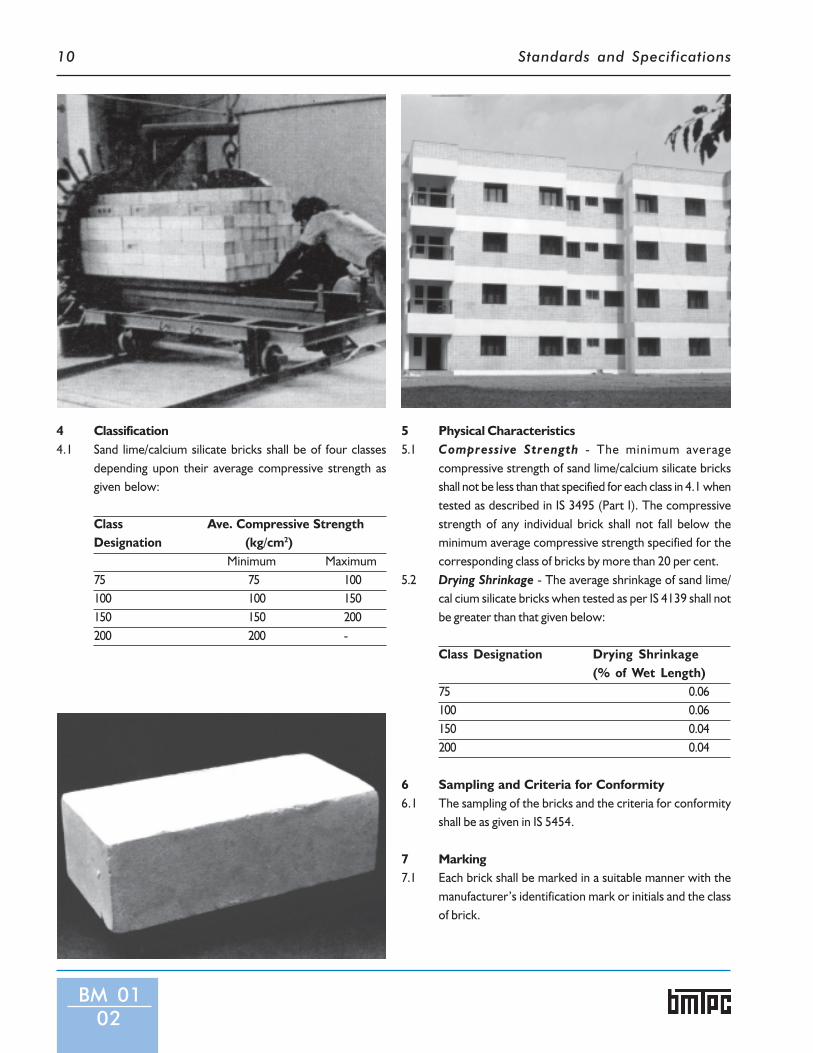
4 Classification4.1 Sand lime/calcium silicate bricks shall be of four classes
depending upon their average compressive strength asgiven below:
Class Ave. Compressive StrengthDesignation (kg/cm2)
Minimum Maximum75 75 100100 100 150150 150 200200 200 -
5 Physical Characteristics5.1 Compressive Strength - The minimum average
compressive strength of sand lime/calcium silicate bricksshall not be less than that specified for each class in 4.1 whentested as described in IS 3495 (Part I). The compressivestrength of any individual brick shall not fall below theminimum average compressive strength specified for thecorresponding class of bricks by more than 20 per cent.
5.2 Drying Shrinkage - The average shrinkage of sand lime/cal cium silicate bricks when tested as per IS 4139 shall notbe greater than that given below:
Class Designation Drying Shrinkage(% of Wet Length)
75 0.06100 0.06150 0.04200 0.04
6 Sampling and Criteria for Conformity6.1 The sampling of the bricks and the criteria for conformity
shall be as given in IS 5454.
7 Marking7.1 Each brick shall be marked in a suitable manner with the
manufacturer’s identification mark or initials and the classof brick.
BM 0102
Standards and Specifications
BM 0201
BM 02
Specificationsfor
Flyash LimeBricks
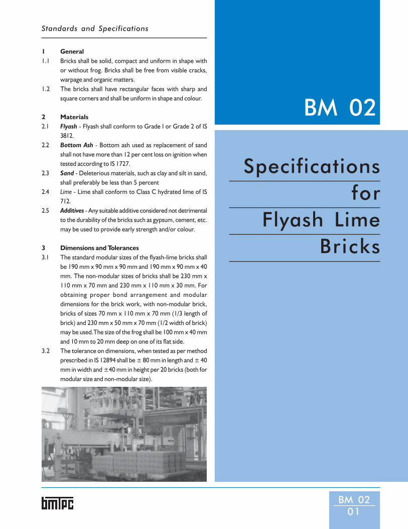
1 General1.1 Bricks shall be solid, compact and uniform in shape with
or without frog. Bricks shall be free from visible cracks,warpage and organic matters.
1.2 The bricks shall have rectangular faces with sharp andsquare corners and shall be uniform in shape and colour.
2 Materials2.1 Flyash - Flyash shall conform to Grade I or Grade 2 of IS
3812.2.2 Bottom Ash - Bottom ash used as replacement of sand
shall not have more than 12 per cent loss on ignition whentested according to IS 1727.
2.3 Sand - Deleterious materials, such as clay and silt in sand,shall preferably be less than 5 percent
2.4 Lime - Lime shall conform to Class C hydrated lime of IS712.
2.5 Additives - Any suitable additive considered not detrimentalto the durability of the bricks such as gypsum, cement, etc.may be used to provide early strength and/or colour.
3 Dimensions and Tolerances3.1 The standard modular sizes of the flyash-lime bricks shall
be 190 mm x 90 mm x 90 mm and 190 mm x 90 mm x 40mm. The non-modular sizes of bricks shall be 230 mm x110 mm x 70 mm and 230 mm x 110 mm x 30 mm. Forobtaining proper bond arrangement and modulardimensions for the brick work, with non-modular brick,bricks of sizes 70 mm x 110 mm x 70 mm (1/3 length ofbrick) and 230 mm x 50 mm x 70 mm (1/2 width of brick)may be used.The size of the frog shall be 100 mm x 40 mmand 10 mm to 20 mm deep on one of its flat side.
3.2 The tolerance on dimensions, when tested as per methodprescribed in IS 12894 shall be ± 80 mm in length and ± 40mm in width and ±40 mm in height per 20 bricks (both formodular size and non-modular size).

Standards and Specifications12
4 Classification4.1 Flyash-lime bricks shall be of the following classes depending
upon their average wet compressive strength:
Class Designation Average Wet CompressiveStrength - Not less thanN/mm2 Kgf/cm2 (Aprox)
30 30.0 (300)25 25.0 (250)20 20.0 (200)17.5 17.5 (175)15 15.0 (150)12.5 12.5 (125)10 10.0 (100)7.5 7.5 ( 75)5 5.0 ( 50)3.5 3.5 ( 35)
5 Physical Characteristics5.1 Compressive Strength - The minimum wet average
compressive strength of flyash-lime bricks shall not be lessthan the one specified for each class in 4.1 when tested inaccordance with IS 3495 (Part 1). The compressive strengthof any individual brick shall not fall below the minimumaverage wet compressive strength specified for thecorresponding class of bricks by more than 20 percent.Note: In case any of the test results of wet compressivestrength exceed the upper limit for the class, the same shallbe limited to the upper limit of the class for the purpose ofaveraging.
5.2 Drying Shrinkage - The average drying shrinkage of thebricks when tested by the method described in IS 4139,being the average of three units, shall not exceed 0.15percent.
5.3 Efflorescence Test - The bricks when tested in accordancewith the procedure laid down in IS 3495 (Part 3), shall havethe rating of efflorescence not more than ‘moderate’ up toClass 12.5 and ‘slight’ for higher classes.
5.4 Water Absorption - The bricks, when tested in accordancewith the procedure laid down in IS 3495 (Part 2), afterimmersion in cold water for 24 h, shall have average waterabsorption not more than 20 percent by weight up to class12.5 and 15 percent by weight for higher classes.
6 Sampling and Criteria for Conformity6.1 Sampling and criteria for conformity of flyash-lime bricks
shall be done in accordance with the procedure laid down inIS 5454.
BM 0202
7 Marking7.1 Each brick shall be marked in a suitable manner with the
manufacturer’s identification mark or initials and the classof brick.

Standards and Specifications
1 General1.1 Bricks shall be made from admixture of suitable soils and
flyash in optimum proportions. The flyash shall conform tograde 1 or grade 2 as per IS 3812.
1.2 Clay-fly ash bricks shall be solid, compact and uniform inshape, size and colour. Bricks shall have rectangular faceswith sharp and square corners. The brick shall be free fromvisible cracks, flaws, warpage, nodules of stone and/or freelime and organic matters. The bricks shall be hand ormachine moulded.
2 Dimensions and Tolerances2.1 The size of clay-flyash bricks shall be as follows:
Modular Sizes:Length (L) Width (W) Height (H)mm mm mm190 90 90190 90 40Non Modular Sizes230 110 70230 110 30For obtaining proper bond arrangement and modulardimensions for the brick work, with non-modular sizes, thefollowing sizes (mm) of brick may also be used:70 110 70 (1/3 length brick)230 50 70 (1/2 width brick)
2.2 Brick of 90 mm or 70 mm height shall be with frog of 100mm in length, 40 mm in width and 10 to 20 mm deep on oneof its flat side.
2.3 The tolerances on dimensions, when tested as per themethod prescribed in IS 13757 shall be ± 80 mm in lengthand ± 40 mm in width and ±40 mm in height per 20 bricks(both for modular size and non-modular size).
3 Physical Characteristics3.1 Classification - Clay flyash bricks shall be classified on the
basis of the average compressive strength as given in Table1.Table 1:Class Designation Average Compressive
Strength - Not less thanN/mm2 Kgf/cm2 (Aprox)
30 30.0 (300)25 25.0 (250)20 20.0 (200)17.5 17.5 (175)
BM 03
Specificationsfor Burnt
Clay-FlyashBricks
BM 0301

Standards and Specifications14
15 15.0 (150)12.5 12.5 (125)10 10.0 (100)7.5 7.5 ( 75)5 5.0 ( 50)3.5 3.5 ( 35)
Notes:(i) In case of any of the test results of wet compressive strength
exceed the upper limit for the class, the same shall be limitedto the upper limit of the class for the purpose of averaging.
(ii) The compressive strength of any individual brick tested shallnot fall below the minimum compressive strength specifiedfor the corresponding class of brick. The lot shall be thenchecked for next lower class of bricks.
3.2 Compressive Strength - The clay flyash bricks, whentested in accordance with the procedure laid down in IS3495(Part-I), shall have a average compressive strength asgiven in Table 1.
3.3 Water absorption - The bricks, when tested in accordancewith the procedure laid down in IS 3495(Part 2), afterimmersion in cold water for 24 h., water absorption shallnot be more than 20 percent by weight upto class 12.5 and15 percent by weight for higher classes.
3.4 Efflorescence - The bricks when tested in accordancewith the procedure laid down in IS 3495(Part 3), the ratingof efflorescence, shall not be more than ‘moderate’ uptoclass 12.5 and ‘slight’ for higher classes.
BM 0302
4 Sampling and Criteria for Conformity4.1 Sampling and criteria for conformity of common clay-flyash
bricks shall be done in accordance with the procedurelaid down in IS 5454.
5 Marking5.1 Each brick shall be marked in a suitable manner with the
manufacturer’s identification mark or initials and the classof brick.

Standards and Specifications
BM 04
Specificationsfor
ClayFlooring
Tiles
1 General1.1 Flooring tiles are unglazed tiles made from natural clays
or shales and burnt to dense mass which are used forflooring of residential, public and industrial buildings.
1.2 Flooring tiles shall be made from good soils of even textureand shall be uniformly well burnt. Tiles shall be uniform insize and shape and shall be free from irregularities, suchas twists, bends, cracks, flaws, laminations andimperfections which affect appearance or serviceability.The faces of tiles shall be plain, grooved, fluted or figuredas specified and the edges shall be square. The back ofthe tiles may have some type of either plain or engravedor embossed design.
1.3 Class I tiles shall be specially hard-burnt as they are meantfor use in industrial flooring where heavy wear isanticipated.
2 Dimensions and Tolerances2.1 Dimensions and shape - The dimensions of the square
tiles shall be as given in Table 1. The tiles & half-tiles, bothrectangular and triangular in shape may also be made. Half-tiles for use with the full tiles shall be such as to make twohalf-tiles, when joined together, match the dimensions ofone full tile.
2.1.1 The dimension and shape of flooring tiles other than squareshall be as agreed to between the purchaser and the vendor.
2.1.2 The depth of the grooves or frogging on the underside offlooring tiles shall not exceed 3 mm.
2.2 Tolerances - The permissible tolerances shall be as under:2.2.1 Length and Breadth-The avenge dimensions of the tile when
measured, as described in 2.2.1.1, shall not vary more than± 5 mm from nominal dimensions and also the dimensionsof the individual tile furnished for a given area or space shallnot vary more than ± 2 mm from the average.
2.2.1.1 The measurement of the dimensions shall be made to thenearest 0.5 mm and the results averaged, the dimensionsshall not include spacers.
2.2.2 Thickness - The average thickness of the tile whenmeasured, as described in 2.2.2.1, shall not vary more than± 2 mm from the nominal thickness, also the thickness ofindividual tile supplied for a given area or a space shall notvary more than ± 1 mm.
2.2.2.1 The thickness of tile shall be measured 10 mm from each ofthe edges of the tile and rounded off to the nearest 0.25mm. Four points in measurement shall be selected to givean average thickness representative of the tile. In case tilehas keys or ribs, these shall be included in the thickness.
BM 0401

Standards and Specifications16
BM 0402
Table 2: Classification of Flooring TilesS.No. Characteristic Requirement for
Class 1 Class 2 Class 31. Water absorption percent, Max 10 19 242. Flexural strength kg/cm width, Min
a) Average 6 3.5 2.5b) Individual 5 3.0 2.0
3. Impact, maximum height in mm of drop of steel ball:a) 15 mm thick 25 20 15b) 20 mm thick 60 50 40c) 25 mm thick 75 65 50d) 30 mm thick 80 70 60
2.2.3 Warpage - When measured asdescribed in 2.2.3.1, the warpageshall not exceed 2 percent along theedges and 1.5 percent along thediagonals.
2.2.3.1 Place a straight edge flat over thetile resting on a plane surface so asto leave maximum gap between thestraight edge and the surface of thetile, as judged by the naked eye.Insert the measuring metallic wedgein the gap and measure the maximumvalue of the gap.
3 ClassificationFlooring tiles shall be of threeclasses, namely, Class 1, Class 2 andClass 3, with the characteristics asspecified in Table 2 and shall satisfythe details of test given in 5.
Table 1:Dimensions of Square TilesS.No. Size (mm) Thickness(mm)1. 150 x l50 mm 15mm2. 150 x l50 mm 20mm3. 200 x 200mm 20 mm4. 200 x 200mm 25 mm5. 250 x 250 mm 30 mm
4 Sampling4.1 For conducting the tests at least six
tiles shall be selected at random forevery 1000 tiles or fraction thereofin a lot. The number of tiles taken
from a lot for tests shall be not lessthan 15 in any one lot.
5 Details of Tests5.1 Water Absorption Test - The
average water absorption of six tiles,when tested by the methoddescribed below, shall conform tothe requirements specified in Table-2.
5.1.1 Dry the six tiles in an oven at atemperature of 100 to 110oC till theyattain a constant weight and thencool; weigh when cool and immersethe dry specimens completely inclean water at 24°C to 30°C for 24h. Remove each specimen, wipe offthe surface water carefully with adamp cloth, and weigh the specimencorrect to a gram, within threeminutes after removing thespecimen from water.
5.1.2 The percentage water absorptionshall be calculated as follows:Percentage water absorption
(B -A)=——— x 100
A
Where A = weight of the dry specimen in g,
and
Where B = weight of the specimen in g after
24 h. immersion in cold water
5.1.3 The average percentage waterabsorption of the six tiles shall becalculated and reported as the
percentage water absorption.5.2 Flexural Strength Test - When
tested as per IS 1478 the averagestrength of six tiles, that is, threetiles in the dry condition and threein the wet condition, shall conformto the requirements specified inTable 2.
5.3 Impact Test - When tested as perIS 1478 the maximum height ofrelease of the steel ball, which doesnot cause a fracture in the tileobtained by tests on threespecimens, shall conform to therequirements specified in Table 2.In case of tiles other than squaretiles, the height of release of the steelball shall be subject to prioragreement between the purchaserand the vendor.
6 Non-Compliance with Tests6.1 If any of the tiles in the sample fails
to comply with the requirements ofany of the tests, another sample shallbe similarly drawn and tested. If anyof tiles in the second sample alsofails to comply with therequirements of any of the tests,then the whole lot, from where thesamples were taken, shall berejected as not complying with thisstandard.
7 Marking7.1 Each tile shall be legibly and indelibly
marked with the name of themanufacturer or his trade mark, ifany, the marking shall not covermore than 5% of the area of thespecimen.

Standards and Specifications
BM 0501
BM 05
Specificationsfor
BurntClayFlat
TerracingTiles
1 General1.1 The terracing tile shall be made from good soil of even
texture and shall be uniformly well burnt They shall beuniform in shape, sizes and shall be free form irregularities,such as twists, bends, cracks and particles of stones. Theface of the tile shall be either plain or grooved but the backof the tile should be corrugated so as to adhere the mortar.
1.2 Burnt clay flat terracing tiles may be machine pressed orhand made and are used for flat roof finishing over limeconcrete or cement concrete base.
A MACHINE MADE TILESThe specifications for machine-made burnt clay flatterracing tiles are as under.
2 Dimensions and Tolerances2.1 The size of terracing tiles shall be as given below:
Length in mm - 150, 175, 200, 225 and 250Width in mm -100,125,150,175 and 200Thickness in mm - 20 and 15
2.2 Tolerance - The tolerances in length, width and thicknessshall be ±2 percent in the case of machine pressed tiles and±3% in case of machine extruded tiles.
3 Physical Characteristics3.1 Water Absorption3.1.1 The average water absorption of the tile when tested by
the method described in 3.1.2 to 3.1.4 shall not exceed 15percent.
3.1.2 Dry the tiles in an oven at a temperature of 100oC to 110o
C till they attain a constant weight and then cool; weighwhen cool and immerse the dry specimen completely inclean water at 24oC to 30o C for 24 h. Remove each specimen,wipe off the surface water carefully with a damp cloth andweigh the specimen correct to a gram within three min.after removing the specimen from water.
3.1.3 The percentage water absorption shall be calculated asfollows:
(B – A)Percentage water absorption = ———x 100
A
WhereA = weight of the dry specimen in g, andB = weight of the specimen in g after 24 h. immersion incold water.
3.1.4 The average percentage water absorption of six tiles shallbe calculated and reported as the percentage water

Standards and Specifications18
absorption.3.2 Flexural Strength - The average
modulus of rupture in bending of sixtiles shall not be less than 20 kg/cm2
when tested as per IS 2690 (Part 1).3.3 Warpage -The maximum warpage
for the tiles measured as describedin 3.4 shall not exceed in anydirection by one percent.
3.4 Place a straight-edge flat over thetile resting on a plane surface so asto leave maximum gap between thestraight-edge and the surface of thetile, as judged by the naked eye,insert the measuring metallicwedge in the gap and measure themaximum value of gap.
4 Sampling and Testing4.1 For conducting the tests specified in
para 3 at least six tiles shall beselected at random for every 1000tiles or fraction thereof in a lot. Thenumber of tiles taken from a lot fortests shall not be less than 15 in anyone lot.
4.2 Tiles shall be tested for waterabsorption and flexural strength. Ifany of the tiles in the sample failsto comply with the requirementsof any of the tests, another sampleshall be similarly drawn and tested.If any of the tiles in the secondsample also fails to comply withrequirements of any of the tests,then the whole lot, from where thesamples were taken shall be rejectedas not complying with the standard.
5 Marking5.1 Each terracing tile shall be legibly
and indelibly marked with indicationof source of manufacture; themarking shall not cover more than5% of the area of specimen. The tilebe also marked by letter 'M' toindicate machine made.
B HAND MADE TILES
1 General1.1 The terracing tile shall be made from
good soil of even texture and shallbe uniformly well burnt. They shallbe uniform in shape and sizes andshall be free from irregularities, suchas twists, bends, cracks and particlesof stones.
1.2 The specifications for hand madeburnt clay flat terracing tiles are asgiven in 2.
2 Dimensions and Tolerances2.1 The size of terracing tiles shall be as
given below:-Length in mm - 150,175,200,225 and250Width in mm - 75, 100, 125, I50, 175and 200Thickness in mm - 25, 30, 35, 40, 45and 50
2.2 Tolerances - The tolerances inlength, width and thickness shall be±3 percent.
3 Physical Characteristics3.1 Water Absorption3.1.1 The water absorption by weight
when tested according to themethod described in IS 3495 (Part2) shall not exceed 20 percent.
3.2 Flexural Strength3.2.1 The modulus of rupture in bending
when tested by the method asdescribed in IS 2690(Part 2) shall notbe less than 15 kg/cm2.
3.3 Warpage3.3.1 The maximum warpage for the tiles
measured as described in 3.3.2 shallnot exceed 2 percent of thedimensions in any direction.
3.3.2 Place a straight-edge flat over thetile resting on a plane surface so asto leave maximum gap between thestraight-edge and the surface of thetile. Judging by the naked eye, insertthe measuring metallic wedge inthe gap and measure the maximumof gap.
4 Sampling and Testing4.1 Sampling and the criteria for
determining the suitability of thehand made tiles shall be as per lS5454.
5 Marking5.1 Each terracing tile shall be legibly
and indelibly marked with indicationof source of manufacture; themarking shall not cover more than5% of the area of specimen. The tilebe also marked by letter 'H' toindicate hand made tiles.
BM 0502

Standards and Specifications
BM 06
Specificationsfor
ReinforcedGypsum
PlasterBoards
BM 0601
1 General1.1 Fibrous Gypsum Plaster Board
A composition of gypsum plaster and sisal, coconut, juteor other fibre forming body of regular dimensions formsthe board.
1.2 Glass Reinforced Gypsum Board (GRG)A composition of gypsum plaster and glass fibre formingbody of regular dimensions forms the board.
1.3 Fibrous Gypsum plaster boards and Glass ReinforcedGypsum boards are used as covering material for walls,ceilings and partitions in normally dry environments inbuildings. These boards have the specific advantage of beinglight weight when compared to other boards of similarnature and have high fire resistant properties.
1.4 The specifications of the boards for use as a lining materialfor ceiling, dry surfacing material for walls are as under:
2 Materials2.1 The gypsum plaster shall comply with the requirements of
IS 8272. For high strength GRG boards, gypsum plaster ofproperties:i) Fineness – Not more than 5 percent retained on BIS
Sieve (75 Micron),ii) Normal Consistency – Min 60 percent, andiii) Compressive Strength – Min 16.0 MPa.By-product gypsum conforming to the requirements of IS12679 shall be used for the preparation of plaster.
2.2 Fibre -The reinforcing fibre may be sisal or a mixture ofsuch sisal fibre and coconut containing not more than 20percent by mass of coconut fibre. It shall be thoroughlyteased and free from dust, grease or other similarsubstances. For GRG Boards, the reinforcing fibre shall beof ‘E-type’ having good chopping characteristics anddispersibility.
2.3 Potable water shall be used for mixing plaster.2.4 The oil and greases used in the preparation of benches and
moulds for casting shall be such as will leave the plastersurface of the product clean and unstained.
3 Methods of Manufacture3.1 Fibre Gypsum Plaster Board
The plaster board shall be manufactured by either of themethods described below:
3.1.1 Method 1a) A steel mould 1 mm thinner than the thickness of the
board required, shall be laid over a concrete casting

Standards and Specifications20
table having smooth trowelled surface or polished stonesurface.
b) The table shall be coated with a thin layer of oil toprevent ht plaster board sticking to the surface.
c) Gypsum plaster shall be gauged to an even consistencyfree from lumps. This shall be spread evenly to coverthe entire surface of the casting table within the mouldto an even thickness of 4 mm and allowed to set partially.
d) The requisite amount of fibre reinforcement shall bedistributed evenly over the surface of the face gauge asto over hang the edges by 50 mm.
e) The requisite amount of body plaster shall then bepoured over the fibre, and the fibre shall be pressed androlled down until it is thoroughly incorporated in thebody plaster.
f) The overhanging fibre shall be turned into the board tostrengthen the edges and the whole board shall then beruled to an even thickness.
3.1.2 Method 2a) A steel mould, 1 mm thinner than the thickness of the
board required, shall be laid over a concrete castingtable having surface trowelled to a high gloss or tablesurfaced with polyester resin.
b) The table shall be coated with a thin layer of oil toprevent the plaster board sticking to the surface.
c) Gypsum plaster shall be gauged to an even consistencyfree from lumps at water-plaster ratio of 0.5 to 0.6.This shall be spread evenly to cover the entire surfaceof the casting table within the mould to an even thicknessof 1.5 to 2.0 mm and allowed to set partially.
d) A plaster of thinner consistency at water-plaster ratioof 0.7 to 0.8 shall be prepared and poured on the bench
BM 0602
to cover it to about the depth of the bench bars.e) When the plaster has spread evenly, teased fibre at the
rate of not less than 250 g/m2 of board shall be spreadover the table. This shall be incorporated into the plasterby running a fluted roller over the table.
f) The overhanging edge of fibre shall be next turned backto strengthen the edges and the plaster ruled off with ascreeding bar to an even thickness.
g) When the sheet has hardened sufficiently, it shall belifted and placed in racks to dry.
3.2 Glass Reinforced Gypsum Boards3.2.1 The GRG Board may be manufactured either by spray
suction technique or premixing method. The main objectivesof these methods is to ensure thorough dispersal of theglass fibre in the plaster slurry.
4 Dimensions and Tolerances4.1 The boards shall be square or rectangular in shape. The
dimensions and tolerances shall be as under:Fibrous Gypsum Plaster BoardDimensions: mm Tolerances: mmLength – 1200, 1500, 1800 +0, -6Width – 400, 600, 900, 1200 +0, -5Thickness – 12 +1, -1Glass Reinforced Gypsum Board (GRG)Dimensions: mm Tolerances: mmLength – 2000, 3000 +0, -6Width – 1000, 1200 +0, -5Thickness – 4, 6, 8, 10, 12 +1, -1
4.2 The minimum mass of plaster per m2 of board shall be 10kg for Fibrous Gypsum Plaster Board and 4-10 kg for1000mm and 6-15 kg, 8-20 kg, 10-25 kg, 12-30 kg for 1200mm for GRG Boards.
4.3 The minimum density for Fibrous Gyspum Plaster Boardshall be 834 kg/m3 and 2500 kg/m3 for GRG Boards.
4.4 The minimum quantity of fibre per square meter of boardshall be 250 g.
5 Finish5.1 The surface of the board shall be true and free from
imperfections that would render the board unfit for uses.The edges shall be straight and corners shall be square.
6 Physical CharactersticsThe tests as described in 6.1, 6.2, 6.3 and 6.4 shall beperformed on the boards:
Standards and Specifications 21
6.1 Visual Inspections6.1.1 All boards shall be sound, free from cracks, broken edges
and such other imperfections.6.2 Thickness
The mean thickness of the board shall be determined asdescribed in IS 2542 (Part 2/Set 1 to 8).
6.3 Transverse/Flexural Strength6.3.1 The test shall be carried out as described in lS 2542 (Part 2/
Sec I to 8). When subjected to a load of 340 N, the deflectionof the specimen shall not exceed 19 mm. Should thedeflection under proof load be less than 6 mm, the loadshall be increased until failure occurs. The specimen shallthen deflect not less than 6 mm before failure occurs.GRG boards when tested as per IS 2542 (Part 2/Set 4) shallhave flexural and impact strength as per the value specifiedbelow:Average Flexural Strength 18 MPa
Minimum Flexural Strength on either Side 15 MPa
Average Impact Strenth 17 Nmm/mm2
Minimum Impact Strength on either Side 14 Nmm/mm2
6.4 Jolting TestThe boards shall be tested in the manner described in IS2095 (Part 3). None of the sample should show crack orchipping off from the surface before 80 cycles of jolting.
6.5 Free MoistureAverage free moisture of the samples shall not exceed 2percent when tested as per IS 2542 (Part 2).
6.6 Surface Hardness TestThe test shall be carried out as described in lS 2095 (Part 3).The diameter of any impression shall not exceed 8 mm forboth the materials.
6.7 Water AbsorptionFor GRG Boards as per IS 2380 (Part 16), the value shall notexceed 15 percent in 24 h.
6.8 SwellingGRG when tested as per IS 2380 (Part 17), the value shallnot exceed 0.5 percent in 24 h.
6.9 Test for Determining Fibre ContentsThe test as specified in IS 2542 (Part I/Sec I to 12) for woodfibre content in wood fibre gypsum plaster shall be used fordetermining the mass of fibre in the board.
7 Sampling and Testing7.1 The number of boards to be selected for the sample from a
lot shall depend upon the size of the lot and shall be asunder:
No.of Boards No.of Permissible Sub-Samplein the Lot Boards to be No.of Size
selected defectives
Upto 100 6 0 3
101 to 150 8 0 3
151 to 300 13 1 4
301 to 500 20 2 5
501 to 1000 32 3 7
1001 and above 50 5 10
7.2 Sampling and criteria for conformity of these boards shallbe done in accordance with the procedure laid in IS 2542Part I and 2/Section 1 to 12 and IS 2095 (Part 1).
8 Specific RequirementsBuilding boards generally used as partitioning, panelling,cladding and false ceiling shall be made from industrial wastessuch as phospho-gypsum.
9 MarkingEach board shall be legibly and indelibly marked orstamped with indication of source of manufacture, size ofboard, year of manufacturer and batch number.
BM 0603

Standards and Specifications
BM 07
SpecificationsforBamboo MatCorrugatedRoofingSheets
1 GeneralBamboo Mat Corrugated Sheet (BMCS) is a sheet made upof adhesive soaked and coated mats assembled and pressedunder specified temperature and pressure to obtainsinusoidal or other suitable corrugations. Bamboo MatCorrugated Sheets (BMCS) are alternate eco-friendly,energy efficient and cost-effective roofing sheets. Thesesheets are resistant to water, decay and fire. They are lightbut strong and possess high resilience and offer thermalcomforts.
2 Dimensions and Tolerances2.1 The sheets shall conform to the dimensions and tolerances
given in Table I and Fig.1.
Table - 1: Dimensions and Tolerances All dimensions in millimeter
Length Width Thickness Depth of Pitch of
(T) Corrugation(D)Corrugation(P)
(1) (2) (3) (4) (5)
1800 1050 3.8 30 120
2140 1050 3.8 30 120
2440 1050 3.8 30 120
Tolerances
±10 mm ±10 mm ±10percent ±2mm -0mm ±2mm
Notes:i. The thickness of the sheets shall be taken as the
average of six measurements and shall be measuredrandomly along the width (except at the valleys) witha suitable screw gauge.
ii. The depth of each of the six corrugations shall bemeasured randomly and the deviation in any of thecases measured shall not exceed the limits, specifiedin Table 1. The gauge shall be measured with suitabledepth gauge.
iii. Tolerances given for pitch of corrugation relate tomeasurement over 6 pitches. The total length over6 pitches shall be mentioned and it shall not varyfrom six times the specified pitch with tolerance.
iv. Any alternate design of corrugation may be used asper agreement between the manufacturer and thepurchaser provided all the requirements of thisstandard are met. In such cases, the manufacturershall specify the corrugation details including a sectionspecifying thickness, depth and pitch and tolerancethereon.
BM 0701

Standards and Specifications 23
2.1.1 Any other dimension as agreed tobetween the manufacturer andpurchaser may also be used.
3 Materials3.1 Bamboo
Any species of bamboo suitable format making may be used for BMCS.
3.1.1 Bamboo MatsBamboo Mats required for themanufacture of BMCS shall becompactly woven in suitable patternfrom slivers of uniform thicknessand width. Thickness of slivers shallbe in the range of 0.6 mm – 0.8 mmand with a minimum width of 5 mm.Care shall be taken to exclude theslivers with epidermal andendodermal layer.
3.1.2 Prophylactic TreatmentIf the storage time including the timeof transportation is one month ormore, the mats shall be given
prophylactic treatment as perGroup 9 in Table 2 of IS 401, IS 1902.
3.2 AdhesiveResin for BMCS shall be of phenolictype conforming to BWP gradespecified in IS 848. For theoutermost layers of mats of BMCS,resin admixed with suitable fillershall be used.
3.3 PreservativePreservative treatment shall begiven by incorporating the suitablepreservatives like sodiumpentachloro phenate into the resinbefore soaking the mats to protectagainst biodegradation.
4 Manufacture4.1 Application of Adhesive
Adhesive shall be applied by soakingthe mats in the adhesive as explainedin 3.2. A second coat of adhesiveshall be applied on the soaked anddried mats which are used as outerlayers, using a mechanical gluespreader.
4.2 Conditioning of Adhesive CoatedBamboo MatsAdhesive coated mats shall be
conditioned to bring down themoisture content to 12, ±2 percent.
4.3 Hot PressingAssembled mats shall be hotpressed to obtain the specifiedproperties.
4.4 Conditioning of BMCSAfter hot pressing the finishedbamboo mat corrugated sheet shallbe stored at ambient conditions atleast for 24 h.
5 Finish5.1 The face of the bamboo mat
corrugated sheet shall be reasonablysmooth and uniform in colour.
5.2 The finished sheets shall be givenbrush coating with light organicsolvent preservatives to avoid fungisgrowth and the edges sealed withsuitable adhesives sealant.
6 Tests & RequirementsBMCS shall conform to therequirements given in Table-2 whentested in accordance with theprovision given in IS 15476.
BM 0702
P
DT
R 24mm
PITCH AND DEPTH OF CORRUGATED SHEETS

Standards and Specifications24
Table 2:
Sl.No. Properties Requirements Method of TestRef to Annexuresof IS 15476
(1) (2) (3) (4)i) Density, g/cm3 0.75, Min Bii) Load bearing capacity, N/mm: C
1. Dry state 4.0, Min2. Wet state 3.0, Min
iii) Impermeability The lower surface shall not show any Dformation of drops of water except fortraces of moisture
iv) Water absorption, 15, Max EPercent (after 24 h soaking)
v.) Cyclic test No delamination Fvi) Resistance to falling weight The test piece shall not break or show G
any crack or tearvii) Resistance to fire: H
1. Flame penetration Not less than 10 min2. Rate of burning Not less than 20 min3. Surface spread of flame, 4500
maximum area of char inmm2
7 Sampling and Criteria forConformity
7.1 Scale of Sampling7.1.1 Lot, in any consignment, all the
sheets of the same size andmanufactured under similarconditions of production shall begrouped together to constitute alot.
7.1.2 All the sheets in the lot shall beinspected for finish requirement asgiven in 5. The defective sheetsshall be removed from lot.
7.1.3 The lot shall then be examined fordimensional requirements. For thispurpose, the number of sheets tobe selected at random from the lotshall be in accordance with IS15476.
7.1.3.1These shall be selected from thelot at random. In order to ensurethe randomized of selection, theprocedure given in IS 4905 may befollowed.
BM 0703
7.2 Criteria for Conformity7.2.1 All the sheets selected in
accordance with IS 15476, shallbe subjected to dimensionalrequirement. A sheet failing tosatisfy the requirements mentionedbelow shall be termed as defective.The lot shall be considered asconforming to dimensionalrequirements, if the number ofdefectives found in the sample isless than or equal to thecorresponding acceptance numbergiven in IS 15476, otherwise thelot shall be rejected withoutfurther testing.
7.2.2 The lot which has been found asconforming to the dimensionalrequirements shall be tested as perTable 2. For this purpose, the samesize shall be in accordance with IS15476.
7.2.3 A lot shall be considered asconforming to the requirements of
IS 15476, if 7.2.1 and 7.2.2 aresatisfied.
8 Marking8.1 Each BMCS shall be legibly and
indelibly marked or stamped withindication of source ofmanufacture, nominal dimension,year of manufacture and batchnumber.
8.2 Each markings shall be done on theface of the sheet near on edge.

Standards and Specifications
BM 08
Specificationsfor
MicroConcrete
RoofingTiles
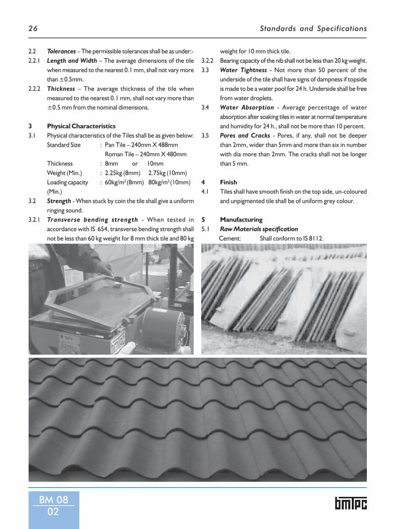
1 General1.1 Micro Concrete Roofing (MCR) tiles are precast tiles made
out of a mix of micro chips (4mm down), coarse sand andcement. These are made on a table vibrator. Tiles thusmade are strong, durable and economical.
1.2 MCR tiles are energy efficient, eco-friendly and low costroofing elements made from a carefully controlled mix ofcement, sand fine stone aggregate and water. The MCRtiles can be made in two distinctive profiles namely Pan andRoman. They are designed to meet high quality standards instrength, shape and colour and are therefore, acceptable toboth the rural and urban markets. MCR is suitable in allplaces where a need for reliable, affordable and aestheticroofing material exists. MCR roofing is similar to roofingmaterials like clay tiles or sheets.
1.3 The MCR technology provides an inexpensive and reliableroof covering and is specially suited for the needs ofdeveloping countries.
2 Shape, Dimensions and Tolerances2.1 Shape of the Pan and Roman tile shall be as given in Fig.1 and
Fig.2. The nominal dimensions of the tile shall be as givenin Table 1.Table 1
Pan Tile Roman TileClear length 488 mm 480 mmClear width 240 mm 240 mmThickness 8 mm or 10 mm 8 mm to 10 mmCorrugation depth 55 mm 55 mm
BM 0801
240
3025 40
Fig.1PAN TILE
Fig.2ROMAN TILE
Standards and Specifications26
2.2 Tolerances – The permissible tolerances shall be as under:-2.2.1 Length and Width – The average dimensions of the tile
when measured to the nearest 0.1 mm, shall not vary morethan ±0.5mm.
2.2.2 Thickness – The average thickness of the tile whenmeasured to the nearest 0.1 mm, shall not vary more than±0.5 mm from the nominal dimensions.
3 Physical Characteristics3.1 Physical characteristics of the Tiles shall be as given below:
Standard Size : Pan Tile – 240mm X 488mmRoman Tile – 240mm X 480mm
Thickness : 8mm or 10mmWeight (Min.) : 2.25kg (8mm) 2.75kg (10mm)Loading capacity : 60kg/m2 (8mm) 80kg/m2 (10mm)(Min.)
3.2 Strength - When stuck by coin the tile shall give a uniformringing sound.
3.2.1 Transverse bending strength - When tested inaccordance with IS 654, transverse bending strength shallnot be less than 60 kg weight for 8 mm thick tile and 80 kg
weight for 10 mm thick tile.3.2.2 Bearing capacity of the nib shall not be less than 20 kg weight.3.3 Water Tightness - Not more than 50 percent of the
underside of the tile shall have signs of dampness if topsideis made to be a water pool for 24 h. Underside shall be freefrom water droplets.
3.4 Water Absorption - Average percentage of waterabsorption after soaking tiles in water at normal temperatureand humidity for 24 h., shall not be more than 10 percent.
3.5 Pores and Cracks - Pores, if any, shall not be deeperthan 2mm, wider than 5mm and more than six in numberwith dia more than 2mm. The cracks shall not be longerthan 5 mm.
4 Finish4.1 Tiles shall have smooth finish on the top side, un-coloured
and unpigmented tile shall be of uniform grey colour.
5 Manufacturing5.1 Raw Materials specification
Cement: Shall conform to IS 8112.
BM 0802
Standards and Specifications 27
Fine Aggregate: Sand or crusher dust passing through4.75mm sieve shall be free from clay andsilt.
Sand: Should conform to the following grading:Sieve size Percent passing through10mm 1004.75mm 90-1002.36mm 75-1001.18mm 55-70600microns 35-59300microns 8-30150microns 0-10Water: Potable, free from organic matter
Chlorides & sulphates should not exceedpermissible limits specified in IS 456.
Water Cement Ratio : 0.5 - 0.65.2 Material preparation - Generally, proportions of
cement, sand and aggregate used shall be 1:2:1 by volume.Proper mix ratio is necessary for optimising the materialsuse and for achieving high strength tile without fine cracks& air bubbles and with low water absorption. With anychange of raw material proportion shall be reviewed to getproper result.
5.3 Casting of tiles - The tiles shall be casted on a Tile MakingMachine after placing plastic sheet in position on vibratingplate. The operation should not take more than 30 - 35seconds. After casting of tile Nib shall be casted. The castedtile shall be placed carefully on the mould to take the shape.
5.4 Mould curing - The curing shall start immediately afterthe product has been cast. The tiles shall be stacked in anairtight manner or covered within 5 minutes after casting.Tiles shall be cured in a horizontal position while still onthe mould, by covering their surface with plastic sheets orstacking with moulds that guarantee airtight and damp proofstacking. The mould shall be placed on a flat surface withfresh tile lying flat on it. Second mould shall be placed carefulenough on the first mould without damaging the edges oftile in the mould underneath. Make sure moulds fit witheach other airtight. All the moulds shall be placed in stacksupto 1m high for the first day curing. Care shall be taken tocover the uppermost tile with cover. The moulds shall bekept in the same position for 24 h.
5.5 Demoulding - Demoulding of tiles shall be done after 24 hof casting.
5.6 Moulds and polythene sheets shall be thoroughly cleanedafter each use.
5.7 Water Tank Curing - After the tiles have been cured for24 h in a horizontal position, they shall be carefully movedto the curing tank, where they shall be kept completelyunder water in a vertical position for atleast 5 days.
5.8 Depending upon the choice of customer/end user, the tileshall be painted by standard procedure.
6 Sampling and Testing6.1 1 percent or more tiles from the daily production stock
shall be tested regularly.6.2 Test6.2.1 Pores and Cracks - Every tile shall be visually checked
for pores and cracks as mentioned in 3.5.6.2.2 Ring Test - Every tile shall be tested. The test is done by
taping the tile with a coin or a stone. A clear ringing soundshall be heard. If there is a dull sound, the tile is probablycracked and shall be rejected.
6.2.3 Water Tightness Test - 1percent of the tile shall be tested.It shall be as per 3.3.
6.2.4 Bending Test - The strength of tile shall be as per 3.2.1.6.2.5 Weight Test - Take 4 randomly chosen tile from each
week’s production. Store them and dry for 24 h and weightthem. The weight of the tile shall not differ more than 10percent from the weight as mentioned in 3.1.
6.2.6 Nib Tensile Test - 1 percent of the tile shall be tested bysuspending a 20 kg weight on the loop of the nib. The nibshould bear a 20 kg weight without cracking.
6.2.7 If any of the tiles in the sample fails to comply with therequirements of any of the tests, another sample shall besimilarly drawn and tested. If any of the tiles in the secondsample also fails to comply with requirements of any of thetests, then the whole lot, from where the samples weretaken shall be rejected.
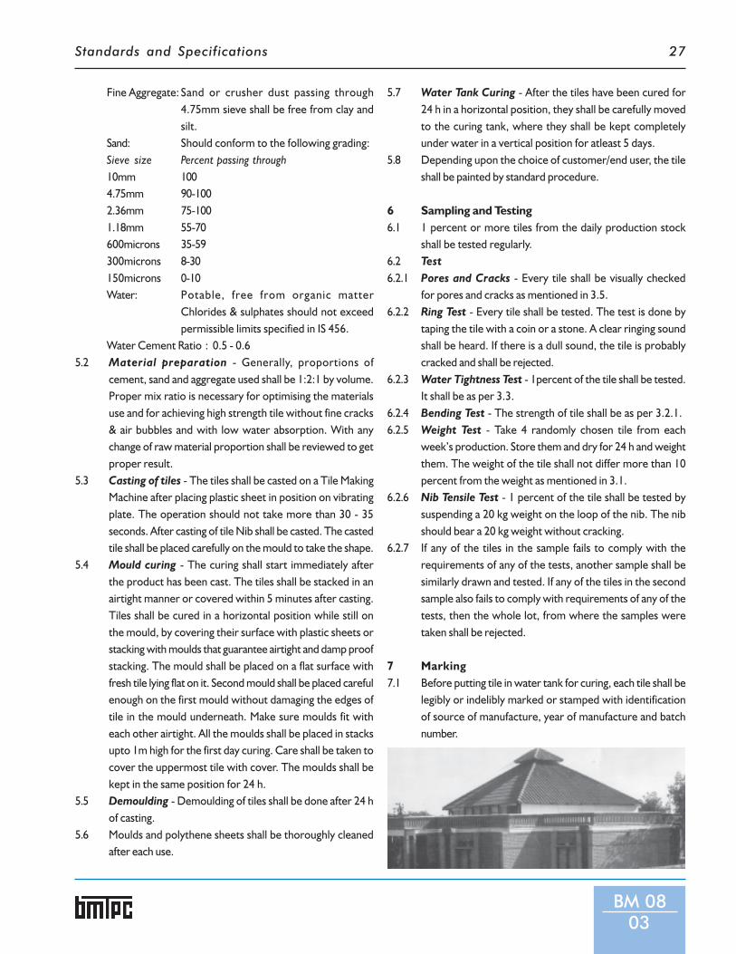
7 Marking7.1 Before putting tile in water tank for curing, each tile shall be
legibly or indelibly marked or stamped with identificationof source of manufacture, year of manufacture and batchnumber.
BM 0803

Standards and Specifications28
List of Indian Standards referred in this Section
BUILDING MATERIALS
1. IS 401:2001 Preservation of Timber - Code of Practice
2. IS 456:2000 Plain and Reinforced Concrete - Code of Practice (Fourth Revision)
3. IS 654:1992 Clay Roofing Tiles, Mangalore Pattern - Specification
4. IS 712:984 Specification for Building Limes (Third Revision)
5. IS 848:2006 Synthetic Resin Adhesives for Plywood (Phenolic and Aminoplastic) - Specification
6. IS 1478:1992 Clay Flooring Tiles – Specification
7. IS 1727:1967 Methods of Test for Pozzolanic Materials (First Revision)
8. IS 1902:1993 Preservation of Bamboo and Cane for Non-structural Purposes - Code of Practice
9. IS 2095:1996 (Part 1) Specification for gypsum plaster boards Part 1 Plain gypsum plaster boards
10. IS 2095:1996 (Part 2) Gypsum Plaster Boards - Specification Part 2 - Coated/Laminated Gypsum PlasterBoards
11. IS 2095:1996 (Part 3) Gypsum Plaster Boards - Specification Part 3 - Reinforced Gypsum Plaster Boards
12. IS 2380:1977 (Part 1 to 21) Method of Test for Wood Particle Boards and Boards from other LignocellulosicMaterials
13. IS 2542:1978 (Part 1/Set 1 to 12) Methods of Test for Gypsum Plaster, Concrete and Products - Part 1 : Plaster andConcrete (First Revision)
14. IS 2542:1981 (Part 2/Set 1 to 8) Methods of Test for Gypsum Plaster, Concrete and Products - Part 2 : Gypsum Products
15. IS 2690:1993 (Part 1) Burnt Clay Flat Terracing Tiles - Specification Part 1: Machine Made
16. IS 2690:1993 (Part 2) Burnt Clay Flat Terracing Tiles - Specification Part 2: Hand Made
17. IS 3495:1992 (Part 1) Methods of Tests of Burnt Clay Building Bricks - Part 1: Determination of CompressiveStrength (Third Revision)
18. IS 3495:1992 (Part 2) Methods of Tests of Burnt Clay Building Bricks - Part 2 : Determination of WaterAbsorption (Third Revision)
19. IS 3495:1992 (Part 3) Methods of Tests of Burnt Clay Building Bricks - Part 3 : Determination of Efflorescence(Third Revision)
20. IS 3812:1981 Specification for Fly Ash for Use as Pozzolana and Admixture (First Revision)
21. IS 4139:1989 Calcium Silicate Bricks – Specification (Second Revision)
22. IS 4905:1968 Methods of Random Sampling – Specification
23. IS 5454:1978 Methods of Sampling of Clay Building Bricks (First Revision)
24. IS 8112:1989 43 Grade Ordinary Portland Cement – Specification
25. IS 8272:1984 Specification for Gypsum Plaster for Use in the Manufacture of Fibrous Plaster Boards(First Revision)
26. IS 12894:2002 Pulverized Fuel Ash-Lime Bricks - Specification (First Revision)
27. IS 13757:1993 Burnt Clay Fly Ash Building Bricks – Specification
28. IS 15476:2004 Bamboo Mat Corrugated Roofing Sheets - Specifications
Note: Indian Standards are subjected to revision from time to time. The actual version at the time of preparing this document hasbeen listed. Users may, however, check for the latest version of the referred Standards from BIS.

Standards and Specifications 29
Construction Techniques


Standards and Specifications
1 GeneralThese are full span precast RCC units-trough shaped insection. These can be used for intermediate floors androof on suitable supporting structures. These do notrequire any in-situ structural concrete over them, nor anyintermediate temporary props or supports. The units arestrong enough for the full span for which these aredesigned.
2 Dimensions and Tolerances2.1 Dimensions2.1.1 The cross-section of the unit is channel shape (Inverted
Trough) with outer sides corrugated and grooved at theends to provide shear key action and transfer of momentsbetween adjacent units (Fig.1 and 2).
2.1.2 Nominal width of the unit shall be 300mm or 600mm andoverall depth 150mm or 200mm. The length of the unitmay be adjusted to suit the span to be covered. However,from stiffness consideration, maximum length shall notexceed more than 4.5m. Actual cross sectional dimensionsof a 300mm unit shall be 295mm x 145mm with a minimumflange thickness of 30mm, and minimum thickness of web25mm (Fig 2).
2.1.3 In case of 600 mm unit, the cross sectional dimensionsshall be 595mm x145mm or 595mm x195mm with aminimum flange thickness of 35mm and minimum webthickness of 25mm.
2.1.4 When the units are placed side by side, the corrugatedsides of the units provide space which shall be filled within-situ concrete to provide monolithicity between theunits and helps in transferring the load in transversedirection.
2.2 Tolerances2.2.1 Tolerances on various dimensions of channel units shall
be length ±5mm, width ±3 mm, Bow (deviation fromintended line or plane) ±3 mm, Twist (distance of anycorner from the plane containing other three corners)±3 mm.
2.2.2 For squareness of the corner, the longer of the two sidesbeing checked, shall be taken as the base line. The shorterlength shall not vary in length from the perpendicular bymore than 3 mm.
2.2.3 For flatness, the maximum deviation from a 1500mmstraight edge placed in any position on a nominal planesurface shall not exceed 2mm.
CT 01
Specificationsfor
PrecastChannelUnit forFloors/
Roofs
CT 0101

Standards and Specifications32
CT 0102
3 Structural Design3.1 The channel units shall have
adequate strength and stability inaccordance with IS 456 duringvarious stages namely demoulding;handling; stacking; transporting andplacing; final stage with all designdead and imposed loads acting onthe roof/floor.
3.2 The unit shall be designed eithersimply supported or continuousdepending upon actual endconditions. Main reinforcement shallbe either designed or shall be as perIS 14215 for residential loads.
3.3 Design Stage 1 (Just afterplacing of in-situ concrete)
3.3.1 At the time of laying the units, theload comprises of self weight of thechannel unit, weight of in-situconcrete in the joint between twounits and also the incidental live load,likely to act on the structure at thisstage. Incidental load may be takenas half the imposed load likely to acton the structure at final stage asrecommended in IS 875 (Part 2).
3.3.2 Effective Section - At this stage ofloading, as the in-situ concrete hasnot attained any strength to ensuremonolithicity, the effective width ofchannel unit shall be taken as widthof flange portion only.
3.4 Design Stage 2 : (With FullDesign Load)
3.4.1 Loads - At this stage, the loadsacting on the structure shallcomprise dead load and full imposedload as per IS 875 (Part 2). This shallbe the maximum load likely to acton the structure during its lifetime.For calculating the limit state ofcollapse at the critical section, acombined load factor of atleast 1.5shall be applied for calculating thelimit state of collapse load.
3.4.2 Effective Section - As the in-situconcrete has attained strength at thisstage, an effective width equal to thenominal width (see Fig 1 and 2) ofthe unit shall be taken for calculatingthe strength of the section.
3.5 Design Bending Movement andShear Force - When the floors/roofs consist of three or morecontinuous and approximately equalspans, the values of BendingMoments and Shear Forcecoefficient given in IS 456 may beused. These coefficients shall be usedfor imposed live load as well as dead
load of finishing but not for deadweight of units (including that of in-situ concrete). To the bendingmoment and shear forces so foundout, simply supported movementand shear force due to dead weightof units (including that of in-situconcrete) shall be added.
3.6 In-situ concrete, which bringsmonolithic connection andcontinuity between precast units,shall be designed in accordance withIS 3935.
3.7 When precast units are used for theconstruction of buildings in high
Fig.01
Corrugations
10mm projections
Flat part
CHANNEL UNIT TOP PLAN
55 30 40 30 40 30 40 30
300
1029
510
1515
ALL DIMENSIONS ARE IN mm
c c
A
A
B
B

Standards and Specifications 33
CT 0103
seismic zones the floors and roofshall be strengthened in accordancewith clause 9 of IS 4326.
3.8 Reinforcement3.8.1 Main reinforcement of the channel
units shall comprise two bars ofrequired diameter as per the designplaced at the bottom of two legs ofchannel unit. Two bars of mild steelgrade I conforming to IS 432 (Part1), 6mm φ shall be provided at thetop corners to support the stirrups(see Fig.1 and 2). Stirrups of 3 mm φ
at the rate of 300 mm c/c along thelength of the channel unit (see Fig.2)shall be provided.
3.8.2 Cover to Reinforcement - Theminimum cover to reinforcementshall be 15 mm.
4 Materials4.1 Concrete - The concrete used for
making precast units shall conformto grade M-20 or higher inaccordance with IS 456. Coarseaggregate used for making concreteshall be well graded with maximum
size of 12 mm.4.2 Steel Reinforcement - The
reinforcing shall be asrecommended in IS 456.
5 Manufacturing of Precast Unit5.1 Moulds5.1.1 The mould consist of two parts -
the outer frame and the innerframe. Typical sketches showingdetails of various components ofmould are given in Fig.3.
5.1.2 The mould shall be made from wellseasoned timber or steel or otherrigid, non- corrodible and non-absorant materials such as fibrereinforced plastic. In case timbermould is used for the inner troughframe, the surface shall be lined withGI sheet.
5.1.3 Dimensions of the mould shall beselected depending upon the size ofchannel units. Tolerances on mouldshall be length ±4mm, width andthickness ±2mm and warp/bow±2mm.
5.2 Manufacturing of Channel Units5.2.1 The inner side of outer frame of the
mould shall be applied with a bondreleasing agent and placed onsmooth and level concrete platformon which a bond releasing agent hasbeen applied.
5.2.2 The reinforcement cage shall beplaced in position. It shall be ensuredthat the reinforcement is notdistorted, in any way, during storage,handling, placement and concreting.
5.2.3 The concrete shall be placed in theflange portion in such a way as toavoid segregation upto such a heightthat it achieves a thickness equal tothe flange of the unit aftercompaction. The concrete shall thenbe compacted with plate vibrator.
5.2.4 The trough frame applied with bondreleasing agent on the outer survace
2515
130
/ 200
1510
5
265 / 565
1510
5
295 / 595SECTION AT A-A
ELEVATION C-C
Corrugations 20 dia
10 mm projections
Flat Part
SECTION OF A CHANNEL UNIT
5
ALL DIMENSIONS ARE IN mm
Fig.02
SECTION AT B
25 245 / 545 25
170 / 470
50 195 / 495 50
295 / 595
300 / 600
130
/ 200
30 / 356mm dia M.S. or tor bar
Stirrups 3 dia @ 300 c/cTwo legged M.S. Wire
Reinforcement as per design
SECTION AT B-B

Standards and Specifications34
CT 0104
50 25 50450
5075
4050
Fly Nut
Trough lined with G.I. Sheet
Wooden Stiffners 40mm th @ 600mm c/c
Longitudnal Members out of 50x130 mm
12mm dia Hole
12mm Bolt
M.S.Angle 50x50x5 mm
5022
0
TOP PLAN OF MOULD
502550
ALL DIMENSIONS ARE IN mm
Fig.03A
175

Standards and Specifications 35
(i.e. the surface facing concrete) shallbe kept inside the outer frame andflange concrete shall be levelled bymoving the trough frame to and fro.Afterwards the trough frame shallbe fixed in position with the outerframe.
5.2.5 The Web (leg) portion of the channelunit shall now be filled with concretecompacted by vibration with a platevibrator/needle vibrator and finishedlevel.
5.2.6 The trough frame may be removedgently after about 1 h (dependingupon the weather) after casting. Theouter frame may also be stripped
off after about 3 h (depending uponthe weather) after casting. The unitsshall be left undisturbed for about48 h and shall be kept wet duringthis period by occasional sprinklingof water or by covering by wetgunny bags.
5.2.7 Curing - After about 48 h the unitsshall be turned upside down so thatthe flange is brought to the top. Theunits shall then be transported tocuring yard by supporting near theends and stacked with the trough(flange) facing up. The units shall becured for atleast 12 days by keepingthe tough filled with water and
further air-cured for another 14 daysbefore placing it in position in abuilding.
6 Storage, Transportation andErection of Precast Elements
6.1 Handling and Transportation ofUnitsThe precast units shall be handledby placing slings placed at about 1/5of span from ends. Care shall betaken to see that no support is placedat the centre of span and the mainreinforcement is always at thebottom of stacked units, that istrough shall be facing downwards.
6.2 Transportation
CT 0105

Standards and Specifications36
TIMBER MOULD
SECTION AT A
M.S. angle 40 x 40 x 5mm
Trough lined with G.I. Sheet
450
4080
25
15 170 15
130
50 25 510mm dia bar projecting out by 25mm @ 1.2m C/C
M.S. Flat 30x5 mm cut to 45 slopeWood end piece 130x50 mm
10mm dia bolt
M.S. Angle 50x50x5 mm
DETAIL XSmooth level Platform
End View of Long Side Mould
ALL DIMENSIONS ARE IN mm
40
42
50
40
42
50
130/
200
520
1520
2020
30
251510
CT 0106
30
30
30
30
55
40
40
40
55
130
Fig.03B

Standards and Specifications 37
CT 0107
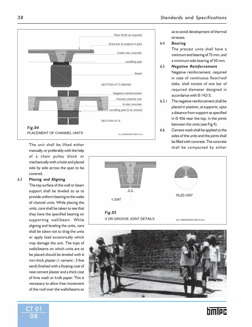
Fig.04
PLACEMENT OF CHANNEL UNITS
Levelling pad (1:4c mortar)
Precast channel unit
In-situ concrete
SECTION AT C (WALL)
75
In-situ concrete
M.S. bars placed in joint
Levelling pad (1:4c mortar)
Wall
SECTION AT A
L/5
230115
75
In-situ concrete
Wall
Pre cast Channel Unit
Wall or Beam
TOP PLAN OF CHANNEL UNITS
B
A
C
D E
50
ALL DIMENSIONS ARE IN mm
Negative reinforcementIn-situ concrete
Precast channel unit
Levelling pad (1:4c mortar)
SECTION AT B
Standards and Specifications38
CT 0108
The unit shall be lifted eithermanually, or preferably with the helpof a chain pulley block ormechanically with a hoist and placedside by side across the span to becovered.
6.3 Placing and AligningThe top surface of the wall or beamsupport shall be leveled so as toprovide uniform bearing to the websof channel units. While placing theunits, care shall be taken to see thatthey have the specified bearing onsupporting wall/beam. Whilealigning and leveling the units, careshall be taken not to drag the unitsor apply load eccentrically whichmay damage the unit. The tops ofwalls/beams on which units are tobe placed should be leveled with 6mm thick plaster (1 cement : 3 finesand) finished with a floating coat ofneat cement plaster and a thick coatof lime wash or kraft paper. This isnecessary to allow free movementof the roof over the walls/beams so
as to avoid development of thermalstresses.
6.4 BearingThe precast units shall have aminimum end bearing of 75 mm, anda minimum side bearing of 50 mm.
6.5 Negative ReinforcementNegative reinforcement, requiredin case of continuous floor/roofslabs, shall consist of one bar ofrequired diameter designed inaccordance with IS 14215.
6.5.1 The negative reinforcement shall beplaced in position, at supports, uptoa distance from support as specifiedin IS 456 near the top, in the jointsbetween the units (see Fig.4).
6.6 Cement wash shall be applied to thesides of the units and the joints shallbe filled with concrete. The concreteshall be compacted by either
Negative reinforcement
Precast channel unit
In-situ concrete
Levelling pad (1:4c mortar)
Levelling pad
Beam
Castin-situ concrete
Extra bar at support in joint
Floor finish as required
PLACEMENT OF CHANNEL UNITS
SECTION AT E
SECTION AT D (BEAM)
ALL DIMENSIONS ARE IN mm
Fig.04
Fig.05V OR GROOVE JOINT DETAILS ALL DIMENSIONS ARE IN mm
55

Standards and Specifications 39
FIXING OF WOODEN PLUG
FIXING OF FAN HOOK
8013
020
0
50 300300
Precast channel unit
12mm dia fan hook
ALL DIMENSIONS ARE IN mm
30 x 30 wooden plug
Cast-in-situ conc.
Little chipping for accomodating fan hook
12 mm dia. fan hook
200
CT 0109
Fig.06
Fig.07

Standards and Specifications40
CT 0110
vibration or rodding.
7 Curing of In-situ Concrete7.1 In-situ concrete shall be cured for
atleast one week. A coat of cementslurry may then be applied to thejoints to fill the hairline cracks thatmight have developed.
8 Fixtures8.1 Designers shall indicate provisions
for fixtures like fanhooks/inserts/electric conduits, etc, to beincorporated within the precastunits or in-situ joints. Some typicalillustrations are given for guidancein 8.1.1 to 8.1.3.
8.1.1 In case of concealed wiring, conduits
may be placed within the joints alongthe length or within the screedwherever it is provided beforeconcreting. If adequate thickness isavailable, it can be concealed withinthe floor/roof finish.
8.1.2 Holes, openings and fixturesrequired to be provided within theprecast units shall be fixed accuratelywith adequate embedment at theprecasting stage. Drilling of holesor cutting of edges shall not bepermitted.
8.1.3 For fixing fan hooks, electric junctionboxes and wooden plugs shall be asgiven in 8.1.3.1 to 8.1.3.3.
8.1.3.1 Fan Hooks - These may beprovided in the cast in-situ concrete
of the units by slightly chipping offthe edges of the units at the locationof the fan (see Fig.6).
8.1.3.2 Electric Junction Boxes - Thesemay be fixed with rawl plugs in thecast in-situ joint between units orembedded during filling of the joint.
8.1.3.3 Wooden Plugs - Wooden plugs forelectrical wiring or any other fixtureshall be provided as illustrated inFig.7.
9 Projection of Balcony9.1 In case of projection in the same
direction as the length of units, theunit itself can be projected out forshort cantilever by designing andproviding necessary reinforcement
Main Reinforcement
Secondary Reinforcement
In situ Concrete
Precast Channel
Levelling Course
Brick WorkCANTILEVER
CANTILEVER
Brick on Edge
Floor finish
Pre cast Channel
ALL DIMENSIONS ARE IN mmBALCONY OR CHAJJAFig.08

Standards and Specifications 41
for cantilever moment in accordancewith IS 456. However, care shall betaken to see that the projecting partof the precast channel unit is keptsupported till in-situ concrete in thejoint hardens. Alternatively, thecantilever can be cast in-situ. In sucha case, reinforcement shall be keptprojecting out from units or fromthe joints between the units asshown in Fig.8.
9.2 No person should be allowed towalk on the floor or roof for atleast3 days after the in-situ concrete hasbeen laid in the joints between theunits.
10 Floor/Roof Finishing10.1 Floor/roof finishing as desired may
be provided directly over the slaberected by using these units.Guidance in this connection may betaken by referring to the relevantIndian Standards. For water proofingtreatment of roofs IS 1346, IS 4365,IS 3036 and IS 9918 may be referred.
10.2 The joints in the ceiling may befinished with deep ruled lines forbetter appearance (see Fig.5). Theruled joints also have the addedadvantage as they conceal the cracksat the joint, which are likely to occurdue to differential shrinkage of in-situ joint concrete and the concretein precast units as well as anydifference in the thickness of theunits.
11 Precautions During and AfterConstruction
11.1 During construction, no heavyloading should be permitted overthe units until the cast in-situconcrete filled in the joints attainsfull strength.
11.2 During all stages of erection, the
units should be handled so that themain reinforcement is always on theunderside only.
11.3 The units should be stacked on alevel ground sprinkled with a thinlayer of sand in single tier ormultiple tiers up to a maximum of5.
11.4 In-situ concreting in the jointsbetween adjacent units at their endsalong the length should also beproperly compacted and its watertightness ensured so as to avoidmoisture ingress.
12 Sampling12.1 All the precast reinforced concrete
units of the same size, manufacturedfrom similar materials and undersimilar conditions of productionshall be grouped together toconstitute a lot.
12.2 Five units shall be selected at randomout of a lot consisting of 300 unitsor less. For lots bigger than 300units, 5 units shall be selected forevery 300 units or part thereof. Inorder to ensure randomness ofselection, procedure given in IS4905may be followed.
13 TestsTests shall be conducted on samplesof the units as given in IS 14215.
14 Criteria for Conformity14.1 If four out of the five samples satisfy
the dimensional requirements, thelot represented by the sample shallbe deemed to have passed thedimensional requirements. If morethan one unit fails to satisfy thedimensional requirements, the lotrepresented by the sample shall berejected.
14.2 In the deflection recovery test, if the
deflection 24 h after the removal ofthe imposed load is atleast 75% ofthe deflection under the load for 24h, the unit shall be deemed to havepassed the test. If the deflectionrecovery is less than 75%, the lotrepresented by the unit shall berejected.If the maximum deflection in mmshown during 24 h under load is lessthan 4012/D, where I is the effectivespan 1 in mm and D, the overalldepth of the section in mm, it is notnecessary for the deflectionrecovery to be measured and therecovery provision mentioned inthis clause earlier will not apply.
14.3 In the failure load test, the unit shallcarry a load atleast equal to 1.33times the characteristic load to passthe test. If the load at failure is lessthan twice the characteristic load, thelot represented by the sample shallbe rejected.
15 Marking15.1 Each channel units manufactured in
accordance with this specificationshall legibly and indelibly markedwith identification of the source ofmanufacture and month and year ofmanufacture.
CT 0111
Standards and Specifications
CT 02
SpecificationsforPrecastRC Planksand JoistsforFloors & Roofs
CT 0201
1 General1.1 Precast Reinforced Cement Concrete (RC) planks are
partially precast rectangular slab elements. These aresupported over partially precast RC joists side by side andthen joined together and also to the joint by pouring in-situ concrete over the haunches provided in the planksand the gaps between the planks over the joists.Monolithic action of the slab elements is ensured by leavinghooks projecting out of joists and providing reinforcementacross the joists over haunched portion of planks, tyingthem together and pouring in-situ concrete over them.
2 Dimensions and Tolerances2.1 The floor/roof shall consist of precast R.C.planks and
partially precast R.C.joists with cast in-situ reinforcedcement concrete as shown in Fig.l.
2.1.1 Precast R.C. Planks - The plank (Fig.2) shall be madepartly 30 mm and partly 60 mm thick. A 100 mm widetapered concrete filling shall be provided for strengtheningthe haunch portion for shear during handling and erection.Length of tapered concrete filling at both ends shall be kept300 mm for all length of planks and the length of central 60mm thick portion shall be decreased for length of plankssmaller than 1.5 m. The plank shall be made up of nominalMS reinforcement as per structural design and concrete ofgrade not less than M-20. The width of the plank shall be300 mm and the maximum length 1500 mm. However, tosuit to the room size, the width may be suitably changed to±50mm. Smaller lengths requires for varying roomdimensions may also be casted. However, it is prefarable touse lengths in multiples of 300 mm only, keeping in viewthe requirement of modular co-ordination.
2.1.2 Partially Precast RC Joists - The width of precast joist(Fig.3) shall be kept equal to required width of web of T-beam (IS 13994) and the depth shall be kept equal to therequired overall depth of T-beam less the thickness of flangei.e. the maximum thickness of RC planks (60 mm).
2.2 Tolerances2.2.l. Casting tolerances on plank shall be, length ±5mm, width
±3mm, thickness ±2mm, Bow (diviation from intendedline or plane) ±2mm, and Twist (distance of any cornerfrom the plane containing other 3 corners) ± 1mm.
2.2.2 For squareness, the long edge of planks shall be taken as thebase line. The shorter side shall not vary in its length fromperpendicular distance between long edges by more than3mm.
2.2.3 The maximum deviation for flatness from a 1.5m straight

Standards and Specifications 43
edge placed in any position on anominal plane surface shall notexceed 2mm.
2.2.4 Casting tolerance for joist shall belength ±8mm, width ±3mm,thickness ±3mm.
3 Structural Design3.1 The design shall be as per limit state
method in accordance with IS 456.Design load on various componentsof the flooring/roofing shallcomprise of self weight, imposedload in accordance with IS 875 (Part-2) and dead load due to floor finishin case of intermediate floors anddead load due to roof treatment incase of roofs shall be in accordancewith IS 875 (Part 1).
3.1.1 Precast R.C.Planks - The RCplanks shall be designed as simplysupported for self weight includingin-situ concrete over haunches, andas continuous slab for a loadcomprising live load, self weight anddead load of floor finish and/or waterproofing treatment. The precastplank for floor as well as roof ofnormal residential buildings has 3nos. 6 mm dia. MS bars as mainreinforcement and the transversereinforcement comprises of 6 mmdia MS bars spaced at 200 mm oncentres. For continuity, in RC planks,at the support, 2 nos.6 mm dia MSbars per plank along the length and2 nos. 6mm dia MS bars as transversereinforcement over each supportare provided in the haunch portion.
3.1 .2 Partially Precast RC Joists - Itshall be designed as simplysupported or continuous T-beamwith 60 mm flange thicknessdepending upon whether the joistsare having single span or continuousover adjacant span. The
reinforcement shall be provided asper design requirements dependingupon the spacing and span of the joistdetermined in accordance with IS456.
3.2 For large spans requiring highmoment of resistance, either thedepth of the joist can be increased,or if depth cannot be increased dueto head room requirements, thejoist shall be designed as doublyreinforced beam at the support. Inthe latter case, the bottomreinforcement of the joist shall bekept projecting out by about 20 mmand the bottom reinforcement ofjoists covering adjacent spans shallbe welded together for continuity.The top reinforcement to resist
negative moment shall be providedin the joists upto a distance fromsupports as specified in IS 456. Thisshall be embedded in in-situ concrete(Fig. 8A, 8B and 8C). The momentsand shears at various sections shallbe determined either theoreticallyor the co-efficients as given in IS 456may be used wherever applicable.The movement of resistance of T-beam with different reinforcementbased on limit state method aregiven in IS 13994 for reference.
3.3 Cover to Reinforcement - Aminimum clear cover of 15 mm forplanks and 25 mm for joists shall beprovided.
3.4 When precast unit are used for theconstruction of building in high
CT 0202

Standards and Specifications44
seismic zones, the roofs/slabs shallbe strengthened in accordance withthe provision of IS 4326.
4 Manufacture of Precast RCPlanks & Joists
4.1 Moulds4.1.1 Mould consist of two frames and
two tapering members of steel,plastic or FRP for planks Fig. 4.
4.1.2 Mould consist of two longitudinalmembers, end cross plates andspacer plates steel, plastic or FRP
CT 0203
50
40 40
150
300 70 300
>1500 >1500
3040
6015
0
Reinforcement as per design
Partially precast joist
PRECAST R.C. PLANK SCHEME
ENLARGED DETAILS A & B
Brick Wall
Floor Finish (30 mm thick)
Base Floor
In situ Conc. (M20)Precast R.C. plank
>1500
PRECAST R.C. PLANK SCHEME
Partially precast joist
Floor Finish (30 mm thick)
In situ Conc. (M 20)Precast R.C. plank
Base Floor
Brick Wall
A B
>1500
ALL DIMENSIONS ARE IN mm.
Fig.01
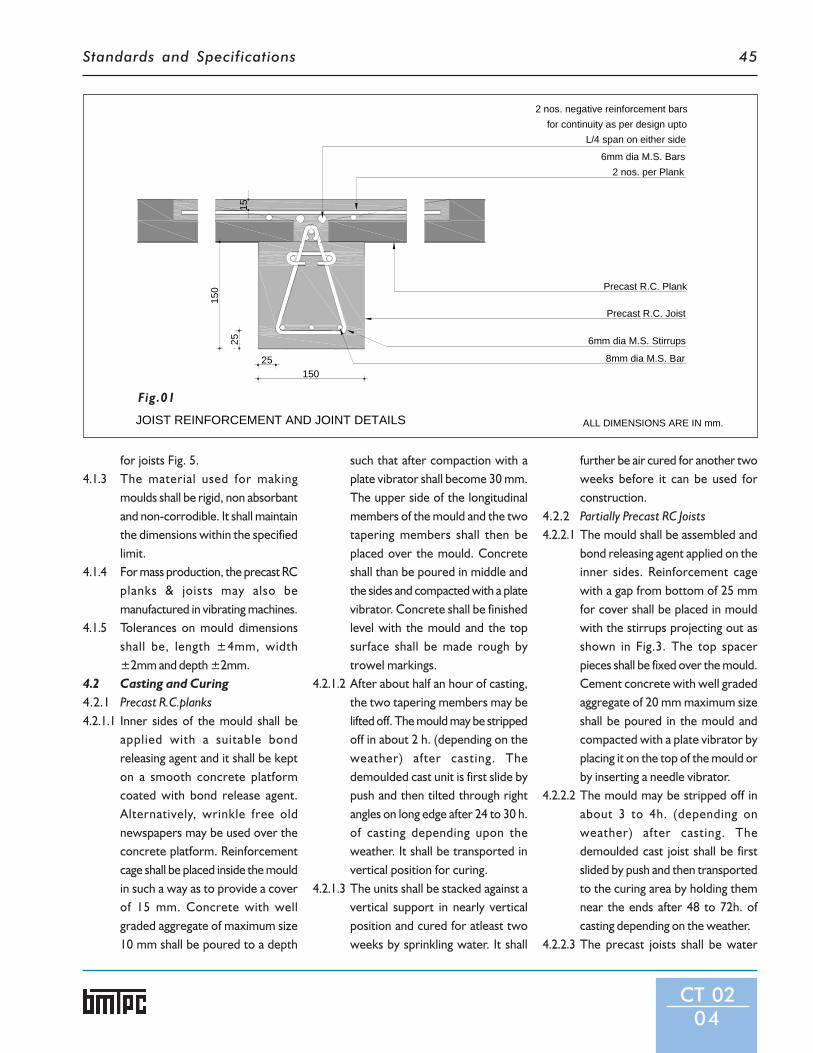
Standards and Specifications 45
for joists Fig. 5.4.1.3 The material used for making
moulds shall be rigid, non absorbantand non-corrodible. It shall maintainthe dimensions within the specifiedlimit.
4.1.4 For mass production, the precast RCplanks & joists may also bemanufactured in vibrating machines.
4.1.5 Tolerances on mould dimensionsshall be, length ±4mm, width±2mm and depth ±2mm.
4.2 Casting and Curing4.2.1 Precast R.C.planks4.2.1.1 Inner sides of the mould shall be
applied with a suitable bondreleasing agent and it shall be kepton a smooth concrete platformcoated with bond release agent.Alternatively, wrinkle free oldnewspapers may be used over theconcrete platform. Reinforcementcage shall be placed inside the mouldin such a way as to provide a coverof 15 mm. Concrete with wellgraded aggregate of maximum size10 mm shall be poured to a depth
such that after compaction with aplate vibrator shall become 30 mm.The upper side of the longitudinalmembers of the mould and the twotapering members shall then beplaced over the mould. Concreteshall than be poured in middle andthe sides and compacted with a platevibrator. Concrete shall be finishedlevel with the mould and the topsurface shall be made rough bytrowel markings.
4.2.1.2 After about half an hour of casting,the two tapering members may belifted off. The mould may be strippedoff in about 2 h. (depending on theweather) after casting. Thedemoulded cast unit is first slide bypush and then tilted through rightangles on long edge after 24 to 30 h.of casting depending upon theweather. It shall be transported invertical position for curing.
4.2.1.3 The units shall be stacked against avertical support in nearly verticalposition and cured for atleast twoweeks by sprinkling water. It shall
further be air cured for another twoweeks before it can be used forconstruction.
4.2.2 Partially Precast RC Joists4.2.2.1 The mould shall be assembled and
bond releasing agent applied on theinner sides. Reinforcement cagewith a gap from bottom of 25 mmfor cover shall be placed in mouldwith the stirrups projecting out asshown in Fig.3. The top spacerpieces shall be fixed over the mould.Cement concrete with well gradedaggregate of 20 mm maximum sizeshall be poured in the mould andcompacted with a plate vibrator byplacing it on the top of the mould orby inserting a needle vibrator.
4.2.2.2 The mould may be stripped off inabout 3 to 4h. (depending onweather) after casting. Thedemoulded cast joist shall be firstslided by push and then transportedto the curing area by holding themnear the ends after 48 to 72h. ofcasting depending on the weather.
4.2.2.3 The precast joists shall be water
CT 0204
1525
150
25150
Precast R.C. Plank
Precast R.C. Joist
6mm dia M.S. Stirrups
8mm dia M.S. Bar
L/4 span on either sidefor continuity as per design upto
2 nos. negative reinforcement bars
2 nos. per Plank6mm dia M.S. Bars
JOIST REINFORCEMENT AND JOINT DETAILS ALL DIMENSIONS ARE IN mm.
Fig.01

Standards and Specifications46
CT 0205
Fig.02

Standards and Specifications 47
cured for a minimum period of twoweeks and air cured further foratleast two or more weeks beforethey may used for construction.
5 Erection of Floor/Roof5.1 Cement concrete bed blocks of 300
mm x 230 mm x 75 mm size forjoist with proportions of 1:3:6(cement : fine aggregate : coarseaggregate) shall be laid on wall in athickness of 75 mm. The top of theblocks shall be finished smooth.
5.2 Partially precast joists shall then bealigned over these blocks. The joistsshall be propped at centre of span,immediately after putting them, witha prop having a timber plank ofminimum dimensions of 350 mm xwidth of joist, of 30 mm thickness atbearing level (Fig.6). The minimumbearing of joists over the wallsshould be 100 mm.
5.3 Top surface of the walls/beamswhere planks have to bear, shall thenbe leveled smooth with 1:6 cement
sand mortar. In case of roofs, theentire wall top shall be leveledsmooth with the mortar and given athick coat of white wash orbitumenised paper or polythene filmshall be placed for free movementof roof/floor.
5.4 Precast planks shall now be placedover the joists/walls side by side.Fan hooks may be provided if thefan is to be hung in between theplanks (Fig.7A and 7B). If, however,the fan is to be hung from the joist,a through and through hole ofaround 15 mm diameter is to be leftin the joist during its casting and thefan can be hung by a clamp (Fig.7C).The minimum bearing of joists shallbe 50 mm on load bearing walls and40 mm on beams.
5.5 Reinforcing bars across the joist(that is, parallel to planks) having anarea required to resist negativemoment and to provide continuityto planks in successive spans shallthen be placed in the haunch portions.
CT 0206
This negative reinforcement may bedetermined in accordance with IS456. Alternatively, two 6 mmdiameter mild steel grade 1 barsconforming to IS 432 (Part1) maybe provided which satisfies thereinforcement requirements fornormal residential buildings.Distribution reinforcementconsisting of two mild steel grade 1bars of 6 mm diameter conformingto IS 432 (Part 1) shall be keptparallel to joists near the ends ofthe planks as shown in Fig.1. Thesebars shall then be tied with the crossbars.
5.6 Near the supports of joists wheretwo joists are meeting the negativereinforcement shall be provided, asshown in Fig.1.
5.7 Cement slurry wash at the rate of 4kg cement per 10 m2 of the floor/roof shall be applied over the joistsand in the haunch portions of theprecast planks where in-situconcrete is to be laid.
PARTIALLY PRECAST JOIST
Stirrups @ 130mm c/c, minimum distance from edge of joist 50mm
150
150
L
ALL DIMENSIONS ARE IN mm.
Fig.03

Standards and Specifications48
CT 0207
Fig.04STEEL MOULD FOR R.C. PLANK
20 10
45
25 5
525
30
20 20
300 20
7530
20 100 20
6mm dia M.S.Bar (as stiffener) two nos. in each side
75mm Long Hinge
3mm thick M.S. Plate
L 25x25x3mm
Handle 10mm dia. M.S. Bar
L 30x20x3mm
Handle 10mm dia. M.S. Bar
L 30x20x3mm
M.S. angle 30x20x3mm10mm dia. M.S. Handle
75mm Long Hinge
M.S. angle 25x25x3mm
300 900 300
1500
B
100
A C
5 5
7530
ALL DIMENSIONS ARE IN mm.

Standards and Specifications 49
CT 0208
70100
150
150
300
400
10mm dia. Bolt
L 50x50x5mm welded to ISJC 150
300x150x6mm M.S. Plate
L/4 L/4
300
400
10mm dia. hole
Spacer Plates 400 x 50 x 5 mm
Longitudnal Member ISJC 150
10mm dia. M.S. bolt
300 x 150 x 6 mm M.S. Plate
L 50 x 50 x 5 mm 100mm long
STEEL MOULD FOR R.C. JOIST
A
L/4
ALL DIMENSIONS ARE IN mm.
L/4
Fig.05

Standards and Specifications50
CT 0209
5.8 A thick paste of cement-sand (1:4)mortar shall be laid in the gapsbetween the planks along theirlength, to fill them up completely.
5.9 Cement concrete of M-20 gradewith well graded coarse aggregateof maximum size 10 mm shall thenbe laid over the joists and inhaunches between the planks and thetop leveled flush with the top ofcentral portion of the planks.
5.10 In case of roofs without parapet, theplanks shall be kept projecting outby a maximum of 100 mm in eitherdirection to avoid leakage at the
junction of wall and roof (Fig.9).Alternatively, a maximumprojection of 500 mm across thejoists may be provided by providingshuttering, laying reinforcement andconcreting flush with the rooftreatment as shown in Fig.9. Aprojection of 100 mm may beprovided along the joists byproviding the negativereinforcement in joist at top andprojecting the same and concretingas shown in Fig.1.
5.11 In-situ concrete shall be cured for aminimum period of 10 days. The
props of the joists shall not beremoved before the curing periodis over and in-situ concrete hasattained strength.
5.12 A minimum clear cover to all thereinforcement bars shall be 15 mmor the diameter of the bar whicheveris greater.
6 Floor/Roof Finishing6.1 For waterproofing using bitumen
felts, bitumen mastic, glass fibretissue reinforced bitumen and limeconcrete, IS 1346, IS 9918 and IS 3036may be referred.
7 Care During and After Erection7.1 Concentrated load shall not be
allowed on the floor/roof till in-situconcrete has attained strength.Workers shall not walk on the floor/roof before the insitu concrete hasattained strength. For placing ofreinforcement and concreting in thehaunches and over joists, cat walksresting on joists/walls shall beprovided.
7.2 The planks shall be handled andtransported in vertical position asfar as possible and these should besupported only near the edges. Thejoists shall be handled from verynear the ends or at a distance of L/5from the ends.
7.3 Partition walls shall not beconstructed over the planks but onlyover joists or wall in which case theirweight has to be considered whiledesigning the joists.
8 Service Area Provisions8.1 In service area, pipes, floor traps,
water closet etc. are provided andhence the supporting slab is sunk. Insuch cases, to take care of theadditional load of the filling and also

Standards and Specifications 51
CT 0210
PROPPING OF PARTIALLY PRECAST JOIST
Partially Precast Joist
30mm thick Wooden Plank
100mm dia BalliC.C.bed block
Brick Wall
230
100
L/2
350
ALL DIMENSIONS ARE IN mm.
Fig.06

Standards and Specifications52
CT 0211
FIXING OF FAN HOOK
300 70 300
150
75
150
3050
30
12mm dia. M.S. Bolt
Conduit embedded during casting
50 x 5 mm M.S. Flat
5015
0
Partially Precast joistFloor/Roof finish
M 20 Insitu Concrete
12mm fan hook
150
150
50
75
L
Partially R.C.C. Plank
Partially Precast Joist
12mm fan hook
60
40
ALL DIMENSIONS ARE IN mm.
Fig.07

Standards and Specifications 53
CT 0212
to make the floor leak-proof, the in-situ concrete thickness is increasedby 25 mm over top of the planks inaddition to haunch filling.
9 Balcony/Chhajja Projections9.1 Balcony projections shall be
provided along the partially precastjoists as given in IS 13994. The joist
shall be designed with an overhang,carrying superimposed loads forbalcony as specified in IS 875, inaddition to the self load and the loaddue to railing. Main reinforcementshall be provided at the top in in-situ concrete while the precastportion will take the compression.The free end of the joist shall be
propped adequately until in-situconcrete attains sufficient strength.
10 Sampling10.1 All the precast reinforced concrete
units of the same size, manufacturedfrom similar condition ofproductions shall be groupedtogether to constitute a lot.
DETAIL FOR PLANKS BEARING AT ROOF TO AVOID LEAKAGE100 30 100
230
50 130 50
100mm th. average Lime Concrete Terracing laid to slope 1:50
Bitumen Painting in case of roof only
M 20 Insitu Concrete12mm Bitumen board in case of roof
Partially Precast R.C.Joist
Brick wall
Precast R.C. Plank
12mm thick levelling pad
DETAIL FOR SIMPLY SUPPORTED JOIST AT SUPPORT
100mm th. average Lime Concrete Terracing laid to slope 1:50
Bitumen Painting in case of roof only
Precast R.C. Plank
Partially Precast R.C.Joist
12mm Bitumen board in case of roof
Cement concrete bed block
Brick wall
100 30 100
230
50 130 50
ALL DIMENSIONS ARE IN mm.
Fig.08A
Fig.08B

Standards and Specifications54
CT 0213
10.2 Five units shall be selected at randomout of a lot consisting of 300 unitsor less. For lot bigger than 300 units5 units shall be selected for everyadditional 300 units or part thereof.In order to ensure randomness ofselection, procedure given in IS 4905may be followed.
10.3 The samples shall be suitablymarked for future identification ofthe lot it represents.
11 Test11.1 Tests shall be conducted on samples
of the units as given in IS 13994.11.2 Dimensional test and deflection
recovery test shall be routine testwhereas failure load test shall be atype test. Type test is intended toprove the suitability andperformance of a new design andsize of a component. Failure load testbe applied at the time of design of acomponent of a particular size or atthe time of any change in the design/size.
12 Criteria of Conformity12.1 If four out of the five samples satisfy
the shape and dimensionalrequirements, the lot representedby the sample shall be deemed tohave passed the dimensionalrequirements, otherwise it shall berejected.
12.2 In the deflection recovery testperformed in accordance with IS13994, if the deflection after 24 h ofthe removal of the imposed load isatleast 75 percent of the deflectionunder the load for 24 h, the unitsshall be deemed to have passed thetest. If the deflection recovery is lessthan 75 percent the lot representedby the unit shall be rejected. If themaximum deflection in mm, shownduring 24 h under load is less than40 l2/D, where l is the effective spanin mm and D, the overall depth ofthe section in mm, it is not necessaryfor the deflection recovery to bemeasured and the recoveryprovision mentioned in this clauseearlier shall not apply.
In case of the failure load performedin accordance with IS 13994, the unitshall carry a load atleast equal to 1.33times the characteristics load to passthe test. If the load at failure is lessthan 1.33 times the characteristicload, the lot represented by thesample shall be rejected.
13 Marking13.1 Each component shall be legibly and
indelibly marked with identificationof the source of manufacture, andmonth and year of manufacture.
DETAIL FOR CONTINUITY OF JOIST ATSUPPORT IN INTERMIDIATE FLOORS
230 L/4 6mm dia M.S. Stirrups2 No as per Design
Base FloorM 20 Insitu ConcretePrecast R.C.C. Plank
Partially Precast R.C.C. Joist
Welding of bottom ReinforcementCement Concrete bed block
ALL DIMENSIONS ARE IN mm.
Fig.08C

Standards and Specifications 55
CT 0214
150
230 100
M 20 in-situ conc.
12mm thick smooth cement plaster
Precast R.C. Plank
Brick Wall
laid to slope 1 in 50100mm water proofing treatment
60
230 120
Brick Wall
100mm water proofing treatment
M 20 in-situ conc.
Precast R.C. Plank
12mm thick smooth cement plaster
Partially Precast Joist
230 max. 500
6040
300
DETAIL OF ROOF WITHOUT PARAPET
Brick Wall
M 20 in-situ conc.
6mm dia. M.S.Bars
Main reinforcement 6mm @ 100 c/c
ALL DIMENSIONS ARE IN mm.
Fig.09

Standards and Specifications
CT 0301
CT 03
SpecificationsforThinR.C.RibbedSlab forFloors andRoofs
1 General1.1 Thin R.C. ribbed slab consists of precast R.C. ribs 110
mm x 200 mm spaced equidistance at 1200 mm/centreto centre and 50 mm thick cast-in-situ R.C. flanges (Fig1). It can be used for floors as well as roofs in buildings.Conventional floor/roof finish can be used above theribbed slab, as the case may be. Ceiling plaster could beavoided in case of exposed concrete is desired.
2 Dimensions & Tolerances2.1 Partially precast RC rib: The cross section of R.C. Rib has
two portions, precast portion is rectangular shape, 110mmwidth and 150mm height, with stirrups projecting out 25mm on top surface of the rib. The total height of rib,including 50mm thick in-situ concrete shall be minimum200 mm. The maximum length of precast rib shall not bemore than 4.0 m. It is designed as composite T-Beam with50mm thick RCC flange. RC ribs can be placed on loadbearing walls or beams.
2.2 RC Flange: The minimum thickness of in-situ concretefor flange shall be 50mm.The flanges are treated ascontinuous slab spanning over the ribs.
2.3 Tolerances on precast rib shall be length ± 8 mm, widthand height ± 3 mm and for in-situ concrete thickness ±3mm.
3 Structural Design3.1 Ribs: The structural design shall be as per the limit state
method as per IS 456. The precast ribs shall be designed toact as rectangular Tee beam during the construction tosupport the weight of concrete in the flange, till it hasattained strength, the shuttering and the live load ofworkmen and equipments. The flange shall be designedas a continuous slab spanning over the ribs.
3.2 Flanges: The monolithic action of precast ribs with in-situconcrete flange shall be ensured by keeping rib stirrupsprojected which shall be embeded along flanges. Thethickness of the flange shall be minimum 50mm and thisshall be designed as continuous slab.
4 Manufacture of Thin RC Ribbed Slab4.1 Moulds4.1.1 The moulds for the ribs shall be made of steel or FRP as per
details shown in Fig.2.4.1.2 The shuttering for the flange shall be made of well seasoned
timber or steel plates or FRP as per details shown in Fig.3.

Standards and Specifications 57
CT 0302
THIN R.C. RIBBED SLAB
Precast Ribs 110x200 mm
5015
0
110
1200 (max.)
Clear cover 25 mm
6mm dia. bars @ 100 mm c/c
6mm dia. bars @ 150 mm c/c
Cast-in-situ flange
and 2 nos. 6 mm dia. in the middleAs per design over supports
Precast rib6mm dia. 2-legged stirrups @ 150 c/c
Clear cover 25 mm
230
EQ
.11
0EQ
.11
0E
Q.
230
L
(Projecting bottom reinforcement ofprecast ribs welded together)
230mm thick Wall
ALL DIMENSIONS ARE IN mm.
Fig.01

Standards and Specifications58
CT 0303
Fig.02
STEEL MOULD FOR PRECAST RIB
1000 (max) 1000 (max) 1000 (max)
110
240
170
Spacer Flat 240 x 50 x 5 mm
240 x 200 x 6 mm M.S. PlateL 50 x 50 x 5 mm 100mm longLongitudnal Member ISJC 200
10mm dia. M.S. bolt
100
150
200
110
240
M.S. Flat 50 x 5 mm
10mm dia. Bolt Welded
angle 50 x 50 x 5 mm Welded to ISJC 200
240 x 200 x 6 mm M.S. Plate
ISJC 200
Casting Plateform
54
25 mm square holes 900 c/c
1000 (max)
* ALL DIMENSIONS ARE IN mm.

Standards and Specifications 59
CT 0304
TIMBER SHUTTERING FOR THIN R.C. RIBBED SLAB
EQ.
EQ
.EQ
.
1200
/ 15
00 /
1800
mm
1050
1101200 max
G.I. sheet lining
10 mm th. shuttering plywood
Wedges
(Reusable timber shuttering)Wooden battens 50 x 50 mm
in 25 mm square hole 1200 (max.)20 mm square M.S. bar
1050
1080 mm (max.)
Batten 50 x 50 mm
10 mm thick shuttering plywood
28 gause G.I. sheet lining
ALL DIMENSIONS ARE IN mm.
Fig.03

Standards and Specifications60
4.2 Casting and Curing4.2.1 Precasting of Ribs4.2.1.1 The ribs shall be cast in steel moulds
(Fig.2) over a casting plat form. Thecasting platform and inner sides ofthe mould shall be applied withmould oil and reinforcement cagekept in position with 25 mm cover.To provide holes in the ribs, 25 mmsquare MS hollow box sections shallbe inserted through square holes inthe longitudinal members of themould. The concrete used shall beof grade M-20 with 20 mm and downgraded coarse aggregate. Theconcrete shall be thoroughlycompacted by needle vibrator andthe top surface shall be finishedrough.
4.2.1.2 When Ordinary Portland Cement isused, about 3 to 4 h. after casting,the rib shall be demoulded bysliding the longitudinal pieces of themould away from the precast rib.The rib shall be kept covered withwet gunny bags for 72 h. Afterwards,they shall be slided horizontally onthe casting platform to break thebond with platform and transportedto the curing yard or curing tank byde-moulding them from the ends.After two weeks of water curing,the units shall be allowed to air dryfor another two weeks, beforeusing them in any construction. Thepre cast ribs shall be placed in 115mm wide recesses left in the wall atthe specified spacing either manuallyor with mechanical means.
4.2.2 Casting of Flange4.2.2.1 The width of the shuttering panel
shall be kept as the clear distancebetween the ribs with theclearance of 5mm on both sides.The length of the panels shallpreferably be kept in modules of300mm i.e. 1200mm, 1500mm,
1800mm. A combination of thesecould be used to suit the span of theroom. Even number of panels shallbe used in each bay, so that theycould be placed symmetrical withrespect to midspan of the rib. Theshuttering panels shall be keptsupported on 20mm square MS barsprojecting out of holes left in theprecast ribs as shown in Fig. 3. Asthe ribs are designed to act asrectangular Tee beams to take loadof the in-situ concrete, shuttering,workmen and equipments duringconcreting, no props are requiredin this type of construction. Theshuttering panels shall then be keptin position and levelled with the helpof wedges, with the top surface ofthe precast ribs in level with the topof the shuttering.
4.2.2.2 Reinforcement in the flanges shallbe laid over the shuttering as shownin Fig. 1. The minimum cover of 15mm to the main reinforcement shallbe ensured by tying thereinforcement to the projectingstirrups of the precast ribs atsupports and by keeping cementmortar cover blocks below the mainreinforcement bars at mid span. Forfree movement of ribbed slab oversup porting walls/beams, the bearingarea shall be plastered with 1:6cement sand mortar finishedsmooth and applied with a thick coatof white wash. The top surface ofthe precast ribs shall be given acoating of cement slurry 4kg per10m2 just before concreting.Concrete of grade M-20 with 12mmand down graded coarse aggregateshall then be laid over theshuttering and ribs and compactedto a thickness of 50mm by a platevibrator and the top surface finishedwith floats.
4.2.2.3 The concrete shall be water curedfor two weeks by ponding waterover the flange and then allowedto air cure.
5 Fitting and Fixtures5.1 Provision for fan hooks shall
preferably be provided in theprecast ribs at the time of casting.In case the fan is to be located inthe flange portion, the fan hookshall extend over the adjacent ribsand rest over them.
5.2 Positions of electrical junctionboxes and other fittings shall bepreplanned and provided in the precast ribs or cast-in-situ flange. Ifconcealed wiring is to be done,conduits of diameter not exceeding20mm may be provided above theprecast ribs along its length. In theother direction, conduits shall beprovided along recess cut in thewall.
6 Balcony or Chajja Projections6.1 Short cantilevers, such as roof
projection or chajja projectionsupto 500mm can be provided in theribbed slab along or across thedirection of the ribs by keeping theflange projected out. The cantileverhas to be designed as per thenormal practice.
6.2 For larger projections along thedirection of the ribs, the ribs haveto be designed suitably. They canbe precast and kept projecting outand the cantilever portion of theribs can be cast-in-situ along withthe flange. For large cantileverprojections across the direction ofthe ribs, cantilever beams have tobe provided in the direction.
CT 0305

Standards and Specifications
CT 0401
CT 04
Specificationsfor
PrecastConcrete
Waffle Unitsfor
Floors & Roofs
1 General1.1 The scheme consists of nominally reinforced precast open
box type concrete units called waffle units laid in a gridpattern and cast in-situ concrete is laid in the joints betweenthe units with the reinforcement provided in the joints.Minimum thickness of top screed is provided dependingupon structural and functional requirements. The finishedscheme has a pleasant grid pattern in the ceiling. The schemeis suitable for floors/roofs spanning in two directions.
2 Dimensions and Tolerances2.1 The units are of the shape of inverted trough, square,
rectangular, triangular, or any other shape. The ribs of theunits may be given an out ward slope to enable the precastcomponents to demoulded easily and also to enable themto act monolithically with cast-in-situ beams in jointsbetween the units.
2.2 Typical details of cross-section of square waffle unit andcross-section of floor/roof using waffle units are shown inFig.1 and 2.
2.3 The lateral dimensions of the units shall be modular (IS6820). The depth of the unit shall be as per structural designand will vary according to loads and spans. The minimum

Standards and Specifications62
CT 0402
thick ness of the flange and web ofthe units shall be 25 mm.
2.4 Tolerance on precast waffle unit shallbe as under:(a) Length/breadth : ±5mm or ±0.1percent, whichever is greater(b) Thickness : ±2mm.
3 Structural DesignThe grid floor slab design shall beanalysed by any of the acceptedmethods of analysis.
3.1 Loads and Forces - Loads and
forces shall be taken in accordancewith IS 456. In addition, slab shall bechecked for incidental concentratedload which is likely to occur duringthe construction.
3.2 Analysis of Floors/Roofs3.2.1 The floor/roof with waffle units upto
a span of 6 meters having ribs ofwidth not less than 100 mm(excluding thickness of precast wafflerib) spaced at not more than 750 mmmay be analysed as solid slabspanning in two directions at right
angles in accordance with Clause23.4 of IS 456 or as a flat slab inaccordane with clause 30 of IS 456.
3.2.2 The floor/roof with waffle unithaving span of more than 6 m andrib spacing of more than 750 mmshall be designed as slab and gridbeam system. The shear at theinterface of precast and in-situconcrete shall be calculated andsuitable shear keys/shearreinforcement shall be provided toavoid separation.
SECTION OF FLOOR USING WAFFLE UNITS
TYPICAL SQUARE WAFFLE SLAB UNIT
800 20
770 62.5
895
20
35
3012
015
0
265
35
800
900
100 100
300
130 770 130
Insitu Concrete
Reinforcement as per design
Precast unit
Steel Wire Fabric
27.5
ALL DIMENSIONS ARE IN mm.
Fig.02
Fig.01

Standards and Specifications 63
CT 0403
3.3 Reinforcement in Precast UnitReinforcement shall be providedaccording to the structuralrequirements. Any mesh type ofreinforcement/ welded mesh/expanded metal/ chicken mesh witha maximum spacing of 100 mm bothways shall be provided.
4 Moulds4.1 The mould used for manufacture of
waffle unit shall consist of two parts(a) bottom mould and (b) sidemoulds. The bottom mould can bemade out of timber, masonry,concrete, steel, FRP, plastic or anyother suitable materials. The sidemoulds similarly can be of timber,steel, FRP or plastic. When usingmasonry or concrete moulds, thetop surface shall be finished to therequired accuracy and made smooth.In case of masonry moulds, the useof chicken mesh or fibrereinforcement in the top surface willhelp in making the mould last longerand higher efficiency. Admixtures forhigher strength of concrete can alsobe used.
5 Concrete5.1 Mix - The concrete mix shall be of
minimum of M 20 as per IS 456.
6 Casting and Curing6.1 Waffle units shall be cast on a smooth
and level concrete platform. Theouter mould shall be placed and oiledon inner side. Cement concrete M-20 grade as per IS 456 shall be laidand compacted to a minimum depthof 12mm. Reinforcement cage shallthen be placed over the laidconcrete. Concrete shall be laid tothe full thickness and compactedeither through mould/table vibrator
or screet vibrator. The inner mouldshall then be placed and concrete shallbe filled in the webs and compactedby a needle vibrator or shuttervibrator. After 2h. of casting, theinner mould shall be demoulded.The outer mould shall bedemoulded after 4h. dependingupon the weather.
6.2 The cast unit shall be covered withwet gunny bags for 2 to 3 days. After
wards, the unit shall be pushed toslide to break bond with the bottom.The cast units shall be transportedby placing them on trolly to curingyard where these shall be placed inthe same position as cast and filledwith water for 10 to 14 days forcuring. These shall be air cured foranother 2 weeks before use inbuilding.

Standards and Specifications64
7 Lifting, Stacking andTransportation
7.1 Lifting Hooks - Wherever liftinghooks/holes are used these shall beprovided at structurallyadvantageous points to facilitatedemoulding and erection of theprecast unit. The lifting hooks canbe formed out of normal mild steelreinforcing bars with adequatecarrying capacity to carry the selfweight during demoulding, handlingand erection. After erection, thehooks can be either cut or bentdown inside the screed or jointconcrete that will be laidsubsequently.
7.2 Stacking of Units - After removalfrom moulds the precast units shallbe stacked over support placed atabout 1/6 of span from ends. Careshall be exercised that no support isplaced at the centre of span.
7.3 Transportation - For transportingand erecting the units, rope slingsshall be tied near the ends at 1/5 ofthe length from either end of theunit. In case the units are transportedin trolleys, the overhang of the unitsfrom the trolley shall not be morethan 1/5 of length. The units shall belifted manually or with the help ofchain pulley blocks or mechanicallywith a hoist or a crane.
8 Method of Construction8.1 The area to be covered with waffle
units shall be provided with adequateshuttering.
8.2 The units shall be placed and alignedside by side across the span to becovered. Placing of units shall bestarted from one end of the building.The top of the bearing walls shall beplastered with a smooth coat of 1:6cement, sand mortar finished with a
thick coat of l ime wash. Theminimum bearing of the waffle unitsover the walls shall be 50mm.
8.3 Reinforcement shall be laid in boththe directions in the spaces inbetween the waffle units.
8.4 Before concreting a cement slurrywash of 4kg per 10m2 shall be carriedout on all the faces of the joints.
8.5 M-20 grade cement concrete shallbe laid in all the joists which formsthe ribs and compacted by needlevibrator.
8.6 In-situ Concrete in Joints shall becured for at least 7 days and thenshall be allowed to dry for at least aweek. A coat of cement slurry maybe applied to the joints to fill thehairline cracks that might havedeveloped.
9 Fitting and Fixtures9.1 Provisions for fixtures like fan
hooks/ inserts/electric conduits, etc.to be incorporated within theprecast units or the in-situ joints/screed concrete shall be indicated.
9.2 In case of concealed wiring, conduitsmay be placed within the joints alongthe length or within the screedbefore concreting. If adequatethickness is available this may beconcealed within the floor/rooffinish.
9.3 Holes, openings and fixturesrequired to be provided within theprecast units shall be fixed accuratelywith adequate embedment at theprecasting stage. Drilling of holes/cutting of edges shall not be made.
10 Floor Finish10.1 In case of floor slab, the floor finish
shall be done in accordance with therelevant IS code.
CT 0404
10.2 To provide adequate resistanceagainst impact/acoustic treatmentthe floor thickness at any place shallnot be less than 75mm.
11 Roof Treatment11.1 Adequate water proofing and
thermal insulation to suit the localthe local climatic conditions shall beadopted in accordance with relevantIndian Standard Code of Practice.
12 Sampling12.1 The sampling procedure for precast
concrete waffle unit shall be inaccordance with IS 10505.
13 Tests and Criteria forConformity
13.1 The test and criteria for conformityof precast waffle unit shall be inaccordance with IS 10505.

Standards and Specifications
CT 0501
CT 05
Specificationsfor
PrecastReinforced
ConcreteL-Panelsfor Roofs
1 General1.1 Precast RC L-panels are replacement of conventional
roofing materials for gable or lean to roof. It consists offull span monolithic rib and flange to act as purlin and sheet.The panel is designed as L beam having wide flange forresisting flexural compressive stress. L panels are durableand reusable for temporary construction. (Fig. 1)
2 Dimensions and Tolerances2.1 L-Panels2.1.1 The precast L-panel units shall have a cross section of L-
shape with end bearing of the same depth and width as therib of L-section at the two ends of length. The end bearinglength of rib parallel to the width of L-panel shall be keptlesser than overall width of L-panel to provide overlappingof 80-150 mm depending upon climatic conditions (Fig.2A).
2.1.2 Length - The length of L-panel depends upon the roomsize but the maximum span of L-panels shall be restricted to4 m. Lower length may be preferred, whenever possible,for easy handling. A minimum bearing on the gable wallsshall be kept 60 mm on either side of the L-panel.
2.1.3 Width - The width of L-panel also varies depending uponthe span and is so chosen as to give maximum overalleconomy. The guidance may be taken from choosing thewidth from Table - 2. Also keeping in view the need formodular coordination, final value of width and the numberof L-panels required to cover the room of given dimensionmay be calculated by using following approximate formulafor a moderate size of room:Br +2p = N(B-b-2) +D/2 +2b ….for double sloping roofBr +2p = N(B-b-2) +D/4+b …. for single slope roof
over two vertical walls with outer projections on both sides.

Standards and Specifications66
Br +p = N(B-b-2) +D/4+b …. for single slope roof adjoining avertical wall (with outer projectionson one side only).
Where:Br = Outer dimension of room
perpendicular to span of L-panel incm.
p = Outer roof projection (horizontallymeasured) in cm.
N = Number of L-panels required.B = Width (overall) of L-panel in cm.b = Overlap of L-panel.D = Depth of L-panel in cm.
2.1.3.1 The maximum overall width of L-panels shall be as per Table-2 andminimum overlap between adjacentL-panel shall be as per Table-1. Fordesign of panel based on upon utility
and climatic factor, Table-1 may bereferred.
2.1.4 A thickness of flange of 30-40 mmdepending upon the size of units andclimatic condition shall be adopted,keeping it 30 mm for overall widthupto and including 700 mm and 40mm for widths upto 900 mm.
2.1.5 After deciding span, width, thicknessof flange, the dimensions of rib shallbe determined in accordance withthe design procedure laid down inIS 14242. Alternatively, the depth andwidth of rib may also be takendirectly from Table-2. In any case,the width of rib shall not be less thanthose given in Table-2.
2.1.6 Units having a cross section ofchannel shape shall also be producedin required numbers, to be used at
eaves in a verandah or for achievingaesthetic effect. The dimensions ofchannel unit shall be as that of L-panels (Flg.2B).
2.1.7 Main reinforcement required shallconsist of one bar or requireddiameter provided at the bottom ofthe rib of L-panel having an adequatecover. The required diameter maybe taken from Table-2 which appliesfor reinforcement conforming tomild steel grade 1 of IS 432(Part 1)and high strength deformed bar asper IS 1786. The detailing shall befollowed in accordance with Fig.2.
2.1.7.1 Reinforcement for temperature andhandling shall be provided in theflange as per Table-2.
2.1.7.2 At the eaves over verandah wherechannel unit are provided, the same
CT 0502
Fig.01

Standards and Specifications 67
CT 0503
100 340 40
3090
M.S. Bar
3mm dia. G.I. wires @ 200 c/c
40
3090
40 400
40
M.S. Bar
3mm dia. G.I. wires @ 200 c/c
>4000
DETAILS OF L-PANEL AND CHANNEL UNIT
>4000
L PANEL
* ALL DIMENSIONS ARE IN mm.
Fig.02B CHANNEL UNIT
Fig.02A

Standards and Specifications68
CT 0504
Table 1: Utility and Climatic Factors for Design
Sl. Deciding Factor Mimimum SpecificationsNo. Types of Building Utility Climates Slope of Overlap Thickness Grade of Admix- Other
Gable Between of Flange Concrete tures in TreatmentsWall Panels (cm) (M) Concrete Recommended(tan 0) (cm)
(1) (2) (3) (4) (5) (6) (7) (8) (9)1 School buildings, sheds, Very low 1:4 8 3 15 Nil -
garage, etc. rainfall area2 School buildings, sheds, Low rainfall 1:4 9 3 15 Nil -
ordinary storage, areacommunity buildings,office buildings, etc.
3 School buildings, Medium 1:3.5 10 3 15 Nil -residential buildings, rainfall areaordinary shops,general stores, etc.
4 Important residential High 1:3 12 3.5 20 D.P.C. -buildings, important rainfall areashops, importantstorages, recordrooms, etc.
5 Very important shops, Very high 1:2.5 15 4 25 D.P.C. -record rooms, rainfall areadry storage, etc.
6 Any building Cold and 1:2 10 3.5 20 Nil -snowfall regions
7 Any building at Aggressive 1:3 12 3.5 20 D.P.C. Anticorrosivecoastal area climates treatments to
reinforcement8 Chemical factories, Reactive 1:3.5 10 3.5 20 D.P.C. Anticorrosive
industrial buildings environment treatments todealing with reactive reinforcementmaterials, etc. and other
suitablecoatings andadmixtures
Note: Any one of col (2) and (3) shall be the deciding factor for the design.
tensile reinforcement as for L-panelshall be provided in both the ribs,while the overall dimension shall bekept the same.
3 Structural Design3.1 L-Panels3.1.1 L-Panels shall be designed as simply
supported L-beams in accordancewith IS 456.
3.1.2 Total moment acting on the L panelsshall be spilt into two components,one perpendicular to the flange ofpanels and the other parallel to theflange of panels. Bending movementparallel to the flange is usually verysmall and shall be taken care of by
steel provided in flange fortemperature and handling stress.The L-panel shall be designed forbending movement perpendicular toflange.
3.1.3 Safety against shear force and bondstresses shall also be checked as perIS 456.
3.2 Loads3.2.1 Following loads shall be considered
in designing the L panels:i) Self weightii) Live load as per IS 875 (part 2)iii) Wind load as per IS 875(part 3)iv) Handling stresses while lifting
the unit simply supported andupside down. In absence of active
load, 1-25 times the self weightof the panels may be consideredfor calculation.
3.2.2 Load factors taken while designingor checking the stability under windload and handling stresses shall bethose recommended in IS 456.
3.3 No anchorage is found necessary forbasic wind pressure of 150 kg/m2 , ifthe dimensions given in Table-2 areadopted. For basic wind pressurehigher than 150 kg/m2, anchorageshall be designed. However, fordimensions other than thoseindicated above, anchoragerequirement shall always be checked.
3.4 For prevailing wind speed in India,

Standards and Specifications 69
CT 0505
Table 2 : Schedule of Design of L-Panels and Channel Units
Sl. Length Reasonable Depth Width Thick- Dead Dia of Tension Bar Diameter of Bars in FlangeNo. Breadth of Rib of Rib ness of Weight
Ranges FlangeL B D r T Wd R1 R2 R3 R4 R5 R6
(All dimensions in millimeters)(1) (2) (3) (4) (5) (6) (7) (8) (9) (10) (11) (12) (13)1 1200 500 80 40 30 52 6 6 6 - 6 -2 1200 600 80 40 30 62 6 6 6 - 6 -3 1200 700 100 50 40 96 6 6 6 6 6 64 1200 800 100 50 40 110 6 6 6 6 6 65 1200 900 100 50 40 123 6 6 6 6 6 66 1500 500 80 40 30 65 6 6 6 6 6 -7 1500 600 80 40 30 77 8 6 6 6 6 -8 1500 700 100 50 40 120 8 6 6 6 6 69 1500 800 100 50 40 135 8 6 6 6 6 610 1800 500 100 40 30 82 8 6 6 - 6 -11 1800 600 100 40 30 96 8 6 6 6 6 612 1800 700 100 50 40 142 8 6 6 6 6 613 2100 500 100 50 30 100 8 6 6 - 6 -14 2100 550 100 50 30 108 8 6 6 6 6 -15 2100 600 100 55 35 132 8 6 6 6 6 616 2100 650 100 55 35 143 8 6 6 6 6 617 2400 500 100 50 30 113 8 6 6 6 6 -18 2400 550 100 50 30 122 8 6 6 6 8 619 2400 600 120 55 35 154 10 6 6 6 8 620 2700 450 100 50 30 115 8 8 6 - 6 -21 2700 500 100 50 30 126 10 6 6 6 6 -22 2700 550 120 55 30 150 10 8 6 6 8 623 3000 450 120 60 30 144 10 8 6 - 6 -24 3000 500 120 60 30 156 10 8 6 6 8 -25 3000 550 120 60 30 158 10 8 6 6 8 626 3150 500 120 60 30 163 10 8 6 6 8 627 3300 400 120 60 30 145 10 8 6 - 8 -28 3300 450 130 60 30 164 10 8 6 - 8 -29 3600 350 130 60 30 150 10 8 6 - 8 -30 3600 400 140 65 30 174 10 10 6 - 8 -31 3900 300 140 65 30 157 10 10 6 - 8 -32 3900 350 150 70 30 184 10 10 6 - 8 -Note: Mild steel should be used up to 6 mm dia and high strength deformed bars shouldbe for 8 mm dia and above.
no exra reinforcement in L-panelsshall be needed to resist wind forces.
4 Supporting Beam or Truss4.1 When the rooms of large lengths
are required to be covered by morethan one span of L-panels, L-panelsshall be supported on either a trussor a simply supported rectangularreinforced concrete, steel orcomposite beam. Any of thesesupporting members shall bedesigned to take all the loads actingon the roof in addition to its selfweight.
5 Manufacturing of L-Panels &Channels
5.1 Moulds5.1.1 The mould shall generally be made
of well seasoned good qualitytimber or an equivalent woodsubstitute. For mass production, asteel, FRP or plastic mould may beused. The mould consists of mainlytwo parts - an outer frame and aninner piece. Typical details of a mouldare shown in Fig.3. While designinga plastic or FRP mould warping ofmembers should be taken care of.Appropriate clamps should be usedduring casting of panels.
5.1.2 The L-panels & channels may also
be cast on vibrating machine.5.2 Materials5.2.1 Concrete - Concrete used for
making L-Panels, shall conform tograde M-20,or for higher rainfall areaor corrosive atmosphere as per IS456. Raw materials used for makingconcrete shall conform to therequirements of IS 456.Impermeability of concrete shall beensured, in addition to the strength.While designing the mix orotherwise choosing the properties,recommendations of Table-1 shouldbe considered.
5.2.2 Steel - Mild steel conforming tograde 1 of IS 432(Part 1), high

Standards and Specifications70
CT 0506
strength deformed bar conformingto IS 1786 or other steelsrecommended in IS 456 shall be used.
5.3 Casting and Curing5.3.1 Casting - Outer piece of the mould,
after lubrication of inner faces shallbe assembled over a smooth sheetof paper or alkathene sheet spreadover a smooth and level platform.A thin layer of cement-sand (1:1)slurry with suitable water proofingcompound (see lS 2645) mixed in itshall be spread over the sheet to athickness of 3 to 5 mm. Well mixedconcrete shall then be filled in themould over the slurry to half theflange thickness. Reinforcement cageshall then be placed over it and theinner piece of the mould shall alsobe placed in position. Remainingmould shall be filled with concreteand well compacted. The top surfaceof concrete shall be finished withvery thin (2-3 mm) cement, fine sand(1:3) plaster. Inner frame of themould may be removed after about20 min. and the outer frame after 30min. depending on the weather.
5.3.2 Curing - The panels may be movedto curing yards after 48 to 60 h. ofcasting depending upon the weatherconditions (temperature andhumidity). The panels shall be keptvertical at all stages of handling andtransportation. Old papers stickingto the back of panels shall beremoved just at the time of liftingthem from the platform, otherwiseit becomes difficult to remove onceit is dried and hardened. The panelsshall be cured by sprinkling waterfor atleast 2 weeks and air cured forfurther two week before using inconstruction.
6 Transportation6.1 The panels keeping the flange in
vertical position may be transportedby trolley, cart or truck. For loadingin layers, intermediate flat crosstimber pieces shall be used betweentwo layers.
7 Method of Erection7.1 The bearing surfaces of gable walls
and the L panels shall be properlycleaned to remove dust and loosematerials. The panels shall then beplaced over the gable walls withsuitable overlap and side bearing.The joints shall then be filled within-situ concrete of the same gradeas used for L panels along withrequired reinforcement (see Fig.4).
7.2 The ridge shall be finished with in-situ M-20 grade concrete withreinforcement as shown in fig 5.
7.3 The intermediate gable wall orrafter shall be finished in the samemanner as in 7.2.
7.4 The gaps over the gable walls shallbe filled with cement mortar 1:3 andthe side and the top finished smoothwith plaster.
7.5 In-situ concrete shall be cured bysprinkling water for atleast oneweek. Roof surfaces shall now bepainted with cement slurry mixedwith water proofing compounds(see IS 2645).
8 Sampling and AcceptanceCriteria
8.1 All the precast reinforced concreteunits of the same size, manufacturedfrom similar materials and undersimilar conditions of productionshall be grouped together toconstitute a lot.
8.2 Five L-panels and five channel unitsshall be selected at random out of
the lots consisting of 300 units orless of each category. For lots biggerthan 300 units, 5 units shall beselected for every 200 units or partthereof. In order to ensurerandomness of selection, proceduregiven in IS 4905 may be followed.
8.3 The sample shall be marked forfuture identification of the lot itrepresents.
9 Tests9.1 Tests shall be conducted on samples
of the units as given in IS 14241.9.2 Dimension test and deflection
recovery during test shall be routinetest whereas failure load test shallbe a type test. Type test is intendedto prove the suitability andperformance of a new design andsize of the component. Failure loadtest be applied at the time of anychange in the design.
10 Criteria for Conformity10.1 If four out of the five samples of each
category satisfy the dimensionalrequirements, the lot representedby the sample shall be deemed tohave passed the dimensionalrequirements. If more than one unitfail to satisfy the dimensionalrequirements, the lot representedby the sample shall be rejected.
10.2 In the deflection recovery test of theassembly of components, as per IS14241, if the deflection of all the units24 h after the removal of theimposed load is atleast 75 percentof the deflection under the load for24 h, the units shall be deemed tohave passed the test. If the deflectionrecovery is less than 75 percent, thelot represented by the unit shall berejected.If the maximum deflection in mm,

Standards and Specifications 71
CT 0507
DETAILS OF MOULDS FOR L-PANEL AND CHANNEL UNIT
100
70B
40L
U-clamp
100
70B
U-clamp
M.S. flat
120
10
EQ. EQ.
4012
0
A
B
50150 50
40L
50150 50
150
5050
ALL DIMENSIONS ARE IN mm.
Fig.03

Standards and Specifications72
JOINT DETAILS IN L-PANEL ROOFING
50
100 50
280 50
50
200
280 50
D50
D10
0
In-situ concrete
3 nos. 6mm dia. bars
L Panel
Projected stirrups
Reinforcement as per design
Partially precast joist
In-situ concrete
3 nos. 6mm dia. bars
L Panel
Mid gable wall
In-situ concrete
2 nos. 6mm dia. bars
L Panel
Bricks laid after placing the roofing unit
Plaster
End gable wall
ALL DIMENSIONS ARE IN mm.
CT 0508
Fig.04

Standards and Specifications 73
CT 0509
shown during 24 h under is less than40 l2/D, where l is the effective spanin meter and D the overall depth ofthe section in mm, it is not necessaryfor the deflection recovery to bemeasured and the recoveryprovision mentioned in this clauseearlier shall not apply.
10.3 In the failure load test as per IS 14241,every unit in assembly shall carry aload atleast equal to twice thecharacteristic load to pass the test.If the load at failure is less than twicethe characteristic load, the lotrepresented by the sample shall berejected.
11 Marking11.1 Each component shall be legibly and
indelibly marked with the indicationof the source of manufacture andmonth and year of manufacture.
JOINT DETAILS IN L-PANEL ROOFING
100
In-situ concrete
3 nos. 6mm dia. bars
L-Panel
Gable wall
Mortar filling below the panel rib on wall
ALL DIMENSIONS ARE IN mm.
Fig.05

Standards and Specifications
CT 06
SpecificationsforPrecastDoubly-CurvedShell Units forFloors/Roofs
1 General1.1 Precast doubly-curved or funicular shells in conjunction
with precast joists or battens or planks or by providingin-situ ribs in two directions are suitable for floors/roofsin buildings, workshop floors and loading platformscarrying heavy uniform loads.
2 Dimensions and Tolerances2.1 Doubly curved shell2.1.1 The cross section of the unit shall be simple shell with
double curvature, mid rise of 20mm having square shape,sides dimension of minimum 700mm, maximum 1200 mmand thickness of 25 mm. The shell shall be square,rectangular or triangular in plan to suit the dimensions ofthe floor or roof. Fig. 1
2.1.2 The unit shall be stiffened all around by an edge beam orflange as per design. The flange, shall be 20 mm wide and25mm thick. In case of rib/beam, 40mm width andminimum depth shall be 70mm with 6mm dia MS bars asreinforcement. Fig.4
2.2 Partially Precast Joist/Beam/Plank2.2.1 The length of beam shall be maximum 3600mm.The cross
section of precast portion shall be 130mm breadth and90mm depth. The stirrups shall be kept projected 40mmheight from the top of the joist or beam or plank.
2.3 Tolerances2.3.1 The tolerance on unit shall be length and thickness ±2mm.2.3.2 For individual partially precast unit the tolerance on length
shall be ±8mm and that on width and height ±2mm.
3 Structural Design3.1 Precast shell units supported on prefabricated joists or
battens made in reinforced concrete or prestressedconcrete. When concrete beams or battens are used, theyshall be designed either to carry the entire load withoutprops or as proposed tensioned flanges with in-situconcrete poured between the haunches to formcompression flange later. In this type of construction, thesupporting elements and the shell units shall be at differentlevels in the two directions. The partially precast elementsshall be designed for the following loading:
a. Live load - 147 kg/m2
b. Water proofing - 147 to 225 kg/m2
c. Weight of shell units and in-situ concrete in haunches and
CT 0601

Standards and Specifications 75
CT 0602
Fig.01
Fig.02
Fig.03AN INTERGRID SHELL
700
700
25 min.
120 to 200
TYPICAL DETAILS OF PRECAST SHELL UNITS AND PRECAST JOISTS/BATTENS
VIEW OF THE SHELL
In-situ concrete
Waterproofing to slope
with stirrups projectingR.C.precast
ShellEdge beam
50 to 180
11001200
In-situ conc.
Reinforcement
Doubly curved shell
Recess
* ALL DIMENSIONS ARE IN mm.
plank

Standards and Specifications76
elements - 225 kg/m2.A typical detail of the scheme isshown in Fig.2.
3.2 Precast shell units kept supportedon staging to form waffles in twodirections. The haunches withreinforcement placed between theshell units shall be concreted upwith structural concrete and madeto a level of 20 to 50 mm(depending upon span) above thecrown of the shell. The schemefinished in this pattern will have ribsin both directions in the room orcolumn grid at same level. Recessin the rib may be given for thepurposes of architecturaltreatment. A typical detail of thescheme is shown in Fig.3.
4 Casting and Curing4.1 Precasting of the doubly-curved
shell units shall be carried out byany one of the following methods:
4.1.1 Sagging fabric moulda) Frame for casting the shell unit shall
be fabricated of well seasonedtimber which will have headlessnails projecting out on all four outersides to hold hessian cloth or canvasas given in Fig.4.
b) A level platform of the size of shellunit in masonry shall be built onlevel ground.
c) The frame with hessian, canvas orcloth stretched and tucked to itshall be placed over the masonryplatform so that the inside surfaceof the frame snugly fits into theoutside of the plat form. The fabricis thus fully supported from sagging.A frame equal to the shell thicknessshall be set up on the plat form.Concrete of the specific mix gradeM-20 shall be poured inside the frameand compacted. The mould shall next
be lifted off the platform and supported at 4 corners. The hessian sagsand the shell gets itself cast (seeNote). Ensure that shell is finishedsmooth as for ceiling finish.
d) The mould for the edge beam shallbe next set up. The reinforcementcage shall be placed in position andthe edge beam concreted all round.
e) The edge beams shall bedemoulded 3 h. after casting.
f) The shell unit with frame shall becarried to curing yard after 24 h. ofcasting and inverted on level groundhaving sand filled and cured in thenormal way.
g) The shell units shall be cured bysprinkling water for 14 days and aircured for another 14 days beforeuse in buildings.NOTE -The extent of sag andtension in the fabric may beregulated within the prescribedlimits by two to three trial castings.
4.1.2 Masonry Moulda) For any desired plan shape and rise
of the shell ordinates on variouspoints shall be calculated usingformula as per IS 6332.The ordinates thus obtained shallbe set off from a level platform andthe surface concreted and finishedsmooth.
b) The finished surface shall be coatedwith oil, grease or any otherreleasing agents.
c) Outer mould of timber or steel orFRP for the edge beams shall be setup.
d) The designed reinforcement forthe edge beam shall be placedbetween the outer edge beam mouldand the built up masonry platform.
e) Concrete of the specified mix M20shall be laid in the edge beam andover the shell mould. The thickness
over the shell mould equal to thedesigned thickness of the shell shallbe con trolled by thickness gauge.The shell is thus cast in the erectposition. Ensure that finishedconcrete is rough enough to bondwith screed concrete.
f) The edge beam mould shall bereleased 3 h. after casting.
g) The shell unit shall be lifted off themould using levers at the fourcorners 24 to 48 h. after castingdepending on weather conditions.Longer time up to 72 h. may benecessary in cold climate (below25oC) as also when pozzolanacement is used. In using leversensure that the levers are operatedonly on one side at a time and neverat the end at diagonals.
h) The shell unit shall be kept stackedon level ground with sand filing andcured by sprinkling water for 14days and air cured for another 14days before using them in buildings.The stacking of the shells may bedone one above the othersupported at four corners only, inpiles of 8 to 10 shells.
I) Shell units up to 1500 mm in sizemay be handled manually. Shellsheavier than this shall need liftinghooks for hoisting equipment.
4.1.3 Mechanised Processa) The mechanised process shall
normally be adopted when the sizeof the shell exceeds 1500 mm andwhere reinforcement is provided inthe body of the shell.
b) Surface of the shell shall becalculated using the equations givenin IS 6332.
c) The ordinates thus obtained shallbe laid out to form a steel, timber,or plastic mould. The mould for theshell unit and the inner surface of
CT 0603

Standards and Specifications 77
the edge beam shall be fabricated asa monolithic block.
d) A level platform 600mm to 1000mm above the ground level shall bemade in RCC with openings equalto the size of internal dimensionsof the shell unit. Four to fiveopenings may be provided inplatform.
e) The fabricated mould shall bemounted on a trolley with jackingarrangements for lifting andlowering the mould to the level ofthe casting platform.
f) The trolley shall be positionedbelow the opening and the mouldraised to the appropriate levels.The outer edge beam mould shallthen be positioned over the castingplatform. The designedreinforcement in the edge beamand in the shells, if any, shall thenbe placed.
g) Concrete of the specified mix M-20grade shall be laid in the edge beam
and over the shell mould. Thethickness over the shell mould shallbe controlled by thickness gauges.The shell is thus cast in the erectposition.
h) Outer edge beam mould may bereleased 3h. after casting. Twenty-four to forty-eight hours aftercasting the shell depending uponweather, the mould shall be loweredand the cast shell left on the platformfor a further period of 24 to 48 h.
i) The mould shall then be moved tothe next opening in the castingplatform and set for the casting ofthe next shell. The shells thus castmay be lifted off the castingplatform after 48 to 96 h.
j) Lifting hooks shall be provided atcorners of the shell within the edgebeam thickness.
k) The shell units shall then be keptstacked and cured by sprinklingwater for 14 days and air cured foranother 14 days before use.
4.2 Joists/Beams/Planksa) Place two wooden planks 130 mm
apart and equal to the overalllength, on a level and firm base.
b) Place reinforcement bars accordingto the design requirement and castthe elements up to required depth.
c) Keep stirrups projecting out of theelement.
d) Cure these elements by sprinklingwater for 10 days, and
e) Then keep them in shaded place forabout 15 days before use.
5 Method of Construction5.1 The construction of the floor or
roof using the doubly-curved shellunits shall be carried out as givenbelow:
5.1.1 Precast Battens and Precast ShellUnits
a) The supporting elements either onload bearing walls or beams shallbe finished smooth to the bearinglevel of the precast elements, andcoated with a thick coat ofwhitewash, or bituminous paperplaced.
b) The precast, RCC or prestressplanks or battens or beams or joistsshall be placed at the appropriatelevels with proper mortar padbearing over the walls or beams.
c) The battens or precast joists shallbe proped at points mentioned inthe design.
d) The shell units shall then be placedon spanning of the battens or joistsor beams with proper mortar padbearing.
e) The shells thus positioned leavespace between edge beam equal toweb thicknesses to be concretedalong the length of battens or beams.In the other direction, between twoshell units, only dry mortar packing
CT 0604
DETAIL OF EDGE BEAM IN CORROSIVE ATMOSPHERE
7060
35
45
25
Reinforcement
Fig.04
ALL DIMENSIONS ARE IN mm

Standards and Specifications78
CT 0605
A
340 L 340
B
L
7011
0
EXAMPLE OF A FRAME FOR CASTING A SHELL UNIT
25 x 25 x6 mm angle
25mm thick Concrete
Hessian, trucked to headless nails
Main frame 1200 x 1200 out to out
Hessian, trucked to headless nails
25mm thick Concrete25 x 25 x6 mm angle
Brick Work
Blocks for support
50 x 6 mm flat
6mm dia reinforcement
75 x 6 mm flat40 x 40 x 6 mm angle cleat
25 2525
50
ALL DIMENSIONS ARE IN mm.
Fig.04

Standards and Specifications 79
of cement sand mortar (1:4) shall beprovided.
f) The necessary reinforcement in thecompression flange of the joist andfor continuity over supports shallthen be placed.
g) The in-situ cement concrete ofdesigned grade for compressionflange of the battens or beams shallthen be poured to the designedlevel and width. The haunches anduneven surface now left shall befilled with dry filling to the level ofthe crown of the shell. This dryfilling may be replaced by leanconcrete.
h) On attaining strength by the in-situcompression flange, props shall beremoved.
i) The floor or roof shall then beready to receive finishes and water-proofing as the case may be.
5.1.2 Precast Shell Units in IntergridPattern
a) Erect staging and place shutteringplanks for the bottom of the ribs atthe spacing of edge ribs of shells.
b) The staging and the shutteringplanks shall be levelled to thedesigned level.
c) If recess is provided in the ribs,strips of planks or plywood shall be
nailed along the ribs in twodirections over the shutteringplanks for the ribs.
d) The precast shell units shall then bepositioned in the grid pattern. Thereinforcement designed for the ribsshall be tied and placed with 25 mmcover. The distributionreinforcement and torsion bars shallalso be laid over the shells and tiedup to the rib reinforcement. Thenecessary triangular stirrups inwebs shall also be tied up.
e) Concrete of the specified mix M-20shall then be poured in the ribs andover the shells to the designed level.
CT 0606
TEMPLATE FOR SHELL UNIT
57.510
050
60
Block for support
6mm dia. reinforcement
50 x 6 mm flat
75 x 6 mm flat
40 x 40 x 6 mm angle cleat
A FRAME FOR CASTING A SHELL UNIT
B
750
3mm thick Flat handle
60
ALL DIMENSIONS ARE IN mm.
Fig.04
Fig.05
Standards and Specifications80
Compaction of the concrete shall bedone with vibrators.
f) The surface of the shell units at thetop shall be made as rough aspossible, while precasting them, toensure perfect bonding betweenthe in-situ con crete and the shellunits.
g) After the normal curing of 10 to 14days, staging and shuttering planksshall be removed.
h) The floor or roof shall now be readyto receive the finishes and
CT 0607
waterproofing as the case may be.5.2 Openings: The necessary
provision of openings shall be preplanned in advance for the shell unitswhile precasting. Such openings shallbe proper stiffened by addingreinforcement around the openingof shell. It shall not be desirable topuncture openings in the precastshell units.
5.3 Water proofing : Waterproofingtreatments shall also be provided forthe roofs built with doubly-curvedshell units.
5.4 Floor Finishes: In finishing theceiling of the floor or roof usingdoubly-curved shells, the jointsbetween precast units shall beneatly finished with 1:6 cement-sand mortar. Small air holes on thesurface of the shell units shall befinished by taking lime or cementpaste on a piece of gunny bag andwiping the same before painting. Noraking of surface shall be done toreceive plaster on the inside of theshell or its edge beam.

Standards and Specifications
CT 0701
CT 07
Specificationsfor
PrecastReinforcedPrestressed
ConcreteRibbed or
Cored SlabUnits for
Floors / Roofs
1 General1.1 Precast ribbed slab units have a thin flange stiffened by
longitudinal and/or transverse ribs. Cored slab units arepanels in which voids are created in manufacturing processto reduce the cross-section without appreciably decreasingthe stiffness or strength. These ribbed or cored slabs arelighter than the normal cast in-situ solid slabs or slab andbeam. These units can be used for floors, roofs as well asfor wall panels, in residential, public and industrial buildings.These units can be advantageously used for spans up to 9meters in case of reinforced concrete units and up to 30metres in case of prestressed concrete units with mechanicalhandling equipment.
2 Dimensions and Tolerances2.1 Design Dimensions2.1.1 The width of the ribbed units shall be a maximum of 3000
mm with cross ribs and 2100 mm without cross ribs.2.1.2 The nominal width of the unit may vary from 300, 600,
900 or 1200 mm.2.1.3 The preferred nominal width may be 1500 mm for channel
units and 2100 mm for double Tee units.2.1.4 The cored slab units the breadth shall be a minimum
1200mm and maximum 2100 mm.2.2 The overall depth of the longitudinal ribs shall not be less
than 1/25 of span for reinforced concrete units and 1/30of span in the case of prestressed concrete units.
2.3 The minimum breadth of the rib shall not be less than 50mm for spans up to 5.0 m and 70 mm in the case of largerspans. The cross section of the rib shall have internal slopesin the range of 1/15 to 1/8 of depth of the rib.
2.4 The minimum thickness of flange shall be 35 mm withconcrete mix M-20 grade using the maximum size of coarseaggregate as 12mm and compacted by mechanical vibrator.The reinforcement in the flange shall be provided in theform of a mesh with spacing of bars/wires not exceedingthose stipulated for slabs in IS 456 subject to the conditionthat the maximum unreinforced concrete area does notexceed 15 t2 where t is the thickness of the flange. In the thinunits (of 35 mm thickness of flange) the spacing may be amaximum of 150 mm both ways.
2.5 Tolerances2.5.1 Tolerances of units shall be as follows.a) Length: ± 5 mm or ±0.1 per cent, whichever is greater.b) Cross-Sectional Dimensions : ± 3 mm or ± 0.1 percent,
whichever is greater.

Standards and Specifications82
c) Straightness of Bow :± 5 mm or 1/750 of the length, whichever isgreater.
d) Squareness : When considering thesquareness of the corner, thelonger of the two adjacent sidesbeing checked shall be taken as thebase line. The shorter side shall notvary in length from theperpendicular by more than 5 mm.
e) Twist : Any corner shall not bemore than the tolerance givenbelow from the plane containingthe other three corners:Up to 600 mm in breadth and upto 6000 mm in length, 5 mm Over600 mm in breadth and for anylength, 10 mm.
f) Flatness : The maximum deviationfrom a 1500 mm straight edgeplaced in any position on a nominalplane surface shall not exceed 5
mm.
3 Materials3.1 The materials used for the
construction shall conform to IS 456or IS 1343 depending upon type i.e.reinforced or prestressed.
3.2 Concrete : The concrete mix usedshall be minimum of M-20 grade inaccordance with IS 456. In the caseof prestressed concrete units, it willbe in accordance with IS 1343. Themaximum size of aggregate usedshall be restricted to 12 mm in thecase of ribbed slabs and cored slabswith flange thickness less than 50mm.
4 Structural Design4.1 The precast units shall have
adequate strength and stability inaccordance with the relevant codeof practice (IS 456 or IS 1343 and IS3935) during the following stages:
a) Demoulding;b) Handling, stacking, transporting and
placing; andc) With all design loads together with
dead load of in-situ concrete placedfor connection purposes.
4.2 Loads shall be in accordance with IS875 and the continuity of in-situconcrete joints shall be designedaccording to IS 3935.
4.3 For calculating the critical cross-sections, at stage of demouldingand handling, a load factor of atleast 1.5 shall be applied forcalculating the design limit state of
collapse load.
4.4 Effective Flange Width4.4.1 Reinforced Concrete Ribbed Slab
Units :When the thickness of flangeis more than 1/10 of overall depthof the rib, the overall width of theflange is effective in thecompressive zone and can be takeninto consideration in calculationsfor moment of resistance of thecross sections.
4.4.2 In case the thickness of flange is lessthan 1/10 of the overall depth ofthe rib, the effective flange widthcan be taken as in Tee section.Typical sketch of the channel unitand double tee unit is shown inFig.l.
4.4.3 Prestressed Concrete Ribbed SlabUnits - In the design of prestressedribbed slabs, the entire flange shallbe taken as effective for all casesand the Tee beam formula shall notbe applied as this may lead to underestimation of the prestressing forcerequired, if a lesser cross-section isassumed to be effective.
4.4.4 Reinforced or Prestressed CoredSlab Units - The thickness ‘d’ of coredslab units shall be in accordance with2.2. The depth ‘d1’ be at least 1/4 d
and ‘d2’ shall be at least 1/5 d (Fig.2)subject to minimum of 20 mm.
a) The smallest cross-section widthexcluding the hollow space, bo=b-Σa, shall be at least 1b/3 unless agreater width is required forcontemplated shear stress.
b) The effective cross section for design can be modified by adoptingequivalent rectangular/squareinstead of circular or ellipticalopenings as given in Fig.3.
5 Mould5.1 The mould used for casting ribbed
slabs shall consist of two parts, (a)bottom mould, and (b) side moulds.The bottom mould shall be madeout of masonry, concrete, steel,FRP, or any other materialacceptable to engineer-in-charge.The side moulds similarly can be ofsteel or FRP. If masonry or concretemoulds, the use of chicken wiremesh or fibre reinforcement in thetop surface shall help in making themould last longer for higherefficiency. The top surface shall besmooth finished to the requiredaccuracy.
5.2 In case of cored slabs, the voidsshall be created either by anextrusion process, by inflated tubesor mild steel tubes.
5.3 The castellations/depressions/roughening of depth shall beprovided in the sides of the precastunits. Suit able provisions in the sideof the mould may create better keyaction between in-situ concrete andprecast concrete units at the joints.
6 Reinforcement Cover6.1 Minimum cover for the
reinforcement for precast units shallbe as follows:
CT 0702

Standards and Specifications 83
CT 0703
Fig.01
CORED SLAB UNIT
d2d1
d 10
0~20
0
60 d/5
b
ReinforcementRIBBED SLAB UNIT
2100 ~ 3000
70
60
400
1200 max
40
200
d2
Fig.02
25

Standards and Specifications84
TYPICAL CROSS SECTION OF HOLLOWS OF CORE UNIT
0.9bb
0.95
hh
0.95bb
0.95
hh
0.95bb
0.95
hh
ALL DIMENSIONS ARE IN mm
a) In the flange, 15 mm clear in alldirections. This shall be increasedto 20 mm when surfaces of precastmembers are exposed to corrosiveatmosphere; and
b) Main reinforcement in the rib, 20mm or diameter of bar whicheveris greater. In case of corrosiveatmosphere, this shall be increasedto 25 mm, or diameter of bar,whichever is greater.
6.2 It shall be ensured that thereinforcement cages are not in anyway distorted during storage,handling, placement and casting. Inthe case of mass production in largeprecasting factories, the use ofreinforcement ladders and meshmade by using a resistant-weldingmachine will be advantageous forimproving production.
7 Casting and Curing7.1 Mechanical vibration either through
mould/table vibrators or screedvibrators shall be essential toensure good compaction. Needlevibrators shall be used forcompacting concrete in the ribs.Screed vibrators for compactingconcrete in the flange. Concreteplacing machine which level, vibrateand finish the concrete units shallbe used for mass production ofunits.
7.2 Curing - Curing shall be done asper lS 456 i.e., by sprinkling waterfor 14 days and air curing for another14 days. If necessary, low pressuresteam curing may be adopted toobtain early stripping/releasestrength.
7.3 Lifting Hooks - The lifting hooks/holes shall be provided atstructurally advantageous points(such as, 1/5 of the length from the
end of the element) to facilitatedemoulding and erection of theprecast unit. The lifting hooks shallbe formed out of normal mild steelreinforcing bars with adequatecarrying capacity to carry the selfweight during demoulding, handlingand erection. After erection, thehooks shall either be cut or bentdown inside the screed or jointconcrete that will be laidsubsequently.
7.4 Stacking of Units -The demouldedprecast units shall be stacked oversupports placed at about 1/6 of spanfrom ends. Care shall be exercised
that no support is placed at the centreof span, and main reinforcement shallalways be at the bottom of stackedunits which shall be achieved inpractice by proper markings.
7.5 Transportation - The units shallbe transported always with the mainreinforcement at the bottom. Fortransporting and erecting the units,rope slings shall be tied near theends at 1/5 of the length from eitherend of the unit. If the units aretransported in trolleys, the over-hang of the units from the trolleyshall not be more than 1/5 of thelength. The unit shall be lifted
CT 0704
Fig.03

Standards and Specifications 85
manually or with the help of chainpulley blocks or mechanically with ahoist or a crane.
8 Method of Construction8.1 Placing and Aligning - The units
shall be placed and aligned side byside across the span to be covered.Placing of units shall be started fromone end of the building with specifiedbearing on supporting wall/beam.
8.2 Bearing - The precast units shallhave a minimum bearing of 75 mmon the beams and 100 mm on theconventional masonry wall.
8.3 The ribbed slab units without enddiaphragm shall be placed overconcrete bed blocks beneath the ribsin conventional masonry walls.
8.4 Curing of In-situ Concrete inJoints - The in-situ concrete in thejoint shall be cured for at least 7days by sprinkling water or puttingwet gunny bags. The concrete shallthen be allowed to dry for at least a
week. A coat of cement slurry shallbe applied to the joints to fill thehairline cracks that might havedeveloped.
8.5 Load tests shall be carried out inaccordance with IS 456.
9 Fittings and Fixtures9.1 Provisions for fixtures like
fanhooks/ inserts/electric conduits,etc. shall be incorporated within theprecast units or in-situ joints/screedconcrete. This shall bepredetermined and indicated onthe drawings.
9.2 For the concealed wiring, conduitsshall be placed within the joint alongthe length or within the screedbefore concreting. The conduit shallbe permitted to conceal within thefloor/roof finish.
9.3 Holes, openings and fixturesrequired to be provided within theprecast units shall be fixedaccurately with adequateembedment at the precasting stage.Drilling of holes/cutting of edgesshall not be made unless permittedby the engineer-in- charge beforehand.
10 Floor Finish10.1 In case of floor slab, the floor finish
shall be done as per the relevant
Indian Standard Code of Practice.The Indian Patent Stone or mosaicflooring shall be layed in bays withthe bay lines in the direction of theunit coinciding with any of the jointsbetween the units.
10.2 When the floor is made up of seriesof strips, mechanical connections/screed concrete/overlappingreinforcement may be provided toaccount for differential loading.
10.2 To provide adequate resistanceagainst impact/acoustic treatment,the floor thickness at any place shallnot be less than 75 mm.
11 Roof Treatment11.1 Adequate waterproofing and
thermal insulation to suit localclimatic conditions shall be adoptedin accordance with relevant IndianStandard Code of Practice.
12 Sampling12.1 The sampling procedure for precast
slab units, number of test and criteriafor conformity shall be as per IS10297.
CT 0705

Standards and Specifications
CT 08
SpecificationsforReinforcedBrick andReinforcedBrick ConcreteSlabs forFloors / Roofs
1 General1.1 Reinforced brick slab consist of bricks, steel and mortar
while reinforced brick concrete slab comprise of bricks,steel and concrete. In case of Reinforced Brick (RB), thecompression is taken by brick while in Reinforced BrickConcrete (RBC), the compression is taken by cementconcrete, thus in RB, good quality bricks are required. Inlater case, the slab can be laid even with low strengthbricks. In both cases bricks can be placed either flat oron-edge. RB slab can be constructed with two layers ofbricks depending upon the load and span.
1.2 Reinforced brick work (Fig.1) is practically the same asreinforced concrete in all its essential features except thatbrick work in cement mortar is substituted for cementconcrete.
2 Dimensions and Tolerances2.1 Reinforced Brick Slab2.1.1 Reinforced brick floor/roof shall consist of good quality
bricks placed each brick on-edge with keeping 8mm to 10mmdia. MS bars in Joints width of 30 mm in both direction filledup with cement mortar. Normally span shall vary from 2.4m to 3.6 m. The reinforcement spacing shall form grid of190mm x 260 mm.
2.1.2 The thickness of floor/roof shall also vary 110mm to150mm (Fig.1).
CT 0801

Standards and Specifications 87
CT 0802
2.2 Reinforced Brick ConcreteSlab
2.2.1 In reinforced brick concreteconstruction cement concrete M-20shall be used in conjunction withbricks (Fig.2). Normally two bricks-on-edge shall form reinforcementgrid of 260 mm. The cementconcrete, joints thickness shall be40 mm. On top of the bricks 30 mmto 50mm cement concrete M-20shall be laid along the joints. Thecompression zone shall be made upof concrete alone. Bricks shall beconsidered as fillers.
2.2.2 Normally, span shall vary from 2.4m to 3.9 m with reinforcement of
10 mm or 12 mm MS bars.2.2.3 The thickness shall be 150 mm,
having top concrete of minimum 40mm.
2.3 Tolerances – On joints and thickness of slab shall be ±3 mm.
3 Materials3.1 Bricks - These shall be of atleast
Class 75 for RB and Class 35 for RBCconstruction and conforming to IS1077. Overburnt bricks havingvitrified surface shall not be used.
3.2 Cement Concrete - Cementconcrete used in fi l l ing theinterstices in reinforced brick slabsand for providing top decking of
reinforced brick concrete slabs shallbe of grade not less than M-20 andshall conform to IS 456. It shallcontain just enough water to flowfreely without segregation of theaggregates. The size of theaggregates may be suitably selectedto suit the construction.
3.3 Reinforcement - It shall conformto IS 432 (Part 1) or IS 1786.Reinforcement shall be free fromrust scale or other coating.
3.4 Centering and Formwork - Theformwork shall consist of timber orsteel possessing sufficient strengthso as to carry the superimposedload. Unless otherwise specifiedformwork shall consist of platformscomposed of planks or sheetssupported on runners or beams.The props and bracings supportingthe platforms shall have sufficientlateral stability.
4 Structural Design4.1 Reinforced Brick Slab4.1.1 The behaviour of reinforced brick
slab is similar to that of reinforcedconcrete. Within the range ofpractical applications of reinforcedbrick slabs, failures are generally byyielding of tensile reinforcement.R.B. slabs may be designed by thesame methods as followed in R.C.C.
4.2 Reinforced Brick ConcreteSlab
4.2.1 RBC slabs may also be designed likeR.C.C. slab, both by working loadas well as limit state methods givenin IS 456.
4.2.2 A continuous RBC slab is to bedesigned at the support like R.B.slab. The bottom reinforcement isto be continued over the supportand advantage of this reinforcementtaken in resisting the compression.
CROSS SECTION OF R.B.C. SLAB
110
60
dept
h of
sla
b170
150 40
190 c/c
Main bars
Distribution bars
CROSS SECTION OF R.B. SLAB
dept
h of
sla
b110
70 40
110
Main bars
Distribution bars
40
Fig.02
Fig.01
ALL DIMENSIONS IN mm

Standards and Specifications88
Reinforcement for taking negativemoment over the support is to beprovided in the top concrete.
4.3 Reinforcement4.3.1 Design - The reinforcement in RB
and RBC slabs shall be designedaccording to the provision of IS 456taking the spacing of bricks intoconsideration. The reinforcement ineither direction shall, however, notbe less than 0.20 percent of the crosssectional area of the slab where plainsteel bars are used and not less than0.16 percent where high strengthdeformed bars are used.
4.3.2 Spacing - The horizontal distancebetween two parallel mainreinforcement shall not be morethan three times the effective depthof the slab or 450 mm whichever issmaller. The pitch of the distributionbars shall not be more than five timesthe effective depth or 450 mmwhichever is smaller.
4.3.3 Protection Against Corrosion -Reinforcements shall be so placedthat they do not touch bricks at anypoint. A minimum cover of 25 mmshall be provided all round thereinforcement. Further measuresfor preventing corrosion ofreinforcements shall be taken asrecommended in IS 9077. In general,two bars shall not be used in thesame joint.
5 Method of Construction5.1 Medium absorption bricks (about 15
percent) should be preferred sincethese develop comparatively highbond strength with mortar.
5.2 Bricks should be thoroughly wettedand preferably soaked in waterbefore use but at the time of layingit should be ensured that they areskin-dry.
CT 0803
5.3 Erection of Centering andFormwork - Centering shall beerected to support the RB floor orroof from below. The centering shallbe smooth, clean and to correctalignment. The top surface offormwork shall be given an upwardcamber of 1 mm for every 150 mmof span subject to a maximum of 30mm to allow for initial settlement.Before laying the slab, the formworkand the supports shall be checked toprevent undue sag and to ensureoverall safety and stability of theformwork.
5.4 Detailing of Reinforcement - Allmain and distribution reinforcementshall be placed in the position shownin Fig.1 & 2 and shall be completelyembedded in concrete. They shallbe rigidly secured against anydisplacement and arrangement shallbe made to ensure proper cover tothe reinforcements. Splices inadjacent bars, if needed shall bestaggered.
5.5 Spacing of Bricks - The bricksprepared shall be laid as show in Fig.1and 2 with cement mortar 1:3.Preferably a minimum spacing of 60mm in between the bricks shouldbe maintained for preventingcorrosion.
5.6 Laying of Bricks andReinforcement - The bricks forsingle brick thickness of floor orroof shall be laid directly on theforms without bedding of any kind.After one row of bricks has beenlaid the next row is similarly laidproviding the gap for concrete joint.Concrete shall be then poured in thegaps to fill the bottom of the jointto a uniform thickness equal to theclear bottom cover to thereinforcing bars. Concrete should bepoured into the joints after the
placement of reinforcement.Concrete shall be fluid enough torun freely around the reinforcingbars and fill the joints completely.The joints shall be puddledsufficiently with a trowel or a sharpended 16 mm diameter rod to aidthe flow of concrete to everycorner and to fill any void space leftin the joint due to entrapping of airor otherwise. A typical crosssection of RB and RBC floor or roofis show in Fig.1 & 2. If a slab of twocourses of brick is laid, a fresh layerof concrete shall be spaced over thefirst course to make the middlehorizontal joints and screededproperly to the desired thickness ofthe joint. The top course of brick isthen laid in the same manner as inthe first course.
5.7 Curing - The brick work shall bekept wet by means of wet straw orwet sand or merely by sprinklingwater gently over the surface forabout 24 h after finishing. The slabshall then be watered profusely andallowed to set for a period of atleast10 days.
5.8 Removal of Formwork - Theformwork for the RB and RBC flooror roof shall not be removed before14 days after laying.
5.9 Finishing - The completed floor orroof shall be further finished with awaterproofing course of l imeconcrete (IS 3036) or Mud Phuskawith tiles (IS 2115). The ceiling shallbe rendered or plastered after dryingwith cement mortar (1:3) or limemortar (1:2) as specified. The plastermay be in a single coat of 12 mmthick, and shall be done in accordancewith IS 1661. The finished surface ofthe floor or roof shall be cured withwater for a period of not less than 3weeks.

Standards and Specifications
CT 09
Specificationsfor
PrefabricatedBrick Panels
forFloors / Roofs
1 General1.1 Prefabricated brick panels are made by a combination of
concrete, bricks and reinforcement. These prefab brickpanels are placed on partially precast RC joists. The precastjoists are supported on walls or beams. Concrete is usedin the zone of maximum compressive stresses thus bricksof lower compressive strength may also be used. Furtherthe in-situ concrete, provide over the prefabricated brickpanels helps in designing the supporting partially precastRC joists as T beam.
1.2 The floor/roof consists of (i) prefab brick panel (ii) partiallyprecast R.C.joists and insitu concrete (reference Fig. 1).
2 Dimensions and Tolerances2.1 Prefab brick panel : Brick panel (Fig.2) shall be made of
good quality bricks reinforced with two M.S.bars of 6 mmdia. and joists filled with either 1:3 cement, coarse sandmortar or concrete grade M-20. The length of brick panelshall not exceed 1.1 m for brick having strength less than 40N/mm2. For bricks having strength more than 40 N/mm2
conforming to IS 2180, the length of brick panel shall notexceed 1.2 m For economic point of view, the minimumrecommended length of panel is 0.9 m. The width of brickpanel shall be 530 mm for panels made out of conventionalsize (230 mm x 110 mm x 75 mm) bricks and 450 mm forpanel made out of modular size (190 mm x 90 mm x 90 mm)bricks. The thickness of panel shall be equal to thickness ofbrick i.e. 75 mm for conventional size brick and 90 mm formodular size bricks. The thickness of longitudinal jointsshall be 40 mm to accommodate 6 mm reinforcing bar withadequate cover. However, the thickness of joints may varyto compensate for variation in brick dimensions, so thatspecified panel dimensions remain the same. The thicknessof transverse joints shall vary from a minimum of 15 mm toa maximum of 30 mm. However, in a single panel unit, thisshall be kept uniform for all transverse joints. Each panel of530x900 mm require 16 bricks and 530x1150mm require18 bricks of conventional type.
2.2 Partially precast RC Joist : The joist shall be rectangularin shape with steel stirrups projecting out which shall betied with reinforcement along the joists to achivemonolithicity with concrete (see Fig.2). The width of partiallyprecast joists shall be sufficient to support two successivespans of brick panels with sufficient bearing, leaving anadequate gap between them. The minimum recommendedwidth is 130 mm, which may be increased, if required, for
CT 0901

Standards and Specifications90
structural strength. Therecommended depth for precastjoists, for clear span of joist up to4200 mm shall be 100 mm for bothconventional and modular sizebricks. Accordingly, overall depth ofjoist with in-situ concrete of 350 mmshall be 210 mm for conventionalbricks and 225 mm for modularbricks.It shall be designed ascomposite Tee beam with 35mmthick flange concrete.
2.3 Tolerances : The tolerance onvarious dimensions of the panelsshall be length ± 10mm, width ±5mm and thickness ±4mm.Thetolerances for moulds shall be,length ±8mm,width ±3mm anddepth ±3mm.
3 Reinforcement3.1 Reinforcement required for brick
panel shall be provided as per designalong the length. This shall consistof 2 bars of required diameterembedded in longitudinal joints asshown in Fig.2.
3.1.1 For span and dimension of brickpanels mentioned in 2.1, areinforcement with 2 mild steel
Grade 1 bar of 6 m conforming to IS432 may be used in residentialbuildings without any calculation.
3.1.2 Reinforcement of RCC joist shall beprovide as per design (see IS 14142).
3.2 A minimum clear cover of 15 mmshall be provided to reinforcementin the panel while for the joist theminimum clear cover shall be 25mm.
4 Structural Design4.1 Prefabricated Brick Panels4.1.1 The prefabricated brick panel shall
be designed as simply supportedbetween two joists or a joist and awall.
4.1.2 The panel shall be designed for threestages as follows:
i) Precasting, lifting, transportationand handling (Stage I)
ii) Placing and accidental loading duringconstruction (Stage 11)
iii) Final loading condition (Stage III)4.1.2.1 The following loads shall be
considered for different stages ofdesign:
i) For stage I, self weight of panelwithout in-situ concrete plus 50percent of self weight of panel forimpact or vibration during handlingand transporting.
ii) For stage II, self weight of panelincluding weight of in-situ concreteand an accidental load, which, inabsence of more accurateinformation, may be taken as half theimposed load given for stage III.
iii) For stage III, self weight of panelincluding in-situ concrete andimposed load as specified in IS 875(Part 2) and a load of 200 kg/m2 or100 kg/m2 for roofs or floorsrespectively. Load of 200 kg/m2 istaken for weight of waterproofingand insulation treatment while the
load of 100 kg/m2 in case ofintermediate floors is taken forweight of floor finish. In case otherspecification being followed theloads for the floors or roofs may beaccordingly considered in thedesign.
4.1.2.2 While designing the panel for stageII, the in-situ concrete shall not beconsidered as sharing thecompression because it does notattain strength at this stage. Whiledesigning for stage III, the in-situconcrete of 3.5 cm depth shall beconsidered as acting together withbrick panels in the compressionzone.
4.2 Partially Precast Joists4.2.1 The partially precast joist shall be
designed for three stages as follow:i) Precast, lifting, transportation and
handling (Stage I).ii) Placing and accidental loading during
construction (Stage II)iii) Final loading condition (Stage III)4.2.1.1 The following loads shall be
considered for different stages ofdesign:
i) Stage I, self weight of joists plus 50percent of self weight of joist forimpact or vibration during handlingand transportation.
ii) Stage II, joist shall be propped at twopoints at 1ard span before laying
CT 0902
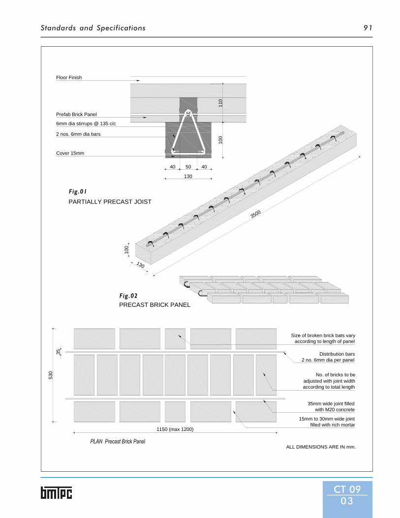
Standards and Specifications 91
130
100
3500
3553
0
1150 (max 1200)
Size of broken brick bats varyaccording to length of panel
Distribution bars2 no. 6mm dia per panel
adjusted with joint width according to total length
No. of bricks to be
35mm wide joint filledwith M20 concrete
15mm to 30mm wide jointfilled with rich mortar
PRECAST BRICK PANEL
PARTIALLY PRECAST JOIST
40 50 40
130
100
110
Floor Finish
Prefab Brick Panel
6mm dia stirrups @ 135 c/c
2 nos. 6mm dia bars
Cover 15mm
ALL DIMENSIONS ARE IN mm.
CT 0903
Fig.02
Fig.01

Standards and Specifications92
bricks panel and l/3 span shall betaken for design purpose and selfweight of joist and panel includingin-situ concrete and accident load,which in the absence of moreaccurate information, may be takenas half the imposed load given forstage II.
iii) Stage III, self weight of joist, deadweight of brick panels including in-situ concrete, imposed load inaccordance with IS 875 (Part 2) andload of roof or floor.
4.2.2 The partially precast concrete joistshall be designed as T-beam with 35mm flange thickness for stage III ofloading and as a partially precastbeam for stage I and II of loading.Reinforcement required withnormal loading for various span ofjoist for a spacing of 1200 mm c/cmay be taken from Table 1.
4.2.3 The joist shall be designed ascontinuous beam, it may bedesigned either as simply supportedor continuous T-beam in accordance
with IS 456.4.2.3.1 When the joist is designed as
continuous beam, it may bedesigned as doubly reinforced beam.When it is possible to weld thebottom reinforcement at supportsthe same shall be kept projecting. Ifthe welding is not possible, the joistshall be designed as singly reinforcedfor hogging bending moment atsupport. In such a case,redistribution of moment inaccordance with IS 456 may be
CT 0904
Fig.03

Standards and Specifications 93
resorted.4.2.4 A clear cover of 25 mm shall be
provided for longitudinalreinforcement.
4.3 When precast units are used forconstruction of building in highseismic zones, the roofs/floors shallbe strengthened as per the provisionof IS 4326.
5 Manufacturing of PrecastElements
5 .1 Prefabricated Brick Panels5.1.1 Mould: The mould for brick panels
shall be made from well seasonedgood quality timber or an equivalentwood substitute. For massproduction, moulds may be made ofmild steel or other rigid, nonabsorbent and non-corrodiblematerial such as FRP.
5.1.2 Casting: The moulds which areopen at bottom shall be kept on alevelled ground having thin layer ofsand or pucca floor or platform.Bricks properly wetted shall bearranged in the mould with outermost bricks touching the sides ofmould and keeping specified gaps inbetween bricks for joints. Brokenbrick bat shall be used for staggering
transverse joints as shown in Fig.2.The frogs of bricks shall faceupwards to provide shear key todeck concrete laid in-situ. 15mmthick layer of concrete or 1:3 cementcoarse sand mortar shall be placedin the longitudinal gaps between thebricks and two reinforcing bars shallbe provided over it. All the gapsbetween the bricks shall then befilled with mortar or concrete. Themould may be removed just aftercasting.
5.1.3 The panels shall be cured for 14 daysby sprinkling water and dried for 14days thereafter before they are usedin construction.
5.2 Partially Precase Joists5.2.1 Same as 5.1.1.5.2.2 Casting: Moulds shall be placed on
a smooth and levelled surface and25mm thick layer of M-20 gradeconcrete shall be laid in the mould.Over this concrete layer,reinforcement shall be placed. M-20grade concrete shall be poured inthe mould and well compacted byvibration. The mould may bestripped after 2 to 3 h. of castingdepending upon weather.
5.2.3 The joist shall be water cured for 2
weeks followed by air-curing foranother 2 weeks, before using themin construction.
6 Method of ConstructionThe floor/roof shall be assembledin the following sequence.
6.1 The joists and panels shall be cleanedproperly by using wire brush toremove dust and loose particlesbefore lifting and placing in positionfor assembly of floor/roof.
6.2 The surface of wall on which thejoists are placed shall be overlaid by10-15 mm thick layer of 1:4 cementand coarse sand mortar. Top of themortar shall have smooth finish. Thejoist shall be placed above this andproperly aligned.
6.3 The joists shall be proppedimmediately after placing, at twoplaces dividing the length of joist inthree equal spans. The props shallnot be removed before the insituconcrete has hardned. The minimumbearing of joists over walls shall be75 mm. The wall in between thejoists shall be raised to the level ofjoists using cement sand (1:6)mortar.
6.4 The brick panels shall be placed over
Table 1: For Steel Reinforcement Requirement for Various Spans for Joists for a Spacing to 1200 mm c/c
Reinforce- Clear Span of Joists in mm ment at 1800 2100 2400 2700 3000 3300 3600 3900 4200 Bottom 2-8φ 2-10φ 2-10φ 2-12φ 3-10φ 3-12φ 2-16φ 2-16φ 3-16φ
o r o r o r o r o r o r o r 1-10φ2-8‡ 2-8‡ 3-8‡ 1-10‡+ 1-12‡+ 2-12‡+ 3-12‡ o r o r
2-8‡ 2-8‡ 1-10‡ 2-16‡ 1-16‡+2-12‡
Middle 1 No.6φ 1 No.6φ 1 No.6φ 1 No.6φ 1 No.8φ+ 1 No.8φ+ 1 No.8φ+ 1 No.10φ+1 No.10φ+ Top 1 No.6φ 1 No.6φ 1 No.6φ 1 No.6φ 1 No.6φ 1 No.6φ 1 No.6φ 1 No.6φ 1 No.6φ Stirrups 6φ 6φ 6φ 6φ 6φ 6φ 6φ 6φ 4 No.6φ
130 mm 130 mm 130 mm 130 mm 130 mm 130 mm 130 mm 130 mm 100 mmc/c c/c c/c c/c c/c c/c c/c c/c c/c
at ends and130 mm c/c inmiddle portion
+= Can be reduced to 6φ if proper handling is ensured. φ = Mild steel bars ‡= Deformed bars
CT 0905
Standards and Specifications94
the joists/walls, side by side afterlaying a 6 mm thick layer of 1:4cement coarse sand mortar toensure propoer setting of panels.Frogs of bricks should be keptupwards while casting and placing ofbrick panel on joists. The minimumbearing of at least 40 mm shall beprovided for panels. A gap of 20-40mm is left in between adjacent panels.
6.5 All the joints between panels shallbe filled up with M-20 concrete withthe help of wooden strips placedbelow the joists and held in positionduring filling of concrete. The stripcan be removed immediately bysliding horizontally.
6.6 D i s t r i b u t i o n / t e m p e r a t u r ereinforcement shall than be laid overthe panels in both directions i.e.parallel and perpendicular to thejoists. This may consist of atleastone 6 mm mild steel grade I barconforming to IS 432 in eachdirection.
6.7 Concrete shall then be laid over thepanels and joists to a depth of 135mm above the top of panels.
6.8 The roof shall then be finished witha floating coat of 1:3 cement, finesand mortar of not more than 6mmthickness just after laying the insituconcrete.
6.9 The in-situ concrete shall be curedfor atleast 2 weeks by ponding.
6.10 The spouts for rain water shall bemade while laying the deck concreteto avoid any seepage through thejoints.
6.11 To have proper drainage of rainwater, a slope of 1:40 shall be givento roof either by raising the joistson one side or if needed, otherwiseby completing and finishing the wallswith the required slope.
7 Floor/Roof Finish7.1 Floor/roof finish shall be provided
after the in-situ concrete hashardened. Guidance for providingdifferent types of floor/roof finishesmay be taken from relevant IndianStandards. Waterproofing treatmentto the roofs shall be provided asdesired. Guidance for this may betaken from relevant Indian Standards.For waterproofing using bitumenfelts, bitumen mastic, glass fibretissue reinforced bitumen and limeconcrete, IS 1346, IS 4365, IS 9918and IS 3036 may be referred.
8 Sampling8.1 All prefabricated brick panels and
joists of the same size manufacturedfrom similar materials and undersimilar conditions of productionshall be grouped together toconstitute the lot.
8.2 Five units of prefabricated brick paneland joist shall be selected at randomout of a lot consisting of 300 unitsor less. For a lot bigger than 300units, 5 units shall be selected forevery 300 units or part thereof. Inorder to ensure randomness ofselection, procedure given in IS 4905may be followed.
8.3 The samples shall be suitablymarked for future identification ofthe lot it represents.
9 TestsTests shall be conducted on samplesof the units as given in IS 14143.
9.1 Dimensional test and deflectionrecovery test shall be routine testswhereas failure load test shall be atype test. Type test is intended toprove the suitability andperformance of a new design andsize of a component. Failure load test
is applied at the time of any changein the design/size.
10 Criteria for Conformity10.1 If four out of five samples satisfy the
shape and dimensionalrequirements, the lot representedby the sample shall be deemed tohave passed the dimensionalrequirements. If more than onepanel fails to satisfy the dimensionalrequirements, the lot representedby sample shall be rejected.
10.2 In the deflection recovery test as perIS 14143, if the deflection 24 h afterthe removal of imposed load is atleast 75 percent of the deflectionunder the load for 24 h, the unitsshall be deemed to have passed thetest. If the deflection recovery is lessthan 75 percent, the lot representedby the unit shall be rejected. If themaximum deflection in mm, shownduring 24 h under load is 40 l2/D,where l is the effective span in mmand D, the overall depth of thesection in mm, it is not necessaryfor deflection recovery to bemeasured and the recoveryprovision mentioned in this clauseearlier shall not apply.
10.3 In the case of the failure loadperformed in accordance with IS14143, the unit shall carry a load atleast equal to 1.33 times thecharacteristic load to pass the test.If the load at failure is less than 1.33times the characteristic load, the loadrepresented by the sample shall berejected.
11 Marking11.1 Each component shall be legibly and
indelibly marked with identificationof the source of manufacture, monthand year of manufacture.
CT 0906

Standards and Specifications
CT 10
Specificationsfor
FerocementRoofing
Channels
1 GeneralFerrocement is a thin walled concrete, reinforced withclosely spaced layers of galvanized wire mesh. Ferrocementroofing channels are prefabricated lightweight, slenderelement shell structures. The standardization on theseroofing channels is based on Optimized concrete mix,Controlled vibration and Dimensional regularity in shapeand size.
2 Dimensions and Tolerances2.1 There are two portions in a channel: Shell, Curved portion
and Nibs, the square edges at the bottom. The clear baylength shall be 750 mm and the outer to outer dimensionincluding the nibs 840 mm. The rise of Arch shall be 290mm and shell thickness 25mm. The bottom nib dimensionshall be 40 x 45 mm. Length of the full channel can be upto6100 mm. (Fig.1)
2.2 Tolerance limit for thickness, bay length & nibs shall bewithin ±1.00 which ensure consistency of channels in termsof strength, performance and durability.
2.3 Porosity measured as dampness (%) of ponding area shallnot exceed 5% of contact area with water in pond test.
2.4 Bottom surface finish measured as pore >5 mm in nos.shall not be more than 0 and pores <2 mm in nos. shall notbe more than 2.
3 Materials3.1 The Cement to be used shall be Ordinary Portland Cement
43 grade conforming to IS 8112. The Fine Aggregate ofsand or crusher dust passing 4.75mm sieve, free from clay,loam shall be used. Sand shall confirm to the followinggrading:
Sieve size % passing through10mm 1004.75mm 90-1002.36mm 75-1001.18mm 55-70600microns 35-59300microns 8-30150microns 0-10
The ratio of cement and fine aggregate shall be 1:2 to 1:3 byweight. Water used shall be potable and free from organicmatter. Chlorides & sulphates shall not exceed permissiblelimits. Water- Cement Ratio shall be 0.45 to 0.55 (by weight)for getting the required strength and durability.
CT 1001

Standards and Specifications96
3.2 Reinforcement: 8-16mm High Strength Deformed Bars depending upon application.
Bottom Steel ReinforcementSpan Range Roof Application Floor ApplicationUpto 3.00 m 2 Nos. 6mm φ 2 Nos. 8mm φ3.00 - 3.30 m 2 Nos. 8mm φ 2 Nos. 8mm φ3.30 - 3.60 m 2 Nos. 10mm φ 2 Nos. 10mm φ3.60 - 3.90 m 2 Nos. 10mm φ 2 Nos. 10mm φ3.90 – 4.20 m 2 Nos. 10mm φ 2 Nos. 12mm φ4.20 – 4.50 m 2 Nos. 10mm φ 2 Nos. 12mm φ4.50 – 4.80 m 2 Nos. 12mm φ 2 Nos. 12mm φ4.80 – 5.10 m 2 Nos. 12mm φ 2 Nos. 16mm φ5.10 – 5.40 m 2 Nos. 12mm φ 2 Nos. 16mm φ5.40 – 5.70 m 2 Nos. 12mm φ 2 Nos. 16mm φ5.70 – 6.10 m 2 Nos. 12mm φ 2 Nos. 16mm φ
Mesh Reinforcements: 200mm stripof MS square welded mesh of 25 mmopening along crown of channel GIwire mesh of hexagonal pattern of22 gauge, 12mm openingthroughout the shell.
4 Structural Design4.1 The channels shall be designed to
ensure 250kg/cm2 of 28 dayscompressive strength and in such away that the roof of floor, as thecase may be, shall be able to carryloads as per IS-875. Channels are todesign as idealized T-beam whenthey are laid in succession one afterthe another on roof. The valleyportion formed between theadjacent channels constitutes theweb of the idealized T-beams and thefilling concrete is to act as the flangeof the beam. Once the channeldimension and geometric areoptimized and standardized, all theparameter except thereinforcement becomes constant.
4.2 The reinforcement in the channel isthe tensile reinforcement thatresists bending moment caused byloads and the span. For astandardized channel profile,moment carrying capacity ofchannels in roofs or floors can beincreased or decreased usingvarious steel rods reinforcement asgiven in 3.2.
4.3 Other than tensile reinforcement,the channel shall satisfy other designrequirement such as bendingcompression and shear. Bendingcompression is governed by thegrade of concrete and shear isresisted primarily by reinforcement(mesh reinforcement) provided inthe shear zone. The thickness ofconcrete fil l ing and mesh
CT 1002
FERROCEMENT ROOFING CHANNELS
Fig.01ACHANNEL SECTION
Fig.01BEQUIPMENT FOR MAKING
FERROCEMENT ROOFING CHANNEL
ALL DIMENSIONS ARE IN mm

Standards and Specifications 97
reinforcement provided in thechannel can be suitably designed forthe shear stresses. This will alsotake care of handling stresses thatare developed while using channelsduring lifting, transportation andhoisting.
4.4 Serviceability requirement such asdeflection of channels should also beconsidered in the design of thechannel.
4.5 Such standards are set not only forproduct but for the building system.They include strength, performanceand durability specifications.Ferrocement roofing channel can beused in two different applications viz.simple roofs (Flat terrace) andimmediate floors (for upper storeyliving). Accordingly, the standardsare given in Table-1.
5 Casting and Curing5.1 Mesh Preparation5.1.1 Chicken Wire mesh - galvanised, 22
gauge, mesh opening 12mm &hexagonal, wire netting - uniformWelded mesh - galvanised or MS, of14 gauge & 25mm square opening
Reinforcement - Deformed barsBinding Wire - 20 gauge.All steel shall be cleaned of dust &rust Chicken mesh (Lx1.5)x widthlaid flat on ground. Welded mesh(300 mm wide for apex) is tied overit. Reinforcement, as required, aretied on two sides. Chairs (usingwelded mesh) are placed asrequired.
5.2 Casting5.2.1 Wash Sand or fine aggregate Mix:
1:2 to 1:2.5. Dry mix Cement & FineAggregates / Sand. W/C ratio 0.45
to 0.55 (by weight) is used. Addwater later. Use of mixerrecommended.
5.2.2 Mesh is placed on mould. Chairs shallbe used for spacing. Mesh shall bealigned correctly and stoppers placedcorrectly. Top part of the mould isclosed and all the nuts & bolts fixed.After fixing the hopper, all nuts &bolts are checked and tightened.
5.2.3 Measurable quantities of mortar arepoured at the same time. Thevibrator is switched on. ‘Karni’ isused to ensure uniform spread ofmortar. Process is repeated till nomore mortar is going inside themould.
5.2.4 Casting mix shall be used within 30min. of preparation. Uniformvibration required. No air gaps shallcome inside and mortar shall notleak. The process shall take about15 min.
5.3 Demoulding5.3.1 After 24 h. of setting, all the nuts &
bolts are carefully unscrewed. Thetongs are carefully placed on thebase of the top cover. They are thenlifted carefully and place on floor forcleaning. After the top cover hasbeen removed, tongs are carefully
CT 1003
Table 1: Performance StandardsMode of Use Simple Roof Intermediate FloorAccessibility Inaccessible AccessibleStructural StandardsLoad carrying capacity (kg/sqm.) 450 800Dead loads 75 75Superimposed loads 150 250Live loads 75 200Total loads 300 525Factor of safety 1.50 1.50Design loads 450 800Deflection to span ratio not to exceed 1/240 not to exceed 1/240PerformanceWater tightness Should not leak Should not leakDampness <20% area in contact <20% area in contact
with water in 24 h. with water in 24 h.
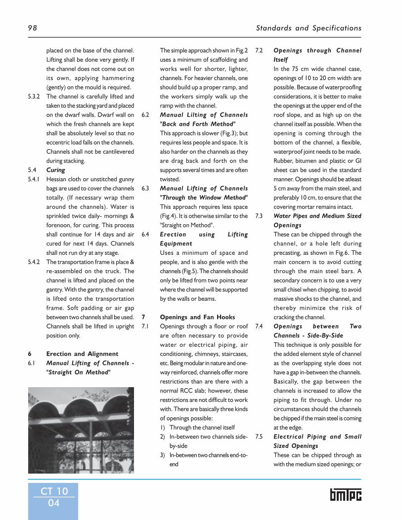
Standards and Specifications98
placed on the base of the channel.Lifting shall be done very gently. Ifthe channel does not come out onits own, applying hammering(gently) on the mould is required.
5.3.2 The channel is carefully lifted andtaken to the stacking yard and placedon the dwarf walls. Dwarf wall onwhich the fresh channels are keptshall be absolutely level so that noeccentric load falls on the channels.Channels shall not be cantileveredduring stacking.
5.4 Curing5.4.1 Hessian cloth or unstitched gunny
bags are used to cover the channelstotally. (If necessary wrap themaround the channels). Water issprinkled twice daily- mornings &forenoon, for curing. This processshall continue for 14 days and aircured for next 14 days. Channelsshall not run dry at any stage.
5.4.2 The transportation frame is place &re-assembled on the truck. Thechannel is lifted and placed on thegantry. With the gantry, the channelis lifted onto the transportationframe. Soft padding or air gapbetween two channels shall be used.Channels shall be lifted in uprightposition only.
6 Erection and Alignment6.1 Manual Lifting of Channels -
"Straight On Method"
The simple approach shown in Fig.2uses a minimum of scaffolding andworks well for shorter, lighter,channels. For heavier channels, oneshould build up a proper ramp, andthe workers simply walk up theramp with the channel.
6.2 Manual Lilting of Channels"Back and Forth Method"This approach is slower (Fig.3); butrequires less people and space. It isalso harder on the channels as theyare drag back and forth on thesupports several times and are oftentwisted.
6.3 Manual Lifting of Channels"Through the Window Method"This approach requires less space(Fig.4). It is otherwise similar to the"Straight on Method".
6.4 Erection using LiftingEquipmentUses a minimum of space andpeople, and is also gentle with thechannels (Fig.5). The channels shouldonly be lifted from two points nearwhere the channel will be supportedby the walls or beams.
7 Openings and Fan Hooks7.1 Openings through a floor or roof
are often necessary to providewater or electrical piping, airconditioning, chimneys, staircases,etc. Being modular in nature and one-way reinforced, channels offer morerestrictions than are there with anormal RCC slab; however, theserestrictions are not difficult to workwith. There are basically three kindsof openings possible:1) Through the channel itself2) In-between two channels side-
by-side3) In-between two channels end-to-
end
7.2 Openings through ChannelItselfIn the 75 cm wide channel case,openings of 10 to 20 cm width arepossible. Because of waterproofIngconsiderations, it is better to makethe openings at the upper end of theroof slope, and as high up on thechannel itself as possible. When theopening is coming through thebottom of the channel, a flexible,waterproof joint needs to be made.Rubber, bitumen and plastic or GIsheet can be used in the standardmanner. Openings should be atleast5 cm away from the main steel, andpreferably 10 cm, to ensure that thecovering mortar remains intact.
7.3 Water Pipes and Medium SizedOpeningsThese can be chipped through thechannel, or a hole left duringprecasting, as shown in Fig.6. Themain concern is to avoid cuttingthrough the main steel bars. Asecondary concern is to use a verysmall chisel when chipping, to avoidmassive shocks to the channel, andthereby minimize the risk ofcracking the channel.
7.4 Openings between TwoChannels - Side-By-SideThis technique is only possible forthe added element style of channelas the overlapping style does nothave a gap in-between the channels.Basically, the gap between thechannels is increased to allow thepiping to fit through. Under nocircumstances should the channelsbe chipped if the main steel is comingat the edge.
7.5 Electrical Piping and SmallSized OpeningsThese can be chipped through aswith the medium sized openings; or
CT 1004

Standards and Specifications 99
Fig.2: Manual Lifting “Straight on Method”
Fig.3: Manual Lifting “Back and Forth Method”
Fig.4: Manual Lifting “Through the Window Method”
Fig.5: Erection using Lifting Equipment
Fig.6: Openings through the Ferrocement Channel
CT 1005

Standards and Specifications100
in many cases, can be put throughthe gaps in between the channels asshown in Fig.7.
7.6 Openings between TwoChannels - End-To-EndFor larger openings such asstaircases, it is often necessary tostop one or two of the channelsshort of the wall support. One canthen support these channels in oneof three ways:1)With one or two pillars2)With one or two beams3)By hanging these channels on theadjacent channels.As the first two methods arecommon and self-explanatory,regarding (3), it has the advantagesof giving a clean look from below,and using a minimum of materials.Essentially, hanging a beam from theadjacent channels and then restingthe short channels inside this beam,This is illustrated in Fig.8.
7.7 Fan Hooks and OtherAnchorage'sWhile, in principle, these can be putanywhere, in practice, the two bestplaces are at the top of the channelor at the joint in-between twochannels. The best place will dependon which kind of channel is beingused; especially in the bare case. Inthe filled case, one may provide theadditional reinforcement requiredexternally (to be later covered withthe filling), (Fig.9). In the bare case,where the waterproofing isprovided by over-lapping the edgesof the channels, the best would beto put the anchorage in the lowerchannel edge (because ofwaterproofing). In order to facilitatethis, additional reinforcement needsto be built into the channel at thatspot during its fabrication (Fig.10).
8 Joining and Grouting8.1 In placing the channels on the roof,
there are essentially threepossibilities for joining themtogether to form the surface of theroof. In the majority of the simplecases, this will be side-to-side;however, sometimes it is alsointeresting to place them end-to-end, to cover longer spans or tocreate a sloping roof or overhang;or end-to-side to accommodate L-shaped buildings, or for architecturaleffect,The main problem in joiningchannels is to ensure waterproofing.Specifically, the problems are:
• Side-to-Side (Fig.11): This is themost common case. The maindifficulty is that as the structuremoves, or there is shrinkage in thegrouting, a crack in-between thechannels appears. If overlapping oradded element 'U'-shaped channelsare used, there is little problem asthe overlap or added-element (Ifdone with some room formovement) act as an expansionjoint. Otherwise, in the filled case,where the 'U' shape is less practical,minimum 'distribution' steel can beplaced in the slab (6 mm every 50cm) or a separate, elastic,waterproofing layer may beprovided.
• End-to-End (Fig.12): The tensionmoment comes from the bottom ofthe channel, in-between thesupports, to the top of the channel,at the support. The top steel of thetwo channels should be connected,or additional steel should be placed,or a crack will often appear as thetop of the channels pull apart due tocreep (additional deflection overtime) or thermal cycling.
• End-to-Side (Fig.13): This is thesame as the End-to-End situation,except that only the channels withthe ends on the support need toextend their top steel, in one fashionor another, over the top of one ortwo of the 'Side' channels.
8.2 Joining Channels - Filled CaseThe techniques for the filled case aresimilar to the bare case. The majoraddition is that because we arecreating a slab, we have both theopportunity and the necessity(because of the higher dead and liveloads) to put additional steel to fakeup tensile stresses over the fop ofthe supports. The main mistakemade in joining the channels end-to-end or end-to-side is to leave outthis top steel. The main mistakesmade in joining the channels side-by-side are:1) not cleaning and wire brushing
the edges before joining2) not using the mortar mix within
one hour of mixing3) not using the proper water/
cement ratio.4) not immediately beginning the
curing by covering the joint withdamp sand, plastic sheet, orother suitable material toprevent the mortar from dryingout.
5) additionally, for roofs, 6 mmdistribution steel every 30 to 50cm in the slab will help to takeup thermal stresses. But this isoptional depending on otherfactors such as waterproofingand weathering course,
9 Filling9.1 Normally the channels, by
themselves, provide a thin, irregularsurface. Often it is desirable to have
CT 1006

Standards and Specifications 101
Fig.7: Piping through gap in-between Channels
Fig.8: Staircase Opening, Overview & Section A
Fig.9: Fan Hook Anchorage Detail
CT 1007

Standards and Specifications102
Fig.10: Channels Joined Side-to-Side
Fig.12: Channels Joined End-to-Side
Fig.13: Filled Channels Joined Side-by-Side
Fig.11: Channels Joined End-to-End
CT 1008

Standards and Specifications 103
either a smooth surface, to use as afloor or terrace; or a thicker, moreinsulating section to protect fromthe heat. The valleys in-between thechannels in the '∩∩∩∩∩' orientation canbe readily filled in to provide such asurface and protection.
9.2 Broken Brick - Lime (BBL)Also called brick jelly lime, themixture of 1 part hydrated lime with2 parts by volume broken fired brick(nominally 1.5 cm dia. pieces alongwith the brick powder (surkhi) fromthe breaking process) creates a lowdensity, lower cost concrete. In thegeneral case, broken brick limeconcrete is recommended for thefil l ing because of its thermalcharacteristics and lower cost.
9.3 Concrete (M10)Normally filled channels are under-reinforced. In other words, thestrength of the resulting slab is notlimited by the compressive stressof the concrete, but by the size andtype of steel used. Except when using16 or 20 mm tension steel, themaximum compressive stress is 25kg/cm2 or less. The implication isthat either where a waterproof fillingis not required or wherewaterproofing is supplied by someother means (such as animpermeable membrane), a lowergrade concrete can be used.
9.4 Concrete (M20)As channels are only one-wayreinforced, it is advisable for highquality floors or roofs to lay
distribution steel in the slab. In orderto protect this steel, M20 or bettergrade concrete is recommended.
10 Equipment SpecificationsTable: 4.6 m or 6.1m in length, 0.9 mwide and freestandingMoulds: 5m x 4.6m or 4m x 6.1mlength fabricated in steelVibrators: 2 vibrators each poweredwith 1 HP motor, 440V, 3000 r.p.m.Lifting Frame: 4.6m or 6.1m inlength for lifting of green channelsGantry: chain pulley block or liftingcrane of capacity 2 tonnes with X-Y-Z motion provided through electricmotors or manuallyAccessories: consisting of liftingtongs, strength testing cubes, toolsand spanners.
CT 1009

Standards and Specifications104
List of Indian Standards referred in this Section
CONSTRUCTION TECHNIQUES
1 IS 432:1982 (Part l) Specification for Mild Steel and Medium Tensile Steel Bars and Hard-Drawn Steel Wire forConcrete Reinforcement - Part I : Mild Steel And Medium Tensile Steel Bars (Third Revision)
2 IS 456:2000 Plain and Reinforced Concrete - Code of Practice (Fourth Revision)3 IS 875:1987(Part 1) Code of Practice for Design Loads (other than Earthquake) for Buildings and Structures - Part
1 : Dead Loads – Unit Weights of Building Materials and Stored Materials (Second Revision)4 IS 875:1987 (Part 2) Code of Practice for Design Loads (Other than Earthquake) for Buildings and Structures - Part
2 : Imposed Loads (Second Revision)5 IS 875:1987 (Part 3) Code of Practice for Design Loads (other than Earthquake) for Buildings and Structures - Part
3 : Wind Loads (Second Revision)6 IS 1343:1980 Code of Practice for Prestressed Concrete (First Revision)7 IS 1346:1991 Code of Practice for Waterproofing of Roof with Bitumen Felt.8 IS 1489:1991 (Part 1) Portland-Pozzolana Cement – Specification - Part 1 : Fly Ash Based (Third Revision)9 IS 1489:1991 (Part 2) Portland-Pozzolana Cement – Specification - Part 2 : Calcined Clay Based (Third Revision)10 IS 1786:2008 High Strength Deformed Steel Bars and Wires for Concrete Reinforcement - Specification11 IS 2011:1980 Code of Practice for Flat Roof Finish – Mud Phuska12 IS 2645:2003 Integral Waterproofing Compounds for Cement Mortar and Concrete - Specification (Second
Revision)13 IS 3036:1992 Laying Lime Concrete for Waterproofed Roof Finish – Code of Practice14 IS 3935:1966 Code of Practice for Composite Construction (Fifth Reprint May 1993)15 IS 4326:1993 Earthquake Resistance Design Construction of Buildings – Code of Practice16 IS 4365:1967 Code of Practice for Application of Bitumen Mastic for Waterproofing of Roofs17 IS 4905:1968 Method of Random Sampling18 IS 6332:1984 Code of Practice for Construction of Floors and Roofs Using Precast Doubly-curved Shell
Units (First Revision)19 IS 6820:1987 Recommendation for Modular Coordination in Building Industry - Application20 IS 8112:1989 43 Grade Ordinary Portland Cement – Specification (First Revision)21 IS 9918:1981 Code of Practice for Insitu Waterproofing and Damp proofing Treatment with Glass Fibre
Tissue Reinforced Bitumen22 IS 10297:1982 Code of Practice for Design and Construction of Floors using Precast Reinforced/Prestressed
Concrete Ribbed or Core Slab Units23 IS 10440:1983 Code of Practice for Construction of RB & RBC Floors & Roofs24 IS 10505:1983 Code of Practice for Construction of Floors & Roofs using Precast Concrete Waffle Units25 IS 13990:1994 Precast Reinforced Concrete Planks & Joists for Roofing & Flooring - Specification26 IS 13994:1994 Design and Construction of Floor & Roof with Precast Reinforced Concrete Planks & Joists –
Code of Practice27 IS 14142:1994 Design and Construction of Floors & Roofs with Prefabricated Brick Panels – Code of Practice28 IS 14143:1994 Prefabricated Brick Panel and Partially Precast Concrete Joist for Flooring & Roofing -
Specification29 IS 14201:1994 Precast Reinforced Concrete Channel Units for Construction of Floors & Roofs - Specification30 IS 14215:1994 Design and Construction of Floors & Roofs with Precast Reinforced Concrete Channel Units –
Code of Practice31 IS 14241:1995 Precast Reinforced Concrete L-Panels for Roofing – Specification32 IS 14242:1995 Design and Construction of Roofs using Precast Reinforced Concrete L-Panels – Code of Practice.

Standards and Specifications 105
Building Components


Standards and Specifications
BC 0101
BC 01
Specificationsfor
PrecastSolid /Hollow
CementConcrete
Blocks
1 General1.1 Precast Solid/Hollow Cement Concrete Blocks shall be
used as masonry units for walls. The blocks shall be madeto required shape and sizes to fit the different constructionneed. They include strecher, corner, double corner or pier,jamb, header, bull nose, and partition block, and concretefloor units. Well-graded concrete mix shall be adopted forcasting of blocks.
1.2 Following types of blocks are used in the construction ofload bearing and partition walls:a) Hollow (open and closed cavity) load bearing concrete
blocks,b) Hollow (open and closed cavity) non-load bearing
concrete blocks, andc) Solid load-bearing concrete blocks and non-load bearing
concrete blocks.1.3 Hollow (Open and Closed Cavity) Concrete Block
The hollow (open and closed cavity) concrete blocks shallconform to the following grades:a) Grade A – These are used as load bearing units and
Shall have a minimum block density of 1500 kg/m3.These shall be manufactured for minimum averagecompressive strengths of 3.5, 4.5, 5.5, 7.0, 8.5, 10.0,12.5 and 15.0 N/mm2 respectively at 28 days,
b) Grade B – These are also used as load bearing units andshall have a block density between 1100 kg/m3 and 1500kg/m3. These shall be manufactured for minimumaverage compressive strengths of 3.5 and 5.0 N/mm2
respectively at 28 days.1.4 Solid Concrete Block – Grade C
The solid concrete blocks are used as load bearing unitsand shall have a block density not less than 1800 kg/m3.These shall be manufactured for minimum averagecompressive strength of 4.0 and 5.0 N/mm2 respectively.
2 Dimensions and Tolerances2.1 The actual dimensions of the blocks shall be 10 mm short
of the nominal dimensions. The nominal dimensions ofconcrete block shall be as follows:Length : 400, 500 or 600 mmHeight : 200 or 100 mmWidth : 50,75, 100, 150,200, 250 or 300 mm.
2.2 In addition, block shall be manufactured in half lengths of200, 250 or 300 mm to correspond to the full lengths. Fulllength and half length U-blocks may also be manufacturedfor the purposes of band and lintels.

Standards and Specifications108
Table-1: Minimum Face Shell and Web Thickness
All dimensions in millimetres.
S1 Nominal Face Thickness Total Web Thickness
No. Block Shell of Web per Course in Anv
Width Thickness 200 mm Length of Wall
Min Min Min
i) 100 or less 25 25 25
ii) 100-150 25 25 30
iii) 150-200 30 25 30
iv) Over 200 35 30 38
2.3 The nominal dimensions of the unitsare so designed that taking accountof the thickness or mortar joints,they will produce wall lengths andheights which will conform to theprinciples of modular co-ordination.
2.4 Blocks of sizes other than thosespecified in 2.1 may also be used bymutual agreement between thepurchaser and the supplier. In thecase of special concrete masonryunits such as jallie wall blocks andornamental blocks, the specifiedsizes may not necessarily apply.
2.5 Face shells and webs shall increasein thickness from the bottom to thetop of the unit. Depending upon thecore moulds used, the face shells and
webs shall be flared and tapered orstraight tapered, the formerproviding a wider surface formortar. The thickness of the faceshell and web shall be not less thanthe values given in Table-1.
2.6 A block with special faces shall bemanufacatured and supplied. Theseshall be semi-circular recess foraccommodating verticalreinforcement or conduits etc. Fig.1.
2.7 Tolerances:Following maximum deviation in theeach block shall be permittedLength ±5mmBreadth/width ±3mmHeight ±3mm
3 Materials3.1 Cement
33 grade ordinary Portland cement,conforming to IS 269 or 43 gradeordinary Portland cement,conforming to 1S 8112, or Portlandslag cement conforming to IS 455,or Portland pozzalana cement, flyash based conforming to IS 1489(Part 1), or Supersulphated cementconforming to IS 6909, or Rapidhardening Portland cementconforming to IS 8041, or WhitePortland cement conforming to IS8042, or Hydrophobic Portlandcement conforming to IS 8043, or53 grade ordinary Portland cementconforming to IS 12269, may beused.
3.1.1 When cement conforming to IS 269or IS 8112 or IS 12269 is used,replacement of cement by fly ashconforming to IS 3812 (Part 1) maybe permitted up to a limit of 25percent. However, it shall beensured that blending of fly ash withcement is as intimate as possible, toachieve maximum uniformity.
3.2 Aggregates3.2.1 The aggregates used in the
manufacture of blocks at the mixer
BC 0102

Standards and Specifications 109
BC 0103
or the mixing platform shall be cleanand free from deleterious matterand shall conform to therequirements of IS 383.
3.2.2 Fly ash conforming to IS 3812 (Part2) may be used for part replacementof fine aggregate upto a limit of 20percent .
3.3 WaterThe water shall conform to therequirements of IS 456.
3.4 Additives or AdmixturesAdditives or admixtures may beadded either as additives to thecement during manufacture, or asadmixtures to the concrete mix.Additives or admixtures used in themanufacture of concrete masonryunits may be:a) accelerating, water reducing,
air-entraining and superplasticizer conforming to IS9103,
b) Waterproofing agentsconforming to IS 2645, and
c) Colouring pigments.
3.5 Well-graded concrete mix shall beused for casting of the blocks. It isadvisable to adopt the precise mixdesign with the available ingredients.The concret mix used for the blocksshall not be richer than one part byvolume of cement to six parts byvolume of combined aggregatebefore mixing.
4 Manufacture4.1 Manual Method :
The mould shall be of mild steelplate of required size with handlesfor obtaining clean, sharp-edgedblocks with pre-finished faces. 8 to20 moulds can be arranged in a rowwith no gap in between to form abattery. Platform and moulds shallbe cleaned properly. Lubricating oilshall be applied inside the mouldsand on the area of platform underthe moulds. The moulds shall befilled up thoroughly and compactedwith a plate vibrator. Pressure isapplied on the handles of the high
frequency vibrator to impart thevibrations more effectively.Vibration shall be stopped as soonas slurry appears under the mouldsside. The mould shall be releasedwithin a few minutes of casting.
4.2 Mechanised Method:The blocks can be manufactured byvibro compaction type of machines.
4.3 Mixing4.3.1 Batching of the ingredients should
be done accurately and concretemixing shall be done in a mixer toachieve homogeneous mix.
4.3.2 Mixing shall be continued until thereis a uniform distributicm of thematerials, and the mass is uniformin colour and consistency.
4.4 Placing and Compaction4.4.1 The block should be compacted by
vibro-compaction and finished toproper size -without broken edges.
4.4.2 After ejection demoulding, theblocks shall be handled carefully toavoid damage. The bIocks shall beprotected until they are sufficiently
SPECIAL BLOCK FOR EMBEDDING VERTICAL STEEL40
90
5580
155
290
ALL DIMENSIONS ARE IN mm

Standards and Specifications110
hardened before starting curing.4.5 Curing4.5.1 The blocks hardened shall then be
cured as per IS 456 or by mist curingso as to deliver the specifiedstrength of block.
4.5.2 The blocks hardened mayalternatively be cured by steam.
4.6 DryingAfter curing the blocks, they shallbe dried for a period of 4 weeksbefore being used on the work. Incase of curing by steam, once lowpressure steam curing has beendone, the blocks shall be dried atambient temperature for a periodof seven days. The blocks shall thenbe stacked with voids horizontal tofacilitate through passage of air. Itshall be ensured that the blocks havebeen thoroughly dried and allowedto complete their initial dryingshrinkage before supply to thework-site.
5 Physical Properties of the Block5.1 All units shall be sound and free of
cracks or other defects whichinterfere with the proper pIacing ofthe unit or impair the strength orperformance of the construction.Minor chiping resulting from thecustomery methods of handlingduring delivery, shall not be deemedgrounds for rejection.
5.1.1 Where units are to be used inexposed wall construction, the faceor faces that are to be exposed shallbe free of chips, cracks, or otherimperfections, except that if notmore than 5 percent of aconsignment contains slight cracksor small chippings not larger than25 mm, this shall not be deemedgrounds for rejection.
5.2 The overall dimensions of the unitsshall be as per point 2 subject totolerances mentioned therein.
5.3 Block Density, CompressiveStrength at 28 days for various typesof blocks will be as per Table-2.
5.4 The water absorption, being theaverage of three units, whendetermined in the manner prescribed
in IS 2185 (Part 1) shall not be morethan 10 percent by mass.
5.5 The drying shrinkage of the unitswhen unrestrained being the averageof three units, shall be determinedin the manner described in IS 2185(Part 1) and shall not exceed 0.06percent.
5.6 The moisture movement of thedried blocks on immersion in water,being the average of three units,when determined in the mannerdescribed in IS 2185 (Part 1), shallnot exceed 0.09 percent.
6 Method of Construction6.1 The wall made of solid/hollow
concrete masonry blocks shall bedesigned like any other masonrywall. The values of basic permissiblestresses given in IS 1905 ‘Structuralsafety of building masonry wall’ shallalso be adopted for these blocks.
6.2 Provision of vertical reinforcementat corners and openings to impartdesired protection to the structurein seismic regions shall be made by
Table 2 : Physical Properties of Blocks
Type Grade Density of Block Minimum Average Minimum CompressiveCompressive Strength of Units Strength of Individual Units,
kg/m2 N/mm2 N/mm2
A(3.5) 3.5 2.8A(4.5) 4.5 3.6
Hollow (open and A(5.5) Not less than 5.5 4.4closed cavaty) load A(7.0) 1500 7.0 5.6bearing unit A(8.5) 8.5 7.0
A(10.0) 10.0 8.0A(12.5) 12.5 10.0A(15.0) 15.0 12.0
B(3.5) Less than 1500 but 3.5 2.8B(5.0) not less than 1100 5.0 4.0
Solid load C(5.0) Not less than 1800 5.0 4.0
bearing unit C(4.0) 4.0 3.2
BC 0104

Standards and Specifications 111
BC 0105
using special blocks with recess.6.3 Average joint thickness shall be 10
mm.6.4 Control of shrinkage cracks and in
joints - It shall be controlled by usingthe mortar weaker than that ofblocks and metal reinforcementsshall be embedded in block masonryat openings or other points wherethe section of a wall changes.
6.5 Wetting of blocks - Wetting maygenerally not be necessary. Theblocks shall be dry at the time ofbeing laid in the wall. In dry hotclimate, the blocks shall be wettedon the surface only by sprinklingwater.
6.6 Laying of blocks -Recommendations for laying ofblocks are similar to those for layingof brick work.
6.6.1 Vertical joints in alternate coursesshall be broken by 1/3 overlap or byusing smaller length blocks.
6.6.2 At T junction of two 200mm walls,a vertical joint at the centre line ofcross wall shall be broken inalternate courses by providing 2/3size blocks.
6.6.3 At T junction of 200mm wall with100 mm wall and 100 mm wall with100 mm wall, the joints shall bestaggered by using 1/3 size and 2/3size blocks respectively.
6.7 Service pipes and electrical fittings -The nitches for fixing electricalswitch boards can be created by usingthinner 100 mm thick precast blocks.In case the opening is required afterconstruction, full blocks shall betaken out. The cement concrete shallbe filled in remaining gap, if any.
7. The testing, sampling and markingof blocks shall be as per the IS 2185(Part 1).

Standards and Specifications
BC 02
SpecificationsforPrecastConcreteStoneMasonryBlocks
BC 0201
1 General1.1 Concrete Stone masonry blocks are made of large size
stone spalls bonded together with lean cement concretemix. Precast concrete stone masonry block are true insize and shape.
1.2 Concrete Stone Masonry Blocks are a precast cementconcrete solid blocks having stone spalls 25-30 percent ofblock volume and cement concrete with dense stoneaggregate and sand. It is 100 percent solid.
1.3 Stone Spalls are broken stone pieces of varying sizesobtained by breaking the natural river boulders or quarrystones.
1.4 In case of Stone Face Exposed Blocks the stone spallsare exposed at one of its face. This face, when forms theexposed wall face, the wall gets the texture of stones.
2 Dimensions and TolerancesThe nominal dimensions of concrete stone masonry blocksshall be as given in Table-1.
2.1 The term ‘nominal’ means that the dimension includes thethickness of the mortar joint. Actual dimensions shall be 10mm short of the nominal dimensions.
2.2 A special block with semi-circular recess can be cast foraccommodating vertical reinforcement or conduits or pipesfor earthquake resistant construction.
2.3 Tolerances2.3.1 The maximum variation in the units shall not be more
than specified.Length : ±5mmBreadth : ±3mmHeight : ±3mm
3 Materials3.1 Stone Spalls
The stone spalls shall be of size ranging from 50mm to250mm in dimension.The stone spalls shall be hard, solid,round in shape, durable, free from decay and weathering.These shall not be flaky. The spalls shall have rough surfacefor better bond with cement concrete. Good quality stones,such as granite, sand stone and basalt shall be used. Slateshale or any other soft and flaky stone shall not be used.
3.2 Cement3.2.1 Ordinary and low heat Portland cement conforming to
IS 269, or Portland slag cement conforming to IS 455, orPortland pozzolana cement conforming to IS 1489 (Part1), or Supersulphated cement conforming to IS 6909, or

Standards and Specifications 113
Table 1: Dimensions of Blocks
Nominal Size (mm) Actual Size (mm)
Length Breadth Height Length Breadth Height
100 100 150 200 150 90 90 140 190 140
150 100 150 200 150 140 90 140 190 140
200 100 150 200 150 190 90 140 190 140
225 100 150 200 150 215 90 140 190 140
300 100 150 200 150 290 90 140 190 140
Rapid hardening Portland cementconforming to IS 8041, or WhitePortland cement conforming to IS8042, or Hydrophobic Portlandcement conforming to IS 8043 shallbe used.
3.2.2 When cement conforming to IS269 is used, replacement of cementby flyash conforming to IS 3812(Part 1) may be permitted up to alimit of 25 percent. However, itshall be ensured that blending offlyash with cement is as intimateas possible, to achieve maximumuni- formity.
3.3 Coarse aggregate shall be 10mm anddown grade conforming to IS 383.
3.4 Sand shall be well-graded, clean andfree from deleterious matter, andshall conform to IS 383. Besides, itshall have fine particles 15 to 20percent passing 300 micron ISSieve and 5 to I5 percent passing150 micron IS Sieve.
3.5 The grading of the combinedaggregates shall conform as nearas possible to the requirementsindicated in IS 383. It is recom-mended that the fineness modulusof the combined aggregates shallbe between 3.6 and 4.
3.6 Flyash conforming to IS 38I2 (Part2) may be used for partreplacement of fine aggregate up
to a limit of 20 percent.3.7 The water used in the manufacture
of precast concrete stone masonryblocks shall conform to thercquirements of IS 456.
4 Casting and Curing4.1 Blocks may be manufactured either
at construction site or in factory. Itshall be cast on platform using steelmoulds with surface vibrator forcompaction of cement concrete.
4.2 Mix4.2.1 The cement concrete mix for blocks
shall not be richer than 1:3:6 and shallnot be leaner than 1:5:8.
4.3 Placing and compaction4.3.1 Depending upon the size of the
stone spalls, these shall be usedeither in one layer or in two layers.When used in two layers, large sizespalls of 100mm and above shall beplaced in the bottom and concretepoured all around and at top, and shallbe tamped manually. Second layerof stone spalls of size 50 mm andabove shall be placed over the firstlayer, and again concrete is pouredall around and up to 20 to 30 mmabove the top level of mould.Afterwards compaction of concreteshall be achieved by placing platevibrator on the top of concrete filled.
BC 0202

Standards and Specifications114
4.3.2 Each stone spall shall have minimumspace of about 15 to 20 mm aroundit and between mould and spall toenable cement concrete to flow infor binding together the stone spallsand also to provide cover and giveshape to the block. For blocks withexposed stone texture, the stonespalls shall touch the surface of themould or the casting platform.
4.3.3 Blocks may be compactedmanually as well as mechanically.In case of manual compaction, theconcrete laid after the first layerof stone spalls shall be tampedwith mason’s tool and again itshall be tamped with suitabletampers and compacted from topand finally struck off level withtrowel.
4.3.4 In case of mechanical compaction,the mould shall be filled up tooverflow, vibrated and mechanicallytamped using external vibrator andstruck off level.
4.3.5 Demoulding shall be done 5 to 10minutes after compaction. In caseof fixed type mould it shall bepulled up with side handles while
BC 0203
SPECIAL BLOCK FOR EMBEDDING VERTICAL STEEL40
90
5580
155
290
ALL DIMENSIONS ARE IN mm
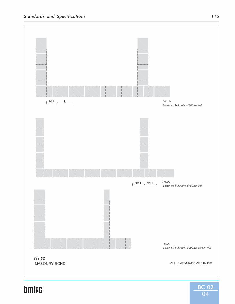
Standards and Specifications 115
BC 0204
Fig.02
Fig.2A
Fig.2B
Fig.2C

Standards and Specifications116
pressing down the block with theplate at top with thumb. In caseof split type mould, the sidesshall be removed first and thepartition plates (gang mould) shallbe pulled up subsequently.
4.3.6 After demoulding, the blocks shallbe protected until they aresufficiently hardened to permithandling without damage.
4.4 Curing - The blocks shall he curedby sprinkling water for at least 14days. There after the blocks shall bedried for a period of 2 weeks beforeuse in construction.
5 Physical Requirements5.1 General - All blocks shall be solid
and free of cracks or other defectswhich interfer with the properplacing of the unit or impair thestrength or performance of theconstruction.
5.2. Classification - The blocks shallbe classified according to the averagecompressive strength as given inTable 2.
5.3 Compressive Strength - Theminimum compressive strength at28 days, being the average of eightblocks, and the minimumcompressive strength at 28 days ofindividual blocks, when tested asdescribed in IS 12440 shall be asprescribed in Table.2.
5.4 Water Absorption - The waterabsorption, being the average ofthree blocks, when determined inthe manner prescribed in IS 12440shall not be more than 6 per centby mass.
5.5 The testing, sampling and markingshall be as per IS 12440.
BC 0205
Fig.02
Fig.2D
Fig.2E
Fig.2F

Standards and Specifications 117
BC 0206
Fig.03
Fig.02
Fig.2G
Fig.3A
Fig.3B
MASONRY BOND AND PILASTER

Standards and Specifications118
Table 2 : Compressive Strength of BlocksClass Designation Minimum Average* Minimum Strength
Compressive of IndividualStrength of Blocks Blocks
kg/cm2 kg/cm2
50 50 3560 60 4270 70 5090 90 63100 100 75
* For 100mm wide blocks (for 100mm thick walls) the minimum strength may be 35 kg/cm2
6 Method of Construction6.1 The wall made of solid concrete
masonry blocks shall be designedlike any other masonry wall. Thevalues of basic permissible stressesgiven in IS 1905 ‘Structural safety ofbuilding masonry wall’ shall also beadopted for precast concrete stonemasonry blocks.
6.2 Provision of vertical reinforcementat corners and openings to impartdesired protection to the structurein seismic regions shall be made byusing special blocks with recess(Fig.1).
6.3 The cutting of these blocks is notpossible, building dimensions shallbe planned to suit block dimensions.
Alternatively special size blocks canbe made.
6.4 Average joint thickness shall be10mm.
6.5 Shrinkage cracks and in joints shallbe controlled by using the mortarweaker than that of blocks, and metalreinforcements shall be embeddedin masonry at opening or otherpoints where the section of a wallchanges (Fig. 2E).
6.6 Wetting of blocks shall generally notbe necessary. The blocks shall be dryat the time of being laid in the wall.In dry hot climate, the blocks shallbe wetted on the surface only bysprinkling water.
6.7 Laying of blocks –
Recommendations for laying ofblocks are similar to those for layingof brick work. This is shown in Fig.2and 3.
6.8 Curing - The masonry shall be keptconstantly wet for at least 7 days.
6.9 Service pipes and electrical fittings -The nitches for fixing electricalswitch boards can be created by usingthinner 100 mm thick precast stoneblocks. In case the opening isrequired after construction, fullblocks shall be taken out. Thecement concrete shall be filled inremaining gap, if any.
6.10 Method of construction shallconform to the IS 14213.
BC 0207
Fig.03
Fig.3C
Standards and Specifications
BC 03
Specificationsfor
Hollowor Solid
LightweightConcreteMasonry
Units
1 General1.1 Hollow or solid light weight concrete masonry units can
be produced from wastes such as sintered flyash, light-weight aggregate or bloated clay light-weight aggregate.Their use will be specially economical in high rise buildingsto reduce the dead weight. The following type of light-weight concrete masonry units are used in theconstruction of load-bearing and non-load bearing walls:A Hollow (open and closed cavity) load bearing
concrete blocks,B Hollow (open and closed cavity) non-load bearing
concrete blocks,C Solid load-bearing concrete blocks, andD Solid non-load bearing concrete blocks.
2 Dimensions and Tolerances2.1 The nominal sizes of concrete block shall be as follows:
Length 400, 500 or 600 mmHeight 100 or 200 mmBreadth 50, 75, 100,150,200,250 or 300 mm
2.2 In addition, block shall be manufactured in half lengths of200, 250 or 300 mm to correspond to the full length.
2.3 Hollow concrete blocks shall be made either with twocores or three cores. Stretchers in the 200, 250 and 300mm breadth shall generally have concave ends, each endflange being grooved or plain. All 100 and 150 mm wideunits shall generally be made with plain ends.
2.3.1 Face shells and webs shall increase in thickness from thebottom to the top of the unit. Depending upon the coremoulds used, the face shells and webs shall be flared andtapered or straight tapered the former providing a widersurface for mortar. The minimum thickness of the face shelland web shall not be less than 20mm. However, for the topface shell of the closed cavity units, the minimum thicknessmay be less than 20 mm, but not less than 15 mm.
2.4 Tolerances on each unit shall be: length ± 5mm, height andbreadth ± 3.
3 Materials3.1 Cement: Ordinary portland cement, portland slag cement,
portland pozzolana cement, super sulphated cement, whiteportland cement, rapid harderning portland cement,hydrophobic portland cement conforming to relevantstandards can be used for manufacture of these blocks. Whenordinary and low heat portland cement is used, replacementof cement by fly ash conforming to IS 3812 (Part 1) may
BC 0301

Standards and Specifications120
be permitted up to a limit of 25percent. However, it shall beensured that blending of fly ashwith cement is as intimate aspossible, to achieve maximumuniformity.
3.2 Light-weight aggregate: Thelight-weight aggregate used formaking blocks shall conform to IS9142. The dry loose bulk density ofthe light-weight aggregates shall beas shown in above Table 1.
3.3 Water: The water shall conformto IS 456.
3.4 Additives and Admixtures :Additives or admixtures may beadded either as additives to thecement during manufacture, or asadmixtures to the concrete mix.Additives or admixtures used in themanufacture of concrete masonryunits may be:a) accelerating, water-reducing and
air entraining admixturesconforming to IS 9103,
b) colouring pigments,c) flyash conforming to IS 3812
(Part 2), andd) waterproofing agents
conforming to IS 2645.3.5 The additives or admixtures shall be
shown by test or experience to benot deterimental to the durabilityof the concrete.
4 Casting and Curing4.1 Concrete Mix: The concrete mix
used for blocks shall not be richerthan one part by volume of cement
Table I:
Fine aggregate - 1120 kg/m3 maximum
Coarse aggregate - 880 kg/m3 maximum
Combined aggregate - 1100 kg/m3 maximum
to six parts of combined fine andcoarse aggregates. Allowance shallbe made for bulking of materials, ifnecessary. Concrete shall benormally mixed in a mechanicalmixer for good results,
4.2 Casting of blocks: The blocks shallbe made by hand or mechanicallyoperated machine. Immediately theblock is made it should be releasedfrom the mould and removed withthe pallet to a covered shed, toprotect it against sun and strongwinds. The blocks shall normally bestored in the shed until they aresufficiently hardened to permithandling.
4.3 Curing: After 12 h. the blocks shallbe removed from the pallets andplaced in a curing tank or taken tocuring yard where these shall bekept moist for at least 21 days. Steamcuring of the blocks may also beadopted provided the requirementsof pressure or non-pressure steamcuring are fulfilled. For non-pressuresteam curing the blocks shall besubjected to the action ofthoroughly saturated steam at atemperature of 38°C to 54° C for aperiod not less than 24 h., or whennecessary, for such additional timeas may be necessary.
4.4 Drying: After curing the blocksshall be dried for a period of 4weeks before being used for theworks. The blocks shall be allowedto complete their initial shrinkagebefore they are use in construction.
5 Physical Requirements5.1 Classification: Load-bearing light
weight masonry units hollow (openand closed cavity) or solid shallconform to the following twogrades:
5.1.1 Grade A - These are used below andabove ground level in damp-proofcourse, in exterior walls that mayor may not be treated with a suitableweather-protective coating and forinterior walls.
5.1.2 Grade B - These are used aboveground level in damp-proof course,in exterior walls that are treated witha suitable weather-protectivecoating and for internal walls.
5.2 Non-load-bearing light-weightconcrete masonry units, hollow(open and closed cavity) or solidshall be used in interior walls,partitions, panels and for exteriorpanel walls in steel or reinforcedconcrete frame construction whenprotected from weather byrendering or by some otherefficient treatment.
5.3 Blocks/units shall be solid and freeof cracks or other defects whichinterfere with the proper placing orimpair the strength and performanceof the construction. The blockdensity shall not exceed 1600 kg/m3.The physical requirements shall beas prescribed in Table 2.
5.4 Drying Shrinkage: The dryingshrinkage of the units whenunrestrained shall be determined inthe manner described in IS 2185(Part II) Appendix-E and shall be asfollows:
5.4.1 Load-bearing light-weight concretemasonry units, hollow (open orclosed cavity) or solid,Grade A - 0.08 percent, maximum,
BC 0302

Standards and Specifications 121
Table 2: Physical RequirementsTypes and Grade Minimum Compressive Maximum Average Water
Strength Absorption, with Oven-dryMass of Concrete
Average of Individual unit, Less than 1360 Less than 16008 units, min Min. kg/m3 kg/m3
N/mm2 N/mm2
Hollow, load bearing
Grade A 7.0 5.5 - 290
Grade B 5.0 4.0 320 -
Hollow, non-load bearing 4.0 3.5 - -
Solid, load-bearing
Grade A 12.5 10.8 - 290
Grade B 8.5 7.0 320 -
and Grade B - 0.09 percent.maximum.
5.4.2 Non-Load-bearing light-weight -0.09 percent, maximum concretemasonry units.
5.5 Moisture movement of the driedblocks on immersion in water shallbe less than the drying shrinkagesas specified above by at least 0.01.
6 Surface Texture and Finish6.1 Concrete masonry building units
shall be given a variety of surfacetextures ranging from a very fineclose texture to a coarse opentexture by proper selection, gradingand proportioning of the aggregatesat the time of manufacture.
6.2 Textures may also be developed bytreating the face of the units whilestill green by wire brushing orcombing, by slightly eroding thesurface, by a fine spray of water uponit, and by splitting (split block).
6.3 Colour may be introduced byincorporating non-fading mineralpigments in the facing concrete orby applying a coloured Portlandcement grout or paint to the face of
BC 0303
the units soon after they areremoved from the moulds. Selectedcoloured aggregates may also beused in the facing and exposed bywashing with water or dilutehydrochloric acid.
7 The testing, sampling and markingshall be as per IS 12440.

Standards and Specifications
BC 04
SpecificationsforCellularLight-weightConcreteBlocks
1 General1.1 The cellular concrete is concrete which contains stable air
or gas cells uniformly distributed in the mix. It is a productconsisting of Portland cement, silica, pozzolana or pastescontaining blends of these ingredients and havinghomogeneous void or cell structure, attained withpreformed srable foam. The air cells are usually added atthe mixer as stable preformed foam metered from acalibrated nozzle and thoroughly blended into the mix. Inpreformed foam cellular concrete the density control isachieved by substituting macroscopic air cells for all or partof the fine aggregate. Normal weight coarse aggregate isusually not used. The blocks for masonry units of variousdimensions can be produced which are relatively large andtrue in size and shape from Cellular Light-weight Concrete(CLC).
2 Dimensions and Tolerances2.1 The CLC blocks shall be made in sizes and shapes to fit
different construction needs. They include stretcher, corner,double corner or pier, jamb, header, bull nose and partitionblock and floor units.
2.2 The term ‘nominal' means that the dimension includes thethickness of the mortar joint. Actual dimensions (lengthand height) shall be 10 mm short of the nominal dimension(or 6 mm short in special cases where finer jointing isspecified).
2.3 The nominal sizes of concrete block shall be as follows:Length 400, 500 or 600 mmHeight 250 or 300 mmBreadth 100,150,200 or 250 mm
2.4 In addition, block shall be manufactured in half lengths of200, 250 or 300 mm to correspond to the full length.
2.5 Tolerances on each unit shall be: length ± 5mm, height andbreadth ± 3.
3 Materials3.1 Cement: 43 or 53 Grade ordinary portland cement, rapid
harderning portland cement, sulphate resisting portlandcement, portland pozzolana cement, portland slag cementconforming to relevant standards may be used formanufacture of these blocks.
3.2 Sand: Sand conforming to IS 383 and to suit the final productdensity shall be used.
3.3 Fly Ash: Fly ash conforming to IS 3812 (Part 1) maybeused, if cements enumerated in 3.l except portland pozzalana
BC 0401

Standards and Specifications 123
cement and portland slag cement, areused and provided uniform blendingwith cement is ensured.
3.4 Water: The water shall conformto IS 456.
3.5 Foaming Agent: The foamconcentrate shall be of such chemicalcomposition that is capable ofproducing stable foam cells inconcrete, which can resist thephysical and chemical forcesimposed during mixing,transporting, pumping, placing andsetting of concrete. The foamingagent should meet the requirementsof IS 9103 and the foam producedshall be stable for duration beyondthe final setting time of Portlandcements. Such foaming agents shallbe completely harmless to concreteand embedded steel reinforcementand be non- toxic, non-flammableand biodegradable.
3.6 Additives and Admixtures :Additives or admixtures may beadded either as additives to thecement during manufacture, or asadmixtures to the concrete mix.Additives or admixtures used in themanufacture of concrete masonryunits may be:a) accelerating, water-reducing and
air entraining admixturesconforming to IS 9103,
b) colouring pigments,c) waterproofing agents
conforming to IS 2645.3.7 The additives or admixtures shall be
shown by test or experience to benot deterimental to the durabilityof the concrete.
4 Casting and Curing4.1 Mix
The concrete mix design indicatingthe proportions of variousingredients should be worked outcarefully keeping in view the desiredphysical properties of the finishedblocks.
4.2 BatchingThe quantities of various ingredientsshould be proportioned on the basisof weight, with due correction beingmade to the quantity of solidingredients on account of theirinherent moisture content.
4.3 MixingThe ingredients shall be mixed in amechanical mixer having rotatingdrum. These may also be mixed in amobile truck mixer. The dryingredients like sand, fly ash andcement shall be fed into the mixerfirst and thoroughly mixed toensure even distribution of cement.The appropriate amount of watershall be added thereafter continuing
the mixing. The preformed foam,which is made by blending the foamconcentrate, water and compressedair in predetermined proportions ina foam generator, calibrated for aspecific discharge rate, shall be addedin measured amount to the slurryof cement, sand, fly ash and water inthe batch mixer. After an additionalmixing to get uniform consistency,the slurry form of foamed cellularconcreteof desired wet unit weightshall be ready to be poured out intoforms/moulds, etc. When truckmixing equipment is used forfoamed cellular concrete, thepreformed foam should be added atthe job site just prior to pumping orotherwise conveying the concreteinto forms, unless it is demonstratedthat a mix of the desired density andother properties can be deliveredto the job site after adding the foamat the batching plant.
4.4 MouldsGang moulds of required sizes ofblocks may be constructed either ofwood, steel, rigid plastics,aluminium, concrete or otheracceptable materials. The mouldsurfaces should be pre-coated withan approved ‘mould releasing agent’to ensure proper surface finish.
BC 0402
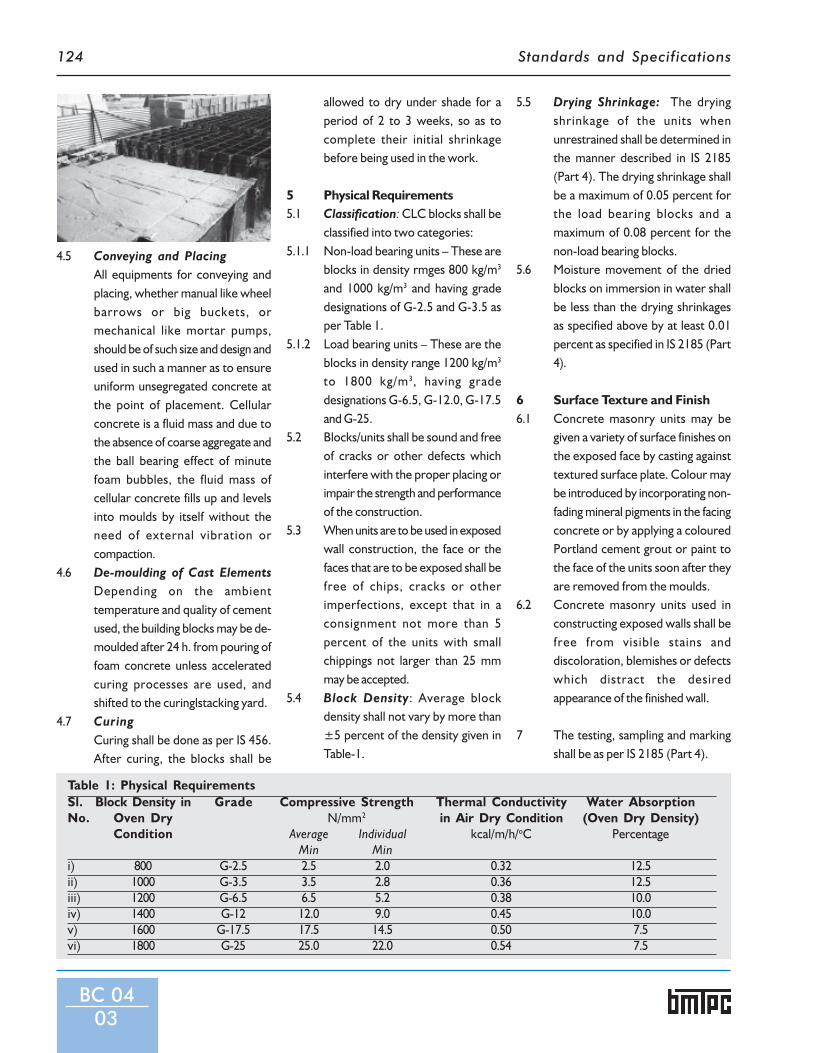
Standards and Specifications124
4.5 Conveying and PlacingAll equipments for conveying andplacing, whether manual like wheelbarrows or big buckets, ormechanical like mortar pumps,should be of such size and design andused in such a manner as to ensureuniform unsegregated concrete atthe point of placement. Cellularconcrete is a fluid mass and due tothe absence of coarse aggregate andthe ball bearing effect of minutefoam bubbles, the fluid mass ofcellular concrete fills up and levelsinto moulds by itself without theneed of external vibration orcompaction.
4.6 De-moulding of Cast ElementsDepending on the ambienttemperature and quality of cementused, the building blocks may be de-moulded after 24 h. from pouring offoam concrete unless acceleratedcuring processes are used, andshifted to the curinglstacking yard.
4.7 CuringCuring shall be done as per IS 456.After curing, the blocks shall be
allowed to dry under shade for aperiod of 2 to 3 weeks, so as tocomplete their initial shrinkagebefore being used in the work.
5 Physical Requirements5.1 Classification: CLC blocks shall be
classified into two categories:5.1.1 Non-load bearing units – These are
blocks in density rmges 800 kg/m3
and 1000 kg/m3 and having gradedesignations of G-2.5 and G-3.5 asper Table 1.
5.1.2 Load bearing units – These are theblocks in density range 1200 kg/m3
to 1800 kg/m3, having gradedesignations G-6.5, G-12.0, G-17.5and G-25.
5.2 Blocks/units shall be sound and freeof cracks or other defects whichinterfere with the proper placing orimpair the strength and performanceof the construction.
5.3 When units are to be used in exposedwall construction, the face or thefaces that are to be exposed shall befree of chips, cracks or otherimperfections, except that in aconsignment not more than 5percent of the units with smallchippings not larger than 25 mmmay be accepted.
5.4 Block Density: Average blockdensity shall not vary by more than±5 percent of the density given inTable-1.
Table 1: Physical RequirementsSl. Block Density in Grade Compressive Strength Thermal Conductivity Water AbsorptionNo. Oven Dry N/mm2 in Air Dry Condition (Oven Dry Density)
Condition Average Individual kcal/m/h/oC PercentageMin Min
i) 800 G-2.5 2.5 2.0 0.32 12.5ii) 1000 G-3.5 3.5 2.8 0.36 12.5iii) 1200 G-6.5 6.5 5.2 0.38 10.0iv) 1400 G-12 12.0 9.0 0.45 10.0v) 1600 G-17.5 17.5 14.5 0.50 7.5vi) 1800 G-25 25.0 22.0 0.54 7.5
5.5 Drying Shrinkage: The dryingshrinkage of the units whenunrestrained shall be determined inthe manner described in IS 2185(Part 4). The drying shrinkage shallbe a maximum of 0.05 percent forthe load bearing blocks and amaximum of 0.08 percent for thenon-load bearing blocks.
5.6 Moisture movement of the driedblocks on immersion in water shallbe less than the drying shrinkagesas specified above by at least 0.01percent as specified in IS 2185 (Part4).
6 Surface Texture and Finish6.1 Concrete masonry units may be
given a variety of surface finishes onthe exposed face by casting againsttextured surface plate. Colour maybe introduced by incorporating non-fading mineral pigments in the facingconcrete or by applying a colouredPortland cement grout or paint tothe face of the units soon after theyare removed from the moulds.
6.2 Concrete masonry units used inconstructing exposed walls shall befree from visible stains anddiscoloration, blemishes or defectswhich distract the desiredappearance of the finished wall.
7 The testing, sampling and markingshall be as per IS 2185 (Part 4).
BC 0403

Standards and Specifications
BC 05
Specificationsfor
PrecastReinforced
ConcreteDoor
and WindowFrames
1 General1.1 Precast RC door and window frames are alternate to
traditional timber frames. They are more suitable in wetareas and are resistant to termite, fungus and fire ascompared to wooden frames. Door and window framesare precast reinforced concrete of similar cross sectionof wooden frames. The maximum opening width of precastreinforced concrete door and window frames are restrictedto 2250 mm.
2 Dimensions and Tolerances2.1 Precast reinforced concrete door and window frames shall
be 60 x100 mm or 70 x 75 mm in cross-section for singlerebate door and 60x 120 mm for two rebates.
2.2 The tolerance in dimensions shall be of ± 2 mm
3 Materials3.1 Cement shall be ordinary portland cement or portland slag
cement or portland pozzolana cement or rapid harderningportland cement or high strength ordinary portland cementconforming to relevant Indian Standards. The aggregatesshall consist of well graded mixture of clean coarse and fineaggregate. The size of coarse aggregates shall be 10mm andbelow. The aggregates shall conform to IS 383 and IS 456.(Fig.1).
3.2 Steel reinforcement shall conform to IS 432 (Part 1) and ISl786. Reinforcement shall be a minimum 3 bars of 6 mm diaor equivalent of about 1.5 percent of the sectional area ofthe concrete member whichever is more. It shall be cleanand free from loose millscale, loose rust, mud, oil, greaseor any other coating (which may reduce the bond betweenthe concrete and steel).
3.3 The mix proportion of the concrete shall be such as toproduce a dense concrete not weaker than grade M-25.
4 Casting and Curing4.1 Mould : The mould shall be of steel. Provision shall be
made in the mould to accommodate fixing devices forhinges and hold fast.
4.2 Construction and finish: Each member of the frame shallhave a dense surface finish free from voids, honeycombingand showing no coarse aggregate. Compaction byvibration may be done using a vibrating table or a shuttervibrator Any small defects may be removed by rubbingwith carborundum stone before erection of the frame.Plastering or touching shall not be permitted.
BC 0501

Standards and Specifications126
BC 0502
Fig.02 Fig.02
Fig.1B
Fig.01
Fig.1A
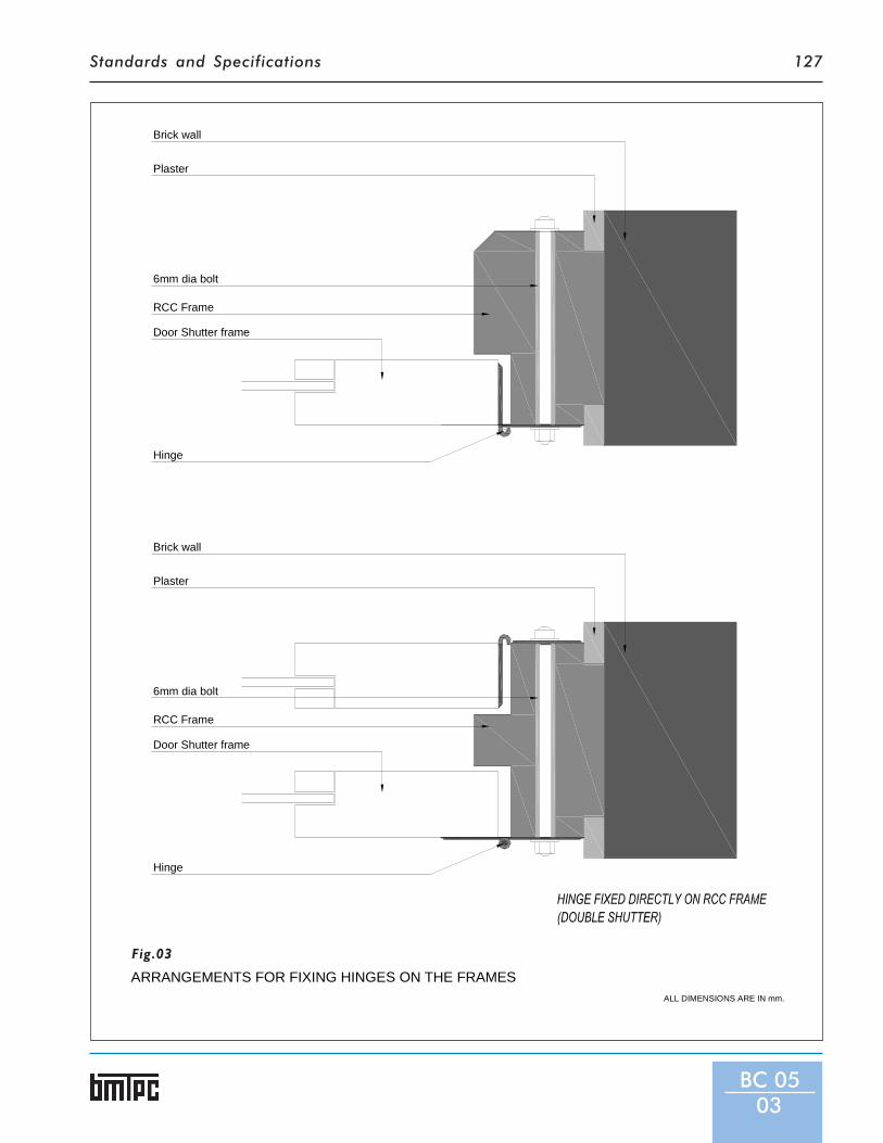
Standards and Specifications 127
BC 0503
Hinge
Door Shutter frame
RCC Frame
6mm dia bolt
Plaster
Brick wall
Plaster
6mm dia bolt
RCC Frame
Door Shutter frame
Hinge
Brick wall
ARRANGEMENTS FOR FIXING HINGES ON THE FRAMESALL DIMENSIONS ARE IN mm.
Fig.03

Standards and Specifications128
BC 0504
Fig.04
Fig.05
Welding
M.S.Flat 6mm thick
Main reinforcement of 6mm
100
106
60
3 mm stirrups6 mm dia bar
Welding30
30 50 or 130 30
METHOD OF FIXING TOWERBOLTS TO RCC FRAMES
FIXING HINGE TO RCC FRAMES
WITH WOOD BLOCK INSERT
Precast frame
150 x 35 x 35 mmWooden block
Bolt
HINGE
* ALL DIMENSIONS ARE IN mm.

Standards and Specifications 129
4.3 Positioning of reinforcement :The longitudinal reinforcement foreach of the vertical or horizontalmember shall be in one piece. Thelongitudinal bar shall be firmally heldby means of at least 3 mm dia steelstirrups spaced at not more than 300mm c/c.
4.4 Casting: The entire frame may becast complete in one piece orseparately. The vertical andhorizontal members of the framemay be cast in separate parts. Theentire frame shall be assembled atsite. If the frame is cast in separateparts (see Fig.2), one of thereinforcing bars of the vertical postsshall be kept projected to fit intothe corresponding holes horizontalmember for rigid bonding. Thehole in the head member shall beslightly larger than the bar diameterto facilitate easy insertion of theprojected bar. After assembly at site
the holes shall be grouted withcement slurry 1:1.5 (cement:sand).
4.5 Arrangements for Fixtures andFittings: Suitable arrangements forfixing of hinges shall be provided inthe frame by any one of thefollowing methods (Fig.3):
4.5.1 Hinge directly attached to frame:L type flap hinge may be attacheddirectly to the reinforced cementconcrete frame with the help of 6mm dia mild steel bolt (see Fig.3).
4.5.2 Hinge welded to frame:The hingemay be welded to two numbersmild steel flat 30 x 5 mm size and70mm long, embedded in thereinforced concrete frame. Gaswelding is recommended.
4.6 Tower bolts: Suitable arrangementsshall be provided in the frame forthe receiving tower bolts, slidingbolts and other door and windowfixtures as shown in Fig.4 & 5.
4.7 Hold fasts : 3 nos. hold fast of 40x
3mm flat shall be fixed with themachine screws to M.S. anchors orrubber plug/bushes alreadyprovided on the back of each of thevertical member of the door frame.In case of windows 2 nos. hold fastshall be provided in the each verticalmembers (see figures IA and IB).
5 Method of Construction:5.1 The vertical members shall be held
in position and the top memberplaced over them. The frame shallbe plumbed, aligned, andsupported temporarily till theconcrete around the hole fast hasproperly set and hardened.
5.2 The window door frames havingsills, the bottom member shall befirst placed in the position and theother members erected on thisbase.
5.3 Cement slurry 1:1.5 (cement:sand)shall be used in grouting the jointsbetween the vertical and horizontalmembers of the door frames (Fig.2).
6 The testing, sampling and markingshall be as per IS 6523.
BC 0505

Standards and Specifications
BC 06
SpecificationsforFerrocementDoorShutters
1 General1.1 The Ferrocement is an alternative material for making
door and window shutters. It could be described as a layerof steel meshes embedded in a mortar mix. Ferrocementis a composite material consisting of rich cement sandmortar normally in 1:3 or 1:2 proportions and can be madeto get any shape with mild steel sections/bars and morethan one layer of chicken/wire mesh/expanded mesh etc.
2 Dimensions and Tolerances2.1 The ferrocement shutters shall be in following dimensions.
However, the shutters can be manufactured in whateversize is specified by users.Panelled or flush shutters sizeHeight = upto 2500 mmWidth = upto 1500mm
Thickness of Flush Shutters shall be minimum 8mm andmaximum 12mm.Thickness of Panelled ShuttersStiles & rails minimum = 20mmStiles & rails maximum = 25mmPanels minimum = 12mmPanels maximum = 14mm
Weight:Between 20 to 50 kg/m2
For flush shutters, 30 kg/m2
2.2 Tolerances : Height ±8mm, width ±5mm, thickness±2mm.
3 Materials3.1 The door shutters with ferrocement of single leaf, double
leaf, and jali shutter, panelled, one side panelled and otherside flush, both sides flush, shutter with glass peepingwindow can all be cast with this technology using steelmoulds. The fixing of the shutters shall be achieved eitherwith hinges or on pivots.
3.2 Ferrocement shall consist of following materials: steel,cement, sand and water.
3.3 The type and number of layers of mesh used inferrocement door and window shutters shall depend onthe proposed utilisation which influences the requiredstrength. The most commonly used steel reinforcementsin ferrocement are:
BC 0601

Standards and Specifications 131
- Galvanized or non-galvanizedwire mesh in various gauges
- Chicken mesh.- Woven mesh.- Expanded mesh.- Welded mesh.- Small diameter mild steel wires.- Binding wire.- Steel bars (mild or tor).- M.S.Angles (Additional
supports)3.4 The ferrocement shutters shall be
of different designs and thicknessesdepending upon the application anduse identified by engineer-in-charge. These shall be normallyprocured from the manufacturersunless at in-house production unitis proposed to be set up.
3.5 Ratio of the mix shall be given byWater:Cement:Sand (W:C:S) byweight. This ratio for ferrocementdoors is 0.40:1:1.5 by weight. Sandand cement shall first be evenlymixed, the required quantity ofwater shall be added afterwards.
4 Casting and Curing4.1 Mesh Preparation4.1.1 Hexagonal 12 mm x 0.71 mm (22
gauge) galvanized iron (GI)“chicken mesh”. Rolls of either 900or 1200 mm width shall be used asreinforcement.
4.1.2 Four separate pieces of mesh shallbe cut off with a wiremesh cutterEach piece shall be door size plus100 mm all around. They shall beflattened separately on the floor.
4.1.3 These 4 separate layers ofwiremesh shall be laid on top of eachother in alternate layers at rightangles to one another Two layers ofmesh projecting beyond the doormarking shall be folded in so thatthe final mesh size is 10mm less all
around than the actual door size forcement cover For folding the meshan aluminium or timber straightedge may be used. The 4 layers shallbe correctly bound together withbinding wire and the whole steelmatshall once more be lightly flattened.
4.1.4 A standard door size of 900mm wideand 2000 mm height needs 3 kg ofhexagonal 12mm x 0.71 mm wiremesh of 4 layers and 200 g of bindingwire.
4.2 Casting4.2.1 The portion of the casting platform
shall be oiled with a paint brush toensure easy demoulding.
4.2.2 The required amount of sand,cement and water is mixed onclean surface nearby or in a mixingvat.
4.2.3 The following quantity of materialsand water shall be required fordoor shutter size of 900x2000x12mm thick.water = 8.1 litrecement = 20.0 kgsand = 30.0 kg(dry)
4.2.4 A fine layer of mortar thickness notmore than 5 mm shall be spread outover the oiled surface.
4.2.5 The steel mat shall be softlypressed onto the spread outmortar layer taking care to positionit correctly. Two wooden oraluminium rulers shall be placedalong the two longest sides of thedoor to facilitate the filling up of thesecond layer of 5mm thick mortarover the steelmat.
4.2.6 A smooth finish shall be obtained bysprinkling a handful of cement andrubbing it in with a masons trowelby moving it in a circular mannerand special care shall be taken tofinish the top, sides and edges of theshutter neatly.
4.2.7 The cast door shutter shall be keptin postion at least for 12 h. forproper setting.
4.3 Demoulding4.3.1 The ferrocement door shutter shall
be demoulded by carefully insertinga large mason’s trowel under oneof the long sides of the door shutterand moved slowly under the wholelength of the door shutter toseparate the ferrocement platesoftly from the casting platform.The oil ensures that no bond hastaken place with the mortar duringthe casting and curing period.
4.3.2 The door shall now be ready forthe fitting of the hinges and locks.
4.4 Curing4.4.1 A pond shall be used to submerge
the whole product in order to havean absolutely reliable curingprocess.
4.4.2 Alternatively the freshly cast doorshutter shall be left in place on thecasting platform. Sand or coirdust
BC 0602

Standards and Specifications132
layer shall be spread out evenly overthe shutter. Water shall be sprinkledseveral times a day so that it doesnot get dry and remains moist forabout 15 to 21 days depending onweather.
5 Method of Construction5.1 In the simplest form the door
shutter is now ready to be fitted withhinges, handles and lockingarrangement. For this purpose300mm to 460mm steel Tee-hinges,
tower bolts, aldrops and rim locksmay be used.
5.1.1 The holes are premarked for hingesand locks.
5.1.2 An electric power drill with a smalldiameter masonry drill bit is usedto dril l the required holes.Afterwards a bigger size masonrydrill is used to enlarge the holes tothe required size.
5.1.3 The hinges are attached with bolts,nuts and washers.
5.1.4 Tower bolts, aldrops and rim locks
are fitted in the same way.
6 Painting6.1 A mastic paste made from chalk
powder and white cement primerpaint is prepared and applied on thetwo surfaces.
6.2 After the mastic has dried, the doorshutter is properly sand-papereddown and is ready for the final paintcoats.
BC 0603

Standards and Specifications
BC 07
Specificationsfor
PrecastFerocement
WaterTanks
1 General1.1 Ferrocement is a versatile material possessing unique
properties of strength and serviceability. It is made withclosely- knit wire mesh and mild steel reinforcing bars orwelded mesh filled with rich cement mortar (Fig. 1). Thematerials required for making it, namely, cement, sand,wire mesh, and welded mesh or mild steel reinforcingbars. Ferrocement combines the lightness of steel andmouldability of mortar and can be cast to any shape. Thesewater storage tanks are suited for residential andcommunity buildings.
1.2 Capacity1.2.1 The net capacity of the tank shall be taken as the volume
of the actual usable water confined between the levels ofthe centres of the overflow and out-let sockets.
1.2.2 Gross capacity of a tank shall be taken as the total storagecapacity including the dead storage and free board.
1.2.3 The following net capacities are recommended fordifferent uses:Uses Net Capacity (Litres)Domestic use 270, 540, 750 & 1250Industrial & 1250, 2500, 5000, 7500, 10,000Community use
2 Dimensions and Tolerances2.1 Ferrocement water tanks shall generally be made in
square, rectangular and circular shapes. The tanks shallhave flat bottom. The circular tanks having diameter morethan 2.0 meter, a shallow spherical dome, shall beprovided for the bottom or alternatively suitable filletsmay be provided at the junction of bottom slab and verticalwall.
2.2 Circular tanks, height to diameter ratio shall be 1.2.3 Rectangular tanks, length to breadth ratio shall be 1.5
where as height to length or breadth ratio shall be 0.5 to1.5. If the length of any side exceeds 1.5m it is desirable toprovide stiffness in the side walls at spacing not exceeding1.5m.
2.4 A free board of 75 mm shall be provided.2.5 Sizes of water tanks based on capacity is given in Table 1.2.6 Tolerances shall be ± 5mm for height, length and breadth
and diameter upto 1 m, and above 1 m the tolerance will be±10 mm. For wall thickness it shall be ± 2 mm
BC 0701

Standards and Specifications134
3 Materials3.1 The cement used shall conform to
IS 269 or IS l489(Part I and 2) or IS455.
3.2 The sand shall be clean, inert andfree from organic matter silt and claycontent shall be less than 3%. Sandshall conform to grading zone II ofIS 383. The maximum particle sizeshall be less than 1.18 mm.
3.3 Mild steel wire conforming to IS 280shall be used in the manufacture ofwire mesh. The mesh shall havehexagonal, rectangular or squareopenings. It shall be woven orwelded. The wires shall begalvanized before weaving. Aperturesize of 6 mm to 20 mm and wirediameter shall be 0.56 to 1.25 mm.In case of welded wire mesh thediameter of wire shall be not lessthan I mm.
3.4 Mild steel skeletal bars diameter shallbe from 3 mm to 10 mm conformingto 1S 432 (Part 1) or hard-drawnsteel wire IS 432 (Part 2) or harddrawn steel wire mesh fabric IS1566. Normally the diameter ofskelatal steel should be from 3 mmto 10 mm.
3.5 In case galvanized wire mesh isused with mild steel bars/wires,chromium trioxide at the rate of200 to 300 ppm of water shouldbe added to the water used formortar preparation.
3.6 Admixtures may be used inferrocement for reducing water-cement ratio without affecting theworkability and for gaining instrength and durability. Sucha.dmixture shall conform to IS 9103.Integral cement waterproofingcompound, when used, shallconform to IS 2645.
4 Design4.1 The minimum compressive
strength of cement mortar cubeshaving area of face equal to 50 cm2
shall be 25 N/mm2.4.2 The tensile stress in reinforcement
under service condition shall notexceed 200 N/mm2.
4.3 Ferrocement shall be treated as acomposite material for calculationof strength of sections. Theprinciples of reinforced concretemay also be used for calculation offlexural strength. Effective area ofsteel in the direction of principaltension shall be calculated forhexagonal wire mesh.
4.4 Laps in wire mesh, whereprovided, shall be not less than 100mm.
4.5 The skeletal steel shall be spaced atnot more than 300 mm centre tocentre in both directions. Laps inbars where, provided, shall be notless than 150 mm. The skeletalsteel may not be necessary in caseof mechanized or semi-mechanizedcasting processes.
4.6 The minimum wall thickness shallbe 12 mm for tanks up to 2000
litres capacity in case of mechanizedor semi-mechanized casting and 15mm for tanks up to 1000 litrescapacity when hand cast. For largercapacity tanks the wall thickness maybe 20 mm to 40 mm depending oncapacity.
4.7 The minimum thickness of the lid/cover slab shall in no case be lessthan 15 mm.
4.8 In case the bottom slab thicknessexceeds 30 mm, the slab may becast in ferrocement only. However,an intermediate plain concrete layerusing graded coarse aggregate ofnominal maximum size 6.3 mm maybe introduced between the wiremesh layers to achieve the designthickness without excessive use ofcement. In case of composite slab,the minimum thickness of top aswell as bottom layer offerrocement shall not be less than8 mm.
4.9 The minimum clear cover toreinforcement shall be 4 mm.
5 Method of Construction5.1 The tanks shall be constructed as per
IS 13356. The general fabrication offerrocement water tanks are givenin the figures 2 & 3.
5.2 Reinforcement : A cage made ofwelded mesh or mild steel rods, asper the details given separately fordifferent types of tanks form theskeletal reinforcement for theferrocement tanks. This mainreinforcement cage, once tied inposition, automatically takes therequired shape of the tank.Galvanized (GI) thicken mesh or GIsquare woven mesh as per therequirement forms the distributivereinforcement. This is tied orstitched together on either side of
BC 0702

Standards and Specifications 135
the cage using 20 gauge binding wire.5.3 The necessary pipe fittings required
for the inlet, outlet, overflow, scourpipe connecting pieces and liftinghooks are arranged and tied inposition. While forming the cage,care should be taken to see that thewall reinforcement is vertical andsufficient lap length is provided.Similarly, the reinforcement for topcover slab can also be made readyincluding the necessary liftinghooks.
5.4 The recommended mix proportionof mortar is one part of cement to1.5 to 2.5 parts of sand by weightand water cement ratio is 0.35 to0.45.
5.5 The minimum cross-sectional areaof main reinforcement in any one ofthe two directions shall not be lessthan 1 percent of the gross cross-sectional area of the element.
5.6 The cover shall be provided with amanhole opening of 500 or 600 mmdepending on the capacity of the tankand a suitable matching lid shall beprovided to cover the manholeopening.
Table I: Sizes of Ferrocement Water Tanks based on Capacity
Sl. Capacity Circular Square/RectangularNo. (litres)
Internal Height** Plan Inside* Inside Height** Plandiameter area length breadth* area(mm) (mm) (m2) (mm) (mm) (mm) (m2)
1 300 740 700 0.430 720 720 580 0.5182 400 800 800 0.503 800 800 640 0.6403 600 930 890 0.680 910 910 730 0.8284 800 1040 950 0.850 1000 1000 800 1.0005 1000 1100 1060 0.950 1080 1080 860 1.1666 1500 1260 1210 1.247 1240 1240 980 1.5387 2000 1400 1300 1.540 1350 1350 1100 1.822* Suitable rectangular base also can be adopted instead of square.
** Excluding free board.
5.7 The cover slab and lid shall be suchthat when positioned on the tanksno external dirt or water shall enterthe tank and contaminate the waterinside.
6 Casting and Curing6.1 Casting Platform: The cage is
made to the required shape and size,a separate shuttering is not necessaryfor casting the tank. However, aplain, perfectly horizontal castingplatform of the appropriate base areaof the tank is essential. This platformcan be of masonry, steel, or wood.The casting platform is to belubricated using mould oil in advanceof the casting of the tank base.
6.2 Casting:6.2.1 First, cement mortar paste shall be
made by mixing Portland cement andriver sand in 1:2 ratio by weight Theriver sand shall be sieved through asieve with an aperture size 2.36mmand mixed with cement thoroughlyin dry condition for evendistribution of cement If manualmixing is resorted to, water shallbe added only after dry mixing the
mortar. The quantity of water to beadded shall depend on the water/cement ratio of 0.45 to 0.5. It isrecommended to prepare aconsistent and workable cementmortar for casting ferrocementwater tanks.
6.2.2 The reinforcement cage shall beplaced on the lubricated levelplatform over 10mm thick cementmortar cover blocks at the base. Thebottom slab of the requiredthickness shall be cast by placing thealready prepared cement mortarpaste over the bottom slab part ofthe cage.
6.2.3 In the second stage, the vertical wallsshall be plastered with the cementmortar from outside the tank, withthe help of another one standinginside over the already cast baseslab. A piece of plywood may beused as a back-up on the inside whileforcing the mortar from outside.The mortar may be forced into thecage with uniform pressure andfinished to the required approximatethickness. This plastering applicationshall be done in layers of 150mm
BC 0703

Standards and Specifications136
height all-round continuously.Otherwise, there is the chance ofthe mesh reinforcement tilting dueto the extra weight of mortar onone side of the wall, resulting in thenon-verticality of the tank wall. Sincethe tank is unstable at this stage,maximum care should be taken sothat the plastered tank wall is notsubjected to unforeseen impacts.
6.2.4 After completing the plastering ofthe walls, the tank shall be leftundisturbed for 24 h. The mortar
would attain about half of its requiredstrength and the tank would attainstability by the next day. Thesurfaces on either side of the wallsare then finished to the exactrequired thickness using mortar ofthe same proportions. Cementslurry is applied over the finishedsurface of the tank by using a brush.The surface shall be finished smoothusing a trowel. Extra are shall betaken in finishing the area around thepipe fixtures.
6.2.5 The cover slab shall be castseparately on a level platform byfollowing the procedure adoptedfor base slab.
6.3 Curing6.3.1 The tank shall be cured after 24 h. of
finishing the surface of the tank.Continuous water spray for sevendays will be sufficient to attain therequired strength.
6.4 Painting6.4.1 Tanks which are properly cured shall
be put to use in about 10 days after
BC 0704
100 1040 1040 100
100
800
DETAILS OF WELDED MESH FOR
FOLD HERE FOLD HERE
SQUARE OR RECTANGULAR TANKS
TYPICAL CROSS SECTION OF FERROCEMENT ELEMENT
15
Mesh Reinforcement
High strength Mortar
Mild steel rod or weld mesh
ALL DIMENSIONS ARE IN mm.
Fig.02
Fig.01

Standards and Specifications 137
BC 0705
casting. Though the ferrocementtanks made by the above process aresafe against leakage and consequentcorrosion, it is preferable to paintthe interior of the tanks using aTankmastic paint or its equivalentcommonly known as drinking waterblack paint. On application by brush,this type of paint dries immediately.However, a day shall be allowed forits proper drying, before water isfilled in the tank.
6.5 Cover Slab6.5.1 The cover slab should be handled
carefully. If they are heavier andconsequently difficult for handling,separate man-holes may beprovided at the time of casting.Additional mild steel rodreinforcement shall be providedaround the manhole.
7 Water Tightness Test7.1 When filled with water, the external
faces of the tanks shall show no signof leakage and sweating and remainapparently dry over the period ofobservation of seven days afterallowing a seven day period forabsorption of water after filling. Thistest shall be done before paintingthe interior of the tanks.
7.2 In case any leakage is observedduring the test, necessaryrectifications by exposing the wiremesh at the desired locations andusing the same mortar as used inthe manufacture of tank shall becarried out and the tank shall beretested.
7.3 All the units shall be tested forwater-tightness before put in use.
8 The testing, sampling and markingshall be as per IS 13356.
200 3300
FOR OVERLAP
DETAILS OF WELDED MESH FOR CIRCULAR TANKS
10G x 10G100 x 100 mm
Welded Mesh bent to shape
ALL DIMENSIONS ARE IN mm.
Fig.03

Standards and Specifications
BC 08
SpecificationsforPrecastConcreteManholeCoversand Frames
1 General1.1 Precast concrete manhole covers and frames are alternate
to cast iron manhole covers used in sewerage and waterworks. These are manufactured as per IS 12592.
1.2 The specifications for precast reinforced cement concretemanhole covers intended for use in sewerage and waterworks shall be as under:
2 Dimensions and Tolerances2.1 Shapes - The shapes of precast concrete manhole covers
shall be square, rectangular, circular & lamphole.2.2 Dimensions & Tolerances – The dimensions and
tolerances on dimensions of frames shall be as shown inTable 1 but outside dimensions of cover at top shall matchwith the corresponding frame so that the maximumclearance at top between the frame and the cover allround the periphery is not more than 5 mm and the topsurface of the frame and cover is in level within a toleranceof ±5 mm.For facility of removing the cover from the frame, suitabletaper matching with taper given for the frame shall beprovided to the periphery of the cover (see Fig.1).
3 Materials3.1 Cement - Cement used for the manufacture of precast
concrete manhole covers shall conform to IS 269 or IS 455or IS 1489 (Part 1) or IS 1489 (Part 2) or IS 6909 or IS 8041or IS 8043 or IS 8112 or IS 12269.
3.2 Aggregates - The aggregates used shall be clean and freefrom deleterious matter and shall conform to therequirements of IS 383. The aggregates shall be well gradedand the nominal maximum size of coarse aggregate shallnot exceed 20mm.
3.3 Concrete - The mix proportions of concrete shall bedetermined by the manufacturer and shall be such as willproduce a dense concrete without voids, honey combingetc. The minimum cement content in the concrete shallbe 360 kg/m3 with a maximum water cement ratio of 0.45.Concrete weaker than grade M-30 shall not be used.Compaction of concrete shall be done by machinevibration.
3.4 Reinforcement - The reinforcement steel shall conformto Grade A of IS 2062 or IS 432 (Part 1) or IS 432 (Part 2) orIS 1786 as appropriate.Reinforcement shall be clean and free from loose millscale, loose rust, mud, oil, grease or any other coating
BC 0801
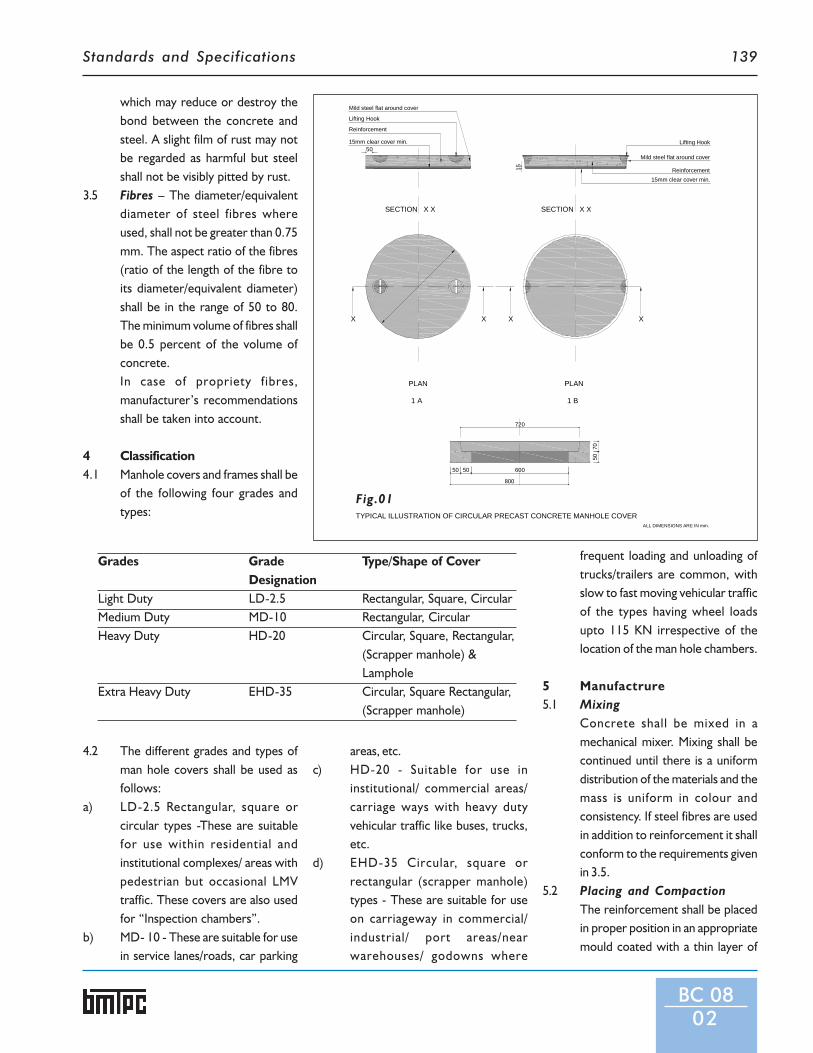
Standards and Specifications 139
Grades Grade Type/Shape of CoverDesignation
Light Duty LD-2.5 Rectangular, Square, CircularMedium Duty MD-10 Rectangular, CircularHeavy Duty HD-20 Circular, Square, Rectangular,
(Scrapper manhole) &Lamphole
Extra Heavy Duty EHD-35 Circular, Square Rectangular,(Scrapper manhole)
which may reduce or destroy thebond between the concrete andsteel. A slight film of rust may notbe regarded as harmful but steelshall not be visibly pitted by rust.
3.5 Fibres – The diameter/equivalentdiameter of steel fibres whereused, shall not be greater than 0.75mm. The aspect ratio of the fibres(ratio of the length of the fibre toits diameter/equivalent diameter)shall be in the range of 50 to 80.The minimum volume of fibres shallbe 0.5 percent of the volume ofconcrete.In case of propriety fibres,manufacturer’s recommendationsshall be taken into account.
4 Classification4.1 Manhole covers and frames shall be
of the following four grades andtypes:
4.2 The different grades and types ofman hole covers shall be used asfollows:
a) LD-2.5 Rectangular, square orcircular types -These are suitablefor use within residential andinstitutional complexes/ areas withpedestrian but occasional LMVtraffic. These covers are also usedfor “Inspection chambers”.
b) MD- 10 - These are suitable for usein service lanes/roads, car parking
areas, etc.c) HD-20 - Suitable for use in
institutional/ commercial areas/carriage ways with heavy dutyvehicular traffic like buses, trucks,etc.
d) EHD-35 Circular, square orrectangular (scrapper manhole)types - These are suitable for useon carriageway in commercial/industrial/ port areas/nearwarehouses/ godowns where
frequent loading and unloading oftrucks/trailers are common, withslow to fast moving vehicular trafficof the types having wheel loadsupto 115 KN irrespective of thelocation of the man hole chambers.
5 Manufactrure5.1 Mixing
Concrete shall be mixed in amechanical mixer. Mixing shall becontinued until there is a uniformdistribution of the materials and themass is uniform in colour andconsistency. If steel fibres are usedin addition to reinforcement it shallconform to the requirements givenin 3.5.
5.2 Placing and CompactionThe reinforcement shall be placedin proper position in an appropriatemould coated with a thin layer of
BC 0802
TYPICAL ILLUSTRATION OF CIRCULAR PRECAST CONCRETE MANHOLE COVER
Lifting Hook
Mild steel flat around cover
Reinforcement
15mm clear cover min.50
15
Mild steel flat around cover
Lifting Hook
Reinforcement15mm clear cover min.
SECTION X X SECTION X X
X X X X
PLAN PLAN
1 A 1 B
720
50 50 600
7050
800
ALL DIMENSIONS ARE IN mm.
Fig.01

Standards and Specifications140
Table 1: Dimensions of Frame(All dimensions are in mm)
Grade Description Clear Opening B C D E F
Designation in Frame Min. Min.
LD-2.5 Light Duty 450 x 450 50 50 50 50 566
Rectangular
LD-2.5 Light Duty 450 x 450 50 50 50 50 566 x 566
Square 450 x 400 50 50 50 50 516 x 516
LD-2.5 Light Duty 370 50 50 50 50 486
Circular 560 50 50 50 50 676
500 50 50 50 50 616
450 50 50 50 50 566
MD-10 Medium Duty 450 x 600 70 50 50 50 570 x 720
Rectangular
MD-10 Medium Duty 450 70 50 50 50 570
Circular 500 70 50 50 50 620
560 70 50 50 50 680
600 70 50 50 50 720
HD-20 Heavy Duty 900 x 450 90 75 75 75 1080 x 630
Rectangular
(Scrapper)
HD-20 Heavy Duty 560 x 560 90 75 75 75 740 x 740
Square
HD-20 Heavy Duty 450 90 75 75 75 630
Circular 500 90 75 75 75 680
560 90 75 75 75 740
600 90 75 75 75 780
HD-20 Heavy Duty 350 90 75 75 75 530
Lamphole
EHD-35 Extra Heavy Duty 900 x 560 100 75 75 75 1078 x 738
Rectangular
EHD-35 Extra Heavy Duty 560 x 560 100 75 75 75 738 x 738
Square
EHD-35 Extra Heavy Duty 450 100 75 75 75 628
Circular 500 100 75 75 75 678
560 100 75 75 75 738
600 100 75 75 75 778
Notes:1. Tolerance on C shall be ±5mm, tolerance on A, B, D and E shall be +5, -0 mm.2. For facility of removing the manhole cover suitable upward taper not more than 5o may be provided to the inner periphery
of the frame.3. If required for the removal of the moulds suitable taper not more than 5o can be given at the lower inner periphery of the
frame (see Fig.1).
BC 0803

Standards and Specifications 141
mould oil in case of frames andwithinthe protectivesheet in case ofcovers.Concrete shall be tilledtoslightly overalland compacted byvibration and struckoff level with atrowel.
5.2.1 Use of needle vibrators forcompacting the wet concrete mixcontaining fibres is notrecommended since the holes leftby the vibrator in the wet mix maynot close after its removal owing tothe interlocking of the fibres withthe mix. Compaction by means ofshutter or form or table vibratorsis recommended. In case of extraheavy duty and heavy duty cover andframe, compaction by means ofpressure-cum-vibration techniquemay also be employed so as toachieve dense and strong concrete.
5.2.2 Clear cover to reinforcement shallnot be less than 15 mm.
5.2.3 After demoulding, cover and frameshall be protected until they aresufficiently hardened to permithandling without damage.
5.3 Curing5.3.1 The hardened concrete manhole
cover and frame shall be placed in acuring water tank. The period ofcuring shall be as given in IS 456.
5.3.2 Steam curing of manhole cover andframes may be adopted, followedby normal curing for 7 daysprovided the requirements ofpressure or non-pressure steamcuring are fulfilled and the manholecover and frames meet therequirements specified in IS 12592.
5.4 Edge Protection and Finishing5.4.1 Frame - The top and inside surface
of frames shall be smooth. Toprevent the top outer edge frompossible damages, it shall beprotected by 25 mmx3 mm mild
steel flat as part of the frame.Sufficient number of steel connectorsshall be welded to the inner surfaceof the mild steel flat so as to connectit with the frame reinforcement andthese shall be embedded in theconcrete during casting. Exposedsurface of mild steel flat shall be givensuitable treatment withanticorrosive paint or coating.
5.4.2 Cover - To prevent any possibledamage from corrosion ofreinforcing steel, the underside ofthe covers shall be treated withanticorrosive paint. The top surfaceof the covers shall be given achequered finish. In order to protectthe edges of the covers frompossible damage at the time of liftingand handling, it is necessary that themanhole covers shall be cast with aprotective mild steel sheet ofminimum 2 mm thickness aroundthe periphery of the covers.Exposed surface of mild steel sheetshall be given suitable treatmentwith anti-corrosive paint or coating.
5.4.3 Suitable arrangements may be madefor fixing the manhole cover andframe in position on the manholes.
5.4.4 The manufacture of manhole coverand frame shall be such as to ensurethe compatibility of their seatings.For classes HD 20 and HD 35, theseseatings shall be manufactured in sucha way as to ensure stability and
BC 0804
quiteness in use. This may beachieved by grinding the contactsurface, if needed.
6 Lifting DeviceThe minimum diameter of mildsteel rod used as lifting device shallbe 10mm for light and 12 mm formedium duty covers and 16 mm forheavy and extra heavy duty covers.The lifting device shall be protectedfrom corrosion by hot dipgalvanizing or epoxy coating or anyother suitable material.
7 Physical Requirements7.1 General - All units shall be solid and
free from cracks and other defectswhich interface with the properplacing of the unit or impair thestrength or performance of theunits. Minor chipping at the edges/surface resulting from thecustomary methods of handlingduring delivery shall not be deemedfor rejecting.
7.2 Load Test - The breaking load ofindividual units when tested inaccordance with the methoddescribed in IS 12592 shall be notless than the values specified in Table2.
8 The testing, sampling and markingshall be as per IS 12592.
Table 2: Test Load and Diameter of BlockGrade of Type Load Diamter ofcover (kN) Block (mm)LD-2.5 Rectangular, 25 300
Square or circularMD-10 Rectuangular or 100 300
circularHD-20 Rectangular, 200 300
square or circularEHD-35 Rectangular, 350 300
square or circular

Standards and Specifications142
List of Indian Standards referred in this Section
BUILDING COMPONENTS
1 IS 269:1989 Ordinary Portland Cement, 33grade – Specification (Fourth Revision)
2 IS 280:1978 Specification for Mild Steel Wire for General Engineering Purposes
3 IS 383:1970 Specification for Coarse and Fine Aggregates from Natural Sources forConcrete (Second Revision)
4 IS 401:2001 Preservation of Timber – Code of Practice (Fourth Revision)
5 IS 432:1982 (Part l) Specification for Mild Steel and Medium Tensile Steel Bars and Hard-DrawnSteel Wire for Concrete Reinforcement - Part I : Mild Steel and MediumTensile Steel Bars (Third Revision)
6 IS 432:1982 (Part 2) Specification for Mild Steel and Medium Tensile Steel Bars and Ward-DrawnSteel Wire for Concrete Reinforcement - Part 2 : Hard-Drawn Steel Wire(Third Revision)
7 IS 455:1989 Portland Slag Cement-Specification (Fourth Revision)
8 IS 456:2000 Plain and Reinforced Concrete - Code of Practice (Fourth Revision)
9 IS 848:1974 Specification for Synthetic Resin Adhesives for Plywood (Phenolic andAminoplastic) (First Revision)
10 IS 875:1987 (Part 1) Code of Practice for Design Loads (other than Earthquake) for Buildings andStructures - Part 1: Dead Loads - Unit Weights of Building Materials andStored Materials (Second Revision)
11 IS 1489:1991 (Part 1) Portland-Pozzolana Cement – Specification - Part 1: Fly Ash Based (ThirdRevision)
12 IS 1489:1991 (Part 2) Portland-Pozzolana Cement – Specification - Part 2 : Calcined Clay Based(Third Revision)
13 IS 1566:1982 Specification for Hard-Drawn Steel Wire Fabric for Concrete Reinforcement(Second Revision)
14 IS 1786:1985 SupersedingIS 1139:1966 Specification for High Strength Deformed Steel Bars and Wires for Concrete
Reinforcement (Third Revision)
15 IS 1902:1993 Preservation of Bamboo and Cane for Non-Structural Purposes - Code ofPractice (First Revision)
16 IS 1905:1987 Code of Practice for Structural Use of Unreinforced Masonry (Third Revision)
17 IS 2062:1999 Steel for General Structural Purposes –Specification
18 IS 2185:2005 (Part 1) Concrete Masonry Units - Specification Part 1 : Hollow and Solid ConcreteBlocks
19 IS 2185:1983 (Part 2) Specification for Concrete Masonry Units - Part 2 : Hollow and SolidLightweightConcrete Blocks (First Revision)

Standards and Specifications 143
20 IS 2185:2008 (Part 4) Specification for Concrete Masonry Units - Part 4 : Preformed CellularConcrete Blocks
21 IS 2645:2003 Integral Waterproofing Compounds for Cement Mortar and Concrete –Specification (Second Revision)
22 IS 3812:1981 Specification for Fly Ash for Use as Pozzolana and Admixture (First Revision)
23 IS 3812:2003 (Part 1) Pulverised Fuel Ash - Specification - Part 1 : For Use as Pozzolana in Cement,Cement Mortar and Concrete
24 IS 3812:2003 (Part 2) Pulverised Fuel Ash - Specification - Part 2 : For Use as Admixture in CementMortar and Concrete
25 IS 3951:1975 (Part I) Specification for Hollow Clay Tiles for Floors and Roofs - Part I : Filler Type(First Revision)
26 IS 6523:1983 Specification for Precast Reinforced Concrete Door & Window Frames
27 IS 6909:1990 Supersulphated Cement – Specification (First Revision)
28 IS 8041:1990 Rapid Hardening Portland Cement – Specification (Second Revision)
29 IS 8042:1989 White Portland Cement - Specification
30 IS 8043:1991 Hydrophobic Portland Cement – Specification (Second Revision)
31 IS 8112:1989 43 Grade Ordinary Portland Cement – Specification (First Revision)
32 IS 9103:1999 Concrete Admixtures – Specification (First Revision)
33 IS 9142:1979 Specification for Artificial Lightweight Aggregates for Concrete MasonryUnits
34 IS 12269:1987 Specification for 53 grade Ordinary Portland Cement
35 IS 12440:1988 Specification for Precast Concrete Stone Masonry Blocks
36 IS 12592:2002 Precast Concrete Manhole Cover and Frame – Specification (First Revision)
37 IS 13356:1992 Precast Ferrocement Water Tanks upto I0000 litres Capacity specification
38 IS 14213:1994 Construction of Walls using Precast Concrete Masonry Blocks - Code ofPractice


Standards and Specifications 145
RatesAnalysis
for items of‘Standards andSpecifications’ forcost-effectiveInnovative BuildingMaterials andTechniques
Section 2

Standards and Specifications146
CONTENTS
Basis for Rate Analysis .............................................................................................................................................. 147
BUILDING MATERIALS
BM04 Specifications for Clay Flooring Tiles ......................................................................................................................148
BM05 Specifications for Burnt Clay Flat Terracing Tiles ....................................................................................................150
BM06 Specifications for Reinforced Gypsum Plaster Boards .............................................................................................152
BM07 Specifications for Bamboo Mat Corrugated Roofing Sheets ....................................................................................155
BM08 Specifications for Micro Concrete Roofing Tiles .....................................................................................................157
CONSTRUCTION TECHNIQUES
CT0 I Specifications for Precast Channel Unit for Floors / Roofs ......................................................................................158
CT02 Specifications for Precast R.C.C. Planks and Joists for Floors/Roofs ........................................................................161
CT03 Specifications for Thin R.C. Ribbed Slab for Floors and Roofs ................................................................................165
CT04 Specifications for Precast Concrete Waffle Units for Floors / Roofs ........................................................................167
CT05 Specifications for Prefabricated Reinforced Concrete L-Panels for Roofs ...............................................................169
CT06 Specifications for Precast Doubly Curved Shell Units for Floors/Roofs ...................................................................171
CT07 Specifications for Precast Reinforced / Prestressed Concrete Ribbed or Cored
Slab Units for Floors / Roofs ....................................................................................................................................175
CT08 Specifications for Reinforced Brick and Reinforced Brick Concrete Slabs for
Floors / Roofs ..........................................................................................................................................................177
CT09 Specifications for Prefabricated Brick Panel for Floors / Roofs ...............................................................................178
CT10 Specifications for Ferrocement Roofing Channels ...................................................................................................180
BUILDING COMPONENTS
BC01 Specifications for Precast Solid Cement Concrete Blocks .......................................................................................181
BC02 Specifications for Precast Concrete Stone Masonry Blocks ....................................................................................186
BC03 Specifications for Hollow or Solid Lightweight Concrete Masonry Units ...............................................................188
BC04 Specifications for Cellular Light-weight Concrete Blocks .......................................................................................188
BC05 Specifications for Precast Reinforced Concrete Door and Window Frames ...........................................................190
BC06 Specifications for Ferrocement Door Shutters ........................................................................................................193
BC07 Specifications for Precast Ferrocement Water Tanks ..............................................................................................193
BC08 Specifications for Precast Concrete Manhole Covers & Frames .............................................................................195
Basic Rates of Labour ...............................................................................................................................................................197
Basic Rates of Important Material and Carriage of Materials ...................................................................................................198

Standards and Specifications 147
The rate analysis of cost-effective and innovative items contained in ‘Standards and Specifications’ has been worked out. The rateanalysis has been done in two parts. Part – I has been done keeping in view all operations for production of building components/elements completed manually based on the practice followed earlier. With the development of machines by BMTPC and otherentrepreneurs, it has become possible to produce these building components/elements with partial mechanization by adopting theuse of these machines resulting in limited automation which gives enhanced production and better quality control. Second part ofrate analysis is focused on manufacture of building materials/components by mechanised process.
For analyzing the rates for various items of work, the coefficients have been derived from CBRI-Building Digest Notes, All IndiaStandard Schedule of Rates and Analysis as prepared by NBO which contains many of cost effective/innovative techniques andCPWD-DSR 2007. Some of the coefficients have been derived based on the BMTPC experience on utilization of the innovativetechniques in the field.
In order to achieve some uniformity and rationale, the basic rates for various materials and labour have been drawn from CPWDDSR – 2007. The basic rates of these materials and labour are in Indian Rupees & can vary from place to place and can be replaced inthe rate analysis as and when required.
This rate analysis will act as tool for adoption of innovative techniques in the field.
BASIS FOR RATE ANALYSIS
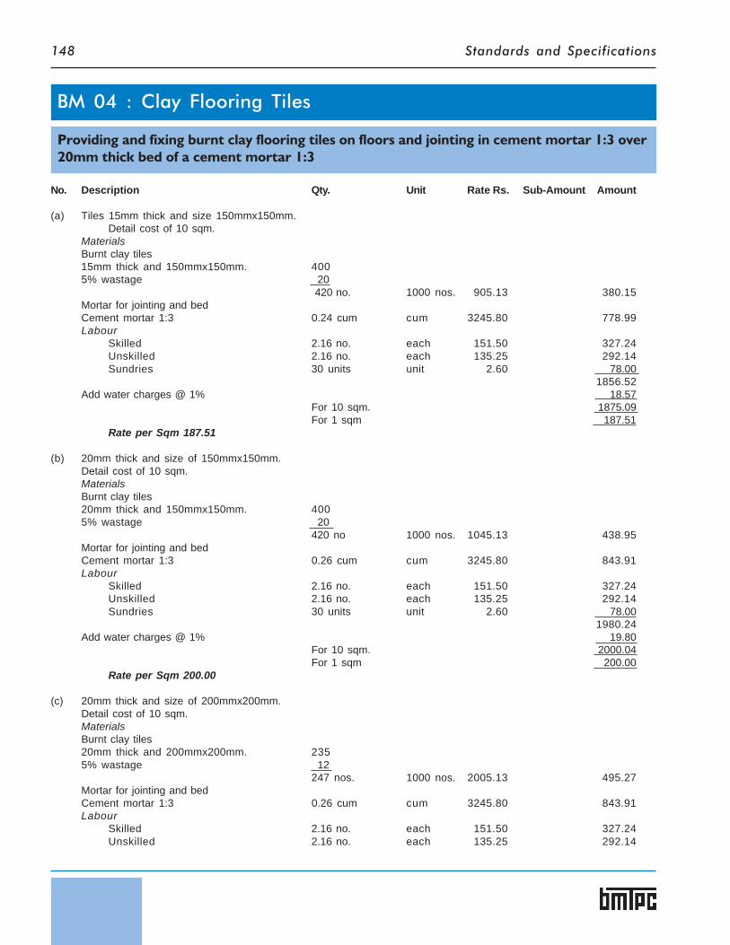
Standards and Specifications148
No. Description Qty. Unit Rate Rs. Sub-Amount Amount
(a) Tiles 15mm thick and size 150mmx150mm.Detail cost of 10 sqm.
MaterialsBurnt clay tiles15mm thick and 150mmx150mm. 4005% wastage 20
420 no. 1000 nos. 905.13 380.15Mortar for jointing and bedCement mortar 1:3 0.24 cum cum 3245.80 778.99Labour
Skilled 2.16 no. each 151.50 327.24Unskilled 2.16 no. each 135.25 292.14Sundries 30 units unit 2.60 78.00
1856.52Add water charges @ 1% 18.57
For 10 sqm. 1875.09For 1 sqm 187.51
Rate per Sqm 187.51
(b) 20mm thick and size of 150mmx150mm.Detail cost of 10 sqm.MaterialsBurnt clay tiles20mm thick and 150mmx150mm. 4005% wastage 20
420 no 1000 nos. 1045.13 438.95Mortar for jointing and bedCement mortar 1:3 0.26 cum cum 3245.80 843.91Labour
Skilled 2.16 no. each 151.50 327.24Unskilled 2.16 no. each 135.25 292.14Sundries 30 units unit 2.60 78.00
1980.24Add water charges @ 1% 19.80
For 10 sqm. 2000.04For 1 sqm 200.00
Rate per Sqm 200.00
(c) 20mm thick and size of 200mmx200mm.Detail cost of 10 sqm.MaterialsBurnt clay tiles20mm thick and 200mmx200mm. 2355% wastage 12
247 nos. 1000 nos. 2005.13 495.27Mortar for jointing and bedCement mortar 1:3 0.26 cum cum 3245.80 843.91Labour
Skilled 2.16 no. each 151.50 327.24Unskilled 2.16 no. each 135.25 292.14
BM 04 : Clay Flooring Tiles
Providing and fixing burnt clay flooring tiles on floors and jointing in cement mortar 1:3 over20mm thick bed of a cement mortar 1:3

Standards and Specifications 149
No. Description Qty. Unit Rate Rs. Sub-Amount Amount
Sundries 30 units unit 2.60 78.002036.56
Add water charges @ 1% 20.36For 10 sqm. 2056.92For 1 sqm 205.69
Rate per Sqm 205.69
(d) 25mm thick and size of 200mmx200mm.Detail cost of 10 sqm.
MaterialsBurnt clay tiles25mm thick and 200mmx200mm. 2355% wastage 12
247 nos. 1000 nos. 2485.13 613.83Mortar for jointing and bedCement mortar 1:3 0.28 cum cum 3245.80 908.82Labour
Skilled 2.16 no. each 151.50 327.24Unskilled 2.16 no. each 135.25 292.14Sundries 30 units unit 2.60 78.00
2220.03Add water charges @ 1% 22.20
For 10 sqm. 2242.23For 1 sqm 224.22
Rate per Sqm 224.22
(e) 30mm thick and size of 250mmx250mm.Detail cost of 10 sqm.MaterialsBurnt clay tiles30mm thick and 250mmx250mm. 1515% wastage 8
159 nos. 1000 nos. 4585.13 729.04Mortar for jointing and bedCement mortar 1:3 0.24 cum cum 3245.80 778.99Labour
Skilled 2.16 no. each 151.50 327.24Unskilled 2.16 no. each 135.25 292.14Sundries 30 units unit 2.60 78.00
2205.41Add water charges @ 1% 22.05
For 10 sqm. 2227.46For 1 sqm 222.75
Rate per Sqm 222.75
Rate Analysis for Cement Mortar 1:3 (1cement :3 Sand )Details of cost for 1 Cum.
Materials:Cement 10.20 bag bag 227.36 2319.07Sand 1.07cum cum 653.21 698.93Labour
Unskilled 0.60 no. each 135.25 81.15Semi-skilled 0.30 no. each 138.45 41.53
Mixer Charges (running and hire charges) 26.91 unit 2.60 69.97Sundries 13.52 unit 2.60 35.15
For 1 Cum 3245.80

Standards and Specifications150
No. Description Qty. Unit Rate Rs. Sub-Amount Amount
(a) 20mm thick 150mmx100mmDetail of cost for 10 sqm
MaterialsBurnt clay tiles20mm thick and 150mmx100mm. 5905% wastage 30
620 nos. 1000 nos. 805.13 499.18Mortar for grouting and jointingCement mortar 1:3 0.061cum cum 3245.80 197.99Labour
Skilled 1.5 no. each 151.50 227.25Unskilled 1.5 no. each 135.25 202.88Sundries 30 units unit 2.60 78.00
1205.30Add water charges @ 1% 12.05
For 10 sqm. 1217.35For 1 sqm 121.73
Rate per Sqm 121.73
(b) 20mm thick 175mmx125mmDetail of cost for 10sqmMaterialsBurnt clay tiles20mm thick and 175mmx125mm. 4135% wastage 21
434 nos. 1000 nos. 1135.13 492.65Mortar for grouting and jointingCement mortar 1:3 0.061cum cum 3245.80 197.99Labour
Skilled 1.5 no. each 151.50 227.25Unskilled 1.5 no. each 135.25 202.88Sundries 30 units unit 2.60 78.00
1198.77Add water charges @ 1% 11.99
For 10 sqm. 1210.76For 1 sqm 121.08
Rate per Sqm 121.08
(c) 20mm thick 200mmx150mmDetail of cost for 10 sqm
MaterialsBurnt clay tiles20mm thick 200mmx150mm 3065% wastage 16
322 nos. 1000 nos. 1525.13 491.09Mortar for grouting and jointingCement mortar 1:3 0.061cum cum 3245.80 197.99Labour
Skilled 1.5 no. each 151.50 227.25Unskilled 1.5 no. each 135.25 202.88Sundries 30 units unit 2.60 78.00
1197.21
Providing and fixing burnt clay tiles on roof terrace grouted with cement mortar 1:3(1cement:3 Sand ) and finished neat.
BM 05 : Burnt Clay Flat Terracing Tiles

Standards and Specifications 151
No. Description Qty. Unit Rate Rs. Sub-Amount Amount
Add water charges @ 1% 11.97For 10 sqm. 1209.18For 1 sqm 120.92
Rate per Sqm 120.92
(d) 20mm thick 225mmx175mmDetail of cost for 10 sqm
MaterialsBurnt clay tiles20mm thick 225mmx175mm 2365% wastage 12
248 nos. 1000 nos. 1975.13 489.83Mortar for grouting and jointingCement mortar 1:3 0.061cum cum 3245.80 197.99Labour
Skilled 1.5 no. each 151.50 227.25Unskilled 1.5 no. each 135.25 202.88Sundries 30 units unit 2.60 78.00
1195.95Add water charges @ 1% 11.96
For 10 sqm. 1207.91For 1 sqm 120.79
Rate per Sqm 120.79
(e) 20mm thick 250mmx200mmDetail of cost for 10 sqm
MaterialsBurnt clay tiles20mm thick 250mmx200mm 1875% wastage 10
197 nos. 1000 nos. 2485.13 489.57Mortar for grouting and jointingCement mortar 1:3 0.061cum cum 3245.80 197.99Labour
Skilled 1.5 no. each 151.50 227.25Unskilled 1.5 no. each 135.25 202.88Sundries 30 units unit 2.60 78.00
1195.69Add water charges @ 1% 11.96
For 10 sqm. 1207.65For 1 sqm 120.76
Rate per Sqm 120.76

Standards and Specifications152
No. Description Qty. Unit Rate Rs. Sub-Amount Amount
Consider a panel for gypsum board partitionof size 4.165 m long and 2.40 m height.
For 4.165 x 2.40 = 9.996 or 10 sqm
Details of cost of gypsum board partition for 10 sqmMaterialsGypsum board 8.50 mm thick 2 x 10 20.00 sqmAdd 5% for wastage 1.00 sqm
21.00 sqm sqm 145.00 3045.00Floor and ceiling channels50 mm x 32 mm x 0.50 mm 2 x 4.17 8.34 mAdd:- for wastage 0.66 m
9.00 m m 37.00 333.00Studs(48 mmx34mmx36mmx0.50mm)No. of studs 4.17 6.83607 or 7+1 8
0.61 8 x 2.4 19.20 m
Add:- for wastage 0.80 m20.00 m m 24.00 480.00
20 mm long screws 9 x 8 x 2 144.00 15 x 2 x 2 60.00
204.00Add:- for wastage 6.00
210.00 nos. cent 40.10 84.21
Dash fastners 8 x 2 16.00 nos. each 8.10 129.60Rawl plugs 7 x 2 14.00 nos. each 1.00 14.00Plaster of Paris (Gypsum Anhydrous)88% of 10 sqm 8.80Add:- for wastage 0.20
9.00 kg kg 2.50 22.50
BM 06 : Reinforced Gypsum Plaster Boards
BM 0601 : Providing and fixing partition upto 2.40 meter height having composite thicknessof 67 mm. Consisting of frame and double skin 8.5mm Thick gypsum board including provid-ing and fixing of frame work made of special section power pressed from M.S. Sheet andgalvanized with Zinc coating of grade 175 and consisting of floor and ceiling channel 50 mmWide having equal flages of 32 mm width 0.50 mm thick fixed to floor/ceiling at the spacingof 610 mm center to center with dash fastner of 12.5 mm diameter 40 mm length and thestuds 48mm wide having one flange of 34mm and other flange 36mm and 0.50mm thickfixed vertically within flange of floor and ceiling channel and placed at a spacing of 610mmcentre to centre by 6mm dia bolts and nuts at both ends of partition fixed flush to wall withrawl plugs at the spacing of 450mm centre to center and fixing of gypsum board to eitherside of frame work by 20mm long drive all screws on studs, floors and ceilings channels atthe spacing of 300 mm centre to center, including jointing and finishing to a flush finish withrecommended joint filler, joint paper tape and joint finisher and two coats of primer suitablefor gypsum board.
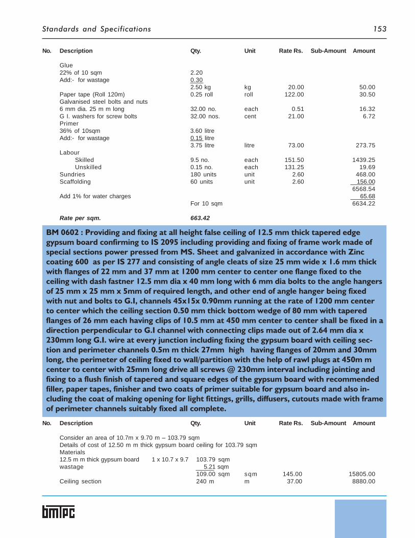
Standards and Specifications 153
No. Description Qty. Unit Rate Rs. Sub-Amount Amount
Glue22% of 10 sqm 2.20Add:- for wastage 0.30
2.50 kg kg 20.00 50.00Paper tape (Roll 120m) 0.25 roll roll 122.00 30.50Galvanised steel bolts and nuts6 mm dia. 25 m m long 32.00 no. each 0.51 16.32G I. washers for screw bolts 32.00 nos. cent 21.00 6.72Primer36% of 10sqm 3.60 litreAdd:- for wastage 0.15 litre
3.75 litre litre 73.00 273.75Labour
Skilled 9.5 no. each 151.50 1439.25Unskilled 0.15 no. each 131.25 19.69
Sundries 180 units unit 2.60 468.00Scaffolding 60 units unit 2.60 156.00
6568.54Add 1% for water charges 65.68
For 10 sqm 6634.22
Rate per sqm. 663.42
BM 0602 : Providing and fixing at all height false ceiling of 12.5 mm thick tapered edgegypsum board confirming to IS 2095 including providing and fixing of frame work made ofspecial sections power pressed from MS. Sheet and galvanized in accordance with Zinccoating 600 as per IS 277 and consisting of angle cleats of size 25 mm wide x 1.6 mm thickwith flanges of 22 mm and 37 mm at 1200 mm center to center one flange fixed to theceiling with dash fastner 12.5 mm dia x 40 mm long with 6 mm dia bolts to the angle hangersof 25 mm x 25 mm x 5mm of required length, and other end of angle hanger being fixedwith nut and bolts to G.I, channels 45x15x 0.90mm running at the rate of 1200 mm centerto center which the ceiling section 0.50 mm thick bottom wedge of 80 mm with taperedflanges of 26 mm each having clips of 10.5 mm at 450 mm center to center shall be fixed in adirection perpendicular to G.I channel with connecting clips made out of 2.64 mm dia x230mm long G.I. wire at every junction including fixing the gypsum board with ceiling sec-tion and perimeter channels 0.5m m thick 27mm high having flanges of 20mm and 30mmlong, the perimeter of ceiling fixed to wall/partition with the help of rawl plugs at 450m mcenter to center with 25mm long drive all screws @ 230mm interval including jointing andfixing to a flush finish of tapered and square edges of the gypsum board with recommendedfiller, paper tapes, finisher and two coats of primer suitable for gypsum board and also in-cluding the coat of making opening for light fittings, grills, diffusers, cutouts made with frameof perimeter channels suitably fixed all complete.
No. Description Qty. Unit Rate Rs. Sub-Amount Amount
Consider an area of 10.7m x 9.70 m – 103.79 sqmDetails of cost of 12.50 m m thick gypsum board ceiling for 103.79 sqmMaterials12.5 m m thick gypsum board 1 x 10.7 x 9.7 103.79 sqmwastage 5.21 sqm
109.00 sqm sqm 145.00 15805.00Ceiling section 240 m m 37.00 8880.00

Standards and Specifications154
No. Description Qty. Unit Rate Rs. Sub-Amount Amount
Perimeter channel 42m m 24.00 1008.00Intermediate channel 91.5 m m 39.00 3568.50Strap hangers 11 nos. each 11.00 121.00Connecting clips 190 nos. each 5.10 969.006 m m dia bolts & nuts 22 nos. each 0.51 11.22Soffit cleats 75 nos. each 3.10 232.5025 m m long drive all screws 1000 nos. cent 40.10 401.00Joint filler 24 kg. kg 20.00 480.00Joint finisher 35 kg. kg 23.00 805.00Joint tape 1.5 roll roll 122.00 183.0012 m m dia 40 m m long with 6 m m dia bolts
dash fastner 75 nos. each 8.10 607.50LabourFor assembling the structure and fixing
Skilled 40 no. each 151.50 6060.00Unskilled 70 no. each 131.25 9187.50
Scaffolding 600 units unit 2.60 1560.00Sundries (Rawl plugs, cutting openings) 1500 units unit 2.60 3900.00Cutting channels, angle iron drilling holes
etc. (welding, riveting etc. 5%) 1200 units unit 2.60 3120.0056899.22
Add 1% for water charges 568.99For 103.79 sqm 57468.21
Rate per sqm. 553.70

Standards and Specifications 155
No. Description Qty. Unit Rate Rs. Amount
Details of cost for a shed of size 20mx10m in planArea of roof 20.2 x 10.7 216.14 sqm Slope 1:3 (both side)
A Sub-StructureRafters32mm diameter G.I. Pipe (light grade)
3x10 = 30 m3x2x5.27 = 31.62 m = 61.62 m @ 2.61 kg/m 160.83 kg
Purlins(25mm dia) @2.01kg/m.2x5x20 = 200 m @ 2.03 kg/m 406.00 kg
566.83 kgAdd:- 15% for fitting and wastage 85.02 kg
651.85 kg
G.I.pipe(i/c labour charges) 651.85 kg kg 68.00 44325.80Bamboo sheets 90 nos. each 758.50 68265.008mm dia G.I. J or L hooks 476 nos. ten 60.00 2856.00G.I.Washers 476 nos. cent 21.00 99.96Bitumen Washers 476 nos. cent 19.00 90.44Labour
Skilled 19.5 nos. each 151.50 2954.25Unskilled 17.28 nos. each 131.25 2268.00
120859.45Add 1% for water charges 1208.60
For 216.14 sqm 122068.05
Rate per sqm. 564.76
G.I. PipeDetails of cost for 10m (20.3kg)25mm dia (@2.03kg/m) 10 m x 2.03 kg/m 20.3 kg32mm dia (@2.61kg/m) 10 m x 2.61 kg/m 26.1 kg
46.4 kgMaterials25mm dia G.I.pipe 10.15 m m 109.06 1106.9632mm dia G.I.pipe 10.15 m m 140.08 1421.81Labour
Skilled 1.66 nos. each 151.50 251.49Unskilled 1.67 nos. each 131.25 219.19
Sundries 60 units unit 2.60 156.00For 46.40 kg 3155.45
Rate per kg. 68.00
BM 07 : Bamboo Mat Corrugated Roofing Sheets
Providing and fixing Bamboo Mat Corrugated Roofing Sheet fixed with G.I. Jor L hooks,bolts, nuts, bitumen washers complete on G.I. Pipe Sub-Structure.

Standards and Specifications156
By Mechanical Process
Production of Bamboo Mat Corrugated Roofing Sheets
Size of sheet 1 No. 8' x 3'-6" 28.00 sqft or 2.60 sqmAnnual Production 36000.00 sheets
OR 1008000.00 sqftOR 93600.00 sqm
Production per month 3000.00 sheetsDetails of cost for 3000 sheets 7800.00 sqmMaterialsBamboo Mats 4 mats per sheet 4 x 3000 12000.00 nos. mat 54.00 648000.00Glue (350gm/sqm) 4 x 5577 x 0.35=7808.00 kg kg 96.00 749568.00Preservation @ Rs.25,000 pm. 25000.00Brush Bond Coating 8922.00 sqm sqm 42.00 374724.00Labour
Supervisor 1 no. month 6000.00 6000.00Foreman 1 no. month 8400.00 8400.00Skilled 10 nos. month 4545.00 45450.00Semi-skilled 10 nos. month 4155.00 41550.00Unskilled 20 nos. month 4000.00 80000.00
1978692.00Add for interest, depreciation, maintenance of P&M,electricity,water and other consumables @ 15% 296804.00
For 3000 Sheets 2275496.00
Rate per Sheet. 758.50 each
Rate per sqm. 291.73 sqm

Standards and Specifications 157
No. Description Qty. Unit Rate Rs. Sub-Amount AmountArea of roof in plan 6 x 3 18.00 sqmArea of roof in slope 6.46 x 4.28 27.65 sqmDetails of cost for 27.65 sqmMaterialsNo. of MCR Tiles 395.00 nos. each 8.66 3420.70(area of tile with overlap 0.07sqm)Sub-Structure steelAngle Iron Rafters40x40x5mmequal angle (3kg/m) 2 x 6.46 12.92 m
4 x 4.28 17.12 m 30.04 m 3.00 kg/m 90.12 kg
Flat Iron Purlin40x6mm (1.9kg/m)
9 x 6.46 = 58.14 m 1.9 kg/m 110.47 kg(structural steel work) 200.59 kg kg 37.03 7427.85Nails 2.00 kg kg 41.00 82.00G.I.Wire 3.00 kg kg 40.10 120.30Labour
Skilled 3.5 nos. each 151.50 530.25Unskilled 3.5 nos. each 135.25 473.38
12054.48Add 1% for water charges 120.54
For 27.65 sqm 12175.02
Rate per sqm. 440.33
BM 08 : Micro Concrete Roofing Tiles
Providing and fixing MCR Tile roofing on steel Sub-Structure.
Production of MCR Tiles using 2 machines each day
Production per day 200 tilesProduction for a month 2 x 200 x 25 10000 tilesMaterial for 1 tileCement 0.7 kg kg 4.55 3.18Coarse sand 0.0007cum cum 653.21 0.466 mm & down
stone aggregate 0.0003 cum cum 803.21 0.243.88
Production of 10000 tilesMaterial 10000 nos. each 3.88 38800.00Labour
Machine operator 2 nos. month 6000.00 12000.00Skilled 1 no. month 4545.00 4545.00Unskilled 5 nos. month 4000.00 20000.00
75345.00Add for interest, depreciation, maintenance of P&M,electricity,water and other consumables @ 15% 11301.75
For 10000 tiles 86646.75
Rate per Tile 8.66 each
By Mechanical Process

Standards and Specifications158
No. Description Qty. Unit Rate Rs. Sub-Amount Amount
Detail cost for a unit 3.60mx0.30 1.08sqm1.(i) Concrete in channel unit
[{0.245x0.025+2x(0.05x0.105)}] x (3.60 - 2 x 0.05) + (2 x 1 x 0.295+0.245 x 0.05x0.105) 2
[0.0061 + 0.0105] x 3.5 + 0.00283
0.0581 + 0.00283 0.06093 cum
(ii) Haunch Concrete1 x 0.05x0.13x3.6 + 1 x 0.05x0.13x.2952 2
0.0117 + 0.00096 0.01266 cumM-20 concrete 0.07359 cum cum 3177.33 233.82
2. Wooden Mould(i) Outer Frame
[(2x3.60x0.05x0.13)sides + (2x0.45x0.05x0.13)ends+ (2x3.60 - 2x0.05)inner frame x 0.025x0.08 + 1x(3.60-2x0.05)x0.17x0.025 + 5x0.08x0.04x0.195] 0.084 cumAdd :- 5% wastage 0.004 cumDeodar wood 0.088 cum cum 33560.81 2953.35
(ii) M.S. Angle 40mmx40mmx5mm(for fixing the trough to mould 0.45x10) 4.5 m
4.5m @3kg/m 13.50 kg
M.S. Angle 75mmx50mmx5mm for U-clamps at ends4 x 0.13 0.52 m0.52m @4.71kg/m 2.45 kg
15.95 kgM.S. flat 30mmx5mm
2 x 3.6 7.2 m7.20m @1.2kg/m 8.64 kg
24.59 kg kg 31.05 763.52
(iii) G.I. Sheet 28 gauge outside the inner frame1x(3.60 - 2 x 0.05) x (0.17+ 0.105 + 0.105) + 2 x 0.17+0.195 x 0.105 1.7 sqm
2
1.70sqm @3.15kg/sqm 5.355kg kg 34.55 185.01
(iv) 10mm dia bolts 90mm long with fly nuts and washers. 8 nos. each 9.00 72.00Sundries (for mould nails, kerosine, grease mixture) 30 units unit 2.60 78.00
(v) Labour for making mouldSkilled (3 no.+1.50 no.) 4.5 no. each 151.50 681.75Unskilled 3 no. each 135.25 405.75
CT 01 : Precast Channel Unit for Floors / Roofs
Providing and laying pre-cast reinforced cement concrete channel units (as per standarddesign) in suspended floors and roofs in M-20 (1:11/2:3) concrete including pointing of joints,form work in pre-casting, handling, hoisting, erection and placing in position complete.

Standards and Specifications 159
No. Description Qty. Unit Rate Rs. Sub-Amount Amount
Cost of mould (Assuming 100 uses.) 5139.38Cost of 1 use 51.39
3. Transporting Units (within construction site)For 40 Units
Unskilled 1 no. each 135.25 135.25Trolley charges [(5000.00)/(40x12x23)] Rs.0.45each(Assuming cost of trolley as Rs. 5,000/-and its life as 12 month, working days23 per month and number of units transportedper day per trolley 40. Trolley charges per unit)40 x 0.45 18.00For 40 Units 153.25
For 1 Units 153.25 3.83 40
4. Handling, hoisting and erectionFor 40 units
Skilled 1 no each 151.50 151.50Unskilled 10 nos. each 135.25 1352.50Scaffolding L.S. 80.00
1584.00For 1 Units 1584.00 39.60
40
5. Joint finishing and ‘V’ grooving in(cement mortar 1:2 ) (3.60m)For 1.08 sqm 1.08 sqm sqm 61.44 66.35For 1 m = 17.07
6. Steel reinforcement6mm dia tor steel 2 x 3.6 7.2 m
7.20m @0.222kg/m 1.60 kg12mm dia tor steel 2 x 3.6 7.2 m
7.20m @0.89kg/m 6.41kg3mm dia M.S. wire 13 x 0.46 6 m
6.00m @0.07kg/m 0.42 kgNegative reinforcement6mm dia tor steel 1 x 3.6 3.6 m
3.60m @0.222kg/m 0.80 kg9.23 kg kg 37.24 343.72
738.71
Add :- for water charges @ 1% 7.39For 1.08 sqm 746.10
Rate per Sqm 690.83
Pointing in cement mortar 1:2Detail cost for 10 sqmMaterialCement mortar 1:2 0.03 cum cum 3940.46 118.21Labour
Skilled 0.80 no. each 151.50 121.20Un-skilled 0.80 no. each 135.25 108.20Semi-skilled 0.80 no. each 138.45 110.76

Standards and Specifications160
No. Description Qty. Unit Rate Rs. Sub-Amount Amount
Sundries 30 units unit 2.60 78.00Scaffolding etc. 30 units unit 2.60 78.00
614.37Add :- for water charge @1% 6.14For 10 sqm. 620.51
Rate per Sqm 62.05Rate per Sqm (without water charges) 61.44
Cement Mortar 1:2 (1 cement : 2 sand)Details of cost for 1 Cum.MaterialsCement 13.60 bag bag 227.36 3092.10Coarse Sand 0.95 cum cum 653.21 620.55Labour
Unskilled 0.60 no. each 135.25 81.15Semi-skilled 0.30 no. each 138.45 41.54
Mixer Charges (running and hire charges) 26.91 unit 2.60 69.97Sundries 13.52 uni 2.60 35.15
For 1 Cum 3940.46
Providing M.S./Tor steel reinforcement for R.C.C. work includingcutting, bending, binding and placing in position.Detail cost for 1 quintalMaterialsSteel 1.00 quintal5% wastage 0.05 quintal
1.05 quintal quintal 3142.23 3299.34Labour for bending, binding and placing in position
Skilled 1.00 no. each 151.50 151.50Unskilled 1.00 no. each 135.25 135.25
Sundries (binding wire etc.) 52.91 unit 2.60 137.563723.65
Add :- for water charge @1% 37.24For 1 quintal 3760.89For 1 kg 37.61
Rate per kg 37.61Rate per kg (without water charges) 37.24
3104.73 + 3179.73Average of M.S. & Tor = = 3142.23 per quintal
2

Standards and Specifications 161
No. Description Qty. Unit Rate Rs. Sub-Amount Amount(a) Considering a size of roof 7.13x3.60 = 25.67sqm. (including bearing)
Size of R.C. Plank = 113 x 30 x 6 cmSize of R.C. Joist = 15 x 15 x 360 cmNo. of Planks 72 nos.No. of Joists 5 nos.Total quantity of concrete in roof (7.13 x 3.6 x 0.06) 1.54 cumQuantity of concrete in 1 Plank 0.01457 cum(Quantity of concrete in one plank 0.01457 cum.As given in Building Research note 4 of CBRI)Concrete in 72 planks. (72 x 0.01457) 1.05 cumQuantity in-situ concrete (haunches etc.) (1.54-1.05) 0.49 cumR.C.Planks (113x30x6cm) 72 nos.Mould (timber) - Deodar wood 0.015 cum cum 33560.81 503.41M.S. Tie rod 10mm dia 50cm long withnuts & Washers 2 nos. each 60.00 120.00M.S. hinges 7.5cm 4 nos. each 10.00 40.00Sundries 6 units each 2.60 15.60Labour (for making mould)
Skilled 1no. each 151.50 151.50Un-skilled 1no. each 135.25 135.25
965.76Assuming 60 uses of mouldCost for 1 use 16.10Mould cost for 72 Planks 72 nos. each 16.10 1159.20
(b) R.C. PlanksMaterailsConcrete M-20 (for 72 nos.) 1.05 cumCement 8.40 bag bag 227.36 1909.82Coarse Sand 0.45 cum cum 653.21 293.94Stone aggregate 10mm 0.89 cum cum 753.21 670.36Labour
Skilled 4.00 nos. each 151.50 606.00Un-skilled 8.50 nos. each 135.25 1149.62
Miscellaneous Expenditure 72 nos. each 7.20 518.40Casting platform 2.40 per plankMould oil & paper 2.40 per plankVibratar, mixture etc 2.40 per plank
7.20 per plank
CT 02 : Precast RCC Planks and Joists
Providing and laying floor/roof slab consisting of pre-cast R.C.C. plank of cement concrete1:11/2:3 (1 cement:11/2 sand :3 granded stone aggtregate 10mm and down), partially pre-cast R.C. Joist cement concrete of 1:11/2:3 (1 cement:11/2 sand :3 granded stone aggregate20mm nominal size)and in-situ cement concrete 1:11/2:3 (1 cement:11/2 sand :3 gradedstone aggregate 10mm nominal size) filling in haunches and between planks and joists aftera coat of cement slurry at the rate of 4kg per 10 sqm including `casting, stacking, curing,erection, and placing in position with bedding cement mortar 1:4(1 cement: 4 sand), cost ofmould oil, casting plateform, props, scaffolding, lifting equipments and finishing the jointsbetween plank in ‘V’ groove pointing in C.M.1:4 (1 cement: 4 sand) in ceiling etc. and includ-ing cost of reinforcement complete all respects.

Standards and Specifications162
No. Description Qty. Unit Rate Rs. Sub-Amount AmountPartially pre-cast R.C. Joists
size 15 x 15 x 360 cm 5no.Mould for Joist - Timber (Deodar wood) 0.055cum cum 33560.81 1845.84(As per Building Research note 4 of CBRI)M.S. Angle Iron clamps 25x25x3mm
Type ‘A’ 1 no. each 50.00 50.00Type ‘B’ 2 nos. each 75.00 150.00
200.00 200.00Labour
Skilled 0.5 no. each 151.50 75.75Un-skilled 0.5 no. each 135.25 67.63Sundries 12 units 2.60 31.20
174.58 174.582220.42
Assuming 100 uses of mouldCost for 1 use 22.20Mould cost for 5 Joists 5 nos. each 22.20 111.00
R.C. JoistsMaterialsConcrete M-20 (for 5 nos.) 5 x 3.6 x 0.15 x 0.15 0.405 cumCement 3.24 bag per bag 227.36 736.65Coarse Sand 0.172 cum cum 653.21 112.35Stone aggregate 20mm nominal size 0.35 cum cum 753.21 263.62Labour
Skilled 0.30 no. each 151.50 45.45Un-skilled 0.90 no. each 135.25 121.72
Miscellaneous Expenditure 5 nos. each 12.00 60.00Casting platform 3.60 per joistMould oil & paper 4.80 per joistVibrator, mixer etc 3.60 per joist
12.00 per joist
Erection and AssemblyTransportation with in construction sitefrom casting yard. 5 nos. each 30.00 150.00
(a) Partially pre-cast Joist proping material (Ballies, wedges etc)per Joist L.S. Rs 30/- per JoistLabour
Skilled (0.25 + 0.25) 0.50 no. each 151.50 75.75Un-skilled 1.00 no. each 135.25 135.25
(b) Pre-cast R.C. plank 72 nos.Materials (for jointing etc.)Cement 1.40 bag per bag 227.36 318.30Coarse Sand 0.2 cum cum 653.21 130.64Labour
Skilled 1.80 nos. each 151.50 272.70Un-skilled 7.20 nos. each 135.25 973.80
In situ concrete 0.49 cumCement (including cement for slurry) 4.02 bag per bag 227.36 913.99Coarse Sand 0.22 cum cum 653.21 143.71Stone aggregate 10mm 0.44 cum cum 753.21 331.41Labour
Skilled 0.65 no. each 151.50 98.47Un-skilled 2.60 no. each 135.25 351.65
Scaffolding, etc ( cats walk etc.) 60 units unit 2.60 156.00

Standards and Specifications 163
No. Description Qty. Unit Rate Rs. Sub-Amount AmountFinishingV’-groove pointing in cement mortar 1:4MaterialsCement 0.06 bag per bag 227.36 13.64Course Sand 0.008 cum cum 653.21 5.23Labour
Skilled 1.30 no. each 151.50 196.95Un-skilled 1.30 no. each 135.25 175.83
Scaffolding, etc 30 units unit 2.60 78.00Add :- T&P and Sundries 60 units unit 2.60 156.00
Steel reinforcement6mm dia M.S. bar for planksand -ve reinforcement
72 x 3 x 1.13 244.08 m72 x 7 x 0.3 151.20 m7 x 2 x 3.6 50.40 m2 x 72 x 0.3 43.20 m
488.88 m488.88 @0.22kg/m 107.55 kg
JoistsSteel reinforcement8mm dia 5 x 4 x 3.6 72.00 m
72.00m @0.395kg/m 28.44 kg6mm dia 5 x 2 x 3.6 36.00 m 5 x 28 x 0.5 70.00 m
5 x 28 x 0.15 21.00 m127.00 m
127.00m @0.22kg/m 27.94 kg164.00 kg kg 37.24 6107.36
18542.81Add for water charges @ 1% 185.43
For 25.67 sqm 18728.24For 1 sqm 729.57
Rate per Sqm 729.57
By Mechanical Process
CT 0201 : Pre-cast R.C planks of size 113 x 30 cm using M20 concrete
Quantity of M 20 concrete 0.01457 cumMaterial for 1 PlankCement 5.83 kg kg 4.55 26.53Coarse sand 0.00625 cum cum 653.21 4.0810 mm stone aggregate 0.01236 cum cum 803.21 9.93Steel 1.4 kg kg 37.24 52.13Binding Wire 3 units units 2.66 7.98
100.65Production 80 planks per day with 1 machineProduction in one month 1 x 25 x 80 2000.00 PlankMaterial 2000 nos. each 100.65 201300.00Labour
Machine operator 1 no. month 6000.00 6000.00Skilled 1 no. month 4545.00 4545.00Unskilled 5 nos. month 4000.00 20000.00
231845.00

Standards and Specifications164
No. Description Qty. Unit Rate Rs. Sub-Amount Amount
Add for interest, depreciation, maintenance of P&M,electricity,water and other consumables @ 15% 34777.00
For 2000 planks 266622.00
Rate per plank. 133.31 each
CT 0202 : Pre-cast R.C. Joists of size 360 x15 x15cm cast inM20 concrete
Cement Concrete M20 (1 :1½ : 3) 0.081 cumProduction 80 Joists per day with 1 machineProduction in one month 1 x 25 x 80 2000 JoistMaterial for 1 JoistsCement 32.4 kg kg 4.55 147.42Coarse sand 0.0344 cum cum 653.21 22.47Stone aggregate 0.07 cum cum 753.21 52.72Steel 7.29 kg kg 37.24 271.48Binding Wire 4 units unit 2.60 10.40
504.49
Material (for 2000 joists) 2000 nos. each 504.49 1008980.00Labour
Machine operator 1 no. month 6000.00 6000.00Skilled 1 no. month 4545.00 4545.00Unskilled 5 nos. month 4000.00 20000.00
1039525.00Add for interest, depreciation, maintenance of P&M,electricity,water and other consumables @ 15% 155929.00
For 2000 joists 1195454.00
Rate per joist 597.73 each
Rate Analysis for M20 (1 :1½ : 3) in RCC
Details for 1 cum. Quantity Unit Rate Amount
Material10mm stone aggregate 0.85 cum. 753.21 640.23Sand (coarse) 0.425 cum. 653.21 277.61Cement 8 bag 227.36 1818.88
LabourSkilled 0.26 each 151.50 39.39Semi-skilled 0.47 each 138.45 65.07Unskilled 1.90 each 135.25 256.97
Mixer hire charges 0.07 day 400.00 28.00Vibrator hire charges 0.07 day 200.00 14.00
Sundries 14.30 unit 2.60 37.183177.33
Add 1% for water charges 31.773209.10
Rate for M20 (1 :1½ : 3) in RCCincluding water charges per cum. 3209.10
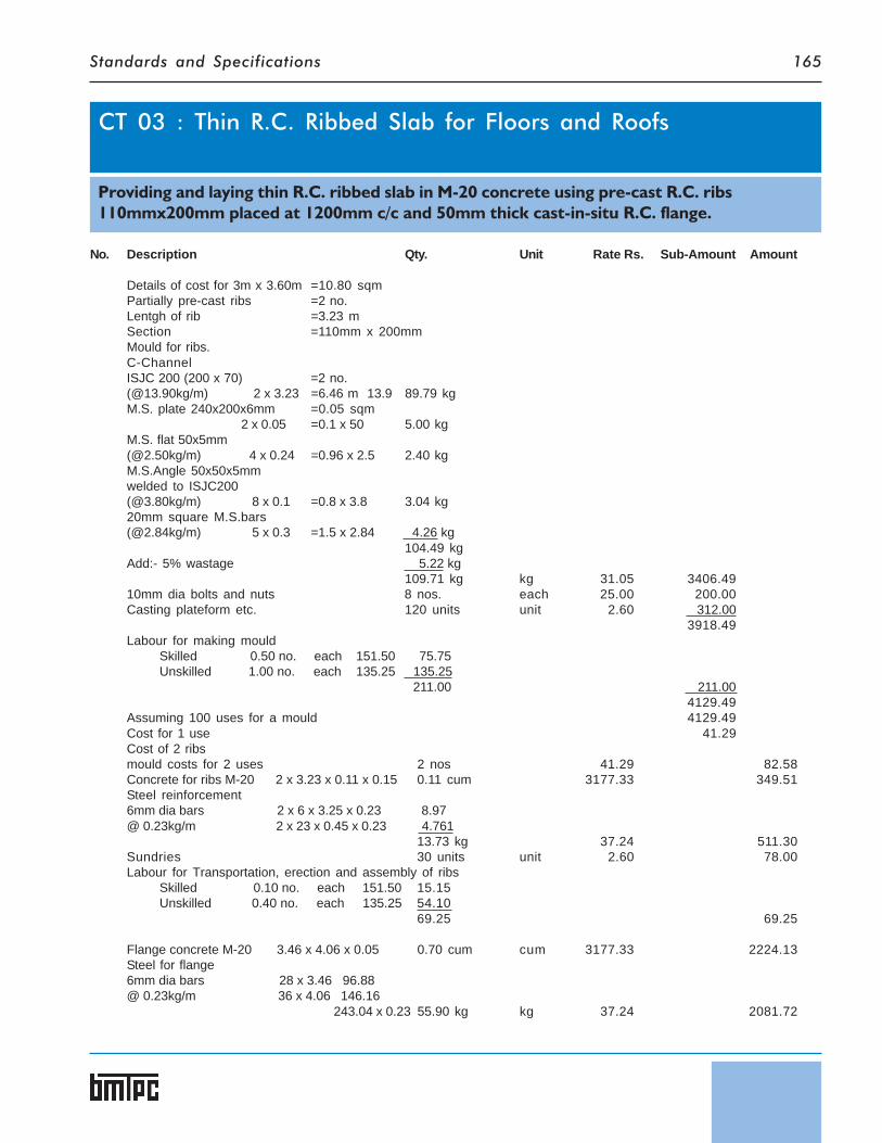
Standards and Specifications 165
No. Description Qty. Unit Rate Rs. Sub-Amount Amount
Details of cost for 3m x 3.60m =10.80 sqmPartially pre-cast ribs =2 no.Lentgh of rib =3.23 mSection =110mm x 200mmMould for ribs.C-ChannelISJC 200 (200 x 70) =2 no.(@13.90kg/m) 2 x 3.23 =6.46 m 13.9 89.79 kgM.S. plate 240x200x6mm =0.05 sqm
2 x 0.05 =0.1 x 50 5.00 kgM.S. flat 50x5mm(@2.50kg/m) 4 x 0.24 =0.96 x 2.5 2.40 kgM.S.Angle 50x50x5mmwelded to ISJC200(@3.80kg/m) 8 x 0.1 =0.8 x 3.8 3.04 kg20mm square M.S.bars(@2.84kg/m) 5 x 0.3 =1.5 x 2.84 4.26 kg
104.49 kgAdd:- 5% wastage 5.22 kg
109.71 kg kg 31.05 3406.4910mm dia bolts and nuts 8 nos. each 25.00 200.00Casting plateform etc. 120 units unit 2.60 312.00
3918.49Labour for making mould
Skilled 0.50 no. each 151.50 75.75Unskilled 1.00 no. each 135.25 135.25
211.00 211.004129.49
Assuming 100 uses for a mould 4129.49Cost for 1 use 41.29Cost of 2 ribsmould costs for 2 uses 2 nos 41.29 82.58Concrete for ribs M-20 2 x 3.23 x 0.11 x 0.15 0.11 cum 3177.33 349.51Steel reinforcement6mm dia bars 2 x 6 x 3.25 x 0.23 8.97@ 0.23kg/m 2 x 23 x 0.45 x 0.23 4.761
13.73 kg 37.24 511.30Sundries 30 units unit 2.60 78.00Labour for Transportation, erection and assembly of ribs
Skilled 0.10 no. each 151.50 15.15Unskilled 0.40 no. each 135.25 54.10
69.25 69.25
Flange concrete M-20 3.46 x 4.06 x 0.05 0.70 cum cum 3177.33 2224.13Steel for flange6mm dia bars 28 x 3.46 96.88@ 0.23kg/m 36 x 4.06 146.16
243.04 x 0.23 55.90 kg kg 37.24 2081.72
CT 03 : Thin R.C. Ribbed Slab for Floors and Roofs
Providing and laying thin R.C. ribbed slab in M-20 concrete using pre-cast R.C. ribs110mmx200mm placed at 1200mm c/c and 50mm thick cast-in-situ R.C. flange.

Standards and Specifications166
No. Description Qty. Unit Rate Rs. Sub-Amount Amount
Form work for flange.G.I sheet (@ 3.15kg/sqm) 3x3.6x10.8x3.15 34.02 kg kg 34.55 1175.39ShutteringPly 10mm thick 10.8 sqm sqm 482.00 5205.60Battens of deodar wood50mmx50mm 6 x 3 x 0.05 x 0.05 0.045 cum
3 x 3.6 x 0.05 x 0.05 0.027 cum0.072 cum
Add:- 5% wastage 0.004 cum0.076 cum cum 33560.81 2550.62
Wedges 6 nos. 25.00 150.00(50x50x150mm)M.S.square bars 20mm dia 6 x 0.22 x 3.84 5.07 kg kg 31.05 157.42(@3.84kg/m) 9239.03Assuming 20 uses for a mould 9239.03Cost for 1 use 461.95LabourFor erection and assembly of form work for flange
Skilled 1.50 no. 151.50 227.25Unskilled 1.50 no. 135.25 202.88
Bearing area of ribs plastered andcement slurry on ribs 60 units unit 2.60 156.00Sundries 60 units unit 2.60 156.00
6600.57Add :- 1% for water charges 66.00
For 10.8 sqm 6666.57
Rate per sqm. 617.27Structural Steel WorkDetails of cost for 1 quintalSteel section 1.05 qtl qtl 3104.73 3259.97Labour
Skilled 1.00 no. each 151.50 151.50Unskilled 1.00 no. each 135.25 135.25
Bolts etc. 30 units unit 2.60 78.00Sundries 30 units unit 2.60 78.00
For 1 quital 3702.72
Rate per qtl. 3702.72
Rate per kg. 37.03
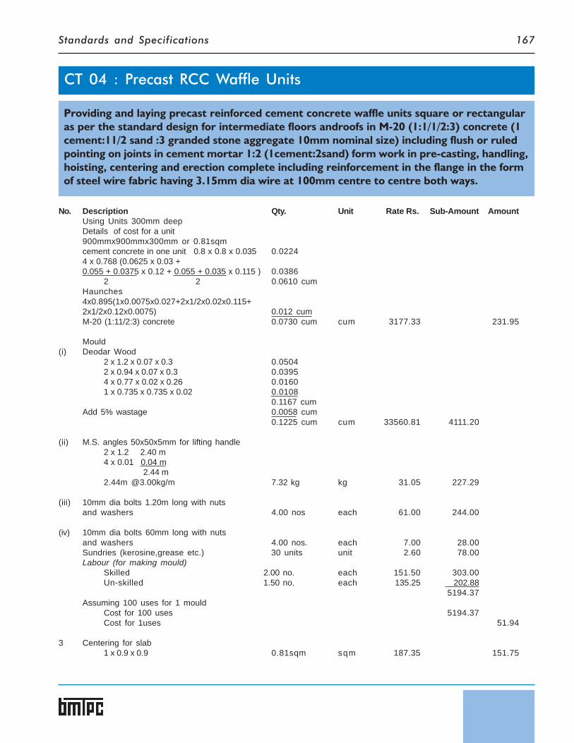
Standards and Specifications 167
No. Description Qty. Unit Rate Rs. Sub-Amount AmountUsing Units 300mm deepDetails of cost for a unit900mmx900mmx300mm or 0.81sqmcement concrete in one unit 0.8 x 0.8 x 0.035 0.02244 x 0.768 (0.0625 x 0.03 +0.055 + 0.0375 x 0.12 + 0.055 + 0.035 x 0.115 ) 0.0386
2 2 0.0610 cumHaunches4x0.895(1x0.0075x0.027+2x1/2x0.02x0.115+2x1/2x0.12x0.0075) 0.012 cumM-20 (1:11/2:3) concrete 0.0730 cum cum 3177.33 231.95
Mould(i) Deodar Wood
2 x 1.2 x 0.07 x 0.3 0.05042 x 0.94 x 0.07 x 0.3 0.03954 x 0.77 x 0.02 x 0.26 0.01601 x 0.735 x 0.735 x 0.02 0.0108
0.1167 cumAdd 5% wastage 0.0058 cum
0.1225 cum cum 33560.81 4111.20
(ii) M.S. angles 50x50x5mm for lifting handle2 x 1.2 2.40 m4 x 0.01 0.04 m 2.44 m2.44m @3.00kg/m 7.32 kg kg 31.05 227.29
(iii) 10mm dia bolts 1.20m long with nutsand washers 4.00 nos each 61.00 244.00
(iv) 10mm dia bolts 60mm long with nutsand washers 4.00 nos. each 7.00 28.00Sundries (kerosine,grease etc.) 30 units unit 2.60 78.00Labour (for making mould)
Skilled 2.00 no. each 151.50 303.00Un-skilled 1.50 no. each 135.25 202.88
5194.37Assuming 100 uses for 1 mould
Cost for 100 uses 5194.37Cost for 1uses 51.94
3 Centering for slab1 x 0.9 x 0.9 0.81sqm sqm 187.35 151.75
CT 04 : Precast RCC Waffle Units
Providing and laying precast reinforced cement concrete waffle units square or rectangularas per the standard design for intermediate floors androofs in M-20 (1:1/1/2:3) concrete (1cement:11/2 sand :3 granded stone aggregate 10mm nominal size) including flush or ruledpointing on joints in cement mortar 1:2 (1cement:2sand) form work in pre-casting, handling,hoisting, centering and erection complete including reinforcement in the flange in the formof steel wire fabric having 3.15mm dia wire at 100mm centre to centre both ways.

Standards and Specifications168
No. Description Qty. Unit Rate Rs. Sub-Amount Amount
4 Transportation and erectionLabour for 20 units
Skilled 1.00 no. each 151.50 151.50Un-skilled 5.00 nos. each 135.25 676.25For 20 units 827.75
Total Cost for 1 units 827.75 41.3920
477.03
5 Pointing in Cement mortar 1:2 0.9 m m 17.07 15.36
6 Reinforcement3mm dia welded mesh
2 x 9 x 1.00 18.00 m 2 x 4 x 0.30 2.40 m 2 x 9 x 1.00 18.00 m38.4m @0.07kg/m 38.40 m 0.07 2.69 kg
6mm dia 2 x 1.00 2.00 m 2 x 6 x 0.30 3.60 m5.60m @0.222kg/m 5.60 m 0.222 1.24 kg
3.93 kgsay 4.00 kg 37.24 148.96
641.35Add for water charges @ 1% 6.41
For 0.81 sqm 647.76For 1 sqm 799.70
Rate per Sqm 799.70

Standards and Specifications 169
No. Description Qty. Unit Rate Rs. Sub-Amount Amount
1 MouldMaterial per mouldDeodar wood 0.062 cum 33560.81 2080.77Sundries (screws, nails, fixtures) 30 units unit 2.60 78.00Labour for making mould
Skilled 1no. 151.50 151.50Unskilled 1no. 135.25 135.25
For 100 uses 2445.52
Cost for 1 use 24.46(Assuming 100 uses for a mould)
2 RCC 1:11/2:3 L- PanelConcrete 0.067 cumCement 0.60 bag bag 227.36 136.42Coarse sand 0.031cum cum 653.21 20.25Stone Agg. 10 mm and down 0.06 cum cum 753.21 45.19
201.86 201.86Mild Steel 5.52 kgG.I. Wire(3mm dia) 0.69 kg
6.21 kg kg 40.10 249.02Labour(casting, curing, stacking etc.)
Skilled 0.14 no. each 151.50 21.21Unskilled 0.57 no. each 135.25 77.09
98.30 98.30
3 Miscellaneous itemsCasting platform 12.00Oil paper etc. 10.00Vibrator etc. 2.50T & P 2.50
27.00
1.00 no. each 27.00 27.00
4 Transportation(with in construction site)Trolley etc 3.00 no. each 0.45 1.35Labour
Unskilled 0.19 no. each 135.25 25.7027.05 27.05
5 Erection & AssemblyMannual Hoisting Scaffolding 6 units unit 2.60 15.60Labour
Skilled 0.04 no. each 151.50 6.06Unskilled 0.33 no. each 135.25 44.63
50.69 50.69
CT 05 : Prefabricated Reinforced Concrete L-Panels for Roofs
Providing and laying precast reinforced cement concrete L- Panels as per standared designsfor roofs in M20 (1:11/2:3 ) concrete (1 cement : 11/2 sand: 3 graded stone agg. 10 mm anddown) including jointing ,placing in position, formwork in precasting, handling, hoistingcentring, erection complete including reinforcement. Size 315 cm x 50cm x 12 cm

Standards and Specifications170
No. Description Qty. Unit Rate Rs. Amount
6 Jointing and PlasteringMaterialCement 0.10 bag bag 227.36 22.74Coarse sand 0.01 cum cum 653.21 6.53Stone agg. 0.01 cum cum 753.21 7.53
36.80 36.80
Steel 0.4 kg kg 37.24 14.90Labour
Skilled 0.10 no. each 151.50 15.15Unskilled 0.10 no. each 135.25 13.52
28.67 28.67
7 Surface finish outer surface2 coats of cement slurry or lime coat 9 units unit 2.60 23.40Inner surface 9 units unit 2.60 23.40
46.80 46.80Labour
Skilled 0.06 no. each 151.50 9.09Unskilled 0.06 no. each 135.25 8.11
17.20 17.20Insitu Ridge for 1 m of ridgeM-20 concrete 0.014 cum cum 3177.33 44.48Reinforcement (assuming 1 m cost of ridgefor 1 L-Panel) 1.4 kg kg 37.24 52.13
934.96
Add for water charges @ 1% 9.35For 1.575 sqm. (3.15 x 0.50) 944.31
Rate per sqm. For 1 sqm 599.56
Rate per Sqm 599.56

Standards and Specifications 171
No. Description Qty. Unit Rate Rs. Sub-Amount Amount
Detail of cost for 0.49 Sqm.considering an area of 3.5mx3.5m of roof or 12.25 Sqm(size of shell unit 700mmx700mmx25mm deep).
No. of Shell units 12.25 25 0.7x0.7
Concrete 1:11/2:325 x 0.7 x 0.7 x 0.025 0.30625 cum
Concrete in haunches over supporting joists.5 x 3.5 x 0.08 x 0.05 0.07 cumOver haunches
25 x (0.7x0.7x0.075 - 0.65x0.65x0.04)25 x (0.037 - 0.0169)25 x 0.02 0.50 cum
1 C.C. 1:11/2:30.50 + 0.306 + 0.07 0.876 cum cum 3177.33 2783.34
2 Mould(i) Deodar Wood
1st set of frame2 x 1.32 x 0.06 x 0.05 0.007922 x 0.86 x 0.06 x 0.05 0.005164 x 0.74 x 0.02 x 0.02 0.001184
0.014 cumIInd set of Frame
2 x 1 x 0.06 x 0.04 0.00482 x 0.86 x 0.06 x 0.04 0.004128
0.009 cumTemplate
1 x 0.75 x 0.10 x 0.10 0.00751 x 0.1 x 0.05 x 0.03 0.00015
0.008 cumTotal 0.031 cumAdd wastage 5% 0.002 cum
0.033 cum cum 33560.81 1107.51
(ii) Headless nails 2mm and 5cm long 36 no. each 0.50 18.00(iii) Sundries (Kerosene,Grease mixture) 30 units unit 2.60 78.00
Labour for mouldSkilled 0.36 no. each 151.50 54.54Unskilled 0.36 no. each 135.25 48.69
Assuming 100 uses of mould 4090.08
CT 06 : Precast Doubly Curved Shell Units for Floors/Roofs
Providing and Laying pre-cast Cement Concrete doubly curved shells as per standard designfor roof in 1:11/2:3 mix (1 cement:11/2 sand :3 graded stone aggregate 10mm and down) of25mm thick including form work in pre-casting, handling, hoisting and erection includingfilling haunches in cement concrete 1:11/2:3 mix (1 cement:11/2 sand :3 graded stoneaggtregate 10mm and down) upto top level of crown of shell unit over partially pre-castR.C.C Joists.

Standards and Specifications172
No. Description Qty. Unit Rate Rs. Sub-Amount Amount
Cost for 1 use 40.90Cost for hessian cloth
1 0.86 0.86 0.74 sqm sqm 10.20 7.55Cost of polythene sheet.
1 0.8 0.8 0.64 sqm sqm 24.20 15.4963.94
3 Brick Work in cement mortar.1:6 (1cement:6 fine Sand) in foundation and plinth.
1 x 0.64 x 0.64 x 0.075 0.03072 x 0.64 x 0.13 x 0.1 0.0166
0.047 cum cum 1851.77 87.03
4 Cement Plaster in Cemet Mortar1:4 (1cement : 4 fine Sand)
1 x 0.64 x 0.64 0.412 x 0.64 x 0.13 0.17
0.58 sqm sqm 86.55 50.203 + 4. 137.23Assuming 50 uses of ( 3 + 4 ) above.Cost for 1 use 2.74Cost of mould 63.94+ 2.74 66.68 for 25 units. Rs. 66.68/each 66.68x25 1667.00
5 Cost of transporting, hoisting and erection of tiles(for 25 units of shells)
Skilled 1no. 151.50 151.50Unskilled 2 nos. 135.25 270.50
For 25 units 422.00 422.00For 1 unit 16.88
Cost of partially pre-cast joistUsing M-20 concrete. (for 12.25 sqm.)C.C. 1:11/2:3
5 3.5 0.12 0.08 0.17 cum 3177.33 540.15
Mould for Partially pre-cast joist.Deodar wood.
3.75 0.12 0.02 0.0092 3.75 0.08 0.02 0.0122 0.12 0.08 0.02 0.0004
0.022 cum 33560.81 738.34M.S. Angle Iron clamps 25x25x3mmType ‘A’ 1 No. @ Rs.60.00 each 60.00Type ‘B’ 2 No. @ Rs.80.00 each 160.00
220.00 220.00Labour
Skilled 0.50 no. @Rs 151.50 each 75.75Unskilled 0.50 no. @Rs 135.25 each 67.63
Sundries L.S. 25.00168.38 168.38
Total 660.96 + 200.00 + 131.50 1126.72Assuming 100 uses for a mould 1126.72Cost for 1 use 11.27Cost of mould for 5 joists @ Rs.11.27/- each 56.35Erection and AssemblyTransportation within constructionsite from casting yard 5 no. each 30.00 150.00Propping material 90 units unit 2.60 234.00

Standards and Specifications 173
No. Description Qty. Unit Rate Rs. Sub-Amount Amount
LabourSkilled (0.25 + 0.25) 0.5 no. each 151.50 75.75Unskilled 1no. each 135.25 135.25
Steel6mm dia 5 x 2 x 3.5 35 m
5 x 15 x 0.12 9 m 44 m 5 x 15 x 0.35 26.25 m 70.25 m (@ 0.22kg/m) 15.455 kg
12mm dia 5 x 2 x 3.5 35 m(@ 0.89kg/m) 31.15 kg
46.605 kg kg 37.24 1735.577791.41
Add for water chareses @ 1% on 77.91For 12.25 sqm. 7869.37For 1 sqm. 642.39
Rate per sqm. 642.39
Brick work in cement mortar 1:6 (1 cement : 6 fine sand)Detail of cost for 1cum.MaterialsBricks 475 no per thousand 2041.88 969.89Cement mortar (1:6) 0.24 cum cum 1814.82 435.56Sundries 30 units unit 2.60 78.00Labour
Skilled 0.82 no. each 151.50 124.23Semi Skilled 0.2 no. each 138.45 27.69Unskilled 1.6 no. each 135.25 216.40
for 1 cum 1851.77Cement Mortar 1:6Detail of cost for 1cum.MaterialsCement 5 bag bag 227.36 1136.80Fine sand 1.07 cum cum 373.21 399.33Labour
Semi Skilled 0.3 no. each 138.45 41.54Unskilled 0.6 no. each 135.25 81.15
Hire chargesand running charges of mixer 30 units unit 2.60 78.00Sundries 30 units unit. 2.60 78.00
for 1 cum 1814.82
12mm thick Cement Plaster in cement mortar 1:4 (1 cement : 4 fine sand)Detail of cost for 10 sqm.MaterialsCement mortar (1:4) 0.172 cum cum 2405.96 413.82Labour
Skilled 0.83 no. each 151.50 125.75Semi Skilled 0.98 no. each 138.45 135.68Unskilled 0.83no. each 135.25 112.26Scaffolding Sundries 30 units unit 2.60 78.00
For 10sqm. 865.51
Rate per sqm. 86.55
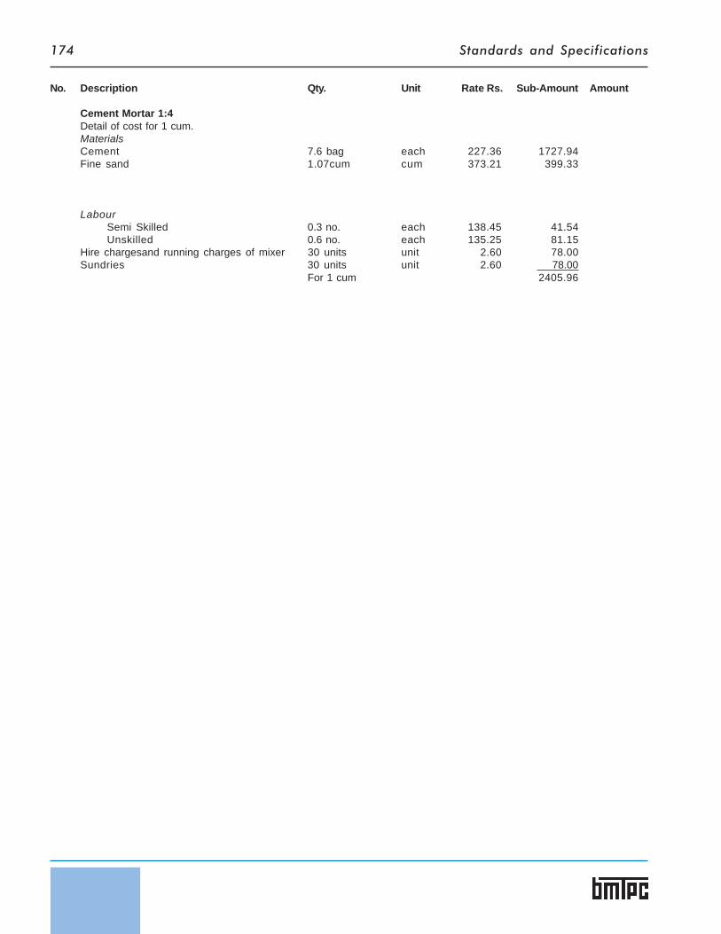
Standards and Specifications174
No. Description Qty. Unit Rate Rs. Sub-Amount Amount
Cement Mortar 1:4Detail of cost for 1 cum.MaterialsCement 7.6 bag each 227.36 1727.94Fine sand 1.07cum cum 373.21 399.33
LabourSemi Skilled 0.3 no. each 138.45 41.54Unskilled 0.6 no. each 135.25 81.15
Hire chargesand running charges of mixer 30 units unit 2.60 78.00Sundries 30 units unit 2.60 78.00
For 1 cum 2405.96

Standards and Specifications 175
No. Description Qty. Unit Rate Rs. Sub-Amount Amount
Detail of cost for 1.08 sqm.Considering a unit 300mm wide and 3600mm longConcrete M-20Cored unit
3.6 x 0.3 + 0.243 x 0.13 - 2 x 3.14 x 1 x (0.09 x 0.09) 2 4
0.106 - 0.013 0.0933 cum
Concrete in haunchesEnd Plugs 2 x 2 x 3.14 x 1 x 0.09 x 0.09 x 0.32 0.008 cum
4 1 x 0.04 x 0.13 x 3.6 0.019 cum
1 Total M-20 concrete in cored unit and haunches0.1203 cum cum 3177.33 382.23
2 Mould for cored units.(i) Deodar Wood
2 x 3.6 x 0.13 x 0.05 0.04682 x 0.45 x 0.13 x 0.05 0.00598 x 0.05 x 0.05 x 0.05 0.0010
0.054Add :- 5%wastage 0.0030
0.057 cum 33560.81 1912.97(ii) M.S. angles
40mmx40mmx5mm4 x 0.356 1.4244 x 2 x 0.075 0.64 x 0.356 1.424
(3.45m@3kg/m) 3.45 10.35 kg75mmx50mmx5mm([email protected]/m) 4 x 0.13 0.52 2.44 kg
12.79 kgAdd 5%wastage 0.64 kg
13.43 kg kg 31.05 417.00(iii) 10mm diameter bolts 90mm long with
fly nuts and washers 12 no. each 7.00 84.00(iv) Kerosene grease mixture (sundries) 30 units unit 2.60 78.00(v) Labour
Skilled 4 nos. each 151.50 606.00Unskilled 4 nos. each 135.25 541.00Skilled 0.25 no. each 151.50 37.87
Assuming 100 uses cost 3676.84Cost for 1 use ‘A’ 36.77
CT 07 : Precast Reinforced / Prestressed Concrete Ribbed orCored Slab Units for Floors / Roofs
Providing and laying pre-cast reinforced cement concrete cored units as per standard de-sign for intermediate floors or roof using M-20 1:11/2:3 mix (1 cement:11/2 sand :3 grandedstone aggregate)with 130mm thick (a.v.) units - 300mm wide at bottom and 243mm wide attop with two circular cores (hollow) of 90mm diameter including pointing of joints in cementmortar 1:2 including formwork in pre-casting, handling, hoisting and placing in position etc.complete and reinforcement.

Standards and Specifications176
No. Description Qty. Unit Rate Rs. Sub-Amount Amount
(vi) 90mm dia (external) G.I. Pipe2 x 4 8 m x 363.36 2906.88
Assuming 500 uses pipe as mouldCost for 1 use ‘B’ 2906.88 5.81
500
Mould cost for one use (A+B) 42.58 42.58
3 Transporting of units with in construction site and erection and placing in position.(for 12 units)Labour
Skilled 1 no. each 151.50 151.50Unskilled 7 no. each 135.25 946.75
1098.25Cost for 1 unit 91.52 91.52
For 1.08sqm 516.33
4 Pointing of joints 3.6 m m 12.61 45.40
5 Reinforcement6mm diameter 3 x 3.6 10.8 m
1 x 3.6 3.6 [email protected]/m 14.4 m 0.23 3.312 kg kg 37.24 123.34
685.07Add for water chareses @ 1% on 6.85
For 1.08 sqm. 691.92For 1 sqm. 644.67
Rate per sqm. 644.67
Pointing in cement mortar 1:2 (1cement:2 fine sand) to underside of jointsDetail of cost for 10m.MaterialsCement mortar (1:2) 10 x 0.025 x 0.009 0.0023 cum10%wastage 0.0002 cum
0.0025 cum cum 3940.46 9.85Labour
Skilled 0.2 no. each 151.50 30.30Semi Skilled 0.2 no. each 138.45 27.69Unskilled 0.2 no. each 135.25 27.05
Sundries & scaffolding 12 no. each 2.60 31.20For 10 m. 126.09
Rate per m. 12.61
Cement Concrete 1:1:2 (1 cement:1 sand :2 granded stone aggregate 10mm and down)Detail for 1cumMaterialsCement 11.20 bag bag 227.36 2546.43Coarse Sand 0.39 cum cum 653.21 254.75Stone aggregate 10mm 0.78 cum 753.21 587.50Labour
Skilled (0.40+0.08) 0.48 no. each 151.50 72.72Semi Skilled 0.47 no. each 138.45 65.07Un-skilled 1.90 no. each 135.25 256.97
Hire and running charges of mixer 30 units unit 2.60 78.00Cost for 1cum 3861.44

Standards and Specifications 177
No. Description Qty. Unit Rate Rs. Amount
Details of cost for 3.30m x3.30m.(thickness of slab170mm) 3.3 x 3.3 10.89 sqmC.C 1:11/2:3 10.89 x 0.17 1.85 cumDeduct volume of bricks
11 20 x 0.23 x 0.15 x 0.11 0.83 cum1.02 cum cum 3177.33 3240.88
Add cost of bricks 220 nos. 1000 nos 2041.88 449.21Extra labour for laying R.C.C
Skilled 0.13 nos. each 151.50 19.69Semi-skilled 0.2 nos. each 138.45 27.69Unskilled 0.28 nos. each 135.25 37.87
3775.34Add 1% for water charges 37.75
For 10 sqm 3813.39
Rate per sqm. 381.31
CT 08 : Reinforced Brick and Reinforced Brick Concrete Slabsfor Floors / Roofs
CT 0801 : Providing and laying Cement Concrete (M-20) 1:11/2:3 in R.B.C slab (1cement:11/2coarce sand:3 graded stone aggregate 20mm nominal size)and curing complete excludingcost of reinforcement and form work in suspended floors, roofs.
Details of cost for 3.30mx3.30m.(thickness of slab110mm) 3.3 x 3.3 10.89 sqm
10.89 x 0.11 1.20 cumDeduct volume of bricks
30 11 x 0.23 x 0.11 x 0.07 0.58 cum0.62 cum cum 3940.46 2443.08
Add cost of bricks 330 nos. 1000 nos 2041.88 673.82Labour
Skilled 0.16 nos. each 151.50 24.24Semi-skilled 0.17 nos. each 138.45 23.54Unskilled 1.18 nos. each 135.25 159.59
3324.27Add 1% for water charges 33.24
For 10.89 sqm 3357.51
Rate per sqm. 308.31
CT 0802 : Providing and laying reinforced brick slab in suspended floors/roof consisting ofbricks,steel reinforcement and mortar using 1:2 cement mortar and curing complete usinggood quality bricks having minimum crushing strength of 70kg/sqcm excluding the cost ofreinforcement and form work.

Standards and Specifications178
No. Description Qty. Unit Rate Rs. Sub-Amount Amount
Details of cost for a room of size 3.55mx3.363.55 m x 3.36 m 11.93 sqm
Size of pre-fabricated panels 1150 mm x 530.00 mmNo of pre-fabricated brick panels 21 No.Size of partially pre-cast R.C. Joists 3590 x 130 x 100 mmPre-fabricated brick panels
(a) Mould (timber)Deodar wood
2 x 1.18 x 0.075 x 0.015 0.0026 cum 2 x 0.53 x 0.075 x 0.015 0.0012 cum
0.0038 cumAdd 5% wastage 0.0002 cum
0.0040 cum cum 33560.81 134.24M.S. Strap etc 4.00 nos. each 25.00 100.00Sundries 6 nos. each 2.60 15.60Labour
Skilled 0.50 no. each 151.50 75.75Unskilled 0.50 no. each 135.25 67.63
393.22Assuming 60 uses for a mould 393.22Cost for 1 use 6.55
(b) Brick panelMaterialBricks 18.00 nos. 1000 nos 2041.88 36.75M-20 concrete for joints 0.01 cum cum 3177.33 31.77Steel reinforcement6mm dia bars @ 0.23kg/m 2 x 1.25 x 0.23 0.58 kg kg 37.24 21.60Labour for laying of bricks and jointing
Skilled 0.05 no. each 151.50 7.57Unskilled 0.12 no. each 135.25 16.23
Miscellaneous like oil, sand etc, 3 units unit 2.60 7.80Cost for mould 6.55
128.27(c) Partially pre-cast joists
3.59 x 0.13 x 0.10Cost same as in Planks & Joists system (mould) 22.20C.C 1:11/2:3 3.59 x 0.13 x 0.1 0.05 cum cum 3177.33 158.87Reinforcement steel6mm dia bars 3 x 3.6 = 10.8 m @ 0.23kg/m 28 x 0.5 = 14 m
24.8 x 0.23 5.70 kg kg 37.24 212.27Sundries 6 units unit 2.60 15.60
408.94
CT 09 : Prefabricated Brick Panel for Floors / Roofs
Providing and laying in position floor/roof slab consisting of pre-fabricated brick panels ofconcrete, bricks and reinforcement placed on partially pre-cast R.C. joists and in situ con-crete laid over the pre-fabricated brick panels complete including casting, staking, curing,erection and placing in position, cost of mould, joists, casting plateform, reinforcement.

Standards and Specifications 179
No. Description Qty. Unit Rate Rs. Sub-Amount Amount
Erection and Assembly for 11.93 sqmCost of 2 joists 2 each each 408.94 817.88Transportation with in construction sitefrom casting yard. 2 each each 30.00 60.00
(a) Partially pre-cast joistsProping material - (Ballies, wedges etc.) 30 units unit 2.60 78.00Labour
Skilled 0.20 no. each 151.50 30.30Unskilled 0.40 no. each 135.25 54.10
(b) Pre-fabricated brick panels 21nos. 21.00 nos. each 128.27 2693.67Labour
Skilled 0.53 no. each 151.50 80.30Unskilled 2.10 no. each 135.25 284.02
(c) In situ concrete 1:11/2:3 11.92 x 0.035 0.42 11.92 x 0.075 0.89
1.31Less:- volume of brick panel
21x1.15x0.53x0.07 (-) 0.890.42 cum cum 3177.33 1334.48
(d) Steel6mm dia bars @0.23kg/m 8 x 3.8 x 0.23 7 kg kg 37.24 260.68
Scaffolding, catwalk, T&P etc. 120 unit 2.60 312.006005.43
Add 1% for water charges 60.05For 11.93 sqm 6065.48
Rate per sqm. 508.42

Standards and Specifications180
No. Description Qty. Unit Rate Rs. Amount
Details of cost for 2.55 x 4.6 11.73 sqmLength of Freo-cement Channel 4.6 mNo. of Fero-cement Channel 2.55 3.00 Nos.
0.84MaterialsChannels 4.60m long 3 nos. each 1541.10 4623.30
Jointing in cement concrete M-203 x 4.6 x 0.1 x 0.1 0.1382 x 4.6 x 0.335 x 0.1 0.308
0.446 cum cum 3177.33 1417.09Negative reinforcement8mm dia (@.39kg/m) 9.2 m x 0.39 kg/m 3.59 kg kg 37.24 133.69Labour
Skilled 0.56 nos. each 151.50 84.84Unskilled 2.8 nos. each 135.25 378.70
Sundries 30 units unit 2.60 78.006715.62
Add 1% for water charges 67.16For 11.73 sqm 6782.78
Rate per sqm. 578.24
CT 10 : Ferrocement Roofing ChannelProviding and Laying in position Fero-cement roofing Channel.
By Mechanical Process
Ferrocement Channel - size -Bay length 750mm, Rise of arch 290mm,Shell thickness 25mm, Length upto 6.10m
1 machine + 4 moulds, 5 channel per day.Production in 1 month. 5 x 25 125 ChannelsMaterial for 1 channel 4.60m long.Cement 68.15 kg kg 4.55 310.08Coarse sand (Density ofsand 1520kg/cum) 0.1605 cum cum 653.21 104.84Steel 8.52 kg kg 31.05 264.54Chicken mesh 9.2 sqm sqm 31.00 285.20Welded mesh 1.23 sqm sqm 62.00 76.26Binding wire 0.46 kg kg 40.10 18.45
1059.37Production of 125 Channels units in a month.Material 125 nos. each 1059.37 132421.25Labour
Supervisor 1 no. month 6000.00 6000.00Skilled 2 nos. month 4545.00 9090.00Unskilled 5 nos. month 4000.00 20000.00
167511.25Add for interest, depreciation, maintenance of P&M,electricity,water and other consumables @ 15% 25126.69
For 125 Channel units 192637.94
Rate per Channel. 1541.10each

Standards and Specifications 181
No. Description Qty. Unit Rate Rs. Amount
Details of cost for 1 cum of masonryWall thickness 200mmMaterialsPre-cast solid concrete blocks of C.C(1:9) -(1cement : 4sand : 5stone aggregate 40mm down)Block size 40 x 20 x 20 cm (nominal)No. of blocks 60.00 no. each 39.38 2362.80Cement mortar 1:6 0.10 cum cum 1814.82 181.48Labour
Skilled 1.33 no. each 151.50 201.50Unskilled 1.85 no. each 135.25 250.21
Sundries 12 no. each 2.60 31.203027.19
Add 1% for water charges 30.27For 1 cum 3057.46
Rate per cum 3057.46
BC 01 : Precast Solid Cement Concrete Blocks
BC 0101 : Providing and laying pre-cast Concrete block masonry with Solid concrete blocksof approved size made of 1:9 concrete mix (1cement : 9 Aggregates) in foundations andplinth laid in cement mortar 1:6 (1 cement : 6 Sand) using blocks of size 400x200x200 mm
No. Description Qty. Unit Rate Rs. Amount
Details of cost for 10sqm.MaterialsPre-cast cement concrete blocks mix 1:9(1cement : 9 aggregates) - (1cement : 4sand :5stone aggregate 40mmdown)Block size 40 x 10 x 20 cm (nominal)No. of blocks 122.00 no. each 20.98 2559.56Cement mortar 1:4 0.11 cum cum 2405.96 264.65Labour
Skilled 2.15 no. each 151.50 325.73Unskilled 3.25 no. each 135.25 439.56
Scaffolding 12 units unit 2.60 31.20Sundries 12 units unit 2.60 31.20
3651.90Add 1% for water charges 36.52
For 10 sqm 3688.42
Rate per sqm. 368.84
BC 0102 : Providing and laying pre-cast Concrete block masonry 100mm thick using Solidconcrete blocks of nominal size 40x10x20cm in partitions of 1:9 concrete mix (1cement : 9Aggregates) in cement mortar 1:4 (1 cement : 4 Sand)

Standards and Specifications182
No. Description Qty. Unit Rate Rs. AmountDetail of cost for 1cum.Scaffolding 18 no each 2.60 46.80Labour
Skilled 0.16 no. each 151.50 24.24Unskilled 0.33 no. each 135.25 44.63
115.67Add 1% for water charges 1.16
For 1 cum 116.83Rate per cum. 116.83
No. Description Qty. Unit Rate Rs. AmountDetails of cost for 1 cum.MaterialsPre-cast hollow cement concrete blocksBlock size 40 x 20 x 20 cm (nominal)No. of blocks 60.00 no. each 24.61 1476.60Cement mortar 1:6 0.10 cum cum 1814.82 181.48Labour
Skilled 1.33 no. each 151.50 201.49Unskilled 1.85 no. each 135.25 250.21
Sundries 12 units unit 2.60 31.202140.98
Add 1% for water charges 21.41For 1 cum 2162.39
Rate per cum. 2162.39
BC 0103 : Providing and laying pre-cast Concrete block masonry with hollow cement con-crete block of approved size confirming to IS 2185 using concrete mix (1cement : 9 Aggre-gates) having solid materials not less than 50% of total volume of block in foundation andplinth laid in cement mortar 1:6 (1 cement : 6 sand). Size of block40cmx20cmx20cm.(nominal).
No. Description Qty. Unit Rate Rs. AmountDetails of cost for 10sqm.MaterialsPre-cast concrete hollow blocks mix 1:9(1cement : 9 aggregates)Block size 40 x 10 x 20 cm (nominal)No. of blocks 122.00 no. each 15.25 1860.50Cement mortar 1:4 0.11cum cum 2405.96 264.65Labour
Skilled 2.15 no. each 151.50 325.72Unskilled 3.25 no. each 135.25 439.56
Scaffolding 12 units unit 2.60 31.20Sundries 12 units unit 2.60 31.20
2952.83Add 1% for water charges 29.53
For 10 sqm 2982.36Rate per sqm. 298.24
BC 0104 : Providing and laying pre-cast Concrete block masonry 100mm thick in partitionsusing hollow concrete blocks of approved size made of concrete mix 1:9 (1cement : 9 Ag-gregates) having solid materail not less than 50% of the total volume of block confirming toIS 2185 and of size 40x10x20cm laid in cement mortar 1:4 (1 cement : 4 sand)
BC 0105 : Extra for masonry work with pre-cast concrete block (solid or hollow) using blockof nominal size 40cmx20cmx20cm in Super structure

Standards and Specifications 183
By Mechanical Process
BC 0101 : Centre concrete solid blocks mix 1:9(1:4:5). Size 400x200x200 mm(Production in one month)
1000 x 1 x 25 25000
Mix 1:9-C.C 1:4:5Size of block 400 x 200 x 200 mm (nominal size)Actual size 390 x 200 x 190 mmMaterial for 1 blockCement 3.75 kg kg 4.55 17.06Coarse sand 0.01 cum cum 653.21 6.5340 mm stone aggregate 0.008 cum cum 707.83 5.6620 mm stone aggregate 0.003 cum cum 753.21 2.2610 mm stone aggregate 0.002 cum cum 753.21 1.51
33.02For 25,000 blocks in a monthsMaterial 25000 nos. each 33.02 825500.00Labour
Machine operator 1 nos. month 6000.00 6000.00Skilled 1 nos. month 4545.00 4545.00Unskilled 5 nos. month 4000.00 20000.00
856045.00
Add for interest, depreciation, maintenance of P&M,electricity,water and other consumables @ 15% 128407.00
For 25000 blocks 984452.00
Rate per block 39.38 each
BC 0102 : Cement Concrete Solid block using CC 1 : 3 : 6 and of nominal size 30 x 20 x 15cm.(Production in one month)
1000 x 1 x 25 25000
Mix 1:9-C.C 1:3:6Size of block 300 x 200 x 150 mm (nominal size)Actual size 290 x 200 x 140 mmMaterial for 1 blockVolume of concrete in 1 block 0.0081 cumCement 1.78 kg kg 4.55 8.10Coarse sand 0.004 cum cum 653.21 2.6140 mm stone aggregate 0.005 cum cum 707.83 3.5420 mm stone aggregate 0.002 cum cum 753.21 1.5110 mm stone aggregate 0.001 cum cum 753.21 0.75
16.51For 25,000 blocks in a monthsMaterial 25000 nos. each 16.51 412750.00Labour
Machine operator 1 nos. month 6000.00 6000.00Skilled 1 nos month 4545.00 4545.00Unskilled 5 nos. month 4000.00 20000.00
443295.00Add for interest, depreciation, maintenance of P&M,electricity,water and other consumables @ 15% 66494.25
For 25000 blocks 509789.25
Rate per block 20.39 each

Standards and Specifications184
No. Description Qty. Unit Rate Rs. Sub-Amount Amount
BC 0103 : Road Paver blocks of size 23 cm x7.5 cm x 5 cm.
Mix 1:3:6 0.0009 cum(Production in a month with 2 machines)
2 x 25 x 2500 125000MaterialFor 1 paver blockCement 0.2 kg kg 4.55 0.91Coarse sand 0.00044 cum cum 653.21 0.2910 mm stone aggregate 0.0009 cum cum 753.21 0.68
1.88For one month production of 1,25,000 paver blocksMaterial 125000 nos. each 1.88 235000.00Labour
Machine operator 2 nos. month 6000.00 12000.00Skilled 2 nos. month 4545.00 9090.00Unskilled 10 nos. month 4000.00 40000.00
296090.00Add for interest, depreciation, maintenance of P&M,electricity,water and other consumables @ 15% 44413.50
For 125000 blocks 340503.50
Rate per block 2.72 each
BC 0104 : Cement Concrete Solid blocks size 40x10x20 cm(nominal) using cement concrete (1:4:5)1 cement :4coarse sand : 5 stone aggregate 40mm and down(Production in one month)
1000 x 1 x 25 25000
Mix 1:9-C.C 1:4:5Size of block 400 x 100 x 200 mm (nominal size)Actual size 390 x 100 x 190 mmMaterial for 1 blockCement 1.88 kg kg 4.55 8.55Coarse sand 0.0053cum cum 653.21 3.4640 mm stone aggregate 0.0041cum cum 707.83 2.9020 mm stone aggregate 0.002 cum cum 753.21 1.5110 mm stone aggregate 0.0008 cum cum 753.21 0.60
17.02For 25,000 blocks in a monthsMaterial 25000 nos. each 17.02 425500.00Labour
Machine operator 1 no. month 6000.00 6000.00Skilled 1 no. month 4545.00 4545.00Unskilled 5 nos. month 4000.00 20000.00
456045.00Add for interest, depreciation, maintenance of P&M,electricity,water and other consumables @ 15% 68406.75
For 25000 blocks 524451.75
Rate per block 20.98 each

Standards and Specifications 185
No. Description Qty. Unit Rate Rs. Sub-Amount Amount
BC 0105 : Cement Concrete Hollow blocks mix. 1:9:(1:4:5)-1 cement 4 coarse sand : 5 stone aggregateSize 400x200x200 mm (Production in one month)
1000 x 1 x 25 25000
Mix 1:9-C.C 1:4:5Size of block 400 x 200 x 200 mm (nominal size)Actual size 390 x 200 x 190 mmMaterial for 1 blockCement 2.25 kg kg 4.55 10.24Coarse sand 0.006 cum cum 653.21 3.9220 mm stone aggregate 0.004 cum cum 753.21 3.0110 mm stone aggregate 0.004 cum cum 753.21 3.01
20.18For 25,000 blocks in a monthsMaterial 25000 nos. each 20.18 504500.00Labour
Machine operator 1 no. month 6000.00 6000.00Skilled 1 no. month 4545.00 4545.00Unskilled 5 nos. month 4000.00 20000.00
535045.00Add for interest, depreciation, maintenance of P&M,electricity,water and other consumables @ 15% 80256.75
For 25000 blocks 615301.75
Rate per block. 24.61 each
BC 0106 : Cement Concrete Hollow block mix 1:9 (1:4:5) - 1 cement:4coarse sand:5 stone agg. 20 mm and down.Size 400x100x200 mm (Production in one month)
1000 x 1 x 25 25000
Mix 1:9-C.C 1:4:5Size of block 400 x 100 x 200 mm (nominal size)Actual size 390 x 100 x 190Material for 1 blockCement 1.313 kg kg 4.55 5.97Coarse sand 0.004 cum cum 653.21 2.6120 mm stone aggregate 0.0023 cum cum 753.21 1.7310 mm stone aggregate 0.0023 cum cum 753.21 1.73
12.04For 25,000 blocks in a monthsMaterial 25000 nos. each 12.04 301000.00Labour
Machine operator 1no/pm month 6000.00 6000.00Skilled 1 no/pm month 4545.00 4545.00Unskilled 5 no/pm month 4000.00 20000.00
331545.00
Add for interest, depreciation, maintenance of P&M,electricity,water and other consumables @ 15% 4973175
For 25000 blocks 381276.75
Rate per block. 15.25 each
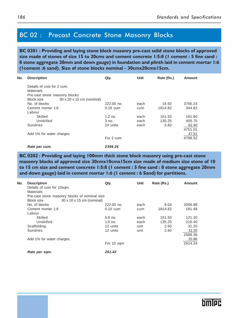
Standards and Specifications186
BC 0201 : Providing and laying stone block masonry pre-cast solid stone blocks of approvedsize made of stones of size 15 to 20cms and cement concrete 1:5:8 (1 cement : 5 fine sand :8 stone aggregate 20mm and down gauge) in foundation and plinth laid in cement mortar 1:6(1cement :6 sand). Size of stone blocks nominal - 30cmx20cmx15cm.
No. Description Qty. Unit Rate (Rs.) Amount
Details of cost for 2 cum.MaterialsPre-cast stone masonry blocksBlock size 30 x 20 x 15 cm (nominal)No. of blocks 222.00 no. each 16.92 3756.24Cement mortar 1:6 0.19 cum cum 1814.82 344.82Labour
Skilled 1.2 no. each 151.50 181.80Unskilled 3 no. each 135.25 405.75
Sundries 24 units each 2.60 62.404751.01
Add 1% for water charges 47.51For 2 cum 4798.52
Rate per cum. 2399.26
No. Description Qty. Unit Rate (Rs.) AmountDetails of cost for 10sqm.MaterialsPre-cast stone masonry blocks of nominal sizeBlock size 30 x 10 x 15 cm (nominal)No. of blocks 222.00 no. each 9.04 2006.88Cement mortar 1:6 0.10 cum cum 1814.82 181.48Labour
Skilled 0.8 no. each 151.50 121.20Unskilled 1.6 no. each 135.25 216.40
Scaffolding 12 units unit 2.60 31.20Sundries 12 units unit 2.60 31.20
2588.36Add 1% for water charges 25.88
For 10 sqm 2614.24
Rate per sqm. 261.42
BC 0202 : Providing and laying 100mm thick stone block masonry using pre-cast stonemasonry blocks of approved size 30cmx10cmx15cm size made of medium size stone of 10to 15 cm size and cement concrete 1:5:8 (1 cement : 5 fine sand : 8 stone aggregate 20mmand down gauge) laid in cement mortar 1:6 (1 cement : 6 Sand) for partitions.
BC 02 : Precast Concrete Stone Masonry Blocks

Standards and Specifications 187
BC 0203 : Solid Stone Blocks 30 x 20 x 15 cm nominal size in Cement Concrete1:5:8 withstones of 8 cms to 15 cms
Actual size of block = 290 x 200 x 140 mmVolume of block = 0.00812 cum.Volume of 1000 blocks = 8.12 cum.25% of stone spalls by volume
Volume of stone spalls = 2.03 cum.Volume of concrete = 8.12 - 2.03 = 6.09 cum.
Details of cost for 1000 blocksConcrete 1:5:8 = 6.09 cum.
Materials Qty. Unit Rate (Rs.) AmountCement = 1.03 tonne 20.60 bag 227.36 4683.62Coarse sand 3.59 cum 653.21 2345.0240 mm stone aggregate 2.86 cum 707.83 2024.3920 mm stone aggregate 2.86 cum 753.21 2154.18Stone 2.03 cum 394.60 801.04Labour
Skilled 0.81 no. each 151.50 122.71Semi-skilled 2.19 no. each 138.45 303.20Skilled 0.31 no. each 151.50 46.96Unskilled 13.22 no. each 135.25 1788.00
Sundries 120 units each 2.60 312.00Hire and running charges of mixer/vibrator 120 units each 2.60 312.00Form work 150 sqm. sqm. 13.50 2025.00For 100 blocks 16918.12Rate per block 16.92
BC 0204 : Solid Stone Blocks 30 x 10 x 15 cm nominal size in Cement Concrete 1:5:8 withstones of 8 cms to 15 cms
Actual size of block = 290 x 100 x 140 mmVolume of block = 0.00406 cum.Volume of 1000 blocks = 4.06 cum.25% of stone spalls by volume
Volume of stone spalls = 1.01 cum.Volume of concrete = 4.06 - 1.01 = 3.05 cum.
Details of cost for 1000 blocksConcrete 1:5:8 = 3.05 cum.
Materials Qty. Unit Rate (Rs.) AmountCement 10.30 bag 227.36 2341.81Coarse sand 1.80 cum 653.21 1175.7840 mm stone aggregate 1.43 cum 707.83 1012.2020 mm stone aggregate 1.43 cum 753.83 1077.09Stone 1.01 cum 394.60 398.54Labour
Skilled 0.40 no. each 151.50 60.60Semi-skilled 1.10 no. each 138.45 152.29Unskilled 6.61 no. each 135.25 894.00
Sundries 60 units each 2.60 156.00Hire and running charges of mixer/vibrator 60 units each 2.60 156.00Form work 120 sqm. sqm. 13.50 1620.00For 100 blocks 9044.31
Rate per block 9.04

Standards and Specifications188
No. Description Qty. Unit Rate Rs. Amount
Details of cost for 1 cum.MaterialsPre-cast solid CLC blocks of nominal size.Block size 400 x 200 x 200 mm (nominal)No. of blocks 60.00 no. each 32.94 1976.40Cement mortar 1:6 0.10 cum cum 1814.82 181.48Labour
Skilled 1.33 no. each 151.50 201.49Unskilled 1.85 no. each 135.25 250.21
Sundries 12 units each 2.60 31.202640.78
Add 1% for water charges 26.41For 1 cum 2667.19
Rate per cum. 2667.19
BC 0301 : Providing and laying pre-cast solid light weight concrete block masonry of ap-proved size400mmx200mmx200mm (CLC blocks) having a density of 1200kg/cum for loadbearing structures in foundation and plinth laid in cement mortar 1:6 (1cement :6 coarsesand).
BC 0401 : Providing and laying pre-cast solid light weight concrete block (CLC blocks) ofapproved size400mmx100mmx200mm in partition walls 100mm thick laid in cement mor-tar 1:4 (1cement :4 coarse sand).
No. Description Qty. Unit Rate Rs. Amount
Details of cost for 10sqm.MaterialsPre-cast solid CLC blocks.Block size 400 x 100 x 200 mm (nominal)No. of blocks 122.00 no. each 17.44 2127.68Cement mortar 1:4 0.11cum cum 2405.96 264.65Labour
Skilled 2.15 no. each 151.50 325.72Unskilled 3.25 no. each 135.25 439.56
Scaffolding 12 units each 2.60 31.20Sundries 12 units each 2.60 31.20
3220.01Add 1% for water charges 32.20
For 10 sqm 3252.21
Rate per sqm. 325.22
BC 03 : Hollow or Solid Lightweight Concrete Masonry Units
BC 04 : Cellular Light-weight Concrete Blocks

Standards and Specifications 189
Details of cost for 1000 blocksVolume of concrete (1000 x 0.39 x 0.20 x 0.19) = 14.82 cum. – Say 15 cum.
Description Qty. Unit Rate Rs. AmountMaterialsCement (205x15=2075 kg) 61.50 bags bag 227.36 13982.64Flyash (389x15) 5835 kg kg 0.15 875.25Sand (610x15=9150 kg) 6.10 cum. cum. 653.21 3984.58Foaming agent (0.69x15) 10.35 kg kg 450.00 4657.50Water mix and foam (255x15) 3825 kg kg 0.03 114.75Labour 15 cum. cum 159.15 2387.25
Labour for 1250 cum.Supervisor 1 no. @ 12000/- pm = 12000.00Project Manager 1 no. @ 25000/- pm = 25000.00Skilled 3 nos @ 4545/- pm = 13635.00Semi skilled 2 nos @ 4150/- pm = 8300.00Unskilled 35 nos. @ 4000/- pm = 140000.00 For 1250 cum. 198935.00 For 1 cum. 159.15
Add for interest, depreciation, maintenanceof P&M, electricity, water and utilities 15% 3900.30
29902.27
Mould 225 sqm. sqm 13.50 3037.50For 1000 blocks 32939.77
Rate per block 32.94
BC 0402 : CLC Solid Blocks size 40 x 20 x 20 cms nominal size
BC 0403 : CLC Solid Blocks size 40 x 10 x 20 cms nominal size
Details of cost for 1000 blocksVolume of concrete (1000 x 0.39 x 0.10 x 0.19) = 7.41 cum. – Say 7.50 cum.
Description Qty. Unit Rate Rs. AmountMaterials
CLC (as per details at BC0303) 7.50 cum cum. 1993.48 14951.10
Mould 184 sqm. sqm 13.50 2484.00For 1000 blocks 17435.10
Rate per block 17.44

Standards and Specifications190
No. Description Qty. Unit Rate Rs. Sub-Amount Amount
Details of cost for 1 frame size 2100mmx900mmA. 5.1m size 60mmx100mm (single shutter frame)
Materials1 Cement concrete 1:1:2 5.1 x 0.1 x 0.06 0.0306 cum cum 3861.44 118.162 Mould for frame(i) Deodar Wood
2 x 1 x 2.1 x 0.04 x 0.25 0.0421 x 1 x 0.9 x 0.04 x 0.25 0.0092 x 2 x 2.1 x 0.10 x 0.025 0.0212 x 1 x 0.9 x 0.10 x 0.025 0.0052 x 2.1 x 0.04 x 0.015 0.003
ends4 x 0.1 x 0.06 x 0.02 0.001
0.081Add:- 5% wastage 0.004
0.085 0.085 cum cum 33560.81 2852.75
(ii) Angle iron 30mmx30mmx5mm 10 x 0.08 0.8 m
[email protected]/m 0.8 x 2.2 1.76 kgAdd:- 5% wastage 0.088 kg
1.85 kg kg 31.05 57.44
(iii) Screw 37.5mm long 20 no. each 0.35 7.00
(iv) Labour for mouldSkilled 2 no. each 151.50 303.00Un Skilled 2 no. each 135.25 270.50
(assuming 40 uses of a mould) 3490.69Cost for 1 use 87.27
3 Steel reinforcement6mm dia M.S. bar
3 x 2.1 6.3 m3 x 2.1 6.3 m3 x 0.9 2.7 m
15.3 m 0.222 kg/m 3.403mm dia M.S. Wire @ 300mm c/c
2.10+2.1+0.9 18 no. 0.3018x(0.07+0.03+0.08) 3.24 m 0.063 kg/m 0.204
[email protected]/m 3.604Add:- 5% wastage 0.180
3.784 kg 37.24 140.92
4 Aluminium tube sleeves 5mm dia45mm long 20 x 0.045 0.9 m m 36.00 32.40Sundries 12 units each 2.60 31.20
BC 05 : Precast RCC Door & Window Frames
Providing and fixing pre-cast reinforced cement concrete door, window frames in 1:1:2 mixcement concrete (1 cement:1 sand :2 graded stone aggregate 10mm and down) includingformwork reinforcement, handling and erection etc. complete.

Standards and Specifications 191
No. Description Qty. Unit Rate Rs. Sub-Amount Amount
5 Labour for handling and erectionfor 20 nos of frames
Skilled 1 no. each 151.51 151.50Un Skilled 2 no. each 135.25 270.50
(for 20 nos) 422.00Cost for 1 farme 21.10 21.10
431.05Add 1% water charges 4.31
For 1 frame or 5.10m 435.36
Rate / each 435.36Rate per meter 85.36
B For double shutter framesize 2100 x 900mm 5.10m long60mm x 120mm
Materials1 Cement concrete 1:1:2 5.1 x 0.12 x 0.06 0.037 cum cum 3861.44 142.872 Mould for frame(i) Deodar Wood
2 x 1 x 2.1 x 0.04 x 0.25 0.0421 x 1 x 0.9 x 0.04 x 0.25 0.0092 x 2 x 2.1 x 0.12 x 0.025 0.0252 x 1 x 0.9 x 0.12 x 0.025 0.0052 x 2.1 x 0.04 x 0.015 0.0034 x 0.12 x 0.06 x 0.02 0.001
0.085Add:- 5% wastage 0.004
0.089 0.089 cum cum 33560.81 2986.91
(ii) Angle iron 30mmx30mmx5mm10 x 8 cm 0.8 m
[email protected]/m 0.8 x 2.2 1.76 kgAdd:- 5% wastage 0.088 kg
1.85 kg kg 31.05 57.44
(iii) Screw 37.5mm long 20 no each 0.35 7.00
(iv) Labour for mouldSkilled 2 no each 151.50 303.00Un Skilled 2 no. each 135.25 270.50
(assuming 40 uses of a mould) 3624.85Cost for 1 use 90.62
3 Steel reinforcement6mm dia M.S. bar
3 x 2.1 = 6.3 m3 x 2.1 = 6.3 m3 x 0.9 = 2.7 m 15.3 m 0.222 kg/m 3.40
3mm dia M.S. Wire @ 300mm c/c2.10+2.1+0.09 18 no. 0.3018x(0.07+0.03+0.08) 3.24 m 0.063 kg/m 0.204
(@0.063kg/m) 3.604Add:- 5% wastage 0.180
3.784 kg 37.24 140.92

Standards and Specifications192
No. Description Qty. Unit Rate Rs. Sub-Amount Amount
4 Aluminium tube sleeves 5mm dia45mm long 20 x 0.045 0.9m m 36.00 32.40Sundries 12 each 2.60 31.20
5 Labour for handling and erectionfor 20 nos of framesSkilled 1 no. each 151.50 151.50Unskilled 2 no. each 135.25 270.50(for 20 nos) 422.00Cost for 1 frame 21.10 21.10
459.11Add 1% water charges 4.59
For 1 frame or 5.10m 463.70
Rate / each 463.70Rate per meter 90.92
By Mechanical Process
BC 0501 : Door/window frame using cement concrete 1:1:2
Opening Size 2100 mm x 900 mm 0.0306 cum5.10 m long 60 mm x 100 mm
4 frames in a day from 1 machineProduction from 5 machines
in a month 5 x 4 x 25 500.00 units
Material for 1 FrameCement 17.14 kg kg 4.55 77.99Coarse sand 0.012 cum cum 653.21 7.84Stone aggregate 10 mm and down 0.024 cum cum 753.21 18.08Steel 3.78 kg kg 31.05 117.37Binding Wire, Inserts, gullies, botls polyproplyne fibre 15 units unit 2.60 39.00
260.28
Details of cost for 500 units of Frames in a monthusing 5 machinesMaterial 500 nos. each 260.28 130140.00Labour
Skilled 6 nos. month 4545.00 27270.00Unskilled 10 nos. month 4000.00 40000.00
197410.00
Add for interest, depreciation, maintenance of P&M,electricity,water and other consumables @ 15% 29611.50
For 500 frames 227021.50
Rate per Frame. 454.04 each

Standards and Specifications 193
No. Description Qty. Unit Rate Rs. Amount
Details of cost for 1 door of size 2000mmx900mm 12mm thick.MaterialsCement 20 kg kg 4.55 91.00Coarse sand 30 kg or 0.02 cum 0.02 cum cum 653.21 13.06SteelSteel mat of 4layer of Chicken mesh 4 x 1.8 7.2 sqmAdd for cutting wastage @ 10%. 0.72 sqm
7.92 sqm sqm 31.00 245.52Binding wire 0.2 kg kg 40.10 8.02Hinges 6 nos. each 9.20 55.20Labour (for casting curing)
Skilled 0.5 no. each 151.50 75.75Unskilled 0.8 no. each 135.25 108.20
596.75Add:- 10% for mould etc 59.68For fixing in position
Skilled 0.6 no. each 151.50 90.90Semi-skilled 0.06 no. each 138.45 8.31Unskilled 0.8 no. each 135.25 108.20
863.84Add :- 1% for water charges 8.64
For 1.80 sqm 872.48Rate per sqm. 484.71
BC 06 : Ferrocement Door Shutter
Providing and fixing ferrocement Flush door shutter of size 2000mmx900mm having thick-ness of 12mm.
No. Description Qty. Unit Rate Rs. Amount
(i) Circular, internal diameter 1100mm and height 1060mmDetails of cost for 1 Ferro-cement water tank of 1000 litres capacity.Size of tank Internal dia 1100mm, height 1060mmActual height of tank
1060 + 250mm (free board) 1310 mmMaterialsChicken meshBottom 2 x 0.95 1.9 sqmPeriphery 22 x 1.1=3.46 m
7Wall area 3.46 x 1.31=4.53 sqmTwo layers 2 x 4.53 9.06 sqmCover
(0.95 - 1 x 3.14 x 0.50 x 0.50 ) 40.95 - 0.19 0.76
Two layers 2 x 0.76 1.52 sqm12.48 sqm
BC 07 : Precast Ferrocement Water Tanks
Ferro-cement Water Tank - 1000 litres

Standards and Specifications194
No. Description Qty. Unit Rate Rs. Amount
Add:- 10% wastage 1.25 sqm13.73 sqm sqm 31.00 452.63
Welded mesh 6.24 + 0.62 6.86 sqm sqm 62.00 425.32Binding wire 0.69 kg kg 40.10 27.67Cement mortar 1:2 6.24 x 0.015 0.0936 cum cum 3940.46 368.83
1247.45Sundries mould etc (10%) 124.75
1372.20Labour
Skilled 0.21 no. each 151.50 31.81Unskilled 0.42 no. each 135.25 56.81
1460.82Cost of lid 60.00
1520.82Add 1% for water charges 15.21
For 1 tank 1536.03
Rate per tank. 1536.03
(ii) Square Tank - 1000 litre capacityDetails of cost for 1 Ferro-cement water tank of 1000 litres capacity.Tank size 1080mmx1080mmx860mmActual height of tank
860+250mm (free board) 1110 mmMaterialsChicken meshBottom 2 x 1.166 2.332 sqmSide 2 x 1.095 x 1.11 2.43 sqm
2 x 1.08 x 1.11 2.40 sqmCover 2 x (1.166 - 0.19) 1.952 sqm
9.114 sqmAdd:- 10% wastage, overlap 0.911 sqm
10.025 sqm sqm 31.00 310.77Welded mesh 4.56 sqmAdd:- 10% wastage, overlap 0.45 sqm
5.010 sqm sqm 62.00 310.62Binding wire 0.5 kg kg 40.10 20.05Cement mortar 1:2 4.56 x 0.015 0.068 cum cum 3940.46 267.95
909.39Sundries mould etc (10%) 90.94
1000.33Labour
Skilled 0.21 no. each 151.50 31.82Unskilled 0.42 no. each 135.25 56.81
1088.96Cost of lid 60.00
1148.96Add 1% for water charges 11.49
For 1 tank 1160.45
Rate per tank. 1160.45
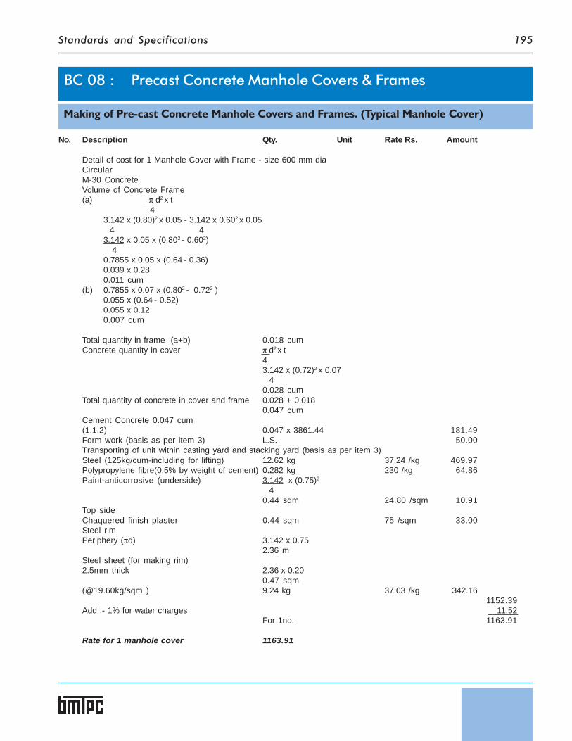
Standards and Specifications 195
No. Description Qty. Unit Rate Rs. Amount
Detail of cost for 1 Manhole Cover with Frame - size 600 mm diaCircularM-30 ConcreteVolume of Concrete Frame(a) π d2 x t
43.142 x (0.80)2 x 0.05 - 3.142 x 0.602 x 0.05 4 43.142 x 0.05 x (0.802 - 0.602) 40.7855 x 0.05 x (0.64 - 0.36)0.039 x 0.280.011 cum
(b) 0.7855 x 0.07 x (0.802 - 0.722 )0.055 x (0.64 - 0.52)0.055 x 0.120.007 cum
Total quantity in frame (a+b) 0.018 cumConcrete quantity in cover π d2 x t
43.142 x (0.72)2 x 0.07 40.028 cum
Total quantity of concrete in cover and frame 0.028 + 0.0180.047 cum
Cement Concrete 0.047 cum(1:1:2) 0.047 x 3861.44 181.49Form work (basis as per item 3) L.S. 50.00Transporting of unit within casting yard and stacking yard (basis as per item 3)Steel (125kg/cum-including for lifting) 12.62 kg 37.24 /kg 469.97Polypropylene fibre(0.5% by weight of cement) 0.282 kg 230 /kg 64.86Paint-anticorrosive (underside) 3.142 x (0.75)2
40.44 sqm 24.80 /sqm 10.91
Top sideChaquered finish plaster 0.44 sqm 75 /sqm 33.00Steel rimPeriphery (πd) 3.142 x 0.75
2.36 mSteel sheet (for making rim)2.5mm thick 2.36 x 0.20
0.47 sqm(@19.60kg/sqm ) 9.24 kg 37.03 /kg 342.16
1152.39Add :- 1% for water charges 11.52
For 1no. 1163.91
Rate for 1 manhole cover 1163.91
BC 08 : Precast Concrete Manhole Covers & Frames
Making of Pre-cast Concrete Manhole Covers and Frames. (Typical Manhole Cover)

Standards and Specifications196

Standards and Specifications 197
S.No. Description Unit Rate (in Rs.)1. Bandhani Per day 138.452. Bhishti Per day 138.453. Black smith 1st class Per day 151.504. Carpenter 1st class Per day 151.505. Unskilled Per day 135.256. Fitter (grade-I) Per day 151.507. Mason Per day 151.508. Mate Per day 138.459. Mistry Per day 151.5010. Painter Per day 141.6011. White washer Per day 138.4512. Foreman Per day 151.50
S.No. Description Unit Rate (in Rs.)1. Skilled Per day 151.502. Semi skilled Per day 138.453. Un skilled Per day 135.25Source : CPWD DSR 2007
BASIC RATES OF LABOUR
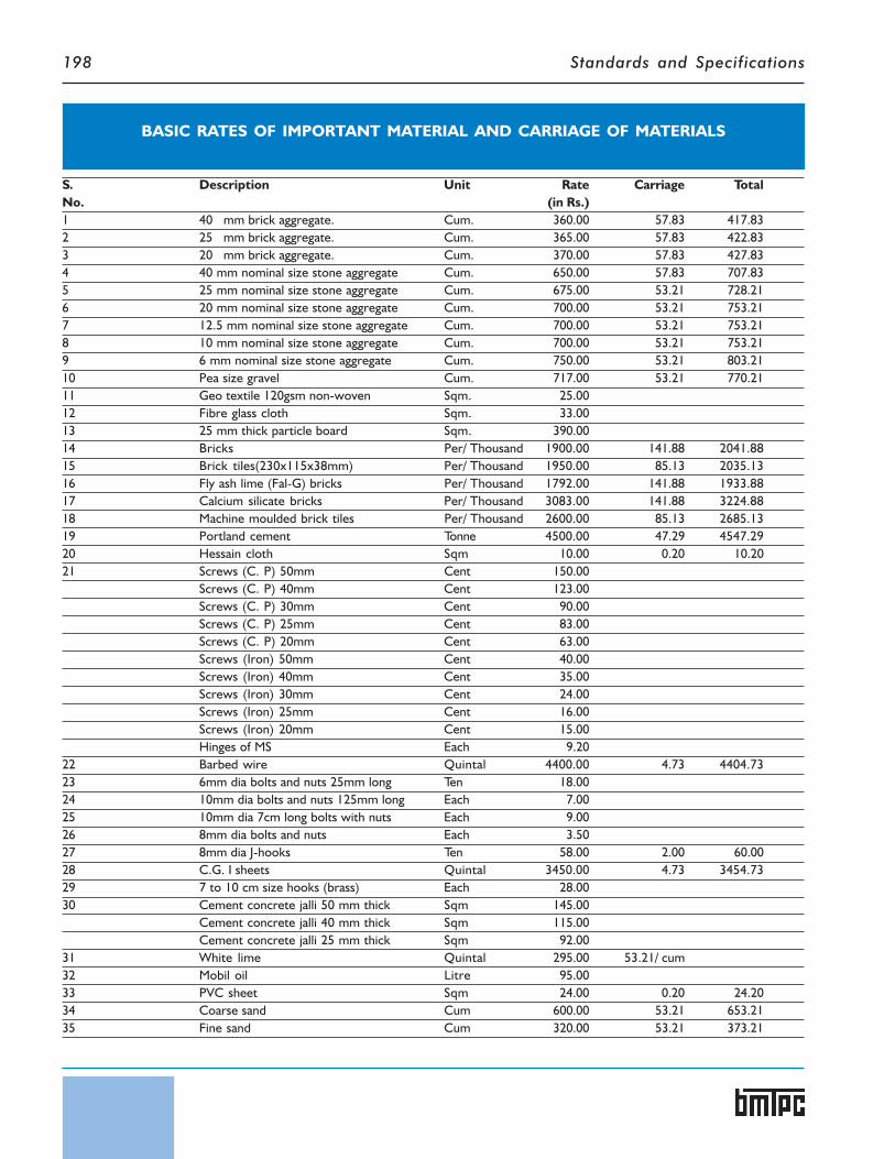
Standards and Specifications198
BASIC RATES OF IMPORTANT MATERIAL AND CARRIAGE OF MATERIALS
S. Description Unit Rate Carriage TotalNo. (in Rs.)1 40 mm brick aggregate. Cum. 360.00 57.83 417.832 25 mm brick aggregate. Cum. 365.00 57.83 422.833 20 mm brick aggregate. Cum. 370.00 57.83 427.834 40 mm nominal size stone aggregate Cum. 650.00 57.83 707.835 25 mm nominal size stone aggregate Cum. 675.00 53.21 728.216 20 mm nominal size stone aggregate Cum. 700.00 53.21 753.217 12.5 mm nominal size stone aggregate Cum. 700.00 53.21 753.218 10 mm nominal size stone aggregate Cum. 700.00 53.21 753.219 6 mm nominal size stone aggregate Cum. 750.00 53.21 803.2110 Pea size gravel Cum. 717.00 53.21 770.2111 Geo textile 120gsm non-woven Sqm. 25.0012 Fibre glass cloth Sqm. 33.0013 25 mm thick particle board Sqm. 390.0014 Bricks Per/ Thousand 1900.00 141.88 2041.8815 Brick tiles(230x115x38mm) Per/ Thousand 1950.00 85.13 2035.1316 Fly ash lime (Fal-G) bricks Per/ Thousand 1792.00 141.88 1933.8817 Calcium silicate bricks Per/ Thousand 3083.00 141.88 3224.8818 Machine moulded brick tiles Per/ Thousand 2600.00 85.13 2685.1319 Portland cement Tonne 4500.00 47.29 4547.2920 Hessain cloth Sqm 10.00 0.20 10.2021 Screws (C. P) 50mm Cent 150.00
Screws (C. P) 40mm Cent 123.00Screws (C. P) 30mm Cent 90.00Screws (C. P) 25mm Cent 83.00Screws (C. P) 20mm Cent 63.00Screws (Iron) 50mm Cent 40.00Screws (Iron) 40mm Cent 35.00Screws (Iron) 30mm Cent 24.00Screws (Iron) 25mm Cent 16.00Screws (Iron) 20mm Cent 15.00Hinges of MS Each 9.20
22 Barbed wire Quintal 4400.00 4.73 4404.7323 6mm dia bolts and nuts 25mm long Ten 18.0024 10mm dia bolts and nuts 125mm long Each 7.0025 10mm dia 7cm long bolts with nuts Each 9.0026 8mm dia bolts and nuts Each 3.5027 8mm dia J-hooks Ten 58.00 2.00 60.0028 C.G. I sheets Quintal 3450.00 4.73 3454.7329 7 to 10 cm size hooks (brass) Each 28.0030 Cement concrete jalli 50 mm thick Sqm 145.00
Cement concrete jalli 40 mm thick Sqm 115.00Cement concrete jalli 25 mm thick Sqm 92.00
31 White lime Quintal 295.00 53.21/ cum32 Mobil oil Litre 95.0033 PVC sheet Sqm 24.00 0.20 24.2034 Coarse sand Cum 600.00 53.21 653.2135 Fine sand Cum 320.00 53.21 373.21

Standards and Specifications 199
S. Description Unit Rate Carriage TotalNo. (in Rs.)36 Fly ash (800kg/cum) Cum 6.00 53.21 59.21
Primer Litre 72.00 1.00 73.0037 Stone dust Cum 700.00 53.21 753.2138 Surkhi Cum 390.00 53.21 443.2139 STEEL
Steel plates Quintal 3400.00 4.73 3404.73Steel sheets Quintal 3475.00 4.73 3479.73Steel barbed wire Quintal 4400.00 4.73 4404.73Wire mesh Sqm 38.00Steel wire Quintal 3100.00 4.73 3104.73Bolts and nuts upto 300mm length Quintal 4300.00 4.73 4304.7320mm dia holding down bolts Quintal 3800.00 4.73 3804.73Flats iron upto 10 mm thickness Quintal 2900.00 4.73 2904.73Flats exceeding 10 mm thickness Quintal 2875.00 4.73 2879.73Steel hooks Each 22.00Hoop Iron 30mmx25mmx1.6mm Quintal 2900.00 4.73 2904.73Rivets – M. S Quintal 3500.00 4.73 3504.73M. S bars 12mm dia and below Quintal 3100.00 4.73 3104.73Twisted or deformed bars Quintal 3175.00 4.73 3179.73Structural steel Quintal 3100.00 4.73 3104.73“U”- shaped MS clamps Each 35.00Wire nails Kg 40.00 1.00 41.00Steel beading M 15.00Tie bolts 12mm dia 100mm long Each 29.0012mm dia 150mm long Each 31.0020mm dia 150 mm long Each 57.0020mm dia 225 mm long Each 72.00Binding wire Kg 40.00 0.10 40.10
40 TimberDeodar wood Cum 33500.00 60.81 33560.81Teak wood Cum 41000.00 60.81 41060.81
41 WashersLimpet washers –G.I Cent 20.00 1.00 21.00Bitumen washers Cent 18.00 1.00 19.00
42 GYPSUM BOARD CEILINGGypsum board Sqm 140.00 5.00 145.00Ceiling sections Meter 36.00 1.00 37.00Perimeter channel Meter 23.00 1.00 24.00Intermediate channel Meter 38.00 1.00 39.00Ceiling angle Meter 16.00 1.00 17.00Connecting clips each 5.00 0.10 5.10Soffit cleat each 3.00 0.10 3.10Joint filler kg 19.00 1.00 20.00Joint finisher kg 22.00 1.00 23.00Joint tape roll 120.00 2.00 122.00Dash fastner each 8.00 0.10 8.10Drive all screws 100nos. 40.00 0.10 40.10Plaster of paris kg 2.50
43 Stone –size 15cm to 20cm cum 332.00 62.60 394.6044 Alumimium beading meter 28.0045 Alumimium grip strip 50x12x2mm each 7.00

Standards and Specifications200
S. Description Unit Rate Carriage TotalNo. (in Rs.)46 Foaming agent kg 450.0047 Chicken mesh sqm 30.00 1.00 31.0048 Welded mesh sqm 60.00 2.00 62.0049 32mm dia G. I. Pipe meter 140.00 0.08 140.0850 25 mm dia G. I. Pipe meter 109.00 0.06 109.0651 Plain G.I. Pipe Quintal 3800.00 4.73 3804.7352 10mm thick shuttering ply sqm 480.00 2.00 482.00Assumed Rates :-53 Burnt clay Tiles
Flooring Tiles(a) 150mmx150mmx15mm Per/ Thousand 820.00 85.13 905.13(b) 150mmx150mmx20mm Per/ Thousand 960.00 85.13 1045.13(c) 200mmx200mmx20mm Per/ Thousand 1920.00 85.13 2005.13(d) 200mmx200mmx25mm Per/ Thousand 2400.00 85.13 2485.13(e) 250mmx250mmx30mm Per/ Thousand 4500.00 85.13 4585.13
54 Burnt clay TilesRoofing
(a) 150mmx100mmx20mm Per/ Thousand 720.00 85.13 805.13(b) 175mmx125mmx20mm Per/ Thousand 1050.00 85.13 1135.13(c) 200mmx150mmx20mm Per/ Thousand 1440.00 85.13 1525.13(d) 225mmx175mmx20mm Per/ Thousand 1890.00 85.13 1975.13(e) 250mmx200mmx20mm Per/ Thousand 2400.00 85.13 2485.13
55 10mm dia bolts 1.20m long with each 60.00 1.00 61.00nuts and washers.
56 90mm dia (external) G.I pipe meter 355.00 8.36 363.3657 5mm dia Aluminium Sleeve meter 36.00 36.00Source : CPWD DSR 2007

The Building Materials & Technology Promotion
Council (BMTPC) was setup in 1990 as an inter-
ministerial organisation under the Ministry of
Housing & Urban Poverty Alleviation to bridge the
gap between laboratory research and field level
application. The Council provides technical support
for strengthening of SMEs in the building materials
sector through development and promotion of eco-
friendly and energy-efficient projects, manufacturing
technologies and appropriate services to
entrepreneurs.
VisionBMTPC to be world class knowledge and
demonstration hub for providing solutions to all with
special focus on common man in the area of
sustainable building materials, appropriate
construction technologies & systems including
disaster resistant construction.
MissionTo work towards a comprehensive and integrated
approach for promotion and transfer of potential,
cost-effective, environment-friendly, disaster
resistant building materials and technologies
including locally available materials from lab to land
for sustainable development of housing.