Relay and Timer Specifications
250
Technical Data Relay and Timer Specifications Bulletin Number 700 Topic Page Summary of Changes 2 General Information 3 General Purpose Relays 9 700-HA General-purpose Relay 12 700-HB Square Base Relay 22 700-HD Flange Mount Square Base Relay 28 700-HF Square Base Relay 32 700-HC Miniature Ice Cube Relay 39 700-HK Slim Line Relay 44 700-HL Terminal Block Relay 50 700-HLF Terminal Block Timing Relay 60 700-HP Slim Line Relay 64 700-HJ Magnetic Latching Relay 71 700-HG Power Relay 75 700-HHF Flange Mount Power Relay 80 700-HTA Alternating Relay 83 General Purpose Electronic Timers and Counters 89 700-FE Economy Timing Relay 92 700-FS High Performance Timing Relay 96 700-HNC Miniature Timing Relay 103 700-HNK Ultra-Slim Timing Relay 109 700-HR Dial Timing Relays 116 700-HT Plug-in Timing Relay 128 700-HV Timing Relay 133 700-HX Multi-Function Digital Timing Relay 138 NEMA Industrial Relays 149 700-P Industrial Relays 151 700S-P and 700S-PK — Heavy-Duty Safety Control Relays 167 700-N Industrial Relays 172 700-R Sealed Switch Relays 176 700-RTC — Solid-State Timing Relay 181 IEC Control Relays 187 700-CF Control Relay 188 700S-CF Control Relays 207 700-K Miniature Control Relays 212 Solid-state Relays 219 Solid-state Relay Glossary 221 700-SC Ice Cube Relays 226 700-SF Square Base Relays 231 700-SH Hockey Puck Relays 235 700-SK Slim Line Relays 244 Topic Page
-
Upload
khangminh22 -
Category
Documents
-
view
0 -
download
0
Transcript of Relay and Timer Specifications

Technical Data
Relay and Timer SpecificationsBulletin Number 700
Topic Page
Summary of Changes 2
General Information 3
General Purpose Relays 9
700-HA General-purpose Relay 12
700-HB Square Base Relay 22
700-HD Flange Mount Square Base Relay 28
700-HF Square Base Relay 32
700-HC Miniature Ice Cube Relay 39
700-HK Slim Line Relay 44
700-HL Terminal Block Relay 50
700-HLF Terminal Block Timing Relay 60
700-HP Slim Line Relay 64
700-HJ Magnetic Latching Relay 71
700-HG Power Relay 75
700-HHF Flange Mount Power Relay 80
700-HTA Alternating Relay 83
General Purpose Electronic Timers and Counters 89
700-FE Economy Timing Relay 92
700-FS High Performance Timing Relay 96
700-HNC Miniature Timing Relay 103
700-HNK Ultra-Slim Timing Relay 109
700-HR Dial Timing Relays 116
700-HT Plug-in Timing Relay 128
700-HV Timing Relay 133
700-HX Multi-Function Digital Timing Relay 138
NEMA Industrial Relays 149
700-P Industrial Relays 151
700S-P and 700S-PK — Heavy-Duty Safety Control Relays 167
700-N Industrial Relays 172
700-R Sealed Switch Relays 176
700-RTC — Solid-State Timing Relay 181
IEC Control Relays 187
700-CF Control Relay 188
700S-CF Control Relays 207
700-K Miniature Control Relays 212
Solid-state Relays 219
Solid-state Relay Glossary 221
700-SC Ice Cube Relays 226
700-SF Square Base Relays 231
700-SH Hockey Puck Relays 235
700-SK Slim Line Relays 244
Topic Page

Relay and Timer Specifications
Summary of Changes
This publication contains new and updated information as indicated in the following table.
Topic Page
Added 700-CF DC Replacement Coils 199
Updated 700-CF Operating Times in Control Circuit Specifications 202
2 Rockwell Automation Publication 700-TD552C-EN-P - October 2018

Relay and Timer Specifications
General Information
Contact Data Tables
Relay Type
Contact Arrangement
Contact Style
Contact Material
NEMA Pilot Duty(1)
(1) NEMA contact rating chart is on page 19.
AC and DC Switching Capability
1 mA 20 mA
50 mA
100 mA 1 A 3 A 5 A 10 A 20 A 25 A 30 A 35 A
IEC R
elay
s
700-CF Up to 8 form Xor 8 form Y cross stamped Ag A600
P600 AC24VDC
700S-CF Up to 8 form Xor 8 form Y cross stamped Ag A600
P600
AC24V DC
700-K Up to 8 form Xor 8 form Y bifurcated AgCu A300
Q300ACDC17V
NEM
A Re
lays
700-P Up to 12 form X or 8 form Y bifurcated NiAg A600
P600 10V ACDC
700-PK Up to 12 form X or 8 form Y single AgCdO 2X A600
2X P600 10V AC (20 A LightingLoad)DC
700-PH Up to 6 form Xor 4 form Y tandem AgCdO A600
P600 10V
AC
DC (35 A LightingLoad)
700-R Up to 8 form Aor form B sealed sw. W
B300C600P300
5V ACDC
700-RTC Up to 4 form Aor form B sealed sw. W B600
P300 5V ACDC
700S-P Up to 12 form X or 8 form Y bifurcated NiAg A600
P600 10V AC
Rockwell Automation Publication 700-TD552C-EN-P - October 2018 3

Relay and Timer Specifications
Contact Data Tables
Relay Type
Contact Arrangement
Contact Style
Contact Material
NEMA Pilot Duty
AC and DC Switching Capability
1 mA 10 mA
50 mA
100 mA 1 A 3 A 5 A 10 A 20 A 25 A 30 A 35 A
Tim
ing
Rela
ys 700-FE 1 N.O. single AgCdO D300ACDC(24V Max.)
10V
700-FS 1, 2 form C single AgCdO B300ACDC(24V Max.)
10V
Gene
ral P
urpo
se R
elay
s
700-HA 2, 3 form C single AgNi B300ACDC(24V Max)
10V
700-HAX 2, 3 form C bifurcated Au/AgNi B300ACDC(24V Max)
6V
700-HB 2, 3 form C single AgNi B300ACDC(24VMax.)
10V
700-HC14 4 form C single Ag/AuC300Q300
ACDC(30V Max.)10V
700-HC22 2 form C single AgNiB300Q300
10V ACDC
700-HC24 4 form C single AgNiC300Q300
10VACDC(30V Max.)
700-HD 2, 3 form C single AgCdO B300ACDC(24V Max)
10V
700-HF 2, 3, 4 form C single AgCdO B300ACDC(30V Max)
10V
700-HG1 form X, 1 form C, 2 form A, 2 form C
single AgNi A600ACDC(28V Max)
10V
700-HHF45 1 form X single AgNi A600
ACDC(28V Max)
10V
700-HHF62 2 form C single AgNi B600
ACDC(28V Max)
10V
700-HHF73 3 form C single AgNi B300
ACDC(28V Max)
10V
700-HJ 1, 2 form C single AgCdO —ACDC(24V Max.)
10V
700-HK36 1 form C single AgNi B300 ACDC(30V Max)
10V700- 1 form C single Au/AgNi B300
700-HK32 2 form C single AgNi B300 ACDC(30V Max)
5V700- 2 form C single Au/AgNi B300
4 Rockwell Automation Publication 700-TD552C-EN-P - October 2018

Relay and Timer Specifications
Contact Data Tables
NEMA Ratings and Test ValuesNEMA Ratings and Test Values for AC Control Circuit Contacts at 50 or 60 Hz
Gene
ral P
urpo
se R
elay
s (co
ntin
ued)
Relay Type Contact Arrangement
Contact Style
Contact Material
NEMA Pilot Duty
AC and DC Switching Capability
1 mA 10 mA
50 mA
100 mA 1 A 3 A 5 A 10 A 20 A 25 A 30 A 35 A
700-HLS Solid-State 1 N.O.
— — — 3V AC/DC
700-HLT 1 Form C single AgSnO B300R300
12V 6 A
AC/DC
700-HLT_ _X 1 Form C single AgSnO B300R300
8V 6 A
AC/DC
700-HP 2 Form C single AgNi B300Q300
5V(300 mW)
8 A
AC/DC
700-HPX 2 Form C single AgNi + Gold
B300Q300
5V(50 mW)
8 A
AC/DC
700-HS 2 Form C single AgCdO B300 10V ACDC
(30VMax)
700-HT 2 form C single AgNi B300 AC DC
(30VMax)10V
Maximum Current [A]
NEMA Contact Rating Designation
Thermal Continuous Test Current [A]
120V 240V 480V 600V VA
Make Break Make Break Make Break Make Break Make Break
A150 10 60 6.00 — — — — — — 7200 720
A300 10 60 6.00 30 3.00 — — — — 7200 720
A600 10 60 6.00 30 3.00 15 1.50 12 1.20 7200 720
B150 5 30 3.00 — — — — — — 3600 360
B300 5 30 3.00 15 1.50 — — — — 3600 360
B600 5 30 3.00 15 1.50 7.5 0.75 6 0.60 3600 360
C150 2.5 15 1.50 — — — — — — 1800 180
C300 2.5 15 1.50 7.5 0.75 — — — — 1800 180
C600 2.5 15 1.50 7.5 0.75 3.75 0.375 3 0.30 1800 180
D150 1.0 3.60 0.60 — — — — — — 432 72
D300 1.0 3.60 0.60 1.8 0.30 — — — — 432 72
D600 0.5 1.80 0.30 — — — — — — 216 36
2X A300 20 120 12 60 6.00 — — — — 14400 1440
2X A600 20 120 12 60 6.00 30 3.00 24 2.40 14400 1440
Rockwell Automation Publication 700-TD552C-EN-P - October 2018 5

Relay and Timer Specifications
NEMA Ratings and Test Values for DC Control Circuit Contacts
NEMA Definitions for Contact Arrangements
Maximum Current [A]
NEMA Contact Rating Designation Thermal Continuous Test Current [A] 5…28V 125V 250V 301…600V Make or Break at 300V or less [VA]
N150 10 10 2.2 — — 275
N300 10 10 2.2 1.1 — 275
N600 10 10 2.2 1.1 0.40 275
P150 5.0 5.0 1.1 — — 138
P300 5.0 5.0 1.1 0.55 — 138
P600 5.0 5.0 1.1 0.55 0.20 138
Q300 2.5 2.5 0.55 0.27 0.11 69
Q600 2.5 2.5 0.55 0.27 0.11 69
2X P600 10 10 2.2 1.1 0.40 275
Contact Arrangement
Description Diagram
Form A A Form A contact arrangement is one that has single-pole, single-throw, normally open contacts. The function of this arrangement is to close a circuit when actuated.
Form B A Form B contact arrangement is one that has single-pole, single-throw, normally closed contacts. The function of this arrangement is to open a circuit when actuated.
Form C A Form C contact arrangement is one that has single-pole, double-throw contacts with three terminals - one for normally open, one for normally closed, and one common. The function of this arrangement is to transfer a circuit when actuated.
Form X A Form X contact arrangement is one that has single-pole, single-throw, normally open double-make contacts. The function of this arrangement is to close a circuit when actuated.
Form Y A Form Y contact arrangement is one that has single-pole single-throw normally closed double-break contacts. The function of this arrangement is to open a circuit when actuated.
Form Z A Form Z contact arrangement is one that has single-pole, double-throw, contacts with four terminals — two for normally open and two for normally closed. The function of this arrangement is to open one circuit and close the other.
or
or
6 Rockwell Automation Publication 700-TD552C-EN-P - October 2018

Relay and Timer Specifications
Timing Relay Selection CriteriaSingle Function Timers: Timers that have only 1 timing mode (for example, ON-Delay or OFF-Delay).
Multi-Function Timers: Timers that have 4…8 timing modes that are selected by turning the mode selection switch.
FlexibilityMounting — Timing relays are available in several different models. They can be plugged into the same socket as the relay, or use a separate plug-in socket mounting.
Contacts — The contacts are of various types and ratings. See the appropriate specification pages for more details.
Functionality — Timing relays with multi-range and multi-function capability are available. Allowing you to stock one relay to cover a wide variety of applications.
External Trigger Switch — OFF-Delay, One-Shot, and other timer functions require an external trigger switch (from a relay or push button) to control the timing function. The external trigger switch will cause the timing function to start. In OFF-Delay, the trigger switch closes to energize the output and when the trigger switch opens the OFF-Delay starts to time out. At the end of the time delay, the output is de-energized and the output contacts return to their shelf state
ON-Delay or (Delay on Operate)When power is applied continuously (or when power and a start signal are applied), the timing cycle begins. The output contacts change state after the time delay is completed. The contacts will return to their normal state when a reset signal is applied or power is removed.
OFF-Delay or (Delay on Release)Power is applied continuously. When a start signal is applied, the output contacts change state immediately. When the start signal is removed, the timing cycle begins. The output contacts will return to their normal state once the time delay is completed. Reset will occur when a reset signal is applied or power is removed.
One Shot or (Repeat Cycle)Power is applied continuously. When a start signal is applied, the output contacts change state immediately and the timing cycle begins. The output contacts will return to their normal state once the time delay is completed. Reset will occur when a reset signal is applied or power is removed.
Repeat Cycle or (Flicker)Power is applied continuously. When a start signal is applied, the timing cycle begins. When the time delay is completed, the output contacts change state and the next timing cycle begins. This cycle will repeat until a reset signal is applied or power is removed.
POWER
START SIGNAL
OUTPUT
RESET
ONOFF
CHANGED STATENORMAL STATE
ONOFF
TIME DELAY
POWER
START SIGNAL
OUTPUT
RESET
TIME DELAY
ONOFF
CHANGED STATENORMAL STATE
ONOFF
POWER
START SIGNAL
OUTPUT
RESET
TIME DELAY
ONOFF
CHANGED STATENORMAL STATE
ONOFF
OFFTIME
POWER
START SIGNAL
OUTPUT
RESET
ONOFF
CHANGED STATENORMAL STATE
ONOFF
ONTIME
OFFTIME
ONTIME
OFFTIME
Rockwell Automation Publication 700-TD552C-EN-P - October 2018 7

Relay and Timer Specifications
Surge Suppression Information
Photo Cat. No. For use withSuppression Technique
Max. Relay Contact Dropout Time
Max. Transient Voltage Relative to System Voltage
700-ADR 700-HA, -HB,-HK, -HP (6…220V DC) Diode 3X —
700-ADL1 700-HC (6…24V DC) Diode + LED 3X —
700-ADL1R 700-HB, -HA, -HK, -HP (6…24V DC) Diode + LED 3X —
700-ADL2 700-HC (28…60V DC) Diode + LED 3X —
700-ADL2R 700-HB, -HA, -HK, -HP (28…60V DC) Diode + LED 3X —
700-ADL3 700-HC (110…220V DC) Diode + LED 3X —
700-ADL3R 700-HB, -HA, -HK, -HP (110…220V DC) Diode + LED 3X —
700-AR1 700-HB, -HA, -HC,-HK, -HP (6…24V AC/DC) RC No Effect 3
700-AR2 700-HB,-HA, -HC,-HK, -HP (110…240V AC/DC) RC No Effect —
700-AV1R 700-HB,-HA, -HC,-HK, -HP (6…24V AC) Varistor + LED No Effect —
700-AV3R 700-HB, -HA, -HC, -HK, -HP (110…240V AC) Varistor + LED No Effect —
700-CF Relay 700-CF built-in — Diode — 6…10X
100-FSC 100C, 700-CF R-C Ckt No Effect 3X
100-FSV 100C, 700-CF MOV No Effect —
100-FSD 100C, 700-CF Diode 70…95 ms 6…10X
100-JE 100C, 700-CF Diode 5X 6…10X
700-N5 700-P, 700-N RC No effect 3X
700-N24 700-P, 700-N RC No effect 3X
700-R Relay 700-R built-in — Diode — 6…10X
199-FSMA1, FSMA2 700-P, 700-H, 700-CF, 700DC-R RC No effect 3X
199-FSMA9, 10, 11 700-P, 700-H, 700-CF, 700DC-R MOV No effect —
199-FSMZ 700-P, 700-H, 700-CF, 700DC-R Diode 5X —
8 Rockwell Automation Publication 700-TD552C-EN-P - October 2018
Relay and Timer Specifications
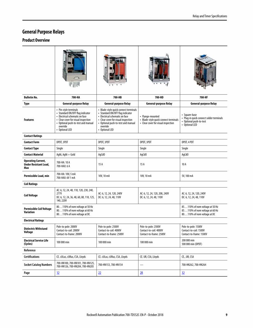
General Purpose RelaysProduct Overview
Bulletin No. 700-HA 700-HB 700-HD 700-HF
Type General-purpose Relay General-purpose Relay General-purpose Relay General-purpose Relay
Features
• Pin-style terminals• Standard ON/OFF flag indicator• Electrical schematic on face• Clear cover for visual inspection• Optional push-to-test and manual
override• Optional LED
• Blade-style quick connect terminals• Standard ON/OFF flag indicator• Electrical schematic on face• Clear cover for visual inspection• Optional push-to-test and manual
override• Optional LED
• Flange-mounted• Blade-style quick connect terminals• Clear cover for visual inspection
• Square-base• Plug-in quick connect solder terminals• Optional push-to-test• Optional LED
Contact Ratings
Contact Form DPDT, 3PDT DPDT, 3PDT DPDT, 3PDT DPDT, 4 PDT
Contact Type Single Single Single Single
Contact Material AgNi, AgNi + Gold AgCdO AgCdO AgCdO
Operating Current, Under Resistant Load, Max
700-HA: 10 A700-HAX: 6 A 15 A 15 A 10 A
Permissible Load, min 700-HA: 10V, 5 mA700-HAX: 6V 1 mA 10V, 10 mA 10V, 10 mA 5V, 100 mA
Coil Ratings
Coil Voltage
AC: 6, 12, 24, 48, 110, 120, 230, 240, 277VDC: 6, 12, 24, 36, 48, 60, 80, 110, 125, 140, 220V
AC: 6, 12, 24, 120, 240VDC: 6, 12, 24, 48, 110V
AC: 6, 12, 24, 120, 208, 240VDC: 6, 12, 24, 48, 110V
AC: 6, 12, 24, 120, 240VDC: 6, 12, 24, 48, 110V
Permissible Coil Voltage Variation
80…110% of nom voltage at 50 Hz80…110% of nom voltage at 60 Hz80…110% of nom voltage at DC
85…110% of nom voltage at 50 Hz85…110% of nom voltage at 60 Hz80…110% of nom voltage at DC
Electrical Ratings
Dielectric Withstand Voltage
Pole-to-pole: 2000VContact-to-coil: 2000VContact-to-frame: 2000V
Pole-to-pole: 2500VContact-to-coil: 4000VContact-to-frame: 2500V
Pole-to-pole: 2500VContact-to-coil: 4000VContact-to-frame: 2500V
Pole-to-pole: 1500VContact-to-coil: 1500VContact-to-frame: 1500V
Electrical Service Life (Cycles) 100 000 min 100 000 min 100 000 min 200 000 min
500 000 min (DPDT)
Reference
Certifications CE. cULus, cURus, CSA, Lloyds CE. cULus, cURus, CSA, Lloyds CE. UR, CSA, Lloyds CE., UR, CSA
Socket Catalog Numbers 700-HN100, 700-HN101, 700-HN125, 700-HN126, 700-HN204, 700-HN205 700-HN153, 700-HN154 — 700-HN262, 700-HN264
Page 12 22 28 32
Rockwell Automation Publication 700-TD552C-EN-P - October 2018 9

Relay and Timer Specifications
Bulletin Number 700-HC 700-HK 700-HL 700-HP
Type Interposing/Isolation Relay Interposing/Isolation Relay Interposing/Isolation Relay Interposing/Isolation Relay
Features
• Blade-style terminals• Standard ON/OFF flag indicator• Electrical schematic on face• Clear cover for visual inspection• Optional push-to-test and
manual override• Optional LED
• Optional pilot light• Retainer clip (comes with socket)• Low switching capacity• Push-to-test and manual override
• Ideal for PLC Interfaces• Built-in Coil Surge Protection• Fully Assembled Relay/Sockets• Standard LED• Relay or Solid-state Output• Optional: Leakage Current• Suppression Solution
• PCB “Pin Style” mounting• 5 mm pin spacing
Contact Ratings
Contact Form DPDT, 4PDT SPDT, DPDT SPDT 1 N.O. (SSR) DPDT
Contact Type Single Single Single Single
Contact Material AgNi, AgNi + Gold AgNi, AgNi + Gold AgSnO AgNi, AgNi + Gold
Operating Current, Under Resistant Load, Max
10 A (DPDT)7 A (4PDT)
8 A (DPDT), 16 A (SPDT)6 A (SPDT), 2 A (SSR DC output),2 A (SSR AC output)
8 A
Permissible Load, min
10V, 10 mA (Gold), 5V, 10 mA or25V, 2 mA (Silver)
5V 60 mA (Silver), 5V 10 mA (Gold)12V 6 mA (72 mW) Silver8V, 2.5 mA (20 mW) Gold
5V 5 mA (50 mW) Gold,5V 5 mA (300 mW) Silver
Coil Ratings
Coil VoltageAC: 6, 12, 24, 120, 240VDC: 6, 12, 24, 48, 110V
AC: 6, 12, 24, 120, 240VDC: 6, 12, 24, 48, 110V
AC: 12, 24, 48, 110, 120, 230, 240VDC: 12, 24, 48, 125, 230, 240V
AC: 6, 12, 24, 120, 240VDC: 6, 12, 24, 48, 110V
Permissible Coil Voltage Variation
80…110% of nom voltage at 50 Hz80…110% of nom voltage at 60 Hz80…110% of nom voltage at DC
80…110% of nom voltage at 50 Hz80…110% of nom voltage at 60 Hz73…110% of nom voltage at DC
85…110% of nom voltage at 50 Hz85…110% of nom voltage at 60 Hz80…110% of nom voltage at DC
80…110% of nom voltage at 50 Hz80…110% of nom voltage at 60 Hz73…150% of nom voltage at DC
Electrical Ratings
Dielectric Withstand Voltage
Pole-to-pole: 1000VContact-to-coil: 2000VContact-to-frame: 2000V
Pole-to-pole: 1500VContact-to-coil: 1500VContact-to-frame: 1500V
Pole-to-pole: 1000VContact-to-coil: 4000VContact-to-frame: 1500V
Pole-to-pole: 2000VContact-to-coil: 5000V
Electrical Service Life (Cycles) 100 000 min 100 000 min 100 000 min 100 000 min
Reference
Certifications CE, cULus, cURus, CSA, Lloyds CE, UL, UR, CSA CE, cURus, cULus, ABS CE, cULus, cURus, CSA, Lloyds
Socket Catalog Numbers 700-HN103, 700-HN128, 700-HN104 700-HN121, 700-HN221, 700-HN122,
700-HN222, 700-HN223, 700-HN224 — 700-HN123, 700-HN230
Page Number 39 44 50 64
10 Rockwell Automation Publication 700-TD552C-EN-P - October 2018

Relay and Timer Specifications
Bulletin Number 700-HJ 700-HG 700-HHF
Type Magnetic Latching Relay Power Relay Power Relay
Features • Socket mounted• Ideal for lighting applications
• Panel mount with screw terminals• Optional magnetic blowouts for switching DC
loads• Optional snap action switch
• Flange mounted• Optional LED
Contact Ratings
Contact Form SPDT, DPDT (Single or Dual Coil) SPST-N.O.-DM, SPDT, DPST-N.O., DPDT SPST-NO-DM, DPDT, 3PDT
Contact Type Single Single Single
Contact Material AgCdO AgNi AgNi
Operating Current, Under Resistant Load, Max
10 A 40 A 20 A (3PDT), 25 A (DPDT), 30 A (SPDT)
Permissible Load, min 10V 50 mA 10V 50 mA
10V 50 mA10V 100 mA (3PDT)
Coil Ratings
Coil VoltageAC: 24V, 120V, 240VDC: 12V, 24V
AC: 24V, 120V, 240V, 277V, 480VDC: 12V, 24V, 48V, 110V, 220V, 250V
AC: 24V, 120V, 240VDC: 6V,12V, 24V
Permissible Coil Voltage Variation
85…110% of nom voltage at 50 Hz85…110% of nom voltage at 60 Hz80…110% of nom voltage at DC
85…110% of nom voltage at 50 Hz85…110% of nom voltage at 60 Hz80…110% of nom voltage at DC
85…110% of nom voltage at 50 Hz85…110% of nom voltage at 60 Hz80…110% of nom voltage at DC
Electrical Ratings
Dielectric Withstand Voltage
Pole-to-pole: 1500V AC Contact-to-coil: 1500V AC Contact-to-frame: 1500V AC
Pole-to-pole: 2200V AC Contact-to-coil: 2200V AC Contact-to-frame: 2200V AC
Pole-to-pole: 2200V AC Contact-to-coil: 2200V AC Contact-to-frame: 2200V AC
Electrical Service Life (Cycles) 100 000 minimum 100 000 minimum 100 000 minimum
Reference
Certifications CE, UR, CSA CE, UL, CSA CE, UR, CSA
Socket Catalog Numbers 700-HN153, 700-HN154 — —
Page Number 71 75 80
Rockwell Automation Publication 700-TD552C-EN-P - October 2018 11

Relay and Timer Specifications
700-HA General-purpose Relay• 10 A contact rating• DPDT, 3PDT• Pin-style terminals• Standard ON/OFF flag indicator• Options: LED, push-to-test and manual override, socket-mounted surge suppressor module, or
multi-function timer• Contact choices: standard silver nickel, or bifurcated silver nickel with gold plating
Tube Base Relay with PIN Terminals (Single Contact) — Mechanical ON/OFF Indicator Included(1)
Description Contact RatingWiring Diagrams
Coil Voltage Cat. No.(1)
(1) LED Option: Add suffix (-4) to the selected 700-HA Relay Cat. No., except for the 240V AC Units, add (-4L). Push-to-test, Manual Override, and LED Option: Add suffix (-3-4) to the selected 700-HA Relay Cat. No., except for the 240V AC units, add (-3-4L). Push-to-test and Manual Override option: Add suffix (-3) to the selected 700-HA relay.LED not available for 220V DC and 277V AC coils.
U.S./Canada International
DPDT2-pole2 Form CSingle AgNi Contact
10 AB300
6V AC 700-HA32A0612V AC 700-HA32A1224V AC 700-HA32A24
120V AC 700-HA32A1240V AC 700-HA32A2277V AC 700-HA32A27
6V DC 700-HA32Z0612V DC 700-HA32Z1224V DC 700-HA32Z2436V DC 700-HA32Z3648V DC 700-HA32Z4860V DC 700-HA32Z6080V DC 700-HA32Z80
110V DC 700-HA32Z1125V DC 700-HA32Z01
Sockets 700-HN125 700-HN100700-HN204
140V DC 700-HA32Z3220V DC 700-HA32Z2
3PDT3-pole3 Form CSingle AgNi Contact
10 AB300
6V AC 700-HA33A0612V AC 700-HA33A1224V AC 700-HA33A24
120V AC 700-HA33A1240V AC 700-HA33A2
6V DC 700-HA33Z0612V DC 700-HA33Z1224V DC 700-HA33Z2448V DC 700-HA33Z4860V DC 700-HA33Z6080V DC 700-HA33Z80
110V DC 700-HA33Z1125V DC 700-HA33Z01
Sockets 700-HN126 700-HN101700-HN205
140V DC 700-HA33Z3220V DC 700-HA33Z2
(1) For Time Modules and Surge Suppressor Modules, see Accessories.
12 Rockwell Automation Publication 700-TD552C-EN-P - October 2018

Relay and Timer Specifications
Tube Base Relay with PIN Terminals (Bifurcated Contacts with Gold Overlay) — Mechanical ON/OFF Indicator Included
Description Contact RatingWiring Diagrams
Coil Voltage Cat. NoU.S./Canada International
DPDT2-Pole2 Form CBifurcated AgNi Contacts with Gold Plating 6 A
6V AC 700-HAX2A06
12V AC 700-HAX2A12
24V AC 700-HAX2A24
120V AC 700-HAX2A1
240V AC 700-HAX2A2
277V AC 700-HAX2A27Δ
6V DC 700-HAX2Z06
12V DC 700-HAX2Z12
24V DC 700-HAX2Z24
36V DC 700-HAX2Z36
48V DC 700-HAX2Z48
110V DC 700-HAX2Z1
Sockets 700-HN125 700-HN100700-HN204
125V DC 700-HAX2Z01
140V DC 700-HAX2Z3
3PDT3-Pole3 Form CBifurcated AgNi Contacts with Gold Plating 6 A
6V AC 700-HAX3A06
12V AC 700-HAX3A12
24V AC 700-HAX3A24
120V AC 700-HAX3A1
240V AC 700-HAX3A2
6V DC 700-HAX3Z06
12V DC 700-HAX3Z12
24V DC 700-HAX3Z24
48V DC 700-HAX3Z48
110V DC 700-HAX3Z1
Sockets 700-HN126 700-HN101700-HN205
125V DC 700-HAX3Z01
140V DC 700-HAX3Z3
Rockwell Automation Publication 700-TD552C-EN-P - October 2018 13

Relay and Timer Specifications
Accessories - 700-HA Relays
Photo DescriptionPkg. Qty.
Cat. No.
Screw Terminal Tube Base Socket — Panel or DIN Rail Mounting; Guarded Terminal Construction. 8-Pin for use with DPDT 700-HA Relays, -HX Timing Relays, -HT (On-Delay), and -HRM, -HRC and -HV (Repeat Cycle) Timing Relays.
10 700-HN100
Screw Terminal Tube Base Socket — Panel or DIN Rail Mounting; Open Style Construction. 8-Pin for use with DPDT 700-HA Relays, -HT (On-Delay) and -HRM, -HRC, and -HV (Repeat Cycle) Timing Relays. No retainer clip required.
10 700-HN125
Screw Terminal Tube Base Sockets — Panel or DIN Rail Mounting; Guarded Terminal Construction. 11-pin for use with 3PDT 700-HA relays. 10 700-HN101
Screw Terminal Tube Base Sockets — Panel or DIN Rail Mounting; Open Style Terminal Construction. 11-pin for use with 3PDT 700-HA relays. No retainer clip required. 10 700-HN126
8-Pin Socket — Can Be Used With or Without Timing Attachment or Surge SuppressorScrew Terminal Tube Base Sockets — panel or DIN Rail mounting. Guarded terminal construction. Used with DPDT 700-HA Relays.
10 700-HN204
11-Pin Socket — Can Be Used With or Without Timing Module or Surge Suppressor. Screw Terminal Tube Base Sockets — panel or DIN Rail mounting. Guarded terminal construction.Used with 3PDT 700-HA relays.
10 700-HN205
DIN (#3) symmetrical hat rail35 x 7.5 x 1 m 10 199-DR1
Photo Description Pkg. Qty. Cat. No.
Diode Surge Suppressor Voltage Range: 6…220V DC used with 700-HN204 and 700-HN205 socket 10 700-ADR
Diode with LED Surge Suppressor Voltage Range: 6…24V DC used with 700-HN204 and 700-HN205 socket 10 700-ADL1R
Diode with LED Surge Suppressor Voltage Range: 28…60V DC used with 700-HN204 and 700-HN205 socket 10 700-ADL2R
Diode with LED Surge Suppressor Voltage Range: 110…220V DC used with 700-HN204 and 700-HN205 socket 10 700-ADL3R
Varistor with LED Surge Suppressor Voltage Range: 6…24V AC used with 700-HN204 and 700-HN205 socket 10 700-AV1R
Varistor with LED Surge Suppressor Voltage Range: 110…240V AC used with 700-HN204 and 700-HN205 socket 10 700-AV3R
RC Surge Suppressor Voltage Range: 6…24V AC/DC used with 700-HN204 and 700-HN205 socket 10 700-AR1
RC Surge Suppressor Voltage Range: 110…240V AC/DC used with 700-HN204 and 700-HN205 socket 10 700-AR2
14 Rockwell Automation Publication 700-TD552C-EN-P - October 2018

Relay and Timer Specifications
Socket and Retainer Clip Reference
Timing ModuleOn-Delay or One-Shot selectable voltage range: 12…24V AC/DC used with sockets that accept plug-in accessory modules.
1 700-AT3
Timing ModuleOn-Delay or One-Shot selectable voltage range: 110…125V AC used with sockets that accept plug-in accessory modules.
1 700-AT3A1
Timing ModuleOn-Delay or One-Shot selectable voltage range: 230…240V AC used with sockets that accept plug-in accessory modules.
1 700-AT3A2
1. 1 s 0.05 s…1 s
1 700-HT3
2. 10 s 0.5 s…10 s
3. 100 s 5 s…100 s
4. 10 min 0.5 min…10 min
5. 100 min 5 min…100 min
6. 10 hours 0.5 h…10 h
7. 100 hours 5 h…100 h
8. LED Indicator
Relay Type Socket Retainer Clip
700-HA32700-HAX2
700-HN100700-HN125700-HN204
700-HN157Not Required700-HN157
700-HA33700-HAX3
700-HN101700-HN126700-HN205
700-HN157Not Required700-HN157
Photo Description Pkg. Qty. Cat. No.
t
U (A1/A2)
LED & R
tU (A1/A2)
LED & R
On-Delay
One-Shot
Rockwell Automation Publication 700-TD552C-EN-P - October 2018 15

Relay and Timer Specifications
Specifications - 700-HA Relays
Attribute 700-HA
Electrical RatingsPilot Duty Rating (1)
(1) See NEMA Ratings and Test Values on page 5
NEMA B300
Rated Thermal Current (Ith) HA = 10 A – 120V, 240V; HAX = 6 A – 120V, 240V
Rated Insulation Voltage (Ui) 250V IEC – 300V UL/CSA
Contacts
InductiveMake Break Hp
120V AC 30 A 3 A 1/3
240V AC 15 A 1.5 A 1
General-purpose 10 A, 240V AC
Resistive 10 A, 30V DC
Min. Low Energy Permissible Load HA = 10V, 5 mA HAX = 5V, 2 mA
Permissible Coil Voltage Variation Pickup:80…110% of nom voltage at 50 Hz, 80…110% of nom voltage at 60 Hz, 80…110% of nom voltage at DC
Coil Consumption ±10%
AC Coils 50 Hz 60 Hz
Inrush 3.3VA 2.85VA
Sealed 2.2VA 1.9VA
DC Coils 1.3 W
Must Dropout Voltage 20% of nom V AC; 10% of nom V DC
Max. Contact Resistance 50 MΩ (700-HA), 30 MΩ (700-HAX)
Design Specification/Test Requirements
Electrical
Pole-to-Pole 2000V
Contact to Coil 2000V
Electrical Life (Operating) 100 000 min.
Mechanical
Degree of Protection (Open Type) IEC 529 IP 40
Mechanical Lifecycles (AC/DC) > 20 x 106/ 50 x 106
Switching Frequency Operations 3600/HR
Coil Voltages See Product Selection
Operating TimePickup 12 ms
Dropout 12 ms
Maximum Operating Rate 4 Ops/s
VibrationEndurance 5 G
Operational 2.5 G
ShockEndurance 50 G
Operational 9 G
Environmental
TemperatureOperating AC/DC –40…+70 °C
Storage AC/DC –40…+100 °C
Altitude 2000 m (6560 ft)
Construction
Insulating Material Molded High-Dielectric Material
Enclosure Transparent Dust Cover
Contact Material700-HA: 10 A – AgNi
700-HAX: 6 A – Bifurcated/Gold Plating AgNi
Terminal Markings on Socket In accordance with EN50 0005
Sockets 8-Pin Socket — 700-HN100, -HN125, -HN204, 11-Pin Socket — 700-HN101, -HN126, -HN205
Certifications cURus Recognized (File No. E3125, Guide NLDX2/NLDX8), cULus Listed when used with 700-HN sockets noted (File No. E3125, Guide NLDX/NLDX7), CE Marked, CSA Certified, UR Certified (File 229473)
Standards UL508, CSA C22.2 No. 14, EN 61810-1
16 Rockwell Automation Publication 700-TD552C-EN-P - October 2018
Relay and Timer Specifications
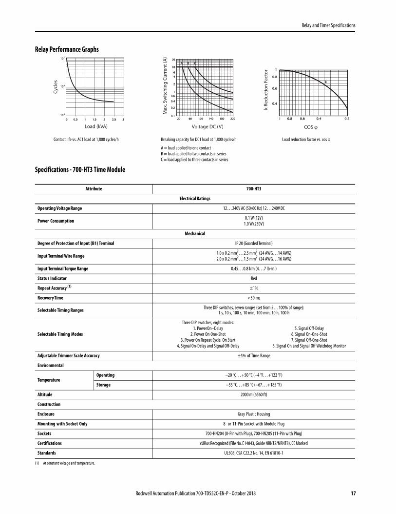
Relay Performance Graphs
Contact life vs. AC1 load at 1,800 cycles/h Breaking capacity for DC1 load at 1,800 cycles/h Load reduction factor vs. cos φ
A = load applied to one contactB = load applied to two contacts in seriesC = load applied to three contacts in series
Specifications - 700-HT3 Time Module
Attribute 700-HT3
Electrical Ratings
Operating Voltage Range 12…240V AC (50/60 Hz) 12…240V DC
Power Consumption 0.1 W (12V)1.0 W (230V)
Mechanical
Degree of Protection of Input (B1) Terminal IP 20 (Guarded Terminal)
Input Terminal Wire Range 1.0 x 0.2 mm2…2.5 mm2 (24 AWG…14 AWG)2.0 x 0.2 mm2…1.5 mm2 (24 AWG…16 AWG)
Input Terminal Torque Range 0.45…0.8 Nm (4…7 lb-in.)
Status Indicator Red
Repeat Accuracy (1)
(1) At constant voltage and temperature.
±1%
Recovery Time <50 ms
Selectable Timing Ranges Three DIP switches, seven ranges (set from 5…100% of range):1 s, 10 s, 100 s, 10 min, 100 min, 10 h, 100 h
Selectable Timing Modes
Three DIP switches, eight modes:1. Power On–Delay
2. Power On One-Shot3. Power On Repeat Cycle, On Start
4. Signal On-Delay and Signal Off-Delay
5. Signal Off-Delay6. Signal On-One-Shot7. Signal Off-One-Shot
8. Signal On and Signal Off Watchdog Monitor
Adjustable Trimmer Scale Accuracy ±5% of Time Range
Environmental
TemperatureOperating –20 °C…+50 °C (–4 °F…+122 °F)
Storage –55 °C…+85 °C (–67…+185 °F)
Altitude 2000 m (6560 ft)
Construction
Enclosure Gray Plastic Housing
Mounting with Socket Only 8- or 11-Pin Socket with Module Plug
Sockets 700-HN204 (8-Pin with Plug), 700-HN205 (11-Pin with Plug)
Certifications cURus Recognized (File No. E14843, Guide NRNT2/NRNT8), CE Marked
Standards UL508, CSA C22.2 No. 14, EN 61810-1
Load (kVA)
Cy
cle
s
k R
ed
uc
tio
n F
ac
tor
Voltage DC (V)
Ma
x. S
wit
ch
ing
Cu
rre
nt
(A)
COS φ
Rockwell Automation Publication 700-TD552C-EN-P - October 2018 17

Relay and Timer Specifications
Timing Charts - 700-HT3 Multi-function Time Module (t = Time Range 0.05 s…100 h)
Timing Charts -Cat. No. 700-HT3 Timing Modes, Time Description, Timing Charts, and DIP Switch Selections
Terms:U is Power InputR is Relay OutputS Signal, +A1 Socket, B1 Timert is the resulting Time Delay (Red light-emitting diode)
1. Power On-delayApply power (U) to timer. Relay contacts (R) change state after time delay (t) is complete. Contacts return to their shelf state when power is removed. Terminal B1 is not used in this mode.
3. Power On Repeat Cycle, On StartApply power (U) to timer. Relay contacts (R) change state immediately and the time delay (t) begins. When the time delay is complete, the contacts return to their shelf state for time delay (t)(time on = time-off). This cycle repeats until the power is removed. Terminal B1 is not used in this mode.
2. Power On One-shotApply power (U) to timer. Relay contacts (R) change state immediately and the time delay begins. When the time delay (t) is complete, contacts return to their shelf state. Contacts return to their shelf state when power is removed. Terminal B1 is not used in this mode.
4. Signal On-delay and Signal Off-delayApply power (U) to timer. When the signal (S) is closed the time delay (t) begins, after the time delay is completed the relay contacts (R) change state. Opening the signal starts the time delay, after the time delay is completed the contacts return to their shelf state. If the signal is closed or opened before the time delay is complete, the time delay is reset. Contacts return to their shelf state when power is removed.
Terms:U is Power Input R is Relay OutputS Signal, +A1 Socket, B1 Timert is the resulting Time Delay (Red light-emitting diode)
5. Signal Off-delayApply power (U) to timer. When the signal (S) is closed, the relay contacts (R) change state immediately. When the signal is opened, the time delay (t) begins. If the signal is closed before the time delay is complete, the time delay is reset and the relay remains energized. When the time delay is complete, the contacts return to their shelf state. Contacts return to their shelf state when power is removed.
7. Signal Off One-shotApply power (U) to timer. When the signal (S) is closed and then opened, the relay contacts (R) change state immediately and the time delay (t) begins. After the time delay begins, opening or closing the signal will not reset the time delay. When the time delay is complete, the contacts return to their shelf state. Contacts return to their shelf state when power is removed.
6. Signal On One-shotApply power (U) to timer. When the signal (S) is closed, the relay contacts (R) change state immediately and the time delay (t) begins. After the time delay begins, opening or closing the signal will not reset the time delay. When the time delay is complete, the contacts return to their shelf state. Contacts return to their shelf state when power is removed.
8. Signal On and Signal Off Watchdog MonitorApply power (U) to timer. When the signal (S) is closed, the relay contacts (R) energize immediately and the time delay (t) begins. If the signal is opened before the time delay is complete, the relay remains energized and the time delay is reset. When the time delay is completed, the contacts return to their shelf state. If the signal is opened after the time delay is complete, the relay contacts energize immediately and the same time delay begins. Continuous cycling of the signal at a rate that is faster than the time delay causes the relay contacts to remain energized. Contacts return to their shelf state when power is removed.
18 Rockwell Automation Publication 700-TD552C-EN-P - October 2018

Relay and Timer Specifications
Dimensions -700-HA RelaysApproximate dimensions are shown in millimeters (inches). Dimensions are not intended for manufacturing purposes.
700-HA Relay
Cat. No. 199-DR1 DIN Mounting Rail Series B
Cat. No. 199-DR4 DIN Mounting Rail Series B Has No Mounting Holes
Cat. No. A B C D Approx. Shipping Wt.
199-DR1 35(1-3/8)
27(1-1/16)
7.5(19/64)
1.02(1/64)
1.85 kg(4.07 lb) (10/pkg)
199-DR4 35(1-3/8)
27(1-1/16)
15(19/32)
2.3(3/32)
3.68 kg(8 lb) (5/pkg)
54.1(2-1/8)
36.5(1-9/20)
32.8(1-3/10)
50
(1-63/64)
1000
(39-3/8)
6.2
(15/64)
12.5
(1/2)5.2
(13/64)
1.0
(0.04)
7.5
(0.3)
27.0
(1.06)
35.0
(1.38)
Rockwell Automation Publication 700-TD552C-EN-P - October 2018 19

Relay and Timer Specifications
Approximate dimensions are shown in millimeters (inches). Dimensions are not intended for manufacturing purposes.
Cat. No. 700-HN100 Panel Mounting Cat. No. 700-HN125
Wire Size: 2 x 2.5 mm2
Single Wire – Up to #12 AWGDouble Wire – 2 x 2.5 mm2 (#2-14 AWG… #2-20 AWG)(Either Solid or Stranded)Strip Length: 9 mm (3/8 in.) – Torque: 0.8 N•m (7 lb•in)
Wire Size: 2 x 2.5 mm2
Single Wire – Up to 12 AWGDouble Wire – 2 x 2.5 mm2 (#2–14 AWG…#2–20 AWG)(Either Solid or Stranded)Strip Length: 9 mm (3/8 in.) – Torque: 0.8 N•m (7 lb•in)
Cat. No. 700-HN101 Panel Mounting Cat. No. 700-HN126
Wire Size: 2 x 2.5 mm2
Single Wire – Up to #12 AWGDouble Wire – 2 x 2.5 mm2 (#2–14 AWG…#2–20 AWG)(Either Solid or Stranded)Strip Length: 9 mm (3/8 in.) – Torque: 0.8 N•m (7 lb•in)
Wire Size: 2 x 2.5 mm2
Single Wire – Up to #12 AWGDouble Wire – 2 x 2.5 mm2 (#2–14 AWG…#2–20 AWG)(Either Solid or Stranded)Strip Length: 9 mm (3/8 in.) – Torque: 0.8 N•m (7 lb•in)
65.0(2-35/64)
38.0(1-1/2)
#4–40M3
26(1-1/32)
30.0(1-3/16)
40.1(1-37/64)
24.9(63/64)
4.2(5/32)
33.0(1-19/64)
24.6(31/32)
20.8(53/64)
54.9(2-5/32)
51.1(2-1/64)
14.7(37/64)
65.0(2-35/64)
38.0(1-1/2)
30(1-3/16)
#4-40M3
26(1-1/32)
20 Rockwell Automation Publication 700-TD552C-EN-P - October 2018

Relay and Timer Specifications
Approximate dimensions are shown in millimeters (inches). Dimensions are not intended for manufacturing purposes.
Cat. No. 700-HN204 Cat. No. 700-HN205
Wire Size: 2 x 2.5 mm2
Single Wire – Up to #12 AWGDouble Wire – 2 x 2.5 mm2 (14 AWG… 20 AWG) Qty. 2 wires(Either Solid or Stranded)Strip Length: 9 mm (3/8 in.) – Torque: 0.8 N•m (7 lb•in)
Wire Size: 2 x 2.5 mm2
Single Wire – Up to #12 AWGDouble Wire – 2 x 2.5 mm2 (14 AWG …20 AWG) Qty. 2 wires(Either Solid or Stranded)Strip Length: 9 mm (3/8 in.) – Torque: 0.8 N•m (7 lb•in)
Cat. No. 700-HT3
Wire Size: 2 x 1.5 mm2 (#2 – 16 AWG…#1–20 AWG)(Either Solid or Stranded)Strip Length: 9 mm (3/8 in.) – Torque: 0.8 N•m (7 lb•in)
33.5(1.32)
26.9(1.06)
20.4(0.80)
35.5(1.40)
21.6(0.85)
4.0 (0.16)
11.0(0.43)
49.7(1.96)
16.8(0.66)
77.5(3.05)
38.0 (1.50)
3.2(0.13) 77.5
(3.05)
38.0(1.50)
3.2 (0.13)
33.5(1.32)
26.9(1.06)
11.0 (0.43)
49.7(1.96)
16.8(0.66)
20.4(0.80)
35.5(1.40)
21.6(0.85)
4.0 (0.16)
38.0(1.50)
54(2.13)
10.5
(0.41)
6.3(0.25)
Rockwell Automation Publication 700-TD552C-EN-P - October 2018 21

Relay and Timer Specifications
700-HB Square Base Relay• 15 A contact rating• DPDT, 3PDT• Blade-style quick connect /solder terminals• Standard ON/OFF flag indicator• Options: LED, push-to-rest, and manual override• Faston 187 (4.8 x 0.5 mm)
Photo Description Contact RatingWiring Diagrams Coil
VoltageCat. No.(1)
(1) LED Option: Add suffix (-4) to the selected 700-HB Relay Cat. No., except for the 240V AC Units, add (-4L).Push-to-test, Manual Override, and LED Option: Add suffix (-3-4) to the selected 700-HB Relay Cat. No., except for the 240V AC units, add (-3-4L)Push-to-test and Manual Override option: Add suffix (-3) to the selected 700-HB relay.
U.S./Canada International
DPDT2-Pole2 Form CSingle AgCdO Contact
15 AB300
6V AC 700-HB32A06
12V AC 700-HB32A12
24V AC 700-HB32A24
120V AC 700-HB32A1
240V AC 700-HB32A2
6V DC 700-HB32Z06
12V DC 700-HB32Z12
24V DC 700-HB32Z24
48V DC 700-HB32Z48
Sockets 700-HN154 700-HN153 110V DC 700-HB32Z1
3PDT3-Pole3 Form CSingle AgCdO Contact
15 AB300
6V AC 700-HB33A06
12V AC 700-HB33A12
24V AC 700-HB33A24
120V AC 700-HB33A1
240V AC 700-HB33A2
6V DC 700-HB33Z06
12V DC 700-HB33Z12
24V DC 700-HB33Z24
48V DC 700-HB33Z48
Sockets 700-HN154 700-HN153 110V DC 700-HB33Z1
Input
34
32
31
Input
22 Rockwell Automation Publication 700-TD552C-EN-P - October 2018

Relay and Timer Specifications
Rockwell Automation Publication 700-TD552C-EN-P - October 2018 23
Accessories - 700-HB Relays
Photo Description Pkg. Qty. Cat. No.
Diode Surge Suppressor Voltage Range: 6…220V DC used with 700-HN204 and 700-HN205 socket 10 700-ADR
Diode with LED Surge Suppressor Voltage Range: 6…24V DC used with 700-HN204 and 700-HN205 socket 10 700-ADL1R
Diode with LED Surge Suppressor Voltage Range: 28…60V DC used with 700-HN204 and 700-HN205 socket 10 700-ADL2R
Diode with LED Surge Suppressor Voltage Range: 110…220V DC used with 700-HN204 and 700-HN205 socket 10 700-ADL3R
Varistor with LED Surge Suppressor Voltage Range: 6…24V AC used with 700-HN204 and 700-HN205 socket 10 700-AV1R
Varistor with LED Surge Suppressor Voltage Range: 110…240V AC used with 700-HN204 and 700-HN205 socket 10 700-AV3R
RC Surge Suppressor Voltage Range: 6…24V AC/DC used with 700-HN204 and 700-HN205 socket 10 700-AR1
RC Surge Suppressor Voltage Range: 110…240V AC/DC used with 700-HN204 and 700-HN205 socket 10 700-AR2
Timing ModuleOn-Delay or One-Shot selectable voltage range: 12…24V AC/DC used with sockets that accept plug-in accessory modules.
1 700-AT3
Timing ModuleOn-Delay or One-Shot selectable voltage range: 110…125V AC used with sockets that accept plug-in accessory modules.
1 700-AT3A1
Timing ModuleOn-Delay or One-Shot selectable voltage range: 230…240V AC used with sockets that accept plug-in accessory modules.
1 700-AT3A2
1. 1 s 0.05 s…1 s
1 700-HT3
2. 10 s 0.5 s…10 s
3. 100 s 5 s…100 s
4. 10 min 0.5 min…10 min
5. 100 min 5 min…100 min
6. 10 hours 0.5 h…10 h
7. 100 hours 5 h…100 h
8. LED Indicator
t
U (A1/A2)
LED & R
tU (A1/A2)
LED & R
On-Delay
One-Shot

Relay and Timer Specifications
Socket and Retainer Clip Reference
Photo Description Pkg. Qty. Cat. No.
Screw Terminal Socket — Panel or DIN Rail Mounting. Guarded Terminal Construction11-blade socket for use with 700-HB relays. This socket has coil and contact separation as well as the ability to use optional plug-in modules (700-A__ accessories, LED, surge suppression, timing modules).
10 700-HN153
Screw Terminal Base Socket — Panel or DIN Rail Mounting. Open Style Construction11-blade for use with 700-HB relays. 10 700-HN154
DIN (#3) symmetrical hat rail35 x 7.5 x 1 m 10 199-DR1
Retainer ClipFor Cat. Nos. 700-HN154 Sockets with 700-HB RelaysSecures relay in socket. Order must be for 10 clips or multiples of 10.
10 700-HN156
Retainer ClipFor Cat. Nos. 700-HN153 Sockets with 700-HB RelaysSecures relay in socket. Order must be for 10 clips or multiples of 10.
10 700-HN158
Relay Identification Snap-in Markers Snap-in markers fit on top of product covers. The following are blank cards. Squares slip into molded slot on top of product covers.
100
1492-MS5X12 1492-MS6X9 1492-MS6X12 1492-MS8X9 1492-MS8X12 1492-MP-Blank
Pre-Printed Identification Tags — contains 10 sheets of pre-printed and blank tags. Each sheet contains 13 sets of the markings CR…9CR, TR…9TR, M…9M, F, R, 1S, and 117 blank tags. Tags are peel-off with sticky backing for easy placement on relays.
10 700-N40
Blank Identification Tags — contains 10 sheets of blank identification tags for customer specialized printing. Each sheet contains 546 blank tags. Tags are peel-off with sticky backing for easy placement on relays.
10 700-N41
Relay Type Socket Cat. No. Retainer Clip Cat. No.
700-HB700-HN153 700-HN154
700-HN158 700-HN156
24 Rockwell Automation Publication 700-TD552C-EN-P - October 2018

Relay and Timer Specifications
Rockwell Automation Publication 700-TD552C-EN-P - October 2018 25
Specifications - 700-HB Relays
Attribute 700-HB
Electrical Ratings
Pilot Duty Rating (1)
(1) See NEMA Ratings and Test Values on page 5
NEMA B300Rated Thermal Current (Ith) 15 A – 120V, 240VRated Insulation Voltage (Ui) 250V IEC-300V UL/CSA
Contacts
InductiveMake Break Hp
2 -Pole 3 -Pole 2 -Pole 3 -Pole120V AC 60 A 30 A 6 A 3 A 3/4240V AC 30 A 15 A 3 A 1.5 A 2General-purpose 15 A, 240V ACResistive 15 A, 30V DC
Min. Low Energy Permissible Load 1000 mW (10V, 10 mA)
Permissible Coil Voltage Variation80…110% of Nominal Voltage at 50 Hz80…110% of Nominal Voltage at 60 Hz
80…110% of Nominal Voltage at DC
Coil Consumption±10%
AC Coils 50 Hz 60 Hz
Inrush 3.3VA 2.85VASealed 2.2VA 1.9VADC Coils 1.3 W
Max. Allowable Leakage25% of VA10% of W
Max. Contact Resistance 50 MΩDesign Specification/Test Requirements
Dielectric Withstand VoltagePole-to-Pole 2500VContact to Coil 4000V
Mechanical
Degree of Protection (Open Type) IEC 529 IP 40Mechanical lifecycles (AC/DC) > 10 x 106/30 x 106
Switching Frequency Operations 3600/HRCoil Voltages See Overview/Product Selection
Operating Time (ms)Pickup 20 msDropout 4 ms
Maximum Operating Rate 4 Ops/s
VibrationEndurance 5 GOperational 1.5 G
ShockEndurance 50 GOperational 15 G
Environmental
TemperatureOperating AC/DC –40…+70 °CStorage AC/DC –40…+100 °C
Altitude 2000 m (6560 ft)Construction
Insulating Material Molded High Dielectric MaterialEnclosure Transparent Dust CoverContact Material AgCdOTerminal Markings on Socket In accordance with EN50 0005Sockets 700-HN153, -HN154Certifications cURus Recognized (File No. E3125, Guide NLDX2/NLDX8), cULus Listed when used with 700-HN sockets notedStandards UL508, CSA C22.2 No. 14, EN 61810-1

Relay and Timer Specifications
Technical Data - 700-HB Relays
Contact life versus AC1 load at 600 cycles/h.
Breaking capacity for DC1 load at 600 cycles/h.Load applied to one contact.
A = for N.O. typesB= other types
Load Reduction factor versus cos φ
Load (kVA)
Cy
cle
s
Voltage DC (V)
Ma
xim
um
Sw
itc
hin
g C
urr
en
t (A
)
(Highly Resistive) COS φ (Inductive)
Re
du
cti
on
Fa
cto
r
26 Rockwell Automation Publication 700-TD552C-EN-P - October 2018

Relay and Timer Specifications
Dimensions - 700-HB RelaysApproximate Dimensions are shown in millimeters (inches). Dimensions are not intended for manufacturing purposes.
700-HB Relay Cat. No. 700-HN153
Wire Size: 2 x 2.5 mm2
Single Wire – Up to #12 AWGDouble Wire – 2 x 2.5 mm2 (14 AWG… 20 AWG), Qty. 2 wires(Either Solid or Stranded)Strip Length: 9 mm (3/8 in.) – Torque: 0.8 N•m (7 lb•in)
Cat. No. 700-HN154 Cat. No. 700-HT3
Wire Size: 2 x 2.5 mm2
Single Wire – Up to #12 AWGDouble Wire – 2 x 2.5 mm2 (14 AWG… 20 AWG), Qty. 2 wires(Either Solid or Stranded)Strip Length: 9 mm (3/8 in.) – Torque: 0.8 N•m (7 lb•in)
Wire Size: 2 x 1.5 mm2 (#2 – 16 AWG…#1–20 AWG)(Either Solid or Stranded)Strip Length: 9 mm (3/8 in.) – Torque: 0.8 N•m (7 lb•in)
35.8(1.41)
38.2(1.50)
51.4(2.02)
40(1.57)
Ø 3.2(0.13)
35.5(1.40)
46.3(1.82)
91.3(3.59)
95.3(3.75)
60.9(2.40)
30.25(1.19)
27.0(1.06)
34.3(1.35)
35.4(1.39)
21.6(0.85)
32.0(1.26)
4.0(0.16)
49.5(1.95)
35.4(1.40)
25.6(1.01)
84.85(3.34)
84.3(3.32)
41.5(1.63)
38.0(1.50)
54(2.13)
10.5
(0.41)
6.3(0.25)
Rockwell Automation Publication 700-TD552C-EN-P - October 2018 27

Relay and Timer Specifications
700-HD Flange Mount Square Base Relay• Flange-mounted/panel-mounted• 15 A contact rating• DPDT, 3PDT• Blade-style quick connect terminals (0.187 x 0.020)
• Solder terminals (no socket required)
Accessories - 700-HD Relays
Photo Contact Rating Wiring Diagrams Coil Voltage Cat. No.U.S./Canada International
DPDT2-Pole2 Form CAgCdO Contacts
15 A
6V AC 700-HD32A0612V AC 700-HD32A1224V AC 700-HD32A24120V AC 700-HD32A1208V AC 700-HD32A20240V AC 700-HD32A26V DC 700-HD32Z0612V DC 700-HD32Z1224V DC 700-HD32Z2448V DC 700-HD32Z48110V DC 700-HD32Z1
3PDT3-Pole3 Form CAgCdO Contacts
15 A
6V AC 700-HD33A0612V AC 700-HD33A1224V AC 700-HD33A24120V AC 700-HD33A1208V AC 700-HD33A20240V AC 700-HD33A26V DC 700-HD33Z0612V DC 700-HD33Z1224V DC 700-HD33Z2448V DC 700-HD33Z48110V DC 700-HD33Z1
Photo Description Pkg. Qty.
Cat. No.
Relay Identification Snap-in Markers Snap-in markers fit on top of product covers. The following are blank cards. Squares slip into molded slot on top of product covers.
100
1492-MS5X12 1492-MS6X9 1492-MS6X12 1492-MS8X9 1492-MS8X12 1492-MP-Blank
Pre-Printed Identification Tags — contains 10 sheets of pre-printed and blank tags. Each sheet contains 13 sets of the markings CR…9CR, TR…9TR, M…9M, F, R, 1S, and 117 blank tags. Tags are peel-off with sticky backing for easy placement on relays.
10 700-N40
Blank Identification Tags — contains 10 sheets of blank identification tags for customer specialized printing. Each sheet contains 546 blank tags. Tags are peel-off with sticky backing for easy placement on relays. 10 700-N41
Input
32
34
31
Input
28 Rockwell Automation Publication 700-TD552C-EN-P - October 2018

Relay and Timer Specifications
Specifications - 700-HD Relays
Attribute 700-HD
Electrical Ratings
Pilot Duty Rating (1) NEMA B300
Rated Thermal Current (Ith) 15 A(2) – 120V15 A (2) – 240V,
Rated Insulation Voltage (Ui) 250V IEC-300V UL/CSA
Contacts
Inductive Make Break Hp
2-Pole 3-Pole 2-Pole 3-Pole
120V AC 60 A 30 A 6 A 3 A 3/4
240V AC 30 A 15 A 3 A 1.5 A 2
General-purpose 15 A, 240V AC
Resistive 15 A, 30V DC
Min. Low Energy Permissible Load 1000 mW (10V, 10 mA)
Permissible Coil Voltage Variation80…110% of Nominal Voltage at 50 Hz80…110% of Nominal Voltage at 60 Hz
80…110% of Nominal Voltage at DC
Coil Consumption±10%
AC Coils 50 Hz 60 Hz
Inrush 3.3VA 2.85VA
Sealed 2.2VA 1.9VA
DC Coils 1.3 W
Maximum Contact Resistance 50 MΩ
Must Dropout Voltage 20% of Nominal V AC10% of Nominal V DC
Design Specification/Test Requirements
Electrical
Dielectric WithstandVoltage
Pole-to-Pole 2500V
Contact to Coil 4000V
Mechanical
Degree of Protection (Open Type) IEC 529 IP 40
Mechanical lifecycles (AC/DC) See Overview/Product Selection
Switching Frequency Operations 3600/HR
Coil Voltages > 10 x 106 / 30 x 106
Operating TimePickup 20 ms
Dropout 4 ms
Maximum Operating Rate 4 Ops/s
Minimum Low Energy Permissible Load 1000 mN (10V, 10 mA)
Environmental
TemperatureOperating –40…+70 °C
Storage –40…+100 °C
Altitude 2000 m (6560 ft)
Rockwell Automation Publication 700-TD552C-EN-P - October 2018 29

Relay and Timer Specifications
Construction
Insulating Material Molded High Dielectric Material
Enclosure Transparent Dust Cover
Contact Material Silver Cad. Ox.
Terminal Markings In accordance with EN50 0005
Certifications cURs Recognized (File No. E3125, Guide NLDX2/NLDX8), CSA Certified (File No. 229473), CE Marked, UR Certified
Standards UL 508, CSA C22.2 No. 14, EN 61810-1
(1) See NEMA Ratings and Test Values on page 5(2) 3-pole relays have a 20 A maximum total current rating for all three poles.
Contact life versus AC1 load at 600 cycles/h. Breaking capacity for DC1 load at 600 cycles/h.
Load applied to one contact.A = for N.O. typesB = other types
Load Reduction factor versus cos φ
Attribute 700-HD
Load (kVA)
Cy
cle
s
Voltage DC (V)
Ma
xim
um
Sw
itc
hin
g C
urr
en
t (A
)
(Highly Resistive) COS φ (Inductive)
Re
du
cti
on
Fa
cto
r
30 Rockwell Automation Publication 700-TD552C-EN-P - October 2018

Relay and Timer Specifications
Dimensions - 700-HD RelaysApproximate dimensions are shown in millimeters (inches). Dimensions are not intended for manufacturing purposes.
700-HD Relay
35.9(1.41)
68(2.67)
63(2.48)
38.2(1.50)
Rockwell Automation Publication 700-TD552C-EN-P - October 2018 31

Relay and Timer Specifications
700-HF Square Base Relay• 12 A contact rating• DPDT, 4PDT• Plug-in quick connect/solder terminals• Options: LED, push-to-test manual override operator
Photo DescriptionContact Rating
Wiring DiagramsCoil Voltage Cat. No.(1)
(1) Pilot Light Option: Add suffix (-4) to the selected 700-HF Relay Cat. No. except for the 240V AC units, add (-4L).Manual Operator and LED Option: Add suffix (-3-4) to the selected 700-HF Relay Cat. No., except for the 240V AC units, add (-3-4L).
U.S./Canada International
DPDT2-pole2 Form CAgCdO Contacts
12 A
6V AC 700-HF32A06
12V AC 700-HF32A12
24V AC 700-HF32A24
120V AC 700-HF32A1
240V AC 700-HF32A2
6V DC 700-HF32Z06
12V DC 700-HF32Z12
24V DC 700-HF32Z24
48V DC 700-HF32Z48
Socket 700-HN116700-HN262
700-HN116700-HN262 110V DC 700-HF32Z1
4PDT4-pole4 Form CAgCdO Contact 12 A
6V AC 700-HF34A06
12V AC 700-HF34A12
24V AC 700-HF34A24
120V AC 700-HF34A1
240V AC 700-HF34A2
6V DC 700-HF34Z06
12V DC 700-HF34Z12
24V DC 700-HF34Z24
48V DC 700-HF34Z48
Socket 700-HN139700-HN264
700-HN139700-HN264 110V DC 700-HF34Z1
32 Rockwell Automation Publication 700-TD552C-EN-P - October 2018

Relay and Timer Specifications
Accessories - 700-HF RelaysPhoto Description Pkg. Qty. Cat. No.
Pre-Printed Identification Tags — contains 10 sheets of pre-printed and blank tags. Each sheet contains 13 sets of the markings CR…9CR, TR…9TR, M…9M, F, R, 1S, and 117 blank tags. Tags are peel-off with sticky backing for easy placement on relays.
10 700-N40
Blank Identification Tags — contains 10 sheets of blank identification tags for customer specialized printing. Each sheet contains 546 blank tags. Tags are peel-off with sticky backing for easy placement on relays. 10 700-N41
Screw Terminal Socket — Panel or DIN Rail Mounting 8-blade miniature socket for use with DPDT HF relays. 10 700-HN116
Screw Terminal Socket — Panel or DIN Rail Mounting, Guarded Terminal Construction8-blade socket for use with DPDT 700-HF relays. The socket has the ability to use optional plug-in modules (Cat. No. 700-A_ _ accessories, LED, surge suppression, timing modules).
10 700-HN262
Screw Terminal Socket — Panel or DIN Rail Mounting, Guarded Terminal Construction14-blade socket for use with 4PDT 700-HF relays. 10 700-HN139
Screw Terminal Socket — Panel or DIN Rail Mounting, Guarded Terminal Construction14-blade socket for use with 4PDT 700-HF relays. The socket has coil and contact separation and the ability to use optional plug-in modules (Cat. No. 700-A_ _ accessories, LED, surge suppression, timing modules).
10 700-HN264
DIN (#3) symmetrical hat rail35 x 7.5 x 1 m 10 199-DR1
Retainer Clip for Cat. Nos. 700-HN103, -HN104 and -HN128 Sockets with 700-HC Relays and Cat. Nos. 700-HN116, 700-HN262 Sockets with 700-HF DPDT Relays§Secures relay in socket. Order must be for 10 clips or multiples of 10.
10 700-HN114
Retainer Clip for Cat. Nos. 700-HN139 and -HN264 Sockets with 700-HF 4PDT Relays§Secures relay in socket. Order must be for 10 clips or multiples of 10. 10 700-HN266
Rockwell Automation Publication 700-TD552C-EN-P - October 2018 33

Relay and Timer Specifications
Diode with LED Surge SuppressorVoltage Range: 6…24V DC used with sockets that accept plug-in accessory modules. 10 700-ADL1
Diode with LED Surge SuppressorVoltage Range: 28…60V DC used with sockets that accept plug-in accessory modules. 10 700-ADL2
Diode with LED Surge SuppressorVoltage Range: 110…220V DC used with sockets that accept plug-in accessory modules. 10 700-ADL3
Varistor with LED Surge SuppressorVoltage Range: 6…24V AC used with sockets that accept plug-in accessory modules. 10 700-AV1R
Varistor with LED Surge SuppressorVoltage Range: 110…240V AC usedwith sockets that accept plug-in accessory modules.
10 700-AV3R
RC Surge SuppressorVoltage Range: 6…24V AC/DC usedwith sockets that accept plug-in accessory modules.
10 700-AR1
RC Surge SuppressorVoltage Range: 110…240V AC/DC usedwith sockets that accept plug-in accessory modules.
10 700-AR2
Timing ModuleOn-Delay or One-Shot selectable voltage range: 12…24V AC/DC used with sockets that accept plug-in accessory modules.
1
700-AT3
Timing ModuleOn-Delay or One-Shot selectable voltage range: 110…125V AC used with sockets that accept plug-in accessory modules.
700-AT3A1
Timing ModuleOn-Delay or One-Shot selectable voltage range: 230…240V AC used with sockets that accept plug-in accessory modules.
700-AT3A2
Socket, and Retainer Clip Reference
Relay Type Cat. No. Socket Cat. No. Retainer Clip
700-HF32 700-HN116700-HN262 700-HN114
700-HF34 700-HN139700-HN264 700-HN266
Accessories - 700-HF RelaysPhoto Description Pkg. Qty. Cat. No.
34 Rockwell Automation Publication 700-TD552C-EN-P - October 2018

Relay and Timer Specifications
Specifications- 700-HF RelaysElectrical Ratings 700-HF 2 Pole 700-HF 4 Pole
Contacts
Inductive V AC230V AC
AC 15 @ 700 VA
AC-1 @ 3000 VA
1 Hp @ 240V AC
120V AC 1/2 Hp @ 120V AC
VDC DC-112 A @ 30V DC
0.5 A @ 110V DC
0.25 A @ 220V DC
ResistiveAC 12 A @ 250 V AC (per pole)
DC 12 A @ 30 V DC (per pole)
Operating RangeAC 80...110% nom voltage
DC 80...110% nom voltage 85...110% nom voltage
Rated PowerAC (50 Hz) 1.5 VA 2 VA
DC 1 W 1.3 W
Holding VoltageAC 80% nom voltage
DC 60% nom voltage
Must Drop Out VoltageAC 20% nom voltage
DC 10% nom voltage
Insulation Voltage 250V AC
Design Specification/Test Requirements
Dielectric Withstand VoltagePole-to-Pole 2500V AC
Contact to Pole 2500V AC
Mechanical
Degree of Protection Open Type (Sockets)
Mechanical Life Operations 20 x 106
Switching Frequency Operations 3600/hr
Coil Voltages See Product Selection
Operating Time at nom voltage at 20 °C
Pickup 8 ms 10 ms
Dropout 3 ms 4 ms
Maximum Operating Rate 4 Ops/s
Vibration 15 G
Shock 15 G
Environmental
TemperatureOperating –40…+70 °C (–40…+268 °F)
Storage –50…+80 °C (–89…+176 °F)
Altitude 2000 m (6560 ft)
Construction
Insulating Material Molded High-Dielectric Material
Enclosure Transparent Dust Cover
Contact Material Silver Cad. Oxide
Terminal Markings on Socket In accordance with EN50 0005
Sockets 8-Blade Socket (DPDT) Cat. No. 700-HN116 & 700-HN262, 14-Blade Socket (4PDT) Cat. No. 700-HN139 & 700-HN264
Certifications CSA Certified (File No. 229473), UL Recognized (File No. E3125, Guide NLDX2/NLDX8), CE Marked,UL Listed when used with sockets shown above, (File No. E3125, Guide NLDX/NLDX 7), LR Certified, RINA Certified, IMQ Certified
Standards UL 508, CSA 22.2 No. 14, EN-61810-1
Rockwell Automation Publication 700-TD552C-EN-P - October 2018 35

Relay and Timer Specifications
Dimensions -700-HF RelaysApproximate Dimensions are shown in millimeters (inches). Approximate Dimensions are not intended to be used for manufacturing purposes.
700-HF Relay (DPDT)
700-HF (4PDT)
Cat. No. 199-DR1 DIN Mounting Rail Series BCat. No. 199-DR4 DIN Mounting Rail Series B Has No Mounting Holes
Cat. No. A B C D Approx.Shipping Wt.
199-DR1 35(1-3/8)
27(1-1/16)
7.5(19/64)
1.02(1/64)
1.85 kg(4.07 lb) (10/pkg)
199-DR4 35(1-3/8)
27(1-1/16)
15(19/32)
2.3(3/32)
3.68 kg(8 lb) (5/pkg)
36 Rockwell Automation Publication 700-TD552C-EN-P - October 2018

Relay and Timer Specifications
Rockwell Automation Publication 700-TD552C-EN-P - October 2018 37
Dimensions - 700-HF RelaysApproximate Dimensions are shown in millimeters (inches). Approximate Dimensions are not intended to be used for manufacturing purposes.
Cat. No. 700-HN116Wire Size: 2 x 2.5 mm2
Single Wire – Up to #12 AWGDouble Wire – 2.5 mm2 (14 … 20 AWG), Qty. 2 wires
(Either Solid or Stranded)Strip Length: 9 mm (3/8 in.) – Torque: 0.8 N•m (7 lb·in)
Cat. No. 700-HN262Wire Size: Solid - 1x6/ 2 x 2.5 mm2
1x10 / 2 x 14 AWGStranded - 1x4 / 2x2.5 mm2
1x12 / 2x14 AWGLength: 9 mm (3/8 in.) - Torque: 0.8 N∙m (7 lb. ∙ in.)
300V AC, 12 A, 50 °C

Relay and Timer Specifications
Cat. No. 700-HN139Wire Size: 2 x 2.5 mm2
Single Wire – Up to #12 AWGDouble Wire – 2.5 mm2 (14 … 20 AWG), Qty. 2 wires
(Either Solid or Stranded)Strip Length: 9 mm (3/8 in.) – Torque: 0.8 N•m (7 lb·in)
Cat. No. 700-HN264Wire Size: Solid - 1x6/ 2 x 2.5 mm2
1x10 / 2x14 AWGStranded - 1x4 / 2x2.5 mm2
1x12 / 2x14 AWGLength: 9 mm (3/8 in.) - Torque: 0.8 N∙m (7 lb. ∙ in.)
300V AC, 10 A, 70 °C
38 Rockwell Automation Publication 700-TD552C-EN-P - October 2018
Relay and Timer Specifications
Rockwell Automation Publication 700-TD552C-EN-P - October 2018 39
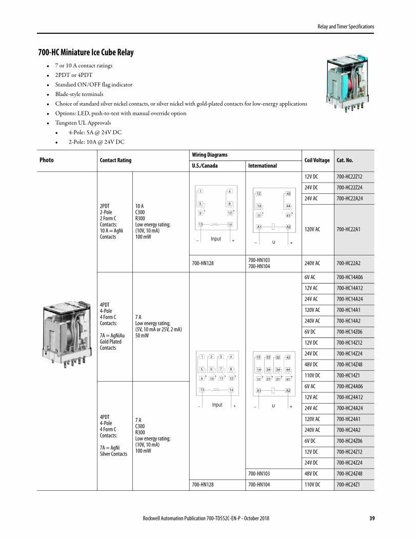
700-HC Miniature Ice Cube Relay• 7 or 10 A contact ratings• 2PDT or 4PDT• Standard ON/OFF flag indicator• Blade-style terminals• Choice of standard silver nickel contacts, or silver nickel with gold-plated contacts for low-energy applications• Options: LED, push-to-test with manual override option• Tungsten UL Approvals
• 4-Pole: 5A @ 24V DC• 2-Pole: 10A @ 24V DC
Photo Contact RatingWiring Diagrams
Coil Voltage Cat. No.U.S./Canada International
2PDT2-Pole2 Form CContacts:10 A = AgNiContacts
10 AC300R300Low energy rating;(10V, 10 mA)100 mW
12V DC 700-HC22Z12
24V DC 700-HC22Z24
24V AC 700-HC22A24
120V AC 700-HC22A1
700-HN128 700-HN103700-HN104 240V AC 700-HC22A2
4PDT4-Pole4 Form CContacts:
7A = AgNiAuGold PlatedContacts
7 ALow energy rating;(5V, 10 mA or 25V, 2 mA)50 mW
6V AC 700-HC14A06
12V AC 700-HC14A12
24V AC 700-HC14A24
120V AC 700-HC14A1
240V AC 700-HC14A2
6V DC 700-HC14Z06
12V DC 700-HC14Z12
24V DC 700-HC14Z24
48V DC 700-HC14Z48
110V DC 700-HC14Z1
4PDT4-Pole4 Form CContacts:
7A = AgNiSilver Contacts
7 AC300R300Low energy rating;(10V, 10 mA)100 mW
6V AC 700-HC24A06
12V AC 700-HC24A12
24V AC 700-HC24A24
120V AC 700-HC24A1
240V AC 700-HC24A2
6V DC 700-HC24Z06
12V DC 700-HC24Z12
24V DC 700-HC24Z24
700-HN103 48V DC 700-HC24Z48
700-HN128 700-HN104 110V DC 700-HC24Z1
Input
Input

Relay and Timer Specifications
Accessories - 700-HC Relays
PhotoDescription
Pkg. Qty.
Cat. No.
Diode with LED Surge Suppressor Voltage Range: 6…24V DC used with 700-HN104 socket
10 700-ADL1
Diode with LED Surge Suppressor Voltage Range: 28…60V DC used with 700-HN104 socket
10 700-ADL2
Diode with LED Surge Suppressor Voltage Range: 110…220V DC used with 700-HN104 socket
10 700-ADL3
Varistor with LED Surge Suppressor Voltage Range: 6…24V AC used with 700-HN104 socket
10 700-AV1R
Varistor with LED Surge Suppressor Voltage Range: 110…240V AC used with 700-HN104 socket
10 700-AV3R
RC Surge SuppressorVoltage Range: 6…24V AC/DCused with 700-HN104 socket
10 700-AR1
RC Surge SuppressorVoltage Range: 110…240V AC/DCused with 700-HN104 socket
10 700-AR2
Timing ModuleOn-Delay or One-Shot selectable voltage range: 12…24V AC/DC used with sockets that accept plug-in accessory modules.
1
700-AT3
Timing ModuleOn-Delay or One-Shot selectable voltage range: 110…125V AC used with sockets that accept plug-in accessory modules.
700-AT3A1
Timing ModuleOn-Delay or One-Shot selectable voltage range: 230…240V AC used with sockets that accept plug-in accessory modules.
700-AT3A2
Screw Terminal Socket — Panel or DIN Rail Mounting; Guarded Terminal Construction.Ith = 10 A per pole. 14-blade miniature socket for use with 700-SC Relays. 10 700-HN103
Screw Terminal Socket — Panel or DIN Rail Mounting; Guarded Terminal Construction Ith = 10 A per pole. 14-blade miniature socket for use with 700-HC relays. This socket has coil and contact separation as well as the ability to plug in optional plug in modules (700-A__ accessories: LED, Surge Suppression, Timing Modules)
10 700-HN104
Screw Terminal Base Socket — Panel or DIN Rail Mounting; Open-Style Construction Ith = 10 A per pole. 14-blade miniature socket for use with 700-HC Relays. 10 700-HN128
40 Rockwell Automation Publication 700-TD552C-EN-P - October 2018

Relay and Timer Specifications
Socket and Retainer Clip Reference
DIN (#3) symmetrical hat rail35 x 7.5 x 1 m 10 199-DR1
Retainer Clip for Cat. Nos. 700-HN103, -HN104 and -HN128 Sockets with 700-HC Relays. Secures relay in socket.(1) 10 700-HN114
Plastic Retainer and Ejection LeverFor use with the 700-HN104 Sockets for 700-HC relays.Built-in ability to accept 1492 Snap-in Markers
10 700-HN124
(1) See 700-HC Miniature Square Base Relay, Socket, and Retainer Clip Reference Chart
Photo Description Pkg. Qty. Cat. No.
Relay Identification Snap-in MarkersSnap-in markers fit on top of product covers. Squares slip into molded slot on top of product cover.
5 1492-MS5X12
5 1492-MS6X9
5 1492-MS6X12
5 1492-MS8X9
5 1492-MS8X12
100 1492-MP-Blank
Pre-Printed Identification Tags — contains 10 sheets of pre-printed and blank tags. Each sheet contains 13 sets of the markings CR…9CR, TR…9TR, M…9M, F, R, 1S, and 117 blank tags. Tags are peel-off with sticky backing for easy placement on relays.
10 700-N40
Markers — Used for terminal identification 50 700-N41
Relay Type Socket Cat. No. Retainer Clip Cat. No.
700-HC
700-HN103 700-HN114
700-HN128 700-HN114
700-HN104 700-HN114 or 700-HN124
PhotoDescription
Pkg. Qty.
Cat. No.
Rockwell Automation Publication 700-TD552C-EN-P - October 2018 41

Relay and Timer Specifications
Specifications- 700-HC Relays
Attribute 700-HC
Electrical Ratings
Pilot Duty Rating (1)
(1) See General Information on page 3
NEMA C300, R300
Rated Thermal Current (Ith) 7 A and 10 A
Rated Insulation Voltage (Ui) 250V IEC – 300V UL/CSA
Contacts
Inductive700-HC_4 Hp 700-HC22 Hp
120V AC 15 A 1.5 A 1/8 15 A 1.5 A 1/3
240V AC 7.5 A 0.75 A 1/3 7.5 A 0.75 A 3/4
General-purpose 7 A, 277V AC 10 A, 277V AC
Resistive 7 A, 30V DC 10 A, 24V DC
Min. Low Energy Permissible Load 100 mW (10V, 10 mA) - Silver Contacts50 mW (5V, 10 mA, or 25V, 2 mA) - Gold Contacts
Permissible Coil Voltage Variation Pickup:80…110% of nom voltage at 50 Hz80…110% of nom voltage at 60 Hz
80…110% of nom voltage at DC
Must Dropout Voltage:
20% of nom voltage at AC10% of nom voltage at DC
50 Hz 60 Hz
Coil Consumption±10%
AC CoilsInrush 2.2VA 1.6VA
Sealed 1.3VA 1.1VA
DC Coils 1.0 W
Max. Allowable Leakage20% of VA (AC)
10% of W (DC)
Design Specification/Test Requirements
Electrical
Dielectric Withstand VoltagePole-to-Pole 2000V
Contact to Coil 2000V
Electrical Life (Cycles) 100 000 min
Mechanical
Degree of Protection (Open Type) IEC 529 IP 20 (Guarded Terminal Sockets)
Mechanical lifecycles 20 x 106 (AC), 50 x 106 (DC)
Switching Frequency Operations 1800/HR
Coil Voltages See Product Selection
Operating Time (ms)Pickup 10
Dropout 3
Maximum Operating Rate 8 cycles/s
Environmental
TemperatureOperating –30…+55 °C (–22…+131 °F)
Storage –55…+85 °C (–67…+185 °F)
Altitude 2000 m (6560 ft)
Insulating Material Molded High Dielectric Material
Enclosure Transparent Dust Cover
Contact Material AgNi (700-HC2), AgNi + 5 μm All (700-HC1)
Terminal Markings on Socket In accordance with EN50 0005
Sockets 700-HN103, -HN128, -HN104
Certifications cURus Recognized (File No. E14843, Guide NRNT2/NRNT8), cULus Listed when used with 700- HN103, -HN104, and -HN128 sockets (File No. E14843, Guide NRNT/NRNT7), CE Marked, LR Certified
Standards UL 508, CSA 22.2 No. 14, EN 61810-1
42 Rockwell Automation Publication 700-TD552C-EN-P - October 2018

Relay and Timer Specifications
Dimensions, 700-HC RelaysApproximate dimensions are shown in millimeters (inches). Dimensions are not intended for manufacturing purposes.
700-HC Relay (Two-Pole) 700-HC Relay (Four-Pole)
Cat. No. 700-HN104
Single Wire: 0.2 mm2…2.5 mm2 (24 AWG…14 AWG), Double Wire: 0.2 …2.5 mm2 (24 AWG…14 AWG), Qty. 2 wiresWire Type: solid or stranded, copper only, Strip Length: 7 mm (9/32 in.), Torque: 0.5 N•m (4.4 lb•in)
Cat. No. 700-HN103 Cat. No. 700-HN128
Single Wire: 0.2 mm2…2.5 mm2 (#24 AWG…14 AWG)Double Wire: 0.2…2 x 1.5 mm2 (24 AWG…16 AWG), Qty. 2 wires
Wire Type: Solid or Stranded, Copper onlyStrip Length: 8 mm (5/16 in.), Torque: 0.5 N•m (4.4 lb•in)
Wire Size: 2 x 1.5 mm2 (#2-16 AWG…#1-20 AWG)(Either Solid or Stranded)
Strip Length: 9 mm (3/8 in.) – Toque: 0.8 N•m (7 lb•in
20.7(0.82)
6.1(0.24)
27.7(1.09)
36.7(1.44)
20.7(0.82)
27.7(1.09)
5.6(0.22)
37.2(1.46)
27.0(1.06)
76.0(2.99)
34.9(1.37)
2.5(0.10)
3.2(0.13)
60.9(2.40)
21.5(0.85)
35.6(1.40)
18.9(0.74)
32.0(1.26)
35.5(1.40)
Panel Mounting
67.0(2-5/8)
30.0(1-11/64)
24.5(31/32)
28.9(1-9/64)
#4-40M3
65.0(2-9/16)
62.0(2-15/64)
24.9(57/64)21.1
(53/64)
4.2(5/32)
26.0(1-1/64)
6.1 (15/64)
30.0(1-3/16)
911 1012
1314
8 7 6 5
4 3 2 1
Rockwell Automation Publication 700-TD552C-EN-P - October 2018 43

Relay and Timer Specifications
700-HK Slim Line Relay• 8 A/16 A contact ratings• DPDT/SPDT• Plug-in blade-style terminals• Retainer clip with sockets• Options: LED, push-to-test and manual override, socket-mounted surge suppressor module, or
timer module• Standard ON/OFF flag indicator• Relay faceplate accepts optional 1492 snap-in markers• Choice of standard silver/nickel contacts or silver/nickel with gold plated contacts• Maximum duty version available
Photo Description Contact RatingWiring Diagrams
Coil Voltage Cat. No.U.S./Canada International
SPDT1-Pole1 Form CAgNi Contacts 16 A
6V AC 700-HK36A06
12V AC 700-HK36A12
24V AC 700-HK36A24
120V AC 700-HK36A1
240V AC 700-HK36A2
6V DC 700-HK36Z06
12V DC 700-HK36Z12
24V DC 700-HK36Z24
48V DC 700-HK36Z48
Socket 700-HN121, 700-HN221, 700-HN223
700-HN121, 700-HN221, 700-HN223 110V DC 700-HK36Z1
DPDT2-Pole2 Form CAgNi Contacts 8 A
6V AC 700-HK32A06
12V AC 700-HK32A12
24V AC 700-HK32A24
120V AC 700-HK32A1
240V AC 700-HK32A2
6V DC 700-HK32Z06
12V DC 700-HK32Z12
24V DC 700-HK32Z24
48V DC 700-HK32Z48
Socket 700-HN122, 700-HN222, 700-HN224
700-HN122, 700-HN222, 700-HN224 110V DC 700-HK32Z1
Input
Input
44 Rockwell Automation Publication 700-TD552C-EN-P - October 2018

Relay and Timer Specifications
Rockwell Automation Publication 700-TD552C-EN-P - October 2018 45
Accessories- 700-HK Relays
Photo Description Pkg. Qty. Cat. No.
Screw Terminal Socket — Panel or DIN Rail Mounting 5-blade miniature socket with 10 A rating for use with 1-pole, 700-HK relays. Accepts forked lug conductors. Socket includes a retainer clip. 10 700-HN121
Screw Terminal Socket — Panel or DIN Rail Mounting 5-blade miniature socket with 16 A rating for use with 1-pole, 700-HK relays. Retainer clips are packaged separately with socket. Guarded terminal construction and compatible with optional plug-in module accessories.
10 700-HN221
Spring Clamp Terminal Socket — Panel or DIN Rail Mounting5-blade miniature socket for use with 1-pole, 700-HK relays. 10 700-HN223
Screw Terminal Socket — Panel or DIN Rail Mounting8-blade miniature socket with 5 A rating for use with 2-pole, 700-HK relays. Accepts forked lug conductors. This socket includes a retainer clip.
10 700-HN122
Screw Terminal Socket — Panel or DIN Rail Mounting8-blade miniature socket with 8 A rating for use with 2-pole, 700-HK relays. Retainer clips are packaged separately with socket. Guarded terminal construction and compatible with optional plug-in module accessories.
10 700-HN222
Spring Clamp Terminal Socket — Panel or DIN Rail Mounting8-blade miniature socket for use with 2-pole 700-HK relays. 10 700-HN224
Flange Mount AdapterUsed for panel-mounting bulletin 700-HK relays. Order must be for 10 adapters or multiples of 10. 10 700-HN226
35 mm Rail Mount AdapterMounts bulletin 700-HK relays to a 35 mm rail. Order must be for 10 adapters or multiples of 10. 10 700-HN227
Socket Retainer Clip and Ejection LeverFor use with 700-HN22, -HN222, -HN223, and -HN224 sockets. Orders must be for 10 clips or multiples of 10.
10 700-HN229

Relay and Timer Specifications
Specifications- 700-HK Relays
Attribute 700-HK
Electrical Ratings
Rated Thermal Current (Ith) 1-Pole, 1 CO, SPDT — 16 A 2-Pole, 2 CO, DPDT — 8 A
Rated Insulation Voltage (Ui) 250V IEC, 300V UL/CSA
Contacts
Inductive V AC
120V ACAC-15, 6.2 A
B300 Pilot Duty, 3 A A300 (700-HKM_)1/3 Hp (0.24 kW) 1-phase
120V AC AC-15, 2.9 AB300 Pilot Duty, 3.0 A 1/4 Hp (0.18 kW), 1-phase
240V ACAC-15, 3.1 A
B300 Pilot Duty, 1.5 A A300 (700-HKM_)3/4 Hp (0.55 kW), 1-phase
240V AC AC-15, 1.4 AB300 Pilot Duty, 1.5 A 1/2 Hp (0.37 kW), 1-phase
230V AC 0.55 kW, 1-phase 230V AC 0.37 kW, 1-phase
Inductive V DC
24V DC DC-13, 5.0 A 24V DC DC-13, 3.0 A
125V DC DC-13, 0.2 A / R300 Pilot Duty, 0.22 A 125V DC DC-13, 0.2 A / R300 Pilot Duty, 0.22 A
250V DC DC-13, 0.1 A / R300 Pilot Duty, 0.11 A 5 A, 250V AC DC-13, 0.1 A / R300 Pilot Duty, 0.11 A
Resistive230V AC AC-1, 16 A 230V AC AC-1, 8 A
277V AC 16 A, General Use 277V AC 8 A, General Use
Make, Break , and Continuous 30V DC DC-1, 12 A / 10 A, Resistive 30V DC DC-1, 6 A / 6 A, Resistive
Min. Permissible Contact Ratings300 mW (5V/60 mA or 60V/5 mA) for AgNi Contacts (700-HK3_)
50 mW (5V/10 mA or 25V/2 mA) for AgNi + Gold Contacts (700-HKX_)500 mW (100V/5 mA or 5V/100 mA) for AgSnO2 Contacts (700-HKM_)
Permissible Coil Voltage Variation
Pickup:holding Voltage:Must Dropout Voltage:
80…110% of Nominal Voltage at 50/60 Hz, 73...110% of Nominal Voltage at DC80% of Nominal V AC at 50/60 Hz, 40% of Nominal V DC
20% of Nominal V AC at 50/60 Hz, 10% Nominal V DC
Power Consumption 1.2V A (V AC Coils), 0.5 W (V DC Coils)
Coil Voltages See Overview/Product Selection
Design Specification/Test Requirements
Dielectric Withstand Voltage
Pole to Pole (VRMS)Contact to Coil (VRMS)
2000V AC4000V AC
Mechanical
Degree of Protection IP 20 (guarded terminal sockets), RT II — Flux-proof (Relay)
Mechanical Life Operations 10 x 106
Electrical Lifecycles
230V AC, 16 A Resistive: 100 000 min.277V AC, 16 A Resistive: 30 000 min.30V DC, 10 A Resistive: 30 000 min.
B300, R300, Hp (kW): 6000 min.A300 (700-HKM_): 100,000 min.
230V AC, 8 A Resistive: 100 000 min.277V AC, 8 A Resistive: 30 000 min.30V DC, 6 A Resistive: 30 000 min.B300, R300, Hp (kW): 6000 min.
Switching Frequency Mechanical: 18,000 cycles/hr.Electrical: 900 cycles/hr.
Operating Time at NominalVoltage at 20 °C (ms)
Pickup 15 ms
Dropout 5 ms
Vibration OperationalNon-Operational
10…2000 Hz, 0.76 mm (0.03 in.) 2.5 G10…2000 Hz, 0.76 mm (0.03 in.) 5.0 G
Shock OperationalNon-Operational
15 G50 G
Environmental
Temperature OperatingStorage
–40…+70 °C (–40…+158 °F)–40…+85 °C (–40…+185 °F)
Altitude 2000 m (6560 ft)
Construction
Insulating Material Molded High Dielectric Material
Enclosure Transparent Dust Cover
Contact Material 700-HK3_: Silver nickel (AgNi); 700-HKX_: Silver Nickel + Gold Plating (AgNi + Au); 700-HKM_: Silver Tin Oxide (AgSnO2)
Terminal Markings on Socket In accordance with EN 50005
46 Rockwell Automation Publication 700-TD552C-EN-P - October 2018

Relay and Timer Specifications
Rockwell Automation Publication 700-TD552C-EN-P - October 2018 47
Dimensions- 700-HK RelaysApproximate dimensions are shown in millimeters (inches). Dimensions are not intended for manufacturing purposes.
Sockets
1-Pole 2-Pole
Screw Terminal 700-HN121 (10 A @ 70 °C)700-HN221 (16 A @ 50 °C, 12 A @ 70 °C)
700-HN122 (2 x 5 A @ 70 °C)700-HN222 (2 x 8 A @ 70 °C)
Spring Clamp 700-HN223 (15 A @ 40 °C with 2 conductors per terminal)(10 A @ 70 °C with 1 conductor per terminal) 700-HN224 (2 x 8 A@ 70 °C)
Approvals
Certifications CSA Certified, File 75088, UL Recognized, File E3125Guide NLDX2/NLCX8, cULus Listed with Allen-Bradley sockets (File No. 3125 Guide NLDX/NLDX7), CE Marked
Standards EN61810-1, CSA 22.2 No. 14, UL 508
Attribute 700-HK
Cat. No. 700-HN223
COM 114
NO 143
NC 122
A15
A21
COM 113
NO 144
NC 122
A18
COM 216
NO 245
NC 227
A21
44.7(1-3/4)
Cat. No. 700-HN224
Cat. No. 700-HN223, 700-HN224Wire Size: 0.2 mm2...1.5 mm2 (#24 AWG....#14 AWG)
Either Solid or Stranded
Strip Length: 8 mm (5/16 in)
Cat. No. 700-HN221
A21
COM 114
NO 143
NC 122
A15
COM 216
NO 245
NC 227
A21
Cat. No. 700-HN222
COM 113
NO 144
NC 122
A18
Cat. No. 700-HN221, 700-HN222Wire Size: 0.2 mm2...2.5 mm2 (#24 AWG....#12 AWG)
Either Solid or Stranded
Strip Length: 8 mm (5/16 in), Torque: 0.8Nm (7.0 lb.-in.)
Cat. No. 700-HK36_ (SPDT) Cat. No. 700-HK32_ (DPDT)
6.5(1/4)
30.1(1-3/16)
12.4(1/2)
29.0(1-9/64)
32.8(1-19/64)
4.75(3/16)
0.5(1/32)
4A15
A21 NC 12
2NO 14
3
12.4(1/2)
29.0(1-9/64)
32.8(1-19/64)
30.1(1-3/16)
0.5(1/32)
2.5(3/32)
6.5(1/4)
NC 122
COM 11
COM 113 NO 14
4
NO 245
COM 216
A18
A21
NC 227
15.8(5/8)
15.8(5/8)
15.8(5/8)
15.8(5/8)
64.9(2-9/16)
35.3(1-25/64)
35.4(1-13/32)
82.85(3-17/64)
32.5(1-9/32)
22.6(57/64)
34.7(1-3/8)
95.6(3-49/64)

Relay and Timer Specifications
48 Rockwell Automation Publication 700-TD552C-EN-P - October 2018
Dimensions - 700-HK RelaysApproximate dimensions are shown in millimeters (inches). Dimensions are not intended for manufacturing purposes.
Cat. No. A B C D Approx. Shipping Wt.
199-DR135
(1-3/8)27
(1-1/16)7.5
(19/64)1.02
(1/64)
1.85 kg(4.07 lb)(10/pkg)
199-DR435
(1-3/8)27
(1-1/16)15
(19/32)2.3
(3/32)
3.68 kg(8 lb)
(5/pkg)
Cat. No. 199-DR4 DIN Mounting Rail Series B Has No Mounting HolesCat. No. 199-DR1 DIN Mounting Rail Series B
Cat. No. 700-HN226 Cat. No. 700-HN227
46.0(1-13/16)
38.0(1-1/2)
14.4(37/64)
3.6(9/64)
14.4(37/64)
46.9(1-27/32)
18.1(23/32)2.0
(5/64)
36.6(1-11/16)
42.4(1-43/64)
39.8(1-37/64)
34.8(1-3/8)
1000(39-3/8)
5.2(13/64)
50(1-63/64)
6.2(15/64)
12.5(1/2)
1.0(0.04)
7.5(0.30)
35.0(1.38)
27.0(1.06)

Relay and Timer Specifications
Cat. No. 700-HN121Wire Size: 2 x 2.5 mm2
Single Wire – Up to #14 AWGDouble Wire – 2 x 2.5 mm2 (14 AWG… 20 AWG) Qty. 2 wires
(Either Solid or Stranded)Strip Length: 9 mm (3/8 in.) – Torque: 0.8 N•m (7 lb•in)
Cat. No. 700-HN122Wire Size: 2 x 2.5 mm2
Single Wire – Up to #14 AWGDouble Wire – 2 x 2.5 mm2 (14 AWG… 20 AWG) Qty. 2 wires
(Either Solid or Stranded)Strip Length: 9 mm (3/8 in.) – Torque: 0.8 N•m (7 lb•in)
Five M3.5 x 0.315 Screws
3.0 Ø (1)
(1/8) Use M3 Screws
2.03(5/64)
4.06(5/32)
39.5(1-17/32)
35.5(1-13/32)
29.9(1-3/16)
54.1(2-1/8)
7.11(9/32)11
4
143
5 (+)(A1)
84.1(3-5/16)
122
1 (-)(A2)
4.06(5/32)
15.6(5/8)
2.03(5/64)
29.9(1-3/16)
54.1(2-1/8)
39.5(1-17/32)
35.5(1-13/32)
4.06
(5/32)
3.0 Ø (1)
(1/8)Use M3 Screws
EightM3.5 x 0.315Screws
7.11(9/32)21
6113
227
84.1(3-5/16)
15.6(5/8)
4.06(5/32)
1 (-)(A2)
8 (+)(A1)
245 12
2144
Rockwell Automation Publication 700-TD552C-EN-P - October 2018 49

Relay and Timer Specifications
700-HL Terminal Block Relay• Relay and socket assembled interface modules for high density interposing or isolation
applications• Screw terminal and spring-clamp bases• 6 A relay, choice of silver or gold contacts• 2 A solid-state relay — DC output• 2 A solid-state relay — AC output• SPDT (relay), 1 N.O. (solid-state)• Built-in retainer clip and snap-in marker lever• Standard LED, reverse polarity protection, and surge protection • Externally replaceable relay modules• Unique leakage current suppression version to address industry concerns of nuisance coil turn-on or contact non-drop out when connecting
to PLCs with leakage current• Available with hazardous location certification
Standard built-in Features:• LED• Reverse Polarity Protection
for DC Inputs• Coil Surge Protection(1)
(1) Diode surge protection provided.
Cat. No. 700-HLT1Z24 Cat. No. 700-HLT2Z24 Cat. No. 700-HLS1Z24 Cat. No. 700-HLS11Z24
Specifications
(3)
(3) Reverse polarity on the output terminals of the solid-state relay will result in the output being "ON" regardless of the state of the input voltage.
Output Type SPDT (1 C/O); Ith = 6A(2)
(2) For Gold-plated contacts: Add the letter “X” at the end of the catalog number. For example: if Cat. No. 700-HLT1Z24 is required with gold plating, the new cat. no. is 700-HLT1Z24X.
1 N.O. solid-state; Ith = 2 A, 24V DC or Ith = 2 A, 240V AC
Recommended Tightening Torque 0.5 N• m max. (4.4 lb• in)
Wire Range Screw Terminal: 0.14 mm2…2.5 mm2 (#26…#14 AWG), Spring Terminal: 0.2 mm2…2.5 mm2 (#24…#14 AWG)
Approvals UL, cULus, cURus, ABS, CE
Input VoltagePkg. Qty.
Cat. No.(Screw Terminals)
Cat. No.(Spring Clamp Terminals)
Pkg. QuantityCat. No.(Screw Terminals)(DC Output)
Cat. No.(Spring Clamp Terminals)(DC Output)
Cat. No.(Screw Terminals)(AC Output)
12V DC 10 (2) 700-HLT1Z12 700-HLT2Z12 — — — —
24V DC 10 (2) 700-HLT1Z24 700-HLT2Z24 10 (2) 700-HLS1Z24 700-HLS2Z24 700-HLS11Z24
48V DC 10 (2) 700-HLT1Z48 700-HLT2Z48 10 (2) 700-HLS1Z48 700-HLS2Z48 700-HLS11Z48
12V AC/DC 10 700-HLT1U12 700-HLT2U12 — — — —
24V AC/DC 10 700-HLT1U24 700-HLT2U24 — — — —
48V AC/DC 10 700-HLT1U48 700-HLT2U48 — — — —
110/125V AC/DC 10 700-HLT1U1 700-HLT2U1 10 (2) 700-HLS1U1 700-HLS2U1 700-HLS11U1
220…240V AC/DC 10 700-HLT1U2 700-HLT2U2 10 (2) 700-HLS1U2 700-HLS2U2 700-HLS11U2
240V AC 10 700-HLT1A2 — — — — —
50 Rockwell Automation Publication 700-TD552C-EN-P - October 2018

Relay and Timer Specifications
Accessories - 700-HLT, -HLS Relays
Built-in LCSC (leakage current suppression circuit)120V AC and 125V DC(1)
10 (2) 700-HLT1L1 — 10 (2) 700-HLS1L1 — 700-HLS11L1
Built-in LCSC (leakage current suppression circuit) 240V AC (1)
10 (2) 700-HLT1L2 — 10 (2) 700-HLS1L2 — 700-HLS11L2
Hazardous Location Certification 24V DC 10 700-HLT1Z24-EX — 10 700-HLS1Z24-EX — —
Hazardous Location Certification 12V DC 10 700-HLT1Z12-EX — 10 — — —
Hazardous Location Certification 110/125V AC/DC
10 700-HLT1U1-EX — 10 700-HLS1U1-EX — —
(1) Leakage current suppression up to 2.2 mA off state current.
(2) Electromechanical relay to solid-state relay interchangeability is possible.
Photo Description Pkg. Quantity
Socket Input Voltage Cat. No.
Replacement Relays(1)
Order must be for 20 relays or multiples of 20. 20
12V AC/DC 700-TBR12
24V AC/DC 700-TBR24
48V AC/DC 700-TBR48
110/125V AC/DC220…240V AC/DC 700-TBR60
Replacement SSR4-blade miniature relay for use with 1 N.O. SSR DC output. Order multiples of 20.
2024V DC 700-TBS24
48V DC, 110/125V AC/DC220…240V AC/DC 700-TBS60
Replacement SSR4-blade miniature relay for use with 1 N.O. SSR AC output. Order multiples of 20.
20 24V DC 700-TBS124
Replacement SSR4-blade miniature relay for use with 1 N.O. SSR AC output. Order must be for 20 relays or multiples of 20.
2048V DC110/125V AC/DC220…240V AC/DC
700-TBS160
20-Way Jumper Can be cut to required length.Ith = 36 A max per 20-way jumper.
1
Color
Red 700-TBJ20R
Grey 700-TBJ20G
Blue 700-TBJ20B
Input VoltagePkg. Qty.
Cat. No.(Screw Terminals)
Cat. No.(Spring Clamp Terminals)
Pkg. QuantityCat. No.(Screw Terminals)(DC Output)
Cat. No.(Spring Clamp Terminals)(DC Output)
Cat. No.(Screw Terminals)(AC Output)
Rockwell Automation Publication 700-TD552C-EN-P - October 2018 51

Relay and Timer Specifications
Dimensions - 700-HL Relays
Specifications - 700-HLT Relays
End BarrierUsed for visual inspection of groups, safe separation of neighboring 700-HL modules that end with jumpers.
10 Black 700-HN177
Snap-in MarkerThese snap-in markers have a 6 x 10 mm surface and snap into the ejection lever for the relay. For custom markers, contact your local Rockwell Automation sales office or Allen-Bradley distributor for more information.
100 Blank 1492-MC6X10
(1) For gold-plated contacts: Add the letter “X” at the end of the catalog number. For example: if Cat. No. 700-TBR24 is required with gold plating, the new cat. no. is 700-TBR24X
Cat. No. 700-HLT… (Relay Output)
Electrical Ratings
Pilot Duty Rating B 300, R 300
Rated Thermal Current (Ith) 1-Pole — 6 A
Rated Insulation Voltage (Ui) 250V IEC, 300V UL/CSA
Contacts
Inductive 1-Pole
24V AC, 1-phase 30 A 5 A
120V AC, 1-phase 30 A 3 A
240V AC, 1-phase 15 A 1.5 A
Make, Break and Continuous V DC
24V DC 1.0 A
120V DC 0.2 A
240V DC 0.1 A
Inductive Load AC-15 250V, 3 A N.O. Contact, 1.5 A N.C. ContactDC-13 24V, 1 A N.O., and N.C. Contact
Min. Permissible Contact Ratings 12V, 6 mA (72 mW) for Silver Contacts, 8V, 2.5 mA (20 mW) for Gold Contacts
Permissible Coil Voltage Variation Pickup:85…110% of Nominal Voltage at 50 Hz85…110% of Nominal Voltage at 60 Hz
80…110% of Nominal Voltage at DC
Must Dropout Voltage:
10% of Nominal Voltage at AC5% of Nominal Voltage at DC
Photo Description Pkg. Quantity
Socket Input Voltage Cat. No.
700-HL Spring Terminal Design Single Wire: 0.2 mm2…2.5 mm2 (#24 AWG…#14 AWG )Wire Type: Solid or stranded, copper only.Strip Length: 9 mm (11/32
Cat. No. 199-DR1 DIN Mounting Rail Series B, Cat. No. 199-DR4 DIN Mounting Rail Series B Has No Mounting Holes
52 Rockwell Automation Publication 700-TD552C-EN-P - October 2018

Relay and Timer Specifications
Rockwell Automation Publication 700-TD552C-EN-P - October 2018 53
Power Consumption ±10%ACDC
0.3VA0.2 W
Design Specification / Test Requirements
Dielectric Withstand Voltage
Pole to Pole (VRMS) 1000V
Contact to Coil (VRMS) 4000V
Input Voltage 12V AC/DC 24V AC/DC 48V AC/DC 120V AC/DC 240V AC/DC 120V LCSC 240V LCSC
Impedance (Ohms) 1K 2 K 6 K 26 K 56 K 16 K 35 K
Mechanical
Degree of Protection IP20
Mechanical Life Operations 1 x 10⁷
Electrical Life Operations6 A Resistive: 100 000 min.
24V DC, 1 A Inductive: 200 000 min.120V AC 1 A Inductive: 300 000 min.
Switching Frequency Operations (no-load) 10 cycles/sec
Coil Voltages See Overview/Product Selection
Operating Time at Nominal Voltage at 20 °C (ms)Pickup 7 ms
Dropout 3 ms
Maximum Operating Rate (full load = 6 A) 6 cycles/min.
Coil Surge Protection Per EN 61000-4.5; Surge Immunity (801-5)Class III: 2 kV common and 1 kV differential mode
Environmental
TemperatureOperating –40…+55 °C
Storage –40…100 °C
Altitude 2000 m (6560 ft)
Construction
Insulating Material Molded High Dielectric Material
Enclosure Relay IP67
Contact Material Silver Tin Ox, AgSnO2 or Silver with Gold Plating, AgSnO2 + Au
Terminal Markings on Socket In accordance with EN50 0005
Certifications cULus Listed (File No. E3125, E14843 Guide NLDX/NLDX7) with Allen-Bradley socket, CE Marked, ABS (American Bureau of Shipping)
Standards EN 61810-1, CSA 22.2,UL 508,NEMA IEE MAC Compliant, ICS-2 Compliant
Hazardous Location Approvals
Class 1, Zn 2, Groups IIC, Ex nC IIC T5 Ta < 55 °C
UL Listed(UL 60079-15)
700-HLT1Z12-EX (12V DC supply)700-HLT1Z24-EX, 700-HLS1Z24-EX (24V DC supply)
700-HLT1U1-EX, 700-HLS1U1-EX (110V/125V AC/DC supply)
CSA Certified (1)
(CAN/CSA E60079-15)
700-HLT1Z12-EX (12V DC supply)700-HLT1Z24-EX, 700-HLS1Z24-EX (24V DC supply)
(1) Product shall be installed in an enclosure providing at least IP54 protection. Provisions shall be made to prevent the rated voltage from being exceeded by transient disturbances of more than 40%.
Cat. No. 700-HLS… (Solid-state Output)
Electrical
Rated Thermal Current (Ith) 2 A (DC output) 2 A (AC output)
Rated Insulation Voltage (Ui) 250V IEC, 300V UL/CSA
Cat. No. 700-HLT… (Relay Output)

Relay and Timer Specifications
Control Circuit
Min. Control Voltage 80% nominal voltage
Maximum Control Voltage 110% nominal voltage
Control Current 9 mA ±10% (24V) 4 mA ±10% (120/240V)
Release Voltage 0.4 x nominal voltage (24V), 0.35 x nominal voltage (120/240V)
Min. Control Circuit Resistance3200 ohms (24V),16k ohms (120V),32k ohms (240V)
2500 ohms (24V),12k ohms (120V),24k ohms (240V)
Outputs
Load Voltage Range 0…24V DC 24…240V AC
Max. Repetitive Blocking Voltage 33V 600V
Max. Switching Current (inductive/resistive) 2 A DC 1 A AC
On State Voltage Drop @ Max.Switching Current
<120 mV DC <1V AC
Leakage Current max. 100 μA (@U = 24V)
Power Consumption ±10%AC 0.6VA (120V), 1VA (240V)
DC 0.2 W 0.3 W
Design Specification/Test Requirements
Dielectric Withstand VoltagePole to Pole (VRMS) 2500V
Contact to Coil (VRMS) 2500V
Input Voltage 24V DC 48V DC 120V AC/DC 240V AC/DC 120V LCSC 240V LCSC
Impedance (Ohms) 2K 9 K 26 K 58 K 16 K 35 K
Mechanical
Degree of Protection IP20
Input Voltages See Overview/Product Selection
Operating Time at Nominal Voltage at 20 °C (ms)
Turn on Time 30 μs (DC only input voltage), 7 ms (AC/DC input voltage)
Drop Out Time 350 μs (DC only input voltage), 10 ms (AC/DC input voltage)
Maximum Operating Rate 300 Hz
Environmental
TemperatureOperating –20…+55 °C
Storage –40…70 °C
Altitude 2000 m (6560 ft)
Construction
Insulating Material Molded High-Dielectric Material
Enclosure Relay IP67
Terminal Markings on Socket In accordance with EN50 0005
Certifications cULus Listed (File No. E14843, Guide NLDX/NLDX7), CE Marked, ABS (American Bureau of Shipping)
Standards UL 508, CSA C22.2 No. 14, EN 61810-1
Hazardous Location Approvals
Class 1, Zn 2, Groups IIC, Ex nC IIC T5 Ta < 55 °C
UL Listed(UL 60079-15)
700-HLT1Z24-EX, 700-HLS1Z24-EX (24V DC supply)700-HLT1U1-EX, 700-HLS1U1-EX (110V/125V AC/DC supply)
CSA Certified (1) (CAN/CSA 60079-15) 700-HLT1Z24-EX, 700-HLS1Z24-EX (24V DC supply)
(1) Product shall be installed in an enclosure providing at least IP54 protection. Provisions shall be made to prevent the rated voltage from being exceeded by transient disturbances of more than 40%.
Cat. No. 700-HLS… (Solid-state Output)
54 Rockwell Automation Publication 700-TD552C-EN-P - October 2018

Relay and Timer Specifications
Dimensions - 700-HLT, -HLS RelaysApproximate dimensions are shown in millimeters (inches). Dimensions are not intended for manufacturing purposes.
700-HLT / -HLS Screw Terminal DesignSingle Wire: 0.14 mm2…2.5 mm2 (#26 AWG…#14 AWG)
Double Wire: 2 x 0.14 mm2…2 x 1.5 mm2 (2 x #26 AWG…2 x #16 AWG)Wire Type: Solid or stranded, copper only
Strip Length: 9 mm (11/32 in). Torque: 0.5 N•m (4.4 lb•in)
700-HLT / -HLS Spring Terminal DesignSingle Wire: 0.2 mm2…2.5 mm2 (#24 AWG…#14 AWG)
Wire Type: Solid or stranded, copper onlyStrip Length: 9 mm (11/32 in.)
Dimensions - 700-HLT, -HLS Relay Accessories
Cat. No. 199-DR1 DIN Mounting Rail Series BCat. No. 199-DR4 DIN Mounting Rail Series B Has No Mounting Holes
Cat. No. A B C D Approx. Shipping Wt. Pkg. Qty.
199-DR1 35 (1-3/8) 27 (1-1/16) 7.5 (19/64) 1.02 (1/64) 1.85 kg (4.07 lb) 10/pkg
199-DR4 35 (1-3/8) 27 (1-1/16) 15 (19/32) 2.3 (3/32) 3.68 kg (8 lb) 5/pkg
88.0(3.46)
76.0(2.99)
6.2(0.24)
76.0(2.99)
93.0(3.66)
6.2(0.24)
50
(1-63/64)
1000
(39-3/8)
6.2
(15/64)
12.5
(1/2)5.2
(13/64)
1.0
(0.04)
7.5
(0.3)
27.0
(1.06)
35.0
(1.38)
Rockwell Automation Publication 700-TD552C-EN-P - October 2018 55

Relay and Timer Specifications
700-HL 2-pole Terminal Block Relay• Relay and socket assembled interface modules for high density interposing or isolation applications• Screw terminal and spring-clamp bases• 10 A relay, choice of silver or gold contacts• DPDT (relay)• Built-in retainer clip and snap-in marker lever• Standard LED, reverse polarity protection, and surge protection• Externally replaceable relay modules
Accessories - 700-HL Relays (2- pole)
Output Type DPDT (2 C/O); Ith = 10 A
Recommended Tightening Torque 0.6 N•m max. (5.3 lb•in.)
Wire Range Screw Terminal: 0.2…2.5 mm2 (#24…14 AWG), Spring Terminal: 0.2…2.5 mm2 (#24…14 AWG)
Approvals cULus, cURus, CE
Input Voltages Pkg. Quantity Cat. No.(1) (Screw Terminals)
(1) For Gold-plated contacts: Add the letter "X" at the end of the catalog number. Example: Cat. No. 700-HLT12Z24 with gold plated contacts is Cat. No. 700-HLT12Z24X. The following relays are available with the gold-plated contact option: 700-HLT_2Z24, 700-HLT_2U24, 700-HLT_2U1, and 700-HLT_2U2. Not available on 12V and 48V DC products.
Cat. No.(Spring Clamp Terminals)
12V DC 10 700-HLT12Z12 700-HLT22Z12
24V DC 10 700-HLT12Z24 700-HLT22Z24
48V DC 10 700-HLT12Z48 700-HLT22Z48
24V AC/DC 10 700-HLT12U24 700-HLT22U24
110/125V AC/DC 10 700-HLT12U1 700-HLT22U1
220…240V AC/DC 10 700-HLT12U2 700-HLT22U2
Photo DescriptionPkg. Qty.
Socket Input Voltage/Color Cat. No.
Replacement RelaysOrder must be for 20 relays or multiples of 20.
20
12V DC 700-TBR212
24V AC/DC 700-TBR224
48V DC 700-TBR248
110/125V AC/DC, 220…240V AC/DC 700-TBR2110
8-Way JumperCan be cut to required length. Ith = 10 A max per 8-way jumper.
1
Red 700-TBJ08R
Grey 700-TBJ08G
Blue 700-TBJ08B
End BarrierUsed for visual inspection of groups, safe separation of neighboring 700-HL modules that end with jumpers.
10 Black 700-HN177
Snap-in Marker(1)
These snap-in markers have a 6 x 12 mm surface and snap into the ejection lever for the relay.
(1) For custom markers, contact your local Rockwell Automation sales office or Allen-Bradley distributor for more information.
100 Blank 1492-MS6X12
56 Rockwell Automation Publication 700-TD552C-EN-P - October 2018

Relay and Timer Specifications
Specifications - 700-HL Relays (2-Pole)
Cat. No. 700-HLT…2-Pole (Relay Output)
Electrical Ratings
Pilot Duty Rating B 300, R 300
Rated Thermal Current (Ith) 2-Pole — 10 A
Rated Insulation Voltage (Ui) 250V IEC, 300V UL/CSA
Contacts
Inductive V AC UL
120V AC AC-15, 3.0A B 300, 3.0 A 1/4 HP (186 W), 1-phase
240V ACAC-15, 3.0 AB 300, 1.5 A
1/2 HP (373 W), 1-phase
Inductive V DC
24V DC DC-13, 2.0 A
125V DC DC-13, 0.3 A
250V DC DC-13, 0.2 A
Resistive Make, Break, and Continuous
250V AC 10 A
24V DC 10 A
250V DC 0.28 A
Min. Permissible Contact Ratings 12V, 10 mA (120 mW) for Silver Contacts, 5V, 1 mA (50 mW) for Gold Contacts
Permissible Coil Voltage Variation Pickup:85…110% of Nominal Voltage at 50 Hz85…110% of Nominal Voltage at 60 Hz
80…110% of Nominal Voltage at DCMust Dropout Voltage:
10% of NominalVoltage at AC5% of Nominal Voltage at DC
Design Specification/Test Requirements
Dielectric Withstand Voltage
Pole to Pole (VRMS) 1000V
Contact to Coil (VRMS) 5000V
Adjacent Contacts (VRMS)
2500V
Input Voltage 12V AC/DC 24V AC/DC 48V DC 120V AC/DC 240V AC/DC
Impedance (Ohms)
Power Consumption ±10%
1 K 2 K 3 K 34 K 72 K
AC N/A 0.5V A N/A 0.4V A 0.8V A
DC 0.4 W 0.5 W 0.8 W 0.5 W 0.7 W
Mechanical
Degree of Protection IP20
Mechanical Life Operations 3 x 10⁷
Electrical Life Operations
250V AC/24V DC, 8 A Resistive: 100 000 min.24V DC, 10 A Resistive: 6000 min.
250V DC, 0.28 A Resistive: 6000 min.250V AC, 10 A Resistive: 30 000 min.
Switching Frequency Operations (no-load) 1200 cycles/sec
Coil Voltages See Overview/Product Selection
Operating Time at Nominal Voltage at 20 °C (ms)Pickup typical 10 ms
Dropout typical 10 ms
Maximum Operating Rate (full load = 6 A) 6 cycles/min.
Rockwell Automation Publication 700-TD552C-EN-P - October 2018 57

Relay and Timer Specifications
Dimensions - 700-HL (2-pole)Approximate dimensions are shown in millimeters (inches). Dimensions are not intended for manufacturing purposes.
Environmental
TemperatureOperating –40…+60 °C
Storage –40…+100 °C
Altitude 2000 m (6560 ft)
Construction
Insulating Material Molded High-Dielectric Material
Enclosure Relay RT II — flux-proof, pollution degree 2 installation environment
Contact Material AgNi 90/10 or AgNi 90/10 + Au
Terminal Markings on Socket In accordance with EN50 0005
Certifications cULus Listed (File No. E3125, Guide NRNT/NRNT7), CE Marked
Standards UL 508, CSA C22.2 No. 14, EN 61810-1
Cat. No. 700-HLT…2-Pole (Relay Output)
92.8(3.65)
Bulletin 700-TBJ08_ 8-Way Jumper
Bulletin 700-HL Screw Terminal DesignSingle Wire: 0.14 mm2…2.5 mm2 (#26 AWG…14 AWG)
Double Wire: 2 x 0.14 mm2…2 x 1.5 mm2 (2 x #26 AWG…2 x 16 AWG)Wire Type: Solid or stranded, copper only
Strip Length: 9 mm (11/32 in). Torque: 0.5 N•m (4.4 lb•in)
Bulletin 700-HL Spring Terminal DesignSingle Wire: 0.2 mm2…2.5 mm2 (#24 AWG…#14 AWG)
Wire Type: Solid or stranded, copper onlyStrip Length: 9 mm (11/32 in)
14(0.55)
75(2.95)
97.8(3.85)
87.7(3.45)
14(0.55)
75(2.95)
58 Rockwell Automation Publication 700-TD552C-EN-P - October 2018

Relay and Timer Specifications
Cat. No. 199-DR1 DIN Mounting Rail Series BCat. No. 199-DR4 DIN Mounting Rail Series B Has No Mounting Holes
Cat. No. A B C D Approx. Shipping Wt.
199-DR135
(1-3/8)27
(1-1/16)7.5
(19/64)1.02
(1/64)
1.85 kg(4.07 lb)(10/pkg)
199-DR435
(1-3/8)27
(1-1/16)15
(19/32)2.3
(3/32)
3.68 kg(8 lb)
(5/pkg)
50
(1-63/64)
1000
(39-3/8)
6.2
(15/64)
12.5
(1/2)5.2
(13/64)
1.0
(0.04)
7.5
(0.3)
27.0
(1.06)
35.0
(1.38)
Rockwell Automation Publication 700-TD552C-EN-P - October 2018 59

Relay and Timer Specifications
700-HLF Terminal Block Timing Relay• Relay and socket assembled modules for high-density applications• Screw terminal bases• 6 A relay, choice of silver or gold contacts• SPDT (relay)• Four timing functions• Time range from 0.1 sec...6 hr• Built-in retainer clip and snap-in marker lever• Standard LED, reverse polarity protection, and surge protection • Externally replaceable relay modules
Accessories - 700-HLF RelaysTerminal block timing relay bases are not sold separately.
Wiring Diagram
Output Type SPDT (1 C/O); Ith = 6A§
Recommended Tightening Torque 0.5 N•m max. (4.4 lb•in)
Wire Range Screw Terminal: 0.14 mm2…2.5 mm2 (#26…#14 AWG)
Approvals cULus, cURus, CE
Assembled Device
Input Voltage Pkg. Quantity Cat. No.(1)
(1) For gold-plated contacts add an X after the catalog number listed.
24V AC/DC 10 700-HLF1U24
Photo Description Pkg. Quantity Socket Input Voltage
Cat. No.
Replacement RelaysOrder must be for 20 relays or multiples of 20. 20 24V AC/DC 700-TBR24(1)
(1) For gold-plated contacts: Add the letter “X” at the end of the catalog number. For example: if Cat. No. 700-TBR24 is required with gold plating, the new cat. no. is 700-TBR24X.
20-Way JumperCan be cut to required length. Ith = 36 A max per 20-way jumper.
1
Color
Red 700-TBJ20R
Grey 700-TBJ20G
Blue 700-TBJ20B
End BarrierUsed for visual inspection of groups, safe separation of neighboring 700-HL modules that end with jumpers.
10 Black 700-HN177
Snap-in MarkerThese snap-in markers have a 6 x 10 mm surface and snap into the ejection lever for the relay.
100 Blank 1492-MC6X10
60 Rockwell Automation Publication 700-TD552C-EN-P - October 2018
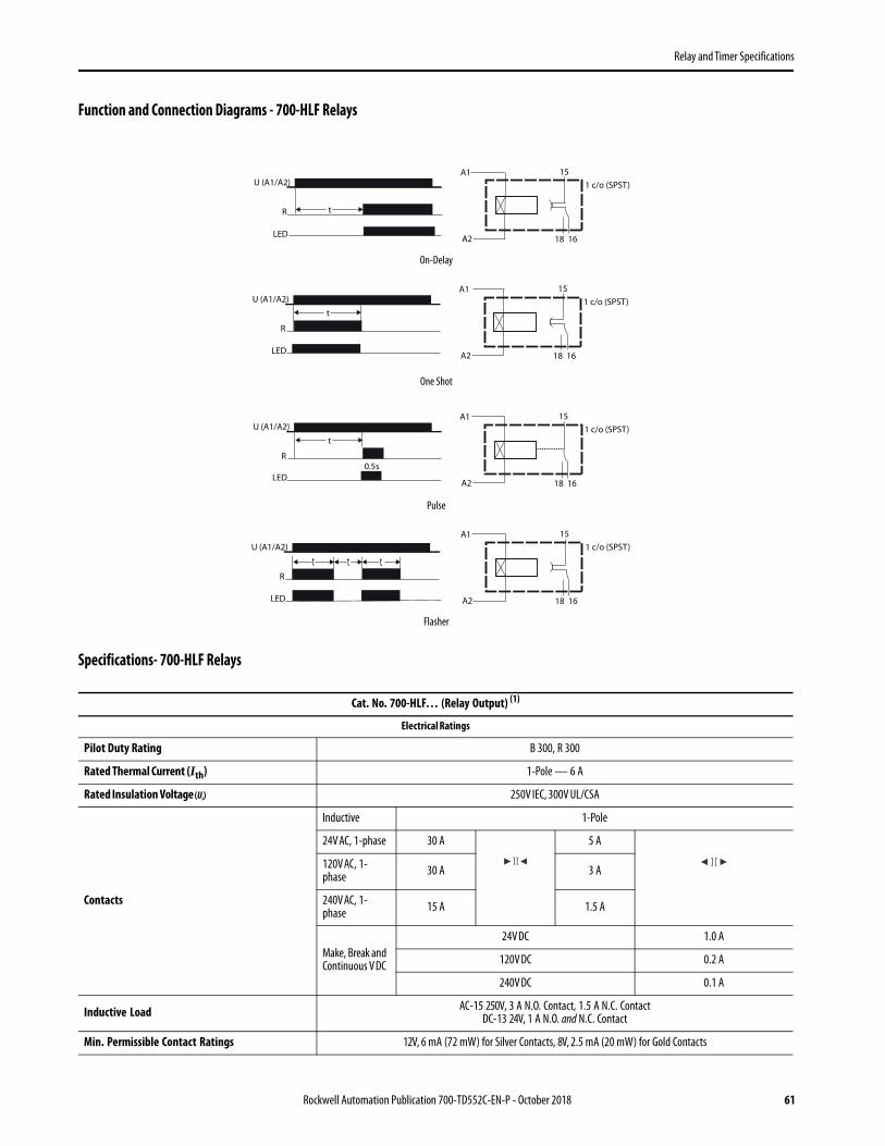
Relay and Timer Specifications
Function and Connection Diagrams - 700-HLF Relays
Specifications- 700-HLF Relays
On-Delay
One Shot
Pulse
Flasher
Cat. No. 700-HLF… (Relay Output) (1)
Electrical Ratings
Pilot Duty Rating B 300, R 300
Rated Thermal Current (Ith) 1-Pole — 6 A
Rated Insulation Voltage (Ui) 250V IEC, 300V UL/CSA
Contacts
Inductive 1-Pole
24V AC, 1-phase 30 A 5 A
120V AC, 1-phase 30 A 3 A
240V AC, 1-phase 15 A 1.5 A
Make, Break and Continuous V DC
24V DC 1.0 A
120V DC 0.2 A
240V DC 0.1 A
Inductive Load AC-15 250V, 3 A N.O. Contact, 1.5 A N.C. ContactDC-13 24V, 1 A N.O. and N.C. Contact
Min. Permissible Contact Ratings 12V, 6 mA (72 mW) for Silver Contacts, 8V, 2.5 mA (20 mW) for Gold Contacts
U (A1/A2)
R
LED
t
18 16
15
1 c/o (SPST)
A1
A2
U (A1/A2)
R
LED
t
18 16
15
1 c/o (SPST)
A1
A2
U (A1/A2)
R
LED
t
18 16
15
1 c/o (SPST)
A1
A2
0.5s
U (A1/A2)
R
LED
t
18 16
15
1 c/o (SPST)
A1
A2
tt
Rockwell Automation Publication 700-TD552C-EN-P - October 2018 61

Relay and Timer Specifications
Permissible Coil Voltage Variation Pickup: 85…110% of Nominal Voltage at 50 Hz85…110% of Nominal Voltage at 60 Hz
80…110% of Nominal Voltage at DCMust Dropout Voltage:
10% of Nominal Voltage at AC,
5% of NominalVoltage at DC
Power Consumption ±10% AC/DC 0.5 VA
Design Specification/Test Requirements
Dielectric Withstand Voltage
Pole to Pole (VRMS) 1000V
Contact to Coil (VRMS) 4000V
Input Voltage 24V AC/DC
Impedance (Ohms) 2 K
Mechanical
Degree of Protection IP20
Mechanical Life Operations 1 x 10⁷
Electrical Life Operations6 A Resistive: 100 000 min.
24V DC, 1 A Inductive: 200 000 min.120V AC 1 A Inductive: 300 000 min.
Switching Frequency Operations (no-load) 10 cycles/sec
Coil Voltages See Overview/Product Selection
Timer Functions On-Delay, One Shot, Pulse, and Flasher
Timer Settings 0.1...3 s, 3...60 s, 1...20 min, and 0.3...6 hr
Timer Adjustments Min and Max adjustments with Potentionmeter
Timer Accuracy Repeatability 1%, Recovery Time < 50 ms, Setting Accuracy Full Range 5%
Coil Surge Protection Per EN 61000-4.5; Surge Immunity (801-5) Class III: 2 kV common and 1 kV differential mode
Environmental
TemperatureOperating –40…+55 °C
Storage –40…+100 °C
Altitude 2000 m (6560 ft)
Construction
Insulating Material Molded High Dielectric Material
Enclosure Relay IP67
Contact Material Silver Tin Ox, AgSnO2 or Silver with Gold Plating, AgSnO2 + Au
Terminal Markings on Socket In accordance with EN50 0005
Certifications cULus Listed (File No. E3125, Guide NLDX/NLDX7) with Allen-Bradley socket, CE Marked
Standards EN60947-4-1,EN60947-5-1,CSA 22.2,UL 508,NEMA IEE MAC Compliant, ICS-2 Compliant
(1) Product shall be installed in an enclosure providing at least IP54 protection. Provisions shall be made to prevent the rated voltage from being exceeded by transient disturbances of more than 40%.
62 Rockwell Automation Publication 700-TD552C-EN-P - October 2018

Relay and Timer Specifications
Dimensions- 700-HLF RelaysApproximate dimensions are shown in millimeters (inches). Dimensions are not intended for manufacturing purposes.
700-HLF Screw Terminal DesignSingle Wire: 0.14 mm2…2.5 mm2 (#26 AWG…14 AWG)
Double Wire: 2 x 0.14 mm2…2 x 1.5 mm2 (2 x #26 AWG…2 x 16 AWG)Wire Type: Solid or stranded, copper only
Strip Length: 9 mm (11/32 in.). Torque: 0.5 N•m (4.4 lb•in)
Cat. No. 199-DR1 DIN Mounting Rail Series BCat. No. 199-DR4 DIN Mounting Rail Series B Has No Mounting Holes
Cat. No. A B C D Approx. Shipping Wt.
199-DR1 35 (1-3/8) 27 (1-1/16) 7.5 (19/64) 1.02 (1/64) 1.85 kg (4.07 lb) (10/pkg)
199-DR4 35 (1-3/8) 27 (1-1/16) 15 (19/32) 2.3 (3/32) 3.68 kg (8 lb) (5/pkg)
88.0(3.46)
6.20(0.24)
76.0(2.99)
50
(1-63/64)
1000
(39-3/8)
6.2
(15/64)
12.5
(1/2)5.2
(13/64)
1.0
(0.04)
7.5
(0.3)
27.0
(1.06)
35.0
(1.38)
Rockwell Automation Publication 700-TD552C-EN-P - October 2018 63

Relay and Timer Specifications
700-HP Slim Line Relay • 8 A contact ratings• DPDT/ (2 c/o) contacts• Plug-in PIN style (PCB) terminals (5 mm pinning)• Choice of standard silver nickel contacts, or silver nickel with gold-plated contacts• Available with mechanically linked contacts (Type B)• Safety Control Relay Version (700-HPS)
Photo DescriptionContact Rating
Wiring Diagrams Coil Voltage
Pkg. Qty.
Cat. No.U.S./Canada International
DPDT2-Pole2 Form CAgNi + AuGold PlatedContacts
8 A
6V AC 10 700-HPX2A06
12V AC 10 700-HPX2A12
24V AC 10 700-HPX2A24
120V AC 10 700-HPX2A1
240V AC 10 700-HPX2A2
6V DC 10 700-HPX2Z06
12V DC 10 700-HPX2Z12
24V DC 10 700-HPX2Z24
48V DC 10 700-HPX2Z48
110V DC 10 700-HPX2Z1
DPDT2-Pole2 Form CAgNi Contacts
6V AC 10 700-HP32A06
12V AC 10 700-HP32A12
24V AC 10 700-HP32A24
120V AC 10 700-HP32A1
240V AC 10 700-HP32A2
6V DC 10 700-HP32Z06
12V DC 10 700-HP32Z12
24V DC 10 700-HP32Z24
48V DC 10 700-HP32Z48
Sockets 700-HN123 700-HN123 110V DC 10 700-HP32Z1
64 Rockwell Automation Publication 700-TD552C-EN-P - October 2018

Relay and Timer Specifications
700-HPS Safety Control Relay
Accessories - 700-HP, -HPS
Photo DescriptionContact Rating
Wiring Diagrams Coil Voltage
Pkg. Qty.
Cat. No.U.S./Canada International
DPDT 2-Pole2 Form C AgNi +Au Gold PlatedMechanically LinkedContacts
8 A
6V DC 10 700-HPSXZ06
12V DC 10 700-HPSXZ12
24V DC 10 700-HPSXZ24
48V DC 10 700-HPSXZ48
60V DC 10 700-HPSXZ60
110V DC 10 700-HPSXZ1
125V DC 10 700-HPSXZ01
DPDT 2-Pole2 Form C AgNiMechanically LinkedContacts
6V DC 10 700-HPS2Z06
12V DC 10 700-HPS2Z12
24V DC 10 700-HPS2Z24
48V DC 10 700-HPS2Z48
60V DC 10 700-HPS2Z60
110V DC 10 700-HPS2Z1
700-HPS DPDT Sockets 700-HN123 700-HN123 125V DC 10 700-HPS2Z01
Photo DescriptionPkg. Qty.
Cat. No.
Diode Surge SuppressorVoltage Range: 6…220V DC used with 700-HN123 socket 10 700-ADR
Diode with LED Surge SuppressorVoltage Range: 6…24V DC used with 700-HN123 socket 10 700-ADL1R
Diode with LED Surge SuppressorVoltage Range: 28…60V DC used with 700-HN123 socket 10 700-ADL2R
Diode with LED Surge SuppressorVoltage Range: 110…220V DC used with 700-HN123 socket 10 700-ADL3R
Diode with LED Surge SuppressorVoltage Range: 6…24V AC used with 700-HN123 socket 10 700-AV1R
Varistor with LED Surge SuppressorVoltage Range: 110…240V ACused with 700-HN123 socket
10 700-AV3R
RC Surge SuppressorVoltage Range: 6…24V AC/DC used with 700-HN123 socket 10 700-AR1
RC Surge SuppressorVoltage Range: 110…240V AC/DC used with 700-HN123 socket 10 700-AR2
Timing ModuleOn-Delay or One-Shot selectable voltage range: 12…24V AC/DC used with sockets that accept plug-in accessory modules.
1
700-AT3
Timing ModuleOn-Delay or One-Shot selectable voltage range: 110…125V AC used with sockets that accept plug-in accessory modules.
700-AT3A1
Timing ModuleOn-Delay or One-Shot selectable voltage range: 230…240V AC used with sockets that accept plug-in accessory modules.
700-AT3A2
Rockwell Automation Publication 700-TD552C-EN-P - October 2018 65

Relay and Timer Specifications
Screw Terminal Socket — Panel or DIN Rail Mounting8-pin miniature socket for use with 2-pole, 700-HP relays. Incorporates coil and contact separation. 10 700-HN123
8-Way Jumper can be cut to required length. Rated 10 A – 250V 1
Color
Red
Gray
Blue
Plastic Retainer and Ejection LeverFor use with the 700-HN123 socketsBuilt-in ability to accept 1492 snap-in markers
10 700-HN119
Spring Clamp Terminal Socket — Panel or DIN Rail Mounting8-pin miniature socket for use with 2-pole, 700-HP relays. Incorporates coil and contact separation. 10 700-HN230
Plastic Retainer and Ejection LeverFor use with the 700-HN230 socketsBuilt-in ability to accept 1492 snap-in markers
10 700-HN232
DIN (#3) symmetrical hat rail35 x 7.5 x 1 m 10 199-DR1
Relay Identification Snap-in MarkersNote - These markers can only be used when the Plastic Retainer and Ejection Lever accessory (part # 700-HN119) is used because the markers snap into the Ejection Lever (and not into the relay itself).
5 1492-MS5X12
5 1492-MS6X9
5 1492-MS6X12
5 1492-MS8X9
5 1492-MS8X12
100 1492-MP-Blank
Pre-Printed Identification Tags — contains 10 sheets of pre-printed and blank tags. Each sheet contains 13 sets of the markings CR…9CR, TR…9TR, M…9M, F, R, 1S, and 117 blank tags. Tags are peel-off with sticky backing for easy placement on relays.
10
700-N40
700-N41
Socket, and Retainer Clip Reference
Relay Type Socket Cat. No. Retainer Clip Cat. No.
700-HPX2 700-HN123 700-HN119
Photo DescriptionPkg. Qty.
Cat. No.
66 Rockwell Automation Publication 700-TD552C-EN-P - October 2018
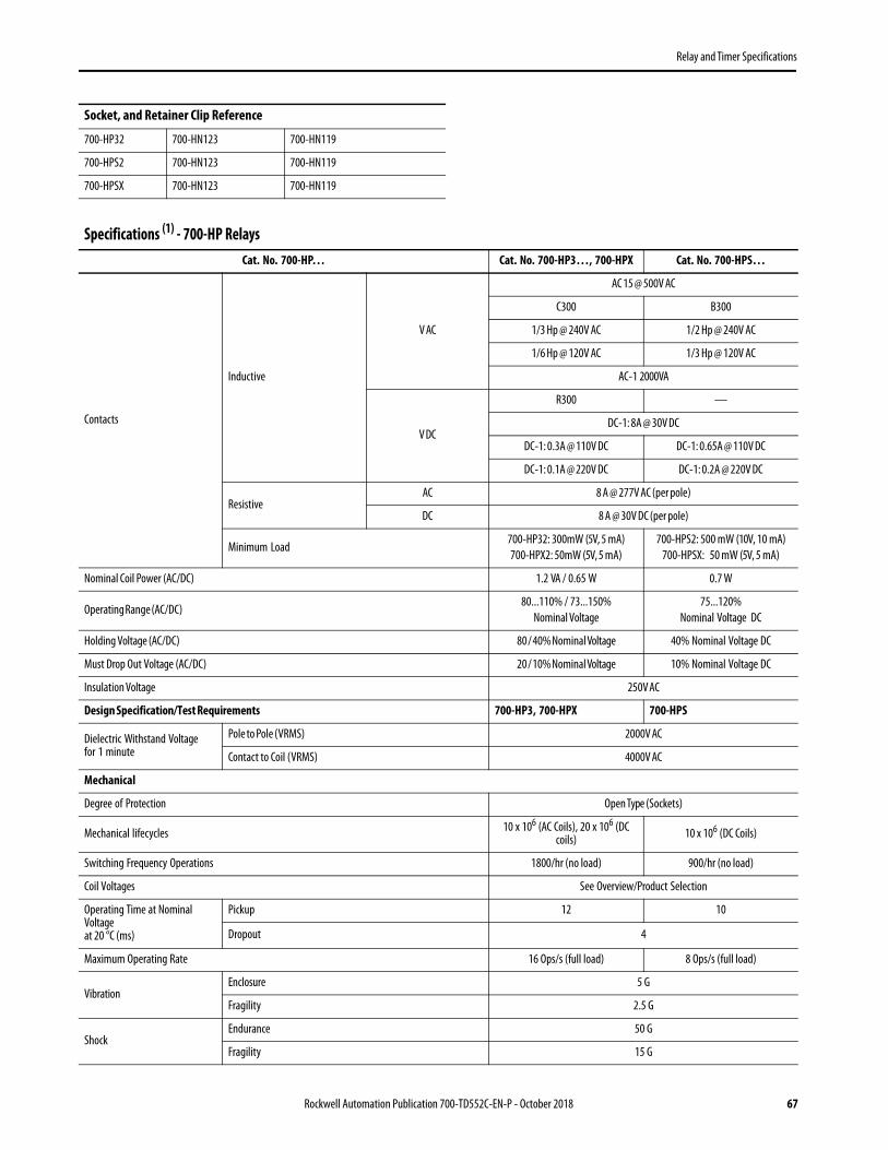
Relay and Timer Specifications
700-HP32 700-HN123 700-HN119
700-HPS2 700-HN123 700-HN119
700-HPSX 700-HN123 700-HN119
Specifications (1) - 700-HP RelaysCat. No. 700-HP… Cat. No. 700-HP3…, 700-HPX Cat. No. 700-HPS…
Contacts
Inductive
V AC
AC 15 @ 500V AC
C300 B300
1/3 Hp @ 240V AC 1/2 Hp @ 240V AC
1/6 Hp @ 120V AC 1/3 Hp @ 120V AC
AC-1 2000VA
V DC
R300 —
DC-1: 8A @ 30V DC
DC-1: 0.3A @ 110V DC DC-1: 0.65A @ 110V DC
DC-1: 0.1A @ 220V DC DC-1: 0.2A @ 220V DC
ResistiveAC 8 A @ 277V AC (per pole)
DC 8 A @ 30V DC (per pole)
Minimum Load700-HP32: 300mW (5V, 5 mA)700-HPX2: 50mW (5V, 5 mA)
700-HPS2: 500 mW (10V, 10 mA)700-HPSX: 50 mW (5V, 5 mA)
Nominal Coil Power (AC/DC) 1.2 VA / 0.65 W 0.7 W
Operating Range (AC/DC)80...110% / 73...150%
Nominal Voltage75...120%
Nominal Voltage DC
Holding Voltage (AC/DC) 80 / 40% Nominal Voltage 40% Nominal Voltage DC
Must Drop Out Voltage (AC/DC) 20 / 10% Nominal Voltage 10% Nominal Voltage DC
Insulation Voltage 250V AC
Design Specification/Test Requirements 700-HP3, 700-HPX 700-HPS
Dielectric Withstand Voltagefor 1 minute
Pole to Pole (VRMS) 2000V AC
Contact to Coil (VRMS) 4000V AC
Mechanical
Degree of Protection Open Type (Sockets)
Mechanical lifecycles 10 x 106 (AC Coils), 20 x 106 (DC coils) 10 x 106 (DC Coils)
Switching Frequency Operations 1800/hr (no load) 900/hr (no load)
Coil Voltages See Overview/Product Selection
Operating Time at Nominal Voltageat 20 °C (ms)
Pickup 12 10
Dropout 4
Maximum Operating Rate 16 Ops/s (full load) 8 Ops/s (full load)
VibrationEnclosure 5 G
Fragility 2.5 G
ShockEndurance 50 G
Fragility 15 G
Socket, and Retainer Clip Reference
Rockwell Automation Publication 700-TD552C-EN-P - October 2018 67

Relay and Timer Specifications
Max. Socket Torque 0.5 N•m (4.4 lb•in)
Environmental
TemperatureOperating –40…+85 °C –40…+70 °C
Storage –45…+100 °C –50…+80 °C
Altitude 2000 m (6560 ft)
Construction
Insulating Material Molded High-Dielectric Material
Enclosure Transparent Dust Cover Red Transparent Dust Cover
Contact Material Silver Nickel, (AgNi) (700-HP32 and 700-HPS2), Silver Nickel + Gold Plating (AgNi + Au) (700-HPX2 and 700-HPSX)
Terminal Markings on Socket In accordance with EN50 0005
Sockets2-Pole
700-HN123
Approvals
Certifications
cURus Recognized (File No. E3125, Guide NLDX2/NLDX8), cULus Listed when used with 700-HN123 socket (File No. E3125, Guide NLDX/NLDC7), CSA
Certified (files 229473), CE Marked, LR Certified (700-HP), IMQ & TÜV Certified (700- HPS)
Standards UL 508, CSA 22.2 No. 14, EN 61810-1, EN 50205 (700-HPS)
(1) The inrush VA equals 1.5 times the sealed VA.
Specifications (1) - 700-HP Relays
68 Rockwell Automation Publication 700-TD552C-EN-P - October 2018

Relay and Timer Specifications
Dimensions - 700-HP RelaysApproximate dimensions are shown in millimeters (inches). Dimensions are not intended for manufacturing purposes.
700-HP Relay
Cat. No. 700-HN123Single Wire: 0.2.....2.5 mm2 (#24.....14 AWG)
Double Wire: 2 X 0.2.....2 X 2.5 mm2 (#2 X 24....2 X 14 AWG)Wire Type: solid or stranded, copper only
Strip Length: 7 mm (9/32 in.), Torque: 0.5 N•m (4.4 lb•in)
Cat. No. A B C D Approx. Shipping Wt.
199-DR135
(1-3/8)27
(1-1/16)7.5
(19/64)1.02
(1/64)
1.85 kg(4.07 lb)(10/pkg)
199-DR435
(1-3/8)27
(1-1/16)15
(19/32)2.3
(3/32)
3.68 kg(8 lb)
(5/pkg)
29.0(1.14)
12.4(0.49)
25.0(0.98)
50
(1-63/64)
1000
(39-3/8)
6.2
(15/64)
12.5
(1/2)5.2
(13/64)
1.0
(0.04)
7.5
(0.3)
27.0
(1.06)
35.0
(1.38)
Rockwell Automation Publication 700-TD552C-EN-P - October 2018 69

Relay and Timer Specifications
Approximate dimensions are shown in millimeters (inches). Dimensions are not intended for manufacturing purposes.
Cat. No. 700-HN123Single Wire: 0.2.....2.5 mm2 (#24.....14 AWG)
Double Wire: 2 X 0.2.....2 X 2.5 mm2 (#2 X 24....2 X 14 AWG)Wire Type: solid or stranded, copper only
Strip Length: 7 mm (9/32 in.), Torque: 0.5 N•m (4.4 lb•in)
35.4(1.39)
17.5(0.69)
17.5(0.69)
60.9(2.40)
21.6(0.85)
21.6(0.85)
Use M3 Screws
8 (+)A1
Ø 3.2(0.12)
122
144
15.8(0.62)
4.0(0.16)
113
216
245
227
78.6(3.09)
1 (-)A2
70 Rockwell Automation Publication 700-TD552C-EN-P - October 2018

Relay and Timer Specifications
700-HJ Magnetic Latching Relay• 10 A Contact Rating• SPDT• DPDT Single Coil• DPDT Dual Coil• Blade Style Quick Connect Terminals
Photo DescriptionContact Rating
Wiring DiagramsCoil Voltage Cat. No.
AC(2)
(2) AC Relays include internal diodes.
DC(3)
(3) For DC operation, polarity must be observed.
SPDT1-Pole1 Form CAgCdO Contacts(Single CoilAC or DC)
10 A
24V AC 700-HJ36A24
120V AC 700-HJ36A1
24V DC 700-HJ36Z24
Sockets 700-HN153 700-HN154
DPDT2-Pole2 Form CAgCdO Contacts(Single CoilAC or DC)
10 A
24V AC 700-HJ32A24
120V AC 700-HJ32A1
240V AC 700-HJ32A2
12V DC 700-HJ32Z12
Sockets 700-HN153 700-HN154 24V DC 700-HJ32Z24
DPDT2-Pole2 Form CAgCdO Contacts(Dual Coil(1)
(1) Available only in DC Coil with DPDT contacts.
10 A DC Only 24V DC 700-HJD32Z24
Sockets 700-HN153 or700-HN154
Rockwell Automation Publication 700-TD552C-EN-P - October 2018 71
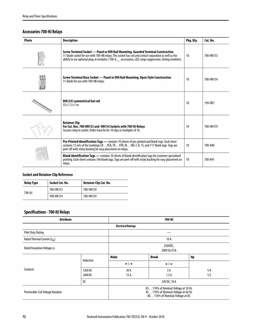
Relay and Timer Specifications
Accessories-700-HJ Relays
Socket and Retainer Clip Reference
Photo Description Pkg. Qty. Cat. No.
Screw Terminal Socket — Panel or DIN Rail Mounting. Guarded Terminal Construction11-blade socket for use with 700-HB relays. This socket has coil and contact separation as well as the ability to use optional plug-in modules ( 700-A__ accessories, LED, surge suppression, timing modules).
10 700-HN153
Screw Terminal Base Socket — Panel or DIN Rail Mounting. Open Style Construction11-blade for use with 700-HB relays. 10 700-HN154
DIN (#3) symmetrical hat rail35 x 7.5 x 1 m 10 199-DR1
Retainer ClipFor Cat. Nos. 700-HN153 and -HN154 Sockets with 700-HJ RelaysSecures relay in socket. Order must be for 10 clips or multiples of 10.
10 700-HN159
Pre-Printed Identification Tags — contains 10 sheets of pre-printed and blank tags. Each sheet contains 13 sets of the markings CR…9CR, TR…9TR, M…9M, F, R, 1S, and 117 blank tags. Tags are peel-off with sticky backing for easy placement on relays.
10 700-N40
Blank Identification Tags — contains 10 sheets of blank identification tags for customer specialized printing. Each sheet contains 546 blank tags. Tags are peel-off with sticky backing for easy placement on relays.
10 700-N41
Relay Type Socket Cat. No. Retainer Clip Cat. No.
700-HJ700-HN153 700-HN159
700-HN154 700-HN159
Specifications - 700-HJ RelaysAttribute 700-HJ
Electrical Ratings
Pilot Duty Rating —
Rated Thermal Current (Ith) 10 A
Rated Insulation Voltage (Ui)250V IEC,
300V UL/CSA
Contacts
InductiveMake Break Hp
120V AC240V AC
30 A15 A
3 A1.5 A
1/41/3
DC 24V DC, 10 A
Permissible Coil Voltage Variation85…110% of Nominal Voltage at 50 Hz85…110% of Nominal Voltage at 60 Hz
80…110% of Nominal Voltage at DC
72 Rockwell Automation Publication 700-TD552C-EN-P - October 2018

Relay and Timer Specifications
SingleAC Coil
SingleDC Coil
DualDC Coil
Coil Consumption ±10%
AC Coils InrushSealed
1.44 VA1.44 VA
— —
DC Coils — 1.2 W12V 1.63 W24V 1.67 W
Design Specification/Test Requirements
Dielectric Withstand Voltage
Pole-to-Pole 1500V AC
Contact-to-Pole 1500V AC
Contact-to-Frame 1500V AC
Mechanical
Degree of Protection Open Type(Guarded Terminal Sockets)
Mechanical Life Operations 10 x 106
Switching Frequency Operations 1800/HR
Coil Voltages See Product Selection
Operating Time at Nominal Voltage at 20 °CPickupDropout
25 ms25 ms
Maximum Operating Rate —
Environmental
TemperatureOperating –45…+50 °C
(–49…+122 °F)
Storage –45…+100 °C(–49…+212 °F)
Altitude 2000 m (6560 ft.)
Construction
Insulating Material Molded High Dielectric Material
Enclosure Transparent Dust Cover
Contact Material Silver Cad. Ox.
Terminal Markings on Socket In accordance with EN50 0005
Sockets11-Blade Socket
Cat. No. 700-HN153Cat. No. 700-HN154
Certifications CSA Certified, File LR700026, UL Recognized, File E3125, Guide NLDX 2
Standards UL 508, CSA 22.2 No. 14, EN/IEC 60947-4-1, -5-1
Specifications - 700-HJ Relays
Rockwell Automation Publication 700-TD552C-EN-P - October 2018 73

Relay and Timer Specifications
Dimensions - 700-HJ RelaysApproximate dimensions are shown in millimeters (inches). Dimensions are not intended for manufacturing purposes.
700-HJ Relay Cat. No. 700-HN153Wire Size: 2 x 2.5 mm2
Single Wire – Up to #12 AWGDouble Wire – 2 x 2.5 mm2 (#2–14 AWG… #2–20 AWG)
(Either Solid or Stranded)Strip Length: 9 mm (3/8 in) – Torque: 0.8 N•m (7 lb•in
Cat. No. 700-HN154Wire Size: 2 x 2.5 mm2
Single Wire – Up to #12 AWGDouble Wire – 2 x 2.5 mm2 (#2–14 AWG… #2–20 AWG)
(Either Solid or Stranded)Strip Length: 9 mm (3/8 in) – Torque: 0.8 N•m (7 lb•in)
Cat. No. 199-DR1 DIN Mounting Rail Series BCat. No. 199-DR4 DIN Mounting Rail Series B Has No Mounting Holes
Cat. No. A B C D Approx. Shipping Wt.
199-DR1 35 (1-3/8) 27 (1-1/16) 7.5 (19/64) 1.02 (1/64) 1.85 kg (4.07 lb) (10/pkg)
199-DR4 35 (1-3/8) 27 (1-1/16) 15 (19/32) 2.3 (3/32) 3.68 kg (8 lb) (5/pkg)
50
(1-63/64)
1000
(39-3/8)
6.2
(15/64)
12.5
(1/2)5.2
(13/64)
1.0
(0.04)
7.5
(0.3)
27.0
(1.06)
35.0
(1.38)
74 Rockwell Automation Publication 700-TD552C-EN-P - October 2018
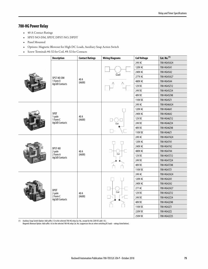
Relay and Timer Specifications
700-HG Power Relay• 40 A Contact Ratings• SPST-NO-DM, SPDT, DPST-NO, DPDT• Panel Mounted• Options: Magnetic Blowout for High DC Loads, Auxiliary Snap Action Switch• Screw Terminals #6-32 for Coil, #8-32 for Contacts
Description Contact Ratings Wiring Diagrams Coil Voltage Cat. No.(1)
(1) Auxiliary Snap Switch Option: Add suffix (-5) to the selected 700-HG relay Cat. No., except for the 220V DC add (-5L).Magnetic Blowout Option: Add suffix (-6) to the selected 700-HG relay Cat. No. (suppresses the arc when switching DC loads – ratings listed below).
SPST-NO-DM1 Form XAgCdO Contacts
40 A(A600)
24V AC 700-HG45A24
120V AC 700-HG45A1
240V AC 700-HG45A2
277V AC 700-HG45A27
480V AC 700-HG45A4
12V DC 700-HG45Z12
24V DC 700-HG45Z24
48V DC 700-HG45Z48
110V DC 700-HG45Z1
SPDT1-pole1 Form CAgCdO Contacts
40 A(A600)
24V AC 700-HG46A24
120V AC 700-HG46A1
240V AC 700-HG46A2
12V DC 700-HG46Z12
24V DC 700-HG46Z24
48V DC 700-HG46Z48
110V DC 700-HG46Z1
DPST-NO2-pole2 Form AAgCdO Contacts
40 A(A600)
24V AC 700-HG47A24
120V AC 700-HG47A1
240V AC 700-HG47A2
480V AC 700-HG47A4
12V DC 700-HG47Z12
24V DC 700-HG47Z24
48V DC 700-HG47Z48
110V DC 700-HG47Z1
DPDT2-pole2 Form CAgCdO Contacts
40 A(A600)
24V AC 700-HG42A24
120V AC 700-HG42A1
240V AC 700-HG42A2
277 AC 700-HG42A27
12V DC 700-HG42Z12
24V DC 700-HG42Z24
48V DC 700-HG42Z48
110V DC 700-HG42Z1
220V DC 700-HG42Z2
250V DC 700-HG42Z25
Rockwell Automation Publication 700-TD552C-EN-P - October 2018 75

Relay and Timer Specifications
Accessories - 700-HG Relays
Auxiliary Snap Action Switch
Photo DescriptionPkg. Qty.
Cat. No.
Pre-Printed Identification Tags — contains 10 sheets of pre-printed and blank tags. Each sheet contains 13 sets of the markings CR…9CR, TR…9TR, M…9M, F, R, 1S, and 117 blank tags. Tags are peel-off with sticky backing for easy placement on relays.
10 700-N40
Blank Identification Tags — contains 10 sheets of blank identification tags for customer specialized printing. Each sheet contains 546 blank tags. Tags are peel-off with sticky backing for easy placement on relays.
10 700-N41
Type 1 Enclosure For use with any of the listed relays. Knockouts for 1/2 in. and 3/4 in. conduit connections. The enclosure exceeds the minimum clearances required by U.S. standards, resulting in generous wiring spaces.
1 700-HN120
Contact Material Rating Dielectric Withstand V (1 Min.)
SPDT (1 Form C) Silver Cad. Ox. 10 A at 120 or 240 Resistive 1500V AC RMS Contact to Frame
76 Rockwell Automation Publication 700-TD552C-EN-P - October 2018

Relay and Timer Specifications
Specifications - 700-HG RelaysAttribute 700-HG
Electrical Ratings
Pilot Duty Rating (1) A600
Rated Thermal Current (Ith) 40 A
Rated Insulation Voltage (Ui) 600V UL
Contact Ratings: AC Ratings SPST-NO-DM Contact Ratings: AC Ratings SPDT, DPST - NO and DPDT
Volts
Inductive Resistive -Make/Break
and Continuous
HP Volts
Inductive Resistive -Make/Break
and Continuous
HP (2)
Make Break Continuous Make Break Continuous
120 60 A 6 A 10 A 40 A2
120 60 A 6 A 10 A 40 A1 - 1/2
240 30 A 3 A 10 A 40 A 240 30 A 3 A 10 A 40 A
480V 15 A 1.5 A 10 A 12 A2
480 15 A 1.5 A 10 A 5 A1 - 1/2
600V 12 A 1.2 A 10 A 10 A 600 15 A 1.2 A 10 A 5 A
DC Ratings: Without Magnetic Blowouts - 28V 40 A - Make, Break and Continuous Est Drop 125V 1.2...3 A
DC Ratings: With Magnetic Blowouts: SPST - NO - DM SPDT, DPST - NO and DPDT
Make, Break, and Continuous
110V 20 A 10 A
220V 8 A 4 A
325V 4 A 2 A
500V 2 A —
Permissible Coil Voltage Variation
80...100% of Nominal Voltage at 50 Hz
85...110% of Nominal Voltage at 60 Hz
80...110% of Nominal Voltage at DC
50 HZ 60 HZ
Coil Consumption ±10%AC Coils
Inrush 13 VA 16 VA
Sealed 10 VA 11 VA
DC Coils 2.0 W
Design Specification/Test Requirements
Dielectric WithstandVoltage
Pole-to-Pole 2200V AC
Contact to Pole 2200V
Contact to Frame 2200V AC
Mechanical
Degree of Protection Open Type
Mechanical Life Operations 5 x 10⁶
Switching Frequency Operations 1600/Hr
Coil Voltage See Overview/Product Selection
Operating Time at Nominal Voltage at 20 °C
PickupDropout
40 ms35 ms
Maximum Operating Rate —
Rockwell Automation Publication 700-TD552C-EN-P - October 2018 77
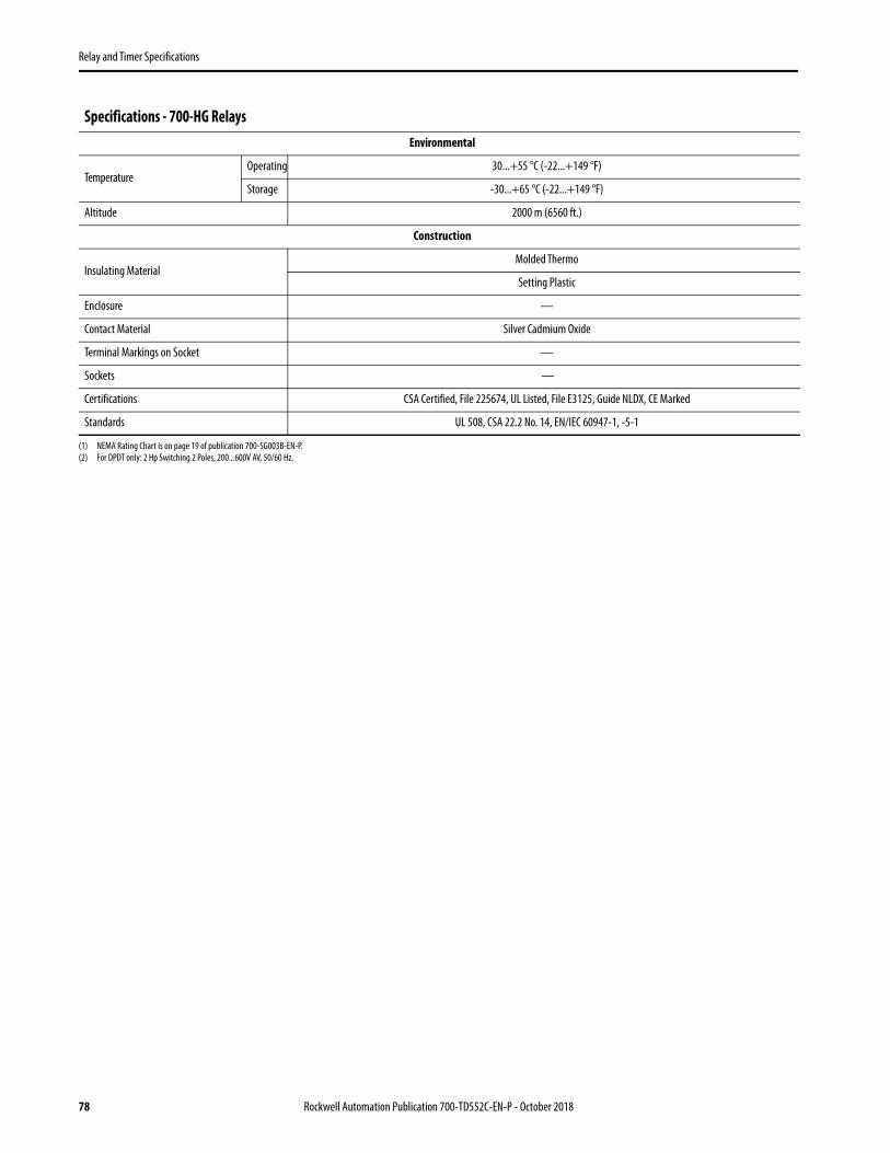
Relay and Timer Specifications
Environmental
TemperatureOperating 30...+55 °C (-22...+149 °F)
Storage -30...+65 °C (-22...+149 °F)
Altitude 2000 m (6560 ft.)
Construction
Insulating MaterialMolded Thermo
Setting Plastic
Enclosure —
Contact Material Silver Cadmium Oxide
Terminal Markings on Socket —
Sockets —
Certifications CSA Certified, File 225674, UL Listed, File E3125, Guide NLDX, CE Marked
Standards UL 508, CSA 22.2 No. 14, EN/IEC 60947-1, -5-1
(1) NEMA Rating Chart is on page 19 of publication 700-SG003B-EN-P.(2) For DPDT only: 2 Hp Switching 2 Poles, 200...600V AV, 50/60 Hz.
Specifications - 700-HG Relays
78 Rockwell Automation Publication 700-TD552C-EN-P - October 2018

Relay and Timer Specifications
Dimensions - 700-HG RelaysApproximate dimensions are shown in millimeters (inches). Dimensions are not intended for manufacturing purposes.
700-HG Relay, SPST-NO-DM
700-HG Relay
Rockwell Automation Publication 700-TD552C-EN-P - October 2018 79

Relay and Timer Specifications
700-HHF Flange Mount Power Relay• Flange-Mounted• Blade Style 0.250 x 0.032 Quick Connect/Solder (no socket) Terminals• Solder Terminals (no socket)
Description Contact RatingWiring Diagrams
Coil Voltage Cat. No.U.S./Canada International
SPST-NO-DM1 Form XAgCdO Contacts
30 A(A600)
120V AC 700-HHF45A1
24V DC 700-HHF45Z24
DPDT2-Pole2 Form CAgCdO Contacts
25 A(B600)
24V AC 700-HHF62A24
120V AC 700-HHF62A1
240V AC 700-HHF62A2
12V DC 700-HHF62Z12
24V DC 700-HHF62Z24
3PDT3-Pole3 Form CAgCdO Contacts
20 A(B300) 120V AC 700-HHF73A1
Specifications - 700-HHF RelaysAttribute 700-HHF…
Electrical Ratings
Pilot Duty Rating (1)
SPST-NO-DM NEMA A600
DPDT NEMA B600
3PDT NEMA B300
Rated Thermal Current (Ith) SPST-NO-DM 30 A, DPDT 25A, 3PDT 20 A
Rated Insulation Voltage (Ui) 250V IEC-300V UL/CSA
Contacts
Inductive SPST-NO-DM Hp DPDT Hp 3PDT Hp
120V AC 60 A 6 A 1 30 A 3 A 1 30 A 3 A 1/2
240V AC 30 A 3.0 A 1-1/2 15 A 1.5 A 1-1/2 15 A 1.5 A —
DC 28V DC, 30 A 28V DC, 13 A —
80 Rockwell Automation Publication 700-TD552C-EN-P - October 2018

Relay and Timer Specifications
Permissible Coil Voltage Variation
85…110% of Nominal Voltage at 50 Hz
85…110% of Nominal Voltage at 60 Hz
80…110% of Nominal Voltage at DC
SPST-NO-DM DPDT 3PDT
50 Hz 60 Hz 50 Hz 60 Hz 50 Hz 60 Hz
Coil Consumption±10%
AC CoilsInrush 7.2 VA 6.3 VA 7.2 VA 6.3 VA 7.2 VA 6.3 VA
Sealed 4.8 VA 4.2 VA 4.8 VA 4.2 VA 4.8 VA 4.2 VA
DC Coils 1.4 W
Max. Allowable Leakage25% of VA
10% of W
Design Specification/Test Requirements
Dielectric Withstand Voltage
Pole-to-Pole 2200V AC
Contact-to-Pole 2200V AC
Contact-to-Frame 1600V AC
Mechanical
Mechanical Life Operations 5 x 10⁶
Switching Frequency Operations 3600/Hr
Coil Voltages See Overview/Product Selection
Operating Time at Nominal Voltage at 20 °C
Pickup 20 ms
Dropout 15 ms
Maximum Operating Rate 4 Ops/s.
Environmental
Temperature
Operating–30…+50 °C
(–22…+122 °F)
Storage–30…+100 °C
(–22…+212 °F)
Altitude 2000 m (6560 ft)
Construction
Insulating Material Molded High Dielectric Material
Enclosure Transparent Dust Cover
Contact Material Silver Cadmium Oxide
Terminal Markings In accordance with EN50 0005
Sockets (2)
Certifications cURus Recognized, File E3125,Guide NLDX2/NLDX8, CE Marked
Standards UL 508, CSA 22.2 No.14, EN/IEC 60947-1, -5-1
(1) See NEMA Ratings and Test Values on page 5.(2) 700-HHF relay wiring and terminals are the quick connect / solder type 6.35 x 0.82 mm (0.250 x 0.032 in) termination.
Specifications - 700-HHF RelaysAttribute 700-HHF…
Rockwell Automation Publication 700-TD552C-EN-P - October 2018 81

Relay and Timer Specifications
Dimensions - 700-HHF RelaysApproximate dimensions are shown in millimeters (inches). Dimensions are not intended for manufacturing purposes.
700-HHF Relay
35.7
(1-13/32)
38.9(1-17/32)
3.97(5/32)
63.5(2-1/2)
73.8(2-29/32)
82 Rockwell Automation Publication 700-TD552C-EN-P - October 2018

Relay and Timer Specifications
700-HTA Alternating Relay• Alternating Relay• Rugged Pin Style Socket Mounting• 10 A, SPDT, DPDT, and Cross Wired• Excellent for Pump Panel Applications
Alternating Relays with Pin-Style Terminations
700 – HTA 2 A12 7a b c d e
Catalog Number Explanation - 700-HTA Relays
aBulletin Number
-b
Relay Typec
Model Typed
Coil Voltagee
Gold Plated Contacts Option
700 HTA - Tube Base Alternating Relay
1 - SPDT2 - DPDT
3 -Cross-Wired
A12 - 12V AC 50/60 HzA24 - 24V AC 50/60 HzA1 - 120V AC 50/60 HzA2 - 240V AC 50/60 Hz
Blank - Without switch7 - With switch
700-HTA Alternating RelayWiring Diagrams
U.S./Canada International
SPDT Form C Contact SPDT
DPDT 2 Form C Contact DPDT
Cross-Wired DPDT 2 Form C Contacts Cross-Wired
Rockwell Automation Publication 700-TD552C-EN-P - October 2018 83

Relay and Timer Specifications
Accessories - 700-HTA Relays
Photo Description Pkg. Qty. Cat. No.
Screw Terminal Tube Base Socket — Panel or DIN Rail Mounting; Guarded Terminal Construction. 8-Pin for use with 700-HTA1A or -HTA3A alternating relays. Order ten or multiples of ten. 10 700-HN100
Screw Terminal Tube Base Socket — Panel or DIN Rail Mounting; Open Style Construction. 8-Pin for use with 700-HTA1A or -HTA3A alternating relays. Order ten or multiples of ten. No retainer clip required. 10 700-HN125
Screw Terminal Tube Base Sockets — Panel or DIN Rail Mounting; Guarded Terminal Construction. 11-pin for use with 700-HTA2A alternating relays. Order in multiples of 10. 10 700-HN101
Screw Terminal Tube Base Sockets — Panel or DIN Rail Mounting; Open Style Terminal Construction. 11-pin for use with 700-HTA2A alternating relays. Order in multiples of 10. No retainer clip required. 10 700-HN126
DIN (#3) symmetrical hat rail35 x 7.5 x 1 m 10 199-DR1
Retainer Clip for Cat. Nos. 700-HN100 and -HN101 Sockets with 700-HT Timing Relays, and 700-HTA Alternating RelaysSecures relay in socket. Order must be for 10 clips or multiples of 10.
10 700-HN110
Pre-Printed Identification Tags — contains 10 sheets of pre-printed and blank tags. Each sheet contains 13 sets of the markings CR…9CR, TR…9TR, M…9M, F, R, 1S, and 117 blank tags. Tags are peel-off with sticky backing for easy placement on relays.
10 700-N40
Blank Identification Tags — contains 10 sheets of blank identification tags for customer specialized printing. Each sheet contains 546 blank tags. Tags are peel-off with sticky backing for easy placement on relays. 10 700-N41
84 Rockwell Automation Publication 700-TD552C-EN-P - October 2018

Relay and Timer Specifications
Specifications - 700-HTA RelaysAttribute 700-HTA
Electrical Ratings
Pilot Duty Rating (1) NEMA B300 AC 15
Rated Thermal Current (Ith) 10 A
Rated Insulation Voltage (Ui) 250V IEC, 300V UL/CSA
Contacts
Inductive Make Break HP
120V AC 30 A 3 A 1/3
240V AC 15 A 1.5 A 1/2
Resistive 30V DC 10 A 10 A —
Permissible Coil Voltage Variation 85…110% of Nominal Voltage at 50 Hz85…110% of Nominal Voltage at 60 Hz
Power Consumption ±10% AC
24V AC 2 VA
120V AC 4 VA
240V AC 4 VA
Design Specification/Test Requirements
Dielectric Withstand Voltage
Pole-to-Pole, same circuit (VRMS) 1000V AC
Pole-to-Pole, different circuits (VRMS) 2000V AC
Contact-to-Coil (VRMS) 2000V AC
Electrical Life Operations 100,000 minimum
Switching Frequency Operations 1800/hr
Coil Voltages See product selection
Mechanical
Degree of Protection Open Type (Guarded Terminal Sockets)
Mechanical Life Operations 10 x 106
Switching Frequency Operations 18,000/hr
Start-up Time (max. time from power application until unit is timing) 0.05 sec
Max. Function Time (max. time power can drop out and unit continues timing) 0.01 sec
Min. Cycle Time 100 ms on release of the control switch
Rockwell Automation Publication 700-TD552C-EN-P - October 2018 85

Relay and Timer Specifications
Environmental
TemperatureOperating –28…+65 °C (50 °C max., 240V AC coil)
(–18…+149 °F) (122 °F max., 240V AC coil)
Storage –55…+85 °C(–67…+185 °F)
Altitude 2000 m (6560 ft)
Construction
Insulating Material Molded High Dielectric Material
Enclosure Impact Resistant Dust Cover
Contact Material Silver Tin Oxide
Terminal Markings on Socket In accordance with EN50 005
Sockets 8- or 11-Pin Socket 700-HN100, -HN125700-HN101, -HN126
Certifications
CSA Certified, File 223833, UL Recognized (File E3125 Guide NLDX2/NLDX8), cULus Listed with 700-HN100, 700-HN101, 700-HN125, and 700-HN126
Sockets (File No. E3125 Guide NLDX/NLDX7), CE-Marked(per EU Low Voltage Directive)
Standards EN 61812-1, CSA 22.2 No. 14, UL 508
(1) See NEMA Ratings and Test Values on page 5
Specifications - 700-HTA RelaysAttribute 700-HTA
86 Rockwell Automation Publication 700-TD552C-EN-P - October 2018
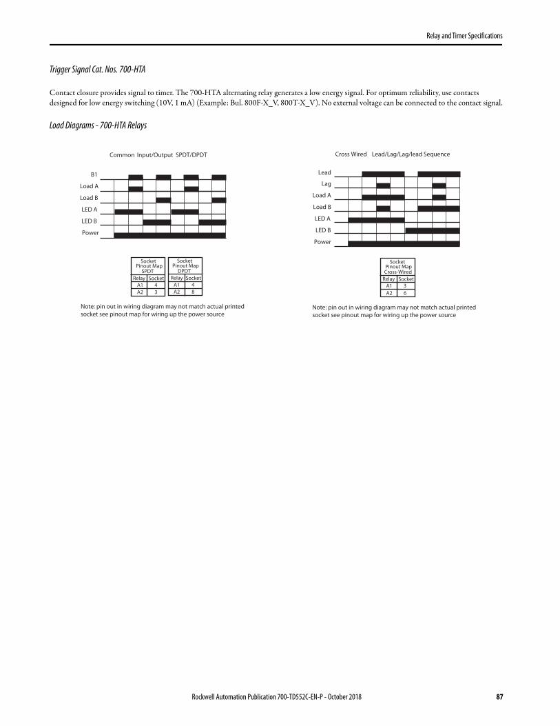
Relay and Timer Specifications
Trigger Signal Cat. Nos. 700-HTA
Contact closure provides signal to timer. The 700-HTA alternating relay generates a low energy signal. For optimum reliability, use contacts designed for low energy switching (10V, 1 mA) (Example: Bul. 800F-X_V, 800T-X_V). No external voltage can be connected to the contact signal.
Load Diagrams - 700-HTA Relays
Common Input/Output SPDT/DPDT
B1
Load A
Load B
LED A
LED B
Power
SocketPinout Map
SPDT
Relay Socket
A1
A2 3
4
SocketPinout Map
DPDT
Relay Socket
A1
A2 8
4
Note: pin out in wiring diagram may not match actual printed
socket see pinout map for wiring up the power source
Cross Wired Lead/Lag/Lag/lead Sequence
Lag
Load A
Load B
LED A
LED B
Power
Lead
SocketPinout MapCross-Wired
Relay Socket
A1
A2 6
3
Note: pin out in wiring diagram may not match actual printed
socket see pinout map for wiring up the power source
Rockwell Automation Publication 700-TD552C-EN-P - October 2018 87

Relay and Timer Specifications
Dimensions - 700-HTA RelaysApproximate dimensions are shown in millimeters (inches). Dimensions are not intended for manufacturing purposes.
Cat. No. 700-HN100Panel Mounting
Double Wire — 2 x 2.5 mm2 (#2 – 14 AWG…#2 – 20 AWG)(Either Solid or Stranded)
Strip Length: 9 mm (3/8 in) – Torque: 0.8 N•m (7 lb•in)
Cat. No. 700-HN125Wire Size: 2 x 2.5 mm2
Single Wire — Up to #12 AWGDouble Wire — 2 x 2.5 mm2 (#2 – 14 AWG… #2 – 20 AWG)
(Either Solid or Stranded)Strip Length: 9 mm (3/8 in) — Torque: 0.8 N•m (7 lb•in)
Cat. No. 700-HN101Panel Mounting
Double Wire – 2 x 2.5 mm2 (#2 – 14 AWG…#2 – 20 AWG)(Either Solid or Stranded)
Strip Length: 9 mm (3/8 in) – Torque: 0.8 N•m (7 lb•in)
Cat. No. 700-HN126Wire Size: 2 x 2.5 mm2
Single Wire — Up to 12 AWGDouble Wire — 2 x 2.5 mm2 (#2 – 14 AWG…#2 – 20 AWG)
(Either Solid or Stranded)Strip Length: 9 mm (3/8 in) — Torque: 0.8 N•m (7 lb•in)
(2-23/64)
74(2-29/32)
79(3-7/64)
60
43(1-11/16)
65.0(2-35/64)
38.0(1-1/2)
#4–40M3
26(1-1/32)
30.0(1-3/16)
40.1(1-37/64)
24.9(63/64)
4.2(5/32)
33.0(1-19/64)
24.6(31/32)
20.8(53/64)
54.9(2-5/32)
51.1(2-1/64)
14.7(37/64)
65.0(2-35/64)
38.0(1-1/2)
30(1-3/16)
#4-40M3
26(1-1/32)
59.2
(2-1/3)
7.9(0.31)
26.9(1.06)
4.2(5/32)
54.9(2-5/32)
51.1(2-1/64)
20.8(53/64)
24.6(31/32)
52.3(2.06)
88 Rockwell Automation Publication 700-TD552C-EN-P - October 2018

Relay and Timer Specifications
General Purpose Electronic Timers and Counters
Product Overview
Bulletin No. 700-FE 700-FS 700-HR52, -HRP,-HRS, -HRT, -HRV
700-HRM/-HRC 700-HRF
Type DIN Rail Timer DIN Rail Timer Multifunction Timer On-Delay Timer Twin Timer
Features
• Only 17.5 mm wide
• 5 A contact rating
• Multifunction or single function
• No additional socket required
• Only 22.5 mm wide
• 8 A contact rating
• Multifunction or single function
• No additional socket required
• Optional: • Star-delta
timing function• True off-delay
timing function• Hazardous
location certification
• Dial timing relays• 5 A contact rating• Multiple programmable timing
ranges• Tube base pin style terminals• Multi-voltage inputs• Timed contacts and
instantaneous contacts• Transistor outputs• Single function and multi-
function• 7 different operating modes
• Dial timing relays• 5 A contact rating• Multiple programmable timing
ranges• Tube base pin-style terminals• Multi-voltage inputs• Timed contacts and
instantaneous contacts• Transistor outputs• Single function and multi-
function
• Independent ON and OFF settings
• 14 time ranges • 8-pin models available• Dial timing relays • UL508
Control Outputs:Time Limit Instantaneous
1 N.O. or SPDT timed
SPDT or DPDT or 2 N.O. + 1 common
DPDT Timed, TransistorSPDT Timed/Instantaneous
DPDT Timed, TransistorSPDT Timed/Instantaneous DPDT Timed
Operation Modes:
On-delayOff-delayOne shotRepeat cycle-pulseFleeting off-delayPulse converter
11 timing modes
On-DelayOff-DelayOne ShotRepeat Cycle Off StartRepeat Cycle On StartSignal On/Off-DelayOn-Delay One Shot
On-Delay Repeat Cycle Off StartRepeat Cycle On Start
Time Range 0.05 s…10 hr 0.05 s…60 hr 0.05 s…300 h 0.05 s…300 h 0.05 s…300 h
Supply Voltage 24V AC/DC110…240V AC24…48V AC/DC24…240V AC
12V DC24V…48V DC24V…240V AC
12…48V DC24…48V AC100…240V AC100…125V DC
12…48V DC24…48V AC100…240V AC100…125V DC
12V DC24V AC/DC48…125V DC100…240V AC
Contact Rating at 120V AC
5 A 8 A 5 A 5 A 5 A
Certifications CE, cULus CE, cULus cURus, CE, C-Tick cURus, CE, C-Tick cURus, CE, C-Tick
Socket Cat. No(s). DIN Rail or panel mount
DIN Rail or panel mount
700-HN100 OR 700-HN101700-HN125 OR 700-HN126
700-HN100 700-HN125
700-HN100 700-HN125
Page 92 96 116 117 117
Rockwell Automation Publication 700-TD552C-EN-P - October 2018 89

Relay and Timer Specifications
Bulletin No. 700-HRY 700-HRQ 700-HNC 700-HNK
Type Star-Delta Timer True Off-Delay Timer Miniature Timer Ultra-Slim Timer
Features
• A wide star-time range(up to 120 s)
• Star-delta transfer time range (up to 0.5 s)
• UL Recognized
• Dial timing relays• Long power Off-delay times• 11-pin and 8-pin models are
available• UL Recognized
• Four different operating modes• DIN Rail mount with socket• Pin configuration same as 700-HC
relay
• Ultra-slim timing relay• Four different operating
modes• Three operating voltages• DIN Rail mount with
socket• Pin configuration same as
700-HK relay
Control Outputs:Time Limit Instantaneous
SPST (Star, Delta) TimedSPST - NO Instantaneous DPDT Timed 4PDT SPDT, DPST-NO
Operation Modes: Star-Delta True OFF-delay TimerTrue OFF-delay Timer w/reset
On-DelayOne ShotRepeat Cycle Off StartRepeat Cycle On Start
On-DelayOne ShotRepeat Cycle Off StartRepeat Cycle On Start
Time Range 0.5 s…120 s 0.05 s…12 min. 0.1 s…10 h 0.1 s…10 h
Supply Voltage 100…120V AC200…240V AC
48V DC24V AC/DC100…240V AC100…125V DC
12V DC24V AC/DC48…125V DC100…240V AC
12V DC24V DC24V AC
Contact Rating at 120V AC
5 A 5 A 5 A 5 A
Certifications cURus, CE, C-Tick cURus, CE, C-Tick cURus, CSA, CE, C-Tick cURus, CE, ACA
Socket Cat. No(s). 700-HN100 700-HN125
700-HN100 OR 700-HN101700-HN125 OR 700-HN126
700-HN103 700-HN128
700-HN121700-HN122
Page 117 118 103 109
90 Rockwell Automation Publication 700-TD552C-EN-P - October 2018

Relay and Timer Specifications
Bulletin No. 700-HT 700-HV 700-HX
Type Tube Base Timing Relay Repeat-Cycle Timing Relay Digital Timer
Features Pin-style terminals Single range or fixed timers Available as ON- or OFF-Delays
Pin-style terminals Single-range timer Repeat cycle
Digital timer 5 A contact rating Negative transmissive LCD display 10 functions or modes Environmentally friendly—flash memory, no battery NEMA B300 rated NEMA 4/IP66 DIN Rail or panel mount capable
Control Outputs:Time Limit Instantaneous
DPDT DPDT SPDT
Timing Operation Modes: On-DelayOff-Delay Repeat Cycle
Signal On-Delay 1 and 2Signal Off-DelayOne ShotRepeat Cycle Off StartRepeat Cycle On StartSignal On/Off-DelayPower On-Delay 1 and 2Twin Timer Cumulative
Time Range 0.1 s…30 min. 0.1 s…30 min. 0.05 s…300 h
Supply Voltage
12V DC24V DC24V AC120V AC240V AC
24V DC24V AC120V AC240V AC
12…24V DC24V AC100…240V AC
Contact Rating at 120V AC 10 A 10 A 5 A
Certifications UR, UL, CSA, CE UR, UL, CSA, CE cURus, CE, C-Tick
Socket Cat. No(s). 700-HN100 OR 700-HN101700-HN125 OR 700-HN126
700-HN100700-HN125
700-HN100 700-HN125
Page 128 133 138
Rockwell Automation Publication 700-TD552C-EN-P - October 2018 91

Relay and Timer Specifications
92 Rockwell Automation Publication 700-TD552C-EN-P - October 2018
700-FE Economy Timing Relay• Adjustable function and timing range timing relays• DIN Rail mounted without cost of socket• 17.5 mm wide, multi-function or single function• Available as 1 N.O. or SPDT contact output, 5 A• Timing ranges from 0.05 s…10.0 hr• Coil surge protection
Multi-Function This device offers you the flexibility of selecting one of 4 single timing functions.
Single-Function This device offers you one specific timing function.
Special Functions
Operating Mode Contact Output Timing Range(1)
(1) Time ranges: 0.05 s…1 s, 0.5…10 s, 0.05…1 min, 0.5…10 min, 0.05…1 hr, 0.5…10 hr.
Input Voltage Cat. No.
ON-delay, OFF-delay, One Shot, Flasher (repeat cycle starting with pulse) 1 N.O. 0.05 s…10 hr (6 settings)
24V AC/DC (2)
110…240V AC50/60 Hz
(2) Voltage is either 24V AC/DC 50/60 Hz.
700-FEM1TU22
ON-delay, OFF-delay, One Shot, Flasher (repeat cycle starting with pulse) SPDT (1 C/O) 0.05 s…10 hr (6 settings)§
24V…48V AC/DC24…240V AC50/60 Hz
700-FEM3TU23
Operating Mode Contact Output Timing Range(1)
(1) Time ranges: 0.05 s…1 s, 0.5…10 s, 0.05…1 min, 0.5…10 min, 0.05…1 hr, 0.5…10 hr.
Input Voltage Cat. No.
ON-delay1 N.O. 0.05 s…10 hr (6 settings) 24V AC/DC
110…240V AC 50/60 Hz(2)
(2) Voltage is either 24V AC 50/60 Hz or 24V DC.
700-FEA1TU22
SPDT (1 C/O) 0.05 s…10 hr (6 settings) 24V…48V AC/DC24…240V AC 50/60 Hz 700-FEA3TU23
OFF-delay1 N.O. 0.05 s…10 hr (6 settings) 24V AC/DC
110…240V AC 50/60 Hz(2) 700-FEB1TU22
SPDT (1 C/O) 0.05 s…10 hr (6 settings) 24V…48V AC/DC24…240V AC 50/60 Hz 700-FEB3TU23
One Shot1 N.O. 0.05 s…10 hr (6 settings) 24V AC/DC
110…240V AC 50/60 Hz(2) 700-FED1TU22
SPDT (1 C/O) 0.05 s…10 hr (6 settings) 24V…48V AC/DC24…240V AC 50/60 Hz 700-FED3TU23
Fleeting OFF-delay SPDT (1 C/O) 0.05 s…10 hr (6 settings) 24V…48V AC/DC24…240V AC 50/60 Hz 700-FEE3TU23
Flasher (repeat cycle starting with pulse)
1 N.O. 0.05 s…10 hr (6 settings) 24V AC/DC 110…240V AC 50/60 Hz(2) 700-FEF1TU22
SPDT (1 C/O) 0.05 s…10 hr (6 settings) 24V…48V AC/DC24…240V AC 50/60 Hz 700-FEF3TU23
Pulse Converter SPDT (1 C/O) 0.05 s…10 hr (6 settings) 24V…48V AC/DC24…240V AC 50/60 Hz 700-FEL3TU23
Operating Mode Contact Output Timing Range(1)
(1) Time ranges: 0.15…3 s, 0.5…10 s, 3 s…1 min, 30 s…10 min.
Input Voltage Cat. No.
Star-Delta 2 N.O. with 1 Common 0.15 s…10 min (4 settings) 24V…48V AC/DC24…240V AC 50/60 Hz 700-FEY2QU23

Relay and Timer Specifications
Accessories - 700-FE Relays
Function and Connection Diagrams - 700-FE Relays
Description Pkg. Quantity Cat. No.
Panel Mounting AdapterFor surface mounting according to drilling plan EN 50 002 5 199-FSA
Label Sheet 105 self-adhesive paper labels each, 6 x 17 mm 10 100-FMS
(A) On-Delay (B) Off-Delay
(D) One Shot (F) Flasher (Repeat Cycle Starting with Pulse)
(E) Fleeting Off-Delay (L) Pulse Converter
(Y) Star-Delta Timing Relay
Bi-color light-emitting diode: 1 C/O (SPDT) or 1 N.O. Contact Timers Single Color light-emitting diode: 2 N.O. with Common
Output
LED
1 N.O. (SPST)
t
A1/A2
18
15
U A1/A3
A2 18
15
Output
LED
1 N.O. (SPST)
U
S
A1/A2
A1/B1
1815
A1
A2
B1 S 15
18t
Output
LED
1 C/O (SPDT)
U A1/A218
1615
A1
A2
15
18 16
tOutput
LED
1 C/O (SPDT)
U
S
t
A1/A2
A1/B118
1615
15
18 16
SA1
A2
B1
OutputLED
1 N.O. (SPST)
U
t
A1/A2
1815
A1
A2 18
15
Output
LED
1 N.O. (SPST)
U A1/A2
1815
A1
A2
15
18
t tttt
Output
LED
1 C/O (SPDT)
U
t
A1/A218
1615
A1
A2
15
18 16
Output
LED
1 C/O (SPDT)
U A1/A2
1518
16t
tt t t
15
18 16
A1
A2
1 C/O (SPDT)
t
A1/A2
B1
LED
1)
A1S
B1
A2
15
18 16 Output
LED
U
S
t t
A1/A2
A1/B1
1518
16
15
18 16
1)
SB1A1
A2
LED
U
∆tu = 50...65 ms
A1/A2
17/18
17/28
A1 17
18 28A2∆
t
LED U = green: Supply voltage available.
LED Relay = red: Output is energized.
ON = green
OFF = red
Rockwell Automation Publication 700-TD552C-EN-P - October 2018 93

Relay and Timer Specifications
Specifications - 700-FE Relays(1)
(1) Time Characteristics (according to VDE 0435, part 2021)
Attribute 700-FE
1 N.O. SPDT
Setting Accuracy ±5% of full scale
Repeatability ±1% of setting (typical)
Tolerance By voltage: ±0.01%/%ΔUBy temperature: ±0.25%/°C
By voltage: ±0.001%/%ΔUBy temperature: ±0.025%/°C
Supply
Supply Voltage 24V AC/DC(1) and 110…240V AC, 50/60 Hz 24…48V DC and 24…240V AC, 50/60 Hz
Voltage ToleranceAC –15%/+10%
DC –15%/+20%
Power Consumption 0.5 W at 24V DC, 5VA at 240V AC
Time Energized 100%
Reset Time 100 ms
Cable Length (Supply Voltage Control) Max. 250 m (750 feet)
Pulse Control (B1)
Impulse Duration ≥ 250 ms ≥ 50 ms (AC), ≥ 30 ms (DC)
Input Voltage supply voltage range
Input Current 1 mA
Cable Length Max. 250 m without parallel load between B1 and A2Max. 50 m with load (< 3 kΩ between B1 and A2
Outputs
Contact Type 1 N.O. contact 1 Form C – SPDT contact
Dielectric Withstand Voltage Contact-to-coil 4000V
Switching Capacity
Power 1250VA
According to IEC 947-5-1
AC-1 5 A /250V AC (resistive load)
AC-14 1 A/250V AC (inductive load)
DC-13 1 A/24V DC (inductive load)
According to UL 508 NEMA D300 - 1 A/300V AC
Short circuit Resistance 6 A gL (Fast Blow Fuse)
Life
Mechanical 20 million operations
Electrical0.4 million at 1 A/250V AC, resistive
0.4 million at 0.5 A/250V AC, cos φ = 0.40.4 million at 1 A/24V DC, resistive
State Indicator 1 bicolor light-emitting diode (Supply; Relay)
Certifications cULus Listed (File No. E14840, Guide NKCR/NKCR7), CE Marked
Standards EN/IEC 60947-1, EN/IEC 60947-5-1, UL 508, CSA 22.2 No. 14
Insulation Characteristics 2 kV AC/50 Hz test voltage according to VDE 0435and 4 kV 1.2/50 μs surge voltage according to IEC 60947-1 between all inputs and outputs
EMC/Interference Immunity
The following requirements are fulfilled:Surge capacity of the supply voltage according to IEC 61000-4-5: Level 3
Burst according to IEC 61000-4-4: Level 3ESD discharge according to IEC 61000-4-2: Level 3
EMC / Emission electromagnetic fields according to EN 55 022: Class B
94 Rockwell Automation Publication 700-TD552C-EN-P - October 2018

Relay and Timer Specifications
Dimensions - 700-FE RelaysApproximate dimensions are shown in millimeters (inches). Dimensions are not intended for manufacturing purposes.
Safe Isolation according to VDE 0106 T 101
Climatic Withstand 56 cycles (24 hr) at 25…40 °C and 95% relative humidity according to IEC 60068-2-30
Vibration Resistance 4 g in three axes at 10…500 Hz, test FC according to IEC 60068-2-6
Shock Resistance 50 g according to IEC 68-2-27
Protection Class IEC 60947-1 Enclosure: IP 40Terminal: IP 20
Weight 60 g 60 g
Certifications cULus, CE Certified cULus, Germanischer Lloyd, CE Certified
Ambient TemperatureOpen: –25…+60 °C
Enclosed: –25…+45 °CStorage: –40…+85 °C
Connections
Screw terminal M3 for Pozidriv No.1, Philips, and slotted screws No.2. suitable for power screwdriver.Rated tightening torque 8.8 lb.-in. (max. 1.0 Nm)
For terminal cross-sections of 1 x 0.5 mm2…2 x 1.5 mm2 (solid) or 2 x 1.5 mm2 (stranded with sleeve), #20…14 AWG. Finger protection according to EN 50274
Mounting For surface mounting in any position; snap-on mounting on 35 mm DIN Rail or by adapter and two screws (M4 type)
Disposal Synthetic materials without dioxin according to EC/EFTA-Notification No. 93/0141/D electrical contacts are AgCdO
(1) Voltage is either 24V DC or AC 50/60 Hz.
Cat. No. 700-FE… Cat. No. 199-FSA…
Attribute 700-FE
80.0(3-5/32)
17.5(11/16)
45.0(1-25/32)
66.0(2-9/16)
70.0(2-49/64)
43.0(1-11/16)
75.0(2.95)
22.5(0.89)
4.3(0.17)
4.3(0.17)
9.0(0.35)
35.0(1.38)58.0
(2.28)
13
(0.51)
17(0.67)
12(0.47)
2.0(0.08)
5.5(0.22)
Rockwell Automation Publication 700-TD552C-EN-P - October 2018 95

Relay and Timer Specifications
700-FS High Performance Timing Relay• Adjustable function and timing range timing relays• DIN Rail mounted without cost of socket• 22.5 mm wide multi-function or single functions• Available as SPDT or DPDT contact output, 8 A• Timing Ranges From 0.05 s…60 hr• Coil surge protection• Hazardous location version available
Catalog Number Explanation - 700-FS Relays
Single Function (With 2PDT 2 C/O contacts)
Single Function With Hazardous Location Certification(1) (With SPDT 1 C/O contacts)
700 – FS H 3 U – U23a b c d e f
aBulletin Number
-b
Type of Relay
cOperating Mode
dContact Output
eTiming Range
fInput Voltage
700 FS
A–On-delay B–Off-delay
C–On- and off-delayD–One shot
E–Fleeting off-delayF–Flasher (repeat cycle starts with pulse)G–Flasher (repeat cycle starts with pause)
I–On-delay pulse generatorJ–On-delay (pulse controlled)
K–One shot/watch dog (pulse controlled)L–Pulse converter
3–One changeovercontact (SPDT)1 C/O
A–0.05…1 sB–0.15…3 sC–0.5…10 sD–1.5…30 s
E–0.05…1 minF–0.15…3 minG–0.5…10 minH–1.5…30 min
I–0.05…1 hrJ–0.15…3 hrK–0.5…10 hrL–3.0…60 hr
U–0.05 s…60 hr (1)
(1) Valid for functions "A" and "B" only.
Z12–12V DCU23–24…48V DC | 24…240V AC 50/60 Hz
Operating Mode Contact Output Timing Range(1)
(1) The time range of "0.05 s…60 hr" is selectable in 12 smaller ranges plus an ON and OFF function for maintenance needs.
Input Voltage Cat. No.
On-delay (DPDT) 2 C/O
0.05 s…60 hr
12V DC 700-FSA4UZ12
On-delay (DPDT) 2 C/O 24…48V DC24…240V AC, 50/60 Hz 700-FSA4UU23
Off-delay (DPDT) 2 C/O 12V DC 700-FSB4UZ12
Off-delay (DPDT) 2 C/O 24…48V DC24…240V AC, 50/60 Hz 700-FSB4UU23
Operating Mode Contact Output Timing Range Input Voltage Cat. No.
One Shot / Watch Dog(Pulse Controlled) (SPDT) 1 C/O
0.05 s…1 s 24…48V DC24…240V AC50/60 Hz
700-FSK3AU23-EX
0.5 s…10 s 700-FSK3CU23-EX
96 Rockwell Automation Publication 700-TD552C-EN-P - October 2018

Relay and Timer Specifications
Multi-FunctionThis device allows the flexibility of selecting one of 8 single timing functions.
Multi-Function With Hazardous Location Certification (1)
This device allows the flexibility of selecting one of 8 single timing functions.
Special Function
(1)Temp. Code T4A 2A 32VDC MAX.: II 3 G, EEx nL IIC T4 DEMKO 04 ATEX 0404974X 2A 32VDC MAX. Ta 70 °CInd. Cont. Eq. for Hazardous Location Listed 87SL Class 1, Div. 2, Groups A,B,C,D Class 1, Zn 2, Group IICSubject devices are to be installed in an ATEX Certified IP54 (as defined in IEC 60529) enclosure and accessible only by the use of a tool.
Operating Mode Contact Output Timing Range Input Voltage Cat. No.
Multi-function timing relays8 Single-functions:A, B, C, D, E, F, I, and LON and OFF function additional(for installation and maintenance)note: See connection diagrams for further description.
(SPDT) 1 C/O
0.05 s…60 hr
12V DC 700-FSM3UZ12
(SPDT) 1 C/O24…48V DC24…240V AC50/60 Hz
700-FSM3UU23
(DPDT) 2 C/O 12V DC 700-FSM4UZ12
(DPDT) 2 C/O24…48V DC24…240V AC50/60 Hz
700-FSM4UU23
Operating Mode Contact Output Timing Range(1)
(1) The time range of "0.05 s…60 hr" is selectable in 12 smaller ranges plus an ON and OFF function for maintenance needs.
Input Voltage Cat. No.
M Multi-function timing relays8 Single-functions:A, B, C, D, E, F, I, and LON and OFF function additional(for installation and maintenance)Note: See connection diagrams for further description.
(SPDT) 1 C/O
0.05 s…60 h24…48V DC24…240V AC50/60 Hz
700-FSM3UU23-EX
(DPDT) 2 C/O 700-FSM4UU23-EX
Operating Mode Contact Output Timing Range Input Voltage Cat. No.
Flasher (repeat cycle starting with pulse or pause) (SPDT) 1 C/O
0.05 s…60 hr (2)
(2) The time range of "0.05 s…60 hr" is selectable in 12 smaller ranges plus an ON and OFF function for maintenance needs.
12V DC 700-FSH3UZ12
24…48V DC24…240V AC50/60 Hz
700-FSH3UU23
2 x 0.05 s…60 hr (2 ranges)12V DC 700-FSH3VZ12
24…48V DC24…240V AC, 50/60 Hz 700-FSH3VU23
OFF-delay without supply voltages (True OFF-delay)(1)
(1) Due to shock during shipment, the state of the contacts should be verified before initial use. Minimum power on time is 800 msec
(SPDT) 1 C/O0.15 s…10 min(3)
(3) This time range is selectable in four smaller ranges: 0.15 s…2.5 s, 0.5 s…10 s, 4 s…80 s, 30 s…10 min.
24…240V DC24…240V AC50/60 Hz
700-FSQ3QU18
(DPDT) 2 C/O 700-FSQ4QU18
Star-Delta 2 N.O. + 1 Common
0.5 s…10 s 24…48V DC 700-FSY2CU23
1.5…30 s
24…240V AC50/60 Hz
700-FSY2DU23
0.05 s…1 min 700-FSY2EU23
0.15…3 min 700-FSY2FU23
0.5…10 min 700-FSY2GU23
Rockwell Automation Publication 700-TD552C-EN-P - October 2018 97

Relay and Timer Specifications
Multi-Function Timing Relay Function and Time Range Settings - 700-FS Relays
Accessories - 700-FS Relays
Description SPDT DPDT
Multi-function timing relays 700-FSM3U includes 10 setting functions: Multi-Time Setting Range 0.05 s…60 h
(A)On-Delay
(1 s) 0.05…1 s(3 s) 0.15…3 s(10 s) 0.5…10 s(1 min) 0.05…1 min(3 min) 0.15…3 min(10 min) 0.5…10 min(1 hr) 0.05…1 hr(3 hr) 0.15…3 hr(10 hr) 0.5…10 hr(60 hr) 3.…60 hr
(B)Off-Delay
(C)On- and Off-Delay
(D)One shot
(E)Fleeting Off-Delay
(F)Flasher (repeat cycle starts with pulse)
(I)On-Delay pulse generator
(L)Pulse converter
(On)ON-Function (1)
(1) For installation and maintenance.
(Off)OFF-Function(1)
Note: Switch ⊗ is on DPDT relays only. When switch is down, one contact is instantaneous and one is timed. When switch is up, both contacts are timed.
Description Pkg. Quantity Cat. No.
Setting Knob with Scale(for time setting without tools) 10 700-FSK
Panel Mounting AdapterFor surface mounting according to drilling plan EN 50 002 5 199-FSA
Label Sheet105 self-adhesive paper labels each, 6 x 17 mm 10 100-FMS
Marking Tag Sheet160 perforated paper labels each, 6 x 17 mm, to be used with a transparent cover
10 100-FMP
Transparent CoverTo be used with marking tag sheets 100 100-FMC
Marking Tag AdaptersTo be used with marking tag: System 1492 W 100 (1)
(1) Cat. No. 100-FMA2 is only a marking tag carrier. Please refer to the Terminal Block Accessories section, Marking Solutions of this publication for appropriate marker cards to be used with this carrier.
100-FMA2
IMPORTANT Versatile Mounting: The 700-FS timing relay can be panel or DIN rail mounted. For best long-term performance, allow at least 5 mm (0.2 in.) of space on each side of the relay for proper ventilation.
98 Rockwell Automation Publication 700-TD552C-EN-P - October 2018

Relay and Timer Specifications
Function and Connection Diagrams - 700-FS Relays
(1)
(A) On-Delay
(B) Off-Delay (Min. Pulse AC 50 ms…DC 30 ms)
(C) On- and Off-Delay
(D) One Shot
(E) Fleeting Off-Delay (Min. Pulse AC 50 ms…DC 30 ms)
(F) Flasher (Repeat Cycle Starts with Pulse)
(1) A voltage other than the supply voltage can be used at B1, but must be within voltages specified on timer.(2) Output 2 is selectable as instantaneous contact with sliding switch (⊗) on front panel (instantaneous when switch is down, timed when switch is up).(3) Available on multifunction "M," and single function "A" or "B" option timing relays along with code "4" (2PDT contacts).
Bridge or potentiometer 10 kΩ, 0.25 W min. (low voltage) for external time setting. Set timer dial to 0.0.
Output
LED
(1)
(3)
Output
(3)
Output
LED
t
(1)
(3)
Output
(3)
(G) Flasher (Repeat Cycle Starts with Pause)
(I) On-Delay Pulse Generator
(J) On-Delay (Pulse Controlled)
(K) One Shot/Watch Dog (Pulse Controlled)
(On) ON-Function (Off) OFF-Function
(L) Pulse Converter (Min. Pulse AC 50 ms…DC 30 ms)
Cleverly Designed Function Display light-emitting diode (Green)
Output
Output
LED
(3)
Output
LED
(1)
Output
LED
(1)
Output 1
Output 2
Output 1
Output 2
LED LED
Output
LED
(1)
(3)
Output in Rest Position, No Timing
Output in Rest Position, Time Running
Output in Operation Position, No Time Running
Output in Operation Position, Time Running
Rockwell Automation Publication 700-TD552C-EN-P - October 2018 99

Relay and Timer Specifications
Special Function Flasher Timing Relay
Description
Supply Voltages (A1/A2)Z12 12V DCU23 24…48V DC, 24…240V AC, 50/60 Hz
700-FSH3U 700-FSH3V
Function Diagram / Connection Diagram(1)
(1) If B1 is pulsed, a one full time cycle consisting of t1 and t2 is completed.
(H) Flasher (Repeat Cycle Starting with Pulse or Pause)The repeat cycle timer permits different settings for on and off times. The following operating modes are possible:• Oscillating mode; repeat cycle starts with voltage that is applied at A1 and B1, and continues to repeat until voltage is off.• One cycle mode; started by energizing B1 with voltage on A1 and A2.• Output starts with pulse or pause (switch ⊗ Up or Down).• 700-FSH3U provides (1) range setting for t1 and t2
700-FSH3V provides (2) range settings for t1 and t2
Supply Voltage Controlled, Oscillating Mode Starting with Pause— Switch ⊗ Is up
Supply Voltage Controlled, Oscillating Mode Starting with Pulse— Switch ⊗ is Down
Pulse Controlled, Output Starts With Pause (Min. Pulse AC 50 ms— DC 30 ms) — Switch ⊗ is Up One Cycle Mode— Voltage Supplied at A1 and A2, then Pulsing “s” to Energize B1 willInitiate One Cycle.
Pulse Controlled, Output Starts with Pulse (Min. Pulse AC 50 ms— DC 30 ms) — Switch ⊗ is Down One Cycle Mode— Voltage Supplied at A1 and A2, then Pulsing “s” to Energize B1 willInitiate One Cycle.
1 Range Setting
t2 Setting
Seperate Range Settings
t1 Setting
UpDown
Switch
U
S
Output
LED
A1/A2
A1/B11816
15t1 t1t2 t2
A1
A2
B1 15
18 16
U
SOutput
LED
A1/A2
A1/B1181615
t1 t1t2 t2
A1
A2
B1 15
18 16
U
S
Output
LED
A1/A2
A1/B1
18
1615t1t1 t2
t2
A1
S
A2
15
18 16
B1
U
S
Output
LED
A1/A2
A1/B1t1
t2 t2t1 18
1615
sA1
A2
B1 15
18 16
LED Operation Chart Ñ Green LED
LED
LED
LED
LED
Output at Shelf State, No Timing - LED OFF
Output at Shelf State, Time is Running - LED Flashing
Output NO Contact is Closed, No Timing - LED On
Output NO Contact is Closed, Time is Running - LED Long Flashing
100 Rockwell Automation Publication 700-TD552C-EN-P - October 2018

Relay and Timer Specifications
Specifications - 700-FS Relays(1)
Supply
Pulse Control (B1)
Outputs
Function Diagram / Connection Diagram(1)
(Q) Off-Delay without Supply Voltage (True Off-Delay)• When input power is turned on, the output contact changes state. When the power is removed, the time delay begins. The output contact returns to shelf state at the end of the
time delay.
(Y) Star-Delta Timing Relay• When power is applied, the output contact 17/18(Y) changes state. After the time setting, the output contact 17/18(Y) returns to shelf state. After the fixed time (50… 60 ms),
the output contact 17/28Δ changes state. Both output contacts return to shelf state whenever the power is removed.
(1) Min. pulse (tp) required: 800 ms
U
LED
Output
tp A1/A2
1816
15t
A1
A2
15
18 16
A1
A2
15 25
18 16 28 26
Output 1
Output 2
U
LED
tp
t
t
A1/A2
18
1615
28
2625
U
LED
A1/A2
17/18
17/28
t
tu = 50...65 ms
A1
A2 18 28
17
Attribute Value
Setting Accuracy ±5% of full scale
Repeatability ±0.2% of the setting values
Tolerance Voltage: ±0.001%/%ΔUTemperature: ±0.025%/°C
(1) Time Characteristics (according to VDE 0435, Part 2021)
Attribute Value
Supply Voltages 24…48V DC and 24…240V AC, 50/60 Hz (multi voltage)
Voltage Tolerance –20…+20% (DC), –15…+10% (AC)
Power Consumption 0.5 W at 24V DC, 5 VA at 240V AC
Time Energized 100%
Reset Time 50 ms
Voltage Interruption ≥20 ms without reset (supply voltage)
Input Impedance Relay ON: 3K-13K ohms, Relay OFF: 0.7K-4K ohms
Cable Length (Supply Voltage Control) Max. 250 m (800 ft)
Attribute Value
Pulse Duration ≥50 ms (AC), ≥30 ms (DC)
Input Voltage Supply voltage range
Input Current 1 mA
Max. Leakage Current 400 micro Amps
Cable Length Max. 250 m (800 ft) without parallel load between B1 and A2, Max. 50 m (160 ft) with load (<3 kΩ) between B1 and A2
Contact Type Relay as changeover switch
Dielectric Coil to Contact 5000 V
Switching Capacity
Voltage: 440V AC
Current Ith (AC-1): 8 A (5 A for 700- FSQ)
Power: 2000 VA
According to IEC 947-5-1:
3 A/440V AC (inductive load, AC 14)
3 A/250V AC (inductive load, AC 15)
1 A/24V DC (inductive load, DC 13)
According to UL 508:
1.5 A/250V AC (B300)
3 A/120V AC (B300)
Short-Circuit Resistance 10 A gL
Rockwell Automation Publication 700-TD552C-EN-P - October 2018 101
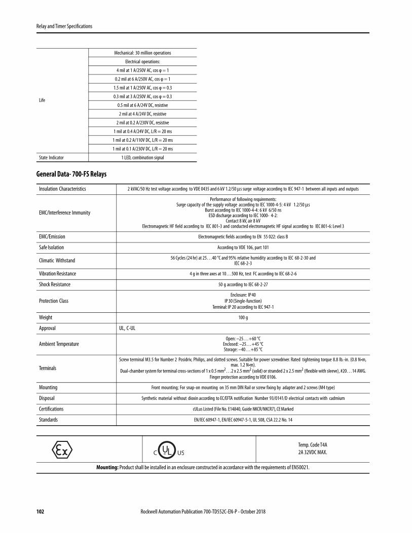
Relay and Timer Specifications
102 Rockwell Automation Publication 700-TD552C-EN-P - October 2018
General Data- 700-FS Relays
Life
Mechanical: 30 million operations
Electrical operations:
4 mil at 1 A/250V AC, cos φ = 1
0.2 mil at 6 A/250V AC, cos φ = 1
1.5 mil at 1 A/250V AC, cos φ = 0.3
0.3 mil at 3 A/250V AC, cos φ = 0.3
0.5 mil at 6 A/24V DC, resistive
2 mil at 4 A/24V DC, resistive
2 mil at 0.2 A/230V DC, resistive
1 mil at 0.4 A/24V DC, L/R = 20 ms
1 mil at 0.2 A/110V DC, L/R = 20 ms
1 mil at 0.1 A/230V DC, L/R = 20 ms
State Indicator 1 LED, combination signal
Insulation Characteristics 2 kVAC/50 Hz test voltage according to VDE 0435 and 6 kV 1.2/50 μs surge voltage according to IEC 947-1 between all inputs and outputs
EMC/Interference Immunity
Performance of following requirements:Surge capacity of the supply voltage according to IEC 1000-4-5: 4 kV 1.2/50 μs
Burst according to IEC 1000-4-4: 6 kV 6/50 nsESD discharge according to IEC 1000- 4-2:
Contact 8 kV, air 8 kVElectromagnetic HF field according to IEC 801-3 and conducted electromagnetic HF signal according to IEC 801-6: Level 3
EMC/Emission Electromagnetic fields according to EN 55 022: class B
Safe Isolation According to VDE 106, part 101
Climatic Withstand 56 Cycles (24 hr) at 25…40 °C and 95% relative humidity according to IEC 68-2-30 andIEC 68-2-3
Vibration Resistance 4 g in three axes at 10…500 Hz, test FC according to IEC 68-2-6
Shock Resistance 50 g according to IEC 68-2-27
Protection ClassEnclosure: IP 40
IP 30 (Single-function)Terminal: IP 20 according to IEC 947-1
Weight 100 g
Approval UL, C-UL
Ambient TemperatureOpen: –25…+60 °C
Enclosed: –25…+45 °CStorage: –40…+85 °C
TerminalsScrew terminal M3.5 for Number 2 Posidriv, Philips, and slotted screws. Suitable for power screwdriver. Rated tightening torque 8.8 lb.-in. (0.8 N•m,
max. 1.2 N•m).Dual-chamber system for terminal cross-sections of 1 x 0.5 mm2…2 x 2.5 mm2 (solid) or stranded 2 x 2.5 mm2 (flexible with sleeve), #20…14 AWG.
Finger protection according to VDE 0106.
Mounting Front mounting; For snap-on mounting on 35 mm DIN Rail or screw fixing by adapter and 2 screws (M4 type)
Disposal Synthetic material without dioxin according to EC/EFTA notification Number 93/0141/D electrical contacts with cadmium
Certifications cULus Listed (File No. E14840, Guide NKCR/NKCR7), CE Marked
Standards EN/IEC 60947-1, EN/IEC 60947-5-1, UL 508, CSA 22.2 No. 14
Temp. Code T4A 2A 32VDC MAX.
Mounting: Product shall be installed in an enclosure constructed in accordance with the requirements of EN50021.

Relay and Timer Specifications
Rockwell Automation Publication 700-TD552C-EN-P - October 2018 103
700-HNC Miniature Timing Relay• Miniature timer, perfect for converting 700-HC "Ice Cube" relays into timing relays• 4 operating modes• 4PDT contact output• Timing range from 0.1 s…10 hr• Socket mounted
Accessories - 700-HNC Relays
Model Timing Mode Contact Output Input Voltages Timing Range Socket Type Cat. No.
On-DelayOne ShotRepeat cycle, OFF-startRepeat cycle, ON-start
4PDT
12V DC 0.1 s…10 min
700-HN103700-HN128
700-HNC44AZ12.1 min…10 hr 700-HNC44BZ12
24V DC 0.1 s…10 min 700-HNC44AZ240.1 min.…10 hr 700-HNC44BZ24
48V DC 0.1 s…10 min 700-HNC44AZ480.1 min.…10 hr 700-HNC44BZ48
100…110V DC 0.1 s…10 min 700-HNC44AZ110.1 min.…10 hr 700-HNC44BZ11
125V DC 0.1 s…10 min 700-HNC44AZ250.1 min.…10 hr 700-HNC44BZ25
24V AC 0.1 s…10 min 700-HNC44AA240.1 min.…10 hr 700-HNC44BA24
100…120V AC 0.1 s…10 min 700-HNC44AA120.1 min.…10 hr 700-HNC44BA12
200…230V AC 0.1 s…10 min 700-HNC44AA23Cat. No. 700-HNC 0.1 min.…10 hr 700-HNC44BA23
Photo Description Pkg. Quantity Cat. No.
Screw Terminal Socket — Panel or DIN Rail Mounting.Guarded Terminal Construction14-Blade miniature socket for use with 700-HNC timers.
10 700-HN103
Screw Terminal Base Sockets — Panel or DIN Rail Mounting.Open Style Construction14-blade miniature socket for use with 700-HNC timers.
10 700-HN128
Screw Terminal Socket – Panel or DIN Rail Mounting. Guarded Terminal Construction 14-blade miniature socket for use with 700-HNC timers. This socket has coil and contact separation.
10 700-HN104
Retainer Clip for Cat. Nos. 700-HN103, -HN104 and -HN128 Sockets with 700-HNC Timers. Secures Timer in Socket. 10 700-HN263

Relay and Timer Specifications
Specifications - 700-HNC Relays
Attribute 700-HNC
Pilot Duty Rating NEMA B300
Pin type Plug-in
Operating voltage range 85%…110% of rated supply voltage (12V DC: 90%…110% of rated supply voltage) (1)
Reset voltage 10% min. of rated supply voltage
Power consumption
24V AC: Relay ON:Relay OFF:
1.5 VA (1.1 W) (at 24V AC, 60 Hz)0.2 VA (0.1 W) (at 24V AC, 60 Hz)
100…120V AC: Relay ON:Relay OFF:
1.5 VA (1.3 W) (at 120V AC, 60 Hz)0.8 VA (0.5 W) (at 120V AC, 60 Hz)
200…230V AC: Relay ON:Relay OFF:
1.8 VA (1.5 W) (at 230V AC, 60 Hz)1.2 VA (0.9 W) (at 230V AC, 60 Hz)
12V DC: Relay ON:Relay OFF:
0.9 W (at 12V DC)0.07 W (at 12V DC)
24V DC: Relay ON:Relay OFF:
0.9 W (at 24V DC)0.07 W (at 24V DC)
48V DC: Relay ON:Relay OFF:
1.0 W (at 48V DC)0.2 W (at 48V DC)
100…110V DC: Relay ON:Relay OFF:
1.3 W (at 110V DC)0.3 W (at 110V DC)
125V DC: Relay ON:Relay OFF:
1.3 W (at 125V DC)0.3 W (at 125V DC)
Control outputs 4PDT: 5 A at 250V AC, resistive load (cos φ = 1)
Characteristics
Make 120V AC 30 A
240V AC 15 A
Break 120V AC 3 A
240V AC 1.5 A
Hp at 120V AC 1/6 Hp
Hp at 240V AC 1/6 Hp
Accuracy of operating time ±1% FS max. (1 s range: ±1%±10 ms max.)
Setting error ±10%±50 ms FS max.
Reset time Min. power-opening time: 0.1 s max. (including halfway reset)
Influence of voltage ±2% FS max.
Influence of temperature ±2% FS max.
Insulation resistance 100 mΩ min. (at 500V DC)
Dielectric strength
2000V AC, 50/60 Hz for 1 min (between current-carrying terminals and exposed non-current-carrying metal parts) (2)
2000V AC, 50/60 Hz for 1 min (between operating power circuit and control output)
2000V AC, 50/60 Hz for 1 min (between different pole contacts; 2-pole model)
1500V AC, 50/60 Hz for 1 min (between different pole contacts; 4-pole model)
1000V AC, 50/60 Hz for 1 min (between non-continuous contacts)
Vibration resistance Malfunction: 10…55 Hz, 0.5 mm single amplitude
Shock resistance Malfunction: 100 m/s2 (approx. 10G)
Ambient temperatureOperating: -10 °C…50 °C (with no icing)
Storage: -25 °C…65 °C (with no icing)
104 Rockwell Automation Publication 700-TD552C-EN-P - October 2018

Relay and Timer Specifications
General Timer Functions
Ambient humidity Operating: 35%…85%
Life expectancyMechanical: 10 000 000 operations min. (under no load at 1800 operations/hr)
Electrical: 4PDT: 200 000 operations min. (3 A at 250V AC, resistive load at 1800 operations/hr)
Noise immunity ±1.5 kV, square-wave noise by noise simulator (pulse width: 100 ns / 1 μs, 1- ns rise)
Static immunity Destruction:8 kV Malfunction:4 kVIP40Enclosure rating
Weight Approx. 50 g
EMC
Emission Enclosure:EN55011 Group 1 class A
Emission AC Mains:EN55011 Group 1 class A
Immunity ESD:EN61000-4-2:4 kV contact discharge (level 2) 8 kV air discharge (level 3)
Immunity RF-interference:ENV50140:10 V/m (amplitude modulated, 80 MHz to 1 GHz) (level 3) 10 V/m (pulse modulated, 900 MHz)
Immunity Conducted Disturbance:ENV50141:10 V (0.15…80 MHz) (level 3)
Immunity Burst:EN61000-4-4:2 kV power-line (level 3) 2 kV I/O signal-line (level 4)
Standards UL 508, CSA 22.2 No. 14, EN/IEC 61812-1
Certifications cURus Recognized (File No. E14843, Guide NRNT2/NRNT8), CSA Certified (File 224268), CE Marked, C- Tick Marked
(1) Single-phase, full-wave-rectified power supplies can be used.(2) When using the 700-HNC continuously in any place where the ambient temperature is in a range of 45 °C…50 °C, supply 90%…110% of the rated supply voltages supply 95%…110% with 12V DC type).
Attribute 700-HNC
Rockwell Automation Publication 700-TD552C-EN-P - October 2018 105

Relay and Timer Specifications
Timing Charts - 700-HNC Relays
IMPORTANT t: Set time, Rt:Reset time
Operating Mode Timing Charts / Wiring Diagram
General Timer Functions Pulse Operation
A pulse output for a certain period can be obtained with a random external input signal. Use the 700-HNC timing relay in interval mode as shown in the following timing charts.
ON-Delay
tPower
Output
Power (13-14)
Time limit contactNC (9-1, 10-2, 11-3, 12-4)
Time limit contactNO (9-5, 10-6, 11-7, 12-8)
Run / Power Indicator (PW)
Output Indicator (UP)
t Rt t
UP PW
TimerCircuit
One shot
Power
Output
Power (13-14)
Time limit contactNC (9-1, 10-2, 11-3, 12-4)
Time limit contactNO (9-5, 10-6, 11-7, 12-8)
Run / Power Indicator (PW)
Output Indicator (UP)
t t t
Repeat Cycle OFF-Start
Power
Output
t t t t
Power (13-14)
Time limit contactNC (9-1, 10-2, 11-3, 12-4)
Time limit contactNO (9-5, 10-6, 11-7, 12-8)
Run / Power Indicator (PW)
Output Indicator (UP)
t t t
Repeat Cycle ON-Start
Power
Output
t t t t
Power (13-14)
Time limit contactNC (9-1, 10-2, 11-3, 12-4)
Time limit contactNO (9-5, 10-6, 11-7, 12-8)
Run / Power Indicator (PW)
Output Indicator (UP)
Run/Power Indicator(Green)(Lit: Power ON)
Output Indicator (Orange)(Lit: Output ON)
Main DialSet the desired time according to time range selectable by DIP switch.
External Input
1 432
5 6 7 8
9 10 11 12
TimerCircuit(—)
UP FW(~)
(+)(~)
~( )
1413
Note: t: Set timeRt: Reset time
Power (9-14)
External short circuit(5-13)External input(9-13)
Time limit contact NO(10-6, 11-7, 12-8)Time limit contact NC(10-2, 11-3, 12-4)Run/Power indicator(PW)Output indicator (UP)
50 msmin.
106 Rockwell Automation Publication 700-TD552C-EN-P - October 2018
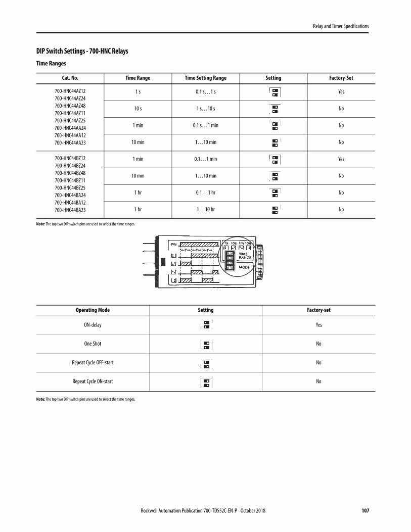
Relay and Timer Specifications
DIP Switch Settings - 700-HNC RelaysTime Ranges
Note: The top two DIP switch pins are used to select the time ranges.
Note: The top two DIP switch pins are used to select the time ranges.
Cat. No. Time Range Time Setting Range Setting Factory-Set
700-HNC44AZ12700-HNC44AZ24700-HNC44AZ48700-HNC44AZ11700-HNC44AZ25700-HNC44AA24700-HNC44AA12700-HNC44AA23
1 s 0.1 s…1 s Yes
10 s 1 s…10 s No
1 min 0.1 s…1 min No
10 min 1…10 min No
700-HNC44BZ12700-HNC44BZ24700-HNC44BZ48700-HNC44BZ11700-HNC44BZ25700-HNC44BA24700-HNC44BA12700-HNC44BA23
1 min 0.1…1 min Yes
10 min 1…10 min No
1 hr 0.1…1 hr No
1 hr 1…10 hr No
Operating Mode Setting Factory-set
ON-delay Yes
One Shot No
Repeat Cycle OFF-start No
Repeat Cycle ON-start No
Rockwell Automation Publication 700-TD552C-EN-P - October 2018 107

Relay and Timer Specifications
Dimensions - 700-HNC RelaysApproximate dimensions are shown in millimeters (inches). Dimensions are not intended for manufacturing purposes.
Cat. No. 700-HNC… Cat. No. 700-HN128 (1)
Wire Size: 2 x 1.5 mm2 (#2-16 AWG…#1-20 AWG)(Either Solid or Stranded)
Strip Length: 9 mm (3/8 in.) - Torque: 0.8 N•m (7 lb•in)
(1) Total height of 700-HN128 + 700-HNC is 82.5 mm.
Cat. No. 700-HN103Single wire: 0.2…2.5 mm2 (#24 AWG…14 AWG)
Double wire: 2 x 0.2 mm2…2 x 1.5 mm2 (2 x 24 AWG…2 x 16 AWG)Wire type: solid or stranded, copper only
Strip length: 8 mm (5/16 in.), Torque: 0.5 N•m (4.4 lb•in)
Cat. No. 700-HN104Single Wire: 0.2…2.5 mm2 ( #24 AWG…14 AWG)
Double Wire: 2 x 0.2 mm2…2 x2.5 mm2 (2 x 24 AWG…2 x 14 AWG)Wire Type: solid or stranded, copper only
Strip Length: 7 mm (9/32 in.), Torque: 0.5 N•m (4.4 lb•in)
Fourteen 3 x 1.2 mm Elliptic Holes
28(1.10)
6.3(.024)
21.5 max(084)
52.6(2.07)63.0
(2.48)
6.4(0.25)
4.0(0.15)
65.0(2-9/16)
62.0(2-15/64)
24.9(57/64)21.1
(53/64)
4.2(5/32)
26.0(1-1/64)
6.1 (15/64)
30.0(1-3/16)
911 1012
1314
8 7 6 5
4 3 2 1
Panel Mounting
67.0(2-5/8)
30.0(1-11/64)
24.5(31/32)
28.9(1-9/64)
#4-40M3
27.0(1.06)
76.0(2.99)
34.9(1.37)
2.5(0.10)
3.2(0.13)
60.9(2.40)
21.5(0.85)
35.6(1.40)
18.9(0.74)
32.0(1.26)
35.5(1.40)
108 Rockwell Automation Publication 700-TD552C-EN-P - October 2018

Relay and Timer Specifications
700-HNK Ultra-Slim Timing Relay• The ultra-slim timing relay is the smallest relay available• It is perfect for converting 700-HK relays into a timing relay• SPDT and DPST-NO contact output• Socket-mounted• Timing range From 0.1 s…10 hr
Sockets and Retainer Clip Reference
Photo Timing Mode Socket Type Contact Output Timing Range Input Voltage Cat. No.
On-DelayOne ShotRepeat Cycle, OFF-startRepeat Cycle, ON-start
700-HN121 SPDT (1)
(1) 5-blade terminal type only.
0.1 s…10 min
12V DC 700-HNK41AZ12
24V DC 700-HNK41AZ24
24V AC 700-HNK41AA24
0.1 min…10 hr
12V DC 700-HNK41BZ12
24V DC 700-HNK41BZ24
24V AC 700-HNK41BA24
700-HN122 DPST-NO(2)
(2) 8-blade terminal type only.
Accessories - 700-HNK Relays
0.1 s…10 min
12V DC 700-HNK42AZ12
24V DC 700-HNK42AZ24
24V AC 700-HNK42AA24
0.1 min…10 hr
12V DC 700-HNK42BZ12
24V DC 700-HNK42BZ24
24V AC 700-HNK42BA24
Description Pkg. Quantity Cat. No.
Screw Terminal Socket — Panel or DIN Rail Mounting5-blade miniatue socket. For use with 1-pole type 700-HNK41 timers. Socket includes a retainer clip. 10 700-HN121
Screw Terminal Socket — Panel or DIN Rail Mounting8-blade miniature socket for use with 2-pole, 700-HNK42 timers. This socket includes a retainer clip. 10 700-HN122
Timer Type Socket Cat. No. Retainer Clip Cat. No.
700-HNK 700-HN121 Provided700-HN122 Provided
Rockwell Automation Publication 700-TD552C-EN-P - October 2018 109

Relay and Timer Specifications
Specifications - 700-HNK Relays
Attribute 700-HNK
Pilot Duty Rating NEMA B300
Rated Supply Voltage 24V AC; 12, 24V DC
Pin Type Plug-in
Operating Mode ON-delay, One Shot, Repeat Cycle OFF start, or Repeat Cycle ON start selectable with DIP switch.
Operating Voltage Range 85%…110% of rated supply voltage (12 VDC: 90%…110% of rated supply voltage) (1)
Power Consumption24V AC:Relay ON:approx. 0.8 VA (at 24 VAC, 60 Hz) Relay OFF:0.5 VA (at 24V AC, 60 Hz)
12V DC:Relay ON:approx. 0.4 W (at 12V DC) Relay OFF:0.1 W (at 12V DC)24V DC:Relay ON:approx. 0.5 W (at 24V DC) Relay OFF:0.2 W (at 24V DC)
Control Outputs5 A at 250V AC, resistive load (cos φ = 1)
The minimum applicable load is 10 mA at 5 VDC (P reference value).
Characteristics
Make 120V AC 30 A
240V AC 15 A
Break 120V AC 3 A
240V AC 1.5 A
Hp at 240V AC 1/6 Hp
Accuracy of Operating Time ±1% FS max. (1 s range: +1% ±10 ms max.)
Setting Error ±15% +50 ms FS max.
Reset Time Min. power-opening time: 12, 24V DC: 0.1 s max. (including halfway reset)24V AC: 0.5 s max. (including halfway reset)
Influence of Voltage ±2% FS max.
Influence of Temperature ±2% FS max.
Insulation Resistance 100 mΩ min. (at 500V DC)
Dielectric Strength2000V AC, 50/60 Hz for 1 min (between operating circuit and control output, or contacts of different poles)
1000V AC, 50/60 Hz for 1 min (between non-continuous contacts)
Vibration Resistance Malfunction: 10…55 Hz, 0.5 mm single amplitude
Shock Resistance Malfunction: 100 m/s2 (approx. 10G)
Ambient Temperature Operating: -10 °C…50 °C (with no icing)Storage: -25 °C…65 °C (with no icing)
Ambient Humidity Operating: 35…85%
Life Expectancy Mechanical: 10 000 000 operations min. (under no load at 1800 operations/hr)Electrical: 100 000 operations min. (3 A at 250V AC, resistive load at 1800 operations/hr)
Impulse Withstand Voltage Between power terminals: 1 kV
Noise Immunity ±1.5 kV, square-wave noise by noise simulator (pulse width: 100 ns/1 μs, 1-ns rise)
Static Immunity Destruction: 8 kVMalfunction: 4 kV
Enclosure Rating IP20
Weight Approx. 18 g
110 Rockwell Automation Publication 700-TD552C-EN-P - October 2018

Relay and Timer Specifications
General Timer Functions
EMC
Emission Enclosure: EN55011 Group 1 class AEmission AC Mains: EN55011 Group 1 class A
Immunity ESD: EN61000-4-2:4 kV contact discharge (level 2) 8 kV air discharge (level 3)Immunity RF-interference: ENV50140: 10 V/m (amplitude modulated, 80 MHz…1GHz) (level 3) 10 V/m (pulse
modulated, 900 MHz)Immunity Conducted Disturbance: ENV50141:10 V (0.15…80 MHz) (level 3)
Immunity Burst: EN61000-4-4:2 kV power-line (level 3) 2 kV I/O signal-line (level 4)
Standards UL508, CSA C22.2 No. 14, EN/IEC 60947-5-1, EN/IEC 61812-1
Certifications cURus Recognized Component (File No. E14843, Guide NRNTZ/NRNT8), CE Marked, C-Tick Marked
(1) When using 700-HNK timer in any place where the ambient temperature is more than 50 °C, supply 90…110% of the rated voltages (12V DC: 95…11% of the rated voltage).
IMPORTANT t: Set time, Rt:Reset time
Attribute 700-HNK
Main DialSet the desired time according to timerange selectable by DIP switch.
Run/Power Indicator (Green)(Lit: Power ON)
Output Indicator (Orange)(Lit: Output ON)
Rockwell Automation Publication 700-TD552C-EN-P - October 2018 111

Relay and Timer Specifications
Operating Mode Timing Charts / Wiring Diagram
700-HNK41… 700-HNK42…
ON-Delay
tPower
Output
Power (1-5)
Time limit contactNC (4-2)
Time limit contactNO (4-3)
Run/ Power
Indicator (PW)
Output Indicator(OUT)
t Rt t
Power (1-8)
Time limit contactNO 4-3, 5-6
Run/Powerindicator (PW)
Output indicator(OUT)
t Rt t
One shot
Power
Output
Power (1-5)
Time limit contactNC (4-2)
Time limit contactNO (4-3)
Run/ Power
Indicator (PW)
Output Indicator(OUT)
Power (1-8)
Time limit contactNO (4-3, 5-6)
Run/Powerindicator (PW)
Output indicator(OUT)
tRt
t
t t t
Repeat Cycle OFF-Start
Power
Output
t t t tPower (1-5)
Time limit contactNC (4-2)
Time limit contactNO (4-3)
Run/ Power
Indicator (PW)
Output Indicator(OUT)
Power (1-8)
Time limit contactNO (4-3, 5-6)
Run/Powerindicator (PW)
Output indicator(OUT)
t t t t
t t t
Repeat Cycle ON-Start
Power
Output
t t t t
Power (1-5)
Time limit contactNC (4-2)
Time limit contactNO (4-3)
Run/ Power
Indicator (PW)
Output Indicator(OUT)
Power (1-8)
Time limit contactNO (4-3, 5-6)
Run/Powerindicator (PW)
Output indicator(OUT)
t t t t
112 Rockwell Automation Publication 700-TD552C-EN-P - October 2018

Relay and Timer Specifications
Wiring- 700-HNK Relays
A pulse output for a certain period can be obtained with a random external input signal. Use the 700-HNK in interval mode as shown in the following timing chart.
Note:t:Set timeRt: Reset time
Mode Terminals
Pulse OperationPower supply between 3 and 8Short-circuit between 4 and 1Input signal between 3 and 1
Operating mode; One shot and all other modes Power supply between 1 and 8
OUT PW
4
3
1
5
6
8TimerCircuit
(~) (~)( ) ( )
Cat. No. 700-HNK42...
TimerCircuit
OUT PW
1 5
3
4
2
( ~ )( ~ )( ) ( )
Cat. No. 700-HNK41...
TimerCircuit
~
8
63
4 5
1
( ) ( )( )~ ( )~
( )
External Input
OUT PW
Rt Rtt t t
50 msmin.
Run/Power Indicator (PW)Output Indicator (OUT)
Time Limit Contact NO (6-5)
External Input (1-3)
External Short Circuit (1-4)
Power (3-8)
Rockwell Automation Publication 700-TD552C-EN-P - October 2018 113

Relay and Timer Specifications
Time Ranges- 700-HNK Relays
Note: The left two DIP switch pins are used to select the time ranges.
Operating Modes - 700-HNK Relays
Note: The right two DIP switch pins are used to select the operating modes.
Cat. No. Time Range Time Setting Range Setting Factory-Set
700-HNK41AZ12700-HNK41AZ24700-HNK41AA24700-HNK42AZ12700-HNK42AZ24700-HNK42AA24
1 s 0.1…1 s Yes
10 s 1…10 s No
1 min 0.1 s…1 min No
10 min 1…10 min No
700-HNK41BZ12700-HNK41BZ24700-HNK41BA24700-HNK42BZ12700-HNK42BZ24700-HNK42BA24
1 min 0.1…1 min Yes
10 min 1…10 min No
1 hr 0.1…1 hr No
10 hr 1…10 hr No
Operating Mode Setting Factory-set
On-delay Yes
One Shot No
Repeat Cycle Off-start No
Repeat Cycle On-start No
114 Rockwell Automation Publication 700-TD552C-EN-P - October 2018
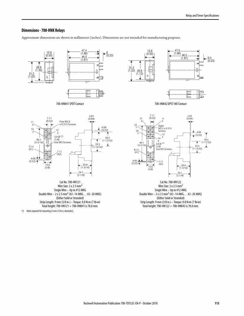
Relay and Timer Specifications
Dimensions - 700-HNK RelaysApproximate dimensions are shown in millimeters (inches). Dimensions are not intended for manufacturing purposes.
(1) Holes required for mounting [3 mm (1/8 in.) diameter].
700-HNK41 SPDT Contact 700-HNK42 DPST-NO Contact
Cat No. 700-HN121Wire Size: 2 x 2.5 mm2
Single Wire – Up to #12 AWGDouble Wire – 2 x 2.5 mm2 (#2–14 AWG… #2–20 AWG)
(Either Solid or Stranded)Strip Length: 9 mm (3/8 in.) – Torque: 0.8 N•m (7 lb•in)
Total height: 700-HN121 + 700-HNK41 is 78.0 mm.
Cat No. 700-HN122Wire Size: 2 x 2.5 mm2
Single Wire – Up to #12 AWGDouble Wire – 2 x 2.5 mm2 (#2–14 AWG… #2–20 AWG)
(Either Solid or Stranded)Strip Length: 9 mm (3/8 in.) – Torque: 0.8 N•m (7 lb•in)
Total height: 700-HN122 + 700-HNK42 is 78.0 mm.
6(0.23)
47.4(1.86)46.0
(1.81)
12.8(0.50)
28.8(1.30)
31.2(1.22)
47.0(1.86)
46.0(1.81) 6.0
(0.23)
28.8(1.13)
31.2(1.22)
12.8(0.50)
Five M3.5 x 0.315 Screws
3.0 Ø (1)
(1/8) Use M3 Screws
2.03(5/64)
4.06(5/32)
39.5(1-17/32)
35.5(1-13/32)
29.9(1-3/16)
54.1(2-1/8)
7.11(9/32)11
4
143
5 (+)(A1)
84.1(3-5/16)
122
1 (-)(A2)
4.06(5/32)
15.6(5/8)
2.03(5/64)
29.9(1-3/16)
54.1(2-1/8)
39.5(1-17/32)
35.5(1-13/32)
4.06
(5/32)
3.0 Ø (1)
(1/8)Use M3 Screws
EightM3.5 x 0.315Screws
7.11(9/32)21
6113
227
84.1(3-5/16)
15.6(5/8)
4.06(5/32)
1 (-)(A2)
8 (+)(A1)
245 12
2144
Rockwell Automation Publication 700-TD552C-EN-P - October 2018 115

Relay and Timer Specifications
700-HR Dial Timing Relays• Socket- or panel-mounted• 5 A contact ratings or transistor outputs• Single- or Multi-Function• Timing range from 0.05 s…300 hr• Multi-voltage inputs
Multi-Function Timing Relays with Trigger and Reset Switch Options• Socket or Panel Mounted• Timing Range From 0.05 s…300 hr• 11-pin base for socket cat. nos. 700-HN101, -HN126, -HN129• Trigger: Power on or optional trigger signal• Reset: Power off or optional reset signal
Multi-Function Timing Relays with Power On Trigger• Socket or Panel Mounted• Timing Range From 0.05 s…300 hr• 8-pin base for socket cat. nos. 700-HN100, -HN125, -HN108• Trigger: Power on• Reset: Power off
Timing Mode Supply Voltage Trigger Options Reset Options Outputs Cat. No.
On-Delay (A)OFF-Delay (D)One Shot (E)Repeat cycle OFF-Start (B)Repeat Cycle ON-Start (B2)Signal ON/OFF-delay (C)Delayed One Shot (J)Signal ON/OFF - Delay (G)
24…48V AC12…48V DC
1. Power On2. Start Signal- contact closure (zero volts)- NPN transistor3. Gate Signal (pause)
1. Power Off2. Reset Signal- contact closure (zero volts)- NPN transistor
DPDT 700-HR52TU24
Transistor (1)
(1) Voltage input connection to high signal instead of OV signal.
700-HRT6TTU24
1. Power On2. Start Signal- contact closure (voltage)- NPN transistor- PNP transistor
Power Off DPDT 700-HRV52TU24
100…240V AC100…125V DC
1. Power On2. Start Signal- contact closure (zero volts)3. Gate Signal (pause)
1. Power Off2. Reset Signal- contact closure (zero volts)
DPDT 700-HR52TA17
1. Power On2. Start Signal- contact closure (voltage)
Power Off DPDT(1)
700-HRV52TA17
Timing Mode Supply Voltage Trigger Options Reset Options Outputs Cat. No.
ON-Delay (A)One Shot (E)Repeat Cycle OFF-Start (B)Repeat Cycle ON-Start (B2)Delayed One Shot (J)
24…48V AC12…48V DC Power On Power Off
DPDT 700-HRS42TU24
Transistor
(1)
(1) Voltage input connection to high signal instead of OV signal.
700-HRT4TTU24
24…48V AC/DC Power On Power Off SPDT Timed + Instantaneous Contact 700-HRP42TU24
100…240V AC100…125V DC Power On Power Off
SPDT Timed + Instantaneous Contact 700-HRP42TA17
DPDT 700-HRS42TA17
116 Rockwell Automation Publication 700-TD552C-EN-P - October 2018

Relay and Timer Specifications
ON-Delay Timing Relays• Socket or Panel Mounted• Timing Range From 0.05 s…300 h• 8-pin base for socket cat. nos. 700-HN100, -HN125, -HN108• Trigger: Power on• Reset: Power off
Timing Mode Description
700-HRF Repeat Cycle Timing Relays• Socket or Panel Mounted• Independently adjustable on- and off-time• 8-Pin base for socket cat. nos. 700-HN100, -HN125, and -HN108• DPDT contact outputs• Trigger: Power on• Reset: Power off
• Hazardous location version available
Catalog Number Explanation
700-HRY Star-Delta Timing Relays• 8-Pin base for socket cat. nos. 700-HN100, -HN125, and -HN108• SPDT timed + instantaneous contact outputs• Trigger: Power on• Reset: Power off
Catalog Number Explanation
Timing Mode Supply Voltage Trigger Options Reset Options Outputs Cat. No.
ON-Delay (A)
24…48V AC/DC Power On Power Off SPDT Timed + Instantaneous Contact 700-HRC12TU2424…48V AC, 12…48V DC DPDT 700-HRM12TU24
100…240V AC Power On Power Off DPDT 700-HRM12TA17SPDT Timed + Instantaneous Contact 700-HRC12TA17
700 – HRF 7 2 D Z12a b c d e f
aBulletin Number
- bType of Relay
cFunction
dContact Output
eTiming Range
fSupply Voltage
700 HRF–Repeat cycle with adjustable ON/OFF times
7–Repeat cycle with OFF start8–Repeat cycle with ON start
2- DPDT D–0.05 s…300 hr
A18- 100...240V AC 50/60 HzU25 - 24V AC, 50/60 Hz; 24V DC
Z12 - 12V DCZ45 - 48...125V DC
700 – HRYY 6 F A12a b c d e
aBulletin Number
- bType of Relay
cFunction
dTiming Range
eSupply Voltage
700 HRYY–YStar-Delta timer 6–SPDT timed + SPDT instantF–Star: 0.5…120 s
Delta: 0.05, 0.1, 1.25, 0.5, 0.75, 1.0 sA12–100…120V AC, 50/60 HzA22–200…240V AC, 50/60 Hz
Rockwell Automation Publication 700-TD552C-EN-P - October 2018 117
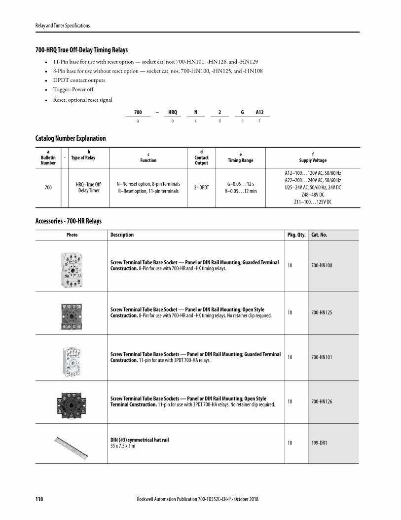
Relay and Timer Specifications
700-HRQ True Off-Delay Timing Relays• 11-Pin base for use with reset option — socket cat. nos. 700-HN101, -HN126, and -HN129• 8-Pin base for use without reset option — socket cat. nos. 700-HN100, -HN125, and -HN108• DPDT contact outputs• Trigger: Power off
• Reset: optional reset signal
Catalog Number Explanation
Accessories - 700-HR Relays
700 – HRQ N 2 G A12a b c d e f
aBulletin Number
-b
Type of Relay
cFunction
dContact Output
eTiming Range
fSupply Voltage
700 HRQ–True Off-Delay Timer
N–No reset option, 8-pin terminalsR–Reset option, 11-pin terminals
2–DPDTG–0.05…12 s
H–0.05…12 min
A12–100…120V AC, 50/60 HzA22–200…240V AC, 50/60 HzU25–24V AC, 50/60 Hz; 24V DC
Z48–48V DCZ11–100…125V DC
Photo Description Pkg. Qty. Cat. No.
Screw Terminal Tube Base Socket — Panel or DIN Rail Mounting; Guarded Terminal Construction. 8-Pin for use with 700-HR and -HX timing relays. 10 700-HN100
Screw Terminal Tube Base Socket — Panel or DIN Rail Mounting; Open Style Construction. 8-Pin for use with 700-HR and -HX timing relays. No retainer clip required. 10 700-HN125
Screw Terminal Tube Base Sockets — Panel or DIN Rail Mounting; Guarded Terminal Construction. 11-pin for use with 3PDT 700-HA relays. 10 700-HN101
Screw Terminal Tube Base Sockets — Panel or DIN Rail Mounting; Open Style Terminal Construction. 11-pin for use with 3PDT 700-HA relays. No retainer clip required. 10 700-HN126
DIN (#3) symmetrical hat rail35 x 7.5 x 1 m 10 199-DR1
118 Rockwell Automation Publication 700-TD552C-EN-P - October 2018

Relay and Timer Specifications
Specialty Socket8-pin backwired socket with solder terminals for use with 700-HR timing relays. Order 10 or multiples of 10.
10 700-HN108
Specialty Socket11-pin back-wired socket with solder terminals for use with 700-HR timing relays. 10 700-HN129
Frame AdapterFor flush or door mounting of all 700-HR and -HX timers. 1 700-HN130
Retainer Clip for Cat. Nos. 700-HN100 and -HN101 Sockets with all 700-HR Timing RelaysSecures timer in socket.
Note: Not required for installation
10 700-HN131
Protective CoverHelps prevent tampering of timing and mode settings. Provides a degree of protection against water and dirt from entering the front of the relay. For use with all 700-HRs and -HX timing relays.
1 700-HN132
Pre-Printed Identification Tags — contains 10 sheets of pre-printed and blank tags. Each sheet contains 13 sets of the markings CR…9CR, TR…9TR, M…9M, F, R, 1S, and 117 blank tags. Tags are peel-off with sticky backing for easy placement on relays.
10 700-N40
Blank Identification Tags — contains 10 sheets of blank identification tags for customer specialized printing. Each sheet contains 546 blank tags. Tags are peel-off with sticky backing for easy placement on relays.
10 700-N41
Timer Type Socket Cat. No. Retainer Clip Cat. No.
700-HR52, -HRT6, -HRV, -HRQR (1)
700-HN101 700-HN131
700-HN126 Not Required (3)
700-HN129 Not Applicable
700-HRS, -HRT4, -HRP, -HRC, -HRM, -HRF, -HRY, -HRQN (2)
700-HN100 700-HN131(See note above)
700-HN108 Not Applicable
700-HN125 Not Required(3)
(1) 11 pins.(2) 8 + pins.(3) Design of these sockets holds the timing relays securely and does not require retainer clips.
Photo Description Pkg. Qty. Cat. No.
Rockwell Automation Publication 700-TD552C-EN-P - October 2018 119

Relay and Timer Specifications
Specifications - 700-HR Relays
700-HR,700-HRS,700-HRV
700-HRP 700-HRC 700-HRM 700-HRF 700-HRY 700-HRQ 700-HRT(Transistor Outputs)
Electrical Ratings
Pilot Duty Rating NEMA B300 —
Thermal Current (Ith) 5 A100 mA @ 30V
DC max.
Make 120V AC 30 A —
240V AC 15 A —
Break 120V AC 3 A —
240V AC 1.5 A —
Hp at 120V 1/6 Hp (0.12 kW) 1/4 Hp (0.18 kW) 1/6 Hp (0.12 kW) 1/4 Hp (0.18
kW)1/6 Hp (0.12
kW) —
Hp at 240V 1/3 Hp (0.25 kW) —
Resistive Load 5 A at 250V AC/30V DC
Inductive Load AC-15 @ 250V AC, 3 A/DC-13 @ 30V DC, 0.5 A
Accuracy of Operating Time ±0.2% FS max. (±0.2% ±10 ms max. in a range of 1.2 s)
Setting Error ±5 % FS ±50 ms (The value is ±5% FS +100 ms to -0 ms max. when the C or D mode signal of the 700-HRVs are OFF.)
Influence of Voltage ±0.2% FS max. (±0.2% ±10 ms max. in a range of 1.2 s)
Influence of Temperature ±1% FS max. (±1% ±10 ms max. in a range of 1.2 s)
Permissible Leakage Current
Power Consumption -HR52, -HRS -HRV -HRP, -HRC -HRM -HRF -HRY -HRQ -HRT
240V AC, Output ON 2.1 VA 2.5 VA 2.0 VA 2.1 VA 10 VA 12 VA 0.4 VA —
240V AC, Output OFF 1.3 VA 1.8 VA 2.0 VA 1.3 VA 10 VA 12 VA 0.4 VA —
24V DC, Output ON 0.8 W 0.9 W 0.9 W 0.8 W 1.0 W — 0.2 W 0.3 W
24V DC, Output OFF 0.2 W 0.3 W 0.9 W 0.2 W 1.0 W — 0.2 W 0.2 W
Design Specifications
Dielectric Strength
2000V AC (1000V AC for 700-HRT), 50/60 Hz for 1 min (contact to frame)2000V AC (1000V AC for 700-HRT), 50/60 Hz for 1 min (between control output terminals and operating circuit)
2000V AC, 50/60 Hz for 1 min (pole-to-pole)1000V AC, 50/60 Hz for 1 min (between contacts not located next to each other)
2000V AC, 50/60 Hz for 1 min (contact to coil)
Mechanical
Vibration Resistance Malfunction: 10…55 Hz with 0.5 mm double amplitude each in three directions for ten minutes each
Shock Resistance Malfunction: 100 m/s2 (10 G) 98 m/s2 (10 G)
294 m/s2 (10 G) 98 m/s2 (10 G) 100 m/s2 (10 G)
Environmental
Noise Immunity ±1.5 kV for ±600V DC ±400V for 12V DC ±1kV for 48V DC
±1.5 kV for ±600V DC
Static Immunity Malfunction: 8 kV
Ambient Temperature Operating: -10…55 °C (with no icing) Storage: -25…65 °C (with no icing)
Ambient Humidity Operating: 35…85 %
Construction
Life Rxpectancy (Min. Operations)
Mechanical:20 000 000. (under no load at 1800 operations/h)Electrical: 100 000 (5 A at 250V AC, resistive load at 1800 operations/h)
Mech: 107
Electrical: 104
120 Rockwell Automation Publication 700-TD552C-EN-P - October 2018
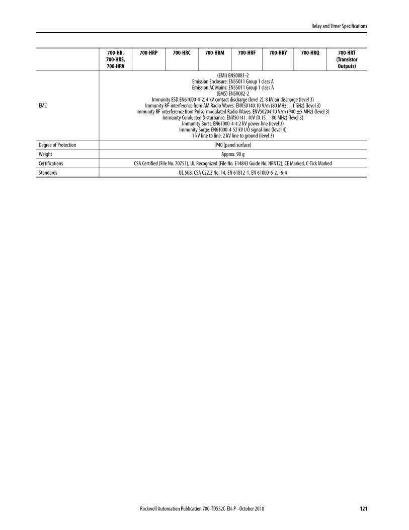
Relay and Timer Specifications
Rockwell Automation Publication 700-TD552C-EN-P - October 2018 121
EMC
(EMI) EN50081-2Emission Enclosure: EN55011 Group 1 class AEmission AC Mains: EN55011 Group 1 class A
(EMS) EN50082-2Immunity ESD:EN61000-4-2: 4 kV contact discharge (level 2); 8 kV air discharge (level 3)
Immunity RF-interference from AM Radio Waves: ENV50140:10 V/m (80 MHz…1 GHz) (level 3)Immunity RF-interference from Pulse-modulated Radio Waves: ENV50204:10 V/m (900 ±5 MHz) (level 3)
Immunity Conducted Disturbance: ENV50141: 10V (0.15…80 MHz) (level 3)Immunity Burst: EN61000-4-4:2 kV power-line (level 3)
Immunity Surge: EN61000-4-52 kV I/O signal-line (level 4)1 kV line to line; 2 kV line to ground (level 3)
Degree of Protection IP40 (panel surface)
Weight Approx. 90 g
Certifications CSA Certified (File No. 70751), UL Recognized (File No. E14843 Guide No. NRNT2), CE Marked, C-Tick Marked
Standards UL 508, CSA C22.2 No. 14, EN 61812-1, EN 61000-6-2, -6-4
700-HR,700-HRS,700-HRV
700-HRP 700-HRC 700-HRM 700-HRF 700-HRY 700-HRQ 700-HRT(Transistor Outputs)

Relay and Timer Specifications
Timer Functions - 700-HR Relays
700-HR Multifunction Timer
700-HRC -HRM On-Delay Timer
700-HRF Twin Timer
700-HRY Star-Delta Timer
700-HRQ True Off-Delay Timer
Output indicator (orange)(Lit when energized)
Time Range selector (selectone from 1.2, 3, 12, and 30 at full scale.)
Time settingknob (set time)
Operating mode display window
Operating mode selectorSelect a mode from:A, B, B2, C, D, E, J, and G (700-HR52, -HRV, and HRT 6)A, E, B2, J, and B (800-HRS, -HRP, and -HRT4)
Scale range display windows
Time unit display window
Time unit selector (select one from sec, 10 s, min, 10 m, hrs, and 10 h)
Power indicator (green) (Flashes when Timer operates;lit when Timer stops operating)
Power indicator (green) (Flashes when Timer operates;lit when Timer stops operating)
Output indicator (orange)(Lit when energized)
Time Range selector (selectone from 1.2, 3, 12, and 30 at full scale.) Time setting
knob (set time)
Time unit selector (select one from sec, 10 s, min, 10 m, hrs, and 10 h)
Time unit display window
Scale range display windows
OFF indicator (green)Lit when the output is OFF.
ON indicator (orange)Lit when the output is ON.
Scale range display windows
Time range selector (select one from 1.2, 3, 12, and 30 at full scale.)
OFF-time unit display
OFF-time unit selector (select one from sec, 10 s, min., 10 m, hrs, and 10 h)
ON-time setting knob (with orange pointer)For ON-time setting
OFF-time setting knob (with green pointer)For OFF-time setting
ON-time unit display
ON-time unit selector (select one from sec, 10 s, min., 10 m, hrs, and 10 h)
Time unit display(sec. is fixed)
Time setting knob (for setting star operation time)
Star-delta transfer time selector (selectone from 0.05 s, 0.1 s, 0.25 s, 0.5 s, 0.75 s and 1.0 s)
Star-delta transfer time unit display
Star operation time range selector (select one from 6, 12, 60 and 120 at full scale.)
Scale range display windows
Delta operation indicator(orange)
Star operation indicator(green)
Scale range display windows
Time setting knob (for setting OFF-delay time)
True OFF-Delay time unit display
Time range selector (select one from 0.6, 1.2, 6, and 12at full scale.)
Output indicator (red)
122 Rockwell Automation Publication 700-TD552C-EN-P - October 2018

Relay and Timer Specifications
Rockwell Automation Publication 700-TD552C-EN-P - October 2018 123
Specifications for Start, Gate, Reset Signal (Cat. Nos. 700-HR52, -HRT6, -HRV, -HRQR)Start, Reset, and Gate signals are typically contact closures or signals from a solid-state sensor.
(R) Reset SignalThe reset signal is not required for normal operation. Reset can be accomplished by removing power from the timing relay. To reset the timer without removing power, a signal must be applied which resets the timing cycle and returns the output contacts to their shelf state. The reset signal will override both the start signal and gate signal. The reset signal can be either momentary or maintained.
(G) Gate SignalThe gate signal is not required for normal operation. The gate signal provides a pause or retentive timing function. When the gate signal is applied the timing cycle is momentarily interrupted. When the signal is removed, the timing cycle resumes timing at the point the cycle was interrupted and will continue timing until the time delay is completed or the gate signal isre-applied.
Contact Signal — Cat. Nos. 700-HR52, -HRT6, -HRQRContact closure provides signal to timer. A low energy signal is generated by the 700-HR timing relay. For optimum reliability, use contacts designed for low energy switching (5V, 1 mA)(Bul. 800F-X V, 800T-X V). No external voltage should be connected to the contact signal.
Contact Signal — Cat. No. 700-HRVFor use in applications where it is not possible to use contacts designed for low energy switching. Contact closure provides signal to timer. A signal is generated by the 700-HR timing relay, and is the same potential as the supply voltage of the timing relay. No external voltage should be connected to contact signal. 700-HRV52TU24 supply voltage: 24...48V AC, 12...48V DC / 700-HRV52TA17 supply voltage: 100...240V AC, 100...125V DC.
Solid-State Signal — Cat. Nos. 700-HR52, -HRT6Timing relay is suitable for use with a 3-wire NPN 12...24V DC sensor. Supply voltage potential of sensor must be the same as the supply voltage potential of the timing relay. Permissible off-state leakage current from sensor: 0.01 mA max.
Solid-State Signal — Cat. No. 700-HRVTiming relay is suitable for use with a 3-wire NPN or PNP 12...24V DC sensor. Supply voltage potential of sensor must be the same as the supply voltage potential of the timing relay. Permissible off-state leakage current from sensor: 0.01 mA max.
Signal Specifications
Circuit ImpedanceCircuit impedance can be used to calculate the maximum wiring distance from the signal switch to the timing relay, for example.
Permissible signal-ON impedance: 1 kΩ max.Permissible signal-OFF impedance: 100 kΩ min.
Power-OFF Reset Min. power-off time: 0.1 s, Reset Voltage: 10% max. of rated voltage
Signal Duration Min. pulse width: 0.05 s
Signal Options
700-HR52 700-HRT6 700-HRV5 700-HRQR
Start X X X NA
Reset X X NA X
Gate X X NA NA
Power to Timing Relay
Reset Signal
t1 T t1< T
Timing Cycle
Timing Relay Output
Power to Timing Relay
Gate (pause)
t1 t2 t1+t2 = T
Timing Cycle Timing Relay Output
R
G
S
5v, 1mA
S
U( ) ( + )
U
(+) 12...24V DC( )
R S G
+ 12...24V DC COM
COM
0.1mA
(+) 12...24V DC
S
+ 12...24V DC COM
( )COMPNP Wiring Diagram NPN Wiring Diagram (+) 12...24V DC
S
+ 12...24 V DC COM
( )COM

Relay and Timer Specifications
Timing Charts - 700-HR Relays
Mode A — ON-Delaya. Needs continuous input power applied.b. Timing is initiated by the leading edge of the start signal.c. Contacts change state after timing is complete.d. Additional start signals during timing don't reset timing or contacts.e. When the input power is removed contacts return to shelf state.
Mode B — Repeat Cycle, Off Starta. Need continuous input power applied.b. Timing is initiated by the leading edge of the start signal. Additional start signals during timing do not reset timing or contacts.c. For the first time period the contacts remain in their shelf state. When that time period is complete contacts change state for the same time period (time on = time off).d. This cycle repeats itself until input power is removed or reset signal is applied. When the input power is removed or reset signal is applied contacts return to the shelf state.
Mode B2 —Repeat Cycle On starta. Need continuous input power applied.b. Timing is initiated by the leading edge of the start signal. Additional start signals during timing do not reset timing or contacts.c. For the first time period the contacts change state. When that time period is complete contacts return to the shelf state for the same time period (time on = time off).d. This cycle repeats itself until input power is removed or reset signal is applied. When the input power is removed or reset signal is applied contacts return to the shelf state.
Mode C — Watchdog monitor (Trigger = Signal On/Off)a. Need continuous input power applied.b. Contacts change state immediately when start signal is applied or when start signal is removed (only if timing cycle was complete).c. Timing is initiated at the leading edge of the start signal. After the first timing cycle is complete, timing is initiated by the trailing edge of the start signal.d. At the end of the time period contacts return to the shelf state.e. Relay timing is reset when additional start signals are applied while the relay is timing. Contacts remain in energized state.f. When the input power is removed contacts return to the shelf state.
PowerT
Power LED
Start
Output (N.C.)
Output (N.O.)
TPower
Start
Output
Basic Operation
PowerT
Start
T T
Power LED
Output (N.C.)Output (N.O.)
PowerT
Start
T T
Output
Basic Operation
Basic Operation
Power
Start
Output
T TTPowerStart
Output (N.C.)
Output (N.O.)Power LED
T TT
PowerT
Start
Output
Basic OperationT T t TPower
Start
Power LEDOutput (N.O.)
t<T
Output (N.C.)
T
124 Rockwell Automation Publication 700-TD552C-EN-P - October 2018

Relay and Timer Specifications
Mode D — Off-Delay (Trigger = Signal Off)a. Need continuous input power applied.b. Contacts change state immediately when start signal is applied.c. Timing is initiated by the trailing edge of the start signal.d. At the end of the time period contacts return to the shelf state.e. Relay timing is reset when additional start signals are applied while the relay is timing. Contacts remain in energized state.f. When the input power is removed contacts return to the shelf state.
Mode E — One-Shot (Trigger = Signal On) 700-HR52, -HRV, and -HRT6a. Need continuous input power applied.b. Timing is initiated by the leading edge of the start signal.c. Contacts change state immediately when start signal is applied.d. At the end of the time period contacts return to the shelf state.e. Relay timing is reset when additional start signals are applied while the relay is timing. Contacts remain in energized state.f. When the input power is removed contacts return to shelf state.
Mode E — One-Shot (Trigger = Power On) 700-HRS, -HRP, and -HRT4a. Need continuous input power applied.b. Timing is initiated when the input power is applied.c. At the end of the time period contacts return to the shelf state.d. Relay timing is reset when input power is removed.
Mode G — Watchdog Monitor (Trigger=Signal ON/OFF)a. Need continuous input power applied.b. Timing is initiated by the landing edge of the start signal.c. After the first timing cycle is complete the contacts change state and timing is initiated by the trailing edge of the start signal.d. At the end of the time period the contacts return to the shelf state.e. Relay timing is reset when additional start signals are applied while the relay is timing.f. When the power is removed contacts return to the shelf state.
Basic Operation
Power
Start
Output
TPower
Start
Power LED
Output (N.C.)
Output (N.O.)
T tt<T
Basic Operation
TPower
Start
Output
t<TT t TPower
StartOutput (N.C.)Output (N.O.)
Power LED
T
Basic Operation
Power
Output
PowerT
t<T
Timed Output (N.C.)Timed Output (N.O.)
Power LED
Rockwell Automation Publication 700-TD552C-EN-P - October 2018 125

Relay and Timer Specifications
Mode J — Delayed One-Shot (Trigger = Power On)a. Need continuous input power applied.b. No start signal applied.c. Timing is initiated when input power is applied.c. Contacts change state after the timing for a fixed time of 1s +/-0.5sd. At the end of the 1 sec period the contacts return to the shelf state.e. When the input power is removed contacts return to the shelf state.
Mode Star-Deltaa. Need continuous input power applied.b. No start signal required. Timing is initiated when input power is applied.c. Star ouput contact changes state when input power is applied.d. After timing is complete star output contact returns to the shelf state then both the star & delta contacts remain in shelf states until transfer time setting is complete.e. Delta output contact changes state after transfer time is complete.f. Instantaneous contact changes state when input power is applied.g. All contacts return to the shelf state when input power is removed.
Mode True Off-Delay (Trigger = Power Off)a. Continuous input power is NOT required.b. No start signal applied.c. Contacts change state immediately when input power is applied.d. Timing starts when input power is removed.e. At the end of the time period contacts return to the shelf state.f. Relay timing is reset when input power is reapplied while the relay is timing. Contacts remain in energized state.
Basic Operation
T
Power
Power LED
Output (N.O.)
1s ±0.5sOutput (N.C.)
TPower
Power LED
Output (N.O.)1s ±0.5s
Powert1
Output (N.O.)
t2
Output 8-5, LED
Output 8-6, LED
Output (N.C.) Powert1
Instantaneous Output
t2
Output 8-5, LED
Output 8-6, LED
Basic Operation
Basic Operation
TPower
Relay On LED
Output (N.O.)
tt<T
T
Output (N.C.)
TPower
Relay On LED
Output
126 Rockwell Automation Publication 700-TD552C-EN-P - October 2018

Relay and Timer Specifications
Dimensions - 700-HR RelaysApproximate dimensions are shown in millimeters (inches). Dimensions are not intended for manufacturing purposes.
Rockwell Automation Publication 700-TD552C-EN-P - October 2018 127

Relay and Timer Specifications
700-HT Plug-in Timing Relay• Timing Relay (On-Delay or Off-Delay)• Rugged Pin Style Socket Mounting• 10 A, DPDT Contact Ratings• 0.1 s…30 min Fixed Timing Relay• 0.1 s…3 min Single Adjustable Timing Relay• Single or Fixed Timing
Single Range Timing Relay with Pin Style Terminations
Catalog Number Explanation - 700-HT Relays
700 – HT 2 2 A A2a b c d e f
a Bulletin Number
-b
Type of Relay cOperating Mode
dNumber of Poles
eTiming Range
fCoil Voltage
700HT -
Tube Base Adjustable Timing Relay
1–On-delay 2–Off-delay 2 - 2PDT
A– 0.1…10 s B– 1.0…100 s
C– 0.1…10 min D– 1.0…100 min
E – 0.1…10 hr
U12– 12V DC U24– 24V AC/DC, 50/60 Hz
U120– 120V AC/DC, 50/60 Hz A2 – 240V AC, 50/60 Hz
Operating ModeWiring Diagrams
U.S./Canada International
On-Delay
Socket 700-HN125 or700-HN100 700-HN100
Off-Delay
700-HTDPDT 2-Pole — 2 Form C Contacts
Socket 700-HN126 or700-HN101 700-HN101
128 Rockwell Automation Publication 700-TD552C-EN-P - October 2018
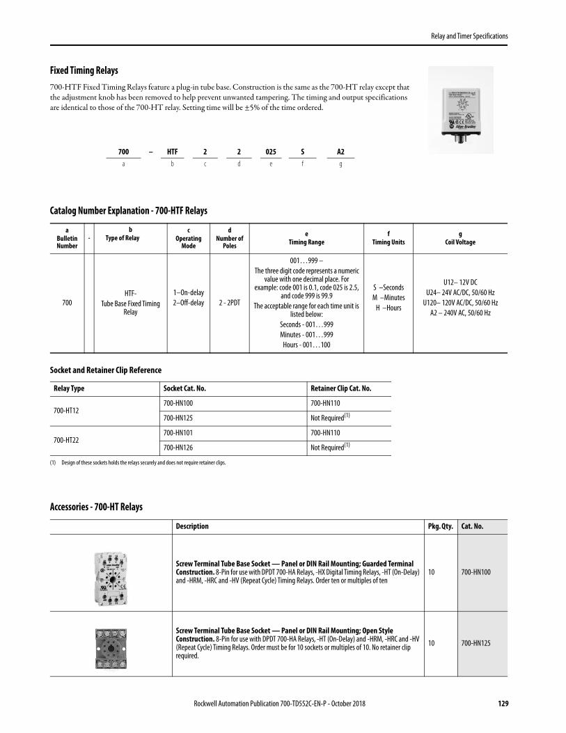
Relay and Timer Specifications
Fixed Timing Relays700-HTF Fixed Timing Relays feature a plug-in tube base. Construction is the same as the 700-HT relay except that the adjustment knob has been removed to help prevent unwanted tampering. The timing and output specifications are identical to those of the 700-HT relay. Setting time will be ±5% of the time ordered.
Catalog Number Explanation - 700-HTF Relays
Socket and Retainer Clip Reference
Accessories - 700-HT Relays
700 – HTF 2 2 025 S A2a b c d e f g
aBulletin Number
-b
Type of Relay c
Operating Mode
dNumber of
Poles
eTiming Range
fTiming Units
gCoil Voltage
700HTF-
Tube Base Fixed Timing Relay
1–On-delay 2–Off-delay 2 - 2PDT
001…999 – The three digit code represents a numeric
value with one decimal place. For example: code 001 is 0.1, code 025 is 2.5,
and code 999 is 99.9The acceptable range for each time unit is
listed below:Seconds - 001…999Minutes - 001…999
Hours - 001…100
S –Seconds M –Minutes
H –Hours
U12– 12V DC U24– 24V AC/DC, 50/60 Hz
U120– 120V AC/DC, 50/60 Hz A2 – 240V AC, 50/60 Hz
Relay Type Socket Cat. No. Retainer Clip Cat. No.
700-HT12 700-HN100 700-HN110
700-HN125 Not Required(1)
(1) Design of these sockets holds the relays securely and does not require retainer clips.
700-HT22 700-HN101 700-HN110
700-HN126 Not Required(1)
Description Pkg. Qty. Cat. No.
Screw Terminal Tube Base Socket — Panel or DIN Rail Mounting; Guarded Terminal Construction. 8-Pin for use with DPDT 700-HA Relays, -HX Digital Timing Relays, -HT (On-Delay) and -HRM, -HRC and -HV (Repeat Cycle) Timing Relays. Order ten or multiples of ten
10 700-HN100
Screw Terminal Tube Base Socket — Panel or DIN Rail Mounting; Open Style Construction. 8-Pin for use with DPDT 700-HA Relays, -HT (On-Delay) and -HRM, -HRC and -HV (Repeat Cycle) Timing Relays. Order must be for 10 sockets or multiples of 10. No retainer clip required.
10 700-HN125
Rockwell Automation Publication 700-TD552C-EN-P - October 2018 129

Relay and Timer Specifications
Screw Terminal Tube Base Sockets — Panel or DIN Rail Mounting; Guarded Terminal Construction. 11-pin for use with 3PDT 700-HA relays. 10 700-HN101
Screw Terminal Tube Base Sockets — Panel or DIN Rail Mounting; Open Style Terminal Construction. 11-pin for use with 3PDT 700-HA relays. No retainer clip required. 10 700-HN126
DIN (#3) symmetrical hat rail35 x 7.5 x 1 m 10 199-DR1
Retainer Clip for Cat. Nos. 700-HN100 and -HN101 Sockets with 700-HT Timing Relays(1)Secures relay in socket. Order must be for 10 clips or multiples of 10. 10 700-HN110
Pre-Printed Identification Tags — contains 10 sheets of pre-printed and blank tags. Each sheet contains 13 sets of the markings CR…9CR, TR…9TR, M…9M, F, R, 1S, and 117 blank tags. Tags are peel-off with sticky backing for easy placement on relays.
10 700-N40
Blank Identification Tags — contains 10 sheets of blank identification tags for customer specialized printing. Each sheet contains 546 blank tags. Tags are peel-off with sticky backing for easy placement on relays.
10 700-N41
(1) Refer to 700-HT Timing Relay, Socket, and Retainer Clip Reference Chart.
Description Pkg. Qty. Cat. No.
130 Rockwell Automation Publication 700-TD552C-EN-P - October 2018

Relay and Timer Specifications
Specifications - 700-HT
Cat. No. 700-HT… Cat. No. 700-HTF…
Electrical Ratings
Pilot Duty Rating (1) NEMA B300
Rated Thermal Current (Ith) 10 A
Rated Insulation Voltage (Ui) 250V IEC, 300V UL/CSA
Contacts
Inductive Make Break HP Make Break HP
120V AC 30 A 3 A 1/2 N.O. 1/3 N.C 30 A 3 A 1/3
240V AC 15 A 1.5 A 1/2 N.O. 1/3 N.C 15 A 1.5 A 1/2
Resistive 28V DC 10 A 10 A — 10 A 10 A —
Permissible Coil Voltage Variation 85…110% of Nominal Voltage at 50 Hz85…110% of Nominal Voltage at 60 Hz
80…110% of Nominal Voltage at DC
Power Consumption ±10%
AC
24V AC 2 VA
120V AC 4 VA
240V AC 4 VA
DC 1.3 W
Design Specification/Test Requirements
Dielectric Withstand Voltage
Pole-to-Pole, same circuit (VRMS) 1000V AC
Pole-to-Pole, different circuits (VRMS) 2000V AC
Contact-to-Coil (VRMS) 2000V AC
Electrical Life Operations 100,000 minimum
Switching Frequency Operations 1800/hr
Coil Voltages See product selection
Mechanical
Degree of Protection Open Type (Guarded Terminal Sockets)
Mechanical Life Operations 10 x 106
Switching Frequency Operations 18,000/hr
Timing Duty Cycle Continuous
Repeat Accuracy (constant voltage and temperature)
±2% (Time Delay: 0.1…2 s)±1% (Time Delay: >2 s)
Repeat Accuracy (variable voltage and temperature) ±10%
Fixed Time Setting Accuracy — ±5% (Time Delay: 0.1…2 s)±1% (Time Delay: >2 s)
Scale Tolerance High End of Range +5% —
Low End of Range -50% —
Reset Time ON Delay 100 ms
OFF Delay 40 ms
Rockwell Automation Publication 700-TD552C-EN-P - October 2018 131

Relay and Timer Specifications
Trigger Signal Cat. Nos. 700-HTContact closure provides signal to timer. A low energy signal is generated by the 700-HT timing relay. For optimum reliability, use contacts designed for low energy switching (10V, 1 mA) (Bul. 800F-X__V, 800T-X__V). No external voltage should be connected to the contact signal.
Timing Diagrams - 700-HT Relays
Environmental
Temperature Operating –28…+65 °C (50 °C max., 240V AC coil)
(–18…+149 °F) (122 °F max., 240V AC coil)
Storage –55…+85 °C(–67…+185 °F)
Altitude 2000 m (6560 ft)
Construction
Insulating Material Molded High Dielectric Material
Enclosure Impact Resistant Dust Cover
Contact Material Silver Cadmium Oxide
Terminal Markings on Socket In accordance with EN50 005
Sockets 8- or 11-Pin Socket(On = 8, Off = 11)
700-HN100, -HN125700-HN101, -HN126
Certifications CSA Certified, File 223833, UL Recognized, File E3125 Guide NLDX 2,UL Listed,whe used with 700-HN100, 700-HN101, 700-HN125, and 700-HN126 Sockets, File No. E3125 Guide NLDX, CE Marked
Standards EN 61812-1, EN 60947-1,-5-1, CSA 22.2 No. 14, UL 508
(1) See NEMA Ratings and Test Values on page 5.
ON Delay OFF Delay
Cat. No. 700-HT… Cat. No. 700-HTF…
132 Rockwell Automation Publication 700-TD552C-EN-P - October 2018

Relay and Timer Specifications
700-HV Timing Relay•Repeat Cycle Timing Relay
•10 A Contact Rating
•DPDT
•Pin Style Terminals
•0.1 s…30 min.
•Repeat Cycle Adjustable Timing
•Two Timing Adjustments T1 ≠ T2
Repeat Cycle Timing Relays with Pin Style Terminations with 2 Adjustments (T1 ≠ T2)
Catalog Number Explanation - 700-HV Relays
Socket and Retainer Clip Reference
Operating Mode Wiring Diagrams
U.S./Canada International
Repeat Cycle
700-HV Repeat Cycle Timing Relay DPDT 2-Pole — 2 Form C Contacts Socket 700-HN125 or700-HN100 700-HN100
700 – HV 3 2 A A A2a b c d e f g
aBulletin Number
-b
Type of Relay c
Operating Mode
dNumber of
Poles
eTiming Range
OFF Time
fTiming Range
ON Time
gCoil Voltage
700 HV – Tube Base Repeat Cycle Timing Relay
3 –Power ON Repeat Cycle,
OFF Start (Repeat Cycle,
OFF/ON Delay)
2 - 2PDT
Code OFF Time — Type HV A – 0.1…10 s
B – 1.0…100 s C – 0.1…10 min
D – 1.0…100 min E –0.1…10 hr
Code ON Time — Type HV A 0.1…10 s
B 1.0…100 s C 0.1…10 min
D 1.0…100 min E 0.1…10 hr
U12 –12V DC U24 –24V AC/DC, 50/60 Hz
U120 – 120V AC/DC, 50/60 Hz A2 –240V AC, 50/60 Hz
Relay Type Socket Cat. No. Retainer Clip Cat. No.
700-HV 700-HN100 700-HN110
700-HN125 Not Required(1)
(1) Design of these sockets holds the relays securely and does not require retainer clips.
Rockwell Automation Publication 700-TD552C-EN-P - October 2018 133

Relay and Timer Specifications
Accessories - 700-HV Relays
Photo Description Pkg. Qty.
Cat. No.
Screw Terminal Tube Base Socket — Panel or DIN Rail Mounting; Guarded Terminal Construction. 8-Pin for use with DPDT 700-HA Relays, -HX Digital Timing Relays, -HT (On-Delay) and -HRM, -NRC and -HV (Repeat Cycle) Timing Relays. Order ten or multiples of ten
10 700-HN100
DIN (#3) symmetrical hat rail35 x 7.5 x 1 m 10 199-DR1
Screw Terminal Tube Base Socket — Panel or DIN Rail Mounting; Open Style Construction. 8-Pin for use with DPDT 700-HA Relays, -HT (On-Delay) and -HRM, -HRC and -HV (Repeat Cycle) Timing Relays. Order must be for 10 sockets or multiples of 10. No retainer clip required.
10 700-HN125
Pre-Printed Identification Tags — contains 10 sheets of pre-printed and blank tags. Each sheet contains 13 sets of the markings CR…9CR, TR…9TR, M…9M, F, R, 1S, and 117 blank tags. Tags are peel-off with sticky backing for easy placement on relays.
10 700-N40
Blank Identification Tags — contains 10 sheets of blank identification tags for customer specialized printing. Each sheet contains 546 blank tags. Tags are peel-off with sticky backing for easy placement on relays.
10 700-N41
134 Rockwell Automation Publication 700-TD552C-EN-P - October 2018

Relay and Timer Specifications
Specifications - 700-HV Relays
Cat. No. 700-HV…
Electrical Ratings
Pilot Duty Rating‡ NEMA B300
Rated Thermal Current (Ith) 10 A
Rated Insulation Voltage (Ui) 250V IEC, 300V UL/CSA
Contacts
Inductive Make Break
Hp
120V AC 30 A 3 A 1/2 N.O. 1/3 N.C.
240V AC 15 A 1.5 A 1/2 N.O. 1/3 N.C.
Resistive 28V DC 10 A 10 A —
Permissible Coil Voltage Variation 85…110 of Nominal Voltage at 50 Hz85…110 of Nominal Voltage at 60 Hz
80…110 of Nominal Voltage at DC
Power Consumption±10%
AC
24V AC 2 VA
120V AC 4 VA
240V AC 4 VA
DC 1.3 W
Design Specification/Test Requirements
Dielectric Withstand Voltage
Pole-to-Pole, same circuit (VRMS) 1000V AC
Pole-to-Pole, different circuits (VRMS) 2000V AC
Contact-to-Coil (VRMS) 2000V AC
Electrical Life Operations 100,000 minimum
Switching Frequency Operations 1800/hr
Coil Voltages See product selection
Mechanical
Degree of Protection Open Type (Guarded Terminal Sockets)
Mechanical Life Operations 10 x 106
Switching Frequency Operations 18,000/hr
Timing Duty Cycle Continuous
Repeat Accuracy (constant voltage and temperature)
±2% (Time Delay: 0.1…2 s)±1% (Time Delay: >2 s)
Repeat Accuracy (variable voltage and temperature) ±10%
Scale Tolerance High End of Range +5%
Low End of Range -50%
Reset Time 100 ms
Environmental
Temperature Operating –28…+65 °C (50 °C max., 240V AC coil)
(–18…+149 °F) (122 °F max., 240V AC coil)
Storage –55…+85 °C(–67…+185 °F)
Altitude 2000 m (6560 ft.)
Construction
Insulating Material Molded High Dielectric Material
Enclosure Impact Resistant Dust Cover
Rockwell Automation Publication 700-TD552C-EN-P - October 2018 135

Relay and Timer Specifications
Timing Diagram- 700-HV Relays
Dimensions - 700-HV RelaysApproximate Dimensions are shown in millimeters (inches). Approximate Dimensions are not intended to be used for manufacturing purposes.
Contact Material Silver Cadmium Oxide
Terminal Markings on Socket In accordance with EN50 005
Sockets 8-Pin SocketCat. No. 700-HN100, -HN125
Certifications CSA Certified, File 223833; UL Recognized, File E3125; Guide NLDX 2; cULus Listed when used with 700-HN100 and 700-HN125 sockets; CE Marked
Standards EN 61812; EN 60947-1, -5-1; CSA 22.2 No. 14; UL 508
700-HV Timing Relay
Cat. No. 199-DR1 DIN Mounting Rail Series BCat. No. 199-DR4 DIN Mounting Rail Series B Has No Mounting Holes
Cat. No. A B C D Approx.Shipping Wt.
199-DR1 35(1-3/8)
27(1-1/16)
7.5(19/64)
1.02(1/64)
1.85 kg(4.07 lbs.) (10/pkg)
199-DR4 35(1-3/8)
27(1-1/16)
15(19/32)
2.3(3/32)
3.68 kg(8 lbs.) (5/pkg)
136 Rockwell Automation Publication 700-TD552C-EN-P - October 2018

Relay and Timer Specifications
Cat. No. 700-HN100Panel Mounting
Double Wire—2 x 2.5mm2 (#2-14 AWG…#2-20 AWG)(Either Solid or Stranded)
Strip Length: 9 mm (3/8 in) - Torque: 0.8 N•m (7 ib•in)
Cat. No. 700-HN125Wire Size: 2 x 2.5 mm2Single Wire—Up to #12 AWGDouble Wire—2 x 2.5mm2 (#2-14 AWG…#2-20 AWG)(Either Solid or Stranded)Strip Length: 9 mm (3/8 in) - Torque: 0.8 N•m (7 ib•in)
Rockwell Automation Publication 700-TD552C-EN-P - October 2018 137

Relay and Timer Specifications
700-HX Multi-Function Digital Timing Relay• Digital timing relay with LCD display• Socket- or panel-mounted (NEMA 4X/IP66)• 5A, B300, SPDT contact ratings• 10 Functions or modes
• Environmentally friendly — flash memory, no battery
Accessories - 700-HX Relays
Photo Operating Mode Timing Range Socket Type Contact Output No. of Pins
Input Voltage Cat. No.
A mode: Signal ON-Delay 1A-1 mode: Signal ON-Delay 2A-2 mode: Power ON-Delay 1A-3 mode: Power On-Delay 2B mode: Repeat Cycle 1B-1 mode: Repeat Cycle 2D mode: Signal OFF-delayE mode: One ShotF mode: CumulativeZ mode: On/Off duty adjustable repeat cycleS mode:stop watchtoff: Flicker OFF start 1ton: Flicker ON start 1toff-1: Flicker OFF start 2ton-1: Flicker ON start 2
0.000…9.999 s0.000…99.99 s0.000…999.9 s0.000…9999 s0.000…99 min 59 s0.000…999.9 min0.000…9999 min0.000…99 hr 59 min0.000…999.9 hr0.000…9999 hr
700-HN100700-HN125 SPDT 8
100…240V AC 700-HX86SA17
24V AC12…24V DC 700-HX86SU24
Socket and Retainer Clip Reference
Timer Type Socket Cat. No. Retainer Clip Cat. No.
700-HX
700-HN100 700-HN131
700-HN108 Not Required (1)
(1) Design of socket holds the relay securely and does not require retainer clips.
700-HN125 Not Required
Photo Description Pkg. Quantity Cat. No.
Screw Terminal Tube Base Socket — Panel or DIN Rail Mounting; Guarded Terminal Construction. 8-Pin for use with 700-HX Timing Relays. Order ten or multiples of ten 10 700-HN100
Screw Terminal Tube Base Socket — Panel or DIN Rail Mounting; Open Style Construction. 8-Pin for use with 700-HX Timing Relays. Order must be for 10 sockets or multiples of 10. No retainer clip required.
10 700-HN125
DIN (#3) symmetrical hat rail35 x 7.5 x 1 m 10 199-DR1
138 Rockwell Automation Publication 700-TD552C-EN-P - October 2018

Relay and Timer Specifications
Specialty Socket8-pin backwired socket with solder terminals. For use with 700-HX Timing Relays. 10 700-HN108
Retainer Clip for Cat. Nos. 700-HN100 Sockets with all 700-HX Timing Relays Secures timer in socket.
Note: Not required for installation
10 700-HN131
Frame AdapterFor flush or door mounting of all 700-HR and -HX timers. 1 700-HN130
Protective CoverHelps prevent tampering of timing and mode settings. Provides a degree of protection against water and dirt from entering the front of the relay. For use with all 700-HR and -HX timing relays.
1 700-HN132
Photo Description Pkg. Quantity Cat. No.
Rockwell Automation Publication 700-TD552C-EN-P - October 2018 139

Relay and Timer Specifications
General Timer Functions- 700-HX Relays
Display Section Operation Key
1. Key Protect Indicator (orange) 8. Mode Key(Changes modes and setting items)2. Control Output Indicator (orange)
3. Reset Indicator (orange) 9. Reset Key(Resets present value and output)
4. Present Value Display (Main display)(Character height: 12 mm, red *)* Characters on models with screw terminalscan be switched between red, green, and orange.
10. Up Keys 1 to 4
11. Down Keys 1 to 4
5. Time Unit Indicators(Color is same as present value display.)(If the time range is 0 min, 0 h, 0.0 h, or 0 h 0 min, these indicators flash to indicate timing operation.)
Switches
12. Key-protect Switch
6. Set Value Display (Sub-display)(Character height: 6 mm, green)
7. Set Value 1, 2 Indicator (green)
Character Size forPresent Value Display
Character Sizefor Set Value Display
1
3
2
8
9
5
4
6
7
10
11
12
Front View
OFF(Disabled)
ON(Enabled)
(Default setting)
12 mm 6 mm
140 Rockwell Automation Publication 700-TD552C-EN-P - October 2018
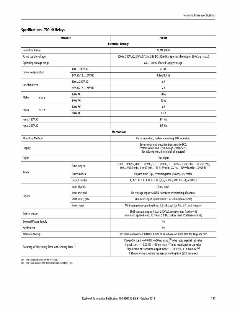
Relay and Timer Specifications
Specifications - 700-HX Relays
Attribute 700-HX
Electrical Ratings
Pilot Duty Rating NEMA B300
Rated supply voltage 100 to 240V AC, 24V AC/12 to 24V DC (50/60Hz) (permissible ripple: 20%(p-p) max.)
Operating voltage range 85…110% of rated supply voltage
Power consumption100…240V AC 4.3VA
24V AC/12…24V DC 3.4VA/1.7 W
Inrush Current100…240V AC 3 A
24V AC/12…24V DC 5 A
Make 120V AC 30 A
240V AC 15 A
Break 120V AC 3 A
240V AC 1.5 A
Hp at 120V AC 1/4 Hp
Hp at 240V AC 1/3 Hp
Mechanical
Mounting Method Flush mounting, surface mounting, DIN mounting
DisplaySeven-segment, negative transmissive LCD;Present value (red, 12 mm high characters);
Set value (green, 6 mm high characters)
Digits Four digits
Timer
Time ranges 0.000…9.999 s, 0.00…99.99 s, 0.0…999.9 s, 0…9999 s, 0 min 00 s…99 min 59 s,0.0…999.9 min, 0 hr 00 min…99 hr 59 min, 0.0 hr…999.9 hr, 0 hr…9999 hr
Timer modes Elapsed time (Up), remaining time (Down), selectable
Output modes A, A-1, A-2, A-3, B, B-1, D, E, F, Z, S, tOFF, tON, tOFF-1, or tON-1
Inputs
Input signals Start, reset
Input method No-voltage input via:NPN transistor or switching of contact
Start, reset, gate Minimum input signal width: 1 or 20 ms (selectable)
Power reset Minimum power-opening time: 0.5 s (Except for A-3, B-1, and F mode)
Control output SPDT contact output: 5 A at 250V AC, resistive load (cosine=1)Minimum applied load: 10 mA at 5 V DC (failure level: P, reference value)
External Power Supply No
Key Protect Yes
Memory Backup EEP-ROM (overwritten 100 000 times min), which can store data for 10 years min.
Accuracy of Operating Time and Setting Error (1)
(1) The values are based on the set value.
Power-ON start: +-0.01% +-50 ms max. (1)to be rated against set valueSignal start: +- 0.005% +-30 ms max. (1)to be rated against set value
Signal start at transistor output model: +- 0.005% +-3 ms max. (2)
If the set value is within the sensor waiting time (250 ms max.)
(2) The value is applied for a minimum pulse width of 1 ms.
Rockwell Automation Publication 700-TD552C-EN-P - October 2018 141

Relay and Timer Specifications
Attribute 700-HX
Environmental
Installation environment Setup category II, pollution degree 2 (as per IEC61010-1)
Ambient temperature -10 to +55 °C (Avoid freezing or condensation)
Ambient humidity 25 % to 85 %
Storage temperature -25 to +65 °C (Avoid freezing or condensation)
Altitude MAX. 2,000 m
Characteristics (1)
(1) More information in the 700-HX User Manual, publication 700-UM002.
Insulation Resistance 100 mΩ min. (at 500V DC)
Dielectric Strength2000V AC, 50/60Hz for 1 min between current-carrying terminals and non-current- carrying
metal parts (1000V AC for 24V AC/12 to 24V DC type), 1000 VAC, 50/60 Hz for 1 min between non-continuous contacts
Noise Immunity±1.5 kV (between power terminals) for 100 to 240 VAC, ±480V for 24VAC/12 to 24VDC, and
±600V (between input terminals), square-wave noise by noise simulator (pulse width: 100 ns/1 μs, 1-ns rise)
Static Immunity ±8 kV (malfunction), ±15 kV (destruction)
Vibration Resistance Malfunction 10…55 Hz with 0.35 mm single amplitude each in three directions for 10 min
Shock Resistance Malfunction 98 m/s2 (approx. 10 G) each in three directions
Life ExpectancyMechanical 10 million operations min. (under no load at 18 000 operation/hr)
Electrical 100 000 operations min. (5 A at 250V AC, resistive load at 1800 operation/hr)
EMC
(EMI) EN61812-1
Emission Enclosure: EN55011 Group1 class A
Emission AC mains: EN55011 Group1 class A
(EMS) EN61812-1
Immunity ESD: EN61000-4-2: 4 kV contact discharge (level2) 8 kV air discharge (level3)
Immunity RF-interference: EN61000-4-3: 10 V/m
Enclosure Ratings Panel surface:IP66 and NEMA Type 4 (indoors) (2)
(2) An attached waterproof packing is necessary to ensure IP66 waterproofing between the 700-HX and installation pan.
Weight Approx. 100 g
Certifications CE Certified; cURus (File No. E14843, Guide NRNTZ/NRNT8), C-Tick Marked
Standards EN61010-1, EN 61326, VDE0106/P 100, CSA C22.2 No. 14, UL 508
142 Rockwell Automation Publication 700-TD552C-EN-P - October 2018

Relay and Timer Specifications
Timing Charts- 700-HX Relays
Output Mode A Mode: Signal ON-Delay (Timer resets when power comes ON.)
Power
Start signal
Gate*
Reset
Control output
Set value
Timingdiagram
UP
DOWN
0
0
Set value
t t t
Timing starts when the start signal goes ON.While the start signal is ON, the timer starts whenpower comes ON or when the reset input goes OFF.The control output is controlled using a sustained or one-shot time period.
*Output is instantaneous when setting is 0.** Start signal input is enabled during timing.
Basic Operation
Power
Timing
Output
Start SignalInput
**
Output Mode A-1: Signal ON-Delay 2 (Timer resets when power comes ON.)
Power
Start signal
Gate*
Reset
Control output
Set value
Timingdiagram
UP
DOWN
0
0
Set value
Timing starts when the reset input goes ON and isreset when the start signal goes OFF.While the start signal is ON, the timer starts when the power comes ON or when the reset input goes OFF.The control output is controlled using a sustained or one-shot time period.Basic Operation
*Output is instantaneous when setting is 0.
Timing
Power
Output
Start Signal Input
Output Mode A-2: Power ON Delay 1 (Timer resets when power comes ON)
Power
Start signal
Gate *
Reset
Control output
Set value
Timingdiagram
UP
DOWN
0
0
Set value
Timing starts when the reset input goes OFF.The start signal disables the timing function (i.e., same function as the gate input).The control output is controlled using a sustained or one-shot time period.Basic Operation
*Output is instantaneous when setting is 0.
TimingPower
Output
Output Mode A-3 Power ON Delay 2 (Timer does not reset when power comes ON)
Power
Start signal
Gate *
Reset
Control output
Set value
Timingdiagram
UP
DOWN
0
0
Set value
Timing starts when the reset input goes OFF.The start signal disables the timing function (i.e., same function as the gate input).The control output is controlled using a sustained or one-shot time period.
Basic Operation
*Output is instantaneous when setting is 0.
Power
OutputTiming
Sustained
Gate not included on any mode of this relay.
One-Shot
Sustained Output
One-shot outputs can be set to 0.1s, 0.5 s, 1 s, 5 s, 10 s, or 20 s.
Rockwell Automation Publication 700-TD552C-EN-P - October 2018 143
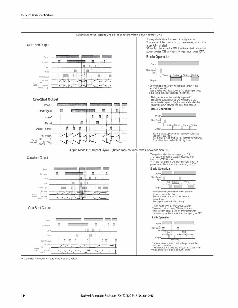
Relay and Timer Specifications
Output Mode B: Repeat Cycle (Timer resets when power comes ON.)
Sustained Output
Power
Start signal
Gate*
Reset
Control output
Set value
Timingdiagram
UP
DOWN
0
0
Set value
Timing starts when the start signal goes ON.The status of the control output is reversed when time is up (OFF at start).While the start signal is ON, the timer starts when thepower comes ON or when the reset input goes OFF.
Basic Operation
TimingTimingTiming Timing
Power
Start SignalInput
Output
**
* Normal output operation will not be possible if the set time is too short. Set the value to at least 100 ms (contact output type).** Start signal input is disabled diring timing.
One-Shot OutputPower
Start Signal
Gate*
Reset
Control Output
Set ValueTiming
DiagramUP
DOWNSet Value
0
0
Timing starts when the start signal goes ON.The control output is turned ON when time is up.While the start signal is ON, the timer starts when the power cones ON or when the reset input goes OFF.
Basic Operation
Timing Timing TimingTiming
Power
Start SignalInput
**
Output
* Normal output operation will not be possible if the set time is too short. Set the value to at least 100 ms (contact output type).** Start signal input is disabled during timing.
Output Mode B-1: Repeat Cycle 2 (Timer does not reset when power comes ON)
Sustained Output
Power
Start signal
Gate*
Reset
Control output
Set value
Timingdiagram
UP
DOWN
0
0
Set value
Timing Sustained Timing
Power
Start SignalInput
**
Output
Basic Operation
* Normal output operation will not be possible if the set time is too short Set the value to at least 100 ms (contact output type).** Start signal input is disabled during.
Timing starts when the start signal goes ON.The status of the control output is reversed whentime is up (OFF at the start).While the start signal is ON, the timer starts when thepower comes ON or when the rest input goes OFF.
One-Shot Output
Power
Start signal
Gate*
Reset
Control output
Set value
Timingdiagram
UP
DOWN
0
0
Set value
Timing starts when the start signal goes ON.The control output comes ON when time is up.While the start signal is ON, the timer starts when the power comes ON or when the reset input goes OFF.
Basic Operation
Timing Timing
Sustaining
Power
Output
**Start SignalInput
* Normal outout operation will not be possible if the set time is too short. Set the value to at least 100 ms (contact output type).** Start signal input is disabled during timing.
Gate not included on any mode of this relay.
144 Rockwell Automation Publication 700-TD552C-EN-P - October 2018

Relay and Timer Specifications
Z ModeOutput quantity can be adjusted by changing the cycle time set in the adjustment level to 1 and by changing the ON duty (%) set value. The set value shows the ON duty (%) and can be set to a value between 0 and 100 (%). When the cycle time is 0, the output will always be OFF. When the cycle time is not 0 and when ON duty has been set to 0 (%), the output will always be OFF. When ON duty has been set to 100 (%), the output will always be ON.
Output Mode D: Signal OFF-Delay (Timer resets when power comes ON.)
Power
Start signal
Gate*
Reset
Control output
Set value
Timingdiagram
UP
DOWN
0
0
Set value
The control output is ON when the start signal is ON (except when the power is OFF or the reset is ON).The timer is reset when the time is up.
Basic Operation
Power
Start SignalInput
Output
Timing
**
* Output functions only during start signal input when setting is 0.** Start signal input is enabled during timing.
Output Mode E: Interval (Timer resets when power comes ON.)
Power
Start signal
Gate*
Reset
Control output
Set value
Timingdiagram
UP
DOWN
0
0
Set value
Timing starts when the start signal comes ON.The control output is reset when time is up.While the start signal is ON, the timer starts whenpower comes ON or when the reset input goes OFF.
Basic Operation
Power
Start SignalInput
Output
Timing
**
* Output is disabled when the setting is 0.** Start signal input is enabled during timing.
Output Mode F: Cumulative (Timer does not reset when power comes ON)
Start signal enables timing (timing is stopped when thestart signal is OFF or when the power is OFF).A sustained control output is used.
Basic Operation
*Output is instantaneous when setting is 0.
Power
Start SignalInput
OutputTiming Timing
Sustained
Gate not included on any mode of this relay.
Rockwell Automation Publication 700-TD552C-EN-P - October 2018 145

Relay and Timer Specifications
Z mode: ON/OFF-duty Adjustable Repeat Cycle
Power
Start signal
* Gate
Reset
Control Output
Cycle timeON duty setting(%) ON time
UP
Cycle timeON duty setting(%) ON time
Timing diagram
DOWN
0
0
Timing starts when the start signal goes ON.The status of the control output is reversedwhen time is up (ON at start).While the start signal is ON, the timer starts when power comes ON or when the reset input goes OFF.
Basic Operation
Power
**Start signal input
Output
* Normal output operation will not be possible if the set time is too short.Set the value to at least 100 ms (contact output type).
** Start signal input is enabled during timing.
Timing ON duty (%)
Timing (cycle time)
Timing (cycle time)
Timing ON duty (%)
Output Mode S: Stop Watch (Timer resets when power comes ON)
9999
Set time
0
Set time
0
UP
DOWN
Power
Start signal
Gate/Reset
Tim
ing
diag
ram
Output
The signal starts and stops timing. The display is held and timing is continued if the reset or gate input is received during timing operation. The timer resets if the reset or gate input is received when the timing operation is stopped.
Note: Output is instantaneous when setting is 0.
Power
Start signal input
Gate/Reset
Display(for elapsed
time) * flashes
*
Timing
RST
Basic Operation
Output Mode T OFF: Twin Timer OFF start
Power
Start signal
* Gate
Reset
Control Output
OFF Time
ON TimeUP
Timing diagram
OFF Time
ON TimeDOWN
0
0
Sustained Output Timing starts when the start signal goes ON.The status of the control output is reversed when time is up (OFF at start).While the start signal is ON, the timer starts whenpower comes ON or when the reset input goes OFF.
Basic Operation
* Normal output operation will not be possible if the ON/OFF set time is too short. Set the value to at least 100 ms (contact output type).** Start signal input is disabled during timing.
Power
Start SignalInput
Output
TimingOFF
**
Timing ON
TimingOFF
Timing ON
Gate not included on any mode of this Relay.
146 Rockwell Automation Publication 700-TD552C-EN-P - October 2018

Relay and Timer Specifications
Output Mode T ON: Twin Timer ON start
Power
Start signal
* Gate
Reset
Control Output
OFF Time
ON TimeUP
Timing diagram
OFF Time
ON TimeDOWN
0
0
Sustained Output Timing starts when the start signal goes ON.The status of the control output is reversed when time is up (ON at start).While the start signal is ON, the timer starts whenpower comes ON or when the reset input goes OFF.
Basic Operation
* Normal output operation will not be possible if the ON/OFF set time is too short. Set the value to at least 100 ms (contact output type).** Start signal input is disabled during timing.
Power
Start SignalInput
Output
TimingON
**
Timing OFF
TimingON
Timing OFF
Output Mode TOFF-1: Flicker OFF start 2 (Timer does not reset when power comes ON)
0
0
ON time
OFF time
OFF time
ON time
UP
DOWN
Power
Start signal
Gate
Reset
Control output
Tim
ing
diag
ram
* Start signal input is disabled during timing.
Timing starts when the start signal goes ON. The status of the control output is reversed when time is up (OFF at start). While the start signal is ON, the timer starts when the power comes ON or when the reset input goes OFF.
Note: Normal output operation will not be possible if the set time is too short.Set the value to at least 100 ms (contact output type).
Power
Output
*Start signal input Timing
OFFTiming
ONTiming
OFF
(a + b = ON time)
a b
Basic Operation
Output Mode TON-1: Flicker ON start 2 (Timer does not reset when power comes ON)
* Start signal input is disabled during timing.
Timing starts when the start signal goes ON. The status of the control output is reversed when time is up (ON at start).While the start signal is ON, the timer starts when the power comes ON or when the reset input goes OFF.
Note: Normal output operation will not be possible if the set time is too short.
TimingON
TimingOFF
TimingON
(a + b = OFF time)
a b
Power
Output
*Start signal input
Basic Operation
Gate not included on any mode of this Relay.
Rockwell Automation Publication 700-TD552C-EN-P - October 2018 147

Relay and Timer Specifications
Dimensions- 700-HX RelaysApproximate dimensions are shown in millimeters (inches). Dimensions are not intended for manufacturing purposes.
63.714.3
7.5
44.8×44.8
48×48
60 min.
60 min.
45+0.6−0
45+0.6−0
15 min.
Cat. No. 700-HX…
Panel Cutout
50(1-63/64)
1000(39-3/8)
6.2(15/64)
12.5(1/2)5.2
(13/64)
1.0(0.04)
7.5(0.3)
27.0(1.06)
35.0(1.38)
Cat. No. 199-DR1 DIN Mounting Rail Series B
Cat. No. 199-DR4 DIN Mounting Rail Series B Has No Mounting Holes
Terminal Arrangement
Internal circuit
4
3
2
1 8
7
6
5
0V
Signal
Reset
(–) (+)
Cat. No. 700-HX…
148 Rockwell Automation Publication 700-TD552C-EN-P - October 2018

Relay and Timer Specifications
NEMA Industrial Relays
Product Overview
Bulletin No. 700-P 700S-P 700-N
Type Heavy-duty control relay Heavy-duty control relay Industrial Relay
Features
• Convertible contacts• Up to 600V AC & DC• Very long life• Timer & latch options• Mechanically linked
• Convertible contacts• Up to 600V AC & DC• Very long life• Timer & latch options• Mechanically linked
• Contact cartridges convertible from N.O. to N.C. and vice versa
• NEMA A300 AC• 24…250V AC coils• Pneumatic timing unit• Solid-state timing unit• Overlap contacts• Logic reed contacts
Contact Form 2…12 poles, double break 2…12 poles, double break 2- or 4-poles
Contact Type Bifurcated double break Bifurcated double break —
Contact Material Bifurcated silver nickel Bifurcated silver nickel Silver
Electrical
Max. Current AC Resistive 10 A 10 A 10 A
Min. load 10V, 50 mA1 mA, 5V with 700-CPR
10V, 50 mA1 mA, 5V with 700-CPR —
Coil Voltage 24…600V AC6…600V DC
24…600V AC6…600V DC —
Coil Voltage Pickup 85…110% AC coils,80…110% DC coils
85…110% AC coils,80…110% DC coils —
Dielectric Withstand 2640V 2640V —
Reference
Electric Service Life (cycles) 10 million at 10 A 120V AC 10 million at 10 A 120V AC —
Certifications cULus, CE cULus, CE UL, CSA, CE
Sockets DIN Rail, relay rail, or panel mount DIN Rail, relay rail, or panel mount —
Product Selection 151 151 172
Rockwell Automation Publication 700-TD552C-EN-P - October 2018 149

Relay and Timer Specifications
Product Overview
Bulletin No. 700-R 700-RTC
Type Sealed Switch Solid-state Timing Relay
Features
• Hazardous location ratings• Long life in dirty environment• Timer and latch options• Switch 600V AC, 300V DC
• Timed and instantaneous contacts. • Sealed contacts for harsh environments and
hazardous locations.
Contact Form 2...8 Poles —
Contact Type Sealed Switch —
Contact Material Sealed Switch —
Electrical —
Max. Current AC Resistive 5 A —
Min. load 1 mA, 5V —
Coil Voltage 24...240V AC24...250V DC
—
Coil Voltage Pickup 85...110% AC Coils80...110% DC Coils
—
Dielectric Withstand 2640V —
Reference
Electric Service Life (cycles) 1.5 million at 5 A 120V AC —
Certifications UL, CSA, CE —
Sockets Panel or rail mount —
Timing Relay Information
Control Outputs:Time Limit Instantaneous
— Four output contacts
Timing Operation Modes: — On-DelayOff-Delay
Time Range — 0.05 s…64 min
Supply Voltage —
24V AC110…120V AC220…240V AC24V DC120V DC240V DC
Product Selection 176 181
150 Rockwell Automation Publication 700-TD552C-EN-P - October 2018

Relay and Timer Specifications
700-P Industrial Relays
700-P — Direct Drive™ Convertible Contact Cartridge Relays• NEMA and IEC ratings• 600V maximum AC/DC• Accessories for field installation: contact cartridges, adder decks, time delay, latching, surge suppressors, mounting strip• Contact Ratings: (10 A) 700-CP1, (20 A) 700-CPM, (35 A) 700-CPH, (Low Power) 700-CPR• For machine tool and other heavy-duty applications• Can accommodate ring tongue terminals• Integral DIN Rail mount on AC relays• Finger-safe protection standard• Factory supplied standard at 120V AC and 24V DC - user configurable for field assembly• Blank relays are available in all coil voltages for field custom configuration• Contact cartridge is convertible from N.O. to N.C. by simply turning cartridge over.
The 700/700DC-P family of Direct Drive Industrial Relays offers switching solutions ranging from 200 mA in Low Energy Circuits to 35 A in Heavy Duty Circuits. All of the contacts can easily be changed from the standard N.O. to N.C. configuration. The relays can be accessorized to meet the application needs with the use of time delayed contacts, mechanical latches and NEMA enclosures. All devices are available in the most popular AC and DC control voltages. Combining different cartridges into one relay can yield a custom-tailored application solution. Relays are available without contact cartridges in all of the available AC and DC coil voltages for maximum flexibility.
700/700DC-P relays use standard (10 A) contact cartridges with a double-break and bifurcated design. Bifurcation provides excellent contact reliability and low-contact bounce, while the double-break contact design reduces the possibility of contacts welding and enhances the relay’s ability to break DC circuits. These relays can be configured with a maximum of 12 contacts (only 8 may be N.C.).
A Modular Approach to Control Circuit Solutions The 700-P AC control relay is factory assembled with a standard 10 A contact cartridges with all contacts as N.O.in either 2, 4, 8, or 12 pole configurations with a 120 volt operating coil. Four pole relays are also available at 240 and 480 VAC and can have up to eight contacts added by using adder decks. The 700DC-P control relay is factory assembled with a standard 10 A contact cartridges with all contacts as N.O. in either 4 or 8 poles with a 24 volt operating coil. The 4 pole is also available with a 120 VDC operating coil.
For control relays that require different contact ratings or control voltages we offer a modular design that are easily field configurable. A base blank relay (either AC or DC control), a variety of contact kits, adder decks, and operating coils can be used to make an infinite number of custom control relay solutions.
• Master Control 700-PMCKIT master control cartridges provide (20 A) switching capability with large single-contact pads on each side of the spanner for twice the current rating to control heavy loads and provide for master control of a system. The cartridge also has the same double-break design as the standard 700-P relay contact cartridge. Relays can be configured with up to a maximum of 12 contacts (only 8 may be N.C.). Time delay and latching attachments are compatible with master cartridges.
• Heavy Duty Control 700-PHDKIT contact cartridges provide (35 A) switching capability through tandem contact cartridges. A jumper allows two (20 A) master contact cartridges to be connected in parallel. A maximum of six poles can be configured in a relay, only four of which can be normally closed. Time delay and latch attachments are available.
• Low Energy Control Logic Reed 700-PLRKIT contact cartridges provide switching to 200 mA @ 30 VDC. These contacts are matched with standard control (10 A) contact cartridges for low energy switching applications.
• Overlapping Contact 700-POLKIT contact cartridges provide (10 A) switching capabilities with the same rating as the standard contact. These cartridge used in pairs operate with the N.O. contact closing before the N.C. contact opens on pick-up and vice versa on the drop-out.
Rockwell Automation Publication 700-TD552C-EN-P - October 2018 151

Relay and Timer Specifications
AC-Operated Relays - In-stock Contact Configurations
DC-Operated Relays - In-stock Contact Configurations
Photo Contacts Contact Arrangement
and Markings
Open Type, DIN Rail, or Relay Rail Mount (700-MP)
N.O.(1)
(1) Factory assembled N.O. contacts can be easily to N.C. in the field.
120V AC 240V AC 480V AC
0 700-P000A1 — —
2 700-P200A1 — —
4 700-P400A1 700-P400A2 700-P400A4
8 700-P800A1 — —
12 700-P1200A1 — —
Photo
Contacts Contact Arrangement
and Markings
Open Type Relay Rail Mount (2)
(2) For DIN Rail mounting, order Cat. No. 700-DRA.
N.O. (1)
(1) Factory assembled N.O. contacts can be easily to N.C. in the field.
24V DC 120V DC
Cat. No. Cat. No.
0 700DC-P000Z24 —
4 700DC-P400Z24 700DC-P400Z1
8 700DC-P800Z24 —
4-PoleRelay
4-PoleRelay
4-PoleRelay
8-PoleRelay
12-PoleRelay
4-PoleRelay
4-PoleRelay
8-PoleRelay
152 Rockwell Automation Publication 700-TD552C-EN-P - October 2018
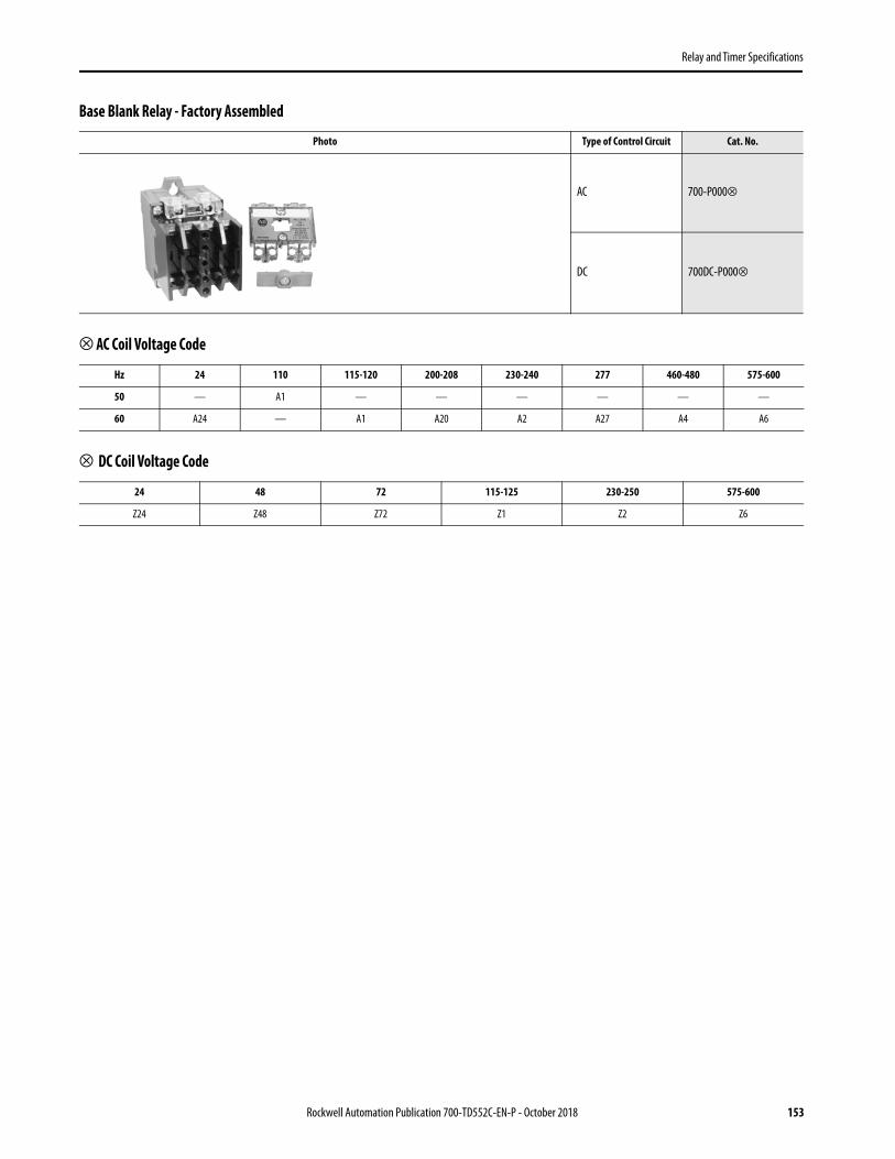
Relay and Timer Specifications
Base Blank Relay - Factory Assembled
⊗ AC Coil Voltage Code
⊗ DC Coil Voltage Code
Photo Type of Control Circuit Cat. No.
AC 700-P000⊗
DC 700DC-P000⊗
Hz 24 110 115-120 200-208 230-240 277 460-480 575-600
50 — A1 — — — — — —
60 A24 — A1 A20 A2 A27 A4 A6
24 48 72 115-125 230-250 575-600
Z24 Z48 Z72 Z1 Z2 Z6
Rockwell Automation Publication 700-TD552C-EN-P - October 2018 153

Relay and Timer Specifications
Master (20 A) and Heavy Duty (35 A) Contact Cartridge OptionsFollow this process to order a relay that utilizes: 20 A master contact cartridges or 35 A heavy duty contact cartridges.
Base Blank Relay + Cartridge Kit + Adder Decks + Coil
Base Blank Relay Type of Control Circuit Cat. No.
AC 700-P000A1
DC 700DC-P000Z24
+ Contact Cartridge Kits
Photo Description Contents Continuous Carrying Current [A]
Cat. No.
Master Contact CartridgeAC Rating Twice NEMA A600DC Rating NEMA N150 P600
4 Master Cartridges (Cat. No. 700-CPM) 20 700-PMCKIT
Heavy Duty Contact Kit 4 Master Cartridges and two sets of jumper terminals, rating label (makes two 35 A poles) 35 700-PHDKIT
+ Adder Decks
Do you have more than four circuits or more than two 35 A circuits in the relay?
Device Description Adder Decks Required Cat. No.
Additional Cartridge Kits Required
8 Pole Device 700-PB00 1 additional kit
12 Pole Device 700-PB00700-PC00(Qty 1 of each)
2 additional kits
EXAMPLE Heavy Duty circuit (35 A) application that requires 4 circuits and 240 AC control circuit:• Base Unit: Cat. No. 700-P000A1• Cartridge Kits: Cat. No. 700-PHDKIT - Qty 2 (Each kit makes two circuits)• Adder Deck: Cat. No. 700-PB00• Coil: Cat. No. PA254
IMPORTANT If required, see Operating Coils for coil selection.
154 Rockwell Automation Publication 700-TD552C-EN-P - October 2018

Relay and Timer Specifications
Logic Reed and Overlapping Contact Cartridge Option
Follow this process to order a relay that utilizes: low energy contact cartridges or overlapping late make or late break cartridges.
Base Blank Relay + Cartridge Kit + Adder Decks + Coil
Base Blank Relay Type of Control Circuit Cat. No.
AC 700-P000A1
DC 700DC-P000Z24
+ Contact Cartridge Kits
Photo Description Contents Continuous Carrying Current [A]
Cat. No.
Logic Reed Cartridge forLow Energy Circuits150V AC 500 mA 25 VA Max. 30V DC 200 mA 6W Max.
2 Logic Reed Cartridges (Cat. No. 700-CPR) 500 mA 150V AC200 mA 30V DC
700-PLRKIT
2 Standard Cartridges (Cat. No. 700-CP1) 10
Overlap Contact CartridgesOverlappingUsed in pairs. N.O. contact closes before N.C. contact opens on pick-up and vice versa on drop-out.
4 Overlapping Cartridges (Cat. No. 700-CP11Z) 10 700-POLKIT
+ Adder Decks
Do you have more than four circuits or more than two 35 A circuits in the relay?
Device Description Adder Decks Required Cat. No.
Additional Cartridge Kits Required
8 Pole Device 700-PB00 1 additional kit
12 Pole Device 700-PB00700-PC00(Qty 1 of each)
2 additional kits
EXAMPLE Logic Reed and Overlapping Contact Cartridge Option:• Low Voltage Circuit 24V DC less than 200 mA• Base Unit: Cat. No. 700-P000A1• Cartridge Kits: Cat. No. 700-PLRKIT - Qty 1• Coil: Cat. No. PA254
IMPORTANT If required, see Operating Coils for coil selection.
Rockwell Automation Publication 700-TD552C-EN-P - October 2018 155

Relay and Timer Specifications
Accessories - 700-P Relays Adder Decks
Photo Description No. of N.O. Contacts
Continuous Carrying Current [A]
Arrangement Cat. No.
Second Deck (0-pole) 0 — 700-PB00
Second Deck (4-pole) 4 10 700-PB40
Third Deck (0-pole) 0 0 700-PC00
Third Deck (4-pole) 4 10 700-PC40
156 Rockwell Automation Publication 700-TD552C-EN-P - October 2018
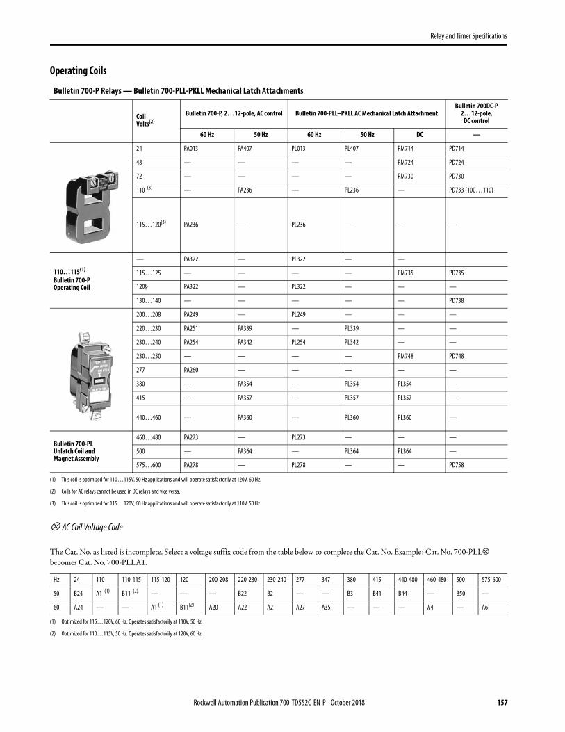
Relay and Timer Specifications
Operating Coils
⊗ AC Coil Voltage Code
The Cat. No. as listed is incomplete. Select a voltage suffix code from the table below to complete the Cat. No. Example: Cat. No. 700-PLL⊗ becomes Cat. No. 700-PLLA1.
Bulletin 700-P Relays — Bulletin 700-PLL-PKLL Mechanical Latch Attachments
CoilVolts(2)
(2) Coils for AC relays cannot be used in DC relays and vice versa.
Bulletin 700-P, 2…12-pole, AC control Bulletin 700-PLL–PKLL AC Mechanical Latch Attachment Bulletin 700DC-P
2…12-pole,DC control
60 Hz 50 Hz 60 Hz 50 Hz DC —
24 PA013 PA407 PL013 PL407 PM714 PD714
48 — — — — PM724 PD724
72 — — — — PM730 PD730
110 (3)
(3) This coil is optimized for 115…120V, 60 Hz applications and will operate satisfactorily at 110V, 50 Hz.
— PA236 — PL236 — PD733 (100…110)
115…120(3) PA236 — PL236 — — —
110…115(1) Bulletin 700-POperating Coil
(1) This coil is optimized for 110…115V, 50 Hz applications and will operate satisfactorily at 120V, 60 Hz.
— PA322 — PL322 — —
115…125 — — — — PM735 PD735
120§ PA322 — PL322 — — —
130…140 — — — — — PD738
200…208 PA249 — PL249 — — —
220…230 PA251 PA339 — PL339 — —
230…240 PA254 PA342 PL254 PL342 — —
230…250 — — — — PM748 PD748
277 PA260 — — — — —
380 — PA354 — PL354 PL354 —
415 — PA357 — PL357 PL357 —
440…460 — PA360 — PL360 PL360 —
Bulletin 700-PLUnlatch Coil andMagnet Assembly
460…480 PA273 — PL273 — — —
500 — PA364 — PL364 PL364 —
575…600 PA278 — PL278 — — PD758
Hz 24 110 110-115 115-120 120 200-208 220-230 230-240 277 347 380 415 440-480 460-480 500 575-600
50 B24 A1 (1)
(1) Optimized for 115…120V, 60 Hz. Operates satisfactorily at 110V, 50 Hz.
B11 (2)
(2) Optimized for 110…115V, 50 Hz. Operates satisfactorily at 120V, 60 Hz.
— — — B22 B2 — — B3 B41 B44 — B50 —
60 A24 — — A1 (1) B11(2) A20 A22 A2 A27 A35 — — — A4 — A6
Rockwell Automation Publication 700-TD552C-EN-P - October 2018 157

Relay and Timer Specifications
⊗ DC Coil Voltage Code
The Cat. No. as listed is incomplete. Select a voltage suffix code from the table below to complete the Cat. No. Example: Cat. No. 700DC-PLL⊗ becomes Cat. No. 700DC-PLLZ24.
Contact Cartridges (Convertible from N.O. to N.C. and N.C. to N.O.)
24 48 64 72 115-125 230-250 575-600
Z24 Z48 Z64 Z72 Z1 Z2 Z6
Photo Description Continuous Carrying Current [A]
Arrangement Pkg. Quantity Cat. No.
Standard Contact CartridgeAC Rating NEMA A600DC Rating NEMA P600
10 1 700-CP1
Overlap Contact CartridgesOverlappingUsed in pairs. N.O. contact closes before N.C. contact opens on pick-up and vice versa on drop-out. (1)
(1) Not Direct Drive
AC RatingNEMA A600 10
2 700-CP11Z DC RatingNEMA P150125V DC, 138 VAMake and Break
5
Master Contact CartridgeAC Rating Twice NEMA A600DC Rating NEMA N150 P600
20 1 700-CPM
Logic Reed Cartridge forLow Energy Circuits150V AC 500 mA 25 VA Max.30V DC 200 mA 6W Max. (2)
(2) The 700-CPR Logic Reed cartridge must be installed only in the 2nd deck (B1X - B4X, B1Y - B4Y position) or 3rd deck (C1X - C4X, C1Y - C4Y position) of the Bulletin 700 Type P relay. It is not recommended that the 700-CPR cartridge be installed in the single deck (A1X - A4X, A1Y - A4Y position) because this may lead to improper operation.
Maximum150V AC 500 mA
1 700-CPR Maximum30V DC 200 mA
158 Rockwell Automation Publication 700-TD552C-EN-P - October 2018

Relay and Timer Specifications
Electrically Held Relays — Typical Wiring Diagrams
Rockwell Automation Publication 700-TD552C-EN-P - October 2018 159

Relay and Timer Specifications
Pneumatic Time-Delay Unit• Timing Range — 0.1…60 s• 0, 2, or 4 instantaneous contacts• Two timed contacts — both ON Delay or both OFF Delay• Convertible from ON Delay to OFF Delay and vice versa• Standard contact cartridges rated NEMA A600 (AC) and P600 (DC)• Master contact cartridges rated 2X NEMA A600 (AC) and N150 P600 (DC)
Mechanical Latch Units
Photo Operating Mode No. of Timed Contacts (1)
(1) In addition to instantaneous cartridges on the relay
Continuous Carrying Current [A]
Arrangement Timing Range
Open TypeWithout
Enclosure(2)
(2) Mounts on 4-pole Bulletin 700-P or -PK relay or 2-pole Bulletin 700-PH relay.
N.O. N.C. Cat. No.
On-DelayOff-Delay 1 1
10
0.1…60 s
700-PT
20 700-PKT
Photo Description Arrangement Continuous Carrying Current [A] Cat. No.
AC-Operated Latch Units
No cartridge 700-PLL⊗
10 700-PLL11⊗
20 700-PKLL11⊗
DC-Operated Latch Units
No cartridge 700DC-PLL⊗
10 700DC-PLL10⊗
20 700DC-PKLL10⊗
160 Rockwell Automation Publication 700-TD552C-EN-P - October 2018

Relay and Timer Specifications
Accessories
Photo Description Relays per
Strip Pkg. Quantity Cat. No.
Relay RailSimplifies panel layout. These indexed strips are easily cut to the required length and bolted, riveted, or spot-welded in place. Relays are installed adjacent to one another on the mounting strip with the captive mounting screws provided. Rows of relays on Relay Rail form their own wiring trough.Can be used with the following relays: 700P, 700DC-P, 700S-P, 700N, 700-R, 700-RTC
4 5 700-MP4
8 5 700-MP8
12 5 700-MP12
16 5 700-MP16
DIN Rail AdapterCan be used with the following relays:Bulletin 700-P, 700DC-P, 700S-P, 700-N, 700-R, 700-RTC
1 700-DRA
DIN (#3) symmetrical hat rail35 x 7.5 x 1 m 10 199-DR1
Type 1 Enclosure — Use for all Bulletin 700-P relays except 10- and 12-pole DC relays or 6-pole DC Bulletin 700-PH relays. 1 700-N31
Type 4/4X Enclosure — For 2- and 4-pole Bulletin 700-P, -N, and -R relays and 2-pole heavy duty relays. 1 700-N39
Type 7 & 9 Enclosure — For 2- and 4-pole Bulletin 700-P, -N, and -R relays and 2-pole heavy duty relays. 1 conduit hub; top and bottom. 1 700-N33
Rockwell Automation Publication 700-TD552C-EN-P - October 2018 161

Relay and Timer Specifications
Accessories
Photo Description Pkg. Quantity Cat. No.
Surge Suppressors (RC Circuit) — Surge suppressors reduce the high transient voltages generated when the coil circuit is opened. These suppressors can be used with Bulletin 700-P, -PH, -PK, and -N relays, and other electromechanical devices. They contain a resistor and capacitor. Maximum ratings: 150V, AC or DC, 35 VA. Cat. No. 700-N5 requires 1 in. additional depth of enclosure.
Mounting behind relay 1 700-N5
Mounting on coil terminal 1 700-N24
Surge SuppressorWhen the circuit to a DC operating coil is opened, the inductive energy stored in the coil can generate very high transient voltages. With the addition of the appropriate surge suppressor, the stored energy is absorbed and dissipated limiting the voltage spikes. A surge suppressor is not required with AC 700-R or -RM relays because the AC operating coil transients are suppressed by a full wave rectifier connected to the coil.
24…48V AC/DC 1 199-FSMA9
50…120V AC/DC 1 199-FSMA10
130…250V AC/DC 1 199-FSMA11
Diode Surge Suppressor — for 6…300V DC voltage coils. Used on Bulletin 700-P, -PH, -PK, -N, -F, and -R relays. 1 199-FSMZ-1
35 A Jumper Kit – CSA Approved, UL ListedThis 35 A Jumper Kit can be used with any Bulletin 700-P and -PK AC or DC relay, Time-Delay relay or Latch Unit equipped with 20 A Master Cartridges. It does not require any additional panel space.Jumper Kit terminals are designed for one #8 AWG wire or two #10 AWG wires. When connecting the two 20 A Master Cartridges in parallel, it is important that they be the same configuration (Normally Open or Normally Closed).Jumpers can be added to any contact cartridge location on a relay except the two center poles because of the wide spacing. An adhesive label is included with each kit listing the contact ratings.
1 700-CPH
Jumpers (Not applicable for Bulletin 700-PH or -PK relays) – For connection between a middle pole and an outer pole on the left or right side of the relay.
Jumper – For outer poles
50 700-N3
Cat. No. 700-N3
Cat. No. 700-N4
Jumpers (Not applicable for Bulletin 700-PH or -PK relays) – For connection between two middle poles.
Jumper – For middle poles 700-N4
Check Out Tool — Mechanically maintains the Bulletin 700-P, -PH, or -PK relay in the energized position for troubleshooting purposes.
1
700-N23
Adapter Plate — Simplified relay conversion. Allows you to use the existing mounting holes when you replace a Bulletin 700-B, -BR, -BX, or -D relay with a Bulletin 700-P, -PH, or -PK relay. 700-N34
162 Rockwell Automation Publication 700-TD552C-EN-P - October 2018

Relay and Timer Specifications
IP 2X Finger-Safe Cover Accessories
Photo Description Pkg. Quantity Cat. No.
Top Covers (Covering Top Level Contact Screws)
IP2X Top Cover for 700-P 1 700-PFSC
Timer Top Cover Kit 1 700-PFSTC
Latch Top Cover Kit (for Relays with Mechanical Latch Attachment) 1 700-PFSLCK
Timer Top Cover Kit, (for Master Cont. Relays with Pneumatic Timer) 1 700-PFSKTC
Latch Top Cover Kit (for Master Cont. Relays with Mechanical Latch) 1 700-PFSKLCK
Deck Covers (Covering all terminals not on top deck, only for multi-deck relays)
IP2X Deck Cover for all AC & DC Relays in the 700P Range 1 700-PFSDEK
Coil Covers
IP2X Coil Cover for all AC Relays in the 700P Range 1 700-PFSACC
IP2X Coil Cover for all DC Relays in the 700P Range 1 700-PFSDCC
Rockwell Automation Publication 700-TD552C-EN-P - October 2018 163

Relay and Timer Specifications
Specifications - 700-P Relays
Type Standard Cartridge Master Cartridge Heavy duty
Bulletin No. 700-P 700-PMCKIT 700-PHDKIT
Electrical
Contact Rating Continuous 10 A @ 600V AC ; 5 A @ 600V DC 20 A @ 600V AC; 10 A @ 600V DC 35 A @ 600V AC; 20 A @ 600V DC
Ratings Make/BreakAC NEMA A600 2 x NEMA A600 2 x NEMA A600
DC NEMA P600 N150 P600 N150 P600
Additional Contact Ratings for AC single-phase loads —
3 Hp @ 240V AC - N.O.2 Hp @ 240V AC - N.O./N.C.1 Hp @ 120V AC - N.O./N.C.
20 A Resistive Heating to 600V AC20 A Tungsten Lighting Load to 480V AC
5 Hp @ 240V AC - N.O.3 Hp @ 240V AC - N.O./N.C.2 Hp @ 120V AC - N.O./N.C.
35 A General Use At 0.75 PF to 600V AC35 A Tungsten Lighting Load to 480V AC
DC Current Ratings Make/Break Cartridge Cat. No. 700-CP1 Cartridge Cat. No. 700-CPM Cartridge Cat. No. 700-CPH
DC Switching Inductive Load
Contacts in Series
Volts DC
24 64 125 250 500 600 24 64 125 250 500 60024 64 125 250 500 600
480W
480W
275W
138W
135W
120W
1 5 A 2.2 A 1.1 A .55 A .24 A .2 A 10 A 5 A 2.2 A .55 A .24 A .2 A 10 A 5 A 2.2 A .55 A .24 A .2 A
2 10 A 10 A 5 A 2 A .7 A .5 A 20 A 10 A 5 A 2 A .7 A .5 A 20 A 10 A 5 A 2 A .7 A .5 A
3 — — 7 A 3 A 1.5 A 1.0 A — 15 A 7 A 3 A 1.5 A 1.0 A — 15 A 7 A 3 A 1.5 A 1.0 A
4 — — 10 A 5 A 2.5 A 1.5 A — 20 A 10 A 5 A 2.5 A 1.5 A — 20 A 10 A 5 A 2.5 A 1.5 A
Coil Voltage Range
AC 85…110% 85…110% 85…110%
DC 80…110% 80…110% 80…110%
Battery 85…115% 85…115% 85…115%
Coil Consumption
50 Hz 60 Hz 50 Hz 60 Hz 50 Hz 60 Hz
ACInrush 132VA (2)
(2) Average value for all coils within range. For values on a specific coil voltage, contact your local Rockwell Automation sales office or Allen-Bradley distributor.
138VA (2) 132VA (2) 138VA (2) 132VA (2) 138VA (2)
Sealed 19.3VA (2) 19VA (2) 19.3 VA (2) 19VA (2) 19.3VA (2) 19VA (2)
DCInrush 12.7VA (2) 12.7VA (2) 12.7VA (2)
Sealed 12.7VA (2) 12.7VA (2) 12.7VA (2)
PLL - PKLLAC Latch Unit
Inrush 15VA (2) 15.6VA (2) 5VA (2) 15.6VA (2) 15VA (2) 15.6VA (2)
Sealed 5.4VA (2) 5.5VA (2) 5.4VA (2) 5.5VA (2) 5.4VA (2) 5.5VA (2)
PLL - PKLLDC Latch Unit
Unlatch 35VA (2) 35VA (2) —
Intermittent 35 W (2) 35 W (2) —
Reset Time PT – PKT 75 ms 75 ms —
Minimum Pulse PLL–PKLL 75 ms 75 ms —
Mechanical
Operating TimePickup AC – 10…20 ms / DC – 30…50 ms AC – 10…20 ms / DC – 30…50 ms AC – 10…20 ms / DC – 30…50 ms
Dropout AC – 10…20 ms / DC – 20…33 ms AC – 10…20 ms / DC – 20…33 ms AC – 10…20 ms / DC – 20…33 ms
Mechanical Life 10 million operations
Construction
Contact Arrangement Up to 12 Poles, Convertible to N.O. or N.C. (8 N.C. Maximum) Up to 6 Poles, Convertible to N.O. or N.C. (4 N.C. Maximum)
Contact Material Silver Nickel Silver Cadmium Oxide Silver Cadmium Oxide
Mounting Panel, Strip Mount, or DIN Rail Horizontal Mounting Recommended
Environmental
TemperatureOperating (1)
(1) Temperature inside the panel.
–20…+65 °C (–4…149 °F) –20…+65 °C (–4…149 °F) –20…+65 °C (–4…149 °F)
Storage –40…+65 °C (–40…149 °F) –40…+65 °C (–40…149 °F) –40…+65 °C (–40…149 °F)
Wire Terminations
Wire size per UL/CSA #18 AWG…(2) #12 AWG
Tightening Torque 8…12 lb•in (0.9…1.4 N•m)
Standards Compliance UL 508, CSA C22.2, No. 14, EN/IEC 60947-1, -5-1
Certifications cULus Listed (File No. E14840, Guide NKCR/NKCR7), CE Marked, ABS
164 Rockwell Automation Publication 700-TD552C-EN-P - October 2018

Relay and Timer Specifications
Dimensions - 700-P Relays with standard, master contact, or heavy-duty contact cartridgeApproximate dimensions are shown in millimeters (inches). Dimensions are not intended for manufacturing purposes.
International Symbol for Mechanically Linked Contacts
2- and 4-pole 700-P RelayApprox Shipping Weight: AC – 0.68 kg (1.5 lb), DC – 1.34 kg (2.95 lb)
2- and 4-pole 700-P with Pneumatic Time Delay AttachmentApprox Shipping Weight: AC – 0.85 kg (1.88 lb), DC – 1.5 kg (3.33 lb)
6- and 8-pole 700-P Relay with one -PB adder deckApprox Shipping Weight: AC – 0.79 kg (1.75 lb), DC – 1.45 kg (3.20 lb)
700-P Relay with Mechanical Latch Attachment Approx Shipping Weight: AC – 0.97 kg (2.13 lb), DC – 1.62 kg (3.58 lb)
700-P Relay, up to 12 poles with -PB and -PC adder decksApprox Shipping Weight: AC – 1.02 kg (2.25 lb), DC – 1.68 kg (3.7 lb)
Relay Rail for 700-P, -N, -NM, -R, -RM, -RT, -RTA RelaysSecure the mounting strip with two screws at each end relay position.Use a minimum of one screw at the 3rd, 5th, 7th, etc., relay positions.
Alternate between upper and lower horizontal slots.
103.43 (4-5/64)
1/2
2.77
(7/64)
— 171.68 (6-49/64)
2.77(7/64)
AC 136.75 (5-25/64)
2.77(7/64)
171.68 (6-49/64)
2.77(7/64)
AC 136.75 (5-25/64)
2.77(7/64)
Cat. No. 700
#8 Screws(Captive)
Rockwell Automation Publication 700-TD552C-EN-P - October 2018 165

Relay and Timer Specifications
Cat. No. 700-N31, Type 1 Enclosure for700-P, -RTC Relays
Approximate Shipping Weight: 1.26 kg (2.8 lb)
700-PS Timer Mounted on a 700-P RelayApproximate Shipping Weight: AC – 0.68 kg (1.5 lb) without 700-PS,
DC – 1.34 kg (2.9 lb) without 700-PS
Cat. No. 199-DR1 DIN Mounting Rail Series BCat. No. 199-DR4 DIN Mounting Rail Series B Has No Mounting Holes
DIN Rail Adapter
178.60(7-1/32)
700-PSTimer
AC – 170.49 (6-23/32)DC – 187 (7-25/64)
50
(1-63/64)
1000
(39-3/8)
6.2
(15/64)
12.5
(1/2)5.2
(13/64)
1.0
(0.04)
7.5
(0.3)
27.0
(1.06)
35.0
(1.38)
0.5(.02)
2.25(0.09)
3.98(0.16)
0.5(.02)
166 Rockwell Automation Publication 700-TD552C-EN-P - October 2018

Relay and Timer Specifications
Rockwell Automation Publication 700-TD552C-EN-P - October 2018 167
700S-P and 700S-PK — Heavy-Duty Safety Control Relays• Mechanically linked contacts meet IEC 947-5-1-L• 2…12 poles – all mechanically linked• Red cover for easy identification of safety circuits• Tamper resistant cover helps prevent changes which could jeopardize safety• IEC mechanically linked contacts symbol displayed on front• Visual indication of contact state• Ideal for use in safety circuits
700S-P (10 A) Safety Control Relays — AC and DC Coil Voltages
⊗ AC Coil Voltage Code(1)
The Cat. No. as listed is incomplete. Select a coil voltage code from the table below to complete the Cat. No. Example: Cat. No. 700S-P310 becomes Cat. No. 700S-P310A1 for a 120V AC coil.
IEC 947-5-1 Annex L has 2 requirements for a relay to meet for mechanically linked contacts:1.) If a N.O. contact welds, all the N.C. contacts will remain open and meet a 2500V impulse test.2.) If a N.C. contact welds, all the N.O. contacts will remain open and meet a 2500V impulse test.700S-P and 700S-DCP relays meet these requirements including the 2500V impulse test.
The relays shown on this page are shipped from the factory with the 700-CPS safety cartridge installed and cannot be converted to N.O. or N.C. in the Field.
Contacts AC Coils 24V DC Coils
Open Type Panel Mount Relay Rail Mount Open Type Panel Mount Relay Rail Mount Open Type DIN Rail Mount
Cat. No. Cat. No. Cat. No.N.O. N.C.
3 1 700S-P310 700S-DCP310Z24 700S-DCP310DZ24
2 2 700S-P220 700S-DCP220Z24 700S-DCP220DZ24
7 1 700S-P710 700S-DCP710Z24 700S-DCP710DZ24
6 2 700S-P620 700S-DCP620Z24 700S-DCP620DZ24
5 3 700S-P530 700S-DCP530Z24 700S-DCP530DZ24
4 4 700S-P440 700S-DCP440Z24 700S-DCP440DZ24
3 5 700S-P350 700S-DCP350Z24 700S-DCP350DZ24
10 2 700S-P1020 700S-DCP1020Z24 700S-DCP1020DZ24
(1) For other coil voltages, consult your local Rockwell Automation sales office or Allen-Bradley distributor.
[V] 24 115-120 230-240 460-480
60 Hz A24 A1 A2 A4

Relay and Timer Specifications
700S-PK (20 A) Safety Control Relays
Contacts Coil Voltage Cat. No.
N.O. N.C.
7 1 110V AC 700S-PK710A1 6 2 110V AC 700S-PK620A1 5 3 110V AC 700S-PK530A1 4 4 110V AC 700S-PK440A1 3 5 110V AC 700S-PK350A1 10 2 110V AC 700S-PK1020A1 3 1 110V AC 700S-PK310A1 7 1 24V DC 700S-DCPK710Z24 6 2 24V DC 700S-DCPK620Z24 5 3 24V DC 700S-DCPK530Z24 4 4 24V DC 700S-DCPK440Z24 3 5 24V DC 700S-DCPK350Z24 10 2 24V DC 700S-DCPK1020Z24 3 1 24V DC 700S-DCPK310Z24
168 Rockwell Automation Publication 700-TD552C-EN-P - October 2018

Relay and Timer Specifications
Specifications - 700S-P Relays
Type 700S-P
Electrical
Contact Rating Continuous 10 A @ 600V AC5 A @ 600V DC
Ratings Make/ BreakAC NEMA A600
DC NEMA P600
Minimum Contact Switching Ratings 10V, 50 mA
DCSwitchingInductive Load
Contacts in SeriesVolts DC
24V 64V 125V 250V 500V 600V
1 5 A 2.2 A 1.1 A 0.55 A 0.24 A 0.2 A
2 10 A 10 A 5 A 2 A 0.7 A 0.5 A
3 — — 7 A 3 A 1.5 A 1.0 A
4 — — 10 A 5 A 2.5 A 1.5 A
Contact Electrical Life— Resistive Loads1.5 million operations at 10A break at 120V AC14 million operations at 1A break at 120V AC
6 million operations at 1A break at 24V DC
Coil Voltage Range (1)
(1) Coil voltage required for proper operation (percent of rated coil voltage).
AC 85…110%
DC 80…110%
Battery Charging 85…115%
Coil Consumption 50 Hz 60 Hz
ACInrush 132 VA 138 VA
Sealed 19.3 VA 19 VA
DCInrush 12.7 W
Sealed 12.7 W
Mechanical
Mechanically Linked Contacts All contacts are mechanically linked per IEC 947- 5-1 annex L for 2 to 12 poles
OperatingTime
Pickup AC – 10…20 msDC – 30…50 ms
Dropout AC – 10…20 msDC – 20…33 ms
Mechanical Life 10 million operations
Construction
Contact Arrangement 2…12 Poles, Double Break ContactsN.O. or N.C. (8 N.C. Maximum)
Contact Material/Design Silver Nickel/Bifurcated
Mounting Panel mount or mount on 700-MP Relay or DIN Rail Horizontal Mounting Recommended
Environmental
Operating Temperature (2)
(2) Temperature inside the panel.
-20…+65 °C (-4…+149 °F)
Storage Temperature -40…+65 °C (-40…+149 °F)
Wire Terminations
Wire size per UL/CSA #18 AWG…(2) #12 AWG
Tightening Torque 8…12 lb•in (0.9…1.4 N•m)
Standards Compliance UL 508, CSA C22.2, No. 14, EN/IEC 60947-1, -5-1
Certifications cULus Listed (File No. E14840, Guide NKCR/NKCR7), CE Marked, ABS
Rockwell Automation Publication 700-TD552C-EN-P - October 2018 169

Relay and Timer Specifications
Specifications - 700S-PK RelaysType 700S-PK
Electrical
Contact Rating Continuous 20 A @ 600V AC10 A @ 600V DC
Ratings Make/ BreakAC NEMA A600
DC NEMA P600
Additional Contact Ratings for AC Single-Phase Loss
3 Hp @ 240V AC - N.O.2 Hp @ 240V AC - N.O./N.C.1 HP @ 120V AC - N.O./N.C.
20 A resistive heating to 600V AC20 A Tungsten lighting load to 480V AC
DC Current Ratings Make/Break Cartridge Cat. No. 700-CMS
DCSwitching
Contacts in SeriesVolts DC
24V 64V 125V 250V 500V 600V
1 10 A 5 A 2.2 A 0.55 A 0.24 A 0.2 A
2 20 A 10 A 5 A 2 A 0.7 A 0.5 A
3 — 15 A 7 A 3 A 1.5 A 1.0 A
4 — 20 A 10 A 5 A 2.5 A 1.5 A
Coil Voltage Range (1)
(1) Coil voltage required for proper operation (percent of rated coil voltage).
AC 85…110%
DC 80…110%
Battery Charging 85…115%
Coil Consumption 50 Hz 60 Hz
ACInrush 132 VA 138 VA
Sealed 19.3 VA 19 VA
DCInrush 12.7 W
Sealed 12.7 W
Mechanical
Mechanically Linked Contacts All contacts are mechanically linked per IEC 947-5-1 annex Lfor 2 to 12 poles
Operating TimePickup AC – 10…20 ms, DC – 30…50 ms
Dropout AC – 10…20 ms, DC – 20…33 ms
Construction
Contact Arrangement 2…12 Poles, Double Break Contacts N.O. or N.C. (8 N.C. Maximum)
Contact Material/Design Silver Cadmium Oxide
Mechanical (Mechanically-Linked Contacts) All contacts, are mechanically linked per IEC 947-5-1 Annex L for 2 to 12 poles
Mounting Panel mount or strip mount recommended
EnvironmentalOperating Temperature (2)
(2) Temperature inside the panel.
-20…+65 °C (-4…+149 °F)
Storage Temperature -40…+65 °C (-40…+149 °F)
Wire TerminationsWire size per UL/CSA #18 AWG…(2) #12 AWG
Tightening Torque 8…12 lb•in (0.9…1.4 N•m)
Standards Compliance UL 508, CSA C22.2, No. 14, EN/IEC 60947-1, -5-1
Certifications cULus Listed (File No. E14840, Guide NKCR/NKCR7), CE Marked, ABS
170 Rockwell Automation Publication 700-TD552C-EN-P - October 2018

Relay and Timer Specifications
Dimensions - 700S-P RelaysApproximate dimensions are shown in millimeters (inches). Dimensions are not intended for manufacturing purposes.
2- and 4-pole 700S-P RelayApproximate Shipping Weight: AC – 0.68 kg (1.5 lb), DC – 1.34 kg (2.95 lb)
6- and 8-pole 700S-P RelayApproximate Shipping Weight: AC – 0.79 kg (1.75 lb), DC – 1.45 kg (3.20 lb)
10- and 12-pole 700S-P (Captive)Approximate Shipping Weight: AC – 1.02 kg (2.25 lb), DC – 1.68 kg (3.7 lb)
Relay Rail
DIN Rail
103.43 (4-5/64)
1/2
2.77
(7/64)
AC 136.75 (5-25/64)
2.77(7/64)
170.10 (6-45/64)
2.77(7/64)
Cat. No. 700
#8 Screws(Captive)
50
(1-63/64)
1000
(39-3/8)
6.2
(15/64)
12.5
(1/2)5.2
(13/64)
1.0
(0.04)
7.5
(0.3)
27.0
(1.06)
35.0
(1.38)
Rockwell Automation Publication 700-TD552C-EN-P - October 2018 171

Relay and Timer Specifications
700-N Industrial Relays• Contact cartridges convertible from N.O. to N.C. and vice versa• NEMA A300 AC• 24…250V AC coils• Pneumatic timing unit• Solid-state timing unit• Overlap contacts• Logic reed contacts• 4-…8-pole
AC-Operated Relays
⊗ AC Coil Voltage Code
The Cat. No. as listed is incomplete. Select a coil voltage code from the table below to complete the cat. no. Example: Cat. No. 700-N200⊗ becomes Cat. No. 700-N200A24 for 24V 60 Hz. For other coil voltages, contact your local Rockwell Automation sales office or Allen-Bradley distributor.
Photo Contacts Contact Arrangement
Open Type
N.O. N.C. Cat. No.
4 — 700-N400⊗
Type NM Relay2 Poles§
2 — 700-NM200⊗
[V] 24 110 120 208 220 240
50 Hz — A1 — — A2 —
60 Hz A24 — A1 A20 — A2
IMPORTANT • NORMALLY CLOSED CONTACTS: Listed relays are supplied with all contacts normally open. These contacts can be readily converted to normally closed in the field.
• OVERLAP CONTACTS: Overlap contacts (normally open contact closes before the normally closed contact opens) can be supplied. See for information on kits for field installation of overlap contact cartridges.
• Location of contacts in 2-pole relays • Permanent Magnet Latch AC Relay. Minimum Operating Time - Type NM - For reliable operation, power to the latch circuit must be maintained for a
minimum time of 75 milliseconds and power to the unlatch circuit must be maintained for minimum time of 50 milliseconds.
172 Rockwell Automation Publication 700-TD552C-EN-P - October 2018

Relay and Timer Specifications
Operating Coils
700-NT Pneumatic Timing Unit
Photo Coil Voltage 700-N Relay • 2-…8-Pole
60 Hz 50 Hz
24 84AB27 84AB28
110 84AB01 84AB86
120 84AB86 —
208 84AB113 —
220 84AB06 84AB83
240 84AB83 —
Photo Description
TimedContacts
ContactArrangement Open Type
N.O. N.C. Cat. No.
Timing Unit Only(for 700-N, 2…4-pole) 1 1
ON-Delay mode is standard. Timer iseasily converted toOFF-Delay mode.
700-NT
Rockwell Automation Publication 700-TD552C-EN-P - October 2018 173

Relay and Timer Specifications
Specifications - 700-N Relays
Attribute Bul. 700-N Bul. 700-NT
Electrical RatingsRated Thermal Current Ith 10 ARated Insulation Voltage 300VContact Rating 10 A @ 300V AC, NEMA A300
Coil Voltage Range AC 85…110% —DC 80…110% —
Coil Consumption50 Hz 60 Hz —
AC Inrush 120 VA 133 VA —Sealed 24 VA 20 VA —
MechanicalAC —
Max. Operating Time Pickup 14 ms —Drop Out 13 ms —
Timing Range — 0.2…60 sRepeat Accuracy — ±15% of settingReset Time — 75 ms
Timing Mode — On-Delay — convertible to OFF Delay, up to 2 poles convertible to N.O. or N.C.
ConstructionContact Arrangement Up to 8 Poles, Convertible to N.O. or N.C. —Contact Material Silver SilverMounting Panel or strip mount Horizontal mounting recommended On relay onlyEnvironmentalAmbient Temperature (Outside Enclosure)
Operating –20…+40 °C (–4…+104 °F)Storage –40…+60 °C (–40…+140 °F)
Operating Temperature Rise (Inside Enclosure) +25 °C Max —Wire TerminationsWire size per UL/CSA #18 AWG…(2) #12 AWGTightening Torque 8…12 lb•in. (0.9…1.4 N•m)Standards Compliance UL 508, CSA C22.2, No. 14
Certifications cULus Listed (File No. E14840, Guide NKCR/NKCR7)
174 Rockwell Automation Publication 700-TD552C-EN-P - October 2018

Relay and Timer Specifications
Dimensions - 700-N RelaysApproximate dimensions are shown in millimeters (inches). Dimensions are not intended for manufacturing purposes.
Type of Relay No. of
Poles
Open TypeWithout Enclosure
Approx. Ship. Wt. kg (lbs.)
Type 1General Purpose Enclosure
Approx. Ship. Wt. kg (lbs.)Drawing
NumberA
WideB
HighC
DeepD A
WideB
HighC
DeepD E
N
700 2…4 1 57.15(2-1/4)
88.90(3-1/2)
82.55(3-1/4)
79.38(3-1/8)
0.68(1-1/2)
107.95(4-1/4)
185.74(7-5/16)
103.19(4-1/16)
146.05(5-3/4)
85.73(3-3/8)
1.59(3-1/2)
700 6…8 2 57.15(2-1/4)
88.90(3-1/2)
106.36(4-3/16)
79.38(3-1/8)
0.79(1-3/4)
112.71(4-7/16)
228.60(9)
120.65(4-3/4)
206.38(8-1/8)
92.08(3-5/8)
2.27(5)
Nwith Pneumatic
Timer700 2…4 3 57.15
(2-1/4)88.90
(3-1/2)
138.11(5-7/16)
79.38(3-1/8)
0.91(2) — — — — — —
Nwith Solid-State
Timer700 2…4 3 57.15
(2-1/4)88.90
(3-1/2)
160.34(6-5/16)
79.38(3-1/8)
1.02(2-1/4) — — — — — —
Drawing Number 1 Drawing Number 2 Drawing Number 3
DIN Rail Adapter
C A
D B
C A
D B
A
BD
C
178.60(7-1/32)
Cat. No. 700
#8 Screws(Captive)
50
(1-63/64)
1000
(39-3/8)
6.2
(15/64)
12.5
(1/2)5.2
(13/64)
1.0
(0.04)
7.5
(0.3)
27.0
(1.06)
35.0
(1.38)
0.5(.02)
2.25(0.09)
3.98(0.16)
0.5(.02)
Rockwell Automation Publication 700-TD552C-EN-P - October 2018 175

Relay and Timer Specifications
700-R Sealed Switch Relays• Sealed contacts• Extremely long mechanical and electrical life• Hazardous locations Class 1, Div 2 Groups A, B, C, D• Harsh environments• Suitable for applications with shock and vibration• High reliability circuit integrity
⊗ Coil Voltage Code
The Cat. No. as listed is incomplete. Select a voltage code from the table below to complete the Cat. No. Example: Cat. No. 700-R000⊗ becomes Cat. No. 700-R000A24.
No.ofPoles
Electrically Held
Contacts Contact Arrangementand Markings‡
AC-Operated Relay Only DC-Operated Relay Only Open Type Open Type
N.O. N.C. Cat. No. Cat. No. 0 0 0 Relay without Contact 700-R000⊗ 700DC-R000⊗
2 2 0 700-R200⊗ 700DC-R200⊗ 1 1 700-R110⊗ 700DC-R110⊗ 0 2 700-R020⊗ 700DC-R020⊗
4
4 0 700-R400⊗ 700DC-R400⊗ 3 1 700-R310⊗ 700DC-R310⊗ 2 2 700-R220⊗ 700DC-R220⊗ 1 3 700-R130⊗ 700DC-R130⊗ 0 4 700-R040⊗ 700DC-R040⊗
6
6 0 700-R600 ⊗ 700DC-R600 ⊗5 1 700-R510 ⊗ 700DC-R510 ⊗4 2 700-R420 ⊗ 700DC-R420 ⊗3 3 700-R330 ⊗ 700DC-R330 ⊗2 4 700-R240 ⊗ 700DC-R240 ⊗1 5 700-R150 ⊗ 700DC-R150 ⊗0 6 700-R060 ⊗ 700DC-R060 ⊗
8
8 0 700-R800 ⊗ 700DC-R800 ⊗7 1 700-R710 ⊗ 700DC-R710 ⊗6 2 700-R620 ⊗ 700DC-R620 ⊗5 3 700-R530 ⊗ 700DC-R530 ⊗4 4 700-R440 ⊗ 700DC-R440 ⊗3 5 700-R350 ⊗ 700DC-R350 ⊗2 6 700-R260 ⊗ 700DC-R260 ⊗1 7 700-R170 ⊗ 700DC-R170⊗ 0 8 700-R080 ⊗ 700DC-R080 ⊗
‡ Arrangement displays all N.O. contacts. ♣ Location of contacts in 6-pole relays.Δ Polarity must be observed for DC voltage (700 DC) relays. ♦ Location of contacts in 2-pole relays.
Type of Relay [V] Coil Volts
24 48 110 115-125 120 220 230-250 240
AC 25, 50, 60 Hz — — A1 — — A2 — — A24 — — — A1 — — A2
DC — Z24 Z48 — Z1 — — Z2 —
176 Rockwell Automation Publication 700-TD552C-EN-P - October 2018

Relay and Timer Specifications
⊗ Coil Voltage Code
The Cat. No. as listed is incomplete. Select a voltage code from the table below to complete the Cat. No. Example: Cat. No. 700-RM000⊗ becomes Cat. No. 700-RM000A24. For other coil voltages, contact your local Rockwell Automation sales office or Allen-Bradley distributor.
Accessories - 700-R Relays
Type of Relay [V] Coil Volts
24 48 110 115-125 120 220 230-250 240
AC 25, 50, 60 Hz — — A1 — — A2 — —
A24 — — — A1 — — A2
DC — Z24 Z48 — Z1 — — Z2 —
Photo Description Pkg. Qty. Cat. No.
Relay RailSimplifies panel layout. These indexed strips are easily cut to the required length and bolted, riveted, or spot-welded in place. Relays are installed adjacent to one another on the mounting strip with the captive mounting screws provided. Rows of relays on Relay Rail form their own wiring trough.Can be used with the following relays: 700P, 700DC-P, 700S-P, 700N, 700-R, 700-RTC
4 Relays per Strip 5 700-MP4
8 Relays per Strip 5 700-MP8
12 Relays per Strip 5 700-MP12
16 Relays per Strip 5 700-MP16
DIN (#3) symmetrical hat rail35 x 7.5 x 1 m 10 199-DR1
DIN Rail AdapterCan be used with the following relays:700-P, 700DC-P, 700S-P, 700-N, 700-R, 700-RTC
1 700-DRA
Front DeckA front deck can be attached to 700 2-, 3-, or 4-pole AC and DC Type R or RM relays.
Front Deck with one N.O. ContactCartridge (700-R Relay) 1 700-RA10
Front Deck with one N.C. ContactCartridge (700-R Relay) 1 700-RA01
Front Deck with one N.O. ContactCartridge (700-RM Relay) 1 700-RB10
Front Deck with one N.C. ContactCartridge (700-RM Relay) 1 700-RB01
Rockwell Automation Publication 700-TD552C-EN-P - October 2018 177

Relay and Timer Specifications
Specifications - 700-RApplication Data – Because of the inherent characteristics of this device, the normally open contacts may close before the normally closed contacts open on energization and the normally closed contacts may close before the normally open contacts open on de-energization.
Ratings
Contact CartridgesThese cartridges are used to increase the number of poles of a relay. A dummy cartridge is also available to fill empty space not occupied by a contact cartridge.
N.O. Contact Cartridge - Green(700-R Relay) 1 700-CR5
N.C. Contact Cartridge - Yellow(700-R Relay) 1 700-CR6
N.O. Contact Cartridge - Blue(700-RM Relay) 1 700-CR7
N.C. Contact Cartridge - Red(700-RM Relay) 1 700-CR8
Cat. No.700-CR5
Cat. No.700-CR6
Cat. No.700-CR9
“DUMMY” Cartridge - Black(700-R and -RM Relays) 1 700-CR9
Surge SuppressorWhen the circuit to a DC operating coil is opened, the inductive energy stored in the coil can generate very high transient voltages. With the addition of the appropriate surge suppressor, the stored energy is absorbed and dissipated limiting the voltage spikes. A surge suppressor is not required with AC 700-R or -RM relays because the AC operating coil transients are suppressed by a full wave rectifier connected to the coil.
12V DC (700-R Relay) 1
199-FSMA9
12V DC (700-RM Relay) 2
24V DC (700-R Relay) 1
24V DC (700-RM Relay) 2
48V DC (700-R Relay) 1
48V DC (700-RM Relay) 2
115…125V DC (700-R Relay) 1 199-FSMA10
115…125V DC (700-RM Relay) 2
230…250V DC (700-R Relay) 1 199-FSMA11
230…250V DC (700-RM Relay) 2
700-PS Solid-State Timing UnitYou can attach a 700-PS solid-state timing unit to 4-pole 700-R or -RM relays. An adaptor kit, Cat. No. 700-N26, is required.
852S Solid-State Timing UnitYou can attach a 852S solid-state timing unit to 4-pole 700-R or -RM relays.
ATTENTION: For 700-RM, energizing both the latch and unlatch coil together will cause the relay to be energized and both latch and unlatch coils can be operated together continuously.
AC Voltage DC Voltage
NEMA Rating Designation
Voltage Make Break Continuous Carrying
Current [A]
NEMA Rating Designation
Volts DC Make/Break Continuous Carrying
Current [A]
B300 Up to 300V AC120V 30 3
5
NEMA P300
46…300 138 VA 5240V 15 1.5
C600 Above 300V AC480V 3.75 0.375
2.5 5…46 3 A 5600V 3.0 0.30
Photo Description Pkg. Qty. Cat. No.
178 Rockwell Automation Publication 700-TD552C-EN-P - October 2018

Relay and Timer Specifications
Maximum Allowable Off-State Leakage Current
Relay Data
700-R Operating Coils
Voltage Maximum Off-State LeakageCurrent [mA]
Maximum Off-State LeakageCurrent [mA]
Type R Type RM
24V DC 23 8
24V AC 23 8
120V AC 5 2
Type 700-R
Contact Arrangement Up to 8 poles, available in any combination of N.O. or N.C. contacts
Contact Material W (tungsten in a controlled gas atmosphere)
Coil Voltage Range 24…250V AC24…250V DC
Coil Power
SealedVoltage Range: –15… +10%
5.5 VA, 50/60 Hz5.5 W DC
Inrush 5.5 VA, 50/60 Hz5.5 W DC
Pickup Time 30 ms
Dropout Time 30 ms
Operating Temperature –40…+60 °C (–40…+140 °F)
Mounting Panel mount
Haz. Loc. Ratings Class I, Division 2, Groups A, B, C, and D
Standards Compliance ISA 12.12, CSA C22.2, No. 213, EN/IEC 60947-1, -5-1
Certifications cULus Listed (File No. E10314, Guide NOIV/NOIV7), CE Marked
Coil Volts 700-R2-…8-Pole AC
700-R2-…8-Pole DC
60 Hz 50 Hz24 77AB27 77AB27 77D152
48 77AB134 77AB134 77D166
110 77AB86 77AB86 —
115…125 — — 77D155
120 77AB86 77AB86 —
208 — — —
220 77AB83 77AB83 —
240 77AB83 77AB83 —
230…250 — — 77D156
Rockwell Automation Publication 700-TD552C-EN-P - October 2018 179

Relay and Timer Specifications
Dimensions - 700-R
Approximate dimensions are shown in millimeters (inches). Dimensions are not intended for manufacturing purposes.
700-R Relays
Type of Relay No. of Poles
Open TypeWithout Enclosures
Approx. Ship
Wt. [kg (lb)]
Type 1General Purpose Enclosure
Approx. Ship
Wt. [kg(lb)]
Drawing Number
AWide
BHigh
CDeep
D AWide
BHigh
CDeep
D E
R 700 and700DC
2…4 155.56(2-3/16)
88.90(3-1/2)
92.25(3-3/8)
79.38(3-1/8)
0.91(2)
104.78(4-1/8)
185.74(7-5/16)
103.19(4-1/16)
146.05(5-3/4)
85.73(3-3/8)
1.81(4)
5…8 255.56(2-3/16)
88.90(3-1/2)
111.13(4-3/8)
79.38(3-1/8)
1.02(2-1/4)
112.71(4-7/16)
228.60(9)
120.65(4-3/4)
206.38(8-1/8)
92.08(3-5/8)
2.49(5)
700-R400… 700-R800…
Type 1 Enclosure DIN Rail Adapter
Secure the mounting strip with 2 screws at each end relay position. Use a minimum of one screw at the 3rd, 5th, 7th, etc., relay positions. Alternate between upper and lower horizontal slots.
Relay Rail
Cat. No. 199-DR1 DIN Mounting Rail Series B
AC
DB
AC
DB
160.6 max(6-21/64)
700 Type R 700-PSTimer
700-N26
AA
B
C
D
E
0.5(.02)
2.25(0.09)
3.98(0.16)
0.5(.02)
Cat. No. 700
#8 Screws(Captive)
50
(1-63/64)
1000
(39-3/8)
6.2
(15/64)
12.5
(1/2)5.2
(13/64)
1.0
(0.04)
7.5
(0.3)
27.0
(1.06)
35.0
(1.38)
180 Rockwell Automation Publication 700-TD552C-EN-P - October 2018

Relay and Timer Specifications
700-RTC — Solid-State Timing Relay• Timing functions• 8 ON-delay• 8 OFF-delay• Timing ranges• Seconds: 0.05…2, 0.2…8, 0.4…30, 2…120• Minutes: 0.015…1, 0.06…4, 0.25…16 and 1…64• AC, 50/60 Hz or DC• 600V AC maximum• 300V DC maximum• Relays with fixed time delay• Sealed contacts• Harsh environments• Hazardous locations Class I, Div. 2, Groups A, B, C and D
700-RTC Relay with Adjustable Time Delay – Relays with Provision for Instantaneous ContactsRelays listed below have slots for two timed contacts and two instantaneous contacts. Unused slots are equipped with removable dummy cartridges.
Number of Contact Cartridges Open Type Without Enclosure
Total Instantaneous Timed
Cat. No. N.O. N.C. N.O. N.C.
0 0 0 0 0 700-RTC00000⊗
1 0 0 1 0 700-RTC00100⊗0 0 0 1 700-RTC00010⊗
2
0 0 2 0 700-RTC00200⊗ 1 0 1 0 700-RTC10100⊗ 0 1 1 0 700-RTC01100⊗ 0 0 1 1 700-RTC00110⊗ 1 0 0 1 700-RTC10010⊗ 0 1 0 1 700-RTC01010⊗ 0 0 0 2 700-RTC00020⊗
3
1 0 2 0 700-RTC10200⊗ 2 0 1 0 700-RTC20100⊗ 0 1 2 0 700-RTC01200⊗ 1 1 1 0 700-RTC11100⊗ 1 0 1 1 700-RTC10110⊗ 2 0 0 1 700-RTC20010⊗ 0 2 1 0 700-RTC02100⊗ 0 1 1 1 700-RTC01110⊗ 1 1 0 1 700-RTC11010⊗ 1 0 0 2 700-RTC10020⊗ 0 2 0 1 700-RTC02010⊗ 0 1 0 2 700-RTC01020⊗
Rockwell Automation Publication 700-TD552C-EN-P - October 2018 181

Relay and Timer Specifications
⊗ Coil Voltage Code
The Cat. No. as listed is not complete. Select a voltage code from the table below to complete the Cat. No. Example: Cat. No. 700-RTC00100⊗ becomes Cat. No. 700-RTC00100U24. For other voltages consult your local Rockwell Automation sales office or Allen-Bradley distributor.
700-RTC Relays with Fixed Time Delay— Relays with Provision for Instantaneous ContactsRelays listed below have slots for two timed and two instantaneous contacts. Unused slots are equipped with removable dummy cartridges.
4
2 0 2 0 700-RTC20200⊗ 1 1 2 0 700-RTC11200⊗ 2 0 1 1 700-RTC20110⊗ 0 2 2 0 700-RTC02200⊗ 1 1 1 1 700-RTC11110⊗ 2 0 0 2 700-RTC20020⊗ 1 1 0 2 700-RTC11020⊗ 0 2 1 1 700-RTC02110⊗ 0 2 0 2 700-RTC02020⊗
[V] 24V DC, 24V AC 120V DC, 110/120V AC
50/60 Hz U24 U1
Number of Contact Cartridges Open Type Without Enclosure
Total Timed Instantaneous
Cat. No. N.O. N.C. N.O. N.C.
0 0 0 0 0 700-RTC00#0⊗
1 1 0 0 0 700-RTC10#0⊗0 1 0 0 700-RTC20#0⊗
2
2 0 0 0 700-RTC40#0⊗ 1 0 1 0 700-RTC11#0⊗ 1 0 0 1 700-RTC12#0⊗ 1 1 0 0 700-RTC30#0⊗ 0 1 1 0 700-RTC21#0⊗ 0 1 0 1 700-RTC22#0⊗ 0 2 0 0 700-RTC50#0⊗
3
2 0 1 0 700-RTC41#0⊗ 1 0 2 0 700-RTC14#0⊗ 2 0 0 1 700-RTC42#0⊗ 1 0 1 1 700-RTC13#0⊗ 1 1 1 0 700-RTC31#0⊗ 0 1 2 0 700-RTC24#0⊗ 1 0 0 2 700-RTC15#0⊗ 1 1 0 1 700-RTC32#0⊗ 0 1 1 1 700-RTC23#0⊗ 0 2 1 0 700-RTC51#0⊗ 0 1 0 2 700-RTC25#0⊗ 0 2 0 1 700-RTC52#0⊗
Number of Contact Cartridges Open Type Without Enclosure
Total Instantaneous Timed
Cat. No. N.O. N.C. N.O. N.C.
182 Rockwell Automation Publication 700-TD552C-EN-P - October 2018

Relay and Timer Specifications
# Operating Mode
Replace the # in the cat. no. with the appropriate letter and numbers to indicate the operating mode and the fixed time delay value. Refer to operating mode table below.
⊗ Coil Voltage Code
The cat. no. as listed is not complete. To complete the cat. no., add a coil code selected from the table below.
Accessories - 700-RTC Relays
4
2 0 2 0 700-RTC44#0⊗ 2 0 1 1 700-RTC43#0⊗ 1 1 2 0 700-RTC34#0⊗ 2 0 0 2 700-RTC45#0⊗ 1 1 1 1 700-RTC33#0⊗ 0 2 2 0 700-RTC54#0⊗ 1 1 0 2 700-RTC35#0⊗ 0 2 1 1 700-RTC53#0⊗ 0 2 0 2 700-RTC55#0⊗
Digit Operating Mode Fixed Time Delay
S On-Delay – s Seconds –Two digits indicating the fixed time delay in seconds.Three digits indicating the fixed time delay (first digit indicates seconds, nexttwo digits indicate 1/100 seconds). Z Off-Delay – s
Y On-Delay – Min. Minutes –Two digits indicating the fixed time delay in minutes.Three digits indicating the fixed time delay (first digit indicates minutes, nexttwo digits indicate 1/100 minutes). I Off-Delay – Min.
EXAMPLE Cat. No. 700-RTC00Y200U1 is for a relay without contact cartridges. “Y20” indicates an On-Delay timer with a 20 minute fixed time delay. This is a “standard relay.” Order the contact cartridges separately. Cat. No. 700-RTC42S020U1 is for a relay with 2 N.O. cartridges in the timed position and 1 N.C. cartridge in the instantaneous position. “S02” indicates an On-Delay timer with a 2 second fixed time delay.
[V] 24V DC, 24V AC 120V DC, 110/120V AC
50/60 Hz U24 U1
Photo Description Cartridge Type Color Cat. No.
Contact Cartridges – These cartridges are used to add contacts to timing relays having unused slots. The N.O., N.C., and Dummy cartridges are interchangeable and can be used in timed or instantaneous contact slots. Dummy cartridges should be placed in unused cartridge slots to guard against entrance of foreign material.
N.O. Grey 700-CRT5
N.C. Orange 700-CRT6
Cat. No.700-CRT5
Cat. No.700-CRT6
Cat. No.700-CR9 Dummy Cartridge Black 700-CR9
Number of Contact Cartridges Open Type Without Enclosure
Total Timed Instantaneous
Cat. No. N.O. N.C. N.O. N.C.
Rockwell Automation Publication 700-TD552C-EN-P - October 2018 183

Relay and Timer Specifications
Specifications - 700-RTC Relays
Voltage and Power Requirements
Type 1 Enclosure — Use for all 700-P relays except 10- and 12-pole DC relays or 6-pole DC 700-PH relays. 700-N31
Relay RailSimplifies panel layout. These indexed strips are easily cut to the required length and bolted, riveted, or spot-welded in place. Relays are installed adjacent to one another on the mounting strip with the captive mounting screws provided. Rows of relays on Relay Rail form their own wiring trough.Can be used with the following relays: 700P, 700DC-P, 700S-P, 700N, 700-R, 700-RTC
Relays per Strip Pkg. Quantity 700-MP4
4 5
8 5 700-MP8
12 5 700-MP12
16 5 700-MP16
DIN (#3) symmetrical hat rail35 x 7.5 x 1 m 10 199-DR1
DIN Rail AdapterCan be used with the following relays:700-P, 700DC-P, 700S-P, 700-N, 700-R, 700-RTC
1 700-DRA
AC Voltage+10% –15% 50/60 Hz
Total Power Required Initiate Terminal Power Maximum AllowableLeakage Current
Coil Code
24V AC 8 VA 4 VA 10 mA U24
110/120V AC 9 VA 4 VA 2.4 mA U1
DC Voltage+10% –20%
Total Power Required Initiate Terminal Power Maximum AllowableLeakage Current
Coil Code
24V DC 10 W 5 W 10 mA U24
120V DC 11 W 5 W 2.4 mA U1
Type 700-RTC
Contact Rating NEMA B600 600V AC, 5 ANEMA P300 300V DC, 5 A
Contact Arrangement1…4 poles. Max. of 2 timed and 2 instantaneous.
Available in any combination of N.O. and N.C. contacts
Contact Material W (tungsten in a controlled gas atmosphere)
Operating Mode Convertible to ON-Delay or OFF-Delay
Photo Description Cartridge Type Color Cat. No.
184 Rockwell Automation Publication 700-TD552C-EN-P - October 2018

Relay and Timer Specifications
Timing Range 0.015…64 minutes; 0.05...120 seconds
Reset Time 25 ms
Repeat Accuracy ±1% (or ±50 ms) at constant voltage and temperature
Mounting Panel or strip mount
Surge Suppression Not required. Timers have internal suppression
Haz. Loc. Ratings Class I, Division 2, Groups A, B, C, and D
Maximum Allowable Leakage Current24V AC/DC 10 mA
110/120V AC,120V DC 2.4 mA
Ambient Temperature (1)
Operating: –20…+60 °C(–4…+140 °F)
Storage: –20…+60 °C(–4…+140 °F)
Standards Compliance ISA 12.12, CSA C22.2, No. 213
Certifications cULus Listed (File No. E10314, Guide NOIV/NOIV7)
(1) Continuous duty units placed close to each other (3 in a row) have a temperature range of –20…+45 °C (–4…+113 °F) or should have air circulated around the units. Approximate space of 3/4 in (mm) on all sides is needed.
Type 700-RTC
Rockwell Automation Publication 700-TD552C-EN-P - October 2018 185

Relay and Timer Specifications
Typical Wiring Diagram - 700-RTC Relays
Dimensions - 700-RTC RelaysApproximate dimensions are shown in millimeters (inches). Dimensions are not intended for manufacturing purposes.
Approximate Shipping Weight 0.92 kg (2.1 lb.) NEMA Type 1 Enclosure for RTC RelaysApproximate Shipping Weight 1.26 kg (2.8 lb.)
ExternalInitiating Contact
(N.O. or N.C.)
Timed ContactsAny Combinationof N.O. and N.C.
InstantaneousContacts Any
Combination ofN.O. and N.C.
P TIMED INST
L1 L2
L1 + L2
5.2 (2-13/64) Dia. Mounting Holes
186 Rockwell Automation Publication 700-TD552C-EN-P - October 2018

Relay and Timer Specifications
IEC Control Relays
Product Overview
Bulletin No. 700-CF and 700S-CF 700-K
Type Control Relay Miniature Control Relay
Features
• Mechanically linked contacts• Timer and latch operations• Switch up to 690V AC and DC• 700S-CF for safety circuits
• Smallest size• Long life• Low power consumption• Switch up to 690V AC and DC
Contact Form 4…12 poles, double break 4...8 Poles Double Break
Contact Type Cross stamp or bifurcated Bifurcated
Contact Material Silver, gold Silver
Electrical
Max. Current AC Resistive 20 A (relay)10 A (adder deck) 10 A
Min. load 17V, 10 mA (Silver)5V, 3 mA (Gold) 15V, 2 mA (700-K)
Coil Voltage 12…600V AC9…250V DC
12…600V AC9…250V DC
Coil Voltage Pickup 85…110% AC coils,80…110% DC coils
85…110% AC Coils,80…110% DC Coils
Dielectric Withstand 2.5 kV 2640V
Reference
Electric Service Life (cycles) 1.2 million at 10 A 800K at 10 A 120V AC
Certifications CE, cULus, CCC CE, cULus, CCC
Sockets DIN Rail or panel mount DIN Rail or panel mount
Page 188 212
Rockwell Automation Publication 700-TD552C-EN-P - October 2018 187

Relay and Timer Specifications
700-CF Control Relay• IEC industrial relays• Mechanically linked contact performance per IEC 60947-5-1• Gold plated, bifurcated version for low level switching applications• Master control relay version rated 15 A (AC-15)• Solid-state and pneumatic timing modules• 4-…10 Poles
4-Pole AC Coil Voltage (Ratings for 700-CF Only)
⊗ AC Coil Voltage Code
The cat. no. as listed is incomplete. Select a coil voltage code from the table below to complete the cat. no. Example: Cat. No. 700-CF220⊗ becomes Cat. No. 700-CF220D for 120V, 60 Hz.
AC-12 AC-15
ConnectionDiagrams
Contacts
StandardContacts(1)
(1) For spring clamp terminals, insert R after 700-C. Example: Cat. No. 700-CRF220D.
Gold PlatedBifurcatedContacts(2)
(2) All Cat. Nos. are factory-stocked.
MasterContacts(2) Ith [A] Ie [A]
40 °C 60 °C 24/48V 120V 240V 400V 500V 600V 690V N.O. N.C. Cat. No. Cat. No. Cat. No.
20 20 10 10 10 6 2.5 1 1
2 2 700-CF220⊗ 700-CFB220⊗ 700-CFM220⊗
3 1 700-CF310⊗ 700-CFB310⊗ 700-CFM310⊗
4 0 700-CF400⊗ 700-CFB400⊗ 700-CFM400⊗
0 4 700-CF040⊗ 700-CFB040⊗ —
[V] 12 24 32 36 42 48 100 100...110 110 120 127 200 200...
220 208 208...240
220...230 230 230...
240 240
50 Hz R K V W X Y KP — D P S KG L — — F — VA T
60 Hz Q J — V — X — KP — D — — KG H L — — — A
50/60 Hz — KJ — — — KY KP — KD — — KG KL — — KL KF — KA
[V] 277 347 380 380...400 400 400...
415 440 480 500 550 600
50 Hz — — — N — G B — M C —
60 Hz T I E — — — N B — — C
50/60 Hz — — — — KN — KB — — — —
188 Rockwell Automation Publication 700-TD552C-EN-P - October 2018

Relay and Timer Specifications
4-Pole DC Coil Voltage (Ratings for 700-CF Only)
⊗ DC Coil Voltage Code
The cat. no. as listed is incomplete. Select a coil voltage code from the table below to complete the cat. no. example: Cat. No. 700-CF220⊗ becomes Cat. No. 700-CF220EJ for 24V DC, electronic with diode.
AC-12 AC-15
ConnectionDiagrams
Contacts
StandardContacts(1)
(1) For spring clamp terminals, insert R after 700-C. Example: Cat. No. 700-CRF220D.
Gold PlatedBifurcatedContacts(2)
(2) All Cat. Nos. are factory-stocked.
MasterContacts(2) Ith[A] Ie [A]
40 °C 60 °C 24/48V 120V 240V 400V 500V 600V 690V N.O. N.C. Cat. No. Cat. No. Cat. No.
20 20 10 10 10 6 2.5 1 1
2 2 700-CF220 ⊗ 700-CFB220⊗ 700-CFM220⊗
3 1 700-CF310⊗ 700-CFB310⊗ 700-CFM310⊗
4 0 700-CF400⊗ 700-CFB400⊗ 700-CFM400⊗
[V] 9 12 24 36 48 48...72
60 64 72 80 110 110... 125
115 125 220 220...250
230 250
Electronic with diode — EQ EJ EW — EY — — — — — ED — — — EA — —
Electronic with diode/ Quick Pick-up
— — QJ — — — — — — — — — — — — — — —
Rockwell Automation Publication 700-TD552C-EN-P - October 2018 189

Relay and Timer Specifications
6- and 8-pole RelaysControl Relays with Overlapping Side-Mounted Contacts
AC-12 AC-15
LeftAux.
RelayArrangement
RightAux.
Contacts
OverlappingSide-MountedContacts Cat. No.
Ith [A] Ie [A]
40 °C
60 °C
24/48V
120V
240V
400V
500V
600V
690V
N.O. N.C. N.O. N.C.
MainRelay 20 20 10 10 10 6 2.5 1 1
4 0 1 1 700-CFZ1510⊗
3 1 1 1 700-CFZ1420⊗
SideContacts 10 10 6 6 5 3 1.6 1 1
2 2 1 1 700-CFZ1330⊗
4 0 2 2 700-CFZ2620⊗
3 1 2 2 700-CFZ2530⊗
2 2 2 2 700-CFZ2440⊗
190 Rockwell Automation Publication 700-TD552C-EN-P - October 2018

Relay and Timer Specifications
Control Relays with Standard Side-mounted Contacts
⊗ AC Coil Voltage Code
The cat. no. as listed is incomplete. Select a coil voltage code from the table below to complete the cat. no. Example: Cat. No. 700-CFZ051⊗ becomes Cat. No. 700-CFZ0510F.
AC-12 AC-15
LeftAux.
RelayArrangement
RightAux.
Contacts
StandardSide-MountedContacts Cat. No. (1)
(1) All Cat. Nos. are factory stocked.
Ith [A] Ie [A]
40 °C
60 °C
24/48V
120V 240V 400V 500V 600V 690V N.O. N.C. N.O. N.C.
MainRelay 20 20 10 10 10 6 2.5 1 1
4 0 1 1 700-CFZ0510⊗
3 1 1 1 700-CFZ0420⊗
2 2 1 1 700-CFZ0330⊗
SideContacts 10 10 6 6 5 3 1.6 1 1
4 0 2 2 700-CFZ0620⊗
3 1 2 2 700-CFZ0530⊗
2 2 2 2 700-CFZ0440⊗
[V] 12 24 32 36 42 48 100 100...110 110 120 127 200 200...
220 208 208...240
220...230 230 230...
240 240
50 Hz R K V W X Y KP — D P S KG L — — F — VA T
60 Hz Q J — V — X — KP — D — — KG H L — — — A
50/60 Hz — KJ — — — KY KP — KD — — KG KL — — KL KF — KA
[V] 277 347 380 380...400 400 400...
415 440 480 500 550 600
50 Hz — — — N — G B — M C —
60 Hz T I E — — — N B — — C
50/60 Hz — — — — KN — KB — — — —
Rockwell Automation Publication 700-TD552C-EN-P - October 2018 191
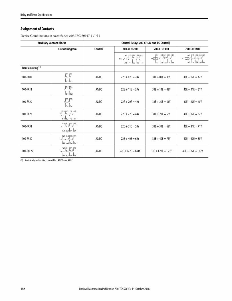
Relay and Timer Specifications
Assignment of ContactsDevice Combinations in Accordance with IEC 60947-1 / -4-1
Auxiliary Contact Blocks Control Relays 700-CF (AC and DC Control)
Circuit Diagram Control 700-CF⊗220 700-CF⊗310 700-CF⊗400
Front Mounting (1)
(1) Control relay and auxiliary contact block AC/DC max. 4 N. C.
100-FA02 AC/DC 22E + 02E = 24Y 31E + 02E = 33Y 40E + 02E = 42Y
100-FA11 AC/DC 22E + 11E = 33Y 31E + 11E = 42Y 40E + 11E = 51Y
100-FA20 AC/DC 22E + 20E = 42Y 31E + 20E = 51Y 40E + 20E = 60Y
100-FA22 AC/DC 22E + 22E = 44Y 31E + 22E = 53Y 40E + 22E = 62Y
100-FA31 AC/DC 22E + 31E = 53Y 31E + 31E = 62Y 40E + 31E = 71Y
100-FA40 AC/DC 22E + 40E = 62Y 31E + 40E = 71Y 40E + 40E = 80Y
100-FAL22 AC/DC 22E + L22E = L44Y 31E + L22E = L53Y 40E + L22E = L62Y
51 61
6252
53 61
54 62
53 63
54 64
53 61 71
7254 62
83
84
53 61
54 62
73
74
83
84
53 63 73 83
8454 64 74
53 61 75
7654 62
87
88
192 Rockwell Automation Publication 700-TD552C-EN-P - October 2018

Relay and Timer Specifications
Auxiliary Contacts
Photo Description N.O. N.C. Connection Diagrams For Use With
StandardContacts (1)
(1) For spring clamp terminals, insert CR after 100-. Example: Cat. No. 100-CRFA02.
BifurcatedContacts
Cat. No. Cat. No.
Auxiliary Contact Blocks for Front Mounting§2- and 4-poleQuick and easy mounting without toolsElectronic-compatible contacts down to 17V, 5 mAMechanically linked performance between N.O. and N.C. poles and to the main relay poles (except for L types)Models with equal function with several terminal numbering choices1L = Late break N.C./early make N.O.Bifurcated version for switching down to 5V, 3 mA
0 2
700-CF
100-FA02 100-FAB02
1 1 100-FA11 100-FAB11
2 0 100-FA20 100-FAB20
1L 1L 100-FAL11 —
0 4 100-FA04 100-FAB04
1 3 100-FA13 100-FAB13
2 2 100-FA22 100-FAB22
3 1 100-FA31 100-FAB31
4 0 100-FA40 100-FAB40
1+1L 1+1L 100-FAL22 —
Photo Description N.O. N.C. Connection Diagrams For Use With Cat. No.
Auxiliary Contact Blocks for Side Mounting without Sequence Terminal Designations§1- and 2-poleTwo-way numbering for right or left mounting on the contactorQuick and easy mounting without toolsElectronic-compatible contacts down to 17V, 10 mAMirror contact performance to the main relay poles1L = Late break N.C./early make N.O.
0 1
700-CF
100-SA01
1 0 100-SA10
0 2 100-SA02
1 1 100-SA11
2 0 100-SA20
1L 1L 100-SAL11
IMPORTANT For maximum number of contacts, see the following tables.
Rockwell Automation Publication 700-TD552C-EN-P - October 2018 193

Relay and Timer Specifications
700-CF (AC electronic coils), vertical mounting, 60 °C(1)
Cat. No.700…
Max. N.O.Side Aux.
Max. N.C.Side Aux.
Max. N.O.Front Aux.
Max. N.C.Front Aux.
Max. N.O.Front + SideAux.
Max. N.C.Front + SideAux.
Max. N.O. + N.C.Front +Side Aux.
CF400 2 4 4 4 6 7 8 CF310 2 4 (2) 4 4(3) 6 5 8 CF220 4 4 (2) 4 2 8 5 8 CF040 2 2 4 0 6 2 6
(1) For other operating conditions, please contact your local Rockwell Automation sales office or Allen-Bradley distributor.(2) With no front auxiliary contacts installed. Otherwise 3 N.C. Maximum(3) With no side auxiliary contacts installed. Otherwise 3 N.C. Maximum
700-CF (DC conventional coils), vertical mounting, 60 °C(1)
(1) For other operating conditions, please contact your local Rockwell Automation sales office or Allen-Bradley distributor.
Cat. No.700…
Max. N.O.Side Aux.
Max. N.C.Side Aux.
Max. N.O.Front Aux.
Max. N.C.Front Aux.
Max. N.O.Front + SideAux.
Max. N.C.Front + SideAux.
Max. N.O. + N.C.Front +Side Aux.
CF400 2 2 4 4 (2)
(2) With no side auxiliary contacts installed. Otherwise 3 N.C. Maximum
6 5 8 CF310 2 2 4 4 (2) 6 5 8 CF220 2 2 4 2 6 4 8
194 Rockwell Automation Publication 700-TD552C-EN-P - October 2018

Relay and Timer Specifications
Control Modules
Photo Description Connection Diagrams
Reset Time
Repeat Accuracy
Delay For Use With Cat. No.
Pneumatic Timing Modules(1) ON-DelayPneumatic timing element contacts switch after the delay time. The contacts on the main control relay continue to operate without delay.
(1) On-Delay modules cannot be used with side-mounted auxiliary contacts on DC coil relays.
25…90 ms for AC Coils
47…85 msfor DC coils
+/-10%
0.3…30 s
700-CF all (1)
100-FPTA30
1.8…180 s 100-FPTA180
Pneumatic Timing Modules OFF-DelayPneumatic timing element contacts switch after the delay time. The contacts on the main control relay continue to operate without delay.
0.3…30 s 100-FPTB30
1.8…180 s 100-FPTB180
Electronic Timing Modules — On-DelayDelay of the control relay coil assembly. The control relay is energized at the end of the delay time.
100 ms +/-1%
0.1…3 s 700-CF110…240V AC110…250V DCconventional coils
100-ETA3
1…30 s 100-ETA30
10…180 s 100-ETA180
0.1…3 s 700-CF24…48V DCcoils
100-ETAZJ3
1…30 s 100-ETAZJ30
10…180 s 100-ETAZJ180
Electronic Timing Modules — Off-DelayDelay of the control relay coil assembly. After interruption of the control signal, the control relay is deenergized at the end of the delay time.
100 ms +/-1%
0.3…3 s 700-CF110…240V ACcoils
100-ETB3
1…30 s 100-ETB30
10…180 s 100-ETB180
0.3…3 s
700-CF24V ACcoils
100-ETBKJ3
1…30 s 100-ETBKJ30
10…180 s 100-ETBKJ180
Photo Description ConnectionDiagrams
For Use With Cat. No.
Mechanical LatchFollowing relay latching, the relay coil is immediately de-energized (off) by the N.C. auxiliary contact (65-66).Electrical or manual release1 N.O. + 1 N.C. auxiliary contacts
700-CF with AC coils 100-FL11⊗
Rockwell Automation Publication 700-TD552C-EN-P - October 2018 195

Relay and Timer Specifications
Coil Voltage Code
The cat. no. as listed is incomplete. Select a coil voltage code from the table below to complete the cat. no. Example: Cat. No. 100-FL11⊗ becomes Cat. No. 100-FL11J.
Photo Description Connection Diagrams
For Use With Cat. No. (1)
Surge SuppressorsFor limitation of coil switching transients.Plug-in, coil mounted
RC ModuleAC OperatingMechanism
24…48V50/60 Hz
700-CF with AC coils
100-FSC48
110…280V50/60 Hz 100-FSC280
380…480V50/60 Hz 100-FSC480
Varistor ModuleAC/DC OperatingMechanism
12…55V AC/12…77V DC
700-CF all
100-FSV55
56…136V AC/78…180V DC 100-FSV136
137…277V AC/181…350V DC 100-FSV277
278…575V AC 100-FSV575
Diode ModuleDC OperatingMechanismDropout Time70…95 ms
12…250V DC 700-CF with Conventional DC coils 100-FSD250
(1) For spring clamp terminals, insert CR after 100-. Example: Cat. No. 100-CRFSC48.
[V] (1)
(1) For special voltages, consult your local Rockwell Automation sales office or Allen-Bradley distributor.
24 48 100 110 120 230...240 240 277 380...400 400...415 440 480
50 Hz K Y KP D — VA T — N G B —
60 Hz J — — — D — A T — — N B
Photo Description (Relays) Connection Diagrams
For Use With (Relays)
Cat. No.
DC Interface (electronic)Interface between the DC control signal (PLC) and the AC operating mechanism of the control relay.Control (input) voltage12V DC24V DC48V DCRequires no additional surge suppression on the relay coils
Input:24V DCOutput:110…240V AC
700-CF with 110…240V AC coils
100-JE
Input:12V DCOutput:110…240V AC
100-JE12
Input:48V DCOutput:110…240V AC
100-JE48
196 Rockwell Automation Publication 700-TD552C-EN-P - October 2018

Relay and Timer Specifications
Specifications 100-J... DC Interfaces
Assembly Components
Cat. No. 100-JE Cat. No. 100-JE12 Cat. No. 100-JE48
Electrical
Input Voltage 24V DC 12V DC 48V DC
Input Voltage Range 18…30V DC 6…12V DC 35…48V DC
Output Voltage 110…240V AC 110…240V AC 110…240V AC
Power Consumption 0.1…0.4 W 0.02…0.12 W 0.2…0.5 W
Minimum Actuation 5V DC, 2 mA DC 5V DC, 2 mA DC 5V DC, 2 mA DC
Mechanical
Finger Protection IP20 IP20 IP20
Pickup Time 0…10 ms + pickup timeof the contactor
0…10 ms + pickup timeof the contactor
0…10 ms + pickup timeof the contactor
Dropout Time 0…10 ms + dropout timeof the contactor
0…10 ms + dropout timeof the contactor
0…10 ms + dropout timeof the contactor
Max. Cycles Per Second 2 (1)
(1) To consider the maximum operations/hour of the relays.
2 (1) 2 (1)
Isolation/Breakdown Voltage In: 50V, Out: 250V In: 50V, Out: 250V In: 50V, Out: 250V
Rated Impulse Withstand Voltage 4 kV 4 kV 4 kV
Environmental
Ambient Temperature Range -25…+60 °C -25…+60 °C -25…+60 °C
Storage Temperature Range -50…+80 °C -50…+80 °C -50…+80 °C
Operating Life 100 + million ops 100 + million ops 100 + million ops
Construction
Wire Size Range
Flexible wire1 Wire 0.5…2.5 mm2 0.5…2.5 mm2 0.5…2.5 mm2
2 Wire 0.75…2.5 mm2 0.75…2.5 mm2 0.75…2.5 mm2
Solid wire1 Wire 1.0…2.5 mm2 1.0…2.5 mm2 1.0…2.5 mm2
2 Wire 1.0…2.5 mm2 1.0…2.5 mm2 1.0…2.5 mm2
Solid and Stranded 18…14 AWG 18…14 AWG 18…14 AWG
Tightening Torque 1…1.5 N•m / 7…15 lb•in 1…1.5 N•m / 7…15 lb•in 1…1.5 N•m / 7…15 lb•in
Type of Light LED LED LED
Photo Description For Use With Pkg Qty. (1)
(1) All Cat. Nos. are factory stocked.
Cat. No.
Protective CoversProvides protection against unintended manual operation 700-CF all 1 100-SCCA
Protective Covers• Provides protection against unintended manual operation• For contactors and front-mounted auxiliary contacts, pneumatic timers,
and latches
100-FA, -FB, -FC, -FP, -FL; 10 100-SCFA
Rockwell Automation Publication 700-TD552C-EN-P - October 2018 197

Relay and Timer Specifications
AccessoriesUniform labeling materials for contactors, motor startup equipment, relays, and circuit breakers.
Photo Description Pkg. Qty. (1)
(1) Must be ordered in multiples of package quantities.
Cat. No.
Label Sheet105 self-adhesive paper labels each, 6 x 17 mm
10 100-FMS
Marking Tag Sheet 160 perforated paper labels each, 6 x 17 mm, to be used with a transparent cover 10 100-FMP
Transparent Cover To be used with marking tag sheets 100 100-FMC
Marking Tag Adapters To be used with marking tag: System V4/V5 100 100-FMA1
System 1492 W 100-FMA2
198 Rockwell Automation Publication 700-TD552C-EN-P - October 2018

Relay and Timer Specifications
Coils
Photo AC CoilCode
AC Voltages Cat. No.700-CF
DC Coil Code DC Voltages Cat. No.700-CF50Hz 60Hz 50/60Hz
Q — 12V — TA006 EQ 12V TC708ER 12V — — TA404 EJ 24 V TC714EJ — 24V — TA013 QJ 24V TC714QK 24V — — TA407 EY 48…72V TC724EKJ — — 24V TA855 EW 36…48 TC719EV 32V 36V — TA481 ED 110…125 TC733EW 36V — — TA410 EA 220…250 TC747EX 42V 48V — TA482Y 48V — — TA414
KY — — 48V TA860KP 100V 100 - 110V 100V TA861D 110V 120V — TA473
KD — — 110V TA856P 120V — — TA425S 127V — — TA428
KG 200V 200 - 220V 200V TA862H — 208V — TA049L 200 - 220V 208 - 240V — TA296
KL — — 200 - 230V TA864A 220V 240V — TA474F 220 - 230V 260V — TA441
KF — — 230V TA851VA 230 - 240V — — TA440T 240V 277V — TA480
KA — — 240V TA858I — 347V — TA065E — 380V — TA067N 380 - 400V 440V — TA071
KN — — 400V TA863G 400-415V — — TA457B 440V 480V — TA475
KB — — 440V TA859M 500V — — TA479C 550V 600V — TA476
Rockwell Automation Publication 700-TD552C-EN-P - October 2018 199

Relay and Timer Specifications
Specifications - 700-CF..., 700S-CF Relays
Main RelayCat. Nos.700-CF,
700S- CF
Front Mounted Standard Auxiliary Contacts
Main RelayCat. No.
700-CFB,700S- CFB
Master Relay Cat. No.
700-CFM
Front Mounted Bifurcated Auxiliary Contacts
Side-mounted Auxiliary Contacts
Contact Ratings — NEMA A600, P600 A600, Q600 A600, Q600 2 x A600, P600 A600, Q600 A600, Q600
Min. Contact Rating 17V, 10 mA 17V, 5 mA 8V, 5 mA — 5V, 3 mA 17V, 10 mA
Contact Ratings — IEC AC-15(solenoids, contactors) at rated voltageIEC 60947-5-1
24V 10 A 6 A 3 A 15 A 3 A 6 A
48V 10 A 6 A 3 A 15 A 3 A 6 A
120V 10 A 6 A 3 A 15 A 3 A 6 A
240V 10 A 5 A 3 A 15 A 3 A 5 A
400V 6 A 3 A 2 A 7.5 A 2 A 3 A
480V/500V 2.5 A 1.6 A 1.2 A 5 A 1.2 A 1.6 A
600V 1 A 1 A 0.7 A 2 A 0.7 A 1 A
690V 1 A 1 A 0.7 A 2 A 0.7 A 1 A
AC-12 (Control of resistive loads)IEC 60947-5-1
40 °C
Ith 20 A
10 A 10 A 20 A 10 A 10 A230V 8 kW
400V 14 kW
690V 24 kW
60 °C
Ith 20 A
6 A 6 A 20 A 6 A 6 A230V 8 kW
400V 14 kW
690V 24 kW
DC-12 Switching DC Loads L/R < 1ms, Resistive LoadsIEC 60947-5-1
24V 15 A 10 A 6 A 20 A 6 A 6 A
48V 10 A 9 A 3.2 A 20 A 3.2 A 3.2 A
110V 6 A 3.5 A 1 A 8 A 1 A 1 A
220V 1 A 0.7 A 0.5 A 1.5 A 0.5 A 0.5 A
440V 0.4 A 0.2 A 0.2 A 0.4 A 0.2 A 0.2 A
DC-13 IEC 60947-5-1,Solenoids and contactors
24V 5 A 5 A 2.5 A 5 A 2.5 A 5 A
48V 3 A 3 A 1.5 A 3 A 1.5 A 2.5 A
110V 1.2 A 1.2 A 0.6 A 1.2 A 0.6 A 0.68 A
220V 0.6 A 0.6 A 0.3 A 0.6 A 0.3 A 0.32 A
440V 0.3 A 0.15 A 0.15 A 0.3 A 0.15 A 0.15 A
Location of weldedN.O. contacts
State of N.C. Contacts if N.O. contact welds
Main Front aux. Side aux.
Main Open Open Open (2)
(2) Defined in IEC 60947-5-1 annex L. Mechanically linked is a relationship between contacts of opposite types (i.e., N.O. and N.C.).
Mechanically Linked Contacts (1)
(1) Side mounted auxiliary contacts provide “mirror contact” performance with main poles only.
Front aux. Open Open —
200 Rockwell Automation Publication 700-TD552C-EN-P - October 2018

Relay and Timer Specifications
AttributeCat. No.700-CF
Aux./Pneumatic Timer Contact (Front mounted)
Mechanical Life [Mil] 15 5
Electrical Life AC-15(240V, 3 A) [Mil] 1.5 1.5
Weight AC Coil [g] 390 —
Terminal Cross-Sections
Terminal Type
Terminal Size per IEC60 947-1 2 x A4 2 x A4
Solid/Stranded 1 Conductor [mm2] 1.5…6 0.5…2.5(1)
(1) For 16 or more strands, end ferrule is required.
2 Conductor [mm2] 1.5…6 0.75…2.5
Max. Wire Size per UL/CSA [AWG] 16…10 18…14
Tightening Torque [lb·in] 13.3…17.7 8.9…13.3
Tightening Torque [N·m] 1.5…2.0 1…1.5
DC Switching Ratings for 700-CF Main Poles in Series (Resistive Load at 60 °C)
Attribute 1 pole 2 poles 3 poles
24/48V 15/10 A 25 A 25 A
125V 6 A 25 A 25 A
220V 1 A 6 A 25 A
440V 0.4 A 1 A 3 A
Rockwell Automation Publication 700-TD552C-EN-P - October 2018 201

Relay and Timer Specifications
Control Circuit
Attribute Cat. No. 700-CF
Operating Voltage
AC 50/60 HzPickup [x Us] 0.85…1.1
Dropout [x Us] 0.3…0.6
DC (conventional) (1)Pickup [x Us] 0.8…1.1
Dropout [x Us] 0.1…0.6
DC (electronic EQ, EW)Pickup [x Us] 0.7...1.25
Dropout [x Us] 0.3...0.4
DC (electronic EY)Pickup [x Us] 0.8...1.25
Dropout [x Us] 0.3...0.4
DC (electronic ED)Pickup [x Us] 0.7...1.12 (2)
Dropout [x Us] 0.3...0.4
DC (electronic EA)Pickup [x Us] 0.8...1.1
Dropout [x Us] 0.3...0.4
Coil Consumption
AC 50/60 HzInrush [VA] 75
Sealed [VA/W] 9.5/2.7
DC (conventional)Inrush [W] 7.7
Sealed [W] 6.3
DC (electronic EQ, EJ)Inrush (avg./ peak) [W] 10/17
Sealed [W] 1.7
DC (electronic EY)Inrush (avg./ peak) [W] 10/17
Sealed [W] 1.9
DC (electronic ED)Inrush (avg./ peak) [W] 12/19
Sealed [W] 2.1
DC (electronic EA)Inrush (avg./ peak) [W] 14/22
Sealed [W] 3.0
Operating Times
AC 50/60 HzPickup Time [ms] 15…30
Dropout Time [ms] 10…60
DC (conventional)Pickup Time [ms] 40…70
Dropout Time [ms] 7…15
With integrated diode Opening Delay [ms] 14...20
With external diode Opening Delay [ms] 70...125
DC (electronic- EQ, EJ)Closing Delay [ms] 25…50
Opening Delay [ms] 27...45
DC (electronic - EW EY, ED, EA)Closing Delay [ms] 25...50
Opening Delay [ms] 23...33
DC (electronic- QJ)Closing Delay [ms] 20...50
Opening Delay [ms] 15…22
202 Rockwell Automation Publication 700-TD552C-EN-P - October 2018

Relay and Timer Specifications
Min OFF time [ms] 50
Max. ripple ± 15%
Latch Attachment Release, 100-FL
Coil ConsumptionAC [VA/W] 45/40
DC [W] 25
Contact Signal Duration [min./max] 0.03…15 s
Timing Attachment
Reset Time, 100- ETA, 100-ETBat min. time setting [ms] 10
at max. time setting [ms] 70
Repeat Accuracy ± 10%
(1) For 9V DC, code ZR, use operating voltage 0.65…1.3 x Us.For 24V DC, code ZJ, DJ, or EJ use operating voltage 0.7…1.25 x Us.
(2) At 110V DC, coil code ED has an operating voltage range of 0.7...1.25 x Us.
Attribute Cat. No. 700-CF
Rockwell Automation Publication 700-TD552C-EN-P - October 2018 203

Relay and Timer Specifications
General Specifications - 700-CF Relays
Utilization Category Table from EN 60947-5-1
Cat. No. 700-CFRated Insulation Voltage UiIEC 690VUL; CSA 600VRated Impulse Strength Uimp 6 kVHigh Test Voltage 1 minute (per IEC 60947- 2500VRated Voltage UeAC 115, 230, 400, 500, 690VDC 24, 48, 110, 220, 440V
Short-Circuit Protection gG Fuse 20 ARated Frequency 50/60 Hz, DCAmbient TemperatureStorage –55…+80 °C (–67…+176 °F)Operation at nominal current –25…+60 °C (–13…+140 °F)15% current reduction for AC-12 at > 60 °C –25…+70 °C (–13…+158 °F)Corrosion Resistance humid-alternating climate, cyclic, per IEC 60068-2-30 and DIN 50 016, 56 cyclesAltitude 2000 m above mean sea level, per IEC 60 947-4Type of ProtectionIP2X (IEC 60529 and DIN 40050) in connected stateShock Resistance IEC 60068-2: Half sinusoidal shock 11 ms, 30 G (in 3 directions)Vibration Resistance IEC 60068-2: Static >2 G, in normal position no malfunction <5 GStandards Compliance UL 508, CSA C22.2 No. 14, EN/IEC 60947-1, -5-1, Meets the material restrictions for European Directive 2002/95/EC - EU-Certifications cULus Listed (File No. E14840, Guide NKCR/NKCR7), CE Marked, CCC Certified
Verification of Making and Breaking Capacities of Switching Elements Under Normal Conditions Corresponding to the Utilization Categories (1)
(1) See sub-clause 8.3.3.5.2.
Utilization Category
Normal Condition of Use
Make (3)
(3) For tolerances on test quantities, see sub-clause 8.3.2.2.
Break (3) Number and Rate of Making and Breaking operations
I/Ie U/Ue cos φ I/Ie U/Ue cos φNo. operating cycles (5)
(5) The first 50 operating cycles shall be run at U/Ue = 1.1 with the loads set at Ue.
Operating cycles per minute
ON time [s] (6)
(6) The ON time shall be at least equal to T0.95.Ie Rated operational current, I Current to be made or brokenUe Rated operational voltage, U Voltage before makePUeIe Steady-state power consumption (W)T0.95 Time to reach 95% of the steady-state current (ms)
AC-12 (2)
(2) Where the break current differs from the make current value, the ON time refers to the make current value after which the current is reduced to the break current value for a suitable period e.g., 0.05 s.
1 1 0.9 1 1 0.9 6050 6 0.05AC-13 (2) 2 1 0.65 1 1 0.65 6050 6 0.05AC-14 (2) 6 1 0.3 1 1 0.3 6050 6 0.05AC-15 (2) 10 1 0.3 1 1 0.3 6050 6 0.05DC — — T0.95 — — T0.95 — — —DC-12 1 1 1 ms 1 1 1 ms 6050 6 0.05 (6)
DC-13 1 1 6 x P (4)
(4) The value ”6 x P” results from an empirical relationship which is found to represent most DC magnetic loads to an upper limit of P = 50 W, e.g., 6 x P = 300 W.
1 1 6 x P (4) 6050 6 0.05 (6)
DC-14 (2) 10 1 15 ms 1 1 15 ms 6050 — 0.05 (6)
204 Rockwell Automation Publication 700-TD552C-EN-P - October 2018

Relay and Timer Specifications
Dimensions - 700-CF... RelaysApproximate dimensions are shown in millimeters (inches). Dimensions are not intended for manufacturing purposes.
Mounting Position
AC and DC Control Relays with 12V or 24V DC Electronic Coil
DC Control Relays with 48...72V, 110...125V or 220...250V DC Electronic Coil
DC Control Relays with Conventional Coil
(1) May be mounted to 35 mm EN 50 022 DIN Rail.
Type a b c c1 c2 Ød d1 d2
700-CF, -CFB, -CFM 45(1-25/32)
81(3-3/16)
80.5(3-11/64)
75.5(3-3/32)
6(1/4)
2 screws 4.5(3/16)
60(2-23/64)
35(1-25/64)
Type a b c c1 c2 Ød d1 d2
700-CF, -CFB, -CFM 45(1-25/32)
105(4-1/8)
80.5(3-11/64)
75.5(3-3/32)
6(1/4)
2 screws 4.5(3/16)
60(2-23/64)
35(1-25/64)
Type a b c c1 c2 Ød d1 d2
700-CF, -CFB, -CFM 45(1-25/32)
81(3-3/16)
106.5(4-3/16)
101.5(4)
6(1/4)
2 screws 4.5(3/16)
60(2-23/64)
35(1-25/64)
(1)
AC and DC Control Relay with DC Electronic Coil
Front View Side View
DC Control Relay
Front View Side View
Rockwell Automation Publication 700-TD552C-EN-P - October 2018 205

Relay and Timer Specifications
Accessories - 700-CF Relays
Relay with AC Control Relay DC Control Relay
mm (inches) mm (inches)
Auxiliary Contact for Front Mounting 2- or 4-pole c/c1 + 39 (c/c1 + 1 – 37/64) c/c1 + 39 c/c1 + 1 – 37/64)
Auxiliary Contact for Side Mounting 1- or 2-pole a + 9 (a + 23/64) a + 9 (a + 23/64)
Pneumatic Timing Module — c/c1 + 58 (c/c1 + 2 – 23/64) — —
Solid-state Timing Module on coil terminal side b + 24 (b + 15/16) b + 24 (b + 15/16)
Mechanical Latching — c/c1 + 61 (c/c1 + 2 – 31/64) — —
DC Interface on coil terminal side b + 9 (b + 23/64) — —
Surge Suppressor on coil terminal side b + 3 (b + 1/8) b + 3 (b + 1/8)
Labelling with: label sheet +0 (+0) +0 (+0)
— marking tag with cover +0 (+0) +0 (+0)
— marking tag carrier for System V4/V5 +5.5 (+7/32) +5.5 (+7/32)
— marking tag carrier for System Bull. 1492W +5.5 (+7/32) +5.5 (+7/32)
206 Rockwell Automation Publication 700-TD552C-EN-P - October 2018

Relay and Timer Specifications
700S-CF Control RelaysThe 700S-CF Safety Control Relay provides mechanically or mirror contact performance, which are required in feedback circuits for safety applications. Bifurcated contacts are ideal for low energy feedback safety circuits where high contact reliability is required.
• IEC industrial safety relay• Mechanically linked contacts as per IEC 60947-5-1• Third party certification SUVA• Red cover and mechanically linked contact symbol on front face• Gold plated, bifurcated version for low level switching applications• Permanently fixed front mounted auxiliary contact block
Type CF and CFB Safety Control Relays — 8-Pole AC Coil Voltage (Ratings for 700S-CF Only)
⊗ AC Coil Voltage Code
The cat. no. as listed is incomplete. Select a coil voltage code from the table below to complete the cat. no. Example: Cat. No. 700S-CF440⊗BC becomes Cat. No. 700S-CF440DBC for 120V, 60 Hz.
AC-12 AC-15
Connection Diagrams
Contacts
Standard Contacts (Main)Gold-Plated Bifurcated (Front)Cat. No.
Gold-Plated Bifurcated, All ContactsCat. No. (1)
(1) Ratings for 700S-CFB are on Specifications
Ith [A] Ie [A]
MainContacts
AuxiliaryContacts
40 °C
60 °C
24/48V
120V
240V
400V
500V
600V
690V
N.O. N.C.
MainContacts
20 20 10 10 10 6 2.5 1 1 4 4 700S-
CF440⊗BC 700S-CFB440⊗C
5 3 700S-CF530⊗BC
700S-CFB530⊗C
AdderDeckContacts
10 6 6 6 5 3 1.6 1 1 6 2 700S-CF620⊗BC
700S-CFB620⊗C
[V] 12 24 32 36 42 48 100 100...110
110 120 127 200 200...220
208 208...240
220...230
50 Hz R K V W X Y KP — D P S KG L — — F
60 Hz Q J — V — X — KP — D — — KG H L —
50/60
Hz
— KJ — — — KY KP — KD — — KG KL — — KL
[V] 230 230...240
240 277 347 380 380...400
400 400...415
440 480 500 550 600
50 Hz — VA T — — — N — G B — M C —
60 Hz — — A T I E — — — N B — — C
50/60 Hz KF — KA — — — — KN — KB — — — —
Rockwell Automation Publication 700-TD552C-EN-P - October 2018 207

Relay and Timer Specifications
Type CF and CFB Safety Control Relays — 8-Pole DC Coil Voltage (Ratings for 700S-CF Only)
⊗ DC Coil Voltage Code
The cat. no. as listed is incomplete. Select a coil voltage code from the table below to complete the cat. no. Example: Cat. No. 700S-CFB440⊗C becomes Cat. No. 700S-CFB440EJC for 24V DC, electronic with diode.
AC-12 AC-15
Connection Diagrams
Contacts
Standard Contacts (Main)Gold-Plated Bifurcated (Front)Cat. No.
Gold Plated Bifurcated All ContactsCat. No.(1)
(1) Ratings for 700S-CFB are on Specifications
Ith [A] Ie [A]
MainContacts
AuxiliaryContacts
40 °C
60 °C 24/48V 120V 240V 400V 500V 600V 690V
No. of N.O. Contacts
No. of N.C. Contacts
Main Contacts
20 20 10 10 10 6 2.5 1 1 4 4 700S-CF440⊗BC
700S-CFB440⊗C
5 3 700S-CF530⊗BC
700S-CFB530⊗C
Adder Deck Contacts
10 6 6 6 5 3 1.6 1 1 6 2 700S-CF620⊗BC
700S-CFB620⊗C
[V] 9 12 24 36 48 48...72
60 64 72 80 110 110... 125
115 125 220 220...250
230 250
Electronic with diode — EQ EJ EW — EY — — — — — ED — — — EA — —
Electronic with diode/ Quick Pick-up
— — QJ — — — — — — — — — — — — — — —
208 Rockwell Automation Publication 700-TD552C-EN-P - October 2018

Relay and Timer Specifications
Assignment of ContactsSafety Control Relays with Front-mount Auxiliary Contacts, 8-Pole AC or DC Coil Voltage
Specifications - 700S-CF RelaysFor more 700S-CF Specifications, see Specifications - 700-CF..., 700S-CF Relays on page 200.
Cat. No.700S-CF
Aux. Contact(Front-mounted)
Mechanical Life [Mil] 15 15
Electrical Life AC-15 (240V, 3 A) [Mil] 1.5 1.5
Weight AC Coil [g] 390 —
Terminal Cross-Sections
Terminal Type
Terminal Size per IEC 947-1 2 x A4 2 x A4
Solid/ Stranded (1)
(1) For 16 or more strands, end ferrule is required
1 Conductor [mm2] 1.5…6 0.5…2.5
2 Conductor [mm2] 1.5…6 0.75…2.5
Max. Wire Size per UL/CSA [AWG] 16…10 18…14
Tightening Torque [lb•in] 13.3…22 8.9…13.3
Tightening Torque [N•m] 1.5…2.5 1…1.5
Standards Compliance UL 508, CSA C22.2 No. 14, EN/IEC 60947-1, -5-1, Meets the material restrictions for European Directive 2002/95/EC - EU-RoHS
Certifications cULus Listed (File No. E14840, Guide NKCR/NKCR7), CE Marked, CCC Certified
700S-CF440…700S-CFB440…
700S-CF530…700S-CFB530…
K1
A2
A1
62
61
72
71
82
81
54
53
22
21
34
33
14
13
44
43
K1
A2
A1
62
61
72
71
54
53
84
83
22
21
34
33
14
13
44
43
700S-CF620…700S-CFB620…
K1
A2
A1
62
61
54
53
84
83
22
21
34
33
14
13
44
43
74
73
Rockwell Automation Publication 700-TD552C-EN-P - October 2018 209
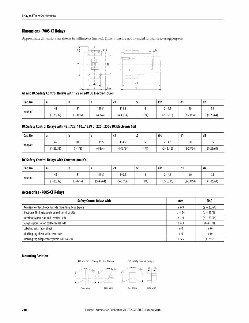
Relay and Timer Specifications
Dimensions - 700S-CF RelaysApproximate dimensions are shown in millimeters (inches). Dimensions are not intended for manufacturing purposes.
AC and DC Safety Control Relays with 12V or 24V DC Electronic Coil
DC Safety Control Relays with 48...72V, 110...125V or 220...250V DC Electronic Coil
DC Safety Control Relays with Conventional Coil
Accessories - 700S-CF Relays
Mounting Position
Cat. No. a b c c1 c2 Ød d1 d2
700S-CF45 81 119.5 114.5 6 2 - 4.5 60 35
(1-25/32) (3-3/16) (4-3/4) (4-43/64) (1/4) (2 - 3/16) (2-23/64) (1-25/64)
Cat. No. a b c c1 c2 Ød d1 d2
700S-CF45 105 119.5 114.5 6 2 - 4.5 60 35
(1-25/32) (4-1/8) (4-3/4) (4-43/64) (1/4) (2 - 3/16) (2-23/64) (1-25/64)
Cat. No. a b c c1 c2 Ød d1 d2
700S-CF45 81 145.5 140.5 6 2 - 4.5 60 35
(1-25/32) (3-3/16) (5-49/64) (5-37/64) (1/4) (2 - 3/16) (2-23/64) (1-25/64)
Safety Control Relays with mm [in.]
Auxiliary contact block for side mounting 1- or 2-pole a + 9 (a + 23/64)Electronic Timing Module on coil terminal side b + 24 (b + 15/16)Interface Module on coil terminal side b + 9 (b + 23/64)Surge Suppressor on coil terminal side b + 3 (b + 1/8)Labeling with label sheet + 0 (+ 0)Marking tag sheet with clear cover + 0 (+ 0)Marking tag adapter for System Bul. 1492W + 5.5 (+ 7/32)
c2
cc1
AC and DC E Safety Control Relays DC Safety Control Relays
Front View Front ViewSide View Side View
210 Rockwell Automation Publication 700-TD552C-EN-P - October 2018

Relay and Timer Specifications
Safety Relay Circuit With 5 Safety Outputs
• Use for E-stop control. E-stop will work properly if any one fault occurs (a fault could be one welded contact or one undesired open connection such as a loose wire).
• High output switching capability and long contact life.• Circuit complies with EN 954 categories 1, 2, 3, 4.• Helps prevent restart of the 5 safety outputs if there is a single fault anywhere in the system.• Use (3) 700S-CF relays and this diagram to construct the circuit
* Numbers shown are the line numbers where the contacts for this relay appear. Contact your local Rockwell Automation sales office or Allen-Bradley distributor for availability.
(5) Output Circuit (3 Relays, 17 Terminal Blocks)
Basic Circuit(1) Output Circuit (3 Relays, 9 Terminal Blocks)
Push To StopPull To Reset
Start
LOAD 1
LOAD 2
LOAD 3
LOAD 4
LOAD 5
Included in factorywired units
Rockwell Automation Publication 700-TD552C-EN-P - October 2018 211

Relay and Timer Specifications
700-K Miniature Control Relays• IEC compact industrial relay• IP2X Finger Protection• Bifurcated contacts for low-level signals• Optional integrated coil protection diode
4-Pole AC or DC Coil Voltage
⊗ Coil Voltage Codes
The cat. no. as listed is incomplete. Select a coil voltage code from the table below to complete the cat. no. Example: 230V, 50/60 Hz: Cat. No. 700-K40E-⊗ becomes Cat. No. 700-K40E-KF. For other voltages, consult your local Rockwell Automation sales office or Allen-Bradley distributor.
AC-12 AC-15 (B600)
ConnectionDiagrams
Contacts
Pkg. Qty.(2)
(2) May be ordered in package quantities of 20. Add letter M to the end of the cat. no. Example: 700-K40E-ZJM.
Cat. No.
Ith [A] Ie [A]
40 °C 60 °C 24/48V 120V 240V 400V 500V 600V 690V N.O. N.C.
10 6 3 3 2 1 1 0.6 0.6
4 0 1 700-K40E-⊗
3 1 1 700-K31Z-⊗
2 2 1 700-K22Z-⊗
1+1L (1)
(1) 1L = Late Break N.C. / Early Make N.O.
1+1L 1 700-KL22Z-⊗
For Screw Type Terminal Versions
[V] 12 24 110 120 125 220 230 240 250 400 440 480 525 600
AC, 50 Hz — — D — — — — — — — B — VC —
AC, 60 Hz — — — D — — — — — — — B — VC
AC, 50/60 Hz — KJ — — — — KF KA — KN — — — —
Standard DC
ZQ ZJ ZD — ZS ZA — — ZT — — — — —
Standard diode — DJ — — — — — — — — — — — —
For Spring Clamp Type Terminal Versions
AC, 50 Hz — — D — — — — — — — — — — —
AC, 60 Hz — — — D — — — — — — — — — —
AC, 50/60 Hz — KJ — — — — KF — — — — — — —
Standard DC
— ZJ ZD — — — — — — — — — — —
Standard diode — DJ — — — — — — — — — — — —
212 Rockwell Automation Publication 700-TD552C-EN-P - October 2018

Relay and Timer Specifications
Assignment of ContactsDevice Combinations in Accordance with IEC 60947-1 / -4-1Table valid for: AC / DC = 0.85…1.1 x Us, Tamb. = -25 °C…+60 °C, normal position (horizontal rail mounting). Also valid for 700-KR relays and
100-KR auxiliary contacts. (3)
Auxiliary Contact Blocks Control Relays 700-K (AC and DC Control)
Cat. No. Circuit Diagram Control 700-K22Z- 700-K31Z- 700-K40E- 700-KL22Z-
Front Mounting
100-KFA02E AC/DC — 31Z + 02E = 33Y (1)
(1) Tamb. max. +40 °C
40E + 02E = 42Y —
100-KFA11E AC/DC 22Z + 11E = 33Y 31Z + 11E = 42Y 40E + 11E = 51Y L22Z + 11E = L33Y
100-KFA20E AC/DC 22Z + 20E = 42Y 31Z + 20E = 51Y 40E + 20E = 60Y L22Z + 20E = L42Y
100-KFA04E AC/DC — — 40E + 04E = 44Y (1) —
100-KFA13E AC/DC — 31Z + 13E = 44Y (1) 40E + 13E = 53Y —
100-KFA22Z AC/DC — 31Z + 22Z = 53Y (1) 40E + 22Z = 62Y —
100-KFA31Z AC/DC — — 40E + 31Z = 71Y (2)
(2) Tamb. max. +40 °C and only allowed for coil voltage 24V DC or 230V AC(3) For other operating limits, please contact our technical consultant.
—
100-KFA40E AC/DC 22Z + 40E = 62Y 31Z + 40E = 71Y 40E + 40E = 80Y L22Z + 40E = L62Y
A1 13 43 21 31
32A2 14 44 22
A1 13 33 43 21
22A2 14 34 44
A1 13 23 33 43
44A2 14 24 34
A1 13 47 21 35
36A2 14 48 22
51 61
6252
53 61
54 62
53 63
54 64
71 81
8272
51 61
6252
53 61 71
7254 62
81
82
53 83 61 71
7254 84 62
73 83 61
74 84 62
53
54
53 63 73 83
8454 64 74
Rockwell Automation Publication 700-TD552C-EN-P - October 2018 213

Relay and Timer Specifications
Auxiliary Contact Blocks
Control Modules
Photo Description Connection Diagrams
For Use With Pkg.Qty.
(1)
(1) May be ordered in package quantities of 10. Add letter M to the end of the cat. no. Example: 100-KFA02EM.
Screw TypeTerminals
Spring ClampTerminals
N.O. N.C. Cat. No. Cat. No.
Front-mounted auxiliary contacts• Auxiliary Contact Blocks• 2- and 4-pole versions• Choice of contact configurations• Snap on, no tools required• Electronic-compatible bifurcated contacts
for signals down to 15V / 2 mA
0 2100/104-K,
700-K1 100-KFA02E 100-KRFA02E
1 1100/104-K,
700-K1 100-KFA11E 100-KRFA11E
2 0100/104-K,
700-K1 100-KFA20E 100-KRFA20E
0 4100/104-K,
700-K1 100-KFA04E 100-KRFA04E
1 3100/104-K,
700-K1 100-KFA13E 100-KRFA13E
2 2100/104-K,
700-K1 100-KFA22Z 100-KRFA22Z
3 1100/104-K,
700-K1 100-KFA31Z 100-KRFA31Z
4 0100/104-K,
700-K1 100-KFA40E 100-KRFA40E
Photo Description ConnectionDiagrams
For Use With Pkg.Qty.
Cat. No.
Mechanical Interlock• For interlocking of two adjacent contactors• No added width to contactor assembly• Front mount plug-in type• Optional auxiliary contact blocks and suppressor modules mount
onto the interlock
100/104-K/- KR,
700-K/- KR1 100-KMCH
Surge Suppressor• Plug-in type• Limits surge voltage on
coil drop-off
RC Suppressor
24…48V AC100/104-K/-
KR,700-K/- KR
1 (1)
(1) May be ordered in package quantities of 10. Add letter M to the end of the cat. no. Example: 100-KFSC50M.
100-KFSC50
110…280V AC 1 (1) 100-KFSC280
380…480V AC 1 (1) 100-KFSC480
MOV Suppressor
12…55V AC,12…77V DC
100/104-K/- KR,
700-K/- KR
1 (1) 100-KFSV55
56…136V AC,78…180V DC 1 (1) 100-KFSV136
137…277V AC,181…250V DC 1 (1) 100-KFSV277
Diode Suppressor 12…250V DC100/104-K/-
KR,700-K/- KR
1 (1) 100-KFSD250
51 61
6252
53 61
54 62
53 63
54 64
71 81
8272
51 61
6252
53 61 71
7254 62
81
82
53 83 61 71
7254 84 62
73 83 61
74 84 62
53
54
53 63 73 83
8454 64 74
214 Rockwell Automation Publication 700-TD552C-EN-P - October 2018
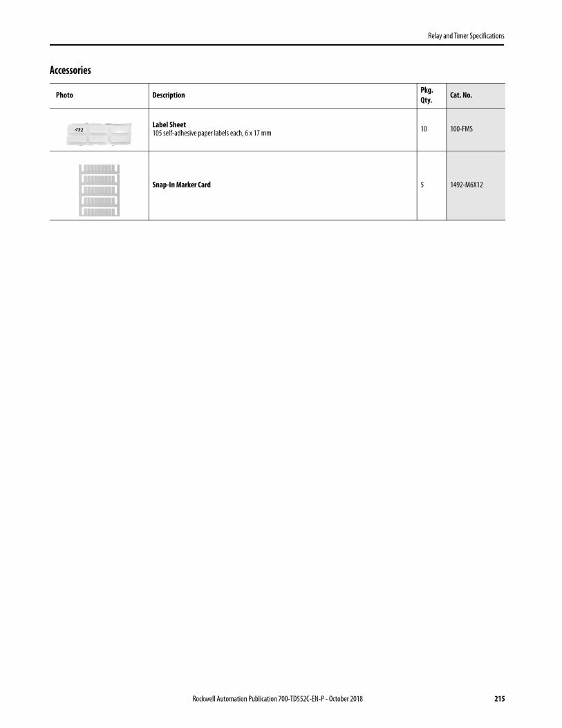
Relay and Timer Specifications
Accessories
Photo Description Pkg. Qty.
Cat. No.
Label Sheet105 self-adhesive paper labels each, 6 x 17 mm 10 100-FMS
Snap-In Marker Card 5 1492-M6X12
Rockwell Automation Publication 700-TD552C-EN-P - October 2018 215

Relay and Timer Specifications
IEC Specifications - 700-K... Relays
700-K 700-KR
AC-12 Rated Thermal Current Ambient temperature 40°C
Ith 24…240V [A] 10
230…500V [A] 10
230…690V [A] 10
Ambient temperature 60°C
Ith 24…240V [A] 6
230…500V [A] 6
230…690V [A] 6
AC-15/B600 Switching of Solenoids and contactors
Ie 24V [A] 3
48V [A] 3
120V [A] 3
230V [A] 2
240V [A] 2
400V [A] 1.2
480V [A] 1
500V [A] 1
600V [A] 0.6
690V [A] 0.6
Short-circuit Protection
Fuse gG [A] 10
Min. Switching Capacity 15V
[mA] 2
Resistance and Power Dissipation
Main current circuit resistance, 1 pole [mΩ] 6.5
Power dissipation, 4 poles [W] 2.6
Total power dissipation
AC control, warm [W] 4.4
DC control, warm [W] 5.2
Lifespan
Mechanical [Mio. op.] 15
Electrical AC-15 (240V / 2 A) [Mio. op.] 0.7
Weight
AC control kg (lbs.) 0.16 (0.35)
DC control kg (lbs.) 0.2 (0.44)
Load Carrying Capacity per UL/CSA
Rated voltage AC [V] max. 600
Continuous rating 40 °C [A] 10 6
Switching capacity AC [A] B 600
Rated voltage DC [V] max. 600
Switching capacity DC [A] Q 600
216 Rockwell Automation Publication 700-TD552C-EN-P - October 2018

Relay and Timer Specifications
Cross Sections
700-K
DC-13/Q600
1 pole 24V [A] 2.3
48V [A] 1
110V [A] 0.55
125V [A] 0.55
220V [A] 0.27
250V [A] 0.27
400V [A] 0.15
440V [A] 0.15
600V [A] 0.1
Conductor Cross Sections- Main Contacts, Auxiliary Contacts, and Coil Terminals
700-K 700-KR
Terminal type
(1)
(1) Pozidriv No. 2 / Blade No. 3 screw
Fine stranded with ferrule(1) Conductor(2) Conductors
[mm2]
[mm2]
0.75…2.50.75…2.5
0.50…2.50.50…2.5
Solid or coarse stranded(1) Conductor(2) Conductors
[mm2]
[mm2]
1…41…2.5 + 1…4
0.75…2.5 (3)
0.75…2.5 (3)
(3) Stranded wire only
Recommended torque [Nm] 1.2 —
Cross section per UL/CSA [AWG] 18…12 (2)
(2) Use same cross sections
18…14 (3)
Recommended torque [lb-in] 10.6 —
Rockwell Automation Publication 700-TD552C-EN-P - October 2018 217

Relay and Timer Specifications
Coil Data
Dimensions - 700-K... RelaysApproximate dimensions are shown in millimeters. To convert millimeters to inches multiply by 0.0394. Dimensions are not intended to be used for manufacturing purposes.
700-K
Operating Limits
AC control50 Hz, 60 Hz, 50/60 Hz
pick-up [x Us] 0.85…1.1
dropout [x Us] 0.2…0.75
DC controlpick-up [x Us] 0.8…1.1
9, 12, 24, 110V DC: 0.7…1.25
dropout [x Us] 0.1…0.75
Coil Consumption
AC control50 Hz, 60 Hz, 50/60 Hz
pick-up [VA/W] 35/32
hold-in [VA/W] 5/1.8
DC controlpick-up [W] cold 3.0, warm 2.6
hold-in [W] cold 3.0, warm 2.6
Operating Times
ACclosing delay [ms] 15…40
opening delay [ms] 15…33
With RC module opening delay [ms] 15…28
DCclosing delay [ms] 18…40
opening delay [ms] 6…12
With integrated diode closing delay [ms] 8…12
With external diode opening delay [ms] 35…50
50 56 54
49
79
35.2435
45
(mm)25° 25°
12
-Minimum distance to grounded parts or walls
*)
*)
180°
218 Rockwell Automation Publication 700-TD552C-EN-P - October 2018

Relay and Timer Specifications
Rockwell Automation Publication 700-TD552C-EN-P - October 2018 219

Relay and Timer Specifications
Solid-state Relays
Product Overview
Bulletin No. 700-SA 700-SC
Type Tube Base, Socketed Miniature, Ice Cube Socketed
Features Compatible with 700-HN100, 125,108, and 204 socket, LED status, zero-cross switching
Compatible with 700-HN103 or 128 socket, LED Status, and Zero-cross AC Switching Options
Load Type AC(47…63 Hz) DC AC (47…63 Hz) DC
Load Voltage Range 75…264V AC 3…125V DC 75…264V AC 3…52.8V DC or 3…125V DC
Load Current Max. (Continuous) 5 A 3 A 3 A 3 A @ 48V DC or 2 A @ 110V DC
Max. Leakage Current to Load 5 mA @ 100V, 10 mA @ 200V 5 mA @ 125V 5 mA @ 100V AC 10 mA @ 200V AC, 5 mA @ 50V DC or 0.1 mA @ 100V DC
Zero Cross Load Switching Yes Not Applicable Yes (optional) Not Applicable
Equivalent Electromechanical Relay Contact Arrangement Form A Form A
Rated Control (Input) Voltage 5…24V DC 5…24V DC, 100…110V AC, 200/220V AC 5...24V DC
LED Indicator Yes Yes (optional) Yes (optional for 48V DC)
Mounting Method Panel or DIN with socket Panel or DIN with socket
Dielectric Strength 1500V AC, 50/60 Hz, 1 min. 1500V AC, 50/60 Hz, 1 min.
Certification cURus, CE, VDE cURus, CE, VDE
Max. Ambient Operating Temperature -30…80 °C (no condensation) -30…80 °C (no condensation)
Page 221 226
Rockwell Automation Publication 700-TD552C-EN-P - October 2018 219

Relay and Timer Specifications
Product Overview
Bulletin No. 700-SF 700-SH 700-SK
Type Square Base, Socketed Hockey Puck Slim Line, Socketed
Features (1)
(1) See Solid-state Relay Glossary on page 221 for term definitions.
Compatible with 700-HN116 socket, LED status, zero-cross AC switching
Panel/DIN Mount, High Current, Protective Cover, LED Status
Compatible with 700-HN121 socket. Supports Input (sensor) module or Output (SSR) module
Load Type AC (47…63 Hz) DC AC (47…63 Hz)3…60V DC
Output Module Input Module
AC(47…63 Hz) DC AC (47…63 Hz) DC
Load Voltage Range
75…264V AC 3 … 52.8V DC 3…50V DC, 24…265V AC42…530V AC, 42…265V AC,42…660V AC
75 … 264V AC 4 … 60V DC, 40 … 200V DC
Field Input: 60… 264V AC
Field Input: 6.6… 32V DC
Load Current Max. (Continuous)
3 A 10 A/100 A‡ 2 A 2 A @ 60V, 1.5 A @ 200V
Supply Current: 0.1…100 mA
Supply Current: 0.1…100 mA
Max. Leakage Current to Load
5 mA @ 100V AC, 10 mA @ 200V AC 5 mA @ 50V DC <3 mA 1.5 mA 1 mA 5 μA 5 μA
Zero Cross Load Switching
Yes Not Applicable Yes Yes (optional) N/A No N/A
Equivalent Electromechanical Relay Contact Arrangement
Form A Form A Form A
Rated Control (Input) Voltage
4V DC or 24V DC 3…32V DC, 4…32V DC,80…130V AC, 20…260V AC20…280V AC/22…48V DC
5… 24 V DC
LED Indicator Yes Yes Yes
Mounting Method
Panel or DIN with socket Panel without heat sink, Panel, or DIN with heat sink Panel or DIN with socket
Dielectric Strength
1500V AC, 50/60 Hz, 1 min. >4000V AC RMS 4000V AC, 50/60 Hz, 1 min.
Certification cURus, CE, VDE cURus, CE, CSA cURus, CE, TÜV
Max. Ambient Operating Temperature
-30…80 °C (no condensation) -20…70 °C (no condensation) -30…80 °C (no condensation)
Page 231 235 244
220 Rockwell Automation Publication 700-TD552C-EN-P - October 2018

Relay and Timer Specifications
Rockwell Automation Publication 700-TD552C-EN-P - October 2018 221
Solid-state Relay Glossary
Terms Meaning
Insulation
Basic insulation Insulation for basic protection from electric shock (IEC950 1.2.9.2)
Supplemental insulation Independent insulation that is provided outside of basic insulation to protect from electric shock when the basic insulation breaks down (IEC950 1.2.9.3)
Reinforced insulation A single-layer of insulation (IEC950 1.2.9.5) that provides the same protection from electric shock as double insulation (insulation including both basic and supplemental insulation) according to conditions stipulated in IEC950 standards
Circuit functionsZero cross circuit A circuit that starts operation with the AC load voltage at close to zero-phase.
Trigger circuit A circuit for controlling the triac or thyristor trigger signal, which turns the load current ON and OFF.
Input
Isolated input circuit
If the external circuit is prone to generating noise, or if wires from external sources are prone to the influence of inductive noise, in order to prevent malfunctions due to noise, it is necessary to electrically isolate internal circuits and external circuits (output circuits). An isolated input circuit is a circuit that isolates inputs and outputs by using components that are not connected electrically but that can transmit signals, such as contact relays or photocouplers.
PhotocouplerA component that runs the electric signal into a light emitter (for example, LED), changes it to a light signal, and then returns it to an electric signal using a photoelectric conversion element, such as a photo transistor. The space that is used for transferring the light signal is isolated thus providing good insulation and a high propagation speed.
Rated voltage The voltage that serves as the standard value of an input signal voltage
Pickup (must-operate) voltage Minimum input voltage when the output status changes from OFF to ON.
Input impedance The impedance of the input circuit and the resistance of current-limiting resistors used. Impedance varies with the input signal voltage in case of the constant current input method.
Operating voltage The permissible voltage range within which the voltage of an input signal voltage may fluctuate.
Dropout (Reset) voltage Maximum input voltage when the output status changes from ON to OFF.
Input current The current value when the rated voltage is applied.
Output
Load voltage This is the effective value for the power supply voltage that can be used for load switching or in the continuous-OFF state.
Maximum load current(continuous)
The effective value of the maximum current that can continuously flow into the output terminals under specified cooling conditions (i.e., the size, materials, thickness of the heat sink, and an ambient temperature radiating condition).
Leakage current The effective value of the current that can flow into the output terminals when a specified load voltage is applied to the SSR with the output turned OFF.
Output ON voltage dropThe effective value of the AC voltage that appears across the output terminals when the maximum load current flows through the SSR under specified cooling conditions (such as the size, material, and thickness of heat sink, ambient temperature radiation conditions, etc.).
Minimum load current(continuous) The minimum load current at which the SSR can operate normally.
Snubber circuit A circuit consisting of a resistor R and capacitor C, which prevents faulty ignition from occurring in the SSR triac by suppressing a sudden rise in the voltage that is applied to the triac.
Semiconductor output element (switching element)
This is a generic name for semiconductors such as the thyristor, triac, power transistor, and power MOS FET. In particular, triacs are often used in SSRs because they allow switching to be performed with one element.
Repetitive peak OFF-state voltage (VDRM) This is a rating for an output semiconductor that used in an SSR for AC loads.
Collector-emitter voltage(VCEO) This is a rating for an output semiconductor that used in an SSR for DC loads.

Relay and Timer Specifications
Solid-state Relay Switching Capacity
Characteristics
Operating (pick-up) time A time lag between the moment a specified signal voltage is imposed to the input terminals and the output is turned ON.
Release (drop-out) time A time lag between the moment the imposed signal input is turned OFF and the output is turned OFF.
Insulation resistance The resistance between the input and output terminals or I/O terminals and metal housing (heat sink) when DC voltage is imposed.
Dielectric strength The effective AC voltage that the SSR can withstand when it is applied between the input terminals and output terminals or I/O terminals and metal housing (heat sink) for more than 1 minute.
Ambient temperature and humidity (operating)
The ranges of temperature and humidity in which the SSR can operate normally under specified cooling, input/output voltage, and current conditions.
Storage temperature The temperature range in which the SSR can be stored without voltage imposition.
Others
Inrush current resistance A current, which can be applied for short periods of time to the electrical element.
Counter-electromotive force Extremely steep voltage rise which occurs when the load switched or turned OFF.
Recommended applicable load The recommended load capacity which takes into account the safety factors of ambient temperature and inrush current.
Bleeder resistance The resistance connected in parallel to the load in order to increase apparently small load currents, so that the ON/OFF of minute currents functions normally. (It is also used to shunt leakage currents.)
IMPORTANT * Requires a heat sink to reach maximum current value.
Terms Meaning
Solid
-State
Relay TypeEquivalent EMRelay ContactConfiguration
Load
VoltageZero-Cross
Load
SwitchingDevice
Maximum AC and DC Switching Capability
1 mA 10 mA 50 mA 100 mA 1 A 3 A 5 A 10 A 20 A 25 A 30 A 35 A 100 A
700-SA
AC
DC N/A
700-SC
AC
DC N/A (2 A)
700-SF
AC
DC N/A
700-SH *
700-S KOAC
(2 A)DC N/A
Yes Triac
Yes Triac
Yes Triac
Yes Triac
YesThyristor or Triac
Transistor
Transistor
Transistor
AC
Form A
Form A
Form A
Form A
Form A
DC N/A Transistor
Transistor
222 Rockwell Automation Publication 700-TD552C-EN-P - October 2018

Relay and Timer Specifications
700-SA Tube Base Relays• 5 A (resistive) max. continuous load (output) current• 264V AC or 125V DC max. load voltage options• Photocoupler isolation between control and load voltage• LED indicator (standard) for input/logic ON/OFF status monitoring• 700-HN100, -HN125, -HN 202, or -HN108 specialty socket compatible• 700-HT2 timing module
Accessories - 700-SA Relays
Input-to-Output Isolation Method
Zero Cross Function Status Indicator Output (Load) Max. Continuous Current and Rated Voltage Range
Rated Input (Control) Voltage
Cat. No.
Photocoupler Yes
Yes 5 A @ 100…240V AC(47…63 Hz) 5…24V DC
700-SAZY5Z25
Not Applicable 3 A @ 5…110V DC 700-SANY3Z25
Photo Description Pkg. Quantity Cat. No.
Screw Terminal Tube Base Socket — Panel or DIN Rail Mounting; Guarded Terminal Construction. 8 Pin for use with DPDT 700-HA Relays.
10 700-HN100
Specialty Socket8 Pin back wired socket with solder terminals
10 700-HN108
Screw Terminal Tube Base Socket — Panel or DIN Rail Mounting; Open Style Construction. 8 Pin for use with DPDT 700-HA Relays. No retainer clip required.
10 700-HN125
DIN (#3) symmetrical hat rail35 x 7.5 x 1 m
10 199-DR1
Pre-Printed Identification Tags — contains 10 sheets of pre-printed and blank tags. Each sheet contains 13 sets of the markings CR…9CR, TR…9TR, M…9M, F, R, 1S, and 117 blank tags. Tags are peel-off with sticky backing for easy placement on relays.
10 700-N40
Blank Identification Tags — contains 10 sheets of blank identification tags for customer specialized printing. Each sheet contains 546 blank tags. Tags are peel-off with sticky backing for easy placement on relays.
10 700-N41
Retainer Clip for Sockets with 700-SA AND 700-HB Relays. Secures relay in socket. 10 700-HN158
8-Pin Socket — Can Be Used With or Without Timing Module or Surge Suppressor. Screw Terminal Tube Base Sockets — panel or DIN Rail mounting. Guarded terminal construction. Used with DPDT 700-HA Relays.
10 700-HN204
Rockwell Automation Publication 700-TD552C-EN-P - October 2018 223

Relay and Timer Specifications
224 Rockwell Automation Publication 700-TD552C-EN-P - October 2018
Specifications - 700-SA RelaysControl/Input Ratings
Load/Output Ratings
Characteristics
(1) With constant current input system. SSR input impedance varies with a change in input (control) voltage.(2) See the following graph “Load Current Vs. Ambient Temperature Characteristics” for additional load current details.(3) If the SSR operation is continuous ON/OFF, this value should be reduced by 50%. See “Inrush Current Resistivity” graph.(4) 60 Hz full cycle time = 16.6 ms, 50 Hz full cycle time = 20 ms.
Cat. No. Rated ControlVoltage
Max. Operating Control
Voltage Range
Max. Reverse ControlVoltage
Impedance Control Voltage LevelsPick-up Voltage Drop-out Voltage
700-SAZY5Z255…24V DC
4…32V DC -32V DC 15 mA max. (1)4V DC max. 1V DC min.
700-SANY3Z25 4…30V DC -30V DC 1.5 kΩ (+20% -10%)
Cat. No. Rated LoadVoltage
Maximum LoadVoltage Range
Continuous Load Current (Resistive) [A] Max. InrushCurrent (3)
Min. Max. (2)
700-SAZY5Z25 100…240V AC 75…264V AC 0.1 5.0 80 A, @ 50/60 Hz for 1 cycle
700-SANY3Z25 5…110V DC 3…125V DC 0.1 3.0 12 A (10 ms)
Description Cat. No. 700-SAZY5Z25 Cat. No. 700-SANY3Z25Load Switching Method/Device Triac Transistor
Pick-up Time 1/2 cycle of load power source cycle time (4) + 1 ms max. 0.5 ms max.
Drop-out Time 1/2 cycle of load power source cycle time (4) + 1 ms max. 2.5 ms max.
Output ON Voltage Drop 1.6V (RMS) max. 1.5V max.
Output Leakage Current 5 mA max. (at 100V AC); 10 mA max. (at 200V AC) 5 mA max. (at 125V DC)Output VDRM VCEO (V) 600 150
Output di/dt (V/uS) 50 —
Output dv/dt (V/uS) 500 —
Output I2t (A2S) 41.6 —
Output Tj (ºC) Max. 125 150
Insulation Resistance 100 MΩ min. (at 500V DC)
Dielectric Strength 1500V AC, 50/60 Hz for 1 min
Vibration Resistance (Max.) 10…55 Hz, 1.5 mm double amplitude (10 G)
Shock Resistance (max.) 1000 m/s2 (100 G)
Ambient TemperatureOperating –30…80 °C (–22…176 °F) with no icing or condensation
Storage –30…100 °C (–22…212 °F) with no icing or condensation
Ambient Humidity 45…85% (no condensation)
Standards Compliance UL 508, CSA C22.2 No. 14, EN 60947-1, -4-3
Certifications cURus Recognized (File No. E96956, Guide NMFT2/NMFT8), CE Marked, VDE Certified
Weight Approx. 70 g
Load Current vs. Ambient Temperature Characteristics Inrush Current Resistivity (1)
(1) Inrush current resistivity is the ability of an SSR to withstand a large surge current for a short period. Surges are considered non-repetitive (max. repeatability once every 5 seconds). Keep the inrush current to half the rated value if it occurs repetitively. Exceeding the non-repetitive inrush current will damage the SSR.
700-SA
Ambient Temperature [° C]
Load
Cur
rent
[A]
700-SA
Inru
sh C
urre
nt [A
. Pea
k]
Energizing Time [ms]
700-SAZY5Z25
700-SANY3Z25
0
1
2
3
4
5
-30
-20 0 20 40 60 80 100
700-SANY3Z25
700-SAZY5Z25
80
70
60
50
40
30
20
10
0
10 30 50 100
200
500
1000
5000

Relay and Timer Specifications
Terminal Arrangement (Bottom View)
Basic Application ConsiderationsHigh Density Mounting of Multiple Solid-state Relays (SSRs)
If multiple SSRs are installed side by side,, the outer case wall of the SSR serves to dissipate heat. Install the relays so that they are adequately ventilated. If poor ventilation is unavoidable, reduce the load current to half.
Protective Component
When controlling AC inductive loads, connect an inrush/surge absorbing device (varistor) across the SSR load terminals. If the SSR has built- in surge suppression (s 700-SE and 700-SH) and additional surge suppression is required, connect the varistor across the terminals of the load device. Select a varistor that meets the conditions of the load voltage that is outlined in the table.
For a DC inductive load, a diode should be connected parallel to the load to absorb the counter electromotive force (OFF) of the load.
Dimensions - 700-SA RelaysAll units in millimeters unless otherwise indicated. To convert millimeters to inches multiply by 0.0394. Dimensions are not intended to be used for manufacturing purposes.
Load Voltage Varistor Voltage [V] Varistor Surge Resistance
100…120V AC 240…270
1000 A min.200…240V AC 440…470
380…480V AC 820…1000
TIP For additional details on solid-state relays, see the Solid-State Relay Application Guide, publication 700-AT001.
700-SA (1)
(1) 700-SA is compatible with Cat. Nos. 700-HN100, -108, -125, and -204 (sockets).
Loadpowersupply
LoadLoad
Note: The plus and minus symbols shown in parentheses are for DC loads.
Input voltage
Input
SSRInput
Load
Load powersupply
EMC Directive Compliance
• Connect a varistor between the output terminals.• Connect a film capacitor to the load power supply.• The input cable must be less than 3 m.
• The input cable must be less than 10 m.
VaristorVaristor: 470 V, 0.6 W
Film Capacitor: 1µ F, 250 VAC
OutputInput
Load3 m max.
Film Capacitor
700-SA
OutputInput
LoadLess than 10 m
700-SA
1. AC-switching models comply with EMC Directives under the following conditions:
2. DC-switching models comply with EMC Directives under the following conditions:
52.5 max.
35 max.
+
+
35 max.
Rockwell Automation Publication 700-TD552C-EN-P - October 2018 225

Relay and Timer Specifications
226 Rockwell Automation Publication 700-TD552C-EN-P - October 2018
700-SC Ice Cube Relays• 3 A (resistive) max. continuous load (output) current• 264V AC, 48V DC or 125V DC max. load voltage options• 5…24V DC or 110/220V AC control (input) voltage options• LED indicator (optional) for input/logic On/Off status monitoring• 700-HN103, 700-HN104, or 700-HN128 socket compatible• Compatible with 700-AT1 or 700-AT2 timer modules
Accessories - 700-SC Relays
Input-to-Output Isolation Method
Zero Cross Function Status Indicator Output (Load) Max. Continuous Current and Rated Voltage Range
Rated Input (Control) Voltage
Cat. No.
Photocoupler Yes
Yes
3 A @ 100…240V AC(1)
(1) 47…63 Hz
5…24V DC 700-SCZY3Z25
2 A @ 100…240V AC(1) 100/110V AC 700-SCZY2A1
200/220V AC 700-SCZY2A2
Phototriac No 3 A @ 100…240V AC (1) 24V DC 700-SCTY3Z24
Photocoupler Not Applicable 3 A @ 4…48V DC 5…24V DC 700-SCNY3Z25
Yes
No
3 A @ 100…240V AC (1)4…24V DC 700-SCZN3Z26
Phototriac No 24V DC 700-SCTN3Z24
Photocoupler Not Applicable 3 A @ 4…48V DC 4…24V DC 700-SCNN3Z26
2 A @ 5…110V DC 5…24V DC 700-SCNN2Z25
Photo Description Pkg. Quantity Cat. No.
Screw Terminal Socket — Panel or DIN Rail Mounting; Guarded Terminal Construction.Ith = 10 A per pole. 14-blade miniature socket for use with 700-SC Relays. 10 700-HN103
Screw Terminal Socket — Panel or DIN Rail Mounting; Guarded Terminal Construction Ith = 10 A per pole. 14-blade miniature socket for use with 700-SC relays. This socket has coil and contact separation and the ability to plug in optional plug-in modules (700-A__ accessories: LED, Surge Suppression, Timing Modules)
10 700-HN104
Screw Terminal Base Socket — Panel or DIN Rail Mounting; Open-Style Construction Ith = 10 A per pole. 14-blade miniature socket for use with 700-SC Relays. 10 700-HN128
DIN (#3) symmetrical hat rail35 x 7.5 x 1 m 10 199-DR1

Relay and Timer Specifications
Specifications- 700-SC Relays
Pre-Printed Identification Tags — contains 10 sheets of pre-printed and blank tags. Each sheet contains 13 sets of the markings CR…9CR, TR…9TR, M…9M, F, R, 1S, and 117 blank tags. Tags are peel-off with sticky backing for easy placement on relays.
10 700-N40
Blank Identification Tags — contains 10 sheets of blank identification tags for customer specialized printing. Each sheet contains 546 blank tags. Tags are peel-off with sticky backing for easy placement on relays.
10 700-N41
Retainer Clip for Cat. Nos. 700-HN103, -HN104, and -HN128 Sockets with 700-HC Relays. Secures relay in socket. 10
(1)
700-HN114
(1) Series B retainer clip must be used with 700-SC
Control/Input RatingsCat. No. Rated Control
VoltageMax. Operating Control Voltage
Range
Max. Reverse Control Voltage [V]
Impedance Control Voltage LevelsPick-up Voltage Drop-out Voltage
700-SCZY3Z25 5…24V DC 4…28V DC -28.8 15 mA max. (1)
(1) With constant current input circuit system. SSR impedance varies with a change in input (control) voltage.
4V DC max. 1V DC min.700-SCZY2A1 100/110V AC 75…125V AC NA 41 kΩ ±20% 75V AC max. 20V AC min.700-SCZY2A2 200/220V AC 150…250V AC NA 72 kΩ ±20% 150V AC max. 40V AC min.700-SCTY3Z24 24V DC 19.2…28.8V DC -28.8 2 kΩ ±20% 19.2V DC max.
1V DC min.
700-SCNY3Z25 5…24V DC 4…28V DC -28 1.5 kΩ +20%/ -10% (2)
(2) Input impedance attains its maximum at the operating voltage.
4V DC max.
700-SCZN3Z26 4…24V DC 3…28V DC -28.8 15 mA max. (1) 3V DC max.700-SCTN3Z24 24V DC 19.2…28.8V DC -28.8 2 kΩ ±20% 19.2V DC max.700-SCNN3Z26 4…24V DC
3…28V DC-28 1.5 kΩ +20%/ -10%
(2) 3V DC max.700-SCNN2Z25 5…24V DC -28.8
Load/Output RatingsCat. No. Rated Control
VoltageMax. Load
Voltage RangeContinuous Load Current (Resistive) [A] Max. Inrush
Current (4)
(4) See the following “Load Current Versus Ambient Temperature Characteristics” graphs on page 112 for additional load current details.
Min. Max. (3)
(3) If the SSR operation is continuous ON/OFF, this value should be reduced by 50%. See “Inrush Current Resistivity” graphs on page 112 for details
700-SCZY3Z25
100…240V AC 75…264V AC0.1 3
45 A (@50/60 Hz,1 cycle)
700-SCTY3Z24
700-SCZN3Z26
700-SCTN3Z24
700-SCZY2A10.1 2
700-SCZY2A2
700-SCNN3Z264…48V DC 3…52.8V DC 0.1 3 18 A (10 ms)
700-SCNY3Z25
700-SCNN2Z25 5…110V DC 3…125V DC 0.1 2 10 A (10 ms)
Photo Description Pkg. Quantity Cat. No.
Rockwell Automation Publication 700-TD552C-EN-P - October 2018 227

Relay and Timer Specifications
Characteristics
Load Current Versus Ambient Temperature Characteristics
Description Cat. No. 700-SCZ… Cat. No. 700-SCT Cat. Nos. 700-SCNY, 700- SCNN3…
Cat. Nos. 700-SCNN2…
Load Switching Method/Device Triac Transistor
Pick-up time
1/2 of load power source cycletime (1) + 1 ms max. (DC
input)
(1) 60 Hz full cycle time = 16.6 ms, 50 Hz full cycle time = 20 ms
3/2 of load power source cycletime (1) + 1 ms max. (AC
input)
Drop-out time
1/2 of load power source cycletime (1) + 1 ms max. (DC input) 1/2 of load power source cycle
time (1) + 1 ms max. 2 ms max. 2.5 ms max.3/2 of load power source cycle
time (1) + 1 ms max. (AC input)Output On Voltage Drop 1.6V (RMS) max. 1.6V (RMS) 1.5V max. 1.5V max.
Output Leakage Current 5 mA max (@ 100V AC)10 mA max (@ 200V AC)
2.5 mA max (@ 100V AC)5 mA max (at 200V AC) 5 mA max (@ 50V DC) 0.1 mA max (@ 100V DC)
Output VDRM, VCEO (V) 600 600 80 80Output di/dt (A/uS) 50 50 — —Output dv/dt (V/uS) 250 250 — —
Output I2t (A2S) 18 18 — —Output Tj (°C) Max. 125 125 150 150
Insulation Resistance 100 MΩ min (@500V DC)Dielectric Strength 1500V AC, 50/60 Hz for 1 minute
Vibration Resistance (max.) 10…55 Hz, 1.5 mm double amplitude (10 G)Shock Resistance (max.) 1000 m/s2 (100 G)
Ambient Temperature Operating: -30…+80 °C (-22...+176 °F) with no icing or condensation Storage: -30…+100 °C (-22...+212 °F) with no icing or condensation
Standards Compliance UL 508, CSA C22.2 No. 14, EN/IEC 60950, EN 50011, EN 61000-6-2, EN/IEC 60947-1, -4-3Certifications cURus Recognized (File No. E96956, Guide NMFT2/NMFT8), CE Marked, VDE Certified
Ambient Humidity Operating: 45…85% (no condensation)Weight Approx. 50 g
700-SC_ _3...
Ambient Temperature [° C]
Load
Cur
rent
[A]
700-SC_ _2...
Load
Cur
rent
[A]
-30
-20 0 4020 1008060
0
1
2
3
4
5
0
1
2
3
4
5
-30
-20 0 4020 1008060
Ambient Temperature [° C]
228 Rockwell Automation Publication 700-TD552C-EN-P - October 2018

Relay and Timer Specifications
Inrush Current Resistivity (1)
(1) Inrush current resistivity is the ability of an SSR to withstand a large surge current for a short period. Surges are considered non-repetitive (max. repeatability once every 2…5 seconds). Keep the inrush current to half the rated value if it occurs repetitively. Exceeding the non-repetitive inrush current will damage the SSR.
700-SCZ.... 700-SCT...
Energizing Time [ms]
700-SCNN3... 700-SCNY3 700-SCNN2...
Inru
sh C
urre
nt [A
. Pea
k]
Energizing Time [ms]
10 20 30 50 100
300
500
1000
3000
5000
12
10
8
6
4
2
0
Energizing Time [ms]
30
20
10
0
468
2
141618
12
242628
22
10 20 30 50 100
200
500
1000
200070 300
Inru
sh C
urre
nt [A
. Pea
k]
Inru
sh C
urre
nt [A
. Pea
k]
10 30 50 100
200
500
1000
5000
50
40
30
20
10
0
EMC Directive Compliance1. AC-switching models comply with EMC Directives under the
following conditions
2. DC-switching models comply with EMC Directives under the following conditions
VaristorVaristor: 470 V, 0.6 WFilm capacitor: 1 µ F, 250 VAC
OutputInput
Load
3 m max.
• Connect a varistor between the output terminals.• Connect a film capacitor to the load power supply.• The input cable must be less than 3 m.
Film capacitor
OutputInput
Load
Less than 10 m
• The input cable must be less than 10 m.
700-SC
700-SC
Rockwell Automation Publication 700-TD552C-EN-P - October 2018 229

Relay and Timer Specifications
Dimensions - 700-SC RelaysAll units in millimeters unless otherwise indicated. To convert millimeters to inches multiply by 0.0394. Dimensions are not intended to be used for manufacturing purposes.
Cat. No 700-SC… (1)
(1) 700-SC is compatible with Cat. Nos. 700-HN103, -HN104, and -HN128 socket.
Basic Application Considerations for 700-SC
High-density Mounting of Multiple Solid-state Relays (SSRs)
If multiple relays are mounted side by side, the outer wall of each SSR works as a radiator. The SSR casing serves to dissipate heat. Install the relays so that they are adequately ventilated. If poor ventilation is unavoidable, reduce the load current by half.
Connection
For DC Load Switching, 700-SC will operate properly if the load is connected to either the positive or negative SSR load terminal.
Protective Component
When controlling AC inductive loads, connect an inrush/surge absorbing device (varistor) across the SSR load terminals. If the SSR has built- in surge suppression (s 700-SE and 700-SH) and additional surge suppression is required, connect the varistor across the terminals of the load device. Select a varistor that meets the conditions of the load voltage that is outlined in the table below.
Load Voltage [V AC] Varistor Voltage [V] Varistor Surge Resistance
100…120 240…270
1000 A min.200…240 440…470
380…480 820…1000
TIP For additional details on solid-state relays, see the Solid-State Relay Application Guide, publication 700-AT001.
Terminal Arrangement/Internal Connections(Bottom View)
1
5
9
13
4
8(+)
12(–)
14
– +
– +
Load
(+)
(–)
Input
Load
Input voltage
Loadpowersupply
Note: The plus and minus symbols shownin parentheses are for DC loads.
28 max.
21.5 max. 36.5 max.
42.5 max.
SSRInput
Load
Load powersupply
230 Rockwell Automation Publication 700-TD552C-EN-P - October 2018

Relay and Timer Specifications
700-SF Square Base Relays• 3 A (resistive) max. continuous load (output) current• 264V AC or 52.8V DC max. load voltage options• 4…24V DC control/input voltage• Photocoupler or phototriac isolation option between control and output voltage• LED Indicator for input/logic ON/OFF status monitoring• 700-HN116 socket compatible
Accessories-700-SF Relays
Specifications- 700-FS Relays
Control/Input Ratings
Input-to-Output Isolation Method
Zero Cross Function Status Indicator Output (Load)Max. Continuous Current and Rated Voltage Range
Rated Input Control Voltage
Cat. No.
Photocoupler Yes
Yes 3 A @ 100…240V AC(47...63 Hz)
5…24V DC 700-SFZY3Z25
Phototriac No 24V DC 700-SFTY3Z24
Photocoupler Not Applicable 3 A @ 4…48V DC 4…24V DC 700-SFNY3Z25
Photo Description Pkg. Quantity Cat. No.
Screw Terminal Socket — Panel or DIN Rail Mounting 8-blade miniature socket for use with DPDT HF relays. 10 700-HN116
DIN (#3) symmetrical hat rail35 x 7.5 x 1 m 10 199-DR1
Pre-Printed Identification Tags — contains 10 sheets of pre-printed and blank tags. Each sheet contains 13 sets of the markings CR…9CR, TR…9TR, M…9M, F, R, 1S, and 117 blank tags. Tags are peel-off with sticky backing for easy placement on relays.
10 700-N40
Blank Identification Tags — contains 10 sheets of blank identification tags for customer specialized printing. Each sheet contains 546 blank tags. Tags are peel-off with sticky backing for easy placement on relays. 10 700-N41
Retainer Clip for Cat. Nos. 700-HN103, -HN104, and -HN128 Sockets with 700-HC Relays. Secures relay in socket. 10 700-HN114(1)
(1) 700-SF must use Cat. No. 700-HN114 series B retainer clip.
Cat. No. Rated Control Voltage
Max. Operating Control Voltage
Range [V DC]
Max. Reverse Control Voltage [V]
Impedance Control Voltage Levels
Pick-up Voltage Drop-out Voltage
700-SFZY3Z25 5…24V DC 4…28V DC –32 15 mA max. (1) 4V DC max. 1V DC min.
700-SFTY3Z24 24V DC 19.2…28.8V DC –28.8 2 kΩ ± 20% 19.2V DC max. 1V DC min.
700-SFNY3Z25 5…24V DC 4…28V DC –28.8 1.5 kΩ + 20%/–10% (2) 4V DC max. 1V DC min.
Rockwell Automation Publication 700-TD552C-EN-P - October 2018 231

Relay and Timer Specifications
Load/Output Ratings
Characteristics
(1) With constant current input circuit system, SSR impedance varies with a change in input voltage.
(2) Input impedance reaches its maximum at the operating voltage.(3) If the SSR operation is continuous ON/OFF, this value should be reduced by 50%. See the “Inrush Current Resistivity” graphs on page 116 for more details.(4) See “Load Current vs. Ambient Temperature Characteristics” on page 116 for additional load current details.(5) 60 Hz full cycle time = 16.6 ms, 50 Hz full cycle time 20 ms.
Cat. No. Rated Control Voltage Max. Load Voltage Range
Continuous Load Current (Resistive) [A] Max. Inrush Current (4)
Min. Max. (3)
700-SFZY3Z25100…240V AC 75…264V AC
0.1 3 45 A @ 50/60 Hz,1 cycle700-SFTY3Z24 0.1 3
700-SFNY3Z25 4…48V DC 3…52.8V DC 0.1 3 18 A (10 ms)
Description Cat. No. 700-SFZY3Z25 Cat. No. 700-SFTY3Z24 Cat. No. 700-SFNY3Z25Load Switching Method/Device Triac Transistor
Pick-up Time 1/2 cycle of load power sourcecycle time (5) + 1 ms max.
1 ms max. 0.5 ms max.
Drop-out Time 1/2 cycle of load power source cycle time (5) + 1 ms max. 2 ms max.Output ON Voltage Drop 1.6V (RMS) max. 1.5V max.
Output Leakage Current 5 mA max. (@ 100V AC);10 mA max. (@ 200V AC)
2.5 mA max. (@ 100V AC); 5 mA max. (@ 200V AC)
5 mA max. (@ 50V DC)
Output VDRM, VCEO (V) 600 600 80
Output di/dt (A/uS) 50 50 —Output dv/dt (V/uS) 250 250 —Output I2t (A2S) 18 18 —
Output Tj (°C) Max. 125 125 150Insulation Resistance 100 MΩ min. (at 500V DC)Dielectric Strength 1,500V AC, 50/60 Hz for 1 minVibration Resistance (Max.) 10…55 Hz, 1.5 mm double amplitude (10 G)Shock Resistance (Max.) 1000 m/s2 (100 G)
Ambient Temperature Operating: –30…+80 °C (–22…+176 °F) with no icing or condensation Storage: –30…+100 °C (–22…=212 °F) with no icing or condensation
Ambient Humidity 45…85% (no condensation)Standards Compliance UL 508, CSA C22.2 No. 14, EN/IEC 60947-1, -4-3, EN/IEC 60950Certifications cURus Recognized (File No. E96956, Guide NMFT2/NMFT8), CE Marked, VDE CertifiedWeight Approx. 50 g
IMPORTANT This data is non-repetitive. Keep the inrush current to half the rated value if it occurs repetitively. Inrush current resistivity is the ability of an SSR to withstand a large surge current for a short period.Surges are considered non-repetitive (max. repeatability once every 2…5 seconds). Keep the inrush current to half the rated value if it occurs repetitively. Exceeding the non-repetitive inrush current will damage the SSR.
232 Rockwell Automation Publication 700-TD552C-EN-P - October 2018

Relay and Timer Specifications
Load Current vs. AmbientTemperature Characteristics700-SF
Inrush Current Resistivity (1)
700-SFZ… 700SFT…
Inrush Current Resistivity (1)
700-SFN…
(1) Inrush current resistivity is defined as the ability of an SSR to withstand a large surge current for a short period. Surges are considered non-repetitive (max. repeatability once every 2…5 seconds).Keep the inrush current to half the rated value if it occurs repetitively. Exceeding the non-repetitive inrush current will damage the SSR.
Load
Cur
rent
[A]
Ambient Temperature [° C]
4
3
2
1
0
-30
-20 0 20 40 60 80 100
Energizing Time [ms]In
rush
Cur
rent
[A P
eak]
50
0
10
20
30
40
10 30 50 100
200
500
1000
5000
Energizing Time [ms]
Inru
sh C
urre
nt [A
]
30
2
2018
0
10864
121416
22242628
10 20 30 50 70 100
300
200
500
1000
2000
EMC Directive Compliance1. AC-switching models comply with EMC Directives under the
following conditions
2. DC-switching models comply with EMC Directives under the following conditions
VaristorVaristor: 470 V, 0.6 WFilm capacitor: 1 µ F, 250 VAC
OutputInput
Load
3 m max.
• Connect a varistor between the output terminals.• Connect a film capacitor to the load power supply.• The input cable must be less than 3 m.
Film capacitor
OutputInput
Load
Less than 10 m
• The input cable must be less than 10 m.
700-SF
700-SF
Rockwell Automation Publication 700-TD552C-EN-P - October 2018 233

Relay and Timer Specifications
Dimensions - 700-SF RelaysAll units in millimeters unless otherwise indicated. To convert millimeters to inches multiply by 0.0394. Dimensions are not intended to be used for manufacturing purposes.
Basic Application Considerations of 700-SF
High-density Mounting of Multiple Solid-state Relays (SSRs)
If multiple SSRs are mounted side by side, the outer case wall of the SSR acts as a radiator. The SSR case serves to dissipate heat. Install the relays so that they are adequately ventilated. If poor ventilation is unavoidable, reduce the load current by half.
Connection
For DC load switching, the Bul. 700-SF SSR will operate properly if the load is connected to either the positive or negative load terminals.
Protective Component to Extend SSR Life
When controlling AC inductive loads, connect an inrush/surge absorbing device (varistor) across the SSR load terminals. If the SSR has built- in surge suppression (700-SE and 700-SH) and additional surge suppression is required, connect the varistor across the terminals of the load device. Select a varistor that meets the conditions of the load voltage that is outlined in the table.
For a DC inductive load, a diode should be connected parallel to the load to absorb the counter electromotiveforce (OFF) of the load.
IMPORTANT 700-SF is compatible with Cat. No. 700-HN116 socket.
Load Voltage [V AC] Varistor Voltage [V] Varistor Surge Resistance
100…120 240…270
1000 A min.200…240 440…470
380…480 820…1000
TIP For additional details on solid-state relays, see the Solid-State Relay Application Guide, publication 700-AT001.
28 max
21.5 max 42.5 max
36.5 max
Terminal Arrangement/Input Connections(Bottom View)
Notes: 1. The plus and minus symbols shown in parentheses are for DC loads. 2. The coil has no polarity.
(+)
(-)
LoadLoad
Input Voltage
1
3
5
7
2
4(+)
6(-)
8
+-Input
+-
SSRInput
Load
Load powersupply
234 Rockwell Automation Publication 700-TD552C-EN-P - October 2018

Relay and Timer Specifications
700-SH Hockey Puck Relays• 100 A max. continuous load (output) current with appropriate heat sink• 264V AC, 530V AC, or 660V AC max. load voltage options• 3…32V DC, 4…32V DC, 80…130V AC, 200…260V AC, 20…280V AC/22…48V DC control (input) voltage options• LED indicator for input/logic ON/OFF status monitoring• Protective cover for added safety
Photo
Input-to-Output Isolation Method
Zero Cross Function
Status Indicator
Output (Load) Max. Continuous Current and Rated Voltage Range (1)
(1) When used with heat sink.
Rated Input Control Voltage
Cat. No.(2)
(2) All catalog numbers are Series A unless noted.
Optocoupler
Yes Yes
10 A @ 42…265V AC 3…32V DC 700-SH10JZ24
10 A @ 42…265V AC 80…130V AC 700-SH10JA12
10 A @ 42…265V AC 200…260V AC 700-SH10JA22
10 A @ 42…530V AC 4…32V DC 700-SH10HZ25 (Series B)
25 A @ 42…530V AC 4…32V DC 700-SH25HZ25 (Series B)
25 A @ 24…265V AC 3…32V DC 700-SH25GZ24
25 A @ 24…265V AC 20…280V AC/22…48V DC 700-SH25GA24
50 A @ 24…265V AC 3…32V DC 700-SH50GZ24
50 A @ 24…265V AC 20…280V AC/22…48V DC 700-SH50GA24
50 A @ 42…530V AC 4…32V DC 700-SH50HZ25
25 A @ 42…660V AC 4…32V DC 700-SH25VZ25
25 A @ 42…660V AC 20…280V AC/22…48V DC 700-SH25VA24
50 A @ 42…660V AC 4…32V DC 700-SH50VZ25
50 A @ 42…660V AC 20…280V AC/22…48V DC 700-SH50VA24
75 A @ 42…530V AC 4…32V DC 700-SH75HZ25
75 A @ 42…660V AC 4…32V DC 700-SH75VZ25
75 A @ 42…530V AC 20…280V AC/22…48V DC 700-SH75HA24
75 A @ 42…660V AC 20…280V AC/22…48V DC 700-SH75VA24
100 A @ 42…530V AC 4…32V DC 700-SH100HZ25
100 A @ 42…530V AC 20…280V AC/22…48V DC 700-SH100HA24
100 A @ 42…660V AC 4…32V DC 700-SH100VZ25
100 A @ 42…660V AC 20…280V AC/22…48V DC 700-SH100VA24
Yes No 5 A @ 3...60V DC 3…32V DC 700-SH5FZ24
Yes Yes 25 A @ 90…280V AC 4…20 mA DC 700-SH25WA25
50 A @ 90…280V AC 4…20 mA DC 700-SH50WA25
Rockwell Automation Publication 700-TD552C-EN-P - October 2018 235

Relay and Timer Specifications
Accessories - 700-SH Relays
Photo Description Pkg. Quantity Cat. No.
Heat Sink— Panel or DIN Rail Mount 1 700-SN10
Heat Sink— Panel or DIN Rail Mount 1 700-SN25
Heat Sink— Panel or DIN Rail Mount 1 700-SN50
Heat Sink— Panel or DIN Rail Mount 1 700-SN50HC
Heat Sink— Panel or DIN Rail Mount 1 700-SN50VHC
DIN (#3) symmetrical hat rail35 x 7.5 x 1 m 10 199-DR1
Thermal Conductive Pads 50 700-SHCPAD
Plastic Covers — for DC output version 25 700-SHCOV
Thermal Adapters - for 100 A Wire 10 700-SHTRMA
236 Rockwell Automation Publication 700-TD552C-EN-P - October 2018

Relay and Timer Specifications
Specifications- 700-SH Relays
Control/Input Ratings
Output Ratings
(2) AC unless indicated.
Cat. No. Operating Voltage Input Current @ Max. Voltage
Voltage Level Pickup Voltage Drop-out Voltage
700-SH10J…
3…32V DC 12 mA 2.75V DC max. 1.2V DC min.
80…130V AC 13 mA 70V AC max. 30V AC min. (1)
(1) When specified heatsink is used.
200...280V AC 13 mA 190V AC max. 90V AC min.
700-SH_ _ H…4…32V DC 12 mA 4V DC max. 1V DC min.
20…280V AC/22…48V DC 20 mA 18V AC/DC 6V AC/DC
700-SH_ _ G…3…32V DC 12 mA 2.5V DC 1.2V DC
20…280V AC/22…48V DC 20 mA -32V DC 6V AC/DC
700-SH_ _ V…4…32V DC 12 mA 3.5V DC 1.2V DC
20…280V AC/22…48V DC 20 mA 18V AC/DC 6V AC/DC
700-SH_ _ W… Current Control 4…20 mA — —
700-SH_ _ F… 3…32V DC 12 mA 3V DC max. 1.0V DC
Cat. No. Load Voltage Range Applicable Load Current with Heat Sink [A] (2)
700-SH5FZ24 3…60V DC 0.001…5 A DC
700-SH10J… 42…265V AC 0.15…10
700-SH10H… 42…530V AC 0.15…10
700-SH25G… 24…265V AC 0.15…25
700-SH25H… 42…530V AC 0.15…25
700-SH25V… 42…660V AC 0.15…25
700-SH25W… 90…280V AC 0.15…25
700-SH50G… 24…265V AC 0.15…50
700-SH50H… 42…530V AC 0.15…50
700-SH50V… 42…660V AC 0.15…50
700-SH50W… 90…280V AC 0.15…50
700-SH75H… 42…530V AC 0.15…75
700-SH75V… 42…660V AC 0.15…75
700-SH100H… 42…530V AC 0.15…100
700-SH100V… 42…660V AC 0.15…100
Rockwell Automation Publication 700-TD552C-EN-P - October 2018 237

Relay and Timer Specifications
Characteristics
Description Cat. Nos. 700-SH10, 25, 50(not including 700-SH_ _W)
Cat. Nos. 700-SH75, 100
Pick-up Time 1/2 of load power source cycle time(DC input) / 1 of load power source cycle time (AC input)
Drop-out Time 1/2 of load power source cycle time (DC input) / 2 of load power source cycle time (AC input)
Output ON Voltage Drop 1.6V (RMS) max.
Output Leakage Current<3 mARMS
100 MΩ min (@ 500V DC)
Insulation Resistance 100 MΩ min. (at 500V DC)
Dielectric Strength >4000V ACRMS
Vibration Resistance Malfunction: 10…55 Hz, 1.5 mm double amplitude
Shock Resistance Malfunction: 1000 m/s2
Ambient TemperatureOperating: –20…+70 °C with no icing or condensation
Storage: –40…+100 °C with no icing or condensation
Ambient Humidity 0…95% no condensing
Standards Compliance UL 508, CSA C22.2 No. 14, EN/IEC 60947-1, -4-2, -4-3, EN 61000-6-2, EN 61000-6-4
Certifications cURus Recognized (File No. E14843, Guide NPNT2), CSA Certified (File No. 240924)
Weight Approx. 60 g Approx. 100 g
Description Cat. No. 700-SH_ _W
Pick-up Current 4.2 mA
Drop-out Current 4.1 mA
Voltage Drop <10V DC @ 20 mA
Leakage Current <3 mA
Insulation Voltage <4000 VRMS
Vibration Resistance Malfunction: 10…55 Hz, 1.5 mm double amplitude
Shock Resistance Malfunction: 1000 m/s2
Ambient Temperature Operating: –20…+70 °C with no icing or condensation
Ambient Humidity 0…95% no condensing
Standards ComplianceUL 508, CSA C22.2 No. 14, EN/IEC 60947-1, -4-2, -4-3, EN 61000-6-2,
EN 61000-6-4
Certifications cURus Recognized (File No. E14843, Guide NPNT2), CSA Certified (File No. 24024)
Weight Approx. 60 g
Description Cat. No. 700-SH5FZ24
Pick-up Voltage <3V DC
Drop-out Voltage >1V DC
Activating Frequency <100 Hz
Input Impedance 1 kΩ
Response Time Pick-up @ Vin > 5V <4000 uS
Response Time Drop-out <1 mS
On-state Voltage Drop @ Rated Current <1.5V
238 Rockwell Automation Publication 700-TD552C-EN-P - October 2018

Relay and Timer Specifications
Surge Current vs. Ambient Temperature Characteristics
Off-state Current Drop @ Rated Voltage <1 mA
Insulation Voltage <1 mA
Vibration Resistance Malfunction: 10…55 Hz, 1.5 mm double amplitude
Shock Resistance Malfunction: 1,000 m/s2
Ambient Temperature Operating: –20…+70 °C with no icing or condensation
Ambient Humidity 0…95% no condensing
Standards Compliance UL 508, CSA C22.2 No. 14, EN/IEC 60947-1, -4-2, -4-3, EN 61000-6-2, EN61000-6-4
CertificationscURus Recognized (File No. E14843, Guide NPNT2), CSA Certified (File No.
240924)
Weight Approx. 60 g
Description Cat. No. 700-SH5FZ24
Surge current resistivity for 700-SH10, 25....
0A
50A
100A
150A
200A
250A
300A
350A
10ms 100ms 1000ms 10000m s
Energizing time (ms)
Inru
sh c
urr
en
t (A
pk
)
Surge current resistivity for 700-SH50....
0A
100A
200A
300A
400A
500A
600A
700A
10ms 100ms 1000ms 10000m s
Energizing time (ms)
Inru
sh c
urr
en
t (A
pk
)
Surge current resistivity for 700-SH75....
0A
200A
400A
600A
800A
1000A
1200A
10ms 100ms 1000ms 10000m s
Energizing time (ms)
Inru
sh c
urr
en
t (A
pk
)
Surge current resistivity for 700SH100....
0A
200A
400A
600A
800A
1000A
1200A
1400A
1600A
1800A
2000A
10ms 100ms 1000ms 10000m s
Energizing time (ms)
Inru
sh c
urr
en
t (A
pk
)
Rockwell Automation Publication 700-TD552C-EN-P - October 2018 239

Relay and Timer Specifications
Load current vs. ambient temperature characteristics for 700-SH10….
0
2
4
6
8
10
12
-20 -10 0 10 20 30 40 50 60 70 80Ambient temperature (ºC)
Load
Cur
rent
(A)
700-SN10 700-SN25
700-SN50
No heatsink
700-SN50HC
700-SN50VHC
Load current vs. ambient temperature characteristics for 700-SH25….
0
5
10
15
20
25
30
-20 -10 0 10 20 30 40 50 60 70 80Ambient temperature (ºC)
Load
Cur
rent
(A)
700-SN10 700-SN25 700-SN50
No heatsink
700-SN50(V)HC
. … 0 5 H S - 0 0 7 r o f s c i t s i r e t c a r a h c e r u t a r e p m e t t n e i b m a . s v t n e r r u c d a o L
0
0 1
0 2
0 3
0 4
0 5
0 6
0 8 0 7 0 6 0 5 0 4 0 3 0 2 0 1 0 0 1 - 0 2 - ) C º ( e r u t a r e p m e t t n e i b m A
Load
Cur
rent
(A)
0 1 N S - 0 0 7 5 2 N S - 0 0 7 0 5 N S - 0 0 7
k n i s t a e h o N
C H V 0 5 N S - 0 0 7
C H 0 5 N S - 0 0 7
Load current vs. ambient temperature characteristics for 700-SH75….
0
10
20
30
40
50
60
70
80
-20 -10 0 10 20 30 40 50 60 70 80Ambient temperature (ºC)
Load
Cur
rent
(A)
700-SN10
700-SN25 700-SN50
No heatsink
700-SN50VHC
700-SN50HC
Load current vs. ambient temperature characteristics for 700-SH100….
0
20
40
60
80
100
120
-20 -10 0 10 20 30 40 50 60 70 80Ambient temperature (ºC)
Load
Cur
rent
(A)
700-SN10 700-SN25
700-SN50
No heatsink
700-SN50VHC700-SN50HC
Load current vs. ambient temperature characteristics for 700-SH5…..
0
1
2
3
4
5
6
-20 -10 0 10 20 30 40 50 60 70 80Ambient temperature (ºC)
Load
Cur
rent
(A)
700-SN10 700-SN25 700-SN50
No heatsink
700-SN50(V) HC
240 Rockwell Automation Publication 700-TD552C-EN-P - October 2018

Relay and Timer Specifications
Mounting Considerations (1) (2) (3) (4)
All units are in millimeters unless otherwise indicated. To convert to inches multiply by 0.0394. Dimensions are not intended for manufacturing purposes.
(1) The proper mounting orientation of the heat sink is so the heat fins run perpendicular to the floor (vertical) to maximize ventilation flow. If the fins do not run perpendicular to the floor, a 30% current derating is required.(2) When attaching a heat sink to 700-SH, apply a thin layer of heat conductive grease (approximately 0.002 in. thick) on the heat sink to maximize heat transfer between the SSR and the heat sink.
Recommended types: Silicon based, Dow Corning 340, Toshiba YG6240; Non-silicon based, AOS company type 53300 (Cat. No. 46801-010-01).(3) Tighten the SSR panel/heat sink mounting screws to a torque of 0.78…0.98 N•m (6.9…8.7 lb•in).(4) Tighten the SSR terminal wiring screws as follows M4: 0.98…1.37 N•m (8.67…12.12 lb•in), M5: 1.57…2.35 N•m (13.89…20.8 lb•in).
Cat. No. 700-SH5F…
Cat. No. 700-SH10, -SH25, -SH50, -SH75, -SH100
45.5
24.530.0
5.3
58.2
47.5
13.0
25
45.5
2 x M5 Screws
2 x M3 Screws
Two Ø 4.4or M4 Holes
LoadPowerSupply
Load
Load
Input
Terminal Arrangement/Internal Connections
(Top View)Mounting Holes(Bottom View)
47.5 L1 T1
A2 A1
44.8
28.8
58.2
47.5
12.3
5.2
2 X M5 Screws
2 X M3 Screws
8.6
Operating Indicator APPLY
HEATSINKCOMPOUND
5.25
25
45.5
Two Ø 4.4 or M4 Holes
47.5
Rockwell Automation Publication 700-TD552C-EN-P - October 2018 241

Relay and Timer Specifications
Cat. No.700-SHTRMA Cat. No. 700-SHCOV
700-SN10 700-SN25
700-SN50 700-SN50HC
700-SN50VHC
47
27
28,5
67
45
12
27,5
242 Rockwell Automation Publication 700-TD552C-EN-P - October 2018

Relay and Timer Specifications
Load Connection
• For an AC load, use a power supply that is rated at 50 Hz. or 60 Hz. The maximum operating frequency is 10 Hz.• The 700-SH has a built-in varistor for surge/inrush protection of AC loads. If additional suppression is required, connect an external
varistor across the load device terminals. Select a varistor, which meets the load voltage condition that is outlined in the table.
Zero Cross Function
An SSR with a zero cross function operates when an AC load voltage reaches the zero point or its vicinity. This reduces clicking noises when the load is switched and minimizes the influence of an inductive load, (such as, lamp, heater, or motor) on the power supply because the inrush current of the load is reduced. This can also minimize the scale of the inrush current protection circuit.
At a low applied voltage (for example, 24V AC) the load current is not fully supplied. When the unit is switched ON, the voltage required to power the unit deprives the output signal of the necessary voltage level and thus creates loss time. The lower the load voltage is, the greater the loss time is. This condition, however, will not create any serious problems.
For a DC inductive load, a diode should be connected parallel to the load to absorb the counter electromotive force (OFF) of the load.
Load Voltage [V AC] Varistor Voltage [V] Varistor Surge Resistance
100…120 240…270
1000 A min.200…240 440…470
380…480 820…1000
TIP For additional details on solid-state relays, see the Solid-State Relay Application Guide, publication 700-AT001.
Output (load voltage)
Input ONOFF
Loss time
SSRInput
Load
Load powersupply
Rockwell Automation Publication 700-TD552C-EN-P - October 2018 243
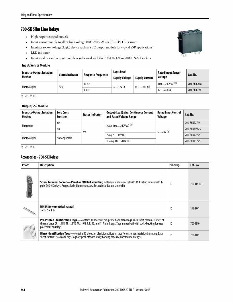
Relay and Timer Specifications
700-SK Slim Line Relays• High-response speed models• Input sensor module to allow high voltage 100…240V AC or 12…24V DC sensor• Interface to low voltage (logic) device such as a PC output module for typical SSR applications• LED indicator• Input modules and output modules can be used with the 700-HN121 or 700-HN221 sockets
Accessories - 700-SK Relays
Input/Sensor Module
Input-to-Output Isolation Method
Status Indicator Response Frequency Logic Level Rated Input Sensor
Voltage Cat. No.
Supply Voltage Supply Current
Photocoupler Yes 10 Hz
4…32V DC 0.1…100 mA 100…240V AC (1)
(1) 47…63 Hz
700-SKICA18
1 kHz 12…24V DC 700-SKICZ24
Output/SSR Module
Input-to-Output Isolation Method
Zero Cross Function
Status Indicator Output (Load) Max. Continuous Current and Rated Voltage Range
Rated Input Control Voltage
Cat. No.
Phototriac Yes
Yes
2 A @ 100…240V AC (1)
(1) 47…63 Hz
5…24V DC
700-SKOZ2Z25
No 700-SKON2Z25
Photocoupler Not Applicable 2 A @ 5…48V DC 700-SKOC2Z25
1.5 A @ 48…200V DC 700-SKOC1Z25
Photo Description Pcs./Pkg. Cat. No.
Screw Terminal Socket — Panel or DIN Rail Mounting 5-blade miniature socket with 10 A rating for use with 1-pole, 700-HK relays. Accepts forked lug conductors. Socket includes a retainer clip. 10 700-HN121
DIN (#3) symmetrical hat rail35 x 7.5 x 1 m 10 199-DR1
Pre-Printed Identification Tags — contains 10 sheets of pre-printed and blank tags. Each sheet contains 13 sets of the markings CR…9CR, TR…9TR, M…9M, F, R, 1S, and 117 blank tags. Tags are peel-off with sticky backing for easy placement on relays.
10 700-N40
Blank Identification Tags — contains 10 sheets of blank identification tags for customer specialized printing. Each sheet contains 546 blank tags. Tags are peel-off with sticky backing for easy placement on relays. 10 700-N41
244 Rockwell Automation Publication 700-TD552C-EN-P - October 2018

Relay and Timer Specifications
Specifications - 700-SK Relays
Input Sensor Module
Input Sensor Ratings
Output Logic Ratings
Characteristics
Output SSR Module
Control/Input Ratings
Cat. No. Rated Input Voltage Max. Operating Input Voltage Range
Input Current Pick-up Voltage Drop-out Voltage
700-SKICZ24 12…24V DC 6.6…32V DC 8 mA max. 6.6V DC max. 3.6V DC min.
700-SKICA18 100…240V AC 60…264V AC 15 mA max. 60V AC max. 20V AC min.
Cat. No. Logic Level Supply Voltage Logic Level Supply Current Draw700-SKICZ24
4…32V DC 0.1…100 mA700-SKICA18
Description Cat. No. 700-SKICA18 Cat. No. 700-SKICZ24Pick-up time 20 ms max. 0.1 ms max.
Drop-out time 20 ms max. 0.1 ms max.
Response frequency 10 Hz 100 kHz
Output ON voltage drop 1.6V max.
Leakage current (from SSR) 5 μA max.
Output VDRM, VCEO (V) 80 (ref. value) 80 (ref. value)
Output di/dt (A/uS) — —
Output dv/dt (V/uS) — —
Output I2t (A2S) — —
Output Tj (°C) Max. 150 150
Insulation Resistance 100 MΩ min. between input and output
Dielectric Strength 4000V AC, 50/60 Hz for 1 min between input and output
Vibration Resistance (Max.) 10…55 Hz, 1.5 mm double amplitude (10 G)
Shock Resistance (Max.) 1000 m/s2 (100 G)
Ambient TemperatureOperating –30…+80 °C (–22…+176 °F) with no icing or condensation
Storage –30…+100 °C (–22…+212 °F) with no icing or condensation
Standards Compliance UL 508, CSA C22.2 No. 14, EN/IEC 60950
Certifications cURus Recognized (File No. E96956, Guide NMFT2/NMFT8), CE Marked, TÜV Certified
Ambient humidity Operating 45…85% (no condensation)
Weight Approx. 18 g
Cat. No. Rated Control Voltage
Max. Operating Control Voltage
Range
Max. Reverse Control Voltage
Impedance (1) Pick-up Voltage Drop-out Voltage
700-SKOZ2Z25
5…24V DC 4…32V DC -32V DC
15 mA max.at 25 °C (77 °F)
4V DC max. 1V DC min.700-SKON2Z25
700-SKOC2Z258 mA max.
700-SKOC1Z25
Rockwell Automation Publication 700-TD552C-EN-P - October 2018 245
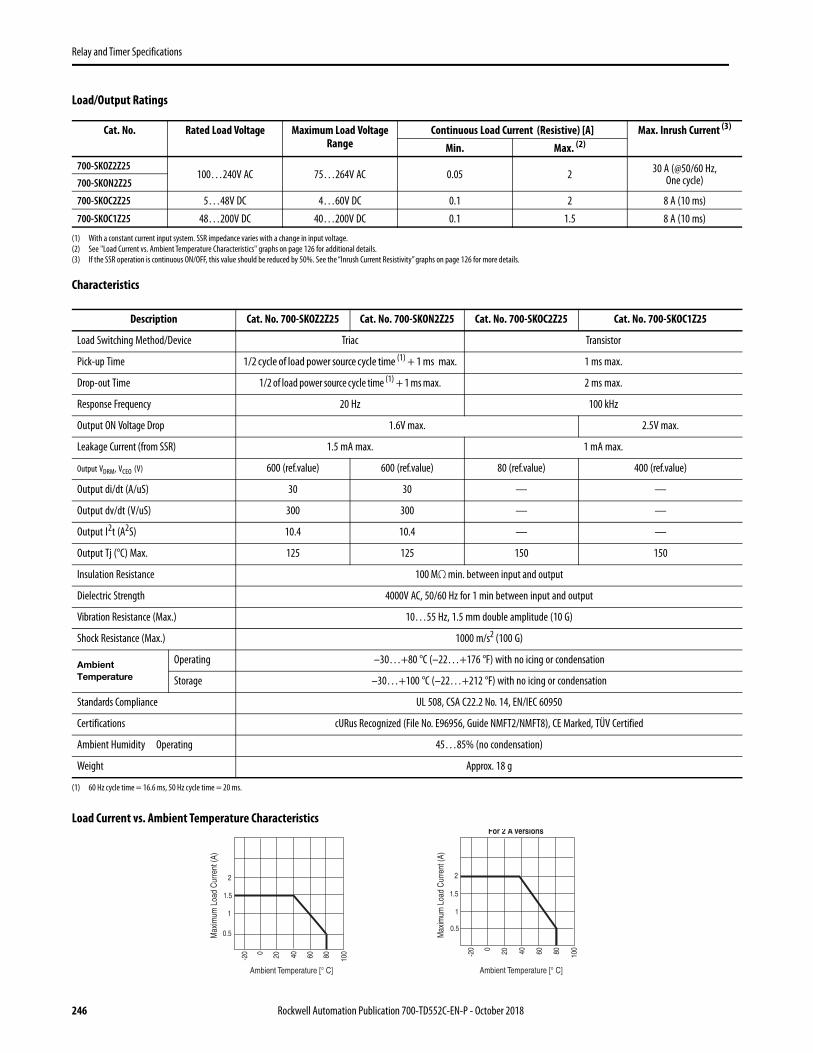
Relay and Timer Specifications
Load/Output Ratings
(1) With a constant current input system. SSR impedance varies with a change in input voltage.(2) See "Load Current vs. Ambient Temperature Characteristics" graphs on page 126 for additional details.(3) If the SSR operation is continuous ON/OFF, this value should be reduced by 50%. See the “Inrush Current Resistivity” graphs on page 126 for more details.
Characteristics
Load Current vs. Ambient Temperature Characteristics
Cat. No. Rated Load Voltage Maximum Load Voltage Range
Continuous Load Current (Resistive) [A] Max. Inrush Current (3)
Min. Max. (2)
700-SKOZ2Z25100…240V AC 75…264V AC 0.05 2 30 A (@50/60 Hz,
One cycle)700-SKON2Z25
700-SKOC2Z25 5…48V DC 4…60V DC 0.1 2 8 A (10 ms)
700-SKOC1Z25 48…200V DC 40…200V DC 0.1 1.5 8 A (10 ms)
Description Cat. No. 700-SKOZ2Z25 Cat. No. 700-SKON2Z25 Cat. No. 700-SKOC2Z25 Cat. No. 700-SKOC1Z25
Load Switching Method/Device Triac Transistor
Pick-up Time 1/2 cycle of load power source cycle time (1) + 1 ms max.
(1) 60 Hz cycle time = 16.6 ms, 50 Hz cycle time = 20 ms.
1 ms max.
Drop-out Time 1/2 of load power source cycle time (1) + 1 ms max. 2 ms max.
Response Frequency 20 Hz 100 kHz
Output ON Voltage Drop 1.6V max. 2.5V max.
Leakage Current (from SSR) 1.5 mA max. 1 mA max.
Output VDRM, VCEO (V) 600 (ref.value) 600 (ref.value) 80 (ref.value) 400 (ref.value)
Output di/dt (A/uS) 30 30 — —
Output dv/dt (V/uS) 300 300 — —
Output I2t (A2S) 10.4 10.4 — —
Output Tj (°C) Max. 125 125 150 150
Insulation Resistance 100 MΩ min. between input and output
Dielectric Strength 4000V AC, 50/60 Hz for 1 min between input and output
Vibration Resistance (Max.) 10…55 Hz, 1.5 mm double amplitude (10 G)
Shock Resistance (Max.) 1000 m/s2 (100 G)
Ambient Temperature
Operating –30…+80 °C (–22…+176 °F) with no icing or condensation
Storage –30…+100 °C (–22…+212 °F) with no icing or condensation
Standards Compliance UL 508, CSA C22.2 No. 14, EN/IEC 60950
Certifications cURus Recognized (File No. E96956, Guide NMFT2/NMFT8), CE Marked, TÜV Certified
Ambient Humidity Operating 45…85% (no condensation)
Weight Approx. 18 g
2
1.5
1
0.5
-20 0 20 40 60 80 100
For 2 A Versions
Ambient Temperature [° C]Ambient Temperature [° C]
Max
imum
Loa
d C
urre
nt (A
)
2
1.5
1
0.5
-20 0 20 40 60 80 100
Max
imum
Loa
d C
urre
nt (A
)
246 Rockwell Automation Publication 700-TD552C-EN-P - October 2018

Relay and Timer Specifications
Inrush Current Resistivity (2)
(2) Inrush current resistivity is the ability of an SSR to withstand a large surge current for a short period. Surges are considered non-repetitive (max. repeatability once every 2…5 seconds). Keep the inrush current to half the rated value if it occurs repetitively. Exceeding the non-repetitive inrush current will damage the SSR.
Dimensions - 700-SK RelaysAll units are in millimeters unless otherwise indicated. To convert to inches multiply by 0.0394. Dimensions are not to be used for manufacturing purposes.
Application Considerations of the700-SK Relay
Connection
For DC load switching, 700-SK SSR will operate properly if the load is connected to either the positive or negative SSR load terminal. The load can be connected to either positive or negative output terminals of the SSR.
Protective Element (to extend SSR life)
Since the SSR does not incorporate a surge absorption component, be sure to connect a surge absorption component when using the SSR to control an inductive load.
IMPORTANT The input module (700-SKI) and output module (700-SKO) are compatible with the Cat. No. 700-HN121 socket.
TIP For additional details on solid-state relays, see the Solid-State Relay Application Guide, publication 700-AT001.
10
9
8
7
6
5
4
3
2
1
0
10
9
8
7
6
5
4
3
2
1
0
10
20
30
Energizing Time (ms) Energizing Time (ms)Energizing Time (ms)
Inru
sh C
urre
nt (A
)
Inru
sh C
urre
nt (A
)
Inru
sh C
urre
nt (A
)
10 30 50 100
200
500
1000
5000 10 30 50 10
0
300
500
1000
2000 10 30 50 10
0
300
500
1000
2000
700-SKOZ/SKON 700-SKOC2 700-SKOZ/SKOC1
(+)
(–)
Load
Input
13 max. 28 max. 5 7.5
9.6
3
4
1
2
20
3
4
1 5
(–) (+)
0.5
5.2
17.4
4.7
4.75
4.750.5
10
4
1 5
Terminal Arrangement/Internal Connections(Bottom View)
29 max.
Rockwell Automation Publication 700-TD552C-EN-P - October 2018 247

Relay and Timer Specifications
Additional Resources
These documents contain additional information concerning related products from Rockwell Automation.
You can view or download publications at http://www.rockwellautomation.com/global/literature-library/overview.page.
Resource Description
General Purpose, Interposing, Solid-State and Specialty Relays Brochure publication 700-BR018 Provides product overview and applications for Bul 700 relay line.
Solid-state Relay Application Guide, publication 700-AT001 Provides methods for applying and troubleshooting Solid-state relays.
Industrial Automation Wiring and Grounding Guidelines, publication 1770-4.1 Provides general guidelines for installing a Rockwell Automation industrial system.
Product Certifications website, rok.auto/certifications. Provides declarations of conformity, certificates, and other certification details.
248 Rockwell Automation Publication 700-TD552C-EN-P - October 2018

Allen-Bradley, Rockwell Automation, and Rockwell Software are trademarks of Rockwell Automation, Inc.Trademarks not belonging to Rockwell Automation are property of their respective companies.
Publication 700-TD552C-EN-P - October 2018 Supersedes Publication 700-TD552B-EN-P - August 2018 Copyright © 2018 Rockwell Automation, Inc. All rights reserved. Printed in the U.S.A.
Rockwell Automation SupportUse the following resources to access support information.
Documentation FeedbackYour comments will help us serve your documentation needs better. If you have any suggestions on how to improve this document, complete the How Are We Doing? form at http://literature.rockwellautomation.com/idc/groups/literature/documents/du/ra-du002_-en-e.pdf.
Technical Support Center Knowledgebase Articles, How-to Videos, FAQs, Chat, User Forums, and Product Notification Updates. www.rockwellautomation.com/knowledgebase
Local Technical Support Phone Numbers Locate the phone number for your country. www.rockwellautomation.com/global/support/get-support-now.page
Direct Dial CodesFind the Direct Dial Code for your product. Use the code to route your call directly to a technical support engineer.
www.rockwellautomation.com/global/support/direct-dial.page
Literature Library Installation Instructions, Manuals, Brochures, and Technical Data. www.rockwellautomation.com/literature
Product Compatibility and Download Center (PCDC)
Get help determining how products interact, check features and capabilities, and find associated firmware.
www.rockwellautomation.com/global/support/pcdc.page
Rockwell Otomasyon Ticaret A.Ş., Kar Plaza İş Merkezi E Blok Kat:6 34752 İçerenköy, İstanbul, Tel: +90 (216) 5698400
Rockwell Automation maintains current product environmental information on its website at http://www.rockwellautomation.com/rockwellautomation/about-us/sustainability-ethics/product-environmental-compliance.page.