Relay module SB300 - Microdetectors
11
Operating instructions Relay module SB300
-
Upload
khangminh22 -
Category
Documents
-
view
0 -
download
0
Transcript of Relay module SB300 - Microdetectors

Operating instructions
Relay module SB300

Work Equipment DirectiveMD Directive

Operating instructions SB300 Relay module
3
Connections
Pin N° Meaning Terminal description (O = Output, I = Input)
1 IN 1 I: K1 relay excitation coil. Connect to OSSD1 terminal
2 COM K1 and K2 relay excitation coils common Connect to 0V
3 IN 2 I: K2 relay excitation coil. Connect to safety control unit OSSD2 terminal
4 Monit. A O: checking output, A side of NC contacts series. Connect to 24V
5 Monit. B O: checking output, B side of NC contacts series. Connect to EDM input of safety control unit
6 OSSD 1B 0: work output, B side, of K1 relay NO contact
7 OSSD 1A 0: work output, A side, of K1 relay NO contact
8 OSSD 2B 0: work output, B side, of K2 relay NO contact
9 OSSD 2A 0: work output, A side, of K2 relay NO contact
Tab. 1: Connections for SB300 module
Technical data
Nominal coils voltage 24V DC (-10 %…+20 %)
Temperature range -20…+60 °C
Coil resistance 720 Ω ±10 %
Output contacts 2 NO
Control contacts 1+1 NC serial connection
Max. switching voltage 250 V AC/DC
Contact rating 690 VA @ 230 V AC
72 W @ 24V DC
Max. inrush current 15 A for 20 ms
Switching current range 20 mA…3 A
Release time 15 ms
Operating time 10 ms
Mechanical life 5x10⁷
Electrical life 1x10⁵
Material PA6
Mounting DIN rail (EN 50022-35)
Tab. 2: Technical data for SB300 relay module

SB300 Relay module
4
Dimensions
Fig. 2: Dimensions of SB300 relay module.
Installation
Warning Install the module (rated IP 20) into a housing with a minimum protection degree
of IP54 ! The module can be attached to a DIN rail EN 50022-35. Make sure the working temperature limits are respected inside the
Generally a machinery guarding requires the use of two or more control safety units, which must be able to arrest the normal machine operation if any hazardous condition is detected. In this case every relay modules (final switching devices FSD), each controlled by its own safety control unit, must be connected in series to a safety emergency stop module (machine primary control element MPCE which controls directly the hazardous motion). In such a way, any relay module is able to interrupt the circuit to the primary control element. Figures in this section show various systems, which Category 2:
Operating instructions
.
minimum protection degree
Make sure the working temperature limits are respected inside the housing.
Generally a machinery guarding requires the use of two or more control safety units, which must be able to arrest the normal machine operation if any hazardous condition
d. In this case every relay modules (final switching devices FSD), each controlled by its own safety control unit, must be connected in series to a safety emergency stop module (machine primary control element MPCE which controls
In such a way, any relay module is able to interrupt the circuit to the primary control element. Figures in this section show various systems, which fulfil the requirements of

Operating instructions SB300 Relay module
5
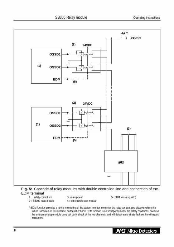
Fig.5 Cascade of relay modules with a double controlled line that provide a further redundancy. The two channels are connected to an emergency stop module, which must carry out a parity check and monitor its own contacts. Pay attention to the fact the contacts of the emergency stop module cannot be checked from the EDM function because the state of the stop module does not match necessarily the state of any safety control unit.
Fig.:6 This figure shows a slightly more simple circuit which will satisfy the requirements of category 2 using only one- channel connection. Note that in this case EDM is compulsory because otherwise single fault might be not detected and could lead to dangerous conditions.
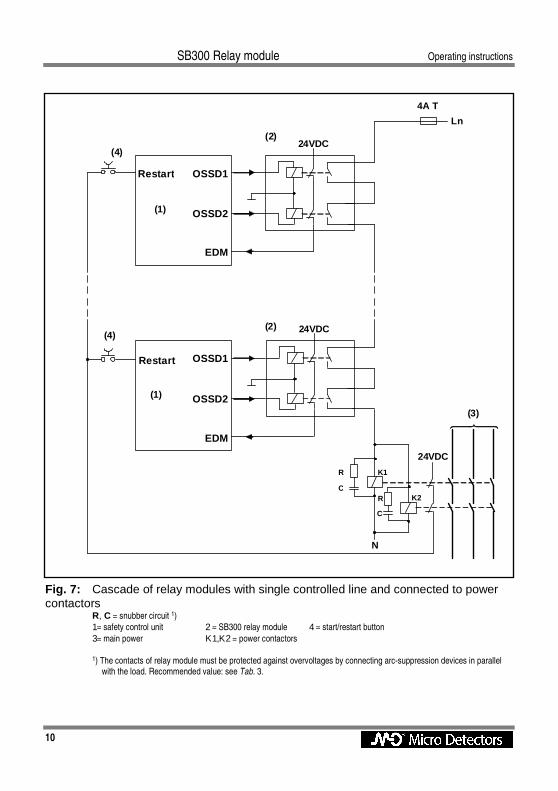
Fig.:7 As shown on Fig. 5 and Fig. 6 it is recommended to employ the emergency stop module which carry out a self control of its own contacts. So, it is not advisable to employ contactors unless particular shrewdness are adopted as shown in Fig. 7. In this case, any safety control unit has to be configured in Restart Interlock mode. The start/restart buttons are enabled only if the NC contacts of two contactors are correctly closed. If any single fault occurs on the contacts, at the next restart it will not be possible to remove the stop condition.
Snubber circuit Generally a relay module is connected to inductive load which can generate detrimental and noxious overvoltage. Connecting arc-suppression devices in parallel with the load is recommended, to protect relay module against overvoltage and, therefore, to avoid damages. The following table lists recommended values for the RC circuit:
Switched voltage Values of group R/C
230 V AC R = 220 Ω C = 0.15 µF 115 V AC R = 220 Ω C = 0.15 µF
24…48 V AC R = 100 Ω C = 1.5 µF 24 V DC R = 47 Ω C = 3.3 µF
Tab. 3: Recommended values for snubber group R/C

SB300 Relay module Operating instructions
6
Sample circuits
Fig. 3: SB300 relay module with single channel connection RM = SB300 relay module R, C = snubber circuit 1 (1)= safety control unit or safety light curtain with EDM function (2) = main power
1) The contacts of relay module must be protected against overvoltages by connecting arc-suppression devices in parallel with the load. Recommended value: see Tab. 3.
Operating instructions SB300 Relay module
7
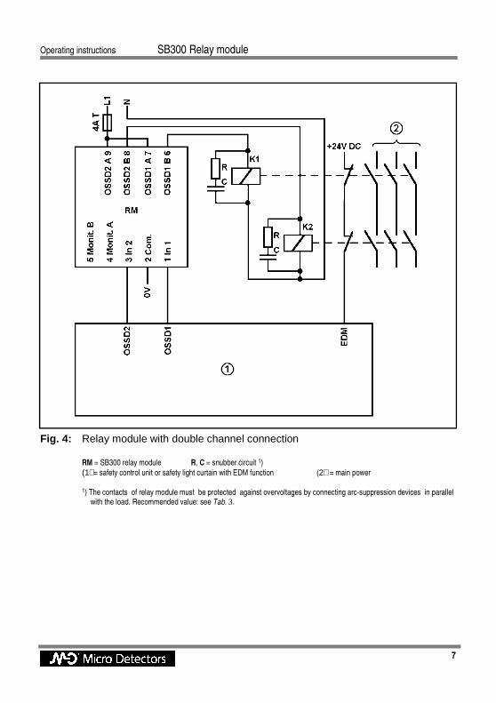
Fig. 4: Relay module with double channel connection RM = SB300 relay module R, C = snubber circuit 1)
(1) = safety control unit or safety light curtain with EDM function (2) = main power
1) The contacts of relay module must be protected against overvoltages by connecting arc-suppression devices in parallel with the load. Recommended value: see Tab. 3.
SB300 Relay module Operating instructions
8
Fig. 5: Cascade of relay modules with double controlled line and connection of the EDM terminal
1 = safety control unit 3= main power 5= EDM return signal 1)
2 = SB300 relay module 4 = emergency stop module
1) EDM function provides a further monitoring of the system in order to monitor the relay contacts and discover where the failure is located. In this scheme, on the other hand, EDM function is not indispensable for the safety conditions, because the emergency stop module carry out parity check of the two channels, and will detect every single fault on the wiring and contactors.
24VDC (2)
(4)(4)(4)(4)
(3)
4A T
24VDC (2)
EDM
EDM66664444777744448888
OSSD2
OSSD1
OSSD2
OSSD1
(1)
(1)
24VDC
(5)
(5)

Operating instructions SB300 Relay module
9
Fig. 6: Cascade of relay modules with single controlled line and connection of the EDM terminal.
1 = safety control unit 2 = SB300 relay module
3 = main power 4 = safety emergency stop module
24VDC (2)
(4)(4)(4)(4)
(3)
4A T
24VDC (2)
EDM
EDM66664444777744448888
OSSD2
OSSD1
OSSD2
OSSD1
(1)
(1)
24VDC
SB300 Relay module Operating instructions
10
Fig. 7: Cascade of relay modules with single controlled line and connected to power contactors
R, C = snubber circuit 1)
1= safety control unit 2 = SB300 relay module 4 = start/restart button
3= main power Κ1,Κ2 = power contactors 1) The contacts of relay module must be protected against overvoltages by connecting arc-suppression devices in parallel
with the load. Recommended value: see Tab. 3.
24VDC (2)
4A T
24VDC (2)
EDM
EDM
OSSD2
OSSD1
OSSD2
OSSD1
(1)
(1)
Ln
(3) 66664444777744448888
24VDC
Restart
Restart
R
C R
C
(4)
(4)
N
K1
K2

CAT8ESB1141904