
Relay Selection Strategies for Single-Carrier Frequency-Domain Equalization Multi-Relay Cooperative...
12
2034 IEEE TRANSACTIONS ON WIRELESS COMMUNICATIONS, VOL. 12, NO. 5, MAY 2013 Relay Selection Strategies for Single-Carrier Frequency-Domain Equalization Multi-Relay Cooperative Networks Homa Eghbali, Sami Muhaidat, Seyed Amin Hejazi, and Yanwu Ding Abstract—In this paper, we investigate several relay selec- tion strategies for cooperative Single-Carrier Frequency-Domain Equalization (SC-FDE) with the amplify-and-forward protocol. We consider both maximum likelihood (ML)-SC-FDE and mini- mum mean square error (MMSE)-SC-FDE receivers. We provide a novel pairwise error probability (PEP)-based selection criterion (SHARM) for frequency selective channels. We further present several selection strategies for cooperative (C) MMSE-SC-FDE receivers, which are motivated by minimizing the instantaneous error rate. These are, norm-based relay selection (NBRS), in- stantaneous mutual information-based relay selection (CBRS), singular value based relay selection (SVRS), and equalizer output signal quality-based relay selection (EQRS) strategies. We further propose a novel relay selection strategy, selective-to-flat fading relay selection (SFRS), in which from the effective frequency selective source-relay-destination channel link associated with the selected relay, only the channel tab with highest power is passed to the destination terminal. Additionally, to tackle the multiple relay selection problem considering generic mobile scenarios with moderately fast fading channels, in order to select the near best relay subset within the minimum processing time, we apply estimation of distribution algorithm (EDA) and formulate a modified EDA for the relay selection problem. Our results show promising performance of EDA with comparable computational complexity. Index Terms—Cooperative networks, equalization, relay selec- tion, SC-FDE, EDA. I. I NTRODUCTION R ELAY subset selection techniques are feasible techniques to reduce the complexity associated with multiple relay assisted cooperative networks. Many studies of the relay selection schemes are based on frequency flat fading chan- nel models. These assumptions can be perhaps justified for narrow-band networks, however, they are far away from being realistic if broadband applications considered. SC-FDE is a proven technology that can overcome cer- tain drawbacks of orthogonal frequency division multiplexing (OFDM) technology, such as insufficient usage of power amplifiers due to high peak to average power ratio, sensitivity Manuscript received February 12, 2012; revised July 9, 2012; accepted December 20, 2012. The associate editor coordinating the review of this paper and approving it for publication was X.-G. Xia. H. Eghbali and S. A. Hejazi are with the School of Engineering Science, Simon Fraser University, Burnaby, Canada, V5A 1S6 (e-mail: [email protected], [email protected]). S. Muhaidat is with Khalifa University, Abu Dhabi, UAE, and with the Centre for Communication Systems Research (CCSR) - University of Surrey, Guildford, UK (e-mail: [email protected]). Y. Ding is with Wichita State University, Wichita, KS 67260 (e-mail: [email protected]). Digital Object Identifier 10.1109/TWC.2013.032013.120168 to phase noise, and frequency offset. Moreover, SC-FDE technology inherits OFDM’s advantages, including robustness against multipath fading, and efficiency by using fast Fourier transform (FFT) algorithm. Related work and contributions: There have been consider- able research efforts on the area of cooperative diversity built upon the assumption of frequency flat fading channels (see for example [1]–[3]). Results have also been reported on relaying schemes for cooperative networks with underlying frequency selective channels [4]–[12] using OFDM technology. Our contributions in this work are summarized as follows: • We investigate the relay selection criteria for amplify- and-forward SC-FDE systems with frequency selective channels assuming ML receivers, by minimizing the average symbol error rate. • We present a novel PEP-based relay selection scheme, namely, SHARM for frequency selective links. A generic upper-bound on the PEP is used for selecting the best K out of N R available relays. • We investigate several relay selection strategies, namely, NBRS, CBRS, SVRS, and EQRS, for MMSE-SC-FDE receivers by minimizing the instantaneous symbol error rate. • To further extend our analysis to the realistic near fast fading scenarios with circulant frequency selective chan- nels, we revisit another evolutionary algorithm, i.e. EDA, and define its parameters specifically for our problem. We further present novel techniques for the generation of the initial population which is critical to the convergence of the EDA. • We present a comprehensive Monte-Carlo simulation study to give insight to system performance with various relay selection algorithms. The rest of this paper is organized as follows. Section II describes the system’s model and assumptions. Different relay selection methods are proposed in Section III. The optimal relay selection using the evolutionary algorithm is presented in Section IV. Numerical results are given in Section V and the paper is concluded in Section VI. Notation: − (.), (.) T , (.) † and(.) H denote conjugate, transpose, pseudo inverse and Hermitian transpose operations, respec- tively. ∗ denotes linear convolution, . F denotes the Frobe- nius norm, · denotes the Euclidean norm of a vector, [.] k,l denotes the (k,l) th entry of a matrix, [.] k denotes the k th entry of a vector, I M denotes the identity matrix of size M , and 0 M×M denotes all-zero matrix of size M × M . 1536-1276/13$31.00 c 2013 IEEE
Transcript of Relay Selection Strategies for Single-Carrier Frequency-Domain Equalization Multi-Relay Cooperative...

2034 IEEE TRANSACTIONS ON WIRELESS COMMUNICATIONS, VOL. 12, NO. 5, MAY 2013
Relay Selection Strategies forSingle-Carrier Frequency-Domain Equalization
Multi-Relay Cooperative NetworksHoma Eghbali, Sami Muhaidat, Seyed Amin Hejazi, and Yanwu Ding
Abstract—In this paper, we investigate several relay selec-tion strategies for cooperative Single-Carrier Frequency-DomainEqualization (SC-FDE) with the amplify-and-forward protocol.We consider both maximum likelihood (ML)-SC-FDE and mini-mum mean square error (MMSE)-SC-FDE receivers. We providea novel pairwise error probability (PEP)-based selection criterion(SHARM) for frequency selective channels. We further presentseveral selection strategies for cooperative (C) MMSE-SC-FDEreceivers, which are motivated by minimizing the instantaneouserror rate. These are, norm-based relay selection (NBRS), in-stantaneous mutual information-based relay selection (CBRS),singular value based relay selection (SVRS), and equalizer outputsignal quality-based relay selection (EQRS) strategies. We furtherpropose a novel relay selection strategy, selective-to-flat fadingrelay selection (SFRS), in which from the effective frequencyselective source-relay-destination channel link associated with theselected relay, only the channel tab with highest power is passedto the destination terminal. Additionally, to tackle the multiplerelay selection problem considering generic mobile scenarioswith moderately fast fading channels, in order to select thenear best relay subset within the minimum processing time, weapply estimation of distribution algorithm (EDA) and formulatea modified EDA for the relay selection problem. Our results showpromising performance of EDA with comparable computationalcomplexity.
Index Terms—Cooperative networks, equalization, relay selec-tion, SC-FDE, EDA.
I. INTRODUCTION
RELAY subset selection techniques are feasible techniquesto reduce the complexity associated with multiple relay
assisted cooperative networks. Many studies of the relayselection schemes are based on frequency flat fading chan-nel models. These assumptions can be perhaps justified fornarrow-band networks, however, they are far away from beingrealistic if broadband applications considered.
SC-FDE is a proven technology that can overcome cer-tain drawbacks of orthogonal frequency division multiplexing(OFDM) technology, such as insufficient usage of poweramplifiers due to high peak to average power ratio, sensitivity
Manuscript received February 12, 2012; revised July 9, 2012; acceptedDecember 20, 2012. The associate editor coordinating the review of this paperand approving it for publication was X.-G. Xia.
H. Eghbali and S. A. Hejazi are with the School of EngineeringScience, Simon Fraser University, Burnaby, Canada, V5A 1S6 (e-mail:[email protected], [email protected]).
S. Muhaidat is with Khalifa University, Abu Dhabi, UAE, and with theCentre for Communication Systems Research (CCSR) - University of Surrey,Guildford, UK (e-mail: [email protected]).
Y. Ding is with Wichita State University, Wichita, KS 67260 (e-mail:[email protected]).
Digital Object Identifier 10.1109/TWC.2013.032013.120168
to phase noise, and frequency offset. Moreover, SC-FDEtechnology inherits OFDM’s advantages, including robustnessagainst multipath fading, and efficiency by using fast Fouriertransform (FFT) algorithm.
Related work and contributions: There have been consider-able research efforts on the area of cooperative diversity builtupon the assumption of frequency flat fading channels (see forexample [1]–[3]). Results have also been reported on relayingschemes for cooperative networks with underlying frequencyselective channels [4]–[12] using OFDM technology. Ourcontributions in this work are summarized as follows:
• We investigate the relay selection criteria for amplify-and-forward SC-FDE systems with frequency selectivechannels assuming ML receivers, by minimizing theaverage symbol error rate.
• We present a novel PEP-based relay selection scheme,namely, SHARM for frequency selective links. A genericupper-bound on the PEP is used for selecting the best Kout of NR available relays.
• We investigate several relay selection strategies, namely,NBRS, CBRS, SVRS, and EQRS, for MMSE-SC-FDEreceivers by minimizing the instantaneous symbol errorrate.
• To further extend our analysis to the realistic near fastfading scenarios with circulant frequency selective chan-nels, we revisit another evolutionary algorithm, i.e. EDA,and define its parameters specifically for our problem. Wefurther present novel techniques for the generation of theinitial population which is critical to the convergence ofthe EDA.
• We present a comprehensive Monte-Carlo simulationstudy to give insight to system performance with variousrelay selection algorithms.
The rest of this paper is organized as follows. Section IIdescribes the system’s model and assumptions. Different relayselection methods are proposed in Section III. The optimalrelay selection using the evolutionary algorithm is presentedin Section IV. Numerical results are given in Section V andthe paper is concluded in Section VI.
Notation:−(.), (.)
T, (.)
†and(.)
H denote conjugate, transpose,pseudo inverse and Hermitian transpose operations, respec-tively. ∗ denotes linear convolution, ‖.‖F denotes the Frobe-nius norm, ‖·‖ denotes the Euclidean norm of a vector, [.]k,ldenotes the (k, l)
th entry of a matrix, [.]k denotes the kth
entry of a vector, IM denotes the identity matrix of sizeM , and 0M×M denotes all-zero matrix of size M × M .
1536-1276/13$31.00 c© 2013 IEEE

EGHBALI et al.: RELAY SELECTION STRATEGIES FOR SINGLE-CARRIER FREQUENCY-DOMAIN EQUALIZATION MULTI-RELAY COOPERATIVE . . . 2035
S D
1R
RNR
iR
1hSR 1
hR D
hiSR
hiR D
hNRSR
hNRR D
Fig. 1. Wireless Relay Network.
Q = Q−1M = QH
M represents the M ×M IFFT matrix, whose(l, k) element is given by Q(l, k) = 1/
√M exp(j2πlk/M)
where 0 ≤ l, k ≤ M − 1. Bold upper-case letters denotematrices and bold lower-case letters denote vectors.
II. SYSTEM MODEL
We consider a multiple-relay assisted cooperative wirelesscommunication system with a single source (S), NR half-duplex relay terminals (Ri), i = 1, 2, ..., NR, and a singledestination (D), as depicted in Fig. 1. The source, destination,and all relays are equipped with single transmit and receiveantenna. We assume the AF relaying and adopt the user co-operation protocol proposed by Nabar et al. [13]. Specifically,in the broadcasting phase, the source node transmits to therelay nodes and the destination node. In the relaying phase,the relay nodes forward a scaled noisy version of the receivedsignal to the destination node.
The channel impulse responses (CIRs) for S → Ri,S → D, and Ri → D links for the ith relay termi-nal in the jth transmission block are given by hj
SRi=[
hjSRi
[0], ..., hjSR[LSRi ]
]T, hj
SD =[hjSD[0], ..., hj
SD[LSD]]T
and hjRiD
=[hjRiD
[0], ..., hjRiD
[LRiD]]T
, respectively, whereLSRi , LSD, and LRiD denote the corresponding channelmemory lengths. All channel links are assumed to experiencefrequency selective Rayleigh fading. The random vectorshjSRi
, hjSD, and hj
RiDare assumed to be independent zero-
mean complex Gaussian with uniform power delay profilevectors.
During broadcasting phase I, the information symbols areparsed to streams of M×1 blocks x. To further remove inter-block interference and make the channel matrix circulant, acyclic prefix (CP) with length LCP = LSRi + LRiD + 1is added between adjacent information blocks. Without lossof generality, we drop the the index j in the system modelderivations for brevity. After removing the cyclic prefix, thereceived block symbol at the ith relay terminal during thebroadcasting phase will be given by
rRi =√ESRiHSRix+ nRi
, (1)
where nRiis the additive white Gaussian noise vector with
each entry having zero-mean and variance of N0/2 per di-mension, ESRi is the average energy available at the relayterminal Ri which takes into account possibly different pathloss and shadowing effects between the S → Ri link, andHSRi is N × N circulant matrix with entries [HSRi
]k,l =hSRi
((k − l) mod N). The relay terminals normalize eachentry of the received signal [rRi
]n, n = 1, 2, ..., N by a factor
of E(|[rRi
]n|2)= ESRi +N0 to ensure unit average energy
and re-transmit the signal during the relaying phase one at atime. After some mathematical manipulations, the ith relay’sreceived signal at the destination terminal during the secondsignaling phase is given by
ri =
√ERiDESRi
ESRi +N0HRiDHSRi
x+ ni, (2)
where ERiD is the average energy available at the destinationterminal which takes into account possibly different path lossand shadowing effects between the Ri → D link, HRiD isN ×N circulant matrix with entries [HRiD
]k,l = hRiD((k−
l) mod N), and each entry of the effective noise term ni
(conditioned on hRiD) has zero mean and a variance of ρiN0
where ρi is defined by
ρi = 1 +ERiD
ESRi +N0
LRiD∑m=0
|hRiD (m)|2. (3)
The destination terminal normalizes the received signal rRi
by a factor of√ρi. This does not affect the signal-to-noise
ratio (SNR), but simplifies the ensuing presentation [13]. Afternormalization, we obtain
rDi =√γiHRiDHSRi
x+ ni, (4)
where ni is complex Gaussian with zero mean and variance ofN0/2 per dimension and the scaling coefficient γi is definedasγi =
(ESRi/N0)ERiD
1 +ESRiN0
LSRi∑lSRi
=0
|hSRi (lSRi)|2 +ERiD
N0
LRiD∑lRiD
=0
|hRiD (lRiD)|2.
(5)Next, we transform the received signal rDi to the frequencydomain by applying the DFT (Discrete Fourier Transform) ,i.e. multiplying by the Q matrix as follows
QrDi =√γiQHRiDHSRix+Qni. (6)
Exploiting the circulant structure of the channel matricesHSRi and HRiD , we have
HSRi= QHΛSRi
Q,HRiD
= QHΛRiDQ,
(7)
where ΛSRi and ΛRiD are diagonal matrices whose (n, n)element is equal to the nth DFT coefficient of hSRi and hRiD,respectively. Thus, (6) can be rewritten as follows
QrDi =√γiΛRiDΛSRi
Qx+Qni. (8)
The input signals to the ML detector are thus, given by
r =[√
γ1ΛR1DΛSR1 , . . . ,√γNRΛRNR
DΛSRNR
]TQx+n′,
(9)

2036 IEEE TRANSACTIONS ON WIRELESS COMMUNICATIONS, VOL. 12, NO. 5, MAY 2013
SNReff =
ERiDESRi
N0
LSRi∑lSRi
=0
|hSRi (lSRi)|2LRiD∑
lRiD=0
|hRiD (lRiD)|2
N0 + ESRi
LSRi∑lSRi
=0
|hSRi (lSRi)|2 + ERiD
LRiD∑lRiD
=0
|hRiD (lRiD)|2=
(SNRSRi
LSRi∑lSRi
=0
|hSRi (lSRi)|2)(
SNRRiD
LRiD∑lRiD
=0
|hRiD (lRiD)|2)
1 + SNRSRi
LSRi∑lSRi
=0
|hSRi (lSRi)|2 + SNRRiD
LRiD∑lRiD
=0
|hRiD (lRiD)|2=
XY
1 +X + Y,
(10)
where n′ is zero mean white Gaussian with varianceof N0/2 per dimension. Note that the effective SNRof the received signal can be formulated as shownin (10), where SNRSRi =
ESRi
N0, SNRRiD =
ERiD
N0, X = SNRSRi
LSRi∑lSRi
=0
|hSRi (lSRi)|2 and Y =
SNRRiD
LRiD∑lRiD
=0
|hRiD (lRiD)|2. To recover the transmitted
symbol x, a receiver is required to remove the linear trans-formation caused by ΛRiDΛSRi in (8). For this purpose,both ML and MMSE receivers can be applied. Note thatthe decoding complexity of the ML decoder increases expo-nentially with the number of relays. On the other hand, thelinear receivers, such as MMSE, offer a significant reductionin complexity and thus, they are the practical choice forsystems with large numbers of relaying nodes. In the followingsection, we will derive the appropriate selection criteria forboth receivers.
III. RELAY SELECTION STRATEGIES
All strategies mentioned in this section perform calculationsassuming full and perfect channel knowledge at the receiver.In the following, the distributed system’s overall NNR × Nchannel matrix Λ is defined as follows
Λ =
⎛⎜⎝√γ1ΛR1DΛSR1
...√γNRΛRNR
DΛSRNR
⎞⎟⎠ (11)
whereas the NK ×N Λ(K) indicates the sub-channel matrixafter applying the relay selection strategy, with K representingthe number of the selected index rows from Λ, i.e. from theselected relays.
A. Selection Criteria for ML-SC-FDE receivers
For the optimal ML receiver, we derive the selection criteriathat minimizes the symbol error rate union bound. Firstly, wefind the PEP for the case where all the relays are participatingand use the results to find the effective selection criteria.Considering the ML-SC-FDE receiver, we use the PEP thatdetermines the probability of erroneously decoding x when xis transmitted with x �= x. The distance is given as follows
d2 (x, x) =
NR∑i=1
γi
Li,max∑li,max=0
|hi,max (li,max)|2‖(χi − χi)hi,min‖2, (12)
where
χi =
⎡⎢⎢⎢⎣[x]0 [x]N−1 . . . [x]N−Li,min
[x]N−Li,min[x]0 . . . [x]N−Li,min+1
...... . . .
...[x]N−1 [x]N−2 . . . [x]N−Li,min−1
⎤⎥⎥⎥⎦ ,
(13), Li,max = max (LSRi , LRiD), hi,max is the chan-nel associated with Li,max, and accordingly, Li,min =min (LSRi , LRiD), and hi,min is the channel associated withLi,min, i = 1, . . . , NR. As an example, if L1,max =max (LSR1 , LR1D) = LSR1 , then h1,max = hSR1 , andsimilarly, if L1,min = min (LSR1 , LR1D) = LR1D, thenh1,min = hR1D . Note that we have used the propertyQH |Λi|2Q = HiH
Hi . Using the Chernoff bound and applying
it on (12), we have
P(x → x|hSR1 , . . . ,hSRNR
,hR1D, . . . ,hRNRD
)�
NR∏i=1
exp
(− αi
4N0
),
(14)
where αi = γiLi,max∑li,max=0
|hi,max (li,max)|2‖(χi − χi)hi,min‖2,i = 1, . . . , NR. Thus, the unconditional PEP can be expressedas follows
P (x → x) ≤NR∏i=1
∫∫exp
(− αi
4N0
)dhSRi dhRiD. (15)
Note that αi = γiLi,max∑li,max=0
|hi,max (li,max)|2hHi,min–χihi,min
where –χi = (χi − χi)H(χi − χi) is Hermitian and thus
can be decomposed to –χi = UiHΔiUi, where Δi has
the Eigen values λli,min, li,min = 0, . . . , Li,min on its di-
agonal. Following that, αi can be expressed as shown in(16), where ai ∼ Γ (Li,max + 1, 1), bi ∼ Γ (Li,min + 1, 1),Ei,min and Ei,max are the average energies associated withhi,min and hi,max correspondingly, and hi,min = Uihi,min
with same first and second order statistical information ashi,min with Ui being a unitary matrix. We define the ratiori = ai
(Ei,max/N0)ai+(Ei,min/N0)biof the two gamma variates
ai and bi, with density [14]
EGHBALI et al.: RELAY SELECTION STRATEGIES FOR SINGLE-CARRIER FREQUENCY-DOMAIN EQUALIZATION MULTI-RELAY COOPERATIVE . . . 2037
αi =
Ei,maxEi,min
N0
Li,max∑li,max
|hi,max (li,max)|2︸ ︷︷ ︸ai
Li,min∑li,min
λli,min
∣∣∣hi,min (li,min)∣∣∣2
1 +Ei,max
N0
Li,amx∑li,max=0
|hi,max (li,max)|2︸ ︷︷ ︸ai
+Ei,min
N0
Li,min∑li,min=0
|hi,min (li,min)|2︸ ︷︷ ︸bi
, (16)
fRi (ri) =
(SNRi,min)−(Li,min+1)
B (Li,max + 1, Li,min + 1)r(Li,max)i (1− SNRi,maxri)
Li,min×(1 + (SNRi,min − SNRi,max) ri
SNRi,min
)−(Li,max+Li,min+2),
(17)where SNRi,min = Ei,min/N0
, SNRi,max = Ei,max/N0, and
B (a, b) = Γ(a)Γ(b)Γ(a+b) is the beta function. Accordingly, the
unconditional PEP in (15) can be rewritten as expressed in(18). Following notations in Table . 1, (18) can be expressedas formulated in (19), where gi = bi/ai, di = (ai + bi)/ai,
fi ∼ Γ
(LRiD + 1,
LRiD∑lRiD=0
κi,lRiD
), and 2F1 (·, ·; ·; .) is the
hyper-geometric function [16].Next, we formulate the best multiple relay selection crite-rion that minimizes the PEP expression in (19). Considering(19), the upper bound mainly depends on the relaying links’minimum SNRs, i.e. SNRi,min, i = 1, . . . , NR, as well asthe channel powers, which are reflected in the terms gi =‖hi,min‖2
‖hi,max‖2 , and di = 1+‖hi,min‖2
‖hi,max‖2 . Therefore, assuming averageSNRi,min, i = 1, . . . , NR, the PEP-based best multiple relayselection criterion can be expressed as below,rSELECTION =
arg mink=1,...,NR
k∏i=1
gLi,min
i
B (Li,max + 1, Li,min + 1) dLi,max+Li,min+2
i
.
(20)
Novel PEP-based SHARM Selection CriterionAssuming average signal-to-noise ratio for all relay links, aswell as similar channel lengths Li,min and Li,max for theunderlying relaying links, a novel version of the harmonicmean selection criteria for frequency selective underlyingchannels (SHARM) can be realized from (20), namely,
rSHARM = arg mink=1,...,NR
gLi,mini
dLi,max+Li,min+2
i
=
= arg mink=1,...,NR
(‖hi,min‖2
‖hi,max‖2
)Li,min
(1+
‖hi,min‖2
‖hi,max‖2
)Li,max+Li,min+2 .(21)
PEP upper bound for the best K relay selectionIn this sub-section, we derive an upperbound on the PEP
when selecting best K relays from the available NR relays.This method is based on the property that the summation ofthe largest K out of NR available numbers is greater than orequal to the average value of the NR numbers multiplied by
K . Refer to Appendix A for the proof. Similarly, having thechannel powers ordered as formulated in (22). we have
K∑i=1
SNRSRiSNRRiD‖hSRi‖2‖hRiD‖2SNRSRi‖hSRi‖2 + SNRRiD‖hRiD‖2
K
NR
NR∑i=1
SNRSRiSNRRiD‖hSRi‖2‖hRiD‖2SNRSRi‖hSRi‖2 + SNRRiD‖hRiD‖2 ,
(23)
which leads toK∑i=1
SNRSRiSNRRiD‖hSRi‖2‖(χ− χ)hRiD‖2SNRSRi‖hSRi‖2 + SNRRiD‖hRiD‖2︸ ︷︷ ︸
d2K
�
K
NR
NR∑i=1
SNRSRiSNRRiD‖hSRi‖2‖(χ− χ)hRiD‖2SNRSRi‖hSRi‖2 + SNRRiD‖hRiD‖2︸ ︷︷ ︸
d2NR
.
(24)As a result, we have,
exp
(−d2K
4
)≤ exp
(− K
NR
d2NR
4
). (25)
We can apply (25) to the bound in (14), which results inthe PEP upper bound, when selecting the best K out of NR
available relays, as follows,
PK (x → x) ≤(
K
NR
)−NR∑i=1
(Li,min+1)
PNR (x → x) . (26)
B. Selection Criteria for SC-MMSE receivers
Unlike ML-SC-FDE, its not easy to find a simple expressionfor the average error probability. Thus, we will develop differ-ent selection criteria based on instantaneous error probabilityas follows:
1) Norm based Relay Selection (NBRS): This method isinspired by the fact that selection based on maximum norm,maximizes the signal-to-noise ratio and minimizes the in-stantaneous probability of error [17]. NBRS method can beused because of its low computational complexity, yet, itsgeneral drawback is that its effective only for frequency flat ormoderate frequency selective channels. NBRS calculates theFrobenius norm of all rows of the channel matrix Λ and selectsthe subset that maximizes the Frobenius norm. The resultingsub-channel matrix Λ(K) contains K out of NR rows of thechannel matrix Λ such that
rNBRS = argmax∈R
K∑rk=1
∥∥∥√λrkΛrkDΛSrk
∥∥∥F. (27)

2038 IEEE TRANSACTIONS ON WIRELESS COMMUNICATIONS, VOL. 12, NO. 5, MAY 2013
P (x → x) �
NR∏i=1
∫ ∞
0
∫ 1SNRi,max
0
exp
⎛⎜⎜⎜⎜⎜⎜⎜⎜⎜⎝−
⎛⎜⎜⎜⎜⎝SNRi,maxSNRi,min
4
fi︷ ︸︸ ︷Li,min∑li,min
λli,minhi,min(li,min)2
⎞⎟⎟⎟⎟⎠︸ ︷︷ ︸
Πi
ri
⎞⎟⎟⎟⎟⎟⎟⎟⎟⎟⎠pridripfidfi,
�NR∏i=1
(SNRi,min)−(Li,min+1)
B (Li,max + 1, Li,min + 1)
∫ ∞
0
∫ 1SNRi,max
0
exp (−Πiri)r(Li,max)i ×
(1− SNRi,maxri)Li,min
(1 + (SNRi,min − SNRi,max) ri
SNRi,min
)−(Li,max+Li,min+2)
dripfidfi.
(18)
P (x → x) ≤NR∏i=1
(SNRi,min)−(Li,min+1)(SNRi,mingi)
Li,min
B(Li,max+1,Li,min+1)d(Li,max+Li,min+2)i
∫ ∞0
∫ 1SNRi,max
0 exp (−Πiri) r−2i dripfidf
≤NR∏i=1
SNR−1i,ming
Li,mini
B(Li,max+1,Li,min+1)d(Li,max+Li,min+2)i
∫∞0
Γ(−1, 1
SNRi,maxΠi
)Πipfidf, [10, eq.3.381.8]
≤NR∏i=1
gLi,mini
B(Li,max+1,Li,min+1)d(Li,max+Li,min+2)i
LRiD∏lRiD
=0
1λlRiD
∫∞0 flRiD
Γ(−1,
SNRi,min
4 flRiD
)× exp
(−λlRiDflRiD
)dflRiD
,
≤NR∏i=1
(SNRi,min)−(Li,min+1)g
Li,mini
B(Li,max+1,Li,min+1)d(Li,max+Li,min+2)i
LRiD∏lRiD
=0
1λlRiD
2F1
(1, 1; 3; 1
SNRi,minλlRiD
4 +1
), [10, eq.6.455.1]
(19)
SNRSR1SNRR1D‖hSR1‖2‖hR1D‖2SNRSR1‖hSR1‖2 + SNRR1D‖hR1D‖2 . . . SNRSRKSNRRKD‖hSRK‖2‖hRKD‖2
SNRSRK‖hSRK‖2 + SNRRKD‖hRKD‖2 . . .
SNRSRNRSNRRNR
D
∥∥∥hSRNR
∥∥∥2∥∥∥hRNRD
∥∥∥2
SNRSRNR
∥∥∥hSRNR
∥∥∥2
+ SNRRNRD
∥∥∥hRNRD
∥∥∥2 ,
(22)
TABLE ILIST OF NOTATIONS USED IN PEP DERIVATIONS IN (20)
I: 1− SNRi,minri =SNRi,minbi
SNRi,maxai+SNRi,minbi≈ SNRi,mingi
aiSNRi,maxai+SNRi,minbi
≈ SNRi,mingiri,
II:1+(SNRi,min−SNRSRi
)ri
SNRRiD= ai+bi
SNRi,maxai+SNRi,minbi≈ diri.
As an example, if we select a single relay out of four availablerelays, rk would be one element from R = {1, 2, 3, 4},while if selection of two relays out of four available relaysis performed, rk would be an element of the set R ={[1, 2] , [1, 3] , [1, 4] , [2, 3] , [2, 4] , [3, 4]}.
2) Ergodic Capacity Based Relay Selection (CBRS): In thisstrategy, the subset of relays that maximizes the instantaneousmutual information among all possible subsets is selected.Note that the source terminal doesn’t have access to theCSI, thus, it distributes the power equally among all subcar-riers. Since we are dealing with frequency selective fadingchannels, the optimum relay selection is not feasible throughCBRS mainly because for different frequencies, differentrelay subsets are optimal, as reported in similar studies onantenna subset selection on MIMO channels [18], [19]. Sincethe source node doesn’t have access to CSI and only thedestination terminal has the perfect channel knowledge, the
channel mutual information is formulated as follows,
C(K) = log2
(det
(INK +
1
KNoΛ(K)
(Λ(K)
)H))
, (28)
where rCBRS = argmax∈RC(K), through which the subset
of the relays that has maximum mutual information of all thesubsets Λ(K) is selected.
3) Singular Value based Relay Selection (SVRS): Con-sidering (4), the expression for the post-processing SNR ofthe kth relaying path applying the MMSE equalizer Gk =
HHk
[HkH
Hk +N0IN
]−1with Hk =
√γkHRkD
HSRkis
given by
SNRk =
∥∥GkHkHHk GH
k
∥∥F∥∥GkN0INGH
k
∥∥F
. (29)

EGHBALI et al.: RELAY SELECTION STRATEGIES FOR SINGLE-CARRIER FREQUENCY-DOMAIN EQUALIZATION MULTI-RELAY COOPERATIVE . . . 2039
Assuming without loss of generality that the symbols havevariance 1, the received SNR can be simplified as follows
SNRk =
∥∥GkHkHHk GH
k
∥∥F∥∥GkN0INGH
k
∥∥F
�∥∥∥∥GkHkH
Hk GH
k
GkN0INGHk
∥∥∥∥F
=
∥∥∥∥ HHk GH
k
N0GkGHk
− I
∥∥∥∥F
.
(30)
Note that the minimum post-processing SNR is directly relatedto the error rate performance and dominates the error rateas well as the receiver performance. Having this, to improvethe error rate, it is desirable to improve the minimum SNR.Approximating (30), we obtain
SNRmin ≥ 1
N0λmax
((HkHH
k +N0IN)−1)
≥ 1N0
λmin
((HkH
Hk +N0IN
)−1)
≥ 1N0
λmin2 (Hk) ,
(31)
where λmin denotes the minimum singular value, and λmax
denotes the maximum singular value. Note that (30) followsfrom the fact that the highest eigenvalue maximizes thehighest diagonal term of a square matrix. (31) shows that theperformance of linear receiver like MMSE improves as thesmallest singular value of the channel Hk increases.Using this,the smallest eigenvalue of the Λ(K)
(Λ(K)
)H, has the highest
impact on the performance of linear receivers for the frequencyselective channels. Following this method, the subset channelwith the maximum minimum eigenvalue is selected as follows,
rSV RS = argmax∈R
minn=1,...,N, k=1,...,NR
λ(k,n) (32)
where λ(k,n) is the eigenvalue of the matrix Λ(K)(Λ(K)
)Hfor the nth subcarrier.
Note that similar methods based on maximum ratio betweenthe minimum and the maximum singular value were proposedin [20]. This ratio indicates the degree of spread of all theeigen values where lower spread means higher ratio and there-fore a better conditioned channel and vice versa. Followingthis method, the selection metric is as follows,
rSV RS = argmax∈R
minn=1,...,N, k=1,...,NR
λ(k,n)
maxn=1,...,N, k=1,...,NR
λ(k,n), (33)
where N stands for the number of the carriers. Note that thecomputational complexity of this method is slightly higherthan the first SVRS method, as it requires the calculation oftwo singular value and their ratios per frequency tone andsubset combination. Note that eventhough both the afore-mentioned SVRS methods are solely based on the acquiredchannel knowledge and can be deployed independently fromthe equalizer, yet, they are both very much sensitive to thechannel estimation errors. This sensitivity is even higher forthe second SVRS method which is based on the ratio ofsingular values.
4) Equalization Quality based Relay Selection (EQRS):This selection technique is motivated by the fact that thepost equalizer signal quality affects the succeeding detector’sdecisions. note that the major advantage of using the postequalizer signal quality as a metric is that all the possibleeffects such as synchronization or spatial correlation that can
degrade the quality of the equalizer output signal are inher-ently handled in such way. The typical signal quality metric isthe Euclidean distance between the equalizer output symbolsx and the known transmit symbols x which is used as theselection criterion. Note that |x− x|2 shows the equalizer’sabilities, as well as the detector’s quality which in turn affectsthe selection [21]. Defining the distortion power to be
Pdistortion = E{|x− x|2
}, (34)
we can use a selection method based on the distortion power(DP) Pdistortion, or on the signal to distortion ratio (SDR)defined as follows
SDR =E
{|x|2
}Pdistortion
. (35)
Our aim is to find the relay that minimizes the distortion powerPdistortion, or maximizes the output SDR.
Note that through this method, the receiver can directlyrecognize the loss of signal quality and take appropriateactions, i.e. switching to another relay. It should be takeninto account that using such a metric requires channel trainingsequences or pilot symbols to be passed through the equalizer.
5) Selective to Flat Fading Relay Selection (SFRS): Here,we propose a novel relay selection method through which onlythe relay with the frequency selective source to destinationlink that acquires the highest norm flat fading channel tab isselected. The selected relay then pre-multiplies and normalizesthe received signal from the source node, such that only thehighest norm flat fading portion of the transmitted signal isreceived at the destination terminal.
Consider the circulant channel matrix Hk = HRkDHSRk
for the kth relaying channel in (4). Introducing the circulantflat fading matrices
[HSRkD,l]p,q, l = 1, ..., LSRk+ LRkD + 1
=
{[HRkDHSRk
]p,q p− q mod N = l
0 p− q mod N �= l
(36)
only the relay with arg maxk=1,...,NR
maxl=1,...,LSRk
+LRkD+1‖HSRkD,l‖F
is selected. Assuming that the mth path from the kth relayingchannel is selected, we introduce the multiplier matrix
P = H−1RkD
HSRkD,mH−1SRk
. (37)
In order to have a fair comparison with other schemes, weobtain the performance of the proposed receiver assuming anamplifier factor for the relay terminal that results in the similarSNR as that of (4). The SNR associated to (4) is as follows
SNRk =
SNRSRkSNRRkD
(LRkD∑m=0
|hRkD (m)|2)
1 + SNRSRk+
(LRkD∑m=0
|hRkD (m)|2)SNRRkD
,
(38)where SNRSRk
= ESRk/N0, and SNRRkD = ERkD/N0.
Assuming that the relay Rk from the kth path applies theamplifier factor Ak, the received signal at the destination node

2040 IEEE TRANSACTIONS ON WIRELESS COMMUNICATIONS, VOL. 12, NO. 5, MAY 2013
and its corresponding post processing SNR for the proposedmethod will be as follows
rDk,SFRS=√
ESRkERkDAkHSRkD,mx+
√ERkDAknRk
+ nD,(39)
SNRK,SFRS =
ESRKSNRRKDAk
(N∑
m=0
|hSRKD,l (m)|2)
1 + AkERkD
(LP∑m=0
|hP (m)|2) ,
(40)where hP is the vector containing the non-zero elements ofthe first row or column of the circulant matrix P , LP isthe number of nonzero elements in each row or column ofP , and similarly, hSRKD,l is the first row or column of thecirculant matrix HSRkD,m that is associated to the maximumnorm flat fading tab. Thus, in order to maintain the postprocessing SNRK,SFRS in (38) similar to SNRK in (36),Ak should follow (41). Note that as can be seen from (37),the frequency selective fading underlying channel HRiD
HSRi
in (4), is converted to a flat fading channel HSRkD,m using thenew selection method. Thus, our selection is done among allthe underlying flat fading subchannels of their correspondingfrequency selective channels of all relaying paths, as follows
rSFRS = arg maxk=1,...,NR
maxm=1,...,LSRk
+LRkD+1
∥∥HSRkD,m
∥∥F.
(42)Note that all the five antenna selection schemes, i.e. NBRS,
CBRS, and SVRS, the last two schemes, i.e. EQRS, andproposed SFRS methods use a low rate feedback informationfrom the transmitter to the receiver, and from receiver to therelay node correspondingly, that as we will see in the followingsection, significantly improves the performance of the openloop selection strategies.
IV. MULTIPLE RELAY SELECTION SCHEME BASED ON
EDA
Considering the fast fading nature of the underlying linksin the vehicular systems, as the number of the participatingrelays in the network increases, to satisfy the high data raterequirements, it is necessary to reach the optimal solutionwithin the least processing time. In conventional methods,the best relay subset is selected after evaluating the selectioncriteria for each possible relay subset. This makes the relayselection problem NP-hard for the cooperative networks withlarge number of participating relays.
We can get the optimal solution using the exhaustive search.However, for large number of relays NR, it is very inefficient.Performance of the heuristic evolutionary algorithms for themultiple relay selection problem in the cooperative networksis sparsely investigated [22], and is reported to achieve nearoptimal solution. In this paper, we propose another evolution-ary algorithm, i.e. EDA, for selecting the subset of relays thatresults in the error performance close to the error performanceof the optimal relay subset in the cooperative network.
EDA creates a new population from the probability dis-tribution estimated from previous generations. No significantparameter tuning is required for EDA as compared to otherEvolutionary Algorithms (EAs). Our simulations with EDAshow that SER performance achieved is significantly improved
as compared to the scenario where random selections areperformed. The EDA scheme is used to approach the optimalsolution much faster and within a smaller number of iterationsas compared with the heuristic evolutionary algorithms, whichleads to a good system capacity with reduced hardware com-plexity and undistributed data rate in the cooperative network.
A. A brief introduction to EDA
Evolutionary algorithms have been often used to solvedifficult optimization problems. Candidate solutions to anoptimization problem are represented as individuals in thepopulation. In EAs the cost function value of a candidatesolution to the optimization problem indicates the fitness ofthe individual in the concept of natural selection [23]. Unlikeother evolutionary algorithms, in EDA, a new population ofindividuals in each iteration is generated without crossoverand mutation operators. Contrary to EAs, in EDA a newpopulation is generated based on a probability distribution,which is estimated from the best selected individuals ofprevious iteration [24].
In general, conventional EDAs can be characterized byparameters and notations
(Is, F,Δl, ηl, βl, ps,Γ, ITer) (43)
where1) Is is the space of all potential solutions (entire search spaceof individuals).2) F denotes a fitness function.3) Δl is the set of individuals (population) at the lth iteration.4) ηl is the set of best candidate solutions selected from setΔl at the lth iteration.5) We denote βl ≡ Δl − ηl ≡ Δl ∩ ηCl , where ηCl is thecomplement of ηl, and ∩ stands for the intersection operation.6) ps is the selection probability. The EDA algorithm selectsps |Δl| individuals from set Δl to make up set ηl, where |Δl|represents the number of individuals in population Δl.7) Γ represents the distribution estimated from Δl (the set ofselected candidate solutions) at each iteration.8) ITer is the number of iterations.
In conventional EDAs, each individual is designated bya binary string of length n (n-dimensional binary vector).The binary row vector X = (x1, x2, . . . , xn) represents anindividual. An EDA maintains a population of individuals ineach iteration. Population Δl can be specified by the followingmatrix,
X =
⎛⎜⎜⎜⎝X1
X2
...X |Δl|
⎞⎟⎟⎟⎠ =
⎛⎜⎜⎜⎜⎜⎝x11 x1
2
... x1n
x21 x2
2
... x2n
· · · · · · · · · · · ·x|Δl|1 x
|Δl|2
... x|Δl|n ,
⎞⎟⎟⎟⎟⎟⎠ (44)
where superscript j in the row vector Xj =(xj1, x
j2, x
j3, ..., x
jn
)indexes an individual in the population.
A typical EDA is described in the following steps:
Step 0: Generate initial population Δ0. The initial pop-ulation (|Δ0| individuals) is typically obtained by sampling
EGHBALI et al.: RELAY SELECTION STRATEGIES FOR SINGLE-CARRIER FREQUENCY-DOMAIN EQUALIZATION MULTI-RELAY COOPERATIVE . . . 2041
Ak =SNRK
SNRRKDESRK
N∑m=0
|hSRKD,l (m)|2 − SNRKERkD
LP∑m=0
|hP (m)|2.
(41)
according to uniform distribution [24] 1
p (θ1, θ2, · · · , θn) =n∏
i=1
pi(θi) ,
∀i = 1, 2, ..., n, and pi(θi = 1) = pi(θi = 0) = 0.5(45)
For iterations l = 1, 2, . . ., follow steps 1 through 6.
Step 1: Evaluate the individuals in the current populationΔl−1 according to the fitness function F . Sort the candidatesolutions (individuals in the current population) according totheir fitness orders.
Step 2: If the best candidate solution satisfies theconvergence criterion or the number of iterations exceeds itslimit ITer , then terminate; else go to step 3.
Step 3: Select the best psΔl−1 candidate solutions(individuals) from current population Δl−1. This selection isaccomplished according to the sorted candidate solutions.
Step 4: Estimate the probability distributionp (θ1, θ2, · · · , θn) on the basis of |ηl−1| best candidatesolutions. We denote this estimation by
Γ = P (θ1, θ2, · · · , θn| ηl−1). (46)
Step 5: Generate new |Δl|− |ηl−1| individuals on the basisof this new estimated probability distribution Γ. Replace thebad |βl−1| individuals with newly generated |Δl| − |ηl−1|individuals.
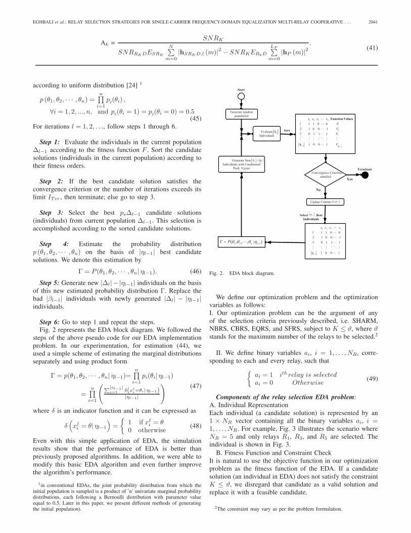
Step 6: Go to step 1 and repeat the steps.Fig. 2 represents the EDA block diagram. We followed the
steps of the above pseudo code for our EDA implementationproblem. In our experimentation, for estimation (44), weused a simple scheme of estimating the marginal distributionsseparately and using product form
Γ = p(θ1, θ2, · · · , θn| ηl−1)=n∏
i=1
pi(θi| ηl−1)
=n∏
i=1
(∑|ηl−1|j=1 δ(xj
i=θi| ηl−1)|ηl−1|
) (47)
where δ is an indicator function and it can be expressed as
δ(xji = θ| ηl−1
)=
{1 if xj
i = θ0 otherwise
(48)
Even with this simple application of EDA, the simulationresults show that the performance of EDA is better thanpreviously proposed algorithms. In addition, we were able tomodify this basic EDA algorithm and even further improvethe algorithm’s performance.
1in conventional EDAs, the joint probability distribution from which theinitial population is sampled is a product of ’n’ univariate marginal probabilitydistributions, each following a Bernoulli distribution with parameter valueequal to 0.5. Later in this paper, we present different methods of generatingthe initial population).
Convergence Criterion satisfied
Yes
No
Select Best Individuals
Evaluate Individuals
Sort
Generate New Individuals with Conditional
Prob. Vector
Generate random population
l
l l
1l
1 2 1( , , , | )n lP
Update Counter l=l+1
Terminate
Start
1
1 2 3
1
2
3
1
1 1 1 0 02 1 0 0 13 0 1 1 1
1 0 0 1l
n
l
x x x xFFF
F
Function Values
1 2 3
1
1 1 1 0 02 1 0 0 13 0 1 1 1
1 0 0 1
n
l
x x x x
Fig. 2. EDA block diagram.
We define our optimization problem and the optimizationvariables as follows:I. Our optimization problem can be the argument of anyof the selection criteria previously described, i.e. SHARM,NBRS, CBRS, EQRS, and SFRS, subject to K ≤ ϑ, where ϑstands for the maximum number of the relays to be selected.2
II. We define binary variables ai, i = 1, . . . , NR, corre-sponding to each and every relay, such that{
ai = 1 ith relay is selectedai = 0 Otherwise
(49)
Components of the relay selection EDA problem:A. Individual RepresentationEach individual (a candidate solution) is represented by an1 × NR vector containing all the binary variables ai, i =1, . . . , NR. For example, Fig. 3 illustrates the scenario whereNR = 5 and only relays R1, R3, and R5 are selected. Theindividual is shown in Fig. 3.
B. Fitness Function and Constraint CheckIt is natural to use the objective function in our optimizationproblem as the fitness function of the EDA. If a candidatesolution (an individual in EDA) does not satisfy the constraintK ≤ ϑ, we disregard that candidate as a valid solution andreplace it with a feasible candidate.
2The constraint may vary as per the problem formulation.

2042 IEEE TRANSACTIONS ON WIRELESS COMMUNICATIONS, VOL. 12, NO. 5, MAY 2013
S D
2R
3R
5R
1R
4R
1 0 1 0 1
Fig. 3. Represents the corresponding individual for the scenario where thefirst, third, and the fifth relays are selected.
Generating the Initial Population:The initial population is typically constructed randomly suchthat each component of the individual is assigned 0 or 1with equal probabilities. Note, however, that the size of thepopulation in EDA is usually much smaller than the sizeof the entire search space, and thus it is quite likely thatrandomly generated initial population may contain no feasiblesolution or on very small number of feasible solutions. Inhere, we propose a novel method to deal with the initialpopulation generation problem specifically designated for ourrelay selection problem:
Subject to the the maximum number of relays to be selected,i.e. ϑ, the initial population includes individuals correspondingto the selection of the relays that would satisfy the argument ofany of the selection criteria already discussed. As an example,assuming that SVRS is the selection criteria based on whichthe initial population individuals are generated, the relay indexthat maximizes (32) is assigned 1 in all individuals inside theinitial population. The choice of number of relay indexes thatare assigned 1 based on this approach is optional. Next, untilwe reach the size of the initial population, starting from tworelays, i.e. 1 already assigned to the relay that is selected basedon (32), 1 is assigned to the rest of the relays in a circularfashion.
V. COMPUTATIONAL COMPLEXITY AND NUMERICAL
RESULTS
In this section, we present Monte-Carlo simulation resultsfor different relay selection methods in the multi-relay systemassuming a quasi-static Rayleigh fading channel for all theS → Ri and Ri → D, i = 1, . . . , NR links. Note that all
0 5 10 15 20 25
10−4
10−3
10−2
10−1
100
ESR
k
/N0
SE
R
NBRSCBRSSVRSEQRSSFRS
Fig. 4. Single Relay Selection in a two relay network for SC-MMSE receiverwith different selection strategies.
simulations are performed using MATLAB software on a 3GHz CPU.
First, we assume that there are two relay nodes, whereeach node is equipped with one antenna, employing MMSEreceiver. We set ERiD = 5dB and the SER curve is plottedagainst ESR
N0=
ESR1
N0=
ESR2
N0. We further assume that
LSR1 = LR1D = LSR2 = LR2D = 1, N=256 for thesymbol block size, and 4-QAM modulation is used. The SERperformance of different relay selection schemes for SC-FDEMMSE receiver is studied. As is illustrated in Fig. 4, theSER performance of the NBRS and CBRS schemes that ismotivated by the receiver input power, is the worst. Moreover,The SVRS and EQRS schemes have almost similar SERperformances, and both outperform the NBRS and CBRSmethods by i.e. ∼ 10 dB at SER = 10−3. The SFRS methodprovides the best SER performances, and also is the onlyscheme that extracts full diversity, similar to that of MRC.Note that SFRS outperforms SVRS and EQRS by ∼ 10 dBand outperforms CBRS and NBRS by ∼ 18 dB at SER =10−3, which is astonishing.
Fig. 5 illustrates the SER performance of different re-lay selection schemes assuming ML-SC-FDE receiver withLSR1 = LR1D = LSR2 = LR2D = 1. As can be seenfrom Fig. 5, the selection criteria based on minimization ofthe average error rate and the proposed method are the mostpowerful methods. Also, the CBRS and NBRS methods haveacceptable performance, i.e. the proposed method outperformsthem by only ∼ 2 dB at SER = 10−3. The SVRS and theEQRS have the worst SER performance, i.e. CBRS and NBRSoutperform them by ∼ 4 dB at SER = 10−3. It can beconcluded from the simulation results that regardless of thereceiver type, the NBRS and CBRS methods have close SERperformances, which are motivated by the receiver input signalpower. Similarly, the SVRS and EQRS methods have closeSER performances, which are motivated by minimizing theinstantaneous SER.
Fig. 6 illustrates the SER performance of the SHARMselection scheme with an MMSE receiver implemented. Weassume there are two relays and SNRSRi
= 10dB, i = 1, 2.

EGHBALI et al.: RELAY SELECTION STRATEGIES FOR SINGLE-CARRIER FREQUENCY-DOMAIN EQUALIZATION MULTI-RELAY COOPERATIVE . . . 2043
0 5 10 1510
−5
10−4
10−3
10−2
10−1
100
ESR
/N0
SE
R
SVRSEQRSCBRS,NBRSML Average error rate CriteriaSFRS
Fig. 5. Single Relay Selection in a two relay network for ML-SC-FDEreceiver with different selection strategies.
0 5 10 15 20
10−8
10−6
10−4
10−2
100
SNR (dB)
SE
R
Scenario 1, DO=2Scenario 2, DO=4Scenario 3, DO=6
Fig. 6. Single Relay Selection in a two relay network for SC-MMSE receiverwith SHARM selection scheme.
We further consider three scenarios:Scenario I: LSR1 = LSR2 = 6, LR1D = LR2D = 0Scenario II: LSR1 = LSR2 = 5, LR1D = LR2D = 1Scenario III: LSR1 = LSR2 = 6, LR1D = LR2D = 2According to (19), the diversity order (DO) for the scenarios I,II, and III should be 2, 4, and 6, correspondingly, which agreeswith the simulation results. More importantly, even though anMMSE receiver is implemented, full diversity advantages areachieved.
In Fig. 7, we evaluate the performance of the proposed EDAmethod. The initial population is generated based on the SVRSscheme. The CBRS criterion is considered as the fitness func-tion. We further assume 4-PSK modulation, 10 relays, LSRi
=5, LRiD = 1, i = 1, . . . , 10, and assume population size = 11, i.e. 3% of the overall population, number of best populationelements = 4, maximum number of relays to be selected = 4for the EDA. Since the proposed EDA algorithm searches forthe best subset of relays, i.e. maximum 4 number of relaysto be selected, the size of the entire search space is equal
0 5 10 15 2010
−9
10−8
10−7
10−6
10−5
10−4
10−3
10−2
SNR (dB)
SE
R
iter = 4iter = 8iter = 20Exhaustive Search
Fig. 7. Relay Selection with EDA with 10 Relays.
to |Is| =(
101
)+
(102
)+
(103
)+
(104
)= 385.
Furthermore, we consider number of iterations ITer = 20. TheEDA algorithm was paused at ITer = 4, 8, and the systemSER performance was considered for three different scenariosat ITer = 4, 8, 20. SER performance of these three scenariosis compared with the performance of the optimal solutionobtained through the exhaustive search algorithm which takesabout 514 mili seconds to run. Note that the average used timeof these scenarios as compared with the exhaustive search isequal to 56.5, 113.1, and 293 mili seconds, respectively. As isillustrated in Fig. 7, by increasing the iterations, better SERperformance is achieved, i.e. ∼ 6 dB difference at SER = 10−8
between scenarios 2, and 3. It can be seen that scenario 3 withITer = 20 performs very close to the exhaustive search, whiletakes about only 0.57% time as compared with the exhaustivesearch.
Fig. 8 evaluates the performance of the proposed EDAscheme for 30 relays, LSRi
= 2, LRiD = 1, i = 1, . . . , 10,4-PSK modulation and assumes population size = 50 , numberof best population elements = 15, and maximum number ofrelays to be selected = 3 for the EDA. We consider numberof iterations ITer = 30. The EDA algorithm was pausedat ITer = 1, 10, 20, and the system SER performance wasconsidered for four different scenarios at ITer = 1, 10, 20, 30.As is illustrated in Fig. 8, by increasing the iterations, betterSER performance is achieved, i.e. ∼ 4 dB difference at SER =10−7 between scenarios 2, and 3. Note that for large number ofrelays NR, it is very inefficient to perform exhaustive search.
Fig. 9 compares the convergence rate of the proposed EDAscheme for different SNR values versus iteration number. Weassume NR = 30, LSRi
= 2, LRiD = 1, i = 1, . . . , 10, 4-PSK modulation and consider population size = 50 , numberof best population elements = 15, and maximum number ofrelays to be selected = 3 for the EDA. As can be seen fromFig. 9, the proposed EDA method converges at 24 ( 1.6959seconds), 27 ( 1.9079 s), 23 (1.6252 s), and 24 (1.6959 s)iterations for 0, 5, 10, and 15 dB, respectively.
To measure the computational complexity of the EDAalgorithm as compared to the exhaustive search algorithm,we consider the number of complex multiplications and ad-

2044 IEEE TRANSACTIONS ON WIRELESS COMMUNICATIONS, VOL. 12, NO. 5, MAY 2013
0 5 10 1510
−8
10−7
10−6
10−5
10−4
10−3
10−2
10−1
SNR (dB)
SE
R
iter = 1iter = 10iter = 20iter = 30
Fig. 8. Relay Selection with EDA with 30 Relays.
0 10 20 30
0.04
0.045
0.05
Iteration
SE
R
SNR = 0 dB
0 10 20 301.5
2
2.5x 10
−3
Iteration
SE
R
SNR = 5 dB
0 10 20 301
1.5
2
2.5
3x 10
−5
Iteration
SE
R
SNR = 10 dB
0 10 20 300
0.5
1
1.5x 10
−7
Iteration
SE
R
SNR = 15 dB
Fig. 9. Convergence rate of the proposed EDA method
ditions . The exhaustive search algorithm needs to computeNR,max∑rk=1
(NR
rk
)complex determinants in (28), with NR,max
being the maximum number of relays to be selected, andNR being the physical relay terminals available. A matrixdeterminant can be computed with complexity O
(K3
)or
better [25]. However, since in (28), only the diagonal matricesΛ (K) are involved, each determinant requires 2NK − 1complex multiplications only. The EDA algorithm, on theother hand, needs to compute |Δ| ITer determinants. Weconsider two scenarios:Scenario I:[NR, NR,max, |Δ| , ITer ] = [10, 4, 11, 20]Scenario II: [NR, NR,max, |Δ| , ITer] = [30, 3, 50, 30]Note that since EDA selects a different relay subset at eachiteration, the number of complex multiplications involved issubjective. Nevertheless, we can provide an upper boundfor EDA’s computational cost, by assuming that at eachiteration, NR,max number of relays are selected. Followingthis assumption, in scenario I, ESA requires 665212 complexmultiplications, and the EDA algorithm requires maximumnumber of 450340 complex multiplications. Note that for
EDA, we have assumed ITer = 20 which was illustrated inFig. 7 to perform close to the optimal solution. In scenarioII, ESA requires 6692435 complex multiplications, and theEDA algorithm requires maximum number of 2302500 com-plex multiplications. Note that for EDA, we have assumedITer = 30 which was illustrated in Fig. 8 to perform closeto the optimal solution. This complexity comparison showsthat EDA requires less computational cost as compared tothe exhaustive search algorithm. Note that similar complexityanalysis can be performed for the rest of selection criteriadiscussed in Sec. III if chosen as the EDA fitness function.
VI. CONCLUSION
We have investigated different relay selection methods forthe multi-relay SC-FDE broadband cooperative networks withunderlying frequency-selective Rayleigh fading channels as-suming both ML and MMSE receivers. We have investigatedthe relay selection criteria for the SC-FDE ML receiversmotivated by minimizing the average symbol error rate. Sim-ilarly, we have investigated different relay selection schemesfor SC-FDE MMSE receivers motivated by minimizing theinstantaneous symbols error rate. We also have proposed novelrelay selection schemes in which only the relay with thefrequency selective source to destination link that acquiresthe highest norm flat fading tab is selected, along with aPEP based scheme which is able to fully investigate theunderlying multipath diversity. Among the relay selectionmethods provided, the SFRS and the relay selection criteriaminimizing the average symbol error rate have the best SERperformance for SC-FDE ML receiver. We finally extendedour analysis to multiple relay selection scenarios by applyingthe EDA algorithm. By further defining the EDA parametersspecifically for our relay selection problem, significant perfor-mance improvement was shown while maintaining comparablecomplexity.
Appendix A
Assuming
N∑i=1
ai
N = E, with a1 ≥ a2 ≥ . . . ≥ aN , we have
K∑i=1
ai = N −N∑
j=K+1
aj
= K + (N −K)E −N∑
j=K+1
aj
= K + (N −K)
K∑i=1
ai +N∑
j=K+1
aj
N−
N∑j=K+1
aj � 0
(50)
where
(N −K)
K∑i=1
ai −K
N∑j=K+1
aj ≥ 0. (51)
REFERENCES
[1] Y. Jing and H. Jaffarkhani, “Single and multiple relay selection schemesan their achievable diversity orders,” IEEE Trans. Wireless Commun., no.3, pp. 1414–1423, Mar. 2009.
EGHBALI et al.: RELAY SELECTION STRATEGIES FOR SINGLE-CARRIER FREQUENCY-DOMAIN EQUALIZATION MULTI-RELAY COOPERATIVE . . . 2045
[2] V. Shah, N. B. Mehta, and R. Yim, “The relay selection and transmissiontradeoff in cooperative communication systems,” IEEE Trans. WirelessCommun., vol. 9, pp. 2505–2515, Aug. 2010.
[3] M. Seyfi, S. Muhaidat, and J. Liang, “Performance analysis of relayselection with feedback delay and channel estimation errors,” IEEESignal Process. Lett., vol. 18, pp. 67-70, Jan. 2011.
[4] Y. Ding and M. Uysal, “Amplify-and-forward cooperative OFDM withmultiple-relays: Performance analysis and relay selection methods,”IEEE Trans. Wireless Commun., vol. 8, no. 10, pp. 4963–4968, Oct.2009.
[5] H. Muheidat, M. Uysal, and N. Al-Dhahir, “Equalization techniques fordistributed space-time block codes with amplify-and-forward relaying,”IEEE Trans. Signal Process., vol. 55, no. 5, part 1, pp. 1839–1852, May2007.
[6] H. Muhaidat, M. Uysal, and R. Adve, “Pilot-symbol-assisted detectionscheme for distributed orthogonal space-time block coding,” IEEETrans. Wireless Commun., vol. 8, no. 3, pp. 1057–1061, Mar. 2009.
[7] H. Muheidat, M. Uysal, and N. Al-Dhahir, “Time-reversal space-timeequalization for amplify-and-forward relaying,” in Proc. 2006 IEEE Int.Conf. Commun., pp. 1705–1711.
[8] H. Eghbali, S. Muhaidat, and N. Al-Dhahir, “Novel receiver designfor single-carrier frequency domain equalization in broadband wirelessnetworks with amplify-and-forward relaying,” IEEE Trans. WirelessCommun., vol. 10, no. 3, pp. 721–727 2011.
[9] H. Eghbali and S. Muhaidat, “Single-carrier frequency-domain equaliza-tion for multi-relay cooperative systems with relay selection,” in Proc.2011 GC Wkshps, pp. 1353–1358.
[10] O.-S. Shin, A. Chan, H. T. Kung, and V. Tarokh, “Design of an OFDMco-operative diversity system,” IEEE Trans. Veh. Technol., vol. 56, no.4, pp. 2203–2215, July 2007.
[11] W. P. Siriwongpairat, A. K. Sadek, and K. J. R. Liu, “Cooperativecommunications protocol for multiuser OFDM networks,” IEEE Trans.Wireless Commun., vol. 7, no. 7, pp. 2430–2435, July 2008.
[12] W. Dang, M. Tao, H. Mu, and J. Huang, “Subcarrier-pair based resourceallocation for cooperative multi-relay OFDM systems,” IEEE Trans.Wireless Commun., vol. 9, no. 5, pp. 1640–1649, May 2010.
[13] R. U. Nabar, H. Boelcskei, and F. W. Kneubhueler, “Fading relaychannels: performance limits and space-time signal design,” IEEE J.Sel. Areas Commun., vol. 22, pp. 1099–1109, Aug. 2004.
[14] R. Kwan and C. Leung “Gamma variate ratio distribution with appli-cation to CDMA performance analysis,” in Proc. 2005 IEEE/SarnoffSymp. Adv. Wired Wireless Commun., pp. 188–191.
[15] I. S. Gradshteyn and I. M. Ryzhik, Table of Integrals, Series, andProducts. Academic Press Inc., 1980.
[16] M. Abramowitz and I. A. Stegun, Handbook of Mathematical Functionswith Formulas, Graphs, and Mathematical Tables, 9th edition. Dover,1970.
[17] D. A. Gore and A. Paulraj, “MIMO antenna subset selection with space-time coding,” IEEE Trans. Signal Process., vol. 50, pp. 2580–2588, Oct.2002.
[18] A. F. Molisch and M. Z. Win, “MIMO systems with antenna selection,”IEEE Microwave Mag., vol. 5, no. 1, pp. 46–56, 2004.
[19] S. Sanayei and A. Nosratinia, “Antenna selection in MIMO systems,”IEEE Commun. Mag., vol. 42, no. 10, pp. 68–73, 2004.
[20] X. Shao, J. Yuan, and P. Rapajic, “Antenna selection for MIMO-OFDMspatial multiplexing system,” in Proc. 2003 IEEE International Symp.Inf. Theory, pp. 90.
[21] A. Wilzeck, P. Pan, and T. Kaiser, “Transmit and receive antenna subsetselection for MIMO SC-FDE in frequency selective channels,” in Proc.2006 European Signal Process. Conf.
[22] J. Xu, H. Zhang, D. Yuan, and M. Jiang, “A new multiple relay selectionscheme in dual-hop amplify-and-forward cooperative network based ongenetic algorithm,” in Proc. 2011 IEEE International Conf. Commun.Technol.
[23] A. E. Eiben and J. E. Smith, Introduction to Evolutionary Computing.Springer Verlag, 2003.
[24] P. Larraaga and J. A Lozano, Estimation of Distribution Algorithms: ANew Tool for Evolutionary Computation. Kluwer Academic Publishers,2001.
[25] G. H. Golub and C.F. VanLoan, Matrix Computations. The JohnsHopkins University Press, 1983.
Homa Eghbali received the B.Sc. degree with hon-ors in Electrical Engineering, and minor in Com-puter Engineering, networking, from American Uni-versity of Sharjah, U.A.E., From 2005 to 2008. Shereceived the M.Sc. degree in Electrical Engineeringwith focus in wireless communications from SimonFraser University, BC, Canada, from 2009 to 2010.Since 2010, she has been working towards her PhDdegree in Electrical Engineering with focus in wire-less communications in Simon Fraser University.Homa is an active IEEE member and a frequent
reviewer for numerous journals/conferences, including ICC, GC, VTC, TWC.She was awarded the IEEE GC 2009 Student Travel Grant, as well as multiplefellowships and honorary awards from Simon Fraser University and AmericanUniversity of Sharjah. Homa’s research interests include MIMO antenna sys-tems, space-time coding, diversity techniques, cooperative diversity, Channelpropagation modeling, Underwater communication, and LTE.
Sami Muhaidat received the Ph.D. degree in Elec-trical and Computer Engineering from the Universityof Waterloo, Waterloo, Ontario, in 2006. From 2007to 2008, he was an NSERC postdoctoral fellow inthe Department of Electrical and Computer Engi-neering, University of Toronto, Canada. From 2008-2012, he was an Assistant Professor in the Schoolof Engineering Science, Simon Fraser University,BC, Canada. He is currently an Assistant Professorat Khalifa University and a Visiting Reader in theFaculty of Engineering, University of Surrey, UK.
Sami’s research focuses on advanced digital signal processing techniquesfor communications, cooperative communications, vehicular communications,MIMO, and space-time coding. He has authored more than 75 journal andconference papers on these topics. Sami is an active Senior IEEE member andcurrently serves as an Editor for IEEE COMMUNICATIONS LETTERS and anAssociate Editor for IEEE TRANSACTIONS ON VEHICULAR TECHNOLOGY.He was the recipient of several scholarships during his undergraduate andgraduate studies. He was also a winner of the 2006 NSERC PostdoctoralFellowship competition.
Seyed Amin Hejazi was born in Iran. He re-ceived the B.Sc. in Electrical Engineering fromUniversity of Tehran, Tehran, Iran, in 2007, andthe M.Sc. degree in Electrical Engineering fromAmirkabir University of Technology, Tehran, Iran, in2009. Since September 2009, he has been with theDepartment of Engineering Science, Simon FraserUniversity, working towards the Ph.D. degree. Hisresearch interests include LTE, LTE self-optimizingnetworks, and cooperative communication.
Yanwu Ding received the B.Eng degree (with honors) from SouthwestJiaotong University, Chengdu, China and the M.Sc. degree (with Best ThesisResearch Award) from McMaster University, Hamilton, ON. Canada. She iscurrently with the Department of Electrical Engineering and Computer Sci-ence, Wichita State University. Her research interests are in signal processingand cooperative communication systems.