RELAY BOARD KIT
19
RELAY BOARD KIT CONTROL YOUR EQUIPMENT WITH THIS TEACHING RESOURCES SCHEMES OF WORK DEVELOPING A SPECIFICATION COMPONENT FACTSHEETS HOW TO SOLDER GUIDE Version 2.0
-
Upload
khangminh22 -
Category
Documents
-
view
1 -
download
0
Transcript of RELAY BOARD KIT

RELAY BOARD KIT
CONTROL YOUR EQUIPMENT WITH THIS
TEACHING RESOURCESSCHEMES OF WORK
DEVELOPING A SPECIFICATIONCOMPONENT FACTSHEETS
HOW TO SOLDER GUIDE
Version 2.0

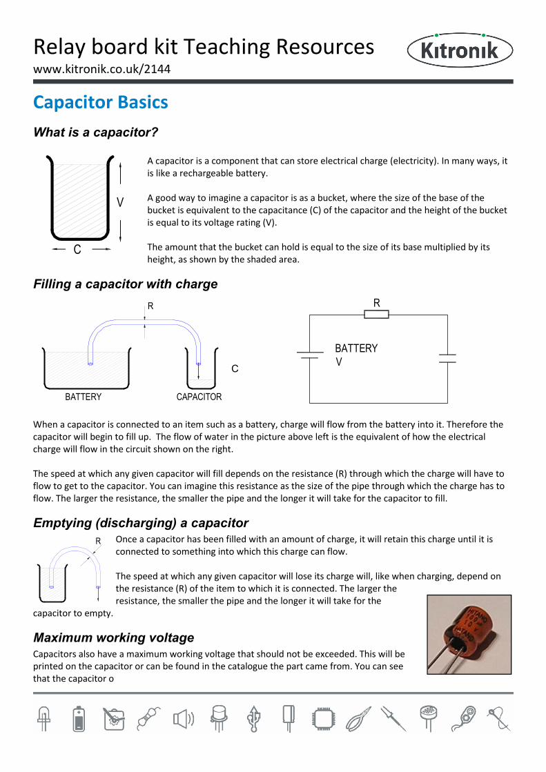
Relay board kit Teaching Resources www.kitronik.co.uk/2144
Index of Sheets TEACHING RESOURCES
Index of Sheets
Soldering in Ten Steps
Resistor Values
LEDs & Current Limit Resistors
LEDs Continued
Capacitor Basics
ESSENTIAL INFORMATION
Features of the Relay board
Using the relay board
Mechanical information
Build Instructions
Build Instructions continued
Checking Your Relay Board PCB
Parts list
Testing the PCB
Example applications
Fault Finding
Using relays
How the Relay board works
Online Information

Relay board kit Teaching Resources www.kitronik.co.uk/2144
Soldering in Ten Steps
1. Start with the smallest components working up to the taller components, soldering any interconnecting wires last.
2. Place the component into the board, making sure that it goes in the right way around and the part sits flush against the board.
3. Bend the leads slightly to secure the part.
4. Make sure that the soldering iron has warmed up and if necessary, use the damp sponge to clean the tip.
5. Place the soldering iron on the pad.
6. Using your free hand, feed the end of the solder onto the pad (top picture).
7. Remove the solder, then the soldering iron.
8. Leave the joint to cool for a few seconds.
9. Using a pair of cutters, trim the excess component lead (middle picture).
10. If you make a mistake heat up the joint with the soldering iron, whilst the solder is molten, place the tip of your solder extractor by the solder and push the button (bottom picture).
Solder joints
Good solder joint Too little solder Too much solder

Relay board kit Teaching Resources www.kitronik.co.uk/2144
Resistor Values A resistor is a device that opposes the flow of electrical current. The bigger the value of a resistor, the more it opposes the current flow. The value of a resistor is given in Ω (ohms) and is often referred to as its ‘resistance’.
Identifying resistor values
Band Colour 1st Band 2nd Band Multiplier x Tolerance
Silver 100 10% Gold 10 5% Black 0 0 1 Brown 1 1 10 1% Red 2 2 100 2%
Orange 3 3 1000 Yellow 4 4 10,000 Green 5 5 100,000 Blue 6 6 1,000,000
Violet 7 7 Grey 8 8 White 9 9
Example: Band 1 = Red, Band 2 = Violet, Band 3 = Orange, Band 4 = Gold The value of this resistor would be: 2 (Red) 7 (Violet) x 1,000 (Orange) = 27 x 1,000
= 27,000 with a 5% tolerance (gold) = 27KΩ
Resistor identification task Calculate the resistor values given by the bands shown below. The tolerance band has been ignored.
1st Band 2nd Band Multiplier x Value Brown Black Yellow Green Blue Brown Brown Grey Yellow
Orange White Black
Too many zeros?
Kilo ohms and mega ohms can be used:
1,000Ω = 1K
1,000K = 1M

Relay board kit Teaching Resources www.kitronik.co.uk/2144
Calculating resistor markings Calculate what the colour bands would be for the following resistor values.
Value 1st Band 2nd Band Multiplier x 180 Ω
3,900 Ω 47,000 (47K) Ω
1,000,000 (1M) Ω
What does tolerance mean? Resistors always have a tolerance but what does this mean? It refers to the accuracy to which it has been manufactured. For example if you were to measure the resistance of a gold tolerance resistor you can guarantee that the value measured will be within 5% of its stated value. Tolerances are important if the accuracy of a resistors value is critical to a design’s performance.
Preferred values There are a number of different ranges of values for resistors. Two of the most popular are the E12 and E24. They take into account the manufacturing tolerance and are chosen such that there is a minimum overlap between the upper possible value of the first value in the series and the lowest possible value of the next. Hence there are fewer values in the 10% tolerance range.
E-12 resistance tolerance (± 10%) 10 12 15 18 22 27 33 39 47 56 68 82
E-24 resistance tolerance (± 5 %)
10 11 12 13 15 16 18 20 22 24 27 30 33 36 39 43 47 51 56 62 68 75 82 91

Relay board kit Teaching Resources www.kitronik.co.uk/2144
LEDs & Current Limit Resistors Before we look at LEDs, we first need to start with diodes. Diodes are used to control the direction of flow of electricity. In one direction they allow the current to flow through the diode, in the other direction the current is blocked.
An LED is a special diode. LED stands for Light Emitting Diode. LEDs are like normal diodes, in that they only allow current to flow in one direction, however when the current is flowing the LED lights. The symbol for an LED is the same as the diode but with the addition of two arrows to show that there is light coming from the diode. As the LED only allows current to flow in one direction, it's important that we can work out which way the electricity will flow. This is indicated by a flat edge on the LED.
For an LED to light properly, the amount of current that flows through it needs to be controlled. To do this we use a current limit resistor. If we didn’t use a current limit resistor the LED would be very bright for a short amount of time, before being permanently destroyed. To work out the best resistor value we need to use Ohms Law. This connects the voltage across a device and the current flowing through it to its resistance. Ohms Law tells us that the flow of current (I) in a circuit is given by the voltage (V) across the circuit divided by the resistance (R) of the circuit.
RVI =
Like diodes, LEDs drop some voltage across them. For a standard red LED this is 1.8 volts. Suppose this LED is run off a 5V supply there must be a total of 5 volts dropped across the LED (VLED) and the resistor (VR). As the LED manufacturer’s datasheet tells us that there is 1.8 volts dropped across the LED, there must be 3.2 volts dropped across the resistor. (VLED + VR = 1.8 + 3.2 = 5V). LEDs normally need about 10mA to operate at a good brightness. Since we know that the voltage across the current limit resistor is 3.2 volts and we know that the current flowing through it is 0.01 Amps, the resistor can be calculated. Using Ohms Law in a slightly rearranged format:
=== 32001.02.3
IVR
Hence in this circuit we would need a 320Ω current limit resistor, or the nearest value of 330Ω.
R
VBATTERY
ILED
VLED
VR

Relay board kit Teaching Resources www.kitronik.co.uk/2144
LEDs Continued Packages LEDs are available in many shapes and sizes. The 5mm round LED is the most common. The colour of the plastic lens is often the same as the actual colour of light emitted – but not always with high brightness LEDs.
Advantages of using LEDs over bulbs Some of the advantages of using an LED over a traditional bulb are:
Power efficiency LEDs use less power to produce the same amount of light, which means that they are more efficient. This makes them ideal for battery power applications.
Long life LEDs have a very long life when compared to normal light bulbs. They also fail by gradually dimming over time instead of a sharp burn out.
Low temperature Due to the higher efficiency of LEDs, they can run much cooler than a bulb. Hard to break LEDs are much more resistant to mechanical shock, making them more difficult to break
than a bulb. Small LEDs can be made very small. This allows them to be used in many applications, which
would not be possible with a bulb. Fast turn on LEDs can light up faster than normal light bulbs, making them ideal for use in car break
lights.
Disadvantages of using LEDs Some of the disadvantages of using an LED over a traditional bulb are:
Cost LEDs currently cost more for the same light output than traditional bulbs. However, this needs to be balanced against the lower running cost of LEDs due to their greater efficiency.
Drive circuit To work in the desired manner, an LED must be supplied with the correct current. This could take the form of a series resistor or a regulated power supply.
Directional LEDs normally produce a light that is focused in one direction, which is not ideal for some applications.
Typical LED applications Some applications that use LEDs are: Bicycle lights Car lights (break and headlights) Traffic lights Indicator lights on consumer electronics Torches Backlights on flat screen TVs and displays
Road signs Information displays Household lights Clocks
Relay board kit Teaching Resources www.kitronik.co.uk/2144
Capacitor Basics What is a capacitor?
A capacitor is a component that can store electrical charge (electricity). In many ways, it is like a rechargeable battery. A good way to imagine a capacitor is as a bucket, where the size of the base of the bucket is equivalent to the capacitance (C) of the capacitor and the height of the bucket is equal to its voltage rating (V). The amount that the bucket can hold is equal to the size of its base multiplied by its height, as shown by the shaded area.
Filling a capacitor with charge
When a capacitor is connected to an item such as a battery, charge will flow from the battery into it. Therefore the capacitor will begin to fill up. The flow of water in the picture above left is the equivalent of how the electrical charge will flow in the circuit shown on the right. The speed at which any given capacitor will fill depends on the resistance (R) through which the charge will have to flow to get to the capacitor. You can imagine this resistance as the size of the pipe through which the charge has to flow. The larger the resistance, the smaller the pipe and the longer it will take for the capacitor to fill.
Emptying (discharging) a capacitor Once a capacitor has been filled with an amount of charge, it will retain this charge until it is connected to something into which this charge can flow. The speed at which any given capacitor will lose its charge will, like when charging, depend on the resistance (R) of the item to which it is connected. The larger the resistance, the smaller the pipe and the longer it will take for the
capacitor to empty.
Maximum working voltage Capacitors also have a maximum working voltage that should not be exceeded. This will be printed on the capacitor or can be found in the catalogue the part came from. You can see that the capacitor o
C
V
R
BATTERYV
R
BATTERY CAPACITOR
R
C

RELAY BOARD KIT
ESSENTIAL INFORMATIONBUILD INSTRUCTIONS
CHECKING YOUR PCB & FAULT-FINDINGMECHANICAL DETAILSHOW THE KIT WORKS
Version 2.0
CONTROL YOUR EQUIPMENT WITH THIS

Relay board kit Essentials www.kitronik.co.uk/2144
Features of the Relay board Introduction This is a versatile board that can easily be configured via jumpers and trimmer potentiometers to do a range of tasks. Most sensor and switches can be connected to the input of the board and the trigger level set for the input device. This can be inverted if required, then there is the option to feed this straight to the relay or a timer of up to 25 minutes can be used.
Technical information Operating voltage: 4.5V - 6.0V Input type: Switch / resistive sensor Max sensor resistance: 100KΩ Sensor threshold: Set via trimmer Input inversion: Via jumper Output delay on/ off: Via jumper Max delay length: 25 minutes Delay accuracy: ±20% Outputs: NO / NC Max output VDC: 28 V Max output VAC: 250 V Max out current NO: 10A Max out current NC: 7A Max propagation delay: 15mS Max operating current: 90mA
Block diagram

Relay board kit Essentials www.kitronik.co.uk/2144
Using the relay board This board is very easy to set-up. 5V should be connected to the power terminal block and a switch or sensor connected to the input terminal block. The sensitivity and duration of the delay are set by potentiometers R4 and R8 respectively. Whether the input is inverted and whether the output is on for a delayed period or follows the sensor state is determined by jumpers PL1 and PL2 respectively. The relay output has connections for the common signal (Com) as well as NO (Normally Open) and NC (Normally Closed).
Mechanical information
All dimensions in mm. Max height of board & components is 18.5 mm.
Sensitivity Duration
Invert / no invert
Timer / no timer
Sensor state
Output state
Power input
Sensor input
Relay output

Relay board kit Essentials www.kitronik.co.uk/2144
Build Instructions Before you start, take a look at the Printed Circuit Board (PCB). The components go in the side with the writing on and the solder goes on the side with the tracks and silver pads.
Start with the 7 resistors: The text on the PCB shows where R1, R2 etc go. Ensure that you put the resistors in the right place.
PCB Ref Value Colour Bands R1, R3 & R5 10kΩ Brown, black, orange R6, R7 & R9 220Ω Red, red, brown R2 47kΩ Yellow, purple, orange
Solder the two diodes into the board. When putting these into the board, be sure to get them the right way around. The band on the diode must match up with the band on the PCB. The diodes are marked D1 & D2.
A wire link needs to be added. Take a piece of wire (use a piece from a resistor you have just cut off) and solder it into the board where it is marked wire link.
Solder the variable resistors into R4 & R8. They will only fit in the holes in the board when they are the correct way around. The two resistors are different values, R4 is a 1M and R8 is 10M, make sure you solder each in the right place.
Solder the IC holder into IC1. When putting it into the board, be sure to get it the right way around. The notch on the IC holder should line up with the notch on the lines marked on the PCB.
Solder the two electrolytic capacitors into C1 & C2. These need to but put in the board the correct way around. The white band on capacitors should line up with the ‘---’ markings on the board. The capacitors are different values, C1 is a 4.7uF and C2 is a 100uF.
PLACE RESISTORS 1
Place the diodes 2
Place the wire link 3
Place the variable resistors 4
Place the IC Holder 5
Place the Capacitors 6

Relay board kit Essentials www.kitronik.co.uk/2144
Build Instructions continued
Place the FET in to the board where it is labelled Q1. Make sure the device is the correct way around. The shape of the device should match the outline on the PCB.
Solder the two Light Emitting Diodes (LEDs) in to LED1 & LED2. The LEDs won’t work if they don’t go in the correct way around. If you look carefully one side of the LED has a flat edge, which must line up with the flat edge on the lines on the PCB.
Solder the terminal blocks into the board. The two way terminal blocks are for the ‘POWER’ and the ‘INPUT’ connections and the three way terminal block is for the ‘OUTPUT’. Make sure the side that the wire goes into is facing the edge of the board.
The kit is supplied with a 6 way section of pin header. This should be snapped into two sections with three pins. It can then be soldered into PL1 & PL2.
Solder the relay into Q2. There is only one way this will go into the board.
Now put the LM324 quad op amp chip into the holder labelled IC1 ensuring the notch on the chip lines up with the notch on the holder.
Place the FET 7
Place the LED’s 8
Place the terminal blocks 9
Place the pin headers 10
Place the relay 11
Place the IC Chip 12

Relay board kit Essentials www.kitronik.co.uk/2144
Checking Your Relay Board PCB Check the following:- Check the bottom of the board to ensure that: All holes (except the 4 large 3 mm holes) are filled with the lead of a component. All these leads are soldered. Pins next to each other are not soldered together. Check the top of the board to ensure that: The notch on the IC is next to C2. R1, R3 & R5 are 10k (Brown, Black, Orange, coloured bands). R6, R7 & R9 are 220R (Red, Red, Brown, coloured bands). The silver bands on diodes D1 and D2 are matching the markings on the board. The two LEDs are in the right way around (the flat edge on the LED matches the markings on the board). The white band on the two capacitors match the ‘---’ markings on the board. A wire link is present next to the jumper PL2.
Parts list Ref Description Qty
R1,R3 & R5 10K resistor 5% 3 R6,R7 & R9 220R resistor 5% 3 R2 47K resistor 5% 1 R4 1M Pot 1 R8 10M Pot 1 D1-D2 1N4001 diode, 1A 2 LED1 – LED2 LED red 5 mm 2 C2 100uF electrolytic capacitor 1 C1 4.7uF electrolytic capacitor 1 Q1 N Chanel FET (2N7000) 1 POWER, INPUT 2 way terminal block 2 OUTPUT 3 way terminal block 1 IC1 14 pin IC holder 1 IC1 LM324 1 Wire Link Discarded resistor lead 1 Q2 Relay, HF7FD 1 PL1, PL2 3 way single row PCB header plug 2 PL1, PL2 Closed link jumper 2

Relay board kit Essentials www.kitronik.co.uk/2144
Testing the PCB To test the board:
Place a jumper on PL1 to set No invert. Place a jumper on PL2 to set No timer. Connect a sensor or a switch to the ‘INPUT’ connection. Connect 5V (3x AA batteries or a power supply to the ‘POWER’
connection. Red to ‘+’ and black to ‘-’. If necessary adjust the sensitivity trimmer potentiometer.
When the sensor is triggered both LEDs should change state and the relay should click.
Now set PL1 to Invert. The LEDs should be the opposite way around to before.
Set PL2 to timer. Turn the duration trimmer fully anti-clockwise and then bring it back clockwise a fraction.
When LED1 turns on this time LED2 should go on for a short time. If there is a problem with the board this can be diagnosed with the fault finding flow chart on the next page.
Example applications PIR triggered sounder
Suppose you want to detect if someone has walked into a space and audibly sound this elsewhere. Then you could use a PIR module, the relay board and a sounder to do this. The connections would be as follows:
Example application – Automatic green house plant watering system Since you don’t want to water a green house in the heat of the day, why not automatically do it from a water butt at dusk for a set duration. To do this the relay board would be used as follows:
JumperJumper
Invert setting No invert settingSetting PL1 – invert / no invert
PL1 PL1
(Over top 2 pins) (Over bottom
2 pins)
PIR module
5V power supply
Or
3x AA battery
Relay boardBuzzer
5V regulator(7805)
12V power supply Relay board 12V
solenoid valveLDR

Relay board kit Essentials www.kitronik.co.uk/2144
Fault Finding
Triggerthe input.
Which LEDslight?
Both
Neither
No
Fault finding flow chart StartConfigure the board with:
PL1 = no invertPL2 = no timer
Check• The input device and the position
of trimmer R4.• The power supply is connected
the right way around.• The ‘POWER’ terminal block for
dry joints.• The ‘INPUT’ terminal block for
dry joints.• R1 is a 10K resistor & the
soldering for dry joints.• R4 for dry joints.• IC1 pins 1 – 4 and pin 11 for dry
joints / shorts.• PL1 for dry joints / shorts.
Check
• IC1 pins 5 – 7 for dry joints / shorts.
• R2 & R3 for dry joints.• PL1 for dry joints or shorts.
Check
• C1 for dry joints or shorts.• R5 for dry joints.• D1 for dry joints.• The value of R6 is 220
and for dry joints.• C2 for dry joints or shorts.• R8 for dry joints.• PL2 for dry joints / shorts.• IC1 pins 8 – 14 for dry
joints / shorts.
Check• Check the soldering on relay Q2
for dry joints.
Stop
Does therelay click as
the lightschange?
Yes
No
Only oneLED lights
WhichLED lights?
Check• The value of R7 is 220
and for dry joints.• That LED1 is the right
way around & for dry joints / shorts.
LED2lights
Check• PL2 for dry joints / shorts.• Q1 for dry joints / shorts.• The value or R9 is 220
and for dry joints.• That LED2 is the right
way around & for dry joints / shorts.
LED1lights
Set PL1 to invert
Is the LEDinverted when
the input istriggered?
Yes
Is the LED2on for a timed
period?
Set PL2 to timer and set the duration just
off minAre therestill problems
with theboard?
Check• C1 is a 4.7F capacitor.• C2 is a 100F capacitor.• R5 is a 10k resistor.• R6 is a 220 resistor.• R8 is a 10M potentiometer.
CheckThe relay Q2 and
the terminal ‘OUTPUT’ for
dry joints
No
The max delay is too short
The relay clicks but the output doesn’t work
NoYes

Relay board kit Essentials www.kitronik.co.uk/2144
Using relays Introduction A relay is a switch that is operated by passing a small amount of current through the coil. When this happens a magnetic field is set up which causes a small strip of metal to move and the switch on the output closes. When the current is turn off to the coil a spring pulls the metal strip open and the switch opens. Typically the coil will take hundreds of mA, whilst the output will switch Amps. Thus the relay allows a small current to drive a bigger current.
The part & circuit symbol
Connections on a relay Relays often have three connections on the output switch (as shown above), but can have more or less connections. The Common (Com) connection is connected to the Normally Closed (NC) connection until current is passed through the coil, when the common connects to Normally Open (NO). In a lot of circuits a device needs to be on when the relay is on, in this case the Com and NO connections are used. Since the relay is a switch a separate circuit including a power source the switch (relay) and a device needs to be connected. This circuit can of course use the same power as the circuit that powers the relay input or can use a higher voltage.
Example circuit
Load
Powersupply

Relay board kit Essentials www.kitronik.co.uk/2144
How the Relay board works
Sensing section - The input device on this circuit, plus the resistor R1 make up a potential divider. As the resistance on the input changes the voltage at the centre point of the potential divider will change. This voltage goes in to the non-inverting input of ‘op amp a’ on IC1 and is compared to the voltage on the inverting input, which is set by the trimmer potentiometer R4. When the sensor input is bigger than the pre-set input the output of the gate will be high, otherwise it will be low.
Invert section - If a jumper is placed on the left two pins of PL1 then the output from op amp a goes straight to the timer section of the circuit. However if the jumper is placed on the right two pins of PL1 then the output of ‘op amp b’ is fed through to the timer section. In the second case the signal is inverted, this happens because the non-inverting input on ‘op amp b’ is held in a known state at about 1V and the output from the sensing op amp goes into the inverting input. This means that if the sensor input is high and greater than 1V the output will be low and if the sensor input is low the output will be high. LED1 shows the state of the sensing section, including the signal being inverted if that option has been selected. The resistor R7 is present to limit the current in to the LED.
Timer section - As the output of the sensing section goes high the capacitor C1 charges through resistor R5. Since C1 is a 4.7µF and R5 is a 10K the timing period on the RC network to charge the capacitor to 2/3 of full capacity is 47mS. Initially C1 has no voltage on it and the non-inverting input of ‘op amp c’ is high. As the capacitor charges the voltage on the op amp input drops. The inverting input is set at a fixed level of about 1V and when the capacitor gets to within 1V of full charge the two inputs will be the same. At this point in time the output of ‘op amp c’ goes from a high state to a low state. Because the comparison of charging the capacitor is to 5/6 of full charge (ratio of R2 / R3) rather than 2/3 of full charge the output of IC1 ‘op amp c’ will be longer than 47mS and closer to 100mS.
For the 100mS the output of ‘op amp c’ is in a high state there is current flowing through the diode D1, resistor R6 and into the capacitor C2. At the end of the period the diode stops the capacitor being discharge when the ‘op amp c’ output returns to a low state. The time constant of R6 & C2 (22mS) is much smaller than R5 & C1 so C2 should be close to being fully charged (except the voltage drop over the diode). At the end of the 100mS the capacitor C2 is more slowly discharged through the variable resistor R8. In this phase the capacitor starts with voltage on it and this drops down towards zero. The output of ‘op amp d’ will be on until the voltage on the capacitor reaches about 1V (as set by R2 / R3 and previously mentioned).
Output section - The jumper PL2 gives the option of feeding the input from the sensing section of the circuit into the output section and bypassing the timer or to feed the timer to the output section. Whichever signal is used if it is in a high state the FET Q1 is turned on and LED2 is illuminated and the relay coil is powered changing the state of the relay. The diode D2 is present to get rid of any unwanted spikes when the relay turns off.
C14.7µF
LED1
R110k
R7220
INPU
T
R247k
R310k
R41M
+-
-+
PL1
R510k
-+
R6220
C2100µF
D1
R810M
PL2
LED2
R9220
-+
Q1
D2
OU
TPUT
IC1c
IC1d
IC1aIC1b
Sensing section Timer sectionInvert section Output section

Online Information Two sets of information can be downloaded from the product page where the kit can also be reordered from. The ‘Essential Information’ contains all of the information that you need to get started with the kit and the ‘Teaching Resources’ contains more information on soldering, components used in the kit, educational schemes of work and so on and also includes the essentials. Download from: www.kitronik.co.uk/2144
Every effort has been made to ensure that these notes are correct, however Kitronik accept no responsibility for issues arising from errors / omissions in the notes. Kitronik Ltd - Any unauthorised copying / duplication of this booklet or part thereof for purposes except for use with Kitronik project kits is not allowed without Kitronik’s prior consent.
This kit is designed and manufactured in the UK by Kitronik