
Relay Retrofit Program Application Manual
224
Relay Retrofit Program Application Manual
-
Upload
khangminh22 -
Category
Documents
-
view
2 -
download
0
Transcript of Relay Retrofit Program Application Manual

Relay Retrofit ProgramApplication Manual


Document ID: 1MRS757638Issued: 2015-06-10
Revision: C
© Copyright 2015 ABB. All rights reserved

Copyright
This document and parts thereof must not be reproduced or copied without writtenpermission from ABB, and the contents thereof must not be imparted to a third party,nor used for any unauthorized purpose.
The software or hardware described in this document is furnished under a license andmay be used, copied, or disclosed only in accordance with the terms of such license.
TrademarksABB and Relion are registered trademarks of the ABB Group. All other brand orproduct names mentioned in this document may be trademarks or registeredtrademarks of their respective holders.
WarrantyPlease inquire about the terms of warranty from your nearest ABB representative.
www.abb.com/servicewww.abb.com/substationautomation

Disclaimer
The data, examples and diagrams in this manual are included solely for the concept orproduct description and are not to be deemed as a statement of guaranteed properties.All persons responsible for applying the equipment addressed in this manual mustsatisfy themselves that each intended application is suitable and acceptable, includingthat any applicable safety or other operational requirements are complied with. Inparticular, any risks in applications where a system failure and/or product failurewould create a risk for harm to property or persons (including but not limited topersonal injuries or death) shall be the sole responsibility of the person or entityapplying the equipment, and those so responsible are hereby requested to ensure thatall measures are taken to exclude or mitigate such risks.
This product has been designed to be connected and communicate data andinformation via a network interface which should be connected to a secure network.It is the sole responsibility of the person or entity responsible for networkadministration to ensure a secure connection to the network and to take the necessarymeasures (such as, but not limited to, installation of firewalls, application ofauthentication measures, encryption of data, installation of anti virus programs, etc.)to protect the product and the network, its system and interface included, against anykind of security breaches, unauthorized access, interference, intrusion, leakage and/ortheft of data or information. ABB is not liable for any such damages and/or losses.
This document has been carefully checked by ABB but deviations cannot becompletely ruled out. In case any errors are detected, the reader is kindly requested tonotify the manufacturer. Other than under explicit contractual commitments, in noevent shall ABB be responsible or liable for any loss or damage resulting from the useof this manual or the application of the equipment.

Conformity
This product complies with the directive of the Council of the European Communitieson the approximation of the laws of the Member States relating to electromagneticcompatibility (EMC Directive 2004/108/EC) and concerning electrical equipment foruse within specified voltage limits (Low-voltage directive 2006/95/EC). Thisconformity is the result of tests conducted by ABB in accordance with the productstandards of the IEC 60255 series.
Safety information
Dangerous voltages can occur on the connectors, even though theauxiliary voltage has been disconnected.
Non-observance can result in death, personal injury or substantialproperty damage.
Only a competent electrician is allowed to carry out the electricalinstallation.
Only trained and qualified persons are allowed to connect and operateRTB615.
National and local electrical safety regulations must always befollowed.
The frame of RTB615 has to be carefully earthed using a separate PEconnection point available on the RTB615 front plate.
When the plug-in unit has been detached from the case, do not touchthe inside of the case. The IED case internals may contain high voltagepotential and touching these may cause personal injury.
The IED contains components which are sensitive to electrostaticdischarge. Unnecessary touching of electronic components musttherefore be avoided.
Whenever changes are made in the IED, measures should be taken toavoid inadvertent tripping.


Table of contents
Section 1 Introduction.......................................................................7This manual........................................................................................ 7Intended audience.............................................................................. 7Product documentation.......................................................................8
Product documentation set............................................................8Document revision history............................................................. 9Related documentation..................................................................9
Symbols and conventions.................................................................10Symbols.......................................................................................10Document conventions................................................................10
Section 2 Relay Retrofit Program overview....................................11Overview...........................................................................................11Existing relays and replacement IEDs..............................................12
Version and compatibility information..........................................13Engineering...................................................................................... 14
IED Migration Support tool.......................................................... 14PCM600 tool................................................................................15
Connectivity packages........................................................... 15Retrofit connectivity package................................................. 16Project preparation................................................................. 16
Migration process........................................................................ 21Selecting devices................................................................... 22Defining the existing relay configuration.................................24Defining the replacement IED order code.............................. 25Entering values manually....................................................... 26Applying migration..................................................................27Commissioning.......................................................................30
Installation........................................................................................ 31Cutting tool.................................................................................. 31Cover plates................................................................................ 32Wire marking sets........................................................................32Wiring harness.............................................................................32
Testing..............................................................................................33Testing templates........................................................................ 33Relion Test Box RTB615.............................................................34
Supported 615 series IEDs.................................................... 36IED analog and binary interfaces........................................... 38Masking plates....................................................................... 38
Table of contents
Relay Retrofit Program 1Application Manual

Test switches..........................................................................39Indication LEDs...................................................................... 39Power supply..........................................................................40
Section 3 SPAJ 140 C and SPAJ 142 C to REF615 Ver.4.0 FP1..41Retrofit scope................................................................................... 41Engineering...................................................................................... 41
Existing relay and system engineering information..................... 42Functions.....................................................................................43
PHLPTOC1 settings............................................................... 44PHIPTOC1 settings................................................................ 44EFLPTOC1 settings............................................................... 45EFHPTOC1 settings...............................................................45CCBRF1 settings....................................................................46INRPHAR1 settings................................................................46
I/O connections............................................................................46Functional diagrams.................................................................... 47
Functional diagrams for protection......................................... 49Functional diagrams for control and interlocking....................52Setting groups........................................................................ 54
Installation........................................................................................ 55Mounting......................................................................................55Connecting.................................................................................. 57
Wiring harness and wire markings......................................... 57SPAJ 140 C and SPAJ 142 C terminal layout andconnection diagrams.............................................................. 58REF615 terminal layout and connection diagrams.................62
Section 4 SPAJ 141 C to REF615 Ver.4.0 FP1............................. 65Retrofit scope................................................................................... 65Engineering...................................................................................... 65
Existing relay and system engineering information..................... 66Functions.....................................................................................66
PHLPTOC1 settings............................................................... 68PHIPTOC1 settings................................................................ 68EFLPTOC1 settings............................................................... 69EFLPTOC2 settings............................................................... 69CCBRF1 settings....................................................................69INRPHAR1 settings................................................................70
I/O connections............................................................................70Functional diagrams.................................................................... 71
Functional diagrams for protection......................................... 72Functional diagrams for control and interlocking....................75Setting groups........................................................................ 77
Table of contents
2 Relay Retrofit ProgramApplication Manual

Installation........................................................................................ 78Mounting......................................................................................78Connecting.................................................................................. 80
Wiring harness and wire markings......................................... 80SPAJ 141 C terminal layout and connection diagrams.......... 81REF615 terminal layout and connection diagrams.................83
Section 5 SPAM 150 C to REM615 Ver.4.0 FP1........................... 85Retrofit scope................................................................................... 85Engineering...................................................................................... 85
Existing relay and system engineering information..................... 86Functions.....................................................................................86
PHLPTOC1 settings............................................................... 88PHIPTOC1 settings................................................................ 88EFLPTOC1 settings............................................................... 89MNSPTOC1 settings.............................................................. 89LOFLPTUC1 settings............................................................. 89STTPMSU1 settings...............................................................89PREVPTOC1 settings............................................................ 89MPTTR1 settings....................................................................90
I/O connections............................................................................90Functional diagrams.................................................................... 91
Functional diagrams for protection......................................... 92Installation........................................................................................ 99
Mounting......................................................................................99Connecting................................................................................ 101
Wiring harness and wire markings....................................... 101SPAM 150 C terminal layout and connection diagrams....... 102REM615 terminal layout and connection diagrams..............104
Section 6 SPAU 130 C to REU615 Ver.4.0 FP1.......................... 107Retrofit scope................................................................................. 107Engineering.................................................................................... 107
Existing relay and system engineering information................... 108Functions...................................................................................109
ROVPTOV1 settings............................................................ 110ROVPTOV2 settings ........................................................... 111PHPTUV1 settings............................................................... 112PHPTOV1 settings............................................................... 113
I/O connections..........................................................................114Functional diagrams.................................................................. 115
Functional diagrams for protection....................................... 116Functional diagrams for control and interlocking..................119Setting groups...................................................................... 121
Table of contents
Relay Retrofit Program 3Application Manual

Installation...................................................................................... 121Mounting....................................................................................121Connecting................................................................................ 123
Wiring harness and wire markings....................................... 123SPAU 130 C terminal layout and connection diagrams....... 125REU615 terminal layout and connection diagrams.............. 127
Section 7 SPAU 320 C1 to REU615 Ver.4.0 FP1........................ 129Retrofit scope................................................................................. 129Engineering.................................................................................... 129
Existing relay and system engineering information................... 130Functions...................................................................................130
ROVPTOV1 settings............................................................ 132ROVPTOV2 settings ........................................................... 133PHPTUV1 settings .............................................................. 133PHPTOV1 settings............................................................... 134
I/O connections..........................................................................135Functional diagrams.................................................................. 137
Functional diagrams for protection....................................... 138Functional diagram for control and interlocking....................142Setting groups...................................................................... 144
Installation...................................................................................... 144Mounting....................................................................................144Connecting................................................................................ 145
Wiring harness and wire markings ...................................... 146SPAU 320 C1 terminal layout and connection diagrams..... 148REU615 terminal layout and connection diagrams.............. 150
Section 8 SPAU 330 C1 to REU615 Ver.4.0 FP1........................ 153Retrofit scope................................................................................. 153Engineering.................................................................................... 153
Existing relay and system engineering information................... 154Functions...................................................................................154
ROVPTOV1 settings............................................................ 156ROVPTOV2 settings............................................................ 157PHPTUV1 settings............................................................... 158PHPTOV1 settings............................................................... 158
I/O connections..........................................................................159Functional diagrams.................................................................. 161
Functional diagrams for protection....................................... 162Functional diagram for control and interlocking....................166Setting groups...................................................................... 168
Installation...................................................................................... 168Mounting....................................................................................168
Table of contents
4 Relay Retrofit ProgramApplication Manual

Connecting................................................................................ 169Wiring harness and wire markings....................................... 170SPAU 330 C1 terminal layout and connection diagrams..... 172REU615 terminal layout and connection diagrams.............. 174
Section 9 MCX 912 and MCX 913 to REM615 Ver.4.0 FP1........ 177Retrofit scope................................................................................. 177Engineering.................................................................................... 177
Existing relay and system engineering information................... 178Functions...................................................................................179
PHLPTOC1 settings............................................................. 180PHIPTOC1 settings.............................................................. 181EFLPTOC1 settings............................................................. 181LOFLPTUC1 settings .......................................................... 182JAMPTOC1 settings.............................................................182MNSPTOC1 settings............................................................ 183STTPMSU1 settings.............................................................184MPTTR1 settings..................................................................184CMMXU1 settings................................................................ 185MDSOPT1 settings...............................................................185
I/O connections..........................................................................186Functional diagrams.................................................................. 187
Functional diagrams for protection....................................... 188Functional diagrams for disturbance recorder andsupervision........................................................................... 193Functional diagrams for control and interlocking..................194MCX 91x tripping matrix functionality................................... 194
Installation...................................................................................... 195Mounting....................................................................................195Connecting................................................................................ 197
Wiring harness and wire markings....................................... 197MCX 91x terminal layout and connection diagrams............. 200REM615 terminal layout and connection diagrams..............204
Section 10 Glossary....................................................................... 209
Table of contents
Relay Retrofit Program 5Application Manual

6
Section 1 Introduction
1.1 This manual
The application manual contains the Relay Retrofit Program overview and theapplication descriptions. The manual describes how the program deliverables can beused in the relay retrofit applications. The manual also provides information on theretrofit process and the recommendations for each supported relay type.
1.2 Intended audience
This manual addresses the service engineers and protection and control engineersresponsible for planning, engineering, installing and commissioning of mediumvoltage relay retrofit applications. The manual also addresses the personnelperforming the replacement (installation and commissioning) of the relay.
The protection and control engineers must be experienced in electrical powerengineering and have knowledge of the related technology, such as protectionschemes and principles.
The installation and commissioning technicians must have basic knowledge ofhandling electronic equipment.
1MRS757638 C Section 1Introduction
Relay Retrofit Program 7Application Manual

1.3 Product documentation
1.3.1 Product documentation set
Pla
nnin
g &
pu
rcha
se
Eng
inee
ring
Inst
alla
tion
Com
mis
sion
ing
Ope
ratio
n
Mai
nten
ance
Dec
omm
issi
onin
g,
dein
stal
latio
n &
dis
posa
l
Application manual
Migration Support Tool tutorial
IED testing tutorial
RTB615 technical manual
Cutting Tool assembly guide and video
Cutting Tool safety guide
Cutting Tool operating guide and video
GUID-0AA8B6DF-9909-4B99-9441-D6C359A32448 V1 EN
Figure 1: The intended use of documents during the product life cycle
The application manual contains the Relay Retrofit Program overview and theapplication descriptions. The manual describes how the program deliverables can beused in the relay retrofit applications. The manual also provides information on theretrofit process and the recommendations for each supported relay type.
Migration Support Tool tutorial shows the steps composing the process fromcollecting the existing relay parameter values to migrating those to the replacementIED settings.
IED testing tutorial illustrates the use of test templates in the Omicron Test Universeenvironment.
The RTB615 technical manual contains general information about the features ofRelion Test Box RTB615, presenting the different parts of the device and givingexamples how to take advantage of the test box in different applications.
Cutting Tool assembly guide and video illustrate how the cutting tool is prepared foroperation.
Cutting Tool safety guide contains safety recommendations to the user.
Cutting Tool operating guide and video contain instructions on how to operate the toolduring relay retrofit.
Section 1 1MRS757638 CIntroduction
8 Relay Retrofit ProgramApplication Manual

1.3.2 Document revision historyDocument revision/date HistoryA/2014-04-23 SPAJ 140 C, SPAJ 141 C, SPAJ 142 C, SPAM 150 C and
SPAU 130 C added to the Relay Retrofit Program.
B/2015-01-07 Added support for SPAU 320 C1, SPAU 330 C1, MCX 912and MCX 913.
C/2015-06-10 Cutting head assembly corrected in figures.
Download the latest documents from the ABB Websitehttp://www.abb.com/substationautomation.
1.3.3 Related documentationName of the document Document IDRelay Retrofit Program Migration Support Tool Tutorial 1MRS757634
Relay Retrofit Program Testing Tutorial 1MRS757639
RTB615 Technical Manual 1MRS758004
Relay Retrofit Program Cutting Tool Assembly Guide 1MRS757994
Relay Retrofit Program Cutting Tool Assembly Guide (video) 1MRS757993
Relay Retrofit Program Cutting Tool Safety Guide 1MRS757995
Relay Retrofit Program Cutting Tool Operating Guide SPACOM 100 1MRS757998
Relay Retrofit Program Cutting Tool Operating Guide SPACOM 100(video)
1MRS758001
Relay Retrofit Program Cutting Tool Operating Guide SPACOM 300 1MRS757999
Relay Retrofit Program Cutting Tool Operating Guide SPACOM 300(video)
1MRS758002
Relay Retrofit Program Cutting Tool Operating Guide BBC Std. casingsize 1
1MRS758000
Relay Retrofit Program Cutting Tool Operating Guide BBC Std. casingsize 1 (video)
1MRS758003
Relay Retrofit Program Quick Start Guide 1MRS758005
See the 615 series documentation for detailed technical informationon the replacement IED. Product series- and product-specific manualscan be downloaded from the ABB Websitehttp://www.abb.com/substationautomation.
1MRS757638 C Section 1Introduction
Relay Retrofit Program 9Application Manual

1.4 Symbols and conventions
1.4.1 Symbols
The electrical warning icon indicates the presence of a hazard whichcould result in electrical shock.
The warning icon indicates the presence of a hazard which couldresult in personal injury.
The caution icon indicates important information or warning relatedto the concept discussed in the text. It might indicate the presence ofa hazard which could result in corruption of software or damage toequipment or property.
The information icon alerts the reader of important facts andconditions.
The tip icon indicates advice on, for example, how to design yourproject or how to use a certain function.
Although warning hazards are related to personal injury, it is necessary to understandthat under certain operational conditions, operation of damaged equipment may resultin degraded process performance leading to personal injury or death. Therefore,comply fully with all warning and caution notices.
1.4.2 Document conventions
A particular convention may not be used in this manual.
• Abbreviations and acronyms are spelled out in the glossary. The glossary alsocontains definitions of important terms.
• Parameter names are shown in italics.The function can be enabled and disabled with the Operation setting.
• Parameter values are indicated with quotation marks.The corresponding parameter values are "On" and "Off".
• IED input/output messages and monitored data names are shown in Courier font.When the function starts, the START output is set to TRUE.
Section 1 1MRS757638 CIntroduction
10 Relay Retrofit ProgramApplication Manual

Section 2 Relay Retrofit Program overview
2.1 Overview
ABB’s life cycle extension initiative is aimed at supporting the life cycle management(LCM) of utility and industrial power distribution systems. One strategicconsideration of the LCM of a power system is to extend the life cycle of a switchgearpanel through retrofit programs targeted at selected switchgear equipment. A timelyexecuted retrofit program for selected devices allows full utilization of the life cycleof the remaining switchgear components.
The Relay Retrofit program is based on using Intelligent Electronic Devices (IEDs)belonging to the Relion® product family as replacement devices, pre-designedinstallation accessories and the IED Migration Support tool. The carefully engineeredprogram provides a controlled and repeatable procedure for replacing existingprotection relays with modern IEDs. Various retrofit phases can be accuratelyscheduled and timely executed to minimize downtime of production or powerdistribution processes.
A number of ABB experts in power system protection have been involved indeveloping the program. The aim is to enable controlled and repeatable execution ofrelay retrofit projects. The tools and accessories simplify the work procedures.
The Relay Retrofit program for replacing selected relays with Relion 615 IEDsconsists of a set of tools and accessories, documentation and training.
• IED Migration Support Tool• Relion Test Box RTB615 with masking plates• Test templates for replacement IEDs• Wire markings and wiring harnesses• Cover plates• Cutting tool• Documentation• Training
1MRS757638 C Section 2Relay Retrofit Program overview
Relay Retrofit Program 11Application Manual

Table 1: Supported retrofit project phases
Retrofit project phases Tools and accessoriesEngineering IED Migration Support Tool
Documentation
Installation Wire markings and wiring harnessCutting toolCover platesDocumentation
Testing Relion Test Box RTB615Test templates for replacement IEDsDocumentation
2.2 Existing relays and replacement IEDs
The selection of replacement IEDs for existing relays has been carefully consideredbased on expert knowledge of previous product generations and recent developmentsin protection and control technology. All selected replacement IEDs belong to the 615series and their functionality corresponds to that of the existing relays. In addition, the615 series offers the possibility to expand the functionality of the power protectionsystem further, for example by adding an optional arc flash protection. The compactsize of the IEDs minimizes the need for additional space in a retrofit installation.
The globally recognized product series features native support for the IEC 61850standard for communication in substations, Parallel Redundancy Protocol (PRP) andthe High-availability Seamless Redundancy (HSR) protocol included. Legacyprotocols are also widely supported.
The order code for a replacement IED includes a fixed (in capital letters) and a non-fixed (in hashes (#)) part. The non-fixed part can be freely selected as when orderingany 615 series IED.
Table 2: Existing relay types and replacement IEDs
Relay type to be retrofitted Replacement IED Order code1)
SPAJ 140 C REF615 Ver.4.0 FP1 IECstandard configuration “C”
#BFCAC##########1E
SPAJ 141 C REF615 Ver.4.0 FP1 IECstandard configuration “C”
#BFCAD##########1E
SPAJ 142 C REF615 Ver.4.0 FP1 IECstandard configuration “C”
#BFCAD##########1E
SPAM 150 C REM615 Ver.4.0 FP1 IECstandard configuration “A”
#BMAAC##########1E
#BMAAG##########1E2)
SPAU 130 C REU615 Ver.4.0 FP1 IECstandard configuration “A”
#BUAEA##########1E
SPAU 320 C1 REU615 Ver.4.0 FP1 IECstandard configuration “A”
#BUAEA##########1E
Table continues on next page
Section 2 1MRS757638 CRelay Retrofit Program overview
12 Relay Retrofit ProgramApplication Manual

Relay type to be retrofitted Replacement IED Order code1)
SPAU 330 C1 REU615 Ver.4.0 FP1 IECstandard configuration “A”
#BUAEA##########1E
MCX 912 REM615 Ver.4.0 FP1 IECstandard configuration “A”
#BMAAC##########1E
MCX 913 #BMAAG##########1E2)
1) The order code for a replacement IED includes a fixed (in capital letters) and a non-fixed (in hashes (#))part. The non-fixed part can be freely selected as when ordering any 615 series IED.
2) With RTD inputs
2.2.1 Version and compatibility information
Following software versions are the minimum requirements to support all relaysreleased under the program. It is recommended to always use the latest availableversions.
Relay Retrofit Program and IED Migration Support Tool (MST) are compatible withthe following software versions.
Engineering• ABB Retrofit Connectivity Package 1.1 or later• ABB IED Connectivity Package REF615 Ver.4.1.1 or later• ABB IED Connectivity Package REM615 Ver.4.1.1 or later• ABB IED Connectivity Package REU615 Ver.4.1.1 or later• CAP 505 Ver.2.4.0 or later (with serial cable SPA-ZP 5A3)• MCX 912/913 Parameter Collection Form Ver. 1.0• Protection and Control IED Manager PCM600 Ver.2.6 or later
Testing• Omicron Test Universe 2.40 or later• Relion Test Box RTB615 Ver.1.0 or later• REF615 Omicron test template 1.0 or later for SPAJ 140 C, SPAJ 141 C and SPAJ
142 C retrofit• REM615 Omicron test template 1.0 or later for SPAM 150 C retrofit• REU615 Omicron test template 1.0 or later for SPAU 130 C retrofit• REU615 Omicron test template 1.0 or later for SPAU 320 C1 and SPAU 330 C1
retrofit
RTB615 version 1.0 does not support the REM615 variant with RTDinputs #BMAAG##########1E nor the REU 615 variant#BUAEA##########1E.
Download connectivity packages from the ABB Websitehttp://www.abb.com/substationautomation or directly with theUpdate Manager in PCM600.
1MRS757638 C Section 2Relay Retrofit Program overview
Relay Retrofit Program 13Application Manual

2.3 Engineering
2.3.1 IED Migration Support tool
IED Migration Support tool (MST) is a flexible and powerful migration tool for relayconfiguration used during the retrofit process. The IED Migration Support toolprocesses the configuration, capabilities and parameters of the existing relay and mapsthem to the selected replacement IED. The result of the migration is a fullyparameterized and configured replacement IED with the exception of communicationconfiguration.
CAP505 or data entry Excel sheet
PCM600
,TSPTSM ACT, IEC 61850 config.
Get existing relay fi i
Instantiate Retrofit IED
New IED is created with
migrated
IED configuration
ready toAdditional
engineeringconfiguration Retrofit IED migrated settings
ready to download
engineering
GUID-91FE6BE0-A9FB-46A4-B5C0-475698B5D43E V1 EN
Figure 2: IED Migration Support tool process
Migration packages contain rules and conditions for each type of relay configurationmigration. The IED Migration Support tool chooses the proper retrofit migrationpackage during the migration process, based on the chosen relays, the existing one andreplacement IED.
Every migration package is designed, tested and certified for each pair of existingrelay and new IED. A migration package is designed considering different factors ofthe existing relay and the new IED.
• Capabilities, protection functions, input and output features, and so on• Set of parameters and configurations
A retrofit migration package is identified using various properties.
• Existing relay, which is fully identified by its product name, for example, SPAJ140 C.
• Replacement IED, which is fully identified by its product name and product ordercode. In particular, the order code is composed of a fixed part and a variable part(for example, #BMAAG##########1E). This variable part (indicated by ‘#’) ofthe order code can be selected during the migration process.
• Release version. The version identifies the improvements into the migrationpackage and changes to reflect compatibility with PCM600 version.
• Certification key. To guarantee the migration results, any migration packagefollows an internal certification process. Only certified packages should be used.
Section 2 1MRS757638 CRelay Retrofit Program overview
14 Relay Retrofit ProgramApplication Manual

Always use the latest version of Retrofit Connectivity Package whichalso contains the latest released migration packages.
The use of un-certified packages may result in erroneous or not testedmigration process and therefore can produce a new IED configurationthat is faulty.
2.3.2 PCM600 tool
Protection and Control IED Manager PCM600 offers all the necessary functionalityto work throughout all stages of the IED life cycle.
• Planning• Engineering• Commissioning• Operation and disturbance handling• Functional analysis
The whole substation can be controlled and different tasks and functions can beperformed with the individual tool components. PCM600 can operate with manydifferent topologies, depending on the customer needs.
For more information, see PCM600 documentation.
2.3.2.1 Connectivity packages
A connectivity package is a software component that consists of executable code anddata which enables system tools to communicate with an IED. Connectivity packagesare used to create configuration structures in PCM600. The latest PCM600 andconnectivity packages are backward compatible with older IED versions.
A connectivity package includes all of the data which is used to describe the IED, forexample, it contains a list of the existing parameters, data format used, units, settingrange, access rights and visibility of the parameter. In addition, it contains code whichallows software packages that consume the connectivity package to properlycommunicate with the IED. It also allows for localization of text even when its readfrom the IED in a standard format such as COMTRADE.
Update Manager is a tool that helps in defining the right connectivity package versionsfor different system products and tools. Update Manager is included with productsthat use connectivity packages.
1MRS757638 C Section 2Relay Retrofit Program overview
Relay Retrofit Program 15Application Manual

2.3.2.2 Retrofit connectivity package
The Retrofit connectivity package contains the IED Migration Support Tool (MST),certified migration packages and related documentation.
The IED Migration Support tool processes the parameters of the existing relay andmaps them to the selected replacement IED. It also defines the configuration of theIED. The result of the migration is a fully parameterized and configured replacementIED, with the exception of communication configuration.
The migration packages contain the existing relay specific migration rules. Certifiedmigration packages are distributed inside the Retrofit connectivity package. The IEDMigration Support tool can also utilize uncertified migration packages, which meansthat packages are created and tested by a third party but not officially certified andreleased under Relay Retrofit Program.
2.3.2.3 Project preparation
Installing connectivity packages
• Install connectivity packages either by running the installer which can bedownloaded on the ABB Website or by using the Update Manager when anetwork connection is available.
Download connectivity packages from the ABB Websitehttp://www.abb.com/substationautomation or directly with theUpdate Manager in PCM600.
Installing connectivity packages by using the connectivity package installer
1. Close PCM600.2. Run the ABB Retrofit Connectivity Package Ver.n.msi installer.
(n = version number)3. To install the connectivity package, follow the steps in the connectivity package
installation wizard.
Installing connectivity packages by using the Update Manager
1. In PCM600, click Help and select Update Manager.Run the Update Manager with administrator rights.
2. Select Get Connectivity Packages from menu on the left column.3. Select all the required connectivity packages.4. Click Download and Install.
The status bar shows the installation status.
Section 2 1MRS757638 CRelay Retrofit Program overview
16 Relay Retrofit ProgramApplication Manual

GUID-CD8A9C2A-0CF0-451F-A820-82482C646EB3 V1 EN
Figure 3: Selecting the connectivity packages
Activating connectivity packagesThe IED connectivity package has to be installed before it can be activated in theUpdate Manager.
1. Select Manage Connectivity Packages from the menu on the left column toaccess the installed connectivity packages.
2. Browse the tree structure to find the correct product.3. Select the connectivity package version from the drop-down list beside the
product name.
Always use the latest version of the connectivity package.
4. Click Apply to activate the connectivity package.PCM600 recognizes the installed connectivity packages during startup, and thecorresponding IED types are available in PCM600 when starting a new project.
Creating a new project
1. Start PCM600.2. To see the projects that are currently available in the PCM600 database, click
File, point to Open and click Manage Project.The Open/Manage Project window is displayed.
1MRS757638 C Section 2Relay Retrofit Program overview
Relay Retrofit Program 17Application Manual

GUID-6A3174B2-48C1-4D34-B01B-2AA21841FE3E V1 EN
Figure 4: Managing projects
3. Select Projects on my computer.• If there are currently any projects or object tools open, close them.
4. Click New Project.The Create New Project dialog box opens.
GUID-22BF63A6-F097-4449-9080-F256162A5964 V1 EN
Figure 5: Creating new projects
5. In the Project Name box, give a name for the project.• Optionally, write a description of the project in the Description box.
Section 2 1MRS757638 CRelay Retrofit Program overview
18 Relay Retrofit ProgramApplication Manual
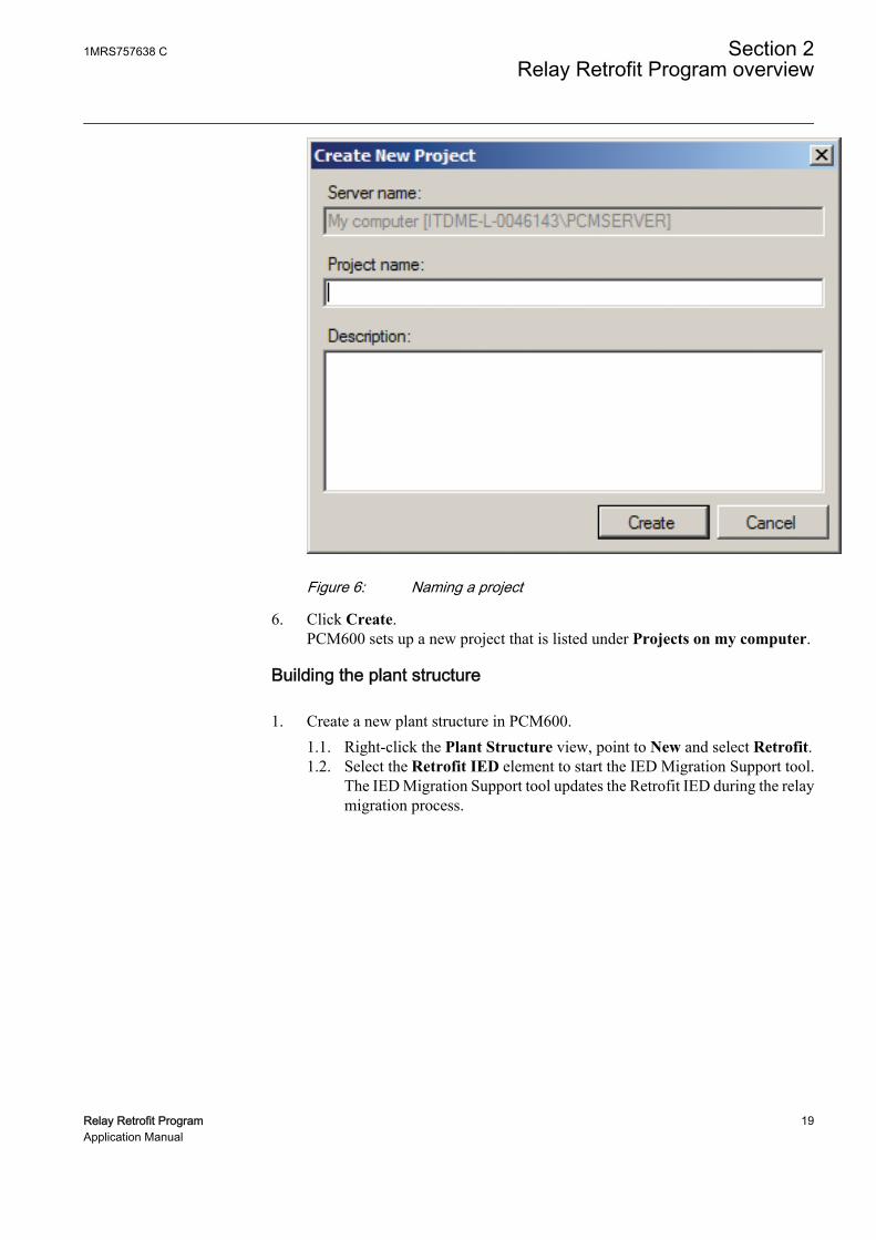
GUID-68CBEF42-CCF2-4EAA-9506-CF4CB4A27B21 V1 EN
Figure 6: Naming a project
6. Click Create.PCM600 sets up a new project that is listed under Projects on my computer.
Building the plant structure
1. Create a new plant structure in PCM600.1.1. Right-click the Plant Structure view, point to New and select Retrofit.1.2. Select the Retrofit IED element to start the IED Migration Support tool.
The IED Migration Support tool updates the Retrofit IED during the relaymigration process.
1MRS757638 C Section 2Relay Retrofit Program overview
Relay Retrofit Program 19Application Manual

GUID-1005115D-7F22-4946-BDC0-643ABAD20972 V1 EN
Figure 7: Starting the IED Migration Support tool
The IED Migration Support tool scans the installed migration packages once theRetrofit IED is instantiated.
GUID-AD91F879-0F47-4622-8550-F1D0339E23B4 V1 EN
Figure 8: Scanning the migration packages
2. Click Next.
Section 2 1MRS757638 CRelay Retrofit Program overview
20 Relay Retrofit ProgramApplication Manual

Reinstall the Retrofit Connectivity Package if errors occur whilescanning the migration packages. If the problem persists, contact theABB support.
2.3.3 Migration process
The IED Migration Support tool executes a migration process with several steps tocomplete the relay migration. Most of the steps require user inputs to get the properinformation about the existing relay and the new IED.
Start PCM600Open or create
a projectCreate project
structure
Create a Retrofit IED
node
MST wizard starts
Follow the migration
instructions
MST updates the Retrofit
IED
Chosen new IED configured
Use PCM600PCM600PCM600
MST
Project preparation Migration process Commissioning
GUID-EE6303F2-1A0D-466B-B1B0-E244F2E1B72D V1 EN
Figure 9: Migration process
1. PCM600 project preparation1.1. Starting the PCM600 tool.1.2. Opening a new or existing project.1.3. Creating or arranging the project structure (plant structure).
2. Relay migration process2.1. Creating a Retrofit IED: The IED Migration Support tool wizard opens.2.2. Migration selection: The IED Migration Support tool reads the installed
migration packages, and queries for existing relay and new IED selection 2.2.3. Existing relay configuration: The existing relay configuration file should
be selected.2.4. New IED configuration: The order code of the new IED should be filled
with replacing the existing relay.2.5. Additional information: Additional information about the existing
installation should be added.2.6. The IED Migration Support tool runs the migration and reports the results.2.7. Checking the reports and commiting the migration to PCM600 tool.
3. Commissioning with PCM600
1MRS757638 C Section 2Relay Retrofit Program overview
Relay Retrofit Program 21Application Manual

3.1. New IED is made available in the plant structure.3.2. Using PCM600 tool for various operations (For example, downloading the
configuration to the IED).
START
Migrationselection (existing relay and new IED)
New IED ordering code input
YES
If required in the package, additional
information shall be given
Shows migration notes, warning and errors.
Confirmation?
Create the new IED
YES
END
NO
Generate a report
Load the existing relay configuration
Example:
GUID-2341B075-AD1D-4778-BDB9-DCCD124B19AC V1 EN
Figure 10: Details of the relay migration process
2.3.3.1 Selecting devices
1. Under Existing relay, select the existing relay to be migrated.
Section 2 1MRS757638 CRelay Retrofit Program overview
22 Relay Retrofit ProgramApplication Manual

The list of existing relays which can be migrated by the IED Migration Supporttool is dependent on the migration packages available on the local computer.
2. Under Replacement IED, select the retrofit IED to be migrated.The number and type of replacement IEDs depends on the installed migrationpackages. The latest and certified migration package is automatically chosenwhen a replacement IED is selected.
3. Under Available mapping packages, check that the correct migration packageis selected and click Next.
GUID-90DC1F36-3554-460C-A037-11F4B4D9025F V1 EN
Figure 11: Selecting devices and migration packages
Table 3: Migration package details
Item DescriptionName Name of the migration package which usually
contains the existing relay and replacementIED names and versions.
Partial order code Partial order code of the replacement IEDwhich can be used for this retrofit.
Version Version of the migration package
Certification Certification credentials for the migrationpackage
1MRS757638 C Section 2Relay Retrofit Program overview
Relay Retrofit Program 23Application Manual

• Unselect Show only latest version to display all installed migrationpackage versions corresponding to the device selection.
• Unselect Show only certified and valid packages to display all certifiedand uncertified migration packages, for example, for testing or demopurposes.
• If no certified migration packages for the selected combination of devicesare available on the local computer, for example, during the testing orapproval phase, the Reading migration packages notification appears.Click Yes to see a list of all certified and uncertified migration packages.
GUID-AC8D4535-A1A4-46C9-89F2-0B2766352074 V1 EN
Figure 12: Selecting uncertified migration packages
Always use certified migration packages which have been testedand verified. An uncertified package may not be fully tested.ABB is not responsible for the improper use of the IEDMigration Support tool on a real plant.
2.3.3.2 Defining the existing relay configuration
1. Under Parameter settings file selection, click Browse to locate the parametersettings file for the existing relay.If the existing relay can be configured using a dedicated engineering tool, theIED Migration Support tool requires a file generated by this engineering tool.This file contains all the configuration information of the existing relay.
Section 2 1MRS757638 CRelay Retrofit Program overview
24 Relay Retrofit ProgramApplication Manual

To complete the migration successfully, use the latest version ofthe existing relay configuration file and ensure that it is up todate. Some parameters may have been changed during the timethe relay and the plant have been in use.
GUID-0B034172-B620-4332-890F-879DD328B3C5 V1 EN
Figure 13: Selecting the existing relay parameters settings
2. Click Next.
If the existing relay does not have a dedicated engineering tool, the Relay RetrofitProgram provides a simple way to gather all the required information. A data-entryMicrosoft Excel sheet is designed for a specific existing relay as a tool for collectingthe settings, protections and parameters of the relay. The data entry Excel sheets cangenerate a relay configuration file to be loaded into the IED Migration Support tool.
Any mistakes in the data-entry sheet affect the migration and possiblyresult in unwanted behavior of the new IED.
2.3.3.3 Defining the replacement IED order code
The migration package requires a partial fixed order code such as#BMAAG##########1E.
1. Under Replacement IED order code, type the order code of the retrofit IED.
1MRS757638 C Section 2Relay Retrofit Program overview
Relay Retrofit Program 25Application Manual

See the product guide of the retrofit IED for order code details.
GUID-AE892B8F-CB00-4386-87F9-D56B56003436 V1 EN
Figure 14: Defining the replacement IED order code
The IED Migration Support tool checks that the order code complies with theselected migration package. A valid code is indicated by a green check mark anderrors by a red cross. The next step can be taken if the order code is correct. TheIED Migration Support tool also checks the syntax of the order code but onlyPCM600 verifies it in the last migration.
2. Click Next.
2.3.3.4 Entering values manually
Depending on the migration package, the IED Migration Support tool may requireadditional information before starting the migration. The requested data, such ascurrent and voltage transformer values or network frequency, concern the existingrelay installation and are not stored in the configuration file.
1. Under Selection of rated values, define the rated frequency and current values.The information is required to complete the configuration of the retrofit IEDaccording to the existing relay configuration, installation and use.
Section 2 1MRS757638 CRelay Retrofit Program overview
26 Relay Retrofit ProgramApplication Manual

GUID-B97CD16A-43EC-48EA-830D-17EA110F5504 V1 EN
Figure 15: Defining additional information
2. Click Next.
Any information which refers to new functions offered by the retrofit IED can beenabled and configured using PCM600. It is possible to upgrade some IED orswitchgear functions, for example protection functions or communication, in theretrofit IED.
2.3.3.5 Applying migration
1. Click Migrate to start the migration process.
1MRS757638 C Section 2Relay Retrofit Program overview
Relay Retrofit Program 27Application Manual

GUID-E2A64104-28FD-442A-ACA2-AF38D00DBBB7 V1 EN
Figure 16: Starting the migration
GUID-7810D91B-A82F-40EF-A54A-EA82C929F321 V1 EN
Figure 17: Applying the migration
Section 2 1MRS757638 CRelay Retrofit Program overview
28 Relay Retrofit ProgramApplication Manual
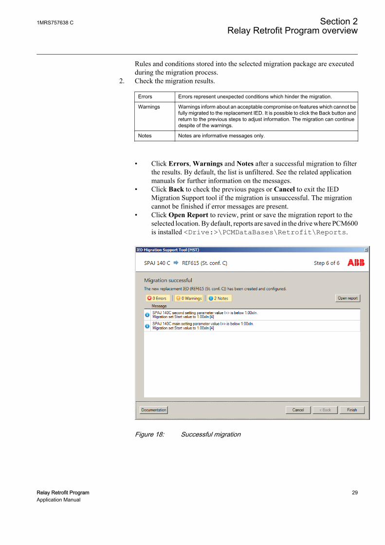
Rules and conditions stored into the selected migration package are executedduring the migration process.
2. Check the migration results.
Errors Errors represent unexpected conditions which hinder the migration.
Warnings Warnings inform about an acceptable compromise on features which cannot befully migrated to the replacement IED. It is possible to click the Back button andreturn to the previous steps to adjust information. The migration can continuedespite of the warnings.
Notes Notes are informative messages only.
• Click Errors, Warnings and Notes after a successful migration to filterthe results. By default, the list is unfiltered. See the related applicationmanuals for further information on the messages.
• Click Back to check the previous pages or Cancel to exit the IEDMigration Support tool if the migration is unsuccessful. The migrationcannot be finished if error messages are present.
• Click Open Report to review, print or save the migration report to theselected location. By default, reports are saved in the drive where PCM600is installed <Drive:>\PCMDataBases\Retrofit\Reports.
GUID-90E5773F-7B6D-4D91-A253-80DFCFC85AC0 V1 EN
Figure 18: Successful migration
1MRS757638 C Section 2Relay Retrofit Program overview
Relay Retrofit Program 29Application Manual

GUID-EEB37A88-F9F2-4A59-95DA-0C842F325996 V1 EN
Figure 19: Unsuccessful migration
3. Click Finish to commit the migration.4. Close the IED Migration Support tool and return to PCM600.
2.3.3.6 Commissioning
Once the migration runs correctly and the result is committed, the replacement IED inthe PCM600 project is configured according the existing relay configuration andfurther settings specified in the IED Migration Support tool.
1. Use PCM600 to engineer the replacement IED.
Section 2 1MRS757638 CRelay Retrofit Program overview
30 Relay Retrofit ProgramApplication Manual
GUID-33DBAC61-A22F-4992-B5AE-A47EAE5CCFB9 V1 EN
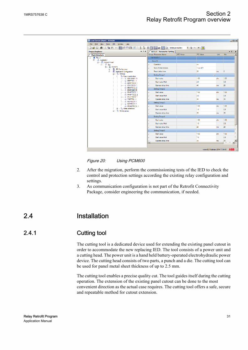
Figure 20: Using PCM600
2. After the migration, perform the commissioning tests of the IED to check thecontrol and protection settings according the existing relay configuration andsettings.
3. As communication configuration is not part of the Retrofit ConnectivityPackage, consider engineering the communication, if needed.
2.4 Installation
2.4.1 Cutting tool
The cutting tool is a dedicated device used for extending the existing panel cutout inorder to accommodate the new replacing IED. The tool consists of a power unit anda cutting head. The power unit is a hand held battery-operated electrohydraulic powerdevice. The cutting head consists of two parts, a punch and a die. The cutting tool canbe used for panel metal sheet thickness of up to 2.5 mm.
The cutting tool enables a precise quality cut. The tool guides itself during the cuttingoperation. The extension of the existing panel cutout can be done to the mostconvenient direction as the actual case requires. The cutting tool offers a safe, secureand repeatable method for cutout extension.
1MRS757638 C Section 2Relay Retrofit Program overview
Relay Retrofit Program 31Application Manual

The cutting tool is delivered in the form of cutting tool kit. The cutting tool kit ispacked into a plastic briefcase containing the power unit, either SPACOM 100/300series or BBC (ABB) standard case size 1 cutting heads, two batteries and a batterycharger. The cutting heads and new batteries are available as spare parts.
2.4.2 Cover plates
Cover plates are available for certain existing relay type retrofits. In case the existingpanel cutout is larger than the one required by the new replacement IED, the coverplate can be used to adjust the size of the cutout. The cover plates come in light greycolor (RAL7035 flat).
The cover plates have ready-made holes for attachment to the panel door. The coverplate can be used as a template for marking the drill holes in the panel door. After theholes have been drilled, the cover plate is attached with the supplied self-tappingscrews.
2.4.3 Wire marking sets
Ready-made wire marking sets are available for retrofit cases, where the existingwiring from terminal blocks to the relay can be utilized.
Wire markings are provided as existing relay type dependent complete sets. Thestructure of the marking is followed by the terminal numbers of the replacement IEDand then the terminal number of the existing relay. The press-on type markers comein white color with a printed black text. The wire marking set contains markings whichcover all terminals of the new replacement IED.
The new wire markings have two functions. Firstly, the old markings are replaced bythe new markings and the wires are connected to the right terminals of the new IED,without wiring tables or diagrams. Secondly, in certain cases, this can eliminate theneed of updating the old drawings, especially if no additional wiring is added.
2.4.4 Wiring harness
Ready-made wiring harnesses are available for the retrofit cases, where the currentcondition of the wiring is set between the existing relay and the terminal block in thelow voltage compartment.
A wiring harness is an existing relay type-specific wire. It is set based on the wiringof the relay and consists of marked wires for each terminal of the new replacementIED. The structure of the marking is followed by the terminal numbers of thereplacement IED and then the terminal number of the existing relay. This enables theconnection of the wiring harness to the new replacement IED. The low voltagecompartment terminal block is based on the existing wiring tables or wiring diagrams.The wiring harness contains wires covering all the terminals of the new replacementIED.
Section 2 1MRS757638 CRelay Retrofit Program overview
32 Relay Retrofit ProgramApplication Manual

The wire set is delivered inside a dark gray protective plastic braided sleeve. Thelength of the wiring harness is four meters and the color of the wires is black, exceptthe yellow-green PE wire. The wires have white printed wire markings at 15 cmintervals. The wire type used is fine-stranded copper wire, either 1.5 mm2, 2.5 mm2 or6.0 mm2 in cross-section, depending on the related signal type. The wiring harness canbe cut to the required length during installation.
2.5 Testing
The basic functionality of the replacement IED can be easily verified in the projectlaboratory before entering the site. The same functionality can be tested at the siteusing the RTB615 test box, thus reducing the amount of tests to be carried out whenthe 615 series plug-in unit is inserted to its original case and installed. By using theXRIO-based test templates for replacement, IEDs together with the secondary testdevices RTB615 and Omicron considerably simplifies and speeds up the testing.
Retrofit program provides testing templates for specific IED models which replace theexisting relays. These templates are verified by ABB together with migratedconfiguration from existing relay.
Benefits of RTB615 are quite similar for all applications. The test box provides aconvenient interface to access plug-in unit’s hardware interfaces and an easy way toenergize the IED. This helps planning and preparing easily reproducible testsequences at office. Tests can be automated by predefining relay characteristics,tolerances and trigger conditions and using the test templates to adapt the settingvalues for each IED being tested.
The final trip test (operating the circuit breaker) should always bedone while the IED is inserted to its original case as a part of theinstallation.
Current and voltage transformers' correct phasing, ratio and circuitconductivity have to be checked while the IED plug-in unit is insertedto the original case as a part of the installation.
Following paragraphs give some examples how RTB615 can be utilized in differentuse cases.
2.5.1 Testing templates
During the migration phase, the parameter settings of the existing relay are migratedinto the new replacement IED parameters and configuration. The testing phase is usedto verify whether the new replacement IED is in full operation condition and thebehavior corresponds to behavior of the existing relay.
1MRS757638 C Section 2Relay Retrofit Program overview
Relay Retrofit Program 33Application Manual

Specific test templates are created to support this phase.
Each test template covers a specific existing relay and new IED set-up. The templatesare designed to be used by the Omicron test universe. The templates support testing ofprotection features as per the existing relay functionalities. An editable report of thecarried out tests is issued at the end of the test sequence.
When the test templates are applied, Omicron test universe guides through a semi-automated test sequence. The templates receive the IED settings from the ParameterSetting tool of PCM600 in XRIO-based format.
Testing templates can be downloaded from theRelay Retrofit Program product webpage.
Before running the test template, make sure that the used Omicron setcan inject the required current signals. If the required current levelexceeds the capability of the tool set, the test is interrupted and the testview box reports the test failure with the "out of range" message.
IECA070901 V3 EN
S1
S2
X1
X2
X3
F1,F2
X100
X110
X120
X130
PE
+48 VDC OUT
+48 VDC IN
0 1
PCM600 &Omicron Test Universe
Omicron test device
Relion® test boxVoltage
Current
GUID-9D8D7515-95A9-457E-8072-2C47EB180D65 V1 EN
Figure 21: Test system based on RTB615 and Omicron toolset
2.5.2 Relion Test Box RTB615
RTB615 is a test box for 615 series plug-in units. The 615 series IED can be withdrawnfrom its original case and inserted to RTB615 for testing. The test box supports
Section 2 1MRS757638 CRelay Retrofit Program overview
34 Relay Retrofit ProgramApplication Manual

periodical IED testing and commissioning of new or retrofit installations. It can alsobe used for demonstration or training purposes and as a support during the engineeringphase. All the IED’s analog inputs and binary input and output interfaces are readilyavailable on the RTB615 front plate to connect to the secondary injection device, forexample, Omicron or Megger.
Both analog and binary signals of the IED, and additional test switches and indicationLEDs are available in the front panel of RTB615. The IED being tested can beenergized using internal power supply or an external 48 V DC power supply. RTB615does not support the physical connections available at the IED’s communication card,including possible arc protection interfaces, nor testing of them.
Benefits of RTB615 are similar for all applications. The test box provides aconvenient interface to access plug-in unit hardware interfaces and an easy way toenergize the IED. This helps to plan and prepare easily reproducible test sequences atoffice. Tests can be automated by predefining relay characteristics, tolerances andtrigger conditions by using the test templates to adapt the setting values for each IEDunder test.
1MRS757638 C Section 2Relay Retrofit Program overview
Relay Retrofit Program 35Application Manual

3
1 2
4
5
6
7
8
GUID-43846782-B850-4692-A003-F867E9EF4BC8 V1 EN
Figure 22: Front view of the Relion Test Box RTB615
1 Test switches
2 Indication LEDs
3 IED I/O interface terminals X100, X110, X120 and X130
4 Main power switch and mains wall plug connector
5 IED auxiliary power supply switch
6 48 V DC IN terminal
7 48 V DC OUT terminal
8 Protective earth (PE) terminal
2.5.2.1 Supported 615 series IEDs
RTB615 can be used with selected IEC 615 series IED variants, excluding RED615.Additionally, the REF615, REM615, RET615, REU615 and REV615 IED variantswhere the hardware slot X130 is in use are not supported. The 615 series IED versionshaving sensor inputs (instead of conventional CTs and VTs), 5 VT inputs, RTD/mAinputs or maximum number of binary inputs are not supported.
Section 2 1MRS757638 CRelay Retrofit Program overview
36 Relay Retrofit ProgramApplication Manual
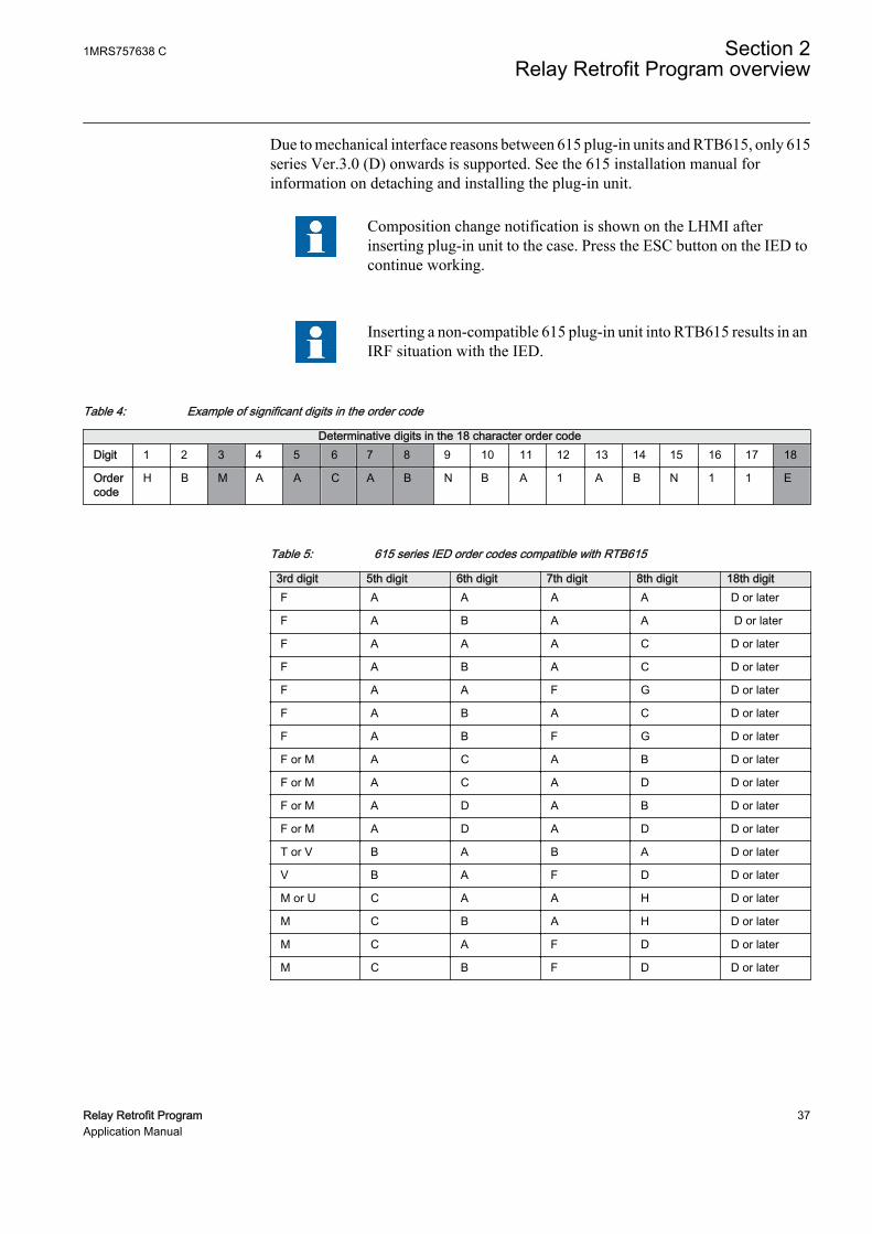
Due to mechanical interface reasons between 615 plug-in units and RTB615, only 615series Ver.3.0 (D) onwards is supported. See the 615 installation manual forinformation on detaching and installing the plug-in unit.
Composition change notification is shown on the LHMI afterinserting plug-in unit to the case. Press the ESC button on the IED tocontinue working.
Inserting a non-compatible 615 plug-in unit into RTB615 results in anIRF situation with the IED.
Table 4: Example of significant digits in the order code
Determinative digits in the 18 character order codeDigit 1 2 3 4 5 6 7 8 9 10 11 12 13 14 15 16 17 18
Ordercode
H B M A A C A B N B A 1 A B N 1 1 E
Table 5: 615 series IED order codes compatible with RTB615
3rd digit 5th digit 6th digit 7th digit 8th digit 18th digitF A A A A D or later
F A B A A D or later
F A A A C D or later
F A B A C D or later
F A A F G D or later
F A B A C D or later
F A B F G D or later
F or M A C A B D or later
F or M A C A D D or later
F or M A D A B D or later
F or M A D A D D or later
T or V B A B A D or later
V B A F D D or later
M or U C A A H D or later
M C B A H D or later
M C A F D D or later
M C B F D D or later
1MRS757638 C Section 2Relay Retrofit Program overview
Relay Retrofit Program 37Application Manual

2.5.2.2 IED analog and binary interfaces
All the IED’s analog input, binary input and output interfaces are available on theRTB615 front plate, to connect to the secondary injection and testing device. Theconnections can be done using standard banana type insulated connectors. Themarking of the interfaces correspond to the markings of 615 series case rearconnections and the related IED connection drawings.
The terminals 1 and 2 in the terminal row X100 are not available in thefront plate. In the IED, these terminals are connected to the powersupply module. For powering up the IED, see the specific section inthis document.
The interface row marked with “X130” is a reservation for futureneeds. The IED versions where X130 hardware slot is used are notsupported by RTB615.
The RTB615 connections towards secondary injection and testing device can be donein the same way as if the IED plug-in unit would be in its original case within theinstallation. Relevant circuit diagrams concerning the actual installation should beused to determine analog signals injection terminals and polarities as well as theexpected binary input and output signals and corresponding terminals.
2.5.2.3 Masking plates
Masking plates are available for certain IED product variants of the Ver.4.0 FP1release as an additional feature of RTB615. The masking plate is applied on the top ofthe terminal rows and it exposes only those signals which are relevant to the specificIED variant. The masking plate also provides references and functional names for theexpected signal types.
Table 6: RTB615 and accessories
Item Description Order CodeRelion Test Box RTB615(including masking plates)
2RCA031791
RTB615 masking plate REF615 #BFCACAB#######1Eand #BFCADAB#######1E
2RCA032077
RTB615 masking plate REM615 #BMAACAD#######1E 2RCA032078
Section 2 1MRS757638 CRelay Retrofit Program overview
38 Relay Retrofit ProgramApplication Manual

GUID-9A8F7733-DEC3-41D1-AF4A-ABF42EC13A90 V1 EN
Figure 23: RTB615 masking plate for REF615
GUID-CF2748CC-A7ED-4D27-80AB-EB0D8142F418 V1 EN
Figure 24: RTB615 masking plate for REM615
2.5.2.4 Test switches
RTB615 is equipped with eight switch controlled general purpose binary outputterminals. They can be wired to the IED binary input terminals to simulate processsignals connected to the IED.
The IED’s binary inputs' threshold voltage level has to be setaccording to the used voltage level. The parameter is found in theLHMI menu Configuration/I/O modules/Common settings/Threshold Voltage.
2.5.2.5 Indication LEDs
RTB615 is equipped with eight general purpose indication LEDs with connectionterminals. LEDs can be wired to any binary output terminal of the IED to indicate theconcerned binary output status. Driving voltage positive pole (+ side) for theindication LEDs has to be taken from RTB615’s internal 48 V DC source marked as48 VDC OUT. The indication LEDs' negative pole (- side) is permanently connectedto this source.
1MRS757638 C Section 2Relay Retrofit Program overview
Relay Retrofit Program 39Application Manual

2.5.2.6 Power supply
RTB615 can be powered up using the mains connection or using an external 48 V DCsupply, for example, from the secondary injection (test) device. In case the mainsconnection is used, the supply rating has to be 100...240 V AC and 50...60 Hz. Figure25 shows the RTB615 internal connections in detail. DUT refers to IED plug-in unitunder test.
0 1
/2.D1
/2.D1
0 1 0 1 0 1 0 1 0 1 0 1 0 1 0 1
-S1 F1 F2
230V
48V
~
-G1
+ + - -
~
1-X10 3 1-X13 2
1-X11
1-X11
2 4
3-X124
2-X11 2-X11
3-X11 3-X11
1-X12
2-X12
24
23
+
-X1
-+
-X2
-
#14+DUT-X100:1
#15+DUT-X100:2
1-X8 2 3 4 5 6 7 8 9
A1
A2
-H1
+PA
NE
L
A1
A2
-H2
A1
A2
-H3
A1
A2
-H4
A1
A2
-H5
A1
A2
-H6
A1
A2
-H7
A1
A2
-H8
-R1 -R2 -R3 -R4 -R5 -R6 -R7 -R8
1-X9 2 3 4 5 6 7 8
-S214
13
-S3.12
1
-S3.22
1
-S3.32
1
-S3.42
1
-S3.52
1
-S3.62
1
-S3.72
1
-S3.82
1
+PA
NE
L5-X12 6 7 8 9 10 11 12
48VDC OUT
48VDC IN
-X3
GUID-048F647D-9914-4A2C-895F-7E7BCAA4CBF2 V1 EN
Figure 25: RTB615 internal connections concerning power supply circuits
Table 7: RBT615 power supply connectors and selection switch
Connector DescriptionS1
S2
X1
X2
X3
F1,F2
PE
+48 VDC OUT
+48 VDC IN
0 1
MAINS switchS1
100...240 V AC, 50...60 Hz, wall plug and the main switchfor an in-built AC/DC converter.Fuses F1 and F2 for the mains connection can be foundunder the plastic hatch below the wall plug.
IED AUX POWERswitchS2
Switch for powering up the inserted IED plug-in unit.Powers up also the 48 V DC OUT connectors
48 VDC INconnectorsX1
Input connectors for an external 48 V DC power supply
48 VDC OUTconnectorsX2
48 V DC output to supply the indication LEDs and testswitches
PE connectorX13:2
Protective earth connection point
Section 2 1MRS757638 CRelay Retrofit Program overview
40 Relay Retrofit ProgramApplication Manual

Section 3 SPAJ 140 C and SPAJ 142 C to REF615Ver.4.0 FP1
3.1 Retrofit scope
Protection functions of SPAJ 14x C are replicated by REF615 with deviations.
• Memorized values are not reset in REF615 from binary input as it is done in SPAJ14x C.
• Operating curve type parameter for PHLPTOC1 is migrated according to SPAJ14x C main setting. SPAJ 140 C secondary setting value is ignored.
• Operating curve type parameter for EFLPTOC1 is migrated according to SPAJ140 C and SPAJ 142 C main setting. SPAJ 140 C secondary setting value isignored.
• In SPAJ 14x C, the latching feature of the overcurrent and the earth-fault tripsignals can be selected separately. In REF615 the latching feature is configuredso that the overcurrent and the earth-fault trip signals are grouped together. Forboth of the protection functions, activating the latching feature for trip output oneither the overcurrent or the earth-fault protection, the functions on SPAJ 14x Cresults in the latching trip output feature in REF615.
• Functionality depending on SGR relay matrix cannot be migrated according tosecondary settings. The dependent features of switchgroups SGR1, SGR2 andSGR3 are migrated according to the main settings.
3.2 Engineering
In retrofit applications, the target of the configuration phase is to parameterize andconfigure the replacement IED to reproduce the features and functions of the existingrelay. The configuration process comprises of various steps with different toolsdepending on the project.
CAP505
• Reading the configuration from the SPACOM relay or manually enteringparameter values.
In CAP505 tool, the actual values read from the SPACOM relay arecalled present values. The manually entered values are called new
1MRS757638 C Section 3SPAJ 140 C and SPAJ 142 C to REF615 Ver.4.0 FP1
Relay Retrofit Program 41Application Manual

values. After relay writing and reading operations present and newvalues become identical.
PCM600
• Instantiating a new retrofit IED (IED Migration Support tool from PCM600).• Selecting the replacement IED (type and order code)• Importing existing relay configuration (.rdb file)• Selecting the set of values to use using the IED Migration Support tool, if
the Present and New values differ in .rdb file• Entering system parameters
• Creating a 615 series IED under PCM600 plant structure using the IED MigrationSupport tool.
• Writing configuration to the IED.
Project specific additional engineering phases
• Using Application Configuration tool in PCM600 to add functionality to themigrated configuration, if required.
• Communication engineering with relevant PCM600 tools, if required.
No engineering activity is required for wiring as marking sets and wiring harness areavailable.
3.2.1 Existing relay and system engineering information
The configuration of the SPACOM relay can be retrieved via the serial connectionusing CAP 505 tool. Parameters are read from the display of the SPACOM relay andmanually inserted in CAP 505. The configuration parameters are exported from CAP505 in .rdb file format and imported in PCM600 during the migration process.
Various system parameters are collected and imported to PCM600 upon requestduring the migration process.
• Rated frequency of the network (50 or 60 Hz)• CT rated primary for phase currents (A)• CT rated secondary for phase current (1 or 5 A)• CT rated primary for residual current (A)• CT rated secondary for residual current
• 1 or 5 A in SPAJ 140 C• 0.2 or 1 A in SPAJ 142 C
Section 3 1MRS757638 CSPAJ 140 C and SPAJ 142 C to REF615 Ver.4.0 FP1
42 Relay Retrofit ProgramApplication Manual

3.2.2 Functions
The configuration of REF615 migrated from SPAJ 14x C contains all the functionsbelonging to standard configuration C, but only the functions that reproduce thebehavior of the existing relay configuration are enabled.
On SPAJ 14x C, selector switchgroups SGF1 and SGF2 define which protectionfunctions are enabled and disabled and the curve characteristics. These settings areconsidered when the REF615 configuration is generated.
Table 8: Functions included in configuration
SPAJ 14x C REF615 Description Enabled1)
I>/In PHLPTOC1 Three-phase non-directional overcurrentprotection, low stage, instance 1
Yes
PHHPTOC1 Three-phase non-directional overcurrentprotection, high stage, instance 1
No
PHHPTOC2 Three-phase non-directional overcurrentprotection, low stage, instance 2
No
I>>/In PHIPTOC1 Three-phase non-directional overcurrentprotection, instantaneous stage, instance 1
Yes, if SGF2/5 = “0”
I0>/In EFLPTOC1 Non-directional earth-fault protection, lowstage, instance 1
Yes
EFLPTOC2 Non-directional earth-fault protection, lowstage, instance 2
No
I0>>/In EFHPTOC1 Non-directional earth-fault protection, highstage, instance 1
Yes, if SGF2/6 = “0”
EFIPTOC1 Non-directional earth-fault protection,instantaneous stage
No
NSPTOC1 Negative sequence overcurrent protection,instance 1
No
NSPTOC2 Negative sequence overcurrent protection,instance 2
No
PDNSPTOC1 Phase discontinuity protection No
T1PTTR1 Three-phase thermal protection for feeders,cables and distribution transformers
No
CBFP CCBRBRF1 Circuit breaker failure protection Yes, if SGF1/4 = “1”
2) INRPHAR1 Three-phase inrush detector Yes, if SGF1/5 = “1”
TRPPTRC1 Master trip, instance 1 Yes
TRPPTRC2 Master trip, instance 2 Yes
ARCSARC1 Arc protection, instance 1 No
ARCSARC2 Arc protection, instance 2 No
ARCSARC3 Arc protection, instance 3 No
CBXCBR1 Circuit-breaker control Yes
DARREC1 Auto-reclosing No
TCSSCBR1 Trip circuit supervision, instance 1 Yes
TCSSCBR2 Trip circuit supervision, instance 2 Yes
Table continues on next page
1MRS757638 C Section 3SPAJ 140 C and SPAJ 142 C to REF615 Ver.4.0 FP1
Relay Retrofit Program 43Application Manual

SPAJ 14x C REF615 Description Enabled1)
RDRE1 Disturbance recorder Yes
CMMXU1 Three-phase current measurement,instance 1
Yes
CSMSQI1 Sequence current measurement Yes
RESCMMXU1 Residual current measurement, instance 1 Yes
1) The function is enabled when the parameter Operation is set to “on” and disabled when the parameteris set to “off”.
2) In SPAJ 14x C, the set Start current value I>> of the high-set phase overcurrent stage can be doubledautomatically on connection of the protected object to the network, that is, at the starting.
3.2.2.1 PHLPTOC1 settings
PHLPTOC1 replicates the behavior of SPAJ 14x C three-phase low-set overcurrentprotection function with definite or inverse definite minimum time characteristic (I>/In).
The Measurement mode parameter is set to “RMS”.
• PHLPTOC1 parameter Operating curve type and curve parameterization arederived from SPAJ 14x C main settings of the switchgroups SGF1/1, SGF1/2,and SGF1/3. If the curve related values of main and second settings of theseswitchgroups differ, PHLPTOC1 Operating curve type is selected in accordancewith the main settings only and a warning message is issued by IED MigrationSupport tool.
• PHLPTOC1 parameter Operating curve type and curve parameterization arederived from SPAJ 14x C main settings of the switchgroups SGF1/1, SGF1/2,and SGF1/3. If the curve related values of main and second settings of theseswitchgroups differ, the function which blocks the operation of PHLPTOC1 (inIDMT mode) by start of PHIPTOC1 is determined in accordance with the mainsettings only and a warning message is issued by the IED Migration Support tool.
• For SPAJ 14x C, the range of parameter Operating time for I> is 0.05…300 s. Thecorresponding parameter on REF615 is Operating delay time whose range is50…200000 ms. Whenever the value of SPAJ 14x C parameter Operating timefor I> is above 200 s, the PHLPTOC1 parameter Operating delay time issaturated to 200000 ms.
3.2.2.2 PHIPTOC1 settings
PHIPTOC1 replicates the behavior of SPAJ 14x C three-phase high-set overcurrentprotection function with instantaneous or definite time characteristic (I>>/In)
PHIPTOC1 is enabled if SPAJ 14x C parameter SGF2/5 = “0”.
• If SPAJ 14x C switchgroup SGB/5 = “1”, the secondary setting can be selectedfrom BS input. In this case, if the main and second settings of SGF2/5 differ, theonly main setting is considered and PHIPTOC1 is enabled or disabled
Section 3 1MRS757638 CSPAJ 140 C and SPAJ 142 C to REF615 Ver.4.0 FP1
44 Relay Retrofit ProgramApplication Manual

accordingly. In this case, a cautionary note is issued by the IED MigrationSupport tool.
• If SPAJ 14x C Start current I>> is below 1.00, PHIPTOC1 Start value is set to“1.00” and a cautionary note is issued by the IED Migration Support tool.
• If automatic doubling of set start current of SPAJ 14x C is enabled (SGF1/5 = “1”)and Start current I>> is above 20.00, PHIPTOC Start value is set to “20” and acautionary note is issued by the IED Migration Support tool.
• If automatic doubling of set start current of SPAJ 14x C is enabled (SGF1/5 =“1”), the parameter Start value Mult is set to “2.0”.
• For SPAJ 14x C, the range of parameter Operating time for I>> is 0.04…300 s.The corresponding parameter on REF615 is Operate delay time whose range is50…200000 ms. If the value of SPAJ 14x C parameter Operating time for I> isabove 200 s, PHIPTOC1 parameter Operate delay time is saturated to 200000 msand a cautionary note is issued by the IED Migration Support tool.
3.2.2.3 EFLPTOC1 settings
EFLPTOC1 replicates the behavior of SPAJ 14x C low-set, non-directional earth-fault unit with definite time or inverse definite minimum time (IDMT) characteristic(Io>/In).
• EFLPTOC1 parameter Operating curve type and curve parameterization arederived from SPAJ 14x C main settings of the switchgroups SGF1/6, SGF1/7,SGF1/8. If curve related values of main and second settings of these switchgroupsdiffer then EFLPTOC1 Operating curve type is selected in accordance with themain settings only and a cautionary note is issued by the IED Migration Supporttool.
• EFLPTOC1 parameter Operating curve type and curve parameterization arederived from SPAJ 14x C main settings of the switchgroups SGF1/6, SGF1/7,and SGF1/8. If the curve related values of main and second settings of theseswitchgroups differ, the function which blocks the operation of EFLPTOC1 (inIDMT mode) by start of EFHPTOC1 is determined in accordance with the mainsettings only and a warning message is issued by the IED Migration Support tool.
• For SPAJ 14x C, the range of parameter Operating time for I0> is 0.05…300 s.The corresponding parameter on REF615 is Operate delay time whose range is50…200000 ms. If the value of SPAJ 14x C parameter Operating time for I> isabove 200 s, the EFLPTOC1 parameter Operate delay time is saturated to 200000ms and a cautionary note is issued by the IED Migration Support tool.
3.2.2.4 EFHPTOC1 settings
EFHPTOC1 replicates the behavior of SPAJ 14x C high-set, non-directional earth-fault unit with instantaneous or definite time function (Io>>/In).
• In SPAJ 14x C, the function Io>> is disabled when SGF2/6 = 1. If the switchgroupSGB/5 = 1, the selection of main or second settings is controlled with the external
1MRS757638 C Section 3SPAJ 140 C and SPAJ 142 C to REF615 Ver.4.0 FP1
Relay Retrofit Program 45Application Manual

control signal BS input. In this case, if the main and secondary setting value ofSGF2/6 is different, EFHPTOC1 is enabled or disabled according to the mainsetting value of SGF2/6. A cautionary note is issued by the IED MigrationSupport tool.
• For SPAJ 14x C, the range of parameter Operating time for I0>> is 0.05…300 s.The corresponding parameter on REF615 is Operate delay time whose range is50…200000 ms. If the value of SPAJ 14x C parameter Operating time for I> isabove 200 s, EFHPTOC1 parameter Operate delay time is saturated to 200000 msand a cautionary note is issued by the IED Migration Support tool.
3.2.2.5 CCBRF1 settings
CCBRF1 replicates the behavior of SPAJ 140 C and SPAJ 142 C Circuit BreakerFailure Protection (CBFP).
• If SPAJ 140 C and SPAJ 142 C switchgroup SGB/5 = “1”, the secondary settingcan be selected from BS input. In this case, if the main and secondary settingvalues of SGF1/4 are different, the operation of CCBRF1 is enabled according tothe main setting value of SGF1/4.
• If SPAJ 140 C and SPAJ 142 C software version is 037C, CB Failure delay is setto “160 ms” else the delay is derived from parameter Operating time for CBfailure protection.
• REF615 parameters Operating phase current and Operating residual current areset to “0.3 In”.
3.2.2.6 INRPHAR1 settings
In SPAJ 14x C, if SGF1/5 the set starting value for I>> is doubled automatically whenone of the phase currents rise from a value below 0.12 I> to a value exceeding 1.5 I>in less than 60 ms.
In REF615, this behavior is obtained by feeding ENA_MULT input of PHIPTOC1with INRPHAR1 output.
• If SPAJ 14x C switchgroup SGB/5 = “1”, the secondary setting can be selectedfrom BS input. Operation of INRPHAR1 is enabled or disabled according to themain setting value of SGF1/5. The secondary setting value of SGF1/5 is ignored.
3.2.3 I/O connections
I/O connections at the SPAJ 14x C terminals are remapped to the REF615 I/Oterminal.
REF615 terminals have additional binary I/Os whose behavior does not depend on theSPAJ 14x C configuration.
Section 3 1MRS757638 CSPAJ 140 C and SPAJ 142 C to REF615 Ver.4.0 FP1
46 Relay Retrofit ProgramApplication Manual

Table 9: Binary inputs
REF615 SPAJ 14x C UsageX120-BI1 BS If SGB/5 = “1” PROTECTION.BI_SG2
If SGB/1 = “1” PHLPTOC1.BLOCKIf SGB/2 = “1” PHIPTOC1.BLOCKIf SGB/3 = “1” EFLPTOC1.BLOCKIf SGB/4 = “1” EFHPTOC1.BLOCKIf SGB/8 = “1” TRPPTRC1.RST_LKOUT
X120-BI2 - Circuit breaker closed indication
X120-BI3 - Circuit breaker open indication
X120-BI4 - Unused
Table 10: Binary outputs
REF615 SPAJ 14x C UsageX100-PO1 - Close circuit breaker
X100-PO2 TS1 Start signal 1 or auxiliary trip signal
X100-PO3 TS2 Open circuit breaker/trip coil 1
X100-PO4 SS3 Open circuit breaker/trip coil 2
X100-SO1 SS1 General start indication
X100-SO2 SS2 General operation indication
The type of contacts (single or multiple pole, single or multiple throw)in the 615 series can be different from the SPACOM relays. See theREF615 standard configuration C connection diagram.
3.2.4 Functional diagrams
The functional diagrams describe the default input, output, alarm LED and function-to-function connections in REF615. The default connections can be viewed andchanged with PCM600 according to the application requirements, if necessary.
Only SPAJ 14x C migrated functions are represented in theconnection diagrams. REF615 also includes other functions whoseconnections are configured according to standard configuration C.See REF615 Application Manual.
Operation of additional REF615 functions is disabled if thecorresponding functionality is not available in SPAJ 14x C. Thesefunctions can be visible in the connection diagrams even if disabled.
1MRS757638 C Section 3SPAJ 140 C and SPAJ 142 C to REF615 Ver.4.0 FP1
Relay Retrofit Program 47Application Manual
The connections in the application which are affected by theswitchgroups SGF1, SGF2.5 and SGF2.6, SGR1, SGR2, SGR3 andSGB are based on the main setting value. In SPAJ 14x C, if the mainand the second setting differ and the setting change is enabled from theBS input (SGB.5=1), a note is issued by the migration tool.
The parts affected by the migration compared to the 615 seriesstandard configuration are highlighted in gray.
Section 3 1MRS757638 CSPAJ 140 C and SPAJ 142 C to REF615 Ver.4.0 FP1
48 Relay Retrofit ProgramApplication Manual

3.2.4.1 Functional diagrams for protection
OVER CURRENT PROTECTION AND INRUSH INDICATION
NEGATIVE SEQ. OVER CURRENT PROTECTION
INRPHAR1-blk2hBl 1
PHIPTOC1-startBl 1
I00
PHLPTOC(1)3l>
3l START
BLOCK
ENA_MULT
OPERATE
51P-1
PHLPTOC(1)
LED1 (NOC OPERATE)
3l>> (1)
3l START
BLOCK
ENA_MULT
OPERATE
51P-2 (1)
PHHPTOC2 OR
LED4 (NPS/PD OPERATE)OR
OR
3l>> (2)
3l START
BLOCK
ENA_MULT
OPERATE
51P-2 (2)
PHIPTOC13l>>>
3l START
BLOCK
ENA_MULT
OPERATE
50P/51P
PHIPTOC13l2f >
3l BLK2H
BLOCK
68
NSPTOC1I2> (1)
3l START
BLOCK
ENA_MULT
OPERATE
46
NSPTOC2I2> (2)
3l START
BLOCK
ENA_MULT
OPERATE
46
GUID-2696B0B9-1E94-4DDC-A9D7-36DAC89D6356 V1 EN
Figure 26: Overcurrent protection
Functional diagrams illustrate the external connections defined in the615 series standard configuration. Check the connection diagram tosee the actual external connections of the replacement IED.
1MRS757638 C Section 3SPAJ 140 C and SPAJ 142 C to REF615 Ver.4.0 FP1
Relay Retrofit Program 49Application Manual

• The high stage protections PHHPTOC1 and PHHPTOC2, and negative sequenceovercurrent protection functions are disabled.
• BI1 input is connected to various function inputs based on the switchgroupconditions.• BLOCK input of PHLPTOC1, if SGB/1 = “1”• BLOCK input of PHIPTOC1, if SGB/2 = “1”
• PHLPTOC1 function works only in inverse mode and it is blocked by thePHIPTOC1-start signal. If SPAJ 14x C software version is prior to “183B”or, from “183B” version onwards, switchgroup SGX/2 = “1”.
• The inrush detection function INRPHAR1 is enabled if SPAJ 14x C switchgroupSGF1/5 = “1”. The output BLK2H enables multiplying (by 2) the active settingsfor PHIPTOC1 function.
LED2 (EF OPERATE)OR
EARTH FAULT PROTECTION
SENSITIVE EARTH FAULT PROTECTION
LED3 (SEF OPERATE)
I >EFLPTOC1
START
OPERATE
I0
BLOCK
ENA_MULT
51N-1
0
I >EFLPTOC2
START
OPERATE
I0
BLOCK
ENA_MULT
51N-1
0
I >>EFHPTOC1
START
OPERATE
I0
BLOCK
ENA_MULT
51N-2
0
I >>>EFIPTOC1
START
OPERATE
I0
BLOCK
ENA_MULT
50N
0
EFHPTOC1-startBl1 OR
GUID-2E6FFCC7-4EC9-4ACF-8EB6-0638AE2FB8E9 V1 EN
Figure 27: Non-directional earth-fault protection
• Sensitive earth-fault function protection EFLPTOC2 and the instantaneous earth-fault protection EFIPTOC1 are disabled.
• BI1 input is connected to the various function inputs based on the switchgroupconditions.
Section 3 1MRS757638 CSPAJ 140 C and SPAJ 142 C to REF615 Ver.4.0 FP1
50 Relay Retrofit ProgramApplication Manual

• BLOCK input of EFLPTOC1, if SGB/3 = “1”• BLOCK input of EFHPTOC1, if SGB/4 = “1”
• EFLPTOC1 function works only in inverse mode and it is blocked by theEFHPTOC1-start signal. If SPAJ 140 C and SPAJ 142 C software version isprior “183B” or, from “183B” onwards, switchgroup SGX/2 = “1”.
PO2 X100
OR
ORLED6 (CBFP OPERATE)
CCBRBRF1
51BF/51NBF
3l>/l0 > BF
PHHPTOC1- operatePHHPTOC2- operatePHIPTOC1- operateEFLPTOC1- operateEFHPTOC1- operateEFIPTOC1- operateARCSARC1- operateARCSARC2- operateARCSARC3- operate
Bl 2 (CB Closed) Start orAuxiliary trip8
9
BREAKER FAILURE PROTECTION
TPGAPC 2IN1IN2
OUT1OUT2
OR
PHLPTOC1- startPHLPTOC1- operatePHIPTOC1- startPHIPTOC1- operateEFLPTOC1- startEFLPTOC1- operateEFLPTOC2- startEFLPTOC2- operate
3l
l0
START CB_FAULT_AL
POSCLOSE
CB_FAULT
BLOCK
TRRET
TRBU
GUID-69C3F6AA-741F-4834-8600-9AF9825D9D19 V1 EN
Figure 28: Circuit breaker failure protection, start or auxiliary trip
• PO2 output replicates SPAJ 14x C TS1 output (Start signal 1 or auxiliary tripsignal).
• The breaker failure protection CCBRBRF1 is enabled if SPAJ 14x C switchgroupSGF1/4 = ”1”. It is initiated via the START input by a number of differentprotection stages in the IED. If SGR3 = ”0”, only the TRBU output is connectedto the output PO2.
• PHLPTOC1- start, if SGR3/1 = ”1”• PHLPTOC1- operate, if SGR3/2 =”1”• PHIPTOC1- start, if SGR3/3 = ”1”• PHIPTOC1- operate, if SGR3/4 = ”1”• EFLPTOC1- start, if SGR3/5 = ”1”• EFLPTOC1- operate, if SGR3/6 = ”1”• EFLPTOC2- start, if SGR3/7 = ”1”• EFLPTOC2- operate, if SGR3/8 = ”1”
1MRS757638 C Section 3SPAJ 140 C and SPAJ 142 C to REF615 Ver.4.0 FP1
Relay Retrofit Program 51Application Manual
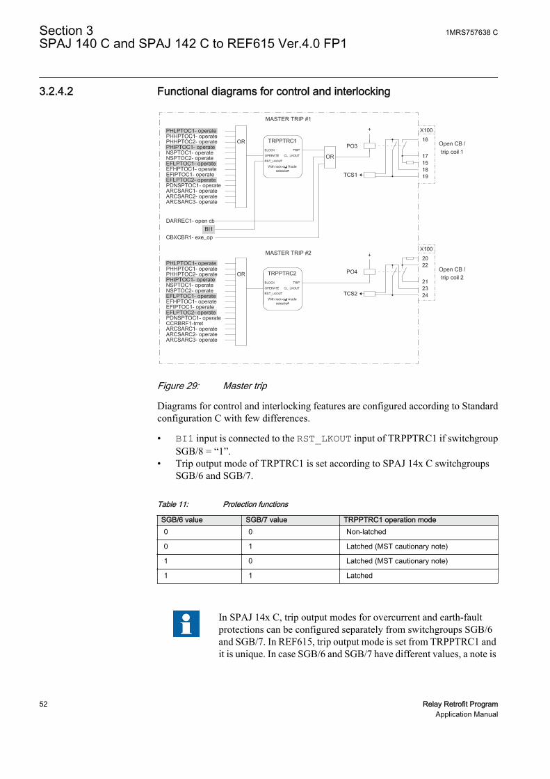
3.2.4.2 Functional diagrams for control and interlocking
GUID-E21FC44D-E312-43CB-9EAA-B064C8372E5E V1 EN
Figure 29: Master trip
Diagrams for control and interlocking features are configured according to Standardconfiguration C with few differences.
• BI1 input is connected to the RST_LKOUT input of TRPPTRC1 if switchgroupSGB/8 = “1”.
• Trip output mode of TRPTRC1 is set according to SPAJ 14x C switchgroupsSGB/6 and SGB/7.
Table 11: Protection functions
SGB/6 value SGB/7 value TRPPTRC1 operation mode0 0 Non-latched
0 1 Latched (MST cautionary note)
1 0 Latched (MST cautionary note)
1 1 Latched
In SPAJ 14x C, trip output modes for overcurrent and earth-faultprotections can be configured separately from switchgroups SGB/6and SGB/7. In REF615, trip output mode is set from TRPPTRC1 andit is unique. In case SGB/6 and SGB/7 have different values, a note is
Section 3 1MRS757638 CSPAJ 140 C and SPAJ 142 C to REF615 Ver.4.0 FP1
52 Relay Retrofit ProgramApplication Manual

issued by IED Migration Support tool and the default value (latched)is kept for the parameter.
• Various function outputs are connected to TRPPTRC1 based on the switchgroupcondition.• PHLPTOC1- operate, if SGR1/2 = “1”• PHIPTOC1- operate, if SGR1/4 = “1"• EFLPTOC1- operate, if SGR1/6 = “1”• EFHPTOC1- operate, if SGR1/8 = “1”
• Various function outputs are connected to TRPPTRC2 based on the switchgroupcondition.• PHLPTOC1- operate, if SGR2/2 = “1”• PHIPTOC1- operate, if SGR2/4 = “1”• EFLPTOC1- operate, if SGR2/6 = ”1”• EFHPTOC1- operate, if SGR2/8 = “1”
• Trip output mode of TRPTRC2 is set to “Non-latched”.
PHLPTOC1-startPHHPTOC1-startPHHPTOC2-start
NSPTOC1-startNSPTOC2-start
PDNSPTOC1-start
PDNSPTOC1-operate
PHLPTOC1-operatePHHPTOC1-operatePHHPTOC2-operatePHIPTOC1-operateNSPTOC1-operateNSPTOC2-operate
ARCSARC1-operateARCSARC2-operateARCSARC3-operate
EFIPTOC1-startEFLPTOC2-start
EFLPTOC1-operateEFHPTOC1-operateEFIPTOC1-operate
TPGAPC1IN1IN2 +
+
X100
10
1112
13
14
EFLPTOC2-operate
OR
OR
COMMON ALARM / INDICATION 1 & 2
Start Indication
Operate Indication
SO1
SO2
PHIPTOC1-start
EFLPTOC1-startEFHPTOC1-start
GUID-C9273108-D413-4857-A0DD-DF6683D08423 V1 EN
Figure 30: Alarm indication
• SO1 reproduces SPAJ 140 C and SPAJ 142 C SS1 output. Various functionoutputs are connected to SO1 via TPGAPC1 based on the switchgroup condition.
1MRS757638 C Section 3SPAJ 140 C and SPAJ 142 C to REF615 Ver.4.0 FP1
Relay Retrofit Program 53Application Manual

• PHLPTOC1-start, if SGR1/1 = “1”• PHIPTOC1-start, if SGR1/3 = “1"• EFLPTOC1-start, if SGR1/5 = “1”• EFHPTOC1-start, if SGR1/7 = “1”
• SO2 reproduces SPAJ 140 C and SPAJ 142 CSS2 output. Various functionoutputs are connected to SO2 via TPGAPC1 based on the switchgroup condition.
• PHLPTOC1-operate, if SGR2/1 = “1”• PHIPTOC1-operate, if SGR2/3 = “1”• EFLPTOC1-operate, if SGR2/5 = “1”• EFHPTOC1-operate, if SGR2/7 = “1”
3.2.4.3 Setting groups
PROTECTIONBI_SG_2BI1 SG_1_ACT
SG_2_ACTSG_3_ACTSG_4_ACTSG_5_ACTSG_6_ACT
BI_SG_3BI_SG_4BI_SG_5BI_SG_6
GUID-704B93FC-3184-4AC4-AD2B-E76838FEAED8 V1 EN
Figure 31: Setting groups
615 IEDs support six setting groups. SPAJ 14x C support two setting groups (mainand second setting) which can be selected from binary input BS if switchgroup SGB/5 = “1”. REF615 setting group 2 is selected if BI1 is active and SGB/5 = “1”. Theactive setting group can be changed at run time.
The connections in the application which are affected by switchgroups SGF1,SGF2/5, SGF2/6, SGR1, SGR2, SGR3, and SGB are based on the main setting value.If the main and second setting differ in SPAJ 141 C, and the setting change is enabledfrom BS input (SGB/5 = “1”), a note is issued by the IED Migration Support tool.
Section 3 1MRS757638 CSPAJ 140 C and SPAJ 142 C to REF615 Ver.4.0 FP1
54 Relay Retrofit ProgramApplication Manual

3.3 Installation
3.3.1 Mounting
The 615 series IED can be mounted on the switchgear door using the hole left by theSPACOM series relay.
1. Widen the original SPACOM relay hole.1.1. Use cutting tool with dedicated cutting head for SPACOM 100/300 series
to get the appropriate cut-out on the switchgear door hosting REF615 IED.1.2. Widen the cut-out to whichever of the four directions as per the existing
installation requirement.
1MRS757638 C Section 3SPAJ 140 C and SPAJ 142 C to REF615 Ver.4.0 FP1
Relay Retrofit Program 55Application Manual

615 seriesA
B
C D
SPA 100 series
GUID-46C4FA59-4D66-4CD0-8CAB-AD8A0D3977DE V1 EN
Figure 32: SPACOM 100 series and 615 series cut-outs
A 165.5 mm
B 129 mm
C 139 mm
D 161.5 mm
2. Mount the 615 series IED's case and insert the plug-in unit.
Cover plate is not required with the SPACOM 100 series.
See the 615 series installation manual for more information.
Section 3 1MRS757638 CSPAJ 140 C and SPAJ 142 C to REF615 Ver.4.0 FP1
56 Relay Retrofit ProgramApplication Manual

3.3.2 Connecting
• If the existing wiring is in good condition and still usable, use the dedicatedmarking sets.
• If the existing wiring has to be replaced, use the dedicated wiring harness.
3.3.2.1 Wiring harness and wire markings
Wiring harness is available for retrofitting SPAJ 14x C with REF615.
Table 12: REF615 wiring harness description for retrofit of SPAJ 14x C
REF615, configuration C SPAJ 14x C WiringTerminal Description Terminal Description MarkingX100:1 Uaux+ 61 Uaux+ X100:1 (61)
X100:2 Uaux- 62 Uaux- X100:2 (62)
X100:3 IRF 72 IRF X100:3 (72)
X100:4 IRF 71 IRF X100:4 (71)
X100:5 IRF 70 IRF X100:5 (70)
X100:6 PO1 - - X100:6
X100:7 PO1 - - X100:7
X100:8 PO2 74 START 1 X100:8 (74)
X100:9 PO2 75 START 1 X100:9 (75)
X100:10 SO1 78 START 2 X100:10 (78)
X100:11 SO1 - - X100:11
X100:12 SO1 77 START 2 X100:12 (77)
X100:13 SO2 81 SIGNAL 1 X100:13 (81)
X100:14 SO2 80 SIGNAL 1 X100:14 (80)
X100:15 PO3 - - X100:15
X100:16 PO3 65 TRIP X100:16 (65)
X100:17 PO3 66 TRIP X100:17 (66)
X100:18 PO3 - - X100:18
X100:19 PO3 - - X100:19
X100:20 PO4 - - X100:20
X100:21 PO4 69 SIGNAL 2 X100:21 (69)
X100:22 PO4 68 SIGNAL 2 X100:22 (68)
X100:23 PO4 - - X100:23
X100:24 PO4 - - X100:24
X120:1 BI1 10EXTERNALCONTROL X120:1 (10)
X120:2 BI1 11EXTERNALCONTROL X120:2 (11)
X120:3 BI2 - - X120:3
Table continues on next page
1MRS757638 C Section 3SPAJ 140 C and SPAJ 142 C to REF615 Ver.4.0 FP1
Relay Retrofit Program 57Application Manual

REF615, configuration C SPAJ 14x C WiringTerminal Description Terminal Description MarkingX120:4 BI3 - - X120:4
X120:5 BI4 - - X120:5
X120:6 BI4 - - X120:6
X120:7 IL1 2/3 IL1, 5A/1A X120:7 (2/3)
X120:8 IL1 1 IL1 X120:8 (1)
X120:9 IL2 5/6 IL2, 5A/1A X120:9 (5/6)
X120:10 IL2 4 IL2 X120:10 (4)
X120:11 IL3 8/9 IL3, 5A/1A X120:11 (8/9)
X120:12 IL3 7 IL3 X120:12 (7)
X120:13 Io 26/27 1)
27/28 2)Io, 1A/5A 1)
Io, 0.2A/1A 2)X120:13(26/27/28)
X120:14 Io 25 Io X120:14 (25)
Earth 63 Earth
1) SPAJ 140 C2) SPAJ 142 C
3.3.2.2 SPAJ 140 C and SPAJ 142 C terminal layout and connection diagrams
686977788081
Mad
e in
Fin
land
2
3
4
5
6
7
8
9
25
26
27
62
63
65
66
74
75
70
71
72
10
11
Ser
ial P
ort
SP
A
GUID-633E232F-3F19-4129-8D44-E2A467626EF1 V1 EN
Figure 33: Terminal layout for SPAJ 140 C
Section 3 1MRS757638 CSPAJ 140 C and SPAJ 142 C to REF615 Ver.4.0 FP1
58 Relay Retrofit ProgramApplication Manual

Mad
e in
Fin
land
= 63
686977788081
1
2
3
4
5
6
7
8
9
25
27
28
61
62
63
65
66
74
75
70
71
72
10
11
Ser
ial P
ort
SPA
GUID-61EAA987-DCDF-4F56-8BC3-57FA240CF1DD V1 EN
Figure 34: Terminal layout for SPAJ 142 C
1MRS757638 C Section 3SPAJ 140 C and SPAJ 142 C to REF615 Ver.4.0 FP1
Relay Retrofit Program 59Application Manual

6162
SPAJ 140 C
63
1 A
1 2 3 4 5 6 7 8 9 25 26 27
5 A
L1L2L3
70 71 72
0
65 66
U+ (~)- (~)
3I>
3I>>
Io>
Io>>
IRF
I/O
68 6977 78
IRF SIGNAL 2
-
+
TRIP
74 75 80 81
START 1
1011
SGB/1
SGB/2
SGB/3
SGB/4
SGB/6SGB/7
SGB/5
LATCHING
SIGNAL 1
RESET
START 2
- I
I 0
++
+
B
+
C
+
F
+
E
+
D
+
A
U1
1 1
T2
T4
T6
T8
T1
T3
T5
T7
RC SETTINGSSGB/8 SGF/4
0.1...1sS
GR
2/8
SG
R1/
6S
GR
1/8
SG
R1/
2S
GR
1/4
U3TRIP
R
U2
U1T9
TS2SS3SS2SS1TS1
SPA
-ZC
_
Rx Tx
SERIALPORT
+ -
1 A
5 A
1 A
5 A
1 A
5 A
SG
R2/
6S
GR
2/4
SG
R2/
2
1
SG
R2/
7S
GR
2/5
SG
R2/
3S
GR
2/1
1
SG
R1/
7S
GR
1/5
SG
R1/
3S
GR
1/1
1
SG
R3/
8S
GR
3/7
SG
R3/
6S
GR
3/5
SG
R3/
4S
GR
3/3
SG
R3/
2S
GR
3/1
aux
~
EXTERNALCONTROL
GUID-C9604244-F2A0-4F58-8CC5-752519B310A5 V1 EN
Figure 35: Connection diagram for SPAJ 140 C
Section 3 1MRS757638 CSPAJ 140 C and SPAJ 142 C to REF615 Ver.4.0 FP1
60 Relay Retrofit ProgramApplication Manual
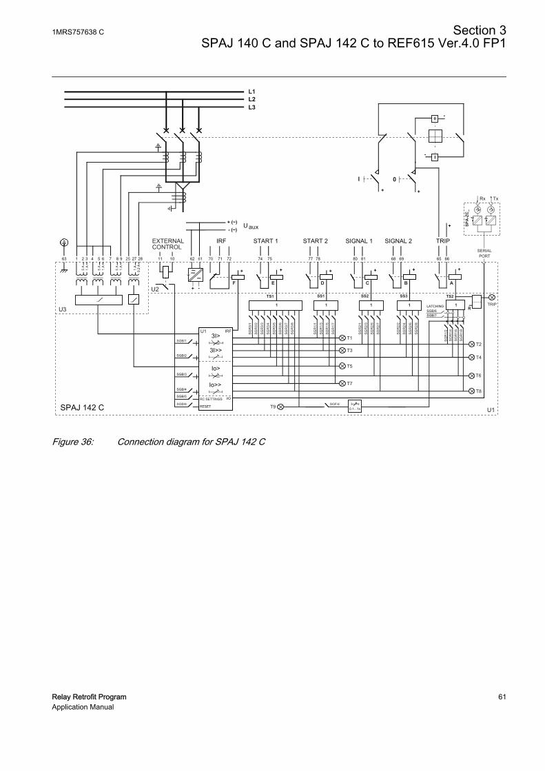
6162
SPAJ 142 C
63 1 2 3 4 5 6 7 8 9 25 27 28
0.2
A1
A
L1L2L3
70 71 72
0
65 66
U+ (~)- (~)
3I>
3I>>
Io>
Io>>
IRF
I/O
68 6977 78
IRF SIGNAL 2
-
+
TRIP
74 75
START 1
80 811011
SGB/1
SGB/2
SGB/3
SGB/4
SGB/6SGB/7
SGB/5
LATCHING
SIGNAL 1 START 2
RESET
I-
I 0
++
+
B
+
C
+
F
+
E
+
D
+
A
U1
1 1
T2
T4
T6
T8
T1
T3
T5
T7
RC SETTINGSSGB/8 SGF/4
0.1...1s
SG
R2/
8
SG
R1/
6S
GR
1/8
SG
R1/
2S
GR
1/4
U3TRIP
R
U2
U1T9
TS2SS3SS2SS1TS1
SPA
-ZC
_
Rx Tx
SERIALPORT
+ -
1 A
5 A
1 A
5 A
1 A
5 A
SG
R2/
6
SG
R2/
4
SG
R2/
2
1
SG
R2/
7
SG
R2/
5
SG
R2/
3
SG
R2/
1
1
SG
R1/
7
SG
R1/
5
SG
R1/
3
SG
R1/
1
1
SG
R3/
8
SG
R3/
7
SG
R3/
6
SG
R3/
5
SG
R3/
4
SG
R3/
3
SG
R3/
2
SG
R3/
1
aux
~
EXTERNALCONTROL
GUID-B129D54F-0F9B-45CD-8BDC-02E6BB27C0A5 V1 EN
Figure 36: Connection diagram for SPAJ 142 C
1MRS757638 C Section 3SPAJ 140 C and SPAJ 142 C to REF615 Ver.4.0 FP1
Relay Retrofit Program 61Application Manual
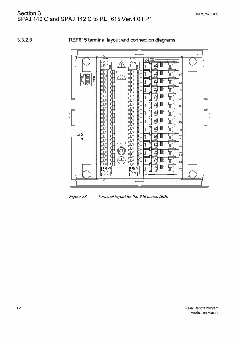
3.3.2.3 REF615 terminal layout and connection diagrams
A070596 V1 EN
Figure 37: Terminal layout for the 615 series IEDs
Section 3 1MRS757638 CSPAJ 140 C and SPAJ 142 C to REF615 Ver.4.0 FP1
62 Relay Retrofit ProgramApplication Manual

REF615
X13Light sensor input 1 1)
X14Light sensor input 2 1)
X15Light sensor input 3 1)
16
17
1918
X100
67
89
10
111213
15
14
2
1
3
45
22
212324
SO2
TCS2
PO4
SO1
TCS1
PO3
PO2
PO1
IRF
+
-Uaux
20
L1L2L3
S1
S2
P1
P2
PositiveCurrentDirection
2)
1) Optional2) The IED features an automatic short-circuit mechanism in the CT connector when plug-in unit is detached
X120
12
3
4
567
89
1011
1213
14Io
IL1
IL2
BI 4
BI 3
BI 2
BI 1
IL3
1/5A
N1/5A
N1/5A
N1/5A
N
P2
P1 S1
S2
EXTERNALCONTROL Uaux
IRF
START 1
START 2
SIGNAL 1
TRIP
SIGNAL 2
GUID-1D0830F0-FBE5-4B9D-85FE-400665BD75B3 V1 EN
Figure 38: Connection diagram for REF615 with standard configuration Creplacing SPAJ 140 C
1MRS757638 C Section 3SPAJ 140 C and SPAJ 142 C to REF615 Ver.4.0 FP1
Relay Retrofit Program 63Application Manual

REF615
X13Light sensor input 1 1)
X14Light sensor input 2 1)
X15Light sensor input 3 1)
16
17
1918
X100
67
89
10
111213
15
14
2
1
3
45
22
212324
SO2
TCS2
PO4
SO1
TCS1
PO3
PO2
PO1
IRF
+
-Uaux
20
L1L2L3
S1
S2
P1
P2
PositiveCurrentDirection
2)
1) Optional2) The IED features an automatic short-circuit mechanism in the CT connector when plug-in unit is detached
X120
12
3
4
567
89
1011
1213
14Io
IL1
IL2
BI 4
BI 3
BI 2
BI 1
IL3
1/5A
N1/5A
N1/5A
N0.2/1A
N
P2
P1 S1
S2
EXTERNALCONTROL Uaux
IRF
START 1
START 2
SIGNAL 1
TRIP
SIGNAL 2
GUID-27969A66-5E99-4744-B813-AA2A7E13816B V1 EN
Figure 39: Connection diagram for REF615 with standard configuration Creplacing SPAJ 142 C
Section 3 1MRS757638 CSPAJ 140 C and SPAJ 142 C to REF615 Ver.4.0 FP1
64 Relay Retrofit ProgramApplication Manual

Section 4 SPAJ 141 C to REF615 Ver.4.0 FP1
4.1 Retrofit scope
Protection functions of SPAJ 14x C are replicated by REF615 with deviations.
• Memorized values are not reset in REF615 with binary input as it is done in SPAJ14x C.
• Operating curve type parameter for PHLPTOC1 is migrated according to SPAJ14x C main setting. SPAJ 141 C secondary setting value is ignored.
• In SPAJ 14x C, the latching feature of the overcurrent and the earth-fault tripsignals can be selected separately. In REF615, the latching feature is configuredso that the overcurrent and the earth-fault trip signals are grouped together. Forboth of the protection functions, activating the latching feature for trip output oneither the overcurrent or the earth-fault protection, functions on SPAJ 14x Cresults in the latching trip output feature in REF615.
• Functionality depending on SGR relay matrix cannot be migrated according tosecondary settings. The dependent features of switchgroups SGR1, SGR2 andSGR3 are migrated according to the main settings.
4.2 Engineering
In retrofit applications, the target of the configuration phase is to parameterize andconfigure the replacement IED to reproduce the features and functions of the existingrelay. The configuration process comprises of various steps with different toolsdepending on the project.
CAP505
• Reading the configuration from the SPACOM relay or manually enteringparameter values.
In CAP505 tool, the actual values read from the SPACOM relay arecalled present values. The manually entered values are called newvalues. After relay writing and reading operations present and newvalues become identical.
PCM600
1MRS757638 C Section 4SPAJ 141 C to REF615 Ver.4.0 FP1
Relay Retrofit Program 65Application Manual

• Instantiating a new retrofit IED (IED Migration Support tool from PCM600).• Selecting the replacement IED (type and order code)• Importing existing relay configuration (.rdb file)• Selecting the set of values to use using the IED Migration Support tool, if
the Present and New values differ in .rdb file• Entering system parameters
• Creating a 615 series IED under PCM600 plant structure using the IED MigrationSupport tool.
• Writing configuration to the IED.
Project specific additional engineering phases
• Using Application Configuration tool in PCM600 to add functionality to themigrated configuration, if required.
• Communication engineering with relevant PCM600 tools, if required.
No engineering activity is required for wiring as marking sets and wiring harness areavailable.
4.2.1 Existing relay and system engineering information
The configuration of the SPACOM relay can be retrieved via the serial connectionusing CAP 505 tool. Parameters are read from the display of the SPACOM relay andmanually inserted in CAP 505. The configuration parameters are exported from CAP505 in .rdb file format and imported in PCM600 during the migration process.
Various system parameters are collected and imported to PCM600 upon requestduring the migration process.
• Rated frequency of the network (50 or 60 Hz)• CT rated primary for phase currents (A)• CT rated secondary for phase current (1 or 5 A)• CT rated primary for residual current (A)• CT rated secondary for residual current (0.2 or 1 A )
4.2.2 Functions
The configuration of REF615 migrated from SPAJ 141 C contains all the functionsbelonging to standard configuration C, but only the functions that reproduce thebehavior of the existing relay configuration is enabled.
On SPAJ 141 C selector switchgroups SGF1 and SGF2 define which protectionfunctions are enabled and disabled and the curve characteristics. These settings areconsidered when the REF615 configuration is generated.
Section 4 1MRS757638 CSPAJ 141 C to REF615 Ver.4.0 FP1
66 Relay Retrofit ProgramApplication Manual

Table 13: Functions included in configuration
SPAJ 141 C REF615 Description Enabled1)
I>In PHLPTOC1 Three-phase non-directionalovercurrent protection, low stage,instance 1
Yes
PHHPTOC1 Three-phase non-directionalovercurrent protection, high stage,instance 1
No
PHHPTOC2 Three-phase non-directionalovercurrent protection, low stage,instance 2
No
I>>/In PHIPTOC1 Three-phase non-directionalovercurrent protection,instantaneous stage, instance 1
Yes, if SGF2/5 = “0”
I0>/In EFLPTOC1 Non-directional earth-faultprotection, low stage, instance 1
Yes
I0>>/In EFLPTOC2 Non-directional earth-faultprotection, low stage, instance 2
Yes, if SGF2/6 = “0”
EFHPTOC1 Non-directional earth-faultprotection, high stage, instance 1
No
EFIPTOC1 Non-directional earth-faultprotection, instantaneous stage
No
NSPTOC1 Negative sequence overcurrentprotection, instance 1
No
NSPTOC2 Negative sequence overcurrentprotection, instance 2
No
PDNSPTOC1 Phase discontinuity protection No
T1PTTR1 Three-phase thermal protection forfeeders, cables and distributiontransformers
No
PDNSPTOC1 Phase discontinuity protection No
T1PTTR1 Three-phase thermal protection forfeeders, cables and distributiontransformers
No
CBFP CCBRBRF1 Circuit breaker failure protection Yes, if SGF1/4 = “1”
2) INRPHAR1 Three-phase inrush detector Yes, if SGF1/5 = “1”
TRPPTRC1 Master trip, instance 1 Yes
TRPPTRC2 Master trip, instance 2 Yes
ARCSARC1 Arc protection, instance 1 No
ARCSARC2 Arc protection, instance 2 No
ARCSARC3 Arc protection, instance 3 No
CBXCBR1 Circuit-breaker control Yes
DARREC1 Autoreclosing No
TCSSCBR1 Trip circuit supervision, instance 1 Yes
TCSSCBR2 Trip circuit supervision, instance 2 Yes
RDRE1 Disturbance recorder Yes
Table continues on next page
1MRS757638 C Section 4SPAJ 141 C to REF615 Ver.4.0 FP1
Relay Retrofit Program 67Application Manual
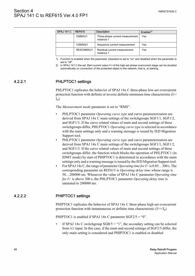
SPAJ 141 C REF615 Description Enabled1)
CMMXU1 Three-phase current measurement,instance 1
Yes
CSMSQI1 Sequence current measurement Yes
RESCMMXU1 Residual current measurement,instance 1
Yes
1) Function is enabled when the parameter Operation is set to “on” and disabled when the parameter isset to “off”.
2) In SPAJ 141 C the set Start current value I>> of the high-set phase overcurrent stage can be doubledautomatically on connection of the protected object to the network, that is, at starting.
4.2.2.1 PHLPTOC1 settings
PHLPTOC1 replicates the behavior of SPAJ 14x C three-phase low-set overcurrentprotection function with definite or inverse definite minimum time characteristic (I>/In).
The Measurement mode parameter is set to “RMS”.
• PHLPTOC1 parameter Operating curve type and curve parameterization arederived from SPAJ 14x C main settings of the switchgroups SGF1/1, SGF1/2,and SGF1/3. If the curve related values of main and second settings of theseswitchgroups differ, PHLPTOC1 Operating curve type is selected in accordancewith the main settings only and a warning message is issued by IED MigrationSupport tool.
• PHLPTOC1 parameter Operating curve type and curve parameterization arederived from SPAJ 14x C main settings of the switchgroups SGF1/1, SGF1/2,and SGF1/3. If the curve related values of main and second settings of theseswitchgroups differ, the function which blocks the operation of PHLPTOC1 (inIDMT mode) by start of PHIPTOC1 is determined in accordance with the mainsettings only and a warning message is issued by the IED Migration Support tool.
• For SPAJ 14x C, the range of parameter Operating time for I> is 0.05…300 s. Thecorresponding parameter on REF615 is Operating delay time whose range is50…200000 ms. Whenever the value of SPAJ 14x C parameter Operating timefor I> is above 200 s, the PHLPTOC1 parameter Operating delay time issaturated to 200000 ms.
4.2.2.2 PHIPTOC1 settings
PHIPTOC1 replicates the behavior of SPAJ 14x C three-phase high-set overcurrentprotection function with instantaneous or definite time characteristic (I>>/In)
PHIPTOC1 is enabled if SPAJ 14x C parameter SGF2/5 = “0”.
• If SPAJ 14x C switchgroup SGB/5 = “1”, the secondary setting can be selectedfrom BS input. In this case, if the main and second settings of SGF2/5 differ, theonly main setting is considered and PHIPTOC1 is enabled or disabled
Section 4 1MRS757638 CSPAJ 141 C to REF615 Ver.4.0 FP1
68 Relay Retrofit ProgramApplication Manual

accordingly. In this case, a cautionary note is issued by the IED MigrationSupport tool.
• If SPAJ 14x C Start current I>> is below 1.00, PHIPTOC1 Start value is set to“1.00” and a cautionary note is issued by the IED Migration Support tool.
• If automatic doubling of set start current of SPAJ 14x C is enabled (SGF1/5 = “1”)and Start current I>> is above 20.00, PHIPTOC Start value is set to “20” and acautionary note is issued by the IED Migration Support tool.
• If automatic doubling of set start current of SPAJ 14x C is enabled (SGF1/5 =“1”), the parameter Start value Mult is set to “2.0”.
• For SPAJ 14x C, the range of parameter Operating time for I>> is 0.04…300 s.The corresponding parameter on REF615 is Operate delay time whose range is50…200000 ms. If the value of SPAJ 14x C parameter Operating time for I> isabove 200 s, PHIPTOC1 parameter Operate delay time is saturated to 200000 msand a cautionary note is issued by the IED Migration Support tool.
4.2.2.3 EFLPTOC1 settings
EFLPTOC1 replicates the behavior of SPAJ 141 C sensitive low-set, non-directionalearth-fault unit with definite time characteristic (Io>/In).
• For SPAJ 141 C, the range of parameter Operating time for I0> is 0.05…300 s.The corresponding parameter on REF615 is Operate delay time whose range is50…200000 ms. If the value of SPAJ 141 C parameter Operating time for I> ismore than 200 s, the EFLPTOC1 parameter Operate delay time is saturated to200000 ms and a warning message is issued by the IED Migration Support tool.
4.2.2.4 EFLPTOC2 settings
EFLPTOC2 replicates the behavior of SPAJ 141 C high-set, non-directional earth-fault unit with instantaneous or definite time function (Io>>/In).
• EFLPTOC2 is disabled when SGF2/6 =“1”. If the switchgroup SGB/5 =“1”, theselection of main or second settings is controlled with the external control signalBS input. In this case, if the main and secondary setting value of SGF2/6 isdifferent, EFLPTOC2 is enabled or disabled according to the main setting valueof SGF2/6. A warning message is issued by the IED Migration Support tool.
• For SPAJ 141 C, the range of parameter Operating time for I0>> is 0.05…300 s.The corresponding parameter on REF615 is Operate delay time whose range is40…200000 ms. If the value of SPAJ 141 C parameter Operating time for I> isabove 200 s, EFLPTOC2 parameter Operate delay time is saturated to 200000 msand a warning message is issued by the IED Migration Support tool.
4.2.2.5 CCBRF1 settings
CCBRF1 replicates the behavior of SPAJ 141 C Circuit Breaker Failure Protection(CBFP).
1MRS757638 C Section 4SPAJ 141 C to REF615 Ver.4.0 FP1
Relay Retrofit Program 69Application Manual

• If SPAJ 141 C switchgroup SGB/5 = “1”, the secondary setting can be selectedfrom BS input. In this case, if the main and secondary setting values of SGF1/4are different, the operation of CCBRF1 is enabled according to the main settingvalue of SGF1/4.
• If SPAJ 141 C software version is 042A, CB Failure delay is set to “160 ms” elsethe delay is derived from parameter Operating time for CB failure protection.
• REF615 parameters Operating phase current and Operating residual current areset to “0.3 In”.
4.2.2.6 INRPHAR1 settings
In SPAJ 14x C, if SGF1/5 the set starting value for I>> is doubled automatically whenone of the phase currents rise from a value below 0.12 I> to a value exceeding 1.5 I>in less than 60 ms.
In REF615, this behavior is obtained by feeding ENA_MULT input of PHIPTOC1with INRPHAR1 output.
• If SPAJ 14x C switchgroup SGB/5 = “1”, the secondary setting can be selectedfrom BS input. Operation of INRPHAR1 is enabled or disabled according to themain setting value of SGF1/5. The secondary setting value of SGF1/5 is ignored.
4.2.3 I/O connections
I/O connections at the SPAJ 14x C terminals are remapped to the REF615 I/Oterminal.
REF615 terminals have additional binary I/Os whose behavior does not depend on theSPAJ 14x C configuration.
Table 14: Binary inputs
REF615 SPAJ 14x C UsageX120-BI1 BS If SGB/5 = “1” PROTECTION.BI_SG2
If SGB/1 = “1” PHLPTOC1.BLOCKIf SGB/2 = “1” PHIPTOC1.BLOCKIf SGB/3 = “1” EFLPTOC1.BLOCKIf SGB/4 = “1” EFHPTOC1.BLOCKIf SGB/8 = “1” TRPPTRC1.RST_LKOUT
X120-BI2 - Circuit breaker closed indication
X120-BI3 - Circuit breaker open indication
X120-BI4 - Unused
Section 4 1MRS757638 CSPAJ 141 C to REF615 Ver.4.0 FP1
70 Relay Retrofit ProgramApplication Manual
Table 15: Binary outputs
REF615 SPAJ 14x C UsageX100-PO1 - Close circuit breaker
X100-PO2 TS1 Start signal 1 or auxiliary trip signal
X100-PO3 TS2 Open circuit breaker/trip coil 1
X100-PO4 SS3 Open circuit breaker/trip coil 2
X100-SO1 SS1 General start indication
X100-SO2 SS2 General operation indication
The type of contacts (single or multiple pole, single or multiple throw)in the 615 series can be different from the SPACOM relays. See theREF615 standard configuration C connection diagram.
4.2.4 Functional diagrams
The functional diagrams describe the default input, output, alarm LED and function-to-function connections in REF615. The default connections can be viewed andchanged with PCM600 according to the application requirements, if necessary.
Only SPAJ 14x C migrated functions are represented in theconnection diagrams. REF615 also includes other functions whoseconnections are configured according to standard configuration C.See REF615 Application Manual.
Operation of additional REF615 functions is disabled if thecorresponding functionality is not available in SPAJ 14x C. Thesefunctions can be visible in the connection diagrams even if disabled.
The connections in the application which are affected by theswitchgroups SGF1, SGF2.5 and SGF2.6, SGR1, SGR2, SGR3 andSGB are based on the main setting value. In SPAJ 14x C, if the mainand the second setting differ and the setting change is enabled from theBS input (SGB.5=1), a note is issued by the migration tool.
The parts affected by the migration compared to the 615 seriesstandard configuration are highlighted in gray.
1MRS757638 C Section 4SPAJ 141 C to REF615 Ver.4.0 FP1
Relay Retrofit Program 71Application Manual
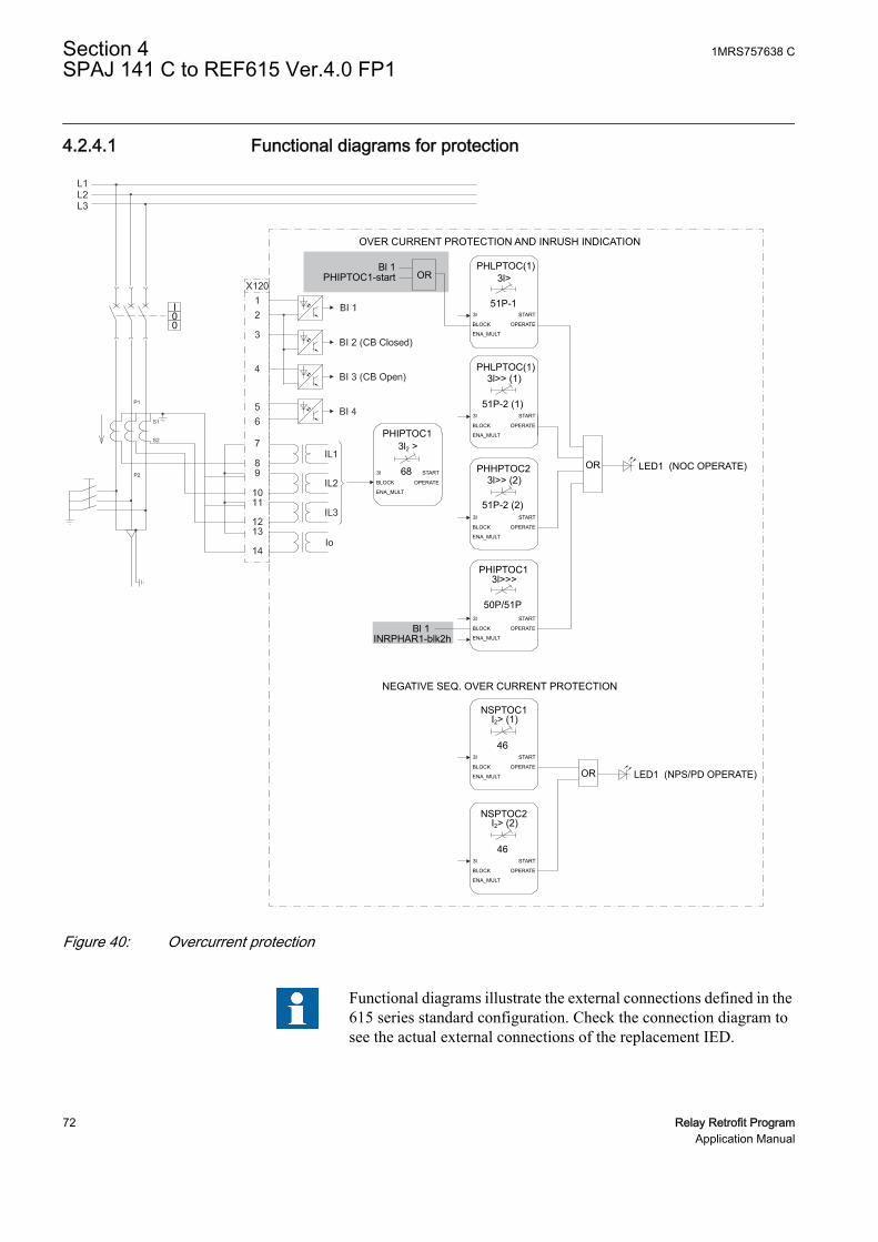
4.2.4.1 Functional diagrams for protection
OVER CURRENT PROTECTION AND INRUSH INDICATION
NEGATIVE SEQ. OVER CURRENT PROTECTION
INRPHAR1-blk2hBl 1
PHIPTOC1-startBl 1
I00
PHLPTOC(1)3l>
3l START
BLOCK
ENA_MULT
OPERATE
51P-1
PHLPTOC(1)
LED1 (NOC OPERATE)
3l>> (1)
3l START
BLOCK
ENA_MULT
OPERATE
51P-2 (1)
PHHPTOC2 OR
LED1 (NPS/PD OPERATE)OR
OR
3l>> (2)
3l START
BLOCK
ENA_MULT
OPERATE
51P-2 (2)
PHIPTOC13l>>>
3l START
BLOCK
ENA_MULT
OPERATE
50P/51P
PHIPTOC13l2 >
3l START
BLOCK
ENA_MULT
OPERATE
68
NSPTOC1I2> (1)
3l START
BLOCK
ENA_MULT
OPERATE
46
NSPTOC2I2> (2)
3l START
BLOCK
ENA_MULT
OPERATE
46
GUID-67B48566-1AAD-4919-8B7C-C9DE5D02C64A V1 EN
Figure 40: Overcurrent protection
Functional diagrams illustrate the external connections defined in the615 series standard configuration. Check the connection diagram tosee the actual external connections of the replacement IED.
Section 4 1MRS757638 CSPAJ 141 C to REF615 Ver.4.0 FP1
72 Relay Retrofit ProgramApplication Manual
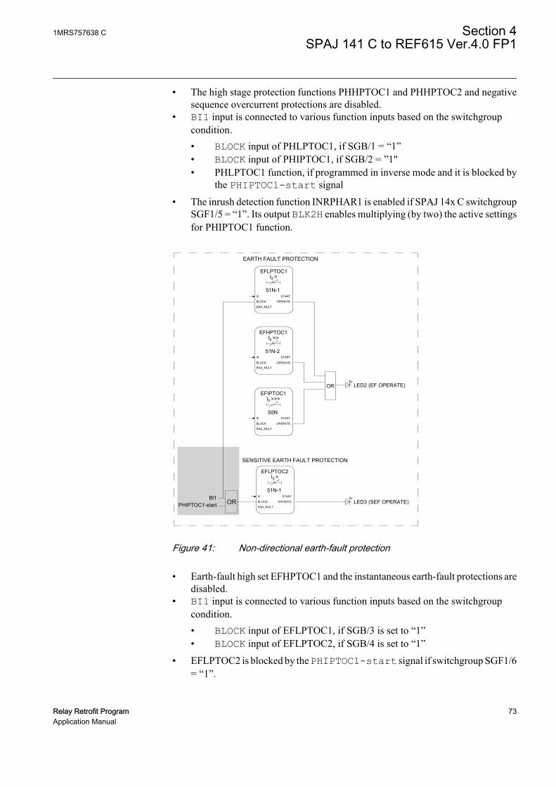
• The high stage protection functions PHHPTOC1 and PHHPTOC2 and negativesequence overcurrent protections are disabled.
• BI1 input is connected to various function inputs based on the switchgroupcondition.• BLOCK input of PHLPTOC1, if SGB/1 = “1”• BLOCK input of PHIPTOC1, if SGB/2 = ”1"• PHLPTOC1 function, if programmed in inverse mode and it is blocked by
the PHIPTOC1-start signal
• The inrush detection function INRPHAR1 is enabled if SPAJ 14x C switchgroupSGF1/5 = “1”. Its output BLK2H enables multiplying (by two) the active settingsfor PHIPTOC1 function.
LED2 (EF OPERATE)OR
EARTH FAULT PROTECTION
SENSITIVE EARTH FAULT PROTECTION
LED3 (SEF OPERATE)PHIPTOC1-startBl1
I >EFLPTOC1
START
OPERATE
I0
BLOCK
ENA_MULT
51N-1
0
I >EFLPTOC2
START
OPERATE
I0
BLOCK
ENA_MULT
51N-1
0
I >>EFHPTOC1
START
OPERATE
I0
BLOCK
ENA_MULT
51N-2
0
I >>>EFIPTOC1
START
OPERATE
I0
BLOCK
ENA_MULT
50N
0
OR
GUID-D5C17D3D-51D6-485B-A906-52979C454778 V1 EN
Figure 41: Non-directional earth-fault protection
• Earth-fault high set EFHPTOC1 and the instantaneous earth-fault protections aredisabled.
• BI1 input is connected to various function inputs based on the switchgroupcondition.• BLOCK input of EFLPTOC1, if SGB/3 is set to “1”• BLOCK input of EFLPTOC2, if SGB/4 is set to “1”
• EFLPTOC2 is blocked by the PHIPTOC1-start signal if switchgroup SGF1/6= “1”.
1MRS757638 C Section 4SPAJ 141 C to REF615 Ver.4.0 FP1
Relay Retrofit Program 73Application Manual

PO2 X100
OR
ORLED6 (CBFP OPERATE)
CCBRBRF1
51BF/51NBF
3l>/l0 > BF
PHHPTOC1- operatePHHPTOC2- operatePHIPTOC1- operateEFLPTOC1- operateEFHPTOC1- operateEFIPTOC1- operateARCSARC1- operateARCSARC2- operateARCSARC3- operate
Bl 2 (CB Closed)
Start orAuxiliary trip8
9
BREAKER FAILURE PROTECTION
TPGAPC 2IN1IN2
OUT1OUT2
OR
PHLPTOC1- startPHLPTOC1- operatePHIPTOC1- startPHIPTOC1- operateEFLPTOC1- startEFLPTOC1- operateEFLPTOC2- startEFLPTOC2- operate
3l
l0
START CB_FAULT_AL
POSCLOSE
CB_FAULT
BLOCK
TRRET
TRBU
GUID-D26B7DFA-34F4-4B9B-B5A3-048B770E5F1B V1 EN
Figure 42: Circuit breaker failure protection, start or auxiliary trip
• PO2 output replicates SPAJ 14x C TS1 output (Start signal 1 or auxiliary tripsignal).
• The breaker failure protection CCBRBRF1 is enabled if SPAJ 14x C switchgroupSGF1/4 = “1”. It is initiated via the START input by a number of differentprotection stages in the IED. If SGR3 = “0”, only the TRBU output is connectedto the output PO2.
• TPGAPC2 is instantiated. Various function outputs are connected to TPGAPC2based on the switchgroup condition.• PHLPTOC1- start, if SGR3/1 = “1”• PHLPTOC1- operate, if SGR3/2 = “1”• PHIPTOC1- start, if SGR3/3 = “1"• PHIPTOC1- operate, if SGR3/4 = “1”• EFLPTOC1- start, if SGR3/5 = ”1”• EFLPTOC1- operate, if SGR3/6 = “1”• EFLPTOC2- start, if SGR3/7= ”1”• EFLPTOC2- operate, if SGR3/8 = “1”
Section 4 1MRS757638 CSPAJ 141 C to REF615 Ver.4.0 FP1
74 Relay Retrofit ProgramApplication Manual

4.2.4.2 Functional diagrams for control and interlocking
GUID-2AA19FD0-05A2-49CB-B30C-860B96F166DA V1 EN
Figure 43: Master trip
Diagrams for control and interlocking features are configured according to Standardconfiguration C with a few differences.
• BI1 input is connected to the RST_LKOUT input of TRPPTRC1 if switchgroupSGB/8 = “1”.
• Trip output mode of TRPTRC1 is set according to SPAJ 14x C switchgroup SGB/6 and SGB/7.
Table 16: Protection functions
SGB/6 value SGB/7 value TRPPTRC1 operation mode0 0 Non-latched
0 1 Latched (warning)
1 0 Latched (warning)
1 1 Latched
In SPAJ 14x C, trip output modes for overcurrent and earth-faultprotections can be configured separately from switchgroups SGB/6and SGB/7. In REF615, trip output mode is set from TRPPTRC1 andis unique. In case if SGB/6 and SGB/7 have different values, a
1MRS757638 C Section 4SPAJ 141 C to REF615 Ver.4.0 FP1
Relay Retrofit Program 75Application Manual

warning is issued by IED Migration Support tool and the default value(latched) is kept for the parameter.
• Various function outputs are connected to TRPPTRC1 based on the switchgroupcondition.• PHLPTOC1- operate, if SGR1/2 = “1”• PHIPTOC1- operate, if SGR1/4 = “1”• EFLPTOC1- operate, if SGR1/6 = “1”• EFLPTOC2- operate, if SGR1/8 = “1”
• Various function outputs are connected to TRPPTRC2 based on the switchgroupcondition.• PHLPTOC1- operate, if SGR2/2 = “1”• PHIPTOC1- operate, if SGR2/4 = “1”• EFLPTOC1- operate, if SGR2/6 = “1”• EFLPTOC2- operate, if SGR2/8 = “1”
• Trip output mode of TRPTRC2 is set to “Non-latched”.
PHLPTOC1-startPHHPTOC1-startPHHPTOC2-startPHIPTOC1-startNSPTOC1-startNSPTOC2-start
PDNSPTOC1-start
PDNSPTOC1-operate
PHLPTOC1-operatePHHPTOC1-operatePHHPTOC2-operatePHIPTOC1-operateNSPTOC1-operateNSPTOC2-operate
ARCSARC1-operateARCSARC2-operateARCSARC3-operate
EFLPTOC1-startEFHPTOC1-startEFIPTOC1-startEFLPTOC2-start
EFLPTOC1-operateEFHPTOC1-operateEFIPTOC1-operate
TPGAPC1IN1IN2 +
+
X100
10
1112
13
14
EFLPTOC2-operate
OR
OR
COMMON ALARM / INDICATION 1 & 2
Start Indication
Operate Indication
SO1
SO2
OUT1OUT2
GUID-9B5703B5-8211-4F5C-90E8-B8A1C281B63A V1 EN
Figure 44: Alarm indication
• SO1 reproduces SPAJ 14x C SS1 output. Various function outputs are connectedto SO1 via TPGAPC1 based on the switchgroup condition.
Section 4 1MRS757638 CSPAJ 141 C to REF615 Ver.4.0 FP1
76 Relay Retrofit ProgramApplication Manual

• PHLPTOC1-start, if SGR1/1 = “1”• PHIPTOC1-start, if SGR1/3 = “1”• EFLPTOC1-start, if SGR1/5 = “1”• EFLPTOC2-start, if SGR1/7 = “1”
• SO2 reproduces SPAJ 14x C SS2 output. Various function outputs are connectedto SO2 via TPGAPC1 based on the switchgroup condition.
• PHLPTOC1-operate, if SGR2/1 = “1”• PHIPTOC1-operate, if SGR2/3 = “1”• EFLPTOC1-operate, if SGR2/5 = “1”• EFLPTOC2-operate, if SGR2/7 = “1”
4.2.4.3 Setting groups
PROTECTIONBI_SG_2BI1 SG_1_ACT
SG_2_ACTSG_3_ACTSG_4_ACTSG_5_ACTSG_6_ACT
BI_SG_3BI_SG_4BI_SG_5BI_SG_6
GUID-704B93FC-3184-4AC4-AD2B-E76838FEAED8 V1 EN
Figure 45: Setting groups
615 IEDs support six setting groups. SPAJ 14x C support two setting groups (mainand second setting) which can be selected from binary input BS if switchgroup SGB/5 = “1”. REF615 setting group 2 is selected if BI1 is active and SGB/5 = “1”. Theactive setting group can be changed at run time.
The connections in the application which are affected by switchgroups SGF1,SGF2/5, SGF2/6, SGR1, SGR2, SGR3, and SGB are based on the main setting value.If the main and second setting differ in SPAJ 141 C, and the setting change is enabledfrom BS input (SGB/5 = “1”), a note is issued by the IED Migration Support tool.
1MRS757638 C Section 4SPAJ 141 C to REF615 Ver.4.0 FP1
Relay Retrofit Program 77Application Manual

4.3 Installation
4.3.1 Mounting
The 615 series IED can be mounted on the switchgear door using the hole left by theSPACOM series relay.
1. Widen the original SPACOM relay hole.1.1. Use cutting tool with dedicated cutting head for SPACOM 100/300 series
to get the appropriate cut-out on the switchgear door hosting REF615 IED.1.2. Widen the cut-out to whichever of the four directions as per the existing
installation requirement.
Section 4 1MRS757638 CSPAJ 141 C to REF615 Ver.4.0 FP1
78 Relay Retrofit ProgramApplication Manual

615 seriesA
B
C D
SPA 100 series
GUID-46C4FA59-4D66-4CD0-8CAB-AD8A0D3977DE V1 EN
Figure 46: SPACOM 100 series and 615 series cut-outs
A 165.5 mm
B 129 mm
C 139 mm
D 161.5 mm
2. Mount the 615 series IED's case and insert the plug-in unit.
Cover plate is not required with the SPACOM 100 series.
See the 615 series installation manual for more information.
1MRS757638 C Section 4SPAJ 141 C to REF615 Ver.4.0 FP1
Relay Retrofit Program 79Application Manual

4.3.2 Connecting
• If the existing wiring is in good condition and still usable, use the dedicatedmarking sets.
• If the existing wiring has to be replaced, use the dedicated wiring harness.
4.3.2.1 Wiring harness and wire markings
Wiring harness is available for retrofitting SPAJ 141 C with REF615.
Table 17: REF615 wiring harness description for retrofit of SPAJ 141 C
REF615, configuration C SPAJ 141 C WiringTerminal Description Terminal Description MarkingX100:1 Uaux+ 61 Uaux+ X100:1 (61)
X100:2 Uaux- 62 Uaux- X100:2 (62)
X100:3 IRF 72 IRF X100:3 (72)
X100:4 IRF 71 IRF X100:4 (71)
X100:5 IRF 70 IRF X100:5 (70)
X100:6 PO1 - - X100:6
X100:7 PO1 - - X100:7
X100:8 PO2 74 START 1 X100:8 (74)
X100:9 PO2 75 START 1 X100:9 (75)
X100:10 SO1 78 START 2 X100:10 (78)
X100:11 SO1 - - X100:11
X100:12 SO1 77 START 2 X100:12 (77)
X100:13 SO2 81 SIGNAL 1 X100:13 (81)
X100:14 SO2 80 SIGNAL 1 X100:14 (80)
X100:15 PO3 - - X100:15
X100:16 PO3 65 TRIP X100:16 (65)
X100:17 PO3 66 TRIP X100:17 (66)
X100:18 PO3 - - X100:18
X100:19 PO3 - - X100:19
X100:20 PO4 - - X100:20
X100:21 PO4 69 SIGNAL 2 X100:21 (69)
X100:22 PO4 68 SIGNAL 2 X100:22 (68)
X100:23 PO4 - - X100:23
X100:24 PO4 - - X100:24
X120:1 BI1 10EXTERNALCONTROL X120:1 (10)
X120:2 BI1 11EXTERNALCONTROL X120:2 (11)
X120:3 BI2 - - X120:3
Table continues on next page
Section 4 1MRS757638 CSPAJ 141 C to REF615 Ver.4.0 FP1
80 Relay Retrofit ProgramApplication Manual

REF615, configuration C SPAJ 141 C WiringTerminal Description Terminal Description MarkingX120:4 BI3 - - X120:4
X120:5 BI4 - - X120:5
X120:6 BI4 - - X120:6
X120:7 IL1 2/3 IL1, 5A/1A X120:7 (2/3)
X120:8 IL1 1 IL1 X120:8 (1)
X120:9 IL2 5/6 IL2, 5A/1A X120:9 (5/6)
X120:10 IL2 4 IL2 X120:10 (4)
X120:11 IL3 8/9 IL3, 5A/1A X120:11 (8/9)
X120:12 IL3 7 IL3 X120:12 (7)
X120:13 Io 27/28 Io, 0.2A/1A X120:13(26/27/28)
X120:14 Io 25 Io X120:14 (25)
Earth 63 Earth
4.3.2.2 SPAJ 141 C terminal layout and connection diagrams
Mad
e in
Fin
land
= 63
686977788081
1
2
3
4
5
6
7
8
9
25
27
28
61
62
63
65
66
74
75
70
71
72
10
11
Ser
ial P
ort
SPA
GUID-61EAA987-DCDF-4F56-8BC3-57FA240CF1DD V1 EN
Figure 47: Terminal layout for SPAJ 141 C
1MRS757638 C Section 4SPAJ 141 C to REF615 Ver.4.0 FP1
Relay Retrofit Program 81Application Manual

GUID-89895F83-8111-4263-B313-BECF0C7FD1AE V1 EN
Figure 48: Connection diagram for SPAJ 141 C
Section 4 1MRS757638 CSPAJ 141 C to REF615 Ver.4.0 FP1
82 Relay Retrofit ProgramApplication Manual
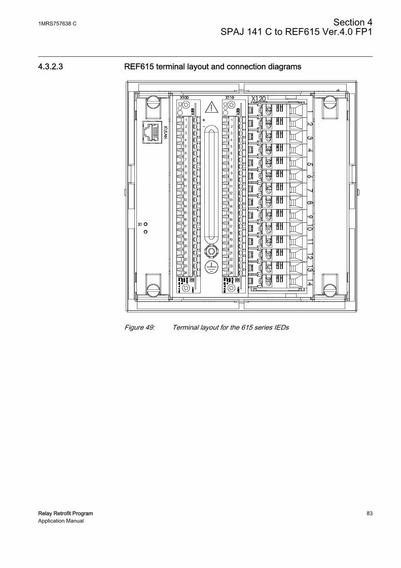
4.3.2.3 REF615 terminal layout and connection diagrams
A070596 V1 EN
Figure 49: Terminal layout for the 615 series IEDs
1MRS757638 C Section 4SPAJ 141 C to REF615 Ver.4.0 FP1
Relay Retrofit Program 83Application Manual

REF615
X13Light sensor input 1 1)
X14Light sensor input 2 1)
X15Light sensor input 3 1)
16
17
1918
X100
67
89
10
111213
15
14
2
1
3
45
22
212324
SO2
TCS2
PO4
SO1
TCS1
PO3
PO2
PO1
IRF
+
-Uaux
20
L1L2L3
S1
S2
P1
P2
PositiveCurrentDirection
2)
1) Optional2) The IED features an automatic short-circuit mechanism in the CT connector when plug-in unit is detached
X120
12
3
4
567
89
1011
1213
14Io
IL1
IL2
BI 4
BI 3
BI 2
BI 1
IL3
1/5A
N1/5A
N1/5A
N0.2/1A
N
P2
P1 S1
S2
EXTERNALCONTROL Uaux
IRF
START 1
START 2
SIGNAL 1
TRIP
SIGNAL 2
GUID-27969A66-5E99-4744-B813-AA2A7E13816B V1 EN
Figure 50: Connection diagram for REF615 with standard configuration Creplacing SPAJ 141 C
Section 4 1MRS757638 CSPAJ 141 C to REF615 Ver.4.0 FP1
84 Relay Retrofit ProgramApplication Manual

Section 5 SPAM 150 C to REM615 Ver.4.0 FP1
5.1 Retrofit scope
Protection functions of SPAM 150 C are replicated by REM615 with deviations.
• In SPAM 150 C, the latching of earth-fault and unbalanced trip signals can beconfigured from an independent setting. Latching for the general trip signal of allthe protection functions can be configured from another setting. In REM615, thelatching feature is configured so that all the trip signals are grouped together.Activating one of the latching features on SPAM 150 C results in latching thegeneral trip output feature in REM615.
5.2 Engineering
In retrofit applications, the target of the configuration phase is to parameterize andconfigure the replacement IED to reproduce the features and functions of the existingrelay. The configuration process comprises of various steps with different toolsdepending on the project.
CAP505
• Reading the configuration from the SPACOM relay or manually enteringparameter values.
In CAP505 tool, the actual values read from the SPACOM relay arecalled present values. The manually entered values are called newvalues. After relay writing and reading operations present and newvalues become identical.
PCM600
• Instantiating a new retrofit IED (IED Migration Support tool from PCM600).
1MRS757638 C Section 5SPAM 150 C to REM615 Ver.4.0 FP1
Relay Retrofit Program 85Application Manual

• Selecting the replacement IED (type and order code)• Importing existing relay configuration (.rdb file)• Selecting the set of values to use using the IED Migration Support tool, if
the Present and New values differ in .rdb file• Entering system parameters
• Creating a 615 series IED under PCM600 plant structure using the IED MigrationSupport tool.
• Writing configuration to the IED.
Project specific additional engineering phases
• Using Application Configuration tool in PCM600 to add functionality to themigrated configuration, if required.
• Communication engineering with relevant PCM600 tools, if required.
No engineering activity is required for wiring as marking sets and wiring harness areavailable.
5.2.1 Existing relay and system engineering information
The configuration of the SPACOM relay can be retrieved via the serial connectionusing CAP 505 tool. Parameters are read from the display of the SPACOM relay andmanually inserted in CAP 505. The configuration parameters are exported from CAP505 in .rdb file format and imported in PCM600 during the migration process.
During the migration process, the control mode of the primary switching device,normally open (NO) for circuit breaker tripping or normally closed (NC) for contactorcontrol, has to be selected. This information is readable from the front plate of SPAM150 C.
Additionally, various system parameters are collected and imported to PCM600 uponrequest.
• Rated frequency of the network (50 or 60 Hz)• CT rated primary for phase currents (A)• CT rated secondary for phase current (1 or 5 A)• CT rated primary for residual current (A)• CT rated secondary for residual current (1 or 5 A)
5.2.2 Functions
The configuration of REM615 migrated from SPAM 150 C contains all the functionsof standard configuration A, but only the functions that reproduce the behavior of theexisting relay configuration are activated. On SPAM 150 C, selector switchgroupsSGF define which protection functions are enabled and disabled and the curvecharacteristics. These settings are considered when the REM615 configuration isgenerated.
Section 5 1MRS757638 CSPAM 150 C to REM615 Ver.4.0 FP1
86 Relay Retrofit ProgramApplication Manual

Table 18: Functions included in REM615 standard configuration A
SPAM 150 C REM615 Description Enabled1)
Is>In PHLPTOC1 Three-phase non-directionalovercurrent protection, low stage,instance 1
Yes, if (SGF/7) = “0” or(SGF/7 = “1” and SG4/1 =“1”)
I>>/In PHIPTOC12) Three-phase non-directionalovercurrent protection, instantaneousstage, instance 1
Yes, if (SGF/1 = “1”) or(SGF/1 = “0” and SGF/3,4> 0,0)
I0[%In] EFLPTOC1 Non-directional earth-fault protection,low stage, instance 1
Yes
EFHPTOC1 Non-directional earth-fault protection,high stage, instance 1
No
ΔI[%IL] MNSPTOC1 Negative sequence overcurrentprotection for motors, instance 1
Yes, if SGF/5 = “1”
MNSPTOC2 Negative sequence overcurrentprotection for motors, instance 2
No
I<[%IӨ] LOFLPTUC1 Loss of load supervision Yes, if SGF/8 = “1”
JAMPTOC1 Motor load jam protection No
Is/InƩtSi[S]
STTPMSU1 Motor startup supervision Yes, if SGF/7 = “1” andSG4/1 = “0”
PhaseReversal
PREVPTOC1 Phase reversal protection Yes, if SGF/6 = “1”
IӨ/In MPTTR1 Thermal overload protection for motors Yes
CCBRBRF1 Circuit breaker failure protection No
TRPPTRC1 Master trip, instance 1 Yes
TRPPTRC2 Master trip, instance 2 No
ARCSARC1 Arc protection, instance 1 No
ARCSARC2 Arc protection, instance 2 No
ARCSARC3 Arc protection, instance 3 No
MAPGAPC1 Multi-purpose protection, instance 1 No
MAPGAPC2 Multi-purpose protection, instance 2 No
MAPGAPC3 Multi-purpose protection, instance 3 No
MAPGAPC4 Multi-purpose protection, instance 4 No
MAPGAPC5 Multi-purpose protection, instance 5 No
MAPGAPC6 Multi-purpose protection, instance 6 No
CBXCBR1 Circuit breaker control No
DCXSWI1 Disconnector control, instance 1 No
DCXSWI2 Disconnector control, instance 2 No
ESXSWI1 Earthing switch control No
DCSXSWI1 Disconnector position indication,instance 1
No
DCSXSWI2 Disconnector position indication,instance 2
No
DCSXSWI3 Disconnector position indication,instance 3
No
Table continues on next page
1MRS757638 C Section 5SPAM 150 C to REM615 Ver.4.0 FP1
Relay Retrofit Program 87Application Manual

SPAM 150 C REM615 Description Enabled1)
ESSXSWI1 Earthing switch indication, instance 1 No
ESSXSWI2 Earthing switch indication, instance 2 No
ESMGAPC1 Emergency startup No
SSCBR1 Circuit-breaker condition monitoring No
TCSSCBR1 Trip circuit supervision, instance 1 Yes
TCSSCBR2 Trip circuit supervision, instance 2 Yes
CCRDIF1 Current circuit supervision Yes
MDSOPT1 Runtime counter for machines anddevices
Yes
RDRE1 Disturbance recorder Yes
CMMXU1 Three-phase current measurement,instance 1
Yes
CSMSQI1 Sequence current measurement Yes
RESCMMXU1 Residual current measurement,instance 1
Yes
XRGGIO130 RTD/mA measurement No
1) The function is enabled when the parameter operation is set to “on” and disabled when the parameteris set to “off”.
2) If SGF/1=0 and at least one among SGF/3 and SGF/4 is set, PHIPTOC1 is used only for blockingprotection function EFLPTOC1.
5.2.2.1 PHLPTOC1 settings
PHLPTOC1 replicates the behavior of SPAM 150 C motor startup supervision (Is>/In). PHLPTOC1 parameter Operating curve type and curve parameterization arederived from SPAM 150 C switchgroups SGF.
• If SGF/7 = “0”, PHLPTOC1 Operating curve time is set to “IEC Def. time”.• If SGF/7 = “1” and SG4/2 = “1”, PHLPTOC1 Operating curve time is set to
“Programmable”.• If SGF/7 = “1” and SG4/2 = “0”, PHLPTOC1 is disabled.
For SPAM 150 C, the range of parameter Starting value of the Is unit is 1.0…10.0 ×In. The corresponding parameter on REM615 is Start value whose range is 1.0…5.0× In. Whenever the value of SPAM 150 C parameter Starting value of the Is unitexceeds 5.0 × In, PHLPTOC1 parameter Start value is saturated to 5.0 × In and awarning message is issued by the IED Migration Support tool.
5.2.2.2 PHIPTOC1 settings
PHIPTOC1 replicates the behavior of SPAM 150 C high-set stage of the overcurrentunit. PHIPTOC1 is enabled if SGF/1 is set to “1”.
If SGF/1 = “1” and at least one of the conditions SGF/3 = “1” and SGF/4 = “1” aresatisfied, PHIPTOC1 blocks the function EFLPTOC1.
Section 5 1MRS757638 CSPAM 150 C to REM615 Ver.4.0 FP1
88 Relay Retrofit ProgramApplication Manual
• If SPAM 150 C parameter Start value for stage I>> is below one, PHIPTOC1Start value is set to one and a warning message is issued by the IED MigrationSupport tool.
5.2.2.3 EFLPTOC1 settings
EFLPTOC1 replicates the behavior of the SPAM 150 C earth-fault unit. This is alwaysenabled.
5.2.2.4 MNSPTOC1 settings
MNSPTOC1 replicates the behavior of the SPAM 150 C unbalance or incorrect phasesequence protection unit.
This is enabled if SGF/5 = “1”.
5.2.2.5 LOFLPTUC1 settings
LOFLPTUC1 protection replicates the behavior of the SPAM 150 C undercurrentunit.
LOFLPTUC1 is enabled if SGF/8 = “1”.
• If SPAM 150 C parameter IƟ (Thermal trip current setting) is such that Startingvalue of stage I< multiplied by IƟ exceeds one, LOFLPTUC1 Start value is set to“1” and a warning message is issued by the IED Migration Support tool.
5.2.2.6 STTPMSU1 settings
STTPMSU1 replicates the behavior of the SPAM 150 C startup stall protection unit.
The function is enabled if SGF/7 = “1” and SG4/1 = “0”.
If switchgroup SGB/1 = “1”, STTPMSU1 parameter Operation mode is set to value“3” (ITT+ STALL) else Operation mode is set to “1” (ITT).
• If SPAM 150 C parameter ts (Operate time of Is or Is2) is below two seconds,STTPMSU1 parameter Lock rotor time is set to “2 sec” and a warning messageis issued by the IED Migration Support tool.
• If SPAM 150 C parameter ts is below one second, the 615 parameter Motor start-up time is set to “1 sec” and a warning message is issued by the IED MigrationSupport tool.
5.2.2.7 PREVPTOC1 settings
PREVPTOC1 replicates the behavior of SPAM 150 C phase reversal unit.
1MRS757638 C Section 5SPAM 150 C to REM615 Ver.4.0 FP1
Relay Retrofit Program 89Application Manual
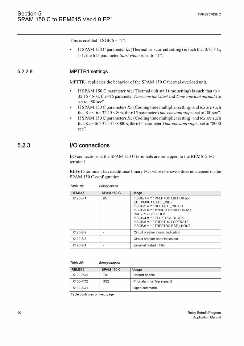
This is enabled if SGF/6 = “1”.
• If SPAM 150 C parameter IƟ (Thermal trip current setting) is such that 0.75 × IƟ> 1, the 615 parameter Start value is set to “1”.
5.2.2.8 MPTTR1 settings
MPTTR1 replicates the behavior of the SPAM 150 C thermal overload unit.
• If SPAM 150 C parameter t6x (Thermal unit stall time setting) is such that t6 ×32.15 < 80 s, the 615 parameter Time constant start and Time constant normal areset to “80 sec”.
• If SPAM 150 C parameters Kc (Cooling time multiplier setting) and t6x are suchthat Kc × t6 × 32.15 < 80 s, the 615 parameter Time constant stop is set to “80 sec”.
• If SPAM 150 C parameters Kc (Cooling time multiplier setting) and t6x are suchthat Kc × t6 × 32.15 > 8000 s, the 615 parameter Time constant stop is set to “8000sec”.
5.2.3 I/O connections
I/O connections at the SPAM 150 C terminals are remapped to the REM615 I/Oterminal.
REF615 terminals have additional binary I/Os whose behavior does not depend on theSPAM 150 C configuration.
Table 19: Binary inputs
REM615 SPAM 150 C UsageX120-BI1 BS If SGB/1 = “1” PHLPTOC1.BLOCK not
(STTPMSU1.STALL_IND)If SGB/2 = “1” RESTART_INHIBITIf SGB/3 = “1” MNSPTOC1.BLOCK andPREVPTOC1.BLOCKIf SGB/4 = “1” EFLPTOC1.BLOCKIf SGB/5 = “1” TRPPTRC1.OPERATEIf SGB/6 = “1” TRPPTRC.RST_LKOUT
X120-BI2 - Circuit breaker closed indication
X120-BI3 - Circuit breaker open indication
X120-BI4 - External restart inhibit
Table 20: Binary outputs
REM615 SPAM 150 C UsageX100-PO1 TS1 Restart enable
X100-PO2 SS2 Prior alarm or Trip signal 2
X100-SO1 - Open command
Table continues on next page
Section 5 1MRS757638 CSPAM 150 C to REM615 Ver.4.0 FP1
90 Relay Retrofit ProgramApplication Manual

REM615 SPAM 150 C UsageX100-SO2 SS1 Start indication
X100-PO3 TS2 Open circuit breaker/Trip coil 1
X100-PO4 SS3 Open circuit breaker/trip
The type of contacts (single or multiple pole, single or multiple throw)in the 615 series can be different from the SPACOM relays. See theREM615 standard configuration A connection diagram.
5.2.4 Functional diagrams
The functional diagrams describe the default input, output, alarm LED and function-to-function connections in REM615. The default connections can be viewed andchanged with PCM600 according to the application requirements, if necessary.
Only SPAM 150 C migrated functions are represented in theconnection diagrams. REM615 also includes other functions whoseconnections are configured according to standard configuration A.See REM615 Application Manual.
Operation of additional REM615 functions is disabled if thecorresponding functionality is not available in SPAM 150 C. Thesefunctions can be visible in the connection diagrams even if disabled.
The parts affected by the migration compared to the 615 seriesstandard configuration are highlighted in gray.
1MRS757638 C Section 5SPAM 150 C to REM615 Ver.4.0 FP1
Relay Retrofit Program 91Application Manual

5.2.4.1 Functional diagrams for protection
GUID-426E6C79-B4EE-47E6-B62F-1571E2C63E7E V1 EN
Figure 51: Overcurrent protection
Functional diagrams illustrate the external connections defined in the615 series standard configuration. Check the connection diagram tosee the actual external connections of the replacement IED.
• The motor jam protection function JAMPTOC1, the high stage protectionfunctions PHHPTOC1 and PHHPTOC2 and negative sequence overcurrentprotection functions are disabled.
• PHLPTOC1 is blocked by BI1 if SGB/1 = “1”.• MOT_START output of STTPMSU1 is connected to ENA_MULT input of
PHIPTOC1 if SGF/2 = “1”.
Section 5 1MRS757638 CSPAM 150 C to REM615 Ver.4.0 FP1
92 Relay Retrofit ProgramApplication Manual

GUID-E1090524-C565-417E-8B7E-D2CF414CCFB4 V1 EN
Figure 52: Non-directional earth-fault protection
• EFLPTOC1 is blocked by the START output of PHIPTOC1, if SGF/1 = “0” andat least one of the conditions SGF/3 = “1” and SGF/4 = “1” is true.
• EFLPTOC is blocked by BI1 if SGB/4 = “1”.• EFHPTOC1 is disabled.
GUID-4685C67C-B1F2-42C5-AB6D-0616EAA00A96 V1 EN
Figure 53: Emergency start and restart inhibit
1MRS757638 C Section 5SPAM 150 C to REM615 Ver.4.0 FP1
Relay Retrofit Program 93Application Manual

• The BLOCK input of the emergency start function ESMGAPC1 is not connectedto any source.
GUID-B34924C7-6ED4-40A1-A774-A9AFADBADDE6 V1 EN
Figure 54: Motor startup supervision
• Binary input BI1 is inverted and connected to STALL_IND input ofSTTPMSU1, if SGB/1 = “1”.
Section 5 1MRS757638 CSPAM 150 C to REM615 Ver.4.0 FP1
94 Relay Retrofit ProgramApplication Manual

GUID-992535AD-44E0-4F0B-A372-F80C487E1459 V1 EN
Figure 55: Phase unbalance protection
• Protection function MNSPTOC1 is enabled if SGF/6 = “1”. CCRDIF_FAILoutput and input BI1 are connected to MNSPTOC1 block input if switchgroupSGB/3 = “1”.
• Protection function MNSPTOC2 is disabled.• Protection PREVPTOC1 is enabled if SGF/6 = “1”. CCRDIF_FAIL output and
input BI1 are connected to PREVPTOC1 block input if switchgroup SGB/3= ”1”.
• Protection function LOFLPTUC1 is enabled if SGF/8 = “1”.
1MRS757638 C Section 5SPAM 150 C to REM615 Ver.4.0 FP1
Relay Retrofit Program 95Application Manual

GUID-D55A572F-3B85-4610-AE4A-0ABD728B65A8 V1 EN
Figure 56: Circuit breaker failure protection
• The circuit-breaker failure protection CCBRBRF1 is disabled and disconnectedfrom PO2 (X100:8/9).
• PO2 (X100:8/9) is connected to TPGAPC1 OUT2 if at least one among SGR1/1,SGR1/2 and SGR1/3 is set.
GUID-EB1F415E-3B04-4E3D-908E-9450FD176D47 V1 EN
Figure 57: Master trip
Section 5 1MRS757638 CSPAM 150 C to REM615 Ver.4.0 FP1
96 Relay Retrofit ProgramApplication Manual

• The operate signal from protection function EFLPTOC1 is connected to theMaster Trip TRPPTRC1 if switchgroup SGR1/8 = “1”.
• Binary input BI1 is connected to the Master Trip if SGB/5 = ”1”.• TRPPTRC1 provides lockout and latching function, event generation and the trip
signal duration setting. If the lockout operation mode is selected and SGB/6 =“1”, binary input BI1 is assigned to the RST_LKOUT input of the Master Trip toenable external reset with a push button.
GUID-4B77B7C6-B33C-41D1-BFC5-AF51B206F367 V1 EN
Figure 58: Circuit breaker control
• The circuit breaker control and condition monitoring functions are disabled.• Output PO4 is driven by TPGAPC2.
1MRS757638 C Section 5SPAM 150 C to REM615 Ver.4.0 FP1
Relay Retrofit Program 97Application Manual

EFLPTOC1_OPERATE
MNSPTOC1_OPERATEPREVPTOC1_OPERATE
LOFLPTOC1_OPERATE
MPTTR1_OPERATEPHLPTOC1_OPERATE
PHIPTOC1_OPERATEEFLPTOC1_OPERATE
LOFLPTUC1_OPERATEPREVPTOC1_OPERATEMNSPTOC1_OPERATE
STTPMSU1_OPR_IIT
GUID-BE03F72E-BB73-4674-B361-AECF5DAA335D V1 EN
Figure 59: Common alarm indication
• TPGAPC1 and TPGAPC2 are enabled.• Signal IN1 of TPGAPC1 collects the start signals of protection functions and is
connected to SO2 (X100:13/14).
• MPTTR1_ALARM, if SGR2/1 = “1”• PHLPTOC1_START, if SGR4/3 = “1”• PHIPTOC1_START, if SGR2/3 = “1”• EFHPTOC1_START• STTPMSU1_MOT_STARTUP, if SGR2/2 = “1”• MNSPTOC1_START• MNSPTOC2_START• PREVPTOC1_START• MAPGAPC1_START• MAPGAPC2_START• MAPGAPC3_START
• Input signal IN2 of TPGAPC1 is connected to PO2 (X100:8/9). If at least oneamong SGR1/1, SGR1/2, SGR1/3 and SGR1/4 is set, IN2 signal collects theoutput signals of various protection functions.• MPTTR1_ALARM, if SGR1/1 = “1”• MPTTR1_OPERATE, if SGR1/2 = “1”• PHLPTOC1_OPERATE, if SGR1/3 = “1”• STTPMSU1_OPR_IIT, if SGR1/3 = “1”
Section 5 1MRS757638 CSPAM 150 C to REM615 Ver.4.0 FP1
98 Relay Retrofit ProgramApplication Manual

• PHIPTOC1_OPERATE, if SGR1/4 = “1”• MNSPTOC1_OPERATE, if SGR1/5 = “1”• PREVPTOC1_OPERATE, if SGR1/5 = “1”• EFLPTOC1_OPERATE, if SGR1/6 = “1”• LOFLPTUC1_OPERATE, if SGR1/7 = “1”
• Input signal IN1 of TPGAPC2 collects the start signals and is connected to PO4(X100:20-24).• MPTTR1_OPERATE, if SGR2/4 = “1”• PHLPTOC1_OPERATE, if SGR2/5 = “1”• STTPMSU1_OPR_IIT, if SGR2/5 = “1"• MNSPTOC1_OPERATE, if SGR2/6 = “1”• PREVPTOC1_OPERATE, if SGR2/6 = “1”• LOFLPTUC1_OPERATE, if SGR2.8 = “1”• EFLPTOC1_OPERATE, if SGR2.7 = “1”• PHIPTOC1_OPERATE
5.3 Installation
5.3.1 Mounting
The 615 series IED can be mounted on the switchgear door using the hole left by theSPACOM series relay.
1. Widen the original SPACOM relay hole.1.1. Use cutting tool with dedicated cutting head for SPACOM 100/300 series
to get the appropriate cut-out on the switchgear door hosting REF615 IED.1.2. Widen the cut-out to whichever of the four directions as per the existing
installation requirement.
1MRS757638 C Section 5SPAM 150 C to REM615 Ver.4.0 FP1
Relay Retrofit Program 99Application Manual
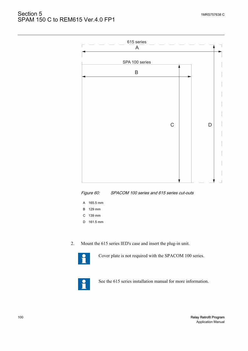
615 seriesA
B
C D
SPA 100 series
GUID-46C4FA59-4D66-4CD0-8CAB-AD8A0D3977DE V1 EN
Figure 60: SPACOM 100 series and 615 series cut-outs
A 165.5 mm
B 129 mm
C 139 mm
D 161.5 mm
2. Mount the 615 series IED's case and insert the plug-in unit.
Cover plate is not required with the SPACOM 100 series.
See the 615 series installation manual for more information.
Section 5 1MRS757638 CSPAM 150 C to REM615 Ver.4.0 FP1
100 Relay Retrofit ProgramApplication Manual

5.3.2 Connecting
• If the existing wiring is in good condition and still usable, use the dedicatedmarking sets.
• If the existing wiring has to be replaced, use the dedicated wiring harness.
5.3.2.1 Wiring harness and wire markings
Wiring harness is available for retrofitting SPAM 150 C with REM615.
Table 21: REM615 wiring harness description for retrofit of SPAM 150 C
REM615, configuration A SPAM 150 C WiringTerminal Description Terminal Description MarkingX100:1 Uaux+ 61 Uaux+ X100:1 (61)
X100:2 Uaux- 62 Uaux- X100:2 (62)
X100:3 IRF 72 IRF X100:3 (72)
X100:4 IRF 71 IRF X100:4 (71)
X100:5 IRF 70 IRF X100:5 (70)
X100:6 PO1 74RESTARTENABLE X100:6 (74)
X100:7 PO1 75RESTARTENABLE X100:7 (75)
X100:8 PO2 80 SIGNAL 2 X100:8 (80)
X100:9 PO2 81 SIGNAL 2 X100:9 (81)
X100:10 SO1 - - X100:10
X100:11 SO1 - - X100:11
X100:12 SO1 - - X100:12
X100:13 SO2 77 START X100:13 (77)
X100:14 SO2 78 START X100:14 (78)
X100:15 PO3 - - X100:15
X100:16 PO3 65 TRIP X100:16 (65)
X100:17 PO3 66 TRIP X100:17 (66)
X100:18 PO3 - - X100:18
X100:19 PO3 - - X100:19
X100:20 PO4 - - X100:20
X100:21 PO4 68 SIGNAL 1 X100:21 (68)
X100:22 PO4 69 SIGNAL 1 X100:22 (69)
X100:23 PO4 - - X100:23
X100:24 PO4 - - X100:24
X120:1 BI1 10CONTROLINPUT X120:1 (10)
X120:2 BI1 11CONTROLINPUT X120:2 (11)
Table continues on next page
1MRS757638 C Section 5SPAM 150 C to REM615 Ver.4.0 FP1
Relay Retrofit Program 101Application Manual

REM615, configuration A SPAM 150 C WiringTerminal Description Terminal Description MarkingX120:3 BI2 - - X120:3
X120:4 BI3 - - X120:4
X120:5 BI4 - - X120:5 (n.a.)
X120:6 BI4 - - X120:6 (n.a.)
X120:7 IL1 2/3 IL1, 5A/1A X120:7 (2/3)
X120:8 IL1 1 IL1 X120:8 (1)
X120:9 IL2 5/6 IL2, 5A/1A X120:9 (5/6)
X120:10 IL2 4 IL2 X120:10 (4)
X120:11 IL3 8/9 IL3, 5A/1A X120:11 (8/9)
X120:12 IL3 7 IL3 X120:12 (7)
X120:13 Io 26/27 IL3, 2A/5A X120:13 (26/27)
X120:14 Io 25 IL3 X120:14 (25)
Earth 63 Earth
5.3.2.2 SPAM 150 C terminal layout and connection diagrams
686977788081
Mad
e in
Fin
land
1
2
3
4
5
6
7
8
9
25
26
27
61
62
63
65
66
74
75
70
71
72
10
11
Ser
ial P
ort
SP
A
GUID-72157F38-2EF3-41CA-8042-C3E2300D00DC V1 EN
Figure 61: Terminal layout for SPAM 150 C
Section 5 1MRS757638 CSPAM 150 C to REM615 Ver.4.0 FP1
102 Relay Retrofit ProgramApplication Manual

SPAM 150 C
63
L1L2L3
70 71 72
0
65 6668 6977 78
IRF SIGNAL 1
-
+
TRIP
74 75
PRIOR ALARM SIGNAL 2
80 811011
1 1
SGB/1
SGB/2
SGB/7SGB/8
SGB/3
TRIPR
LATCHING
STARTPRIOR ALARM
RESTARTENABLE
1
I-
I 0
+
+
+
B
+
C
+
F
+
E
+
D
+
A
SGB/4
1 1
SG
R1/
8
SGB/5SGB/6
U1 SPCJ 4D34
U3 SPTE 4E3
U2 SPTU _ R2
CONTROLINPUT
IRF
Σ >ts
3
STALL
I/O
I>>
Io>
I<
START
∆I
RESTARTINHIBIT
RESTARTINHIBIT
RELAY RESET
θ>θiθ>θaθ>θt
EXTERNAL TRIP
I x t2s s
25 26 271 2 3 4 5 6 7 8 9
1 A
5 A
1 A
5 A
1 A
5 A
1 A
5 A
SERIALPORT
SPA
-ZC
_
Rx Tx
6162
U+ (~)- (~)
+ -
aux
~
SG
R1/
7S
GR
1/6
SG
R1/
5S
GR
1/4
SG
R1/
3S
GR
1/2
SG
R1/
1
SG
R2/
8S
GR
2/7
SG
R2/
6S
GR
2/5
SG
R2/
4
SG
R2/
3S
GR
2/2
SG
R2/
1
SG
4/3
I >s
SG
4/2
TS1 SS1 SS2 SS3 TS2
GUID-9E2E653C-13D3-4395-AE57-006C11ABE13F V1 EN
Figure 62: Connection diagram for SPAM 150 C
1MRS757638 C Section 5SPAM 150 C to REM615 Ver.4.0 FP1
Relay Retrofit Program 103Application Manual

5.3.2.3 REM615 terminal layout and connection diagrams
A070596 V1 EN
Figure 63: Terminal layout for the 615 series IEDs
Section 5 1MRS757638 CSPAM 150 C to REM615 Ver.4.0 FP1
104 Relay Retrofit ProgramApplication Manual

REM615
X13Light sensor input 1 1)
X14Light sensor input 2 1)
X15Light sensor input 3 1)
16
17
1918
X100
67
89
10
111213
15
14
2
1
3
45
22
212324
SO2
TCS2
PO4
SO1
TCS1
PO3
PO2
PO1
IRF
+
-Uaux
20
1)
1)
X110
34
56
7
89
10BI 6
BI 5
BI 4
BI 3
BI 2
BI 8
BI 712
13
11
BI 112
X110
16
14
15
19
17
18
22
20
21
SO3
SO2
SO1
23SO4
24
1) Optional2) The IED features an automatic short-circuit mechanism in the CT connector when plug-in unit is detached
S1
S2
P1
P2
P2
P1 S1
S2
PositiveCurrentDirection
L1L2L3
2)
1)
X130
12
5678
mA 1mA+
_
34
mA 2mA+
_
RTD 1
RTD 2
9101112
RTD 3
13141516
RTD 4
RTD 5
1718
RTD 6
+_
+_
+_
+_
+_
+_
X120
12
3
4
567
89
1011
1213
14Io
IL1
IL2
BI 4
BI 3
BI 2
BI 1
IL3
1/5A
N1/5A
N1/5A
N1/5A
N
CONTROL INPUT Uaux
IRF
RESTARTENABLE
PRIOR ALARMSIGNAL 2
STARTPRIOR ALARM
TRIP
SIGNAL 1
GUID-A6E1987D-5A48-41DF-A1B0-0FB672A693BF V1 EN
Figure 64: Connection diagram for REM615 with standard configuration Areplacing SPAM 150 C
1MRS757638 C Section 5SPAM 150 C to REM615 Ver.4.0 FP1
Relay Retrofit Program 105Application Manual

106

Section 6 SPAU 130 C to REU615 Ver.4.0 FP1
6.1 Retrofit scope
Switch SG1/7 defines the start time selection of U< and U> functions. If the positionof the switch SG1/7 differs in main and remote settings, the position of the mainsetting is considered in migration and a warning message is issued by the IEDMigration Support tool.
6.2 Engineering
In retrofit applications, the target of the configuration phase is to parameterize andconfigure the replacement IED to reproduce the features and functions of the existingrelay. The configuration process comprises of various steps with different toolsdepending on the project.
CAP505
• Reading the configuration from the SPACOM relay or manually enteringparameter values.
In CAP505 tool, the actual values read from the SPACOM relay arecalled present values. The manually entered values are called newvalues. After relay writing and reading operations present and newvalues become identical.
PCM600
• Instantiating a new retrofit IED (IED Migration Support tool from PCM600).• Selecting the replacement IED (type and order code)• Importing existing relay configuration (.rdb file)• Selecting the set of values to use using the IED Migration Support tool, if
the Present and New values differ in .rdb file• Entering system parameters
• Creating a 615 series IED under PCM600 plant structure using the IED MigrationSupport tool.
• Writing configuration to the IED.
Project specific additional engineering phases
1MRS757638 C Section 6SPAU 130 C to REU615 Ver.4.0 FP1
Relay Retrofit Program 107Application Manual
• Using Application Configuration tool in PCM600 to add functionality to themigrated configuration, if required.
• Communication engineering with relevant PCM600 tools, if required.
No engineering activity is required for wiring as marking sets and wiring harness areavailable.
6.2.1 Existing relay and system engineering information
The configuration of the SPACOM relay can be retrieved via the serial connectionusing CAP 505 tool. Parameters are read from the display of the SPACOM relay andmanually inserted in CAP 505. The configuration parameters are exported from CAP505 in .rdb file format and imported in PCM600 during the migration process.
Various SPAU 130 C parameters are collected and imported to PCM600 upon requestduring the migration process.
The following settings are read from the potentiometer knobs and switchgroup SG1for SPCU 3C14 unit.
• Starting value of stage U> ( × Un)• Operate time t> of stage U> (s)• Starting value of stage U< ( × Un)• Operate time t< of stage U< (s)• Switchgroup SG1 (checksum)
The configuration of external blocking signal and output relays is read fromSwitchgroup SGR on the front panel of the relay.
• SGR/1 Route the external blocking signal to U< stage• SGR/2 Route the U< start signal to output relay D (77-78)• SGR/3 Route the U> start signal to output relay D (77-78)• SGR/4 Route the U< operate signal to output relay D (77-78)• SGR/5 Route the U< operate signal to output relay C (80-81)• SGR/6 Route the U< operate signal to output relay A (65-66)• SGR/7 Route the U> operate signal to output relay C (80-81)• SGR/8 Route the U> operate signal to output relay B (68-69)
The following system parameters are collected and imported to PCM600 upon requestduring the migration process.
• Rated frequency of the network (50 or 60 Hz)• Primary voltage (kV)• Phase-to-phase voltage (100 or 110 V)
Section 6 1MRS757638 CSPAU 130 C to REU615 Ver.4.0 FP1
108 Relay Retrofit ProgramApplication Manual

6.2.2 Functions
The configuration of REU615 migrated from SPAU 130 C contains all the functionsbelonging to the standard configuration A, but only the functions that reproduce thebehavior of the existing relay configuration are enabled.
On SPAU130 selector switchgroup, SG1 is set from the front panel. The SG1 valuescan be checked and modified from the IED Migration Support tool during themigration process. SG1 defines the curve characteristics, operating time settingranges and start delay. This setting is taken into account when the REU615configuration is generated.
Table 22: Functions included in configuration
SPAU 130 C REU615 Description Enabled (¹) ROVPTOV1 Residual overvoltage protection, instance 1 No
ROVPTOV2 Residual overvoltage protection, instance 2 No
ROVPTOV3 Residual overvoltage protection, instance 3 No
U</UnPHPTUV1
Three-phase undervoltage protection,instance 1
Yes
PHPTUV2
Three-phase undervoltage protection,instance 2
No
PHPTUV3
Three-phase undervoltage protection,instance 3
No
U>/UnPHPTOV1
Three-phase overvoltage protection,instance 1
Yes
PHPTOV2
Three-phase overvoltage protection,instance 2
No
PHPTOV3
Three-phase overvoltage protection,instance 3
No
PSPTUV1
Positive-sequence undervoltageprotection, instance 1
No
PSPTUV2
Positive-sequence undervoltageprotection, instance 2
No
NSPTOV1
Negative-sequence overvoltage protection,instance 1
No
NSPTOV2
Negative-sequence overvoltage protection,instance 2
No
FRPFRQ1 Frequency protection, instance 1 No
FRPFRQ2 Frequency protection, instance 2 No
FRPFRQ3 Frequency protection, instance 3 No
FRPFRQ4 Frequency protection, instance 4 No
FRPFRQ5 Frequency protection, instance 5 No
FRPFRQ6 Frequency protection, instance 6 No
TRPPTRC1 Master trip, instance 1 Yes
TRPPTRC2 Master trip, instance 2 Yes
ARCSARC1 Arc protection, instance 1 No
Table continues on next page
1MRS757638 C Section 6SPAU 130 C to REU615 Ver.4.0 FP1
Relay Retrofit Program 109Application Manual
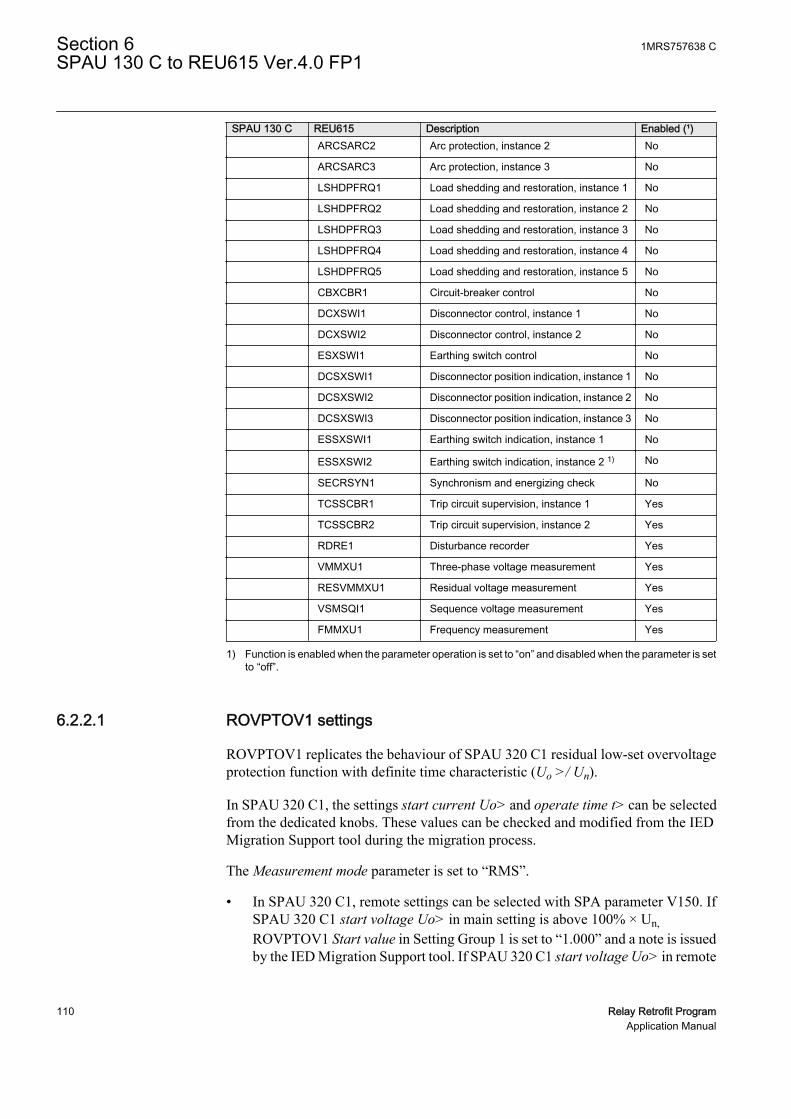
SPAU 130 C REU615 Description Enabled (¹) ARCSARC2 Arc protection, instance 2 No
ARCSARC3 Arc protection, instance 3 No
LSHDPFRQ1 Load shedding and restoration, instance 1 No
LSHDPFRQ2 Load shedding and restoration, instance 2 No
LSHDPFRQ3 Load shedding and restoration, instance 3 No
LSHDPFRQ4 Load shedding and restoration, instance 4 No
LSHDPFRQ5 Load shedding and restoration, instance 5 No
CBXCBR1 Circuit-breaker control No
DCXSWI1 Disconnector control, instance 1 No
DCXSWI2 Disconnector control, instance 2 No
ESXSWI1 Earthing switch control No
DCSXSWI1 Disconnector position indication, instance 1 No
DCSXSWI2 Disconnector position indication, instance 2 No
DCSXSWI3 Disconnector position indication, instance 3 No
ESSXSWI1 Earthing switch indication, instance 1 No
ESSXSWI2 Earthing switch indication, instance 2 1) No
SECRSYN1 Synchronism and energizing check No
TCSSCBR1 Trip circuit supervision, instance 1 Yes
TCSSCBR2 Trip circuit supervision, instance 2 Yes
RDRE1 Disturbance recorder Yes
VMMXU1 Three-phase voltage measurement Yes
RESVMMXU1 Residual voltage measurement Yes
VSMSQI1 Sequence voltage measurement Yes
FMMXU1 Frequency measurement Yes
1) Function is enabled when the parameter operation is set to “on” and disabled when the parameter is setto “off”.
6.2.2.1 ROVPTOV1 settings
ROVPTOV1 replicates the behaviour of SPAU 320 C1 residual low-set overvoltageprotection function with definite time characteristic (Uo >/ Un).
In SPAU 320 C1, the settings start current Uo> and operate time t> can be selectedfrom the dedicated knobs. These values can be checked and modified from the IEDMigration Support tool during the migration process.
The Measurement mode parameter is set to “RMS”.
• In SPAU 320 C1, remote settings can be selected with SPA parameter V150. IfSPAU 320 C1 start voltage Uo> in main setting is above 100% × Un,ROVPTOV1 Start value in Setting Group 1 is set to “1.000” and a note is issuedby the IED Migration Support tool. If SPAU 320 C1 start voltage Uo> in remote
Section 6 1MRS757638 CSPAU 130 C to REU615 Ver.4.0 FP1
110 Relay Retrofit ProgramApplication Manual

setting is above 100% × Un, ROVPTOV1 Start value in Setting Group 2 is set to“1.000” and a note is issued by the IED Migration Support tool.
• If SPAU 320 C1 start voltage Uo> in main setting is below 1% × Un,ROVPTOV1 Start value in Setting Group 1 is set to “0.010” and a note is issuedby the IED Migration Support tool. If SPAU 320 C1 start voltage Uo> in remotesetting is below 1% × Un, ROVPTOV1 Start value in Setting Group 2 is set to“0.010” and a note is issued by the IED Migration Support tool.
• If SPAU 320 C1 operate time t> in main setting is above 300 s, ROVPTOV1Operate delay time in Setting Group 1 is set to “300000 ms” and a note is issuedby the IED Migration Support tool. If SPAU 320 C1 operate time t> in remotesetting is above 300 s, ROVPTOV1 Operate delay time in Setting Group 2 is setto “300000 ms” and a note is issued by the IED Migration Support tool.
• If SPAU 320 C1 operate time t> in main setting is below 0.04 s, ROVPTOV1Operate delay time in Setting Group 1 is set to “40 ms” and a note is issued by theIED Migration Support tool. If SPAU 320 C1 operate time t> in remote settingis below 0.04 s, ROVPTOV1 Operate delay time in Setting Group 2 is set to “40ms” and a note is issued by the IED Migration Support tool.
6.2.2.2 ROVPTOV2 settings
ROVPTOV2 replicates the behaviour of SPAU 320 C1 residual high-set overvoltageprotection function with definite time characteristic (Uo/ >> Un).
In SPAU 320 C1, settings start voltage Uo>> and operate time t>> can be selectedfrom the dedicated knobs. These values can be checked and modified from the IEDMigration Support tool during the migration process.
The Measurement mode parameter is set to “RMS”.
• In SPCU 1C6 module Uo>> stage can be set out of operation by setting the startvoltage Uo>> to infinite (∞or “999”). If the start voltage setting Uo>> differs inmain and remote settings, only the main setting is considered in migration and anote is issued by the IED Migration Support tool.
• If SPAU 320 C1 start voltage Uo>> in main setting is above 100% × Un,ROVPTOV2 Start value in Setting Group 1 is set to “1.000” and a note is issuedby the IED Migration Support tool. If SPAU 320 C1 start voltage Uo>> inremote setting is above 100% × Un, ROVPTOV2 Start value in Setting Group 2is set to “1.000” and a note is issued by the IED Migration Support tool.
• If SPAU 320 C1 start voltage Uo>> in main setting is below 1% × Un,ROVPTOV2 Start value in Setting Group 1 is set to “0.010” and a note is issuedby the IED Migration Support tool. If SPAU 320 C1 start voltage Uo>> inremote setting is below 1% × Un, ROVPTOV2 Start value in Setting Group 2 isset to “0.010” and a note is issued by the IED Migration Support tool.
• If SPAU 320 C1 operate time t>> in main setting is above 300 s, ROVPTOV2Operate delay time in Setting Group 1 is set to “300000 ms” and a note is issuedby the IED Migration Support tool. If SPAU 320 C1 operate time t>> in remote
1MRS757638 C Section 6SPAU 130 C to REU615 Ver.4.0 FP1
Relay Retrofit Program 111Application Manual
setting is above 300 s, ROVPTOV2 Operate delay time in Setting Group 2 is setto “300000 ms” and a note is issued by the IED Migration Support tool.
• If SPAU 320 C1 operate time t>> in main setting is below 0.04 s, ROVPTOV2Operate delay time in Setting Group 1 is set to “40 ms” and a note is issued by theIED Migration Support tool. If SPAU 320 C1 operate time t>> in remote settingis below 0.04 s, ROVPTOV2 Operate delay time in Setting Group 2 is set to “40ms” and a note is issued by the IED Migration Support tool.
6.2.2.3 PHPTUV1 settings
PHPTUV1 replicates the behavior of SPAU 130 C three-phase low-set undervoltageprotection function with definite time characteristic (U</Un).
In SPAU 130 C settings, start voltage U< and operate time t< can be selected from thededicated knobs. These values can be checked and modified from the IED MigrationSupport tool during the migration process. Measurement mode is set to “RMS”.
• The remote settings can be selected with SPA parameter V150. Switch SG1/7defines the U< start delay time. This delay is reproduced on REU615 withTONGAPC1 function. If the position of switch SG1/7 differs in main and remotesettings, only then the position of the main setting is considered in migration anda note is issued by the IED Migration Support tool.
• The switch SG1/6 defines the selection of automatic blocking of U< function. Ifthe position of switch SG1/6 differs in main and remote settings only then themain setting value is considered in migration and a note is issued by the IEDMigration Support tool.
• If start voltage U< in main setting is over 1.2 × Un, PHPTUV start value in settinggroup 1 is set to “1.20” and a note is issued by the IED Migration Support tool. Ifstart voltage U< in remote setting is over 1.2 × Un, PHPTUV start value in settinggroup 2 is set to “1.20” and a note is issued by the IED Migration Support tool.
• If start voltage U< in main setting is below 0.05 × Un, then PHPTUV REU615start value in setting group 1 is set to “0.05” and a note is issued by the IEDMigration Support tool. If start voltage U< in remote setting is below 0.05 × Un,PHPTUV REU615 start value in setting group 2 is set to “0.05” and a note isissued by the IED Migration Support tool.
• If operate time t< in main setting is over 300 s, PHPTUV operate delay time insetting group 1 is set to “300 000 ms” and a note is issued by the IED MigrationSupport tool. If SPAU 130 C operate time t< in remote setting is over 300 s,PHPTUV operate delay time in setting group 2 is set to “300 000 ms” and a noteis issued by the IED Migration Support tool.
• If operate time t< in main setting is below 0.06 s, PHPTUV operate delay time insetting group 1 is set to “60 ms” and a note is issued by the IED Migration Supporttool. If SPAU 130 C operate time t< in remote setting is under 0.06 s, PHPTUVoperate delay time in setting group 2 is set to “60 ms” and a note is issued by theIED Migration Support tool.
Section 6 1MRS757638 CSPAU 130 C to REU615 Ver.4.0 FP1
112 Relay Retrofit ProgramApplication Manual

6.2.2.4 PHPTOV1 settings
PHPTOV1 replicates the behavior of SPAU 130 C three-phase high-set overvoltageprotection function with definite or inverse definite minimum time characteristic (U>/Un).
In SPAU 130 C settings start voltage U> and start time selection of U> are selectedfrom the dedicated knobs. These values can be checked and modified from the IEDMigration Support tool during the migration process.
• The remote settings can be selected with SPA parameter V150. Switch SG1/2defines the U> start time delay. This delay is reproduced on REU615 withTONGAPC1 function. If the position of switch SG1/2 differs in the main andremote settings, only then the position of the main setting is considered inmigration and a note is issued by the IED Migration Support tool.
• If start voltage U> in main setting is over 1.6 × Un, PHPTOV1 start value insetting group 1 is set to “1.60” and a note is issued by the IED Migration Supporttool. If SPAU 130 C start voltage U> in remote setting is over 1.6 × Un,PHPTOV1 start value in setting group 2 is set to “1.60” and a note is issued by theIED Migration Support tool.
• If start voltage U> in main setting is under 0.05 × Un, PHPTOV1 start value insetting group 1 is set to “0.05” and a note is issued by the IED Migration Supporttool. If SPAU 130 C start voltage U> in remote setting is under 0.05 × Un,PHPTOV1 start value in setting group 2 is set to “0.05” and a note is issued by theIED Migration Support tool.
• If operate time t> in main setting is over 300 s, PHPTOV1 operate delay time insetting group 1 is set to “300 000 ms” and a note is issued by the IED MigrationSupport tool. If SPAU 130 C operate time t> in second setting is over 300 s,PHPTOV1 operate delay time in setting group 2 is set to “300 000 ms” and a noteis issued by the IED Migration Support tool.
• If operate time t> in main setting is under 0.04 s, PHPTOV1 operate delay timein setting group 1 is set to “40 ms” and a note is issued by the IED MigrationSupport tool. If SPAU 130 C operate time t> in remote setting is under 0.04 s,PHPTOV1 operate delay time in setting group 2 is set to “40 ms” and a note isissued by the IED Migration Support tool.
• If SPAU 130 C time multiplier k> in main setting is under 0.05, PHPTOV1 timemultiplier in setting group 1 is set to “0.05” and a note is issued by the IEDMigration Support tool. If SPAU 130 C time multiplier k> in remote setting isunder 0.05, PHPTOV1 time multiplier in setting group 2 is set to “0.05” and a noteis issued by the IED Migration Support tool.
• If time multiplier k> in main setting is over 1, PHPTOV1 time multiplier in settinggroup 1 is set to “1” and a note is issued by IED the IED Migration Support tool.If SPAU 130 C time multiplier k> in remote setting is over 1, PHPTOV1 timemultiplier in setting group 2 is set to “1” and a note is issued by the IED MigrationSupport tool.
1MRS757638 C Section 6SPAU 130 C to REU615 Ver.4.0 FP1
Relay Retrofit Program 113Application Manual

6.2.3 I/O connections
I/O connections at SPAU 130 C terminals are remapped to REU615 I/O terminal.
REU615 terminals have additional binary I/Os whose behavior do not depend onSPAU 130 C configuration.
Table 23: Binary inputs
REU615 SPAU 130 C UsageBI1 (X110:1/2) BS (10/11) if SGR/1 = “1” PHPTUV1.BLOCK
BI2 (X110:3/4) - Manual restore group 1 in LSHDPFRQ1
BI3 (X110:5/6) - Manual restore group 2 in LSHDPFRQ2
BI4 (X110:7/6) - Unused
BI5 (X110:8/9) - Voltage transformer truck in indication
BI6 (X110:10/9) - Voltage transformer truck out indication
BI7 (X110:11/12) - Earthing switch closed indication
BI8 (X110:13/12) - Earthing switch open indication
BI1 (X130:1/2) - Unused
BI2 (X130:3/4) - Line voltage transformer MCB open
BI3 (X130:5/6) - Bus voltage transformer MCB open
BI4 (X130:7/8) - Lock-out reset
Table 24: Binary outputs
REU615 SPAU 130 C UsagePO1 (X100:6/7) Trip 2 (68/69) if SGR/8 = “1” PHPTOV1.OPERATE
PHPTUV1.OPERATE
PO2 (X100:8/9) - Unused
SO1(X100:10/11/12)
- PHPTOV1.STARTPHPTUV1.START
SO2(X100:13/14)
- Unused
PO3(X100:16/17)
Trip 1 (65/66) PHPTUV1.OPERATEPHPTOV1.OPERATE
PO4(X100:20/21/22/23/24)
- Master trip 2
SO1(X110:14/16)
Start 1 (77/78) if SGR/3 = “1” PHPTOV1. STARTif SGR/2 = “1” PHPTUV1. STARTif SGR/4 = “1” PHPTUV.OPERATE
Table continues on next page
Section 6 1MRS757638 CSPAU 130 C to REU615 Ver.4.0 FP1
114 Relay Retrofit ProgramApplication Manual
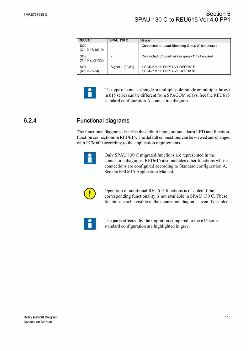
REU615 SPAU 130 C UsageSO2(X110:17/18/19)
- Connected to “Load Shedding Group 2” but unused
SO3(X110:20/21/22)
- Connected to “Load restore group 1” but unused
SO4(X110:23/24)
Signal 1 (80/81) if SGR/5 = “1” PHPTUV1.OPERATEif SGR/7 = “1” PHPTOV1.OPERATE
The type of contacts (single or multiple pole; single or multiple throw)in 615 series can be different from SPACOM relays. See the REU615standard configuration A connection diagram.
6.2.4 Functional diagrams
The functional diagrams describe the default input, output, alarm LED and function-function connections in REU615. The default connections can be viewed and changedwith PCM600 according to the application requirements.
Only SPAU 130 C migrated functions are represented in theconnection diagrams. REU615 also includes other functions whoseconnections are configured according to Standard configuration A.See the REU615 Application Manual.
Operation of additional REU615 functions is disabled if thecorresponding functionality is not available in SPAU 130 C. Thesefunctions can be visible in the connection diagrams even if disabled.
The parts affected by the migration compared to the 615 seriesstandard configuration are highlighted in grey.
1MRS757638 C Section 6SPAU 130 C to REU615 Ver.4.0 FP1
Relay Retrofit Program 115Application Manual
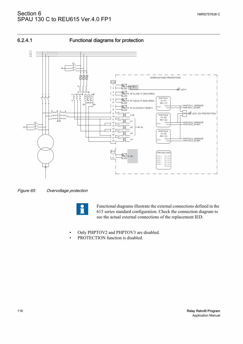
6.2.4.1 Functional diagrams for protection
GUID-A568A82B-6C73-4353-A3D5-DBE499CFEB33 V1 EN
Figure 65: Overvoltage protection
Functional diagrams illustrate the external connections defined in the615 series standard configuration. Check the connection diagram tosee the actual external connections of the replacement IED.
• Only PHPTOV2 and PHPTOV3 are disabled.• PROTECTION function is disabled.
Section 6 1MRS757638 CSPAU 130 C to REU615 Ver.4.0 FP1
116 Relay Retrofit ProgramApplication Manual

GUID-38315ADE-10B1-407E-8CBB-5DD244B2E455 V1 EN
Figure 66: Undervoltaget protection
• Only PHPTUV2 and PHPTUV3 are disabled.
1MRS757638 C Section 6SPAU 130 C to REU615 Ver.4.0 FP1
Relay Retrofit Program 117Application Manual

GUID-E2C390A0-4508-431C-B149-5EA9164742D5 V1 EN
Figure 67: Load-shedding and restoration
• All the five load-shedding and restoration stages are present but all of them aredisabled.
• X110:SO1 and X110:SO4 are used for start and operate signals of overvoltageprotection stages.
Section 6 1MRS757638 CSPAU 130 C to REU615 Ver.4.0 FP1
118 Relay Retrofit ProgramApplication Manual

6.2.4.2 Functional diagrams for control and interlocking
PO2X100 Unused
89
GUID-047EB0C1-8E4C-4154-BB69-5E61A6F79ED8 V1 EN
Figure 68: Master trip
The operate signals from the protections are connected to the two trip output contactsPO3 (X100:15-19) and PO4 (X100:20-24) via the corresponding Master TripsTRPPTRC1 and TRPPTRC2.
• PHPTUV1_OPERATE signal is connected to TRPPTRC1 if SGR/8 is set.• PO2 (X100:8/9) is unused.
1MRS757638 C Section 6SPAU 130 C to REU615 Ver.4.0 FP1
Relay Retrofit Program 119Application Manual

X110
TONGAPC1
PHPTOV1-operate
PHPTOV1-startPHPTUV1-start
PHPTUV1-operate
OR
PHPTUV1-operate
IN1 Q1
Q2IN2
TPGAPC2IN1 OUT1
OUT2IN2
23
24
X10067
X110
14
1615
SO4
OR
SO1
PO1
GUID-E381140D-1FE7-49C6-8475-57AEBE2F0EF4 V1 EN
Figure 69: Alarm indication
The signal outputs from the IED are connected to TPGAPC1 to give dedicatedinformation.
• Start of any protection function SO1 (X100:10/11/12)• Operation (trip) of any protection function SO4 (X110:23/24). This reproduces
SPAU 130 C Signal1 and various voltage protection functions are connected toSO4 depending on the switchgroup condition.
Section 6 1MRS757638 CSPAU 130 C to REU615 Ver.4.0 FP1
120 Relay Retrofit ProgramApplication Manual

• PHPTOV1_OPERATE, if SGR/7 = “1”• PHPTUV1_OPERATE, if SGR/5 = “1”
The signal outputs from the IED are connected to TPGAPC2.
• Operation (trip) and start of PHPTUV1 and start of PHPTOV1 SO1(X110:14-16). This reproduces SPAU 130 C Start1. Thus various voltageprotection functions are connected to SO1 depending on the switchgroupcondition.• PHPTOV1-start, if SGR/3 = “1”• PHPTUV1-start, if SGR/2 = “1”• PHPTUV1-operate, if SGR/4 = “1”
• Operation (trip) of PHPTUV1 and PHPTOV1 PO1 (X100: 6-7). This reproducesSPAU 130 C Trip2. Operate signal of PHPTOV1 is connected to PO1 if SGR/8= “1”.
6.2.4.3 Setting groups
SPAU 130 C supports main and remote settings which are migrated to setting groups1 and 2 in REU615.
Changing setting groups from binary input is not supported by SPAU 130 C. Thisoption is not configured on REU615. Setting groups can be changed only from HMI.
6.3 Installation
6.3.1 Mounting
The 615 series IED can be mounted on the switchgear door using the hole left by theSPACOM series relay.
1. Widen the original SPACOM relay hole.1.1. Use cutting tool with dedicated cutting head for SPACOM 100/300 series
to get the appropriate cut-out on the switchgear door hosting REF615 IED.1.2. Widen the cut-out to whichever of the four directions as per the existing
installation requirement.
1MRS757638 C Section 6SPAU 130 C to REU615 Ver.4.0 FP1
Relay Retrofit Program 121Application Manual

615 seriesA
B
C D
SPA 100 series
GUID-46C4FA59-4D66-4CD0-8CAB-AD8A0D3977DE V1 EN
Figure 70: SPACOM 100 series and 615 series cut-outs
A 165.5 mm
B 129 mm
C 139 mm
D 161.5 mm
2. Mount the 615 series IED's case and insert the plug-in unit.
Cover plate is not required with the SPACOM 100 series.
See the 615 series installation manual for more information.
Section 6 1MRS757638 CSPAU 130 C to REU615 Ver.4.0 FP1
122 Relay Retrofit ProgramApplication Manual

6.3.2 Connecting
• If the existing wiring is in good condition and still usable, use the dedicatedmarking sets.
• If the existing wiring has to be replaced, use the dedicated wiring harness.
6.3.2.1 Wiring harness and wire markings
Wiring harness is available for retrofitting SPAU 130 C with REU615.
Table 25: REU615 wiring harness description for retrofit of SPAU 130 C
REU615, configuration A SPAU 130 C WiringTerminal Description Terminal Description MarkingX100:1 Uaux+ 61 Uaux+ X100:1 (61)
X100:2 Uaux- 62 Uaux- X100:2 (62)
X100:3 IRF 72 IRF X100:3 (72)
X100:4 IRF 71 IRF X100:4 (71)
X100:5 IRF 70 IRF X100:5 (70)
X100:6 PO1 68 TRIP2 X100:6 (68)
X100:7 PO1 69 TRIP2 X100:7 (69)
X100:8 PO2 - - X100:8
X100:9 PO2 - - X100:9
X100:10 SO1 - - X100:10
X100:11 SO1 - - X100:11
X100:12 SO1 - - X100:12
X100:13 SO2 - - X100:13.
X100:14 SO2 - - X100:14
X100:15 PO3 - - X100:15
X100:16 PO3 65 TRIP1 X100:16 (65)
X100:17 PO3 66 TRIP1 X100:17 (66)
X100:18 PO3 - - X100:18
X100:19 PO3 - - X100:19
X100:20 PO4 - - X100:20
X100:21 PO4 - - X100:21
X100:22 PO4 - - X100:22
X100:23 PO4 - - X100:23
X100:24 PO4 - - X100:24
X110:1 BI1 10 BS1 X130:1 (10)
X110:2 BI1 11 BS1 X130:2 (11)
X110:3 BI2 - - X110:3
X110:4 BI2 - - X110:4
X110:5 BI3 - - X110:5
Table continues on next page
1MRS757638 C Section 6SPAU 130 C to REU615 Ver.4.0 FP1
Relay Retrofit Program 123Application Manual

REU615, configuration A SPAU 130 C WiringTerminal Description Terminal Description MarkingX110:6 BI3,4 - - X110:6
X110:7 BI4 - - X110:7
X110:8 BI5 - - X110:8
X110:9 BI5, 6 - - X110:9
X110:10 BI6 - - X110:10
X110:11 BI7 - - X110:11
X110:12 BI7, 8 - - X110:12
X110:13 BI8 - - X110:13
X110:14 SO1 78 START1 X110:14 (78)
X110:15 SO1 - - X110:15
X110:16 SO1 77 START1 X110:16 (77)
X110:17 SO2 - - X110:17
X110:18 SO2 - - X110:18
X110:19 SO2 - - X110:19
X110:20 SO3 - - X110:20
X110:21 SO3 - - X110:21
X110:22 SO3 - - X110:22
X110:23 SO4 81 SIGNAL1 X110:23 (81)
X110:24 SO4 80 SIGNAL1 X110:24 (80)
X130:1 BI1 - - X130:1
X130:2 BI1 - - X130:2
X130:3 BI2 - - X130:3
X130:4 BI2 - - X130:4
X130:5 BI3 - - X130:5
X130:6 BI3 - - X130:6
X130:7 BI4 - - X130:7
X130:8 BI4 - - X130:8
X130:9 U12B - - X130:9
X130:10 U12B - - X130:10
X130:11 U1 14/15 U12, 100V/110V X130:11 (14/15)
X130:12 U1 13 U12 X130:12 (13)
X130:13 U2 17/18 U23, 100V/110V X130:13 (17/18)
X130:14 U2 16 U23 X130:14 (16)
X130:15 U3 20/21 U31, 100V/110V X130:15 (20/21)
X130:16 U3 19 U31 X130:16 (19)
X130:17 Uo - - X130:17
X130:18 Uo - - X130:18
Earth 63 Earth Earth
Section 6 1MRS757638 CSPAU 130 C to REU615 Ver.4.0 FP1
124 Relay Retrofit ProgramApplication Manual

6.3.2.2 SPAU 130 C terminal layout and connection diagrams
Mad
e in
Fin
land
13
14
15
16
17
18
19
20
21
70
71
72
61
62
65
66
68
69
80
81
77
78
10
11
TTLB
4707
01Rx
Tx
GUID-4E084952-717E-448D-833F-A8C8F59A8ED3 V1 EN
Figure 71: Terminal layout for SPAU 130 C
1MRS757638 C Section 6SPAU 130 C to REU615 Ver.4.0 FP1
Relay Retrofit Program 125Application Manual

�
SGR/1
U2
U3
U3 1 1 1 1
D C B A
+ -
Uaux
E
+-
(~)(~)
L1L2L3
A
N
a
SGR
100V110V
19 20 21 10 11 61 62 70 71 72 77 78 80 81 68 69 65 66
7 53 2 4 68
SPAU 130 C
_
SPA-ZC
_
Rx Tx
START1 SIGNAL1 TRIP2 TRIP1BS IRF
100V110V
16 1718
100V110V
1314 15
IRF
3U< TS2
TS1
SGB/5
SS1
SS2
U1 I/O
t<
t>,k>3U>
SERIALPORT
n
GUID-C750ECDC-DA95-44E8-A179-C65D6B5A9D99 V1 EN
Figure 72: Connection diagram for SPAU 130 C
Section 6 1MRS757638 CSPAU 130 C to REU615 Ver.4.0 FP1
126 Relay Retrofit ProgramApplication Manual

6.3.2.3 REU615 terminal layout and connection diagrams
GUID-CCFA401F-C098-432F-9D37-B2F81754E4D4 V1 EN
Figure 73: Terminal layout for the 615 series IEDs
1MRS757638 C Section 6SPAU 130 C to REU615 Ver.4.0 FP1
Relay Retrofit Program 127Application Manual

REU615
X13Light sensor input 1 1)
X14Light sensor input 2 1)
X15Light sensor input 3 1)
16
17
1918
X100
67
89
10
111213
15
14
2
1
3
45
22
212324
SO2
TCS2
PO4
SO1
TCS1
PO3
PO2
PO1
IRF
+
-Uaux
20
L1L2L3
X110
34
56
7
89
10BI 6
BI 5
BI 4
BI 3
BI 2
BI 8
BI 712
13
11
BI 112
X110
16
14
15
19
17
18
22
20
21
SO3
SO2
SO1
23SO4
24
a
nN
A
1) Optional
X13012
34
56
BI 4
BI 3
BI 2
BI 1
87
9101112
U12B
1314
U1
1516
U2
1718
U3
UoN
N
N
N
60 -
N
210V
60 -210V
60 -210V
60 -210V
60 -210V
Uaux
IRF
TRIP 2
TRIP 1
START 1
SIGNAL 1
EXTERNALCONTROL
GUID-ACC44E9B-5E77-4552-869D-2A37397FAFC9 V1 EN
Figure 74: Connection diagram for REU615 with standard configuration Areplacing SPAU 130 C
Section 6 1MRS757638 CSPAU 130 C to REU615 Ver.4.0 FP1
128 Relay Retrofit ProgramApplication Manual

Section 7 SPAU 320 C1 to REU615 Ver.4.0 FP1
7.1 Retrofit scope
Protection functions of SPAU 320 C1 are replicated by REU615 with a deviation.
• SPAU 320 C1 unit SPCU 1C6 can be programmed with a latching feature for thetripping signal with switch SG1/4. This feature is not migrated to REU615.
7.2 Engineering
In retrofit applications, the target of the configuration phase is to parameterize andconfigure the replacement IED to reproduce the features and functions of the existingrelay. The configuration process comprises of various steps with different toolsdepending on the project.
CAP505
• Reading the configuration from the SPACOM relay or manually enteringparameter values.
In CAP505 tool, the actual values read from the SPACOM relay arecalled present values. The manually entered values are called newvalues. After relay writing and reading operations present and newvalues become identical.
PCM600
• Instantiating a new retrofit IED (IED Migration Support tool from PCM600).• Selecting the replacement IED (type and order code)• Importing existing relay configuration (.rdb file)• Selecting the set of values to use using the IED Migration Support tool, if
the Present and New values differ in .rdb file• Entering system parameters
• Creating a 615 series IED under PCM600 plant structure using the IED MigrationSupport tool.
• Writing configuration to the IED.
Project specific additional engineering phases
1MRS757638 C Section 7SPAU 320 C1 to REU615 Ver.4.0 FP1
Relay Retrofit Program 129Application Manual

• Using Application Configuration tool in PCM600 to add functionality to themigrated configuration, if required.
• Communication engineering with relevant PCM600 tools, if required.
No engineering activity is required for wiring as marking sets and wiring harness areavailable.
7.2.1 Existing relay and system engineering information
The configuration of the SPACOM relay can be retrieved via the serial connectionusing CAP 505 tool. Parameters are read from the display of the SPACOM relay andmanually inserted in CAP 505. The configuration parameters are exported from CAP505 in .rdb file format and imported in PCM600 during the migration process.
Various system parameters are collected and imported to PCM600 upon requestduring the migration process.
• Rated frequency of the network (50 or 60 Hz)• Secondary rated voltage (100 or 110 V)• Primary rated voltage (0.100…440.000 kV)• Secondary rated residual voltage (100 or 110 V)• Primary rated residual voltage (0.100…440.000 kV)
7.2.2 Functions
The configuration of REU615 migrated from SPAU 320 C1 contains all the functionsof Standard configuration A, but only the functions that reproduce the behaviour of theexisting relay configurations are enabled.
On SPAU 320 C1, there are three types of selector switchgroups, SGR to configure theoutput relays, SGB to configure the blocking signal and SG1 to define additionalfunctions as operating time setting ranges and start delay. The switchgroup SGR islocated at the front panel of the output relay module. The circuit boards of the relaymodules SPCU1C1 and SPCU 1C6 contains the programming switchgroup SGB.SG1 is located on the front panels of the relay modules. The positions of the switchescan be read and reported to the IED Migration Support tool during the migrationprocess. These settings are considered when REU615 configuration is generated.
Table 26: Functions included in configuration
SPAU 320 C1 REU615 Description Enabled 1)
Uo>/Un ROVPTOV1 Residual overvoltage protection, instance 1 Yes
Uo>>/Un ROVPTOV2 Residual overvoltage protection, instance 2 Yes
ROVPTOV3 Residual overvoltage protection, instance 3 No
U</UnPHPTUV1
Three-phase undervoltage protection,instance 1
Yes
Table continues on next page
Section 7 1MRS757638 CSPAU 320 C1 to REU615 Ver.4.0 FP1
130 Relay Retrofit ProgramApplication Manual

SPAU 320 C1 REU615 Description Enabled 1)
PHPTUV2
Three-phase undervoltage protection,instance 2
No
PHPTUV3
Three-phase undervoltage protection,instance 3
No
U>/UnPHPTOV1
Three-phase overvoltage protection,instance 1
Yes
PHPTOV2
Three-phase overvoltage protection,instance 2
No
PHPTOV3
Three-phase overvoltage protection,instance 3
No
PSPTUV1
Positive-sequence undervoltage protection,instance 1
No
PSPTUV2
Positive-sequence undervoltage protection,instance 2
No
NSPTOV1
Negative-sequence overvoltage protection,instance 1
No
NSPTOV2
Negative-sequence overvoltage protection,instance 2
No
FRPFRQ1 Frequency protection, instance 1 No
FRPFRQ2 Frequency protection, instance 2 No
FRPFRQ3 Frequency protection, instance 3 No
FRPFRQ4 Frequency protection, instance 4 No
FRPFRQ5 Frequency protection, instance 5 No
FRPFRQ6 Frequency protection, instance 6 No
TRPPTRC1 Master trip, instance 1 Yes
TRPPTRC2 Master trip, instance 2 Yes
ARCSARC1 Arc protection, instance 1 No
ARCSARC2 Arc protection, instance 2 No
ARCSARC3 Arc protection, instance 3 No
LSHDPFRQ1 Load shedding and restoration, instance 1 No
LSHDPFRQ2 Load shedding and restoration, instance 2 No
LSHDPFRQ3 Load shedding and restoration, instance 3 No
LSHDPFRQ4 Load shedding and restoration, instance 4 No
LSHDPFRQ5 Load shedding and restoration, instance 5 No
CBXCBR1 Circuit-breaker control No
DCXSWI1 Disconnector control, instance 1 No
DCXSWI2 Disconnector control, instance 2 No
ESXSWI1 Earthing switch control No
DCSXSWI1 Disconnector position indication, instance 1 No
DCSXSWI2 Disconnector position indication, instance 2 No
DCSXSWI3 Disconnector position indication, instance 3 No
ESSXSWI1 Earthing switch indication, instance 1 No
Table continues on next page
1MRS757638 C Section 7SPAU 320 C1 to REU615 Ver.4.0 FP1
Relay Retrofit Program 131Application Manual
SPAU 320 C1 REU615 Description Enabled 1)
ESSXSWI2 Earthing switch indication, instance 2 No
SECRSYN1 Synchronism and energizing check No
TCSSCBR1 Trip circuit supervision, instance 1 Yes
TCSSCBR2 Trip circuit supervision, instance 2 Yes
RDRE1 Disturbance recorder Yes
VMMXU1 Three-phase voltage measurement Yes
RESVMMXU1 Residual voltage measurement Yes
VSMSQI1 Sequence voltage measurement Yes
FMMXU1 Frequency measurement Yes
1) The function is enabled when the parameter Operation is set to “on” and disabled when the parameteris set to “off”
7.2.2.1 ROVPTOV1 settings
ROVPTOV1 replicates the behaviour of SPAU 320 C1 residual low-set overvoltageprotection function with definite time characteristic (Uo >/ Un).
In SPAU 320 C1, the settings start current Uo> and operate time t> can be selectedfrom the dedicated knobs. These values can be checked and modified from the IEDMigration Support tool during the migration process.
The Measurement mode parameter is set to “RMS”.
• In SPAU 320 C1, remote settings can be selected with SPA parameter V150. IfSPAU 320 C1 start voltage Uo> in main setting is above 100% × Un,ROVPTOV1 Start value in Setting Group 1 is set to “1.000” and a note is issuedby the IED Migration Support tool. If SPAU 320 C1 start voltage Uo> in remotesetting is above 100% × Un, ROVPTOV1 Start value in Setting Group 2 is set to“1.000” and a note is issued by the IED Migration Support tool.
• If SPAU 320 C1 start voltage Uo> in main setting is below 1% × Un,ROVPTOV1 Start value in Setting Group 1 is set to “0.010” and a note is issuedby the IED Migration Support tool. If SPAU 320 C1 start voltage Uo> in remotesetting is below 1% × Un, ROVPTOV1 Start value in Setting Group 2 is set to“0.010” and a note is issued by the IED Migration Support tool.
• If SPAU 320 C1 operate time t> in main setting is above 300 s, ROVPTOV1Operate delay time in Setting Group 1 is set to “300000 ms” and a note is issuedby the IED Migration Support tool. If SPAU 320 C1 operate time t> in remotesetting is above 300 s, ROVPTOV1 Operate delay time in Setting Group 2 is setto “300000 ms” and a note is issued by the IED Migration Support tool.
• If SPAU 320 C1 operate time t> in main setting is below 0.04 s, ROVPTOV1Operate delay time in Setting Group 1 is set to “40 ms” and a note is issued by theIED Migration Support tool. If SPAU 320 C1 operate time t> in remote settingis below 0.04 s, ROVPTOV1 Operate delay time in Setting Group 2 is set to “40ms” and a note is issued by the IED Migration Support tool.
Section 7 1MRS757638 CSPAU 320 C1 to REU615 Ver.4.0 FP1
132 Relay Retrofit ProgramApplication Manual

7.2.2.2 ROVPTOV2 settings
ROVPTOV2 replicates the behaviour of SPAU 320 C1 residual high-set overvoltageprotection function with definite time characteristic (Uo/ >> Un).
In SPAU 320 C1, settings start voltage Uo>> and operate time t>> can be selectedfrom the dedicated knobs. These values can be checked and modified from the IEDMigration Support tool during the migration process.
The Measurement mode parameter is set to “RMS”.
• In SPCU 1C6 module Uo>> stage can be set out of operation by setting the startvoltage Uo>> to infinite (∞or “999”). If the start voltage setting Uo>> differs inmain and remote settings, only the main setting is considered in migration and anote is issued by the IED Migration Support tool.
• If SPAU 320 C1 start voltage Uo>> in main setting is above 100% × Un,ROVPTOV2 Start value in Setting Group 1 is set to “1.000” and a note is issuedby the IED Migration Support tool. If SPAU 320 C1 start voltage Uo>> inremote setting is above 100% × Un, ROVPTOV2 Start value in Setting Group 2is set to “1.000” and a note is issued by the IED Migration Support tool.
• If SPAU 320 C1 start voltage Uo>> in main setting is below 1% × Un,ROVPTOV2 Start value in Setting Group 1 is set to “0.010” and a note is issuedby the IED Migration Support tool. If SPAU 320 C1 start voltage Uo>> inremote setting is below 1% × Un, ROVPTOV2 Start value in Setting Group 2 isset to “0.010” and a note is issued by the IED Migration Support tool.
• If SPAU 320 C1 operate time t>> in main setting is above 300 s, ROVPTOV2Operate delay time in Setting Group 1 is set to “300000 ms” and a note is issuedby the IED Migration Support tool. If SPAU 320 C1 operate time t>> in remotesetting is above 300 s, ROVPTOV2 Operate delay time in Setting Group 2 is setto “300000 ms” and a note is issued by the IED Migration Support tool.
• If SPAU 320 C1 operate time t>> in main setting is below 0.04 s, ROVPTOV2Operate delay time in Setting Group 1 is set to “40 ms” and a note is issued by theIED Migration Support tool. If SPAU 320 C1 operate time t>> in remote settingis below 0.04 s, ROVPTOV2 Operate delay time in Setting Group 2 is set to “40ms” and a note is issued by the IED Migration Support tool.
7.2.2.3 PHPTUV1 settings
PHPTUV1 replicates the behaviour of SPAU 320 C1 single-phase low-setundervoltage protection function with definite (DT) or inverse definite minimum time(IDMT) characteristic (U </ Un).
In SPAU 320 C1, the settings start voltage U< and operate time t< can be selectedfrom the dedicated knobs. These values can be checked and modified from the IEDMigration Support tool during the migration process.
The Measurement mode parameter is set to “RMS”.
1MRS757638 C Section 7SPAU 320 C1 to REU615 Ver.4.0 FP1
Relay Retrofit Program 133Application Manual
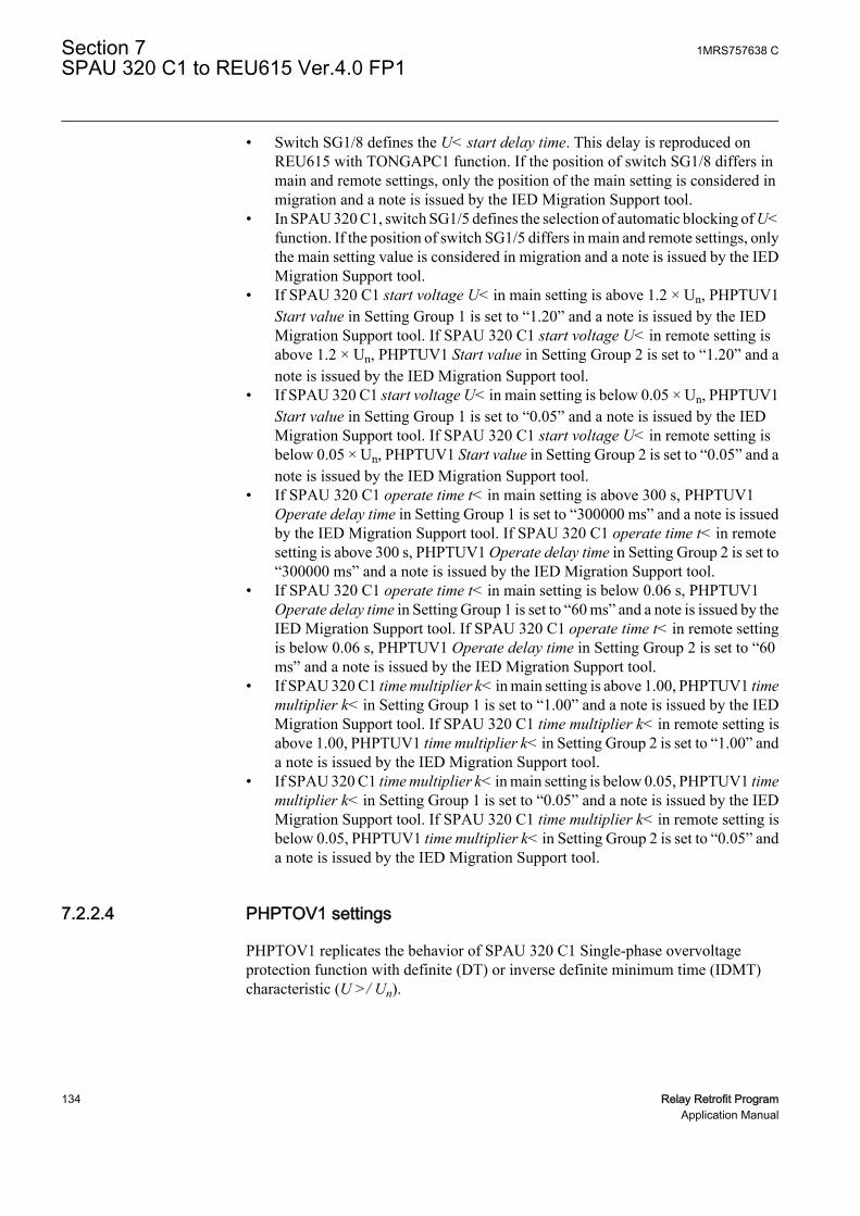
• Switch SG1/8 defines the U< start delay time. This delay is reproduced onREU615 with TONGAPC1 function. If the position of switch SG1/8 differs inmain and remote settings, only the position of the main setting is considered inmigration and a note is issued by the IED Migration Support tool.
• In SPAU 320 C1, switch SG1/5 defines the selection of automatic blocking of U<function. If the position of switch SG1/5 differs in main and remote settings, onlythe main setting value is considered in migration and a note is issued by the IEDMigration Support tool.
• If SPAU 320 C1 start voltage U< in main setting is above 1.2 × Un, PHPTUV1Start value in Setting Group 1 is set to “1.20” and a note is issued by the IEDMigration Support tool. If SPAU 320 C1 start voltage U< in remote setting isabove 1.2 × Un, PHPTUV1 Start value in Setting Group 2 is set to “1.20” and anote is issued by the IED Migration Support tool.
• If SPAU 320 C1 start voltage U< in main setting is below 0.05 × Un, PHPTUV1Start value in Setting Group 1 is set to “0.05” and a note is issued by the IEDMigration Support tool. If SPAU 320 C1 start voltage U< in remote setting isbelow 0.05 × Un, PHPTUV1 Start value in Setting Group 2 is set to “0.05” and anote is issued by the IED Migration Support tool.
• If SPAU 320 C1 operate time t< in main setting is above 300 s, PHPTUV1Operate delay time in Setting Group 1 is set to “300000 ms” and a note is issuedby the IED Migration Support tool. If SPAU 320 C1 operate time t< in remotesetting is above 300 s, PHPTUV1 Operate delay time in Setting Group 2 is set to“300000 ms” and a note is issued by the IED Migration Support tool.
• If SPAU 320 C1 operate time t< in main setting is below 0.06 s, PHPTUV1Operate delay time in Setting Group 1 is set to “60 ms” and a note is issued by theIED Migration Support tool. If SPAU 320 C1 operate time t< in remote settingis below 0.06 s, PHPTUV1 Operate delay time in Setting Group 2 is set to “60ms” and a note is issued by the IED Migration Support tool.
• If SPAU 320 C1 time multiplier k< in main setting is above 1.00, PHPTUV1 timemultiplier k< in Setting Group 1 is set to “1.00” and a note is issued by the IEDMigration Support tool. If SPAU 320 C1 time multiplier k< in remote setting isabove 1.00, PHPTUV1 time multiplier k< in Setting Group 2 is set to “1.00” anda note is issued by the IED Migration Support tool.
• If SPAU 320 C1 time multiplier k< in main setting is below 0.05, PHPTUV1 timemultiplier k< in Setting Group 1 is set to “0.05” and a note is issued by the IEDMigration Support tool. If SPAU 320 C1 time multiplier k< in remote setting isbelow 0.05, PHPTUV1 time multiplier k< in Setting Group 2 is set to “0.05” anda note is issued by the IED Migration Support tool.
7.2.2.4 PHPTOV1 settings
PHPTOV1 replicates the behavior of SPAU 320 C1 Single-phase overvoltageprotection function with definite (DT) or inverse definite minimum time (IDMT)characteristic (U >/ Un).
Section 7 1MRS757638 CSPAU 320 C1 to REU615 Ver.4.0 FP1
134 Relay Retrofit ProgramApplication Manual

In SPAU 320 C1, the settings start voltage U> and operate time t> are selected fromthe dedicated knobs. These values can be checked and modified from the IEDMigration Support tool during the migration process.
• Switch SG1/2 defines the U> start time delay. This delay is reproduced onREU615 with TONGAPC1 function. If the position of switch SG1/2 differs inmain and remote settings, only the position of the main setting is considered inmigration and a note is issued by the IED Migration Support tool.
• If SPAU 320 C1 start voltage U> in main setting is above 1.6 × Un, PHPTOV1Start value in Setting Group 1 is set to “1.60” and a note is issued by the IEDMigration Support tool. If SPAU 320 C1 start voltage U> in remote setting isabove 1.6 × Un, PHPTOV1 Start value in Setting Group 2 is set to “1.60” and anote is issued by the IED Migration Support tool.
• If SPAU 320 C1 start voltage U> in main setting is below 0.05 × Un, PHPTOV1Start value in Setting Group 1 is set to “0.05” and a note is issued by the IEDMigration Support tool. If SPAU 320 C1 start voltage U> in remote setting isbelow 0.05 × Un, PHPTOV1 Start value in Setting Group 2 is set to “0.05” and anote is issued by the IED Migration Support tool.
• If SPAU 320 C1 operate time t> in main setting is above 300 s, PHPTOV1Operate delay time in Setting Group 1 is set to “300000 ms” and a note is issuedby the IED Migration Support tool. If SPAU 320 C1 operate time t> in remotesetting is above 300 s, PHPTOV1 Operate delay time in Setting Group 2 is set to“300000 ms” and a note is issued by the IED Migration Support tool.
• If SPAU 320 C1 operate time t> in main setting is below 0.04 s, PHPTOV1Operate delay time in Setting Group 1 is set to “40 ms” and a note is issued by theIED Migration Support tool. If SPAU 320 C1 operate time t> in remote settingis below 0.04 s, PHPTOV1 Operate delay time in Setting Group 2 is set to “40ms” and a note is issued by the IED Migration Support tool.
• If SPAU 320 C1 time multiplier k> in main setting is above 1, PHPTOV1 Timemultiplier in Setting Group 1 is set to “1.00” and a note is issued by the IEDMigration Support tool. If SPAU 320 C1 time multiplier k> in remote setting isabove 1, PHPTOV1 Time multiplier in Setting Group 2 is set to “1.00” and a noteis issued by the IED Migration Support tool.
• If SPAU 320 C1 time multiplier k> in main setting is below 0.05, PHPTOV1Time multiplier in Setting Group 1 is set to “0.05” and a note is issued by the IEDMigration Support tool. If SPAU 320 C1 time multiplier k> in remote setting isbelow 0.05, PHPTOV1 Time multiplier in Setting Group 2 is set to “0.05” and anote is issued by the IED Migration Support tool.
7.2.3 I/O connections
I/O connections at SPAU 320 C1 terminals are re-mapped to REU615 I/O terminal.
REU615 terminals have additional binary I/Os whose behaviour does not depend onSPAU 320 C1 configuration.
1MRS757638 C Section 7SPAU 320 C1 to REU615 Ver.4.0 FP1
Relay Retrofit Program 135Application Manual

Table 27: Binary inputs
REU615 signalname (terminal)
SPAU 320 C1signal name(terminal)
Usage
BI1 (X110:1/2) BS (10/11) if (unit 1) SGB/4 = “1” ROVPTOV1.BLOCK
if (unit 1) SGB/5 = “1” ROVPTOV2.BLOCK
if (unit 2) SGB/5 = “1” PHPTUV1.BLOCK
BI2 (X110:3/4) - Manual restore group 1 in LSHDPFRQ1
BI3 (X110:5/6) - Manual restore group 2 in LSHDPFRQ2
BI4 (X110:7/6) - Unused
BI5 (X110:8/9) - Voltage transformer truck in indication
BI6 (X110:10/9) - Voltage transformer truck out indication
BI7 (X110:11/12) - Earthing switch closed indication
BI8 (X110:13/12) - Earthing switch open indication
BI1 (X130:1/2) - Unused
BI2 (X130:3/4) - Line voltage transformer MCB open
BI3 (X130:5/6) - Bus voltage transformer MCB open
BI4 (X130:7/8) - Lockout reset
Table 28: Binary outputs
REU615 signalname (terminal)
SPAU 320 C1signal name(terminal)
Usage
PO1 (X100:6/7) Output relay B(67/68/69)
if SGR/5 = “1” PHPTOV1.OPERATE
if SGR/6 = “1” PHPTUV1.OPERATE
ROVPTOV2.OPERATE
PO2 (X100:8/9) Output relay E(79/80/81)
ROVPTOV1.OPERATE
SO1(X100:10/11/12)
- PHPTOV1.START
PHPTUV1.START
ROVPTOV1.START
ROVPTOV2.START
SO2(X100:13/14)
- Unused
PO3(X100:16/17)
Output relay A(65/66)
if SGR/3 = “1” ROVPTOV1.OPERATE
if SGR/4 = “1“ ROVPTOV2.OPERATE
if SGR/1 = “1” PHPTOV1.OPERATE
if SGR/2 = “1” PHPTUV1.OPERATE
PO4(X100:20/21/22/23/24)
- Master trip 2
Table continues on next page
Section 7 1MRS757638 CSPAU 320 C1 to REU615 Ver.4.0 FP1
136 Relay Retrofit ProgramApplication Manual
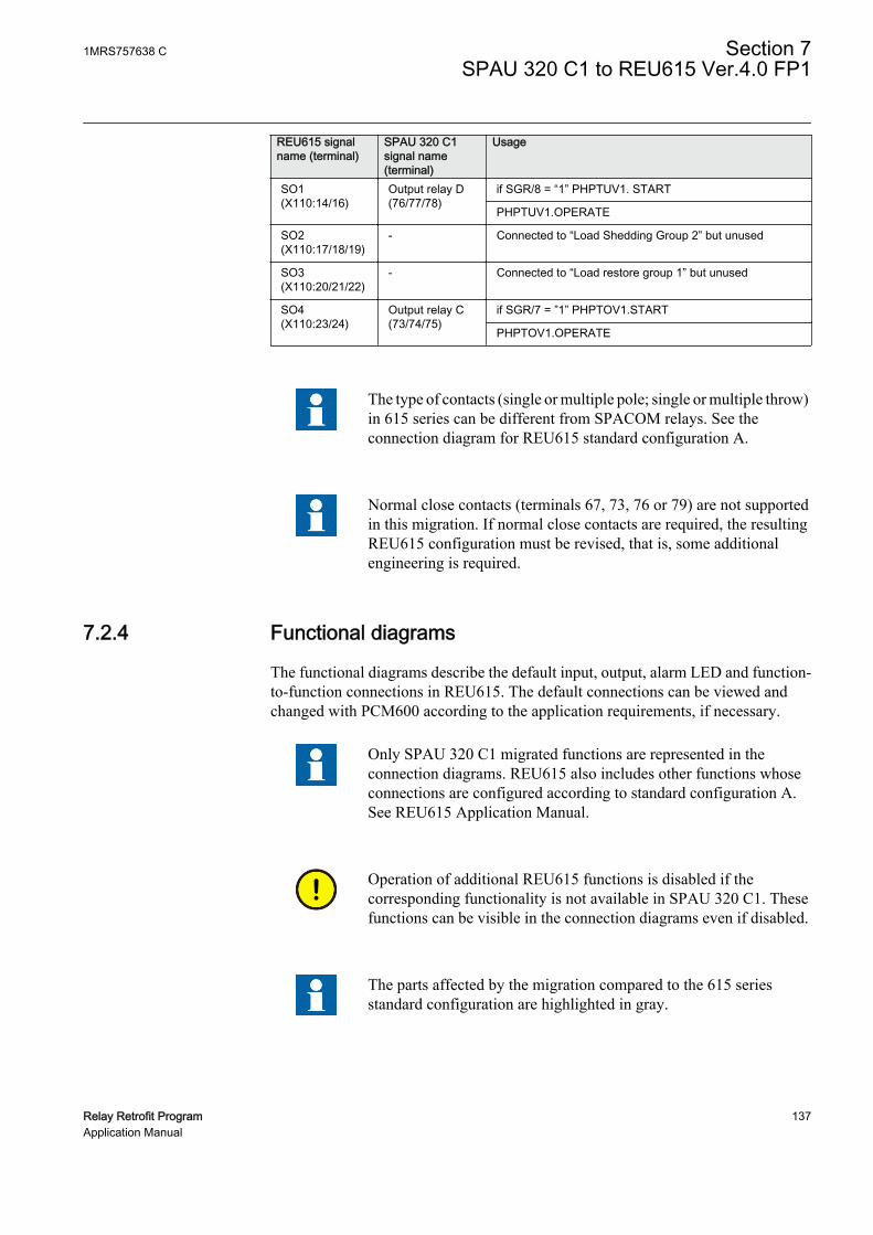
REU615 signalname (terminal)
SPAU 320 C1signal name(terminal)
Usage
SO1(X110:14/16)
Output relay D(76/77/78)
if SGR/8 = “1” PHPTUV1. START
PHPTUV1.OPERATE
SO2(X110:17/18/19)
- Connected to “Load Shedding Group 2” but unused
SO3(X110:20/21/22)
- Connected to “Load restore group 1” but unused
SO4(X110:23/24)
Output relay C(73/74/75)
if SGR/7 = ”1” PHPTOV1.START
PHPTOV1.OPERATE
The type of contacts (single or multiple pole; single or multiple throw)in 615 series can be different from SPACOM relays. See theconnection diagram for REU615 standard configuration A.
Normal close contacts (terminals 67, 73, 76 or 79) are not supportedin this migration. If normal close contacts are required, the resultingREU615 configuration must be revised, that is, some additionalengineering is required.
7.2.4 Functional diagrams
The functional diagrams describe the default input, output, alarm LED and function-to-function connections in REU615. The default connections can be viewed andchanged with PCM600 according to the application requirements, if necessary.
Only SPAU 320 C1 migrated functions are represented in theconnection diagrams. REU615 also includes other functions whoseconnections are configured according to standard configuration A.See REU615 Application Manual.
Operation of additional REU615 functions is disabled if thecorresponding functionality is not available in SPAU 320 C1. Thesefunctions can be visible in the connection diagrams even if disabled.
The parts affected by the migration compared to the 615 seriesstandard configuration are highlighted in gray.
1MRS757638 C Section 7SPAU 320 C1 to REU615 Ver.4.0 FP1
Relay Retrofit Program 137Application Manual
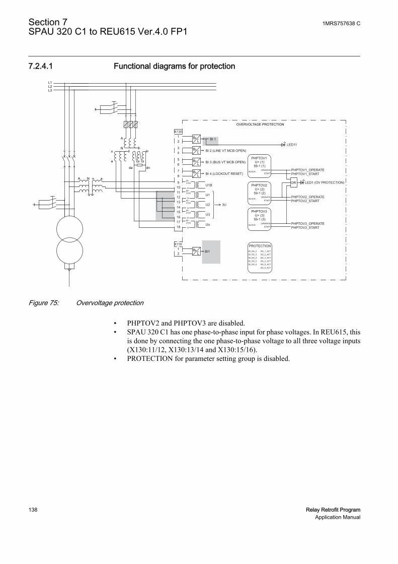
7.2.4.1 Functional diagrams for protection
L1L2L3
OVERVOLTAGE PROTECTION
BI1
X130
BI 1A
Nn
a
A N an
da dn
BI 2 (LINE VT MCB OPEN)
BI 3 (BUS VT MCB OPEN)
BI 4 (LOCKOUT RESET)
U1B
U1
U2
U3
Uo
3U
X110
PHPTOV1U> (1)
59-1 (1)
PHPTOV2U> (2)
59-1 (2)
PHPTOV3U> (3)
59-1 (3)
PHPTOV1_STARTPHPTOV1_OPERATE
OR LED1 (OV PROTECTION)
PHPTOV2_STARTPHPTOV2_OPERATE
PHPTOV3_STARTPHPTOV3_OPERATE
PROTECTION
LED11
OPERATESTART
BLOCK
OPERATESTART
BLOCK
OPERATESTART
BLOCK
BI_SG_2BI_SG_3BI_SG_4BI_SG_5BI_SG_6
SG_1_ACTSG_2_ACTSG_3_ACTSG_4_ACTSG_5_ACTSG_6_ACT
60 -210V
60 -210V
60 -210V
60 -210V
60 -210V
N
N
N
N
N
12
34
56
78
9101112131415161718
12
GUID-52FD0FD6-659F-4F70-AAD8-EE6288DF999E V1 EN
Figure 75: Overvoltage protection
• PHPTOV2 and PHPTOV3 are disabled.• SPAU 320 C1 has one phase-to-phase input for phase voltages. In REU615, this
is done by connecting the one phase-to-phase voltage to all three voltage inputs(X130:11/12, X130:13/14 and X130:15/16).
• PROTECTION for parameter setting group is disabled.
Section 7 1MRS757638 CSPAU 320 C1 to REU615 Ver.4.0 FP1
138 Relay Retrofit ProgramApplication Manual

GUID-38315ADE-10B1-407E-8CBB-5DD244B2E455 V1 EN
Figure 76: Undervoltage protection
• PHPTUV2 and PHPTUV3 are disabled.
1MRS757638 C Section 7SPAU 320 C1 to REU615 Ver.4.0 FP1
Relay Retrofit Program 139Application Manual
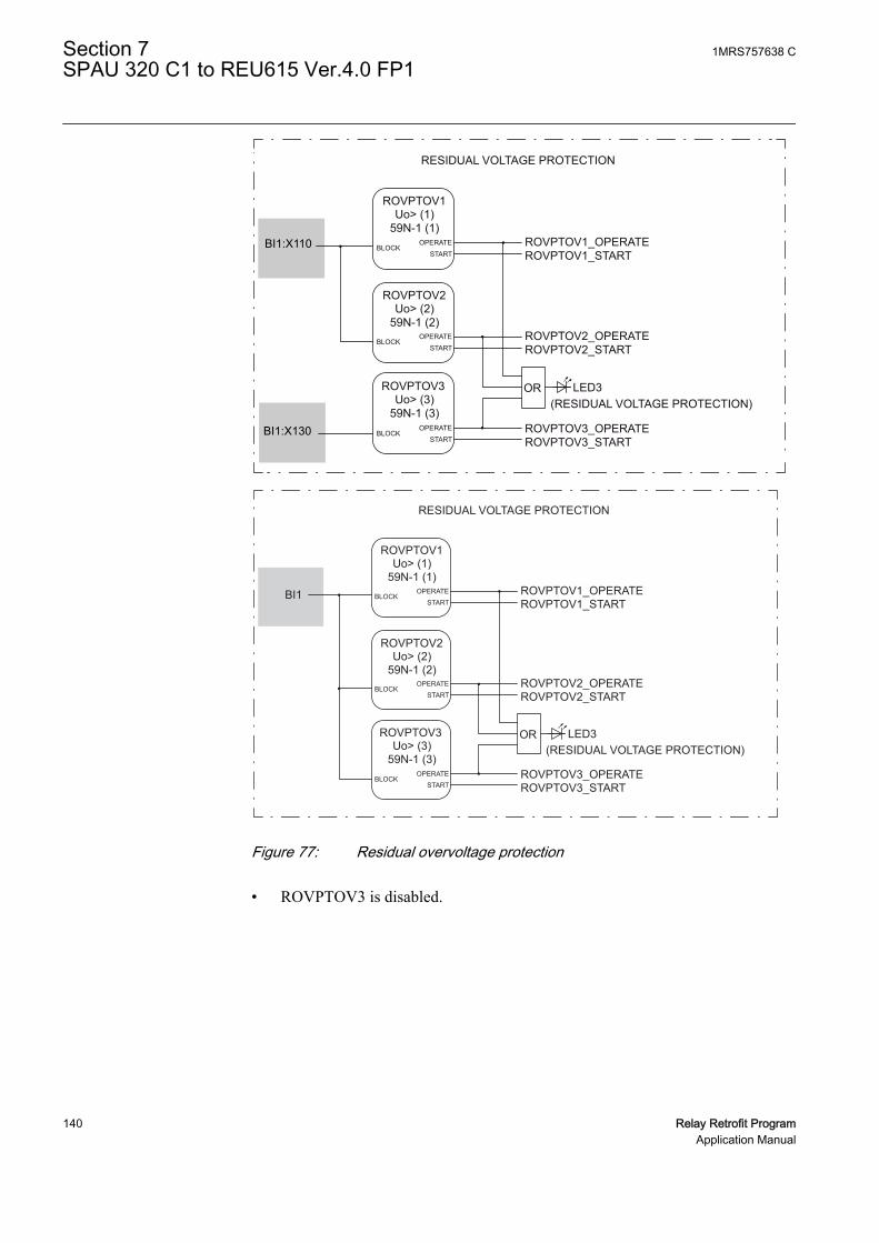
ROVPTOV1 Uo> (1)
59N-1 (1)
ROVPTOV2 Uo> (2)
59N-1 (2)
ROVPTOV3 Uo> (3)
59N-1 (3)
ROVPTOV1_START ROVPTOV1_OPERATE
RESIDUAL VOLTAGE PROTECTION
OR LED3 (RESIDUAL VOLTAGE PROTECTION)
ROVPTOV2_START ROVPTOV2_OPERATE
ROVPTOV3_START ROVPTOV3_OPERATE
OPERATE START BLOCK
OPERATE START BLOCK
OPERATE START BLOCKBI1:X130
BI1:X110
GUID-B48C01C4-5A1C-45CE-B98A-EA803EC43C91 V1 EN
ROVPTOV1Uo> (1)
59N-1 (1)
ROVPTOV2Uo> (2)
59N-1 (2)
ROVPTOV3Uo> (3)
59N-1 (3)
ROVPTOV1_STARTROVPTOV1_OPERATE
RESIDUAL VOLTAGE PROTECTION
BI1
OR LED3(RESIDUAL VOLTAGE PROTECTION)
ROVPTOV2_STARTROVPTOV2_OPERATE
ROVPTOV3_STARTROVPTOV3_OPERATE
OPERATESTART
BLOCK
OPERATESTART
BLOCK
OPERATESTART
BLOCK
GUID-F62C8896-079D-4FE8-B99F-BFD4EDECD928 V1 EN
Figure 77: Residual overvoltage protection
• ROVPTOV3 is disabled.
Section 7 1MRS757638 CSPAU 320 C1 to REU615 Ver.4.0 FP1
140 Relay Retrofit ProgramApplication Manual

GUID-E2C390A0-4508-431C-B149-5EA9164742D5 V1 EN
Figure 78: Load shedding and restoration
• All five load shedding and restoration stages are present but all of them aredisabled.
• X110:SO1 and X110:SO4 are used for start and operate signals of under andovervoltage protection stages.
1MRS757638 C Section 7SPAU 320 C1 to REU615 Ver.4.0 FP1
Relay Retrofit Program 141Application Manual
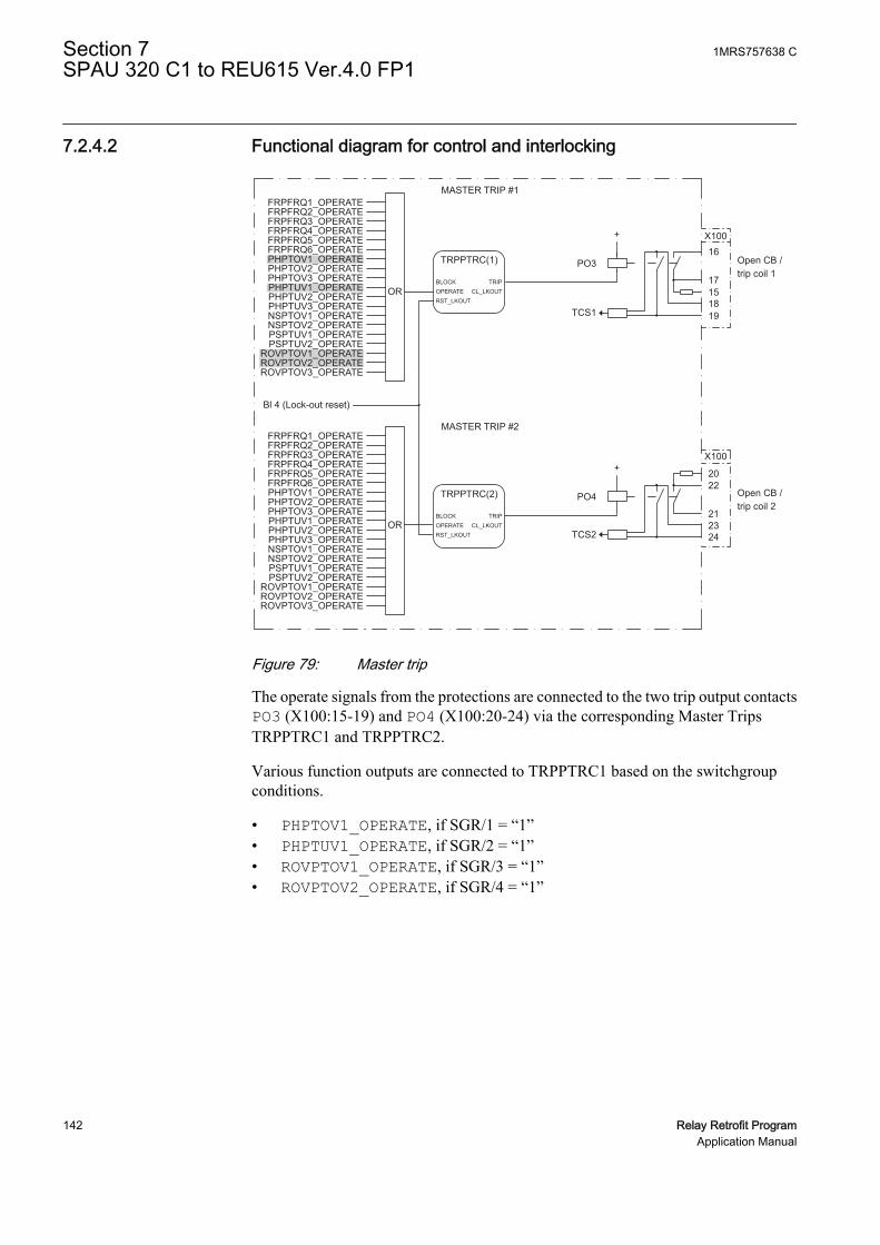
7.2.4.2 Functional diagram for control and interlocking
MASTER TRIP #1FRPFRQ1_OPERATEFRPFRQ2_OPERATEFRPFRQ3_OPERATEFRPFRQ4_OPERATEFRPFRQ5_OPERATEFRPFRQ6_OPERATEPHPTOV1_OPERATEPHPTOV2_OPERATEPHPTOV3_OPERATEPHPTUV1_OPERATEPHPTUV2_OPERATEPHPTUV3_OPERATENSPTOV1_OPERATENSPTOV2_OPERATEPSPTUV1_OPERATEPSPTUV2_OPERATE
ROVPTOV1_OPERATEROVPTOV2_OPERATEROVPTOV3_OPERATE
FRPFRQ1_OPERATEFRPFRQ2_OPERATEFRPFRQ3_OPERATEFRPFRQ4_OPERATEFRPFRQ5_OPERATEFRPFRQ6_OPERATEPHPTOV1_OPERATEPHPTOV2_OPERATEPHPTOV3_OPERATEPHPTUV1_OPERATEPHPTUV2_OPERATEPHPTUV3_OPERATENSPTOV1_OPERATENSPTOV2_OPERATEPSPTUV1_OPERATEPSPTUV2_OPERATE
ROVPTOV1_OPERATEROVPTOV2_OPERATEROVPTOV3_OPERATE
TRPPTRC(1)
CL_LKOUTTRIP
OPERATERST_LKOUT
BLOCK
TRPPTRC(2)
CL_LKOUTTRIP
OPERATERST_LKOUT
BLOCK
MASTER TRIP #2
Bl 4 (Lock-out reset)
OR
OR
PO3
TCS1
PO4
TCS2
Open CB /trip coil 1
Open CB /trip coil 2
X10016
X100
17151819
2022
212324
GUID-5402F75B-0C09-4158-815F-1ED847DA31BF V1 EN
Figure 79: Master trip
The operate signals from the protections are connected to the two trip output contactsPO3 (X100:15-19) and PO4 (X100:20-24) via the corresponding Master TripsTRPPTRC1 and TRPPTRC2.
Various function outputs are connected to TRPPTRC1 based on the switchgroupconditions.
• PHPTOV1_OPERATE, if SGR/1 = “1”• PHPTUV1_OPERATE, if SGR/2 = “1”• ROVPTOV1_OPERATE, if SGR/3 = “1”• ROVPTOV2_OPERATE, if SGR/4 = “1”
Section 7 1MRS757638 CSPAU 320 C1 to REU615 Ver.4.0 FP1
142 Relay Retrofit ProgramApplication Manual

COMMON ALARM / INDICATION 1-2
FRPFRQ1_START FRPFRQ2_START FRPFRQ3_START FRPFRQ4_START FRPFRQ5_START FRPFRQ6_START
LSHDPFRQ1_START LSHDPFRQ2_START LSHDPFRQ3_START LSHDPFRQ4_START LSHDPFRQ5_START LSHDPFRQ5_START
NSPTOV1_START NSPTOV2_START PSPTUV1_START PSPTUV2_START PHPTOV1_START PHPTOV2_START PHPTOV3_START PHPTUV1_START PHPTUV2_START PHPTUV3_START
ROVPTOV1_START ROVPTOV2_START ROVPTOV3_START
FRPFRQ1_OPERATE FRPFRQ2_OPERATE FRPFRQ3_OPERATE FRPFRQ4_OPERATE FRPFRQ5_OPERATE FRPFRQ6_OPERATE
LSHDPFRQ1_OPERATE LSHDPFRQ2_OPERATE LSHDPFRQ3_OPERATE LSHDPFRQ4_OPERATE LSHDPFRQ5_OPERATE
NSPTOV1_OPERATE NSPTOV2_OPERATE PSPTUV1_OPERATE PSPTUV2_OPERATE PHPTOV1_OPERATE PHPTOV2_OPERATE PHPTOV3_OPERATE PHPTUV1_OPERATE PHPTUV2_OPERATE PHPTUV3_OPERATE
ROVPTOV1_OPERATE ROVPTOV2_OPERATE ROVPTOV3_OPERATE
PHPTOV1-operate
PHPTUV1-operate
OR
OR
OR
OR
TPGAPC(1)
OUT1 OUT2 IN1
IN2
SO1
X100 10
11 12
General start indication
X110
23
TPGAPC3
OUT1 OUT2 IN1
IN2
TPGAPC2
OUT1 OUT2 IN1
IN2
TONGAPC1Q1 Q3 IN1
IN3
SO1
X110
PO1
14
16 15
X1006 7ROVPTOV2-operate
ORPHPTOV1-operate
PHPTOV1-startPHPTUV1-start
PHPTUV1-operate
24
X100
14
13
GUID-3FCD16AF-03DD-412D-BA22-502B2919CC40 V2 EN
Figure 80: Alarm indication
The start of any protection function from the IED is connected to TPGAPC1 to givegeneral start information SO1 (X100:10-12).
The signal outputs from the overvoltage and undervoltage protection functions areconnected to TPGAPC3 to give dedicated information.
• Operation (trip) and start of PHPTOV1 SO4 (X110:23-24) reproduces SPAU 320C1 Output relay C. Thus, the following voltage protection functions areconnected to SO4 depending on the switchgroup condition.
1MRS757638 C Section 7SPAU 320 C1 to REU615 Ver.4.0 FP1
Relay Retrofit Program 143Application Manual
• PHPTOV1_START, if SGR/7 = “1”• PHPTOV1_OPERATE, always connected
• Operation (trip) and start of PHPTUV1 SO1 (X110:14-16) reproduces SPAU 320C1 Output relay D. Thus, the following voltage protection functions areconnected to SO1 depending on the switchgroup condition.
• PHPTUV1-start, if SGR/8 = “1”• PHPTUV1-operate, always connected
The signal outputs from the overvoltage and undervoltage protection functions areconnected to TPGAPC2 to give dedicated operation (trip) information.
• Operation (trip) of PHPTUV1 and PHPTOV1 PO1 (X100:6-7) reproducesSPAU 320 C1 output relay B.• Operate signal from PHPTOV1 is connected to PO1, if SGR/5 = “1”• Operate signal from PHPTUV1 is connected to PO1, if SGR/6 = “1”• Operate signal from ROVPTOV2 is always connected to PO1
7.2.4.3 Setting groups
SPAU 320 C1 supports main and remote settings which are migrated to setting groups1 and 2 in REU615. The desired setting groups can be selected with SPA busparameter V152.
Changing setting groups from binary input is not supported by SPAU 320 C1. Thisoption is not configured on REU615. Setting groups can be changed only from HMI.
7.3 Installation
7.3.1 Mounting
The 615 series IED can be mounted on the switchgear door using the hole left by theSPACOM series relay.
1. Widen the original SPACOM relay hole.1.1. Use cutting tool with dedicated cutting head for SPACOM 100/300 series
to get the appropriate cut-out on the switchgear door hosting REF615 IED.1.2. Widen the cut-out to whichever of the four directions as per the existing
installation requirement.
Section 7 1MRS757638 CSPAU 320 C1 to REU615 Ver.4.0 FP1
144 Relay Retrofit ProgramApplication Manual

615 series
SPACOM 300 series
A
C
B
D
GUID-5BCF9EF7-EB7B-4589-BCFC-231DC091DBA0 V1 EN
Figure 81: SPACOM 300 series and 615 series cut-outs
A 165.5 mm
B 214 mm
C 165.5 mm
D 139 mm
2. Insert a cover plate (2RCA027885A0001) to hide visible parts of the oldopening.
3. Mount the 615 series IED's case and insert the plug-in unit.
See the 615 series installation manual for more information.
7.3.2 Connecting
• If the existing wiring is in good condition and still usable, use the dedicatedmarking sets.
• If the existing wiring has to be replaced, use the dedicated wiring harness.
1MRS757638 C Section 7SPAU 320 C1 to REU615 Ver.4.0 FP1
Relay Retrofit Program 145Application Manual
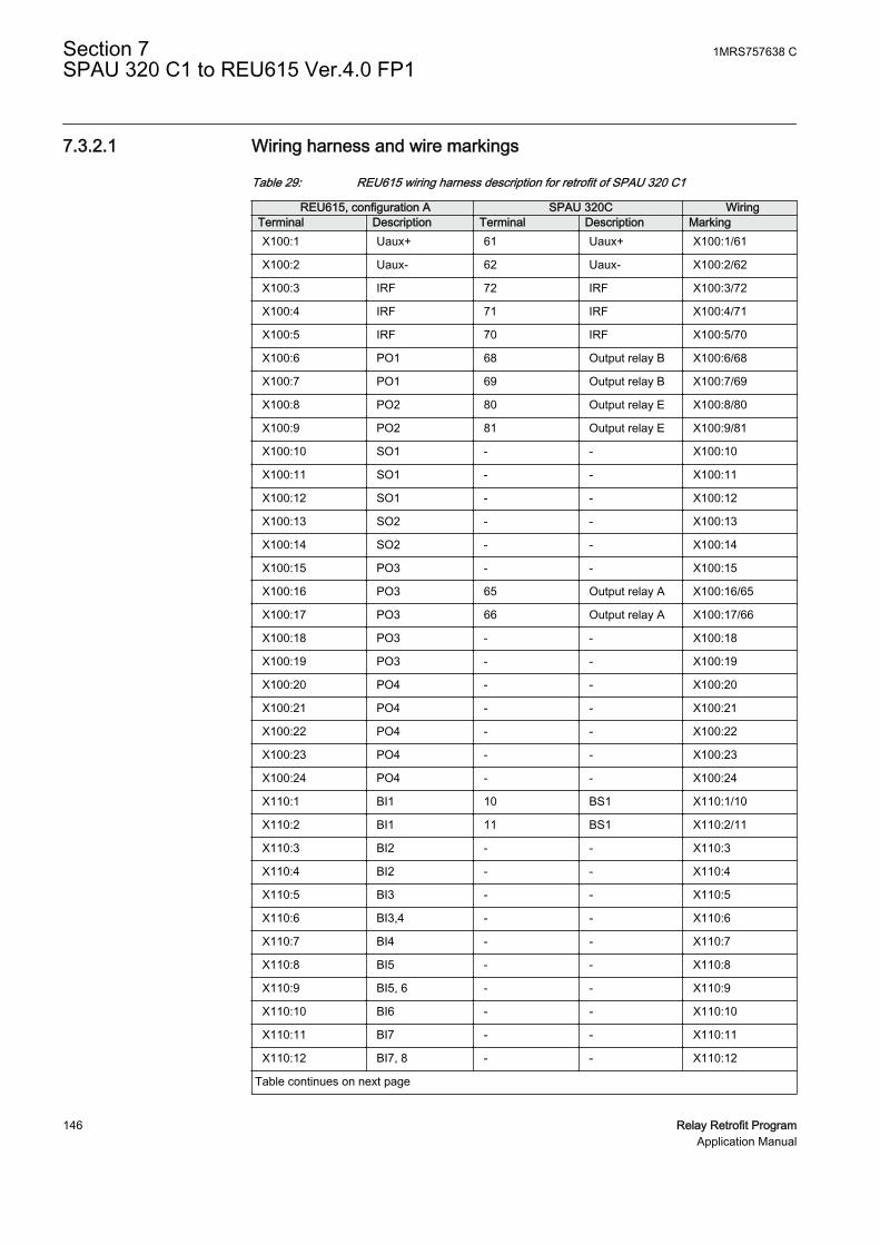
7.3.2.1 Wiring harness and wire markings
Table 29: REU615 wiring harness description for retrofit of SPAU 320 C1
REU615, configuration A SPAU 320C WiringTerminal Description Terminal Description MarkingX100:1 Uaux+ 61 Uaux+ X100:1/61
X100:2 Uaux- 62 Uaux- X100:2/62
X100:3 IRF 72 IRF X100:3/72
X100:4 IRF 71 IRF X100:4/71
X100:5 IRF 70 IRF X100:5/70
X100:6 PO1 68 Output relay B X100:6/68
X100:7 PO1 69 Output relay B X100:7/69
X100:8 PO2 80 Output relay E X100:8/80
X100:9 PO2 81 Output relay E X100:9/81
X100:10 SO1 - - X100:10
X100:11 SO1 - - X100:11
X100:12 SO1 - - X100:12
X100:13 SO2 - - X100:13
X100:14 SO2 - - X100:14
X100:15 PO3 - - X100:15
X100:16 PO3 65 Output relay A X100:16/65
X100:17 PO3 66 Output relay A X100:17/66
X100:18 PO3 - - X100:18
X100:19 PO3 - - X100:19
X100:20 PO4 - - X100:20
X100:21 PO4 - - X100:21
X100:22 PO4 - - X100:22
X100:23 PO4 - - X100:23
X100:24 PO4 - - X100:24
X110:1 BI1 10 BS1 X110:1/10
X110:2 BI1 11 BS1 X110:2/11
X110:3 BI2 - - X110:3
X110:4 BI2 - - X110:4
X110:5 BI3 - - X110:5
X110:6 BI3,4 - - X110:6
X110:7 BI4 - - X110:7
X110:8 BI5 - - X110:8
X110:9 BI5, 6 - - X110:9
X110:10 BI6 - - X110:10
X110:11 BI7 - - X110:11
X110:12 BI7, 8 - - X110:12
Table continues on next page
Section 7 1MRS757638 CSPAU 320 C1 to REU615 Ver.4.0 FP1
146 Relay Retrofit ProgramApplication Manual

REU615, configuration A SPAU 320C WiringTerminal Description Terminal Description MarkingX110:13 BI8 - - X110:13
X110:14 SO1 78 Output relay D X110:14/78
X110:15 SO1 76 Output relay D X110:15/76
X110:16 SO1 77 Output relay D X110:16/77
X110:17 SO2 - - X110:17
X110:18 SO2 - - X110:18
X110:19 SO2 - - X110:19
X110:20 SO3 - - X110:20
X110:21 SO3 - - X110:21
X110:22 SO3 - - X110:22
X110:23 SO4 74 Output relay C X110:23/74
X110:24 SO4 75 Output relay C X110:24/75
X130:1 BI1 - - X130:1
X130:2 BI1 - - X130:2
X130:3 BI2 - - X130:3
X130:4 BI2 - - X130:4
X130:5 BI3 - - X130:5
X130:6 BI3 - - X130:6
X130:7 BI4 - - X130:7
X130:8 BI4 - - X130:8
X130:9 U12B - - X130:9
X130:10 U12B - - X130:10
X130:11 U12 14/15 U12, 100V/110V X130:11/14/15
X130:12 U12 13 U12 X130:12/13
X130:13 U23 17/18 U23, 100V/110V X130:13/17/18
1MRS757638 C Section 7SPAU 320 C1 to REU615 Ver.4.0 FP1
Relay Retrofit Program 147Application Manual

7.3.2.2 SPAU 320 C1 terminal layout and connection diagrams
1314
15
28
29
30
1011
73
74
75
76
77
78
79
80
81
Rx Tx
61
62
63
65
66
67
68
69
70
71
72
131415
2829100
110 30
6162
63
6566676869707172
1011
737475767778798081
100110
GUID-5285594E-BC1D-472E-89A8-5C95293827A6 V1 EN
Figure 82: Terminal layout for SPAU 320 C1
Section 7 1MRS757638 CSPAU 320 C1 to REU615 Ver.4.0 FP1
148 Relay Retrofit ProgramApplication Manual
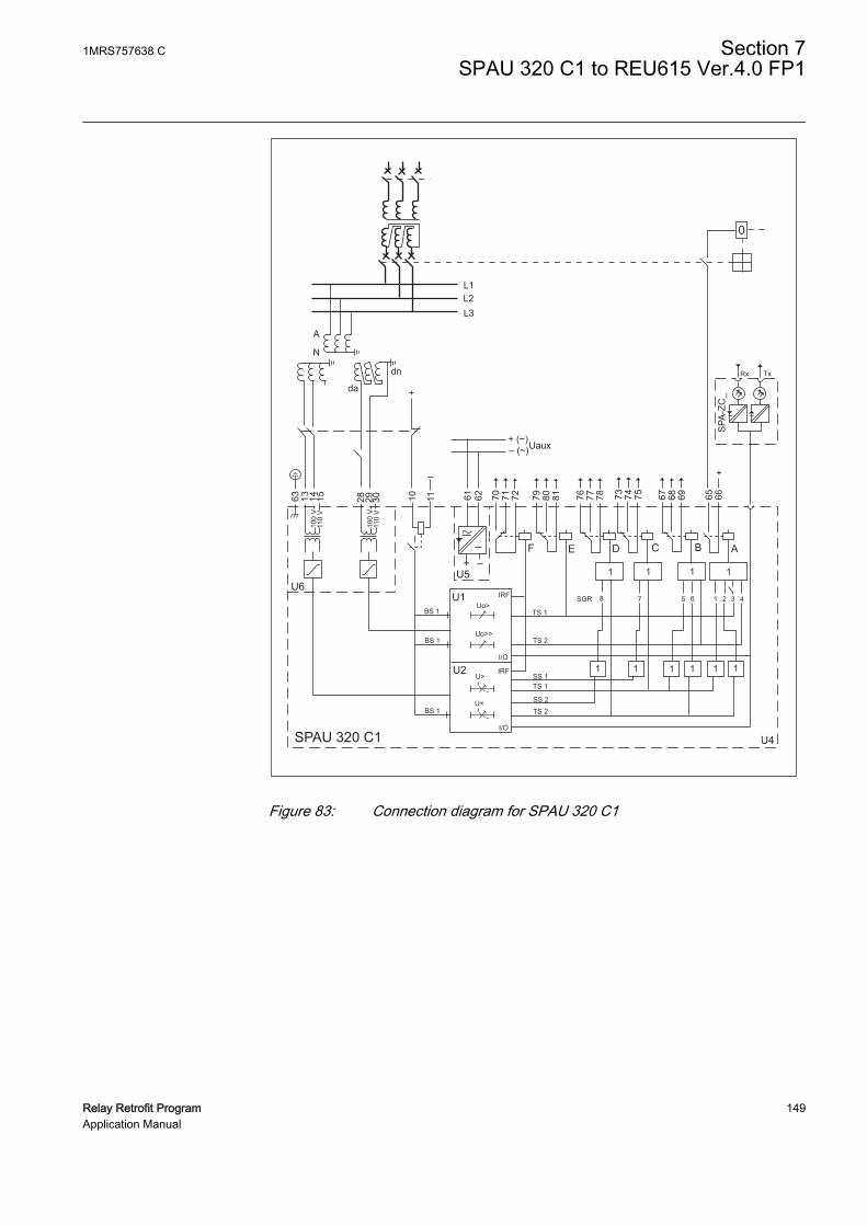
63 13 14 1510
0 V
110
V
100
V11
0 V
28 29 30 10 11
U6U5
+ –
61 62
F
70 71 72 79 80 81E D C
76 77 78 73 74 75 67
B A
68 69 65 66
4
111
3216578
1
SGR
1 1 1 1 1 1
TS 1
TS 1
TS 2
TS 2
SS 2
SS 1
U4
U1
SPAU 320 C1
BS 1
BS 1
BS 1
U2
IRF
IRF
I/O
I/O
U<
U>
Uo>
Uo>>
Rx Tx
SPA
-ZC
_
+ (~)– (~)Uaux
+
+da
dn
A
N
L1L2L3
0
GUID-E5B32E32-D9D3-42F6-9E19-A3AE87F6776E V1 EN
Figure 83: Connection diagram for SPAU 320 C1
1MRS757638 C Section 7SPAU 320 C1 to REU615 Ver.4.0 FP1
Relay Retrofit Program 149Application Manual

7.3.2.3 REU615 terminal layout and connection diagrams
GUID-CCFA401F-C098-432F-9D37-B2F81754E4D4 V1 EN
Figure 84: Terminal layout for the 615 series IEDs
Section 7 1MRS757638 CSPAU 320 C1 to REU615 Ver.4.0 FP1
150 Relay Retrofit ProgramApplication Manual
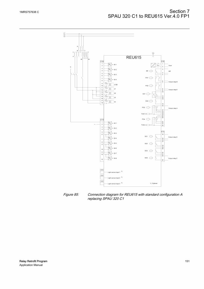
REU615
X13Light sensor input 1 1)
X14Light sensor input 2 1)
X15Light sensor input 3 1)
16
17
1918
X100
67
89
10
111213
15
14
2
1
3
45
22
212324
SO2
TCS2
PO4
SO1
TCS1
PO3
PO2
PO1
IRF
+
-Uaux
20
L1L2L3
da dn
X110
34
56
7
89
10BI 6
BI 5
BI 4
BI 3
BI 2
BI 8
BI 712
13
11
BI 112
X110
16
14
15
19
17
18
22
20
21
SO3
SO2
SO1
23SO4
24
a
nN
A
1) Optional
X13012
34
56
BI 4
BI 3
BI 2
BI 1
87
9101112
U12B
1314
U1
1516
U2
1718
U3
UoN
N
N
N
60 -
N
210V
60 -210V
60 -210V
60 -210V
60 -210V
Uaux
IRF
Output relay B
Output relay A
Output relay E
Output relay D
Output relay C
+
_
GUID-AAFAD844-97D5-44AD-A0E6-675C4F4E1B96 V1 EN
Figure 85: Connection diagram for REU615 with standard configuration Areplacing SPAU 320 C1
1MRS757638 C Section 7SPAU 320 C1 to REU615 Ver.4.0 FP1
Relay Retrofit Program 151Application Manual

152

Section 8 SPAU 330 C1 to REU615 Ver.4.0 FP1
8.1 Retrofit scope
Protection functions of SPAU 330 C1 are replicated by REU615 with a deviation.
• SPAU 330 C1 unit SPCU 1C6 can be programmed with a latching feature for thetripping signal with switch SG1/4. This feature is not migrated to REU615.
SPAU 330 C can be configured for single-phase operation (SG1/1 =1). In REU615,this is done by connecting the single-phase voltage to all three voltage inputsX120-1,2, X120-3,4 and X120-5,6.
8.2 Engineering
In retrofit applications, the target of the configuration phase is to parameterize andconfigure the replacement IED to reproduce the features and functions of the existingrelay. The configuration process comprises of various steps with different toolsdepending on the project.
CAP505
• Reading the configuration from the SPACOM relay or manually enteringparameter values.
In CAP505 tool, the actual values read from the SPACOM relay arecalled present values. The manually entered values are called newvalues. After relay writing and reading operations present and newvalues become identical.
PCM600
• Instantiating a new retrofit IED (IED Migration Support tool from PCM600).
1MRS757638 C Section 8SPAU 330 C1 to REU615 Ver.4.0 FP1
Relay Retrofit Program 153Application Manual

• Selecting the replacement IED (type and order code)• Importing existing relay configuration (.rdb file)• Selecting the set of values to use using the IED Migration Support tool, if
the Present and New values differ in .rdb file• Entering system parameters
• Creating a 615 series IED under PCM600 plant structure using the IED MigrationSupport tool.
• Writing configuration to the IED.
Project specific additional engineering phases
• Using Application Configuration tool in PCM600 to add functionality to themigrated configuration, if required.
• Communication engineering with relevant PCM600 tools, if required.
No engineering activity is required for wiring as marking sets and wiring harness areavailable.
8.2.1 Existing relay and system engineering information
The configuration of the SPACOM relay can be retrieved via the serial connectionusing CAP 505 tool. Parameters are read from the display of the SPACOM relay andmanually inserted in CAP 505. The configuration parameters are exported from CAP505 in .rdb file format and imported in PCM600 during the migration process.
Various system parameters are collected and imported to PCM600 upon requestduring the migration process.
• Rated frequency of the network (50 or 60 Hz)• Secondary rated voltage (100 or 110 V)• Primary rated voltage (0.100…440.000 kV)• Secondary rated residual voltage (100 or 110 V)• Primary rated residual voltage (0.100…440.000 kV)
8.2.2 Functions
The configuration of REU615 migrated from SPAU 330 C1 contains all the functionsbelonging to the standard configuration A, but only the functions that reproduce thebehavior of the existing relay configuration are enabled.
On SPAU 330 C1, there are three types of selector switchgroups: SGR to configure theoutput relays, SGB to configure blocking signal and SG1 to define additionalfunctions as operating time setting ranges and start delay.
The switchgroup SGR is located at the front panel of the output relay module. Thecircuit boards of the relay modules SPCU 1C1 and SPCU 3C14 contain theprogramming switchgroup SGB. SG1 is located on the front panels of the relay
Section 8 1MRS757638 CSPAU 330 C1 to REU615 Ver.4.0 FP1
154 Relay Retrofit ProgramApplication Manual
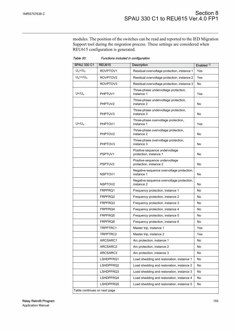
modules. The position of the switches can be read and reported to the IED MigrationSupport tool during the migration process. These settings are considered whenREU615 configuration is generated.
Table 30: Functions included in configuration
SPAU 330 C1 REU615 Description Enabled 1)
Uo>/Un ROVPTOV1 Residual overvoltage protection, instance 1 Yes
Uo>>/Un ROVPTOV2 Residual overvoltage protection, instance 2 Yes
ROVPTOV3 Residual overvoltage protection, instance 3 No
U</Un PHPTUV1Three-phase undervoltage protection,instance 1 Yes
PHPTUV2Three-phase undervoltage protection,instance 2 No
PHPTUV3Three-phase undervoltage protection,instance 3 No
U>/Un PHPTOV1Three-phase overvoltage protection,instance 1 Yes
PHPTOV2Three-phase overvoltage protection,instance 2 No
PHPTOV3Three-phase overvoltage protection,instance 3 No
PSPTUV1Positive-sequence undervoltageprotection, instance 1 No
PSPTUV2Positive-sequence undervoltageprotection, instance 2 No
NSPTOV1Negative-sequence overvoltage protection,instance 1 No
NSPTOV2Negative-sequence overvoltage protection,instance 2 No
FRPFRQ1 Frequency protection, instance 1 No
FRPFRQ2 Frequency protection, instance 2 No
FRPFRQ3 Frequency protection, instance 3 No
FRPFRQ4 Frequency protection, instance 4 No
FRPFRQ5 Frequency protection, instance 5 No
FRPFRQ6 Frequency protection, instance 6 No
TRPPTRC1 Master trip, instance 1 Yes
TRPPTRC2 Master trip, instance 2 Yes
ARCSARC1 Arc protection, instance 1 No
ARCSARC2 Arc protection, instance 2 No
ARCSARC3 Arc protection, instance 3 No
LSHDPFRQ1 Load shedding and restoration, instance 1 No
LSHDPFRQ2 Load shedding and restoration, instance 2 No
LSHDPFRQ3 Load shedding and restoration, instance 3 No
LSHDPFRQ4 Load shedding and restoration, instance 4 No
LSHDPFRQ5 Load shedding and restoration, instance 5 No
Table continues on next page
1MRS757638 C Section 8SPAU 330 C1 to REU615 Ver.4.0 FP1
Relay Retrofit Program 155Application Manual

SPAU 330 C1 REU615 Description Enabled 1)
CBXCBR1 Circuit-breaker control No
DCXSWI1 Disconnector control, instance 1 No
DCXSWI2 Disconnector control, instance 2 No
ESXSWI1 Earthing switch control No
DCSXSWI1 Disconnector position indication, instance 1 No
DCSXSWI2 Disconnector position indication, instance 2 No
DCSXSWI3 Disconnector position indication, instance 3 No
ESSXSWI1 Earthing switch indication, instance 1 No
ESSXSWI2 Earthing switch indication, instance 2 No
SECRSYN1 Synchronism and energizing check No
TCSSCBR1 Trip circuit supervision, instance 1 Yes
TCSSCBR2 Trip circuit supervision, instance 2 Yes
RDRE1 Disturbance recorder Yes
VMMXU1 Three-phase voltage measurement Yes
RESVMMXU1 Residual voltage measurement Yes
VSMSQI1 Sequence voltage measurement Yes
FMMXU1 Frequency measurement Yes
1) Function is enabled when the parameter Operation is set to “on” and disabled when the parameter isset to “off”.
8.2.2.1 ROVPTOV1 settings
ROVPTOV1 replicates the behavior of SPAU 330 C1 residual low-set overvoltageprotection function with definite time characteristic (Uo>/Un).
In SPAU 330 C1, settings start voltage Uo> and operate time t> can be selected fromthe dedicated knobs. These values can be checked and modified from the IEDMigration Support tool during the migration process.
The Measurement mode parameter is set to “RMS”.
• In SPAU 330 C1, remote settings can be selected with the SPA parameter V150.If SPAU 330 C1 start voltage Uo> in main setting is over 100% × Un,ROVPTOV1 Start value in setting group 1 is set to “1.000” and a note is issued bythe IED Migration Support tool. If SPAU 330 C1 start voltage Uo> in remotesetting is over 100% × Un, ROVPTOV1 Start value in setting group 2 is set to“1.000” and a note is issued by the IED Migration Support tool.
• If SPAU 330 C1 start voltage Uo> in main setting is under 1% × Un,ROVPTOV1 Start value in setting group 1 is set to “0.010” and a note is issuedby the IED Migration Support tool. If SPAU 330 C1 start voltage Uo> in remotesetting is under 1% × Un, ROVPTOV1 Start value in setting group 2 is set to“0.010” and a note is issued by the IED Migration Support tool.
• If SPAU 330 C1 operate time t> in main setting is over 300 s, ROVPTOV1Operate delay time in setting group 1 is set to “300 000 ms” and a note is issuedby the IED Migration Support tool. If SPAU 330 C1 operate time t> in remote
Section 8 1MRS757638 CSPAU 330 C1 to REU615 Ver.4.0 FP1
156 Relay Retrofit ProgramApplication Manual

setting is over 300 s, ROVPTOV1 Operate delay time in setting group 2 is set to“300 000 ms” and a note is issued by the IED Migration Support tool.
• If SPAU 330 C1 operate time t> in main setting is under 0.04 s, ROVPTOV1Operate delay time in setting group 1 is set to “40 ms” and a note is issued by theIED Migration Support tool. If SPAU 330 C1 operate time t> in remote settingis under 0.04 s, ROVPTOV1 Operate delay time in setting group 2 is set to “40ms” and a note is issued by the IED Migration Support tool.
8.2.2.2 ROVPTOV2 settings
ROVPTOV2 replicates the behavior of SPAU 330 C1 residual high-set overvoltageprotection function with definite time characteristic (Uo>>/Un).
In SPAU 330 C1, settings start voltage Uo>> and operate time t>> can be selectedfrom the dedicated knobs. The values can be checked and modified from the IEDMigration Support tool during the migration process.
The Measurement mode parameter is set to “RMS”.
• In the SPCU 1C6 module, Uo>> stage can be set out of operation by setting thestart voltage Uo>> to infinite (“∞” or “999”). If the setting start voltage Uo>>differs in main and remote settings, only main setting is considered in migrationand a note is issued by the IED Migration Support tool.
• If SPAU 330 C1 start voltage Uo>> in main setting is over 100% × Un,ROVPTOV2 Start value in setting group 1 is set to “1.000” and a note is issuedby the IED Migration Support tool. If SPAU 330 C1 start voltage Uo>> inremote setting is over 100% × Un, ROVPTOV2 Start value in setting group 2 isset to “1.000” and a note is issued by the IED Migration Support tool.
• If SPAU 330 C1 start voltage Uo>> in main setting is under 1% × Un, theROVPTOV2 Start value in setting group 1 is set to “0.010” and a note is issuedby the IED Migration Support tool. If SPAU 330 C1 start voltage Uo>> inremote setting is under 1% × Un, ROVPTOV2 Start value in setting group 2 is setto “0.010” and a note is issued by the IED Migration Support tool.
• If SPAU 330 C1 operate time t>> in main setting is over 300 s, ROVPTOV2Operate delay time in setting group 1 is set to “300 000 ms” and a note is issuedby the IED Migration Support tool. If SPAU 330 C1 operate time t>> in remotesetting is over 300 s, ROVPTOV2 Operate delay time in setting group 2 is set to“300 000 ms” and a note is issued by the IED Migration Support tool.
• If SPAU 330 C1 operate time t>> in main setting is under 0.04 s, ROVPTOV2Operate delay time in setting group 1 is set to “40 ms” and a note is issued by theIED Migration Support tool. If SPAU 330 C1 operate time t>> in remote settingis under 0.04 s, ROVPTOV2 Operate delay time in setting group 2 is set to “40ms” and a note is issued by the IED Migration Support tool.
1MRS757638 C Section 8SPAU 330 C1 to REU615 Ver.4.0 FP1
Relay Retrofit Program 157Application Manual

8.2.2.3 PHPTUV1 settings
PHPTUV1 replicates the behavior of SPAU 330 C1 three-phase low-set undervoltageprotection function with definite or inverse definite minimum time characteristic (U</Un).
In SPAU 330 C1, settings start voltage U< and operate time t< can be selected fromthe dedicated knobs. These values can be checked and modified from the IEDMigration Support tool during the migration process.
The Measurement mode parameter is set to “RMS”.
• Switch SG1/7 defines the U< start delay time. This delay is reproduced onREU615 with the TONGAPC1 function. If the position of switch SG1/7 differsin main and remote settings, only position of the main setting is considered inmigration and a note is issued by the IED Migration Support tool.
• In SPAU 330 C1, switch SG1/6 defines the selection of automatic blocking of theU< function. If the position of switch SG1/6 differs in main and remote settings,only the main setting value is considered in migration and a note is issued by theIED Migration Support tool.
• If SPAU 330 C1 start voltage U< in main setting is over 1.2 × Un, PHPTUV1Start value in setting group 1 is set to “1.20” and a note is issued by the IEDMigration Support tool. If SPAU 330 C1 start voltage U< in remote setting isover 1.2 × Un, PHPTUV1 Start value in setting group 2 is set to “1.20” and a noteis issued by the IED Migration Support tool.
• If SPAU 330 C1 start voltage U< in main setting is under 0.05 × Un, PHPTUV1Start value in setting group 1 is set to “0.05” and a note is issued by the IEDMigration Support tool. If SPAU 330 C1 start voltage U< in remote setting isunder 0.05 × Un, PHPTUV1 Start value in setting group 2 is set to “0.05” and anote is issued by the IED Migration Support tool.
• If SPAU 330 C1 operate time t< in main setting is over 300 s, PHPTUV1 Operatedelay time in setting group 1 is set to “300 000 ms” and a note is issued by the IEDMigration Support tool. If SPAU 330 C1 operate time t< in remote setting is over300 s, PHPTUV1 Operate delay time in setting group 2 is set to “300 000 ms” anda note is issued by the IED Migration Support tool.
• If SPAU 330 C1 operate time t< in main setting is under 0.06 s, PHPTUV1Operate delay time in setting group 1 is set to “60 ms” and a note is issued by theIED Migration Support tool. If SPAU 330 C1 operate time t< in remote settingis under 0.06 s, PHPTUV1 Operate delay time in setting group 2 is set to “60 ms”and a note is issued by the IED Migration Support tool.
8.2.2.4 PHPTOV1 settings
PHPTOV1 replicates the behavior of SPAU 330 C1 three-phase overvoltageprotection function with definite or inverse definite minimum time characteristic (U>/Un).
Section 8 1MRS757638 CSPAU 330 C1 to REU615 Ver.4.0 FP1
158 Relay Retrofit ProgramApplication Manual

In SPAU 330 C1, settings start voltage U> and operate time t> are selected from thededicated knobs. These values can be checked and modified from the IED MigrationSupport tool during the migration process.
The Measurement mode parameter is set to “RMS”.
• Switch SG1/2 defines the U> start time delay. This delay is reproduced onREU615 with the TONGAPC1 function. If the position of switch SG1/2 differsin main and remote settings, only position of the main setting is considered inmigration and a note is issued by the IED Migration Support tool.
• If SPAU 330 C1 start voltage U> in main setting is over 1.6 × Un, PHPTOV1Start value in setting group 1 is set to “1.60” and a note is issued by the IEDMigration Support tool. If SPAU 330 C1 start voltage U> in remote setting isover 1.6 × Un, PHPTOV1 Start value in setting group 2 is set to “1.60” and a noteis issued by the IED Migration Support tool.
• If SPAU 330 C1 start voltage U> in main setting is under 0.05 × Un, PHPTOV1Start value in setting group 1 is set to “0.05” and a note is issued by the IEDMigration Support tool. If SPAU 330 C1 start voltage U> in remote setting isunder 0.05 × Un, PHPTOV1 Start value in setting group 2 is set to “0.05” and anote is issued by the IED Migration Support tool.
• If SPAU 330 C1 operate time t> in main setting is over 300 s, PHPTOV1 Operatedelay time in setting group 1 is set to “300 000 ms” and a note is issued by the IEDMigration Support tool. If SPAU 330 C1 operate time t> in remote setting is over300 s, PHPTOV1 Operate delay time in setting group 2 is set to “300 000 ms” anda note is issued by the IED Migration Support tool.
• If SPAU 330 C1 operate time t> in main setting is under 0.04 s, PHPTOV1Operate delay time in setting group 1 is set to “40 ms” and a note is issued by theIED Migration Support tool. If SPAU 330 C1 operate time t> in remote settingis under 0.04 s, PHPTOV1 Operate delay time in setting group 2 is set to “40 ms”and a note is issued by the IED Migration Support tool.
• If SPAU 330 C1 time multiplier k> in main setting is over 1, PHPTOV1 Timemultiplier in setting group 1 is set to “1.00” and a note is issued by the IEDMigration Support tool. If SPAU 330 C1 time multiplier k> in remote setting isover 1, PHPTOV1 Time multiplier in setting group 2 is set to “1.00” and a note isissued by the IED Migration Support tool.
• If SPAU 330 C1 time multiplier k> in main setting is under 0.05, PHPTOV1 Timemultiplier in setting group 1 is set to “0.05” and a note is issued by the IEDMigration Support tool. If SPAU 330 C1 time multiplier k> in remote setting isunder 0.05, PHPTOV1 Time multiplier in setting group 2 is set to “0.05” and anote is issued by the IED Migration Support tool.
8.2.3 I/O connections
I/O connections at SPAU 330 C1 terminals are remapped to REU615 I/O terminal.
REU615 terminals have additional binary I/Os whose behavior does not depend onSPAU 330 C1 configuration.
1MRS757638 C Section 8SPAU 330 C1 to REU615 Ver.4.0 FP1
Relay Retrofit Program 159Application Manual

Table 31: Binary inputs
REU615 SPAU 330 C1 UsageBI1 (X110:1/2) BS (10/11) if (unit 1) SGB/4 = “1” ROVPTOV1.BLOCK
if (unit 1) SGB/5 = “1” ROVPTOV2.BLOCK
if (unit 2) SGB/5 = “1” PHPTUV1.BLOCK
BI2 (X110:3/4) Not available Manual restore group 1 in LSHDPFRQ1
BI3 (X110:5/6) Not available Manual restore group 2 in LSHDPFRQ2
BI4 (X110:7/6) Not available Unused
BI5 (X110:8/9) Not available Voltage transformer truck in indication
BI6 (X110:10/9) Not available Voltage transformer truck out indication
BI7 (X110:11/12) Not available Earthing switch closed indication
BI8 (X110:13/12) Not available Earthing switch open indication
BI1 (X130:1/2) Not available Unused
BI2 (X130:3/4) Not available Line voltage transformer MCB open
BI3 (X130:5/6) Not available Bus voltage transformer MCB open
BI4 (X130:7/8) Not available Lockout reset
Table 32: Binary outputs
REU615 SPAU 330 C1 UsagePO1 (X100:6/7) Start B (67/68/69) if SGR/5 = “1” PHPTOV1.OPERATE
if SGR/6 = “1” PHPTUV1.OPERATE
ROVPTOV2.OPERATE
PO2 (X100:8/9) Start E (79/80/81) ROVPTOV1.OPERATE
SO1(X100:10/11/12)
Not available PHPTOV1.START
PHPTUV1.START
ROVPTOV1. START
ROVPTOV2. START
SO2(X100:13/14)
Not available Unused
PO3(X100:16/17)
Trip 1 (65/66) if SGR/3 = “1” ROVPTOV1.OPERATE
if SGR/4 = “1” ROVPTOV2.OPERATE
if SGR/1 = “1” PHPTOV1.OPERATE
if SGR/2 = “1” PHPTUV1.OPERATE
PO4(X100:20/21/22/23/24)
Not available Master trip 2
SO1(X110:14/16)
Start D (76/77/78) if SGR/8 = “1” PHPTUV1. START
PHPTUV1.OPERATE
SO2(X110:17/18/19)
Not available Connected to “Load Shedding Group 2” but unused
Table continues on next page
Section 8 1MRS757638 CSPAU 330 C1 to REU615 Ver.4.0 FP1
160 Relay Retrofit ProgramApplication Manual

REU615 SPAU 330 C1 UsageSO3(X110:20/21/22)
Not available Connected to “Load restore group 1” but unused
SO4(X110:23/24)
Start C (73/74/75) if SGR/7 = “1” PHPTOV1.START
PHPTOV1.OPERATE
The type of contacts (single or multiple pole; single or multiple throw)in 615 series can be different from SPACOM relays. See the REU615standard configuration A connection diagram.
Normally closed contacts (terminals 67, 73, 76 or 79) are notsupported in this migration. If normally closed contacts are required,the resulting REU615 configuration must be revised and someadditional engineering is required.
8.2.4 Functional diagrams
The functional diagrams describe the default input, output, alarm LED and function-to-function connections in REU615. The default connections can be viewed andchanged with PCM600 according to the application requirements, if necessary.
Only SPAU 330 C1 migrated functions are represented in theconnection diagrams. REU615 also includes other functions whoseconnections are configured according to standard configuration A.See REU615 Application Manual.
Operation of additional REU615 functions is disabled if thecorresponding functionality is not available in SPAU 330 C1. Thesefunctions can be visible in the connection diagrams even if disabled.
The parts affected by the migration compared to the 615 seriesstandard configuration are highlighted in gray.
1MRS757638 C Section 8SPAU 330 C1 to REU615 Ver.4.0 FP1
Relay Retrofit Program 161Application Manual

8.2.4.1 Functional diagrams for protection
L1L2L3
OVERVOLTAGE PROTECTION
BI1
X130
BI 1A
Nn
a
A N an
da dn
BI 2 (LINE VT MCB OPEN)
BI 3 (BUS VT MCB OPEN)
BI 4 (LOCKOUT RESET)
U1B
U1
U2
U3
Uo
3U
X110
PHPTOV1U> (1)
59-1 (1)
PHPTOV2U> (2)
59-1 (2)
PHPTOV3U> (3)
59-1 (3)
PHPTOV1_STARTPHPTOV1_OPERATE
OR LED1 (OV PROTECTION)
PHPTOV2_STARTPHPTOV2_OPERATE
PHPTOV3_STARTPHPTOV3_OPERATE
PROTECTION
LED11
OPERATESTART
BLOCK
OPERATESTART
BLOCK
OPERATESTART
BLOCK
BI_SG_2BI_SG_3BI_SG_4BI_SG_5BI_SG_6
SG_1_ACTSG_2_ACTSG_3_ACTSG_4_ACTSG_5_ACTSG_6_ACT
60 -210V
60 -210V
60 -210V
60 -210V
60 -210V
N
N
N
N
N
12
34
56
78
9101112131415161718
12
GUID-52FD0FD6-659F-4F70-AAD8-EE6288DF999E V1 EN
Figure 86: Overvoltage protection
• PHPTOV2 and PHPTOV3 are disabled.• SPAU 330 C1 has one phase-to-phase input for phase voltages. In REU615, this
is done by connecting one phase-to-phase voltage to all three voltage inputs(X130:11/12, X130:13/14 and X130:15/16).
• Function block PROTECTION for parameter setting group is disabled.
Section 8 1MRS757638 CSPAU 330 C1 to REU615 Ver.4.0 FP1
162 Relay Retrofit ProgramApplication Manual

BI1:X110
BI1:X130
GUID-4B5818F9-6951-40C6-9CD2-F8E8B385C35E V1 EN
GUID-38315ADE-10B1-407E-8CBB-5DD244B2E455 V1 EN
Figure 87: Undervoltage protection
1MRS757638 C Section 8SPAU 330 C1 to REU615 Ver.4.0 FP1
Relay Retrofit Program 163Application Manual

• PHPTUV2 and PHPTUV3 are disabled.
ROVPTOV1Uo> (1)
59N-1 (1)
ROVPTOV2Uo> (2)
59N-1 (2)
ROVPTOV3Uo> (3)
59N-1 (3)
ROVPTOV1_STARTROVPTOV1_OPERATE
RESIDUAL VOLTAGE PROTECTION
BI1
OR LED3(RESIDUAL VOLTAGE PROTECTION)
ROVPTOV2_STARTROVPTOV2_OPERATE
ROVPTOV3_STARTROVPTOV3_OPERATE
OPERATESTART
BLOCK
OPERATESTART
BLOCK
OPERATESTART
BLOCK
GUID-F62C8896-079D-4FE8-B99F-BFD4EDECD928 V1 EN
Figure 88: Residual overvoltage protection
• ROVPTOV3 is disabled.
Section 8 1MRS757638 CSPAU 330 C1 to REU615 Ver.4.0 FP1
164 Relay Retrofit ProgramApplication Manual

GUID-E2C390A0-4508-431C-B149-5EA9164742D5 V1 EN
Figure 89: Load shedding and restoration
• All five load shedding and restoration stages are present but disabled.• X110:SO1 and X110:SO4 are used for start and operate signals of undervoltage
and overvoltage protection stages.
Functional diagrams illustrate the external connections defined in the615 series standard configuration. Check the connection diagram tosee the actual external connections of the replacement IED.
1MRS757638 C Section 8SPAU 330 C1 to REU615 Ver.4.0 FP1
Relay Retrofit Program 165Application Manual

8.2.4.2 Functional diagram for control and interlocking
MASTER TRIP #1FRPFRQ1_OPERATEFRPFRQ2_OPERATEFRPFRQ3_OPERATEFRPFRQ4_OPERATEFRPFRQ5_OPERATEFRPFRQ6_OPERATEPHPTOV1_OPERATEPHPTOV2_OPERATEPHPTOV3_OPERATEPHPTUV1_OPERATEPHPTUV2_OPERATEPHPTUV3_OPERATENSPTOV1_OPERATENSPTOV2_OPERATEPSPTUV1_OPERATEPSPTUV2_OPERATE
ROVPTOV1_OPERATEROVPTOV2_OPERATEROVPTOV3_OPERATE
FRPFRQ1_OPERATEFRPFRQ2_OPERATEFRPFRQ3_OPERATEFRPFRQ4_OPERATEFRPFRQ5_OPERATEFRPFRQ6_OPERATEPHPTOV1_OPERATEPHPTOV2_OPERATEPHPTOV3_OPERATEPHPTUV1_OPERATEPHPTUV2_OPERATEPHPTUV3_OPERATENSPTOV1_OPERATENSPTOV2_OPERATEPSPTUV1_OPERATEPSPTUV2_OPERATE
ROVPTOV1_OPERATEROVPTOV2_OPERATEROVPTOV3_OPERATE
TRPPTRC(1)
CL_LKOUTTRIP
OPERATERST_LKOUT
BLOCK
TRPPTRC(2)
CL_LKOUTTRIP
OPERATERST_LKOUT
BLOCK
MASTER TRIP #2
Bl 4 (Lock-out reset)
OR
OR
PO3
TCS1
PO4
TCS2
Open CB /trip coil 1
Open CB /trip coil 2
X10016
X100
17151819
2022
212324
GUID-5402F75B-0C09-4158-815F-1ED847DA31BF V1 EN
Figure 90: Master trip
The operate signals from the protections are connected to the two trip output contactsPO3 (X100:15-19) and PO4 (X100:20-24) via the corresponding Master TripsTRPPTRC1 and TRPPTRC2.
Various function outputs are connected to TRPPTRC1 based on the switchgroupconditions.
• PHPTOV1_OPERATE, if SGR/1 = "1"• PHPTUV1_OPERATE, if SGR/2 = "1"• ROVPTOV1_OPERATE, if SGR/3 = "1"• ROVPTOV2_OPERATE, if SGR/4 = "1"
Section 8 1MRS757638 CSPAU 330 C1 to REU615 Ver.4.0 FP1
166 Relay Retrofit ProgramApplication Manual

COMMON ALARM / INDICATION 1-2
FRPFRQ1_START FRPFRQ2_START FRPFRQ3_START FRPFRQ4_START FRPFRQ5_START FRPFRQ6_START
LSHDPFRQ1_START LSHDPFRQ2_START LSHDPFRQ3_START LSHDPFRQ4_START LSHDPFRQ5_START LSHDPFRQ5_START
NSPTOV1_START NSPTOV2_START PSPTUV1_START PSPTUV2_START PHPTOV1_START PHPTOV2_START PHPTOV3_START PHPTUV1_START PHPTUV2_START PHPTUV3_START
ROVPTOV1_START ROVPTOV2_START ROVPTOV3_START
FRPFRQ1_OPERATE FRPFRQ2_OPERATE FRPFRQ3_OPERATE FRPFRQ4_OPERATE FRPFRQ5_OPERATE FRPFRQ6_OPERATE
LSHDPFRQ1_OPERATE LSHDPFRQ2_OPERATE LSHDPFRQ3_OPERATE LSHDPFRQ4_OPERATE LSHDPFRQ5_OPERATE
NSPTOV1_OPERATE NSPTOV2_OPERATE PSPTUV1_OPERATE PSPTUV2_OPERATE PHPTOV1_OPERATE PHPTOV2_OPERATE PHPTOV3_OPERATE PHPTUV1_OPERATE PHPTUV2_OPERATE PHPTUV3_OPERATE
ROVPTOV1_OPERATE ROVPTOV2_OPERATE ROVPTOV3_OPERATE
PHPTOV1-operate
PHPTUV1-operate
OR
OR
OR
OR
TPGAPC(1)
OUT1 OUT2 IN1
IN2
SO1
X100 10
11 12
General start indication
X110
23
TPGAPC3
OUT1 OUT2 IN1
IN2
TPGAPC2
OUT1 OUT2 IN1
IN2
TONGAPC1Q1 Q3 IN1
IN3
SO1
X110
PO1
14
16 15
X1006 7ROVPTOV2-operate
ORPHPTOV1-operate
PHPTOV1-startPHPTUV1-start
PHPTUV1-operate
24
X100
14
13
GUID-3FCD16AF-03DD-412D-BA22-502B2919CC40 V2 EN
Figure 91: Alarm indication
The start of any protection function from the IED is connected to TPGAPC1 to givegeneral start information SO1 (X100:10-12).
Operation (trip) of any protection function is connected to TPGAPC1 but notconnected to any output.
The signal outputs from the overvoltage and undervoltage protection functions areconnected to TPGAPC3 to give dedicated operation and start information.
1MRS757638 C Section 8SPAU 330 C1 to REU615 Ver.4.0 FP1
Relay Retrofit Program 167Application Manual

• Operation (trip) and start of PHPTOV1 SO4 (X110: 23-24). This reproducesSPAU 330 C1 output relay C. Thus the following voltage protection functions areconnected to SO4 depending on the switchgroup condition.
• PHPTOV1_START, if SGR/7 = “1”• PHPTOV1_OPERATE, always connected
• Operation (trip) and start of PHPTUV1 SO1 (X110: 14-16). This reproducesSPAU 330 C1 output relay D. Thus the following voltage protection functions areconnected to SO1 depending on the switchgroup condition.
• PHPTUV1-start, if SGR/8 = “1”• PHPTUV1-operate, always connected
The signal outputs from the overvoltage and undervoltage protection functions areconnected to TPGAPC2 to give dedicated information.
• Operate signal from PHPTOV1 is connected to PO1, if SGR/5 = “1”• Operate signal from PHPTUV1 is connected to PO1, if SGR/6 = “1”• Operate signal from ROVPTOV2 is always connected to PO1
8.2.4.3 Setting groups
SPAU 330 C1 supports main and remote settings which are migrated to Setting Group1 and 2 in REU615. The setting groups can be selected with SPA-bus parameterV152.
SPAU 320 C1 and REU615 do not support setting group change from binary input.Setting groups can be changed only from HMI.
8.3 Installation
8.3.1 Mounting
The 615 series IED can be mounted on the switchgear door using the hole left by theSPACOM series relay.
1. Widen the original SPACOM relay hole.1.1. Use cutting tool with dedicated cutting head for SPACOM 100/300 series
to get the appropriate cut-out on the switchgear door hosting REF615 IED.1.2. Widen the cut-out to whichever of the four directions as per the existing
installation requirement.
Section 8 1MRS757638 CSPAU 330 C1 to REU615 Ver.4.0 FP1
168 Relay Retrofit ProgramApplication Manual

615 series
SPACOM 300 series
A
C
B
D
GUID-5BCF9EF7-EB7B-4589-BCFC-231DC091DBA0 V1 EN
Figure 92: SPACOM 300 series and 615 series cut-outs
A 165.5 mm
B 214 mm
C 165.5 mm
D 139 mm
2. Insert a cover plate (2RCA027885A0001) to hide visible parts of the oldopening.
3. Mount the 615 series IED's case and insert the plug-in unit.
See the 615 series installation manual for more information.
8.3.2 Connecting
• If the existing wiring is in good condition and still usable, use the dedicatedmarking sets.
• If the existing wiring has to be replaced, use the dedicated wiring harness.
1MRS757638 C Section 8SPAU 330 C1 to REU615 Ver.4.0 FP1
Relay Retrofit Program 169Application Manual

8.3.2.1 Wiring harness and wire markings
Wiring harness is available for retrofitting SPAU 330 C1 with REU615.
Table 33: REU615 wiring harness description for retrofit of SPAU 330 C1
REU615, configuration A SPAU 330C WiringTerminal Description Terminal Description MarkingX100:1 Uaux+ 61 Uaux+ X100:1/61
X100:2 Uaux- 62 Uaux- X100:2/62
X100:3 IRF 72 IRF X100:3/72
X100:4 IRF 71 IRF X100:4/71
X100:5 IRF 70 IRF X100:5/70
X100:6 PO1 68 Start B Signal X100:6/68
X100:7 PO1 69 Start B Signal X100:7/69
X100:8 PO2 80 Start E Signal X100:8/80
X100:9 PO2 81 Start E Signal X100:9/81
X100:10 SO1 - - X100:10
X100:11 SO1 - - X100:11
X100:12 SO1 - - X100:12
X100:13 SO2 - - X100:13
X100:14 SO2 - - X100:14
X100:15 PO3 - - X100:15
X100:16 PO3 65 Trip 1 Signal X100:16/65
X100:17 PO3 66 Trip 1 Signal X100:17/66
X100:18 PO3 - - X100:18
X100:19 PO3 - - X100:19
X100:20 PO4 - - X100:20
X100:21 PO4 - - X100:21
X100:22 PO4 - - X100:22
X100:23 PO4 - - X100:23
X100:24 PO4 - - X100:24
X110:1 BI1 10 BS1 X110:1/10
X110:2 BI1 11 BS1 X110:2/11
X110:3 BI2 - - X110:3
X110:4 BI2 - - X110:4
X110:5 BI3 - - X110:5
X110:6 BI3,4 - - X110:6
X110:7 BI4 - - X110:7
X110:8 BI5 - - X110:8
X110:9 BI5, 6 - - X110:9
X110:10 BI6 - - X110:10
X110:11 BI7 - - X110:11
Table continues on next page
Section 8 1MRS757638 CSPAU 330 C1 to REU615 Ver.4.0 FP1
170 Relay Retrofit ProgramApplication Manual
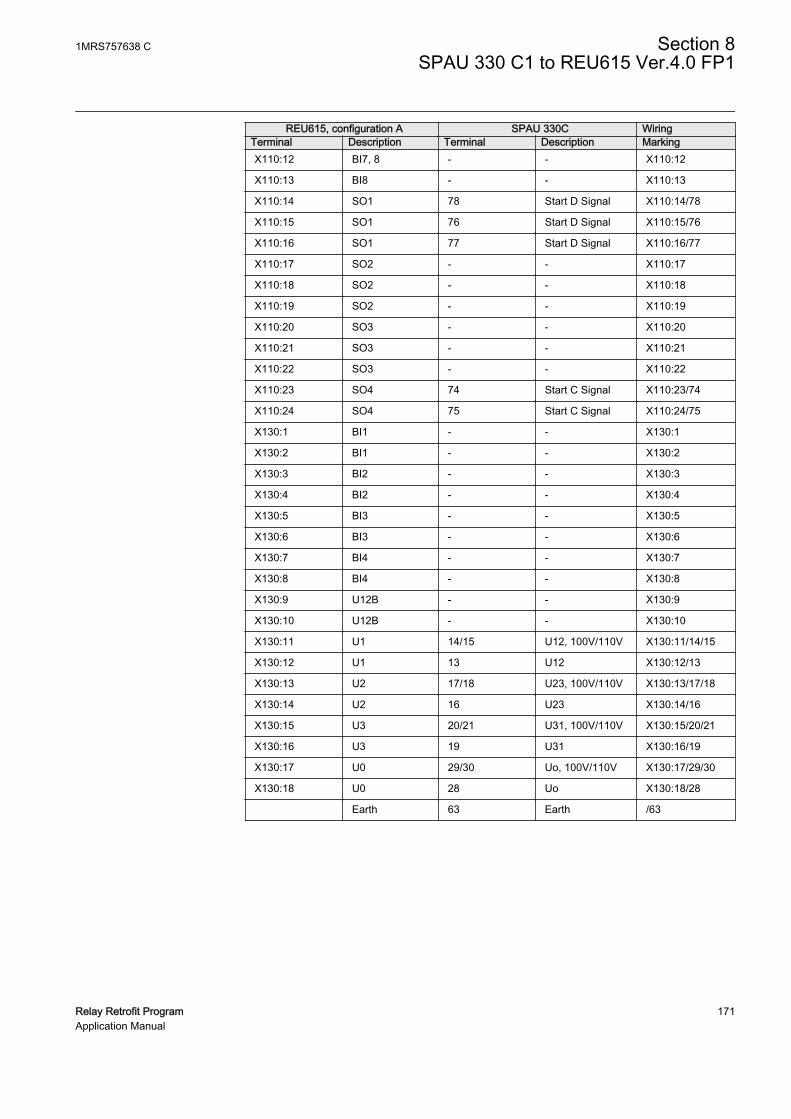
REU615, configuration A SPAU 330C WiringTerminal Description Terminal Description MarkingX110:12 BI7, 8 - - X110:12
X110:13 BI8 - - X110:13
X110:14 SO1 78 Start D Signal X110:14/78
X110:15 SO1 76 Start D Signal X110:15/76
X110:16 SO1 77 Start D Signal X110:16/77
X110:17 SO2 - - X110:17
X110:18 SO2 - - X110:18
X110:19 SO2 - - X110:19
X110:20 SO3 - - X110:20
X110:21 SO3 - - X110:21
X110:22 SO3 - - X110:22
X110:23 SO4 74 Start C Signal X110:23/74
X110:24 SO4 75 Start C Signal X110:24/75
X130:1 BI1 - - X130:1
X130:2 BI1 - - X130:2
X130:3 BI2 - - X130:3
X130:4 BI2 - - X130:4
X130:5 BI3 - - X130:5
X130:6 BI3 - - X130:6
X130:7 BI4 - - X130:7
X130:8 BI4 - - X130:8
X130:9 U12B - - X130:9
X130:10 U12B - - X130:10
X130:11 U1 14/15 U12, 100V/110V X130:11/14/15
X130:12 U1 13 U12 X130:12/13
X130:13 U2 17/18 U23, 100V/110V X130:13/17/18
X130:14 U2 16 U23 X130:14/16
X130:15 U3 20/21 U31, 100V/110V X130:15/20/21
X130:16 U3 19 U31 X130:16/19
X130:17 U0 29/30 Uo, 100V/110V X130:17/29/30
X130:18 U0 28 Uo X130:18/28
Earth 63 Earth /63
1MRS757638 C Section 8SPAU 330 C1 to REU615 Ver.4.0 FP1
Relay Retrofit Program 171Application Manual
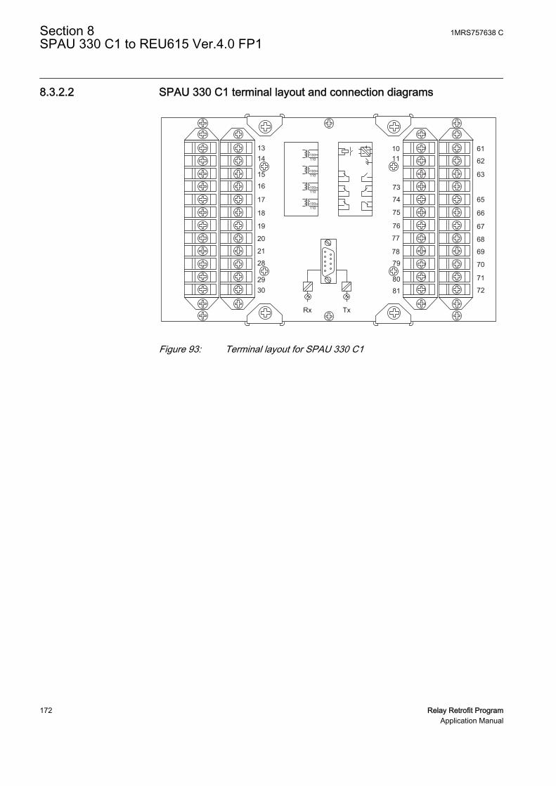
8.3.2.2 SPAU 330 C1 terminal layout and connection diagrams
1314
15
16
17
18
19
20
21
28
2930
1011
73
74
75
76
77
78
79
80
81
Rx Tx
61
62
63
65
66
67
68
69
70
71
72
100110
100110
100110
100110
GUID-0841F2EF-FD35-48DB-A327-77860B839F17 V1 EN
Figure 93: Terminal layout for SPAU 330 C1
Section 8 1MRS757638 CSPAU 330 C1 to REU615 Ver.4.0 FP1
172 Relay Retrofit ProgramApplication Manual

GUID-2980244A-81E4-4F07-9022-37694D5E6C19 V1 EN
Figure 94: Connection diagram for SPAU 330 C1
1MRS757638 C Section 8SPAU 330 C1 to REU615 Ver.4.0 FP1
Relay Retrofit Program 173Application Manual
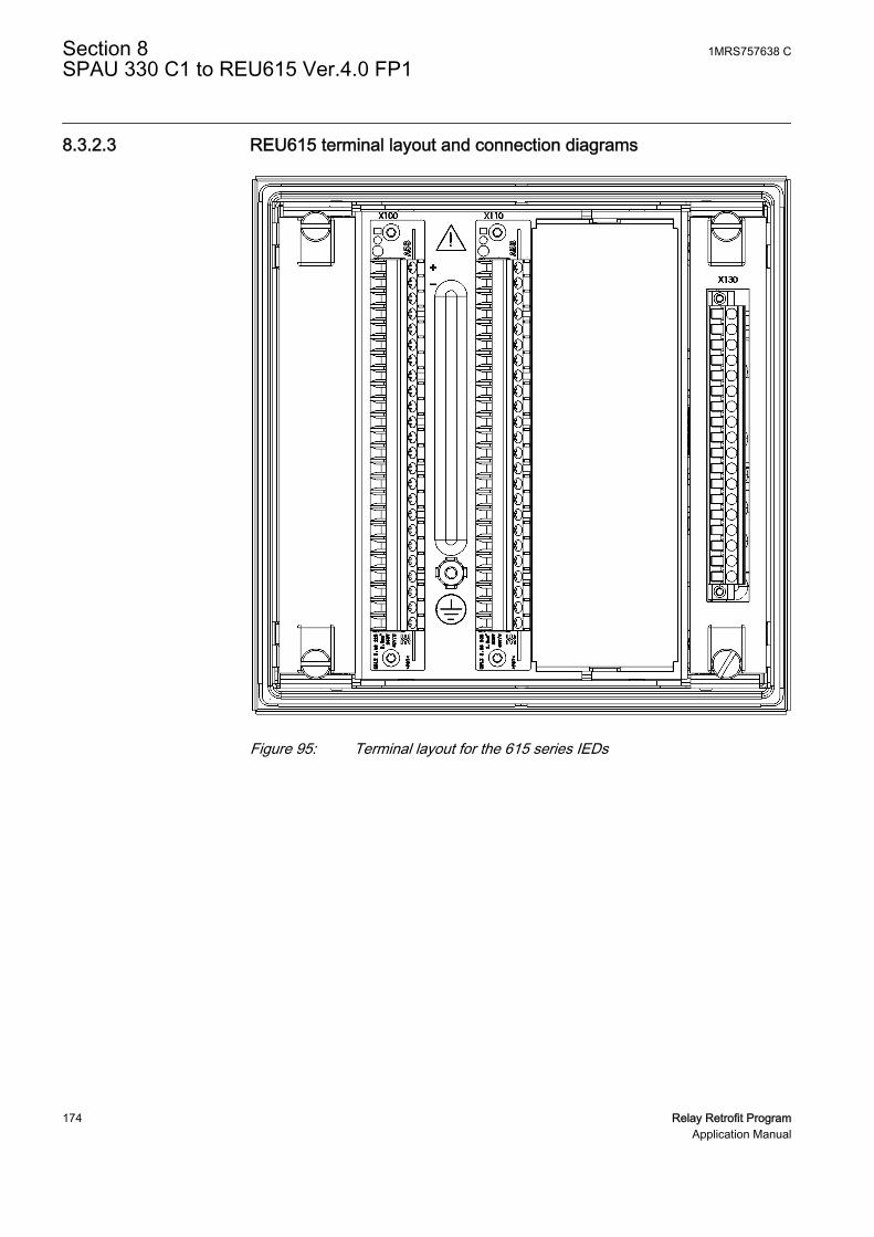
8.3.2.3 REU615 terminal layout and connection diagrams
GUID-CCFA401F-C098-432F-9D37-B2F81754E4D4 V1 EN
Figure 95: Terminal layout for the 615 series IEDs
Section 8 1MRS757638 CSPAU 330 C1 to REU615 Ver.4.0 FP1
174 Relay Retrofit ProgramApplication Manual

REU615
X13
Light sensor input 1 1 )
X14
Light sensor input 2 1 )
X15
Light sensor input 3 1 )
16 17 19 18
X100
6 7 8 9 10 11 12 13
15
14
2 1 3 4 5
22 21 23 24
SO2
TCS2 PO4
SO1
TCS1 PO3
PO2
PO1
IRF
+ -
Uaux
20
L1 L2 L3
da dn
X110
3 4 5 6
7 8 9 10
BI 6
BI 5
BI 4
BI 3
BI 2
BI 8
BI 712 13
11
BI 11 2
X110
16 14 15 19 17 18 22 20 21
SO3
SO2
SO1
23
SO4
24
a n N
A
1 ) Optional
X130
1 2
3 4 5 6
BI 4
BI 3
BI 2
BI 1
8 7 9 10 11 12
U12B
13 14
U1
15 16
U2
17 18
U3
UoN
N
N
N
60 - N 210V
60 - 210V 60 - 210V 60 - 210V 60 - 210V
Uaux IRF
Output relay B
Output relay A
Output relay E
Output relay D
Output relay C
+
_BS1
GUID-CC7372CC-DBFC-45E4-BA85-5A9E9D158F0F V1 EN
Figure 96: Connection diagram for REU615 with standard configuration Areplacing SPAU 330 C1
1MRS757638 C Section 8SPAU 330 C1 to REU615 Ver.4.0 FP1
Relay Retrofit Program 175Application Manual

176

Section 9 MCX 912 and MCX 913 to REM615 Ver.4.0 FP1
9.1 Retrofit scope
Protection functions of MCX 912 and MCX 913 are replicated by REM615 withdeviations.
• REM615 supports only one instance of Overcurrent protection I> (Mode 03,Mode 43 and Mode 45) at the same time. If more than one instance is used inMCX 91x relay, the settings are taken from the first active instance. Otherinstances are ignored in migration.
• REM615 supports only one instance of Short circuit protection I>> (Mode 01and Mode 41) at the same time. If both instances are used in MCX 91x relay, thesettings are taken from the first instance. In this case, the second instance isignored.
• REM615 does not support Temperature rise (Mode 20).• REM615 supports only value “0” for Start with overheating (Mode 21).• REM615 does not support Max demand value (Mode 90).
9.2 Engineering
In retrofit applications, the target of the configuration phase is to parameterize andconfigure the replacement IED to reproduce the features and functions of the existingrelay. The configuration process comprises of various steps with different toolsdepending on the project.
Parameter collection form
• MCX 91x relay does not have a communication interface. The parameter valuesused in the existing relay have to be collected using a Microsoft Excel basedparameter collection form.
• Parameter collection form can export parameter values to a text file in a comma-separated (CSV) format. The .csv file is imported to the IED Migration Supporttool during the migration process.
PCM600
• Instantiating a new retrofit IED using the IED Migration Support tool inPCM600.
1MRS757638 C Section 9MCX 912 and MCX 913 to REM615 Ver.4.0 FP1
Relay Retrofit Program 177Application Manual

• Selecting the replacement IED (type and order code)• Importing existing relay configuration (.csv file)
• Creating a 615 series IED under PCM600 plant structure using the IED MigrationSupport tool.
• Writing configuration to the IED.
Project specific additional engineering phases
• Using Application Configuration tool in PCM600 to add functionality to themigrated configuration, if required.
• Communication engineering with relevant PCM600 tools, if required.
No engineering activity is required for wiring as marking sets and wiring harness areavailable.
ARC and RTD options are not used in the migrated configuration evenif these optional features are selected for REM615.
9.2.1 Existing relay and system engineering information
The parameters of MCX 91x are read from the relay display. All the neededinformation is collected to a Microsoft Excel based parameter collection form. Theconfiguration parameters are exported from the Microsoft Excel template as a .csv fileand imported in PCM600 during the migration process.
Different REM615 system configuration parameters are set based on the informationprovided in the parameter collection form.
• General system settings• Rated frequency is set based on the MCX 91x name plate.• Blocking mode is set to value “Block all”.
• Analog input settings and phase currents• Secondary current is set to “1A” or “5A” based on the collected value.• Primary current is set to the collected value.
• Analog input settings and residual currents• Secondary current is set to “1A” or “5A” based on the collected value.• Primary current is set to the collected value.
Section 9 1MRS757638 CMCX 912 and MCX 913 to REM615 Ver.4.0 FP1
178 Relay Retrofit ProgramApplication Manual

9.2.2 FunctionsTable 34: Functions included in configuration
MCX 91x REM615 Description EnabledMode 03Mode 43Mode 45
PHLPTOC1 Three-phase non-directional overcurrentprotection, low stage, instance 1
Yes1)2)
Mode 01Mode 41
PHIPTOC1 Three-phase non-directional overcurrentprotection, instantaneous stage, instance 1
Yes1)2)
Mode 07 EFLPTOC1 Non-directional earth-fault protection, lowstage, instance 1
Yes1)
EFHPTOC1 Non-directional earth-fault protection, highstage, instance 1
No
Mode 05 MNSPTOC1 Negative sequence overcurrent protectionfor motors, instance 1
Yes1)
MNSPTOC2 Negative sequence overcurrent protectionfor motors, instance 2
No
Mode 15 LOFLPTUC1 Loss of load supervision Yes1)
Mode 11 JAMPTOC1 Motor load jam protection Yes1)
Mode 11Mode 13Mode 17
STTPMSU1 Motor startup supervision Yes1)
PREVPTOC1 Phase reversal protection No
Mode 30Mode 31
MPTTR1 Thermal overload protection for motors Yes1)
CCBRBRF1 Circuit breaker failure protection No
Resetbutton
TRPPTRC1 Master trip, instance 1 Yes3)
TRPPTRC2 Master trip, instance 2 No
ARCSARC1 Arc protection, instance 1 No
ARCSARC2 Arc protection, instance 2 No
ARCSARC3 Arc protection, instance 3 No
MAPGAPC1 Multi-purpose protection, instance 1 No
MAPGAPC2 Multi-purpose protection, instance 2 No
MAPGAPC3 Multi-purpose protection, instance 3 No
MAPGAPC4 Multi-purpose protection, instance 4 No
MAPGAPC5 Multi-purpose protection, instance 5 No
MAPGAPC6 Multi-purpose protection, instance 6 No
CBXCBR1 Circuit breaker control No
DCXSWI1 Disconnector control, instance 1 No
DCXSWI2 Disconnector control, instance 2 No
ESXSWI1 Earthing switch control No
DCSXSWI1 Disconnector position indication, instance 1 No
DCSXSWI2 Disconnector position indication, instance 2 No
Table continues on next page
1MRS757638 C Section 9MCX 912 and MCX 913 to REM615 Ver.4.0 FP1
Relay Retrofit Program 179Application Manual
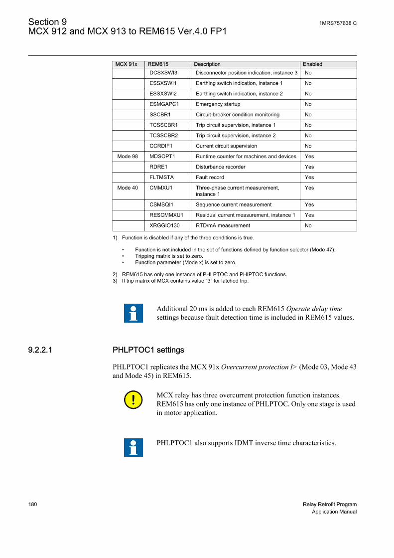
MCX 91x REM615 Description Enabled DCSXSWI3 Disconnector position indication, instance 3 No
ESSXSWI1 Earthing switch indication, instance 1 No
ESSXSWI2 Earthing switch indication, instance 2 No
ESMGAPC1 Emergency startup No
SSCBR1 Circuit-breaker condition monitoring No
TCSSCBR1 Trip circuit supervision, instance 1 No
TCSSCBR2 Trip circuit supervision, instance 2 No
CCRDIF1 Current circuit supervision No
Mode 98 MDSOPT1 Runtime counter for machines and devices Yes
RDRE1 Disturbance recorder Yes
FLTMSTA Fault record Yes
Mode 40 CMMXU1 Three-phase current measurement,instance 1
Yes
CSMSQI1 Sequence current measurement Yes
RESCMMXU1 Residual current measurement, instance 1 Yes
XRGGIO130 RTD/mA measurement No
1) Function is disabled if any of the three conditions is true.
• Function is not included in the set of functions defined by function selector (Mode 47).• Tripping matrix is set to zero.• Function parameter (Mode x) is set to zero.
2) REM615 has only one instance of PHLPTOC and PHIPTOC functions.3) If trip matrix of MCX contains value “3” for latched trip.
Additional 20 ms is added to each REM615 Operate delay timesettings because fault detection time is included in REM615 values.
9.2.2.1 PHLPTOC1 settings
PHLPTOC1 replicates the MCX 91x Overcurrent protection I> (Mode 03, Mode 43and Mode 45) in REM615.
MCX relay has three overcurrent protection function instances.REM615 has only one instance of PHLPTOC. Only one stage is usedin motor application.
PHLPTOC1 also supports IDMT inverse time characteristics.
Section 9 1MRS757638 CMCX 912 and MCX 913 to REM615 Ver.4.0 FP1
180 Relay Retrofit ProgramApplication Manual
If only one instance of function is used, the settings of the active instance are used. Ifmore than one instance is used, the settings are used from the lowest instance numberand the other instances are ignored. In this case, warning messages are issued tomigration report for ignored instances.
• Operation parameter of PHLPTOC1 is set “on” if function parameters (Mode 03,Mode 43 and Mode 45) do not have value “0”, the function belongs to function setdefined by function selector (Mode 47) and trip matrix (Mode 103, Mode 143 andMode 141) does not have value “0”.
• It is possible to set MCX 91x greater than PHLPTOC1 Start value settingmaximum value “5”. A warning message is issued, if necessary.
• Additional 20 ms has been added to PHLPTOC1 Operate delay time settingbecause fault detection time is included in REM615 values.
• Output signals OPERATE and START are connected to X100 PO1, PO2, PO3 andPO4 outputs according to the tripping matrix.
9.2.2.2 PHIPTOC1 settings
PHIPTOC1 replicates the behaviour of MCX 91x short circuit protection I>> (Mode01 and Mode 41) in REM615.
MCX relay has two short-circuit protection function instances.REM615 has only one instance of PHIPTOC, but typically the secondinstance is used as a backup.
If only one instance of function is used, the settings of active instance is used. If bothinstances are used, the settings from the first instance is used and warning message isissued to migration report.
• Operation parameter of PHIPTOC1 is set “on” if function parameters (Mode 01and Mode 41) do not have value “0”, the function belongs to function set definedby function selector (Mode 47) and trip matrix (Mode 101 and Mode 141) doesnot have value “0”.
• It is possible to set MCX 91x value below PHIPTOC1 Start value settingminimum value “1”. A warning message is issued, if necessary.
• Additional 20 ms is added to PHIPTOC1 Operate delay time setting because faultdetection time is included in REM615 values.
• Output signals OPERATE and START are connected to X100 PO1, PO2, PO3 andPO4 outputs according to the tripping matrix.
9.2.2.3 EFLPTOC1 settings
EFLPTOC1 replicates the behaviour of MCX 91x earth-fault protection (Mode 07) inREM615.
1MRS757638 C Section 9MCX 912 and MCX 913 to REM615 Ver.4.0 FP1
Relay Retrofit Program 181Application Manual

• Operation parameter of EFLPTOC1 is set to “on” if the function parameter(Mode 07) does not have value “0”, the function belongs to function set definedby function selector (Mode 47) and trip matrix (Mode 107) does not have value“0”.
• Setting Io signal Sel is set to “Calculated Io” or “Measured Io” according to Mode09.
• Setting Start value is calculated taking the calculated or measured Io into account.It is possible to set MCX 91x below EFLPTOC1 Start value setting minimumvalue “0.01”. A note is generated, if necessary.
• Additional 20 ms is added to EFLPTOC1 Operate delay time setting becausefault detection time is included in REM615 values.
• It is possible to set MCX 91x below EFLPTOC1 Operate delay time settingminimum value “40ms”. A note is generated, if necessary.
• Output signals OPERATE and START are connected to X100 PO1, PO2, PO3 andPO4 outputs according to the tripping matrix.
9.2.2.4 LOFLPTUC1 settings
LOFLPTUC1 replicates the behaviour of MCX 91x protection against low load(Mode 15) in REM615. For loss of load checking, the MCX relay has current settingMode 15 and time setting Mode 16.
• Operation setting of LOFLPTUC1 is set “on” if function parameter (Mode 15)does not have value “0”, the function belongs to function set defined by functionselector (Mode 47) and trip matrix (Mode 115) does not have value “0”.
• Start value low is set to value “0.1 × Mode 00”.• Start value high is set to value “Mode 00 × Mode 15”• Operate delay time is set to value “Mode 16 × 1000”. If the calculated value is less
than REM615 minimum limit, the IED Migration Support tool uses minimumvalue and issues a note to migration report.
• Output signals OPERATE and START are connected to X100 PO1, PO2, PO3 andPO4 outputs according to the tripping matrix.
9.2.2.5 JAMPTOC1 settings
JAMPTOC1 replicates the behaviour of MCX 91x locked rotor protection (Mode 11)in REM615.
The MCX relay contains Mode 11, a locked rotor protection which functions like asimple overcurrent protection. This function is not blocked by any other function inthe MCX relay and is active during motor startup. The start and trip signals can befreely connected via parameterized tripping matrix to the signalling relay MRI, MRII,tripping relay ARI or ARII. The signaling and tripping relays can be connected to aspeed switch to prevent a motor start when the locked rotor time is less than the motorstartup time.
Section 9 1MRS757638 CMCX 912 and MCX 913 to REM615 Ver.4.0 FP1
182 Relay Retrofit ProgramApplication Manual

For retrofit purposes, JAMPTOC1 is used with the settings. JAMPTOC1 is notblocked during motor startup. The locked rotor protection in the STTPMSU1 is notused because the speed switch must not be present in all retrofit panels.
In REM615, start is not available from JAMPTOC1 and cannot beused in tripping matrix.
• Operation setting of JAMPTOC1 is set “on” if function parameter (Mode 11)does not have value “0”, the function belongs to function set defined by functionselector (Mode 47) and trip matrix (Mode 111) does not have value “0”.
• Start value setting is set to value “Mode 00 × Mode 11”. If calculated value is lessthan REM615 minimum limit, the IED Migration Support tool issues a note tomigration report.
• Operation delay time setting is set to value “Mode 12 × 1000”. If calculated valueis greater than REM615 maximum limit, the IED Migration Support tool issuesa note to migration report.
• Output signal OPERATE is connected to X100 PO1, PO2, PO3 and PO4 outputsaccording to the tripping matrix.
9.2.2.6 MNSPTOC1 settings
MNSPTOC1 replicates the behaviour of MCX 91x negative phase sequenceprotection (Mode 05) in REM615.
The proper operation of MNSPTOC1 is dependent on which wiring variant has beenoriginally used for MCX 91x relay. Information of used wiring variant is availablethrough parameter collection form. Mode 09 defines if the calculation is internal orexternal and a separate question defines if Io current transformer is present.
Different wiring variants are described in detail in the installationsection.
• Operation parameter of MNSPTOC1 is set “on” if function parameter (Mode 05)does not have value “0”, the function belongs to function set defined by functionselector (Mode 47) and trip matrix (Mode 105) does not have value “0”.
• It is possible to set MCX 91x greater than MNSPTOC1 Start value settingmaximum value “0.5”. A note is generated, if necessary.
• It is possible to set MCX 91x greater than MNSPTOC1 Operate delay timesetting maximum value “120000 ms”. A note is generated, if necessary.
• Migration package generates a note for which wiring variant to be used.• Output signals OPERATE and START are connected to X100 PO1, PO2, PO3 and
PO4 outputs according to the tripping matrix.
1MRS757638 C Section 9MCX 912 and MCX 913 to REM615 Ver.4.0 FP1
Relay Retrofit Program 183Application Manual
9.2.2.7 STTPMSU1 settings
STTPMSU1 replicates the behavior of MCX 91x motor starting protection (Mode 13)and protection against too many motor starts (Mode 17 and Mode 18).
• Operation parameter of STTPMSU1 is set “on” if function parameters (Mode 13,Mode 17 and Mode 18) do not have value “0”, the function belongs to function setdefined by function selector (Mode 47) and trip matrix (Mode 113 and Mode 117)does not have value “0”.
• Operation Red rate is used to protect against too many motor starts. Motor startuptime is collected from user because it is not available in MCX relay as aparameter. If Mode 17 is enabled, the value of parameter is calculated as Motorstartup time × 3600/Mode 19.
• Cumulative time Lim is used to protect against too many motor starts.• Motor start-up A and Motor start-up time are calculated to give the same inverse
operation curve, although the setting values can look quite different.
In REM615, STTPMSU1 is used for counting starts, but there is noseparation between warm and cold starts. STTPMSU1 does not countthe number of starts. Instead, the cumulative time is used for starts.
A trip signal in the meaning of the MCX relay in not available in theSTTPMSU1. REM615 settings are based on Mode 17.
9.2.2.8 MPTTR1 settings
MPTTR1 replicates the behavior of MCX 91x thermal overload protection (Mode 30and Mode 31). The MCX relay has only one heating time constant which has to beused for the Time constant start and Time constant normal parameter in REM615. TheREM615 ΘA and ΘB handling is eliminated by setting the parameter Weighting factorp fix to “100%”.
• Operation parameter of MPTTR1 is set “on” if function parameter (Mode 30)does not have value “0”, the function belongs to function set defined by functionselector (Mode 47) and trip matrix (Mode 130) does not have value “0”.
• Rated current is set to value of Mode 00 if Operation parameter is “on”.• Overload factor is set to value “sqr (Mode 31/100)”. If the calculated value is out
of REM615 setting range, the minimum or maximum value is used and the IEDMigration Support tool issues a note to migration report.
• Alarm thermal value is set to value ”Mode 30/Mode 31 × 100%”. If calculatedvalue is below the minimum value of REM615, the IED Migration Support toolissues a note to migration report.
Section 9 1MRS757638 CMCX 912 and MCX 913 to REM615 Ver.4.0 FP1
184 Relay Retrofit ProgramApplication Manual

• Restart thermal value is calculated as (Mode 31 - Mode32)/Mode 31 × 100%. Ifthe calculated value is greater than the maximum value of REM615, the IEDMigration Support tool issues a note to migration report.
• Weighting factor parameter value is set to “100%” if Mode 33 is less than “66”.Otherwise, the value is set to “110.5 - 0.158 × Mode 33”.
• Time constant normal is set to value “Mode 33 × 60”. If the calculated value is outof REM615 setting range, correct behavior is achieved by adjusting weightingfactor p setting.
• Time constant start setting value is copied from Time constant normal.• Time constant stop is set to value “Mode 34 × 60”. If calculated value is out of
REM615 setting range, the IED Migration Support tool issues a note to migrationreport.
• Output signals OPERATE and START are connected to X100 PO1, PO2, PO3 andPO4 outputs according to the tripping matrix.
9.2.2.9 CMMXU1 settings
CMMXU1 replicates the behavior of MCX 91x display of mean value and maximummean value (Mode 40, Mode 89 and Mode 90).
• Demand interval parameter does not support value “8 minutes” and it is set to “10minutes”.
• Max demand value (Mode 90) is not supported by REM615.
REM615 supports calculated demand values per phase and actualphase currents.
9.2.2.10 MDSOPT1 settings
MDSOPT1 replicates the behavior of MCX 91x operating hours counter (Mode 98).
When POS_ACTIVE is active, the count is continuously added to the time durationuntil it is deactivated. The OPR_TIME output is the total duration for whichPOS_ACTIVE is active. The unit of time duration count for OPR_TIME is hour. Thevalue of OPR_TIME is available through the monitored data view.
The OPR_TIME output has a continuously increasing value and it is stored in anonvolatile memory. When POS_ACTIVE is active, the OPR_TIME count startsincreasing from the previous value. The count of OPR_TIME saturates at a final valueof “299999”, that is, no further increment is possible. The activation of RESET canreset the count to the Initial value setting.
MDSOPT1 is used to count the operation hours. The POS_ACTIVE input isconnected to the function CMMXU1 output HIGH_WARN. This output is active whenthe current exceeds 0.1 × IE (The MCX relay counts the hours when the relay is ready
1MRS757638 C Section 9MCX 912 and MCX 913 to REM615 Ver.4.0 FP1
Relay Retrofit Program 185Application Manual

and the current is >=0.1 × IE). MDSOPT1 activates the WARNING output when thecounter reaches the MCX value “9999 × 10” h. This output is connected to theMDSOPT1 input RESET to set the counter back to Initial value = “0”.
• Parameter Warning value is set to fixed value “99990”.• Parameter Alarm value is set to fixed value “299999”.• REM615 does not support setting of the counter value from the HMI.
CMMXU1 parameter A high limit is used to start and stop theoperation hour counting of the function MDSOPT1.
9.2.3 I/O connections
I/O connections at MCX 91x terminals are remapped to REM615 I/O terminal.
REM615 terminals have additional binary I/Os whose behavior does not depend onMCX 91x configuration.
Table 35: Binary inputs
REM615 MCX 91x UsageBI1 (X120:1/2) Blocking input (E:1,3,4 or 5/2) Selective or complete blocking
of output relays are based onMCX switch S4 and S65positions.
BI2 (X120:3/2) N/A Circuit breaker closed
BI3 (X120:4/2) N/A Circuit breaker open
BI4 (X120:5/6) N/A External restart inhibit
Table 36: Binary outputs
REM615 MCX 91x UsagePO1 (X100:6/7) MRI (E:11/12) Signal relay I1)
PO2 (X100:8/9) MRII (E:7/8) Signal relay II1)
SO1 (X100:10/11,(12)) N/A Connect parallel with PO3signal for switchover contact
SO2 (X100:13/14) N/A Unused
PO3 (X100:15/19) ARI (A:4/5) Tripping relay I1)
PO4 (X100:20/24) ARII (A:8/9) Tripping relay II1)
1) Behavior of the output relays is defined by MCX tripping matrix functionality
Section 9 1MRS757638 CMCX 912 and MCX 913 to REM615 Ver.4.0 FP1
186 Relay Retrofit ProgramApplication Manual
9.2.4 Functional diagrams
The functional diagrams describe the default input, output, alarm LED and functionto-function connections in REM615. The default connections can be viewed andchanged with PCM600 according to the application requirements.
Only MCX 91x migrated functions are represented in the connectiondiagrams. REM615 also includes other functions whose connectionsare configured according to standard configuration A. See REM615Application Manual.
Operation of additional REM615 functions is disabled if thecorresponding functionality is not available in MCX 91x. Thesefunctions are visible in the connection diagrams even if disabled.
Blocking input behavior and protection function connection to outputrelays are defined by settings provided during the migration.
The parts affected by the migration compared to the 615 seriesstandard configuration are highlighted in gray.
1MRS757638 C Section 9MCX 912 and MCX 913 to REM615 Ver.4.0 FP1
Relay Retrofit Program 187Application Manual

9.2.4.1 Functional diagrams for protection
SHORT CIRCUIT AND OVER CURRENT PROTECTION
PositiveCurrentDirection
L1L2L3
P1
P2S2
S1
P1
P2S2
S1
X120
12
3
4
5
6
7
89
1011
1213
14
BI 1 (Blocking input)
BI 2 (CB Closed)
BI 3 (CB Closed)
STTPMSU1_MOT_STARTUP
IL1
IL2
IL3
Io
BI 4 (External restartinhibit)
3I
PHLPTOC1_STARTPHLPTOC1_OPERATE
PHIPTOC1_STARTPHIPTOC1_OPERATE
JAMPTOC1_OPERATE
3I
BLOCK
START
OPERATE
ENA_MULT
3I
BLOCK
START
OPERATE
ENA_MULT
3I
BLOCK
START
OPERATE
MOTOR JAM PROTECTION
LED1
PHLPTOC(1)3I>
51P-1
PHIPTOC(1)3I>>>
50P/51P
JAMPTOC(1)stI >
51LR
REM615_Conf_A_1M3~
GUID-E2B69335-9A78-4FF1-8F26-5E305542D889 V1 EN
Figure 97: Overcurrent protection
Functional diagrams illustrate the external connections defined in the615 series standard configuration. Check the connection diagram tosee the actual external connections of the replacement IED.
• PHLPTOC1, PHIPTOC1 and JAMPTOC1 are enabled if conditions are fulfilledduring migration.
• X120:BI1 is used as a blocking input.• MOT_STARTUP output of STTPMSU1 is connected to BLOCK input of
PHLPTOC1 instead of BLOCK input of JAMPTOC1.
Section 9 1MRS757638 CMCX 912 and MCX 913 to REM615 Ver.4.0 FP1
188 Relay Retrofit ProgramApplication Manual

EARTH-FAULT PROTECTION
EFLPTOC1_OPERATEEFLPTOC1_START
EFHPTOC1_STARTEFHPTOC1_OPERATE
LED2OR
PHIPTOC1_START
I0
BLOCK
START
OPERATE
ENA_MULT
I0
BLOCK
START
OPERATE
ENA_MULT
EFLPTOC10I >
51N-1
51N-2
EFHPTOC10I >>
GUID-71614205-8C77-459D-ACF0-8C9FB1566C42 V1 EN
Figure 98: Non-directional earth-fault protection
• EFLPTOC1 is enabled if conditions are fulfilled during migration.• Connection from START output of PHIPTOC1 to BLOCK input of EFLPTOC1 is
removed.• EFHPTOC1 is disabled in migration.
EMERGENCY START AND RESTART INHIBIT
X12012
BI1 (Emergency start enable)3I
BLOCK
ST_EMERG_RQ
ST_EMERG_ENA
ESMGAPC(1)ESTART
ESMGAPC1_ST_EMERG_ENA
LED11
LED3
3I
BLOCK
START_EMERG
AMB_TEMB BLK_RESTART
OPERATE
ALARM
MPTTR1_OPERATEMPTTR1_ALARMMPTTR1_BLK_RESTART
ST_REMATPSGAPC1
IN1 OUT1
IN2 OUT2
OR RESTART_INHIBITTRPPTRC1_TRIP
STTPMSU1_LOCK_STARTMNSSPTOC1_BLK_RESTARTMNSSPTOC1_BLK_RESTART LED5
BI4 (External restart inhibit)X120
56
MPTTR(1)30>M
49M
GUID-5F744A59-5FE5-4E4C-9E95-8779B8EBF8B5 V1 EN
Figure 99: Emergency start and restart inhibit
1MRS757638 C Section 9MCX 912 and MCX 913 to REM615 Ver.4.0 FP1
Relay Retrofit Program 189Application Manual

• ESMGAPC1 is disabled.• X120:BI1 is used as a blocking input and its behavior is defined by settings of S4
and S65 during the migration.• MPTTR1 function is enabled if conditions are fulfilled during migration.• START_EMERG input of MPTTRI1 is disconnected.• BLK_RESTART output of MPTTR1 and TRIP output of TRPPTRC1 are
disconnected from the OR condition for RESTART_INHIBIT signal.
MOTOR START UP AND RUNTIME COUNTER
CB Closed
ESMGAPC_ST_EMERG_ENA
PHLPTOC1_OPERATEJAMPTOC1_OPERATEMNSPTOC1_OPERATEMNSPTOC2_OPERATE
PREVPTOC1_OPERATELOFLPTUC_OPERATE
STTPMSU1_OPR_IITMAPGAPC1_OPERATEMAPGAPC2_OPERATEMAPGAPC3_OPERATE
CMMXU1_HIGH_WAR
STTPMSU1_OPR_IIT
STTPMSU1_MOT_STARTUPSTTPMSU1_LOCK_START
MDSOPT1_ALARM
BLOCK
BLK_LK_ST
CB_CLOSED
STALL_IND
ST_EMERG_ENA
CPR_IIT
OPR_STALL
MOT_START
LOCK_START
STTPMSU1ls2t n<
BLOCK ALARM
POS_ACTIVE WARNING
MDSOPT1OPTSOPTM
LED4OR
GUID-D9D7897A-D689-448F-9FC5-14DCBD85D150 V1 EN
Figure 100: Motor startup supervision
• STTPMSU1 function is enabled if conditions are fulfilled during migration.• ST_EMERG_ENA input is disconnected.• CB Closed signal is disconnected.• MDSOPT1 is enabled.• BLOCK input of MDSOPT is connected to HIGH_WARN output of CMMXU1.
Section 9 1MRS757638 CMCX 912 and MCX 913 to REM615 Ver.4.0 FP1
190 Relay Retrofit ProgramApplication Manual

REM615_Conf_A_5
UNBALANCE AND PHASE REVERSAL PROTECTION
MNSPTOC(1)
MNSPTOC(2)
MNSPTOC1_OPERATEMNSPTOC1_STARTMNSPTOC1_BLK_RESTART
3I
BLK_OPR
OPERATE
ALARM
BLK_RESTART
2I >M
46M
2I >M
46M3I
BLK_OPR
OPERATE
ALARM
BLK_RESTART
PREVPTOC(1)2I >>
46R3I
BLOCKSTART
OPERATE
MNSPTOC1_OPERATEMNSPTOC1_STARTMNSPTOC1_BLK_RESTART
PREVPTOC1_OPERATEPREVPTOC1_START
3I
BLOCKSTART
OPERATE
LOSS OF LOAD PROTECTION
LOFLPTUC(1)3l<
37LOFLPTUC1_OPERATE
STTPMSU1_MOT_STARTUP
CCRDIF1_FAIL
GUID-D62D4655-FFCB-4233-8A55-9C0C29F91947 V1 EN
Figure 101: Phase unbalance protection
• MNSPTOC1 and LOFLPTUC1 are enabled if conditions are fulfilled duringmigration.
• BLK_OPER input of MNSPTOC1 is disconnected.• BLOCK input of LOFLPTUC1 is connected to MOT_STARTUP output of
STTPMSU1.• MNSPTOC2 and PREVPTOC1 are disabled.
1MRS757638 C Section 9MCX 912 and MCX 913 to REM615 Ver.4.0 FP1
Relay Retrofit Program 191Application Manual

BREAKER FAILURE PROTECTION
PHLPTOC1_OPERATE
OR
CB Closed
CCBRBRF1_TRRET
PHLPTOC1_OPERATE
EFLPTOC1_OPERATE
STTPMSU1_OPR_IITMNSPTOC2_OPERATEMNSPTOC1_OPERATEEFHPTOC1_OPERATE
JAMPTOC1_OPERATE
ARCSARC1_OPERATEARCSARC2_OPERATEARCSARC3_OPERATE
CCBRBRF1_TRBU
LED6
X100
Circuit breaker failureprotection trip toupstream breaker
PO2
89
3I
I0
POSCLOSE
START
CB_FAULT
BLOCK
TRRET
TRBU
CB_FAULT_AL
CCBRBRF03I> / I > BF
51BF / 51NBF
GUID-9A3DAA61-E9B2-437C-BF8C-8B0F12939154 V1 EN
Figure 102: Circuit breaker failure protection
• CCBRBRF1 is disabled and disconnected from the output PO2.
Section 9 1MRS757638 CMCX 912 and MCX 913 to REM615 Ver.4.0 FP1
192 Relay Retrofit ProgramApplication Manual

9.2.4.2 Functional diagrams for disturbance recorder and supervision
LED7 (DR TRIGGERING)PHLPTOC1_STARTPHIPTOC1_START
PREVPTOC1_START
ESMGAPC1_ST_EMERG_ENA
EFHPTOC1_START
CCBRBRF1_TRRETCCBRBRF1_TRBU
MPTTR1_ALARM
OREFLPTOC1_OPERATEEFHPTOC1_OPERATE
ORARCSARC1_ARC_FLT_DETARCSARC2_ARC_FLT_DETARCSARC3_ARC_FLT_DET ARCSARC1_OPERATE
ARCSARC2_OPERATEARCSARC3_OPERATE
X120 BI 4 (External restart inhibit)
X120 BI 2 (CB Closed)X120 BI 3 (CB Open)
CCRDIF1_FAIL
RDRE1BI#1
BI#2
BI#3
BI#4
BI#5
BI#6
BI#7
BI#8
BI#9
BI#10
BI#11
BI#12
BI#13
BI#14
BI#15
BI#16
BI#17
BI#18
BI#19
BI#20
BI#21
BI#22
BI#23
BI#24
BI#25
BI#26
BI#27
BI#28
BI#29
BI#30
BI#31
BI#32
BI#33
BI#34
BI#35
BI#36
BI#37
BI#38
BI#39
BI#40
TRIGGERED
EFLPTOC1_START
MPTTR1_BLK_RESTART
STTPMSU1_MOT_STARTUPSTTPMSU1_LOCK_STARTMNSPTOC1_STARTMNSPTOC1_BLK_RESTARTMNSPTOC2_STARTMNSPTOC2_BLK_RESTART
MAPGAPC1_STARTMAPGAPC2_STARTMAPGAPC3_START
PHLPTOC1_OPERATEPHIPTOC1_OPERATEJAMPTOC1_OPERATE
PREVPTOC1_OPERATELOFLPTUC1_OPERATEMPTTR1_OPERATEMAPGAPC1_OPERATEMAPGAPC2_OPERATEMAPGAPC3_OPERATE
STTPMSU1_OPR_IIT
ORMNSPTOC1_OPERATEMNSPTOC2_OPERATE
DISTURBANCE RECORDER
BI#41
BI#42
BI#43
BI#44
BI#45
BI#46
BI#47
BI#48
BI#49
BI#50
BI#51
BI 52
BI 53
BI 54
BI 55
#
#
#
#
BI 56#
BI 57#
OR10LOFLPTUC1_STARTMPTTR1_ALARMSR5MRI OUTPUT ACTIVATIONMRII OUTPUT ACTIVATIONARI OUTPUT ACTIVATIONARII OUTPUT ACTIVATIONINVERTED BLOCKING INPUTMRI SELECTIVE BLOCKINGMRII SELECTIVE BLOCKINGARI SELECTIVE BLOCKINGARII SELECTIVE BLOCKINGUNBLOCKED MRI STATUSUNBLOCKED MRII STATUSUNBLOCKED ARI STATUSUNBLOCKED ARII STATUS
GUID-8D37F23F-B695-44C5-99A4-A1772647C543 V2 EN
Figure 103: Disturbance recorder
• Modifications to the original disturbance recorder connections are highlightedwith gray background.
1MRS757638 C Section 9MCX 912 and MCX 913 to REM615 Ver.4.0 FP1
Relay Retrofit Program 193Application Manual

9.2.4.3 Functional diagrams for control and interlocking
MASTER TRIP #1
PHLPTOC1_OPERATEPHIPTOC1_OPERATE
JAMPTOC1_OPERATEEFLPTOC1_OPERATEEFHPTOC1_OPERATEMNSPTOC1_OPERATEMNSPTOC2_OPERATE
PREVPTOC1_OPERATELOFLPTUC1_OPERATE
MPTTR1_OPERATESTTPMSU1_OPR_IIT
STTPMSU1_OPR_STALLCCBRBRF1_TRRET
ARCSAC2_OPERATEARCSAC1_OPERATEARCSAC3_OPERATE
MAPGAPC1_OPERATEMAPGAPC2_OPERATEMAPGAPC3_OPERATE
BLOCK
OPERATE CL_LKOUT
TRIP
RST_LKOUT
With lock-out modeselection
CBXCBR_EXE_OP
TRPPTRC1SO1
X100
TRPPTRC1_TRIP
CB_OPENINGOR
PO3
TCS1
10
1112
Open contactor
X100
16
17151918
Open CB/Trip coil 1
OR
GUID-99B53DC3-E7A2-4355-B7C0-76AF33C5C55A V1 EN
Figure 104: Master trip
• TRPPTRC1 function is used to reset latched trip if value “3” is used in MCX 91xtripping matrix.
• Routing from protection function output to output relays is done by the IEDMigration Support tool. This logic is based on settings in MCX tripping matrix.
9.2.4.4 MCX 91x tripping matrix functionality
In MCX 91x, the start and trip signals of all protection functions are routed to outputrelays through tripping matrix. This functionality is copied to REM615 based on theinformation provided in the parameter collection form.
Table 37: MCX 91x tripping matrix
Matrix mode Symbol IEC 61850 ValueMR IX100:PO1
MR IIX100:PO2
AR IX100:PO3
AR IIX100:PO4
101 I>>1 PHIPTOC1 0...3 0...3 0...3 0...3
103 I>1 PHLPTOC1 0...3 0...3 0...3 0...3
105 I2 MNSPTOC1 0...3 0...3 0...3 0...3
107 I0 EFLPTOC1 0...3 0...3 0...3 0...3
111 Ibl.R. JAMPTOC1 0 and 2 0 and 2 0 and 2 0 and 2
113 IStart STTPMSU1 0...3 0...3 0...3 0...3
115 I< LOFLPTUC1 0...3 0...3 0...3 0...3
117 Nkalt STTPMSU1 0...3 0...3 0...3 0...3
Table continues on next page
Section 9 1MRS757638 CMCX 912 and MCX 913 to REM615 Ver.4.0 FP1
194 Relay Retrofit ProgramApplication Manual

Matrix mode Symbol IEC 61850 ValueMR IX100:PO1
MR IIX100:PO2
AR IX100:PO3
AR IIX100:PO4
120 Δϑ3 - - - - -
130 Δϑ1 MPTTR1 0...3 0...3 0...3 0...3
141 I>>2 PHIPTOC1 0...3 0...3 0...3 0...3
143 I>2 PHLPTOC1 0...3 0...3 0...3 0...3
145 I>3 PHLPTOC1 0...3 0...3 0...3 0...3
0 = Not connected1 = Start2 = Trip3 = Trip latched
9.3 Installation
9.3.1 Mounting
The 615 series IED can be mounted on the switchgear door using the hole left by theMCX 91x relay.
1. Widen the original MCX 91x relay cut-out in horizontal direction.1.1. Use a cutting tool with a cutting head for MCX 91x to get the appropriate
cut-out on the switchgear door hosting the 615 series IED.
See the detailed instructions on how to perform cutting in the Relay RetrofitProgram Cutting Tool Operating Guide, BBC Std. casing size 1, 1MRS758000.
2. Insert a cover plate (2RCA031788A0001) to hide the visible parts of the originalMCX 91x opening.
1MRS757638 C Section 9MCX 912 and MCX 913 to REM615 Ver.4.0 FP1
Relay Retrofit Program 195Application Manual
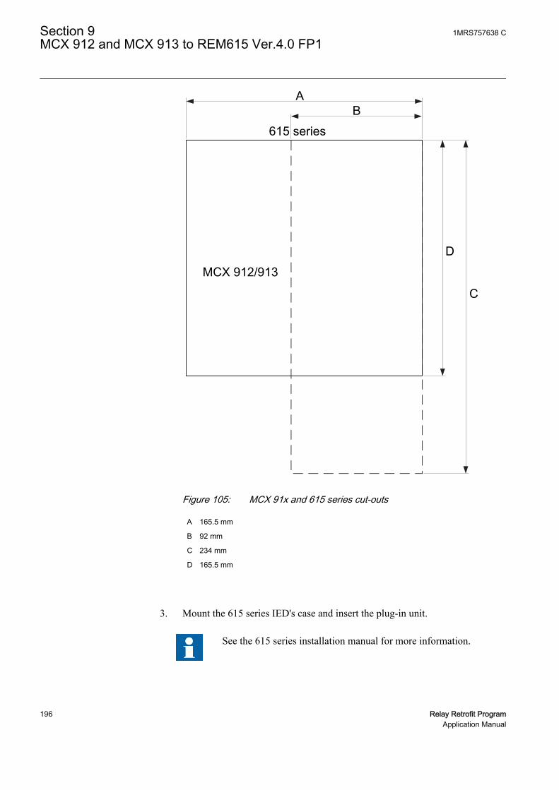
615 series
MCX 912/913
A
D
B
C
GUID-F4687C34-1420-4925-97C3-4016CDC82266 V1 EN
Figure 105: MCX 91x and 615 series cut-outs
A 165.5 mm
B 92 mm
C 234 mm
D 165.5 mm
3. Mount the 615 series IED's case and insert the plug-in unit.
See the 615 series installation manual for more information.
Section 9 1MRS757638 CMCX 912 and MCX 913 to REM615 Ver.4.0 FP1
196 Relay Retrofit ProgramApplication Manual

9.3.2 Connecting
• If the existing wiring is in good condition and still usable, use the dedicatedmarking sets.
• If the existing wiring has to be replaced, use the dedicated wiring harness.
9.3.2.1 Wiring harness and wire markings
Wiring harness is available for retrofitting MCX 91x with REM615.
Table 38: Wiring variants for CT connections
REM615, configuration A MCX 91x WiringTerminal Description Terminal Description MarkingX100:1 Uaux+ E20 Uaux+ X100:1 (E20)
X100:2 Uaux- E19 Uaux- X100:2 (E19)
X100:3 IRF E15 stand-by X100:3 (E15)
X100:4 IRF E17 stand-by X100:4 (E17)
X100:5 IRF E16 stand-by X100:5 (E16)
X100:6 PO1 E11 MRI X100:6 (E11)
X100:7 PO1 E12 MRI X100:7 (E12)
X100:8 PO2 E7 MRII X100:8 (E7)
X100:9 PO2 E8 MRII X100:9 (E8)
X100:10 SO1 - - X100:10
X100:11 SO1 - - X100:11
X100:12 SO1 - - X100:12
X100:13 SO2 - - X100:13
X100:14 SO2 - - X100:14
X100:15 PO3 - - X100:15
X100:16 PO3 A4 ARI X100:16 (A4)
X100:17 PO3 - - X100:17
X100:18 PO3 - - X100:18
X100:19 PO3 A5 ARI X100:19 (A5)
X100:20 PO4 - - X100:20
X100:21 PO4 A8 ARII X100:21 (A8)
X100:22 PO4 - - X100:22
X100:23 PO4 - - X100:23
X100:24 PO4 A9 ARII X100:24 (A9)
X120:1 BI1 E1/E3/E4/E5 Blocking input X120:1(E1/E3/E4/E5)
X120:2 BI1 E2 Blocking input X120:2 (E2)
X120:3 BI2 - - X120:3
X120:4 BI3 - - X120:4
Table continues on next page
1MRS757638 C Section 9MCX 912 and MCX 913 to REM615 Ver.4.0 FP1
Relay Retrofit Program 197Application Manual
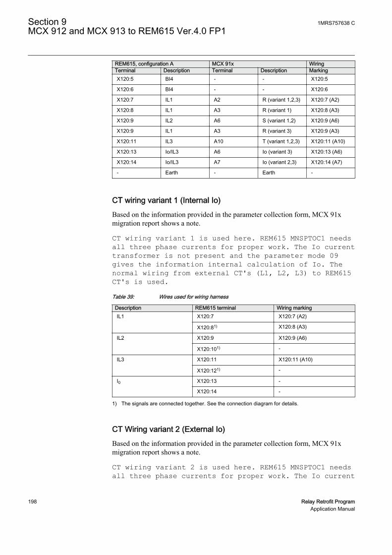
REM615, configuration A MCX 91x WiringTerminal Description Terminal Description MarkingX120:5 BI4 - - X120:5
X120:6 BI4 - - X120:6
X120:7 IL1 A2 R (variant 1,2,3) X120:7 (A2)
X120:8 IL1 A3 R (variant 1) X120:8 (A3)
X120:9 IL2 A6 S (variant 1,2) X120:9 (A6)
X120:9 IL1 A3 R (variant 3) X120:9 (A3)
X120:11 IL3 A10 T (variant 1,2,3) X120:11 (A10)
X120:13 Io/IL3 A6 Io (variant 3) X120:13 (A6)
X120:14 Io/IL3 A7 Io (variant 2,3) X120:14 (A7)
- Earth - Earth -
CT wiring variant 1 (Internal Io)Based on the information provided in the parameter collection form, MCX 91xmigration report shows a note.
CT wiring variant 1 is used here. REM615 MNSPTOC1 needsall three phase currents for proper work. The Io currenttransformer is not present and the parameter mode 09gives the information internal calculation of Io. Thenormal wiring from external CT's (L1, L2, L3) to REM615CT's is used.Table 39: Wires used for wiring harness
Description REM615 terminal Wiring markingIL1 X120:7 X120:7 (A2)
X120:81) X120:8 (A3)
IL2 X120:9 X120:9 (A6)
X120:101) -
IL3 X120:11 X120:11 (A10)
X120:121) -
I0 X120:13 -
X120:14 -
1) The signals are connected together. See the connection diagram for details.
CT Wiring variant 2 (External Io)Based on the information provided in the parameter collection form, MCX 91xmigration report shows a note.
CT wiring variant 2 is used here. REM615 MNSPTOC1 needsall three phase currents for proper work. The Io current
Section 9 1MRS757638 CMCX 912 and MCX 913 to REM615 Ver.4.0 FP1
198 Relay Retrofit ProgramApplication Manual

transformer is not present and the parameter mode 09gives the information external metering of Io. The normalwiring from external CT's (L1, L2, L3) to REM615 CT's isused and additionally the REM615 Io transformer has to beadded in the star point.Table 40: Wires used for wiring harness
Description REM615 terminal Wiring markingIL1 X120:7 X120:7 (A2)
X120:81) -
IL2 X120:9 X120:9 (A6)
X120:101) -
IL3 X120:11 X120:11 (A10)
X120:121) -
I0 X120:131) -
X120:14 X120:14 (A7)
1) The signals are connected together. See the connection diagram for details.
CT Wiring variant 3 (External Io with CBCT)Based on the information provided in the parameter collection form, MCX 91xmigration report shows a note.
CT wiring variant 3 is used here. REM615 MNSPTOC1 needsall three phase currents for proper work. The Io currenttransformer is present and the parameter mode 09 givesthe information external metering of Io. Beside thenormal wiring from external CT's (L1,L3) to REM615 CT'sthe sum of -(IL1+IL2) has to be connected to the REM615L2 transformer and additionally the REM615 Iotransformer has to be connected to the external Iotransformer.Table 41: Wires used for wiring harness
Description REM615 terminal Wiring markingIL1 X120:7 X120:7 (A2)
X120:81) -
IL2 X120:9 X120:9 (A3)
X120:101) -
Table continues on next page
1MRS757638 C Section 9MCX 912 and MCX 913 to REM615 Ver.4.0 FP1
Relay Retrofit Program 199Application Manual

Description REM615 terminal Wiring markingIL3 X120:11 X120:11 (A10)
X120:121) -
I0 X120:13 X120:13 (A6)
X120:14 X120:14 (A7)
1) The signals are connected together. See the connection diagram for details.
9.3.2.2 MCX 91x terminal layout and connection diagrams
A1
A12
E1
E20
GUID-DDB6E6DD-19FE-4F64-9043-E49B00DACB37 V1 EN
Figure 106: Terminal layout for MCX 91x
Section 9 1MRS757638 CMCX 912 and MCX 913 to REM615 Ver.4.0 FP1
200 Relay Retrofit ProgramApplication Manual

A
E
E1E2
E3
E4
E5
MCX 912/913
220/250 V
110/125 V
48/60 V
24 V0 V
A2
A3A6
A7A10
A11
A
A1A4A5
A8A9
A12
AR I
Blocking input
AR II
E
E6E7
E8
E9
E10
E11
E12
E13
E14
E15
E16
E17
E18
E19
E20
MR II
MR I
Stand-by
Uaux
GUID-6AB66C31-DD42-49D7-8556-7C3D4B4766C4 V1 EN
Figure 107: Connection diagram for MCX 91x wiring variant 1 (Internal Io)
1MRS757638 C Section 9MCX 912 and MCX 913 to REM615 Ver.4.0 FP1
Relay Retrofit Program 201Application Manual

A
E
E1E2
E3
E4
E5
MCX 912/913
220/250 V
110/125 V
48/60 V
24 V0 V
A2
A3A6
A7A10
A11
A
A1A4A5
A8A9
A12
AR I
Blocking input
AR II
E
E6E7
E8
E9
E10
E11
E12
E13
E14
E15
E16
E17
E18
E19
E20
MR II
MR I
Stand-by
Uaux
GUID-983A9E66-E656-4809-A60B-016B0CB7C4BA V1 EN
Figure 108: Connection diagram for MCX 91x wiring variant 2 (External Io)
Section 9 1MRS757638 CMCX 912 and MCX 913 to REM615 Ver.4.0 FP1
202 Relay Retrofit ProgramApplication Manual
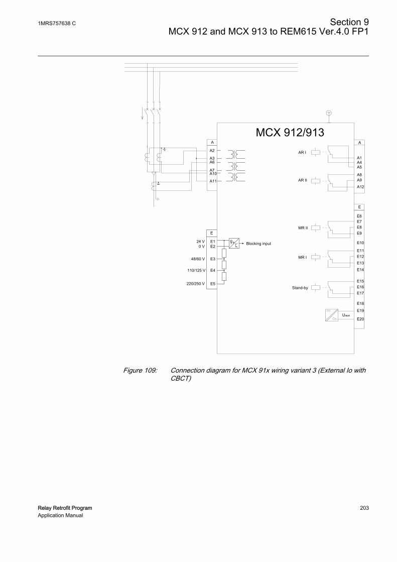
A
E
E1E2
E3
E4
E5
MCX 912/913
220/250 V
110/125 V
48/60 V
24 V0 V
A2
A3A6
A7A10
A11
A
A1A4A5
A8A9
A12
AR I
Blocking input
AR II
E
E6E7
E8
E9
E10
E11
E12
E13
E14
E15
E16
E17
E18
E19
E20
MR II
MR I
Stand-by
Uaux
GUID-41E3FE97-AC82-4961-A731-E142151CEF15 V1 EN
Figure 109: Connection diagram for MCX 91x wiring variant 3 (External Io withCBCT)
1MRS757638 C Section 9MCX 912 and MCX 913 to REM615 Ver.4.0 FP1
Relay Retrofit Program 203Application Manual

9.3.2.3 REM615 terminal layout and connection diagrams
A070596 V1 EN
Figure 110: Terminal layout for the 615 series IEDs
Section 9 1MRS757638 CMCX 912 and MCX 913 to REM615 Ver.4.0 FP1
204 Relay Retrofit ProgramApplication Manual

REM615
X13
Light sensor input 1 1)
X14
Light sensor input 2 1)
X15
Light sensor input 3 1)
16 17 19 18
X100
6 7
8 9
10 11 12 13
15
14
2 1 3 4 5
22 21 23 24
SO2
TCS2 PO4
SO1
TCS1
PO3
PO2
PO1
IRF
+ -
Uaux
20
1)
1)
X110
3 4 5 6
7 8 9
10BI 6
BI 5
BI 4
BI 3
BI 2
BI 8
BI 712 13
11
BI 11 2
X110
16 14 15 19 17 18 22 20 21
SO3
SO2
SO1
23
SO4
24
S1
S2
P1 P2
Positive Current Direction
L1 L2 L3
2)
1)
X130
1 2
5 6
7 8
mA 1mA+
_ 3 4
mA 2mA+
_ RTD 1 RTD 2
9 10
11 12
RTD 3
13 14
15 16
RTD 4 RTD 5
17 18
RTD 6
+ _ + _ + _
+ _ + _ + _
X120
1 2 3 4 5 6
7 8 9
10 11 12 13 14
Io
IL1 IL2
BI 4
BI 3
BI 2
BI 1
IL3
1/5A
N 1/5A
N 1/5A
N 1/5A
N
BLOCKING INPUT Uaux
stand-by
MRI
MRII
ARI
ARII
1) Optional2) The IED features automatic short-circuit mechanism in the CT connector when plug-in unit is detached
GUID-A4153932-33F5-4C71-9270-CCC9F5C1B11B V1 EN
Figure 111: Connection diagram for REM615 wiring variant 1 (Internal Io)
1MRS757638 C Section 9MCX 912 and MCX 913 to REM615 Ver.4.0 FP1
Relay Retrofit Program 205Application Manual
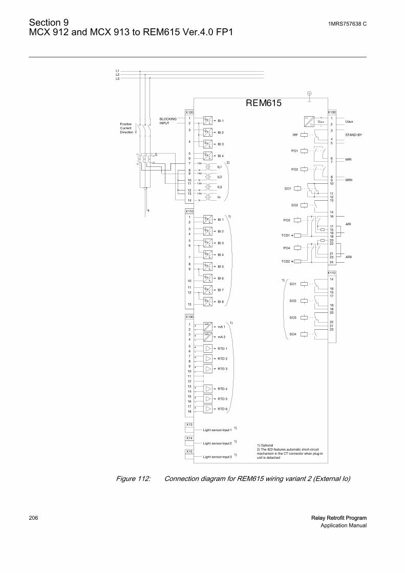
REM615
X13
Light sensor input 1 1)
X14
Light sensor input 2 1)
X15
Light sensor input 3 1)
16 17 19 18
X100
6 7
8 9
10 11 12 13
15
14
2 1 3 4 5
22 21 23 24
SO2
TCS2 PO4
SO1
TCS1
PO3
PO2
PO1
IRF
+ -
Uaux
20
1)
1)
X110
3 4 5 6
7 8 9
10BI 6
BI 5
BI 4
BI 3
BI 2
BI 8
BI 712 13
11
BI 11 2
X110
16 14 15 19 17 18 22 20 21
SO3
SO2
SO1
23
SO4
S1
S2
P1 P2
Positive Current Direction
L1 L2 L3
2)
1)
X130
1 2
5 6
7 8
mA 1mA+
_ 3 4
mA 2mA+
_ RTD 1 RTD 2
9 10
11 12
RTD 3
13 14
15 16
RTD 4 RTD 5
17 18
RTD 6
+ _ + _ + _
+ _ + _ + _
X120
1 2 3 4 5 6
7 8 9
10 11 12 13 14
Io
IL1 IL2
BI 4
BI 3
BI 2
BI 1
IL3
1/5A
N 1/5A
N 1/5A
N 1/5A
N
BLOCKING INPUT Uaux
STAND-BY
MRI
MRII
ARI
ARII
1) Optional2) The IED features automatic short-circuit mechanism in the CT connector when plug-in unit is detached
GUID-E2FB82B2-FA01-4D6C-991C-94A704897CE3 V1 EN
Figure 112: Connection diagram for REM615 wiring variant 2 (External Io)
Section 9 1MRS757638 CMCX 912 and MCX 913 to REM615 Ver.4.0 FP1
206 Relay Retrofit ProgramApplication Manual

REM615
X13
Light sensor input 1 1)
X14
Light sensor input 2 1)
X15
Light sensor input 3 1)
16 17 19 18
X100
6 7
8 9
10 11 12 13
15
14
2 1 3 4 5
22 21 23 24
SO2
TCS2 PO4
SO1
TCS1
PO3
PO2
PO1
IRF
+ -
Uaux
20
1)
1)
X110
3 4 5 6
7 8 9
10BI 6
BI 5
BI 4
BI 3
BI 2
BI 8
BI 712 13
11
BI 11 2
X110
16 14 15 19 17 18 22 20 21
SO3
SO2
SO1
23
SO4
S1
S2
P1 P2
P2 P1 S1
S2
Positive Current Direction
L1 L2 L3
2)
1)
X130
1 2
5 6
7 8
mA 1mA+
_ 3 4
mA 2mA+
_ RTD 1 RTD 2
9 10
11 12
RTD 3
13 14
15 16
RTD 4 RTD 5
17 18
RTD 6
+ _ + _ + _
+ _ + _ + _
X120
1 2 3 4 5 6
7 8 9
10 11 12 13 14
Io
IL1 IL2
BI 4
BI 3
BI 2
BI 1
IL3
1/5A
N 1/5A
N 1/5A
N 1/5A
N
BLOCKING INPUT Uaux
STAND-BY
MRI
MRII
ARI
ARII
1) Optional2) The IED features automatic short-circuit mechanism in the CT connector when plug-in unit is detached
GUID-2EBF6469-7830-4C4C-9892-B00ACB3E475E V1 EN
Figure 113: Connection diagram for REM615 wiring variant 3 (External Io withCBCT)
1MRS757638 C Section 9MCX 912 and MCX 913 to REM615 Ver.4.0 FP1
Relay Retrofit Program 207Application Manual

208

Section 10 Glossary
615 series Series of numerical IEDs for low-end protection andsupervision applications of utility substations, andindustrial switchgear and equipment
CB Circuit breakerCBCT Core balance current transformerCBFP Circuit breaker failure protectionCOMTRADE Common format for transient data exchange for power
systems. Defined by the IEEE Standard.CT Current transformerCutting tool Dedicated device, consisting of a power unit and a
cutting head, for machining the existing panel cut-outDT Definite timeDUT Device under testEMC Electromagnetic compatibilityHMI Human-machine interfaceHSR High-availability seamless redundancyI/O Input/outputIDMT Inverse definite minimum timeIEC 61850 International standard for substation communication
and modelingIED Intelligent electronic deviceIRF 1. Internal fault
2. Internal relay faultLCM Life cycle managementLED Light-emitting diodeLHMI Local human-machine interfaceMCB Miniature circuit breakerMCX 912 Multifunctional relayMCX 913 Multifunctional relayMST IED Migration Support ToolNC Normally closedNO Normally open
1MRS757638 C Section 10Glossary
Relay Retrofit Program 209Application Manual

PCM600 Protection and Control IED ManagerPE Protective earthPRP Parallel redundancy protocolRED615 Line differential protection and control IEDREF615 Feeder protection and control IEDREM615 Motor protection and control IEDRET615 Transformer protection and control IEDREU615 Voltage protection and control IEDRMS Root-mean-square (value)RTB615 Relion Test BoxRTD Resistance temperature detectorRelion Test BoxRTB615
Also known as RTB615. 615 series plug-in unit testfacility which provides auxiliary power for the plug-inunit and an interface for a secondary test device suchas Omicron.
Retrofit connectivitypackage
Consists of the IED Migration Support Tool and theRelay Retrofit Program documentation
SGB Switchgroup for digital inputsSGF Switchgroup for functionsSGR Switchgroup for output contactsSPA Strömberg protection acquisition. ABB proprietary
serial master-slave protocol used in substationautomation for point-to-point communication.
SPAJ 14x C Combined overcurrent and earth-fault relays SPAJ140 C, SPAJ 141 C and SPAJ 142 C
SPAM 150 C Motor protection relaySPAU 130 C Three-phase voltage relaySPAU 320 C1 Overvoltage, undervoltage and residual voltage relaySPAU 330 C1 Overvoltage, undervoltage and residual voltage relayTest templates forreplacement IEDs
IED specific replacement test template containing testrules used by Omicron Test Universe for testingreplacement IEDs after configuration and parametermigration. The test template specifies the content andformat of the test report.
VT Voltage transformerWire markings Provided as complete sets which correspond to the
terminal setup of the existing relay and the
Section 10 1MRS757638 CGlossary
210 Relay Retrofit ProgramApplication Manual

replacement IED. Available for all of the relayssupported in the Relay Retrofit Program.
XRIO eXtended Relay Interface by OMICRON
1MRS757638 C Section 10Glossary
Relay Retrofit Program 211Application Manual

212

213


Contact us
ABB OyMedium Voltage ProductsP.O. Box 699FI-65101 VAASA, Finland
www.abb.com/service
www.abb.com/substationautomation
1MR
S75
7638
C©
Cop
yrig
ht 2
015
AB
B. A
ll rig
hts
rese
rved
.