Belimo-Retrofit Technical Brochure.pdf - Kele
188
Retrofit Solutions Belimo Project: Hearst Tower, New York, New York EFFECTIVE APRIL 2013
-
Upload
khangminh22 -
Category
Documents
-
view
1 -
download
0
Transcript of Belimo-Retrofit Technical Brochure.pdf - Kele

Retrofi t Solutions
Belimo Project: Hearst Tower, New York, New York
EFFECTIVE APRIL 2013

Valves and actuators are responsible for ensuring reliable functioning hydronic and air control HVAC systems all over the world. With innovative technology, verified quality and easy handling during installations and operation, they boost the performance and efficiency of integrated building technology.
Are you in need of a solution for a broken linkage, leaky hydraulic actuator, non-functioning electric or pneumatic actuator? Do you have a need for replacing a non-functioning application within a day or so?
Belimo provides airside and waterside retrofit application solutions, with direct coupled or remote access linkages, and efficient actuators.
Damaged linkages and/or actuators resulting in non-functioning HVAC system applications used to mean a loss of properly functioning systems leading to a degradation of energy efficiency, consumer comfort, time, and labor. Replacing a valve along with the actuator or trying to determine how to fix an airside linkage is not always a sensible solution. Taking a system off-line to replace various components is not only laborious, it’s expensive. Facilities can lose thousands of dollars a day during maintenance shut-down. With retrofit solutions this problem simply goes away. Valves and damper applications can be quickly and conveniently restored without any interruption in service. In fact, entire systems can often be updated in a day. A poorly functioning or even non-functioning system can be transformed into a highly functioning, more efficient system.
Belimo provides many retrofit solutions that are compatible with all major control systems, so there is no need to replace other system controls. MFT Technology is also available and can be reprogrammed to suit your controller needs with just one MFT model actuator.
In addition, Belimo’s design team is ready and willing to customize a solution for non-standard retrofit solutions. Call Belimo at 800-543-9038 for assistance in fulfilling your retrofit application requirements.
Hearst Tower, New York, NY Existing Installation Solution with No Down Time!
Why Retrofi tting Makes Sense

®
P104
06 -
04/1
3 - S
ubje
ct to
cha
nge.
© B
elim
o Ai
rcon
trols
(USA
), In
c.
Table of Contents RETROFIT SOLUTIONS How to Select an Actuator . . . . . . . . . . . . . . . . . . . . . . . . . . . . . . . . . . . . . . . . . . . . . . .3
SOLUTIONS FOR SPECIFIC ACTUATOR MANUFACTURER AND PART NUMBERS Discontinued Belimo Products . . . . . . . . . . . . . . . . . . . . . . . . . . . . . . . . . . . . . . . . . . . . .5 Replacement of Competitor Fire & Smoke Actuators . . . . . . . . . . . . . . . . . . . . . . . . . . . . . . . . . .8 Honeywell . . . . . . . . . . . . . . . . . . . . . . . . . . . . . . . . . . . . . . . . . . . . . . . . . . . . . 11 Invensys . . . . . . . . . . . . . . . . . . . . . . . . . . . . . . . . . . . . . . . . . . . . . . . . . . . . . 14 Johnson Controls . . . . . . . . . . . . . . . . . . . . . . . . . . . . . . . . . . . . . . . . . . . . . . . . . . . 17 Siemens . . . . . . . . . . . . . . . . . . . . . . . . . . . . . . . . . . . . . . . . . . . . . . . . . . . . . 20 Specialized Retrofit Solutions . . . . . . . . . . . . . . . . . . . . . . . . . . . . . . . . . . . . . . . . . . . . . 22 Non-Direct Coupled Retrofit Solutions . . . . . . . . . . . . . . . . . . . . . . . . . . . . . . . . . . . . . . . . 24 Economizer Actuator Retrofit Solutions . . . . . . . . . . . . . . . . . . . . . . . . . . . . . . . . . . . . . . . . 26 ZIP Economizer . . . . . . . . . . . . . . . . . . . . . . . . . . . . . . . . . . . . . . . . . . . . . . . . . . . . 27 GLOBE VALVE RETROFIT SOLUTIONS UGLK.../UGSP... Retrofit Linkage for Globe Valves . . . . . . . . . . . . . . . . . . . . . . . . . . . . . . . . . . 35 New Generation Globe Valve Linkages . . . . . . . . . . . . . . . . . . . . . . . . . . . . . . . . . . . . . . . . 38 New Generation Globe Valve Actuators . . . . . . . . . . . . . . . . . . . . . . . . . . . . . . . . . . . . . . . . 41 UGSL1200 Short Stroke Valve Retrofit Kit . . . . . . . . . . . . . . . . . . . . . . . . . . . . . . . . . . . . . . 89 How to Select a Globe Valve Retrofit Solution . . . . . . . . . . . . . . . . . . . . . . . . . . . . . . . . . . . . 90 Globe Valve Retrofit Actuators . . . . . . . . . . . . . . . . . . . . . . . . . . . . . . . . . . . . . . . . . . . . 91
SOLUTIONS FOR SPECIFIC MANUFACTURER AND PART NUMBERS Honeywell . . . . . . . . . . . . . . . . . . . . . . . . . . . . . . . . . . . . . . . . . . . . . . . . . . . . . 92 Johnson Controls . . . . . . . . . . . . . . . . . . . . . . . . . . . . . . . . . . . . . . . . . . . . . . . . . . . 99 Robertshaw . . . . . . . . . . . . . . . . . . . . . . . . . . . . . . . . . . . . . . . . . . . . . . . . . . . . 114 Siebe - Invensys - Barber Colman . . . . . . . . . . . . . . . . . . . . . . . . . . . . . . . . . . . . . . . . . 114 Siemens - Landis - Powers . . . . . . . . . . . . . . . . . . . . . . . . . . . . . . . . . . . . . . . . . . . . . 122 Warren Controls . . . . . . . . . . . . . . . . . . . . . . . . . . . . . . . . . . . . . . . . . . . . . . . . . . 129 Custom Globe Valve Solutions . . . . . . . . . . . . . . . . . . . . . . . . . . . . . . . . . . . . . . . . . . . 135 Custom Globe Valve Retrofit Solution Form . . . . . . . . . . . . . . . . . . . . . . . . . . . . . . . . . . . . 136 UGSP Series Globe Valve Retrofit Solution . . . . . . . . . . . . . . . . . . . . . . . . . . . . . . . . . . . . . 138 UGLK Retrofit, Components . . . . . . . . . . . . . . . . . . . . . . . . . . . . . . . . . . . . . . . . . . . . 148 Globe Valve Accessories . . . . . . . . . . . . . . . . . . . . . . . . . . . . . . . . . . . . . . . . . . . . . . 149
BUTTERFLY VALVE RETROFIT SOLUTIONS UFLK.../UFSP... Retrofi t Linkage for Butterfl y Valves . . . . . . . . . . . . . . . . . . . . . . . . . . . . . . . . 151 How to Select a Butterfl y Valve Retrofi t Solution . . . . . . . . . . . . . . . . . . . . . . . . . . . . . . . . . . 155 Butterfl y Valve Retrofi t Actuators . . . . . . . . . . . . . . . . . . . . . . . . . . . . . . . . . . . . . . . . . . 156 SOLUTIONS FOR SPECIFIC MANUFACTURER AND PART NUMBERS Belimo . . . . . . . . . . . . . . . . . . . . . . . . . . . . . . . . . . . . . . . . . . . . . . . . . . . . 158 Bray . . . . . . . . . . . . . . . . . . . . . . . . . . . . . . . . . . . . . . . . . . . . . . . . . . . . 159 Centerline . . . . . . . . . . . . . . . . . . . . . . . . . . . . . . . . . . . . . . . . . . . . . . . . . . . . 160 Flowseal . . . . . . . . . . . . . . . . . . . . . . . . . . . . . . . . . . . . . . . . . . . . . . . . . . . . 162 Johnson Controls . . . . . . . . . . . . . . . . . . . . . . . . . . . . . . . . . . . . . . . . . . . . . . . . . . 163 Keystone . . . . . . . . . . . . . . . . . . . . . . . . . . . . . . . . . . . . . . . . . . . . . . . . . . . . 164 Milwaukee . . . . . . . . . . . . . . . . . . . . . . . . . . . . . . . . . . . . . . . . . . . . . . . . . . . . 166 Nibco . . . . . . . . . . . . . . . . . . . . . . . . . . . . . . . . . . . . . . . . . . . . . . . . . . . . 168 PDC . . . . . . . . . . . . . . . . . . . . . . . . . . . . . . . . . . . . . . . . . . . . . . . . . . . . 169 Victualic . . . . . . . . . . . . . . . . . . . . . . . . . . . . . . . . . . . . . . . . . . . . . . . . . . . . 169
SPECIALTY SOLUTIONS FOR VALVE MANUFACTURERS Apollo, Challenger, Chemtrol, Dezurik, FNW, Gruvlok, Hammond, Jamesbury, Jenkins, Metrafl ex, Mueller, Quartermaster, Watts . . . . . . . . . . . . . . . . . . . . . . . . . . . . . . . . . . . . . . . . . . . . . . . . 171
Custom Butterfly Valve Retrofit Solution Form . . . . . . . . . . . . . . . . . . . . . . . . . . . . . . . . . . . 172 Component Identification . . . . . . . . . . . . . . . . . . . . . . . . . . . . . . . . . . . . . . . . . . . . . . 174 Valve Accessories . . . . . . . . . . . . . . . . . . . . . . . . . . . . . . . . . . . . . . . . . . . . . . . . . . 175
BALL VALVE RETROFIT SOLUTIONS Custom Ball Valve Retrofi t Solution Form . . . . . . . . . . . . . . . . . . . . . . . . . . . . . . . . . . . . . . 178 Component Identifi cation . . . . . . . . . . . . . . . . . . . . . . . . . . . . . . . . . . . . . . . . . . . . . . 180 UBSP... Custom Retrofi t Linkages for Ball Valves . . . . . . . . . . . . . . . . . . . . . . . . . . . . . . . . . . 181 Belimo Platinum Distributors . . . . . . . . . . . . . . . . . . . . . . . . . . . . . . . . . . . . . . . . inside back cover
New Generation Globe Valve Actuator• Higher steam inlet rating up to
100 psi. • Increased force ranges for higher
close-off pressures. • Full selection of electronic fail and
non-fail-safe options. • Field selectable, fail-safe position
with switch. • Modular order entry process for
customizing fl exibility, e.g. cable length, run times, etc.
ZG-JSL Jackshaft Linkage• Simplifi es typical installations and
eliminates the diffi culties where jackshaft bearings are hard to access.
• Unique open ended design and clamp insert accommodates any jackshaft ½” to 1.05” in diameter.
• Anti-rotation plate enables various actuators to be mounted and in multiple orientations.

P104
06 -
04/1
3 - S
ubje
ct to
cha
nge.
© B
elim
o Ai
rcon
trols
(USA
), In
c.
®
800-543-9038 USA 866-805-7089 CANADA 203-791-8396 LATIN AMERICA/CARIBBEAN
3
The “10 questions” method for sizing and selection shown below is recommended as the best method for your actuation requirements. Use the “Application Data” column in this chart as a worksheet to help in the selection process.
Retrofit and ReplacementHow to Select an Actuator for Damper Retrofit
APPLICATION INFO APPLICATION DATAAPPLICATION DATA
1 What is the total area of the damper?
sq.ft.
2 Opposed blade or Parallel blade control construction?
L” x W” = Total sq inches/144 = total sq feet
Opposed Blade w/o seals 3 in-lbs/sq feet*
Opposed Blade w/ seals 5 in-lbs/sq feet
Parallel Blade w/o seals 4 in-lbs/sq feet
Parallel Blade w/ seals 7 in-lbs/sq feet
*Less than 1,000 feet per minute
❑ Opposed Blade
❑ Parallel Blade
3 Are there blade and edge seals on the damper?
This will impact the proper selection as theseals add resistancerequiring more torque.If unknown, use a worst casescenario, parallelblade with seals.
❑ Yes
❑ No
4 For the damper in question, what does the manufacturer specify as the torque rating?
If this information is not available refer to the “typical damper requirements and sizing” chart below.
in-lbs/sq.ft.
5 What is the air velocity, static pressure, or design CFM?
Systems above 1,000 FPMrequire additional actuator torque
_______W.G.
_______CFM
_______FPM
ACTUATOR REQUIREMENTS APPLICATION DATAAPPLICATION DATA
6 Is fail-safe actuationrequired?
Consider the application. Is the actuator and/or damper exposed to outside air? If yes, use spring return.
❑ Yes
❑ No
7 What is the supply voltage to the actuator?• 24 VAC/DC
• 120 VAC
• 230 VACsingle phase
Do you need a step down transformer?
If replacing an oil immersed gear train actuator, is the transformer in the defective actuator? You may need to purchase one.
❑ 24 VAC
❑ 120 VAC
❑ 230 VAC
8 What is the control signal to the actuator?
• 2 position
• Floating point
• Modulating
• Sequencing
• “Non-standard” voltage signals
❑ On/Off
❑ Floating Point
❑ 2-10 VDC
❑ 0-10 VDC
❑ 4-20 mA
❑ PWM____range
❑ Other (MFT)
This will be a critical component to the selection of an actuator. Consider the …MFT actuator product range and the flexibility of its application.
9 Can you direct couple to a damper shaft?
Direct-coupling has become the industry standard. Some retrofit applications
do not allow direct coupling. Refer to the Belimo “Mounting & Methods Guide” for application details.
❑ Yes
❑ No, seeaccessoriespage
10 Are there additional accessories required?
PA… SA…
KH-AF USKH-AF-1 US
K4-2 US
For example, some applications require the addition of an auxiliary switch for proof of position; a retrofit application may require an additional mounting bracket and linkage kit. We advise that you identify these needs prior to leaving the job site or ordering products.
❑ No
❑ Yes, seeaccessoriessection oractuator series fordetails
TYPICAL DAMPER REQUIREMENTS AND SIZING
Square Damper (with square shape): ft2 = h x w /144; (h= height, w= width, in inches)
EXAMPLE: Damper Area (8 ft2) x Rated Torque Loading of Damper (4 in-lbs/ft2) = Total in-lbs Required (32 in-lbs) Belimo LF 35 in-lbs/ LM 45 in-lbs actuators
Torque Loading in-lbs/ft2
Damper Blade Type < 1000 FPM 1000-2500 FPM 2500-3500 FPM
SQUA
RE
Parallel blade/edge seals 7 (Typical) 10.5 14Opposed blade/edge seals 5 (Typical) 7.5 10Parallel blade/no edge seals 4 6 8Opposed blade/no edge seals 3 4.5 6Round 10 14 20
P104
06 -
04/1
3 - S
ubje
ct to
cha
nge.
© B
elim
o Ai
rcon
trols
(USA
), In
c.
®
800-543-9038 USA 866-805-7089 CANADA 203-791-8396 LATIN AMERICA/CARIBBEAN
4
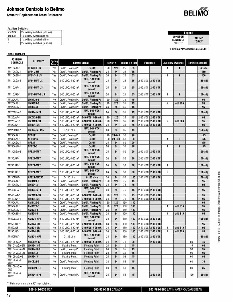
CONTROL SIGNAL OVERVIEW
Belimo actuators are compatible with many control inputs and all direct digital control (DDC) systems. There are many signals to select from with today’s controllers.
On/Off or Open-Close: The actuator is able to drive either to its full clockwise (CW) position, or to its full counter-clockwise (CCW) position. The same indication is used for spring return type actuators. Where the actuator will drive to its full CW position and spring return to its CCW position. This can also be reversed.
3-point, Tri-State, Floating Point: The actuator has both clockwise (CW) and counter-clockwise (CCW) control inputs. One drives the actuator to its CW, the other to its CCW position. If there is no signal (Null point) on either input the actuator simply stays in its last position.
Proportional Control: The actuator drives proportional to its control input and modulates throughout its angle of rotation. This control type is usually a variation of VDC. Common values are:
0-10 VDC 2-10 VDC
It is common to also have a 0-20/4-20 mA output from a controller. This can be very easily converted to 0-10 VDC or 2-10 VDC with a 500 Ω resistor.
Pulse Width Modulation (PWM): The actuator drives to a specified position according to a pulse duration, the “length” of signal. The pulse can originate from a dry contact closure or a triac sink or source controller. An example of PWM control:
Time base: 0 to 10 seconds
Output pulse: 5 seconds
Actuator position: 50%
Phasecut: An actuator drives depending on the power result of a remaining wave. This signal type cuts the amplitude of the wave and the actuator recognizes this signal as a proportional movement.
Multi-Functional Technology (MFT): This technology was developed by Belimo for incorporation into our damper and valve actuators. MFT provides the ability to program certain characteristics of the actuators. Some of the key characteristics to change are:
CONTROL INPUT Selectable on/off, VDC, PWM or floating point
MOTION VALUES Selectable running time adjustment
FEEDBACK Selectable feedback values
Retrofit and ReplacementHow to Select an Actuator
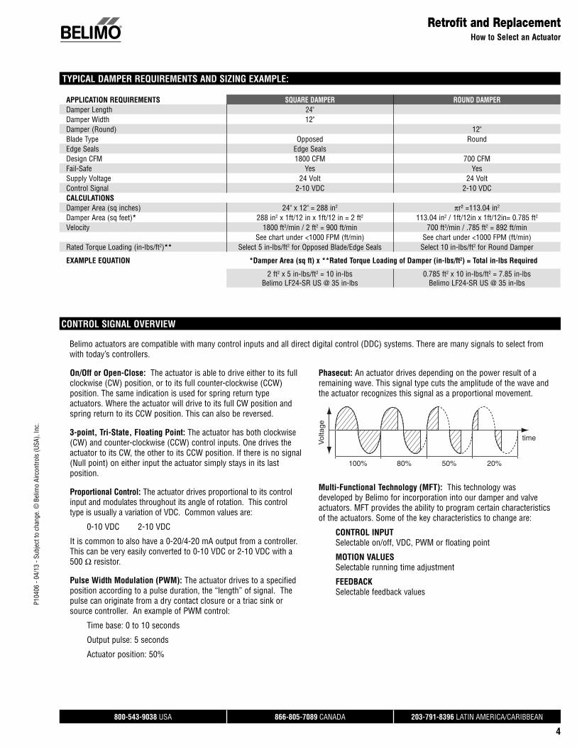
TYPICAL DAMPER REQUIREMENTS AND SIZING EXAMPLE:
APPLICATION REQUIREMENTS SQUARE DAMPER ROUND DAMPERDamper Length 24"Damper Width 12"Damper (Round) 12"Blade Type Opposed Round Edge Seals Edge SealsDesign CFM 1800 CFM 700 CFMFail-Safe Yes YesSupply Voltage 24 Volt 24 VoltControl Signal 2-10 VDC 2-10 VDCCALCULATIONSDamper Area (sq inches) 24" x 12" = 288 in2 πr² =113.04 in2 Damper Area (sq feet)* 288 in2 x 1ft/12 in x 1ft/12 in = 2 ft2 113.04 in2 / 1ft/12in x 1ft/12in= 0.785 ft2
Velocity 1800 ft3/min / 2 ft2 = 900 ft/min 700 ft3/min / .785 ft2 = 892 ft/minSee chart under <1000 FPM (ft/min) See chart under <1000 FPM (ft/min)
Rated Torque Loading (in-lbs/ft2)** Select 5 in-lbs/ft2 for Opposed Blade/Edge Seals Select 10 in-lbs/ft2 for Round Damper
EXAMPLE EQUATION *Damper Area (sq ft) x **Rated Torque Loading of Damper (in-lbs/ft2) = Total in-lbs Required
2 ft2 x 5 in-lbs/ft2 = 10 in-lbsBelimo LF24-SR US @ 35 in-lbs
0.785 ft2 x 10 in-lbs/ft2 = 7.85 in-lbsBelimo LF24-SR US @ 35 in-lbs

P104
06 -
04/1
3 - S
ubje
ct to
cha
nge.
© B
elim
o Ai
rcon
trols
(USA
), In
c.
®
800-543-9038 USA 866-805-7089 CANADA 203-791-8396 LATIN AMERICA/CARIBBEAN
5
Retrofit and Replacement, Damper ActuatorsDiscontinued Belimo Products
When replacing an actuator, whether Belimo or other, be sure to consider the application parameters before selecting the replacement. The new product may not be the best fit for the application.
An example would be an existing SM24-SR US mounted to a valve linkage. The direct replacement of the actuator is the AMX24-MFT. However, the SM… and AM… are different lengths, the linkage would need to be replaced as well. When retrofitting or replacing actuators, it is always best to select the new product based on application parameters. This ensures the selected actuator is fit for the application.
Replacement of Discontinued Belimo Products
SPRING RETURN ACTUATORSDISCONTINUED MODEL REPLACEMENT MODEL DISCONTINUED MODEL REPLACEMENT MODELLF24-SR-MP US LF24-MFT-20 US AF24-SR95 US AFB24-MFT95LF24-SR-S-MP US LF24-MFT-S-20 US AF24-PWM US AFB24-MFT + P-200…NF230 US NFBUP AF24-SR US AFB24-SR**NF230-S US NFBUP-S AFA24-SR US** AFB24-SR**SF24 US AFB24 AF24-PC US AFB24-PCSF24-S US AFB24-S AF24-ECON-R03 US Contact BelimoSF120 US AFBUP AF24-SR US* AFB24-PC if phasecut is neededSF120-S US AFBUP-S AF24-MFT US AFB24-MFTFM24 US AFB24 AF24-MFT-S US AFB24-MFT-SFM24-SR US AFB24-SR AF24-MFT95 US AFB24-MFT95FM24-SR90 US AFB24-MFT95 NF24 US NFB24FM24-SR95 US AFB24-MFT95 NF24-S US NFB24-SFS24 AFB24 NF24-S2 US NFB24-SFS24-S AFB24-S NF120 US NFBUPAFR24 US AFB24 NF120-S US NFBUP-SAFR24-S US AFB24-S NF24-SR US NFB24-SRAFR120 US AFBUP NF24-SR-S US NFB24-SR-SAFR120-S US AFBUP-S NF24-MFT US NFB24-MFTAF24-3 US AFX24-MFT + P-300… TF24 US TFB24AFR24-3 US AFX24-MFT + P-300… TF24-S US TFB24-SAF24-3-S US AFX24-MFT-S + P-300… TF120 US TFB120AFR24-3-S US AFX24-MFT-S + P-300… TF120-S US TFB120-SAFR24-SR US AFB24-SR** TFC120-S US TFCB120-SAF24 US AFB24 TF24-SR US TFB24-SRAF24-S US AFB24-S TF24-SR-S US TFB24-SR-SAF120 US AFBUP TF24-3 US TFB24-3AF120-S US AFBUP-S TF24-3-S US TFB24-3-SAF230 US AFBUP TF24-MFT US TFB24-MFTAF230-S US AFBUP-S TF24-MFT-S US TFB24-MFT-SAF24-SR-S US AFB24-SR-S**
NON-SPRING RETURN ACTUATORSDISCONTINUED MODEL REPLACEMENT MODEL DISCONTINUED MODEL REPLACEMENT MODELLM24-SR US LMB24-SR AM24 US AMB24-3LM24-SR.1 US LMB24-SR.1 AM24-S US AMB24-3-SLM24-SR-2.0 US LMB24-SR AM24-SR US AMB24-SRLM24-SR-T US LMB24-SR-T AM24-PWM-A US AMX24-MFT + # AM100 1C1 W02LM24-SR-T.1 US LMB24-SR-T.1 AM24-PWM-B US AMX24-MFT + # AM100 1C1 W03LM24-SR-T-2.0 US LMB24-SR-T AM24-PWM-C US AMX24-MFT + # AM100 1C1 W01LMC24-SR US LMCB24-SR AM24-SRS-A US AMX24-MFT + # AM100 1C1 A04LM24-MFT US LMX24-MFT + # LM100 1C1 ❑ ❑ ❑ AM24-SRS-B US AMX24-MFT + # AM100 1C1 A05LM24-MFT.1 US LMX24-MFT+ # LM100 1C1 ❑ ❑ ❑ AM24-SRS-C US AMX24-MFT + # AM100 1C1 A06NM24 US NMB24-3 AM24-PC US AMX24-PC + # AM0N0 1C1 ❑ ❑ ❑
NM24-1 US NMB24-3 AM24-MFT US AMX24-MFT + # AM100 1C1 ❑ ❑ ❑
NM24 EU NMB24-3 AM24-MFT 95 US AMX24-MFT95 + # AM0L0 1C1 R01NM24-1/200 US NMX24-3 + # NM00 1C3 000 SM24 US AMB24-3NM24-1/300 US NMX24-3 + # NM00 1C3 000 SM24-S US AMX24-MFT + # AM110 1C1 ❑ ❑ ❑ + S1A/S2ANM24-SR US NMB24-SR SM24-SR US AMB24-SRNM24-SRS US NMX24-MFT + # NM100 1C1 A ❑ ❑ SM24-SR US AMX24-PC if phasecut is neededNM24-PWM US NMX24-MFT + # NM100 1C1 W ❑ ❑ SM24-SRS US AMX24-MFT + # AM100 1C1 A ❑ ❑ NM24-MFT US NMX24-MFT + # NM100 1C1 ❑ ❑ ❑ SM24-SR94 US AMX24-MFT95 + # AM0L0 1C1 R01NM24-MFT.1 US NMX24-MFT + # NM100 1C1 ❑ ❑ ❑ GM24 US GMB24-3NMQ24-MFT US NMQ24-MFT GM24-SR US GMB24-SRNMV24-D US NMV-D3-MFT GM24-SR US GMX24-PC if phasecut is neededNMV24-V US NMV-D3-MFT GM24-MFT US GMX24-MFT+ # GM110 1C1 ❑ ❑ ❑
* Purchased before May 2003. ** Not piggy back capable. ❑ Placeholder for custom options.

P104
06 -
04/1
3 - S
ubje
ct to
cha
nge.
© B
elim
o Ai
rcon
trols
(USA
), In
c.
®
800-543-9038 USA 866-805-7089 CANADA 203-791-8396 LATIN AMERICA/CARIBBEAN
6
Retrofit and Replacement, Valve ActuatorsDiscontinued Belimo Products
When replacing an actuator on a valve, whether Belimo or other, be sure to consider the application parameters before selecting the replacement. The new product may not be the best fit for the application.
An example would be an existing MAR actuator mounted to a valve linkage. The direct replacement of the actuator would be the SY series actuator. However, the MAR and the SY have different linkage construction, and the linkage would need to be replaced as well. When retrofitting or replacing actuators, it is always best to select the new product based on application parameters. This ensures the selected actuator is fit for the application.
Please consult Belimo for assistance with valve actuator replacement.
Replacement of Discontinued Belimo Products
SPRING RETURN ACTUATORSDISCONTINUED MODEL REPLACEMENT MODELLF24-SR-MP US LF24-MFT-20 USLF24-SR-S-MP US LF24-MFT-S-20 USAF24-3 US AFX24-MFT + P-300..AF24-3-S US AFX24-MFT-S + P-300..AF24-SR-S US AFX24-MFT-S + P-100..AF24-SR95 US AFB24-MFT95AF24-PWM US AFX24-MFT + P-200..NVF24-MFT US SVKX24-MFT* or SVKX24-SR*NVF24-MFT-E US SVKX24-MFT* or SVKX24-SR**New linkage required.
NON-SPRING RETURN ACTUATORSDISCONTINUED MODEL REPLACEMENT MODELLV24 US CCV with LR... or TR….LV24/200 US CCV with LR... or TR….LV24/300 US CCV with LR... or TR….LV24-3 US CCV with LR... or TR….LV24-1 US CCV with LR... or TR….LV24-1/200 US CCV with LR... or TR….LV24-1/300 US CCV with LR... or TR….LV24-3-1 US CCV with LR... or TR….LV24-SR US CCV with LR... or TR….LV24-SR/200 US CCV with LR... or TR….LV24-SR/300 US CCV with LR... or TR….LV24-SR-1 US CCV with LR... or TR….LV24-SR-1/200 US CCV with LR... or TR….LV24-SR-1/300 US CCV with LR... or TR….LV24-SR-1-2.0 US CCV with LR... or TR….LV24-SR-1-2.0/200 US CCV with LR... or TR….LV24-SR-1-2.0/300 US CCV with LR... or TR….LR24 US LRB24-3LR24-MFT US LRX24-MFT + # LR100 RC1 ❑ ❑ ❑LR24/200 US LRX24-3 + # LR000 RC3 002LR24/300 US LRX24-3 + # LR000 RC3 002LR24-1 US LRB24-3LR24-1/200 US LRX24-3 + # LR000 RC3 002LR24-1/300 US LRB24-3 + # LR000 RC3 002LR24-3-1 US LRB24-3LR24-3-1/200 US LRX24-3 + # LR000 RC3 002LR24-3-1/300 US LRX24-3 + # LR000 RC3 002LR24-SR/200 US LRX24-SR + # LR030 RC3 002LR24-SR/300 US LRX24-SR + # LR030 RC3 002LR24-SR-1 US LRB24-SRLR24-SR-1/200 US LRX24-SR + # LR030 RC3 002LR24-SR-1/300 US LRX24-SR + # LR030 RC3 002LR24-SR-1-2.0 US LRB24-SRLR24-SR-1-2.0/200 US LRX24-SR + # LR030 RC3 002LR24-SR-1-2.0/300 US LRX24-SR + # LR030 RC3 002LR24-SR-2.0 US LRB24-SRLR24-SR-2.0/200 US LRX24-SR + # LR030 RC3 002LR24-SR-2.0/300 US LRX24-SR + # LR030 RC3 002LR24-MFT/200 US LRX24-MFT + # LR100 RC3 ❑ ❑ ❑LR24-MFT/300 US LRX24-MFT + # LR100 RC3 ❑ ❑ ❑
❑ Placeholder for custom options.
NON-SPRING RETURN ACTUATORSDISCONTINUED MODEL REPLACEMENT MODELNV24-3 US SVX24-3*NV24-MFT US SVX24-MFT* or SVX24-SR*NVG24-MFT US EVX24-MFT* or EVX24-3*NR24-3 US** LRB24-3NR24-SR US** LRX24-MFT + # LR100 RC1 ❑ ❑ ❑NM24 US ARB24-3 NM24-SR US ARX24-SR + # AR030 RC1 ❑ ❑ ❑NM24-MFT US ARX24-MFT + # AR100 RC1A ❑ ❑NM24-SRS US ARX24-MFT + # AR100 RC1W ❑ ❑ AM24 US ARB24-3AM24-S US ARB24-S USAM24-MFT US ARX24-MFT + # AR100 RC1 ❑ ❑ ❑* New linkage required. ❑ Placeholder for custom options.** Consider ambient temperature for application.
NON-SPRING RETURN – 24 VAC NON-SPRING RETURN – 24 VACDISCONTINUED MODEL Torque REPLACEMENT MODEL TorqueMAR100B-24V 1,500 SY4-24* 3,560MAR160-B-24V 2,000 SY4-24* 3,560MAR100BP-24V 1,800 SY4-24MFT* 3,560MAR160-BP-24V 2,500 SY4-24MFT* 3,560MAR250-60-24V 5,000 SY5-24* 4,450MAR250-60P-24V 5,000 SY5-24MFT* 4,450
*New linkage required.
NON-SPRING RETURN – 110 VAC NON-SPRING RETURN – 110 VACDISCONTINUED MODEL Torque REPLACEMENT MODEL TorqueMAR95-15B 1,000 SY3-110* 1,335MAR95-15BP 1,000 SY3-120MFT* 1,335MAR100B 1,500 SY4-110* 3,559MAR160B 2,000 SY4-110* 3,560MAR100BP 1,800 SY4-120MFT* 3,560MAR160-BP 2,500 SY4-120MFT* 3,560MAR250-30 5,000 SY5-110* 4,450MAR250-30P 5,000 SY5-120MFT* 4,450
SY6-110* 6,450SY6-120MFT* 6,450
MAR800-30 10,000 SY7-110* 9,790MAR800-30P 10,000 SY7-120MFT* 9,790
SY8-110 * 13,350SY8-120MFT* 13,350
MAR1600-70 21,000 SY10-110* 22,250MAR1600-70P 21,000 SY10-120MFT* 22,250MAR4000-70 48,000 SY12-110* 31,150MAR4000-70P 48,000 SY12-120MFT* 31,150
*New linkage required.
SPRING RETURN – 110 VAC NON-SPRING RETURN – 110 VAC
DISCONTINUED MODEL Torque REPLACEMENT MODEL
Torque &Battery System
Sure49-30-CW 600 SY2-110* 800 + NSV-SY-01Sure100-30-CW 1,200 SY3-110* 1,335 + NSV-SY-01Sure49-30P-CW 600 SY2-120MFT* 800 + NSV-SY-02Sure100-30P-CW 1,200 SY3-120MFT* 1,335 + NSV-SY-02
*New linkage required.

P104
06 -
04/1
3 - S
ubje
ct to
cha
nge.
© B
elim
o Ai
rcon
trols
(USA
), In
c.
®
800-543-9038 USA 866-805-7089 CANADA 203-791-8396 LATIN AMERICA/CARIBBEAN
7
Retrofit and ReplacementDiscontinued Belimo Products
ZONE VALVES* DISCONTINUED MODEL Size Cv Rating Close-off REPLACEMENT MODEL(S) Size Cv Rating Close-off
Z214T+SEF24 NO ½” 2.3 43.5 ZONE215N-10+ZONE24NOZONE215N-25+ZONE24NO ½” 1
2.57550
Z215T+SEF24 NO ½” 3.7 30 ZONE215N-35+ZONE24NO ½” 3.5 30
Z220T+SEF24 NO ¾” 3.7 30 ZONE220N-35+ZONE24NOZONE220N-50+ZONE24NO ¾” 3.5
5 30
Z214T+SEF120 NO ½” 2.3 43.5 ZONE215N-10+ZONE120NOZONE215N-25+ZONE120NO ½” 1
2.5 75
Z215T+SEF120 NO ½” 3.7 30 ZONE215N-35+ZONE120NO ½” 3.5 30
Z220T+SEF120 NO ¾” 3.7 30 ZONE220N-35+ZONE120NOZONE220N-50+ZONE120NO ¾” 3.5
53025
Z214T+SEF24 NC ½” 2.3 43.5 ZONE215N-10+ZONE24NCZONE215N-25+ZONE24NC ½” 1
2.57550
Z215T+SEF24 NC ½” 3.7 30 ZONE215N-35+ZONE24NC ½” 3.5 30
Z220T+SEF24 NC ¾” 3.7 30 ZONE220N-35+ZONE24NCZONE220N-50+ZONE24NC ¾” 3.5
53025
Z214T+SEF120 NC ½” 2.3 43.5 ZONE215N-10+ZONE120NCZONE215N-25+ZONE120NC ½” 1
2.57550
Z215T+SEF120 NC ½” 3.7 30 ZONE215N-35+ZONE120NC ½” 3.5 30
Z220T+SEF120 NC ¾” 3.7 30 ZONE220N-35+ZONE120NCZONE220N-50+ZONE120NC ¾” 3.5
53025
Z315T+SEF24 NC ½” 5 30ZONE315N-10+ZONE24NCZONE315N-25+ZONE24NCZONE315N-35+ZONE24NC
½”1
2.53.5
755030
Z315T+SEF120 NC ½” 5 30ZONE315N-10+ZONE120NCZONE315N-25+ZONE120NCZONE315N-35+ZONE120NC
½”1
2.53.5
755030
Z320T+SEF24 NC ¾” 5.4 30 ZONE320N-35+ZONE24NCZONE320N-50+ZONE24NC ¾” 3.5
53025
Z320T+SEF120 NC ¾” 5.4 30 ZONE320N-35+ZONE120NCZONE320N-50+ZONE120NC ¾” 3.5
53025
Z814T+SEF24 NO ½” 2.3 43.5 ZONE215S-10+ZONE24NCZONE215S-25+ZONE24NC ½” 1
2.57550
Z815T+SEF24 NO ½” 3.7 30 ZONE215S-35+ZONE24NO ½” 3.5 30
Z820T+SEF24 NO ¾” 3.7 30 ZONE220S-35+ZONE24NOZONE220S-50+ZONE24NO ¾” 3.5
53025
Z814T+SEF120 NO ½” 2.3 43.5 ZONE215S-10+ZONE120NOZONE215S-25+ZONE120NO ½” 1
2.57550
Z815T+SEF120 NO ½” 3.7 30 ZONE215S-35+ZONE120NO ½” 3.5 30
Z820T+SEF120 NO ¾” 3.7 30 ZONE220S-35+ZONE120NOZONE220S-50+ZONE120NO ¾” 3.5
53025
Z814T+SEF24 NC ½” 2.3 43.5 ZONE215S-10+ZONE24NCZONE215S-25+ZONE24NC ½” 1
2.57550
Z815T+SEF24 NC ½” 3.7 30 ZONE215S-35+ZONE24NC ½” 3.5 30
Z820T+SEF24 NC ¾” 3.7 30 ZONE220S-35+ZONE24NCZONE220S-50+ZONE24NC ¾” 3.5
53025
Z814T+SEF120 NC ½” 2.3 43.5 ZONE215S-10+ZONE120NCZONE215S-25+ZONE120NC ½” 1
2.57550
Z815T+SEF120 NC ½” 3.7 30 ZONE215S-35+ZONE120NC ½” 3.5 30
Z820T+SEF120 NC ¾” 3.7 30 ZONE220S-35+ZONE120NCZONE220S-50+ZONE120NC
3.55
3025
Z915T+SEF24 NC ½” 5 30ZONE315S-10+ZONE24NCZONE315S-25+ZONE24NCZONE315S-35+ZONE24NC
½”1
2.53.5
755030
Z915T+SEF120 NC ½” 5 30ZONE315S-10+ZONE120NCZONE315S-25+ZONE120NCZONE315S-35+ZONE120NC
½”1
2.53.5
755030
Z920T+SEF24 NC ¾” 5.4 30 ZONE320S-35+ZONE24NCZONE320S-50+ZONE24NC ¾” 3.5
53025
Z920T+SEF120 NC ¾” 5.4 30 ZONE320S-35+ZONE120NCZONE320S-50+ZONE120NC ¾” 3.5
53025
*The recommended replacements must be considered depending on the Cv rating and Close-off requirement involving your application.

P104
06 -
04/1
3 - S
ubje
ct to
cha
nge.
© B
elim
o Ai
rcon
trols
(USA
), In
c.
®
800-543-9038 USA 866-805-7089 CANADA 203-791-8396 LATIN AMERICA/CARIBBEAN
8
Use FSNF for dampers >4 sq.ft.All HW 50 in-lbs passed UL555S same damper sizes as FSLF.
ML4105A1000 FSLF120 US Yes Yes On/Off 120 120 50 30 14, 25, 75 15ML4105B1009 FSLF120 US Yes Yes On/Off 120 120 50 30 14, 25, 75 15M4105C1008 FSLF230 US Yes Yes On/Off 230 230 50 30 14, 25, 75 15
ML4105D1007 FSLF230 US Yes Yes On/Off 230 230 50 30 14, 25, 75 15ML4115A1009 FSLF120 US Yes Yes On/Off 120 120 30 30 18 15ML4115B1008 FSLF120 US Yes Yes On/Off 120 120 30 30 18 15
ML4115C FSLF230 US Yes Yes On/Off 230 230 30 30 18 15ML4115D FSLF230 US Yes Yes On/Off 230 230 30 30 18 15ML4115H FSLF120 US Yes Yes On/Off 120 120 30 30 18 15ML4115J FSLF120 US Yes Yes On/Off 120 120 30 30 18 15ML4202 FSLF120 US Yes Yes On/Off 120 120 20 30 25 15ML4302 FSLF120 US Yes Yes On/Off 120 120 20 30 25 15ML4702 FSLF230 US Yes Yes On/Off 230 230 20 30 25 15ML4802 FSLF230 US Yes Yes On/Off 230 230 20 30 25 15
ML8105A1006 FSLF24 US Yes Yes On/Off 24 24 30 30 25 15ML8105B1005 FSLF24 US Yes Yes On/Off 24 24 30 30 25 15ML8115A1005 FSLF24 US Yes Yes On/Off 24 24 30 30 18 15ML8115B1004 FSLF24 US Yes Yes On/Off 24 24 30 30 18 15
ML8115H FSLF24 US Yes Yes On/Off 24 24 30 30 22 15ML8115J FSLF24 US Yes Yes On/Off 24 24 30 30 22 15ML8202 FSLF24 US Yes Yes On/Off 24 24 20 30 25 15ML8302 FSLF24 US Yes Yes On/Off 24 24 20 30 25 15
Single FSAF is limited to 12 sq.ft. @250ºF. If fast speed needed, use FSNF.
MS4120F1006 FSAF120 US Yes Yes On/Off 120 120 175 133 15 <75/20MS4120F1204 FSAF120-S US Yes Yes On/Off 120 120 175 133 15 <75/20
UL555S listing of FSNF is 8 sq.ft. @ 350ºF for Ruskin. 12 sq.ft. for others @ 350ºF.
MS4209F FSNF120 US Yes Yes On/Off 120 120 80 70 14, 25, 75 15
MS4309F FSNF120 US Yes Yes On/Off 120 120 80 70 14, 25, 75 15
Single FSAF is limited to 12 sq.ft. @250ºF. If fast speed needed, use FSNF.
MS4620F1005 FSAF230 US Yes Yes On/Off 230 230 175 133 15 <75/20MS4620F1203 FSAF230-S US Yes Yes On/Off 230 230 175 133 15 <75/20
UL555S listing of FSNF is 8 sq.ft. @ 350ºF for Ruskin. 12 sq.ft. for others @ 350ºF.
MS4709F FSNF230 US Yes Yes On/Off 230 230 80 70 14, 25, 75 15
MS4809F FSNF230 US Yes Yes On/Off 230 230 80 70 14, 25, 75 15
Single FSAF is limited to 12 sq.ft. @250ºF. If fast speed needed, use FSNF.
MS8120F1002 FSAF24 US Yes Yes On/Off 24 24 175 133 15 <75/20MS8120F1200 FSAF24-S US Yes Yes On/Off 24 24 175 133 15 <75/20
UL555S listing of FSNF is 8 sq.ft. @ 350ºF for Ruskin. 12 sq.ft. for others @ 350ºF.
MS8209F FSNF24 US Yes Yes On/Off 24 24 80 70 14, 25, 75 15
MS8309F FSNF24 US Yes Yes On/Off 24 24 80 70 14, 25, 75 15
Auxiliary switch packages 32003532-002 Aux Switch Package
Use Belimo “-S”models N/A N/A N/A N/A N/A N/A N/A N/A N/A
Model Numbers
NOTES HONEYWELL BELIMO SpringReturn Control Signal Power Torque (in-lbs) Timing (seconds) Timing Drive/Spring
DISCLAIMER:
For Fire and Smoke series actuators, use the UL555S test to select the correct actuator for your application - do not match actuator to actuator.Different methods have been employed by different manufacturers to achieve the fire spring-closed function. For example, Pottorff with the MA220 used a single spring. To replace the MA220, which is no longer made, the fusible link must be removed and a thermal sensor installed. Alternately, Ruskin used an external spring and a thermal sensor so removal of the old MA220 and external spring and replacement with Belimo is all that is required. Note that NFPA 80 & NFPA 105 require that dampers be repaired as soon as possible. In most jurisdictions, this is a normal repair. In some a permit and 3rd party inspection may be required. In all cases, a log of periodic testing and any repairs must be maintained within the facility.Repair of any fire and smoke damper is required by codes. A permit and retest may be required if the replacement is not an ordinary repair. Where any fire alarm wiring is touched or any structural changes are made, the fire department or building official must be consulted and a permit plus inspection is required.
Visit http://www.belimo.us/firesmoke for detailed instructions for each damper manufacturer.
Replacement of Competitor Fire and Smoke Actuators
Retrofit and ReplacementFire and Smoke Actuators
Legend
COMPETITOR“WHITE”
BELIMO“GRAY”
ECM Some replacements are possible. Call Belimo. Digital photographs of damper may be needed.
Phillips T150 FSNF or FSAF. See www.belimo.us/media/downloads/Technical_Documents/Fire_and_Smoke_Actuators/Ruskin_P150_to_FSNF_or_FSAF.pdf or http://www.belimo.us/fi resmoke, Installation Instructions for Retrofi t Applications.
Prefco 5800 EMB 2X and other models. If damper shaft is present, replacement is possible. Call Belimo.Proportional Various models of HW and other proportional can be replaced. FSAF24-SR, FSAFB24-SR, and FSAF24-BAL are available. All have a -S model available.Pneumatic AHJ permission, permit, and inspection may be required. Call Belimo.

P104
06 -
04/1
3 - S
ubje
ct to
cha
nge.
© B
elim
o Ai
rcon
trols
(USA
), In
c.
®
800-543-9038 USA 866-805-7089 CANADA 203-791-8396 LATIN AMERICA/CARIBBEAN
9
Retrofit and ReplacementFire and Smoke Actuators
The Ruskin/HW motors vary irregularly in torque. It is best to use damper size to select. < 4 sq.ft. use FSLF Series. > 4 sq.ft. use FSNF Series.
H-2000A/3 Low FSLF120 US Yes Yes On/Off 120 120 20 30 25 nominal 15H-2000A/6 Medium FSNF120 US Yes Yes On/Off 120 120 42 70 25 nominal 15
H-2000A/8 High FSNF120 US Yes Yes On/Off 120 120 56 70 25 nominal 15H-2000B/3 Low FSLF120 US Yes Yes On/Off 120 120 20 30 25 nominal 15
H-2000B/6 Medium FSNF120 US Yes Yes On/Off 120 120 42 30 25 nominal 15H-2000B/8 High FSNF120 US Yes Yes On/Off 120 120 56 30 25 nominal 15H-2024A/3 Low FSLF24 US Yes Yes On/Off 24 24 20 30 25 nominal 15
H-2024A/6 Medium FSNF24 US Yes Yes On/Off 24 24 42 70 25 nominal 15H-2024A/8 High FSNF24 US Yes Yes On/Off 24 24 56 70 25 nominal 15H-2024B/3 Low FSLF24 US Yes Yes On/Off 24 24 20 30 25 nominal 15
H-2024B/6 Medium FSNF24 US Yes Yes On/Off 24 24 42 70 25 nominal 15H-2024B/8 High FSNF24 US Yes Yes On/Off 24 24 56 70 25 nominal 15H-2230A/3 Low FSLF230 US Yes Yes On/Off 230 230 20 30 25 nominal 15
H-2230A/6 Medium FSNF230 US Yes Yes On/Off 230 230 42 70 25 nominal 15H-2230A/8 High FSNF230 US Yes Yes On/Off 230 230 56 70 25 nominal 15H-2230B/3 Low FSLF230 US Yes Yes On/Off 230 230 20 30 25 nominal 15
H-2230B/6 Medium FSNF230 US Yes Yes On/Off 230 230 42 70 25 nominal 15H-2230B/8 High FSNF230 US Yes Yes On/Off 230 230 56 70 25 nominal 15
Model Numbers
NOTES RUSKIN BELIMO SpringReturn Control Signal Power Torque (in-lbs) Timing (seconds) Timing Drive/Spring
FSNF with a ZG-AF US linkage kit is necessary for many linkage versions. Check spring on old damper. Where the old shaft is not in plane of wall or drywall has been cut to fi t, replace damper and repair drywall.
MP2430 FSNF Series No Yes On/Off No Data 70 No Data 15
FSLF If a shaft is available for direct coupling. FSNF and ZG-AF US or other linkage if linkage is necessary. Note that old linkage, spring, and motor can be removed and mounting Belimo to the shaft is the accepted procedure.
MP2659 FSLF Series No Yes On/Off No Data 30 No Data 15
Air Balance. FSLF < 3 sq.ft.; FSNF 3 to 8 sq.ft. Remove old motor and external spring. Belimo mounts on shaft without linkages.
MP2724 FSLF Series No Yes On/Off No Data 30 No Data 15
FSLF if a shaft is available for direct coupling. FSNF and ZG-AF US or other linkage if linkage is necessary. Note that old linkage, spring, and motor can be removed and mounting Belimo to the shaft is the accepted procedure.
2814, 2920 FSLF Series No Yes On/Off No Data 30 No Data 15
Prefco. FSLF can be direct coupled if there is an external shaft. Internal mount motors are diffi cult to replace. FSTF may be linkaged on small dampers. Belimo jackshaft linkage may be used in some cases.
5800 EMB FSLF Series No Yes On/Off No Data 30 No Data 15
Prefco. If externally mounted on a shaft, Belimo FSLF can replace old motor and spring. Belimo jackshaft linkage may be used in some cases.
5800 EMB 2XPO/C FSLF Series No Yes On/Off No Data 30 No Data 15
Greenheck. FSLF < 3 sq.ft.; FSNF 3 to 8 sq.ft. Remove old motor and external spring. Belimo mounts on shaft without linkages.
MP3158, 9MP2985, 6 FSLF Series No Yes On/Off No Data 30 No Data 15
Ruskin. FSLF120/MP Kit available from Ruskin Reps. See instructions for negator spring removal. Some dampers will need fusible link replaced and thermal sensor installed.
MP2781 FSLF Series No Yes On/Off No Data 30 No Data 15
FSLF < 3 sq.ft.; FSNF 3 to 8 sq.ft.Remove old motor and external spring. Belimo mounts on shaft without linkages.
TSB2000/1 FSLF Series No Yes On/Off No Data 30 No Data 15
Model Numbers
NOTES MULTIPRODUCTS BELIMO SpringReturn Control Signal Torque (in-lbs) Timing (seconds) Timing Drive/Spring

P104
06 -
04/1
3 - S
ubje
ct to
cha
nge.
© B
elim
o Ai
rcon
trols
(USA
), In
c.
®
800-543-9038 USA 866-805-7089 CANADA 203-791-8396 LATIN AMERICA/CARIBBEAN
10
Retrofit and ReplacementFire and Smoke Actuators
Model Numbers
NOTES SIEMENS BELIMO SpringReturn Control Signal Power Torque (in-lbs) Timing (seconds) Timing Drive/Spring
Where linkages are needed, use FSNF. Timing is a function of damper spring.When replacing the actuator, remove the old spring from the damper.
If the damper has one spring, add a new electric thermal sensor. (Belimo BAE 165)
A -500 part number indicates an auxiliary switch. Replace with a Belimo “-S” version.
MA318 FSNF24 No Yes On/Off 24 24
For <4 sq. ft. dampersuse FSLF Series
For >4 sq. ft. use FSNF Series
180°MA418 FSNF120 No Yes On/Off 120 120
MA220 (23VA)
For <4 sq. ft. dampers
use FSLF Series
For >4 sq. ft. use FSNF Series
No Yes On/Off 120 120
90°
MA220 No Yes On/Off 120 120MA221 (23VA) No Yes On/Off 240 240
MA221 No Yes On/Off 240 240MA223 (23VA) No Yes On/Off 24 24
MA223 No Yes On/Off 24 24MA230 (36VA) No Yes On/Off 120 120
MA230 No Yes On/Off 120 120MA233 (36VA) No Yes On/Off 24 24
MA233 No Yes On/Off 24 24MA240 No direct replacement
MA250FSLF Series No Yes On/Off 24/120 24/120 <4 sq.ft use FSLF
>4.sq.ft. use FSNFMA250 replaces
MA220 and MA230FSNF Series No Yes On/Off 24/120 24/120
Model Numbers
NOTES SIEBE BELIMO SpringReturn Control Signal Power Damper Size Stroke
One FSAF is limited to 12 sq.ft. @ 250ºF. May be paralleled. If fast speed is required, use FSNF. It is UL555S listed for 8 sq.ft. @ 350ºF with Ruskin, 12 sq.ft. with others, and 16 sq.ft. @ 250ºF.
FSLF passes UL555S at 4 sq.ft. (in some cases, 3 ft. wide x 2 ft. high as well.)
GGD121.1U FSAF24 US Yes Yes On/Off 24 24 142* 133 15 <75/20
GGD121.3U FSAF24 US Yes Yes On/Off 24 24 142* 133 15 <75/20GGD221.1U FSAF120 US Yes Yes On/Off 115 120 142* 133 15 <75/20GGD221.3U FSAF120 US Yes Yes On/Off 115 120 142* 133 15 <75/20GGD321.1U FSAF230 US Yes Yes On/Off 230 230 142* 133 15 <75/20GND12x.1x FSLF24 US Yes Yes On/Off 24 24 50 30 15 15GND22x.1x FSLF120 US Yes Yes On/Off 120 120 50 30 15 15GND32x.1x FSLF230 US Yes Yes On/Off 230 230 50 30 15 15
This is a 165ºF thermal sensor. Call for information. ASK79.165 BAE165 US
* While drive torque of Siemens is 142 in-lb, spring torque is 110 in-lbs. Belimo has passed UL555S at 12 sq.ft.

P104
06 -
04/1
3 - S
ubje
ct to
cha
nge.
© B
elim
o Ai
rcon
trols
(USA
), In
c.
®
800-543-9038 USA 866-805-7089 CANADA 203-791-8396 LATIN AMERICA/CARIBBEAN
11
Model Numbers
HONEYWELL BELIMO** SpringReturn Control Signal Power Torque (in-lbs) Feedback Auxiliary Switches Timing (seconds)
M4185A1001 NFBUP Yes On/Off On/Off 120 24-240 60 90 30-60 <75M4185B1009 NFBUP-S Yes On/Off On/Off 120 24-240 60 90 1 2 30-60 <75
M4185B1058 NFBUP-S Yes On/Off On/Off 100-230 24-240 60 90 1 2 30-60 <75
M4185C1007 NFBUP-S Yes On/Off On/Off 120 24-240 60 90 2 2 30-60 <75M6184A1015 AMB24-3 No Floating Point On/Off, Floating Pt. 24 24 150 180 30-60 150M6184A1023 NMX120-3 No Floating Point On/Off, Floating Pt. 120 120 75 90 15-30 45M6184D1001 NMBC24-3 No Floating Point On/Off, Floating Pt. 24 24 75 90 15-30 45M6184D1035 AMCX24-MFT No Floating Point On/Off, Floating Pt. 24 24 150 180 2-10 VDC 30-60 35-adjM6184D1068 AMX24-MFT No Floating Point On/Off, Floating Pt. 24 24 150 180 2-10 VDC 120-240 150-adjM6184F1014 AMCX24-MFT No Floating Point On/Off, Floating Pt. 24 24 150 180 2-10 VDC 2 add S2A 30-60 35-adjM6194B1011 GMB24-3 No Floating Point On/Off, Floating Pt. 24 24 300 360 1 add S1A 60-120 150M6194D1017 GMB24-3 No Floating Point On/Off, Floating Pt. 24 24 300 360 120-240 150M6194E1006 GMB24-3 No Floating Point On/Off, Floating Pt. 24 24 300 360 1 add S1A 120-240 150M6284A1055 AMCX24-MFT* No Floating Point On/Off, Floating Pt. 120 24 150 180 2-10 VDC 30-60 35-adjM6284D1000 AMCX24-MFT No Floating Point On/Off, Floating Pt. 24 24 150 180 2-10 VDC 30-60 35-adjM6284F1013 AMCX24-MFT No Floating Point On/Off, Floating Pt. 24 24 150 180 2-10 VDC 2 add S2A 30-60 35-adj
M6285A1005 NFX24-MFT Yes Floating Point MFT, 2-10 VDC default 24 24 60 90 2-10 VDC 30-60 150-adj
M6285C1001 NFX24-MFT-S Yes Floating Point MFT, 2-10 VDC default 24 24 60 90 2-10 VDC 2 2 30-60 150-adj
M6294D1008 GMB24-3 No Floating Point On/Off, Floating Pt. 24 24 300 360 120-240 150
M7164A1017 LMCB24-SR No 2-10 VDC, 4-20 mA
MFT, 2-10 VDC default 24 24 35 35 2-10 VDC 30-60 35
M7164G1030 LMCB24-SR* No 2-10 VDC, 4-20 mA
MFT, 2-10 VDC default 120 24 35 35 2-10 VDC 30-60 35
M7215A1008 LF24-SR US Yes 2-10 VDC, 4-20 mA 2-10 VDC, 4-20 mA 24 24 25 35 2-10 VDC 2-10 VDC 90 95M7284A1004 AMCX24-MFT* No 2-10 VDC, 4-20 mA 2-10 VDC, 4-20 mA 120 24 150 180 2-10 VDC 30-60 35-adjM7284A1012 AMCX24-MFT* No 2-10 VDC, 4-20 mA 2-10 VDC, 4-20 mA 120 24 150 180 2-10 VDC 30-60 35-adjM7284A1038 AMCX24-MFT* No 2-10 VDC, 4-20 mA 2-10 VDC, 4-20 mA 120 24 75 180 2-10 VDC 15-30 35-adjM7284A1079 AMCX24-MFT No 2-10 VDC, 4-20 mA 2-10 VDC, 4-20 mA 24 24 150 180 2-10 VDC 30-60 35-adjM7284C1000 AMCX24-MFT* No 2-10 VDC, 4-20 mA 2-10 VDC, 4-20 mA 120 24 150 180 2-10 VDC 2 add S2A 30-60 35-adjM7284C1059 AMCX24-MFT No On/Off, Floating Pt. On/Off, Floating Pt. 24 24 150 180 2-10 VDC 2 add S2A 30 35-adjM7284C1067 AMCX24-MFT No On/Off, Floating Pt. On/Off, Floating Pt. 24 24 150 180 2-10 VDC 2 add S2A 60 35-adjM7284Q1009 AMCX24-MFT* No 2-10 VDC, 4-20 mA 2-10 VDC, 4-20 mA 120 24 150 180 2-10 VDC 2 add S2A 30-60 35-adjM7284Q1033 AMCX24-MFT No 2-10 VDC, 4-20 mA 2-10 VDC, 4-20 mA 24 24 150 180 2-10 VDC 2 add S2A 30 35-adjM7284Q1041 AMCX24-MFT No 2-10 VDC, 4-20 mA 2-10 VDC, 4-20 mA 24 24 150 180 2-10 VDC 2 add S2A 60 35-adjM7285A1003 NFX24-MFT* Yes 2-10 VDC, 4-20 mA 2-10 VDC, 4-20 mA 120 24 50 90 2-10 VDC 30-60 150-adjM7285A1045 NFX24-MFT Yes 2-10 VDC, 4-20 mA 2-10 VDC, 4-20 mA 24 24 50 90 2-10 VDC 30-60 150-adjM7285C1009 NFX24-MFT-S* Yes 2-10 VDC, 4-20 mA 2-10 VDC, 4-20 mA 120 24 50 90 2-10 VDC 2 2 30-60 150-adjM7285Q1008 NFX24-MFT-S* Yes 2-10 VDC, 4-20 mA 2-10 VDC, 4-20 mA 120 24 50 90 2-10 VDC 2 2 30-60 150-adjM7286G1009 NFX24-MFT Yes 2-10 VDC, 4-20 mA 2-10 VDC, 4-20 mA 24 24 60 90 2-10 VDC 30-60 150-adjM7294A1010 GMB24-SR No 2-10 VDC, 4-20 mA 2-10 VDC, 4-20 mA 24 24 300 360 2-10 VDC 60-120 150M7294Q1007 GMB24-SR* No 2-10 VDC, 4-20 mA 2-10 VDC, 4-20 mA 120 24 300 360 2-10 VDC 2 add S2A 60-120 150
M7415A1006 LF24-ECON-R03 US Yes Thermistor, 3000 ohm NTC
Thermistor, 3000 ohm NTC 24 24 25 35 2-10 VDC 2-10 VDC 90 95
M7415B1004 LF24-ECON-R03 US Yes Thermistor, 3000 ohm NTC
Thermistor, 3000 ohm NTC 24 24 25 35 2-10 VDC 2-10 VDC 90 95
M7685A1025 NFX24-MFT Yes 2-10 VDC, 4-20 mA MFT, 2-10 VDC default 24 24 60 90 2-10 VDC 30-60 150-adj
M8185D1006 NFB24 Yes On/Off On/Off 24 24 60 90 30-60 <75M8405A1006 LF24-SR-E US Yes On/Off, Floating Pt. 2-10 VDC, 4-20 mA 24 24 25 35 2-10 VDC 2-10 VDC 90 150-adjM9164A1005 LMX24-MFT95* No 0-135 ohm 0-135 ohm 120 24 35 45 2-10 VDC 30-60 150-adj
M9164A1013 LMX24-MFT95* No 0-135 ohm 0-135 ohm 100-230 24 35 45 2-10 VDC 30-60 150-adj
M9164A1013 LMX24-MFT95* No 0-135 ohm 0-135 ohm 100-230 24 35 45 2-10 VDC 30-60 150-adj
M9164A1070 LMX24-MFT95 No 0-135 ohm 0-135 ohm 24 24 35 45 2-10 VDC 30-60 150-adjM9164C1001 LMX24-MFT95 No 0-135 ohm 0-135 ohm 24 24 35 45 2-10 VDC 2 add S2A 30-60 150-adj
Auxiliary Switchesadd S2A 2 auxiliary switches (add-on)add S1A 1 auxiliary switch (add-on)1 1 auxiliary switch (built-in)2 2 auxiliary switches (built-in)
Legend
HONEYWELL“WHITE”
BELIMO“GRAY”
Belimo 24V actuators are AC/DC
Honeywell to BelimoActuator Replacement Cross Reference
** Belimo actuators are 95° max rotation.* Add 120/24 volt transformer.

P104
06 -
04/1
3 - S
ubje
ct to
cha
nge.
© B
elim
o Ai
rcon
trols
(USA
), In
c.
®
800-543-9038 USA 866-805-7089 CANADA 203-791-8396 LATIN AMERICA/CARIBBEAN
12
Honeywell to BelimoActuator Replacement Cross Reference
M9164C1068 LMX24-MFT95* No 0-135 ohm 0-135 ohm 24 24 35 45 2-10 VDC 2 add S2A 30-60 150-adjM9164D1009 LMX24-MFT95 No 0-135 ohm 0-135 ohm 24 24 35 45 2-10 VDC 30-60 150-adjM9174B1027 NMX24-MFT95* No 0-135 ohm 0-135 ohm 24 24 75 90 2-10 VDC 1 add S1A 30-60 150-adjM9174C1025 NMX24-MFT95* No 0-135 ohm 0-135 ohm 24 24 75 90 2-10 VDC 2 add S2A 30-60 150-adjM9174C1033 NMX24-MFT95* No 0-135 ohm 0-135 ohm 24 24 75 90 2-10 VDC 2 add S2A 30-60 150-adjM9174D1007 NMX24-MFT95 No 0-135 ohm 0-135 ohm 24 24 75 90 2-10 VDC 30-60 150-adjM9184A1019 AMX24-MFT95 No 0-135 ohm 0-135 ohm 24 24 150 180 2-10 VDC 30-60 150-adjM9184C1031 AMX24-MFT95 No 0-135 ohm 0-135 ohm 24 24 150 180 2-10 VDC 2 add S2A 30-60 150-adjM9184D1005 NMX24-MFT95 No 0-135 ohm 0-135 ohm 24 24 75 90 2-10 VDC 15-30 150-adjM9184D1021 AMX24-MFT95 No 0-135 ohm 0-135 ohm 24 24 150 180 2-10 VDC 30-60 150-adjM9184F1034 AMX24-MFT95 No 0-135 ohm 0-135 ohm 24 24 150 180 2-10 VDC 2 add S2A 30-60 150-adjM9185A1018 AFB24-MFT95 Yes 0-135 ohm 0-135 ohm 24 24 60 180 2-10 VDC 30-60 150-adjM9185C1006 AFB24-MFT95 Yes 0-135 ohm 0-135 ohm 24 24 60 180 2-10 VDC 2 30-60 150-adjM9185D1004 AFB24-MFT95 Yes 0-135 ohm 0-135 ohm 24 24 60 180 2-10 VDC 30-60 150-adjM9185E1019 AFB24-MFT95 Yes 0-135 ohm 0-135 ohm 24 24 60 180 2-10 VDC 1 30-60 150-adjM9186G1006 AFB24-MFT95 Yes 0-135 ohm 0-135 ohm 24 24 60 180 2-10 VDC 30-60 150-adjM9194D1003 GMX24-MFT95 No 0-135 ohm 0-135 ohm 24 24 300 360 2-10 VDC 120-240 150-adjM9194E1000 GMX24-MFT95 No 0-135 ohm 0-135 ohm 24 24 300 360 2-10 VDC 1 add S1A 120-240 150-adjML6131B2001 LMQX24-MFT No On/Off, Floating Pt. On/Off, Floating Pt. 24 24 6 35 15 2.5-adjML6161A2008 LMB24-SR No 2-10 VDC, 4-20 mA 2-10 VDC, 4-20 mA 24 24 35 45 2-10 VDC 90 95ML6161A2009 LMB24-3-P5-T No On/Off, Floating Pt. On/Off, Floating Pt. 24 24 35 45 2 kΩ 5 kΩ 90 95ML6161B2024 LMB24-3-T No On/Off, Floating Pt. On/Off, Floating Pt. 24 24 35 45 90 95ML6161B2024 LMB24-3-T No On/Off, Floating Pt. On/Off, Floating Pt. 24 24 35 45 90 95ML6174A2002 NMB24-3 No Floating Point Floating Point 24 24 70 90 90 95ML6174A2010 AMB24-3 No Floating Point Floating Point 24 24 70 180 180 95ML6174B2019 NMB24-3 No Floating Point Floating Point 24 24 70 90 90 95ML6174B2019 NMB24-3 No On/Off, Floating Pt. On/Off, Floating Pt. 24 24 90 90 90 95ML6174D2009 NMB24-3 No Floating Point Floating Point 24 24 70 90 90 95ML6174E2008 NMB24-3 No Floating Point Floating Point 24 24 70 90 90 95ML7161A2008 LMB24-SR No 2-10 VDC, 4-20 mA 2-10 VDC, 4-20 mA 24 24 35 45 2-10 VDC 90 95ML7161A2008 LMB24-SR-T No 2-10 VDC, 4-20 mA 2-10 VDC, 4-20 mA 24 24 35 45 2-10 VDC 90 95ML7174A2001 NMB24-SR No 2-10 VDC, 4-20 mA 2-10 VDC, 4-20 mA 24 24 70 90 2-10 VDC 90 95ML7174A2019 NMB24-SR No 2-10 VDC, 4-20 mA 2-10 VDC, 4-20 mA 24 24 70 90 2-10 VDC 2-10 VDC 90 95ML7174E2007 NMB24-SR No 2-10 VDC, 4-20 mA 2-10 VDC, 4-20 mA 24 24 70 90 2-10 VDC 2-10 VDC 90 95MN6120A1002 AMB24-3 No On/Off, Floating Pt. On/Off, Floating Pt. 24 24 175 180 90 95MN6120A1200 AMB24-3 No On/Off, Floating Pt. On/Off, Floating Pt. 24 24 175 180 2 add S2A 90 95MN6134A1003 GMB24-3 No On/Off, Floating Pt. On/Off, Floating Pt. 24 24 300 360 90 150MN6134A1003 GMB24-3 No On/Off, Floating Pt. On/Off, Floating Pt. 24 24 300 360 90 150MN7220A2007 AMB24-SR No 2-10 VDC, 4-20 mA 2-10 VDC, 4-20 mA 24 24 175 180 2-10 VDC 2-10 VDC 90 95MN7234A2008 GMB24-SR No 2-10 VDC, 4-20 mA 2-10 VDC, 4-20 mA 24 24 300 360 2-10 VDC 2-10 VDC 90 150
MS4105A1002 LF230 US Yes On/Off On/Off 100-250 230 35 35 90 40-75
MS4105A1002 LF120 US Yes On/Off On/Off 100-250 120 35 35 90 40-75
MS4110A1002 NFBUP Yes On/Off, Floating Pt. On/Off 100-250 24-240 88 90 90 <75
MS4110A1002 NFBUP Yes On/Off, Floating Pt. On/Off 100-250 24-240 88 90 90 <75
MS4110A1200 LF120-S US Yes On/Off On/Off 100-250 120 35 35 2 1 90 40-75
MS4110A1200 LF230-S US Yes On/Off On/Off 100-250 230 35 35 2 1 90 40-75
MS4120A1001 AFBUP Yes On/Off On/Off 100-250 24-240 175 180 90 <75
MS4120A1209 AFBUP-S Yes On/Off On/Off 100-250 24-240 175 180 2 2 90 <75
MS7150A2206 LF24-SR-S Yes 2-10 VDC, 4-20 mA 2-10 VDC, 4-20 mA 24 24 44 35 2-10 VDC 2-10 VDC 2 1 90 150
MS7505A2008 LFC24-3-R US Yes 2-10 VDC, 4-20 mA, Floating Pt., On/Off Floating Point 24 24 44 35 2-10 VDC 2-10 VDC 90 90
MS7510A2008 NFX24-MFT Yes 2-10 VDC, 4-20 mA, Floating Pt., On/Off
MFT, 2-10 VDC default 24 24 88 90 2-10 VDC 2-10 VDC 90 150-adj
MS7510A2206 LF24-MFT-S US Yes 2-10 VDC, 4-20 mA, Floating Pt., On/Off
MFT, 2-10 VDC default 24 24 88 35 2-10 VDC 2-10 VDC 2 1 90 150-adj
MS7520A2007 AFX24-MFT Yes 2-10 VDC, 4-20 mA, Floating Pt., On/Off
MFT, 2-10 VDC default 24 24 175 180 2-10 VDC 2-10 VDC 90 150-adj
HONEYWELL BELIMO** SpringReturn Control Signal Power Torque (in-lbs) Feedback Auxiliary Switches Timing (seconds)
* Add 120/24 volt transformer.
** Belimo actuators are 95° max rotation.

P104
06 -
04/1
3 - S
ubje
ct to
cha
nge.
© B
elim
o Ai
rcon
trols
(USA
), In
c.
®
800-543-9038 USA 866-805-7089 CANADA 203-791-8396 LATIN AMERICA/CARIBBEAN
13
Honeywell to BelimoActuator Replacement Cross Reference
MS7520A2205 AFX24-MFT-S Yes 2-10 VDC, 4-20 mA, Floating Pt., On/Off
MFT, 2-10 VDC default 24 24 175 180 2-10 VDC 2-10 VDC 2 2 90 150-adj
MS8105A1008 LF24 US Yes On/Off On/Off 24 24 44 35 90 40-75MS8110A1008 NFB24 Yes On/Off, Floating Pt. On/Off 24 24 88 90 90 <75MS8110A1206 NFB24-S Yes On/Off, Floating Pt. On/Off 24 24 88 90 2 2 90 <75MS8120A1007 AFB24 Yes On/Off On/Off 24 24 175 180 90 <75MS8120A1205 AFB24-S Yes On/Off On/Off 24 24 175 180 2 2 90 <75MS8309F1001 FSNF24 US Yes On/Off On/Off 24 24 80 70 25 <15
HONEYWELL BELIMO** SpringReturn Control Signal Power Torque (in-lbs) Feedback Auxiliary Switches Timing (seconds)
** Belimo actuators are 95° max rotation.

P104
06 -
04/1
3 - S
ubje
ct to
cha
nge.
© B
elim
o Ai
rcon
trols
(USA
), In
c.
®
800-543-9038 USA 866-805-7089 CANADA 203-791-8396 LATIN AMERICA/CARIBBEAN
14
Legend
INVENSYS“WHITE”
BELIMO“GRAY”
Belimo 24V actuators are AC/DC
Invensys to BelimoActuator Replacement Cross Reference
Model Numbers
INVENSYS BELIMO** SpringReturn Control Signal Power Torque (in-lbs) Feedback Auxiliary Switches Timing (seconds)
MA-305 TFB24 Yes On/Off On/Off 24 24 16 22 75MA-305 TFB24-MFT Yes On/Off On/Off 24 24 16 22 2-10 VDC 150-adjMA-305-500 TFB24-S Yes On/Off On/Off 24 24 16 22 1 1 75MA-305-500 TFB24-MFT-S Yes On/Off On/Off 24 24 16 22 2-10 VDC 1 1 150-adjMA-318 NFBUP Yes On/Off On/Off 120 24-240 60 90 <75MA-318-500 NFBUP-S Yes On/Off On/Off 230 24-240 60 90 1 2 <75MA-405 TFB120 Yes On/Off On/Off 120 120 16 22 75MA-405 TFCB120-S Yes On/Off On/Off 120 120 16 22 1 <30MA-405-500 TFB120-S Yes On/Off On/Off 120 120 16 22 1 1 75MA-405-500 TFCB120-S Yes On/Off On/Off 120 120 16 22 1 1 <30MA40-7040 LF120 US Yes On/Off On/Off 120 120 35 35 50 40-75MA40-7040-501 LF120-S US Yes On/Off On/Off 120 120 35 35 1 1 50 40-75MA40-7041 LF230 US Yes On/Off On/Off 230 230 35 35 50 40-75MA40-7041-501 LF230-S US Yes On/Off On/Off 230 230 35 35 1 1 50 40-75MA40-7043 LF24 US Yes On/Off On/Off 24 24 35 35 50 40-75MA40-7043-501 LF24-S US Yes On/Off On/Off 24 24 35 35 1 1 50 40-75MA40-7151 AFBUP Yes On/Off On/Off 230 24-240 133 180 190 <75MA40-7070 NFBUP Yes On/Off On/Off 120 24-240 60 90 80 <75MA40-7070-502 NFBUP-S Yes On/Off On/Off 120 24-240 60 90 2 2 80 <75MA40-7071 NFBUP Yes On/Off On/Off 230 24-240 60 90 80 <75MA40-7071-502 NFBUP-S Yes On/Off On/Off 230 24-240 60 90 2 2 80 <75MA40-7073 NFB24 Yes On/Off On/Off 24 24 60 90 80 <75MA40-7073-502 NFB24-S Yes On/Off On/Off 24 24 60 90 2 2 80 <75MA40-7150 AFBUP Yes On/Off On/Off 120 24-240 133 180 190 <75MA40-7150-502 AFBUP-S Yes On/Off On/Off 120 24-240 133 180 2 2 190 <75MA40-7153 AFB24 Yes On/Off On/Off 24 24 133 180 190 <75MA40-7153-502 AFB24-S Yes On/Off On/Off 24 24 133 180 2 2 190 <75MA40-7170 AFBUP Yes On/Off On/Off 120 24-240 150 180 145 <75MA40-7171 AFBUP Yes On/Off On/Off 230 24-240 150 180 145 <75MA40-7173 AFB24 Yes On/Off On/Off 24 24 150 180 145 <75MA-416 NFBUP Yes On/Off On/Off 208 24-240 60 90 104 <75MA-416-500 NFBUP-S Yes On/Off On/Off 208 24-240 60 90 1 2 104 <75MA41-7073 NFB24 Yes On/Off On/Off 24 24 90 <75MA-418-500 NFBUP-S Yes On/Off On/Off 120 24-240 60 90 1 2 <75MA-419 NFBUP Yes On/Off On/Off 240 24-240 60 90 120 <75MA-419-500 NFBUP-S Yes On/Off On/Off 240 24-240 60 90 1 2 120 <75MA40-7151-502 AFBUP-S Yes On/Off On/Off 230 24-240 133 180 2 2 190 <75MA5-419 NFBUP Yes On/Off On/Off 240 24-240 60 90 120 <75MA5-419-500 NFBUP-S Yes On/Off On/Off 240 24-240 60 90 1 2 120 <75MC-351 GMB24-3 No On/Off On/Off, Floating Pt. 24 24 220 360 70 95
MC-421 AMQX24-MFT No On/Off MFT, 2-10 VDC default 24 24 175 140 2-10 VDC 20 7-adj
MC-431 GMB24-MFT No On/Off MFT, 2-10 VDC default 24 24 220 360 2-10 VDC 30 150-adj
MC-4311 GMB24-MFT No On/Off MFT, 2-10 VDC default 24 24 220 360 2-10 VDC 30 150-adj
MC5-4311 GMB24-MFT No On/Off MFT, 2-10 VDC default 24 24 220 360 2-10 VDC 36 150-adj
MF40-6043 LMB24-3 No Floating Point Floating Point 24 24 35 45 <90 95MF40-6043-502 LMB24-3 No Floating Point Floating Point 24 24 35 45 2 add S2A <90 95MF40-6043-510 LMB24-3 No Floating Point Floating Point 24 24 35 45 <90 95MF40-6083 NMB24-3 No Floating Point Floating Point 24 24 70 90 120 95MF40-6153 AMB24-3 No Floating Point Floating Point 24 24 133 180 120 95MF40-7043 LF24-3 US Yes Floating Point Floating Point 24 24 35 35 2-10 VDC 130 150MF40-7043-501 LF24-3-S US Yes Floating Point Floating Point 24 24 35 35 1 1 195 150
MF40-7073 NFX24-MFT Yes Floating Point MFT, 2-10 VDC default 24 24 60 90 2-10 VDC 190 150-adj
MF40-7073-502 NFX24-MFT-S Yes Floating Point MFT, 2-10 VDC default 24 24 60 90 2-10 VDC 2 2 195 150-adj
Auxiliary Switchesadd S2A 2 auxiliary switches (add-on)add S1A 1 auxiliary switch (add-on)1 1 auxiliary switch (built-in)2 2 auxiliary switches (built-in)
** Belimo actuators are 95° max rotation.

P104
06 -
04/1
3 - S
ubje
ct to
cha
nge.
© B
elim
o Ai
rcon
trols
(USA
), In
c.
®
800-543-9038 USA 866-805-7089 CANADA 203-791-8396 LATIN AMERICA/CARIBBEAN
15
MF40-7153 AFX24-MFT Yes Floating Point MFT, 2-10 VDC default 24 24 133 180 2-10 VDC 190 150-adj
MF40-7153-502 AFX24-MFT-S Yes Floating Point MFT, 2-10 VDC default 24 24 133 180 2-10 VDC 2 2 190 150-adj
MF40-7173 AFX24-MFT Yes Floating Point MFT, 2-10 VDC default 24 24 150 180 2-10 VDC 145 150-adj
MF41-6043 LMB24-3 No Floating Point Floating Point 24 24 35 45 90 95MF41-6043-502 LMB24-3 No Floating Point Floating Point 24 24 35 45 2 add S2A 90 95MF41-6043-510 LMB24-3-P10-T No Floating Point Floating Point 24 24 35 45 1 kΩ 10 kΩ 90 95MF41-6083 NMB24-3 No Floating Point Floating Point 24 24 70 90 90 95MF41-6083-502 NMB24-3 No Floating Point Floating Point 24 24 70 90 2 add S2A 90 95MF41-6153 AMB24-3 No Floating Point Floating Point 24 24 133 180 90 95MF41-6343 GMB24-3 No Floating Point Floating Point 24 24 300 360 90 150
MF41-7073 NFX24-MFT Yes Floating Point MFT, 2-10 VDC default 24 24 60 90 2-10 VDC 195 150-adj
MF41-7073-502 NFX24-MFT-S Yes Floating Point MFT, 2-10 VDC default 24 24 60 90 2-10 VDC 2 2 195 150-adj
MF41-7153 AFX24-MFT Yes Floating Point MFT, 2-10 VDC default 24 24 133 180 2-10 VDC 190 150-adj
MF41-7153-502 AFX24-MFT-S Yes Floating Point MFT, 2-10 VDC default 24 24 133 180 2-10 VDC 2 2 190 150-adj
MF-6343 GMB24-3 No Floating Point Floating Point 24 24 300 360 145 150MM-400 LMCB24-SR No 2-10 VDC, 4-20 mA 2-10 VDC, 4-20 mA 24 24 150 45 2-10 VDC 50 35MM-400-002 LMCB24-SR No 2-10 VDC, 4-20 mA 2-10 VDC, 4-20 mA 24 24 150 45 2-10 VDC 2 add S2A 50 35
MM-500 NFX24-MFT Yes 2-10 VDC, 4-20 mA MFT, 2-10 VDC default 24 24 50 90 2-10 VDC 55 150-adj
MM-500-002 NFX24-MFT-S Yes 2-10 VDC, 4-20 mA MFT, 2-10 VDC default 24 24 50 90 2-10 VDC 2 2 55 150-adj
MMR-400 LMCB24-SR No 2-10 VDC, 4-20 mA 2-10 VDC, 4-20 mA 24 24 150 45 2-10 VDC 50 35MMR-400-002 LMCB24-SR No 2-10 VDC, 4-20 mA 2-10 VDC, 4-20 mA 24 24 150 45 2-10 VDC 2 add S2A 50 35
MMR-500 NFX24-MFT Yes 2-10 VDC, 4-20 mA MFT, 2-10 VDC default 24 24 50 90 2-10 VDC 55 150-adj
MMR-500-002 NFX24-MFT-S Yes 2-10 VDC, 4-20 mA MFT, 2-10 VDC default 24 24 50 90 2-10 VDC 2 2 55 150-adj
MP-361 NFB24-SR-S Yes 2-10 VDC, 4-20 mA 2-10 VDC, 4-20 mA 24 24 50 90 2-10 VDC 1 2 95 95
MP-361-600 NFX24-MFT-S Yes 2-10 VDC, 4-20 mA MFT, 2-10 VDC default 24 24 50 90 2-10 VDC 1 2 90 150-adj
MP-361-691 NFX24-MFT-S Yes 2-10 VDC, 4-20 mA MFT, 2-10 VDC default 24 24 50 90 2-10 VDC 1 2 90 150-adj
MP-371 NFB24-SR-S Yes 2-10 VDC, 4-20 mA 2-10 VDC, 4-20 mA 24 24 50 90 2-10 VDC 1 2 90 95
MP-371-600 NFX24-MFT-S Yes 2-10 VDC, 4-20 mA MFT, 2-10 VDC default 24 24 50 90 2-10 VDC 1 2 90 150-adj
MP-371-602 NFX24-MFT-S Yes 2-10 VDC, 4-20 mA MFT, 2-10 VDC default 24 24 50 90 2-10 VDC 1 2 90 150-adj
MP-381 GMB24-SR No 2-10 VDC, 4-20 mA 2-10 VDC, 4-20 mA 24 24 220 360 2-10 VDC 1 add S1A 130 150MP-382 GMB24-SR No 2-10 VDC, 4-20 mA 2-10 VDC, 4-20 mA 24 24 220 360 2-10 VDC 1 add S1A 130 150
MP-421 NMX24-MFT* No 2-10 VDC, 4-20 mA MFT, 2-10 VDC default 120 24 60 90 2-10 VDC 1 add S1A 25 150-adj
MP-422 NMX24-MFT* No 2-10 VDC, 4-20 mA MFT, 2-10 VDC default 120 24 60 90 2-10 VDC 1 add S1A 25-250 150-adj
MP-424 NMX24-MFT* No 2-10 VDC, 4-20 mA MFT, 2-10 VDC default 120 24 60 90 2-10 VDC 1 add S1A 13-130 150-adj
MP-451 NMX24-MFT* No 2-10 VDC, 4-20 mA MFT, 2-10 VDC default 120 24 80 90 2-10 VDC 1 add S1A 80 150-adj
MP-453 GMX24-MFT* No 2-10 VDC, 4-20 mA MFT, 2-10 VDC default 120 24 220 360 2-10 VDC 1 add S1A 40 150-adj
MP-465 NFB24-SR-S* Yes 2-10 VDC, 4-20 mA 2-10 VDC, 4-20 mA 120 24 50 90 2-10 VDC 1 2 50 95MP-475 NFB24-SR-S* Yes 2-10 VDC, 4-20 mA 2-10 VDC, 4-20 mA 120 24 50 90 2-10 VDC 1 2 50 95
MP-481 AMX24-MFT* No 2-10 VDC, 4-20 mA MFT, 2-10 VDC default 120 24 130 180 2-10 VDC 1 add S1A 130 150-adj
MP-483 NMX24-MFT* No 2-10 VDC, 4-20 mA MFT, 2-10 VDC default 120 24 65 90 2-10 VDC 1 add S1A 65 150-adj
MP-485 AMX24-MFT* No 2-10 VDC, 4-20 mA MFT, 2-10 VDC default 120 24 130 180 2-10 VDC 1 add S1A 130 150-adj
MP-495 AMX24-MFT* No 2-10 VDC, 4-20 mA MFT, 2-10 VDC default 120 24 130 180 2-10 VDC 1 add S1A 130 150-adj
MP-483 NMX24-MFT* No 2-10 VDC, 4-20 mA MFT, 2-10 VDC default 120 24 65 90 2-10 VDC 1 add S1A 65 150-adj
Invensys to BelimoActuator Replacement Cross Reference
INVENSYS BELIMO** SpringReturn Control Signal Power Torque (in-lbs) Feedback Auxiliary Switches Timing (seconds)
* Add 120/24 volt transformer.
** Belimo actuators are 95° max rotation.

P104
06 -
04/1
3 - S
ubje
ct to
cha
nge.
© B
elim
o Ai
rcon
trols
(USA
), In
c.
®
800-543-9038 USA 866-805-7089 CANADA 203-791-8396 LATIN AMERICA/CARIBBEAN
16
MP-485 AMX24-MFT* No 2-10 VDC, 4-20 mA MFT, 2-10 VDC default 120 24 130 180 2-10 VDC 1 add S1A 130 150-adj
MP-5233 TFB24-MFT Yes 2-10 VDC, 4-20 mA MFT, 2-10 VDC default 24 24 19 22 2-10 VDC 60 150-adj
MP-5433 TFB24-MFT* Yes 2-10 VDC, 4-20 mA MFT, 2-10 VDC default 120 24 19 22 2-10 VDC 60 150-adj
MP-5613 TFB24-MFT Yes 2-10 VDC, 4-20 mA MFT, 2-10 VDC default 24 24 22 2-10 VDC 60 150-adj
MS-1233 TFB24-MFT No 2-10 VDC, 4-20 mA MFT, 2-10 VDC default 24 24 20 22 2-10 VDC 225 150-adj
MS-1233-002 TFB24-MFT No 2-10 VDC, 4-20 mA MFT, 2-10 VDC default 24 24 20 22 2-10 VDC 225 150-adj
MS-1233-100 TFB24-MFT No 2-10 VDC, 4-20 mA MFT, 2-10 VDC default 24 24 20 22 2-10 VDC 225 150-adj
MS-1233-102 TFB24-MFT No 2-10 VDC, 4-20 mA MFT, 2-10 VDC default 24 24 20 17 2-10 VDC 225 150-adj
MS40-7171 AFB24-SR Yes 2-10 VDC, 4-20 mA 2-10 VDC, 4-20 mA 24 24 150 180 2-10 VDC 2-10 VDC 145 95MS40-7171 AFB24-MFT Yes 2-10 VDC, 4-20 mA 2-10 VDC, 4-20 mA 24 24 150 180 2-10 VDC 2-10 VDC 145 150-adjMS40-7043 LF24-SR US Yes 2-10 VDC, 4-20 mA 2-10 VDC, 4-20 mA 24 24 35 35 2-10 VDC 2-10 VDC 130 150MS40-7043-501 LF24-SR-S US Yes 2-10 VDC, 4-20 mA 2-10 VDC, 4-20 mA 24 24 35 35 2-10 VDC 2-10 VDC 1 1 130 150MS40-7073-502 NFB24-SR-S Yes 2-10 VDC, 4-20 mA 2-10 VDC, 4-20 mA 24 24 60 90 2-10 VDC 2-10 VDC 2 2 130 95MS40-7153 AFB24-SR Yes 2-10 VDC, 4-20 mA 2-10 VDC, 4-20 mA 24 24 133 180 2-10 VDC 2-10 VDC 130 95
MS40-7153-502 AFB24-MFT-S Yes 2-10 VDC, 4-20 mA MFT, 2-10 VDC default 24 24 133 180 2-10 VDC 2-10 VDC 2 2 195 150-adj
MS40-7170 AFB24-SR* Yes 2-10 VDC, 4-20 mA 2-10 VDC, 4-20 mA 120 24 150 180 2-10 VDC 2-10 VDC 145 95MS40-7170 AFB24-MFT* Yes 2-10 VDC, 4-20 mA 2-10 VDC, 4-20 mA 120 24 150 180 2-10 VDC 2-10 VDC 145 150-adjMS40-7173 AFB24-SR Yes 2-10 VDC, 4-20 mA 2-10 VDC, 4-20 mA 24 24 150 180 2-10 VDC 2-10 VDC 145 95MS40-7173 AFB24-MFT Yes 2-10 VDC, 4-20 mA 2-10 VDC, 4-20 mA 24 24 150 180 2-10 VDC 2-10 VDC 145 150-adjMS41-6043 LMCB24-SR No 2-10 VDC, 4-20 mA 2-10 VDC, 4-20 mA 24 24 35 45 2-10 VDC 2-10 VDC 35MS41-6043-502 LMB24-SR No 2-10 VDC, 4-20 mA 2-10 VDC, 4-20 mA 24 24 35 45 2-10 VDC 2-10 VDC 95MS41-6043-520 LMB24-MFT No 2-10 VDC, 4-20 mA 2-10 VDC, 4-20 mA 24 24 35 45 2-10 VDC 2-10 VDC 150-adjMS41-6043-522 LMB24-MFT No 2-10 VDC, 4-20 mA 2-10 VDC, 4-20 mA 24 24 35 45 2-10 VDC 2-10 VDC 150-adjMS41-6083 NMB24-SR No 2-10 VDC, 4-20 mA 2-10 VDC, 4-20 mA 24 24 70 90 2-10 VDC 2-10 VDC 150 95MS41-6083-502 NMB24-MFT No 2-10 VDC, 4-20 mA 2-10 VDC, 4-20 mA 24 24 70 90 2-10 VDC 2-10 VDC 150 150-adjMS41-6083-520 NMB24-MFT No 2-10 VDC, 4-20 mA 2-10 VDC, 4-20 mA 24 24 70 90 2-10 VDC 2-10 VDC 150 150-adjMS41-6083-522 NMB24-MFT No 2-10 VDC, 4-20 mA 2-10 VDC, 4-20 mA 24 24 70 90 2-10 VDC 2-10 VDC 150 150-adjMS41-6153 AMB24-SR No 2-10 VDC, 4-20 mA 2-10 VDC, 4-20 mA 24 24 133 180 2-10 VDC 2-10 VDC 95MS41-6343 GMB24-SR No 2-10 VDC, 4-20 mA 2-10 VDC, 4-20 mA 24 24 300 360 2-10 VDC 2-10 VDC 150MS41-7073 NFB24-SR Yes 2-10 VDC, 4-20 mA 2-10 VDC, 4-20 mA 24 24 60 90 2-10 VDC 2-10 VDC 195 95MS41-7153 AFB24-SR Yes 2-10 VDC, 4-20 mA 2-10 VDC, 4-20 mA 24 24 133 180 2-10 VDC 2-10 VDC 190 95
MS50-E2001 AFB24-MFT Yes 2-10 VDC, 4-20 mA MFT, 2-10 VDC default 24 24 150 180 2-10 VDC 145 150-adj
MS50-E2101 AFB24-MFT Yes 2-10 VDC, 4-20 mA MFT, 2-10 VDC default 24 24 150 180 2-10 VDC 145 150-adj
MS50-E2301 AFB24-MFT Yes 2-10 VDC, 4-20 mA MFT, 2-10 VDC default 24 24 150 180 2-10 VDC 145 150-adj
MS50-H2001 GMB24-MFT No 2-10 VDC, 4-20 mA MFT, 2-10 VDC default 24 24 300 360 2-10 VDC 145 150-adj
MS50-H2101 GMB24-MFT No 2-10 VDC, 4-20 mA MFT, 2-10 VDC default 24 24 300 360 2-10 VDC 145 150-adj
MS50-H2301 GMB24-MFT No 2-10 VDC, 4-20 mA MFT, 2-10 VDC default 24 24 300 360 2-10 VDC 145 150-adj
Invensys to BelimoActuator Replacement Cross Reference
INVENSYS BELIMO** SpringReturn Control Signal Power Torque (in-lbs) Feedback Auxiliary Switches Timing (seconds)
* Add 120/24 volt transformer.
** Belimo actuators are 95° max rotation.
P104
06 -
04/1
3 - S
ubje
ct to
cha
nge.
© B
elim
o Ai
rcon
trols
(USA
), In
c.
®
800-543-9038 USA 866-805-7089 CANADA 203-791-8396 LATIN AMERICA/CARIBBEAN
17
LegendJOHNSON
CONTROLS“WHITE”
BELIMO“GRAY”
Belimo 24V actuators are AC/DC
Johnson Controls to BelimoActuator Replacement Cross Reference
Model Numbers
JOHNSONCONTROLS BELIMO** Spring
Return Control Signal Power Torque (in-lbs) Feedback Auxiliary Switches Timing (seconds)
M110AAB-1 LF120-S US Yes On/Off, Floating Pt. On/Off 120 120 25 35 1 1 40-75M110AGA-1 LF24-3 US Yes On/Off, Floating Pt. On/Off, Floating Pt. 24 24 25 35 150M110AGB-1 LF24-3-S US Yes On/Off, Floating Pt. On/Off, Floating Pt. 24 24 25 35 1 1 150
M110GGA-3 LF24-MFT US Yes 2-10 VDC, 4-20 mA MFT, 2-10 VDC default 24 24 25 35 2-10 VDC 2-10 VDC 150-adj
M110JGA-1 LF24-MFT US Yes 2-10 VDC, 4-20 mA MFT, 2-10 VDC default 24 24 25 35 2-10 VDC 2-10 VDC 150-adj
M110JGB-1 LF24-MFT-S US Yes 2-10 VDC, 4-20 mA MFT, 2-10 VDC default 24 24 25 35 2-10 VDC 2-10 VDC 1 1 150-adj
M120AAA-1 LMB120-3 No On/Off, Floating Pt. On/Off, Floating Pt. 120 120 35 45 95M120AAC-1 LMB120-3 No On/Off, Floating Pt. On/Off, Floating Pt. 120 120 35 45 2 add S2A 95M120AGA-1 LMB24-3 No On/Off, Floating Pt. On/Off, Floating Pt. 24 24 35 45 95
M120GGA-3 LMB24-MFT No 2-10 VDC, 4-20 mA MFT, 2-10 VDC default 24 24 35 45 2-10 VDC 2-10 VDC 150-adj
M120JAA-1 LMX120-SR No 2-10 VDC, 4-20 mA 2-10 VDC, 4-20 mA 120 120 35 45 2-10 VDC 2-10 VDC 95M120JAC-1 LMX120-SR No 2-10 VDC, 4-20 mA 2-10 VDC, 4-20 mA 120 120 35 45 2-10 VDC 2-10 VDC 2 add S2A 95M120JGA-1 LMB24-SR No 2-10 VDC, 4-20 mA 2-10 VDC, 4-20 mA 24 24 35 45 2-10 VDC 2-10 VDC 95
M120MGA-1 LMX24-MFT95 No 0-135 ohm MFT, 2-10 VDC default 24 24 35 45 150-adj
M130AAA-1 NFBUP Yes On/Off, Floating Pt. On/Off 120 24-240 50 90 <75M130AAB-1 NFBUP-S Yes On/Off, Floating Pt. On/Off 120 24-240 50 90 1 2 <75M130AGA-1 NFB24 Yes On/Off, Floating Pt. On/Off 24 24 50 90 <75M130AGB-1 NFB24-S Yes On/Off, Floating Pt. On/Off 24 24 50 90 1 2 <75
M130GGA-3 NFB24-MFT Yes 2-10 VDC, 4-20 mA MFT, 2-10 VDC default 24 24 50 90 2-10 VDC 2-10 VDC 150-adj
M130JGA-1 NFB24-MFT Yes 2-10 VDC, 4-20 mA MFT, 2-10 VDC default 24 24 50 90 2-10 VDC 2-10 VDC 150-adj
M130JGB-1 NFB24-MFT Yes 2-10 VDC, 4-20 mA MFT, 2-10 VDC default 24 24 50 90 2-10 VDC 2-10 VDC 1 150-adj
M130JGC-1 NFB24-MFT Yes 2-10 VDC, 4-20 mA MFT, 2-10 VDC default 24 24 50 90 2-10 VDC 2-10 VDC 2 150-adj
M130MGA-1 AFB24-MFT95 Yes 0-135 ohm 0-135 ohm 24 24 50 180 2-10 VDC 2-10 VDC 150-adjM140AAA-1 LMB120-3 No On/Off, Floating Pt. On/Off, Floating Pt. 120 120 75 45 95M140AGA-1 LMB24-3 No On/Off, Floating Pt. On/Off, Floating Pt. 24 24 75 45 95
M140GGA-3 LMB24-MFT No 2-10 VDC, 4-20 mA MFT, 2-10 VDC default 24 24 75 45 2-10 VDC 2-10 VDC 95
M140JAA-1 LMX120-SR No 2-10 VDC, 4-20 mA 2-10 VDC, 4-20 mA 120 120 75 45 2-10 VDC 2-10 VDC 95M140JGA-1 LMB24-SR No 2-10 VDC, 4-20 mA 2-10 VDC, 4-20 mA 24 24 75 45 2-10 VDC 2-10 VDC 95M150AAA-1 AMB120-3 No On/Off, Floating Pt. On/Off, Floating Pt. 120 120 150 180 95M150AAB-1 AMB120-3 No On/Off, Floating Pt. On/Off, Floating Pt. 120 120 150 180 1 add S1A 95M150AGA-1 AMB24-3 No On/Off, Floating Pt. On/Off, Floating Pt. 24 24 150 180 95M150AGB-1 AMB24-3 No On/Off, Floating Pt. On/Off, Floating Pt. 24 24 150 180 1 add S1A 95
M150GGA-3 AMB24-MFT No 2-10 VDC, 4-20 mA MFT, 2-10 VDC default 24 24 150 180 2-10 VDC 2-10 VDC 150-adj
M150JGA-1 AMB24-SR No 2-10 VDC, 4-20 mA 2-10 VDC, 4-20 mA 24 24 150 180 2-10 VDC 2-10 VDC 95M150JGB-1 AMB24-SR No 2-10 VDC, 4-20 mA 2-10 VDC, 4-20 mA 24 24 150 180 2-10 VDC 2-10 VDC 1 add S1A 95M150JGC-1 AMB24-SR No 2-10 VDC, 4-20 mA 2-10 VDC, 4-20 mA 24 24 150 180 2-10 VDC 2-10 VDC 2 add S2A 95
M150MGA-1 AMB24-MFT No 0-135 ohm MFT, 2-10 VDC default 24 24 150 180 2-10 VDC 2-10 VDC 150-adj
M9108-GGA-2 NMCB24-SR No 2-10 VDC, 4-20 mA 2-10 VDC, 4-20 mA 24 24 70 90 2-10 VDC 60 45M9101-AGA-2N LMB24-3-T No Floating Point Floating Point 24 24 10 45 15 95M9104-AGA-2N LMB24-3-T No On/Off, Floating Pt. Floating Point 24 24 35 45 90 95M9104-AGA-2N LMB24-3 No Floating Point Floating Point 24 24 35 45 90 95M9106-AGA-2 LMB24-3 No Floating Point Floating Point 24 24 53 45 60 95M9106-AGA-2N01 LMCB24-3 No On/Off, Floating Pt. Floating Point 24 24 53 45 60 35
M9106-AGA-2N01 LMCB24-3-T No Floating Point Floating Point 24 24 53 45 60 35
M9106-AGA-2N02 LMB24-MFT No On/Off, Floating Pt. MFT, 2-10 VDC
default 24 24 53 45 2-10 VDC 120 150-adj
Auxiliary Switchesadd S2A 2 auxiliary switches (add-on)add S1A 1 auxiliary switch (add-on)1 1 auxiliary switch (built-in)2 2 auxiliary switches (built-in)
** Belimo actuators are 95° max rotation.

P104
06 -
04/1
3 - S
ubje
ct to
cha
nge.
© B
elim
o Ai
rcon
trols
(USA
), In
c.
®
800-543-9038 USA 866-805-7089 CANADA 203-791-8396 LATIN AMERICA/CARIBBEAN
18
Johnson Controls to BelimoActuator Replacement Cross Reference
JOHNSONCONTROLS BELIMO** Spring
Return Control Signal Power Torque (in-lbs) Feedback Auxiliary Switches Timing (seconds)
M9106-AGA-2N02 LMX24-MFT No Floating Point MFT, 2-10 VDC
default 24 24 53 45 2-10 VDC 120 150-adj
M9106-AGC-2 LMB24-3 No Floating Point Floating Point 24 24 53 45 2 add S2A 60 95M9106-AGF-2 LMB24-3-P10-T No Floating Point Floating Point 24 24 53 45 10 kΩ 60 95M9106-GGA-2 LMB24-SR No 2-10 VDC, 4-20 mA 2-10 VDC, 4-20 mA 24 24 53 45 2-10 VDC 60 95M9106-IGA-2 LMB24-MFT No Floating Point Floating Point 24 24 53 45 2-10 VDC 60 150-adjM9108-AGA-2 NMCB24-3 No Floating Point Floating Point 24 24 70 90 25-50 45M9108-AGC-2 NMCB24-3 No Floating Point Floating Point 24 24 70 90 2 add S2A 25-50 45M9108-GGC-2 NMCB24-SR No 2-10 VDC, 4-20 mA 2-10 VDC, 4-20 mA 24 24 70 90 2-10 VDC 2 add S2A 25-50 45
M9108-HGA-2 NMB24-MFT No 2-10 VDC w/ adj. start and span
MFT, 2-10 VDC default 24 24 70 90 2-10 VDC 25-50 150-adj
M9108-HGC-2 NMB24-MFT No 2-10 VDC w/ adj. start and span
MFT, 2-10 VDC default 24 24 70 90 2-10 VDC 2 add S2A 25-50 150-adj
M9109-AGA-2 NMB24-3 No Floating Point Floating Point 24 24 80 90 60 95M9109-AGC-2 NMB24-3 No Floating Point Floating Point 24 24 80 90 2 add S2A 60 95M9109-GGA-2 NMB24-SR No 2-10 VDC, 4-20 mA 2-10 VDC, 4-20 mA 24 24 80 90 2-10 VDC 60 95M9109-GGC-2 NMB24-SR No 2-10 VDC, 4-20 mA 2-10 VDC, 4-20 mA 24 24 80 90 2-10 VDC 2 add S2A 60 95M9116-AGA-2 AMB24-3 No Floating Point On/Off, Floating Pt. 24 24 140 180 0-10 VDC 70-115 95M9116-AGA-2 AMB24-3 No Floating Point Floating Point 24 24 140 180 70-115 95M9116-AGC-2 AMB24-3-S No Floating Point On/Off, Floating Pt. 24 24 140 180 0-10 VDC 2 add S2A 70-115 95M9116-AGC-2 AMB24-3 No Floating Point Floating Point 24 24 140 180 2 add S2A 70-115 95M9116-AGD-2 AMB24-3 + P140A No Floating Point On/Off, Floating Pt. 24 24 140 180 0-10 VDC 0-140 Ω 70-115 95M9116-AGE-2 AMB24-3 + P1000A No Floating Point On/Off, Floating Pt. 24 24 140 180 0-10 VDC 0-1000 Ω 70-115 95M9116-AGE-2 AMB24-3 + P1000A No Floating Point Floating Point 24 24 140 180 0-1000 Ω 70-115 95M9116-GGA-2 AMB24-SR No 2-10 VDC, 4-20 mA 2-10 VDC, 4-20 mA 24 24 140 180 0-10 VDC 2-10 VDC 70-115 95M9116-GGA-2 AMB24-MFT No 2-10 VDC, 4-20 mA 2-10 VDC, 4-20 mA 24 24 140 180 0-10 VDC 2-10 VDC 70-115 150-adjM9116-GGC-2 AMB24-SR-S No 2-10 VDC, 4-20 mA 2-10 VDC, 4-20 mA 24 24 140 180 0-10 VDC 2-10 VDC 2 add S2A 70-115 95M9116-GGC-2 AMB24-SR No 2-10 VDC, 4-20 mA 2-10 VDC, 4-20 mA 24 24 140 180 2-10 VDC 2 add S2A 70-115 95
M9116-HGA-2 AMB24-MFT No 2-10 VDC w/ adj. start and span
MFT, 2-10 VDC default 24 24 140 180 0-10 VDC 2-10 VDC 70-115 150-adj
M9116-HGA-2 AMB24-MFT No 2-10 VDC w/ adj. start and span
MFT, 2-10 VDC default 24 24 140 180 2-10 VDC 70-115 150-adj
M9116-HGC-2 AMB24-MFT No 2-10 VDC w/ adj. start and span
MFT, 2-10 VDC default 24 24 140 180 0-10 VDC 2-10 VDC 2 70-115 150-adj
M9124-AGA-2 GMB24-3 No Floating Point On/Off, Floating Pt. 24 24 210 360 115-175 150M9124-AGC-2 GMB24-3 No Floating Point On/Off, Floating Pt. 24 24 210 360 2 add S2A 70-130 150M9124-AGD-2 GMB24-3 + P140A No Floating Point On/Off, Floating Pt. 24 24 210 360 0-140 Ω 115-175 150M9124-AGE-2 GMB24-3 + P1000A No Floating Point On/Off, Floating Pt. 24 24 210 360 0-1000 Ω 70-130 150M9124-GGA-2 GMB24-SR No 2-10 VDC, 4-20 mA 2-10 VDC, 4-20 mA 24 24 210 360 2-10 VDC 70-130 150
M9124-HGA-2 GMB24-MFT No 2-10 VDC w/ adj. start and span
MFT, 2-10 VDC default 24 24 210 360 2-10 VDC 70-130 150-adj
M9124-HGC-2 GMB24-MFT No 2-10 VDC w/ adj. start and span
MFT, 2-10 VDC default 24 24 210 360 2-10 VDC 2 add S2A 70-130 150-adj
M9132-AGA-2 GMB24-3 No Floating Point On/Off, Floating Pt. 24 24 280 360 115-205 150M9132-AGC-2 GMB24-3 No Floating Point On/Off, Floating Pt. 24 24 280 360 2 add S2A 70-130 150M9132-AGE-2 GMB24-3 + P1000A No Floating Point On/Off, Floating Pt. 24 24 280 360 0-1000 Ω 115-205 150M9132-GGA-2 GMB24-SR No 2-10 VDC, 4-20 mA 2-10 VDC, 4-20 mA 24 24 280 360 2-10 VDC 70-130 150M9132-GGC-2 GMB24-SR No 2-10 VDC, 4-20 mA 2-10 VDC, 4-20 mA 24 24 280 360 2-10 VDC 2 add S2A 70-130 150
M9206-AGA-2 NFX24-MFT Yes Floating Point MFT, 2-10 VDC default 24 24 53 90 2-10 VDC 90 150-adj
M9206-AGC-2 NFX24-MFT Yes Floating Point MFT, 2-10 VDC default 24 24 53 90 2-10 VDC 2 90 150-adj
M9206-BAA-2S NFBUP Yes On/Off On/Off 120 24-240 53 90 90 <75M9206-BAC-2S NFBUP-S Yes On/Off On/Off 120 24-240 53 90 2 2 90 <75M9206-BGA-2S NFB24 Yes On/Off On/Off 24 24 53 90 60 <75M9206-BGB-2S NFB24-S Yes On/Off On/Off 24 24 53 90 1 2 60 <75M9206-BGC-2 NFB24-S Yes On/Off On/Off 24 24 53 90 2 2 60 <75M9206-GGA-2 NFB24-SR Yes 2-10 VDC, 4-20 mA 2-10 VDC, 4-20 mA 24 24 53 90 2-10 VDC 60 95M9206-GGA-2MP LF24-MFT-20 US Yes 2-10 VDC, 4-20 mA MFT, 2-10 VDC
default 24 24 53 35 2-10 VDC 90 150-adj
M9206-GGC-2 LF24-SR-S US Yes 2-10 VDC, 4-20 mA 2-10 VDC, 4-20 mA 24 24 53 35 2-10 VDC 2 1 90 40-75M9206-GGC-2MP LF24-MFT-S-20 US Yes 2-10 VDC, 4-20 mA MFT, 2-10 VDC
default 24 24 53 35 2-10 VDC 2 1 90 150-adj
M9216-AGA-2 AFX24-MFT Yes Floating Point MFT, 2-10 VDC default 24 24 140 180 2-10 VDC 70-130 150-adj
M9216-AGC-2 AFX24-MFT-S Yes Floating Point MFT, 2-10 VDC default 24 24 140 180 2-10 VDC 2 2 70-130 150-adj
M9216-BAA-2 AFBUP Yes On/Off On/Off 120 24-240 140 180 70-130 <75
** Belimo actuators are 95° max rotation.

P104
06 -
04/1
3 - S
ubje
ct to
cha
nge.
© B
elim
o Ai
rcon
trols
(USA
), In
c.
®
800-543-9038 USA 866-805-7089 CANADA 203-791-8396 LATIN AMERICA/CARIBBEAN
19
JOHNSONCONTROLS BELIMO** Spring
Return Control Signal Power Torque (in-lbs) Feedback Auxiliary Switches Timing (seconds)
Johnson Controls to BelimoActuator Replacement Cross Reference
M9216-BAC-2 AFBUP-S Yes On/Off On/Off 120 24-240 140 180 2 2 70-115 <75M9216-BGA-2 AFB24 Yes On/Off On/Off 24 24 140 180 70-130 <75M9216-BGC-2 AFB24-S Yes On/Off On/Off 24 24 140 180 2 2 70-130 <75M9216-GGA-2 AFB24-SR Yes 2-10 VDC, 4-20 mA 2-10 VDC, 4-20 mA 24 24 140 180 2-10 VDC 70-130 95
M9216-GGC-2 AFB24-MFT-S Yes 2-10 VDC, 4-20 mA MFT, 2-10 VDC default 24 24 140 180 2-10 VDC 2 2 70-130 150-adj
M9216-HGA-2 AFB24-MFT Yes 2-10 VDC w/ adj. start and span
MFT, 2-10 VDC default 24 24 140 180 2-10 VDC 70-130 150-adj
M9216-HGC-2 AFB24-MFT-S Yes 2-10 VDC w/ adj. start and span
MFT, 2-10 VDC default 24 24 140 180 2-10 VDC 2 2 70-130 150-adj
M9216-JGA-2 AFX24-MFT Yes Floating Point Floating Point 24 24 140 180 2-10 VDC 70-130 150-adjM9208-AGA-1 NFX24-MFT Yes On/Off, Floating Pt. On/Off, Floating Pt. 24 24 70 90 150 150-adjM9208-AGC-1 NFX24-MFT-S Yes On/Off, Floating Pt. On/Off, Floating Pt. 24 24 70 90 2 2 150 150-adjM9208-BGA-1 NFB24 Yes On/Off On/Off 24 24 70 90 55-71 <75M9208-BGC-1 NFB24-S Yes On/Off On/Off 24 24 70 90 2 2 55-71 <75M9208-BDA-1 NFBUP Yes On/Off On/Off 230 24-240 70 90 55-71 <75M9208-BDC-1 NFBUP-S Yes On/Off On/Off 230 24-240 70 90 2 2 55-71 <75M9208-GGA-1 NFB24-SR Yes 2-10 VDC, 4-20 mA 2-10 VDC, 4-20 mA 24 24 70 90 2-10 VDC 2-10 VDC 150 95M9208-GGC-1 NFB24-SR-S Yes 2-10 VDC, 4-20 mA 2-10 VDC, 4-20 mA 24 24 70 90 2-10 VDC 2-10 VDC 2 2 150 95
** Belimo actuators are 95° max rotation.
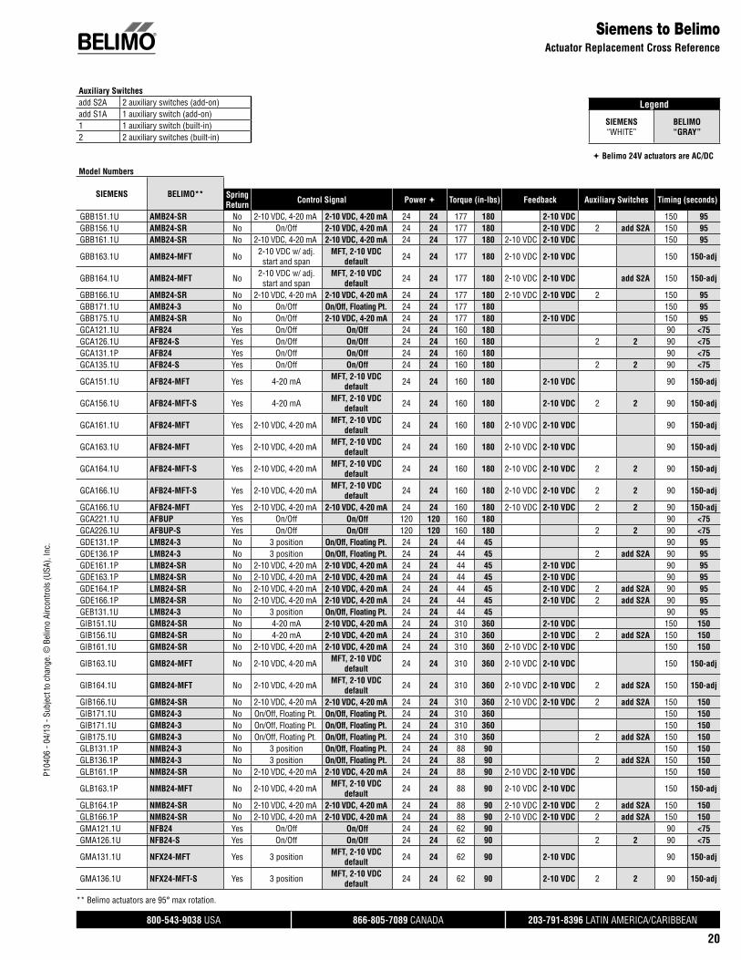
P104
06 -
04/1
3 - S
ubje
ct to
cha
nge.
© B
elim
o Ai
rcon
trols
(USA
), In
c.
®
800-543-9038 USA 866-805-7089 CANADA 203-791-8396 LATIN AMERICA/CARIBBEAN
20
Legend
SIEMENS“WHITE”
BELIMO“GRAY”
Belimo 24V actuators are AC/DC
Siemens to BelimoActuator Replacement Cross Reference
Model Numbers
SIEMENS BELIMO** SpringReturn Control Signal Power Torque (in-lbs) Feedback Auxiliary Switches Timing (seconds)
GBB151.1U AMB24-SR No 2-10 VDC, 4-20 mA 2-10 VDC, 4-20 mA 24 24 177 180 2-10 VDC 150 95GBB156.1U AMB24-SR No On/Off 2-10 VDC, 4-20 mA 24 24 177 180 2-10 VDC 2 add S2A 150 95GBB161.1U AMB24-SR No 2-10 VDC, 4-20 mA 2-10 VDC, 4-20 mA 24 24 177 180 2-10 VDC 2-10 VDC 150 95
GBB163.1U AMB24-MFT No 2-10 VDC w/ adj. start and span
MFT, 2-10 VDC default 24 24 177 180 2-10 VDC 2-10 VDC 150 150-adj
GBB164.1U AMB24-MFT No 2-10 VDC w/ adj. start and span
MFT, 2-10 VDC default 24 24 177 180 2-10 VDC 2-10 VDC add S2A 150 150-adj
GBB166.1U AMB24-SR No 2-10 VDC, 4-20 mA 2-10 VDC, 4-20 mA 24 24 177 180 2-10 VDC 2-10 VDC 2 150 95GBB171.1U AMB24-3 No On/Off On/Off, Floating Pt. 24 24 177 180 150 95GBB175.1U AMB24-SR No On/Off 2-10 VDC, 4-20 mA 24 24 177 180 2-10 VDC 150 95GCA121.1U AFB24 Yes On/Off On/Off 24 24 160 180 90 <75GCA126.1U AFB24-S Yes On/Off On/Off 24 24 160 180 2 2 90 <75GCA131.1P AFB24 Yes On/Off On/Off 24 24 160 180 90 <75GCA135.1U AFB24-S Yes On/Off On/Off 24 24 160 180 2 2 90 <75
GCA151.1U AFB24-MFT Yes 4-20 mA MFT, 2-10 VDC default 24 24 160 180 2-10 VDC 90 150-adj
GCA156.1U AFB24-MFT-S Yes 4-20 mA MFT, 2-10 VDC default 24 24 160 180 2-10 VDC 2 2 90 150-adj
GCA161.1U AFB24-MFT Yes 2-10 VDC, 4-20 mA MFT, 2-10 VDC default 24 24 160 180 2-10 VDC 2-10 VDC 90 150-adj
GCA163.1U AFB24-MFT Yes 2-10 VDC, 4-20 mA MFT, 2-10 VDC default 24 24 160 180 2-10 VDC 2-10 VDC 90 150-adj
GCA164.1U AFB24-MFT-S Yes 2-10 VDC, 4-20 mA MFT, 2-10 VDC default 24 24 160 180 2-10 VDC 2-10 VDC 2 2 90 150-adj
GCA166.1U AFB24-MFT-S Yes 2-10 VDC, 4-20 mA MFT, 2-10 VDC default 24 24 160 180 2-10 VDC 2-10 VDC 2 2 90 150-adj
GCA166.1U AFB24-MFT Yes 2-10 VDC, 4-20 mA 2-10 VDC, 4-20 mA 24 24 160 180 2-10 VDC 2-10 VDC 2 2 90 150-adjGCA221.1U AFBUP Yes On/Off On/Off 120 120 160 180 90 <75GCA226.1U AFBUP-S Yes On/Off On/Off 120 120 160 180 2 2 90 <75GDE131.1P LMB24-3 No 3 position On/Off, Floating Pt. 24 24 44 45 90 95GDE136.1P LMB24-3 No 3 position On/Off, Floating Pt. 24 24 44 45 2 add S2A 90 95GDE161.1P LMB24-SR No 2-10 VDC, 4-20 mA 2-10 VDC, 4-20 mA 24 24 44 45 2-10 VDC 90 95GDE163.1P LMB24-SR No 2-10 VDC, 4-20 mA 2-10 VDC, 4-20 mA 24 24 44 45 2-10 VDC 90 95GDE164.1P LMB24-SR No 2-10 VDC, 4-20 mA 2-10 VDC, 4-20 mA 24 24 44 45 2-10 VDC 2 add S2A 90 95GDE166.1P LMB24-SR No 2-10 VDC, 4-20 mA 2-10 VDC, 4-20 mA 24 24 44 45 2-10 VDC 2 add S2A 90 95GEB131.1U LMB24-3 No 3 position On/Off, Floating Pt. 24 24 44 45 90 95GIB151.1U GMB24-SR No 4-20 mA 2-10 VDC, 4-20 mA 24 24 310 360 2-10 VDC 150 150GIB156.1U GMB24-SR No 4-20 mA 2-10 VDC, 4-20 mA 24 24 310 360 2-10 VDC 2 add S2A 150 150GIB161.1U GMB24-SR No 2-10 VDC, 4-20 mA 2-10 VDC, 4-20 mA 24 24 310 360 2-10 VDC 2-10 VDC 150 150
GIB163.1U GMB24-MFT No 2-10 VDC, 4-20 mA MFT, 2-10 VDC default 24 24 310 360 2-10 VDC 2-10 VDC 150 150-adj
GIB164.1U GMB24-MFT No 2-10 VDC, 4-20 mA MFT, 2-10 VDC default 24 24 310 360 2-10 VDC 2-10 VDC 2 add S2A 150 150-adj
GIB166.1U GMB24-SR No 2-10 VDC, 4-20 mA 2-10 VDC, 4-20 mA 24 24 310 360 2-10 VDC 2-10 VDC 2 add S2A 150 150GIB171.1U GMB24-3 No On/Off, Floating Pt. On/Off, Floating Pt. 24 24 310 360 150 150GIB171.1U GMB24-3 No On/Off, Floating Pt. On/Off, Floating Pt. 24 24 310 360 150 150GIB175.1U GMB24-3 No On/Off, Floating Pt. On/Off, Floating Pt. 24 24 310 360 2 add S2A 150 150GLB131.1P NMB24-3 No 3 position On/Off, Floating Pt. 24 24 88 90 150 150GLB136.1P NMB24-3 No 3 position On/Off, Floating Pt. 24 24 88 90 2 add S2A 150 150GLB161.1P NMB24-SR No 2-10 VDC, 4-20 mA 2-10 VDC, 4-20 mA 24 24 88 90 2-10 VDC 2-10 VDC 150 150
GLB163.1P NMB24-MFT No 2-10 VDC, 4-20 mA MFT, 2-10 VDC default 24 24 88 90 2-10 VDC 2-10 VDC 150 150-adj
GLB164.1P NMB24-SR No 2-10 VDC, 4-20 mA 2-10 VDC, 4-20 mA 24 24 88 90 2-10 VDC 2-10 VDC 2 add S2A 150 150GLB166.1P NMB24-SR No 2-10 VDC, 4-20 mA 2-10 VDC, 4-20 mA 24 24 88 90 2-10 VDC 2-10 VDC 2 add S2A 150 150GMA121.1U NFB24 Yes On/Off On/Off 24 24 62 90 90 <75GMA126.1U NFB24-S Yes On/Off On/Off 24 24 62 90 2 2 90 <75
GMA131.1U NFX24-MFT Yes 3 position MFT, 2-10 VDC default 24 24 62 90 2-10 VDC 90 150-adj
GMA136.1U NFX24-MFT-S Yes 3 position MFT, 2-10 VDC default 24 24 62 90 2-10 VDC 2 2 90 150-adj
Auxiliary Switchesadd S2A 2 auxiliary switches (add-on)add S1A 1 auxiliary switch (add-on)1 1 auxiliary switch (built-in)2 2 auxiliary switches (built-in)
** Belimo actuators are 95° max rotation.

P104
06 -
04/1
3 - S
ubje
ct to
cha
nge.
© B
elim
o Ai
rcon
trols
(USA
), In
c.
®
800-543-9038 USA 866-805-7089 CANADA 203-791-8396 LATIN AMERICA/CARIBBEAN
21
Siemens to BelimoActuator Replacement Cross Reference
GMA161.1U NFB24-MFT Yes 2-10 VDC, 4-20 mA MFT, 2-10 VDC default 24 24 62 90 2-10 VDC 2-10 VDC 90 150-adj
GMA163.1U NFB24-MFT Yes 2-10 VDC, 4-20 mA MFT, 2-10 VDC default 24 24 62 90 2-10 VDC 2-10 VDC 90 150-adj
GMA166.1U NFB24-MFT-S Yes 2-10 VDC, 4-20 mA MFT, 2-10 VDC default 24 24 62 90 2-10 VDC 2-10 VDC 2 2 90 150-adj
GMA221.1U NFBUP Yes On/Off On/Off 120 24-240 62 90 90 <75GMA226.1U NFBUP-S Yes On/Off On/Off 120 24-240 62 90 2 2 90 <75GQD121.1P TFB24 Yes On/Off On/Off 24 24 20 22 40-75 <75GQD131.1P TFB24-3 Yes Floating Point Floating Point 24 24 20 22 40-75 95GQD151.1P TFB24-MFT Yes 2-10 VDC, 4-20 mA 2-10 VDC, 4-20 mA 24 24 20 22 2-10 VDC 2-10 VDC 40-75 150-adjGQD221.1U TFCB120-S* Yes On/Off On/Off 120 120 20 22 40-75 30
SIEMENS BELIMO** SpringReturn Control Signal Power Torque (in-lbs) Feedback Auxiliary Switches Timing (seconds)
*Do not wire switch.
** Belimo actuators are 95° max rotation.

P104
06 -
04/1
3 - S
ubje
ct to
cha
nge.
© B
elim
o Ai
rcon
trols
(USA
), In
c.
®
800-543-9038 USA 866-805-7089 CANADA 203-791-8396 LATIN AMERICA/CARIBBEAN
22
Specialized Retrofit SolutionsDirect Coupled Actuators
AFB24-MFT…
LF24-MFT…
AMX24-MFT…
HONEYWELL SERIES 90, 0-135 ΩBELIMO MODEL TORQUEAFB24-MFT95, AFX24-MFT95 180 in-lbsLMX24-MFT95 45 in-lbsNMX24-MFT95 90 in-lbsAMX24-MFT95 180 in-lbsGMX24-MFT95 360 in-lbs
BARBER COLMAN MP…, 6-9 VBELIMO MODEL TORQUELF24-MFT-20 US 35 in-lbsLF24-MFT-S-20 US 35 in-lbs
STAEFA CONTROL 0-10 V PHASECUTBELIMO MODEL TORQUEAFB24-PC 180 in-lbsLMX24-PC 45 in-lbsNMX24-PC 90 in-lbsAMX24-PC 180 in-lbsGMX24-PC 360 in-lbs
Control Signal Based Retrofi t Solutions

P104
06 -
04/1
3 - S
ubje
ct to
cha
nge.
© B
elim
o Ai
rcon
trols
(USA
), In
c.
®
800-543-9038 USA 866-805-7089 CANADA 203-791-8396 LATIN AMERICA/CARIBBEAN
23
ZG-JSL, ZG-JSLA Jackshaft Retrofi t LinkageFor EF, AF, NF, LF, GM, GK, AM and NM Series Actuators
ApplicationThe ZG-JSL jackshaft linkage is designed to easily attach to any part of a jackshaft and allows easy installation of select Belimo actuators.
The unique open ended design and clamp insert allows the ZG-JSL to be used with any jackshaft from ½” to ¾” in diameter. Removal of the insert will allow the linkage to attach to a maximum shaft diameter of 1.05”. Changing the anti-rotation plate will allow various actuators to be mounted.
Default/ConfigurationThe ZG-JSL linkage can also be configured by moving the anti-rotation plate 90° for space saving applications. See mounting configurations below. The ZG-JSLA will have a factory mounted actuator on the linkage in the vertical position only.
OperationThe ¾” diameter built-in steel shaft allows direct coupling to Belimo series actuators (chart below). There is a torque reduction when using the ZG-JSL linkage. Verify application requirements before ordering.
Actuator Torque ReductionEF Series* 239 in-lbs
Classic AF Series 123 in-lbs
AF Series 166 in-lbs
NF Series 87 in-lbs
LF Series*** 33 in-lbs
GM/GK Series** 288 in-lbs
AM Series 166 in-lbs
NM Series 87 in-lbs
* ZG-121 adapter must be used with EF.** EF, GM/GK not for use with ½” shafts.*** K6-1 clamp must be used with LF.
Dimensions (Inches [mm])
4.76
” [12
1]
8.74” [222]
14.05” [357]
10.16” [258]
4.13” [105] 1.93” [49]
3.86” [98]
4.41” [112]
4.65
” [11
8]
6.42
” [16
3]
10.3
1” [2
62]
D31
4
Technical Data ZG-JSL, ZG-JSLAFits shaft diameter ½” to ¾” with insert, 1.05” without insertMaterials: Housing galvanized steel Bearings GF Delrin Shafts steelMax torque output 90% of rated actuator torqueMax actuator yield see chart on rightMech. angle of rotation 90° mountableAmbient temperature -22°F to +122°F [-33°C to +50°C]Storage temperature -40°F to +176°F [-40°C to +80°C]Housing type NEMA 2Weight 3.25 lbs [1.47 kg]
Mounting Configurations
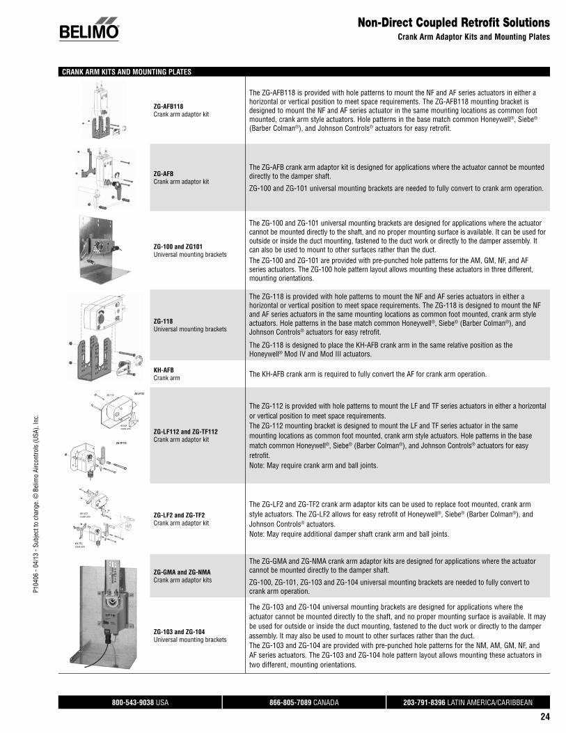
P104
06 -
04/1
3 - S
ubje
ct to
cha
nge.
© B
elim
o Ai
rcon
trols
(USA
), In
c.
®
800-543-9038 USA 866-805-7089 CANADA 203-791-8396 LATIN AMERICA/CARIBBEAN
24
Non-Direct Coupled Retrofit SolutionsCrank Arm Adaptor Kits and Mounting Plates
CRANK ARM KITS AND MOUNTING PLATES
ZG-AFB118 Crank arm adaptor kit
The ZG-AFB118 is provided with hole patterns to mount the NF and AF series actuators in either a horizontal or vertical position to meet space requirements. The ZG-AFB118 mounting bracket is designed to mount the NF and AF series actuator in the same mounting locations as common foot mounted, crank arm style actuators. Hole patterns in the base match common Honeywell®, Siebe® (Barber Colman®), and Johnson Controls® actuators for easy retrofit.
ZG-AFBCrank arm adaptor kit
The ZG-AFB crank arm adaptor kit is designed for applications where the actuator cannot be mounted directly to the damper shaft.
ZG-100 and ZG-101 universal mounting brackets are needed to fully convert to crank arm operation.
ZG-100 and ZG101 Universal mounting brackets
The ZG-100 and ZG-101 universal mounting brackets are designed for applications where the actuator cannot be mounted directly to the shaft, and no proper mounting surface is available. It can be used for outside or inside the duct mounting, fastened to the duct work or directly to the damper assembly. It can also be used to mount to other surfaces rather than the duct. The ZG-100 and ZG-101 are provided with pre-punched hole patterns for the AM, GM, NF, and AF series actuators. The ZG-100 hole pattern layout allows mounting these actuators in three different, mounting orientations.
ZG-118Universal mounting brackets
The ZG-118 is provided with hole patterns to mount the NF and AF series actuators in either a horizontal or vertical position to meet space requirements. The ZG-118 is designed to mount the NF and AF series actuators in the same mounting locations as common foot mounted, crank arm style actuators. Hole patterns in the base match common Honeywell®, Siebe® (Barber Colman®), and Johnson Controls® actuators for easy retrofit.
The ZG-118 is designed to place the KH-AFB crank arm in the same relative position as the Honeywell® Mod IV and Mod III actuators.
KH-AFBCrank arm The KH-AFB crank arm is required to fully convert the AF for crank arm operation.
ZG-112
KH-LFcrank arm
ZG-LF112
ZG-TF112
ZG-LF112 and ZG-TF112Crank arm adaptor kit
The ZG-112 is provided with hole patterns to mount the LF and TF series actuators in either a horizontal or vertical position to meet space requirements.The ZG-112 mounting bracket is designed to mount the LF and TF series actuator in the same mounting locations as common foot mounted, crank arm style actuators. Hole patterns in the base match common Honeywell®, Siebe® (Barber Colman®), and Johnson Controls® actuators for easy retrofit.Note: May require crank arm and ball joints.
KH-LF2crank arm
KH-TF2crank arm
ZG-LF2 and ZG-TF2 Crank arm adaptor kit
The ZG-LF2 and ZG-TF2 crank arm adaptor kits can be used to replace foot mounted, crank arm style actuators. The ZG-LF2 allows for easy retrofit of Honeywell®, Siebe® (Barber Colman®), and Johnson Controls® actuators. Note: May require additional damper shaft crank arm and ball joints.
ZG-GMA and ZG-NMACrank arm adaptor kits
The ZG-GMA and ZG-NMA crank arm adaptor kits are designed for applications where the actuator cannot be mounted directly to the damper shaft.
ZG-100, ZG-101, ZG-103 and ZG-104 universal mounting brackets are needed to fully convert to crank arm operation.
ZG-103 and ZG-104Universal mounting brackets
The ZG-103 and ZG-104 universal mounting brackets are designed for applications where the actuator cannot be mounted directly to the shaft, and no proper mounting surface is available. It may be used for outside or inside the duct mounting, fastened to the duct work or directly to the damper assembly. It may also be used to mount to other surfaces rather than the duct. The ZG-103 and ZG-104 are provided with pre-punched hole patterns for the NM, AM, GM, NF, and AF series actuators. The ZG-103 and ZG-104 hole pattern layout allows mounting these actuators in two different, mounting orientations.
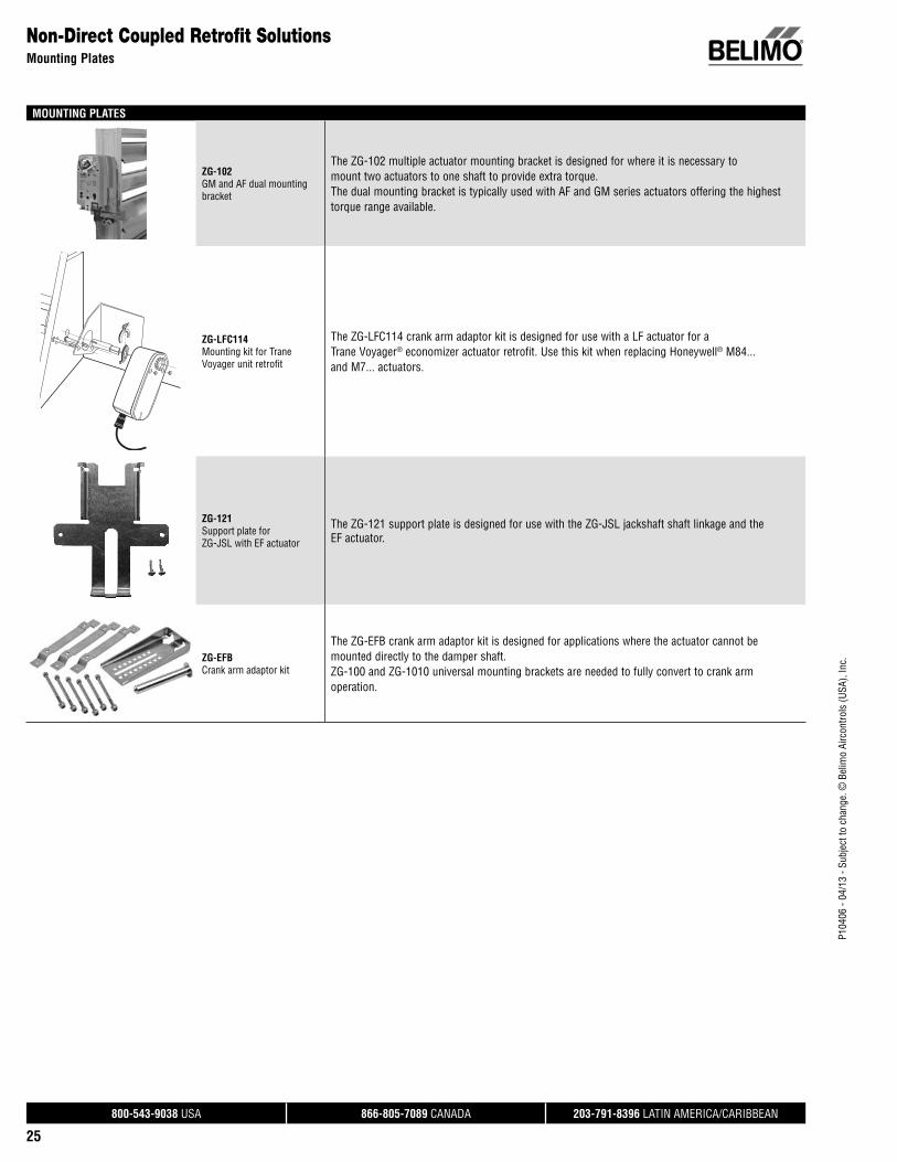
P104
06 -
04/1
3 - S
ubje
ct to
cha
nge.
© B
elim
o Ai
rcon
trols
(USA
), In
c.
®
800-543-9038 USA 866-805-7089 CANADA 203-791-8396 LATIN AMERICA/CARIBBEAN
25
MOUNTING PLATES
ZG-102GM and AF dual mounting bracket
The ZG-102 multiple actuator mounting bracket is designed for where it is necessary to mount two actuators to one shaft to provide extra torque.The dual mounting bracket is typically used with AF and GM series actuators offering the highest torque range available.
ZG-LFC114Mounting kit for Trane Voyager unit retrofi t
The ZG-LFC114 crank arm adaptor kit is designed for use with a LF actuator for a Trane Voyager® economizer actuator retrofit. Use this kit when replacing Honeywell® M84... and M7... actuators.
ZG-121 Support plate for ZG-JSL with EF actuator
The ZG-121 support plate is designed for use with the ZG-JSL jackshaft shaft linkage and the EF actuator.
ZG-EFBCrank arm adaptor kit
The ZG-EFB crank arm adaptor kit is designed for applications where the actuator cannot be mounted directly to the damper shaft. ZG-100 and ZG-1010 universal mounting brackets are needed to fully convert to crank arm operation.
Non-Direct Coupled Retrofit SolutionsMounting Plates

P104
06 -
04/1
3 - S
ubje
ct to
cha
nge.
© B
elim
o Ai
rcon
trols
(USA
), In
c.
®
800-543-9038 USA 866-805-7089 CANADA 203-791-8396 LATIN AMERICA/CARIBBEAN
26
Economizer Actuator Retrofit Solutions
When replacing an existing actuator in an economizer unit, be sure to consider the application parameters before selecting the replacement. Use the chart below for reference. Belimo offers many direct coupled and non-direct replacement solutions. Start with your current model and controller type, and follow the diagram to the appropriate Belimo kit and actuator option.
Please contact Belimo Customer Service for other solutions.
W7215A, B
ACTUATOR CONTROLLER BELIMORETROFIT KITS
BELIMO RETROFITACTUATOR OPTIONS
W7459A, D
HWM7415
HWM8405
HWM7215
HWML7275A
(DMA)
ZG-ECON1LF24-ECON-R03 US
W7460
W7210
W7459C
W7212
W7210A, D
ZG-ECON2
ZG-ECON2
ZG-ECON1
ZG-ECON1
FEMALE SPADES
LF24-SR US
LF24-SR-E US
LF24-SR US
LF24-SR US
Honeywell to Belimo Economizer Solutions
W7215A, B
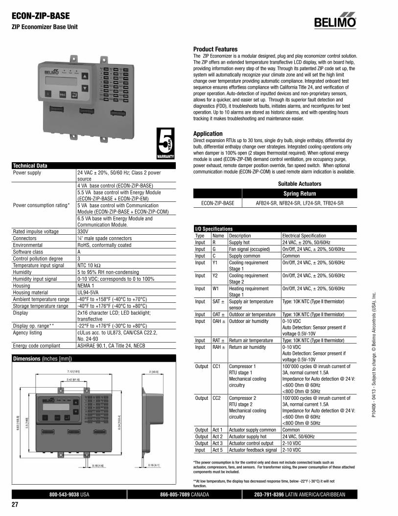
P104
06 -
04/1
3 - S
ubje
ct to
cha
nge.
© B
elim
o Ai
rcon
trols
(USA
), In
c.
®
800-543-9038 USA 866-805-7089 CANADA 203-791-8396 LATIN AMERICA/CARIBBEAN
27
ECON-ZIP-BASEZIP Economizer Base Unit
Technical Data
Power supply 24 VAC ± 20%, 50/60 Hz; Class 2 power source
Power consumption rating*
4 VA base control (ECON-ZIP-BASE)5.5 VA base control with Energy Module (ECON-ZIP-BASE + ECON-ZIP-EM)5 VA base control with Communication Module (ECON-ZIP-BASE + ECON-ZIP-COM)6.5 VA base with Energy Module andCommunication Module.
Rated impulse voltage 330VConnectors ¼" male spade connectorsEnvironmental RoHS, conformally coatedSoftware class AControl pollution degree 3Temperature input signal NTC 10 kΩHumidity 5 to 95% RH non-condensingHumidity input signal 0-10 VDC; corresponds to 0 to 100%Housing NEMA 1Housing material UL94-5VAAmbient temperature range -40°F to +158°F (-40°C to +70°C)Storage temperature range -40°F to +176°F (-40°C to +80°C)Display 2x16 character LCD; LED backlight;
transflectiveDisplay op. range** -22°F to +176°F (-30°C to +80°C)Agency listing cULus acc. to UL873, CAN/CSA C22.2,
No. 24-93Energy code compliant ASHRAE 90.1, CA Title 24, NECB
Dimensions (Inches [mm])
Product FeaturesThe ZIP Economizer is a modular designed, plug and play economizer control solution. The ZIP offers an extended temperature transflective LCD display, with on board help, providing information every step of the way. Through its patented ZIP code set up, the system will automatically recognize your climate zone and will set the high limit change over temperature providing automatic compliance. Integrated onboard test sequence ensures effortless compliance with California Title 24, and verification of proper operation. Auto-detection of inputted devices and non-proprietary sensors, allows for a quicker, and easier set up. Through its superior fault detection and diagnostics (FDD), it troubleshoots faults, initiates alarms, and reconfigures for best operation. Up to 10 alarms are stored as historic alarms, and with operating hours tracking it makes troubleshooting and maintenance easier.
ApplicationDirect expansion RTUs up to 30 tons, single dry bulb, single enthalpy, differential dry bulb, differential enthalpy change over strategies. Integrated cooling operations only when damper is 100% open (2 stages thermostat required). When optional energy module is used (ECON-ZIP-EM) demand control ventilation, pre occupancy purge, power exhaust, remote damper position override, fan speed switch. When optional communication module (ECON-ZIP-COM) is used remote alarm indication is available.
Suitable Actuators
Spring Return
ECON-ZIP-BASE AFB24-SR, NFB24-SR, LF24-SR, TFB24-SR
I/O SpecificationsType Name Description Electrical Specifi cationInput R Supply hot 24 VAC, ± 20%, 50/60HzInput G Fan signal (occupied) On/Off, 24 VAC, ± 20%, 50/60HzInput C Supply common CommonInput Y1 Cooling requirement
Stage 1On/Off, 24 VAC, ± 20%, 50/60Hz
Input Y2 Cooling requirement Stage 2
On/Off, 24 VAC, ± 20%, 50/60Hz
Input W1 Heating requirement Stage 1
On/Off, 24 VAC, ± 20%, 50/60Hz
Input SAT ± Supply air temperature sensor
Type: 10K NTC (Type II thermistor)
Input OAT ± Outdoor air temperature Type: 10K NTC (Type II thermistor)Input OAH ± Outdoor air humidity 0-10 VDC
Auto Detection: Sensor present if voltage 0.5V-10V
Input RAT ± Return air temperature Type: 10K NTC (Type II thermistor)Input RAH ± Return air humidity 0-10 VDC
Auto Detection: Sensor present if voltage 0.5V-10V
Output CC1 Compressor 1RTU stage 1Mechanical coolingcircuitry
100'000 cycles @ inrush current of 3A, normal current 1.5A Impedance for Auto detection @ 24 V:<60O Ohm @ 60Hz<80O Ohm @ 50Hz
Output CC2 Compressor 2RTU stage 2Mechanical coolingcircuitry
100'000 cycles @ inrush current of 3A, normal current 1.5A Impedance for Auto detection @ 24 V:<60O Ohm @ 60Hz<80O Ohm @ 50Hz
Output Act 1 Actuator supply common CommonOutput Act 2 Actuator supply hot 24 VAC, 50/60HzOutput Act 3 Actuator control output 2-10 VDCInput Act 5 Actuator feedback signal 2-10 VDC
*The power consumption is for the control only and does not include connected loads such as actuator, compressors, fans, and sensors. For transformer sizing, the power consumption of these attached components must be included.
**At low temperature, the display has decreased response time, below -22°F (-30°C) it will not function.

P104
06 -
04/1
3 - S
ubje
ct to
cha
nge.
© B
elim
o Ai
rcon
trols
(USA
), In
c.
®
800-543-9038 USA 866-805-7089 CANADA 203-791-8396 LATIN AMERICA/CARIBBEAN
28
ECON-ZIP-BASEZIP Economizer Base Unit
Wiring Diagram
ECON-ZIP-THReturn
Enthalpy
ECON-ZIP-THOutdoor Enthalpy
-SR Actuator
Ro
ofto
p U
nit Term
inal
Therm
ostat
R
C
G
Y1
Y2
W1
W2
Occ
Purge
CC2
RTU Stage 2 Mechanical Cooling
Circuitry
CC1
RTU Stage 1 Mechanical Cooling
Circuitry
Outdoor Air Temperature
Return Air Temperature
Supply Air Temperature
1 When Temperature and Humidity sensors are used for enthalpy, respective temperature only sensors are not used and OAT and RAT and wiring shall terminate at ECON-ZIP-TH
1
1
2 Return Air Temperature and Humidity sensors are only required when differential temperature or differential enthalpy high limit changeover strategy is used
2
23 When the thermostat is not equipped with occupancy control, ”Fan On” output “G” shall be wired to ECON-ZIP-BASE
3
3
4
4 W1 must be wired to ECON-ZIP-BASE when unit is a Heat Pump, using 2 speed fan, and when it is desired to record operational hours in heating
5 Existing refrigeration safety devices may exist, consult RTU wiring diagram
5

P104
06 -
04/1
3 - S
ubje
ct to
cha
nge.
© B
elim
o Ai
rcon
trols
(USA
), In
c.
®
800-543-9038 USA 866-805-7089 CANADA 203-791-8396 LATIN AMERICA/CARIBBEAN
29
ECON-ZIP-COMZIP Economizer Communication Module
Technical Data
Power supply 24 VAC ± 20%, 50/60Hz, class 2 power sourcePower consumption rating* 2.5 VA (ECON-ZIP-COM), 6.5 VA
(ECON-ZIP-BASE + ECON-ZIP-COM)Connectors ¼" male spade connectorsEnvironmental RoHS, conformally coatedCommunication interface RS485 interface, optical isolation max. 1kVDC
(for max.1 min), Pin 4: RS485 Com Gnd, Pin 7:RS485 Com A, Pin 8: RS485 Com B
Supported remote alarm normal current: 0.5A, inrush current: 1AHumidity 5 to 95% RH non-condensingHousing NEMA 1Housing material UL94-5VAAmbient temperature range -40°F to +158°F (-40°C to +70°C)Storage temperature range -40°F to +176°F (-40°C to +80°C)Agency listing cULus acc. to UL873, CAN/CSA C22.2, No.
24-93
*The power consumption is for the control only and does not include connected loads such as actuator, compressors, fans, and sensors. For transformer sizing, the power consumption of these attached components must be included.
Product FeaturesThe ZIP Economizer Communication Module provides alarm output with future capabilities such as data trending, building automation integration, and OEM communication integration.
OperationThe ZIP Economizer Communication Module has full functionality when connected to the ECON-ZIP-Base. Its unique keyed slot makes installation a breeze.
Dimensions (Inches [mm])
Wiring Diagram

P104
06 -
04/1
3 - S
ubje
ct to
cha
nge.
© B
elim
o Ai
rcon
trols
(USA
), In
c.
®
800-543-9038 USA 866-805-7089 CANADA 203-791-8396 LATIN AMERICA/CARIBBEAN
30
ECON-ZIP-EMZIP Economizer Energy Module
Technical Data
Power supply 24 VAC ± 20%, 50/60Hz, class 2 power sourcePower consumption rating* 1.5 VA (ECON-ZIP-EM), 5.5 VA
(ECON-ZIP-BASE + ECON-ZIP-EM)Connectors ¼" male spade connectorsEnvironmental RoHS, conformally coatedIndoor fan speed selection 100'000 cycles @ inrush current of 3A,
normal current 1.5A Exhaust fan selection 100'000 cycles @ inrush current of 3A,
normal current 1.5ASupported CO2 sensor 0-10 VDC, sensor auto-detectionAuxiliary input - purge contact
on/off - 24 VAC, 50/60HZ - current load min10mA
Auxiliary input - remote potentiometer
2-10VDC
Humidity 5 to 95% RH non-condensingHousing NEMA 1Housing material UL94-5VAAmbient temperature range -40°F to +158°F (-40°C to +70°C)Storage temperature range -40°F to +176°F (-40°C to +80°C)Agency listing cULus acc. to UL873, CAN/CSA C22.2, No.
24-93
*The power consumption is for the control only and does not include connected loads such as actuator, compressors, fans, and sensors. For transformer sizing, the power consumption of these attached components must be included.
Product FeaturesThe ZIP Economizer Energy Module provides additional inputs/outputs (I/Os) to offer higher control functionalities that will save energy and will meet new and future minimum code requirements. The Energy Module is needed for CO2 sensors, indoor fan, two speed fan, exhaust fan, remote potentiometer for damper positioning, as well as purge control. The auto-detection and plug and play capability offers quick set up.
ApplicationThe ZIP Economizer Energy Module offers demand control ventilation for high occupancy areas. A third party CO2 sensor is required. Pre-occupancy purge input for VOC removal requires thermostat with purge contact. Power exhaust for building pressure control requires power exhaust fan. Remote damper override requires remote potentiometer installed. Two speed fan control requires supply fan to be equipped with multi speed fan or VFD.
Dimensions (Inches [mm])
I/O SpecificationsType Name Description Electrical Specifi cation
Input CO2 ±CO2 sensor input
0-10 VDC (0-2000 ppm) Sensor auto-detection
Output IFIndoor fan low speed enable
100'000 cycles @ inrush current of 3A, normal current 1.5AImpedance for Auto detection @24 V:<600 Ohm @ 60Hz<800 Ohm @ 50Hz
Output EF Exhaust fan enable
100'000 cycles @ inrush current of 3A, normal current 1.5A Impedance for Auto detection @ 24 V:<600 Ohm @ 60Hz<800 Ohm @ 50Hz
Input AUX1 ±Auxiliary inputPurge con-tact input
On/Off, 24 VAC, 50/60 HzCurrent load min. 10mA
Input AUX2 ±
Auxiliary inputRemote Po-tentiometer Input
2-10 VDC
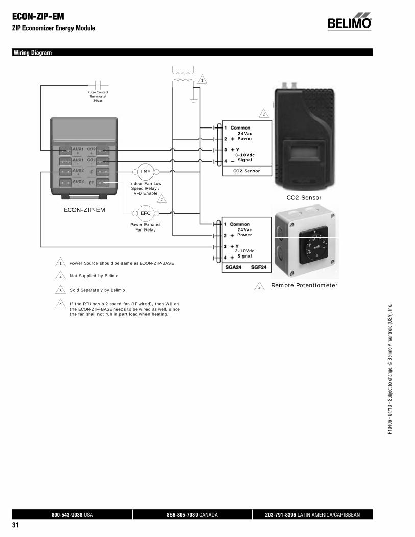
P104
06 -
04/1
3 - S
ubje
ct to
cha
nge.
© B
elim
o Ai
rcon
trols
(USA
), In
c.
®
800-543-9038 USA 866-805-7089 CANADA 203-791-8396 LATIN AMERICA/CARIBBEAN
31
ECON-ZIP-EMZIP Economizer Energy Module
Wiring Diagram
ECON-ZIP-EM
CO2 Sensor
Remote Potentiometer
24VacPower
2-10VdcSignal
24VacPower
0-10VdcSignal
CO2 SensorEFCLSF
EFC
Indoor Fan Low Speed Relay / VFD Enable
Power Exhaust Fan Relay
1
1 Power Source should be same as ECON-ZIP-BASE
Purge ContactThermostat
24Vac
2
2 Not Supplied by Belimo
2
3 Sold Separately by Belimo 3
4 If the RTU has a 2 speed fan (IF wired), then W1 on the ECON-ZIP-BASE needs to be wired as well, since the fan shall not run in part load when heating.

P104
06 -
04/1
3 - S
ubje
ct to
cha
nge.
© B
elim
o Ai
rcon
trols
(USA
), In
c.
®
800-543-9038 USA 866-805-7089 CANADA 203-791-8396 LATIN AMERICA/CARIBBEAN
32
ECON-ZIP-10KZIP Economizer Temperature Sensor
Technical Data
Temperature output signal NTC 10 kΩ, Type IIConnectors ¼" female spade insulated connectors,
3 ft. cableAccuracy ± 0.36°F (± 0.2°C)Stability drift less than 0.036°F/yr [0.02°C/yr]Material etched Teflon, plenum-rated & FEP jacketed
cable; galvanized t-bracketAmbient temperature range -67°F to +176°F (-55°C to +80°C)
ApplicationECON-ZIP-10K allows for reliable temperature air readings. The sensor may be used for outdoor air (OAT), return air (RAT), or supply air (SAT) temperature measurements and control, with no configuration required. A minimum of one SAT and one OAT sensor is required for the ZIP Economizer to function. An RAT sensor can be added for differential temperature change over strategy. For best control results, sensors should be placed in the air stream. T-Bracket mounting is universal and can be inserted through the duct work, fan housing or surface mounted.

P104
06 -
04/1
3 - S
ubje
ct to
cha
nge.
© B
elim
o Ai
rcon
trols
(USA
), In
c.
®
800-543-9038 USA 866-805-7089 CANADA 203-791-8396 LATIN AMERICA/CARIBBEAN
33
Dimensions (Inches [mm]) Dimensions (Inches [mm])
Honeywell W7459 to Belimo ZIP Economizer™
W7459 WIRE TERMINATION ZIP ECONOMIZER WIRE TERMINATION
1 Y12 CC13 Y24 CC25
TR RTR1 CN G
P-P1T-T1 Mixed Air- New Sensor
So-So+ Outside Air- New SensorSr-Sr+ New Sensors
Actuators and sensors connected to the W7459 should be replaced with a Belimo actuator and correctly specifi ed temperature and humidity sensors (ECON-ZIP-10K and/or ECON-ZIP-TH).
Honeywell W7459 Belimo ZIP Economizer™

• Adaptive stroke of actuators utilizes full control signal for maximum resolution.
• Visual stroke indicators allow quick installation.
• Linkages can be mounted in any orientation except upside down.
• Travel ranges of up to 1.5” (38mm) of stroke.
• Steam rated for inlets up to 100 psi.
Applications
UGVL,UGLK, UGSL, and UGSP globe valve retrofi t solutions are designed to easily
attach to the valve bonnet and stem of competitor valves utilizing Belimo actuators.
This kit will help to restore service without removal of the valve, saving down time
and money.
Globe Valve Retrofi t Solutions

P104
06 -
04/1
3 - S
ubje
ct to
cha
nge.
© B
elim
o Ai
rcon
trols
(USA
), In
c.
®
800-543-9038 USA 866-805-7089 CANADA 203-791-8396 LATIN AMERICA/CARIBBEAN
35
UGLK.../UGSP... Retrofi t Linkage for Globe ValvesFor LM and LF Series Actuators
ApplicationThe UGLK/UGSP retrofit kit is designed to easily attach to the valve bonnet on select competitor valves utilizing Belimo LM and LF series actuators. The kit is used to restore service to the valve without removal of the valve, saving down time.
The unique collar design allows the UGLK to be mounted on various two-way or three-way valves. The rack and pinion construction allow the linkage to be used with normally open and normally closed valves.
Default/ConfigurationThe actuator is sold separately from the linkage. This allows users to select the actuator with the desired control signal. The linkage utilizes standard air-side actuators that can be purchased at any time and mounted in the field. With the free spring design of the linkage, clearance is not an issue. The linkage can be oriented at any angle on the bonnet.
OperationThe UGLK/UGSP linkage provides approximately ½” of downward stroke with 95° rotation on the actuator. The linkage travel is based on the size of gear inside. The gear size is stamped on the frame. This allows the valve to extend fully open or closed based on signal. When directional needs vary, the actuator can be flipped or the directional switch turned to a new rotation. The compact design allows for installation in tight spaces.
Suitable Actuators Close-Off RangesLM Series 2-250 psiLF Series 22-250 psi
Competitor Valves** HoneywellJCISiemens / Powers Siebe / Invensys / TAC / Schneider
**Consult pages 92-134 of the Retrofit Technical Documentation and/or SelectPro for close-off pressures and a cross reference of each valve.
UGLK / UGSP
Technical Data UGLK... / UGSP...Materials: Frame, plate, base stainless steel Collar brass Drive shaft ½” brass Gears, rack sinttered steel Bearing bronze Stem adaptor brassStroke max (gear teeth) ½” (12 teeth)Mounting position 360° mountableAmbient temperature -22°F to +122°F [-30°C to +50°C]Storage temperature -40°F to +176°F [-40°C to +80°C]Servicing chilled or hot water
max steam inlet 50 psi Weight 2.8 lbs [1.3 kg]
UGLK / UGSP Parts Breakdown
A
B C
H2
H1
D
Dimensions (Inches [mm])A 6.5” [165] D 4.0” [102]B 1.5” [33] H1 4.0” [102]C 5.0” [127] H2 3.5" [89]
Drive Shaft
Box Frame
Retaining Ring
Collar
Stem Adapter
RackBase Bracket
Actuator PlateK Part Overview

P104
06 -
04/1
3 - S
ubje
ct to
cha
nge.
© B
elim
o Ai
rcon
trols
(USA
), In
c.
®
800-543-9038 USA 866-805-7089 CANADA 203-791-8396 LATIN AMERICA/CARIBBEAN
36
UGLK.../UGSP... Retrofi t Linkage for Globe ValvesFor Single Mounted GK, AF, NF, GM, AM and NM Series Actuators
ApplicationThe UGLK/UGSP retrofit kit is designed to easily attach to the valve bonnet on select competitor valves utilizing Belimo GK, AF, NF, GM, AM and NM series actuators. The kit is used to restore service to the valve without removal of the valve, saving down time.
The unique collar design allows the UGLK to be mounted on various two-way or three-way valves. The rack and pinion construction allow the linkage to be used with normally open and normally closed valves.
Default/ConfigurationThe actuator is sold separately from the linkage. This allows users to select the actuator with the desired control signal. The linkage utilizes standard air-side actuators that can be purchased at any time and mounted in the field. Due to the free spring design of the linkage, clearance is not an issue. The linkage can be oriented at any angle on the bonnet.
OperationThe UGLK/UGSP linkage provides approximately ½” to 1-½” of downward stroke with 95° rotation on the actuator. The linkage travel is based on the size of gear inside. The gear size is stamped on the frame. This allows the valve to extend fully open or closed based on signal. When directional needs vary, the actuator can be flipped or directional switch turned to a new rotation.
Suitable Actuators Close-Off RangesGK Series 10-250 psiAF Series 4-250 psiNF Series 10-250 psiGM Series 10-250 psiAM Series 4-250 psiNM Series 10-250 psi
Competitor Valves** HoneywellJCISiemens / Powers Siebe / Invensys / TAC / SchneiderWarren Controls
**Consult pages 92-134 of the Retrofit Technical Documentation and/or SelectPro for close-off pressures and a cross reference of each valve.
UGLK / UGSP
Technical Data UGLK... / UGSP...Materials: Frame, plate, base stainless steel Collar brass Drive shaft ¾” brass Gears, rack sinttered steel Bearing bronze Stem adaptor brassStroke max (gear teeth) ½” (12 teeth)
¾” (17 teeth)1-1/8” (25 teeth)1-½” (33 teeth)
Mounting position 360° mountableAmbient temperature -22°F to +122°F [-30°C to +50°C]Storage temperature -40°F to +176°F [-40°C to +80°C]Servicing chilled or hot water, and steamWeight 5.7 lbs [2.6 kg]
UGLK / UGSP Parts Breakdown
Dimensions (Inches [mm])A 9”-11” [178-356] D 4.0” [102]B 1.5” [33] H1 4.0” [102]C 5.0” [127] H2 3.5" [89]
Drive Shaft
Box Frame
Retaining Ring
Collar
Stem Adapter
RackBase Bracket
Actuator PlateK Part Overview
A
B C
H1
H2
D
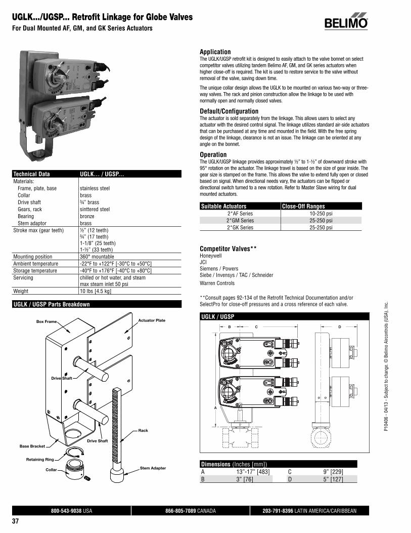
P104
06 -
04/1
3 - S
ubje
ct to
cha
nge.
© B
elim
o Ai
rcon
trols
(USA
), In
c.
®
800-543-9038 USA 866-805-7089 CANADA 203-791-8396 LATIN AMERICA/CARIBBEAN
37
UGLK.../UGSP... Retrofi t Linkage for Globe ValvesFor Dual Mounted AF, GM, and GK Series Actuators
ApplicationThe UGLK/UGSP retrofit kit is designed to easily attach to the valve bonnet on select competitor valves utilizing tandem Belimo AF, GM, and GK series actuators when higher close-off is required. The kit is used to restore service to the valve without removal of the valve, saving down time.
The unique collar design allows the UGLK to be mounted on various two-way or three-way valves. The rack and pinion construction allow the linkage to be used with normally open and normally closed valves.
Default/ConfigurationThe actuator is sold separately from the linkage. This allows users to select any actuator with the desired control signal. The linkage utilizes standard air-side actuators that can be purchased at any time and mounted in the field. With the free spring design of the linkage, clearance is not an issue. The linkage can be oriented at any angle on the bonnet.
OperationThe UGLK/UGSP linkage provides approximately ½” to 1-½” of downward stroke with 95° rotation on the actuator. The linkage travel is based on the size of gear inside. The gear size is stamped on the frame. This allows the valve to extend fully open or closed based on signal. When directional needs vary, the actuators can be flipped or directional switch turned to a new rotation. Refer to Master Slave wiring for dual mounted actuators.
Suitable Actuators Close-Off Ranges2*AF Series 10-250 psi2*GM Series 25-250 psi2*GK Series 25-250 psi
Competitor Valves** HoneywellJCISiemens / Powers Siebe / Invensys / TAC / SchneiderWarren Controls
**Consult pages 92-134 of the Retrofit Technical Documentation and/or SelectPro for close-off pressures and a cross reference of each valve.
UGLK / UGSP
Technical Data UGLK... / UGSP...Materials: Frame, plate, base stainless steel Collar brass Drive shaft ¾” brass Gears, rack sinttered steel Bearing bronze Stem adaptor brassStroke max (gear teeth) ½” (12 teeth)
¾” (17 teeth)1-1/8” (25 teeth)1-½” (33 teeth)
Mounting position 360° mountableAmbient temperature -22°F to +122°F [-30°C to +50°C]Storage temperature -40°F to +176°F [-40°C to +80°C]Servicing chilled or hot water, and steam
max steam inlet 50 psi Weight 10 lbs [4.5 kg]
UGLK / UGSP Parts Breakdown
A
B C D
Dimensions (Inches [mm])A 13”-17” [483] C 9” [229]B 3” [76] D 5” [127]
Box Frame
Drive Shaft
Actuator Plate
Rack
Stem Adapter
Base Bracket
Retaining Ring
Collar
Drive Shaft

P104
06 -
04/1
3 - S
ubje
ct to
cha
nge.
© B
elim
o Ai
rcon
trols
(USA
), In
c.
®
800-543-9038 USA 866-805-7089 CANADA 203-791-8396 LATIN AMERICA/CARIBBEAN
38
UGVL Universal Globe Valve LinkageFor Use with LV and SV Series Actuators
Technical Data
Service chilled or hot water and steamApplicable valve size ½" [13], ¾" [19], 1" [25], 1-¼" [32], 1-½"
[38], 2" [50]Stem slotted, threadedFrame, plate, base aluminum, steelCollar aluminum, steel, (fits bonnets up to 1.7" dia.)Stem adaptor aluminumStroke 0.75" [20mm]Mounting position 360°Media temp range (water) 20°F to 250°F [-7°C to +120°C]Media temp range (steam) 32°F to 388°F [0°C to 170°C]Weight 1.9 lbs
ApplicationThe UGVL retrofit kit is designed to easily attach LV and SV series actuators to select globe valves. Its unique adjustable design allows the UGVL to be mounted on ½” to 2” two-way or three-way valves in both normally open and normally closed configurations.
Default/ConfigurationThe default set up for a UGVL linkage will be factory installed along with a LV or SV series actuator. Included in the kit will be all the necessary hardware to facilitate mounting to the valve.
OperationThe UGVL linkage with actuator will provide 20 mm of linear travel to accommodate a wide range of valves.
Suitable Actuators
Linkage Non-Spring Return Electronic Fail-Safe
UGVL LV, SV LVK, SVK
Dimensions (Inches [mm]) with LV and SV Series Actuators
C
A
B
H1
B
H2
A B C H1 H2
8" [203.2] 4.4" [113] 8.60" [218] 7.5" [190] 11.4" [290]
Dimensions (Inches [mm]) with LVK and SVK Series Actuators
C
A
B
H2
B
H1
A B C H1 H2
8.5" [217] 4.4" [113] 9.6" [244] 8.4" [207] 12.1" [307]
Application Notes
**Consult pages 92-134 of the Retrofit Technical Documentation and/or SelectPro for close-off pressures and a cross reference of each valve.

P104
06 -
04/1
3 - S
ubje
ct to
cha
nge.
© B
elim
o Ai
rcon
trols
(USA
), In
c.
®
800-543-9038 USA 866-805-7089 CANADA 203-791-8396 LATIN AMERICA/CARIBBEAN
39
SGVL Schneider Globe Valve LinkageFor use with LV and SV Series Actuators
Technical Data
Service chilled or hot water and steam
Applicable valve size ½" [13], ¾" [19], 1" [25], 1-¼" [32], 1-½"[38], 2" [50]
Frame, plate, base aluminumCollar* aluminum
(fi ts VB7 ½” to 2”/VB9 ½” to 1-¼” valves)Coupling aluminumStem adaptor steelStroke 0.75" [20 mm]Mounting position 360°Media temp range (water) 20°F to 250°F [-7°C to +120°C]Media temp range (steam) 20°F to 250°F [-7°C to +120°C]Housing material aluminum die cast and plastic casingWeight 0.5 lbs*Will also fi t post 1994 VB9 1-½” to 2” valves.
ApplicationThe SGVL retrofi t kit is designed to easily attach LV and SV series actuators to select Schneider® globe valves. The cast base and free spinning collar allow the SGVL to be mounted on ½” to 2” two-way or three-way valves in both normally open and normally closed confi gurations.
Default/ConfigurationThe default set up for a SGVL linkage will be factory installed along with a LV or SV series actuator. Included in the kit is all the necessary hardware to facilitate mounting to the Schneider valve.
OperationThe SGVL linkage with actuator will provide 20 mm of linear travel to accommodate a wide range of valve sizes.
Suitable Actuators
Linkage Non-Spring Return Electronic Fail-Safe
SGVL LV, SV LVK, SVK
Dimensions (Inches [mm]) with LV and SV Series Actuators
C
A
B
A B C
6" [152] 3.9" [98] 7.8" [199]
Dimensions (Inches [mm]) with LVK and SVK Series Actuators
BC
A
A B C
6.7" [169] 3.9" [98] 8.2" [209]
Application Notes
**Consult pages 92-134 of the Retrofit Technical Documentation and/or SelectPro for close-off pressures and a cross reference of each valve.

P104
06 -
04/1
3 - S
ubje
ct to
cha
nge.
© B
elim
o Ai
rcon
trols
(USA
), In
c.
®
800-543-9038 USA 866-805-7089 CANADA 203-791-8396 LATIN AMERICA/CARIBBEAN
40
WGVL Warren Globe Valve LinkageFor use with EV, RV and AVK Series Actuators
Technical Data
Service chilled or hot water and steamApplicable valve size 2" [50], 2-½" [65], 3" [80], 4" [100], 5" [125],
6" [150]Stem 316 stainless steelFrame, plate, base aluminum, steel (fits Warren Type 20,22,23,30,
and 32) (Belimo G6 & G7 series)Collar steelStem adaptor steelStroke 2" [50 mm]Mounting position 360°Media temp range (water) 20°F to 250°F [-7°C to +120°C]Media temp range (steam) 32°F to 388°F [0°C to 170°C]Housing material aluminum die cast and plastic casingWeight 2.59 lbs
ApplicationThe WGVL retrofit kit is designed to easily attach AVK, EV and RV series actuators to select Warren® globe valves. The cast base and lower lock nut allow the WGVL to be mounted on 2-½” to 6” two-way or three-way valves in both normally open and normally closed configurations.
Default/ConfigurationThe default set up for a WGVL linkage will be factory installed along with an AVK or EV, RV series actuator. Included in the kit is all the necessary hardware to facilitate mounting to the Warren valve.
OperationThe WGVL linkage with actuator will provide 50 mm of linear travel to accommodate a wide range of valve sizes.
Suitable Actuators
Linkage Non-Spring Return Electronic Fail-Safe
WGVL EV, RV AVK
Dimensions (Inches [mm]) with EV and RV Series Actuators
BC
DA
A B C D
10.2" [259] 5.5" [140] 9.2" [233] 10.9" [276]
Dimensions (Inches [mm]) with AVK Series Actuators
BC
DA
A B C D
10.4" [264] 5.5" [140] 10.3" [262] 10.9" [276]
Application Notes
**Consult pages 92-134 of the Retrofit Technical Documentation and/or SelectPro for close-off pressures and a cross reference of each valve.

P104
06 -
04/1
3 - S
ubje
ct to
cha
nge.
© B
elim
o Ai
rcon
trols
(USA
), In
c.
®
800-543-9038 USA 866-805-7089 CANADA 203-791-8396 LATIN AMERICA/CARIBBEAN
41
LVX24-3On/Off, Floating Point, Non-Spring Return Actuator, Linear, 24 V
Technical Data
Power supply 24 VAC ± 20% 50/60 Hz, 24 VDC ± 10%Power consumption running 2 WPower consumption holding 0.5 WTransformer sizing 5 VA (class 2 power source)Electrical connection 3 ft, 18 GA plenum rated cable with ½"
conduit connector protected NEMA 2 (IP54)Overload protection electronic throughout full strokeElectrical protection actuators are double insulatedControl on/off, fl oating pointOperating range Y on/off, fl oating pointInput impedance 100 k (0.1 mA), 500 , 1000 (on/off)Feeback output U no feedbackStroke 0.6" [15 mm]Linear force 112 lbf [500 N]Direction of rotation reversible with switchPosition indication stroke indicator on bracketManual override 4 mm hex crank (shipped with actuator)Running time motor 90 seconds (default), variable (90 to 150
seconds)Humidity 5 to 95% RH non condensingAmbient temperature -22°F to +122°F [-30°C to +50°C]Storage temperature -40°F to +176°F [-40°C to +80°C]Housing NEMA 2, IP54, UL enclosure type 2Housing material aluminum die cast and plastic casingAgency listings† cULus acc. to UL 60730-1A/-2-14,
CAN/CSA E60730-1:02,CE acc. to 2004/108/EC and 2006/95/EC
Noise level <55dB(A)Servicing maintenance freeQuality standard ISO 9001Weight 2.9 lbs† Use flexible metal conduit. Push the Listed conduit fitting device over the actuator’s cable to butt against the enclosure. Screw in conduit connector. Jacket the actuators input wiring with Listed flexible conduit.
Properly terminate the conduit in a suitable junction box. Rated impulse Voltage 800V. Type of action 1.Control Pollution Degree 3.
ApplicationFor on/off and floating point control types of globe valves in HVAC steam and hydronic systems.
Actuator sizing will be dictated by the valve size and in accordance with the flow parameters and system specifications. The actuator is mounted directly onto the globe valve bonnet with the universal clamp and collar.
The actuator operates in response to a 24 volt signal being applied from an electronic controller or positioner.
OperationThe actuator is not provided with and does not require any limit switches, but is electronically protected against overload. The LV series provides 15 mm of downward travel and a visual indicator indicates position of the actuator. When reaching the valve end position, the actuator automatically stops. The gears can be manually disengaged with a button on the actuator cover.
The LV… series actuators use a sensorless brushless DC motor. The ASIC inside monitors and controls the actuator’s rotation and provides a digital rotation sensing (DRS) function to prevent damage to the actuator in a stall condition. Power consumption is reduced in holding mode.
Add-on auxiliary switches are easily fastened directly onto the actuator body for signaling and switching functions.
Dimensions (Inches [mm])
1.8” [45]7.8” [199]
6” [1
52]
3.9” [98]
5.9”
[150
]

P104
06 -
04/1
3 - S
ubje
ct to
cha
nge.
© B
elim
o Ai
rcon
trols
(USA
), In
c.
®
800-543-9038 USA 866-805-7089 CANADA 203-791-8396 LATIN AMERICA/CARIBBEAN
42
LVX24-3 On/Off, Floating Point, Non-Spring Return Actuator, Linear, 24 V
Typical Specification
On/off, floating point control globe valve actuators shall be electronic and direct coupled to the globe valve bonnet via an integrated linkage, which requires no secondary linkage and be capable of mounting to valves ½” to 2” in size. Actuators must provide control in response to a control input from an electronic controller or positioner. Actuators shall have brushless DC motor technology and be protected from overload at all angles of rotation. Actuators shall have reversing switch and manual override on the cover. Run time shall be constant and independent of torque. Actuators shall be cULus listed, have a 5-year warranty, and be manufactured under ISO 9001 International Quality Control Standards. Actuators shall be as manufactured by Belimo.
Wiring Diagrams
2CAUTION Equipment Damage!Actuators may be connected in parallel. Power consumption and input impedance must be observed.
3 Actuators may also be powered by 24 VDC.
Actuators with plenum cable do not have numbers; use color codes instead.
Meets cULus or UL and CSA Standard requirements without theneed of an electrical ground connection.
WARNING Live Electrical Components! During installation, testing, servicing and troubleshooting of this product, it may be
necessary to work with live electrical components. Have a qualifi ed licensed electrician or other individual who has been properly trained in handling live electrical components perform these tasks. Failure to follow all electrical safety precautions when exposed to live electrical components could result in death or serious injury.
2 324 VAC Transformer
Blk (1) Common
Red (2) +
Wht (3) +
LineVolts
18
On/Off
2
24 VAC Transformer (AC only)
Blk (1) – Common
Red (2) + Hot
Wht (3) Y1 Input
Line
Volts
Hot
Controller
Com
Triac Sink
Com
2
24 VAC Transformer (AC only)
Blk (1) – Common
Red (2) + Hot
Wht (3) Y1 Input
Line
Volts
Hot
Controller
Triac Source
18

P104
06 -
04/1
3 - S
ubje
ct to
cha
nge.
© B
elim
o Ai
rcon
trols
(USA
), In
c.
®
800-543-9038 USA 866-805-7089 CANADA 203-791-8396 LATIN AMERICA/CARIBBEAN
43
LVX120-3On/Off, Floating Point, Non-Spring Return Actuator, Linear, 100 to 240 VAC
Technical Data
Power supply 100-240 VAC ± 20%, 50/60 HzPower consumption running 5.5 WPower consumption holding 1 WTransformer sizing 6 VA (class 2 power source)Electrical connection 3 ft, 18 GA appliance rated cable with ½"
conduit connector protected NEMA 2 (IP54)Overload protection electronic throughout full strokeElectrical protection actuators are double insulatedControl on/off, fl oating pointOperating range Y on/off, fl oating pointInput impedance 100 k (0.1 mA), 500 , 1000 (on/off)Feeback output U no feedbackStroke 0.6" [15 mm]Linear force 112 lbf [500 N]Direction of rotation reversible with switchPosition indication stroke indicator on bracketManual override 4 mm hex crank (shipped with actuator)Running time motor 90 seconds (default), variable (90 to 150
seconds)Humidity 5 to 95% RH non condensingAmbient temperature -22°F to +122°F [-30°C to +50°C]Storage temperature -40°F to +176°F [-40°C to +80°C]Housing NEMA 2, IP54, UL enclosure type 2Housing material aluminum die cast and plastic casingAgency listings† cULus acc. to UL 60730-1A/-2-14,
CAN/CSA E60730-1:02,CE acc. to 2004/108/EC and 2006/95/EC
Noise level <65dB(A)Servicing maintenance freeQuality standard ISO 9001Weight 2.9 lbs† Use flexible metal conduit. Push the Listed conduit fitting device over the actuator’s cable to butt againstthe enclosure. Screw in conduit connector. Jacket the actuators input wiring with Listed flexible conduit.Properly terminate the conduit in a suitable junction box. Rated impulse Voltage 2.5 KV. Type of action 1.Control Pollution Degree 3.
ApplicationFor on/off and floating point control types of globe valves in HVAC steam and hydronic systems.
Actuator sizing will be dictated by the valve size and in accordance with the flow parameters and system specifications. The actuator is mounted directly onto the globe valve bonnet with the universal clamp and collar.
The actuator operates in response to a 120 volt signal being applied from an electronic controller or positioner.
OperationThe actuator is not provided with and does not require any limit switches, but is electronically protected against overload. The LV series provides 15 mm of downward travel and a visual indicator indicates position of the actuator. When reaching the valve end position, the actuator automatically stops. The gears can be manually disengaged with a button on the actuator cover.
The LV… series actuators use a sensorless brushless DC motor. The ASIC inside monitors and controls the actuator’s rotation and provides a digital rotation sensing (DRS) function to prevent damage to the actuator in a stall condition. Power consumption is reduced in holding mode.
Add-on auxiliary switches are easily fastened directly onto the actuator body for signaling and switching functions.
Dimensions (Inches [mm])
1.8” [45]7.8” [199]
6” [1
52]
3.9” [98]
5.9”
[150
]

P104
06 -
04/1
3 - S
ubje
ct to
cha
nge.
© B
elim
o Ai
rcon
trols
(USA
), In
c.
®
800-543-9038 USA 866-805-7089 CANADA 203-791-8396 LATIN AMERICA/CARIBBEAN
44
LVX120-3On/Off, Floating Point, Non-Spring Return Actuator, Linear, 100 to 240 VAC
Typical Specification
On/off, floating point control globe valve actuators shall be electronic and direct coupled to the globe valve bonnet via an integrated linkage, which requires no secondary linkage and be capable of mounting to valves ½” to 2” in size. Actuators must provide control in response to a control input from an electronic controller or positioner. Actuators shall have brushless DC motor technology and be protected from overload at all angles of rotation. Actuators shall have reversing switch and manual override on the cover. Run time shall be constant and independent of torque. Actuators shall be cULus listed, have a 5-year warranty, and be manufactured under ISO 9001 International Quality Control Standards. Actuators shall be as manufactured by Belimo.
Wiring Diagrams
Actuators with appliance cables are numbered.
2CAUTION Equipment Damage!Actuators may be connected in parallel. Power consumption and input impedance must be observed.
Meets cULus or UL and CSA Standard requirements without theneed of an electrical ground connection.
WARNING Live Electrical Components! During installation, testing, servicing and troubleshooting of this product, it may be
necessary to work with live electrical components. Have a qualifi ed licensed electrician or other individual who has been properly trained in handling live electrical components perform these tasks. Failure to follow all electrical safety precautions when exposed to live electrical compo-nents could result in death or serious injury.
2100 to 240 VAC
Blu (1) Common
Brn (2) +
Wht (3) +
N L1
H L2
–
A
Line
Hot
On/Off
2100 to 240 VAC
Blu (1) Common
Brn (2) +
Wht (3) +
N L1
H L2
A
Line
Hot
Floating Point
A

P104
06 -
04/1
3 - S
ubje
ct to
cha
nge.
© B
elim
o Ai
rcon
trols
(USA
), In
c.
®
800-543-9038 USA 866-805-7089 CANADA 203-791-8396 LATIN AMERICA/CARIBBEAN
45
LVB24-SRProportional, Non-Spring Return Actuator, Linear, 24 V, for 2 to 10 VDC or 4 to 20 mA
Technical Data
Power supply 24 VAC ± 20% 50/60 Hz, 24 VDC ± 10%Power consumption running 2 WPower consumption holding 0.5 WTransformer sizing 5 VA (class 2 power source)Electrical connection 3 ft, 18 GA plenum rated cable with ½"
conduit connector protected NEMA 2 (IP54)Overload protection electronic throughout full strokeElectrical protection actuators are double insulatedControl 2-10 VDCOperating range Y 2 to 10 VDC, 4 to 20 mA (default)Input impedance 100 k for 2 to 10 VDC (0.1 mA), 500 for 4
to 20 mAFeeback output U 2 to 10 VDCStroke 0.6" [15 mm]Linear force 112 lbf [500 N]Direction of rotation reversible with switchPosition indication stroke indicator on bracketManual override 4 mm hex crank (shipped with actuator)Running time motor 90 seconds (default), variable (90 to 150
seconds)Humidity 5 to 95% RH non condensingAmbient temperature -22°F to +122°F [-30°C to +50°C]Storage temperature -40°F to +176°F [-40°C to +80°C]Housing NEMA 2, IP54, UL enclosure type 2Housing material aluminum die cast and plastic casingAgency listings† cULus acc. to UL 60730-1A/-2-14,
CAN/CSA E60730-1:02,CE acc. to 2004/108/EC and 2006/95/EC
Noise level <55dB(A)Servicing maintenance freeQuality standard ISO 9001Weight 2.9 lbs† Use flexible metal conduit. Push the Listed conduit fitting device over the actuator’s cable to butt againstthe enclosure. Screw in conduit connector. Jacket the actuators input wiring with Listed flexible conduit.Properly terminate the conduit in a suitable junction box. Rated impulse Voltage 800V. Type of action 1.Control Pollution Degree 3.
ApplicationFor proportional modulation of globe valves in HVAC steam and hydronic systems.
Actuator sizing will be dictated by the valve size and in accordance with the flow parameters and system specifications. The actuator is mounted directly onto the globe valve bonnet with the universal clamp and collar.
The actuator operates in response to a 2 to 10 VDC, or with the addition of a 500 resistor, a 4 to 20 mA control input from an electronic controller or positioner. A 2 to 10 VDC feedback signal is provided for position indication.
OperationThe actuator is not provided with and does not require any limit switches, but is electronically protected against overload. The LV series provides 15 mm of downward travel and a visual indicator indicates position of the actuator. When reaching the valve end position, the actuator automatically stops. The gears can be manually disengaged with a button on the actuator cover.
The LV… series actuators use a sensorless brushless DC motor. The ASIC inside monitors and controls the actuator’s rotation and provides a digital rotation sensing (DRS) function to prevent damage to the actuator in a stall condition. Power consumption is reduced in holding mode.
Add-on auxiliary switches are easily fastened directly onto the actuator body for signaling and switching functions.
-SR and –MFT models will have an illuminated green Adaption/Power button to reset and relearn the valve stroke as well as indicate the actuator is powered. This feature allows the actuator to rescale itself based on the actual travel.
Dimensions (Inches [mm])
1.8” [45]7.8” [199]
6” [1
52]
3.9” [98]
5.9”
[150
]

P104
06 -
04/1
3 - S
ubje
ct to
cha
nge.
© B
elim
o Ai
rcon
trols
(USA
), In
c.
®
800-543-9038 USA 866-805-7089 CANADA 203-791-8396 LATIN AMERICA/CARIBBEAN
46
LVB24-SRProportional, Non-Spring Return Actuator, Linear, 24 V, for 2 to 10 VDC or 4 to 20 mA
Typical Specification
Proportional control globe valve actuators shall be electronic and direct coupled to the globe valve bonnet via an integrated linkage, which requires no secondary linkage and be capable of mounting to valves ½” to 2” in size. Actuators must provide control in response to a control input from an electronic controller or positioner. Actuators shall have brushless DC motor technology and be protected from overload at all angles of rotation. Actuators shall have reversing switch and manual override on the cover. Run time shall be constant and independent of torque. Actuators shall be cULus listed, have a 5-year warranty, and be manufactured under ISO 9001 International Quality Control Standards. Actuators shall be as manufactured by Belimo.
Wiring Diagrams
Actuators may also be powered by 24 VDC.
Only connect common to neg. (-) leg of control circuits.
A 500 resistor converts the 4-20 mA control signal to 2-10 VDC.
Actuators with plenum cable do not have numbers; use color codes instead.
Meets cULus or UL and CSA Standard requirements without theneed of an electrical ground connection.
WARNING Live Electrical Components! During installation, testing, servicing and troubleshooting of this product, it may be
necessary to work with live electrical components. Have a qualifi ed licensed electrician or other individual who has been properly trained in handling live electrical components perform these tasks. Failure to follow all electrical safety precautions when exposed to live electrical compo-nents could result in death or serious injury.
Blk (1) Common
Red (2) + Hot
Wht (3) Y Input, 2 to 10V
Org (5) U Output, 2 to 10V
24 VAC Transformer
5
7
Control Signal (+)VDC/mA
(–)
Feedback Signal (+)2 to 10 VDC
(–)
Ω 500 Ω
Line
Volts
3
18
VDC/4-20 mA
18
3
5
7

P104
06 -
04/1
3 - S
ubje
ct to
cha
nge.
© B
elim
o Ai
rcon
trols
(USA
), In
c.
®
800-543-9038 USA 866-805-7089 CANADA 203-791-8396 LATIN AMERICA/CARIBBEAN
47
LVX24-MFTProportional, Non-Spring Return Actuator, Linear, 24 V, Multi-Function Technology®
Technical Data
Power supply 24 VAC ± 20% 50/60 Hz, 24 VDC ± 10%Power consumption running 3 WPower consumption holding 1.5 WTransformer sizing 6 VA (class 2 power source)Electrical connection 3 ft, 18 GA plenum rated cable with ½"
conduit connector protected NEMA 2 (IP54)Overload protection electronic throughout full strokeElectrical protection actuators are double insulatedControl proportional/MFTOperating range Y 2 to 10 VDC, 4 to 20 mA (default), variable
(VDC, PWM, fl oating point, on/off)Input impedance 100 k for 2 to 10 VDC (0.1 mA), 500 for 4
to 20 mA, 1500 for PWM, fl oating point andon/off
Feeback output U 2 to 10 VDC, 0.5 mA max, VDC variableStroke 0.6" [15 mm]Linear force 112 lbf [500 N]Direction of rotation reversible with switchPosition indication stroke indicator on bracketManual override 4 mm hex crank (shipped with actuator)Running time motor 90 seconds (default), variable (90 to 150
seconds)Humidity 5 to 95% RH non condensingAmbient temperature -22°F to +122°F [-30°C to +50°C]Storage temperature -40°F to +176°F [-40°C to +80°C]Housing NEMA 2, IP54, UL enclosure type 2Housing material aluminum die cast and plastic casingAgency listings† cULus acc. to UL 60730-1A/-2-14,
CAN/CSA E60730-1:02,CE acc. to 2004/108/EC and 2006/95/EC
Noise level <45dB(A)Servicing maintenance freeQuality standard ISO 9001Weight 2.9 lbs† Use flexible metal conduit. Push the Listed conduit fitting device over the actuator’s cable to butt againstthe enclosure. Screw in conduit connector. Jacket the actuators input wiring with Listed flexible conduit.Properly terminate the conduit in a suitable junction box. Rated impulse Voltage 800V. Type of action 1.Control Pollution Degree 3.
ApplicationFor multiple control types of globe valves in HVAC steam and hydronic systems.
Actuator sizing will be dictated by the valve size and in accordance with the flow parameters and system specifications. The actuator is mounted directly onto the globe valve bonnet with the universal clamp and collar.
The actuator operates in response to many controls types as desired by the customer and/or design control input from an electronic controller or positioner. A 2 to 10 VDC feedback signal is provided for position indication.
OperationThe actuator is not provided with and does not require any limit switches, but is electronically protected against overload. The LV series provides 15 mm of downward travel and a visual indicator indicates position of the actuator. When reaching the valve end position, the actuator automatically stops. The gears can be manually disengaged with a button on the actuator cover.
The LV… series actuators use a sensorless brushless DC motor. The ASIC inside monitors and controls the actuator’s rotation and provides a digital rotation sensing (DRS) function to prevent damage to the actuator in a stall condition. Power consumption is reduced in holding mode.
Add-on auxiliary switches are easily fastened directly onto the actuator body for signaling and switching functions.
-SR and –MFT models will have an illuminated green Adaption/Power button to reset and relearn the valve stroke as well as indicate the actuator is powered. This feature allows the actuator to rescale itself based on the actual travel. Along with the Adaption button on –MFT models will have a yellow Status light to confirm communication.
Dimensions (Inches [mm])
1.8” [45]7.8” [199]
6” [1
52]
3.9” [98]
5.9”
[150
]

P104
06 -
04/1
3 - S
ubje
ct to
cha
nge.
© B
elim
o Ai
rcon
trols
(USA
), In
c.
®
800-543-9038 USA 866-805-7089 CANADA 203-791-8396 LATIN AMERICA/CARIBBEAN
48
LVX24-MFTProportional, Non-Spring Return Actuator, Linear, 24 V, Multi-Function Technology®
Typical Specification
Proportional control globe valve actuators shall be electronic and direct coupled to the globe valve bonnet via an integrated linkage, which requires no secondary linkage and be capable of mounting to valves ½” to 2” in size. Actuators must provide control in response to a control input from an electronic controller or positioner. Actuators shall have brushless DC motor technology and be protected from overload at all angles of rotation. Actuators shall have reversing switch and manual override on the cover. Run time shall be constant and independent of torque. Actuators shall be cULus listed, have a 5-year warranty, and be manufactured under ISO 9001 International Quality Control Standards. Actuators shall be as manufactured by Belimo.
Wiring Diagrams
CAUTION Equipment Damage!Actuators may be connected in parallel if not mechanically mounted to the same shaft. Power consumption and input impedance must be observed.
3 Actuators may also be powered by 24 VDC.
A 500 resistor converts the 4-20 mA control signal to 2-10 VDC
Control signal may be pulsed from either the Hot (Source) or Common (Sink) 24 VAC line.
For triac sink the common connection from the actuator must be connected to the hot connection of the controller. Contact closures A & B also can be triacs. A & B should both be closed for the triac source and open for triac sink.
For triac sink the common connection from the actuator must be connected to the hot connection of the controller. Position feedback cannot be used with a triac sink controller. The actuator internal common reference is not compatible.
IN4004 or IN4007 diode. (IN4007 supplied, Belimo part number 40155)
Actuators with plenum cable do not have numbers; use color codes instead.
Meets cULus or UL and CSA Standard requirements without theneed of an electrical ground connection.
WARNING Live Electrical Components! During installation, testing, servicing and troubleshooting of this product, it may be
necessary to work with live electrical components. Have a qualifi ed licensed electrician or other individual who has been properly trained in handling live electrical components perform these tasks. Failure to follow all electrical safety precautions when exposed to live electrical compo-nents could result in death or serious injury.
18
Blk (1) Common
Red (2) Hot
Wht (3) Y Input
Org (5) U Output
Line
Volts
24 VAC Transformer
2 to 10 VDCFeedback Signal (+)
(–)
3
On/Off
Line
Volts
(–) (+)
24 VAC Transformer
Blk (1) – Common
Red (2) + Hot
Wht (3) Y1 Input
Org (5) U Output 2 to 10V
A B 18 A B
Direction of rotation switch
A
B
2
9
8
10
12
Feedback Signal 2 to 10 VDC
18
18
Floating Point
7
Blk (1) Common
Red (2) + Hot
Wht (3) Y1 Input, 2 to 10V
Org (5) U Output, 2 to 10V
(–)(+)
Line
Volts
24 VAC Transformer
Ω 500 Ω1/4 watt
3 18
Control SignalVDC/mA
VDC/4-20 mA
18
Functions
0%
50%
100%
Control mode acc. to Y
Min*
Mid*
Max*
Normal**
* Default selectable 0-100%. See Configuration Data Sheet.** Customizable. See Configuration Data Sheet.
a b c
500 Ω
Ω
Blk (1) Common
Red (2) + Hot
Org (5)
Wht (3) Y1 Input, 2 to 10V
(–)(+)
Line
Volts
24 VAC Transformer (AC Only)
7
B
C
A
1/4 watt
VDC/mAControl Signal
Override
7
2
10
12
18
8
9

P104
06 -
04/1
3 - S
ubje
ct to
cha
nge.
© B
elim
o Ai
rcon
trols
(USA
), In
c.
®
800-543-9038 USA 866-805-7089 CANADA 203-791-8396 LATIN AMERICA/CARIBBEAN
49
SVX24-3On/Off, Floating Point, Non-Spring Return Actuator, Linear, 24 V
Technical Data
Power supply 24 VAC ± 20% 50/60 Hz, 24 VDC ± 10%Power consumption running 2.5 WPower consumption holding 0.5 WTransformer sizing 5 VA (class 2 power source)Electrical connection 3 ft, 18 GA plenum rated cable with ½"
conduit connector protected NEMA 2 (IP54)Overload protection electronic throughout full strokeElectrical protection actuators are double insulatedControl on/off, fl oating pointOperating range Y on/off, fl oating pointInput impedance 100 k (0.1 mA), 500 , 1000 (on/off)Feeback output U no feedbackStroke 0.75" [20 mm]Linear force 337 lbf [1500 N]Direction of rotation reversible with switchPosition indication stroke indicator on bracketManual override 4 mm hex crank (shipped with actuator)Running time motor 90 seconds (default), variable (90 to 150
seconds)Humidity 5 to 95% RH non condensingAmbient temperature -22°F to +122°F [-30°C to +50°C]Storage temperature -40°F to +176°F [-40°C to +80°C]Housing NEMA 2, IP54, UL enclosure type 2Housing material aluminum die cast and plastic casingAgency listings† cULus acc. to UL 60730-1A/-2-14,
CAN/CSA E60730-1:02,CE acc. to 2004/108/EC and 2006/95/EC
Noise level <45dB(A)Servicing maintenance freeQuality standard ISO 9001Weight 2.9 lbs† Use flexible metal conduit. Push the Listed conduit fitting device over the actuator’s cable to butt againstthe enclosure. Screw in conduit connector. Jacket the actuators input wiring with Listed flexible conduit.Properly terminate the conduit in a suitable junction box. Rated impulse Voltage 800V. Type of action 1.Control Pollution Degree 3.
ApplicationFor on/off and floating point control types of globe valves in HVAC steam and hydronic systems.
Actuator sizing will be dictated by the valve size and in accordance with the flow parameters and system specifications. The actuator is mounted directly onto the globe valve bonnet with the universal clamp and collar.
The actuator operates in response to a 24 volt signal being applied from an electronic controller or positioner.
OperationThe actuator is not provided with and does not require any limit switches, but is electronically protected against overload. The SV series provides 20 mm of downward travel and a visual indicator indicates position of the actuator. When reaching the valve end position, the actuator automatically stops. The gears can be manually disengaged with a button on the actuator cover.
The SV… series actuators use a sensorless brushless DC motor. The ASIC inside monitors and controls the actuator’s rotation and provides a digital rotation sensing (DRS) function to prevent damage to the actuator in a stall condition. Power consumption is reduced in holding mode.
Add-on auxiliary switches are easily fastened directly onto the actuator body for signaling and switching functions.
Dimensions (Inches [mm])
1.8” [45]7.8” [199]
6” [1
52]
3.9” [98]
5.9”
[150
]

P104
06 -
04/1
3 - S
ubje
ct to
cha
nge.
© B
elim
o Ai
rcon
trols
(USA
), In
c.
®
800-543-9038 USA 866-805-7089 CANADA 203-791-8396 LATIN AMERICA/CARIBBEAN
50
SVX24-3 On/Off, Floating Point, Non-Spring Return Actuator, Linear, 24 V
Typical Specification
On/off, floating point control globe valve actuators shall be electronic and direct coupled to the globe valve bonnet via an integrated linkage, which requires no secondary linkage and be capable of mounting to valves ½” to 2” in size. Actuators must provide control in response to a control input from an electronic controller or positioner. Actuators shall have brushless DC motor technology and be protected from overload at all angles of rotation. Actuators shall have reversing switch and manual override on the cover. Run time shall be constant and independent of torque. Actuators shall be cULus listed, have a 5-year warranty, and be manufactured under ISO 9001 International Quality Control Standards. Actuators shall be as manufactured by Belimo.
Wiring Diagrams
2CAUTION Equipment Damage!Actuators may be connected in parallel. Power consumption and input impedance must be observed.
3 Actuators may also be powered by 24 VDC.
Actuators with plenum cable do not have numbers; use color codes instead.
Meets cULus or UL and CSA Standard requirements without theneed of an electrical ground connection.
WARNING Live Electrical Components! During installation, testing, servicing and troubleshooting of this product, it may be
necessary to work with live electrical components. Have a qualifi ed licensed electrician or other individual who has been properly trained in handling live electrical components perform these tasks. Failure to follow all electrical safety precautions when exposed to live electrical compo-nents could result in death or serious injury.
2 324 VAC Transformer
Blk (1) Common
Red (2) +
Wht (3) +
LineVolts
18
On/Off
2
24 VAC Transformer (AC only)
Blk (1) – Common
Red (2) + Hot
Wht (3) Y1 Input
Line
Volts
Hot
Controller
Com
Triac Sink
Com
2
24 VAC Transformer (AC only)
Blk (1) – Common
Red (2) + Hot
Wht (3) Y1 Input
Line
Volts
Hot
Controller
Triac Source
18

P104
06 -
04/1
3 - S
ubje
ct to
cha
nge.
© B
elim
o Ai
rcon
trols
(USA
), In
c.
®
800-543-9038 USA 866-805-7089 CANADA 203-791-8396 LATIN AMERICA/CARIBBEAN
51
SVX120-3On/Off, Floating Point, Non-Spring Return Actuator, Linear, 100 to 240 VAC
Technical Data
Power supply 100-240 VAC ± 20%, 50/60 HzPower consumption running 5.5 WPower consumption holding 1 WTransformer sizing 6 VA (class 2 power source)Electrical connection 3 ft, 18 GA appliance rated cable with ½"
conduit connector protected NEMA 2 (IP54)Overload protection electronic throughout full strokeElectrical protection actuators are double insulatedControl on/off, fl oating pointOperating range Y on/off, fl oating pointInput impedance 100 k (0.1 mA), 500 , 1000 (on/off)Feeback output U no feedbackStroke 0.75" [20 mm]Linear force 337 lbf [1500 N]Direction of rotation reversible with switchPosition indication stroke indicator on bracketManual override 4 mm hex crank (shipped with actuator)Running time motor 90 seconds (default), variable (90 to 150
seconds)Humidity 5 to 95% RH non condensingAmbient temperature -22°F to +122°F [-30°C to +50°C]Storage temperature -40°F to +176°F [-40°C to +80°C]Housing NEMA 2, IP54, UL enclosure type 2Housing material aluminum die cast and plastic casingAgency listings† cULus acc. to UL 60730-1A/-2-14,
CAN/CSA E60730-1:02,CE acc. to 2004/108/EC and 2006/95/EC
Noise level <45dB(A)Servicing maintenance freeQuality standard ISO 9001Weight 2.9 lbs† Use flexible metal conduit. Push the Listed conduit fitting device over the actuator’s cable to butt againstthe enclosure. Screw in conduit connector. Jacket the actuators input wiring with Listed flexible conduit.Properly terminate the conduit in a suitable junction box. Rated impulse Voltage 2.5 KV. Type of action 1.Control Pollution Degree 3.
ApplicationFor on/off and floating point control types of globe valves in HVAC steam and hydronic systems.
Actuator sizing will be dictated by the valve size and in accordance with the flow parameters and system specifications. The actuator is mounted directly onto the globe valve bonnet with the universal clamp and collar.
The actuator operates in response to a 120 volt signal being applied from an electronic controller or positioner.
Operation
The actuator is not provided with and does not require any limit switches, but is electronically protected against overload. The SV series provides 20 mm of downward travel and a visual indicator indicates position of the actuator. When reaching the valve end position, the actuator automatically stops. The gears can be manually disengaged with a button on the actuator cover.
The SV… series actuators use a sensorless brushless DC motor. The ASIC inside monitors and controls the actuator’s rotation and provides a digital rotation sensing (DRS) function to prevent damage to the actuator in a stall condition. Power consumption is reduced in holding mode.
Add-on auxiliary switches are easily fastened directly onto the actuator body for signaling and switching functions.
Dimensions (Inches [mm])
1.8” [45]7.8” [199]
6” [1
52]
3.9” [98]
5.9”
[150
]

P104
06 -
04/1
3 - S
ubje
ct to
cha
nge.
© B
elim
o Ai
rcon
trols
(USA
), In
c.
®
800-543-9038 USA 866-805-7089 CANADA 203-791-8396 LATIN AMERICA/CARIBBEAN
52
SVX120-3On/Off, Floating Point, Non-Spring Return Actuator, Linear, 100 to 240 VAC
Typical Specification
On/off, floating point control globe valve actuators shall be electronic and direct coupled to the globe valve bonnet via an integrated linkage, which requires no secondary linkage and be capable of mounting to valves ½” to 2” in size. Actuators must provide control in response to a control input from an electronic controller or positioner. Actuators shall have brushless DC motor technology and be protected from overload at all angles of rotation. Actuators shall have reversing switch and manual override on the cover. Run time shall be constant and independent of torque. Actuators shall be cULus listed, have a 5-year warranty, and be manufactured under ISO 9001 International Quality Control Standards. Actuators shall be as manufactured by Belimo.
Wiring Diagrams
Actuators with appliance cables are numbered.
2CAUTION Equipment Damage!Actuators may be connected in parallel. Power consumption and input impedance must be observed.
Meets cULus or UL and CSA Standard requirements without theneed of an electrical ground connection.
WARNING Live Electrical Components! During installation, testing, servicing and troubleshooting of this product, it may be
necessary to work with live electrical components. Have a qualifi ed licensed electrician or other individual who has been properly trained in handling live electrical components perform these tasks. Failure to follow all electrical safety precautions when exposed to live electrical compo-nents could result in death or serious injury.
2100 to 240 VAC
Blu (1) Common
Brn (2) +
Wht (3) +
N L1
H L2
–
A
Line
Hot
On/Off
2100 to 240 VAC
Blu (1) Common
Brn (2) +
Wht (3) +
N L1
H L2
A
Line
Hot
Floating Point
A

P104
06 -
04/1
3 - S
ubje
ct to
cha
nge.
© B
elim
o Ai
rcon
trols
(USA
), In
c.
®
800-543-9038 USA 866-805-7089 CANADA 203-791-8396 LATIN AMERICA/CARIBBEAN
53
SVB24-SRProportional, Non-Spring Return Actuator, Linear, 24 V, for 2 to 10 VDC or 4 to 20 mA
Technical Data
Power supply 24 VAC ± 20% 50/60 Hz, 24 VDC ± 10%Power consumption running 4 WPower consumption holding 2.5 WTransformer sizing 6 VA (class 2 power source)Electrical connection 3 ft, 18 GA plenum rated cable with ½"
conduit connector protected NEMA 2 (IP54)Overload protection electronic throughout full strokeElectrical protection actuators are double insulatedControl 2-10 VDCOperating range Y 2 to 10 VDC, 4 to 20 mA (default)Input impedance 100 k for 2 to 10 VDC (0.1 mA), 500 for 4
to 20 mAFeeback output U 2 to 10 VDCStroke 0.75" [20 mm]Linear force 337 lbf [1500 N]Direction of rotation reversible with switchPosition indication stroke indicator on bracketManual override 4 mm hex crank (shipped with actuator)Running time motor 90 seconds (default), variable (90 to 150
seconds)Humidity 5 to 95% RH non condensingAmbient temperature -22°F to +122°F [-30°C to +50°C]Storage temperature -40°F to +176°F [-40°C to +80°C]Housing NEMA 2, IP54, UL enclosure type 2Housing material aluminum die cast and plastic casingAgency listings† cULus acc. to UL 60730-1A/-2-14,
CAN/CSA E60730-1:02,CE acc. to 2004/108/EC and 2006/95/EC
Noise level <45dB(A)Servicing maintenance freeQuality standard ISO 9001Weight 2.9 lbs† Use flexible metal conduit. Push the Listed conduit fitting device over the actuator’s cable to butt againstthe enclosure. Screw in conduit connector. Jacket the actuators input wiring with Listed flexible conduit.Properly terminate the conduit in a suitable junction box. Rated impulse Voltage 800V. Type of action 1.Control Pollution Degree 3.
ApplicationFor proportional modulation of globe valves in HVAC steam and hydronic systems.
Actuator sizing will be dictated by the valve size and in accordance with the flow parameters and system specifications. The actuator is mounted directly onto the globe valve bonnet with the universal clamp and collar.
The actuator operates in response to a 2 to 10 VDC, or with the addition of a 500 resistor, a 4 to 20 mA control input from an electronic controller or positioner. A 2 to 10 VDC feedback signal is provided for position indication.
OperationThe actuator is not provided with and does not require any limit switches, but is electronically protected against overload. The SV series provides 20 mm of downward travel and a visual indicator indicates position of the actuator. When reaching the valve end position, the actuator automatically stops. The gears can be manually disengaged with a button on the actuator cover.
The SV… series actuators use a sensorless brushless DC motor. The ASIC inside monitors and controls the actuator’s rotation and provides a digital rotation sensing (DRS) function to prevent damage to the actuator in a stall condition. Power consumption is reduced in holding mode.
Add-on auxiliary switches are easily fastened directly onto the actuator body for signaling and switching functions.
-SR and –MFT models will have an illuminated green Adaption/Power button to reset and relearn the valve stroke as well as indicate the actuator is powered. This feature allows the actuator to rescale itself based on the actual travel.
Dimensions (Inches [mm])
1.8” [45]7.8” [199]
6” [1
52]
3.9” [98]
5.9”
[150
]

P104
06 -
04/1
3 - S
ubje
ct to
cha
nge.
© B
elim
o Ai
rcon
trols
(USA
), In
c.
®
800-543-9038 USA 866-805-7089 CANADA 203-791-8396 LATIN AMERICA/CARIBBEAN
54
SVB24-SRProportional, Non-Spring Return Actuator, Linear, 24 V, for 2 to 10 VDC or 4 to 20 mA
Typical Specification
Proportional control globe valve actuators shall be electronic and direct coupled to the globe valve bonnet via an integrated linkage, which requires no secondary linkage and be capable of mounting to valves ½” to 2” in size. Actuators must provide control in response to a control input from an electronic controller or positioner. Actuators shall have brushless DC motor technology and be protected from overload at all angles of rotation. Actuators shall have reversing switch and manual override on the cover. Run time shall be constant and independent of torque. Actuators shall be cULus listed, have a 5-year warranty, and be manufactured under ISO 9001 International Quality Control Standards. Actuators shall be as manufactured by Belimo.
Wiring Diagrams
Actuators may also be powered by 24 VDC.
Only connect common to neg. (-) leg of control circuits.
A 500 resistor converts the 4-20 mA control signal to 2-10 VDC.
Actuators with plenum cable do not have numbers; use color codes instead.Meets cULus or UL and CSA Standard requirements without theneed of an electrical ground connection.
WARNING Live Electrical Components! During installation, testing, servicing and troubleshooting of this product, it may be
necessary to work with live electrical components. Have a qualifi ed licensed electrician or other individual who has been properly trained in handling live electrical components perform these tasks. Failure to follow all electrical safety precautions when exposed to live electrical compo-nents could result in death or serious injury.
Blk (1) Common
Red (2) + Hot
Wht (3) Y Input, 2 to 10V
Org (5) U Output, 2 to 10V
24 VAC Transformer
5
7
Control Signal (+)VDC/mA
(–)
Feedback Signal (+)2 to 10 VDC
(–)
Ω 500 Ω
Line
Volts
3
18
VDC/4-20 mA
18
3
5
7

P104
06 -
04/1
3 - S
ubje
ct to
cha
nge.
© B
elim
o Ai
rcon
trols
(USA
), In
c.
®
800-543-9038 USA 866-805-7089 CANADA 203-791-8396 LATIN AMERICA/CARIBBEAN
55
SVX24-MFTProportional, Non-Spring Return Actuator, Linear, 24 V, Multi-Function Technology®
Technical Data
Power supply 24 VAC ± 20% 50/60 Hz, 24 VDC ± 10%Power consumption running 4 WPower consumption holding 2.5 WTransformer sizing 6 VA (class 2 power source)Electrical connection 3 ft, 18 GA plenum rated cable with ½"
conduit connector protected NEMA 2 (IP54)Overload protection electronic throughout full strokeElectrical protection actuators are double insulatedControl proportional/MFTOperating range Y 2 to 10 VDC, 4 to 20 mA (default), variable
(VDC, PWM, fl oating point, on/off)Input impedance 100 k for 2 to 10 VDC (0.1 mA), 500 for 4
to 20 mA, 1500 for PWM, fl oating point andon/off
Feeback output U 2 to 10 VDC, 0.5 mA max, VDC variableStroke 0.75" [20 mm]Linear force 337 lbf [1500 N]Direction of rotation reversible with switchPosition indication stroke indicator on bracketManual override 4 mm hex crank (shipped with actuator)Running time motor 90 seconds (default), variable (90 to 150
seconds)Humidity 5 to 95% RH non condensingAmbient temperature -22°F to +122°F [-30°C to +50°C]Storage temperature -40°F to +176°F [-40°C to +80°C]Housing NEMA 2, IP54, UL enclosure type 2Housing material aluminum die cast and plastic casingAgency listings† cULus acc. to UL 60730-1A/-2-14,
CAN/CSA E60730-1:02,CE acc. to 2004/108/EC and 2006/95/EC
Noise level <45dB(A)Servicing maintenance freeQuality standard ISO 9001Weight 2.9 lbs† Use flexible metal conduit. Push the Listed conduit fitting device over the actuator’s cable to butt againstthe enclosure. Screw in conduit connector. Jacket the actuators input wiring with Listed flexible conduit.Properly terminate the conduit in a suitable junction box. Rated impulse Voltage 800V. Type of action 1.Control Pollution Degree 3.
ApplicationFor multiple control types of globe valves in HVAC steam and hydronic systems.
Actuator sizing will be dictated by the valve size and in accordance with the flow parameters and system specifications. The actuator is mounted directly onto the globe valve bonnet with the universal clamp and collar.
The actuator operates in response to many controls types as desired by the customer and/or design control input from an electronic controller or positioner. A 2 to 10 VDC feedback signal is provided for position indication.
OperationThe actuator is not provided with and does not require any limit switches, but is electronically protected against overload. The SV series provides 20 mm of downward travel and a visual indicator indicates position of the actuator. When reaching the valve end position, the actuator automatically stops. The gears can be manually disengaged with a button on the actuator cover.
The SV… series actuators use a sensorless brushless DC motor. The ASIC inside monitors and controls the actuator’s rotation and provides a digital rotation sensing (DRS) function to prevent damage to the actuator in a stall condition. Power consumption is reduced in holding mode.
Add-on auxiliary switches are easily fastened directly onto the actuator body for signaling and switching functions.
-SR and –MFT models will have an illuminated green Adaption/Power button to reset and relearn the valve stroke as well as indicate the actuator is powered. This feature allows the actuator to rescale itself based on the actual travel. Along with the Adaption button on –MFT models will have a yellow Status light to confirm communication.
Dimensions (Inches [mm])
1.8” [45]7.8” [199]
6” [1
52]
3.9” [98]
5.9”
[150
]

P104
06 -
04/1
3 - S
ubje
ct to
cha
nge.
© B
elim
o Ai
rcon
trols
(USA
), In
c.
®
800-543-9038 USA 866-805-7089 CANADA 203-791-8396 LATIN AMERICA/CARIBBEAN
56
SVX24-MFTProportional, Non-Spring Return Actuator, Linear, 24 V, Multi-Function Technology®
Typical Specification
Proportional control globe valve actuators shall be electronic and direct coupled to the globe valve bonnet via an integrated linkage, which requires no secondary linkage and be capable of mounting to valves ½” to 2” in size. Actuators must provide control in response to a control input from an electronic controller or positioner. Actuators shall have brushless DC motor technology and be protected from overload at all angles of rotation. Actuators shall have reversing switch and manual override on the cover. Run time shall be constant and independent of torque. Actuators shall be cULus listed, have a 5-year warranty, and be manufactured under ISO 9001 International Quality Control Standards. Actuators shall be as manufactured by Belimo.
Wiring Diagrams
CAUTION Equipment Damage!Actuators may be connected in parallel if not mechanically mounted to the same shaft. Power consumption and input impedance must be observed.
3 Actuators may also be powered by 24 VDC.
A 500 resistor converts the 4-20 mA control signal to 2-10 VDC
Control signal may be pulsed from either the Hot (Source) or Common (Sink) 24 VAC line.
For triac sink the common connection from the actuator must be connected to the hot connection of the controller. Contact closures A & B also can be triacs. A & B should both be closed for the triac source and open for triac sink.
For triac sink the common connection from the actuator must be connected to the hot connection of the controller. Position feedback cannot be used with a triac sink controller. The actuator internal common reference is not compatible.
IN4004 or IN4007 diode. (IN4007 supplied, Belimo part number 40155)
Actuators with plenum cable do not have numbers; use color codes instead.
Meets cULus or UL and CSA Standard requirements without theneed of an electrical ground connection.
WARNING Live Electrical Components! During installation, testing, servicing and troubleshooting of this product, it may be
necessary to work with live electrical components. Have a qualifi ed licensed electrician or other individual who has been properly trained in handling live electrical components perform these tasks. Failure to follow all electrical safety precautions when exposed to live electrical compo-nents could result in death or serious injury.
18
Blk (1) Common
Red (2) Hot
Wht (3) Y Input
Org (5) U Output
Line
Volts
24 VAC Transformer
2 to 10 VDCFeedback Signal (+)
(–)
3
On/Off
Line
Volts
(–) (+)
24 VAC Transformer
Blk (1) – Common
Red (2) + Hot
Wht (3) Y1 Input
Org (5) U Output 2 to 10V
A B 18 A B
Direction of rotation switch
A
B
2
9
8
10
12
Feedback Signal 2 to 10 VDC
18
18
Floating Point
7
Blk (1) Common
Red (2) + Hot
Wht (3) Y1 Input, 2 to 10V
Org (5) U Output, 2 to 10V
(–)(+)
Line
Volts
24 VAC Transformer
Ω 500 Ω1/4 watt
3 18
Control SignalVDC/mA
VDC/4-20 mA
18
Functions
0%
50%
100%
Control mode acc. to Y
Min*
Mid*
Max*
Normal**
* Default selectable 0-100%. See Configuration Data Sheet.** Customizable. See Configuration Data Sheet.
a b c
500 Ω
Ω
Blk (1) Common
Red (2) + Hot
Org (5)
Wht (3) Y1 Input, 2 to 10V
(–)(+)
Line
Volts
24 VAC Transformer (AC Only)
7
B
C
A
1/4 watt
VDC/mAControl Signal
Override
7
2
9
10
12
18
8

P104
06 -
04/1
3 - S
ubje
ct to
cha
nge.
© B
elim
o Ai
rcon
trols
(USA
), In
c.
®
800-543-9038 USA 866-805-7089 CANADA 203-791-8396 LATIN AMERICA/CARIBBEAN
57
EVB24-3On/Off, Floating Point, Non-Spring Return Actuator, Linear, 24 V
Technical Data
Power supply 24 VAC ± 20% 50/60 Hz, 24 VDC ± 10%Power consumption running 6 WPower consumption holding 3.5 WTransformer sizing 7 VA (class 2 power source)Electrical connection 3 ft, 18 GA plenum rated cable with ½"
conduit connector protected NEMA 2 (IP54)Overload protection electronic throughout full strokeElectrical protection actuators are double insulatedControl on/off, fl oating pointOperating range Y on/off, fl oating pointInput impedance 100 k (0.1 mA), 500 , 1000 (on/off)Feeback output U no feedbackStroke 2" [50 mm]Linear force 562 lbf [2500 N]Direction of rotation reversible with switchPosition indication stroke indicator on bracketManual override 5 mm hex crank (3/16" Allen), suppliedRunning time motor 90 seconds (default), variable (90 to 150
seconds)Humidity 5 to 95% RH non condensingAmbient temperature -22°F to +122°F [-30°C to +50°C]Storage temperature -40°F to +176°F [-40°C to +80°C]Housing NEMA 2, IP54, UL enclosure type 2Housing material aluminum die cast and plastic casingAgency listings† cULus acc. to UL 60730-1A/-2-14,
CAN/CSA E60730-1:02,CE acc. to 2004/108/EC and 2006/95/EC
Noise level <65dB(A)Servicing maintenance freeQuality standard ISO 9001Weight 9 lbs† Use flexible metal conduit. Push the Listed conduit fitting device over the actuator’s cable to butt againstthe enclosure. Screw in conduit connector. Jacket the actuators input wiring with Listed flexible conduit.Properly terminate the conduit in a suitable junction box. Rated impulse Voltage 800V. Type of action 1.Control Pollution Degree 3.
ApplicationFor on/off and floating point control types of globe valves in HVAC steam and hydronic systems.
Actuator sizing will be dictated by the valve size and in accordance with the flow parameters and system specifications. The actuator is mounted directly onto the globe valve bonnet with the universal clamp and collar.
The actuator operates in response to a 24 volt signal being applied from an electronic controller or positioner.
OperationThe actuator is not provided with and does not require any limit switches, but is electronically protected against overload. The EV series provides 50 mm of downward travel and a visual indicator indicates position of the actuator. When reaching the valve end position, the actuator automatically stops. The gears can be manually disengaged with a button on the actuator cover.
The EV… series actuators use a sensorless brushless DC motor. The ASIC inside monitors and controls the actuator’s rotation and provides a digital rotation sensing (DRS) function to prevent damage to the actuator in a stall condition. Power consumption is reduced in holding mode.
Add-on auxiliary switches are easily fastened directly onto the actuator body for signaling and switching functions.
Dimensions (Inches [mm])
5.5” [140]2.1” [53]
9.2” [233]
10.9
” [27
6]
10.2
” [25
9]

P104
06 -
04/1
3 - S
ubje
ct to
cha
nge.
© B
elim
o Ai
rcon
trols
(USA
), In
c.
®
800-543-9038 USA 866-805-7089 CANADA 203-791-8396 LATIN AMERICA/CARIBBEAN
58
EVB24-3 On/Off, Floating Point, Non-Spring Return Actuator, Linear, 24 V
Typical Specification
On/off, floating point control globe valve actuators shall be electronic and direct coupled to the globe valve bonnet via an integrated linkage, which requires no secondary linkage and be capable of mounting to valves 2.5” to 6” in size. Actuators must provide control in response to a control input from an electronic controller or positioner. Actuators shall have brushless DC motor technology and be protected from overload at all angles of rotation. Actuators shall have reversing switch and manual override on the cover. Run time shall be constant and independent of torque. Actuators shall be cULus listed, have a 5-year warranty, and be manufactured under ISO 9001 International Quality Control Standards. Actuators shall be as manufactured by Belimo.
Wiring Diagrams
2CAUTION Equipment Damage!Actuators may be connected in parallel. Power consumption and input impedance must be observed.
3 Actuators may also be powered by 24 VDC.
Actuators with plenum cable do not have numbers; use color codes instead.
Meets cULus or UL and CSA Standard requirements without theneed of an electrical ground connection.
WARNING Live Electrical Components! During installation, testing, servicing and troubleshooting of this product, it may be
necessary to work with live electrical components. Have a qualifi ed licensed electrician or other individual who has been properly trained in handling live electrical components perform these tasks. Failure to follow all electrical safety precautions when exposed to live electrical compo-nents could result in death or serious injury.
2 324 VAC Transformer
Blk (1) Common
Red (2) +
Wht (3) +
LineVolts
18
On/Off
2
24 VAC Transformer (AC only)
Blk (1) – Common
Red (2) + Hot
Wht (3) Y1 Input
Line
Volts
Hot
Controller
Com
Triac Sink
Com
2
24 VAC Transformer (AC only)
Blk (1) – Common
Red (2) + Hot
Wht (3) Y1 Input
Line
Volts
Hot
Controller
Triac Source
18
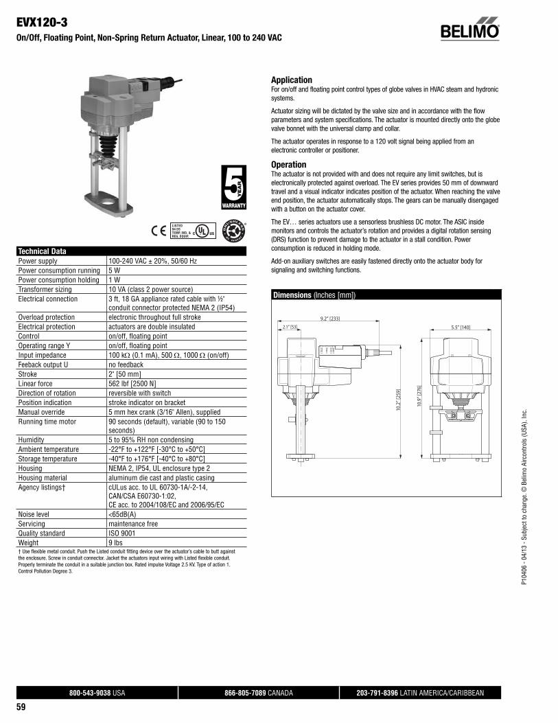
P104
06 -
04/1
3 - S
ubje
ct to
cha
nge.
© B
elim
o Ai
rcon
trols
(USA
), In
c.
®
800-543-9038 USA 866-805-7089 CANADA 203-791-8396 LATIN AMERICA/CARIBBEAN
59
EVX120-3On/Off, Floating Point, Non-Spring Return Actuator, Linear, 100 to 240 VAC
Technical Data
Power supply 100-240 VAC ± 20%, 50/60 HzPower consumption running 5 WPower consumption holding 1 WTransformer sizing 10 VA (class 2 power source)Electrical connection 3 ft, 18 GA appliance rated cable with ½"
conduit connector protected NEMA 2 (IP54)Overload protection electronic throughout full strokeElectrical protection actuators are double insulatedControl on/off, fl oating pointOperating range Y on/off, fl oating pointInput impedance 100 k (0.1 mA), 500 , 1000 (on/off)Feeback output U no feedbackStroke 2" [50 mm]Linear force 562 lbf [2500 N]Direction of rotation reversible with switchPosition indication stroke indicator on bracketManual override 5 mm hex crank (3/16" Allen), suppliedRunning time motor 90 seconds (default), variable (90 to 150
seconds)Humidity 5 to 95% RH non condensingAmbient temperature -22°F to +122°F [-30°C to +50°C]Storage temperature -40°F to +176°F [-40°C to +80°C]Housing NEMA 2, IP54, UL enclosure type 2Housing material aluminum die cast and plastic casingAgency listings† cULus acc. to UL 60730-1A/-2-14,
CAN/CSA E60730-1:02,CE acc. to 2004/108/EC and 2006/95/EC
Noise level <65dB(A)Servicing maintenance freeQuality standard ISO 9001Weight 9 lbs† Use flexible metal conduit. Push the Listed conduit fitting device over the actuator’s cable to butt againstthe enclosure. Screw in conduit connector. Jacket the actuators input wiring with Listed flexible conduit.Properly terminate the conduit in a suitable junction box. Rated impulse Voltage 2.5 KV. Type of action 1.Control Pollution Degree 3.
ApplicationFor on/off and floating point control types of globe valves in HVAC steam and hydronic systems.
Actuator sizing will be dictated by the valve size and in accordance with the flow parameters and system specifications. The actuator is mounted directly onto the globe valve bonnet with the universal clamp and collar.
The actuator operates in response to a 120 volt signal being applied from an electronic controller or positioner.
OperationThe actuator is not provided with and does not require any limit switches, but is electronically protected against overload. The EV series provides 50 mm of downward travel and a visual indicator indicates position of the actuator. When reaching the valve end position, the actuator automatically stops. The gears can be manually disengaged with a button on the actuator cover.
The EV… series actuators use a sensorless brushless DC motor. The ASIC inside monitors and controls the actuator’s rotation and provides a digital rotation sensing (DRS) function to prevent damage to the actuator in a stall condition. Power consumption is reduced in holding mode.
Add-on auxiliary switches are easily fastened directly onto the actuator body for signaling and switching functions.
Dimensions (Inches [mm])
5.5” [140]2.1” [53]
9.2” [233]
10.9
” [27
6]
10.2
” [25
9]

P104
06 -
04/1
3 - S
ubje
ct to
cha
nge.
© B
elim
o Ai
rcon
trols
(USA
), In
c.
®
800-543-9038 USA 866-805-7089 CANADA 203-791-8396 LATIN AMERICA/CARIBBEAN
60
EVX120-3On/Off, Floating Point, Non-Spring Return Actuator, Linear, 100 to 240 VAC
Typical Specification
On/off, floating point control globe valve actuators shall be electronic and direct coupled to the globe valve bonnet via an integrated linkage, which requires no secondary linkage and be capable of mounting to valves 2.5” to 6” in size. Actuators must provide control in response to a control input from an electronic controller or positioner. Actuators shall have brushless DC motor technology and be protected from overload at all angles of rotation. Actuators shall have reversing switch and manual override on the cover. Run time shall be constant and independent of torque. Actuators shall be cULus listed, have a 5-year warranty, and be manufactured under ISO 9001 International Quality Control Standards. Actuators shall be as manufactured by Belimo.
Wiring Diagrams
Actuators with appliance cables are numbered.
2CAUTION Equipment Damage!Actuators may be connected in parallel. Power consumption and input impedance must be observed.
Meets cULus or UL and CSA Standard requirements without theneed of an electrical ground connection.
WARNING Live Electrical Components! During installation, testing, servicing and troubleshooting of this product, it may be
necessary to work with live electrical components. Have a qualifi ed licensed electrician or other individual who has been properly trained in handling live electrical components perform these tasks. Failure to follow all electrical safety precautions when exposed to live electrical compo-nents could result in death or serious injury.
2100 to 240 VAC
Blu (1) Common
Brn (2) +
Wht (3) +
N L1
H L2
–
A
Line
Hot
On/Off
2100 to 240 VAC
Blu (1) Common
Brn (2) +
Wht (3) +
N L1
H L2
A
Line
Hot
Floating Point
A

P104
06 -
04/1
3 - S
ubje
ct to
cha
nge.
© B
elim
o Ai
rcon
trols
(USA
), In
c.
®
800-543-9038 USA 866-805-7089 CANADA 203-791-8396 LATIN AMERICA/CARIBBEAN
61
EVB24-MFTProportional, Non-Spring Return Actuator, Linear, 24 V, Multi-Function Technology®
Technical Data
Power supply 24 VAC ± 20% 50/60 Hz, 24 VDC ± 10%Power consumption running 6 WPower consumption holding 3.5 WTransformer sizing 7 VA (class 2 power source)Electrical connection 3 ft, 18 GA plenum rated cable with ½"
conduit connector protected NEMA 2 (IP54)Overload protection electronic throughout full strokeElectrical protection actuators are double insulatedControl proportional/MFTOperating range Y 2 to 10 VDC, 4 to 20 mA (default), variable
(VDC, PWM, fl oating point, on/off)Input impedance 100 k for 2 to 10 VDC (0.1 mA), 500 for 4
to 20 mA, 1500 for PWM, fl oating point andon/off
Feeback output U 2 to 10 VDC, 0.5 mA max, VDC variableStroke 2" [50 mm]Linear force 562 lbf [2500 N]Direction of rotation reversible with switchPosition indication stroke indicator on bracketManual override 5 mm hex crank (3/16" Allen), suppliedRunning time motor 90 seconds (default), variable (90 to 150
seconds)Humidity 5 to 95% RH non condensingAmbient temperature -22°F to +122°F [-30°C to +50°C]Storage temperature -40°F to +176°F [-40°C to +80°C]Housing NEMA 2, IP54, UL enclosure type 2Housing material aluminum die cast and plastic casingAgency listings† cULus acc. to UL 60730-1A/-2-14,
CAN/CSA E60730-1:02,CE acc. to 2004/108/EC and 2006/95/EC
Noise level <65dB(A)Servicing maintenance freeQuality standard ISO 9001Weight 9 lbs† Use flexible metal conduit. Push the Listed conduit fitting device over the actuator’s cable to butt againstthe enclosure. Screw in conduit connector. Jacket the actuators input wiring with Listed flexible conduit.Properly terminate the conduit in a suitable junction box. Rated impulse Voltage 800V. Type of action 1.Control Pollution Degree 3.
ApplicationFor multiple control types of globe valves in HVAC steam and hydronic systems.
Actuator sizing will be dictated by the valve size and in accordance with the flow parameters and system specifications. The actuator is mounted directly onto the globe valve bonnet with the universal clamp and collar.
The actuator operates in response to many controls types as desired by the customer and/or design control input from an electronic controller or positioner. A 2 to 10 VDC feedback signal is provided for position indication.
OperationThe actuator is not provided with and does not require any limit switches, but is electronically protected against overload. The EV series provides 50 mm of downward travel and a visual indicator indicates position of the actuator. When reaching the valve end position, the actuator automatically stops. The gears can be manually disengaged with a button on the actuator cover.
The EV… series actuators use a sensorless brushless DC motor. The ASIC inside monitors and controls the actuator’s rotation and provides a digital rotation sensing (DRS) function to prevent damage to the actuator in a stall condition. Power consumption is reduced in holding mode.
Add-on auxiliary switches are easily fastened directly onto the actuator body for signaling and switching functions.
-SR and –MFT models will have an illuminated green Adaption/Power button to reset and relearn the valve stroke as well as indicate the actuator is powered. This feature allows the actuator to rescale itself based on the actual travel. Along with the Adaption button on –MFT models will have a yellow Status light to confirm communication.
Dimensions (Inches [mm])
5.5” [140]2.1” [53]
9.2” [233]
10.9
” [27
6]
10.2
” [25
9]
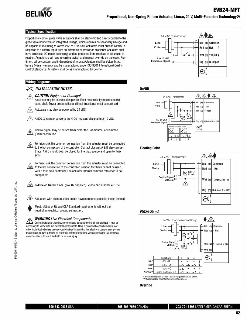
P104
06 -
04/1
3 - S
ubje
ct to
cha
nge.
© B
elim
o Ai
rcon
trols
(USA
), In
c.
®
800-543-9038 USA 866-805-7089 CANADA 203-791-8396 LATIN AMERICA/CARIBBEAN
62
EVB24-MFTProportional, Non-Spring Return Actuator, Linear, 24 V, Multi-Function Technology®
Typical Specification
Proportional control globe valve actuators shall be electronic and direct coupled to the globe valve bonnet via an integrated linkage, which requires no secondary linkage and be capable of mounting to valves 2.5” to 6” in size. Actuators must provide control in response to a control input from an electronic controller or positioner. Actuators shall have brushless DC motor technology and be protected from overload at all angles of rotation. Actuators shall have reversing switch and manual override on the cover. Run time shall be constant and independent of torque. Actuators shall be cULus listed, have a 5-year warranty, and be manufactured under ISO 9001 International Quality Control Standards. Actuators shall be as manufactured by Belimo.
Wiring Diagrams
CAUTION Equipment Damage!Actuators may be connected in parallel if not mechanically mounted to the same shaft. Power consumption and input impedance must be observed.
3 Actuators may also be powered by 24 VDC.
A 500 resistor converts the 4-20 mA control signal to 2-10 VDC
Control signal may be pulsed from either the Hot (Source) or Common (Sink) 24 VAC line.
For triac sink the common connection from the actuator must be connected to the hot connection of the controller. Contact closures A & B also can be triacs. A & B should both be closed for the triac source and open for triac sink.
For triac sink the common connection from the actuator must be connected to the hot connection of the controller. Position feedback cannot be used with a triac sink controller. The actuator internal common reference is not compatible.
IN4004 or IN4007 diode. (IN4007 supplied, Belimo part number 40155)
Actuators with plenum cable do not have numbers; use color codes instead.
Meets cULus or UL and CSA Standard requirements without theneed of an electrical ground connection.
WARNING Live Electrical Components! During installation, testing, servicing and troubleshooting of this product, it may be
necessary to work with live electrical components. Have a qualifi ed licensed electrician or other individual who has been properly trained in handling live electrical components perform these tasks. Failure to follow all electrical safety precautions when exposed to live electrical components could result in death or serious injury.
18
Blk (1) Common
Red (2) Hot
Wht (3) Y Input
Org (5) U Output
Line
Volts
24 VAC Transformer
2 to 10 VDCFeedback Signal (+)
(–)
3
On/Off
Line
Volts
(–) (+)
24 VAC Transformer
Blk (1) – Common
Red (2) + Hot
Wht (3) Y1 Input
Org (5) U Output 2 to 10V
A B 18 A B
Direction of rotation switch
A
B
2
9
8
10
12
Feedback Signal 2 to 10 VDC
18
18
Floating Point
7
Blk (1) Common
Red (2) + Hot
Wht (3) Y1 Input, 2 to 10V
Org (5) U Output, 2 to 10V
(–)(+)
Line
Volts
24 VAC Transformer
Ω 500 Ω1/4 watt
3 18
Control SignalVDC/mA
VDC/4-20 mA
18
Functions
0%
50%
100%
Control mode acc. to Y
Min*
Mid*
Max*
Normal**
* Default selectable 0-100%. See Configuration Data Sheet.** Customizable. See Configuration Data Sheet.
a b c
500 Ω
Ω
Blk (1) Common
Red (2) + Hot
Org (5)
Wht (3) Y1 Input, 2 to 10V
(–)(+)
Line
Volts
24 VAC Transformer (AC Only)
7
B
C
A
1/4 watt
VDC/mAControl Signal
Override
7
2
9
10
12
18
8

P104
06 -
04/1
3 - S
ubje
ct to
cha
nge.
© B
elim
o Ai
rcon
trols
(USA
), In
c.
®
800-543-9038 USA 866-805-7089 CANADA 203-791-8396 LATIN AMERICA/CARIBBEAN
63
RVB24-3On/Off, Floating Point, Non-Spring Return Actuator, Linear, 24 V
Technical Data
Power supply 24 VAC ± 20% 50/60 Hz, 24 VDC ± 10%Power consumption running 6 WPower consumption holding 3.5 WTransformer sizing 10 VA (class 2 power source)Electrical connection 3 ft, 18 GA plenum rated cable with ½"
conduit connector protected NEMA 2 (IP54)Overload protection electronic throughout full strokeElectrical protection actuators are double insulatedControl on/off, fl oating pointOperating range Y on/off, fl oating pointInput impedance 100 k (0.1 mA), 500 , 1000 (on/off)Feeback output U 2 to 10 VDC, 0.5 mA maxStroke 2" [50 mm]Linear force 1011 lbf [4500 N]Direction of rotation reversible with switchPosition indication stroke indicator on bracketManual override 5 mm hex crank (3/16" Allen), suppliedRunning time motor 90 seconds (default), variable (90 to 150
seconds)Humidity 5 to 95% RH non condensingAmbient temperature -22°F to +122°F [-30°C to +50°C]Storage temperature -40°F to +176°F [-40°C to +80°C]Housing NEMA 2, IP54, UL enclosure type 2Housing material aluminum die cast and plastic casingAgency listings† cULus acc. to UL 60730-1A/-2-14,
CAN/CSA E60730-1:02,CE acc. to 2004/108/EC and 2006/95/EC
Noise level <65dB(A)Servicing maintenance freeQuality standard ISO 9001Weight 9 lbs† Use flexible metal conduit. Push the Listed conduit fitting device over the actuator’s cable to butt againstthe enclosure. Screw in conduit connector. Jacket the actuators input wiring with Listed flexible conduit.Properly terminate the conduit in a suitable junction box. Rated impulse Voltage 800V. Type of action 1.Control Pollution Degree 3.
ApplicationFor on/off and floating point control types of globe valves in HVAC steam and hydronic systems.
Actuator sizing will be dictated by the valve size and in accordance with the flow parameters and system specifications. The actuator is mounted directly onto the globe valve bonnet with the universal clamp and collar.
The actuator operates in response to a 24 volt signal being applied from an electronic controller or positioner.
OperationThe actuator is not provided with and does not require any limit switches, but is electronically protected against overload. The RV series provides 50 mm of downward travel and a visual indicator indicates position of the actuator. When reaching the valve end position, the actuator automatically stops. The gears can be manually disengaged with a button on the actuator cover.
The RV… series actuators use a sensorless brushless DC motor. The ASIC inside monitors and controls the actuator’s rotation and provides a digital rotation sensing (DRS) function to prevent damage to the actuator in a stall condition. Power consumption is reduced in holding mode.
Add-on auxiliary switches are easily fastened directly onto he actuator body for signaling and switching functions.
Dimensions (Inches [mm])
5.5” [140]2.1” [53]
9.2” [233]
10.9
” [27
6]
10.2
” [25
9]

P104
06 -
04/1
3 - S
ubje
ct to
cha
nge.
© B
elim
o Ai
rcon
trols
(USA
), In
c.
®
800-543-9038 USA 866-805-7089 CANADA 203-791-8396 LATIN AMERICA/CARIBBEAN
64
RVB24-3On/Off, Floating Point, Non-Spring Return Actuator, Linear, 24 V
Typical Specification
On/off, floating point control globe valve actuators shall be electronic and direct coupled to the globe valve bonnet via an integrated linkage, which requires no secondary linkage and be capable of mounting to valves 2.5” to 6” in size. Actuators must provide control in response to a control input from an electronic controller or positioner. Actuators shall have brushless DC motor technology and be protected from overload at all angles of rotation. Actuators shall have reversing switch and manual override on the cover. Run time shall be constant and independent of torque. Actuators shall be cULus listed, have a 5-year warranty, and be manufactured under ISO 9001 International Quality Control Standards. Actuators shall be as manufactured by Belimo.
Wiring Diagrams
CAUTION Equipment Damage!Actuators may be connected in parallel if not mechanically mounted to the same shaft. Power consumption and input impedance must be observed.
3 Actuators may also be powered by 24 VDC.
Control signal may be pulsed from either the Hot (Source) or Common (Sink) 24 VAC line.
For triac sink the common connection from the actuator must be connected to the hot connection of the controller. Contact closures A & B also can be triacs. A & B should both be closed for the triac source and open for triac sink.
For triac sink the common connection from the actuator must be connected to the hot connection of the controller. Position feedback cannot be used with a triac sink controller. The actuator internal common reference is not compatible.
IN4004 or IN4007 diode. (IN4007 supplied, Belimo part number 40155)
Actuators with plenum cable do not have numbers; use color codes instead.
Meets cULus or UL and CSA Standard requirements without theneed of an electrical ground connection.
WARNING Live Electrical Components! During installation, testing, servicing and troubleshooting of this product, it may be
necessary to work with live electrical components. Have a qualifi ed licensed electrician or other individual who has been properly trained in handling live electrical components perform these tasks. Failure to follow all electrical safety precautions when exposed to live electrical compo-nents could result in death or serious injury.
18
Blk (1) Common
Red (2) Hot
Wht (3) Y Input
Org (5) U Output
Line
Volts
24 VAC Transformer
2 to 10 VDCFeedback Signal (+)
(–)
3
On/Off
Line
Volts
(–) (+)
24 VAC Transformer
Blk (1) – Common
Red (2) + Hot
Wht (3) Y1 Input
Org (5) U Output 2 to 10V
A B 18 A B
Direction of rotation switch
A
B
2
9
8
10
12
Feedback Signal 2 to 10 VDC
18
18
Floating Point
2
9
10
12
18
8

P104
06 -
04/1
3 - S
ubje
ct to
cha
nge.
© B
elim
o Ai
rcon
trols
(USA
), In
c.
®
800-543-9038 USA 866-805-7089 CANADA 203-791-8396 LATIN AMERICA/CARIBBEAN
65
RVB24-MFTProportional, Non-Spring Return Actuator, Linear, 24 V, Multi-Function Technology®
Technical Data
Power supply 24 VAC ± 20% 50/60 Hz, 24 VDC ± 10%Power consumption running 6 WPower consumption holding 3.5 WTransformer sizing 10 VA (class 2 power source)Electrical connection 3 ft, 18 GA plenum rated cable with ½"
conduit connector protected NEMA 2 (IP54)Overload protection electronic throughout full strokeElectrical protection actuators are double insulatedControl proportional/MFTOperating range Y 2 to 10 VDC, 4 to 20 mA (default), variable
(VDC, PWM, fl oating point, on/off)Input impedance 100 k for 2 to 10 VDC (0.1 mA), 500 for 4
to 20 mA, 1500 for PWM, fl oating point andon/off
Feeback output U 2 to 10 VDC, 0.5 mA max, VDC variableStroke 2" [50 mm]Linear force 1011 lbf [4500 N]Direction of rotation reversible with switchPosition indication stroke indicator on bracketManual override 5 mm hex crank (3/16" Allen), suppliedRunning time motor 90 seconds (default), variable (90 to 150
seconds)Humidity 5 to 95% RH non condensingAmbient temperature -22°F to +122°F [-30°C to +50°C]Storage temperature -40°F to +176°F [-40°C to +80°C]Housing NEMA 2, IP54, UL enclosure type 2Housing material aluminum die cast and plastic casingAgency listings† cULus acc. to UL 60730-1A/-2-14,
CAN/CSA E60730-1:02,CE acc. to 2004/108/EC and 2006/95/EC
Noise level <65dB(A)Servicing maintenance freeQuality standard ISO 9001Weight 9 lbs† Use flexible metal conduit. Push the Listed conduit fitting device over the actuator’s cable to butt againstthe enclosure. Screw in conduit connector. Jacket the actuators input wiring with Listed flexible conduit.Properly terminate the conduit in a suitable junction box. Rated impulse Voltage 800V. Type of action 1.Control Pollution Degree 3.
ApplicationFor multiple control types of globe valves in HVAC steam and hydronic systems.
Actuator sizing will be dictated by the valve size and in accordance with the flow parameters and system specifications. The actuator is mounted directly onto the globe valve bonnet with the universal clamp and collar.
The actuator operates in response to many controls types as desired by the customer and/or design control input from an electronic controller or positioner. A 2 to 10 VDC feedback signal is provided for position indication.
OperationThe actuator is not provided with and does not require any limit switches, but is electronically protected against overload. The RV series provides 50 mm of downward travel and a visual indicator indicates position of the actuator. When reaching the valve end position, the actuator automatically stops. The gears can be manually disengaged with a button on the actuator cover.
The RV… series actuators use a sensorless brushless DC motor. The ASIC inside monitors and controls the actuator’s rotation and provides a digital rotation sensing (DRS) function to prevent damage to the actuator in a stall condition. Power consumption is reduced in holding mode.
Add-on auxiliary switches are easily fastened directly onto the actuator body for signaling and switching functions.
-SR and –MFT models will have an illuminated green Adaption/Power button to reset and relearn the valve stroke as well as indicate the actuator is powered. This feature allows the actuator to rescale itself based on the actual travel. Along with the Adaption button on –MFT models will have a yellow Status light to confirm communication.
Dimensions (Inches [mm])
5.5” [140]2.1” [53]
9.2” [233]
10.9
” [27
6]
10.2
” [25
9]

P104
06 -
04/1
3 - S
ubje
ct to
cha
nge.
© B
elim
o Ai
rcon
trols
(USA
), In
c.
®
800-543-9038 USA 866-805-7089 CANADA 203-791-8396 LATIN AMERICA/CARIBBEAN
66
RVB24-MFTProportional, Non-Spring Return Actuator, Linear, 24 V, Multi-Function Technology®
Typical Specification
Proportional control globe valve actuators shall be electronic and direct coupled to the globe valve bonnet via an integrated linkage, which requires no secondary linkage and be capable of mounting to valves 2.5” to 6” in size. Actuators must provide control in response to a control input from an electronic controller or positioner. Actuators shall have brushless DC motor technology and be protected from overload at all angles of rotation. Actuators shall have reversing switch and manual override on the cover. Run time shall be constant and independent of torque. Actuators shall be cULus listed, have a 5-year warranty, and be manufactured under ISO 9001 International Quality Control Standards. Actuators shall be as manufactured by Belimo.
Wiring Diagrams
CAUTION Equipment Damage!Actuators may be connected in parallel if not mechanically mounted to the same shaft. Power consumption and input impedance must be observed.
3 Actuators may also be powered by 24 VDC.
A 500 resistor converts the 4-20 mA control signal to 2-10 VDC
Control signal may be pulsed from either the Hot (Source) or Common (Sink) 24 VAC line.
For triac sink the common connection from the actuator must be connected to the hot connection of the controller. Contact closures A & B also can be triacs. A & B should both be closed for the triac source and open for triac sink.
For triac sink the common connection from the actuator must be connected to the hot connection of the controller. Position feedback cannot be used with a triac sink controller. The actuator internal common reference is not compatible.
IN4004 or IN4007 diode. (IN4007 supplied, Belimo part number 40155)
Actuators with plenum cable do not have numbers; use color codes instead.
Meets cULus or UL and CSA Standard requirements without theneed of an electrical ground connection.
WARNING Live Electrical Components! During installation, testing, servicing and troubleshooting of this product, it may be
necessary to work with live electrical components. Have a qualifi ed licensed electrician or other individual who has been properly trained in handling live electrical components perform these tasks. Failure to follow all electrical safety precautions when exposed to live electrical compo-nents could result in death or serious injury.
18
Blk (1) Common
Red (2) Hot
Wht (3) Y Input
Org (5) U Output
Line
Volts
24 VAC Transformer
2 to 10 VDCFeedback Signal (+)
(–)
3
On/Off
Line
Volts
(–) (+)
24 VAC Transformer
Blk (1) – Common
Red (2) + Hot
Wht (3) Y1 Input
Org (5) U Output 2 to 10V
A B 18 A B
Direction of rotation switch
A
B
2
9
8
10
12
Feedback Signal 2 to 10 VDC
18
18
Floating Point
7
Blk (1) Common
Red (2) + Hot
Wht (3) Y1 Input, 2 to 10V
Org (5) U Output, 2 to 10V
(–)(+)
Line
Volts
24 VAC Transformer
Ω 500 Ω1/4 watt
3 18
Control SignalVDC/mA
VDC/4-20 mA
18
Functions
0%
50%
100%
Control mode acc. to Y
Min*
Mid*
Max*
Normal**
* Default selectable 0-100%. See Configuration Data Sheet.** Customizable. See Configuration Data Sheet.
a b c
500 Ω
Ω
Blk (1) Common
Red (2) + Hot
Org (5)
Wht (3) Y1 Input, 2 to 10V
(–)(+)
Line
Volts
24 VAC Transformer (AC Only)
7
B
C
A
1/4 watt
VDC/mAControl Signal
Override
7
2
9
10
12
18
8

P104
06 -
04/1
3 - S
ubje
ct to
cha
nge.
© B
elim
o Ai
rcon
trols
(USA
), In
c.
®
800-543-9038 USA 866-805-7089 CANADA 203-791-8396 LATIN AMERICA/CARIBBEAN
67
LVKX24-3On/Off, Floating Point, Electronic Fail-Safe Actuator, Linear, 24 V
Technical Data
Power supply 24 VAC ± 20% 50/60 Hz, 24 VDC ± 10%Power consumption running 8.5 WPower consumption holding 2.5 WTransformer sizing 21 VA (class 2 power source)Electrical connection 3 ft, 18 GA plenum rated cable with ½"
conduit connector protected NEMA 2 (IP54)Overload protection electronic throughout full strokeElectrical protection actuators are double insulatedControl on/off, fl oating pointOperating range Y on/off, fl oating pointInput impedance 100 k (0.1 mA), 500 , 1000 (on/off)Feeback output U no feedbackStroke 0.6" [15 mm]Linear force 112 lbf [500 N]Direction of rotation reversible with switchPosition indication stroke indicator on bracketManual override 4 mm hex crank (shipped with actuator)Running time motor 90 seconds (default), variable (90 to 150
seconds)Running time fail-safe 35 secondsHumidity 5 to 95% RH non condensingAmbient temperature -22°F to +122°F [-30°C to +50°C]Storage temperature -40°F to +176°F [-40°C to +80°C]Housing NEMA 2, IP54, UL enclosure type 2Housing material aluminum die cast and plastic casingBridge time 2 second delay before fail-safe activatesInitial charge 5 to 20 secondsAgency listings† cULus acc. to UL 60730-1A/-2-14,
CAN/CSA E60730-1:02,CE acc. to 2004/108/EC and 2006/95/EC
Noise level <55dB(A)Servicing maintenance freeQuality standard ISO 9001Weight 3.6 lbs† Use flexible metal conduit. Push the Listed conduit fitting device over the actuator’s cable to butt againstthe enclosure. Screw in conduit connector. Jacket the actuators input wiring with Listed flexible conduit.Properly terminate the conduit in a suitable junction box. Rated impulse Voltage 800V. Type of action 1.Control Pollution Degree 3.
ApplicationFail-safe for on/off and floating point control types of globe valves in HVAC steam and hydronic systems.
Actuator sizing will be dictated by the valve size and in accordance with the flow parameters and system specifications. The actuator is mounted directly onto the globe valve bonnet with the universal clamp and collar.
The actuator operates in response to a 24 volt signal being applied from an electronic controller or positioner.
OperationThe actuator is not provided with and does not require any limit switches, but is electronically protected against overload. The LV series provides 15 mm of downward travel and a visual indicator indicates position of the actuator. When reaching the valve end position, the actuator automatically stops. The gears can be manually disengaged with a button on the actuator cover.
The LVK… series actuators use a sensorless brushless DC motor. The ASIC inside monitors and controls the actuator’s rotation and provides a digital rotation sensing (DRS) function to prevent damage to the actuator in a stall condition. Power consumption is reduced in holding mode.
Add-on auxiliary switches are easily fastened directly onto the actuator body for signaling and switching functions.
Fail-Safe Green LED Status Indicator Light Sequence:
• On: operation ok, no faults
• Blinking: fail-safe mechanism is active
• Off: fault is detected or not in operation / capacitors charging
Dimensions (Inches [mm])
3.9” [98]1.8” [45]
8.2” [209]
6.6”
[167
]
6.7”
[169
]

P104
06 -
04/1
3 - S
ubje
ct to
cha
nge.
© B
elim
o Ai
rcon
trols
(USA
), In
c.
®
800-543-9038 USA 866-805-7089 CANADA 203-791-8396 LATIN AMERICA/CARIBBEAN
68
LVKX24-3 On/Off, Floating Point, Electronic Fail-Safe Actuator, Linear, 24 V
Typical Specification
On/off, floating point control globe valve actuators shall be electronic and direct coupled to the globe valve bonnet via an integrated linkage, which requires no secondary linkage and be capable of mounting to valves ½” to 2” in size. Actuators must provide control in response to a control input from an electronic controller or positioner. Actuators shall have brushless DC motor technology and be protected from overload at all angles of rotation. Actuators shall have reversing switch and manual override on the cover. Run time shall be constant and independent of torque. Actuators shall be cULus listed, have a 5-year warranty, and be manufactured under ISO 9001 International Quality Control Standards. Actuators shall be as manufactured by Belimo.
Wiring Diagrams
2CAUTION Equipment Damage!Actuators may be connected in parallel. Power consumption and input impedance must be observed.
3 Actuators may also be powered by 24 VDC.
Control signal may be pulsed from either the Hot (Source) or Common (Sink) 24 VAC line.
For triac sink the common connection from the actuator must be connected to the hot connection of the controller. Contact closures A & B also can be triacs. A & B should both be closed for the triac source and open for triac sink.
Actuators with plenum cable do not have numbers; use color codes instead.
Meets cULus or UL and CSA Standard requirements without theneed of an electrical ground connection.
WARNING Live Electrical Components! During installation, testing, servicing and troubleshooting of this product, it may be
necessary to work with live electrical components. Have a qualifi ed licensed electrician or other individual who has been properly trained in handling live electrical components perform these tasks. Failure to follow all electrical safety precautions when exposed to live electrical compo-nents could result in death or serious injury.
2 324 VAC Transformer
Blk (1) Common
Red (2) + Hot
Wht (3) +
LineVolts
–
18
Y input1
Pnk (4)
On/Off
18
Floating Point
18
8
9

P104
06 -
04/1
3 - S
ubje
ct to
cha
nge.
© B
elim
o Ai
rcon
trols
(USA
), In
c.
®
800-543-9038 USA 866-805-7089 CANADA 203-791-8396 LATIN AMERICA/CARIBBEAN
69
LVKX120-3On/Off, Floating Point, Electronic Fail-Safe Actuator, Linear, 120 V
Technical Data
Power supply 100-240 VAC ± 20%, 50/60 HzPower consumption running 8.5 WPower consumption holding 2.5 WTransformer sizing 21 VA (class 2 power source)Electrical connection 3 ft, 18 GA appliance rated cable with ½"
conduit connector protected NEMA 2 (IP54)Overload protection electronic throughout full strokeElectrical protection actuators are double insulatedControl on/off, fl oating pointOperating range Y on/off, fl oating pointInput impedance 100 k (0.1 mA), 500 , 1000 (on/off)Feeback output U no feedbackStroke 0.6" [15 mm]Linear force 112 lbf [500 N]Direction of rotation reversible with switchPosition indication stroke indicator on bracketManual override 4 mm hex crank (shipped with actuator)Running time motor 90 seconds (default), variable (90 to 150
seconds)Running time fail-safe 35 secondsHumidity 5 to 95% RH non condensingAmbient temperature -22°F to +122°F [-30°C to +50°C]Storage temperature -40°F to +176°F [-40°C to +80°C]Housing NEMA 2, IP54, UL enclosure type 2Housing material aluminum die cast and plastic casingBridge time 2 second delay before fail-safe activatesInitial charge 5 to 20 secondsAgency listings† cULus acc. to UL 60730-1A/-2-14,
CAN/CSA E60730-1:02,CE acc. to 2004/108/EC and 2006/95/EC
Noise level <55dB(A)Servicing maintenance freeQuality standard ISO 9001Weight 3.6 lbs† Use flexible metal conduit. Push the Listed conduit fitting device over the actuator’s cable to butt againstthe enclosure. Screw in conduit connector. Jacket the actuators input wiring with Listed flexible conduit.Properly terminate the conduit in a suitable junction box. Rated impulse Voltage 2.5 KV. Type of action 1.Control Pollution Degree 3.
ApplicationFail-safe for on/off and floating point control types of globe valves in HVAC steam and hydronic systems.
Actuator sizing will be dictated by the valve size and in accordance with the flow parameters and system specifications. The actuator is mounted directly onto the globe valve bonnet with the universal clamp and collar.
The actuator operates in response to a 120 volt signal being applied from an electronic controller or positioner.
OperationThe actuator is not provided with and does not require any limit switches, but is electronically protected against overload. The LV series provides 15 mm of downward travel and a visual indicator indicates position of the actuator. When reaching the valve end position, the actuator automatically stops. The gears can be manually disengaged with a button on the actuator cover.
The LVK… series actuators use a sensorless brushless DC motor. The ASIC inside monitors and controls the actuator’s rotation and provides a digital rotation sensing (DRS) function to prevent damage to the actuator in a stall condition. Power consumption is reduced in holding mode.
Add-on auxiliary switches are easily fastened directly onto the actuator body for signaling and switching functions.
Fail-Safe Green LED Status Indicator Light Sequence:
• On: operation ok, no faults
• Blinking: fail-safe mechanism is active
• Off: fault is detected or not in operation / capacitors charging
Dimensions (Inches [mm])
3.9” [98]1.8” [45]
8.2” [209]
6.6”
[167
]
6.7”
[169
]

P104
06 -
04/1
3 - S
ubje
ct to
cha
nge.
© B
elim
o Ai
rcon
trols
(USA
), In
c.
®
800-543-9038 USA 866-805-7089 CANADA 203-791-8396 LATIN AMERICA/CARIBBEAN
70
LVKX120-3 On/Off, Floating Point, Electronic Fail-Safe Actuator, Linear, 120 V
Typical Specification
On/off, floating point control globe valve actuators shall be electronic and direct coupled to the globe valve bonnet via an integrated linkage, which requires no secondary linkage and be capable of mounting to valves ½” to 2” in size. Actuators must provide control in response to a control input from an electronic controller or positioner. Actuators shall have brushless DC motor technology and be protected from overload at all angles of rotation. Actuators shall have reversing switch and manual override on the cover. Run time shall be constant and independent of torque. Actuators shall be cULus listed, have a 5-year warranty, and be manufactured under ISO 9001 International Quality Control Standards. Actuators shall be as manufactured by Belimo.
Wiring Diagrams
Actuators with appliance cables are numbered.
2CAUTION Equipment Damage!Actuators may be connected in parallel. Power consumption and input impedance must be observed. Meets cULus or UL and CSA Standard requirements without theneed of an electrical ground connection.
WARNING Live Electrical Components! During installation, testing, servicing and troubleshooting of this product, it may be
necessary to work with live electrical components. Have a qualifi ed licensed electrician or other individual who has been properly trained in handling live electrical components perform these tasks. Failure to follow all electrical safety precautions when exposed to live electrical compo-nents could result in death or serious injury.
Blu (1)
Brn (2) +
Wht (3) +
Wht (4)
2100 to 240 VAC
Line N L1
Hot H L2
A
On/Off
A
Blu (1)
Brn (2) +
Wht (3) +
Wht (4) +
Line N L1
Hot H L2
100 to 240 VAC
Floating Point
A

P104
06 -
04/1
3 - S
ubje
ct to
cha
nge.
© B
elim
o Ai
rcon
trols
(USA
), In
c.
®
800-543-9038 USA 866-805-7089 CANADA 203-791-8396 LATIN AMERICA/CARIBBEAN
71
LVKB24-SRProportional, Electronic Fail-Safe Actuator, Linear, 24 V, for 2 to 10 VDC or 4 to 20 mA
Technical Data
Power supply 24 VAC ± 20% 50/60 Hz, 24 VDC ± 10%Power consumption running 8.5 WPower consumption holding 2.5 WTransformer sizing 21 VA (class 2 power source)Electrical connection 3 ft, 18 GA plenum rated cable with ½"
conduit connector protected NEMA 2 (IP54)Overload protection electronic throughout full strokeElectrical protection actuators are double insulatedControl 2-10 VDCOperating range Y 2 to 10 VDC, 4 to 20 mA (default)Input impedance 100 k for 2 to 10 VDC (0.1 mA), 500 for
4 to 20 mAFeeback output U 2 to 10 VDCStroke 0.6" [15 mm]Linear force 112 lbf [500 N]Direction of rotation reversible with switchPosition indication stroke indicator on bracketManual override 4 mm hex crank (shipped with actuator)Running time motor 90 seconds (default), variable (90 to 150
seconds)Running time fail-safe 35 secondsHumidity 5 to 95% RH non condensingAmbient temperature -22°F to +122°F [-30°C to +50°C]Storage temperature -40°F to +176°F [-40°C to +80°C]Housing NEMA 2, IP54, UL enclosure type 2Housing material aluminum die cast and plastic casingBridge time 2 second delay before fail-safe activatesInitial charge 5 to 20 secondsAgency listings† cULus acc. to UL 60730-1A/-2-14,
CAN/CSA E60730-1:02,CE acc. to 2004/108/EC and 2006/95/EC
Noise level <55dB(A)Servicing maintenance freeQuality standard ISO 9001Weight 3.6 lbs† Use flexible metal conduit. Push the Listed conduit fitting device over the actuator’s cable to butt againstthe enclosure. Screw in conduit connector. Jacket the actuators input wiring with Listed flexible conduit.Properly terminate the conduit in a suitable junction box. Rated impulse Voltage 800V. Type of action 1.Control Pollution Degree 3.
ApplicationFor fail-safe, proportional modulation of globe valves in HVAC steam and hydronic systems.
Actuator sizing will be dictated by the valve size and in accordance with the flow parameters and system specifications. The actuator is mounted directly onto the globe valve bonnet with the universal clamp and collar.
The actuator operates in response to a 2 to 10 VDC, or with the addition of a 500 resistor, a 4 to 20 mA control input from an electronic controller or positioner. A 2 to 10 VDC feedback signal is provided for position indication.
OperationThe actuator is not provided with and does not require any limit switches, but is electronically protected against overload. The LV series provides 15 mm of downward travel and a visual indicator indicates position of the actuator. When reaching the valve end position, the actuator automatically stops. The gears can be manually disengaged with a button on the actuator cover.
The LVK… series actuators use a sensorless brushless DC motor. The ASIC inside monitors and controls the actuator’s rotation and provides a digital rotation sensing (DRS) function to prevent damage to the actuator in a stall condition. Power consumption is reduced in holding mode.
Add-on auxiliary switches are easily fastened directly onto the actuator body for signaling and switching functions.
-SR and –MFT models will have an illuminated green Adaption/Power button to reset and relearn the valve stroke as well as indicate the actuator is powered. This feature allows the actuator to rescale itself based on the actual travel.
Fail-Safe Green LED Status Indicator Light Sequence:
• On: operation ok, no faults
• Blinking: fail-safe mechanism is active
• Off: fault is detected or not in operation / capacitors charging
Dimensions (Inches [mm])
3.9” [98]1.8” [45]
8.2” [209]
6.6”
[167
]
6.7”
[169
]

P104
06 -
04/1
3 - S
ubje
ct to
cha
nge.
© B
elim
o Ai
rcon
trols
(USA
), In
c.
®
800-543-9038 USA 866-805-7089 CANADA 203-791-8396 LATIN AMERICA/CARIBBEAN
72
LVKB24-SRProportional, Electronic Fail-Safe Actuator, Linear, 24 V, for 2 to 10 VDC or 4 to 20 mA
Typical Specification
Proportional control globe valve actuators shall be electronic and direct coupled to the globe valve bonnet via an integrated linkage, which requires no secondary linkage and be capable of mounting to valves ½” to 2” in size. Actuators must provide control in response to a control input from an electronic controller or positioner. Actuators shall have brushless DC motor technology and be protected from overload at all angles of rotation. Actuators shall have reversing switch and manual override on the cover. Run time shall be constant and independent of torque. Actuators shall be cULus listed, have a 5-year warranty, and be manufactured under ISO 9001 International Quality Control Standards. Actuators shall be as manufactured by Belimo.
Wiring Diagrams
Actuators may also be powered by 24 VDC.
Only connect common to neg. (-) leg of control circuits.
A 500 resistor converts the 4-20 mA control signal to 2-10 VDC.
Actuators with plenum cable do not have numbers; use color codes instead.
Meets cULus or UL and CSA Standard requirements without theneed of an electrical ground connection.
WARNING Live Electrical Components! During installation, testing, servicing and troubleshooting of this product, it may be
necessary to work with live electrical components. Have a qualifi ed licensed electrician or other individual who has been properly trained in handling live electrical components perform these tasks. Failure to follow all electrical safety precautions when exposed to live electrical compo-nents could result in death or serious injury.
Blk (1) Common
Red (2) + Hot
Wht (3) Y Input, 2 to 10V
Org (5) U Output, 2 to 10V
24 VAC Transformer
5
7
Control Signal (+)VDC/mA
(–)
Feedback Signal (+)2 to 10 VDC
(–)
Ω 500 Ω
Line
Volts
3
18
VDC/4-20 mA
18
3
5
7
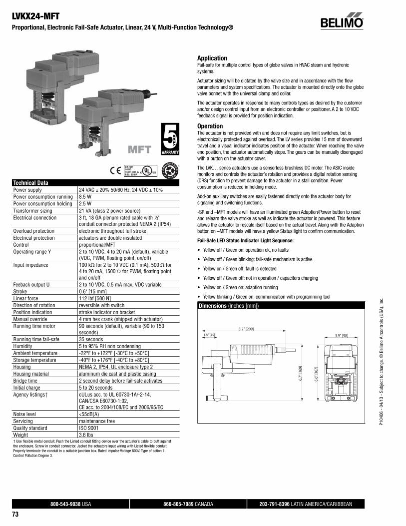
P104
06 -
04/1
3 - S
ubje
ct to
cha
nge.
© B
elim
o Ai
rcon
trols
(USA
), In
c.
®
800-543-9038 USA 866-805-7089 CANADA 203-791-8396 LATIN AMERICA/CARIBBEAN
73
LVKX24-MFTProportional, Electronic Fail-Safe Actuator, Linear, 24 V, Multi-Function Technology®
Technical Data
Power supply 24 VAC ± 20% 50/60 Hz, 24 VDC ± 10%Power consumption running 8.5 WPower consumption holding 2.5 WTransformer sizing 21 VA (class 2 power source)Electrical connection 3 ft, 18 GA plenum rated cable with ½"
conduit connector protected NEMA 2 (IP54)Overload protection electronic throughout full strokeElectrical protection actuators are double insulatedControl proportional/MFTOperating range Y 2 to 10 VDC, 4 to 20 mA (default), variable
(VDC, PWM, fl oating point, on/off)Input impedance 100 k for 2 to 10 VDC (0.1 mA), 500 for
4 to 20 mA, 1500 for PWM, fl oating pointand on/off
Feeback output U 2 to 10 VDC, 0.5 mA max, VDC variableStroke 0.6" [15 mm]Linear force 112 lbf [500 N]Direction of rotation reversible with switchPosition indication stroke indicator on bracketManual override 4 mm hex crank (shipped with actuator)Running time motor 90 seconds (default), variable (90 to 150
seconds)Running time fail-safe 35 secondsHumidity 5 to 95% RH non condensingAmbient temperature -22°F to +122°F [-30°C to +50°C]Storage temperature -40°F to +176°F [-40°C to +80°C]Housing NEMA 2, IP54, UL enclosure type 2Housing material aluminum die cast and plastic casingBridge time 2 second delay before fail-safe activatesInitial charge 5 to 20 secondsAgency listings† cULus acc. to UL 60730-1A/-2-14,
CAN/CSA E60730-1:02,CE acc. to 2004/108/EC and 2006/95/EC
Noise level <55dB(A)Servicing maintenance freeQuality standard ISO 9001Weight 3.6 lbs† Use flexible metal conduit. Push the Listed conduit fitting device over the actuator’s cable to butt againstthe enclosure. Screw in conduit connector. Jacket the actuators input wiring with Listed flexible conduit.Properly terminate the conduit in a suitable junction box. Rated impulse Voltage 800V. Type of action 1.Control Pollution Degree 3.
ApplicationFail-safe for multiple control types of globe valves in HVAC steam and hydronic systems.
Actuator sizing will be dictated by the valve size and in accordance with the flow parameters and system specifications. The actuator is mounted directly onto the globe valve bonnet with the universal clamp and collar.
The actuator operates in response to many controls types as desired by the customer and/or design control input from an electronic controller or positioner. A 2 to 10 VDC feedback signal is provided for position indication.
OperationThe actuator is not provided with and does not require any limit switches, but is electronically protected against overload. The LV series provides 15 mm of downward travel and a visual indicator indicates position of the actuator. When reaching the valve end position, the actuator automatically stops. The gears can be manually disengaged with a button on the actuator cover.
The LVK… series actuators use a sensorless brushless DC motor. The ASIC inside monitors and controls the actuator’s rotation and provides a digital rotation sensing (DRS) function to prevent damage to the actuator in a stall condition. Power consumption is reduced in holding mode.
Add-on auxiliary switches are easily fastened directly onto the actuator body for signaling and switching functions.
-SR and –MFT models will have an illuminated green Adaption/Power button to reset and relearn the valve stroke as well as indicate the actuator is powered. This feature allows the actuator to rescale itself based on the actual travel. Along with the Adaption button on –MFT models will have a yellow Status light to confirm communication.
Fail-Safe LED Status Indicator Light Sequence:
• Yellow off / Green on: operation ok, no faults
• Yellow off / Green blinking: fail-safe mechanism is active
• Yellow on / Green off: fault is detected
• Yellow off / Green off: not in operation / capacitors charging
• Yellow on / Green on: adaption running
• Yellow blinking / Green on: communication with programming tool
Dimensions (Inches [mm])
3.9” [98]1.8” [45]
8.2” [209]
6.6”
[167
]
6.7”
[169
]

P104
06 -
04/1
3 - S
ubje
ct to
cha
nge.
© B
elim
o Ai
rcon
trols
(USA
), In
c.
®
800-543-9038 USA 866-805-7089 CANADA 203-791-8396 LATIN AMERICA/CARIBBEAN
74
LVKX24-MFTProportional, Electronic Fail-Safe Actuator, Linear, 24 V, Multi-Function Technology®
Typical Specification
Proportional control globe valve actuators shall be electronic and direct coupled to the globe valve bonnet via an integrated linkage, which requires no secondary linkage and be capable of mounting to valves ½” to 2” in size. Actuators must provide control in response to a control input from an electronic controller or positioner. Actuators shall have brushless DC motor technology and be protected from overload at all angles of rotation. Actuators shall have reversing switch and manual override on the cover. Run time shall be constant and independent of torque. Actuators shall be cULus listed, have a 5-year warranty, and be manufactured under ISO 9001 International Quality Control Standards. Actuators shall be as manufactured by Belimo.
Wiring Diagrams
CAUTION Equipment Damage!Actuators may be connected in parallel if not mechanically mounted to the same shaft. Power consumption and input impedance must be observed.
3 Actuators may also be powered by 24 VDC.
A 500 resistor converts the 4-20 mA control signal to 2-10 VDC
Control signal may be pulsed from either the Hot (Source) or Common (Sink) 24 VAC line.
For triac sink the common connection from the actuator must be connected to the hot connection of the controller. Contact closures A & B also can be triacs. A & B should both be closed for the triac source and open for triac sink.
For triac sink the common connection from the actuator must be connected to the hot connection of the controller. Position feedback cannot be used with a triac sink controller. The actuator internal common reference is not compatible.
IN4004 or IN4007 diode. (IN4007 supplied, Belimo part number 40155)
Actuators with plenum cable do not have numbers; use color codes instead.
Meets cULus or UL and CSA Standard requirements without theneed of an electrical ground connection.
WARNING Live Electrical Components! During installation, testing, servicing and troubleshooting of this product, it may be
necessary to work with live electrical components. Have a qualifi ed licensed electrician or other individual who has been properly trained in handling live electrical components perform these tasks. Failure to follow all electrical safety precautions when exposed to live electrical compo-nents could result in death or serious injury.
18
Blk (1) Common
Red (2) Hot
Wht (3) Y Input
Org (5) U Output
Line
Volts
24 VAC Transformer
2 to 10 VDCFeedback Signal (+)
(–)
3
On/Off
Line
Volts
(–) (+)
24 VAC Transformer
Blk (1) – Common
Red (2) + Hot
Wht (3) Y1 Input
Org (5) U Output 2 to 10V
A B 18 A B
Direction of rotation switch
A
B
2
9
8
10
12
Feedback Signal 2 to 10 VDC
18
18
Floating Point
7
Blk (1) Common
Red (2) + Hot
Wht (3) Y1 Input, 2 to 10V
Org (5) U Output, 2 to 10V
(–)(+)
Line
Volts
24 VAC Transformer
Ω 500 Ω1/4 watt
3 18
Control SignalVDC/mA
VDC/4-20 mA
18
Functions
0%
50%
100%
Control mode acc. to Y
Min*
Mid*
Max*
Normal**
* Default selectable 0-100%. See Configuration Data Sheet.** Customizable. See Configuration Data Sheet.
a b c
500 Ω
Ω
Blk (1) Common
Red (2) + Hot
Org (5)
Wht (3) Y1 Input, 2 to 10V
(–)(+)
Line
Volts
24 VAC Transformer (AC Only)
7
B
C
A
1/4 watt
VDC/mAControl Signal
Override
18
7
2
9
10
12
8
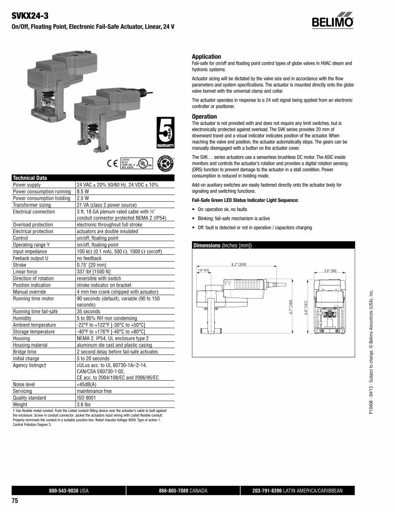
P104
06 -
04/1
3 - S
ubje
ct to
cha
nge.
© B
elim
o Ai
rcon
trols
(USA
), In
c.
®
800-543-9038 USA 866-805-7089 CANADA 203-791-8396 LATIN AMERICA/CARIBBEAN
75
SVKX24-3On/Off, Floating Point, Electronic Fail-Safe Actuator, Linear, 24 V
Technical Data
Power supply 24 VAC ± 20% 50/60 Hz, 24 VDC ± 10%Power consumption running 8.5 WPower consumption holding 2.5 WTransformer sizing 21 VA (class 2 power source)Electrical connection 3 ft, 18 GA plenum rated cable with ½"
conduit connector protected NEMA 2 (IP54)Overload protection electronic throughout full strokeElectrical protection actuators are double insulatedControl on/off, fl oating pointOperating range Y on/off, fl oating pointInput impedance 100 k (0.1 mA), 500 , 1000 (on/off)Feeback output U no feedbackStroke 0.75" [20 mm]Linear force 337 lbf [1500 N]Direction of rotation reversible with switchPosition indication stroke indicator on bracketManual override 4 mm hex crank (shipped with actuator)Running time motor 90 seconds (default), variable (90 to 150
seconds)Running time fail-safe 35 secondsHumidity 5 to 95% RH non condensingAmbient temperature -22°F to +122°F [-30°C to +50°C]Storage temperature -40°F to +176°F [-40°C to +80°C]Housing NEMA 2, IP54, UL enclosure type 2Housing material aluminum die cast and plastic casingBridge time 2 second delay before fail-safe activatesInitial charge 5 to 20 secondsAgency listings† cULus acc. to UL 60730-1A/-2-14,
CAN/CSA E60730-1:02,CE acc. to 2004/108/EC and 2006/95/EC
Noise level <45dB(A)Servicing maintenance freeQuality standard ISO 9001Weight 3.6 lbs† Use flexible metal conduit. Push the Listed conduit fitting device over the actuator’s cable to butt againstthe enclosure. Screw in conduit connector. Jacket the actuators input wiring with Listed flexible conduit.Properly terminate the conduit in a suitable junction box. Rated impulse Voltage 800V. Type of action 1.Control Pollution Degree 3.
ApplicationFail-safe for on/off and floating point control types of globe valves in HVAC steam and hydronic systems.
Actuator sizing will be dictated by the valve size and in accordance with the flow parameters and system specifications. The actuator is mounted directly onto the globe valve bonnet with the universal clamp and collar.
The actuator operates in response to a 24 volt signal being applied from an electronic controller or positioner.
OperationThe actuator is not provided with and does not require any limit switches, but is electronically protected against overload. The SVK series provides 20 mm of downward travel and a visual indicator indicates position of the actuator. When reaching the valve end position, the actuator automatically stops. The gears can be manually disengaged with a button on the actuator cover.
The SVK… series actuators use a sensorless brushless DC motor. The ASIC inside monitors and controls the actuator’s rotation and provides a digital rotation sensing (DRS) function to prevent damage to the actuator in a stall condition. Power consumption is reduced in holding mode.
Add-on auxiliary switches are easily fastened directly onto the actuator body for signaling and switching functions.
Fail-Safe Green LED Status Indicator Light Sequence:
• On: operation ok, no faults
• Blinking: fail-safe mechanism is active
• Off: fault is detected or not in operation / capacitors charging
Dimensions (Inches [mm])
3.9” [98]1.8” [45]
8.2” [209]
6.6”
[167
]
6.7”
[169
]
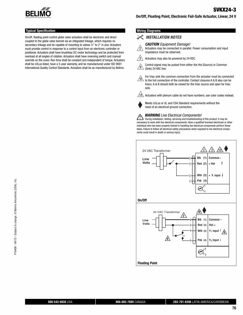
P104
06 -
04/1
3 - S
ubje
ct to
cha
nge.
© B
elim
o Ai
rcon
trols
(USA
), In
c.
®
800-543-9038 USA 866-805-7089 CANADA 203-791-8396 LATIN AMERICA/CARIBBEAN
76
SVKX24-3 On/Off, Floating Point, Electronic Fail-Safe Actuator, Linear, 24 V
Typical Specification
On/off, floating point control globe valve actuators shall be electronic and direct coupled to the globe valve bonnet via an integrated linkage, which requires no secondary linkage and be capable of mounting to valves ½” to 2” in size. Actuators must provide control in response to a control input from an electronic controller or positioner. Actuators shall have brushless DC motor technology and be protected from overload at all angles of rotation. Actuators shall have reversing switch and manual override on the cover. Run time shall be constant and independent of torque. Actuators shall be cULus listed, have a 5-year warranty, and be manufactured under ISO 9001 International Quality Control Standards. Actuators shall be as manufactured by Belimo.
Wiring Diagrams
2CAUTION Equipment Damage!Actuators may be connected in parallel. Power consumption and input impedance must be observed.
3 Actuators may also be powered by 24 VDC.
Control signal may be pulsed from either the Hot (Source) or Common (Sink) 24 VAC line.
For triac sink the common connection from the actuator must be connected to the hot connection of the controller. Contact closures A & B also can be triacs. A & B should both be closed for the triac source and open for triac sink.
Actuators with plenum cable do not have numbers; use color codes instead.
Meets cULus or UL and CSA Standard requirements without theneed of an electrical ground connection.
WARNING Live Electrical Components! During installation, testing, servicing and troubleshooting of this product, it may be
necessary to work with live electrical components. Have a qualifi ed licensed electrician or other individual who has been properly trained in handling live electrical components perform these tasks. Failure to follow all electrical safety precautions when exposed to live electrical compo-nents could result in death or serious injury.
2 324 VAC Transformer
Blk (1) Common
Red (2) + Hot
Wht (3) +
LineVolts
–
18
Y input1
Pnk (4)
On/Off
18
Floating Point
18
8
9

P104
06 -
04/1
3 - S
ubje
ct to
cha
nge.
© B
elim
o Ai
rcon
trols
(USA
), In
c.
®
800-543-9038 USA 866-805-7089 CANADA 203-791-8396 LATIN AMERICA/CARIBBEAN
77
SVKX120-3On/Off, Floating Point, Electronic Fail-Safe Actuator, Linear, 120 V
Technical Data
Power supply 100-240 VAC ± 20%, 50/60 HzPower consumption running 8.5 WPower consumption holding 2.5 WTransformer sizing 21 VA (class 2 power source)Electrical connection 3 ft, 18 GA appliance rated cable with ½"
conduit connector protected NEMA 2 (IP54)Overload protection electronic throughout full strokeElectrical protection actuators are double insulatedControl on/off, fl oating pointOperating range Y on/off, fl oating pointInput impedance 100 k (0.1 mA), 500 , 1000 (on/off)Feeback output U no feedbackStroke 0.75" [20 mm]Linear force 337 lbf [1500 N]Direction of rotation reversible with switchPosition indication stroke indicator on bracketManual override 4 mm hex crank (shipped with actuator)Running time motor 90 seconds (default), variable (90 to 150
seconds)Running time fail-safe 35 secondsHumidity 5 to 95% RH non condensingAmbient temperature -22°F to +122°F [-30°C to +50°C]Storage temperature -40°F to +176°F [-40°C to +80°C]Housing NEMA 2, IP54, UL enclosure type 2Housing material aluminum die cast and plastic casingBridge time 2 second delay before fail-safe activatesInitial charge 5 to 20 secondsAgency listings† cULus acc. to UL 60730-1A/-2-14,
CAN/CSA E60730-1:02,CE acc. to 2004/108/EC and 2006/95/EC
Noise level <45dB(A)Servicing maintenance freeQuality standard ISO 9001Weight 3.6 lbs† Use flexible metal conduit. Push the Listed conduit fitting device over the actuator’s cable to butt againstthe enclosure. Screw in conduit connector. Jacket the actuators input wiring with Listed flexible conduit.Properly terminate the conduit in a suitable junction box. Rated impulse Voltage 2.5 KV. Type of action 1.Control Pollution Degree 3.
ApplicationFail-safe for on/off and floating point control types of globe valves in HVAC steam and hydronic systems.
Actuator sizing will be dictated by the valve size and in accordance with the flow parameters and system specifications. The actuator is mounted directly onto the globe valve bonnet with the universal clamp and collar.
The actuator operates in response to a 120 volt signal being applied from an electronic controller or positioner.
OperationThe actuator is not provided with and does not require any limit switches, but is electronically protected against overload. The SVK series provides 20 mm of downward travel and a visual indicator indicates position of the actuator. When reaching the valve end position, the actuator automatically stops. The gears can be manually disengaged with a button on the actuator cover.
The SVK… series actuators use a sensorless brushless DC motor. The ASIC inside monitors and controls the actuator’s rotation and provides a digital rotation sensing (DRS) function to prevent damage to the actuator in a stall condition. Power consumption is reduced in holding mode.
Add-on auxiliary switches are easily fastened directly onto the actuator body for signaling and switching functions.
Fail-Safe Green LED Status Indicator Light Sequence:
• On: operation ok, no faults
• Blinking: fail-safe mechanism is active
• Off: fault is detected or not in operation / capacitors charging
Dimensions (Inches [mm])
3.9” [98]1.8” [45]
8.2” [209]
6.6”
[167
]
6.7”
[169
]

P104
06 -
04/1
3 - S
ubje
ct to
cha
nge.
© B
elim
o Ai
rcon
trols
(USA
), In
c.
®
800-543-9038 USA 866-805-7089 CANADA 203-791-8396 LATIN AMERICA/CARIBBEAN
78
SVKX120-3 On/Off, Floating Point, Electronic Fail-Safe Actuator, Linear, 120 V
Typical Specification
On/off, floating point control globe valve actuators shall be electronic and direct coupled to the globe valve bonnet via an integrated linkage, which requires no secondary linkage and be capable of mounting to valves ½” to 2” in size. Actuators must provide control in response to a control input from an electronic controller or positioner. Actuators shall have brushless DC motor technology and be protected from overload at all angles of rotation. Actuators shall have reversing switch and manual override on the cover. Run time shall be constant and independent of torque. Actuators shall be cULus listed, have a 5-year warranty, and be manufactured under ISO 9001 International Quality Control Standards. Actuators shall be as manufactured by Belimo.
Wiring Diagrams
Actuators with appliance cables are numbered.
2CAUTION Equipment Damage!Actuators may be connected in parallel. Power consumption and input impedance must be observed.
Meets cULus or UL and CSA Standard requirements without theneed of an electrical ground connection.
WARNING Live Electrical Components! During installation, testing, servicing and troubleshooting of this product, it may be
necessary to work with live electrical components. Have a qualifi ed licensed electrician or other individual who has been properly trained in handling live electrical components perform these tasks. Failure to follow all electrical safety precautions when exposed to live electrical compo-nents could result in death or serious injury.
Blu (1)
Brn (2) +
Wht (3) +
Wht (4)
2100 to 240 VAC
Line N L1
Hot H L2
A
On/Off
A
Blu (1)
Brn (2) +
Wht (3) +
Wht (4) +
Line N L1
Hot H L2
100 to 240 VAC
Floating Point
A

P104
06 -
04/1
3 - S
ubje
ct to
cha
nge.
© B
elim
o Ai
rcon
trols
(USA
), In
c.
®
800-543-9038 USA 866-805-7089 CANADA 203-791-8396 LATIN AMERICA/CARIBBEAN
79
SVKB24-SRProportional, Electronic Fail-Safe Actuator, Linear, 24 V, for 2 to 10 VDC or 4 to 20 mA
Technical Data
Power supply 24 VAC ± 20% 50/60 Hz, 24 VDC ± 10%Power consumption running 8.5 WPower consumption holding 2.5 WTransformer sizing 21 VA (class 2 power source)Electrical connection 3 ft, 18 GA plenum rated cable with ½"
conduit connector protected NEMA 2 (IP54)Overload protection electronic throughout full strokeElectrical protection actuators are double insulatedControl 2-10 VDCOperating range Y 2 to 10 VDC, 4 to 20 mA (default)Input impedance 100 k for 2 to 10 VDC (0.1 mA), 500 for
4 to 20 mAFeeback output U 2 to 10 VDCStroke 0.75" [20 mm]Linear force 337 lbf [1500 N]Direction of rotation reversible with switchPosition indication stroke indicator on bracketManual override 4 mm hex crank (shipped with actuator)Running time motor 90 seconds (default), variable (90 to 150
seconds)Running time fail-safe 35 secondsHumidity 5 to 95% RH non condensingAmbient temperature -22°F to +122°F [-30°C to +50°C]Storage temperature -40°F to +176°F [-40°C to +80°C]Housing NEMA 2, IP54, UL enclosure type 2Housing material aluminum die cast and plastic casingBridge time 2 second delay before fail-safe activatesInitial charge 5 to 20 secondsAgency listings† cULus acc. to UL 60730-1A/-2-14,
CAN/CSA E60730-1:02,CE acc. to 2004/108/EC and 2006/95/EC
Noise level <45dB(A)Servicing maintenance freeQuality standard ISO 9001Weight 3.6 lbs† Use flexible metal conduit. Push the Listed conduit fitting device over the actuator’s cable to butt againstthe enclosure. Screw in conduit connector. Jacket the actuators input wiring with Listed flexible conduit.Properly terminate the conduit in a suitable junction box. Rated impulse Voltage 800V. Type of action 1.Control Pollution Degree 3.
ApplicationFor fail-safe, proportional modulation of globe valves in HVAC steam and hydronic systems.
Actuator sizing will be dictated by the valve size and in accordance with the flow parameters and system specifications. The actuator is mounted directly onto the globe valve bonnet with the universal clamp and collar.
The actuator operates in response to a 2 to 10 VDC, or with the addition of a 500 resistor, a 4 to 20 mA control input from an electronic controller or positioner. A 2 to 10 VDC feedback signal is provided for position indication.
OperationThe actuator is not provided with and does not require any limit switches, but is electronically protected against overload. The SVK series provides 20 mm of downward travel and a visual indicator indicates position of the actuator. When reaching the valve end position, the actuator automatically stops. The gears can be manually disengaged with a button on the actuator cover.
The SVK… series actuators use a sensorless brushless DC motor. The ASIC inside monitors and controls the actuator’s rotation and provides a digital rotation sensing (DRS) function to prevent damage to the actuator in a stall condition. Power consumption is reduced in holding mode.
Add-on auxiliary switches are easily fastened directly onto the actuator body for signaling and switching functions.
-SR and –MFT models will have an illuminated green Adaption/Power button to reset and relearn the valve stroke as well as indicate the actuator is powered. This feature allows the actuator to rescale itself based on the actual travel.
Fail-Safe Green LED Status Indicator Light Sequence:
• On: operation ok, no faults
• Blinking: fail-safe mechanism is active
• Off: fault is detected or not in operation / capacitors charging
Dimensions (Inches [mm])
3.9” [98]1.8” [45]
8.2” [209]
6.6”
[167
]
6.7”
[169
]

P104
06 -
04/1
3 - S
ubje
ct to
cha
nge.
© B
elim
o Ai
rcon
trols
(USA
), In
c.
®
800-543-9038 USA 866-805-7089 CANADA 203-791-8396 LATIN AMERICA/CARIBBEAN
80
SVKB24-SRProportional, Electronic Fail-Safe Actuator, Linear, 24 V, for 2 to 10 VDC or 4 to 20 mA
Typical Specification
Proportional control globe valve actuators shall be electronic and direct coupled to the globe valve bonnet via an integrated linkage, which requires no secondary linkage and be capable of mounting to valves ½” to 2” in size. Actuators must provide control in response to a control input from an electronic controller or positioner. Actuators shall have brushless DC motor technology and be protected from overload at all angles of rotation. Actuators shall have reversing switch and manual override on the cover. Run time shall be constant and independent of torque. Actuators shall be cULus listed, have a 5-year warranty, and be manufactured under ISO 9001 International Quality Control Standards. Actuators shall be as manufactured by Belimo.
Wiring Diagrams
Actuators may also be powered by 24 VDC.
Only connect common to neg. (-) leg of control circuits.
A 500 resistor converts the 4-20 mA control signal to 2-10 VDC.
Actuators with plenum cable do not have numbers; use color codes instead.
Meets cULus or UL and CSA Standard requirements without theneed of an electrical ground connection.
WARNING Live Electrical Components! During installation, testing, servicing and troubleshooting of this product, it may be
necessary to work with live electrical components. Have a qualifi ed licensed electrician or other individual who has been properly trained in handling live electrical components perform these tasks. Failure to follow all electrical safety precautions when exposed to live electrical components could result in death or serious injury.
Blk (1) Common
Red (2) + Hot
Wht (3) Y Input, 2 to 10V
Org (5) U Output, 2 to 10V
24 VAC Transformer
5
7
Control Signal (+)VDC/mA
(–)
Feedback Signal (+)2 to 10 VDC
(–)
Ω 500 Ω
Line
Volts
3
18
VDC/4-20 mA
18
3
5
7

P104
06 -
04/1
3 - S
ubje
ct to
cha
nge.
© B
elim
o Ai
rcon
trols
(USA
), In
c.
®
800-543-9038 USA 866-805-7089 CANADA 203-791-8396 LATIN AMERICA/CARIBBEAN
81
SVKX24-MFTProportional, Electronic Fail-Safe Actuator, Linear, 24 V, Multi-Function Technology®
Technical Data
Power supply 24 VAC ± 20% 50/60 Hz, 24 VDC ± 10%Power consumption running 8.5 WPower consumption holding 2.5 WTransformer sizing 21 VA (class 2 power source)Electrical connection 3 ft, 18 GA plenum rated cable with ½"
conduit connector protected NEMA 2 (IP54)Overload protection electronic throughout full strokeElectrical protection actuators are double insulatedControl proportional/MFTOperating range Y 2 to 10 VDC, 4 to 20 mA (default), variable
(VDC, PWM, fl oating point, on/off)Input impedance 100 k for 2 to 10 VDC (0.1 mA), 500 for
4 to 20 mA, 1500 for PWM, fl oating pointand on/off
Feeback output U 2 to 10 VDC, 0.5 mA max, VDC variableStroke 0.75" [20 mm]Linear force 337 lbf [1500 N]Direction of rotation reversible with switchPosition indication stroke indicator on bracketManual override 4 mm hex crank (shipped with actuator)Running time motor 90 seconds (default), variable (90 to 150
seconds)Running time fail-safe 35 secondsHumidity 5 to 95% RH non condensingAmbient temperature -22°F to +122°F [-30°C to +50°C]Storage temperature -40°F to +176°F [-40°C to +80°C]Housing NEMA 2, IP54, UL enclosure type 2Housing material aluminum die cast and plastic casingBridge time 2 second delay before fail-safe activatesInitial charge 5 to 20 secondsAgency listings† cULus acc. to UL 60730-1A/-2-14,
CAN/CSA E60730-1:02,CE acc. to 2004/108/EC and 2006/95/EC
Noise level <45dB(A)Servicing maintenance freeQuality standard ISO 9001Weight 3.6 lbs† Use flexible metal conduit. Push the Listed conduit fitting device over the actuator’s cable to butt againstthe enclosure. Screw in conduit connector. Jacket the actuators input wiring with Listed flexible conduit.Properly terminate the conduit in a suitable junction box. Rated impulse Voltage 800V. Type of action 1.Control Pollution Degree 3.
ApplicationFail-safe for multiple control types of globe valves in HVAC steam and hydronic systems.
Actuator sizing will be dictated by the valve size and in accordance with the flow parameters and system specifications. The actuator is mounted directly onto the globe valve bonnet with the universal clamp and collar.
The actuator operates in response to many controls types as desired by the customer and/or design control input from an electronic controller or positioner. A 2 to 10 VDC feedback signal is provided for position indication.
OperationThe actuator is not provided with and does not require any limit switches, but is electronically protected against overload. The SVK series provides 20 mm of downward travel and a visual indicator indicates position of the actuator. When reaching the valve end position, the actuator automatically stops. The gears can be manually disengaged with a button on the actuator cover.
The SVK… series actuators use a sensorless brushless DC motor. The ASIC inside monitors and controls the actuator’s rotation and provides a digital rotation sensing (DRS) function to prevent damage to the actuator in a stall condition. Power consumption is reduced in holding mode.
Add-on auxiliary switches are easily fastened directly onto the actuator body for signaling and switching functions.
-SR and –MFT models will have an illuminated green Adaption/Power button to reset and relearn the valve stroke as well as indicate the actuator is powered. This feature allows the actuator to rescale itself based on the actual travel. Along with the Adaption button on –MFT models will have a yellow Status light to confirm communication.
Fail-Safe LED Status Indicator Light Sequence:
• Yellow off / Green on: operation ok, no faults
• Yellow off / Green blinking: fail-safe mechanism is active
• Yellow on / Green off: fault is detected
• Yellow off / Green off: not in operation / capacitors charging
• Yellow on / Green on: adaption running
• Yellow blinking / Green on: communication with programming tool
Dimensions (Inches [mm])
3.9” [98]1.8” [45]
8.2” [209]
6.6”
[167
]
6.7”
[169
]

P104
06 -
04/1
3 - S
ubje
ct to
cha
nge.
© B
elim
o Ai
rcon
trols
(USA
), In
c.
®
800-543-9038 USA 866-805-7089 CANADA 203-791-8396 LATIN AMERICA/CARIBBEAN
82
SVKX24-MFTProportional, Electronic Fail-Safe Actuator, Linear, 24 V, Multi-Function Technology®
Typical Specification
Proportional control globe valve actuators shall be electronic and direct coupled to the globe valve bonnet via an integrated linkage, which requires no secondary linkage and be capable of mounting to valves ½” to 2” in size. Actuators must provide control in response to a control input from an electronic controller or positioner. Actuators shall have brushless DC motor technology and be protected from overload at all angles of rotation. Actuators shall have reversing switch and manual override on the cover. Run time shall be constant and independent of torque. Actuators shall be cULus listed, have a 5-year warranty, and be manufactured under ISO 9001 International Quality Control Standards. Actuators shall be as manufactured by Belimo.
Wiring Diagrams
CAUTION Equipment Damage!Actuators may be connected in parallel if not mechanically mounted to the same shaft. Power consumption and input impedance must be observed.
3 Actuators may also be powered by 24 VDC.
A 500 resistor converts the 4-20 mA control signal to 2-10 VDC
Control signal may be pulsed from either the Hot (Source) or Common (Sink) 24 VAC line.
For triac sink the common connection from the actuator must be connected to the hot connection of the controller. Contact closures A & B also can be triacs. A & B should both be closed for the triac source and open for triac sink.
For triac sink the common connection from the actuator must be connected to the hot connection of the controller. Position feedback cannot be used with a triac sink controller. The actuator internal common reference is not compatible.
IN4004 or IN4007 diode. (IN4007 supplied, Belimo part number 40155)
Actuators with plenum cable do not have numbers; use color codes instead.
Meets cULus or UL and CSA Standard requirements without theneed of an electrical ground connection.
WARNING Live Electrical Components! During installation, testing, servicing and troubleshooting of this product, it may be
necessary to work with live electrical components. Have a qualifi ed licensed electrician or other individual who has been properly trained in handling live electrical components perform these tasks. Failure to follow all electrical safety precautions when exposed to live electrical compo-nents could result in death or serious injury.
18
Blk (1) Common
Red (2) Hot
Wht (3) Y Input
Org (5) U Output
Line
Volts
24 VAC Transformer
2 to 10 VDCFeedback Signal (+)
(–)
3
On/Off
Line
Volts
(–) (+)
24 VAC Transformer
Blk (1) – Common
Red (2) + Hot
Wht (3) Y1 Input
Org (5) U Output 2 to 10V
A B 18 A B
Direction of rotation switch
A
B
2
9
8
10
12
Feedback Signal 2 to 10 VDC
18
18
Floating Point
7
Blk (1) Common
Red (2) + Hot
Wht (3) Y1 Input, 2 to 10V
Org (5) U Output, 2 to 10V
(–)(+)
Line
Volts
24 VAC Transformer
Ω 500 Ω1/4 watt
3 18
Control SignalVDC/mA
VDC/4-20 mA
18
Functions
0%
50%
100%
Control mode acc. to Y
Min*
Mid*
Max*
Normal**
* Default selectable 0-100%. See Configuration Data Sheet.** Customizable. See Configuration Data Sheet.
a b c
500 Ω
Ω
Blk (1) Common
Red (2) + Hot
Org (5)
Wht (3) Y1 Input, 2 to 10V
(–)(+)
Line
Volts
24 VAC Transformer (AC Only)
7
B
C
A
1/4 watt
VDC/mAControl Signal
Override
18
7
2
9
10
12
8

P104
06 -
04/1
3 - S
ubje
ct to
cha
nge.
© B
elim
o Ai
rcon
trols
(USA
), In
c.
®
800-543-9038 USA 866-805-7089 CANADA 203-791-8396 LATIN AMERICA/CARIBBEAN
83
AVKB24-3On/Off, Floating Point, Electronic Fail-Safe Actuator, Linear, 24 V
Technical Data
Power supply 24 VAC ± 20% 50/60 Hz, 24 VDC ± 10%Power consumption running 12 WPower consumption holding 3 WTransformer sizing 21 VA (class 2 power source)Electrical connection 3 ft, 18 GA plenum rated cable with ½"
conduit connector protected NEMA 2 (IP54)Overload protection electronic throughout full strokeElectrical protection actuators are double insulatedControl on/off, fl oating pointOperating range Y on/off, fl oating pointInput impedance 100 k (0.1 mA), 500 , 1000 (on/off)Feeback output U no feedbackStroke 1.25" [32 mm]Linear force 450 lbf [2000 N]Direction of rotation reversible with switchPosition indication stroke indicator on bracketManual override 5 mm hex crank (3/16" Allen), suppliedRunning time motor 90 seconds (default), variable (90 to 150
seconds)Running time fail-safe 35 secondsHumidity 5 to 95% RH non condensingAmbient temperature -22°F to +122°F [-30°C to +50°C]Storage temperature -40°F to +176°F [-40°C to +80°C]Housing NEMA 2, IP54, UL enclosure type 2Housing material aluminum die cast and plastic casingBridge time 2 second delay before fail-safe activatesInitial charge 5 to 20 secondsAgency listings† cULus acc. to UL 60730-1A/-2-14,
CAN/CSA E60730-1:02,CE acc. to 2004/108/EC and 2006/95/EC
Noise level <60dB(A)Servicing maintenance freeQuality standard ISO 9001Weight 9 lbs† Use flexible metal conduit. Push the Listed conduit fitting device over the actuator’s cable to butt againstthe enclosure. Screw in conduit connector. Jacket the actuators input wiring with Listed flexible conduit.Properly terminate the conduit in a suitable junction box. Rated impulse Voltage 800V. Type of action 1.Control Pollution Degree 3.
ApplicationFail-safe for on/off and floating point control types of globe valves in HVAC steam and hydronic systems.
Actuator sizing will be dictated by the valve size and in accordance with the flow parameters and system specifications. The actuator is mounted directly onto the globe valve bonnet with the universal clamp and collar.
The actuator operates in response to a 24 volt signal being applied from an electronic controller or positioner.
OperationThe actuator is not provided with and does not require any limit switches, but is electronically protected against overload. The AVK series provides 32 mm of downward travel and a visual indicator indicates position of the actuator. When reaching the valve end position, the actuator automatically stops. The gears can be manually disengaged with a button on the actuator cover.
The AVK… series actuators use a sensorless brushless DC motor. The ASIC inside monitors and controls the actuator’s rotation and provides a digital rotation sensing (DRS) function to prevent damage to the actuator in a stall condition. Power consumption is reduced in holding mode.
Add-on auxiliary switches are easily fastened directly onto the actuator body for signaling and switching functions.
Fail-Safe Green LED Status Indicator Light Sequence:
• On: operation ok, no faults
• Blinking: fail-safe mechanism is active
• Off: fault is detected or not in operation / capacitors charging
Dimensions (Inches [mm])
5.5” [140]2.1” [53]
10.3” [262]
10.9
” [27
6]
10.4
” [26
4]

P104
06 -
04/1
3 - S
ubje
ct to
cha
nge.
© B
elim
o Ai
rcon
trols
(USA
), In
c.
®
800-543-9038 USA 866-805-7089 CANADA 203-791-8396 LATIN AMERICA/CARIBBEAN
84
AVKB24-3 On/Off, Floating Point, Electronic Fail-Safe Actuator, Linear, 24 V
Typical Specification
On/off, floating point control globe valve actuators shall be electronic and direct coupled to the globe valve bonnet via an integrated linkage, which requires no secondary linkage and be capable of mounting to valves 2.5” to 6” in size. Actuators must provide control in response to a control input from an electronic controller or positioner. Actuators shall have brushless DC motor technology and be protected from overload at all angles of rotation. Actuators shall have reversing switch and manual override on the cover. Run time shall be constant and independent of torque. Actuators shall be cULus listed, have a 5-year warranty, and be manufactured under ISO 9001 International Quality Control Standards. Actuators shall be as manufactured by Belimo.
Wiring Diagrams
2CAUTION Equipment Damage!Actuators may be connected in parallel. Power consumption and input impedance must be observed.
3 Actuators may also be powered by 24 VDC.
Control signal may be pulsed from either the Hot (Source) or Common (Sink) 24 VAC line.
For triac sink the common connection from the actuatormust be connected to the hot connection of the controller. Contact closures A & B also can be triacs. A & B should both be closed for the triac source and open for triac sink.
Actuators with plenum cable do not have numbers; use color codes instead.
Meets cULus or UL and CSA Standard requirements without theneed of an electrical ground connection.
WARNING Live Electrical Components! During installation, testing, servicing and troubleshooting of this product, it may be
necessary to work with live electrical components. Have a qualifi ed licensed electrician or other individual who has been properly trained in handling live electrical components perform these tasks. Failure to follow all electrical safety precautions when exposed to live electrical components could result in death or serious injury.
2 324 VAC Transformer
Blk (1) Common
Red (2) + Hot
Wht (3) +
LineVolts
–
18
Y input1
Pnk (4)
On/Off
18
Floating Point
18
8
9

P104
06 -
04/1
3 - S
ubje
ct to
cha
nge.
© B
elim
o Ai
rcon
trols
(USA
), In
c.
®
800-543-9038 USA 866-805-7089 CANADA 203-791-8396 LATIN AMERICA/CARIBBEAN
85
AVKX120-3On/Off, Floating Point, Electronic Fail-Safe Actuator, Linear, 120 V
Technical Data
Power supply 100-240 VAC ± 20%, 50/60 HzPower consumption running 8.5 WPower consumption holding 2.5 WTransformer sizing 21 VA (class 2 power source)Electrical connection 3 ft, 18 GA appliance rated cable with ½"
conduit connector protected NEMA 2 (IP54)Overload protection electronic throughout full strokeElectrical protection actuators are double insulatedControl on/off, fl oating pointOperating range Y on/off, fl oating pointInput impedance 100 k (0.1 mA), 500 , 1000 (on/off)Feeback output U no feedbackStroke 1.25" [32 mm]Linear force 450 lbf [2000 N]Direction of rotation reversible with switchPosition indication stroke indicator on bracketManual override 5 mm hex crank (3/16" Allen), suppliedRunning time motor 90 seconds (default), variable (90 to 150
seconds)Running time fail-safe 35 secondsHumidity 5 to 95% RH non condensingAmbient temperature -22°F to +122°F [-30°C to +50°C]Storage temperature -40°F to +176°F [-40°C to +80°C]Housing NEMA 2, IP54, UL enclosure type 2Housing material aluminum die cast and plastic casingBridge time 2 second delay before fail-safe activatesInitial charge 5 to 20 secondsAgency listings† cULus acc. to UL 60730-1A/-2-14,
CAN/CSA E60730-1:02,CE acc. to 2004/108/EC and 2006/95/EC
Noise level <60dB(A)Servicing maintenance freeQuality standard ISO 9001Weight 9 lbs† Use flexible metal conduit. Push the Listed conduit fitting device over the actuator’s cable to butt againstthe enclosure. Screw in conduit connector. Jacket the actuators input wiring with Listed flexible conduit.Properly terminate the conduit in a suitable junction box. Rated impulse Voltage 2.5 KV. Type of action 1.Control Pollution Degree 3.
ApplicationFail-safe for on/off and floating point control types of globe valves in HVAC steam and hydronic systems.
Actuator sizing will be dictated by the valve size and in accordance with the flow parameters and system specifications. The actuator is mounted directly onto the globe valve bonnet with the universal clamp and collar.
The actuator operates in response to a 120 volt signal being applied from an electronic controller or positioner.
OperationThe actuator is not provided with and does not require any limit switches, but is electronically protected against overload. The AVK series provides 32 mm of downward travel and a visual indicator indicates position of the actuator. When reaching the valve end position, the actuator automatically stops. The gears can be manually disengaged with a button on the actuator cover.
The AVK… series actuators use a sensorless brushless DC motor. The ASIC inside monitors and controls the actuator’s rotation and provides a digital rotation sensing (DRS) function to prevent damage to the actuator in a stall condition. Power consumption is reduced in holding mode.
Add-on auxiliary switches are easily fastened directly onto the actuator body for signaling and switching functions.
Fail-Safe Green LED Status Indicator Light Sequence:
• On: operation ok, no faults
• Blinking: fail-safe mechanism is active
• Off: fault is detected or not in operation / capacitors charging
Dimensions (Inches [mm])
5.5” [140]2.1” [53]
10.3” [262]
10.9
” [27
6]
10.4
” [26
4]

P104
06 -
04/1
3 - S
ubje
ct to
cha
nge.
© B
elim
o Ai
rcon
trols
(USA
), In
c.
®
800-543-9038 USA 866-805-7089 CANADA 203-791-8396 LATIN AMERICA/CARIBBEAN
86
AVKX120-3 On/Off, Floating Point, Electronic Fail-Safe Actuator, Linear, 120 V
Typical Specification
On/off, floating point control globe valve actuators shall be electronic and direct coupled to the globe valve bonnet via an integrated linkage, which requires no secondary linkage and be capable of mounting to valves 2.5” to 6” in size. Actuators must provide control in response to a control input from an electronic controller or positioner. Actuators shall have brushless DC motor technology and be protected from overload at all angles of rotation. Actuators shall have reversing switch and manual override on the cover. Run time shall be constant and independent of torque. Actuators shall be cULus listed, have a 5-year warranty, and be manufactured under ISO 9001 International Quality Control Standards. Actuators shall be as manufactured by Belimo.
Wiring Diagrams
Actuators with appliance cables are numbered.
2 CAUTION Equipment Damage!Actuators may be connected in parallel. Power consumption and input impedance must be observed.
Meets cULus or UL and CSA Standard requirements without theneed of an electrical ground connection.
WARNING Live Electrical Components! During installation, testing, servicing and troubleshooting of this product, it may be
necessary to work with live electrical components. Have a qualifi ed licensed electrician or other individual who has been properly trained in handling live electrical components perform these tasks. Failure to follow all electrical safety precautions when exposed to live electrical components could result in death or serious injury.
Blu (1)
Brn (2) +
Wht (3) +
Wht (4)
2100 to 240 VAC
Line N L1
Hot H L2
A
On/Off
A
Blu (1)
Brn (2) +
Wht (3) +
Wht (4) +
Line N L1
Hot H L2
100 to 240 VAC
Floating Point
A

P104
06 -
04/1
3 - S
ubje
ct to
cha
nge.
© B
elim
o Ai
rcon
trols
(USA
), In
c.
®
800-543-9038 USA 866-805-7089 CANADA 203-791-8396 LATIN AMERICA/CARIBBEAN
87
AVKB24-MFTProportional, Electronic Fail-Safe Actuator, Linear, 24 V, Multi-Function Technology®
Technical Data
Power supply 24 VAC ± 20% 50/60 Hz, 24 VDC ± 10%Power consumption running 12 WPower consumption holding 3 WTransformer sizing 21 VA (class 2 power source)Electrical connection 3 ft, 18 GA plenum rated cable with ½"
conduit connector protected NEMA 2 (IP54)Overload protection electronic throughout full strokeElectrical protection actuators are double insulatedControl proportional/MFTOperating range Y 2 to 10 VDC, 4 to 20 mA (default), variable
(VDC, PWM, fl oating point, on/off)Input impedance 100 k for 2 to 10 VDC (0.1 mA), 500 for
4 to 20 mA, 1500 for PWM, fl oating pointand on/off
Feeback output U 2 to 10 VDC, 0.5 mA max, VDC variableStroke 1.25" [32 mm]Linear force 450 lbf [2000 N]Direction of rotation reversible with switchPosition indication stroke indicator on bracketManual override 5 mm hex crank (3/16" Allen), suppliedRunning time motor 90 seconds (default), variable (90 to 150
seconds)Running time fail-safe 35 secondsHumidity 5 to 95% RH non condensingAmbient temperature -22°F to +122°F [-30°C to +50°C]Storage temperature -40°F to +176°F [-40°C to +80°C]Housing NEMA 2, IP54, UL enclosure type 2Housing material aluminum die cast and plastic casingBridge time 2 second delay before fail-safe activatesInitial charge 5 to 20 secondsAgency listings† cULus acc. to UL 60730-1A/-2-14,
CAN/CSA E60730-1:02,CE acc. to 2004/108/EC and 2006/95/EC
Noise level <60dB(A)Servicing maintenance freeQuality standard ISO 9001Weight 9 lbs† Use flexible metal conduit. Push the Listed conduit fitting device over the actuator’s cable to butt againstthe enclosure. Screw in conduit connector. Jacket the actuators input wiring with Listed flexible conduit.Properly terminate the conduit in a suitable junction box. Rated impulse Voltage 800V. Type of action 1.Control Pollution Degree 3.
ApplicationFail-safe for multiple control types of globe valves in HVAC steam and hydronic systems.
Actuator sizing will be dictated by the valve size and in accordance with the flow parameters and system specifications. The actuator is mounted directly onto the globe valve bonnet with the universal clamp and collar.
The actuator operates in response to many controls types as desired by the customer and/or design control input from an electronic controller or positioner. A 2 to 10 VDC feedback signal is provided for position indication.
OperationThe actuator is not provided with and does not require any limit switches, but is electronically protected against overload. The AVK series provides 32 mm of downward travel and a visual indicator indicates position of the actuator. When reaching the valve end position, the actuator automatically stops. The gears can be manually disengaged with a button on the actuator cover.
The AVK… series actuators use a sensorless brushless DC motor. The ASIC inside monitors and controls the actuator’s rotation and provides a digital rotation sensing (DRS) function to prevent damage to the actuator in a stall condition. Power consumption is reduced in holding mode.
Add-on auxiliary switches are easily fastened directly onto the actuator body for signaling and switching functions.
-SR and –MFT models will have an illuminated green Adaption/Power button to reset and relearn the valve stroke as well as indicate the actuator is powered. This feature allows the actuator to rescale itself based on the actual travel. Along with the Adaption button on –MFT models will have a yellow Status light to confirm communication.
Fail-Safe LED Status Indicator Light Sequence:
• Yellow off / Green on: operation ok, no faults
• Yellow off / Green blinking: fail-safe mechanism is active
• Yellow on / Green off: fault is detected
• Yellow off / Green off: not in operation / capacitors charging
• Yellow on / Green on: adaption running
• Yellow blinking / Green on: communication with programming tool
Dimensions (Inches [mm])
5.5” [140]2.1” [53]
10.3” [262]
10.9
” [27
6]
10.4
” [26
4]

P104
06 -
04/1
3 - S
ubje
ct to
cha
nge.
© B
elim
o Ai
rcon
trols
(USA
), In
c.
®
800-543-9038 USA 866-805-7089 CANADA 203-791-8396 LATIN AMERICA/CARIBBEAN
88
AVKB24-MFTProportional, Electronic Fail-Safe Actuator, Linear, 24 V, Multi-Function Technology®
Typical Specification
Proportional control globe valve actuators shall be electronic and direct coupled to the globe valve bonnet via an integrated linkage, which requires no secondary linkage and be capable of mounting to valves 2.5” to 6” in size. Actuators must provide control in response to a control input from an electronic controller or positioner. Actuators shall have brushless DC motor technology and be protected from overload at all angles of rotation. Actuators shall have reversing switch and manual override on the cover. Run time shall be constant and independent of torque. Actuators shall be cULus listed, have a 5-year warranty, and be manufactured under ISO 9001 International Quality Control Standards. Actuators shall be as manufactured by Belimo.
Wiring Diagrams
CAUTION Equipment Damage!Actuators may be connected in parallel if not mechanically mounted to the same shaft. Power consumption and input impedance must be observed.
3 Actuators may also be powered by 24 VDC.
A 500 resistor converts the 4-20 mA control signal to 2-10 VDC
Control signal may be pulsed from either the Hot (Source) or Common (Sink) 24 VAC line.
For triac sink the common connection from the actuator must be connected to the hot connection of the controller. Contact closures A & B also can be triacs. A & B should both be closed for the triac source and open for triac sink.
For triac sink the common connection from the actuator must be connected to the hot connection of the controller. Position feedback cannot be used with a triac sink controller. The actuator internal common reference is not compatible.
IN4004 or IN4007 diode. (IN4007 supplied, Belimo part number 40155)
Actuators with plenum cable do not have numbers; use color codes instead.
Meets cULus or UL and CSA Standard requirements without theneed of an electrical ground connection.
WARNING Live Electrical Components! During installation, testing, servicing and troubleshooting of this product, it may be
necessary to work with live electrical components. Have a qualifi ed licensed electrician or other individual who has been properly trained in handling live electrical components perform these tasks. Failure to follow all electrical safety precautions when exposed to live electrical compo-nents could result in death or serious injury.
18
Blk (1) Common
Red (2) Hot
Wht (3) Y Input
Org (5) U Output
Line
Volts
24 VAC Transformer
2 to 10 VDCFeedback Signal (+)
(–)
3
On/Off
Line
Volts
(–) (+)
24 VAC Transformer
Blk (1) – Common
Red (2) + Hot
Wht (3) Y1 Input
Org (5) U Output 2 to 10V
A B 18 A B
Direction of rotation switch
A
B
2
9
8
10
12
Feedback Signal 2 to 10 VDC
18
18
Floating Point
7
Blk (1) Common
Red (2) + Hot
Wht (3) Y1 Input, 2 to 10V
Org (5) U Output, 2 to 10V
(–)(+)
Line
Volts
24 VAC Transformer
Ω 500 Ω1/4 watt
3 18
Control SignalVDC/mA
VDC/4-20 mA
18
Functions
0%
50%
100%
Control mode acc. to Y
Min*
Mid*
Max*
Normal**
* Default selectable 0-100%. See Configuration Data Sheet.** Customizable. See Configuration Data Sheet.
a b c
500 Ω
Ω
Blk (1) Common
Red (2) + Hot
Org (5)
Wht (3) Y1 Input, 2 to 10V
(–)(+)
Line
Volts
24 VAC Transformer (AC Only)
7
B
C
A
1/4 watt
VDC/mAControl Signal
Override
18
7
2
9
10
12
8

P104
06 -
04/1
3 - S
ubje
ct to
cha
nge.
© B
elim
o Ai
rcon
trols
(USA
), In
c.
®
800-543-9038 USA 866-805-7089 CANADA 203-791-8396 LATIN AMERICA/CARIBBEAN
89
UGSL1200 Short-Stroke Valve Retrofi t KitFor CM and TF Series Actuators
ApplicationThe UGSL1200 retrofit kit is designed to easily attach to the valve bonnet on select Siemens 599 MT/MZ short-stroke valves utilizing Belimo CM and TF* series actuators.
The unique coupler design allows the UGSL1200 to be mounted on any ½” to 1¼” two-way or three-way valves. In addition, the linkage is suitable for both normally open and normally closed valves.
Default/ConfigurationThe default set up for this linkage is for usage with the CM actuator. Included in the kit is an extension piece for TF actuators. Hardware is supplied to attach the shaft extension and anti-rotation screws to both a CM or TF actuator.
OperationThe UGSL1200 linkage provides 6 mm of downward stroke with 95° CW rotation on the actuator. This allows the valve to extend fully open or closed based on signal. The slot located on the housing provides indication when the maximum stroke has been reached. For troubleshooting when using a CM actuator, the operator may use the manual override feature to rotate the linkage up or down. When using the TF, refer to electronic override instructions according to actuator model.
Note: Linkage cannot be used on 1-½” normally closed valves.
*TFL series actuators required for on/off applicationsTechnical Data UGSL1200Housing aluminumMaterials: Coupling nut brass Shafts stainless steel Base plate aluminum Upper plate stainless steel Cams nylon 6/6 with MDSStroke 6 mm in CW directionMax out force 67 lbf [300 N]Mounting position 360° mountable as shownAmbient temperature -22°F to +122°F [-30°C to +50°C]Storage temperature -40°F to +176°F [-40°C to +80°C]Servicing chilled or hot water
max steam inlet 15 psi Weight 1.25 lbs [0.57 kg]
Mounting Configurations
CM Dimensions (Inches [mm])
2.4”
[60.
3]
6.3” [159.8]
3.7”
[95.
2]
2.8”
[72]
1.5”
[37.
9]
2.4”
[60.
3]
D31
6
360°
360°
TF Actuator*
CM Actuator
TF Dimensions (Inches [mm])
D31
5

P104
06 -
04/1
3 - S
ubje
ct to
cha
nge.
© B
elim
o Ai
rcon
trols
(USA
), In
c.
®
800-543-9038 USA 866-805-7089 CANADA 203-791-8396 LATIN AMERICA/CARIBBEAN
90
Spring Return Actuators
ModelControl Input Feedback Power
Supply
Running Time(s)VA Rating Auxiliary
Switch
BASIC PRODUCTS
AFB24 On/Off - 24 VAC/DC <75 seconds 20 secs 7.5 -
AFB24-S On/Off - 24 VAC/DC <75 seconds 20 secs 7.5 Built-In
AFBUP On/Off - 24-240 VAC <75 seconds 20 secs 8.5 -
AFBUP-S On/Off - 24-240 VAC <75 seconds 20 secs 8.5 Built-In
AFB24AFB24AFB SR-SRS 2-102-10 CVDC (VDC ((4-20m4-20mA)A)) 2 102-102-10 VDCVDCVDC 24 VA24 VA24 VAC/DCC/DCC/DC 95 se95 se95 secondscondsconds 20 s<20 s<20 secsecsecs 8 58.58.5 -
AFB24AFB24-SR-S-SR-S 2-102 10 VDC (VDC (4-20m4 20mA)A) 2-102 10 VDCVDC 24 VA24 VAC/DCC/DC 95 se95 secondsconds <20 secs 8 58.5 B iltBuilt I-In
AFB24AFB24-PCPC 0-100 10 V PhaV Phasecutsecut 2-102 10 VDCVDC 24 VA24 VAC/DCC/DC 150 seconds <20 secs 10 -
AFB24AFB24-MFTMFT 2-102 10 VDC (VDC (4-20m4 A)) 2-10 VDC 24 VA24 VAC/DCC/DC 150150 s deconds 20<20 secs 1010 -AFB24AFB24 MFT-MFT-SS 2 102-10 VDC (VDC (4 20m4-20mA)A) 2 102-10 VDCVDC 24 VA24 VAC/DCC/DC 150 s150 secondecondss <20 s<20 secsecs 1010 BuiltBuilt-InIn AFB24AFB24 MFT9-MFT955 0 to0 to 135135 2-102-10 VDCVDC 24 VA24 VAC/DCC/DC 150 s150 secondecondss <20 s<20 secsecs 1010 -
Siemens\Landis\Powers658 Series ValvesLinkage/Actuator Selection Guide
Valve Body Model ValveConfi guration Size Body Type Flow Fail-safe Close-Off psi
BelimoActuator Series Belimo
Linkage
658 Series 2-way 1¼” NPT - No 78 LM UGLK1350
156 NM UGLK1350
236 SV UGVL
250250 AMAM UGLKUGLK12141214
YesYes 6161 LFLF UGLKUGLK13501350
156 NF UGLK1214
236 SVK UGVL
250250 AFAF UGLKUGLK12141214
Follow the four steps listed below when ordering a globe valve retrofit kit for either UGLK or GVL series linkages.
Example: Siemens 658 series, 1¼” valve, needing 200 psi close-off pressure and Fail-Safe actuation.
1 Based on the Valve Number, Configuration and Size, select the proper linkage or linkages for your valve.
Some valves will have more than one linkage offered, use the actuator or combination pages to determine the appropriate linkage for a given application. In this example there is a UGLK1214, UGLK1350 and a UGVL series linkage available.
2 Use the selection guide and your close-off pressure requirement to select the correct actuator series for your application. Looking at the UGLK1350 there are no fail-safe actuators that will achieve 200 psi close-off for 1¼" valve. Looking at the UGLK1214 or UGVL, the AF or SVK Series actuator will provide over 200 psi close-off for the 1¼” valve.
3 Use the actuator listings to make your final actuator selection.
4 HOW TO ORDER:
1
Select linkage solution based on the Valve Number, Confi guration, and Size; select theproper Linkage Solution for your valve.
Example: Siemens Series #658, 2-Way, 1¼” valve to be retrofi tted.
Choose correct kit UGLK1214or UGVL.
2
Verify close-off is suitablefor application.Looking at the UGLK or UGVL, the AF and SVK Series actuator will provide 200 psi close-off for the 1¼” valve.
Select actuator from Product Guide and Price List based on needed control type.Decide between AFB24, AFB24-MFT
or SVKX24-3, SVKX24-MFT.
4
Complete Ordering ExampleOption One:
Item 1: UGLK1214Item 2: AFB24-MFT
4
Complete Ordering ExampleOption Two:
Item 1: UGVL + SVKX24-MFT
How to Select the Globe Valve Retrofit Solution
Option One:Item 1 1pc UGLK1214 Item 2 1pc AFB24-MFT
Option Two:Item 1 1pc UGVL + SVKX24-MFT
ACTUATOR PART # LVKX24-3 LVKB24-SR LVKX24-MFT SVKX24-3 SVKB24-SR SVKX24-MFT
Control type On/Off, Floating Point Proportional Proportional/MFT On/Off,
Floating Point Proportional Proportional/MFT
Input signal / Feedback - 2-10 VDC Variable - 2-10 VDC Variable
Running time Motor 150 seconds 150 seconds Variable 150 seconds 150 seconds Variable
Fail-Safe 35 seconds 35 seconds 35 seconds 35 seconds 35 seconds 35 seconds
Actuator travel 24mm 24mm 24mm 24mm 24mm 24mm
Actuator noise level <45 dB(A) <45 dB(A) <45 dB(A) <45 dB(A) <45 dB(A) <45 dB(A)
Valve Description
GVL LINKAGES WITH ELECTRONIC FAIL-SAFE ACTUATORS
UGVLUGVLUGVLUGVL UniveUniveUniversalrsalrsal AdjusAdjusAdjusj tabletabletable forforfor ½” to½ to½ to 2”22 $850$850$850$850.00000000 $895$895$895$895.00000000 $950$950$950$950.00000000 $955$955$955$955.00000000 $1 00$1 00$1 00$1,000 000 000 000.00 $1 05$1 05$1 05$1,050 000 000 000.00
SGVLSGVLSGVL S h iSchniSchni dedereder VB7VB7VB7.. VBVB., VB999... $750$750$750.000000 $795$795$795.000000 $875$875$875.000000 $825$825$825.000000 $875$875$875.000000 $925$925$925.000000
How to Select a Globe Valve Retrofi t Solution
3
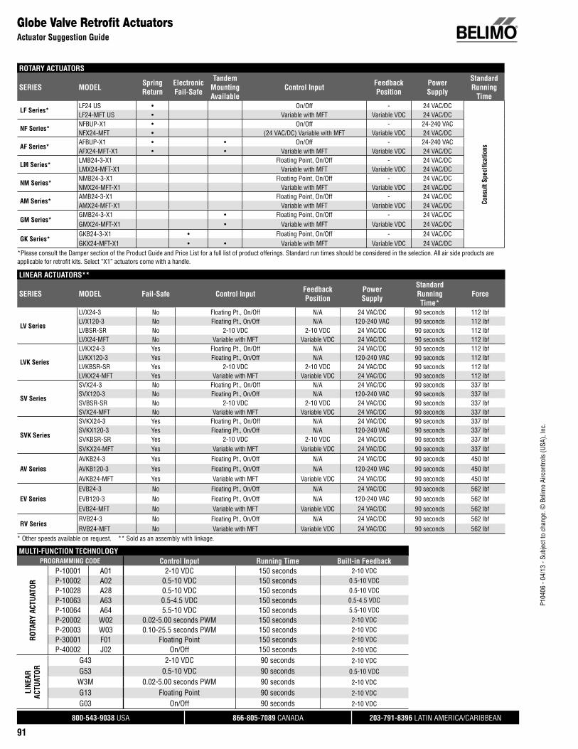
P104
06 -
04/1
3 - S
ubje
ct to
cha
nge.
© B
elim
o Ai
rcon
trols
(USA
), In
c.
®
800-543-9038 USA 866-805-7089 CANADA 203-791-8396 LATIN AMERICA/CARIBBEAN
91
Globe Valve Retrofi t Actuators Actuator Suggestion Guide
ROTARY ACTUATORS
SERIES MODEL Spring Return
ElectronicFail-Safe
TandemMountingAvailable
Control Input Feedback Position
PowerSupply
StandardRunning
Time
LF Series*LF24 US • On/Off - 24 VAC/DC
Cons
ult S
peci
fi cat
ions
LF24-MFT US • Variable with MFT Variable VDC 24 VAC/DC
NF Series*NFBUP-X1 • On/Off - 24-240 VACNFX24-MFT • (24 VAC/DC) Variable with MFT Variable VDC 24 VAC/DC
AF Series*AFBUP-X1 • • On/Off - 24-240 VACAFX24-MFT-X1 • • Variable with MFT Variable VDC 24 VAC/DC
LM Series*LMB24-3-X1 Floating Point, On/Off - 24 VAC/DCLMX24-MFT-X1 Variable with MFT Variable VDC 24 VAC/DC
NM Series*NMB24-3-X1 Floating Point, On/Off - 24 VAC/DCNMX24-MFT-X1 Variable with MFT Variable VDC 24 VAC/DC
AM Series*AMB24-3-X1 Floating Point, On/Off - 24 VAC/DCAMX24-MFT-X1 Variable with MFT Variable VDC 24 VAC/DC
GM Series*GMB24-3-X1 • Floating Point, On/Off - 24 VAC/DCGMX24-MFT-X1 • Variable with MFT Variable VDC 24 VAC/DC
GK Series*GKB24-3-X1 • Floating Point, On/Off - 24 VAC/DCGKX24-MFT-X1 • • Variable with MFT Variable VDC 24 VAC/DC
*Please consult the Damper section of the Product Guide and Price List for a full list of product offerings. Standard run times should be considered in the selection. All air side products are applicable for retrofi t kits. Select “X1” actuators come with a handle.
MULTI-FUNCTION TECHNOLOGYPROGRAMMING CODE Control Input Running Time Built-in Feedback
ROTA
RY A
CTUA
TOR
P-10001 A01 2-10 VDC 150 seconds 2-10 VDCP-10002 A02 0.5-10 VDC 150 seconds 0.5-10 VDCP-10028 A28 0.5-10 VDC 150 seconds 0.5-10 VDCP-10063 A63 0.5-4.5 VDC 150 seconds 0.5-4.5 VDCP-10064 A64 5.5-10 VDC 150 seconds 5.5-10 VDCP-20002 W02 0.02-5.00 seconds PWM 150 seconds 2-10 VDCP-20003 W03 0.10-25.5 seconds PWM 150 seconds 2-10 VDCP-30001 F01 Floating Point 150 seconds 2-10 VDCP-40002 J02 On/Off 150 seconds 2-10 VDC
LINE
AR
ACTU
ATOR
G43 2-10 VDC 90 seconds 2-10 VDC
G53 0.5-10 VDC 90 seconds 0.5-10 VDC
W3M 0.02-5.00 seconds PWM 90 seconds 2-10 VDC
G13 Floating Point 90 seconds 2-10 VDC
G03 On/Off 90 seconds 2-10 VDC
LINEAR ACTUATORS**
SERIES MODEL Fail-Safe Control Input Feedback Position
PowerSupply
StandardRunning Time*
Force
LV Series
LVX24-3 No Floating Pt., On/Off N/A 24 VAC/DC 90 seconds 112 lbfLVX120-3 No Floating Pt., On/Off N/A 120-240 VAC 90 seconds 112 lbfLVBSR-SR No 2-10 VDC 2-10 VDC 24 VAC/DC 90 seconds 112 lbfLVX24-MFT No Variable with MFT Variable VDC 24 VAC/DC 90 seconds 112 lbf
LVK Series
LVKX24-3 Yes Floating Pt., On/Off N/A 24 VAC/DC 90 seconds 112 lbfLVKX120-3 Yes Floating Pt., On/Off N/A 120-240 VAC 90 seconds 112 lbfLVKBSR-SR Yes 2-10 VDC 2-10 VDC 24 VAC/DC 90 seconds 112 lbfLVKX24-MFT Yes Variable with MFT Variable VDC 24 VAC/DC 90 seconds 112 lbf
SV Series
SVX24-3 No Floating Pt., On/Off N/A 24 VAC/DC 90 seconds 337 lbfSVX120-3 No Floating Pt., On/Off N/A 120-240 VAC 90 seconds 337 lbfSVBSR-SR No 2-10 VDC 2-10 VDC 24 VAC/DC 90 seconds 337 lbfSVX24-MFT No Variable with MFT Variable VDC 24 VAC/DC 90 seconds 337 lbf
SVK Series
SVKX24-3 Yes Floating Pt., On/Off N/A 24 VAC/DC 90 seconds 337 lbfSVKX120-3 Yes Floating Pt., On/Off N/A 120-240 VAC 90 seconds 337 lbfSVKBSR-SR Yes 2-10 VDC 2-10 VDC 24 VAC/DC 90 seconds 337 lbfSVKX24-MFT Yes Variable with MFT Variable VDC 24 VAC/DC 90 seconds 337 lbf
AV SeriesAVKB24-3 Yes Floating Pt., On/Off N/A 24 VAC/DC 90 seconds 450 lbfAVKB120-3 Yes Floating Pt., On/Off N/A 120-240 VAC 90 seconds 450 lbfAVKB24-MFT Yes Variable with MFT Variable VDC 24 VAC/DC 90 seconds 450 lbf
EV SeriesEVB24-3 No Floating Pt., On/Off N/A 24 VAC/DC 90 seconds 562 lbfEVB120-3 No Floating Pt., On/Off N/A 120-240 VAC 90 seconds 562 lbfEVB24-MFT No Variable with MFT Variable VDC 24 VAC/DC 90 seconds 562 lbf
RV SeriesRVB24-3 No Floating Pt., On/Off N/A 24 VAC/DC 90 seconds 562 lbfRVB24-MFT No Variable with MFT Variable VDC 24 VAC/DC 90 seconds 562 lbf
* Other speeds available on request. ** Sold as an assembly with linkage.

800-543-9038 USA 866-805-7089 CANADA 203-791-8396 LATIN AMERICA/CARIBBEAN
92
P104
06 -
04/1
3 - S
ubje
ct to
cha
nge.
© B
elim
o Ai
rcon
trols
(USA
), In
c.
Valve Body Model ValveConfi guration Size Body Type Flow Fail-Safe Close-Off psi Belimo
Actuator SeriesBelimoLinkage
HoneywellV5011, V5011N Series Valves
Linkage/Actuator Selection Guide
All close-off pressures listed are approximate and based on valve condition and application.
V5011 Series 2-way ½” NPT - No 250 LV UGVLYes 250 LVK UGVL
¾” NPT - No 211 LV UGVLYes 211 LVK UGVL
1” NPT - No 92 LV UGVL250 SV UGVL
Yes 92 LVK UGVL250 SVK UGVL
1¼” NPT - No 236 SV UGVLYes 236 SVK UGVL
1½” NPT - No 160 SV UGVLYes 160 SVK UGVL
2” NPT - No 85 SV UGVLYes 85 SVK UGVL
2½” NPT - No 59 SV UGVLYes 59 SVK UGVL
3” NPT - No 41 SV UGVLYes 41 SVK UGVL
V5011N Series 2-way ½” NPT - No 250 LM UGLK1806LV UGVL
Yes 250 LF UGLK1806LVK UGVLNF UGLK1800
¾” NPT - No 153 LM UGLK1806211 LV UGVL250 NM UGLK1806
Yes 119 LF UGLK1806211 LVK UGVL250 NF UGLK1800
1” NPT - No 92 LV UGVL86 LM UGLK1806173 NM UGLK1806250 AM UGLK1800
SV UGVLYes 67 LF UGLK1806
92 LVK UGVL173 NF UGLK1800250 SVK UGVL250 AF UGLK1800
1¼” NPT - No 55 LM UGLK1806110 NM UGLK1806221 AM UGLK1800236 SV UGVL
Yes 43 LF UGLK1806110 NF UGLK1800221 AF UGLK1800236 SVK UGVL
1½” NPT - No 38 LM UGLK180677 NM UGLK1806153 AM UGLK1800160 SV UGVL250 GM UGLK1800
Yes 77 NF UGLK180030 LF UGLK1806153 AF UGLK1800160 SVK UGVL250 GK UGLK1800
No 22 LM UGLK180643 NM UGLK180685 SV UGVL86 AM UGLK1800173 GM UGLK1800

800-543-9038 USA 866-805-7089 CANADA 203-791-8396 LATIN AMERICA/CARIBBEAN
93
Valve Body Model ValveConfi guration Size Body Type Flow Fail-Safe Close-Off psi Belimo
Actuator SeriesBelimoLinkage
P104
06 -
04/1
3 - S
ubje
ct to
cha
nge.
© B
elim
o Ai
rcon
trols
(USA
), In
c.
HoneywellV5011N, V5013, V5013N Series Valves
Linkage/Actuator Selection Guide
All close-off pressures listed are approximate and based on valve condition and application.
V5011N Series 2-way 2” NPT - Yes 17 LF UGLK180643 NF UGLK180085 SVK UGVL86 AF UGLK1800173 GK UGLK1800
V5013 Series 3-way ½” NPT - No 250 LV UGVLYes 250 LVK UGVL
¾” NPT - No 211 LV UGVLYes 211 LVK UGVL
1” NPT - No 92 LV UGVL250 SV UGVL
Yes 92 LVK UGVL250 SVK UGVL
1¼” NPT - No 236 SV UGVLYes 236 SVK UGVL
1½” NPT - No 160 SV UGVLYes 160 SVK UGVL
2” NPT - No 85 SV UGVLYes 85 SVK UGVL
2½” NPT - No 59 SV UGVLYes 59 SVK UGVL
3” NPT - No 41 SV UGVLYes 41 SVK UGVL
V5013N Series 3-way ½” NPT - No 250 LM UGLK1806LV UGVL
Yes 250 LF UGLK1806LVK UGVLNF UGLK1800
¾” NPT - No 153 LM UGLK1806211 LV UGVL250 NM UGLK1806
Yes 119 LF UGLK1806211 LVK UGVL250 NF UGLK1800
1” NPT - No 92 LV UGVL86 LM UGLK1806173 NM UGLK1806250 AM UGLK1800
SV UGVLYes 67 LF UGLK1806
92 LVK UGVL173 NF UGLK1800250 SVK UGVL250 AF UGLK1800
1¼” NPT - No 55 LM UGLK1806110 NM UGLK1806221 AM UGLK1800236 SV UGVL
Yes 43 LF UGLK1806110 NF UGLK1800221 AF UGLK1800236 SVK UGVL
1½” NPT - No 38 LM UGLK180677 NM UGLK1806153 AM UGLK1800160 SV UGVL250 GM UGLK1800
Yes 77 NF UGLK180030 LF UGLK1806153 AF UGLK1800160 SVK UGVL250 GK UGLK1800
2” NPT - No 22 LM UGLK180643 NM UGLK180685 SV UGVL86 AM UGLK1800173 GM UGLK1800

800-543-9038 USA 866-805-7089 CANADA 203-791-8396 LATIN AMERICA/CARIBBEAN
94
P104
06 -
04/1
3 - S
ubje
ct to
cha
nge.
© B
elim
o Ai
rcon
trols
(USA
), In
c.
Valve Body Model ValveConfi guration Size Body Type Flow Fail-Safe Close-Off psi Belimo
Actuator SeriesBelimoLinkage
HoneywellV5013N, V5011, V5013 Series Valves
Linkage/Actuator Selection Guide
All close-off pressures listed are approximate and based on valve condition and application.
V5013N Series 3-way 2” NPT - Yes 17 LF UGLK180643 NF UGLK180085 SVK UGVL86 AF UGLK1800173 GK UGLK1800
V5011F (1014, 1022, 1030, 1048, 1121, 1139)
2-way ½” NPT - No 250 LM UGLK1806Yes 250 LF UGLK1806
NF UGLK1800V5011G (1137, 1145, 1152, 1160, 1178, 1186)
2-way ½” NPT - No 250 LM UGLK1806Yes 250 LF UGLK1806
NF UGLK1800V5011H (1002, 1010) 2-way ½” NPT - No 250 LM UGLK1806
Yes 250 LF UGLK1806NF UGLK1800
V5011J (1012, 1079) 2-way ½” NPT - No 250 LM UGLK1806Yes 250 LF UGLK1806
NF UGLK1800V5011F (1055, 1147) 2-way ¾” NPT - No 153 LM UGLK1806
250 NM UGLK1806Yes 119 LF UGLK1806
250 NF UGLK1800V5011 (H1028, G1194, J1023) 2-way ¾” NPT - No 153 LM UGLK1806
250 NM UGLK1806Yes 119 LF UGLK1806
250 NF UGLK1800V5011 (F1063, F1154, H1028, G1194)
2-way 1” NPT - No 86 LM UGLK1806173 NM UGLK1806250 AM UGLK1800
Yes 67 LF UGLK1806173 NF UGLK1800250 AF UGLK1800
V5011F (1071, 1162) 2-way 1¼” NPT - No 55 LM UGLK1806110 NM UGLK1806221 AM UGLK1800
Yes 43 LF UGLK1806110 NF UGLK1800221 AF UGLK1800
V5011 (H1044, G1210, J1049) 2-way 1¼” NPT - No 55 LM UGLK1806110 NM UGLK1806221 AM UGLK1800
Yes 43 LF UGLK1806110 NF UGLK1800221 AF UGLK1800
V5011 (F1089, F1178, G1228) 2-way 1½” NPT - No 38 LM UGLK180677 NM UGLK1806153 AM UGLK1800250 GM UGLK1800
Yes 77 NF UGLK180030 LF UGLK1806153 AF UGLK1800250 GK UGLK1800
V5011 (F1097, F1188, G1103) 2-way 2” NPT - No 22 LM UGLK180643 NM UGLK180686 AM UGLK1800173 GM UGLK1800
V5011 (F1097, F1188, G1103) 2-way 2” NPT - Yes 17 LF UGLK180043 NF UGLK180686 AF UGLK1800173 GK UGLK1800
V5013F (1004, 1012, 1079) 3-way ½” NPT - No 250 LM UGLK1806Yes 250 LF UGLK1806
NF UGLK1800V5013F (1020, 1087) 3-way ¾” NPT - No 153 LM UGLK1806
250 NM UGLK1806Yes 119 LF UGLK1806
250 NF UGLK1800

800-543-9038 USA 866-805-7089 CANADA 203-791-8396 LATIN AMERICA/CARIBBEAN
95
Valve Body Model ValveConfi guration Size Body Type Flow Fail-Safe Close-Off psi Belimo
Actuator SeriesBelimoLinkage
P104
06 -
04/1
3 - S
ubje
ct to
cha
nge.
© B
elim
o Ai
rcon
trols
(USA
), In
c.
HoneywellV5013, V5045, V3350 Series Valves
Linkage/Actuator Selection Guide
All close-off pressures listed are approximate and based on valve condition and application.
V5013F (1038, 1095) 3-way 1” NPT - No 86 LM UGLK1806173 NM UGLK1806250 AM UGLK1800
Yes 67 LF UGLK1806173 NF UGLK1800250 AF UGLK1800
V5013F (1046, 1103) 3-way 1¼” NPT - No 55 LM UGLK1806110 NM UGLK1806221 AM UGLK1800
Yes 43 LF UGLK1806110 NF UGLK1800221 AF UGLK1800
V5013F (1053, 1111) 3-way 1½” NPT - No 38 LM UGLK180677 NM UGLK1806153 AM UGLK1800250 GM UGLK1800
Yes 77 NF UGLK180030 LF UGLK1806153 AF UGLK1800250 GK UGLK1800
V5013F (1061, 1129) 3-way 2” NPT - No 22 LM UGLK180643 NM UGLK180686 AM UGLK1800173 GM UGLK1800
Yes 17 LF UGLK180043 NF UGLK180686 AF UGLK1800173 GK UGLK1800
V5045 2-way ½” NPT - No 250 AM UGLK1804Yes 250 NF UGLK1804
¾” NPT - Yes 250 NF UGLK18041” NPT - No 250 AM UGLK1804
Yes 244 NF UGLK18041¼” NPT - No 250 AM UGLK1804
Yes 156 NF UGLK18041½” NPT - No 217 AM UGLK1804
Yes 217 AF UGLK18042” NPT - No 122 AM UGLK1804
Yes 122 AF UGLK1804V3350 (A2009, A2017, B2007, C2013, D2003)
2-way 2½” Flanged - No 55 AM UGLK1800110 GM UGLK1800196 2*GM UGLK1870
Yes 55 AF UGLK1800110 2*AF UGLK1870
GK UGLK1800196 2*GK UGLK1870
V3350 (A3007, A3015, B3005, C3011, D3001)
2-way 3” Flanged - No 38 AM UGLK180077 GM UGLK1800136 2*GM UGLK1870
Yes 38 AF UGLK180077 2*AF UGLK1870
GK UGLK1800136 2*GK UGLK1870
V3350 (A4005, A4013, B4003, C4019, D4009)
2-way 4” Flanged - No 11 AM UGLK180222 GM UGLK180240 2*GM UGLK1872
Yes 11 AF UGLK180222 2*AF UGLK1872
GK UGLK180240 2*GK UGLK1872
V3350 (A5002, A5010, B5000, C5016, D5006)
2-way 5” Flanged - No 14 GM UGLK180225 2*GM UGLK1872
Yes 7 AF UGLK180214 2*AF UGLK1872
GK UGLK180225 2*GK UGLK1872

800-543-9038 USA 866-805-7089 CANADA 203-791-8396 LATIN AMERICA/CARIBBEAN
96
P104
06 -
04/1
3 - S
ubje
ct to
cha
nge.
© B
elim
o Ai
rcon
trols
(USA
), In
c.
Valve Body Model ValveConfi guration Size Body Type Flow Fail-Safe Close-Off psi Belimo
Actuator SeriesBelimoLinkage
HoneywellV3350, V3351, V3360 Series Valves
Linkage/Actuator Selection Guide
All close-off pressures listed are approximate and based on valve condition and application.
V3350 (A6000, A6008, A6018, C6014, D6004)
2-way 6” Flanged - No 10 GM UGLK180218 2*GM UGLK1872
Yes 10 2*AF UGLK1872GK UGLK1802
18 2*GK UGLK1872V3351 (A2008, C2005, D2002) 2-way 2½” Flanged - No 55 AM UGLK1800
110 GM UGLK1800196 2*GM UGLK1870
Yes 55 AF UGLK1800110 2*AF UGLK1870
GK UGLK1800196 2*GK UGLK1870
V3351 (A3006, C3002, C3003) 2-way 3” Flanged - No 38 AM UGLK180077 GM UGLK1800136 2*GM UGLK1870
Yes 38 AF UGLK180077 2*AF UGLK1870
GK UGLK1800136 2*GK UGLK1870
V3351 ( A4004, C4000, C4001) 2-way 4” Flanged - No 11 AM UGLK180222 GM UGLK180240 2*GM UGLK1872
Yes 11 AF UGLK180222 2*AF UGLK1872
GK UGLK180240 2*GK UGLK1872
V3351 (A5001, C5008, D5005) 2-way 5” Flanged - No 14 GM UGLK180225 2*GM UGLK1872
Yes 7 AF UGLK180214 2*AF UGLK1872
GK UGLK180225 2*GK UGLK1872
V3351 (A6009, C6005, C6006) 2-way 6” Flanged - No 10 GM UGLK180218 2*GM UGLK1872
Yes 10 2*AF UGLK1872GK UGLK1802
18 2*GK UGLK1872V3360E2008, V3361E2007 3-way 2½” Flanged - No 55 AM UGLK1800
110 GM UGLK1800196 2*GM UGLK1870
Yes 55 AF UGLK1800110 2*AF UGLK1870
GK UGLK1800196 2*GK UGLK1870
V3360E3006, V3361E3005 3-way 3” Flanged - No 38 AM UGLK180077 GM UGLK1800136 2*GM UGLK1870
Yes 38 AF UGLK180077 2*AF UGLK1870
GK UGLK1800136 2*GK UGLK1870
V3360E4004, V3361E4003 3-way 4” Flanged - No 11 AM UGLK180222 GM UGLK180240 2*GM UGLK1872
Yes 11 AF UGLK180222 2*AF UGLK1872
GK UGLK180240 2*GK UGLK1872
V3360E5001, V3361E5000 3-way 5” Flanged - No 14 GM UGLK180225 2*GM UGLK1872
Yes 7 AF UGLK180214 2*AF UGLK1872
GK UGLK180225 2*GK UGLK1872

800-543-9038 USA 866-805-7089 CANADA 203-791-8396 LATIN AMERICA/CARIBBEAN
97
Valve Body Model ValveConfi guration Size Body Type Flow Fail-Safe Close-Off psi Belimo
Actuator SeriesBelimoLinkage
P104
06 -
04/1
3 - S
ubje
ct to
cha
nge.
© B
elim
o Ai
rcon
trols
(USA
), In
c.
HoneywellV3360, V3450, V3451 Series Valves
Linkage/Actuator Selection Guide
All close-off pressures listed are approximate and based on valve condition and application.
V3360E6009, V3361E6008 3-way 6” Flanged - No 10 GM UGLK180218 2*GM UGLK1872
Yes 10 2*AF UGLK1872GK UGLK1802
18 2*GK UGLK1872V3450 (A2008, A2016, B2006, C2012, D2002)
2-way 2½” Flanged - No 55 AM UGLK1800110 GM UGLK1800196 2*GM UGLK1870
Yes 55 AF UGLK1800110 2*AF UGLK1870
GK UGLK1800196 2*GK UGLK1870
V3450 (A3006, A3014, B3004, C3010, D3000)
2-way 3” Flanged - No 38 AM UGLK180077 GM UGLK1800136 2*GM UGLK1870
Yes 38 AF UGLK180077 2*AF UGLK1870
GK UGLK1800136 2*GK UGLK1870
V3450 (A4004, A4012, B4002, C4018, D4008)
2-way 4” Flanged - No 11 AM UGLK180222 GM UGLK180240 2*GM UGLK1872
Yes 11 AF UGLK180222 2*AF UGLK1872
GK UGLK180240 2*GK UGLK1872
V3450 (A5001, A5019, B5009, C5015, D5005)
2-way 5” Flanged - No 14 GM UGLK180225 2*GM UGLK1872
Yes 7 AF UGLK180214 2*AF UGLK1872
GK UGLK180225 2*GK UGLK1872
V3450 (A6009, A6007, A6017, C6013, D6003)
2-way 6” Flanged - No 10 GM UGLK180218 2*GM UGLK1872
Yes 10 2*AF UGLK1872GK UGLK1802
18 2*GK UGLK1872V3451 (A2007, C2003, C2004) 2-way 2½” Flanged - No 55 AM UGLK1800
110 GM UGLK1800196 2*GM UGLK1870
Yes 55 AF UGLK1800110 2*AF UGLK1870
GK UGLK1800196 2*GK UGLK1870
V3451 (A3005, C3001, C3002) 2-way 3” Flanged - No 38 AM UGLK180077 GM UGLK1800136 2*GM UGLK1870
V3451 (A3005, C3001, C3002) 2-way 3” Flanged - Yes 38 AF UGLK180077 2*AF UGLK1870
GK UGLK1800136 2*GK UGLK1870
V3451 (A4003, C4000, C4009) 2-way 4” Flanged - No 11 AM UGLK180222 GM UGLK180240 2*GM UGLK1872
Yes 11 AF UGLK180222 2*AF UGLK1872
GK UGLK180240 2*GK UGLK1872
V3451 (A5000, C5006, C5007) 2-way 5” Flanged - No 14 GM UGLK180225 2*GM UGLK1872
Yes 7 AF UGLK180214 2*AF UGLK1872
GK UGLK180225 2*GK UGLK1872

800-543-9038 USA 866-805-7089 CANADA 203-791-8396 LATIN AMERICA/CARIBBEAN
98
P104
06 -
04/1
3 - S
ubje
ct to
cha
nge.
© B
elim
o Ai
rcon
trols
(USA
), In
c.
Valve Body Model ValveConfi guration Size Body Type Flow Fail-Safe Close-Off psi Belimo
Actuator SeriesBelimoLinkage
HoneywellV3451, V3460, V5011 Series Valves
Linkage/Actuator Selection Guide
All close-off pressures listed are approximate and based on valve condition and application.
V3451 (A6008, C6004, C6005) 2-way 6” Flanged - No 10 GM UGLK180218 2*GM UGLK1872
Yes 10 2*AF UGLK1872GK UGLK1802
18 2*GK UGLK1872V3460E2007, V3461E2006 3-way 2½” Flanged - No 55 AM UGLK1800
110 GM UGLK1800196 2*GM UGLK1870
Yes 55 AF UGLK1800110 2*AF UGLK1870
GK UGLK1800196 2*GK UGLK1870
V3460E3005, V3461E3004 3-way 3” Flanged - No 38 AM UGLK180077 GM UGLK1800136 2*GM UGLK1870
Yes 38 AF UGLK180077 2*AF UGLK1870
GK UGLK1800136 2*GK UGLK1870
V3460E4003, V3461E4002 3-way 4” Flanged - No 11 AM UGLK180222 GM UGLK180240 2*GM UGLK1872
Yes 11 AF UGLK180222 2*AF UGLK1872
GK UGLK180240 2*GK UGLK1872
V3460E5000, V3461E5009 3-way 5” Flanged - No 14 GM UGLK180225 2*GM UGLK1872
Yes 7 AF UGLK180214 2*AF UGLK1872
GK UGLK180225 2*GK UGLK1872
V3460E6008, V3461E6007 3-way 6” Flanged - No 10 GM UGLK180218 2*GM UGLK1872
Yes 10 2*AF UGLK1872GK UGLK1802
18 2*GK UGLK1872V5011 (A1734, F1105, F1196, G1111)
2-way 2½” Flanged/NPT - No 55 AM UGLK1800110 GM UGLK1800196 2*GM UGLK1870
Yes 55 AF UGLK1800110 2*AF UGLK1870
GK UGLK1800196 2*GK UGLK1870
V5011 (A1767, F1113, F1204, G1129)
2-way 3” Flanged/NPT - No 38 AM UGLK180077 GM UGLK1800136 2*GM UGLK1870
Yes 38 AF UGLK180077 2*AF UGLK1870
GK UGLK1800136 2*GK UGLK1870
V5011 (A1858, B1013) 2-way 4” Flanged - No 11 AM UGLK180222 GM UGLK180240 2*GM UGLK1872
Yes 11 AF UGLK180222 2*AF UGLK1872
GK UGLK180240 2*GK UGLK1872
V5011 (A1882, B1047) 2-way 5” Flanged - No 14 GM UGLK180225 2*GM UGLK1872
Yes 7 AF UGLK180214 2*AF UGLK1872
GK UGLK180225 2*GK UGLK1872

800-543-9038 USA 866-805-7089 CANADA 203-791-8396 LATIN AMERICA/CARIBBEAN
99
Valve Body Model ValveConfi guration Size Body Type Flow Fail-Safe Close-Off psi Belimo
Actuator SeriesBelimoLinkage
P104
06 -
04/1
3 - S
ubje
ct to
cha
nge.
© B
elim
o Ai
rcon
trols
(USA
), In
c.
HoneywellV5011, V5013 Series Valves
Linkage/Actuator Selection Guide
PDTO = Push down to open PDTC = Push down to closeAll close-off pressures listed are approximate and based on valve condition and application.
Johnson ControlsV52... Series Valves
Linkage/Actuator Selection Guide
V5011 (A1916, B1078) 2-way 6” Flanged - No 10 GM UGLK180218 2*GM UGLK1872
Yes 10 2*AF UGLK1872GK UGLK1802
18 2*GK UGLK1872V5013 (B1003, C1001) 3-way 2½” Flanged - No 55 AM UGLK1800
110 GM UGLK1800196 2*GM UGLK1870
Yes 55 AF UGLK1800110 2*AF UGLK1870
GK UGLK1800196 2*GK UGLK1870
V5013 (B1011, C1019) 3-way 3” Flanged - No 38 AM UGLK180077 GM UGLK1800136 2*GM UGLK1870
Yes 38 AF UGLK180077 2*AF UGLK1870
GK UGLK1800136 2*GK UGLK1870
V5013 (B1029, C1027) 3-way 4” Flanged - No 11 AM UGLK180222 GM UGLK180240 2*GM UGLK1872
Yes 11 AF UGLK180222 2*AF UGLK1872
GK UGLK180240 2*GK UGLK1872
V5013 (B1037, C1035) 3-way 5” Flanged - No 14 GM UGLK180225 2*GM UGLK1872
Yes 7 AF UGLK180214 2*AF UGLK1872
GK UGLK180225 2*GK UGLK1872
V5013 (B1045, C1043) 3-way 6” Flanged - No 10 GM UGLK180218 2*GM UGLK1872
Yes 10 2*AF UGLK1872GK UGLK1802
18 2*GK UGLK1872JOHNSON CONTROLSV-5252-12 2-way 3” Flanged PDTC No 26 AM UGLK1410
52 GM UGLK141093 2*GM UGLK1476
Yes 26 AF UGLK141052 2*AF UGLK1476
GK UGLK141093 2*GK UGLK1476
V-5252-13 2-way 3” Flanged PDTC No 26 AM UGLK141052 GM UGLK141093 2*GM UGLK1476
Yes 26 AF UGLK141052 2*AF UGLK1476
GK UGLK141093 2*GK UGLK1476
V-5252-35 2-way 3” Flanged PDTC No 26 AM UGLK141052 GM UGLK141093 2*GM UGLK1476
Yes 26 AF UGLK141052 2*AF UGLK1476
GK UGLK141093 2*GK UGLK1476
V-5252-14 2-way 4” Flanged PDTC No 15 AM UGLK141029 GM UGLK141052 2*GM UGLK1476
Yes 15 AF UGLK141029 2*AF UGLK1476
GK UGLK141052 2*GK UGLK1476
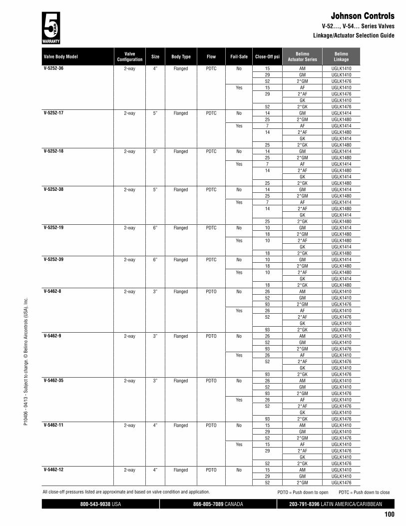
800-543-9038 USA 866-805-7089 CANADA 203-791-8396 LATIN AMERICA/CARIBBEAN
100
P104
06 -
04/1
3 - S
ubje
ct to
cha
nge.
© B
elim
o Ai
rcon
trols
(USA
), In
c.
Valve Body Model ValveConfi guration Size Body Type Flow Fail-Safe Close-Off psi Belimo
Actuator SeriesBelimoLinkage
Johnson ControlsV-52..., V-54... Series Valves
Linkage/Actuator Selection Guide
All close-off pressures listed are approximate and based on valve condition and application. PDTO = Push down to open PDTC = Push down to close
V-5252-36 2-way 4” Flanged PDTC No 15 AM UGLK141029 GM UGLK141052 2*GM UGLK1476
Yes 15 AF UGLK141029 2*AF UGLK1476
GK UGLK141052 2*GK UGLK1476
V-5252-17 2-way 5” Flanged PDTC No 14 GM UGLK141425 2*GM UGLK1480
Yes 7 AF UGLK141414 2*AF UGLK1480
GK UGLK141425 2*GK UGLK1480
V-5252-18 2-way 5” Flanged PDTC No 14 GM UGLK141425 2*GM UGLK1480
Yes 7 AF UGLK141414 2*AF UGLK1480
GK UGLK141425 2*GK UGLK1480
V-5252-38 2-way 5” Flanged PDTC No 14 GM UGLK141425 2*GM UGLK1480
Yes 7 AF UGLK141414 2*AF UGLK1480
GK UGLK141425 2*GK UGLK1480
V-5252-19 2-way 6” Flanged PDTC No 10 GM UGLK141418 2*GM UGLK1480
Yes 10 2*AF UGLK1480GK UGLK1414
18 2*GK UGLK1480V-5252-39 2-way 6” Flanged PDTC No 10 GM UGLK1414
18 2*GM UGLK1480Yes 10 2*AF UGLK1480
GK UGLK141418 2*GK UGLK1480
V-5462-8 2-way 3” Flanged PDTO No 26 AM UGLK141052 GM UGLK141093 2*GM UGLK1476
Yes 26 AF UGLK141052 2*AF UGLK1476
GK UGLK141093 2*GK UGLK1476
V-5462-9 2-way 3” Flanged PDTO No 26 AM UGLK141052 GM UGLK141093 2*GM UGLK1476
Yes 26 AF UGLK141052 2*AF UGLK1476
GK UGLK141093 2*GK UGLK1476
V-5462-35 2-way 3” Flanged PDTO No 26 AM UGLK141052 GM UGLK141093 2*GM UGLK1476
Yes 26 AF UGLK141052 2*AF UGLK1476
GK UGLK141093 2*GK UGLK1476
V-5462-11 2-way 4” Flanged PDTO No 15 AM UGLK141029 GM UGLK141052 2*GM UGLK1476
Yes 15 AF UGLK141029 2*AF UGLK1476
GK UGLK141052 2*GK UGLK1476
V-5462-12 2-way 4” Flanged PDTO No 15 AM UGLK141029 GM UGLK141052 2*GM UGLK1476

800-543-9038 USA 866-805-7089 CANADA 203-791-8396 LATIN AMERICA/CARIBBEAN
101
Valve Body Model ValveConfi guration Size Body Type Flow Fail-Safe Close-Off psi Belimo
Actuator SeriesBelimoLinkage
P104
06 -
04/1
3 - S
ubje
ct to
cha
nge.
© B
elim
o Ai
rcon
trols
(USA
), In
c.
Johnson ControlsV-54..., V-58... Series Valves
Linkage/Actuator Selection Guide
All close-off pressures listed are approximate and based on valve condition and application. PDTO = Push down to open PDTC = Push down to close
V-5462-12 2-way 4” Flanged PDTO Yes 15 AF UGLK141029 2*AF UGLK1476
GK UGLK141052 2*GK UGLK1476
V-5462-37 2-way 4” Flanged PDTO No 15 AM UGLK141029 GM UGLK141052 2*GM UGLK1476
Yes 15 AF UGLK141029 2*AF UGLK1476
GK UGLK141052 2*GK UGLK1476
V-5462-15 2-way 5” Flanged PDTO No 14 GM UGLK141425 2*GM UGLK1480
Yes 7 AF UGLK141414 2*AF UGLK1480
GK UGLK141425 2*GK UGLK1480
V-5462-16 2-way 5” Flanged PDTO No 14 GM UGLK141425 2*GM UGLK1480
Yes 7 AF UGLK141414 2*AF UGLK1480
GK UGLK141425 2*GK UGLK1480
V-5462-39 2-way 5” Flanged PDTO No 14 GM UGLK141425 2*GM UGLK1480
Yes 7 AF UGLK141414 2*AF UGLK1480
GK UGLK141425 2*GK UGLK1480
V-5462-17 2-way 6” Flanged PDTO No 10 GM UGLK141418 2*GM UGLK1480
Yes 10 2*AF UGLK1480GK UGLK1414
18 2*GK UGLK1480V-5462-18 2-way 6” Flanged PDTO No 10 GM UGLK1414
18 2*GM UGLK1480Yes 10 2*AF UGLK1480
GK UGLK141418 2*GK UGLK1480
V-5462-40 2-way 6” Flanged PDTO No 10 GM UGLK141418 2*GM UGLK1480
Yes 10 2*AF UGLK1480GK UGLK1414
18 2*GK UGLK1480V-5842-9 3-way 3” Flanged Mixing No 26 AM UGLK1410
52 GM UGLK141093 2*GM UGLK1476
Yes 26 AF UGLK141052 2*AF UGLK1476
GK UGLK141093 2*GK UGLK1476
V-5842-10 3-way 3” Flanged Mixing No 26 AM UGLK141052 GM UGLK141093 2*GM UGLK1476
Yes 26 AF UGLK141052 2*AF UGLK1476
GK UGLK141093 2*GK UGLK1476
V-5842-32 3-way 3” Flanged Mixing No 26 AM UGLK141052 GM UGLK141093 2*GM UGLK1476
Yes 26 AF UGLK141052 2*AF UGLK1476
GK UGLK141093 2*GK UGLK1476
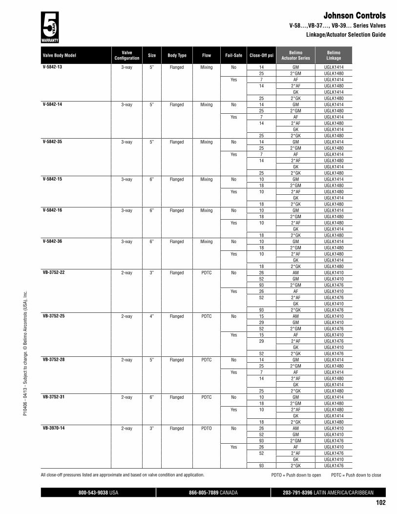
800-543-9038 USA 866-805-7089 CANADA 203-791-8396 LATIN AMERICA/CARIBBEAN
102
P104
06 -
04/1
3 - S
ubje
ct to
cha
nge.
© B
elim
o Ai
rcon
trols
(USA
), In
c.
Valve Body Model ValveConfi guration Size Body Type Flow Fail-Safe Close-Off psi Belimo
Actuator SeriesBelimoLinkage
Johnson ControlsV-58...,VB-37..., VB-39... Series Valves
Linkage/Actuator Selection Guide
All close-off pressures listed are approximate and based on valve condition and application. PDTO = Push down to open PDTC = Push down to close
V-5842-13 3-way 5” Flanged Mixing No 14 GM UGLK141425 2*GM UGLK1480
Yes 7 AF UGLK141414 2*AF UGLK1480
GK UGLK141425 2*GK UGLK1480
V-5842-14 3-way 5” Flanged Mixing No 14 GM UGLK141425 2*GM UGLK1480
Yes 7 AF UGLK141414 2*AF UGLK1480
GK UGLK141425 2*GK UGLK1480
V-5842-35 3-way 5” Flanged Mixing No 14 GM UGLK141425 2*GM UGLK1480
Yes 7 AF UGLK141414 2*AF UGLK1480
GK UGLK141425 2*GK UGLK1480
V-5842-15 3-way 6” Flanged Mixing No 10 GM UGLK141418 2*GM UGLK1480
Yes 10 2*AF UGLK1480GK UGLK1414
18 2*GK UGLK1480V-5842-16 3-way 6” Flanged Mixing No 10 GM UGLK1414
18 2*GM UGLK1480Yes 10 2*AF UGLK1480
GK UGLK141418 2*GK UGLK1480
V-5842-36 3-way 6” Flanged Mixing No 10 GM UGLK141418 2*GM UGLK1480
Yes 10 2*AF UGLK1480GK UGLK1414
18 2*GK UGLK1480VB-3752-22 2-way 3” Flanged PDTC No 26 AM UGLK1410
52 GM UGLK141093 2*GM UGLK1476
Yes 26 AF UGLK141052 2*AF UGLK1476
GK UGLK141093 2*GK UGLK1476
VB-3752-25 2-way 4” Flanged PDTC No 15 AM UGLK141029 GM UGLK141052 2*GM UGLK1476
Yes 15 AF UGLK141029 2*AF UGLK1476
GK UGLK141052 2*GK UGLK1476
VB-3752-28 2-way 5” Flanged PDTC No 14 GM UGLK141425 2*GM UGLK1480
Yes 7 AF UGLK141414 2*AF UGLK1480
GK UGLK141425 2*GK UGLK1480
VB-3752-31 2-way 6” Flanged PDTC No 10 GM UGLK141418 2*GM UGLK1480
Yes 10 2*AF UGLK1480GK UGLK1414
18 2*GK UGLK1480VB-3970-14 2-way 3” Flanged PDTO No 26 AM UGLK1410
52 GM UGLK141093 2*GM UGLK1476
Yes 26 AF UGLK141052 2*AF UGLK1476
GK UGLK141093 2*GK UGLK1476

800-543-9038 USA 866-805-7089 CANADA 203-791-8396 LATIN AMERICA/CARIBBEAN
103
Valve Body Model ValveConfi guration Size Body Type Flow Fail-Safe Close-Off psi Belimo
Actuator SeriesBelimoLinkage
P104
06 -
04/1
3 - S
ubje
ct to
cha
nge.
© B
elim
o Ai
rcon
trols
(USA
), In
c.
Johnson ControlsVB-39…, VB-43…, VG22… Series Valves
Linkage/Actuator Selection Guide
All close-off pressures listed are approximate and based on valve condition and application. PDTO = Push down to open PDTC = Push down to close
VB-3970-17 2-way 4” Flanged PDTO No 15 AM UGLK141029 GM UGLK141052 2*GM UGLK1476
Yes 15 AF UGLK141029 2*AF UGLK1476
GK UGLK141052 2*GK UGLK1476
VB-3970-20 2-way 5” Flanged PDTO No 14 GM UGLK141425 2*GM UGLK1480
Yes 7 AF UGLK141414 2*AF UGLK1480
GK UGLK141425 2*GK UGLK1480
VB-3970-23 2-way 6” Flanged PDTO No 10 GM UGLK141418 2*GM UGLK1480
Yes 10 2*AF UGLK1480GK UGLK1414
18 2*GK UGLK1480VB-4322-11 3-way 3” Flanged Mixing No 26 AM UGLK1410
52 GM UGLK141093 2*GM UGLK1476
Yes 26 AF UGLK141052 2*AF UGLK1476
GK UGLK141093 2*GK UGLK1476
VB-4322-13 3-way 4” Flanged Mixing No 15 AM UGLK141029 GM UGLK141052 2*GM UGLK1476
Yes 15 AF UGLK141029 2*AF UGLK1476
GK UGLK141052 2*GK UGLK1476
VB-4322-18 3-way 6” Flanged Mixing No 10 GM UGLK141418 2*GM UGLK1480
Yes 10 2*AF UGLK1480GK UGLK1414
18 2*GK UGLK1480VB-4322-19 3-way 5” Flanged Mixing No 14 GM UGLK1414
25 2*GM UGLK1480Yes 7 AF UGLK1414
14 2*AF UGLK1480GK UGLK1414
25 2*GK UGLK1480VG2231 UM 2-way 3” Flanged PDTC No 26 AM UGLK1410
52 GM UGLK141093 2*GM UGLK1476
Yes 26 AF UGLK141052 2*AF UGLK1476
GK UGLK141093 2*GK UGLK1476
VG2231 VM 2-way 4” Flanged PDTC No 15 AM UGLK141029 GM UGLK141052 2*GM UGLK1476
Yes 15 AF UGLK141029 2*AF UGLK1476
GK UGLK141052 2*GK UGLK1476
VG2231 WN 2-way 5” Flanged PDTC No 14 GM UGLK141425 2*GM UGLK1480
Yes 7 AF UGLK141414 2*AF UGLK1480
GK UGLK141425 2*GK UGLK1480
VG2231 YN 2-way 6” Flanged PDTC No 10 GM UGLK141418 2*GM UGLK1480

800-543-9038 USA 866-805-7089 CANADA 203-791-8396 LATIN AMERICA/CARIBBEAN
104
P104
06 -
04/1
3 - S
ubje
ct to
cha
nge.
© B
elim
o Ai
rcon
trols
(USA
), In
c.
Valve Body Model ValveConfi guration Size Body Type Flow Fail-Safe Close-Off psi Belimo
Actuator SeriesBelimoLinkage
Johnson ControlsVG22…, VG24…, VG28…, V-52... Series Valves
Linkage/Actuator Selection Guide
All close-off pressures listed are approximate and based on valve condition and application. PDTO = Push down to open PDTC = Push down to close
VG2231 YN 2-way 6” Flanged PDTC Yes 10 2*AF UGLK1480GK UGLK1414
18 2*GK UGLK1480VG2431 UM 2-way 3” Flanged PDTO No 26 AM UGLK1410
52 GM UGLK141093 2*GM UGLK1476
Yes 26 AF UGLK141052 2*AF UGLK1476
GK UGLK141093 2*GK UGLK1476
VG2431 VM 2-way 4” Flanged PDTO No 15 AM UGLK141029 GM UGLK141052 2*GM UGLK1476
Yes 15 AF UGLK141029 2*AF UGLK1476
GK UGLK141052 2*GK UGLK1476
VG2431 WN 2-way 5” Flanged PDTO No 14 GM UGLK141425 2*GM UGLK1480
Yes 7 AF UGLK141414 2*AF UGLK1480
GK UGLK141425 2*GK UGLK1480
VG2431 YN 2-way 6” Flanged PDTO No 10 GM UGLK141418 2*GM UGLK1480
Yes 10 2*AF UGLK1480GK UGLK1414
18 2*GK UGLK1480VG2831 UM 3-way 3” Flanged Mixing No 26 AM UGLK1410
52 GM UGLK141093 2*GM UGLK1476
Yes 26 AF UGLK141052 2*AF UGLK1476
GK UGLK141093 2*GK UGLK1476
VG2831 VM 3-way 4” Flanged Mixing No 15 AM UGLK141029 GM UGLK141052 2*GM UGLK1476
Yes 15 AF UGLK141029 2*AF UGLK1476
GK UGLK141052 2*GK UGLK1476
VG2831 WN 3-way 5” Flanged Mixing No 14 GM UGLK141425 2*GM UGLK1480
Yes 7 AF UGLK141414 2*AF UGLK1480
GK UGLK141425 2*GK UGLK1480
VG2831 YN 3-way 6” Flanged Mixing No 10 GM UGLK141418 2*GM UGLK1480
Yes 10 2*AF UGLK1480GK UGLK1414
18 2*GK UGLK1480V-5210-4595 2-way 2½” Flanged PDTC No 38 AM UGLK1412
75 GM UGLK1412134 2*GM UGLK1478
Yes 38 AF UGLK141275 2*AF UGLK1478
GK UGLK1412134 2*GK UGLK1478
V-5210-4596 2-way 3” Flanged PDTC No 26 AM UGLK141252 GM UGLK141293 2*GM UGLK1478
Yes 26 AF UGLK141252 2*AF UGLK1478
GK UGLK141293 2*GK UGLK1478

800-543-9038 USA 866-805-7089 CANADA 203-791-8396 LATIN AMERICA/CARIBBEAN
105
Valve Body Model ValveConfi guration Size Body Type Flow Fail-Safe Close-Off psi Belimo
Actuator SeriesBelimoLinkage
P104
06 -
04/1
3 - S
ubje
ct to
cha
nge.
© B
elim
o Ai
rcon
trols
(USA
), In
c.
Johnson ControlsV-52… Series Valves
Linkage/Actuator Selection Guide
All close-off pressures listed are approximate and based on valve condition and application. PDTO = Push down to open PDTC = Push down to close
V-5210-4597 2-way 4” Flanged PDTC No 15 AM UGLK141229 GM UGLK141252 2*GM UGLK1478
Yes 15 AF UGLK141229 2*AF UGLK1478
GK UGLK141252 2*GK UGLK1478
V-5252-4 2-way 2½” Flanged PDTC No 55 AM UGLK1404110 GM UGLK1404196 2*GM UGLK1472
Yes 55 AF UGLK1404110 2*AF UGLK1472
GK UGLK1404196 2*GK UGLK1472
V-5252-5 2-way 2½” Flanged PDTC No 55 AM UGLK1404110 GM UGLK1404196 2*GM UGLK1472
Yes 55 AF UGLK1404110 2*AF UGLK1472
GK UGLK1404196 2*GK UGLK1472
V-5252-6 2-way 2½” Flanged PDTC No 55 AM UGLK1404110 GM UGLK1404196 2*GM UGLK1472
Yes 55 AF UGLK1404110 2*AF UGLK1472
GK UGLK1404196 2*GK UGLK1472
V-5252-7 2-way 2½” Flanged PDTC No 55 AM UGLK1404110 GM UGLK1404196 2*GM UGLK1472
Yes 55 AF UGLK1404110 2*AF UGLK1472
GK UGLK1404196 2*GK UGLK1472
V-5252-8 2-way 2½” Flanged PDTC No 55 AM UGLK1404110 GM UGLK1404196 2*GM UGLK1472
Yes 55 AF UGLK1404110 2*AF UGLK1472
GK UGLK1404196 2*GK UGLK1472
V-5252-32 2-way 2½” Flanged PDTC No 55 AM UGLK1404110 GM UGLK1404196 2*GM UGLK1472
Yes 55 AF UGLK1404110 2*AF UGLK1472
GK UGLK1404196 2*GK UGLK1472
V-5252-33 2-way 2½” Flanged PDTC No 55 AM UGLK1404110 GM UGLK1404196 2*GM UGLK1472
Yes 55 AF UGLK1404110 2*AF UGLK1472
GK UGLK1404196 2*GK UGLK1472
V-5252-9 2-way 3” Flanged PDTC No 38 AM UGLK140477 GM UGLK1404136 2*GM UGLK1472
V-5252-9 2-way 3” Flanged PDTC Yes 38 AF UGLK140477 2*AF UGLK1472
GK UGLK1404136 2*GK UGLK1472
V-5252-10 2-way 3” Flanged PDTC No 38 AM UGLK140477 GM UGLK1404136 2*GM UGLK1472
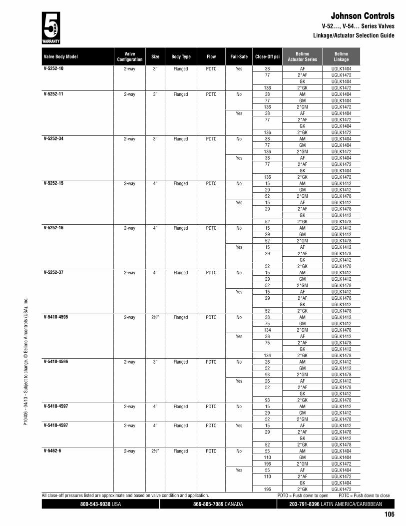
800-543-9038 USA 866-805-7089 CANADA 203-791-8396 LATIN AMERICA/CARIBBEAN
106
P104
06 -
04/1
3 - S
ubje
ct to
cha
nge.
© B
elim
o Ai
rcon
trols
(USA
), In
c.
Valve Body Model ValveConfi guration Size Body Type Flow Fail-Safe Close-Off psi Belimo
Actuator SeriesBelimoLinkage
Johnson ControlsV-52…, V-54… Series Valves
Linkage/Actuator Selection Guide
All close-off pressures listed are approximate and based on valve condition and application. PDTO = Push down to open PDTC = Push down to close
V-5252-10 2-way 3” Flanged PDTC Yes 38 AF UGLK140477 2*AF UGLK1472
GK UGLK1404136 2*GK UGLK1472
V-5252-11 2-way 3” Flanged PDTC No 38 AM UGLK140477 GM UGLK1404136 2*GM UGLK1472
Yes 38 AF UGLK140477 2*AF UGLK1472
GK UGLK1404136 2*GK UGLK1472
V-5252-34 2-way 3” Flanged PDTC No 38 AM UGLK140477 GM UGLK1404136 2*GM UGLK1472
Yes 38 AF UGLK140477 2*AF UGLK1472
GK UGLK1404136 2*GK UGLK1472
V-5252-15 2-way 4” Flanged PDTC No 15 AM UGLK141229 GM UGLK141252 2*GM UGLK1478
Yes 15 AF UGLK141229 2*AF UGLK1478
GK UGLK141252 2*GK UGLK1478
V-5252-16 2-way 4” Flanged PDTC No 15 AM UGLK141229 GM UGLK141252 2*GM UGLK1478
Yes 15 AF UGLK141229 2*AF UGLK1478
GK UGLK141252 2*GK UGLK1478
V-5252-37 2-way 4” Flanged PDTC No 15 AM UGLK141229 GM UGLK141252 2*GM UGLK1478
Yes 15 AF UGLK141229 2*AF UGLK1478
GK UGLK141252 2*GK UGLK1478
V-5410-4595 2-way 2½” Flanged PDTO No 38 AM UGLK141275 GM UGLK1412134 2*GM UGLK1478
Yes 38 AF UGLK141275 2*AF UGLK1478
GK UGLK1412134 2*GK UGLK1478
V-5410-4596 2-way 3” Flanged PDTO No 26 AM UGLK141252 GM UGLK141293 2*GM UGLK1478
Yes 26 AF UGLK141252 2*AF UGLK1478
GK UGLK141293 2*GK UGLK1478
V-5410-4597 2-way 4” Flanged PDTO No 15 AM UGLK141229 GM UGLK141252 2*GM UGLK1478
V-5410-4597 2-way 4” Flanged PDTO Yes 15 AF UGLK141229 2*AF UGLK1478
GK UGLK141252 2*GK UGLK1478
V-5462-6 2-way 2½” Flanged PDTO No 55 AM UGLK1404110 GM UGLK1404196 2*GM UGLK1472
Yes 55 AF UGLK1404110 2*AF UGLK1472
GK UGLK1404196 2*GK UGLK1472

800-543-9038 USA 866-805-7089 CANADA 203-791-8396 LATIN AMERICA/CARIBBEAN
107
Valve Body Model ValveConfi guration Size Body Type Flow Fail-Safe Close-Off psi Belimo
Actuator SeriesBelimoLinkage
P104
06 -
04/1
3 - S
ubje
ct to
cha
nge.
© B
elim
o Ai
rcon
trols
(USA
), In
c.
Johnson ControlsV-54…, V-58... Series Valves
Linkage/Actuator Selection Guide
All close-off pressures listed are approximate and based on valve condition and application. PDTO = Push down to open PDTC = Push down to close
V-5462-7 2-way 2½” Flanged PDTO No 55 AM UGLK1404110 GM UGLK1404196 2*GM UGLK1472
Yes 55 AF UGLK1404110 2*AF UGLK1472
GK UGLK1404196 2*GK UGLK1472
V-5462-34 2-way 2½” Flanged PDTO No 55 AM UGLK1404110 GM UGLK1404196 2*GM UGLK1472
Yes 55 AF UGLK1404110 2*AF UGLK1472
GK UGLK1404196 2*GK UGLK1472
V-5462-10 2-way 3” Flanged PDTC No 26 AM UGLK141252 GM UGLK141293 2*GM UGLK1478
Yes 26 AF UGLK141252 2*AF UGLK1478
GK UGLK141293 2*GK UGLK1478
V-5462-36 2-way 3” Flanged PDTC No 26 AM UGLK141252 GM UGLK141293 2*GM UGLK1478
Yes 26 AF UGLK141252 2*AF UGLK1478
GK UGLK141293 2*GK UGLK1478
V-5462-13 2-way 4” Flanged PDTO No 15 AM UGLK141229 GM UGLK141252 2*GM UGLK1478
Yes 15 AF UGLK141229 2*AF UGLK1478
GK UGLK141252 2*GK UGLK1478
V-5462-14 2-way 4” Flanged PDTO No 15 AM UGLK141229 GM UGLK141252 2*GM UGLK1478
Yes 15 AF UGLK141229 2*AF UGLK1478
GK UGLK141252 2*GK UGLK1478
V-5462-38 2-way 4” Flanged PDTO No 15 AM UGLK141229 GM UGLK141252 2*GM UGLK1478
Yes 15 AF UGLK141229 2*AF UGLK1478
GK UGLK141252 2*GK UGLK1478
V-5842-7 3-way 2½” Flanged Mixing No 55 AM UGLK1404110 GM UGLK1404196 2*GM UGLK1472
Yes 55 AF UGLK1404110 2*AF UGLK1472
GK UGLK1404196 2*GK UGLK1472
V-5842-8 3-way 2½” Flanged Mixing No 55 AM UGLK1404110 GM UGLK1404196 2*GM UGLK1472
Yes 55 AF UGLK1404110 2*AF UGLK1472
GK UGLK1404196 2*GK UGLK1472
V-5842-31 3-way 2½” Flanged Mixing No 55 AM UGLK1404110 GM UGLK1404196 2*GM UGLK1472

800-543-9038 USA 866-805-7089 CANADA 203-791-8396 LATIN AMERICA/CARIBBEAN
108
P104
06 -
04/1
3 - S
ubje
ct to
cha
nge.
© B
elim
o Ai
rcon
trols
(USA
), In
c.
Valve Body Model ValveConfi guration Size Body Type Flow Fail-Safe Close-Off psi Belimo
Actuator SeriesBelimoLinkage
Johnson ControlsV-58…, VB-37..., VB-39..., VB-43... Series Valves
Linkage/Actuator Selection Guide
All close-off pressures listed are approximate and based on valve condition and application. PDTO = Push down to open PDTC = Push down to close
V-5842-31 3-way 2½” Flanged Mixing Yes 55 AF UGLK1404110 2*AF UGLK1472
GK UGLK1404196 2*GK UGLK1472
V-5842-17 3-way 3” Flanged Mixing No 26 AM UGLK141252 GM UGLK141293 2*GM UGLK1478
Yes 26 AF UGLK141252 2*AF UGLK1478
GK UGLK141293 2*GK UGLK1478
V-5842-18 3-way 3” Flanged Mixing No 26 AM UGLK141252 GM UGLK141293 2*GM UGLK1478
Yes 26 AF UGLK141252 2*AF UGLK1478
GK UGLK141293 2*GK UGLK1478
V-5842-33 3-way 3” Flanged Mixing No 26 AM UGLK141252 GM UGLK141293 2*GM UGLK1478
Yes 26 AF UGLK141252 2*AF UGLK1478
GK UGLK141293 2*GK UGLK1478
V-5842-11 3-way 4” Flanged Mixing No 15 AM UGLK141229 GM UGLK141252 2*GM UGLK1478
Yes 15 AF UGLK141229 2*AF UGLK1478
GK UGLK141252 2*GK UGLK1478
V-5842-12 3-way 4” Flanged Mixing No 15 AM UGLK141229 GM UGLK141252 2*GM UGLK1478
Yes 15 AF UGLK141229 2*AF UGLK1478
GK UGLK141252 2*GK UGLK1478
V-5842-34 3-way 4” Flanged Mixing No 15 AM UGLK141229 GM UGLK141252 2*GM UGLK1478
Yes 15 AF UGLK141229 2*AF UGLK1478
GK UGLK141252 2*GK UGLK1478
VB-3752-19 2-way 2½” Flanged PDTC No 55 AM UGLK1404110 GM UGLK1404196 2*GM UGLK1472
Yes 55 AF UGLK1404110 2*AF UGLK1472
GK UGLK1404196 2*GK UGLK1472
VB-3970-11 2-way 2½” Flanged PDTO No 55 AM UGLK1404110 GM UGLK1404196 2*GM UGLK1472
Yes 55 AF UGLK1404110 2*AF UGLK1472
GK UGLK1404196 2*GK UGLK1472
VB-4322-9 3-way 2½” Flanged Mixing No 55 AM UGLK1404110 GM UGLK1404196 2*GM UGLK1472
Yes 55 AF UGLK1404110 2*AF UGLK1472
GK UGLK1404196 2*GK UGLK1472

800-543-9038 USA 866-805-7089 CANADA 203-791-8396 LATIN AMERICA/CARIBBEAN
109
Valve Body Model ValveConfi guration Size Body Type Flow Fail-Safe Close-Off psi Belimo
Actuator SeriesBelimoLinkage
P104
06 -
04/1
3 - S
ubje
ct to
cha
nge.
© B
elim
o Ai
rcon
trols
(USA
), In
c.
Johnson ControlsVG2…, V(B)-37… Series Valves
Linkage/Actuator Selection Guide
All close-off pressures listed are approximate and based on valve condition and application. PDTO = Push down to open PDTC = Push down to close
VG2231 TM 2-way 2½” Flanged PDTC No 55 AM UGLK1404110 GM UGLK1404196 2*GM UGLK1472
Yes 55 AF UGLK1404110 2*AF UGLK1472
GK UGLK1404196 2*GK UGLK1472
VG2231 UN 2-way 3” Flanged PDTC No 26 AM UGLK141252 GM UGLK141293 2*GM UGLK1478
Yes 26 AF UGLK141252 2*AF UGLK1478
GK UGLK141293 2*GK UGLK1478
VG2231 VN 2-way 4” Flanged PDTC No 15 AM UGLK141229 GM UGLK141252 2*GM UGLK1478
Yes 15 AF UGLK141229 2*AF UGLK1478
GK UGLK141252 2*GK UGLK1478
VG2431 TM 2-way 2½” Flanged PDTO No 55 AM UGLK1404110 GM UGLK1404196 2*GM UGLK1472
Yes 55 AF UGLK1404110 2*AF UGLK1472
GK UGLK1404196 2*GK UGLK1472
VG2431 UN 2-way 3” Flanged PDTO No 26 AM UGLK141252 GM UGLK141293 2*GM UGLK1478
Yes 26 AF UGLK141252 2*AF UGLK1478
GK UGLK141293 2*GK UGLK1478
VG2431 VN 2-way 4” Flanged PDTO No 15 AM UGLK141229 GM UGLK141252 2*GM UGLK1478
Yes 15 AF UGLK141229 2*AF UGLK1478
GK UGLK141252 2*GK UGLK1478
VG2831 TM 3-way 2½” Flanged Mixing No 55 AM UGLK1404110 GM UGLK1404196 2*GM UGLK1472
Yes 55 AF UGLK1404110 2*AF UGLK1472
GK UGLK1404196 2*GK UGLK1472
VG2831 UN 3-way 3” Flanged Mixing No 26 AM UGLK141252 GM UGLK141293 2*GM UGLK1478
Yes 26 AF UGLK141252 2*AF UGLK1478
GK UGLK141293 2*GK UGLK1478
VG2831 VN 3-way 4” Flanged Mixing No 15 AM UGLK141229 GM UGLK141252 2*GM UGLK1478
Yes 15 AF UGLK141229 2*AF UGLK1478
GK UGLK141252 2*GK UGLK1478
V(B)-3754 Series, Bronze Trim 2-way ¾” NPT - No 211 LV UGVLYes 211 LVK UGVL
1” NPT - No 92 LV UGVL250 SV UGVL

800-543-9038 USA 866-805-7089 CANADA 203-791-8396 LATIN AMERICA/CARIBBEAN
110
P104
06 -
04/1
3 - S
ubje
ct to
cha
nge.
© B
elim
o Ai
rcon
trols
(USA
), In
c.
Valve Body Model ValveConfi guration Size Body Type Flow Fail-Safe Close-Off psi Belimo
Actuator SeriesBelimoLinkage
Johnson Controls V(B)-37…, V(B)-39…, V(B)-43…, V(B)-58…, V-43… Series Valves
Linkage/Actuator Selection Guide
All close-off pressures listed are approximate and based on valve condition and application.
V(B)-3754 Series, Bronze Trim 2-way 1” NPT - Yes 92 LVK UGVL250 SVK UGVL
1¼” NPT - No 236 SV UGVLYes 236 SVK UGVL
1½” NPT - No 160 SV UGVLYes 160 SVK UGVL
2” NPT - No 85 SV UGVLYes 85 SVK UGVL
V(B)-3974 Series, Bronze Trim 2-way ¾” NPT - No 211 LV UGVLYes 211 LVK UGVL
1” NPT - No 92 LV UGVL250 SV UGVL
Yes 92 LVK UGVL250 SVK UGVL
1¼” NPT - No 236 SV UGVLYes 236 SVK UGVL
1½” NPT - No 160 SV UGVLYes 160 SVK UGVL
2” NPT - No 85 SV UGVLYes 85 SVK UGVL
V(B)-4324 Series, Bronze Trim 3-way ¾” NPT - No 211 LV UGVLYes 211 LVK UGVL
1” NPT - No 92 LV UGVL250 SV UGVL
Yes 92 LVK UGVL250 SVK UGVL
1¼” NPT - No 236 SV UGVLYes 236 SVK UGVL
1½” NPT - No 160 SV UGVLYes 160 SVK UGVL
2” NPT - No 85 SV UGVLYes 85 SVK UGVL
V(B)-5844 Series 2-way ¾” NPT - No 211 LV UGVLYes 211 LVK UGVL
1” NPT - No 92 LV UGVL250 SV UGVL
Yes 92 LVK UGVL250 SVK UGVL
1¼” NPT - No 236 SV UGVLYes 236 SVK UGVL
1½” NPT - No 160 SV UGVLYes 160 SVK UGVL
2” NPT - No 85 SV UGVLYes 85 SVK UGVL
3-way ¾” NPT - No 211 LV UGVLYes 211 LVK UGVL
1” NPT - No 92 LV UGVL250 SV UGVL
Yes 92 LVK UGVL250 SVK UGVL
1¼” NPT - No 236 SV UGVLYes 236 SVK UGVL
1½” NPT - No 160 SV UGVLYes 160 SVK UGVL
2” NPT - No 85 SV UGVLYes 85 SVK UGVL
V-4332 3-way ¾” NPT - No 211 LV UGVLYes 211 LVK UGVL
1” NPT - No 92 LV UGVL250 SV UGVL
Yes 92 LVK UGVL250 SVK UGVL
1¼” NPT - No 236 SV UGVLYes 236 SVK UGVL
1½” NPT - No 160 SV UGVLYes 160 SVK UGVL

800-543-9038 USA 866-805-7089 CANADA 203-791-8396 LATIN AMERICA/CARIBBEAN
111
Valve Body Model ValveConfi guration Size Body Type Flow Fail-Safe Close-Off psi Belimo
Actuator SeriesBelimoLinkage
P104
06 -
04/1
3 - S
ubje
ct to
cha
nge.
© B
elim
o Ai
rcon
trols
(USA
), In
c.
Johnson ControlsV-43…, VG7000, V-37…, V-38…, V-39… Series Valves
Linkage/Actuator Selection Guide
All close-off pressures listed are approximate and based on valve condition and application.
V-4332 3-way 2” NPT - No 85 SV UGVLYes 85 SVK UGVL
VG7000 Series 2-way ½” NPT - No 250 LV UGVLNVG UGVL
Yes 250 LVK UGVL¾” NPT - No 211 LV UGVL
Yes 211 LVK UGVL1” NPT - No 92 LV UGVL
250 SV UGVLYes 92 LVK UGVL
250 SVK UGVL1¼” NPT - No 236 SV UGVL
Yes 236 SVK UGVL1½” NPT - No 160 SV UGVL
Yes 160 SVK UGVL2” NPT - No 85 SV UGVL
Yes 85 SVK UGVL3-way ½” NPT - No 250 LV UGVL
NVG UGVLYes 250 LVK UGVL
¾” NPT - No 211 LV UGVLYes 211 LVK UGVL
1” NPT - No 92 LV UGVL250 SV UGVL
Yes 92 LVK UGVL250 SVK UGVL
1¼” NPT - No 236 SV UGVLYes 236 SVK UGVL
1½” NPT - No 160 SV UGVLYes 160 SVK UGVL
2” NPT - No 85 SV UGVLYes 85 SVK UGVL
V-3754-(4, 1008, 1022, 1026) 2-way ¾” NPT PDTC No 215 LM UGLK1550250 NM UGLK1550
Yes 215 LF UGLK1550250 NF UGLK1400
V-3754-(5, 1010, 1023, 1027) 2-way 1” NPT PDTC No 250 AM UGLK1402Yes 173 NF UGLK1402
250 AF UGLK1402V-3754-8 2-way 1¼” NPT PDTC No 221 AM UGLK1402
Yes 110 NF UGLK1402221 AF UGLK1402
V-3754-(6, 1028, 1029, 1030) 2-way 1½” NPT PDTC No 153 AM UGLK1402250 GM UGLK1402
Yes 77 NF UGLK1402153 AF UGLK1402209 2*AF UGLK1478250 GK UGLK1402
V-3754-7 2-way 2” NPT PDTC No 86 AM UGLK1406173 GM UGLK1406250 2*GM UGLK1474
Yes 43 NF UGLK140686 AF UGLK1406173 2*AF UGLK1474
GK UGLK1406250 2*GK UGLK1474
V-3766 2-way ½” FLARE PDTC No 250 LM UGLK1552Yes 250 LF UGLK1552
V-3854-5 2-way ½” NPT PDTC No 250 LM UGLK1554Yes 250 LF UGLK1554
V-3966 2-way ½” FLARE PDTO No 250 LM UGLK1552Yes 250 LF UGLK1552
V-3974-(4, 1004, 1010) 2-way ¾” NPT PDTO No 215 LM UGLK1550250 NM UGLK1550
Yes 215 LF UGLK1550250 NF UGLK1400
PDTO = Push down to open PDTC = Push down to close

800-543-9038 USA 866-805-7089 CANADA 203-791-8396 LATIN AMERICA/CARIBBEAN
112
P104
06 -
04/1
3 - S
ubje
ct to
cha
nge.
© B
elim
o Ai
rcon
trols
(USA
), In
c.
Valve Body Model ValveConfi guration Size Body Type Flow Fail-Safe Close-Off psi Belimo
Actuator SeriesBelimoLinkage
Johnson Controls V-39…, V-43…, V-52…, V-54… Series Valves
Linkage/Actuator Selection Guide
All close-off pressures listed are approximate and based on valve condition and application. PDTO = Push down to open PDTC = Push down to close
V-3974-(5, 1005, 1011) 2-way 1” NPT PDTO No 250 AM UGLK1402Yes 173 NF UGLK1402
250 AF UGLK1402V-3974-(6, 1012, 1013) 2-way 1½” NPT PDTO No 153 AM UGLK1402
250 GM UGLK1402Yes 77 NF UGLK1402
153 AF UGLK1402209 2*AF UGLK1478250 GK UGLK1402
V-3974-7 2-way 2” NPT PDTO No 86 AM UGLK1406173 GM UGLK1406250 2*GM UGLK1474
Yes 43 NF UGLK140686 AF UGLK1406173 2*AF UGLK1474
GK UGLK1406250 2*GK UGLK1474
V-4324-(4, 1005, 1006, 1013) 3-way ¾” NPT Mixing No 215 LM UGLK1550250 NM UGLK1550
Yes 215 LF UGLK1550250 NF UGLK1400
V-4324-(5, 1007, 1008, 1014) 3-way 1” NPT Mixing No 250 AM UGLK1402Yes 173 NF UGLK1402
250 AF UGLK1402V-4324-8 3-way 1¼” NPT Mixing No 221 AM UGLK1402
Yes 110 NF UGLK1402221 AF UGLK1402
V-4324-(6,1015, 1016, 1017) 3-way 1½” NPT Mixing No 153 AM UGLK1402250 GM UGLK1402
Yes 77 NF UGLK1402153 AF UGLK1402209 2*AF UGLK1478250 GK UGLK1402
V-4324-7 3-way 2” NPT Mixing No 86 AM UGLK1406173 GM UGLK1406250 2*GM UGLK1474
Yes 43 NF UGLK140686 AF UGLK1406173 2*AF UGLK1474
GK UGLK1406250 2*GK UGLK1474
V-4332 3-way ½” FLARE PDTC No 250 LM UGLK1552Yes 250 LF UGLK1552
V-5254-(1, 2, 3, 11) 2-way 1½” NPT PDTC No 153 AM UGLK1404250 2*GM UGLK1472
GM UGLK1404Yes 77 NF UGLK1404
153 AF UGLK1404250 2*GK UGLK1472
GK UGLK1404307 2*AF UGLK1472
V-5254-(4, 5, 6, 12) 2-way 2” NPT PDTC No 86 AM UGLK1406173 GM UGLK1406250 2*GM UGLK1474
V-5254-(4, 5, 6, 12) 2-way 2” NPT PDTC Yes 43 NF UGLK140686 AF UGLK1406173 2*AF UGLK1474
GK UGLK1406250 2*GK UGLK1474
V-5464-(1, 2, 11) 2-way 1½” NPT PDTO No 153 AM UGLK1404250 2*GM UGLK1472
GM UGLK1404

800-543-9038 USA 866-805-7089 CANADA 203-791-8396 LATIN AMERICA/CARIBBEAN
113
Valve Body Model ValveConfi guration Size Body Type Flow Fail-Safe Close-Off psi Belimo
Actuator SeriesBelimoLinkage
P104
06 -
04/1
3 - S
ubje
ct to
cha
nge.
© B
elim
o Ai
rcon
trols
(USA
), In
c.
Johnson ControlsV-54…, V-58…, VG7… Series Valves
Linkage/Actuator Selection Guide
All close-off pressures listed are approximate and based on valve condition and application. PDTO = Push down to open PDTC = Push down to close
V-5464-(1, 2, 11) 2-way 1½” NPT PDTO Yes 77 NF UGLK1404153 AF UGLK1404250 2*GK UGLK1472
GK UGLK1404307 2*AF UGLK1472
V-5464-(3, 4, 12) 2-way 2” NPT PDTO No 86 AM UGLK1406173 GM UGLK1406250 2*GM UGLK1474
Yes 43 NF UGLK140686 AF UGLK1406173 2*AF UGLK1474
GK UGLK1406250 2*GK UGLK1474
V-5844-(1, 2, 3, 11) 3-way 1½” NPT Mixing No 153 AM UGLK1404250 2*GM UGLK1472
GM UGLK1404Yes 77 NF UGLK1404
153 AF UGLK1404250 2*GK UGLK1472
GK UGLK1404307 2*AF UGLK1472
V-5844-(4, 5, 6, 12) 3-way 2” NPT Mixing No 86 AM UGLK1406173 GM UGLK1406250 2*GM UGLK1474
Yes 43 NF UGLK140686 AF UGLK1406173 2*AF UGLK1474
GK UGLK1406250 2*GK UGLK1474
VG7XXX-(C, E, GT) *Threaded Stem Only
2-way ½” NPT - No 250 LM UGLK1416Yes 250 LF UGLK1416
3-way ½” NPT - No 250 LM UGLK1416Yes 250 LF UGLK1416
VG7XXX-LT *Threaded Stem Only 2-way ¾” NPT - No 217 LM UGLK1416250 NM UGLK1416
Yes 169 LF UGLK14163-way ¾” NPT - No 217 LM UGLK1416
250 NM UGLK1416Yes 169 LF UGLK1416
VG7XXX-NT *Threaded Stem Only 2-way 1” NPT - No 122 LM UGLK1418244 NM UGLK1418
Yes 95 LF UGLK14183-way 1” NPT - No 122 LM UGLK1418
244 NM UGLK1418Yes 95 LF UGLK1418
VG7XXX-PT *Threaded Stem Only 2-way 1¼” NPT - No 78 LM UGLK1418156 NM UGLK1418
Yes 61 LF UGLK14183-way 1¼” NPT - No 78 LM UGLK1418
156 NM UGLK1418Yes 61 LF UGLK1418
VG7XXX-RT *Threaded Stem Only 2-way 1½” NPT - No 38 LM UGLK142077 NM UGLK1420153 AM UGLK1422250 GM UGLK1422
Yes 77 NF UGLK142230 LF UGLK1420250 GK UGLK1422
3-way 1½” NPT - No 38 LM UGLK142077 NM UGLK1420153 AM UGLK1422250 GM UGLK1422
Yes 77 NF UGLK142230 LF UGLK1420153 AF UGLK1422250 GK UGLK1422

800-543-9038 USA 866-805-7089 CANADA 203-791-8396 LATIN AMERICA/CARIBBEAN
114
P104
06 -
04/1
3 - S
ubje
ct to
cha
nge.
© B
elim
o Ai
rcon
trols
(USA
), In
c.
Valve Body Model ValveConfi guration Size Body Type Flow Fail-Safe Close-Off psi Belimo
Actuator SeriesBelimoLinkage
Johnson ControlsVG7…, VTM Series Valves
Linkage/Actuator Selection Guide
All close-off pressures listed are approximate and based on valve condition and application.
RobertshawV6700, V6600, V6800 Series Valves
Linkage/Actuator Selection Guide
VG7XXX-ST *Threaded Stem Only 2-way 2” NPT - No 22 LM UGLK142043 NM UGLK142086 AM UGLK1422173 GM UGLK1422
Yes 17 LF UGLK142043 NF UGLK142286 AF UGLK1422153 AF UGLK1422173 GK UGLK1422
3-way 2” NPT - No 22 LM UGLK142043 NM UGLK142086 AM UGLK1422173 GM UGLK1422
Yes 17 LF UGLK142043 NF UGLK142286 AF UGLK1422173 GK UGLK1422
VTM-TN-(007, 019, 047)*Threaded Stem Only
2-way ½” FLARE - No 250 LM UGLK1550Yes 250 LF UGLK1550
3-way ½” NPT - No 250 LM UGLK1550Yes 250 LF UGLK1550
ROBERTSHAWV6700 2-way ½” NPT - No 250 LV UGVL
Yes 250 LVK UGVL¾” NPT - No 211 LV UGVL
Yes 211 LVK UGVL1” NPT - No 92 LV UGVL
250 SV UGVLYes 92 LVK UGVL
250 SVK UGVL1¼” NPT - No 236 SV UGVL
Yes 236 SVK UGVL1½” NPT - No 160 SV UGVL
Yes 160 SVK UGVL2” NPT - No 85 SV UGVL
Yes 85 SVK UGVLV6600 3-way ½” NPT - No 250 LV UGVL
Yes 250 LVK UGVL¾” NPT - No 211 LV UGVL
Yes 211 LVK UGVL1” NPT - No 92 LV UGVL
250 SV UGVLYes 92 LVK UGVL
250 SVK UGVL1¼” NPT - No 236 SV UGVL
Yes 236 SVK UGVL1½” NPT - No 160 SV UGVL
Yes 160 SVK UGVL2” NPT - No 85 SV UGVL
Yes 85 SVK UGVLV6800 2-way ¾” NPT - No 211 LV UGVL
Yes 211 LVK UGVLSIEBE\INVENSYS\BARBER COLMANBelimo USA G2 Series 2-way ½” NPT - No 250 LV SGVL
Yes 250 LVK SGVL¾” NPT - No 211 LV SGVL
Yes 211 LVK SGVL1” NPT - No 250 SV SGVL
Yes 250 SVK SGVL1¼” NPT - No 236 SV SGVL
Yes 236 SVK SGVL1½” NPT - No 160 SV SGVL
Yes 160 SVK SGVL2” NPT - No 85 SV SGVL
Yes 85 SVK SGVL
Siebe\Invensys\Barber Colman Belimo USA G2 Series Valves
Linkage/Actuator Selection Guide

800-543-9038 USA 866-805-7089 CANADA 203-791-8396 LATIN AMERICA/CARIBBEAN
115
Valve Body Model ValveConfi guration Size Body Type Flow Fail-Safe Close-Off psi Belimo
Actuator SeriesBelimoLinkage
P104
06 -
04/1
3 - S
ubje
ct to
cha
nge.
© B
elim
o Ai
rcon
trols
(USA
), In
c.
All close-off pressures listed are approximate and based on valve condition and application.
Siebe\Invensys\Barber ColmanBelimo USA G2..., G3..., VB7000, VB9000 Series Valves
Linkage/Actuator Selection Guide
Belimo USA G2…S Series 2-way ½” NPT - No 250 LV SGVLYes 250 LVK SGVL
¾” NPT - No 211 LV SGVLYes 211 LVK SGVL
1” NPT - No 92 LV SGVL250 SV SGVL
Yes 92 LVK SGVL250 SVK SGVL
1¼” NPT - No 236 SV SGVLYes 236 SVK SGVL
1½” NPT - No 160 SV SGVLYes 160 SVK SGVL
2” NPT - No 85 SV SGVLYes 85 SVK SGVL
Belimo USA G3 Series 3-way ½” NPT - No 250 LV SGVLYes 250 LVK SGVL
¾” NPT - No 211 LV SGVLYes 211 LVK SGVL
1” NPT - No 92 LV SGVL250 SV SGVL
Yes 92 LVK SGVL250 SVK SGVL
1¼” NPT - No 236 SV SGVLYes 236 SVK SGVL
1½” NPT - No 160 SV SGVLYes 160 SVK SGVL
2” NPT - No 85 SV SGVLYes 85 SVK SGVL
VB7000 Series 2-way ½” NPT - No 250 LV SGVLYes 250 LVK SGVL
¾” NPT - No 211 LV SGVLYes 211 LVK SGVL
1” NPT - No 92 LV SGVL250 SV SGVL
Yes 92 LVK SGVL250 SVK SGVL
1¼” NPT - No 236 SV SGVLYes 236 SVK SGVL
1½” NPT - No 160 SV SGVLYes 160 SVK SGVL
2” NPT - No 85 SV SGVLYes 85 SVK SGVL
3-way ½” NPT - No 250 LV SGVLYes 250 LVK SGVL
¾” NPT - No 211 LV SGVLYes 211 LVK SGVL
1” NPT - No 92 LV SGVL250 SV SGVL
Yes 92 LVK SGVL250 SVK SGVL
1¼” NPT - No 236 SV SGVLYes 236 SVK SGVL
1½” NPT - No 160 SV SGVLYes 160 SVK SGVL
2” NPT - No 85 SV SGVLYes 85 SVK SGVL
VB9000 Series 2-way ½” NPT - No 250 LV SGVLYes 250 LVK SGVL
¾” NPT - No 211 LV SGVLYes 211 LVK SGVL
1” NPT - No 92 LV SGVL250 SV SGVL
Yes 92 LVK SGVL250 SVK SGVL
1¼” NPT - No 236 SV SGVLYes 236 SVK SGVL

800-543-9038 USA 866-805-7089 CANADA 203-791-8396 LATIN AMERICA/CARIBBEAN
116
P104
06 -
04/1
3 - S
ubje
ct to
cha
nge.
© B
elim
o Ai
rcon
trols
(USA
), In
c.
Valve Body Model ValveConfi guration Size Body Type Flow Fail-Safe Close-Off psi Belimo
Actuator SeriesBelimoLinkage
All close-off pressures listed are approximate and based on valve condition and application.
Siebe\Invensys\Barber Colman VB9000, Belimo USA G2, Belimo USA G3, VB3... Series Valves
Linkage/Actuator Selection Guide
VB9000 Series 3-way ½” NPT - No 250 LV SGVLYes 250 LVK SGVL
¾” NPT - No 211 LV SGVLYes 211 LVK SGVL
1” NPT - No 92 LV SGVL250 SV SGVL
Yes 92 LVK SGVL250 SVK SGVL
1¼” NPT - No 236 SV SGVLYes 236 SVK SGVL
Belimo USA G2 Series 2-way 1” NPT - No 250 AM UGLK1000Yes 250 AF UGLK1000
1¼” NPT - No 250 AM UGLK1000Yes 250 AF UGLK1000
1½” NPT - No 217 AM UGLK1000Yes 217 AF UGLK1000
2” NPT - No 122 AM UGLK1000Yes 122 AF UGLK1000
Belimo USA G3 Series 3-way 1” NPT - No 250 AM UGLK1000Yes 250 AF UGLK1000
1¼” NPT - No 250 AM UGLK1000Yes 250 AF UGLK1000
1½” NPT - No 217 AM UGLK1000Yes 217 AF UGLK1000
2” NPT - No 122 AM UGLK1000Yes 122 AF UGLK1000
Belimo USA G2 Series 2-way ½” NPT - No 250 LM UGLK1150Yes 250 LF UGLK1150
¾” NPT - No 215 LM UGLK1150250 NM UGLK1150
Yes 215 LF UGLK11501” NPT - No 120 LM UGLK1150
244 NM UGLK1150Yes 95 LF UGLK1150
1¼” NPT - No 78 LM UGLK1150156 NM UGLK1150
Yes 61 LF UGLK1150Belimo USA G3 Series 3-way ½” NPT - No 250 LM UGLK1150
Yes 250 LF UGLK1150¾” NPT - No 215 LM UGLK1150
250 NM UGLK1150Yes 215 LF UGLK1150
1” NPT - No 120 LM UGLK1150244 NM UGLK1150
Yes 95 LF UGLK11501¼” NPT - No 78 LM UGLK1150
156 NM UGLK1150Yes 61 LF UGLK1150
VB304X-0-1-4 3-way ½” NPT Mixing No 250 LM UGLK1002NM UGLK1002
Yes 250 AF UGLK1004LF UGLK1002
VB304X-0-1-7 3-way ¾” NPT Mixing No 153 LM UGLK1002250 NM UGLK1002
Yes 119 LF UGLK1002VB304X-0-1-8 3-way 1” NPT Mixing No 86 LM UGLK1002
173 NM UGLK1002250 AM UGLK1004
Yes 67 LF UGLK1002250 AF UGLK1004
VB304X-0-1-9 3-way 1¼” NPT Mixing No 55 LM UGLK1002110 NM UGLK1002221 AM UGLK1004
Yes 43 LF UGLK1002221 AF UGLK1004

800-543-9038 USA 866-805-7089 CANADA 203-791-8396 LATIN AMERICA/CARIBBEAN
117
Valve Body Model ValveConfi guration Size Body Type Flow Fail-Safe Close-Off psi Belimo
Actuator SeriesBelimoLinkage
P104
06 -
04/1
3 - S
ubje
ct to
cha
nge.
© B
elim
o Ai
rcon
trols
(USA
), In
c.
All close-off pressures listed are approximate and based on valve condition and application.
Siebe\Invensys\Barber ColmanVB3..., VB7... Series Valves
Linkage/Actuator Selection Guide
VB304X-0-1-10 3-way 1½” NPT Mixing No 38 LM UGLK100277 NM UGLK1002153 AM UGLK1004250 GM UGLK1004
Yes 30 LF UGLK1002153 AF UGLK1004250 GK UGLK1004
VB304X-0-1-11 3-way 2” NPT Mixing No 22 LM UGLK100243 NM UGLK100286 AM UGLK1004173 GM UGLK1004
Yes 17 LF UGLK100286 AF UGLK1004173 GK UGLK1004
VB7XXX-0-4-1 2-way ½” NPT - No 250 LM UGLK1150Yes 250 LF UGLK1150
3-way ½” NPT - No 250 LM UGLK1150Yes 250 LF UGLK1150
VB7XXX-0-4-2 2-way ½” NPT - No 250 LM UGLK1150Yes 250 LF UGLK1150
3-way ½” NPT - No 250 LM UGLK1150Yes 250 LF UGLK1150
VB7XXX-0-4-3 2-way ½” NPT - No 250 LM UGLK1150Yes 250 LF UGLK1150
3-way ½” NPT - No 250 LM UGLK1150Yes 250 LF UGLK1150
VB7XXX-0-4-4 2-way ½” NPT - No 250 LM UGLK1150Yes 250 LF UGLK1150
3-way ½” NPT - No 250 LM UGLK1150Yes 250 LF UGLK1150
VB7XXX-0-4-5 2-way ¾” NPT - No 215 LM UGLK1150250 NM UGLK1150
Yes 215 LF UGLK11503-way ¾” NPT - No 215 LM UGLK1150
250 NM UGLK1150Yes 215 LF UGLK1150
VB7XXX-0-4-6 2-way ¾” NPT - No 215 LM UGLK1150250 NM UGLK1150
Yes 215 LF UGLK11503-way ¾” NPT - No 215 LM UGLK1150
250 NM UGLK1150Yes 215 LF UGLK1150
VB7XXX-0-4-7 2-way 1” NPT - No 120 LM UGLK1150244 NM UGLK1150250 AM UGLK1000
Yes 95 LF UGLK1150250 AF UGLK1000
3-way 1” NPT - No 120 LM UGLK1150244 NM UGLK1150250 AM UGLK1000
Yes 95 LF UGLK1150250 AF UGLK1000
VB7XXX-0-4-8 2-way 1” NPT - No 120 LM UGLK1150244 NM UGLK1150250 AM UGLK1000
Yes 95 LF UGLK1150250 AF UGLK1000
3-way 1” NPT - No 120 LM UGLK1150244 NM UGLK1150250 AM UGLK1000
Yes 95 LF UGLK1150250 AF UGLK1000
VB7XXX-0-4-9 2-way 1¼” NPT - No 78 LM UGLK1150156 NM UGLK1150250 AM UGLK1000
Yes 61 LF UGLK1150250 AF UGLK1000

800-543-9038 USA 866-805-7089 CANADA 203-791-8396 LATIN AMERICA/CARIBBEAN
118
P104
06 -
04/1
3 - S
ubje
ct to
cha
nge.
© B
elim
o Ai
rcon
trols
(USA
), In
c.
Valve Body Model ValveConfi guration Size Body Type Flow Fail-Safe Close-Off psi Belimo
Actuator SeriesBelimoLinkage
All close-off pressures listed are approximate and based on valve condition and application.
Siebe\Invensys\Barber ColmanVB7..., VB8..., VB9... Series Valves
Linkage/Actuator Selection Guide
VB7XXX-0-4-9 3-way 1¼” NPT - No 78 LM UGLK1150156 NM UGLK1150250 AM UGLK1000
Yes 61 LF UGLK1150250 AF UGLK1000
VB7XXX-0-4-10 2-way 1½” NPT - No 217 AM UGLK1000Yes 217 AF UGLK1000
3-way 1½” NPT - No 217 AM UGLK1000Yes 217 AF UGLK1000
VB7XXX-0-4-11 2-way 2” NPT - No 122 AM UGLK1000Yes 122 AF UGLK1000
3-way 2” NPT - No 122 AM UGLK1000Yes 122 AF UGLK1000
VB804X-0-1-4 3-way ½” NPT Mixing No 250 LM UGLK1002NM UGLK1002
Yes 250 AF UGLK1004LF UGLK1002
VB804X-0-1-7 3-way ¾” NPT Mixing No 153 LM UGLK1002250 NM UGLK1002
Yes 119 LF UGLK1002VB804X-0-1-8 3-way 1” NPT Mixing No 86 LM UGLK1002
173 NM UGLK1002250 AM UGLK1004
Yes 67 LF UGLK1002250 AF UGLK1004
VB804X-0-1-9 3-way 1¼” NPT Mixing No 55 LM UGLK1002110 NM UGLK1002221 AM UGLK1004
Yes 43 LF UGLK1002221 AF UGLK1004
VB804X-0-1-10 3-way 1½” NPT Mixing No 38 LM UGLK100277 NM UGLK1002153 AM UGLK1004250 GM UGLK1004
Yes 30 LF UGLK1002153 AF UGLK1004250 GK UGLK1004
VB804X-0-1-11 3-way 2” NPT Mixing No 22 LM UGLK100243 NM UGLK100286 AM UGLK1004173 GM UGLK1004
Yes 17 LF UGLK100286 AF UGLK1004173 GK UGLK1004
VB9XXX-0-4-1 2-way ½” NPT - No 250 LM UGLK1150Yes 250 LF UGLK1150
3-way ½” NPT - No 250 LM UGLK1150Yes 250 LF UGLK1150
VB9XXX-0-4-2 2-way ½” NPT - No 250 LM UGLK1150Yes 250 LF UGLK1150
3-way ½” NPT - No 250 LM UGLK1150Yes 250 LF UGLK1150
VB9XXX-0-4-3 2-way ½” NPT - No 250 LM UGLK1150Yes 250 LF UGLK1150
3-way ½” NPT - No 250 LM UGLK1150Yes 250 LF UGLK1150
VB9XXX-0-4-4 2-way ½” NPT - No 250 LM UGLK1150Yes 250 LF UGLK1150
3-way ½” NPT - No 130 LM UGLK1150Yes 250 LF UGLK1150
VB9XXX-0-4-5 2-way ¾” NPT - No 215 LM UGLK1150250 NM UGLK1150
Yes 215 LF UGLK11503-way ¾” NPT - No 215 LM UGLK1150
250 NM UGLK1150Yes 215 LF UGLK1150
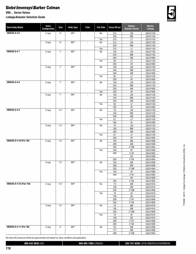
800-543-9038 USA 866-805-7089 CANADA 203-791-8396 LATIN AMERICA/CARIBBEAN
119
Valve Body Model ValveConfi guration Size Body Type Flow Fail-Safe Close-Off psi Belimo
Actuator SeriesBelimoLinkage
P104
06 -
04/1
3 - S
ubje
ct to
cha
nge.
© B
elim
o Ai
rcon
trols
(USA
), In
c.
Siebe\Invensys\Barber ColmanVB9... Series Valves
Linkage/Actuator Selection Guide
All close-off pressures listed are approximate and based on valve condition and application.
VB9XXX-0-4-6 2-way ¾” NPT - No 215 LM UGLK1150250 NM UGLK1150
Yes 215 LF UGLK11503-way ¾” NPT - No 215 LM UGLK1150
250 NM UGLK1150Yes 215 LF UGLK1150
VB9XXX-0-4-7 2-way 1” NPT - No 120 LM UGLK1150244 NM UGLK1150250 AM UGLK1000
Yes 95 LF UGLK1150250 AF UGLK1000
3-way 1” NPT - No 120 LM UGLK1150244 NM UGLK1150250 AM UGLK1000
Yes 95 LF UGLK1150250 AF UGLK1000
VB9XXX-0-4-8 2-way 1” NPT - No 120 LM UGLK1150244 NM UGLK1150250 AM UGLK1000
Yes 250 AF UGLK10003-way 1” NPT - No 120 LM UGLK1150
244 NM UGLK1150250 AM UGLK1000
Yes 95 LF UGLK1150250 AF UGLK1000
VB9XXX-0-4-9 2-way 1¼” NPT - No 78 LM UGLK1150156 NM UGLK1150250 AM UGLK1000
Yes 61 LF UGLK1150250 AF UGLK1000
3-way 1¼” NPT - No 78 LM UGLK1150156 NM UGLK1150250 AM UGLK1000
Yes 61 LF UGLK1150250 AF UGLK1000
VB9XXX-0-4-10 (Pre ‘94) 2-way 1½” NPT - No 104 AM UGLK1008209 GM UGLK1008250 2*GM UGLK1064
Yes 104 AF UGLK1008209 2*AF UGLK1064
GK UGLK1008250 2*GK UGLK1064
3-way 1½” NPT - No 104 AM UGLK1008209 GM UGLK1008250 2*GM UGLK1064
Yes 104 AF UGLK1008209 2*AF UGLK1064
GK UGLK1008250 2*GK UGLK1064
VB9XXX-0-4-10 (Post ‘94) 2-way 1½” NPT - No 79 AM UGLK1016158 GM UGLK1016250 2*GM UGLK1066
Yes 79 AF UGLK1016158 GK UGLK1016209 2*AF UGLK1066250 2*GK UGLK1066
3-way 1½” NPT - No 79 AM UGLK1016158 GM UGLK1016250 2*GM UGLK1066
Yes 79 AF UGLK1016158 GK UGLK1016209 2*AF UGLK1066250 2*GK UGLK1066
VB9XXX-0-4-11 (Pre ‘94) 2-way 2” NPT - No 59 AM UGLK1008117 GM UGLK1008209 2*GM UGLK1064

800-543-9038 USA 866-805-7089 CANADA 203-791-8396 LATIN AMERICA/CARIBBEAN
120
P104
06 -
04/1
3 - S
ubje
ct to
cha
nge.
© B
elim
o Ai
rcon
trols
(USA
), In
c.
Valve Body Model ValveConfi guration Size Body Type Flow Fail-Safe Close-Off psi Belimo
Actuator SeriesBelimoLinkage
Siebe\Invensys\Barber ColmanVB9..., VB3... Series Valves
Linkage/Actuator Selection Guide
All close-off pressures listed are approximate and based on valve condition and application.
VB9XXX-0-4-11 (Pre ‘94) 2-way 2” NPT - Yes 59 AF UGLK1008117 2*AF UGLK1064
GK UGLK1008209 2*GK UGLK1064
3-way 2” NPT - No 59 AM UGLK1008117 GM UGLK1008209 2*GM UGLK1064
Yes 59 AF UGLK1008117 2*AF UGLK1064
GK UGLK1008209 2*GK UGLK1064
VB9XXX-0-4-11 (Post ‘94) 2-way 2” NPT - No 44 AM UGLK101689 GM UGLK1016209 2*GM UGLK1066
Yes 44 AF UGLK101689 GK UGLK1016117 2*AF UGLK1066209 2*GK UGLK1066
3-way 2” NPT - No 44 AM UGLK101689 GM UGLK1016209 2*GM UGLK1066
Yes 44 AF UGLK101689 GK UGLK1016117 2*AF UGLK1066209 2*GK UGLK1066
VB9XXX-0-4-12 2-way 2½” NPT - No 38 AM UGLK101075 GM UGLK1010134 2*GM UGLK1070
Yes 38 AF UGLK101075 2*AF UGLK1070
GK UGLK1010134 2*GK UGLK1070
3-way 2½” NPT - No 38 AM UGLK101075 GM UGLK1010134 2*GM UGLK1070
Yes 38 AF UGLK101075 2*AF UGLK1070
GK UGLK1010134 2*GK UGLK1070
VB9XXX-0-4-13 2-way 3” NPT - No 26 AM UGLK101052 GM UGLK101093 2*GM UGLK1070
Yes 26 AF UGLK101052 2*AF UGLK1070
GK UGLK101093 2*GK UGLK1070
3-way 3” NPT - No 26 AM UGLK101052 GM UGLK101093 2*GM UGLK1070
Yes 26 AF UGLK101052 2*AF UGLK1070
GK UGLK101093 2*GK UGLK1070
VB304X-0-2-12 3-way 2½” Flanged Mixing No 38 AM UGLK100675 GM UGLK1006134 2*GM UGLK1072
Yes 38 AF UGLK100675 2*AF UGLK1072
GK UGLK1006134 2*GK UGLK1072
VB304X-0-2-13 3-way 3” Flanged Mixing No 26 AM UGLK100652 GM UGLK100693 2*GM UGLK1072
Yes 26 AF UGLK100652 2*AF UGLK1072
GK UGLK100693 2*GK UGLK1072
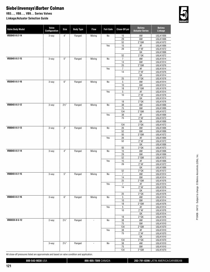
800-543-9038 USA 866-805-7089 CANADA 203-791-8396 LATIN AMERICA/CARIBBEAN
121
Valve Body Model ValveConfi guration Size Body Type Flow Fail-Safe Close-Off psi Belimo
Actuator SeriesBelimoLinkage
P104
06 -
04/1
3 - S
ubje
ct to
cha
nge.
© B
elim
o Ai
rcon
trols
(USA
), In
c.
Siebe\Invensys\Barber ColmanVB3..., VB8..., VB9... Series Valves
Linkage/Actuator Selection Guide
All close-off pressures listed are approximate and based on valve condition and application.
VB304X-0-2-14 3-way 4” Flanged Mixing No 15 AM UGLK100629 GM UGLK100652 2*GM UGLK1072
Yes 15 AF UGLK100629 2*AF UGLK1072
GK UGLK100652 2*GK UGLK1072
VB304X-0-2-15 3-way 5” Flanged Mixing No 7 AM UGLK101414 GM UGLK101425 2*GM UGLK1076
Yes 7 AF UGLK101414 2*AF UGLK1076
GK UGLK101425 2*GK UGLK1076
VB304X-0-2-16 3-way 6” Flanged Mixing No 5 AM UGLK101410 GM UGLK101418 2*GM UGLK1076
Yes 5 AF UGLK101410 2*AF UGLK1076
GK UGLK101418 2*GK UGLK1076
VB804X-0-2-12 3-way 2½” Flanged Mixing No 38 AM UGLK100675 GM UGLK1006134 2*GM UGLK1072
Yes 38 AF UGLK100675 2*AF UGLK1072
GK UGLK1006134 2*GK UGLK1072
VB804X-0-2-13 3-way 3” Flanged Mixing No 26 AM UGLK100652 GM UGLK100693 2*GM UGLK1072
Yes 26 AF UGLK100652 2*AF UGLK1072
GK UGLK100693 2*GK UGLK1072
VB804X-0-2-14 3-way 4” Flanged Mixing No 15 AM UGLK100629 GM UGLK100652 2*GM UGLK1072
Yes 15 AF UGLK100629 2*AF UGLK1072
GK UGLK100652 2*GK UGLK1072
VB804X-0-2-15 3-way 5” Flanged Mixing No 7 AM UGLK101414 GM UGLK101425 2*GM UGLK1076
Yes 7 AF UGLK101414 2*AF UGLK1076
GK UGLK101425 2*GK UGLK1076
VB804X-0-2-16 3-way 6” Flanged Mixing No 5 AM UGLK101410 GM UGLK101418 2*GM UGLK1076
Yes 5 AF UGLK101410 2*AF UGLK1076
GK UGLK101418 2*GK UGLK1076
VB9XXX-0-5-12 2-way 2½” Flanged - No 38 AM UGLK101075 GM UGLK1010134 2*GM UGLK1070
Yes 38 AF UGLK101075 2*AF UGLK1070
GK UGLK1010134 2*GK UGLK1070
3-way 2½” Flanged - No 38 AM UGLK101075 GM UGLK1010134 2*GM UGLK1070

800-543-9038 USA 866-805-7089 CANADA 203-791-8396 LATIN AMERICA/CARIBBEAN
122
P104
06 -
04/1
3 - S
ubje
ct to
cha
nge.
© B
elim
o Ai
rcon
trols
(USA
), In
c.
Valve Body Model ValveConfi guration Size Body Type Flow Fail-Safe Close-Off psi Belimo
Actuator SeriesBelimoLinkage
Siebe\Invensys\Barber ColmanVB9... Series Valves
Linkage/Actuator Selection Guide
All close-off pressures listed are approximate and based on valve condition and application.
VB9XXX-0-5-12 3-way 2½” Flanged - Yes 38 AF UGLK101075 2*AF UGLK1070
GK UGLK1010134 2*GK UGLK1070
VB9XXX-0-5-13 2-way 3” Flanged - No 26 AM UGLK101052 GM UGLK101093 2*GM UGLK1070
Yes 26 AF UGLK101052 2*AF UGLK1070
GK UGLK101093 2*GK UGLK1070
3-way 3” Flanged - No 26 AM UGLK101052 GM UGLK101093 2*GM UGLK1070
Yes 26 AF UGLK101052 2*AF UGLK1070
GK UGLK101093 2*GK UGLK1070
VB9XXX-0-5-14 2-way 4” Flanged - No 11 AM UGLK101222 GM UGLK101240 2*GM UGLK1074
Yes 11 AF UGLK101222 2*AF UGLK1074
GK UGLK101240 2*GK UGLK1074
3-way 4” Flanged - No 11 AM UGLK101222 GM UGLK101240 2*GM UGLK1074
Yes 11 AF UGLK101222 2*AF UGLK1074
GK UGLK101240 2*GK UGLK1074
SIEMENS/LANDIS/POWERS591 Series 2-way ½” NPT - No 250 AM UGLK1200
LV UGVLYes 250 LVK UGVL
NF UGLK1200¾” NPT - No 211 LV UGVL
Yes 211 LVK UGVL250 NF UGLK1200
1” NPT - No 92 LV UGVL250 AM UGLK1200
SV UGVLYes 92 LVK UGVL
244 NF UGLK1200250 SVK UGVL250 AF UGLK1200
1¼” NPT - No 236 SV UGVL250 AM UGLK1200
Yes 156 NF UGLK1200236 SVK UGVL250 AF UGLK1200
1½” NPT - No 104 AM UGLK1202209 GM UGLK1202
Yes 52 NF UGLK1202104 AF UGLK1202209 GK UGLK1202
2” NPT - No 59 AM UGLK1202117 GM UGLK1202
Yes 29 NF UGLK120259 AF UGLK1202117 GK UGLK1202
Siemens\Landis\Powers591 Series Valves
Linkage/Actuator Selection Guide

800-543-9038 USA 866-805-7089 CANADA 203-791-8396 LATIN AMERICA/CARIBBEAN
123
Valve Body Model ValveConfi guration Size Body Type Flow Fail-Safe Close-Off psi Belimo
Actuator SeriesBelimoLinkage
P104
06 -
04/1
3 - S
ubje
ct to
cha
nge.
© B
elim
o Ai
rcon
trols
(USA
), In
c.
Siemens\Landis\Powers591 Series Valves
Linkage/Actuator Selection Guide
591 Series 2-way 2½” Flanged - No 55 AM UGLK1204110 GM UGLK1204196 2*GM UGLK1270
Yes 55 AF UGLK1204110 2*AF UGLK1270
GK UGLK1204196 2*GK UGLK1270
3” Flanged - No 38 AM UGLK120477 GM UGLK1204136 2*GM UGLK1270
Yes 38 AF UGLK120477 2*AF UGLK1270
GK UGLK1204136 2*GK UGLK1270
4” Flanged - No 11 AM UGLK120622 GM UGLK120640 2*GM UGLK1274
Yes 11 AF UGLK120622 2*AF UGLK1274
GK UGLK120640 2*GK UGLK1274
5” Flanged - No 14 GM UGLK120625 2*GM UGLK1274
Yes 14 2*AF UGLK1274GK UGLK1206
25 2*GK UGLK12746” Flanged - No 18 2*GM UGLK1274
Yes 10 2*AF UGLK127418 2*GK UGLK1274
3-way ½” NPT - No 250 AM UGLK1200LV UGVL
Yes 250 LVK UGVLNF UGLK1200
¾” NPT - No 211 LV UGVLYes 211 LVK UGVL
250 NF UGLK12001” NPT - No 92 LV UGVL
250 AM UGLK1200SV UGVL
Yes 92 LVK UGVL244 NF UGLK1200250 SVK UGVL250 AF UGLK1200
1¼” NPT - No 236 SV UGVL250 AM UGLK1200
Yes 156 NF UGLK1200236 SVK UGVL250 AF UGLK1200
1½” NPT - No 217 AM UGLK1200250 GM UGLK1200
Yes 109 NF UGLK1200217 AF UGLK1200250 GK UGLK1200
2” NPT - No 85 SV UGVL122 AM UGLK1200244 GM UGLK1200
Yes 61 NF UGLK120085 SVK UGVL122 AF UGLK1200244 GK UGLK1200
2½” Flanged - No 55 AM UGLK1204110 GM UGLK1204196 2*GM UGLK1270
All close-off pressures listed are approximate and based on valve condition and application.

800-543-9038 USA 866-805-7089 CANADA 203-791-8396 LATIN AMERICA/CARIBBEAN
124
P104
06 -
04/1
3 - S
ubje
ct to
cha
nge.
© B
elim
o Ai
rcon
trols
(USA
), In
c.
Valve Body Model ValveConfi guration Size Body Type Flow Fail-Safe Close-Off psi Belimo
Actuator SeriesBelimoLinkage
All close-off pressures listed are approximate and based on valve condition and application.
Siemens\Landis\Powers599 Flowrite, 591 Series Valves
Linkage/Actuator Selection Guide
591 Series 3-way 2½” Flanged - Yes 55 AF UGLK1204110 2*AF UGLK1270
GK UGLK1204196 2*GK UGLK1270
3” Flanged - No 38 AM UGLK120477 GM UGLK1204136 2*GM UGLK1270
Yes 38 AF UGLK120477 2*AF UGLK1270
GK UGLK1204136 2*GK UGLK1270
4” Flanged - No 11 AM UGLK120622 GM UGLK120640 2*GM UGLK1274
Yes 11 AF UGLK120622 2*AF UGLK1274
GK UGLK120640 2*GK UGLK1274
5” Flanged - No 14 GM UGLK120625 2*GM UGLK1274
Yes 14 2*AF UGLK1274GK UGLK1206
25 2*GK UGLK12746” Flanged - No 18 2*GM UGLK1274
Yes 10 2*AF UGLK127418 2*GK UGLK1274
599 Flowrite 2-way ½” NPT - No 250 AM UGLK1208LV UGVL
Yes 250 LVK UGVLNF UGLK1208
¾” NPT - No 211 LV UGVL250 AM UGLK1208
Yes 211 LVK UGVL250 NF UGLK1208
1” NPT - No 92 LV UGVL250 AM UGLK1208
SV UGVLYes 92 LVK UGVL
173 NF UGLK1208250 SVK UGVL250 AF UGLK1208
1¼” NPT - No 221 AM UGLK1208236 SV UGVL
Yes 110 NF UGLK1208221 AF UGLK1208236 SVK UGVL
1½” NPT - No 153 AM UGLK1208250 GM UGLK1208
Yes 77 NF UGLK1208153 AF UGLK1208250 GK UGLK1208
2” NPT - No 85 SV UGVL86 AM UGLK1208173 GM UGLK1208
Yes 43 NF UGLK120885 SVK UGVL86 AF UGLK1208173 GK UGLK1208
2½” Flanged - No 55 AM UGLK1210110 GM UGLK1210196 2*GM UGLK1272
Yes 55 AF UGLK1210110 2*AF UGLK1272
GK UGLK1210196 2*GK UGLK1272

800-543-9038 USA 866-805-7089 CANADA 203-791-8396 LATIN AMERICA/CARIBBEAN
125
Valve Body Model ValveConfi guration Size Body Type Flow Fail-Safe Close-Off psi Belimo
Actuator SeriesBelimoLinkage
P104
06 -
04/1
3 - S
ubje
ct to
cha
nge.
© B
elim
o Ai
rcon
trols
(USA
), In
c.
All close-off pressures listed are approximate and based on valve condition and application.
Siemens\Landis\Powers599 Flowrite Series Valves
Linkage/Actuator Selection Guide
599 Flowrite 2-way 3” Flanged - No 38 AM UGLK121077 GM UGLK1210136 2*GM UGLK1272
Yes 38 AF UGLK121077 2*AF UGLK1272
GK UGLK1210136 2*GK UGLK1272
4” Flanged - No 11 AM UGLK121222 GM UGLK121240 2*GM UGLK1276
Yes 11 AF UGLK121222 2*AF UGLK1276
GK UGLK121240 2*GK UGLK1276
5” Flanged - No 14 GM UGLK121225 2*GM UGLK1276
Yes 14 2*AF UGLK1276GK UGLK1212
25 2*GK UGLK1276599 Flowrite 3-way ½” NPT - No 250 AM UGLK1208
LV UGVLYes 250 LVK UGVL
NF UGLK1208¾” NPT - No 211 LV UGVL
250 AM UGLK1208Yes 211 LVK UGVL
250 NF UGLK12081” NPT - No 92 LV UGVL
250 AM UGLK1208SV UGVL
Yes 92 LVK UGVL173 NF UGLK1208250 SVK UGVL250 AF UGLK1208
1¼” NPT - No 221 AM UGLK1208236 SV UGVL
Yes 110 NF UGLK1208221 AF UGLK1208236 SVK UGVL
1½” NPT - No 153 AM UGLK1208250 GM UGLK1208
Yes 77 NF UGLK1208153 AF UGLK1208250 GK UGLK1208
2” NPT - No 85 SV UGVL86 AM UGLK1208173 GM UGLK1208
Yes 43 NF UGLK120885 SVK UGVL86 AF UGLK1208173 GK UGLK1208
2½” Flanged - No 55 AM UGLK1210110 GM UGLK1210196 2*GM UGLK1272
Yes 55 AF UGLK1210110 2*AF UGLK1272
GK UGLK1210196 2*GK UGLK1272
3” Flanged - No 38 AM UGLK121077 GM UGLK1210136 2*GM UGLK1272
Yes 38 AF UGLK121077 2*AF UGLK1272
GK UGLK1210136 2*GK UGLK1272

800-543-9038 USA 866-805-7089 CANADA 203-791-8396 LATIN AMERICA/CARIBBEAN
126
P104
06 -
04/1
3 - S
ubje
ct to
cha
nge.
© B
elim
o Ai
rcon
trols
(USA
), In
c.
Valve Body Model ValveConfi guration Size Body Type Flow Fail-Safe Close-Off psi Belimo
Actuator SeriesBelimoLinkage
All close-off pressures listed are approximate and based on valve condition and application.
Siemens\Landis\Powers599 Flowrite, 656, 658 Series Valves
Linkage/Actuator Selection Guide
599 Flowrite 3-way 4” Flanged - No 11 AM UGLK121222 GM UGLK121240 2*GM UGLK1276
Yes 11 AF UGLK121222 2*AF UGLK1276
GK UGLK121240 2*GK UGLK1276
5” Flanged - No 14 GM UGLK121225 2*GM UGLK1276
Yes 14 2*AF UGLK1276GK UGLK1212
25 2*GK UGLK1276656 Series 2-way ½” NPT - No 250 AM UGLK1214
LM UGLK1350Yes 250 LF UGLK1350
NF UGLK1214¾” NPT - No 215 LM UGLK1350
250 NM UGLK1350Yes 215 LF UGLK1350
250 NF UGLK12143-way ½” NPT - No 250 AM UGLK1214
LM UGLK1350Yes 250 LF UGLK1350
NF UGLK1214¾” NPT - No 215 LM UGLK1350
250 NM UGLK1350Yes 215 LF UGLK1350
250 NF UGLK1214658 Series 2-way ½” NPT - No 250 AM UGLK1214
LM UGLK1350LV UGVL
Yes 250 LF UGLK1350LVK UGVLNF UGLK1214
¾” NPT - No 211 LV UGVL215 LM UGLK1350250 NM UGLK1350
Yes 211 LVK UGVL215 LF UGLK1350250 NF UGLK1214
1” NPT - No 92 LV UGVL120 LM UGLK1350244 NM UGLK1350250 AM UGLK1214
SV UGVLYes 92 LVK UGVL
95 LF UGLK1350244 NF UGLK1214250 SVK UGVL250 AF UGLK1214
1¼” NPT - No 78 LM UGLK1350156 NM UGLK1350236 SV UGVL250 AM UGLK1214
Yes 61 LF UGLK1350156 NF UGLK1214236 SVK UGVL250 AF UGLK1214
3-way ½” NPT - No 250 AM UGLK1214LM UGLK1350LV UGVL
Yes 250 LF UGLK1350LVK UGVLNF UGLK1214
¾” NPT - No 211 LV UGVL215 LM UGLK1350250 NM UGLK1350

800-543-9038 USA 866-805-7089 CANADA 203-791-8396 LATIN AMERICA/CARIBBEAN
127
Valve Body Model ValveConfi guration Size Body Type Flow Fail-Safe Close-Off psi Belimo
Actuator SeriesBelimoLinkage
P104
06 -
04/1
3 - S
ubje
ct to
cha
nge.
© B
elim
o Ai
rcon
trols
(USA
), In
c.
All close-off pressures listed are approximate and based on valve condition and application.
Siemens\Landis\Powers658, 599 Powermite Series Valves
Linkage/Actuator Selection Guide
658 Series 3-way ¾” NPT - Yes 211 LVK UGVL215 LF UGLK1350250 NF UGLK1214
1” NPT - No 92 LV UGVL120 LM UGLK1350244 NM UGLK1350250 AM UGLK1214
SV UGVLYes 92 LVK UGVL
95 LF UGLK1350244 NF UGLK1214250 SVK UGVL250 AF UGLK1214
1¼” NPT - No 78 LM UGLK1350156 NM UGLK1350236 SV UGVL250 AM UGLK1214
Yes 61 LF UGLK1350156 NF UGLK1214236 SVK UGVL250 AF UGLK1214
599-01100 MZ (Cv <.4) 2-way ½” NPT - No 70 CM UGSL1200Yes 70 TF UGSL1200
599-01102 MZ (Cv <.63) 2-way ½” NPT - No 70 CM UGSL1200Yes 70 TF UGSL1200
599-01104 MZ (Cv <1) 2-way ½” NPT - No 70 CM UGSL1200Yes 70 TF UGSL1200
599-01106 MZ (Cv <1.6) 2-way ½” NPT - No 70 CM UGSL1200Yes 70 TF UGSL1200
599-01108 MZ (Cv <2.5) 2-way ½” NPT - No 40 CM UGSL1200Yes 40 TF UGSL1200
599-01110 MZ (Cv <4) 2-way ½” NPT - No 40 CM UGSL1200Yes 40 TF UGSL1200
599-01115 MZ (Cv <.4) 2-way ½” NPT - No 60 CM UGSL1200Yes 60 TF UGSL1200
599-01117 MZ (Cv <.63) 2-way ½” NPT - No 60 CM UGSL1200Yes 60 TF UGSL1200
599-01119 MZ (Cv <1) 2-way ½” NPT - No 60 CM UGSL1200Yes 60 TF UGSL1200
599-01121 MZ (Cv <1.6) 2-way ½” NPT - No 60 CM UGSL1200Yes 60 TF UGSL1200
599-01123 MZ (Cv <2.5) 2-way ½” NPT - No 35 CM UGSL1200Yes 35 TF UGSL1200
599-01126 MZ (Cv <4) 2-way ½” NPT - No 35 CM UGSL1200Yes 35 TF UGSL1200
599-01132 MZ (Cv <.4) 3-way ½” NPT - No 70 CM UGSL1200Yes 70 TF UGSL1200
599-01133 MZ (Cv <.63) 3-way ½” NPT - No 70 CM UGSL1200Yes 70 TF UGSL1200
599-01134 MZ (Cv <1) 3-way ½” NPT - No 70 CM UGSL1200Yes 70 TF UGSL1200
599-01135 MZ (Cv <1.6) 3-way ½” NPT - No 70 CM UGSL1200Yes 70 TF UGSL1200
599-01136 MZ (Cv <2.5) 3-way ½” NPT - No 40 CM UGSL1200Yes 40 TF UGSL1200
599-01137 MZ (Cv <4) 3-way ½” NPT - No 40 CM UGSL1200Yes 40 TF UGSL1200
599-02000 MT (Cv <.4) 2-way ½” NPT - No 95 CM UGSL1200Yes 95 TF UGSL1200
599-02002 MT (Cv <.63) 2-way ½” NPT - No 95 CM UGSL1200Yes 95 TF UGSL1200
599-02004 MT (Cv <1) 2-way ½” NPT - No 95 CM UGSL1200Yes 95 TF UGSL1200
599-02006 MT (Cv <1.6) 2-way ½” NPT - No 95 CM UGSL1200Yes 95 TF UGSL1200

800-543-9038 USA 866-805-7089 CANADA 203-791-8396 LATIN AMERICA/CARIBBEAN
128
P104
06 -
04/1
3 - S
ubje
ct to
cha
nge.
© B
elim
o Ai
rcon
trols
(USA
), In
c.
Valve Body Model ValveConfi guration Size Body Type Flow Fail-Safe Close-Off psi Belimo
Actuator SeriesBelimoLinkage
All close-off pressures listed are approximate and based on valve condition and application.
Siemens\Landis\Powers599 Powermite Series Valves
Linkage/Actuator Selection Guide
599-02008 MT (Cv <2.5) 2-way ½” NPT - No 50 CM UGSL1200Yes 50 TF UGSL1200
599-02010 MT (Cv <4) 2-way ½” NPT - No 50 CM UGSL1200Yes 50 TF UGSL1200
599-02030 MT (Cv <.4) 2-way ½” NPT - No 120 CM UGSL1200Yes 120 TF UGSL1200
599-02032 MT (Cv <.63) 2-way ½” NPT - No 120 CM UGSL1200Yes 120 TF UGSL1200
599-02034 MT (Cv <1) 2-way ½” NPT - No 120 CM UGSL1200Yes 120 TF UGSL1200
599-02036 MT (Cv <1.6) 2-way ½” NPT - No 120 CM UGSL1200Yes 120 TF UGSL1200
599-02038 MT (Cv <2.5) 2-way ½” NPT - No 65 CM UGSL1200Yes 65 TF UGSL1200
599-02041 MT (Cv <4) 2-way ½” NPT - No 65 CM UGSL1200Yes 65 TF UGSL1200
599-02064 MT (Cv <.4) 3-way ½” NPT - No 95 CM UGSL1200Yes 95 TF UGSL1200
599-02065 MT (Cv <.63) 3-way ½” NPT - No 95 CM UGSL1200Yes 95 TF UGSL1200
599-02066 MT (Cv <1) 3-way ½” NPT - No 95 CM UGSL1200Yes 95 TF UGSL1200
599-02067 MT (Cv <1.6) 3-way ½” NPT - No 95 CM UGSL1200Yes 95 TF UGSL1200
599-02068 MT (Cv <2.5) 3-way ½” NPT - No 50 CM UGSL1200Yes 50 TF UGSL1200
599-02069 MT (Cv <4) 3-way ½” NPT - No 50 CM UGSL1200Yes 50 TF UGSL1200
599-02070 MT (Cv <6.3) 3-way ¾” NPT - No 40 CM UGSL1200Yes 40 TF UGSL1200
599-01129 MZ (Cv <6.3) 2-way ¾” NPT - No 30 CM UGSL1200Yes 30 TF UGSL1200
599-01138 MZ (Cv <6.3) 3-way ¾” NPT - No 10 CM UGSL1200Yes 10 TF UGSL1200
599-02012 MT (Cv <6.3) 2-way ¾” NPT - No 40 CM UGSL1200Yes 40 TF UGSL1200
599-01112 MZ (Cv <6.3) 2-way ¾” NPT - No 30 CM UGSL1200Yes 30 TF UGSL1200
599-02044 MT (Cv <6.3) 2-way ¾” NPT - No 55 CM UGSL1200Yes 55 TF UGSL1200
599-01131 MZ (Cv <10) 2-way 1” NPT - No 30 CM UGSL1200Yes 30 TF UGSL1200
599-01114 MZ (Cv <10) 2-way 1” NPT - No 30 CM UGSL1200Yes 30 TF UGSL1200
599-01139 MZ (Cv <10) 3-way 1” NPT - No 10 CM UGSL1200Yes 10 TF UGSL1200
599-02071 MT (Cv <10) 3-way 1” NPT - No 40 CM UGSL1200Yes 40 TF UGSL1200
599-02046 MT (Cv <10) 2-way 1” NPT - No 55 CM UGSL1200Yes 55 TF UGSL1200
599-02014 MT (Cv <10) 2-way 1” NPT - No 40 CM UGSL1200Yes 40 TF UGSL1200
599 MZ (Cv 16) 2-way 1¼” NPT - No 20 CM UGSL1200Yes 20 TF UGSL1200
3-way 1¼” NPT - No 10 CM UGSL1200Yes 10 TF UGSL1200
599-02084 MT (Cv <10) 2-way 1¼” NPT - No 20 CM UGSL1200Yes 20 TF UGSL1200
599-02085 MT (Cv <10) 2-way 1¼” NPT - No 21 CM UGSL1200Yes 20 TF UGSL1200
599-02086 MT (Cv <16) 3-way 1¼” NPT - No 10 CM UGSL1200Yes 10 TF UGSL1200
599 MZ (Cv 25) 2-way 1½” NPT - No 10 CM UGSL1200Yes 10 TF UGSL1200

800-543-9038 USA 866-805-7089 CANADA 203-791-8396 LATIN AMERICA/CARIBBEAN
129
Valve Body Model ValveConfi guration Size Body Type Flow Fail-Safe Close-Off psi Belimo
Actuator SeriesBelimoLinkage
P104
06 -
04/1
3 - S
ubje
ct to
cha
nge.
© B
elim
o Ai
rcon
trols
(USA
), In
c.
All close-off pressures listed are approximate and based on valve condition and application.
Type 20 2-way 2½” Flanged - No 94 EV WGVL185 RV WGVL
Yes 71 AVK WGVL3” Flanged - No 63 EV WGVL
126 RV WGVLYes 47 AVK WGVL
4” Flanged - No 68 RV WGVL5” Flanged - No 42 RV WGVL
Type 22 2-way 2½” Flanged - No 94 EV WGVL185 RV WGVL
Yes 71 AVK WGVL3” Flanged - No 63 EV WGVL
126 RV WGVLYes 47 AVK WGVL
4” Flanged - No 68 RV WGVL5” Flanged - No 42 RV WGVL
Type 23 2-way 2½” Flanged - No 228 EV WGVLYes 228 AVK WGVL
3” Flanged - No 157 EV WGVLYes 157 AVK WGVL
4” Flanged - No 340 EV WGVLYes 340 AVK WGVL
5” Flanged - No 232 EV WGVLYes 232 AVK WGVL
Type 30 3-way 2½” Flanged - No 94 EV WGVL185 RV WGVL
Yes 71 AVK WGVL3” Flanged - No 63 EV WGVL
126 RV WGVLYes 47 AVK WGVL
4” Flanged - No 68 RV WGVL5” Flanged - No 42 RV WGVL
Type 32 3-way 2½” Flanged - No 94 EV WGVL185 RV WGVL
Yes 71 AVK WGVL3” Flanged - No 63 EV WGVL
126 RV WGVLYes 47 AVK WGVL
4” Flanged - No 68 RV WGVL5” Flanged - No 42 RV WGVL
100 SGL SEAT 2-way 2½” Flanged - No 28 AM UGLK220257 GM UGLK2202101 2*GM UGLK2272
Yes 14 NF UGLK220228 AF UGLK220257 2*AF UGLK2272
GK UGLK2202101 2*GK UGLK2272
3” Flanged - No 40 GM UGLK220220 AM UGLK220270 2*GM UGLK2272
Yes 40 2*AF UGLK2272GK UGLK2202
10 NF UGLK220220 AF UGLK220270 2*GK UGLK2272
4” Flanged - No 11 AM UGLK220222 GM UGLK220240 2*GM UGLK2272
Yes 11 AF UGLK220222 2*AF UGLK2272
GK UGLK220240 2*GK UGLK2272
5” Flanged - No 14 GM UGLK220225 2*GM UGLK2272
Warren ControlsType 20, Type 22, Type 23, Type 30, Type 32, 100 Series Valves
Linkage/Actuator Selection Guide
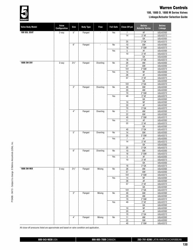
800-543-9038 USA 866-805-7089 CANADA 203-791-8396 LATIN AMERICA/CARIBBEAN
130
P104
06 -
04/1
3 - S
ubje
ct to
cha
nge.
© B
elim
o Ai
rcon
trols
(USA
), In
c.
Valve Body Model ValveConfi guration Size Body Type Flow Fail-Safe Close-Off psi Belimo
Actuator SeriesBelimoLinkage
All close-off pressures listed are approximate and based on valve condition and application.
Warren Controls100, 1800 D, 1800 M Series Valves
Linkage/Actuator Selection Guide
100 SGL SEAT 2-way 5” Flanged - Yes 7 AF UGLK220214 2*AF UGLK2272
GK UGLK220225 2*GK UGLK2272
6” Flanged - No 10 GM UGLK220218 2*GM UGLK2272
Yes 5 AF UGLK220210 2*AF UGLK2272
GK UGLK220218 2*GK UGLK2272
1800 3W DIV 3-way 2½” Flanged Diverting No 28 AM UGLK220257 GM UGLK2202101 2*GM UGLK2272
Yes 14 NF UGLK220228 AF UGLK220257 2*AF UGLK2272
GK UGLK2202101 2*GK UGLK2272
3” Flanged Diverting No 40 GM UGLK220220 AM UGLK220270 2*GM UGLK2272
Yes 40 2*AF UGLK2272GK UGLK2202
10 NF UGLK220220 AF UGLK220270 2*GK UGLK2272
4” Flanged Diverting No 11 AM UGLK220222 GM UGLK220240 2*GM UGLK2272
Yes 11 AF UGLK220222 2*AF UGLK2272
GK UGLK220240 2*GK UGLK2272
5” Flanged Diverting No 14 GM UGLK220225 2*GM UGLK2272
Yes 7 AF UGLK220214 2*AF UGLK2272
GK UGLK220225 2*GK UGLK2272
6” Flanged Diverting No 10 GM UGLK220218 2*GM UGLK2272
Yes 5 AF UGLK220210 2*AF UGLK2272
GK UGLK220218 2*GK UGLK2272
1800 3W MIX 3-way 2½” Flanged Mixing No 28 AM UGLK220257 GM UGLK2202101 2*GM UGLK2272
Yes 14 NF UGLK220228 AF UGLK220257 2*AF UGLK2272
GK UGLK2202101 2*GK UGLK2272
3” Flanged Mixing No 40 GM UGLK220220 AM UGLK220270 2*GM UGLK2272
Yes 40 2*AF UGLK2272GK UGLK2202
10 NF UGLK220220 AF UGLK220270 2*GK UGLK2272
4” Flanged Mixing No 11 AM UGLK220222 GM UGLK220240 2*GM UGLK2272

800-543-9038 USA 866-805-7089 CANADA 203-791-8396 LATIN AMERICA/CARIBBEAN
131
Valve Body Model ValveConfi guration Size Body Type Flow Fail-Safe Close-Off psi Belimo
Actuator SeriesBelimoLinkage
P104
06 -
04/1
3 - S
ubje
ct to
cha
nge.
© B
elim
o Ai
rcon
trols
(USA
), In
c.
All close-off pressures listed are approximate and based on valve condition and application.
Warren Controls1800 M, 1800 BAL, Type 20 Series Valves
Linkage/Actuator Selection Guide
1800 3W MIX 3-way 4” Flanged Mixing Yes 11 AF UGLK220222 2*AF UGLK2272
GK UGLK220240 2*GK UGLK2272
5” Flanged Mixing No 14 GM UGLK220225 2*GM UGLK2272
Yes 7 AF UGLK220214 2*AF UGLK2272
GK UGLK220225 2*GK UGLK2272
6” Flanged Mixing No 10 GM UGLK220218 2*GM UGLK2272
Yes 5 AF UGLK220210 2*AF UGLK2272
GK UGLK220218 2*GK UGLK2272
1800 BAL 2-way 2½” Flanged - No 28 AM UGLK220257 GM UGLK2202101 2*GM UGLK2272
Yes 14 NF UGLK220228 AF UGLK220257 2*AF UGLK2272
GK UGLK2202101 2*GK UGLK2272
3” Flanged - No 40 GM UGLK220220 AM UGLK220270 2*GM UGLK2272
Yes 40 2*AF UGLK2272GK UGLK2202
10 NF UGLK220220 AF UGLK220270 2*GK UGLK2272
4” Flanged - No 11 AM UGLK220222 GM UGLK220240 2*GM UGLK2272
Yes 11 AF UGLK220222 2*AF UGLK2272
GK UGLK220240 2*GK UGLK2272
5” Flanged - No 14 GM UGLK220225 2*GM UGLK2272
Yes 7 AF UGLK220214 2*AF UGLK2272
GK UGLK220225 2*GK UGLK2272
6” Flanged - No 10 GM UGLK220218 2*GM UGLK2272
Yes 5 AF UGLK220210 2*AF UGLK2272
GK UGLK220218 2*GK UGLK2272
Type 20 2-way 2½” Flanged - No 55 AM UGLK2200110 GM UGLK2200196 2*GM UGLK2270
Yes 28 NF UGLK220055 AF UGLK2200110 2*AF UGLK2270
GK UGLK2200196 2*GK UGLK2270
3” Flanged - No 38 AM UGLK220077 GM UGLK2200136 2*GM UGLK2270
Yes 19 NF UGLK220038 AF UGLK220077 2*AF UGLK2270
GK UGLK2200136 2*GK UGLK2270
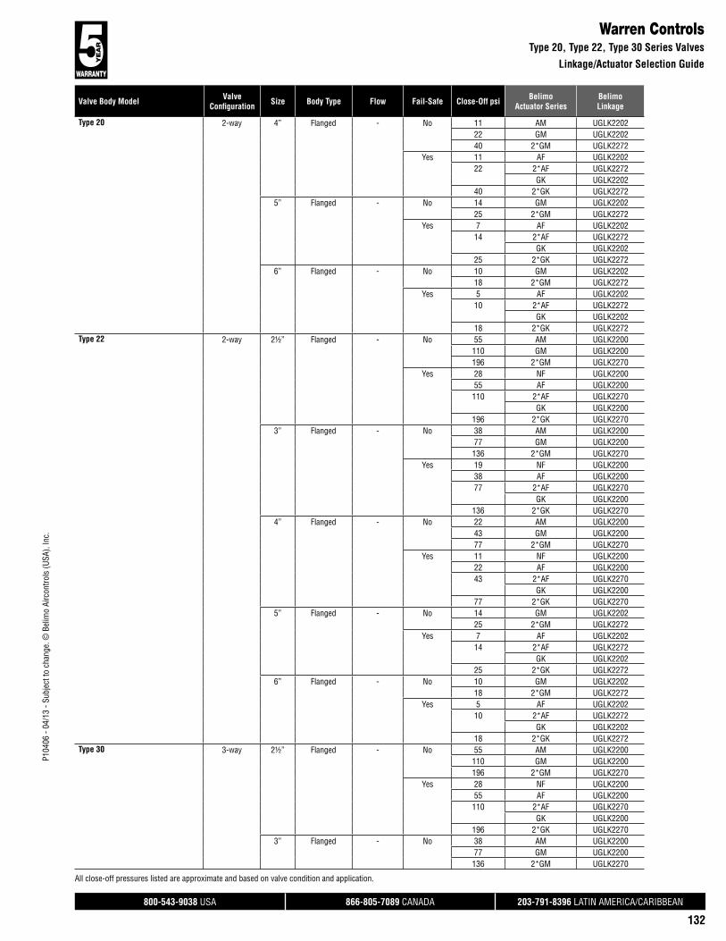
800-543-9038 USA 866-805-7089 CANADA 203-791-8396 LATIN AMERICA/CARIBBEAN
132
P104
06 -
04/1
3 - S
ubje
ct to
cha
nge.
© B
elim
o Ai
rcon
trols
(USA
), In
c.
Valve Body Model ValveConfi guration Size Body Type Flow Fail-Safe Close-Off psi Belimo
Actuator SeriesBelimoLinkage
All close-off pressures listed are approximate and based on valve condition and application.
Warren ControlsType 20, Type 22, Type 30 Series Valves
Linkage/Actuator Selection Guide
Type 20 2-way 4” Flanged - No 11 AM UGLK220222 GM UGLK220240 2*GM UGLK2272
Yes 11 AF UGLK220222 2*AF UGLK2272
GK UGLK220240 2*GK UGLK2272
5” Flanged - No 14 GM UGLK220225 2*GM UGLK2272
Yes 7 AF UGLK220214 2*AF UGLK2272
GK UGLK220225 2*GK UGLK2272
6” Flanged - No 10 GM UGLK220218 2*GM UGLK2272
Yes 5 AF UGLK220210 2*AF UGLK2272
GK UGLK220218 2*GK UGLK2272
Type 22 2-way 2½” Flanged - No 55 AM UGLK2200110 GM UGLK2200196 2*GM UGLK2270
Yes 28 NF UGLK220055 AF UGLK2200110 2*AF UGLK2270
GK UGLK2200196 2*GK UGLK2270
3” Flanged - No 38 AM UGLK220077 GM UGLK2200136 2*GM UGLK2270
Yes 19 NF UGLK220038 AF UGLK220077 2*AF UGLK2270
GK UGLK2200136 2*GK UGLK2270
4” Flanged - No 22 AM UGLK220043 GM UGLK220077 2*GM UGLK2270
Yes 11 NF UGLK220022 AF UGLK220043 2*AF UGLK2270
GK UGLK220077 2*GK UGLK2270
5” Flanged - No 14 GM UGLK220225 2*GM UGLK2272
Yes 7 AF UGLK220214 2*AF UGLK2272
GK UGLK220225 2*GK UGLK2272
6” Flanged - No 10 GM UGLK220218 2*GM UGLK2272
Yes 5 AF UGLK220210 2*AF UGLK2272
GK UGLK220218 2*GK UGLK2272
Type 30 3-way 2½” Flanged - No 55 AM UGLK2200110 GM UGLK2200196 2*GM UGLK2270
Yes 28 NF UGLK220055 AF UGLK2200110 2*AF UGLK2270
GK UGLK2200196 2*GK UGLK2270
3” Flanged - No 38 AM UGLK220077 GM UGLK2200136 2*GM UGLK2270

800-543-9038 USA 866-805-7089 CANADA 203-791-8396 LATIN AMERICA/CARIBBEAN
133
Valve Body Model ValveConfi guration Size Body Type Flow Fail-Safe Close-Off psi Belimo
Actuator SeriesBelimoLinkage
P104
06 -
04/1
3 - S
ubje
ct to
cha
nge.
© B
elim
o Ai
rcon
trols
(USA
), In
c.
All close-off pressures listed are approximate and based on valve condition and application.
Warren ControlsType 30, Type 32, Type 20 Series Valves
Linkage/Actuator Selection Guide
Type 30 3-way 3” Flanged - Yes 19 NF UGLK220038 AF UGLK220077 2*AF UGLK2270
GK UGLK2200136 2*GK UGLK2270
4” Flanged - No 11 AM UGLK220222 GM UGLK220240 2*GM UGLK2272
Yes 11 AF UGLK220222 2*AF UGLK2272
GK UGLK220240 2*GK UGLK2272
5” Flanged - No 14 GM UGLK220225 2*GM UGLK2272
Yes 7 AF UGLK220214 2*AF UGLK2272
GK UGLK220225 2*GK UGLK2272
6” Flanged - No 10 GM UGLK220218 2*GM UGLK2272
Yes 5 AF UGLK220210 2*AF UGLK2272
GK UGLK220218 2*GK UGLK2272
Type 32 3-way 2½” Flanged - No 55 AM UGLK2200110 GM UGLK2200196 2*GM UGLK2270
Yes 28 NF UGLK220055 AF UGLK2200110 2*AF UGLK2270
GK UGLK2200196 2*GK UGLK2270
3” Flanged - No 38 AM UGLK220077 GM UGLK2200136 2*GM UGLK2270
Yes 19 NF UGLK220038 AF UGLK220077 2*AF UGLK2270
GK UGLK2200136 2*GK UGLK2270
4” Flanged - No 11 AM UGLK220222 GM UGLK220240 2*GM UGLK2272
Yes 11 AF UGLK220222 2*AF UGLK2272
GK UGLK220240 2*GK UGLK2272
5” Flanged - No 14 GM UGLK220225 2*GM UGLK2272
Yes 7 AF UGLK220214 2*AF UGLK2272
GK UGLK220225 2*GK UGLK2272
6” Flanged - No 10 GM UGLK220218 2*GM UGLK2272
Yes 5 AF UGLK220210 2*AF UGLK2272
GK UGLK220218 2*GK UGLK2272
Type 20 2-way ½” NPT - No 250 AM UGLK2200Yes 250 NF UGLK2200
¾” NPT - No 250 AM UGLK2200Yes 250 NF UGLK2200
1” NPT - No 250 AM UGLK2200Yes 173 NF UGLK2200
250 AF UGLK2200

800-543-9038 USA 866-805-7089 CANADA 203-791-8396 LATIN AMERICA/CARIBBEAN
134
P104
06 -
04/1
3 - S
ubje
ct to
cha
nge.
© B
elim
o Ai
rcon
trols
(USA
), In
c.
Valve Body Model ValveConfi guration Size Body Type Flow Fail-Safe Close-Off psi Belimo
Actuator SeriesBelimoLinkage
All close-off pressures listed are approximate and based on valve condition and application.
Warren ControlsType 20, Type 30 Series Valves
Linkage/Actuator Selection Guide
Type 20 2-way 1¼” NPT - No 221 AM UGLK2200Yes 110 NF UGLK2200
221 AF UGLK22001½” NPT - No 153 AM UGLK2200
250 GM UGLK2200Yes 77 NF UGLK2200
153 AF UGLK2200250 GK UGLK2200
2” NPT - No 86 AM UGLK2200173 GM UGLK2200
Yes 43 NF UGLK220086 AF UGLK2200173 GK UGLK2200
Type 30 3-way ½” NPT - No 250 AM UGLK2200Yes 250 NF UGLK2200
¾” NPT - No 250 AM UGLK2200Yes 250 NF UGLK2200
1” NPT - No 250 AM UGLK2200Yes 173 NF UGLK2200
250 AF UGLK22001¼” NPT - No 221 AM UGLK2200
Yes 110 NF UGLK2200221 AF UGLK2200
1½” NPT - No 153 AM UGLK2200250 GM UGLK2200
Yes 77 NF UGLK2200153 AF UGLK2200250 GK UGLK2200
2” NPT - No 86 AM UGLK2200173 GM UGLK2200
Yes 43 NF UGLK220086 AF UGLK2200173 GK UGLK2200

P104
06 -
04/1
3 - S
ubje
ct to
cha
nge.
© B
elim
o Ai
rcon
trols
(USA
), In
c.
®
800-543-9038 USA 866-805-7089 CANADA 203-791-8396 LATIN AMERICA/CARIBBEAN
135
Custom Globe Valve SolutionsUGSP Series Globe Valve Retrofit System
The single actuated globe retrofit linkage depicts the MINIMUM and MAXIMUM dimensional data for use in determining the space required to mount the linkage. These dimensions do NOT include VALVE dimensions which will affect combined height requirements.
Dims H1 & H2 are used only when override handles are utilized on the linkage system, and are not required for proper operation of the linkage system.
The dual MINIMUM and MAXIMUM actuated globe retrofit linkage depicts the MAXIMUM dimensional data for use in determining the space required to mount the linkage. These dimensions do NOT include VALVE dimensions which will affect combined height requirements.
Dimensions UGSP0002 (Inches [mm])
A
B C D
Globe valves which cannot be matched to one of the Belimo UGLK part numbers, for quotation only, use p/n UGSP0000 for valves requiring single actuation, and UGSP0002 for valves requiring dual actuation. These part numbers do not have Bill of Materials (BOM) associated with them, and therefore cannot be produced and shipped. When these two part numbers are quoted, sold and orders processed, the “Globe Valve Retrofit” form must be completed and accompany the order. Our engineering department will then determine the correct UGSP linkage number for production. UGSP0000 and UGSP0002 will NOT be stated on final paperwork but will be replaced with the correct UGSP part number.
Custom kits are designed to your unique specifi cation and are not returnable.
A B C D H1 H2
7.50 [190] min 14.00 [356] max 3.00 [76] 9.00 [229] 5.00 [127] 9.50 [242] 9.50 [242]
A B C D
9.50 [241] min 19.00 [483] max 3.00 [76] 9.00 [229] 5.00 [127]
Dimensions UGSP0000 (Inches [mm])
A
B C
H1
H2
D

P104
06 -
04/1
3 - S
ubje
ct to
cha
nge.
© B
elim
o Ai
rcon
trols
(USA
), In
c.
®
800-543-9038 USA 866-805-7089 CANADA 203-791-8396 LATIN AMERICA/CARIBBEAN
136
Custom Globe Valve SolutionsUGSP Series Globe Valve Retrofit System
Dimensions A, B & C relate to the existing valve stem. Dim A is the stem diameter where it is NOT threaded (Style A), or grooved (Style B). Dim B refers to the length of the threaded region on the valve stem or top region of the grooved stem. Dim C is the actual thread specification for the threaded style stem (1/4-28, 5/16-24, 3/8-24, 7/16-20 & 1/2-20 are typical). Dim C for the grooved style is the measurement of the stem groove height. This information is used to design a stem adapter which will connect the valve stem to the new linkage drive rack. It is important to specify the correct thread pattern, as incorrect data will prevent the stem adapter from attaching to your valve. If you cannot determine the correct thread spec, you can send a nut from the valve stem and we will match the correct specification. In some cases where older valves are concerned, some valve stems must be trimmed in the field to allow attachment of the linkage system. In these cases, a stem adapter is designed to “bite” into the smooth surface of the valve stem itself.
Dimensions D1, D2 & D3 are used to determine the height of the linkage assembly required to clear the valves’ full stroke. A minimum of two dimensions are required to manufacture the correct linkage system for your valve. These dimensions also provide the information necessary to determine valve stroke. The maximum stroke from Belimo globe valve retrofit systems is 1.500”.
Dimension E refers to the valve bonnet diameter (regardless if threads are present or not). Over time, impurities will react to the bonnet threads and corrode them to the point where they no longer meet the original thread specification. Because of this, we manufacture slip fit collars designed to slide over the bonnet threads, and locking setscrews are provided which “bite” into the original threads. All retrofit systems are designed to work with the raw valve body and do not account for previous actuation components which must be removed from the valve body before attaching the new linkage system.
Dimension F refers to the thread specification on threaded bonnets, and refers to the minor diameter on slip on bonnets (Landis type). This information helps us determine the length of the locking devices required to hold the collar onto the bonnet.
Dimensions G & H are used to determine working height of the bonnet region of your globe valve, while Dim I is used in calculating the minimum ID of the collar that will fit over the packing nut. Additionally, information about the environment and process in which this linkage system will be utilized should be provided.
All the requested information contained on this form is required to guarantee the complete, perfect fit of your retrofit system. Keep in mind that retrofit kits are designed with close-tolerance components which afford the most efficient linkage systems. Measurements rounded to the nearest 1/8 or 1/16 inch will not perform as well as a kit designed around careful measurements using proper equipment. Our designs are typically +.005” tolerance.
Required Tools - calipers, thread gauge and retrofit form
DISCLAIMER:
We will do our best to provide a linkage system designed around your specifications and measurements however, we cannot be held responsible for linkages which do not fit as a result of incorrect data given to Belimo. We will re-work components which do not fit properly for a nominal fee.
To reduce the possibility of incorrect linkage solutions, we respectfully request that you fill out the retrofit form completely and forward that information with your order. This will serve as a double check between your valve and the actuator/linkage package designed for your application.
Actuation, weather shields and linkages cannot be pre-assembled at the Belimo factory prior to your receipt. The linkages are designed to be attached onto the valve body first, then optional weather shields, and finally actuation products.
Close-off pressures are calculated using actuator torque, valve stroke, and valve area. Other factors may affect the rated close-off pressures, including flow rates, system maintenance schedules, chemicals used in the shot feeder process, vicinity to pumps, condition of valve stem seals, and assembly of linkage material in the field.
Valves that are being considered for retrofit of actuation should be analyzed for their life expectancy before the retrofit has taken place. Valves that leak through stem seals or casings will continue to leak with the new linkage system in place, maybe even more so. Rebuilding the packing on these valves may be more costly than replacing the valves themselves. In some instances, older valve stem heights will require field modifications to the valve in order to utilize the retrofit kit. Belimo takes no responsibility for the operation of these valves after they have been modified.
Instructions for Completing this Form

P104
06 -
04/1
3 - S
ubje
ct to
cha
nge.
© B
elim
o Ai
rcon
trols
(USA
), In
c.
®
800-543-9038 USA 866-805-7089 CANADA 203-791-8396 LATIN AMERICA/CARIBBEAN
137
Custom Globe Valve Retrofit FormUGSP Series Globe Valve Retrofit System
EXISTING ACTUATOR MODEL: _______________________ CONTROL TYPE: ON/OFF FLOATING POINT VDC PWM FAIL SAFE: YES NOFAIL POSITION: NO NC VOLTAGE _____
ACTUATOR
STEM STYLE A STEM STYLE B
VALVE STYLE 1 VALVE STYLE 2 VALVE STYLE 3
VALVE STYLE 4
STEM DIAMETERDIM A:
STEM STYLEA or B:
2 WAY/3 WAY:
VALVE SIZE:
MEDIA TEMP:
MEDIA TYPE:
SYSTEM PRESSURE:
VALVE MANUFACTURE:
VALVE SERIES:
VALVE MODEL:
VALVE TAG/LOCATION:
QUANTITY:
Range:_____
COMPANY:
JOB NAME:
PO#:
PHONE:
EMAIL:
NOTE: THIS INFORMATION WILL BE UTILIZED IN THE FABRICATION OF A CUSTOM LINKAGE SYSTEM FOR YOUR VALVE REQUIREMENT; THEREFORE, IT IS ESSENTIAL THAT THE
ABOVE DIMENSIONS BE FURNISHED WITH READINGS TAKEN TO THE NEAREST .001". ANY ERRONEOUS DIMENSIONS FURNISHED WHICH RESULT IN IMPROPER FIT OF THIS LINKAGE
SYSTEM ARE NOT THE RESPONSIBILITY OF BELIMO AIRCONTROLS. ANY REWORK REQUIRED WILL RESULT IN AN EXTRA CHARGE.
CUSTOM KITS ARE DESIGNED TO YOUR UNIQUE SPECIFICATIONS AND ARE NOT RETURNABLE. COMPANY CONTACT/DIMENSIONS PROVIDED BY: ____________________________________________________________________ DATE: ___________________
INDOOR OUTDOOR
VALVE STYLE 5
Range:_____
D3 D1
(i.e. Barber Colman)
HG
E
F
Nut "F" rotates onvalve bonnet!!
NOTE:
D2
Internal Packing Nut
G
E
F
D3 D1
D2
(i.e. Powers)
H GI
EF
D3 D1
D2
External Packing Nut
GI
EF
D3 D1
D2
(i.e. Honeywell)
G
EFE
H
D3 D1
D2 VALVE STYLE:DIM D1*: Stem up, length to base mount surface
DIM D2: Stem stroke, stem up vs. stem down (D1-D3)
DIM D3: Stem down, length to base mount surface
DIM E: Bonnet major diameter
DIM F: Thread spec or bonnet minor diameter
DIM G: Bonnet mount height
DIM H: Bonnet minor diameter height
DIM I: External packaging nut, across points
VALVE STYLE DIMENSIONS
AØ
C BB
C
THREAD LENGTHDIM B:
TO STEM GROOVEDIM B:
STEM GROOVE HEIGHTDIM C:
THREADS PER INCHDIM C:
*MAXIMUM LENGTH LINKAGE FRAME WILL ACCOMODATE UP TO 6.500” D1 MEASUREMENT VALVE STEMS LONGER THAN THIS NEED TO BE CUT.
max.1.500”
AØ
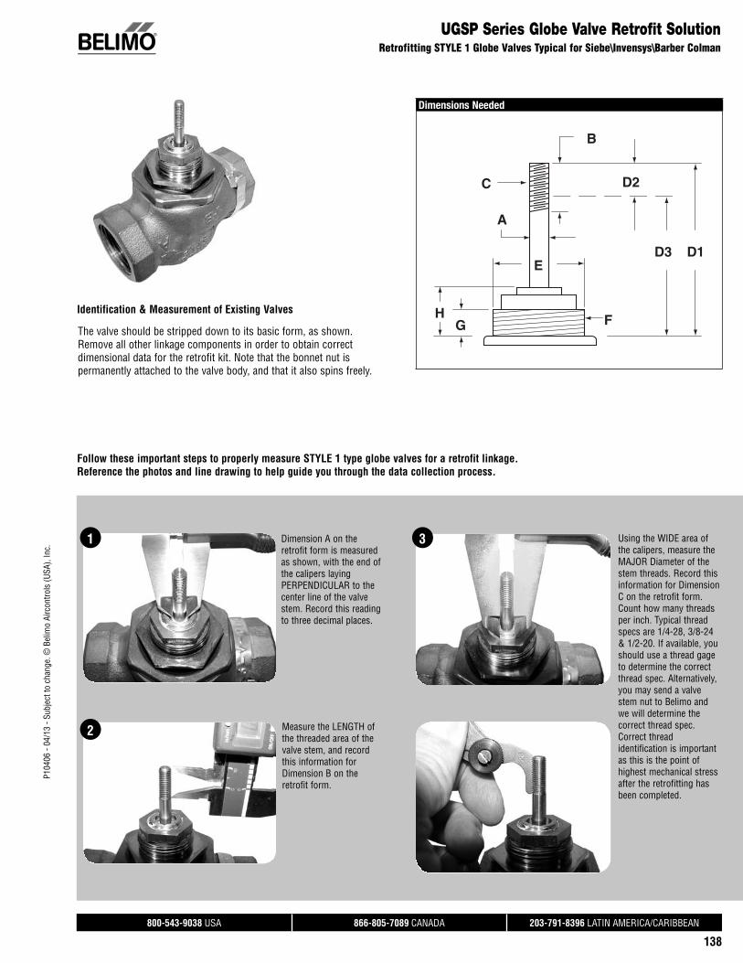
P104
06 -
04/1
3 - S
ubje
ct to
cha
nge.
© B
elim
o Ai
rcon
trols
(USA
), In
c.
®
800-543-9038 USA 866-805-7089 CANADA 203-791-8396 LATIN AMERICA/CARIBBEAN
138
Dimensions Needed
E
GH
A
C
F
D1D3
D2
B
UGSP Series Globe Valve Retrofit SolutionRetrofitting STYLE 1 Globe Valves Typical for Siebe\Invensys\Barber Colman
Identification & Measurement of Existing Valves
Follow these important steps to properly measure STYLE 1 type globe valves for a retrofit linkage. Reference the photos and line drawing to help guide you through the data collection process.
The valve should be stripped down to its basic form, as shown. Remove all other linkage components in order to obtain correct dimensional data for the retrofit kit. Note that the bonnet nut is permanently attached to the valve body, and that it also spins freely.
1
2
Dimension A on the retrofit form is measured as shown, with the end of the calipers laying PERPENDICULAR to the center line of the valve stem. Record this reading to three decimal places.
Measure the LENGTH of the threaded area of the valve stem, and record this information for Dimension B on the retrofit form.
Using the WIDE area of the calipers, measure the MAJOR Diameter of the stem threads. Record this information for Dimension C on the retrofit form. Count how many threads per inch. Typical thread specs are 1/4-28, 3/8-24 & 1/2-20. If available, you should use a thread gage to determine the correct thread spec. Alternatively, you may send a valve stem nut to Belimo and we will determine the correct thread spec. Correct thread identification is important as this is the point of highest mechanical stress after the retrofitting has been completed.
3
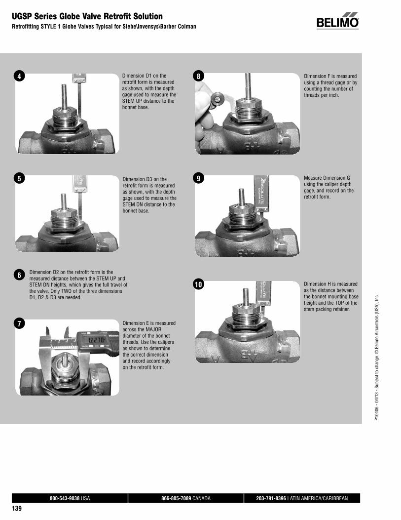
P104
06 -
04/1
3 - S
ubje
ct to
cha
nge.
© B
elim
o Ai
rcon
trols
(USA
), In
c.
®
800-543-9038 USA 866-805-7089 CANADA 203-791-8396 LATIN AMERICA/CARIBBEAN
139
UGSP Series Globe Valve Retrofit SolutionRetrofitting STYLE 1 Globe Valves Typical for Siebe\Invensys\Barber Colman
4
5
Dimension D1 on the retrofit form is measured as shown, with the depth gage used to measure the STEM UP distance to the bonnet base.
Dimension D3 on the retrofit form is measured as shown, with the depth gage used to measure the STEM DN distance to the bonnet base.
Dimension F is measured using a thread gage or by counting the number of threads per inch.
8
7 Dimension E is measured across the MAJOR diameter of the bonnet threads. Use the calipers as shown to determine the correct dimension and record accordingly on the retrofit form.
6 Dimension D2 on the retrofit form is the measured distance between the STEM UP and STEM DN heights, which gives the full travel of the valve. Only TWO of the three dimensions D1, D2 & D3 are needed.
9 Measure Dimension G using the caliper depth gage, and record on the retrofit form.
10 Dimension H is measured as the distance between the bonnet mounting base height and the TOP of the stem packing retainer.

P104
06 -
04/1
3 - S
ubje
ct to
cha
nge.
© B
elim
o Ai
rcon
trols
(USA
), In
c.
®
800-543-9038 USA 866-805-7089 CANADA 203-791-8396 LATIN AMERICA/CARIBBEAN
140
UGSP Series Globe Valve Retrofit SolutionRetrofitting STYLE 2 Globe Valves Typical for Internal Packing Nut Type Valves
Dimensions Needed
G
E
A
C
D3
F
D2
D1
B
Identification & Measurement of Existing Valves
Follow these important steps to properly measure STYLE 2 type globe valves for a retrofit linkage. Reference the photos and line drawing to help guide you through the data collection process.
The valve should be stripped down to its basic form, as shown. Remove all other linkage components in order to obtain correct dimensional data for the retrofit kit. Note that the packing nut is inside the bonnet, and does NOT interfere with the bonnet threads.
1
2
Dimension A on the retrofit form is measured as shown, with the end of the calipers laying PERPENDICULAR to the center line of the valve stem. Record this reading to three decimal places.
Measure the LENGTH of the threaded area of the valve stem, and record this information for Dimension B on the retrofit form.
Using the WIDE area of the calipers, measure the MAJOR Diameter of the stem threads. Record this information for Dimension C on the retrofit form. Count how many threads per inch. Typical thread specs are 1/4-28, 3/8-24 & 1/2-20. If available, you should use a thread gage to determine the correct thread spec. Alternatively, you may send a valve stem nut to Belimo and we will determine the correct thread spec. Correct thread identification is important as this is the point of highest mechanical stress after the retrofitting has been completed.
3

P104
06 -
04/1
3 - S
ubje
ct to
cha
nge.
© B
elim
o Ai
rcon
trols
(USA
), In
c.
®
800-543-9038 USA 866-805-7089 CANADA 203-791-8396 LATIN AMERICA/CARIBBEAN
141
UGSP Series Globe Valve Retrofit SolutionRetrofitting STYLE 2 Globe Valves Typical for Internal Packing Nut Type Valves
4
5
Dimension D1 on the retrofit form is measured as shown, with the depth gage used to measure the STEM UP distance to the bonnet base.
Dimension D3 on the retrofit form is measured as shown, with the depth gage used to measure the STEM DN distance to the bonnet base.
Dimension F is measured using a thread gage or by counting the number of threads per inch.
8
7 Dimension E is measured across the MAJOR diameter of the bonnet threads. Use the calipers as shown to determine the correct dimension and record accordingly on the retrofit form.
6 Dimension D2 on the retrofit form is the measured distance between the STEM UP and STEM DN heights, which gives the full travel of the valve. Only TWO of the three dimensions D1, D2 & D3 are needed.
9 Measure Dimension G using the caliper depth gage, and record on the retrofit form.

P104
06 -
04/1
3 - S
ubje
ct to
cha
nge.
© B
elim
o Ai
rcon
trols
(USA
), In
c.
®
800-543-9038 USA 866-805-7089 CANADA 203-791-8396 LATIN AMERICA/CARIBBEAN
142
UGSP Series Globe Valve Retrofit SolutionRetrofitting STYLE 3 Globe Valves Typical for Powers 599 Series
and Other Non-Threaded, Non-Tapered Bonnet Valves
Dimensions Needed
F
H G
A
C
E
B
D3I
D1
D2
Identification & Measurement of Existing Valves
Follow these important steps to properly measure STYLE 3 type globe valves for a retrofit linkage. Reference the photos and line drawing to help guide you through the data collection process.
The valve should be stripped down to its basic form, as shown. Remove all other linkage components in order to obtain correct dimensional data for the retrofit kit. Note that there are no threads on the bonnet. The packing nut is smaller that the diameter of the bonnet. There is a groove in the bonnet used to secure the retrofit collar to the valve.
1
2
Dimension A on the retrofit form is measured as shown, with the end of the calipers laying PERPENDICULAR to the center line of the valve stem. Record this reading to three decimal places.
Measure the LENGTH of the threaded area of the valve stem, and record this information for Dimension B on the retrofit form.
Using the WIDE area of the calipers, measure the MAJOR Diameter of the stem threads. Record this information for Dimension C on the retrofit form. Count how many threads per inch. Typical thread specs are 1/4-28, 3/8-24 & 1/2-20. If available, you should use a thread gage to determine the correct thread spec. Alternatively, you may send a valve stem nut to Belimo and we will determine the correct thread spec. Correct thread identification is important as this is the point of highest mechanical stress after the retrofitting has been completed.
3

P104
06 -
04/1
3 - S
ubje
ct to
cha
nge.
© B
elim
o Ai
rcon
trols
(USA
), In
c.
®
800-543-9038 USA 866-805-7089 CANADA 203-791-8396 LATIN AMERICA/CARIBBEAN
143
UGSP Series Globe Valve Retrofit SolutionRetrofitting STYLE 3 Globe Valves Typical for Powers 599 Series and Other Non-Threaded, Non-Tapered Bonnet Valves
4
5
Dimension D1 on the retrofit form is measured as shown, with the depth gage used to measure the STEM UP distance to the bonnet base.
Dimension D3 on the retrofit form is measured as shown, with the depth gage used to measure the STEM DN distance to the bonnet base.
DImension F is measured using calipers across the MINOR diameter of the bonnet. This may be a square or a round groove. Measure the SMALLEST dimension of this groove.
8
7 Dimension E is measured across the MAJOR diameter of the bonnet. Use the calipers as shown to determine the correct dimension and record accordingly on the retrofit form. This dimension should be checked both above and below the locking groove.
6 Dimension D2 on the retrofit form is the measured distance between the STEM UP and STEM DN heights, which gives the full travel of the valve. Only TWO of the three dimensions D1, D2 & D3 are needed.
9 Measure Dimension G using the caliper depth gage, and record on the retrofit form.
10 Measure Dimension H using the caliper depth gage, and record on the retrofit form.
11 Dimension I is measured on the outside diameter of the external packing nut.

P104
06 -
04/1
3 - S
ubje
ct to
cha
nge.
© B
elim
o Ai
rcon
trols
(USA
), In
c.
®
800-543-9038 USA 866-805-7089 CANADA 203-791-8396 LATIN AMERICA/CARIBBEAN
144
UGSP Series Globe Valve Retrofit SolutionRetrofitting STYLE 4 Globe Valves Typical for Johnson Controls
and Other External Packing Nut Type Valves
Dimensions Needed
C
G
A
D2
E
F
ID3 D1
B
Identification & Measurement of Existing Valves
Follow these important steps to properly measure STYLE 4 type globe valves for a retrofit linkage. Reference the photos and line drawing to help guide you through the data collection process.
The valve should be stripped down to its basic form, as shown. Remove all other linkage components in order to obtain correct dimensional data for the retrofit kit. Note that many pneumatically operated valves have hardware that must be removed from the threaded bonnet area before measurements can be taken.
1
2
Dimension A on the retrofit form is measured as shown, with the end of the calipers laying PERPENDICULAR to the center line of the valve stem. Record this reading to three decimal places.
Measure the LENGTH of the threaded area of the valve stem, and record this information for Dimension B on the retrofit form.
Using the WIDE area of the calipers, measure the MAJOR Diameter of the stem threads. Record this information for Dimension C on the retrofit form. Count how many threads per inch. Typical thread specs are 1/4-28, 3/8-24 & 1/2-20. If available, you should use a thread gage to determine the correct thread spec. Alternatively, you may send a valve stem nut to Belimo and we will determine the correct thread spec. Correct thread identification is important as this is the point of highest mechanical stress after the retrofitting has been completed.
3

P104
06 -
04/1
3 - S
ubje
ct to
cha
nge.
© B
elim
o Ai
rcon
trols
(USA
), In
c.
®
800-543-9038 USA 866-805-7089 CANADA 203-791-8396 LATIN AMERICA/CARIBBEAN
145
UGSP Series Globe Valve Retrofit SolutionRetrofitting STYLE 4 Globe Valves Typical for Johnson Controls and Other External Packing Nut Type Valves
4
5
Dimension D1 on the retrofit form is measured as shown, with the depth gage used to measure the STEM UP distance to the bonnet base.
Dimension D3 on the retrofit form is measured as shown, with the depth gage used to measure the STEM DN distance to the bonnet base.
DImension F is measured using a thread gage or by counting the number of threads per inch. It is easier to use a thread gage with the external packing nut removed.
8
7 Dimension E is measured across the MAJOR diameter of the bonnet. Use the calipers as shown to determine the correct dimension and record accordingly on the retrofit form. Do NOT measure the diameter of the packing nut for this dimension.
6 Dimension D2 on the retrofit form is the measured distance between the STEM UP and STEM DN heights, which gives the full travel of the valve. Only TWO of the three dimensions D1, D2 & D3 are needed.
9 Measure Dimension G using the caliper depth gage to measure the distance between the bottom on the packing nut and the valve collar seating surface.
10 Dimension I is measured on the outside diameter or point of the external packing nut.

P104
06 -
04/1
3 - S
ubje
ct to
cha
nge.
© B
elim
o Ai
rcon
trols
(USA
), In
c.
®
800-543-9038 USA 866-805-7089 CANADA 203-791-8396 LATIN AMERICA/CARIBBEAN
146
UGSP Series Globe Valve Retrofit SolutionRetrofitting STYLE 5 Globe Valves Typical for Honeywell
and Other Non-Threaded, Tapered Bonnet Valves
Dimensions Needed
G F
E
E
A
C
H
D3
D2
B
D1
Identification & Measurement of Existing Valves
Follow these important steps to properly measure STYLE 5 type globe valves for a retrofit linkage. Reference the photos and line drawing to help guide you through the data collection process.
The valve should be stripped down to its basic form, as shown. Remove all other linkage components in order to obtain correct dimensional data for the retrofit kit.Note that there are no threads on the bonnet. The packing nut is smaller that the diameter of the bonnet. There is a groove in the bonnet used to secure the retrofit collar to the valve.
1
2
Dimension A on the retrofit form is measured as shown, with the end of the calipers laying PERPENDICULAR to the center line of the valve stem. Record this reading to three decimal places.
Measure the LENGTH of the threaded area of the valve stem, and record this information for Dimension B on the retrofit form.
Using the WIDE area of the calipers, measure the MAJOR Diameter of the stem threads. Record this information for Dimension C on the retrofit form. Count how many threads per inch. Typical thread specs are 1/4-28, 3/8-24 & 1/2-20. If available, you should use a thread gage to determine the correct thread spec. Alternatively, you may send a valve stem nut to Belimo and we will determine the correct thread spec. Correct thread identification is important as this is the point of highest mechanical stress after the retrofitting has been completed.
3

P104
06 -
04/1
3 - S
ubje
ct to
cha
nge.
© B
elim
o Ai
rcon
trols
(USA
), In
c.
®
800-543-9038 USA 866-805-7089 CANADA 203-791-8396 LATIN AMERICA/CARIBBEAN
147
UGSP Series Globe Valve Retrofit SolutionRetrofitting STYLE 5 Globe Valves Typical for Honeywell and Other Non-Threaded, Tapered Bonnet Valves
4
5
Dimension D1 on the retrofit form is measured as shown, with the depth gage used to measure the STEM UP distance to the bonnet base.
Dimension D3 on the retrofit form is measured as shown, with the depth gage used to measure the STEM DN distance to the bonnet base.
DImension F is measured using calipers across the MINOR diameter of the bonnet. This may be a square or a round groove. Measure the SMALLEST dimension of this groove.
8
7 Dimension E is measured across the MAJOR diameter of the bonnet. Use the calipers as shown to determine the correct dimension and record accordingly on the retrofit form. This dimension should be checked both above and below the locking groove.
6 Dimension D2 on the retrofit form is the measured distance between the STEM UP and STEM DN heights, which gives the full travel of the valve. Only TWO of the three dimensions D1, D2 & D3 are needed.
9 Measure Dimension G using the caliper depth gage, and record on the retrofit form.
10 Measure Dimension H using the caliper depth gage, and record on the retrofit form.
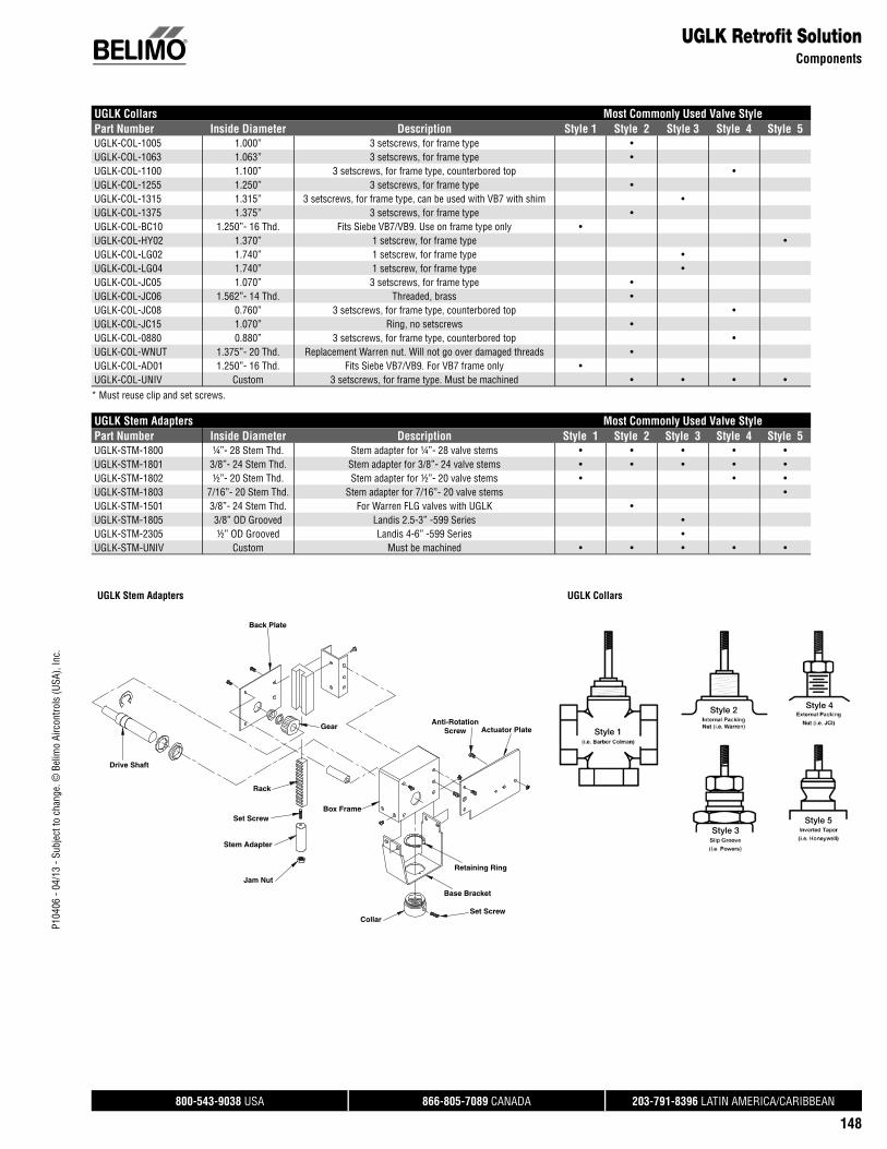
P104
06 -
04/1
3 - S
ubje
ct to
cha
nge.
© B
elim
o Ai
rcon
trols
(USA
), In
c.
®
800-543-9038 USA 866-805-7089 CANADA 203-791-8396 LATIN AMERICA/CARIBBEAN
148
UGLK Collars Most Commonly Used Valve StylePart Number Inside Diameter Description Style 1 Style 2 Style 3 Style 4 Style 5UGLK-COL-1005 1.000” 3 setscrews, for frame type •UGLK-COL-1063 1.063” 3 setscrews, for frame type •UGLK-COL-1100 1.100” 3 setscrews, for frame type, counterbored top •UGLK-COL-1255 1.250” 3 setscrews, for frame type •UGLK-COL-1315 1.315” 3 setscrews, for frame type, can be used with VB7 with shim •UGLK-COL-1375 1.375” 3 setscrews, for frame type •UGLK-COL-BC10 1.250”- 16 Thd. Fits Siebe VB7/VB9. Use on frame type only •UGLK-COL-HY02 1.370” 1 setscrew, for frame type •UGLK-COL-LG02 1.740” 1 setscrew, for frame type •UGLK-COL-LG04 1.740” 1 setscrew, for frame type •UGLK-COL-JC05 1.070” 3 setscrews, for frame type •UGLK-COL-JC06 1.562”- 14 Thd. Threaded, brass •UGLK-COL-JC08 0.760” 3 setscrews, for frame type, counterbored top •UGLK-COL-JC15 1.070” Ring, no setscrews •UGLK-COL-0880 0.880” 3 setscrews, for frame type, counterbored top •UGLK-COL-WNUT 1.375”- 20 Thd. Replacement Warren nut. Will not go over damaged threads •UGLK-COL-AD01 1.250”- 16 Thd. Fits Siebe VB7/VB9. For VB7 frame only •UGLK-COL-UNIV Custom 3 setscrews, for frame type. Must be machined • • • •
UGLK Stem Adapters Most Commonly Used Valve StylePart Number Inside Diameter Description Style 1 Style 2 Style 3 Style 4 Style 5UGLK-STM-1800 ¼”- 28 Stem Thd. Stem adapter for ¼”- 28 valve stems • • • • • UGLK-STM-1801 3/8”- 24 Stem Thd. Stem adapter for 3/8”- 24 valve stems • • • • •UGLK-STM-1802 ½”- 20 Stem Thd. Stem adapter for ½”- 20 valve stems • • •UGLK-STM-1803 7/16”- 20 Stem Thd. Stem adapter for 7/16”- 20 valve stems •UGLK-STM-1501 3/8”- 24 Stem Thd. For Warren FLG valves with UGLK •UGLK-STM-1805 3/8” OD Grooved Landis 2.5-3” -599 Series •UGLK-STM-2305 ½” OD Grooved Landis 4-6” -599 Series •UGLK-STM-UNIV Custom Must be machined • • • • •
UGLK Stem Adapters UGLK Collars
UGLK Retrofi t SolutionComponents
Style 1
Style 2 Style 4
Style 3Style 5
* Must reuse clip and set screws.
Actuator PlateAnti-Rotation
Screw
Retaining Ring
Base Bracket
Collar
Box Frame
Jam Nut
Stem Adapter
Set Screw
Rack
Drive Shaft
Back Plate
Gear
Set Screw

P104
06 -
04/1
3 - S
ubje
ct to
cha
nge.
© B
elim
o Ai
rcon
trols
(USA
), In
c.
®
800-543-9038 USA 866-805-7089 CANADA 203-791-8396 LATIN AMERICA/CARIBBEAN
149
Non-Spring Return Spring Return
Auxiliary Switches & Potentiometers LMBLMX
NMBNMX
AMBAMX
GMBGMX LF NF AF
S1AAuxiliary switch - 1x SPDT, 3A (0.5A Inductive) @ 250 VAC
• • • •
S2AAuxiliary switch - 1x SPDT, 3A (0.5A Inductive) @ 250 VAC
• • • •
P140A GRFeedback potentiometer 140 Ω • • • •
P500A GRFeedback potentiometer 500 Ω • • • •
P1000A GRFeedback potentiometer 1000 Ω • • • •
P2800A GRFeedback potentiometer 2800 Ω • • • •
P5000A GRFeedback potentiometer 5000 Ω • • • •
P10000A GRFeedback potentiometer 10000 Ω • • • •
Battery BackupNSV24 USBattery backup module • • • • • • •
NSV-BAT US12VDC 1.2 AH battery (2 required) • • • • • • •
Note: Each NSV-24 US requires 2 NSV-BAT.
Valve AccessoriesGlobe Valves

• Full range of kits for 2-way and 3-way valve assemblies.
• Visual stroke indicators allow quick installation.
• Linkages can be mounted in any orientation except upside down.
• NEMA 2 and NEMA 4 options available.
Applications
UFLK and UFSP butterfl y retrofi t solutions are designed to easily attach to the valve
mounting pad of competitor valves utilizing Belimo actuators. This kit will help to
restore service without removal of the valve, saving down time and money.
Butterfl y Valve Retrofi t Solutions
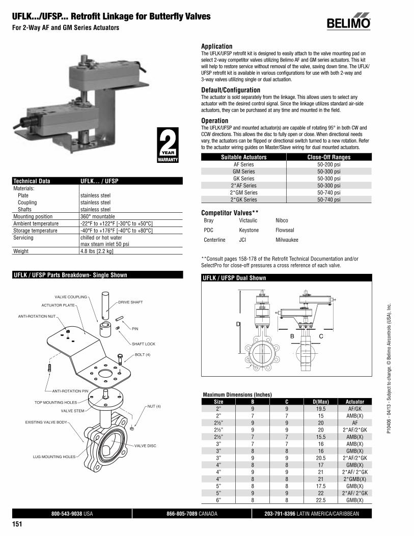
P104
06 -
04/1
3 - S
ubje
ct to
cha
nge.
© B
elim
o Ai
rcon
trols
(USA
), In
c.
®
800-543-9038 USA 866-805-7089 CANADA 203-791-8396 LATIN AMERICA/CARIBBEAN
151
UFLK.../UFSP... Retrofi t Linkage for Butterfl y ValvesFor 2-Way AF and GM Series Actuators
ApplicationThe UFLK/UFSP retrofit kit is designed to easily attach to the valve mounting pad on select 2-way competitor valves utilizing Belimo AF and GM series actuators. This kit will help to restore service without removal of the valve, saving down time. The UFLK/UFSP retrofit kit is available in various configurations for use with both 2-way and 3-way valves utilizing single or dual actuation.
Default/ConfigurationThe actuator is sold separately from the linkage. This allows users to select any actuator with the desired control signal. Since the linkage utilizes standard air-side actuators, they can be purchased at any time and mounted in the field.
OperationThe UFLK/UFSP and mounted actuator(s) are capable of rotating 95° in both CW and CCW directions. This allows the disc to fully open or close. When directional needs vary, the actuators can be flipped or directional switch turned to a new rotation. Refer to the actuator wiring guides on Master/Slave wiring for dual mounted actuators.
Suitable Actuators Close-Off RangesAF Series 50-200 psiGM Series 50-300 psiGK Series 50-300 psi
2*AF Series 50-300 psi2*GM Series 50-740 psi2*GK Series 50-740 psi
Competitor Valves** Bray Victaulic Nibco
PDC Keystone Flowseal
Centerline JCI Milwaukee
**Consult pages 158-178 of the Retrofit Technical Documentation and/or SelectPro for close-off pressures a cross reference of each valve.
UFLK / UFSP Dual Shown
Technical Data UFLK... / UFSPMaterials: Plate stainless steel Coupling stainless steel Shafts stainless steelMounting position 360° mountableAmbient temperature -22°F to +122°F [-30°C to +50°C]Storage temperature -40°F to +176°F [-40°C to +80°C]Servicing chilled or hot water
max steam inlet 50 psi Weight 4.8 lbs [2.2 kg]
UFLK / UFSP Parts Breakdown- Single Shown
DRIVE SHAFT
PIN
SHAFT LOCK
ANTI-ROTATION NUT
ANTI-ROTATION PIN
ACTUATOR PLATE
BOLT (4)
NUT (4)
EXISTING VALVE BODY
VALVE STEM
TOP MOUNTING HOLES
VALVE DISC
LUG MOUNTING HOLES
VALVE COUPLING
Maximum Dimensions (Inches)Size B C D(Max) Actuator2” 9 9 19.5 AF/GK2” 7 7 15 AMB(X)
2½” 9 9 20 AF2½” 9 9 20 2*AF/2*GK2½” 7 7 15.5 AMB(X)3” 7 7 16 AMB(X)3” 8 8 16 GMB(X)3” 9 9 20.5 2*AF/2*GK4” 8 8 17 GMB(X)4” 9 9 21 2*AF/ 2*GK4” 8 8 21 2*GMB(X)5” 8 8 17.5 GMB(X)5” 9 9 22 2*AF/ 2*GK6” 8 8 22.5 GMB(X)
D
B C

P104
06 -
04/1
3 - S
ubje
ct to
cha
nge.
© B
elim
o Ai
rcon
trols
(USA
), In
c.
®
800-543-9038 USA 866-805-7089 CANADA 203-791-8396 LATIN AMERICA/CARIBBEAN
152
UFLK.../UFSP... Retrofi t Linkage for Butterfl y ValvesFor 3-Way AF and GM Series Actuators
ApplicationThe UFLK/UFSP retrofit kit is designed to easily attach to the valve mounting pad on select 3-way competitor valves utilizing Belimo AF and GM series actuators. This kit will help to restore service without removal of the valve, saving down time. The UFLK/UFSP retrofit kit is available in various configurations for use with both 2-way and 3-way valves utilizing single or dual actuation.
Default/ConfigurationThe actuator is sold separately from the linkage. This allows users to select any actuator with the desired control signal. Since the linkage utilizes standard air-side actuators, they can be purchased at any time and mounted in the field.
OperationThe UFLK/UFSP and mounted actuator(s) are capable of rotating 95° in both CW and CCW directions. This allows the disc to fully open or close. When directional needs vary, the actuators can be flipped or directional switch turned to a new rotation. Refer to the actuator wiring guides on Master/Slave wiring for dual mounted actuators.
Suitable Actuators Close-Off RangesAF Series 50-200 psiGM Series 50-300 psiGK Series 50-300 psi
2*AF Series 50-300 psi2*GM Series 50-740 psi2*GK Series 50-740 psi
Competitor Valves** Bray Victaulic Nibco
PDC Keystone Flowseal
Centerline JCI Milwaukee
**Consult pages 158-178 of the Retrofit Technical Documentation and/or SelectPro for close-off pressures a cross reference of each valve.
UFLK / UFSP Dual ShownUFLK / UFSP Parts Breakdown- Single Shown
EXISTING VALVE
CRANK ARM (2)
COTTER PIN (2)
CONNECTING ROD
EXISTING VALVE
EXISTING TEE
ANTI-ROTATION NUT
NUT (4)
TOP MOUNTING HOLES
ANTI-ROTATION PIN
ACTUATOR PLATE
BOLT (4)
SHAFT LOCK (2)
PIN
CLEVIS PIN (2)
YOKE (2)
DRIVE SHAFT
CRANK LOCK (2)
JAMB NUT
VALVE COUPLING (2)
VALVE STEM
10 0
10 0
D
A B
C
Maximum Dimensions (Inches)Size A B C D(Max) Actuator2” 7 9 9 19.5 AF/GK2” 5 7 7 15 AMB(X)
2½” 7 9 9 20 AF2½” 7 9 9 20 2*AF/2*GK2½” 5 7 7 15.5 AMB(X)3” 5 7 7 16 AMB(X)3” 6 8 8 16 GMB(X)3” 7 9 9 20.5 2*AF/2*GK4” 6 8 8 17 GMB(X)4” 7 9 9 21 2*AF/ 2*GK4” 6 8 8 21 2*GMB(X)5” 6 8 8 17.5 GMB(X)5” 7 9 9 22 2*AF/ 2*GK6” 6 8 8 22.5 GMB(X)
Technical Data UFLK... / UFSPMaterials: Bracket stainless steel Couplings stainless steel Crank arms steel Yoke steel Rod steelMounting position configuration specific (X10-X35)Ambient temperature -22°F to +122°F [-30°C to +50°C]Storage temperature -40°F to +176°F [-40°C to +80°C]Servicing chilled or hot waterWeight 7 lbs [3.2 kg]

P104
06 -
04/1
3 - S
ubje
ct to
cha
nge.
© B
elim
o Ai
rcon
trols
(USA
), In
c.
®
800-543-9038 USA 866-805-7089 CANADA 203-791-8396 LATIN AMERICA/CARIBBEAN
153
UFLK.../UFSP... Retrofi t Linkage for Butterfl y ValvesFor 2-Way SY Industrial Series Actuators
ApplicationThe UFLK/UFSP retrofit kit is designed to easily attach to the valve mounting pad on select 2-way competitor valves utilizing Belimo SY industrial series actuators. This kit will help to restore service without removal of the valve, saving down time. The UFLK/UFSP retrofit kit is available in various configurations for use with both 2-way and 3-way valves.
Default/ConfigurationThe actuator is sold separately from the linkage. This allows users to select any actuator with the desired control signal. Since the linkage utilizes standard SY actuators, they can be purchased at any time and mounted in the field.
OperationThe UFLK/UFSP and mounted actuator(s) are capable of rotating 95° in both CW and CCW directions. This allows the disc to fully open or close. When directional needs vary, the actuator’s directional switch can be flipped to change the rotation. The SY is NEMA 4 rated and can be used outdoors.
Suitable Actuators Close-Off RangesSY1 Series 50-300 psiSY2 Series 50-740 psi
SY3-SY4 Series 50-780 psiSY5 Series 150-300 psi
SY6-SY12 Series 150-780 psi
Competitor Valves** Bray Victaulic Nibco
PDC Keystone Flowseal
Centerline JCI Milwaukee
**Consult pages 158-178 of the Retrofit Technical Documentation and/or SelectPro for close-off pressures a cross reference of each valve.
Technical Data UFLK... / UFSPMaterials: Bracket stainless steel Couplings stainless steel Crank arms steel Yoke steel Rod steelMounting position 360° mountableAmbient temperature -22°F to +122°F [-30°C to +50°C]Storage temperature -40°F to +176°F [-40°C to +80°C]Servicing chilled or hot waterWeight 7 lbs [3.2 kg]
UFLK / UFSP Parts Breakdown
UFLK / UFSP
D
B C
LUG MOUNTING HOLES VALVE DISC
TOP MOUNTING HOLES
EXISTING VALVE BODY
VALVE STEM
COUPLING(WELDED)
INDUSTRIAL
BRACKET
BOLT (4)
BOLT (4)
NUT (4)
LOCK WASHER (4)
Maximum Dimensions (Inches)Size B C D(Max) Actuator2” 6.15 6.15 15.5 SY1…2” 6.15 6.15 20.25 SY2…
2½” 6.76 6.76 16 SY1…2½” 6.76 6.76 20.75 SY2…3” 7.28 7.28 21 SY2…4” 8.55 8.55 21.75 SY2…5” 9.64 9.64 22.25 SY2…5” 9.64 9.64 22.25 SY3…6” 10.19 10.19 22.75 SY2…6” 10.19 10.19 22.75 SY3…8” 11.37 11.37 24.25 SY3…8” 11.37 11.37 29 SY4…10” 13.58 13.58 30 SY4…12” 15.01 15.01 32 SY4…12” 15.01 15.01 32 SY5…14” 17.02 17.02 33 SY6…16” 18.39 18.39 38.5 SY7…18” 20.63 20.63 39.5 SY9…20” 23 23 41.5 SY9…24” 27.9 27.9 53.25 SY12…

P104
06 -
04/1
3 - S
ubje
ct to
cha
nge.
© B
elim
o Ai
rcon
trols
(USA
), In
c.
®
800-543-9038 USA 866-805-7089 CANADA 203-791-8396 LATIN AMERICA/CARIBBEAN
154
UFLK.../UFSP... Retrofi t Linkage for Butterfl y ValvesFor 3-Way SY Industrial Series Actuators
ApplicationThe UFLK/UFSP retrofit kit is designed to easily attach to the valve mounting pad on select 3-way competitor valves utilizing Belimo SY industrial series actuators. This kit will help to restore service without removal of the valve, saving down time. The UFLK/UFSP retrofit kit is available in various configurations for use with both 2-way and 3-way valves.
Default/ConfigurationThe actuator is sold separately from the linkage. This allows users to select any actuator with the desired control signal. Since the linkage utilizes standard SY actuators, they can be purchased at any time and mounted in the field.
OperationThe UFLK/UFSP and mounted actuator(s) are capable of rotating 95° in both CW and CCW directions. This allows the disc to fully open or close. When directional needs vary, the actuator’s directional switch can be flipped to change the rotation. The SY is NEMA 4 rated and can be used outdoors.
Suitable Actuators Close-Off RangesSY1 Series 50-285 psiSY2 Series 50-200 psi
SY3-SY4 Series 50-780 psiSY5 Series 150-300 psi
SY6-SY12 Series 150-780 psi
Competitor Valves** Bray Victaulic Nibco
PDC Keystone Flowseal
Centerline JCI Milwaukee
**Consult pages 158-178 of the Retrofit Technical Documentation and/or SelectPro for close-off pressures a cross reference of each valve.
Technical Data UFLK... / UFSPMaterials: Bracket stainless steel Couplings stainless steel Crank arms steel Yoke steel Rod steelMounting position configuration specific (X10-X35)Ambient temperature -22°F to +122°F [-30°C to +50°C]Storage temperature -40°F to +176°F [-40°C to +80°C]Servicing chilled or hot waterWeight 12.6 lbs [5.73 kg]
UFLK / UFSP Parts Breakdown
MASTER VALVE COUPLING
ACTUATOR COUPLING
MASTER CRANK ARM
WELDED ASSEMBLY
BRACKET
YOKE (2)
JAMB NUT
CONNECTING ROD
CONNECTING ROD
SLAVE CRANK ARM
SLAVE VALVE COUPLING
SHAFT LOCK
CLEVIS BOLT (2)
LOCK WASHER (2)
CLEVIS NUT (2)
BOLT (4)
LOCK WASHER (4)
NUT (4)
EXISTING TEE
EXISTING SLAVE VALVE
EXISTING MASTER VALVE
VALVE STEM
TOP MOUNTING HOLES
BOLT (4)
LOCK WASHER (4)
WELDED ASSEMBLY
0
S
D
A B
C
Maximum Dimensions (Inches)Size A B C D(Max) Actuator2” 4.15 6.15 6.15 15.5 SY1…2” 4.15 6.15 6.15 20.25 SY2…
2½” 4.76 6.76 6.76 16 SY1…2½” 4.76 6.76 6.76 20.75 SY2…3” 5.28 7.28 7.28 21 SY2…4” 6.55 8.55 8.55 21.75 SY2…5” 7.64 9.64 9.64 22.25 SY2…5” 7.64 9.64 9.64 22.25 SY3…6” 8.19 10.19 10.19 22.75 SY2…6” 8.19 10.19 10.19 22.75 SY3…8” 9.37 11.37 11.37 24.25 SY3…8” 9.37 11.37 11.37 29 SY4…10” 11.58 13.58 13.58 30 SY4…12” 13.01 15.01 15.01 32 SY4…12” 13.01 15.01 15.01 32 SY5…14” 15.02 17.02 17.02 33 SY6…16” 16.39 18.39 18.39 38.5 SY7…18” 18.63 20.63 20.63 39.5 SY9…20” 21 23 23 41.5 SY9…24” 25.9 27.9 27.9 53.25 SY12…
UFLK / UFSP
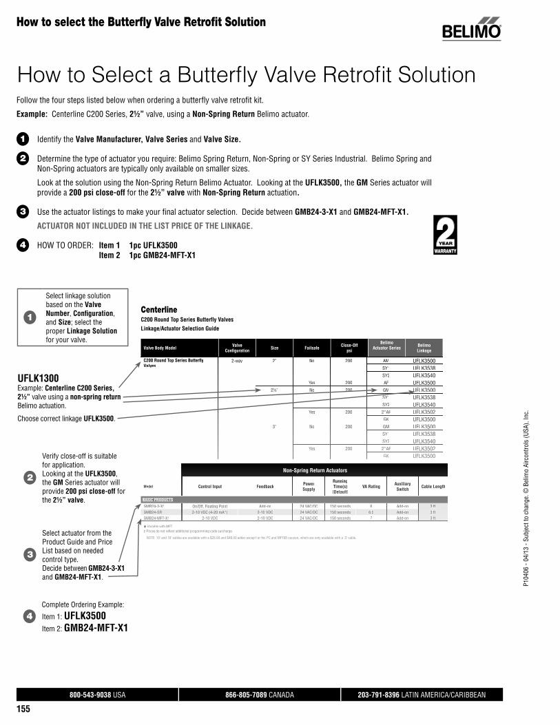
P104
06 -
04/1
3 - S
ubje
ct to
cha
nge.
© B
elim
o Ai
rcon
trols
(USA
), In
c.
®
800-543-9038 USA 866-805-7089 CANADA 203-791-8396 LATIN AMERICA/CARIBBEAN
155
How to select the Butterfl y Valve Retrofi t Solution
Valve Body Model ValveConfi guration Size Failsafe Close-Off
psi
BelimoActuator Series Belimo
Linkage
CenterlineC200 Round Top Series Butterfly Valves
Linkage/Actuator Selection Guide
Follow the four steps listed below when ordering a butterfly valve retrofit kit.
Example: Centerline C200 Series, 2½” valve, using a Non-Spring Return Belimo actuator.
1 Identify the Valve Manufacturer, Valve Series and Valve Size.
2 Determine the type of actuator you require: Belimo Spring Return, Non-Spring or SY Series Industrial. Belimo Spring and Non-Spring actuators are typically only available on smaller sizes.
Look at the solution using the Non-Spring Return Belimo Actuator. Looking at the UFLK3500, the GM Series actuator will provide a 200 psi close-off for the 2½” valve with Non-Spring Return actuation.
3 Use the actuator listings to make your final actuator selection. Decide between GMB24-3-X1 and GMB24-MFT-X1.
ACTUATOR NOT INCLUDED IN THE LIST PRICE OF THE LINKAGE.
4 HOW TO ORDER: Item 1 1pc UFLK3500 Item 2 1pc GMB24-MFT-X1
1
Select linkage solution based on the Valve Number, Confi guration, and Size; select theproper Linkage Solution for your valve.
UFLK1300Example: Centerline C200 Series, 2½” valve using a non-spring return Belimo actuation.
Choose correct linkage UFLK3500.
2
Verify close-off is suitablefor application.Looking at the UFLK3500, the GM Series actuator will provide 200 psi close-off for the 2½” valve.
3
Select actuator from the Product Guide and Price List based on needed control type.Decide between GMB24-3-X1 and GMB24-MFT-X1.
4Complete Ordering Example:
Item 1: UFLK3500Item 2: GMB24-MFT-X1
C200 Round Top Series Butterfl y Valves
2-way 2” No 200 AM UFLK3500SY1SY1 UFLKUFLK35383538SY2 UFLK3540
Yes 200 AF UFLK35002½”2½” NNo 200200 GMGM UFLKUFLK35003500
SY1 UFLK3538SY2 UFLK3540
YesYes 200200 2*AF2 AF UFLKUFLK35023502GK UFLK3500
3” No 200 GM UFLK3500SY1SY1 UFLKUFLK35383538SY2 UFLKU 3540
Yes 200 2*AF UFLK3502GK UFLK3500
Non-Spring Return Actuators
Model Control Input Feedback PowePowerrSupply
RunningTime(s)[Def[Defaultault]]
VA Rating AuxiAuxiliarliaryySwitch Cable Length
BASIC PRODUCTS
GMB24GMB24-3-X1-3-X1 On/OfOn/Off Flf, Floatinoating Poig Pointnt Add-oAdd-onn 24 VA24 VAC/DCC/DC 150 s150 secondecondss 66 Add-oAdd-onn 3 ft3 ft.GMB24-SR 2-10 VDC ((4-20 mA*)) 2-10 VDC 24 VAC/DC 150 seconds 6.5 Add-on 3 ft.GMB24-MFT-X1 2-10 VDC 2-10 VDC 24 VAC/DC 150 seconds 7 Add-on 3 ft.
VariaVariable wible with MFTth MFT‡ Prices do not refl ect additional programming code surcharge.
NOTE: 10’ and 16’ cables are available with a $28.00 and $48.00 adder except fp or the PC and MFT95 version, w, hich are only avaiy lable with a 3’ cable.
How to Select a Butterfl y Valve Retrofi t Solution

P104
06 -
04/1
3 - S
ubje
ct to
cha
nge.
© B
elim
o Ai
rcon
trols
(USA
), In
c.
®
800-543-9038 USA 866-805-7089 CANADA 203-791-8396 LATIN AMERICA/CARIBBEAN
156
Butterfl y Valve Retrofi t ActuatorsActuator Selection Guide
SY Series Actuators
CONTROL TYPESERIES MODEL Run Time(s) 90°@60Hz Power Supply Duty Cycle Proportional 3 Point On/Off Feedback
SY1
SY1-110 12 seconds 120 VAC ±10%, 50/60 Hz 30% • • none, opt 1kSY1-24 15 seconds 24 VAC ±10%, 50/60 Hz 30% • • none, opt 1kSY1-220 12 seconds 230 VAC ±10%, 50/60 Hz 30% • • none, opt 1kSY1-110P 12 seconds 120 VAC ±10%, 50/60 Hz 75% • 2-10 VDC/4-20 mASY1-24P 15 seconds 24 VAC ±10%, 50/60 Hz 75% • 2-10 VDC/4-20 mASY1-220P 12 seconds 230 VAC ±10%, 50/60 Hz 75% • 2-10 VDC/4-20 mA
SY2
SY2-110 15 seconds 120 VAC ±10%, 50/60 Hz 30% • • none, opt 1kSY2-24 15 seconds 24 VAC ±10%, 50/60 Hz 30% • • none, opt 1kSY2-220 15 seconds 230 VAC ±10%, 50/60 Hz 30% • • none, opt 1kSY2-120MFT 15 seconds 120 VAC ±10%, 50/60 Hz 75% • 2-10 VDC/4-20 mASY2-24MFT 15 seconds 24 VAC ±10%, 50/60 Hz 75% • 2-10 VDC/4-20 mASY2-230MFT 15 seconds 230 VAC ±10%, 50/60 Hz 75% • 2-10 VDC/4-20 mA
SY3
SY3-110 22 seconds 120 VAC ±10%, 50/60 Hz 30% • • none, opt 1kSY3-24 22 seconds 24 VAC ±10%, 50/60 Hz 30% • • none, opt 1kSY3-220 22 seconds 230 VAC ±10%, 50/60 Hz 30% • • none, opt 1kSY3-24MFT 22 seconds 120 VAC ±10%, 50/60 Hz 75% • 2-10 VDC/4-20 mASY3-120MFT 22 seconds 120 VAC ±10%, 50/60 Hz 75% • 2-10 VDC/4-20 mASY3-230MFT 22 seconds 230 VAC ±10%, 50/60 Hz 75% • 2-10 VDC/4-20 mA
SY4
SY4-110 16 seconds 120 VAC ±10%, 50/60 Hz 30% • • none, opt 1kSY4-24 16 seconds 24 VAC ±10%, 50/60 Hz 30% • • none, opt 1kSY4-220 16 seconds 230 VAC ±10%, 50/60 Hz 30% • • none, opt 1kSY4-24MFT 16 seconds 120 VAC ±10%, 50/60 Hz 75% • 2-10 VDC/4-20 mASY4-120MFT 16 seconds 120 VAC ±10%, 50/60 Hz 75% • 2-10 VDC/4-20 mASY4-230MFT 16 seconds 230 VAC ±10%, 50/60 Hz 75% • 2-10 VDC/4-20 mA
SY5
SY5-110 22 seconds 120 VAC ±10%, 50/60 Hz 30% • • none, opt 1kSY5-24 22 seconds 24 VAC ±10%, 50/60 Hz 30% • • none, opt 1kSY5-220 22 seconds 230 VAC ±10%, 50/60 Hz 30% • • none, opt 1kSY5-24MFT 22 seconds 120 VAC ±10%, 50/60 Hz 75% • 2-10 VDC/4-20 mASY5-120MFT 22 seconds 120 VAC ±10%, 50/60 Hz 75% • 2-10 VDC/4-20 mASY5-230MFT 22 seconds 230 VAC ±10%, 50/60 Hz 75% • 2-10 VDC/4-20 mA
SY6
SY6-110 28 seconds 120 VAC ±10%, 50/60 Hz 30% • • none, opt 1kSY6-220 28 seconds 230 VAC ±10%, 50/60 Hz 30% • • none, opt 1kSY6-120MFT 28 seconds 120 VAC ±10%, 50/60 Hz 75% • 2-10 VDC/4-20 mASY6-230MFT 28 seconds 230 VAC ±10%, 50/60 Hz 75% • 2-10 VDC/4-20 mA
SY7
SY7-110 46 seconds 120 VAC ±10%, 50/60 Hz 30% • • none, opt 1kSY7-220 46 seconds 230 VAC ±10%, 50/60 Hz 30% • • none, opt 1kSY7-120MFT 46 seconds 120 VAC ±10%, 50/60 Hz 75% • 2-10 VDC/4-20 mASY7-230MFT 46 seconds 230 VAC ±10%, 50/60 Hz 75% • 2-10 VDC/4-20 mA
SY8
SY8-110 46 seconds 120 VAC ±10%, 50/60 Hz 30% • • none, opt 1kSY8-220 46 seconds 230 VAC ±10%, 50/60 Hz 30% • • none, opt 1kSY8-120MFT 46 seconds 120 VAC ±10%, 50/60 Hz 75% • 2-10 VDC/4-20 mASY8-230MFT 46 seconds 230 VAC ±10%, 50/60 Hz 75% • 2-10 VDC/4-20 mA
SY9
SY9-110 58 seconds 120 VAC ±10%, 50/60 Hz 30% • • none, opt 1kSY9-220 58 seconds 230 VAC ±10%, 50/60 Hz 30% • • none, opt 1kSY9-120MFT 58 seconds 120 VAC ±10%, 50/60 Hz 50% • 2-10 VDC/4-20 mASY9-230MFT 58 seconds 230 VAC ±10%, 50/60 Hz 50% • 2-10 VDC/4-20 mA
SY10
SY10-110 58 seconds 120 VAC ±10%, 50/60 Hz 30% • • none, opt 1kSY10-220 58 seconds 230 VAC ±10%, 50/60 Hz 30% • • none, opt 1kSY10-120MFT 58 seconds 120 VAC ±10%, 50/60 Hz 50% • 2-10 VDC/4-20 mASY10-230MFT 58 seconds 230 VAC ±10%, 50/60 Hz 50% • 2-10 VDC/4-20 mA
SY11
SY11-110 58 seconds 120 VAC ±10%, 50/60 Hz 30% • • none, opt 1kSY11-220 58 seconds 230 VAC ±10%, 50/60 Hz 30% • • none, opt 1kSY11-120MFT 58 seconds 120 VAC ±10%, 50/60 Hz 50% • 2-10 VDC/4-20 mASY11-230MFT 58 seconds 230 VAC ±10%, 50/60 Hz 50% • 2-10 VDC/4-20 mA
SY12
SY12-110 58 seconds 120 VAC ±10%, 50/60 Hz 30% • • none, opt 1kSY12-220 58 seconds 230 VAC ±10%, 50/60 Hz 30% • • none, opt 1kSY12-120MFT 58 seconds 120 VAC ±10%, 50/60 Hz 50% • 2-10 VDC/4-20 mASY12-230MFT 58 seconds 230 VAC ±10%, 50/60 Hz 50% • 2-10 VDC/4-20 mA
Proportional actuators will accept 0-10 VDC, 2-10 VDC (default), or 4-20 mA control signals as standard. All SY actuators are non-spring return, but can be used with NSV-SY back up systems for fail-safe applications.These products carry a two year warranty when sold as part of an assembly or with a UFLK retrofi t kit.

P104
06 -
04/1
3 - S
ubje
ct to
cha
nge.
© B
elim
o Ai
rcon
trols
(USA
), In
c.
®
800-543-9038 USA 866-805-7089 CANADA 203-791-8396 LATIN AMERICA/CARIBBEAN
157
Butterfl y Valve Retrofi t Actuators Actuator Selection Guide
ROTARY ACTUATORS
SERIES MODEL Spring Return Electronic Fail-Safe
Tandem Mounting Available
Control Input Feedback Position
Power Supply
AF Series*AFBUP-X1 • • On/Off - 24-240 VACAFX24-MFT-X1 • • Variable with MFT Variable VDC 24 VAC/DC
AM Series*AMB24-3-X1 Floating Point, On/Off - 24 VAC/DCAMX24-MFT-X1 Variable with MFT Variable VDC 24 VAC/DC
GM Series*GMB24-3-X1 Floating Point, On/Off - 24 VAC/DCGMX24-MFT-X1 • Variable with MFT Variable VDC 24 VAC/DC
GK Series*GKB24-3-X1 • Floating Point, On/Off - 24 VAC/DCGKX24-MFT-X1 • • Variable with MFT Variable VDC 24 VAC/DC
*Please consult the Damper sections of the Product Guide and Price List for a full list of product offerings. Standard run times should be considered in the selection. All air side products are applicable for retrofi t kits. Select “X1” actuators come with a handle.
MULTI-FUNCTION TECHNOLOGYP-CODE Control Input Running Time Built-in Feedback
ROTA
RY A
CTUA
TOR
CODE
S P-10001 A01 2-10 VDC 150 seconds 2-10 VDCP-10002 A02 0-10 VDC 150 seconds 0-10 VDCP-10028 A28 0-10 VDC 150 seconds 0-10 VDCP-10063 A63 0.5-4.5 VDC 150 seconds 0.5-4.5 VDCP-10064 A64 5.5-10 VDC 150 seconds 5.5-10 VDCP-20002 W02 0.02-5.00 seconds PWM 150 seconds 2-10 VDCP-20003 W03 0.10-25.5 seconds PWM 150 seconds 2-10 VDCP-30001 F01 Floating Point 150 seconds 2-10 VDCP-40002 J02 On/Off 150 seconds 2-10 VDC
SY MULTI-FUNCTION TECHNOLOGYDescription MFT-CODE Control Input Built-in Feedback Loss of Signal Running Time
MFT ACE 2-10 VDC 2-10 VDC stop actuator(s) constantMFT ACF 0.5-10 VDC 0.5-10 VDC stop actuator(s) constantMFT ACG 4-20mA 4-20mA stop actuator(s) constantMFT ACH 4-20mA 2-10 VDC stop actuator(s) constantMFT ACJ 2-10 VDC 2-10 VDC open actuator(s) constantMFT ACK 0.5-10 VDC 0.5-10 VDC open actuator(s) constantMFT ACL 4-20mA 4-20mA open actuator(s) constantMFT ACM 4-20mA 2-10 VDC open actuator(s) constantMFT ACN 2-10 VDC 2-10 VDC close actuator(s) constantMFT ACP 0.5-10 VDC 0.5-10 VDC close actuator(s) constantMFT ACR 4-20mA 4-20mA close actuator(s) constantMFT ACS 4-20mA 2-10 VDC close actuator(s) constant
Standard delivery may vary, please consult your customer service representative for the latest lead time(s).

800-543-9038 USA 866-805-7089 CANADA 203-791-8396 LATIN AMERICA/CARIBBEAN
158
P104
06 -
04/1
3 - S
ubje
ct to
cha
nge.
© B
elim
o Ai
rcon
trols
(USA
), In
c.
Valve Body Model ValveConfi guration Size Fail-Safe Close-Off
psiBelimo
Actuator SeriesBelimoLinkage
All close-off pressures listed are approximate and based on valve condition and application.
BelimoHS, HSU Series Butterfly Valves
Linkage/Actuator Selection Guide
HS Series Butterfl y Valves 2-way 2” No 200 AM UFLK3900SY2 UFLK3918
Yes 200 AF UFLK39302½” No 200 AM UFLK3900
SY2 UFLK3918Yes 200 2*AF UFLK3936
3” No 200 GM UFLK3900SY2 UFLK3918
Yes 200 2*AF UFLK3936GK UFLK3900
4” No 200 2*GM UFLK3908SY2 UFLK3920
Yes 200 2*GK UFLK39085” No 200 SY2 UFLK39226” No 200 SY3 UFLK39228” No 200 SY4 UFLK397010” No 200 SY4 UFLK397012” No 200 SY4 UFLK392814” No 150 SY5 UFLK392816” No 150 SY6 UFLK397618” No 150 SY8 UFLK397820” No 150 SY8 UFLK3978
UFLK398024” No 150 SY11 UFLK3982
3-way 2” No 200 AM UFLK6900SY2 UFLK6910
Yes 200 AF UFLK69502½” No 200 2*GM UFLK6902
SY2 UFLK6910Yes 200 2*AF UFLK6952
3” No 200 2*GM UFLK6902SY2 UFLK6910
Yes 200 2*GK UFLK69024” No 200 SY2 UFLK69125” No 200 SY3 UFLK69146” No 200 SY3 UFLK69148” No 200 SY4 UFLK6920
10” No 200 SY4 UFLK692012” No 200 SY5 UFLK692214” No 150 SY6 UFLK701816” No 150 SY7 UFLK702018” No 150 SY8 UFLK702220” No 150 SY9 UFLK702424” No 150 SY12 UFLK7026
HSU Series Butterfl y Valves 2-way 2” No 50 AM UFLK3900SY1 UFLK3912SY2 UFLK3918
Yes 50 AF UFLK39302½” No 50 AM UFLK3900
SY1 UFLK3912SY2 UFLK3918
Yes 50 AF UFLK39303” No 50 AM UFLK3900
SY1 UFLK3912SY2 UFLK3918
Yes 50 2*AF UFLK39364” No 50 GM UFLK3905
SY2 UFLK3920Yes 50 2*AF UFLK3938
GK UFLK39055” No 50 GM UFLK3905
SY2 UFLK3922Yes 50 GK UFLK3905
6” No 50 2*GM UFLK3910SY2 UFLK3922

800-543-9038 USA 866-805-7089 CANADA 203-791-8396 LATIN AMERICA/CARIBBEAN
159
P104
06 -
04/1
3 - S
ubje
ct to
cha
nge.
© B
elim
o Ai
rcon
trols
(USA
), In
c.
Valve Body Model ValveConfi guration Size Fail-Safe Close-Off
psiBelimo
Actuator SeriesBelimoLinkage
BelimoHSU Series Butterfly Valves
Linkage/Actuator Selection Guide
All close-off pressures listed are approximate and based on valve condition and application.
Bray30/31 Series Butterfly Valves
Linkage/Actuator Selection Guide
HSU Series Butterfl y Valves 2-way 6” Yes 50 2*GK UFLK39108” No 50 SY3 UFLK392410” No 50 SY3 UFLK392612” No 50 SY4 UFLK3928
3-way 2” No 50 GM UFLK6900SY1 UFLK6908SY2 UFLK6910
Yes 50 AF UFLK6950GK UFLK6900
2½” No 50 GM UFLK6900SY1 UFLK6908SY2 UFLK6910
Yes 50 2*AF UFLK6952GK UFLK6900
3” No 50 GM UFLK6900SY2 UFLK6910
Yes 50 2*AF UFLK6952GK UFLK6900
4” No 50 2*GM UFLK6904SY2 UFLK6912
Yes 50 2*GK UFLK69045” No 50 2*GM UFLK6906
SY2 UFLK6914Yes 50 2*GK UFLK6906
6” No 50 2*GM UFLK6906SY2 UFLK6914
Yes 50 2*GK UFLK69068” No 50 SY3 UFLK691910” No 50 SY4 UFLK692012” No 50 SY4 UFLK6922
BRAY30/31 Series Butterfl y Valves 2-way 2” No 175 AM UFLK1100
SY1 UFLK1130SY2 UFLK1132
Yes 175 2*AF UFLK11022½” No 175 GM UFLK1100
SY1 UFLK1130SY2 UFLK1132
Yes 175 2*AF UFLK1102GK UFLK1100
3” No 175 2*GM UFLK1102SY2 UFLK1132
Yes 175 2*GK UFLK11024” No 175 2*GM UFLK1108
SY2 UFLK1134Yes 175 2*GK UFLK1108
5” No 175 SY3 UFLK11366” No 175 SY3 UFLK11368” No 175 SY4 UFLK1138
10” No 175 SY4 UFLK114012” No 175 SY6 UFLK114214” No 175 SY7 UFLK114416” No 175 SY8 UFLK114418” No 175 SY9 UFLK114620” No 175 SY10 UFLK1146
3-way 2” No 200 SY1 UFLK4130SY2 UFLK4132
Yes 200 2*AF UFLK41022½” No 200 2*GM UFLK4102
SY2 UFLK4132Yes 200 2*GK UFLK4102
3” No 200 2*GM UFLK4102SY2 UFLK4132
Yes 200 2*GK UFLK41024” No 200 SY3 UFLK41345” No 200 SY4 UFLK4136

800-543-9038 USA 866-805-7089 CANADA 203-791-8396 LATIN AMERICA/CARIBBEAN
160
P104
06 -
04/1
3 - S
ubje
ct to
cha
nge.
© B
elim
o Ai
rcon
trols
(USA
), In
c.
Valve Body Model ValveConfi guration Size Fail-Safe Close-Off
psiBelimo
Actuator SeriesBelimoLinkage
All close-off pressures listed are approximate and based on valve condition and application.
Bray30/31, 40/41 Series Butterfly Valves
Linkage/Actuator Selection Guide
CenterlineC200 Round Top Series Butterfly Valves
Linkage/Actuator Selection Guide
30/31 Series Butterfl y Valves 3-way 6” No 200 SY4 UFLK41368” No 200 SY5 UFLK413810” No 200 SY6 UFLK414012” No 200 SY7 UFLK414214” No 150 SY8 UFLK414416” No 150 SY9 UFLK414618” No 150 SY11 UFLK414820” No 150 SY12 UFLK4148
40/41 Series Butterfl y Valves 2-way 2½” No 285 2*GM UFLK1200SY2 UFLK1224
Yes 285 2*GK UFLK12003” No 285 2*GM UFLK1200
SY2 UFLK1224Yes 285 2*GK UFLK1200
4” No 285 2*GM UFLK1200SY2 UFLK1224
Yes 285 2*GK UFLK12005” No 285 SY3 UFLK12266” No 285 SY4 UFLK12288” No 285 SY4 UFLK123010” No 285 SY6 UFLK123212” No 285 SY7 UFLK123414” No 285 SY8 UFLK123616” No 285 SY9 UFLK123818” No 285 SY11 UFLK124020” No 285 SY12 UFLK1242
3-way 2½” No 285 2*GM UFLK4200SY2 UFLK4222
Yes 285 2*GK UFLK42003” No 285 2*GM UFLK4200
SY2 UFLK4222Yes 285 2*GK UFLK4200
4” No 285 SY3 UFLK42225” No 285 SY4 UFLK42246” No 285 SY4 UFLK42248” No 285 SY5 UFLK422610” No 285 SY7 UFLK422812” No 285 SY8 UFLK423014” No 285 SY10 UFLK423216” No 285 SY12 UFLK4234
CENTERLINEC200 Round Top Series Butterfl y Valves 2-way 2” No 200 AM UFLK3500
SY1 UFLK3538SY2 UFLK3540
Yes 200 AF UFLK35002½” No 200 GM UFLK3500
SY1 UFLK3538SY2 UFLK3540
Yes 200 2*AF UFLK3502GK UFLK3500
3” No 200 GM UFLK3500SY1 UFLK3538SY2 UFLK3540
Yes 200 2*AF UFLK3502GK UFLK3500
4” No 200 2*GM UFLK3508SY2 UFLK3542
Yes 200 2*GK UFLK35085” No 200 SY2 UFLK35446” No 200 SY3 UFLK35448” No 200 SY4 UFLK3546
10” No 200 SY4 UFLK354812” No 200 SY5 UFLK355014” No 150 SY5 UFLK355016” No 150 SY7 UFLK355218” No 150 SY8 UFLK3554
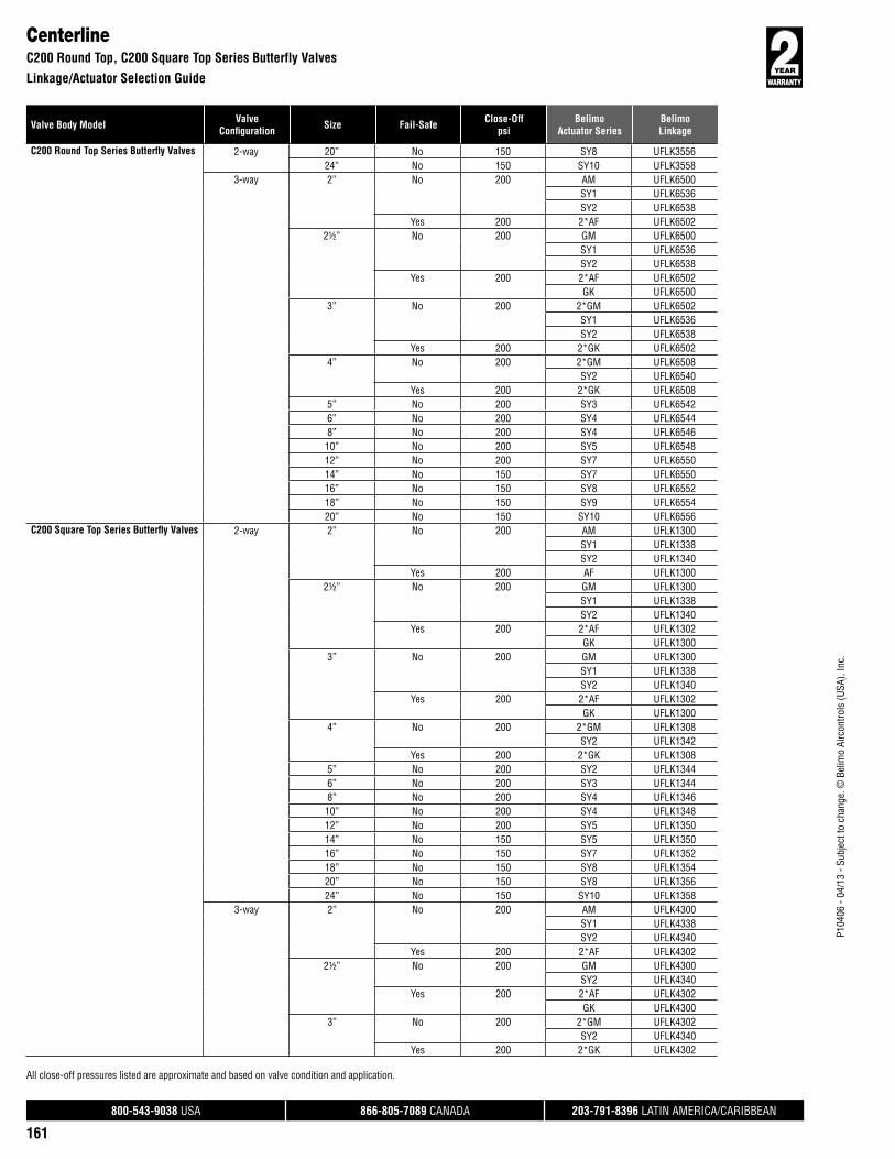
800-543-9038 USA 866-805-7089 CANADA 203-791-8396 LATIN AMERICA/CARIBBEAN
161
P104
06 -
04/1
3 - S
ubje
ct to
cha
nge.
© B
elim
o Ai
rcon
trols
(USA
), In
c.
Valve Body Model ValveConfi guration Size Fail-Safe Close-Off
psiBelimo
Actuator SeriesBelimoLinkage
All close-off pressures listed are approximate and based on valve condition and application.
CenterlineC200 Round Top, C200 Square Top Series Butterfly Valves
Linkage/Actuator Selection Guide
C200 Round Top Series Butterfl y Valves 2-way 20” No 150 SY8 UFLK355624” No 150 SY10 UFLK3558
3-way 2” No 200 AM UFLK6500SY1 UFLK6536SY2 UFLK6538
Yes 200 2*AF UFLK65022½” No 200 GM UFLK6500
SY1 UFLK6536SY2 UFLK6538
Yes 200 2*AF UFLK6502GK UFLK6500
3” No 200 2*GM UFLK6502SY1 UFLK6536SY2 UFLK6538
Yes 200 2*GK UFLK65024” No 200 2*GM UFLK6508
SY2 UFLK6540Yes 200 2*GK UFLK6508
5” No 200 SY3 UFLK65426” No 200 SY4 UFLK65448” No 200 SY4 UFLK654610” No 200 SY5 UFLK654812” No 200 SY7 UFLK655014” No 150 SY7 UFLK655016” No 150 SY8 UFLK655218” No 150 SY9 UFLK655420” No 150 SY10 UFLK6556
C200 Square Top Series Butterfl y Valves 2-way 2” No 200 AM UFLK1300SY1 UFLK1338SY2 UFLK1340
Yes 200 AF UFLK13002½” No 200 GM UFLK1300
SY1 UFLK1338SY2 UFLK1340
Yes 200 2*AF UFLK1302GK UFLK1300
3” No 200 GM UFLK1300SY1 UFLK1338SY2 UFLK1340
Yes 200 2*AF UFLK1302GK UFLK1300
4” No 200 2*GM UFLK1308SY2 UFLK1342
Yes 200 2*GK UFLK13085” No 200 SY2 UFLK13446” No 200 SY3 UFLK13448” No 200 SY4 UFLK1346
10” No 200 SY4 UFLK134812” No 200 SY5 UFLK135014” No 150 SY5 UFLK135016” No 150 SY7 UFLK135218” No 150 SY8 UFLK135420” No 150 SY8 UFLK135624” No 150 SY10 UFLK1358
3-way 2” No 200 AM UFLK4300SY1 UFLK4338SY2 UFLK4340
Yes 200 2*AF UFLK43022½” No 200 GM UFLK4300
SY2 UFLK4340Yes 200 2*AF UFLK4302
GK UFLK43003” No 200 2*GM UFLK4302
SY2 UFLK4340Yes 200 2*GK UFLK4302

800-543-9038 USA 866-805-7089 CANADA 203-791-8396 LATIN AMERICA/CARIBBEAN
162
P104
06 -
04/1
3 - S
ubje
ct to
cha
nge.
© B
elim
o Ai
rcon
trols
(USA
), In
c.
Valve Body Model ValveConfi guration Size Fail-Safe Close-Off
psiBelimo
Actuator SeriesBelimoLinkage
Flowseal1L/W Series Butterfly Valves
Linkage/Actuator Selection Guide
All close-off pressures listed are approximate and based on valve condition and application.
CenterlineC200 Square Top, C225 Square Top Series Butterfly Valves
Linkage/Actuator Selection Guide
C200 Square Top Series Butterfl y Valves 3-way 4” No 200 2*GM UFLK4308SY2 UFLK4342
Yes 200 2*GK UFLK43085” No 200 SY3 UFLK43446” No 200 SY4 UFLK43468” No 200 SY4 UFLK4348
10” No 200 SY5 UFLK435012” No 200 SY7 UFLK435214” No 150 SY7 UFLK435216” No 150 SY8 UFLK435418” No 150 SY9 UFLK435620” No 150 SY10 UFLK4358
C225 Square Top Series Butterfl y Valves 2-way 2” No 285 GM UFLK1400SY1 UFLK1436SY2 UFLK1438
Yes 285 2*AF UFLK1402GK UFLK1400
2½” No 285 GM UFLK1400SY1 UFLK1436SY2 UFLK1438
Yes 285 2*AF UFLK1402GK UFLK1400
3” No 285 GM UFLK1400SY1 UFLK1436SY2 UFLK1438
Yes 285 2*AF UFLK1402GK UFLK1400
4” No 285 2*GM UFLK1408SY2 UFLK1440
Yes 285 2*GK UFLK14085” No 285 SY2 UFLK14426” No 285 SY4 UFLK14448” No 285 SY4 UFLK1446
10” No 285 SY5 UFLK144812” No 285 SY6 UFLK145014” No 285 SY7 UFLK145216” No 285 SY9 UFLK145418” No 285 SY10 UFLK145620” No 285 SY10 UFLK1458
3-way 2” No 285 GM UFLK4400SY1 UFLK4436SY2 UFLK4438
Yes 285 GK UFLK44002½” No 285 GM UFLK4400
SY2 UFLK4438Yes 285 GK UFLK4400
3” No 285 2*GM UFLK4402SY2 UFLK4438
Yes 285 2*GK UFLK44024” No 285 SY3 UFLK44405” No 285 SY3 UFLK44426” No 285 SY4 UFLK44448” No 285 SY5 UFLK4446
10” No 285 SY7 UFLK444812” No 285 SY8 UFLK445014” No 285 SY8 UFLK445216” No 285 SY12 UFLK4454
FLOWSEAL1L/W Series Butterfl y Valves 2-way 2” No 285 GM UFLK1700
SY1 UFLK1734SY2 UFLK1736
Yes 285 2*AF UFLK1702GK UFLK1700
2½” No 285 2*GM UFLK1702SY2 UFLK1736
Yes 285 2*GK UFLK1702

800-543-9038 USA 866-805-7089 CANADA 203-791-8396 LATIN AMERICA/CARIBBEAN
163
P104
06 -
04/1
3 - S
ubje
ct to
cha
nge.
© B
elim
o Ai
rcon
trols
(USA
), In
c.
Valve Body Model ValveConfi guration Size Fail-Safe Close-Off
psiBelimo
Actuator SeriesBelimoLinkage
Flowseal1L/W, 3L/W Series Butterfly Valves
Linkage/Actuator Selection Guide
All close-off pressures listed are approximate and based on valve condition and application.
Johnson ControlsVF...(H) Series Butterfly Valves
Linkage/Actuator Selection Guide
1L/W Series Butterfl y Valves 2-way 3” No 285 2*GM UFLK1708GM UFLK1709SY2 UFLK1738
Yes 285 2*GK UFLK1708GK UFLK1709
4” No 285 2*GM UFLK1708GM UFLK1709SY2 UFLK1738
Yes 285 2*GK UFLK1708GK UFLK1709
5” No 285 SY3 UFLK17406” No 285 SY3 UFLK17408” No 285 SY4 UFLK174210” No 285 SY4 UFLK174412” No 285 SY6 UFLK174614” No 285 SY6 UFLK174616” No 285 SY7 UFLK174818” No 285 SY9 UFLK175020” No 285 SY9 UFLK1752
3-way 2” No 285 GM UFLK4700SY2 UFLK4734
Yes 285 2*AF UFLK4702GK UFLK4700
2½” No 285 2*GM UFLK4702SY2 UFLK4734
Yes 285 2*GK UFLK47023” No 285 2*GM UFLK4708
SY2 UFLK4736Yes 285 2*GK UFLK4708
4” No 285 SY3 UFLK47365” No 285 SY4 UFLK47386” No 285 SY4 UFLK47388” No 285 SY4 UFLK4740
10” No 285 SY6 UFLK474212” No 285 SY7 UFLK474414” No 285 SY8 UFLK474416” No 285 SY9 UFLK474618” No 285 SY11 UFLK474820” No 285 SY12 UFLK4750
3L/W Series Butterfl y Valves 2-way 2” No 780 SY3 UFLK18282½” No 780 SY3 UFLK18283” No 780 SY3 UFLK18304” No 780 SY4 UFLK18325” No 780 SY4 UFLK18346” No 780 SY4 UFLK18368” No 780 SY7 UFLK1838
10” No 780 SY7 UFLK184012” No 780 SY9 UFLK184214” No 780 SY9 UFLK1844
3-way 2” No 780 SY3 UFLK48282½” No 780 SY3 UFLK48283” No 780 SY3 UFLK48444” No 780 SY4 UFLK48305” No 780 SY4 UFLK48326” No 780 SY4 UFLK48348” No 780 SY8 UFLK483610” No 780 SY8 UFLK483812” No 780 SY12 UFLK484014” No 780 SY12 UFLK4842
JOHNSON CONTROLSVF.. (H) Series Butterfl y Valves 2-way 2” No 175 GM UFLK2100
SY1 UFLK2136SY2 UFLK2138
Yes 175 2*AF UFLK2102GK UFLK2100
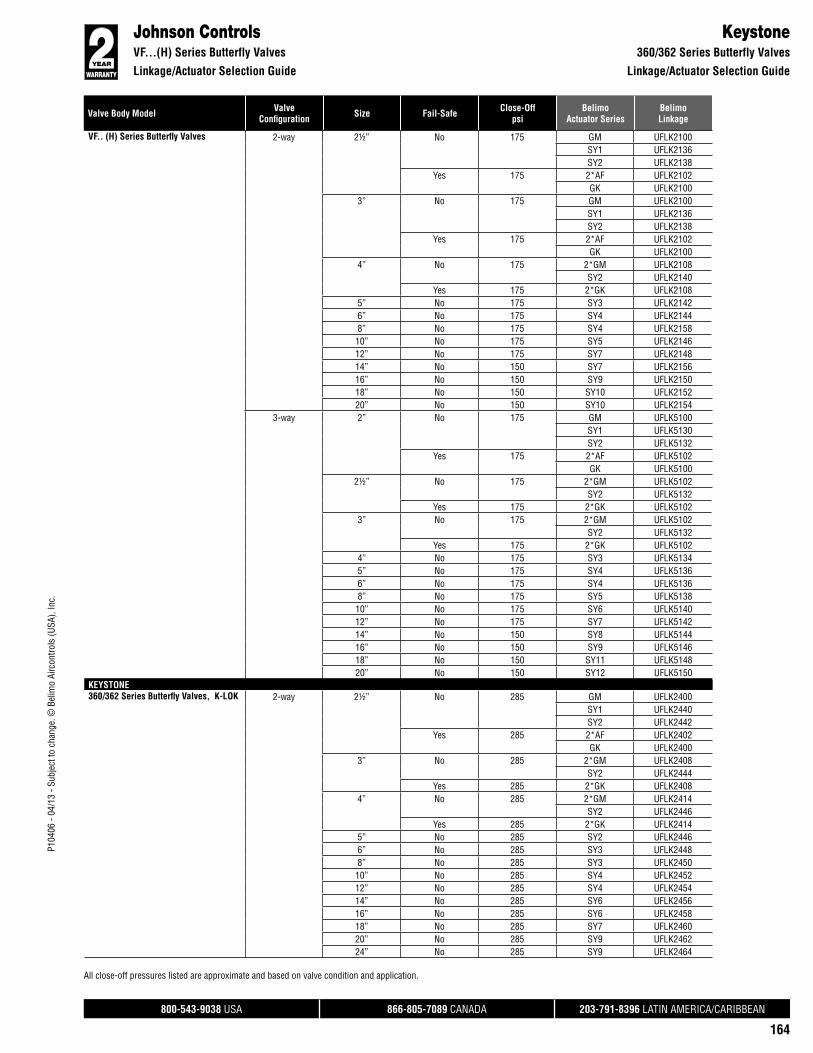
800-543-9038 USA 866-805-7089 CANADA 203-791-8396 LATIN AMERICA/CARIBBEAN
164
P104
06 -
04/1
3 - S
ubje
ct to
cha
nge.
© B
elim
o Ai
rcon
trols
(USA
), In
c.
Valve Body Model ValveConfi guration Size Fail-Safe Close-Off
psiBelimo
Actuator SeriesBelimoLinkage
Johnson ControlsVF...(H) Series Butterfly Valves
Linkage/Actuator Selection Guide
All close-off pressures listed are approximate and based on valve condition and application.
Keystone360/362 Series Butterfly Valves
Linkage/Actuator Selection Guide
VF.. (H) Series Butterfl y Valves 2-way 2½” No 175 GM UFLK2100SY1 UFLK2136SY2 UFLK2138
Yes 175 2*AF UFLK2102GK UFLK2100
3” No 175 GM UFLK2100SY1 UFLK2136SY2 UFLK2138
Yes 175 2*AF UFLK2102GK UFLK2100
4” No 175 2*GM UFLK2108SY2 UFLK2140
Yes 175 2*GK UFLK21085” No 175 SY3 UFLK21426” No 175 SY4 UFLK21448” No 175 SY4 UFLK215810” No 175 SY5 UFLK214612” No 175 SY7 UFLK214814” No 150 SY7 UFLK215616” No 150 SY9 UFLK215018” No 150 SY10 UFLK215220” No 150 SY10 UFLK2154
3-way 2” No 175 GM UFLK5100SY1 UFLK5130SY2 UFLK5132
Yes 175 2*AF UFLK5102GK UFLK5100
2½” No 175 2*GM UFLK5102SY2 UFLK5132
Yes 175 2*GK UFLK51023” No 175 2*GM UFLK5102
SY2 UFLK5132Yes 175 2*GK UFLK5102
4” No 175 SY3 UFLK51345” No 175 SY4 UFLK51366” No 175 SY4 UFLK51368” No 175 SY5 UFLK5138
10” No 175 SY6 UFLK514012” No 175 SY7 UFLK514214” No 150 SY8 UFLK514416” No 150 SY9 UFLK514618” No 150 SY11 UFLK514820” No 150 SY12 UFLK5150
KEYSTONE360/362 Series Butterfl y Valves, K-LOK 2-way 2½” No 285 GM UFLK2400
SY1 UFLK2440SY2 UFLK2442
Yes 285 2*AF UFLK2402GK UFLK2400
3” No 285 2*GM UFLK2408SY2 UFLK2444
Yes 285 2*GK UFLK24084” No 285 2*GM UFLK2414
SY2 UFLK2446Yes 285 2*GK UFLK2414
5” No 285 SY2 UFLK24466” No 285 SY3 UFLK24488” No 285 SY3 UFLK245010” No 285 SY4 UFLK245212” No 285 SY4 UFLK245414” No 285 SY6 UFLK245616” No 285 SY6 UFLK245818” No 285 SY7 UFLK246020” No 285 SY9 UFLK246224” No 285 SY9 UFLK2464

800-543-9038 USA 866-805-7089 CANADA 203-791-8396 LATIN AMERICA/CARIBBEAN
165
P104
06 -
04/1
3 - S
ubje
ct to
cha
nge.
© B
elim
o Ai
rcon
trols
(USA
), In
c.
Valve Body Model ValveConfi guration Size Fail-Safe Close-Off
psiBelimo
Actuator SeriesBelimoLinkage
All close-off pressures listed are approximate and based on valve condition and application.
Keystone360/362, 370/372, AR1/AR2 Series Butterfly Valves
Linkage/Actuator Selection Guide
360/362 Series Butterfl y Valves, K-LOK 3-way 2½” No 285 GM UFLK5400SY2 UFLK5440
Yes 285 2*AF UFLK5402GK UFLK5400
3” No 285 2*GM UFLK5408SY2 UFLK5442
Yes 285 2*GK UFLK54084” No 285 2*GM UFLK5414
SY2 UFLK5444Yes 285 2*GK UFLK5414
5” No 285 SY3 UFLK54446” No 285 SY4 UFLK54468” No 285 SY4 UFLK544810” No 285 SY4 UFLK545012” No 285 SY6 UFLK545214” No 285 SY7 UFLK545416” No 285 SY8 UFLK545618” No 285 SY9 UFLK545820” No 285 SY11 UFLK546024” No 285 SY12 UFLK5462
370/372 Series Butterfl y Valves, K-LOK 2-way 2½” No 600 SY3 UFLK25263” No 600 SY3 UFLK25284” No 600 SY4 UFLK25305” No 600 SY4 UFLK25306” No 600 SY4 UFLK25328” No 600 SY7 UFLK2534
10” No 600 SY7 UFLK253612” No 600 SY9 UFLK253814” No 600 SY9 UFLK2540
3-way 2½” No 600 SY4 UFLK55263” No 600 SY4 UFLK55284” No 600 SY4 UFLK55305” No 600 SY4 UFLK55306” No 600 SY4 UFLK55328” No 600 SY8 UFLK553410” No 600 SY8 UFLK553612” No 600 SY12 UFLK553814” No 600 SY12 UFLK5540
AR1/AR2 Series Butterfl y Valves 2-way 2” No 175 GM UFLK2300SY1 UFLK2334SY2 UFLK2336
Yes 175 2*AF UFLK2302GK UFLK2300
2½” No 175 GM UFLK2300SY1 UFLK2334SY2 UFLK2336
Yes 175 2*AF UFLK2302GK UFLK2300
3” No 175 GM UFLK2300SY1 UFLK2334SY2 UFLK2336
Yes 175 2*AF UFLK2302GK UFLK2300
4” No 175 2*GM UFLK2308SY2 UFLK2338
Yes 175 2*GK UFLK23085” No 175 SY3 UFLK23406” No 175 SY4 UFLK23568” No 175 SY4 UFLK234210” No 175 SY5 UFLK234412” No 175 SY7 UFLK234614” No 150 SY7 UFLK234816” No 150 SY9 UFLK235018” No 150 SY10 UFLK235220” No 150 SY11 UFLK235224” No 150 SY12 UFLK2354

800-543-9038 USA 866-805-7089 CANADA 203-791-8396 LATIN AMERICA/CARIBBEAN
166
P104
06 -
04/1
3 - S
ubje
ct to
cha
nge.
© B
elim
o Ai
rcon
trols
(USA
), In
c.
Valve Body Model ValveConfi guration Size Fail-Safe Close-Off
psiBelimo
Actuator SeriesBelimoLinkage
All close-off pressures listed are approximate and based on valve condition and application.
KeystoneAR1/AR2, Figure 222/221 Series Butterfly Valves
Linkage/Actuator Selection Guide
MilwaukeeCL Series Butterfly Valves
Linkage/Actuator Selection Guide
AR1/AR2 Series Butterfl y Valves 3-way 2” No 175 GM UFLK5300SY1 UFLK5332SY2 UFLK5334
Yes 175 2*AF UFLK5302GK UFLK5300
2½” No 175 GM UFLK5300SY2 UFLK5334
Yes 175 2*AF UFLK5302GK UFLK5300
3” No 175 2*GM UFLK5302SY2 UFLK5334
Yes 175 2*GK UFLK53024” No 175 SY3 UFLK53365” No 175 SY4 UFLK53386” No 175 SY4 UFLK53388” No 175 SY5 UFLK534010” No 175 SY7 UFLK534212” No 175 SY8 UFLK534414” No 150 SY9 UFLK534616” No 150 SY10 UFLK534818” No 150 SY12 UFLK5350
Figure 222 Series Butterfl y Valves 2-way 2” No 200 GM UFLK2200SY1 UFLK2224SY2 UFLK2226
Yes 200 2*AF UFLK2202GK UFLK2200
2½” No 200 GM UFLK2200SY1 UFLK2224SY2 UFLK2226
Yes 200 2*AF UFLK2202GK UFLK2200
3” No 200 GM UFLK2200SY1 UFLK2224SY2 UFLK2226
Yes 200 2*AF UFLK2202GK UFLK2200
4” No 200 2*GM UFLK2208SY2 UFLK2228
Yes 200 2*GK UFLK22085” No 200 SY3 UFLK22306” No 200 SY4 UFLK22328” No 200 SY4 UFLK223410” No 200 SY5 UFLK223612” No 200 SY7 UFLK2238
3-way 2” No 200 GM UFLK5200SY2 UFLK5224
Yes 200 2*AF UFLK5202GK UFLK5200
2½” No 200 GM UFLK5200SY2 UFLK5224
Yes 200 2*AF UFLK5202GK UFLK5200
3” No 200 2*GM UFLK5202SY2 UFLK5224
Yes 200 2*GK UFLK52024” No 200 SY3 UFLK52265” No 200 SY4 UFLK52286” No 200 SY4 UFLK52288” No 200 SY5 UFLK5230
10” No 200 SY7 UFLK523212” No 200 SY8 UFLK5234
MILWAUKEECL Series Butterfl y Valves 2-way 2” No 150 AM UFLK2600
SY1 UFLK2624SY2 UFLK2628
Yes 150 AF UFLK2600
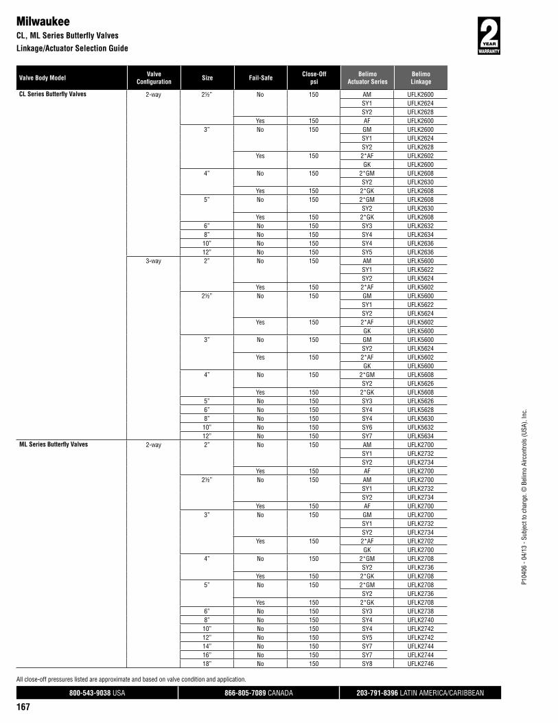
800-543-9038 USA 866-805-7089 CANADA 203-791-8396 LATIN AMERICA/CARIBBEAN
167
P104
06 -
04/1
3 - S
ubje
ct to
cha
nge.
© B
elim
o Ai
rcon
trols
(USA
), In
c.
Valve Body Model ValveConfi guration Size Fail-Safe Close-Off
psiBelimo
Actuator SeriesBelimoLinkage
All close-off pressures listed are approximate and based on valve condition and application.
MilwaukeeCL, ML Series Butterfly Valves
Linkage/Actuator Selection Guide
CL Series Butterfl y Valves 2-way 2½” No 150 AM UFLK2600SY1 UFLK2624SY2 UFLK2628
Yes 150 AF UFLK26003” No 150 GM UFLK2600
SY1 UFLK2624SY2 UFLK2628
Yes 150 2*AF UFLK2602GK UFLK2600
4” No 150 2*GM UFLK2608SY2 UFLK2630
Yes 150 2*GK UFLK26085” No 150 2*GM UFLK2608
SY2 UFLK2630Yes 150 2*GK UFLK2608
6” No 150 SY3 UFLK26328” No 150 SY4 UFLK263410” No 150 SY4 UFLK263612” No 150 SY5 UFLK2636
3-way 2” No 150 AM UFLK5600SY1 UFLK5622SY2 UFLK5624
Yes 150 2*AF UFLK56022½” No 150 GM UFLK5600
SY1 UFLK5622SY2 UFLK5624
Yes 150 2*AF UFLK5602GK UFLK5600
3” No 150 GM UFLK5600SY2 UFLK5624
Yes 150 2*AF UFLK5602GK UFLK5600
4” No 150 2*GM UFLK5608SY2 UFLK5626
Yes 150 2*GK UFLK56085” No 150 SY3 UFLK56266” No 150 SY4 UFLK56288” No 150 SY4 UFLK5630
10” No 150 SY6 UFLK563212” No 150 SY7 UFLK5634
ML Series Butterfl y Valves 2-way 2” No 150 AM UFLK2700SY1 UFLK2732SY2 UFLK2734
Yes 150 AF UFLK27002½” No 150 AM UFLK2700
SY1 UFLK2732SY2 UFLK2734
Yes 150 AF UFLK27003” No 150 GM UFLK2700
SY1 UFLK2732SY2 UFLK2734
Yes 150 2*AF UFLK2702GK UFLK2700
4” No 150 2*GM UFLK2708SY2 UFLK2736
Yes 150 2*GK UFLK27085” No 150 2*GM UFLK2708
SY2 UFLK2736Yes 150 2*GK UFLK2708
6” No 150 SY3 UFLK27388” No 150 SY4 UFLK274010” No 150 SY4 UFLK274212” No 150 SY5 UFLK274214” No 150 SY7 UFLK274416” No 150 SY7 UFLK274418” No 150 SY8 UFLK2746

800-543-9038 USA 866-805-7089 CANADA 203-791-8396 LATIN AMERICA/CARIBBEAN
168
P104
06 -
04/1
3 - S
ubje
ct to
cha
nge.
© B
elim
o Ai
rcon
trols
(USA
), In
c.
Valve Body Model ValveConfi guration Size Fail-Safe Close-Off
psiBelimo
Actuator SeriesBelimoLinkage
All close-off pressures listed are approximate and based on valve condition and application.
MilwaukeeML Series Butterfly Valves
Linkage/Actuator Selection Guide
NibcoLD1/WD1, LD2/WD2, LD3 Series Butterfly Valves
Linkage/Actuator Selection Guide
ML Series Butterfl y Valves 2-way 20” No 150 SY9 UFLK274824” No 150 SY10 UFLK2750
3-way 2” No 150 AM UFLK5700SY1 UFLK5732SY2 UFLK5734
Yes 150 2*AF UFLK57022½” No 150 AM UFLK5700
SY1 UFLK5732SY2 UFLK5734
Yes 150 2*AF UFLK57023” No 150 GM UFLK5700
SY2 UFLK5734Yes 150 2*AF UFLK5702
GK UFLK57004” No 150 2*GM UFLK5708
SY2 UFLK5736Yes 150 2*GK UFLK5708
5” No 150 SY3 UFLK57366” No 150 SY4 UFLK57388” No 150 SY4 UFLK5740
10” No 150 SY6 UFLK574212” No 150 SY7 UFLK574414” No 150 SY8 UFLK574616” No 150 SY9 UFLK574818” No 150 SY10 UFLK575020” No 150 SY11 UFLK5750
NIBCOLD1/WD1 Series Butterfl y Valves 2-way 14” No 150 SY7 UFLK2960
16” No 150 SY8 UFLK296818” No 150 SY8 UFLK296220” No 150 SY9 UFLK296424” No 150 SY11 UFLK2966
3-way 14” No 150 SY8 UFLK595616” No 150 SY9 UFLK595818” No 150 SY10 UFLK596020” No 150 SY12 UFLK5962
LD2/WD2, LD3 Series Butterfl y Valves 2-way 2” No 150 GM UFLK2900SY1 UFLK2942SY2 UFLK2946
Yes 150 2*AF UFLK2902GK UFLK2900
2½” No 150 GM UFLK2908SY1 UFLK2944SY2 UFLK2948
Yes 150 2*AF UFLK2910GK UFLK2908
3” No 150 2*GM UFLK2910SY2 UFLK2948
Yes 150 2*GK UFLK29104” No 150 2*GM UFLK2916
SY2 UFLK2950Yes 150 2*GK UFLK2916
5” No 150 SY3 UFLK29526” No 150 SY3 UFLK29528” No 150 SY4 UFLK2954
10” No 150 SY4 UFLK295612” No 150 SY6 UFLK2958
3-way 2” No 150 GM UFLK5900SY2 UFLK5942
Yes 150 2*AF UFLK5902GK UFLK5900
2½” No 150 2*GM UFLK5910SY2 UFLK5944
Yes 150 2*GK UFLK5910

800-543-9038 USA 866-805-7089 CANADA 203-791-8396 LATIN AMERICA/CARIBBEAN
169
P104
06 -
04/1
3 - S
ubje
ct to
cha
nge.
© B
elim
o Ai
rcon
trols
(USA
), In
c.
Valve Body Model ValveConfi guration Size Fail-Safe Close-Off
psiBelimo
Actuator SeriesBelimoLinkage
All close-off pressures listed are approximate and based on valve condition and application.
PDC27 Series Butterfly Valves
Linkage/Actuator Selection Guide
VictaulicMasterseal Series Butterfly Valves
Linkage/Actuator Selection Guide
LD2/WD2, LD3 Series Butterfl y Valves 3-way 3” No 150 2*GM UFLK5910SY2 UFLK5944
Yes 150 2*GK UFLK59104” No 150 SY3 UFLK59465” No 150 SY4 UFLK59486” No 150 SY4 UFLK59488” No 150 SY6 UFLK595010” No 150 SY6 UFLK595212” No 150 SY8 UFLK5954
PDC27 Series Butterfl y Valves (Double D Shaft Type)
2-way 2” No 150 GM UFLK3100SY1 UFLK3122SY2 UFLK3124
Yes 150 2*AF UFLK3102GK UFLK3100
2½” No 150 2*GM UFLK3102SY2 UFLK3124
Yes 150 2*GK UFLK31023” No 150 2*GM UFLK3102
SY2 UFLK3124Yes 150 2*GK UFLK3102
4” No 150 2*GM UFLK3108SY2 UFLK3126
Yes 150 2*GK UFLK31085” No 150 SY3 UFLK31286” No 150 SY3 UFLK31308” No 150 SY4 UFLK313210” No 150 SY4 UFLK313212” No 150 SY6 UFLK3132
3-way 2” No 150 GM UFLK6100SY2 UFLK6122
Yes 150 2*AF UFLK6102GK UFLK6100
2½” No 150 2*GM UFLK6102SY2 UFLK6122
Yes 150 2*GK UFLK61023” No 150 2*GM UFLK6102
SY2 UFLK6122Yes 150 2*GK UFLK6102
4” No 150 SY3 UFLK61245” No 150 SY4 UFLK61266” No 150 SY4 UFLK61288” No 150 SY4 UFLK613010” No 150 SY6 UFLK613212” No 150 SY7 UFLK6134
VICTAULICMasterseal (New Style) Series Butterfl y Valves
2-way 2” No 200 AM UFLK8172SY1 UFLK8178SY2 UFLK8180
Yes 200 2*AF UFLK81742½” No 200 GM UFLK8172
SY1 UFLK8178SY2 UFLK8180
Yes 200 2*AF UFLK8174GK UFLK8172
3” No 200 GM UFLK8172SY2 UFLK8180
Yes 200 GK UFLK81724” No 200 2*GM UFLK8176
SY2 UFLK8182Yes 200 2*GK UFLK8176
5” No 200 SY3 UFLK81846” No 200 SY3 UFLK81848” No 200 SY4 UFLK8188
10” No 200 SY5 UFLK819012” No 200 SY6 UFLK8190
NibcoLD2/WD2, LD3 Series Butterfly Valves
Linkage/Actuator Selection Guide

800-543-9038 USA 866-805-7089 CANADA 203-791-8396 LATIN AMERICA/CARIBBEAN
170
P104
06 -
04/1
3 - S
ubje
ct to
cha
nge.
© B
elim
o Ai
rcon
trols
(USA
), In
c.
Valve Body Model ValveConfi guration Size Fail-Safe Close-Off
psiBelimo
Actuator SeriesBelimoLinkage
All close-off pressures listed are approximate and based on valve condition and application.
VictaulicMasterseal, Vic300 Series Butterfly Valves
Linkage/Actuator Selection Guide
Masterseal (New Style) Series Butterfl y Valves
3-way 2” No 200 GM UFLK7400SY1 UFLK7404SY2 UFLK7406
Yes 200 2*AF UFLK7402GK UFLK7400
2½” No 200 2*GM UFLK7402SY2 UFLK7406
Yes 200 2*GK UFLK74023” No 200 SY2 UFLK74064” No 200 SY2 UFLK74085” No 200 SY3 UFLK74108” No 200 SY4 UFLK741412” No 200 SY7 UFLK7418
Vic300 (Old Style) Series Butterfl y Valves
2-way 2” No 300 AM UFLK3300SY1 UFLK3338SY2 UFLK3342
Yes 300 AF UFLK33002½” No 300 AM UFLK3308
SY1 UFLK3340SY2 UFLK3344
Yes 300 AF UFLK33083” No 300 GM UFLK3308
SY1 UFLK3340SY2 UFLK3344
Yes 300 2*AF UFLK3310GK UFLK3308
4” No 300 2*GM UFLK3316SY2 UFLK3346
Yes 300 2*GK UFLK33165” No 300 SY2 UFLK33486” No 300 SY3 UFLK33508” No 300 SY4 UFLK3352
10” No 300 SY4 UFLK335412” No 300 SY4 UFLK3356
3-way 2” No 300 GM UFLK6300SY1 UFLK6336SY2 UFLK6340
Yes 300 AF UFLK6300GK UFLK6300
2½” No 300 GM UFLK6308SY1 UFLK6338SY2 UFLK6342
Yes 300 2*AF UFLK6310GK UFLK6308
3” No 300 SY2 UFLK63424” No 300 SY3 UFLK63445” No 300 SY3 UFLK63466” No 300 SY4 UFLK63488” No 300 SY4 UFLK635010” No 300 SY5 UFLK635212” No 300 SY6 UFLK6354

P104
06 -
04/1
3 - S
ubje
ct to
cha
nge.
© B
elim
o Ai
rcon
trols
(USA
), In
c.
®
800-543-9038 USA 866-805-7089 CANADA 203-791-8396 LATIN AMERICA/CARIBBEAN
171
Considerations:
• The kits above do not require a completed retrofi t form. Only the make
and model of the competitor valve is needed.
• Each linkage order is custom made and will take additional time to ship
than a stock kit.
• Prices may vary with complexity of kit and material availability.
• Every retrofi t solution is available in 2-way and 3-way confi gurations for
both SY and damper style actuators.
Belimo offers specialty linkage solutions for the manufacturers in the chart below. Please contact technical support for a quotation.
Specialty Solutions for Valve Manufacturers
Valve Company Valve Series Valve Confi guration
Apollo® 141/143 Series Butterfl y Valves2-way3-way
Challenger® CH100 Series Butterfl y Valves2-way3-way
Chemtrol® PVC Model C Series Butterfl y Valves2-way3-way
Dezurik® BRS Series Butterfl y Valves2-way3-way
FNW® Figure 1000/2000 Series Butterfl y Valves2-way3-way
Gruvlok®
Figure 7700 (Double D Shaft 2003 and Newer) Series Butterfl y Valves2-way3-way
Figure 7700 (Sheared Pin Shaft Pre 2003) Series Butterfl y Valves2-way3-way
Hammond® 61/62 Series Butterfl y Valves2-way3-way
Jamesbury®
815 L/W Series Butterfl y Valves2-way3-way
830 L/W Series Butterfl y Valves2-way3-way
Jenkins® 22XXEXJ Series Butterfl y Valves2-way3-way
Metrafl ex® 200 WOG Series Butterfl y Valves2-way3-way
Mueller® 65/66 Series Butterfl y Valves2-way3-way
Quartermaster® 42/44 Series Butterfl y Valves2-way3-way
Watts® DBF Series Butterfl y Valves (Pre 2009)2-way3-way

P104
06 -
04/1
3 - S
ubje
ct to
cha
nge.
© B
elim
o Ai
rcon
trols
(USA
), In
c.
®
800-543-9038 USA 866-805-7089 CANADA 203-791-8396 LATIN AMERICA/CARIBBEAN
172
Please keep in mind that all dimensions should be taken with ALL original actuation and hardware components removed from the valve body.
Examples of dimensions A & B (Dim A and Dim B) relate to the TOP mounting holes on the butterfl y valve body. These holes are usually arranged on the body in either an “X” pattern (MOUNT STYLE 1), or a cross pattern (MOUNT STYLE 2). This information is entered on the UFSP Series Butterfl y Valve Retrofi t Form in the MOUNT STYLE section. The length of the valve stem sticking out of the top of the valve body is recorded under Dim C. The TOP mounting holes are usually drilled through the top fl ange, but sometimes are threaded. Enter this information on the form next to the mount style information previously recorded.
Next is the valve stem data. The fi ve styles of valve stems cover 98% of the butterfl y valves ever produced. Examine the valve being retrofi tted to establish which shaft style matches the diagrams above. Use caution when recording these dimensions. Careless use of calipers will result in a sloppy and possibly dysfunctional linkage system. Dim D refers to the valve stem diameter and should be measured at several points up and down as well as around the stem itself. Dim E refers to the length of the drive surface available, whether it be a key, fl atted surface, or the distance a drive hole is from the top of the stem. There are two types of keys (Keyway-Shaft Style 4 and Woodruff Key-Shaft Style 5). Please select the key size as noted in the column “For Shaft Style 4 & 5”. Dim F refers to the width of the drive surface. This is the most critical dimension for correct linkage operation. Please measure accordingly.
In addition, we require information about the environment and process in which this linkage system will be utilized.
The form must be completed in its entirety to guarantee the complete, perfect fi t of your retrofi t system. Keep in mind that retrofi t kits are designed with close-tolerance components which afford the most effi cient linkage system for the facility. Measurements rounded to the nearest 1/8 or 1/16 inch will not perform as well (sometimes not at all) as a kit designed around careful measurements using proper equipment. Our designs are typically +.005” tolerance.
Required tools - calipers and retrofi t form.
DISCLAIMER:
We will do our best to provide a linkage system designed around your specifications and measurements however, we cannot be held responsible for linkages which do not fit as a result of incorrect data given to Belimo. We will re-work components which do not fit properly for a nominal fee.
To reduce the possibility of incorrect linkage solutions, we respectfully request that you fill out the retrofit form completely and forward that information with your order. This will serve as a double check between your valve and the actuator/linkage package designed for your application.
Actuation, weather shields and linkages cannot be pre-assembled at the Belimo factory prior to your receipt. The linkages are designed to be attached onto the valve body first, then optional weather shields, and finally actuation products.
Close-off pressures are calculated using actuator torque, valve stroke, and valve area. Other factors may affect the rated close-off pressures, including flow rates, system maintenance schedules, chemicals used in the shot feeder process, vicinity to pumps, condition of valve stem seals, and assembly of linkage material in the field.
Valves that are being considered for retrofit of actuation should be analyzed for their life expectancy before the retrofit has taken place. Valves that leak through stem seals or casings will continue to leak with the new linkage system in place, maybe even more so. Rebuilding the packing on these valves may be more costly than replacing the valves themselves. In some instances, older valve stem heights will require field modifications to the valve in order to utilize the retrofit kit. Belimo takes no responsibility for the operation of these valves after they have been modified.
Custom Butterfl y Valve Retrofi t Solution FormUFSP Series
Instructions for Completing this Form

P104
06 -
04/1
3 - S
ubje
ct to
cha
nge.
© B
elim
o Ai
rcon
trols
(USA
), In
c.
®
800-543-9038 USA 866-805-7089 CANADA 203-791-8396 LATIN AMERICA/CARIBBEAN
173
Custom Butterfl y Valve Retrofi t Solution FormUFSP Series
EXISTING ACTUATOR MODEL: _______________________ CONTROL TYPE: ON/OFF FLOATING POINT VDC PWM FAIL SAFE: YES NOFAIL POSITION: NO NC VOLTAGE_____
ACTUATOR
MOUNT STYLE 1 MOUNT STYLE 2
MOUNT STYLE 3
DIM F:DIM E:DIM D:SHAFT STYLE
DIM G: DIM H:
2 WAY/3 WAY:
VALVE SIZE:
MEDIA TEMP:
MEDIA TYPE:
SYSTEM PRESSURE:
VALVE MANUFACTURE:
VALVE SERIES:
VALVE MODEL:
VALVE TAG/LOCATION:
QUANTITY:
Range:_____
COMPANY:
JOB NAME:
PO#:
PHONE:
EMAIL:
NOTE: THIS INFORMATION WILL BE UTILIZED IN THE FABRICATION OF A CUSTOM LINKAGE SYSTEM FOR YOUR VALVE REQUIREMENT; THEREFORE, IT IS ESSENTIAL THAT THE
ABOVE DIMENSIONS BE FURNISHED WITH READINGS TAKEN TO THE NEAREST .001". ANY ERRONEOUS DIMENSIONS FURNISHED WHICH RESULT IN IMPROPER FIT OF THIS LINKAGE
SYSTEM ARE NOT THE RESPONSIBILITY OF BELIMO AIRCONTROLS. ANY REWORK REQUIRED WILL RESULT IN AN EXTRA CHARGE.
INDOOR OUTDOORRange:_____
VALVE
B
A
SHAFT
CBODY
BA
SHAFT
VALVEBODY C
BA
CBODYVALVE
SHAFT
SHAFT STYLE 9
VALVE CLOSED
CHECK ONE
FG
PINNED
SHAFT STYLE 8
E
DFD
E
SHAFT STYLE 6
DOUBLE DKEYWAY
SHAFT STYLE 4
E
D
D
E
SHAFT STYLE 9
SQUARE
F
KEY SIZE
.125"
.1875"
.250"
.3125"
.375"
.4375"
.500"H
E
D
F
G
SHAFT STYLE 5
WOODRUFF KEY
F
E
SHAFT STYLE 7
HEXCHECK ONE
DIA Ø:
DRILLED
MOUNTING HOLES:
MOUNT STYLE
DIM C:
DIM B:
DIM A:
THREAD
SPEC.
DIM. A & B MEASURED FROM CENTER OF HOLE
TAPPED
MOUNT STYLE DIMENSIONS
MOUNT STYLE 4 SKETCH YOUR MOUNT STYLE USING MOUNT STYLE EXAMPLES.
D
Ex: 0.437"
Ex: 1/2-20
MOUNTINGHOLES
MOUNTINGHOLES
MOUNTINGHOLES
F
G

P104
06 -
04/1
3 - S
ubje
ct to
cha
nge.
© B
elim
o Ai
rcon
trols
(USA
), In
c.
®
800-543-9038 USA 866-805-7089 CANADA 203-791-8396 LATIN AMERICA/CARIBBEAN
174
Custom Butterfly Valve Retrofit SolutionsComponent Identification
2-way Single ActuatorGeneric – Retrofit Form Required
2-way Dual ActuatorGeneric – Retrofit Form Required
2-way SY ActuatorGeneric – Retrofit Form Required
DRIVE SHAFT
PIN
SHAFT LOCK
TI-ROTATION NUT
ANTI-ROTATION PIN
ACTUATOR PLATE
BOLT (4)
NUT (4)
EXISTING VALVE BODY
VALVE STEM
TOP MOUNTING HOLES
VALVE DISC
LUG MOUNTING HOLES
VALVE COUPLING
EXISTING VALVE BODY
LUG MOUNTING HOLESVALVE DISC
TOP MOUNTING HOLES
ANTI-ROTATION PIN
NUT (4)
ANTI-ROTATION NUTBOLT (4)
VALVE STEM
ACTUATOR PLATE
SHAFT LOCK
PIN
DRIVE SHAFT
VALVE COUPLING
(2)
(2)
LUG MOUNTING HOLES VALVE DISC
TOP MOUNTING HOLES
EXISTING VALVE BODY
VALVE STEM
COUPLING(WELDED)
INDUSTRIAL
BRACKET
BOLT (4)
BOLT (4)
NUT (4)
LOCK WASHER (4)
UFSP0000 UFSP0008 UFSP0020 SY1 - SY8 UFSP0022 SY9 - SY12
3-way Single ActuatorGeneric – Retrofit Form Required
3-way Dual ActuatorGeneric – Retrofit Form Required
3-way SY ActuatorGeneric – Retrofit Form Required
EXISTING VALVE
CRANK ARM (2)
COTTER PIN (2)
CONNECTING ROD
EXISTING VALVE
EXISTING TEE
ANTI-ROTATION NUT
NUT (4)
TOP MOUNTING HOLES
ANTI-ROTATION PIN
ACTUATOR PLATE
BOLT (4)
SHAFT LOCK (2)
PIN
CLEVIS PIN (2)
YOKE (2)
DRIVE SHAFT
CRANK LOCK (2)
JAMB NUT
VALVE COUPLING (2)
VALVE STEM
EXISTING VALVE
NUT (8)
EXISTING VALVE
TOP MOUNTING HOLES
ANTI-ROTATION PIN (2)
ANTI-ROTATION NUT (2)
ACTUATOR PLATE (2)
CRANK ARM (2)
COTTER PIN (2)
CONNECTING ROD
YOKE (2)
DRIVE SHAFT (2)
PIN (2)
SHAFT LOCK (2)
BOLT (8)
CLEVIS PIN (2)
EXISTING TEE
CRANK LOCK (2)
VALVE STEM
VALVE COUPLING (2)
JAMB NUT
UFSP0002 UFSP0010 UFSP0024 SY1 - SY8UFSP0026 SY9 - SY12
NOTE: 3-way bracket configuration shown is only one of many possible arrangements. Custom kits are designed to your unique specifi cation and are not returnable.

P104
06 -
04/1
3 - S
ubje
ct to
cha
nge.
© B
elim
o Ai
rcon
trols
(USA
), In
c.
®
800-543-9038 USA 866-805-7089 CANADA 203-791-8396 LATIN AMERICA/CARIBBEAN
175
Valve AccessoriesButterfly Valves
ELECTRIC DISCONNECT
HOA-120V Local electric disconnect SY2-SY12; 2 position - 110/230V
HOA-120VMFT Local electric disconnect SY2-SY12; proportional - 110/230V
HOA-24V Local electric disconnect SY2-SY12; 2 position - 24V
HOA-24VMFT Local electric disconnect SY2-SY12; proportional - 24V
POTENTIOMETERS
SY-1000-FB01 1000 feedback potentiometer. SY2-12, 2 position
SY-1000-FB02 1000 feedback potentiometer. SY2-12, proportional
BATTERY BACKUP
EXT-NSV-B01-120 Battery backup system for Belimo SY1 - SY3 120 VAC, on/off actuators
EXT-NSV-B02-120 Battery backup system for Belimo SY1 - SY3 120 VAC, MFT actuators
EXT-NSV-B03-120 Battery backup system for Belimo SY4 - SY6 120 VAC, on/off actuators
EXT-NSV-B04-120 Battery backup system for Belimo SY4 - SY6 120 VAC, MFT actuators
EXT-NSV-B05-120 Battery backup system for Belimo SY7 - SY12 120 VAC, on/off actuators
EXT-NSV-B06-120 Battery backup system for Belimo SY7 - SY12 120 VAC, MFT actuators
EXT-NSV-B11-24 Battery backup system for Belimo SY1 24 VAC, on/off actuators
EXT-NSV-B12-24 Battery backup system for Belimo SY1 24V MFT actuators
EXT-NSV-B13-24 Battery backup system for Belimo SY2 - SY5 24 VAC, on/off actuators
EXT-NSV-B14-24 Battery backup system for Belimo SY2 - SY5 24 VAC, MFT actuators
EXT-NSV-B21-230 Battery backup system for Belimo SY1 - SY3 230 VAC, on/off actuators
EXT-NSV-B22-230 Battery backup system for Belimo SY1 - SY3 230 VAC, MFT actuators
EXT-NSV-B23-230 Battery backup system for Belimo SY4 - SY6 230 VAC, on/off actuators
EXT-NSV-B24-230 Battery backup system for Belimo SY4 - SY6 230 VAC, MFT actuators
EXT-NSV-B25-230 Battery backup system for Belimo SY7 - SY12 230 VAC, on/off actuators
EXT-NSV-B26-230 Battery backup system for Belimo SY7 - SY12 230 VAC, MFT actuators
HANDWHEELS
ZG-SY23 SY2-3 handwheel (replacement only)
ZG-SY46 SY4-6 handwheel (replacement only)
ZG-SY78 SY7-8 handwheel (replacement only)
ZG-SY912 SY9-12 handwheel (replacement only)

• Full range of kits for 2-way and 3-way valve assemblies.
• Visual stroke indicators allow quick installation.
• Linkages can be mounted in any orientation except upside down.
• NEMA 2 and NEMA 4 options available.
Applications
UBSP Ball Valve Retrofi t Solutions are designed to easily attach to the valve mounting
pad of competitor valves utilizing Belimo actuators. This kit will help to restore service
without removal of the valve, saving down time and money.
Ball Valve Retrofi t Solutions

®
P104
06 -
04/1
3 - S
ubje
ct to
cha
nge.
© B
elim
o Ai
rcon
trols
(USA
), In
c.
This PageIntentionally Left Blank
800-543-9038 USA 866-805-7089 CANADA 203-791-8396 LATIN AMERICA/CARIBBEAN
177

P104
06 -
04/1
3 - S
ubje
ct to
cha
nge.
© B
elim
o Ai
rcon
trols
(USA
), In
c.
®
800-543-9038 USA 866-805-7089 CANADA 203-791-8396 LATIN AMERICA/CARIBBEAN
178
Custom Ball Valve Retrofi t Solution FormUBSP Series
Ball valves with-out a mounting fl ange are typically not designed for installing actuation, therefore the valve design may not support modulation outside of manual usage. Belimo does not recommend retrofi tting these types of ball valves.
All dimensions should be taken with ALL original actuation and hardware components removed from the valve body.
An example using Mounting Style 3: Dimensions A & B (Dim A and Dim B) relate to the TOP mounting holes on the ball valve body. These holes are usually arranged on the body in a “X” pattern (MOUNT STYLE 3). This information is entered on the UBSP Series Ball Valve Retrofi t Form in the MOUNT STYLE section. The length of the valve stem sticking out of the top of the valve body is recorded under Dim D and E. The TOP mounting holes are usually drilled through the top fl ange, but sometimes are threaded. Enter this information on the form next to the mount style information previously recorded.
MOUNT STYLE 3: Dimensions A & B (Dim A and Dim B) relate to the TOP mounting holes on the ball valve body. These holes are usually arranged on the body in a “X” pattern (MOUNT STYLE 3). This information is entered on the UBSP Series Ball Valve Retrofi t Form in the MOUNT STYLE section. The length of the valve stem sticking out of the top of the valve body is recorded under Dim D and E. The TOP mounting holes are usually drilled through the top fl ange, but sometimes are threaded. Enter this information on the form next to the mount style information previously recorded.
STEM STYLE: Examine the valve being retrofi tted to establish which stem style matches the diagrams above. Use caution when recording these dimensions. Dim H refers to the valve stem diameter and should be measured at several points up and down as well as around the stem itself. Dim E refers to the length of the drive surface available, whether it is a key or fl atted surface. Dim F refers to the width of the drive surface or the distance across the fl ats. This is the most critical dimension for correct linkage operation. Please measure accordingly. Lastly please specify the desired actuator orientation in reference to the valve body using the ports as reference, i.e. over the “A” port etc. We have also includes an ISO-5211 standard dimension chart for reference. If the valve is labeled please specify its “F” number so that we may confi rm the dimensions per the ISO spec.
In addition, we require information about the environment and process in which this linkage system will be utilized. As well as the frequency of use the current actuator runs. This will help to ensure the longevity of the new linkage and actuator. Having the prior actuator spec and model will help.
The form must be completed in its entirety to guarantee the complete, perfect fi t of your retrofi t system. Keep in mind that retrofi t kits are designed with close-tolerance components which afford the most effi cient linkage systems. Measurements rounded to the nearest 1/8 or 1/16 inch will not perform as well (sometimes not at all) as a kit designed around careful measurements using proper equipment. Our designs are typically +.005” tolerance.
Required tools - calipers and retrofi t form.
DISCLAIMER:
We will do our best to provide a linkage system designed around your specifications and measurements however, we cannot be held responsible for linkages which do not fit as a result of incorrect data given to Belimo. We will re-work components which do not fit properly for a nominal fee.
To reduce the possibility of incorrect linkage solutions, we respectfully request that you fill out the retrofit form completely and forward that information with your order. This will serve as a double check between your valve and the actuator/linkage package designed for your application.
Actuation, weather shields and linkages cannot be pre-assembled at the Belimo factory prior to your receipt. The linkages are designed to be attached onto the valve body first, then optional weather shields, and finally actuation products.
Close-off pressures are calculated using actuator torque, valve stroke, and valve area. Other factors may affect the rated close-off pressures, including flow rates, system maintenance schedules, chemicals used in the shot feeder process, vicinity to pumps, condition of valve stem seals, and assembly of linkage material in the field.
Valves that are being considered for retrofit of actuation should be analyzed for their life expectancy before the retrofit has taken place. Valves that leak through stem seals or casings will continue to leak with the new linkage system in place, maybe even more so. Rebuilding the packing on these valves may be more costly than replacing the valves themselves. In some instances, older valve stem heights will require field modifications to the valve in order to utilize the retrofit kit. Belimo takes no responsibility for the operation of these valves after they have been modified.
Instructions for Completing this Form

P104
06 -
04/1
3 - S
ubje
ct to
cha
nge.
© B
elim
o Ai
rcon
trols
(USA
), In
c.
®
800-543-9038 USA 866-805-7089 CANADA 203-791-8396 LATIN AMERICA/CARIBBEAN
179
EXISTING ACTUATOR MODEL: _______________________ CONTROL TYPE: ON/OFF FLOATING POINT VDC PWM FAIL SAFE: YES NOFAIL POSITION: NO NC FREQUENCY OF OPERATION (specify how often): DAILY_____ WEEKLY_____ MONTHLY_____
ACTUATORORIENTATION:
SKETCH YOUR MOUNT STYLE USING EXAMPLES ABOVE
DIA Ø:DRILLED
MOUNTING HOLES:MOUNT STYLE
DIM C:
DIM B:
DIM A:
A A
B
THREAD SPEC.
DIM. A & B MEASURED FROM CENTER OF HOLE
TAPPED
ACTUATOR
B
A
MOUNTING HOLE
HACROSS FLATS
I LARGEST AREATO CLEAR OR NUT
# OF NUTS: ______
G
F
TOP OF NUT TO TOP OF STEM
J DIAMETER OF STEM
C
J DIAMETER OF STEM
NUT ON STEM NO NUT
G F
STEM STYLE 1
DIM D:
D
STEM STYLE 2
MOUNT STYLE 1 MOUNT STYLE 2 MOUNT STYLE 3
MOUNT STYLE 4
STEM STYLE 3
VALVE IN CLOSED POSITION
DIM H:DIM G:DIM F:STEM STYLE
DIM I: DIM J:
CENTER OF STEMTO END OF STOP
MOUNTING HOLE MOUNTING HOLE
ISO STANDARD
H
H
G
F
TOP OF NUT TO TOP OF STEM
DIAGONAL PARALLEL
2 WAY/3 WAY:
VALVE SIZE:
MEDIA TEMP:
MEDIA TYPE:
SYSTEM PRESSURE:
VALVE MANUFACTURE:
VALVE SERIES:
VALVE MODEL:
VALVE TAG/LOCATION:
QUANTITY:
ISO BOLT SQUARE
BOLT SIZE Ø
CHECK ONE
F03 1.002 M5F04 1.169 M5F05 1.392 M6F07 1.949 M8F10 2.840 M10F12 3.480 M12F14 3.879 M16F16 4.593 M20F25 7.071 M16
Range:_____
COMPANY:
JOB NAME:
PO#:
PHONE:
EMAIL:
NOTE: THIS INFORMATION WILL BE UTILIZED IN THE FABRICATION OF A CUSTOM LINKAGE SYSTEM FOR YOUR VALVE REQUIREMENT; THEREFORE, IT IS ESSENTIAL THAT THE
ABOVE DIMENSIONS BE FURNISHED WITH READINGS TAKEN TO THE NEAREST .001". ANY ERRONEOUS DIMENSIONS FURNISHED WHICH RESULT IN IMPROPER FIT OF THIS LINKAGE
SYSTEM ARE NOT THE RESPONSIBILITY OF BELIMO AIRCONTROLS. ANY REWORK REQUIRED WILL RESULT IN AN EXTRA CHARGE.
CUSTOM KITS ARE DESIGNED TO YOUR UNIQUE SPECIFICATIONS AND ARE NOT RETURNABLE. COMPANY CONTACT/DIMENSIONS PROVIDED BY: ____________________________________________________________________ DATE: ___________________
A AB
B
INDOOR OUTDOOR
DIM E:
E E
E
MOUNT STYLE DIMENSIONS
Range:_____
SQUARE DRIVE
VOLTAGE: _____
I
Custom Ball Valve Retrofi t Solution Form

P104
06 -
04/1
3 - S
ubje
ct to
cha
nge.
© B
elim
o Ai
rcon
trols
(USA
), In
c.
®
800-543-9038 USA 866-805-7089 CANADA 203-791-8396 LATIN AMERICA/CARIBBEAN
180
Custom Ball Valve Retrofi t SolutionsComponent Identification
2-way/3-way Single ActuatorGeneric – Retrofit Form Required
2-way/3-way Dual ActuatorGeneric – Retrofit Form Required
DRIVE SHAFT
ROLL PIN
BUSHING
NYLON WASHER
VALVE COUPLING
MOUNTINGBRACKET
NUT
LOCK WASHER
BOLT
ANTI-ROTATIONPIN
ACTUATOR PLATE
NUT
BOLT
NUT
ANTI-ROTATION PIN
NUT
EXTENSION
EXTENSION
BOLT
BUSHING ACTUATOR PLATE
ROLL PIN
DRIVE SHAFT
BUSHING
NYLONWASHER
VALVE COUPLING
NUTNUT
LOCKWASHER
MOUNTINGBRACKET
BOLTANTI-ROTATION
PIN
NUT
ACTUATOR PLATE
BOLT
BOLT
UBSP0004 UBSP0006
Industrial Electric 2-way/3-wayGeneric – Retrofit Form Required
MOUNTINGBRACKET
SY CPL/INTERFACE
VALVE COUPLING
NUT
LOCK WASHER
BOLT
BOLT
SPLIT LOCKWASHER
UBSP0012 SY7-SY9Custom kits are designed to your unique specifi cation and are not returnable.
UBSP0008 SY1-SY6

P104
06 -
04/1
3 - S
ubje
ct to
cha
nge.
© B
elim
o Ai
rcon
trols
(USA
), In
c.
®
800-543-9038 USA 866-805-7089 CANADA 203-791-8396 LATIN AMERICA/CARIBBEAN
181
UBSP0004 Custom Retrofi t Linkage for Ball ValvesFor Use with Belimo Rotary Actuators
Technical Data
Service chilled or hot water and steamApplicable valve size ½" [13], ¾" [19], 1" [25], 1-¼" [32], 1-½"
[38], 2" [50]Frame, plate, base stainless steelShaft diameter ½” to ¾” roundShaft stainless steelCoupling stainless steelBearing bronze oil-liteMounting position 360°Media temp. range (water) -22°F to +298°F [-30°C to +148°C]Media temp. range (steam) 20°F to 298°F [-7°C to +148°C]Weight 9 lbs
ApplicationThe UBSP custom retrofit kit is designed to easily attach to the valve mounting pad on select competitor valves utilizing Belimo actuators. This kit will help to restore service without removal of the valve, saving down time. The UBSP retrofit kit is available in various configurations for use with both 2-way and 3-way valves utilizing single or dual actuation.
OperationThe UBSP custom kit and mounted actuator(s) are capable of rotating 95° in both CW and CCW directions. This allows the ball to fully open or close. When directional needs vary, the actuators can be flipped or directional switch turned to a new rotation. Refer to Master Slave wiring for dual mounted actuators.
Default/ConfigurationThe actuator is sold separately from the linkage, allowing users to select an actuator with the desired control signal. The linkage utilizes standard airside or SY actuators which can be purchased at any time and mounted in the field.
Suitable Actuators
Linkage Spring Return Electronic Fail-Safe
Non-Spring Return
UBSP0004 LF, NF, AF GK LM, NM, AM, GM
Dimensions (Inches [mm])
F
A
BC
A B C F
8.00 [203.2] 2.00 [51] 8.00 [203] 6.00 [152.4]
Application NotesCustom retrofit kits require a filled out retrofit form during or before ordering.
DRIVE SHAFT
ROLL PIN
BUSHING
NYLON WASHER
VALVE COUPLING
MOUNTINGBRACKET
NUT
LOCK WASHER
BOLT
ANTI-ROTATIONPIN
ACTUATOR PLATE
NUT
BOLT
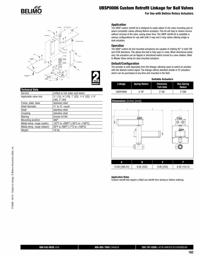
P104
06 -
04/1
3 - S
ubje
ct to
cha
nge.
© B
elim
o Ai
rcon
trols
(USA
), In
c.
®
800-543-9038 USA 866-805-7089 CANADA 203-791-8396 LATIN AMERICA/CARIBBEAN
182
UBSP0006 Custom Retrofi t Linkage for Ball ValvesFor Use with Belimo Rotary Actuators
Technical Data
Service chilled or hot water and steamApplicable valve size ½" [13], ¾" [19], 1" [25], 1-¼" [32], 1-½"
[38], 2" [50]Frame, plate, base stainless steelShaft diameter ½” to ¾” roundShaft stainless steelCoupling stainless steelBearing bronze oil-liteMounting position 360°Media temp. range (water) -22°F to +298°F [-30°C to +148°C]Media temp. range (steam) 20°F to 298°F [-7°C to +148°C]Weight 18 lbs
ApplicationThe UBSP custom retrofit kit is designed to easily attach to the valve mounting pad on select competitor valves utilizing Belimo actuators. This kit will help to restore service without removal of the valve, saving down time. The UBSP retrofit kit is available in various configurations for use with both 2-way and 3-way valves utilizing single or dual actuation.
OperationThe UBSP custom kit and mounted actuator(s) are capable of rotating 95° in both CW and CCW directions. This allows the ball to fully open or close. When directional needs vary, the actuators can be flipped or directional switch turned to a new rotation. Refer to Master Slave wiring for dual mounted actuators.
Default/ConfigurationThe actuator is sold separately from the linkage, allowing users to select an actuator with the desired control signal. The linkage utilizes standard airside or SY actuators which can be purchased at any time and mounted in the field.
Suitable Actuators
Linkage Spring Return Electronic Fail-Safe
Non-Spring Return
UBSP0006 2*AF 2*GK 2*GM
Dimensions (Inches [mm])
FBC
A
A B C F
15.60 [396.24] 8.00 [203] 8.00 [203] 6.00 [152.4]
Application NotesCustom retrofit kits require a filled out retrofit form during or before ordering.
NUT
ANTI-ROTATION PIN
NUT
EXTENSION
EXTENSION
BOLT
BUSHING ACTUATOR PLATE
ROLL PIN
DRIVE SHAFT
BUSHING
NYLONWASHER
VALVE COUPLING
NUTNUT
LOCKWASHER
MOUNTINGBRACKET
BOLTANTI-ROTATION
PIN
NUT
ACTUATOR PLATE
BOLT
BOLT

P104
06 -
04/1
3 - S
ubje
ct to
cha
nge.
© B
elim
o Ai
rcon
trols
(USA
), In
c.
®
800-543-9038 USA 866-805-7089 CANADA 203-791-8396 LATIN AMERICA/CARIBBEAN
183
UBSP0008 Custom Retrofi t Linkage for Ball ValvesFor Use with Belimo SY Actuators
Technical Data
Service chilled or hot water and steamApplicable valve size ½" [13], ¾" [19], 1" [25], 1-¼" [32], 1-½"
[38], 2" [50], 2-½” [63.5], 3” [76.2]Frame, plate, base stainless steelShaft steelCoupling steelMounting position 360°Media temp. range (water) -22°F to +298°F [-30°C to +148°C]Media temp. range (steam) 20°F to 298°F [-7°C to +148°C]Housing NEMA 4X, IP66Weight 12 lbs
ApplicationThe UBSP custom retrofit kit is designed to easily attach to the valve mounting pad on select competitor valves utilizing Belimo actuators. This kit will help to restore service without removal of the valve, saving down time. The UBSP retrofit kit is available in various configurations for use with both 2-way and 3-way valves utilizing single or dual actuation.
OperationThe UBSP custom kit and mounted actuator(s) are capable of rotating 95° in both CW and CCW directions. This allows the ball to fully open or close. When directional needs vary, the actuators can be flipped or directional switch turned to a new rotation. Refer to Master Slave wiring for dual mounted actuators.
Default/ConfigurationThe actuator is sold separately from the linkage, allowing users to select an actuator with the desired control signal. The linkage utilizes standard airside or SY actuators which can be purchased at any time and mounted in the field.
Suitable Actuators
Linkage Non-Spring Return
UBSP0008 SY1, SY2, SY3, SY4, SY5, SY6
Dimensions (Inches [mm])
CB
A
A B C
16.63 [422.4] 12.00 [305] 15.00 [381]
Application NotesCustom retrofit kits require a filled out retrofit form during or before ordering.
MOUNTINGBRACKET
SY CPL/INTERFACE
VALVE COUPLING
NUT
LOCK WASHER
BOLT
BOLT
SPLIT LOCKWASHER

P104
06 -
04/1
3 - S
ubje
ct to
cha
nge.
© B
elim
o Ai
rcon
trols
(USA
), In
c.
®
800-543-9038 USA 866-805-7089 CANADA 203-791-8396 LATIN AMERICA/CARIBBEAN
184
UBSP0012 Custom Retrofi t Linkage for Ball ValvesFor Use with Belimo SY Actuators
Technical Data
Service chilled or hot water and steamApplicable valve size 3” [76.2], 4” [101.6], 5” [127], 6” [152.4]Frame, plate, base stainless steelShaft steelCoupling steelMounting position 360°Media temp. range (water) -22°F to +298°F [-30°C to +148°C]Media temp. range (steam) 20°F to 298°F [-7°C to +148°C]Housing NEMA 4X, IP66Weight 20 lbs
ApplicationThe UBSP custom retrofit kit is designed to easily attach to the valve mounting pad on select competitor valves utilizing Belimo actuators. This kit will help to restore service without removal of the valve, saving down time. The UBSP retrofit kit is available in various configurations for use with both 2-way and 3-way valves utilizing single or dual actuation.
OperationThe UBSP custom kit and mounted actuator(s) are capable of rotating 95° in both CW and CCW directions. This allows the ball to fully open or close. When directional needs vary, the actuators can be flipped or directional switch turned to a new rotation. Refer to Master Slave wiring for dual mounted actuators.
Default/ConfigurationThe actuator is sold separately from the linkage, allowing users to select an actuator with the desired control signal. The linkage utilizes standard airside or SY actuators which can be purchased at any time and mounted in the field.
Suitable Actuators
Linkage Non-Spring Return
UBSP0012 SY7, SY8, SY9, SY10, SY11, SY12
Dimensions (Inches [mm])
CB
A
A B C
19.7 [499] 14.00 [356] 21.00 [533]
Application NotesCustom retrofit kits require a filled out retrofit form during or before ordering.
MOUNTINGBRACKET
SY CPL/INTERFACE
VALVE COUPLING
NUT
LOCK WASHER
BOLT
BOLT
SPLIT LOCKWASHER

Visit www.belimo.us to fi nd the latest resources for Retrofi t Solutions.
02/1
3 -
Subj
ect t
o ch
ange
. © B
elim
o Ai
rcon
trols
(USA
), In
c.7
15
35
-00
00
1.B INSTRUCTION MANUAL
SGVL/G2/G3 with LV and SV Series Actuators
4mm
1
2
!3
2!
2
1
A AB
B
A AB
A AB
1
2
1
2
4
36
32 4
5
7
5Nm
4mm
2
2
1
8
Adaption
1
1
Belim
o Pr
ojec
t: Ne
w Y
ork
Tim
es B
uild
ing,
New
Yor
k
Valve Retrofit Installation Instructionsfor use with Electronic Actuators Effective February 2010
®
• Installation Instructions• Animations• Submittal Pages• Product Presentations• Terms & Conditions• Actuator and Valve Specifi cations• And much more!

Belimo Americas Platinum DistributorsU
SA ACR Supply Company Inc.
4040 S. Alston AvenueDurham, NC 27713Phone: 919-765-8081With branches in NC
Aireco Supply9120 Washington BoulevardSavage, MD 20763-0414Phone: 301-953-8800With branches in MD, VA
Amcon Controls, Inc.11906 Warfield StreetSan Antonio,TX 78216Phone: 210-349-6161Houston, TX branch 713-464-7002Mandeville, LA branch 985-624-3303
Wilson Mohr (was Applied Automation) 3186 South Washington Street, #230Salt Lake City, UT 84115Phone: 801-486-6454With branches in CO, TX
Boston Aircontrols, Inc.8 Blanchard RoadBurlington, MA 01803Phone: 781-272-5800
Charles D. Jones Co.445 Bryant Street, Unit #1Denver, CO 80204-4800Phone: 800-777-0910With branches in CO, MO, KS
Cochrane Supply and Engineering, Inc.30303 Stephenson HighwayMadison Heights, MI 48071-1633Phone: 800-482-4894With branches in MI and Maumee, OH
Columbus Temperature Control1053 E. 5th AvenueColumbus, OH 43201Phone: 800-837-1837
Controlco985 3rd StreetOakland, CA 94607 Phone: 510-636-7900With branches in CA, NV
Control Products9101 Jameel, Suite 130Houston, TX 77447Phone: 713-849-7200
Edward C. Smyers & Co.223 Fort Pitt BoulevardPittsburgh, PA 15222-1505Phone: 412-471-3222
Engineered Control Systems5627 NW 74th AvenueMiami, FL 33166Phone: 305-885-8804With branches in FL
G & O Thermal Supply5435 N. Northwest HighwayChicago, IL 60630Phone: 773-763-1300With branches in IL
Industrial Controls Distributors, LLC (was Climatic Control) 5061 W. State StreetMilwaukee, WI 53208Phone: 800-242-1656With branches in WI
Industrial Controls Distributors LLC17 Christopher WayEatontown, NJ 07724Phone:800-543-8200With branches inGA, KY, IN, MA, ME, NC, NY, OH, PA, TN
Interstate HVAC Controls30 Vineland StreetBrighton, MA 02135 Phone: 617-782-9000
Jackson Controls1708 E. 10th StreetIndianapolis, IN 46201Phone: 317-231-2200
M & M Controls9E West Aylesbury RoadTimonium, MD 21093Phone: 410-252-1221With a branch in Alexandria, VA
MICONTROLS, Inc.6516 5th Place SouthSeattle, WA 98124Phone: 800-877-8026With branches in WA, OR
Meier Supply123 Brown StreetJohnson City, NY 13790 Phone: 607-797-7700With branches in NY, PA
Minvalco, Inc.3340 Gorham AvenueMinneapolis, MN 55426-4267Phone: 952-920-0131With branches in MN
RSD / Refrigeration Supplies Distributor 26021 Atlantic Ocean DriveLake Forest, CA 92630Phone: 949-380-7878With branches inCA, NV, OR, AK, AZ, ID, UT, WA, MT, CO
Saint Louis Boiler Supply, Co. 617 Hanley Industrial CourtSt. Louis, MO 63144Phone: 314-962-9242
South Side Control Supply, Co. 488 N. Milwaukee AvenueChicago, IL 60610-3923Phone: 312-226-4900With branches in IL, IN
Stromquist and Company4620 Atlanta RoadSmyrna, GA 30080Phone: 404-794-3440With a branch in Orlando, FL
Temperature Control Systems10315 Brockwood RoadDallas, TX 75238Phone: 214-343-1444With branches in OK, TX
Tower Equipment Co., Inc.1320 West Broad StreetStratford, CT 06615Phone: 800-346-4647
Twinco Supply Corporation55 Craven StreetHuntington Station, NY 11746-2143Phone: 800-794-3188With branches in NY
Wilson-Mohr, Inc.12610 West Airport Blvd, Suite 100Sugarland, TX 77478Phone: 281-295-8850
For a complete list of distributors in Canada, please visit our website: www.belimo.caor call toll free: 866-805-7089
For a complete list of distributors in Latin America and the Caribbean, please visit our website: www.belimo.usor call: 203-791-8396
C
AN
AD
AL
AT
IN A
ME
RIC
A &
TH
E C
AR
IBB
EA
N
For a complete list of distributors in Brazil, please visit our website: www.belimo.com.bror call: 55 11 3643-5656
B
RA
ZIL

P104
06 -
04/1
3 - S
ubje
ct to
cha
nge.
© B
elim
o Ai
rcon
trols
(USA
), In
c.
Sizing and Selection Made Simple. Get it Here, Download it Now!www.belimo.us/ishop/cms/sh/selectpro/select.html
SelectPro provides a fast, user-friendly and fl exible means for accurately sizing and selecting control valves, damper actuators, retrofi t linkages and actuators, and piping packages in HVAC systems. Software capabilities include:
Calculating HVAC component cost for any size project.
Generating valve/actuator submittal data for project.
Printing project data, component data and pricing.
Exporting project data and selected products to Excel data format.
Saving projects in .xls or .bel fi le format for future editing or ordering.
Automatically uploading data through web interface for easy ordering.
SelectProTM
Belimo worldwide: www.belimo.com
BELIMO AmericasUSA Locations, 43 Old Ridgebury Road, Danbury, CT 06810Tel. 800-543-9038, Fax 800-228-8283, [email protected]
1049 Fortunato Loop, Sparks, NV 89436Tel. 800-987-9042, Fax 800-987-8875, [email protected]
Canada Locations, 5845 Kennedy Road, Mississauga, Ontario L4Z 2G3Tel. 866-805-7089, Fax 905-712-3124, [email protected]
Latin America and the Caribbean Customer Service Tel. 203-791-8396, Fax 203-791-9139, [email protected]
Belimo Brasil Comércio de Automação Ltda.Tel: 55 11 3643-5656, Fax: 55 11 3643 5657, [email protected].