2-way and 3-way globe valves - Belimo
12
www.belimo.com P6-globe valves • en • v1.2 • 04.2017 • Subject to changes 1 / 12 Notes for project planning 2-way and 3-way globe valves Table of Contents Background Project planning 2 Flow characteristics 2 Principles of flow control 3 Hydraulic circuits 4 Design and dimensioning Cavitation diagrams 5 Design for use with glycol 6 Design in low-pressure steam applications 6 Dimensions diagram for 2-way and 3-way globe valves 7 Selection of globe valves 8 Selection of globe valve actuators 8 M M
-
Upload
khangminh22 -
Category
Documents
-
view
0 -
download
0
Transcript of 2-way and 3-way globe valves - Belimo
www.belimo.com P6-globe valves • en • v1.2 • 04.2017 • Subject to changes 1 / 12
Notes for project planning
2-way and 3-way globe valves
Table of Contents
BackgroundProject planning 2Flow characteristics 2Principles of flow control 3Hydraulic circuits 4
Design and dimensioningCavitation diagrams 5 Design for use with glycol 6Design in low-pressure steam applications 6Dimensions diagram for 2-way and 3-way globe valves 7Selection of globe valves 8Selection of globe valve actuators 8
MM
2 / 12 P6-globe valves • en • v1.2 • 04.2017 • Subject to changes www.belimo.com
Project planning
Relevant information The data, information and limit values listed on the data sheets for the globe valves and globe valve actuators are to be taken into account and/or complied with, respectively.
Closing pressures Maximum closing pressures ∆ps are dependent on the valve size and the drive force. The values for all valve-actuator combinations are to be found in the closing pressure table «Overview Valve-actuator combinations».
Pipeline clearances The minimum clearances between the pipelines and the walls and ceilings required for project planning depend not only on the valve dimensions but also on the selected actuator. The dimensions are defined in the «Globe valves» data sheets.
2-way globe valves 2-way globe valves are to be provided as the preferred throttling devices in the return. This leads to lower thermal loads on the sealing elements in the valve. The prescribed direction of flow must be observed.
3-way globe valves 3-way globe valves are mixing devices. The direction of flow must be observed for all pressure levels. Installation in the supply or return is dependent on the selected hydraulic circuit.In the case of the diverting circuit, it is recommended that a balancing valve be provided in the bypass line.
Dirt filter Globe valves are regulating devices. The use of dirt filters is recommended in order to prolong their service life for performing control tasks.
Shut-off devices Care must be taken to ensure that sufficient numbers of shut-off devices are installed.
Water quality The water quality requirements specified in VDI 2035 must be adhered to.
Flow characteristics
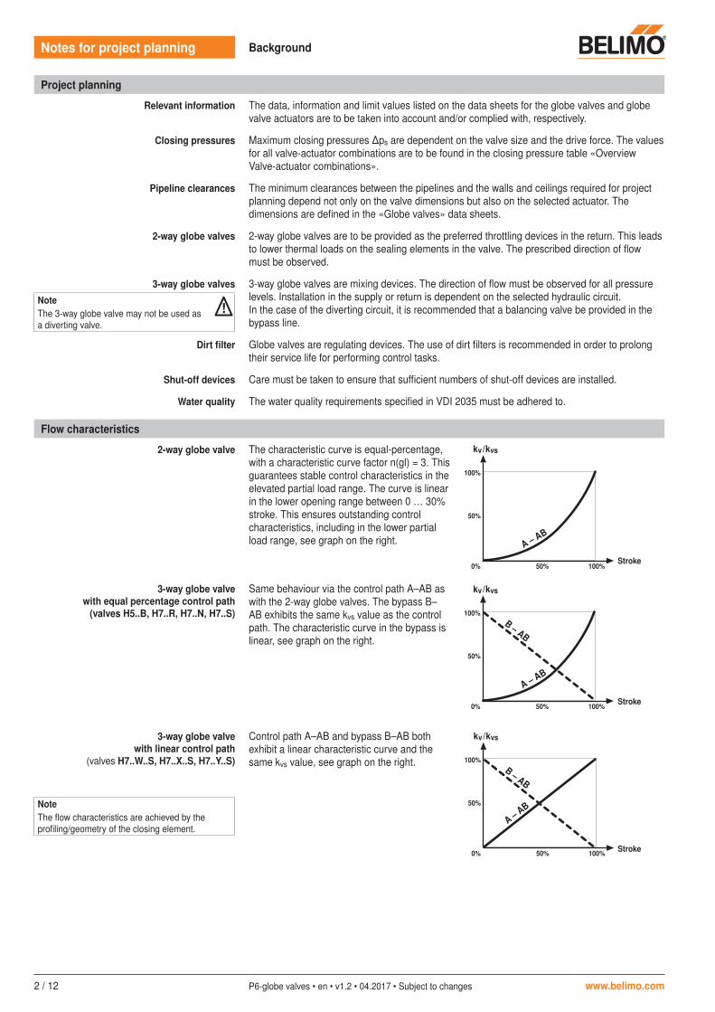
2-way globe valve The characteristic curve is equal-percentage, with a characteristic curve factor n(gl) = 3. This guarantees stable control characteristics in the elevated partial load range. The curve is linear in the lower opening range between 0 … 30% stroke. This ensures outstanding control characteristics, including in the lower partial load range, see graph on the right.
kv/kvs kv/kvs
100%
50%
0% 50% 100%
A – AB
B – AB
100%
50%
0% 50% 100%
kv/kvs
B – AB
100%
50%
0% 50% 100%
A – AB
kv
H
kv
H
kv
H
A – AB
3-way globe valve with equal percentage control path
(valves H5..B, H7..R, H7..N, H7..S)
Same behaviour via the control path A–AB as with the 2-way globe valves. The bypass B–AB exhibits the same kvs value as the control path. The characteristic curve in the bypass is linear, see graph on the right.
kv/kvs kv/kvs
100%
50%
0% 50% 100%
A – AB
B – AB
100%
50%
0% 50% 100%
kv/kvs
B – AB
100%
50%
0% 50% 100%
A – AB
kv
H
kv
H
kv
H
A – AB
3-way globe valve with linear control path
(valves H7..W..S, H7..X..S, H7..Y..S)
Control path A–AB and bypass B–AB both exhibit a linear characteristic curve and the same kvs value, see graph on the right.
kv/kvs kv/kvs
100%
50%
0% 50% 100%
A – AB
B – AB
100%
50%
0% 50% 100%
kv/kvs
B – AB
100%
50%
0% 50% 100%
A – AB
kv
H
kv
H
kv
H
A – AB
Notes for project planning Background
NoteThe 3-way globe valve may not be used as a diverting valve.
!
NoteThe flow characteristics are achieved by the profiling/geometry of the closing element.
Stroke
Stroke
Stroke
www.belimo.com P6-globe valves • en • v1.2 • 04.2017 • Subject to changes 3 / 12
Notes for project planning Background
Principles of flow control
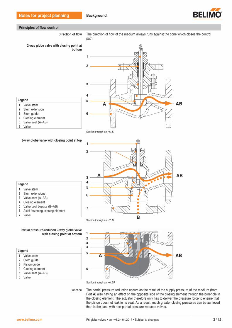
Direction of flow The direction of flow of the medium always runs against the cone which closes the control path.
2-way globe valve with closing point at bottom
AB
1
2
3
4
5A
6
Section through an H6..S
3-way globe valve with closing point at top1
2
4 3
5
7
6
A
B
AB
Section through an H7..N
Partial pressure-reduced 2-way globe valve with closing point at bottom
AB
1
234
5 A
6
Section through an H6..SP
Function The partial pressure reduction occurs as the result of the supply pressure of the medium (from Port A) also having an effect on the opposite side of the closing element through the borehole in the closing element. The actuator therefore only has to deliver the pressure force to ensure that the piston does not leak in its seat. As a result, much greater closing pressures can be achieved than is the case with non-partial pressure-reduced valves.
Legend1 Valve stem2 Stem extension3 Stem guide4 Closing element5 Valve seat (A–AB)6 Valve
Legend1 Valve stem2 Stem extensions3 Valve seat (A–AB)4 Closing element5 Valve seat bypass (B–AB)6 Axial fastening, closing element7 Valve
Legend1 Valve stem2 Stem guide3 Piston guide4 Closing element5 Valve seat (A–AB)6 Valve
4 / 12 P6-globe valves • en • v1.2 • 04.2017 • Subject to changes www.belimo.com
Notes for project planning Background
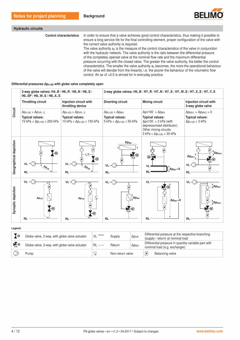
Differential pressures ∆pv100 with globe valve completely open
Circ
uit
2-way globe valves: H4..B / H6..R / H6..N / H6..S / H6..SP / H6..W..S / H6..X..S
3-way globe valves: H5..B / H7..R / H7..N / H7..S / H7..W..S / H7..X..S / H7..Y..S
Throttling circuit Injection circuit with throttling device
Diverting circuit Mixing circuit Injection circuit with 3-way globe valve
�pv100 > ∆pVR / 2
Typical values:15 kPa < �pv100 < 200 kPa
�pv100 > ∆pVR / 2
Typical values:10 kPa < �pv100 < 150 kPa
�pv100 > ∆pMV Typical values:5 kPa < �pv100 < 50 kPa
�pv100 > ∆pMV Typical values:∆pv100 > 3 kPa (with depressurised distributor). Other mixing circuits: 3 kPa < �pv100 < 30 kPa
�pMV1 + ∆pMV2 ≈ 0Typical values:�pv100 > 3 kPa
Geo
grap
hica
l dep
ictio
nSy
nopt
ic d
epic
tion
VL
∆pMV
∆pMV
∆pVR
∆pVR∆pVR
∆pVR
∆pMV ≈ 0
∆pMV ≈ 0
∆pMV1
∆pMV2
∆pMV1
∆pMV2
M
RL
VL
VL
RL
VL
RL
RL
VL
RL
VL
RL
VL
RL
VL
RL
VL
RL
VL
RL
M
M
M
M M
MM
M
M
M
M
VL
∆pMV
∆pMV
∆pVR
∆pVR∆pVR
∆pVR
∆pMV ≈ 0
∆pMV ≈ 0
∆pMV1
∆pMV2
∆pMV1
∆pMV2
M
RL
VL
VL
RL
VL
RL
RL
VL
RL
VL
RL
VL
RL
VL
RL
VL
RL
VL
RL
M
M
M
M M
MM
M
M
M
M
VL
∆pMV
∆pMV
∆pVR
∆pVR∆pVR
∆pVR
∆pMV ≈ 0
∆pMV ≈ 0
∆pMV1
∆pMV2
∆pMV1
∆pMV2
M
RL
VL
VL
RL
VL
RL
RL
VL
RL
VL
RL
VL
RL
VL
RL
VL
RL
VL
RL
M
M
M
M M
MM
M
M
M
M
VL
∆pMV
∆pMV
∆pVR
∆pVR∆pVR
∆pVR
∆pMV ≈ 0
∆pMV ≈ 0
∆pMV1
∆pMV2
∆pMV1
∆pMV2
M
RL
VL
VL
RL
VL
RL
RL
VL
RL
VL
RL
VL
RL
VL
RL
VL
RL
VL
RL
M
M
M
M M
MM
M
M
M
M
VL
∆pMV
∆pMV
∆pVR
∆pVR∆pVR
∆pVR
∆pMV ≈ 0
∆pMV ≈ 0
∆pMV1
∆pMV2
∆pMV1
∆pMV2
M
RL
VL
VL
RL
VL
RL
RL
VL
RL
VL
RL
VL
RL
VL
RL
VL
RL
VL
RL
M
M
M
M M
MM
M
M
M
M
VL
∆pMV
∆pMV
∆pVR
∆pVR∆pVR
∆pVR
∆pMV ≈ 0
∆pMV ≈ 0
∆pMV1
∆pMV2
∆pMV1
∆pMV2
M
RL
VL
VL
RL
VL
RL
RL
VL
RL
VL
RL
VL
RL
VL
RL
VL
RL
VL
RL
M
M
M
M M
MM
M
M
M
M
VL
∆pMV
∆pMV
∆pVR
∆pVR∆pVR
∆pVR
∆pMV ≈ 0
∆pMV ≈ 0
∆pMV1
∆pMV2
∆pMV1
∆pMV2
M
RL
VL
VL
RL
VL
RL
RL
VL
RL
VL
RL
VL
RL
VL
RL
VL
RL
VL
RL
M
M
M
M M
MM
M
M
M
M
VL
∆pMV
∆pMV
∆pVR
∆pVR∆pVR
∆pVR
∆pMV ≈ 0
∆pMV ≈ 0
∆pMV1
∆pMV2
∆pMV1
∆pMV2
M
RL
VL
VL
RL
VL
RL
RL
VL
RL
VL
RL
VL
RL
VL
RL
VL
RL
VL
RL
M
M
M
M M
MM
M
M
M
M
VL
∆pMV
∆pMV
∆pVR
∆pVR∆pVR
∆pVR
∆pMV ≈ 0
∆pMV ≈ 0
∆pMV1
∆pMV2
∆pMV1
∆pMV2
M
RL
VL
VL
RL
VL
RL
RL
VL
RL
VL
RL
VL
RL
VL
RL
VL
RL
VL
RL
M
M
M
M M
MM
M
M
M
M
VL
∆pMV
∆pMV
∆pVR
∆pVR∆pVR
∆pVR
∆pMV ≈ 0
∆pMV ≈ 0
∆pMV1
∆pMV2
∆pMV1
∆pMV2
M
RL
VL
VL
RL
VL
RL
RL
VL
RL
VL
RL
VL
RL
VL
RL
VL
RL
VL
RL
M
M
M
M M
MM
M
M
M
M
Legend:
VL
∆pMV
∆pMV
∆pVR
∆pVR∆pVR
∆pVR
∆pMV ≈ 0
∆pMV ≈ 0
∆pMV1
∆pMV2
∆pMV1
∆pMV2
M
RL
VL
VL
RL
VL
RL
RL
VL
RL
VL
RL
VL
RL
VL
RL
VL
RL
VL
RL
M
M
M
M M
MM
M
M
M
M
Globe valve, 2-way, with globe valve actuator VL Supply �pVRDifferential pressure at the respective branching (supply / return) at nominal load
VL
∆pMV
∆pMV
∆pVR
∆pVR∆pVR
∆pVR
∆pMV ≈ 0
∆pMV ≈ 0
∆pMV1
∆pMV2
∆pMV1
∆pMV2
M
RL
VL
VL
RL
VL
RL
RL
VL
RL
VL
RL
VL
RL
VL
RL
VL
RL
VL
RL
M
M
M
M M
MM
M
M
M
M
Globe valve, 3-way, with globe valve actuator RL ..... Return �pMVDifferential pressure in quantity-variable part with nominal load (e.g. exchanger)
VL
∆pMV
∆pMV
∆pVR
∆pVR∆pVR
∆pVR
∆pMV ≈ 0
∆pMV ≈ 0
∆pMV1
∆pMV2
∆pMV1
∆pMV2
M
RL
VL
VL
RL
VL
RL
RL
VL
RL
VL
RL
VL
RL
VL
RL
VL
RL
VL
RL
M
M
M
M M
MM
M
M
M
M
Pump
VL
∆pMV
∆pMV
∆pVR
∆pVR∆pVR
∆pVR
∆pMV ≈ 0
∆pMV ≈ 0
∆pMV1
∆pMV2
∆pMV1
∆pMV2
M
RL
VL
VL
RL
VL
RL
RL
VL
RL
VL
RL
VL
RL
VL
RL
VL
RL
VL
RL
M
M
M
M M
MM
M
M
M
M
Non-return valve
VL
∆pMV
∆pMV
∆pVR
∆pVR∆pVR
∆pVR
∆pMV ≈ 0
∆pMV ≈ 0
∆pMV1
∆pMV2
∆pMV1
∆pMV2
M
RL
VL
VL
RL
VL
RL
RL
VL
RL
VL
RL
VL
RL
VL
RL
VL
RL
VL
RL
M
M
M
M M
MM
M
M
M
M
Balancing valve
Hydraulic circuits
Control characteristics In order to ensure that a valve achieves good control characteristics, thus making it possible to ensure a long service life for the final controlling element, proper configuration of the valve with the correct valve authority is required.The valve authority av is the measure of the control characteristics of the valve in conjunction with the hydraulic network. The valve authority is the ratio between the differential pressure of the completely opened valve at the nominal flow rate and the maximum differential pressure occurring with the closed valve. The greater the valve authority, the better the control characteristics. The smaller the valve authority av becomes, the more the operational behaviour of the valve will deviate from the linearity, i.e. the poorer the behaviour of the volumetric flow control. An av of >0.5 is strived for in everyday practice.
www.belimo.com P6-globe valves • en • v1.2 • 04.2017 • Subject to changes 5 / 12
Notes for project planning Design and dimensioning
Cavitation diagrams
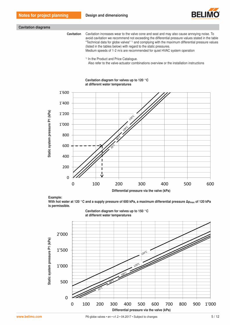
Cavitation Cavitation increases wear to the valve cone and seat and may also cause annoying noise. To avoid cavitation we recommend not exceeding the differential pressure values stated in the table "Technical data for globe valves" 1) and complying with the maximum differential pressure values (listed in the tables below) with regard to the static pressures. Medium speeds of 1-2 m/s are recommended for quiet HVAC system operation
1) In the Product and Price Catalogue. Also refer to the valve-actuator combinations overview or the installation instructions
Cavitation diagram for valves up to 120 °Cat different water temperatures
Differential pressure via the valve (kPa)
Stat
ic s
yste
m p
ress
ure
P1 (k
Pa)
0
500
1'000
1'500
2'000
2'500
0 100 200 300 400 500 600 700 800 900 1'000
Stat
ische
r Vor
druc
k P
1 (k
Pa)
Differenzdruck über Ventil (kPa)
Kavitations-Diagramm Ventile bis 150 °C bei unterschiedichen Wassertemperaturen
Cavitation diagram for valves up to 150 °Cat different water temperatures
Differential pressure via the valve (kPa)
Stat
ic s
yste
m p
ress
ure
P1 (k
Pa)
0
200
400
600
800
1'000
1'200
1'400
1'600
0 100 200 300 400 500 600
Stat
ische
r Vor
druc
k P
1 (k
Pa)
Differenzdruck über Ventil (kPa)
Kavitations-Diagramm Ventile bis 120 °C bei unterschiedichen Wassertemperaturen
Example: With hot water at 120 °C and a supply pressure of 600 kPa, a maximum differential pressure ∆pmax of 120 kPa is permissible.
6 / 12 P6-globe valves • en • v1.2 • 04.2017 • Subject to changes www.belimo.com
Notes for project planning Design and dimensioning
Design for use with glycol
Salts were formerly added to the water to reduce its freezing point; this was referred to as brine applications. Nowadays, glycols are used and one speaks of refrigerant agents. Depending on the concentration of the refrigerant agent (type of glycol) used and the medium temperature, the density of the water/glycol mixture varies from 1 … 9%. The volumetric deviation which results from this process is less than the permitted quantity tolerance of the kvs value of the valve (of ±10% in accordance with VDE 2173) and need not as a rule be taken into account, even if glycols require a slightly elevated kv value.Depending on the type of glycol, tolerance with the valve materials used must be ensured and the permitted maximum concentration may not be exceeded.
Rounding-off rules In practice, the desired kv value never exactly matches the available kvs value of a valve. It is therefore either the next largest or the next smallest valve which is selected when it comes to selecting the valve. This could lead to two situations:
1. The desired kv value is not exactly between two kvs values. The value is rounded up or down accordingly.
Example A valve is needed with a kv value of 4.8 m3/h. The kvs values 4 m3/h and 6.3 m3/h are available, and a kvs value of 4 m3/h is then selected.
2. The desired kv value is exactly between two kvs values. We would recommend selecting as follows:• 2-way valve – the smaller kvs value• 3-way valve – the larger kvs value
Example A valve is needed with a kv value of 5.15 m3/h. The kvs values 4 m3/h and 6.3 m3/h are available. Accordingly, a kvs value of 4 m3/h is selected for the 2-way valve and a kvs value of 6.3 m3/h is selected for the 3-way valve.
Design in low-pressure steam applications
Alignment and installation position
Trouble-free operation in steam applications depends on the correct installation position and design of the control valve. The arrangement of the steam pipeline and the positioning of the condensation drain are also decisive.
Restrictions
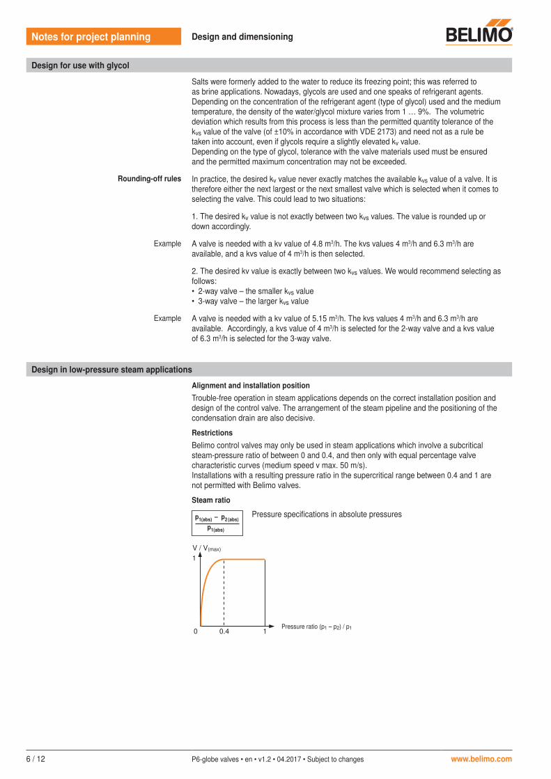
Belimo control valves may only be used in steam applications which involve a subcritical steam-pressure ratio of between 0 and 0.4, and then only with equal percentage valve characteristic curves (medium speed v max. 50 m/s).Installations with a resulting pressure ratio in the supercritical range between 0.4 and 1 are not permitted with Belimo valves.
Steam ratio
p1(abs) – p2 (abs)
p1(abs)
Pressure specifications in absolute pressures
0
1V / V(max)
0.4 1Pressure ratio (p1 – p2) / p1
www.belimo.com P6-globe valves • en • v1.2 • 04.2017 • Subject to changes 7 / 12
Notes for project planning Design and dimensioning
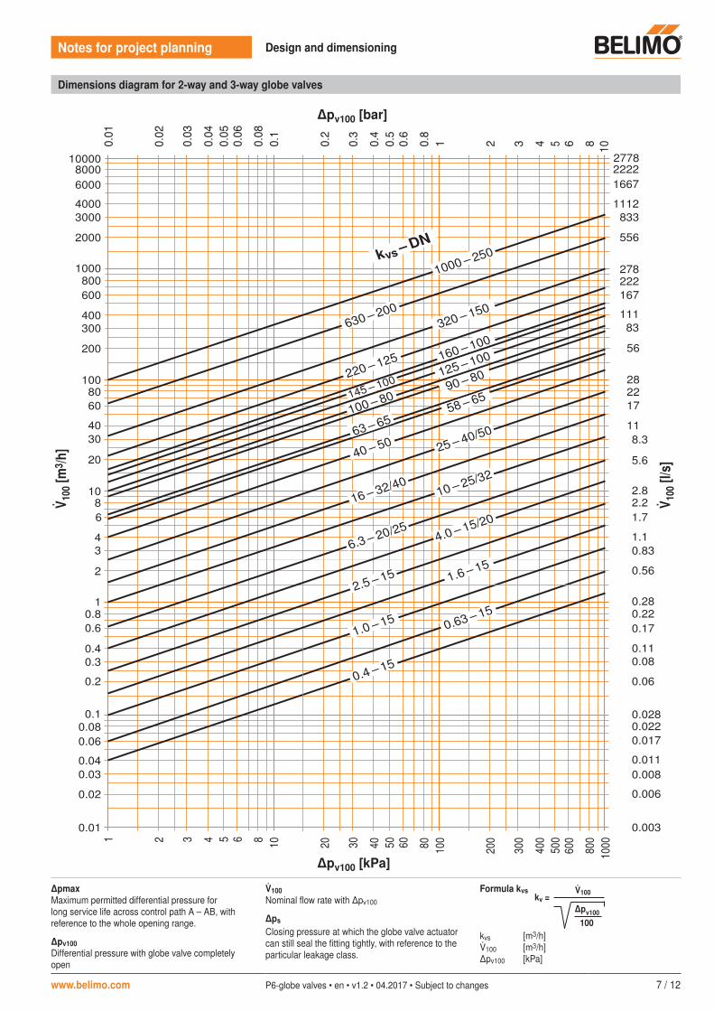
Dimensions diagram for 2-way and 3-way globe valves
278222
556
8331112
166722222778
10
167
11183
56
282217
118.3
5.6
2.82.21.7
1.10.83
0.56
0.280.220.17
0.110.08
0.06
0.0280.0220.017
0.0110.008
0.006
0.0030.01
0.02
0.030.04
0.060.08
0.1
0.2
0.30.4
0.60.8
1
2
34
68
10
20
3040
6080
100
200
300400
600800
1000
2000
30004000
60008000
10000
5
1 2 3 4 5 6 8 10 20 30 40 50 60 80 100
200
300
400
500
600
800
1000
63 – 65100 – 80145 – 100
125 – 100160 – 100320 – 150
220 – 125
630 – 200
90 – 80
kvs – DN
1000 – 250
0.4 – 15
0.63 – 15
1.0 – 15
1.6 – 15
2.5 – 15
40 – 50
58 – 65
4.0 – 15/20
6.3 – 20/25
10 – 25/32
16 – 32/40
25 – 40/50
∆pv100 [kPa]
∆pv100 [bar]
100
[m3 /h
]
100
[l/s
]
�pmaxMaximum permitted differential pressure for long service life across control path A – AB, with reference to the whole opening range.
�pv100Differential pressure with globe valve completely open
100Nominal flow rate with �pv100
∆ps
Closing pressure at which the globe valve actuator can still seal the fitting tightly, with reference to the particular leakage class.
Formula kvs 100kv =∆pv100
100kvs [m3/h]100 [m3/h]�pv100 [kPa]
8 / 12 P6-globe valves • en • v1.2 • 04.2017 • Subject to changes www.belimo.com
Notes for project planning Design and dimensioning
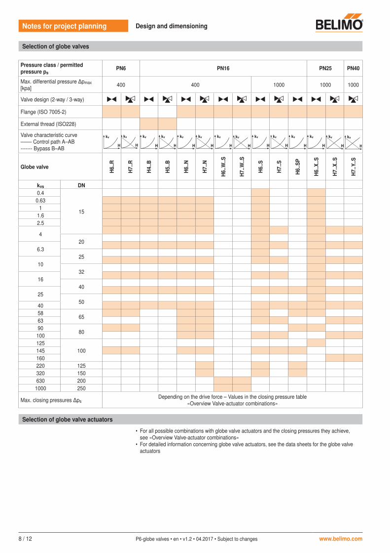
Pressure class / permitted pressure ps
PN6 PN16 PN25 PN40
Max. differential pressure �pmax [kpa] 400 400 1000 1000 1000
Valve design (2-way / 3-way)
Flange (ISO 7005-2)
External thread (ISO228)
Valve characteristic curve–––– Control path A–AB------- Bypass B–AB
kv/kvs kv/kvs
100%
50%
0% 50% 100%
A – AB
B – AB
100%
50%
0% 50% 100%
kv/kvs
B – AB
100%
50%
0% 50% 100%
A – AB
kv
H
kv
H
kv
H
A – AB
kv/kvs kv/kvs
100%
50%
0% 50% 100%
A – AB
B – AB
100%
50%
0% 50% 100%
kv/kvs
B – AB
100%
50%
0% 50% 100%
A – AB
kv
H
kv
H
kv
H
A – AB
kv/kvs kv/kvs
100%
50%
0% 50% 100%
A – AB
B – AB
100%
50%
0% 50% 100%
kv/kvs
B – AB
100%
50%
0% 50% 100%
A – AB
kv
H
kv
H
kv
H
A – AB
kv/kvs kv/kvs
100%
50%
0% 50% 100%
A – AB
B – AB
100%
50%
0% 50% 100%
kv/kvs
B – AB
100%
50%
0% 50% 100%
A – AB
kv
H
kv
H
kv
H
A – AB
kv/kvs kv/kvs
100%
50%
0% 50% 100%
A – AB
B – AB
100%
50%
0% 50% 100%
kv/kvs
B – AB
100%
50%
0% 50% 100%
A – AB
kv
H
kv
H
kv
H
A – AB
kv/kvs kv/kvs
100%
50%
0% 50% 100%
A – AB
B – AB
100%
50%
0% 50% 100%
kv/kvs
B – AB
100%
50%
0% 50% 100%
A – AB
kv
H
kv
H
kv
H
A – AB
kv/kvs kv/kvs
100%
50%
0% 50% 100%
A – AB
B – AB
100%
50%
0% 50% 100%
kv/kvs
B – AB
100%
50%
0% 50% 100%
A – AB
kv
H
kv
H
kv
H
A – AB
kv/kvs kv/kvs
100%
50%
0% 50% 100%
A – AB
B – AB
100%
50%
0% 50% 100%
kv/kvs
B – AB
100%
50%
0% 50% 100%
A – AB
kv
H
kv
H
kv
H
A – AB
kv/kvs kv/kvs
100%
50%
0% 50% 100%
A – AB
B – AB
100%
50%
0% 50% 100%
kv/kvs
B – AB
100%
50%
0% 50% 100%
A – AB
kv
H
kv
H
kv
H
A – AB
kv/kvs kv/kvs
100%
50%
0% 50% 100%
A – AB
B – AB
100%
50%
0% 50% 100%
kv/kvs
B – AB
100%
50%
0% 50% 100%
A – AB
kv
H
kv
H
kv
H
A – AB
kv/kvs kv/kvs
100%
50%
0% 50% 100%
A – AB
B – AB
100%
50%
0% 50% 100%
kv/kvs
B – AB
100%
50%
0% 50% 100%
A – AB
kv
H
kv
H
kv
H
A – AB
kv/kvs kv/kvs
100%
50%
0% 50% 100%
A – AB
B – AB
100%
50%
0% 50% 100%
kv/kvs
B – AB
100%
50%
0% 50% 100%
A – AB
kv
H
kv
H
kv
H
A – AB
kv/kvs kv/kvs
100%
50%
0% 50% 100%
A – AB
B – AB
100%
50%
0% 50% 100%
kv/kvs
B – AB
100%
50%
0% 50% 100%
A – AB
kv
H
kv
H
kv
H
A – AB
Globe valve
H6.
.R
H7.
.R
H4.
.B
H5.
.B
H6.
.N
H7.
.N
H6.
.W..S
H7.
.W..S
H6.
.S
H7.
.S
H6.
.SP
H6.
.X..S
H7.
.X..S
H7.
.Y..S
kvs DN0.4
15
0.631
1.62.5
420
6.325
1032
1640
2550
4058
656390
80100125
100145160220 125320 150630 2001000 250
Max. closing pressures �psDepending on the drive force – Values in the closing pressure table
«Overview Valve-actuator combinations»
Selection of globe valves
Selection of globe valve actuators
• For all possible combinations with globe valve actuators and the closing pressures they achieve, see «Overview Valve-actuator combinations»
• For detailed information concerning globe valve actuators, see the data sheets for the globe valve actuators
kv/kvs kv/kvs
100%
50%
0% 50% 100%
A – AB
B – AB
100%
50%
0% 50% 100%
kv/kvs
B – AB
100%
50%
0% 50% 100%
A – AB
kv
H
kv
H
kv
H
A – AB
www.belimo.com P6-globe valves • en • v1.2 • 04.2017 • Subject to changes 9 / 12
Notes for project planning 2-way and 3-way globe valves
Notes for project planning 2-way and 3-way globe valves
10 / 12 P6-globe valves • en • v1.2 • 04.2017 • Subject to changes www.belimo.com
www.belimo.com P6-globe valves • en • v1.2 • 04.2017 • Subject to changes 11 / 12
Notes for project planning 2-way and 3-way globe valves

5-year guarantee
On site around the globe
A complete range of products from one source
Tested quality
Short delivery times
Comprehensive support
All-inclusive.
Belimo worldwide: www.belimo.com
Belimo Europe
BELIMO Automation AGBrunnenbachstrasse 1CH-8340 Hinwil, Switzerland
Tel. +41 43 843 61 11Fax. +41 43 843 62 [email protected]