Minimally invasive aortic valve replacement: 12-year single center experience
Upload
khangminh22Category
view
0download
0
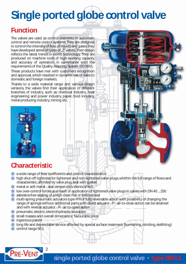
Function
a wide range of flow coefficients and control characteristicshigh shut-off tightness for lightened and non-lightened valve plugs, whithin the full range of flows andcharacteristic, afforded by valve plug seat with gasketmetal or soft metal - seal version with identical KvSlow over-control forces as a result of application of lightened valve plugs in valves with DN 40 ... 250asbestos-free sealing of a high class: Flat or bellows sealmulti-spring pneumatic actuators type P/R of fully reversable action with possibility of changing therange of springs without additional parts; with direct actuator - P - air-to-close action can be attainedand with reverse actuator - R - air-to-open actionpneumatic, electric, electrohydraulic acutacionsmall masses and overall dimensions; favourable priceingenious patentlong life and dependable service afforded by special surface treatment (burnishing, nitriding, stelltiting)control range 50:1
Characteristic
single ported globe control valve · type BR 11
Single ported globe control valve
2
The valves are used as control elements in automaticcontrol and remote control systems. They are designedto control the intensity of flow of liquids and gases; theyhave developed series of types of „Z“ valves.Their designreflects the latest trends in world technology. They areproduced on machine tools of high working capacityand accuracy of operation, in compliance with therequirements of the Quality Assuring System ISO 9001.These products have met with customers recognitionand approval, which resulted in dynamic rise of sales todomestic and foreign markets.Thanks to a wide material range and various designversions, the valves find their application in differentbranches of industry, such as: chemical industry, heatengineering and power industry, paper, food industry,metal producing industry, mining etc.

Construction and technical specification
single ported globe control valve · type BR 11
3
Fig. 2Bonnet types
Standard
Fig. 1Valve construction
Extension Bellows seal
The valve fitted with pneumatic actuator iscomposed of the following main parts:
Body (sec to Fig. 1)Single-ported, cast, flangedNominal diameterDN 15; 20; 25; 32; 40; 50; 65; 80; 100; 150; 200; 250Nominal pressurePN 10; 16; 25; 40 or ANSI 150; 300 lbsConnectionFlange face DIN EN 1092-1Flange face ANSI B 16.5 (RF, RTJ)Housing lengthAs per DIN or ANSI B 16.10Housing lengthDuctile iron (EN-JS1020 / EN-GJS-400-18)Carbon steel (1.0619 / GP240GH)Acid proof steel (1.4408 / GX5CrNiMo19-11-2)
Working pressure and temperature, materials andnominal pressure - sec. to Fig. 3
BonnetMade in four varieties (sec. to Fig. 2)StandardFor fluid temperature -40° ... +350° CExtensionFor fluid temperature -198° ... +560° CBellow sealFor fluid temperature -100° ... +400° CTA-Luft packingFor fluid temperature -40° ... +200° C

Material designation
Fig. 3Body material, nominal pressure, working pressure and temperature
single ported globe control valve · type BR 11
4
Valve plug (3), valve seat (5)of acidproof steel.In case of strongly abrasive medium being used andapperance of cavitation or pressure drops, hightemperatures and flow velocity, the faying faces ofplugs and seats or their whole profiles are stellitedor plasma nitrided.
Types of valve plugs in usenon-lightened (standard)lightened
Type of flow characteristicequal percentage (P)linear - (L)quick - opening for on/off action (O)
Type of valve seats in usemetal sealsoft (PTFE or silicone rubber packing)
Shut of tightnessbelow 0,01 % Kvs - (Class IV, as per IEC 534/4)for metal sealbubble tight (Class VI, as per IEC 534/4)for soft seal
Direction of fluid flowunder the valve plug
Note
1. Flow coefficients Kvs - acc. to Tab. 1 and Tab. 2
2. Equal percentage flow characteristicacc. to Fig. 4
3. The valve plug types, characteristic, flow
coefficients Kvs are the same for metal andsoft seal versions
4. In valves with quick-opening characteristic (O)Kvs coeficients are greater by 20% than thosegiven in Tab. 1 and Tab. 2
1 2 3
2 3
1 2 3
1 2 3
0 50 100 120 150 200 250 300 350 400 450 500 550 560
4,0
3,5
3,0
2,5
2,0
1,5
1,0
Ductil iron Stainless steelCarbon steel
Carbon steel
Ductile iron
Stainless steel
PN 40
PN 25
PN 16
pt
[MPa]
tp [ °C]

single ported globe control valve · type BR 11
5
Flow coefficients Kvs (m3/h)for unbalanced valve plugs
0,010
Kvs(m3/h)
Stroke(mm)
Plug face(mm) 15 20 25 32 40 50 65 80 100 150 200 250 PL S
Valve nominal size DN Characteristic
0,016
0,025
0,040
0,063
0,10
0,16
0,25
0,40
0,63
1,0
1,6
2,5
4,0
6,3
10
16
25
40
63
94
125
160
250
320
500
630
20
38
50
63
6,35
9,52
12,70
19,05
20,64
25,25
31,72
41,25
50,80
66,70
88,90
107,92
126,95
158,72
195,00
Flow coefficients Kvs (m3/h)for pressure balanced valve plugs Tab. 2
Tab. 1
Translation: Kv-value to Cv-value = Kv x 1,16
Kvs(m3/h)
Stroke(mm)
Valve nominal size DN Characteristic
40 50 65 80 100 150 200 250 L P S
25
40
63
94
125
160
320
500
630
20
38
63
25050

6
Equ
al percen
tage flo
w ch
aracteristic
Fig.4C
on
trol valves Kvs =
0,25 ...630 m3/h

single ported globe control valve · type BR 11
7
Valve stem packing box (6)Consist of ring seals made of:
a high quality packing cord (PTFE, graphite)expanded graphite band or „V“ rings of PTFE
Valve plug stem (4)Of acid proof steel outside surface burnished,enables to plug to be rigidly connected to the actu-ator stem, allows for effective cooperationwith packing
Packing
PTFE - „V“-type
PTFE + graphite
PTFE - „V“-type / „TA-Luft“
Graphite
Graphite / „TA-Luft“
Bonnet
Standard Extension Bellows seal
Temperature [ °C ]
200 ... 300
PTFE
Minimum Maximum
Maximum workingtemperature [MPa]
Working temperature [ °C ]Valve designe
with pressure balanced plug
with bellows seal bonnet
with soft sealsilicon rubber
-100
-50
-60
-100
260
250
220
400
3,5
4,0
3,5
3,5
Note:Allowable pressure drops Δp (MPa) specified in a/m tables concern the closed valve.Actual pressure drops should not exceed 70 % of the admissible working pressure.
Allowable pressure drop ΔΔp [MPa] - acc. to tab. 5, 6 and 7
Tab. 4: Operating parameters for special design valves
Tab. 3: Valve stem packing and application range
Guiding sleeve (7)Of stainless steel, ion nitrided for resistance to frettingConnection plate (8)Connects the valve with pneumatic actuator,electric actuator, electrohydraulic actuator or manu-al operating mechanism type NN.It is made of carbon steel or stainless steeldepending on the body materialBody gasket (9)Of asbestos-free cardboard or sealant in acidproofcasing, depending on operation conditionsDrain plug (10)Of steel or stainless steel designed for a periodicalcleaning of the valve body interior-optionalCases (11) and (12)Of sheet, form the pressure chamber
Diaphragm (13)With permanent effective surface, provides lineardependence of the valve stem displacement on theactuator control pressure, made of neoprene withpolyester fabricDiaphragm plate (14)Drawn of steel with spring seatsActuator stem (15)Of toughened stainless steel; connects thediaphragm unit to the valveActuator packing box (16)Designed to seal and guide the valve stem,enables the spring tension to be pre-setSprings (17)Of constructional spring steel 3, 6 or 12 springsare used depending on the required rangeSleeve (18) and spacer pieces (19)Designed to change the pneumatic actuator actionfrom direct to reverse and to change the springrange
300 ... 450 200 ... 400
-46 ... 200 -100 ... 200-198 ... -46
200 ... 300

single ported globe control valve · type BR 11
8
Tab. 5: Allowable pressure drop ΔΔp [MPa] for valves with unbalanced plugs,metal seal and pneumatic actuators
-0,150,30,5
40 - 20080 - 240
120 - 280180 - 380
1000100010001000
0,90,4-20 - 1001000
Note:1. In valves, mode of operation being „air-to-open“ the actuator with spring range 40-200 [kPa] can be replaced by an actuator with
spring range 40-120 [kPa] at the same pressure drops.2.The actuators for valves with lightened plugs and hard seal for the pressure drop down to the value Δp=4,0 [MPa] should be selected in a following way:
- valve mode of operation „air-to-close“ - spring range 20 - 100 [kPa], supply pressure 140 [kPa]- valve mode of operation „air-to-open“ - spring range 40 - 120 [kPa] or 40 - 200 [kPa]
63630 250
-0,250,5
0,75
40 - 20080 - 240
120 - 280180 - 380
1000100010001000
1,40,6-20 - 100100063200; 250
0,150,450,8
1,25
40 - 20080 - 240
120 - 280180 - 380
1000100010001000
2,21,00,1520 - 100100050150; 200; 250
0,250,651,1
1,75
40 - 20080 - 240
120 - 280180 - 380
1000100010001000
3,01,40,2520 - 100100050150; 200; 250
0,41,01,72,6
40 - 20080 - 240
120 - 280180 - 380
1000100010001000
4,02,20,420 - 100100038150; 200; 250
0,20,40,61,01,6
40 - 20060 - 14080 - 240
120 - 280180 - 380
630630630630630
2,81,30,220 - 10063038100
500
320
250
125; 160
0,82,03,14,0
40 - 20080 - 240
120 - 280180 - 380
1000100010001000
4,03,20,820 - 100100038150; 200
0,40,81,11,82,9
40 - 20060 - 14080 - 240
120 - 280180 - 380
630630630630630
4,02,40,420 - 1006303880; 100
94
1,63,64,0
40 - 20080 - 240
120 - 280
100010001000
-4,01,620 - 100100038150
0,91,52,13,44,0
40 - 20060 - 14080 - 240
120 - 280180 - 380
630630630630630
-4,00,8520 - 1006303865; 80; 100
63
0,61,21,82,9
40 - 20060 - 14080 - 240
120 - 280
400400400400
4,03,80,6520 - 1004002050; 65; 80; 100
0,41,42,43,44,0
20 - 10040 - 20060 - 14080 - 240
120 - 280
400400400400400
-4,01,420 - 1004002040; 50; 65; 8025
40
0,82,44,0
20 - 10040 - 20060 - 140
400400400
-4,02,420 - 1004002065
16
20 - 10040 - 20060 - 14080 - 240
120 - 280
250250250250250
-4,01,220 - 1002502032; 40; 50
0,21,22,23,24,0
20 - 10040 - 20060 - 14080 - 240
250250250250
-4,02,020 - 1002502025; 32; 40; 500,52,03,04,0
10
20 - 10040 - 20060 - 140
250250250
-4,02,420 - 1002502020; 25; 32;
40; 500,72,44,0
6,3
20 - 10040 - 200
250250--4,020 - 10025020
15; 20; 25;32; 40; 50
2,34,0to 4
Flowcoefficient
Kvs[m3/h]
Nominalvalve size
DN
Strokemm
SizeSpringrange[kPa]
Supply pressure [kPa]
ΔΔp [MPa]
Air-to-close
140Size
Springrange[kPa]
ΔΔp [MPa]ActuatorActutaor
Air-to-open
250 400

single ported globe control valve · type BR 11
9
Tab. 6: Allowable pressure drop ΔΔp [MPa] for valves with unbalanced plugs,soft seal and pneumatic actuators
-0,10,20,4
40 - 20080 - 240
120 - 280180 - 380
1000100010001000
0,80,3-20 - 100100063630 250
-0,20,40,7
40 - 20080 - 240
120 - 280180 - 380
1000100010001000
0,80,5-20 - 100100063200; 250
-0,350,651,15
40 - 20080 - 240
120 - 280180 - 380
1000100010001000
2,10,9-20 - 100100050150; 200; 250
0,10,51,01,6
40 - 20080 - 240
120 - 280180 - 380
1000100010001000
2,91,30,1220 - 100100050150; 200; 250
0,20,91,52,5
40 - 20080 - 240
120 - 280180 - 380
1000100010001000
3,52,00,2520 - 100100038150; 200; 250
-0,20,40,81,4
40 - 20060 - 14080 - 240
120 - 280180 - 380
630630630630630
2,61,1-20 - 10063038100
500
320
250
125; 160
0,71,93,03,5
40 - 20080 - 240
120 - 280180 - 380
1000100010001000
-3,50,720 - 100100038150; 200
0,30,71,01,82,8
40 - 20060 - 14080 - 240
120 - 280180 - 380
630630630630630
3,52,30,320 - 1006303880; 100
94
1,33,33,5
40 - 20080 - 240
120 - 280
100010001000
-3,51,320 - 100100038150
0,61,21,93,13,5
40 - 20060 - 14080 - 240
120 - 280180 - 380
630630630630630
-3,50,620 - 1006303865; 80; 100
63
0,350,91,52,6
40 - 20060 - 14080 - 240
120 - 280
400400400400
-3,50,3520 - 1004002050; 65; 80; 100
1,02,03,03,5
40 - 20060 - 14080 - 240
120 - 280
400400400400
-3,51,020 - 1004002040; 50; 65; 8025
40
1,83,43,5
40 - 20060 - 14080 - 240
400400400
-3,51,820 - 1004002065
16
40 - 20060 - 14080 - 240
120 - 280
250250250250
-3,50,620 - 1002502032; 40; 50
0,61,62,63,5
40 - 20060 - 14080 - 240
250250250
-3,51,220 - 1002502025; 32; 40; 501,22,63,5
10
40 - 20060 - 140
250250-3,51,720 - 10025020
20; 25; 32;40; 50
1,73,56,3
20 - 10040 - 200
250250--3,520 - 10025020
15; 20; 25;32; 40; 50
1,53,5to 4
Flowcoefficient
Kvs[m3/h]
Nominalvalve size
DN
Strokemm
SizeSpringrange[kPa]
Supply pressure [kPa]
ΔΔp [MPa]
Air-to-close
140Size
Springrange[kPa]
ΔΔp [MPa]ActutaorActutaor
Air-to-open
250 400
Note:1. In valves, mode of operation being „air-to-open“ the actuator with spring range 40-200 [kPa] can be replaced by an actuator with
spring range 40-120 [kPa] at the same pressure drops.2.The actuators for valves with lightened plugs and hard seal for the pressure drop down to the value Δp=3,5 [MPa] should be selected in a following way:
- valve mode of operation „air-to-close“ - spring range 20 - 100 [kPa], supply pressure 140 [kPa]- valve mode of operation „air-to-open“ - spring range 40 - 120 [kPa] or 40 - 200 [kPa]

single ported globe control valve · type BR 11
10
Tab. 7: Allowable pressure drop ΔΔp (MPa) for valveswith electric actuators - metal seal and soft seal
FlowcoefficientKvs [m3/h]
Nominalvalve size
DN
Strokemm
Actuator force [kN]
0,5 0,6 0,8 1,8 2,0 3,2 4,0 6,3 10 12 16 20 25 4,0 10
unbalanced plug balanced plug
2,3 3,0 4,0 4,0 4,0to 4 15; 20; 25; 32;
40; 5020
1,8 2,3 3,5 3,5 3,5
0,7 1,0 1,7 4,0 4,06,3 20; 25; 32;
40; 5020
0,3 1,0 3,5 3,5
0,6 0,9 1,5 4,0 4,010 25; 32; 40; 50 20
0,6 3,5 3,5
0,4 0,8 2,8 4,0
16
32; 40; 50 200,2 2,2 2,6
2,8 4,065 20
2,2 2,6
4,0
3,5
4,0
3,5
0,4 1,6 1,9
25
40; 50 201,2 1,5
1,6 1,965; 80 20
1,2 1,5
3,4
3,0
3,4
3,0
0,8 0,940 50; 65; 80; 100 20
0,5 0,6
1,8
1,5
4,0
3,5
4,0
3,5
4,0
3,5
4,0
3,5
2,3
2,0
4,0
3,5
4,0
3,5
0,5 0,6
63
65; 80; 100 380,2 0,3
150 38
1,2
0,9
1,6
1,3
4,0
3,5
0,2 0,25
94
80; 100 380,1 0,15
150; 200 38
0,6
0,5
0,8
0,7
4,0
3,5
4,0
3,5
125; 160
100 38
150; 200; 250 38
0,3
0,1
0,4
0,25
4,0
3,5
4,0
3,5
2,5
2,7 4,0
3,5
4,0
3,5
4,0
3,5
1,5 2,5
1,4 2,4
2,5
2,4
3,1
3,0
4,0
3,5
0,8 1,4
0,6 1,2
1,4
1,2
1,7
1,5
2,3
2,2
3,0
2,8
3,8
3,5
250 150; 200; 250 504,0
3,5
0,9
0,7
1,1
1,0
1,5
1,4
2,0
1,8
2,5
2,4
320 150; 200; 250 504,0
3,5
0,6
0,5
0,8
0,7
1,1
1,0
1,4
1,3
1,8
1,7
500 200; 250 634,0
3,5
0,4
0,3
0,5
0,4
0,7
0,6
0,9
0,8
1,1
1,0
630 250 634,0
3,5
0,2
0,15
0,3
0,2
0,4
0,35
0,55
0,5
0,7
0,65

250
Stroke mm
Tab. 8: Pneumatic actuator typesTurns for rated stroke (applies to P/R)Diaphragm effective area [cm2]Size
250 20 5
400 400 20 5
630 630 38 9
1000 1000 38, 50, 63 8, 10, 13
250
Tab. 9: Kinds of manual operating mechanisms type NNSize Diaphragm effective area [cm2] Turns for rated stroke
400
630
1000
250
400
630
1000
5
5
9
8, 10, 13
single ported globe control valve · type BR 11
11
The following type of actuators are in use:1. Pneumatic - Diaphragm multi-spring actuators type P/R, without handwheel or withupper handwheel type P/R-N as per tab. 8
Control air connexion G 1/4“Air pipes diameter6 x 1 mm; 8 x 1 mm and other optionsSpring ranges20 ... 100 kPa; 40 ... 120 kPa = 3 springs40 ... 200 kPa; 80 ... 240 kPa; 120 ... 280 kPa = 6 springs180 ... 380 kPa = 12 springsMax. supply pressure 600 kPaActuator ambient temperature range-40° C ... +80° C
Accessories (optional)upper handwheelpneumatic positionerelectopneumatic positionerair filter regulatorthree-way solenoid valvecut-off unitlimit switches
Valve actuator
2. Electric or electrohydraulic actuatorsDetailed information and technical data concerningthese actuators may are provided upon request
3. Manual operating mechanism type NN -acc. to tab. 9
Pneumatic actuator type P/R

single ported globe control valve · type BR 11
12
withstandard bonnet
and pneumatic actuator
Total dimensions of valves
with extension or bellowstype bonnet and
pneumatic actuator
with manual operatingmechanism type NN
electric
with ESL-03actuator(example)
Mass, external and connection dimensions of valves
15; 20; 25
Tab. 10: Linkages [mm]
DN Ø C E L Ø P R K
44 111 12,5 110 14
12,516,520,5
110132160
1610244
16,520,5
132160
20,524,5
160216
18
20
50
80
104
162118
M16x1,5
M12x1,25
150; 200; 250
65; 80; 100
32; 40; 50
Note:1. Dimension R und φ P may be changed upon request2. Dimension L - given for closed valve3. Dimension L = 118 for electric actuators

Tab. 12: Valve weight(without drives) [kg]
DNstandard
1520253240506580
100150200250
67
7,59,5
11,514,520
28,542
120180320
single ported globe control valve · type BR 11
13
Valve with bonnetextension and
bellow seal
9101113162028
36,550
135195335
Tab. 13:Masses ofactuator [kg]
P/R - 250P/R - N - 250
P/R - 400P/R - N - 400
P/R - 630P/R - N - 630
P/R - 1000P/R - N - 1000
Type of actuator Weight10
14,516
20,5303774
100
Tab. 14:Weight ofmanual operatingmechanism [kg]
NN - 250NN - 400NN - 630
NN - 1000
Type of actuator Weight5,56,58,540
Tab. 11: Dimensions of valves with operating mechanisms [mm]
Tab. 11a: Fitting lenght - with flanged connection
DNDimensions A [mm]
DIN, ISO ANSI
152025405080
100150200250
- PN 40130150160200230310350480600730
150 RF
184 197190 200
207210248283333384489584724
194197235267317368473568708
222 235267311366464556686
254298353451543673
150 RTJ 300 RF 300 RTJ
DNG
HF D
Standardbonnet
Extension andbellows seal
P/R250
P/R400
P/R630
P/R1000
N/N250
N/N400
N/N630
N/N1000
P/R250
P/R400
P/R630
P/R1000
N/N250
N/N400
N/N630
N/N1000
1520253240506580
100150200250
107107107114118122166166173305458475
241241241243253257410410417510623623
306306306306306306
------
----
312312312312312
---
------
402402402
---
---------
565565565
290290290290290290
------
----
290290290290290
---
------
308308308
---
---------
510510510
240240240240240240
------
----
305305305305305
---
------
375375375
---
---------
477477477
225225225225225225
------
----
225225225225225
---
------
305305305
---
---------
450450450
150150150150150150150150150230230230

single ported globe control valve · type BR 11
14
Our standard-control valve BR 11
Please pay attention to our special valves
Control valves for high pressure and high temperature: BR 12a, BR 12b
Three-way-control valve with mixing- and distribution service
Rotary-globe valve for aggressive fluid and fluid with solid contents
More information to our special valves you will find it on www.pre-vent.com

single ported globe control valve · type BR 11
N O T E S
15

Special-purpose solutionsa problem?
Not with PRE-VENT®-valves!
Ask our specialists!
Piracher Straße 76D-84489 Burghausen
Phone +49 86 77 9 87 88 0Fax +49 86 77 9 87 88 80
E-Mail: [email protected]
Local distributor:
EMSR-TechVertriebs- Logistik- und Produktions GmbH
www.pre-vent.com
Copyright © 2022 FDOKUMEN