
CONTROL VALVE
16
clarkevalve.com A WORLD’S MOST COMPACT + EFFICIENT CONTROL VALVE
-
Upload
khangminh22 -
Category
Documents
-
view
1 -
download
0
Transcript of CONTROL VALVE
c l a r k e v a l v e . c o m A
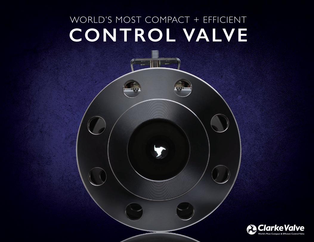
WORLD’S MOST COMPACT + EFFICIENT
CONTROL VALVE

B C l a r k e Va l v e c l a r k e v a l v e . c o m 1
Welcome
Our Valued Customers Clarke Valve works with organiza-tions worldwide to deliver optimized flow control in a broad array of industries and applications.
PatentsReference listing of Clarke Valve’s intellectual property.
Product LineThe Shutter Valve offers complete versatility across ¼” up to 12” piping. Available in pressure classes up to ASME 1500# and multiple different end connections.
Product Quality & CertificationsClarke Valve is dedicated to provid-ing the highest quality industrial valves to our customers, defect-free, and on time.
Shutter Valve™ Multiple Global Patents And Hundreds of Customers Best-in-class results and value for a diverse installed base. The Shutter Valve has been successfully deployed in a broad spectrum of customer applications, with some units installed and operational since 2015.
Clarke Valve™ Shatters Benchmarks for Reliability and Fugitive EmissionsOwing to its unique design, the Shutter Valve is one of the few control valves to qualify for both ISO 15848-1 and API 641 certification.
Solutions The Shutter Valve is designed to seamlessly replace the globe valves that are used for process control in every industry, every day, with zero disruption or switching costs.
02 Replacing Legacy Control Valves with the Shutter Valve The selection of orifice sizes to match desirable CV ratings.
Extending Operational Life and Ensurinng a Tight SealThe 3-piece O-ring groove creat-ed by the valve Petals in the closed position as a solution to survive high-cycle fatigue and wear.
Precision Throttling and Tight Shutoff with Minimal TorqueThe Ring Gear as an appropriate means of driving the movement of the Petals to minimize torque.
Achieving Tight Shutoff and Extending Component LifeThe interlocking seal and rib combination as a safeguard against seat leakage, high cycle fatigue, and wear.
04
06
08
12
15
16
18
22
24
20
TA B L E O F C O N T E N T S
10
2 C l a r k e Va l v e c l a r k e v a l v e . c o m 3
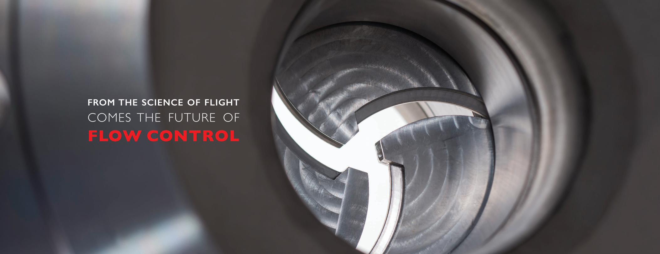
FROM THE SCIENCE OF FLIGHT
COMES THE FUTURE OF FLOW CONTROL

4 C l a r k e Va l v e c l a r k e v a l v e . c o m 5
OUR VALUED CUSTOMERS
Clarke Valve works with organizations worldwide to deliver optimized flow control in a broad array of industries and applications.
Each logo below represents a selected example from the Shutter Valve installed base.

c l a r k e v a l v e . c o m 7 c l a r k e v a l v e . c o m 7
* Inventor: Kyle P. Daniels, Clarke Valve
LOW EMISSION BONNET SEAL
US 10,612,661
SHUTTER VALVE WITH
PIVOT ARMS
US 14/462,047US 8,910,920
SHUTTER VALVE
US 14/634,002
SHUTTER VALVE
US 15/392,663US 9,970,554
SHUTTER VALVE WITH
PIVOT ARMS
CA 2,892,194
SHUTTER VALVE WITH
PIVOT ARMS
CN 201510441654.2
SHUTTER VALVE WITH
PIVOT ARMS
EP 15020089.7
SHUTTER VALVE WITH
PIVOT ARMS
JP 2015-134332
SHUTTER VALVE
WITH SEALS
US 14/795,442US 9,206,911
VALVE HOUSING
US 29/530,857US D800870
6 C l a r k e Va l v e
PATENTSReference listing of Clarke Valve’s intellectual property.
SHUTTER VALVE SYSTEM FOR
INTERNAL COMBUSTION
ENGINES
US 09/425,900US 6,199,531
SHUTTER VALVE WITH
PIVOT ARMS
FR 15020089.7FR 2988044
SHUTTER VALVE WITH
PIVOT ARMS
DE 15020089.7DE 2988044
SHUTTER VALVE WITH
PIVOT ARMS
IE 15020089.7IE 2988044
SHUTTER VALVE WITH
PIVOT ARMS
IT 15020089.7IT 2988044
SHUTTER VALVE WITH
PIVOT ARMS
NL 15020089.7NL 2988044
SHUTTER VALVE WITH
PIVOT ARMS
ES 15020089.7ES 2988044
SHUTTER VALVE WITH
PIVOT ARMS
GB 15020089.7GB 2988044
PAT E N T S *
8 C l a r k e Va l v e c l a r k e v a l v e . c o m 9
SHUTTER VALVE™
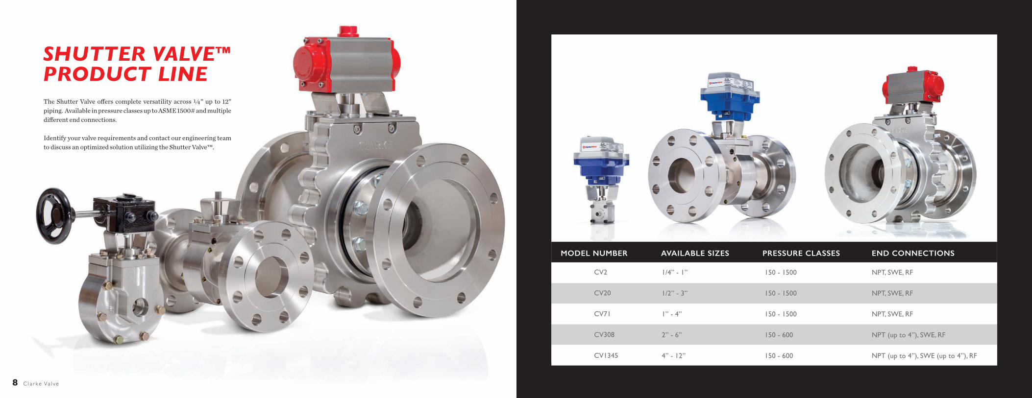
PRODUCT LINEThe Shutter Valve offers complete versatility across ¼” up to 12” piping. Available in pressure classes up to ASME 1500# and multiple different end connections.
Identify your valve requirements and contact our engineering team to discuss an optimized solution utilizing the Shutter Valve™.
MODEL NUMBER AVAILABLE SIZES PRESSURE CLASSES END CONNECTIONS
NPT, SWE, RF
NPT, SWE, RF
NPT, SWE, RF
NPT (up to 4”), SWE, RF
NPT (up to 4”), SWE (up to 4”), RF
150 - 1500
150 - 1500
150 - 1500
150 - 600
150 - 600
1/4” - 1”
1/2” - 3”
1” - 4”
2” - 6”
4” - 12”
CV2
CV20
CV71
CV308
CV1345

c l a r k e v a l v e . c o m 11
PRODUCT QUALITY & CERTIFICATIONSClarke Valve is dedicated to providing the highest quality industrial valves to our customers, defect-free, and on time.
ISO 9001:2015 CERTIFICATEThe ISO 9000 family of quality management systems standards is designed to help organizations ensure that they meet the needs of customers and other stakeholders while meeting statutory and regulatory requirements related to a product or service.
ISO 15848-1:2015 CERTIFICATE“Industrial valves – Measurement, test and qualification pro-cedures for fugitive emissions” outlines the testing require-ments for control valves and isolation valves. Control valves must cycle from 40% open to 60% open more than 100,000 times to achieve a CC3 endurance rating, and must allow less than 50 parts per million by volume leakage of methane to achieve the Class AM tightness rating.
API 641 CERTIFICATION: GROUP AThe American Petroleum Institute (API) 641 standard, “Type Testing of Quarter-Turn Valves for Fugitive Emissions,” applies to all stem seal materials, and requires a stringent maximum al-lowable leakage of 100 parts per million by volume (PPMv). This API test standard calls for 610 cycles of the valve under extreme temperature fluctuations to evaluate emissions performance over an accelerated life cycle.
PED MODULE H CERTIFICATE (CE MARKING)Clarke Valve has implemented, operates and maintains a quality assurance system as described in the Pressure Equipment Di-
ANSI/FCI 70-2Control Valve Seat Leakage
ANSI/ISA-75.02.01-2008Control Valve Capacity Test Procedure
ANSI/ISA-75.17Control Valve Aerodynamic Noise Prediction
ANSI/ISA-75.01.01Flow Equations for Sizing Control Valves
API 598Valve Inspection and Testing
We are committed to satisfying all customer and applicable requirements and to the continual improvement of our business, products, processes, and quality management system. All valves produced by Clarke are designed, inspected,
and tested in strict conformance to the applicable industrial valve standards and codes to ensure maximum product safety and reliability.
From ASME B16.34 to ISO 5211, Clarke Valve proudly conforms to, or maintains certifications for, more than 20 respected industry standards, ensuring seamless integration and zero disruptions when a customer makes the choice to deploy the Shutter Valve.
API 641Type Testing of Quarter-turn Valves for Fugitive Emissions
API 689Collection and Exchange of Reliability and Maintenance Data for Equipment
ASME B16.34Valves – Flanged, Threaded, and Welded
ASME B16.5Pipe Flanges and Flanged Fittings
ASME B16.10Face-to-Face and End-to-End Dimensions of Valves
Hazardous ServiceExdllB T6, Class 1, Div 1, Group C&D T6
CRNCanadian Registration Numbers 0C20008.25, 0C1330.9
IEC 60534-2-1Flow Capacity – Sizing Equations for Fluid Flow Under Installed Conditions
IEC 60534-2-3Flow Capacity – Test Procedures
IEC 60534-2-4Flow Capacity – Inherent Flow Characteristics and Rangeability
IEC 60534-7Control Valve Data Sheet
IEC 60534-8-4Industrial Process Control Valves – Part 8-4: Noise Considerations – Prediction of Noise Generated by Hydrodynamic Flow
ISA-RP75.23Considerations for Evaluating Control Valve Cavitation
Clarke Valve proudly conforms or maintains certifications to these respected industry standards.
ISO 15848-1:2015Industrial valves – Measurement, test and qualification procedures for fugitive emissions
ISO 5211Industrial Valves – Part Turn Actuator Attachments
ISO 9001:2015Quality Management Systems – Requirements
MIL-V-24509AMilitary Specification – Valves, Flanged, Ball and Plug for Sewage and Sea Water Service
MIL-S-901D (NAVY)Military Specification – Shock Tests (High Impact) Shipboard Machinery, Equipment, and Systems
MIL-STD-167-1 (SHIPS)Department of Defense Test Method – Mechanical Vibrations of Shipboard Equipment (TYPE 1 – Environmental and TYPE II – Internally Excited)
MIL-DTL-32632 (NAVSEA)Detail Specification – Valves, Flow Control, Dilating Disk, for Naval Shipboard Water, Oil, and Gas Service
MSS SP-61Pressure Testing of Steel Valves
QQ-N-281D Federal Specification Nickel Copper Alloy Bar, Rod, Plate, Sheet, Strip, Wire, Forgings, and Structural and Special Shaped Sections
rective 2014/68/EU Annex III, Module H for the scope of “De-sign and manufacture of dilating disk and/or Shutter Valves.”
“The manufacturer is authorized to provide the pressure equipment produced within the scope of the assessed quality assurance system with the following Notified Body Number: CE 0036.”
CANADIAN REGISTRATION NUMBER (CRN)The drawings, engineering calculations, and materials of con-struction for the Shutter Valve have been approved by ABSA, TSSA, and ACI, and are exempt in all other Provinces, by virtue of their conformance with the pressure and temperature rat-ings defined by ASME B16.34.
10 C l a r k e Va l v e

c l a r k e v a l v e . c o m 13
SHUTTER VALVE™ MULTIPLE GLOBAL PATENTS AND HUNDREDS OF CUSTOMERS
PROVEN PERFORMANCEBest-in-class results and value for a diverse installed base. The Shutter Valve has been successfully deployed in a broad spectrum of customer applications, with some units installed and operational since 2015.
The only control valve to earn both the API 641 and ISO 15848 certifica-tions. We work with industry leading testing partners like Yarmouth Research and Technology for third party certification of the Shutter Valve’s capabilities.
In 2018, Yarmouth certified the Shutter Valve as the first control valve to achieve the American Petroleum Institute (API) 641 certification for fugitive emissions reduction. In 2019, the Shutter Valve shattered existing benchmarks for ISO 15848-1:2015 by limiting fugitive methane emissions to 2 ppm by volume for more than 100,000 mechanical cycles.
DURABLE, HIGH QUALITYEngineered to last. Clarke Valve is ISO 9001:2015 certified, and maintains the highest quality standards for our materials, manufacturing processes, and products.
REFINED THROUGH REAL WORLD TESTING.The Shutter Valve has been subjected to millions of operational cycles in the field. The result is a dependable and efficient design that is infinitely adaptable to new customer applications.
Over time, the Shutter Valve design has become even more durable and streamlined. The internal mechanism now uses 7 parts, instead of 22.
We have chosen 316L and CF3M stainless steel as our default materials for fabrication, due to their favorable properties for hardness and corrosion resistance.
However, the Shutter Valve can be manufactured from whatever mate-rial the customer specifies, with some other examples being carbon steel, MIL-SPEC bronze, nickel, and aluminum.
Best-in-class results and value for a diverse installed base. The Shutter Valve has been successfully deployed in a broad spectrum of customer applications, with some units installed and operational since 2015.
The unique design delivers improved flow control and reduced emissions from a valve body that is at least 50% smaller, lighter, and more cost-effective than a globe valve. Yet, despite all the ways that the Shutter Valve stands apart from the competition, it meets or exceeds all of the same standards for safety, quality, and durability.”
OLD DESIGN NEW DESIGN
12 C l a r k e Va l v e

c l a r k e v a l v e . c o m 15 14 C l a r k e Va l v e
Under ISO 15848-1, control valves must cycle from 40% open to 60% open, while meeting one of the tightness class ratings for methane leakage: tightness class CM signifies allowable leakage of ≤ 500 parts per million by volume (ppmv); BM is for ≤ 100 ppmv; and AM is the world’s most stringent standard for methane leakage, at ≤ 50 ppmv.
One of the other key ratings addressed by ISO 15848-1 is reliability, as measured by the endurance class that a control valve can surpass, while maintaining a CM tightness class or better: endurance class CC1 signifies 20,000 mechanical cycles completed; CC2 is for 60,000 mechanical cycles; and CC3 is the highest endurance threshold under ISO 15848-1, at 100,000 cycles.
“The Shutter Valve has shattered the previously held stan-dards for low emissions by a control valve, as expected,” said
ABOUT CLARKE VALVE
Founded in 2011, Clarke Valve™ provides high quality industrial control valves to organizations worldwide. Using aerospace design principles, Clarke has developed the Shutter Valve™, the first major innovation in valve design in the last fifty years. The Shutter Valve is the first control valve to achieve both API 641 and ISO 15848-1 certification, making it the world’s most compact, efficient, and environmentally responsible control valve. Clarke Valve technology is currently deployed in a diverse spectrum of markets, including oil and gas, aerospace, chemical, power plants, and water management.
CLARKE VALVE™ SHATTERS BENCHMARKSOwing to its unique design, the Shutter Valve is one of the few control valves to qualify for both ISO 15848-1 and API 641 certification.
UNIQUE FORMA step change in valve design, perfected over a decade of R&D. The Shutter Valve employs a geometry unlike any other industri-al valve on the market, providing best-in-class, dynamic process control from a quarter-turn stem.
Three interlocking Petals form the aperture of the Shutter Valve. They open perpendicular to the flow of process fluids.
The mechanical operation of the valve is driven by a rugged and efficient Ring Gear, which delivers precise throttling, tight shutoff, and high cycle life while requiring minimal torque.
With a valve body that is 50-80% smaller and lighter than the globe valves it is designed to replace, the Shutter Valve provides the same CV (flow rate) at a significantly lower cost.
SAME FITPlug and play with no added cost and zero risk. Even though the Shutter Valve is unlike any other control valve on the market, it fits seamlessly into existing lines.
To eliminate switching costs, the entire Shutter Valve product line conforms to the face-to-face dimensions for globe valves de-fined by the ISA 75.08 and ASME B16.10 standards.
Safety and reliability are the foundation we’ve built our business on. From ASME B16.34 to ISO 5211, Clarke Valve proudly conforms or maintains certifications for more than 20 respected industry standards, ensuring seamless integration and zero disruptions when a customer makes the choice to deploy the Shutter Valve.
BETTER FUNCTIONBy opening perpendicular to the flow of process fluids, the Shut-ter Valve requires much less operating torque than other control valves; reducing actuator size & energy requirements.
The proprietary design of the Shutter Valve’s bonnet and stem leads to a 97% reduction of fugitive emissions when compared to “low emissions” globe valves, while eliminating the need for pack-ing adjustments in the field.
Kyle Daniels, President and CEO of Clarke Valve. “It achieved the ISO 15848-1 CC3 endurance rating for 100,000 mechani-cal cycles, while allowing a maximum of 2 ppmv, during more than 3 weeks of continuous testing. We have clearly demon-strated that we have the best fugitive emissions solution on the market, and we look forward to deploying this technology through the OGCI member companies.”
Owing to its unique design, the Shutter Valve is one of the few control valves to qualify for both ISO 15848-1 and API 641 certification, as confirmed through independent testing by Yarmouth Research and Technology, LLC. API 641 is the American Petroleum Institute’s fugitive emissions standard for quarter-turn valves, which is the category of valve the Shutter Valve belongs to, and is the most common category of valve in use today.
c
b
a
b
c
a

c l a r k e v a l v e . c o m 17
THE OPPORTUNITIES ARE ENDLESS.
Engineered control valves with our unique geometry means you will have precision flow control, zero pressure drop, and tight shut off all in one valve. For severe service applications, we offer Tungsten-coated Petals, Ceramic Petals, Teflon-lined valves, and optional seals for dir ty service. Think of what that would mean for your processes.
ADVANCED WATER SYSTEMSPopulation growth and climate change present new, pressing challenges for our world’s water supply.
WE SPECIALIZE IN:Lime Slurry | Water TreatmentWater Control | Aeration
SOLUTIONSThe Shutter Valve is designed to seamlessly replace the globe valves that are used for process control in every industry, every day, with zero disruption or switching costs.
CHEMICAL PLANT PRECISIONWhen precision counts, the Shutter Valve shines. In both batch and continuous operations, having the abil-ity to control media at varying temperatures, pressures, and flow rates is key.
WE SPECIALIZE IN:Vacuum | Oxygen | Gases | Acids
OIL & GAS APPLICATIONSOil and natural gas touch our lives in countless ways every day. Together, they supply more than 60 percent of our nation’s energy. Helping the oil and natural gas industry optimize plant operations is a key feature of the Shutter Valve.
WE SPECIALIZE IN:Gas Lift | VRU | Gas Compression | SeparatorsUpstream and Downstream
16 C l a r k e Va l v e

c l a r k e v a l v e . c o m 19
The selection of orifice sizes to match desirable CV ratings.
REPLACING LEGACY CONTROL VALVES WITH THE SHUTTER VALVE
The Shutter Valve provides greater volumetric flow, rangeability, and maximum Cv coeffi-cient than larger legacy valve designs, such as the butterfly, globe, and eccentric plug. At the same time, the Shutter Valve weighs less than all three comparable valves. With this in mind, Clarke Valve engineers follow a strict method-ology for sizing valves, ensuring that the Shut-ter Valve meets or exceeds all of the functional requirements for any legacy valve that it might be replacing. For new build projects, the Shutter Valve enables EPCs and end users to design flow control systems that take advantage of the Shut-ter Valve’s size and weight advantages.
Two ANSI Pressure Class 150 valves, side by side. On the left is the 4” Shutter Valve, and on the right is a 4” globe valve. Despite the significant size difference between each valve body and the attached actuators, the Shutter Valve delivers equivalent flow rate (Cv) to the globe valve and has been engineered to match the same face-to-face dimensions.
P rocess plant engineers conduct a siz-ing analysis to determine whether a selected control valve has the appro-
priate flow capacity and operating character-istics to provide the intended process control. Typically, end user control valve sizing is done in accordance with international standards, and the steps outlined by ISA, ANSI, and IEC.
During the sizing process, plant engineers must avoid choosing an undersized valve, since this would result in process inefficien-cies and lowered production. An oversized valve also comes with disadvantages, includ-ing poor process control, the need for larger actuators, and unnecessary additional weight and cost.
CHALLENGEThe Shutter Valve™ is an ideal solution for control valve applications, and is especial-ly well suited to perform the same functions as globe valves. However, the Shutter Valve represents a step change in valve design. As such, any new and unique technology can face many barriers to adoption, such as anticipated switching costs and a lack of end user famil-iarity with performance characteristics and potential applications.
The challenge for Clarke Valve™, there-fore, is to ensure that the different sizes and pressure classes of the Shutter Valve corre-spond to commonly available globe valve sizes, and that the CV coefficient, pressure drop, and other performance characteris-tics are also appropriately matched. Cycle testing also needs to be performed, to ensure reliability.
SOLUTIONTo begin with, the unique geometry of the Shutter Valve means that it can deliver a CV equivalent to a much larger globe valve. The centralized flow stream produced by the aperture of the Shutter Valve allows for superior process control, while also providing for full port operation with zero pressure drop.
During our process of research and de-velopment, we reviewed publicly available performance data for many globe valves, and cross referenced this information with our own testing results. For example, despite the fact that the CV71 has a 1-inch port, it can effectively replace 2-inch, 3-inch, and 4-inch legacy globe valves in many applications.
18 C l a r k e Va l v e
Volumetric Flow Rate(�P=10 psid) (US GPM)
Assembly Weight(lbs)
Rangeability Maximum Cv Coefficient
4”Globe
4”Eccentric
Plug Rotary
3”Butterfly
2”CV308ShutterValve™
0
200
400
600
800
1000
4”Globe
4”Eccentric
Plug Rotary
3”Butterfly
2”CV308ShutterValve™
0
50
100
150
200
250
4”Globe
4”Eccentric
Plug Rotary
3”Butterfly
2”CV308ShutterValve™
0
40
80
120
160
4”Globe
4”Eccentric
Plug Rotary
3”Butterfly
2”CV308ShutterValve™
0
80
160
240
320

20 C l a r k e Va l v e c l a r k e v a l v e . c o m 21
The 3-piece O-ring groove created by the valve Petals in the closed position as a solution to survive high-cycle fatigue & wear.
EXTENDING OPERATIONAL LIFE AND ENSURING A TIGHT SEAL
Figure 1: This view illustrates the placement of the interior diameter O-ring in the body of the Shutter Valve. In the top panel, the groove (red arrow) that is machined into each half of the valve body is visible, around the central port. In the bottom panel, the O-ring has been placed into the groove. There is a corresponding groove and O-ring on each of the two halves of the valve body, resulting in a tight seal during shutoff on the upstream and downstream sides of the valve Petals.
T he Shutter Valve™ employs a valve mechanism unlike any other design currently used for process control. Unlike the plug and seat combination of the globe
valve, or the disc and seat configuration of a butterfly valve, the Shutter Valve has 3 precisely machined, interlocking Petals that are capable of ANSI Class IV, Class V, or Class VI bubble-tight shutoff, depending upon the application.
CHALLENGEThe 3 Petals that function as the throttling mechanism in the Shutter Valve are essentially high-strength, robust metal blades that pivot about a Hinge Pin, into (or away from) the central opening of the valve, similar to the motion of scissors. The Pet-als are driven by a rugged and efficient Ring Gear, which enables the Shutter Valve to operate with minimal torque.
Clarke Valve™ engineers needed to devise a method for cre-ating a tight seal on the upstream and downstream faces of the valve Petals, while avoiding erosion, pitting, or tearing of any seals or gaskets during operation.
SOLUTIONAfter extensive testing in Clarke Valve’s R&D facility, as well as with customers in the real world, our engineers identified a design solution that would protect the inner diameter O-ring seal surrounding the central aperture of the Shutter Valve from particle impacts or fluid erosion, while still achieving a tight shutoff.
The axial face of each of the 3 Petals is precisely machined to incorporate a curved arc-circle geometry. This approach bene-fits the Shutter Valve in 2 ways:
The arc-circle of the Petal prevents a shearing motion across the face of the O-ring by avoiding any pinch points between 2 metal surfaces: the O-ring only comes into contact with any of the valve Petals during the full closed position.
The lip of the arc-circle on all 3 Petals presses tightly against the O-ring in the fully closed position, compressing it against the edge of the valve port and the groove where the O-ring sits in the valve body and cover, effectively creating the second half of the O-ring groove.
Similar to the seals in the bonnet and valve body, Clarke Valve made a design decision to use standard, off-the-shelf sizes for the O-ring surrounding the valve port. While the arc-circle design helps the O-ring to survive high cycle fatigue and wear, the use of standard parts will ensure that any ser-vice or replacements of the soft goods in the Shutter Valve is cost-effective, and immediately available in case of emergency, for the customer.
RESULTSBy using the arc-circle design, Clarke Valve has extended the life of the interior diameter O-ring in each Shutter Valve, while ensuring a tight seal when the 3 Petals are in the fully closed po-sition. Clarke Valve engineers have conducted 360,000 test cy-cles on a valve to successfully demonstrate the extended life of the O-ring seal, while maintaining the tight shutoff that results from this design.
Customers therefore benefit from longer periods between maintenance and greater overall uptime, while having total con-fidence in tight closure at ANSI Class IV, Class V, and even Class VI bubble-tight leakage ratings.
Figure 2: This rendering shows the orientation of the 2 interior O-rings (shown here in red), relative to the 3 Petals and Ring Gear of the Shutter Valve, as the Petals move from open to closed. In the first image (left), the valve mechanism is dissected, showing the 2 O-rings which are seated in matching grooves on both halves of the valve body. The valve body has been removed for this illustration, and the flow of process fluids goes straight through the port in the center of these O-rings. In the second image (center), only 1 of the O-rings is completely visible. The O-ring on the posterior of the valve mechanism is mostly obscured by the 3 open Petals of the valve. In the third image (right), the valve aperture is closed, illustrating the tight fit of the O-ring against the concave circle formed by the axial faces of the 3 Petals.

22 C l a r k e Va l v e c l a r k e v a l v e . c o m 23
Figure 1: The Ring Gear enables the Shutter Valve to deliver precise throttling and tight shutoff, with quarter-turn operation and low torque requirements. A Pinion Gear (top) transfers torque from the Valve Stem to the Ring Gear. The Ring Gear then drives the open/close motion of three interlocking Petals of the Shutter Valve via three control Arms.
Figure 2: The components that work together to drive the movement of the three interlocking Petals of the Shutter Valve: the Pinion Gear ( left), the Ring Gear ( left-center), one of the three stationary Hinge Pins (right-center), and one of the three pivoting control Arms (right).
T he globe valves used most often for process control typically require significant torque to operate, and the Valve Stem must complete at least one 360-de-
gree rotation, to transition from fully closed to fully open. These torque and rotational requirements lead to larger, heavi-er actuators, which require more energy to operate.
Reducing the torque requirements of control valves is the most important area of improvement for reducing cost, emis-sions, and complexity. A reduction in torque requirements also increases the efficiency and reliability of control valves.
Although butterfly valves and ball valves often cycle from fully closed to fully open on a 90-degree quarter-turn, they still require significant operating torque, and produce fluid effects that make them less than ideal for process control applications.
CHALLENGEHow can valve OEMs deliver quarter-turn operation, with minimal torque, while still providing precision throttling and tight shutoff?
SOLUTIONWith the patented design of the Shutter Valve™, the engineer-ing team at Clarke Valve™ has effectively addressed the chal-lenge of reducing torque requirements and providing precision control and tight shutoff, through the use of a Ring Gear.
The Ring Gear in a Shutter Valve is a beveled gear, and it is mounted at a 90-degree angle to the Pinion Gear. The Pinion Gear transfers torque from the actuator and Valve Stem to the Ring Gear, using a quarter-turn motion to cycle from fully closed to a fully open port.
Energy is then transferred from the Ring Gear to the three valve Petals by control Arms that link the Ring Gear to each Petal. The Ring Gear is connected to each arm, and each arm is then connected to the other end of the Petal. There are also three Hinge Pins mounted in the valve body, that act as a sta-tionary connection point for each Petal. Through this mecha-nism, the rotating motion of the Ring Gear is transformed into the pivoting movement of each Petal, into (or away from) the center of the valve port. The Ring Gear essentially provides a torque multiplication effect, like a bicycle gear or the trans-mission in a car.
In addition to the leverage provided by this mechanism, the movement of the three valve Petals also occurs in such a way as to further minimize torque requirements. In the Shutter Valve, the three Petals open and close perpendicular to the flow of any process fluids being controlled, encountering minimal
The Ring Gear as an appropriate means of driving the movement of the Petals to minimize torque.
PRECISION THROTTLING AND TIGHT SHUTOFF WITH MINIMAL TORQUE
flow-related resistance. If you’ve ever seen a car become sub-merged under water, on television or in a movie, you’re familiar with this concept. The people trapped inside the car are unable to open the door of the car, against the force of the fluid pressure surrounding the vehicle. However, they can easily roll down the window, as the window is moving perpendicular to the force/pressure of the water.
As a result of this design feature, the Shutter Valve does not require the high amounts of torque needed by a butterfly or globe valve, each of which need to push against the force of the flow, for throttling or shutoff. In fact, no matter how much the pressure or flow rate are increased in a given process, the Shut-ter Valve does not require any additional torque to open and close. The same cannot be said for a butterfly or a globe valve, both which require more torque to operate, as the pressure in-creases in the pipe.
To further maximize efficiency and achieve reliable op-eration from the gearing in the Shutter Valve design, Clarke Valve has worked closely with our supplier Tracey Gear. Together, we have optimized the alignment and synchro-nization between the Pinion Gear and Ring Gear, by ensur-ing consistent tolerances between the gears. This degree of precision helps to prevent any backlash or play in the mech-anism, delivering smooth and controlled operation. The re-duction or elimination of play also minimizes energy loss and ensures the efficient conversion of torque into the opening and closing function of the valve.
RESULTSBy design, the Ring Gear is an efficient means of transmitting torque into the functional motion of the Shutter Valve. Only a quarter-turn of the Valve Stem is required for a dynamic range of process control, and the gearing of the valve ensures that minimal energy is lost.
These features allow customers who deploy the Shutter Valve to use much smaller, lighter, and more energy efficient actuators, thereby reducing the cost, complexity, and energy consumption, as described above, while increasing reliability and efficiency.
Energy is then transferred from the Ring Gear to the three valve Petals by control Arms that link the Ring Gear to each Petal.

24 C l a r k e Va l v e c l a r k e v a l v e . c o m 25
The interlocking seal and rib combination as a safeguard against seat leakage, high cycle fatigue, and wear.
ACHIEVING TIGHT SHUTOFF AND EXTENDING COMPONENT LIFE
The Shutter Valve™ is a unique and innova-tive control valve design that signals a dis-tinct departure from the globe, ball, but-
terfly, eccentric plug, and other variations used for shutoff and process control over the last 100 years.
The closest comparison to the Shutter Valve is the iris valve, which has seen limited market pen-etration as a control valve due to a few key flaws. 1) The angular elements of the iris are in constant contact with each other, even when the valve is fully open. This high amount of metal-to-metal compo-nent contact leads to high cycle fatigue and wear for the iris valve. 2) The sealing capability of the iris is limited, with limited leakage control along the adja-cent boundaries of each component. 3) There is al-ways a small opening at the center of the iris – even when the components of the iris are machined to very tight tolerances, gas or liquid at high pressure will leak through this pinhole opening, and prevent the iris valve from achieving Class IV, Class V, or Class VI leakage ratings.
CHALLENGEClarke Valve™ set out to capitalize on the positive elements of an iris design—central flow stream, and a dynamically variable orifice—while addressing the seat leakage, high cycle fatigue, and wear that cannot be prevented for the iris valve, due to its inherent design flaws.
Figure 4: Several examples of iris valve designs. In addition to the segmented aperture design shown here (typically constructed with metal) there is also a “diaphragm iris” valve which uses a single, dilating piece of pliable material to open and close the valve aperture.
The seal between these interlocking surfaces is further en-hanced by the addition of soft material to the cavity on each Petal, which can conform more tightly to the metal on the ad-jacent rib than a metal-to-metal connection would. For many applications, elastomer is used, which provides more flexibility and therefore, greater sealing ability, when compressed against the metal sealing rib on the adjacent Petal. Through testing, we have found that a durometer between 60 and 80 is most effec-tive, depending upon the application and the liquid or gases be-ing handled by the valve.
When a more durable material is required—for high velocity fluids with greater erosion potential, or corrosive fluids—we can equip the sealing surfaces of each Petal with PTFE. In all cases, the elastomer or PTFE seals are designed to be recessed within the interlocking cavity, with minimal exposure to the fluids be-ing controlled.
The other leakage point of the iris valve—the central meet-ing point of the valve elements, which is never completely sealed—is addressed by the design of the interlocking notch at the end of each Shutter Valve Petal. In a forthcoming post, we will outline the design of this critical feature of the valve.
Finally, as we will describe in greater detail elsewhere, there are 2 interior diameter O-rings that ensure a tight seal between the 3 Petals and the ports on either side of the aper-ture. The O-ring sits in a groove that is machined into the valve
SOLUTIONTo address the wear and leakage of the iris valve, Clarke Valve has developed a control valve aper-ture comprised of 3 curved, interlocking Petals.
First, we addressed the challenge of friction and wear by designing the Shutter Valve to pre-vent contact between the 3 Petals during oper-ation: the Petals of the Shutter Valve are only in contact with each other when the valve is fully closed. As soon as the valve begins to open, the Petals are moving away from each other to create a central aperture, without any of the sliding con-tact of the iris valve.
Next, we addressed the potential for leakage by designing each Petal to feature a cavity along its top/outer surface that aligns with a protruding rib on the lower/inner surface of the adjacent Petal. The result is that each valve has a male and fe-male sealing component, which are machined to high precision. Extensive testing has enabled us to identify the optimal design ratio of rib height to width, and the corresponding dimensions for the sealing cavity for each valve trim and size. These design specifications address not only per-formance, but also manufacturability: we find the ideal seal-to-rib combination to achieve the high-est working pressure class (ANSI 1500), while ensuring that each Petal can be machined with maximum efficiency and minimal material waste.
When a more durable material is required—for high velocity fluids with greater erosion potential, or corrosive fluids—we can equip the sealing surfaces of each Petal with PTFE.
Figure 3: The 3 Petals of the Shutter Valve are shown in a throttling position ( left), illustrating the manner in which the valve aperture is controlled by the Petals pivoting in unison. On the right, 1 Petal has been removed, providing a direct view of the interlocking seat-and-rib mechanism between the 2 remaining Petals. The metal rib/male component on the inner curve of each Petal fits precisely into the seat/female component ( fitted with a PTFE seal, here) on the back of its neighboring Petal. The removal of this Petal also exposes 1 of the 2 black elastomer O-rings, which form a seal between the central valve port and the 3 Petals, on both sides of the valve mechanism.
body around the circumference of each port. The face of each Petal is also machined to include an arc-circle concavity that compresses the O-ring when fully closed.
RESULTSThe combination of all these elements allows the Shutter Valve to seal as tightly as any comparable control valve, and deliver a centralized flow stream, while minimizing the high cycle fatigue and wear that occur with designs like the iris valve. When appropriate torque is applied, the Shutter Valve can achieve ANSI Class V and Class VI bubble-tight shutoff using elastomer seals. For applications that require PTFE, we can achieve Class IV shutoff.
Furthermore, the deployment of 3 identically machined Pet-als as the control and sealing mechanism also provides econo-mies of scale, allowing Clarke Valve to reduce the cost of each Shutter Valve sold.
Figure 1: The aperture of the Shutter Valve, comprised of 3 interlocking Petals that pivot on a Ring Gear within the valve body. Here, one half of the valve body has been removed, and the Shutter Valve is in the fully open position.a
Figure 2: Individual valve Petals shown from multiple angles, and with 2 types of sealing material. The left image illustrates the inner sealing surface of a Petal, with the rib/male feature seen straight on. The seat/female feature in this Petal is equipped with a white PTFE seal. Another angle (center) of the same Petal shows the full length of the seat/female feature and white PTFE seal, as well as the arc-circle concavity on the Petal’s face, which compresses the interior O-ring. A third view (right) shows a Petal equipped with a black elastomer seal. The hole at the narrow end of each Petal is for the stationary Hinge Pin, while the hole at the wide part of the Petal is for the pivoting control arm.

26 C l a r k e Va l v e
CONFIGURE YOUR
Take the first step to improving flow control operations, maintenance and cost of ownership, configure a Shutter Valve for your unique application.
SHUTTER VALVE

42 WHITECAP DRIVENORTH KINGSTOWN, RI [email protected]
PHONE: (401) 667-7880(800) 401-6618FAX: (401) 667-0045