Pressure control valve Type KDC 65-200
16
The KDC valve is a pressure control valve . The valve controls the discharge pressure of the compressor to ensure fast build-up of pressure and lubrication pressure. The valve also acts as a check valve in the discharge line of the compressor. The KDC valve is force-controlled so that when pressure in the oil separator becomes 2 bar (29 psi) higher than the suction pressure, the spring is compressed and the valve opens. In lowpressure units (boosters), the spring requires a differential pressure of 0.5 bar (7 psi) for the valve to open. Features • Applicable to HCFC, HFC, R717(Ammonia) and R744 (CO 2 ). • Each valve type is clearly marked with type, size and performance range • Angle valves with weld connections • Fast build-up of oil pressure in oil separator during start-up. • High closing force on the cone during standstill, even without differential pressure across the valve • Very low pressure drop because of spring force • Low part-load without risk of valve chattering • Stainless steel bolts • Housing and bonnet material is in low temperature steel according to requirements of the Pressure Equipment Directive and other international classification authorities • Pressure range: 40 bar (580 psig) • Temperature range: -50 °C / +150 °C (-58 °F / +302 °F) • Classification: DNV, CRN, BV, EAC etc. To get an updated list of certification on the products please contact your local Danfoss Sales Company. AI225686433549en-001001 Data Sheet Pressure control valve Type KDC 65-200 Efficient control of excessive discharge pressure
-
Upload
khangminh22 -
Category
Documents
-
view
1 -
download
0
Transcript of Pressure control valve Type KDC 65-200

The KDC valve is a pressure control valve . Thevalve controls the discharge pressure of thecompressor to ensure fast build-up of pressureand lubrication pressure. The valve also acts asa check valve in the discharge line of thecompressor.
The KDC valve is force-controlled so that whenpressure in the oil separator becomes 2 bar (29psi) higher than the suction pressure, thespring is compressed and the valve opens. Inlowpressure units (boosters), the springrequires a differential pressure of 0.5 bar (7 psi)for the valve to open.
Features• Applicable to HCFC, HFC, R717(Ammonia)
and R744 (CO2).• Each valve type is clearly marked with type,
size and performance range• Angle valves with weld connections• Fast build-up of oil pressure in oil separator
during start-up.• High closing force on the cone during
standstill, even without differential pressureacross the valve
• Very low pressure drop because of springforce
• Low part-load without risk of valve chattering• Stainless steel bolts• Housing and bonnet material is in low
temperature steel according to requirementsof the Pressure Equipment Directive andother international classification authorities
• Pressure range: 40 bar (580 psig)• Temperature range: -50 °C / +150 °C (-58 °F /
+302 °F)• Classification: DNV, CRN, BV, EAC etc. To get
an updated list of certification on theproducts please contact your local DanfossSales Company.
AI225686433549en-001001
Data Sheet
Pressure control valveType KDC 65-200
Efficient control of excessive discharge pressure

Functions
The KDC valve opens in a 3 step sequence. The sequence of steps depends on the start-up situation (see Figure 1:KDC valve).
Step 1The valve is always closed by a minimum differential pressure of 1.5 to 2.0 bar (0.3 to 0.5 bar in a booster system).Step 1 will occur when the compressor is stopped and the discharge pressure has equalized to the top of the valvethrough the suction side of the compressor.
pc – p1 < 2 bar (0.5 bar for booster) and pc > p2
Step 2Step 2 will occur as soon as the condensing pressure becomes higher than the pressure in the oil separator, andwhen the differential pressure between suction side and condensing pressure is bigger than the spring force.
pc – p1 > 2 bar (0.5 bar for booster) and pc > p2
When the compressor starts the valve will either be in step 1 or step 2 position, depending on the pressuredifference between the oil separator and the condensing pressure.
Start up situation 1Condensing pressure is lower than oil separator pressure.
Start up will occur from step 1 position and go to step 3 as soon as a differential pressure between suction side andoil separator that can overcome the spring force is present.
Start up situation 2Condensing pressure is higher than oil separator pressure but the differential pressure is lower than the spring force.
Start up will occur from step 1 and go to step 2 when differential pressure between suction side and condensingpressure is bigger than the spring force. When oil separator pressure comes close to the condensing pressure thevalve will start opening and the small spring will open the valve completely. The valve will then be in step 3 position.
Start up situation 3Condensing pressure is higher than oil separator pressure + spring force pressure. Start up will occur from step 2position.
When oil separator pressure comes close to the condensing pressure the valve will start opening and the smallspring will open the valve completely. The valve will then be in step 3 position.
When the compressor stops, the valve will be in step 3 position and as soon as the condensing pressure hasequalized to the suction side the spring force will close the valve. The valve will be in step 1 position until enoughdifferential pressure between condensing pressure and oil separator/suction side pressure occurs for the valve toenter into step 2 position.
NOTE: The KDC valve cannot be used on compressor units where the non-return valve is placed between compressor andoil separator instead of on the suction side of the compressor. The reason for this is that the KDC valve needs to havethe pilot pipe connected to a point on the compressor unit, where the pressure is low during running and highduring standstill.
Pressure control valve, type KDC 65-200
© Danfoss | Climate Solutions | 2021.02 AI225686433549en-001001 | 2
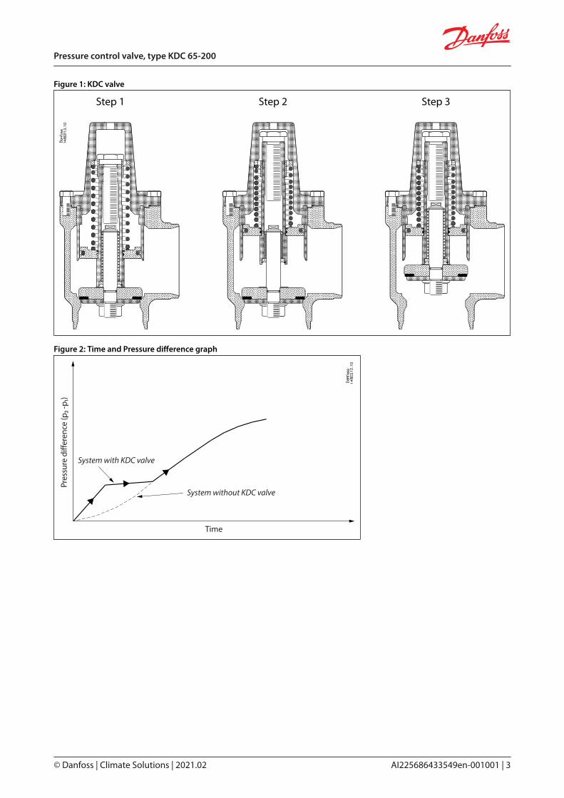
Figure 1: KDC valve
Step 1 Step 2 Step 3
Figure 2: Time and Pressure difference graph
System with KDC valve
System without KDC valve
Time
Pres
sure
diff
eren
ce (p
₂ -p₁
)
© Danfoss | Climate Solutions | 2021.02 AI225686433549en-001001 | 3
Pressure control valve, type KDC 65-200

Applications
Example
Figure 3: Compressor discharge line after oil separator
KDC valve
pcScrew
compressor
Oil separator
p1p2
Pressure control valve, type KDC 65-200
© Danfoss | Climate Solutions | 2021.02 AI225686433549en-001001 | 4

Media
Refrigerants
Applicable to HCFC, HFC, R717(Ammonia) and R744 (CO2).
For further information please see installation instruction for KDC.
New refrigerants
Danfoss products are continually evaluated for use with new refrigerants depending on market requirements.
When a refrigerant is approved for use by Danfoss, it is added to the relevant portfolio, and the R number of therefrigerant (e.g. R513A) will be added to the technical data of the code number. Therefore, products for specificrefrigerants are best checked at store.danfoss.com/en/, or by contacting your local Danfoss representative.
© Danfoss | Climate Solutions | 2021.02 AI225686433549en-001001 | 5
Pressure control valve, type KDC 65-200

Product specification
Pressure and temperature
Table 1: Pressure and temperatureDescription Values
Temperature range -50 °C / +150 °C (-58 °F / +302 °F)
Pressure rangeThe valves are designed for max. working pressure
40 bar (580 psig)
Design
HousingMade of special, cold resistant steel approved for low temperature operations.
Valve coneThe valve cone has two teflon tightening rings with built-in metallic stops to prevent damage to the teflon rings incase of an extreme pressure difference.
SpindleThe spindle is made of gas-tempered steel. Consequently the valve spindle has an extremely hard and smoothsurface. The valve rod has an internal weak spring (Figure 4: KDC, pos. 13), which is active when the servo piston is inupright position.
ActuatorThe KDC actuator has one chamber. It is separated from the main flow by a piston (Figure 4: KDC, pos. 6). Thechamber has a spring (Figure 4: KDC, pos. 14) which provides differential opening of the valve. The chamber of theactuator is connected to the suction line of the compressor.
InstallationThe valve must be mounted vertically with the cone in downward position. On top of the bonnet the actuator hasone threaded (NPT 1/4 in.) connection (Figure 4: KDC, pos. A) for the pilot line. Fittings for connection of steel pipeDN 10 (do/di = 10/6 mm) by means of cutting rings. The valve is designed to resist very high internal pressure, but asto the pipe system in general, hydraulic pressure caused by thermal expansions in entrapped refrigerants should beavoided.
For further information please refer to KDC installation instruction.
Pressure control valve, type KDC 65-200
© Danfoss | Climate Solutions | 2021.02 AI225686433549en-001001 | 6

Figure 4: KDC Figure 5: Example of ID-plate for KDC
Connections
Available with the following connections:• Butt-weld DIN (2448)• Butt-weld ANSI (B 36.10 Schedule 40), DN 65 - 200 (2½ - 8 in.)
Figure 6: DIN
T
ØD
Dan
foss
A14
8B15
.10
Table 2: Butt-weld DIN (2448)Sizemm
Sizein.
ODmm
Tmm
ODin.
Tin.
kv-anglem3/h
Cv-angleUSgal/min
65 2½ 76.1 2.9 3 0.11 78 90
80100
34
88.9114.3
3.23.6
3.504.50
0.130.14
118203
137235
125150200
568
139.7168.3219.1
4.04.56.3
5.506.638.63
0.160.180.25
333509757
386590878
© Danfoss | Climate Solutions | 2021.02 AI225686433549en-001001 | 7
Pressure control valve, type KDC 65-200

Figure 7: ANSIT
ØD
Table 3: Butt-weld DIN (2448)Sizemm
Sizein.
ODmm
Tmm
ODin.
Tin.
kv-anglem3/h
Cv-angleUSgal/min
65 2½ 73.0 5.2 2.87 0.20 78 90
80100
34
88.9114.3
5.56.0
3.504.50
0.220.24
118203
137235
125150200
568
141.3168.3219.1
6.67.18.2
5.566.638.63
0.260.280.32
333509757
386590878
Nominal capacities
High pressure compressor
Capacity table at tc / to = +35 °C / -15 °C,QN [kW],Δp = 0.05 bar
Table 4: Capacity tableKDC 65 KDC 80 KDC 100 KDC 125 KDC 150 KDC 200
R717 434 656 1128 1851 2829 4207
R404A 132 200 344 564 863 1283
R22 157 238 410 672 1028 1528
Booster compressor
Capacity table at tc / to = -18 °C / -40 °C,QN [kW],Δp = 0.05 bar
Table 5: Capacity tableKDC 65 KDC 80 KDC 100 KDC 125 KDC 150 KDC 200
R717 229 347 597 978 1496 2225
R404A 101 153 263 432 661 983
R22 102 154 265 435 665 990
Pressure control valve, type KDC 65-200
© Danfoss | Climate Solutions | 2021.02 AI225686433549en-001001 | 8

Material specification
Figure 8: KDC 65 - 200 (2½ - 8 in.)
Table 6: Material and Parts listNo. Part Material EN ISO ASTM
1 Valve House SteelG20Mn5QTEN10213-3
LCCA352
2 Bonnet SteelP285QHEN10222-4
LF2A350
3 Piston SteelS235JRG2EN10025
Fe260B630
Grade CA283
4 Piston rod SteelS235JRG2EN10025
Fe260B630
Grade CA283
5 Piston Steel11SMn30EN10087
Type 2R683/9
Grade 1213A29
6 Cone Steel11SMn30EN10087
Type 2R683/9
Grade 1213A29
7 Screw for spring Steel11SMn30EN10087
Type 2R683/9
Grade 1213A29
8 Bushing for spring Cast iron
9 Cone plate Steel11SMn30EN10087
Type 2R683/9
Grade 1213A29
10 Cone rod Steel11SMn30EN10087
Type 2R683/9
Grade 1213A29
11 Rear bushing Cast iron
12 Front bushing Cast iron
13 Spring for cone Steel
14 Spring Steel
16 Teflon ring PTFE
17 GasketFiber gasketnon-asbestos
18 Washer Nylon
19 Glide ring PTFE
© Danfoss | Climate Solutions | 2021.02 AI225686433549en-001001 | 9
Pressure control valve, type KDC 65-200

No. Part Material EN ISO ASTM
20 O-ring
Cloroprene (Neoprene)(Standard KDC)
FKM(Hydrocarbon KDC)
21 O-ring
Cloroprene (Neoprene)(Standard KDC)
FKM(Hydrocarbon KDC)
22 O-ring
Cloroprene (Neoprene)(Standard KDC)
FKM(Hydrocarbon KDC)
23 Retaining ring bore Steel
24 Spring ring Steel
25 Spring ring Steel
26 Nut Steel
27 Bolts SteelA2-70EN1515-1
A2-703506
Grade B8A320
28 ID plate Aluminium
29 Driv screw Steel
30 Washer Steel
31 Nut Steel
32 Screw Steel
Dimensions and weights
Figure 9: KDC 65 - 200 (2½ - 8 in.)
Pressure control valve, type KDC 65-200
© Danfoss | Climate Solutions | 2021.02 AI225686433549en-001001 | 10

Table 7: KDC typesValve size A B C ØD Weight
KDC 65 mm 250 62 90 42 7.3 kg
KDC 2½ in. 9.84 2.44 3.54 1.65 16.1 lb
KDC 80 mm 298 90 129 51 11.1 kg
KDC 3 in. 11.73 3.54 5.08 2.01 24.5 lb
KDC 100 mm 346 106 156 64 17.3 kg
KDC 4 in. 13.62 4.17 6.14 2.52 38.1 lb
KDC 125 mm 407 128 192 64 36.9 kg
KDC 5 in. 16.02 5.04 7.56 2.52 81.3 lb
KDC 150 mm 471 145 219 75 49.9 kg
KDC 6 in. 18.54 5.71 8.62 2.95 110.0 lb
KDC 200 mm 539 180 276 75 99.6 kg
KDC 8 in. 21.22 7.09 10.87 2.95 219.6 lb
NOTE: Specified weights are approximate values only.
Bolt in top of the valve is for transportation purposes only. For further information please see installation instruction.
© Danfoss | Climate Solutions | 2021.02 AI225686433549en-001001 | 11
Pressure control valve, type KDC 65-200

Ordering
IMPORTANT: Where products need to be certified according to specific certification societies or where higher pressures arerequired, the relevant information should be included at the time of ordering.
Table 8: Standard KDC with welding branches - DINSize
Type bar Code no.mm in.
65 2½ KDC 650.523
148G3585148G3586148G3713
80 3 KDC 800.523
148G3589148G3590148G3714
100 4 KDC 1000.523
148G3593148G3594148G3715
125 5 KDC 1250.523
148G3597148G3598148G3716
150 6 KDC 1500.52
148G3601148G3602
200 8 KDC 2000.52
148G3605148G3606
Table 9: Standard KDC with welding branches - ANSISize
Type bar Code no.mm in.
65 2½ KDC 650.523
148G3587148G3588148G3811
80 3 KDC 800.523
148G3591148G3592148G3812
100 4 KDC 1000.523
148G3595148G3596148G3813
125 5 KDC 1250.52
148G3599148G3600
150 6 KDC 1500.52
148G3603148G3604
200 8 KDC 2000.52
148G3607148G3608
NOTE: The HYDROCARBON versions of the KDC valves are not compatiable with Ammonia as refrigerant. They can only beused in systems with HYDROCARBON as refrigerant.
Table 10: Standard KDC with welding branches - ANSISize
Type bar Code no.mm in.
65 2½ KDC 650.52
148G3825148G3831
80 3 KDC 800.52
148G3826148G3832
100 4 KDC 1000.52
148G3827148G3833
125 5 KDC 1250.52
148G3828148G3834
150 6 KDC 1500.52
148G3829148G3835
200 8 KDC 2000.52
148G3830148G3836
Pressure control valve, type KDC 65-200
© Danfoss | Climate Solutions | 2021.02 AI225686433549en-001001 | 12

Spare parts and accessories
Table 11: Spare partsType Code no.
GASKET BONNET/HOUSING KDC/GVD 65 148G3048
GASKET BONNET/HOUSING KDC/GVD 80 148G3049
GASKET BONNET/HOUSING KDC/GVD 100 148G3050
GASKET BONNET/HOUSING KDC/GVD 125 148G3051
GASKET BONNET/HOUSING KDC/GVD 150 148G3052
GASKET BONNET/HOUSING KDC/GVD 200 148G3053
Table 12: Seal kitType Code no.
SEAL KIT SET KDC/GVD 65 148G3054
SEAL KIT SET KDC/GVD 80 148G3055
SEAL KIT SET KDC/GVD 100 148G3056
SEAL KIT SET KDC/GVD 125 148G3057
SEAL KIT SET KDC/GVD 150 148G3058
SEAL KIT SET KDC/GVD 200 148G3059
Table 13: Seal kitType Code no.
SEAL KIT SET KDC/GVD 65 Hydrocarbon 148G3837
SEAL KIT SET KDC/GVD 80 Hydrocarbon 148G3838
SEAL KIT SET KDC/GVD 100 Hydrocarbon 148G3839
SEAL KIT SET KDC/GVD 125 Hydrocarbon 148G3840
SEAL KIT SET KDC/GVD 150 Hydrocarbon 148G3841
SEAL KIT SET KDC/GVD 200 Hydrocarbon 148G3842
NOTE: The HYDROCARBON versions of the seal kits are not compatible with Ammonia as refrigerant. They can only be usedin systems with HYDROCARBON as refrigerant.
The seal kit
Figure 10: The seal kit
© Danfoss | Climate Solutions | 2021.02 AI225686433549en-001001 | 13
Pressure control valve, type KDC 65-200

Table 14: The seal kitNo. Part Material
16 Teflon ring PTFE
17 Gasket Fiber gasket non-asbestos
18 Washer Nylon
19 Glide ring PTFE
20-22 O-ring- Standard valve- Hydrocarbon valve
Cloroprene (Neoprene) Viton
Pressure control valve, type KDC 65-200
© Danfoss | Climate Solutions | 2021.02 AI225686433549en-001001 | 14

Certificates, declarations, and approvals
The list contains all certificates, declarations, and approvals for this product type. Individual code number may havesome or all of these approvals, and certain local approvals may not appear on the list.
Some approvals may change over time. You can check the most current status at danfoss.com or contact your localDanfoss representative if you have any questions.
Table 15: Pressure Equipment Directive (PED)
KDC valves are approved according to the European standard specified in the Pressure Equipment Directive and are CEmarked.
For further details / restrictions - see Installation Instruction.
Table 16: KDC valvesKDC valves
Nominal bore DN65-80 mm (1¼ - 3 in.) DN100 - 200 mm (4-8 in.)
Classified for Fluid group I
Category II III
File name Document type Document topic Approval authority
RU Д-DK.БЛ08.В.00191_18 EAC Declaration Machinery & Equipment EAC
0045 202 1204 Z 00354 19 D 001(00) Pressure - Safety Certificate - TÜV
03709-F0 BV Marine - Safety Certificate - BV
TSX71002520151142 Manufacturing Permission - GMPI
RU Д-DK.РА01.B.72054_20 EAC Declaration PED EAC
RU C-DK.БЛ08.B.01093_20 Pressure - Safety Certificate PED EAC
GL TAP0000001 Rev. 1 Marine - Safety Certificate - DNV GL
033F0685.AK EU Declaration EMCD/PED Danfoss
033F0691.AE Manufacturers Declaration RoHS Danfoss
0045 202 1204 Z 00355 19 D 001(00) Pressure - Safety Certificate - TÜV
19.10048.266 Marine - Safety Certificate - RMRS
© Danfoss | Climate Solutions | 2021.02 AI225686433549en-001001 | 15
Pressure control valve, type KDC 65-200

Danfoss can accept no responsibility for possible errors in catalogues, brochures and other printed material. Danfoss reserves the right to alter itsproducts without notice. This also applies to products already on order provided that such alterations can be made without subsequentialchanges being necessary in specifications already agreed. All trademarks in this material are property of the respective companies. Danfoss andthe Danfoss logotype are trademarks of Danfoss A/S. All rights reserved.
Online support
Danfoss offers a wide range of support along with our products, including digital product information, software,mobile apps, and expert guidance. See the possibilities below.
The Danfoss Product StoreThe Danfoss Product Store is your one-stop shop for everything product related—no matter whereyou are in the world or what area of the cooling industry you work in. Get quick access to essentialinformation like product specs, code numbers, technical documentation, certifications, accessories,and more.Start browsing at store.danfoss.com.
Find technical documentationFind the technical documentation you need to get your project up and running. Get direct access toour official collection of data sheets, certificates and declarations, manuals and guides, 3D modelsand drawings, case stories, brochures, and much more.
Start searching now at www.danfoss.com/en/service-and-support/documentation.
Danfoss LearningDanfoss Learning is a free online learning platform. It features courses and materials specificallydesigned to help engineers, installers, service technicians, and wholesalers better understand theproducts, applications, industry topics, and trends that will help you do your job better.
Create your Danfoss Learning account for free at www.danfoss.com/en/service-and-support/learning.
Get local information and supportLocal Danfoss websites are the main sources for help and information about our company andproducts. Find product availability, get the latest regional news, or connect with a nearby expert—allin your own language.
Find your local Danfoss website here: www.danfoss.com/en/choose-region.
Spare PartsGet access to the Danfoss spare parts and service kit catalog right from your smartphone. The appcontains a wide range of components for air conditioning and refrigeration applications, such asvalves, strainers, pressure switches, and sensors.
Download the Spare Parts app for free at www.danfoss.com/en/service-and-support/downloads.
Coolselector®2 - find the best components for you HVAC/R systemCoolselector®2 makes it easy for engineers, consultants, and designers to find and order the bestcomponents for refrigeration and air conditioning systems. Run calculations based on your operatingconditions and then choose the best setup for your system design.
Download Coolselector®2 for free at coolselector.danfoss.com.
© Danfoss | Climate Solutions | 2021.02 AI225686433549en-001001 | 16