
ADVANCED VALVE TECHNOLOGY - DTIC
188
NASA SP-5019 TECHNOLOGY SURVEY Technology Utilization Division ADVANCED VALVE TECHNOLOGY DISTRIBUTION STATEMENT A Apprcy.-xi ;-or Public Release Distribution unlimited - >,,,»• K ;siS 'S ^ n. iß *2. " ». .I'fl i> ^ $ -r ; .) ;. v "': : * AV «"'- "* •!: $ |" i t J ft; if fe '«*Btf** Vw v fc * fc Ü HI 20020328 077 NATIONAL AERONAUTICS AND SPACE ADMINISTRATION
-
Upload
khangminh22 -
Category
Documents
-
view
13 -
download
0
Transcript of ADVANCED VALVE TECHNOLOGY - DTIC

NASA SP-5019
TECHNOLOGY SURVEY
Technology Utilization Division
ADVANCED VALVE TECHNOLOGY
DISTRIBUTION STATEMENT A Apprcy.-xi ;-or Public Release
Distribution unlimited - >,,,»• K;siS 'S ^ n. iß *2. "■». .I'fl i> ^ $ -r ; .) ■;.
v "': :* AV «"'- "* •!: $ |" i t ■J ft; ■if fe '«*Btf**
Vw v fc * fc Ü HI
20020328 077
NATIONAL AERONAUTICS AND SPACE ADMINISTRATION

NASA SP-5019
TECHNOLOGY SURVEY
Technology Utilitization Division
ADVANCED VALVE
TECHNOLOGY ,
CO By KENNETH D. MAY
Prepared under contract for NASA
by Midwest Research Institute
/Q- Kansas City, Missouri
NATIONAL AERONAUTICS AND SPACE ADMINISTRATION WMmmmwsL2FC~:^-;ssi\f M»^'c^«vSKSKi"«iTXi;«w',i T<vssssgB^axEm^^mssB3ask Washington, D. C. (^o . February 1963

NOTICE
This document was prepared under the sponsor- ship of the National Aeronautics and Space Ad- ministration. Neither the United States Govern- ment, nor NASA, nor any person acting in behalf of NASA: (A) makes any warranty or repre- sentation, express or implied with respect to the accuracy, completeness, or usefulness of the in- formation contained in this document, or that the use of any information, apparatus, method, or process disclosed in this document may not infringe privately owned rights; or (B) assumes any liabilities with respect to the use of, or damages resulting from the use of, any informa- tion, apparatus, method, or process disclosed in this document.
For sale by the Clearinghouse for Federal Scientific and Technical Information, Springfield, Va. 22151--Price $5.00

J
FOREWORD
The Administrator of the National Aeronautics and Space Administration has estab- lished a Technology Utilization Program for "the rapid dissemination of information .... on technological developments .... which appear to be useful for general industrial applica- tion." From a variety of sources, such as NASA Research Centers and NASA contractors, space-related technology is screened, and that which has potential industrial use is made generally available. Thus American industry will receive information from the Nation's space program about developments in operating techniques, management systems, materials, pro- cesses, products, and analytical and design procedures. This publication is part of a series designed to provide this technical information.
.•■•■V ' f >c- JThe objectives of the book are threefold: to identify present limitations of commer-
cially available valves; to recognize current technological advancements beyond the general state-of-the-art; and to disseminate this advanced valve technology through the industry. To fulfill these objectives, present valve problem areas were recognized, research and develop- ment activities in these areas discussed, and the newer trends and techniques reported.
This book should be useful to valve users, designers, and manufacturers throughout industry as well as to military and space administration valve application engineers. Useful references, publications, and locations of advanced valve research programs are identified to enable the reader to obtain further specific information in depth. I
An explanation of abbreviations and a glossary of terms used in this publication are listed in the Appendices.
The Director, Technology Utilization Division National Aeronautics and Space Adminstration
111

TABLE OF CONTENTS
Chapter Page No.
BACKGROUND 1
1 Introduction 3 Purpose of Book 4
Determine State-of-the-Art 4 Identify New Advancements 4 Report New Technology 4
Sources of Information 5 Literature 5 Industry 5 NASA Centers 5
Bibliography 6
2 Identification of Newer Problem Areas 7 Specific Problem Areas 7
Leakage 7 Materials 7 Compatibility 8 Wear 8 Design Tolerances 8 Reliability 8 Response Time 8 Repeatability 9 Radiation 9 Acceleration, Vibration, and Zero-Gravity 9 Weight and Size Reduction 9 Vacuum 9
Summary 9 Bibliography 10
NEW TRENDS AND TECHNIQUES 11
3 Leakage , 13 Definition of Leakage 13 Definition of Zero-Leakage 14 General Approaches 14
Seals 14 Seats 15 Packings 15 Housings 16
Special Developments 16 Wet Seals and Cold Welding 16 Labyrinth Type Seal 18 Inflatable and Large Valve Seals 20 Flange Seals 20

TABLE OF CONTENTS (Continued)
Chapter Page No.
3 (concluded) Unique Solutions 24
Valve Seat With Expanding and Scrubbing Action 24 Finger-Tight Assembly is Leak-Proof to 4,000 psi 24 Floating, Non-Rotating Poppet for Dead Tight Shut-Off 24
Erosion Protection 27 Commercially Available Valves for Special Problems 27 Bibliography 29
4 Materials 31 Temperature Considerations 31
Cryogenic Temperatures 31 Moderate Temperatures 32 High Temperatures 32 Temperature and Strength Relationship 32 Temperature and Fatigue Relationship 32 Elongation and Reduction of Area Relationship 35 Temperature and Hardness Relationship 36 Temperature and Thermal Expansion Relationship 37 Temperature and Vapor Pressure Relationship 38
Vacuum Considerations 39 Sublimation and Evaporation of Materials 39 Vacuum Effects on Organic Materials 40 Organic Material Recommendations 40
Other Considerations 41 Seats for High Pressure 41 "0"-Ring Assembly Under Zero Lubrication Requirements . . 41 Cold Flow of Soft Seats 42 Porosity and Plating 42 Hot Valve Design 42
Bibliography • • • 43
5 Compatibility 45 Major Propellants 46
Liquids 46 Nonmetallized Gels 46 Metallized Gels 47
Hydrogen Peroxide (H„0„) 47 Liquid Fluorine (LFj . . 48 Chlorine Trifluoride (C1F„) 50 Liquid Oxygen (LOX). 52 Aerozine-50 (50 Per Cent Hydrazine/50 Per Cent UDMH) 53 Unsymmetrical Dimethylhydrazine (UDMH) 59 Hydrazine (N^) 62 Nitrogen Tetroxide (N„0.) 62 Pentaborane (B5Hg) 65
VI

TABLE OF CONTENTS (Continued)
Chapter Page No.
5 (concluded) Liquid Hydrogen (H„) 72 Valve Selection Based On Compatibility 75 Bibliography 75
6 Contamination 77 Sources of Contamination 77 Filters 78 Wear 78 Valve Clinic 82 Common Particle Sizes 82 Bibliography 82
7 Wear 85 Double Valve Solution 85 Retract Seat, Then Actuate Valve 85 Translate Poppet, Then Rotate 86 Wear Particle Study 86 Wear 86 Conclusions 90 Bibliography 90
8 Reliability 93 Reliability Improvement 93 Missile Valve Failure Analysis 95 Bibliography 97
9 Response Time 99 Quick Response, Low Inertia Check Valves 100 Quick Opening/Closing Plug Valve 100 Bistable, Quick Response Valve 100 Quick Response Bipropellant Valve 104 Rupture Diaphragms 107 Gate Valve Opened in Less Than One Millisecond 107 Bibliography 108
10 Repeatability Ill Solenoid Current Trace Charts Ill Summary 112
11 Valve Actuators, Position Indicators, and Computer Control 117 Valve Actuators 117 Valve Position Indicators 117 Computer Control of Valves 118
Vll

TABLE OF CONTENTS (Continued)
Chapter PaSe No-
11 (concluded) A Digital Actuator (by A. E. Stone and R. K. Madsen) 119
Abstract iia
Introduction H^ Background H" Principle of Operation 120 Characteristics I24
Summary 124
12 Proportional Flow Control 125
Sliding Stem Proportional Valve 125 Curtain Flap Proportional Valve 127
13 Heat Transfer 129
Relocation of Valves in X-15 Rocket Aircraft 129 Relocation of Hot Liquid Valves 129 Liquid Metal Valve Bellows I30
Low Temperature Valves 130 Sweating of Low Temperature Valves 131 Heat Isolation at Valve Flange Coupling 131 Bibliography 133
14 High Pressure, High Temperature 135 Industrial High Temperature Valve Developments 135 NASA Valve Development 136 Bibliography 139
15 Pressure Surge Protection 141 Accurate Release with High Flow Rates 141 Accurate, High Flow, Pressure Surge Release with
Rupture Diaphragms I44
Protection of Low Pressure System from High Pressure System I44
Pressure Surge Stops Flow I44
16 Flutter and Chatter I47
Valve Anti-Flutter Baffle I47
Bibliography I4'
Vlll

TABLE OF CONTENTS (Concluded)
Chapter Page No.
SPECIAL PURPOSE DEVELOPMENTS 149
17 Unique Designs and Applications 151 Valve Seats Despite Misalignment 151 Backup Ring for Flexure Diaphragms 151 Zero Leak, Laboratory Curiosity 154 Rotary Valves 154 Valves With No Moving Parts , 154
Freeze Valve Design 154 Air Pressure Holds Helium at Ten Atmospheres 155
Self-Sealing Disconnect Forms Metal Seal After Break-Away. . . 155 Bibliography 159
NEW GUIDES FOR DESIGN, SELECTION AND SPECIFICATION 161
18 Abstracts of Recently Published Valve Technology (by John B. Loser) 163
Appendices 171 Abbreviations Used 173 Glossary of Valve Terms 175
IX

BACKGROUND

CHAPTER 1. INTRODUCTION
The use of valves dates back some 4,000 years. When man first invented the tube or pipe to transport fluids, a method was also needed to stop and start the flow. A type of wood plug valve was used by the Chinese in early bamboo pipelines. The depths of the Mediterran- ean have yielded artifacts which contain fragments of petcocks dating from before the time of Christ. During the time of the Roman Empire, wooden valves were used which bore a strik- ing resemblance to the present-day plug valves. In those ancient times, and for centuries to follow, a type of plug valve or petcock has been used. In our modern times, this same type of wooden plug valve is still in use on wine casks and beer kegs to dispense these timeless drinks.
Almost every person in the civilized world comes into contact with valves each day of his life. The wash basin, the fire hydrant, the gasoline pump hose handle, the drinking foun- tain, and the gas range all contain valves of one type or another. These are only the obvious valves behind which, and in the same system, are numerous other valves controlling the com- plex pipelines which furnish these services.
The controlling elements in any gas or liquid handling system are valves. Therefore, system control can be no better than the valves which are used. Valves have been developed to serve five primary control functions: to start and stop flow; to regulate or throttle flow; to prevent back flow; to regulate pressure; and to relieve excessive pressures.
Industrial management is becoming more and more aware of the importance that valves play in industrial plants and processes. In the hydrocarbon and natural gas industries, for example, valves represent approximately eight per cent of new plant capital expenditures and approximately ten per cent of the maintenance budget for replacement purchases.
Until the late 1950's, technological advancements by valve manufacturers pretty well kept pace with industrial and military demands. Then, with the dawning of the space age, valve manufacturers were requested to meet strange and heretofore unheard of specifications. Fluid system control became a major problem in the design and development of newer mis- siles, advanced aircraft, hypersonic testing facilities, and space vehicles. Engineers were called on to design valves that could control extremely cold or hot, noxious, highly reactive, intractable, self-igniting fluids, environments of high and low extremes of both temperature and pressure, high vibration levels, lightweight, and be remotely operated. New terminol- ogies entered the valve designers' vocabulary such as meteorite penetration, zero-leakage, hard vacuum, radiation tolerance, and zero-gravity. These and other space related terms and conditions entered the listing of specifications for valve purchases. Government funded programs accomplished much of the required research and development efforts to produce valves which meet these new and strenuous requirements. The National Aeronautics and Space Administration is deeply involved in many of the advanced research and development programs on valves.

NASA has established a Technology Utilization Division whose mission is to dissemi- nate information and encourage the commercial use of developments and technology resulting from NASA research programs. In view of the considerable amount of advanced valve tech- nology that exists within NASA, this publication was prepared after conducting a survey of valve advancements within NASA that are considered to be beyond the industrial state-of-the- art. During this survey, it was apparent that the magnitude of advanced valve technology which was available within NASA was so great that this publication could only highlight the major developments. It is hoped that a much more thorough and detailed publication may be prepared in the future.
PURPOSE OF BOOK
The purpose of this book is to disseminate advanced valve technology throughout all branches of industry. To achieve this objective, it was necessary to: (1) determine the present industrial state-of-the-art; (2) recognize new advancements; and (3) report the new technology.
Determine State-of-the-Art
Before new technological advancements could be recognized, it was necessary to determine the industrial state-of-the-art. This was accomplished in three ways: interviews were conducted with the Chief Engineers of several valve manufacturers during which current problem areas were identified and discussed; a literature search was conducted for published information extending back to January 1, 1960; and discussions were held with various applica- tion and system engineers at NASA installations to identify shortcomings of present valve designs, modifications which are being made, and problem areas which still exist.
Identify New Advancements
New advancements in valve technology were readily recognized as being associated with new, custom-made hardware. Valves which have qualified for newer missiles, advanced aircraft, and spacecraft and which are not available from a commercial supplier or manufac- turer usually represent improvements and advancements beyond the industrial state-of-the- art.
Report New Technology
After data and technical information had been gathered on a large number of special purpose valves, it was sorted into specific categories describing the important features of these custom-made valves. These categories represent chapters within this book and concern reliability, leakage, repeatability, etc.

When a considerable number of custom-made valves fall within a given category, the combined technical information in that category will often fall into a pattern and indicate new trends and approaches. It is within this area that this book should be most beneficial.
SOURCES OF INFORMATION
The technical information reported within this book is the result of a survey of: (1) open literature; (2) industry; and (3) NASA installations.
Literature
Standard engineering indexes were screened for valve references to magazine articles, government publications, technical papers, etc. While specific, individual valve developments were noted, major emphasis was placed on new guides for the design, selection, and specifica- tion of valves.
A number of extremely valuable new guides for valve designers, application engineers, and users were uncovered. While this material has appeared in print, it has not been widely disseminated to valve designers. Most of these articles have been published in magazines with severely limited geographical or industrial distribution.
Industry
Personal interviews were conducted with a number of industrial consultants, designers, and valve application engineers. These persons furnished advanced technology in several areas in which their company was particularly strong. In many cases, this industrial strength can be traced to the company's involvement in aerospace and missile contract work.
NASA Centers
Major advancements in valve technology are materializing through NASA's work on the Saturn, Apollo, X-15 Aircraft, and other aerospace programs. Personal visits were made to seven NASA Research Centers to interview the scientific personnel directly involved in the design and application of new valve concepts.
The following NASA installations were visited to gather information for this book:
Ames Research Center Mountain View, California

Flight Research Center Edwards, California
Jet Propulsion Laboratory Pasadena, California
Langley Research Center Hampton, Virginia
Lewis Research Center Cleveland, Ohio
Manned Spacecraft Center Houston, Texas
George C. Marshall Space Flight Center Huntsville, Alabama
In addition, NASA's Western Operations Office, Santa Monica, California, was visited to collect information from work accomplished on various contracts awarded to industry for research and development work in the valve field. One NASA contractor (Space Technology Laboratories of Thompson Ramo Wooldridge, Inc., Redondo Beach, California) who had col- lected a considerable wealth of valve information was also visited. That company is under a NASA contract to develop advanced valves for spacecraft engines.
BIBLIOGRAPHY
"Fundamentals of Valves," Petroleum Management, The Engineer, General Section, July 1963.
"A Valve is a Valve is a Valve," by J. E. Kastrop, Petroleum Management, The Engineer, General Section, July 1963.
"Valves," a Special Report by Frank L. Evans, Mechanical Engineering Editor, Petroleum Refiner, October 1961,
"Valves," Special Report by T. W. Edwards, Associate Editor, Power, June 1961
"Advanced Bearing Technology," by Office of Technology Utilization of the National Aero- nautics and Space Administration (Mechanical Engineering, May 1964).
"Our Investment in Space Brings Manifold Returns in Valve and Filter Design," Marshall Star, Space Information Digest, George C. Marshall Space Flight Center, June 17, 1964.

CHAPTER 2. IDENTIFICATION OF NEWER PROBLEM AREAS
To identify the present valve problem areas, both industrial manufacturers and per- sonnel at various NASA installations were asked:
1. In what applications do commercially available valves fail to meet requirements?
a. What has been done to correct or improve the deficiencies ? b. What specific parts of valves are changed, modified, or redesigned so that
requirements are met?
2. For what applications are custom-designed valves required because commercial valves are not available ?
a. What unique valve characteristics were developed? b. What new technology resulted from the custom development?
The majority of valve user problems are occurring in three principal areas: extreme low-temperature applications; extreme high-temperature applications; and reliability.
SPECIFIC PROBLEM AREAS
Leakage
Leakage of extremely expensive, toxic, corrosive or explosive fluids cannot be toler- ated. A great effort is being expended to reach that nearly impossible goal of the zero leak valve.
Materials
The material problems facing the aerospace valve designer are all but impossible. He must select materials to withstand:
Large temperature excursions; The annealing effect of temperature cycling; Out-gassing in a hard vacuum; High vibration and shock loads;

Cold welding in a hard vacuum; Welding at high temperature; Extremely high or low temperatures; Galling of sliding parts; Warping; Radiation; Wear; and Corrosion in many hostile chemical atmospheres.
At the same time, he must select materials that are nonporous, easy to fabricate, readily available, and economical.
Compatibility
Corrosive and chemically active propellants and other fluids continue to present major problems to the valve design and application engineers.
Wear
Friction and wear have become serious problems since the vacuum of space tends to reduce or eliminate the effectiveness of lubricants, thereby increasing frictional forces.
Design Tolerances
Extremely high or low temperatures require special consideration of differences in thermal expansion rates to such extremes that valves may be inoperable at ambient tempera- tures. Temperature excursions can anneal springs, warp parts, and cause permanent sets under high or sustained pressure conditions.
Reliability
With no repair facilities in outer space, it becomes mandatory to design valves that will operate perfectly for thousands of cycles in that hostile environment.
Response Time
Valve response rates below 5 ms. have become a standard requirement in many aero- space systems.

Repeatability
In systems designed to release a fuel and an oxidizer simultaneously, moving parts of the valves must retrace the identical time-versus-travel curve with each operation. Extreme precision is required in the design and fabrication of these valves.
Radiation
Some aerospace valves must operate in high radiation fields that are virtually un- known in conventional valve applications. Polymeric materials can be greatly affected.
Acceleration, Vibration, and Zero-Gravity
These new considerations, associated with rocket launch vehicles, impose a new operating parameter that cannot be ignored, as it is in most earthbound applications.
Weight and Size Reduction
A major design criterion in aerospace valves has been and will continue to be the further reduction in valve weight and size.
Vacuum
Cold welding of mating metal parts in a vacuum is a little understood problem, par- ticularly with seat and poppet, plunger and solenoid, and conventional fastening devices such as flanges, crimped tubes, and screw threads.
SUMMARY
The problems outlined above appear to cover almost every facet of valve design, and have occurred (within the past two or three years) in every area of valve technology. No area of existing valve technology is immune to question or critical analysis when utilized for aero- space application.

BIBLIOGRAPHY
'Advanced Valve Technology for Spacecraft Engines," by B. P. Brady, R. S. Salvinski, Space Technology Laboratories, Inc., Redondo Beach, California (Final Report, Contract No. NAS 7-107, March 1963, plus later Quarterly Progress Reports).
'The Commercial Application of Missile/Space Technology," Parts 1 and 2, Denver Research Institute, University of Denver, September 1963.
10

NEW TRENDS AND TECHNIQUES

CHAPTER 3. LEAKAGE
The detrimental effects associated with leakage include a loss of propellants and pressurants, the corrosive effect of the leak media on materials, interference with other systems or components, fire and explosion hazard, and the toxic properties of propellants to personnel in the area of the leak.
The loss of propellants may or may not be a serious problem, depending upon the system and mission duration. For example, a leakage of 1 cc. per day at 20°C of N„0. would equal 2.3 pounds in two years. For a lunar mission of a few days duration, the Toss of propellant at this rate may not be a serious problem; however, for an interplanetary mission this loss rate could be intolerable.
The corrosive effects resulting from propellant loss may be a more severe problem than would be the mere loss of fuel. A significant leak could envelop components within the spacecraft with corrosive vapors and cause interference with experiments, perhaps degrade materials and equipment, or even cause failure of the mission. For manned missions and for ground handling, the possible danger from toxic vapors would be a prime consideration.
In the Apollo Spacecraft, the Command Module, the Service Module, and the Lunar Excursion Module use a total of 44 attitude control engines. If a valve should leak either fuel or oxidizer into any engine and if a sufficient quantity should build up, the engine may explode when it is called upon to develop thrust. In many industrial processes requiring accurate mixing, valve leakage could ruin a run or batch.
DEFINITION OF LEAKAGE
The leakage rate of a specific valve is not only meaningless by itself but cannot be compared with leakage rates of other specific valves unless all factors which contribute to leakage problems are specified. The identification of test parameters must include both fluid and environment temperatures and pressures, flow direction and viscosity, static or dynamic conditions, complete vibration and acceleration specifications (particularly in spring loaded valve designs subjected to high g forces), contamination particle size and concentration, etc. The fallacy of considering only fluid pressure specification is demonstrated by the con- ditions where leakage generally increases as fluid pressure increases with hard seat designs but leakage generally decreases as fluid pressure increases with soft seat designs, provided the flow direction tends to close the poppet on the seat.
13
DEFINITION OF ZERO-LEAKAGE
In references where "zero-leakage" or "no leakage" is stated, it is not known precise- ly what is meant because of the lack of an accepted definition for this term. In general, the zero-leakage specification is an indication to use polymeric seats and seals. Metal-to-metal seals usually fail to fulfill this requirement, except for one-time seal applications where metal can be deformed to obtain a leakage of less than 10" b atmospheric cc/sec helium.
In an extensive study by Advanced Technology Laboratories, General Electric Company, Schenectady, New York, zero-leakage has been defined to be a leakage of less than 10"8 atmospheric cc/sec helium. Another industrial source indicates that, while zero-leak- age has no meaning, it may be considered to be in the range of 10"4 to 10" b atmospheric cc/sec helium. At NASA's Manned Spacecraft Center in Houston, Texas, zero-leakage is defined as no more than 1.4 x 10" 3 standard cc/sec GN2 at 300 psig and at ambient tempera- ture. Leakage requirements and specifications for valves for unmanned missions, obtained from interviews with the prime manufacturers, varied from 1.15 x 10"5 standard cc/sec to 0 for N„0., and from 8.3 x 10"3 standard cc/sec to 1.4 x 10"4 standard cc/sec for other gases.
GENERAL APPROACHES
Seals
The major problems encountered with valve seals result from the extremes in tem- perature, pressure, and vibrational environment in which seals must function reliably. Gen- erally the static seals, as used to seal flanges, employ either the "On-ring or the self-load- ing principle. In both cases, an increase in fluid pressure causes an increase in tightness of the seal. This also applies to dynamic seals, such as those used in a piston ring, but the design of this type seal is quite different. Mechanical seals used on high speed rotating shafts are pressure balanced so that the unit load on the face is nearly constant over the fluid pres- sure range for which it is designed to operate. The secondary seal in such a mechanical sealing arrangement is usually a plastic material, but a welded metal bellows is often used for a more positive secondary seal. Plastic materials usually used for "0"-ring type application are the fluorocarbon plastics (Teflon and Kel-F)* because of: (1) the wide temperature range over which they can work efficiently; (2) their chemical inertness; and (3) their excellent wear properties.
* Teflon: Trademark for tetrafluoroethylene (TFE) fluorocarbon resin, E. I. du Pont de Nemours and Company, Inc.
Kel-F: Trade name for a line of fluorocarbon products, Minnesota Mining and Manufactur- ing Company, Chemical Division.
14

Seats
A recent NASA-supported investigation of existing low or zero leak valves showed that most would fail to meet desired leakage specifications. An ideal valve would seal any fluid at substantially any working pressure, maintain zero-leakage for extended periods of time, be capable of many cycles of operation, be relatively insensitive to contamination, and be operable in a temperature range from cryogenic applications up to 1000° F. Under these specifications, soft seats would be eliminated by temperature considerations. Metal-to-metal seats can be produced that will give good leakage control, approaching zero, depending upon the quality and surface finish of the seating surfaces. However, the slightest contamination from the fluid, the system, or from the moving parts within the valve itself can raise the leakage rates very quickly to an unacceptably high level. Squib operated valves and burst diaphragm valves approach or meet the requirement of zero leakage. Both types, however, are normally limited to a single actuation. (Some squib units having six cycles of operation are available.) Squib valves have additional disadvantages such as degradation from radi- ation and possible inadvertent firing. Therefore, current developments are centered around improved soft seat design configurations and new approaches in sealing methods.
Soft seats give better leakage control than hard seats where fluid compatibility and temperature limits are suitable, but hard seats must be used in cases where fluid media and operating temperature would cause problems. The use of a particular polymeric material for seats is a controversial subject among some manufacturers. While general agreement is reached that Teflon and Kel-F are good seat materials, some manufacturers state that Teflon should not be used above 2,000 psi. When pressures above 2,000 psi are encountered, Kel-F is recommended. While temperature requirements for these two materials are also a con- sideration, the primary selection factor between these materials should be the pressure.
Packings
Packing materials, as such, were not found in valves designed for critical leakage applications. Methods used for sealing these valve stems are either chevron or "0"-ring types or a combination of both. In sliding motions, the chevron packings exhibit higher fric- tional properties than "0"-rings. When power requirements are critical and actuating forces must be limited, "O"-rings are recommended.
Synthetic rubber nO"-rings were found superior to plastic "0"-rings in several spe- cialized applications. However, the synthetic rubbers generally require lubrication and are seldom compatible with the fluid contained in aerospace systems. A unique trade-off of advantages and disadvantages of rubber and plastic "O"-rings was found in several applica- tions. Plastic "O"-rings are used in contact with the contained fluid to solve the materials compatibility problem. Behind the plastic "0"-ring, a synthetic rubber "0"-ring is used to take advantage of its superior leak sealing properties. To protect the synthetic rubber "O" -ring from contacting the contained fluid, the space between the two "0"-rings is packed with a compatible grease. This grease provides the necessary lubrication for the synthetic rubber "0"-ring in addition to forming a barrier to protect it from the system fluid. An expansion of this concept is being investigated, where a number of plastic rings is followed by a number of synthetic rubber "O"-rings with a grease packing between all rings.
15

Marshall Space Flight Center has replaced a large portion of the "0"-ring type seal (or packing) with Teflon coated "K" seals. The "K" seal requires better component sealing surfaces than the "0"-ring seal; however, the advantages gained are the elimination of a source for generation of particles and limited life type elastomers such as the rubber "Co- ring due to expiring cure dates.
Housings
Gases with low molecular weights such as helium and hydrogen are extremely diffi- cult to contain in a pressurized system. These gases will leak through some valve housings which would adequately contain other fluids. Valve housing porosity has become a critical problem in numerous aerospace systems.
Nonuniform and/or low density valve housing materials allow helium and hydrogen gas to escape through the housing wall. Difficult-to-produce high grades of cast valve parts are required for these aerospace flight components. Up to 60 per cent of all cast valve parts are presently being rejected upon receiving-inspection at the Marshall Space Flight Center for Saturn V valves. Much development work is being performed at this NASA installation to ease this problem. Impregnated castings were tried without success. However, the substitution of forged instead of cast parts does represent an apparent solution to the problem.
The use of forged valve housing does, however, imply the redesign of the valve around the limitations of the geometry of parts that can be forged.
SPECIAL DEVELOPMENTS
Wet Seals and Cold Welding
Cold welding is a relatively new phenomenon which appears to be a serious problem area in space applications. This effect can best be illustrated by an example where a copper tensile test specimen, surrounded by the hard vacuum environment of space, is pulled apart by thousands of pounds of force. When the broken pieces are pushed together with one or two hundred pounds of force, the fracture mends itself and regains 96 per cent of its original strength. This same effect has been observed with materials other than copper.
In consideration of this phenomenon, drilling, cutting, unscrewing threaded parts, and other operations may be impossible in the space vacuum, particularly since standard lubri- cants volatilize off the working parts.
This cold welding effect occurs in hard vacuum; the effect of vacuum on materials in the range of 10~6 mm. Hg may have no relationship to the effects in the range of 10" H mm. Hg. A stainless steel seat valve used by Dr. D. V. Keller in his work with high vacuum at Syracuse University welded shut after baking-out at 450°F for 2 hours at 10"° mm. Hg.
16

Studies at Thompson-Ramo-Wooldridge's Space Technology Laboratories are current- ly being conducted in the area of "wet seals" toward minimizing leakage of metal-to-metal seals. In this study, leakage, contamination, and cold welding are identified as serious and unsolved problems in valves. This new sealing concept, called the "wet seal," is believed to be a possible solution for the cold welding problem. Leakage occurs between mating surfaces of metal because it is virtually impossible to eliminate all of the leakage paths across the mating surfaces. Very high finishes on the metal reduce the height of the asperities and serve to reduce, but not eliminate, the leakage paths. Plastic deformation of the seat will reduce the leakage to essentially zero, but this approach is not always desirable when metal- to-metal seats are used, because of the adverse effect upon the life of the seat and the re- introduction of the cold welding problem. The goal of the new concept is to retain the ad- vantages of the metal seat, to achieve the leakage control afforded by a soft seat, and to pre- vent cold welding.
The approach being taken is to introduce a liquid metal interface between the seats, so that the liquid will fill all potential leakage paths and permit valve operation at stresses considerably less than the yield strength of the seat material.
Part of the study is to determine what materials can be wet with liquid metals. Two liquid materials were selected for test purposes: one is a gallium 13 per cent tin alloy and the other is a mercury base alloy which has minor constituents of thallium and indium. The freezing temperatures of these two alloys are reported to be about 40° F for the gallium and -42° F for the Hg base alloy.
The wet seal was investigated for static applications in the latter part of 1963 by the Space Technology Laboratories. This year, studies are in process on the application of liquid metals for a dynamic valve closure.
Readers interested in more detailed information should review Thompson-Ramo- Wooldridge's Space Technology Laboratories, Inc. (Redondo Beach, California), final report, March 1963, "Advanced Valve Technology for Spacecraft Engines," under Contract No. NAS 7-107, together with subsequent quarterly progress reports covering work, under the same subject and contract, extending from the final report and currently in progress. The quarterly progress reports identify theory, applicable calculations, compatibility studies, tests, procedures, and equipment. Conclusions of the work accomplished up to 1964 are:
1. The surface finishes for sealing are a very important condition relating to the ability of liquid metals to produce essentially zero leak seals at both high and low pressures. If nominal state-of-the-art finishes of less than 1 microinch are utilized and can be main- tained, both theory and the static test experimental results confirm that pressure in excess of 2,000 psi can be sustained in a leak free condition.
2. For both static and dynamic seals, compatibilities between the liquid metal and the sealing surface must be exceptionally good in order that long term sealing ability can be maintained. It appears that tantalum, tungsten, or their alloys are the most promising seat materials.
3. The limited observations to date would indicate that seal separation, such as poppet action requires, is detrimental to the seal effectiveness. This may be overcome through the use of porous media or other reservoir techniques to provide replenishment of liquid metal to the sealing surfaces. A dynamic valve which does not utilize a poppet type action would appear to be the next most logical step. Such a valve using rotational motion, where the majority of the sealing area remains in contact, should not suffer loss of sealing properties in the liquid metal film.
17

4. Long term materials compatibility, possible enhancement of diffusion bonding and long term stability of the seal against pressure are yet to be evaluated.
Labyrinth Type Seal
Smirra Development Company, Los Angeles, California, has developed a valve concept, the "Cone Labyrinth Valve" (patent pending) which employs a novel means of seat surface contact. This concept promises improvements in contamination-insensitive, leak-tight seal- ing, coupled with an unusual method for throttling a wide range of propellant fluids. Figure 1 illustrates a prototype version of this device.
The flow control element of the Cone Labyrinth Valve accomplishes both throttling and shut-off by the use of two concentric sets of flexible metal blades. Throttling is effected by forcing capillary flow through the labyrinth created in closing the valve; the sealing action results from the engagement of the resilient metallic sliding surfaces. The concentric blades approach each other with an inter meshing action which tends to be self-adjusting and finally provides shearing contact.
Some of the advantage of this type of design are:
1. Maximum possible corrosion resistance is afforded by the material choices possi- ble with an all-metal design. Corrosion resistance is further increased by minimizing the erosive cavitation normally associated with deep throttling but which is almost nonexistent in capillary throttling.
2. Extreme service temperature capability (cryogenic liquids, nuclear reactor liquid metals) resulting from an all-metal design. Radiation and vacuum problems associated with the use of elastomers and plastics are similarly eliminated.
3. Contamination insensitivity, since impurities are scraped away instead of being crushed or imbedded. This feature is particularly desirable when the valve is controlling metalized propellants.
4. Extended seal life due to the self-adjusting feature which results in both cleaning and self-lapping of the seat contact surfaces.
5. Sealing redundancy by the use of multiple seats.
6. Extreme pressure throttle range resulting from division and spread of the energy conversion process over several labyrinth stages.
7. Improved flow control characteristics, without the discontinuities associated with cavitation.
8. The intermeshing action and flexibility of the multiple seat cone blades provide many of the advantages of soft seats without the incorporation of the less durable elastomers and plastics.
A quick-disconnect coupling for cryogenic and hazardous fluids was developed at NASA's Lewis Research Center which also utilizes the advantages of the labyrinth seal. The leakage characteristics of this design appear to be enhanced by the additional use of
18

LABYRINTH SEAL BEFORE INITIAL CONTACT
LABYRINTH SEAL AFTER INITIAL CONTACT
LABYRINTH SEAL NEAR TOTAL ENGAGEMENT
Figure 1. Cone Labyrinth Valve - Prototype Version
19

elastomeric seals. As shown in Figure 2, easily replaceable soft seals are positioned both inside and outside of the labyrinth. Patents covering this design have also been applied for.
At NASA's George C. Marshall Space Flight Center, labyrinth seals of Teflon have been developed and are being used to solve many long standing leakage problems.
Inflatable and Large Valve Seals
Leak prevention in large valves usually requires a different approach than used for small valves At NASA's Lewis Research Center, a 10 foot diameter, high vacuum valve was required in test equipment for ion engines. A special gate valve was designed and fabricated using a unique sealing method. In operation, the gate is lowered to its bottom position with- out contacting the seats. Then, eight equally spaced pistons are actuated to force the gate against rubber seals (double concentric "0"-rings). To open, the gate retracts from the seal before raising.
A valve problem was encountered and solved at NASA's Ames Research Center with large wind tunnel diverter valves. Twenty-foot and twenty-four foot diameter valves in the unitary wind tunnel complex divert the flow through one of two passages. Personnel at this NASA center developed an inflatable rubber seal for use around the periphery of the valve disc. The inflatable rubber seal is deflated before valve actuation and reinflated after valve actuation to prevent leakage around the 24 foot diameter seal.
Flange Seals
Considerable work has been accomplished at NASA's George C. Marshall Space Flight Center to stop leakage from flange seals. From a number of materials tested, Teflon is the most satisfactory material at cryogenic temperatures for flanged seals. In addition, unique design developments have emerged for solving flange seal problems. Figure 3A illustrates the flat surface method in which Teflon seals (or gaskets) are normally clamped between two flat metal flanges. When leaks occurred, attempts were made to stop the leakage by machin- ing projections or indentations on the metal surface such as are illustrated in Figure 3B. These approaches were unsuccessful because the metal cut into the Teflon and eventually sheared through the material. A simple solution is indicated in Figure 3C. Grooves and mating projections are cut into the metal parts so that when these flanges are clamped to- gether (within strict torque tolerances), the Teflon material provides the most effective seal.
To make a more reliable seal, after the Teflon seal has been placed between the flanges and torqued to the specified torque, place in a preheated oven of 160° Fahrenheit for three hours then remove from oven and allow valve to return to ambient temperature, then retorque. The above heating process will aid the Teflon to flow into the flange grooves but will also require the flanges to be retorqued. The torqueing of this seal is very important and should be accomplished in the most uniformly loaded sequence. Complete torque should not be obtained in the first operation. For example, if complete torque should be 100 inch lbs., use sequence indicated and torque in steps of 50, 70, 90 and 100 inch lbs.
20

SEAT-
DISCONNECTED'
SOFT SEALS
^^ POPPET
"HALVES MATED'
Figure 2. Quick-Disconnect Coupling with Labyrinth Seal
21

Figure 3A.
STANDARD SEALED FLANGE (TEFLON COMPRESSED BUT LEAKS)
■m-i M.«AV.'.'.MIV.V.*.1XKT,
Figure 3B.
TEFLON SEALED FLANGES WITH OPPOSING "V" PROJECTIONS OR GROOVES
(TEFLON SPLITS AND FAILS)
Figure 3C.
TEFLON SEALED FLANGE WITH MATING V GROOVES AND PROJECTIONS
Figure 3. Flange Seal Leakage Prevention
22

UNIQUE SOLUTIONS
Valve Seat With Expanding and Scrubbing Action
NASA's Jet Propulsion Laboratory has developed a simple, elastic metal, tube-like seat which is formed in a valve to receive a ball member or pintle type closure. As the ball is moved down on the valve seat in a closing action, the tubular seat is forced radially out- ward to create a scrubbing or wiping action on the closure surface. This action is illustrated in Figure 4. The scrubbing action tends to clear away any particles which may hold the valve seat partially open, as well as to form a uniformly tight seal on the ball. Preliminary exper- imental work on this valve seat indicates that it is necessary to provide a back-up ring around the tubular valve seat. The ring is sized to stop the radial expansion of the valve seat before the tube material reaches its elastic limit. Figure 4 also illustrates several different methods and designs for utilizing the expanding seat and back-up ring concept.
Finger-Tight Assembly is Leak-Proof to 4,000 psi
A major improvement in reducing leakage was made at NASA's Jet Propulsion Labor- atory. This improvement is designed to fit into a standard AN plumbing system using a con- ventional flare tube configuration, and is called a "Bull nose "0"-ring". A standard male fitting is provided with an "0"-ring groove cut into the external surface of the flared portion near the end. An "0"-ring is fitted over the groove as illustrated in Figure 5. After this simple modification, finger-tight assemblies have been tested with no leaks at 4,000 psi helium. This modification is primarily for fittings, but is mentioned here because of the potential of incorporating it into some valve design.
Floating, Non-Rotating Poppet for Dead Tight Shut-Off
Much work has been done at NASA's Jet Propulsion Laboratory to determine new design configurations for dead tight shut-off. Figure 6 illustrates several methods of achiev- ing self-alignment of a ball or poppet with the valve seat. These designs do not allow the poppet to rotate against the valve seat, thereby reducing wear. These particular valve designs have been developed for advanced liquid propulsion systems and, specifically, the Mariner "C" Spacecraft. Leakage measurements with a mass spectrometer indicate leakage rates on the order of 1 atmospheric cc/yr helium.
At one stage in the development of this valve, a 0.125 in. diameter sapphire ball was used against a seat diameter of 0.085 in. The 6061T6 aluminum seat was diamond lapped to produce a 0.002 in. chamfer at an angle which would mate against the ball. The finish on the ball was 1 microinch rms or better. A further modification involved the use of a 1/4 in. dia- meter aluminum oxide ball coated with molybdenum disulfide. Molykote Z is satisfactory, but Molykote in the 5 micron size range is best. To apply the coating, the aluminum oxide ball is rolled between a molybdenum disulfide powder-coated rubber pad and a hand held Teflon block. The ceramic ball picks up a thin coating of molybdenum disulfide and a micro- scopic amount of Teflon.
23

LIMITS LIP MOVEMENT (BACK-UP RING)
DOES NOT EXCEED ELASTIC LIMIT (SEAT)
ALTERNATE DESIGNS
Figure 4. Valve Seat with Expanding and Scrubbing Action
24

Figure 5. Finger-Tight Assembly is Leak-Proof to 4,000 psi
25

BALL
SPHERICAL SPHERICAL
CONICAL FLAT
Figure 6. Floating, Non-Rotating Poppet for Dead Tight Shutoff
26

In service tests, the coating lasts through many operations. Leakages of less than 1 atmospheric cc/yr of helium were estimated from measurements with a mass spectrometer.
Another valve, in the zero-leak, non-rotating category, was developed by the Marquardt Corporation for use in the Lockheed JF- 104A. Figure 7 is a schematic illustra- tion of this special-purpose valve. Rotation of the poppet against the Teflon seat is elimi- nated by the use of a push-pull solenoid. Numerous chevron seals are used along with an "0"-ring seal. In this application, no galling, leaks (either internal or external), corrosion, or other, troubles have been experienced. The valve action is relatively fast even though it is unbalanced.
EROSION PROTECTION
At NASA's Ames Research Center, a throttling valve with positive shut-off was needed to handle extremely dry air being used in wind tunnel tests. Pressures across the valve were from 140 psi to atmospheric. Commercially available valves were used satisfactorily for only a short period of time; the pressure forces on the valve disc during throttling action of the extremely dry air caused rapid galling of the non-lubricated seats. Stainless steel proved to be unsatisfactory for the disc and seat materials, as did chrome-plated steel. Finally, both the seat and the sealing areas in this 6 in. valve were coated with Stellite, which was ground to a fine finish before the addition of a 0.020 in. thick, hard chrome plating over the Stellite. The chrome plating was then ground and polished to a fine finish. This combin- . ation of chrome plating over Stellite on the standard steel valve then provided completely satisfactory dry operation.
COMMERCIALLY AVAILABLE VALVES FOR SPECIAL PROBLEMS
7 The Valve Division of Honeywell, Inc. has designed a commercially available valve for
use in an industrial process to handle a liquid lithium compond. Of particular interest is the fact that, should a small air bubble leak into the system, the liquid would immediately solidify in the process piping. Therefore, an essentially zero-leak valve was necessary. Valve tests indicated a leakage rating of less than 10" ' atmospheric cc/sec of air, thus meeting the de- sigd requirement.
At NASA's Langley Research Center, a dead tight shutoff of helium at ambient temper- ature and at 6,600 psi pressure was required. The Combination Pump Valve Company, Phila- delphia, Pennsylvania, uses a nylon insert in their standard plug valve to seat against a Monel seat in the valve body. This design has proven satisfactory in a number of valves at Langley Research Center in sizes up to 2 in. for the control of helium.
At NASA's Lewis Research Center, valves in the zero-leak category were necessary for use in helium systems. Satisfactory valves of a unique design were furnished by the
27

POPPET
TEFLON SEAT
CHEVRON SEALS
SOLENOID
SPRING
Figure 7. Zero-Leak Valve
28

P-K Paul Company.* Actual tests indicated that these 3 in. valves have a leakage rate of 5 x 10"6 atmospheric cc/sec as measured with a mass spectrometer. This valve has a metal- to-metal seating surface, using a hollow ball of hard Stellite to seat on a softer Stellite seat. This valve is a caged-ball design with a stainless steel body.
*The former P-K Paul Valve Company is now the Devar Kinetics Division of the Consolidated Electrodynamics Corporation, Bridgeport, Connecticut 06605. The particular valve re- ferred to is now called the Hi-100 Valve.
BIBLIOGRAPHY
"Advanced Valve Technology for Spacecraft Engines," by B. P. Brady, R. J. Salvinski, Space Technology Laboratories, Inc., Redondo Beach, California (Final Report, Contract No. NAS 7-107, March 1963 plus later Quarterly Progress Reports).
"The Commercial Application of Missile/Space Technology," Parts 1 and 2, Denver Research Institute, University of Denver, September 1963.
"Elastic Seat for Ball or Needle Valves," Invention Report No. 30-164 (Inventor: W. F. MacGlashan, Jr.; Prepared by L. S. Sauer) Jet Propulsion Laboratory, California Institute of Technology, Pasadena, California, (Contract No. NAS 7-100), December 11, 1962.
"nO"-Ring Seals," Invention Report No. 30-31 (Inventors: O. F. Keller, W. F. MacGlashan,Jr.), Jet Propulsion Laboratory, California Institute of Technology, Pasadena, California (Contract No. NASw- 6), June 16, 1960.
"Design Criteria for Zero-Leakage Connectors for Launch Vehicles," Advanced Technology Laboratories, General Electric Company, Schenectady, New York, (Contract No. NAS8- 4012), March 15, 1963.
29

30

CHAPTER
f A discussion on valve materials can touch upon almost every area of valve design including reliability, wear, compatibility, etcj When a large quantity of new information on a specific material application was obtained,' a separate chapter was written. Therefore, this chapter combines the valve material applications that are not covered under separate chapter headings.
TEMPERATURE CONSIDERATIONS
The operating temperatures discussed under this heading refer to the temperatures of the flowing media and are considered independently of temperature effects from environ- ments.
Cryogenic Temperatures
Cryogenic temperatures are considered to be in the range from -100°F to absolute zero. This temperature range encompasses a number of gases and liquids which are used in space vehicles. These fluids are becoming more and more common in industry, since com- mercial organizations manufacture and supply these fluids. The values for boiling points (measured at standard pressure) for most of the gases used in space vehicles are as follows:
Helium: -452° F Nitrogen: -320° F Argon: -302°F Oxygen: -297°F Hydrogen: -423° F Fluorine: -306° F
The effects of cryogenic temperatures on valves and valve materials may be sum- marized as follows: (1) dimensional changes in critical subcomponents, such as seats and seals; (2) greatly increased viscosity in lubricants with conventional lubricants reaching the solid state; (3) change in the structural properties of materials with some properties being enhanced and some being degraded; and (4) contamination resulting from the solidification of gases.
31
Moderate Temperatures
Moderate temperatures are defined as the range from -100°F to +400° F. If devices such as gas generators are excluded from consideration, the temperature range of the vari- ous flow media encountered on spacecraft using storable propellants may vary from approxi- mately -100°F to +400° F.
High Temperatures •
High temperatures are defined by the range from +400°F upwards. Requirements for valves to operate in this range arise from hot, liquid metal systems and from the use of products of combustion, obtained either from rocket engine exhaust or from gas generators that burn fuels for the purpose of generating hot gases. The effects produced by these hot gases vary with the materials that are being used and with the duration of exposure. The significant effects are as follows: (1) All metals experience a reduction in strength as the temperature is raised. Additional material must therefore be provided for operation at high temperature, thus incurring a weight penalty. (2) Extreme changes in temperature can cause relatively large changes in dimensions, which may be critical for a given part. If severe temperature gradients exist across the valve, seizure of movable parts can occur because of differential expansion. (3) Rocket exhaust and gases may contain large quantities of particle contaminants. These contaminants, in conjunction with gases that may be corro- sive in nature, can produce severe erosion and corrosion on surfaces on which they impinge.
Temperature and Strength Relationship /
\ The strength of materials as a function of temperature must be given prime consid- eration in valve application and selection. Chart No. 1 illustrates the large magnitude of change in strength of several metals with temperature variation, i
Temperature and Fatigue Relationship ,
The fatigue strength of a material as a function of temperature is illustrated in Chart No. 2'.' /The absence of an oxidizing atmosphere and the loss of the initial oxide films on the surftrce j)f structural parts may influence the fatigue strength of the parts. Investigators have shown that the fatigue life of many metals increased substantially when the metals are tested iii a vacuum, as compared to tests performed in air.
32

300
260
240
2 20
200
280
a.
i h- O z hi a:
</> 120
'V.r/ -460 -400 -300 -200 -100 0
TEMPERATURE, °F
Chart 1. Strength as a Function of Temperature
33

280
260
240
r4340_.STEEL FLEXURE, '3/4IN. DIA.ROD.HEAT TREATEC
"TENSILE STR^231,000 PSI FULLY REVERSED BENDING
AT 2,000 CYCLES PAX.MIN.
£:V-N0TCt<,Kt=2.75 ÜNN0TCHED
-460-400 -300 -200 -100 0 100
TEMPERATURE, °F
200 300 400 500 i-
Chart 2. Fatigue Strength as a Function of Temperature
34

I Elongation and Reduction-of-Area Relationship versus Temperature
\ Elongation and reduction of area as functions of temperature are shown in Charts No. 3 and No. 4. These characteristics may be of some significance in the design of rup- ture or break-away types of valves.1 jf ,-.,. I C
30
25
20
15
< o z o
10
T4
/ ^==—
^" '^_ ^y
% IN <■
-**'
4
I ID.A. 1 2024 AL
A-IIO-/ 1 1 f"
\T TITANIUM (ANNEALED)
1 1 1 1 -460-400 -300 -200 -100 0 100
TEMPERATURE, °F
200 300 400 500
Chart 3. Elongation as a Function of Temperature
60
50
S 40 < o ÜJ
* 30 t- z UJ o S 20 a.
TIT ANIUM IIO-AT 0NEALE(
A- (Af 3)
T4 ^> 202 4 ALUMI YUM
T86
10
-460 -400 -300 -200 -100 0 100
TEMPERATURE, °F
200 300 400 500
Chart 4. Reduction in Area as a Function of Temperature
35

Temperature and Hardness Relationship »J Chart No. 5 illustrates the relationship between hardness and temperature. Caution
should be exercised in designing to the increased hardness which occurs at cryogenic tem- peratures, unless a valve or valve parts are to be exposed to these conditions indefinitely.
If the initial hardness level of a material was obtained through heat treatment, then an annealing effect will occur with temperature cycling. This effect is particularly trouble- some with springs. The temperature cycling can cause springs and metal diaphragms to take a permanent set. One problem area identified at NASA's George C. Marshall Space Flight Center involved springs used in valve position indicators.
-it.p- V
Furthermore, the temperature cycling of valves will relieve the stresses which are left in valve parts during their manufacture. This results in warpage and out-of-tolerance parts. Sliding parts may bind and fail to operate; valve seats can develop serious warpage problems. Before valves are flight-qualified for use in the Saturn V program, it is common practice to anneal all valve parts, reassemble, and test each valve.
Test programs are presently underway at the Marshall Space Flight Center to inves- tigate the use of new materials for springs. At the present time, Inconel X appears to be a superior spring material for cryogenic use.
600
UJ (£ z >- o a. <r < in x5 200
x o
A- MO AT TITANIUM (ANNEALED)
T4 2024 ALUMINUM
-460 -400 -300 -200 -100 0 100 TEMPERATURE, °F
200 300 400 500
/- / Chart 5. Hardness as a Function of Temperature
36

Temperature and Thermal Expansion Relationship
The thermal expansion of metals should be thoroughly investigated for either cryogenic or hot valves. Very critical working clearances and tolerances exist for most valves operating in these extreme temperature ranges. The valve designer must recognize the differences in thermal expansion of various materials as illustrated in Chart No. 6.1,/,;. Personnel at several NASA installations have stated that valves which work completeTysatis- factorily at extremely high or low temperature environments may exhibit extremely poor qualities or may not even function at room temperature.
In the chapter on leakage, references were made to various ball and seat closure configurations for obtaining essentially zero-leak conditions. The ball type poppet appears to be a good answer to problems involving thermal expansion, warpage, and annealing of built-in stresses. Present state-of-the-art is excellent for manufacturing and producing extremely good surface finishes on spheres. Geometrically, a sphere is less critical than other shapes to physical distortion due to temperature changes. Further, hollow spheres are exhibiting better dimensional stability properties than solid spheres. In extremely
U
i >-
500
400
300
200
100
z o
< a. x UJ
<t Z n: ui z
-100
-200
-300
-400
-500
LT = LENGTH AT TEMP. T
L68= LENGTH AT 68°F
A - 1 TIT
10 AT ANIUM -
-T3 AN 2024
D T4 ALUMIN UM
-460-400 -300 -200 -100 0 100 200 300 400 500 TEMPERATURE, °F
Chart 6. Thermal Expansion as a Function of Temperature
37

critical applications, ceramic poppet balls have been substituted for both solid and hollow metal balls because the ceramic balls retain the precision spherical geometry better at low temperatures. An added bonus with ceramic balls also resulted: they outlasted stainless steel balls, in one application, by a 5:1 ratio. --■
f Temperature and Vapor Pressure Relationship j i . y
f" [ The temperature versus vapor pressure relationship for a number of materials is
illustrated in Chart No. 7. f The effects of hard vacuum on both industrial and space systems must include the consideration of sublimation, evaporation, and vapor pressure of materials.
Z> ■■">■ i" /
X E E
(K 3 CO co cr Q.
O a. < >
10"
10"
10"
10"
10"
10"
100 200 TEMPERATURE (°C)
400 600 800
—i 1 r 1000 1200 1400
T"
Se , PoZn Te Mg ,Li Ba
T
Al ,Be Au Ge
// // // / / / // // // // / / // // //////
I 400 600 800 1000
TEMPERATURE (°K)
2000
Chart 7. Vapor Pressure as a Function of Temperature
38
\ VACUUM CONSIDERATIONS J Whether valve designs are being anticipated for interplanetary space travel in
ultra-low-density gas mixtures consisting primarily of hydrogen and helium or the appli- cation is for an industrial process requiring the use of high vacuums, definite effects and phenomena exist which must be recognized and overcome.
As mentioned in the chapter on leakage, the phenomena of cold welding and out- gassing present very serious problems. As lower and lower presjsures are encountered, newer and heretofore unheard of effects are being discovered.^Of recognized concern are vacuum problems involving friction, wear, and strength of materials.
Sublimation and Evaporation of Materials J ) The effects of high vacuum on the sublimation rates of metals can be calculated from
the Langmuir Equation, assuming that none of the molecules leaving the surface return to it. The higher the vapor pressure of the material, the higher the rate of sublimation^ j'r.p ■ lf > Cadmium, which is often used for plating of parts, is a poor material to use in high vacuum. Metals that sublimate from a warm surface will have a tendency to condense and collect on a cooler-surface, possibly causing electrical short-circuiting, change of surface emissivities, or change of optical properties of mirrors and lenses.
A detailed discussion of sublimation and evaporation of metals can be found in a sec- tion on Space Environments in the March 1963 Final Report (1) prepared by Space Technology Laboratories.
39

Vacuum Effects on Organic Materials
The Space Technology Laboratories have investigated the weight-loss exhibited by various organic materials in high vacuum. These experimental results show that the rate of weight-loss of materials in hard vacuums is, for some initial period, relatively high. It is assumed that the products of this initial loss are, in general, surface contaminants such as moisture, absorbed gases and low molecular weight products of the formulation. Fol- lowing this initial rapid rate of loss, the plastic begins to indicate its true character. The weight-loss rate begins to follow a characteristic path for the material, suggestive of its general character, formulation, and cure. In some instances, such as for unmodified epoxies, the rate of weight-loss becomes exceedingly small and may even be undetectable. Materials formulated with completely unreactive additives, with additives which do not completely cross-link, or those materials polymerized by catalysts exhibit varying rates of weight-loss. It is doubtful whether any of the materials tested to date exhibit actual depolymerization or chemical breakdown of the polymers during the experiments because of the relatively moderate test temperature of 200° F. Exceptions to this statement may pos- sibly be the polysulfide, Pro-Seal 727, and the polysulfide-polyamide adhesive, Pro-Seal 501. These materials, because of their poor elevated temperature stability, may have suf- fered some thermal decomposition during test. However, the chemical composition of the vaporized products formed in these experiments was not determined. The conclusions from this program are:
1. High molecular weight polymers apparently do not evaporate or sublime in vacuum.
2. The thermal stability of these polymers should be at least as good in vacuum as in air.
3. The weight-loss exhibited by engineering plastics in vacuum is the result of the evaporation of relatively lower molecular weight fractions, unreacted additives, contami- nants, etc.
4. Weight-loss rate and amount of weight-loss are greatest early in the test period when the materials at or near the surface evaporate; these loss factors decreased subse- quently to a rate determined principally by diffusion rate through the polymer to the surface.
Organic Material Recommendations
For high vacuum usage:
1. Rigid plastics are, in general, preferred over flexible, elastomeric materials. 2. Materials with minimum number and quantity of additives and modifiers are
preferred. 3. Complete cure of the plastics must be obtained by extended time and/or elevated-
temperature post-curing to insure the elimination of unreacted, low molecular fractions in the products.
4. Those materials exhibiting high loss rates but considered necessary for use on space vehicles and other high vacuum systems, because of special desirable properties, should be preconditioned in vacuum at elevated temperature to reduce, as much as possible, the potential loss of the material in actual operation.
40

OTHER CONSIDERATIONS
Seats for High Pressure
Design considerations for valve seats and packing glands under normal operating pressures become more critical for higher pressures in the range of 1, 500 to 6, 000 psi. The usual practice of tightening the packing gland when it begins to leak may cause damage to the gland, may damage the valve stem, and may result in even more leakage. For these high pressures, both packing glands and seats are usually made of a Teflon, nylon, or Poly- urethane material. These materials not only minimize the turning forces to operate the valve, but also require little or no lubrication.
Many industrial valves can adequately close-off pressures up to 4, 000 psi, but not bubble tight to a pressure beyond 1, 000 psi if metal-to-metal seats are used. In metal-to- metal seat design, surface finish becomes the determining factor for leakage control; imperfections in the surface finish form passages for leakage to occur. Higher closing torques will produce frictional wear and cause even further problems. Erosion of hard valve seats is a particular problem with throttling valves. In the use of metal-to-metal seats, caution is of importance to avoid use of materials which will acquire magnetization during temperature cycling, thereby increasing vulnerability to seat damage by system generated contamination.
Thermal shocking of the valve seats can cause warpage, cracks, and other problems. As high pressure gases are released, the sudden expansion normally causes cooling which results in uneven temperature gradients across the valve.
Soft resilient valve seats have been a common solution to tight leakage control, even under high pressure application. At NASA's Langley Research Center, an experimental Polyurethane valve seat has operated satisfactorily in a liquid nitrogen system. Considera- tion is being given to replacing Teflon and Kel-F seats with the solid polyurethane material.
Under certain special temperature-pressure combinations, helium gas will experience a rise in temperature upon throttling. If even the most minute valve seat surface scratch exists, localized heating will soften the soft material and cause very rapid erosion. It has been determined that, when this reverse Joule-Thompson Law effect is encountered, the surface finish of the valve seat must be extremely smooth, preferably less than an rms value of 16, to eliminate minor leaks and subsequent throttling heat problems.
"0"-Ring Assembly Under Zero Lubrication Requirements
A number of aerospace applications require valves with surfaces 20 microinch clean, with no permanent lubricant. The assembly of seals and "0"-rings must be accomplished in an essentially dry condition. At the Marshall Space Flight Center, Freon was used in an attempt to temporarily lubricate the seals and rings for easy assembly; however, the Freon is so volatile that it evaporates too fast for proper assembly. Alcohol is now used on K-seals and "O"-rings to provide a temporary lubricant with a slow evaporation rate permitting easy assembly of these parts. After assembly, the use of a vacuum oven will hasten drying and prevent, to some extent, residual contamination.
41

Cold Flow of Soft Seats
The problem of cold flow, encountered with soft seats, has been experienced in nu- merous applications. A number of good design practices have been developed to solve this problem at the various NASA installations. The majority of the solutions involves the sur- rounding of the soft seat material on three sides with a metal back-up and then closing the poppet against the fourth surface. Another design which satisfactorily solves the problem was accomplished by machining a groove on the poppet at the mating seat area. Teflon material was then molded in the groove and machined flush with the metal poppet surface. As the poppet closes on the metal seat, the Teflon is compressed into the poppet.
Porosity and Plating
1 Problems occurred on the poppet of valves used to control hydrogen peroxide in the Project Mercury program. Steel materials were not compatible with the hydrogen peroxide; the steel valve materials were porous. Nickel plating overcame the porosity problem. The nickel plating, polished smooth, was found to be compatible with hydrogen peroxide. How- ever, in some other aerospace programs, plating has been eliminated from valve parts because of the porosity of the plating material itself.
In solenoid valves, if a material is selected for its magnetic properties, it seldom is compatible with the fluid being controlled. When compromises are made to select a mate- rial that is somewhat magnetic and yet is somewhat compatible with the fluid being con- trolled, new problems often occur with galling, binding, design clearances and tolerances. A magnetic material covered with a fluid-compatible plating has seldom proved successful due to the porosity problem.
In other applications using nitrogen tetroxide (NJD ), NASA strictly avoids plating of materials. Standard specifications for N204 allow one-Tialf per cent of moisture in the gas. Excess moisture will produce nitric acid which is corrosive to most materials normally used in valves. The attempted use of plating to overcome the compatibility problem introduced insurmountable porosity problems.
Hot Valve Design
The handling of liquid metals at high temperatures has pinpointed valve problems in the areas of strength of materials and corrosion.
At NASA's Lewis Research Center, stainless steel is used up to 1500° F. Haynes 25 is used from 1500° F up to 1750° F. A 99% columbium and 1% zirconium alloy looks prom- ising from 1750° F up to 2000° F.
At this NASA Center, liquid metal systems are in operation using mercury to 800° F, sodium from 200° F to 1500° F, and NaK (sodium potassium mixture) in the range of 200° F to 1200° F. Valves for these liquid metals depend upon thicker walls to overcome the high temperature strength problem. However, corrosion problems are extremely critical. Hot liquid sodium has a very high affinity for oxygen, and sodium oxide is extremely corrosive.
42

These corrosion problems require special fabrication techniques. For example, deep penetration welds are required and no cracks or crevasses can exist. These welds are very carefully inspected, using X-ray, radiography, and dye penetration techniques.
Packings and bellows present very critical design problems. To gain strength for high temperature valve usage, it is not always possible to utilize thicker walls. Parts such as packings and bellows must remain thin for flexibility.
Another unique problem with high temperature valves is that, when high seating forces are encountered, plugs can weld to the seat and stems can weld to guides. Any metal- to-metal contact surface subjected to both high temperature and high pressure should be critically analyzed in view of the welding problem. In several applications, solutions have been found to the welding problem at high temperatures and pressures by the use of two different grades of Steinte which have different hardnesses.
REFERENCES
"Advanced Valve Technology for Spacecraft Engines, " by B. P. Brady, R. J. Salvinski, Space Technology Laboratories, Inc., Redondo Beach, California (Final Report, Contract No. NAS 7-107, March 1963).
43

44

CHAPTER 5.\ COMPATIBILITY
In the missile/space programs, many cryogenic and noncryogenic propellants have caused serious compatibility problems. / This materials compatibility problem for propel- lants extends not only through missile/space programs, but through many branches of industry where these propellants and cryogenic fluids are manufactured, stored, and trans- ported.
/Many liquid propellants are highly reactive with the engineering material§_uaed in valve construction, the results of the reaction being evidenced by severe corrosion and, under certain conditions, by fire or detonation. Conversely, some metals cause a degra- dation of the propellants by effecting a decomposition of the fluid. Cryogenic fluids can adversely affect the strength of structural materials and care must be taken to base design calculations on the allowable stress at the operating temperatures.
In considering the compatibility of valve materials with propellants, many propel- lants of current interest for space application are taken into account. Consideration is given only to the materials that would be subjected to the propellant environment for long- term duration, or as would be experienced by the valves operating in industrial processes, storage facilities, transportation equipment, or on a space vehicle in an extended orbit of approximately two years. In general, materials that are considered acceptable are rated according to corrosion and impact tests that have been performed. These materials exhibit a very small corrosion rate (approximately 1 mil per year or less), do not promote decomposition of the propellant, and are free from impact sensitivity. In the case of cryo- genic application, such as would be experienced with liquid hydrogen, materials are selected that maintain structural strength at the temperature of LH2.
The materials selected as compatible with a given propellant are intended to be used as a guide to the valve designer. Disagreement in ratings of some materials by different sources of information may have resulted from inadequate test procedures, isolated adverse effects due to improper cleaning, etc. In many cases temperatures given are only test temperatures and are not necessarily limit temperatures needed to maintain an acceptable rating.
Omission of some design materials often used in valve construction, e.g., tungsten carbide, is due to lack of sufficient test data and does not necessarily mean such materials are incompatible with the propellants. / , —
^j> > 9/
45

MAJOR PROPELLANTS
Liquids
The major liquid propellants used in missile/space activities include the following:
Aerozine 50 Hybaline A5 Hybaline B Hydrazine (NgHj) Liquid Fluorine Liquid Hydrogen Liquid Oxygen Oxygen Difluoride Chlorine Trifluoride (ClFo) Monomethyl Hydrazine (MMH) Nitrogen Tetroxide (N204) Pentaborane (B5H9) Perchloryl Fluoride Tetrafluorohydrazine UDMH
Nonmetallized Gels
The major nonmetallized, gelled propellants used in missile/space activities include the following:
N2°4 C1F3 Mixed Amine Fuels (MAF)
The gels include propellants such as RP-1 gelled with carbon black and hydrocarbon fuels gelled with carbopol 940. These propellants are believed to represent only minor problems for control valves. When under dynamic flow, these propellants may be considered slightly viscous with flow and chemical properties similar to the parent propellant without the gelling agent. The viscosity of the gelled propellant will vary with velocity and, there- fore with distance from the container wall. This will not have a significant effect on typical valve operations, such as opening, closing, or throttling. Pressure drops will tend to be higher than for the parent propellant. In the static state, gelled propellants are chemically similar to the parent propellants, but are not fluid in appearance. This lack of fluidity has two prime effects: Propellants can easily be trapped (hung up) in pockets and crevices m the valve, thus making cleaning of the valve difficult. Secondly, the vapor pressure of the parent propellant is unaffected by gelling; however, the rate of vapor evolution is reduced. This factor may tend to reduce leakage rates through sealed areas.
46

Metallized Gels
The major metallized gelled propellants used in missile/space activities include the following:
N2H4 UDMH Monomethyl Hydrazine (MMH)
Metallized gelled propellants present more serious problems for control valves. The metal particles incorporated in these propellants range in size from 10 to 20 microns. The valve problem areas associated with the control of these propellants are as follows:
1. The metal particles are abrasive and could cause severe erosion of valve clo- sures or other internal elements.
2 Metal particles can be trapped between a valve closure, causing the valve to leak. 3! Cases have been noted where valve leaks have left a porous solid matrix of the
metal as a residual, hampering propellant flow.
HYDROGEN PEROXIDE (H202)
H9O2 is a useful material for the introduction of active oxygen into numerous com- mercial chemical compounds, and appreciable quantities of H202 are used for this purpose. For some of these reactions, high strength peroxide is preferable or even mandatory. There- fore the present availability of 90 per cent H202 (made possible largely by missile/space requirements) has had a salutary effect on the growth of numerous oxygen-containing chemi- cals The industries presently using high strength hydrogen peroxide for chemical manufacturing include those interested in epoxidation and hydroxylation reactions. The more important epoxidation products made in this way are plasticizers and stabilizers for vinyl resins (epoxidized soy bean oil being the prime product) and insecticides (Dieldrin and Endrin).
At NASA's Flight Research Center, Edwards, California/) considerable work has been done with hydrogen peroxide as a rocket "engine fuel. Research studies indicated that pure aluminum is best for storing and contacting this fuel to keep decomposition to a minimum. However, it was necessary to alloy the aluminum to achieve the required strength character- istics. Further development studies indicated that although aluminum did not contaminate a hydrogen peroxide system, it was not acceptable for working parts in the control system. A combination of materials within a system has detrimental effects due to galvanic action with resultant rapid corrosion, deposition of salts, and formation of aluminum hydroxide gelatin within the fluid, which is exceedingly difficult to filter without clogging the system. The first X-15 Rocket Aircraft had aluminum parts and control components throughout the entire system. Today, everything in the X-15 H202 system, except for the bladder in the fuel tank, is stainless steel.
NASA's Langley Research Center reports that stainless steel and Teflon should be used in hydrogen peroxide systems. Any 300-Series stainless steel is compatible. In sev- eral valve designs, No. 347 stainless steel was used for valve trim parts, and No. 304 stainless steel for valve body material, j

LIQUID FLUORINE (LF2) /
Jj Fluorine is the most powerful chemical oxidizing agent known./ It reacts with practi- cally Jail organic and inorganic substances, with a few exceptions bETTTg the inert gases, some metal fluorides and a few uncontaminated fluorinated organic compounds. It exhibits excel- lent thermal stability and resistance to catalytic breakdown, thereby presenting little or no problem in these areas. Compatibility ratings are, therefore, based primarily on the reaction of the fluorine with the various materials used.
Although fluorine is the most chemically active of all elements, many of the common metals can be considered for use in liquid fluorine systems.
fFluorine is a liquid at atmospheric pressure only in the short temperature range of -306°F to -363°F. At these low temperatures, chemical reactions in general tend to take place rather slowly, thus corrosive attack by the liquid fluorine is generated at a slower rate. Another factor responsible for low rate of attack by liquid fluorine on the common metals is that protective films of fluoride compounds tend to form on metal surfaces and act as a barrier to further reaction.
The effectiveness of the protective film formed on the metals by the liquid fluorine is based on the solubility of the various metal fluorides that form in the film in fluorine. It is believed that, as a protective film builds up and the rate of reaction slows down, an equi- librium between reactive rate and solubility of the film will be reached and a relatively steady corrosion rate will result. The small amount of solubility data for fluorine com- pounds and corrosion rates for long periods of exposure can only be supplemented by actual service data and extrapolation of existing data. Service data indicate that the fluorides of nickel, copper, chromium and iron are relatively insoluble in liquid fluorine. Also, metals such as Monel, nickel and stainless steels exhibit satisfactory performance in liquid fluorine and indications are that much lower rates of corrosion can be expected for long term expo- sure where equilibrium rates are reached, than for short term laboratory exposure.
Several light-weight metals such as the alloys of aluminum, titanium and magnesium are also known to produce protective films in liquid fluorine. Of these, titanium probably exhibits the lowest rate of corrosion; however, tests have shown it to be impact sensitive in fluorine.
Other factors to consider in selecting materials for use in a liquid fluorine system are: (1) flow rates, (2) water contamination in the system, and (3) mechanical properties of the material at the low temperatures experienced with liquid fluorine. The rate of flow of the liquid fluorine in a valve and through an orifice is considered to be an important factor in maintaining the protective film on the materials being attacked. Fluoride coatings on some metals that are less resistant to fluorine, such as low-alloy steels, are sometimes very brittle or porous and powdery. High flow rates tend to remove these coating and thus increase corrosive action. In restricted flow applications, "flaking" of the coating may result in contamination of the propellant and thus create leakage problems at the valve seat.
Of the non-metals, Teflon has withstood exposure to liquid fluorine in a static "T condition. However, Teflon tends to react with fluorine to break down the polymers and form unsaturated low molecular weight fluorocarbons. These fluorocarbons do not adhere to the surface. Any flow of the propellant or movement of material over the surface of Teflon will remove these fluorocarbons, thus leaving them valueless as a protective film.
48
I Fluorine will react with any water present in the system to form hydrofluoric acid. This acid tends to attack some materials that are normally resistant to uncontaminated fluorine. Of all the metals showing resistivity to fluorine attack, Monel is generally preferred for use because of its inherent resistivity to the hydrofluoric acid. In selecting materials for use in fluorine systems, consideration should also be given to the effects of low tempera- ture environment on the mechanical properties of the materials. Some metals such as the martensitic stainless steels become brittle at these low temperatures.J
To date there are no polymers that are known to be entirely resistant to reaction with liquid fluorine. Almost all organic materials react spontaneously and violently with liquid fluorine, with the exception of the halogen-carbon compounds. Although organic gaskets should be avoided where possible, Teflon and Kel-F can be used, both of which exhibit cold-flow characteristics. Of the inorganic nonmetallics, alumina is resistant to fluorine, glass is suitable if na water is present to form hydrofluoric acid, and asbestos, although difficult to clean, may be used.
j Table I lists those materials that are considered to be compatible for service with liquid fluorine^/ However, as previously stated, insufficient information on prolonged usage of these materials 'in liquid fluorine restricts any rating for long-term application. Also, before using any material with fluorine, extreme care should be exercised in cleaning the material thoroughly to remove all possible contamination that may be present. Pretreatment or conditioning treatment is also recommended. After thoroughly cleaning the material, a conditioning treatment exposes the material at room temperature to a mixture of fluorine diluted with an inert gas. This initiates the formation of a relatively inert fluoride film. With the use of a diluted gas, the reaction that may take place with any traces of contami- nation remaining after cleaning would be less violent in nature. This treatment will then permit the material to withstand attack by full strength fluorine with much less reaction.
A study of material compatibility and other factors in a liquid fluorine system was conducted at NASA's Lewis Research Center. Details of this study are contained in NASA Technical Note D-1727, National Aeronautics and Space Administration, "Experimental Evaluation of Liquid-Fluorine System Components, " Richard L. DeWitt and Harold W. Schmidt, June 1963, 21 pages, (OTS price, $0.75).
The authors of the above report state that the design of liquid fluorine system compo- nents is still an art and not straightforward design procedure. However, the design and manufacture of systems utilizing liquid fluorine present no serious problem. They further state that impurities in Teflon composite could cause burning.
The Allied Chemical Company, Baton Rouge, Louisiana, a major supplier of fluorine, was questioned about problems associated with the handling of fluorine. At this company, fluorine is produced in individual electrolytic cells and collected by a manifold which employs commercially available iron gate valves. These gate valves are suitable because of the extremely low pressures (approximately 5 in. of water) in the piping system. The packing of these valves is Teflon. For higher pressures, needle or globe valves are recommended with stainless or Monel seats and Teflon packing at the stem. Teflon is the only polymer that is recommended for use with fluorine under static conditions.
49
TABLE I. MATERIALS COMPATIBLE WITH LIQUID FLUORINE (LF2)
Aluminum Alloys Other Metals
1100 2017 2024 5052 6061 7079
Stainless Steels
Brass (excluding castings) Bronze Copper Cupro -Nickel Everdur 1010 Inconel Magnesium Alloy HK31 Magnesium Alloy A31 Monel Nickel Tantalum Zircaloy-2
304 304L 316 347 410 420 PH 15-7 AM 350
Mo
Note: Materials listed above are rated compatible based on corrosion resistance and shock sensitivity; they do not include effects of cryogenic temperatures on the materials' mechanical properties.
CHLORINE TRIFLUORIDE (ClFg)
Chlorine trifluoride, (ClFg), like fluorine, is among the most active chemicals known'. Being a very strong oxidizing agent it reacts vigorously with most oxidizable sub- stances at room temperature and with most common metals at elevated temperatures. Under ordinary conditions, chlorine trifluoride reacts violently with water. It is, however, insen- sitive to mechanical shock, nonflammable in air, and shows good thermal stability at ambient temperature.
The corrosion resistance of all materials of construction used with chlorine trifluoride depends on the formation of a passive metal-fluoride film which protects the metal from further attack. The ability of some common metals such as Monel, copper, nickel,
t-t „5)
50

stainless steel, etc., to form a passive metal-fluoride film makes them resistant to attack by chlorine trifluoride. Among the metals mentioned, Monel and nickel are preferred because of their resistance to hydrazine fluoride and hydrazine chloride, which are formed by the reaction of chlorine trifluoride with watei\J -(~ o. <f7~~^
There are at the present no nonmetallic materials or lubricants that are completely compatible with chlorine trifluoride. Teflon and Kel-F have been found to be compatible with chlorine trifluoride under static propellant (non flow) conditions if it has been properly cleaned.
TABLE II. MATERIALS COMPATIBLE WITH CHLORINE TRIFLUORIDE (C1F3) UNDER MOST CONDITIONS FOR LONG-TERM APPLICATION
Aluminum Alloys Other Metals
1100 1160 2024 3003 5052 60.61 6066
356 Tens 50
Stainless Steels
Nickel Monel K. Monel Inconel Rene Nickel 41 Nitralloy Copper Tin Indium Tin Indium Alloy Lead Indium Alloy Bronze Magnesium Magnesium Alloys
301 302 303 304 316 321 347
Non-Metals
Teflon (Under Static Cond. Only)
Kel-F (Under Static Cond. Only)
Note: Metals must be properly cleaned and passivated prior to use.
51

sTable II lists those materials that are considered to be compatible with chlorine trifluoride under most conditions for long-term application^ However, materials that are listed in the table must be thoroughly cleaned and passiVaTed (in the case of metal) to insure contamination free surface. All chlorine trifluoride systems must also be dry and leakproof.
LIQUID OXYGEN (LOX)
Oxygen has been the most commonly used cryogen, its consumption increasing steadily since the Linde Company set up the United States' first air liquefaction plant in 1907. The steel and chemical industries are the largest consumers of liquid oxygen with the rocket and missile industry ranking third. Illiquid oxygen is the oxidizer most commonly used in liquid-fueled rocket engines. It was used in the early Rocketdyne engine for the Redstone missile and in the engine of the Viking missile. It was used in both the Atlas and Titan I missiles. It is presently in use in the Saturn V program. It will probably remain in this dominant position for rocket use for quite some time, because of its relatively low cost, and its relative ease of handling./
- ..' *~4 V] The propellants used in the Saturn vehicle are RP-1 fuel (Kerosene) and LOX (liquid
oxygen). Kel-F seals are superior to other types for use with the RP-1 fuel. However, Kel-F materials are incompatible with LOX and substitution of other materials is required, usually Teflon^
f Liquid oxygen is a non-toxic, nonflammable, and non-explosive oxidizing agent having a reactivity much lower than gaseous oxygen. Mixing of liquid oxygen with a fuel will cause the latter to solidify, the resulting mixture being extremely shock sensitive^/
( Most metals are not corroded by liquid oxygen; however, the low temperature of liquid oxygen (-300°F) does cause embrittlernent of some metals, especially the body- centered ferrous alloys. As a result, the alloys most commonly used in liquid oxygen handling equipment are nickel, Monel, copper, aluminum, the 300-series of stainless steels, brass, and silver solder. Several instances have been reported of violent reactions of titanium and liquid oxygen, presumably due to impact. On the other hand, titanium alloys have been successfully used for helium pressure bottles in contact with liquid oxygen in the Titan missile, and for the liquid oxygen pressure bottles used in the'X-lS rocket planes. It has been postulated that a gas phase is needed to initiate the reaction, but this is still under investigation. Apparently, the surface conditions of cleanliness and smoothness are of major importance in reducing the danger of detonation. Thus, the use of titanium in con- tact with liquid oxygen must be carefully investigated with respect to the specific conditions present. Impact studies have also shown some reactivity of liquid oxygen with zirconium and aluminum. / </ <; >
The use of organic materials in a liquid oxygen system should be avoided wherever possible because of possibilities of explosions. Many plastics, elastomers and even certain oils and greases do not spontaneously react with liquid oxygen. However, if energy is introduced into a system of an organic material and liquid oxygen, explosions or at least ignition may occur. Energy introduced into the system need not be from just impact alone. Sources of energy may also be from operation of mechanical parts such as: (1) heat produced by friction of metal surfaces, (2) heat from shearing of liquids, (3) shock waves, (4) heat generated by the catalytic breakdown of an organic material in contact with the metal sur- face, etc.
52

The most reliable organic materials for liquid oxygen applications are the fluorinated organic compounds (the more highly fluorinated the compound, the more stable* to attack by liquid oxygen). In special applications many other organic compounds probably can be used. However, investigations with satisfactory testing procedures are needed before organic materials can be used with liquid oxygen with any great assurance of success.
Currently, there is no single test or group of tests which gives a reliable compati- bility rating for materials suitable for use with liquid oxygen because of difficulty in determining impact sensitivity. Much of the data which is available was based on a 70 ft-lb acceptance level for impact sensitivity. Apparently, this was an arbitrary requirement based on the impact threshold level of a particular lubricant which, at the time, was con- sidered to be the only safe available lubricant. Because of the lack of a technical basis for the establishment of the 70 ft-lb as an acceptance test parameter, and because the size and shape of the sample and the design of the testing machine affect the detonation results, little value can be assigned to published compatibility tables. For this reason, none is included.
f AEROZINE-50 (50 PER CENT HYDRAZINE/50 PER CENT UDMH)
I NASA's Manned Spacecraft Center, Houston, Texas, has encountered a number of problems with propellant valves. The Apollo Spacecraft will use a total of 44 attitude con- trol engines on its three Modules: 12 engines on the Command Module, 16 engines on the Service Module, and 16 engines on the Lunar Excursion Module. The propellant for these engines is aerozine-50. The oxidizer is nitrogen tetroxide. Plug materials being used in the propellant valves are Stellite and 321 corrosion resistant stainless steel. Seat materials are Carpenter stainless 440C and 303 corrosion resistant stainless steeLi Glass impregnated Teflon and Kel-F are used in the seats to meet low leakage requirements. These materials are used at temperatures under 200°F.
The storable fuel blend of a nominal 50 per cent by weight of hydrazine and 50 per cent by weight of unsymmetrical dimethylhydrazine is a hygroscopic (capable of absorbing moisture readily) liquid which is insensitive to mechanical shock but flammable in both liquid and vapor states. When combined there is a definite tendency for each to dissolve in the other. However, because of their different densities they are easily stratified with UDMH being above the N2H4. Since the vapor above the fuel blend at 72°F is predominantly UDMH, the flammability hazards of the mixture are the same as for UDMH. Explosion hazards can be minimized, however, by maintaining the fuel in closed systems.
/Most common metals, with the exception of the magnesium and copper alloys which might be used for valve construction, are compatible with the 50/50 fuel blend providing they are clean. Care should be exercised when using ferrous alloys because of the possible catalytic decomposition of the fuel blend due to rust. Under certain conditions (e. g., high temperature) rust may be a decomposition catalyst to N2H4 and ignition may result.
/
*The word stable here is more applicable than resistant because it deals with impact sensitivity and not resistance to corrosion.
53
I Although there has been some skepticism on the use of molybdenum-bearing stainless steels becausef of catalytic decomposition of N2H4 by the molybdenum, many tests have shown that up to 160°F alloys of this type have shown no adverse effects^
Most plastics, elastomers, lubricants and coatings are either dissolved, their physi- cal properties altered, or completely destroyed by the 50/50 fuel blend. Of the plastics ?rf£nSS Teflon products are chemically resistant to the 50/50 fuel blend Other plastics may be suitable if a change in physical properties, e. g., swelling and bntt eness can be tolerated Of the elastomers, most butyl rubbers show good resistance to the 50/50 blend. Most lubricants dissolve or wash out when exposed to the 50/50 blend with the exception of the dry lubricants such as Microseal.
\ Table in lists those materials that are considered to be compatible with the 50/50 fuel blend for long-term application A
pTable IV indicates the compatibility of metals with a 50/50 blend of hydrazine and UDMH together with additional information on exposure timesj ^ y .-'.?
Table V indicates the compatibility of non-metals with a 50/50 blend of hydrazine and UDMH together with additional information on exposure.
TABLE III MATERIALS COMPATIBLE WITH AEROZINE-50 (50% Hydrazine/50% UDMH) FOR LONG-TERM APPLICATION
Material Test Temp (°F)
Aluminum Alloys
1100 55"60
2014-T4 55_6° *2014-T6 160
*2024-T6 160
2219-T81 55-60
3003-H14 15° 5086-H36 160
5254-F 160
5456-H24 55-60
5456-H321 160
6061-T6 160
6066 160
*7075-T6 16° 356 160
Tens 50 160
54

TABLE III. MATERIALS COMPATIBLE WITH AEROZINE-50 (50% Hydrazine/50% UDMH) FOR LONG-TERM APPLICATION -Continued
Material Test Temp (°F)
Stainless Steels
303 304L
*316 321 347 PH15- 7Mo (Cond. A)
*17-4PH 17-4PH (Cond. A)
*AM355 (Cond. H) *AM 350 SCT *410 H & T 440C
160
160 160 160 160 160 160 160 160 160 160
Other Metals
*1020 Steel ( rust free) 4130 Steel (rust free) A286 Steel (rust free) Monel
*Nickel Ti Alloy B/20VCA Ti Alloy Al 10-AT Ti Alloy C/20 AV Stellite 25 Steinte 6K
*Stellite 21 Berylco 25 Non-porous Chromium Plating Non-porous Electrolytic Nickel Plating Electroless Nickel Plating Silver Tin Anodize Coatings on Aluminum Titanium Carbide (Ni Binder) Silver Solder
55-60 55-60 55-60 80 160 55-60 160 160 160 160 160 160 55-60 55-60 160 55-60 55-60 160 160 55-60
55

TABLE III MATERIALS COMPATIBLE WITH AEROZINE-50 (50% Hydrazine/50% UDMH) FOR LONG-TERM APPLICATION - Concluded
Material Test TemP (°F>
Plastics and Elastomers
Teflon (TFE) 7°-80
Teflon filled with Graphite 55-60 Teflon filled with Molydisulfide 55-60 Teflon filled with Asbestos 55-60 Fluorobestos filled with Asbestos 55-60 Fluorogreen JJ uu
Teflon (FEP) 70_8° Low-density Polyethylene 55-60 Zytel 31 Nylon 7°-80
Hadbar XB800-71 Rubber 160 Parker B496-7 Rubber 160
Lubricants and Graphite
Microseal 100-1 (dry lube) 70-80 Graphitar 39 70~80
Graphitar 84 7°-80
Graphitar 86 160
National Carbon CCP-72 160 Purebon P3N I60
Ceramics
Temporall 1500 55"60 Sauereisen 31 55-60
♦Disagreement exists between authorities as to acceptability.
56

w
CG
u co
CD
o
c co -t-i TO
tn JH ti O O O a a a «^ cd oj co o > > > a c c c > to co w c
-1_> ■*-» -4-J •!-< • rH .r-l .H CO CO tfl CO o o o c a a a ^ CD CD CD CO
PPOm
0
ft
73 CD C CD
CO Q
Q
w Q
< X S Q !=> Pn O Q 55 W iJ m o in
i o in
<3
H
W
PQ
H
CD
a o CO £ to t;
M CD CO
CD M 3 CO o a
.y ^ -4->
CTJ -(-> CG
•3.2 CO -" CO °*
U O a as c
o
CD CO
a a
c o
TO £ rt
So 3
§ Pn o 5* b PQ
CD
3 CO ^ H ^ Pn
< ft 8 ° a^—-
S CD
O H u
CD
O 00
<<
-& o I-H en
<;<<;<<<;
o o o o o o CB CO O) ffi Ol CO
o CO
<<
o o en co
o CO
<.< <J <i <
o o o o o co co co co en
<<<
o o o co en co
o co
o o o o CD CD CD CD
inininin in in in in
O CD O
I CD in »-t in
O O CD O CD O O O O
I CD I CD CD CD -CD m *—I in *—I t—I »—< *—I in in
co >> O
o en
o en
<<
o o en co
o o CD CD I «H in
in
r—1 i—1
< ^ CO CO CD CD
CD 0
TO fP in ft m ^ U co
5 3 S H H H g iii 5 o ■* en TH
• H O H H !D
H 1
in to CO J
c- CO 0) ^4 CD r- i O S t- "* 5
Nic
kel
N
ie
Ni C TH O CM O
S '-' CN CN1 CD 3 .—i
<
o in .S co CO TO
T—l ■*
t- co CO co H Tjl <
o C33
O CO
<<
o o 00 CO
o CO
o CD
in in
o o CD CD
in in in in
to >> O 3co < H
a« 3 «-" •3M
CD X ca
to >> o
o O CO CD I I-H m
in
CD 2 in T3
o o <N CM I—I rH CQ U
o O TO
£ h >> CD U > CD rj
CQ TO
in
cf
>>
& Vl faß o
•r-4 1—I £2
PQ
O O
X! T3 C co X >> c a S o u to
S CD
CO >» CO o u CD
CD CQ
CD CD CO
CD TS O CJ
C O
-t->
o s CO CO CO"
o Pn *
57

TABLE V. COMPATIBILITY OF NONMETALS WITH A 50-50 BLEND OF UDMH AND HYDRAZINE
Static Exposure
Material Temperature
(°F) Time in
Days Classifi- cation* Remarks
Plastics Teflon (TFE)
Teflon (FEP)
Armalon 7700 Armalon 7700 B Armalon TFE Felt Mylar Nylon 31 Nylon 101 Kel-F 300
Unplasticized
Phenolic Laminate Epoxy Laminate
Butyl Rubbers Parco 823-70 Precision Rubber
9257, 9357 Parco 805-70
70-80 125 A 160 30 B Shrinks; Tensile Loss 7%
70-80 60 A 160 30 B
55-60 90 C 2% H2O; Fuel discolored brown 55-60 90 A 2% H20 55-60 90 C 2% H9O; Fuel discolored brown
Dissolved 55-60 30 D 70-80 110 A No visible change 55-60 180 D 2% H20; Disintegrated
Up to 3% H20 Hardened, cracking tendency
55-60 180 A 70-80 70 B
160 30 D Blackened, became fragile 55-60 30 D Fuel red, resin removed 55-60 30 D Delaminated
70-80 142 B Softened
70-80 50 B Softened 70-80 68 D Softened, fuel discolored amber
Polybutadiene Rubbers BWK 422 160 30
Stillman EX 904-90 160 30 (Hydropol)
Fluorosilicone Rubbers LS 53 55-60 30 Hadbar 58789-23GT 160 30
C
D
D C
Precipitate extracted Tensile loss 8. 3% 29% volume swell Tensile loss 77.2%, brittle
Decomposed Precipitate extracted Tensile loss 73.8%
58

TABLE V. COMPATIBILITY OF NONMETALS WITH A 50-50 BLEND OF UDMH AND HYDRAZINE - Concluded
Material
Static Exposure
Temperature Time in Classifi- (°F) Days cation* Remarks
Fluoro Rubbers Viton A 55-60 30 D Decomposed Viton B 55-60 30 D Dissolved Kel-F Elastomer 55-60 30 D Dissolved
Lubricants Molykote Z 55-60 30 D Reacted and evolved gas Drilube 703 55-60 30 D Gas Evolved
*For classification code, see Bell Aerosystems Company Handbook. (Bibliography, page 75).
UNSYMMETRICAL DIMETHYLHYDRAZINE (UDMH)
I UDMH (unsymmetrical dimethylhydrazine) is a moderately toxic, shock insensitive, high energy storable liquid propellantJ It exhibits excellent thermal stability and resistance to catalytic breakdown. UDMH has-been rapidly accepted as a high energy storable propel- lant due to its compatibility with almost all metals under normal environmental conditions and also for its ability to be stored for extended periods of time.
Because of its extremely wide flammable range in air and the possibility that explo- sive vapor-air mixtures may be found above the liquid, UDMH should not be exposed to 'open air. Instead, it should be stored in a closed container under a nitrogen blanket.
At the present time, test results imply that lubricants which are compatible for use with UDMH are still in the development stage. Lubricants such as Parkerlube 6PB, Molykote and Peraline 12-4 may cause decomposition, while petroleum and silicone greases are dissolved by the UDMH.
\ Table 6 lists those materials which are considered to be compatible with UDMH for long-term application./
59

TABLE VI. MATERIALS COMPATIBLE WITH UNSYMMETRICAL DIMETHYLHYDRAZINE (UDMH) FOR LONG-TERM APPLICATION
Materials Remarks
Aluminum Alloys
1100 Temp <75°F 1260-H14 2014 Temp <75°F 2017 Temp <75°F 2024 Temp <75°F 3003 Temp <75°F 3004-H34 5052 Temp <75°F 5086-H34 5154-H34 6061 Temp <75°F 6063-T6 7075 Temp < 160°F
43 356 Temp <75°F
Stainless Steel
302 303 Temp < 140°F 303 (Passivated) Temp < 160°F 304 Temp < 140°F 316 321 Temp < 140°F 347 Temp < 160°F 410 Temp < 160°F 416 Temp < 160°F 422 17-7 PH Temp < 160°F Carpenter 20 Temp < 140°F Haynes Alloy \ 15 A286 AM350 AM355 17-4 PH Cond. H925 17-4 PH Cond. H1150
60

TABLE VI. MATERIALS COMPATIBLE WITH UNSYMMETRICAL DIMETHYLHYDRAZINE (UDMH) FOR LONG-TERM APPLICATION - Concluded
Materials Remarks
Misc. Metals
Mild Steel 4130 Steel Hastelloy (B, C, X, F) Inconel Monel Magnesium Alloy AZ-92-F Magnesium Alloy AZ-31B-0 Titanium A-55 (Commercially Pure) Titanium Alloy BO120VCA Titanium Alloy C-120AV
*Copper *Brass
Temp < 75°F
Temp < 160°F Temp < 75°F Temp < 75°F
Plastics and Elastomers
Teflon Teflon (FEP) Polyethylene Nylon Kel-F (Unplasticized)
Temp < 160°F
Temp < 80°F Temp < 130°F Temp < 140CF
Misc. Materials
Delanium Glass Pyrex Graphite
Temp < 75°F Temp < 160°F Temp < 75°F
♦Disagreement exists between authorities as to acceptability.
61
HYDRAZINE (N2H4)
Hydrazine is a high-energy propellant that is insensitive to mechanical shock or friction and exhibits excellent thermal stability at ambient temperatures. It is considered a hazardous propellant, however, because of its toxicity, reactivity and flammability. Being a strong reducing agent, hydrazine, when decomposed under elevated temperatures and catalyzed by a metal oxide such as an iron oxide or copper oxide, releases considerable energy resulting in a possible explosion or fire. | In addition, liquid hydrazine exerts sufficient vapor pressure above 100°F to form flarnmable air mixtures.
fin assessing the compatibility of a material with hydrazine, the specific application for its use must be considered. /
f Metals satisfactorily used with hydrazine where air oxidation of the surface can be prevented may not be satisfactory for service where prolonged exposure to air cannot be avoided. Factors to consider when selecting materials to use with hydrazine for any given exposure condition are: (1) corrosiveness of the material in contact with hydrazine and (2) the effect of the material and/or its corrosion products formed on the rate of decompo- sition of hydrazine.
These factors to be considered are particularly true for carbon steel, low-alloy steels, copper alloys and molybdenum. From the corrosion standpoint, these metals are satisfactory for use in hydrazine; however, these metals and/or their oxides may catalyze hydrazine decomposition at elevated temperatures and explosions may result.
Table 7 lists those materials considered to be compatible with hydrazine for long- term application. /
NITROGEN TETROXIDE (N204) )
'Nitrogen tetroxide is a highly reactive, toxic oxidizer, insensitive to all types of mechanical shock and impact. Although it is nonflammable itself, it will support combustion and upon contact with certain high-energy fuels such as the hydrazines will react hyper- golically.
Dry nitrogen tetroxide is compatible with many materials and alloys used in space vehicle constructions. However, water contamination present in the nitrogen tetroxide causes the formation of nitric acid which is corrosive to many metals.
In general, aluminum alloys and stainless steels are most suitable for use as materials in contact with nitrogen tetroxide. The resistance to corrosion exhibited by the various alumi- num alloys is a function of water content in the nitrogen tetroxide and the aluminum content of the alloy in question. As the water content in the nitrogen tetroxide exceeds 0.3 per cent, the highly alloyed materials (e.g., 7075 Aluminum Alloy) show a sharp increase in corrosion rates as contrasted by the purer aluminum alloys (e.g., 1100 Al. Alloy), whose increase in corrosion rate is much less pronounced. For stainless steel, however, the corrosion rate in nitrogen tetroxide varies directly with water content, j _ ,
-— / ;'' '
62

TABLE VII. MATERIALS COMPATIBLE WITH HYDRAZINE (N„H.) FOR LONG- ■TERM APPLICATION
Material Remarks
Aluminum Alloys
1100 Temp <77°F 2014 2024 Temp < 68 °F 3003 Temp <80°F 4043 Temp <75°F 5052 6061 6066
**7075 356
Tens 50
Stainless Steel
304 Temp < 80°- 160°F 304L Temp < 80°- 160°F 347 AM350 Temp < 100°F AM355 Temp < 100°F A286 Temp < 100°F
Miscellaneous Metals
Inconel Temp <80°F InconelX Temp <73°F
**Nickel Temp <80°F **Monel Temp <80°F
Ti Alloy 6AL-4V Temp < 160°F Tantalum
**Disagreement exists between authorities as to acceptability.
63

TABLE VII. MATERIALS COMPATIBLE WITH HYDRAZINE (N-Hj FOR LONG-TERM APPLICATION - Concluded
Material
Plastics and Elastomers
Teflon Kel-F Polyethylene Teflon 100-X Nylon
Remarks
Temp < 140°F Temp < 80°F Temp < 80°F
Temp <80°F
Miscellaneous Materials
Asbestos Chromium Plating Glass Graphite
Temp <80°F
Temp <80°F
64

yThe use of titanium alloys with nitrogen tetroxide has been questioned due to their known impact sensitivity with strong oxidizers. However, majority of data indicates that titanium alloys exhibit satisfactory resistance to nitric acid and are suitable for use except under extreme impact conditions.
Copper, magnesium and nickel alloys are not recommended for use because of their poor corrosive resistance to nitric acicL_j
Most nonmetallic materials show poor resistance to nitrogen tetroxide and are con- sidered unsatisfactory for use. Reaction of nitrogen tetroxide with non-metals can result in decomposition of the materials causing degradation or complete destruction, or it can alter the physical properties such as volume and/or hardness of the material. The propellant may also be affected in its physical characteristics. |Of all plastics available for use, Teflon and Teflon products exhibit the best resistance to nftrogen tetroxide, jhowever, nitrogen tetroxide permeates and is absorbed by Teflon. Results from permeability tests conducted show that the permeability rate for Teflon TFE7 is three times greater than Teflon FEP.
Most lubricants in contact with nitrogen tetroxide are either dissolved and washed off or undergo a substantial change in hardness. Dry lubricants Molykote Z, Drilube 703 and Electrofilm 66-C have been rated as compatible with nitrogen tetroxide. At the present, Microseal 100-1 is rated as compatible with nitrogen tetroxide and does not undergo any physical changes.
I Table vin lists those materials which are considered to be compatible with nitrogen tetroxide for long-term application. It should be noted that temperatures, temperature ranges and per cent of water contamination are parameters of conducted tests and are not necessarily temperature limits or moisture content limits.
Table DC indicates the compatibility of metals with nitrogen tetroxide, together with test times and additional remarks, j
Table X indicates the compatibility of non-metals with liquid nitrogen tetroxide, together with exposure times and remarks.
PENTABORANE(B Hj
(Pe [Pentaborane is an extremely hazardous, high-energy rocket fuel, insensitive to mechanical shock, and in an inert atmosphere it exhibits satisfactory thermal stability. It is considered a hazardous propellant due to its toxicity, high reactivity and erratic hypergolic characteristics. Pure pentaborane will usually ignite spontaneously upon contact with air and at atmospheric pressure. It is also hypergolic with high-energy oxidizers such as chlorine trifluoride at atmospheric pressures. In oxidation-reduction reactions, pentaborane behaves as a very strong reducing agent.
Any substance which will function as a potential oxidizer will react with pentaborane. Materials such as water, air, metal oxides and reducible organic compounds are in this category. For this reason, considerable care should be exercised in the selection of materials to be used with pentaborane, so as to avoid use of any organic compounds containing a reducible functional group.
65

TABLE VIII. MATERIALS COMPATIBLE WITH NITROGEN TETROXIDE (N„0 ) FOR LONG-TERM APPLICATION
Material
Aluminum Alloys
1060 1100 2014-T6 2024-0 2219-T81 3003-H14 5052-0 5086-H34 5086-H36 5254-F 5456-H24 5456-H321 4043 6061-T6 6066 7075-0 7075-T6 356-T6 Tens 50
er Cent of H20 Less Than Test Temp (°F)
0.1 80 0.3 55-60 0.2 55-60 0.2 100 0.2 55-60 0.6 150 0.3 100 0.5 115
63-67 63-67
0.2 55-60 0.2 55-60 0.1 0.5 130
0.2 100 0.6 55-60 0.2 55-60
Other
Stainless Steel
301 302 303 304 304 L (Incl. Welded) 316 321 (Incl. Welded) 347 (Incl. Welded) 17-4 PH (Cond A) 17-4 PH (H 1100) 17-7 PH 17-7 PH (TH 950) PH 15-7 Mo (Cond A) AM 355 (Cond H)
3.2
3.0 10.0
0.3 3.0 0.3 3.2
100 100 55-65 63-67 63-67 55-60 100 63-67 100 55-65 100 63-67 63-67
66

TABLE VIII. MATERIALS COMPATIBLE WITH NITROGEN TETROXIDE (N„0J FOR LONG-TERM APPLICATION - Continued
Per Cent of H20 Less Than Material Test Temp (°F) Other
Stainless Steel (Cont.)
AM 350 Ann. 10.0 100 A 286 Ann. 0.5 55-60 *410 H& T 63-67 *410 (RC41) 1.0 100 416 55-60 440 C 63-67 440 C Ann. 0.6 100 8630 140
Other Metals
ASTM A-28 5 (Grade C) 0.8 165 Steel 1020 Steel 0.2 55-60 Cast Iron 0.1 80 Inconel 55-65 InconelX *Ti Alloy - B-120 VCA 55-60 *Ti Alloy - C-120 AV 0.2
3.2 55-60 70-165
*Ti Alloy - 75 A 3.2 70-165 *Ti Alloy - 65 A 25.0 100 *Ti Alloy - A-110 AT 55-65 Cobalt Alloy - Stellite 55-67 Non-porous Chromium
Plating 0.0005-0.003 In. Thickness Gold Plating 55-60 0.0001-0.001 In. Thickness Tin Plating 55-60 0.001-0.003 In. Thickness Tantalum 55-65
Plastics and Elastomers
Teflon (TFE)
Teflon filled with Asbestos
63-67
55-60
N„0. Permeated and was absorbed
disagreement exists between authorities as to acceptability.
67
TABLE VIII. MATERIALS COMPATIBLE WITH NITRQGEN TETROXIDE (NO) FOR LONG-TERM APPLICATION - Concluded
Per Cent of HO Material Less Than Test Temp (°F) Other
Plastics and Elastomers (Continued)
Teflon filled with Glass
Teflon filled with Calcium Fluoride
Fluorobestos filled with Asbestos
Fluorogleen filled with Ceramic
Teflon (FEP) 70-80 Less Permeable by N„0. than TFE
Kynar 63-67
Lubricants
Microseal 100-1 63-67 Molycote Z (Binder-
less) 55-60 Drilube 703 55-60 Electrofilm 66-C 55-60 Graphite (Dry) 63-67
70- -80
70- -80
55- •60
55- -60 70- -80
68

CM
to ,W SH rt S 01 «
i * ■-H c
CO +J to rt
lil rt ü u <*H U u CD Ö r„ •r-C tO c m >>
1—1 ^ oi SQ
CD SH
3 to o a x W
co
*• 1]H a to
o •rH
to a rt O (H O n Ut
> c •rH CO
>> 01 rrl SQ
•rH
H
* -rH Ö
CO O
■rH 4->
CO rt a! o
Tf .—i ■rH ( > 3 rr
i-l J •rH
CD rt id Q
01 JH 3
rH f> CD &H ft".
0)
SH 01
■*-> rt
O CD
O CD
o CD
<<:
o o CD CD
<: <
■* CO i-l 00
<<
o t- CD
<*<: ffl
o c- r- CD
<<<:<:<;cQ<:<;<;m<;
or-ot-c-cDOc-oc-o Ol fl) CM CD CD CD
<j <:<
o o o CD CD CD
<<<<:<:
o o o o o CD CD CO CD CD
o o o o o coocoooocoocooco i O i in o ■* i in i in i
lOrilOHrt HinHlOHlf) in in in in in
ffitoococo I I CO I I
in co i-i co co tn to co co
CO
o
s 3 a
•rH
s 3
CD CM CD CD H O O H H I
H o ■^ ^t1 CN1 T-H in o H CM in CD t- CD 1—1 o O O o O in i-H CM CM in CD t- CO
CD CD
-l-i TO CO CO CD
C ■rH CS
TO
rj U ^h ■* COD- O I O T-t -# ■* c- CO CO CO "tf1 i-l
to >> o
CD Mi
f
<<
^ o i-H CO
c- O in CD CO CD
I I I co in in co in in
CD f. Mi <~>
£ at CD
- TO CH C
in tr-
CD
U
O •rH l—I
• rH
CQ
o o ü
W
c a. a o o
CO
>. co o u CD
<!
CD
CQ o> CD CO
<D
T3 O Ü
C o •rH -*H rt o
CO to rt
!H O
*
69

TABLE X. COMPATIBILITY OF NONMETALS WITH LIQUID K O^
Material
Static Exposure
Temperature (°F)
Time in Days
Classifi- cation* Remarks
Plastics
Teflon (TFE)
Teflon (FEP)
Armalon 7700B Kel-F 300 Unplasticized Polyethylene Nylon 101 Mylar Plexiglas Epoxy Laminate
Butyl Rubber
Enjay 268 Parker 805-70
Hydrocarbon Polymers
Marlex 5003
Fluoro Rubbers
Viton A Parker 1235
Kel-F 3700, 5500
70-80 55-60 70-80 63-67 55-60 70-80 55-60 55-60 55-60 55-60 55-60
55-60 55-65
70-80
55-60 70-80
55-65
00 B Softened 30 B 1 to 3% HO, softened 90 A 30 A 90 A 70 C Softened 30 C Sample turned brown 30 D Broke apart 30 D Dissolved 30 D Dissolved 30 D Delaminated
D Dissolved 7 D Became tacky
30 D Became brittle
30 D Dissolved 7 D Excessive volume swell
and softening D Excessive volume swell
in 45 min.
Flurosilicone Rubbers
LS 53 63-67 30 D Excessive volume swell
70

TABLE X. COMPATIBILITY OF NONMETALS WITH LIQUID N^ - Concluded
Static E xposure
Temperature Time in Classifi- Material (°F) Days cation* Remarks
Lubricants
DC 11 70-80 14 C Washed off in liquid, partly in vapor
Molykote Z 55-60 30 A Satisfactory Drilube 703 55-60 30 A Satisfactory Electrofilm 66-C 55-60 30 A Satisfactory Rayco No. 32 Grease 55-60 30 D Decomposed
Thread Sealants
Waterglass Graphite 70-80 14 A Satisfactory
Paints
Epoxy No. 1 55-60 30 D Dissolved Polyurethane 55-60 30 D Stripped Vinyl 55-60 30 C Blistered
*For classification code, see Bell Aerosystems Company Handbook. (Bibliography, page 75).
71
Organic materials such as gaskets, lubricants, and seals must be chemically inert to pentaborane if they are to be used. High-porosity castings and gaskets should be avoided. To date, no metals are known to be incompatible with pentaborane at ordinary room temperatures and atmospheric pressure.
Table XI lists these materials which are considered to be compatible with pentaborane for long-term application. /
LIQUID HYDROGEN (Hg) /'
\ Liquid hydrogen as a rocket fuel appears destined to increase in usage because of its high specific impulse. It is used in the Centaur and Saturn Space Vehicles junder development by NASA. ' '
Liquid hydrogen is a transparent, odorless liquid that normally does not present an explosive hazard when it evaporates and mixes with air in an unconfined space. However, an unconfined mixture of hydrogen gas and air will burn if exposed to a limited ignition source such as a spark. Liquid hydrogen is not in itself explosive but reacts violently with strong oxidizers. If it is contaminated with oxygen it becomes unstable and an explosion is likely to occur. Reaction with fluorine and chlorine trifluoride is spontaneous.
( At the low temperature (-423°F) at which hydrogen is a liquid, corrosive attack on materials is not considered to be an important factor in selecting materials to be used. A tüor^e important factor in selecting the materials for use with liquid hydrogen is the mbrittlement of the materials by the low temperature of the liquid. Embrittlement of some
materials by the low temperature of the liquid requires selection of materials on the basis of their structural properties, i.e., yield strength, tensile strength, ductility, impact strength, and notch sensitivity. The materials must also be metallurgically stable, so that phase changes in the crystalline structure will not occur either with time or temperature cycling. It is known that body-centered metals (such as low-alloy steels) undergo a transition from a
' ductile to brittle behavior at low temperatures, therefore, are generally not suitable for structural applications at cryogenic temperatures. Face-centered metals, such as the austenitic stainless steels, normally do not show a transition from a ductile to brittle_ behavior at low temperatures. For this reason these types of materials are desirable for use in cryogenic" applications. However, care should be exercised in selection of face-centered metals. Low temperature toughness is not a characteristic of all face-centered metals, nor is it a characteristic of all conditions of a specific metal. For example, severely cold-worked or sensitized (carbide precipitation at grain boundaries) austenitic stainless steels can become embrittled at low temperatures.!
The use of organic materials is limited because of the brittling effect of the low tem- peratures on their physical properties. However, by maintaining the sealing or bearing material at a higher temperature than that of liquid hydrogen, so that only the hydrogen gas contacts the joint, materials such as Teflon, Mylar, Kel-F, Nylon and Micarta have found uses.
fTable XE lists those materials which are considered to be compatible with liquid hydrogen for long-term application. ]
72

TABLE XI. MATERIALS COMPATIBLE WITH PENTABORANE (B H ) FOR LONG- -TERM APPLICATIONS
Aluminum Alloys Nonmetals
2024-T3 Fluoroflex T 3003-H14 Fluorosilicon Rubber 5052-S Glass 6061-T6 Kel-F 7075-T6 Kel-F No. 5500
356-T6 Kel-F and Glass Yarn Chromated Aluminum Viton Cadmium Coated Aluminum Viton A
Graphite Impregnated Asbestos Teflon
Stainless Steel Graph Tar No. 39 Molybdenum Disulfide
302 Rockwell Nordstrom Lube No. 921 304 Polyethylene 321 Polypropylene 347 Velumoid
Barlack 230
Other Metals
Cadmium Plated Steel Brass Copper Hastelloy No. X-1258 Titanium Alloy C-110M Titanium Alloy C-130AM Magnesium Alloy, AZ318 Magnesium Alloy, AZ63A Monel, Soft, M-8330-B Nichrome "V" Iron K-Monel
73

TABLE XII. MATERIALS COMPATIBLE WITH LIQUID HYDROGEN (H ) FOR LONG-TERM APPLICATION
Aluminum Alloys Other Metals
1100 Molybdenum HOOT Nickel 2024T Monel 4043 Inconel 5052 Low Carbon Steel
High Nickel Steel Titanium
Stainless Steel Nonmetals
301 Nitryl Rubber 302 Silicone Rubber 303 Teflon 304 Garlock Packing 304L Bakelite 316 Micarta 321 Lucite 347 Graphite 410 Haynes 21
NOTE: The above listed materials were rated compatible primarily for their embrittlement properties at cryogenic temperatures. Nonmetals shown as being compatible should be restricted for "warm" joint application or equivalent.
74

VALVE SELECTION BASED ON COMPATIBILITY
Attention is invited to the part of the book on New Guides for Design, Selection and Specification (Chapter 18). That chapter contains a valve analysis chart which summarizes and cross-references the material contained here on compatibility together with information from other chapters involving temperature, contamination, response, leakage, and other factors related to specific types, parts, and materials for valves. Readers should obtain authoritative information from the sources listed below.
BIBLIOGRAPHY
"Advanced Valve Technology for Spacecraft Engines," by B. P. Brady, R. J. Salvinski, Space Technology Laboratories, Inc., Redondo Beach, California (Final Report, Contract No. NAS 7-107, March 1963, plus later Quarterly Progress Reports).
"The Commercial Application of Missile/Space Technology," Parts 1 and 2, Denver Research Institute, University of Denver, September 1963.
Bell Aerosystems Company. "Titan II Storable Propellant Handbook", March 1962, Bell Report No. 8182-933004, for AFBSD, Contract No. AF04(694)-72.
Battelle Memorial Institute, Defense Metals Information Center, "Compatibility of Rocket Propellants with Materials of Construction", DMIC Memorandum 65, 15 Sept. 1960.
Rocketdyne. "Hydrazine Handling Manual", AF/SSD-TR-61-7, R-3134, Sept. 1961.
Rocketdyne. "Nitrogen Tetroxide Handling Manual", AF/SSD-TR-61-8, R-3135, October 1961.
Rocketdyne. "Chlorine Trifluoride Handling Manual", AF/SSD-TR-61-9, R-3136, October 1961.
Rocketdyne. "Pentaborane Handling Manual", AF/SSD-TR-61-10, R-3137, October 1961.
Arthur D. Little, Inc. "Hydrogen Handbook", AF 33(616)-6710, AFFTC TR-60-19, April 1960.
Liquid Propulsion Information Agency, Maryland. "Liquid Propulsion Manual I", March 1961.
Rocketdyne. "Mechanical System Design Criteria Manual for Nitrogen Tetroxide", AF/SSD-TR-61-5, R-3131, September 1961.
Rocketdyne. "Mechanical System Design Criteria Manual for Pentaborane". Rocketdyne. "Mechanical System Design Criteria Manual for Hydrazine". Rocketdyne. "Mechanical System Design Criteria Manual for Chlorine Trifluoride".
75

F. W. Fink and E. L. White. Corrosion Effects of Liquid Fluorine and Liquid Oxygen on Materials of Construction, NACE Paper submitted at the 16th Annual Conference, 22 March 1960.
The Martin Company. "Compatibility of Materials with Liquid Oxygen" November 1958, Report No. M-M-MI-58-66.
76

CHAPTER 6. CONTAMINATION
One of the most serious sources of valve problems is dirt. In both industrial and aero- space systems, contamination due to foreign matter in valves causes erratic system opera- tion frequently leading to complete system shutdown.
NASA's Ames Research Center has experienced drain valve problems in a helium re- covery system which processes up to one million standard cu. ft./day of helium. In addition to the helium, these drain valves must pass oil, water, and other foreign matter which have contaminated the system. NASA's Langley Research Center indicates that one of the most severe aerospace system problems is contamination caused by wear and erosion within the system itself. NASA's George C. Marshall Space Flight Center has experienced numerous contamination problems in the Saturn program. This center has supported a "Hydraulic Servo Valve Reliability Improvement Study, " performed by Cadillac Gage Company under Contract No. NAS 8-5485, in which servo valves in electrohydraulic circuits were singled out as one of the components most vulnerable to contamination.
Whereas MSFC has experienced difficulty in cleaning components to cleanliness levels required for use in gas supply systems such as for the ST-90 and ST-124 Air Bearing Gyro System, maintaining the cleanliness level of these components during assembly and installa- tion is equally important for satisfactory operation of the system. MSFC plans to use hoods, shields, and possibly "portable clean rooms" during assembly and installation operations so as to exercise better control of contamination through control of environment of the work area.
SOURCES OF CONTAMINATION
There are normally two sources of contamination, "built-in" and system generated. The built-in contamination is caused during the manufacture and handling of the parts and at installation of the components in a system. Also, contamination may be introduced by the fluids in the system. Generated contamination is contamination created within the system, and is caused by wear and chemical action of the fluids on the materials. Also, freezing of small amounts of water or other constituents mixed with the propellants or other fluids can cause serious problems.
77

FILTERS
Filters are normally used to protect the mechanical function of a valve from contam- ination and are usually found in the line and sometimes in the valve itself. Filters, however, can be a contamination source in that the filter industry has not yet solved the problem of pro- ducing a clean filter. Also, filters cannot protect the moving parts from the wear particles created by the parts. The valve seats themselves will contain wear particles created by bearings, actuators, etc., upstream of the seats. Three separate, extensive test programs have recently been conducted on filters of various types. In one program conducted by Space Technology Laboratories for the Air Force at a commercial laboratory, filters of sixteen separate manufacturers were tested and evaluated. The filters ranged in size from small airborne hydraulic filters to 12" line size filters used in propellant loading systems. In general, the filters were examined for initial cleanliness, bubble point, cleanliness after vi- bration, differential pressure and rated flow, filtration efficiency and dirt-holding capacity. A similar but completely separate test was conducted by the Army Corps of Engineers, and a third test was conducted by the Materials Section of the Structures and Mechanics Laboratory, Marshall Space Flight Center at Huntsville, Alabama. A remarkable agreement among these three separate test programs was obtained on one point in particular, viz., the lack of initial cleanliness of the filters in the as-received condition. The essence of the test results is that almost all of the filters contained built-in dirt or contamination particles that were greatly in excess of the absolute rating of the filter. This dirt is a result of a general disregard among the manufacturers for even elementary care with respect to cleanliness during the manufac- turing process. While the reports of these tests that have been recently issued have been very critical of the filtration industry's product and may be expected to initiate reforms, it must be recognized that considerable time will elapse in the normal course of events before correc- tive action is taken. It is necessary, therefore, to be aware of the fact that it is possible for a filter to be a contaminant generator and thus defeat the very purpose for which the filter was installed. Interested personnel should also obtain a recently approved SAE document, ARP 599, which defines the various procedures in cleaning and inspecting filters.
WEAR
Wear particles are products of adhesive wear. Much work has been done on the deter- mination of wear particle size under atmospheric conditions at room temperature and without lubrication. Lubricated surfaces or surfaces exposed to various gaseous atmospheres will produce smaller wear particles. At present no information is available on wear particles produced in a vacuum, but it is estimated that the wear particle size would not be greater than two times the wear particle produced in atmosphere.
78

TABLE Xm. CLEAN ROOM CONDITION
Maximum Particles Normal At per Cubic Foot Operation Rest
Above 0.5 Micron 10,000 3,000
Above 1 Micron NA 1,000
Above 5 Micron 65 20*
Maximum Size #* 5 (Microns)
* Should be random in nature. Constant counts in this range will indicate a problem exists either in the air handling system or in the facility structure.
** This will be a function of processes carried on in the room.
TABLE XIV. CLEAN ROOM BENCH CONDITION
Maximum Particles Normal At per Cubic Foot Operation Rest
Matthews Bench
Above 0.5 Micron 1,000 100
Above 5 Micron 10 0
Laminar Flow Bench
Above 0.5 Micron 1,000 100
Above 5 Micron 20 0
79

9 _ .—
H
' H
5 a ■H
!> >>
d
«8
A
I .
? o ■H H •H CO
1 <a o
■H ■P
1 i i +>
1
§
:i
, -1
* H
— (^
=3 Q
+5
■p
a H •H
i y 2 -r-^ _
< i
>>
a) H .o a >
■a a
a at
.
+> to
&
a
1 <
1
hn
p< 1 a S' O . —. —
a 1 &
to a
5 - 8
= 8 u 2
•H
01
■H <u —
a
V
1 o o 8 j
'
o o
1 H
J
O — i o
a 2
— t-l O
O. ' ' -a
O -2 +» o
r-f
8- 09
Ü
'
o 4)
a i
,
1
i H
0 cu
g> h CO cu C w> o
I—I -r-(
0) S
„o
0)
»■•3
.5 a 2 CO 43
O <P
5 S a U
a a' oS
>> u e 01
T3 Ö cu
-4-)
CD 43 4-)
CO
i-» CU
u 5 X! O
!§ »a bpg Tj co
CO JH CD ° fH (J, a 43 cu S3 U CO
rj CD
•rH CD
.2 & 43 h
o 3 Ü fn
o "■ U u
| g, .5 h
" 3 .3 -a
s f-l
° CO
CU
h
PH
c o 3 a o U
CO 0 N
rt
oo -4-*
XI U
5
80

TABLE XV. APPROXIMATE PARTICLE SIZE AND CONCENTRATIONS IN TYPICAL RURAL AND METROPOLITAN AREAS
Particle Size in Microns
Particles per Cubic Foot City Rural
0.7 - 1 1,000,000 - 1,500,000 40,000 - 50,000
1-3 100,000 - 125,000 10,000 - 15,000
3-6 35,000 - 40,000 4,500 - 5,000
6-12 3,000 - 4,000 1,000 - 1,200
12 - 25 400 - 500 5 - 10
TABLE XVI. TYPICAL SOURCES OF LARGER PARTICLES GENERATED IN LABORATORIES, MANUFACTURING SHOPS, AND STORAGE AREAS
Size Source (Microns)
Crumpling paper 65
Writing with ballpoint pen on ordinary paper 20
Vinyl abraded by a wrench or other object 8
Rubbing or abrading an ordinary painted surface 90
Rubbing an epoxy painted surface 40
Handling passivated metals 10
Seating screws 30
Sliding metal surfaces (nonlubricated) 75
Belt drive 30
Abrading the skin 4
Soldering (60/40 solder) 3
81

VALVE CLINIC
Valve contamination has become such a critical problem and valve reliability is so important in aerospace programs that, at NASA's George C. Marshall Space Flight Center, a valve clinic is being built to provide ultra-clean working conditions. All valves requiring cleaning, disassembly, or repair for the Saturn program will be cleaned and reassembled in this valve clinic before final installation in a system. Log books are maintained for every valve going into the Saturn piping systems. Numerous studies are under way to improve the packaging materials for handling and storing valves after assembly and before installation in a system. The containers for transporting valves must also be ultra-clean, moisture proof, and designed to prevent foreign matter from entering the package. Routine practice at the George C. Marshall Space Flight Center is to use Teflon closures and caps on the valves before wrapping each valve individually in aclar sheet material (a material which is less permeable to gases and also generates fewer particles than polyethylene) within the ultra- clean areas. Even more stringent operating procedures are under investigation.
The critical requirements specified for the clean room valve clinic at George C. Marshall Space Flight Center are shown in Table XHI. Even tighter specifications are called for on the bench area where the valves will be inspected, cleaned and packaged, as shown in Table XIV.
COMMON PARTICLE SIZES
It is hard to conceive the true meaning of the 0. 5, 1, and 5 micron particle sizes specified as limitations for the valve clinic areas without relating them to the common par- ticle sizes indicated in Chart No. 8.
While the information in Chart No. 8 presents a review of common particle sizes, a better understanding of the sizes involved may be obtained from Table XV, showing the con- centration of these particle sizes in 1 cu. ft. of typical rural and metropolitan area atmos- phere. Typical sources of large particle generation in laboratories, manufacturing shops, and storage areas are listed in Table XVI.
BIBLIOGRAPHY
"Advanced Valve Technology for Spacecraft Engines, " by B. P. Brady, R. J. Salvinski, Space Technology Laboratories, Inc., Redondo Beach, California (Final Report, Contract No. NAS 7-107, March 1963).
"Hydraulic Servovalve Reliability Improvement Study, " Cadillac Gage Company (Final Report, Contract No. NAS 8-8485).
82

"Manufacturing Plan, Operation and Maintenance Procedure, Environmentally Controlled Valve Clinic, " Manufacturing Engineering Laboratory, George C. Marshall Space Flight Center, NASA, Huntsville, Alabama (R-ME-MPROC-190. 0) March 30, 1964.
83

84

CHAPTER 7. WEAR
The subject of valve wear, together with the resulting contamination problems, has received close attention at numerous NASA installations. In most cases, wear problems are associated with the poppet and seat. Three unique approaches have been used within NASA to minimize, if not entirely eliminate wear problems. They are: (1) double valve installation; (2) seat retraction; and (3) poppet translation.
DOUBLE VALVE SOLUTION
Soft seat valves can solve some of the problems encountered with hard seat valves, but at the price of introducing new problem areas. Hard seat valves can solve some of the problems associated with soft seat valves, but they also present new problem areas. A single, satisfactory solution has not yet been developed.
A relatively simple, straightforward solution to this dilemma is used in a system at NASA's Langley Research Center. In this particular application, two valves are used at every point in the process requiring one valve. In the substitution of two valves for one, one valve is a soft seat design and the other valve is a hard seat design. The pair of valves is installed in tandem with the soft seat valve downstream and the hard seat valve upstream. When the process is started, all soft seat valves are opened first; then, all hard seat valves are opened. The process is reversed for shutdown. In this manner, the soft seats are protected from serious erosion and wear problems. The soft seat valves provide excellent leakage control and are not subjected to erosive throttling action and other wear problems. Standard, com- mercially available valves are utilized to minimize the cost of this double valve system.
RETRACT SEAT, THEN ACTUATE VALVE
At NASA's Marshall Space Flight Center, custom-made valves are being used to minimize and/or eliminate wear problems on valve seats and seals. Actuation of these custom- made valves is a two-step operation. First, the seal or seat is physically retracted, then the valve is actuated. No sliding action exists between the gate or poppet and its seat.
85

TRANSLATE POPPET, THEN ROTATE
At Ames Research Center, valve seat wear problems have been successfully mini- mized or eliminated by the use of a commercially available valve design which utilizes a ball type poppet. Upon actuation, the ball is retracted from the seat before rotation of the poppet is allowed. Upon closure, the rotating ball stops rotation just prior to seating and is then translated against the seat. In this manner, no scraping action occurs between the ball and seat. This valve is manufactured by the Orbit Valve Company, Tulsa, Oklahoma.
WEAR PARTICLE STUDY
A comprehensive wear particle study is being conducted by Space Technology Labora- tories, Redondo Beach, California, under NASA Contract No. NAS7-107. This study has already furnished new information on the problem of wear. The objectives of this study are:
1. Determination of a relationship between leakage and materials used in metal-to- metal seats including poppet, ball and spool configurations.
2. Prediction of the optimum filter size for use in valves or in valve-controlled systems.
3. Determination of the minimum clearance between moving parts before seizure can occur, or determination of the optimum materials for close-fitted parts in sliding contact.
4. Determination of the final surface finish that can be expected for sliding surfaces given a long period of time, or determination of the materials that will develop the best finish after wear-in.
5. Determination of the type of motion between sliding materials that will minimize roughness. This may prove useful for ball-type seat configurations.
6. Determination of the minimum normal load that materials will sustain before wear takes place or when loose wear particles will not be formed.
WEAR
The mechanism of friction is related to the phenomenon of adhesion. When two clean surfaces (surfaces in a vacuum) are brought together, contact is made at the tips of the many microscopic asperities and consequently the pressure at the junctions is high. Adhesions or welding takes place at these junctions and, when the surfaces slide relative to each other, these junctions must be sheared. When a junction shears during sliding, and depending on the materials, the shear will take place within one of the surface layers and a wear particle is formed that will adhere to the other surface. Wear particles between surfaces in contact are
86

first developed by adhesive wear, that is, there is adhesion between the asperities. The asperity of the softer material is sheared and retained by the harder material. In the shear- ing process the particle is deformed and strain energy is stored in the particle. The vertical or normal component of the strain force is relieved but the particle is strained in the horizon- tal plane and the surface is restrained from contracting at the adhered joint. However, if the strain or surface energy is greater than the adhesive energy of the joint, the joint will fail, creating a loose wear particle.
The theoretical diameter of a particle may set an upper limit on the spacing between the surfaces in contact. It may be an indicator in setting an upper limit on leakage of a valve seat configuration and may predict the screening size of the filters used in the valve or in the plumbing.
A relationship between particle size and adhesive energy has been developed by E. Rabinowicz at Massachusetts Institute of Technology, and is given by the equation
60 E Wab d = —
y 2
yp
where d = the average diameter of the particle
E = Young's modulus
W 1= the work of adhesion of the contacting materials a and b and is defined as:
Wab = \ + Yb - >ab
where 70 = surface free energy of material a per unit area a
y, = surface free energy of material b per unit area
y . = interface free energy per unit area
y = yield stress of the material in compression
It is found that y is about one-third the hardness p and that yvp/E is about 3 x 10 for
many materials. Then,
60, 000 Wab d =
P
Experimental results showing a relation between material and an average wear particle diameter, obtained by E. Rabinowicz, are given in Table XVII. It can be seen that the average of the W/pd ratio is close to 16 x 10 , as predicted by the equation d = 60, 000 Wab/p . Table XVII also shows the relation between some nonmetals and their corresponding particle size. Extensive testing of nylon on nylon produced no apparent wear. With Teflon on Teflon, the wear fragments were fibrous and had fairly uniform cross-sectional diameters varying from 40 ß to 150 ju, with the average taken as 90 [i.
87

Table XVII also shows that the smaller average wear particle diameters are obtained for the harder materials. It is interesting to note that the harder materials also appear to be more successful in limiting leakage in metal-to-metal seats used in valves. It would appear that one parameter influencing leakage in valve seat closures would be the particle size generated between the seated surfaces.
Wear experiments carried out by Rabinowicz show that the size of copper wear parti- cles are essentially independent of surface velocity and that the wear particle size tends to increase with the load. At higher loads a large per cent of the particles are greater than 500 ju in diameter, and for the lower loaded specimens there were no particles greater than 350 ju, with the largest per cent of particles being less than 44 \i in diameter. Tests made with 1020 steel on 1020 steel showed that a low loads the wear debris was oxides while at higher loads the wear debris was metallic.
TABLE XVII. SIZE OF WEAR PARTICLES AND RELATED FUNCTIONS UNDER STANDARDIZED CONDITIONS OF AMBIENT ATMOSPHERE
Metal p W W/p d W/pd
Lead 4 x 10⁸ 440 110 x 10"8 270 x 10 42 x 10"6
Tin 6 540 90 120 75 Bismuth 12 375 31 50 62 Woods Alloy 16 400? 25 400 6.2 Cadmium 23 600 26 320 8 Aluminum 30 900 30 140 21 Zinc 30 750 25 440 5.6 Antimony 45 380 85 400 22 Copper 60 1,100 18 250 7.3 Brass 120 700? 5.8 100 5.8 Mild Steel 200 1,000 5 60 8.3 Iron (oxide) 2,000? 600? 0.3 1 30 Aluminum (oxide) 2,000 900 0.45 1 45 Teflon 4 15? 3.8 90 4.2 Nylon 20 30? 1. 5 ? ? Babbitt 30 400 13 350 3.7 Silver 80 920 11.5 330 3.5 Nickel 260 1,650 6.3 35 18 Glass 550 200? 0.36 1 36
NOTE: p is the penetration hardness in dynes/cm . „ W is the work of adhesion of the system in ergs/cm . d is the diameter of the average wear particle in cms.
88

Atmosphere composition also has an effect on particle size. Wear experiments on copper conducted by John N. Elliott support the theory of E. Rabinowicz that the average particle size should vary inversely as the reactivity of the atmosphere. Table XVIII gives the results of Elliott's work and includes the effect of some lubricants on copper wear particles.
After the "wear in" period between any two connecting surfaces has been accom- plished, the surface finish will reach a value that is characteristic of the wear particle size, which in time is a function of the materials. If the finish is initially very fine but the wear particle size is relatively coarse, the surface finish will degrade to a lower value (higher rms number). Conversely, if the initial surfaces have a relatively poor finish, the wear-in process will refine the finish to a lower rms value.
The tests by E. Rabinowicz and his associates at M.I. T. were conducted in atmos- phere. The oxide layers formed in the atmosphere will have an effect on the particle size. In a vacuum the formation of the surface oxides is retarded and the particle size is larger.
TABLE XVIII. WEAR OF COPPER IN VARIOUS ENVIRONMENTS
Atmosphere Average Fragment Diameter
Nitrogen 480 /i Helium 380 Carbon Dioxide 300 Dry Air 224 Oxygen 201 Laboratory Air 177 Wet Air 144
Lubricant
Cetane 12.0 Silicone DC 200 9. 5 Ucon LB-70X 9. 5 Palmitic Acid in Cetane 8. 0
89

CONCLUSIONS
The present state of knowledge on friction and wear predicts that the friction force can be reduced for materials in sliding contact in a vacuum by proper selection and combina- tion of materials. The optimum would be a hard material sliding on a softer material plated to a harder material. However, the softer material will produce large wear particles that may influence the leakage.
A parameter to consider in selecting a material for a valve seat is the wear particle size generated by the seat materials. By selecting hard materials which produce the smaller wear particles, leakage should be minimized.
Normally, a valve seat or closure is protected by a filter in the system, usually located as close as possible to the valve, sometimes being integral with the valve. The size of the wear particles generated by the operating action of the valve may dictate the micron size of the filter to be used. For example, if the wear particles generated by the closure were equal to or greater than 10 p, there would be no justification to use a 5 \i filter.
A knowledge of the effects that various planetary atmospheres have on wear particle size may be essential to aerospace component design. For the atmosphere of the planet Venus, which is estimated to be 90 to 95 per cent nitrogen, the mean particle size would be greater than if it were produced in the earth's atmosphere. The significance of this can be important for many mechanical functions; for instance, in close-fitted moving parts such as a shaft sliding in a bushing, the clearance should be larger than the expected wear particle size. For close-fitted parts seizure may take place in the Venus atmosphere or in the space vacuum, while working perfectly in the earth's atmosphere. A tolerable leak rate for a given valve in an earth atmosphere may increase for the same valve operating in the atmos- phere of Venus or Mars due to the larger particle size produced.
The surface finish on valve seats is important for leakage control. The initial sur- face finish should then be comparable or better than the characteristic wear particle size for the softer material.
BIBLIOGRAPHY
F. P. Bowden, and D. Tabor, The Friction and Lubrication of Solids, Clarendon Press, Oxford, England (1950).
E. Rabinowicz, "Influence of Surface Energy on Friction and Wear Phenomena, " Journal of Applied Physics, 32, No. 8, p. 1440, August 1961.
E. Rabinowicz and R. G. Foster, "Final Report on the Size Distribution of Wear Fragments, " Contract No. DA-19-202-ORD-4705, Massachusetts Institute of Technology, 10 April 1962.
90

J. N. Elliott, "Some Studies on the Mechanism of Wear," M. S. Dissertation, Massachusetts Institute of Technology, June 1956.
"Advanced Valve Technology for Spacecraft Engines, " by B. P. Brady, R. J. Salvinski, Space Technology Laboratories, Inc., Redondo Beach, California (Final Report, Contract No. NAS7-107, March 1963).
91

92

CHAPTER 8. RELIABILITY
Because of the intensified performance demands made upon defense and space sys- tems, a premium has necessarily been placed on reliability. The failure of a single part can cause the failure of an entire mission. Designs for the fulfillment of aerospace missions are producing technological advancements in valve reliability.
RELIABILITY IMPROVEMENT
At times, improved reliability can be accomplished with relatively minor modifica- tions of standard components. At NASA's Langley Research Center, quick response plug valves (of the 90 degree turn type) were failing in service due to valve stem binding. Figure 8 illustrates how the valves were modified to include ball bearings to provide free movement of the plug and yet retain the ability to externally adjust the plug in a vertical direction to control leakage.
A spring was installed backwards in a small valve in an aerospace application. This spring had one end squared and the other end plain. The squared end pushes a piston forward; however, when the spring is installed backwards, the plain end cocks and wedges the piston. A simple redesign of the spring to square both ends was accomplished so that it would be im- possible to assemble the spring backwards.
Preventative maintenance is used to increase system reliability by replacing valve parts after a given number of cycles. Also, shelf life is important since the valve parts, such as springs, soft seats, seals, and diaphragms, can deteriorate through non-use in as little as several months' time. All switches are removed from storage and functionally inspected after three months of shelf life. All valves or regulators are removed from storage and are functionally inspected after six months of shelf life. This indicates the condition of springs, seals and lubrication and whether reservice is required. The reliability requirements for valves in certain systems are so high that alternate systems actuated in a fail-safe way, must be provided should valve failure occur. An example of such requirements was in connection with NASA's Ames Research Center studies of respiratory functions under high acceleration. A special valve was needed for the oxygen supply in the astronaut's breathing supply system. Requirements for the valves were quick switching operation, extreme reliability up to 20/g's, fail safe, low back pressure, low leakage, and capability for remote control. Commercially available valves failed to meet all requirements. A valve of special design was developed and tested at NASA's Ames Research Center; then used in flight simulation and actual flight. This valve, shown in Figure 9, is unique in that it is driven by a rotary solenoid in one di- rection and is spring loaded to return in the other. It requires very low holding currents in one position and none in the other. The spring loading insures the valve's return to a non- actuated position in the event of electrical failure. A rocking tee design is utilized whereby
93

90° TURN 0N-0FF
CONTROL LEAKAGE
LEAKAGE ADJUSTMENT
Figure 8. Non-Binding Plug Valve
94

CLOSES AGAINST PORT 2 CLOSES
AGAINST PORT I
Figure 9. Ames Closed Circuit Respiratory System Valve
the rotary motion of the tee extends to dead center on each end of its stroke. Figure 10 illustrates the five locations in the Ames closed circuit respiratory system where this valve design is utilized.
MISSILE VALVE FAILURE ANALYSIS
The Milmanco Corporation of Seattle, Washington, is presently conducting research on design criteria for valves under Air Force Contract AF01-(601)53635. A part of their pro- gram involves failure analysis of missile valves. Causes for valve failures reported by Milmanco are summarized below:
1. Insufficient clearance between body and poppet carrier; 2. Eccentric loading of internal components; 3. Material incompatibility; 4. Poor diaphragm materials; 5. Pulsation caused by large bore and small volume of flow; 6. Galling of internal parts (material selection); 7. "0"-ring extruded over edge of poppet undercut; 8. Similar hardness of seat surfaces; 9. Elastomer (Bunaduna N) hardened and deformed because of heat generated by
normally energized solenoids;
95

CO >> m >> u o ts •r-* a CO
Ö o u
•r-*
O 73 CO CO o
1—I O
CO 0) a
bß •1-4
96

10. Galled poppet disc and stem; 11. Poor construction; 12. Poor workmanship; 13. Improper assembly; 14. Improper fabrication; 15. Faulty "0"-ring; 16. Actuator piston binding; and 17. Improper installation of seals.
Twenty-one failures were also reported due to contamination which involved the fol- lowing valve types:
Bleed valves; Check valves (6 cases); Fuel drain valves; Hand valves; Regulator; Regulator and release valves; Release valves (Hydraulic); Safety valves; and Solenoid valves (8 cases).
Also reported were 25 failures caused by incorrect maintenance procedures and 14 miscellaneous failures.
BIBLIOGRAPHY
"Advanced Valve Technology for Spacecraft Engines," by B. P. Brady, R. J. Salvinski, Space Technology Laboratories, Inc., Redondo Beach, California (Final Report, Contract No. NAS 7-107, March 1963, plus later Quarterly Progress Reports.)
"The Commercial Application of Missile/Space Technology," Parts 1 and 2, Denver Research Institute, University of Denver, September 1963.
"Valve Failure Delays MA-8, But Flight is Just Routine," ISA Journal, November 1962.
97

98

CHAPTER 9. RESPONSE TIME
Many factors affect the response time of a valve. Assuming that galling, binding, sur- face finish, pitting, contamination, and other such valve problems do not exist, then the pre- dominant factors affecting valve response time are:
1. Mass of moving parts; 2. Pressure differential; 3. Fluid viscosity; 4. Travel; 5. Friction; 6. Seat material; and 7. Current and coil winding (if solenoid actuated).
An examination of the above variables suggests that a requirement for a higher re- sponse time than is actually necessary will incur great penalties in cost, weight, size of coil, and power requirements.
When soft seat materials are substituted for hard seat materials, response time is lengthened since the softer materials compress and require longer strokes. If solenoid ac- tuated, the longer strokes usually me an a reduction in the magnitude of available actuating forces.
It should further be noted that associated with fast response times are high seat and poppet loads, as a suddenly applied load will produce a much higher stress than if the load had been applied gradually. A valve having a high poppet velocity will introduce high seat stresses which tend to reduce the life expectancy of the unit.
The speed with which a modulating valve can respond to a signal will be governed by actuator force available, mass of moving parts, spring force, friction forces, and forces due to dynamic effects of the flowing medium. The signal transport time must be included in the case of a valve having pneumatic actuation if the sensing point is remote from the valve and the signal is transmitted by pneumatic lines.
The response of a regulator or a vent valve must be sufficiently fast to compensate for the most rapid change that could occur in the system. Normally, a vent or regulator valve is subjected to relatively slow changes and demands. However, at the instant of application of an inlet pressure surge to a regulator, a high speed transient pulse may be imposed, especially if the downstream ullage is very small. Similarly, a vent valve could be subjected to a tran- sient pulse condition if a sudden application of pressure could be effected in a small ullage. The response time of the valves would therefore have to be equal to the rise time of these in- let pressure applications.
99

Typical response requirements for liquid bipropellant shutoff valves are 5 to 50 ms. Typical response requirements for gaseous shutoff valves are 12 to 200 ms. In certain in dustrial processes and space vehicle systems, faster response times are desirable. Several valve designs discussed in this chapter are capable of response times in the range from less than 1 ms to 5 ms.
QUICK RESPONSE, LOW INERTIA CHECK VALVES
An extremely quick response, low inertia, check valve was developed at NASA's Jet Propulsion Laboratory. This check valve is illustrated in Figure 11. The only moving part in the valve is an "0"-ring; thus, this valve is suitable for application in low to medium pres- sure systems only. The normal flow of fluid passes over the outside diameter of the "0"-ring and radially compresses the "0"-ring inwards. Should reverse flow occur, the higher pressure is applied around the inside diameter of the "0"-ring; thus, the "0"-ring is forced radially outwards to seal off the reverse flow. Since only the lightweight "0"-ring moves, inertial is low and response is quick.
QUICK OPENING/CLOSING PLUG VALVE
Helium at pressure up to 2,000 psi flows through one of the hypersonic helium tunnels at Ames Research Center. A custom-designed valve pulls a plug from the test chamber nozzle in 2 to 3 ms. Figure 12 illustrates the concept used in this custom design. In this schematic illustration, only the method of opening the valve is illustrated. An extension of the same con- cept can be used to close the valve in the same 2 to 3 ms. time. Helium at 2,000 psi exists around the plug, in the bleed port, inside the cylinder, and in the exhaust port. Upon electrical actuation of the solenoid, the small amount of helium contained in the cylinder is dumped to atmosphere. Because the bleed port has a much smaller diameter than the exhaust port, the pressure differential of 2,000 psig is created across the piston. When the piston stroke is completed, the cylinder is sealed from further helium leakage by the piston's "0"-rings.
It should be noted that in this instance the quick response times are enhanced by the use of an extra heavy duty solenoid and by the use of helium rather than air. Because of their low molecular weight and mass, helium molecules can accelerate much more rapidly than the heavier air molecules.
BISTABLE, QUICK RESPONSE VALVE
Figure 13A is a cutaway view of a valve developed for NASA by the Marquardt Corpora- tion. The toroidal permanent magnet shown is arranged with one pole at the inner radius and the opposing pole at the outer radius. Magnetic lines of flux from this magnet, 0 1 and 0 2, flow through the magnetic reluctance gaps (analogous to electrical resistance) 1 and 2. The highest flux density (magnetic flus lines per unit area) and consequently the largest attractive
100

« NORMAL FLOW -► REVERSE PRESSURE
■FLOW FLOW —
Figure 11. Quick response, Low Inertia Check Valve
force exists in the shortest magnetic reluctance gap when no current is flowing through the actuator coils 1 and 2. If the dimensions are such that gap 1 is shorter than gap 2 when the valve is closed (as shown), the flux produced by the permanent magnet acts to hold the valve closed. This condition is shown in the schematic where 0i»02 because gap l<gap 2. Sim- ilarly, if gap 2 is shorter than gap 1 when the valve is open, the permanent magnet flux will tend to hold the valve open. Consequently, under these conditions, the valve has two stable positions, i.e., is bistable.
Applying a sufficient pulse of current to the appropriate actuator coil serves to switch the higher magnitude of magnetic flux density from one gap to the other. If, when the valve is closed (armature is down, gap 1 is shortest) as shown in the schematic, current is caused to flow in coil 2 in the proper direction, flux in gap 2 will increase and in gap 1 will decrease. When the magnetic force of attraction in gap 2 becomes large enough (02 > 0 l), the valve will open. Likewise a pulse of current in coil 1 will close the valve.
Figure 13B shows that there is a decrease in electric power required when using a bi- stable actuator in lieu of a solenoid actuator. Since inductance in actuators delays the buildup of current, the bistable actuator with its smaller current requirement for a given inductance can respond much faster (approximately 3.5 to 4 ms. nominal) than many other designs. An additional advantage of this actuator design is that it does not require a spring load return. This feature avoids the problem of poor repeatability of response time normally associated with the use of springs. At this time, the two limitations of this valving concept for space- craft applications are (1) it does not incorporate a fail-closed feature and (2) special switch- ing circuitry is required for operation. Design modification may decrease or eliminate these limitations.
101

Lü er Lü X Ü_
o
<0 >
> faß
.—l
faß c tn o
i—i o faß Ö
•r-4
ö d> ft O
o «r-<
01
faß •r-l PH
102

THE MARQUARDT CORPORATION VAN NUYS, CALIFORNIA
BI-STABLE VALVE OPERATIONAL SCHEMATIC
COIL 2 FLUX WHEN ACTIVATED
PERMANENT MAGNET
COIL 1 FLUX WHEN ACTIVATED
GAP 1
Figure 13A.
OPENING FORCE COMPARISON
SOLENOID ACTUATOR
Figure 13B.
Figure 13. Bistable Quick Response Valve
103
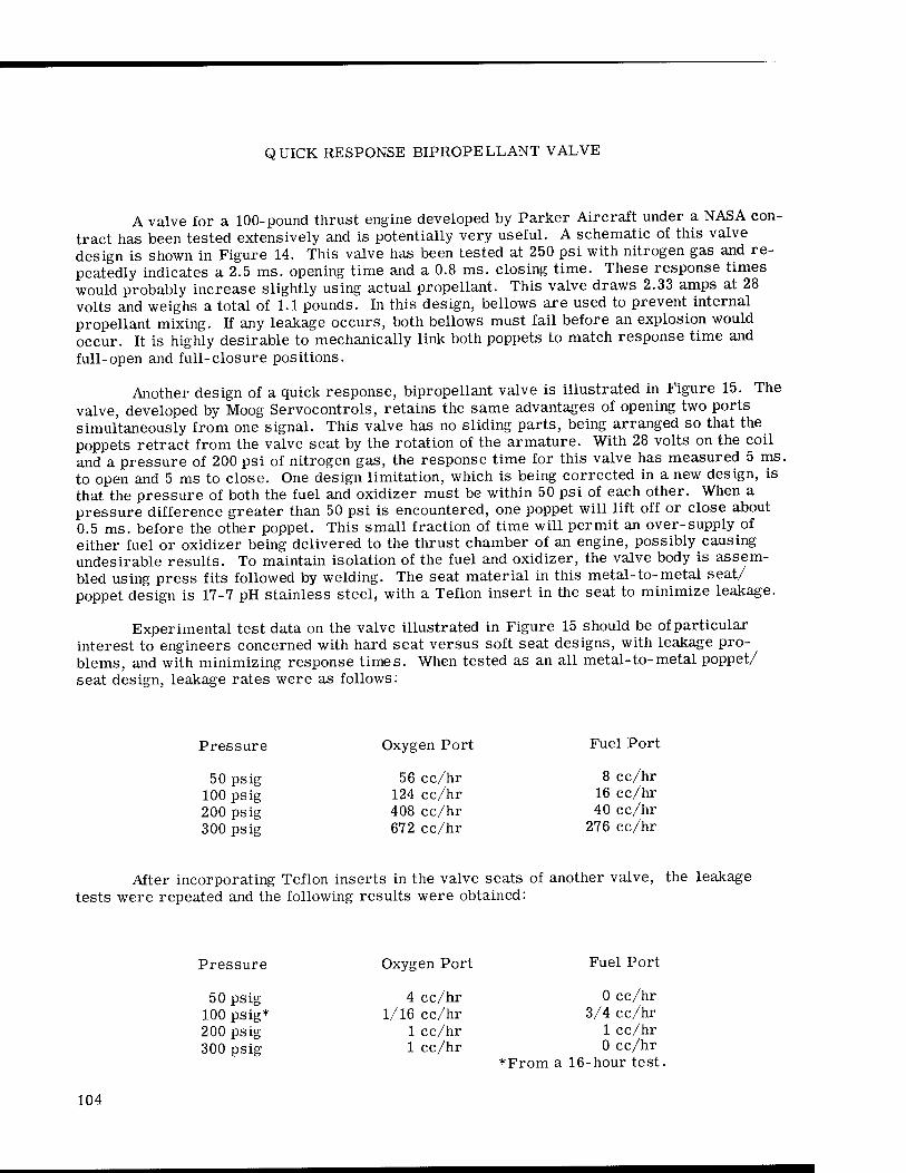
QUICK RESPONSE BIPROPELLANT VALVE
A valve for a 100-pound thrust engine developed by Parker Aircraft under a NASA con- tract has been tested extensively and is potentially very useful. A schematic of this valve design is shown in Figure 14. This valve has been tested at 250 psi with nitrogen gas and re- peatedly indicates a 2.5 ms. opening time and a 0.8 ms. closing time. These response times would probably increase slightly using actual propellant. This valve draws 2.33 amps at 28 volts and weighs a total of 1.1 pounds. In this design, bellows are used to prevent internal propellant mixing. If any leakage occurs, both bellows must fail before an explosion would occur. It is highly desirable to mechanically link both poppets to match response time and full-open and full-closure positions.
Another design of a quick response, bipropellant valve is illustrated in Figure 15. The valve, developed by Moog Servocontrols, retains the same advantages of opening two ports simultaneously from one signal. This valve has no sliding parts, being arranged so that the poppets retract from the valve seat by the rotation of the armature. With 28 volts on the coil and a pressure of 200 psi of nitrogen gas, the response time for this valve has measured 5 ms. to open and 5 ms to close. One design limitation, which is being corrected in a new design, is that the pressure of both the fuel and oxidizer must be within 50 psi of each other. When a pressure difference greater than 50 psi is encountered, one poppet will lift off or close about 0.5 ms. before the other poppet. This small fraction of time will permit an over-supply of either fuel or oxidizer being delivered to the thrust chamber of an engine, possibly causing undesirable results. To maintain isolation of the fuel and oxidizer, the valve body is assem- bled using press fits followed by welding. The seat material in this metal-to-metal seat/ poppet design is 17-7 pH stainless steel, with a Teflon insert in the seat to minimize leakage.
Experimental test data on the valve illustrated in Figure 15 should be of particular interest to engineers concerned with hard seat versus soft seat designs, with leakage pro- blems, and with minimizing response times. When tested as an all metal-to-metal poppet/ seat design, leakage rates were as follows:
Pressure
50 psig 100 psig 200 psig 300 psig
Oxygen Port
56 cc/hr 124 cc/hr 408 cc/hr 672 cc/hr
Fuel Port
8 cc/hr 16 cc/hr 40 cc/hr
276 cc/hr
After incorporating Teflon inserts in the valve seats of another valve, the leakage tests were repeated and the following results were obtained:
Pressure
50 psig 100 psig* 200 psig 300 psig
Oxygen Port
4 cc/hr 1/16 cc/hr
1 cc/hr 1 cc/hr
Fuel Port
0 cc/hr 3/4 cc/hr
1 cc/hr 0 cc/hr
*From a 16-hour test.
104

FLOW
FLOW
BELLOWS
BELLEVILLE SPRING
COIL
BELLEVILLE SPRING
Figure 14. Quick Response, Bipropellant Valve
105

COIL B
COIL A
COIL B
POPPETS
Figure 15. Quick Response, Bipropellant Valve with No Sliding Parts
The response time for both the hard seat and the soft seat tests were recorded and are listed below:
Seat
Hard Soft
Opening Time
4 to 4.5 ms. 4 to 5 ms.
Closing Time
1.5 to 2.25 ms, 5 to 6 ms.
106
RUPTURE DIAPHRAGMS
NASA's Ames Research Center is performing free flight model tests at velocities up to 50,000 ft/sec, or approximately 34,000 miles/hr. Figure 16 is a schematic illustration of the test facility used to accomplish the model test. An explosive powder charge is detonated in a high pressure vessel, Area 1. The resulting products of combustion, under high pressure and temperature, move a 1 1/2 in. diameter Teflon or nylon slug down the tube.
The moving slug, acting like a piston, compresses hydrogen or helium in the high pressure coupling, Item 4. Area 5 in the high pressure coupling then contains the helium or hydrogen gas at a temperature of 20,000°F and a pressure of 350,000 psi. A rupture dia - phram, Item 6, designed to momentarily contain the gas at this high temperature and pres- sure, gives way and the gas drives a sabot, Item 7, down the launch tube, Item 8, and into the free flight chamber, Item 9. The sabot, an incasement around the model being tested, sepa- rates from the model in the free flight chamber.
At the other end of the system a mixture of helium, hydrogen, and oxygen is contained in a 70 ft. long naval gun, Item 13. The hydrogen-helium-oxygen mixture is ignited by an exploding wire detonated from a high potential electrical discharge. This explosive com- bustion heats the helium gas up to 5000°F and creates a pressure of 7,000 psi. This high temperature and pressure gas is contained by a diaphragm, Item 12. Upon signal, an explo- sive charge is detonated, rupturing the diaphragm. A shock wave is driven down the tube, Item 10, heating the dry air in the tube. The pressure difference across the throat is suffi- cient to provide the air velocity of 20,000 fps.
Extensive research programs were conducted at Ames Research Center in developing these explosive diaphragms. Shaped explosive charges of many different configurations were used. Any desired shape can be cut or etched in the diaphragm, with close control on depth of penetration. For example, an "X" configuration can be etched into the diaphragm to a depth of 75 per cent of its thickness, plus or minus 5 per cent. In this manner, the diaphragm is weakened and the pressure of the gas itself ruptures the diaphragm rather than the explo- sive, which could fragment the diaphragm and allow loose pieces to enter the free-flight chamber. In another configuration, circular arcs of 300 degrees are etched into the dia- phragm so that when the pressure ruptures the diaphragm, the disc hinges out of the way without shedding any loose material.
To protect the explosive charge from the high gas temperatures, an epoxy potting compound is used for a thermal insulation on the diaphragm.
GATE VALVE OPENED IN LESS THAN ONE MILLISECOND
In some industrial research and development programs, a single time operation, quick valve may be useful. At Ames Research Center, the valve illustrated in Figure 17 opens a lightweight gate in less than 1 ms. A double Teflon membrane with an embedded electrical wire contains helium at 300 psi. Helium or hydrogen is used since its low mass has little inertia and it can accelerate much more rapidly than air. An electrical discharge from a bank of condensers is used to explode the wire rupturing the Teflon, and releasing the gas on one side of a lightweight piston. The 300 psi gas on the other side of the piston moves
107

©—
>- _l I-
>
en
o o o o ro
UJ o >- X o
~ s K u Co liJ <
3E
T C
HA
MB
L
GU
N
20 P
SI
DIA
PH
R
L G
UN
z UJ
o Q
5 x <i_ <> ra
x^2a:c/)z 2
> i—i
o . • < O f_- 3 > >>
_J •rH
<ir oir xo UJ • r-l
_l U. <T> Q UJ r*- x En
00 CD O — CM ro <fr -4-) CO
H >>
-w • r-t
*^*»» O
LÜ O
i—f 0
U_Ü_ > CD° > J3
•rH
, vDCLOrr to
E OR
N H
ELI
C
OU
T
20
, U
PTU
En ^ o:£<a: (TZoc ~ <o^=>-
OW
DER
C
H
LUG
= T
EF
L
YD
RO
GE
N
IGH
-PR
ES
S
50
,00
0
PS
lAP
HR
AG
M
_l UJ Q O
(L(/)llrOü5
— C\J ro <fr IT) CD Is-
108

I irAa
FIRES PROJECTILE DOWN TUBE
■LIGHT WEIGHT CYLINDER
LIGHT WEIGHT GATE VALVE
DOUBLE TEFLON MEMBRANE
ELECTRICAL WIRE
Figure 17. Gate Valve Opened in Less Than 1 Ms.
109

the piston to open the gate in less than 1 ms. This particular design was utilized in a facility where free-flight test models are fired through the air, down an air-filled tube, and into a gas-filled chamber under higher pressure.
BIBLIOGRAPHY
"Advanced Valve Technology for Spacecraft Engines," by B. P. Brady, R. J. Salvinski, Space Technology Laboratories, Inc., Redondo Beach, California (Final Report, Contract No. NAS 7-107, March 1963).
""0"-Ring Check Valve," Invention Report No. 30-33 (Inventors: W. F. MacGlashan, Jr., and O. F. Keller), Jet Propulsion Laboratory, California Institute of Technology, Pasadena, California (Contract No. NASw-6), June 22, 1960.
110

CHAPTER 10. REPEATABILITY
In automatic system control, machine design, and other areas of automation, a definite series of events must occur in proper, timed sequence. Nonrepeatable valve response times lead to erratic total system behavior.
In many industrial processes which require mixing of two fluids, the response time and repeatability of the valves which start and stop the flow of each fluid are critical factors. Recent advances in aerospace valve technology have produced improved "bipropellant valves" which are ideally suited for simultaneously controlling flows of several fluids in industrial mixing operations. These valves have a single actuating mechanism to control the flow of two or more fluids through separate ports, thereby eliminating the synchronization problem associated with the use of separate, individual valves in each fluid line. Since only one actuating means is used, both valve poppets will always act together.
SOLENOID CURRENT TRACE CHARTS
When separate actuating mechanisms are unavoidable, an analysis of valve response is important.
A detailed study of the repeatability of solenoid valves in synchronized, paired operation was accomplished at NASA's Manned Spacecraft Center in Houston, Texas. A careful review of the solenoid valve current traces produced in this study provides a valuable insight into the many problems associated with synchronization of valves, whether they be electrical, pneumatic, hydraulic, or mechanical types.
Two identical, high quality, commercially available, solenoid valves were tested in the "as received" condition. Fuel flowed through one valve and an oxidizer flowed through the other valve. The objective of the test was to determine the factors related to obtaining exacting mixing ratios, since an excess of either fuel or oxygen could result in system mal- function.
The solenoid valves tested used a spring to hold the poppet against the seat. The sole- noid pulls the plunger and poppet away from the seat and compresses the spring. Upon re- lease of current to the solenoid, the spring moves the plunger and poppet to a closed position against the seat. A current probe is used in conjunction with an oscilloscope to produce the chart illustrated in Figure 18.
Figure 18A shows the solenoid current trace with no plunger motion. Figure 18B illus- trates the change in the curve when a plunger motion is introduced. From time zero, cur- rent builds up in the solenoid until point T, is reached. Motion of the plunger introduces a
111
voltage that opposes the buildup of current. Because the plunger motion starts quite abruptly, the peak in the waveform at Tl is actually somewhat sharper than shown in Figure 18 and, for practical purposes, the instant of initiation of plunger motion may be taken as occurring in coincidence with Tj, the instant when the current actually begins to decrease. Current continues to decrease as plunger motion continues until the plunger motion stops at point T2. Then current begins to build up and levels off when the solenoid steady-state current value is reached. The decrease in current during plunger motion is indicated by di. The duration of plunger movement is indicated by dt.
Figure 18C illustrates the ideal synchronization of two valves, one controlling fuel and the second controlling the oxidizer. In this theoretically perfect, matched pair of valves, both plungers begin motion at the same instant, Tj, end motion at the same instant, T2, and thereby achieve the same time of travel, dti being identical to dt2. Also, the current levels when plunger motion begins, Ii, are identical; the current levels when plunger motion stops, 12, are identical; and the change of currents are identical for both valves, dii being equal to di2.
Figure 18D illustrates a test condition where both valves received a signal at the same instant but the motion of one valve was retarded. In this illustration, the durations of plunger motion between points Tj and T2 are identical. This pair of traces indicates that a different voltage level existed between the two solenoids, or there was a difference in the solenoid winding.
Figure 18E illustrates a condition where electrical characteristics of both valves are identical but, due to some mechanical problem, the fuel valve plunger moves slower than the oxidizer valve plunger.
Figure 18F indicates valve sticking problems where the current required to begin plunger motion had reached the final steady-state current level before movement began. In Fig. 18F the curve would rise to Tj and then level off if the plunger of the valve should stick.
The effect of pressure upon two supposedly synchronized valves is illustrated in Fig. 19. As the pressure increases from 0 psig through steps up to 500 psig, the time lapse from signal input to the beginning of plunger motion also increases. In addition, as the pressure increases there is an increase in the level of current necessary before plunger motion begins, since high pressure is exerted on the poppet from inside the valve to hold the poppet against the valve seat. Should the flow be reversed, with pressure applied to the valve seat, the pressure would tend to open the valve, thereby decreasing the current necessary to operate the valve. The change of plunger velocity with pressure is readily apparent. As pressures and, therefore, actuating current increase, plunger velocities also increase. The slope of the curve between the points where plunger motion begins and plunger motion stops is indica- tive of plunger velocity. At lower pressures, this slope is gentle and longer periods of time are used for plunger travel; at the higher pressures approaching 500 psig, the slope of the curve becomes very steep. This curve indicates the presence of extremely high plunger velocities, high impact forces and high stress levels in the valve structure.
SUMMARY
When industrial processes require synchronized valve motion for mixing and process synchronization controls, the repeatability of valve motion (specifically poppet motion) should
112
receive a critical review. Consideration should be given to the use of the newer types of single actuator bipropellant valves.
It should be noted that the valves tested in this program were not representative of the best available solenoid valves. The results do, however, depict problems which have been and are still being found in many solenoid valve designs. This is especially true in valves with an excessive number of sliding parts and fits.
113

TIME SOLENOID CURRENT TRACE WITH NO PLUNGER MOTION
Figure 18A.
Figure 18C.
PLUNGER MOTION ■BEGINS (MAXIMUM)
PLUNGER MOTION STOPS (MINIMUM)
»-T SOLENOID CURRENT TRACE
WITH PLUNGER MOTION
Figure 18B.
Figure 18D.
Figure 18E. Figure 18F.
O-OXIDIZER VALVE F- FUEL VALVE
Figure 18. Solenoid Valve Current Traces
114

*— T
TEST I- 0 PSIG- GN2 TEST 2-100 PSIG-6N2
TEST 3-200 PSIG - GN2 TEST 4- 250 PSIG-GN2
*~T
TEST 7- 400 PSIG- GN2 TEST 8- 500 PSIG - GN2
Figure 19. Solenoid Valve Tests
115

116

CHAPTER 11. VALVE ACTUATORS, POSITION INDICATORS, AND COMPUTER CONTROL
Many valve problems encountered in industry and aerospace applications concern valve accessories rather than the valve itself. These accessories include valve actuators, valve position indicators, and computer systems used to control valves.
VALVE ACTUATORS
Personnel at NASA's Lewis Research Center report that a number of problems have occurred with valve actuators, and particularly with electro-hydraulic control actuators.
These actuators contain pistons, position feed back means, and hydraulic servo valves. The problems encountered are:
1. Leakage of hydraulic fluids through seals; 2. Poor seal life; 3. Special non-standard piston size requirements; 4. Lack of rigidity in the attachment of the linkage for feed-back position control; 5. Inadequate control over fits and tolerances; 6. Inadequate resolution. Honed and lapped cylinders and pistons were used in
place of "0"-ring seals where high positioning resolution was required. 7. Different flow rates depending upon the direction of piston travel. Only double-
ended pistons are used so that identical rods extend in both directions from the piston. In this manner, differential speeds and flow rates are not present when the direction of pis- ton movement changes.
Boonshaft and Fuchs, Inc., Hatboro, Pennsylvania, is a commercial source that can satisfactorily furnish actuators at the extremely high response rates in the range of 50 to 150 cps.
VALVE POSITION INDICATORS
The position of valves is monitored in many aerospace and industrial systems to furnish a signal indicating the true position of the valve. The monitoring operation is normally accomplished through the use of metal diaphragms and springs. Temperature cycling of springs and metal diaphragms from ambient temperatures to either cryogenic
117

temperatures or liquid metal process temperatures can cause these parts to weaken and take a permanent set. When these parts remain in a given position over a long period of time, the position actuators may stick and produce erroneous position signals.
Pressure switches have been a problem on the Saturn V Program at the George C. Marshall Space Flight Center. Component response requirements are coupled with speci- fications for wide environment ranges in both temperature and pressure. While this problem has not been solved, development work is being performed to improve the reliability of opera- tion of these components. "Klixon" (Texas Instruments) switches are being used in environ- ments below -100°F but with minimum specified relief force which is much greater than that used at ambient temperatures. They are pressure sensitive.
A new concept for indicating open and closed conditions of valves at cryogenic tem- peratures is needed - mechanically actuated switches, even though improved, leave much to be desired in regard to reliability.
COMPUTER CONTROL OF VALVES
In many cases, computers are receiving input signals from valve position indicators and feeding output signals to valve actuators for the control of process liquids, gases and mechanical equipment using pneumatic and hydraulic systems. Much information is avail- able on the use of analog computers for controlling processes. Digital computers are now beginning to take their place in the automatic control of industrial processes and systems. The following paper, recently presented at a technical conference by personnel from Honeywell, Inc., includes information on the digital computer control of valves.
118

A DIGITAL ACTUATOR
by
A. E. Stone - Chief Engineer, and R. K. Madsen - Application Engineer
Honeywell, Inc., Valve Division Fort Washington, Pennsylvania
Abstract
A straightforward approach to building a digital actuator is to develop a digital posi- tioner which can be mounted on a conventional pneumatic diaphragm actuator. In this way all of the good features of the diaphragm actuator are retained and cost is kept to a minimum. This paper describes such a positioner.
Introduction
There has been recent widespread interest in the concept of direct digital computer controlled processes. The reason for this interest is, quite naturally, one of economics. Conventional process control methods call for a process sensor, a controller, and a final control element for each loop in the process. If the process has enough loops, there will be a point where a single digital computer can be substituted for all of the controllers at a net financial gain.
The traditional stumbling block of this concept is the final control element. Almost all final control elements are analog in nature. That is, they operate from a continuous signal rather than from a signal composed of discrete steps or digits. For this reason con- ventional valve actuators are incompatible with the type of signal output that would come from a digital computer. The most direct way to get around this problem is to insert some sort of converter between the computer and the actuator which would receive the computer output and convert it into an appropriate analog signal suitable for the actuator. This has been done and it works. But the cost is high.
Background
The purpose of this paper is to describe an actuator which receives a signal which is digital in nature and operates a control valve directly. In the development of this actuator it was decided that everything possible should be done to retain the basic concept of the
119

diaphragm actuator. The reasons for this were:
1. The diaphragm actuator is the simplest and most dependable way to operate a control valve.
2. The maintenance requirements are very low and maintenance people are familiar with them.
3. They are the least expensive way of getting high thrusts.
4. They are mechanically compatible with existing control valves.
It would be possible to develop a special purpose actuator which has a number of dis- crete positions available on command from a computer, but this actuator would need 1,000 such positions to give the same degree of resolution available from today's diaphragm ac- tuators. An actuator of this type would probably be very large, very complicated, and very expensive. It was therefore decided that the best approach to getting a digital actuator was to develop a valve positioner which could receive a step type input and drive a diaphragm ac- tuator with the output. This seems even more practical when one considers that an electro- pneumatic positioner or transducer is required on every valve used with modern electronic control systems anyway. The cost of a digital control valve would be higher than a conven- tional valve by an amount equal to the difference in cost between an electro-pneumatic posi- tioner and the digital positioner. It turns out that this difference in cost is modest, and digital control valves can thus become practical.
Principle of Operation
We can learn the principle of operation of this positioner by comparing it to an elec- tro-pneumatic positioner which is by now a familiar instrument. An electro-pneumatic valve positioner can operate on the force-balance principle wherein the input signal and feedback motion are both converted into forces which are then applied to a common member. Any error is reflected as a net "unbalance force" which can be used to operate a pneumatic flapper-nozzle system. In the case of an electro-pneumatic positioner the input signal is a current, usually of milliampere magnitude, which can be converted to a force by feeding it into a coil situated in a magnetic field. The force is then directly proportional to current. The positioner is controlling valve stem position, so this position must be converted into a feedback force. Of course, motion can easily be converted to force by means of a spring, a and this "feedback spring" is the method usually employed in a force balance positioner. Now, if we have an electro-pneumatic positioner we should be able to change the nature of the input by substituting some other force for that force supplied by the input coil. This is exactly what was done to make the digital valve positioner.
In the digital positioner a d.c. stepping motor is the element that receives the input signal and converts it into a force. This motor replaces the input signal used on the electro- pneumatic positioner. The motor moves in discrete steps, each of which amounts to 1.8 degrees of rotation. The shaft of the motor is threaded and has a fixed nut which cannot ro- tate but is free to move up and down the shaft as the shaft rotates. The nut is in contact with a spring which provides the input force.
At this point it would be helpful to study the d.c. stepping motor in more detail in order to learn its principle of operation and the nature of the input signal. These motors
120

have a rotor which is really no more than a permanent magnet with teeth milled into it. The stator has coils which can be energized with either positive or nagative polarity. Figure 20 illustrates a motor as it goes through one sequence of steps. The end of the rotor shown is the north pole. When phases A and B are both energized positive as at position 1, it creates the effect of a north pole at the top and a south pole at the bottom. Therefore, a rotor tooth will align itself opposite the south pole at the bottom, and a gap will appear opposite the north pole at the top. This is consistent with the principle of attraction of opposite poles since the teeth of the rotor have a higher magnetic flux density than do the slots. If we reverse the polarity of the phase A coils, the magnetic field rotates 90° clockwise as shown in position 2, and the rotor turns 1/4 tooth. Reversing phase B polarity shifts the magnetic field another 90° in the clockwise direction, and restoring the original polarity to phase A shifts it once again. It can be seen that four polarity changes cause the rotor to turn 1 tooth. The illustra- tion shows a rotor with 5 teeth for the purpose of simplifications. Actually, the motor has 50 teeth, and 200 steps are required for a complete revolution of the motor.
POSITION I POSITION 2
POSITION 3 POSITION 4
Figure 20. Position Illustrations
121
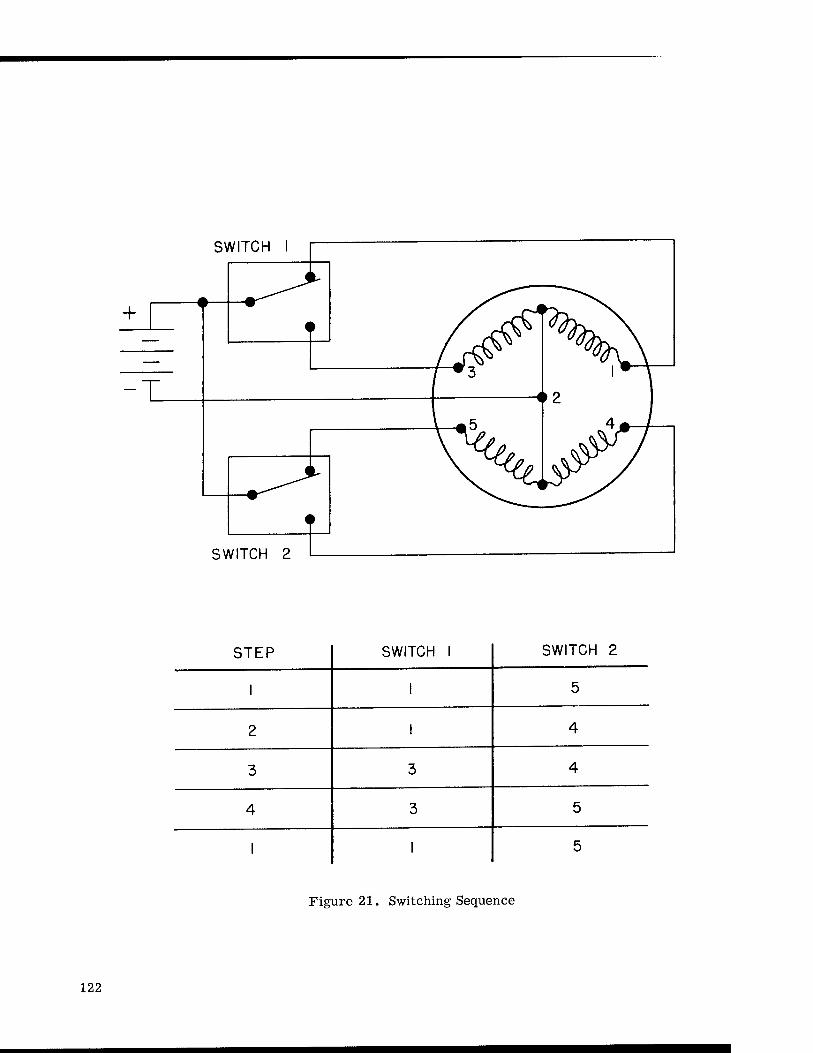
SWITCH I
SWITCH 2
STEP SWITCH 1 SWITCH 2
1 1 5
2 1 4
3 3 4
4 3 5
1 1 5
Figure 21. Switching Sequence
122

AIR SUPPLY
DIAPHRAGM ACTUATOR"
I FLAPPER NOZZLE I BEAM
D.C. STEPPING MOTOR
Figure 22. Schematic of Digital Valve Positioner
There is another type of motor which uses the same principle described above, but has a slight modification. This motor has half of each coil wound in the opposite direction so that it can be stepped by switching from one half of the winding to the other rather than chang- ing the polarity of the coil. This motor is said to have bifilar windings and is the motor prin- cipally used in the digital positioner. Figure 21 shows the switching sequence required to get clockwise rotation. Counter clockwise rotation is obtained by simply reversing the switching sequence.
A schematic representation of the positioner is shown in Figure 22. A d.c. switching sequence is fed into the motor windings causing rotation of the threaded shaft. The nut then travels up the shaft because it is restrained from rotating. This motion lets the nut bear against a spring which places a force on the flapper-beam and moves the flapper away from the nozzle a slight amount. When the flapper moves away from the nozzle the air pressure behind the nozzle is reduced because the resistance to flow is reduced. This back pressure is directed to a pneumatic booster relay, and since the pressure into the booster was reduced, the pressure output is also reduced. This lower output pressure allows the diaphragm ac- tuator to move upwards under the influence of the actuator spring. As the actuator stem
123
moves up the feedback cam rotates counter clockwise as does the cam follower. This action results in a downward force on the flapper beam which opposes the upward force applied by the input spring. When the moments on the beam are equal, the instrument is in equilibrium and the control valve has reached the new position called for by the computer.
Characteristics
The digital valve positioner is set up to have a 1,000-step span for full valve travel. This gives a resolution roughly equivalent to a standard control valve with a positioner. The span remains constant for any valve travel within the 1/2-inch to 4-inch range of the instru- ment. The motor will accept d.c. steps at any rate up to 400 steps per second. This means that the instrument can give full output in a minimum time of 2-1/2 seconds. The motor has a power requirement of about 5.5 watts.
The positioner has an air handling capacity of 7 standard cubic feet per minute with a 20 psig supply pressure. The maximum supply pressure is 50 psig. Air consuption is about 0.3 standard cubic feet per minute when the instrument is in equilibrium.
The feedback is accomplished through a cam which normally gives a linear relation- ship between valve position and number of input steps received. Other cams can be used to give nonlinear relationships when required.
The positioner can be used with several types of control. One type is valve stem posi- tion control. Here the computer measures the process variable and computes the position to which the valve should move to correct the error, if any. It then sends the required number of d.c. steps to the positioner at a rate not exceeding 400 steps per second. With this type of control the computer has to remember the last position of the valve.
Another type of control is valve stem velocity control. In this case there are several switching frequencies available to the computer on demand. The computer then determines how far the process is off set-point and computes what corrective action is required. De- pending on the magnitude of the correction, the computer selects one of the programmed switching frequencies and sends the signal to the positioner. If the error is large, a high fre- quency is send to the positioner resulting in a high stem velocity. If the error is zero, no signal is sent to the positioner and the valve stem holds its position. One advantage of this type of control is that once the frequency is selected the computer is free to scan the next loop. The switching frequency selected will continue to go to the positioner until the com- puter selects a new one. Another advantage is that no valve position memory is required.
Summary
The digital positioner was developed with the aim of retaining the conventional pneu- matic diaphragm actuator as the means of operating the control valve. The positioner re- ceives a d.c. step which is actually a switching sequence directing current to the motor coils in a predetermined program. The output of the positioner is an air pressure which is applied to the diaphragm actuator. Valve stem position is fed back into the positioner through a cam arrangement, so the instrument becomes a closed loop device.
124

CHAPTER 12. PROPORTIONAL FLOW CONTROL
Proportional flow control valves are designed so the volume of flow varies with the motion of the valve actuator.
SLIDING STEM PROPORTIONAL VALVE
System engineers at NASA's Flight Research Center have required truly proportional flow control valves for several research aircraft. Specifications were so exacting that they could not be met by suppliers of commercially available valves. The requirements are for a totally stainless steel and Teflon valve with motorized operation. This valve is for operation at ambient temperatures, but the material problems concern compatibility with hydrogen peroxide.
•VENT
FLUID ORIFICES FLOW SHUT-OFF PLATE
Figure 23. Sliding Stem proportional Valve
125

The temperature of the environment in which this valve functions is held very close to 75°F with heating and cooling applied as required. (Rocket response deteriorates as the H2O2 temperature is reduced below 60°F and the autodecomposition rate increases as the temperature increases. 75°F is a usable compromise.)
Figure 23 illustrates the unique design concept which provided truly proportional flow control in this application. A series of very small holes is drilled in a spiral pattern in a hollow valve stem. With linear stem travel, the number of holes open to transmit hydrogen peroxide changes in proportion to the distance traveled. Good proportional flow character- istics are obtained with this design.
OUT
Figure 24A.
Figure 24B.
Figure 24. Curtain Flap Proportional Valve
126

CURTAIN FLAP PROPORTIONAL VALVE
Another unique design for obtaining proportional flow was developed for NASA's Flight Research Center. Figure 24A illustrates the concept of this design where one end of a Teflon curtain is secured to a rotatable valve stem. The other end of the curtain is secured to the inside of a stationary hollow cylinder. Fluids under pressure are introduced into the hollow cylinder, exerting fluid pressure against the curtain flap which covers all holes to prevent flow. The holes in the hollow cylinder should be small enough to prevent extrusion of the Teflon curtain into or through the holes. As the valve stem is rotated, the curtain flap is either woundup or unwound from the rotating stem, thereby covering more or fewer holes, allowing fluid flow in proportion to the amount of stem rotation.
Figure 24B illustrates the geometric layout of the holes around the hollow cylinder. The angle 0 and the separation are chosen so that the holes are in a uniform angular step pattern. In this manner, the curtain covers successive holes by progressively varying a- mounts and provides proportional flow.
127

128

CHAPTER 13. HEAT TRANSFER
In addition to establishing the requirement for special valves in systems operating at extreme low or high temperatures, the space age has accentuated the problem of heat con- duction into or away from a valve in or near such a system. Before charging head-on into the design of a special valve to operate in close proximity to a very hot or very cold system, the alert engineer will usually explore ways of avoiding the problem. This procedure of eliminating the problem has been followed successfully in the two examples cited below.
RELOCATION OF VALVES IN X-15 ROCKET AIRCRAFT
In original designs for the X-15 rocket aircraft, pressure loaded check valves were placed immediately adjacent to rocket engines to control flow into these engines without de- lays in starting and dribble at cut-off. The heat developed in the engine soaked back to the valves and caused severe valve operating problems.
Before undertaking an extensive research development program to redesign the valves to handle the problems of seal damage and loss of temper in springs, an investigation was made of the possibilities of merely relocating the existing valves. This study resulted in the relocation of the valves to a point in the piping 8 in. from the rocket engine. This dis- tance was sufficient to provide thermal isolation from the hot rocket engine without intro- ducing serious problems in the timing of engine ignition or shut-off.
RELOCATION OF HOT LIQUID VALVES
At NASA's Langley Research Center, this same type of analysis resulted in the re- location of a fluid control valve from the outlet to the inlet connection of a heat exchanger. Since the heat exchanger is the source of heat for the controlled fluid, the placement of the control valve in the cool inlet location permitted the use of a standard, commerically avail- able valve.
129

LIQUID METAL VALVE BELLOWS
In some applications, it becomes necessary to design valves to cope with extreme heat transfer conditions. One such application is the case of valves for use in systems handling liquid metals. A flexible bellows seal is often used to isolate the metal valve stem from the liquid metal. This design creates a new problem, however, because when the valve is closed and the system cools, the liquid metal on the underside of the bellows freezes, destroying the flexibility of the bellows and preventing the valve from being opened. There- fore, when these types of valves are used, it has become necessary to apply heat when the system cools, to keep the entire valve above from freezing temperature of the liquid metal.
LOW TEMPERATURE VALVES
To prevent freezing of valve stem packings, valves designed for cryogenic use will normally have the stem and packing extending far away from the process piping. Another approach to keep the stem packings from freezing is to surround the stem and packing areas with a bellows and keep the packings warm through the use of an extended bonnet with fins to absorb heat from the ambient environment or from some external source. In some applica- tions, welded bellows are used in place of packings.
Valves for use in liquid helium systems present especially severe problems. The stems are usually much longer to keep all heat out of the helium flow. When possible, the use of valves for liquid helium systems should be minimized or avoided. In some instances, back pressures are controlled by other means to stop and start flow rather than resorting to the use of valves in the liquid helium system. Generally speaking, valves for liquid helium are not too troubled with heat transfer problems when used in systems where extremely high flow rates occur. However, at NASA's Lewis Research Center, where very low flow rates of liquid helium are encountered, the heat absorbed by the valve stems can create crucial problems. This type of problem can be solved by constructing a vacuum chamber or jacket to surround the valve. To prevent thermal radiation from entering the valve area, a radia- tion shield is then placed around the vacuum jacket. This shield consists of a second jacket enclosure. Then liquid nitrogen (-320. 8°F to -345. 5°F) is circulated between the two jack- ets, to act as a thermal barrier between the liquid helium and the surrounding atmosphere. As a final precaution, a foamed insulation is installed around the liquid nitrogen jacket.
In this design, metal jacket walls are kept as thin as possible to minimize the area available for heat transfer paths.
The "rules of thumb" for valve insulation at NASA's Lewis Research Center are:
1. Liquid nitrogen and liquid oxygen: use insulation, preferably a foam type con- taining Freon bubbles to utilize its superior insulating properties.
2. Liquid hydrogen: use a vacuum jacket in addition to foam insulation.
3. Liquid helium: surround the valve with a vacuum jacket, then a thermal radia- tion shield containing another flowing cryogenic fluid, and finally a foam insulation as an outside covering.
130

SWEATING OF LOW TEMPERATURE VALVES
A potential fire hazard exists in the use of valves for processing cryogenic fluids. Water vapors in the air freeze on these surfaces to form frost or snow on the metal. Then, due to the excellent insulating characteristics of the frost, extremely low temperatures occur at the base of the frost layer, allowing liquid air to form on the pipe or valve surfaces. This liquid air tends to wash off the frost. The liquid dripping from the now wet process piping and valves contains both liquid nitrogen and liquid oxygen. Liquid nitrogen in the drippings vaporizes first, leaving essentially pure liquid oxygen, creating a potential fire hazard. At the various NASA centers, insulation is placed around the valve and piping which contain cryogenic fluids to prevent this fire hazard, even though it may not be required for any other reason.
HEAT ISOLATION AT VALVE FLANGE COUPLING
At NASA's Langley Research Center, the problem of heat soaking from attitude con- trol motors to valves was encountered in a system where it was not possible to avoid the problem by valve relocation. The valves handle a 90 per cent concentration of hydrogen peroxide which will decompose at a temperature of 1364°F when placed in contact with a silver catalyst. The catalytic silver screen must be located immediately adjacent to the control valve.
The flow of hydrogen peroxide through the valves will normally keep these valves cool. However, when the motor is intermittently fired, the off periods allow heat to con- duct back to the valve.
A special development program was undertaken to provide a conduction heat barrier at the valve flanges. Two special materials were incorporated in a design which provided a satisfactory solution. These materials are Armalon and Fluorogold. *
A combination of these two materials was used to overcome a leakage problem asso- ciated with the laminated Armalon product and a cold flow problem associated with the non- laminated Fluorogold product. The Armalon will stand compression without the associated cold flow and the Fluorogold will prevent leakage associated with laminated structures. Figure 25 illustrates the custom-design which was used for this application of a valve flange heat shield. The combination of these two materials has successfully passed temperature cycling tests from ambient to 600° F where other materials have failed. The unique proper- ties of this design are that it is good for liquid pressures up to 600 psi maximum; it can withstand cycling through extreme temperature ranges where expansion and contraction
*Armalon: Trademark for TFE-Fluorocarbon resin coated glass fabrics and laminates, E. I. du Pont de Nemours and Company, Inc.
Fluorogold: Trade name by Fluoro Carbon Company, Anaheim, California.
131
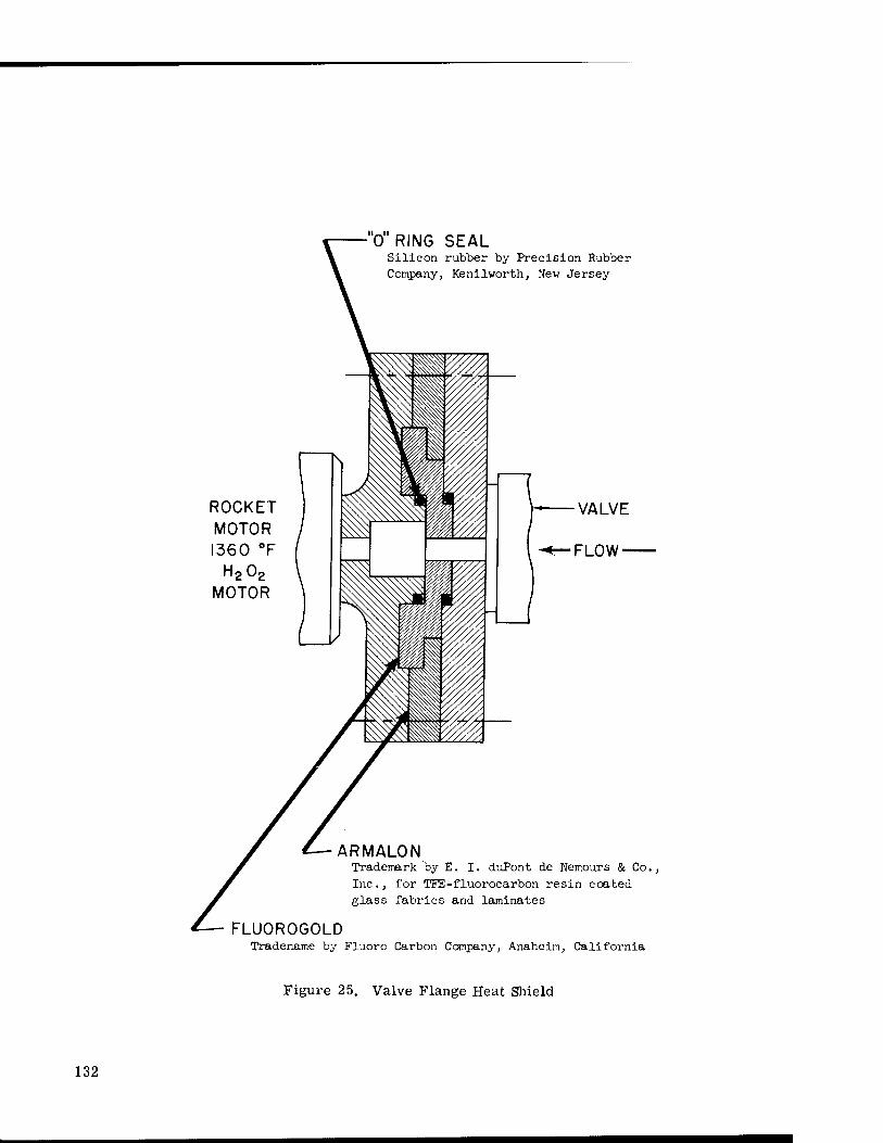
0 RING SEAL Silicon rubber by Precision Rubber Company, Kenilworth, New Jersey
ROCKET MOTOR 1360 °F
H202
MOTOR
ARMALON Trademark by E. I. duPont de Nemours & Co., Inc., for TFE-fluorocarbon resin coated glass fabrics and laminates
FLU0R0G0LD Tradename by Fluoro Carbon Company, Anaheim, California
Figure 25. Valve Flange Heat Shield
132

occurs; it prevents deformation of insulating materials; it is compatible with hydrogen per- oxide; it has excellent thermal barrier characteristics for heat conduction; and it will with- stand vibration loads beyond 10 g.
BIBLIOGRAPHY
"Control Valves for Cryogenic Fluids, " Introductory Product Literature, Black, Sivalls and Bryson, Inc., Kansas City, Mo. (BS&B 70-240; 10M-9/63).
"Insulating Structure, " Patent No. 3,012,407; December 12, 1961; Inventor Dale L. Burrows, George C. Marshall Space Flight Center, Huntsville, Ala.
133

134

CHAPTER 14. HIGH PRESSURE, HIGH TEMPERATURE
Considerable developmental work is being accomplished in both industrial and aero- space research programs on high temperature-high pressure valve designs. A number of the industrial development programs have led to commercially available valves. Continuing research and development will be required to meet the ever increasing demand for valves to operate reliably at very high or very low temperatures.
INDUSTRIAL HIGH TEMPERATURE VALVE DEVELOPMENTS
The Arde-Portland, Inc., in a company-funded program, developed a valve for the Air Force which operated successfully during a 1 minute, static firing at Edwards Air Force Base in a rocket motor burning highly aluminized solid propellant at temperatures above 5000° F. These valves are designed to handle erosive and corrosive gases at temperatures up to 6500° F. The design employs an unusual self-cooling principle where plugs, made of tungsten imbedded with silver, are installed on the end of valve stems. In high tempera- ture operation the silver boils off into the atmosphere, thereby absorbing heat and cooling the valves.
Honeywell Research Center, Hopkins, Minnesota is responsible for the development of a short-length, in-line, all-metal valve. The valve is designed for ultra-high vacuum systems and has a leakage rate measured at less than 10"10 standard cc/sec with atmos- pheric pressure on one side. The valve is constructed of non-magnetic stainless steel and copper and is a bakeable assembly.
Flomatics, Inc., Natoma, California, furnished a 1500 psi valve to NASA's Ames Research Center for operation at temperatures up to 1540° F. A Stellite-on-Stellite design was used for this needle valve seat and stem.
At NASA's Ames Research Center, a commercially available, "ball-cage" valve design is used to control wind tunnel pressures. These 4 in. and 8 in. valves were useful for controlling pressure from 0 to 2, 000 psi across the valve with up to 3, 000 psi on the up- stream side. These valves are furnished by P-K Industry. * A small amount of air leakage is present but this particular application does not require a leak-proof design.
*The former P-K Paul Valve Company is now the Devar Kinetics Division of the Consoli- dated Electrodynamics Corporation, Bridgeport, Connecticut 06605. The particular valve referred to is now called the Hi-100 Valve.
135

NASA VALVE DEVELOPMENT
A great many isolation valve designs have been developed for numerous applications. Some of these valves use low melting point materials to provide a positive seal. Other valves provide simple barriers to molecular flows and are only effective in high vacuum systems. Leakage through these types of valves is normally molecular in nature, and fine- finished mating surfaces of the poppet and seat are required. A design developed at NASA's Lewis Research Center utilizes Pyrex glass in a construction using a highly polished glass ball and seat for an ultra-high vacuum system. This design is bakeable to about 842°F. A magnetic slug is imbedded in the ball type poppet to permit external valve operation.
NASA's Jet Propulsion Laboratory developed an all-metal valve to handle wide temperature-pressure ranges. Figure 26 indicates the construction of this packless valve. This valve has been pressure tested at 5, 000 psi and is applicable in systems with tempera- tures from -459°F to +1000°F. (This limitation is due to molykote lubrication of actuation screw.)
The valve body is No. 347 stainless steel for corrosion resistance. The design uses a stack of spring discs. In the open position the flat form of the disc provides an opening for fluid flow past the 1/8 in. diameter seat. For closing, the actuating screw deflects the discs, covering the valve seat. The bottom disc is plated with 0.002 in. of soft gold, which is left with a dull finish. This gold plating provides a soft seat for better leak resistance. This design should be excellent for throttling service.
Some valves are excluded from high temperature applications due to the excessive softening of "0"-ring seals. NASA's Lewis Research Center has successfully substituted a metal "0"-ring seal which was fabricated from a length of annealed copper tubing. The tubing was fitted into a rectangular groove which is formed in one or both of the two mating surfaces (such as pipe flanges). The cross-sectional perimeter of the groove was approxi- mately the same as the cross sectional perimeter of the tube. Hence, when compressed, the tube deforms and tends to fill the groove, thus producing continuous lines of high pres- sure contact which are evenly distributed around the sealed areas. For a completely leak- proof seal against high pressure, it is necessary that the two ends of the tube be joined to- gether by welding, brazing or soldering. This development has been particularly success- ful for providing high temperature seals between high temperature ovens and large pipe flanges.
A 22 in. diameter valve was required at Ames Research Center to isolate air at 2000° F. This valve is used as an isolation valve when it is necessary to close off the heated section'for access to other parts of the wind tunnel. No industrial supplier could be found to supply this size of valve for this temperature and pressure requirement. Figure 27 illustrates this custom design. The valve is water cooled and is made of nickel plated steel; however, should a second valve be needed, stainless steel would be used. The valve is in a line that operates at 2, 000 psi. However, this valve cannot operate across that kind of pressure difference. It is normally operated across a zero pressure difference, but was designed to open at pressure drops up to 400 psig.
136

HOUSING =. /—MULTIPLE DISCS
VALVE SEAT
INLET PORT OUTLET PORT
PORT BLOCK OPEN
CLOSED
Figure 26. All Metal Valve
137

■SPHERICAL SEGMENT
AXIS OF ROTATION
AXIS OF ECCENTRIC
HOUSING
SPHERICAL SEGMENT
SEALING SURFACE
NOZZLE
Figure 27. A 22-Inch Diameter, High Temperature High Pressure Valve
138

BIBLIOGRAPHY
"Gases Bled During Char Motor Firing, " Aviation Week & Space Technology, (p. 64) May 18, 1964.
"Hot Gas Valves System, " (Short Report on Air Force Testing of New Development by Arde- Portland, Inc.), Aviation Week & Space Technology, (p. 29) June 15, 1964.
"Bakeable High Vacuum Isolation Valve, " by Allen J. Metzler, Lewis Research Center, NASA, Cleveland, Ohio; The Review of Scientific Instruments, Vol.33, No. 1, pp. 130-131, January 1962.
"All Metal Line Valve, " Invention Report No. 30-97; (Inventor; William F. MacGlashan, Jr.), Jet Propulsion Laboratory, California Institute of Technology, Pasadena, California (November 15, 1961).
"High-Temperature, High-Pressure Spherical Segment Valve Provides Quick Opening, " NASA Tech Brief B63-10431, April 1964.
"Short-Length in-Line All-Metal Valve, " by David Lichtman and Robert Oswald, Honeywell Research Center, Hopkins, Minnesota, (The Review of Scientific Instruments, Vol. 34, No. 10, October 1963).
139

140

CHAPTER 15. PRESSURE SURGE PROTECTION
The problem of protecting a pressurized system, whether gas or liquid, against pres- sure surges is encountered throughout industry and in many aerospace applications. Many commercial components are available, but each has certain limitations.
In the course of this survey, four unique designs were encountered which overcome some of the long standing problems associated with pressure relief components. Three of these designs provide for dumping the pressurized system to the atmosphere, and the fourth provides for stopping the flow and containing the fluid when a pressure surge occurs.
ACCURATE RELEASE WITH HIGH FLOW RATES
Many applications require the rapid release of a high pressure system at an accu- rately predetermined pressure. In general, pressure relief valves can be designed for accu- rate release points but these designs are not applicable for very high flow rates. Rupture diaphragms can be designed to burst and relieve pressure at very high flow rates, but they are not useful when accurately predetermined release pressures are required. In NASA con- ducted tests of rupture diaphragms, a plot of a number of apparently identical rupture dia- phragms showed a wide "shot-gun" pattern of release pressures.
Two major factors are associated with the inaccuracy of rupture discs. First, rup- ture discs are normally mounted between flanges which are bolted together. The clamping pressure around the circumference of the disc affects the rupture point of the disc. Second, when rupture discs are pressure-cycled at pressures close to their theoretical release point, the disc weakens and will often release at a lower pressure point.
At NASA's Ames Research Center, a very accurately predetermined pressure release point was combined with a capability of handling high flow rates in the design illustrated in Figure 28. This design uses high precision tensile test specimens. In tension, the test specimens will separate at a very predictable point, when close control is maintained over the material used and the geometry of the test specimen. In actual practice, about ten test specimens are fabricated from the same material. Then, several are tested for their ulti- mate strength, as a control group. In this manner, the ultimate strength of the one test specimen used in the system determined and replacement test specimens are available with the same known ultimate strength.
141

* CO \ <D \ -i->
\ g V £ \ o \ f—1
1 f"4 1 Xi
\- •rH
LÜ « *: J3
(/) •£ < CD CO
cd
z 0) UJ « s cu ___ rt o u Ld 3
Ü
Q_
\~ CO CM
(f) <D Ld u H bD
•r-l
LÜ _J (/) Z Ld
142

RELIEF VALVE
PRESSURE REGULATOR
Figure 29. Accurate, High Flow, Pressure Surge Relief
143
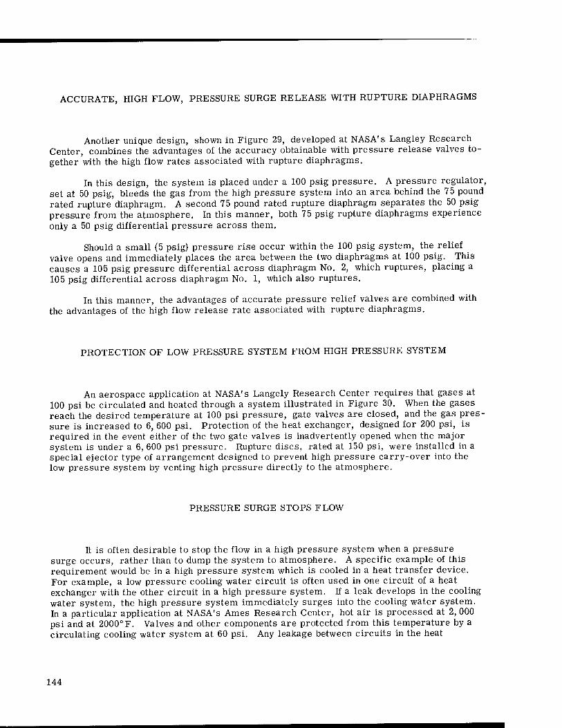
ACCURATE, HIGH FLOW, PRESSURE SURGE RELEASE WITH RUPTURE DIAPHRAGMS
Another unique design, shown in Figure 29, developed at NASA's Langley Research Center, combines the advantages of the accuracy obtainable with pressure release valves to- gether with the high flow rates associated with rupture diaphragms.
In this design, the system is placed under a 100 psig pressure. A pressure regulator, set at 50 psig, bleeds the gas from the high pressure system into an area behind the 75 pound rated rupture diaphragm. A second 75 pound rated rupture diaphragm separates the 50 psig pressure from the atmosphere. In this manner, both 75 psig rupture diaphragms experience only a 50 psig differential pressure across them.
Should a small (5 psig) pressure rise occur within the 100 psig system, the relief valve opens and immediately places the area between the two diaphragms at 100 psig. This causes a 105 psig pressure differential across diaphragm No. 2, which ruptures, placing a 105 psig differential across diaphragm No. 1, which also ruptures.
In this manner, the advantages of accurate pressure relief valves are combined with the advantages of the high flow release rate associated with rupture diaphragms.
PROTECTION OF LOW PRESSURE SYSTEM FROM HIGH PRESSURE SYSTEM
An aerospace application at NASA's Langely Research Center requires that gases at 100 psi be circulated and heated through a system illustrated in Figure 30. When the gases reach the desired temperature at 100 psi pressure, gate valves are closed, and the gas pres- sure is increased to 6, 600 psi. Protection of the heat exchanger, designed for 200 psi, is required in the event either of the two gate valves is inadvertently opened when the major system is under a 6, 600 psi pressure. Rupture discs, rated at 150 psi, were installed in a special ejector type of arrangement designed to prevent high pressure carry-over into the low pressure system by venting high pressure directly to the atmosphere.
PRESSURE SURGE STOPS FLOW
It is often desirable to stop the flow in a high pressure system when a pressure surge occurs, rather than to dump the system to atmosphere. A specific example of this requirement would be in a high pressure system which is cooled in a heat transfer device. For example, a low pressure cooling water circuit is often used in one circuit of a heat exchanger with the other circuit in a high pressure system. If a leak develops in the cooling water system, the high pressure system immediately surges into the cooling water system. In a particular application at NASA's Ames Research Center, hot air is processed at 2, 000 psi and at 2000° F. Valves and other components are protected from this temperature by a circulating cooling water system at 60 psi. Any leakage between circuits in the heat
144

exchanger would immediately allow the high pressure, hot air to enter the water system and raise the pressure of the entire cooling water system from 60 psi to the process 2, 000 psi. This potentially dangerous situation is protected by a unique valve development, illustrated in Fig. 31.
In normal operation, water at 60 psi flows through the valve as shown, the differen- tially-sized double piston being held in place by a shear pin. Should a leak develop in the cooling water system, increasing its pressure above 60 psi, the pin shears, allowing the piston to shift and block the entry of any high pressure fluid into the downstream cooling water system.
6,600 PSI
GATE VALVES
HEAT EXCHANGER
50 PSI RUPTURE DISK
Figure 30. Protection of Low Pressure System from High Pressure System
145

o t—l
fr CO a o
CD Ml JH
eg CD
CO CO CD
CD U
be ■rH
fr
146

CHAPTER 16. FLUTTER AND CHATTER
A number of structural and vibrational problems (such as adjacent machinery) can result in the malfunction of a valve and/or a valve control system. The valve itself is not the real problem, but the over-all effect is to make the valve appear to be the problem. Among these was a problem of flutter in the control system servo valves. In one flight of the X-15, the pilot experienced a sensational ride when the elevator control fluttered. An analysis of the control system indicated that a 13 cps natural frequency of the aircraft entered the system, was amplified, and reproduced by the elevator control system. An electrical damping means was used, wherein the undesirable 13 cps frequency was filtered out electrically with a notch-filter. This modification reduced the magnitude of the sine wave input to the control valves to approximately 1/30 of its previous value. Now, the structure still vibrates at its natural frequency, but the control system does not excite the fluttering action which produced instability.
VALVE ANTI-FLUTTER BAFFLE
This development is useful in valve applications through practically any pressure range, has no particular temperature limitations, and is designed for nominal flow rates. This design has been used in space vehicles.
An unsupported ball, when off its seat during flow, as in a ball check valve, tends to flutter. The flutter causes squeal and impact damage to the seat. The design illustrated in Fig. 32 prevents flutter by the use of a star spring to hold the ball on its seat. For severe high flow conditions, a baffle plate in conjunction with the star spring is necessary. Any tendency of the ball to flutter is damped by the friction of the fingers on the innerface. A baffle is used to direct the flow around the spring fingers in cases where the dynamic pressure would be great enough to damage the fingers. The pressure drops through the baffle exert an additional force on the spring finger contact. Thus, additional damping is automatically provided and is proportional to the flow.
BIBLIOGRAPHY
"Valve with Ball Seat Spring and Antiflutter Baffle, " Invention Report No. 30-140, (Inventor: William F. MacGlashan, Jr.) Jet Propulsion Laboratory, California Institute of Technology, Pasadena, California, July 27, 1962.
147

DETAIL B
Figure 32A. Figure 32B.
SECTION A-A
Figure 32C.
DETAIL B
Figure 32D.
Figure 32. Antiflutter Valve Design
148

SPECIAL PURPOSE DEVELOPMENTS
149

150

CHAPTER 17. UNIQUE DESIGNS AND APPLICATIONS
In the course of this investigation, a number of unique valve designs were found which resulted from various development programs within NASA. These designs are interesting in that they represent unique solutions to problems that touch on many areas of commercial valve design.
VALVE SEATS DESPITE MISALIGNMENT
A unique valve design was developed at NASA's Lewis Research Center in which a valve will seat despite misalignment of the stem. This design is illustrated in Figure 33.
The sealing element is a conical plug mounted on the end of a valve stem. The cross section of the valve plug is the shape of a shallow cone. In closing, the outer edge or cir- cumference of the cone contacts the spherical valve seat.
This arrangement permits the valve to seal effectively even though the valve stem is out of axial alignment. The conical-walled valve plug is always perpendicular to the tangent of the spherical valve seat at the point of contact, whether the stem is in its proper position or not. Uniformly diminishing thickness of the conical valve plug maintains a uniform level of stress in the plug.
Many hundreds of closing and opening cycles can be obtained from this combination of conical valve plug and spherical seat. This arrangement allows the valve to seal tightly without exceeding the elastic limit of either the plug or seat.
BACKUP RING FOR FLEXURE DIAPHRAGMS
This development relates to a means for providing a very low spring rate axial motion coupled with a low friction radial support for two or more concentric members which are actuated by a diaphragm. This development has been successfully used on Ranger, Mariner and other advanced spacecraft.
Figures 34A and B illustrate two of the various configurations of the backup ring. The ring has a number of pie-shaped beams extending radially to bridge the gap between the axially moving member and the valve housing. Separated pie-shaped beams have also been used. A stem diaphragm of metal or an elastomer, to seal the fluid pressure, is spread
151
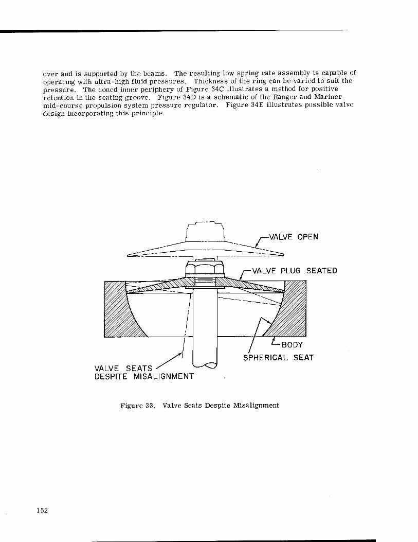
over and is supported by the beams. The resulting low spring rate assembly is capable of operating with ultra-high fluid pressures. Thickness of the ring can be varied to suit the pressure. The coned inner periphery of Figure 34C illustrates a method for positive retention in the seating groove. Figure 34D is a schematic of the Ranger and Mariner mid-course propulsion system pressure regulator. Figure 34E illustrates possible valve design incorporating this principle.
VALVE OPEN
VALVE PLUG SEATED
BODY
SPHERICAL SEAT VALVE SEATS DESPITE MISALIGNMENT
Figure 33. Valve Seats Despite Misalignment
152

Figure 34C
Figure 34E.
Figure 34. Backup Ring for Flexure Diaphragms
153

ZERO LEAK, LABORATORY CURIOSITY
At NASA's Jet Propulsion Laboratory in Pasadena, California, indium is used as a seat material for a special valve for high vacuum, and for cryogenic temperature appli- cations in the laboratories. At low cryogenic temperatures, Teflon becomes brittle. Indium stays ductile at these extreme temperatures and is useful in systems for processing liquid helium.
In this valve design, the seats always remain in a horizontal position. The indium seat material is soft, similar to lead, thereby providing a good sealing action. Each time a valve is opened, the indium seat is electrically heated, melted, and cooled to form a new surface for the reclosure of the poppet. The indium seat is contained so that it remains in place during the liquefying operation. In this manner, a fresh, soft, new seat is provided for the poppet each time the poppet closes upon the seat.
ROTARY VALVES
At NASA's Langley Research Center, a unique rotary valve was developed which has the potential for use in many industrial processes which require sequence timing of opera- tions.
The valve is essentially a solid cylinder designed to rotate inside a barrel housing. A groove is machined on the outer surface of the cylinder so that it is filled with a fluid introduced through a port of the stationary barrel housing. Numerous passages are drilled in the cylinder to pass the fluid to various slots which are machined around the cylinder. These slots match stationary ports in the barrel housing. In this manner, fluid flow from various outlet ports of this valve can be pulsed, sequenced, overlapped, and timed to con- trol various operations.
Figure 35 illustrates this valve concept. The problem of seals was overcome by using a very close fit between the inside of the barrel and the outside of the cylinder. How- ever, some leakage may be experienced at high pressures. For leakage control at low rotational speeds, a "T" connection can be used at the outlet ports B and C with one leg of the "T" containing an orifice which is sized to pass the leakage volume for return to a supply tank. When fluid flow, other than leakage, occurs at the outlet ports, this flow is then greater than the leakage flow through the orifice.
VALVES WITH NO MOVING PARTS
Freeze Valve Design
A thermoelectric cooling type of valve was developed at NASA's Goddard Space Flight Center where the liquid flowing through the valve can be frozen to stop flow in about
154

one-hundredth of a second. By reversing the current, heat is applied to the line to melt the frozen fluid in about one-thousandth of a second.
Air Pressure Holds Helium at Ten Atmospheres
Figure 36 illustrates a valve design which was developed at NASA's Ames Research Center. Wind tunnel models are fired from a gun down a pipeline and into a ten atmosphere pressure helium tank. The 6 in. pipeline had to be essentially wide open since any valve in the line could not open rapidly enough for successful tests to be performed.
In this design, a standard gate valve contains the pressurized helium prior to the test run. Air is introduced into the 6 in. diameter tube through rings. Each ring can build up approximately three to five atmospheres pressure on the gate valve. Three rings were used to build up ten atmospheres of air pressure on the back side of the gate valve to balance the ten atmospheres helium pressure on the other side of the gate valve. When pressure sensors indicate matched pressures across the valve, it is opened. Little intermixing of air and helium occurs as the pipeline remains open for the gun to fire a free-flight model down the tube and into the pressurized helium. The nozzle arrangement and the injector shape is extremely important. This valve is in reality a coaxial multi-stage injector.
SELF-SEALING DISCONNECT FORMS METAL SEAL AFTER BREAK-AWAY
This design has application in industry where a one-time, pressurized filling opera- tion occurs. An example could be refrigeration systems that are filled and sealed during manufacture.
NASA's Jet Propulsion Laboratory encountered a problem where it was necessary to design a special disconnect fitting that would automatically form a positive metal-to-metal seal in tubing when the fitting is broken by disconnecting forces. The fitting need only be used once but must not leak during or after filling operations.
Figure 37 illustrates a novel fitting in which the fill tube, during disconnect action, holds against a metal sleeve to form a positive metal seal. The fill tube is made so that the inner end has a shoulder extending beyond the outside diameter of the tube. Holes at that end permit the passage of liquids or gases. Surrounding the fill tube is a specially designed sleeve, also with a shoulder that drops into a recess of a main body of the fitting. During filling, "0"-rings in the shoulder of the sleeve and near the outer end of the fill tube seal against leakage. When the fitting is disconnected, as would occur during the launching of a rocket or when one part of a rocket separates from another in space, the fill tube breaks at the "0"-ring groove in the tube. Before it breaks, however, the disconnecting force pulls the shoulder on the inner end of the tube against the open end of the sleeve. The thin sleeve walls bulge out against the tapered inner wall of the main body of the fitting. This action established a metal-to-metal seal. An anvil which can be re-used positions this sleeve until breakaway is completed. Two of the "0"-rings now act as back-up for the metal seal.
155
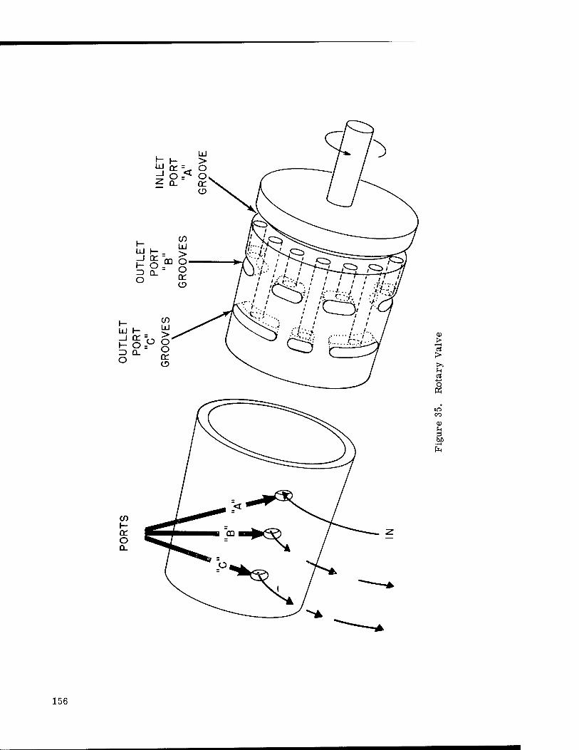
(1) >
I—I
>> u a
s in CO
a>
s> ■t-H
156

CO a: o to z Ld CO
LÜ tr ^ ID < CO Ld CO U_ |_ LÜ <co Q_ tr
o
A
o rH
cd
s CD
a 05
i—1 o X tu
to to CD
fi FH
<:
CO CO
CD u a
-r-(
o
Nl
157
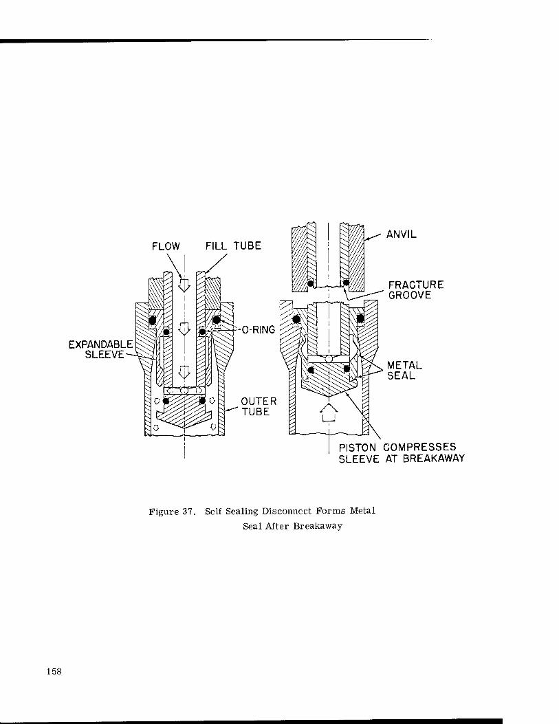
FLOW
EXPANDABLE SLEEVE
ANVIL
FRACTURE GROOVE
METAL SEAL
PISTON COMPRESSES SLEEVE AT BREAKAWAY
Figure 37. Self Sealing Disconnect Forms Metal
Seal After Breakaway
158

BIBLIOGRAPHY
"Design of Valve Permits Sealing Even if the Stem is Misaligned, " NASA Tech Brief 63-10341, January 1964.
"Backup Ring for Flexure Diaphragms, " Invention Report No. 30-185 (Inventor: William F. MacGlashan, Jr., prepared by L. S. Sauer), Jet Propulsion Laboratory, California (NASA Contract No. NAS7-100), April 29, 1963.
"Self-Sealing Disconnect Forms Metal Seal After Breakaway, " NASA Tech Brief No. 63-10226, January 1964.
"Prepressurization Disconnect, " Invention Report No. 30-151 (Inventors: H. Gernandt, C. Aardahl), Jet Propulsion Laboratory, California Institute of Technology, Pasadena, California (NASA Contract No. NAS 7-100), October 10, 1962.
159

160

NEW GUIDES FOR DESIGN,
SELECTION AND SPECIFICATION
161

162

CHAPTER 18. ABSTRACTS OF RECENTLY PUBLISHED VALVE TECHNOLOGY
by
John B. Loser Midwest Research Institute
This chapter is a series of abstracts of recently published guides that are considered to be extremely useful by valve engineering specialists, both within NASA and industry. The guides, representing hundreds of pages, are not generally known to most valve designers, application engineers, and users since distribution of the parent publication was generally limited to specific industries.
The abstracts are not presented in any particular order (such as types of valves, ma- terials for valves, and sizing of valves) because of the duplication that would be required by the overlapping of the subject areas. The reader may use these abstracts as an aid in select- ing those articles most appropriate to his needs.
"Quick Guide to Product Selection," Hydraulics and Pneumatics, January 1964, Vol. 17, No. 1, The Industrial Publishing Corporation, 812 Huron Road, Cleveland, Ohio, 44115, $1.25 (16 pp. on valves).
This is an availability guide for types of fluid power products. Directional control, flow control, pressure control, and servo valves are listed by manufacturer and include information on type, design, use, operation, ports, maxi- mum flow rating, and maximum pressure rating.
"Corrosion Guide," Unit 70-00-15 (7 pp. on metals), and Unit 70-00-16 (lp. on nonmetals); Black, Sivalls and Bryson, Incorporated, Tulsa, Oklahoma, May 1961.
This corrosion guide provides an indication of the results that might be expected from using particular materials in combination with 376 different corrosive media. The materials include the following metals: cast iron, cast steel, 316 and 304 stainless, 440C stainless, Hastalloy C, Monel, nickel, Durimet, cast bronze, and 17-4PH. Also included are the following nonmetals: Teflon, Buna-N, Kel-F, Teflon asbestos, graphitized asbestos, and asbestos.
"Fluid Throttling Devices for Controlled Flow Resistance," Louis Dodge, Product Engineer- ing, March 30, 1964, pp. 81-87. \
This article deals with planned^ressure drops; not the unintentional pressure drop. In the relationship HL = K^-, for use in the basic formula Q = AC 2g HT , the
<£g Li
163

author gives values of K for relief, gate, butterfly, ball, disc, needle, simple ball and four-way valves. Also included are K values for typical ports, notches in plungers, partial orifices, ramp slots, slotted sleeves, intersecting holes, and rotary notches, slots and wedges, and the formula for converting the flow coeffi- cient Cv to K.
"How to Select Flow-Control Valves," E. A. DiBartolo, Fluid Controls, Incorporated, Machine Design, July 18, 1963, pp. 167-184.
The author discusses principles of operation, types of valves, valve capabilities, and application circuits. Major topics are: Mobile vs. Industrial, Flow-Control Prin- ciples, Circuit Types, Metering Methods, Pressure-Compensated Capabilities, and Proportional Flow Divider.
"Valves," T. W. Edwards, Power, June 1961, pp. 69-92.
This is a Special Report concerning the factors in selection, recent advances in ma- terials and fluid-loss technology, a study of fluid-end types, valve actuators avail- able, and practical ideas on maintenance. The article is well illustrated and con- tains tables on material selection, ASTM materials specifications for pressure- temperature extremes, pressure-temperature ratings, and American Standards Association valve dimensions.
"A Course in Hydraulic Valves (Parts 1, 2, and 3)," Hydraulics and Pneumatics, February, April, and July 1961, pp. 55-63, 69-77, and 73-78, respectively.
This series of articles explains basic design and performance characteristics and presents important factors in selecting the proper valve for a particular applica- tion. Each part contains symbols and schematics of the various types of valves discussed.
Part 1 - Directional Control Valves, includes porting, spool valves, packed plung- er, rotary, poppet, sliding plate, check valves, and valve actuators.
Part 2 - Pressure Control Valves, includes relief, pressure reducing, sequence, counterbalance, unloading, and prefill-sequence valves.
Part 3 - Flow Control Valves, includes needle and globe valves, fixed flow and by- pass flow regulators, adjustable flow controls, integral check valves, builtin overload relief valves, temperature compensation, decelerating valves, and metering circuits.
"Valves," Frank L. Evans, Hydrocarbon Processing and Petroleum Refiner, October 1961, Vol. 40, No, 10, pp. 121-136.
A discussion of valves used in industry, with emphasis on how to select the right valve for performance and economy. This is a general, yet thorough, article about industrial valves and includes a number of hints, or tips, for valve users.
"Limitations of Valve-Sizing Formulas," Paul Wing, Jr., Instruments and Control Systems, March 1963, Vol. 36, pp. 131-135.
This article discusses several of the basic limitations of the standard working form- ulas for valve sizing.
164

"Special Valve Report," The Petroleum Engineer Publishing Company ran a special report on valves in all five of their July 1963 publications. All five publications carried the articles, "Fundamentals of Valves," (8 p.), and a "Directory of Valve Products and Valve Manufacturers," (32 p.). Other articles were distributed among the publications as fol- lows:
Petroleum Engineer "What to Look for in Oilfield Valves," (10 p.) "Helpful Hints for Valve Usage in Waterflooding," (5 p.)
Petro/Chem Engineer "Valve Makers Face Up to User Needs," (1 p.) "Stainless Valves Success with Sludge Acids," (2 p.) "When Does a Control Valve Cost Too Much? (1 p.) "Valve Design Overcomes Early Seat Failure," (1 p.) "Nomographs to Speed Valve Selection," (5 p.) "R&D Facility Aids Valve Design," (1 p,) "New Patents Pertaining to Valves," (2 p.)
Pipeline Engineer "How to Select Crude and Products Line Valves," (7 p.) "Which Valve in Gas Pipelining?" (8 p.) "The Good Business Role of Valve Standards," (3 p.) "LPG Pipelining Has Its Special Valve Demands," (2 p.)
American Gas Journal "Distribution Valving Today," (5 p.)
"Design Criteria for Zero-Leakage Connectors for Launch Vehicles," Advanced Technology Laboratories, General Electric Company for NASA, George C. Marshall Space Flight Center, Contract No. NAS8-4012.
This detailed study, in five volumes, is slanted toward connectors, but contains con- siderable information on advancements applicable to valves and to zero leakage.
"Standards," The Fluid Controls Institute, Incorporated, P. O. Box 1485, Pompano Beach, Florida 33060, has a series of five "standards" available. They are:
FCI 55-1: Standard Classification and Terminology for Power Actuated Valves (8 p.) - 20 cents
FCI 58-1: Definitions of Regulator Capacities (8 p.) - 20 cents
FCI 58-2: Recommended Voluntary Standards for Measurement Procedure for Determining Control Valve Flow Capacity (4 p.) - 10 cents
FCI 61-1: Recommended Voluntary Standards for Procedure in Rating Flow and Pressure Characteristics of Solenoid Valves (12 p.) - 20 cents
FCI 62-1: Recommended Voluntary Standard Formulas for Sizing Control Valves (8 p.) - 20 cents
165

"Advanced Valve Technology for Spacecraft Engines," B. P. Brady and R. J. Salvinski, Space Technology Laboratories, Incorporated, Contract No. NAS 7-107, Final Report, March 1963 (357 p.). (Available from Office of Technical Services, Department of Com- merce, Washington 25, D. C; ask for N63-15032, photocopy $21.00, microfilm $11.00.)
A valve design study was made to determine what elements or design features should be included or omitted in the design of many valve types. Each valve and the ele- ments within the valve were analyzed for their performance with propellants, space environments, and functional reliability. Technological advancements were accomplished and reported in detail.
The following four pages (Charts Nos. 9, 10, and 11) are reproductions of charts and tables from the report and will be of immediate interest to valve designers and and valve users because the environments encompass a number of fields of inter- est.
166

w
J O ü-<
< § »S B p ft ÖH ™ B> >- WK0m
ffl O P M
< p -1 § S PZK
SE W
EL
DE
D C
ON
ST
RU
CT
ION S
i B
O
CR
EW
S W
HE
RE
PO
SS
IBL
E S
; W
HE
R
/lA
INT
EN
AN
CE I
S N
OT R
EQ
UIR
ED
E
SIG
N C
ON
CE
PT
S R
EQ
UIR
ED
FO
R
PA
CE M
AIN
TE
NA
NC
E
£
S fcJ_z - opSa S3 Szz J
o to u
3
s Cd
w
il go1
offi
a z o
P < d
-1 ■< H
S
P <
< Z I« Q O Z
L M
ET
AL D
IAP
HR
AG
D
ISP
LA
CE
ME
NT
S)
2. U
SE
ME
TA
L B
EL
L
DIS
PL
AC
EM
EN
TS
P
RE
SS
UR
E G
RA
DI
VID
E
ME
TE
OR
OtD
AL S
H
z < C
E
0 z
Ü X
J M
L D
RIV
ES A
ND B
EA
RIN
G
SID
ER
ED E
XC
EP
T I
N V
A
EM
PE
RA
TU
RE S
ER
VIC
E
IIN
GS W
ITH S
MA
LL C
LE
w] Z J2I"5 j^
P ft p p m u ffi m OJ
33NVN3XNIVW P P p P < z
< p P p p p O O o aovdS ^
3AIXISN3S X o X X X o X X X o X o X X X X X o O X <
it:
NOIXVNIWVXNOO
HV3T 0H3Z X o X X X o X X X < z < z z
< z
<: z < z < z < z < z
O X < z
Srf S30NVH31OX o X X X o X X X X X o X o o o X o O X X ONinnxovanNvw
ONLMDIiS o X < < o X
< < < X X o X X X X X X < ? < z
u* a
3SN0dS3H HDIH
< z < z < z < z
o X X X X X X o X X X X X o < Z
< z z
S330Ä0 0001 X X z z X X X X X X X o X X X X X X
< z < z < z 3311 DNUVJISdO
S to
öS
P
NOIXVZI3IH3XS o X o X o X X X o p o o X X X X X X X X X
SCH0H03.L3IM < z
< z z
< z < z
< z o o o X X <: z
< z < z z
< z p z p X X
0-0H3Z X X X X X X X X X X o X X X X X X X X X X
nnnovA o o o X o o X X o p o o X o o o X o X X X
NOIXVIOVH o X o X o X X X o p o X X X X X X X X X X
fe c* 3.051" X X X X X X X X X X o o X X X X X o o X X
0, 3HnXVH3dW3X A\01
3.0001
aanxvH3<iw3i-m o X o X o X p X o X o o X o o o X o o X X
S33D o p o X o X X X o o o o X X X X X X X X X
H
aazmvj.au-NON
S130 Q3ZIT1V13W
o o o X p p X X o o o o X o o o X o X X X
SXNV313dOHd o X o X o X X X o o o o X X X X X X X X X cc o ambn
PM ft
w E VISd ooos OX SXNVHflSSaild
X o X X X o o X o X X o X X X X X X X X X
•s o
M j ca <
«o OT J >
s w s 5-i
og J P
s w s p
p <
u a M s >•
p < 1 p p ft
OS
w K o =3
a p a
u u z <c
p-<
w u z ■<
W K Ü <
5!1
1 J K
< CO
K w <C M H >
I o CO CO
P £:
> ft M
s X s
zJ
a M a
ur.i a S J < M <; K J So MZH!
ft OT ss ft s ft s a Ep ft Q Q p en u J o co m JO CO Q M a c£ CO ui
aiinsoio S3 V3S S*tt 'as S1V3S S33 m s XHVd ONIAOM SH3N3XSV3 PQZÖ 3A1VA 31 LVXS oirav NAQ 3IX3WH3H 'S SDNIXXI3
m cu ö
c w
M o o
u C) J3 01 u c > rt ö
,?• u (/J 4-1
c>
o 0)
CO Ä a
rt en > 0 ■+J Q S •c
i—i CD !-H N (D ■w
o i—i
JH 0>
ft 1—1
TS • rH
3 o<
U
XO <3
167

p < 3S
-i ra
US"!
< ^
0
So pfc: Q O
K W H W ■3 •X, Pi < P, P < !< W
O
w H X Ü P P W u p.
(oNnoiiv NHn.i.) Noixsna -woo ao sxoncioud - « „ CM CO « „ CO CO - - - „ CO CO „ „ CO „ CO CO CO „
sciiociaxaw $ * -a £ J < < y.
< y.
< z
< y.
< y-
B ^ s s % < <
y. CO CO CO CO < z
acinxvHBdwax co « „ CO CO CO CO CO CO CO ~ c CO CO CM P « CO CO CO CO CO CO
31MIX «, « <o CM „ ,, CO CO CO CO CM c CO CO CO P « CM CO CO CO CO CO
D oiiaz co co c - " < „ CO CO < " CO CO CO CO CO „ CM CO CO CO CO CO
z o H < 3
(flNfnHVHXRSMHHa) aaonaNi CM c. „ CM c C „ CO CO „ CM CM CO CO CM P P CM » CO CO CO CO
panvaa HVTOS p p CO a p CN oi CM' « CO CM CM „ CO CM D P Ö
CO « CO c, CO
x^os ivnounv <o ,o CO CO CO CO CO CO CO CO O, „ CO CO CO P " CO CO CO CO CO
(xaau Narriv NVA) ou.afjovwoao CM <M co CM CM - m CO CO CO - CM CM CO CM p P CM CO CO CO CO CO
xaxoiA-vuxin co CO co CO CO CO CO CO CO CO CO „ CO CO CO CO P „ CO CO CO CO CO
OIWSOD co CO CO CO CO CO CO „ O CO CO CO CO CO CO c, CO CO CO CO CO CO CO
p P
<
U3H01H pill! 3H I"1" 6-01 CM •o
c, CM CO c CO CO CO - CM CM CO CO CM « CM CM „ CO CO CO CO
;tij mil] c_oi OX
oiuaHcisowxv CM ~ co CM CO c CO CO CO - CM CM CO c CM CO CM CM CO CO CO CO CO
K IP H K
< Ps
P < o H U y. P t*
HOOHS CINV NOXLVHOIA c. co co CO CO C c ,, CO CO CO CO CO CO CO CO CO CO CO „ CO CO CM
asNOcisau < Z
CM CO CM CM «, CO CM CO 2 y. « " CO CM CO y < y.
< y z
< z
< y.
< y
aONVNHXNlVW aOVdS ^ rt _ _ ■H < <
7- y < < < - - - - - - - - - - - -
NOIXVNIWVXNOO - - CO CO - c, CM CO ,, - CO CO CO CO < z z c, CO CO CO CO
< CM
aan DNU.vua.io co CM CO " C CO CO -■ - " CO CO CO CO CO - CO CO c, CO CO CO CO
anvMva'i - - < z - <-, CO CO CO CO ~. CO y.
CO CO < y.
< y - CM CM CO
< y
<
s.LNHwamnöaii HS/IKM < Z CM c, <
7. c CO CM CO < z y
— CO CO CM CO
< v.
< Z y
< y
< z
< < y.
xnoiaM co CO CO CO CO CO CO CO CO CO ™ co- CO CM CO CO CO « CM CO CO «
a>inKsan<i oNixjcciajo CO CO CO CO » CO CO C, CO CO « < y. co CO y..
< V
< < CO CO ™
< CO
aHnxvuadwax DNUVdadO .O o, CO c, CO - CO „ " CM - „ CO CO
< y
< y- CM- - CO CO CO "-
Noixvznmaxs CM CM CO C c „ CO " CO ^ « « CO CO CO 3
CO CO « CO CO CO CO
< Q W s
svo C-J CO co CM
„ r-< en <r> CO CO ^. CO CO y, < y
-< CM " CO
"■ CO CO CO
amori CM CO CO „ < - CO CO CO CO - < y.
< z « <
Y. y. " - CO CO CO CO
H U W Y ;.. o u w 5
P tu o H
O Y s w H H > q P
H y. td >
o < P
Ü w Pi
< ffi
H w p, a. o p.
w H H p a;
< K
p. < 5 H
K p ca
p < H w
w
o P.
c o w p o
y
< w z a.
y p P < a
O H O
f-" L>
P o f/1
OS Q
9 g p
< p p y. <
w p w cr < p
a [d Q p M
CO
w a CJ
H
o CQ
K CO H
p
3A1VA JO 3-TAX aHflSOlD sivas noivniDV J,NV3
-lUflQl
SH3N3XSV.1
QNV SONIXXIJ
to
a)
in d
Pn 0) >
i—(
>
-U a
a Ö o
•r-4
> c
Pd
C o o e
X! U
168

PERFORMANCE WITH PROPELLANTS
PROPELLANT GASES OR PRESSURANTS TO 5000 PSIA
5 'n X X o
38 O m z8 OH
2>ö
Is OO U H
LIQUID PROPELLANTS TO 1000 PSIA
GELS- NON- METAL- METALLIZED LIZED CELS
APPLICABILITY
Z w O o X >• X
a si X
Z w
8 x H
z
z w a a o
Z O a o1
U
S3 <o
ss OS X o a- so
gs
z H
w Z N < X a X
Q Ss
X s
x w H Z as P IS E X
tu Z
o
3
Pi O
z C^ i
a W X z o
Sb X X
x a u o W J OH fc
go X O
Z w
a8 ►J X
Z
eg
3 td
< zM
X S g
1 o0* Z O
OS
i w ■ s,2 < F S.<
FM
W
> < >
FLOW METERING 3 3 3 3 3 3 NA 2-3 3 3 3 3 3 3 3 3d 3d 3d 3d 2d 3 U U U U U u S SHUTOFF 3 2C 3 3 3 3 U 2-3 3 3 3 3 3 3 3 3 3 3 3 2 3 1 1 1 2C 2C 2C
V VENT OR RELIEF 3 2 = 3 3 3 3 2-3 3 3 3 3 3 3 3 3 3 3 3 3 3 3 NA NA NA NA NA NA
CR COLD GAS REGULATOR
3 2C 3 3 3 3 NA NA NA NA NA NA NA NA NA NA NA NA NA NA NA NA NA NA NA NA NA
HR HOT GAS REGULATOR NA NA 3 U NA 3 NA 2 NA NA NA NA NA NA NA NA NA NA NA NA NA NA NA NA NA NA NA
LF LIQUID FILL OR DISCONNECT NA NA NA NA NA NA 2-3 NA 2b 2b 2b 2" 2" 2b 2b 2b 2b
ia 2l>
la
2'> '^b 3 1 1 1 1 1 1
PF PNEUMATIC FILL OR DISCONNECT 2» 2b 2" 2b 2b 2b NA NA NA NA NA NA NA NA NA NA NA NA NA NA NA NA NA NA NA NA NA
S w PS
t/3 o J o
BALL (POLYMERIC SEAL) 3 3 3 3 3 3 3 1 2 3 3 3 3 3 2 1 1 2 2 1 3 3 3 3 3 3 3 .
S,V,CR,HR,LF,PF POPPET 3 3 3 3 3 3 3 2 3 3 3 3 3 3 3 3 2 3 3 3 3 2 2 2 2 2 2
FM,S BUTTERFLY 3 3 3 3 3 3 3 2 2 2 2 2 3 3 3 3 2 3 3 3 3 1 1 1 1 1 1
S BURST DIAPHRAGM
3 3 3 3 3 3 NA NA 3 3 3 3 3 3 3 3 3 3 3 3 3 3 3 3 3 3 3
S,V,CR,HR,LF,PF i U <n VALVE CLOSURE 3 1-2= 3 3 3 3 1-2 1 2 2 2 2 2 2 1 1 1 2 2 1 U 1 1 1 2 1 2
ALL 2P"< ft *5 en
STATIC SEALS 3 1-3 3 3 3 3 1-2 I 2 3 3 3 3 2 1-2 1-2 1-2 3 3 1-2 3 2 3 3 2 3 3
ALL DYNAMIC SEALS 3 1-2 3 3 3 3 1-2 1 1 3 3 3 3 3 1 1 1 2 2 1 U 1 1 1 2 2 2
S,V,CRfHR,LF,PF
H <
VALVE CLOSURE \-i 1* 1-2= l-2f 1-2= 1-2' 1-2* 1-2C 3 3 3 3 3 3 3 3 3 3 3 2 3 2 2 2 2= 2C 2C
ALL STATIC SEALS 3 3 3 3 3 3 3 3 3 3 3 3 3 3 3 3 3 3 3 3 3 3 3 3 3 3 3
ALL !£ t/3 DYNAMIC SEALS 3 1U 3 3 3 3 3 3 3 3 3 3 3 3 3 3 3 3 3 2 3 U U U 3 3 3
S 8 o <: u <
SOLENOID 3 3 3 3 3 3 1-3 1 3 3 3 3 3 3 3 u U U U 1 3 3 3 3 3 3 3
FM,S PNEUMATIC 3 3 3 3 3 3 NA NA NA NA NA NA NA NA NA NA NA NA NA NA NA NA NA NA NA NA NA
FM,S HYDRAULIC NA NA NA NA NA NA NA NA 3 2 2 2 2 3 3 U U U U U U U U U U U U
FM,S ELECT. MOTOR 1 3 3 3 3 3 NA NA NA NA NA NA NA NA NA NA NA NA NA NA NA NA NA NA NA NA NA
S SQUIB 3 3 3 3 3 3 3 1 NA NA NA NA NA NA NA NA NA NA NA NA NA NA NA NA NA NA NA
ALL SCREW DRIVES U 2f 2' 21 2< 2< 1-2' 1 U I1 1' l' l' l' U U U 2' 2' U U 1 1 1 3' U 1'
ALL BALL SCREW DRIVES
2' 2' 2< 2' 2' 2' 1-2' 1 3' 1' l' 1' l' l' U U u 2' 2' U U 1 1 1 3' U 1(
ALL LINEAR BALL DRIVES
2f 2' 2< 2' 2' 2' 1-2' 1 3' l' l' lf l' I1 U U u 2' 2' U U 1 1 1 3' U 1'
ALL u; GEARED II ?' 2< ?' 2< 2< 1-2' 1 3' l' lf l' l' l| U II II II II u 1) U II II 11 II U
ALL Ä
PISTON U U 2' 2' 2' 2' 1-2' 2 3' 1' l1 I1 lf I1 u U u 2' U u U U U U K 1' 1'
ALL U3 W
BALL-ROTARY 2' 2f 21 2[ 2f 2' !-2( 1 3f l' l' l' l' l1 u u u 2' nl u 2' 1 ) 1 3[ U lf
ALL p y POLYMERIC 3 3 3 3 3 3 1-3 1 1 U U 1 U U 1 1 1 2-3 2-3 1 U 1 1 1 u II JJ ALL METAL 21 2' 2< 2[ ,( 2[ 1-2' 1 3' lf l' 1[ l' l' u u u 2' 2t u 2' 1 1 1 l' l' l'
ALL FLEXURE PIVOTS 3 3 3 3 3 3 3 3 3 3 3 3 3 3 3 3 3 3 3 3 3 3 3 3 3 3 3
ALL W en
ij H W
BELLOWS 2 3 3 3 3 3 3 3 3 3 3 3 3 3 3 3 3 3 3 u 3 3 3 3 3 3 3
ALL DIAPHRAGMS METAL 2 3 3 3 3 3 3 3 3 3 3 3 3 3 3 3 3 3 3 u 3 3 3 3 3 3 3
ALL ffl DRY FILM 3 3 3 3
3
3 3 1-2 1 2 2 2 2 2-3 2 ' 1 1 1 1 1 1 U U U U U II U ALL LIQUID 3 3 3 3 3 1-2 1 1 2 2 1 2 1-2 1 1 1 1 1 1 U 1 1 1 1 1 1 ALL
Ü
C/3
COIL 3 3 3 3 3 3 3 3 3 3 3 3 3 3 3 3 3 3 3 3 3 3 3 3 3 3 3 ALL BELLVILLE 3 3 3 3 3 3 3 3 3 3 3 3 3 3 3 3 3 3 3 3 3 3 3 3 3 3 3 ALL LIQUID 1-2 3 3 2 3 3 1-2 1 2h 2h 3h 3h 3h 3h 2h U U U U u U U U U U U U
FM.S.CR, HR W3 Cd
Z w
AN FLARE & MS FLARELESS 3 3 3 3 3 3 3 3 3 3 3 3 3 3 3 3 3 3 3 3 3 3 3 3 3 3 3
ALL WELDED 3 3 3 3 3 3 3 3 3 3 3 3 3 3 3 3 3 3 3 3 3 3 3 3 3 3 3
ALL BOLTS AND SCREWS 3 3 3 3 3 3 3 3 3 3 3 3 3 3 3 3 3 3 3 3 3 3 3 3 3 3 3
ALL FILTERS 3 3 3 3 3 3 3 3 3 3 3 3 3 3 3 3 3 3 3 3 3 NA NA NA U U U
(See next page for legend.)
Chart 11 A, Valve Analysis Chart - Part A
169
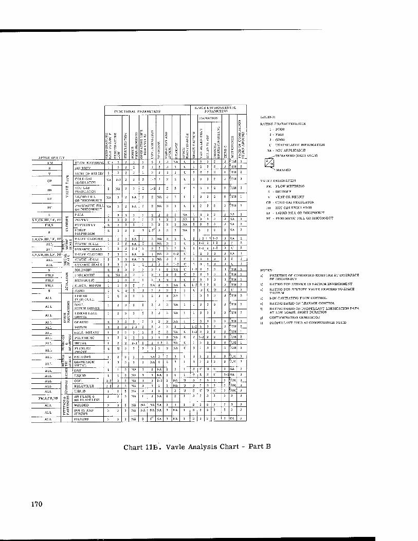
FUNCTIONAL PARAMETERS SPACE ENVIRONMENTAL
PARAMETERS
W (fa
H§
W K
H
W
Eg w O H -1
O H < 13
w
w E w
S Q" O W
U [fa m
P u
V u
Po So a, ^ o
O H <
< h
p
V. o a. w
1 < o
§8
W O
H
< ?- w
w t- U V.
11
U <
u < 0.
RADIATION
ü O
K N
Q O K O w H w 2
o H
C3 2 S z; O D u o
gi APPLICABILITY
C
w p < <
<
< o
ü
'j
< re
PS 2 3
W £fa >n f-
W > <
FLOW METERING U 3 ?. 3 3 3 3 3 NA IF 3 3 3 2 3 "'IM 3
S SHUTOFF 1 3 2 2 2 1 2 3 1 V 1 2 2 2 3 ''/IM 2
V VENT OH RELIEF 2 3 2 3 3 3 2 3 1 U 2 2 2 2 1 71M 2
CR COLD GAS REGULATOR
NA 2-3 2 3 2 1-2 2 2 2 U 3 3 3 2 3 TIM 3
HR HOT GAS REGULATOR
2 NA 2 3 2 1-2 2 2 2 U 3 3 3 2 3 TIM 3
LF LIQUID FILL OR DISCONNECT
NA 2 2 NA 3 2 NA 3 1 U 2 2 2 2 3 TIM 1
PF PNEUMATIC FILL OR DISCONNECT
NA 3 2 NA 3 2 NA 3 1 u 2 2 2 2 3 TIM 1
S W Et p
o -i u
BALL I 2 3 3 3 3 2 3 3 NA 1 3 3 3 3 NA 3
S,V,CR,HR,LF, PF POPPET 2 3 3 3 3 2 3 2 3 NA 2 3 3 3 3 NA 3
FM,S BUTTERFLY U 3 3 2 3 3 2 3 3 NA 2 3 3 3 3 NA 3
S BURST DIAPHRAGM
u 3 3 3 1 1-2L 3 3 3 NA 3 3 3 3 3 NA 3
S,V,CR,HR,LF, PF
Ö w U a. S3 <«
VALVE CLOSURE ! 2 2 NA 3 3 NA 3 3 U 2 1-2 1-2 1-2 3 NA 2
ALL STATIC SEALS 1 2 2 NA 2 3 NA 3 3 U 2 1-2 2 1-2 3 3 2
DYNAMIC -SEALS 1 2 2 1-2 3 3 2 3 3 U 2 1-2 2 1-2 3 U 2
s,v,cn,nn,LF, PF VALVE CLOSURE 2 3 3 NA 3 1 NA 3 1-2 u 1 3 3 3 3 NA 1
ALL STATIC SEALS 2 3 3 NA 1 3 NA 3 3 u 2 3 3 3 3 3 1
ALL DYNAMIC SEALS 2 3 3 2 2 1 2 3 1-2 u 1 3 3 3 3 U 1
S
O H < Ü <
SOLENOID U 2 3 2 3 3 3 3 NA u 1-2 2 2 3 3 VIM 3
FM.S PNEUMATIC U NA 3 3 3 3 3 3 3 u 3 2 3 3 3 TIM 3
FM,S HYDRAULIC 1 1 3 3 3 3 3 3 3 u 3 3 3 3 3 TIM 3
FM,S ELECT. MOTOR 1 I 3 2 3 NA 2 3 NA u 1-2 2 2 2 3 TIM 3
S SQUIB 1 U U 3 1 3 3 3 1 U U U U 3 u 3
ALL
7. <
LINEAR PUSH-PULL
1 U 3 2 3 2 3 3 NA 1 3 3 3 3 Z/1M 2
ALL BALL SCREW DRIVES
1 2 3 3 3 3 3 3 NA 1 3 3 3 3 "71M 3
ALL LINEAR BALL DRIVES
1 2 3 3 3 3 3 3 NA 1 3 3 3 3 TIM 3
ALL GEARED u 2 3 2 3 3 2 3 NA 1 3 3 3 3 TIM 3
PISTON 3 2 3 2-3 3 2 3 3 2 1-2 3 3 3 3 TIM 2
ALL
o p HALL-ROTARY 1 2 3 3 3 2 2 3 NA u 1-2 3 3 3 3
Z/IM 1
ALL POLYMERIC 1 2 2 2 2 3 1 3 NA u 2 1-2 2 2 3 TIM 2
ALL METAL 1 2 2 2-3 2 1 1-2 3 NA u 1 3 3 3 3 TIM 1
ALL FLEXURE PIVOTS
U U 3 3 3 3 3 3 NA u 3 3 3 3 3 TIM 3
ALL
EH"
BELLOWS 1 2 3 1 3 NA 3 3 3 1 3 3 3 3 3 TIM 3
ALL DIAPHRAGM METAL
1 3 3 3 3 NA 3 3 3 1 3 3 3 3 3 TIM 3
ALL —C5
u m D
DRY 1 1 3 NA 3 2 NA 3 3 1 2 U U U 3 NA 3
ALL LIQUID 1 1 3 NA 3 3 NA 3 1 1 2 2 2 U 1-: NA 3
ALL Ü
ft
COIL 1-2 3 3 NA 3 3 2-3 3 NA u 3 3 3 3 3 TIM 3
ALL BELLVILLE 1-2 3 3 NA 3 3 2 3 NA u 3 3 3 3 3 VIM 3
ALL LIQUID 1 1 3 NA 3 3 3 3 2 u 2 U U U 3 TIM 3
FM,S,CR,HR P [fa [fa
AN FLARE & MS FLARELESS
1 3 3 NA 1 3 NA 2 2 1 3 3 3 3 3 3 3
ALL WELDED 3 3 3 NA NA NA NA 3 3 1 3 3 3 3 3 3 3
ALL BOLTS AND SCREWS
3 3 3 NA NA NA NA 3 NA 1 3 3 3 3 3 3 3
ALL FILTERS 3 3 3 NA 3 1C NA 3 NA 1 3 3 3 3 3 NA 3
LEGEND:
RATING CHARACTERISTICS
1 - POOR
2 - FAIR
3 - GOOD
U - UNAVAILABLE INFORMATION
NA - NOT APPLICABLE
^^-UNMANNED (DIGIT ONLY)
'IM
VALVE DESIGNATION
FM - FLOW METERING
S -SHUTOFF
V - VENT OR RELIEF
CR - COLD GAS REGULATOR
HR - HOT GAS REGULATOR
LF - LIQUID FILL OR DISCONNECT
PF - PNEUMATIC FILL OR DISCONNECT
a) FREEZING OF CONDENSED MOISTURE AT INTERFACE OF DISCONNECT
b) RATING FOR SERVICE IN VACUUM ENVIRONMENT
c) RATING FOR SHUTOFF VALVE EXPOSED TO SPACE VACUUM
d) NON CAVITATING FLOW CONTROL
e) RATING BASED ON LEAKAGE CONTROL
f) RATING BASED ON PROPELLANT LUBRICATION DATA AT LOW LOADS, SHORT DURATION
g) CONTAMINATION GENERATOR
h) PROPELLANT USED AS COMPRESSIBLE FLUID
Chart 11B. Vavle Analysis Chart - Part B
170

APPENDICES
171

172
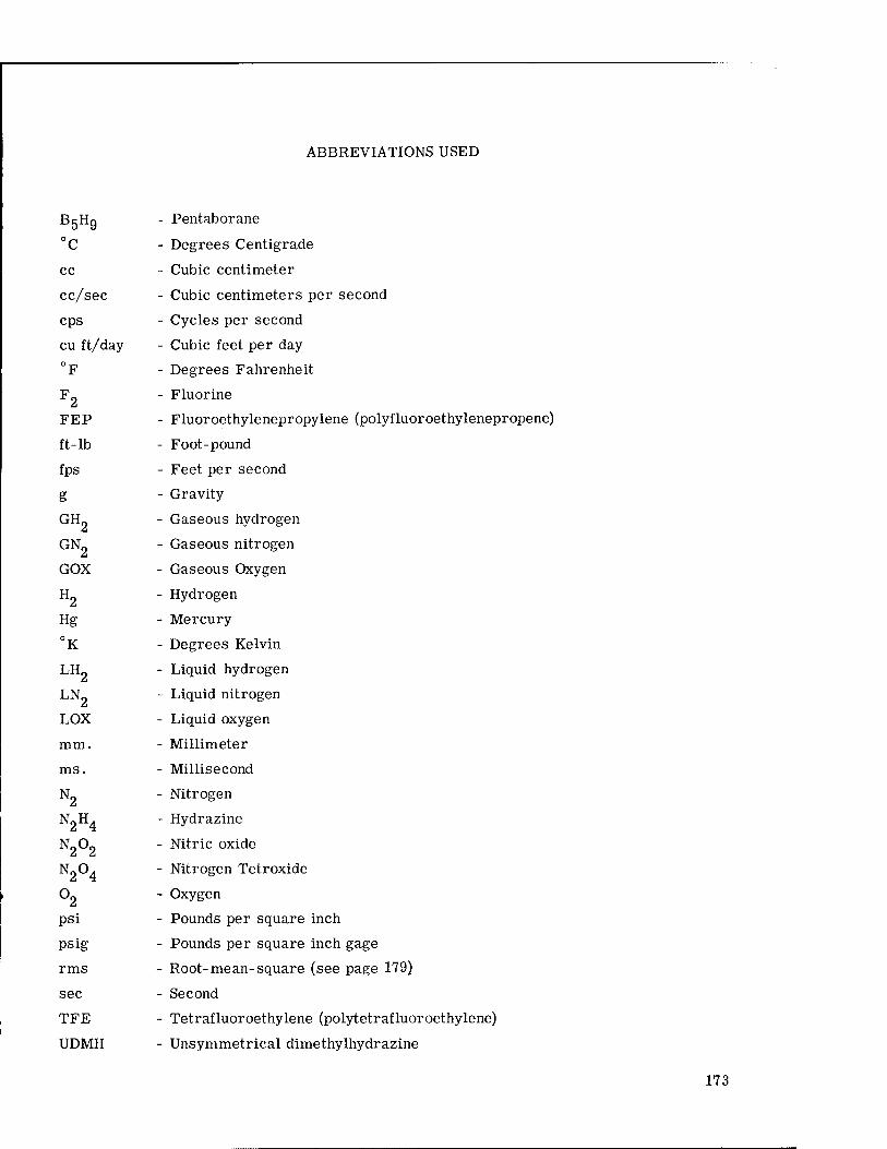
ABBREVIATIONS USED
B5H9 - Pentaborane
°C - Degrees Centigrade
cc - Cubic centimeter
cc/sec - Cubic centimeters per second
cps - Cycles per second
cu ft/day - Cubic feet per day
°F - Degrees Fahrenheit
F2 - Fluorine
FEP - Fluoroethylenepropylene (polyfluoroethylenepropene)
ft-lb - Foot-pound
fps - Feet per second
g - Gravity
GH2 - Gaseous hydrogen
GN2 - Gaseous nitrogen
GOX - Gaseous Oxygen
H2 - Hydrogen
Hg - Mercury
°K - Degrees Kelvin
LH2 - Liquid hydrogen
LN2 - Liquid nitrogen
LOX - Liquid oxygen
mm. - Millimeter
ms. - Millisecond
N2 - Nitrogen
N2H4 - Hydrazine
N2°2 - Nitric oxide
N2°4 - Nitrogen Tetroxide
°2 - Oxygen
psi - Pounds per square inch
psig - Pounds per square inch gage
rms - Root-mean-square (see page 179)
sec - Second
TFE - Tetrafluoroethylene (polytetrafluoroethylene)
UDMH - Unsymmetrical dimethylhydrazine
173

174

GLOSSARY OF VALVE TERMS
Accumulator
Actuator
Air bleeder
Ambient temperature
Amplifier
Asperities
Channel
Choke
Clarifier
Cold welding
Control
Control, electric
Control, liquid-level
Control, mechanical
Control, pneumatic
Control, servo
A fluid-pressure storage chamber in which fluid pressure energy may be accumulated and from which it may be withdrawn.
A device to convert control energy into mechanical motion.
A device used to remove air from the high point in a circuit. It may be a needle valve, capillary tubing to the tank, or a bleed plug.
The temperature of the surrounding environment.
- A device used to increase volume rather than pressure. The opposite of a pressure intensifier.
- Rough places.
- A fluid passage which is long with respect to its cross-section dimension.
- A restriction which is relatively long with respect to its cross-sec- tion dimension.
- A device for removing deleterious solids and assisting in maintain- ing the chemical stability of hydraulic fluid.
- The mechanical bonding of two similar or dissimilar materials in a vacuum environment; see page 16 for an example.
- A device used to regulate the functions of a machine.
- A control actuated by electric means.
- A device which controls the liquid level by a float switch or other means.
- A control actuated by linkages, gears, screws, cams, or other mechanical elements.
- A control actuated by air pressure.
- A control actuated by a feed-back system which compares the output with the reference signal and makes corrections to reduce the difference.
Cryogenic tempera- tures - Very cold temperatures, see page 31.
175

Cushion, hydraulic
Cushion, hydro-pneu- matic
Cushion, pneumatic
Cycle, automatic
Cycle, semi-automatic
Cylinder
Cylinder, double- acting
Cylinder, double- end-rod
Cylinder, piston-type
A cushion in which a hydraulic cylinder provides the resistance. Pressure in the cylinder is developed by the mainram movement. The cushion is returned to its normal position hydraulically.
A cushion in which a hydraulic cylinder provides the resistance. Pressure in the cylinder is developed by the mainram movement. The cushion is returned to its normal position by air pressure acting on the hydraulic fluid in the reservoir.
A cushion in which an air cylinder provides the resistance.
A cycle of operation which, once started, is repeated indefinitely in a predetermined sequence until stopped.
A cycle which is started upon a given signal, proceeds through a predetermined sequence, and then stops with all the elements in their initial position.
A linear-motion device for converting fluid energy into mechanical energy (or vice versa) in which the thrust or force is proportional to the effective cross-sectional area.
A cylinder in which fluid force can be applied in either direction.
A cylinder with two rods, one extending from each end.
A cylinder in which the internal element is of one or more diameters and the seal is of the expanding type.
Cylinder, plunger type. A cylinder in which the internal element is of a single diameter and upon which the seal applied is of the contracting type.
Cylinder, single acting-
Damper
Dwell
Face-centered metals-
Feed
Filter
A cylinder in which the fluid force is applied in only one direction.
A device used to restrict the amplitude of a shock wave.
The portion of the cycle in which feed or pressure stroke is stopped.
An arrangement of atoms in crystals which may be initiated by packing spheres. The atomic centers are disposed in space in such a way that they may be supposed to be situated at the corners and the middle of the faces of a set of cubic cells.
The portion of the cycle in which the work is performed on the work- piece.
A device for the removal of solids from a fluid wherein the resist- ance to motion of such solids is in a tortuous path.
176

Flow rate
Fluid
Fluid absolute viscosity
Fluid flash point
Fluid oxidation
Fluid SAE viscosity numbers
Fluid specific gravity
Fluid viscosity
Gage, fluid-level
Gage, pressure
The number of units of volume of a fluid passing through any channel in one unit of time.
A substance which yields and suffers indefinite distortion due to any pressure tending to alter its shape. Fluids include both liquids and gases.
The force in dynes required to move a plane surface of 1 sq. cm. over another plane surface at the rate of 1 cm/sec when the surfaces are separated by a layer of fluid 1 cm. in thickness. The unit is known as the poise. Since absolute viscosity is difficult to determine, the viscosity usually is expressed as Saybolt Universal Seconds (SSU), which is the time in seconds for 60 cc. of oil to flow through a stand- ard orifice at a given temperature.
The temperature at which a fluid first gives off sufficient flammable vapor to ignite when approached by a small flame or spark.
A chemical breakdown of a fluid, causing the formation of oxidation products, which in turn cause emulsification, foaming, and the deposition of sludge.
The arbitrary numbers for classifying fluids according to their viscosities. The numbers in no way indicate the viscosity index of the fluids.
The ratio of the weight of a given volume of fluid to the weight of an equal volume of water.
A measure of the internal friction or the resistance of a fluid to flow. (See: fluid absolute viscosity.)
An instrument which indicates the fluid level at all times.
An instrument which indicates the pressure in the system to which it is connected.
Hard vacuum
Intensifier
Intractable
Joule- Thompson effect
- See page 16.
- A device which increases the working pressure over that delivered by a primary source.
- Not easily managed or directed; stubborn; obstinate.
Simply stated, the effect of decreasing temperature accompanying the expansion of a fluid.
177

Joule-Thompson effect, reverse
Labyrinth
Langmuir equation
Line
Line, drain
Line, exhaust
Line, pilot
Line, working
Orifice
Outgassing
Passage
Poppet
Port
Port, valve
Positive position stop
Positive safety stop
Pressure, back
Pressure, operating
Pressure, suction
The effect of increasing temperatue accompanying the expansion of a fluid.
Presenting a folded or tortuous path.
G = -5-\ 17.14 \J — . where G = rate of loss per unit area of exposed T ', 2 surface in g/sec/cm2; P = vapor pressure at temperature T in mm.
Hg; M = molecular weight of the metal in the gas phase; T = abso- lute temperature (°K).
A tube, pipe, or hose which acts as a conductor of fluid.
A line returning leakage fluid independently to the reservoir or vented manifold.
A return line which carries power or control-actuating fluid back to the reservoir.
A line which acts as a conductor of control-actuating fluid.
A line which acts as a conductor of power-actuating fluid.
A restriction which is relatively short with respect to its cross- section dimension.
The evolution of gas from a solid in a vacuum environment.
A machine or cored connection which lies within or passes through a hydraulic component and which acts as a conductor or hydraulic fluid.
A mushroom or tulip-shaped valve consisting of a circular head with a conical face.
An opening at a surface of the component, e.g., the terminus of a passage. It may be internal or external.
A controllable opening between passages, i.e., one which can be closed, opened, or modulated.
A structural member which definitely limits the working motion at a desired position.
A fixed structural member which confines maximum travel within the design limits of the machine or equipment.
The pressure encountered on the return side of a system.
The pressure at which the system is operated.
The absolute pressure of the fluid at the inlet of a pump.
178

Pressure head
Pump
Pump, centrifugal
Pump, gear
Pump, screw
Radiation tolerance
Reservoir
Restriction
Reverse Joule- Thompson effect
rms
Sabot
Schematic diagram
Soluble oil
Specific impulse
Spool
Squib
Surge
Trip device
Ullage
The pressure resulting from the height of a column or body of fluid, expressed in feet.
A device which converts mechanical energy into fluid energy.
A power-driven device for converting mechanical energy into fluid energy, having an impeller rotating into a volute housing with liquid carried around the periphery of a housing and discharged by means of centrifugal force.
A power-driven pump having two or more inter meshing gears or lobed members enclosed in a suitably shaped housing.
A power-driven pump consisting of one or more screws rotating in a housing.
The ability of a material to withstand radiation.
A chamber used to store fluids. Pumps, motors, and valves may be mounted on the reservoir.
A device which produces a deliberate pressure drop or resistance in a line or passage by means of a reduced cross-sectional area.
The effect of increasing temperature accompanying the expansion of a fluid.
A measure of surface roughness; the root-mean-square variation.
A fixture for temporarily holding an object in a particular attitude.
A drawing or drawings showing the functional construction of all valves, controls, and actuating mechanisms.
A substance added to water to provide lubricating qualities and inhibit corrosion.
The total impulse of thrust provided by the combustion of a unit mass of propellant. It is proportional to the combustion temperature of the fuel and inversely proportional to its molecular weight. Since hydro- gen has the lowest molecular weight, it has a correspondingly high specific impulse.
A device within a valve for changing the flow from one port to another port.
An explosive device used to initiate an event or action.
A transient rise of hydraulic pressure in the circuit.
A mechanical element for the actuation of a position control.
The amount which a vessel lacks of being full.
179

Valve
Valve, cam-operated
Valve, center- pressure
Valve, check
Valve, counter- balance
Valve, directional
Valve, flow-dividing
Valve, four-way
Valve, gate
Valve, globe
Valve, needle
Valve, pilot
Valve, pilot-check
Valve, pilot-operated
A device for controlling flow rate, direction, or pressure of a fluid.
A valve on which the spool is positioned mechanically by a cam.
A valve which in the center position connects the supply to working ports only.
A valve which permits flow of fluid in one direction only and self- closes to prevent any flow in the opposite direction.
A valve which maintains resistance against flow in one direction but permits free flow in the other. It is usually connected to the outlet of a double-acting cylinder to support its weight or to prevent uncon- trolled movements.
A valve which selectively directs or prevents fluid flow through desired channels.
A valve which divides the flow from a single source into two separate branches of a circuit at a constant ratio regardless of the difference in pressure between the two branches.
A valve having four controlled working passages, usually ending in four external ports. A four-way valve usually has one inlet port and three outlet ports.
A valve used to start, stop, or limit the flow of fluid. It controls the flow by means of a gate, which is raised or lowered by the action of a screw or other means to close or open the passage.
A valve used to start, stop, or limit the flow of fluid. It controls the flow by means of a plug, a ball, or a disk, which by action of a screw or other means is pulled away from or lowered into a corresponding seat.
A valve used to start, stop, or limit the flow of fluid. It controls the flow by a tapered needle, which is pulled away from or forced into a corresponding seat. The tapered needle permits gradual opening or closing of the passage.
A small directional-control valve generally used for operation other valves.
A check valve provided with a piston to unseat the check poppet when pilot pressure is applied.
A valve which is positioned by pilot fluid pressure.
180

Valve, poppet-type
Valve, pressure- reducing
Valve, relief
Valve, safety
Valve, shuttle
Valve, spool-type
Valve, standard- action
Valve, surge-damping -
Valve, three-way
Valve, time-de lay
Valve, two-way
Zero leak
A valve construction which closes off flow by a poppet seating against a suitable seating material. Normally considered a dead-tight seal. The poppet may be a ball, a cone, or a flat disc.
A valve which maintains a reduced pressure at its outlet regardless of the higher inlet pressure.
A valve which limits the maximum pressure which can be applied to the portion of the circuit to which it is connected.
A poppet-type two-way valve intended to release fluid to a secondary area when pressures approach the maximum set value.
A valve with three ports and a floating piston between two of the ports moving in a horizontal plane. Pressure entering either of these two ports will shift the piston blocking the opposite port and directing fluid to the third port.
A valve construction using a spool consisting of machined undercuts or recesses on a cylinder of metal. The spool is fitted to a bore con- taining annular undercuts. Movement of the spool in the bore con- nects ports uncovered by the spool undercuts. Clearance flow is usually necessary to insure free spool movement.
A valve which is positioned by manual, mechanical, or pilot means without springs or detents.
A valve which prevents shock by controlling the rate of acceleration of fluid flow.
A valve having three controlled working passages, usually ending in three external ports. A three-way valve usually has one inlet port and two outlet ports.
A valve in which the change of fluid occurs only after a desired time interval has elapsed.
A valve having two controlled working passages, usually ending in two external ports. A two-way valve has one inlet and one outlet port.
See page 14.
181