t:TIjC, - DTIC
89
DTIC FILE COPV !, Validation and Application of COGNET -Model of Human-Computer Interaction In Naval Air ASW N Wayne Zachary, Ph.D. Joan M. Ryder, Ph.D. Lorna Ross Monica-C. Zubntzky CHI SYSTEMS Gwynedd Plaza III Bethlehem Pike and Sheble-Lane ring House, PA, 19477 t:TIjC, S ELECTEQ CHI SYSTEMS TECHNICAL REPORT 900531.8704 31 My, 1990 CONTRACT N00014-87-C-0814 R&T Project Code: 4429007 IApiWUI ix pubic zrslecz; cu re tcktb, 0T"4 4q
-
Upload
khangminh22 -
Category
Documents
-
view
5 -
download
0
Transcript of t:TIjC, - DTIC

DTIC FILE COPV
!, Validation and Application of COGNET -Model ofHuman-Computer Interaction In Naval Air ASW
NWayne Zachary, Ph.D.Joan M. Ryder, Ph.D.
Lorna RossMonica-C. Zubntzky
CHI SYSTEMSGwynedd Plaza III
Bethlehem Pike and Sheble-Lanering House, PA, 19477 t:TIjC,S ELECTEQ
CHI SYSTEMS TECHNICAL REPORT 900531.870431 My, 1990
CONTRACT N00014-87-C-0814
R&T Project Code: 4429007
IApiWUI ix pubic zrslecz;
cu re tcktb, 0T"4 4q

UnclassifiedSECURITY CLASSIFICATION OF THIS PAGE
Form Approved
REPORT DOCUMENTATION PAGE OMB No. 0704.0188
la. REPORT SECURITY CLASSIFICATION lb RESTRICTIVE MARKINGS
Unclassified N.A.2a. SECURITY CLASSIFICATION AUTHORITY 3. DISTRIBUTION IAVAILABILITY OF REPORTN.A.N..Approved for public release;2b. DECLASSIFICATION /DOWNGRADING SCHEDULE
N.A. distribution unlimited4. PERFORMING ORGANIZATION REPORT NUMBER(S) 5. MONITORING ORGANIZATION REPORT NUMBER(S)
Technical Report 900531.8704 Same6a. NAME OF PERFORMING ORGANIZATION 6b OFFICE SYMBOL 7a. NAME OF MONITORING ORGANIZATION
CHI Systems Inc. (if applicable) Office of Naval Research
6c. ADDRESS (City, State, and ZIP Code) 7b ADDRESS (City, State, and ZIP Code)
G wynedd Plaza III 800 N. Quincy StreetBethlehem Pike at Sheble Lane Arlington, VA 22217-5000Soring House, PA 19477
8a. NAME OF FUNDING/ SPONSORING Bb OFFICE SYMBOL 9 PROCUREMENT INSTRUMENT ;DENTIFICATION NUMBERORGANIZATION (If applicable) N00014-87-C-0814
Office of Naval Research Code 1142PS8c. ADDRESS (City, State, and ZIP Code) 10 SOURCE OF FUNDING NUMBERS
800 N. Quincy Street PROGRAM PROJECT ITASK WORK UNITArigoV 21-00ELEMENT NO NO|,NO ACCESSION NO.
Arlington, VA 22217-5000 61153N 42 RR04209 0420901 04429007
11. TITLE (Include Security Classification)
Validation and Application of COGNET Model of Human-Computer Interaction inNaval Air ASW
12. PERSONAL AUTHOR(S)Zachary, W.; Ryder, J.; Ross, L.R.; Zubritzky, M.
13a. TYPE OF REPORT 13b TIME COVERED 14 DATE OF REPORT (Year, Month, Day) 15 PAGE COUNT
Technical I FROM B2Zq/3atOQ_0(/34 31 May 1990 8416. SUPPLEMENTARY NOTATION
17. COSATI CODES 18 SUBJECT TERMS (Continue on reverse if necessary and identify by block number)
FIELD GROUP SUB-GROUP human-computer interaction; decision-making; cognitivemodel; ASW; COGNET; attention; GOMS; adaptive interface
19 ABSTRACT (Continue on reverse if i"ecessary and identify by block number)
This is the final report on a two-year research effort to investigate the cognitive basis for human-computer interaction and decision-making in complex, real-world environments, particularly thosewhich unfold in real-time and make multiple demands on the attention of the human decision-maker. The main emphasis in the project has been to explore the extent to which models of thecomputer-user's problem-solving strategies in these real-time multi-tasking (RTMT) environmentscan lead to the design of more effective human-computer interfaces. This research developed theCOGNET (COGnitive Network of Tasks) RTMT modeling framework, as an integration of theGOMS and blackboard cognitive modeling techniques. COGNET was then applied to a vehicletracking domain based on Naval Air AntiSubmarine Warfare (ASW). The COGINIET Air ASWmodel was validated by comparing the attention shifts and task performance sequences generatedby the model to experimental data from human ASW experts solving realistic problems. A firstcomparison used previously-recorded problem solving data that had been used to generate the Air
20. DISTRIBUTION/AVAILABILITY OF ABSTRACT 21 ABSTRACT SECURITY CLASSIFICATION
IX1 UNCLASSIFIED/UNLIMITED 0] SAME AS RPT 0 DTIC USERS Unclassified22a. NAME OF RESPONSIBLE INDIVIDUAL 22b, TELEPHONE (Include Area Code) 22c OFFICE SYN'BOL
Gerald Malecki (202) 696-4044 1 Coe 112DD Form 1473, JUN 86 Previous editions are obsolete SECURITY CLASSIFiCATION OF THIS PAGr
SIN 0102-LF-014-6603 Unclassified
UnclassifiedSECURITY CLASSIFICATION OF THIS PAGE
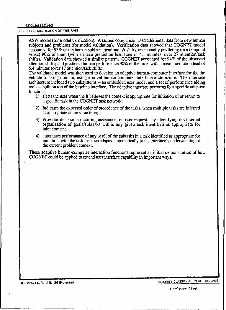
ASW model (for model verification). A second comparison used additional data from new humansubjects and problems (for model validation). Verification data showed that COGNET modelaccounted for 93% of the human subject attention/task shifts, and actually predicting (in a temporalsense) 90% of them (with a mean prediction lead time of 4.1 minutes, over 27 attention/taskshifts). Validation data showed a similar pattern. COGNET accounted for 94% of the observedattention shifts; and predicted human performance 90% of the time, with a mean prediction lead of5.4 minutes (over 17 attention/task shifts).The validated model was then used to develop an adaptive human-computer interface for the thevehicle tracking domain, using a novel human-computer interface achitecture. The interfacearchitecture included two subsystems -- an embedded user model and a set of performance aidingtools -- built on top of the baseline interface. The adaptive interface performs fou specific adaptivefunctions:
1) alerts the user when the it believes the context is appropnate for initiation of or return toa specific task in the COGNET task network;
2) Indicates the expected order of precedence of the tasks, when multiple tasks are inferredas appropriate at the same time;
3) Provides decision structuring assistance, on user request, by identifying the internalorganization of goals/subtasks within any given task identified as appropriate forinitiation; and
4) automates performance of any or all of the subtasks in a task identified as appropriate forinitiation, with the task instance adapted automatically !o t*he Literface's understanding ofthe current problem context.
These adaptive human-computer interaction functions represent an initial demonstration of howCOGNET could be applied to extend user interface capability in important ways.
DD Form 473, JUN 86 (Reverse) SECURITY CLASSIFICATION OF THIS PAGE.
Unclassified

Table of Contents
Acknowledgements1. Introduction and Background ................................................................................... 1-12. The COGNET Framework and the COGNET Model of Air
ASW Mission Management ....................................................................................... 2-12.1 COGNET Framework and COGNET Modeling Notations .................... 2-12.2 A Vehicle Tracking Problem Domain ....................................................... 2-52.3 COGNET Model of Air ASW Mission Management ............................... 2-7
2.3.1 Task Decomposition ..................................................................... 2-72.3.2 Blackboard Organization ............................................................. 2-82.3.3 Perceptual Demons ...................................................................... 2-122.3.4 Cognitive Task Models ................................................................ 2-13
3. Model Analysis and Validation ................................................................................ 3-13.1 Analysis and Validation Methodology ................................................... 3-13.2 Post-hoc Model Verification ..................................................................... 3-33.3 Independent Model Validation ............................................................... 3-12
4. Model Application to Intelligent Computer-Human Interaction .......................... 4-14.1 Model Based Human-Computer Interaction ...................... 4-14.2 Adaptive Interaction Functionality for the Mission Management
D o m a in ........................................................................................................ 4 -34.3 COGNET-Based HCI Architecture ............................ 4-5
5. Implementation of the Adaptive Mission Management Interface ....................... 5-15.1 Screen Design and Layout ...................................................................... 5-15.2 Im plem entation .......................................................................................... 5-45.3 User Interaction .......................................................................................... 5-9
6. C onclusions .................................................................................................................. 6-16.1. Main Theoretical and Methodological Accomplishments ...... 6-16.2. Operational Benefits and Results ........................................................... 6-36.3 Additional Research Issues ..................................................................... 6-4
6.3.1 Adaptive Interface and Interaction Issues ................................ 6-46.3.2 COGNET Elaboration and Further Validation Issues ............. 6-5
R efe re nces ........................................................................................................................ R -1
Accession ForSTTS GTA&IDTIC TAB
Justification
ByDistribution/
i Availability Codos
TAvail ad/orDist Special

List of Tables
Table 2-1. Individual Tasks in COGNET ASW Mission Management Model ..2-8Table 2-2. Perceptual Demons (contd) ................................................................... 2-15Table 3-1. Post-hoc Verification Trial Data ............................................................. 3-10Table 3-2. Post-hoc Verification Subject Data ....................................................... 3-10Table 3-3. Post-hoc Verification Problem Data ..................................................... 3-10Table 3-4. Post-hoc Verification Task Data ............................................................ 3-11Table 3-5. Validation Trial Data ................................................................................ 3-15Table 3-6. Validation Problem Data ........................................................................ 3-16Table 3-7. Validation Subject Data ......................................................................... 3-16Table 3-8. Validation Task Data ............................................................................... 3-16Table 5-1. Example Blackboard Definition ............................................................. 5-6Table 5-2. Summary of Preflight Information ......................................................... 5-10
ii
List of Figures
Figure 2-1. COGNET Concept ................................................................................... 2-2Figure 2-2. Attention Flow Between Tasks .............................................................. 2-3Figure 2-3. COGNET Decision Task Description Language ................................ 2-4Figure 2-4. COGNET Attention Flow with Perceptual Demons ............................ 2-5Figure 2-5. Target Situation Panel with Example Data ......................................... 2-9Figure 2-6. Situation Blackboard Panel with Example Data ................................ 2-11Figure 2-7. Portion of "Identify Area of Interest" Task Model ................................ 2-16Figure 2-8. Portion of "Broaden Initial Contact" Task Model ................................ 2-17Figure 3-1. Subject 1 Problem 3 ................................................................................ 3-4Figure 3-2. Subject 1 Problem 4 ................................................................................ 3-4Figure 3-3. Subject 2 Problem 1 ................................................................................ 3-5Figure 3-4. Subject 2 Problem 2 ................................................................................ 3-5Figure 3-5. Subject 2 Problem 3 ......................................................................... 3-6Figure 3-6. Subject 3 Problem 3 ................................................................................ 3-6Figure 3-7. Subject 4 Problem 1 ................................................................................ 3-7Figure 3-8. Subject 4 Problem 3 ................................................................................ 3-7Figure 3-9. Subject 2 Problem 4 ................................................................................ 3-8Figure 3-10. Subject 5 Problem 1 ................................................................................ 3-8Figure 3-11. Subject 5 Problem 3 ................................................................................ 3-9Figure 3-12. Subject 6 Problem 5 ................................................................................ 3-12Figure 3-13. Subject 7 Problem 3 ............................................................................... 3-13Figure 3-14. Subject 8 Problem 1 ................................................................................ 3-13Figure 3-15. Subject 8 Problem 6 ................................................................................ 3-14Figure 3-16. Subject 9 Problem 4 ................................................................................ 3-14Figure 3-17. Subject 9 Problem 6 ................................................................................ 3-15Figure 4-1. Architecture for User-Model Based Adaptive HCI ............................. 4-6Figure 5-1. Baseline Interface Organization ............................................................ 5-2Figure 5-2. Adaptive Interaction Layout .............................................................. 5-3Figure 5-3. Experimental Environment Organization ............................................ 5-5Figure 5-4. Initial Task Triggers are Fired ................................................................ 5-11Figure 5-5. Search Pattern Broken Off and New Contact Gained ....................... 5-13Figure 5-6. Subgoal Structure of "Broaden Initial Contact" Displayed ............... 5-14Figure 5-7. Focus on Contact Subgoal Accomplished by Interface .................... 5-15Figure 5-8. Build Prudential Pattern Subgoal Accomplished by Interface ........ 5-17Figure 5-9, Subgoal Structure of "Investigate Convergence Zone" Displayed 5-18Figure 5-10. Display CZ Circles Subgoal Accomplished by Interface .................. 5-19Figure 5-11. Focus on Contact Subgoal Accomplished by Interface .................... 5-20Figure 5-12. Build CZ Pattern Subgoal Accomplished by Interface ...................... 5-21Figure 5-13. Later Contacts in Convergence Zone .................................................. 5-23Figure 5-14. Expand Pattern for C -ontact Triggered......5-24Figure 5-15. Subgoal Structure of "Expand Pattern For Contact" Displayed ...... 5-25Figure 5-16. Focus on Contact Subgoal Accomplished by Interface .................... 5-26Figure 5-17. Build Tritac Subgoal Accomplished by Intorface ............................... 5-27
III

Acknowledgements
We wish to acknowledge the important contributions to this research by theTACCOs stationed at the Naval Air Development Center and NAS Willow Grove whoparticipated as experimental participants in this research. Without their enthusiasmand generous contribution of their own time, this research would not have beenpossible. They are not acknowledged by name only because their anonymity asexperimental participants was promised. The authors also wish to thank Mr. StanleyWinsko (Naval Air Development Center) and LT Michael Holmes (USN AerospaceMedical Service Corps) in identifying and gaining access to experimental participants,and of Mr. Eric Haas for providing ASW expertise and advise. In addition, valuablecomments and suggestions have been provided by Dr. John O'Hare of ONR, Mr.William Weiland of the University of Maryland, Dr. Lee Goodman of MagnavoxElectronics (formerly of NADC), and Dr. Stanley Schwartz here at CHI Systems.
iv

1. INTRODUCTION AND BACKGROUND
This is the final report on a two year research effort to investigate the cognitivebasis for human-computer interaction and decision-making in complex, real-worldenvironments, particularly those which unfold in real-time and make multiple demandson the attention of the human decision-maker. The main emphasis in the project hasbeen to explore the extent to which models of the computer-user's problem-solvingstrategies in these real-time multi-tasking (RTMT) environments can lead to the designof a more effective human-computer interfaces. RTMT environments include many ofthe most challenging problem domains faced by humans. Examples of theseenvironments include aircaft (and other vehicle) cockpits, nuclear power controlrooms, automated manufacturing environments, air traffic control, hospital operatingrooms, satellite and telecommunication network control, and weapons systemsoperation, to name but a few. These problem environments are undergoing rapidcomputerization, and are all critical to economic, personal, and national well-being.Therefore, they are inherently worthy of close study. (
Three specific goals have been pursued in this project. The first was to developnew cognitive and human-computer interaction modeling methodologies and tools.At the outset of this reserach, the available tools for analyzing and representingcognitive processes in human-computer interaction were not directly applicable toreal-time or multi-tasking domains. A major result of this research has been thedevelopment of such an RTMT modeling framework, which we have called COGNET(for COGnitive Network of Tasks).
The second goal of the research was to develop the modelling framework in thecontext of a specific, realistic RTMT domain. This is done to provide a basis for testingand refining the modeling languages and tools developed, and to demonstrate that themodeling framework was applicable to 'real-world' RTMT problems. The COGNETframework and the methodology used to apply it in developing specific human-computer intera;tion models was previously reported in Zachary, Ryder, and Zubritzky(1989), as was the initial applicaton of COGNET to the domain of Naval AirAntiSubmarine Warfare (ASW).
The third goal of the research was to explore the use of a COGNET model ofHuman Computer Interaction in a specific domain could be used as a basis forunderstanding human performance in the domain, and, if so, how it might be used as abasis for develoing more intelligent and adaptive human-computer interfaces in thedomain. These subjects are the topic of this final report. The link between COGNETmodels of human-computer interaction and intelligent human-computer interfaces liesin the notion of embedded user models as discussed in Norman (1983) andelsewhere.
The theory of user models builds on the theory of mental models and their role inintelligent interaction (see various papers in Robertson, Zachary, and Black, Eds.,1990). This theory holds that one key way in which human-human interaction andtraditionai human-computer interaction differ is that when two human interact, eachperson has a mental model of the other, which is used to reason about how to conductand adapt the interaction to the shared goal (e.g. Bruce and Newman, 1978) and/orthe unfolding situation (e.g., Suchman, 1990). However, when a human and acomputer interact, the computer does not have a model of the person. It cannotunderstand what the person is doing, nor reason about it, nor adapt the interaction to
1-1
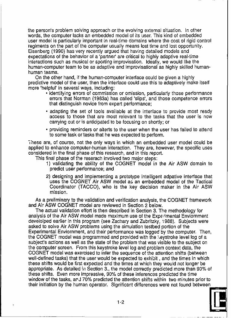
the person's problem solving approach or the evolving external situation. In otherwords, the computer lacks an embedded model of its user. This kind of embeddeduser model is particularly important in real-time domains where the cost of rigid controlregiments on the part of the computer usually means lost time and lost opportunity.Eisenberg (1990) has very recently argued that having detailed models andexpectations of the behavior of a 'partner' are critical to highly adaptive real-timeinteractions such as musical or sporting improvisation. Ideally, we would like thehuman-computer team to be as adaptive and improvisational as highly skilled human-human teams.
On the other hand, if the human-computer interface could be given a highlypredictive model of the user, then the interface could use this to adaptively make itselfmore 'helpful' in several ways, including:
" identifying errors of commission or omission, particularly those performanceerrors that Norman (1983a) has called 'slips', and those competence errorsthat distinguish novice from expert performance;
" adapting the set of tools available at the interface to provide most readyaccess to those that are most relevant to the tasks that the user is nowcarrying out or is anticipated to be focusing on shortly; or
* providing reminders or alterts to the user when the user has failed to attendto some task or tasks that he was expected to perform.
These are, of course, not the only ways in which an embedded user model could beapplied to enhance computer-human interaction. They are, however, the specific usesconsidered in the final phase of this research, and in this report.
This final phase of the reserach involved two major steps:1) validating the ability of the COGNET model in the Air ASW domain to
predict user performance; and
2) designing and implementing a prototype intelligent adpative interface thatuses the COGNET Air ASW model a, an embedded model of the TacticalCoordinator (TACCO), who is the key decision maker in the Air ASWmission.
As a preliminary to the validation and verification analysis, the COGNET frameworkand Air ASW COGNET model are reviewed in Section 2 below.
The actual validation effort is then described in Section 3. The methodology foranalysis of the Air ASW model made maximum use of the Experimental Enviornmentdevelolped earlier in this program (see Zachary and Zubritzky, 1988). Subjects wereasked to solve Air ASW problems using the simulation testbed portion of theExperimental Enviornment, and their performance was logged by the computer. Then,the COGNET model was programmed and provided with the '.,eystroke level log of asubject's actions as well as the state of the problem that was visible to the subject onthe computer screen. From this keystroke level log and problem context data, theCOGNET model was exercised to infer the sequence of the attention shifts (betweenwell-defined tasks) that the user would be expected to exhibit, and the times in whichthese shifts would be first expected and the times at which they would not longer beappropriate. As detailed ,o Section 3., the model correctly predicted more than 90% ofthese shifts. Even more impressive, 90% of these inferences predicted the timewindow of the tasks, arJ 70% predicted the attention shifts within two minutes prior totheir initiation by the human operator. Significant differences were not found between
1-2

previously recorded logs of subjects used to develop the model and separatevalidation subjects. Taken together, the results of this analysis were taken to indicatethat the model was indeed able to provide an Air ASW interface with an ability tomodel and anticipate the actions of its users.
The design and implementation of a demonstration intelligent interface ispresented in Sections 4 and 5. Section 4 discusses the theoretical model underlyingthe use of embedded users models to achieve intelligent human-computer interaction.It also presents the computational architecture used to embed the COGNET model intothe interface of the Experimental Environment's Air ASW mission simulator. Section 5de ils the layout of the specific demonstration intelligent Air ASW interface built withthe architecture introduced in Section 4, as well as the rationale for this specificdesign. This section also describes an example session with the intelligent interface,and how it differs from what is currently used in the fleet. Section 6 presents finalconclusions and a summary of accomplishments of the program.
1-3

2. THE COGNET FRAMEWORK AND THE COGNET MO6EL OF AIR ASWMISSION MANAGEMENT
This section reviews the structure of the COGNET modeling framework. It alsodescribes the specific model that was built using this framework, and the vehicletracking domain which the model addresses. It is the COGNET model of the vehicletracking problem that is subjected to a detailed validation analysis in Section 3, andused as an embedded user model in an adaptive human-computer interface for thevehicle tracking domain in Section 5.
2.1 COGNET Framework and COGNET Modeling Notations
The conceptual basis for COGNET lies in the early work of Selfridge (1959). Heproposed a "pandemonium" metaphor of cognitive processes composed of "shriekingdemons." Each demon was able to perform some aspect of cognition and shrieked forattention as an opportunity arose for that process to occur. As the situation becamecloser to the ideal conditions for the demon, it shrieked louder and louder. Attention, inSelfridge's model, was simply the process of placating the shrieking demons byallowing the loudest one to act. Real-time multi-tasking arises in this conceptualframework when the context and temporal dynamics of the problem allow (or require)many of these shrieking demons to compete for attention in such a way that no one ofthem maintains control for very long.
COGNET represents RTMT decision making in a similar manner. The person isconceptualized as a network of cognitive tasks, each of which represents a partial orlocal strategy for performing some task or for solving some aspect of the overallproblem. The flow of attention from one task to another is triggered by momentarychanges in the problem environment. These changes may be the result of actionstaken by the person or the result of actions of other agents and/or the environment asperceived by the decision-maker. Figure 2-1 shows an abstraction of how attentionflows through this network of tasks.
In Figure 2-1, the user is performing a task ("Task 1"), when he/she receives noticeof some condition at the workstation, such as an error or warning alert. This explicitcondition triggers the user to defer further work on Task 1 and instead to initiate workon Task 4 (perhaps a trouble shooting task). While performing Task 4, however, apiece of information is observed on the screen. This datum, in the context of thetrouble-shooting task and the user's prior experience with this specific informationitem, causes her/him to suspend Task 4 and instead begin Task 3 (perhaps ananalytical or information gathering task). The analysis performed in doing this taskthen uncovers yet another piece of data ("Item D"), which in the context of the originalcondition (Condition A in Figure 2-1) leads the user to cease the analytical task (Task3) and initiate yet another task (e.g., Task 5). While performing this task, however, theuser enccunters condition A again (as he/she did while previously performing Task 1).Because the context is different now, though, the response is also different. Whereasprevus ly., Condito A trigered an init-ation of Ts-k 4, ;n this case it triggers aninitiation of Task 2. Figure 2-1 thus indicates various factors that can influence shiftsin attention among tasks -- explic:( cues, prior knowledge, local problem-solvingcontext, and associations or inferences (i.e., knowledge).
2-1

Task1Task 3Condition Aat Workstation
Information Item DFollowing Condition
Information Item B A or E at Workstationfo n Item BObserved on screen Condition C inferred Observed on screen
and Information Item Dobserved on screen
Task 2
Information Item B andCondition A Condition C inferred Task 4at Workstation
Figure 2-1 COGNET ConceptOne element of COGNET not anticipated in Selfridge's metaphor is the basis for
the coordination among the various tasks or 'demons'. Coordination, as defined inMalone (1990), r6fers to the means by which cooperating but independent agentsorganize their individual problem-solving activity to achieve a solution to a more globalproblem. In COGNET, each task acts as an independent problem-solving agent (likeone of Selfridge's demons). Each task may be partly completed, interrupted by someother task, and perhaps later resumed at the place where it was interrupted. Thus, thetasks are all in various states of completion at any one time, giving them theappearance of concurrence, albeit not actual simultaneous activity. COGNETconsiders this to be a form of weak concurrence (as opposed to the strongconcurrence of completely independent, active-in-parailel agents). Moreover, theseweakly concurrent tasks (unlike Selfridge's demons), are also all interrelated, in thatthey each contribute to some higher-level problem-solving goal. This commoninterrelationship among the tasks -- their linkages to a common goal -- implies somemechanism for coordination among the tasks. In COGNET, coordination among theindividual tasks is established through their use of a common global problemrepresentation. That is, all tasks use the same (overall) representation of the problembeing solved. Each task contributes to some specific portion of the problem (asbounded by the representation), acting to move that portion of the representationtoward a solution (or at least away from some losing or unacceptable state).
The COGNET framework is actually a meta-model, or architecture, for buildingmodels of specific RTMT domains. The flow of cognitive processing in a COGNETmodel resides at any given moment ir a specific task in the network. The focus ofattention remains there for some time jntil it is captured by another task/decision node(by a change in the problem representation that enables the second task node tocapture control from the first). The flow may also be opportunistic, such as when agoal-based shift is supported by a specific state of knowledge in the problemrepresentation. Overall, the flow of attention between and among the tasks both
2-2 [[

reflects the changing context of the problem evolution (via the changes in the commonproblem representation). This flow also contributes to the problem evolution andchange in context by directing the specific sequence of operations that are performedby the sequence of tasks that gain sufficient priority to gain control.
To support the development of domain-specific COGNET models, three formalconstructs have been developed. The first is a global problem representation notation.The common problem representation shared by the individual cognitive tasks is ageneralized, multi-panel blackboard structure of the kind described by Hayes-Roth(1983) and Nil (1986). The flow of information processing within this COGNETarchitecture is shown in Figure 2-2. A given Task (e.g., Task B in Figure 2-2) may beactive at a certain point in the problem evolution. Task B 'reads' or uses certaininformation from the current blackboard contents in its task processes, and may thensubrogate to Task A to provide more localized or complementary analysis. Task Aboth 'reads' information from the blackboard and posts new information to theblackboard. This new information, upon its posting, may then complete a blackboardpattern that satisfies a triggering condition for Task C, which then captures control.Task C similarly posts new information on the blackboard, but this does not satisfy thepattern associat.jd with any trigger with sufficient priority to displace it. Ultimately,however, the activity undertaken in Task C leads to an action which involves asubstantial time delay before its effects are known. Task C then suspends itself untilthese effects are known (i.e., postd on the blackboard), and this allows Task D tocapture control. Task D previously iiad its triggering condition satisfied but hadinsufficient priority to capture attention from Task C, which is now suspended.
Blackboard Panel I Blackboard Panel II-
TASK C
-.. Posting Mesage on Blackboard................. Reading Message from BlackboardW.4* Flow of Attention
Figure 2-2 Attention Flow Between Tasks
2-3

The second formalism for building COGNET models is a notation for describing theinformation processing and associated person-machine behavioral interactionsassociated with each task in the COGNET network. The COGNET task level notationis summarized in Figure 2-3. This notation is related to the GOMS notation of Card,Moran and Newell (1984), but it includes additional features to allow for the accessingand creation of information on the blackboard structure, and to allow for theinterruption, suspension, and subrogation of the current task. (For a detaileddiscussion of GOMS/COGNET differences, see Zachary, Ryder and Zubritzky (1989).
GOAL: Goal name... TRIGGERGOAL: SUBGOAL NAME...<...conditions>
OPERATORs <...conditions>Perform FUNCTION. <(accompanying data/ parameters)>
where FUNCTION=any invokable functionPoint element/location on screenEnter alphanumeric data in response to cuesSelect item from screenEosLobject on blackboardUnDost object on blackboardTransform object on blackboardSuspend until conditionSubrogate to "new Goal Name"Determine ..... (generic mental operator -- find from display, calculate,decide,etc..
TRIGGERSMessage pattern templates based on blackboard contents
CONDITIONS includecontext free CONTROL information:
if ..., repeat until ..., repeat n times, optional, etc.domain-dependent EVALUATIVE information:
boolean statements based on blackboard message patternsSELECTION RULES
Use Method.. .based on selection factorsSelection Rules: .
if condition then Method 1...if condition then Method 2 <with probability .x>
METHODSMethod 1 Name:
list of operators (and subgoals)
Figure 2-3 COGNET Decision Task Description Language
Finally, the third element of the modeling notation is a mechanism to deal withpercep - .-all ... Auv It .- pr.,+ke I with th es% %Ii Itt ILA$ ,,.Jge 0s diner~d abovec iS
that it links the global problem representation -- the blackboard -- strictly to cognitiveoperations performed within the individual tasks in the COGNET network. However, ina human-computer interaction situation much elementary information on theblackboard arises from essentially perceptual events (e.g; observing a symbol appearor change on the display screen). COGNET also provides a notation similar to
2-4

production rules, which describes the processes by which information, onceperceived, is introduced into the pcrson's understanding of the problem (i.e., theglobal problem representation). The perceptual demons therefore have a key role inchanging the momentary problem representation (i.e., blackboard contents)independent from the operations of the individual tasks in the network. This role ispictured in an enhanced version of Figure 2-2 shown as Figure 2-4.
Blackboard Panel I Blackboard Panel II
rTASK B "
TASK A S
~TASK C
- Posting Mesage on Blackboard
Reading Message from Blackboard
inlo- Flow of Attention
. Perceptual Demons
Figure 2-4 COGNET Attention Flow With Perceptual Demons
The COGNET architecture represents real-time multi-tasking in such a way thatperformance is sensitive to both situation effects and the experience and knowledge ofthe human operator. Experience and knowledge affect both the methods encoded inthe individual tasks in the network as well as the triggers that allow for attention flowbetween tasks in the network. Situational effects are introduced by the attentionmechanism, as well as by the use of a common, problem-specific representation by allthe tasks in the network.
2.2 A Vehicie Tracking Problem Domain
It is almost impossible to study human cognitive processes (or tools to model them)without doing so in some specific problem domain. In addition, the domain had torequire real-time computer-based problem solving on the part of the person, and toinvolve some competing demands for the person's attention. The domain selected to
2-5

do this was a vehicle tracking task, in which the tracking is done via remote sensingdevices. This task is based in the real-world domain of Naval Air Anti-SubmarineWarfare (ASW), in which the vehicles being tracked are submarines. The persondoing the tracking is located in an aircraft and using remote sensors to gather dataabout the vehicle, and is processing those data to detect, locate, and track the vehicle.The motivation for using this problem was discussed in Zr f et aL (1989). Asummary of the Air ASW domain is provided below for reao,.,s unfamiliar with it.
Air Anti-Submarine Warfare (ASW) is concerned with the detection andidentification of a target submarine from an aircraft. The Air ASW mission begins withsearching an area of ocean where a submarine is thought to be located. The missionprogresses through a series of stages in which it systematically increases knowledgeof the target's location, until it is possibl to track it (in peacetime), or attack and destroyit (in wartime). This problem is currently solved jointly by several cooperatingcrewmembers aboard a P-3 or S-3 aircraft. The crew typically consists of the aircraftpilot and navigator, one or more Sensor Operators (SENSOs), and othermiscellaneous operators (not concerned with tactics). The Tactical Coordinator(TACCO) guides all of these personnel during the mission, coordinating their effortsand the available resources.
Virtually all information about the target is gained from a suite of remote sensorsthat includes passive acoustic sensors, or sonobuoys, active sonobuoys, RADAR, andMagnetic Anomaly Detection (MAD) sensors. Passive sonobuoys are the principalmeans for detection and localization of the submarine, and are preferred for trackingas well. They are often used in combination with active acoustic (and nonacoustic)sensors to speed the localization process or to deal with a target that has been alertedto its pursuit by the ASW aircrart. Typical phases of an Air ASW mission are:
1. Search -- Initial detection of a target is sought using passive sonobuoysdropped in the water to form a geometric pattern.
2. Direct-Path Contact -- Additional passive sonobuoys are dropped to obtain asensor contact in which the target is detected within close range of a sonobuoy.
3. Target Fix -- One or more specific locational hypotheses about the target'sprecise location (i.e., 'fixes') are developed using analysis of sensor data overtime.
4. Target Track -- Fixes are viewed together to develop a motion hypothesis thatcan predict target location over time.
5. Attack -- Doctrinal criteria for using a weapon are met, and a weapon, usually atorpedo, is deployed against the target track.
6. Alerted Target -- The target detects the presence of the #ASW aircraft, andtakes evasive action, making localization, fix development, and tracking muchmore difficult.
During the use of passive sonobuoys, a physical phenomenon called theconvergence zone (CZ) often makes the interpretation of the received data difficult. Anacoustic sonobuoy can 'hear' sound directly propagated from an emitting source overa small distance; this is called its direct path (DP) detection range (e.g., 2 -5 nauticalmiles). Because of ducting of sound underwater, there may be a small annular regionquite distant from the DP zone in which detection may also occur. This is called a CZ.There may be none, one, or possibly two CZs in any given acoustical environment.The presence of CZs creates a complex pattern of potential detection regions in a field
2-6

of sonobuoys. Directional passive sonobuoys also provide a bearing to the target, butthis bearing contains error, and does not help disambiguate whether the soundoriginates from the DP zone or from a first or second CZ.
Thus, the heart of the Air ASW problem involves using this ambiguous, errorful datafrom fields of sonobuoys in conjunction with data from active sonobuoys andnonacoustic sensors to detect the presence of a submarine and iteratively refine itslocation, course, and speed. The problem requires the TACCO to continuously revisetarget hypotheses based on the current situation and plan new tactics to gather furtherdata, which in turn will cause an update of the hypotheses. Embedded within thisprocess is the fact that the TACCO must direct the aircraft to deploy new sensors as away of disambiguating data from existing sensors. This makes the movementdynamics and attendant time-lags another part of the decision process. Often, forexample, the TACCO may know where to place an additional sensor, but cannot getthe aircraft to the desired location in time for the data to be meaningful. Thus, thevehicle tracking problem based on Air ASW provides a rich and difficult domain inwhich human problem solvers must make real-time decisions and share their attentionamong a variety of tasks.
2.3 COGNET Model of Air ASW Mission Management
Earlier phases of this research applied the COGNET modeling formalisms to thevehicle tracking problems based on Naval Air ASW. The emphasis in this model wason responsibilities of the TACCO that were termed mission management. This termencapsulates the TACCO's tactical role in the later (i.e., post search) portions of the AirASW problem. These are the portions which involve a protracted period of real-timemulti-tasking on the part of the TACCO.
The TACCO actually begins to build him mental model (or in COGNET terms, topopulate a blackboard representation) of the mission as early as the preflight briefing.The mission management model, however, concerns problem evolution only after aninitial cortact with a target is obtained through the search strategies. Once tht firstsensor contact is gained, then the TACCO must begin a protracted prosecution of thecontact that is in part goal-driven (based on training, experience, and standarddoctrine) and in part data-driven (based on the specific sensor data received). Theoverall goal of this prosecution is to form a highly accurate hypothesis as to thelocation, depth, course and speed of the target submarine. "Highly accurate" isoperationally defined as sufficiently accurate to launch against the target with astandard (torpedo) weapon. In peacetime, of course, the TACCO does not launch anattack but merely attempts to maintain this level of knowledge and track the submarine.M!ssion management, covers a period of persistent RTMT activity, that in practialterms ranges from 30 minutes to two hours.
2.3.1 Task DecompositionThe mission management COGNET model was developed using an experimental
para di and datL a,-alySiS methodolog Y, dhescribed in IZc %a I e7 t. a!. (1989). A total offourteen information processing activities were identified as individual cognitive tasksin the basic COGNET network. These tasks can be grouped conveniently into relatedareas as follows:
* maintaining a complete picture of the tactical situation,* managing control of the aircraft,
2-7

" hypothesizing/inferring the activities of the target, and* managing the patterns of sonobuoys deployed.
Table 2-1 lists the fourteen tasks according to these groups.
Control Aircraft Control Sensor SuitePosition in Area of Interest Manage Sonobuoy ResourcesPreposition for Expected Events Broaden Initial ContactManeuver for MAD Investigate Convergence Zones
Expand Pattern for ContactContinuity
Deploy Sensor/Pattern
Maintain Situational Awareness Hypothesize Target ActivityPlot Acoustic Environmental Features Identify Area of InterestReview Overall Situation Develop Target Fix
Gain Attack CriteriaDetermine Target Track
Table 2-1 Individual Tasks in COGNET ASW Mission ManagementModel
2.3.2 Blackboard OrganizationAs described in Subsection 2.1 above, the integrative problem representation is
formalized in COGNET as a blackboard structure. In general, a blackboard structuremay contain separate partitions, or panels, to deal with information about differentaspects of the problem. Each panel is decomposed hierarchically into levelscontaining one or more hypotheses or partial solutions constructed by the individualtasks. The ASW mission management blackboard structure contains two panels--thetarget panel and the situation panel -- each representing separate yet highlyinterrelated aspects of the problem solution space. The target panel containsinformation about the TACCO's evolving hypotheses about target behavior; thesituation panel contains an understanding of the evolving prosecution. These twosolution aspects are constructed separately, but draw on each other as sources ofdata.
The target panel is divided into six levels of abstraction which are used by theTACCO to process sensor data about a possible target. Each level representsincreasingly more refined hypotheses about target behavior.
The lowest !Gvel is the contact level. It contains hypotheses and/or perceptualevents denoting sensor contact. When a contact 'appears' as a display symbol on theTACCOs tactical display, a perceptual demon is immediately triggered which posts theinformation on the contact level.
The next level of abstraction involves the application of kncwledge about thesensor which produced the contact, properties of the specific acousticenvironment, and the overall situation to define areas of interest that mayarise from sensor contacts and/or other, more abstract, information on theblackboard.
2-8

The third hierarchical level on the blackboard represents a special kind ofarea of interest, a direct path region around an acoustic sensor, MAD, orradar contact. Direct path information represents a maximally crudelocational hypotheses about a target.
The fourth level refers to more precise locational hypotheses that are basedon various combinations of other hypotheses, knowledge, and/or sensordata from other levels on the blackboard. Usually, it is necessary to fuseinformation from multiple contacts to obtain a location hypothesis.
The fifth level of the target blackboard refers to directional hypotheses aboutthe target. These may be mixed levels of abstraction, from generaldirectional information gleaned from prior knowledge to specific directionalhypotheses inferred from sensor data on the blackboard.
Finally, the sixth and highest level on the target blackboard refers to fuseddirectional and locational hypotheses, which are referred to as tracs.These hypotheses often correspond to moving track symbols generated bythe TACCO via the workstation software. It is not uncommon for a TACCO tohave five or more of these track hypotheses for ,, single target.
Figure 2-5 indicates the blackboard target panel organization, showing its contentsas reconstructed from a specific experimental trial. The arrows show the general flowby which information is posted and transformed, indicating the mixed directions inwhich information is processed on the blackboard. Initially, there is only a weakdirectional hypothesis of an expected southwesterly motion of the target. Thishypothesis would have been developed prior to take off, as the result of intelligenceinformation in the pre-flight briefing. Because the pre-contact mission phases are notincluded in the present model, such hypotheses are dealt with as assumptions. Thatis, the model assumes that relevant information about the mission that would havebeen developed prior to the beginning of the mission management phase is alreadyposted on the blackboard at the start of this phase. (This assumption is generally moreimportant to the situation blackboard than to the target blackboard).
Track Generate Auto-Track1................. e ........................Direction (prior data) - Inferred Mvmt:Bearing200
............ ....... . . . . . . . . . . . . .... ................. at t-
Lo cation /,(w z) at t2 (xy) at t3
Direct Path I around 6iFAR 22 ......
A rea.of..nte.e... ......... .... .AConvergence Zone on DIFAR 19I.. . ...... R...............
Contact N ew DIFAR, channel 19 channel22 att3att t2, earinn 1950
..._- - - --C at t,0 at t2, bearing 195
Figure 2-5 Target Situation Panel with Example Data
2-9

The example in Figure 2-5 begins with deployment of the initial search pattern.One sensor on Channel 19 from that pattern gains a directional contact. That contactis posted on the contact level of this blackboard panel as "New DIFAR on 19 at t1,bearing 30" ,indicating a new directional contact was first obtained on a DIFAR sensorusing channel 19 at time t1, with the directional bearing at 300 to the sensor having thecontact. The TACCO incorporates this information into a representation through aperceptual event, i.e., by perceiving the contact and associated bearing line as theyappear on the tactical screen. Thus, this initial posting in the model is done via aperceptual demon.
The posting of a new contact on the blackboard triggers the Identify Areas ofInterest (AOI) task which determines the possible areas of interest associated with thenew contact and posts them as AOIs on the AOI level of the target panel. Only one ofthese is shown in Figure 2-5, the Convergence Zone Area of Interest that is associatedwith the sensor on Channel 19. The overall pattern of information on the blackboard atthis time triggers two additional tasks. These are 1) the Broaden Initial Contact task,which deploys a sonobuoy pattern around the sensor on channel 19; and (2) theInvestigate Convergence Zone task, which deploys a pattern of sensors in theChannel 19 CZ AOL. The layout of this pattern is influenced by the existing motionhypothesis already on the direction layer of the target panel. Because of thishypothesis, the Investigate Convergence Zone task maps out the pattarn slightly to thesouthwest of where it would have been laid out (in a no-information case). One ofthese sonobuoys in the CZ pattern is deployed using Channel 22, and soon gains acontact at time t2. This new contact is also posted on the blackboard by a perceptualdemon. The influence of the existing directional hypothesis on this contact is indicatedby the arrow from the directional hypothesis to the contact message.
The new contact on Channel 22 again triggers the Identify AOI task, which this timeimplies that only a direct path contact is reasonable for the sensor using Channel 22.This information, in combination with the continuing CZ AOI on sensor 19, furtherleads to a direct path hypothesis being posted on the Direct Path layer of the targetpanel. After a short time, the TACCO makes an initial locational hypothesis about thetarget at the location of the intersecting bearing lines for sensors on channels 19 and22. This locational hypothesis is denoted as (w,z) and time t2 on the blackboard.
The new pattern of information on the blackboard at this time triggers the Maneuverfor MAD (Magnetic Anomaly Detector) task, through which the TACCO attempts todevelop a more precise locational hypothesis via a combined DIFAR and MADcontact. Through this task, the aircraft does obtain a MAD contact, at location (x,y) andtime t2, as indicated on the contact layer. This contact is then combined with thedirectional information and direct path hypothesis from the sensor on Channel 22, toyield a revised hypothesis that the target was near x,y at time t3. Moreover, thislocational hypothesis is further combined with the previous directional hypothesis andthe previous locational hypothesis (i.e., w,z at t2) to generate a refined directionalhypothesis, i.e., that of movement along bearing 2000. This is also followed bycreation of a moving track symbol on the screen, anchored at location x,y at time t2,and moving on course 2000.
The Situation panel of the blackboard contains information about the individualelements (e.g., the aircraft and sonobuoys) and features (e.g., environmentalproperties) of the tactical situation. It also is divided into six levels as shown in Figure
2-10

Expectations Arrive in AOl about 03:00
Environment -- DP to 3NM, 1 CZ (29NM with 2 NM width)
MissionFactors Buoy Resources Remaining: 17 DIFAR, 7 DICASS
Time on Station -- 3 hours remaining
PatternsSearch pattern -- 16 buoy barrier oriented at 135T
Contacts Contact gained on buoy #1 at bearing 52 at time 14:$$
Ck
Tactical Center (15.83, -067), Scale 64NM
Display AC (12,3) bearing 135, alt 5000, speed 2168 Buoys: DIFAR at 11.46,-2.46, DIFAR at 8.71,0.21,....
8 FTPs: UNDES\XP at 12.3,2.0, UNDES EXP at 7.0,5.0.....
Off-screenElements
2-6. In this figure, as in Figure 2-6, the contents show data from a specific
experimental trial.
Figure 2-6. Situation Blackboard Panel with Example Data
The first two levels of the situation panel, off-screen elemen. and taticiLalaI,contain situational information that is represented on the TACCO workstation. Most ofthese data are plotted on the tactical screen, such as location of the aircraft all tacticaldisplay symbols. These display symbols include buoy locations, fly-to-points, contact
2-11

symbology (e.g., bearing lines, MAD contact symbols), 'chalkboard' information suchas reference circles, reference lines, and reference marks; and other symbology.
These two levels provide a means for representing the spatial relationships amongelements over the complete tactical area. The tactical displ level contains thoseelements which are visible on the TACCO's tactical display screen, and hence, are ofimmediate interest. The off-screen elements level contains all other elements over thewhole mission a~ea. Because the tactical display has a 'zoom/pan' organization, thereis often symbology that is not currently on the screen. These data, represented as theywere last viewed by the TACCO, are contained on the off-screen elements layer. Inaddition to the actual tacti,'al display contents, the tactical display level indicates otheritems of information that are perceived from the workstation, such as the center point ofthe dispiay and its scale, the aircraft bearing and speed, and other status information.
The third and fourth levels are c and patterns. The contact level contains atime-stamped history of the sensors that have gained and/or lost contact. If at somepoint the TACCO gets information conflicting with a current target hypothesis, thatindividual may refer to the contact history to re-evaluate what is known about thetarget.
The pattern level contains a record of all buoy patterns planned or in use. Differentpatterns are used for different mission phases and are selected based on theTACCO's current target hypothesis and various mission factors. An important aspectof the pattern level is that patterns are usually defined relative to other aspects of thesituation. For example, a convergence zone investigative pattern reflects a standardgeometry that is adjusted to reflect features of the acoustical environment and laid outrelative to another sensor that has the contact being investigated. Thus, an entry onthe pattern level will indicate pattern type (e.g., investigative, contact-broadening) andalso status (e.g., planned, partially-in-water, fully-deployed, partially dead, dead). Itwill also contain links to other sensors or features on the tactical display layer (e.g.,sensor locations) and the mission factors layer (e.g., environmental features).
The fifth level contains data/hypotheses about _mission factors. These includeenvironmental information about how sound will be propagated in the mission areaand resources remaining. The TACCO's current hypothesis about the environmentinfluences how that person interprets contacts. Normally, these hypotheses aredeveloped prior to the mission management period at either the pre-flight briefing orthe initial on-station phase where environmental sensors are deployed and analyzed.However, patterns of sensor contacts may conflict with posted environmentalinformat!on, which may in some cases cause the TACCO to revise envi'onmentalhypotheses. Resources remaining influence what strategies will be used for targetprosecution. For example, the number of buoys remaining influences the selection ofbuoy patterns to use.
The sixth level contains expectations about future events and when they are likelyto occur. For example, when the TACCO enters a Fly-to-Point (FTP), a steeringcommand to the pilot, he creates an expectation about when that FTP will becaptured. This influences his decisions about what he can accomplish until that time.Such expectations can lead to suspensions of currently active tasks, as wll astriggers for suspended tasks to recapture control.
2.3.3 Perceptual DemonsEffective mission management relies on the TACCO's ability to monitor the large
amount of information on the tactical screen and perceive importnat events and/or
2-12
information as they are displayed there, e.g.,observing a contact bearing come up onthe screen. The perdeptual demon construct in COGNET accounts for this type ofinformation access. In the ASW Mission Management model, the perceptual demonsare linked with the k,ds of visual events that the TACCO encounters. These are thedisplay events that were programmed into the ASW Mission Managementexperimental environment (see, Zachary & Zubritzky, 1988). In an operationalapplication, the perceptual demons would be based on the display and/or auditoryinformation that could be presented at the operatiornal crewstation. The list of theperceptual demons developed for the Mission Management model is shown in Table2-2.
2.3.4 Cognitive Task ModelsDetailed models were built of all fourteen tasks indicated in Table 2-1 above, using
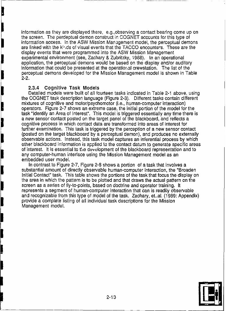
the COGNET task description language (Figure 2-3). Different tasks contain differentmixtures of cognitive and motor/psychomotor (i.e., human-computer interaction)operators. Figure 2-7 shows an extreme case, the initial portion of the model for thetask "Identify an Area of Interest". This model is triggered essentially any time there isa new sensor contact posted on the target panel of the blackboard, and reflects acognitive process in which contact data are transformed into areas. of interest forfurther examination. This task is triggered by the perception of a new sensor contact(posted on the target blackboard by a perceptual demon), and produces no externallyobservable actions. Instead, this task model captures an inferential process by whichother blackboard information is applied to the contact datum to generate specific areasof interest. It is essential to t e development of the blackboard representation and toany computer-human interface using the Mission Management model as anembedded user model.
In contrast to Figure 2-7, Figure 2-8 shows a portion of a task that involves asubstantial amount of directly observable human-computer interaction, the "BroadenInitial Contact" task. This table shows the portions of the task that focus the display onthe area in which the pattern is to be plotted and that draws the actual pattern on thescreen as a series of fly-to-points, based on doctrine and operator training. Itrepresents a segment of human-computer interaction that can is readily observableand recognizable from this type of model of the task. Zachary, et..al. (1989: Appendix)provide a complete listing of all individual task descriptions for the Mission,Management model.
2-13

Buoy gains contact ==>if DIFAR contact
POST "New DIFAR Contact at time [mission-time] on Buoy [ChannelNo] with Bearing [bearing] and Strength [high/low]on Target/Contacts and Situation/Contacts"
if LOFAR contactPOST: "New LOFAR Contact at time [mission-time] on Buoy [Channel
No] and Strength [high/low]on Target/Contacts and Situation/Contacts"
if DICASS contactPOST: "New DICASS Contact at time [mission time] on Buoy [Channel
No] indicating range of [range in yards] and Bearing [bearing]on Target/Contacts and Situation/Contacts"
if CASS contactPOST: "New CASS Contact at time [mission time] on Buoy [Channel No]
indicating range of [range in yards]on Target/Contacts and Situation/Contacts"
if MAD contactPOST "MAD Contact at time [mission time] at [x,y]
on Target/Contacts and Situation/Contacts"if RADAR contact
POST:" RADAR contact at time [mission time] at [x,y]on Target/Contacts and Situation/Contacts"
Buoy loses contact ==>if DIFAR contact
POST: "DIFAR Contact on Buoy [Channel No] lost contact at time[mission-time] on Target/Contacts and Situation/Contacts"
if LOFAR contactPOST: "LOFAR Contact on Buoy [Channel No] lost contact at time
[mission-time] on Target/Contacts and Situation/Contacts"Bearing shift of DIFAR contact ==>
POST: "DIFAR Contact on Buoy [Channel No] bearing shift at time [mission time]to bearing [bearing] on Target/Contacts and Situation/Contacts"
Change in signal strength ==>if DIFAR contact
POST: "DIFAR Contact on Buoy [Channel No] changed strength to[high/low] at time [mission time] on Target/Contacts andSituation/Contacts"
if LOFAR contactPOST: "LOFAR Contact on Buoy [Channel No] changed strength to
[high/low] at time [mission time] on Target/Contacts andSitu atio n/Co ntacts"
Capture of FTP ==>
UNPOST: "[type] at [x,y]
Table 2-2. Perceptual Demons
2-14

if expenditureTRANSFORM: "[type] at [x,y]" TO "[symbol type] at location [x,y] at
time [time] on Situation/Tactical Display"
Change in aircraft location ==>POST: "AC (x,y) bearing [bearing] alt [feet] speed [TAS] on
Situation/Tactical Display
Symbol moved off-screen by recenter or downscale ==>TRANSFORM: [type] at [x,y] on situation/tactical display" to "[type] at [x,y] at time
[time] on Situation/Off-screen Elements"
Expenditure of buoy resources ==>if DIFAR
TRANSFORM: "Buoy resources remaining: [number] DIFAR" to "Buoyresources remaining: [number -1] DIFAR"
if DICASSTRANSFORM: "Buoy resources remaining: [number] DICASS" to "Buoy
resources remaining: [number -1] DICASS"
Table 2-2. Perceptual Demons (contd)
2-15

GOAL: IDENTIFY AREA OF INTEREST ... ANY NEW TSENSOR TYPEIC2ONTACT POSTED ON CONTACT LEVEL OF TARGET B
GOAL: Identify Acoustic AOI ... if new DIFAR, LOFAFI, CASS. orDICASS contact
GOAL: Identify passive AOI ... if new DIFAR or LOFAR contactDetermine [contact buoy number] from contact level of target BBPost "DP A01 on 'contact buoy number' on AQl level of tre BPost "BTm~n A01 on 'contact buoy number' on A01 level of target BB.-.if
Bottom Bounce on mission factors level of situation B8LJPost "OZi A01 on 'contact buoy number' on target BB ... if 2CZ or 1 CZon
mission factors level of situation BBPost "CZ2 AQl on 'contact buoy numbere on target BB ... if 207 on iso
factors level of situation- BTransform "New [buoy typel contact at time [mission-timel on Buy fhnnel
No] with Bearing (bearing]' into "[buoy type] contact at time fmission-time]on Buoy [Channel No] with Bearing (begring]"on contact level of target
GOAL: Identify active AO ..it CASS or DICASS contact
Determine [contact buoy number] from-contact level of target BBPost "CASS A01 with MDR [distance] on buoy [Channel No]" on A0l level of
target BB .. if CASES contactPost "DICASS A01 with bearina [bearing] and with MDR (distancel on buoy
['Channel No]" on A01 level of target!1 .. if DICASS contactTransform "Ngw [buoy type] contact at time [mission-time] on Buoy [Channel1
No] with Bearing (bearing]" into 'buoy type] contect at time [mission-timelon Buoy [Channel No] with Baring (bearing]"on contact level of target
BBFigure 2-7. Portion of "Identify Area of Interest" Task Model
2-16

GOAL: Focus tactical display on AOl
Perform UPSCAL ... until A0l visible on displayP -erform RECENTER (contact buoy) ... if contact buoy not near center
of screen
Perform DOWN SCAL... until A0l fills displayGOAL: Build prudential pattern
Subrogate to "iPlot Acoustic Environmental Features"...if DP notalready plotted
GOAL: Enter FTPsI±QQ~i5J point on DP crl
P~erorm CNDES FTP (expendable. hooked locatin)~Hook 2nd point on DP Circle.Perform UNDES FTP (expendable. hooked location)~Hook 3rd point on DP cir IPerform UNDES, FTP (expendable, hoked locaionjHoQok 4th point on DP ciclPerform UNDES FTP (expendable. hooked location)
Figure 2-8. Portion of "Broaden Initial Contact" Task Model
2-17

3. MODEL ANALYSIS AND VALIDATION
The value of the COGNET framework as a methodology for modeling RTMTdomains lies ultimately in its utility for developing more adaptive and intelligenthuman-computer interfaces. A necessary, though not sufficient, condition for utility isthe validity of the models the COGNET methodology generates. Validation of theCOGNET model of air ASW mission management involved evaluating the model'spredictive power. In other words, for a given operator and mission scenario does themodel allow prediction of what tasks should be undertaken next and when attentionshifts should occur. A related, but somewhat different question is whether the modelimplemented as computer code allows this prediction. This is the focus that was takenhere.
This section describes the analysis and validation methodology and the results ofthe validiation analysis applied first to the data from the subjects who were used toconstruct the model (post-hoc verification), and subsequently to the data fromadditional subjects (validation analysis).
3.1 Analysis and Validation Methodology
The model described in Subsection 2.3 above was developed directly fromexperimental data on human performance in air ASW (see Zachary et al., 1989, for acomplete description of the modeling methodology). Using an experimentalenvironment, data were collected from experienced TACCOs solving a variety ofproblems using different mission scenarios. Five problems which differed on the basisof mission objectives, target behavior, environmental conditions of the ocean andsensor capabilities were used. These problems were chosen in order to view a rangeof possible TACCO strategies. Five experienced TACCOs participated in the studysolving one practice problem and from one to four experimental problems each. Datawere collected on a total of sixteen trials; however, the first problem each TACCOsolved was considered practice and was not included, leaving eleven problems whichwere used in actual model development.
The data collected for each problem were used both for model construction andsubsequently for model verification. The experimental data recorded during each trialincluded a time-stamped record of all TACCO actions (key presses and mouse inputson the graphical screen), and a symbol data file which recorded the state of eachtactical symbol displayed on the screen at the occurrence of every TACCO action orany change in the tactical situation. On average, each trial generated an average of400 actions and 40,000 display items. The action data file was transformed into anarrative timeline for ease of use during model construction and analysis. In addition,protocol data for each problem was recorded by replaying the completed problem(using the saved action data file as input to the problem environment simulation) withthe TACCO, and asking for a description of his/her thoughts and intentions inperf rmig . .. ' -- " ' -" - '--or rou - -'*"-- -r... .... - 6 :.. &6 -... 4;,*;.,.
11Uiiu1iii.iii ll a I lLIcUIa;II € sUVII Or gjI UU I wAI.1II . I IIU O IU W 1 ICiLI U111VV ,II IlL
but interrelated types of data were collected: 1) TACCO actions, 2) Situational contextof TACCO actions, and 3) TACCO intentions while performing sets of actions. All threeof the data sources described above were used for model construction (see Section3.2 of Zachary et al., 1989, for a complete description of the model constructionprocess).
3-1

The narrative timeline provided the basis for model validation. Using the timeline,the task sequence was reconstructed, identifying the point at which each task wasinitiated by the TACCO. Analysis and validation of the model involved a comparison ofindividual performance on each problem with that predicted by the COGNET model.COGNET model predictions were generated by a programmed version of the model.
The COGNET model of air ASW mission management was implemented ascomputer code in the project's experimental environment. The model code executed"on top of" the problem environment simulation and emulated TACCO workstation (seeSections 4 and 5 below). The implemented model included the full blackboardstructure, all perceptual demons and five of the fourteen individual tasks. Theblackboard contents were continually updated by perceptual demons viewing theinterface and posting information (assuming the TACCO perceived every change inthe display), and by POST and UNPOST operators in the task models. Attentiontriggering conditions for each task monitored the blackboard contents and "triggered"whenever the pattern on the blackboard matched. When the pattern no longermatched the triggering condition, the task was "untriggered." The time the task triggerwas active was taken as the time when the model predicted that task.
The validation analysis was conducted for four tasks, which had been implementedin the programmed model:
1) Broaden Initial Contact (BIC)
2) Investigate Convergence Zones (CZI)
3) Manuever for MAD (MAD)
4) Expand Contact for Continuity (EXP)The fifth task which was included in the implemented model, Identify Area of Interest,was not included in the validation ane lysis because it is a purely cognitive task, withno observable confirmation of its occurrence. The analysis was conducted for onehour of data for each trial beginning at the time of first contact. For each problem, thevalidation methodology was as follows:
1) Each instance that the TACCO initiated one of the four tasks listed abovewas identified. '
2) The problem replay file was rerun through the programmed COGNETmodel to identify when each of the four tasks was triggered and untriggered(i.e., to determine when the modAl predicted the operator should shiftattention to that task).
3) Each TACCO-initiated task was evaluated to determine whether it was
4) The time the TACCO initiated each task was compared to the time when thethe modeied task trigger first became active.
3-2

Thus, two types of data were derived:
1) Task Occurrence Predictions: For each task instance performed by thesubject, the model did or did not predict the task. If the model produced acorresponding task trigger, it i:idicated the model predicted the attention shiftto that task. When the model did not produce a corresponding task trigger, it
was taken to indicate that the attention shift was not predicted.
2) Task Prediction Lead: For those tasks that were predicted, a simplecalculation yielded the amount of time by which the model prediction leadthe actual task initiation.
3.2 Post-hoc Model Verification
The initial stage in model validation involved comparing the derived COGNETmodel of air ASW mission management with the performance of the individualTACCOs on each problem used to derive the model. The baseline data set includedeleven trials (five subjects solving between one and four problems each). The post-hoc model verification also involved these eleven problems. A total of 30 instances ofthe four tasks were performed by the subjects. Of these 27, or 90%, were predicted bythe COGNET model. That is, they were performed while the task trigger was active.Assuming that the probability of correctly predicting a single task initiation is .5 (i.e.,50/50), the probability of correctly predicting 27 of 30 tasks by chance is < .001. Forthe 27 predicted tasks the task trigger lead the actual task initiation by an average of4:06 min (3:12 min when only the first occurrence of each task is considered). Insubsequent paragraphs and accompanying figures and tables, the details of theresults are presented. One additional task was predicted by the model just after thesubject's initiation of the task (within 2 min). If this task is considered to be predictedby the model, the prediction accuracy of the model increases to 93% (28 of 30 tasks).However, the data presented in the following discussion takes the more conservativeapproach -. ncluding only those tasks initiated during the exact time the task triggerwas active.
Figures 3-1 through 3-11 show actual and predicted task performance on each ofthe eleven trials. Each figure shows the actual task initiations (subject actions) at thetop and the model predictions (active triggers) at the bottom.
3-3

4 H
SubectK BC PActions( JIBICA MAtD
TriggersrI
II I I I
0 15 30 45 60Time at
1st Contact TIME (Min.)(Normalized to 0)
Figure 3-1 Subject 1 Problem 3
Subject( i f i iActions BIC C I MAD MAD
Active EXP a HTriggers
0 15 30 45 60Time at
1st Contact TIME (Min.)(Normalized to 0)
Figure 3-2 Subject 1 Problem 4
3-4

SubjectfActions UZI MAD MADK &
BIC
1'_MA. D
Active EXPTriggers ___ .zI
'BIC.I I III
0 15 30 45 60Time at
1st Contact TIME (Min.)(Normalized to 0)
Figure 3-3 Subject 2 Problem 1
Subject fActions BIC CZI
Active z.XP -E]Triggers CZ ' -
0 15 30 45 60Time at
ISr tac+ TIME -(Normalized to 0) "
Figure 3-4 Subject 2 Problem 2
3-5

Subjectf CZ 4Actions BIC EXP MAD
MID.Active EXP.. i1
Triggers .ZI
BIC", ,I,, I I I
0 15 30 45 60Time at
1st Contact TIME (Min.)(Normalized to 0)
Figure 3-5 Subject 2 Problem 3
Subjectf Et4Actions CI EXP
Active EXPTriggers :CZIf
BIG-I ,I I I i...... ..
0 !5 30 45 60Time at
1st Contact TIME (Min.)(Normalized to 0)
Figure 3-6 Subject 3 Problem 3
3-6

SubjectfActions< CZI
MAD,
Active EXPTriggers ___ ___
": BIG
0 15 30 45 60Time at
1st Contact TIME (Min.)(Normalized to 0)
Figure 3-7 Subject 4 Problem 1
Subject iczlActions BIC
ActiveTriggers .ZI '
0 15 30 45 60Time at
1st Contact TIME (Min.)(Normalized to 0)
Figure 3-8 Subject 4 Problem 33-7I

SubjectfActions JZI iBIC
ActiveTriggers' .
C
0 15 30 45 60Time at
1st Contact TIME (Min.)(Normalized to 0)
Figure 3-9 Subject 2 Problem 4
Subject 4Actions CZ! EXP
MAD "
ActiveTriggers
I I I0 15 30 45 60
Time at1st Contact TIME (Min.)
(Normalized to 0)
Figure 3-10 Subject 5 Problem I
3-8

Subject(
Actions CZl
Active
Triggers __CZI__
0 15 30 45 60Time at
1st Contact TIME (Min.)(Normalized to 0)
Figure 3-11 Subject 5 Problem 3
Table 3-1 provides a tabular summary of the eleven trials. Three additional datasummaries are provided to allow inspection of the contribution of different variables tothe model's predictiveness. Table 3-2 summarizes the data for each subject; Table 33for each problem; and Table 3-4 for each task. Each table includes the number oftasks performed and predicted, a simple calculation to yield the % of tasks predicted,and the mean prediction lead time. The mean prediction lead was calculated usingonly predicted tasks. In some cases subjects performed more than one instance of atask (e.g., two or three MAD runs); for those cases a second calculation, shown inperentheses, included only the first occurrence of each task. The prediction lead isobviously going to be longer for the second or later occurrence of a task. Thus, thesecond number is probably more representative of the model's performance.Examination of Table 3-4 indicates that the first MAD run follows the model predictionby an average of 1:05 min, while for all MAD runs the average is 4:38 min after themodel initially predicts a possible attention shift.
3-9

Table 3-1. Post-hoc Verification Trial Data
Subj # - Prob # Number of Number of % of tasks Mean prediction leadtasks performed tasks predicted predicted (for predicted tasks)
Subj 1 - Prob 3 1 5 100% 3:39 (2:56)1 4 5 5 100% 6:27 (5:19)2 1 4 3 75% 2:50 (2:06)2 2 2 2 100% 6:372 3 4 4 100% 2:442 4 2 2 100% 4:483 3 2 2 100% 2:444 1 1 1 100% 0:504 3 2 2 100% 4:015 1 2 0 0% -
5 3 1 1 100% 3:27Total 1 30 27 90% 4:06 (3:12)
Table 3-2. Post-hoc Verification Subject Data
Subj # Number of Nurnber of % of tasks Mean prediction leadtasks performed tasks predicted predicted (for predicted tasks)
1 10 10 100% 5:03 (3:57)2 12 11 92% 3:51 (3:48)3 2 2 100% 2:444 3 3 100% 2:575 3 1 33% 3:27
Table 3-3. Post-hoc Verification Problem Data
Prob # Number of Number of % of tasks Mean prediction leadtasks performed tasks predicted predicted (for predicted tasks)
1 7 4 57% 2:20 (1:40)2 2 2 100% 6:373 14 14 100% 3:18 (3:03)_ _4 7 7 100% 5:59 (5:06)
3-10

Table 3-4. Post-hoc Verification Task Data
Tasks Number of Number of % of tasks Mean prediction leadtasks performed tasks predicted predicted (for predicted tasks)
BIC 7 7 100% 2:44CZI 11 10 91% 5:29EXP 4 3 75% 1:21MAD 8 7 88% 4:38
1st MAD 4 3 75% 1:05
For nine of the eleven trials, all tasks performed were predicted by the model. Thethree unpredicted task occurrences were for two of five subjects and all on oneprobl,'rn. Of the three tasks that were not predicted, one was performed 1:58 min priorto the task trigger (Subj 2-Prob 1); one was performed 4:05 min after the task was"untriggered" (Subj 5-Prob 1); and one was never predicted (Subj 5-Prob 1). In thefirst case, the subject shifted attention to 'Expand Contact for Continuity' prior to themodel prediction, indicating the model actually predicted the attention shift, but justafter the TACCO performed it. Subject 5 performing Problem 1 took a long time toanalyze the situation prior to beginning prosecution, and by the time he began, he lostthe initial contact and never regained control. Thus, the model was not able to predictattention shifts. This suggests elaboration of the model to cover cpes in which contactis lost for long enough that a complete re-evaluation of the situatio nust beundertaken. As it stands now, the model begins from the point of initial contact.
As Table 3-2 indicates, there is some variability in the model's 'goodness"acrossdifferent subjects. This may, in part, be due to differences in the TACCOs' abilityand/or expereince. Subject 5, the subject for whom the model was least able to predictperformance,13 had the fewest hours of operational experience of the five subjects andthe longest period since active TACCO duties. Those TACCOs for whom the % oftasks predicted is high but the mean prediction lead time is longer, are probably theones who would benefit the most from an adaptive interface that provided alerts that aparticular task is appropriate. Variability in % of predicted attention shifts andprediction lead time across problems (Table 3-3) most likely reflects problem difficulty,amount of deviation from standard situations or tactics, or problems in which multipletasks are appropriate simultaneously.
Table 3-4 indicates that the model was able to predict attention shifts to all fourtasks. Although the % of tasks predicted varies from 75% to 100%, the variability isdue to the number of task performances (i.e., there is one failure on each of threetasks). The prediction lead time varies among tasks, with the longest lead for'Investigate Convergence Zones.' This is probabiy to to the fact that when both BICand CZI are appropriate, the doctrinally correct approach is to perform BIC first.
3-11
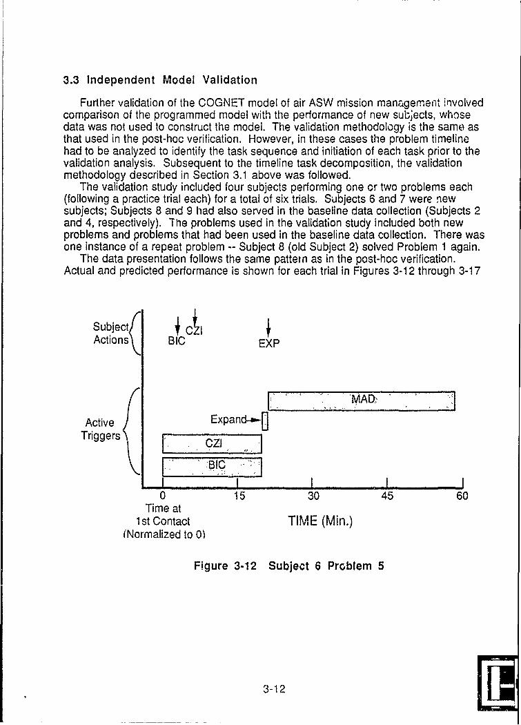
3.3 Independent Model Validation
Further validation of the COGNET model of air ASW mission management involvedcomparison of the programmed model with the performance of new subjects, whosedata was not used to construct the model. The validation methodology is the same asthat used in the post-hoc verification. However, in these cases the problem timelinehad to be analyzed to identify the task sequence and initiation of each task prior to thevalidation analysis. Subsequent to the timeline task decomposition, the validationmethodology described in Section 3.1 above was followed.
The validation study included four subjects performing one or two problems each(following a practice trial each) for a total of six trials. Subjects 6 and 7 were newsubjects; Subjects 8 and 9 had also served in the baseline data collection (Subjects 2and 4, respectively). The problems used in the validation study included both newproblems and problems that had been used in the baseline data collection. There wasone instance of a repeat problem -- Subject 8 (old Subject 2) solved Problem 1 again.
The data presentation follows the same pattern as in the post-hoc verification.Actual and predicted performance is shown for each trial in Figures 3-12 through 3-17
Subjects iA,Actions BIC EXP
Active Expand-a-DTriggers _Z_____.oz_, L_ _
0 15 30 45 60Time at
1st Contact TIME (Min.)(Normalized to 0')
Figure 3-12 Subject 6 Problem 5
3-12
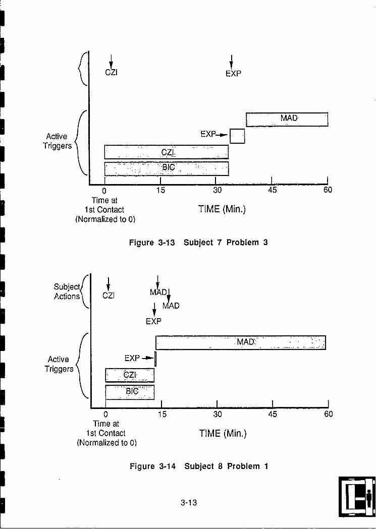
(C~zIEXP
MAD
Active EXP-- DTriggers _ _ "_"__
I I
0 15 30 45 60Time at
1st Contact TIME (Min.)(Normalized to 0)
Figure 3-13 Subject 7 Problem 3
Subject( DActions( CZI MAD
EXP
MAD"
Active EXP-"GTriggers ,
II III0 15 30 45 60
Time at1st Contact TIME (Min.)
(Normalized to 0)
Figure 3-14 Subject 8 Problem 1
3-13

Subject(O
Active ExP-- -LTriggers CZI
0 15 30 45 60
Time at1st Contact TIME (Min.)
(Normalized to 0)
Figure 3-15 Subject 8 Problem 6
SubjectfActions EXP
Active EXP - .7Triggers ,"
0 15 30 45 60Time at
1st Contact TIME (Min.)(Normalized to 0)
Figure 3-16 Subject 9 Problem 4
3-14

Subject fActions J
CZI UZI EXP
Active EXP-' Iii"ITriggers ___________________
BIC.I I III0 15 30 45 60
Time at1st Contact TIME (Min.)
(Normalized to 0)
Figure 3-17 Subject 9 Problem 6
Table 3-5 provides a tabular summary of the six trials. Table 3-6 summarizes databy subject; Table 3-7 by problem; and Table 3-8 by task.
Table 3-5. Validation Trial Data
Subj # - Prob # Number of Number of % of tasks Mean prediction leadtasks performed tasks predicted predicted (for predicted tasks)
Subj 6 - Prob 5 3 3 100% 4:077 3 2 2 100% 1:098 1 4 3 75% 2:058 6 3 3 100% 10:42 (2:16)9 4 2 2 100% 3:179 6 3 3 100% 10:10 (1:04)Total 17 16 94% 5:38 (2:27)
3-15

Table 3-6. Validation Problem Data
Prob # Number of Number of % of tasks Mean prediction leadtasks performed tasks predicted predicted (for predicted tasks)
6 3 3 100% 4:077 5 5 100% 7:25 (2:35)8 7 6 86% 6:24 (1:44)9 2 2 100% 1:09
Table 3-7. Validation Subject Data
Subj # Number of Number of % of tasks Mean prediction leadtasks performed tasks predicted predicted (for predicted tasks)
1 4 3 75% 2:05 (1:12)3 2 2 100% 1:094 2 2 100% 3:175 3 3 100% 4:076 6 6 100% 10:26 (2:04)
Table 3-8. Validation Task Data
Tasks Number of Number of % of tasks Mean prediction leadtasks performed tasks predicted predicted (for predicted tasks)
BIC 1 1 100% 3:14CZI 8 8 100% 9:19
1st CZI 6 6 100% 3:22EXP 6 5 83% 1:22MAD 2 2 100% 2:44
1st MAD 1 1 100% 1:39
3-16
In the validation study, a total of 17 task instances were performed. Sixteen ofthese, or 94%, were predicted by the model (p<.O01). The prediction lead timeaveraged 5:38 min for all task occurrences and 2:27 min for first task occurrences only.In this study only one task instance was not predicted -- it was an 'Expand Contact forContinuity' that was performed 0:28 min prior to the task being triggered by the model(Subj 8-Prob 1). By the less stringent criteria of including tasks performed within 2 minof the model triggering the task, all 17 task instances, or 100% were predicted.
The fact that model performance at least as good in the validation study as in thepost-hoc verification analysis indicates that the model has generalizable predictivepower. Examination of the cases in which the model did not predict an attention shiftprovides data for model elaboration to enhance its predictive power and predictiontimeliness.
3-17

4. MODEL APPLICATION TO INTELLIGENT COMPUTER-HUMANINTERACTION
This section discusses the approach and philosophy used to apply the COGNETmission management model to an adaptive interface for the ASW TACCO. Generalissues regarding the use of, and nomenclature for, cognitive models in user interfacesare discussed first. The functionality desired for the adaptive mission managementinterface is discussed next, followed by the interface system architecture created toimplement that functionality.
4.1 Model Based Human-Computer Interaction
The concept of using models of the human operator of a person-machinesystem to support the design process has been around for a long time. Traditionalhuman factors has long used behavioral models to support system design (e.g. Siegeland Wolfe, 1969). For example, the main purpose of task analysis is to develop amodel of the user and the user's requirements as a basis for system design and/ormodification. The idea of building and using models of the operator's cgnitiveprocess as a basis for system design is of more recent origin. Within this context,designers attempt to model the user's internal representation of the system and itsoperation, or "mental model", in order to design the interface to support the user'scognitive processes. It has come into increasing importance as human operator rolesin systems has moved from 'inner loop' physical control to 'outer loop' supervisorycontrol (see Sheridan and Johansen, 1976; Van Cott, 1985). Cognitive model-baseddesign approaches have been constructed and successfully applied by Rassmussen(1986), Zachary (1986,1988), Rouse (1981), Woods and Hollnagle (1986) and others.A previous report in this project (Zachary et al., 1989) discusses this issue in moredetail.
The use of mental models in interface design has suffered from a history ofconfusing terminology and conflicting claims. As noted in and Wilson and Rutherford(1989) and Dehdashdi (1989), the concept of mental model has been usedindiscriminately to refer to:
* the user's model of system,
* the system's model of user,
* the designer's model of user, and even occasionally to
" designer's model of the user's model of system.In this research, careful nomenclature is particularly important. The most widelyaccepted terminological framework for mental models in system design was put forthby Norman (1983). He defined a "mental model", in a person-machine system context,as the user's model of the 'target' machine system. In contrast, he used the term"conceptual model" to refer to the designer's representation of the 'target' system.Wilson and Rutherford (1989) added some terms to this definition to bridge thedesigner's and user's models. To complement Norman's conceptual model, theyadded the notion of a "designers conceptual model" as the designer's representationof the target system's user. They then distinguished the "user's conceptual model"from the "user's mental model the user's conceptual representation of the system asdefined in arbitrary terms.corresponds to the "user's conceptual model". The "user
4-1 9

mental model" described as the user's internal representation of the system, defined interms tied to psychological/cognitive theory. To this intricate set of distinctions we mustadd the idea of a "user model" as a designer's model of the user's mental model.
With th~se terms, the intended application of this research to interface design cannow be clearly stated. A COGNET model such as the mission management model,provides a mental model of the user. It represents the knowledge and procedures theuser employs to operate the system and to solve the specific domain problem. Themodel is expressed in terms tied to a specific general cognitive architecture (theformalized Pandemonium architecture) and notation. It is important to note that thisCOGNET architecture is based on the assumption that the user's internalrepresentation of the evolving problem context is critical to the problem solvingprocess. Thus, a main component of a COGNET model of the system user is theuser's representation of the problem being solved. This adds a distinction not widelymade in other literature on user's mental models, a distinction between the systemaspect of the model and the problem aspect of the model. To make matters even morecomplex, the uitimate goal is to embed the COGNET model into a human-computerinterface to allow the interface to interact more intelligently and adaptively with thehuman operator. Thus, we seek to translate the COGNET mental model of the userinto a design-oriented user model. The embedded COGNET user model, therefore,becomes the computer's model of the human operator of the system. This includes arepresentation of the user's mental model of the problem being solved as well as arepresentation of the user's mental model of the system itself and the procedures formanipulating it.
There are two general applications of user models in human-computer interfacedesign processes. The first and much more common one is as part of the analysis anddesign process. In this case, the user model forms the basis for critical aspects of thesystem design, ranging from control flow and data representation to functionality. Thedesign approaches suggested by Zachary (1988) or Rassmussen (1986) are detailedexamples of this use. In both methodologies, a model of the user's representation ofthe system is constructed first, and then analyzed to define feature of the system-underdesign and to guide critical design decisions. Similarly, Elkerton and Palmiter (1989)have used a user model of Hypercard programming (expressed in GOMS) to designan online help or training system as a way of enhancing the explanation or instructioncapability of an interactive system.
A second and more ambitious use of user models is to physically embed them inthe interface coupled with some additional reasoning apparatus. The interface canthen reason about the actions, goals, and plans of the user and to support, enhance,and adapt the human-computer interaction to the cognitive processes of the humansystem user. There are specific functions which an embedded user-model-basedinterface could perform in this vein. Croft and his colleagues at the University ofMassachusetts, for example (references) sought to emplc; an embedded model of theuser's planning process as a way of correcting errors and irconsistencies in userperformance.
Rouse et al. (i987) have used an embedded user model for intent inferencing in apilot's associate context. In an intent inferencing concept, the interface infers the intentof the user and adapts the interaction to that inferred intent. User models for intentinferencing have been applied in other domains as well, including simulated sattelighttracking (Rubin et al, 1988), and computer-aided engineering (Finegold, 1984).
4-2

4.2 Adaptive Interaction Functionality for the Mission ManagementDomain
In practice, the use of an embedded model in an interface application is not simplyan unconstrained design choice. The functionality possible from an embedded-user-model-enhanced interface is constrained by a tradeoff between three key factors --technology, need, and implementation factors. Of these three, need is the moststraightforward.
In any given RTMT domain, human operators exhibit different difficulties andproblems. For example, in Croft's accounting domain, the amount of detail to bementally managed by the user interacted with the complexity of the computer interfaceto lead to an increased number of errors and inconsistencies, many of which requiredremedial action. This, in turn, suggested to the researchers a need for interfacesupport via an embedded user model. In other more real-time domains, operatorinability to complete all desired or required tasks suggested a need for streamlined,more intelligent human-computer interaction via an embedded user model. Still otherdomains suggest other needs for intelligent interface support. It is critical to note thatthe need for an embedded user model at the interface is relative and dependent onspecific features of the domain and operator population involved. The determinationof need for intelligent interface support can be made on the basis of empiricalanalyses of person-machine system performance, by human factors task-analyticmethods, or by some combination of expert opinion and case study. For the Air ASWmission management domain, the experimental problem solving data provided a goodsource of empirical information on the need for intelligent interaction.
Technology provides a different set of constraints on the application of anembedded user model. Different notations and model structures facilitate some kindsof operations and inhibit others. GOMS type models, for example, are useful inpredicting performance in goal-directed interactions (John and Rosenblum, 1985), butfail to represent or support real time or multi-tasking domain features. In an idealworld, there would be a clear mapping of user modeling technologies to classes ofneeds (similar to that provided by Zachary, 1986, for decision support technologies),but at present no such classification exists. Thus, the technology used to model thesystem user limits the kinds of support that could be added to the interface throughembedding the user model into an interface.
Finally, implementation issues will always be an important consideration. Sometypes of need may be met only with great cost and difficulty, while others can beachieved with much less effort. This issue is intertwined with the organization andstructure of the baseline interface into which the user model (and associatedfunctionality) is to be embedded.
A specific set of adaptive interaction functions for the Air ASW missionmanagement interface was chosen against the backdrop of these tradeoffs. It shouldbe noted that, as a research effort (albeit as an applied one), our goal was todemonstrate the application of COGNET to adaptive human-computer interaction. Aparallel interest was to identify and address a real need of the Air ASW domain withinthe constraints of the implementation costs and the technology range of COGNET.
A complete analysis of operational deficiencies in Air ASW decision-making wasclearly beyond the scope of this effort. Nonetheless, several issues surfacedrepeatedly in the experimental data collection efforts. One was a delay in respondingto task opportunities. Operators often needed several minutes to initiate a task after
4-3 l

conditions were appropriate for its execution. These were usually clear during theverbal protocols taken during problem replays, when subjects would make suchcomments as "I could have started to make a MAD run [or some other task] here, but Iguess I didn't realize that until later on." In other cases, operators failed altogether torecognize a tactical opportunity because they were focusing on only one or twohypotheses. (Schmidt and Goodson, 1990, show more detailed and compellingexperimental data supporting this tendency to focus on only a small number ofhypotheses in Air ASW). Taken together, these problems suggested one opportunityfor use of the embedded model -- alerting the user to conditions where a specific taskexecution is appropriate. This use would address the first issue (delayed recognition)directly. Moreover, given the results of the attention flow validation cited above, (i.e.,the anticipatory capability of the Air ASW model), the model could be re-sonablyexpected to achieve this goal. This user model in the interface would also address thesecond issue, although indirectly. By alerting the TACCO to opportunities to perform atask, the interface would occasionally identify a task opportunity that the TACCO hadmissed, because the opportunity was triggered by a hypothesis that the TACCO wasignoring. Such an alert could force the TACCO to expand his decision strategy toinclude the hypotheses implied by the interface's recommendation. Task-level alertingwas thus chosen as the first function of the model-based interface.
A second set of interrelated issues also arose from the experimental datacollection. These dealt with certain kinds of errors and omissions made by theoperators during the experiments. Many actions in the Air ASW domain must betailored on the basis of some aspect of the operator's mental representation of theproblem context. Most sonobuoy pattern deployments, for example, are laid outrelative to some abstract anchor point such as primary contact buoy, or expected axisof target movement. All operators were observed to make errors in translating theirmental representations into physical actions in the complex TACCO interface. That is,the operator may have 'known' that the primary contact buoy was buoy 14, butnonetheless based the pattern on the nearby buoy 15 (particularly when neither hadcontact at the time) by mistake. Such errors were particularly insidious, because theyappeared to be correct, and resulted in patterns that had some limited value. Thismasked the original error lead the operator to propagate it forward. A seeminglydifferent class of errors of omission resulted when operator's truncated tasks orignored them because of time limitations. There were many cases where details oftasks were omitted to save time in a time-critical part of the missions, and where theseomissions later came back to 'haunt' the future prosecution of the target.
Together these two issues suggested a second adaptive interface function, taskaiding. That is, the interface would assist the TACCO in performing any tasksuggested by the alerting function outlined above. The detailed model of the task fromthe COGNET model would be retrieved and instantiated using the current blackboardcontents. The user could then have the interface perform any part of the task in anautomated or semi-automated mode, including the parts of the task which requiredreference to the current mental representation of the Droblem. To the extent that theblackboard contents are an accurate representation of the TACCO's mental model ofthe problem, the interface should be able to perform those representation-specificactions more accurately than the human TACCO, since it is invulnerable to thosereferential or translational errors which seem to give rise to the human 'slips.'Similarly, this function would allow the interface to speed execution of those tasks,thus also addressing the problem of time-constrained task performance.
4-4 0

These two functions represented areas of reasonable need for the problem domainand were within the technological range of the COGNET representation. They werealso amenable to implementation within the scope of the current effort. The nextsect-on discussed the architecture and interface implementation used to realize thesefunctions in an adaptive ASW Mission Management Interface.
4.3 COGNET-Based HCI Architecture
Accomplishing the functionality defined above required development of a noveland sophisticated architecture for the human computer interface. This architecturebuilt layers and tools for embedded user models and adaptive interaction on top of thebasic displa-,s and controls components of the baseline interface in the MissionManagement experimental environment (as described in Zachary and Zubritzky,1988). The architecture is shown in Figure 4-1. Five separate parts of the COGNETmodel were extracted and programmed into distinct components in this extended HCIarchitecture. They were added to and integrated with the Air ASW experimentalenvironment. This environment linked a simulated Air ASW environment with anemulated TACCO workstation with separate display and control software. The addedcomponents formed two distinct adaptive interaction subsystems.
The first subsystem monitored the interactions between the user and theworkstation and used pieces of the COGNET user model to interpret and simulate theuser's problem solving state inside the interface. Within this subsystem, the perceptualdemons in the model were programmed to constantly review the display contents forevents that would trigger perceptual events. When such events were detected, theperceptual demon would execute itself, resulting in the POSTing of information onprogrammed representation of the blackboard structure. In addition, the purelycognitive components of individual task models were extracted from the overall set oftask models and programmed. These cognitive extracts consisted of attention triggersand the associated POST/UNPOST operations (with their attached executionconditions). Thus, as the perceptual demons began to populate the blackboard datastructure with information, the patterns would begin to match triggers for cognitiveactivities, which would then execute themselves and further transform the blackboardcontents. In several cases, it was necessary to link the cognitive task triggers withextended conditions that included both blackboard patterns and observable useractions. For example, the cognitive portions of the Develop Target Fix task would beallowed to execute until the embedded user operation -- the user's placement of atarget fix symbol on the display screen -- was also observed by the interface. In thisway, the cognitive task components, (POST/UNPOSTs, and perceptual demons)simulated the system user's cognitive processes. Moreover, this model was linked tothe evolving problem context and observable user behavior.
The second subsystem within the adaptive interface used other aspects of theCOGNET model to provide the adaptive interaction functions identified above. Theattention triggers for each of the tasks in the COGNET model were each programmedseparately and placed into a loop in which they monitored the (constantly changing)blackboard contents. When any of them detected a pattern that matched theirtriggering conditions, they formed a 'hypothesis' that the user's intent would be tobegin executing the corresponding task as soon as possible. When multiple triggersdetected their triggering patterns on the blackboard simultaneously, they consulted apriority map to establish a (partial order) among these hypotheses. This can beviewed as similar to what Rubin et al (1988) and Rouse et al (1987) have termed inter '
__4-5 a

inferencing. As new task hypotheses were formed, they were then used to form alertsto the user that the execution of that task might be appropriate (thus providing the tasklevel alerting function). When the partial ordering was able to define a precedenceamong concurrent task hypotheses, it was use to 'stack' the task-execution alerts inorder of decreasing priority.
Problem
Simulation
aWorkstation Embedded User Model Subsystem
Tactical PerceptualAdaptive Interaction Subsystem Displays Demons
i' ,"> "ControlsTask ,,-, ,," ;:;. ,-- -- -, Cognitive
____ ___ ____ ___ ____ ___ ____ ___ ___ Blackboard
Figure 4-1. Architecture for User-Model Based Adaptive HCi
Any active task hypotheses would be displayed to the TACCO. The TACCO couldinteract directly with the hypothesis symbol to obtain a display of the subgoal structureof the task, as represented in the COGNET model of that task. These provided adecision structuring function for the user (see Zachary, 1986), by indicating the logicalcomponents of the task. The subgoal structures were retrieved from an executablerepresentation of the task-level COGNET model for the task. The model wasprogrammed in executable form, to allow the interface to automatically perform any orall of the subgoals listed for a task. The interface would respond to TACCO requestsby retrieving and executing the description of the part of the task model thatcorresponded to that subgoal. It is important to note that in most cases, thisinstantiation of a subgoal procedure required use of current problem context, asrepresented on the blackboard data structure. For example, when the user needed to'draw environmental features' as part of a task, the interface would use the blackboardrepresentation to infer which features were relevant, and which reference point(usually a specific sensor) to use in drawing them. Thus, the blackboard structure wasintegral to the context sensitive aiding and task automation provided by the adaptiveinterface. The implementation of this architecture is discussed in the next Section.
4-6

5. IMPLEMENTATION OFTHE ADAPTIVE MISSION MANAGEMENT INTERFACE
The proof of the pudding, as the old saying goes, lies in the eating. And so thevalue of COGNET as a vehicle for embedded user models must lie in the ability to linkthe model to a human-computer interface in a way that enhances the performance ofthe human operator as well as the larger system being controlled. This sectiondescribes the adaptive extensions to the existing ASW TACCO human-computerinterface that were developed to demonstrate the applicability of the ability of theCOGNET model. These extensions provide the general intelligent and adaptiveinterface functions defined in Section 4, as well as implement the architecturepresented there.
The interface, as developed, performs four specific adaptive functions:1 Provides reminders or alerts to the user when the system believes the
context is appropriate for initiation of or return to a specific task in theCOGNET task network;
2 Indicates the expected priority or order of precedence of the tasks, whenmultiple tasks are inferred as appropriate;
3 Provides decision structuring assistance, on user request, by identifying theinternal organization of goals/subtasks within any given task identified asappropriate for initiation; and
4 Offers automated performance of any or all of the subtasks in a taskidentified as appropriate for initiation, with the task instance adaptedautomatically to the interface's understanding of the problem context.
These are not the only ways in which an embedded user model could be applied toenhance computer-human interaction. Rather, they represent an initial demonstrationof how a COGNET user model could be applied to extend user interface capability inimportant ways.
5.1 Screen Design and Layout
In practical terms, it would be an enormous improvement over current interfacetechnology if the system could simply be given access to an approximation of the task-specific, user's mental representation of the problem, and could use this to adapt theinterface to the state of the user's problem solving process and current decisionmaking needs. These were the goals of the initial application of the COGNET model ofvehicle tracking to enhance the existing HCI used in the initial vehicle trackingsimulation.
The actual screen design was guided by a philosophy of minimal intrusion. Anattempt was made to minimize the actual visibility of the adaptive interaction functionsto t he user relative ft the rr-,victi n inftrfo,- This miw S rinn heca, se the intentionof the adaptive interaction functions was to streamline and simplify the interaction withthe underlying system. The baseline system was, on the one hand, integral to experto; aratoes problem-solving procedure. It was difficult for them to separate theirknowledge of their current system and its interface from their knowledge of how tosolve Air ASW problems. This is quite reasonable since the system and its interfaceconstitutes their view into the ASW world and their only capability to solve problems in
5-1 9

that domain. Thus, changing the baseline interface in a fundamental way wouldrequire potentially substantial re-learning efforts. On the other hand, the functionalitypresent in the baseline interface represents the capabilities of the underlyinghardware/software/electro-mechanical systems that interact with the submarine andoceanographic world. These basic functions cannot be changed without rendering theentire problem moot to both the user and this research. Thus, the only reasonableapproach was to build the adaptive interface features 'on top of' the existing interface,but in a highly transparent way, so that:
• the user's pre-existing knowledge about system use was not vitiated,* the system's underlying functionality was not compromised, and" minimal additional interaction demands were created by the adaptive
interface functions.The organization of the baseline interface to the TACCO station in the experimental
environment is shown in Figure 5-1. The majority of the screen is occupied by a
Time Scale
ARO
TACTIA DSLY
Alert
Status Info
Cueing
Verification
Soft Buttbn Panel
Figure 5-1. Baseline Interface Organization
spatial -.Acal plot window, with TACCO control functions implemented as 'soft'buttons . the bottom of the screen. The extreme left side of the display was used todisplay an alphanumeric read out (ARO), plus additional windows for making menr "
5-2 Ili

selections associated with specific soft button functions. The full interface to theexisting TACCO station, and its emulation in the experimental environment used in thisstudy is discussed in Zachary and Zubritzky (1988). The adaptive interfacemodifications were designed to be as unobtrusive as possible within this basic screenlayout.
The basic configuration for the adaptive interface extensions is shown in Figure 5-2. The ARO windows have been moved to an auxiliary alphanumeric display screen(actually making it more like the real workstation). In their place, two aiding windowswere added. The top is an alerting window, where task hypotheses are displayed asthey are triggered. The hypotheses are labeled to the user as "SUGGESTEDSTRATEGIES". This is to avoid any implication that the computer is controlling theinteraction or is dictating behavior to the user. Any such approach was certain to meetsubstantial resistance among the user community.
Suggested StrategieAlert &Priority Ts
WindowW
Task ASubtaskl
SuppoSubtask2
Window Subtask3Subtask4
,< ' ' ."* ,.. '", MenuA"", w " Selection,,,,, .: .... Window
External Terminal ,C , ( ' , . C, ..C,,C .,," :.., ',
'Soft' Buttons for Graphic Functions
Figure 5-2. Adaptive Interaction Layout
As new hypotheses are triggered, the list may spontaneously reconfigure itself, tomove some active hypotheses to higher (or lower priority), or to remove them as theirassociated blackboard patterns disappear. Within the "SUGGESTED STRATEGIES"u ,inm,, the user may slet a n tansk name hy nling the cursor over the nnm andi
clicking the mouse button. At that time, a display is created, in the window immediatelybelow it, of the subgoal structure of that task. This window is labeled to the user onlywith the title of the chosen task from the Suggested Strategies window.
The user may simply review this structure as a sort of procedural checklist, keepingit displayed as the task is performed manually, or the user may close the windowdirectly and focus on a different task. The user can also interact directly with the item
5-3

listed in this window. Any subgoal in the window can be selected (again, by byplacing the cursor over the name and clicking the mouse button). Once selected, theinterface will execute that subgoal, following a confirmation by the user.
5.2 Implementation
The initial implementation of the mission management adaptive interface wasundertaken as a demonstration of COGNET as a technology for supporting adaptiveinteraction. Therefore, only a subset of the full COGNET model was used. This subsetmodel consisted of the full blackboard structure (i.e., both panels and all levels withinthose panels), all perceptual demons, but only five of the 14 cognitive tasks. Thesefive were:
• Identify Area of Interest* Broaden Initial Contact° Investigate Convergence Zones,* Expand Contact for Continuity, and* Maneuver Aircraft for Magnetic Anomaly Detection (MAD)
These tasks were selected for different reasons.
The first of these tasks, determine area of interest, is a purely cognitive task. It hasno behavioral operators within it. It consists of a complex goal/condition structure andPOST/UNPOST operators. The mental operations in this task are essential to theproper building and maintenance of the blackboard structure, making this taskessential for successful implementation of the "embedded user model" subsystem ofthe interface (see Figure 4-1 above). This task comprised a major part of the"cognitive task components" module in the adaotive interface architecture. Because ithad no behavioral component, it was not included in the adaptive interactionsubsystem. That is, tha interface made no attempt to alert the user of situations wherethis task should be performed or to assist the user in performing it.
The other four tasks, on the other hand, were selected only for inclusion in theadaptive interaction subsystem. They were chosen because they:
° represent different phases of the mission, with 'Broaden Initial Contact' and'Investigate Convergence Zones' (usually) occuring early in a prosecution,and 'Expand Pattern for Continuity' and 'Maneuver Aircraft for MAD' usuallyoccuring later in the prosecution; and
o within these phases, these tasks often compete for attention, thus providingan opportunity to demonstrate both the alerting and the task prioritizationfunctions in the interface.
The adaptive interface architecture discussed in Section 4 was implemented in thecontext of the ASW mission management experimental environment (Zachary andZubritzky, i988). The organization of the experimental environment is shown here inFigure 5-3. The full environment supports scenario/problem development, interactiveperson-in-the-loop simulation of ASW mission management problems, and recordingand analysis of problem data. In this phase of the research only the interactivesimulation or testbed portion of the environment was of interest. The ASW missionsimulation and emulated TACCO workstation from the experimental environmentprovided the "problem simulation" and "workstation" components of the architecture i
5-4

Interactive DataSimulation Mission Analysis
Trial Simulation ProgramParameters I E x p e ri -
Desg StoredDesign .=i Experi-Program -mental
-,_,,. ... ; = = ==.,,= ,.,.== =,,.%, ,Data
Experi- Library of Datamental Partial Catuin
Problems & Mission FailtScenarios Evolutions
Figure 5-3. Experimental Environment Organization
5-5

Figure 4-1. Thus only the components shown as the embedded user modelsubsystem and the adaptive interaction subsystem had to be added. These pieceswere programmed as discussed below, all in the C language as used in the remainderof the experimental environment.
Although the present implementation was intended as a technology demonstration,care was taken to create a set of tools that would support the efficient implementationof the current version of the adaptive interface as well as later extensions to the fullsystem model. Key to this development environment were blackboard-relatedsoftware tools. The blackboard panels in a COGNET model are extremely complexentities which must be mutable not only during execution in an adaptive interface, butalso during the course of software development. This is because efforts atimplementation of a model point out hidden ambiguities, conflicts, or omissions,requiring further model revision. Thus, it was necessary to allow for blackboardstructure redefinition during the implementation process as well as blackboardcontents modification during execution. To do this, we developed a language todefine the blackboards which could be used by the model-builder.
The language incorporated the concept of hierarchical layers of items on levelswithin the blackboard. Each hierarchical layer was addressed by a user-defined name(see the example definition in Table 5-1), in order to make the definition of all the
Table 5-1. Example Blackboard Definition
BLACKBOARD SituationLEVEL mission_factors
ITEM missionfactors environment CURRENT ARRAY OF 2 INTEGER;DEFINE NUMBERCZS BOITOM_BOUNCE;
ITEM missionfactors envir..param CURRENT ARRAY OF 5 INTEGER;DEFINE DIRECTPATH CZIINNER CZIOUTER CZ2_INNER CZ2_OUTER;
ITEM missionfactors buoyresources CURRENT ARRAY OF 2 INTEGER;DEFINE NUMBER-DIFAR NUMBERDICASS;
ITEM mission-factors mission_time CURRENT INTEGER;ITEM missionfactors mad.range CURRENT FLOAT;ITEM missionjactors mad_ceiling CURRENT INTEGER;ITEM missionjactors radar~jange CURRENT INTEGER;ITEM missionfactors active.mdr CURRENT FLOAT;
LEVEL expectationsITEM expectations contacLexpectation HISTORICAL ARRAY OF 3 INTEGER;
DEFINE EXP_BUOY ID EXPBUOYTIME EXPBEARING;ITEM expectations captureftp_..expectation HISTORICAL ARRAY OF 2 INTEGER;
DEFINE EXP_FTP_ID EXP._FTP_TIME;ITEM expectations arriveexpectation HISTORICAL ARRAY OF 4 DIFFERENT:(FLOAT INTEGER INTEGER INTEGER);
DEFINE ARRIVERADIUS EXPARRIVE TIME ARRIVEX ARRIVEY;LEVEL patterns
ITEM patterns search-pattern CURRENT ARRAY OF 6 INTEGER;DEFINE S_PATTERNID S_PATTERNTYPE SPATTERNCENTERXS_PA'ITERNCENTERY S PATIERN NUMBUOYS S Pr'A iiR,'_.ST TUS;
ITEM patterns referenLpattern HISTORICAL ARRAY OF 6 INTEGER;DEFINE R_PATIERNID RPATTERNTYPE RPATTERN-BUOYR_PATrERNREFERENTX RPATTERNREFERENTY RPATTERNSTATUS;
5-6

cognitive information groupings more readable to the model-builder who was definingthe POSTING and TRIGGERING mechanisms. This blackboard definition linked to aparser that translated tne high level blackboard definition language into the defineddynamic blackboard data structure. The parser was constructed using the UNIXutilities YACC and LEX. This simplified the modification of blackboards duringdevelopment. Experimenting with different cognitive structures brought about manyenhancements and refinements to the structures and their interactions with theenvironment. It also supported an iterative process of model development, interfaceimplementation, and model refinement.
The execution-time operation of the adaptive interface revolved around the multi-panel blackboard that represented the TACCO's mental model of the problem beingsolved. The blackboard is a highly dynamic entity. One of the distinctions inblackboard structure that emerged primarily in attempts to implement the baselineCOGNET model was a distinction between blackboard items or messages that aretransient and items or messages that are historical. This refereed to the fact that somekinds of reasoning embedded in the various task models refereed to recent rather thancurrent blackboard contents, and in some cases required access to an entiresequence of messages posted in a specific slot on the blackboard. A good example isthat of compensating for bearing shift. In several tasks, the user must reason abouttarget location or sonobuoy pattern location. Typically, such reasoning is based oncontact messages posted on the blackboard. When there is little movement orrandom fluctuation in the contact bearing line, the reasoning is straightforward. But inmany cases, a locational hypothesis or pattern reference point must be slewed orbiased to compensate for perceived systematic movement in the bearing data. Suchreasoning requires more information that just the current bearing message posted onthe blackboard. It requires the recent history of behavior of that bearing. Thus, it wasdiscovered that some blackboard message types need to carry historical values, whileothers need only current problem data.
To accommodate this need, two basic types of structures were included in theblackboard: HISTORICAL and STATIC. When a message is POSTed to a STATICitem, the current message in the item is simply replaced with the new message beingposted (there is no memory of the previous message). When a POSTing to anHISTORICAL item, the new message group is created and placed at the head of thechronologically linked group of messages which had preceded it. Additional softwaremechanisms were then developed to support pattern matching with this HISTORIALtype of black board entry. These tools allowed the model-builder to search theblackboard (level and item), from most recent to least recent, looking for the messagegroup which matched the necessary criteria. The model retrieved information whichhad been stored previously by the user. When an UNPOSTing or a TRANSFORM isperformed on an HISTORICAL item, the model would request a search based on oneor more desired matching values in the message, or could ask to have the operationperformed on the most recently posted message. Data on the blackboard is thereforelinked in cognitive groupings (message groups) and in lime orieniation (memorystack). UNPOSTing a message group makes it unretrievable by the model.
At execution time, all blackboard manipulations are done through a blackboardhandler. To TRANSFORM HISTORICAL entries, for example, the blackboard handlersearches through the historically maintained list of values to find the one whichmatches the exact set of requirements, and makes the requested changes. If no
5-7

matching value exists, it returns a message to the calling routine stating that no matchwas found.
The blackboard contents are manipulated from two sources -- the perceptualdemons and the cognitive task components (see Figure 4-1). In a real-worldimplementation, the perceptual demons would be true spontaneous computationelements, operating in a closed loop examining the contents of the user's displayscreen and firing themselves based on new events that matched their 'firing'conditions. In this testbed implementation, however, a shortcut was taken, at no loss ofgenerality to the overall model. Specifically, each perceptual demon was linked to thesoftware event that would generate a display change of the type sought by the demon.Thus, for example, the demon that sought a new DIFAR contact was embedded in thedisplay routine that created new DIFAR contacts, effectively firing the demon everytime that display event occured.
The cognitive task components consisted of sequences of POST/UNPOSToperations organized into logical groups (corresponding to task-model subgoals).Each group was predicated on a specific blackboard pattern, and its execution wassometimes further conditioned by the specific blackboard contents. The POSTing ofvarious areas of interest from a new contact message is an example. These weregroups of operators corresponding to subgoals in the Identify Area of Interest task fromthe COGNET model. Each subgoal was tied to a blackboard condition, e.g., "any newDIFAR contact". All such groups were evaluated for execution in a closed event loop,by suitable calls to the blackboard handler. When a sought-after pattern was found bythe handler, the associated POST/UNPOST operations were allowed to execute,again interacting with the blackboard through the blackboard handler.
The preceding parts of the implementation all concerned the embedded usermodel subsystem. All remaining portions of the interface implementation concernedthe adaptive interaction functions. These include the attention triggers and taskmodels.
Attention triggers are the model component which compared the blackboardcontents against the conditions associated with each task in the COGNET model, andalerted the user each time a task's execution conditions were met. In doing this, thetrigger uses the blackboard contents as an approximation of the user's mental modelof the problem situation. Two sets of conditions were necessary for each trigger -- thecondition which would trigger the cognitive task, and the trigger which would cancelthe cognitive task. Both were expressed as blackboard patterns, and were evaluatedusing calls to the blackboard handler. It should be noted that in these cases, theblackboard access was 'read only', in contrast to the embedded user modelcomponents described above, which could modify blackboard contents as well.Triggers were checked explicitly by the model when appropriate.
When a given attention trigger was satisfied (i.e., found its desired pattern on theblackboard), two events occurred. First, the associated task name was displayed inthe "suggested strategies" window in the interface (see Figure 5-2), and second, thetask model component was activated. These task models are the second portion ofthe adaptive interaction functions. The model had two ieveis. The first was a listing ofthe set of subgoals involved in that task, based or, the COGNET model of the task.When the the task name was selected from the "suggested strategies" window, thesubgoal structure would be displayed to the user in the task support window.
The behavioral activities associated with each task subgoal were also coded as C-language operations and linked with the displayed subgoal in the task support
5-8

window. By selecting and invoking the displayed subgoal, the user could invoke codethat performed the behavioral operations. In most, if not all cases, however, the taskcould not be carried out without reference to some inferred aspect of the situation,which was represented in the blackboard structure. The task-automation routineswould, therefore, adapt their execution to the user's inferred mental model of thesituation, as contained in the blackboard structure. For example, the task InvestigateConvergence Zones, is meaningful only with regard to a specific buoy contact. TheInvestigate Convergence Zones subtasks are able to infer the proper reference buoyfrom the blackboard model, and proceed without further intervention from the user, viacalls to the blackboard handler. Thus, these are not simple 'task automation' routines,but complex adaptive automation routines which use the embedded user model tocontextualize their execution.
Two types of data recording output were also included in the implementation. Alltransactions on the blackboard were reported in blackboard.log file. All the activity ofthe triggers and the user relative to the triggers, tasks, and subgoals was reported inanother file called the 'trigger file'. The trigger file was a strict chronological orderingof trigger on/off events and times, and subgoal selections by the user. These wereused in the model validation experiment described in Section 3 earlier.
5.3 User Interaction
The actual content and style of interaction afforded by the COGNET-basedinterface is best understood through an example. This section describes a sequenceof interactions between a user and the ASW experimental environment workstationaugmented by the adaptive interaction capabilities described above. The example isbased on one of the experimental problems created for the experimental datacollection phase of this project (see Zachary et al, 1989).
The problem facing the TACCO is to gain contact and prosecute a hostilesubmarine believed to be transiting in a specific open-ocean area. A summary of thepre-flight information is shown in Table 5-2. It is presumed that some mission planningaid (either on-board the aircraft or at the operations center) has developed a plan foran initial search pattern of sonobuoys, in this case a line or barrier pattern. When theaircraft arrives on-station in this (simulated) mission, the TACCO begins to deploy therecommended line pattern. After deploying the first eight sonobuoys, he gains areliable contact on the sonobuoy using channel 07. The Sensor Operator hasclassified this contact as likely hostile.
While these events are occurring, the adaptive interface software, has beenPOSTING information on the blackboard beginning with the pre-flight information (i.e.,Table 5-2) and continuing through the partial deployment of the search pattern and theinitial contact. This blackboard information pattern is sufficient to trigger two of the fourtasks included in the initial adaptive interaction subsystem. These are the 'BroadenInitial Contact' and 'Investigate Convergence Zone'. These tasks are initiallydisplayed in the "suggested strategies" window of the workstation momentarily afterthe stable contact is gained. The 'Investigate Convergence Zone' task has beenassigned an implicit priority lower then the 'Broaden Initial Contact' so that the latter isdisplayed first in the suggested strategies window, and the former below it. Thissituation is shown in the screen snapshot in Figure 5-4.
The TACCO next decides to break off deploying the search pattern, and thusremoves the fly-to-points associated with it. (These are part of the 'DeploySensor/Pattern' task in the overall model, but this task is not included in the initial
5-9

Mission: Detect, Localize, and close Track target submarine. Target is currentlytransiting southwesterly enroute to onstation. Attempt to gain and maintain attackcriteria.
Area: Operating area is 200 NM around datum
Altitude: Unrestricted
Relieve: None
Relief: None
EMCON: Unrestricted
Intel: Latest datum (center of pattern) is a ten hours old at comex. The centerof the cold pattern is 120 NM ahead of the lact datum at a heading of 225T. The coldpattern covers a target MLA of 200T - 230T and an SOA from 12 - 8.5 KTS.
Tactics: Search pattern is a 16 buoy barrier pattern oriented at 135T with a buoyspacing 4 NM. Buoys are set deep and have a three hour life.
Environmentals: Previous events have been reporting direct path contact out to 3NM and a CZ at 29 NM with a width of 2 NM.
Surface Temperature 55FLayer Depth 150 FTSea State 3Ambient Noise 85 HZDepth Excess 400 FM
Target Data:
Predominate Frequency 500 HZSource Level 160 dBRD -5 dBFOM 80 dB
Detection Ranges:MDR CZ1 CZW CZ2
Target/Source above layer 2.5 29 2Target/Source below layer 3 29 2 --
Target/Source cross layer 2 29 2
Buoy Load: 17 DIFAR7 DICASS
Weapons: 4 MK-46
Table 5-2. Summary of Preflight Information
5-10

TAC stto euao
SUGGESTED STRATEGIES
BROADEN INITIAL CONTACTINVEST IGA7E CONVERGENCE ZONES
88IS 64
AC: 588PFT 2l6XT;
DESIG FTP INEI T ~~ ~ ODDSR EI I RWCRL RWLN ENR ETDT
OWER CAS ClltL CASS P14 AS DEPLOY BUOY -WEAP SE-L -- IrDISARPM WEA-P- DEPLOY 7W-EAP A PTL RAA R
Figure 5-4. Initial Task Triggers Are Fired
5-11
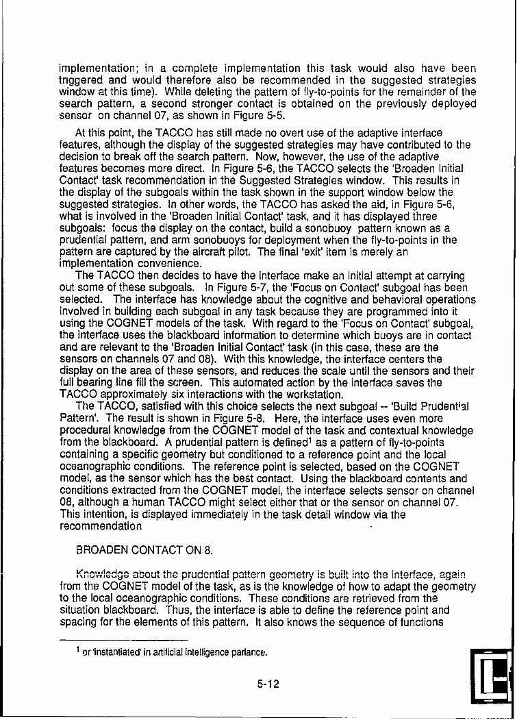
implementation; in a complete implementation this task would also have beentriggered and would therefore also be recommended in the suggested strategieswindow at this time). While deleting the pattern of fly-to-points for the remainder of thesearch pattern, a second stronger contact is obtained on the previously deployedsensor on channel 07, as shown in Figure 5-5.
At this point, the TACCO has still made no overt use of the adaptive interfacefeatures, although the display of the suggested strategies may have contributed to thedecision to break off the search pattern. Now, however, the use of the adaptivefeatures becomes more direct. In Figure 5-6, the TACCO selects the 'Broaden InitialContact' task recommendation in the Suggested Strategies window. This results inthe display of the subgoals within the task shown in the support window below thesuggested strategies. In other words, the TACCO has asked the aid, in Figure 5-6,what is involved in the 'Broaden Initial Contact' task, and it has displayed threesubgoals: focus the display on the contact, build a sonobuoy pattern known as aprudential pattern, and arm sonobuoys for deployment when the fly-to-points in thepattern are captured by the aircraft pilot. The final 'exit' item is merely animplementation convenience.
The TACCO then decides to have the interface make an initial attempt at carryingout some of these subgoals. In Figure 5-7, the 'Focus on Contact' subgoal has beenselected. The interface has knowledge about the cognitive and behavioral operationsinvolved in building each subgoal in any task because they are programmed into itusing the COGNET models of the task. With regard to the 'Focus on Contact' subgoal,the interface uses the blackboard information to determine which buoys are in contactand are relevant to the 'Broaden Initial Contact' task (in this case, these are thesensors on channels 07 and 08). With this knowledge, the interface centers thedisplay on the area of these sensors, and reduces the scale until the sensors and theirfull bearing line fill the screen. This automated action by the interface saves theTACCO approximately six interactions with the workstation.
The TACCO, satisfied with this choice selects the next subgoal -- 'Build PrudentialPattern'. The result is shown in Figure 5-8. Here, the interface uses even moreprocedural knowledge from the COGNET model of the task and contextual knowledgefrom the blackboard. A prudential pattern is defined1 as a pattern of fly-to-pointscontaining a specific geometry but conditioned to a reference point and the localoceanographic conditions. The reference point is selected, based on the COGNETmodel, as the sensor which has the best contact. Using the blackboard contents andconditions extracted from the COGNET model, the interface selects sensor on channel08, although a human TACCO might select either that or the sensor on channel 07.This intention, is displayed immediately in the task detail window via therecommendation
BROADEN CONTACT ON 8.
c~u ~ t~ % +ir ~ % Y o yi ,gl mnr% ho n rf no' nri n
,& I U Yvv1K Av v "AIJ%JUL Lit V I %. jJ I H~ k II ~ I S, h/ I$L - LW *I~ * k- " W.. - -
from the COGNET model of the task, as is the knowledge of how to adapt the geometryto the local oceanographic conditions. These conditions are retrieved from thesituation blackboard. Thus, the interface is able to define the reference point andspacing for the elements of this pattern. It also knows the sequence of functions
or 'instantiated' in artificial intelligence parlance.
5-12
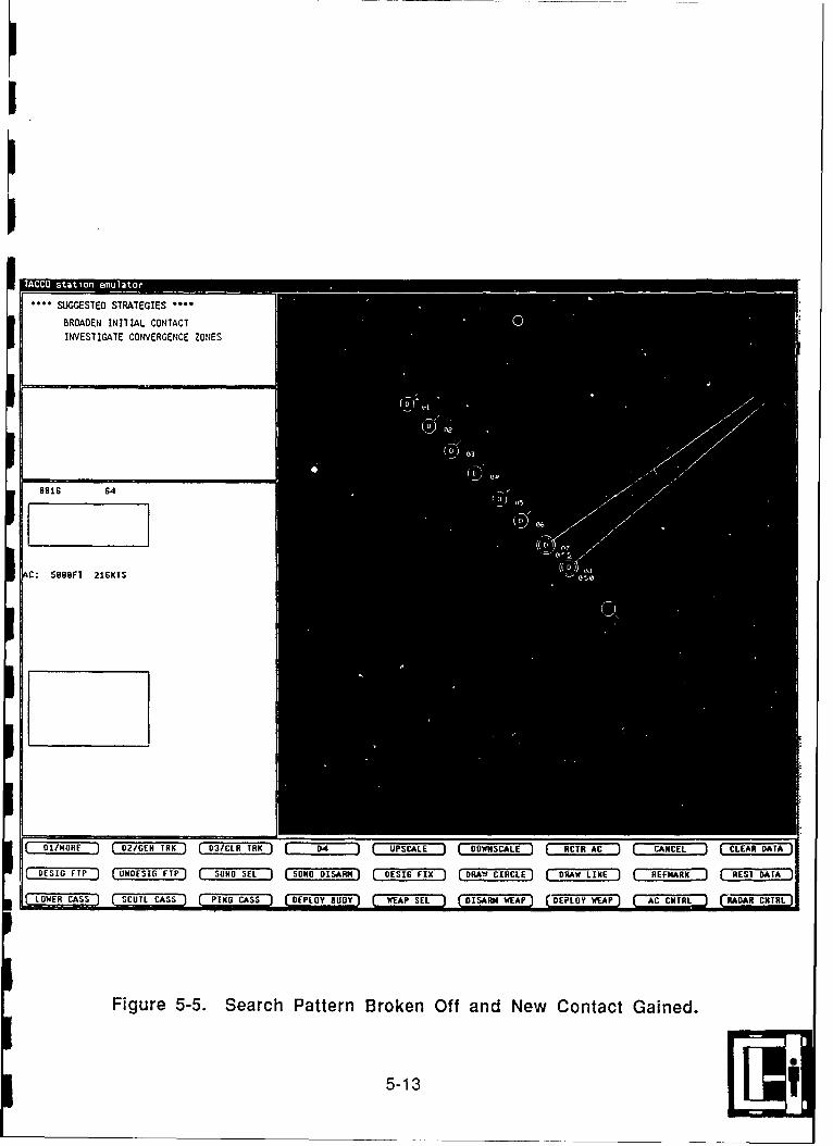
...SUGGESTfED STRAT[EGIES ""
BROADEN INIIA L CONTACT SIWVESIIGAIE COINERGENCE ZON(ES
691G 64
C: 5888FT 21GKI$
01MR 2GE R 3d IR . UPSCALE D oW.scA.L ) R CTR, AC CANCEL CLEAOR AT
D ESIG FTP ) UNDESIG FTP) SON EL SONO DISARM} 065ES6 FIX ) DRAW CIRCLE) ,.DRAW LINE ) REFUARK REST DATA J
iA
LOWR CTS SCUI ATS PIG CS (DEPLOY BUOY) WA 6 IAMWA DEPLOY FWEAPI A HR AA NR
Figure 5-5. Search Pattern Broken Off and New Contact Gained.
5-13

TAC staineuao
SUGGESTED STRATEGIES
INVESTIGATE C0ONVERGENCE ZONES
BROADEN CONTACT ONO 8 locus on ContactBuild Prudential Patt,Arm BuoysExit
C: S888FT 216KTS
Figure 5-6. Subgoal Structure of "Broaden Initial Contact" Displayed.
5-14

INVESI IGAIE CONVERGENCE ZOtNES
BROADEN CONTACT ON 0
ui aruaetiaPattq
Exit
8916 32
AC: 5888FI 216K1S
M1.1 o
IINrORE 02 GEM IRK D 3/CLR IRK I 4 )[ UPSCALE ][DOWNICALE'I RCTR AC [ CANCEL ] CLEAR DATA ]
DESIG FTP UNDESIG FTP SONO SF1 SONDI SARy DESIG FIX DRAW CIRCLE DRAW LINE REFIARK REST DATA
LOWER CASS SCUT CASS PING CASS DEIPLOY IUDOY rWEA P-1SEL--- R EP DPLYWA CCI AA NR
Figure 5-7. Focus on Contact Subgoal Accomplished by Interface
5-15

needed to implement this pattern instance as fly-to-points on the screen, yielding thedisplay shown in Figure 5-8.
The TACCO in our example chooses to accept the solution adapted by theinterface. The solution has saved him several minutes of detailed interaction andeliminated several opportunities for slips that could have had serious tacticalconsequences later.2 However, the TACCO chooses not to have the interface arm thesonobuoys for deployment, but reserves that task for himself and selects 'exit' from thesupport window.
With the task of broadening the initial contact completed, the user follows theadvice in the suggested strategies window and seeks to investigate the convergencezone. This entry in the suggested strategies is selected, resulting in the display of thesubgoals in the support window as pictured in Figure 5-9. As in the case ofbroadening an initial contact, this task has an implicit reference point which is basedon the current mission context. The interface has inferred that this should also be thesensor using channel 08. It bases this decision on both the context of the current andrecently-past sensor contacts, and the fact that the broadening of initial contact is alsousing the sensor on channel 08 as a reference.
The first subgoal of this task is the plotting of CZ circles. The TACCO decides toallow the interface to attempt this, and selects that subgoal, creating the display shownin Figure 5-10. In this case, the interface has not only used the information on thesituation blackboard panel about the environment (i.e., where the CZs, if any, arelocated), it has also used knowledge about the display. Specifically, it has determinedthat if the CZ circles are to be displayed, then the screen must be upscaled to do so.This gives the TACCO a 'big picture' of the convergence zone location with regard tothe remainder of the pattern already deployed. The next subgoal, though, is to focusthe display on the contact-sensor and convergence zone area where the investigativepattern is to be displayed. This is accomplished by letting the interface perform thesecond subgoal in the task detail window. This is pictured in Figure 5-11. In this case,the interface aqain uses display-manipulation knowledge from the COGNET model todetermine that the primary contact sonobuoys ad the relevant convergence zonearea should both be visible during this operation. The interface has, therefore, notonly changed scale but also recentered the display area to support these visualneeds.
The TACCO accepts this action also, and then selects the Build CZ Pattern subgoalto allow the interface to make the initial layout of the fly-to-points that comprise theconvergence zone investigative pattern. The resulting display is shown in Figure 5-12.As with the prudential pattern, the convergence zone investigative pattern consists of afixed geometry and reference point or line, adapted to the specific context of itsapplication. The interface has already selected the sonobuoy on channel 08 as thereference point for the entire task, but this must be more refined in the interactionassociated with laying out the convergence zone investigative pattern itself to includean orientation. The orientation must be a specific reference line in relationship to thereference point. The logic for detarminhin it n-n he ,nmply; in thi s case the interfacehas attempted to average the bearing of the two sensors in contact to produce theorientation line. (This interface chose this averaging because, in the context shownhere, the two 'good' contact lines do not intersect in the convergence zone, and thus
21n following Norman (1983), we define 'slip' as an error of performance in contrast to a 'mistake',which represents an error of knowledge or competence.
5-16

I.
ROADENAC NA 6 CUs oCotac
Exxt
01/MORE 02 MTK 0/L R PCL OWCL CRA ACL CERDT
DIESIG FTP UDSOFP 110SL SN IAM DSGFI RWCRL RWLN EMR ETDT
LOWER ASS SO~t CSS PIG CAS DEPLY NUD EAPSEL DSM WEAP CD-EPLOYWE-AP) A NR AA R
Figure 5-8. Build Prudential Pattern Subgoal Accomplished by Interface
5-17Fl t

SGM STEO SIRAEGIES...I
BRCAOEN INITIAL CONTACT
INVESTIGATE CZ ON a jlot CZ CirclesFocus on CZBuild CZ Pattern
.1~ Buoys
9915 32
AC: SRBOFT 21GKTS 56
A E
DIJNORE 02/SEN TRK 03/CIR IRK ~UPSCALE ONCL CRA ~ iEI CERDT
rSCUTI ASLS DPO UY ( ~ IANWA EYWA CCNTR CRADAR CNTRi
Figure 5-9. S ubgoal Structure of'lnvestigate Convergence Zone" Displayed
5-18

SUGGES IED STRATEGIES
EROAEN IN1TIAL CONTACT
Build CZ PatternA rm BuoysExit
C: 5006FT 21CKTS
DUS FP I NEIGFP SONO SEI SaN DISA RM DECFI DRAW CIR CLE DRWLNRMK RST AA
Figure 5-10. Display CZ Circles Subgoal Accomplished by Interface
5-19

...SUGGESTED STRA'TEGIES °°'
BROAOEN INITIAL CONTACT
INVESTIGATE CZ ON 8 Plot CZ Circles
l~ut ttern
Arm BuoysExit
9816 64
C: 5800FT 2IGKTS
o1/HoNE 0 (2/GEM TRK D (3/CLR IRK()[ D UPSCALE D (o0WNSCALE RCTRI AC { CANCEL ][CLEAR DATA
DESIG FTP J UNDESIG rrPJ SOlIO S[:L S ONO DISAJRM D ESI[G FIX D (RAW UI[HCLE D ( RAW LINE ] 1",FMA4RK REST DAkTA
Figure 5-11. Focus on Contact Subgoal Accomplished by Interface
5-20

NVE SY]AI E ONVERloNCZ ice
ROIS 6r
C: IRROT build
tOWER CASSJ SOtlS IGCS DEPLOY UO1Y1 WEAP SEL DISAR W"t DE YW= CCTL RARCTR
Figure 5-12. Build CZ Pattern Subgojal Accomplished by Interface
5-21

suggest that both contain some bearing error.) The orientation line for the pattern isthus derived from the blackboard containing the current context. The convergencezone width is similarly retrieved from the blackboard to define the sonobuoy spacingand pattern center, resulting in the pattern layout shown in Figure 5-12.
As in the broaden initial contact case, the TACCO decides to retain control over thearming of buoys for himself, and thus 'exits' from the investigate convergence zonetask after building the CZ pattern. Here again, the interface is unable to determine thatthis task has been completed, and keeps it on the suggested strategies list for sometime.
The TACCO continues with prosecution of the mission for some time forward fromthis point. The prudential and convergence zone investigative patterns are deployed,and eventually result in additional contacts in the convergence zone, as shown inFigure 5-13. At this point in time, the TACCO has several sensors in contact, includingthe two shown in the tactical plot in Figure 5-13. Others are in the initial search patternor the prudential pattern. The TACCO now feels that he has a reliable intersection ofthe bearings on sensors assigned to channels 11 and 12, and so places a referencemark to indicate a target fix on the screen (represented by the 'X' on the screen). Thispatten is still consistent with the triggers for both the 'Broaden Initial Contact' and the'Investigate Convergence Zone' tasks, and so both are still displayed in the suggestedstrategies window.
After the target fix is placed, however, several things change. The first change isthat the pattern associated with the 'Broaden Initial Contact' and the 'InvestigateConvergence Zone' tasks is no longer satisfied. The 'untriggers' associated with thesetasks are then invoked, resulting in these tasks being removed from the suggestedstrategies window. At the same time, the pattern for another task -- 'Expand Patternfor Contact Continuity'-- is satisfied by the new blackboard contents (for the first time).The display from Figure 5-12 therefore transforms itself into that shown in Figure 5-14.Almost immediately the sensor on channel 13 gains a strong contact, leading theTACCO to follow the suggestion of expanding the current pattern to maintain continuityof this contact.
The TACCO selects the 'Expand Pattern for Contact' task from the suggestedstrategies window, creating the subgoal structure shown in the task detail window inFigure 5-15. Many of these subgoals are mutually exclusive in the full COGNET modelof this task, and the interface, in fact, will not perform any that are not appropriate forthe current context.
In Figure 5-16, the TACCO selects the first subgoal in the support window -- 'Focuson Contact' -- allowing the interface to attempt to accomplish this subgoal. Theinterface has determined from its COGNET model of the task and the currentblackboard contents that the pattern should be expanded using the sensor on channel13 as a reference point. Note at this point that the interface must upscale in order toaccomplish its strategy for the 'Focus on Contact' goal. Its strategy seekssimultaneous display of the primary sensors in contact, the full bearing lines, and theaircraft symbol. Accepting the results, the TACCO selects a tritac tactic to maintaincontact continuity. In Figure 5-17, he invokes the interface to define and build a tritacpattern. As in previous pattern related cases, the interface has used its blackboardrepresentation to adapt the canonical pattern geometry to the specific tactical andenvironmental context of this situation.
5-22
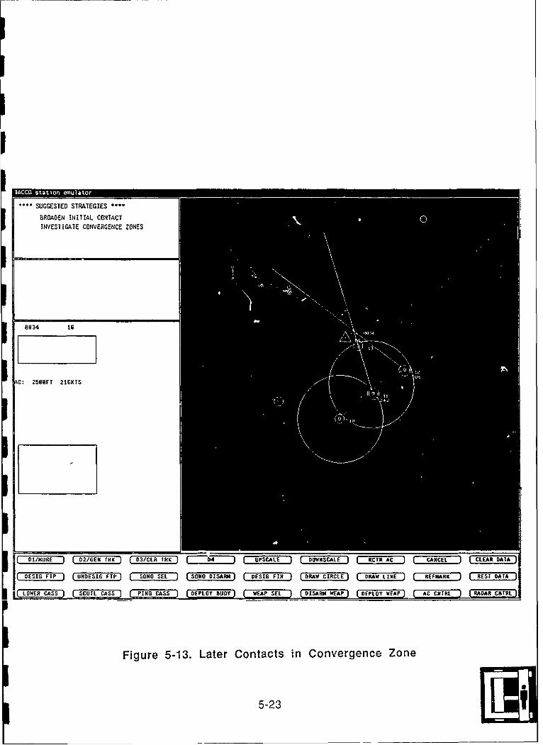
BROADE IN A OTC
BRf 13
01/MORE 02/GEN TRK D/L R PCL ONCL CRA ACL CERDT
DEIS TP NDSSTP SN SE SOODAR DEIG FIX RWCRL DA IE RFMR ETDT
LOWER CASSOSC lL CASS PING CASS DEPLOYEBUOY WEAP S t DISARM WEAP DPLO-Y WE AP A C CN T RL RADAR- C NRRI
Figure 5-13. Later Contacts in Convergence Zone
5-23

SSUGGESEo SIRAtEGIES
EXPAND PAHlERN FOR CONIACT
0.0
8834 8
C. 588F| 216Kr5
01/HORE " (02/0(EN TRK 03/CLR TRK "J( D4 J[UPSCALE DJ(OOWNSCAILE RCTR AC CANCEL CLEAN DATA
(5E10 FTP ) UNDES[O FTP . 50140 5E1 50 DISA [,RN DESIG FI[X D RAW CI[RCLE D [RAW LINE REFI4ARK R (EST DATA'
LOV, ER C;ASS SC 5UTL CASS PINO ICAS$ DELY UIOY WEAP SEt ISR WEAP DEPLOY WEAP AC CNTRL [RADAR CNTRL]
Figure 5-14. Expand Pattern For Contact Triggered5-24
EXPANU cONATRN 13 R louWnACotc
Build I 0i3a
Slew Ir3ta
BuildDitacAbv
C: SAUFTP2GT
LOWR AS SUTICAS IN CAS EPOYBUO WAPSE DIAR WAP DEPLOY WEA)r AC CMNTRL- RADAR CNTRL
Figure 5-15. Subgoal Structure of 'Expand Patterrn For Contacr' Displayed.
5-25

* I. .. S U G G E S IE D S IR A rEG I E S . .
CXPANO CORIAC
T ON 13
rUNmA
Exltt
884 32
C' 588(T 216KfS
or/ OR E 02/G 4 TIRK ) 03/C IR TRK )4 } UPSCALE DOWNSCAL E A ( R AT AC ) , CANCEL J CLE R DATA
Oi: SO FTP tJ N (I G FTP1 0, 40H S[' t 504 D'OO I[SAIRMj DES IG F X D RAW C IRCL ) R AW tINE R MARK R EST AA )
Figure 5-16. Focus on Contact Subgoal Accomplished by Interface
5-26
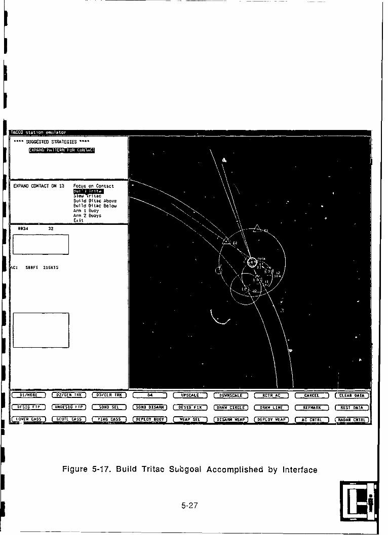
11CC ai oneua
SUGGESTED STRATEGIES ..
EXPAND CONTACT ON 13 Focus on Contact
Build Ditac AboveBuild Ditac BelowiArm 1 BuoyArms 2 BuoysExit
034 32
C: IBBFT 21GK1S
DESIGTP UN FTP T OOSL SlDDSR (1 I RWCRL RWLM EMR (- RESTDATA
WIRCASSQ SUICS 14 AS DPO UY ( *51I DSR EP DPO WEAPl A CHIR RAARCTRL
Figure 5-17. Build Tritac Suibgoal Accomplished by Interface
5-27

The interaction continues for some time. Opportunities to apply Magnetic AnomalyDetection (MAD) sensors arise later in the interaction, but are not shown here. Ingeneral, the initial adaptive interface is not hampered by having only four of thepossible 14 tasks implemented. It is able to make recommendations and provideinteraction support based on the evolving mission context and estimations of theTACCOs relationship to that situation. Such a feature is positive, in that is suggeststhat the interface will not be easily 'sice-tracked' in cases or situations where it can notmaintain a constant model of precisely what the TACCO is doing. This is highly likelyin real-world applications of this interface concept.
5-28

6. CONCLUSIONS
This research effort to investigate the cognitive basis for human-computerinteraction and decision making in RTMT environments has resulted in thedevelopment of COGNET, a new approach for modeling RTMT information processing.COGNET provides both theoretical and methodological advances for developinghuman-computer interfaces in RTMT environments. The three major advances are:
* development of the COGNET framework for modeling human RTMTinformation processing;
• development of a COGNET cognitive task analysis toolkit and methodology;and
* demonstration of a novel adaptive human-computer interaction concept andarchitecture.
The COGNET framework has been developed and applied to a vehicle trackingdomain based on Naval Air ASW. Within this context, a COGNET model of missionmanagement was developed. Initial validation of the model as a behavioral predictorhas been accomplished, and an adaptive interface developed. While additionalresearch is suggested by the results and technologies discussed in this report, theCOGNET toolkit is sufficiently well developed and validated to support real-worldsystem development efforts in Naval ASW or other RTMT domains.The main theoretical and methodological accomplishments are summarized below inSubsection 6.1. Additional operational benefits are summarized in Subsection 6.2.Finally, a set of future issues raised by this research is introduced in Subsection 6.3.
6.1. Main Theoretical and Methodological Accomplishments
The first and foremost product of this research is COGNET, a theoretical model ofhuman problem solving and human-computer interaction in real-time multitaskingdomains. COGNET is a general framework for decomposing and understandinghuman information processing in this important class of human-computer systems.The framework has applicability far beyond the Air ASW case used in this research totest and apply it. COGNET is also a powerful tool for cognitive task analysis that canbe used for modeling, interpreting, and analyzing human performance in RTMTcomputer-based environments. As noted earlier, this includes virtually all tacticalnaval decision-making roles. The COGNET modeling techniques provide a novelintegration of two previously unrelated cognitive analysis methods, the GOMS notationof Card, Moran and Newell, and the blackboard architecture that originally arose fromthe 1970's HEARSAY research program. In linking these two powerful notations,COGNET is able to represent features of both goal-directed and data-directedreasoning processes. and to relate them uniformly to a stream of human-computertransactions.
Along with the notational formalioms that constitute the COGNET descriptionlanguage, a new methodology for analyzing cognitive processes has been developed.This methodology incorporates a range of techniques in a layered approach thatparallels the layered structure of the COGNET framework. In the methodology,timelines of key-stroke level human-computer interactions are developed and then
6-1
analyzed with a verbal, question-Canswering, protocol technique to segment thetimeline into perceived segments of task activity and to develop a vocabulary of mentalrepresentations of the domain. These two (the protocol and vocabulary) approachesare used to develop an initial blackboard structure. The task timelines and verbalprotocol data are then iteratively analyzed to develop formal representations of eachtask type and to refine the blackboard structure. The overall methodology provides anovel and replicable way of integrating simulation, verbal protocol, and keystroke-leveltimeline data in a cognitive task analysis.
Validation and verification of any cognitive architecture or theory is a difficultundertaking (see Pylyshyn, 1984, for an excellent discussion of this subject). Onespecific key aspect of COGNET -- the RTMT flow of divided attention among tasks --was experimentally investigated as a preliminary effort at validation. This is the aspectof COGNET which motivated its development, and which most differentiates it fromother approaches (e.g., from MHP/GOMS).
A major feature of COGNET is that it is a context-based framework. The flow ofattention and human-computer interaction are dependent on the evolving context ofthe human-computer problem. Initially this dependence is relatively low, but increasesas the problem representation (as modeled by the blackboard contents) assumesspecific patterns which trigger tasks, subgoals, and task-operator conditions.Moreover, the attention model in COGNET is driven by the trigger/condition elementsin a specific model, which themselves represent pieces of knowledge that are held byhumans who are experts in the domain. Thus, COGNET's attention framework canonly be assessed through a specific model of a specific domain, and against theperformance of human experts. The experimental data showed that in the operationaldomain of Air ASW, a COGNET-based model was able to predict 90% of instances offour tasks in the model. If the basis is included to consider cases where the modelindicated a task shortly after the human initiated it, and/or those where instances ofopportunities for task-execution were also indicated by the model and accepted asvalid opportunities by domain experts but not acted upon by the human subjects in theexperiments, then the 90% figure rises further. Even more impressive, perhaps, is thefact that the 90% figure represents p task-instances. That is, the model wasable to antciat the task execution 90% of the time for both post hoc verification andexternal validation data. This provides strong support for the validity of the approach,as well as for the likely usefulness of a COGNET model to support adaptive human-computer interaction.
The research has provided a novel conclept and architecture for adaptive human-computer interaction. This concept builds on the pre-existing but highly abstractconcept of embedded user models, and is based on the use of a COGNET model of aspecific domain as an embedded model of an RTMT system user. The concept is touse the RTMT user model to:
* alert the real system user to situations where an attention shift is warranted,* help prioritize competing attention demands," provide structuring guidance for specific tasks on which tihe user wishes to
focus, and" support automated and semi-automated execution of the task, including
tailoring its performance to the momentary tactical context.A COGNET-based model, because of its structure and organization, is able to supportall of these functions. The research has gone further, however, by implementing a H
6-2

architecture that actually incorporates a specific COGNET model and performs theabove functions. Thus, the architecture and its implementation have served as proof ofconcept for COGNET-based adaptive interface.
6.2, Operational Benefits and Results
As an applied research program, this effort has also addressed significantoperational problems in the Naval Air ASW domain, and contributed to their long-termunderstanding and solution, including:
° a COGNET model of Air ASW mission management;
* an experimental environment for exploring human performance anddecision-making in Air ASW; and
* an adaptive interface enhancement for the current TACCO workstation.
The COGNET cognitive task analysis tools were tested and refined throughapplication to the human-computer interaction that occurs between an Air ASWTactical Coordinator (TACCO) and his computer workstation. The results are a highlydetailed model of the Air ASW mission management process, that represents the mostcomplete set of expert operator knowledge captured in this domain. The missionmanagement model provides a rich data base for future studies individual differencesin TACCO performance and evaluating different tactics. Studies of these types couldlead to improved methods for selection or evaluation of TACCOs or to better trainingtechniques.
Early emphasis in this research was placed on developing an experimentalenvironment that could support this and future research into human-computerinteraction and problem solving in Air ASW. The experimental environmentdeveloped here has proven invaluable in all stages of the research:
• collecting baseline data on human-computer interaction in the domain;
• supporting manipulation, summary, and analysis of the data via playbackand automatic data reporting;
* implementing the COGNET mission management model for validation andrefinement; and
• implementing an adaptive mission management interface and seamlesslyintegrating it into the baseline TACCO interface.
This development environment makes future research in this domain more efficient,cost effective, and powerful.
Finally, the research has provided a working implementation of an adaptivemission management interface for the Air ASW TACCO. This interface provides both aproof of concept (as noted above) and points towards possible refinement andoperational use in ASW systems. The fact that the adaptive interface is integrated intoa realistic TACCO workstation emulation makes its appicability to operational Navalconcerns direct and obvious. Of course, substantial advanced development would stillbe required before the implementation in the experimental environment could beimplemented in fleet settings. It is nonethe!ess an example of how applied researchcan benefit real-world operational issues and theoretical concerns beneficially andsimultaneously.
6-391

6.3 Additional Research Issues
Several new areas or issues of research emerged from the research reported here.This fall into two categories, those dealing with the adaptive interface, and thosedealing with COGNET and its validation.
6.3.1 Adaptive Interface and Interaction IssuesFurther work remains to be done in evaluating the adaptive interaction concept and
in achieving a more robust range of functionality. The initial implementationdemonstrated a range of adaptive interface functions using an architecture based onthe COGNET model. However, further research and development is necessary tocomplete implementation and validation of the full set of mission management tasks.
A number of specific research issues were identified during implementation of theadaptive mission management interface. One issue involves when and how the tasktriggers should be evaluated. Initially, the triggers were checked cyclically, but thisproduced side effects which could not be controlled in a straightforward manner. Theimmediate problem was solved by checking the triggers only when appropriate.Additional research is needed on this, as the cyclic checking approach is theoreticallypreferable for maximum generality.
Another area for future research and expansion of the adaptive interface involvesthe conditions for removing tasks from the suggested strategies list. It should be notedthat in the current implementation, recommendations sometimes remain in thesuggested strategies window after a task has been performed. The interface is not yetsophisticated enough to recognize that the task has been performed and should beremoved from the list. On the other hand, each task trigger has been associated withan 'untrigger condition,' which does remove this task from the list when the pattern thattriggered it in the first place no longer exists on the blackboard. All tasks in the initialimplementation use this 'untrigger' mechanism in lieu of a more sophisticatedmechanism to recognize when the task is actually completed. Furthermore, sometasks can be performed more than once while others should only be performed once.The interface has to be sophisticated enough to determine not only when a task hasbeen completed, but also whether the conditions exist in which the task could orshould be performed again.
Many of the sensor patterns (e.g., prudential, convergence zone investigation) canbe implemented in more than one way. For example, when two nearby sensorsindicate a convergence zone contact, the convergence zone investigative pattern canbe based on either sensor or some estimation procedure taking both sensors intoaccount. In the current minimal version of the interface, only one version of eachpattern is implemented. There is no mechanism by which the TACCO can direct thesoftware to adapt the pattern to a different set of assumptions. This is an importantsubject for future research. In addition, there are several variant methods for adaptingthe canonical convergence zone investigative pattern to the current context. Theinterface currently oniy supports the most common, and d i standard,approach. Exploration of mechanisms to allow alternative approaches including somethat are adaptive to individual users is another issue for future research.
As discussed in Section 5 above, some tasks contain subgoals that are mutuallyexclusive. Although the current interface does not perform any subtasks that are notappropriate for the current context, it has no way of conveying this to the the TACCO.This, too, must be a subject for future research.
6-4
I6.3.2 COGNET Elaboration and Further Validation IssuesOne major area for further research is the need for more extensive validation of
COGNET, particularly aspects other than the attention flow aspect considered here.Additional validation data and research is needed to validate both the representationand the underlying concept of cognitive tasks and their interaction with the blackboardrepresentation. The blackboard as a basis for integrative task representation alsorequires further validation. There is some implicit validation of these constructs in thevalidation discussed in Section 3 above, because the attention flow aspect of themodel builds on these constructs. Still, the COGNET architecture, which deals withlarge segments of goal-directed problem solving in a overall process which is datadirected and opportunistic, is a novel one. Major existing cognitive architectures suchas the Model Human Processor (Card et al., 1983) or the generalized blackboardarchitecture (Hayes-Roth, 1983) tend to represent human problem solving either totallygoal driven or totally opportunistic. The SOAR architecture of Newell and colleagues(Laird, Newell, and Rosenblum, 1987) is an exception and does seem compatible withCOGNET, but further work is needed to relate these two.
A more detailed need for further COGNET elaboration research was identifiedduring the validation analysis. There were two cases -- one in the post-hoc verificationand one in the independent validation -- when a task was indicated by the model butnot counted as a pre.diction because the subject performeu the action just prior to thetask trigger. , -.,.,n replay of these two cases, it became clear that there were changesin the tactical , Jation that the TACCOs acted on more quickly than the model. Thesecases point out areas of potential improvement in the model. What is required are,laborations of COGNET that provide more sophisticated rules for transformation ofinformation on the blackboard, corresponding to the types of inferences an operatormakes about new perceptual information. An example is calculation of location fromtwo direct path contacts on different buoys that give bearing reversals. The currentimplementation of the model infers a locational hypothesis when the TACCO enters a'designated fix' command. However, as the two cases Ehove indicate, the TACCOshifts attention to the new '-:3k a locational hypothesis leads him to undertake, andonly subsequently takes the direct action indicating his hypothesis. Implementation ofthis and other similar problems involves mathematical calculations integrating datafrom multiple sensors to provide the model with the capability to trigger tasks based onchanges in th_ tactical situation prior to the TACCO acting on them. Not only will thisadded capability enhance the model's predictive power; it will also allow betterdecision aiding by pointing out oppolunities for action to the TACCO. The aidingcapabilities could be particularly he~pful in fast-paced or complex situations when theTACCO cannot process all situational changes as quickly as they occur.
There are also otner applications of embedded user models that are possible forCOGNET, including for training and embedded training, and/or decision aiding. Inaddition, COGNET has substantial potential for application in knowledge elicitationand knowledge representation for artificial intelligence systems. Finally, COGNET asa cognitive architecture has potential applicability to the measurement of cognitiveprocesses, since it provides a highly computable mechanism for rea,-time multi-tasking problem solving. Thius, this research has opened a potentially rich set ofresearch questions for the future in addition to its concrete results.
6-5

REFERENCES
Bruce, B. and Newman, D. (1978) Interacting Plans. Cognitive Science. 2. 196-233.
Card, S., Moran, T. and Newell, A. (1983) The Psychology of Human-Computer Interaction. Hillsdale, NJ:
Lawrence Erlbaum Assoc.
Dehdashdi, Parto (1989) A Study of Mental Models Through Communication Between Users and
Advisors Solving Software Manipulation Problems. Unpublished Doctoral Thesis, Drexel
University.
Eisenberg, E. M (1990, April). Transcendence Through Organizing. Communications Research. 17. 2,
139-164.
Elkerton, J. and Pamiter, S.(1989). Designing help systems using a GOMS model. Part 1 - An information
reiieval evaluation (Technical Report C4E-ONR-3). Ann Arbor: University of Michigan, Center
for Ergonomics.
Finegold, A. (1984) The engineer's apprentice. In P.H. Watson and K.A. Prendergast Eds., The Al
Business: The Commercial Artificial Intelligenc.. Cambridge, MA: MIT Press.
Hayes-Roth, B. (1983). A Blackboard Model of Control. Technical Report, Computer Science
Department, Stanford University, Stanford, CA.
John, B., Rosenblum, P. & Newell, A. (1985) A Theory of Stimulus-Response Compatibility Applied to
Human-Computer Interaction. Proceedings of CHI '3.5. 213-219. New York:ACM
Malone, T.W., (1990). Organizing information processing systems: Parallels between human
organizations and computer systems. In S. Robertson, W. Zachary, & J. Black (Eds.),
Cognition. Computing and Cooperation. Norwood, NJ: Ablex Press.
Nii, P.H., (1986) Blackboard Systems. The Blackborad Model of Problem Solving and the Evolution of
Blackboard Architectures, AI Mazine, 7, 36.
Norman,D. (1983) Some Observations on Mental Models. In D. Gentner and A.L. Stevens (Eds.) Mentg1Models, Erlbaum, Hillsdale, NJ
Norman, D. (1983a) Design Rules Based on User Errors, Communications of the ACM,
Pylyshyn,Z. (1984) Computation and Cognition. Cambridge,MA: The MIT Press.
R-1

Rasmussen, J. (1986) Information Processing and Human-Machine Interfaces, Amsterdam North Holland
Robertson S., Zachary W. and Black J.,Eds. (1990) Cognition. Computing. and Cooperation, Norwood,
NJ:Ablex Press.
Rouse, W. B., and Morris, N. M. (1986) On looking into the black box. Prospects and limits in the search
for mental models. Psychological Bulletin. 100, 349-363.
Rouse , W. B. (1980) Systems Engineering Models of Human-Machine Interaction. New York: North
Holland.
Rubin, K., Jones, P., Mitchell, C.(1988) OFMspert: Interference of Operator Intentions in Supervisory
Control Using a Blackboard Architecture. IEEE Transactions on Systems. Man. and
Cybernetics, 18, 618-636.
Schmidt, C. F. and Goodson, J. L. (1990) The Design of Cooperative Person-Machine Problem Solving
Systems: A Methodology and Example. In S. Robertson, W. Zachary, & J. Black (Eds.),
Cognition. ComDuting and Cooperation. Norwood, NJ: Ablex Press.
Selfridge, Oliver G.(1959) Pandemonium: A paradigm for learning. In Proceedings of the Sympsiurn onthe Mechanization of Thought Processes. 511-529.
Sheridan, T. B., and Johannsen, G. (1976). Monitoring Behavior and Supervisory Control. New Yo rk:
Plenum.
Siegel A. and Wolf, J (1969) Mao-machine simulation modeIs.Psychoscial and Performance Interaction,
New York:John Wiley & Sons.
Suchman, L. A. (1990) What is Human-Machine Interaction?, Ip S. Robertson, W. Zachary, & J Black
(Eds.), Cognition. Computing and Cooperation. Norwood, NJ: Ablex Press.
Van Cott, H. P. (1984) From Control Systems to Knowledge Systems. In Human Factors. 26, No. 1, 115-
122.
Wilson and Rutherford (1989) Mental Models. Theory and Application in Human Factors..Humn Factors.
Woods, D. D., and Hollnagle, E. (1987) Mapping cognitive demands in complex probiem-solving worlds.
Jl.ur.t.al Journal of Man-Machine Sltu .es.26 257-275.
IR-2 N

Zachary, W. (1986) A Cognitive Based Functional Taxonomy of Decision Support Techniques. In Human-
Computer Interaction. 2. 25-63.
Zachary, W. (1988). Decision Support Systems. Designing to Extend the Cognitive Limits. In Handbook
of Human-Computer Interaction, Martin Helander (Ed.), New Yod: North Holland, 997-1028.
Zachary W.W. and Zubritzky M.C. (1988). An Experimental environment and Laboratory for Studying
Human Information Processing in Naval Air ASW (Technical Report 881020.8704), Blue Bell,
PA: CHI systems, Inc.
Zachary,W., Ryder, J., & Zubritzky,M (1989). Information Processing Models of Human-Computer
Interaction in Naval Air Anti-Submarine Warfare. Technical Report 891215.8704. Spring
House, PA:CHI Systems.
R-3
hDISTRIBUTION LIST
Prof. Jay Elkerton
OUSDR (A)/R&A(E&LS) University of MichiganPentagon 3D129 Dept. of I & 0 EngineergWashington, DC 20301-3080 Center for Ergonomics
1205 Beal AvenueAnn Arbor, MI 48109-2117I Dr. Bruce Barnes
Program Director, Div. Info Dr. Robert A. FlemingRobotics, & Intell. Systems Naval Ocean Systems CenterNational Science Foundation Human Factors Support Group1800 G Street, N.W. 1411 South Fern StreetWashington, DC 20550 Arlington, VA 22202-2896
Mr. Charles Bates Dr. Alfred R. FreglyDirector, HE Division AF Office of Sci. Res.USAF AAMRL/HE Life Sciences DirectorateWPAFB, OH 45433 Bldg. 410
Bolling AFB, DC 20332-6448
Dr. Kenneth R. Boff Mr. Jeffrey GrossmanAAMRL/HE Naval Ocean Systems CenterWPAFB, OH 45433 Code 4402
Bldg. 334Mr. Luiz Cabral San Diego, CA 92152Naval Underwater Sys. Ctr.Code 2212 Dr. Thomas E. HannaBldg. 1171/1 Naval Sub Med Res LabNewport, RI 02841 Submarine Systmes Dept.
Naval Submarine BaseCdr. Robert C. Carter USN Groton, CT 06349-5900Naval Research LaboratoryCode 5532 Dr. Edgar M. JohnsonWashington, DC 20375-5000 Technical Director
US Army Research Institute5001 Eisenhower Avenue
Dr. Marvin S. Cohen Alexandria, VA 22333-5600Dec. Sci. Consortium, Inc.1895 Preston White Drive Dr. William RouseSuite 300 Search Technology, Inc.Reston, VA 22091 4725 Peachtree
Corners CircleDr. Stanley C. Collyer Suite 200Office of Naval Technology Norcross, GA 30092Code 222800 N. Quincy Street Capt T. E. Jones, MSC, USNArlington, VA 22217-5000 Aviation Medicine & Human
Performance (Code 404)Defense Tech. Info. Center Naval Medical R & D CmdCameron Station, Bldg 5 National Capital RegionAlexandria, VA 22314 Bethesda, MD 21814-5044(2 copies)
Dr. Michael Kaplan,Director, Office Basic Res US Naval Test CenterUS Army Research Institute Aircrew Systems Branch5001 Eisenhower Avenue Systems Engineering TestAlexandria, VA 22333-5600 Directorate
Patuxent River, MD 20670Mr. Keith KramerNaval Research Laboratory Commanding OfficerCode 5532 Naval Weapons CenterWashington, DC 20375-5000 Human Factors Branch
Code 3152Dr. Richard Loutitt China Lake, CA 93555National Science FoundationDivision of Behavioral & Dr. Michael Letsky
Neural Sciences Office of the Chief of1800 G Street, N. W. Naval OperationsWashington, DC 20550 OP-01B7
Washington, DC 20350Capt. William Moroney, USNNaval Air Development Ctr. Office of the Chief ofCode 602 Naval OperationsWarminster, PA 18974 OP-933D3
Washington, DC 20350-2000Naval Aerospace MedicalResearch LaboratorySensory Division Code 23 Office of Naval ResearchPensacola, FL 32508 Perceptual Science Program
Code 1142PSCommanding Officer 800 N. Quincy StreetNaval Air Systems Command Arlington, VA 22217-5000Crew Station Design (3 copies)NAVAIR 5313Washington, DC 20361 Dr. Jesse Orlansky
Inst. for Defense AnalysesCommanding Officer 1801 N. Beauregard StreetNaval Biodynamics Lab Alexandria, VA 22311Michoud StationBox 29407 Dr. E. SalasNew Orleans, LA 70189 Head, Human Factors Div.
Naval Training Systems CtrCommanding Officer 12350 Research ParkwayNavy Health Research Ctr. Orlando, FL 32826-3224P.O. Box 85122San Diego, CA 92138 Dr. H. Wallace Sinaiko
Manpower Research &Commanding Officer Advisory ServicesNa1 Personnel n jA SmithniaTn stitutionSan Diego, CA 92152-6800 801 N. Pitt St. Suite 120
Alexandria, VA 22314-1713DirectorTechnical Information Div.Code 2627Naval Research LaboratoryWashington, DC 20375-5000

Mr. James G. SmithOffice of Naval ResearchCode 121800 N. Quincy StreetArlington, VA 22217-5000
Cdr. S. SnyderOffice of Naval TechnologyCode 222800 N. Quincy StreetArlington, VA 22217-5000
Dr. John TangneyAF Office of Sci. Res.Life Sciences DirectorateBldg. 410Bolling AFB, DC 20332-6448
Dr. Douglas TowneUniversity of Southern
CaliforniaBehavioral TechnologyLaboratory
1845 South Elena AvenueFourth FloorRedondo Beach, CA 90277
Dr. Harold P. Van CottCommittee on Human FactorsNAS-National Res. Council2101 Constitution Ave, N.W.Washington, DC 20418
Dr. John WeiszTechnical DirectorUS Army Human
EngineeringLaboratory
AberdeenProving GroundsMD 21005
Prof. Christopher D. WickensDepartment of PsychologyUniversity of IllinoisChampaign, IL 61801