EommEEEEEmhshEE - DTIC
177
IrO-Ai?4 85 EARLY DEVELOPMENT OF A HA2ARDOUS CHEMICAL PROM ET I ENSEMBLE(U) COAST GUARD WASHINGTON DC OFFICE OF I RESEARCH AND DEVELOPMENT J 0 STULL OCT 86 USCG-D-24-86 IUNCSSIFIED DTC-280 3 -8iC-2B86/ U EommEEEEEmhshEE
-
Upload
khangminh22 -
Category
Documents
-
view
1 -
download
0
Transcript of EommEEEEEmhshEE - DTIC

IrO-Ai?4 85 EARLY DEVELOPMENT OF A HA2ARDOUS CHEMICAL PROM ETI ENSEMBLE(U) COAST GUARD WASHINGTON DC OFFICE OFI RESEARCH AND DEVELOPMENT J 0 STULL OCT 86 USCG-D-24-86IUNCSSIFIED DTC-280 3 -8iC-2B86/ U
EommEEEEEmhshEE

14. U32
7L 12.2
LL
.liii I AO 2.0IIII 25 11A
R RCOPY RESOLUTION TEST CHARTNATC,NAL P1IUFAII rf) SYANDARD I% A
.W.
0~% %

L°
00004
Report No. CG-D-24-86
EARLY DEVELOPMENT OF AHAZARDOUS CHEMICAL PROTECTIVE ENSEMBLE
LI- .enant Jeffrey O. StullU. S. Coast Guard
Office of Research and Development
DTICELECTE
DEC 1 0 '1986 j1:
Thi document is available to the U.S. public through the NationalTechnical Information Serwic, Springfield, Virginia 22161
FINAL REPORT
October 1986
Prepared for:
U.S. Departmentof TransportationUnited States CoastGuardOffice of Research and DevelopmentWashington, D.C. 20593
86 12 09 008 :"
.. . . .. . . . . . ..

Technical Report Documentation Page
I. Report No. 2. Government Accesson No. 3. Recipient S Caaooog No.
CG-D-24-86 Libps74___4. Ttle and Subtile 5. Report Date
EARLY DEVELOPMENT OF A HAZARDOUS CHEMICAL October 1986PROTECTIVE ENSEMBLE 6. Performing Orgoni zaton Code
74897S. Performing Organization Report No.
7. Author s)
Lieutenant Jeffrey 0. Stull CG-D-24-869. Performing Organization Nomo and Address 10. Work Unit No. (TRAIS)
A. U. S. COAST GUARD (G-DMT-3) 4155.4.1.1Washington, D. C. 20593 11. Contract o, Grant No.
B. ILC Dover, Inc. DTCG23-81--C-20003Frederica, Delaware 19946 13. Type of Report and Period Covrered
12. Sponsoring Agency Name and Address
Same as A above Final, March 1981 toAugust 1985
14. Sponsoring Agency Code
15. Supplementary Notes
Information in report is in performance to contract DTCG23-81-C-20003.Final report prepared by U. S. Coast Guard Office of Research and Development
This report describes-A U.S.-4i dt!GTMrd program for developing a HazardousChemical Protective Ensemb _.for protection of personnel during chemical spillresponsaY j;. nki-nkk-u.L ehelection and testing of chemically resistantmaterials,-tm-design of a totallr encapsulating suit employing the selected
- materials, -Q design of a full body cooling garment, 6 construction of prototypesuits, and laboratory evaluation of the complete ensemblecr' .r ,4. ,
The Coast Guard chose butyl rubber, chlorinated polyethylene, and VITON/chlorobutyl laminate for outergarment materials, and fluorinated ethylene propylene-surlyn laminate as the visor material for a three material suit 'system'.Material selection criteria involved chemical resistance, physical properties, andthe material's ability to form high integrity seams. Immersion testing was per-formed for 160 chemicals and permeation against 56 chemicals for each of theselected materials. Suit seam chemical resistance and material decontaminationpotential were 4"se investigated.
The outergarment was designed to accomodate the cooling system and a varietyof commercial breathing and communication devices. Features of the outergarment
. included a pressure-sealing zipper, integral gloves, sock-like booties, and.1. internal positive pressure. The cooling system was designed to interface directly
with the outergarment with a full body cooling garment, pump, and field-servicedice pouch/heat exchanger.
Laboratory evaluations included protection factor testing to measure ensembleintexrity and manned stress testin; to assess ensemble function, fit. and comfort.
17. Key fords 18. Oitribution StatementHazardous Chemical Protective Ensemble
'.1 Totally-encapsulating suit This document is available to the U. .
Chemical protective materials public through the National TechnicalChemical resistance testing Information Service, Springfield, VA
pImmersion/Permeation testing 22161.19, 5ecv,,oy .Zloss-6. of 4 ' 0 ,e rti 20. Secu¢,.ty Class~f. ,of th, s p)age, 21. No. o Pog~j s 2 .:
Unclassified Unclassified 171
Form DOT F 1700.7 - Reproduction of completed page authorized
%

NOTICE
This document is disseminated! under the sponsorship of the Departmentof Trunspowtaton in the interest of information excliangs. The UnitedSus Government assumes no liability for its contents or use therof.
The content of this repor do not neceuuaiiv reflec fte official viewor policy of the Coat Guard; and they do not constitute a standard,specification, or regulation.
This report, or portions thereof may not be used for advertising orsales promotion purposes. Citation of trade names and manufacturersdoes not constitute endorsement or approval of such products.
pi.
S.(

TABLE OF CONTENTS
CHAPTER 1 - INTRODUCTION AND BACKGROUND . ............. .. ................. 1 I
CHAPTER 2 - CHEMICAL PROTECTIVE MATERIALS SELECTION AND COMPATIBILITY ........ 6TESTING
Selection and Screening of Chemical Protective Materials ......... 6
Compatibility Testing of Chemical Protective Materials .......... 17
I ame rsion Testing ..... .............................. 19
Additional Immersion Testing ... ................................. 27
Permeation Testing .................... .............. 27
Seam Testing .................................................... 38
Decontamination Testing ......................................... 41
Analysis and Significance of Material Testing Results ...........41
CHAPTER 3 - DESIGN OF HAZARDOUS CHEMICAL PROTECTIVE ENSEMBLE ................ 83
Outergarment ............................... 83
Environmental Control Unit .................................... 88
Cooling System ............................. 9
Communications System ........................................... 93
CHAPTER 4 - OVERALL ENSEMBLE TESTING ............................... 0 ........ 95
Protection Factor Testing ................ ... .... o ..... ............ 95
Manned Stress Testing ....................... o ................... 98
Subjective Comments ............ .............................. 106
CHAPTER 5 -CONCLUSIONS AND RECOMMENDATIONS ................... oe.. ***..o108
REFERENCES
APPENDIX A - CHRIS CODES AND CHEMICAL NAMES FOR COMPOUNDS CONSIDERED IN THISSTUDY
APPENDIX B - SURVEY OF SPILLED SUBSTANCES FROM NAT'L RESPONSE CENTER (81-82)
APPENDIX C - DETAILED TEST PLAN AND PROCEDURES FOR EVALUATING THE HAZARDOUSCHEMICAL PROTECTIVE ENSEMBLE
APPENDIX D - PROTECTION FACTOR TESTING RESULTS
ft

LIST OF FIGURES
Figure No. Title Page No.
1 Single-Sided Immersion Test Cell for Liquid Chemicals 20
2 Single-Sided Immersion Test Cell for Gaseous Chemicals 22
3 Permeation Test Cell for Liquid and Gaseous Chemicals 31
4 Material Sea* Configurations 39
5 Outergarment Design 84
6 Closure Assembly Configuration 86
7 Glove Ring Assembly Configuration 87
8 Outergaruent Pressure Sensing Diaphragm for ECU 89
9 Cooling System Configuration 91
10 Full Body Cooling Garment Design 92
11 Cooling Pouch and Heat Exchanger Design 94
.
copyINSPECTED
S. ... D T ICSCTE
El kPDEC 10 1986
,' A- ir . I . odE
I' 1)
S . -.% ~

LIST OF TABLES
Table No. Title Page N~o.
1 Original Coast Guard Ensemble Requirements 3-4
2 General Chemical Compatibility of Potential Garment 7-8
* Materials
3 Characteristics of Potential Garment Materials 9-10
4 Physical Property Screening Tests 12
5 Physical Property Screening Test Results of Garment 13Material Candidates
6 Chemical Screening Test Procedures 14
7 Chemical Screening Test Results 15-16
8 Summary of Results for Imersion Testing 23-26
9 Comparison of 20 Nil Thick Scrim Supported and 28Unsupported Chlorinated Polyethylene I mme rsion Testing
10 Results of One Sided Immersion Testing for Three Forms 29of Chlorinated Polyethylene Over Time
11 Summary of Results for Permeation Testing 32-33
12 Breakthrough Times and Sensitivity of Analytical 34-36
Methods
13 Distribution of Breakthrough Times for 56 CHRIS 37
Chemicals and the Three Materials
14 Seam Test After Three-Hour, Single Side Immersion In 40
Chemical
15 Results of Decontamination Tests 42-44
16 Side-by-Side Immersion and Permeation Test ResultsA. For Fluorinated Polyethylene Propylene 45-50B. For VITON/Chlorobutyl Laminate 51-56C. For Chlorinated Polyethylene 57-62
17 Material - Chemical Compatibility Recommendations 64-69
18 Material - Chemical Compatibility Recommendations 71-76Based on Modified Criteria
19 Summary of Suit Material Compatibility Recommendations 77

LIST OF TABLES (continued)
Table No. Title Page No.
20 Summary of Suit Material Failures 78
21 Outergarment Material Recomendations for Spilled 80-82Substances
22 Sumary of Protection Factor Testing 97
23 Phase I - Manned Stress Testing Schedule 101
24 Phase II - Manned Stress Testing Schedule 102
25 Phase I - Manned Stress Testing Results 103
26 Phase II -Manned Stress Testing Results 104
27 Phases I and II - Manned Stress Testing Equipment 105Results
( °'A
i -.
A..
~ ~ A
.7U
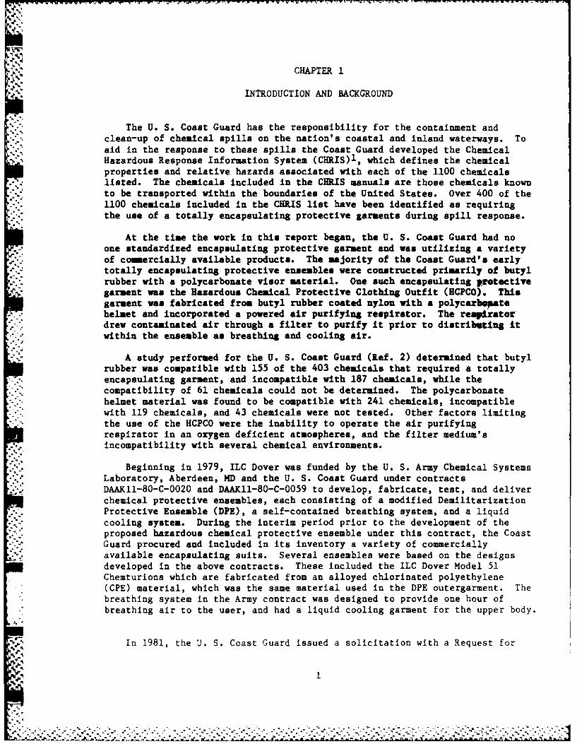
CHAPTER 1
INTRODUCTION AND BACKGROUND
The U. S. Coast Guard has the responsibility for the containment andclean-up of chemical spills on the nation's coastal and inland waterways. Toaid in the response to these spills the Coast Guard developed the Chemical
-Hazardous Response Information System (CHRIS)l, which defines the chemicalproperties and relative hazards associated with each of the 1100 chemicalslisted. The chemicals included in the CHRIS manuals are those chemicals known
*. to be transported within the boundaries of the United States. Over 400 of the1100 chemicals included in the CHRIS list have been identified as requiringthe use of a totally encapsulating protective garments during spill response.
At the time the work in this report began, the U. S. Coast Guard had noone standardized encapsulating protective garment and was utilizing a varietyof commercially available products. The majority of the Coast Guard's earlytotally encapsulating protective ensembles were constructed primarily of butylrubber with a polycarbonate visor material. One such encapsulating protectivegarment was the Hazardous Chemical Protective Clothing Outfit (HCPCO). Thisgarment was fabricated from butyl rubber coated nylon with a polycarbesatehelmet and incorporated a powered air purifying respirator. The resviratordrew contaminated air through a filter to purify it prior to distributing itwithin the ensemble as breathing and cooling air.
A study performed for the U. S. Coast Guard (Ref. 2) determined that butylrubber was compatible with 155 of the 403 chemicals that required a totally
- - encapsulating garment, and incompatible with 187 chemicals, while the*" compatibility of 61 chemicals could not be determined. The polycarbonate
helmet material was found to be compatible with 241 chemicals, incompatiblewith 119 chemicals, and 43 chemicals were not tested. Other factors limiting
* the use of the HCPCO were the inability to operate the air purifyingrespirator in an oxygen deficient atmospheres, and the filter medium'sincompatibility with several chemical environments.
.. . Beginning in 1979, ILC Dover was funded by the U. S. Army Chemical SystemsLaboratory, Aberdeen, MD and the U. S. Coast Guard under contractsDAAKII-80-C-0020 and DAAKII-80-C-0059 to develop, fabricate, test, and deliverchemical protective ensembles, each consisting of a modified DemilitarizationProtective Ensemble (DPE), a self-contained breathing system, and a liquidcooling system. During the interim period prior to the development of theproposed hazardous chemical protective ensemble under this contract, the CoastGuard procured and included in its inventory a variety of commerciallyavailable encapsulating suits. Several ensembles were based on the designsdeveloped in the above contracts. These included the ILC Dover Model 51Chemturions which are fabricated from an alloyed chlorinated polyethylene(CPE) material, which was the same material used in the DPE outergarment. Thebreathing system in the Army contract was designed to provide one hour ofbreathing air to the user, and had a liquid cooling garment for the upper body.
In 1981, the U. S. Coast Guard issued a solicitation with a Request for
- i..d'.: . .... ....

Proposals to develop a new Hazardous Chemical Protective Ensemble. Thecontract was awarded to ILC Dover with the principal objectives ofinvestigating protective materials which provided a wider range ofcompatability to the CHRIS chemicals, and designing overgarments which couldaccomodate a variety of breathing systems and other protective equipment. Theuse of a uniform design was a primary criterion to avoid ensembles havingdifferent training and maintenance requirements. The Coast Guard's original
% requirements for the Hazardeous Chemical Protective Ensemble are listed inTable 1.
This report summarizes the work performed during the four task program todevelop a Hazardous Chemical Protective Ensemble for the Coast Guard. Thiswork involved the design of a totally encapsulated protective ensemble usingmaterials that would provide protection to as many hazardous chemicals aspossible, testing of the suits, and development of final specifications. Thespecific tasks in this program included:
1. Task I - Selection of Chemical Protective Materials and CompatibilityVTesting.
The objective of this task was to identify materials that are r~MilskUt tothe chemicals that were found to be incompatible with butyl orpolycarbonate in a previous test program. Verification of thecompatibility of the selected materials was accomplished by acompatibility test program that consisted of an imersion test phase todetermine the extent of physical attack by the chemicals on the material,and permeation testing to determine the effectiveness of the material as abarrier against the chemicals. Additionally, seam chemical resistance andmaterial decontamination potential were investigated.
2. Task II - Design of the Hazardous Chemical Protective Ensemble.
The objective of this task was to develop an ensemble that integrates thematerials selected in task I, along with Coast Guard selected respiratoryprotection, a body cooling system, an internal suit pressurization system,and Coast Guard provided communications into a single design. The designcharacteristics developed in this task identified a totally encapsulating,self-supporting protective ensemble capable of meeting Coast Guardrequirements.
3. Task III - Fabrication of Preliminary Prototype Ensembles.
The objective of this task was to fabricate prototype total encapsulatingsuits of each selected material. Six suits were constructed including twoVITON/chlorobutyl laminate suits, two butyl rubber suits, one 30 milunsupported chlorinated polyethylene suit, and one 20 mil supportedchlorinated polyethylene suit. These total encapsulating suits were builtaccording to preliminary drawings and specifications developed in TaskII. The resulting suits were completed and fully operational to interfacewith government provided breathing appartuses, communications equipment,and the ELC Dover designed full body cooling suit.
2
.............................................................- XN.7

TABLE 1
ORIGINAL COAST GUARD ENSEMBLE REQUIREMENTS
ITEM REQUIREMENT
Time Limit
Wear Time 3 hoursChemical Service Time
Primary level-lit use 3 hoursNo. wear cycles I (disposable)
Shelf Life 3 years
Ambient Work Conditions
Pressure 1 Atmosphere (Air with no contaminantto 100Z contaminant)
Temperature -30 0 C (-220 F) to 400C (10407)Humidity Up to 1002-water contact is probable'Sunlight No Ultraviolet (UV) or ozone (03)
degradationFungus Will not support mold growth
Storage Conditions
Stability Non-cracking, no blocking, stiffening,flaking or separation in storage
Temperature range -300C (-220F) to 700C (15807)
Durability Meet physical properties per MIL-C-12189E(particularly pertaining to Section 4.3.4- Testing). See also:Fed STD 191 - Textile Test Methods
* Fed STD 406 - Plastics-Methods ofTesting
Fed STD 601 - Rubber Sampling & Testing
Odor No offensive odors
Toxicity No inherent toxicity hazard
Fabrication Methods Sewed, glued, heat bonded, impulse heated,sonic bonded, radio frequency bonded orother method to provide leak tightjoints. Capable of bonding to otheracceptable materials. Seam sealing methodlends itself for simple field repairs.

TABLE 1 (continued)
ORIGINAL COAST GUARD ENSEMBLE REQUIREMENTS
Support and Maintenance Provide data and procedures to sanitize,leak check, seal, repair, inspect, checkoptical quality, storage requirements
Decontamination Material does not degrade fromdecontamination procedures
Material and Production Cost Material Cost Range $10-50 per square yardProduction Cost Range variable depending
upon garment material (max of $1500 persuit)
Chemical Compatibility Estimated 400 Compounds from CHRIS requiring;encapsulated protection;
100% compatibility desired
Safety Requirements Impermeable; Fire retardant; Staticelectricity free
F'
4%4
.e-.d
..
.. . . *- --. --- -

4. Task IV - Laboratory Ensemble Testing.
The objective of this task was to 1) determine the ensemble protectionfactor, and to 2) conduct manned ensemble performance testing. Protectionfactor testing was performed to quantitavely measure the effectiveness ofthe ensemble in protecting the user from a hazardous chemicalenvironment. Manned ensemble performance testing allowed an assessment ofensemble functionally, as well as effectiveness of the body cooling systemand the ensemble in terms of comfort and freedom from physical exhaustion.
Portions of this work were earlier reported in an Interim Report published byILC Dover for the U. S. Coast Guard in November 1982 (authored by RobertAlgera of ILC Dover) and a subcontractor report by Arthur D. Little, Inc.,entitled, "Chemical Resistance of Three Candidate Materials for the U. S.Coast Guard's Hazardous Chemical Protective Ensemble," (Ref. 3).

CHAPTER 2
CHEMICAL PROTECTIVE MATERIALS SELECTION AND COMPATIBILITY TESTING
In an earlier study, NSA Research Corp. determined that 403 of the CHRISchemicals would require the use of a totally-encapsulating garment forpersonnel protection during spill response operations.2 Their investigationalso entailed testing the chemical resistance of primary materials in aninitial Coast Guard protective garment design, known as the Hazardous ChemicalProtective Clothing Outfit (HCPCO). Butyl rubber and polycarbonate,comprising the garment and visor materials, respectively, were tested againsta number of chemicals listed in the Coast Guard'sa Chemical Hazard ResponseInformation System (CHRIS).1 Both materials demonstrated limited chemicalcompatibility for the three hour test period; butyl rubber showed permeationbreakthrough for 30% of the chemicals tested whereas polycarbonate wascompatible with 60% of the chemicals that require total suit encapsulation.Based on these findings, the Coast Guard recommended identifying maiq1alsthat would provide protection against those chemicals for which butjyhruberand polycarbonate are incompatible. This was to include chemicalcompatibility testing of the materials to verify their chemical resistance.
Conclusions from the MSA report and other studies indicated that *o osuit material would resist degradation or permeation by all chemicals.Furthermore, nearly all plastic and rubber materials used in chemicalprotective clothing are permeable to some degree, and for some chemicals theremay be no acceptable garment material available to provide adequate protectionfor the user. Based on this information, the Coast Guard adopted the idea ofa .systems- approach in which an inventory of two or more total encapsulatingsuits constructed of different materials would be employed. Materialselections would involve materials with chemical compatibilities for differentclasses of chemcials to achieve an overall broad chemical resistance of thesuit "system". Butyl rubber was selected to be one of the materials in thissystem. Material selection and compatibility testing were to consider thetotal ensemble, i.e. if a particular suit material is chemically resistant toa group of hazardous materials, a visor material selected for use with thatmaterial should be effective against the same chemicals.
Selection and Screening of Chemical Protective Materials
Research of the chemicals which are not compatible with butyl rubbershoved that they fall mainly into the classes of aldehydes, chiorosilanes,ethers, hydrocarbons and inorganic acids. Based on these observations, ILCDover concentrated its material investigation on finding materials that wereresistant to these chemical groups. Considerations were also given tomaterial characteristics such as low temperature performance and cost. Table2 gives generalized compatibility of several protective clothing materials toa number of different chemical classes. Table 3 summarizes advantages anddisadvantages of these materials based on their known physical and operationalcharacteristics. This first phase of the materials search led to the initial9
6

;Asia a ]a] alialla~14
P4 0
14
I a a
I~ a a
. ai~I I I a.a a a an144
8 14 14 14 14
V.. 4
-114 4 1.a w d 4 Ida Is a a~a4 .4 1
0 44 0 000 4 I a C3 I0 ~ ~ ~ ~ ~ . .3- .1 3u U -8 AM 4 6 l
.414 Z1 0. U1 14 1014
7

~4 b
-- 4

TAILI 3
CHA CTEISTICS OF POTEITIAL GARMEIT NAIEhiLS
SUIT MiTfL CANDIDAT&S ADVITAOES DISADVANTAGES
Butyl lubber Coetinuous service temperature Flaxibility at low temperaturerange from -700 to 4WO°F. is good.Good abrasion resistance. Poor esistance to aliphatic,Low permeability to gases. aroatic and halogenatedGood resistance to ketomes, hydrocarbons, phanols sadestere, met acids sad bae, ozidLang acids.and inorgaic s lts. 1 1.ble.
Chlorinated Polyethylene Temperture capebility range Flexibility at low(Cfl) from -400 to +30001. temperature is fair.
Good sbrssioa resistance. Poor resistance to aromaticVery low permability to pse. sad haloeomated hydrocarbons.Gsed to aselimt reulatmeto aliphatic hydrocarbons,phemol, ketems, esters, acidssad bases, Ad sats.est sealable. Low cost.
Fluorocarbon - Temperature capability renges Poor chemical resistance toPluorel/lluorosilicos from -430 to +40007 depend- ketoes and esters.
lng an the percentage to which High cost.the pluorel and fluor.oilicoa Difficulty in maufacturing.are blooded.Izellaet resistance to hotoils, gaolies, J. P. fuels,and hot corrosive fluids sadgases under extreme conditions.Ovrall good, to mellntchemcal resistance to hydro-erch*", acids sad bases, andsalts. Self exinguishing.
Polyvinyl Chloride Lw temperature flwxbility Poor resistance to halogenated
to -400F. hydrocarbons, ketones andAesistance to amlae and esters.aromatic@, inorganic acids,bases, and sIts. lest@salable. Low cost.
Polyethylone/Saransx Provides excell nt barrier flexibility at lowprotection with low perme- temperatures is fair.ability to moisture and gases. Poor resistance to hydrocar-Izcellent resistance to acids bons, phenols and ketones.and bases and salts.Ezcellent abrasion resist aceand toughness. lest sealable.Low cost.
-..- "-9

T..LE 3 (continued) ICHARACTEISTICS Of POTENTIAL GARMENT NA TNIALS
SUIT NT , L CANDIDATES ADVAW, DISADVANTAGES
Chlorotrifluoroethyln - Operational over wide tempera- l1gh cost."IWZ-F" 81 turs ranst frog -40007 to Difficult to manufacture.
" ooao flsh optlcal t eanmratncoe oc,o l w s characterkticd.
Low permebility to ltir vapor-," gass..
"letamt to sot organic Solovato ad eedaa concentrated-
oo tand strong caustds.
bass.L cwt
Fluorocarboa Te lon Contimma Service tmperature Poo res tance to olte
ran from 00 to +2700 1.rs tli mealsi and aminai.
Loo c ,l ty to itquls Solulex an td Camporedtc das-, mtt e. lo a organic 9yrc0 osst.oe a e to diluto to mutue.
mine shent r iancesto A" bases dad sovnts
Ioaoer - tly Rains flexiblt at tempera- azrm srvice* tpaoeatoetusat -2000F. is.,tll
RI tenslo ad tst strenth. Attacked a oowly by oyddoalrbGood traspemcy. ocot".
ogood Che ca resistance tools, gasoline, atos, ad.ase.a cs, and ba
Poly"Tet rCaotgur service tempertuoe ttackead by kesolu- a,range from -IWo to +27007. tlons amol a . ad &mines.Good c~larity and virtualy Soluble In armtic and
, h&-r-he. clorinaoted hydocarbons and
Good ets etance to i cslutt atots.miala Ad organic acids,alphtic hydrocarbons andalcohols.
Pl Zuorosilicos Ietam flaibollty at tempera- poor resfstenc, to f d p oodu*d% tere aus low as ,-40o0 and hydrocarbons.wi.ll not "mbrittl or malt up KJih cost.
to 43001 . Good resistance to to Diffi cult to manufact.oils, gsoline, salts, li tr• tic hyp, rocabool, ketmuts,
• -" asters, ac=ids, an be8.
.PI" Touperoturo ierviceablity poor resistance to ketones andS"ranges frow -650 to +3500°P. olcobolff.
Izca ant ruJ~oance oHigh cost and has not beenExcll nt ruesitacet fu.ly developed for produc-
"" tion. Difficult to Ganufsc-~turOo
10
.4

selection of the following materials for further investigation.
Garment Materials- Chlorinated Polyethylene (CPE)- Fluorosilicone- Fluoroelastomer (Viton)- Chlorobutyl/Viton laminate- Fluoroelastomer - Fluorosilicone blend
Visor Materials- Polyvinyl Chloride- Fluorinated Ethylene Propylene (FEP)/Surlyn laminate
These materials were then subjected to a screening test program thatconsisted of physical property testing to determine if the garment could standup to the rigors of a protective garment application, and swatch testing tocompare the basic chemical compatibilities of the candidate materials.Physical property tests included those listed in Table 4. The requirementsfor passing these tests were established on the basis of MilitarySpecification MIL-C-12189B for butyl coated nylon (previously used ia totalencapsulating suits). A summary of the physical property results forcandidate materials is shown in Table 5. Swatch Testing involved cutti4 amaterial sample, subjecting it to a chemical exposure, and observing theresults. A detailed description of the procedure is provided in Table 6.Results of this testing for 17 representative chemicals is given in Table 7.
As a result of the screening tests, ILC Dover recommended that a laminateof FEP and Surlyn be used as the visor material for all garments. ChlorinatedPolyethylene (CPE) and a laminate of VITON and chlorobutyl rubber wererecommended as materials to supplement butyl rubber. The FEP/Surlyn was
selected based on the excellent chemical resistance of both materials to wideranges of chemicals. The FEP selected was a .001 in. thick film supplied bySaunders Engineering Co., P/N 100C20. The film has good optical clarity inthis thickness in addition to its chemical resistance. Thick FEP would notmeet light transmission and haze requirements. Therefore, FEP was laminatedto .020 in. thick Surlyn ionomer film supplied by Flex-O-Glass Co., P/N SF71BT
4 (Type 1601). The Surlyn provided an excellent back up to the FEP layer interms of chemical resistance and met the physical and structural propertiesrequired for visor applications.
The VITON/chlorobutyl laminate consisted of 5-7 oz/yd2 layers of vitonand chlorobutyl coated on opposite sides of a 3 oz/yd2 polyester fabric.This laminate was selected because the chemical resistance of the two
materials strongly complement each other. The chlorobutyl is resistant to the
polar solvents such as ketones and esters, but it is attacked by the non-polaraliphatic and aromatic hydrocarbons. Conversely the VITON is resistant to~~non-polar solvents, and is attacked by polar solvents. This ..
combinationprovides versatility through a wide range of chemicals.
The second garment material consisted of two .010 thick layers of CPElaminated on either side of a nylon scrim fabric. The CPE was selected due toits good overall chemical resistance, especially to inorganic acids, and itsrelatively low cost, both as a raw material and as a finished garment, when
11S

TABLE 4
PHYSICAL PROPERTY SCREENING TESTS
PROPERTY TEST METHOD REQUIREMENT
WEIGHT (oz./yd2) FED. STD. 191,5041 11 (min.), 20 (max.)
TENSILE STRENGTH (lbs/in) FED. STD. 191,5102 50 (Warp) (min.),STRIP TENSILE 45 (Fill) (min.)
TEAR STRENGTH (lbs.) FED. STD. 191,5134 12 (warp) (sin.)(TONGUE) 15 (Fill) (min.)
FLEX vs. PINHOLE Flex lOx, Place in Air Pass, No Air Bubbles
Fixture & Check for Bubbles
FLAMMABILITY ASTM D568-68 Self Extinguishing
COLD CRACK @ -250F ASTM D1790 Pass
COLD TEMP FLEX @ -250 F ASTM D2136 Pass
ABRASION RESISTANCE FED. STD. 406,1091 No loose fibers shouldH-18 wheel, 1000 cycles appear
HYDROSTATIC RESISTANCE (psi) FED. STD. 191,5512 200 (sin.)
12q , Idin -- ,- ;- - . ., ,,.... ,_ . ----:--. - - -..-. ': ':-:', '- : . .-. '.-. . > ; , .,.' . ... "r J

F.4 ~ '. a oI g n C
4 04 C4 04 1 041c
OP% O% 0.. 4J 41 AjuON 44d % %_ a a ' e
C4 C4 CZ.-4 X4 U)3 01 "I 0.1 1044 1
o - ~ '.4 a u Su4 3 u%.0 41
too -4 -4~ 0 -e 04 U)3 041 0.l *
be
a wl. a~ go so
1;'. po-i Cb. H1 a. "I H(nlOi
441
u%m c . C4*g C4 e04 U0. r4 0 , ' Lnu m1 'A1 4
...- -4 -4 m
$4 0 "q 41 ac 0N.- 41 H -4 H- S*e 0 0o jo $ 4 41
ad 00 m $ 0 V o0 - 4 . 04 H w4 '-.
0d ) 41 H -4 --4 4
A H & 4I4 w~S O
13
.4. .li p

TABLE 6
CHEMICAL SCREENING TEST PROCEDURES
Test Procedure
1. Die cut material samples (1.5" diameter).2. Wipe off sample with cloth on both sides.3. Place .25cc of solvent on sample with syringe.4. Cover solvent drop with cap and weight and allow drop to sit for 5
minutes.5. Remove cap and blot away excess solvent.6. Record visual observations about solvent attack.
Chemical List
1. Acetic Acid2. Acetone3. Cellosolve Acetate4. Chloroform5. Cyclohen-none6. DKF7. DMSO8. Ethanolamine9. Ethyl Acetate10. Isoamyl Acetate11. Isooctane12. IPA13. Methylene Chloride14. MEK15. Pyridine16. Toluene17. Xylene
Materials
1. Chlorinated Polyethylene2. Fluorosilicone3. Fluoroelastomer4. Viton/Chlorobutyl5. Viton-Fluorosilicone6. Polyvinyl Chloride7. FEP/Surlyn
14
% %

414
%4..4
d Ud

It
all is i l. l~ la. a I ,
*
L6
16
II lij
.. . ., , . . .U, - -. ,i," . r ' .. . . - ,

compared to the VITON/chlorobutyl or butyl materials. As such, it was felt* that this material could be used in a large number of the responses to
hazardous chemical spiiis, and thus minimize the overall cost of the HazardousChemical Protective Ensemble system.
Compatibility Testing of Chemical Protective Materials
Arthur D. Little, Inc., under subcontract to ILC Dover, evaluated thechemical resistance of the three selected materials for the new HazardousChemical Protective Ensemble. Chemical compatibility was tested using twoprocedures:
1) Immersion Testing - involving the determination of changes in weightand elongation (under a dead load) of the selected materialsfollowing a three-hour, single-sided immersion in each chemical.
2) Permeation Testing - involving the determination of the amount ofchemical which permeated the selected materials in three hours, andthe tine the chemical wasn detected to "break through" the materialsample.
The three hour exposure time was selected to be consistent with the intendedmaximum wear time for the totally-encapsulating suit. Additional chemicalresistance testing entailed evaluating several seam constructions for chemicalresistance and investigating a detergent/water washing decontamination method
4 of selected materials.
Selection of Chemicals for Testing. The U.S. Coast Guard reevaluated NSAResearch Corps findings and selected 199 chemicals to be included in thisstudy. The criteria for choosing these chemicals included:
1) chemicals that severely attacked both butyl rubber and polycarbonate.
2) chemicals that had moderate effects on one of the materials (usuallythe polycarbonate) and severe effects on the other material (usuallythe butyl rubber).
3) chemicals having high interstate volumes of sales.
4) chemicals which are or are thought to be particularly hazardous tohuman health.
A listing of these chemicals (alphabetical by the CHRIS three letter Code) ispresented in Appendix A. NOTE: CHRIS codes are employed in some sections ofthe text in lieu of chemical names.
Of the selected chemicals, one hundred and forty eight chemicals wereacquired in technical or better grades from the usual laboratory supplyhouses. The 12 pesticides in the listing were obtained in the form of liquid 1
concentrates directly from their manufacturers. All the concentrates, exceptDiuron, were based on xylene, naptha, or some other petroleum distillate;Diuron was water-based. Generally, the most common liquid solvent for thepesticide was chosen. The remaining 39 chemicals were not acquired for a
17

variety of reasons as itemized below:
1) Six aldehydes (BAD, BTR, DAL, EHA, HAL, IDA) - The listing of 199contained 13 aldehydes; it was concluded that the testing of seven
%. chemicals of this class would be adequate.
2) Six chlorosilanes (ATS, BCS, CHT, DTC, ECS, EPS) - The listing of 199chemicals included 14 chlorosilanes; it was concluded the testing ofeight chemicals of this class would be sufficient.
3) Thirteen chemicals due to cost (BTF, APF, BEC, BPF, CTF, FXX, MFA,CMS, NTC, MPD, PDL, TEL, TML) - Many of these chemicals are highlyreactive and form hydrogen fluoride or hydrogen chloride (or theiracids) upon contact with air. Since these reaction products werealready included in the listing of 199, it was concluded that littleor nothing would be lost by omitting these costly chemicals. TheMFA, TEL, and TML are lead alkyls. Their cost from a chemical supplyhouse was extremely high (on the order of $1500 per 100 grams). Inlieu of performing the chemical resistance tests for thesesubstances, the subcontractor searched the literature for informationpertinent to protective clothing for lead alkyls. Their finding wasthat both neoprene and nitrile rubbers were preferred for use withlead alkyls.
4) Eight insoluble and unreactive solid chemicals (CAS, DNZ, DNB, NTA,PCP, TPH, CNO, DCP) - For the purposes of this study, it wasconcluded that there was little to be gained by testing chemicalsthat would inertly sit on the surface of the candidate materials.
5) Liquid sulfur (SXX) - The principal hazard of liquid sulfur is itsheat. Thermal protection was not a requirement for the ensemble tobe developed in this program.
6) Oleum (OLM) - Concentrated sulfuric acid (SFA) and 50Z sulfuric acid(SAC) were tested.
7) Three chemicals for which we found no source (DZP, TED and TEB).
The types of testing performed with each selected chemical, if any, isindicated in Appendix A.
Material Samples. All material samples were supplied to Arthur D. Little,Inc., by ILC Dover. Detailed descriptions of these materials are given below:
VITON/Chlorobutyl Laminate: Polyester fabric (3 oz/yd 2) is coatedon one side with 5-7 oz/yd 2 VITON fluoroelastomer (orange) and theother side with 5-7 oz2 chlorobutyl rubber (gray). The totalthickness was 0.014 inch. The VITON side was designated as theexternal or chemical-facing side.
Chlorinated Polyethylene: Nylon scrim (3 oz/yd2) is supported with10 mil chlorinated polyethylene (Chloropel) on each side. Totalthickness was 0.020-0.024 inch, and the color was white. Immersion
18
9. -a. . . . . .- W --- .~a a~~ .- .. ~ .. * . . . . .
~~~~~~~ -.- a. . . . *

testing was also performed with 0.020 inch and 0.030 inch unsupportedChloropel.
FEP/Surlyn Laminate: FEP film laminated to Surlyn. The FEP film was0.001 inch in thickness while the thickness of the laminate rangedfrom 0.17 to 1.24 inch. The FEP side faced the chemical.
Immersion Testing
Procedure. The first step in evaluating the compatibility of thematerials and seams with the chemicals was the immersion test. In the test,only the normally outside surface of the material or seam was exposed to thechemical. In the case of the VITON/chlorobutyl rubber material, the VITONsurface faced the chemical; while with the FEP/Surlyn, the FEP film faced thechemical. The Chloropel material was the same on both sides. The exposureduration was three hours.
At the end of the exposure, a four-inch long ASTM D412 Die C specimen(with one-quarter inch neck) was cut from the center of the material. Thespecimen was promptly weighed and then subjected to the elongation test. Theelongation test simply involved suspending a five-pound load from one end ofthe specimen and noting the length to which the specimen extended in 5seconds. (This was not a creep test.) The percentage differences between theweight and extensions of unexposed (i.e., control) Die C shaped specimens andthe exposed specimens were then calculated. The results are reported aspercentage change from original.
Apparatus. Immersion testing with the liquid chemicals was conductedusing fixtures designed and fabricated specifically for this study. A sketchof the device is shown in Figure 1. The apparatus was composed of a plastic,two-piece exposure chamber and a clamping mechanism.. Into one piece of thechamber was milled a 5.5-inch long x 1-1/4-inch x 3/8-inch deep trough.Around the perimeter of the trough was an 0-ring. The other piece of thechamber (the cover) was a smooth, plastic rectangle that was fastened to theclamping mechanism.
In practice about 5 cm3 of the chemical was placed in the trough. A 2 x7-inch swatch of the material to be tested was placed (outside surface down)over the trough. The two pieces of the apparatus were clamped together,thereby compressing the 0-ring and sealing the chemical in the chamber. Thechamber was then turned upside down and placed in a storage rack for threehours. After the exposure period, the material was removed from the apparatusand a Die C specimen cut from its center. The specimen was immediatelyweighed and evaluated for elongation and described above.
19 test chambers were fabricated: 15 were fabricated from high densitypolyethylene and 4 were made of TEFLON. Both VITON and EPR 0-rings wereused. The principal reason for using a plastic rather than a glass chamberwas that the chemical reservoir could be machined to dimensions that minimizedthe amount of chemical required to cover the entire ASTM Die C specimen. Theobjective was to minimize the amounts of chemicals handled in the study forsafety reasons. The buil':-in clamping mechanism also contributed to safe aswell as efficient experimentation. At the end of a test, the entire device
-' 19
_-r -4. . . . . . . . . .

CL
ii
I u
000
20 ALAirrUDttie, hcx)N- ~? P. /.''
4.

could be immersed in a neutralizing bath in order to decontaminate it ofchemical in preparation for the next test.
The list of 199 chemicals included 12 gases. Immersion testing with thesewas single-sided, with weight and elongation changes again of interest. Theapparatus is illustrated in Figure 2. The chamber was simply an X-section of2-inch diameter glass pipe. The three test materials were clamped acrossthree of the openings of the "X" and the gas inlet and exit were at the fourthopening. A 2-inch diameter area of the material was exposed to the gas. TheDie C specimen for weight and elongation measurements was cut from the centerof this area such that its 1-1/4-inch long neck section had been entirelyexposed to the gas. The gas flowed through the chamber for the entirethree-hour period.
Results. Each of the three candidate materials were subjected toimmersion testing with the 160 chemicals. These findings are summarized inTable 8 in terms of percentage changes in weight and elongation (under 5-poundload) from those of unexposed specimens. In cases where the Die C specimenbroke under the 5-pound load, the elongation is reported as "F for failure.
The table also includes a comment column for each material. Observationsof appearance changes in the materials are reported using codes. Theright-most column of the table contains general comments pertaining to thechemical. The footnotes to the table elaborate on the abbreviations in thecomments column.
Overall observations are:
1) The FEP/Surlyn exhibited excellent resistance to virtually all 160chemicals. The exceptions were acrolien (ARL), n-butyl amine (BAM),di-n-butyl amine (DBA), and methyl acrylate (MAM). The subcontractoralso noted slight curling of the material after its exposure toiso-propyl ether (IPE) and trimethylamine water solution (TMA).Finally, upon exposure to fluosulfonic acid (FSA), the FEP/Surlyndeveloped several small dark spots. This may have been an indicationof pinholes in the FEP film.
2) For the VITON/chlorobutyl rubber, the weight changes were less than10% and there was no noticeable change in appearance or elongationfor 119 of the 160 chemicals. The material was degraded by threechemicals - butyl amine (BAM), isobutyl amine (LAM), and propylamine(PRA) - to the point that elongation tests could not be performed.The material failed the elongation test after exposure tofluosulfonic acid (FSA). For the remaining 37 chemicals, there was avarying level of reaction, as indicated in Table 8.
3) Seventy-one chemicals caused the failure of the chlorinatedpolyethylene under elongation testing. For 29 additional chemicals,the percentage weight change of the material was greater than 10%.
4) In all, twenty-two of the chemicals were in the form of aqueoussolutions; none had a significant effect on any of the materials.
21

a9 z
a IAr. W
w
300
n'6.4
22A
UN
il
o *
S °a.
26W"

(A a
of ii 09
1- 0
.5 6
No j0 a..gOT
= u~gp. .5 .5.5W
11:0VOC O .50000000000000000000060kS w -
&SA
a as'
i23Art. Sb Ud,

46
in ~DI -too-
I-Itg~ I I I*.1 000000000aooceeccewooc
Neal dS 5~ U ## @ * e# IU~-U- *
inE6w5 *~w W Wu~~ 41-W~S
-24
ALrd Ct, m

''al
: i::
5'o
.1b.0
i36 .
b..J j IISb6
02
Ar- tt, m

OA.
IsI
05 Sit
03' Sd.MAO 00- .1)
Is Fa 036
bA Is
'N A5 I 'I

5) Twelve pesticide formulations were evaluated. None had a measurableeffect on the VITON/chlorobutyl rubber or the FEP/Surlyn. However,large weight increases or elongation failures occurred with theChloropel with eight of the pesticides.
Additional Immersion Testing
The findings reported above were for 0.02-inch thick scrim supportedChloropel. ILC Dover speculated that the poor performance of the scrimsupported CPE may have been the result of a "wicking" process in which thefabric support absorbed chemical permeating the outer layer and becameweakened as a result (contributing to the large number of elongation testfailures). Because of the relatively high number of failures, additionaltesting was conducted with 15 chemicals using 0.02-inch and 0.03-inchunsupported Chloropel. In part of this additional test series, supported andunsupported 20 mil materials were compared. The scrim supported material wasincluded as a control and as a means for determining the reproducibility ofthe method. Results for this testing with 10 chemicals are presented in Table9 (The right-most colmn of the table repeats the data from Table 8, forconvenient comparison of the results of the two test series). For andifferent 5 chemicals, weight and elongation changes were determined atseveral different times over the three-hour period with the objective ofestimating the rates at which the chemicals attacked the Chloropel. Theseresults appear in Table 10.
Overall, the results of the two studies were in remarkably goodagreement. Exceptions to this generalization were the results for coumaphos(COU), 4-chloro-o-toluidine (CTD), and nicotine (NIC). In these cases theweight changes were similar in both studies; but the results of the elongationtests differ. A. D. Little, Inc. suspected this is due to variability in theamount of scrim included in the strength test specimens due to its open meshconstruction. From the results for the five chemicals for which measurementswere taken over the three-hour period, it is seen that sorption of thechemicals is rapid. In six cases there were failures under the five-poundload after only 15 minutes' exposure to the chemicals. In several othercases, the elongation was well above that which could be consideredacceptable. In fact, taken together, the elongation and weight change resultsseem to suggest that none of the Chloropel materials would be an effective,15-minute barrier to Acrolein (ARL), Acrylonitrile (ACN), Methyl Acrylate(MAM), Methyldichlorosilane (MPY), or Toluene-2,4-Diisocyanate (TDI). A finalobservation is that, as expected, for an equivalent or lesser weight changethe unsupported material undergoes a significantly greater elongation thandoes the scrim-supported material.
Permeation Testing
Procedures and Apparatus. Due to cost and time constraints, permeationtesting was limited to approximately 60 chemicals. The list of 160 chemicalswas organized in chemical reactivity classes. Representative chemicals werechosen from each class for permeation testing (see Table 11). In addition tothe permeation tests with CHRIS chemicals, the three materials were also
27
.L

'A"
p
TABLE 9
COMPARISON OF 20 MIL THICK SCRIM SUPPORTED AND UNSUPPORTEDCHLORINATED POLYETHYLENE IMMERSION TESTING
4'.
Chemical Materiall New Study Prey StudyWt. Elon&2 Wt. Elon
Carbon Disulfide 20sc 55 F 33 F20us 34 F
Chloroform 20sc 161 F 72 F20us 69 F
Coumaphoe 20sc 59 22 42 F20us 33 156
Crotonaldehyde 20sc 35 F 41 F20us 26 F
4-Chloro-o-toludine 20sc 61 F 70 620us 37 F
Dimethyl Dichlorotlane 209c 44 F 44 F20us 19 179
Demeton 20sc 44 F 27 F20us 32 F
Isobutronitrile 20sc 40 F 36 F20us 21 F
Naptha, Coal tar 20sc 93 F 81 F20us 27 F
Nicotine 20sc 57 0 64 F,1W
20us 43 156
1 20sc: 20 ml thick serum supported CPE; 20us: 20 mil thick unsupported CPE2 F: Failed under 5 lb (20 lb/in.) load
28
' , .4~4 .'! j' ~ '4 ~ *44444ii

j4 0
'V~~~~ E; 2222
tIA 0 -404)
z~ .t OH -- )rP
1 4g C1 e cot
C, %II %, 0' C0'~ r-' 0ec)d n . n C
c' M 4U 4.-
1-. en~ en m r. qe p ni
0%4rg! *Itsr * en~, ~
4.. C; m l n C 0 & 0 cop
~~~~~~~1 04 0 0 0 0 0 0
w El0 3 1
4N
000I- coo 0 C
'4~- C4~ to U ~ U W
(UU41 ~ - 6
41
>%
-4 U c
C4 -4 U 4.8ad d - - cd Z
-4 -4-4 to8 4)00 0% Ow- 4
4)~- --4- .4-
29

subjected to testing with Freon 12. Freon 12 was originally intended for useas the tracer gas in the protection factor testing of prototype ensembles.
Permeation testing was conducted using a method which subsequently becameASTM F739-81, "Standard Test Method for Permeation Resistance of ProtectiveClothing Materials to Liquid Chemicals." In this procedure, a 2-inch diameterarea of the test material is continuously exposed to the chemical - liquid orgas - for the duration of the test. The duration of the test was threehours. A diagram of the apparatus appears in Figure 3. Both the total amountof chemical that permeated each material over the three hours and thebreakthrough tine were measured. Breakthrough time is the time at which the
- . chemical is first detected in the collection side of the permeation cell.
The ASTh Method does not specify a means for detecting the chemical. Theprincipal analytical instrument used to monitor permeation was a ?firan 80A(Foxboro, Inc.). This instrument was used for virtually all (organic)chemicals having appropriately high vapor pressures at room temperature. Air
* from the collection side of the cell was continuously circulated through theMiran, which measures the infrared absorbance of the chemical vapor. Theinstrument was calibrated for each chemical by first determining itswavelength of maximum infrared absorbance and then injecting known amunts ofchemicals into the air stream. In cases where high levels of permeationoccurred, the system was modified from a recirculating flow pattern to asingle pass system.
Other analytical methods were:
1) Atomic absorption for metal-containing compounds.
2) Ion chromatography for the acids, halogen-containing gases andchlorosilanes.
3) Scintillation counting for organic compounds having low vaporpressures and available in radiolabeled form.
4) Gas chromatography for organic compounds having low vapor pressuresbut not available in radiolabeled form.
The sensitivity of the analytical method varied from chemical-to-chemical andwas dependent on the analytical method.
Results. The three selected materials were subjected to permeationtesting with 56 CHRIS chemicals, plus Freon 12. The results are reported inTable 11 as the mass flux of chemical for a three hour period. In Table 12,permeation breakthrough times are given for each selected material. "NBT"indicates that no permeation was detected in three hours. Since detection wasdependent on the sensitivity of the analytical method and since thesensitivity varied from chemical to chemical, the detection methods andsensitivities are also reported in Table 12. The sensitivity is reported interms of the minimum number of milligrams of chemical that would have had topermeate a square meter of material in three hours in order to be detected.Table 13 gives the distribution of breakthrough times for each material.There was no detectable permeation of Freon 12 through any of the materials in
30

.... ... ,, ... .. . . . . . ... r - n .:r .r -w -,. r . - :.-- - . . . . . .-, . , - -- - .
.q
* STIRRER
CHEMICAL INLET
CHAMBER RETAININGWEDGE
MEDIUM OR STOPPER
GAS SAMPUNG 'PORT LL LEVEL
::- ]k":: tCHEMICALSTOPPER CHALLENGEi ' CHAMBER
FLANGES'TOSAMPLING "----CLAMP CELL
~MEDIUM HALVES "
CHAMBER I.
COLLECTIONMEDIUM OUTLET TEFLON GASKETS
PERMEATION TEST CELL
Figure 3
31
55!

N--. r. -. ..' .
us:l1 10... .... ...0 .. ... ...
.60
I -1
. . . . . . .a Esccii~~~~cccccii660
vt Ia5:2
v* j:c 3c
MUMs A oesCt
woo. 0 Sww
~~~3 Ara EX UeaaaaataaaaoInc.aa

gc~gcC;C~c~gc;tl.e
00
J:Ovoooooooooo AUa~
.6-
t. d%
fW 1 00.
3u33
Art. IO Itk m
I.S.

TABLE 12
BREAKTHROUGH TIMES AND SENSITIVITYOF ANALYTICAL METHODS
Breakthrough Time, minutes Analytical *',
Chemical, Viton/ FEP/ Analytical Sensitivity *_
CHRIS Code Chlorobutyl Surlyn Chloropel Method mg/m2/3 hrs
Acrylonitrile 70 nd 17 IR 1.3
Allyl Alcohol nd ad 120 IR 1.2
Allyl Chloride 3.5 nd 75 IR 2.1
n-Butyl Amine 21 ad 20 IR 1.0
Benzyl Chloride nd ad 47 IR 2.7
Barium Cyanide nd ad ad AA 1.0
Beryllium Nitrate nd nd nd AA 0.1
Benzene nd nd 26 IR 9.4
Benzene PhosphorousThiodichloride nd ad nd I 2.0
1,2-Butylene Oxide 10 ad 10 IR 4.0
Carbon Disulfide ad ad 8 I 2.0
Carbolic Oil nd nd nd GC 0.7
Cyclohexyl Amine 57 ad 125 IR 2.2
Chloroform 165 ad 12 IR -
Crotonaldehyde 105 nd 38 IR 1.7
4-Chloro-o-Toluidine nd nd ad SC 2.0
Cumene nd ad 78 IR 11.0
Dimethylacetamide nd ad 40 GC 2.0
Di-n-Butyl Amine nd ad nd GC 1.4
o-Dichlorobenzene nd nd 39 GC 1.0
Dichlorobutene nd nd 45 GC 3.2
Dodecydbenzene nd nd nd GC 0.01
34

w(
TABLE 12 (Continued)
BREAKTHROUGH TIMES AND SENSITIVITYOF ANALYTICAL METHODS
Breakthrough Time, minutes AnalyticalChemical, Viton/ FEP/ Analytical SensitivityCHRIS Code Chlorobutyl Surlyn Chloropel Method ng/m2/3 hrs
Dichloroethyl Ether nd nd 80 IR 0.3
Dimethyldichlorosilane ad ad nd IC 10.0
Dichloropropane nd nd 36 IR 3.6
Ethyl Acrylate 26 ad 24 IR 0.5
2-Ethylhexyl Acrylate(inhibited) ad ad ud GC 0.04
Ethylene Dibroide ad ad 44 II 1.3
Ethylene Dichloride ad ad 15 IR 1.0
Ethylene Cyanohydrin nd nd nd GC 0.7
Ethyl Methacrylate 30 ad 32 IR 1.3
Formaldehyde Sol'n ad rd rd I 0.3
Hydrochloric Acid nd ad ad IC 10.0
Hydrogen Chloride nd ad nd IC 10.0
d Hexamethyleneimine rd ad 155 GC 0.3
Isobutyronitrile nd nd 53 IR 1.0
Isooctaldehyde rd rd nd IR 2.0
Isoprpoyl Ether rd ad nd IR 0.7
Isovaleraldehyde 50 nd 35 IR 1.0
Mesityl Oxide 40 nd 25 IR 2.9
Nitric Acid nd nd nd IC 10.0
Nicotine nd nd nd SC 0.7
Naptha nd nd nd IR -
Nitrobenzene nd nd 62 GC 2.0
35
.%

TABLE 12 (Continued)
BREAKTHROUGH TIMES AND SENSITIVITYOF ANALYTICAL METHODS
Breakthrough Time, minutes AnalyticalChemical, Viton/ FEP/ Analytical SensitivityCHRIS Code Chlorobutyl Surlyn Chloropel Method mg/m2/3 hrs
PolychlorinatedBiphenyls nd nd nd SC 0.2
n-Propyl Amine 18 nd 9 Ii 10.0
Sulfuric Acid (50%) nd nd nd IC 60.0
Sulfuric Acid nd nd nd IC 60.0
p-Toluene SulfuricAcid nd nd nd IC 50.0
Trichloroethylene 25 nd 12 IR 0.4
Toluene-24-Disocyanate nd nd nd GC 8.0
Tetrachloroethane nd nd 64 IR 4.0
Triethylanine 9 nd nd IR 4.0
Tetrahydrofuran 8 nd 12 IR 1.0
Trimethylchlorosilane nd nd nd IC 10.0
Vinyl Chloride nd nd nd IR 2.0
36

TABLE 13
DISTRIBUTION OF BREAKTHROUGH TIMES FOR 56 CHRISCHEMICALS AND THE THREE MATERIALS
Number of Chemicals per Breakthrough Time(min) Interval
Minutes 30 31-60 61-120 121-180 None1
Viton/Chlorobutyl 9 3 2 1 41
FEP/Surlyn - - - 56
Chloropel 12 10 6 2 26
No breakthrough was detected during the 3-hour permeation test.
POO
37
.

three hours. The sensitivity of detection was 0.04 mg/m2/3 hours.
Seam Testing
Seam Samples. ILC Dover provided Arthur D. Little, Inc. with sample seamsusing the selected materials. There were four material combinations of seams:
1) Chloropel to Chloropel - heat sealed2) Chloropel to FEP/Surlyn- heat sealed3) VITON/chorobutyl to Viton/chlorobutyl - adhesive only4) VITON/chiorobutyl to FEP/Surlyn - adhesive and stitching
Three types of Chloropel to Chioropel seams were tested in order to establishthe strongest of the alternative designs:
1) Type A - fabricated from scrim-supported Chloropel2) Type B - modified version of Type A.3) Type C - seas of unsupported Chloropel.
These seam were specially constructed such that elongation (strength) testscould be performed following chemical exposure using the same apparatus as wasused in imrsion testing of the unseamed sheetstock materials. Sketches ofthe seamed test specimens are shown in Figure 4.
Procedure and Appartus. Seam strength tests were performed by measuringthe seam's hydrostatic resistance with FEDERAL STANDARD METHOD 191,5122 andelongation following one-sided immersion. In FED STD 191,5212, the minimumburst pressure was determined by pressurizing water on one side of the seam
4 until penetration was noted. Immersion testing of seams was conducted usingthe procedures described earlier (no weight change was measured; seams weresubjected to elongation testing only). After the three-hour immersion period,the standard ASTM Die C specimen was cut from the center of the seam samplesuch that at one location the seam spanned the entire 0.25-inch width of theneck (see Figure 4). Thus, upon suspending a five-pound dead load from thespecimen, the integrity of the seam could be determined.
Results. The minimum burst pressure recorded on all seams was 50 psi.The integrities of sample seams were also evaluated after three-hour exposuresto twelve selected chemicals. The seam length was 0.25 inch and the seam waschallenged with a five-pound dead load. The results are presented in Table
'* 14. Three comments on these results are:
1) As would be expected, the Chloropel seams failed with those chemicalsthat caused relatively high changes in weight or elongation of the
Chloropel itself.
2) For the VITON/chlorobutyl to VITON/chlorobutyl seam, it appeared thatthe VITON surface has been abraded in order to promote adhesion.Where the abraded area was not covered with adhesive, there wasnoticeable penetration of the chemical to the chlorobutyl rubber
4. layer.
38
V.

CPE-CPE TYPE AHeat Seal
CPE-CPE TYPES B AND C XHeat Seal
CPE-FEP/9URLYN 0eat Soals
CP CPU
PEP
VITONICHLOROSUTYL-VITONICHLOROEUTYL
VITONICHLONOBUTYL-FEP/SURLYN
TTape*
Figure 4. Material Seam Configurations
-N
39

o -4 -4
a 04 0 0 04 0 0 0 0 0 0 0
0 4
-4-4
a 0
00 a 00aI! ,-- 4
0U $4 0 0 03
A it ok 0 I
-E-
cn0 0
-"4 .i "-4
41 4
0 1 'IOU
d C3 10 0 0O mw ~ . -H 0 U1 0, 4 3-
4 0- X .0 ~ EDO0 )0 -4W
:A t '-% .0 ouI 0ci - 0 00 ) --1 .j .0
-A cED 00 CQ4 4 -4 4>t~~~ ~ ~ ~ 0) w 10 - 4u0 A
I N N 0 C3 0 41 2% 0 4-4 @1cl C3d -4 1 10 ca w0 1 0 -4.4 "4-
0. ca0 - 0 I 4 0 w cl LiC z
40
.4%
3) The failures of the VITON/chlorobutyl to FEP/Surlyn seam appeared tobe due to chemical attack of the adhesive used at the chlorobutyl tochlorobutyl interface.
Decontamination Testing ,
Procedure. After the three-hour permeation test, contaminated tvo-inchdiameter pieces of test materials were subjected to a five-minute detergent(Alconox 0.75%) and water wash. The objective was to investigate washing as a
- means for decontaminating the materials. The extent of decontamination was tobe judged by comparing the weight of the washed specimen with that of asimilar area of unexposed material. This procedure is similar to that used byMSA Research Corp. in their evaluation of butyl rubber decontamination.
Results. Table 15 gives the results of the decontamination experiments.Two overall observations pertinent to the data are:
1) Significant quantities of chemical may remain in the fabrics after adetergent and water wash.
2) Detectable levels of chemical may remain in the fabrics which exhibitlittle or no weight variation from new fabrics.
It is apparent that, while the detergent and water wash may remove surface
contamination, significant quantities of penetrating chemicals can remain inthe fabrics after the wash.
Analysis and Significance of Material Testing Results
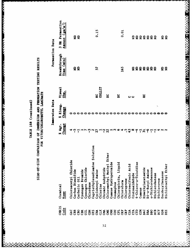
Correlation of Immersion and Permeation Test Results. Generally immersiontesting is considered a screening technique for material-chemicalcompatibility, whereas permeation testing is a more detailed evaluation forchemical resistance. A side by side tabulation of immersion and permeationdata are presented in Table 16. A comparison of the results show that, inmost cases, significant indicators of degradation in immersion testing ".
(greater than 10% weight change, elongation test failure, and visual signs ofdegradation) occur for material-chemical combinations where permeation is alsoobserved. Of the 15 chemicals which permeated VITON/chlorobutyl laminate,there were 9 cases of significant weight change, none of elongation testfailure, and 11 showing visual signs of deterioration in correspondingimmersion testing. Three chemicals (Dimethylacetamide, Hexamethyleneimine,and Isobutyronitrile) demonstrated significant indicators for the immersiontesting of the laminate, but no breakthrough during permeation testing.Conversely, Allyl chloride, Chloroform, Trichloroethylene, and Triethylamine,all permeated VITON/Chlorobutyl laminate within 3 hrs with no significantchanges in weight, elongation, or visual appearance during immersion testing.Similarly, Allyl Alcohol and n-Butyl Amine had the same effects on thechloropel material. A number of chemicals (BPT, CTD, DBO, NIC, and TDI)caused severe degradation (in terms of weight change and elongation failure)of the chloropel, yet no permeation breakthrough was detected for thesematerial-chemical combinations. Furthermore, less degradation was noted for
41m~'C

TABLE 15
RESULTS OF DECONTAMINATION TESTS
Percent Change in Weight Chemical DetectedFollowing Exposure by odor
Chemical and Decontamination or Appearance
Allyl Alcohol
Viton/Chlorobutyl -1 NoFEP/Surlyn 2 NoChloropel 3 Yes
Benzyl Chloride
Viton/Chlorobutyl 1 NoFEP/Surlyn -3 NoChloropel Severely degraded beyond recovery
Benzene Phosphorous Thiodichloride
Viton/Chlorobutyl -1 YesFEP/Surlyn -1 NoChloropel 78 Yes
Carbon Disulfide
Viton/Chorobutyl 0 YesFEP/Surlyn 2 NoChloropel 22 Yes
Carbolic Oil
Viton/Chlorobutyl 1 YesFEP/Surlyn 0 NoChloropel 19 Yes
4-Chloro-o-toluidine
Viton/Chlorobutyl -
FEP/Surlyn -Chloropel 91 Yes
Cumene
Viton/Chlorobutyl -1 YesFEP/Surlyn 0 NoChloropel 56 Yes
Dimethylacetamide
Viton/Chlorobutyl 17 Yes
FEP/Surlyn -1 NoChloropel 65 Yes
42
',,,.

TABLE 15 (continued)
RESULTS OF DECONTAMINATION TESTS
Percent Change in Weight Chemical DetectedFollowing Exposure by odor
Chemical and Decontamination or Appearance
Di-n-Butyl Amine
Viton/Chlorobutyl 1 NoFEP/Surlyn 3 NoChloropel 4 Yes
2-Ethylhexyl Acrylate (inhibited)
Viton/Chlorobutyl 7 YesFEP/Surlyn 3 NoChloropel 36 Yes
Ethylene Dichloride
Viton/Chlorobutyl 4 NoFEP/Surlyn 3 NoChloropel Severely degraded beyong recovery
Formaldehyde Solution
Viton/Chlorobutyl 0 YesFEP/Surlyn 3 NoChloropel 0 Yes
Hexamethyleneimine
Viton/Chlorobutyl 25 YesFEP/Surlyn -1 NoChloropel 48 Yes
Isobutyronitrile
Viton/Chlorobutyl 1 YesFEP/Surlyn 2 NoChloropel 14 Yes
Isooctaldehyde
Viton/Chlorobutyl 1 NoFEP/Surlyn 6 NoChloropel 1 No
Isovaleraldehyde
Viton/Chlorobutyl 1 YesFEP/Surlyn 3 YesChloropel 28 Yes
43
&**- .'.',-* ",<"' .' ."*'. * -/ '","°. - a.( -e' '. ,4

TABLE 15 (continued) 4.
RESULTS OF DECONTAMINATION TESTS
Percent Change in Weight Chemical DetectedFollowing Exposure by odor
Chemical and Decontamination or Appearance
Nicotine
Viton/Chlorobutyl 4 YeaFEP/Surlyn -1 NoChloropel 45 Yes
Nit robenzene
Viton/Chlorobutyl 5 YesFEP/Surlyn 1 NoChloropel Severely degraded beyond recovery
Polychlorinated Biphenyl
Viton/Chlorobutyl 0 Yea1
FEP/Surlyn 1 NoChloropel 5 YesI
p-Toluene Sulfonic Acid
INViton/Chiorobutyl 1 No ,
FEP/Surlyn 3 NoChloropel -1 No
Trichloroethylene
Viton/Chlorobutyl 5 YesFEP/Surlyn 3 NoChloropel Severely degraded beyond recovery
Trethylamine
Viton/Chlorobutyl 2 YesFEP/Surlyn 0 NoChloropel 5 Yes
1High levels indicated by radiolabel in specimens
44
is- 's."-..-,- - .. ,4.555. 5 . . .. .. ... . %. . ,

rwln ~ . - --.- C . . - - .-
0Z0
cc 04 z z z
iiI U
0en -4
0c .0
0 93
to 4)9z00
e0' 0
i t III- I , I I I I
00
0,4
0 0
* I - -I NC.-I 0 , I 0 "
*: '-4. ,= ° a oo < =
* l
00
C*0
-4 " .14 % w 9)4,~ w - 1 i-
Q0o 0
II .
'04 8 0"4- 0W- H 4 c0,l0L)WC 0 '-4 U.-00 c .
w0 .0 w - 4-, - 8 a@1 ane L') 414 -4A0 u'a 0 " < u 4 U H0 ) - -0 -4 a4. %0 0 0 0 r
to >N 0 ~ 1- H0 1a,4c 3a
441 4~1 . 01> 80 M4-40 .4. z .0 6> NN11- -H4O -44 r-4.40 0 ~4 0-410-W W 0 0
Uut Iu - rU0I 4) CO ,-4 4S.W 4;~.1e.- B ~ 0 .0 0
V a 14 z .C UE- 0 0 c4 U.P0 -- -
U 00 0 ~ .- E-4 mu u w z0
45

$4-
0
0*-439
E- 0a
.4.4 UA
'.4
0J .
IQ 00
00
E-44
00
H~ 0 0
6 .41
o1 (VHC~
go. 4)1 4) 4
.4. a 0 )a V m" 0 a0r )-
-4- 0- 0 > - z H 4 0 ) N>
ca4 0 oQ ' -4 0 0 w10 4w03 -
r4 w 0%> - 4 u.- 4) 0. "a I cc-i w. >.-4 V u0 00= L 4 - 0.- w.- 0 . q4-4 40 00-4 03
04 qww 41w 43 a = n U* 43.0 w U 4 >1 =3 14 w -
04a -4 w000 (U0 04 0 q)1.0 0 ~ 0 - 0 04.8 00wO00 00 ".1. '04 w W0 $4W 03-4 -WI4UN4 1- -
a w 0.4. 0*9 0 43 4 ' 0 0. w -0 09004 =ww 0 =4) -q w wtv 0 -4 .- 0 u a a~ I.IQ.u430J Wu
= m m t ;.'40% 43 00 . =.- 43 0 4 .04 " 0.
P-.4.0 44 43 0.4Q4j4 -4 . 0 00 0 '44 z 0n x CUU a0.44 .C4 u
0. w00.0 owUCd0 .4c.4E-40JJ ;N u-44
-4... 943 0.0.0
000$.4-~ ~460 4 g 0 480 34 0-400'.
439 4 I- I- 00- 0. -I 14 -1-40 JU~gUi-

.C1
0z 0
41
* 0 0~'Z
0
-H
41%
E-41 0 a-v -4
51..
C-) a -4
E-4
0 cc
0 040 "
41 I4 P-4
3c 4 - 4O P4- r-4 NOO (DC'J OC 4 0 0 U n -4 a -I$4i i ii
E-4 -4
00I~
.54 cc4
0 3 I- 0Jca1. "'ci-4
rz 4 I4 4- 1.0-H- 3 0 4 0 4
0 0% ca1 " w=.40 --4 0 4 0 4 4 w Ai "-0 >1 -4
0 N w ".4 w- $4 8J410 0 0 0 C4 CO4 3 0 a0 a 0 0 0".4 4) $O4 w '04 0H
gm nd4) 0-400 C 41 1.4 *44.4 .Ic a 0 >0 C: wON ( . . 4.0 C 1' c U- 0.0 0 00 = = a
W0 0 u0 z 141 >4 0w 4 -H c H . i. 4 >. 0v--ps1 "4d- w. 4In. m .40'z0 w 0 01. m u=
0 0 0 .00 ,-4 0 0 0 O.-4.0 =0 0444 ) "(cc ww 4 >N >,w >tC3 . 4 u . 10 r w04 -4L).0 .
(1 0 -49 . d 00 0 C 0 c 0.-. 04141)0 44..4.4 m ) -4Az0 j I w 1 " 4 A 4 " 1. 1. 4. 1-. 0--4. 0 -00 4 -.4 00 --4w ww0 4$ >,> ,>
440 -H I .U M U 0=4==1
C o " 4" - , 4,'- j A 1 4)0 1 " 4 j 0 - j A
47

cc
41
cc 0
0
C-4
414
12,1
93 0
0 r-
0 00
E- r4
1-44
A41
,fl4 400 4)
1 104 0$ 4 41V 0 cccc o0.I..w0 lu VU.-U.444 -4 v41'41P0-40
0 cn 4-4.- $4. 44,-4"hr" P1-4 wwQ >N41 ~41 ~44 0-w-$ " 4U V 0 0 0 4) 4)0 9 W 0 .0k CM CO0 $4 0 W
r41 4 %44 4 9 $4 L)U $4 rk-4 1-4 - 04 0 -4 w~ W .- 4.0 Ow 4A ok C P4-4 10 0 0 >.00 0 -44 c w Q 0u4 0) z "-4 3rI0 930 93 .04 w4 > D% m4-
ccg41 cw go( *41 141 0) 14 4 P.. ON 1.0.m m4)0 U-4 00. w 00(1 0 0U-4 00 UAJ 4J 4J 00 r4 - -4 r-4 >%0 0 k k w 00 0 04N4 4$41, ZUW > >%> J .J
0 01 41 k k w w w w1 0 V'.0.0 A0 0. I4. >W .90) 4=1U = = 0A 1A
41 414 (U G)0 - 4- C )4 )1 4Oz C4 4 wo L a .
48

cc
to 0
040
4, N
E-44
00
$4 -45-
0 00
0.44
00
0w E-4
.4 0
E- I 11.1
00
05 S0
'-40 93 0- . Os- -V-.40 04 92 ".. C w
(na 0a cc .w u m$400 S4 .0 4 1 -4 M O P 4 ) 3 4 -4 4
>.5. 0 $ 1zJ z$~~ 5 4 =$ W =N$ . w
.5.C0 41 c '- H 0$ ~ -41 A4u u w0 C 0~-40 "'4 64 0 VJJ C -4 0 ..8>%.4 0 4
w 4 4 0.0000 1W0 ' ~ w 4 > w10 $ 4 - w-H -4 C. UCv-.-4 Q o 0 4 4'-4Uj 0 3 1"
$4 .-H " U 0 N U u 0 w0 0 0 cc
cc 0 a 0*. 0) 4)C 4 0 HOCO > 00 0 >%.-4 >-4O -4 - 0 U CO-H $4 000CO.0 U U 4) 4 4 -4 W -4 .0.=0.- 4 W W
PP o 4 - J O= 0 .- 4 U 0.00 00 00. 0.0 0 ZUS =0.. $4 W 0 - 4$4" $44w $4 - o ,u2 0 04Cc$4 4 44 44-4
C 1 4U Ji 4 .I Ai u Z A 0. 4.8. A $4c 0-4 w$ 44300 0 0 41-4 1- "4) 41 w0 5 4 -4 to" I4-H cc- 4NCw .0.0 0 .0 =I = =I W = O
u.. LJ M M Z 0 Z ZZZZ 20 040.Ad 00ad 04 N0493A4A4 A V (
.5, 49
-~~n - ,5 .5. .-*.*~. , .7-- Id -A , -* -'r 5. * "-

10
0
00 E04
U00
41 .
- -4 Ul 00
41.O93 041%
0 Z-
'-41
VV
41 U
03 M- 0q cOO O O O O o vO o u j C14
00 W1~ 4- 4 - $ CC4) 0 4414 C4 1 a 0www $a1 11 1 VI II o qPQ4 )$ 0 w "I V 00 I
-H- 4 0= 14 z41=I4 A " WO4o4 *P4 -4 .
w Z- 0U 44 4 J .- 4 U1
= 4w 1 U 0 C1 4) toA s( j )M9 . -4 .0 4 .,4wV 44 4- H > U 0 CO CO0 U - 1..U
0 v -M4J1 k0 ) 4 t 0 WW U 0i -4 -4 0H 04H-
V 414 U W4 0ad 0.4 u- Q oCU44QWE- E-41U04 W4 x L-4 'V u -4 u owH u
E- -4 C-4.0 1i . 41 -4 E- E-4 E4 E-4 4.4' > > > > N
04 41 Cl4.*.-II.. .411 U~I~.50E-0

4f
41 0 0 0D
co 04 01 Z M0410 1
0 -
00009
144 00
A;U3 4j %-o
0 do P.
an. 00 0
" 0 40
00
0 '0 0 0 0 n 0 000 0 0 r"O 000 0004
-oH
14
ii.0
1-4 00 41 V-1 "q '-I
?-I Ajw ~ :0W4 0 4 1.0 woo P-4~. 5.j $4 1 w
4F 14 -0 4 41 000c 0 -M
Q 04$ - q( 40 0w 49 -4.yw4-H5.HU00r-4 0 0.4cn v ~0-4 0 $ 4c v - .0 W - 1900 .4z 0 = $4 r
0 0$ -C. -4 0 -4 14 . .4 0%,4W lw "-H -4o 4 000 u O4 1-4. > 3 > 0~.4- 0 1-40w-p4 0- - 0 93 - 1cU 3-4E-4 0 -40 .19-H w-,4 E-4
4WI .IJ >1 0 o 0 >'- 0 N N, Q. t4 N 1900 1WE 4c 4c.1W<W c .4 c44A JJ .4 .. 4 4J op00* go m m g m 0 no -
N..
4wP
04
0 a.
U .W
$4 V4
U 0
.4.
cc z1.44
U, >
01.
1-4Co3
2 '-4
41.4 0 0
444
r-- P--E 409 :. [email protected] 4v wa1 .44 40 04
;W4 -<.. 4J C 4( - 0 c:. 0 4Coo 0 cm0 w 0 40wzP40 1- 1000-
40 V4 0) 4N CC.-1J 0 & . I CO ~ $4 I% = I4$ 4>
0 3140 0. )04 n 000000( 00.
W 00 WH U4 q0-
u0 0 4 rx 4go m4 0 adV ad E0 0 1.4m
0 1 A .M 0 U 1 W

414
o4 41Z 0
V4o 03
(4o
E-4
00
ama
P- 00 400 MMr4 MP%00 0 Mt r4% 7 -
I--a
E- w- -
-0 -W4
_o 4 4I U
0 u 41$4 r
0o 4-4 u -4
V4 "4 41 VI OOOO OOO OvOO$OO OOOO O
0 (L
0 F I 8i -4 .-4 ('>%~ WI " 19 . . %c
C6 0. 93 * *0a.4 . 3 c 4
0 ~ ~ ~ ~ ~ ~ .0.. 400=0c %I W( 44 ) QA
a-4 I.'c, a Imu 14 W ccc 0=-
u z 0 MQ 022 w aw w wa w w
0 0 4 0 u4) 0 4 w
"40 04 04 U) 0 a" ) 4 owmH4h-8.40 000 ) 14 *"S~a .4 J0 ~0 %
OW .. 4k) ~ o .43 0 00534

00
00,0E0 0 9
mG
00
"4a
'-440 m C
88
U3 Aj -M- a0Ql30 " 0 w #
V .4 4 v. Q 40v v"o 0
0 21 0V(' u d =()~' $4- -4F44 0 vC Q-4 Z%4c' c 04 .-4 >%
4 0w4 - 4" V- 40qf4-42 "49 0 - > %$0m. Q. 4 1 -4
4-40 1'4 W 0 4.1041%I ww ===I01 N 0 0 0 0 41 0 0 000A A
cc w140l4 w. *-40"z C 2 '9ww-14c P4 1 1 '.4 J 01 041
-4 C&41..4 "0,4u 0 124 4 10-414x0X
544 eU

- - - - - - -
0
4.0 41
00
E-4 0
0 '4
.4E-4
-4'.4
cc V-
Z'
E-44
Z- 8 8 8
401CA.
4.-. w~ ~oH0Ue
Uc
in 0 VV 0 a0 r ~4. u 4)
4 0 4 4.8 -
0 41u 00 0H4 jcN 4) 4 10 4) go44 w4' W
v 4 0.m 4) - .$ >" E 10 H 4)
CA O4)' 10% toa0 =4 .0 v 4r93w 0 c co= 4
0(10 4 P4 4 FlW 1 V 44 "4 a = z U -4I-I '$4'4 Wu 0 4)4.h)4) 0 5.4 0 0.4-
-4 4 w >4.4 0) 1 0 a 0 IC H5w 0 w Oww0 0" 1 -4-4 ~ 414 0 0 0 W 001 j 4J 0r-4) 00>.CC- :-
-o 4 - 4 c c-4 64Go .0UO4).0C 0.0 -4w . = .d5
.6 1ZI410 uZZ Z O Z "0.4 c. 0 w0 a 0 0 A4 4 -4 -4
to 5w 1 r . 41440 xwC0Q= I-
U i MMZ =Z0 Z Z0 4 4A4040 9W C~ -4 A~4 4*4. W M 4.
C/). .

Co
00
0 93
r.4
41
0 Z a
ca
@00*
FZ >
'.4 ca4 3 V 0 1nu 0'a 41i .00 r4 V4o $-4 u a0 ) 4 -
0 )4 C. 00 0 0 0 0 @ 0 0 0 0 0 0) O
4 0 W4 -P c o93 0w 0 dc
.d .4 = @0 49 1 40 0 0 4
W 3 41 C 0 "3 W H4 6 4 4= 4 -40 40 0 0 0c 0 E-4 w '00 u w 4 to
.fl '. E4 0 Sj0 0 c %,1 4 44 -4z- 0 a m@3u 1= 0 " '-1 - -4 a 4 .0 0 @3( - 6 4= 3 4
co P -4= 0 0 w 6= P - =40 00 uE4 = -H-4tj $4 $4 0 C z H 3 U= I A 1.0 4U9 k Q
40 0 4 u .1 4 0 00 41L d4 0 m $30 4 -0 00@3OU 444. Z > 0Q O ( -W 0 to 33$ co>%> > % iiu
-4-444-'' E4-4 4 - 4J "h@ @3 4 - j" $40W ~ 0 ' 0toH 0 z "4 " k .0 4 -( @34J'4 W="-44 4.-, -...- 43 -'4
'I UQWOn c -4 E-4 H -4 CI4E- HE- HE- &@.4 > $>-> > N
0 '4 0 04 4 w uu 0 m =w E-4m o
w00 w " I. 4 0 @ 3 $4 x3 u4 ow u 044' .-. 4u U ~ U W f W f W P 0.-W E- E-4 E-4 F-4 E-4 &-5454 E- -4 ~> >> > NN
56

Ajz oT C-4 co
0
W1 0 d,0 00- 02-000
id I 0~ 0n 00I% 0
04
%aa
14
41 140. C
14-0
141
14a
1 0-4 4'-4 -4".1 4tIV 0 w
la J0 w w-044Aj $ V 44) 14V 04 - 0c
v 0~ w0)c Hr 0 WV( 4$
A 4C 41 0-4 -4 .44 wdC :. - 4 -0o u.40 4 0 - nu 4
100- H C - 3 )W 4 E4E44
l0u ur4r4u P4f- - 34 41 o" w w 0 14 0 0
" 041MgIs 2 UO 4 14 L) U0 4> - -u 4-8 0 W cn-4 g z0 dC4E4F
JWq414 0 410 0w
570 4 014

41-
0~ 0C)0 0 0
CD~ 0a Z C4 zo041 04 ST r
0
C,'4
0 V- 4
* 409
to 41% O Hm m " w 0 c - V1 N c - - ( l n N 0 rI%M l nP4r4r4 P% 0 . %f%0 4 P tn md P0 00 %D Pu* %.
.4 -Ir-
r4 (L)q
'4 1
"II W4
Vo 0 )V4 0 10 H4
Q4. -H - 0 4 1 4u 4 -
0. 0' hiwA 4 0%1 H 4 4 04-J 0 0- 02U - - 0q 4 M 44 40z04
'4 ,4 W . >% < 41 Co u 4) -4 v 1 40 >%4 i. > . )-4 u 12 j a a r.0 0 W 0 -4000 0
.0 cc 41 cQa Q4 0 0 z Q-
0 . on- CQr u 4 c p co0 1 U U U UU 41.01 Im C a 0 M0
m -41 4*0 141 d.J ,- ~ ~ ~4058
I .d ~ O~-4~40 -~oI~ ~in-'a4

*,-4 c'
2 0
E00 a--0'
.W k-"C4
10 nCw
4 0
Do
0 .z v-4 9-
caad4
N r- 4- n -1C F4r-W-4c" C % %r.e n nr.( . 4coq"0 4& ac 40 0.1i - 41 %W D ca.UI-I-4 4-
0*
CA 10 4)
V. -4 0CC0P 0 $
u NH
0 *4 10 .0 -H0 -0 0AA 0
Cfl 0. 1 0 51- Nc
1- 0 4 wr Ww1 00 =-00 a 400rI .0v1 4 0>-S 4c -4t 44 4 000 0w $
0 C-0 C M 4 cc- . 50naP4 u - -4 04. - ' c -
PN -4 >- 4 $4 W5 :0- m r Q 0 0 u
m 93 10 0.0 4 Of- 02 -00a0S 0 4 4 04 -4 u 4 C4). 0) 4 P=- 0 ) 0~
9-4 z 0 "_ 0 a). AI w. 41 .0 - -4 -4 4-4..-4 -- 4 -4 -4 -4 W -4~ -4O-
8)U~~~-, -4.- E .K
u,
r59
V) :D 04 d0 0 L

0-.0
'a 0
0
0 0 -
0 4E-
E-440
E-/ 4 I1.41 A~
0 T-
U0
j4 ~ 3
a a
4) 0 0
.n41" -0. 4O 4 V 93 41 0V 3 -4Cd 4u1 -T V w ~ cc V o cc cc*JJ
V, 0 En 0 00 - " W -14 -4 -4 J W4 U DN 4J ",04 0
0 4-0%0 c -4 Q =~ aaC. 93 6 1 > 4 0 r -4 k~ ~4 00 w4- .0 i 0 4 w- - )0)Vc 0E 0 >1~V 0 0
., z-4 0w00 u a00 0 00 41ju Ai41410 0 1- qr4-414C>wV 0 0 w w .0.0 0 M00. " >-
Q~ $41010aa 0 V 0 00 0 0 0 Jj Ai Aixw
co w0 11-4.-4~ ~ > V 0 W W r 0 V i
60

0 Z.
00
* 00 90
~.410 0 0-
0 ~0
U30
0 A4.01
CCI
'N--
2o
~bIn
0 V~U, 0
0 24 (L .01 -U0 V w g X cc=
41.0u
0- 4)9 4V 4O -
a 9 >E- 1
0 0o. D0C .ww040 3" r - n q "'4J Z 2 -
$4 OIf " $ U u .w 00 CCno 40 > 1< - W064 1400 0 -.0.0- C
ca 4.40 0 0~4 W0 -40 J 0U %toO
-H 41 A= 4 - u 0. u.0 00 0Eo-.iQGoJ '0W A-4-4 0 -4$ J W W -4 W U > M4. r.4 W M .- $. -4 4
e, 4JAJA " " 4 J 0 1400r-4 P4 0 4) 00 A, " -4 "a4to v-4 -HCd v-H CC 4 -4 )4 (UC-4U CW
u .3m..-z0== ZON..u 0 N~U014 04 o wwc
0 i CI44.O 0 -4U X> x0.O m 49.u.40 4.H.J-4
'00 E-4 .04.1U." 00 W0E-4- 4 -U 0.. 00 0 .004)Z ZI Z44'44 0.ZJ Z Z Z Z 0 N~ 04 04 04 )0.0 LIC 13..'N.M4W4M
61

4.1
0~ Q%
04 41 z0 0 0qz4700
00
E-4 00 0 %3
E-4-
4) 0
4 904
cn C-4 1 .~
g. 1-4 4.
E-4z
'.9ad
4.v'
'5 0
4P4
W- -4 t ., -4 0 i-I -1 0 4 (U 0 4) v4 C rJ-4 V 0-4P- 3 aC3w4I4 w4
$4= 0 0 c ( % 0 . ct
0 j 4 4 1 4 v 4 = $ C 1 W 40 0) 0 4"a - cc N 9z" ww cl0 k 0 0 "1"4 -4 C 4 = w -W " r.4 -1 "0 U .
0 414~,4 4J r 340
4 - 4- -4 k 4 " " ~..-T " "-4 - X00 4 .0EW0 0u4 00 V)rn 9:-4 H E4E- 4E- -4 - E4E4
'J U9- M E4 C
u n( - E- - ~4 H HH -4 > > N
62
'V d',

"wm m n
'S five other chemicals (CBO, DBA, DMD, EAI, and SFA) where again permeation wasnot detected for the majority of chioropel-chemical combinations. Significantindicators of degradation in immersion testing did not always correspond todetection of breakthrough in permeation testing. Based on these results, itappears that both immersion and permeation testing are needed to assessmaterial chemical compatibility. Consequently, compatibility recommendationscannot be based on immersion testing alone.
Development of Compatibility Recommendation Criteria. Recommedationcriteria were established to determine whether subject suit mater: als werecompatible for use against the chemicals evaluated in this study.Recommendations for suit materials are limited to "Pass" (compatible), "fail"(not compatible), or "unknown". The basis for these recommendations is asfollows:
Pass - material compatible with chemical; no indications of degradationin immersion testing and no detection of breakthrough inpermeation testing.
Fail - material not compatible with chemical; any indication ofdegradation in imersion testing or the detection ofbreakthrough in permeation testing.
Unknown -material compatibility uncertain; insufficient data for arecommendation (i.e. permeation testing not conducted).
Criteria leading to a "fail" recommendation are essentially consistent with
the judgement of a significant indication used in the results. These include:
A -Chemical Permeation breakthrough within 3 hours
B -A material weight change greater than 10% following immersion testing
C -Failure of the material in the elongation (strength) test; samplebreaks when subjected to 5 lb (20 lb/in) load
D -Elongation greater than 25% following immersion testingI
E -Any visual sign of material deterioration involving polymerdegradation, moderate to severe material curling, stiffening and thedelamination. Material discoloration (lightening or darkening) andslight curling are not judged as deteriorations.
Material-Chemical Compatibility Recommendations. "Pass," "fail," and"unknown " recommendations are made for each material and chemcial combinationtesting in Table 17. Table 19 summarized these recommendations for eachmaterial while Table 20 breaks down the reasons for failure by material. Alarge number of "unknown" determinations exist since the majority of chemicalswere not involved in permeation testing. A material-chemical combinationcould not be recommended "pass" unless permeation data was present to show nobreakthrough for the three hour test period. On the other hand, amaterial-chemical combination could be judged "fail" on the basis of immersiontest data in the absence of permeation testing. This approach was adopted by
63
S..'N

C.;4
Cho ao ao ao a ad ao
ooo 4 00 C2 ON CZ0 4 04 40 04
00
"4 -4,4 1-.
.4 E- 0 C.) L Q0
0 z0
.- 4 66 *6
W E-4 H a-
64-

000d 0 4 C 0 4 2 04 4 04 0 owN 00FaF
0404 0
00
b44
aa
~ 4 0 04
0 U~04 w-
0 HH
CA u adSS ! U d aA
?= ONH00
us) 0 4
u 0 4-AH -Mon
*6
* ' ~k 2H

alla
a!41
0o 0
0 rn U H
ad ada ad
H 14 dMS U3 4~r~U OW o->4 Z
>1 E-4 IQ0u
EE-1
2 H
0= ca 20 W w COU~ ok .
26

ci) ge) C.)C.)C.)C.)0 C.
Oak 000
Ci a3 0aa alla a," a14 a,4 a14 1
.- 4v-w-40-4 I. E40 r-4--4- 4-I- U
U~~~p~~q.4. H CAqI.q.~.4r
C- 0.
z ,- z
'44 I- - z zhi hi67

C.4 0u an.C U u go u0 a
a a a. a a a a 1
U3
.01%1
a ad. 44HP
000
0 A~ .0-H H= 24 W1
cn x 0 0k0
8~ 0 1 00 0 ~ 10 0 OM1- p 4
o ~ -4c~1-4f-
aC. 2 n
FnU4 04n04 -4E-
68

-4 U 4 ,- 4 0-4 -4
A I
0
iinn69

the Coast Guard since immersion testing does give indications of materialdegradation that appear to be often associated with permeation breakthrough.Nonetheless, even in the case of apparent material degradation vis-a-visimmersion testing without permeation breakthrough, significant weight change,elongation failure, or visible deterioration suggest material breakdown whichcould decrease overall garment integrity.
The original premise for the three hour duration of both immersion andpermeation testing was based on an intended maximum stay time in the suit of2.5 hours. During the course of this development, this requirement wasreduced to 1 hour. The impact of this change affects the basis of therecommendation criteria. Since new testing was not performed, i.e. one hourimmersion testing, the failure criteria were adapted for a 1 hour application,with less stringent requirements relevant to immersion testing.
A* - Chemical permeation breakthrough in 1 hour
B* - A material weight change greater than 25%
C* - Failure of the material in the elongation (strength) test; samplebreaks when subjected to 5 lb (20 lb/in) load
E* - Any usual sign of material deterioration involving polymerdegradation, severe curling, and delamination
Recommendations based on the above modified criteria appear in Table 18.Tables 19 and 20 give summaries of the recommendations and types failure bymaterial. The difference of these results as shown by comparing materialsummaries of Tables 19 and 20 indicate few changes in the number ofmaterial-chemical combination "pass" recommendations. There is a limitedincrease of "pass" recommendations for each material (4- VITON/Chlorobutyl; 3- FEP/Surlyn; 4 - CPE). There are also fewer failures. The most significantreduction in "fail" recommendations, 20 is noted for the chloropel. This isprimarily due to relaxing the percent weight change criterion. With the newcriteria, FEP/Surlyn has either a "pass" or "unknown" recommendation with nofailures.
Significance of Compatibility Recommendations. On the basis of the newcriteria and excluding -unknown- recommendations, VITON/Chlorobutyl laminateis recommeded for 62% (43 out of 71) of the rated chemicals, FEP/Surlynlaminate for all rated chemicals, and Chloropel for only 221 (21 of 97) ratedchemicals. The choice of FEP/Surlyn fully meets the requirement for a visormaterial compatible to the same chemicals as the garment material.Overlapping chemical compatibility is provided for 20 chemicals by theVITON/Chlorobutyl laminate and chloropel. That leaves only 1 chemical(Triethylamine) which is judged compatible with Chloropel but notVITON/Chlorobutyl. This combined with the general poor performance ofChloropel would seem to provide little basis for the use of this material inthe Coast Guard's HCPE System.
The Coast Guard decided to make a closer examination of the chemicals forwhich the materials were recommended and to also take into account economic
.4.considerations in analyzing the suit material compatibility recommendations.
°7 01

AC
pa aW
a4 a1 1 a a a 0a Ha- L
40 z 0a
c.i 04uw M2 We9 i
240 oc L
4a0 0 C4
X 4 k4Z14 4 M ' 0
71~
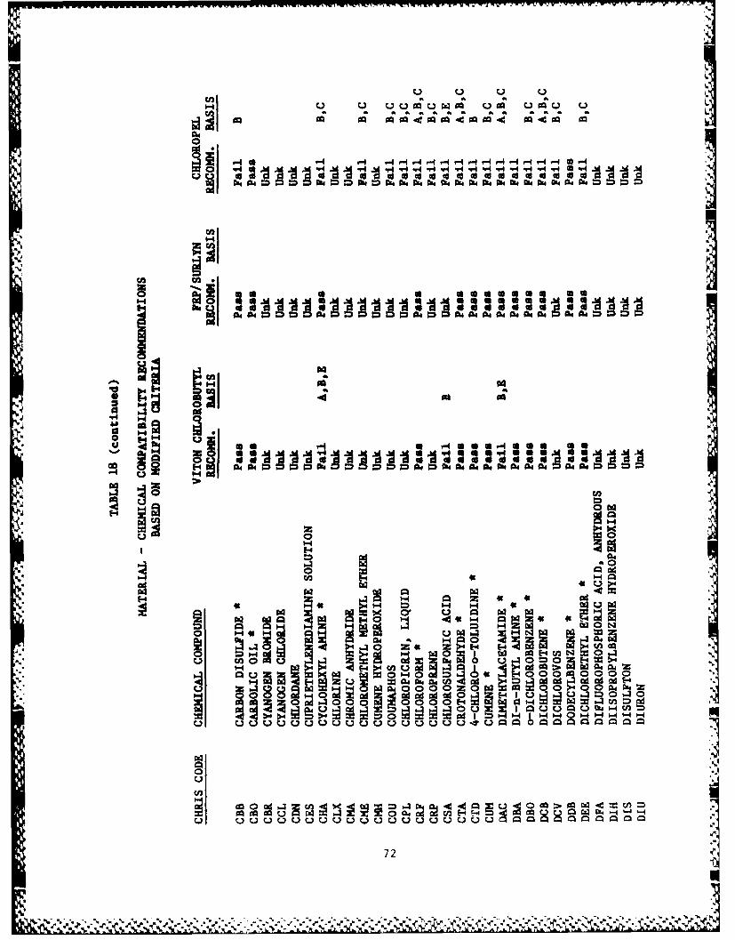
Ire, C. 1)
ao a" at a4 at a4 A ao a2 a0 a aWa4
.4 0r4 C3 3 44 CD 4 04,4 094 .94 q4 A4 094 4 a
C.C4
iiE- UE4d mu tt 5 g
g.44n
72

OMa Qa a
0
ci 014~- 6 -
mi U
4J40
I4--4
m 9!
a 0 6 C ' H
m- pa4 00 14 i 040a
OO~~~ ~ cn CAmmlO
ZH '-0 0 E4
H Ho41.1E-- 141- -
0U)
0 d 0hmV ftml u 0~ Of 4 ~
* 73
- . . - . .* - ~ . -, *4* **5

101 4 0 CC N4 c
44 04 04 04 0 2
00
-4 "4
H 1 4a
I4 C- ON 0 r4 CAO N
03 u IHmA U ~ 559 45 U-,. F-4 "49-
0 ~ 0"44
0 -4 4
HO ad 0 - UQP4 6, z 1-4 - z
74.

-1 - . 4 *-4 -4 -4-4 -4 0H -4-44 0 -
a.
4 Z4
14CHO: D Ii *m 4m 4 E4C*,-w 0 1 -4
00
H 44
.2 H
z 004a4CI 4 4 w 4 NW ~wUw H0E 4 E-4 - -
~~it
75

amP- r4m CO "
CA I U
coe
m 3 Ho 0
104 a c O. m 4 0
w N ad
0 0bzN
H E 444
N7

TABLE 19
SUMMARY OF SUIT MATERIAL COMPATIBILITY RECOMMENDATIONS
Original Criteria1
Pass Fail Unknown Not Tested
VITON/Chlorobutyl 39 35 86 0
FEP/Surlyn 55 4 100 1
Chloropel 17 95 42 0
Modified Criteria2
Pass Fail Unknown Not Tested
VITONR/Chlorobutyl 43 28 89 0
FEP/Surlyn 58 0 101 1
Chloropel 21 76 58 0
1 Original criteria, see p 63.2 Modified criteria, see p 70.
77
..

TABLE 20
SUMMARY OF SUIT MATERIAL FAILURES
Original Criterial
A B C D E
VITONR/Chlorobutyl 15 28 5 0 26
FEP/Surlyn 0 3 0 3 1
Chloropel 29 96 71 0 6
Modified Criteria2
A B C 9
VITONR/Chlorobutyl 12 15 4 17.
FEP/Surlyn 0 0 0 0
Chloropel 23 77 71 3
1 Original criteria, see p 63.2 Modified criteria, see p 70.
78N

Appendix B provides a Coast Guard survey of spilled substances. Using theresults of this investigation and those from MSA Study for butyl rubber, suitmaterial recommendations were made for the majority of the chemicals listed inAppendix B. These recommendations appear in Table 21. When more than onematerial was compatible for a particular chemical, the estimated cost of thegarment was considered and the least expensive suit chosen. For example, thecost of a VITON/Chlorobutyl garment is predicted to be 3 to 4 times greaterthan that of a Chloropel suit, based on material costs and differences infabrication. Though VITON/Chlorobutyl and butyl rubber suits would befabricated in si~Alar ways, the cost of butyl rubber material is substantiallyless, making it a less costly suit.
An analysis of the compatibility recommendations together with spillfrequency and suit cost considerations show how a three suit material systemmight be employed. The summary below shows the relative numbers of bothchemicals and chemical spills (chemical spill frequency) that each suitmaterial would protect against:
Approx Number of Pct. Number of Pct.Cost(l) Chemicals Spll
Butyl Rubber $1200 11 20 421 26Chloropel 500 7 15 877 55VITON/Chlorobutyl 1500 10 18 63 4None Recommended 10 18 106 7Insufficient Data 18 29 127 8
NOTE: 1. 1981 Cost Estimates
In spite of poor test results, suits made of Chloropel could be used themajority of time, whereas VITON/Chlorobutyl suits which have relatively broadchemical resistance would find limited employment. Nevertheless the threematerial HCPE system allows response personnel to be protected against manymore CHRIS chemicals than if suits used were based on a single material. Thedifficulty in a multimaterial suit system is selection in the cases of unknownchemicals or chemical mixtures. If personnel entry is dictated by theOn-scene Commander, these situations would require judicious selection of theappropriate protective suit. It is suspected that the best overall suit, thatconstructed from VITON/chlorobutyl laminate might be used in these cases. Onthe other hand, chloropel suits should not employed for unknown chemicals or
", chemical mixtures due to their poor overall performance against many of theCHRIS chemicals. Additional testing will continue to determine which otherCHRIS chemicals are compatible to the selected suit materials as thedevelopment continues.
79
%|

TABLE 21
OUTERGARMENT MATERIAL RECOMMENDATIONFOR SPILLED SUBSTANCES
ANNUAL RECOMMENDED ALTERNATE
COMPOUND CHRIS CODE NO. OF SPILLS MATERIAL MATERIALS
Acetaldehyde AAD 35 Insuff.
Acetic Acid MC 90 Butyl
Acetic Anhydride ACA 10 Butyl
Acrylonitrile ACK 12 None
Allyl Alcohol ALA NR Viton
Allyl Chloride ALC 3 None
Benzene BNZ 9 Viton
Benzyl Chloride BCL 2 Viton
Bromine BRM 3 Insuff.
Butyl Amine BAM 2 None
Carbon Disulfide CBB 6 Viton
Chlorine CLX 20 Insuff.
Chlorodane CDN 2 Insuff.
Chloroform CEF 4 Viton
Chloropicrin CPL 7 Insuff.
Chlorosulfonic Acid CAS 6 None
Cumene Hydroperoxide CMH 4 Insuff.
Cyanides (Sodium,
Potassium, Sol'n) -- 5 Butyl
Cyanogen Bromide CBR 2 Insuff.
Cyanogen Chloride CCL NR Insuff.
Cyclohexane --- 6 Butyl
Dichlorobenzene DCB 1 Viton
1,2-Dichloropropane DPP NR Viton
Dichlorovos DCV NR Insuff.
80 7.

TABLE 21 (continued)
OUTERGARMENT MATERIAL RECOMMENDATIONFOR SPILLED SUBSTANCES
ANNUAL RECOMMENDED ALTERNATECOMPOUND CHRIS CODE NO. OF SPILLS MATERIAL MATERIALS
Dimethyl Sulfate DSL 4 Insuff.
Ethyl Acrylate EAC 38 None
Ethylene Dichloride EDC 2 Viton
Ethylene Oxide EOX 1 Ineuff.
Formaldehyde FMS 18 CPE Viton
Hexane HEX 8 Ineuff.
Hydrazine HDZ 7 Butyl
Hydrogen Chloride HDC 305 CPE VitonHydrochloric Acid HCL
Hydrogen Cyanide HEN 2 CPE VitonHydrocyanic Acid
Hydrogen Fluoride HFX 35 NoneHydrofluoric Acid HFA
Hydrogen Peroxide HPO 35 Butyl
Mercury MCR 5 Butyl
Methyl Bromide MTB 2 None
Naptha, Coal Tar NCT 22 CPE Viton
Nitric Acid NAC 101 CPE Viton
Nitrobenzene NTB 8 Viton
Nitrogen Tetroxide NOX NR Insuff.
o-Nitrotoluene NIE NR Insuff.
Parathion PTO 10 Butyl
Phenol PHN 38 Insuff. IPhosgene PHG NR Insuff.
81
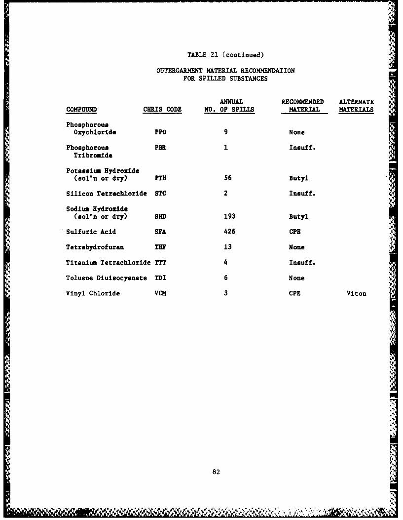
TABLE 21 (continued)
OUTERGARMENT MATERIAL RECOMMENDATIONFOR SPILLED SUBSTANCES
ANNUAL RECOMMENDED ALTERNATECOMPOUND CHRIS CODE NO. OF SPILLS MATERIAL MATERIALS
PhosphorousOzychloride PPO 9 None
Phosphorous PBR 1 Insuff.Tribromide
Potassium Hydroxide
(sol'n or dry) PTH 56 Butyl
Silicon Tetrachloride STC 2 Insuff.
Sodium Hydroxide(sol'n or dry) SHD 193 Butyl
Sulfuric Acid SFA 426 CPE
Tetrahydrofuran THF 13 None
Titanium Tetrachloride TTT 4 Insuff.
Toluene Diuisocyanate TDI 6 None
Vinyl Chloride VCM 3 CPE Viton
82
82

CHAPTER 3
DESIGN OF THE HAZARDOUS CHEMICAL PROTECTIVE ENSEMBLE
The objective of Task II was to develop a Hazardous Chemical ProtectiveEnsemble (HCPE) which integrated a self-contained breathing apparatus, liquidcooling system, communications equipment, and totally-encapsulatingoutergarment into one ensemble design. Outergarment materials selected inTask I (VITON/chlorobutyl laminate, butyl rubber, and chlorinatedpolyethylene) were to provide as complete resistance to all chemicalsidentified in the CHRIS list as possible in a minimum of material-suitcombinations. The design of the outergarment was to have the same operationalcharacteristics and general configuration regardless of the material used.The entire ensemble was to provide Level A protection as defined by the U. S.Environmental Protection Agency for trotection of personnel against bothchemical vapors and liquid splashes.9
Outergarment
*The outergarment design concept developed for the HCPE was a totallyencapsulating garment configured to accept the Environmental Control Unit(ECU) which provided breathing air and cooling, and communications equipmentwithin the envelope of the outergarment. This would ensure that the equipmentwas protected from a contaminated environment since the chemical effects onthese items were unknown. ILC Dover used many of the characteristics in its
2 commercial and other self-contained protective suit developments (i.e., theDimilitarized Protective Ensemble and the Model 51 Chemturion) as models forthe Coast Guard outergarment design.
Seams. The design configuration for the outergarment, sketched in Figure5, was the same for all materials with the only difference being in theconstruction of the suit seams. The butyl and VITON/chlorobutyl laminatematerials required that the seams be stitched and, in order to prevent leakagethrough the needle holes, the stitching was coated with an neoprene basedadhesive and tape was applied over the seam (see Figure 4). A polyesterthread was used in this seam construction; the seam tapes were simply one inchstrips of same material as that for the outergarment. The CPE garment wasfabricated using a radio-frequency sealing technique that yielded integral,leak-proof half inch lap seams (see Figure 4).
Visor. A integral visor was selected to prevent the possibility ofchemical penetration in the head area of the outergarment. FEP/Surlynlaminate was used with all three garment materials. ILC Dover laminated the 1ml FEP to the 20 mil Surlyn using heated press (250 0C at 44,000 psi for sixminutes). This material was flexible at its overall thickness and became asimple extension of the upper torso in a hood-like configuration. Seams ofthe vi.sor material with the outergarment material required stitching for eachmaterial type since ILC Dover experienced problems with heat sealing CPEdirectly to the FEP/Surlyn and still maintaining structural strength.Visor-garment seams for the butyl and VITON/laminate suits employed tapes of
83

Zipper Closure
Visor
Nihaust ValveAssembly
Gloves
Nzpamsioa
TOTAL ENCAPSULATING SUIT DESIGN
Figure 5
84
the same material bonded over the edge of the visor with a neoprene basedadhesive. Tapes of CPE were heat sealed over the inner Surlyn part of thevisor and bonded on the FEP side.
Sizing. The garments were to be sized to accomodate the 5th to 95thpercentile range of sizes (using military data). ILC Dover recommended threesizes: small, medium, and large based on their experience in sizing itscommercial encapsulating garments. However, the Coast Guard chose to use onesize (large) for fabricating suit prototypes and was to later consider a threesuit size system for production. The large size generally fit large-buildpersons up to a height of 6'6". Shorter users (less than 5'6") had difficultyin seeing out of the suit visor. The VITON/chlorobutyl and butyl rubber suitshad a weight of 10.5 pounds (less the cooling system pouch) whereas the CPEsuit weighed approximately 13 pounds.
Closure Assembly. Each outergarment had an extruded closure and restraintzipper to provide entry into the garment (Figure 6). The outer closure was atwo-track interlocking seal that provided resistance to chemical penetration.The inner restraint zipper protected the outer closure from structural loadsthat might tend to pull the seal open. The outer closure on the CPE garmentwas extruded from the same material as the outergarment, while the closures onthe butyl and VITON/chlorobutyl laminate garments were extruded from achlorobutyl compound. The inner closure was a Talon OEB pressure sealingzipper having neoprene tape and brass chain, sliders, and pulls. The innerclosure was stitched and bonded to the garment material with a neoprene basedadhesive. ILC Dover believed that the relative thickness of the outer closure(approximately 0.080 inch) would provide chemical resistance as good as theVITON/chlorobutyl laminate. Yet, testing was never conducted to verify thisbelief. The closure assembly was installed in the rear of the garment forease of entry, access to the ECU, protection of the closure (due to uncertainchemical resistance), and to avoid interference with the ensemble coolingsystem located on the front of the outergarment (described later).
Hand and Foot Protection. Each outergarment had 0.012 VITON glovesintegrally bonded to the sleeves at a cuff ring located at the wrist (Figure7). The cuff ring was a 5 inch diameter one inch wide ring made out of highimpact plastic. Use of the cuff ring allowed the ensemble user to withdrawhis hands and make adjustments on his or her breathing apparatus inside thesuit. Sock-like booties were fabricated from the base material attached tothe overgarment. These gloves and boot-socks acted as liners and ensured thatthe garment remained totally encapsulating without the use of additionalsealing surfaces at glove or boot disconnects. A 0.028 inch thick butylrubber overglove was used over the liner glove to provide additional chemicalprotection as well as protection against abrasion and puncture. Similarly,the Coast Guard planned that overboots would be worn over the sock-likebootie. Flanges on the lower arms and legs were provided to roll down overthe edges of the overgloves and boots. These flanges reduced the possibilityof chemical impinging on the glove or boot edge and collecting between theboot/glove liners and the outer layers.
Suit Pressurization System. A key feature of the ensemble was its suitpressurization system, which was designed to provide positive pressure (i.e.greater than ambient) within the garment. The use of positive pressure
85
L. N
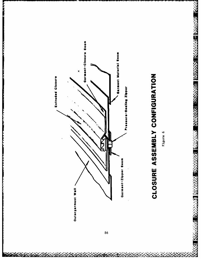
* U
" '2* 0
* U
0
N." .
, .. . ; ;. 4

-9c
00
00
0@ 0
aui
0
0z'5 :2 -2C
0 5(U
87 I

operation within the garment was to prevent contamination from entering the
ensemble should a leak occur as caused by a puncture or tear in theoutergarment. Internal suit pressurization was to be maintained by theensemble breathing system, either by leakage around the facepiece duringexhalation with a rebreather (closed-circuit) system, or by the direct.xhalation from an open-circuit self-contained breathing apparatus. Toprevent excessive pressure within the garment, pressure relief valves wereinstalled in the outergarment. Four Halkey Roberts one-way check valves setat a cracking pressure of 2.0 inches water guage were used. These valves werelocated on the left rear shoulder area of the outergarment and covered by aninverted pocket for protection against liquid chemical splashes.
Suit Volume Accumulators. To maintain a positive pressure within theensemble at all times, it was necessary to incorporate a means of volumeaccumulation in the overgarment design. The purpose of volume accumulationwas to maintain constant suit volume during a full range of body movements.For example, when the ensemble wearer went from a standing position into acrouch, excess air would be expelled through the relief valves as the suitvolume was reduced. When the wearer stood up again, the volume accumulatorwould reduce the volume of the garment to compensate for the air that expelledduring the crouch motion. The design configuration of the volume accumulatorswere simply 2.0 inch wide elastics sewn into a strip of garment material whenit was in the fully stretched position. This assembly was then sealed or sewnto the outergarment wall in four places; directly under the arms, and in thehip area, on both sides of the garment (see Figure 5). The pre-stretchedelastic relaxes and pleats the suit wall, which allowed it to expand orcontract as required to maintain positive pressure within the ensemble.
-. Environmental Control Unit
The Environmental Control Unit (ECU) was initially specified for use inthe Hazardous Chemical Protective Ensemble. The basis and feasibility for theECU was developed by MSA Research Corporation for the Coast Guard in ContractDOT-CG-73210-A.5 The ECU was envisioned as a multipurpose system which
V. would provide an extended period of breathing air (2-1/2 hours), aid in.1 maintaining suit pressurization, and contain some elements of the ensemble
cooling system. Essentially, the ECU was a closed-circuit (non-exhausting)positive pressure rebreather. Oxygen depleted in the user's exhaust air wouldbe made up with oxygen from a cylinder with carbon dioxide removed in scrubber
2 cannister. The ECU also contained a small pressurized air bottle to providemake-up air should the pressure in the outergarment drop below 0.4 incheswater guage pressure. A controller in the ECU was designed to respond to thedifference in internal suit and ambient pressures as sensed by a diaphragmbuilt into the suit wall (Figure 8). Lastly, the ECU also housed thecirculating pump for ensemble cooling system and a water sleeve for coolingthe inhalation air coming out of the CO2 scrubber.
.4. The Environmental Control Unit was being developed for ILC Dover by U. S.Divers, Survivair Division under contract DAAKlI-80-C-0059. When theoutergarment was being designed, this 2-1/2 hour system still needed furtherdevelopment. At that time, there were concerns that the ECU would not be themost desirable ensemble component in terms of availability and cost. The
88
*. - -" " . K:. -"- ' ,% %

000
u00
uJuit
.4.- w
89S.

AD-Ri74 885 EARLY DEVELOPMENT OF A HAZARDOUS CHEMICAL PROTECTIVE 2/2ENSEMBLE(U) COAST GUARD WASHINGTON DC OFFICE OFRESEARCH AND DEVELOPMENT J 0 STULL OCT 86 USCG-D-24-86
UNCLASSIF DTC238iC?02 3 8C88F/G 6/1 U

lull'2W L I IL2.5
-0
1111 I L )jj)2.
kROCOPY RESOLUTION TEST CHARTIIATINA[ RIJFAAU OF StANDA~ri 1961-A

Coast Guard also decided that a one hour ensemble use period was morerealistic than 2-1/2 hours, primarily on the basis of field experiences anduser heat stress. The Coast Guard therefore requested that the ensembleoutergarment accomodate a variety of commercial self-contained breathing(SCBA) systems. This would greatly increase the flexibility of the ensembleand afford end-users the option of using whichever breathing system he or she .was most comfortable and confident with.
The HCPE outergarment was designed to meet the space requirements of theU. S. Divers prototype 2-1/2 hour breathing system. Other commerciallyavailable rebreather systems contemplated for use in the outergarment, such asthe Siebe Gorman (Aerolox), Draeger, and Biomarine systems, appearedcompatible with the outergarment design. Yet, their use in the ensemble wouldnot provide sufficient air to maintain the positive pressure, lacking themake-up air supply of the ECU. Additionally, a cooling sleeve for theinhalation air hose would be necessary to remove the heat build-up in the airas the resilt of respiration and the carbon dioxide scrubbing process. At thesame tim. in the development, one-hour (4500 psi) open-circuit SCBA's werebeing offered by some manufacturers. These breathing systems were lighter,simpler in design, and had greater user acceptance than rebreathers havingsimilar capabilities. The dimensions of the open-circuit SCBA's also seemedcompatible with the overgarment design. ILC Dover recomended that theoutergarment exhaust valves be sized accordingly for the different types ofbreathing systems if both were to be used in the field.
Cooling System
The cooling system developed for the HCPE was designed based on aclosed-loop water-recirculating cooling concept. This type of cooling systemwas recommended by MSA Research Corporation in their study for the feasibilityof a self-contained Environmental Control Unit. 5 The system consisted ofthree parts: a full body cooling garment, a heat exchanger/ice-water slurryreservoir, and a centrifugal pump. The system worked by picking up body heatthrough the liquid cooled full body garment and transferring this excess bodyheat via a heat exchanger to the ice-water/water reservoir that could bereplenished when depleted. This refillable system design enabled theice-water reservoir to be sized to a convenient weight, while still coolingthe man for the length of the mission. Figure 9 shows the overallconfiguration for the HCPE cooling system.
"77Full-Body Cooling Garment. The full-body cooling garment was developed by
ILC Dover under contracts DAAKII-79-C-0060 and DAAKII-80-C-0020. It consistedof cooling panels located at the neck, front and back torso, and front andback upper legs, through which the cooling media (water) flowed. These panelswere constructed of polyurethane coated nylon and were located in areas where _"
large amounts of blood flow occurred in order to maximize the cooling -,
effciency of the garment. TYGON tubing was used to connect the individualpanels which were integrated into a spandex comfort liner that covered thebody to the wrists and ankles as shown in Figure 10.
Heat Exchanger and Cooling Pouch Assembly. The cooling garment interfacedwith a heat exchanger installed on the upper front of the outergarment. The
90
'*." '

zz
0
Z z
0 16z P
ILI
00
MA z
0 0
9'

0*0 4w
z
0ILU
c0 0
go 0
L0 0
0
cr.
Elmm
0
ec
U,
92

purpose of the heat exchanger was to remove heat from the water circulatingthrough the cooling garment after it had passed through the cooling panels.The design configuration of the heat exchanger was approximately five feet ofcopper tubing bent into a serpentine shape as shown in Figure 11. Theinterface of the cooling garment and the heat exchanger was a sealedpass-through at the garm~at wall thereby insuring that the water in thecooling system was always protected from the contaminated environment. Bothwater and ice would be placed in the outside pouch to act as a heat sink forthe recirculating cooling system water. This external pouch containing theheat exchanger could be refilled as required throughout the mission. Thepouch was constructed of the same material as the rest of the garment and waslined with a polyurethane bag having a two track closure at the top and adrain valve at the bottom. A similar smaller polyurethane bag without a drainwas used as a sump on the interior of the suit from which water was pulled bythe pump to feed the cooling garment. The entire assembly had a weight ofapproximately 3 pounds.
Other cooling components. The pump used for the cooling system was aTuthill 12 Volt DC Ryton pump (Part number 9058) having a throughput of 0.5gallons per minute. Originally the pump was to be incorporated into theEnvironmental Control Unit. But because the use of the ECU in the HCPE wasabandoned, the pump and two gel cell batteries (12 V) were housed in a plasticcase having the approximite dimensions of 8" x 8" x 2" (approx. 5 lbs.). Thiscase could either be worn attached to the user's hip or taped somewhere to thebreathing apparatus. An adjustable internal suit harness was provide tosupport the weight of the cooling system. Quick disconnects were used toconnect the TYGON tubing between cooling system components. A separatecooling sleeve was fabricated by ILC Dover for use with the Draeger BH174rebreather. This sleeve was approximately 12 inches long and fit over themajority of the inhalation hose to the breathing mask. It was constructed ofpolyurethane coated nylon and had fittings on either end to allow the inflowand outflow of cooling water. The recommended configuration had the coolingsleeve after the cooling garment in the cooling system sequence (see Figure 9).
Communications System
The communications system for the HCPE was provided by the Coast Guard. A
Remic model 7800 HL Portable transmitter/transceiver (49.86 MHz) and accessorythroat microphone were planned for use with the ensemble. Considerations forthe design of the outergarment included the head space requirements of thisand other similar commercial communications systems. The Coast Guard feltthat like the breathing apparatus, the outergarment should accomodate a largevariety of communications systems to allow greater flexibility in use.
93* .%
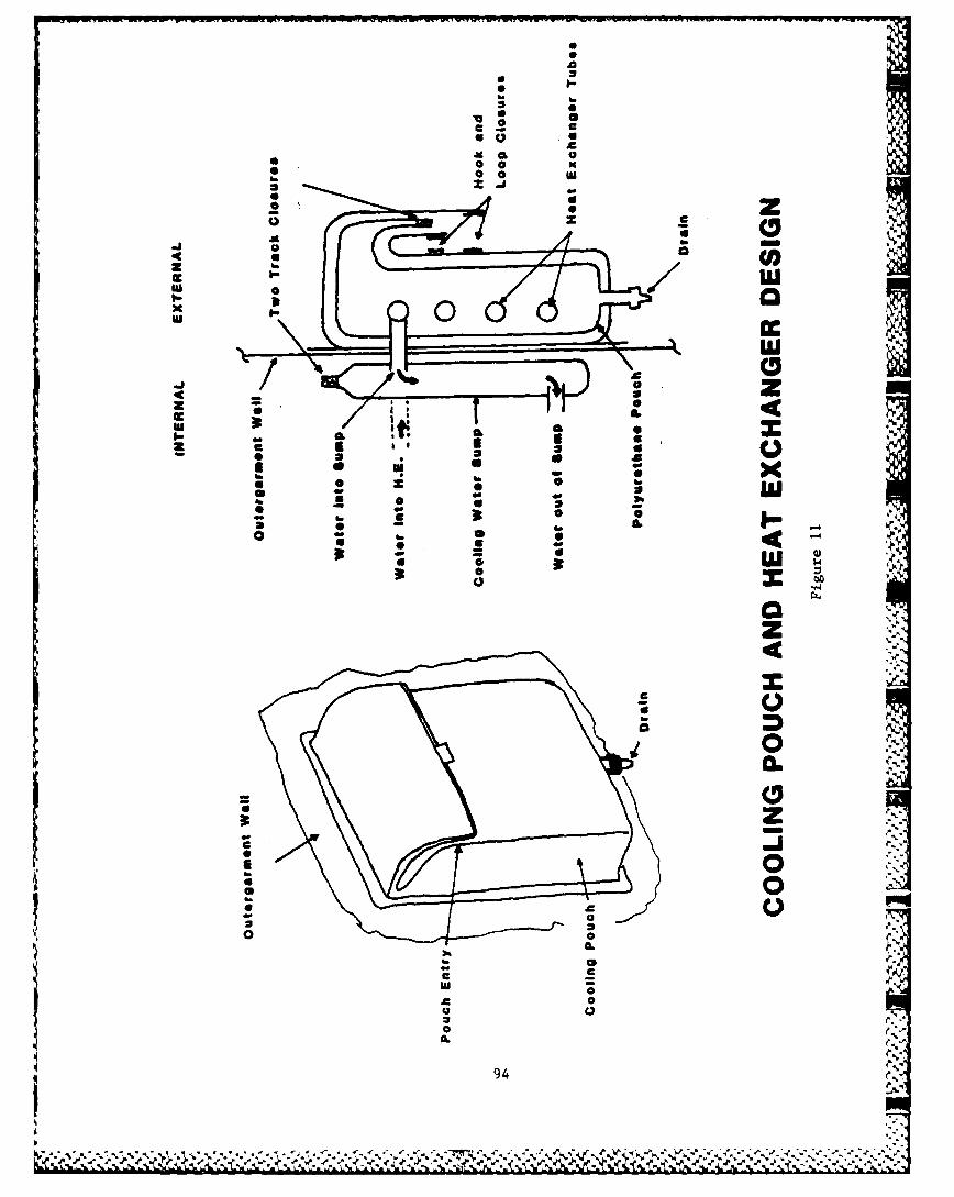
A6
00
UCU
S UU
CC
S0
z 02
ul 0
9-94

CHAPTER 4
OVERALL ENSEMBLE TESTING
ILC Dover fabricated two prototype outergarments out of each material fortesting the overall Hazardous Chemical Protective Ensemble. Of the twochlorinated polyethylene garments, one was constructed of 20 mil unsupportedCPE, the other from 30 mil nylon supported CPE. These two differentprototypes were constructed to demonstrate the relative wear performance ofthe supported versus unsupported materials. The six prototype garments wereevaluated together with other ensemble components including the ILC Dovercooling system, Remic Corp. communications system and two different breathingsystems (Draeger BG174 Rebreather and the Survivair 60 minute open-circuitSCBA). The principal purpose of the overall ensemble testing was determinethe extent to which the outergarment and cooling system met Coast Guardrequirements and the compatibility of the outergarment with supportingequipment within the ensemble. The evaluation consisted of two parts:protection factor measurements and manned stress testing.
Protection Factor Testing
The "protection factor" is a quantitative measure of the effectiveness ofthe ensemble in protecting the user from a hazardous chemical environment. Itis an established means for measuring the integrity of encapsulating garmentsor equipment (particularly breathing system masks). Protection factors aredetermined by measuring the concentration of a "challenge" chemical agent bothinside and outside the suit or other protective equipment; the ratio ofexternal (ambient) to internal concentration measurements is the protectionfactor:
PF - Ambient Concentration of ContaminantConcentration of Contaminant inside Suit
Challenge Agent (Contaminant). To date, most suit protection factor testshave been conducted using aerosols of chemical agents such as dioctylphthalate (DOP) and dioctyl sebacate (DOS). ILC Dover originally proposed to
use dichlorodifluoromethane (Freon 12) as a non-toxic, gaseous contaminate.However, their detection equipment did not have the capability to quantifyFreon 12 over a sufficient concentration range. A large concentration rangeis necessary to measure large protections factors since the measurements areratios; generally, protection factors are measured up to 10,000 or 100,000.ILC Dover then decided to use a the conventional DOS aerosol consisting of
liquid droplets averaging 10 microns.
Testing Apparatus. Testing was carried out using an aluminum-lined 8' x8' x 10' air-tight chamber at ILC Dover's plant in Frederica, Delaware. Thechamber was equipped with air circulation fans to produce and maintain uniformchallenge chemical concentrations throughout the chamber over the testingperiod. In the study, both the chamber and the ensemble were instrumentedfor gas monitoring. Aerosol concentrations were measured using an Air
95

Techniques Model TDA-50 Aerosol Tester which uses a detection technology basedon light scattering (photometry). Equipment parameters used during the tests
Sample line intack - 2.5 liters per minuteDiluent air flow pressure - 4 inches water guageGenerator pressure - 6 psiEquilibration time - 1.5 hours
One of the problems with this detection technique is its inability todistinguish types of aerosol; any aerosol (e.g. perspiration) or dustparticles will deflect light resulting in an instrument reading. Instrumentconnections to the ensemble were via vinyl tubing through a pass-throughbulkhead connector on the suit wall of the outergarment. Aerosol sampling wasconducted at three locations within the garment-hood area, middle torso, andlover leg. This sampling scheme was used to determine the approximatelocations of any leaks in the outergarment. Furthermore, aerosol dropletstend to fall to the ground with time.
Test Procedure. Two phases of protection factor testing were performed:mannequin testing to establish baseline performance characteristics, andmanned testing to allow an analysis of the influence of body movements on theprotection factor. Mannequin testing involved sampling of the test chamberand the three ensemble ports in a squential fashion every fifteen minutes overa two hour period. The manned testing introduced a suit subject into theensemble who performed a series of exercises including arm movements, toetouches, and deep knee bends. The test chamber and three ensemble ports weresampled after each exercise. After the each complete test, the ensemble wasvisually examined for any wear and an inflation test was performed to assess -
the static integrity of the overgarment. The inflation test involvedoutergarment pressurization to 5 inches of water guage pressure, observing thepressure drop over time for several hours (if any), and soaping the suitexterior to determine leaks if a significant pressure drop was noted. Both amannequin and manned protection factor test were conducted for each suit type(based on suit material) with the exception that no manned test was performedon the supported CPE suit prototype. Draeger BG174 Rebreathers wereexclusively used for manned protection factor testing since this presented theworst case for chemical agent penetration (less suit exhaust air). The testprotocol and the detailed procedures are given in Appendix C.
Testing Results. Tables of the raw measurements are provided in AppendixD. Test portection factors were calculated using the following formula:
Chamber conc. before exercise + Chamber conc. after exercise2
PF -(Head + Torso + Foot Ensemble conc. measurements)
Table 22 gives the protection factor measurements for each of the outergarmenttypes (by material) for both mannequin and manned tests. These protectionfactors have been rounded to two significant figures due to the imprecision inthe averaging measurements. A number of the calculated protection factorswere beyond the normal operating range of ILC Dover's equipment, i.e., theT
96

TABLE 22
SUMMARY OF PROTECTION FACTOR TESTING
Test No. Outer Garment Type Test Protection Factor
P-1-01 30 mll CPE (unsup.) Mannequin 100,000*P-1-02 20 mil CPE (sup.) Mannequin 55,000P-2-01 30 mll CPE (unsup.) Manned 27,000
P-1-03 VITON/chlorobutyl Mannequin 100,000*P-2-03 VIOTN/chlorobutyl Manned 64,000
P-2-04 Butyl rubber Mannequin 100,000*P-2-02 Butyl rubber Manned 100,000*
* Protection factors exceeded limits of detectors
97

lower concentrations measured were below the sensitivity of the detectiondevice. This reiterates the problem of achieving a large concentration rangefor measuring protection factors. The ILC Dover Penetrometer had asensitivity of 0.1 ppm for the ensemble measurements and 100 ppm for chambermeasurements (different scales were used) and could accurately measureprotection factors up to 100,000. Some of the protection factors appeared toexceed this level.
Analysis of Protection Factor Measurements. No standard exists forassessing the integrity of a garment or equipment item based on protectionfactor measurements. Protection factors are most commonly measured forbreathing apparatus face masks for determining how well they seal against theface of the user. Generally, protection factors on the order of 10,000 areconsidered 'good'. Several investigators have also reported that protectionfactors measured under ideal lab conditions are much higher than thosemeasured during a work routine or during field use of the equipment. Thisobservation is analogous to data in this study where manned protect! on factortests had lover protection factors than their mannequin counterpart Lsts.Yet even manned protection factor tests yielded relative high measurements(greater than 10,000). Based on the reported protection factors, it appear.that each of the suit types demonstrated a high level of integrity. It isimpossible to determine if the lover protection factors for manned teats werethe result of aerosol penetration into the suit or aerosol generated insidethe outergarment by the suit subject via internal dust or perspiration. Thisphenomena could have been verified by running a blank protection factor test(with no aerosol generation)
Relative Comparison of Protection Factors. If the relative magnitude ofthe measured protection factors are any indication of suit integrity, thencertain observations can be made. The butyl overgarment outperformed each ofthe other garments with protection factors for both mannequin and manned testsexceeding 100,000. The largest penetrations were noted for the supported 20mul CPE overgarment. All other mannequin tests demonstrated protectionfactors over 100,000. Inspection of the 20 mil CPE outergarment followingtesting revealed a greater level of wear for suit particularly at criticalseam areas (such as the crotch and armpits areas). This suit also failed theinflation test following the inspection and needed repair of some seams.
Manned Stress Testing
Manned stress testing was performed to assess the performance of theHazardous Chemical Protective Ensemble during simulated work cycles. This
testing involving evaluating the work stress of ensemble users by measuringJtheir physiological responses during simulated work exercises. Testparticipants also subjectively evaluated the design and comfort of theensemble. Test subjects included representatives from the National StrikeForce (with at least one member from each Strike Team) and an ILC Dover suitsubject. The manned stress testing was divided into two identical phases. Atwo month interval between phases allowed minor modifications to the suitprototypes, and redesign of the test protocol.
Testing Approach and Equipment. Each test subject was required to perform
98

a series of two hour work cycles consisting of exercises and simulated worktasks. The subjects heart rate and core temperature were constantlymonitored. In addition, the following parameters were measured: -
ambient temperatureambient humidityinhalation temperature (inhalation hose)exhalation temperature (exhalation hose)cooling system inlet water temperaturecooling system outlet water temperatureensemble (outergarment) internal temperatureensemble (outergarment) internal pressure
Temperature measurements were made using thermocouples attached to cablesgoing through a pass-through in the suit; suit pressure was measured using apressure guage attached to a length of vinyl tubing passing through the suitwail. Each test subject performed one two hour cycle per test day. Testing4was terminated at the completion of the two hour work cycle, when any of thephysiological parameters exceeded the maximum limits (heart rate 180 bprn, coretemperature 3900), or at the request of the test subject. Prior to themanned stress testing of HCPE, each test subject performed two work cycles in'work' clothes to establish baseline physiological parameters. After eachtest, the used overgarment was then inspected visually and by an inflationtest.
Work Cycle Exercises and Simulated Tasks. The first phase of mannedstress test were two hours in length and consisted of a 1/2 hour exerciseperiod, a 112 hour treadmill test, and a one hour work period. The excerixeperiod entailed the following exercises:
1) Kneeling on each knee and both knees (repeated three times)
2) Duck squats with pivoting (repeated three times)
3) Body bends (repeated three times)
4) Arm extensions (repeated three times)
5) Body twists with subject's arms out (repeated three times)
6) Cross-body reaches (repeated three times)
7) Crawling on hand and knees for a distance of 20 feet
The suit subject rested for five minutes following the exercise routine andthen repeated the entire exercise sequence once more. The treadmill test wasconducted at 5 degrees of incline and a speed of 3 miles per hour. The suitsubjects walked for one minute at those conditions and rested two minutes,repeating the process a total of ten times. The work period consisted of sixtasks:
1) Lifting four boxes from the floor and placing them on a table
99

2) Placing a 55 gallon drum on handtruck and moving it 25 feet, removingthe drum from the handtruck, putting back on the handtruck, andreturning it to the original position
3) Uncoiling and coiling a 10 foot section of one inch diameter hose
4) Opening and closing an overhead valve
5) Removing and installing a bolt with a wrench
6) Removing and installing a screw with a screwdriver
These work tasks were repeated followed by a five minute rest period and theentire sequence repeated two additional times. The Draeger rebreather wasable to provide sufficient breathing air during the entire work cycle. TheSurvivair SCBA needed replenishment of its air bottle midway through thetests. Appendix C provides a detailed procedure for the manned stress tests.
Test Conditions. All tests were conducted at the ILC Dover Plant inFrederica, Delaware indoors or inside a temperature and humidity controlledchamber. A number of environmental conditions were used during theperformance of the manned stress tests. These included:
Ambient (temperature 23 - 260C, relative humidity 45 - 55%)High temperature (1100F), low relative humidity (10%)High temperature (950F), high relative humidity (85%)Moderate temperature (300F) with RH near saturationLow temperature (0°F) with RH near saturation
Baseline tests (without wearing the ensemble) were conducted on each testsubject at ambient and high temperature/low humidity conditions only. Onetest with each type of suit (by material) at each condition was performed.The work task portion of the work cycle was deleted for all tests conducted inthe environmental chamber due to limited space (this reduced the test lengthto one hour). Tables 23 and 24 give lists of the test conditions, respectiveoutergarments, and test subjects for each of the manned stress testing phases.
General Results for Phases I and II. A number of test failures wereobserved during phase I. These included both breakdowns of ensemble equipment(suit and cooling system leaks) and test instrumentation (environmentalchamber, thermocouples, core temperature probe). As a result, the procedureand equipment status was reviewed between the two manned stress testingphases. Some outergarment prototypes were modified or repaired, a betterpassthrough in the outergarment was constructed, and new test instrumentationIwas obtained. One major change in the test plan was to reduce the number oftest subjects from four to three thus providing more time for testing. PhaseII generally went much more smoothly with only one test being aborted due toequipment problems. For this reason, the majority of test analysis wasconducted using the results of Phase II. The basic test conditions andphysiological results for each phase are presented in Tables 25 and 26.Ensemble equipment measurements are provided in Table 27.
General Observations. Due to the limitations in time and resources, it
100
2oo .7

TABLE 23
PHASE I - MANNED STRESS TESTING SCHEDULE
CONDITION SUBJECT OVERGARMENT
Ambient ILC-l Work ClothesAmbient USCG-1 Work Clothes .°
Ambient USCG-2 Work ClothesAmbient USCG-3 Work Clothes1100F, 10%RH ILC-l Work Clothes1100F, 10%RH USCG-l Work Clothes1100F, 10%RH USCG-2 Work Clothes1100F, 10%RH USCG-3 Work ClothesAmbient ILC-l Butyl #1Ambient USCG-I CPE-20 MilAmbient USCG-2 Viton #1Ambient USCG-3 CPE-30 Mil
- Ambient ILC-l CPE-20 MilAmbient USCG-l Butyl #2Ambient USCG-2 CPE-30 MilAmbient USCG-3 Viton #21100F, 10%RH ILC-l Viton #11100F, 10%RH USCG-l CPE-30 Mil1100F, 10%RH USCG-2 Butyl #11100F, 10%RH USCG-3 CPE-20 Mil900F, 85% RH ILC-1 CPE-30 Mil900F, 85% RH USCG-l Viton #2900F, 85% RH USCG-2 CPE-20 Mil900F, 85% RH USCG-3 Butyl #230°F ILC-I Butyl #1RH Approaching USCG-l CPE-20 MilSaturation USCG-2 Viton #1
USCG-3 CPE-30 Mil0°F ILC-l CPE-20 MilRH Approaching USCG-l Butyl #2Saturation USCG-2 CPE-30 Mil
USCG-3 Viton #2
101
*4

TABLE 24
PHASE II - MANNED STRESS TESTING SCHEDULE
CONDITION SUBJECT OVERGARMENT
Ambient USCG-4 Work ClothesAmbient USCG-5 Work ClothesAmbient USCG-6 Work Clothes1100F, 10ZRH USCG-4 Work Clothes1100F, lO RH USCG-5 Work Clothes1100F, 10RH USCG-6 Work ClothesRm Ambient USCG-4 Butyl #1Ra Ambient USCG-5 Viton #1Rn Ambient USCG-6 CPE-30 mi1100F, lOZRH USCG-4 CPE-30 Mil1100F, 10RH USCG-5 Butyl #11100F, 10ZRH USCG-6 Viton #1900F, 85% RH USCG-4 Viton #2900F, 85% RH USCG-5 CPE-30 mil900F, 85% RH USCG-6 Butyl #2300F, RH Approaching USCG-4 Butyl #1Saturation USCG-5 Viton #1
USCG-6 CPE-30 Mil0°F, RH Approaching USCG-4 Butyl #2Saturation USCG-5 CPE-30 Mil
USCG-6 Viton #2
102
7
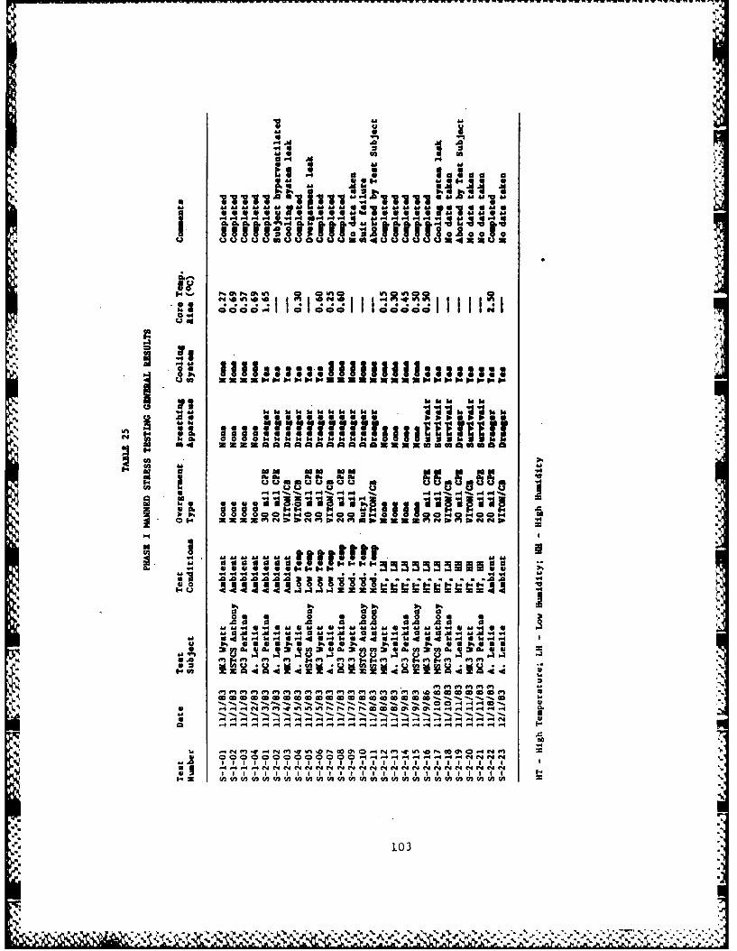
'I w
'a.1
4a 3 bMoo ma a o 0
"I I i'. 11 1 b. I I -3
co a- C-130"1 1 O"o00,1C a& 1 &d0'a '''''aaU-'' u1'''' m~ '
Q (A an 0."P. . C pw==wwww= e ona IN u INP. O
N d uUmUOUm4UUU M~U
P4 r4 "IP 4wo- l P- 4
I. W.09-4 C'29N~ NMW to94 o od 04to
a 0 O .r*"*4 *I1i42 J2 J3 A A .0 0
m00a
0 0 dZ Z Id 4 14 1A " 4 11 ,l "4 ,4441"
Z Z Z 0 .44 4 4 0 A 1 4C A P e e A 1 ,rZ zr o4 o0 F f 4. 414 4u.. uu 00046 % - Z1 . , ,1 . ,%ON 4 49 4 4. 0 4 - - 4.0, - 4 4 4 z 1-0C4 0
CA 4 4 14 4 14 4~ f'-414 4fC 014 4M'1 4 Nf'
II I I I I I I I
1030

. tem'a
040
.P4
a13z (.4 0.4x
0 0A .
0 18 4,
60." 1. 1 w .41 - . "
cc34
441
00wl 10 d 0%a e W 0F C C% Nm.0 lDPaco 0 ',4-4 4ANe ne n4 ne
.. " f 4 '4 1 4 ,4 44 N N
44104

CLC
0% 0000% 00 " 0% m A 00000000Aa
C4 44 4
Imn omc* I I
ft .~4 44I 4441 1.1.. 1. 1 164 14 00
"1 N 4441009 a00000004 34L4
44 C4 C 4 14 44 4 44444 4 "N" . . .
* cj 1 51 1 g
a 4a %IVAk f00 00 100 at00 h0r 0
'IN011 1 cl '0%O~ 45 A ).aC. 01 0
w 144t 0 Inr% m 0 6616
.10

was impossible to test each subject at each condition in each ensembleconfiguration (outergarment/breathing apparatus combination). Such a testplan would have required 108 tests for three suit subjects. Rather it was theintent of the test plan to gain general assessments on how well the HCPEperformed in terms of function, fit, and comfort. Therefore, it is impossibleto make specific conclusions on the results between different test conditionsor ensemble configurations. General observations that can be made withrespect to the data include:
1) Effect of Ensemble Outergarment - Core temperatures were higher fortest subjects wearing the overgarments compared to baseline tests.There was no way to distinguish heat effects between eachoutergarment type. The high temperature conditions (both low andhigh humidity) causes the greatest rises in core temperature.However, low temperature conditions also significantly affected thetest subject core temperature in some cases. Future tests mustisolate the various conditions and ensemble configurations by subjectto determine their respective effects on the subject's physiology.
2) Effect of Ensemble Cooling System - The cooling effect provided bythe ensemble cooling system is uncertain. In some tests,particularly those at ambient or moderate temperature conditions, thecooling system appeared to prevent a large core temperature rise.However, under high heat conditions, the ability of the coolingsystem to stabilize core temperature is questionable. Further workis necessary to determine the differences in subject physiologicalresponse with and without the cooling system.
3) Effect of Ensemble Breathing System - Mixed results were found withthe use of the two types of breathing systems. In many cases,especially high heat conditions, the rebreather caused hightemperatures in the ensemble. Part of the heat buildup may be due topartial ineffectiveness of the cooling sleeve on the rebreatherinhalation hose. Breathing air from the open-circuit system was notcooled and generally reflected the conditions of the test.
Subjective Comments (based on test subject critique responses).
1) Overgarment. The general design of the outergarment was found to befunctional and allow a wide degree of fit for the test subjects inthis study. Test subjects rated the butyl suit as most comfortable,then VITON/chlorobutyl, and the CPE suit as least comfortable. TheCPE suit became very stiff at the lower temperatures. The two trackclosures were difficult to operate in cold conditions. The length ofthe closure was found to be too short for easy donning and doffing.The outergarment visor tended to fog over at low temperature and highhumidity conditions.
2) Ensemble Cooling System. The ensemble cooling system was well-likedby all test particpants. It gave an apparent 'cool' feeling underall conditions for which it was operated. The major disadvantage ofthe cooling system was the bulkiness of the pump unit and theoccasional disconnection or crimping of cooling tubes within the
106
- %

ensemble. The cooling sleeve for the rebreather seemed effectivehowever it made the breathing hose too stiff which In turn restrictedmovement.
3) Ensemble Breathing Systems. The high heat release of the DraegerBG174 rebreather was found a disadvantage since the heat was not onlytransmitted to the breathing air but also to the wearer's back (dueto poor insulation of the system). This made its use uncomfortablein the hot conditions. The rebreather was also heavier and moredifficult to use compared with the Survivair open-circuit SCBA. Theoutergarment accomodated both types of breathing systems, however,the top of the SCBA air bottle did tend to rub against the back ofthe outergarment in the vicinity of the closure. The rebreathercould not maintain a positive pressure inside the outergarment.Several times during the test, the outergarment needed inflation tolift the suit off the subject's shoulders. On the other hand, theSCBA kept the suit over-inflated and required the user tooccasionally force the air out of the suit. The test subjectsrecommended that appropriate sized outergarment exhaust valves beused to relieve this problem.
4) Comunications System. The REMIC system was found to operate well as
part of the HCPE. However, the attenna protruding from the headsetaffected head movement inside the outergaruent. No attempt was madeto evaluate the radio's operational capabilities.
I,
107
S %q
I. 107
.i:f\'

CHAPTER 5
CONCLUSIONS AND RECOMMENDATIONS
This study has successfully identified chemical protective materials andintegrated these materials into the design of a outergarment for the CoastGuard Hazardous Chemical Protective Ensemble. The focus of this work was tofind materials which could supplement butyl rubber for protection against asmany CHRIS chemicals as possible. Material selection criteria were based onchemical resistance, physical properties (for indicating strength anddurability), and the material's capability for forming high integrity seams.A uniform outergarment design was then developed which could incorporate eachof the materials and accomodate other ensemble components such as thebreathing, cooling, and communications systems.
Under the current technology, protection against the majority of CHRISchemicals can only be achieved with a multimaterial suit system. In thisinvestigation, the outergarment materials-butyl rubber, chlorinatedpolyethylene, and VITON/chlorobutyl laminate each using a FEP/Surlyn laminatevisor-are collectively compatible with 74% of the chemicals commonly spilled(for which test data exist). When the number of spills are considered usingpast frequencies, spill compatability is 92% for the selected materials (forwhich test data exist). Material - chemical compatability is relative to thepass/fall conditions chosen. For this study, materials were judgedincompatible when they exhibited moderate to severe degradation effects(visual, weight change, elongation change) following one-sided immersion or apermeation breakthrough of less than one hour to the with a particularchemical.
The Hazardous Chemical Protective Ensemble was developed as a completepersonnel protection package incorporating the outergarment together with fullbody cooling system, a breathing system, and a communications systems. ILCDover designed the outergarment for flexibility to fit different sizes ofusers and their protective equipment. It was also developed with features toprovide the highest level of protection to chemical vapors and splashesconsistent with the U. S. Environmental Protection Agency's definition ofLevel A protection. These features include a pressure sealing zipper locatedon the back of the garment with a splash cover, integral gloves and sock-likebooties, and a outergarment pressurization system. The cooling system alsodesigned by ILC Dover was directly interfaced to the outergarment with a fullbody cooling garment, pump, and field-reserviceable ice pouch/heat exchanger.
SGovernment provided breathing and communications systems easily fit inside the
garment and completed the ensemble package.
SOf the two types of ensemble laboratory testing performed, the protection
~factor testing was conclusive in demonstrating that the ensemble provided a
shigh level of integrity against external chemical (aerosol) challenges. Theresults obtained from the manned stress testing were not easily compared dueto the large number of variables associated with each test. The design of thethese experiments allowed only qualitative assessments about the performanceof the ensemble under different environmental conditions. In cases where
108
'.
" . -. . ,,, , d ... , - " ." .% '.' .. % '." o.-' .- ' .. o. ' ' ' '. ' -. '.N .' '. ." -
% ".
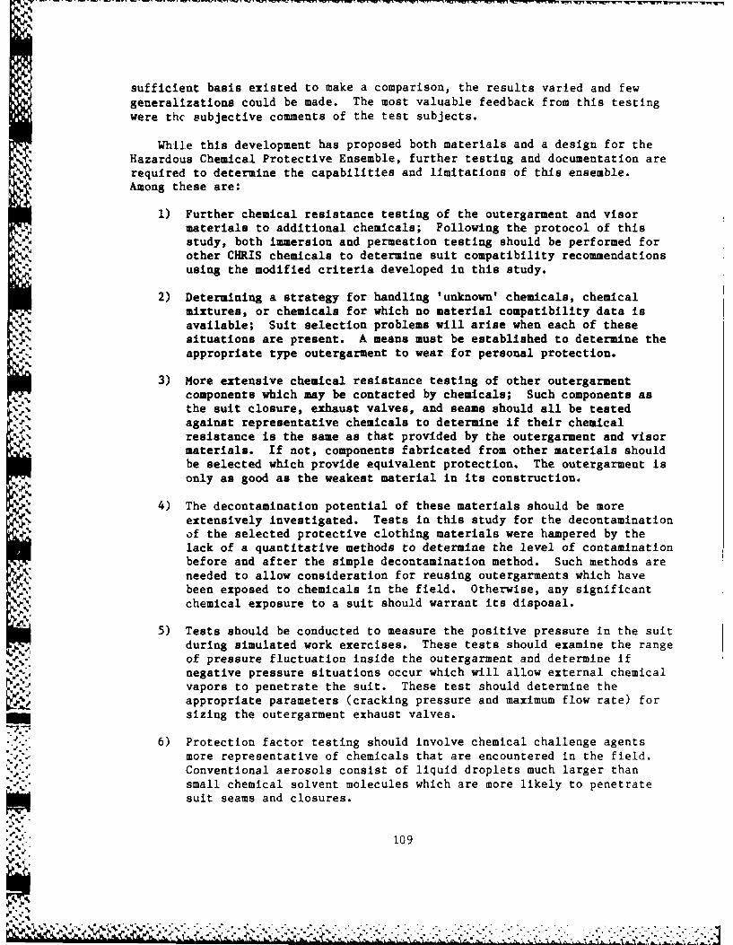
sufficient basis existed to make a comparison, the results varied and fewgeneralizations could be made. The most valuable feedback from this testingwere thc subjective comments of the test subjects.
While this development has proposed both materials and a design for theHazardous Chemical Protective Ensemble, further testing and documentation arerequired to determine the capabilities and limitations of this ensemble.Among these are:
1) Further chemical resistance testing of the outergarment and visormaterials to additional chemicals; Following the protocol of thisstudy, both immersion and permeation testing should be performed for
-M, other CHRIS chemicals to determine suit compatibility recommendationsusing the modified criteria developed in this study.
2) Determining a strategy for handling 'unknown' chemicals, chemical
% mixtures, or chemicals for which no material compatibility data isavailable; Suit selection problems will arise when each of thesesituations are present. A means must be established to determine the
% appropriate type outergarment to wear for personal protection.
3) More extensive chemical resistance testing of other outergaruentcomponents which may be contacted by chemicals; Such components asthe suit closure, exhaust valves, and seams should all be testedagainst representative chemicals to determine if their chemicalresistance is the same as that provided by the outergarment and visormaterials. If not, components fabricated from other materials shouldbe selected which provide equivalent protection. The outergarment isonly as good as the weakest material in its construction.
4) The decontamination potential of these materials should be moreextensively investigated. Tests in this study for the decontaminationof the selected protective clothing materials were hampered by thelack of a quantitative methods to determine the level of contaminationbefore and after the simple decontamination method. Such methods areneeded to allow consideration for reusing outergarments which havebeen exposed to chemicals in the field. Otherwise, any significantchemical exposure to a suit should warrant its disposal.
5) Tests should be conducted to measure the positive pressure in the suitduring simulated work exercises. These tests should examine the rangeof pressure fluctuation inside the outergarment and determine ifnegative pressure situations occur which will allow external chemical
YJ vapors to penetrate the suit. These test should determine theappropriate parameters (cracking pressure and maximum flow rate) forsizing the outergarment exhaust valves.
6) Protection factor testing should involve chemical challenge agentsmore representative of chemicals that are encountered in the field.Conventional aerosols consist of liquid droplets much larger thansmall chemical solvent molecules which are more likely to penetratesuit seams and closures.
109
4.." " .1%

7) The effect of the cooling system should be quantitatively defined.Experiments should be run to determine how much cooling is provided bythe in-suit cooling system versus wearing no cooling suit underdifferent environmental conditions. The physiological response ofteat subjects should be monitored by measuring heart rate, coretemperature, internal ensemble temperature, and inlet/outlet coolingwater temperatures. The amount of cooling effect provided by thesystem should be weighed against the additional burden (weight andmobility) placed on the user. This data should also be used toestablish heat stress considerations for using the ensemble.
110

- ---- rnrw-rn w -~pI ,z. 'w lr W-r rW"r ~ ~'- fin j_%-. _. 7__ - -
REFERENCES
1. "Chemical Hazards Response Information System (CHRIS)", U. S. Coast GuardCommandant Instruction M16465.12. Stock No. 050-012-00215-1 (Obtainablefrom Superintendent of Documents, Government Printing Office, Washington,D. C. 20402).
2. J. V. Friel, M. J. McGoff, and S. J. Rodgers. "Material Development Studyfor a Hazardous Chemical Protective Clothing Outfit," Coast Guard ReportNo. CG-D-58-80. MSA Research Corporation, Evans City, Pennsylvannia.August 1980. (NTIS Accession No. AD-A-095993). '.
3. R. Algera. "Development of a Hazardous Chemical Protective Ensemble,"Phase I Interim Report for Coast Guard Contract DTCG23-81-C-20003. ILCDover, Inc., Frederica, Delaware. November 1982.
4. "Standard Operating Safety Guidelines." U. S. Environmental ProtectionAgency, Office of Emergency and Remedial Response, Hazardous ResponseSupport Division, Environmental Response Branch, Edison, New Jersey.November 1984.
5. M. J. McGoff and J. W. Maustellar. "Feasibility Study of a Self-ContainedEnvironmental Control Unit," Coast Guard Report No. CG-D-04-79. MSAResearch Corporation, Evans City, Pennsylvannia. November 1978. (NTISAccession No. AD-A-071154).
"i
1;I "111

APPENDIX A
CHRIS CODES AND CHEMICAL NAMES FORCOMPOUNDS CONSIDERED IN THIS STUDY
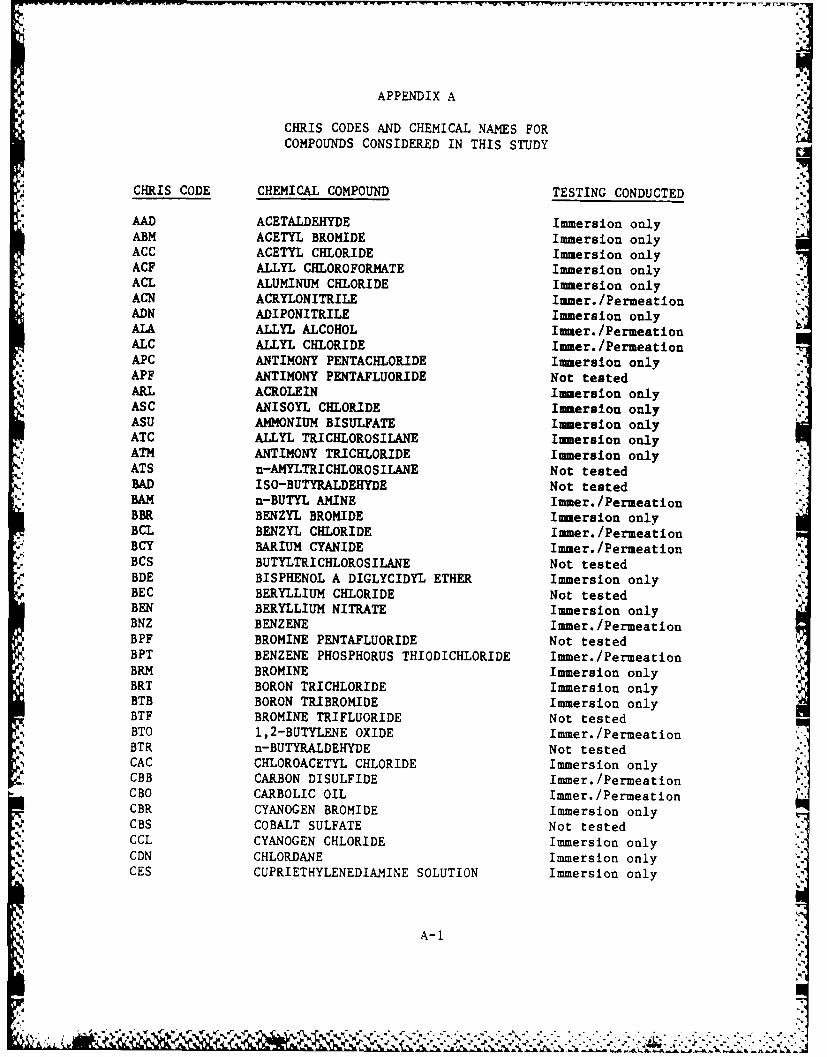
APPENDIX A
CHRIS CODES AND CHEMICAL NAMES FORCOMPOUNDS CONSIDERED IN THIS STUDY
CHRIS CODE CHEMICAL COMPOUND TESTING CONDUCTED
AAD ACETALDEHYDE Immersion onlyABM ACETYL BROMIDE Immersion onlyACC ACETYL CHLORIDE Immersion onlyACF ALLYL CHLOROFORMATE Immersion onlyACL ALUMINUM CHLORIDE Immersion onlyACN ACRYLONITRILE Immer./PermeationADN ADIPONITRILE Immersion onlyALA ALLYL ALCOHOL Immer./PermeationALC ALLYL CHLORIDE Immer./PermeationAPC ANTIMONY PENTACHLOIDE Immersion onlyAPF ANTIMONY PENTAFLUORIDE Not testedARL ACROLEIN Immersion onlyASC ANISOYL CHLORIDE Immersion onlyASU AMMONIUM BISULFATE Immersion onlyATC ALLYL TRICHLOROSILANE Immersion onlyATM ANTIMONY TRICHLORIDE Immersion onlyATS n-AMYLTRICHLOROSILANE Not testedBAD ISO-BUTYRALDEHYDE Not tested-AM n-BUTYL AMINE Immer./PermeationBBR BENZYL BROMIDE Immersion onlyBCL BENZYL CHLORIDE Immer./PermeationBCY BARIUM CYANIDE Immer./PermeationBCS BUTYLTRICHLOROSILANE Not tested
4 BDE BISPHENOL A DIGLYCIDYL ETHER Immersion onlyBEC BERYLLIUM CHLORIDE Not testedBEN BERYLLIUM NITRATE Immersion onlyBNZ BENZENE amer./PermeationBPF BROMINE PENTAFLUORIDE Not testedBPT BENZENE PHOSPHORUS THIODICHLORIDE Immer./PermeationBRM BROMINE Immersion onlyBRT BORON TRICHLORIDE Immersion only IBTB BORON TRIBROMIDE Immersion onlyBTF BROMINE TRIFLUORIDE Not testedBTO 1,2-BUTYLENE OXIDE Immer./PermeationBTR n-BUTYRALDEHYDE Not testedCAC CHLOROACETYL CHLORIDE Immersion only 4.CBB CARBON DISULFIDE Immer./PermeationCBO CARBOLIC OIL Immer./PermeationCBR CYANOGEN BROMIDE Immersion onlyCBS COBALT SULFATE Not testedCCL CYANOGEN CHLORIDE Immersion onlyCDN CHLORDANE Immersion onlyCES CUPRIETHYLENEDIAMINE SOLUTION Immersion only
A-1

- I W: VIM. Ir r'' Rr~ ol'Y 7X . .vvr v x .
APPENDIX A (continued)
CHRIS CODES AND CHEMICAL NAMES FORCOMPOUNDS CONSIDERED IN THIS STUDY
CHRIS CODE CHEMICAL COMPOUND TESTING CONDUCTED
CHA CYCLOHEXYL AMINE tamer. /Permeat ionCHT CYCLOHEXENYLTROCHLOROSILANE Not testedCLX CHLORINE Immersion onlyCMA CHROMIC ANHYDRIDE Immersion onlyCME CHLOROMETHYL METHYL ETHER Immersion onlyCH CUMENE HYDROPEROXIDE, Immersion onlyCMS CADMIUM SULFATE Not testedCON COBALT NITRATE Not testedCOU COUMAPHOS Immersion onlyCPL CHLOROPICRIN, LIQUID Immersion onlyCRF CHLOROFORM Iamer. /PermeationCRP CHLOROPRENE Imersion onlyCSA CHLOROSULFONIC ACID Imersion onlyCTA CROTONALDEHYDE Immer. /PermeationCTD 4-CIMORO-o-TOLUIDINE lamer. /PermeationCTF CHLORINE TRIFLUORIDE Not testedcum CUMENE lamer. /Permeation
*DAC DIMETHYLACETAMIDE tamer. /PermeationDAL DECALDEHYDE Not testedDIA DI-n-BUTYL AM INE lamer. /PermeationDBO o-DICHLOROBENZENE Iamer. /Permeation -
DCB DICHLOROBUTENE Iamer. /PermeationDCP 2,4-DICHLOROPHENOL Not testedDCV DICHLOROVON Immersion onlyDDB DODECYLBENZENE tamer. /PermeationDEE DICHLOROETHYL ETHER Immer. /PermeationDFA DIFLUOROPHOSPHORIC ACID, ANHYDROUS Immersion onlyDIH DIISOPROPYLBENZENE HYDROPEROXIDE Immersion onlyDIS DISULFTON Immersion onlyDIU DIURON Immersion onlyDMD DIMETHYLDICHLOROSILANE Iamer. /PermeationpDNA DI-n-PROPYLAMINE Immersion onlyDNB .r-DINITROBENZENE Not testedDPD DIPHENYLDICHLOROSIIANE Immersion onlyDPP DICHLOROPROPANE turner. /PermeationDSL DIMETHYL SULFIDE Immersion onlyDTC DODECYLTRICHLOROSILANE Not testedDTN DEMETON Immersion onlyDUR DURSBAN Immersion onlyDZN DIAZINON Not tested
*DZP DI-p-CHLOROBENZOYL PEROXIDE Not testedFAC ETHYL ACRYLATE Immer./PermeationEAI 2-ETHYLHEXYL ACRYLATE, INHIBITED Immer./Permeation
A- 2]
J KA

APPENDIX A (continued)
CHRIS CODES AND CHEMICAL NAMES FORCOMPOUNDS CONSIDERED IN THIS STUDY
CHRIS CODE CHEMICAL COMPOUND TESTING CONDUCTED
EAM ETHYLAMINE Immersion onlyECF ETHYL CHLOROFORMATE Immersion onlyECS ETHYLDICHLOROSILANE Not testedEDB ETHYLENE DIBROMIDE Immer./PermeationEDC ETHYLENE DICHLORIDE Immer./PermeationEDR ENDRIN Immersion onlyEHA ETHYLHEXALDEHYDE Not testedENB ETHYLIDENENORBORNENE Immersion onlyEOX ETHYLENE OXIDE Immersion onlyEPD ETHYL PHOSPHOROTHIOIC DICHLORIDE Immersion onlyEPP ETHYL PHOSPHORODICHLORIDATE Immersion onlyEPS ETHYLPHENYLDICHLOROSILANE Not testedESF ENDOSULFANE Immersion onlyETC ETHYLENE CYANOHYDRIN Immer./PermeationETM ETHYL METHACRYLATE Immer./PermeationETO ETHION Immersion onlyETS ETHYLTRICHLOROSILANE Immersion onlyFCL FERRIC CHLORIDE Immersion onlyFFB FERROUS FLUOROBORATE Immersion onlyFMS FORMALDEHYDE SOLUTION Immer./PermeationFSA FUOROSULFONIC ACID Immersion onlyFSL FLUOSILICIC ACID Immersion onlyFXX FLUORINE Not testedGTA GLUTERALDEHYDE Immersion onlyHAL n-HEXALDEHYDE Not testedHBR HYDROGEN BROMIDE Immersion onlyHCL HYDROCHLORIC ACID Immer./PermeationHCN HYDROGEN CYANIDE Immersion onlyHDC HYDROGEN CHLORIDE Immer./PermeationHFA HYDROFLUORIC ACID Immersion onlyHFX HYDROGEN FLUORIDE Immersion onlyHMI HEXAMETHYLENEIMINE Immer./PermeationHMT HEXAMETHYLENETETRAMINE Immersion onlyIAI ISODECYL ACRYLATE Immersion onlyIANM ISOBUTYLAMINE Immersion only IIBN ISOBUTYRONITRILE Immer./PermeationIDA ISODECALDEHYDE Not testedI0C ISOOCTALDEHYDE Immer./Permeation
IPE ISOPROPYL ETHER Immer./PermeationIPM ISOPROPYL MERCAPTAN Immersion onlyIVA ISOVALERALDEHYDE Immer./PermeationLPM LAURYL MERCAPTAN Immersion onlyMAM METHYL ACRYLATE Immersion only
A-

APPENDIX A (continued)
CHRIS CODES AND CHEMICAL NAMES FORCOMPOUNDS CONSIDERED IN THIS STUDY
CHRIS CODE CHEMICAL COMPOUND TESTING CONDUCTED
MCH METHYL CHLOROFORMATE Immersion onlyMCS METHYLDICHLOROSILANE Immersion onlyMFA MOTOR FUEL, ANTIKNOCK COMPOUNDS Not tested
CONTAINING LEAD ALKYLSMPD METHYL PHOSPHONOTHOIC DICHLORIDE Not testedMPY 1-METHYL PYROLIDONE Immersion onlyMSO MESITYL OXIDE Immer./PermeationMTB METHYL BROMIDE Immersion onlyMTS METHYLTRICHLOROSILANE Immersion onlyMVK METHYL VINYL KETONE Immersion onlyNAA NITRILOTRIACETIC ACID AND SALTS Immersion onlyNAC NITRIC ACDImmer. /PermeationNCT NAPHTHA: COAL TAR Immersion onlyNIC NICOTINE Immer./PermeationNIE o-NITROTOLUENE Immersion onlyNOX NITROGEN TETROXIDE Immersion onlyNSV NAPHTHA: SOLVENT Imer./PermeationNTA 2-NITROANILINE Not testedNTB NITROBENZENE Immer./PermeationNTC NITROSYL CHLORIDE Not testedNTX NITRIC OXIDE Immersion onlyOLK OLEUM Not testedOXA OXALIC ACID Immersion onlyPAA PERACETIC ACID Immersion onlyPBR PHOSPHOROUS TRIBROMIDE Immersion onlyPCB POLYCHLORINATED BIPHENYL Immer./PermeationPCM PERCHLOROMETHYL MERCAPTAN Immersion onlyPCP PENTACHLOROPHENOL Not testedPDL PHENYLDICHLOROARSINE (LIQUID) Not testedPHG PHOSGENE Immersion onlyPHN PHENOL Immersion onlyPMN n-PROPYL MERCAPTAN Immersion onlyPPO PHOSPHOROUS OXYCHLORIDE Immersion onlyPPT PHOSPHOROUS TRICHLORIDE Immersion onlyPRA n-PROPYLAMINE Immer./PermeationPTL PETROLATUM Immersion onlySAC SULFURIC ACID, SPENT (50%) Immer./PermeationSCL SULFURYL CHLORIDE Immersion onlySDS SODIUM SULFIDE Immersion onlySFA SULFURIC ACID Immer./PermeationSFD SULFUR DIOXIDE Immersion onlySFM SULFUR MONOCHLORIDE Immersion onlySTC SILICON TETRACHLORIDE Immersion only
A-4
0I

APPENDIX A (continued)
CHRIS CODES AND CHEMICAL NAMES FORCOMPOUNDS CONSIDERED IN THIS STUDY
CHRIS CODE CHEMICAL COMPOUND TESTING CONDUCTED
STR STRYCHNINE Immersion onlySXX SULFUR (LIQUID) Not testedTAP p-TOLUENE SULFONIC ACID Immer./PermeationTCL TRICHLOROETHYLENE Immersion onlyTDI TOLUENE-2,4-DIISOCYANATE Imer. /PermeationTEB TRIETHYLBENZENE Not testedTEC TETRACHLOROETHANE Immer./PermeationTED TETRAETHYL DITHIOPYROPHOSPHATE Not testedTEL TETRAETHYL LEAD Not testedTEN TRIETHYLAMINE Immer./PermeationTES 2,4,5-T (ESTERS) Immersion only
BUTYL 2,4,5-TRICHLOROPHENOXYACETATETHF TETRAHYDROFURAN Immer./PermeationTMA TRIMETHYLAMIM Immersion onlyTMC TRIMETHYLCHLOROSIALNE Immer./PermeationTML TETRAMETHYL LEAD Not testedTPG THIOPHOSGENE Immersion onlyTPH TRICHLOROPHENOL Not testedTTT TITANIUM TETRACHLORIDE Immersion onlyTXP TOXAPHENE Immersion onlyVCI VINYLIDENECHLORIDE, INHIBITED Immersion onlyVCM VINYL CHLORIDE Immer./PermeationVFI VINYL FLUORIDE, INHIBITED Immersion onlyVIS VINYLTRICHLOROSILANE Immersion onlyZCL ZINC CHLORIDE Immersion onlyZCT ZIRCONIUM TETRACHLORIDE Immersion onlyZFB ZINC FLUOROBORATE Immersion onlyZPF ZINC POTASSIUM FLUORIDE Immersion only
A-5

APPENDIX B
SURVEY OF SPILLED SUBSTANCES FROMNATIONAL RESPONSE CENTER
FOR 1981-1982
-V .." .

ph
APPENDIX BI.%
TABLE B-I RANKED LIST OF SPILLED SUBSTANCES
Annual Significance Carcino-Number of Code of Toxicity Class genicity Chemical
Compound Spills Worst Spill TLV IDLH STEL Class Class
Sulfuric Acid 426 Q 2 2 0 23Hydrochloric Acid, 305 Q 1 2 0 23
Hydrogen ChlorideSodium Hydroxide 193 Q 1 1 - 0 23
(Sol'n or dry)Nitric Acid 101 T 1 2 2 0 23Methyl Alcohol 96 R 0 0 0 0 1,4Ammonia 94 G 0 1 1 1 23Acetic Acid 90 A 1 1 1 0 1,7Xylenes 61 A 0 0 0 1 14Potassium Hydroxide 56 R 2 2 - 0 23
(Sol'n or dry)Toluene 50 T 0 0 0 1 14Styrene 46 K 0 0 1 2 2,14Ethyl Acrylate 38 A 1 0 1 2 2,8Phenol 38 A 1 2 2 1 17Acetone 37 A 0 0 0 0 1,6
" Toluene Diisocyanate 37 A 3 3 3 0 9,14Acetaldehyde 35 A 0 0 0 1 14Hydrofluoric Acid, 35 Q 1 2 - 0 23
-:: Hydrogen FluorideHydrogen Peroxide 35 R 2 2 2 0 23,25Methyl Ethyl Ketone 26 A 0 0 0 0 1,6Naptha, Coal Tar 22 J 0 0 - 0 22Chlorine 20 Q 2 2 2 0 23Formaldehyde 18 Q 1 2 - 2 1,6Hydrogen Sulfide 18 A 1 1 1 0 23Vinyl Acetate 15 K 1 - 1 3 2,8Oleum 13 S 2 2 - 0 23Pyridine 13 A 1 - 2 1 21Tetrahydrofuran 13 K 0 0 0 0 27,32Thionyl Chloride 13 A - - - 0 23Acrylonitrile 12 A 1 3 - 3 2,9Formic Acid 11 A 1 2 - 0 1,7Acetic Anhydride 10 C 1 1 - 0 1,7Parathion 10 Q 1 2 2 0 26Acrylic Acid 9 A 1 - - 0 2,7Benzene 9 .P 1 0 1 3 14Hydrofluosilicic Acid* 9 A - - - 0 23Nitromethane 9 A 0 1 0 0 1,19Phosphorous Oxychloride 9 A 3 - 3 0 23 .,
B-i

APPENDIX B (continued)
TABLE B-1 RANKED LIST OF SPILLED SUBSTANCES
Annual Significance Carcino-Number of Code of Toxicity Class genicity Chemical
Compound Spills Worst Spill TLV IDLH STEL Class Class
Hexane 8 V 0 0 0 0 1Nitrobenzene 8 4P 2 1 2 0 14,19Phosphorous (White) 8 -Y 3 - - 0 23Chloropicrin 7 S 3 3 3 2 3,19Creosote 7 K 1 1 - 1 17Hydrazine 7 4P 3 2 - 3 11Propionic Acid 7 A 1 0 1 0 1,7Aniline 6 A 1 2 2 0 10,14Carbon Disulfide 6 B 0 1 - 0 12
. Chlorosulfonic Acid 6 A 1 - - 0 3,13Cyclohexane 6 A 0 0 0 0 1,32Thloglycolic Acid 6 A 2 - - 0 7,12Trichloroethylene 6 4P 0 1 0 3 1,3Cyanides (Sodium, 5 R 1 2 - 0 23
Potassium Sol'n)Mercury 5 J 3 3 - 1 23Methylene Chloride 5 A 0 0 0 1 1,3Petroleum Ether 5 B - - - 0 24Sulfur Dioxide 5 A 1 2 2 0 23Acetonitrile 4 A 0 0 1 0 1,9Chloroform 4 P I 1 1 3 1,3
- Cumene Hydroperoxide* ** 4 ZP - - - 2 14,25Dimethyl Sulfate 4 A 3 - - 3 15Ethyl Silicate 4 Q 1 1 1 0 1,31Phosphorous Pentasulfide 4 R 1 2 - 0 23
* Sulfur Chloride 4 A 2 2 2 0 23Titanium Tetrachloride** 4 Q 1 - - 0 23Allyl Chloride 3 A 2 2 2 2 2,3Bromine 3 A 3 3 3 0 23Dioxane 3 4P 0 2 - 3 27,32Ethyl Mercaptan 3 B 2 0 2 0 1,12
'S Methyl Chloride 3 A 0 0 1 2 1,3Trichloroacetic Acid 3 A 2 - - 0 3,7Trichloro-s-triazine** 3 A - - - 1 3,21Valeric Acid* 3 Q - - - 0 1,7Vinyl Chloride 3 .P 1 - - 3 2,3Benzoyl Chloride 2 Q - 3 - 0 14,30Benzyl Chloride 2 A 2 3 - 3 3,14Butyl Amine 2 A 1 0 - 0 1,10Carbon Tetrachloride 2 A 1 1 1 3 1,3Chlordane 2 ' P 3 2 - 3 2,3,33
-2

APPENDIX B (continued)
TABLE B-I RANKED LIST OF SPILLED SUBSTANCES
Annual Significance Carcino-Number of Code of Toxicity Class genicity Chemical
Compound Spills Worst Spill TLV IDLH STEL Class Class
Cyanogen Bromide 2 4-P 2 - - 0 3,9* Ethylene Dichloride 2 - 1 1 1 3 1,3
Hydrocyanic Acid 2 'LP 1 2 - 0 23Methyl Bromide 2 .P 1 0 1 0 1,3Silicon Tetrachloride 2 S - - - 0 23Cyanogen 1 4P 2 - - 0 9Dichlorobenzene 1 4 0 0 - 0 3,14Ethylene Oxide 1 K 1 2 - 2 1,5,32Furfural 1 A 1 1 2 1 2,6,27,33Hydrogen Cyanide 1 <P 1 2 - 0 23Malathion 1 P 2 1 - 0 26Phosphorous Tribromide* 1 A - - - 0 23Propylene Oxide 1 4P 0 0 - 2 1,5,32Tetrachloroethylene 1 J 0 1 0 3 2,3Tetraethyl lead 1 <P 3 3 - 2 16Allyl Alcohol NR - 1 2 1 0 2,4Cyanogen Chloride NR - 2 - - 0 3,91,2-Dichloropropane NR - 1 - 0 1 1, 3Dichlorvos MR - 3 - 3 2 26Epichlorohydrin NR - 1 2 2 3 1,3,5,32Fluorine R - 2 2 2 0 23Methyl Hydrazine MR - 2 - - 2 11Nitrogen Tetroxide R - 1 2 1 0 23o-Nitrotoluene NR - 1 1 1 0 14,19Phosgene NR - 3 3 - 1 30Sulfur NR - 1 - 1 0 23Tetramethyl lead NR - 3 3 - 2 16
*IDLH class numbers determined by assuming that the IDLH class number of a chemically
similar compound is the same.
**IDLH class numbers taken to be the same as those for compounds with similar toxicity
data.
Tables B-2, B-3, and B-4 provide supplementary information for spill codes andchemical classes (toxicity, carcinogen, functional group)
B-3
~V

APPENDIX B (continued)
TABLE B-2 WORST SPILL SIGNIFICANCE CODES
Significance Property Damage Injuries DeathsCode $I,000-i0,000 $10,000 1-10 10 1-10 10 Rank
ya x x x 1
X X X X 2W x x x 3H X X 4F X X 5D x 6G x x 7E X X 8V X X 9U x x 10C X 11T X X 12S X X 13B X 14R X X 15Q x x 16
A X 17Z people evacuated 18K X 19J X 20<pb 1 or more containers broken 21
ay differs from X in that it includes a high percentage of containers failed.b 4p - codes P,L,M,N,I, all of which refer to different percentages of containers
failed.
4"
B-4
%7!n
• ,, :,..:,- , ........ ,,... ,, .. . .. : ... , ,, .. , , ' . - ..

APPENDIX B (continued)
TABLE B-3 TOXICITY AND CARCINOGEN CLASSES
Toxicity Classes
Class TLV IDLH STEL
3 O.lppm lOppm lppm2 0. lppm 6-TLV 4ippm 10ppm - IDLH - 100ppm lppm STEL4 10ppm1 ippm tTLV .10ppm lO0pm -IDLH -1000ppm lOppm,& STEL < 100ppm0 lOppm 1000ppm lOOppm
Carcinogen Classes
Description
*4 Class3 Compound is a probable carcinogen.
2 Compound is a possible carcinogen.
1 Compound is a questionable carcinogen.0 Compound is not a carcinogen or no data is available.
.. .. B-5
-, •~d
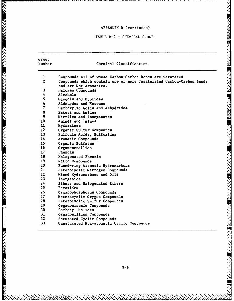
- -w w --------------- . .....
APPENDIX B (continued)
TABLE B-4 - CHEMICAL GROUPS
GroupNumber Chemical Classification
1 Compounds all of whose Carbon-Carbon Bonds are Saturated2 Compounds which contain one or more Unsaturated Carbon-Carbon Bonds
and are Not Aromatics.3 Halogen Compounds4 Alcohols5 Glycols and Epoxides6 Aldehydes and Ketones7 Carboxylic Acids and Anhydrides8 Esters and Amides9 Nitriles and Isocyanates
10 Amines and Imines11 Hydrazines12 Organic Sulfur Compounds13 Sulfonic Acids, Sulfoxides14 Aromatic Compounds15 Organic Sulfates16 Organometallics17 Phenols
* 18 Halogenated Phenols19 Nitro Compounds
* 20 Fused-ring Aromatic Hydrocarbons21 Heterocyclic Nitrogen Compounds22 Mixed Hydrocarbons and Oils23 Inorganics24 Ethers and Halogenated Ethers25 Peroxides26 Organophosphorus Compounds27 Heterocyclic Oxygen Compounds28 Heterocyclic Sulfur Compounds29 Organoarsenic Compounds30 Carbonyl Halides31 Organosilicon Compounds32 Saturated Cyclic Compounds33 Unsaturated Non-aromatic Cyclic Compounds
B-6
*il,jN JL.

APPENDIX C
DETAILED TEST PLAN AND PROCEDURESFOR EVALUATING THE
HAZARDOUS CHEMICAL PROTECTIVE ENSEMBLE

LIST OF CONTENTS
SECIO INTRODUCTION TITLE.............................PAG
1.1 SCOPE................................. 1
_ _2 OBETV.....................12.0 APPLICABLE DOCUMENTS ..................... 2
3.0 TEST PROGRAM............................... .3
3.1 PROTECTION FACTOR TESTING ................... 3
3.2 MANNED STRESS TESTING.................. . 3
3.3 TEST SCHEDULE .......... . .. . ..... .......... 3
3.4 GENERAL REQUIREMENTS .............................. 5
3.4.1 Test Identification........................... 5
3.4.2 Test Procedures.............................. 5
3.4.3 Notification of Test ............................. 5
3.4.4 Test Area Conditions..... o........................ 6
3.4.5 Test Article Handling and Storage ................. 6
3.4.6 Test Responsibilities and Accountability ............ 6
3.4.6.1 Test Engineer .................................. 6
3.4.6.2 Test Conductor .................................. 7
3.4.6.3 Test Subjects................. o................. 7
3.5 DOCUMENTATION .................................. 7
3.5.1 Test Preparation Sheet ........................... 8
3.5.2 Data Sheet Formis................................ 83.5.3 Discrepancy Report...................... 1
3.5.4 Test Reoort..................................
77.2S-EA:CC2 ES ES .........................

1.0 INTRODUCTION
This document sets forth the test plan and detailed test procedures
by which prototype units of the Hazardous Chemical Protective Ensem-
ble (HCPE) design are to be subjected to Laboratory Ensemble Test-
ing. Successful completion of the Laboratory Ensemble Test Program
will establish a quantitative measure of the effectiveness of the
HCPE garment in protecting the user in a hazardous environment, andI
provide a measure of the effectiveness of the ensemble in terms of
*4. work performance, work stress, comfort, and other physiological fac-
tors.I
1.1 SCOPE
$ The scope of the testing described herein is limited to ensemble
testing of the HCPE required to verify the operational characteris-
tics of the HCPE design that cannot be verified by other means (ma-
F terial sample testing, vendor certification, acceptance testing,
etc.)
1.2 OBJECTIVE
The objective of this document is to provide a test program inte-
grated to develop the test results and data required to verify th~e
operational characteristics of the HCPE design.
C-

2.0 APPLICABLE DOCUMENTS
The following documents form a part of this test plan to the extent
specified herein:
ILC DOCUMENT NO. 0000-73070 S
Standard Operating Procedure for Stress Testing Procedure (SOP
1005).
C-14
%
-- 4'
C-2 I~A. . AA-~, ~ ~ ~ . AI.A
...............................................................................
4.4~., -.- ~j"~~- ~ - - -*.- I

3.0 TEST PROGRAM
The laboratory testing of the HCPE consists of two phases: protec-
tion factor testing, and manned stress testing.
3.1 PROTECTION FACTOR TESTING
Protection factor testing will provide a quantitative measure of the
effectiveness of the HCPE in protecting the user from a hazardous
environment. Protection factor testing will consist of two parts:
mannequin testing to establish baseline performance characteristics,
and manned testing to establish the influence of body motions on the
protection factor. Protection factor testing will occur at the test
facilities of ILC Dover.
3.2 MANNED STRESS TESTING
Manned stress testing will be performed to assess the performance of
the HCPE during work cycles. The testing will provide a quantita-
tive evaluation of the work stress by measurements of physiological
factors throughout the work cycle as well as subjective evaluations
by the test subjects regarding ensemble comfort. Manned stress test-
ing will be performed at the test facilities of ILC Dover.
3.3 TEST SCHEDULE
4 Laboratory Ensemble Testing of the HCPE shall be performed 4n aczor-
dance with the schedule shown in Figure 1.
C -
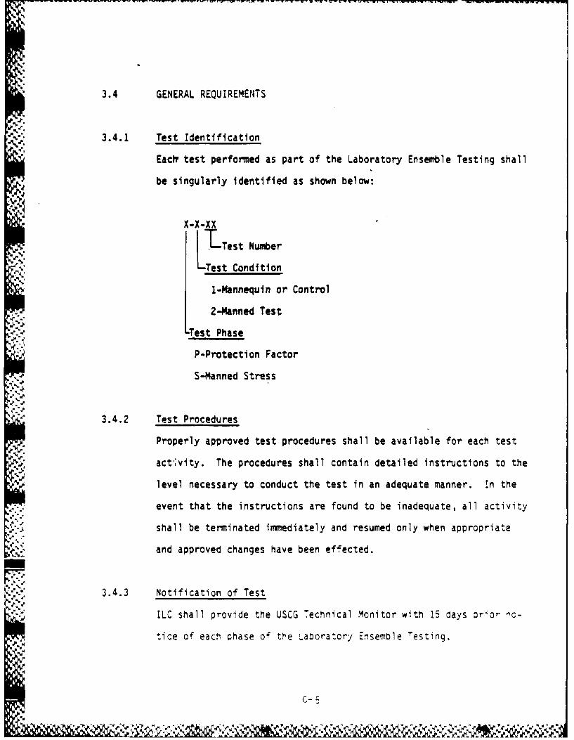
%"3.4 GENERAL REQUIREMENTS
3.4.1 Test Identificationt4.
Eactv test performed as part of the Laboratory Ensemble Testing shall
be singularly identified as shown below:
X-X-XX
I-Test Number
-Test Condition
1-Mannequin or Control
2-Manned Test
'. .Test Phase
*" P-Protection Factor
S-Manned Stress
3.4.2 Test Procedures
Properly approved test procedures shall be available for each test
act';vity. The procedures shall contain detailed instructions to the
level necessary to conduct the test in an adequate manner. In the
event that the instructions are found to be inadequate, all activity
shall be terminated immediately and resumed only when appropriate
and approved changes have been effected.
3.4.3 Notification of Test
ILC shall provide the USCG Technical Monitor with 15 days prior ,c-
tice of each phase of the Labora:ory Ensemole Testing.
C-
.4.

3.4.4 Test Area Conditions
Abient conditions for conducting the Laboratory Ensemble Testing
shall be specified in the applicable detailed test procedures. The
test area shall be maintained at a level of cleanliness comparable
to that of offices and laboratories in which good housekeeping is
practiced. Smoking and consumption of beverages or food shall not
be permitted.
3.4.5 Test Article Handling and Storage
Throughout the performance of the Laboratory Ensemble Testing, ex-
trame care shall be exercised in the handling of test articles topreclude damage. Special care shall be taken during transportation
and folding, and during engagement and di sengagement of comp onents,
plugs, fixtures, umbilicals, etc. Where applicable, protective coy-
ers shall be in place at all times except during test, inspections,
cleaning, or repair. After each test segment, the test garment
shall be sanitized and stored in an appropriate location.
3.4.6 Test Responsibilities and Accountability
3.4.6.1 Test Engineer
I> The test engineer shall be fully responsible for the technical di-
rection and timely progress of testing and related activities. The
* test engineer will be responsible for initiating all testing in theformi of Test Preparation Sheets, and advise all ccgnizant perscnnel,
with ample advance notice, of test cormmencement.
C- S

The test engineer shall be accountable to the Program Manager and
shall advise the Program Manager of any delay which, in his opinion,
would significantly affect the normal progress and schedule of the
test program.
3.4.6.2 rest Conductor
The test conductor shall be responsible for carrying out all tests
in accordance with detailed test procedures, and recording all data
in the manner required by the test procedure. The test conductor
shall be accountable to the Manager, Test Lab, and shall be respon-
sible for ensuring that all Test Lab equipment and instrumentationis calibrated and in proper working order prior to the beginning of
each test sequence.
3.4.6.3 Test Subjects
Test subjects for the manned test portions of the test program shall
be USCG Strike Team members. ILC suit subjects shall be available
to participate in the manned testing should manpower contraints lim-
6 it the number of Strike Team members present for manned testing.
3.5 DOCUMENTATION
Documentation of all test activity shall be in accordance with ap-
plicable ILC documents. Copies of all data generated during and
pertinent to this test program shall be submitted to the Test En-
gineer immi~ediately upon availability.
C-

3.5.1 Test Preparation Sheet (TPS)
The TPS (See Figure 2) provides the authority for
a) Performance of a test activity
b) Any change to this test plan
c) Implementation of any activity affecting test articles used in
the performance of this test program when not authorized by any
other appropriate document.
Each TPS shall be approved by the Program Manager, Quality Engineer,
and Manufacturing Engineer prior to initiation of testing. No other
concurrance or approval is required for the performance of this test
program.
The number of the TPS system shall be unique to this program
807-X-X-XX-XX
--TesTPS Number
Test Number
A TPS log (See Figure 3) shall be included as a part of the detailed
test procedure peculiar to each test and shall be maintained by the
test conductor.
3.5.2 Data Sheet Forms
Appropriate data sheet forms shall be included as a part of the de-
tailed test procedure peculiar to each test. The test conductor
shall enter all test data required by the test procedure as well as
any other pertinent information such as test subject comments :n
com"ort !rd mcbility, etc.
C-8

I Ph
ph-p. I'P ow 4 I I 4.
'P I -
-- -
'aO
-~ - I~~Ii ii :uii flIH
- -
4 4
U * 0
ua U
- w - - - - - - -
"P
~Wia. *
- 42~ '
~Q. 4 44,'4 .aAp * "4
'Pp *
w . a 6
ph a 4* 4 4* 4 * 14* 0 * Pb: : I.I 4 ~
- 9 4 4
* * . I..: : : :
1a
B 6~*I.
if S S 5 .4 -
p.' U * I I IC -
ph, U-~--I 0U "4
4 £0
-. B
wz 4 C4 w T£ *-U ~ Ii 4
S I 4~0 .- w. .
%PD P~ p.B IC . P~ ~; I -
~- 6~. 0
S1 -. - -,--------.--- I
-~ c-9~ g * Ii
S1%, .1'' ~ *.*% 4.~ 4, 4~ -. *** **\~~ - C'J.'4.'C'~~JC''
~P. ~q -- **~*~-"%'*''4C~'*'C*'' -- --

[!r
HAZARDOUS CHEMICAL PROTECTIVE ENSEMBLE
LABORATORY TEST PROGRAM
TPS LOG
TPS NUMBER DATE TITLE
C-1
C--1

3.5.3 Discrepancy Report
A discrepancy report will be written to document each discrepan.cy or
problem with the HCPE that occurs during the course of the test pro-
gram. Each report shall contain a description of the discrepancy
with photographs where applicable, an analysis of the cause of the
discrepancy, and corrective action to be taken to prevent the dis-
crepancy from recurring during testing or in future units. Each
discrepancy report shall be prepared by the test engineer and ap-
proved by the Quality Assurance Engineer and the Program Manager.
A discrepancy log shall be included as a part of the detailed test
* procedure peculiar to each test and shall be maintained by the Test
Conductor.
3.5.4 Test Report
At the conclusion of the Laboratory Ensemble Test Program, ILC shall
prepare a test report to be included as a section of the program
final report. The test report shall include a description of all
testing, procedures, discrepancies and corrective action, and a
summary with detailed test results. Included in the ILC test report
will be a subjective report from USCG Strike Team members participa-
ting in the test program.
Significant test results or problems will be conveyed to the rogramr
Technical Monitor by telecon as they cccur.
*/~]
' i C-
,- t,. ]

4.0 DETAILED TEST PROCEDURES
The Laboratory Ensemble Testing of the HCPE shall be conducted in
accordance with the detailed test procedures attached.
Pq
c-12
: ',;+ , ,P,'" XP,.' . .?.. ;,. ,.,. ,,.,,..,:. ..:./ -, .....:... ..',-,,:,.'., ,.:; '-4.,

TEST PROCEDURE
PROTECTION FACTOR TESTING
FOR
HAZARDOUS CHEMICAL PROTECTIVE ENSEMBLE
'C41

1.0 SCOPE
1.1 OBJECTIVE
The objective of the Protection Factor testing of the HCPE is to
quantitatively determine a protection factor for the HCPE for each
type of material and construction.
1.2 METHOD OF APPROACH
The protection factor is defined by the following:
PF- Ambient Concentration of Contaminant
Concentration of Contaminant Inside Ensemble
To determine the PP. each ensemble will be instrumented to monitor
the concentration of a challenge gas. The PP test will consist of
two phases: mannequin testing to establish baseline performance
characteristics, and manned testing to allow an analysis of the in-
fluence of body movements on the PP.
C-14-

2.0 SUPPORT FACILITIES AND EQUIPMENT
ILC Protection Factor Test Chamber
Air Techniques Model TOA-50 Aerosol Tester
VC.-
. . . . .

3.0 REQUIREMENTS
3.1 GENERAL REQUIREMENTS
This test shall be conducted with the general requirements of ILC
Document 807-1 paragraph 3.4 and as detailed below.
3.1.1 Test Sequence
The sequence of operations detailed in section 4.0 of this procedure
is mandatory except as noted. Rearrangement of the sequence shall
be permitted only with the approval of the Test Engineer of the Pro-
gram Manager.
3.1.2 Test Documentation
All testing performed shall be documented by the documentation forms
detailed in section 5.0 of this procedure. Each individual test
shall have a complete set of documentation forms completed by the
test conductor.
3.1.3 Verification
The successful completion of each operation shall be indicated by
the initials of the test conductor and verification by the test en- Ii'gineer in the columns provided for this purpose.
C-162

4.0 OPERATIONS
4.1 PRE-TEST PROCEDURE
A. Identify the test article.
I. Outergarment P/N
S/N
2. Cooling Garment P/N
S/N
3. Breathing System P/N
S/N
B. Verify successful completion of outergarment and cooling gar-
.J. ment acceptance tests. Attach Test Data Sheets as a part of
this completed procedure.
.4. 4.2 TEST PROCEDURE
4.2.1 Mannequin Test
A. Begin aerosol generation, allow test chamber to equilibrate
.over next 1.5 hours.
B. Install ensemble on mannequin in area remote from test chamber.
C. Inflate outergarment to operating pressure.
D. Sample ensemble from each of three sampling ports to determine
background levels of challenge agent.
E. Establish chamber concentration by sampling 3 times for I mrn-
ute at 2 minute intervals.
F. Sampling of the suit will be accomplished via 1/4" oolyor c.-i "e,,e t~c~c 3:t3:!,eC :0 eat', 01 ".ree s. ro* 4,rC :-"'S -
C-17
. . . . . . . . . .

suit, one in the torso, one near the head/shoulaer area, and
one in the lower leg. Sampling duration will be 1 minute per
port.
G. Repeat chamter and ensemble sampling every 15 minutes for two
hours.
H. Exhaust the test chamber for 15 minutes to reduce aerosol con-
centration to a low level.
I. Remove mannequin and ensemble from the test chamber.
4.2.2 Manned Test
A. Begin aerosol generation, allow test chamber to equilibrate
over next 1.5 hours.
B. Don ensemble in area remote from test chamber.
C. Inflate outergarment to operating pressure and fill cooling
system.
0. Sample ensemble from each of three sampling ports to determine
background levels of challenge agent.
E. Introduce suit subject into testing chamber.
F. Establish chamber concentration by sampling 3 times for I min-
ute at 2 minute intervals.
G. Conduct first manned exercise, 3 minute exercise consisting of
moving arms. Arms will be fully extended horizontally and
moved simultaneously to the forward position and then returnec
to the horizontal extended position. There shall be acoroxi-
mately 30 repetitions of this movement each minute.
C-18

H. Sampling of the suit will be accomplished via 14" polypropy-
lene tubing attached to each of three sampling ports in the
suit, one in the torso, one in the head/shoulder area, and one
in the lower leg. Sampling duration will be 1 minute per port.
1. At 15 minutes following the first test the second 3 minute test
shall be performed consisting of bending at the waist and touch-
ing the toes (or as close as possible). There shall be approx-
imately 10 repetitions of this exercise each minute of the test.
J. Sample room atmosphere as in Step F.
K. Sample ensemble as in Step H.
L. At 15 minutes after Step #9 the next 3 minute exercise shall be
performed which consists of a deep knee bend and return to the
upright position. There shall be approximately 10 repetitions
of this exercise each minute of the test.
M. Sample room atmosphere as in Step F.
N. Sample ensemble as in Step H.
0. Repeat Steps F through N.
P. Exhaust the test chamber for 15 minutes to reduce aerosol con-
centration to a low level.
Q. Remove test subject from test chamber.
R. Doff garment.
4.3 POST-TEST PROCEDURE
A. Perform a visual examination of the test ensemble.
B. Perform an overpressure and pressure drop test on the test out-
ergarmTent.
-. Attach, test :ata sreets as a par- of *this c:rrcle-e :-ccec.-9.
C-19

5.0 TEST DOCUMEN~TATION FORMS
Test information and data shall be recorded on the attached forms.
.
C- 20-
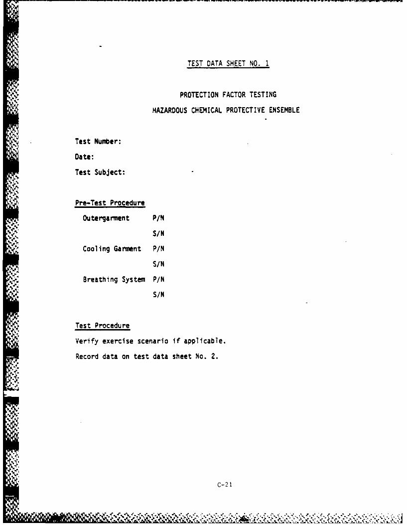
TEST DATA SHEET NO. 1
PROTECTION FACTOR TESTING
HAZARDOUS CHEMICAL PROTECTIVE ENSEMBLE
Test Number:
Date:
Test Subject:
Pre-Test Procedure
Outergarment P/N
S/N
Cooling Garment P/N
S/N
Breathing System P/N
S/N
Test Procedure
Verify exercise scenario if applicable.
Record data on test data sheet No. 2.
C
i C-2 1

TEST UATA SHEET NO.2
Sensitivity
Moemn of Measurement Reading
Generator. Prsue
GilenrAr Fresur:
Sampling Rate:
C-2 2 .
TEST PROCEDURE
MANNED STRESS TESTING
FOR
HAZARDOUS CHEMICAL PROTECTIVE ENSEMBLE
N4.
4' C-2 3

1.0 SCOPE
1.1 OBJECTIVE
The objective of the Manned Stress testing of the HCPE is to assess
the performance of the HCPE during work cycles by measuring physio-
logical factors throughout the work cycle.
1.2 METHOD OF APPROACH
Each test subject will be required to perform a series of two hour
work cycles consisting of exercises and simlated work tasks. Each
garment will be replaced after each two hour scenario for inspection
and sanitizing. Each test subject will perform one two hour work
cycle per test day. Testing will be terminated on the request of the
subject, when any physiological parameter reaches the maximum limit,
or at completion of the two hour work cycle by one subject. Prior to
manned stress testing of the HCPE, each test subject shall perform
two work cycle scenarios in conventional work clothes for familiar-
ization and to establish baseline physiological parameters.
C-24
'~a.~Ia.

2.0 SUPPORT FACILITIES AND EQUIPMENT
ILC Environmental Chamber
*Fiberboard Box (Gross Wt, 20 ibs)
55 Gallon Drum
Handtruck
Handwheel Valve
Hose
Screwdriver
Wrench
Treadmill
*°
look
C-25
I) ~

3.0 REQUIREMENTS
3.1 GENERAL REQUIREMENTS
This test shall be conducted with the general requirements of ILC
Document 807-1 paragraph 3.4 and as detailed below.
3.1.1 Test Sequence
The sequence of operations detailed in Section 4.0 of this procedure
is mandatory except as noted. Rearrangement of the sequence shall be
permitted only with the approval of the Test Engineer or the Program
Manager.
3.1.2 Test Documentation
All testing performed shall be documented by the documentation forms
detailed in Section 5.0 of this procedure. Each individual test shall
have a complete set of documentation forms completed by the test con-
ductor.
3.1.3 Verification
The successful completion of each operation shall be indicated by the
Initials of the test conductor and verification by the test engineer
in the columns provided for this purpose.
C-26

- - -
4.0 OPERATIONS
4.1 PRE-TEST PROCEDURE
A. Identify the test article
1. Outer garment P/N
S/N
2. Cooling Garment P/N
S/N
3. Breathing System P/N
S/N
B. Verify successful completion of outergarment and cooling garment
acceptance test. Attach Test Data Sheets as part of this com-
pleted procedure.
4.2 TEST PROCEDURE
The manned stress tests are to be two hours in length consisting of a
1/2 hour exercise period, a 1/2 hour treadmill test, and a 1 hour
work period.
A. Oonn ensemble.
B. Inflate outergarment to-operating pressufe-and fill cooling sys-tem.
C. Perform exercise scenario.
1. Kneel on left knee, kneel on both knees, kneel on right
knee, stand. Repeat three times.
2. Duck squat, pivot right, pivot left, stand. Repeat three
times.
C-27

:z
3. Stand erect. Bend body to left and return, bend body for- ;
ward and return, .bend body to right arid ,u Lu rri. RupuiL
three times..
4. Stand erect. Extend arms overhead, then bend elbows.
Repeat three times.
5. Stand erect. Extend arms perpendicular to the sides of
torso. Twist torso left and return, twist torso right and
return. Repeat three times.
6. Stand erect. Cross-body reach arms across chest. Repeat
three times.
7. Crawl on hands and knees for a distance of 20 feet.
8. Repeat steps 1 through 7 for 10 minutes. -
9. Rest for 5 minutes.
10. Repeat steps 1 through 9.
D. Perform treadmill.test.
1. Set treadmill at 5 of incline and 3 mph speed.
2. Walk for I minute and rest for 2 minutes.
3. Repeat step 2, 10 times.
E. Perform work tasks at room temperature 1W
1. Lift four boxes from the floor and place on a table. Re-
turn boxes to floor..2. Place a 55 gallon drum on a handtruck and move 25 feet.
Remove drum from handtruck. Replace drum on handtruck and• A
move to original position.
3. Remove drum from handtruck.
4. Uncoil and coil hose.
5. Opin overhead valve. Close overhead valve.
C-28 !
77' .
AM "

6. Remove and install bolt with wrench.
7. Remove and install screw with screwdriver.
8. Repeat steps 1 through 7 for 15 minutes.
9. Rest for 5 minutes.I10. Repeat steps 1 through 9 two additional times.
F. Doff ensemble.
4.3 POST-TEST PROCEDURE
A. Perform a visual examination of the test ensemble.
B. Perform an overpressure and pressure drop test on the test out-
C. Atctetdata sheets as a part of this completed procedure.
C-29

5.0 TEST DOCUMENTATION FORMS
Test information and data shall be recorded on the attached forms.
C-3
wit'

TEST DATA SHEET NO. 1
MANNED STRESS TESTING
HAZARDOUS CHEMICAL PROTECTIVE ENSEMBLE
Test Number:
Date:
Test.Subject:
Pre-Test Procedure
Outergarment P/N
S/N
Cooling Garment P/N
S/N
Breathing System P/N
S/N
Exercise Test
Verify performance of exercise scenario.
Record data on test data sheet No. 2.
Treadmill Test
Verify performance of treadmill scenario.
Record data on test data sheet No. 2.
Work Task Test
Verify performance of work task scenario.
qecori da'a on test data sheet Nc.
C-31

-jar
40-
I-- A .9
Z S
66J
-C-3

APPENDIX D)
PROTECTION FACTOR TESTING RESULTS

PROTECTION FACTOR TEST DATA
Test Number: P-I-01 Outergarment: 30 mil C1,F unsupportedType Te ,t: Mannequin Breathing Apparatus: not applicable
Time Type/Location of Detector Detector Protection(min.) Measurement Scale Reading Factor
00 Suit background 0.1 2.0Chamber 100.0 88.0
15 Head 0.1 1.0Torso 0.1 1.0 76,500Foot 0.1 1.5Chamber 100.0 91.5
30 Head 0.1 1.0Torso 0.1 1.0 93,750 jFoot 0.1 1.0Chamber 100.0 96.0
45 Head 0.1 1.0Torso 0.1 1.0 92,550Foot 0.1 1.0Chamber 100.0 89.0
60 Head 0.1 0.5Torso 0.1 0.5 137,000Foot 0.1 1.0Chamber 100.0 92.0
75 Head 0.1 0.5, Torso 0.1 0.5 187,000
Foot 0.1 0.5Chamber 100.0 95.0
90* Head 0.1 0.5Torso 0.1 0.1 286,500Foot 0.1 0.5Chamber 100.0 96.0
105* Head 0.1 0.5Torso 0.1 0.1 180,000Foot 0.1 0.5Chamber 100.0 84.0
120 Head 0.1 0.1Torso 0.1 0.1 455,000Foot 0.1 0.1Chamber 100.0 67.0
AVERAGE 188,500
* Chamber evacuation fans accidently activated between 90 and 105 minutes
D-1

PROTECTION FACTOR TEST DATA
Test Number: P-1-03 Outergarment: VITON/chlorobutylType Tesc: Mannequin Breithing Apparatus: not applicable
Time Type/Location of Detector Detector Protection(min.) Measurement Scale Reading Factor
00 Suit background 0.1 1.0Chamber 100.0 73.5
15 Head 0.1 0.5Torso 0.1 1.0 68,500Foot 0.1 2.0Chamber 100.0 85.0
30 Head 0.1 1.0Torso 0.1 0.5 101,500Foot 0.1 1.0Chamber 100.0 84.0
45 Head 0.1 1.0Torso 0.1 0.5 125,750Foot 0.1 0.5Chamber 100.0 82.0
60 Head 0.1 0.5Torso 0.1 0.1 75,000Foot 0.1 0.5Chamber 100.0 83.0
75 Head 0.1 0.5Torso 0.1 0.5 167,000Foot 0.1 0.5Chamber 100.0 84.0
90 Head 0.1 0.1Torso 0.1 0.1 850,500Foot 0.1 0.1Chamber 100.0 86.0
105 Head 0.1 0.1Torso 0.1 0.1 865,000Foot 0.1 0.1Chamber 100.0 87.0
120 Head 0.1 0.1 -.
Torso 0.1 0.1 885,000Foot 0.1 0.1Chamber 100.0 90.0 .
AVERAGE 191,750
D-2
%IZ!

PROTECTION FACTOR TEST DATA
Test Number: P-1-03 Outergarment: Butyl rubberType Test; Mannequin Breathing Apparatus: not applicable
Time Type/Location of Detector Detector Protection(min.) Measurement Scale Reading Factor
00 Suit background 0.1 0.2Chamber 100.0 79.0
15 Head 0.1 0.1Torso 0.1 0.1 780,000Foot 0.1 0.1Chamber 100.0 77.0
30 Head 0.1 0.1Torso 0.1 0.1 775,000Foot 0.1 0.1Chamber 100.0 78.0
45 Head 0.1 0.1Torso 0.1 0.1 790,000Foot 0.1 0.1Chamber 100.0 80.0
60 Head 0.1 0.1Torso 0.1 0.1 785,000Foot 0.1 0.1Chamber 100.0 77.0
75 Head 0.1 0.1Torso 0.1 0.1 760,000Foot 0.1 0.1Chamber 100.0 75.0
90 Head 0.1 0.1Torso 0.1 0.1 790,000Foot 0.1 0.1Chamber 100.0 83.0
105 Head 0.1 0.1Torso 0.1 0.1 825,000Foot 0.1 0.1
Chamber 100.0 82.0
120 Head 0.1 0.1Torso 0.1 0.1 815,000Foot 0.1 0.1Chamber 100.0 81.0
AVERAGE 775,000
D-3

PROTECTION FACTOR TEST DATA
Test Number: P-1-02 Outergarment: 20 mil C1PE (supported)Type Test: Mannequin Breathing Apparatus: not applicable
Time Type/Location of Detector Detector Protection(min.) Measurement Scale Reading Factor
00 Suit background 0.1 1.0Chamber 100.0 92.0
15 Head 0.1 11.0Torso 0.1 11.0 85,000Foot 0.1 11.0Chamber 100.0 95.0
30 Head 0.1 9.0Torso 0.1 13.0 30,250Foot 0.1 9.0Chamber 100.0 92.0
45 Head 0.1 8.0Torso 0.1 7.5 41,000Foot 0.1 7.0Chamber 100.0 93.0
60 Head 0.1 7.0Torso 0.1 6.0 49,000Foot 0.1 6.0Chamber 100.0 93.0
75 Head 0.1 5.5Torso 0.1 6.0 54,500Foot 0.1 5.5Chamber 100.0 92.0
90 Head 0.1 4.5Torso 0.1 4.0 70,250Foot 0.1 5.0Chamber 100.0 98.0
105 Head 0.1 4.0Torso 0.1 4.0 79,500Foot 0.1 4.0Chamber 100.0 93.0
120 Head 0.1 3.0Torso 0.1 3.0 31,500Foot 0.1 3.0Chamber 100.0 96.0
AVERAGE 55,135
D- 4

PROTECTION FACTOR TEST DATA
Test Numter: P-2-01 Outergarment: 30 mil CPE (unsupported)Type Test: Manned Breathing Apparatus: Draeger BG174
Test Subject: DC2 C. WYATT
Movement Type/Location of Detector Detector Protection(Time) Measurement Scale Reading Factor
Initial Head 0.1 10.0Torso 0.1 10.0 8,900Foot 0.1 10.0Chamber 100.0 89.0
Arm Extensions Head 0.1 3.030/minute Torso 0.1 3.5 86,5003 minutes Foot 0.1 4.0
Chamber 100.0 93.0
Bend at Waist Head 0.1 2.510/minute Torso 0.1 3.0 40,0003 minutes Foot 0.1 1.5
Chamber 100.0 94.0
Deep Knee Bends Head 0.1 8.010/minute Torso 0.1 10.0 10,5003 minutes Foot 0.1 8.5
Chamber 100.0 93.0
Arm Extensions Head 0.1 11.030/minute Torso 0.1 12.0 7,9003 minutes Foot 0.1 12.0
Chamber 100.0 92.0
Bend at Waist Head 0.1 13.010/minute Torso 0.1 15.0 7,2003 minutes Foot 0.1 10.0
Chamber 100.0 91.0
Deep Knee Bends Head 0.1 10.010/minute Torso 0.1 12.0 8,9003 minutes Foot 0.1 8.5
* .,.~Chamber 100.0
AVERAGE 26,900
* Test subject overheated and was removed from the test chamber; the cooling
vest was not worn in the ensemble
D-5

PROTECTION FACTOR TEST DATA
Test Number: P-2-02 Outergarment: Butyl rubberType Test: Manned Breathing Apparatus: Draeger BG174
Test Subject: Andy Leslie (ILC Dover)
Movement Type/Location of Detector Detector Protection(Time) Measurement Scale Reading Factor
Initial Head 0.1 6.0Torso 0.1 5.0 16,500Foot 0.1 5.0Chamber 100.0 86.0
Arm Extensions Head 0.1 2.030 /minute Torso 0.1 2.0 48,0003 minutes Foot 0.1 1.5
Chamber 100.0 90.0
Bend at Waist Head 0.1 1.010/ainute Torso 0.1 1.0 108,5003 minutes Foot 0.1 0.5
Chamber 100.0 91.0
Deep Knee Bends Head 0.1 0.510/minute Torso 0.1 0.5 138,0003 minutes Foot 0.1 1.0
Chamber 100.0 93.0
Arm Extensions Head 0.1 0.530/minute Torso 0.1 0.5 138,5003 minutes Foot 0.1 1.0Chamber 100.0 92.0
Bend at Waist Head 0.1 0.510/minute Torso 0.1 0.5 182,0003 minutes Foot 0.1 0.5
Chamber 100.0 90.0
Deep Knee Bends Head 0.1 0.510/minute Torso 0.1 0.5 182,0003 minutes Foot 0.1 0.5
Chamber 100.0 92.0
AVERAGE 133,000
D-6
i ,is- - - ~ ~ - -

PROTECTION FACTOR TEST DATA
Test Number: P-2-03 Outergarment: VITON hlorobutylType Test: Manned Breathing Apparatus: Draeger BC174
Test Subject: Andy I-t.ca]e (ILC Dover)
Movement Type/Location of Detector Detector Protection(Time) Measurement Scale Reading Factor
Initial Head 0.1 2.0Torso 0.1 2.0 46,500Foot 0.1 1.5Chamber 100.0 85.0
Arm Extensions Head 0.1 0.530/minute Torso 0.1 1.0 104,0003 minutes Foot 0.1 1.0
Chamber 100.0 89.5
Bend at Waist Head 0.1 1.510/minute Torso 0.1 1.0 77,5003 minutes Foot 0.1 1.0
Chamber 100.0 93.0
Deep Knee Bends Head 0.1 1.510/minute Torso 0.1 1.0 69,9003 minutes Foot 0.1 1.5
Chamber 100.0 93.0
Arm Extensions Head 0.1 1.530/minute Torso 0.1 1.5 69,9003 minutes Foot 0.1 1.0
Chamber 100.0 93.0
Bend at Waist Head 0.1 1.510/minute Torso 0.1 1.5 62,5003 minutes Foot 0.1 1.5
Chamber 100.0 95.0
Deep Knee Bends Head 0.1 1.510/minute Torso 0.1 2.0 19,2003 minutes Foot 0.1 1.5
Chamber 100.0 97.0
AVERAGE 64,300
D-7

D T(~~'2