UNCLASSIFIED - DTIC
308
UNCLASSIFIED AD 4031i iAlkthe DEFENSE DOCIUMENTATION CENT I FOR SCIENTIFIC AND TECHNICAL INFORMATION CAMERON STATION, ALEXANDRIA. VIRGINIA UNCLASSIFIHED
-
Upload
khangminh22 -
Category
Documents
-
view
1 -
download
0
Transcript of UNCLASSIFIED - DTIC

UNCLASSIFIED
AD 4031iiAlkthe
DEFENSE DOCIUMENTATION CENT IFOR
SCIENTIFIC AND TECHNICAL INFORMATION
CAMERON STATION, ALEXANDRIA. VIRGINIA
UNCLASSIFIHED

NOTICE: When government or other dravings, speci-fications or other data are used for any purposeother than in connection with a definitely r.!'latedgovernment procurement operation, the U. S.Government thereby incurs no responsibility, nor anyobligation whatsoever; and the fact that the Govern-ment may have formulated, furnished, or in any waysupplied the said drawings, specifications, or otherdata is not to be regarded by implication or other-wise as in any manner licensing the holder or anyother person or corporation, or conveying any rightsor permission to manufacture, use or sell anypatented invention that may in any way be relatedthereto.

R-5135
SLtEE ~MISSILE SYSTEM SAFETY
AN EVALUATION OF
SYSTEM TEST DATA"(Atlas MA-3 Engine System)
ROM 3181-1001
MAY • 1963
cRTISIA
PERSON NEL SUBSYSTEMS REPORT
SANI
Ii O CUKETDFI3'h'IE3 * A DIVIUIONM OF NORTH AMERICAN AVIATION, INC

BestAvai~lable
Copy

R-5135
MISSILE SYSTEM SAFETY:
AN EVALUATION OF
SYSTEM TEST DATA
(ATLAS MA-3 ENGINE SYSTEM)
4L'400 4C:ý MC E -I" 1 '- I F-A DIVISION OF NORTH AMERICAN AVIATION. INC.
6633 CANOGA AVENUECANOGA PARK, CALIFORNIA
Contract AF04(694)-8
C.
PREPARED BYG.A. Peters and F.S. Hall
Reliability Operations - Human FactorsRocketdyne EngineeringCanoga Park, California
APPROVE BY
G.J.Griffin
Atlas Program Manager
NO. OF PAGES 317 & vi REVISIONS DATE 1 March 1963
DATE REV, MY PAGES AFFECTED R EM AR KS
FORM R ISG .PLATF,

MISSILE SYSTEM SAFETY
AN EVALUATION OFSYSTEM TEST DATA
(Atlas MA-3 Engine System)
GEORGE A. PETERSand
FRANK S. HALL
ROM 3181-10011 MARCH 1963
RELIABILITY OPERATIONS - HUMAN FACTORS
ROCKETDYNE ENGINEERING, CANOGA PARK, CALIFORNIA
A DIVISION OF NORTH AMIERICAN AVIATION, INC

A IIVI"LON OV NýLFTH AM•ERICAN AVIArIL)N I-1
ACKNOWLEDGWINTS
The authors wish to acknowledge the technical assistance of Charles A.
Mitchell and Kay Warming of the Reliability Human Factors Staff. They
also wish to express appreciation for the contributions of C. Stevens,
C. Wilson, and H. Straight who participated as human factors observers/
analysts at various test sites. The encouragement of Capt. R. Burns of
the Air Force Ballistic Systems Division, and numerous requests by various
other individuals, contributed materially to the extra motivation required
for the pursuit of the numerous technical details involved in a study of
this kind.

A fU],-t I 1N -F N11f1TH Amf RICAN4 AVIATI, I ¼
FOREWORD
The purpose of this publication is to present detailed
information concerning actual incidents and problems
which have affected the operational safety of rocket
engine systems. The test data contained in this re-
port were collected and evaluated under the provisions
of Contract AFO4(694)-8, GM 6300.5-1060, GM 6300.3-2106,
and Atlas SPO Category II Program Instructions.
ROM 3181-1001 iii

l~l. C /. T , I•A DIVISION OW NORTH AMERICAN AVIATION INC
7)
CONTENTS
SECTION 1. INTRODUCTION .......... ..... .............. 1
Part 1. Purpose of the Study . ............. ........... 3
Part 2. Method or Approach .......... .... ............. 7
Part 3. Variables Affecting Human Performance. . ....... 9
Part 4. Safety Criticality and Associated Factors .... ..... 15
SECTION 2. CASE STUDIES.............. . .. 19
SECTION 3. SUPPLEMENTAL INFORMATION ............ ....... . 145
Part 1. Failure Reports .................. .......... 147
Part 2. Test Reports .................... .......... 153
Part 3. Protective Equipment .............. ........ 155 )Part 4. Personnel Performance Guides ........... ...... 157
Part 5. Safety Problems on the Atlas "F" Series. ..... ....163
SECTION 4. DATA EVALUATION ................ ......... 167
Part 1. Derivative Humaii Factors Design Principles. .... ....169
Part 2. Design Implications ............... ......... 177
Part 3. Supplemental Checklist Materials. . ...... ....185
Part 4. Generality of the Findings.. ........ ....187
Part 5. Human Error Principles ............... ....... 191
SECTION 5. PERSPECTIVE .................. ......... 195
Part 1. Human Error and Goofproofing ............. ....... 1Q7
Part 2. Requirements for a Safety Evaluation ...... ....... 205
Part 3. General Safety Functions .......... ............ 209
iv ROM 3181-1001

A O•IVIION OF NORTH AMERICAN AVIATION INC
(),
SECTION 6. SYST SAFETY PROGRA • .,ELEMENTS .. .... . ... . . . 217
Part 1. Identification of Human .Error ............ 219
Part 2. Systems Analysis .a . . .......... .... 225
Part 3. Safety Motivation :. • ............... 239
Part 4. Human Engineering Surveillance........ 243
Part 5. Personnel Subsystem Analysis..... ... ..... . 249
Part 6. Systems Test . .... .•. 257
Part 7. Safety Surveillance Teams . . . . ... 279
Part S. Design Review ...... 281
Part 9. Catastrophic Analysis . ............ 283
APPENDIXES...... . . ..... .......... 285
(_ ROM 3181-1001 v

IM0 C-- AC IE ir "IV M~ KE* flIVUISION OF NflRTN AME4ILAN AV•ATIY I
ILLUSTRATIONS
1. Categorization of Human Factors Problems by Variables
Affecting Human Performance 10
2. Categorization of Human Factors Problems
Having Safety Implications (N = 60) 16
3. Criticality Rating of Human Factors
Problems (OSTF-1 Only) ...... 17
4. Systems Flow Chart 227
5. Sequence Charts ........... 229
6. Test and Evaluation Parameters ...... 235
7. Personnel Subsystem Development Cycle ...... 251
8. EMA Human Factors Data Processing System 258
9. Personnel Subsystem-Human Factors Data )Flow Chart (VAFB OSTF) 261
10. Planned Event Index 265
11. Analysis of DTO Completion Status Ratings 271
12. Illustrative Test Event Log Sheet 274
vi ROM 3181-1001

SECTION 1
INTRODUCTION
0 The purpose, approach, and
importance of the study
00
This section contains introductory information regarding the basic pur-
poses and objectives toward which this missile system safety study was
oriented. The basic method or approach used to gather and interpret the
data is described, and the relative importance of safety as a technical
objective and the constituent factors of the safety variable are discussed.
•O• 3181-1001

* r,.jL)4,1-- OP NorlYN AMEN•I tN AVIANION IWf
N1TRODUCTION
PART 1. PURPOSE OF THE STUDY . . . . . . . . . 3
Over-all Analysis and Evaluation of Basic Data 3Prevent Recurrence of Problems . .Information for Planning a SSE Program .
Basic Reference and Training Material 5Descriptive and Explanatory Information 5
PART 2. METHOD OR APPROACH.7
Source of System Test Data.7Type of Incidents Reported.8
PART 3. VARIABLES AFFECTING HUMAN PERFO•MANCE 9
Safety... 9Technical Data .. 9Organizational Controls 11Maintainability 12Job Environment 12Training.13 )Operability .... 13Personnel Selection and Manning 14
PART 4. SAFETY CRITICALITY AND ASSOCIATED FACTORS . . . 15
Secondary Factors Associated with Safety . 15Relative Importance of Safety Variables 15
2 RONEO 3181-1001

A V-1- OF NfRIH AMERICAN AVIATIOTN IEC
PART 1. PURPOSE OF THE STUDY
A significant amount of humar-a factors data that pertained to missile system
safety was accumulated durinj_ the course of various operational system test
exercises. These data were in the form of incidents (deviations/difficul-
ties), which were gathered duxring the direct observation of various job
operations. Much of the basirc dita and the results of preliminary analyses
have been reported previouslyw- in some 36 monthly periodic and logical
function reports (Appendix E_,List of OSTF Reports).
The purpose of this report is to provide additional pertinent information;
it was obtained as a result icf further updating and detailed analyses of
the data, and oriented toward the following five objectives.
OVER-ALL ANALYSIS AND EVALUA"•WION OF BASIC DATA
A review was made of all of -the human factors incidents and problems that
have affected the operationa_1- safety of the Atlas engine system. The
information concerning each problem was updated, further analyses were
made, supporting data were olbtained, and a case study format was pre-
pared. Each case study contains statements regarding the equipment
affected, job operation invo ived, problem criticality, problem type, sys-
tem implication, recommended corrective action, and a chronological indica-
tion of the current disposit :ion. These problems were then critically
examined to determine what n*-w knowledge could be gained from these opera-
tional experiences.
ROM 3181 -1001 3

JRL41CU NW"14 IE Jr" t'r NE3A DIVISION OP NORTH. AMERICAN AVIAT ION Nr4
PI1E1 MNT ttECUM~ENCE: 0l'PROIILMS,
TIhere Is a tlelirl'diry for' somf, Pr)l'ol)ms to cord. i lue , vvecur, or' be i'UplwaLed
by ~ ~ ~ P- sbeun.prsonnel', si tes ' dpro ' m. To help preverit rveirrtc
of' pro!) eris , -some form of t'xperi'jeIW4 re1 ent ion is necessary Co al (1' C hosp
K't'spoiis i b) h conicern'injg spe c ili c 1 rwob I (-ml a reas o r if i 17r7i cu] Lie s i nit atta iii-
inrg var'i olis kwhiri c i I obj(,jc I, i ves Thliis vxper'iveice retv(iltionl sholrod ill-
c I tde analysis of' accumulated past. (hitI, transIlat io Oin to a form whii ch
WOtim i, h ,liost nwiie~rinrigfui , Wridl t. mel y tratilsmint tal (or avail abli iity ) to
Chose Who WoulId he ill a pos it ion to uise suell in formaLi on priofli tab ly.
AlIl Loo 4)1'll tn i asio ia 'll from i ive s L igLtory programs may he rehIegrated to
I i I , isherv i'4 iorp.I'l lIi ly, at1. son111 I' uiitur'e Liniii , it, 'ould b( e oi'gari i vd , aria-
I zvden ill t( i'pi'('t,4(, andh wade avail abir to o thiers . llowevvvr, the prnessure1
oL, c'tii i'rorld, acii t iVi.Ies~ and C.Iiirg~riadua I loss o)f' perut.Iiient. rinte'rat in.g facts
Ir'voil tire inloryi)' of, tillost invle 111,1Y4'h ir r'esuilt ill the almrost complete I loss
,If VI I inble( itiif'onirmt i Oil bial, was obhta ined at. coils iderabi e cost.
011v' (1i the pr incipal obij eeL i es of' thiis re(poI' t, Ltrere fore , is to analyze
thlese (110t1 be fore4. LI4'll h4ecOnivri'en'legate Q1 o f ile a~5nd mlakeO the pert innert
re'sul ts availiable Cou 1i ose w~ho can itse' tririn en the Atlas programn andi
I NTOIPIAT'I1 ON F"OR PJAINN 1Nt A SYSTEM
AJ I!' hinr of.~jec~i iVt Wa s Co explIore Clic'. i4'a:i ng and1( impli cat ions of the diata
Iill ordier Lo deriv e nun ri' generalI infl'u ea ti oil01 systemn develIoprmeut that couldIt
Iiiv4 some applIiceabilit y to o thler programs. Ali attempt was made to derive
hoHi riseht fl nts igri andi systeiis plIanimnirg iiiforrra 1.1on. Al thorughr basic data
all- l1in tlie At. Ias programr surpjl('merwt a i iti fror:rat.ion, frorri other p)rograms was
P11DM _5I8 -1 001

I0 c K NET " 1W •EA nIVI•O.IN ýF" NORTM AMCRICAN AVIATION INC
obtained where necessary to verify the generality of the emergent concepts.
Particular emphasis was then placed on developing a general approach to
a system safety engineering program that could eliminate or greatly reduce
the effect of the operational problems described.
BASIC REFERENCE AND TRAINING MATERIAL
Although a great deal of discrete work relative to system safety engineer-
ing has been done on the Atlas program, no summary description nor cross
referencing of this work exists for those who might wish to utilize this
material.
This report contains such information as well as pertinent references to0
a number of applicable specifications, exhibits, technical papers, and
related activities that could provide further useful information. An
attempt was made to logically organize, digest, and concentrate informa-
tion that could be of maximum value if this report were to be utilized
as a reference source, and to include materials suitable for use in reli-
ability or safety training courses.
DESCRIPTIVE AND EXPLANATORY INP'O•IMATION
General approaches to system safety engineering, techniques for implement-
ing such an effort, and methodological difficulties which have been and
could be encountered are described. Ideas, concepts, and general informa-
tion that could facilitate future planning, proposal efforts, coordination,
or direction of effort in the area are discussed.
Section 53, Part 2, contains additional information on requirements for
safety evaluation.
RiOM 3181-1001 '

A OIVIGION OF NCRIMI AMCtiCAN AVIATION. INC
PART 2. METHOD OR APPROACH
SOURCE OF SYSTEM TEST DATA
Human factors-personnel subsystem data were obtained by interviews
with personnel operating Rocketdyne equipment, by observation of all
test operations involving Rocketdyne equipment, and by investigation of
all deviations from standard procedures which involved Rocketdyne
equipment or personnel. The specific tools which were used to gather
and report the data included Personnel Performance checklists, Human
Engineering checklists, Ppsttest Interview forms, Deviation/Difficulty
reports, Problem Analysis reports, and Summary Analysis reports. Supple-
mental reference was made to failure reports, aptitude test results,
field service reports, inspection and maintenance logs, and various Atlas
Associate Contractor reports.
0 The system test data presented were obtained during operational system
test exercises involving the Atlas 4A-3 engine system during the period
from October 1960 to November 1962. The incidents reported were per-
sonally observed by trained human factors observer/analysts during job
operations at the following locations:
1. OSTF Engine Maintenance Area, Rocketdyne Van Nuys Facility,
Van Nuys, California
2. 576th Strategic Missile Squadron, Missile Assembly and Maintenance
Shop C (MAM II), Vandenberg AFB, California
3. 576th Strategic Missile Squadron, Launch Site C, Vandenberg AFB,California
4. OSTF-l Launch Site, Vdndenberg AFB, California
5. OSTF-2 Launch Site, Vandenberg AFB, California (corroborative data)
ROM 3181-1001 7

A DIVISION OF NOATM AMWOICAN AVIATION INC
0
The teb data were supplemented by data obtained from other operational sites
(i.e., Category II test information) where some verification or further
understanding of a general problem area was desirable. In some cases, the
human factors case studies and analytic information presented reflect a
continuous accumulation of information over a fairly long period of time.
Where it would contribute to problem understanding or actions undertaken
relative to a problem, the specific chronology of events is given. Addi-
tional support data from various sources are presented where needed to
substantiate, illustrate, or extend the systems safety engineering analyses
and evaluations.
TYPE OF INCIDENTS REPORTED
A human factors incident (deviation/difficulty) was reported whenever there ()was any unexpected interruption, time delay, error, difficulty, or change
in the established sequence of work tasks caused by equipment, procedural,
supply support, or operator difficulty. All incidents were reported even
if they did not involve injury to personnel or damage to equipment or
property. The primary concern was to identify what went wrong and how it
might be corrected, rather than to establish blame or responsibility.
The following definition was utilized by operational system test observers:
"A deviation/difficulty is any incident which occurs
outside the standard, predicted, or expected template
of human behavior (such as excessive time to complete
a task, an identifiable difficulty in performing an
assigned task, any pattern of behavior which could lead
to undesirable system performance characteristics, or
any act which leads to a human-initiated failure)."*
*ROM 2181-1002, Human Performance in the Atlas Engine Maintenance Area, byG. A. Peters, F. S. Hall, and C. A. Mitchell, Rocketdyne Reliability
Eugineering, 1 February 1962.
8 ROM 1181-1001

¶ DIVISION OF NORTH AMSRICAN AVIATION INC
PART 3. VARIABLES AFFECTING HUMAN PERFORMANCE
A number of functional variables in the operational situation directly
affect the performance of required work tasks. To assess the relative
importance of these variables, each human factors problem was examined
to determine if it bore some significant relationship to each of these
functional variables. Figure 1 shows the results.
SAFETY
It can be seen in Fig. 1 that safety is a major problem area affecting the
performance of work tasks. Approximately one out of every five problems
involved safety. The relative proportion of safety problems did not dimin-
ish as system testing continued.
Safety problems were those which could result in accidental equipment
damage, physical hazard, or personnel injury. The cause of the hazard
could involve hardware design, system configuration, task sequence, pro-
cedures, materials, operations, or common personnel practices. It would
remain a problem until it was clearly identified, understood, and the
hazard minimized (consistent with operational needs).
TECHNICAL DATA
The predominant continuing contributing factor in the problems encountered
(Fig. 1) was the technical data used to guide or support the required job
performance. More than one third of the problems involved in some way the
use of technical data such as technical manuals or operation and maintenance
checklists.
ROM 3181-1001 9

!•O•14::Ic ETD I• "EW1WJ
A U)IVISION OF NORTH AMERICAN AVATiLC,, INCN
TECHNICAL DATA 4 .:120
ORGANIZATION CONTROLS 7 =..=====68
MAINTAINABILITY 4 51
JOB ENVIRONMENT I 43
TRAINING 41
OSTF EMA PRtOBLEMS
OPERABILITY O33VJUN ID 11)
VAFB PROBLEMS(JULY 1961 THROUGH
OCTOBER 1961)OTHER 24 24VF PROBLEMS
PERSONNEL SELECTION 7AND MANNING
Figure 1 Categorization of Human Factors Problems by VariablesAffecting Human Performance
NOTE: N = 303. Each problem may be supported by a number of re-ported incidents (D/D's), and each problem could be relatedto one or more of the functional variables listed above.Chrondlogy is based upon the initial report of the problem;subsequent incidents were reported only when they contributedin some way to the analysis or understanding of a problem,its causal effects, or the effectiveness of the correctiveaction.
10 R0M 3181-1001

A 0IVlbiON OF NORTH AMERICAN AVI^TIUN INC_
Technical data problems were those in which some difficulty was experienced
because of an omission, technical error, or lack of clarity in a technical
manual, i.e., an individual's inability to understand the prescribed
written procedure or his failure to find all the information required to
complete a job task. More often, it involved an impractical sequencing
÷ of task elements or an erroneous assignment of these elements, e.g.,
emp'loyment of the wrong technical specialist.
ORGANIZATIONAL CONTROLS
Another major problem area (one of every five problems) involved organi-
zational control procedures.
These problems involved the methods used for controlling activities of per-
sonnel in the work area, e.g., implementation of regulations, rules, or
local policy that governed the employment of nonauthorized equipment or
job practices. A proublem could have involved:
1. The supervisory or administrative approach used to govern certain
desired aspects of job performance
2. The application or use of procedural devices such as
a. Operation and maintenance checklist
b. Inspection work card
c. Job manual procedure
d. Regulation
e. Policy
ROM 3181-1001 11

A DIVIION OF NORTH AMERICAN AVIATI)N INC
0
It would involve:
1. Shift assignment and rotation
2. Housekeeping standards
3. Standard operating procedures
4. Military discipline, etc.
which affect the manner in which work tasks are accomplished.
MAINTAINABILITY
A substantial number of maintainability problems were reported during the
earlier maintenance demonstration exercises at the Van Nuys Engine Main-
tenance Area. The relative number of problems reported during subsequent
operational system testing was much smaller (as would be expected).
The term "maintainability problem" was applied where characteristics or
features of the equipment did not enhance the economical and effective
ac-complishment of maintenance tasks with the minimum time, skill, and
resources in the operational environment. In addition to the obvious
things, the problem may cause the mechanic to dislike performing main-
tenance operations on the equipment, encourage him to perform tasks in
too great a hurry to accomplish them properly, or it may divert his at-
tention to personal comfort or security when he should be attending to
proper task performance or malfunction indications.
JOB ENVIRONMENT
Another variable or problem area which adversely affected personnel
performance involved poor environmental conditions in the work area.
12 ROM 3181-1001

A DIVISION OF NORTH ANERICAN AVIATION INC
Job environment problems may involve:
1. Excessive noise
2. Poor illumination
3. Temperature and humidity extremes
4. Psychological pressure -
5. Inadequate tools
6. Inappropriate test equipment
7. Crowded work space
8. Unsafe maintenance platforms
TRAINING
Problems involving the prior training of individuals performing various
work tasks increased in relative importance during the conduct of opera-
tional system testing. These problems were related to discovered deficien-
cies in skills, job knowledge, and work habits, attitudes traceable to
individual or integrated system training, or deficiencies more appropriately
rectified by additional operational readiness training.
OPERABILITY
Operability problems were reported with greater frequency during the earlier
EMA maintenance demonstration exercises. These problems relate to the
tasks of activating, monitoring, regulating, or changing the performance
of an item of equipment by means of controlling devices.
ROM 3181-1001 13

1PFMSONNEL SEI.ETTTON AND RANNIN(
CIlp la vv I-v few~ proble 'Ims WP wre P i e11C4(Ie ill tII i aril LL' '1 I'lI4esv I)101) il('J
It' it .t't to Hie io ete (C i on of, asLt)4M i Infnt( , of, p.ersolnitel 1 o Var ionli jot)
otperat ions. A Itrobl) in(I! miaLi C iavv hinoved Ill,'( hit nnnnr or wi-sorns ass igtrrwd
t~o (to a Job, tHe reqhi irement, '.'ior spec ial apti. i tde taF taI li I.," of- 11i1
ROM 35181-1001
A rIVI-ION Or NORTH *ME4ICAN AVIr11r * ,C
PART 4. SAFETY CRITICALITY AND ASSOCIATED FACTORS
SECONDARY FACTORS ASSOCIATED WITH SAFETY
Each of the 60 safety problems was reviewed to determine the general vari-
ables related to such problems (Fig. 2). Most of the equipment design
problems were identified early in the system testing when intensive main-
tenance demonstration exercises were conducted. The major safety problems
reported from the field site involved job environment, organizational con-
trols, and training. There were 114 reported incidents (deviation/diffi-
culties) on these 60 safety problems, i.e., an average of 1.9 reports per
problem.
RELATIVE IMPORTANCE OF SAFETY VARIABLES
All problems, and the safety problems alone, were rated as to their
relative importance or criticality (Fig. 3). Whereas 47 percent of all
problems were rated of major importance, 68 percent of the safety prob-
lems were of major importance. In both cases, the problems initially
reported during the later phases of the system testing were proportionally
of greater criticality.
Since more than 13 percent of all problems reported have major safety im-
plications, this area merits serious consideration of the contributing or
causal factors and their amelioration.
For further information on safety criticality, see Section 3, Parts 1 and 2.
ROM 3181-1001 15

SA rI~e ISIC •C1~N F~t Ap~t qi AN AVIATr I(_N INC
l7
JOB ENVIRONMENT . ...... 28
ORGANIZATIONAL CONTROLS.. ' 2
EQUIPMENT DESIGN 4 / 19
"TRAINING Ia 16
PROVISIONING 4 7
TECHNICAL DATA 2 OSTF EMA PROBLEMS(NOVEMSER 160 THROUGJUNE tSBI)
VAFS PROBLEMSPERSONNEL SELECTION IJULY 1961 THROUSH
AND MANNING OCTOBER 1""
VAFB PROBLEMS(NOVEMBER 1961 THROIXIH
OCTOBER 1962)
MANUFACTURING ERROR
Figure 2. Categorization of Human Factors ProblemsHaving Safety Implications (N = 60)
16 ROM 3181-1001

A DIVISION OF NORVH AMERICAN AVIATION INC
ALL PROB3LEMS (N:303)
MAJOR 242I. 19 .
MODERATE 4083
MINOR 7 78
SAFETY PROBLEMS (N=60) EPOSl EMA PROBLEMS(NOVEMBER 3 "-11MO
JUNE 1961)
SVAFB PROBLEMS(IJULY 1961 TH4ROW"
MAJOR I 1OC70KR 1961)SVAFS PROBLEMS
j~(NOVEMSER 1361 1USOCTOBER 62
MODERATE to:1
MINOR : 9
Figure 3. Criticality Rating of Human Factors
Problems (OSTF-l Only)
ROM 3181-1001 17

4- 1Ki~ WE~ *Afl1tt'.*M.6
'
SUCTION 2
CASE STUDIES
Safety data in the form of
directly observe'd operation-
al incidents.
In this section of the report, various operational problems reported by
human factors observers during system test operations are described. These
problems are presented in abbreviated case study fashion. Each problem
contains a short description of the incidents, the equipment affected,
the job operation/task involved, the type of problem and its criticality,
the implications of the problem, the recommended corrective action, a
chronological statement of the action taken, and some cross-reference
notations.
ROM 3181-1001 19

A flIVIIUION OPP NORTVH AMCNICAIN AVIATION INC
SCIIEIULING OF INCOMPATIBLE OP RATIONS. . 21INlLAT1N(G Tit, THIROAT PLUG i 111 23OV1'31, 11'iSUIlIZATEON DURING [NO INENIA JN)1I ANI1) 2It; 1)2
S A )[OON TIIIUIT CILAMI1Elt . 3INSTALLING; THIROATr PLUG~S . . 35..CLEANING4 WITH! 1100LO1omlorrYul .. 7l'lUEMIMBALM IWOPIECAIITTONS.FUEL lUMPS IN BOATTA IL . . .CROWDING IN MISSILE THROAT SECT(IION . .
HUMAN PACK IIOWuSE. . . . . tit)
CHECK! 151 iEII~ ATIONS . . . .51..
DR!OPP'ING SOLID IitOPEIJ3ANT! WAV GW~I"!TORtS . . 5...5AI)Afl"I' IDINI [FICATION...... . . 5 7IW ISlING VI,3NN1131. INGINE' WkINTMNAN('E PLATFORM.......................61OP'EHUTOII, FOOTING, ON HISHI NG SIAN!).... ........................... 3SIIOCK MIZARDI . ... . . .. .... ... 5PLACARD )ING OF" OP!'2AT ING VOLTAGE..... ............................ 7I'l, 11 PI3ti, STEP' 6
NONPlIACAUlDl:! OANGI31. MIUtS .. . .... .. ...... 71SI IA!! P COUN II-3( . ... . . . .. ...... 754,0MMINNI CATIVO'4 VEEMEI) . ... . . . .. ...... 77CONRO OF10! 01' 1:1.STIORAGE TANK( U.. .......................... 79
TOGl) 'I ~l MF COMMUN ICAlTIONS SYSTI-M~ . ...STEPIPING0 ON ELECTIRW[A! CAL........ ........................... 8BUCMPIING HEADS ON f11AM CONT1101! DOX.... ........................... 7LIA C 1.11%W~ WORK M'A'I'iOIU. B" IC IN I E.....................89SIPPR I L'~t ATINC(IIl']t A(CIESS ROUTE...... ................. ......... 93IHARD HATS . ... .. . ........ 97
i (iAN r0 VFt IIACWAIWS .. . . .. ........ 99IM 11MVIi El) WOIIK$'ANDS) AND IP i!P1'ING HAZARDI ......................... 101
MA INT'A IN (Ght0l NDI EVUQUI NITl, TOO....... .......................... 103Sil IN% OvI'Th4 Nvs 'IIIAr s..... ............................ 10
A11)JTSTIABLE. WHIM7CIIES . ... .. ... ...... 107BLOCWKED SAFETYl3 A ISLE .; .. . . .... ...... 1o9INSING TURPOI10'UMUN'- FOR1 S'1EIADI)II'S..... ............ .. .. .... 11MA IN'MI'INNC'1" O PLAITS AND PUSKIT 'S.......... .. . .. .. .... 11TE'AMWORtK Tl:I II$IEAM PRACT [l....... .......................... 119iti-MOVi LOCKS AVN) COVEUS BIEF"ORE IAIN..... ....................... 123IN'I',tlj'I,:Itu.N(!I,: WIll! SSTSlA INI'21, IIYI'l'IGOII RIVtIDGE.....................125
NCU LINE~ 3 vs i.INi i. . ... .. . . ...... 1291GIIIlI-PIIIKSSURi: lo! NON TIEDO......... .......................... 131HIE! FI'AME-IllCKE-'l' NET'l IS lOlR PEOPLE.... .......................... 133lIIIHIUSI (IANIJUI'21 PAD NO'T US!)........... ..... .................... 135
MlISAL IGNEl) MA IN'I'NAN(:E PLATlFORMS...... ......................... 137INIW"I'l OFF BIEFORE :u2IOvING F.XP1.,OSI~ ........................ 139N !X INI. F1JEL! AND LIQUI [POYI';I-N "FMS..................110.
IlMM3181-1001

SAFETY PROBLEM NO. 1
(HUMA N FACTORS PROBLEK NO. 279)
SCHEDULING OF INCOMPATIBLE OPERATIONS
Incidents
Three crews were working simultaneously at the OSTF-1 launch site. One crew
was attempting an engine flush and purge, another was performing ECP* mod-
ifications, and the third was draining the facility LO2 (liquid oxygen) tank.
Suddenly, the facility LO2 tank vented, spilling clouds of GOX (gaseous
oxygen) over the wall into the open missile bay where the other two crews
were working. Fuel fumes are quite strong during early portions of an
engine flush and purge, and operations stopped immediately as both crews
quickly evacuated the area then, and each time thereafter that there seemed
to be a possibility of again venting the LO2 tank.
A second complication involved the fact that some of the ECP changes were
on the flame bucket. It was difficult for the engine maintenance crew to
keep from wetting the ECP crew with toxic trichloroethylene solvent or
asphyxiating them with fumes.
Job Operation/Task
Checklist AP62-0132, Section 49-22, Engine Flush and Purge (4 June 1962);
other tasks were not identified more specifically than indicated above.
*See appendix for list of abbreviations.
ROM 3181-1001 21

xa"C:: c~w uV F n1r•11Vr.ON OF NOr4TH AMF ICAN AVIATV-(N IN,
Problem Criticality Problem Type
Major Safety; Job Environment;
Organizational Controls
System Implications
GOX was able to enter the missile bay from the facility LO2 storage room
because the roof was open when the missile was erected for the flush and
purge. Any task in the missile bay, or which generates fuel fumes in the
missile bay, and is performed with the overhead doors open is, therefore,
incompatible with the task of draining the facility LO2 storage tank. Like-
wise, any task on the lower portion of the launcher or in the flame bucket
is incompatible with the engine flush and purge.
Recommended Corrective Action
Do not schedule incompatible tasks for simultaneous accomplishment.
Action Taken
Incident ReportNumber and Date Disposition
D/D 6118R 25 July 1962: PSRB assigned to OSTF-12 July 1962 Site Commander with information copy going to
6595th Test Wing Safety Group.
NOTE: The BSD Deputy IG for Safety at NortonAFB was on the distribution of the home plantOSTF reports which described this and othersafety problems encountered.
22 ROM 3181-1001

mrb c:: uK 1E qr" ' rw EA 0,IVI-10N -F N-1•lH AMERI(CAN A.IATIC'4 1I,
SAFETY PROBLEU NO. 2
(HUMAN FACTORS PROBLE NO. 111)
INFLATING THE THROAT PLUG TIRE
Incident
While attempting to inflate the throat plug tire, the MET/M connected the
NCU line to the bleed fitting on the handle of the sustainer engine thrust
chamber throat plug (instead of the tire Schraeder valve).
Job Operation/Task
Preparing the missile for MAPCHE checkout at launch site, T.O. 21-SM65E-CL-14-
Problem Criticality Problem Type
Major Safety; Training
System Implications
Fortunately, the human factors observer informed the MET/M of his error before
pneumatic pressure was applied. Otherwise, the throat plug could have been
blown out, with probable major damage to engine, throat plug, and RPIE, and
with possible fatal injury to personnel. It is customary for such procedures
to be accomplished from operational checklists where detailing of procedures
is usually to be avoided. Therefore, the proposed addition of warning notes
ROM 3181-1001 25

to job manuals would not solve the problem completely: the technician must
be familiar enough with the equipment to recognize a need to consult the
job manuals.
Recommended Corrective Action
Revise individual training for METi/M to include: (1) practice in throat
plug insertion and tire inflation, (2) internal details of throat plug
construction, and (3) knowledge of hazard crea'ted by applying tire in-
flation pressure to the thrust chamber by means of bleed fitting. Inform
field personnel already'graduated from individual training of (2) and (3);and include appropriate warning notes in Rocketdyne manuals to the inte-
grating contractor. For future design, a more convenient and obvious loca-,. 4tion for the tire inflation valve and clear identification of all ports
is recommended.
Action Taken
Incident ReportNumber and Date Disposition
D/D 616R 6 September 1961: Information copy of D/D to ATC13 July 1961 for upgrading training package
December 1961: Article "Inflating Thrust ChamberThroat Plug Tire" appeared in R/NAA Service News,page 3
7 December 1961: revision to Rlk69P-6-8 (checklist)contained the suggested warning notes
13 December 1961: revision to R1469P-2-25 (checklist)contained the requested warning notes
24 ROM 3181-1001

SAFEtY PROBLEM NO. 3
(HUMAN FACTORS PROBLEM NO. 19)
OVEIPRESSURIZATION DURING ENGINE FLUSH
AND PURGE
Incidents
The MET/M was unable to set the specified purge pressures within a reason-
able length of time. The various purging .tasks required setting dynamic
purge pressures ranging from 40to 260 ±-10 psig. The loaders used to set
these pressures were designed for 0 to 6000 psig operating pressure range,
which made the loaders too sensitive for making the required settings with-
in the allowable tolerances with ease. Several cycles of overshooting and
undershooting were observed before the desired settings were obtained.
Equipment Affected
Rocket engine lubricating-purging service unit AF/M46M-l.
Job Operation/Tasks
1. Flush and purge booster engines
2. Flush and purge sustainer engine
3. Purge vernie,' engines
ROM 3181-1001 25

A DIVISION O NORTW AMERICAN AVIATION NC
Problem Criticality Problem Te
Equipment Design (Operability); Equipment Design (Operability);
Safety Safety
System Implications
Problems of this type are difficult to avoid when equipment delivery dates
are scheduled ahead of the firming up of system requirements. In other
words, when an AGE item is designed to take care of all possibilities, it
sometimes must be modified to do a better job when actual requirements be-
come firm.
The identification and maintenance deficiencies reported in Human Factors
Problems 57 and 291 cause this problem to be even more hazardous. They
introduce the possibility that the system being purged may not be properly
protected from the consequences of overpressurization with relief valves.
Recommended Corrective Action
Modify delivered equipment.
Action Taken
Incident ReportNumber and Date Disposition
Van Nuys EMA 23 March 19b1, MCR MA,2-178 (30 November 1960) revisedTesting SE No. 5, and reactivated for proposing a retrofit of loadersJanuary 1961 with 0 to 800 psig operating pressure range
D/D 4921R, 31 July 1961, technical approval from BSD (received18 November 1961 30 August 1961)
10 November 1961, TCTO 35E22-2-5-514, published andreleased to accomplish this change
26 ROM 3181-1001

r442 4C:11 c EZ u r " 1% PA .IVIýION OF NORTH AMEFICAN AVIATION INC
SAFETY PROBLEM NO.
(MIMuN FACTORS PROBLE, NO. 230)
COMPOUNDING PROCEDURAL ERRORS
Incidents
A series of six major procedural errors were made by Air Force and civilian
technicians resulting in hardware damage and an extra week of downtime for
missile 66E. These errors began during sustainer engine system checkout
when the hydraulic control package failed to open the head suppression
valve and had to be replaced. The approved remove-and-replace procedure
was not followed and somehow* the sustainer engine hydraulic accumulator
was not properly recharged. This was the first error.
When hydraulic system pressure was applied, the accumulator developed a
leak and had to be replaced. The crew replaced it with the one from the
previously inspection rejected hydraulic control package. The second error
was in using components from a rejected assembly. The third error was in
breaking into two sealed components in a working environment which was not
dust-free and humidity controlled.
During this installation, the wrong size and type uf 0-ring was used, which
subsequently faile~d and leaked. This was the fourth error.
*An unsuccessful effort was made to find out exactly how this error was made.Since technical data procedures were not used, it was impossible to recon-struct exactly who did what and when. One thing is sure; if the accumulatorever was recharged, the technician failed to close the Schreeder valve, orsomeone subsequently reopened the Schraeder valve, because the valve wasopen when the accumulator failed, i.e., it caused the failure.
ROM 3181-1001 27

* IVIION OF NORTH AMERICAN AVIA*VCN INC
During efforts to correct this leak, it was noted that a 1/8-inch piece of
this 0-ring was missing. When it could not be found, it then became neces-
sary to reject this entire hydraulic control package. GD/A logistics could
not supply another control package so soon after the first request. There-
fore, the package on missile 64E was cannibalized. This was the fifth error.
Meanwhile, the sustainer turbopump gears were rotated three times in 4 days
and were not represerved until 6 days after first rotation. This was the
sixth error since the maximum delay should have been 72 hours.
Equipment Affected
LRI05NA-5 sustainer engine; 551751 hydraulic control package; 453902 turbo-
pump assembly.
Job Operation/Task
Missile systems checkout, T.O. 21-SM65E-CL-7-3
Problem Criticality Problem Type
Major Safety; Personnel Selection
and Manning; Organizational
Controls; Training
System Implications
During an investigation of errors of this variety, there are invariably a
great number of excuses offered by personnel involved. Many of these employ a
misleading kind of false logic that it is important to dispel.
28 ROM 3181-1001

W R CI) KN~N IT.) 'I I
One of the major questions to be investigated concerns why the approved
techni.cal data 'were not followed. One frequent reply. is, 'Oh 'didn't
:you'know?' No one ever uses the tech data." This is not true. The approved
technical'data are often used, and when they'are there are invariably fewer
mistakesimade.. However, even if. it were true that no one ever uses the ap-
-proved technical data procedures, this would not justify the practice and
it would still require some explanation.
Another answer. often given is, "Sometimes we don't have the latest tech-
nical 'data." True, but immaterial. They had the latest technical data
available this time.
A third example of false logic is, "I looked at that T.O. once, and it
called the (such-and-such) a (so-and-so)." Just because the technical data
did not coizform to local jargon, or. once contained a mistake, does not mean
the entire book is wrong. If technicians find errors in the technical data,
they should attempt to have it corrected. They should never use it as an
excuse to stop using it altogether.
Top,.caliber airline flight and maintenance personnel have used and valued
checklists and other technical data for many years as a tool for improving
their own personal performance reliability. The most dependable civilian
and military missile maintenance personnel have developed the same attitudes.
There are undoubtedly many trivial reasons why some individuals do not choose
to follow the approved technical data. Disregarding these reasons, such
technicians, should immediately be recycled through an appropriate type of
reliability motivational training, 0RT, or, in-extreme'cases, be removed
from this career field.
ROM 3181-1001 29

A DIViSION OF NORTH AMLRICAN AVIATION -t.C
Recommended Corrective Action
The ability and inclination to follow the established procedures should be
made a major criterion of both personnel certification and proficiency eval-
uations. Uncertified technicians should never be permitted to perform
critical maintenance tasks except under close supervision. Failure to fol-
low the approved procedures should invariably require corrective training
or transfer to a less critical career field.
Action Taken
Incident ReportNumber and Date Disposition
D/D 5751R 7 February 1962: PSRB assigned to SAC MAB-226 January 1962 Site Commander for corrective action.
30 ROM 3181-1001

A DlIVISION OF NORTH AMERICAN AVIATION INC
SAFETY PROBLEK NO. 5
(HUMAN FACTORS PROBLE4 NO. 98)
STANDING ON THRUST CHAMBERS
Incidents
On 19 separate occasions, personnel were observed standing, sitting, or
jumping on booster or sustainer thrust chambers. In most cases, this
recourse was taken because no work platform provisions had been made for
access to certain task areas, i.e., certain tasks were difficult if not
impossible to perform satisfactorily without standing on the thrust
chambers.
Equipment Affected
Booster and sustainer engine thrust chambers.
Job Operati ons/Tasks
1. Placing missile in stretch at launch Fite
2. Removing missile from stretch at launch site
3. Installing upper riseoff disconnect panel at HAMS
4. Aft rail alignment and inching operation at launch site
Problem Criticality Problem Type
Major Safety; Potential Engine Failure;
Provisioning Deficiency; Training;
Organizational Control
ROM 3181-1001 31

A DIVISION OF NcRTH AMERICAN AVIATION INC
System Implications
The discovery and correction of this kind of major oversight is an example
of the important contribution of operational systems testing to the op-
erational reliability of. the weapon system. It is difficult to understand
how such oversights could get through to the activation stage, but they do
in spite of task analysis and other efforts which could be expected to dis-
cover and correct such conditions much earlier in the design cycle. Since
these were not "Rocketdyne tasks," Rocketdyne does not have access to the
Task Analysis Work Sheets that would be necessary for determining the exact
reasons for this oversight. One reason may be that task analysts some-
times are forced by time restrictions to hurry to complete a particular
study. They may merely list part numbers of access platforms without
actually determining if these platforms do support the human task
requirements.
There have been several false rumors regarding this practice of standing
on thrust chambers. At one missile base, it was reputed to be "okay with
Rocketdyne because these engines are rugged and are built to take much
greater loads than a mere man." Rocketdyne's position is that such "rugged-
ness" would constitute extremely poor design; the engine thrust chambers
are built to handle large combustion pressures and thrust loads, but they
are not built to be maintenance platforms.
At another base, it was reported that standing on thrust chambers was
"okay with Rocketdyne if you take your shoes off." Admittendly, stock-
ing feet are less likely to scratch and dent fuel tubes than GI shoes, but
the man's weight can still cause tube deformations and overstressed brazing.
At another site on the same base, it was alleged and erroneously supported
in some instances by a misinformed Rocketdyne field service representative
32 ROM 3181-1001

j ~ ~A IllI.IVI IN Of N-I41 H AMERjICAN AVIATION INC
that standing on thrust chambers is "okay with Rocketdyne if you put the
red shipping covers on first," Since the red shipping covers were not de-
signed for this purpose, the degree of protection afforded when used in
this way is somewhat unpredictable, and this practice therefore is not
condoned by R/NAA. The widespread prevalence of misinformation is sig-
nificant for understanding the complexity of corrective measures.*
Recommended Corrective Action
1. Disseminate correct information concerning the necessity of stay-
ing off thrust chambers.
2. Provide additional maintenance platforms, as required, for access
to stretch hooks and upper riseoff disconnect panels and any
other tasks that may later be found to contribute to this problem.
3. Strict. enforcement by integrating contractor and customer of
Rocketdyne recommendations concerning not standing or walking
on thrust chambers.
Action Taken
Incident ReportNumber and Date Disposition
DiD 430R, 23 August 1961: PSUB approved D/D 430R and sent5 July 1961 to SAC and EDRB
D/D 1134R, September 1961 issue of R/NAA Service News urges4 September 1961 personnel to stay off thrust chambers at all times,
and explains why.
D/D 2018R 6 October 1961: PSRB approved D/D 2018R, assigned18 September 1961 to EDRB, SAC, and AF Safety for action.
ROM 3181-1001 33

Um " 4-l "C V3 qF " 1%, 11 a_A. 1 1'. .ll N OFN- *$ AM1 -1-A' A TvI rI- I I
Incident ReportNumber and Date Disposition
D/D 2214R, 11 October 1961: R/NkA policy statement: "Personnel2 October 1961 shall not stand or walk on any part of the thrust
D/D 2596R,* chamber assembly or on the red shipping covers."
13 October 1961 18 October 1961:. PSRB approved Par 24, assigned
D/D 2204, to EDRB.
2 October 1961 25 October 1961: PSRB added D/D 2596R to Par 24.
D/D 2251, 16 November 1961: EDRB approved GD/A Par 39; CRL 93 October 1961 to San Diego.
D/D 2300, 22 November 1961: EDRB approved R/NAA Par 24;4 October 1961 authorized CRL.
D/D 2388, 26 November 1961: EDRB rejected R/NAA Par 24, be-10 October 1961 cause problem will be resolved by workstand requested
D/D 2419, by CRL 9.
11 October 1961 28 December 1961: PSRB assigned 544R to MAB Site
D/D 2420, Commander
11 October 1961 12 January 1962: MAB Site Commander reported that
D/D 2439, corrective action (undescribed) has been taken.
11 October 1961 4 April 1962: PSRB rejected 5940R; not a new problem.
D/D 2440, 8 May 1962: R/NAA PSS coordinator cancelled D/D 5964R11 October 1961 due to unwillingness of PSRB to process 5940R.
D/D 3006, 25 July 1962: PSRB assigned 6037R to OSTF-l Site16 October 1961 Commander.
D/D 2008, August 1962: Article entitled "Thrust Chambers18 September 1961 are Not Work Platforms" appeared in the July-August
PCS A-651-1462, 1962 issue of RocketdyneService News, pages 4 and 5.
13 November 1961
GD/A Par 38,8 November 1961
D/D 5444R,1 December 1961
D/D 594OR,28 March 1962
D/D 5964,8 February 1962
D/D 6037R,18 June 1962
34 ROM 3181-1001

o -C: ]I-T" r IEA DiVISiON OF NORTH AMERICAN AVIATION INC
SAFETY PROBLEM NO. 6(MUMAN FACTORS PROBLEM NO. 302)
INSTALLING THROAT PLJGS
Incident
The-MET/M was observed trying to install the booster engine thrust chamber
throat plug, a task not considered hazardous if correctly performed. How-
ever, the assistant usually assigned was not on hand and the -ET/M elected
to proceed unassisted. The work stands were not in position around the
thrust chamber, either. After several minutes of unsuccessful pushing upon
the plug, the MEI_/M climbed into the thrust chamber and attempted to kick
it into position in the throat. The kick only succeeded in overcoming his
own coefficient of sliding-friction and he half slid, half rolled to the
end of the thrust chamber, where he was barely able to catch the fuel re-
turn manifold with his fingers and save himself from falling. After several
repetitions of this near accident, he pulled the throat plug out to investi-
gate the cause of his difficulties and found that the tire was not completely
deflated. Upon proper deflation, the plug was installed without excessive
difficulty.
Equipment Affected
LR89NA-5 booster engine; 903404-11 throat plug in the G3080 plates and plugs
kit
Job Operation/Task
Checklist AP62-0133, Section 3b, Booster Engine System Checkout (11 July 1962)
ROM 3181-1001 31

A IIVI.0N CF NORTH ACE-ICAN AVIATION NIJ
Problem Criticality Problem Type
Major Safety; Training; Job Environment
System Implications
If the ME-T/M had had a helper, or if the work stands had been in position,
the kicking of the throat plug could possibly have been done without hazard
to himself. However, the nickle thrust chamber fuel tubes are easily scratched
or dented. The MET/M should know better than to kick anything in proximity
to a thrust chamber.
Recommended Corrective Action
Operational Readiness Training could be modified to place greater emphasis
upon team work, the importance of work stands, and a thorough compliance
with procedural details (as opposed to presuming that certain steps were
previously accomplished by someone else).
Action Taken
Incident ReportNumber and Date Disposition
D/D 6315R 26 November 1962: PSRB assigned to Capt. Spowart,26 October 1962 BSD, MAB-2
36 ROM 3181-1001

A OIViGION OF NORTN AMURICAN AVIATION INC
SAFETY PROBLEM NO. 7
- ~(HMNuii FACTORS PROBLEM4 NO. 151&)
CLFANING WITH TRICHLOROVHYLENE
Incidents
The MET/d was observed cleaning inside the missile thrust section using
rags and trichloroethylene solvent. He did not, however, use gloves, a
face shield, or breathing apparatus. Several months later, another MET/M
was observed cleaning lubricant from the engine thrust chamber throat
using rags and trichloroethylene, but without gloves.
Job Operations/Tasks
1. Ready State B, Securing from residual fuel drain, T.O. 21-SM65E-
CL-15-2, Section 22
2. Booster Engine System Checkout, removing thrust chamber throat
plug, AP62-0133, Section 36, 11 July 1962
Problem Criticality Problem Type
Major Safety; Organizational Controls;
Training
ROM 3181-1001 37

A. O3IVIbION OF NORTH AMERiCAN AVIATION INC.
System Implications
If personnel were this negligent concerning critical safety precautions
while they were beingwatched by a human factors observer, it may be
supposed that a great deal more of this is going on when no one is looking.
This means that merely designing good safety equipment and safe procedures
for doing hazardous tasks is'not enough:
1. The safety equipment must be made conveniently available. (In
the incident cited above, gloves were not worn because they were
not conveniently available from the nearest tool crib. They had
to be obtained from base supply.)
2. Personnel must know what the dangers are in their tasks and un-
derstand how their technical data and safety equipment protect
them when they use them properly. Case histories of recent acci-
dent victims can be used to "bring the hazard home." Refresher
training may be appropriate when a technician is observed deviat-
ing from safe practices; frequent deviation must be cause for dis-
ciplinary action, not just for the sake of the deviant individual
but largely to encourage and support those who are conscientiously
trying to do their jobs correctly.
3. Standard operating procedures must be revised to require and sup-
port sound safety practices, and must undergo further revisions
and reorganizations as necessary until real success is achieved,
i.e., individual technicians identify with safety needs, volun-
tarily defend them, and habitually employ them.
38 ROM 3181-1001

A II•IV ION -F NCIRTH AMERICAN AVIATION INC
Recommended Corrective Action
Safety equipment must be made more readily available. Organizational controls
to support safety requirements in the technical data must be revised as
necessary. Personnel must be trained to employ safe cleaning practices when
using trichloroethylene.
Action Taken
Incident ReportNumber and Date Disposition
D/D 2120R, 6 October 1961: PSRB assigned to TDIRB25 September 1961 9 October 1961.: TDRB holding for investigationD/D 6213R, 12 October 1961: TDRB rejected; technical data
August 1962 contains proper safety information; considered atraining and organizational control problem; sent
to SAC for incorporation in SOP, ORT
February 1962:' The necessity of observing propersafety precautions while using toxic solvents inconfined areas was re-emphasized by article onpage 4 of R/NAA Service News.
10 September 1962: PSRB assigned 62131R toCapt. Spowart, B8D, MAB-2,with information copiesto 6595th Safety.
ROM 3181-1001 39

Mac I• C__A JE r "Y 1%, 11E
A D-VI610N OF NOATH AMERICA^N AVIATILON UltC
SAFETY PROBL.M NO. 8
(HUMAN FACTORS PROBLEM NO. 231)
PRIEIIMBALING PRECAUTIONS
Incident
A postmaintenance verification of sustainer engine gimbaling had just be-
gun when a loud clatter and banging was heard coming from the missile thrust
section. Operations were quickly aborted and a man entered the thrust sec-
tion to see what was the matter. Six steel pressure plugs and caps were
found in various parts of the missile thrust section. A mechanic admitted
having left-these on top of the No. 2 booster engine several hours pre-
viously. The missile thrust section interior apparently had not been
properly policed before gimbaling operations were allowed to begin.
Equipment Affected
R105NA-5 sustainer engine
Problem Criticality Problem Type
Major Safety; Organizational Controls;
Training
ROM 3181-1001 41

A DIVIhIoN OF NORTH AMERICAN AVIATION INC
System Implications
Gimbal vibrations undoubtedly caused the caps and plugs to roll off the
B-2 engine and bounce through the thrust section envelope. Extensive
damage could have resulted had the parts become trapped or wedged in any
of the numerous areas of small clearances, or in convolutions of flexible
ducts or bellows, during the gimbaling.
Both the technical data involved and local SOP require policing of the
thrust section before gimbaling the'engines. However, some of the personnel
involved in this incident did not seem to know the purpose for this.
Recommended Corrective Action
Expose personnel during ORT to information concerning why it is important
to police thoroughly before gimbaling the engine. Employ organizational
controls to support SOP and technical data requirements.
Action Taken
Incident Report -
Number and Date Disposition
D/D 5752R 7 February 1962: PSRB a.ssigned to MAB-2 Site Com-26 January 1962 mander for action.
42 ROM 3181-1001

IA DIVISION OF NORTH AMCRICAN AVIATION INC
SAFL•,Y PROBIX. NO. 9
(HUMA FACTORS PROBLEM NO. 148)
FUEL FUMES IN BOATTAIL
Incident
While the MET/M was connecting fuel drain hoses inside the missile thrust
section, fuel leaked out of joints and fittings in the drain spider.
The concentration of fuel fumes became so heavy that the MEV/M was
nearly asphyxiated. The human factors observer helped him to exit
safely.
Equipment Affected
Fuel drain kit, part number unknown.
Job Operation/Task
Ready State B, Vertical drain residual fuel, T.O. 21-SM65E-CL-15-2,
Section 22
Problem Criticality Problem Type
Ma j or Safety; Provisioning; Equipment
Design; Job Environment
ROM 3181-1001 43

A DIVISION OF NORTH AMERICAN AVIATION INC
System Implications
The drain kit used was not the operational equipment. Later tests showed
that less fuel will be spilled using the operational configuration. How-
ever, it is still fairly easy to spill enough fuel to make the boattail
atmosphere noxious.
The cost of providing a completely goofproof drain kit is probably exces-
sive. However, an existing thrust section heater has a blower unit which
(if it could be used independently of the heater) might fulfill the rec-
ommended corrective action and maintain a satisfactory breathing atmosphere.
Recommended Corrective Action
Install either a blower or an exhaust fan for elimination of fuel fumes
inside the missile thrust section during fuel draining procedures.
Action Taken
Incident ReportNumber and Date Disposition
D/D 2042R 11 October 1961: PSRB approved and assigned to AF20 September 1961 Safety.
29 November 1961: Unspecified corrective actioncompleted.
44 ROM 3181-1001
A DIVIbiON OF NORTH AMVRICAN AVIATION INC
SAFETY PROBLE4 NO. 10
(HUMAN FACTORS PROBLEM NO. 283)
CROWDING IN MISSILE THRUST SECTION
Incidents
On three different occasions the human factors observers reported exces-
sively'crowded work conditions inside the missile thrust section. There
is enough room for 2 or 3 to work efficiently, but from 4 to 15 people
have been seen inside the Atlas E and F series missile thrust sectionsat VAFB OSTF sites on approximately 20 different occasions. Incidents in-
volving minor to moderate crowding and minor to moderate loss of efficiency
were not reported. Incidents were reported when the crowding was severe,
or when the crowding caused critical safety hazards, i.e., during installa-
tion and removal of live pyrotechnics and hypergolics where safety exit routes
were obstructed.
Job Operations/Tasks
Checklist AP62-0132, Section 68 and 40, Ready State A Training and Missile
Securing from EWO, 4 June 1962.
Problem Criticality Problem Type
Major Safety; Job Environment; Organi-
zational Control
ROM 3181-1001 45

A('I.,ON F ffi4A• H AND AVAINEN
System Implication
Control action on this problem conflicts with other legitimate goals, e.g.,
training certification and quality assurance. Task manning in the thrust
section usually involves one technician (to do the work), one engineer
(who is responsible for the missile until it is sold and therefore wants
to see everything that is done), and one inspector (because he has to
certify that the job was done and was done properly). Add a human factors
observer to certify the technician, and it gets worse. Some tasks require
or can be expedited by using more than one technician. And sometimes (for
new procedures), a publications representative needs to be present to
verify or validate the technical data. Add to this the fact (established
by personal interview) that many of the people who are responsible for
task scheduling do not know what tasks are performed inside the missile
thrust section, and the observed results are then understandable: two
and sometimes three tasks are scheduled for simultaneous accomplishment
in the boattail section, each with a crew of three to eight people.
Recommended Corrective Action
Be certain that task schedulers know which tasks are performed inside the
missile thrust section, and add controls to prevent scheduling more than
one of these tasks at a time. Hazardous tasks, e.g., removal and installa-
tion of live pyrotechnics and hypergolics should not be "speeded up" by
assigning extra helpers, but should be done with as few people as possible.
46 ROM 3181-1001

A fIV 111N - NOITH A- RI, AN AIATTI If .l-
Action Taken
Incident ReportNumber and Date Disposition
D/D 6124R 25 July 1962: PSRB assigned 6124, 6126, and 61425 July 1962 to OSRF-l Site Commander with information copies to
6595th Test Wing Safety Group
D/D 6126R
5 July 1962
D/D 6142R11 July 1962
ROM 3181-1001 47

A DIVISION OF NORTH A^NM ICAKI AVIATION INC
SAFETY PROBLEM NO. 11
(HUMAN FACTORS PROBLEM NO. 223)
HUMAN PACK HORSE
Incident
At the time the No. 1 vernier engine was to be installed, the overhead crane
was down for maintenance. Rather than wait, a husky MET/M picked up the
engine and hand carried it up the ramps and ladders to the top of the missile.
Job Operation/Task
T.O. 21-SM65E-CL-3-3, Section 12, Vernier engine installation, 15 December 1.961
Problem Criticality Problem Type
Major Safety; Organizational Controls;
Training
System Implications
With the gimbal actuators, flight fairings, and other auxiliary equipment
installed, this engine weighed approximately 95 pounds and required both
hands. Carrying a bulky 95 pound piece of hardware up an 8-foot ladder
in this manner is difficult and dangerous. The airman demonstrated initia-
tive and equipoise. But he subjected the engine to unnecessary risks of
ROM 3181-1001 49

bumping or dropping, and he jeopardized his own and the missile's safety.
He also carried the engine by propellant lines instead of using proper
hoisting points.
Recommended Corrective Action
If operations could not wait for the overhead crane to be repaired, a
suitable alternate method (e.g., a block-and-tackle, two-sheave hoist),
should have been substituted.
Action Taken
Incident ReportNumber and Date Disposition
D/D 5621R 10 January 1962: PSRB assigned action to MA&B-2 Site
5 January 1962 Commander
D/D 5622R 27 January 1962: Brought to the attention of GD/A5 January 1962 test supervision, and to SAC Lt. Col. Sullivan
6 February 1962: Action considered complete, D/D'sclosed.
NOTE: Problem recurred on "F" series missiles on16 October 1962 during OSTF-2 test program. (SeeProblem F-51 in Rocketdyne report R-3569-9,15 December 1962.)
50 ROM 3181-1001

¶ r)AIVI~rON OF NORTH AMERICAN AVIATION INC.
SAFETY PROB]1 NO. 12
(Hu.Nk FACTORS PROBLH NO. 285)
CHECKLIST DEVIATIONS
Incidents
The checklist enumerated the safety equipment which was to be worn during
the task, but some technicians did not wear any. The checklist required
excluoion of all unauthorized and unessential persons from the area for
the duration of the intense hazards, but they were permitted to remain.
The checklist stated the correct tools to be used; unsatisfactory sub-
stitutes were made. The checklist step sequence and task manning were
totally ignored and were varied to suit the whims of the test engineer.
Job Operations/Tasks
Checklist AP62-0132, Section 40, Missile Securing from EWO, particularly
the removal of pyrotechnics and hypergolics; and Section 68, Ready State
"A" Training, particularly the installation of pyrotechnics and hypergolics.
Problem Criticality Problem Type
Major Safety; Job Environment; Organi-
zational Controls; Training
ROM 3181-1001 51

Ma 412 uCý ME -K' X3"' 1IA fIIVhION OF NORTH AMERICAN AVIATION IN-
System Implication
There has been a sprinkling of problems throughout the OSTF-l test program
which was caused by not following the technical data requirements (e.g.,
problems 154, 230, 274, and 288). The four D/Ds which reported the above
incidents could have been analyzed separately, but by grouping them a
very significant relationship may be seen. As the average beginning tech-
nician gains in proficiency, job knowledge, and confidence, he seems to
enter a stage that is somewhat analogous to some adolescents (as far as the
types of behavior control problems that occur). Some teenagers tend to
resent parental authority. They may try to find fault with the parent
authority. They may try-to find fault with the parents' directions, stand-
ards, and methods. At times, they may attempt to function independently
of their parents in areas where they are not yet sufficiently wise or ex-
perienced to do so successfully. And they may quickly (thoughtlessly) use
or incorporate group norms which condone rebellious or defi~ant attitudes
or deeds toward parents, teachers, policemen, or other persons in positions
of authority. In much the same way, some technicians approaching a medium
skill or proficiency level begin to resent the technical data, nitpick it,
try to get along without it when they cannot or should not, and they react
negatively and somewhat rebelliously toward every requirement that seems
in the least bit unnecessary. Also, social support is exchanged with other
technicians in the same stage of development so that the process of growing
out of this stage appears to be retarded or stopped.
Recommended Corrective Action
1. Emphasis should be placed on the mature technician who has developed
respect for the technical data in relation to the need for ultra-
high reliability and personnel performance standards.
52 ROM 3181-1001

A DtLV- hA OFI NOnl. AMERICAN AVIAI ON N
2. Both the civilian and military organizations with this problem
could develop reliability orientation lectures, films, posters,
and brochures which would include material to help the technicians
to counteract or gain insight into this type of behavior.
3. It will also be necessary to provide organizational control rein-
forcement of appropriate reactions and discouragement of the
irresponsible reactions and attitudes toward technical data
requirements.
Action Taken
Incident ReportNumber and Date Disposition
D/D 6126R 25 July 1962: all four D/D's were assigned by the5 July 1962 PSRB to the OSTF-l Site Commander, with informationD/D 6143R copies to 6595th Safety.10 July 1962D/D 6144R10 July 1962D/D 6145R.10 July 1962
ROM 3181-1001 53
RI43 ROc:K JETI•"", IF-7"
A DIVIGION OF NORTH AMIERICAN AVIATION INC
SAFETY PROBLEM NO. 13
(HUJMAN FACTORS PROBLEM NO. 227)
DROPPING SOLID PROPELLANT GAS GENERATORS
Incident
The No. 1 MET/M attempted to hand the B-1 SPGG through the turbine spinner
access door to his helper outside the missile thrust section. (He should
have handed it through the boattail.) He bumped the SPGG against the
turbopump and dropped it.
Equipment Affected
Booster engine SPGG, part No. 650982-21.
Job Operation/Task
T.O. 21-SM65E-CL-21-2, Section 1, 24 November 1961, Missile Removal;
20.63/50009 Explosive Assemblies Removal.
Problem Criticality Problem Type
Major Safety; Training
R0M 3181-1001 55

A DIVISION OF NONTM AMZMICAN AVIATION INC
System Implications
Inert igniters, initiators and SPGG's were used during the test run, and so
nothing was seriously damaged. However, if live SPGG's had been used, it is
probable that the propellant grain would have been clipped or fractured and
thereby ruined. Also, nearby components could have been badly dented or
broken. Apparently, during Operational Readiness Training, neither KET/M
had been taught the proper routing for handling SPGG's into and out of the
missile thrust section.
Recommended Corrective Action
Train MET/M's in the proper handling of SPGG's, i.e., never to attempt handing
them through the turbine spinner access door, but to hand them through the boattail.
Action Taken
Incident ReportNumber and Date Disposition
D/D 5737R 24 January 1962: PSRB assigned action to AF Site9 January J962 Safety
5 April 1962: Action also assigned to SAC,Capt. Smith.
56 ROM 3181-1001

A DIVI•ON OF NORTH AMERICAN AVIATION INC
SAFETY PROBLEM NO. l4*
(HUMAN FACTORS PROBLEM NO. 57)
ADAPTER IDENTIFICATJON
Incidents
Many difficulties were encountered by operators attempting to use the various
checkout, servicing, and maintenance adapter sets because of inadequate
part and location identification:
1. Some adapters are not identified by part number, or by a complete
part number.
2. Many are standard AN or MS fittings and carry no identification
which would make them identifiable as a part of a kit.
3. None is color coded to indicate special use.
4. Storage pockets do not have identification numbers.
5. Kit contents decals list only the part numbers and quantities,
and do not contain any size data or descriptive nomenclature.
The specific problems caused by these identification deficiencies are:
1. Quickly finding the adapter wanted is moderately difficult. The
often untrained and unskilled worker helping the skilled MEM (who is
inside the missile thrust section) will make several trips with
wrong parts before bringing as many as he can carry so the skilled
man may select.
2. The desired adapter is frequently missing. With more than a dozen
sets to choose from, the adapters are often returned to the wrong
set, or even put back in AF stock.
INOTE: This problem is not classified as a primary safety problem but isincluded in this report because several of the other safety problemcase studies make reference to it.
ROM 3181-1001 57

A DIVISION OF NORTM AMgRICAN AVIATION INC
3. When adapters are missing it is extremely difficult to find
them again.
Equipment Affected
Adapter sets 9010364-11, 9014490, 9014475, and adapters in other AGE,
such as the G3004 flow tester.
Job Operations/Tasks
Engines flush and purge, servicing, checkout, and turbopump preservation
Problem Criticality Problem Type
Minor, moderate, and major Equipment Design (operability;
functional deficiency)
System Implications
Four effects have been noted so far.
1. Unpredictable maintenance time: the actual time required to perform
these operations becomes a function of the condition of the adapter
kits, i.e., how long it takes to locate the needed adapters.
Normal maintenance controls suffer.
58 ROM 3181-1001

A MiVIMSON OF NOVH A^MWICAN AWATION ANC
2. Potential hardware damage: Several mechanics will be keeping an
improvised facsimile of the most frequently used adapters in their
tool boxes. Several of the safety features of the approved adapters
may be lost (controlled pressure drop, relief valves, contamination
control, protective packaging of threads, flares, etc.).
3. Technician irritation and frustration: The more conscientious the
technician, the more this problem will tend to irritate him.
4. Deviations from approved procedures: A growing use of improvised
adapters leads to improvised procedures and the related problems.
Recommended Corrective Action
1. Permanently identify all adapters with their complete part numbers
and the part number of the kit to which it belongs.
2. Identify kit storage pockets with the part number of the adapter
that belongs in it.
3. Provide separate storage pockets or compartments for each adapter
in the few cases where this has not already been done.
4. Color code adapters intended for special use, wherever feasible,
and group adapters (i.e., store all oxidizer system adapters
together, separated from electrical adapters, fuel and hydraulic
system adapters, etc.).
5. Revise kit contents decals to include quantity, name, complete
part number (or part number and size), and special use (if
applicable) for each item.
ROM 3181-1001 59

A (II'CI1I-N OF NORTH AMERICAN AVIATION INC
Action Taken
Incident ReportNumber and Date Disposition
VAFB OSTF Training R/NAA will consider recommendations for future design.Static Evaluation,Items 3, 4, and 9
VAFB OSTF Training None. D/D's written by observers in training were notD/D T-12R, June 1961 processed by the PSRB.
D/D 5601R, 10 January 1962. PSRB assigned to EDRB and R/NAA28 December 1961 1 February 1962. EDRB rejected. "If MEM. doesn't
know his adapters, he shouldn't be an MEM."
D/D 5881R, 28 February 1962. PSRB rejected.15 February 1962
NOTE: Adapter kits manufactured by other firms havehad similar problems.
6o ROM 3181-1001

* 0IiVI-lhAN CWl Nc~Ft'r I- AMEHIC AN4 *VIATION IrCC
I
SAFETY PROBLEM NO. 15
(IRuMAN FACTORS PROBLEM NO. 221)
HOISTING VERNIER ENGINE MAINTENANCE PLATFORM
Incident
Four men were observed struggling with the combination maintenance platform
and access ladder to the No. 1 vernier engine. They were trying to lift it
into the proper position for use. The ladder section was approximately
8-feet long, and the platform section at the top was about 5-feet across,
constructed of aluminum and complete with hand rails. It was top heavy
and awkward to handle in this manner. One slip by one man could have
resulted in a punctured missile fuel tank.
Equipment Affected
Work platform set 27-97020-1
Job Operation/Task
Task 75002/121.1A, Install Maintenance Platforms, T.O. 21-SM65E-CL-3-3.
Problem Criticality Problem Type
Major Safety; AGE Provisioning
ROM 3181-1001 61

A niVisiON Or NOMYT AMENICAN AVIATION INC
System Implications
A punctured fuel tank could result in a bulkhead reversal, requiring
additional major repairs and missile out-of-commission time beyond the
repair of the punctured tank. These difficulties would tend to discourage
personnel from using the platform at all. (See Human Factors Problem
No. 216 for a related problem.)
Recommended Corrective Action
A special sling could be provisioned that would enable the overhead crane
to be used to hoist and position the platform.
Action Taken ()
Incident ReportNumber and Date Disposition
D/D 5619R 10 January 1962: PSRB assigned action to EDRB5 January 1962 1 February 1962: CRL 46 submitted for approval
14 February 1962: EDRB approved and forwarded CRL46 to ECAG at Norton AFB.
(Date of action unknown): ECAG placed on hold.Later approval depends upon availability of funds.ECAG control No. 2238. (Information received4 January 1963.)
62 ROM 3181-1001

A OIVI*ION OF NOf'TH AMtNICAN AVIATION INC
SAFETY PROBLEM NO. 16
(HUMAN FACTORS PROBLEM NO. 16)
OPERATOR FOOTING ON FLUSHING STAND
Inc idents
Very insecure footing for the MET/M made it difficult to connect flush and
purge hoses to the engine safely while it was installed on the flushing
and maintenance stand. The only places to stand were on the round frame
members which are often slippery and never really safe. The MET/H had to
make most connections using one hand, and holding on with the other. When
a two-handed task was encountered, it was usually performed from the top of
a tall stepladder, leaning awkardly toward the engine. A helper must hold
the ladder firmly or it will tip over. The problems were particularly acute
when the stand was pumped to the vertical position.
Equipment Affected
Rocket Engine Flushing and Maintenance Stand, Air Logistics Part No. 107175
Job Operations/Tasks
(1) Flush and Purge Booster Engine, T.O. 2K-LR89-12-3; (2) Flush and Purge
Sustainer Engine, T.O. 2K-LR105-12-3
Problem Criticality Problem Type
Major Safety; Job environment
ROM 3181-1001 63

* DIV.I1ON OF NORTH AMEHICAN AVIATCJN INC
0
System Implications
This is a standard flushing and maintenance stand for all liquid-pro-
pellant rocket engines. Therefore, the obvious welding-on of work
platforms is not appropriate since the universal capabilities would
be compromised.
Recommended Corrective Action
A special work platform which can be temporarily clamped onto the flushing
and maintenance stand should be designed and provided for Atlas operational
sites.
Action Taken
Incident ReportNumber and Date Disposition
Van Nuys EMA Testing February 1961: R/NAA engineering concurrence withS.E. No. 6, EMA recommendations; AFBSD queried.January 1961
May 1961: STL/AFBSD indicated approval with formalrequest for proposal to follow after end of fiscalyear.
September 1961: Request for design proposal receivedand design layout begun.
October 1961: Drawing 901499 4 completed, ready forcustomer review and approval.
November 1961: All work stopped; 576th-SMSmaintenance shops fabricated their own maintenancestand; found it entirely adequate, and other usingactivities may copy it.
64 ROM 3181-1001

NR40 C-_ AC IEF qr " Ie'rW -A nlVIbRON OF NORTH ^MKRICAN AVIATION Nt.
SAFETY PROBLEM NO. 17
(HUMAN FACTORS PROBLEM NO. 60)
SHOCK HAZARD
Incident
On several occasions, the mechanic mistook an "off" condition of the MAIN
POWER ON indicating light to mean that 440-volt power was off the G2000
service unit. Since this light was on the 110-volt control power circuit,
it actually functioned as an'and-gate indicator." An off condition merely
meant that at least one of five circuit-completing functions had not taken
place. In each case, the task decisions which resulted from this inter-
pretive error were inappropriate for Ihe situation. Although none of these
incidents resulted in injury to the personnel, the possibility existed.
Equipment Affected
G2000 Rocket Engine Lubricating-Purging Service Unit AF/M46M-1
Problem Criti"cality Program Type
Minor Safety Maintainability
ROM 3181-1001 65

A OIVISION OF NORYH AMCRIC.N AVIATION INC'
System Implications
Prevention of major ambiguities in control panel nomenclature deserves
more attention during the earliest stages of equipment design, and during
any subsequent major configuration changes which affect the function or
meaning of controls and indicators. This task can be performed by a pro-
cedure resembling design review, but performed by one or more people who
have: (1) a systems perspective emphasizing the use to be made of the
equipment, (2) a thorough understanding of the internal circuitry and
functioning of the unit in question, (3) a knowledge of human engineering
design principles, and (4) experience with human error prediction, in-
vestigation, and control for operational systems.
Recommended Corrective Action ()
The cost would not justify changes to existing units. Therefore, it was
recommended that information be made available to customer maintenance
personnel concerning the actual meaning of this indicator light. For future
designs, similar lights should be identified CONTROL POWER ON, and additional
lights added to indicate 440-V POWER APPLIED and MAIN POWER ON.
Action Taken
Incident ReportNumber and Date Disposition
Van Nuys EMA Testing, June 1961: Article prepared for Rocketdyne ServiceBE5, May 1961 News; nomenclature and indicator light changes will be
considered for future design.
VAFB OSTF Observer August 1961: Service News article appeared, Vol. 2, No. 7,Training D/D T-4R page 5, "Main Power Indicator Lights'!(not processedbecause it merelyduplicated EMA data)
66 ROM 3181-1001

I c:: Ic~ A-=r "'W" iw JA noVISiON or NORTH AMERICAN AVIATION INr
SAFETY PROBLEM NO. 18
(HUMAN FACTORS PROBLEM NO. 71)
PLACARDING OF OPERATING VOLTAGE
Incidents
During a human engineering static evaluation of propulsion system operational
AGE, it was noted that the operating voltages of both circuit breakers on
the G2000 service unit werenot placarded. During later operational testing
at the Van Nuys EMA, it was noted that this lack of placarding contributed
to operator error and confusion in following the job manual procedures.
Job Operations/Tasks
1. Preparation of G2000 for Servicing Operations
2. Securing of G2000
Problem Criticality Problem Type
Minor Safety
System Implications
Usual safety practice requires the placarding of the operating voltage of all
circuit breakers in a room or on a piece of equipment if the operating voltage
ROM 3181-1001 67

A f•lýIICION OF NORTH AMERICAN AVIATI0N INC
of any one of them exceeds 200 volts. On this service unit there was no
identification marking of the operating voltage on either the 110- or 41 0-volt
circuit breakers. For operators with recent experience on this equipment,
this lack of identification is no problem. However, when a period of time
elapses between receipt of training and actual use of the equipment, the
operator can make minor procedural errors such as turning the wrong circuit
breaker off or on.
Recommended Corrective Action
Stencil or otherwise placard the operating voltage in a conspicuous place on the
exterior of the circuit breakers.
Action Taken
Incident ReportNumber and Date Disposition
VAFB OSTF Observer June 1961: The recommended corrective action will beTraining Static incorporated in future designs. In existing unitsEvaluation Item No. 11 this is not a mandatory fix; R/NAA is thereforeJanuary 1961 reluctant to propose any retrofit action out of
consideration for current Air Force budgetary re-strictions. The using activities are capable ofaccomplishing this simple fix without contractordirections. Rocketdyne reports R-3520 and R-2831-8informed the Air Force of this need.
June 1962: Placarding was not required on new designsG2016 solvent pumping unit and G2017 oil pumping unitbecause all circuits are 110-volt.
68 ROM 3181-1001

AI O-N UK NORT14 AýME CAN *V T _rNINC
SAFETY PROBLEM NO. 19
(HUMAN FACTORS PROBLEM NO. 85)
SLIPPERY STEP
Incident
A human factors observer, performing a static evaluation of the G2000 service
unit, stood on the step to check accessibility to the servicing points on
top of the unit. The step was found to be so slippery that it would have
been difficult to maintain secure footing during actual servicing tasks.
Equipment Affected
G2000 Rocket engine lubricating-purging service unit AF/M46M-1.
Job Operation/Task
Servicing the G2000
Problem Criticality Problem Type
Minor Safety
ROM 3181-1001 69
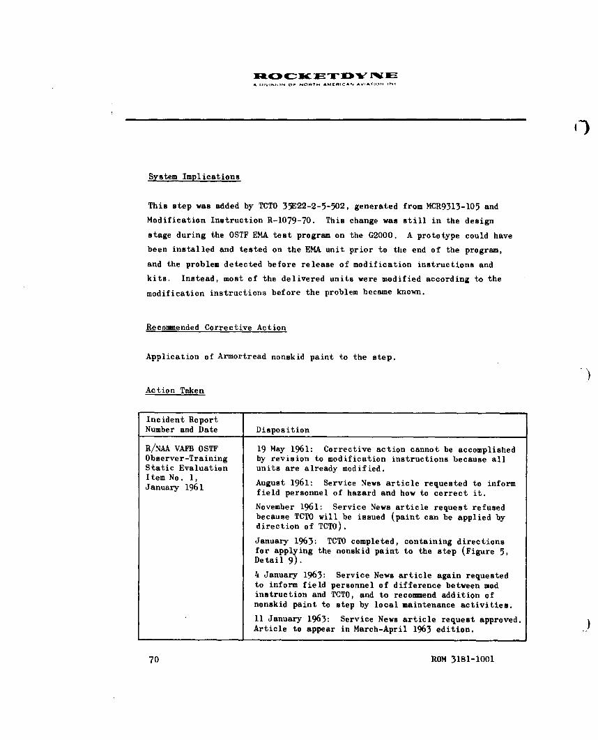
iNC K~ UTD iEA D01VlIN N OF NORTH AMERICAN AV* AYILN INC
System Implications
This step was added by TCTO 35E22-2-5-502, generated from MCR9313-105 and
Modification Instruction R-1079-70. This change was still in the design
stage during the OSTF EMA test program on the G2000. A prototype could have
been installed and tested on the EMA unit prior to the end of the program,
and the problem detected before release of modification instructions and
kits. Instead, most of the delivered units were modified according to the
modification instructions before the problem became known.
Recommended Corrective Action
Application of Armortread nonskid paint to the step.
Action Taken
Incident ReportNumber and Date Disposition
R/NAA VAFB OSTF 19 May 1961: Corrective action cannot be accomplishedObserver-Training by revision to modification instructions because allStatic Evaluation units are already modified.Item No. 1, August 1961: Service News article requested to informJanuary 1961 field personnel of hazard and how to correct it.
November 1961: Service News article request refusedbecause TCTO will be issued (paint can be applied bydirection of TCTO).
January 1963: TCTO completed, containing directionsfor applying the nonskid paint to the step (Figure 5,Detail 9).
4 January 1963: Service News article again requestedto inform field personnel of difference between modinstruction and TCTO, and to recommend addition ofnonskid paint to step by local maintenance activities.
11 January 1963: Service News article request approved.Article to appear in March-April 1963 edition.
70 ROM 3181-1001

A OIVISION OF NORTH AMERICAN AVIATION INC
SAFEEY PROBLE. NO. 20
(HUMAN FACTORS PROBL!24 NO. 86)
NONPLACAPtDED DANGER ARFAS
Incident
During a human engineering static evaluation of propulsion system opera-
tional AGE, it was noted that four danger areas on two pieces of equipment
were not appropriately placarded.
1. The high-pressure pneumatic supply inlet fitting on the G3077test stand (1500 to 3200 psig operating pressure): The existing
placard was inconspicuous and only indirectly conveyed the in-
formation that a pressure hazard could exist.
2. Hose reel No. 5 on the G2000 service unit (also 1500 to 3200 psig
operating pressure): The same deficiencies were noted, as above,
in existing placards.
3. The solvent tank filler cap on the G2000 service unit: None of
the placarding warned the operator not to remove the cap while
the tank was pressurized.
4. The main power cable (440 VAC) on the G2000: All placarding was
satisfactory except that it was located inside the access door to
hose reels instead of inside the access door to the power cable.
Equipment Affected -
1. G2000 rocket engine lubricating-purging service unit AF/M46M-1
2. G3077 electrical-pneumatic systems test stand AF/E47T-1
ROM 3181-1001 71

A DIVISION OF NORTH AMKRICAN AVIATION INC
Problem Criticality Problem Type
Minor Safety
System Implications
Less experienced maintenance personnel, who are not yet completely
familiar with the equipment, can get hurt. A few such accidents or near
accidents can earn a negative reputation for an item of equipment, and it
often becomes a negative prestige factor for technicians to be assigned
to maintenance functions on it. This, in turn, produces a degradation of
maintenance standards and progressively increases the severity of other
man-machine problems on this equipment. This example serves to emphasize
the importance of early human factors evaluations of equipment design.
Recommended Corrective Action
Correct the noted placarding deficiencies.
Action Taken
Incident ReportNumber and Date Disposition
R/NAA VAFB OSTF May 1961: Placarding requirements will be more closelyObserver-Training studied for future designs.Static EvaluationItem No. 2,January 1961
72 ROM 3181-1001

A 11V-I-N OlF N•RTH AMERICAN AVIATION INC
(9
Incident ReportNumber and Date Disposition
February 1962: A safety interlock feature and anindicator are an integral part of the 9420-W-40C solventtank filler cap, superseding present G2000 solventtank caps for future procurement. The new caps auto-matically lock in place when tank is pressurized.
June 1962: Stencilled lettering "CAUTION, DO NOTREMOVE PRESSURE CAP WHILE UNIT IS OPERATING" addedto new designs for G2016 solvent pumping unit andG2017 oil pumping unit adjacent to appropriate caps.
ROM 3181-1001 73
DA IVISION OF NORTM AMtIEMCAN AVIATION INC
SAFET'Y PROBLEM NO. 21
(iJM&N FACTORS PROBLEM NO. 88)
SHARP CORNERS
Incident
During a human engineering static evaluation of propulsion system operational
AGE, sharp corners were noted on two items. Bumping these could injure or
annoy engine maintenance personnel or damage other equipment.
Equipment Affected
1. G3080 Booster Engine Checkout and Maintenance Plate and Plug Kit
KMU- 15/E
2. G3087 Sustainer Engine Checkout and Maintenance Plate and Plug
Kit KMU-16/E
Problem Criticality Problem Type
Minor Safety
System Implications
None
ROM 3181-1001 75
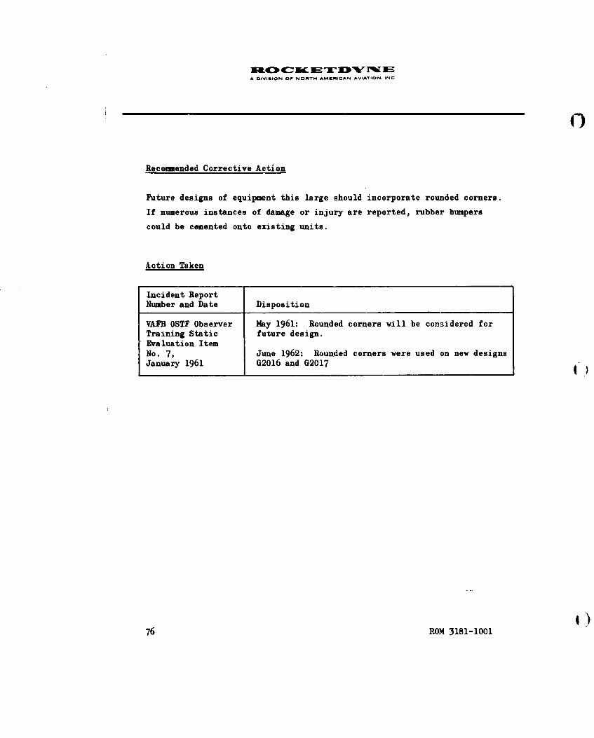
A DIVISION OF NORTH AMERICAN AVIATION. INC
Recommended Corrective Action
Future designs of equipment this large should incorporate rounded corners.
If numerous instances of damage or injury are reported, rubber bumpers
could be cemented onto existing units.
Action Taken
Incident ReportNumber and Date Disposition
VAFB OSTF Observer May 1961: Rounded corners will be considered forTraining Static future design.Evaluation ItemNo. 7, June 1962: Rounded corners were used on new designsJanuary 1961 G2016 and G2017
76 ROM 3181-1001

-1.10 Or ý0-iA flIVt.ION 07 NOfl VI * EIJC AN AVIAT IOV.,t•rf
SAFETY PIROBLEM NO. 22
(1fUMAN FACTOILS PROBLEM NO. 121)
COMMUNICATION NEEDED
Incident
The MI-ET/ entered the missile thrust -eetion and connected drain hoses for drain-
ing residual fuel. Ile did not communicate with the missile pressurization
crew before connecting the drain hoses. The crew was temporarily pre-
occupied with other things a,-d almost failed to notice the dropping fuel
tank pressure until too late to prevent equipment damage and personnel
injuri es.
Job Operation/Task
Ready State B, J'X.. 21-Smb5E-CL-15-2, 11 November 1961, section 22, Verti-
cal Drain lResidual Fuel
Problem Criticality Problem Type
Major Safety; Technical Data;
Organization Controls
ROM 3181-1001 77

A DIVISION OF NORTH AMERICAN AVIATION INC
System Implications
Many thousands of dollars have been spent designing, building, and refin-
ing the launch site communications system. However, it still must be used
at crucial points or it cannot prevent the well-known calamities that re-
sult from uncoordinated operations of this type.
Recommended Corrective Action
1. Add a requirement to the checklist to establish communications
with the missile pressurization crew before commencing the fuel
drain
2. Support the technical data requirements with appropriate organi-
zational control action
Action Taken
Incident ReportNumber and Date Disposition
D/D 855R 9 August 1961: PSRB approved and assigned to TDRBAugust 1961 and 576C Site Commander (SAC) for action
16 August 1961: TDRB approved for GD/A TMCR
30 August 1961: 576C Site Commander corrected theproblem by briefing personnel and by adding communi-cations requirements to SOP
15 September 1961: TDRB cancelled THCR action
78 ROM 3181-1001

A DIVISION OF NORTH AMERICAN AVIATION INC
SAFETY PROBLEK 1O. 23
(HUMAN FACTORS PROBLEM NO. 140)
CONTROL OF FUEL STORAGE TANK PRESSURE
Incident
The MET/M connected the fuel drain hoses and fuel began draining back into
the storage tank. A short time later, however, the fuel stopped draining
due to increased storage tank pressure. The checklist and job manuals
offered no help in getting the fuel to start flowing again. A GD/A engineer
directed the periodic opening of the Bl bleed valve ob the No. 2 fuel skid
to relieve the back pressure and obtain continuous draining. Perhaps in-
tensified by this back pressure, the drain hoses allowed a large amount of
fuel to be squirted or sprayed inside the thrust section.
Job Operation/Task
Ready State B; Vertical drain residual fuel, T.O. 21-SM65E-CL-15-2, Section 22
Problem Criticality Problem Type
Major Safety and Technical Data or
Equipment Design
PnV 3181-lIMl 79

A OIVIGION OF NORTH AMKNICAN AVIATION INC
System Implications
Insufficient information has been made available to R/NAA concerning the
nature of this problem; system implications are therefore undetermined.
Recommended Corrective Action
Either add the steps to the procedure or correct the equipment so the extra
steps are not necessary.
Action Taken
Incident ReportNumber and Date Disposition
D/D 2033R 11 October 1961: PSRB approved, sent to AF Safety20 September 1961 for investigation and corrective action recommendations.
NOTE: Corrective action information feedback hasnot indicated the specific problem nor the specificaction taken. The problem has been eliminated with-out technical data changes; therefore, it was ap-parently an equipment problem.
80 ROM 3181-1001 )

i IVISION OPP NORTM AMCRICAN AVIATION INr
SAFETY PROBLEM NO. 24
(HUMAN FACTORS PROBLEM NO. 166)
NEGLECTING TO USE COMMUNICATIONS SYSTEM
Incidents
On two occasions the MET/M was observed entering the missile thrust section
to work, but his headset and microphone were left outside. Because of the
ambient noise level, persons outside found it necessary to climb up and
at least put their head into the thrust section before they could com-
municate with him intelligibly.
Job Operation/Task
Ready State B, Vertical Drain Residual Fuel, T.O. 21-SM65E-CL--15-2, Section 22,
11 November 1961; Wet Countdown, Return to Ready State A, Horizontal Fuel
Drain, T.O. 21-SM65E-CL-17-2, Section 3, 10 November 1961.
Problem Criticality Problem Type
Major Safety; Organizational Controls
ROM 3181-1001 81

U 4c METDsrw NEA DIVibION Or NORTH AMERICAN AVIATION INC
System Implications
The unfortunate consequences of failure to maintain two-way communications
during operations of this type are voluminous. The inconvenience of
climbing up to the boattail to communicate is certain to reduce the amount
of communication, and eventually, a judgemental error in assessing the need
to communicate will cause important information not to be disseminated. In
emergency situations (e.g., that described in Human Factors Problem No. 155)
the consequences could be quite disastrous. Also, the man inside the thrust
section may have the need to communicate to those outside.
Recommended Corrective Action
Revise the SOP of using activities, as necessary, to ensure that the com-
munications system will be used when appropriate.
Action Taken
Incident ReportNumber and Date Disposition
D/D 2026R, 6 October 1961: PSRB approved 2026 and sent to OSTF-118 September 1961 Site Commander for action.
18 October 1961: 2026 returned to R/NAA with suggestionthat notes be added to operational checklists requir-ing establishment of crew communications during fueldraining.
D/D 2250R, 18 October 1961: PSRB approved 2250, asked R/NAA2 October 1961 to hand carry to OSTF-1 Site Commander
25 October 1961: 2250 returned to R/NAA; samesuggestion
26 October 1961: 2026, 2250 resubmitted to PSRB;2026 assigned to TDRB for action
82 ROM 3181-1001

J1W0 4C- IC JE -K) "'W I"W A-A OIVI.IIN OF NORTH AMýEILAN AVIATION INC
Incident ReportNumber and Date Disposition
31 October 1961: 2250 cancelled by PSRB; duplicates2026
2 November 1961: TDRB rejected 2026: corrected bySOP
ROM )181-I001 83

A DI~iSION OF NORTH AMERICAN AVIATION ANC
SAFETY PROBLEM NO. 25
(HUMAiN FACTORS PROBLEM NO. 206)
STEPPING ON ELECTRICAL CABLES
Incident
A human factors observer noticed that test personnel were stepping on
electrical test cables. A closer look revealed that numerous test cables
and hoses were stretched across the floor in a random fashion (i.e., not
routed through racks or tunnels) so that it was virtually impossible to
work in the area without stepping on the cables.
Job Operation/Task
Missile systems checkout, T.O. 21-SM65E-CL-14-2
Problem Criticality Problem Type
Major Safety; Job Environment, MAB Design; Training
System Implications
Frequent stepping on electrical cables produces progressive insulation
breakdown,and it is only a matter of time before electrical shock hazards
ROM 3181-1001 85

A 0IVISION Or NORTH AMCRICAN AVIATION INC
develop. (Meanwhile, a mild tripping hazard exists.) With insulation break-
down, there is also the possibility of "spectre malfunction indications"
during systems checkout.
Recommended Corrective Action
For existing missile assembly buildings, the test cables should be clustered
into one or more cable runs and temporary wooden ramps positioned over them.
For future MAB designs, covered cable trenches should be employed, where
practical.
Action Taken
Incident ReportNumber and Date Disposition
D/D 5425R, 28 December 1961: PSRB assigned to MAB-2 Site
1 December 1961 Commander for action.
7 March 1962: Authors visited MAB-2 and noted thatwooden ramps had been built and were being used.
86 ROM 3181-1001

A DIVISION OF NORTH AMERICAN AVIATION INC
SAFETY PROBLEM NO. 26
(HUMAN FACTORS PROBLEM NO. 237)
BUMPING HEADS ON CRANE CONTROL BOX
Incident
The human factors observer noted that the three control boxes for the two-
section overhead crane were hanging approximately 4 to 5 feet above the
floor, where personnel could easily bump into them.
Job Operations/Tasks
All inspection and checkout operations in the Missile Assembly and Main-
tenance Shops missile bays
Problem Criticality Problem Type
Moderate Safety; Job Environment
System Implications
No static human engineering evaluations of MAMS facility items had been
conducted by R/NAA observers. This hazard was noted during actual maintenance
operations.
ROM 3181-1001 87

X&0 - C N F UW " Ik 11 EA OIVISION OF NORTH AMIEqICAN AVIATION IN,
Recommended Corrective Action
Suspend control boxes by springs or bungees about 7 feet from the floor
so that they can be pulled down (to 4-1/2 feet) for use.
Action Taken
Incident ReportNumber and Date Disposition
D/D 5924R, 21 March 1962: PSRB held D/D for consideration14 March 1962 4 April 1962: PSRB approved D/D and assigned to
Capt. Spowart, MAB-2, with copy to 6595th Safety
88 ROM 3181-1001

A DIVIbION OF NORTH AMERICAN AVIATION INC
SAFETY PROB1E4 NO. 27
(RUMAN FACTORS PROBLEM NO. 235)
IAUNCHER WORK PIATFORM DEFICIENCIES
Incident
The MET/M and from one to five helpers were observed having great diffi-
culty with their footing while trying to remove blowoff covers and install
thrust chamber closures and covers, booster engine gimbal locks, and the
sustainer engine transport strut. The latter two tasks were not only dif-
ficult, but dangerous. The men had to lift the thrust chambers while stand-
ing precariously on tubular members of the launcher framework, or on launcher
pedestals. (It was later reported and verified that one member of the
usual crew was absent that day, still convalescing from a back injury re-
ceived while performing these tasks several days earlier.)
Job Operations/Tasks
Missile Removal, T.O. 21-SM65E-CL-21-2, Sections 1 and 2; also Missile
Installation, T.O. 21-SM65E-CL-12-2, Section 1
Problem Criticality Problem Type
Major Safety; Job Environment; Technical Data;
Provisioning
ROM 3181-1001 89

A DIVIGION OF NORTH AMRICAN AVIATION INC
System Implications
In January 1962, this problem was extracted from Problem 129, first
reported in September 1961, because it was seen that the majority of the
major hazards reported in problem 129 could be avoided by a procedural
crutch (see recommended corrective action). In January, the prospects
of obtaining provisioning action to correct these problems by the addition
of maintenance platforms seemed small. For this reason the partial fix
discussed here was recommended, even though it meant that sometimes the
tasks of exchanging blowoff covers for shipping covers and closures must
take place outdoors in inclement weather. These disadvantages should be
compared with those discussed in relation to problem 129, which will exist
until either one or the other of the two fixes is adopted. (Please note
that R/NAA never intended that both fixes should be adopted, which now
appears to be happening.)
Recommended Corrective Action
Relocate the problem tasks to a later section of the checklist after the
missile has been moved out of the missile bay. At this time, access plat-
forms can be stationed wherever they are needed, and a hydraulic jack can
be used to lift the thrust chambers.
Action Taken
Incident ReportNumber and Date Disposition
D/D 5774R, 7 February 1962: PSRB assigned 5774 to TDRB and25 January 1962 Safety
16 May 1962: TDRB approved for TMCR V-1272-II
9g ROM 3181-1001

A DIVISION OF NOUTH AMFRICAN AVIATI,,N INC
Incident ReportNumber and Date Disposition
23 May 1962: EID 27-0375, Figure A Item 5141, rocketengine maintenance set, provides portable work plat-forms with integral hydraulic jack for this purpose.Platforms can be installed on launcher quadrant Iand II pedestals when made available to using activities;
D/D 6015R 19 June 1962: GD/A test conductor holding 6015 for
13 June 1962 review
ROM 3181-1001 91

( uc:3 4C- 3W 1-= u"'W r%[ 1BA OIVISION OF NOAT" AM[RICAN AVIATiON INC
SAFET~Y PROBLEM NO. 28
(iikN FACTORS PROBLEM NO, 129)
SLIPPERY IAUNCHER ACCESS ROUTES
Incidents
The MEI/M was oserved performing many operations without the benefit of
safe access routes, steps, or platforms. He had to climb over, under,
or around, or stand on the launcher hardware, exposing himself to
injury from bumping or falling. Under certain conditions, the situation
is especially hazardous because the surfaces are wet with fuel and very
slippery. Sometimes, heavy lifting tasks must be performed while struggling
to maintain footing atop slippery launcher hardware. At least one back in-
jury resulted from this situation.
Job Operations/Tasks
Ready State B, Vertical Drain Residual Fuel; DPL, Horizontal Fuel Drain;
Missile Installation, remove gimbal actuator locks and sustainer trans-
port strut; Missile Removal, install gimbal actuator locks and sustainer
transport strut.*
Problem Criticality Problem Type
Major Safety; Equipment Design Deficiency;
Job Environment; Provisioning
*The operations and tasks listed are those considered the most hazardous.
Every propulsion system task performed at the launch site is affected bythis problem to some degree. (Also see related Human Factors Problem 235.)
ROM 3181-1001 93
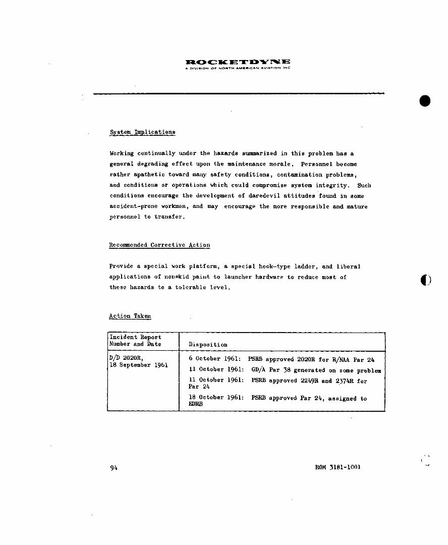
A OIVISION OP NONTH AM4NICAN AVIATION INC
System Implications
Working continually under the hazards summarized in this problem has a
general degrading effect upon the maintenance morale. Personnel become
rather apathetic toward many safety conditions, contamination problems,
and cohditions or operations which could compromise system integrity. Such
conditions encourage the development of daredevil attitudes found in some
accident-prone workmen, and may encourage the more responsible and mature
personnel to transfer.
Recommended Corrective Action
Provide a special work platform, a special hook-type ladder, and liberal
applications of nonskid paint to launcher hardware to reduce most of Ithese hazards to a tolerable level.
Action Taken
Incident ReportNumber and Date Disposition
D/D 2020R, 6 October 1961: PSRB approved 2020R for R/NAA Par 2418 September 1961 11 October 1961: GD/A Par 38 generated on some problem
11 October 1961: PSRB approved 2249R and 2374R forPar 24
18 October 1961: PSRB approved Par 24, assigned toEDRB
94 ROM 3181-1001

A 1IVISION OF NORTH AMERICAN AVIATION INC
Incident ReportNumber and Date Disposition
10 November 1961: PSRB approved Par 38, assignedto kDRB
16 November 1961: EDRB approved Par 38 for CRL 15to design and provision access platform
22 November 1961: EDRB approved Par 24
23 May 1962: EID 27-9375, GD/A Figure A Item 5141,rocket engine maintenance platform set added.
ROM 3181-1001 99

A DIVISION OF NORTM AMCMiCAN AViATION. INC
SAFEFY PROBLEM NO. 29
(HUMAN FACTORS PROBLEM NO. 243)
HARD HATS
Incident
In spite of rules which forbade it, an engineer deliberately wore his hard
hat inside the missile thrust section to protect his head. A technician
immediately reported him,and a heated argument followed concerning whether
or not missile hardware does get damaged from hard hats, and whether people
can teach themselves to avoid painfully bumping bare heads if they try.
Job Operation/Task
The task in progress was to lubricate the booster and sustainer gimbal
bearings. However, this could have happened with any task inside the
missile thrust section.
Problem Criticality Problem Type
Moderate Safety; Organizational Controls
System Implications
Hardware damage had been blamed on the practice of wearing hard hats in-
side the missile. The integrating contractor therefore issued an order for-
bidding this practice. This incident was not the first violation of the
order, but technicians do not normally report other technicians.
ROM 3181-1001 97

aC c IF: :Tq l " q 4EA DIVISION OF NORTH AMERICAN AVIArION INC
Recommended Corrective Action
Investigate hardware damage attributed to hard hats. if allegations are
untrue, rescind the order.
Action Taken
Incident ReportNumber and Date Disposition
D/D 5841R, 21 February 1962: PSRB assigned to AF Safety12 February 1962 8 November 1962: Safety returned D/D to R/NAA;
no action indicated
98 ROM 3181-1001

A r-VI-IoN OF NORiT AMERICAN AVIATION INC
SAFETY PROBLEM NO. 30
(HUMAN FACTORS PROBLEM NO. 255)
LEANING OVER BACKWARDS
Incident
The MET/M experienced considerable difficulty in trying to open the B-1
turbine spinner access door because no suitable work platform or access
ladder had been provided at the launcher. He was able to reach the screws
(with some difficulty) by standing on the trailer alignment rail and lean-
ing backward and to one side. The possibility of falling was serious.
Job Operation/Task
Systems Validation, T.O. 21-SM65E-CL-13-2, Section 7, Engine Start Sys-
tem Checkout.
Problem Criticality Problem Type
Major Safety; Provisioning
System Implications
Adding this problem description to those of problems 98, 103, 129, 235, and272 gives a total view of the work platform problem at the "E" serieslauncher.
ROM 3181-1001 99

A DIVISION OW NORTN AMCMICAN AVIATION INC
Recommended Corrective Action
Provide a suitable work platform or access ladder for this purpose.
Action Taken
Incident ReportNumber and Date Disposition
D/D 5868R, 28 February 1962: Approved by PSRB and assigned14 February 1962 to OSTF-1 Site Commander for action; copy to 6595th
Safety.
1)100 R0M 3181-1001"

A DIVISION Or NOMTH AMKRICAN AVIATION INC
SAFETY PROBLEM NO. 31
(HNUM FACTORS PROBLEM NO. 262)
IMPROVISED WORKSTANDS AND TRIPPING HAZARDS
Incident
The MET/M was carrying some tools and test equipment up the ramp onto the mis-
sile maintenance platforms (in MAB-2, missile bay 2). In stepping over a
folded guard rail he did not lift his feet quite high enough and almost
tripped and fell. He stumbled in the direction of the side of the plat-
form which had no guard rail. For the duration of the observation, every
person who came up or down the ramp, to or from the missile maintenance
platform, stumbled over this folded guard rail.
Equipment Affected
Work platform set 27-97020-1
Job Operation/Task
Systems Checkout, T.O. 21-SM65E-CL-7-3; Task 121.1A/75002, Prepare propul-
sion system for checkout
Problem Criticality Problem Type
Major Safety; Provisioning
ROM 3181-1001 101
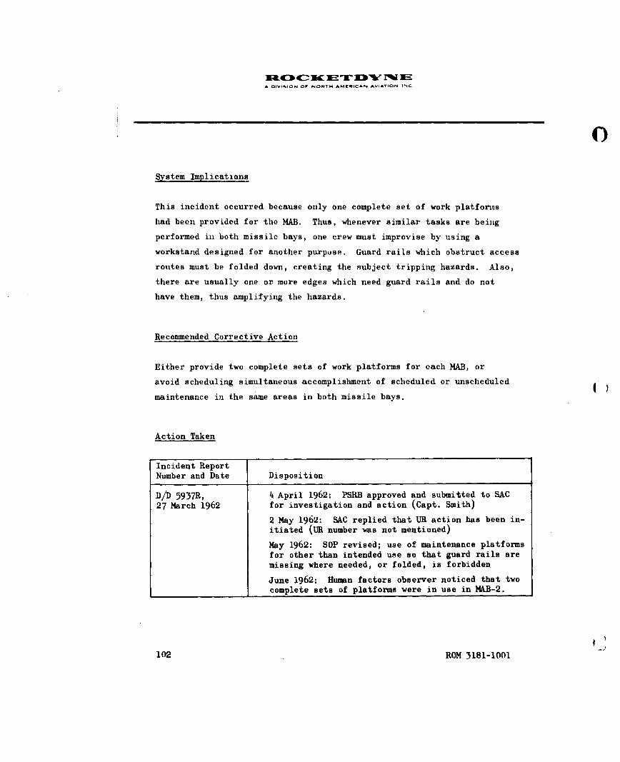
XR1:0 4c: K AM T "IVY 1%1• EO OIViMiON OF NORTH AMERICAN AVIATiON INC
0
System Implications
This incident occurred because only one complete set of work platforms
had been provided for the MAB. Thus, whenever similar tasks are being
performed in both missile bays, one crew must improvise by using a
workstand designed for another purpose. Guard rails which obstruct access
routes must be folded down, creating the subject tripping hazards. Also,
there are usually one or more edges which need guard rails and do not
have them, thus amplifying the hazards.
Recommended Corrective Action
Either provide two complete sets of work platforms for each MAB, or
avoid scheduling simultaneous accomplishment of scheduled or unscheduled
maintenance in the sane areas in both missile bays.
Action Taken
Incident ReportNumber and Date Disposition
D/D 5937R, 4 April 1962: PSRB approved and submitted to SAC27 March 1962 for investigation and action (Capt. Smith)
2 May 1962: SAC replied that UR action has been in-itiated (UR number was not mentioned)
May 1962: SOP revised; use of maintenance platformsfor other than intended use so that guard rails aremissing where needed, or folded, is forbidden
June 1962: Human factors observer noticed that twocomplete sets of platforms were in use in MAB-2.
102 ROM 3181-1001

A DIVINION OF NORTH AMCRICAN AVIATION INC
()
SAFETY PROBLEM4 NO. 32
(HUMAN FACTORS PROBLEM NO. 276)
MAINTAIN GROUND EQUIPMENT, TOO
Incident
A missile arrived from the MAR and was being installed on the OSTF-1 launcher.
When the MET/M removed the B-1 exit closure, it was found to have been in-
stalled with one protective pad missing from the closure retaining rod. The
thrust chamber fuel tubes in the combustion zone had been scraped by the
retaining rod foot, but a careful inspection determined that the damage was
not critical.
Equipment Affected
LR89NA.-5 booster engine; RX20041 booster thrust chamber exit closure;
BX20299-3 pad.
Job Operation/Task
Checklist APb2-0132, section 37, Missile Installation (4 June 1962)
Problem Criticality Problem Type
Major Equipment Safety; Organizational Control
ROM 3181-1001 103

D OIVISION Or NOnTM AMERICAN AVIATION INC
System Implications
Although the damage to the B-1 engine on this missile (67E) was super-
ficial, it is believed that this practice, if permitted to continue,
will result in critical damage to an engine.
Recommended Corrective Action
Use better judgement in the use and maintenance of equipment which can
vitally affect engine performance.
Action Taken
Incident Report 4)Number and Date Disposition
D/D 6039R, 25 July 1962: PSRB assigned to MAB-2 Site Commander18 June 1962
13)104 RUMl 3181-1001

xaO(l!cET 4C1Kc1 i r Nw is
A DIVISION OF NORTM AMCRICAN AVIATION INC
SAFETY PROBLD4 NO. 33
(MIiuw FACTORS PROBLE14 NO. 271&)
SHIPPING COVERS VS TEST PLATES
Incident
A MET/M got the gas generator test plate (P/N 9011329) from the G3087 sus-
tainer engine plate and plug kit and began to remove the thin, plastic
shipping cover to install the test plate in preparation for leak tests.
The test engiileer stopped him. The tests were run using the shipping
cover in lieu of the test plate. The test engineer justified this de-
viation from the approved procedure by explaining that the test plate
" ... took too long to install and remove."
Job Operation/Task
Checklist AP62-0133, Section 35, Sustainer Engine Checkout (21 May 1962)
Problem Criticality Problem Type
Major Safety; Job Environment; Organizational
Controls
ROM 3181-1001 105

A DIVIIION OF NORTH ANMCICAN AVIATION INC.
System Iplications
During these leak test operations, a pneumatic pressure of 7 ±1 psi is ap-
plied to the gas generator system in sufficient volume that, should the
shipping cover fail during this usage for which it was not intended, flying
pieces of plastic could cause personnel injury.
No tests were run to determine how much time is saved by this unorthodox
procedure, but an experienced MET/M estimated that it might be as much
as 5 minutes.
Several crew members were interviewed by the human factors observer in an
effort to determine why such risks would be taken for such a small time
saving. It was unanimously reported that the civilian test engineer was
solely responsible, and his error apparently stemmed from somewhat mis-
directed motives.
Recommended Corrective Action
Discontinue using shipping covers in lieu of test plates or test plugs.
In the future, perhaps shipping covers can be designed sufficiently
rugged to permit this dual function.
Action Taken
Incident ReportNumber and Date Disposition
D/D 6032R 25 July 1962: PSRB assigned to Capt. Spowart, BSD,15 June 1962 MAB-2; information copies to 6595th Safety
106 ROM 3181-1001

A DIVI•ION OF NORTH AMERICAN AVIATIOI', INC
SAFETY PROBLEM4 NO. 34
(HUMl&N FACTORS PROBLEM NO. 252)
ADJUSTABLE WRENCHES
Incident
The human factors observer noted that the technician was using a crescent
wrench to remove the plugs in the B-1 gas generator igniter bosses.
Equipment Affected
LR89NA-5 booster engine
Job Operation/Task
Ready State "A" Training, T.O. 21-SM65E-CL-18-2, Section 1, Missile Ex-
plosive Assemblies Checkout and Installation
Problem Criticality Problem Type
Major Safety; Training
ROM 3181-1001 107

A MIVISION OF NORTH AMEAICAN AVIATION INC
System Implications
Adjustable wrenches are never to be used on rocket engine hardware. If
the wrench jaws are not parallel, or if the wrench is not carefully ad-
justed on the fitting, the hex is easily stripped. A stripped hex on
this plug could be quite serious since the drilling and tapping opera-
tions could damage the igniter boss threads and introduce metal clips
into the gas generator. This could result in damage to the turbine. The
technician indicated that he did not know that this practice is taboo.
Recommended Corrective Action
Instruct all propulsion system maintenance personnel in the proper selection
and use of wrenches.
Action Taken
Incident ReportNumber and Date Disposition
D/D 5884R 28 February 1962: PSRB assigned to 0STF-1 Site19 February 1962 Commander for action
108 ROM 3181-1001

A OIVIRION OF NORTH AUPEICAN AVOATION, INC
SAFLVY FROBLEK NO. 35
(mUMAN FACTORS PROBLEN NO. 248)
BLOCKED SAFETY AISLES
Incident
On several occasions, the human factors observer noticed that the MAB safety
aisles were obstructed by (1) careless positioning of workstands or safety
barricades, or (2) improper location of test equipment, blueprint tables, etc.
Job Operations/Tasks
All of those associated with the MAMS Receiving Inspection, T.O. 21-S465E-
CL-3-3, and Systems Checkout, T.O. 21-SM65E-CL-7-3.
Problem Criticality Problem Type
Moderate to major, depending on extent Safety; Job Environmentobstructed
System Implications
Both the north and south aisles were obstructed. In an emergency, medical
personnel could not utilize the aisles carrying a stretcher, and excessive
time would be required to evacuate personnel from the area.
ROM 3181-1001 109

A OWIVIION O NORTH AMERICAN AVIATION INC
Recommended Corrective Action
Observe the painted lines demarking the safety aisles and keep both aisles
clear.
Action Taken
Incident ReportNumber and Date Disposition
D/D 5968R, February 1962: Not processed through PSRB because13 February 1962 AF personnel were not directly responsible for these
errors.
8 May 1962: Rejected by R/NAA PSS analysis becausethe problem no longer exists
110 ROM 3181-1001

za<0 4C7r A ET DYN ",k E
A DIVISION OF NORTH AMERICAN AVIATION INC
SAFETY PROBLEM NO. 36
(HUMAN FACTORS PROBLEM NO. 216)
USING TURBOPUMPS FOR STEPLADDERS
Incidents
On eight separate occasions the human factors observers reported from one
to six technicians using the booster turbopsm~p volutes and high-pressure
propellant ducting as steps in climbing to the top of the missile. In
six instances, the access ladder which should have been used was removed
temporarily to permit the accomplishment of tasks with which it physically
interfered. However, in the other two cases the ladder was in place
and could easily have been used. In no case was there such urgency that
the practice could be considered justified for the sake of expediency.
Equipment Affected
LRS9NA-5 booster engines on missiles 64E, 66E, 67E, and 65E
Job Operations/Tasks
T.O. 21-Sm65E-CL-7-3, Systems Checkout, Section 21, Vernier Engine Solo
System Leak Check; Checklist AP62-0133, Section 34, Vernier Engine Solo
System Checkout; AP62-0133, Section 24, Hydraulic Fill and Bleed; and un-
designated unscheduled maintenance.
ROM 3181-1001 111

A DOIV(ION OF NORTH AMCMrCAN AVIATION INC
Problem Criticality Problem Type
Major Safety; Organizational Controls; Training
System Implications
In all but one case the (interfering) titsks were completed and the ladder already
should have been returned to its proper poeition. Nevertheless, it would
have taken about 1 minute for four men ýýo reposition it.* (For the one ex-
ception the delay might have been as m'uch as 30 minutes.) Stepping on the
volutes and ducts scratches the ducts ard :places undue stress on flanges
and seals. It also damages electrical viring to heaters and instrumentation.
Missiles on which this practice has beeu t)lerated could be studied to de-
termine possible effects on propulsion system performance at launch (although
a direct cause-and-effect relationship vrould be hard to prove).
Recommended Corrective Action
1. For any task which requires temporary removal of the No. 1 vernier
engine access ladder and maintenimnce platform, make the reinstalla-
tion one of the final steps oi the task.
2. Employ organizational controls (Os strong as necessary) to guarantee
that no one climbs on the engi[uLe for any reason.
*See Problem 221 for a suggested means (f improving this situation.
112 ROM 3191-1001

A l, nlISION OF NORTH AMERICAN AVIATION INC
Action Talken
Incident ReportNumber ar I DAte Disposition
D/D 54465., 28 December 1961: PSRB assigned action to the MALB-212 Decemter 1961 Site Commander
3 January 1962: PSRB assigned supplementary actionto TDRB
12 January 1962: MALB-2 Site Commander reports that(unspecified) corrective action has been taken
D/D 5969R, 8 May 1962: PSRB rejected D/D 5969R because "dup-8 March )9" licate of D/D 5446R."
D/D 602211, 25 July 1962: PSRB assigned to Capt. Spowart, BSD13 June '%96'ý MAB-2 Site Commander
D/D 6035], 26 June 1962: D/D 6035R cancelled by R/NAA PSS15 June :1.96.! analyst because ". ... duplicate of D/D 6022R."
D/D 627211, 22 October 1962: PSRB assigned to Capt. Spowart2 Octobe:r 1962
D/D 629%]1, 19 October 1962: D/D 6294R cancelled by R/NAA PSS
5 Octobe:ý 1962 analyst because "...duplicate of D/D 6296R."
D/D 62961, 5 November 1962: PSRB assigned to Capt. Spovart9 Octobex 1962
D/ID 6305I-., 19 November 1962: PSRB assigned to Capt. Spowart25 Octeber 1962
ROM 3181-1001 113

A DIVISION OF NORTH AMERICAN AVIATION IN{
SAFETY PROBLEM NO. 37
(HMAN FACTORS PROBLEM NO. 291)
MAINTENANCE OF PLATES AND PLUGS KITS
Incidents
On three occasions within as many days the MET/M could not use the test
plate and adapter which were required because they had not been maintained
properly. A closer examination of the plates and plugs kits disclosed that
these particular plates and adapters were not the only ones which could
not be used. Most of the adapter assemblies had been disassembled; several
of the original parts had been cannibalized for other equipment. Some
effort had been made to reassemble some adapters, but none of these was
correctly reassembled. Many were so badly contaminated that the HAMS
cleaning facilities could not" restore them to a LOX-clean condition. It
had become customary to improvise test connections, which often did not
contain the relief valve features of the approved test hardware.
Equipment Affected
G3080 Booster Engine Plates and Plugs kit KIU-15/E; G3087 Sustainer Engine
Plates and Plugb kit KMU-16/E
Job Operations/Tasks
Checklist AP62-0133, Section 34, Vernier Engine Solo System Checkout (11
July 1962); Section 36, Booster Engine System Checkout (11 July 1962)
ROM 3181-1001 115

A DIVISION OF NORTH AMERICAN AVIATION INC
Problem Criticality Problem Type
Major Safety; Job Environment; Organizational Controls
System Implicqtions
Improvising test connections is a dangerous practice from many different
viewpoints, but it becomes particularly hazardous when combined with such
problems as human factors problem No. 290 (HPU Line 3 vs Line 4) and 274
(Test Plates vs Shipping Covers). Not only does it compromise the protec-
tive measures intended to prevent equipment damage, but it frequently has
a snowballing effect in that it also forces improvisations of procedures,
task scheduling, manning, etc., which create further problems. If the
test equipment is not properly maintained, there is only one way to keep
personnel from improvising test connections, and that is to relax main-
tenance schedules, i.e., do not have them do the operations in question
until the equipment is usable. Since this is obviously an unsatisfactory
procedure, it should serve to emphasize the importance of proper maintenance
of all AGE.
Present practices concerning responsibility for and frequency of mainten-
ance on these plates and plugs kits have not yet been thoroughly studied.
Apparently, the personnel who use this equipment (AFSC 443X1A MET/Ms) are
charged, jointly, with the responsibility for its maintenance between
scheduled (periodic) inspections. However, this mutual responsibility
is somewhat loose and vague as to its execution. It appears that positive
corrective action can be evaded at least until the next periodic inspection
(which occurs at 6-calendar-month intervals). If this comprehensiveinspection is adequately supported by local SOP and other organizational
controls, the noted discrepancies would probably be detected and corrected
at that time.
116 ROM 3181-1001

N Ic s KET Y" IEA DIVISION OF NORTH AMERICAN AVIATION INC
Recommended Corrective Action
Place the plates and plugs kits under tool crib jurisdiction. Require that
a knowledgeable tool crib attendant check the kits for completeness, con-
tamination, and proper maintenance before allowing the MET/M's to turn them
in or check them out. Use whatever organizational controls are appropriate
and necessary to stop cannibalization of test kits and guarantee conscientious
performance of maintenance duties.
Action Taken
Incident ReportNumber and Date Disposition
D/D 620611 10 September 1962: PSRB assigned all three reports7 August 1962 to Capt. Spowart, BSD, KkB-2
D/D 6210R,9 August 1962
D/D 6212R,9 August 1962
ROM 3181-1001 117

A DIVISION OF NORTH AMERICAN AVIATION INC
SAFETY PROBLEM NO. 38
(HUMAN FACTORS PROBLEM NO. 288)
TEAMWORK REQUIRES TFAM PRACTICE
Incident
The human factors observer noticed that the test crew was not proceeding
strictly by the checklist. In a short time, the MIET/M was ahead of the
others. He was busily performing a leak check of the vernier engine
solo system with no pressure applied as yet. This error was detected and
corrected, but the occasioning error of not following checklist sequence
was continued. Again, the MET/M got ahead of the others. He began to
open the pressure regulator on the 50 to 600 supply panel before the
supply shutoff valve had been opened to admit pressure to the panel.
Because of the hazards involved, the observer broke silence and called the
situation to his attention, As he began to close the regulator, one of
the other crew members opened.the supply shutoff valve. The pressure surge
apparently damaged the supply gage so that it had to be removed and repaired.
Equipment Affected
G3077 Electrical Pneumatic Systems Test Stand AF/E47T-1
Job Operation/Task
Checklist AP62-0133, section 34, vernier engine solo system checkout
(11 July 1962)
ROM 3181-1001 119

A DIVISION OF NORTH AMSMICAN AVIATION INC
Problem Criticality Problem Tvpe
Major Safety; Training; OrganizationalControls
System Implications
Many of the comments made on problems 230, 285, and 154 could be repeated
here, but there are other implications. The MET/M who had contributed most
toward these errors had received the least Operational Readiness Training.
During ORT, such errors are quite common; however, the instructors are
skilled in prognostication, and usually are able to intercede before actual
equipment damage has occurred.
Until the technicians have made a few errors of this type, it seems that
they just cannot understand why it is important to follow checklists
carefully, and why teamwork is important (as opposed to going ahead on
one's own tasks as fast as one can without due regard for the progress
achieved by the other crew members). In other words, it takes a few
failures resulting from incomplete teamwork to prove the necessity of
thorough teamwork before the technician is adequately motivated and proper-
ly oriented to learn from the present practice situation the cooperative
skills, attitudes, and work habits that will be needed later.
Recommended Corrective Action
This particular MET/M needed more training on the G3077. Also, he should
have completed ORT before assignment to an operational site. Recommendations
made on Problem 285 concerning the use of training and organizational controls
to inculcate proper use of technical data also apply here.
120 ROM 3181-1001

A DIVISION Or NORTH AMERICAN AVIATION INC
Action Taken
Incident ReportNumber and Date Disposition
D/D 6201R, 10 September 1962: PSRB assigned both D/D's to7 August 1962 Capt. Spowart, BSD MAIB-2 Site Commander
D/D 6202R,7 August 1962
"ROM 3181-1001 121

A DIVISION OF NORTH AMIEICAN AVIATION. INC
SAFLVY PROBLEM NO. 39(HUMAN FACTORS PROBLEM NO. 236)
REMOVE LOCKS AND COVEIS BEFORE LAUNCH
Incidents
On two separate occasions a human factors observer noticed that a fuel
duct cover, gimbal actuator locks, and a transport strut were painted yellow
or grey. It was his understanding that such equipment should be red and
have attention-getting red streamers attached to reduce human errors in
quickly determining whether the equipment is removed or installed.
Problem Criticality Problem Type
Major Safety; Equipment Design
System Implications
Air Force System Control document 80-6 (C.4-3.6) requires that all equip-
ment such as locks, covers, and supports which must be removed before flight
shall be painted red and (if not sufficiently conspicuous already) have a
red streamer attached. On two missiles (64E and 66E) the noted items were
not red and had no streamers. Failure to remove any one of them before
ROM 3181-1001 123

A DIVISION OF NORTH AMERICAN AVIATION INC
launch could result in mission failure. Failure to install them before
transport or certain maintenance operations could result in hardware damage.
Recommended Corrective Action
Comply with AFSC 80-6
Action Taken
Incident ReportNumber and Date Disposition
D/D 5775R, 7 February 1962: PSRB assigned to Air Force Systems30 January 1962 Command Quality Control
D/D 5793R, March 1962: Red fuel duct cover observed in use on 41 February 1962 Missile 67E
November 1962: Some yellow and gray locks and coversstirl in use.
124 ROM 3181-1001

1M41Z4__* NIE W " I, =A -IVISION OF NORY. AMEWICAN AVIATION INC
SAFETY PROBLE24 NO. 40
(H~UMA~N FACTORS PROBLE4 NO,. 284)
INT•RFERENCE WITH SUSTAINER HYPERGOL CARTRIDGE
Incident
A MEt/M had difficulty installing the sustainer hypergol cartridge. Before
the cartridge was properly aligned with the hypergol container so it could
be inserted, the aft end of the cartridge struck a welded bracket on the
thrust chamber which is used for attaching the shipping strut. The MET/M
finally found a position in which he could exert sufficient pull on the
container to spring it outboard about 3/16 inch, which allowed the cart-
ridge to clear the bracket and enter the container. A slip of the hand
at the wrong moment could have resulted in a ruptured cartridge and a
devastating fire (triethylaluminum and triethylboron).
Job Operation/Task
Checklist AP62-0132, Section 68, Ready State A Training (4 June 1962)
Problem Criticality Problem Type
Major Safety; Job Environment; Manufacturing Error
ROM 3181-1001 125

A DIVISION OF NORTH AMERICAN AVIATION. INC
System Implications
BecLuse the sustainer hypergol container is mounted by clamping it to a
turbopump strut, it can assume a variety of positions during assembly op-
erations. If the mouth of the container is tilted inboard too much, the
problem described above occurs. This problem is not new. It was first
discovered at a Santa Susana test stand on one of the earliest Kk-3 sus-
tainer engines. As a result, Rocketdyne Quality Control added one item
to their inspection buyoff on the hypergol container installation: a
test fixture (dummy hypergol cartridge) was to be inserted in the con-
tainer mouth and the clearance between cartridge and bracket was to be
at least 0.05 inch. However, no production change point was established,
and no change was made to the engineering drawing. Therefore, most of
the related maintenance and modification instructions produced by R/NAA
and the integrating contractor were lacking in this dimensional requirement.
Although the incident recorded here was probably the result of maintenance
or modification after the engine left the Rocketdyne plant, it did occur
before the missile was turned over to the Air Force and must therefore be
classified a manufacturing error.
Recommended Corrective Action
For this particular engine, the hypergol container should be repositioned
to provide adequate clearance. To prevent recurrences of this problem on
future engines, the clearance dimensions should be specified on the engi-
neering drawing so that they will be automatically picked up and included
in maintenance and modification instructions.
126 ROM 3181-1001

uM40 4C: WC -Er ""k WX-A DIVISION OF NORTH AMERICAN AVIATION INC
Action Taken
Incident ReportNumber and Date Disposition
D/D 6125R, 25 July 1962: PSRB assigned to R/NAA Canoga5 July 1962 12 July 1962: Clearance dimension corrected on
Missile 67E
20 July 1962: R change to drawing 400120, note 10and view R; add the clearance requirement for engines,serial No. 2892, and subsequent.
ROM 3181-1001 127

A OIVIhION OP NORTH AMERICAN AVIATION INC
SAFETY PROBLEM4 NO. 41
(HUMAN FACTORS PROBLEM NO. 290)
NCU LINE 3 VS LINE 4
Incident
The checklist called for connecting NCU line 3 (pressure range 40 to 250 psig)
to the vernier engine; line 4 (pressure range 0 to 1000 psig) was used instead.
Job Operation/Task
Checklist AP62-0133, Section 34, Vernier Engine Solo System Checkout
(11 July 1962).
Problem Criticality Problem Type
Major Safety; Organization Controls
System Implication
There are two NCU's in MAB-2. Line 3 on the first NCU had been contaminated
earlier. The action to determine how it happened and to prevent its re-
currence was apparently ineffective because the same line on the other
ROM 3181-1001 129

W&1 NC7 "% 14W E-A DIVISION Or NORTH AMERICAN AVIATION INC
4-)
NCU was later contaminated. Since neither line 3 could be used, this caused
the test crew to try the hazardous substitution described above, creating
a basic situation conducive to overpressurizing engine systems. Coupled with
human factors problem 291, this problem becomes extremely dangerous.
Recommended Corrective Action
Determine what causes line 3 to become contaminated and fix it. Decontaminate
line 3. Discontinue engine testing until line 3 is useable or be positive
that the engine systems are protected with relief valves capable of handling
the pressure and volume of NCU line 4.
Action Taken
Incident ReportNumber and Date Disposition
D/D 6205R 10 September 1962: PSRB assigned to Capt. Spowart,7 August 1962 MAB-2.
130 ROM 3181-1001

A nIVI•ION OF NORTH AMERICAN AVIATION INC
SAFETY PROBLE4 NO. 42
(HUMAN FACTORS PROBLEM NO. 168)
HIGH-PRESSURE HOSE TIEDOWN
Incident
The MET/M was observed using a test hose containing 1000 psig pneumatic pres-
sure, but with no sand bags or tiedown cables.
Job Operation/Task
Ready State B, Propulsion System Setup for DPL; Pressurize the Sustainer Engine
Hydraulic Accumulator, T.0. 21-SM65E-CL-15-2, Section 8, 11 November 1961.
Problem Criticality Problem Type
Major Safety; Training; Organizational
Control; Job Environment
System Implications
Test hoses sometimes do rupture, and if not properly anchored with sandbags
(or shot bags) and tiedown cables, the pressurized fragment will whip violently
ROM 3181-1001 131

M" Cý C OET -W "A DIVISION OF NORTH AMKRICAN AVIATION INC
until pressure is depleted or shut off. Personnel and equipment can be
seriously harmed. TLe few minutes saved by skipping this standard safety
precaution are not worth the risks involved.
Recommended Corrective Action
Since the requirement to tie down high-pressure hoses is already included
in the related technical data, corrective action should consist of the use
of organizational controls to enforce the requirement and the addition of
supporting information and practice during Operational Readiness Training.
Action Taken
Incident Report 4)Number and Date Disposition
D/D 2253R, 11 October 1961: PSRB assigned to Site Commander3 October 1961 and EDRB.
16 November 1961: F1)RB rejected, sent to TDRB
22 November 1961: TDRB rejected, "Training problem"
29 November 1961: PSRB returned to TDRB
16 January 1962: TDRB rejected, "Training problem"
14 February 1962: PSRB reassigned to EDRB which isholding D/D in abeyance.
132 ROM 3181-1001

A 0IVISION OF NORTH AMERICAN AVIATION INC
SAFETY PROBLEM NO. 43
(uuMfN FACTORS PROBLEM NO. 272)
THE FLAME-BUCKLV NET IS FOR PEOPLE
Incidents
On two occasions, a human factors observer saw the MET/K's remove engine
blowoff covers, thrust chamber covers, and the sustainer engine support
strut, and toss them into the flame-bucket net.
Job Operations/Tasks
Checklist AP 62-0132, Section 30, Missile Removal (4 June 1962), and Section
37, Missile Installation (4 June 1962).
Problem Criticality Problem Type
Major Safety; Job Environment; Organizational Controls
System Implications
This problem illustrates the old axiom that when bad conditions are condoned,
they multiply. Problems 98 and 103 (July 1961) were concerned with the ab-
sence of safe footing for maintenance personnel at the launcher. Problems
129, 235 and 255 disclosed further areas where this same condition was pre-
valent. Now, because the MET/M's do not have secure footing, they cannot
handle large or heavy pieces of equipment after removal and are obliged to
ROM 3181-1001 133

A DIVISION O NORTH A^MRICAN AVIAIJON INC
toss them into the flame-bucket net, which was intended to protect people
from injury resulting from falls into the flame bucket. Should anyone
fall while this equipment is in the net they would probably be seriously
injured.
Recommended- Corrective Action
Assign an extra helper to the HET/M's during these tasks. Covers, closures,
and struts can be handed to the helper instead of tossing them into the net.
(This would not require a manning change because extra people are available
at the stipulated times.)
Action Taken
Incident ReportNumber and Date Disposition
D/D 6013R, 20 June 1962: PSRB assigned 6013R to OSTF-1 Site13 June 1962 Commander for corrective action
25 July 1962: PSRB assigned 6038R to OSTF-1 SiteCommander
NOTE: The portable rocket engine maintenance platformset provided to resolve problem 235 is expected to helpwith this problem also.
134 ROM 3181-1001

A DIVISION Or NORTH AMERICAN AVIATION INC
SAFETY PROBLEM NO. 44
(mJLZ FACTORS PROBLEM NO. 211)
THRUST CHAMBER PAD NOT USED
Incidents
On four separate occasions, human factors observers noticed that technicians
were not using the pad to protect the thrust chamber fuel tubes from dents,
scratches, and punctures when they were working inside the thrust chamber.
On two occasions, a thin sheet of vinyl plastic was used instead. On one
occasion, a bunk mattress was used, and on another occasion, nothing was used.
Equipment Affected
LR89-NA5 booster engine; 9011565 thrust chamber pad.
Job Operations/Tasks
Systems Checkout, T.O. 21-SM65E-CI-7-3 and T.O. 21-SM65E-2J-3-1; particularly
such tasks as installing or removing thrust chamber throat plug, cleaning,
inspecting, etc.
!Problem Criticality Problem Type
Major Safety; Organizational Controls
ROM 3181-1001 135

A lIVIhION OF NO-THI AMERICAN AVIATION INC
System Implications
This practice can cause a mission failure by degrading engine operation.
A sharp-radius scratch will often split. Small splits and punctures cause
fuel leaks which reduce tube cooling downstream from the leak. Overheated
tubes erode and make bigger leaks. These, in turn, produce thrust losses
and sometimes explosions. The substitution of the bunk mattress was satis-
factory for protecting the engine if it could be kept in place. (Since
it was approximately 2 feet too long, it tended to slide out of position.)
The vinyl sheet afforded some protection from scratching, but virtually
none from dents or punctures. In all four cases, the person responsible
for not using the pad mentioned some difficulty in finding it; however, in
three cases, there was reason to doubt that a very exhaustive search had
been conducted.
Recommended Corrective Action
Have a regular place to store the 9011565 pad when it is not in use. Make
certain that all personnel know where to store it. Encourage them to use
it and to return it to its proper place when through.
Action Taken
Incident ReportNumber and Date Disposition
D/D 5441R, 28 December 1961: PSRB assigned to MAB Site Commander6 December 1961 12 January 1962: (unspecified) Corrective action complete
D/D 5450R, Cancelled. (Duplicates D/D 5441R)14 December 1961
D/D 6023R, 25 July 1962: PSRB assigned to Capt. Spowart, MAB-216 June 1962
D/D 6314R, 26 November 1962: PSRB assigned to Capt. Spowart,26 October 1962 MAB-2
136 ROM 3181-1001

A DIVIION OF NORTH AMRIICAN AVIAIION jNr
SAFETY PROBLEM NO. 45(HUMAN FACTORS PROBLEM NO. 213)
MISALIGNED MAINTEANCE PLATFORMS
Incident
The MET/M hastily pushedthe maintenance platforms up to the missile boattail
section in preparation for the MA.MS fourth periodic checkout operations, and
he did not take time to align them properly. A large gap (approximately 1
by 3 feet) remained where personnel would normally expect to step onto a
platform when leaving the missile thrust section. A nasty fall could have
resulted..
Equipment Affected
Task 75002/121.1A, Install Maintenance Platforms, T.O. 21-SM65E-CL-3-3.
Problem Criticality Problem Type
Major Safety; Job Environment; Organizational
Controls; Training
System Implications
The only quality control checks and balances built into many personnel sub-
systems is the basic, underlying assumption that people will do correctly
a task which directly affects their own personal safety. This incident is
one of several (e.g., 154, 168, 223) which demonstrates that this assumption
is not always correct.
ROM 3181-1001 137

A DIVISION OF NORTH AMERICAN AVATION INC
Recommended Corrective Action
A stand talker, or task controller, or leadman function seems necessary
during this type of operation. This person should be trained, motivated,
and oriented to feel responsible for the safety of his crew. In addition
to this, each maintenance crew should have a safety committeeman who would
identify more Lnpletely with personnel and equipment, safety goals.
Action Taken
Incident ReportNumber and Date Disposition
D/D 5443R, 28 December 1961: PSRB assigned action to GD/A29 November 1961 for Par action
138 ROM 3181-1001

A OIVISION OF NORTH AMERICAN AVIATION INC
SAFETY PROBLE4 NO. 46
(MIkN FACTORS PROBLEM NO. 199)
POWERt OFF BEFORE REMOVING ECPLOSIVES
Incident
The MEFT/M was slow in performing the steps for which he was responsible during
the task of removing the missile battery and explosives. He studied his
checklist procedures for a long time and was not certain that he was doing
the right things, particularly in regard to turning the power off. The
checklist did not say which power, how many places, or where. He finally
deduced what was needed and completed the job correctly, hut,obviously,
there was too much possibility of making a serious error.
Job Operation/Task
Missile Removal, Re-Entry Vehicle and Missile Explosive Assemblies Removal,
T.O. 21-SM65E-CL-21-2, Section 1, 24 November 1961.*
Problem Criticality Problem Type
Major Safety; Technical Data
*NOTE: The same difficulty may be expected with the explosives installationtasks contained in Section 1 of T.O. 21-SM65E-CL-18-2 (18 November 1961)and T.O. 21-SM65E-CL-19-2 (11 December 1961).
ROM 3181-1001 139
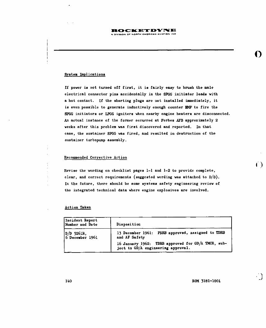
iciOc u£TD NiA OIVISION OF NONT4 AMCMICAN AVIATION. INC
System Implications
If power is not turned off first, it is fairly easy to brush the male
electrical connector pins accidentally in the SPGG initiator leads with
a hot contact. If the shorting plugs are not installed immediately, it
is even possible to generate inductively enough counter EMF to fire the
SPGG initiators or LPGG igniters when nearby engine heaters are disconnected.
An actual instance of the former occurred at Forbes AFB approximately 2
weeks after this problem was first discovered and reported. In that
case, the sustainer SPGG was fired, and resulted in destruction of the
sustainer turbopump assembly.
Recommended Corrective Action
Revise the wording on checklist pages 1-1 and 1-2 to provide complete,
clear, and correct requirements (suggested wording was attached to D/D).
In the future, there should be some systems safety engineering review of
the integrated technical data where engine explosives are involved.
Action Taken
Incident ReportNumber and Date Disposition
D/D 5261R, 13 December 1961: P$RB approved, assigned to TDhB
6 December 1961 and AF Safety
16 January 1962: TDRB approved for GD/A TI4CR, sub-ject to GD/A engineering approval.
l4O ROM 3181-1001

A DIVISION O NORTH AMERICAN AVIATION INC
Incident ReportNumber and Date Disposition
27 February 1962: TDRB held in abeyance
10 May 1962: TDRB approved for THCR V1272 II15 July 1962: Recommended changes appeared in15 July revision to Checklist AP62-0132, Section 60.
(ROM 3181-1001 1•1

SC NC IM Tr "W M EA DIVIION OF NORTH A^M•ICAN AVIATION INC
0
SAFETY PROBLEM NO. 47
(HUMAŽN FACTORS PROBLEN NO. 155)
MIXING FUEL AND LIQUID OXYGEN FUMES
Incident
The MOCAM crew was busily draining residual fuel after a dual propellant
loading exercise when someone noticed clouds of liquid oxygen fumes billow-
ing through the open fire door between the missile bay and the liquid oxy-
gen storage room, where another crew was loading liquid oxygen. Since the
fire door could not be closed quickly, all operations were quickly shut
down and all personnel were evacuated until the fumes were cleared.
Job Operation/Task
T.O. 21-SM65E-CL-17-2, Section 3, Return to Ready State A; liquid oxygen
loading task name and technical data not available.
Problem Criticality Problem Type
Major Safety
System Implications
The firex hose is connected in the liquid oxygen storage room and is routed
out to the launcher during residual fuel drain and return to ready state A
procedures. Naturally, the fire door between the liquid oxygen storage
ROM 3181-1001 143
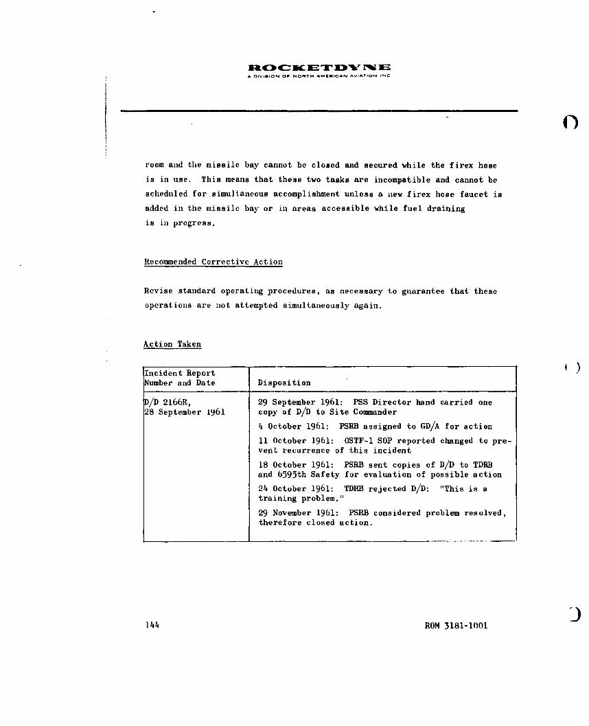
A DIVISION OW NORTH AMERICAN AVIATION INC
C)
room and the missile bay cannot be closed and secured while the firex hose
is in use. This means that these two tasks are incompatible and cannot be
scheduled for simultaneous accomplishment unless a new firex hose faucet is
added in the missile bay or in areas accessible while fuel draining
is in progress.
Recommended Corrective Action
Revise standard operating procedures, as necessary to guarantee that these
operations are not attempted simultaneously again.
Action Taken
Incident ReportNumber and Date Disposition
D/D 2166R, 29 September 1961: PSS Director hand carried one28 September 1961 copy of D/D to Site Commander
4 October 1961: PSRB assigned to GD/A for action
11 October 1961: OSTF-I SOP reported changed to pre-vent recurrence of this incident
18 October 1961: PSRB sent copies of D/D to TDRBand 6595th Safety for evaluation of possible action
24 October 1961: TDRB rejected D/D: "This is atraining problem."
29 November 1961: PSRB considered problem resolved,therefore closed action.
144 ROM 3181-1001

0
SECTION 3
SUPPL4M•N TAL INFORMATION
Quantitative and qualitative
C safetv data from various
sources
The preceding section presented specific incidents from system test op-
erations which were observed by trained human factors observer/analysts.
This section supplements those field test data by presenting pertinent
system safety engineering data which were obtained by surveillance or
sampling of the failure reporting system, test reporting systems, and
special studies. Additional data are presented which relate to the em-
pirical nature of system test and evaluation exercises involving safety
t0st objectives.
ROM 3181-l100t1 1.5
n fON OF NO"MTH &K4MICAN AVIOTI ON INC
SUPILBOTAL INFONWTI(ON
PART 1. FAILURE REPORTS . 147
Introduction . . . . .. 147System Safety Criticality Evaluation 148
PART 2. TEST REPORTS ............ 153
PART 3. PROTECTIVE EQUI.M ..T .. 155
PART 4. PERSONNEL PERFORMANCE GUIDES 157
Verification Difficulties ........ 157Dependence vs Reluctance to use TD 158Causal Factors . .......... 158Safety Implications ........ 160Current Action ........ 161
PART 5. SAFETY PROBLEMS ON THE ATLAS "1' SERIES 163
l146 ROM 3181-1001

i1O K ET DY i' E~A DIVISION OW NORT. AMEMICAN A.'IAION IN-
PART 1. FAILURE REPORTS
INTRODUCTION
Missile and space system programs are now required to have established
procedures for the generation, transmittal, storage, and analysis of in-
formation relating to failures, malfunctions, deficiencies or troubles
discovered by the contractor, subcontractor, associate contractors,
military or government representatives. Procedures should also have
been established for immediate corrective action and failure recurrence
control. Data may be reported from manufacturing, assembly, inspection,
test, and use of system hardware.
One important aspect of these failure (or operation, failure, and operat-
ing time) reporting systems is that surveillance and analysis of all human-
initiated failures, human error, or faulty acts should be made by special-
ists skilled in human factors engineerinjg.*
Such an established procedure for reporting hardware failure, cycle, and/or
operating time data (which includes a provision for reporting human error
data) would seem to provide an ideal framework for obtaining input data,
maintaining surveillance, and initiating analyses relative to systems
safety objectives.
*AFBM Exhibit 58-10, Reliability Program for Ballistic Missile and Space
Systems, 1 June 1959, 34.
NASA Quality Publication 200-2, Quality Control Provision for SpaceSystem Contractors, 1 March 1962, 36-37.
ROM 3181-1001 147

I OIVISION OV NORTH AMURICAN AVIATION INC
0
SYSTEM SAFETY CRITICALITY EVALUATION
Various Air Force documents* now require that contractors identify system
functions, malfunctions, and procedures; perform a hazard evaluation; and
rate each according to a four-point system safety scale (safe, marginal,
critical, and catastrophic).
To determine how a system safety criticality rating should be made, an
attempt was made to rate a series of operation and failure reports (OFR's).
This necessitated the formulation of more definitive criteria for the
rating process (Table 2 ) and a set of assumptions and limitations
(Table 3 ).
To assess the consistency between raters (i.e., would different individuals I)
demonstrate gross differences in attempting to supply the rating criteria?),
a mutually independent rating was obtained from three different raters
evaluating three different sets of failure reports (Table 1 ). The differ-
ences obtained were in a logically predictable direction, and an assump-
tion of inter-rater consistency can therefore be postulated.
For the purposes of this study, the evaluation was made only of operation
and failure reports (OFR's) submitted during 1962. The "Advanced" rocket
engine system reports were submitted as a result of receiving inspection,
pretest electrical and mechanical checkout, and poststatic firing operations.
*Proposed General Specification for Missile/Space System Safety, (par. 3.2.10
Safety Analyses), BSD Exhibit 62-41, 5 October 1962 (par 3.2.10.2 Safety Analyses)and SSD Exhibit 62-161, 1 November 1962.
148 ROM 3181-1001

A DIVISION OF NORTH AMERICAN AVIATICIN INC
The "Early" rocket engine system reports were submitted as a result of
early research and development testing. The "Late" rocket engine system
reports were submitted as a result of customer receiving inspection,
operational exercises, and field usage.
This evaluation indicates that more than half of the failures reported
were of a nature that they could have resulted in an operationally haz-
ardous condition (if they occurred during launch operations involving a
manned vehicle). However, only a small percentage were of a serious
nature. (It should be cautioned that this evaluation was in terms of
potential resultant consequences, did not fully consider the likelihood
of detection and correction, did not consider current engineering changes
or remedies nor does it present the results of effects which are reflected
in normal reliability growth curves.)
The use of data from failure data reporting systems would emphasize poten-
tial safety design and procedural problems (in contrast to the post facto
corrective emphasis of an accident/incident reporting system).
Additional system safety criticality rating information is contained in
Section 1, Part 4, and Section 3, Part 2.
( ROM 3181-1001 149
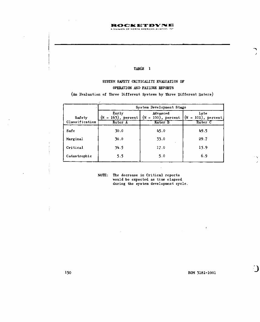
A DIVISION OF NORTH AMERICAN AVIATION INI
TABLE 1
SYSTEM SAFETY CRITICALITY EVALUATION OF
OPERATION AND FAILURE REPORTS
(An Evaluation of Three Different Systems by Three Different Raters)
System Development Stage
Early Advanced LateSafety (N = 163), percent (N = 100), percent (N = 101), percent
Classification Rater A Rater B Rater C
Safe 30.0 45.0 49.5
Marginal 30.0 33.0 29.7
Critical 34.5 17,0 13.9
Catastrophic 5.5 5.0 6.9
NOTE: The decrease in Critical reportswould be expected as time elapsedduring the system development cycle.
150 ROM 3181-1001

A DVISION OW NORTH AMIflCAN AVIATION INC
TABLE 2
SAFETY CRITICALITY CODE
Classificationand Code Definition* Examples
Safe (S) Would not result in equip- Instrumentation failures, con-
ment damage or personnel nector bent pins, check valveinjury leakage, wrong caps on drains,
B-nut sleeve jammed or frozen,minor fuzz leaks of thrustchamber
.Marginal (M) Resultant problems could Damaged electrical harness,be detected and counter- B-nuts overtorqued, gas generatoracted without major dam- igniter loose tube, ignitionage or injury monitor valve not adjusted, too
high gearcase vibration, gasgenerator liquid oxygen valveslow start, burnt insert inelectrical harness, fuel poppetseat leak, aspirator or fueltubes dented
Critical (C) Could result in substan- Flange scratches, fuel ratiotial damage or injury changes, loose bearings, turbo-
pump nuts undertorqued, liquidoxygen dome bolts incorrectlytorqued, incorrect marking onhypergol containers
C('ataistiophic (K) Could result in extensive Turbopump contamination, delayedor major damage and SPGG ignition, inadvertent SPGGinjuries ignition, throat plug not removed
'rN,.tIains to) human error, design deficiency, or component malfunction
'*BaId .I pon IIhe sI)pcific cases analyzed in this study
ROM 3181-1001 151

.0.
4-C-
4--fi. -,
4-4 '.-
41 r- 7-
.S p. bb Z .
2. -4 r-4 -
-3 C.) 10- ' L-ca: ) u. 2l -d CU4 v )2 4 9 il :z~CL9 t~ L) .0 5. 4Cp , )C
CU b4 9:5 cu w cc f.2) C) 0. ). . ' 2
+) 0 P, c-iU~ .4 22 S~'
=~ 0 .5 0. CU 00 U0. ws Cd -. S. 0- a. U ..
cc 9 03 a- 0 ::1 11k W) f.44 a,-C U)- 0 cU C) -: -0 Q. 9-. 2." 04 >.~~4
.29 ) .- C C a ) C) CIS C4- .4 '4 ;1.4 4- 0 I=. -4 -4 VUU) OC
*.. es 4..) r - dt- (n 4 .. 4-)U m CSF4- 4-42bC . 2 2 U CS~~~~~ -4 4)~ U 0'4 *4 ~ b U.) CU c .
(a '4.' U) -4.) Cd 4-)~e* *.~ 07. ) ul 4. 44 C7 2 a;-q .3
44.4 0.1-4 U) U) C)U .U 2 .- -4 0 4
Q) 0 2 . U . 0 4q )
2.. -~a 2 2 4.) 0z :3. 2
0)9 C) '4-4 i4 4.) 0 U w) .4.)2 2 Cd 4' ~ .. )-4 .
WU P a)-4 c. N)22 N 4 ) .2 22 ~ C -4CI ... 5.. 5.. 2 " U .13.4)C U Cý4 ' 0 0 -4 ~ 44.c) t5) 9 w) k.. W.. tc U) 0. w C 0 U) u U)C2d L,' C .. C. C 0 2.C) -P. C) C3 r_ 5.9;: A-~ - 2 - .- . U) C) . 02.. '-4 C) -. ~ U ) C 4 2 rq4 2 PI.,C.) -4 kS .4 FB m~ C) 0. S.~~ 2 C) * ) 'Ucl C L 5. 4-4 9 C 0 C) U) 41 V44 U;S5.. :3 Ui CL) td ~ -' 0 c) 5. "(.'4o :j m CU $-4 + 4) ca ~ CU 4., 04 4 C) 2 0 '"(f a ) ) U)i 5t o $42 0 5.. 0 U) ~ , 2. ~ -
U) ) ) 0 9 $.. 2= ) 2 C 4) ,4 . ' ) ..CU~Q cu a 5.. 9 9 9Stj ) . 0 2 . ~ -cd4- 0. E ;.. .0 -4. m U .. 54 CC-) a) W, ,.) -. 54 4 U 4). caa) 0 0 2C .'C . . U C U 0 2 C - r.
Lo~'2 3 C -4 L.4 0 4-) U) BE. 4. '-4 3CU 2 2 C. ) > m. 4-. 2 '- C
C) .'-' .L U C) S.-) 4.)
-4 F- U)-
-4

A DIVISPON DO, NORTH AMERICAN VAO.IN
4) 0 ýo-
*- U bD 43. '.. 4 :~ ~C) +) +) 4~.a 4)
g. . ) .tw -3 b) U' -4 WI ' U) 4W3.0C)4) 0' 0 bo -
'UA .0 -. b )'
UIt .9.) -U -- f0 0.4 41U) ~ ~ C CH 4..) ~ UU
4) ~44 S 4 ) -43 4, 4U) r. "U0 U0 . 4j U. ) 4U'U . ' 4 .)C.) 3 i 50 ''U U ' ~ . .4bI) *M U .'oU - 44)~Q 0. 104' ) U0 4 U)U) V 4)'4 00 .0,44) '
'-4 4'U 0.4 4) r. =. d)' - .00 4) 'U .0 .0. 4--4 44) 0'U~ ca -A.4C U: 5.- .
(z kU 4) w) 'U0) 4J '44 0'U 4 cc4 U '.4 -4 0 U ''U U) 0 04 - 4) - ) '4 4)4 r.cu4 El -4 U) ;3. Ul og4)1 4) 14 4) 'U. e4 . " U
U) .4 ' U) to "U 03 k . ~ ~ U) U - 4U cis 0) 0 ILI 04 0. k ) . I 4 0.0~~~~g 64 4) 04'~ '4 4) 0 4 U 0 4 .-4 -4-1 ' ) 9. .. 4 4) 9. 'i.34
4)0 tU -4b U 'U ' - n 'U 9. ~ '
V' .o 0. 'U 'U Go4 >44 ' . ) 0 0.0~~ 4) 0I 9.. 4j '.4 -4. ) - ) 9 ) 0 ' U '.4 --4 ... 0U Uo .. ' 3 4 4).4-4 3 C) U) U) -U 9.' 14 ) ai C-. 0 'U w) " 4-4 4) cc 4) 0 4
Lo U) 0 'U - w U ~ .- 3 0.'U 0 'U 035. 4 ) 4 0. -. 4 C4 '. .4 -
0 0 4) +) ") 4)1- 4- ' - '- 0 -. 0 ' . 4.' 'U3 go 0 4 '
A1. .0. a'. =4 0.. 'U 'U U2 (m4 3U U-4 ~ ~ ~ ~ ~ ~ ` 01 C) co . ) . U .e U ' U " 40 44 +-) 0 U)4 . 4U) 430 UIII Q0 - U d) 43I U t 0 4) 'p . 0 49..~v C) 0.9. ' 9C.. Uz #43 43
4) 'U 5. U U ILI. -4) ' " W U U. " 4 4 00.. YU 'U44)U 0 '. 0.. 4 ) U 3 '93 U) 44Uc 4)4 r. '4 01 CU .- . U ' U '
Er C ;:I.' >' ... -,q 'Uc 4)) "4 U) .4g 9
4) ~ ~ ~ ~ ~ 4 0 (a ca09. 4 ' 3 ~ 0 .
' -4 c) C) 1-4 0c U WI 0'. . ' ) " 4 '4) - 'U U - 0. '4 )~ 4) 'U ) 4) bi S., 'U432 N 0 ''U~Ef (L. 'UC U 4 - 4 4 4 U '4 d . ) '4 4 I '"U ' ). ) ' ' ) 9 ~ ' .14 +-.) U .. 4.4) U 4 - U U4U " 4) "4H' U) 'Ucce. '- ~~~ ~ ~ ~ ~ f. In0 U . - . ) 9 U ' ) '~- ~ ~ ~ ~ ~ ~ ~ ~ ~ c 4) '4) U'' U 9. ) ' .4 4 4a .-
9.. ' .' , ) 0 t-4 4)43 IV0 0 . 4
0 " -. ~ U " 'U 4) 0 9 "'' 'U 4-e 3 U .i
-~~~~O 3181-10014 ' U U

A fnIIIOI OF NORTH AMEHICAN AVIATION INC
PART 2. TEST REPORTS
A gystem safety criticality evaluation was made of rocket engine test
incidents that were found to be not included in the failure reporting
system. The incidents were found in various reports of discrepancies
occurring before, during, or after the R&D firing of a large rocket en-
gine system. The criticality evaluation was made in accordance with the
definitions utilized in Part 1. The reports evaluated were made by
personnel other than human factors, safety, or reliability engineers.
All incidents occurred during 1962.
The evaluation was made of a different type of data, relating to another
different engine system; roughly the same distribution was obtained
(compare Table 4 with Table 1 ). In all four cases, over half of the
reports involved a situation which was of a potentially hazardous nature.
However, caution should be used in interpreting these results because of
the assumptions and limitations of the classificatory process (Table 4 ).
It can be concluded that surveillance of data on reports which are, for
various reasons, riot included in a formal failure reporting system could
yield worthwhile supplemental information upon which to base system
safety investigations and analyses. It can also be concluded that prob-
lem reports initiated by personnel located in different geographical
locations, working on different rocket engine systems, tend to report
difficulties which have roughly the same proportional magnitude of sys-
tem implications. It appears that evaluations of potential hazards,
which at first seem fraught with subjectivism, have sufficient objectivity
to be useful.
ROM 3181-1001 153

A DIVIGION OF NORTM AM•NICAN AVIATION INC
TABLE I'
SYSTEM SAFETY CRITICALITY EVALUATION OF
TEST OBSERVER REPORTS
(Rater D)
Classification N Percentage
Safe 18 46.1
Marginal 15 38.5
Critical 6 15.4
Catastrophic 0 0.0
39 100.0
NOTE: Engine system is different from thethree engine systems shown in Table
154 ROM 3181-1001

D CIVIION OF NORTH AMCRICAN AVIATION INC
0
PART 3. PROTECTIVE FQUIH4ENT(FOR HANDLING HAZARDOUS MATERIALS)
A recent study was made of the hazards present in handling Atlas ignition
devices (hypergolic igniters, protechnic initiators and igniters, and
solid propellant gas generators)* Of particular interest in this study
was the use of protective equipment during the handling of Atlas ignition
devices. A previous report had furnished a list of protective equipment
similar to that used during research, development, and manufacture of
hypergolic igniters.** This list was compared to lists of protective
equipment found to be in use at various Atlas sites by Rocketdyne field
service representatives. A review was made of all reported accidents
and incidents that occurred during handling of Atlas ignition devices.
A further analysis was made of potential fire, explosive, toxic, and
work area layout hazards relative to the operational sites. The study
indicated these results:
1. Some Rocketdyne callouts did not appear in the integrated
technical manual (e.g., deerskin gloves).
2. Some technical manual callouts were not available at part-
icular bases (e.g., synthetic rubber gloves).
3. No safety equipment was used for certain operations because
of difficulty in moving about or handling the tools and missile
explosiveswhilewearing protective clothing (e.g., during in-
stallation of the SPGG's).
SR-3621, Evaluation of Hazards and Preliminary Design of ProtectivyEauipment for Handlina Atlas Ignition Devices, Rocketdyne, a Divisionof North American Aviation, Inc., Canoga Park, California, 18 June 1962.
i R-3066, Hypermol Cartridge Maintenance and SLorage, Rocketdyne, a Div-ision of North American Aviation, Inc.,Canoga Park,California, 13 July 1961
ROM 3181-1001 155

A OlI-ION OF NOfTW AMERICAN AVIATION INC
It was concluded that:
1. The protective clothing items listed in Air Force T.O. 21SM65E-
2FJ-7-2 have proved unsatisfactory for application to the hand-
ling operations encountered at the operational sites.
2. The substitution of items better adapted to particular site re-
quirements has resulted in unstandardized, varied equipment
lists to perform similar tests at different sites.
3. This situation resulted "from the fact that the original equip-
ment list supplied by Rocketdyne was applicable to research and
development operations on which it was used, but is very unsat-
isfactory for use under operational conditions".
Recommendations were made relative to the design and use of improved pro-
tective clothing.
156 ROM 3181-1001

A I lIl -. N OF Nf TH AMýE ICAN AVIATION INC
PART 4. PERSONNEL PERFORMANCE GUIDES
One of the principal factors in preventing personnel and procedural errors
which could have catastrophic consequences, is the proper use of job per-
formance guides (i.e., job manuals or operation and maintenance check
lists). It is pertinent, therefore, to determine the accuracy of such
technical data and the manner in which they may be used.
VERIFICATION DIFFICULTIES
A detailed study was made of two MA-3 technical manuals for accuracy,
clarity, and usefulness as personnel performance guides and authoritativereference documents. This study, conducted at the Rocketdyne Van Nuys
OSTF-1 EMA facility (October 1960 to June 1961) indicated that even good
technical publications could be significantly improved in relation to the
criterion of operational effectiveness. The results of these evaluations,
the results of a technical manual verification process study, and some of
the specific human factors recommendations which were made were included
in a special report.*
The following statement, taken from that report,indicates some of the
difficulties inherent in the technical manual verification process.
"Ample opportunities to verify, update, and change themanuals before OSTF verification can be seen. Manychanges and improvements were made, but,despite theseopportunities and resultant changes, more than half thetechnical manual pages required some OSTF change, andeach page required an average of five or more changes.Many, perhaps most, of these changes were minor or non-significant; any categorization as to significance, how-ever, depends on individual, subjective judgment whichvaries as to the role, need, or perspective of the personmaking the judgment. Conclusion can certainly
*Peters, G.A.,F.S. Hall, and C.A. Mitchell: Human Performance in theAtlas Engine Maintenance Area, ROM 2181-1002, 1 February 1962, 3-19,215-224.
ROM 3181-1001 157

A rliViSION OF NONRTH AMIIICAN AVIATION INC
be drawn that one verification process would not be enoughto permit placing faith in the accuracy and readability oftechnical manuals. In further support of this conclusion,it was found that during the EMA 0STF program three separaterunthroughs were required for each manual to catch all changesrequired."
DEPENDENCE VS RELUCTANCE TO USE THE TECHNICAL DATA
The Peters, Hall, and Mitchell study also included a section on operator
comments. Statements regarding the use of technical manuals were sum-
marized as follows:
"... relatively inexperienced SAC personnel ... have to rely almost
entirely upon the directions given in the TO's, and, if the TO'sare wrong, incomplete, or hard to understand, they really don'tknow what to do and may have to improvise or just do the bestthey can under the circumstances."
The study also stated:
"Using personnel seemingly make only limited use of varioustechnical data sources. They rely on general information orpast experience or locally prepared material rather thanuse lengthy, hard-to-find, or elaborate procedures. Theyrevert to the approach which requires the minimum of effortand inconvenience."
CAUSAL FACTORS
There are 65 Rocketdyne technical publications for just the MA-3 engine
system. One of them, the overhaul technical manual entitled Rocket Engine
Common Components, T.O. 2KAl-l-113, was issued as a new edition dated
21 March 1961. It was 2-7/8 inches thick and contained 1466 pages.
Less than 7 months later, on 12 October 1961, a revision was issued which
was 1-5/8 inches thick and contained over 800 pages. When replacement
and new pages were added, there were 1526 pages in the revised manual.
158 ROM 3181-1001

A OIVIUION OP NONYN AMUNICAN AVIATION, INC
0
Two months later, on 19 December 1961, another 3/4-inch-thick revision
was issued, containing over 350 pages. The new total number of pages
for this revised manual was 1,532 pages. While the size of this partic-
ular manual may not be typical, each of the 65 Rocketdyne publications
does represent a considerable volume of technical information to be
mastered by the user.
Many of the technical manuals are being constantly changed and re-issued
at periodic intervals (i.e., every 90 or 180 days). Much of these data
is site-peculiar (i.e., each geographical location has a somewhat unique
system configuration). This imposes an added burden to those individuals
who must learn and update their skills from such personnel performance
guides.
In a recent Aerospace Support and Operations Meeting (held by the Institute
of Aerospace Sciences at Orlando, Florida on 4 to 6 December 1961, B.J.
Smith of GE-MSVD discussed what he called the "recent dissatisfaction with
technical manuals for checkout and maintenance".*
He gave greater use as the reason for this dissatisfaction, saying that
"it is unlikely that anymissile manuals were less good than they had been
for manned aircraft ... it is more likely that, with man out of the flight,
he came to rely much more heavily on checkout and maintenance manuals than
he had before." This greater use would probably have caused whatever short-
comings there may have been in technical manuals to be noticed and commented
upon more frequently. While there may be greater use or reliance upon
technical data in missile system operations, there are other factors which
have served to focus attention on problems related to the development and
use of technical manuals. One of these factors, already mentioned, may
*Smith, B.J.: Achieving 0.9+ Human Reliability in Check-Out and Maintenance,Proceedings of the IAS Meeting on Aerospace Support and Operations (Un-classified Papers), 1961, 147-152.
ROM 3181-1001 159
I

A DIVISION OF NORTH AMiRICAN AVIATION INC
be the sheer number and constant change of the technical manuals and
technical support documentation which is used in a complex weapons
system.
One approach toward the improvement of operational usage of technical
data used to support or assure reliable human performance might be in
the application of human factors principles and techniques to technical
data generation, presentation, verification and validation, updating,
and operational usage. For example, B. H. Manheimer and J. R. Kelley
recently stated:
"In the publications area there is an astonishing lack ofapplication of human factors knowledge to the specificationand preparation of instructional material--astonishing be-cause of the large scope of the effort in terms of moneyand time expended, because of the importance of publicationsin proper maintenance, because of the known deficiencies in C)publications, and because of the obvious contributions thathuman factors information has made and can make in the areaof written conminication."*
SAFETY IMPLICATIONS IN MRE USE OF TECHNICAL DATA
It is difficult to authoritatively document an unquestioned, unclassified,
and direct relationship between the improper use of technical data and a
catastrophic consequence. However, an illustrative case is available in
the Civil Aeronautics Board Accident Investigation Report of the
17 September 1961 crash of Northwest Airlines' Lockheed Electra N 137US.
The 37 fatalities of this crash were due to a missing safety wire. The
report states:
*(Manheimer, B. H. and Kelley, J. R. An Overview of Human Factors in Main-tenance. IRE Transactions or Human Factors in Electronics, HFE-2, No. 2,September 1961, 73-78).
160 ROM 3181-1001

licI cETDcN EA oiVIliON OF NONTH AMERICAN AVIATION INC
"Installation of the new aileron boost unit was performedby two mechanics on Shift 3 during the night of July 11-12.Testimony established that neither mechanic had followedthe manual step by step, referring to it only when a problemwan encountered, and that neither had read the removal in-structions to determine what components had been unsafetied,disconnected, or rendered inoperative in the removal of theboost unit...
"The Board therefore concludes from the testimony thatmaintenance and inspection personnel showed an ignoranceor disregard of published directives and instructions...
"The Board determines that the probable cause of thisaccident was a mechanical failure in the aileron primarycontrol system due to an improper replacement of the ail-
eron boost .assembly, resulting in a loss of lateral con-trol of the aircraft at an altitude too low to effect re-covery." *
CURRENT ACTION
A "new concept in overhaul manuals" was announced in the Rocketdyne Service
News (Vol.3, No. 9, September-October 1962),which stated that "the tra-
ditional concept of the organization and use of overhaul manuals has been
changed considerably in recent months. These changes have been motivated
by the field experience of our 'using' agency ... and by our application
of 'human engineering' techniques to the rocket engine overhaul manuals."
Some of the changes are:
1. "Emphasis on the assembly of the engine in actual sequence rather
than in an engine systems order"
2. "The supporting illustrations are now placed as near as possible
to the text relating to them"
*Aviation Week, Vol. 77, No.26, 24 December 1962, 77-91
ROM 3181-1001 161
t

A DiViftION Or NORTH AM*RICA^N AVIATION INC
3. "The illustrations are designed to provide the technician with
appropriate assembly details"
4. "New illustration sizes have been developed to provide more
flexibility in page layout"
"5. "Foldout illustrations are not used except for schematics and
flow diagrams "
6. "Manuals are typeset and the pages are mocked up to coordinate
text and illustrations closely"
"Two 'pilot' manuals incorporating these features are now being produced."
162 ROM 3181-1001

S DIVISION OF NONTi AMMMICAN AVIATION INC
PART 5. SAFETY PROBLEM ON THE ATLAS "F" SERIES
The following 30 safety problenw (Table 5 ) were encountered during the
early stages of Category II testing on the Atlas F Series at the OSTF-2
(silo) facility at Vandenberg AFB. These problems, affecting the relia-
bility of the propulsion system, are listed (with references to the data
reports which contain additional descriptive informati-on). These problems
provide supplemented support for the evaluations, conclusions, and recom-
mendations contained in the following sections of this report.
(SROM 3181-1001 163

uCb CuC ETIr i EA DIVISION Of NORTH AMC ICAN AVIATION INC
TABLE 5SAFETY PROBLES ON THE ATLAS F SERIES TESTING
Further DetailsHuman Factors May Be Found In
Problem The Following(Identification No.) Problem Description Reports
F-1 Rain incursion through silo doors soaks R-3569-1*vernier engines, possible degrades V.E.reliability, and creates slippery work-ing conditions for engine technicians
F-2 No safety barriers to work platforms R-3569-13D and 4D to prevent propulsion per-sonnel from falling down silo
F-3 Provisions missing for safe removal R-3569-1and storage of MGS pod fairing andBl nacelle by MET/M
F-4 Unsafe route used in SPGG removal which R-3569-1could cause this fragile solid propellantto be dropped
F-5 Many difficulties and hazards associated R-3569-1with task of installing No. 2 vernierengine in MAB
F-S Lack of safety chains along access route R-3569-2to booster engines creates severe fallinghazard for MET/M
F-13 Using turbopumps and high-pressure pro- R-3569-4,-7pellant ducts for stepladders
F-18 No barricades, flashing lights, or R-3569-4warning signs were used during leak andfunctional tests using 1500 psi pneumaticpressure to G3077 test stand; visitorswere unaware of dangers present
F-19 Technicians were observed-standing and R-3569-5and sitting on engine thrust chambers
*See AppendixE forbist of OSTF Reports
164 ROM 3181-1001

NM0 4 C Z_ q 3 1k, IW WEA OIVISlON Or NORTm AMZRICAN AVIATION IN
0TABLE 5
(Continued)
Further DetailsHuman Factors May be Found In
Problem The Following(Identification No.) Problem Description Reports
F-25 Unsafe, "homemade" access ladder being R-3569-6used to reach thrust section of missilein raised position
F-27 MET/M used thrust chamber hat band and R-3569-9aspirator as steps to enter thrust sec-tion and as work platform to stand onwhile working on engines
F-28 MET/M used RX 20699-31 hypergol con- R-3569-6tainer shipping plug instead of 9010572test plug to contain leak test (pneu-matic) pressure
F-29 G2000 service unit was left unattended R-3569-6during lunch period, with 440 volts poweron, trich heaters on, facility GN2 pres-sure applied, and low-pressure systempressurized to 90 psig
F-30 G2000 was not properly secured at end R-3569-6of task; 110 psig was locked in high-pressure purge system
F-35 Propulsion system tasks were espec- R-3569-7,-8ially hazardous because launcher re-furbishment was not completed beforemissile was installed
F-36 No.1 booster engine hydraulic flow limit R-3569-7valve must be opened manually duringturbopump preservation procedures andis inaccessible except by standing onBl gimbal actuator outrigger struts
F-37 Permanent platform in front of elevator R-3569-7at silo level 6A has no safety chains orguard rails at either end and is oftencrowded
F-43 NET/H did not use safe access route to R-3569-8and from the work platform
(_OR0N 3181-1001 165

A ODIVIION OF NORM AMSqiCAN AVIATION. INC
TABLE 5(Continued)
Further DetailsHuman Factors May Be Found In
Problem The Following(Identification No.) Problem Description Reports
F-49 The MET/M's "work platform" while R-3569-8connecting electrical harnesses toRERW is extremely dangerous andtiring
F-50 Personnel did not wear the prescribed R-3569-8,-9safety equipment while installingmissile pyrotechnics and hypergolics
F-51 No.1 vernier engine was hand carried to R-3569-9top of missile because sling could notbe found
F-52 MET/M failed to maintain LOX-clean con- R-3569-9dition when connecting vernier engineoxidizer lines
F-53 Falling hazards were noted during missile R-3569-9ordnance removal tasks because safetyrails were not installed on the launcherand the B-2 work platform
F-54 Checklist manning was not followed, e.g., R-3569-9three men (instead of one) were used toremove igniters and initiators
P-1 Silo work platforms, safety chains, and R-3569-10safety rails were not effective in pro-ducing safe task performance because ofdeficiencies in maintenance, organiza-tional controls, and design
P-3 Integrity of engine, missile and AGE R-3569-10hardware was jeopardized by deficienciesin maintenance, organizational controls,and equipment design
P-7 Tasks were not performed: hardware and R-3569-10personnel were thereby exposed to un-necessary hazards
P-18 MAD facility design permits personnel R-3569-10to injure themselves
P-19 Personnel did not use safety equipment R-3569-10provided for their protection
166 ROM 3181-1001

A OIVISION OF P4OATN AMCEICAN AVIATION INC
SECTION 4I
DATA EVALUATION
Analysis and evaluation
derivation of principles,
and discussion of the
implications of the data
The two preceding sections presented various types of data relating to
systems safety engineering. An attempt was made to discuss the implica-
tions of each specific incident or group of uaterial presented. More can
now be gained by a summary evaluation of the data. This section presents
the results of a general analysis of the data,with emphasis on the deriva-
tion of principles useful in future design and development activities.
ROM 3181-1001 1b7

A frtVIoN OF NOR7TH AMERICAN AVIATION' Nc
DATA EVALUATION
PART 1. DERIVATIVE HUMAN FACTORS DESIGN PRINCIPLES 169
The 25 Design Principles 170
PART 2. DESIGN IMPLICATIONS ... .. .. 177
Restrict Procedural Llternatives 177Design for Minimum Personnel ........ 180Anticipate Rough Usage ........ 180Unambiguous Identification ... . ... 181Design to Eliminate Support Items Which May Not Be Used 182Make Identification of Parts Obvious 182Do Not Hide Fittings _ .. .. 183Design by Task Rather Than by Cookbook Data 183
PART 3. SUPPLEMN•TAL CHECKLIST MATEIALS.I 185
PART 4. GENERALITY OF THE FINDINGS .. 187
PART 5. HUMAN ERROR PRINCIPLES 191
168 ROM 3181-1001

A nIVISION OF NORTM AMERICAN AVIAIION IC
0
PART 1. DERIVATIVE HUMAN FACTORS DESIGN PRINCIPLES
The specific design changes needed to correct or ameliorate each system
safety incident have been described in the preceding case studies. Implicit
in the data are a number of human factors design principles which should
be carefully reviewed and considered by engineers designing new equipment.
These principles offer some answer to two questions sometimes voiced by
the design engineer: Why do people make such mistakes? How can these errors
be eliminated? These problems are the type to which human engineers
address themselves. However, if the design engineer is provided information
concerning what actually does occur to his equipment in actual use, he
can often solve the preventative question (what to do about it), by
himself, for his particular design. This section therefore attempts to
capsulize some of the human factors principles derived from the operational
system test data. The information should be useful to designers of
equipment, facilities, test'instrumentation, procedures, and operations
support material.
The following principles describe what actually does happen and how people
actually deal with equipment in the field. It does not describe what
should happen or what they are supposed to do. To correct for human
factors difficulties, the design should be in terms of anticipated usage in
the operational situation. Therefore, bearing the following principles in
mind, the design engineer should strive to prevent or properly channel the
undesirable aspects of human performance in relation to the item of equip-
ment being designed.
S( ROM 3181-1001 169

Naz 4c: Mc 1Z 79 Ir EA OIVISION OF NOMTH AMerICAN AVIATiON NC
THE 25 DESIGN PRINCIPIES
Principle 1
If insufficient or inadequate equipment is provided, equipment will be
improvised or modified at the site in order to get the job done. Improvised
equipment generally leads to improvised procedures. Improvised procedures
often result in safety hazards (Human Factors Problems 57, 272, 290).
Principle 2
A weak excuse is enough for some people to do what they please. To do
what they please is often to do what they should not do (Human Factors
Problems 154, 211, 213, 230, 274, 276, 285, 291).
Principle 3
People often feel that "it can't happen here." They feel that other people
at other locations may get hurt (or damage equipment) by disregarding in-
structions, but "not us." (Human Factors Problems 154, 168, 213, 223,
252, 288). Therefore, foolproof procedures are necessary where possible.
Since procedures are based upon the design of equipment, it is the basic
design which permits foolproof procedures to be developed.
Principle 4
Corrective action on a problem does not always mean the end of the problem.
The action taken may not be sufficient, appropriate, or affect the real
cause of the problem. It might not completely prevent it from recurring
elsewhere or in some other way (Human Factors Problem 284).
170 ROm 3181-1001

A OIVISION OF NOCTH AMERICAN AVIATION INC
0
Principle 5
No matter how simple and foolproof it looks on paper, try it before you
buy it (Human Factors Problems 85, 129, 199, 235, 237, 262, 279).
Principle 6
If the implicit response of the equipment is wrong, it will eventually
produce some wrong responses (Human Factors Problems 60, 111, 227).
Principle 7
A warning note in the appropriate technical manual usually will not overcome
a safety problem; it is of only limited and supplementary value to reduce
the probability of mishap. People may not have read, remembered, or even
know where to find such warning notes.
Principle 8
Some people have to see equipment get damaged by inadequate task per-
formance before they take their assignment seriously and do it thoroughly
and carefully, ( Human Factors Problems 231, 274, 288).
Principle 9
Do not rely upon special training for those who may use the equipment.
Not all individuals will receive the "required" training. Some will
have had outdated training, related training, or catch-as-catch-can
ROM 3181-1001 171

OcK ucTD NIA DIVSIOlN OF NORTH AMNICAN AVIATION. INC
training. Therefore, try to design for safety rather than hope for
special safety training.
Principle 10
Some people have to see someone get hurt before they will believe the
practice is dangerous (Human Factors Problems 168, 274).
Principle 11
People sometimes prefer to work under hazardous conditions, as if their
bravery makes the job more important (Human Factors Problems 98, 103,
129, 216, 235, 255, 272).
Principle 12
Tell some people "don't" and they do, notwithstanding the magnitude of
personal risk. Instructions alone are not enough to guarantee proper
care, operation, and safety (Human Factors Problems 154, 168, 211, 216,
221, 223, 243, 252, 274).
Principle 13
Expect that the equipment will be used in the wrong way. Study the con-
sequences of doing the job incorrectly. Then design the equipment so that
incorrect operation will do minimal damage.
172 ROM 3181-1001

A CIVI|ION Or NORT04 ANCAICAN AVIATION INC
Principle 14
Will the technician damage it or injure himself if he does not know what
it is? Be sure that full, understandable, and legible identification is
provided (Human Factors Problems 71, 86).
Principle 15
Bad conditions which are condoned often seem to multiply and interact
to produce serious safety problems (Human Factors Problems 216, 248,
272, 291).
Principle 16
People tend to avoid or eliminate continual sources of difficulty,
not always by sensible or logical approaches (Human Factors Problems
57, 211, 272, 274).
Principle 17
Just as development engineers work the "bugs" out of critical equipment,
so must others work the "bugs" out of the task performances of each
person assigned to critical tasks. This may be done, for example, by
tutoring them as they practice on nonhazardous simulators or inerts
(Human Factors Problems 227, 288). A certain amount of on-the-job
training takes place using operational equipment. Mistakes will be made
by these partially trained personnel. The original design of the equip-
ment must anticipate such usage and mistakes.
ROM 3181-1001 173

Principle 18
If the designer does not know all of the requirements of the equipment,
it is not likely that his design will meet all of them (Human Factors
Problem 236).
Principle 19
In the midst of complex, multimillion-dollar items of equipment, an item
of inexpensive and simple construction may seem unimportant, and its use
or maintenance may be neglected (Human Factors Problems 276, 291).
Principle 20
Unfortunately, people must be protected from themselves. Each leadman,
stand talker, and/or safety committeeman must be responsible for certain
areas of personnel and equipment safety. An extremely important part
of this responsibility is combatting foolish shortcuts and deviations
from the prescribed procedures (Human Factors Problems 16, 98, 121, 154,
166, 168, 206, 211, 213, 216, 223, 248, 274, 285, 288, 302).
Principle 21
Abbreviated checklists are good only when the detailed procedures are known.
It is difficult to get technicians to leave a checklist and consult the
detailed job procedures when they encounter an unfamiliar area (Human
Factors Problems 111, 199). When in doubt, people tend to experiment
and fill in the gaps themselves.
I•174 ROM 3181-1001

A fIVI-ION OF NORTH AMCNICAN AVIATION INC
Principle 22
Reputations of equipment are important (Human Factors Problems 86, 88, 291).
If there is even a rumor of hazard or difficulty, task performance and use
of the equipment may be adversely affected.
Principle 23
An item of equipment which is difficult to maintain may not be kept in a
condition to be used when needed. Equipment which is difficult to use will
not be used if any substitute is available.
Principle 24
If the equipment is designed in such a way as to be dependent upon
communications between crew members, it is susceptible to human error.
People are seldom able to recognize that they have not communicated
sufficiently until mistakes have been made, and sometimes not even then
(Human Factors Problems 121, 166, 288).
Principle 25
In summary, the designer should remember that most of the reliability
problems affecting operational equipment did not represent defects in the
equipment itself, but defects in the way in which it was used. To count
upon any significant differences in treatment of equipment on future
programs may constitute a form of wishful thinking. It is much better
ROM 3181-1001 175

A OIVISION OP NOYTH AMCNICAN AVIATION, INC
that the worst problems are precluded because of original design than
to grapple with them after designs are relatively frozen.
176 ROM 3181-1001

A DIVISION OP NORTM AMENICAN AVIATION. INC
0
PART 2. ZESIGN IMPLICATIONS
The case studies, and other data, have provided examples which indicate
that equipment of a perfectly good de--ign sometimes fails to do its job
because of something the designer had no control over, didn't think of,
or bad no way of anticipating. Some of these problems could have been
prevented if the following suggestions were known, made available, and
utilized by the design engineers in the design of equipment for human
use.
RESTRICT PRO(ZDURAL ALTERNATIVES
There is only one way to get people consistently to do a thing the rightway: make it impossible to do it any other way. Since this is not always
possible, several approaches are listed that can be used to get people
to do things the desired way more consistently:
1. Sometimes the right way can be made the easiest way.
EXAMPLES: Human Factors Problem 57:Adapter Identification
Human Factors Problem 206:Stepping on Electrical Cables
Human Factors Problem 216:Using Turbopumps for Stepladder
2. Sometimes the wrong way can be made the most difficult.
EXAMPLE: Human Factors Problem 121:Communications Needed
ROM 3181-1001 177

Sl•O~u c C ¶E' I•a rlt EI ~A OAISI~ON 07 NOWTM AMCNICAN AVIATrON INC
3. Clearcut guide lines can be established on what can be done
safely.
EXAMPLE: Human Factors Problem 290:NCU Line 3 vs Line 4
4. Planning could include every location where the task would ever
be performed.
mEAMPLE: Human Factors Problem 284:Interference with Sustainer Hypergol Cartridge
5. The wrong way could be made unpopular (and the right way popular).
EXAMPLE: Human Factors Problem 243:Are Hard Hats Okay?
6. For some tasks, continuiL1 reminders may be necessary from a )safety committeeman, leadman, or stand talker.
EXAMPLE: Human Factors Problem 248:Blocked Safety Aisles
7. Organization Controls could be used to direct and strictly enforce
the use of the right procedure and prohibit use of wrong practices.
EXAMPILE: Human Factors Problems 98, 154, 168, 211, 216,
223.
8. Identify the specific people whowill have clearly defined respon-
sibility for the integrity of the equipment and the safety of the
people for stated period of time.
EXAMPLES: Human Factors Problem 121:Commication Needed
Human Factors Problem 168:
High-Pressure Hose Tiedown
178 ROM 3181-1001 (1)

N&4c3 Cý'X uc I r "V M JEA DIVISION OF NORTH AMERICAN AVIATYIN INC
0
Human Factors Problem 206:
Stepping on Electrical Cables
Human Factors Problem 211:Thrust Chamber Pad Not Used
Human Factors Problem 231:Pregimbaling Precautions
Human Factors Problem 248:Blocked Safety Aisles
9. Provision could be made for continued orientation, indoctrination,
or education concerning the dangers or faults of improper practices,
as contrasted with virtues of the right way.
EXAMPLES: Human Factors Problem 98:Standing on Thrust Chambers
Human Factors Problem 168:High-Pressure Hose Tiedown
Human Factors Problem 211:Thrust Chamber Pad Not Used
Human Factors Problem 216:Using Turbopump for Stepladders
Human Factors Problem 111:Inflating Throat Plug Tire
Human Factors Problem 121:Communication Needed
Human Factors Problem 154:Cleaning with Trichloroethylene
Human Factors Problem 166:Neglecting to Use Communications System
Human Factors Problem 223:Human Pack Horse
ROM 3181-1001 179

A CIVIsION or NOPYT4 AM^EMICAN AVIATION. INC
DESIGN FOR MINIMUM PERSONNEL
"One is easy, two is hard, and three is almost impossible." This is
what service personnel consistently reply when asked if they can get a
helper for a few seconds to assist in removing covers, erecting access
ladders, or positioning platforms. If an item of equipment has to be
lifted or opened and is large or heavy:
1. Counterbalance it
2. Hinge it
3. Build it in sections
4. Attach lifting eyes for crane hooks
Do something so that one or two people could handle it. Do not rely
or be dependent upon having a lifting sling to go with it because the
sling may be cut out of the budget or not available at all locations.
Do not tell yourself that they will always have plenty of extra people
standing around because, even if this were so, having them and getting
them to lift your equipment are two entirely different things.
EXAMPLE: Human Factors Problem 221:Hoisting Vernier Engine Maintenance Platform
ANTICIPATE ROUGH USAG
If your equipment is large, fairly strong, somewhat flat on top, and
located near areas where people will be trying to work, you can be assured
that some of them will sooner or later sit on it, stand on it, jump on it,
180 ROM 3181-1001

A DIVISION OF NORTM AMENICAN AVIATION JNC
lay or drop tools on it, etc. If your equipment is rugged enough to
take all this, well and good. If not, see what you can do about rugged-
izing it, or getting some good maintenance platforms provisioned, or putting
some protective covers on it that will take all this abuse. Do not
mislead yourself that stencilling NO STEP on it will do the trick.
Neither will complaints, directives, and detailed instructions. Prepare
for the worst, anticipate rough usage, and design accordingly.
EXAMPLE: Human Factors Problem 98:
Standing on Thrust Chambers,
Human Factors Problem 216:
Using Tarbopump for Stepladders.
UNAMBIGUOUS IDENTIFICATION
The addition of appropriate panel nomenclature to clearly and unambiguously
identify switches, lights, gages, regulators, valves, etc., is a major
step forward in aiding operators and repairmen. But careless use is a
major step backward. After assignment of proper nomenclature to the com-
ponents on the control panel or other location, back away and take a
second look to be sure that each component really is what the nomenclature
says it is. For example, do not identify a switch or a light as MAIN
POWER unless it really is tied to the main power. Be careful with
abbreviations. They are often ambiguous, e.g., REG might stand for regu-
lator, regulated, regulating, registered, regular, etc. Be sure to ask
yourself: is it what it says it is?
EXAMPIE: Human Factors Problem 60:Shock Hazard
ROM 3181-1001 181

A OIVISION OF NORTH AMCRICAN AVIATION INC
DESIGN TO ELIMINATE SUPPORT ITEMS WHICH MAY NOT BE USED
Consider what would happen if the customer does not use a particular
item of equipment. Would or could the consequences be serious? If so,
either design to ensure that they will use it or eliminate the need for
it. For example, you can be sure they will use your thrust chamber
throat plug (they can rnt perform leak checks without it). But you
cannot be sure they will use a thrust chamber protective pad, because
they can step on the bare chamber while installing and removing the
throat plug. Therefore, it would be better to forget the pad alto-
gether and design the plug long enough and light enough to be installed
from the outside (also design it, if possible, so it is not necessary to
use lubricants or other compounds which must be wiped off the chamber
walls when through).--)
EmAMPIE: Human Factors Problem 211:Thrust Chamber Pad Not Used
Another example of the same principle: either make shipping covers so
fragile that they cannot be used for test plates, or make them rugged
enough to double for test plates (and forget about provisioning test
plates).
EXAMPIE: Human Factors Problem 274:Shipping Covers vs Test Plates
MWKE IDENTIFICATION OF PAR•S OBVIOUS
Many checkout operations use quantities of standard fittings and hardware
which are obtained from local stock and returned when tasks are completed.
182 ROM 3181-1001

A DIVIiION OF NORTH AMERICAN AVIATION. INC
0
If you supply special adapters with your equipment and they are made
from what looks like standard fittings and hardware (no special identi-
fication), your adapters will also get "returned" to stock, or put in
some other adapter set (where they cannot be found when needed).
EXAMPII,: Human Factors Problem 57:Adapter Identification
DO NOT HIDE FITTINGS
If the item of equipment has to be placed inside something else, do not
put some of the connections or fittings the technician has to reach up
inside and some out where they are easily reached (unless the symmetry
or other features make the presence of the inside connections very ob-
vious). Otherwise, the technician will try to connect to the near
fittings when he should be using the hidden or distant fittings.
EXAMPLE: Human Factors Problem 111:Inflating Throat Plug Tire
DESIGN BY TASK RATHER THAN BY COOKBOOK DATA
When using standard human engineering data from textbooks, handbooks, or
other data sources, be sure that the task to be performed is similar to
that upon which the data vae based. For example, data n access door
dimensions could be misleading if based strictly upon anthropometric data
which are expressed in terms of minimum permissible dimensions. The
turbine spinner access door opening iq 12 inches square, which is adequate
for maintenance tasks involving reaching in simultaneously with both hands,
for distances less than 12 inches (according to some standard human
S " ROM 3181-1001 183

A OIVISION Off NORTH AMCRICAN AVIATION iNC
engineering references). There are exceptions to every rule, and this is
one. The solid propellant gas generator is too heavy. The technician
who tries to remove or install it through the access door provided will
almost invariably smash or pinch a finger and drop the SPGG. When using
standard dimensions, be sure the task is not the exception to the rule.
When in doubt, leave a little extra room.
EXAMPLE: Human Factors Problem 227:Dropping Solid Propellant Gas Generators
184 ROM 3181-1001

A CIVISION OW NOYTN AMCMICAN AVIATION. INC
0
PART 3. SUPPLEMENTAL CHECKLIST MATERIALS
The design principles and design implications just described can be
supplemented quite easily by reviewing the specific design principles
already available in various design checklists. There are many compil-
ations of such design checklists which contain special safety sections.
A few representative checklist references are described below for the
interested reader.
1. Greek, D.C.: Checklist of Human Engineering Design Principles,MD 58-334, Missile Division, North American Aviation, Inc.,Downey, California, January 1959. This publication contains
seven sections, one of which deals with safety. The safety
section contains questions relating to materials, fire and
explosive protection, protection against corrosive agents,
protection from mechanical hazards, and electrical safety.
2. Arnsfield, P. J.: Human Engineering Maintenance Design
Criteria: AIR-345-61-IR-139 (DAC Report No. SM-38686), Pre-
pared for Douglas Aircraft Co., Santa Monica, California by
American Institute for Research, Los Angeles, California,
January 1961. This human engineering design checklist contains
86 pages of items. These items are supposed to be reviewed by
the designer who circles, as appropriate, "NA" (not applicable),
"Y" (yes), or "N" (not incorporated). Each question is coded
as to five kinds of effects or consequences. Two of the five
consequences relate directly to safety: NT, Maintenance Time;
ME, Maintenance Error; LO, Logistics; ED, Equipment Damage; and
PI, Personnel Injury.
ROM 3181-1001 185

A DIVISION OF NORTH AMERICAN AVIATION INC
3. Designer's Checklist for Improving Maintainability, ASD-TLB-62-45
(AD 275 889), Wright-Patterson Air Force Base, Ohio, February 1962.
This publication contains 12 general design categories, including
one on "Safety, Damage and Interference." Out of a total of 327
checklist items, the safety category contains 37 design suggestions.
4. Folley, J. D. (Editor): Human Factors Methods for Systems Design,
AIR-290-60-FR-225, American Institute for Research, Pittsburgh,
Pennsylvania, 1960. Chapter 4, "Detection of Error Producing
Designs," by R. L. Weislogel, contains a section on checklists
and evaluation guides (with some sample items) to identify error
producing designs.
5. Peters, G. A., F. S. Hal] and C. A. Mitchell: Human Performance
in the Atlas Engine Maintenance Area, ROM 2181-1002 (also see
R-3520), Rocketdyne Reliability Engineering, Canoga Park, ( )California, 1 February 1962. This publication contains a
section evaluating a human engineering checklist (containing
a Safety and Hazards section), a task evaluation checklist
(containing a Safety section), an equipment evaluation checklist
(containing a Safety section), and a posttest interview question-
naire (containing a Safety sectiont). For system testing, it was
concluded that checklists were useful for the initial guidance
and training of observer/interviewers, but were not suitable as
test-and-evaluation management control devices.
1I)186 ROM 3181-1001

X&u 3 4C: AC I- qr N30'W r%1WA OIVISION OF NOMTH AMEMICAN AVIATION INC
0
PART 4. GEINERALITY OF THE FINDINGS
The Case Study and Supplemental Data sections contain a great deal of
highly specific detail information. The question often arises whether
such data are so "situation specific" that generalizations cannot be
validly made to other situations, projects, or efforts. If such a
belief were completely true, it would probably preclude or negate the
worth of any consideration of field data because of the following reasons:
1. Despite efforts at standardization, any particular field situa-
tion is only an approximation of some theoretically ideal or
"representative" operational situation. That is, no perfect
situation could probably ever be found in which to collect
truly representative data.
2. If it were possible to obtain system development data under
experimental conditions (i.e., with clear definition and full
replicable control over all variables), the rigidly controlled
conditions required would create an extremely-artificial,
"nonrepresentative" situation. That is, perfect experimental
data probably would not be valid for the purposes of this
report.
3. In relatively new areas of investigation such as this area of
human performance research, there is only a limited fund of
directly applicable and useful knowledge available from related
areas of activity. This makes it extremely difficult to render
judgment as to what is or is not situation specific and what
has or has not some communality of characteristics with other
situations. Therefore, itwould seem highly desirable that
empirical data, gathered under known conditions, be closely
ROM 3181-1001 187
I

A OIVISlON OF NORTN AMERiCAN AVIATION INC
examined in order to organize or generate some logical group of
assumptions which would permit the formulation or deduction of
verifiable or testable hypotheses. This is the only logical
approach toward developing useful operating principles or tenta-
tive guides for decision.
When examining various human factors problems, some problems appear to
stand by themselves as "important" while others seem quite trivial and of
minor import. However, the cumulative effect of a series of minor problems
may markedly influence the manner in which some job operations are finally
accomplished. So it is of some importance that attention be directed to
the resolution of seemingly minor, highly specific, problems as well as
to the more critical or major problem areas in a complex man-machine system.
In order to encourage the discovery of commununality of characteristics
between discrete events or incidents, this report contains
1. A grouping of incidents into logical problem areas
2. A cross referencing between various problems and incidents
3. An elaboration of system implications and.the corrective
action process
4. An introduction of pertinent supplemental data from related
sources
5. A presentation of appropriate background material and reference
to the matrix of related system development activities
It is felt, therefore, that there is sufficient generality in the findings
of this report to warrant its careful review and study by individuals
188 ROM 3181-1001

A OIVIUlON OF NOMTW AMERiCAN AVIATION. INC
0
responsible for the design and development of similar systems even
though the performance specifications, intended use, and basic configura-
tion may be different. This presentation of information is basically
intended as a stimulus and guide to actions which could more efficiently,
quickly, and effectively resolve or prevent the occurrence of system
development difficulties previously experienced. However, the material
should be considered as part of a working paper which would necessarily
be subject to revision or extension as needs are evidenced or state-of-
the-art refinements are evolved.
K1
IC ROM 3181-1001 189
(

A OVISiiON Op NORTM AMXMiCAN AVIATION INC
0
PART 5. EUMAN ERROR PRINCIPLES
An examination of the experiences which have resulted from the human error
investigation, analysis, and corrective action process has permitted the
formulation of 10 tentative "principles," generalizations, or guides for
those attempting to understand the nature of the human error investiga-
tion process.
Principle 1
You can trust your knowledge of a human-initiated failure to the degree
to which you are able to make a first-hand investigation of all of the
facts in the case. A corollary principle to this is that upon investiga-
tion a human factors engineer (i.e., a human error "detective") will
usually jee a problem quite differently than it is originally reported
because his perspective (or what he is trained to look for) is different.
Principle 2,
There usually is no one simple solution to human error problems; it is
more typical to find that there are multiple corrective actions required.
In tracing back the causes which led up to or permitted the error to occur,
it is more typical to find that there are a series of branching preven-
tive measures which are desirable to help preclude the recurrence of such
difficulty.
R SROM 3181-1001 191

Na" 4"c~ NE 1r "I, w IF-* DIVISION OF NOUTN AMCNICAN AVIArION INC
Principle 3
Beware of general solutions to classes of problems. Dramatic solutions
to big problems are rare and usually misleading. There is much more
assurance of constructive action when specific problems are analyzed in
a specific fashion and when sufficient effort is budgeted for follow-
through to ensure the attainment of a satisfactory remedy.
Principle 4
People do not always act as they are supposed to, as they have been in-
structed or directed, or as you might suppose that they would or should.
Hence, equipnent and procedures have to be adapted (and readapted) to
reduce or prevent the intrusion of unwanted human variability during
periods of inadequate organizational control, work stress, and the typical
operational handicaps which have to be expected on the basis of past
experience.
Principle
Intelligent workers can "beat any system" of arbitrary or paperwork
controls which might create some difficulty or unpleasantness for them
or which seeks to impose upon them what they feel are unrealistic
requirements.
Principle 6
A flood of previously unreported incidents could result as people hear
more about human error, become sensitive to it, and suffer no personal
192 ROM 3181-1001

A DIVISION OF NORTM AMERICAN AVIATION INC
repercussions as a result of reporting it; this new information could
easily change the ascribed causes of some chronically recurring problems.
Principle 7
Avoid attempting to utilize figures-of-merit based upon human error to
rate equipment items or attempting to use human error percentages as an
index of workmanship, craftsmanship, or morale. Any comparative rating
scheme will unfavorably influence opportunities to gain or evaluate infor-
mation and will hinder negotiation for corrective action.
Principle 8
Superficial c~rrective action, such as the "notification of responsible
supervision' or "re-emphasis" of existing regulations, generally appears
helpful in the absence of any other course of action. However, it should
be recognized that habitual response of this type may be inadequate and
that it sometimes does more harm than help.
Principle 9
Da not ignore minor, trifling, nuisance, or marginal problems. They often
serve as fruitful leads to significant problems.
Principle 10
Direct observation of actual working conditions is critically important
( to determine the true nature of the situation under study, to locate
ROM 3181-4001 193

A DIVIISION Or NOTH AME[NICAN AVIATION INC
significant unreported or unrecognized problems, and to determine
what could be an effective remedy. Analysis, theory, logic,
and hypothetical assumptions are no substitute for direct
observation.
Additional information regarding the current need to reduce human error,
-the contractual requirements for this activity, and some of the techniques
for the implementation of a program to reduce human error may be found in
Section 5, Part 1, Human Error and Goofproofing,and Section 6, Part 1,
Identification of Human Error.
194 ROM 3181-1001

A o*VSUO@N OP NORTh A&IMUCA1NO AVIATION INC
0
SICTION 5
General information on the back-
IC ground, context, and approach of
safety engineering.
The preceding section is an analysis of system safety engineering data,
its evaluation relative to the variables of an operational system, and
the implications relative to various design and development activities.
This section presents general background information for a clearer
understanding of the approaches involved in achieving safety design
objectives during system design and development.
ROM1 3181-1001 195

n l*'JtiON 00 1NOA'0 AMgMICAN AVIAT~bN -N1,
H O L *TX. '
PERSPECT IVE
PART 1. HUMAN • D3• MD GOOFFPROOFING . 197
What is Human Error . ......... 197¶ Recent Specifications ......... 199
Basic Requirements ............ 200Operational Definition of Human Error .....
PART 2. REQUIR•WENTS FOR A SAFETY EVALUATION ....... 205,
Original Design Requirement ......... 205General Personnel Subsystem Test Requirement 205Category II Test Requirement ........OSTF Test Plan Requirement .......... 207
PART 3. GENERAL SAFETY FtNCTIOS 29.......209
Relationship Between Industrial and Systems Safety 209Industrial Safety Functions ......... 210Relation Between Reliability and Systems Safety 211System Safety Engineering ......... 211
190 ROM 3181-1001

SA t3VISION OP' NOfR' AMEICAN A*iAlION, INC
PART 1. HUMAN ERROR AND GOOFPROOFING
WHAT IS HUMAN EOR?
Ihuman error is defined in AFBM Exhibit 58-10 (Reliability Program for
Ballistic Misileo and Space Systems) in terms of "hnmann-initiated failhtri,"
i.e., "any system failure, the cause of which is traceable principally to
a faulty human act or actions (either of omission or commission)," and
includes "such things as incorrect wiring, rough handling, incorrect adjust-
ments, activation of wrong control, etc." This 1959 Air Force exhibit also
went on to state that "all human-initiated failures will be identified and
will be reviewed by specialists in human factors."
We could define human error as "any deviation from a previously established,
required, or expected standard of human performance that results in an
unwanted or undesirable time delay, difficulty, problem, incident, mal-
function or failure."
Some human errors are straightforward and simple as to their identification
and their cause, but the vast majority of human errors only appear to have
simple causation and corrective action remedies. In regard to corrective action,
for example, reports of excessive human error could be termed" a manifes-
tation of personnel carelessness and indifference that should be corrected
by greater detailing and enforcement of procedures, or by more discipline and
"running a tighter ship." Such simple solutions may appear effective as the
reported malfunctions or difficulties decline. However, the case may be more
apparent than real if the difficulties are just not reported or are not openly
discussed, i.e., if the campaign to "do better" merely restricts, screens,
masks, or recategorizes the same recurring problems. This is but a variation
of the general principle that intelligent workers can "beat any system" of
IROM 3181-1001 197

arbitrary or paperwork controls which might create some difficulty or
unpleasantness for them, or which seeks to impose upon them what they
feel are unrealistic requirements.
Some other immediate, but self-defeating, corrective action alternatives
are the passive or essentially nonaction-oriented responses, such as the
following:
1. "People are not perfect"
2. "We need better people"
3. "We are doing the best we can under the circumstances"
4. "Our real difficulty is caused by that other(department, process,
or supplier)"
Unfortunately, if we fail to systematically attempt to reduce human error
as we gradually reduce or eliminate all the other sources of product un-
reliability or error variance, it means that human error can only loom
proportionally greater and greater as a residual uncontrolled error
variance. Eventually, this problem of human error must be realized, and
a positive plan of action undertaken to find relief or control. At this
point, another general principle taces effect. As people hear more about
human error and become sensitive to it, more of it is reported. If no
personal repercussions result, it may well open a floodgate of previously
unreported incidents, and it could easily change the perception as to actual
causative factors underlying some chronic malfunctions, failures, incidents,
or difficulties. For example, a continuing component design difficulty may
actually be the inadvertent result of some seemingly minor upstream
procedural difficulty during test operations.
198 ROM 3181-1001

A DIVISION OP NORTH AMRNICAN AVIATION. INM
0
If we are truly interested in imoroving uur product reliability and lowering
redesign and rework costs, any increased and broadenled flow of meaningful
information will provide an excellent oppoitirtuity for constructive action.
RECENT SPECIFICATIONS
The actual extent of human error and its resultant costs, in terms of produc-
tion dollars and operational capability, has been widely discussed and is
well known to those who work close to the physical hardware of almost any
large man/machine system during its system development stages. It is
explicitly recognized in the missile and space system requirements for
organized human factors efforts which have been published by NASA and
various military agencies during the past year.
The April 1962 edition of NASA Quality Publication NPC 200-2, quality
Program Provisions for Space Systems Contractors, contains the following
statement (paragraph l4.3c) dealing with Corrective Action:
"Analysis of malfunctions, troubles, and failures
traceable to human or operator error shall be made
by persons skilled in human factors engineering."
The October 1961 edition of the Air Force military specification MIL-R-27542,
Reliability Program Requirements for Acrosnace Systems. Subsystems. and
Equipment, contains the following statement (paragraph 3.1f):
"A factor in systems reliability is human reliability
which includes the extent to which the equipment has been
human engineered to minimize human error in the manu-
facture, test, operation, and maintenance of the system."
ROM 1181-10o1 199

A DIVISION OF NORT6 AMirNICAN AVIATiON INC
This same reliability specification also states (paragraph 3.5.3):
"The reliability program shall apply the principles of
human engineering in all operations during the manufacture,
test, maintenance, and operation of the system or subsystem
where personnel are involved."
In February 1962, AF BSD 61-99 was issued as Human Engineering: General
Specification for the Development of Air Force Ballistic Missile Systems.
It contained a broad outline of the activities necessary for effecting an
integrated human engineering effort, including the information submittals
thought necessary to effect a positive management control of these acti-
vities during system development. It emphasized the need for human engi-
neering participation in systems analysis, detail design, and system test
and evaluation.
The July 1962 edition of the Handbook of Instructions for Aerospace Personnel
Subsystem Designers was issued by the Air Force Systems Command as AFSCM 80-3.
This document contains over 200 pages describing the means by which human
factors may be considered during each stage of system development. The
emphasis was on system requirements, design engineering, and operational
support activities. The equally critical areas of inplant test, fabrication,
assembly, and inspection are covered only in a cursory fashion.
BASIC REQUIREMENTS
The very fact that these and other requirements have been issued is prima
facie evidence that there is a fairly widespread recognition of the need
for the reduction of human error and for an organized, systematic approach
to the problem.
200 ROM 3181-1001

A OIVIGION OF NO4TM AMCICAN AVIATION INC
Such specifications or requirements usually involve the following five
considerations:
1. Separate, identifiable, and specialized analytic activities should
be established to deal with human error (i.e., it is not just
"another hat" to be wornby other activities; although uniqueorganizational needs and talents may dictate that various
combinations of existing functions might best perform some of the
technical requirements of a particular program).
2. Such activities should emphasize corrective or preventive action
(i.e., tabulations of the extent of human error may make people
aware of the problem, but they do not change the situation).
3. This effort should deal with all stages of system development and
all product-oriented functions within a company (i.e., it should
not be entirely a design engineering function).
4. Specialists in human factors engineering are required to perform
such specialized services and, quite often, requests to bid
specifically ask that the human factors engineers be listed by
name in the proposal. Obviously, properly qualified* and trained
individuals are needed--if you can find them. One more note
of caution: human error has absolutely no direct relation to
current time-and-motion work, current industrial psychology,
or current industrial engineering.
*Qualified by virtue of basic academic coursework in the engineering andbehavioral sciences, supplemented by special training courses in humanfactors engineering, followed by properly supervised or tutorial workexperiences in human factors engineering. Specialization in this workarea is usually evidenced by affiliation with the appropriate professionalsections of various technical and scientific societies, contributions tothe technical literature, and some professional stature or recognition in
( the field.
ROM 3181-1001 201

A DIVISION OF NORTH AMERICAN AVIATION INC
5. Broad outlines as to effective human factors programs are often
provided, and, in some cases, extremely detailed analytic efforts
in certain restricted areas are described (i.e., there are estab-
lished and effective techniques for uertain aspevls of this type
of activity).
OPERATIONAL DEFINITION OF HUMAN ERROR
Several standard definitions of the terms "human error" and "human-
initiated failure" have been presented (Section 5, Part 1; Appendix A,
Glossary). The authors also presented a general definition of human error:"any deviation from a previously established, required, or expected
standard of human performance that results in an unwanted or undesirable
time delay, difficulty, problem, incident, malfunction, or failure."
This general definition may be employed in a wide variety of activities,
e.g., the categorization of human-initiated failures in a failure-reporting
data system, the identification of human error in a manufacturing inspection
procedural audit, the tabulation of the dependent variable in a simulation
test, or the initiation of a deviation/difficulty observer report in an
operational system test situation.
When attempting to utilize any general definition in a specific situa-
tion, some further explanation and elaboration of classification cri-
teria are often necessary. In its application to the categorization of
failure data, the definition appears clear and concise until someone
conscientiously attempts to classify all failure reports into one of the
two implied categories (human-initiated failure and nonhuman-initiated
failure). At this point, it is discovered that all failures could be
considered as human-initiated if the cause is traced back far enough.
For example, a valve shaft may have failed because a supplier design engineer
selected an inadequate material specification. O
202 ROM 3181-1001

A DIVISiON OF NORTH AMERICAN AVIATION iNý
0
In order to differentiate or segregate the data into a set of meaningful
categories, it is necessary to know the purpose of such a tabulation and
the specific use which will be made of such a categorization. It would be
meaningless to classify almost every failure as being human-initiated;
another breakdown of such data would then be necessary in order to have
meaningful trend or appropriate information for investigation (i.e.,
corrective action) purposes.
Therefore, for practical purposes, it is wise to restrict the standard of
human performance to the behavior standard established for the particular
area or set of activities under study in which corrective action is
contemplated or considered feasible. For example, one study might consider
as human error only the errors of personnel assigned to a particular test
site who directly or indirectly affect the operation of the particularI
activity being investigated. Another study might consider only the errors
committed by manufacturing personnel (machinists, inspectors, planners,
material handling personnel, etc.), but would exclude the errors committed
by vendor, purchasing, engineering design, and other personnel as being
outside the realm of that particular study.
For the purposes of operational system testing, the "standard of human
performance" is any accepted, established template of expected behavior,
which is detailed and documented prior to a test exercise, e.g., the
personnel performance checklist.
For the purposes of simulation testing, the "standard of human performance"
is explicitly recognized in the statements of the hypothesis being tested
and the definition of the measurements to be taken of the dependent vari-
able in the experimental design.
ROM 3181-1001 203

A OIV6IlON OF MONT64 AMCNICAN AVIATION INC
C)
The basic question "How may we identify and control sources of human
error that might affect the design, development, fabrication, test, and
operational reliability of complex systems?" is discussed at further
length in Section 4, Part 5, under Human Error Principles, and in
Section 6, Part 1, under Identification of Human Error.
2)
204 ROM 3181-1001

A OIVIOION OF NONTM AMSNICAN AVIATION INC
PART 2. REQUIDMENTS FOR A SAFETY EVALUATION
There have been a number of separate requirements for an evaluation of
missile systems relative to safety criteria. Several are described in the
following paragraphs and serve to illustrate the nature of such require-
ments. Recently, several versions of AFBSD Exhibit 62-41 dealing withSystem Safety Engineering have been distributed for review and coordina-
tion preparatory to the issuance of a military specification covering the
system safety engineering area. Additional emphasis has also been given
safety in man-rated reliability formulations. Because of current interest
in this area, it can be anticipated that future requirements for detailed
safety evaluations will, most likely, be increased rather than de-emphasized.
ORIGINAL DESIGN REQUIREMENT
There were a number of requirements to incorporate safety features into the
design and development of Atlas equipment and procedures. For example,
the military standard on Human Engineering Criteria for Aircraft. Missile,
and Space Systems, Ground Support Equipment: (MIL-STD-803 (USAF), 5 November
1959), contains a section on "Hazards and Safety." This military standard
also references various other applicable regulations, standards, specifica-
tions, technical reports, and handbooks that deal, in part, with the
safety design criteria.
GENERAL PERSONNEL SUBSYSTEM TEST REQUIREMENT
The general requirement for a safety objective during system test and evalua-
tion may be found in AFRO Exhibit 60-1*. One of the test objectives
*AFBMD Exhibit 60-1, Personnel Subsystem Testing for Ballistic Missileand Space Systems, 22 April 1960.
ROM 3181-1001 205

A OIVISION OW NORT" AMCRI AN AVIATION INC
(paragraph 3.6.1, Human Engineering) is the "identification of design
features or procedures which constitute a hazard to safety of personnel
or equipment."
CATEGORY II TEST REQUIREMENT
The detailed safety test objectives for a Category II test program were
specified under paragraph IV g, Safety, in AFR 80-14.* The test objec-tives are:
1. "Determine whether all hazardous operations are properly identi-
fied, controlled, and conducted."
2. "Determine whether hardware design, safety equipment, or pro- -(cedures of sequencing of operations impose a hazard to safety
of personnel."
3. "Determine whether weapon system checkout can be performed
safely under the operational system."
4. "Determine whether propellant loading (liquid systems) and count-
downs can be safely performed."
5. "Determine whether maintenance of the weapon system in a standby
readiness condition can be safely performed."
6. "Determine whether proper and adequate protective clothing and
equipment are specified for use during hazardous operations."
7. "Determine whether safety distance criteria specified for
hazardous operations are adequate and do not hinder operational
procedures."
*APR 80-14, Category II Test Program Plan for Ballistic Missiles. 13 April1961.
206 ROM 3181-1001

W&4O 4C KW 1=C F"krW l EEA DIVISION OF NORTH AMERICAN AVIATION INL
~0
8. "Determine whether hazard-detecting devices are adequate and
properly detect hazards they are to monitor."
9. "Determine toxicity implications and establish and document
adequate safety precautions."
OSTF TEST PLAN REQUIREMENT
Specific safety evaluation requirements for the OSTF-1 VAFB test and
evaluation program were outlined in a test plan*prepared with the partici-
pation and coordination of all Atlas associate contractors, ATC, and
AFBMD.
1. Paragraph 5.0, PSS Activities to be Performed During Part I:
C ý "(h) Review of procedures for use and handling of explosives
and hazardous equipment."
2. Paragraph 6.0, PSS.0bjectives for Part II OSTF: "(a) Equipment
Design. Human design considerations relative to maintainability,
operability, communications (loads), reliability, and safety"
3. Paragraph 8.1.1, Data Sources: "8.1.1.2 .......... the checklist
shall contain provisions to gather information on ..............
d. Safety Hazards"
I *GM 6300.5-1060, Integrated Test Plan for WS-107A-1 Operational SystemTest Facility OSTF No. 1 and No. 2. Supplement: Personnel SubsystemTest!Plan Annex, 15 December 1960.
R1|jR0M 3181-1001 207

A DIVIlSION OF NORTH AMERICAN AVIATION INC
PART 3. GENER•AL SAFETY FUNCTIONS
RELATIONSHIP BETWEEN INI)JSTRIAL AND SYSTEMS SAFETY
An organized and systematic approach to safety may involve two or more
separate but closely interrelated safety functions. First, there is the
more traditional inplant industrial hygiene and safety function, which
is usually oriented toward protecting the health and safety of each em-
ployee. This may be located within the Personnel department because it
may be considered as a general overhead or burden charge (i.e., it is not
financially chargeable to any one particular program or project).
A second type of activity would be the newer product-oriented System
Safety function, which is concerned with the engineering design analysis
and development engineering functions relating to the safe operational
use of a particular product (e.g., an engine system). This type of ac-
tivity, to be effective, is generally undertaken as part of the normal
engineering design function. However, such a specialized function could
easily become lost among the multitude of objectives, criteria, and
tradeoffs seemingly heaped upon the shoulders of each designer and prod-
uct review function (e.g., maintainability, producibility, value, opera-
bility, simplicity, schedule, checking, inspectability, quality assurance,
reliability, and safety). To ensure that safety does not become just
another vague design objective which could be inadvertently overlooked,
there are increasing requests to designate or delegate some identifiable
central responsibility to ensure that some organized and continuing ef-
fort is applied to meet the required operational system safety objectives.
This might include, for example, provisions for independent design sur-
veillance and audit of processes or functions relative to operational
system safety.
(ROM 3181-1001 209

A DIVISION OF NORTTM AMiRICAN AVIATION• INC
I)
INDUSTRIAL SAFETY FUNCTIONS
Industrial safety might include functions such as the following:
1. A Hazards Review Committee which could include the self-
descriptive functions such as might be performed by a Flammable
and Hazardous Chemical Committee, a Propellant Review Board,
and an Exposure Evaluation Connittee
2. A Safety Committeeman organization established at the workman
level to report hazardous conditions or incidents
3. An Executive Safety Committee to establish safety policy. This
could be a top-level management group consisting of the heads of
each major company division and an executive at the level of
vice-president. It is often felt that the prime responsibility 4)for the day-by-day implementation of the safety program should
rest with first-line supervision
4. An Industrial Hygiene and Safety organization could establish
levels and criteria for operations involving use of hazardous
materials; it might be, for example, concerned with the chemical
and physical properties of new propellants and their possible
toxicologic effects on propellant handlers. It could also re-
view safety factors during the design and construction of test
facilities, review written test operating procedures where
potentially hazardous conditions exist, and conduct formal in-
plant training courses dealing with Industrial Safety.
0210 ROM 3181-1001

A DIVISION OF NORTN AMtqICA. AVIATION. INC
0
RELATION BETWEEN RELIABILITY AND SYSTEMS SAFETY
A review of the required, proposed, and suggested system safety engineer-
ing functions reveals a marked similarity to the parallel system develop-
ment activities already required (and in existence) in engineering
reliability organizations (Table 6 ). It is conceivable that many of the
proposed system safety engineering functions could constitute part of
another functional activity (i.e., reliability analysis), and that safety
might be only one of several objectives of a functional activity (i.e.,
design review).
Such an approach to system safety would provide the greatest economy andefficiency of operation, while permitting flexibility to meet the varyingdemands of various missile/space systems programs. It would be essential
that sufficient emphasis could be placed upon the system safety objective
in each functional activity, and that some reasonable coordination of ef-
fort would be implemented.
SYSTEM SAFETY ENGINEERING
To achieve high safety standards, it is necessary to have a clearly
organized, systematic approach to the problem of safety assurance. There
are outlines* of the basic requirements to be met by Air Force ballistic
*AF BSD Exhibit 62-41, System Safety Engineering: General Specificationfor the Development of Air Force Ballistic Missile Systems, 5 October 1962;
AF SSD Exhibit 62-161, Program 624A System Safety Engineering Requirements,1 November 1962, and Proposed General Specification for Missile/SpaceSystem Safety, 30 September 1962.
ROM 3181-1001 211

A OIVISION OF NORTH AMEIlCAN AVIATION INC
TABLE 6
INTERRELATIONSHIP BETWEEN RELIABILITY AND SYSTEM
SAFETY PROGRAM ELEMENTS
Reliability Function Systems Safety Function
Identification of Human Error Identification of Personnel Error
Design Review Safety Design Review
Human Engineering Design for Minimum HazardHazards and Safety Postanalysis Action
Failure Effect Analysis Catastrophic AnalysisMalfunction Analysis
Systems Analysis Safety AnalysisPersonnel Subsystem Analysis Definition of Safety Characteristics
Functional Flow Diagrams
System Test Safety TestAcceptance Test 4)Demonstration ExerciseCategory I, II, III Evaluation
Reliability Test Special Safety TestsEnvironmental TestOverstress TestingSimulation Studies
Reliability Training and Safety TrainingMotivation
Reliability Data Safety DataOperation and Failure Reports Accident/Incident Reports
Reliability Analysis Safety Research
NOTE: Other reliability functions may beinvolved in various types of safetyanalyses, i.e., packaging, maintain-ability, design services, standards,value engineering (depending upon thenature of the program and its mode ofimplementation).
212 ROM 3181-1001
A DIVISION OF NORTH AMEMICAN AVIATION INC
0
missile systems contractors (in order to achieve an integrated and compre-
hensive system safety engineering effort). The intent of the application
of safety engineering principles in system design is, according to these
publications, to assure optimum freedom from inadvertent and destructive
mishaps resulting from facilities, equipment, procedural, or personnel
deficiencies either singly or in combination. It further states that the
safety objectives should be "applicable to the design, research, manu-
facture, and test of the system or subsystem."
A review and analysis of various program requirements, state-of-the-art
techniques in related activites, and current operational safety problems
indicates that the elements of a system safety engineering program could
involve the application of the following 10 procedures, methods, or tech-
niques (in various combinations, depending upon the needs of a particular
program):
1. Systems analysis
2. Safety motivation
3. Human engineering design surveillance
4. Personnel subsystem analysis
5. Systems test
6. Safety surveillance teams
7. Design review
8. Data surveillance
9. Catastrophic analysis
10. Human error investigation
ROM 3181-1001 213

A CIViSiON OF NORTH AMEIRCAN AVIATION INC
Each of these activities are described in the context of the system safety
program elements described in the following section of the report.
Where it would be desirable to have intensive coordination or specializa-
tion relative to system safety engineering, some central responsibility
should be assigned for the coordination, implementation, and detail analy-
sis of various work tasks (Table 7 ).
In general, an organized and planned system safety engineering function
serves to emphasize safety factors during the early design and development
of each system. Its approach is characterized by rigorous, step-by-step
methods or controls to ensure that safety criteria cannot be inadvertently
overlooked. The activity should cover all stages of product design, de-
velopment, fabrication, inspection, test, maintenance, and use. The focus
should be on the early identification and resolution of potential problems
(i.e., on preventive action rather than corrective action following the
occurrence of mishap).
214 ROM 3181-1001

UJ) 94- 03
4) >1 ~ +,)I) 4d1 40 )-~0 ~ ~ 4A -4
4) ~ ~ 4)'~-4
4) 4) ca ) caco)d0 '-PU 4M ~ U1&4 4) F44 U)N
-4~ ~ +) U)4 e4 c'4 4)1U)~4- (d c',-4 E) ' w. 4 ) U 4)U
U) 4) k d4.4 +
al~ 04 -,4 +)) ulý, - = u -CL) 4)cO4. a w.C~ cd cu m. - 4 U)) . ~
U) 0 10£. 0 c)4U- k w +a4 +0)
1) 4.) 04 0d 4) u 4) ý0 . k U U) UU".I d 44 0+ý .4 M 0 a))4-4 0 "U.Q 4)U w d dN ..
U 41~+ (nU *'4 co) 4)0 + 0 Id~'*-$4)b) Q ~ ~ 0 ) cd- U 44 4.4. 0J od 4- 124 W
-~ ?"0~ a£.'0 ) 4))4, Cd cc,.404).Q04) 4) ~ U C4 $4 CH 'ý U) U)m00 U) (.
'.49. 4) r.4)4 4)0 -4 kj4~ $4) 4U)0wk h -4) w* m> 4' 0dC a.a 4 a0 ) -r4
4 r. w .4 -4 H~ U d- ) a4) w ~ M -1 Vw 'c
0 ) u w 4)4 lj0- + do CH k Q N wU- + ) k M4 0H U)
4)
'-4 -4 -kU c
04U
04 4-CZ= H
cd r Cd0u)
o '-40 41
-4 ~ -4) ~c 04c 0
wU - 0 71 w r
C . )~ H 4. 1~
U U)%.44)'4.4 >-4'-
-4 0
4J m4
'.4 0 '.
~-. 0 ~E
Ttr, 31 1-00

0* i * w n) '4
N~ ti
:12 C-
=.-.
*~t -4
F2-
Best Avilbl Cp

I~oc i cz ETD3 ¶ N E3
SECTION 6
SYSTEM SAFETY PROGRAM ELEMENTS
Specific system safety engi-
neering methods, procedures,
and illustrative techniques.
The preceding section dealt with the general approaches, background,
and perspective involved in tWe safety engineering aspe-cts of system
design mad deve1Opment. This sec'-, of the report describes in de-
tail some of the essential clemen s that are felt to be useful in the
effective implementation of a system safety engineering program. Spe-
cific analytic techniques which could be employed are illustrated,
and whe relationship of these techniques to the matrix of related
systerm deve lopment activities is present ed.
RlOM 3181-1001 217

A DIVI*IMN OW NORT" AMENICAN AVIA-ION INC
SAFETY PROGRAM ELEMENTS
PART 1. IDENTIFICATION OF HUMAN ERROR .......... 219
Methods and Techniques .................... 219Systems Analysis ........ ................. 219Data Surveillance I........... .............. 220
Simulation Studies ........... .............. 221Direct Observation ........... .............. 221
PART 2. SYSTEMS ANALYSIS ............ .............. 225
Diagrammatic Representation ....... ........... 225Task Elaboration ............ .............. 231Application to Human Performance Evaluation 2......2
PART 3. SAFETY MOTIVATION ............ .............. 239
Objective ............... ................. 239Safety Orientation and Indoctrination ...... ....... 239Safety Motivation .......... ... .............. 240Safety Training ..... .................. . . 240
PART 4. HUMAN ENGINEERING SURVEILLANCE ....... .......... 243
General Objectives ............. .............. 243Implementation .......... .... ............... 244Criteria .................. 245Allocation of Human Engineering Effort ...... ....... 246
PART 5. PERSONNEL SUBSYSTFM ANALYSIS ...... .......... 249
General Objectives ........... ............... 249Difficulties and Context ......... ............ 249Implications for Further Research ..... ......... 253PSS Safety Data ............. ............... 256
PART 6. SYSTEMS TEST ............... ................ 257
Contractor System Tests .......... ............ 257Operational System Tests ......... ............ 259Estimating Progress in the Test Program ... ....... 263Test Data Control ............ .............. 275
PART 7. SAFETY SURVEILLANCE TEAMS ........ ........... 279
PART 8. DESIGN REVIEW. ............. ............... 281
PART 9. CATASTROPHIC ANALYSIS ........... ............. 283
218 ROM 3181-1001

IM3 l cO Kc WE TIu "%e I'mA OIVISION OF NORTH AMERICAN AVIATION INC
PART 1. IDENTIFICATION OF HUMAN ERROR
METHODS AND TECHNIQUES
The current need to reduce human error and the recent requirements for an
organized program in this area were discussed in Section 5, Part 1 (Human
Error and Goofproofing). In addition, 10 empirically derived principles
encountered in human error analysis were described in Section 4, Part 5
(Human Error Principles). The following paragraphs desciibe the basic
approaches or methods which can be used to identify sources of human
error encountered during various phases of the system development cycle.
The four principal methods are (1) systems analysis, (2) data surveil-
lance, (3) simulation studies, and (4) direct observation.
SYSTEM ANALYSIS
The first approach, System Analysis, may involve any of the following
techniques:
1. Detailed task analysis of the job operations required for opera-
tion, maintenance, transport, and assembly
2. Preparation of block diagrams representing each step in the
functional flow or operations sequence
3. Review of conceptual and detail drawings, process specifications,
and technical data to be used in support of job performance
These analyses serve to locate potential problems (based upon logic or
theoretical assumptions, previous research, or past experience). They do not
necessarily require the presence of physical hardware. Hence, they may be
ROM 3181-1001 219

c: 4- 16C ET " I EA OIVIGION OF NORTH AMERICAN AVIATION INC
performed sufficiently early in the design cycle so that changes can be
effected before design or procedural concepts become too fixed. Inciden-
tally, the information derived from these analyses is of decided benefit
to a number of other functions in the system development cycle.
DATA SURVEILLANCE
The second approach, Data Surveillance, may involve any of the following:
1. Monitoring the failure reporting system to locate specific cases
of human-initiated failure
2. Reviewing test malfunction or incident reports, field operation
reports, or component laboratory reports for incidents which
might involve human error
3. Sampling the inspection discrepancy, quality history, part re-
placement requests, maintenance forms, or equipment logs
Data Surveillance is an indirect means for locating probable instances of
human error. However, sufficient background information for properly
interpreting the failure, malfunction, incident, or difficulty may not
always be present. The failure may be described in terms of symptoms or
results, not in terms of cause or contributing factors. How many in-
dividuals would willingly accept the consequences of reporting "I dropped
and damaged the part," rather than state that the part was received in a
damaged condition? The question is whether there is a high enough pro-
portion of minor or quick replacement items reported in a data reporting
or log system. Looking at the problems involved in data surveillance,
it can be said that this is an excellent means for locating problems if
the incidents are treated only as leads for further direct investigation.
220 ROM 3181-1001

A DIVISION OF NORTH AMERICAN AVIATION INC
SIMUIATION STUDIES
The third approach, Simulation Studies, may involve the use of a close physi-
cal model or approximation of the equipment, process, or subsystem under
study such as:
1. Cardboard mockups, soft mockups, battleship mockups, R&D hard-
ware, or prototype equipment for early or initial studies of
human performance
2. Special research apparatus for static or dynamic simulation of
unique man-machine problems
3. Production hardware in a simulated operational situation for
various verification, validation, demonstration, acceptance, or
Category I test exercises
Simulation studies provide data on observed instances of human error or
difficulty. While simulation studies are somewhat artificial because they
only approximate the real situation, they do provide human error data not
usually obtained solely from systems analysis studies (which are only
predictive in nature), or from data surveillance studies (which must
sample an information flow which is easily biased, restricted, or
screened). Simulation studies do provide a systematic and intensive
means of gathering data concerning human performance factors.
DIRECT OBSERVATION
The fourth approach, Direct Observation, involves systematic and thorough
personal observation of all scheduled and unscheduled job operations on
"ROM 3181-1001 221

A OIVISION OF NORTH AMCRICAN AVIATION INC
existing equipment configurations in the cperational or working situation.
It could include personal observation during any of the following:
1. Transport, receive and inspect, storage, assembly, installation,
checkout, or test operations
2. Attainment of initial operational capability, operational training
exercises, special operational R&D projects, or even in a special
operational systems test facility as an integral part of a
Category II test program
3. Normal operation of the system either as part of a Category III
test program or to ensure that the inherent reliability of the
hardware or process is not inadvertently or unknowingly depreciated.
Direct observation is often disparaged because it is assumed that (1) the
observation is post facto, (2) the hardware is frozen, (3) procedures are
already established, and (4) any change would be very costly. However,
often it is not as late in the system development cycle as one might be-
lieve, and such direct contact often is very necessary to achieve the
full inherent operational effectiveness of a system. It may also be of
importance in terms of modernizing, updating, or modifying downstream equip-
ment. It is certainly an effective means for systematically accumulating
and evaluating "real-life" data that can be applied to related systems
then in the planning or design stage.
The very process of conducting systematic direct observation on fairly
large, complex systems in the operational environment has often been termed
impossible or unscientific (because of the lack of experimental controls)
by individuals most familiar with laboratory or behavioral research. How-
ever, even informal, short-term, direct observation of a small segment of a
working situation generally yields some practical and useful information
about "real-life" problems.
222 ROM 3181-1001
A DIVI-ION OF NORTH AMERICAN AVIArION INC
During the past few years, the technique for conducting field research on
large-scale man-machine systems has evolved or been developed. This tech-
nique is based upon empirical data such as the recorded observed diffi-
culties or deviations from a prescribed template of required human perform-
ance by all personnel involved in the system. It is a broadly oriented
means for identifying even the cumulative minor problems which people
actually face in attempting to operate and maintain a system composed of
a conglomeration of various items of equipment, personnel, procedures,
and support functions. The problems which serve to induce or foster human
error may relate to (1) equipment design interfaces, (2) organizational
control procedures, (3) technical data such as checklists used to guide
human performance, (4) previous personnel training or the maintenance of
skill proficiency, (5) availability of tools or test equipment, and (6)
alteration or nonavailability of appropriate procedures.
ROM 3181-1001 223

A DIVI&ION OF NORTH AMtRICAN AVIATION INC
PART 2. SYSTEMS ANALYSIS
To apply safety engineering principles to all aspects of product develop-
ment, some early and orderly means must be employed for identifying and
subdividing all functions where hazardous personnel-equipment interactions
might occur.
DIAGRAMMATIC REPRESENTATION
One technique (which is an aid in performing a systems safety analysis)
involves the sequential identification and description of all functions,
phases, events, processes, or elements of the system under consideration.
Block diagrams representing groups of systems elements may be prepared.
These block diagrams result in conceptual building blocks that enable
further schematic representation of the functional flow and system element
interrelationships. Further detailed information regarding each system
element can then be prepared in the form of task analysis work sheets,
narrative functional analyses, or other detailed systems analysis forms.
The interrelationships and derivative data are obtainable by transposing
these data to tabular, data pickoff, and matrix charts. These charts are
found in position equipment task summaries, integrated task inventories,
equipment-maintenance analyses, equipment function matrixes, personnel
data cards, maintenance loading charts, etc.
ROM 3181-1001 225

OC7 W 1 W " I REA lIVIhION OF NORTH AMERICAN AVIATION INC
These block diagrams may be prepared as an aid during the systems analysis
of any one of a wide variety of activities. It may be of use in these ways:
1. Locating inadequacies in the control of the routing of parts
during manufacturing operations
2. Detailing assembly operations to determine the nature of re-
quired technical data support
3. Determining manning or tool requirements for items of ground
support equipment
4. Determining areas of safety hazard in the operational employ-
ment of the system
This tool or technique then is fairly flexible, as indicated in the
Sequence Charts (Fig. 5 ) and the applications given below.
It is important to recognize that the information contained and method
of pictorial representation selected for diagramming should vary as to
the purpose and subsequent use of the analysis. The block diagram is
only a tool in an evaluation or descriptive process. In general, block
diagrams will contain block descriptors and codes, predecessor and event
dependencies, recognizable milestones or locators, dummy or redundant
blocks, and significant interface event/activities (Fig. 4 ). The
consistency and rigor of this standardized or forced-think approach is
one of the essential properties and chief values of the technique when
it is utilized for evaluative purposes.
A somewhat analogous approach to systems analysis may be found in various
time, motion, or industrial engineering studies. For example, information
on product process, form process, man process, therblig, simo, multiactivity,
226 ROM 3181-1001

I
SEQUENCE OF EVENTS (OISPI
HEATERS ONENNGNNREAD
GSE POWERSWITCH ON
DEPRESSED
DC GROUND DC MISSILE
POWER ON POWER ON
FUNCTIONAL FLOW (JOB OPERATIONS, I
MISSILE ASSEMBLY AND MAINTENANCE SHOPPf STORAGE 9.0 PLACE ITEMS IN
TIMEIEXPND:[*"ý READT STORAGE
AIR TRANSPORT, 17T.0 UNLOAD AND 70 PER!'ORM NEW5.PEFRTRNSPORT TO
ITEM INSPECTIONSQUADRON
FACTORY TO AT EASE MAINTENANCE AREA RECEIVING INSPECTION AND CHECKOUTFACTRY O A SAS HTN T 10.0 TRANSPORT ITEMS
U, .. .. l TO AND FROM SITE -1 -
OR MAMS A.0 P"ERFOMI
MAINTENANCECOUNTDOWN DUAL
5.0 RECYCLE MDL, PROPELLANT LOADING)
PERFORM AGE, MISSILE
5YSTEM CHECKOUT
LAUN H SITE
D o1.+.o+. MATERIAL FLOW (HARDWARE, WITD/54 XP PANNNGTIKE
MATERIAL SERVICES
REWORK IF NO .)054 EPRIMENTAL LN NG TCE
R- L0 PLANNINGTOOLING I I
REQUIRED DETERMINE REWORKSEQUENCE, SCHEDULES. AND
TIME STANDARDSA
d14
614
ROMf) 3181-1001

A OlVIhION OF N-I TH AME fli *1 *vIArIc It,(
ESUENCE OF EVENTS (DISPLAYED EVENTS)
IIN
NID DC MISSILE FNGINE STANDB
041 OE NTASE IKO LAUNCH
To MS POWER ARMED
IL FLOW (JOB OPERATIONS, WITH LOCATIONS)
)RAGE 9.0 PLACE ITEMS INýPENDED -
READY STORAGEREFORM
;CTION
HECKOUT10.0 TRANSPORT ITEMS
TO AND FROM SITE
OR MAMS 6.0 PERFORM 10MNTRST . R TMAINTENANCE .0 MNITO SIT 2.AERCT
COUNTDOWN IDUAL ERENYWR TACTICAL LAUNCH
50REYL S, PROPELLANT LOADING]_ ORDER READINESS
I.
RECYCLE
MDLPERFORM AGE, MISSILE
SYSTEM CHECKOUT 40D PERFORM FIRST 3D0 PEREFORM
PERIODIC INSPECTION SPECIAL INSPECTION EýHEDULED MAINTENANCII
LAUN H SITE
ITERIAL FLOW (HARDWARE, WITH FORMS)2
D/574 EXPERIMENTAL PANGTIKTD/574 EXPERIMENTAL PLNIGTCEPLANNING MANUATRN
DETERMINE REWORK REWORK PERSEQUENCE, SCHEDULES, AND _PLANNING TICKET
TIME STANDARDS
KEYPUCHFigure 4. Systems Flow Chart
14 UN FILE227

fL0 z 40- NC JE -r u"W' IF-A DIVISION OF NORTH AMERICAN AVIATION INC
I
CLASSIFICATION DIAGRAMMATIC EMPHASIS EXAMPLES
SEQUENCE INTRINSIC EVENTS OPENING AND CLOSING OF VALVES;OF MAKING AND BREAKING OF RELAY
(EIOI[NI CONTACTS; ETC.
OCCURREHCE OF DISCRITESYSTISU CANTS)
DISPLAYED EVENTS LEGEND OR INDICATOR LIGHTS;(TRAMISOUCED) PANEL SCHEMATICS; CRT DISPLAY; ETC.
OBSERVED EVENTS DIRECTLY OBSERVED MECHANICALACTUATION; MISSILE ERECTED,
(OVIRT) LIFTOFF; ETC.
FUNCTIONAL JOB OPERATIONS OR PERIODIC INSPECTION TASKS; ASSEMBLIFLOW WORK TASKS OF TURBOPUMPS; ETC.
(oISCON4iSLE (WHAT)
GEOGRAPHIC LOCATIONS FINAL ASSEMBLY LINE; ELECTRICALOR WORK STATIONS HARNESS BUILDUP; ETC.
(WHERE)
WORK SCHEDULE OR OPERATOR TIME LINE CHARTS;TIME LINE OPERATIONAL ANALYSIS; ETC.
(HOW LoCSS)
INPUT-OUTPUT ANALOG INFORMATION HANDLING NETWORK OR
(INTERACTION) TRANSFER DIAGRAM
MATERIAL DATA FLOW FORMS; TECHNICAL DATA; COM-FLOW (PAPER) MUNICATIONS; REPORTS; ETC.
(PHYSICALMOVEMENT) HARDWARE PROCESS MOVEMENT OF COMPONENT DURING
FABRICATION; TRANSPORT OF
(PARTS) MISSILE; PARTS SUPPLY; ETC.
PLANNING PROGRAM SCHEDULE PROGRAM MILESTONES; PERT; SCANS,AND DATA SUBMITTAL POINTS; PROJECT
C ONTROL ELEMENTS; DEVELOPMENTAL STEPS;(ANTICIPATEO ETC.ACCOHPLISHMIrNTS)
(MILESTONES)
Figure 5. Sequence Charts
ROM 3181-1001 229

A DIVISION OF NORTN AMZRICAN AVIATION INC
and operation process charts, symbols, and diagrams may be found in various
texts.* The differences which exist between the human factors and the
industrial engineering approach reflect the differences in orientation,
perspective, purpose, and use of the techniques involved.
Reliability functional block diagrams may be used during quantitative re-
liability allocation and estimation or for a graphic presentation of total
system capability. The use of reliability functional block diagrams to
identify model elements against which to apply operating time and cycle
data may be found in the Atlas OSTF Reliability Mathematical Model Program.
In this case, it was possible to utilize standard tactical operational
conditions (STOC), i.e., standby, countdown, flight, first periodic main-
tenance, etc., for the basic building blocks of the model.**
Such logical functional blocks in a systems operational diagram can be
assigned probability values and distribution functions of a predicted or
an empirically derived nature. Various combinations of the functional
blocks can then be utilized to determine a total or composite reliability
estimate for a given sequence of operational functions. For example, a
set of six functional blocks may represent the six job operations re-
quired to launch a particular missile. If reliability estimates are
available for each of these job operations, based upon the set of events
or tasks involved in each job operation, a total reliability estimate
*e.g., Nadler, G.: Motion and Time Study, McGraw-Hill Co., New York,
1955, 65-187.**See Lough, T. M. and E. Cupo: Proposed Reliability Measurement Method
for Atlas E and F Weapon Systems, Reliability Mathematical Models-General Description, 6301-6214-RUOOO (Preliminary), Space TechnologyLaboratories, Inc., Inglewood, California, 3 May 1962.
230 ROM 3181-1001

A DIVIGION OF NORTH AMCRICAN AVIATION INC
could be calculated for this launch sequence based upon a particular
weapon system configuration. One recent detailed study, utilizing data
gathered specifically for this purpose and applied to a model represent-
ing the operational situation, may be found in a Rocketdyne report.*
Supplemental remarks on the relationship of such models to human per-
formance research may be found in Part 6 of this report under Operational
Systems Test (page 259).
TASK ELABORATION
Following completion of the initial draft of a systems functional flow
chart (e.g., those for user-scheduled job operations), the stage of
analysis best described as a task elaboration may be started. Each block
of each functional flow chart may be treated as a discrete task and can
be methodically analyzed for the man-machine interface factors which must
be resolved or supported by job instructions, training, training equipment,
safety equipment, equipment design features, special tools or test equip-
ment, etc. This task elaboration develops what is commonly referred to
as a Personnel-Equipment Data (PED) pool or Personnel Subsystem Basic
Data Pool. (See Section 1 of HIAPSD, AFSCM 80-3, July 1962 edition).
Some of the first generation of paperwork produced are typified by the
Preliminary Task Index, Time-Line Task Analysis, Qualitative and Quanti-
tative Personnel Requirements Information (QQPRI), Training Concepts (TC),
*Karkau, A.: OSTF-1 Reliability Mathematical Model Program, Final Report,Rocketdyne Report R-3925, 15 December 1962.
ROM 3181-1001 231

ARW0 4:: Ic rF W ) ",rA OIVISION O0 NORTH AMERiCAN AVIATION INC
Technical Manual Planning Documents, Position-Equipment Task Summary
(PETS), and various preliminary maintainability and reliability planning
documents. The relationships of these documents to each other and to
subsequent generations within the PED or PSS basic data pool may be seen
in Fig. 7 (Section 6, Part 5, Personnel Subsystem Development Cycle(page 251)
Perhaps the core documents generated during the task elaboration stage
of analysis are the Task Analysis Worksheets (TAWS), which contain both
detailed task descriptions and training information. AFBM58-7, Exhibit
for Development and Preparation of Task Analysis Data for WS 107A-1
(1 October 1958), presents some of the early thinking concerning what
TAWS should contain. (See also AFBM Exhibit 60-65A, Aerospace System
Personnel Subsystem Development, 17 November 1961.) Many companies
that have prepared TAWS according to this specification have found addi-
tional significant information which has needed to be delineated. Such
specifications should therefore be considered as simply a valuable aid
or guide in getting started in the right direction.
One of Rocketdyne's recent TAWS had a format which was 10 pages long;
6 pages detailed such information as task name, location, frequency,
starting cues, completion cues, detail steps, assumptions, tools and
test equipment, materials, technical data, quantities and types of
personnel, environmental conditions, requirements for speed, communica-
tions, special skills, etc. Some items of particular interest to a
system safety engineering effort are:
1. An evaluation of task criticality
2. An estimation of the probability of human error
3. An analysis of requirements for special care or special
handling of equipment
232 ROM 3181-1001
1ma" <. A& WE TV"V I 1W JEA DIVISION OF NORTH AMERICAN AVIATION INC
4. A delineation of sources of special danger
5. A rough indication of procedural or equipment means for
minimizing or controlling these hazards.
Additional items might include predictions of probable and potential equip-
ment damage, contamination, and/or personnel injury. The final four pages
of the Rocketdyne TAWS contained such training information as-'
1. Type of information transmission desired (i.e., simple or de-
tailed circuit knowledge, component location, construction,
operation, etc.)
2. Anticipated training difficulties
3. Assumptions concerning prior training, skills to be learned,
class descriptions, method of evaluation of learning, training
time, visual aids, training equipment, malfunction insertion
capabilities, etc.
One item, Student Safety Precautions in Performance of Task, presented
an opportunity to incorporate into both the student's classroom and inte-
grated training the safety skills, knowledge, and attitudes identified
as necessary in the previous pages.
If the TAWS are prepared at the proper stage of system development, they
could become a basic source of information for many purposes, including
preparation of maintenance handbooks, checklists, inspection work cards,
some types of process specifications, training plans, personnel performance
checklists, portions of parts and materials provisioning schedules, etc.
ROM 3181-1001 233

A CIVISION Or NORTM AMERICAN A.ATION CN
Task analysis material (i.e., PED) may also be used in the preparation
of Unit Proficiency Exercises designed to evaluate the operational readi-
ness of missile crews. Such exercises* may employ a three-point rating
scale on each of these factors: (1) procedures, (2) time, (3) equipment
handling, (4) communications, and (5) personnel safety. This resulted
in a seven-point final rating for each exercise. Such a procedure would
permit the isolation and comparative group rating on a personnel
safety/proficiency test objective.
One limitation of this evaluation approach is that it requires the use
of at least one highly proficient and knowledgeable team to observe,
rate, and evaluate the performances of other crews. This is the Stra-
tegic Air Command, UPS Standboard Team concept. Evaluations by training
instructors, development engineers, or other persons who are not actually
direct working personnel may result in only superficial validity and
could result in biasing from the personal eccentricities or preferences
of the evaluators. This tendency is not completely absent using the
standboard-team approach, and it could be controlled to a greater degree
if several evaluation teams were cross checked by a standardization team.
APPLICATION TO HUMAN PERFORMANCE EVALUATION
An evaluation of human performance during systems testing is predicated
upon the gathering of a body of appropriate and significant test data.
But, what sort of man-machine interaction data should be gathered and
*e.g., R-2771, Unit Proficiency Exercise Instructions for A-2 Pro-ulSystem Troubleshooting (Experimental), Part I I, Rocketdyne, A Division o;North American Aviation Inc., Canoga Park, California 23 February 1961.
234 ROM 3181-1001

A DIVISION OF NORTH AMERICAN AVIATION INC
reported? What consitutes a reportable incident? Is there a consistent
standard that can be used to gather objective test data in situations that
may be fairly complex in terms of the work or activities to be observed?
There is a reliable and valid standard that can be used; it involves a
vital concept in system testing, the nature and significance of which will
be concisely described.
In experimental laboratory research, all extraneous variables are rigidly
controlled while the independent variables are manipulated in a carefully
defined fashion. The data obtained are in terms of objective measure-
ments of the dependent variable. The correlation or relationship between
the manipulated and dependent variables can then be determined (Fig. 6 ).
SITUATION FORCINg FUNCTION CONSTRAINTS OUTPUT USE
DIASRAMMATIC ..0
REPRESENTATION 0 0
CONTROL OF ALL MEASUREMENTS DETERMINE RELATIONSHILABORATORY MANIPULATION OF EXTRANEOUS OF DEPENDENT BETWEEN EXPERIMENTALRESEARCH INDEPENDENT VARIASLES VARIABLES VARIABLES VARIABLES
SYSTEMS JOB OPERATION OR ESTABUSHED OR DEVIATIONS FROM ASSESS EFFECTIVENESSRESEARCH OBJECTIVE TO Is OPERATIVE 05I[015 PERFORMANCE OF SYSTEM AND HUMAN
ACCOMPLISHED CONTROiLS AND SUPPORTS TEMPLATE PMYRPOR AN TMODIFY C0HSTRCAI&S
TO IMPROVE OUTPUT
Figure 6 . Test and Evaluation Parameters
(R 1 0R0OM 3181-1001 235

N&W: 4C: SC N3Z9r" ' l~i JA DIVISION OF NOATW AMERICAN AVIATION INC
In system testing, there are also constraints, limits, or restrictions
as to what should occur during the test activity. These situation con-
straints are established by virtue of the procedures and tasks specified
in (1) performance guides (i.e., job manuals or operation and maintenance
checklists), (2) organizational controls employed, (3) prior training of
the crew, (4) equipment used, and (5) physical facilities involved. The
forcing function, which may be invariant, is the particular job operation
or test objective to be accomplished. The only meaningful measurements
or data which can be obtained are the deviations from the expected or
prescribed pattern of activity that could result in changes (variance) in
the desired or specified system performance.
One essential difference between experimental and system research is
that system testing involves determinations of the relationship between
output and the constraints, rather than between the independent and de-
pendent variables. That is, if the output is not adequate and signifi-
cant deviations are found, the remedy involves altering (i.e., improving)
the constraints which serve to guide or control human performance. It
is assumed that every deviation has one or more causes for which remedies
can be instituted. The successive elimination or control of causes, by
changing the constraints, will both upgrade product reliability or
systems effectiveness and provide additional reliability assurance control.
The detailed information which can be obtained from a system analysis and
task elaboration is of particular importance for systems testing because
it provides, in conjunction with other documents, the information neces-
sary to establish the standard or template of required human performance.
This standard should be clearly established and defined by translation
into a personnel performance checklist (to be used during the actual
observation of task performance).
236 ROM 3181-1001

A DIVIl-ON Or NORTH AMERICAN AVIATION INC
The review of systems and task analysis information also provides the
observer with background information as to probable errors and their
criticality, the required crew training, safety precautions, special
skills, etc. Therefore, the systems analysis activity is a vital pre-
requisite for a maximally productive observer and analyst function in a
system test program (See Section 6, Part 6, System Test (page 257);
Section 1, Part 2, Method or Approach (page 7 ); and Section 4, Part 4,
Generality of the Findings (page 187).)
ROM 3181-1001 237

¶l uc K c u DFx' I
A OIVISION OF NORTH AMERICAN AVIATION INC
PART 3. SAFETY MOTIVATION
OBJECTIVES
To attain ultrahigh safety goals, it is necessary to provide some means
for the safety orientation, indoctrination, and motivation of individuals
in various departments or facilities who may be involved in critical
aspects of system development. This is important to forestall or reduce
those sources of personnel error, carelessness, oversight, or indifference
which may be due to lack of knowledge of the safety and reliability
goals, and the effect of each individual's actions on product effectiveness.
The general objective of this effort is to cffectively focus the capa-
bilities or talents of various specialized groups toward achieving a
vigorous safety motivation effort. This, in turn will (1) heighten
employee motivatibn, (2) assure appropriate and positive attitudes toward
safety objectives, (3) improve the transfer of critical job skills, and
(4) increase work proficiency to meet higher safety and reliability
standards.
SAFETY ORIENTATION AND INDOCTRINATION
Initial safety orientation is needed for employees who are new to a pro-
gram (to emphasize the unique needs and special requirements of that
program). Continued safety indoctrination of a limited nature may be
desirable to emphasize program objectives, procedures, problems, and
accomplishments.
The initial safety orientation may utilize general safety and reliability
films, printed material, lectures, discussions, audiovisual training
aids etc., as needed.
ROM 3181-1001 239

A OVlISION OF NORTH AMERICAN AVIATION INC
The continued safety indoctrination may be accomplished by means of films,
newsletters, closed circuit television, conferences, posters, etc., as
deemed necessary and appropriate in terms of cost.
SAFETY MOTIVATION
Motivational training aids or devices may be employed to secure changes
in attitude or motivation relative to specific safety problem areas or
technical objectives.
The use of special techniques, such as audiovisual devices, could be
employed in certain critical areas. This should be done on a limited
basis following careful study of the actual need and optimum programming
techniques which should be employed. It is important that there should
be thorough coordination between various groups which could contribute
to an understanding of the problems involved in attempting to secure
attitudinal change. Reviews of proposed motivational training aids or
programs should be made by a qualified psychologist, industrial psychi-
atrist, or human factors engineer.
SAFETY TRAINING
Special intensive training may be deemed necessary to improve the transfer
of critical job skills or to develop new skills for improved procedures
and operations. Significant detailed safety information must be communi-
cated on a timely basis to foster greater utilization of experience-retention
services and encourage the use of safety techniques and services.
240 ROM 3181-1001
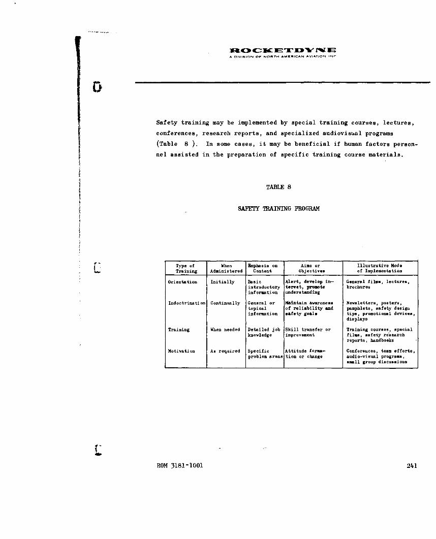
I1C0 ETF sc " IA DIVI-ION Or NORTH AMERICAN AVIATION INC
Safety training may be implemented by special training courses, lectures,
conferences, research reports, and specialized audiovisual programs
(Table 8 ). In some cases, it may be beneficial if human factors person-
nel assisted in the preparation of specific training course materials.
TABLE 8
SAFETY TRAINING PROGRAM
Type of When Eaphasis on Aims or Illustrative ModeTraining Administered Content Objectives of Implementation
Orientation Initially Basic Alert, develop in- General films, lectures,introductory terest, promote brochuresinformation understanding
Indoctrination Continually General or Maintain awareness Newsletters, posters,topical of reliability and pamphlets, safety designinformation safety goals tips, promotional devices,
displays
Training When needed Detailed job Skill transfer or Training courses, specialknowledge improvement films, safety research
reports, handbooks
Motivation As required Specific Attitude forma- Conferences, team efforts,problem areas tion or change audio-visual programs,
small group discussions
ROM 3181-1001 241

A DIVISION or NORT" AMcmICAN AVIATION INC
IPART 4. HUMAN ENGINERING SUMVEILIANCE
GENERAL OBJECTIVES
The design of all man-machine interfaces should be in accordance with gen-
erally accepted human engineering design principles and practices. These
design criteria provide for maximum simplicity and ease of handling, serv-
icing, and operation. A careful assessment should also be made, during
design and development, to determine the relative biomedical health hazards
and possible equipment dangers to operating, handling, and wnintenance per-
sonnel. Potential personnel hazards should be reduced or eliminated through
the use of design features which minimize the possibility of accidental
injury. An attempt should be made to ensure that the design prevents, or
is maximally resistant,to the sources of human error anticipated in the
operational environment. An attempt should be made -io minimize and simplify
the maintenance, storage, and handling procedures. Careful attention
should be paid to the procedures for the diagnosing, confirmation, and
correction of malfunctions.
Consideration should be given to those interface areas of design (both con-
traction items and those of other contractors) which have implications in
regard to personnel skill, training requirements, job aids and manuals,
and test and evaluation procedures. The primary objective would be to
provide specialized human engineering technical information, analyses,
and consultation services to various design and development groups and de-
sign review boards, as well as review or study requirements of the customer
or user.
ROM 3181-1001 243

A DIVISION OF NORTH AMERICAN AVIATION INC
IMPWLNE TION
A relatively formal design review activity should routinely consider the
human engineering aspects of equipment design during its Preliminary,
Critical, and Production Release reviews. A specialized human factors re-
view procedure should also be available throughout the development of pre-
liminary design specifications, establishment of detail design, construction
of mockups and prototype equipment, and the field testing of operational
equipment. Formal checklists containing human factors safety criteria should
form part of the prereview design review procedure. (See the Data Evaluation
section for further information on safety checklists.) The design review
function is extremely important in order to preclude inadvertent omission
of relevant human factors considerations early in the design process.
Specialized detail technical information and analytic studies relative to
human factors engineering should be provided, on a timely basis, to various
engineering design and support groups during the development of the system.
bnphasis should be placed on the system integration (relative to human factors)
of the engine system and its associated equipment in assembly, test facil-
ities, and in the vehicle. The implications relative to training requirements
and training equipment (manuals of operating and maintenance instruction
manuals) and the evaluation of on-the-job skill or proficiency factors should
be carefully considered. In addition to the design review function, it is
necessary to participate in various three-dimension real-life hardware tests
and evaluations. Finally,a series of human engineering evaluations should
be conducted to verify the adequacy of human task performance, safety, and
human reaction to the system, relative to the operational system in the
operational configuration and working environment.
244, ROM 3181-1001

tuOc KET D w FEA OIVIhION OF NORTH AMERICAN AVIATION INC
CRITEglA
Human factors engineering may involve research, analyses, tradeoffs, and
assessments (performed by qualified human factors engineers, perceived
in terms of the intellectual and physical capabilities of the intended
user, and with appropriate consideration of the personnel-logistic-physical-
social environment actually experienced during use of similar equipment).
These assessments involve consideration of the following factors:
1. Displays, controls, and display-control relationships
2. Panel and work space layout
3. Physiological requirements; including health hazards and personnel
comfort (where it may significantly affect efficiency or effective-
ness of required human performance)
4. Safety during operation, maintenance, transport, or other work
tasks
5. Ease of operation and simplification of maintenance tasks
6. Environmental factors; such as temperature, humidity, dust, fumes,
noise, vibration, blast, lighting, etc.
7. Communications required during various job operations
8. Procedures; including technical data support documents
9. Human dimensional and dynamic characteristics
10. Visual and auditory factors as they affect human performance
11. Training and training equipment, work skills, evaluation and
maintenance of job proficiency
ROM 3181-1001 245

A DIVISION OF NORTH AMERICAN AVIATION INC
ALLOCATION OF HUMAN EMINE]IING EFFORT
It is vitally important to properly phase, time, and allocate the required
human engineering effort in accordance with the expected system development
stages and typical design process. Without appropriate advance planning,
opportunities to perform human engineering evaluations will not become im-
mediately obvious. Such evaluations are most economically performed in
conjunction with other tests, review procedures, or evaluations (and these
easily overlooked opportunities rarely recur). Table 9 serves as an aid
or guide in planning the timely, systematic, and rigorous incorporation of
human engineering effort in a program plan or plan of action. Obviously,
the extent of such an effort would vary from a sampling in areas of maximum
likelihood of beneficial results, to an exhaustive reliability assurance
effort. The extent of effort would be affected by budgetary restrictions,
the unique needs of a particular program, available talent, the existence
of various facilitating or limiting factors in the developmental process,
the qualifications of applicable governing specifications and requirements,
and the constraints of the existing state of the art.
246 ROM 3181-1001

A DIVISION OF NORTH AMERICAN AVIATION INC
TABLE 9
HUMAN ENGINEERING MILESTONES
ReliabilityStage Milestone* Human Engineering Function Human Reliability Estimate+*
1 Detailed design System analysis Predictedstudy
2 Preprototype Static mockup, model, drawing, Interpolatedand simulation studies
3 Prototype Dynamic simulation and pro- Empirically derivedcedures development
4 Production Verification and validation Refineddemonstration
5 Demonstration of Category I, personnel subsystem Demonstrated"service readiness test and evaluation
6 Service Category II and III, personnel Achievedevaluation subsystem test and evaluation
7 Full-scale Monitor process, product, and Surveillanceproduction system application and use
8 Demonstration of Modification and special system Validation ormajor product test and evaluation revalidationimprovement
*These general reliability milestones are specified in Air Force Regulation 375-5,Reli.abiliy Proiramfor_ Weapon. Support. and Command and Control Systems.,17 October 1960"**Quan iitative Q.r qua.iquantitative human performance mathematical model, operation,
or maintenance zradeoff, task time, or personnel subsystem data estimation
ROM 3181-1001 247

X&4[3 4-uc-- Zw JEI "rMIEA 01ViMION OF NMORT AýMRICAN AVIATION INC
PART 5. PERSONNEL SUBSYSTEM ANALYSIS
GENERAL OBJECTIVES
The Personnel Subsystem (PSS) is a systems analysis and data development
program to ensure the adequate consideration of all factors affecting
personnel performance. One basic objective is to provide for the de-
tailed information which is required to ensure delivery of qualified
personnel and valid support documents concurrently with delivery of
hardware to the using agency. It provides for the derivation of personnel-
equipment or task analysis data to be used for:
1. Development of technical manuals and checklists
S-- 2. Identification of training and training equipment requirements
3. Maintenance support information
4. Human engineering evaluation of task performance and equipment
design
5. Requirements of a system test and evaluation program
(The methods used to derive such data were described in Part 2, Systems
Analysis (page 225).)
DIFFICULTIES AND CONTEXT
In the past, the primary emphasis in Personnel Subsystem activities has
been on basic data development below the level of the systems analysis
function. Such development would include:
1. Systems Functional Flow Diagrams
ROM 3181-1001 249

A DIVISION OF NORTH AMWRICAN AVIATION INC
4)
2. Quantitative and Qualitative Personnel Requirements Information
(QQPRI)
3. Task Index with time line
4. Position-Equipment Task Summary (PETS)
5. Training requirements
6. Training equipment justification
7. Technical Manual requirements
8. Basic field requirements for collection and validation of PSS
data
Therefore, the identification of safety hazards and the description of
personnel protective materials and procedures was in terms of what would
be required during training or customer use of the system under study.
The actual effect upon project-oriented engineering design and develop-
ment activities has not been as great as it could have been if
(i) system analysis had been initiated earlier in the development cycle,
(2) PSS analysis activity had been performed in closer association with
the design and development groups, or (3) PSS activity had better de-
fined and more effective points of contact, such as a project-oriented
safety function through which to effect desirable (safety) changes in
design or procedure.
Probably the major difficulty in the implementation of a maximally effec-
tive personnel subsystem program is the very breadth and complexity of
the process involved--plus the interaction and interdependency with other
organizational functions. This is perhaps best illustrated by the matrix
of activities shown in Fig. 7 . This figure represents somewhat of a
250 ROM 3181-1001

0 -
Notes:
1. Not all interactions are shown. Substantial cross fertiliza-
tion between human subsystem elements is implied (e.g., mainte- TA
nance and task information should heavily influence the formal
equipment layout and design review process).
( 2. Time sequencing shown may vary to accord with the exact nature
of the development project and various organizational responsi-
bilities (e.g., Preliminary Operating and Servicing Instructions
may be derived directly from Process Specifications or TAWS,
maintenance data may be combined with task analysis or FED, and "•
TOTM elements may involve many discrete steps).
3. Each block may be expanded into a separate flow chart to show
what should or did occur, its preliminary or followon phases, and
its supplemental input-output or interaction relationships.
4. In the interests of simplicity, certain vital human subsystem
functions are not shown (e.g., test and evaluation, human
engineering, and systems management) because of their general
and repeated application at various stages of the development
cycle.
ROM 3181-1001

NI 4c0 o It.,l WIC NC,,- Hw AMUIDCfN AVA,
PROCEDURES
PERSONNEL DATA
MAINTENANCE REQUIREMENTS
7j~j TRAINING INFORMATION
TRAINING EQUIPMENT SPECIFICATIONS
Cycle (t))Ciciilsiii LlA Iii i * .II(!
t Ti mvR-Sequ('ii v((EI .1 IKIUI 1$i ti ifthe
Performane I f'lfffll'll I.

MN 4t4C4 -r ETW W E* f~lV.,oN¢ 0F N4OYH AMED4lCA• AVl~,t* 4r,
compromise position between the various desired, ideal, and theoretical
posit ions held by specialists in this field and the constraints, re-
al ities, and forcing functions found to affect such a program. The
rapidly developing state of the art and current material in the field
is reflected in the expanding content of Handbook of Instructions for
Aerospace Subsystems Designers (AFSCM 80-3; see also Appendix F, Related
References).
IMPLICATIONS FOR FUITIER`1 ItESF1 RC1
Osly a few of the missile and space system development programs have had
a requirement. for a formally organized Personnel Subsystem Program. In
some cases, similar functions may have been performed by various discrete
organizational elements under a variety of descriptive headings. In other
cases, little may have been accomplished in terms of what some specialists
in this area may feel is appropriate or necessary. This may be indicative
of the wide differences of opinion that exist relative to the following
questtions regal di'i the general applicability, the time and place of
accomplishment, the methods employed, and the costs involved in a personnel
subsystem programn:
1. G;eneral applicability. Most system engineers seem to agree that
PSS is a necessity for the more complex systems. However, is
such an involved effort really necessary for smaller programs or
systems which will not. involve a great dieal of operation and
maintenance activity?
ROY" 3181-1001 253

A OIVISION OF NORTH AMERICAN AVIATION INC
2. Time and place of accomplishment. Is such an effort best
accomplished by the participation of all subcontractors
working on the development of a system, by just a few
selected associate contractors, or by the selection of
one prime, integrating, or separate systems contractors
for just this purpose? Is it predominantly a product
support, technical data, or systems engineering function?
At what stage of system design could PSS analysis most
effectively and economically take place? Should this be
based upon the extent to which PSS problems might affect
equipment design or the need for constantly updated pro-
duct support information?
3. Methods employed. Does the method of implementation (of
the PSS basic data program) actually facilitate the designer's
task, or does it tend to impose additional burdens by re-
quiring him to supply or continuously review various types
of information? Do the resultant documents and data find
ready acceptance and serve to facilitate the accomplishment
of all of the various functions which could profitably use
such information? (These questions indicate the need for
much more direct research on the integration of PSS activi-
ties within the system development cycle to obtain greater
acceptance and more profitable use of derivative information.)
254 ROM 3181-1001

A DIVISION Of NORTN AMgNiCAN AVIATION INC
4. Costs involved. Where funds are very limited (as they
usually are),is there a more economical, efficient, and
timely means for basically accomplishing the same goals?
Is this the best means of utilizing available talent for
the purposes intended? Could surges of manpower be
avoided in producing initial and periodically updated
documents? Would simplified forms and more discrete or
narrower goals violate the multipurpose utility of a
central personnel-equipment data bank?
While such questions may be thought provoking,* it must be remembered
that the very concept of a personnel subsystem program would not have
been formulated or found acceptance had there not been a recognized
need or some known better means to fill that need. These questions
"should not be interpreted as a challenge to PSS concerning its basic
right to exist. They serve only to indicate that the requirements for
personnel subsystem programs should be flexible and modifiable in terms
of the unique requirements of various system development programs. Also,
they should have provisions for the incorporation of continued advances
in the state of the art of this type of endeavor. It also indicates
that further research on hypotheses derived from these questions should
result in personnel subsystem procedures which would be of even more
benefit in the system development and operational employment cycle.
*See Majesty, M.S.: Research Proposals for Personnel Subsystem State-of-
the-Art Advancement in Ballistic and Space System Development, DCAS-
TDR-62-80, Ballistic Systems Division, Air Force Systems Command,
Inglewood, California, 22 March 1961.
ROM 3181-1001 255

A 1-1VIIION OF NORTH AMERICAN AVIATION INr
PSS SAFETY DATA
It is obvious from Fig. 7 that system safety is an integral and vital
part of the personnel subsystem. The PSS activity will produce data
related to the following system safety objectives:
1. General missile system safety requirements
2. Identification of potential safety problems
3. Determination of support equipment relative to safety consider-
ations
4. Delineation of task performance in hazardous job operations
5. Support documentation describing safety cautions or practices
6. Outlining of training requirements relative to safety, etc.
(See Part 2, Systems Analysis, for the methods employed.)
Therefore, wherever a personnel subsystem effort is part of a system de-
velopment program, this effort should in some degree be oriented toward
furnishing detailed information and data in support of the system safety
objectives.
256 ROM 3181-1001

A DIVISION OF NORTH AMCRICAN AVIATION ING
PART 6. SYSTEM TEST
Despite careful design and component development tests, it has become
increasingly obvious in the development of complex systems that inde-
pendent or collaborative operational systems tests and evaluation pro-
cedures are a vital requirement to ensure the attainment of maximum
safety, effectiveness, and operational capability. Special systematic
operability tests should be conducted to ensure and verify the suit-
ability of human factors provisions, the engine/GSE/personnel compati-
bility, and the correctness, clarity, and adequacy of procedural
instructions. Equally important is the necessity for system re-
evaluation tests to ensure the suitability of modification kits, pro-
cedural changes, and changes of parts, materials, or source of supply.
The basic objective of this task should be, therefore, the evaluation
of the operational safety and reliability of the propulsion system
under operational conditions.
CONTRACTOR SYSTEMS TESTS
Operability verification tests could be conducted by a specially trained
test team to verify the ease of operation, servicing, handling, main-
tenance, and safety of the contractor's equipment. For example, special
test teams may be composed of representatives from each of the following:
engine development, GSE-AGE, maintenance engineering, product manual,
and reliability human engineering. Operability tests should be conducted
periodically on various equipment items or subsystems during all phases
of use from factory to test station and, as possible, during assembly,
static firing, and launch operations. Careful attention should be given
to verifying and updating the technical data or procedures used in
ROM 3181-1001 257

A DIVISION OF NORTH AMERICAN AVIATION INC
2 z-
u' .4 w .0
40 om 2 ago. wýlflw i .
If w on hioo 0 0£-4L~
w
ro , 0U) te U2
Z. W
z z a
uzow I-
h I->.
ai w' 0)U
z 0~h 0 0
a' zzhiS -.0g
>1 i16ý iL ,00 Z2
hi 2 h
hi~~ oigz P4l
hi- z~ 4ih- U
W £4
Z hi
zo-2
258 ROM 3181-1001

A DIVIUION OW NORTM AMKRICAN AVIATION INC
support of the system. The test team should be responsible for early
test planning, the preparation of test directives, the gathering of
data during tests, subsequent analysis, report preparation, and the re-
quirement for posttest corrective action efforts to actually secure the
indicated improvements in equipment design or procedures. The basic
organization and data flow of the Atlas OSTF Van Nuys test program is
shown in Fig. 8 , which illustrates one organizational approach to a
maintenance demonstration program.
OPERATIONAL SYSTEMS TESTS
The collection and evaluation of human performance data during the opera-
tional usage of complex systems (such as the gathering of deviation/
difficulty reports) is important in relation to six potential areas of
application:
1. Identification of specific problems in order to secure immediate
corrective action to upgrade the effectiveness of the system
2. Definition of general problem areas in order to ensure that
preventative action can be taken on related future systems
3. Assignment of data (such as difficulty or failure reports) in
some sort of implied or purposeful, haphazard, or systematic
manner in order to achieve some form or type of grading process,
or effectiveness rating, or merit judgment concerning various
items of equipment or subsystems
4. Evaluation of data relative to various systems development
phases, attainment of technical objectives, the adequacy of
support services, or methods used in meeting customer
requirements
ROM 3181-1001 259

iM C ET -W "W ISA nlIVIION OF NORT04 AMERICAN AVIATION INC
5. Utilization of empirical data to verify and/or correct the
logical assumptions of some prior systems analysis
6. Incorporation of representative human performance data in
relatively formal or scientific mathematical models of the
operational situation in order to achieve better management
control, permit more effective management decisions, or attain
a definable comparative evaluation of men, machines, material,
and monetary expenditures relative to the over-all systems.
The method by which personnel subsystem and human factors data are used
to identify and correct operational problems is readily apparent in
various sections of this report. However, it has been more difficult
to apply such data in rigorous systems analysis and mathematical model
formulations. In fact, one of the more critical methodological problems
in man-machine research is the need to develop much more realistic, use-
ful, and appropriate mathematical models for human performance research
(Chapanis, et al).
The basic data flow for the Atlas OSTF-l and OSTF-2 VAFB programs is
shown in Fig. 9 . It should be noted that a separate safety board was
located close (geographically and in terms of data flow) to the source
of the basic test data. Copies of all home plant reports contained a
separate evaluation of test data relative to system safety, and were
sent to the AF BSD safety personnel at Norton AFB for possible applica-
tion to other Atlas sites.
260 ROM 3181-1001

0
DATA AM B.UI
COLLECTION
OKVIMrION DWFOiKtTy/Ifl Os.F. NTE~tV
It DEVIATION DFCTTY
REPORTS
FROCMTOYNEFIEL m.o DENINEERNGANALYSIS OFI
DEVIATION IfnCILTuyAND PRO.EM
ANALYSIS REPORTS
FIELDEVALUATION PESOULUS S
2.E..
REVIEW BOARD
REVIEWW BOW
-2--k 2,
SAFETY
ROM 3181-1001

NTENANCEA BUILDING HOME PLANT EVALUATION
~ OSTF-ILAUNCH SITE
OBSERVER INTERVIEWERSENIERGI DESIGN AND I
DEVELOPMENT UHITSENGINE SYSTEMS,
IAGE-GSE,ETC.AIG SYSTEM RELIABILITY
ETC. ~EVA"JATION__ ATLAS RELIABILITY
\7ICOORDINATORI596181CANOGA
QUICK RESPONSE CORRECTIVE ACTION INFORMATIONLOG AND FILE PANNIING AND REPORTS AND TRANSMITTAL .
SERVICE ENGINEERING RELIABILITY ATLAPRGAOFIE-
963-703 CANOGA HUMAAN ENGINEERING 578-101 CANOGA
SAC
SUPOR UNTSGENERAL PRODUCTSUPPRT UITSIMPROVEMENTTECH4NICALPUBLICATIONS, VARIOUS ROCICETOYNETRAINING INFORMATION, ENGINEERING GROUPS,
ATC MAINTENANCE ANALYSIS, DESIGN REVIEWPSS DOCUMENTS, COMMITTEE,ETC. ETC.
.. 2 2.2*PERIODIC REPORTS PREPARED BY RELIABILITY- HUMAN ENGINEERING WERE COORDINATED W:TH
ýý7 VAFB OBSERVER /ANALYSTS AND OTHER EVALUATION PERSONNEL
4NICAL DATA ALfIEW BOARD \AL
-1. 1.PERVARII
;N MAINTAINABILITYREVIEW BOARD

A DIVISION OF NORTH AMERICAN AVIATION. INC.
APUAIi
HOME PLANT EVALUATION APIAIN
(SEE CATEGORY UTEST EVALUJATION4 DIAGAM!
U4804AM NO SAC,ATC, ALC, 1G , ETC.
DEVELOPMENT LIMTS
aweIN SYSTEMS,AM-GOE,FACIITIES
ETSYSTEM PELIABLiTY ~~EVASLUATIO\ Y ATLAS RELIABILITYCOORINATOR
594-181 CANOGA
hu--~.-- USAF BALLISTICQUCICK RESPONSE C ORRECTIVE ACTION I NFORMATION SYSTEMS DIVISIONLOS AND FILE PLNIGAND RE AN RASITA
SERVICE ENGINEERING RELIABILITY r ATLAS PROGRAM OFFICE363-?03 CAW"G HUIMAN ENGINEERING I 5?IOI CANOGAI
PLANNINGSUPPORT UNITS GENERAL. PRODUCT ft
IMPROVEMENT 6-"ý
TRAINING WINOIMATION, ENGINEERING GRAOU"PS,MAINTENAMa ANALYSIS DES"G REVIEWQ QQPSS DOCUMiENTS, COMM TTEE,ETC. ETC.
I / i ~TECHNICAL *____________________________________REVIEW MEETINGS
DIC REPORTS PREPARED SY RELIASILITY-HUMAN ENGINEERING WERE COORDINATED WITH RPENTATIVES PROMOBSERVER /ANALYSTS AND OTHER EVALUATION PERSONNEL STL 350, ARMAA R/NAA,&WA, ACOSIAM
ITT-KELLOGG, oE/MSVb, ETC
RRIPERIODIC ASSOCIATE CONTRACTOR OSTF PL.ANNING MEETINGS WERE HELD BY A GROUPVARIOUSLY CAL.LED THE HUMAN FACTORS INTEGRATING COMMITTEE, THE PSS INTEGRATIONCOMMITTEE, THE PSS SUBCOMMITTEE, AND THE PSS TEST SUBCOMMITTEE
Figure 9. Parsl'nne I Subsys tern-Human Fac torsO)Ata Flo~w Char-t. (VAFB OSTF)
201

A DIVISION OF NORTH AMERICAN AVIATION INC
ESTIMATING PROGRESS IN THE TEST PROGRAM
During the course of the OSTF-1 test program at VAFB, it became obvious
that it was extremely difficult to accurately determine the progress or
completion status of the test program. At a given point of time, was
the program 30 percent finished or 60 percent finished? What criteria
of completion could or should be used? How could it be determined what
had to be done in order to complete the necessary testing?
Periodic status completion information is important for those who make
general management decisions regarding the test program (i.e., to de-
termine how much longer the test program will or should run). Detailed
status information is needed (1) to accurately forecast the actual costs
of the program, (2) to properly schedule personnel assignments during
"and upon completion of the program, and (3) to help establish cutoff
dates for program milestones and periodic data evaluations for change
packages.
Detailed status completion information is, similarly, important to those
involved in subsystem or associate contractor test planning. The fol-
lowing example will illustrate a typical situation where this information
could be used. On a given day, tests may be scheduled at two different
locations and only one test team is available for coverage (because of
previous night shift operations, personnel sickness or leave, or priority
tasks on other programs. By referring to a status completion record,
it could be seen that both tests contained tasks which had been previously
run. However, the tests involving one set of tasks were considered in-
valid and excluded from application toward demonstrating operational per-
formance of the tasks. These tasks also required several repetitions to
ROM 3181-1001 263

A OIVISION OF NORTN AMERICAN AVIATION INC
meet the test objectives. Therefore, these tasks required further test
observation. On the other hand, the other set of tasks had been validly
observed and no further testing was required relative to the subsystem
test objectives (however, several further tests were scheduled because
of the total system and special test requirements). Therefore, a de-
cision could be quickly made as to the most profitable test to observe.
Planned Events
An index of the midstream progress of a test program could be derived
simply by comparing the scheduled test events of the program plan with
the tests already completed (i.e., if 75 of the 100 planned tests have
been completed as of a certain date, this could indicate 75 percent
completion). However, too literal an interpretation of this estimate
would assume that each test takes an equal amount of time to accomplish,
is equally difficult, and is of equal importance or criticality. This
linear or equal increment relationship is rarely found in operational
test programs. In addition, it assumes that the number of tests are
constant when, generally speaking, the number of required tests seems
inevitably to be constantly changing. In a Maintenance-in-Readiness
Test Series, for example, there might be five tests scheduled of a 5-day
hold operation. During the course of the test program, this might be
reduced to four tests (then three tests, then two tests) as time or
money runs out, difficulties are encountered, or other priority tasks
accumulate. A test program could, conceivably, show rapid progress
towards successful completion (using a Planned Event Index) merely by
264 ROM 3181-1001
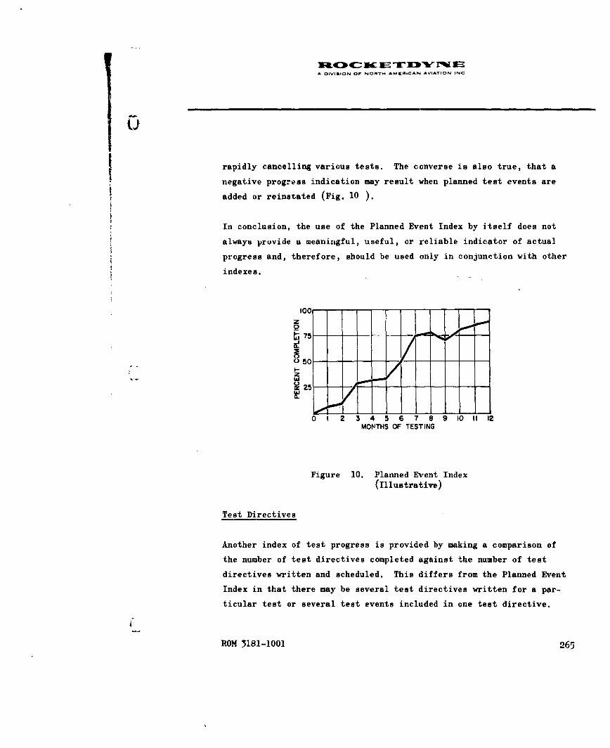
A DIVIGION OF NORTM AMEIACAN AVIATION INC
rapidly cancelling various tests. The converse is also true, that a
negative progress indication may result when planned test events are
added or reinstated (Fig. 10 ).
In conclusion, the use of the Planned Event Index by itself does not
always provide a meaningful, useful, or reliable indicator of actual
progress and, therefore, should be used only in conjunction with other
indexes.
100z
2 5
0 1 2 3 4 5 6 7 8 9 10 11 12
MONTHS OF TESTING
Figure 10. Planned Event Index(Illustrative)
Test Directives
Another index of test progress is provided by making a comparison of
the number of test directives completed against the number of test
directives written and scheduled. This differs from the Planned Event
Index in that there may be several test directives written for a par-
ticular test or several test events included in one test directive.
ROM 3181-1001 265
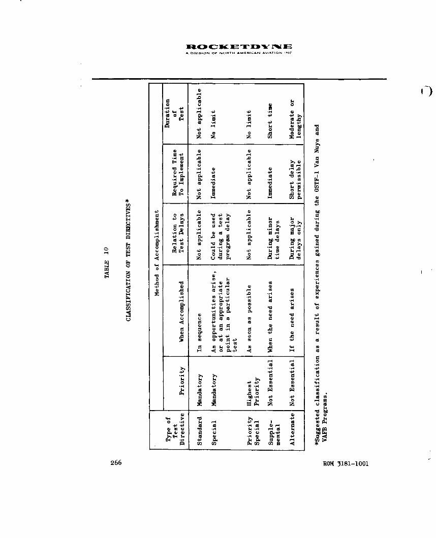
A OIVISON OF NOIRTH AMERICAN AVIATION INC
14
$4 E4 4 al-d .,j 4 +
004 1.4 4) 4)10.
14)
4) 4)*+)-4
V C.D 4)- -'4) 1- - .4 4) 0)
(9~ -4 E-44
CL) UC3 1.4 00
E-4 -1 bf CP w0od c m4 0 1-4 0o 0 0
9L4)
4) a) -
.0 4)0 $4:3 P0 00 A 0)i
Z u v P4 $4 +) v
0)1.
4 4$0 04 k4oo V~ 0C.) 4) 0P-~ ) VCL
U U 000 0) 0ad
.~i1 0 ) 0 so.
-40)-4)
030co4
0 a 0
ca a.ca 0) r4 0) -44).4 0)4
4) 4)0.-rn'4 r ~ 4
06 ROM 3181-10010

A OIVISION OF NORTH AMCRICAN AVIATION INC
The number of teet directives might vary without the contractual, co-
ordination, or over-all planning implications inherent in a change in
the number of tests to be conducted. The Test Directive Index might
have to be derived from a review of each type of test directive pre-
pared (Table 10), although it could be limited to a composite of the
mandatory (Standard and Special) test directives. This type of index,
again, implies a linear or equal increment assignment of values which
is not inherent in such a test program. In addition, Special tests un-
doubtedly will be added during the course of the test program and Supple-
mental tests may be added if test delays require such additional tests
to maintain the proficiency and inertia of the test team.
Status Completion Estimated by Checklist
In view of the foregoing difficulties, the following status completion
method was formulated based upon completion of detailed test objectives
by checklist section.
A 100 percent coLpletion rating was assigned to a specific checklist
section for a specific test objective (Table 10 ) when it had been
verified by testing that the equipment design, technical data, job en-
vironment, personnel selection and manning, training, organizational
controls, or safety (whichever objective is being evaluated) adequately
supports human performance so that the operational AF personnel can
effectively operate, maintain, or control the weapon system (in terms
of what was required in the checklist section).
ROM 3181-1001 267

A DIVIGION OF NONTH AMERICAN AVIATION, INC
A zero percent completion rating was assigned when the testing did not
verify the adequacy of this support. Some of the test conditions which
would result in a zero percent completion status for one or more objectives
are:
1. The test was not performed (all objectives).
2. PSS observers did not observe the test performance (all
objectives).
3. Major deviations from operational procedures were employed
(technical data and, sometimes, others).
4. No attempt was made to use operational equipment (equipment de-
sign and, sometimes, others).
5. Operational crew complement and composition was not observed
(personnel selection and manning, training, and, sometimes,others).
6. Operational controls were not used, or were severely adulterated
with contractor organizational controls (organizational controls,
and, sometimes, others).
7. Major deviations from safety standards were consistently employed
(safety, and sometimes others).
A 50 or 75 percent completion rating was assigned when the adequacy of
this support had been only partly verified (i.e., major problems have
been identified, showing that the support is not adequate in some par-
ticular respect and that these problems have been reported by deviation/
difficulty or incident reports).
268 ROM 3181-1001

. OIVIGION OW NORTH AMCRICAN AVIATION INC
A 50 percent rating is given when either of these conditions exists:
1. No corrective action has been determined.
NOTE: If the recommended corrective actionis rejected and no suitable alternate isinitiated, for all practical purposes no cor-rective action has been determined becausethe inadequacy still exists.
2. There are indications of other major problems which have
not yet been adequately identified.
A 75 percent rating is given when either of these conditions exists:
1.. Corrective action for major problems has been determined pre-
viously and accepted, but it has noL been demonstrated by test-
ing that the corrective action does correct or control the
problem without creating additional major problems.
NOTE: This is not the same as correctiveaction across the weapon system, which isnot a Category II requirement.
2. Corrective action has been tested, but the extent of the con-
trol or elimination of the problem is marginal; further test-
ing is required for assurance that the support of human
performance is adequate under all conditions which may be en-
countered during operational use.
ROM 3181-1001 269

A 0IVISION OF NORTH AMERICAN AVIATION INC
This detailed method is termed the Qualitative Checklist Method because
of the emphasis on fidelity of test conditions and effectiveness of
corrective action proposed.
For purposes of comparison, another approach (Quantitative Checklist
Method) to the estimation of status completion would be simply the
assignment of a 100 percent completion rating when the following con-
ditions are met:
1. The test was observed.
2. Major problems were reported.
3. Corrective action was recommended.
For this same level of accomplishment, the Qualitative Checklist approach
would be to assign a rating of from zero to 100 percent complete (depend-
ing upon how well the objective conditions of the test directive were
achieved and how successful were the efforts to obtain corrective action).
In general, the Qualitative Checklist completion ratings are consistently
lower than those made by the Quantitative Checklist approach.
The Qualitative Checklist DTO completion ratings will meaningfully indi-
cate where Category II will overlap into Category III, i.e., where the
using activity must apply additional effort to upgrade the weapon system
to full operational effectiveness. Any area which shows less than
100 percent completion at the end of such testing will require additional
Category II type of activity during Category III use (Fig. lland
Table 11 ).
270 ROM 3181-1001

(,I
CHECKLIST SECTIONS 0 I 2 3 4 5 6 78 9 10 11 12 11
A. EQUIPMENT DESIGN
NOT OBSERVED (RATED 0 PERCENT(36.4 PERCENT)
MAJOR PROBLEMS (RATED 5OPERCENT) 10 (25.6 PERCENT)N"
MODERATE PROBLEMS (RATED 75 PERCENT) 4 (10.3 %)
MINOR OR NO PROBLEMS (RATED 100 PERCENT) (25.6 ,'R',,T
B. TECHNICAL DATA
NOT OBSERVED (RATED 0 PERCENT) 1.. ***4 (59PRET
MAJOR PROBLEMS (RATED so PERCENT) 0 I5I'. (PERCEN
MODERATE PROBLEMS (RATED 75 PERCENT) 5 (12.8 PERCENT)>
MINOR OR NO PROBLEMS (RATED 100 PERCENT) 11 , 1,1,110 25.6
C. JOB ENVIRONMENT .. 2TTT~~.I6(1PERCE h
NOT OBSERVED (RATED 0 PERCENT) It N..'
MAJOR PROBLEMS ( RATED S0 PERCENT) 13(33.3"PERCE;. :
MODERATE PROBLEMS ( RATED 75 PERCENT) 15.4lECNT)
MINOR OR NO PROBLEMS (RATED 100 PERCENT) 4,(,0.3
0. PERSONNEL SELECTION AND MANNING
NOT OBSERVED (RATED 0 PERCENT) 23 E
MAJOR PROBLEMS ( RATED 50 PERCENT) I (2.6 PERCENT)
MODERATE PROBLEMS ( RATED 75 PERCENT) ,10"• (•2.9 6 PEPNT)I
MINOR OR NO PROBLEMS (RATED 100 PERCENT) ,• ',]E. TRAINING
NOT OBSERVED (RATED 0- PERCENT) . . . " .- 5 (64.1 PERI
MAJOR PROBLEMS ( RATED 50 PERCENT) 10 i(25•.• PERCEI
MODERATE PROBLEMS ( RATED 75 PERCENT) 1 (2.6 PERCENT)
MINOR OR NO PROBLEMS (RATED 100 PERCENT) 770
F. ORGANIZATIONAL CONTROL
NOT OBSERVED (RATED 0 PERCENT) N. . ... ..- :.
MAJOR PROBLEMS ( RATED 50 PERCENT) 3 o
MODERATE PROBLEMS ( RATED '75 PERCENT 0
MINOR OR NO PROBLEMS ( RATED 100 PERCENT) I (2,6 PERCENT)
G. SAFETY
NTOBSERVED (RATED 0 PERCENT).....................R.CENT) __
MAJOR PROBLEMS ( RATED 50 PERCENT) 13\(33.3\PERCENT)
MODERATE PROBLEMS ( RATED 75 PERCENT) 2(.%
MINOR OR NO PROBLEMS (RATED 100 PERCENT) 2.,P
ROM 3181-1001

A CiVIGION OF MORNY MAMNICAN AVIATION. INC.
4 5 6 7 S 9 10 11 12 13 14 15 16 17 1S 19 20 21 22 23 24 25 26 27 28 29 30 31 32 33 34 35
15.6 PERCET
5.
NT)cNT
56 (41PERCENT
53(659. PERCENT) 7.-7
NT)
PE6CPERCENT)
25(4NPRCN)T)_______
56 PERCENT ICE
.l(33.3 PERCENT)
'igutre 1]1. Aiualys is of DTC. "ompletion

TABLE 11
DTO STATUS COMLETION BY
MininmRuns Total Nuon Full or Equipment Technical
Required Total Rune Made to Partial Design, Data, a,Tasks Reference for R-588 Scheduled 30 .lly 1962 2xclusions Percent Percent
Nissile Flight Control Section 14 2 6 2 2 100 100System Checkout page 1-2 (33 percent)
lubricate Engine GimbelDoarinia
Nissile Frequency Response Section 15 2 6 2 2 100 100Check pages 15-2 and 15-3 (33 percunt)
Vernier Engine Solo System Section 21 2 6 4 4 75 50Leak Check page. 21-7 through 21-48 (67 percent)
Suatainer Engine System Section 22 2 6 75 75Le•k Cheek pages 22-1 through 22-51 (83 percent)
Booster Engine System Section 23 2 6 & 4 100 75Leak Test pages 23-3 through 23-38 (67 percent)
Miseile Ordnance Circuit Section 24 2 6 3 1 100 100Resistance Tests pages 24-11 through 24-23 (50 percent)
Sustainer Turboprop Section 25 2 6 1-3/A 3/4 75 75
Preservation pages 25-1 through 25-17 (so percent)
DTO Completion ior CL-7-3 average (36 percent) 73 68
esk at launch Area (05TY-1)Missile Installation T.0. 21-5S655-CL-12-2
26 January 1962
Remove Booster Actuator Section 10 2 1 4 4 50 50Locks, Sustainer Transport pages 10-1 thruugh 10-.4 (100 percent)
Strut; Install BlovoffCovers and Desiccants
DTO Completion for CL-12-2 1 100 percent) 1 _ 1 50 50
RON 3181-1001

A OIVISION OF NORTH AMERICAN AVIATION. INC
TABLE I1
DTO STATUS COMPLETION BY CHECKLIST
DTO Completion Status
PersonnelRuns Full or Equipment Technical Job Selection Organizational Are TheseSto Partial Design, Data, Environment, and Manning, Training, Control, Safety, Operations Required to Achieve Operations
1962 Exclusions Percent Percent Percent Percent Percent Percent Percent Category II PSS Test Objectives Scheduled?
2 100 100 75 100 100 0 100 Run twice using AF personnel, AF SOP, Norcent) and 90-degree fitting from AF supply (and
not a VAFB-peculiar fitting)
2 100 100 75 100 100 100 Same as above Norcent)
4 75 50 50 0 0 0 50 nun twice usi~ig AF personnel HT SOP, Yesrcent) .. .verified technical data, proper hand tools.
liht.in: , work platforms, and withi latest'PD and FID clanres incorporated.
75 75 50 0 50 0 50 Run usinr AF personnel, AF SOP, better Norcent) lighting, adequate hand tools. Compare
VP'FB-peculiar adapter with operationalconfiguration; use work platform, modifiedtest plate (G 3087)
L 100 75 50 0 0 0 50 Run twice using AF personnel, AF SOP, Yesrcent) thrust chtamber protective pad, safe work
platforms, and a complete G 3080 platesand plugs kit
100 100 50 100 100 100 100 Make available torque-set screwdriver tips Yesrcent)
./4 3,1, 75 75 100 100 0 50 100 Modify engine lube oil drain line, then No,rcent) run using AF personnel and AF SOP
!rcent) 73 68 55 50 45 25 65
4 50 50 50 75 50 0 50 Color code locks, strut; expand 10T's pro- Nopercent) pellant system training; revise access
routes and platforms; complete revision toP-4 technical data, then run twice usingnew MOCAM crew (one MET/M), AF SOP, adequatetools, lighting, and jack or hoist to lift
- - - - - - - thrust chamberpercent) 50 50 o0 75 o50 1 0
273

WiO40 (rý-' K E Tj D'" IV T"EA IN hI'IlN O)F N.)IRTH -AMLEHI( AN A.IATIL''Nfl'+
4+)
TEST EVENT: No. 1W-I Title - c /-,. "
PLANNING INFORMATION TIME AND PERSONNEL
Test Series Code: ;',- 3 A Date Started: o ,jor)'J, ,, L7
rT&S-/7 FFC 27-1362TAWS So o V Date Completed:/J' "t//" *,
Applicable Logical Function: CIL,,.... I'-"
site AnalystObserver-/."'., :-
Ohm CheckUstir0-2/-9fN,5,FCL --. 2A ~~ O sre~. 2Participants•./-.: ..... //3S1f"
Personnel Performance Checklistzý,LA " L-, Pa,./--/
Test Directive "SG6- OqC ( 6.:) /"',, '.3;//)
TEST DATA ACCRUED
Deviation/Difficulty Reports 6/1Z 3 - 7 2-,ý i 6' 35 77 7
Problem Analysis Reports RAK 37-- 7, -R, + e -r ,K,
Operation and Failure Reports R / ,9 :' ? 2-
Personnel Subsystem Change Requests Pl; C P IY -A 3 4Publication Change Requests 3C A3r//4'V•
ECP/MCR Action___ __ ___ __ __ _ __ __
RELEVANT REMARKS
Pending Action 4-t• .- c{ ,- ',." ' '" . +' 9.''
Significant Time Delays or Other Incidents Y. . , . ,".
U Exclusion, * Reasons Why iL',.dZ+ ., ,, ,. (,--. .-_ -. .... )
Other Remarks f/+ -77( ... ,. ' ,,"•.; "
*An exclusion is a test event which is not applicable 6 r is nonrepresentative of anoperational test event.
Figure 12 . Illustrative Test Event Log Sheet
274 ROM 3181-1001

S~A DIVISION or NORTM 4MIR'CAN AVI^TION, INC
Comparison of Status Completion Methods
1. Planned Event: Tests completed/tests scheduled in program plan
2. Test Directive: Test directives completed/test directives formu-
lated and scheduled
3. Quantitative Checklist: Checklists actually completed/checklists
scheduled
4. Qualitative Checklist: Checklists appropriately evaluated/
checklists scheduled
TEST DATA CONTROL
Immediately following each day's testing, a Test Event Log sheet should
be prepared for each completed identifiable test event. If this is not
done, a review of the available test records after several weeks of
elapsed time could be misleading (i.e., the test directions may not have
been followed, or followed only in part because of shortages, aborts, or
unusual circumstances). Therefore, it would be difficult to assess in
detail which test events were validly performed, which were omitted for
some reason, or which should be treated as exclusions when evaluated
against test objective criteria.
An Illustrative Test Event Log sheet is shown in Fig. 12. It is based
upon the experience gained during both the EMA and VAFB test programs
and it constitutes what is felt to be a vital test data control feature
in system test programs. Future test programs might require modified
versions of this log sheet. While the format may change, the content be
varied, the form integrated with other forms, the need for such a daily
record is basic to the conduct of any test program.
ROM 3181-1001 275

A DIVISION OF NORTN AMCEICAN AVIATiON. INC
In the control of test data, there are five other features which are of
vital importance to the accomplishment of a successful test program:
1. There should be no immediate screening or restrictions on the
recording of test data. Restrictions are implicit in such
remarks as:
a. "Don't report that kind of a problem."
b. "Everyone already knows about that."
c. "We'll handle that ourselves."
d, "That's no problem."
It should be clearly understood by all observers that all data
should be immediately recorded without restriction or limitation.
2. Some protection should be afforded to the data collector so that
he may record all data, however crude or incomplete, for subse-
quent analysis. A requirement for perfect, defensible, raw
data may reiult in significant data going unrecorded because
of some min,)r flaw, confusion, or uncertainty. Every problem
seen should be recorded and described as accurately and com-
pletely as possible, even though some organizations or indivi-
duals may not approve of the generaLion of such information.
3. Raw data should move rapidly through the primary data analysis
system. There should be no orifices, biases, or liability to
the data generator (observer) other than to report as Ecccurately
and completely as he can. The primary data analysis system in-
cludes home plant analysis by those who are part of the program
test team.
276 ROM 3181-1001

W 400OC-- ACEZT-J "%t' r IE
A r)IVI.iI)N OF N- TrH AMERICAN AVIATIOIN INC
4i. The basic assumptions, purposes, and guiding philosophy of the
over-all test plan must be clearly understood and maintained
throughout the test program (against the wide fluctuations
which can occur during an extended period of time in a large-
scale test program). Section 6, Part 2, Application to Human
Performance Evaluation, contains further information concern-
ing the fundamental nature of system test efforts.
5. The importance of appropriate and timely test directives was
previously described in Rocketdyne Report R-3520, OSTF Test
and Evaluation Program for the Atlas MA-3 Engine Maintenance
Area, May 1962 (Part 2, Program Management, 15-67). The im-
portance of adhering to the established test directive is
adequately described in several of the case studies (Section 2
of this report).
ROM 3181-1001 277

AOIVIGION OF NORTH AMCRICAN AVIATION, iNC
PART 7. SAFETY SURVEILLANCE TEAMS
One approach to the identification of potential safety problems could
involve the use of Safety Surveillance Teams. The objective would be
to provide an independent means through which program engineers, project
engineers, and other responsible supervision can operationally investi-
gate, find causes, and determine solutions to reliability problems of a
safety nature which appear to be acute, chronic, or interorganizational
in nature.
Occasionally, this may be necessary in order to complement the activities
or gain supporting information from (or for) inplant safety committeeman
organization or an operational-site failure reporting system. It may
also serve to provide a means for monitoring or maintaining surveillance
as to the effectiveness of a more extensive or scheduled safety report-
ing system. However, it is more often needed to intensively investigate,
to realistically identify, and to find solutions to problems affecting
equipment and processes which cannot be satisfactorily solved by other
methods.
The distinguishing feature of this approach is the effort to ef-fectively
identify and resolve problems on a grass root or local level. Many of
these safety problem areas involve, to some degree, the basic motivation
or fundamental attitude held by direct working personnel and first-line
supervision. This approach accurately determines, isolates, investigates,
and solves these safety problems in a more immediate, direct, and knowlege-
able fashion than might otherwise be the case. It is a general management
ROM 3181-1001 279

A DIVISION OF NORTH AMERICAN AVIATION INC
technique for handling a class of safety problems and provides direct
information on both specific or organization-unique problems and inter-
organization or interface problems. The scope could conceivably include
efforts in various organizations ordepartments, such as Engineering,
Manufacturing, Material Procurement, Quality Control, Test, Logistics,
Field Service, maintenance or checkout areas, launch sites, or missile
assembly points.
The implementation of such an approach might involve formation of
temporary Safety Surveillance Teams consisting of an experienced safety
or reliability engineer, a human factors engineer, a department leadman
or supervisor, and a direct working person. These teams could meet
periodically in various locations while a particular safety problem,
function, or area is being investigated, while corrective action is
being determined, or while the effectiveness of various changes in
procedure or design is being assessed.
280 ROM 3181-1001

,I A DIVISION OW NORTH AMERICAN A-IATION. INC
PART 8. DESIGN REVIEW
An audit team, functionally independent of the responsible design and
development groups, can provide an effective design review activity which
could consider safety as one of the major design criteria. The design
review committee may be composed of senior level engineers supported by
various technical specialties (including those which can contribute to a
detailed system safety engineering evaluation).
The design review may occur at several logical checkpoints. Examples
are:
1. Preliminary review of proposed design concepts
2. Critical review upon completion of formal layout to evaluate
design details
3. Final review prior to the release to production or tests
The design review committee may, for example, utilize design checklists,
static and dynamic analyses, malfunction studies, material and stress
studies, component evaluation test data, and information on the effects
of environmental extremes.
The formal design review process provides greater assurance of:
1. Use of the best possible design practices, standards, and
preferred parts
2. Employment of all applicable past experience, IDEP and failure
report information, and previous development test data
ROM 3181-1001 281

A OIVI6ION OF NORTH AMENICAN AVIATION INC
3. Focusing of all appropriate design services talent and
specialty disciplines on each drawing
4. Full consideration of system safety engineering recommendations
at crucial points in the design process
282 ROM 3181-1001

A OIVIDION OF NOfTH AMCNICAN AVIATION INC
PART 9. CATASTROPHIC ANALYSIS
A thorough analysis of all possible failure modes, causes, and effects
should be made to render failure less probable and less critical through
redesign, use of derating, redundancy, use of malfunction detection
systems, fail-safe design features, etc. Such catastrophic analysis in-
formation should be regularly used in the design review activity to
evaluate the acceptability of proposed designs. It should also be used
by design groups in determining tradeoffs between alternative design
paths. It also serves to determine and focus attention on design areas
where some modification could result in a significant gain in reliability.
Catastrophic analysis information is available from reliability malfunc-
tion analyses or failure effect analyses. Malfunction analysis is a de-
tail design drawing analysis of all probable failure modes, their causes,
and their consequences. Failure effect analysis is a detail drawing
analysis of all possible system failures and their consequences. In the
process of attempting to achieve a manrated design, special attention
has to be paid to personnel safety factors during malfunction or failure
effect-analyses.
The search for design weakness involves the listing of all possible modes
of failure and the stress conditions which might induce failure under the
anticipated operational environment. The system consequences of each
mode of failure are described. A quantitative prediction of the likeli-
hood of failure can be derived from applicable related experience on
similar elements, components, or subsystems. Such failure mode predic-
tions can serve, as a basis for formulating detail test objectives and
statistical test design planning efforts.
ROM 3181-1001 283

A OIVISION OF NORTH AMCRICAN AVIATION INC
Any significant critical failure which could cause a mission failure
should receive special safety design attention relative to counter-
acting all hazardous consequences. (See Section 3, Parts 1 and 2,
dealing with Safety Criticality Rating.)
2 )284 ROM 3181-1001

APPENDIXES
ROM 3181-1001 285

A DIVI&ION OF NCIfPTH AMERIC AN AVIATION IN(
APPENDIXES
APPENDIX A .................. ................... 287
Glossary ................ ................. 287
APPENDIX B .................. ................... 295
List of Abbreviations ........... ............. 295
APPENDIX C . . . .. . . . . .................... 303
Safety Problem Tabulation and Cross-Reference Index 303
APPENDIX D .................. ................... 305
Product Tabulation and Cross-Reference Index ..... 305
APPENDIX E .................. ................... 307
List of Related Home Office Reports ......... 307
APPENDIX F .................. ................... 311
Related References ........... .............. 311
APPENDIX G .................. ................... 317
Human Factors and Safety Problemu Cross Reference . ... 317
286 ROM 3181-1001

NII00OCý_Ic M ITDYk 1WE
A 0IVISION OW NORTH AMEAICAN AVIATION INC
APPENDIX A
GLOSSARY
The following terms are defined in accordance with their usage in this
report. Only those terms found to have some inherent ambiguity or very
specific meaning are defined. Emphasis is given to terminology which
is new or particularly germane to the report content.
Achieved reliability: the reliability demonstrated, at a particular
point in time, under certain specified conditions
Bachelor time: the accumulation of hours, minutes, and/or cycles
on an item of equipment before delivery to the
customer when it is not installed in its OCL
assembly
Calibration: comparison of an instrument or device with another,
which is of known accuracy, to detect or adjust
the accuracy of the instrument being compared
Cannibalization: removal of needed parts from a similar system or
assembly for installation on another system which
is being repaired or modified
Compatibility: that particular quality of characteristics of a
model which assures its ability to function effec-
tively with other models of the system
ROM 3181-1001 287

A DIVISION Or NORTM AMERICAN AVIATION ING
4)
Category II testing: development testing and evaluation of the complete
system, i.e., the integrated subsystems, to de-
termine if the theories, techniques, personnel
skills, material, and items of equipment are
technically sound, safe, reliable, and meet
established specifications and operational re-
quirements (It is a joint contractor-customer
effort, with gradually increasing customer
participation.)
Checkout: any sequence of operational and calibrational
tests which could provide information necessary
to determine the condition and status of an item
of equipment
Configuration: the composition or listing of the serially coded
noninterchangeable part numbers or names of a
model
Deviation difficulty: any incident which occurs outside the standard,
predicted, or expected template of human behavior
(such as excessive time to complete a task, an
indentifiable difficulty in performing an assigned
task, any pattern of behavior which could lead to
undesirable system performance characteristics, or
any act which leads to a human-initiated failure)
2288 ROM 3181-1001

14CDC a I-r "'rM =A DIVISION OF NORTH APMERCAN AVIATION INC
Down time: the sum of the active maintenance down time,
supply down time, waiting down time, and other
lost time during which the system is not in a
condition in which it can perform its intended
function.
Effectivity: date of effective change
End item: a final combination of products, component parts,
and/or materials which is ready for its intended
purpose (e.g., turbopump or rocket engine)
Failure analysis: a detailed study or analysis to determine the cause
-. or mechanism of failure
Fail-safe: self-checking features which will cause a function
to cease and return to hazard-free condition in
case of failure, malfunction, or out-of-tolerance
drift
Failure: inability or an item to perform its required func-
tion or any reportable physical, electrical,
mechanical, or electromechanical deviations from
the controlling specifications
Human error: (see definition in Section 5, Part 1, Operational
Definition)
3 -
ROM 3181-1001 289

1&4:3 41c Ic JE ip "'f rA OIVISION Or NORTH AhtRICAN AVIATION INC
Human-initiated failure: any malfunction, failure, damage, or delay which
is directly traceable to improper or faulLy acts
of commission or omission (including such things
as incorrect adjustments, activation of wrong
control incorrect wiring, and improper handling)
Inherent reliability: the potential reliability present in a design
(This would be the probability of equipment
operating properly under the contractually
stated operational conditions, utilizing, in
the manner intended, the required supporting
equipment, procedures, personnel, and controls.)
Inherent safety: the potential safety present in the design or
features of the design (See inherent reliability.)
Inspection: the process of comparing an item with the applicable
requirements by examining, measuring, testing, or
gaging
Interface: a point between subsystems where appropriate matching,
compatibility, or accommodation must be attained
to ensure proper operation relative to all other
functional entities in the system (to achieve the
purpose of the project or mission)
Item: an all-inclusive term which may refer to parts,
subassemblies, assemblies, accessories, or
equipments
290 ROM 3181-1001

A OIVIGION OF NORTH AMERICAN AVIATION INC
I k
Maintainability: the resultant of those factors of the equipment,
as installed, which facilitates accomplishment
of maintenance tasks with minimum time, skill,
and resources. (See definition in Section 1,
Part 3.)
Malfunction: any occurrence of unsatisfactory performance
Maintaining: a term including work tasks related to inspection,
servicing, repairing, and testing as to service-
ability where the objective is to retain or re-
store equipment serviceability (It may be
scheduled (preventive) or unscheduled (corrective)
in nature and may be assigned as an organizational,
field, or depot responsibility.)
MD number: a compound term consisting of letters and figures
which, when used with a Model Designation, indi-
cates the configuration of a model, and from which
its compatibility with other models in the same
system may be ascertained by reference to support-
ing documentation
O&M checklist: detailed checklists used to perform operations
and maintenance on the system at the operational
site (GD/A Report AP60-0967, Style Guide for
Preparation of Operational Checklists for WS 107A-1,
Atlas Series E, 1 December 1960, gives illustrative
details of preparation.)
ROM 3181-1001 291

A OIVIGION OF NORTH AMERICAN Avii.TroNr ,NC
Operational: the status of a system which permits its use by
field or customer personnel in its intended
environment
Operating: a term including tasks of activating, monitoring,
regulating, or changing the performance of an
item of equipment by means of controlling
devices
Organizational controls: (See definition in Section 1, Part 3.)
Production model: an equipment model in its final production form
and design which is made by production tools,
jigs, fixtures, methods, and processes
Periodic inspections: regularly scheduled repetitive inspections (based
on specific calendar periods or operating time)
to ensure that equipment is in readiness to
operate satisfactorily and to identify conditions
which could possibly degrade systems performance
Process: the procedure or technique followed in the produc-
tion of a product
Prototype: an equipment model which is suitable for use in
the preliminary evaluation, design, form ana
performance of the production equipment
292 ROM 3181-1001

Iu.OcI ETD -EA DIVISION OW NOftTH AMERICAN AVIATION INC
Preliminary design: the design phase during which the basic configura-
tion and performance of a system is established
Preventive maintenance: the periodic checking, inspecting, or recondition-
ing of a system to identify or reduce possible
deterioration of performance and to detect and
correct incipient malfunctions before they can
develop into failures
Quality control: an operation oriented toward assuring the manu-
facture of a uniform product, within specified
defect limits, in accordance with the design
intent as described in engineering drawings,
specifications, and requirements
Reliability: the probability that an item will perform a re-
quired function under specified conditions for
a specified period of time.
Safety: (See definition in Section 1, Part 3, Safety.)
Servicing: work tasks of lubricating, filling, bleeding,
purging, draining, preserving, cleaning, packaging,
and storing
Simulation: a set of test conditions designed to closely
approximate some phase of the field operating or
usage environment
ROM 3181-1001 293

A OIVISION OF NORTH AMERICAN AVIATION INC
System effectiveness: the probability that a system can successfully
meet an operational demand within a given time
when operated under specified conditions
Time-significant item: an item which is degraded as a result of usage
and/or calendar age
Time-compliance technical order: directives issued to provide instructions
for accomplishing one-time changes, modifications,
inspections, or installation of equipment
294 ROM 3181-1001'

A DIVISION OW NORTH AMERICAN AVIATION, INC
APPENDIX B
ABBREVIATIONS USED IN THIS REPORT
AFBSD Air Force Ballistic Systems Division (formerly AF Ballistic
Missiles Command)
AFLC Air Force Logistics Command (formerly Air Material Command)
AFQC Air Force Quality Control
AFSC Air Force Specialty Code or Air Force Systems Command
AGE Aerospace Ground Equipment (forwerly GSE)
ATC Air Training Command
APIN Atlas Propulsion Information Notice
BHAT/S Ballistic Missile Analyst Technician/Specialist (AFSC 312X4C
on Atlas E Series; 312X4D on Atlas F Series)
CCB Change Control Board
CL Checklist
CRL Change Recommendation Letter
ROM 3181-1001 295

A DIVISION Or NORT" AMENICAN AVIATION INC
D/D Deviation/Difficulty Report (VAFB OSTF Program)
DPL Dual Propellant Loading
D/R Difficulty Report
ECAG Equipment Change Analysis Group (Norton AFB)
ECP Engineering Change Proposal
EDRB Equipment Design Review Board
EMA Engine Maintenance Area
FCDR Failure and Consumption Data Report (Rocketdyne Form 609-P)
FFC Functional Flow Charts
GSE Ground Support Equipment (also called AGE)
GD/A General Dynamics Corporation, Astronautics Division
(formerly Convair)
GI Government Issue
GG Gas Generator
GN2 Gaseous Nitrogen
296 ROM 3181-1001

ADiVISION OF NORTH ^MKRIC:AN AVIATION. ONC
HS Head Suppression or Human Subsysteu
HFU Hydraulic Pumping Unit
IR Inspection Rejection Procedure
IOL Interoffice Letter (Rocketdyne)
ITI Integrated Task Index
LEf Large Engine Report (Rocketdyne)
LFS•4T/S Liquid Fuel Systems Maintenance Technician/Specialist
(546XOA, formerly 568XOB)
L02 Liquid Oxygen
IR Prefix to Engine Model Number Indicating "Liquid Propellant
Rocket Engine"
LP Launch Platform
MAPCHE Mobile Automatically-Programmed Checkout Equipment
MCR Master Change Record
MDL Master Deficiency Log (maintained by VAFB AFQC)
ROM 3181-1001 297

A DIVISION OP NORTH AMLEICAN AVIATION INC
MET/M Missile Engine Technician/Mechanic (443X1A, formerly 433Xl)
MET/S Missile Electrical Technician/Specialist (441XOA, formerly
MERT/R, 423Xo)
MFT/S Missile Facility Technician/Specialist (421X3)
MMT Missile Maintenance Technician (443XOA, formerly 433XO)
MPRT/R Missile Pneudraulic Repair Technician/Repairman (I42XOA,
formerly 421X2)
MAB Missile Assembly Buildup
MAMS Missile Assembly and Maintenance Shops
MRB Maintainability Review Board
NCU Nitrogen Charge Unit
OJT On-the-Job Training
OSTF Operational Systems Test Facility
ORT Operational Readiness Training
P/N Part Number
298 ROM 3181-1001

A DIV-I;.,-N OF NORTH AMERIICAN AVIATION INC
PAR Problem Analysis Report
PCS Publication Change Suggestion (Rocketdyne form)
PECP Preliminary Engineering Change Proposal
PETS Position-Equipment Task Summary
psig Pounds per Square Inch, gage pressure reading
PSS or PS Personnel SubsysLem (see, also, HS)
PSRB Personnel Subsystem Review Board of the OSTF Task Working
Group (formerly PSSRB)
PTD Program Test Director
PU Propellant Utilization
QD Quick Disconnect Fitting
RC Prefix to Rocketdyne correspondence control number
REM Reliability Engine Memorandum
RFB Reliability Function Block
R/NAA Rocketdyne, a Division of North American Aviation, Inc.
ROM Reliability Operations Memorandum (Rocketdyne)
ROM 3181-1001 299

IN.Oc K£T NA DIVIlON Of NONTH AMCRICAN AVIATION INC
R&R Remove and Replace
RERB Rocket Engine Relay Box
SAC Strategic Air Command,
SBAMA San Bernardino Air Material Area
SC Site Commander
SOP Standard Operating Procedure (for an Air Force squadron)
STL Space Technology Laboratories, Inc.
SMA Squadron Maintenance Area
SPGG Solid Propellant Gas Generator
SPO Systems Project Office
STOC Standard Tactical Operational Condition
TAWS Task Analysis Worksheets
TCTO Time Compliance Technical Order
TDRB Technical Data Review Board
300 ROM 3181-1001

i A I)IVI.-ItN OF NOt4It4 AMMIcnN AVATI,.,f+ tJ(
TMCR Technical Manual Change Request (GD/ A equivalent of
Rocketdyne PCS)
TO Technical Order
TWSG Test Wing Safety Group
VAFB Vandenberg Air Force Base
VE Vernier Engine
IPOM 3181-1001 301

A DiVIION OF NORTH AMEUICAN AVIATION INC
APPENDIX C
SAFETY PROBLEM TABULATION AND CROSS-REFERENCE INDEX
Type of Problem Human Factors Problem No.
Potential Engine Failure 98, 211, 216, 276, 290
Equipment Design
Maintainability 60, 235
Operability 19, 57, 71
Functional Deficiency 57, 86, 88, 129, 140, 148, 206, 236
Susceptibility to Damage, Deteriora-tion, or Cannibalization 206, 223, 276
Technical Data
Crutch for Equipment or Organization 98, 121, 235
- -Omissions 140, 199
Job Environment
Falling or Tripping Hazard 16, 85, 98, 129, 213, 216, 223, 235255, 262, 302
Electrical Shock Hazard 60, 71, 86, 206
Pressure or Explosion Hazard 86, 111, 155, 168, 274, 279, 291
Fumes 148, 154, 279
Other 88, 237, 243
Impaired Functioning of Safety Feature 248, 272, 274, 283, 285, 291
Fire Hazard 155, 279, 284, 285
Personnel Selection and Manning 230
Training
Job Knowledge 111, 155, 223, 227, 279
Job Skills 213, 223, 230, 288, 302
Work Habits 121, 168, 206, 231, 252
Attitudes 98, 154, 166, 216, 285
ROM 3181-1001 303

A DIVI.IUN OP NORTH AMERICAN AVIATION INC
APPENDIX C
(Continued)
Type of Problem Human Factors Problem No.
Organizational Control
Need for New Controls 121, 153, 166, 216, 230, 283
Existing Controls not Adequate 98, 168, 213, 230, 231, 279
Use of Nonauthorized Equipment, 154, 211, 216, 223, 230, 243,r o272, 274, 276, 285, 288, 290,
Procedures, or Personnel 291, 302
Technical Representative Utilization 230
Provisioning 98, 129, 148, 221, 235, 255, 262
Manufacturing Error 284 4
3)30'i R0M 3181-1001

A DIVISION OF NORTH AMERICAN AVIATION INC
APPENDIX D
PRODUCT TABULATION AND CROSS-REFERENCE INDEX
Rocketdyne Products Human Factors Problem No.
Engine Hardware
Booster Engine 98, 154, 211, 216, 230,231, 252, 276, 285, 291, 302
Sustainer Engine 231, 274, 284, 285, 291
Vernier Engine 223, 285, 290, 291
Loose Equipment None
Pyrotechnics 199, 227, 283, 285
Hypergolics 283, 284, 285
Technical Data ill
AGE
G3080 Booster Plates and Plug Kit 88, 291, 302
G3087 Sustainer Plates and Plug Kit 88, 111, 291
Engine Covers and Closures 274, 276, 285
Adapters 57
G2000 Service Unit 19, 60, 71, 85, 86
G3077 Test Stand 86, 288
9011565 Thrust Chamber Pad 211
PMA Facility Design None
ROM 318]-1001 305

A DIVI•ION OF NOROTH AMCRICAN AVIATION INC
APPENDIX D
(Continued)
Non-Rocketdyne Products Human Factors Problem No.
Missile Hardware 283, 285
GD/A Technical Data
T.0. 21-S465E-CL-3-3 98
CL-7-3 98
CL-12-2 98
CL-13-2 98
CL-14-2 98
CL-15-2 140, 166
CL-17-2 166
CL-17-3 121
CL-21-2 98, 199, 235
Launcher Facility 129, 140, 155, 272, 279
MAMS Facility 206, 223, 237, 248
Launcher AGE 148, 168, 235, 236, 255
MAMS AGE 16, 213, 216, 221, 262, 288, 290
Communications System 121, 166
Safety Equipment 154, 243, 283, 285
306 ROM 3181-1001

A DiVlII&ON OF~ NOIRTH AMIERICAN AVIATION INC::
APPENDIX E
LIST OF RELATED HOME OFFICE REPORTS
Rocketdyne home office reports containing Personnel Subsystem-Human
Factors evaluations, submitted under the OSTF Program, are listed by
month.
1960: December R-2831-1, Monthly Progress Report for OSTF-1 Pro-
gram EMA Testing, October and November 1960
(28 December 1960), Van Nuys OSTF
1961: January R-2831-2, Monthly Progress Report for OSTF-l Pro-
gram E•A Testing, December 1960 (15 January 1961),
"Van Nuys OSTF
February R-2831-3, Monthly Progress Report for OSTF-1 Pro-
gram EMA Testing.. January 1961 (15 February 1961),
Van Nuys OSTF
March R-2831-4, MonthlX Progress Report for OSTF-1 Pro-
gram EKA Testing, February 1961 (15 March 1961),
Van Nuys OSTF
April R-2831-5, Monthly Progress Report for OSTF-l Pro-
gram EMA Testing, March 1961 (15 April 1961),
Van Nuys OSTF
May R-2831-6, Monthly Progress Report for OSTF-1 Pro-
gram EMA Testing, April 1961 (15 May 1961),
Van Nuys OSTF
R
ROM 3181-1001 307

XRO4ET DýE Nc WA DIVISION OF NORTH AMERICAN AVIATION INC
June R-2831-7, Monthly Progress Report for OSTF-1 Pro-
gram EMA Testing, May 1961 (15 June 1961),
Van Nuys OSTF
July R-2831-8, Monthly Progress Report for OSTF-1 Pro-
gram EMA Testing, June 1961 (15 July 1961),
Van Nuys OSTF
August REM'1181-5556, OSTF-1 Summary Analysis Report, July
1961 (31 August 1961), VAFB OSTF
September REM 1181-1559, OSTF-1 Summary Analysis Report,
August 1961 (15 September 1961), VAFB OSTF
October ROM 1181-1001, OSTF-1 Summary Analysis Report,
September 1961 (15 October 1961, VAFB OSTF
November ROM 1181-1006, OSTF-1 Summary Analysis Report,
October 1961 (15 November 1961, VAFB OSTF
December ROM 1181-1007, OSTF-1 Summary Analysis Report,
November 1961 (15 December 1961), VAFB OSTF
ROM 1181-1008, OSTF-1 Countdown Series, Logical
Function Report on Personnel Subsystem Objectives
(29 December 1961), VAFB OSTF
1962: January R-3450-1, OSTF-1 Periodic Report on Personnel Sub-
system Objectives (30 January 1962), VAFB OSTF
February R-3450-2, OSTF-1 Periodic Report for January 1962
on Personnel Subsystem Objectives (28 February 1962)
March R-3450-3, OSTF-1 Periodic Report for February 1962
on Personnel Subsystem Objectives (30 March 1962)
308 ROM 3181-1001

A DIVISION OF NORTH AMAMIICAN AVIATION INC
April R-3569-1, OSTF-2 Human Factors-Personnel Subsystem
Report for March 1962 (15 April 1962)
R-3450-4, OSTF-1 Periodic Report for March 1962
on Personnel Subsystem Objectives (30 April 1962)
May R-3569-2, OSTF-2 Human Factors-Personnel Subsystem
Report for April 1962 (15 May 1962)
R-3450-5, OSTF-1 Periodic Report for April 1962
on Personnel Subsystem Objectives (30 May 1962)
R-3520, OSTF Test and Evaluation Program for the
Atlas MA-3 Engine Maintenance Area
June R-3569-3, OSTF-2 Human Factors-Personnel Subsystem
Report for May 1962 (15 June 1962)
R-3450-6, OSTF-1 Periodic Report for May 1962 on
Personnel Subsystem Objectives (30 June 1962)
July R-3569-4, OSTF-2 Human Factors-Personnel Subsystem
Report for June 1962 (15 July 1962)
R-3450-7, OSTF-1 Periodic Report for June 1962 on
Personnel Subsystem Objectives (30 July 1962)
August R-3737, OSTF-1 Logical Function Report, Missile
Maintenance-in-Readiness, Human Factors-Personnel
Subsystem Objectives (13 August 1962)
R-3774, OSTF-l Logical Function Report, Launch Area
Preparation and Checkout, Human Factors-Personnel
Subsystem Objectives (13 August 1962)
ROM 3181-1001 309

A DIVISION OP NONRT AMMNiCAN AVIATION INC
R-3569-5, OSTF-2 Human Factors-Personnel Subsystem
Report for July 1962 (15 August 1962)
R-3450-8, OSTF-1 Periodic Report for July 1962 on
Personnel Subsystem Objectives (30 August 1962)
September R-3569-6, OSTF-2 Human Factors-Personnel Subsystem
Report for August 1962 (15 September 1962)
R-3450-9, OSTF-1 Periodic Report for August 1962
on Personnel Subsystem Objectives (30 September)
October R-3569-7, OSTF-2 Human Factors-Personnel Subsystem
Report for September 1962 (15 October 1962)
R-3450-10, OSTF-1 Periodic Report for September 1962
on Personnel Subsystem Objectives (30 October 1962)
November R-3569-8, OSTF-2 Human Factors-Personnel Subsystem
Report for October 1962 (15 November 1962
R-3450-11, OSTF-1 Periodic Report for October 1962on Personnel Subsystem Objectives (30 November 1962)
December R-3569-9, OSTF-2 Human Factors-Personnel Subsystem
Report for November 1962 (15 December 1962)
1963: January R-3569-1o, OSTF-2 Human Factors-Personnel Subsystem
Report for December 1962 (15 January 1963)
February R-3369-11, OSTF-2 Human Factors-Personnel Subsystem
Report for January 1963 (15 February 1963)
310 ROM 3181-1001

A DIVISION OF NONTH AMEMCAN AVIATION INC
APPENDIX F
RELATED REFERENCES
The following references contain information which is related to the
designated portions of the text. These references are provided so that
the interested reader may be able to gain initial access to representative
portions of the technical literature dealing with each area of activity,
obtain further amplification of some of the basic methodological concepts
presented, clarify or gain better undersanding of some of the technical
details mentioned, or to derive a better perspective of the nature of the
procedures described in this report.
"SYSTEMS ANALYSIS
1. Van Cott, H. P. and J. W. Altman: Procedures for Including Human
Engineering Factors in the Development of Weapon Systems, WADC
Technical Report 56-488, (AD-97305), Wright-Patterson Air Force
Base, Ohio, October 1956.
2. Kearns, J. H. and M. L. Ritchie: Cockpit Control-Display Subsystem
Engineering, ASD Technical Report 61-545, Wright-Patterson Air Force
Base, Ohio, October 1961.
3. Sinaiko, H. W. and E. P. Buckley: Human Factors in the Design of
Systems, NRL Report 4996. Naval Research Laboratory, Washington, D. C.,
August 1957.
4. Shapero, A. and C. Bates: A Method for Performing Human Engineering
Analysis of Weapon Systems, WADC Technical Report 59-784, Wright-
Patterson Air Force Base, Ohio, September 1959.
ROM 3181-1001 311

A DIVISION OP NORIN AMCNICAN AVIATION INC
5. Aerospace System Personnel-Equipment Data for Personnel Subsystem
Development, AFBM Exhibit 60-65A, 17 November 1961.
6. Data for Aeronautical Weapon Systems and Support Systems.
MIL-D-9310B(USAF).
7. Data for Aerospace Ground Equipment (AGE), MIL-D-9412D(USAF),
27 September 1961.
8. Instructions for the Preparation of Minuteman, WS-133A and WS-133A-M,
Ground Operational and Support System Specifications, AF/BSD 61-56,
6 March 1962.
9. Weapon Systems: Aeronautical, General Specification for,
MIL-W-9411A(USAF).
10. Maintainability Requirements for Aerospace Systems and Equipment,
MIL-M-26512B(USAF), 23 March 1962.
11. Human Engineering: General Specification for the Development of
Air Force Ballistic Missile Systems, AF/iBSD Exhibit 61-99,
1 February 1962.
12. Lindquist, 0. H. and R. L. Gross: Human Engineering Man-Machine Study
of a Weapon System, MH Aero Report R-ED 6094, Minneapolis-Honeywell
Regulator Co., Minneapolis, Minnesota, October 1958.
HUMAN ERROR
1. Shapero, A., J. I. Cooper, M. Rappaport, K. H. Schaeffer, and C. Bates:
Human Engineering Testing and Malfunction Data Collection in Weapon
System Test Programs, WADD Technical Report 60-36, Wright-Patterson
Air Force Base, Ohio, February 1960.
312 ROM 3181-1001

W&12 4Cý AC I= r X3'e MI-A nIVISION OF NORVH AK49MICAN AVIATION INC
2. Chapanis, A.: "Methods for the Study of Accidents and Near Accidents,"
Chapter 3 iii Research Techniques in Human Engineering, The Johns
Hopkins Press, Baltimore, Maryland, 1959.
3. Meister, D.: Human Reliability Production Audit. Proceedings
of the Ninth National Symposium on Reliability and Quality Control,
San Francisco, California, January 22-24, 1963, 194-191.
4. Brady, J. S.: Application of a Personnel Personnel Performance Metric,
Proceedings of the IAS Aerospace Systems Reliability Symposium, Salt
Lake City, Utah, April 16-18, 1962, 215-219 (NASA 62-16223).
SYSTEMS TEST
1. McAbee, W. H.: A Bibliography of Research Reports and Publications
in the Areas of Hirman Performance and Personnel Subsystem Test Ind
Evaluation, PGN Document 62-3, Eglin Air Force Base, August 1962.
2. Manley, R. W.: Maintainability of the Falcon Missile System, SAE
Preprint 93C, presented at the Society of Automotive Engineers,
National Aeronautic Meeting, Los Angeles, California, October 1958.
3. Meister, D.: The Measurement of Man-Machine Systems Under Field
Operational Conditions, General Dynamics/Astronautiesi. San Diego,
California, 1 June 1961.
4. AFR 80-14, Category II Test Program Plan for Ballistic Missiles,
13 April 1961.
5. GD/A Report AE60-0806, Integrated Test Plan for Operational Systems
Test Facilities, OSTF-1, Part II, 21 December 1960, CONFIDENTIAL.
ROM 3181-1001 313

A DIVISION UF NORTM AMCNIK AN AVIATION INC
6. STL Report GM 6300.5-1060, Personnel Subsystem Test Plan Annex,
15 December 1960.
7. AFRND Exhibit 60-1, Personnel Subsystem Testing for Ballistic Missile
and Space Systems, 22 April 1960.
MOTIVATION
1. Thibodo, D. R. and M. L. Nigberg: Effective Indoctrination to Accelerate
the Acceptance of Reliability Controls, Proceedings of the IAS Aerospace
Systems Reliability Symposium, Salt Lake City, Utah, April 16-18, 1962,
183-190 (NASA N62-16218).
SAFETY IN DESIGN
Publications issued by Flight Safety Foundation, Inc., 468 Fourth Ave.,
New York 16, New York:
1. Human Factors Bulletins
2. Design Notes
3. Air Safety Digests
4. Newsletters
5. Accident Prevention Bulletins
6. Aviation Mechanics Bulletins
7. Safety Exchange Bulletins
8. Publications Index and Membership Roster
314 ROM 3181-1001

A DIVISION OF NORTH AMERICAN AVIATION INI
PERSONNEL SUBSYSTEM
1. Majesty, M. S.: Personnel Subsystem Reliability for Aerospace
Systems, Proceedings of the IAS Aerospace System Reliability Sym-
posium, Salt Lake City, Utah, April 16-18, 1962, 199-204
(NASA N62-16220).
2. Handbook of Instructions for Aerospace Personnel Subsystem Designers,
AFSCM 80-3, July 1962.
3. Rabideau, G. F.: Prediction of Personal Subsystem Reliability Early
in the System Development Cycle, Proceedings of the IAS Aerospace
Systems Reliability Symposium, Salt Lake City, Utah, April 16-18,
1962, 199-198 (NASA N62-16219).
4. Personnel Subsystem Management, Joint ARDC-ATC Policy on Management
Aw of Personnel Subsystem Development for Weapon/Supporting Systems,
I February 1960.
ROM 3181-1001 315

Sl~NiCO C~ iu[ N~l" IF,"W 1 N
* DIVI-ION O• NORTH AMERICAN AVIATION INC
APPENDIX G
IHUAN FACTORS AND SAFETY PROBLEM CROSS REFERENCE
Human Factors Safety Problem Human Factors Safety Problem
Problem No. No. Problem No. No.
16 16 223 11
19 3 227 13
57 14 230 4
60 17 231 8
71 18 235 27
85 19 236 39
86 20 237 26
88 21 243 29
98 5 248 35
iii 2 254 34
121 22 255 30
129 28 262 31
140 23 272 43
148 9 274 33
154 7 276 32
155 47 279 1
166 24 283 10
168 42 284 40
199 46 285 12
206 25 288 38
211 44 290 41
213 41- 291 37
216 36 302 6
221 15
ROM 3181-1001 517