UNCLASSIFIED (FOUO) - EverySpec
63
INCH-POUND MIL-PRF-32432A 11 September 2018 SUPERSEDING MIL-PRF-32432 9 January 2013 PERFORMANCE SPECIFICATION MILITARY COMBAT EYE PROTECTION (MCEP) SYSTEM This specification is approved for use by all Departments and Agencies of the Department of Defense. 1. SCOPE 1.1 General. This specification covers the Military Combat Eye Protection (MCEP) system. This document covers both prescription and non-prescription wearers. MCEP provides protection from dust, flying debris, and ballistic hazards both in training and on the battlefield while maintaining compatibility with existing Soldier equipment. This specification establishes the requirements for MCEP Qualification. Qualification of potential eyewear candidates is a process of testing product to ensure technical acceptability and auditing vendors to ensure quality management. Eyewear candidates must conform to the specification requirements outlined in this document before a purchase request is released to the public for the eyewear. This document covers MCEP systems that are both compatible and non-compatible with prescription eyewear issued to users. MCEP is a Critical Safety Item (CSI). 1.2 Classification. The eyewear will be of the following classes and styles as specified (see 6.3). 1.2.1 Classes. Class 1 - Spectacles Class 2 - Goggles Class 3 - Hybrid Google Design Comments, suggestions, or questions on this document should be addressed to: Attn: DLA Troop Support Standardization Team, 700 Robbins Avenue, Philadelphia, PA 19111-5096. Since contact information can change, you may want to verify the currency of the address information using Acquisition Streamlining and Standardization Information System (ASSIST) online database at https://assist.dla.mil. AMSC N/A FSC 4240 Downloaded from http://www.everyspec.com
-
Upload
khangminh22 -
Category
Documents
-
view
0 -
download
0
Transcript of UNCLASSIFIED (FOUO) - EverySpec

INCH-POUND MIL-PRF-32432A 11 September 2018
SUPERSEDING MIL-PRF-32432
9 January 2013
PERFORMANCE SPECIFICATION
MILITARY COMBAT EYE PROTECTION (MCEP) SYSTEM
This specification is approved for use by all Departments and Agencies of the Department of Defense. 1. SCOPE 1.1 General. This specification covers the Military Combat Eye Protection (MCEP) system. This document covers both prescription and non-prescription wearers. MCEP provides protection from dust, flying debris, and ballistic hazards both in training and on the battlefield while maintaining compatibility with existing Soldier equipment. This specification establishes the requirements for MCEP Qualification. Qualification of potential eyewear candidates is a process of testing product to ensure technical acceptability and auditing vendors to ensure quality management. Eyewear candidates must conform to the specification requirements outlined in this document before a purchase request is released to the public for the eyewear. This document covers MCEP systems that are both compatible and non-compatible with prescription eyewear issued to users. MCEP is a Critical Safety Item (CSI). 1.2 Classification. The eyewear will be of the following classes and styles as specified (see 6.3). 1.2.1 Classes. Class 1 - Spectacles Class 2 - Goggles Class 3 - Hybrid Google Design
Comments, suggestions, or questions on this document should be addressed to: Attn: DLA Troop Support Standardization Team, 700 Robbins Avenue, Philadelphia, PA 19111-5096. Since contact information can change, you may want to verify the currency of the address information using Acquisition Streamlining and Standardization Information System (ASSIST) online database at https://assist.dla.mil.
AMSC N/A FSC 4240
Downloaded from http://www.everyspec.com

MIL-PRF-32432A
2
1.2.2 Styles. The Class 1, 2 and 3 eyewear may be available with the following style styles (see 6.3).
Style U - Universal Prescription Lens Carrier (UPLC) Compatible Style T - Transition Lenses (transition from clear state to dark state and vice versa) Style C - Cold Weather Googles (resistance to fogging under extreme cold weather environments) Note: It is possible that some eyewear may be capable of being configured as, and qualified as, a class with more than one style of MCEP system provided all requirements for each respective style of MCEP system are met. For example, if a set of Class 2 Goggles meets requirements for UPLC Compatibility and Cold Weather, they would be Class 2UC.
2. APPLICABLE DOCUMENTS
2.1 General. The documents listed in this section are specified in Sections 3, 4, or 5 of this specification. This section does not include documents cited in other sections of this specification or recommended for additional information or as examples. While every effort has been made to ensure the completeness of this list, document users are cautioned that they must meet all specified requirements of documents cited in Sections 3, 4, and 5 of this specification whether or not they are listed.
2.2 Government documents. 2.2.1 Specifications, standards, and handbooks. The following specifications, standards, and handbooks form a part of this document to the extent specified herein. Unless otherwise specified, the versions of these documents are the most current versions published. FEDERAL STANDARDS SAE-AMS-STD-595A Colors Used in Government Procurement Black 357 - See color chip 27041 Tan 499 - See color chip 20180 DEPARTMENT OF DEFENSE SPECIFICATIONS MIL-DTL-83133 Turbine Fuel, Aviation, Kerosene Type, JP-8
MIL-PRF-6083 Hydraulic Fluid, Petroleum Base for Preservation and Operation
MIL-PRF-46170 Hydraulic Fluid, Rust Inhibited, Fire Resistant Synthetic Hydrocarbon Base
(Copies are available online at http://quicksearch.dla.mil.)
Downloaded from http://www.everyspec.com

MIL-PRF-32432A
3
2.2.2 Other Government documents, drawings, and publications. The following other Government documents, drawings, and publications form a part of this document to the extent specified herein. Unless otherwise specified, the issues are those cited in the solicitation or contract. U.S. ARMY TEST AND EVALUATION COMMAND ITOP 4-2-805 - Projectile Velocity and Time of Flight Measurements
Application for copies should be addressed to the Defense Technical Information Center, 8725 John J. Kingman Road, Ste. 0944, Fort Belvoir, VA 22060-6218. (Copies of documents required by contractors in connection with specific acquisition functions should be obtained from the contracting activity or as directed by the contracting activity.) 2.3 Non-Government publications. The following documents form a part of this document to the extent specified herein. Unless otherwise specified, the issues of these documents are those cited in the solicitation or contract. AMERICAN ASSOCIATION OF TEXTILE CHEMISTS AND COLORISTS (AATCC) AATCC Evaluation Procedure 9 Visual Assessment of Color Difference of
Textiles (Copies are available on line at http://www.aatcc.org.)
AMERICAN NATIONAL STANDARDS INSTITUTE (ANSI)
ANSI S12.42 Methods for the Measurement of Insertion Loss of Hearing Protection Devices in Continuous or Impulsive Noise Using Microphone-in-Real-Ear or Acoustic Test Fixture Procedures
ANSI Z80.1 Prescription Ophthalmic Lenses- Recommendations
ANSI/ISEA Z87.1-2015 American National Standard for Occupational and Educational Personal Eye and Face Protection Devices
(Copies are available online at http://webstore.ansi.org/ansidocstore.) AMERICAN SOCIETY FOR QUALITY (ASQ) ANSI/ASQ Z1.4 Sampling Procedures and Tables for Inspection of Attributes (Copies are available online at http://www.asq.org.)
Downloaded from http://www.everyspec.com
MIL-PRF-32432A
4
ASTM INTERNATIONAL
ASTM D635 Standard Test Method for Rate of Burning and/or Extent and Time of Burning of Plastics in a Horizontal Position ASTM D1003 Standard Test Method for Haze and Luminous Transmittance of Transparent Plastics ASTM D3359 Standard Test Methods for Measuring Adhesion by Tape Test ASTM D6413 Standard Test Method for Flame Resistance of Textiles (Vertical Test) ASTM E29 Standard Practice for Using Significant Digits in Test Data to Determine Conformance with Specifications ASTM G155 Standard Practice for Operation of Xenon Arc Light Apparatus for Exposure of Non-Metallic Materials (Copies are available online at http://www.astm.org.) EASTMAN KODAK COMPANY Eastman Kodak EKCO CM-4 Paddle (Copies are available from Edmund Optics Part number NT53-197) EUROPEAN STANDARD (EN)
EN 168 Personal Eye-Protection – Non-optical Test Methods (Copies are available online at www.en-standard.eu.) INTERNATIONAL ORGANIZATION FOR STANDARDIZATION (ISO) ISO 9001 Quality Management Systems - Requirements
ISO 17025 General Requirements for the Competence of Testing and Calibration Laboratories
(Copies are available online at www.iso.org ) NORTH ATLANTIC TREATY ORGANIZATION
NATO Standard AFLP 3747
Guide Specifications (Minimum Quality Standards) for Aviation Turbine Fuels (F-24, F-27, F-34, F-35, F-37, F-40, and F-44)
(Copies are available online at http://www.nato.int.)
Downloaded from http://www.everyspec.com

MIL-PRF-32432A
5
DRAWINGS Revision Military, Inc. Drawing 1-0036 Universal Rx Carrier & Connector (Drawings are available from the Defense Technical Information Center, 8725 John J. Kingman Road, Ste. 0944, Fort Belvoir, VA 22060-6218) OTHER PUBLICATIONS
INFORMA HEALTHCARE Repeat Insult Patch Test – Modified Draize Procedure Principles and Methods of Toxicology, A Wallace Hayes (editor).
(Copies are available online at http://www.crcpress.com.) 2.4 Order of precedence. Unless otherwise noted herein or in the contract, in the event of a conflict between the text of this document and the references cited herein, the text of this document takes precedence. Nothing in this document, however, supersedes applicable laws and regulations unless a specific exemption has been obtained. 3. REQUIREMENTS 3.1 Materials The contractor shall select the materials, but the materials shall meet all of the operational and environmental requirements specified herein unless otherwise specified. 3.2 Recycled, recovered, environmentally preferable, or bio-based materials. Recycled, recovered, environmentally preferable, or bio-based materials should be used to the maximum extent possible, provided that the material meets or exceeds the operational and maintenance requirements, and promotes economically advantageous life cycle costs. 3.3 Qualification. Eyewear furnished under this specification are products that are authorized by the qualifying authority for listing on the Authorized Protective Eyewear List (APEL). Eyewear shall meet all requirements in this specification to be considered qualified. The APEL Qualified Products List is a process in advance of and independent of an acquisition by which a manufacturer’s or distributor's products are examined, tested, and approved to be in conformance with specification requirements, and subsequent approval for future acquisition (see 4.1 and 6.4). 3.4 Significant digits in test data. For the purposes of determining conformance with these specifications, an observed value or a calculated value shall be rounded “to the nearest unit” in the last right-hand digit used in expressing the specification limit, in accordance with the rounding method of ASTM E29: Using Significant Digits in Test Data to Determine Conformance with Specifications.
Downloaded from http://www.everyspec.com

MIL-PRF-32432A
6
3.5 MCEP system configuration. 3.5.1 System configuration. The MCEP system shall contain: eyewear (Class 1 spectacles, Class 2 goggles, or Class 3 hybrid goggles), spare lens (with nosepiece, if applicable) and carrying case, instruction booklet, cleaning cloth, anti-fog reapplication, and a retaining strap (see 6.10). Lenses shall be capable of being removed easily from the primary frame and replaced with another lens, as tested in 4.2. For those products designed without a frame around the lens, the lens shall be easily removed from the supporting structure (i.e., temple arms or retention strap) and replaced with another lens, as tested in 4.2. Goggles shall also include a protective sleeve. Style U items shall include any adaptors required to interface with the UPLC system. Items that require electric power for use shall include an appropriate means of charging the battery. 3.5.1.1 Class 1 spectacles. Spectacles are defined as eyewear that protects the wearer’s eyes from hazards and threats associated with fragmentation and light energy; additional wind and dust protection in the form of a seal around the eye socket, spectacle, or frame perimeter is optional. If a removable wind and dust protective seal is proposed as part of the configuration, it shall be included as part of the kit, and the kit shall meet all specification requirements both with and without the removable seal in place. Primary means of retention for spectacles shall be temple arms or retention strap (for those designs that do not have temple arms); an additional retention strap shall be included with the system for use in conjunction with, or in place of, the temple arms for designs that include temple arms. 3.5.1.2 Class 2 goggles. Goggles are defined as eyewear that protects the wearer’s eyes from hazards and threats associated with fragmentation and light energy through the protective lens as well as from wind and dust through a protective seal around the eyes. The primary means of retention for goggles shall be a goggle strap. A protective sleeve shall be provided for the goggle when not in use (such as when stowed on helmet). If a removable facefoam is proposed as part of the configuration, it shall be included as part of the kit; the kit shall meet all specification requirements both with and without the removable facefoam. 3.5.1.3 Class 3 hybrid goggles. Hybrid goggles are defined as eyewear that provides the same protection as the goggle (see 3.5.1.2), with the exception that it cannot take a 3rd (center) impact during ballistic fragmentation testing due to the physical nature of the design. A hybrid goggle may be either a goggle design with individual right and left lenses or a goggle design with a lens height of less than five times the diameter of the projectile (2.73 cm) for the center section of the lens. 3.5.1.4 Style U: UPLC compatibility. Defined as eyewear of Class 1, 2, or 3 that is compatible with the Universal Prescription Lens Carrier, and shall include any adapters necessary to interface with the UPLC system. Style U adaptors that are used to make the system compatible with the UPLC, shall be able to survive a ballistics fragmentation impact in all configurations for which they are intended. The assembly and associated interfaces shall be
Downloaded from http://www.everyspec.com

MIL-PRF-32432A
7
sufficiently durable to remain intact upon impact. Style U items shall be ballistics tested both with and without prescription lenses for initial approval of the design for use with the UPLC. 3.5.1.5 Style T. transition lenses. Defined as eyewear of Class 1, 2, or 3 that can transition from light state to dark state and vice versa. The photopic luminous transmittance (for the light adapted eye) of the lens in the light state shall be greater than 55 percent, with an objective of 89 percent. The photopic luminous transmittance of the dark state shall be within 12 to 18 percent. Lenses shall transition from light to dark state and vice versa in one second or less. Transition lens shall be able to function manually or automatically. In manual mode, users shall be able to easily switch between light and dark states, as tested in 4.2. In automatic mode, the eyewear will automatically switch between light and dark states based on ambient light.
Table I. Transition lens requirement.
Lens State Photopic Luminous Transmittance
Light State 55% minimum, 89% objective
Dark State 12-18 % 3.5.1.6 Style C. cold weather goggles. Defined as eyewear of Class 2 or 3 that provides resistance to fogging in extreme cold weather environments. Photopic luminous transmittance of the clear lens shall be not less than 75 percent, with an objective of 89 percent. NOTE: It is possible that some eyewear may be capable of being configured as, and qualified as, a class with more than one Style of MCEP system provided all requirements for each respective Style of MCEP system are met. 3.5.1.7 Carrying case. A carrying case shall be provided for each class of eyewear. Separately sized or designed carrying cases may be used for each class as necessary. The carrying case shall be capable of carrying one MCEP system (eyewear, retaining strap instruction booklet, cleaning cloth and anti-fog reapplication) with or without attached prescription lenses and at least one extra protective lens. The carrying case shall provide a means of draining any liquid that enters the case. The carrying case shall easily attach to and detach from the Soldier’s equipment belt and load bearing equipment. The method for attaching and detaching the case to and from the user’s belt, vest or packs shall be easy to accomplish, yet durable and remain attached during field operations such as crawling, climbing, etc. The carrying case shall be designed so as to allow for quick and easy access to the MCEP system by the user and shall be operable and resistant to breaks and cracks, discoloration, corrosion, and rust during operation, shipping, and storage. Carrying case color shall either be Black 357, Tan 499, or corresponding US military camouflage pattern (see 6.9).
Downloaded from http://www.everyspec.com
MIL-PRF-32432A
8
3.5.1.8 Instruction booklet. An instruction booklet shall be provided, which, at a minimum, includes a description and use of the MCEP system to include lens installation and removal, configurations, maintenance and cleaning procedures. If the item meets style requirements, the instruction booklet will contain procedures and diagrams for the appropriate style. Safety information shall be included, as appropriate, and shall be made to stand out from the remainder of the text. Language shall be simple, clear, and concise. Type style, size, and spacing shall be in accordance with best commercial practices for technical publications. The instruction booklet shall be small enough to fit in the MCEP system carrying case with the components as specified in 3.5.1.7 yet the print shall be large enough to be read by the individual. 3.6 MCEP system attributes 3.6.1 General. Eyewear shall provide protection to the eye against ballistic fragmentation threats, as well as from electromagnetic radiation, to include bright sunlight and harmful ultraviolet (UV) radiation. Ballistic fragmentation protection and UV protection is required in all possible configurations. At least one configuration shall protect the eye from bright sunlight (i.e., sunglasses). NOTE 1: A lens is defined as an optical quality protective shield for the eye(s). NOTE 2: Configuration is defined as a lens, or combination of lenses, arranged together to achieve the desired protection and prescription. No more than two (2) types of lenses (or four exposed surfaces), including prescription lenses, shall be arranged in front of the eyes in any configuration. A self-contained lens system (i.e., a thermal lens with a sealed space between two lenses, an electrochromic lens configuration, etc.) shall be counted as two surfaces (front and back). Those surfaces that are physically sealed in between shall not be counted. 3.6.2 Color. Class 1 frames shall be available in Black 357. Class 2, and Class 3 frames shall be available in Black 357, Tan 499 or as specified in the contract. The finished eyewear shall match the standard sample for shade and appearance, and shall, unless otherwise specified, be equal to or better than the standard sample with respect to all characteristics for which the sample is referenced (see 6.9). Retention straps and protective sleeves shall match the eyewear frame in solid color or corresponding US military camouflage pattern, and shall match the corresponding standard for shade and appearance (see 6.9). 3.6.3 System retention. All MCEP systems shall provide maximum system retention during conduct of rigorous activities in all configurations. Class 1 primary means of retention for spectacles shall be temple arms or retention strap (for those designs that do not have temple arms); an additional retention strap shall be included with the system for optional use in conjunction with, or in place of, the temple arms for designs that include temple arms. Class 2 and 3 primary means of retention shall be a goggle strap. Retention of the Class 2 and Class 3 shall allow the items to be worn on the helmet when not in use.
Downloaded from http://www.everyspec.com
MIL-PRF-32432A
9
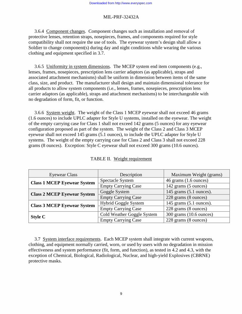
3.6.4 Component changes. Component changes such as installation and removal of protective lenses, retention straps, nosepieces, frames, and components required for style compatibility shall not require the use of tools. The eyewear system’s design shall allow a Soldier to change component(s) during day and night conditions while wearing the various clothing and equipment specified in 3.7. 3.6.5 Uniformity in system dimensions. The MCEP system end item components (e.g., lenses, frames, nosepieces, prescription lens carrier adaptors (as applicable), straps and associated attachment mechanisms) shall be uniform in dimension between items of the same class, size, and product. The manufacturer shall design and maintain dimensional tolerance for all products to allow system components (i.e., lenses, frames, nosepieces, prescription lens carrier adaptors (as applicable), straps and attachment mechanisms) to be interchangeable with no degradation of form, fit, or function. 3.6.6 System weight. The weight of the Class 1 MCEP eyewear shall not exceed 46 grams (1.6 ounces) to include UPLC adapter for Style U systems, installed on the eyewear. The weight of the empty carrying case for Class 1 shall not exceed 142 grams (5 ounces) for any eyewear configuration proposed as part of the system. The weight of the Class 2 and Class 3 MCEP eyewear shall not exceed 145 grams (5.1 ounces), to include the UPLC adapter for Style U systems. The weight of the empty carrying case for Class 2 and Class 3 shall not exceed 228 grams (8 ounces). Exception: Style C eyewear shall not exceed 300 grams (10.6 ounces).
TABLE II. Weight requirement
Eyewear Class Description Maximum Weight (grams)
Class 1 MCEP Eyewear System Spectacle System 46 grams (1.6 ounces) Empty Carrying Case 142 grams (5 ounces)
Class 2 MCEP Eyewear System Goggle System 145 grams (5.1 ounces). Empty Carrying Case 228 grams (8 ounces)
Class 3 MCEP Eyewear System Hybrid Goggle System 145 grams (5.1 ounces). Empty Carrying Case 228 grams (8 ounces)
Style C Cold Weather Goggle System 300 grams (10.6 ounces) Empty Carrying Case 228 grams (8 ounces)
3.7 System interface requirements. Each MCEP system shall integrate with current weapons, clothing, and equipment normally carried, worn, or used by users with no degradation in mission effectiveness and system performance (fit, form, and function), as tested in 4.2 and 4.3, with the exception of Chemical, Biological, Radiological, Nuclear, and high-yield Explosives (CBRNE) protective masks.
Downloaded from http://www.everyspec.com

MIL-PRF-32432A
10
3.7.1 Advanced Combat Helmet (ACH), 2nd Generation ACH (ACH Gen II), or Enhanced Combat Helmet (ECH). All MCEP systems shall be capable of being worn with the ACH, ACH Gen II, or ECH. Class 2 and Class 3 shall be capable of being worn over or under the ACH, ACH Gen II, or ECH. 3.7.2 Combat Vehicle Crewman Helmet (CVC-H) (DH-132B) and the Advanced CVC Helmet (ACVC-H). Class 2, and Class 3 MCEP systems shall be capable of being worn with the CVC-H (DH-132B) and the Advanced CVC-H. Class 2 and Class 3 shall not break the ear cup seal when worn over the helmet. Class 1 spectacles claiming compatibility with this helmet shall demonstrate they can do so without degrading the noise attenuation characteristics of the CVC-H ear cups by more than 5 decibels. 3.7.3 Lightweight helmet (LWH) or Lightweight Advanced Combat Helmet (LW ACH). All MCEP systems shall be capable of being worn with the Marine Corps LWH. Class 2 and Class 3 shall be capable of being worn over the LWH or LW ACH. 3.7.4 Integrated Head Protection System (IHPS). All MCEP systems shall be capable of being worn with the IHPS. Class 1 MCEP systems shall be capable of being worn with the IHPS in all configurations, including the ballistic mandible and ballistic visor. Class 2 and 3 MCEP systems shall be capable of being worn with the IHPS with ballistic mandible. 3.7.5 Weapons. All MCEP systems shall not degrade the users’ ability to shoulder, aim, fire at and hit targets, carry, or inhibit head flexing and rotation when using the following: M-16 RIFLE family, M-4 Carbine "Flat Top", M-24 with Leupold Sight, M203, M-249, M-60, M-67 mortar sight, M-240B, Light Anti-Tank Weapon (LAW), TOW missile ITAS, Dragon, SAW, M18A1 Claymore, M141 Bunker Defeat Munition, M136E1 AT4CS, Family of Smoke Grenades, Hand Grenades, Pyrotechnics and Simulators, M136 AT4, M72 LAW (Lightweight Anti-Armor Series),M-203 GL, Iron Sight M-240B MG, Iron Sight M60 MG, Iron Sight M-24 SWS, M107 LRSR, M110 SAAS, M500 Shotgun, M26 Shotgun, M320 GL.M 3.7.6 Optics & displays. All MCEP systems shall be capable of being used physically and optically with the following without degrading the user’s ability: TOW missile ITAS, M-144 telescope (spotting scope), JAVELIN command launch unit, M-67 mortar sight, AN/PVS-4, AN/PVS-6, AN/PVS-10, AN/PVS-14 (monocular image intensifier), AN/PAS 13 (thermal weapon sight), AN/TVS 5 (monocular image intensifier), M-68 close combat optic, M-24 and M22 binoculars, XM25 Stabilized Binocular, AT4, RS, M126 Bunker Defeat Munitions, M68 CCO, M150 RCO, A2 Iron Sight, Back Up Iron Sight (BUIS), M145 MGO, Leupold Fixed 10X, Leupold 4.5-14X, Leupold 3.5 -10X, Redfield BUIS, M151 Spotting Scope, PVS14, PVS-7 Image Intensifier, AN/PSQ-20 ENVGS (Enhanced Night Vision Goggles). 3.7.7 Environmental protective clothing. The MCEP system shall be capable of being worn with the Extended Cold Weather Clothing System (ECWCS).
Downloaded from http://www.everyspec.com

MIL-PRF-32432A
11
3.8 Eyewear system technical requirements. 3.8.1 Prescription lens. Style U MCEP systems shall be able to accommodate the use of the UPLC filled with military polycarbonate prescription lenses (from -10.00 to +8.00 diopters sphere with up to -3.25 diopters of cylinder) without degrading the system performance beyond requirement limits. 3.8.2 Mildew resistance. The textile materials used in the eyewear shall be resistant to mildew for a service life of six (6) months or greater and a shelf life of five (5) years or greater. 3.8.3 Chemical resistance. The eyewear lenses shall maximize resistance to: 6.0% Sodium Hypochlorite by weight; insect repellent-controlled release diethyl toluamide (30% concentration DEET), Fire resistant hydraulic fluid (MIL-PRF-46170), Hydraulic Fluid, Petroleum Base (MIL-PRF-6083), Gasoline (87% Octane), Motor oil (SAE 10W-30), and F24 fuel (NATO Standard AFLP 3747) without degrading performance beyond requirement limits. 3.8.4 Ballistic fragmentation characteristics. The eyewear shall provide ballistic fragmentation protection in all configurations. Eyewear shall be sufficiently durable to remain intact (i.e., all components required for protection and proper retention of the eyewear remain attached) upon and after impact. Style U items shall be tested both with and without prescription lenses for initial approval of the design for use with the UPLC. 3.8.4.1 Class 1 spectacles. Class 1 spectacles shall provide ballistic fragmentation protection in all configurations in accordance with 4.8.4. 3.8.4.2 Classes 2 and 3 goggles Classes 2 and 3 Goggles shall provide ballistic fragmentation protection in all configurations in accordance with 4.8.5. 3.8.5 Optical characteristics. All classes of eyewear shall be capable of meeting the optical requirements in all configurations. Style U shall be capable of meeting the optical requirements with and without the UPLC adapter installed. All eyewear shall be able to pass all optical requirements at all points within the critical optical area. 3.8.5.1 MCEP Clear Lens. The photopic luminous transmittance (for the light adapted eye) of the lens shall not be less than eight-nine (89) percent. The scotopic luminous transmittance of the lens shall not be less than eighty-five (85) percent. Exceptions: 1) Style T shall follow luminous transmittance as outlined in 3.5.1.5. 2) Style C clear lens: photopic luminous transmittance shall not be less than 75 percent, and the scotopic luminous transmittance shall not be less than 70 percent. 3.8.5.2 MCEP Dark Lens. The photopic luminous transmittance of the configuration shall be within 12 to 18 percent when measured within the critical optical areas.
Downloaded from http://www.everyspec.com
MIL-PRF-32432A
12
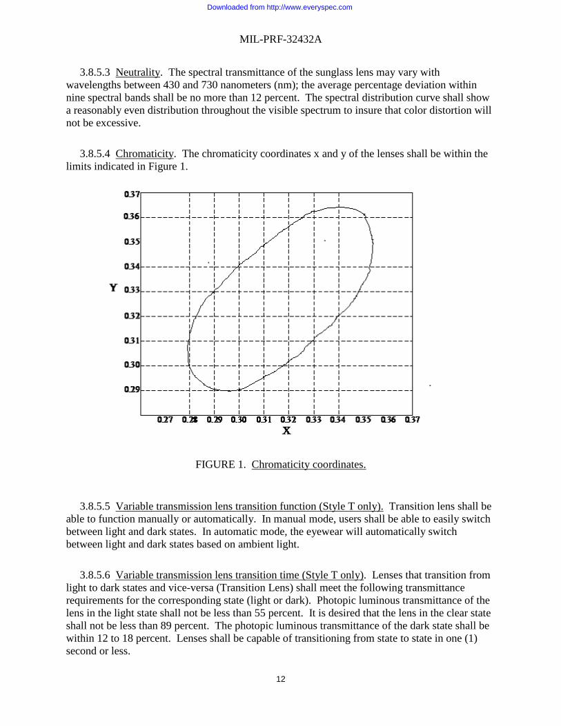
3.8.5.3 Neutrality. The spectral transmittance of the sunglass lens may vary with wavelengths between 430 and 730 nanometers (nm); the average percentage deviation within nine spectral bands shall be no more than 12 percent. The spectral distribution curve shall show a reasonably even distribution throughout the visible spectrum to insure that color distortion will not be excessive. 3.8.5.4 Chromaticity. The chromaticity coordinates x and y of the lenses shall be within the limits indicated in Figure 1.
FIGURE 1. Chromaticity coordinates.
3.8.5.5 Variable transmission lens transition function (Style T only). Transition lens shall be able to function manually or automatically. In manual mode, users shall be able to easily switch between light and dark states. In automatic mode, the eyewear will automatically switch between light and dark states based on ambient light. 3.8.5.6 Variable transmission lens transition time (Style T only). Lenses that transition from light to dark states and vice-versa (Transition Lens) shall meet the following transmittance requirements for the corresponding state (light or dark). Photopic luminous transmittance of the lens in the light state shall not be less than 55 percent. It is desired that the lens in the clear state shall not be less than 89 percent. The photopic luminous transmittance of the dark state shall be within 12 to 18 percent. Lenses shall be capable of transitioning from state to state in one (1) second or less.
Downloaded from http://www.everyspec.com

MIL-PRF-32432A
13
3.8.5.7 Field of view. The MCEP system shall provide unobscured vision with a field of view adequate for mission in all configurations. 3.8.5.8 Optical distortion. Eyewear lenses shall be free of blurs or distortion (evidenced by waves or ripples or shearing patterns) in the image of a straight line in any meridian when viewed through the lens. Conformance shall be determined via the acceptable standards shown in Figure 2. Style T eyewear shall be tested for optical distortion in both light and dark states.
FIGURE 2. Examples of Acceptable and Unacceptable Optical Distortion.
3.8.5.9 Ultraviolet absorption. The clear eyewear lenses and transition lenses (Style T only, light and dark lenses) shall absorb at least 99.9 percent of the incident ultraviolet radiation in the range 290 to 380 nanometers (nm). MCEP dark lenses shall absorb at least 99.9 percent of incident UV radiation in the range 280 to 400 nm. 3.8.5.10 Haze, resistance to scratching and abrasion. Eyewear shall maximize resistance to scratching abrasion. Initial haze of the eyewear for all MCEP lenses shall be no greater than three (3) percent. No more than six (6) percent haze shall be added to the baseline haze value as a result of abrasion testing IAW 4.10. Style T eyewear shall be tested for initial haze in both light and dark states.
ACCEPTABLE
UNACCEPTABLE
Downloaded from http://www.everyspec.com

MIL-PRF-32432A
14
3.8.5.11 Resistance to fogging. The item shall not fog to the extent that the user is unable to perform their intended mission. A topical antifog treatment (see 6.10) compatible with the eyewear coatings shall be included as part of the MCEP kit. Style C eyewear shall provide resistance to fogging in extreme cold weather environments. 3.9 Eyewear system durability. 3.9.1 Carrying case protection. The carrying case shall protect the eyewear during carrying, storage, and shipping such that there is no degradation beyond the requirement limits in optical or ballistic fragmentation performance. The carrying case shall minimize dirt infiltration and scratching of lenses. 3.9.2 Service life and shelf life. The system shall have a minimum field life of six (6) months and a minimum shelf life of 60 months or longer. 3.9.3 Repair. The system shall be capable of being repaired by replacing components that have become damaged. Repairs shall be capable of being performed without tools. 3.9.4 Environment. The MCEP system shall be capable of being worn/used in all climatic categories (i.e. -60 °F to 120 °F) during day, dusk, and nighttime operations, and during various environmental conditions, such as rain, snow, wind, etc. 3.9.5 Eyewear. The eyewear shall not warp or deform, delaminate, discolor, corrode, rust, or crack, nor shall its ballistic fragmentation or optical characteristics be degraded beyond the requirement limits during operation, shipping, or storage in all climatic categories. 3.9.5.1 Temperature. The eyewear shall not degrade (to include configurations with removable eyewear components, such as removable facefoam and retention straps) beyond the requirement limits following exposure for 72 hours at 160°F and 72 hours at -60°F. 3.9.5.2 Solar radiation. The eyewear shall not degrade (to include configurations with removable eyewear components, such as removable facefoam and retention straps) beyond the requirement limits when tested against 200 hours of simulated solar radiation. 3.9.5.3 Humidity. The eyewear shall not degrade beyond the requirement limits after exposure to ten (10) cycles for a combined total of 240 hours of temperature and humidity. 3.9.5.4 Adhesion. If a coating has been applied to the lens, the coating on the front surface and back surface of the lens shall not be able to be removed, dislodged, or affected in any way.
Downloaded from http://www.everyspec.com

MIL-PRF-32432A
15
3.9.5.5 Wind and dust. The Class 2 and Class 3 eyewear shall provide protection to the eyes from wind and dust. The design of the goggles shall minimize the wind and dust entering the space between the eyes and the goggle lens(es). 3.9.5.6 Salt water. The eyewear shall not degrade beyond the requirement limits when exposed to salt water. 3.9.6 Style C power requirements. If cold-weather eyewear is power driven, then the battery shall be capable of functioning in the powered state for at least six (6) hours before requiring recharge. A means to recharge the battery shall be included as part of the MCEP kit. The kit shall provide a power source for a minimum field life of six months and minimum shelf life of 24 months. 3.9.7 Style T power requirements. If eyewear transition lens is power driven, then the battery shall be capable of functioning in the powered state for at least 36 hours before requiring recharge, as tested in section 4.14.2. When the power fails, the transition eyewear shall fail to the light state, as tested in section 4.14.2.1. A means to recharge the battery shall be included as part of the MCEP kit. The kit shall provide a power source for a minimum field life of six (6) months and minimum shelf life of 24 months. 3.10 Human Factors Engineering (HFE). 3.10.1 Size and fit. The MCEP system shall accommodate (i.e., fit, adjust, and successful use) U.S. Army target audience users with 5th percentile female through 95th percentile male design critical dimensions, while wearing appropriate clothing and individual equipment. Sufficient numbers of sizes for each class of MCEP system, and adjustments within the sizes, shall be provided to correctly fit the full range of body dimensions of the target audience. All MCEP systems shall be designed to minimize eyelash contact in all configurations. Correct fit and eyelash contact will be assessed in accordance with 4.3. 3.10.2 Pantoscopic tilts and faceform angles. The UPLC interface for Style U systems shall be such that the pantoscopic tilt of the UPLC when installed in the eyewear is 15 degrees or less. Negative pantoscopic tilts are not acceptable. The UPLC interface design shall not visibly distort the faceform angle of the UPLC when the UPLC is installed (empty of prescription lenses) into the eyewear. 3.10.3 Adjustment and comfort. Each MCEP system shall provide a means to adjust the eyewear for proper fit and comfort. MCEP system shall be designed to minimize localized discomfort when used alone or in conjunction with the items identified in paragraph 3.7. The finished parts of the MCEP system shall be free of sharp and rough edges which could result in discomfort or abrasion to the face.
Downloaded from http://www.everyspec.com

MIL-PRF-32432A
16
3.10.4 Donning and doffing. The MCEP system shall be easily and quickly (less than 10 seconds) donned and doffed with minimal realigning and readjusting. Donning and doffing of the spectacle shall be without the retention strap since its use is optional, and shall be to/from the carrying case. Donning and doffing of the eyewear in general shall be accomplished without removing other equipment, to include the LWH, ECH, ACH, Lightweight ACH (LW ACH), second generation ACH (ACH Gen II), CVC-H, ACVC-H, IHPS, and heavy gloves (trigger finger and Arctic mittens). The MCEP system shall be easily and quickly (less than 10 seconds) accessed from the protective carrying case when attached to the Soldier's belt, vest, or other equipment. 3.10.5 Use. Users of the MCEP system shall be able to accomplish the following tasks (at a minimum) in order to make the system function (tasks may or may not be required, based on selected configuration):
TABLE III. Task list for MCEP.
No. Task to be performed Standard A Stow/remove MCEP system to/from carrier Y/N B Adjust Class 1 MCEP system to fit on the face in the as worn configuration
under the helmet (LWH, ACH, LW ACH, ACH Gen II, ECH, CVC-H, ACVC-H, IHPS (As applicable))
Y/N
C Adjust Class 2 and Class 3 MCEP system to fit over the helmet (LWH, ACH, LW ACH, ACH Gen II, ECH, CVC-H, ACVC-H, IHPS (As applicable))
Y/N
D Adjust Class 2 and Class 3 MCEP system to fit on the face in the as worn configuration under the helmet (LWH, ACH, LW ACH, ACH Gen II, ECH, CVC-H, ACVC-H, IHPS (As applicable))
Y/N
E Remove and install lenses Y/N F Manipulate movable parts Y/N G Perform operator level Preventative Maintenance Checks and Services
(PMCS) Y/N
H Install and remove the UPLC (Style U only) Y/N I Manually transition lens from light to dark and vice versa (Style T only) Y/N J Switch transition function from manual to automatic and vice versa (Style T
only) Y/N
K Operate active anti-fog (Style C only) Y/N 3.10.6 Survivability in a tactical environment. The MCEP system shall have no adverse impact upon user survivability. Detection of the system by reflected light is a potential survivability issue which shall be eliminated or minimized to the greatest extent possible.
3.11 Safety and health hazards.
Downloaded from http://www.everyspec.com

MIL-PRF-32432A
17
3.11.1 Prolonged effects. Prolonged wearing of the MCEP system with and without the UPLC containing prescription lenses ranging from -10.00 to +8.00 diopters sphere with up to -3.25 diopters of cylinder shall not cause headaches, dizziness, blurred vision, or undue eye strain/fatigue, when tested as specified in 4.3.
3.11.2 Skin irritants. MCEP shall be free of sharp and rough edges, minimize hot spots, and be easy to keep clean and sanitary to avoid cuts, abrasion or irritation to the skin that could result in infection.
3.11.3 Risk assessment. MCEP system shall comply with all safety and health standards and performance requirements of this section. Residual user safety or health hazards (those introduced by the use of the product) shall be controlled to a hazard severity and hazard probability (Risk Assessment Code) of 4C or less, as defined by the matrix in Table IV.
3.11.4 Toxicity. The finished MCEP system shall not present a health hazard with prolonged, direct skin contact when tested as specified in 4.2 and 4.3. Chemicals recognized by the Environmental Protection Agency (EPA) as human carcinogens shall not be used.
THIS SECTION IS INTENTIONALLY LEFT BLANK
Downloaded from http://www.everyspec.com

MIL-PRF-32432A
18
TABLE IV. Decision authority matrix
Downloaded from http://www.everyspec.com

MIL-PRF-32432A
19
3.12 Administrative markings and identification.
3.12.1 Identification and marking. MCEP system components shall be permanently marked in accordance with ANSI Z87.1. All MCEP Systems shall include a date clock (indicating month and year of manufacture) on all frames and a date stamp on all lenses. The date stamp on the lens shall be a two digit month followed by a four digit year (e.g., 04/2009). All frames and lenses shall also be marked with a mold and cavity identifier indicating the mold or cavity from where the lens and frames came, along with a marking to indicate the manufacturer of the lens. Date clock and date stamp information shall be in a readily accessible location that does not require destruction of the item to find or read the date stamp or date clock. Application of the marking shall not degrade the eyewear’s ability to meet the requirements of this specification beyond the required limits nor shall the markings be placed in a location that impinges on the user’s field of view. All classes of eyewear shall have the trademarked letters “APEL” marked on the left temporal region of the eyewear once authorized for use. The logo shall be durable for the life of the item, legible and visible when worn with helmets in 3.7, and present no hazard to the Soldier (e.g., rubbing, snagging) through its manner of construction and placement. Approval to use the logo must be obtained by the Government prior to implementation. 3.12.2 Bar coding. Bar codes (if applicable) shall be as specified in the solicitation and contract (see 6.4). 3.13 Compliance with ANSI Z87.1. The eyewear (in all configurations) shall be fully compliant with the current edition of ANSI Z87.1 unless otherwise stated. The eyewear shall be assessed as a High Impact Protector. The eyewear shall meet impact protection requirements in all configurations (to include the use of multiple nosepieces to accommodate both prescription and non-prescription wearers). Each MCEP system shall provide peripheral protection. Each type of lens delivered as part of the MCEP system shall be separately tested and meet the requirement for the following parameters: Penetration, Prismatic Power, Refractive Power and Astigmatism, Resolving Power, Haze, and Transmittance. A minimum of three (3) samples shall be used for each test if less than three is specified. Class 3 items shall be tested to the ANSI Z87.1 goggle requirement. Style T eyewear shall be tested for Prismatic Power, Refractive Power and Astigmatism, Resolving Power, and Haze in both Light and Dark states. 3.13.1 ANSI Z87.1 refractive power and astigmatism. Eyewear will be tested for refractive power and astigmatism in accordance with ANSI Z87.1 2015, with the following exceptions: the refractive power shall be measured as the highest absolute value of the individual meridians. For lenses with multiple layers of different materials, the tolerance on refractive power and astigmatism is ± 0.125. 3.13.2 ANSI Z87.1 resolving power. Eyewear with lenses consisting of multiple layers of different materials are exempt from ANSI Z87.1 Resolving Power requirements. NOTE: Anti-scratch and anti-fog coatings are not considered separate layers.
Downloaded from http://www.everyspec.com
MIL-PRF-32432A
20
3.14 Flammability and ignition. 3.14.1 Flammability and ignition. MCEP systems shall not burn at a rate greater than 76 mm per minute when subjected to flammability testing in accordance with 4.19. MCEP systems shall meet ANSI Z87.1 2015 requirements for ignition. This shall include any plastic components, such as buckles, that are present on the Class 2 and Class 3 retention straps. 3.14.2 Textile flammability. Textile components (not covered by 4.19) worn as part of the Class 2 and Class 3 eyewear assemblies, to include the retention strap shall be flame resistant. Five (5) samples of each textile component shall be tested using a vertical flame as specified in 4.20. Textile components shall exhibit an average char length no greater than 10 centimeters and shall not exhibit any visible after-flame for greater than 20.0 seconds average after removal from the test flame. It is desired that the protective sleeve on these items also be flame resistant. Textile components shall not exhibit flaming melt-drip. Cleaning cloths and carrying cases are exempt from this requirement. 3.15 Workmanship. MCEP system shall be free from all defects that would affect proper functioning in service. Parts (zippers, snaps, hook and pile, glides, drawstrings, adjustable eyewear features, etc.) shall function properly. Component interfaces shall be secure. All components shall be present. Stitching shall be complete and secure (i.e., no loose, broken, or missing stitching). Components shall be free of rough and sharp edges. Lenses shall minimize imperfections, scratches, etc. 4. VERIFICATION 4.1 Eyewear product inspections. 4.1.1 Classification of inspections. The inspection requirements specified herein are classified as follows: a. Qualification and 2-year recertification inspection (see 4.1.2). b. Six (6) month conformance and Lot Acceptance Test (LAT) inspection (see 4.1.3). 4.1.2 Qualification and 2-year recertification inspection. The eyewear shall be examined and pass the requirements as specified in Table V. The eyewear shall be subjected to the verifications indicated by an “x” in the Qualification Column of Table VI. Qualification requirements are further subdivided into technical verification and user evaluation. Failure to meet any of the tests in Table VI as stated shall be considered failure of the verification. 4.1.2.1 2-Year recertification. As part of the Qualified Product List (QPL) procedures for the eyewear, the eyewear will be subjected to the verifications indicated with an “x” in the 2-Year Recertification column of TABLE VI every two years. Failure to meet any of the tests in
Downloaded from http://www.everyspec.com

MIL-PRF-32432A
21
Table VI for 2-Year Recertification shall be considered failure of the qualification and the product will be subject to removal from the QPL. 4.1.3 Six (6) month conformance and lot acceptance test inspection. Conformance inspection shall include the examination in accordance 4.1.8. The eyewear shall be subjected to the verifications indicated by an “x” in the 6 Month Conformance/ LAT column of Table VI. Sampling for inspection shall be performed in accordance with ANSI/ASQ Z1.4 and with the Acceptance Quality Limit (AQL) as specified in the contract and/or order, except where otherwise specified. 4.1.4 Order of inspection/testing. Perform chemical resistance, adhesion, abrasion, and ballistic fragmentation tests last, as these are destructive tests.
4.1.5 Inspection conditions. Unless otherwise specified, all inspections shall be performed in accordance with all the requirements of referenced documents, unless otherwise excluded, amended, modified, or qualified in this specification or applicable procurement document. 4.1.6 Examinations. Sampling for examination shall be in accordance with ANSI/ASQ Z1.4 or the contract document. Unless otherwise indicated in the contract document, the Inspection Level shall be I. Samples selected shall be subjected to the examinations as specified in Table V. 4.1.7 Tests. Samples for testing will be as selected as indicated below and subjected to the appropriate verifications specified in Table VI. Failure of any test shall constitute failure of the entire verification. All verification tests shall be conducted on a minimum sample size of three, unless otherwise specified in this document or reference standards (ANSI Z87.1). If the sample size specified in reference standards is less than three then three samples shall be used. Ballistic fragmentation testing requires a minimum sample size of ten for initial (pre-exposure) ballistic fragmentation testing, and a minimum sample size of three (3) for post exposure ballistic testing. Flame testing on textiles requires a minimum sample size of five (5) in each direction of the material, with the exception of the goggle strap which shall require a minimum sample size of five (5) in the lengthwise direction only. A sample unit for conformance testing shall be comprised of 60 eyewear systems for each configuration being tested to ensure adequate quantity of product to conduct all tests. For the purposes of flame testing, previously tested items (such as high velocity impact items) may be used. Product may be disassembled and reassembled prior to test to verify product dimensions are uniform and interchanging components do not cause a degradation in system performance beyond performance requirements. If a product design incorporates removable or optional components (such as removable facefoam or UPLC adaptors), then all configurations shall be tested and sufficient samples shall be pulled for each. If multiple lenses are incorporated as part of the system, the quantity of optical tests (to include, but not limited to, ANSI optics) conducted on each lens type shall be based on the total number of each lens type contained within the lot, frames used for optical testing may be re-used for the purposes of testing different lens types in order to minimize the amount of product used up in testing.
Downloaded from http://www.everyspec.com

MIL-PRF-32432A
22
The number of sample units selected shall be determined by the lot size as indicated below:
Lot Size Sample Units 0 – 10,000 1 10,001 – 40,000 2 40,001 – 80,000 3
Lot size shall not exceed 80,000. Any additional quantity over 80,000 shall be treated as a new lot.
4.1.8 End item visual examination. End items shall be examined for the visual defects listed in Table V. Any defect found in an end item listed in Table V shall be considered failure of the visual inspection. Visual inspection of the lens for imperfections, scratches, etc. shall consist of holding the lens approximately 45 centimeters (18 inches) from the eye with the lens viewed against a background of contrasting black and white areas illuminated by a white light. Initial assessment may be made by subjective examination by a trained individual, or by a comparison to the Eastman-Kodak Scratch and Dig Paddle or equivalent. If required, final assessment shall be made using an optical comparator with a reticule scale of 0.20 millimeters gradations. Defects that are hidden after final assembly, such as those masked by the eyewear frame, will not be scored. The end items shall be examined for the following defects: 4.1.8.1 Imperfections. An imperfection is defined as a pit, bubble, speck, or dig. Dimensions are measured from the diameter of a circular imperfection or the largest dimension of a non-circular imperfection. 4.1.8.2 Critical area. The critical area (defined by a circle having a 20 millimeters radius centered on the horizontal centerline and 32 millimeters from the vertical centerline) shall not contain more than four imperfections as follows: a. One (1) imperfection from 0.21 millimeters to 0.30 millimeters and three imperfections from 0.15 millimeters to 0.20 millimeters. b. OR four (4) imperfections from 0.15 millimeters to 0.20 millimeters. The critical area shall not contain any imperfections larger than 0.30 millimeters.
Imperfections larger than 0.15 millimeters must be separated by 20 millimeters. Any number of imperfections less than 0.15 millimeters are allowed. Imperfections less than 1 millimeter apart, including those less than 0.15 millimeters, shall be scored together (sizes added) as one imperfection.
4.1.8.3 Non-critical area. The non-critical area (all optical surfaces other than the critical optical areas) shall not contain more than 30 imperfections as follows: a. Ten imperfections from 0.21 millimeters to 0.40 millimeters and twenty (20) imperfections from 0.15 millimeters to 0.20 millimeters.
b. OR thirty imperfections from 0.15 millimeters to 0.20 millimeters.
Downloaded from http://www.everyspec.com

MIL-PRF-32432A
23
The non-critical area shall not contain any imperfections larger than 0.40 millimeters.
Imperfections larger than 0.30 millimeters must be within 10 millimeters of the edge of the lens. Imperfections from 0.21 millimeters to 0.40 millimeters must be separated from each other by at least 20 millimeters and imperfections from 0.15 millimeters to 0.20 millimeters must be separated from each other and any larger imperfections by 10 millimeters. Any number of imperfections less than 0.15 millimeters are allowed. Imperfections less than 1 millimeters apart, including those less than 0.15 millimeters, shall be scored together (sizes added) as one imperfection.
4.1.8.4 Scratches. The critical area shall not contain any scratches. The non-critical area shall not contain any scratches exceeding the size 40 width defined by the Eastman-Kodak Scratch and Dig Paddle. Acceptable scratches shall not exceed 10 millimeters in length. Multiple scratches must be separated by at least 80 millimeters. 4.1.8.5 Cloudiness, scuffs, runs. The critical area shall not contain any areas of cloudiness, scuffs, coating lines, coating runs, or areas of partial coating unless the anomaly is within two (2) millimeters of the lens edge. The non-critical area shall not contain any areas of cloudiness, scuffs, coating lines, coating runs, or areas of partial coating unless the anomaly is within three (3) millimeters of the lens edge.
THIS SECTION IS INTENTIONALLY LEFT BLANK
Downloaded from http://www.everyspec.com

MIL-PRF-32432A
24
TABLE V. End item visual defects. Examine Defect Eyewear Quality of Material
More than four (4) imperfections greater than or equal to 0.15 mm in critical area More than one 0.21 mm to 0.30 mm imperfections in critical area Any imperfection larger than 0.30 mm in critical area Any pair of imperfections greater than or equal to 0.15 mm separated by less than 20 mm in critical area More than 10 imperfections from 0.21 mm to 0.40 mm in non-critical area More than 30 imperfections greater than or equal to 0.15 mm in non-critical area Any imperfection larger than 0.40 mm in the non-critical area Any pair of imperfections greater than 0.20 mm separated by less than 20 mm in non-critical area Any pair of imperfections greater than or equal to 0.15 mm separated by less than 10 mm in non-critical area Any imperfections larger than 0.30 mm not within 10 mm of the edge of the lens in non-critical area Break, crack or fracture Sharp or rough edges (enough to cause skin abrasion) Any scratch in the critical area Any scratch greater size 40 in the non-critical area Any scratch greater than 10mm in length in the non-critical area
Continued - Eyewear Quality of Material -
Any pair of scratches not separated greater than or equal to 80 mm
Case-quality of material Crazing, cracks, warped sidewalls, off shade, mottled or streaky Workmanship and assembly of eyewear
Any component missing Component malformed, warped, chipped or otherwise damaged, otherwise improperly functioning Stitching not complete or secure Any rough or sharp edges Not connected or joined as specified or assembly is poorly accomplished
Instruction Booklet Instruction booklet missing Instruction booklet not in one piece
Missing Parts or Components
Any missing components
Downloaded from http://www.everyspec.com

MIL-PRF-32432A
25
4.2 Verification methods. The types of verification methods included in this section are visual inspection, measurement, sample tests, demonstration tests, engineering evaluation, component properties analysis, and similarity to previously-approved or previously-qualified designs. A summary of the verification methods is given in Table VI.
4.3 User evaluation. As part of the qualification inspection, the eyewear will be subjected to a field user evaluation. At least 20 users shall wear the eyewear while performing unit training, weapons firing, field exercises, and other representative tasks. Field testing of spectacles and goggles shall include an assessment of fit, comfort, stability, compatibility with equipment, appearance, field of view, ability to sight and fire weapons and use optical augmentation, ability to use mission equipment, ease of changing lenses, ease of fit, durability, resistance to fogging , ease of cleaning, minimization of glint and glare, adequacy and design of carrying case, adequacy of instruction booklet, adequacy and use of anti-fog application, Style function (as applicable), and overall user acceptance and preference. Goggles will also be assessed for effectiveness of seal, adequacy of strap, ease of strap adjustment, and degree of wind and dust protection. Upon completion of the user evaluation, the users will score the eyewear on each requirement indicated by an “x” in the “user evaluation” column of Table VI. The scores will be on a scale of “1” (Very Poor), “2” (Poor), “3” (Neutral), “4” (Good), and “5” (Very Good). An average score of “3” or higher from participating users is required for successful completion of each verification. An average score of less than “3” for a single test combined with an overall average score of less than “3” in all areas, or an average score of less than “2” for a single test (regardless of the overall average score), shall be cause for rejection. 4.4. Verification alternatives. The manufacturer may propose alternative test methods, techniques, or equipment, including the application of statistical process control, tool control, or cost-effective sampling procedures to verify performance. Any alternative test method, technique or equipment must be approved by the Government prior to implementation.
THIS SECTION IS INTENTIONALLY LEFT BLANK
Downloaded from http://www.everyspec.com

MIL-PRF-32432A
26
TABLE VI: Verification methods.
Qualification Retention
Requirement
Requirement paragraph
Verification paragraph
Qualification inspection
2-Year Recertification
6-Month Conformance/LAT
Tech User Evaluation
SYSTEM CONFIGURATION
3.5 4.5 X X X
System Configuration
3.5.1 4.5.1 X X X
Carrying Case 3.5.1.7 4.5.2 X X X
Instruction Booklet 3.5.1.8 4.5.3 X X X
SYSTEM ATTRIBUTES
3.6
Color 3.6.2 4.5.4 X X
Systems Retention 3.6.3 4.5.5 X
Component Changes
3.6.4 4.5.6 X X X
Uniformity system dimensions
3.6.5 4.5.7 X
System weight 3.6.6 4.5.8 X X X
SYSTEM INTERFACE REQTS
3.7 4.6
ACH AND ECH Helmet
3.7.1 4.6.1 X
CVC Helmet 3.7.2 4.6.2 X
Hearing Protection Loss
3.7.2 4.6.2.1 X
LWH Helmet 3.7.3 4.6.3 X
IHPS 3.7.4 4.6.4 X
Weapons 3.7.5 4.6.5 X
Optics/Displays 3.7.6 4.6.6 X
Environ. Prot. Clothing
3.7.7 4.6.7 X
SYSTEM TECH REQUIREMENTS
3.8 4.7
Prescription lens 3.8.1 4.7.1 X X X
Mildew resistance 3.8.2 4.7.2 X
Downloaded from http://www.everyspec.com

MIL-PRF-32432A
27
TABLE VI: Verification methods. - Continued
Qualification Retention
Requirement
Requirement paragraph
Verification paragraph
Qualification Requirements
2-Year Recertification
6-Month Conformance/LAT
Tech User Evaluation
Chemical Resistance 3.8.3 4.7.3 X X
Ballistic Fragmentation Characteristics.
3.8.4 4.8, 4.8.1, 4.8.2, 4.8.3, 4.8.4, 4.8.5, 4.8.6
X X X
OPTICAL CHARACTERISTICS
3.8.5 4.9
Luminous transmittance
3.8.5.1 and 3.8.5.2
4.9.1, 4.9.2 X X X
Neutrality 3.8.5.3 4.9.3 X X X
Chromaticity 3.8.5.4 4.9.4 X X X
Transition Function (Style T only)
3.8.5.5 4.9.5 X X X
Transition Time (Style T only)
3.8.5.6 4.9.5 X X X
Field of view (with and without UPLC)
3.8.5.7 4.9.6 X
Optical distortion 3.8.5.8 4.9.8 X X X
Ultraviolet absorption
3.8.5.9 4.9.9 X X X
Abrasion 3.8.5.10 4.10 X X X
Fogging 3.8.5.11 4.11 X
Style C fogging 3.8.5.11 4.11.1 X
DURABLITY 3.9 4.12 X
Carrying case protection
3.9.1 4.12.1 X
Service Life/Shelf life
3.9.2 4.12.2 X
Repair 3.9.3 4.12.3 X
Downloaded from http://www.everyspec.com

MIL-PRF-32432A
28
TABLE VI: Verification methods. - Continued
Qualification Retention
Requirement
Requirement paragraph
Verification paragraph
Qualification inspection
2-Year Recertification
6-Month Conformance/LAT
Tech User Evaluation
ENVIRONMENT TESTS
3.9.4 4.13
Eyewear 3.9.5 4.13.1
-Temperature 3.9.5.1 4.13.1 X X
-Solar Radiation 3.9.5.2 4.13.2 X X
-Humidity 3.9.5.3 4.13.3 X X
-Adhesion 3.9.5.4 4.13.4 X X X
-Wind/dust 3.9.5.5 4.13.5 X
-Salt water 3.9.5.6 4.13.6 X
Style C Power Requirements
3.9.6 4.14.1 X X X X
Style T Power Requirements
3.9.7 4.14.2 X X X X
HUMAN FACTORS 3.10 4.15
Dimensions 3.10.1 4.15.1 X
Pantoscopic tilts and face form angles
3.10.2 4.15.2 X
Adjustment 3.10.3 4.15.3 X
Comfort 3.10.3 4.15.4 X
Donning/doffing 3.10.4 4.15.5 X
Use 3.10.5 4.15.6 X
User survivability 3.10.6 4.15.7 X
SAFETY/HEALTH HAZARDS
3.11 4.15.8 X
Prolonged effects 3.11.1 4.15.8 X
Skin irritants 3.11.2 4.15.8 X
Risk Assessment 3.11.3 4.15.9 X
Toxicity 3.11.4 4.15.10 X X
Identification and Marking
3.12 4.16 X X X
Downloaded from http://www.everyspec.com

MIL-PRF-32432A
29
TABLE VI: Verification methods. - Continued
Qualification Retention
Requirement
Requirement paragraph
Verification paragraph
Qualification inspection
2-Year Recertification
6-Month Conformance/LAT
Tech User Evaluation
Compliance with ANSI Z87.1
3.13 4.17 X X X
Refractive Power/Astigmastism
3.13.1 4.17 X X X
FLAMMABILITY 3.14 4.18
ANSI Flammability 3.14.1 4.18 X X
ANSI Ignition 3.14.1 4.18 X X
Textile Flammability
3.14.2 4.19 X X
WORKMANSHIP 3.15 4.20 X X X * The Government may perform, or request these tests be performed, periodically to re-verify compliance with specification requirements.
4.5 System configuration and attributes verification. 4.5.1 General. Complete each verification in this section. Each eyewear system shall be visually inspected for the components listed in 3.5.1. The eyewear shall also be visually examined for the number of protective lenses provided. Style U shall also be verified for compatibility with the UPLC. Failure to have the correct components, incorrect number of protective lenses or inability to be compatible with the UPLC (Style U only) shall constitute failure of this verification. 4.5.2 Carrying case. Demonstrate carrying case carrying capacity by placing the components specified in 3.5.1.7 into the carrying case. Visually examine the carrying case for a means of drainage. Visually and physically manipulate the carrying case for function and to determine the presence of a means for attaching and detaching the carrying case to and from the User's belt, vest, and packs. Demonstrate accessibility by opening the carrying case and removing and storing components while the carrying case is attached to each an equipment belt, vest and pack. The carrying case shall be resistant to break and cracks, discoloration, corrosion and rust during operation, shipping and storage. Nonconformance to 3.5.1.7 shall constitute failure of this verification.
Downloaded from http://www.everyspec.com

MIL-PRF-32432A
30
4.5.3 Instruction booklet. Visually examine the instruction booklet and determine compliance with the requirements of 3.5.1.8. Nonconformance with 3.5.1.8 shall constitute failure of this verification. 4.5.4 Color. The color and appearance of the eyewear frames, cases, straps and sleeves shall match the standard sample when viewed using the AATCC Evaluation Procedure 9, Option A, with sources simulating artificial daylight D75 illuminant with a color temperature of 7500K (± 200) illumination of 100 (±20) foot candles, and shall be a good match to the standard sample under incandescent A illuminant with a color temperature of 2856K (± 200).Failure to match the standard sample shall be considered a failure of this verification. 4.5.5 System retention. System retention will be assessed as part of the user evaluation in accordance with 4.3. Class 1 shall be assessed both with and without the optional retention strap. At the end of the user evaluation tasks, participating users will rate the retention capability of the MCEP system while performing representative user tasks. 4.5.6 Component changes. As part of the user evaluation, users shall change out eyewear components (e.g., frames, lenses, nosepieces, and retention straps) and install the UPLC, without the aid of tools. At the end of the user evaluation tasks, participating users will rate ability of the MCEP system design to change configurations in accordance with 4.3. 4.5.7 Uniformity in system dimensions. The end items shall be examined for uniform dimensions between items of the same class, size and product. Samples from the same class, size and product shall be disassembled to a principal component stage, and the components randomly interchanged with components of other systems within the sample. The disassembly and reassembling cycle shall be repeated for three cycles ending on reassembling. UPLC, and any associated adaptors, shall also be included as part of this examination to verify consistency of interface points between the baseline eyewear and the UPLC. Inability to correctly disassemble and reassemble or inability to meet system requirements after interchanging components shall constitute a failure of this verification. If the failure is between the UPLC and the associated adapter, then the dimensions shall be measured at the interface of each part and recorded. Parts that are dimensionally out of tolerance shall be cause for failure for that component. 4.5.8 System weight. The MCEP system eyewear and empty carrying case shall be weighed by a currently calibrated scale accurate to 0.1gram for compliance with the requirements of 3.6.6. Nonconformance to 3.6.6 shall constitute failure of this verification. 4.6 System interface requirements. Complete each verification in this section. 4.6.1 Advanced Combat Helmet (ACH), 2nd Generation ACH (ACH Gen II), or Enhanced Combat Helmet (ECH). As part of the user evaluation, the interface with the ACH, ACH Gen II, or ECH will be assessed in accordance with 4.3. Users fitted representing all sizes of ACH, ACH Gen II, or ECH will assess the ability to don and doff the helmet while wearing all classes
Downloaded from http://www.everyspec.com

MIL-PRF-32432A
31
of MCEP system, to don and doff the Class 2 and Class 3 MCEP system while wearing a ACH, ability to wear the Class 2 and Class 3 MCEP system over the ACH, ACH Gen II, or ECH , to rotate and tilt the head while wearing the eyewear with the ACH, ACH Gen II, or ECH , and to perform the user evaluation tasks while wearing the eyewear with the ACH, ACH Gen II, or ECH . Assessments will be made both with and without the UPLC for Style U of the MCEP system. At the end of the user evaluation tasks, participating users will rate interface capability of the MCEP system design with the ACH or ECH in accordance with 4.3. 4.6.2 Combat Vehicle Crewman Helmet (CVC-H) (DH-132B) and the Advanced CVC-H (ACVC-H) As part of the user evaluation, the interface with the CVC-H and ACVC-H will be assessed in accordance with 4.3. Users fitted representing all sizes of CVC-H and ACVC-H will assess the ability to don and doff the helmet while wearing all classes of MCEP system, to don and doff the Class 2 and Class 3 MCEP system while wearing a CVC-H and ACVC-H, to rotate and tilt the head while wearing the eyewear with the CVC-H and ACVC-H, and to perform the tasks while wearing the eyewear with the CVC-H and ACVC-H. Assessments will be made both with and without the UPLC for Style U of the MCEP system. Users will also assess the impact, if any, on the noise attenuation characteristics of the CVC-H and ACVC-H ear cups. The change in apparent loudness should be, at most, barely perceptible. At the end of the user evaluation tasks, participating users will rate interface capability of the MCEP system design with the CVC-H and ACVC-H in accordance with 4.3. 4.6.2.1 Hearing protection loss. Class 1 spectacles claiming compatibility with the CVC-H and ACVC-H shall be tested for hearing protection loss in accordance with ANSI S12.42. A hearing loss of greater than 5 decibels shall be considered failure of this verification and the product will not be approved for use with CVC-H and ACVC-Hs. Class 2 and 3 shall be visually inspected to ensure they do not break the ear cup seal when worn over the helmet. 4.6.3 Lightweight Helmet (LWH) or Lightweight ACH (LW ACH). As part of the user evaluation, the interface with the LWH or LW ACH will be assessed in accordance with 4.3. Users fitted representing all sizes of LWH or LW ACH will assess the ability to don and doff the helmet while wearing all classes of MCEP system, to don and doff the Class 2 and Class 3 MCEP system while wearing a LWH or LW ACH, ability to wear the Class 2 and Class 3 MCEP system over the LWH or LW ACH, to rotate and tilt the head while wearing the eyewear with the LWH or LW ACH, and to perform the user evaluation tasks while wearing the eyewear with the LWH or LW ACH. Assessments will be made both with and without the UPLC for Style U of the MCEP system. At the end of the user evaluation tasks, participating users will rate interface capability of the MCEP system design with the LWH or LW ACH in accordance with 4.3. 4.6.4 Integrated Head Protection System (IHPS). As part of the user evaluation, the interface with the IHPS will be assessed in accordance with 4.3. Users fitted representing all sizes of IHPS will assess the ability to don and doff the helmet while wearing all classes of MCEP system, to don and doff the Class 2 and Class 3 MCEP system while wearing a IHPS, ability to wear the Class 1 MCEP system with the IHPS including ballistic mandible and ballistic visor, ability to wear the Class 2 and Class 3 MCEP system with IHPS including ballistic mandible, to
Downloaded from http://www.everyspec.com

MIL-PRF-32432A
32
rotate and tilt the head while wearing the eyewear with the IHPS, and to perform the user evaluation tasks while wearing the eyewear with the IHPS. Assessments will be made both with and without the UPLC for Style U of the MCEP system. At the end of the user evaluation tasks, participating users will rate interface capability of the MCEP system design with the IHPS in accordance with 4.3. 4.6.5 Weapons. As part of the user evaluation, the user will assess their ability to shoulder, aim, fire at, hit targets, and carry the weapons stated in 3.7.5 while wearing all classes of MCEP (with or without the UPLC for Style U). Participating users will rate their ability to perform any of the above tasks while wearing MCEP system in accordance with 4.3. 4.6.6 Optics and displays. As part of the user evaluation, on the user will assess their ability to successfully operate and use optics and displays stated in 3.7.6 while wearing all classes of MCEP (with or without the UPLC for Style U). Participating users will rate their ability to perform any of the above tasks while wearing MCEP system in accordance with 4.3. 4.6.7 Environmental protective clothing. As part of the user evaluation, the interface with the Gen III Extended Cold Weather Clothing System (ECWCS) Parka and Balaclava will be assessed in accordance with 4.3. Participating users will rate their ability to don and doff the MCEP system while wearing the ECWCS Parka and Balaclava, and perform user evaluation tasks while wearing the eyewear with the ECWCS Parka and Balaclava in accordance with 4.3. 4.7 Materials/characteristics verification. All tests shall be performed in a standard atmosphere of 68ºF (±10ºF) and 50% (±20%) relative humidity, unless otherwise specified. 4.7.1 Prescription lenses (Style U only). Two pair of prescription lenses shall be used for evaluation. One prescription of -10.00 diopters, and one prescription of +8.00 diopters shall be sized and fitted into the UPLC for the MCEP system. Each prescription UPLC shall be inserted and removed from the MCEP system. Each MCEP system shall be donned and doffed with each prescription UPLC. Inability to mechanically insert and remove the filled prescription into the MCEP system, or mechanically don and doff the MCEP system with each prescription, shall be considered a failure of this verification. 4.7.2 Mildew resistance. The eyewear textile materials to include the carrying case shall be visually inspected for signs of mildew after storage per paragraph 3.8.2. Any visual indication of mildew shall be considered a failure of this verification. . 4.7.3 Chemical resistance. The front surface of the lens shall be exposed to each of the specified chemicals in 3.8.3. A new lens shall be used for each new chemical and testing shall be conducted on a sample size of three (3) for each chemical. To expose the lens, the chemical shall be contained within an O-ring (18mm in diameter or more) sealed to the surface of the lens (centered within the critical area, defined by a circle having a 20 millimeters radius centered on the horizontal centerline and 32 millimeters from the vertical centerline) using silicone grease or
Downloaded from http://www.everyspec.com

MIL-PRF-32432A
33
white glue such that the entire area within the O-ring becomes exposed. The lens exposed to the chemical shall then be allowed to sit undisturbed in an area with minimal draft for a 24 hour period. At the end of the test period, the location of the chemically exposed area shall be marked, the O-ring removed, and the surface of the lens rinsed and then dried with compressed air or a non-scratching non-linting cleaning cloth. Lenses that don’t rinse clean with water alone may be cleaned using Dawn Dishwashing Detergent (original scent, NON-ultra) or isopropyl alcohol by rubbing the lens with the thumb or a non-scratching non-linting cleaning cloth rinsed with running water and dried with compressed air or a non-scratching non-linting cleaning cloth. Once dry, samples shall then be inspected in the critical optical area for any obvious visible damage within a 6 mm radius circle centered in the critical optical area and for optical distortion in the same region (see 4.9.8). Observations shall be recorded. If, within the specified area, obvious visual damage beyond specification requirements (see Table VI) is present or the sample is unable to meet the optical distortion requirements of 3.8.5.9, this shall be considered a failure of the verification and testing may be stopped. Products that successfully pass the visual examination and optical distortion testing shall then be tested for ballistic fragmentation impact characteristics in accordance with 4.8 except the impact of the lens shall be limited to one impact within each chemically exposed area. Inability to meet the ballistic fragmentation protection requirements of 3.8.4, obvious visible lens degradation beyond specification requirements (see Table VI), or inability to meet optical distortion requirements of 3.8.5.9 after exposure shall constitute failure of this verification. 4.8 Ballistic fragmentation characteristics. 4.8.1 Test fixtures. An EN small head form shall be used for those items designated as fitting small faces as declared by the manufacturer and an EN medium head form shall be used for all other items when conducting ballistic testing. Head forms shall be a hardness of 50 ±5 IRHD and on a test fixture mounting, or stand support that is capable of restraining the head form supporting the test item, and withstanding shock resulting from ballistic impact. The fixture, stand, or mounting shall be capable of adjustment for moving the test specimen in the vertical or horizontal positions so that the point of impact can be located anywhere on the test specimen, and rotation on the vertical axis so that the correct obliquity for the test specimen can be achieved anywhere on the test specimen. A 0.05 mm thick aluminum foil witness sheet shall be mounted on the head form, situated 16 mm back from the nasal bridge and behind the area of impact of the critical area, defined by a circle having a 20 millimeters radius centered on the horizontal centerline and 32 millimeters from the vertical centerline. The integrity of the witness foil shall be inspected after all impacts, and the foil replaced if wear or tear is observed. The witness sheet for the medium EN head form shall be in the shape of an ellipse; the major (horizontal) axis of the ellipse shall be 40 mm in width, and the minor (vertical) axis shall be 34 mm in height. The distance between ellipse centers shall be approximately 64 mm so that each witness sheet is centered over each eye of the head form. The witness sheet for the small EN head form shall be in the shape of an ellipse; the major (horizontal) axis of the ellipse shall be 33 mm in width, and the minor (vertical) axis shall be 26 mm in height. The distance between ellipses centers shall be approximately 54 mm so that each witness sheet is centered over each eye of the head form. Unless the eye sockets of the head form have been removed, an air gap shall be created between the witness sheet and the head form surface (minimum 2 mm air gap).
Downloaded from http://www.everyspec.com

MIL-PRF-32432A
34
4.8.2 Velocity measurement. Electronic velocity measurement devices (light beam) shall be used to determine velocity of the projectile. At least a single velocity “time gate” shall be used. Muzzle velocity as measured by the “time gate” shall be corrected using ITOP 4-2-805 to give a strike velocity. Drag coefficients will be provided by the Government for each projectile used. The strike velocity shall be used to determine if a test item has passed or failed ballistic testing. For ballistic testing the velocity measurement instrumentation shall be placed no less than 20 cm (7.8 inches) and no more than 61 cm (24 inches) from the target. The distance is defined as the distance from the middle of the last time gate to the front surface of the item being tested. The velocity measurement devices shall be mounted in such a way that the devices do not move, adjust or shift to ensure consistent measurements. A hit shall be considered fair if the impact velocity is within the specified test range and results in a pass or fail, if the impact velocity is below the test range and results in a fail, or if the impact velocity is above the specified test range and results in a pass. 4.8.3 Projectile obliquity and yaw determination. All test projectile impacts shall be at approximately normal incidence (i.e., zero obliquity) to the primary lens. Projectile yaw shall be checked after every shot by performing a visual inspection of the impact location on the test item. A shot shall be “valid” if at least three (3) out of four (4) points of the projectile “chisel” are visible at the point of impact. If this criterion is not met, then the shot shall be considered a misfire and a new test item shall be shot in its place. 4.8.4 Ballistic fragmentation protection, Class 1. Spectacles shall be hit twice with a 0.15 caliber, 5.85 (± 0.15) grain, T37 shaped projectile at 700-725 ft/sec once on the left side and once on the right with both impacts at normal incidence (0 degree obliquity) to the primary lens at a location within the critical area. The critical area is defined as a circle having a 20 mm radius centered on the horizontal centerline and 32 mm from the vertical centerline. A shot shall be considered valid if the projectile hits within the critical area, if the velocity requirements have been met for the shot (i.e., considered “fair” per paragraph 4.8.2), if obliquity requirements have been met for the shot, if the impact location is at least two projectile diameters (.76 cm) away from the edge of a lens, and the projectile does not impact the frame. Projectiles shall be a fragment simulating project (FSP) of shape and dimensions as specified in Figure 3 and shall be manufactured from cold rolled, annealed steel conforming to composition 4340H; the projectile hardness shall be Rockwell C30 (±2). Projectiles will be visually inspected for damage in between each shot. Projectiles may be reused after they have been fired unless visual observation indicates that the projectile has been damaged or deformed. The test item shall be mounted on a medium EN head form, as specified in EN 168, in the as-worn position. The test item shall be removed after each impact for inspection of both the sample and the witness and any other observations noted. Damage to the witness sheet or eyewear and all observations (i.e., breakage, cracks, complete dislodgement, partial dislodgement, delamination, flaking, etc.) shall be noted. Any slight dislodgements shall be reset between impacts on the same test item. Ballistic fragmentation testing shall be conducted on a sample size of ten (10) for each configuration tested initially, and a sample size of three (3) for each post exposure (such as post chemical and post environmental). Class 1 spectacles designed with temple arms shall be tested without the optional retention strap. The test shall be considered a failure if one or more of the following occur:
Downloaded from http://www.everyspec.com
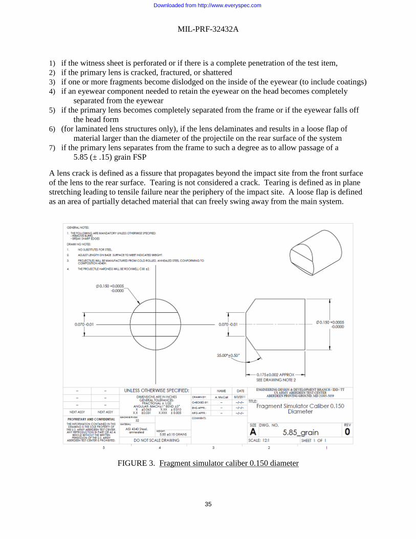
MIL-PRF-32432A
35
1) if the witness sheet is perforated or if there is a complete penetration of the test item, 2) if the primary lens is cracked, fractured, or shattered 3) if one or more fragments become dislodged on the inside of the eyewear (to include coatings) 4) if an eyewear component needed to retain the eyewear on the head becomes completely
separated from the eyewear 5) if the primary lens becomes completely separated from the frame or if the eyewear falls off
the head form 6) (for laminated lens structures only), if the lens delaminates and results in a loose flap of
material larger than the diameter of the projectile on the rear surface of the system 7) if the primary lens separates from the frame to such a degree as to allow passage of a
5.85 (± .15) grain FSP
A lens crack is defined as a fissure that propagates beyond the impact site from the front surface of the lens to the rear surface. Tearing is not considered a crack. Tearing is defined as in plane stretching leading to tensile failure near the periphery of the impact site. A loose flap is defined as an area of partially detached material that can freely swing away from the main system.
FIGURE 3. Fragment simulator caliber 0.150 diameter
Downloaded from http://www.everyspec.com

MIL-PRF-32432A
36
4.8.5 Ballistic fragmentation protection, Class 2 and Class 3. Class 2 Goggles shall be hit three (3) times with a 0.22 caliber, 17 (± 0.5) grain, T37 shaped projectile at 580-590 ft/sec, once on the left side and once on the right with both impacts at normal incidence (0 degree obliquity) to the primary lens at a location within the critical area. The third shot shall be in the center at the vertical center line at normal incidence (0 degree obliquity) to the primary lens. Class 3 shall be impacted in the same manner, with the exception that the center shot shall not be taken. The critical area is defined as a circle having a 20 mm radius centered on the horizontal centerline and 32 mm from the vertical centerline). A shot shall be considered valid if the projectile hits within the critical area or within 10 mm of the designated impact point, if the velocity requirements have been met for the shot (i.e., considered “fair” per paragraph 4.8.2), if obliquity requirements have been met for the shot, if the impact location is at least two projectile diameters (1.09 cm) away from the edge of a lens, and the projectile does not impact the frame. Projectiles shall be a fragment simulating project (FSP) of shape and dimensions as specified in Figure 4 and shall be manufactured from cold rolled, annealed steel conforming to composition 4340H; the projectile hardness shall be Rockwell C30 (±2). Projectiles will be visually inspected for damage in between each shot. Projectiles may be reused after they have been fired unless visual observation indicates that the projectile has been damaged or deformed. The test item shall be mounted on an EN head form (small or medium) in the as-worn position. The test item shall be removed after each impact for inspection of both the sample and the witness sheet and any other observations noted. Damage to the witness sheet or eyewear and all observations (i.e. breakage, cracks, complete dislodgement, partial dislodgement, delamination, flaking, etc.) shall be noted. Any slight dislodgements shall be reset between impacts on the same test item. Ballistic fragmentation testing shall be conducted on a sample size of ten (10) for each configuration tested initially, and a sample size of three (3) for each post exposure (such as post chemical and post environmental). The test shall be considered a failure if one or more of the following occur: 1) if the witness sheet is perforated or if there is a complete penetration of the test item, 2) if the primary lens is cracked, fractured, or shattered, 3) if one or more fragments become dislodged on the inside of the eyewear (to include coatings) 4) if eyewear component needed to retain the eyewear on the head becomes completely
separated from the eyewear 5) if the primary lens becomes completely separated from the frame or if the eyewear falls off
the head form 6) (for laminated lens structures only), if the lens delaminates and results in a loose flap of
material larger than the diameter of the projectile on the rear surface of the system 7) if the primary lens separates from the frame to such a degree as to allow passage of a
5.85 (±.15) grain FSP
A lens crack is defined as a fissure that propagates beyond the impact site from the front surface of the lens to the rear surface. Tearing is not considered a crack. Tearing is defined as in plane stretching leading to tensile failure near the periphery of the impact site. A loose flap is defined as an area of partially detached material that can freely swing away from the main system.
Downloaded from http://www.everyspec.com

MIL-PRF-32432A
37
FIGURE 4. 0.22 Caliber fragment simulating projectile.
4.8.6 Universal prescription lens carrier (UPLC)/adaptors ballistic fragmentation protection (Style U only). Components specific to prescription configurations shall be tested in the prescription configuration for all eyewear it is approved to be used with and shall follow the ballistics testing as defined in 4.8.4 and 4.8.5, as applicable, except that the UPLC and prescription lens shall be inspected for damage and dislodgement after each impact and shall be reinstalled/reseated before each impact. Testing with prescription lenses shall include at least one set of polycarbonate prescription lenses consisting of one prescription at +8, one at -10, two at +5, two at -5 diopters, two at +1.5 and two at -1.5 diopters, unless otherwise noted. Damage to the witness sheet, eyewear, UPLC or prescription lens and all observations (i.e. breakage, cracks, complete dislodgement, partial dislodgement, delamination, flaking, etc.) shall be noted. The test shall be considered a failure if one of the failure mechanisms identified 4.8.4 or 4.8.5 occur (for the respective eyewear under test), or if one or more of the following occur with respect to the prescription lens carrier:
1) if the prescription lens is cracked or chipped on the posterior surface; 2) if complete separation of a prescription lens occurs during testing and results in one or
more of the following: a. the witness sheet is perforated for any reason; b. If more than ten (10) percent of the total number of impacts result in complete
dislodgement of the prescription lens from the UPLC in a sample of ten (10) or more test items with the total number of impacts defined as the number of test items multiplied by the number of impacts per test item
Downloaded from http://www.everyspec.com

MIL-PRF-32432A
38
c. If an adaptor or interface component included as part of the MCEP system Style U capability is completely dislodged
d. If the UPLC is completely dislodged from the MCEP Style U adaptor component due to inadequate design or quality of the MCEP Style U adaptor component. All interface dimensions for the both the adaptor component and UPLC shall be measured in this case and recorded. An MCEP Style U adaptor component deemed out of tolerance or otherwise insufficient fit to the UPLC dimensions shall be cause for rejection.
A lens crack is defined as a fissure that propagates beyond the impact site from the front surface of the lens to the rear surface. Tearing is not considered a crack. Tearing is defined as in plane stretching leading to tensile failure near the periphery of the impact site.
4.9 Optical tests. Complete each verification in this section. All optical testing shall be conducted in the critical optical area (defined by a circle having a 20 millimeters radius centered on the horizontal centerline and 32 millimeters from the vertical centerline), unless otherwise specified. The spectral transmittance shall be measured with the use of a spectrophotometer from 380 nanometers (nm) to 780 nanometers in increments of two (2) nanometers or less. The photopic and scotopic transmittances shall be calculated according to the methods of 4.9.1 and 4.9.2. Neutrality and chromaticity shall be measured in accordance with 4.9.3 and 4.9.4. The lens shall be orientated in such a way that the light source impinges the front surface of the lens and the light captured by the aperture is coming from the back surface of the lens.
Two methods of calculation are provided. Either may be used for the purpose of this verification.
Method 1:
The average luminous transmittance T is given by the general relationship
𝑇𝑇 = 1𝑘𝑘 ∫ 𝑇𝑇(𝜆𝜆)𝐸𝐸(𝜆𝜆)𝑉𝑉(𝜆𝜆)𝑑𝑑𝜆𝜆780
380
where
𝐾𝐾 = 1𝑘𝑘 ∫ 𝐸𝐸(𝜆𝜆)𝑉𝑉(𝜆𝜆)𝑑𝑑𝜆𝜆780
380
and
T(λ) = spectral transmittance of material at wavelength λ
E(λ) = relative spectral irradiance of source
V(λ) = luminous efficiency as a function of wavelength
Downloaded from http://www.everyspec.com

MIL-PRF-32432A
39
The spectral transmittance of the sample shall be measured with a spectrophotometer and the integrals computed. A 2 nanometer increment for the integration is recommended, particularly if the source emission bands or the absorption/rejection bands are narrow. The calculations for photopic and scotopic transmittance may be done concurrently with the use of a computer or programmable calculator.
Method 2:
The spectral transmittance of the sample shall be measured with a spectrophotometer in increments of 2 nanometers or less.
Using Table VII, the photopic and scotopic transmittances are calculated as follows. The calculations may be done concurrently or with the use of a computer or programmable calculator.
• Multiply Vλ by T at each wavelength • Multiply Vλ’ by T at each wavelength • Obtain separate totals for the number in Vλ, Vλ’, Vλ x T and Vλ’ x T, columns. • Sum of Vλ x T column divided by sum of Vλ column is the photopic transmittance.
Multiply this by 100 to get percent. • Sum of Vλ’ x T column divided by sum of Vλ’ column is the scotopic transmittance.
Multiply this by 100 to get percent.
Where: Vλ = Photopic relative luminosity (CIE 1924 standard)
Vλ’ = Scotopic relative luminosity (CIE 1951 standard)
T = Transmittance of device under test
Tp = Percent photopic transmittance
Ts = Percent scotopic transmittance
For the example data included as part of Table VI, the totals for the columns are as follows:
Sum Vλ = 53.4292
Sum Vλ’ = 48.5375
Sum Vλ x T = 6.7187
Sum Vλ’ x T = 1.1691
For this example, the photopic transmittance would be (6.7187/53.4291)*100 = 12.57% and the scotopic transmittance would be (1.1691/48.5375)*100 = 2.41%
Downloaded from http://www.everyspec.com

MIL-PRF-32432A
40
NOTE: For the purposes of the actual calculation, the example transmittance numbers (T) in bold type in Table VII shall be replaced by measurements made on the actual device under test. The example V(λ) x T and V’(λ) x T in italics in Table VII shall, in turn, be replaced by the product that results from using the actual transmittance numbers of the device under test.
4.9.1 Photopic transmittance. Photopic luminous transmittance TP (transmittance for the light adapted eye) is calculated by either method 1 (using for V(L) the photopic luminous efficiency values and the spectral irradiance function for CIE Illuminant C which are listed in Table VII) or method 2 (using V(λ) listed for each wavelength in Table VII). Nonconformance to 3.8.5.1 and 3.8.5.2 shall constitute failure of this verification. 4.9.2 Scotopic transmittance. Scotopic luminous transmittance TS (transmittance for the dark adapted eye) shall be calculated by either Method 1 (using for V(L) the scotopic luminous efficiency values and the spectral irradiance function for CIE Illuminant C which are listed in Table VII) or Method 2 (using V’(λ) listed for each wavelength in Table VII). Nonconformance to 3.8.5.1 shall constitute failure of this verification.
THIS SECTION IS INTENTIONALLY LEFT BLANK
Downloaded from http://www.everyspec.com

MIL-PRF-32432A
41
TABLE VII. Data for transmittance calculations.
Method 1 Method 2
Wave-length V(L) V’(L) E(L) Source Distribution V(λ) V’(λ) ExampleT Example Example
nm Photopic Scotopic Illuminant C Photopic Scotopic V(λ) x T V’(λ) x T 380 0 5.9 33 0 0.0006 0 0 0 382 0 7.9 35.77 0 0.0008 0 0 0 384 1 10.06 38.54 0.0001 0.001 0 0 0 386 1 13.3 41.42 0.0001 0.0013 0 0 0 388 1 17.7 41 0.0001 0.0017 0 0 0 390 1 22.1 47.4 0.0001 0.0022 0 0 0 392 1 31.38 50.51 0.0002 0.0029 0 0 0 394 2 40.66 53.62 0.0002 0.0039 0 0 0 396 2 54.82 56.8 0.0002 0.0052 0 0 0 398 3 73.86 60.05 0.0003 0.007 0 0 0 400 4 92.9 63.3 0.0004 0.0093 0 0 0 402 5 129.74 66.7 0.0005 0.0123 0 0 0 404 6 166.58 70.11 0.0006 0.0162 0 0 0 406 7 217.68 73.57 0.0007 0.0211 0 0 0 408 10 283.04 77.08 0.0009 0.0273 0 0 0 410 12 348.4 80.6 0.0012 0.0348 0 0 0 412 16 450.64 84.17 0.0015 0.0439 0 0 0 414 20 552.88 87.74 0.0019 0.0545 0 0 0 416 26 676.4 91.24 0.0025 0.0668 0 0 0 418 33 821.2 94.67 0.0031 0.0808 0 0 0 420 40 966 98.1 0.004 0.0966 0 0 0 422 53 1154 101.18 0.0052 0.1141 0 0 0 424 66 1342 104.26 0.0065 0.1334 0 0 0 426 82 1548.4 107.12 0.0081 0.1541 0 0 0 428 99 1773.2 109.76 0.0098 0.1764 0 0 0 430 116 1998 112.4 0.0116 0.1998 0 0 0 432 137 2248.8 114.54 0.0136 0.2243 0 0 0 434 158 2499.6 116.68 0.0157 0.2496 0 0 0 436 180 2756.2 118.5 0.018 0.2755 0 0 0 438 205 3018.6 120 0.0205 0.3017 0 0 0 440 230 3281 121.5 0.023 0.3281 0 0 0 442 257 3541 122.28 0.0256 0.3543 0 0 0 444 284 3801 123.06 0.0284 0.3803 0 0 0 446 314 4054.8 123.56 0.0313 0.406 0 0 0 448 347 4302.4 123.78 0.0345 0.431 0 0 0 450 380 4550 124 0.038 0.455 0 0 0 452 420 4781.6 123.84 0.0418 0.479 0 0 0 454 460 5013.2 123.68 0.0458 0.502 0 0 0 456 504 5237.6 123.5 0.0502 0.524 0 0 0 458 552 5454.8 123.3 0.055 0.546 0 0 0 460 600 5672 123.1 0.06 0.567 0 0 0 462 656 5885.2 123.18 0.0653 0.588 0 0 0 464 711 6098.4 123.26 0.0709 0.61 0 0 0 466 773 6315.2 123.4 0.077 0.631 0 0 0 468 842 6535.6 123.6 0.0837 0.653 0 0 0
Downloaded from http://www.everyspec.com

MIL-PRF-32432A
42
TABLE VII: Data for transmittance calculations. - Continued
Method 1 Method 2 Wave-length
V(L) V’(L) E(L) Source Distribution
V(λ) V’(λ) ExampleT
Example Example
nm Photopic Scotopic Illuminant C Photopic Scotopic V(λ) x T V’(λ) x T
470 910 6756 123.8 0.091 0.676 0 0 0 472 996 6988.4 123.88 0.099 0.699 0 0 0 474 1083 7220.8 123.96 0.1079 0.722 0 0 0 476 1179 7455.6 123.98 0.1175 0.745 0 0 0 478 1284 7692.8 123.94 0.128 0.769 0.0001 0 0 480 1390 7930 123.9 0.139 0.793 0.0001 0 0.0001 482 1511 8161.6 123.51 0.1505 0.817 0.0001 0 0 484 1632 8393.2 123.12 0.1627 0.84 0 0 0 486 1771 8615.8 122.48 0.1762 0.862 0 0 0 488 1925 8829.4 121.59 0.1913 0.884 0 0 0 490 2080 9043 120.7 0.208 0.904 0 0 0 492 2282 9222.2 119.18 0.2267 0.923 0 0 0 494 2485 9401.4 117.66 0.2475 0.941 0 0 0 496 2715 9556.2 115.94 0.2702 0.957 0 0 0 498 2972 9686.6 114.02 0.2951 0.97 0 0 0 500 3230 9817 112.1 0.323 0.982 0 0 0 502 3567 9883.8 110.05 0.3547 0.99 0 0 0 504 3904 9950.6 108 0.3893 0.997 0 0 0 506 4264 9980.4 106.04 0.4256 1 0 0 0 508 4647 9973.2 104.17 0.4634 1 0 0 0 510 5030 9966 102.3 0.503 0.997 0 0 0 512 5451 9879.6 100.9 0.5445 0.99 0 0 0 514 5872 9793.2 99.51 0.587 0.981 0 0 0 516 6286 9670.4 98.43 0.6293 0.968 0 0 0 518 6693 9511.2 97.66 0.6709 0.953 0 0 0 520 7100 9352 96.9 0.71 0.935 0 0 0 522 7433 9129.6 96.85 0.7455 0.915 0 0 0 524 7766 8907.2 96.8 0.7778 0.892 0 0 0 526 8070 8658.8 97.02 0.8081 0.867 0 0 0 528 8345 8384.4 97.51 0.8363 0.84 0 0 0 530 8620 8110 98 0.862 0.811 0 0 0 532 8832 7798.8 98.78 0.885 0.781 0.0002 0.0001 0.0001 534 9043 7487.6 99.55 0.9054 0.749 0.0003 0.0003 0.0002 538 9384 6831 101.24 0.9399 0.683 0.0024 0.0022 0.0016 540 9540 6497 102.1 0.954 0.65 0.0037 0.0035 0.0024 542 9645 6155.8 102.84 0.966 0.616 0.0111 0.0107 0.0068 544 9750 5814.6 103.58 0.976 0.581 0.0184 0.018 0.0107 546 9832 5476.8 104.2 0.9841 0.548 0.0319 0.0314 0.0175 548 9891 5142.4 104.7 0.9903 0.514 0.0514 0.0509 0.0264 550 9950 4808 105.2 0.995 0.481 0.071 0.0706 0.0342 552 9971 4490.8 105.39 0.9981 0.448 0.1001 0.0999 0.0448 554 9992 4173.6 105.58 0.9997 0.417 0.1292 0.1291 0.0539 556 9992 3869.6 105.6 0.9999 0.3864 0.1575 0.1575 0.0609 558 9971 3578.8 105.45 0.9983 0.3569 0.1852 0.1849 0.0661 560 9950 3288 105.3 0.995 0.3288 0.2129 0.2118 0.07 562 9884 3028.4 104.82 0.9897 0.3018 0.2321 0.2297 0.07
Downloaded from http://www.everyspec.com

MIL-PRF-32432A
43
TABLE VII: Data for transmittance calculations - Continued
Method 1 Method 2 Wave-length
V(L) V’(L) E(L) Source Distribution
V(λ) V’(λ) ExampleT
Example Example
nm Photopic Scotopic Illuminant C Photopic Scotopic V(λ) x T V’(λ) x T
564 9819 2768.8 104.35 0.9827 0.2762 0.2512 0.2469 0.0694 566 9733 2526.4 103.75 0.9741 0.2519 0.2664 0.2595 0.0671 568 9626 2301.2 103.02 0.9639 0.2291 0.2777 0.2676 0.0636 570 9520 2076 102.3 0.952 0.2076 0.2889 0.275 0.06 572 9374 1886.4 101.4 0.9385 0.1876 0.2939 0.2758 0.0551 574 9227 1696.8 100.5 0.9235 0.169 0.2989 0.276 0.0505 576 9063 1524 99.6 0.907 0.1517 0.3014 0.2734 0.0457 578 8882 1368 98.7 0.8892 0.1358 0.3015 0.2681 0.0409 580 8700 1212 97.8 0.87 0.1212 0.3016 0.2624 0.0366 582 8485 1086.8 96.85 0.8494 0.1078 0.2976 0.2527 0.0321 584 8270 961.6 95.9 0.8276 0.0956 0.2935 0.2429 0.0281 586 8044 850.2 94.98 0.8048 0.0845 0.2885 0.2322 0.0244 588 7807 752.6 94.09 0.7812 0.0745 0.2824 0.2206 0.021 590 7570 655 93.2 0.757 0.0655 0.2763 0.2092 0.0181 592 7322 580.6 92.41 0.7324 0.0574 0.2696 0.1975 0.0155 594 7073 506.2 91.62 0.7075 0.0502 0.2629 0.186 0.0132 596 6821 441.7 90.92 0.6822 0.0438 0.2554 0.1742 0.0112 598 6566 387.1 90.31 0.6567 0.0382 0.2469 0.1621 0.0094 600 6310 332.5 89.7 0.631 0.0332 0.2384 0.1504 0.0079 602 6053 291.98 89.35 0.6053 0.0287 0.2278 0.1379 0.0065 604 5796 251.46 89 0.5796 0.0249 0.2171 0.1259 0.0054 606 5540 216.82 88.74 0.554 0.0215 0.2049 0.1135 0.0044 608 5285 188.06 88.57 0.5284 0.0185 0.1912 0.101 0.0035 610 5030 159.3 88.4 0.503 0.0159 0.1775 0.0893 0.0028 612 4783 139.1 88.32 0.478 0.0137 0.1623 0.0776 0.0022 614 4536 118.9 88.23 0.4534 0.0118 0.147 0.0667 0.0017 616 4292 101.78 88.17 0.4291 0.0101 0.1326 0.0569 0.0013 618 4051 87.74 88.14 0.405 0.0086 0.1191 0.0482 0.001 620 3810 73.7 88.1 0.381 0.0074 0.1055 0.0402 0.0008 622 3570 64.1 88.08 0.3568 0.0063 0.0962 0.0343 0.0006 624 3330 54.5 88.07 0.3328 0.0054 0.0869 0.0289 0.0005 626 3098 46.43 88.05 0.3093 0.0046 0.0793 0.0245 0.0004 628 2874 39.89 88.02 0.2866 0.0039 0.0735 0.0211 0.0003 630 2650 33.15 88 0.265 0.0033 0.0677 0.0179 0.0002 632 2458 28.95 87.94 0.2449 0.0028 0.0637 0.0156 0.0002 634 2266 24.55 87.89 0.2261 0.0024 0.0597 0.0135 0.0001 636 2086 20.87 87.85 0.2082 0.0021 0.056 0.0117 0.0001 638 1918 17.92 87.82 0.1912 0.0018 0.0526 0.0101 0.0001 640 1750 14.97 87.8 0.175 0.0015 0.0492 0.0086 0.0001 642 1603 13 87.88 0.1596 0.0013 0.0462 0.0074 0.0001 644 1456 11.03 87.95 0.1451 0.0011 0.0431 0.0063 0 646 1320 9.39 88.03 0.1315 0.0009 0.0402 0.0053 0 648 1195 8.08 88.12 0.1188 0.0008 0.0375 0.0044 0 650 1070 6.77 88.2 0.107 0.0007 0.0347 0.0037 0 652 968 5.9 88.2 0.0962 0.0006 0.0319 0.0031 0 654 867 5.03 88.2 0.0863 0.0005 0.0292 0.0025 0
Downloaded from http://www.everyspec.com

MIL-PRF-32432A
44
TABLE VII: Data for transmittance calculations. - Continued
Method 1 Method 2 Wave-length
V(L) V’(L) E(L) Source Distribution
V(λ) V’(λ) ExampleT
Example Example
nm Photopic Scotopic Illuminant C Photopic Scotopic V(λ) x T V’(λ) x T
656 775 4.3 88.14 0.0771 0.0004 0.0264 0.002 0 658 692 3.71 88.02 0.0687 0.0004 0.0235 0.0016 0 660 610 3.13 87.9 0.061 0.0003 0.0207 0.0013 0 662 544 2.74 87.63 0.054 0.0003 0.0181 0.001 0 664 479 2.34 87.36 0.0475 0.0002 0.0154 0.0007 0 666 421 2.01 87.04 0.0418 0.0002 0.0129 0.0005 0 668 370 1.75 86.67 0.0366 0.0002 0.0106 0.0004 0 670 320 1.48 86.3 0.032 0.0001 0.0083 0.0003 0 672 285 1.3 85.9 0.0281 0.0001 0.0065 0.0002 0 674 250 1.12 85.5 0.0247 0.0001 0.0048 0.0001 0 676 220 0.96 85.04 0.0218 0.0001 0.0034 0.0001 0 678 195 0.84 84.52 0.0193 0.0001 0.0025 0 0 680 170 0.72 84 0.017 0.0001 0.0015 0 0 682 150 0.63 83.28 0.0148 0.0001 0.0011 0 0 684 129 0.54 82.57 0.0128 0.0001 0.0007 0 0 686 112 0.47 81.81 0.0111 0 0.0004 0 0 688 97 0.41 81 0.0095 0 0.0003 0 0 690 82 0.35 80.2 0.0082 0 0.0002 0 0 692 72 0.31 79.42 0.0071 0 0.0002 0 0 694 62 0.27 78.63 0.0061 0 0.0001 0 0 696 54 0.24 77.85 0.0053 0 0.0001 0 0 698 47 0.21 77.08 0.0047 0 0 0 0 700 41 0.18 76.3 0.0041 0 0 0 0 702 36 0.16 75.52 0.0036 0 0 0 0 704 31 0.14 74.75 0.0031 0 0 0 0 706 27 0.12 73.97 0.0027 0 0 0 0 708 24 0.11 73.18 0.0024 0 0 0 0 710 21 0.09 72.4 0.0021 0 0 0 0 712 19 0.08 71.6 0.002 0 0 0 0 714 16 0.07 70.8 0.0017 0 0 0 0 716 14 0.06 69.98 0.0015 0 0 0 0 718 12 0.06 68.14 0.0013 0 0 0 0 720 10 0.05 68.3 0.0011 0 0 0 0 722 9 0.04 67.5 0.001 0 0 0 0 724 8 0.04 66.7 0.0009 0 0 0 0 726 7 0.03 65.92 0.0007 0 0 0 0 728 6 0.03 65.16 0.0006 0 0 0 0 730 5 0.03 64.4 0.0006 0 0 0 0 732 5 0.02 63.76 0.0005 0 0 0 0 734 4 0.02 63.12 0.0004 0 0 0 0 736 4 0.02 62.54 0.0004 0 0 0 0 738 3 0.02 62.02 0.0003 0 0 0 0 740 3 0.01 61.5 0.0003 0 0 0 0 742 3 0.01 60.98 0.0002 0 0 0 0 744 2 0.01 60.46 0.0002 0 0 0 0 746 2 0.01 60 0.0002 0 0 0 0
Downloaded from http://www.everyspec.com

MIL-PRF-32432A
45
TABLE VII: Data for transmittance calculations. – Continued
Method 1 Method 2 Wave-length
V(L) V’(L) E(L) Source Distribution
V(λ) V’(λ) ExampleT
Example Example
nm Photopic Scotopic Illuminant C Photopic Scotopic V(λ) x T V’(λ) x T
748 1 0 59.6 0.0001 0 0 0 0 750 1 0 59.2 0.0001 0 0.0001 0 0 752 1 0 58.92 0.0001 0 0.0001 0 0 754 1 0 58.64 0.0001 0 0 0 0 756 1 0 58.42 0.0001 0 0 0 0 758 1 0 58.96 0.0001 0 0 0 0 760 1 0 58.1 0.0001 0 0.0001 0 0 762 1 0 58.06 0.0001 0 0.0001 0 0 764 0 0 58.02 0 0 0 0 0 766 0 0 58.04 0 0 0 0 0 768 0 0 58.12 0 0 0 0 0 770 0 0 58.2 0 0 0 0 0 772 0 0 34.92 0 0 0 0 0 774 0 0 11.64 0 0 0 0 0 776 0 0 0 0 0 0 0 0 778 0 0 0 0 0 0 0 0 780 0 0 0 0 0 0 0 0
4.9.3 Neutrality test. If a configuration providing bright sunlight (sunglass) protection or transition lens capability (Style T only) is offered as part of the system, the spectral transmittance of the eyewear shall be measured by a spectrophotometer having a monochromator band width of ten nanometers or less and a reproduction of ± 1 percent. The neutrality shall be calculated, using the average spectral transmittance over the 520-580 nm band (Tc) for comparison. CIE Illuminant C shall be used. Table VIII shows an example for the calculation of spectral transmittance deviations. Nonconformance to 3.8.5.3 shall constitute failure of this verification.
THIS SECTION IS INTENTIONALLY LEFT BLANK
Downloaded from http://www.everyspec.com

MIL-PRF-32432A
46
TABLE VIII: Example for calculation of spectral transmittance deviations.
NOTES:
a. Spectral transmittance 520-580 nm band, Tc = 0.155.
b. T = Transmittance at 10 nanometers intervals.
Average Wavelength Band Wavelength
Range Transmittance Percent deviation
(nm) (nm) 100(1-Tn/Tc)T n Tn
430 0.114440 0.118450 0.127460 0.137 1 430-490 0.133 14.19 5 71470 0.142480 0.144490 0.145 2 460-520 0.145 6.45 10 64.5500 0.147510 0.149520 0.151 3 490-550 0.151 2.58 10 25.8530 0.153540 0.154550 0.155 4 520-580 0.155 0 10 0560 0.157570 0.158580 0.159 5 550-610 0.159 -2.58 10 25.8590 0.16600 0.16610 0.16 6 580-640 0.16 -3.23 10 32.3620 0.161630 0.161640 0.16 7 610-670 0.16 -3.23 10 32.3650 0.159660 0.159670 0.158 8 640-700 0.158 -1.94 5 9.7680 0.157690 0.156700 0.153 9 670-730 0.153 1.29 1 1.3710 0.151720 0.149730 0.148 ____ _____
Totals 71 262.6
Weight Product
Downloaded from http://www.everyspec.com

MIL-PRF-32432A
47
c. Tn = Average transmittance of 60 nanometers band. The average transmittance Tn for
a given band is the average of the seven tabulated values within that band except that
the first and last values are divided by 2 and the average computed by dividing the
sum of the values by 6. At 520-580 nm Tc = Tn
d. Average percentage deviation of spectral transmittance within nine spectral bands.
(Average deviation – 262.6/71 = (3.7%)
e. This Table is based on illuminant “C”.
f. The value in the product will be considered a positive value even if the final value is a negative value.
4.9.4 Chromaticity test. If a configuration providing ballistic fragmentation protection and bright sunlight (sunglass) protection is offered as part of the system, the chromaticity coordinates x and y shall be calculated from spectrophotometric data. CIE Illuminant C shall be used. Table IX illustrates a sample calculation. Non-conformance to 3.8.5.4 shall constitute failure of this verification.
THIS SECTION IS INTENTIONALLY LEFT BLANK
Downloaded from http://www.everyspec.com

MIL-PRF-32432A
48
TABLE IX. Sample computation table of coordinates.
Wavelength (nm) x y Z T xT yT zT
380 4 - 20 0.104 0 0 2390 19 - 89 0.24 5 0 21400 85 2 404 0.301 26 1 122410 329 9 1,570 0.175 90 2 432420 1,238 37 5,949 0.174 215 6 1,035430 2,997 122 14,628 0.11 330 13 1,609440 3,975 262 19,938 0.093 370 24 1,854450 3,915 443 20,638 0.092 360 41 1,899460 3,362 694 19,299 0.1 336 69 1,930470 2,272 1,058 14,972 0.11 250 116 1,647480 1,112 1,618 9,461 0.122 136 197 1,154490 363 2,358 5,274 0.132 48 311 696500 52 3,401 2,864 0.14 7 476 401510 89 4,833 1,520 0.142 13 686 216520 576 6,462 712 0.142 82 918 101530 1,523 7,934 388 0.141 215 1,119 55540 2,785 9,149 195 0.141 393 1,290 27550 4,282 9,832 86 0.155 664 1,524 13560 5,880 9,841 39 0.17 1,000 1,673 7570 7,322 9,147 20 0.167 1,223 1,528 3580 8,417 7,992 16 0.153 1,288 1,223 2590 8,984 6,627 10 0.142 1,276 941 1600 8,949 5,316 7 0.136 1,217 723 1610 8,325 4,176 2 0.136 1,312 568 0620 7,070 3,153 2 0.137 969 432 0630 5,309 2,190 0 0.137 727 300 0640 3,693 1,443 0 0.138 510 199 0650 2,349 886 0 0.15 352 133 0660 1,361 504 0 0.199 256 94 0670 708 259 0 0.27 191 70 0680 369 134 0 0.368 136 49 0690 171 62 0 0.475 81 29 0700 82 29 0 0.576 47 17 0710 39 14 0 0.62 24 9 0720 19 6 0 0.636 12 4 0730 8 3 0 0.643 5 2 0740 4 2 0 0.642 3 1 0750 2 1 0 0.632 1 1 0760 1 1 0 0.63 1 1 0770 1 0 0 0.6 1 0 0
Totals 13,992 14,790 13,228
Downloaded from http://www.everyspec.com

MIL-PRF-32432A
49
NOTES
a. X= Ʃx̄T, Y= ƩȳT, Z= Ʃz̄T
b. Spectral transmittance, Tc = Y/1,000 = 14.8 percent
c. Chromaticity coordinates:
x = X/(X + Y + Z) = 13,992/(13,992+14,790+13,228) = 0.3331 y = Y/(X + Y + Z) = 14,790/(13,992+14,790+13,228) = 0.3521
d. Spectral transmittance, Tc, and chromaticity coordinates, x
and y, for photopic vision.
e. The symbol "T" represents the transmittance, the ratio of
transmitted to homogeneous radiant flux.
4.9.5 Transition time and function(Style T only). Style T eyewear shall be placed in a spectrophotometer or suitable light instrument capable of measuring transmittance vs. time. The instrument shall either be attached to a system that is capable of capturing transmittance change over time. The Style T system shall be transitioned from the dark state to the light state and the amount of time taken shall be determined. The system shall then be transitioned from light state to dark state and the amount of time taken shall be determined. Systems that do not transition in one second or less in either state shall be considered failure of this test. 4.9.6 Field of view. As part of the user evaluation, the ability of the MCEP system to provide unobscured vision with a field of view adequate for the mission will be assessed. The eyewear will be assessed both with and without the UPLC. Users that normally wear corrective lenses will be utilized to assess the adequacy of the eyewear with prescription lenses. At the end of the user evaluation tasks, participating users will rate the ability of the MCEP system design to provide an adequate field of view in accordance with 4.3. 4.9.7 Prismatic power. Prismatic Power of the eyewear shall be tested in accordance with ANSI Z87.1. Alternate methods may be used with Government approval. The telescope method may be used if the primary line of sight is defined by the contractor and verified by the Government, and suitable jigs are made to hold the lenses in an “as worn” position during measurement. Other methods such as autolensometers may be used with suitable jigs if calibrated to the telescopic method. Non-conformance to ANSI Z87.1 shall constitute failure of this verification. 4.9.8 Optical distortion. Optical distortion of the lens shall be determined by inserting the lens with its surface normal to the line of sight into a Data Optics Inc. “E” distortion tester, or equivalent as described in Figure 5. The area of measurement on the lens for this test shall consist of the area defined by a 50 degree field of view radius measured along the primary line of sight of the designed right and left eye locations, and starting from the center of eye rotation (13-mm behind the apex of the cornea). Lenses should be examined from the viewer’s look.
Downloaded from http://www.everyspec.com

MIL-PRF-32432A
50
Without changing the pitch and yaw of the lens with respect to the as worn position, slowly roll the lens (± 90) degrees about the axis of the forward looking line of site so as to view the image of the straight lines in all meridians. Alternatively, the image of straight lines may be rotated (±90) degrees while maintaining the eyewear in the as worn position. The degree of off-parallelism shall constitute the amount of distortion, evidenced by waves or ripples. The lens shall be compared with Figure 2. Any distortion or blurs observed in the defined viewing area that fall in the unacceptable range when compared to Figure 2 shall be recorded/reported and the lens shall be inspected with a lensometer with a beam diameter in the range of 4 millimeters to 6 millimeters. The exception is if the distortion falls within 2 millimeters of the lens edge, or in an area that cannot be viewed by any line of sight (such as areas masked by the eyewear frame after final assembly). If an autolensometer is used, the refractive power shall not exceed (+ 0.125) diopters in any meridian in the area in question Nonconformance to 3.8.5.8 shall constitute failure of this verification. 4.9.9 Ultraviolet absorption. The spectral transmittance of the sample shall be measured with a standard spectrophotometer from 280 nanometers to 400 nanometers for sunglass lenses, and 290 to 380 nanometers for clear and transition lenses (light and dark state). The mean transmittance shall be calculated as described in ANSI Z80.3. Nonconformance to 3.8.5.9 shall constitute failure of this verification.
THIS SECTION IS INTENTIONALLY LEFT BLANK
Downloaded from http://www.everyspec.com

MIL-PRF-32432A
51
FIGURE 5. Distortion tester.
4.10 Abrasion resistance. The haze of the coated lenses shall be determined before and after the abrasion test in accordance with ASTM D1003 procedure A Illuminate A or Illuminate C except that an aperture with an opening of 5mm in width and 15mm in height shall be inserted in the optical beam of the apparatus so that only the abraded area is measured. The abrasion test shall be performed by rubbing the front surface of the lens with a specially standardized eraser, mounted in a Summers Optical 2-1/2 lb Test Instrument Part Number 12901 (see Figure 6), and manually held approximately normal to the surface of the lens.
DISTORTION TESTER
Table Top
1
Lens C
Focal Length
Position of eye
for direct
Optical
Support for
Line
Variable voltage
Optical
Any Support for
Eyewear/
1st Surface
All parts adjustable
to centerline
C
Distance necessary
to view a minimum of
1. Model "E" Distortion Tester, or equivalent, with a 50 to 60-line grating, or equivalent (obtainable from
Data Optics Inc., 115 Holmes Road, Ypsilanti, Michigan, 48198-3020, telephone 1-800-321-9026).
Downloaded from http://www.everyspec.com
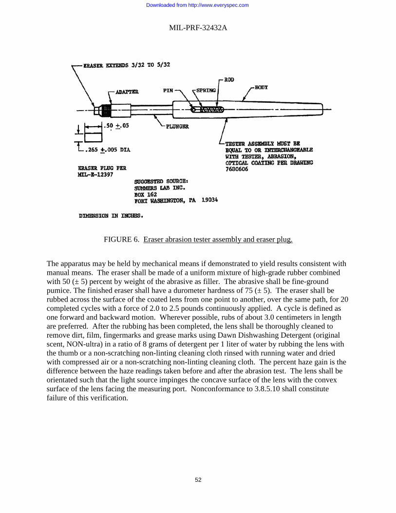
MIL-PRF-32432A
52
FIGURE 6. Eraser abrasion tester assembly and eraser plug.
The apparatus may be held by mechanical means if demonstrated to yield results consistent with manual means. The eraser shall be made of a uniform mixture of high-grade rubber combined with 50 (± 5) percent by weight of the abrasive as filler. The abrasive shall be fine-ground pumice. The finished eraser shall have a durometer hardness of 75 (± 5). The eraser shall be rubbed across the surface of the coated lens from one point to another, over the same path, for 20 completed cycles with a force of 2.0 to 2.5 pounds continuously applied. A cycle is defined as one forward and backward motion. Wherever possible, rubs of about 3.0 centimeters in length are preferred. After the rubbing has been completed, the lens shall be thoroughly cleaned to remove dirt, film, fingermarks and grease marks using Dawn Dishwashing Detergent (original scent, NON-ultra) in a ratio of 8 grams of detergent per 1 liter of water by rubbing the lens with the thumb or a non-scratching non-linting cleaning cloth rinsed with running water and dried with compressed air or a non-scratching non-linting cleaning cloth. The percent haze gain is the difference between the haze readings taken before and after the abrasion test. The lens shall be orientated such that the light source impinges the concave surface of the lens with the convex surface of the lens facing the measuring port. Nonconformance to 3.8.5.10 shall constitute failure of this verification.
Downloaded from http://www.everyspec.com

MIL-PRF-32432A
53
4.11 Fogging. As part of the user evaluation, the ability of the MCEP system to provide vision unobscured by fogging will be assessed. The topical antifog treatment provided with the MCEP system shall be included as part of the test. At the end of the user evaluation tasks, participating users will rate the overall ability to complete tasks using the eyewear and topical antifog treatment in accordance with 4.3. 4.11.1 Fogging in extreme cold weather environments (Style C only): The user evaluation will assess the ability of the Style C MCEP system to provide vision unobscured by fogging in extreme cold weather environments. The Style C MCEP system shall include any components that are part of the anti-fog methodology. At the end of the user evaluation tasks, participating users will rate the overall visibility and ability to complete tasks using the eyewear in accordance with 4.3. 4.12 Verification of durability. 4.12.1 Carrying case protection (dirt infiltration). MCEP system shall be visually examined for a protective carrying case. The carrying case shall be examined for a means of minimizing dirt infiltration (such as secure closure around its contents), and scratching of the lenses. Non-conformance to 3.9.1 shall constitute failure of this verification. 4.12.2 Service life and shelf life. As part of the user evaluation, the MCEP system shall be visually examined and physically manipulated to determine whether damage has occurred to the eyewear system during use. At the end of the user evaluation tasks, participating users will rate the durability of the MCEP system in accordance with 4.3. 4.12.3 Repair. The eyewear system shall be disassembled to its principal component stage and switched out with replacement parts for that eyewear system without the aid of tools. Nonconformance to 3.9.3 shall constitute failure of this verification. 4.13 Environment. Complete each verification in this section. 4.13.1 Temperature. The same MCEP eyewear system assembly shall be exposed to 160°F (± 3°F) for 72 hours and -60°F (± 3°F) for 72 hours. Immediately following each heat and each cold exposure samples shall also be allowed to return to ambient conditions for one hour then examined for visible signs of damage, distortion or discoloration in accordance with 4.1.8. After visual examination all moveable parts (to include any fasteners, hinges, and any means of adjustment) shall be manually operated. Any sign of damage, distortion or discoloration beyond specification requirements, as determined by the Government, or inability to operate moving parts, or the presence of breaks and cracks, shall constitute a failure of this verification. Should no damage, distortion or notable discoloration be seen then the exposed MCEP systems shall be tested for ballistic fragmentation protection in accordance with 4.8. Failure to meet the ballistic fragmentation protection requirements of 3.8.4 shall constitute failure of this verification.
Downloaded from http://www.everyspec.com

MIL-PRF-32432A
54
4.13.2 Solar radiation. The MCEP eyewear system assembly shall be exposed in a weatherometer as to ASTM G 155, although with the following changes and modifications: The weatherometer shall contain an internal, narrowband 340-nanometer or 420-nanometer self-monitoring radiometer system. Simulated solar radiant energy shall be produced via water-cooled xenon “long-arc” lamp, vertically located at the center axis of a vertical, flat, or canted 2-tier or 3-tier specimen rack. The specimen rack shall rotate at a velocity of 1.0 (± 0.1) revolutions per minute (rpm). The xenon arc lamp shall consist of a quartz burner tube. High borosilicate type-S inner and outer optical filters shall be used. Test cycle shall consist of twenty (20) hours of full light exposure, with no water spray, followed by four (4) hours of darkness, with no water spray. Test sample(s) shall be exposed continuously for 10 complete cycles. Irradiance shall be set to 0.35 W/m2/nm or 0.75 W/m2/nm, for weatherometers employing either the 340 nanometers or 420 nanometers sensor, respectively. A rack mounted black panel thermometer sensor shall be used to monitor black body temperature, while under test. Black panel temperature and humidity values during test shall be maintained at 63 (± 3)°C (145 (± 5)°F), with a relative humidity of 35 (± 5) percent, for light-on conditions, and during the darkness phase shall be 35 (± 3)°C (95 (± 5)°F), with 90 (± 5) percent relative humidity. At the end of the test the item shall be examined for any visible signs of damage, distortion or discoloration in accordance with 4.1.8. Any sign of damage, distortion or discoloration beyond specification requirements, as determined by the Government, shall be considered failure of this verification. Should no damage, distortion or notable discoloration be seen then the exposed MCEP systems shall be tested for ballistic fragmentation protection in accordance with 4.8. Failure to meet the ballistic fragmentation protection requirements of 3.9.5.2 shall constitute failure of this verification. 4.13.3 Humidity. The eyewear assemblies shall be placed in a chamber that is capable of cycling the humidity and temperature according to Table X. The samples shall be exposed to 10 complete cycles. One hour after completion of the humidity test and removal from the humidity chamber, the samples shall be dried with a non-scratching non-linting cleaning cloth or compressed air and then subjected to the adhesion test (4.13.4). Following the adhesion test, the product shall be visually assessed for damage, distortion or discoloration on the opposite (left or right) ocular, in accordance with 4.1.8. Any visible sign of damage, distortion or discoloration beyond specification requirements, as determined by the Government, shall constitute failure of this verification. Should no sign of damage, distortion or notable discoloration on the sample be seen then the exposed lenses shall be tested for ballistic fragmentation protection in accordance with 4.8. Failure to meet the ballistic fragmentation protection requirements of 3.8.4 shall constitute failure of this verification.
Downloaded from http://www.everyspec.com

MIL-PRF-32432A
55
TABLE X. Relative humidity and temperature versus time.
Start Time Temperature Temperature Relative Humidity RH
°F °C Percent (%) 0:00 95 35 63 1:00 95 35 67 2:00 94 34 72 3:00 94 34 75 4:00 93 34 77 5:00 92 33 79 6:00 95 33 80 7:00 97 36 70 8:00 104 40 54 9:00 111 44 42
10:00 124 51 31 11:00 135 57 24 12:00 144 62 17 13:00 151 66 16 14:00 156 69 15 5:00 160 71 14
16:00 156 69 16 17:00 151 66 18 18:00 145 63 21 19:00 136 58 29 20:00 122 50 41 21:00 105 41 53 22:00 103 39 58 23:00 99 37 62
4.13.4 Adhesion. A test tape, with an adhesion rating of 40 ounces per 2.5 centimeters of width, shall be firmly applied to the front surface of the lens and the back surface of the lens. The minimum area covered shall be 13 square centimeters. To ensure good contact, rub the area firmly with an eraser. Within 90 (± 30) seconds of application, the tape shall be rapidly (not jerked) removed by pulling it back upon itself at an angle as close to 180 degrees as possible. Inspect the area to which the tape was applied for removal of coating. Removal or loosening of the coating on the front surface or back surface of the lens shall be cause for failure of this verification and cause for rejection of the lot. ASTM D3359 may be used as a reference.
Downloaded from http://www.everyspec.com

MIL-PRF-32432A
56
4.13.5 Wind and dust. As part of the user evaluation, the ability of the Class 2 and Class 3 MCEP system to provide protection to the eyes from wind and dust. At the end of the user evaluation tasks, participating users will rate the ability of the Class 2 and Class 3 MCEP system design to provide protection to the eyes from wind and dust in accordance with 4.3. 4.13.6 Salt water. The items shall be tested for corrosion resistance in accordance with ANSI Z87.1 except that the eyewear shall be exposed fully assembled. Once exposure is complete and the eyewear is dry, the assembly shall be checked for functional impairment and for visible signs of degradation of the frame affecting the integrity of the item. Inability or difficulty in articulation of parts or any visible sign of degradation of the frame shall constitute failure of this verification. Nonconformance to 3.9.5.6 shall constitute failure of this verification. 4.14 Power consumption. As part of the user evaluation, the MCEP system shall be assessed for its power consumption and battery life under normal use, as applicable. At the end of the user evaluation tasks, participating users will rate the battery life of the MCEP system in accordance with 4.3. 4.14.1 Style C power consumption: The transition eyewear shall be left in the powered state for a period of 6 hours. The system shall also have a means to recharge the battery. Absence of a means to recharge, or failure to maintain the powered state for 6 hours shall be considered failure of this verification. 4.14.2 Style T power consumption: The transition eyewear shall be left in the powered state for a period of 36 hours. At 36 hours, the item shall be checked for powered function. The system shall also have a means to recharge the battery. Absence of a means to recharge, or failure to maintain the powered state for 36 hours shall be considered failure of this verification. 4.15 Human Factors Verification. 4.15.1 Sizing and fit. As part of the user evaluation, the ability of the MCEP system to accommodate (i.e., fit, adjustment, number of sizes, and successful use) U.S. Army target audience users with 5th percentile female through 95th percentile male design critical dimensions, while wearing appropriate clothing and individual equipment will be assessed. Verification of fit with the helmets, weapons, and equipment shall be determined via the verifications in 4.6. Test participants requiring prescription correction shall also asses the interface of the eyewear with the UPLC for fit. At the end of the user evaluation tasks, participating users will rate the sizing and fit of the MCEP system in accordance with 4.3. 4.15.2 Pantoscopic tilts and faceform angles. The eyewear (without prescription lenses installed) shall be mounted in the as worn position on an appropriately sized EN headform for the eyewear under test. The pantoscopic tilt shall be determined by measuring the angle formed between the intersection of the following two lines, as viewed from the side of the headform (i.e., 90 degrees from the line of sight of the headform):
Downloaded from http://www.everyspec.com

MIL-PRF-32432A
57
1. a vertical line tangent to the upper rim of the prescription lens carrier at a point 32 mm from the vertical centerline of the carrier.
2. a line segment tangent to the upper rim of the prescription lens carrier at a point 32 mm from the vertical centerline, and tangent to the lower rim of the prescription lens carrier at a point 32 mm from the vertical centerline of the carrier.
The angle (in degrees) may be measured physically (such as with a coordinate-measuring machine, or pendulum/protractor) or photographically (with a drop line as a visual aide for measuring the angle formed in the photographic image), by measuring the angular reflection of a laser beam off a mirrored lens installed into the carrier, or other suitable method. The faceform angle is considered positive if the lower rim of the prescription lens carrier falls between the headform and the vertical line described in 1 above. The faceform angle is considered negative if the lower rim of the carrier falls outside this line away from the headform. The eyewear assembly shall also be visually inspected for physical interference with the natural faceform angle of the UPLC (without prescription lenses installed). Visible changes to the faceform angle of the UPLC when installed in the eyewear, negative pantoscopic tilt, or inability to conform to the pantoscopic tilt requirements of 3.10.2 shall constitute failure of this verification. 4.15.3 Adjustment. As part of the user evaluation, the MCEP system shall be visually examined and physically manipulated to determine whether a means of adjustment for proper fit/comfort is present and to determine its effectiveness. At the end of the user evaluation tasks, participating users will rate the means of adjustment for proper fit and comfort of the MCEP system in accordance with 4.3. 4.15.4 Comfort. As part of the user evaluation, the comfort of the MCEP system will be assessed. Any discomfort exhibited during performance of verification paragraph 4.15.5 or 4.15.6 shall be applied here. The MCEP system shall also be examined (by sight and feel) for any sharp or rough edges. Any sharp or rough edge that could result in discomfort or abrasion to the users face or prevalent hot spots shall be considered failure of this verification. At the end of the user evaluation tasks, participating users will rate the comfort of the MCEP system in accordance with 4.3. 4.15.5 Donning and doffing. As part of the user evaluation, the ability of the MCEP system to be donned and doffed will be assessed. Throughout the evaluation, users will be retrieving and donning and doffing the MCEP system while wearing required helmets and equipment and while performing assigned tasks. At the end of the user evaluation tasks, participating users will rate the ability of the MCEP system to be donned and doffed in accordance with 4.3. 4.15.6 Use. As part of the user evaluation, the users will perform the following: a. Stow and remove MCEP system to and from carrier. b. Adjust Class 1 MCEP system to fit on the face in the as worn configuration under the helmet (LWH, ECH, ACH, CVC, IHPS (As applicable))
Downloaded from http://www.everyspec.com

MIL-PRF-32432A
58
c. Adjust Class 2 and Class 3 MCEP system to fit over the helmet (CVC, LWH, ECH, ACH, IHPS). d. Adjust Class 2 and Class 3 MCEP system to fit on the face in the as worn configuration under the helmet (CVC-H, ACVC-H; LWH, ACH, LW ACH, ACH Gen II, ECH, and IHPS). e. Install and remove lenses f. Manipulate movable parts g. Perform operator level Preventative Maintenance Checks and Services (PMCS) h. Install and remove UPLC (Style U only). i. Transition from light to dark and dark to light (Style T only) j. Switch transition function from manual to automatic and vice versa (Style T only) k. Operate active anti-fog, if applicable (Style C only) At the end of the user evaluation tasks, participating users will rate the ability to use the MCEP system in accordance with 4.3. 4.15.7 User survivability. As part of the user evaluation, the impact of the MCEP system upon user survivability will be assessed. Users will assess their ability to detect the MCEP system by reflected light. At the end of the user evaluation tasks, participating users will rate the user survivability aspects of the MCEP system in accordance with 4.3. 4.15.8 Safety and health hazards. Safety will be verified by verifying that MCEP system can be used together with other protective equipment, by verifying that MCEP system provides the protective capabilities for which it was designed, and by verifying that MCEP system complies with the American National Standard practice for occupational and educational eye and face protection. As part of the user evaluation, the impact of the MCEP system upon safety/health will be assessed. Users will assess whether prolonged wearing of the MCEP system causes headaches, dizziness, blurred vision, or undue eyestrain. At the end of the user evaluation tasks, participating users will rate the safety and health aspects of the MCEP system in accordance with 4.3. Additionally, end items shall be visually inspected to ensure MCEP is free of sharp and rough edges and constructed from materials that are easy to keep clean and sanitary, particularly in areas that contact the skin. 4.15.9 Risk assessment. PM SPE will assess the risk introduced by the product. Residual user safety or health hazards (those introduced by the use of the product) shall be controlled to a hazard severity and hazard probability (Risk Assessment Code) of 4C or less, as defined by the matrix in Table IV. 4.15.10 Toxicity test. Unless otherwise specified, an acute dermal irritation study and a skin sensitization study shall be conducted on laboratory animals. When the results of these studies indicate the eyewear is not a sensitizer or irritant, a Repeat Insult Patch Test shall be performed in accordance with the Modified Draize Procedure (see 2.3). If the toxicity requirement (3.11.4) can be demonstrated with historical use data, toxicity testing may not be required.
Downloaded from http://www.everyspec.com
MIL-PRF-32432A
59
4.16 Identification and marking. Identification and Marking of the eyewear shall be visually inspected to determine that the information identified in 3.12 is on the eyewear, is accessible without destroying the item is, does not degrade the performance of the eyewear and is not in the user’s field of view. Nonconformance to 3.12 shall constitute failure of this verification. 4.17 Compliance with ANSI Z87.1. The eyewear shall be evaluated in accordance/compliance with ANSI Z87.1 2015 except a) where otherwise noted in this specification and b) a minimum of three samples shall be used for each test if less than three samples are specified. Test fixtures, velocity measurements, temperature and humidity requirements shall all be performed and maintained in accordance with ANSI Z87.1. Refractive Power, Astigmatism, Prism, and Prism Imbalance tests shall be tested on the appropriate sized EN head form for the product under test. All optical tests shall be conducted in the critical optical area (defined by a circle having a 20 millimeters radius centered on the horizontal centerline and 32 millimeters from the vertical centerline), unless otherwise specified in ANSI. The size medium EN head form shall be used for one-size-fits-all products. Eyewear shall be tested in all configurations (to include the use of multiple nosepieces to accommodate both prescription and non-prescription wearers and with and without optional components that alter standoff distance from the face (such as removable face foam). Nonconformance to 3.13 and all applicable requirements of ANSI Z87.1 shall constitute failure of this verification. 4.18 ANSI flammability and ignition. The front, temple, lens, and removable side shields (as applicable) of Class 1 MCEP systems shall be tested for flammability in accordance with ASTM D635 except that three (3) samples shall be used. The frame, lens, and lens housing (as applicable) of Class 2 and 3 MCEP systems shall be tested in accordance with ASTM D635 except that three (3) samples shall be used. All MCEP systems shall be tested in accordance with ANSI Z87.1 2015. Non-conformance to 3.14.1 and all applicable requirements of ANSI Z87.1 shall constitute failure of this verification. 4.19 Textile flammability. Five (5) samples of each textile component of the Class 2 and Class 3 eyewear assemblies shall be tested in accordance with ASTM D6413 with the following exceptions: sample length may be 20-25 cm in length and the standard test fixtures may be modified to better accommodate retention strap samples (such as through the use of narrow clips at periodic intervals along the edge of the sample holder to prevent the sample from moving or curling away from the flame; edges shall not be held along the entire periphery to avoid impeding any burning that may occur and documented in the test report; the test fixture shall not be such that it prevents the strap from otherwise burning; retention strap samples will only be tested in the lengthwise direction due to narrowness of the strap and the nature of the test; after flame and char length shall be measured and recorded as part of the results; afterglow will be noted and recorded as an observation. Each test specimen shall be suspended using fixtures or clamping that firmly holds the specimen in place around its periphery in a vertical position and the flame applied to the center portion of the strap only. Char length for goggle straps shall be determined by measuring the amount of material visibly charred and consumed after testing, which may appear as an area of reduced elasticity (based on initial and post-test sample lengths), rather than applying the specified force to the sample. Elasticity of the sample shall be checked
Downloaded from http://www.everyspec.com

MIL-PRF-32432A
60
before the test to determine normal elasticity of the material. Nonconformance to 3.14.2 shall constitute failure of this verification. 4.20 Workmanship. End items shall be visually inspected and manually operated to ensure the product is free from all defects which would affect proper functioning in service. Lens defects are addressed in 4.1.9. Parts (zippers, snaps, hook and pile, glides, adjustable features, etc.) shall be easy to manipulate and provide a secure hold as evidenced by manual manipulation. Removable components shall be easily removed and reinstalled, and interfaces shall be secure (to include UPLC interface for Style U). Kits shall be examined to ensure all components are present, and no pieces/parts missing. Textile components shall be examined to ensure there are no rips, tears, or holes. Stitching shall be inspected to ensure it is complete, durable and secure (i.e., no loose, broken, or missing stitching; stitching does not easily become undone). Components shall be inspected to ensure they are free of abrasive edges. 5. PACKAGING 5.1 Packaging. Each manufacturer shall include on the APEL eyewear package a standard APEL certification label as shown below. The label shall be displayed on at least two sides and one end of a boxed product totaling three labels or the front surface of a blister packed product. The label may be in the form of an applied sticker or be permanently printed on the container and should be green in color. If a product is removed from the QPL then the use of APEL must immediately be discontinued. The APEL label (see Figure 7) is required on the final single pack item, replacement frames and lenses but is not required on larger packages containing multiple single pack items.
FIGURE 7. APEL Label.
Each manufacturer shall include on the APEL approved eyewear package a statement that states “This product meets the manufacturing and performance testing requirements as authorized by PEO Soldier. This authorization does not constitute an endorsement by the U.S. Army.”
AUTHORIZED
PROTECTIVE
EYEWEAR
LIST (APEL)
NTE 1 in
Downloaded from http://www.everyspec.com

MIL-PRF-32432A
61
6. NOTES (This section contains information of an explanatory nature on administration and implementation of the eyewear qualification and quality surveillance procedures that may be helpful to potential vendors. Detail requirements for qualification and quality will be outline any future contracts.)
6.1 Intended use. MCEP system is intended for use by military personnel for eye protection against ballistic fragmentation (primary function), electromagnetic radiation, as well as sand, wind, and dust. 6.2 Qualifying activity. Product Manager Soldier Protective Equipment (PdM SPE) is designated by the preparing activity as the qualifying activity to administer the MCEP APEL program and maintain this specification. 6.3 Cross-reference: The characteristics of previously used Classes 1a, 2a, 3a are now described by Style U in Classes 1U, 2U, 3U, respectively (see 1.2 and 1.2.2). 6.4 Acquisition requirements. Acquisition documents should specify the following: a. Title, number, and date of this Specification
b. Classes of MCEP System (see 1.2) and Styles (see 1.2.2) c. When first article is required d. When toxicity testing is required (3.11.4 and 4.15.10) e. When bar coding (if applicable) is required (3.12.2) f. Conformance inspection Acceptance Quality Limit (AQL) (see 4.1) g. Inspection conditions (see 4.1.5) h. Lot size and sample size and acceptance criteria (see 4.1.7) i. Packaging (see 5.1)
6.5 Qualification. With respect to products requiring qualification, awards will be made only for products which are, at the time of award of contract, qualified for inclusion in the APEL whether or not such products have actually been so listed by that date. The attention of the contractors is called to these requirements, and manufacturers are urged to arrange to have the products that they propose to offer to the Federal Government tested for qualification in order that they may be eligible to be awarded contracts or orders for the products covered by this specification. Information pertaining to qualification of products may be obtained from Product Manager - Soldier Protective Equipment, ATTN: SFAE-SDR-SPE, 10170 Beach Road, Building 328T, Fort Belvoir, VA 22060-5800. 6.6 Qualified Products List manufacturing facility audits. All audits will be conducted by PEO-Soldier quality assurance personnel. The audit will use ISO 9001 and ISO 17025 (as applicable) as the baseline to conduct the audit.
Downloaded from http://www.everyspec.com
MIL-PRF-32432A
62
NOTE: There is no requirement for vendors to be ISO certified. All manufacturers and distributor will be compliant with ISO 9001, and with ISO 17025 if applicable. The PEO-Soldier audit will issue observations, opportunities for improvement and non-conformances that are encountered during the audit. These will be contained in a Final Report which will be provided by the auditors to the vendor as soon as possible after the audit. Observations which contain opportunities for improvement, do not require immediate vendor corrective actions, but should be routinely corrected prior to the next audit. Observations may also contain areas of excellence and commendation for employees or Sections/Teams which are doing outstanding work. PEO Soldier will list all non-conformances on the final audit report with timelines for corrective action. Failure to complete non-conformance corrective actions by the agreed upon deadline will constitute an immediate major non-conformance and consideration for removal from the APEL. 6.7 Initial assessment audit. Vendors who have passed physical property testing and user evaluation testing will have their Quality Management System (QMS) and production facilities audited by PEO-Soldier prior to addition of the items to the APEL. The QMS will be shown to be in compliance with ISO 9001 and acceptable to PEO-Soldier or the items will not be added to the APEL until the QMS has been shown to be acceptable. Acceptable level is defined as no major non-conformances and no systematic issues found during the ISO 9001 QMS audit. 6.8 Prime vendor audits. Vendors who have products on the APEL will have their Quality Management System (QMS) and production facilities audited at a minimum once a year. Audits include a review of evidence that the prime vendor has conducted reliability assessments and QMS audits at all Subcontractor and Supplier facilities. 6.9 Standard sample. For access to samples, address the Contracting Activity issuing the invitation for bids or request for proposal. 6.10 Cleaning cloth, anti-fog reapplication and Retaining Strap. A commercial item that is compatible with the MCEP system is acceptable. 6.11 Subject Term (Key Word) Listing
Fragmentation Glasses Ballistic Sun
Downloaded from http://www.everyspec.com

MIL-PRF-32432A
63
6.12 Source of Supply.
Item Source of Supply Scratch and Dig Paddle Edmund Optics Part number NT53-197
Chemicals Fire Resistant Hydraulic Fluid (MIL-H-46170)
Royco #770
Hydraulic Fluid Petroleum Base (MIL-PRF-6083)
Royco #783
Cleaning Cloth 3M Lens Cleaning Cloth 9021 Insect repellent-controlled release 30% concentration DEET
3M Ultrathon Insect Repellent Lotion (water based), or equivalent
6.13 Changes from previous issue. Marginal notations are not used in this revision to identify changes with respect to the previous issue due to the extent of the changes.
Custodians PREPARING ACTIVITY: Army - GL Army – GL DLA - IS Project 4240-2018-007
NOTE: The activities listed above were interested in this document as of the date of this document. Since organizations and responsibilities can change, you should verify the currency of the information above using ASSIST Online database at https://assist.dla.mil/.
Downloaded from http://www.everyspec.com