Mmmmmmmmm - DTIC
114
A7-A097 743 JOHNS HOPKINS UNIV LAUREL ND APPLIED PHYSICS LAB F/6 15/6 NAVAL NUCLEAR WARFARE SIMULATION OPERATOR'IS MANUAL.(U) UNLSIID MAR Al1 N K BROWN, R B GUENTHER, P A JAFFRAY N00024-81-C-531 mmmoml//llllI Mmmmmmmmm NLSIFIEDs o m 'L 2 jlffllffllffllf
-
Upload
khangminh22 -
Category
Documents
-
view
2 -
download
0
Transcript of Mmmmmmmmm - DTIC

A7-A097 743 JOHNS HOPKINS UNIV LAUREL ND APPLIED PHYSICS LAB F/6 15/6
NAVAL NUCLEAR WARFARE SIMULATION OPERATOR'IS MANUAL.(U)
UNLSIID MAR Al1 N K BROWN, R B GUENTHER, P A JAFFRAY N00024-81-C-531
mmmoml//llllI
MmmmmmmmmNLSIFIEDs o m 'L
2 jlffllffllffllf

I OF
* A A
I .AI
This doc'a-mc-ut ria% been aPPK~vdI for pubh' rc.'-,e and sale; iu
distributicn is unlimited.
STAEI AND THEATER
81 3 16 058

I UNCLASSIFIEDSECURITY CLASSIFICATION 0OF THIS PhrE (When Dole Entered) ~ -/-
READ INSTRUCTIONSREPORT DOCUMENTATION PAGE BEFORE COMPLETING FORM
I. REPORT NUMBER ]a. OVT ACCESSION No. S. RECIPICUTIS CATALOG NUMUEN
I ,.i.. * Ti I (And g........'.TI. 7 OP RPORT & PERIOD COVERIED
NvlNuclear Warfare Simulation Operator's YeChn "icleManual. .~cnclA
-
1 ~ Z-AUTIRa . .. 4 CONTRACT OR GR1ANT NUM1119111(s)
N.; K.Bo RR.Gete P.A. Aaf fray p ,- *$do4-81-C-50
PC. PRORMING ORGANZATION NAME AND ADDREKSS '.PROGRAM ELEMENT. PROJECT. TASK
Johns opkins University AE OEUI UER
oApplied Phys Lab--Chem Prop Inf Agy CA/P
Naval PaRe f;JhsHpisR 3.s Coudmu ONF-30 UNC A IED
Washington, DC 20361 C5. ko CASSI PicATION/ DOWNGRADING
16. OISTRiluUTiON STATEMENT (*I this Roetot)
17I. 01IST01 U T ION ST AT EMEN T (of th. obot~enae ~fdN inleek 0.It difrent fros Report)
ISl. SUPPLEMENTARY NOTECS
j 19 eEy WORDS (Countinue on reverse side I# moecompW7 ,dB danIN, i block Rankse.)
NNWS Tactical Nuclear WarfareNaval Warfare Engagements Computer Simulation OperatingICampaign Models ProceduresInteractive War Games
SOAGSTMACT fCoallmne-wsooe side I mw EIeh~I ehmm~II The Naval Nuclear Warfare Simulation (NNWIS) Operator's Manual is a proceduresmanual for operating NNWS hardware and software. It contains procedures forcomputer start-uip; program initiation, operation shut-down and restart; database maintenance and backup file creation; and error recovery. It also sum-I marizes the possible player actions during the simulation game with proce-dures for using the NNWS player displays, and the scheme for player interfacewith the simulation.
Ali 711 1473. EDITIO OP 6NO01 ISLSSFE seesEEtct.ssn iI S ~02SSSECURITY CLAMAPICATIO O. TI41 PAGE (men OWa hWm0d4

NAVAL NUCLEAR WARFARE SIMULATIONOPERATOR'S MANUAL
N A
STRATEGIC AND THEATERNUCLEAR WARFARE DIVISION 7

I
I
CHANGE RECORD
CHANGE TITLE OR BRIEFNO. DATE DESCRIPTION ENTERED BY
iii/(iv blank)!

I
TABLE OF CONTENTS
Section Page
LIST OF ILLUSTRATIONS ............ ......................... vi
LIST OF TABLES .......... ............................ .... vi
1 INTRODUCTION .......... ........................... .... 1-1
NAVAL NUCLEAR WARFARE SIMULATION CONCEPT ...... ............. 1-1NNWS TEAMS ........... ............................ ... 1-1SCOPE OF DOCUMENT ........ ........................ .... 1-1
2 DESCRIPTION .......... ........................... .... 2-1
NNWS SYSTEM DESCRIPTION ....... ..................... ... 2-1EQUIPMENT DESCRIPTION ....... ...................... .... 2-1NNWS PLAYING ENVIRONMENT ....... ..................... .... 2-2NNWS SOFTWARE ENVIRONMENT ....... .................... ... 2-3
3 NNWS OPERATOR PROCEDURES
3-1 POWER TURN-ON ............ ........................ 3-13-2 INITIAL START-UP ........ ...................... ... 3-73-3 GAME PLAY .......... .......................... .... 3-113-4 SHUTDOWN .......... .......................... ... 3-173-5 RESTART .......... ........................... .... 3-253-6 DECWRITER II PAPER LOAD ....... ................... ... 3-49
I1Iv!V

LIST OF ILLUSTRATIONS
Numbe r Title page
2-1 NNWS EQUIPMENT LAYOUT. ........ .......... 2-42-2 MIINICOMIPUTERS AND DISK DRIVES (TYPICAL) .. ........ 2-52-3 OPERATOR TERMINAL. ....... ............. 2-62-4 ALPHANUMERIC TERMINAL. ........ .......... 2-72-5 GR.APHIC SCOPE. ........ ............... 2-82-6 GRAPHICS CONTROLLERS .. ........ .......... 2-92-7 NNWS INFORMATION FLOW .. ................. 2-10
LIST OF TABLES
Number Title Page
1-1 ABBREVIATIONS AND ACRONYMS .. ..... .. ....... 1-23-1 OPERAND) LIST .. ...... ................ 3-513-2 ALPHA MENU .. ...... ................. 3-533-3 EVENT REPORTS SUMMARY. ....... .......... 3-543-4 ALPHANUMERIC REPORTS .. ........ ......... 3-593-5 DISPLAY ABBREVIATIONS. ......... ........ 3-623-6 ORDER DESCRIPTIONS .. ....... ........... 3-653-7 STANDARD ORDER ELEMENTS. ........ ........ 3-763-8 GRAPHIC DISPLAY SYMBOLS. ........ ........ 3-793-9 GRAPHIC REPORTS. ........ ............ 3-803-10 ERROR RECOVERY .. ...... ............... 3-83
vi

I,I
LIST OF EFFECTIVE PAGES
I The total number of effective pages in this document is 112, consistingof the following:
Page Status Page Status
Title page Originalii through viii Original1-I and 1-2 Original2-1 through 2-10 Original3-1 through 3-86 OriginalDL-1 through DL-4 Original
I
I1iI=
II
vii/(viii blank)
I6

Section 1
INTRODUCTION
NAVAL NUCLEAR WARFARE SIMULATION CONCEPT
The Naval Nuclear Warfare Simulation (NNWS) is a software system designedto simulate theater-wide naval conflict over an extended period of time. Thesimulation is capable of modeling naval campaigns with a duration of severalmonths in simulated time, has virtually no limit of the number of units andinteractions simulated, and allows for the modeling of the human decision-making element through interactions with players of the simulation.
NNWS utilizes a large scale IBM computer to model the actions and encoun-ters of a campaign through stochastic algorithms dependent on system andplatform effectiveness parameters that can also vary as a function of environ-ment and tactical situation. Interaction with the simulation is accomplishedfrom minicomputer-controlled player stations. The players direct employmentof assets through composed orders generated at the player stations. Knowledgeof campaign status and actions is provided by reports generated by the simula-tion and subsequently processed and displayed at the player stations.
The NNWS simulation is played in three to four hour sessions, each encom-passing several days of simulated time. At the end of each session, the simu-lation status is preserved so ti>3. -he next session can be resumed as if therewere no interruption. This suspend and restart capability also allows theanalyst to play multiple replications from the same point within a scenario,testing sensitivity to tactical responses or systems effectiveness parameters.
NNWS TEAMS
Each player station is manned by a team consisting of a Player and anOperator. The Player assumes the responsibility o- a Naval Theater Commander.He is responsible for continually assessing the game situation and makingdecisions regarding allocation of forces and initiation of engagements. ThePlayer is responsible for the theory of the game.
The Operator is responsible for the mechanics of the game. He supportsthe Player by providing the available situation and status displays to aid thePlayer in decision making and by formulating, entering, and transmittingPlayer's orders. The Umpire Operator, in addition to supporting Umpire ac-tions, is responsible for initiating PDP 11/XX system operation, establishinggame play, monitoring system operation, and conducting system startup, shut-down, and error recovery procedures.
SCOPE OF DOCUMENT
This manual is intended for use by NNWS Operators. It contains a descrip-tion of the NNWS and provides the procedures and additional information re-quired by the Operators to fulfill their assigned tasks. Table 1-1 provides alist of abbreviations and acronyms used in this manual.
-I-

Table 1-1. ABBREVIATIONS AND ACRONYMS
ADR Automated Decision RulesAPL Applied Physics LaboratoryASW Anti-Submarine WarfareCAU Crypto Auxiliary UnitCROSSREFTABLE Cross Reference TableDEC Digital Equipment CorporationDEFCON:L Defense Condition: Low LevelDEFCON:H Defense Condition: High LevelDEFCON:W Defense Condition: War LevelDSL Diesel SubmarineFCC Fleet Command CenterJHU/APL Johns Hopkins University/Applied Physics LaboratoryNNWS Naval Nuclear Warefare SimulationP:E Precedence: EmergencyP:F Precedence: FlashP:O Precedence: ImmediatePIN Position and Intended MovementP3-A/B(C) Class of airplaneROM Read Only MemoryS:A Searchtype: AreaS:B Searchtype: BarrierSLBM Submarine Launched Ballistic MissileSPA SOSUS Probability AreaSOSUS Sound Surveillance SystemSS Diesel SubmarineSSB Ballistic Missile Diesel SubmarineSSBN Ballistic Missile Nuclear SubmarineSSG Guided Missile Diesel SubmarineSSGN Guided Missile Nuclear SubmarineSSN Nuclear SubmarineSUB SubmarineSURF Surface UnitSURTASS Surveillance Towed Array Sensor SystemTAR Tactical Action RulesTC Theater CommanderTSO Time-Sharing OptionVP Maritime Patrol AircraftVP STREAM Patrol Aircraft Group
1-2

Section 2
DESCRIPTION
NNWS SYSTEM DESCRIPTION
The NNWS consists of RED, BLUE, and UMPIRE stations and an IBM 3033computer. The RED and BLUE stations provide for the associated Team's inter-action with the game simulation. Each station contains a VT-100 AlphanumericTerminal and a MEGATEK Graphic Scope. The RED station also contains a PowerDistribution Panel for the Player and UMPIRE stations.
The UMPIRE station provides for the UMPIRE Team's control and monitoringof NNWS system operation. The UMPIRE station contains a DEC PDP 11/XX Mini-computer, two DEC RK-OX Disk Cartridge Drives, a DECWRITER II OperatorTerminal, a VERSATEC 1160A Printer/Plotter, a VT-100 Alphanumeric Terminal, aMEGATEK Graphic Scope, and three MEGATEK 7000 Graphic Controllers.
In addition, an IBM 3033 computer is located at JHU/APL. It serves as ahost computer for the NNWS game simulation. Figure 2-1 provides a typicallayout of NNWS equipment.
EQUIPMENT DESCRIPTION
The following paragraphs provide a brief description of each individualequipment in the NNWS.
IBM 3033 COMPUTER. The IBM 3033 Computer is a general purpose IBMcomputer. It carries out game simulation, monitors for occurrence of criticalevents and generates interrupts and system error messages. The Computerutilizes a time shared NNWS Simulation Model program and a TSO Sessionprogram.
DEC PDP 11/XX MINICOMPUTER. The DEC PDP 11/XX Minicomputer, figure 2-2,is a general purpose computer that carries out executive, communication,graphics processing, and data base update functions. It serves as the inter-face between the three stations and the IBM 3033 and as the software controlfor the Alphanumeric Terminals and the Graphic Scopes. The Minicomputer FrontPanel contains the power and operating switches and indicators.
DEC RK-OX DISK DRIVES. The two DEC RK-OX Disk Drives, figure 2-2,referred to in Section 3 as Disk Drive 0 and 1, provide direct access memoryto the Minicomputer. Disk Cartridges within each Drive contain RSX-11M oper-ating system software, MEGATEK graphics software, game data, and informationfiles. Operating controls and indicators are located on the Disk Drive FrontPanel.
2-1
DECWRITER II OPERATOR TERMINAL. The DECWRITER II Operator Terminal,figure 2-3, serves as the console for Umpire Operator interaction with theMinicomputer. The Operator Terminal keyboard contains the power and operatingswitches and indications.
VERSATEC 1160A PRINTER/PLOTTER. The VERSATEC 1160A Printer/Plotterserves as line printer for the Minicomputer and as a plotter to produce hardcopies of Graphic Scope displays. The power and operating switches and indi-cators are located on the Printer/Plotter Orange Panel.
DEC VT-1O0 ALPHANUMERIC TERMINALS. The three DEC VT-100 AlphanumericTerminals, figure 2-4, provide for Player and Umpire Operators interactionwith the game simulation through display of reports and generation of orders.Each team's Alphanumeric Terminal displays Host Computer generated statusinformation in the form of reports and provides for the formulation and trans-mission of Player's inputs in the form of orders. The power switch is locatedon the left rear of the Alphanumeric Terminal. The Alphanumeric TerminalKeyboard contains the operating keys and indicators.
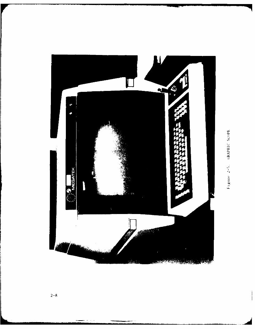
MEGATEK GRAPHIC DISPLAY SCOPES. The three MEGATEK Graphic DisplayScopes, figure 2-5, provide a theater wide situation map containing theidentities and plotted positions of all friendly and detected enemy units.The situation map is updated each interrupt and a variety of routines areenabled to aid the Players in generating orders. A hard copy of the situationmap may be obtained on the Printer Plotter. The power switch is located onthe right rear of the Graphic Scope. Operating keys and a joy-stick arelocated on the Graphic Scope Front Panel. INTENSITY and FOCUS knobs and thepower indicator are located above the display screen.
MEGATEK 7000 GRAPHICS CONTROLLERS. The three MEGATEK 7000 GraphicsControllers, figure 2-6, drive the Graphic Scopes. The three GraphicsControllers are mounted together in a free standing cabinet with a commonpower switch on the bottom rear of the cabinet. Power indicators are loca..don the front of each Graphics Controller.
NNWS PLAYING ENVIRONMENT
NNWS Campaigns are played in multiple sessions. Each session is three tofour hours in duration and spans up to several days of simulated time. Thesession begins with the umpire operator initiating inter-computer communica-tions, starting or resuming the simulation, and enabling the player functionsfor their respective stations.
A session itself consists of an indeterminate number of turns or cycles,each marked by an interrupt giving both sides an opportunity to receivereports and issue orders. The frequency of the interrupts is controlled bytwo parameters that are entered by the umpire at the beginning of each sessionand by the events that occur within the simulation.
2-2

A session terminates normally with an ordered halt by the umpire. Thesimulation and all player functions are terminated. The status of all sta-tions and all the simulated units and systems is preserved enabling play to beresumed at the next session, as if it had never been disrupted.
On occasion, a session may terminate involuntarily because of a hardware,software or data transmission error. In such cases, the game is resumed as ofthe last available interrupt. Depending on the cause of termination, theresumption of the game will occur at the current interrupt, the previousinterrupt or the interrupt corresponding to the beginning of the session.
NNWS SOFTWARE ENVIRONMENT
NNWS consists of a minicomputer driven display system and a large mainframe computer on which the engagements, events and processes are simulated.Both portions of the simulation have their own software systems with a collec-tion of computer programs, databases and execution procedures. The NNWSplayer uses both s'stems. The display system gathers and analyzes reportsfrom the simulated events and processes, and provides the information togenerate orders. Order generation is the means of player control over thesimulation. Figure 2-7 provides a diagram of NNWS information flow.
The reports/orders scheme requires that each system have two modes,active and passive, and while each system is active its counterpart must bepassive. With the IBM 3033 simulation system active, reports are collected upto the simulated time of the next mode change (called interrupt time). Thereports are then transmitted to the player stations. The simulation is thensuspended, the Minicomputer display system becomes active, and the playersview the reports and issue orders for the next simulation cycle.
The process originates on the Minicomputer with installation of the datacommunications programs and the umpire's executive program. The operator atthe umpire's station then establishes communications with the IBM 3033 andperforms initialization of the simulation by loading the scenario database andon-line NNWS system performance databases and setting the session parameters.
Upon starting the simulation, the first interrupt occurs immediately interms of simulation time. This activates the Minicomputer display system,initializes the player databases and presents an opportunity to issue ordersto the units being simulated. After each player has transmitted his set oforders, the Minicomputer enters passive mode. The players can continue toreview their information, but cannot issue orders.
The simulation on the IBM 3033 becomes active and advances to the nextinterrupt time. Reports are transmitted and the process is repeated until theumpire orders a halt in play.
2-3

r -JHU/APL
I HOST COMPUTER I
I IL ---- - -
r UMPIRE STATION
MEGATEK PDP 11/XX DECWRITER II RK-OX DISKGRAPHICS MINICOMPUTER OPERATOR CARTRIDGECONTROLLER TERMINAL DRIVES
MEGATEK VT-100GRAPHIC ALPHANUMERICSCOPE TERMINAL EMODEM _ CAU KG-13
II--- --- -- - --- ------------
RED STATION BLUE STAT!ON
MEGATEK VT-1O0 MEGATEK VT-1O0GRAPHIC ALPHANUMERIC GRAPHIC ALPHANUMERICSCOPE TERMINAL SCOPE TERMINAL
POWER DISTRBTO IPANEL I
-- -- -- - -- 1------------------------ --- - - -- ----
Figure 2-1. NNWS EQUIPMENT LAYOUT
2-4
....... ... .. ...

II
z
L~I-
2-5

- 1
'p.,
0
0
2-6

I
Lz~
'C
C
-t
04
Cs
zto
2-7
2-8

I
F ig~JrE' 2-b. ;RAIII IrS 'NI Hfl!.I.ERS
2-

IBM 3033HOST COMPUTER
ORDERS,COMMANDS
RK.OX REPORTS, VRAEDISK RIVESERRORDISK DRIVES MESSAGES PITR
(2) INFORMATION PRINTOUTS_ PLOTTER___________
PDP lliXX PRINTOUT)
MINICOMPUTER
DECWRITER 11MIAEOPERATOR COMMANDS RPRSGAHC
REPORTS ORDERS COMMANS]CMAD
TERMINTER CONALLER((3)
FigureS 2E.RRS NOR COMOMAFLO
2-PORT

9.,
IUI

NNWS OPERATORPROCEDURE 3.1
POWER TURN-ON
NOTE
If expected printout/display does not occur or containserrors, and no operator recovery procedure is provided,contact APL NNWS Programning Personnel
1. At RED Station Power Distribution Panel, place circuit breakers 1, 3, 4,5, 6, 7, 8, 10, 12, 14 and 16 to ON.
2. Apply power to MEGATEK 7000 Graphics Controller as follows:
A. At bottom rear of Graphics Controller cabinet, place AC POWER Toggleswitch UP.
B. Verify each Graphics Controller Front Panel indicator is lit WHITE.
3. Apply power to three MEGATEK Graphic Scopes as follows:
A. At right rear of each Graphic Scope, place Power switch DOWN.
B. Verify each Graphic Scope Front Panel Power indicator is lit ORANGE.
C. Verify INTENSITY knob is above midrange for each Graphic Scope.
4. Apply power to VERSATEC Printer/Plotter as follows:
A. At Printer/Plotter Orange Panel, depress Power (topmost) Actuator/Indicator.
B. Verify Actuator/Indicator is lit WHITE.
C. Verify Paper Supply (RED) indicator is OUT.
NOTE
If Paper Supply indicator is lit RED, replenish paper inaccordance with instructions located inside hinged FrontPanel
D. Open hinged Front Panel.
E. Depress RESET pushbutton.
F. Close hinged Front Panel.
3-1
NNWS OPERATORPROCEDURE 3.1
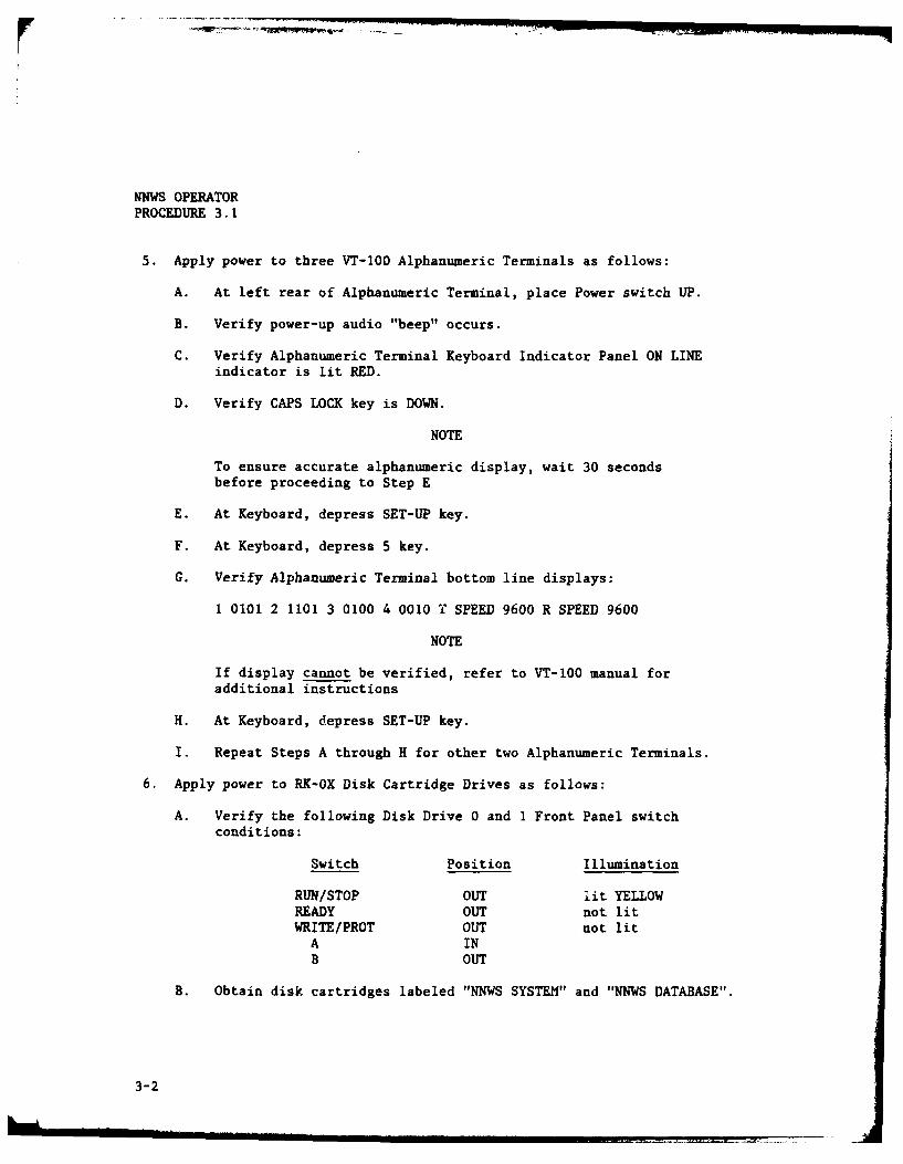
5. Apply power to three VT-100 Alphanumeric Terminals as follows:
A. At left rear of Alphanumeric Terminal, place Power switch UP.
B. Verify power-up audio "beep" occurs.
C. Verify Alphanumeric Terminal Keyboard Indicator Panel ON LINEindicator is lit RED.
D. Verify CAPS LOCK key is DOWN.
NOTE
To ensure accurate alphanumeric display, wait 30 secondsbefore proceeding to Step E
E. At Keyboard, depress SET-UP key.
F. At Keyboard, depress 5 key.
G. Verify Alphanumeric Terminal bottom line displays:
1 0101 2 1101 3 0100 4 0010 T SPEED 9600 R SPEED 9600
NOTE
If display cannot be verified, refer to VT-100 manual foradditional instructions
H. At Keyboard, depress SET-UP key.
I. Repeat Steps A through H for other two Alphanumeric Terminals.
6. Apply power to RK-OX Disk Cartridge Drives as follows:
A. Verify the following Disk Drive 0 and 1 Front Panel switchconditions:
Switch Position Illumination
RUN/STOP OUT lit YELLOWREADY OUT not litWRITE/PROT OUT not litA INB OUT
B. Obtain disk cartridges labeled "NNWS SYSTEM" and "NNWS DATABASE".
3-2

NNWS OPERATOR NNWS OPERATOR
PROCEDURE 3.1 PROCEDURE 3.1
NOTES
1. Disk Drives hinged top lid can only be opened when
power is applied.
2. Loading instructions are located inside the Disk
Drive hinged Front Panel.
C. Load "NNWS SYSTEM" cartridge in Disk Drive 0.
D. Load "NNWS DATABASE" cartridge in Disk Drive 1.
E. Depress RUN/STOP switch.
NOTE
Wait 15 to 30 seconds for Disk Drive spin-up prior to
performing Step F
F. Verify the following Disk Drive 0 and I Front Panel switch
conditions:
Switch Position Illumination
RUN/STOP IN not lit
READY OUT lit WHITE
FAULT OUT not lit
WRITE/PROT OUT not lit
A INB OUT
7. Apply power to DECWRITER 11 Operator Terminal as follows:
A. At Keyboard upper left corner, place Power (Rocker) switch to ON(I).
B. Verify position of following Keyboard Switches:
Switch Position
BAUD RATE 110 UPBAUD RATE 300 DOWN
LINE/LOCAL UPFDX UPALT CHAR SE"' UPCHAR SET LOCK DOWNAUTO LF DOWNHERE IS UP
CAPS LOCK DOWN
3-3

NNWS OPERATORPROCEDURE 3.1
C. Verify Keyboard STD CHAR indicator is lit RED
D. Verify PAPER OUT (RED) indicator is not I .,.
E. Verify paper supply stock is at least one inch thick.
NOTE
If PAPER OUT indicator is lit RED or paper supply is lessthan one inch thick, load paper in accordance with INWSOperator Procedure 3.6
8. Apply power to PDP ll/XX Minicomputer as follows:
A. At Minicomputer Front Panel, rotate Power knob to RUN position.
B. Verify DC ON indicator is lit RED.
9. Load operating system software as follows:
A. At Minicomputer Front Panel, depress and hold CNTRL pushbutton.
B. Depress BOOT pushbutton.
C. Simultaneously release CNTRL and BOOT pushbuttons.
D. At Operator Terminal verify one line of four six-digit numbers and a$ sign on the second line is printed.
EXAMPLE: 070730 000024 000716 003632
$
E. At Operator Terminal, enter DM
F. At Operator Terminal,verify the following printout occurs:
RSX-11M V3.1 BL22 124K MAPPED>RED DMO:=SYO:>RED DMO:=LBO:>MOU DMO:RSX11MBL22>@ [1, 2] STARTUP>; RSX11M VERSION 3.1 autopatched 19-april-79 by DEC>; +512. byte DRVPAR, +1024. byte POOL space, by NKB>; 4096, byte MEGCOM partit. add. 27-may-1979 by NKB>; post-boot load of GX: & GP: 21-JUN-1979 by NKB>* MUST ENTER TIME, DATE (HR:MN DD-MMM-YY) [S]:
3-4
NNWS OPERATORPROCEDURE 3.1
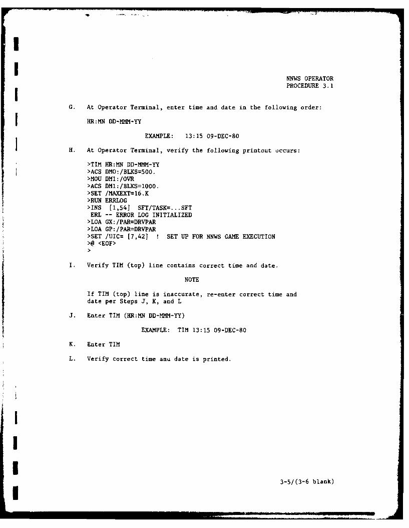
G. At Operator Terminal, enter time and date in the following order:
J HR:MN DD-MMM-YY
EXAMPLE: 13:15 09-DEC-80
IH. At Operator Terminal, verify the following printout occurs:
>TIM HR:MN DD-MMM-YY>ACS DM0: /BLKS=500.>MOU DM1:/OVR>ACS DM1: /BLKS=1OOO.I>SET /MAXEXT=16.K>RUN ERRLOG>INS [1,54] SFT/TASK=. .. .SFTERL -- ERROR LOG INITIALIZED>LOA GX: /PAR=DRVPAR>LOA GP: /PAR-DRVPAR>SET /UIC= [7,42]1 SET UP FOR NNWS GAME EXECUTION>@ <EOF>
I. Verify TIM (top) line contains correct time and date.
NOTE
If TIM (top) line is inaccurate, re-enter correct time anddate per Steps J, K, and L
J. Enter TIM (HR:MN DD-MMM-YY)
EXAMPLE: TIM 13:15 09-DEC-80
K. Enter TIM
L. Verify correct time anu date is printed.
3-5/(3-6 blank)

-4
w
I-
r,)-I
C-u

NNWS OPERATORPROCEDURE 3.2
INITIAL START-UP
NOTES
1. This procedure is for starting the NNWS applicationat game time equal to zero. If NNWS is to be startedat game time other than zero, refer to NNWS OperatorProcedure 3.5.
2. If expected printout/display does not occur or con-tains errors, and no operator recovery procedure isprovided, contact APL NNWS Programming Personnel.
1. Verify NNWS Power Turn-On has been completed in accordance with NNWS
Operator Procedure 3.1.
2. Initialize Files from Operator Terminal as follows:
A. Enter SET /UIC= [7,42]
B. Enter @FILEINIT
C. After approximately 15 minutes, verify the following printoutoccurs:
INIT IS NOW COMPLETE
3. Load NNWS Application Software from Operator Ter rnal as follows:
A. Enter @NNWS
B. After approximately 10 minutes, verify the following printoutoccurs:
> @ <EOF>
C. Verify all lines have leading > character.
D. Retain printout as a system configuration log.
4. Initiate Umpire's Alphanumeric Terminal from Operator Terminal asfollows:
A. Verify the following printout has occurred:
IS THE GAME UMPIRE TERMINAL (TT2:) AVAILABLE? (T or F)
B. Enter T
3-7

NNWS OPERATORPROCEDURE 3.2
5. Initiate communications with Host Computer from Umpire's Alphanumeric
Terminal as follows:
NOTE
Use DELETE key to erase entries
A. At Crypto Auxiliary Unit (CAU) verify Terminal Isolation Switch isin APL/JHU.
B. Sync CAU and Cryptographic Unit (KG-13).
C. At Modem unit verify ON and CO indicators are lit RED.
D. Verify the following display has occurred:
IS NNWS TO COMMUNICATE INTER-PROCESSOR? (T or F)
E. Enter T
F. Verify the following display has occurred:
enter LOGON USERID/PASSWORD SIZE ( )EXEC model, answer queries, then depress CTRL Z
G. Enter LOGON OP65 SIZE(4096)
H. Verify prompt display for account number and password.
NOTE
If prompt does not occur, repeat Step G
I. Enter account number and password.
J. Verify the following display has occurred:
OP65 logon in progress at (Time) on (Date)Availability: Mon-Fri--8:30 a.m. to midnight,Sat.--8:30 to 4:30 p.m.
USERPROC CMDPROCFREE FILE (SYSUDUMP)READY
NOTE
If READY display does not occur, repeat Step I
3-8

NNWS OPERATORPROCEDURE 3.2
6. Initiate NNWS Application on Host Computer from Umpire's Alphanumeric
Terminal as follows:
NOTE
Refer to Table 3-1 for explanation and listing of operandlist
A. Enter NNWS [operand list].
B. Verify a single line ot' four values separated by commas isdisplayed.
EXAMPLE: S, A, OND, LANT
C. Observe prompt for password.
D. Enter password.
NOTE
CNTRL Z entry (Steps F and G) must be made within 5seconds after CNTRL Z prompt
E. Repeat Steps C and D for each additional prompt until the followingprompt occurs:
ENTER CNTRL Z NOW
F. Depress and hold CTRL key.
G. Depress Z key.
H. Simultaneously release CTRL and Z keys.
I. Verify the following display has occurred:
ENTER MAP PPOJECTION FILE NAME - up to 9 chars.
J. Enter Map Projection File.
NOTE
Continually monitor Umpire's Alpainumeric Terminal forunsolicited system messages from the host computer. Allsuch messages will be preceded by the characters "TSO:".If a message is displayed, notify the Umpire and APL NNWSProgramming Personnel and refer to NNWS Operator Procedure3.3 Part 3.
3-9

NNWS OPERATORPROCEDURE 3.2
7. Initiate RED and BLUE Alphanumeric Terminals from Umpire's Alphanumeric
Terminal as follows:
A. Verify the following display has occurred:
Are the RED and BLUE TEAMS available? (T or F)
B. Enter T
8. Initiate game play as follows:
A. At Umpire's Alphanumeric Terminal, verify 21 function menu isdisplayed.
B. At RED and BLUE Alphanumeric Terminals, verify Alpha Menu isdisplayed.
C. At RED and BLUE Graphic Scopes, verify initial situation map is
displayed.
D. At Umpire's Alphanumeric Terminal, enter 20
E. At Operator Terminal, verify the following printout has occurred:
ORDRS SENT @ (Time)
3-10

w'4a
*1
- -- i-- - ~--~- -
NNWS OPERATOR
PROCEDURE 3.3
GAME PLAY
The RED and BLUE Operators are responsible for generating the specificreports required by their respective Players and for entering and transmitting£ layer orders during game interrupts. The Umpire Operator is responsible formonitoring and verifying system operation and for detecting and correctingsystem and transmission errors.
To aid the operators in performing their required tasks, this procedureis divided into three parts as follows:
Part 1 PLAYER REPORTSPart 2 PLAYER ORDERSPart 3 UMPIRE CONTROL AND MONITORING
Parts I and 2 contain the information required by the RED and BLUE TeamOperators to generate the reports and orders and provide definitions to trans-late the symbology into meaningful data for the player. Part 3 contains theinformation, actions, and error recovery procedures required by the UmpireOperator during the game.
3-11

NNWS OPERATORPROCEDURE 3.3
PART 1PLAYER REPORTS
NOTES
1. This procedure is not to be used if Umpire hasdirected to forego receipt of reports.
2. If reports are desired at a time other than a gameinterrupt, proceed to Step 7.
1. At RED (BLUE) Alphanumeric Terminal, verify the follow display hasoccurred:
NEW REPORTS RECEIVED
2. Depress RETURN key.
3. Verify Alphanumeric Terminal displays Event Reports Summary. (Refer toTable 3-3 for an explanation of these reports).
4. Verify Graphic Scope displays an updated situation plot. (Refer to Table3-8 for a summary of NNWS graphical display symbols).
NOTE
Displays that have geographical coordinates off the cur-:ent map are not plotted
5. Verify Alphanumeric Terminal displays Alpha Menu (Table 3-2).
6. Verify Graphic Scope displays the following Graphic Menu beneath thetheater map.
INPUT P, T, D, F, S, A, 9 (TEMP, TRK, DST, FLD, SUB/SURF, AC, QUIT)
7. Generate reports on Alphanumeric Terminal as follows:
A. Select desired report option from Alpha Menu items 01 through 05.
B. Enter corresponding menu option number.
C. Verify desired report is displayed. (Refer to Table 3-4 for expla-nation of reports.)
8. Generate graphic displays as follows:
3-12

NNWS OPERATOR
PROCEDURE 3.3
NOTES
1. The Graphics Menu is enabled during game interruptsonly.
2. Refer to Table 3-9 for explanation and operation ofGraphic displays.
3. Perform Step A only if a hard copy of current displayis desired.
A. Depress COPY key and wait until hard copy is completed.
B. Select desired option from Graphics menu.
C. Enter corresponding menu item letter.
D. When no additional graphic displays are desired, enter 9.
3-13
NNWS OPERATORPROCEDURE 3.3
PART 2PLAYER ORDERS
NOTE
This procedure is to be used during game interrupts only
1. At RED (BLUE) Alphanumeric Terminal, verify the Alpha Menu is displayed(Table 3-2).
2. Generate orders on Alphanumeric Terminal as follows:
A. Select desired order option from Alpha Menu items 06 through 19.
B. Enter corresponding menu option number.
C. Verify desired order format is displayed. (Refer to Table 3-6 foruse, format, and order element description).
D. Depress RETURN key with no data entered (null entry) to return toAlpha Menu.
3. After all orders have been entered and verified, transmit orders asfollows:
A. If not previously accomplished at Graphic Keyboard, enter 9.
B. Verify Graphic Scope displays the following below the map:
SITRD (SITBL) JOY-KEY OFF
C. At RED (BLUE) Alphanumeric Terminal, enter 20
3-14 I

I
I NNWS OPERATORPROCEDURE 3.3
I PART 3UMPIRE CONTROL AND MONITORING
1 I. Verify Operator Terminal prints REPTS RECV @ (Time).
2. Verify Umpire's Alphanumeric Terminal displays NEW REPORTS RECEIVED.
3. If directed by Umpire, inform RED and BLUE Teams to forego receipt ofreports.
I 4. Depress RETURN key.
5. Verify Umpire's Alphanumeric Terminal displays raw data received for both
teams.
NOTE
If an error is found, refer to NNWS Operator Procedures3.4 and 3.5 for Shutdown and Restart, respectively
6. Review all raw data displayed for transmission errors such as unusualcharacters.
7. Continually monitor overall system operation. If an error is detected,refer ta Table 3-10 for appropriate recovery procedures.
I
I
II
I
,[ 3-15/(3-16 blank)
, I i

.. , - -
14
C-4
I

NNWS OPERATORPROCEDURE 3.4
SHUTDOWN
The NNWS Shutdown procedure is divided into two parts: NORMAL SHUTDOWNand ABNORMAL SHUTDOWN. Part 1, NORMAL SHUTDOWN, is used for normal sessiontermination initiated by the Umpire Operator during a game interrupt. Part 2,ABNORMAL SHUTDOWN, is used when the simulation has been halted due to a systemor user error. Each part contains the information required to terminate thesession, preserve the files and, if desired, ready the system for Restart.
3-17
NNWS OPERATORPROCEDURE 3.4
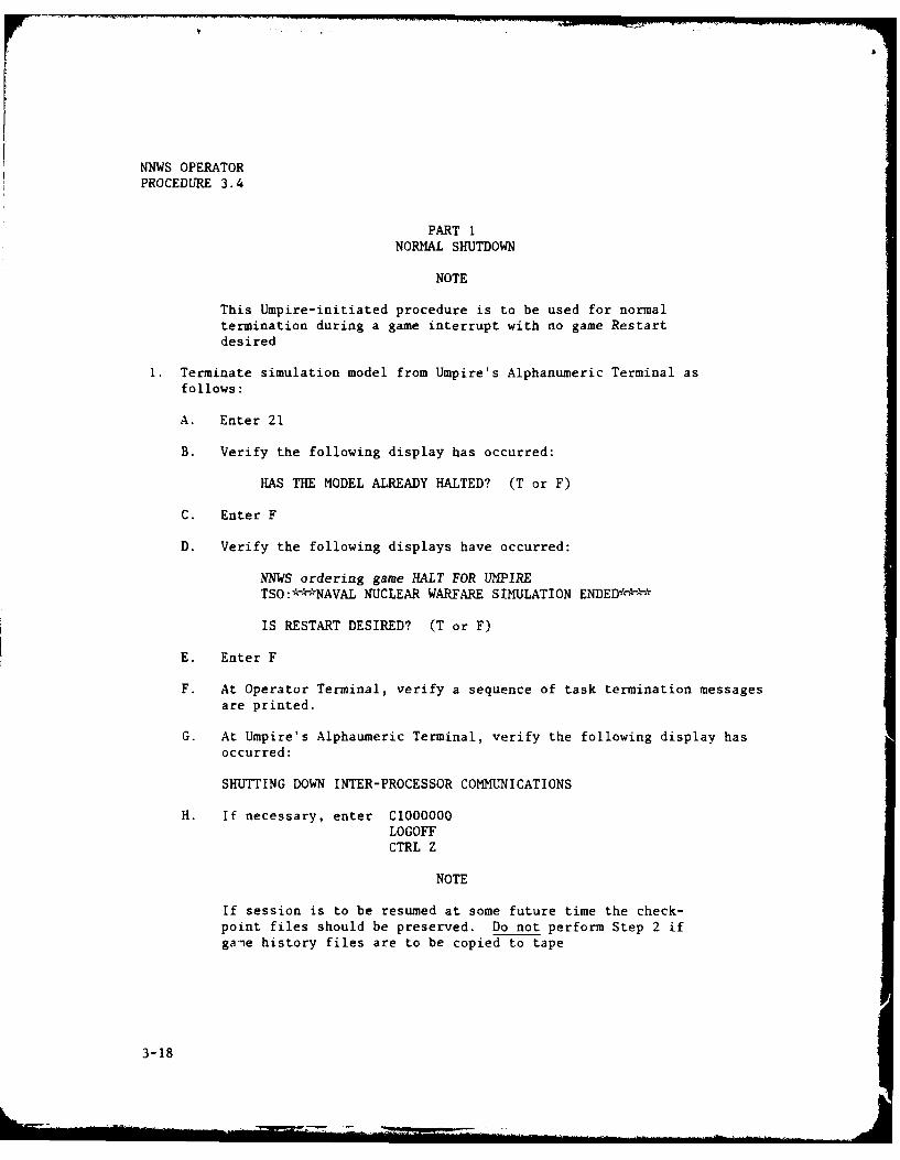
PART 1NORMAL SHUTDOWN
NOTE
This Umpire-initiated procedure is to be used for normaltermination during a game interrupt with no game Restartdesired
1. Terminate simulation model from Umpire's Alphanumeric Terminal asfollows:
A. Enter 21
B. Verify the following display has occurred:
HAS THE MODEL ALREADY HALTED? (T or F)
C. Enter F
D. Verify the following displays have occurred:
NNbJWS ordering game HALT FOR UMPIRETSO:-, -NAVAL NUCLEAR WARFARE SIMULATION ENDED -,**
IS RESTART DESIRED? (T or F)
E. Enter F
F. At Operator Terminal, verify a sequence of task termination messagesare printed.
G. At Umpire's Alphaumeric Terminal, verify the following display has
occurred:
SHUTTING DOWN INTER-PROCESSOR COMMUNICATIONS
H. If necessary, enter C1O00000LOGOFFCTRL Z
NOTE
If session is to be resumed at some future time the check-point files should be preserved. Do not perform Step 2 ifga'e history files are to be copied to tape
3-18

NNWS OPERATORPROCEDURE 3.4
2. If desired, preserve the checkpoint files from Umpire's AlphanumericTerminal as follows:
A. Enter GAMESAVE
B. Verify the following displays have occurred:
F4A.OP65.CHKBACK.BlmmddhhF4A.OP65.CHKBACK.B2mmddhh
3. If desired, copy current game history to tape from Umpire's AlphanumericTerminal as follows:
NOTES
1. Current game history should be copied to tape at endof each day's play and before a new scenario or gameis started.
2. APL NNWS Programming Personnel must be contacted tosubmit tapes and passwords forms and to set agreedidentifying character prior to executing the GAMEBACKcommand.
3. The GAMEBACK command automatically executes theGAMESAVE command.
4. Steps B through I may be performed as time and condi-tions permit.
A. Enter GAMEBACK (Character ID)
B. Enter OUT OP65BKT PR(A)
C. Enter E A 0 D
D. Enter VERIFY
E. Enter F /CODE /
F. Verify a code of 0000 is displayed.
G. Enter F
H. Verify a code of 0000 is displayed.
I. Repeat Steps G and H two additional times.
3-19

NNWS OPERATORPROCEDURE 3.4
J. Enter END NOS
K. Verify READY is displayed.
NOTE
If Steps F and H could not be verified, contact APL NNWSProgramming Personnel prior to starting a new session
4. Terminate TSO session from Umpire's Alphanumeric Terminal as follows:
A. Enter LOGOFF
B. Verify statistical information concerning the session is displayed.
5. Terminate Minicomputer NNWS Tasks from Umpire's Alphanumeric Terminal asfollows:
A. Depress and hold CTRL key.
B. Depress Z key.
C. Simultaneously release CTRL and Z keys.
NOTE
NNWS file maintenance should be performed daily. Mainten-ance should be performed only if game play is to be sus-pended for a minimum of 20 minutes
6. If desired, perform NNWS file maintenance from Operator Terminal asfollows:
A. Enter @FILEPURG
7. Shutdown Minicomputer as follows:
A. At Operator Terminal, enter RUN (1,541 SHUTUP
B. Verify the following printout occurs:
ENTER MINUTES TO WAIT BEFORE SHUTDOWN
C. Enter 0
3-20

NNWS OPERATORPROCEDURE 3.4
D. Verify the following printout occurs:
**kDMI: -DISMOUNT COMPLETE
E. At Minicomputer Front Panel, verify RUN indicator is OUT.
F. At Disk Drive Front Panel, depress RUN/STOP switch.
NOTE
Wait 30-60 seconds before proceeding to Step G
G. Verify RUN/STOP indicator is lit YELLOW.
8. If desired, secure power to system as follows:
A. At Minicomputer Front Panel, rotate Power knob to DC OFF.
B. At Operator Terminal, place Power (Rocker) switch to OFF.
C. At left rear of all three Alphanumeric Terminals, place Power switchDOWN.
D. At Printer/Plotter Orange Panel, depress Power (topmost) switch.
E. At right rear of all three Graphic Scopes, place Power switch UP.
F. At RED Station Power Distribution Panel, place circuit breakers 1,3, 4, 5, 6, 7, 8, 10, 12, 14 and 16 to OFF.
3-21
IsmI

NNWS OPERATORPROCEDURE 3.4
PART 2ABNORMAL SHUTDOWN
NOTES
1. An Abnormal Shutdown is any simulation model termina-tion that is not initiated by the Umpire.
2. If TSO:***NAVAL NUCLEAR WARFARE SIMULATION ENDED***display did not occur, proceed to Step 4.
1. At Umpire's Alphanumeric Terminal, verify the following display hasoccurred:
TSO*.*NAVAL NUCLEAR WARFARE SIMULATION ENDED**
NOTE
Abnormal Shutdown occurs during transmission of orders,receipt of reports, a game interrupt or between gameinterrupts
2. Determine when Abnormal Shutdown occurred as follows:
A. If last message received on Umpire's Alphanumeric Terminal wasORDERS TRANSMITTED, perform the following:
(1) At Operator Terminal, enter PIP DMI:UMPRPT.DAT/LI
(2) At Operator Terminal, observe time of creation printout.Compare time of creation printout with last ORDRS SENT print-out. If time of creation was prior to the ORDRS SENT time,shutdown occurred between interrupts. If time of creation wasafter ORDRS SENT time, shutdown occurred during receipt ofreports.
B. If last message received on Umpire's Alphanumeric Terminal wasREPORTS RECEIVED, perform the following:
(1) Determine if RED and BLUE Operators have transmitted orders.
(2) If both Operators have entered 20 on their respective Alpha-numeric Terminals, shutdown occurred during transmission oforders. If either Operator has not entered 20, shutdownoccurred during the game interrupt.
3. Terminate NNWS Executive from Umpire's Alphanumeric Terminal as follows:
A. Enter 21
3-22

NNWS OPERATORPROCEDURE 3.4
B. Verify the following display has occurred:
HAS THE MODEL ALREADY HALTED? (T or F)
C. Enter T
D. Verify the following display has occurred:
IS RESTART DESIRED? (T or F)
NOTE
Cause of Abnormal Shutdown as determined by Step 2 dict-ates whether to perform Step E, F or G
E. If shutdown occurred during game interrupt perform the following:
(1) Enter T
(2) Observe simulation restart.
F. If shutdown occurred between game interrupts, refer to NNWS OperatorProcedure 3.5 Part 2.
G. If shutdown occurred during transmission of orders or receipt ofreports, perform the following:
(1) Enter F
(2) Enter OUT 0P65 PR(A)
(3) Enter E A 0 D
(4) Enter VERIFY
(5) Enter B
(6) Observe display.
(7) Enter UP until name of terminating routine is displayed.
(8) Enter END
(9) If routine name is NPUT or NGET, depress and hold CTRL key.Depress Z key and release both (Refer to NNWS Operator Proce-dure 3.5 Part 2).
(10) For any other routine name, enter LOGOFF and notify APL NNWSProgramming Personnel.
I3-23
i|

NNWS OPERATORPROCEDURE 3.4
4. Terminate NNS Executive from Umpire's Alphanumeric Terminal as follows:
A. Enter 21
B. Verify the following display has occurred:
HAS THE MODEL ALREADY HALTED? (T or F)
C. Enter T
D. Verify the following display has occurred:
IS RESTART DESIRED? (T or F)
E. Enter F
F. Depress and hold CTRL key.
G. Depress Z key.
K. Simultaneously release CTRL and Z keys.
I. If Restart is desired, refer to NNWS Operator Procedure 3.5 Part 2.
3-24

p
U2-4
NNWS OPERATORPROCEDURE 3.5
RESTART
The NNWS Restart procedure is divided into three parts: STANDARDRESTART, NON-STANDARD RESTART, and REPLICATION RESTART. Part 1, RTANDARDRESTART, is used to restart when the session was terminated by either Umpireaction or equipment malfunction during a game interrupt. Standard Restartinitiates the session at the game time corresponding to the last game inter-rupt of the previous session.
Part 2, NON-STANDARD RESTART, is used to restart the game following anAbnormal Shutdown during receipt of reports, transmission of orders, betweengame interrupts, or due to TSO session termination.
Part 3, REPLICATION RESTART, is used to replay a game from a particularinitial state. This enables Players to vary their responses to identicalsituations. It can also be used to perform Monte Carlo Analysis by playingmultiple replications with same responses but different random number streams.
3-25
NNWS OPERATORPROCEDURE 3.5
PART ISTANDARD RESTART
1. Verify NNWS Power Turn-On has been completed in accordance with NNWSOperator Procedure 3.1.
NOTE
If no equipment shutdown has occurred since last session,perform Step 2 and omit Step 3. If equipment shutdown hasoccurred since last session, omit Step 2 and proceed toStep 3
2. At Operator Terminal, enter RUN NNWS
3. Load NNWS Application Software from Operator Terminal as follows:
A. Enter @NNWS
B. After approximately 10 minutes, verify the following printout hasoccurred:
> @ <EOF>
C. Verify all lines have leading > character.
D. Retain printout as a system configuration log.
4. Initiate Umpire's Alphanumeric Terminal from Operator Terminal asfollows:
A. Verify the following printout has occurred:
IS THE GAME UMPIRE TERMINAL (TT2:) AVAILABLE? (T or F)
B. Enter T
5. Initiate communications with Host Computer from Umpire's AlphanumericTerminal as follows:
A. Verify the following display has occurred.
IS NNWS TO COMMUNICATE INTER-PROCESSOR? (T or F)
B. Enter T
3-26

NNWS OPERATORPROCEDURE 3.5
C. Verify the following display has occurred:
enter LOGON USERID/PASSWORD SIZE (EXEC model, answer queries, then depress CTRL Z
D. Enter LOGON 0P65 SIZE(4096)
E. Verify prompt display for accou.it number and password.
NOTE
If prompt does not occur, repeat Step D
F. Enter account number and password.
G. Verify the following display has occurred:
0P65 logon in progress at (Time) on (Date)Availability: Mon-Fri--8:30 a.m. to midnight, Sat.--8:30 a.m.to 4:30 p.m.USERPROC CMDPROCFREE FILE (SYSUDUMP)READY
NOTE
If READY display does not occur, repeat Step F.
6. Initiate NNWS Application on Host Computer from Umpire's AlphanumericTerminal as follows:
NOTES
1. Refer to Table 3-1 for explanation and listing ofoperand list.
2. Do not use MODE or G2W parameters.
3. If GAMEBACK command was successfully executed duringtermination of previous session, use DISP parameterwith value of OLD.
A. Enter NNWS [operand list].
B. Verify a single line of four values separated by commas isdisplayed.
EXAMPLE: S, A, OND, LANT
3-27

NNWS OPERATORPROCEDURE 3.5
C. Observe prompt for password.
D. Enter password.
NOTE
CNTRL Z entry (Steps F and G) must be made within 5seconds after CNTRL Z prompt.
E. Repeat Steps C and D for each additional prompt until the followingprompt occurs:
ENTER CNTRL Z NOW
F. Depress and hold CTRL key.
G. Depress Z key.
H. Simultaneously release CTRL and Z keys.
I. Verify the following display has occurred:
ENTER MAP PROJECTION FILE NAME - up to 9 chars.
J. Enter Map Projection file
NOTE
Continually monitor Umpire's Alphanumeric Terminal forunsolicited system messages from the Host Computer. Allsuch messages will be preceded by the character "TSO:".If a message is displayed, notify the Umpire and APL NNWSProgramming Personnel and refer to NNWS Operator Procedure3.3 Part 3.
7. Initiate the RED and BLUE Alphanumeric Terminals from Umpire's Alpha-numeric Terminal as follows:
A. Verify the following display has occurred:
Are the RED and BLUE TEAMS available? (T or F)
B. Enter T
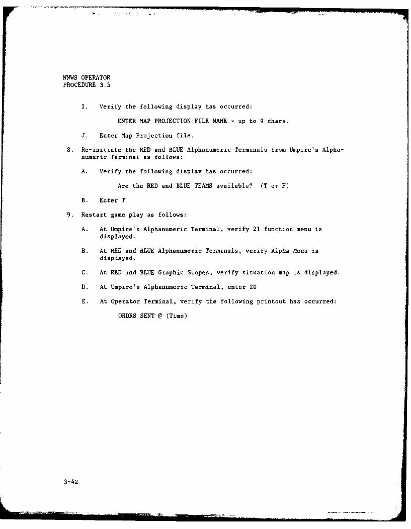
8. Restart game play as follows:
A. At Umpire's Alphanumeric Terminal, verify 21 function menu isdisplayed.
3-28

NNWS OPERATORPROCEDURE 3.5
B. At RED and BLUE Alphanumeric Terminals, verify Alpha Menu isdisplayed.
C. At RED and BLUE Graphic Scopes, verify initial situation map isdisplayed.
D. At Umpire's Alphanumeric Terminal, enter 20.
E. At Operator Terminal, verify the following printout has occurred:
ORDRS SENT @ (Time)
NOTE
The first set of reports received during this session willbe identical to the last set of reports received duringthe previous session. If players have previously reviewedthese reports and do not wish to create orders, the gamemay be advanced to the next interrupt by entering 20 onthe Umpire's Alphanumeric Terminal.
3-29
NNWS OPERATORPROCEDURE 3.5
PART 2
NON-STANDARD RESTART
NOTE
Non-Standard Restart is dependent upon when the priorsession was terminated. Refer to the applicable case asdetermined in NNWS Operator Procedure 3.4 Part 2.
Case 1. SHUTDOWN OCCURRED DURING TRANSMISSION OF ORDERS
1. Verify appropriate shutdown steps were completed in accordance with NNWSOperator Procedure 3.4 Part 2.
NOTE
Players should forego receipt of reports at first gameinterrupt of the Non-Standard Restart. Umpire will ensurethat all orders created during last game interrupt ofprior session will be re-transmitted. When all orders areready for transmission, Umpire operator transmits ordersby entering 20 on the Umpire's Alphanumeric Terminal.Game play is to be resumed on second game interrupt.
2. Conduct Standard Restart in accordance with NNWS Operator Procedure 3.5Part 1.
3. Verify Umpire's Alphanumeric Terminal displays NEW REPORTS RECEIVED.
4. Direct RED and BLUE Teams to forego receipt of reports.
5. Determine version number, size, and time of creation of the latest ordersfile from the Operator Terminal as follows:
NOTE
If BLUE team did not enter orders, proceed to Step E.
A. Enter PIP BLUORD.DAT/LI
B. Observe version and size printout
EXAMPLE: BLUORD.DAT;26 0 9-DEC-80 13:57(Version) (Size)
NOTE
If size is other than 0, proceed to Step E.
3-30
NNWS OPERATORPROCEDURE 3.5
C. Enter PIP BLUORD.DAT;26/DE
D. Repeat Steps A, B and, if necessary, C.
E. If RED team did not enter orders, proceed to Step J.
F. Enter PIP iDORD.DAT/LI
G. Observe version and size printout
EXAMPLE: REDORD.DAT;26 0 9-DEC-80 13:57
NOTE
If size is other than 0, proceed to Step J.
H. Enter PIP REDORD.DAT;26/DE
I. Repeat Steps F, G and, if necessary, H.
J. At Umpire's Alphanumeric Terminal, enter 20
NOTE
Game play is resumed at next game interrupt.
Case 2. SHUTDOWN OCCURRED DURING GAME INTERRUPT
1. Refer to NNWS Operator Procedure 3.4 Part 2.
Case 3. SHUTDOWN OCCURRED BETWEEN INTERRUPTS
1. Request APL NNWS Programming Personnel to determine cause of abnormalshutdown and appropriate game interrupt time for restart.
2. Re-establish communications with Host Computer from Umpire's AlphanumericTerminal as follows:
A. Verify the following display has occurred:
IS NNWS TO COMMUNICATE INTER-PROCESSOR? (T or F)
B. Enter T
3-31

YNWS OPERATORPROCEDURE 3.5
C. Verify the following display has occurred:
enter LOGON USERID/PASSWORD SIZE (EXEC model, answer queries, then depress CNTL Z
D. Enter LOGON OP65 SIZE(4096)
E. Verify prompt for account number and password is displayed.
NOTE
If prompt does not occur, repeat Step D.
F. Enter account number and password.
G. Verify the following display has occurred:
0P65 logon in progress at (Time) on (Date)Availability: Mon-Fri--8:30 a.m. to midnight, Sat-8:30 a.m. to 4:30 p.m.USERPROC CMDPROCFREE FILE (SYSUDUMP)READY
NOTE
If READY display does not occur repeat Step F
3. If required, perform checkpoint file maintenance from Umpire's Alpha-numeric Terminal as follows:
A. Enter GETIME CHKPTI
B. Verify game time display occurs.
EXAMPLE: DAY 21 HOUR 13 MIN 36
C. Enter GETIME CHKPT 2
D. Verify game time display occurs.
E. Compare both displays to determine which CHKPT file contains theproper game state.
F. Enter E CHKEY 0 D
G. Enter V
H. Enter DO
3-32
NNWS OPERATORPROCEDURE 3.5
I. Verify display of CHKPT1 or CHKPT2 has occurred.
NOTE
Perform Steps J and K only if CHKPT number displayed inStep I does not correspond to proper CHKPT file. IfCHKPT2 was displayed in Step I, reverse numbers entered inStep J
J. Enter C /1/2
K. Verify display of CHKPT2 or CHKPTI has occurred.
L. Enter SAVE
M. Enter END
4. Re-initiate NNWS Application on Host Computer from Umpire's AlphanumericTerminal as follows:
NOTES
1. Refer to Table 3-1 for explanation and listing ofoperand list.
2. Do not use MODE or G2W parameters.
A. Enter NNWS [operand list].
B. Verify a single line of four values separated by commas isdisplayed.
EXAMPLE: S, A, OND, LANT
C. Observe prompt for password.
D. Enter password.
NOTE
CNTRL Z entry (Steps F and G) must be made within 5seconds after CNTRL Z prompt
E. Repeat Steps C and D for each additional prompt until the followingprompt occurs:
ENTER CNTRI Z NOW
3-33

NN1S OPERATORPROCEDURE 3.5
F. Depress and hold CTRL key.
G. Depress Z key.
H. Simultaneously release CTRL and Z keys.
I. Verify the following display has occurred:
ENTER MAP PROJECTION FILE NAME - up to 9 chars.
J. Enter Map Projection file.
5. If required, re-initiate RED and BLUE Alphanumeric Terminals fromUmpire's Alphanumeric Terminal as follows:
A. Verify the following display has occurred:
Are the RED and BLUE TEAMS available? (T or F)
B. Enter T
6. Restart game play as follows:
A. At Umpire's Alphanumeric Terminal, verify 21 function menu isdisplayed.
B. At RED and BLUE Alphanumeric Terminals, verify Alpha Menu isdisplayed.
C. At RED and BLUE Graphic Scopes, verify situation map is displayed.
D. At Umpire's Alphanumeric Terminal, enter 20.
E. At Operator Terminal, verify the following printout has occurred:
ORDRS SENT @ (Ti-'
)TE
Players should forego receipt of reports at first gameinterrupt of the Non-Standard Restart. Umpire will ensurethat all orders created during the last game interrupt ofprior session will be re-transmitted. When all orders areready for transmission, Umpire Operator transmits ordersby entering 20 on the Umpire's Alphanumeric Terminal.Game play is to be resumed on second game interrupt.
7. Verify Umpire's Alphanumeric Terminal displays NEW REPORTS RECEIVED.
3-34
NNWS OPERATORPROCEDURE 3.5
8. Direct RED and BLUE Teams to forego receipt of reports.
9. Determine version, number, size and time of creation of the latest ordersfile from the Operator Terminal as follows:
NOTE
If BLUE Team did not enter orders, proceed to Step E.
A. Enter PIP BLUORD.DAT/LI
B. Observe version and size printout.
EXAMPLE: BLUORD.DAT;26 0 9-DEC-80 13:57(version) (size)
NOTE
If size is other than 0, proceed to Step E.
C. Enter PIP BLUORD.DAT;26/DE
D. Repeat Steps A, B and, if necessary, C.
E. If RED Team did not enter orders, proceed to Step J.
F. Enter PIP REDORD.DAT/LI
G. Observe version and size printout.
EXAMPLE: REDORD.DAT;26 0 9-DEC-80 13:57
NOTE
If size is other than 0, proceed to Step J.
H. Enter PIP REDORD.DAT;26/DE
I. Repeat Steps F, G and, if necessary, H.
J. At Umpire's Alphanumeric Terminal, enter 20.
NOTE
Game play is resumed at next game interrupt.
3-35

,(NWS OPERATORPROCEDURE 3.5
Case 4. SHUTDOWN OCCURRED DURING RECEIPT OF REPORTS
1. Verify appropriate Shutdown steps were completed in accordance with NNWSOperator Procedure 3.4 Part 2.
2. Request APL NNWS Programming Personnel to determine cause of shutdown andappropriate game interrupt time for restart.
3. If required, perform checkpoint file maintenance from Umpire's Alpha-
numeric Terminal as follows:
A. Enter GETIME CHKPTI
B. Verify game time display occurs.
EXAMPLE: DAY 21 HOUR 13 MIN 26
C. Enter GETIME CHKPT2
D. Verify game time display occurs.
E. Compare both displays to determine which CHKPT file contains theproper game state.
F. Enter E CHKEY 0 D
G. Enter V
H. Enter DO
I. Verify display of CHKPT1 or CHKPT2 has occurred.
NOTE
Perform Steps J and K only if CHKPT number displayed inStep I does not correspond to proper CHKPT file. IfCHKPT2 was displayed in Step I, reverse numbers entered inStep J.
J. Enter C /1/2
K. Verify display of CHKPT2 or CHKPT1.
L. Enter SAVE
M. Enter END
4. Re-initiate NNWS Application on Host Computer from Umpire's AlphanumericTerminal as follows:
3-36

!!
NNWS OPERATORPROCEDURE 3.5I
NOTES
1. Refer to Table 3-1 for explanation and listing ofoperand list.
2. Do not use MODE or G2W parameters.
A. Enter NNWS [operand list].
B. Verify a single line of four values separated by commas isdisplayed.
EXAMPLE: S, A, ON]D, LANT
C. Observe prompt for password.
D. Enter password.
NOTE
CNTRL Z entry (Steps F and G) must be made within 5seconds after CNTRL Z prompt
E. Repeat Steps C and D for each additional prompt until the followingprompt occurs:
ENTER CNTRL Z NOW
F. Depress and hold CTRL key.
G. Depress Z key.
H. Simultaneously release CTRL and Z keys.
I. Verify the following display has occurred:
ENTER MAP PROJECTION FILE NAME - up to 9 chars.
J. Enter Map Projection file.
5. If required, re-initiate RED and BLUE Alphanumeric Terminals fromUmpire's Alphanumeric Terminal as follows:
A. Verify the following display has occurred:
Are the RED and BLUE TEAMS available? (T or F)
B. Enter T
3-37

NNWS OPERATORPROCEDURE 3.5
6. Restart game play as follows:
A. At Umpire's Alphanumeric Terminal, verify 21 function menu isdisplayed.
B. At RED and BLUE Alphanumeric Terminals, verify Alpha Menu isdisplayed.
C. At RED and BLUE Graphic Scopes, verify situation map is displayed.
D. At Umpire's Alphanumeric Terminal, enter 20
E. At Operator Terminal, verify the following printout has occurred:
ORDRS SENT @ (Time)
Case 5. TSO SESSION ON HOST COMPUTER SHUTDOWN and REPLICATION RESTART
NOTES
1. Omit Step 1 if procedure is used for ReplicationRestart
2. Verify restart procedure with APL NNWS ProgrammingPersonnel. Restart with improper procedure couldresult in loss of history file data.
1. Verify appropriate shutdown steps were completed in accordance with NNWSOperator Procedure 3.4 Part 2.
2. At Operator Terminal, enter RUN NNWS
3. Re-initiate Umpire's Alphanumeric Terminal from Operator Terminal asfollows:
A. Verify the following printout has occurred:
IS THE GAME UMPIRE TERMINAL (TT2:) AVAILABLE? (T or F)
B. Enter T
4. Re-initiate communications with Host Computer from Umpire's AlphanumericTerminal as follows:
A. Verify the following display has occurred:
IS NNWS TO COMMUNICATE INTER-PROCESSOR? (T or F)
3-38

NNWS OPERATORPROCEDURE 3.5
B. Enter T
C. Verify the following display has occurred:
enter LOGON USERID/PASSWORD SIZE ( )EXEC model, answer queries, then depress CTRL Z
D. Enter LOGON OP65 SIZE(4096)
E. Verify prompt display for account number and password.
F. Enter account number and password.
G. Verify the following display has occurred:
0P65 logon in progress at (Time) on (Date)Availability: Mon-Fri--8:30 a.m. to midnight, Sat--8:30 a.m. to 4:30 p.m.USERPROC CMDPROCFREE FILE (SYSUDUMP)READY
NOTE
If READY display does not occur, repeat step F
5. If required, perform History File maintenance from Umpire's AlphanumericTerminal as follows:
NOTES
1. If checkpoint files have to be restored, APL NNWSProgramming Personnel should be contacted to deter-mine the proper date-time group.
2. APL NNWS Programming Personnel must be contacted tosubmit tapes and password forms and to set agreedidentifying character prior to executing the GAMEBACKcommand.
3. Steps C through J may be performed as time and condi-tions permit.
A. If required, enter RESTORE mmddhh
B. Enter GAMEBACK (character ID)
C. Enter OUT OP65BKT PR(A)
D. Enter E A 0 D
3-39
"~~~ ~~ ~~~~~ ~~~~~~~ -------L--- - - --.. W .. . ' ... . , . ... --- =
NNWS OPERATORPROCEDURE 3.5
E. Enter VERIFY
F. Enter F /CODE/
G. Verify a code of 0000 is displayed.
H. Enter F
I. Verify a code of 0000 is displayed.
J. Repeat Steps H and I two additional times.
K. Enter END NOS
L. Verify READY is displayed.
NOTE
If Steps G and I cannot be verified, contact APL NNWSProgramming Personnel prior to starting a new session
6. If required perform checkpoint file maintenance from Umpire's Alphanu-meric Terminal as follows:
A. Enter GETIME CHKPT1
B. Verify game time display occurs.
EXAMPLE: DAY 21 HOUR 13 MIN 26
C. Enter GETIME CHKPT2
D. Verify game time display occurs.
E. Compare both displays to determine which CHKPT contains the propergame state.
F. Enter E CHKEY 0 D
G. Enter V
H. Enter DO
I. Verify display of CHKPT1 or CHKPT2 has occurred.
NOTE
Perform Steps J and K only if CHKPT number displayed inStep I does not correspond to proper CHXPT file. IfCHKPT2 was displayed in Step I, reverse numbers entered byStep J.
3-40

NNWS OPERATORPROCEDURE 3.5
J. Enter C /1/2
K. Verify display of CHKPT2 or CHKPT1.
L. Enter SAVE
M. Enter END
7. Re-initiate NNWS Applications on Host Computer from Umpire's AlphanumericTerminal as f'..lows-
NOTES
1. Refer to Table 3-1 for explanation and listing ofoperand list.
2. Do not use MODE parameter.
3. Use DISP parameter with value of OLD.
4. G2W parameter may be used only when running replica-tions.
A. Enter NNWS [operand list].
B. Verify a single line of four values, separated by commas, isdisplayed.
EXAMPLE: S, A, OND, LANT
C. Observe prompt for password.
D. Enter password.
NOTE
CNTRL Z entry (Steps F and G) must be made within 5seconds after CNTRL Z prompt.
E. Repeat Steps C and D for each prompt until the following promptoccurs:
ENTER CNTRL Z NOW
F. Depress and hold CTRL key.
G. Depress Z key.
H. Simultaneously, release CTRL and Z keys.
3-41
NNWS OPERATORPROCEDURE 3.5
I. Verify the following display has occurred:
ENTER MAP PROJECTION FILE NAME - up to 9 chars.
J. Enter Map Projection file.
8. Re-iniLiate the RED and BLUE Alphanumeric Terminals from Umpire's Alpha-numeric Terminal as follows:
A. Verify the following display has occurred:
Are the RED and BLUE TEAMS available? (T or F)
B. Enter T
9. Restart game play as follows:
A. At Umpire's Alphanumeric Terminal, verify 21 function menu isdisplayed.
B. At RED and BLUE Alphanumeric Terminals, verify Alpha Menu is
displayed.
C. At RED and BLUE Graphic Scopes, verify situation map is displayed.
D. At Umpire's Alphanumeric Terminal, enter 20
E. At Operator Terminal, verify the following printout has occurred:
ORDRS SENT @ (Time)
3-42

NNWS OPERATORPROCEDURE 3.5
PART 3REPLICATION RESTART
1. At the desired game interrupt, shutdown game from Umpire's AlphanumericTerminal as follows:
A. Enter 21
B. Verify the following display has occurred:
HAS THE MODEL ALREADY HALTED? (T or F)
C. Enter F
D. Verify the following displays have occurred:
NNWS ordering game HALT for UMPIRETSO: , **NAVAL NUCLEAR WARFARE SIMULATION ENDED*--*IS RESTART DESIRED? (T or F)
E. Enter F
F. At Operator Terminal, verify a sequence of task termination messagesis printed.
2. Preserve the checkpoint and history files from Umpire's AlphanumericTerminal as follows:
NOTES
1. Record checkpoint file date-time group for futurereference.
2. APL NNWS Programming Personnel must be contacted tosubmit tapes and password forms and to set agreedidentifying character prior to executing thiscommand.
3. Steps B through I may be performed as time and condi-
tions permit.
A. Enter GAMEBACK (character ID).
B. Enter OUT OP65BKT PR(A)
C. Enter E A 0 D
D. Enter VERIFY
3-43

NU'S OPERATOR
PROCEDURE 3.5
E. Enter F /CODE/
F. Verify a code of 0000 is displayed.
G. Enter F
H. Verify a code of 0000 is displayed.
I. Repeat Steps G and H two additional times.
J. Enter END NOS
K. Verify READY is displayed.
NOTE
If Steps F and H cannot be verified, contact APL NNWSProgramming Personnel prior to starting a r.ew session
3. Terminate TSO session from Umpire's Alphanumeric Terminal as follows:
A. Enter LOGOFF
B. Verify statistical information concerning the session is displayed.
4. Terminate Minicomputer NNWS Tasks from Umpire's Alphanumeric Terminal as
follows:
A. Depress and hold CTRL key.
B. Depress Z key.
C. Simultaneously release CTRL and Z keys.
NOTE
Perform Step 5 and omit Step 6 for initial running ofreplication. Perform Step 6 and omit Step 5 for sub-sequent replications.
5. Copy Data Base Disk to Scratch Disk as follows:
A. At Operator Terminal, enter BOO [1,54]DSCSYS
B. At Operator Terminal, verify the following printout occurred:
DSC>
C. At Disk Drive Front Panel, depress RUN/STOP switch.
3-44

NNWS OPERATORPROCEDURE 3.5
D. Dismount "NNWS SYSTEM" cartridge from Disk Drive 0.
E. Obtain and load Scratch cartridge in Disk Drive 0.
F. At Disk Drive Front Panel, depress RUN/STOP switch.
NOTE
Wait 15 to 30 seconds for Disk Drive spin-up prior toperforming Step G
G. At Operator Terminal, enter DM0: /VE=DMI:
NOTE
Wait approximately 30 minutes prior to performing Step H
H. At Operator Terminal, verify > prompt is printed.
I. At Disk Drive Front Panel, depress RUN/STOP switch.
J. Dismount scratch cartridge from Disk Drive 0 and re-load NNWS SYSTEMcartridge.
NOTE
Label scratch cartridge DATABASE COPY and retain cartridgefor subsequent replications
6. Copy DATABASE COPY to DATABASE cartridge as follows:
A. At Operator Terminal, enter BOO [l,54]DSCSYS
B. At Operator Terminaj, verify the following printout occurred:
DSC>
C. At Disk Drive Front Panel, depress RUN/STOP switch.
D. Dismount NNWS SYSTEM cartridge from Disk Drive 0.
E. Load DATABASE COPY cartridge in Disk Drive 0.
F. At Disk Drive Front Panel, depress RUN/STOP switch.
NOTE
Wait 15 to 30 seconds for Disk Drive spin-up prior toperforming Step G
3-45
44
NNWS OPERATORPROCEDURE 3.5
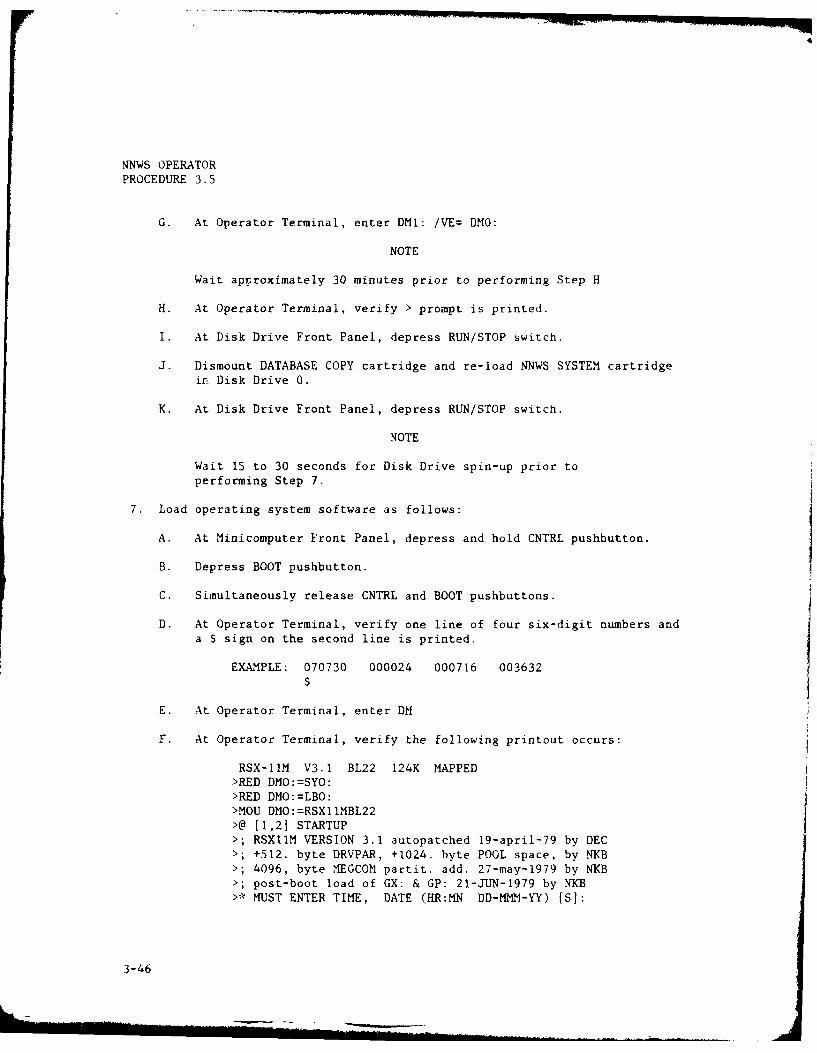
G. At Operator Terminal, enter DM1: /VE= DMO:
NOTE
Wait approximately 30 minutes prior to performing Step H
H. At Operator Terminal, verify > prompt is printed.
I. At Disk Drive Front Panel, depress RUN/STOP switch.
J. Dismount DATABASE COPY cartridge and re-load NNWS SYSTEM cartridgein Disk Drive 0.
K. At Disk Drive Front Panel, depress RUN/STOP switch.
NOTE
Wait 15 to 30 seconds for Disk Drive spin-up prior toperforming Step 7.
7. Load operating system software as follows:
A. At Minicomputer Front Panel, depress and hold CNTRL pushbutton.
B. Depress BOOT pushbutton.
C. Simultaneously release CNTRL and BOOT pushbuttons.
D. At Operator Terminal, verify one line of four six-digit numbers anda $ sign on the second line is printed.
EXAMPLE: 070730 000024 000716 003632
$
E. At Operator Terminal, enter DM
F. At Operator Terminal, verify the following printout occurs:
RSX-11M V3.1 BL22 124K MAPPED>RED DMO:=SYO:>RED DMO:=LBO:>MOU DMO:=RSX1IMBL22>@ [1,2] STARTUP>; RSXllM VERSION 3.1 autopatched 19-april-79 by DEC>; +512. byte DRVPAR, +1024. byte POOL space, by NKB>; 4096, byte MEGCOM partit. add. 27-may-1979 by NKB>; post-boot load of GX: & GP: 21-JUN-1979 by NKB>* MUST ENTER TIME, DATE (HR:MN DD-MMM-YY) [S]:
3-46

I
t
NNWS OPERATORPROCEDURE 3.5
G. At Operator Terminal, enter time and date in the following order:HR:MN DL-MMM-YY
EXAMPLE: 13:15 09-DEC-80
H. At Operator Terminal, verify the following printout occurs:
> TIM HR:MN DD-MMM-YY> ACS DMO:/BLKS=500.> MOU DM1:/OVR> ACS DMI:/BLKS=1000.> SET /MAXEXT=16.K> INS [1,54] SFT/TASK=... SFTERL ERROR LOG INITIALIZED
> LOA GY:/PAR=DRVPAR> LOA GP:/PAR=DRVPAR> SET /UIC= [7,42] ! SET UP FOR NNWS GAME EXECUTION> @ <EOF>
I. Verify TIM (top) line contains correct time and date.
NOTE
If TIM (top) line is inaccurate, re-enter correct time anddate per Steps J, K, and L
J. Enter TIM (HR:MN DD-MMM-YY)
EXAMPLE: TIM 13:15 09-DEC-80
K. Enter TIM
L. Verify correct time and date is printed
M. Perform restart in accordance with NNWS OPERATOR PROCEDURE 3.5 Part2 Case 5.
NOTES
1. The checkpoint files must be restored and the CHKEYmust be set to the desired interrupt time for eachreplication.
2. Random variation of replications may be obtained bychanging the G2W operand parameter.
3. A replication's interrupt cycle may be altered bychanging the IC operand parameter.
!3-47/(3-48 blank)I

w
-u-Um
I-0

INNWS OPERATORPROCEDURE 3.6
DECWRITER II PAPER LOAD
1. Grasp sides of Platen Cover and raise.
2. Flip left and right Paper Bailers outward.
3. Position Paper Supply stack between DECWRITER's Front Legs.
4. Feed top Paper Supply sheet upward through rectangular slot beneathKeyboard until second sheet emerges.
5. Engage first four holes of second sheet into corresponding Traction Nubs.
6. Snap Paper Bailers flat against Traction Belt to secure second sheet.
7. Feed first sheet through slot located beneath Hinged Cover until sheetemerges from rear of clear plastic window.
8. Lower Platen Cover until it snaps into detents.
9. Place DECWRITER II Power Switch to OFF and then to ON to resetelectronics.
3-49/(3-50 blank)

-g
wI-m

Table 3-I. OPERAND LIST
PARAMETER ALLOWABLE VALUE DESCRIPTION
DATA NNWS. data set name Name of scenario or data set
AREA LANT, PAC, MED Geographical theater area (presetvalue = Pacific)
SEASON JFM, AMJ, JAS, OND Calendar months (preset value = OND)
S S, W Season (summer or winter) for SOSUSperformance data (preset value =summer)
CIC Integer > 0 Critical interrupt cycle time inminutes (preset value = 6 minutes)
IC Integer > 0 Interrupt cycle time in minutes, valuemust be a multiple of CIC (presetvalue = 720 minutes)
G2W 0 < Integer < 215-1 Random number generator initialization(preset value = 0)
MODE NEW, RES Operating mode (new or restart)(preset value of restart)
DISP MOD, OLD History file disposition (preset value =modified)
Sample entry:
Operand List
NNWS ARA Ar ) IC(360) MODE(NEWY
L tValue
Procedure
Description:
The operand list specifies the parameters to be overridden and the valuesto be assigned to them. Parameters not overridden will default to presetvalues.
3-51/(3-52 blank)

'1' -
r
-v
I

Table 3-2. ALPHA MENU
01 EVENT REPORT SUMMARY
02 HOSTILE SUB CONTACT SUMMARY
03 SURF/SUB EMPLOYMENT SUMMARY
04 AIRCRAFT EMPLOYMENT SUMMARY
05 AIRFIELD STATUS
06 SUBMARINE ASSIGNMENT
07 SUB DIRECTED ASSIGNMENT
08 SUB ATTACK ORDER
09 DELAYED ATTACK/STRIKE ORDER
10 NUCLEAR WEAPON RELEASE AUTHORITY
11 DEFENSE CONDITION ORDER
12 SURTASS UNIT ASSIGNMENT
13 AIRCRAFT ASSIGNMENT
14 AIRCRAFT DIRECTED ASSIGNMENT
15 AIRCRAFT ATTACK ORDER
16 REQUEST AIRCRAFT TRANSFER
17 VP BREAK STREAM ORDER
18 SUB REPAIR/RELOAD ORDER
19 SUB/AIRCRAFT COORDINATION
20 XMIT ORDERS/RESUME GAME
21 request GAME TERMINATION (available on Umpires AlphanumericTerminal only)
3-53
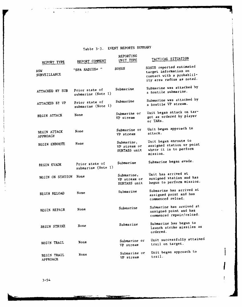
Table 3-3. EVENT REPORTS SUMMARY
REPORTING
REPORT TYPE REPORT COMMENT UNIT TYPE TACTICAL SITUATION
ASW "SPA RADIUS= " SOSUS SOSUS reported estimated
target information onSURVEILLANCE contact with a probablil-
ity area radius as noted.
ATTACKED BY SUB Prior state of Submarine Submarine was attacked by
submarine (Note 1) a hostile submarine.
ATTACKED BY VP Prior state of Submarine Submarine was attacked by
submarine (Note 1) a hostile VP stream.
BEGIN ATTACK None Submarine or Unit began attack on tar-VP stream get as ordered by player
or TARs.
BEGIN ATTACK None Submarine or Unit began approach to
APPROACH VP stream attack.
BEGIN ENROUTE None Submarine, Unit began enroute to
VP stream or assigned station or point
SURTASS unit where it is to perform
mission.
BEGIN EVADE Prior state of Submarine Submarine began evade.
submarine (Note 1)
BEGIN ON STATION None Submarine, Unit has arrived at
VP stream or assigned station and has
SURTASS unit begun to perform mission.
BEGIN RELOAD None Submarine Submarine has arrived at
assigned point and has
commenced reload.
BEGIN REPAIR None Submarine Submarine has arrived at
assigned point and has
commenced repair/reload.
BEGIN STRIKE None Submarine Submarine has begun tolaunch strike missiles as
ordered.
BEGIN TRAIL None Submarine or Unit successfully attained
VP stream trail on target.
BEGIN TRAIL None Submarine or Unit began approach to
APPROACH VP stream trail.
3-54

Table 3-3. EVENT REPORTS SUMMARY (Continued)
REPORTINGREPORT TYPE REPORT COMMENT UNIT TYPE TACTICAL SITUATION
CANNOT ATTACK "NO AVAIL WEAPONS" Submarine or Unit cannot attack targetor "NOT ENGAGED VP stream because of lack of appro-WITH # " priate weapons or unit
was not in contact withtarget.
CANNOT STRIKE "NO AVAIL WEAPONS" Submarine Submarine cannot attackor "INVALID STATE/ because of a lack of ap-MISSION" propriate weapons or be-
cause it is not in properstate (on station orevading while on station)or mission (strike).
COMPLETE STRIKE "NRML= " and post- Submarine Submarine successfullyengagement order completed strike mission,(Note 2) reported the number of
reliable missileslaunched (NRML), and ap-pealed to the post-strikePEOs.
DETECTION None Submarine or Unit detected a hostileVP stream submarine. Report is
generated only if noother report implying thedetection (example: BEGINEVADE) is generated.
DROP ATTACK None Submarine Submarine dropped ap-APPROACH proach to attack in order
to prosecute a second,higher priority, contactas determined by TARs.
DROP TRAIL None Submarine Submarine dropped trail
to prosecute a second,higher priority, contactas determined by TARs.
DROP TRAIL None Submarine Submarine dropped approachAPPROACH to trail to prosecute a
second, higher priority,
contact as determined byTARs.
3-55

Table 3-3. EVENT REPORTS SUMMARY (Continued)
REPORTINGREPORT TYPE REPORT COMMENT UNIT TYPE TACTICAL SITUATION
END ATTACK Whether "TGT LIVED" Submarine or Unit completed its attack,or "TGT DIED" and VP stream reported the outcome, andpost-engagement and appealed to the post-order (Note 2) attack PEOs.
END EVADE Post-engagement Submarine Submarine ended evade andorder (Note 2) appealed to the post-
evade PEOs.
END RELOAD None Submarine Submarine completed re-load and is available forreassignment.
END REPAIR None Submarine Submarine completedrepair/reload and isavailable for reassign-ment.
KILLED Mone Submarine Submarine was killed inengagement with a hostileunit.
LOSE CONTACT Post-engagement Submarine or Unit was forced to loseorder (Note 2) VP stream contact either when it
began an attack immediatelyafter another unit attackedits contact, clouding thewater or when the condi-tions under which a detec-
tion was made would notpermit engagement despiteasq --- ant of the unit to"he tact. Unit appealed
.I. -s+-contact PEOs.
LOSE TRAIL Post-engagement Submarine Submarine lost contactorder (Note 2) while in trail on the
target and appealed tothe lost-contact PEOs.
MISSED ATTACK Post-engagement Submarine or Unit failed to localizeAPPROACH order (Note 2) VP stream to within the stated
criteria and appealed tothe lost-contact PEOs.
MISSED TRAIL Post-engagement Submarine or Unit failed to localizeAPPROACH order (Note 2) VP stream to within the stated
criteria and appealed tothe lost-contact PEOs.
3-56
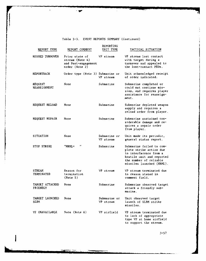
Table 3-3. EVENT REPORTS SUMMARY (Continued)
REPORTINGREPORT TYPE REPORT COMMENT UNIT TYPE TACTICAL SITUATION
MISSED TURNOVER Prior state of VP stream VP stream lost contactstream (Note 4) with target during aand Post-engagement turnover and appealed toorder (Note 2) the lost-contact PEOs.
REPORTBACK Order type (Note 3) Submarine or Unit acknowledged receiptVP stream of order indicated.
REQUEST None Submarine Submarine completed orREASSIGNMENT could not continue mis-
sion, and requires playerassistance for reassign-ment.
REQUEST RELOAD None Submarine Submarine depleted weaponsupply and requires areload order from player.
REQUEST REPAIR None Submarine Submarine sustained con-siderable damage and re-quires a repair orderfrom player.
SITUATION None Submarine or Unit made its periodic,VP stream general status report.
STOP STRIKE "NRML= Submarine Submarine failed to com-plete strike action due
to interference from ahostile unit and reportedthe number of reliablemissiles launched (NRML).
STREAM Reason for VP stream VP stream terminated dueTERMINATED termination to reason stated in
(Note 5) comment field.
TARGET ATTACKED None Submarine Submarine observed targetFRIENDLY attack a friendly sub-
marine.
TARGET LAUNCHED None Submarine or Unit observed targetSLBM VP stream launch of SLBM strike
missiles.
VP UNAVAILABLE None (Note 6) VP airfield VP stream terminated dueto lack of appropriatetype VP at home airfieldto support the stream.
3-57j
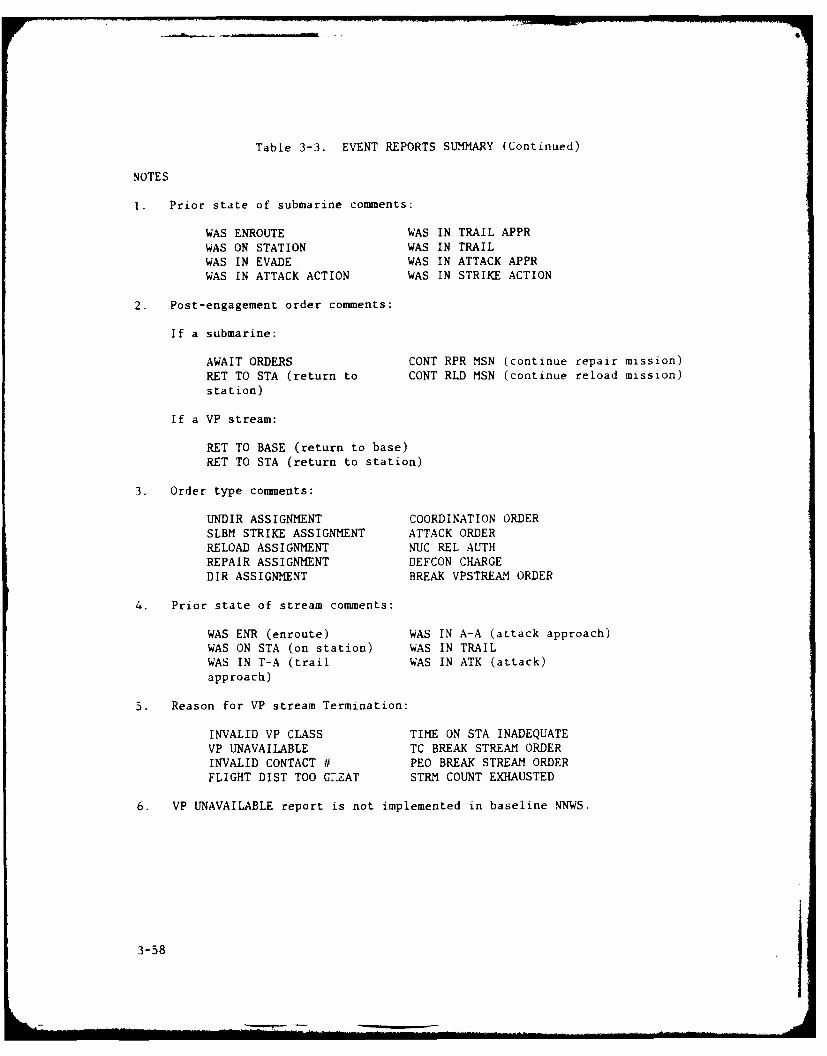
Table 3-3. EVENT REPORTS SUMMARY (Continued)
NOTES
1. Prior state of submarine comments:
WAS ENROUTE WAS IN TRAIL APPRWAS ON STATION WAS IN TRAILWAS IN EVADE WAS IN ATTACK APPRWAS IN ATTACK ACTION WAS IN STRIKE ACTION
2. Post-engagement order comments:
If a submarine:
AWAIT ORDERS CONT RPR MSN (continue repair mission)RET TO STA (return to CONT RLD MSN (continue reload mission)station)
If a VP stream:
RET TO BASE (return to base)RET TO STA (return to station)
3. Order type comments:
UNDIR ASSIGNMENT COORDINATION ORDER
SLBM STRIKE ASSIGNMENT ATTACK ORDERRELOAD ASSIGNMENT NUC REL AUTHREPAIR ASSIGNMENT DEFCON CHARGEDIR ASSIGNMENT BREAK VPSTREAM ORDER
4. Prior state of stream comments:
WAS ENR (enroute) WAS IN A-A (attack approach)WAS ON STA (on station) WAS IN TRAILWAS IN T-A (trail WAS IN ATK (attack)approach)
5. Reason for VP stream Termination:
INVALID VP CLASS TIME ON STA INADEQUATEVP UNAVAILABLE TC BREAK STREAM ORDERINVALID CONTACT # PEO BREAK STREAM ORDERFLIGHT DIST TOO G.7ZAT STRM COUNT EXHAUSTED
6. VP UNAVAILABLE report is not implemented in baseline NNWS.
3-58

Table 3-4. ALPHANUMERIC REPORTS
Item 01 EVENT REPORTS SUMMARY
Typical Display:
GAME TIME = 151245DAY TIME UNIT REPORT ECN CLS MISSION COMMENT15 1 0 SOSUS ASW SURV 1 YD SPA RADIUS=5015 330 FLT1MRNH 574 REPORT BACK SURVASW UNDIR ASSIGNMENT
END OF SUMMARY REPORT
Remarks: Redisplays report summary displayed at last game interrupt.Refer to Table 3-3 for explanation of reports.
Item 02 HOSTILE SUB CONTACT SUMMARY
Typical Display:
GAME TIME = 151245
REPORTED BY ASSIGNED TO ENGAGED BYCN CLS LAT LONG SPA UNIT DAY HRMN UNIT
I YD 54 35N 16 12W 120 SOSUS 3 1 0SSN 638
FLT2MRN[ 5752 HEN 70 24N 17 53W 10 SSN 637 5 534
SSN 637SSN 637
Remarks: Displays all reported contacts. The RED display differs fromthe BLUE in that the RED contains no surveillance data and itclassifies contacts as nuclear powered (NUC) or diesel powered(DSL) only.
The ASSIGNED TO field will contain a unit designator only if aunit has been assigned to the contact by a Directed AssignmentOrder (Alpha Menu items 07 and 14).
The ASSIGNED TO field unit designator will be dropped when theunit has been reassigned (Alpha Menu items 06, 07, 17 and 18)or when one of the following reports is received:
REQUEST RELOAD REQUEST REPAIR
KILLED REQUEST REASSIGNMENT
VP STREAM TERMINATED
The ENGAGED BY field will contain a unit designator only if aunit has been linked to the contact by one of the following
reports:
BEGIN TRAIL APPROACH BEGIN ATTACK APPROACH
BEGIN TRAIL BEGIN ATTACK
3-59

Table 3-4. ALPHANUMERIC REPORTS (Continued)
The ENGAGED BY field unit designator will be dropped uponreceipt of one of the following reports:
LOST CONTACT MISSED ATTACK APPROACH
LOST TRAIL MISSED TRAIL APPROACH
END ATTACK KILLED
DROP TRAIL MISSED TURNOVER
DROP TRAIL APPROACH VP STREAM TERMINATED
DROP ATTACK APPROACH
Item 03 SURF/SUB EMPLOYMENT SUMMARY
Typical Display:
GAME TIME = 151245ASSN ENGAG ---- OATS----* -.*MISSION AVAIL-p.
UNIT MSN SRCH CN CL CN CL SW MB WD SN CM DR PT SV ST RP RL STATUSSSN 637 P.ASW AREA 2 YD 2 YD 100 100 100 100 100 1 1 1 1 1 1 TRAILSSN 638 D.ASW BARR 1 YD 100 100 100 100 100 1 1 1 1 1 1 ONSTA
Remarks: Displays status of submarine and surface units.
Item 04 AIRCRAFT EMPLOYMENT SUMMARY
Typical Display:
GAME TIME = 151245ASSIGNED ENGAGED
TYPE BASE FLT NO MISSION SEARCH CN CLS CN CLS TOS STATUSFLT3 KEFK 591 0 PAT ASW AREA 2 YD 6.8 TRAILFLTI MRNH 574 10 SERV ASW AREA 8.5 ENROUTE
Remarks: Displays status of aircraft units. Display is enabled for BLUEteam only.
3-60

Table 3-4. ALPHANUMERIC REPORTS (Continued)
Item 05 AIRFIELD STATUSGAME TIME = 151245
Typical Display:
AIRFIELD STATUS REPCRT
AIRFLD #VP1 #VP2 #VP3
KEFK 1 10 8 10
ROTA 2 0 10 10
LAJS 3 0 0 0
BERM 4 10 3 0
SGMA 5 10 10 0
JAXE 6 10 10 0
BRWK 7 10 10 0
SUDA 8 10 10 0
ORLS 9 10 10 0
RRDS 10 10 10 0
ESPO 11 10 8 0
BODA 12 10 10 0
ADYA 13 10 10 0
MR'NH 14 10 10 8
Remarks: Displays availability of aircraft of each platform class.Platform class (VPI, VP2, VP3) corresponds to the classesdefined in the scenario data set. Display is enabled for BLUEt Only. Airfields are defined in the scenario data set.
3-61

Table 3-5. DISPLAY ABBREVIATIONS
A-A Attack ApproachAIRFLD AirfieldAPPR ApproachATK AttackAVAIL AvailableCL Contact classificationCLS ClassCM Communications - Operational AttributeCN Contact numberCONT RLD MSN Continue Reload MissionCONT RPR MSN Continue Repair MissionCONV Conventional SubmarineCSE CourseCVAP Composite submarine class - Charlie, Victor, Alpha, PapaDIR DirectDR Directed ASW MissionECN Contact NumberENR EnrouteFLT VP Stream Flight NumberHEN Composite submarine class - Hotel, Echo, NovemberHRMN Time (Hour/Minutes)M:A Mission: Reload/Re-armMB Mobility - Operational AttributeM:K Mission: StrikeM:P Mission: PatrolM:R Mission: Repair
M:S Mission: Surveillance ASWMSN MissionNO Number of VP in streamNRML Number of Reliable Missiles LaunchedNUC Nulcear Powered SubmarineOATS Operational AttributesPEO Post-Engagement OrderPT Patrol ASW MissionRET TO BASE Return to BaseRET TO STA Return to StationRL Reload MissionRP Repair MissionSN Sensors - Operational AttributeSRCH SearchST Strike MissionSTAT Unit StateSURV Surveillance MissionSV Surveillance ASW MissionSW Seaworthiness - Operational AttributeT-A Trail ApproachTGT TargetTOS Time on Station
3-62
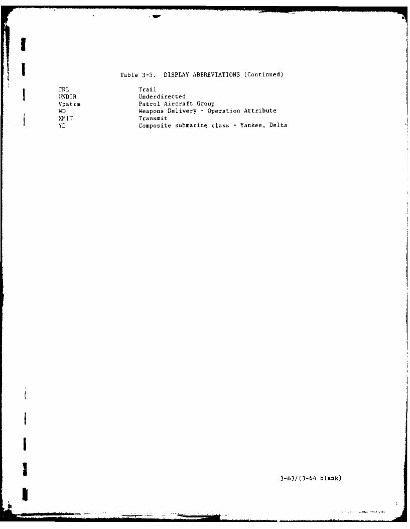
I
I Table 3-5. DISPLAY ABBREVIATIONS (Continued)
TRL TrailUNDIR UnderdirectedVpstrm Patrol Aircraft Group
WD) Weapons Delivery - Operation AttributeXMlIT TransmitYD Composite submarine class - Yankee, Delta
III 3-63/(3-64 blank)
'I

Y -
I
I

Table 3-6. ORDER DESCRIPTIONS
Item 06 SUBMARINE ASSIGNMENT
Use: Directs submarine to assume a specified mission and to proceed viaa particular route to a specified region. This order breaks allpreviously established coordination and terminates any existingassignment orders.
Order Format:
PIM STATIONP UNIT M S SLAT_ sLONG SP AT sLON
Order Elements:
Element Option
P Enter precedence 0, E, F (see Table 3-7).
UNIT Enter submarine unit identifier (See Table 3-7for format).
M P: Patrol ASW Mission.S: Surveillance ASW Mission.K: Strike Mission.
S A: Area search is only option presentlydeveloped for undirected searches and isrequired option for strike assignment.
B: Barrier search is not developed forundirected search and is not used for strikeassignments.
PIM Refer to Table 3-7.
STATION Refer to Table 3-7.
Item 07 SUB DIRECTED ASSIGNMENT
Use: Directs submarine to search for a particular hostile submarine inresponse to available contact information. The assignment allowsfor either a barrier search (target is enroute) or an area search(target is on station) and permits specification of coordinationagainst the contact. This order breaks all previously establishedcoordination and terminates any existing assignment order.
Order Format:
EST TGT INFOCN CE-§ SP LA-T LN SPA DAY HRN
5--. 5-- --- ------
P UNIT SP S BAR Crd?
3-65 j
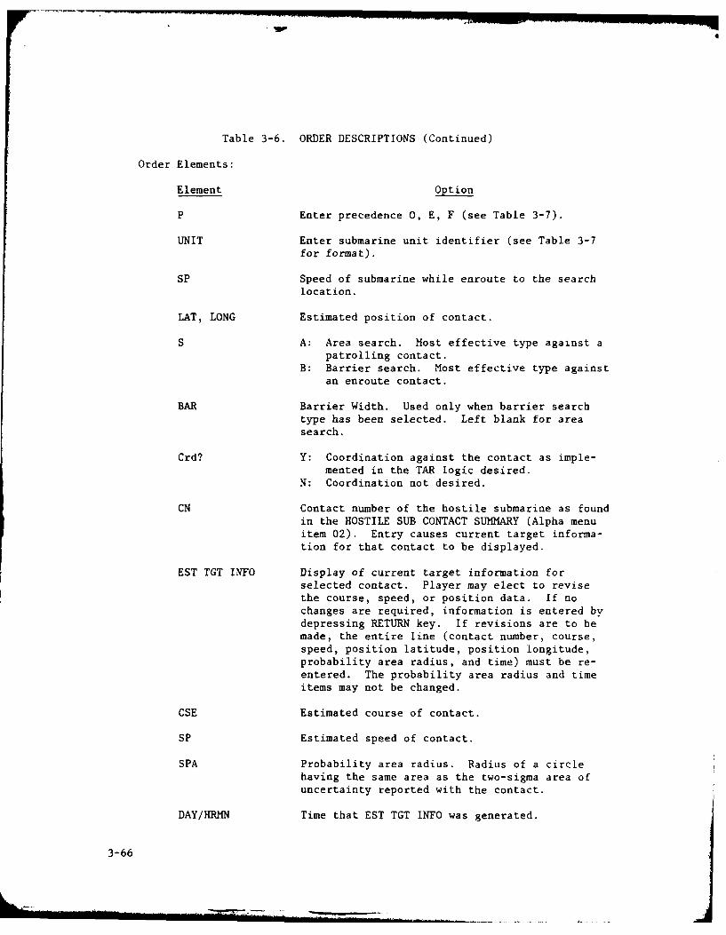
Table 3-6. ORDER DESCRIPTIONS (Continued)
Order Elements:
Element Option
P Enter precedence 0, E, F (see Table 3-7).
UNIT Enter submarine unit identifier (see Table 3-7for format).
SP Speed of submarine while enroute to the searchlocation.
LAT, LONG Estimated position of contact.
S A: Area search. Most effective type against apatrolling contact.
B: Barrier search. Most effective type againstan enroute contact.
BAR Barrier Width. Used only when barrier searchtype has been selected. Left blank for areasearch.
Crd? Y: Coordination against the contact as imple-mented in the TAR logic desired.
N: Coordination not desired.
CN Contact number of the hostile submarine as foundin the HOSTILE SUB CONTACT SUMMARY (Alpha menuitem 02). Entry causes current target informa-tion for that contact to be displayed.
EST TGT INFO Display of current target information forselected contact. Player may elect to revisethe course, speed, or position data. If nochanges are required, information is entered bydepressing RETURN key. If revisions are to bemade, the entire line (contact number, course,speed, position latitude, position longitude,probability area radius, and time) must be re-entered. The probability area radius and timeitems may not be changed.
CSE Estimated course of contact.
SP Estimated speed of contact.
SPA Probability area radius. Radius of a circlehaving the same area as the two-sigma area ofuncertainty reported with the contact.
DAY/KRMN Time that EST TGT INFO was generated.
3-66

Table 3-6. ORDER DESCRIPTIONS (Continued)
Item 08 SUB ATTACK ORDER
Use: Directs submarine to attack currently engaged contact. If sub-
marine is currently in trail approach, it will initiate attackapproach upon attaining trail state. If submarine is currently intrail state, it will enter attack approach. If submarine is cur-rently in attack approach or attack state, the order will beignored. If submarine is no longer in contact or lacks appropriate
ASW weapons, it will generate a CANNOT ATTACK report.
Order Format:
P UNIT CN NUC
Order Elements:
Element Option
P Enter precedence 0, E, F (see Table 3-7).
UNIT Enter submarine unit identifier (see Table 3-7for format).
CN Contact number of target as found in the SURF/SUB EMPLOYMENT SUMMARY (Alpha menu item 03) orHOSTILE SUB CONTACT SUMMARY (Alpha menu item
02). An invalid contact number will result in a
CANNOT ATTACK report.
NUC Y: Authority given for release of nuclear ASWweapons.
N: Authority not given for release of nuclearASW weapons.
Item 09 DELAYED ATTACK/STRIKE ORDER
Use: Initiates a multiple unit attack or strike action at a specifiedtime. If order is for an attack action, all units engaged with ahostile unit and possessing appropriate weapons will initiate anattack. If order is for a strike action, all units with a strikemission that are on station and possess appropriate weapons willstrike.
Order Format:
if DELAYed
P UNIT K NUC DAY HIRN
3-67

Table 3-6. ORDER DESCRIPTIONS (Continued)
Order Elements:
Element Optio
P Enter precedence 0, E, F (see Table 3-7).
UNIT ALLUNITS (see Table 3-7).
K Y: Order for a strike action.N: Order for an attack action.
NUC Y: Authority given for release of nuclearweapons.
N: Authority not given for release of nuclearweapons.
DAY/HRMN Time attack/strike action is to occur, may be
current game time or a future game time.
Item 10 NUCLEAR WEAPON RELEASE AUTHORITY
Use: Authorizes unit to use nuclear ASW weapons (submarines and VPstreams) or nuclear strike missiles (submarines).
Order Format:
if VPP UNIT A K AFFLT
Order Elements:
Element Option
P Enter precedence 0, E, F, (see Table 3-7).
UNIT Enter submarine or VP stream unit identifier(see Table 3-7 for format).
A Y: Authority given for release of nuclear ASWweapons.
N: Authority not given for release of nuclearASW weapons.
K Y: Authority given for release of nuclear
strike weapons.N: Authority not given for release of nuclear
strike weapons.
AF Enter 2-digit numeric airfield designator (seeTable 3-7).
FLT Enter 3-digit stream number (see Table 3-7).
3-68
.. .. ...7

Table 3-6. ORDER DESCRIPTIONS (Continued)
Item 11 DEFENSE CONDITION ORDER
Use: Assigns a specific Defense Condition (DEFCON) level to a particularsubmarine, VP airfield (and thereby eventually all associated VPstreams), or to the Theater Commander (TC). Changes in DEFCONlevel affect such things as communications delay time for ordersand reports, priority and precedence of reports and orders, variousTARs, and trial, attack, and strike parameters.
Order Format:
P UNIT DEFCON
Order Elements:
Element Option
P Enter precedence 0, E, F (see Table 3-7).
UNIT If submarine: Enter submarine unit identifier(see Table "-- for format).
If VP airfield: Enter 8-character designatorobtained by combining 6-char-
acter AIRFLD designator with 2-character AF designator (seeTable 3-7).
If Theater Commander: Enter 2-character desig-
nator TC.DEFCON L: Low
H: HighW: War
Item 12 SURTASS UNIT ASSIGNMENT
Use: Reassigns SURTASS unit to another position. Unit will go onstation and conduct surveillance ASW at the last PIM point.
Order Format:
PIMP UNIT L .AT ..G SP
Order Elements:
Element Option
P Enter precedence 0, E, F (see Table 3-7).
UNIT Enter SURTASS unit identifier (See Table 3-7 forformat),
PIM Refer to Table 3-7.
3-69
. . . . .. I I I I - - - - I . . . . .. . . ..

Table 3-6. ORDER DESCRIPTIONS (Continued)
Item 13 AIRCRAFT ASSIGNMENT
Use: Creates a VP stream to conduct either patrol or surveillance ASW.Since the airfield is prevented from generating a VP UNAVAILABLEreport, the airfield's aircraft availability should be verifiedusing the AIRFIELD STATUS report (Alpha Menu item 05) prior togenerating this order. If no aircraft of the VP class are avail-able at the airfield when this order is received, the order will beignored.
Order Format:
STATION WEP LOADP TYPE BASE AF MSNO sLAT sLONG VP CLASS 1 2 3 4
----.----.---------------
Order Elements:
Element Option
P Enter precedence 0, E, F (see Table 3-7).
TYPE Enter 4-character VP stream type identifier(see Table 3-7).
BASE Enter 4-character abbreviated airfield name(see Table 3-7).
AF Enter 2-digit numeric airfield identifier(see Table 3-7).
M P: Patrol ASW mission.S: Surveillance ASW mission.
S A: Undirected area search.B: Undirected barrier search.
NO Number of individual VP in the stream.
STATION Refer to Table 3-7.
VP CLASS Refer to Table 3-7.
WEP LOAD Weapon loadout for each VP in stream. Impliedweapon types are identified by WEPCAT parameterof CROSSREFTABLE of the particular class of VPaircraft.
3-70
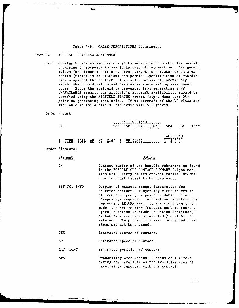
Table 3-6. ORDER DESCRIPTIONS (Continued)
Item 14 AIRCRAFT DIRECTED-ASSIGNMENT
Use: Creates VP stream and directs it to search for a particular hostilesubmarine in response to available contact information. Assignmentallows for either a barrier search (target is enroute) or an areasearch (target is on station) and permits specification of coordi-nation against the contact. This order breaks all previouslyestablished coordination and terminates any existing assignmentorder. Since the airfield is prevented from generating a VPUNAVAILABLE report, the airfield's aircraft availability should beverified using the AIRFIELD STATUS report (Alpha Menu item 05)prior to generating this order. If no aircraft of the VP class areavailable at the airfield, the order will be ignored.
Order Format:
EST TGT INFOCM HE SP LT -- LON---SPA DAY HRMN
WEP LOADP TYPE BASE AF NO Crd? S VP CLASS I2-3-4
Order Elements:
Element Option
CN Contact number of the hostile submarine as foundin the HOSTILE SUB CONTACT SUMMARY (Alpha menuitem 02). Entry causes current target informa-tion for that target to be displayed.
EST TG' INFO Display of current target information forselected contact. Player may elect to revisethe course, speed, or position data. If nochanges are required, information is entered bydepressing RETURN key. If revisions are to bemade, the entire line (contact number, course,speed, position latitude, position longitude,probability are radius, and time) must be re-entered. The probability area radius and timeitems may not be changed.
CSE Estimated course of contact.
SP Estimated speed of contact.
LAT, LONG Estimated position of contact.
SPA Probability area radius. Radius of a circlehaving the same area as the two-sigma area ofuncertainty reported with the contact.
3-71
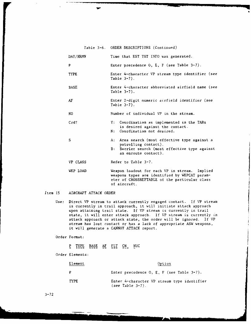
Table 3-6. ORDER DESCRIPTIONS (Continued)
DAY/HRMN Time that EST TGT INFO was generated.
P Enter precedence 0, E, F (see Table 3-7).
TYPE Enter 4-character VP stream type identifier (seeTable 3-7).
BASE Enter 4-character abbreviated airfield name (seeTable 3-7).
AF Enter 2-digit numeric airfield identifier (seeTable 3-7).
NO Number of individual VP in the stream.
Crd? Y: Coordination as implemented in the TARsis desired against the contact.
N: Coordination not desired.
S A: Area search (most effective type against apatrolling contact).
B: Barrier search (most effective type againstan enroute contact).
VP CLASS Refer to Table 3-7.
WEP LOAD Weapon loadout for each VP in stream. Impliedweapons types are identified by WEPCAT param-eter of CROSSREFTABLE of the particular classof aircraft.
Item 15 AIRCRAFT ATTACK ORDER
Use: Direct VP stream to attack currently engaged contact. If VP streamis currently in trail approach, it will initiate attack approachupon attaining trail state. If VP stream is currently in trailstate, it will enter attack approach. If VP stream is currently inattack approach or attack state, the order will be ignored. If VPstream has lost contact or has a lack of appropriate ASW weapons,it will generate a CANNOT ATTACK report.
Order Format:
P TYPE BASE AF FLT CN NUC
Order Elements:
Element Option
P Enter precedence 0, E, F (see Table 3-7).
TYPE Enter 4-character VP stream type identifier(see Table 3-7).
3-72

Table 3-6. ORDER DESCRIPTIONS (Continued)
BASE Enter 4-character abbreviated airfield name (seeTable 3-7).
A.F Enter 2-digit numerical airfield identifier(see Table 3-7).
FLT Enter 3-digit stream number (see Table 3-7).
CN Contact number of target as found in the AIR-CRAFT EMPLOYMENT SUMMARY (Alpha Menu item 04) orHOSTILE SUB CONTACT SUMMARY (Alpha Menu item 02).An invalid contact number will result in a CAN-NOT ATTACK report.
NUC Y: Authority given for release of nuclear ASWweapons.
N: Authority not given for release of nuclearASW weapons.
Item 16 REQUEST AIRCRAFT TRANSFER
Use: Reassigns aircraft from one VP base to another. Since the airfieldis prevented from generating a VP UNAVAILABLE report, the originat-ing airfield's aircraft availability should be verified using theAIRFIELD STATUS report (Alpha Menu item 05) prior to generatingthis order. If no aircraft of the VP class are available at theairfield when the oruer is received, the order will be ignored.
Order Format:
P VP CLASS NO from AF to AF
Order Elements:
Element Option
P Enter precedence 0, E, F (see Table 3-7).
VP CLASS Refer to Table 3-7.
NO Number of aircraft to be transferred.
AF Enter 2-digit numerical airfield identifier (seeTable 3-7). (From AF denotes originating air-field; to AF denotes receiving airfield.)
Item 17 VP BREAK-STREAM ORDER
Use: Breaks a particular VP stream prior to its natural termination uponexhausting the VP stream count.
3-73

Table 3-6. ORDER DESCRIPTIONS (Continued)
Order Format:
P TYPE BASE AF FLT
Order Elements:
Element Option
P Enter precedence 0. E, F (see Table 3-7).
TYPE Enter 4-character VP stream type identifier (seeTable 3-7).
BASE Enter 4-character abbreviated airfield name (seeTable 3-7).
AF Enter 2-digit numeric airfield identifier (seeTable 3-7).
FLT Enter 3-digit stream number (see Table 3-7).
Item 18 SUB REPAIR/RELOAD ORDER
Use: Directs submarine to proceed via a particular route to a specifiedposition where it will be repaired and/or rearmed.
Order Format:
PIM WEP LOADP UNIT M A--T- sLONG. SP 1 2 3 4 5
Order Elements:
Element Option
P Enter precedence 0, E, F (see Table 3-7).
UNIT Enter submarine unit identifier (see Table 3-7for format).
M R: Submarine is assigned to repair and reloadmission.
A: Submarine is assigned to reload/re-armmission.
PIM Refer to Table 3-7.
W EP LOAD Weapons loadout for submarine. Implied weap.types ace identified by WEPCAT parameter ii:
submarine class CROSSREFTABIE.
3-74
L." AOA7 73 JOHNS HOPKINS UNIV LAUREL MD APPLIED PHYSICS LAB F/6 15/6
I NAVAL NUCLEAR WARFARE SIMULATION OPERATOR'S MANUAL U)
IMAR Al1 N K BROWN. R R GUENTHER, P A JAFFRAT N00024-RI C-5311
UNCLASSIFIED NL"2h~~hE.1111E

Table 3-6. ORDER DESCRIPTIONS (Continued)
Item 19 SUB/AIRCRAFT COORDINATION
Use: Directs a unit to engage in coordinated operations as determined bythe unit's TARs when the unit detects a specified contact that isengaged by one or more friendly units that also have coordinatedassignments against the contact. The unit may be assigned coordi-nated operations against any number of contacts and any number ofunits may be assigned to a particular contact.
Order Format:
if VPP UNIT CN AFFLT
Order Elements:
Element Option
P Enter precedence 0, E, F (see Table 3-7).
UNIT Jf submarine: Enter unit identifier (seeTable 3-7 for format).
If VP stream: 8-character designator obtainedby combining 4-character TYPEdesignator with 4-character Base
designator. Refer to Table 3-7.
CN Contact number of hostile submarine as found inthe HOSTILE SUB CONTACT SUMMARY (Alpha Menu item02).
AF Enter 2-digit numeric airfield identifier (seeTable 3-7).
FLT Enter 3-digit stream number (see Table 3-7).
3-75
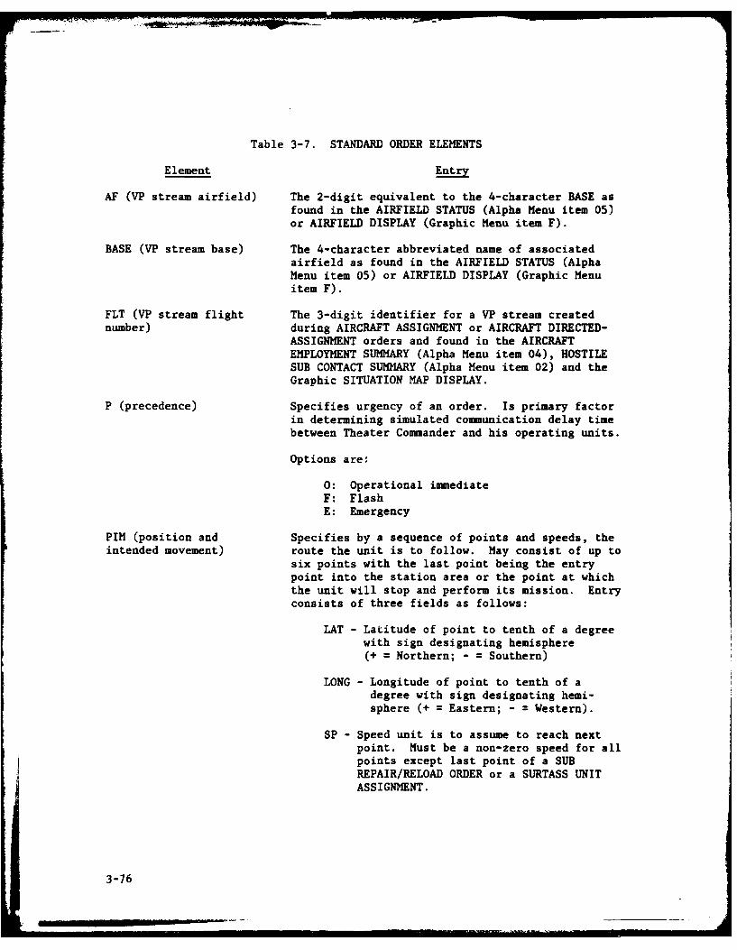
Table 3-7. STANDARD ORDER ELEMENTS
Element Entry
AF (VP stream airfield) The 2-digit equivalent to the 4-character BASE asfound in the AIRFIELD STATUS (Alpha Menu item 05)or AIRFIELD DISPLAY (Graphic Menu item F).
BASE (VP stream base) The 4-character abbreviated name of associatedairfield as found in the AIRFIELD STATUS (AlphaMenu item 05) or AIRFIELD DISPLAY (Graphic Menuitem F).
FLT (VP stream flight The 3-digit identifier for a VP stream creatednumber) during AIRCRAFT ASSIGNMENT or AIRCRAFT DIRECTED-
ASSIGNMENT orders and found in the AIRCRAFTEMPLOYMENT SUMMARY (Alpha Menu item 04), HOSTILESUB CONTACT SUMMARY (Alpha Menu item 02) and theGraphic SITUATION MAP DISPLAY.
P (precedence) Specifies urgency of an order. Is primary factorin determining simulated communication delay timebetween Theater Commander and his operating units.
Options are:
0: Operational immediateF: FlashE: Emergency
PIM (position and Specifies by a sequence of points and speeds, theintended movement) route the unit is to follow. May consist of up to
six points with the last point being the entrypoint into the station area or the point at whichthe unit will stop and perform its mission. Entryconsists of three fields as follows:
LAT - Latitude of point to tenth of a degreewith sign designating hemisphere(+ = Northern; - Southern)
LONG - Longitude of point to tenth of adegree with sign designating hemi-sphere (+ = Eastern; - = Western).
SP - Speed unit is to assume to reach nextpoint. Must be a non-zero speed for allpoints except last point of a SUBREPAIR/RELOAD ORDER or a SURTASS UNITASSIGNMENT.
3-76

11
Table 3-7. STANDARD ORDER ELEMENTS (Continued)
Element Entry
STATION Describes the patrol or search station as either abarrier or an area and defines the region withappropriate latitude and longitude coordinates.A barrier requires the center and one end point tobe specified. An area requires the interior andfour vertex points to be specified. The pointsare entered in a center/interior then vertexpoint(s) order in the appropriate fields:
LAT -Latitude of point to tenth of a degreewith sign designating hemisphere(+ = Northern; - = Southern).
LONG - Longitude of point to tenth of adegree with sign designating hemi-sphere (+ = Eastern; - = Western).
TYPE The 4-character identifier of a VP stream typeinitially entered during AIRCRAFT ASSIGNMENT orAIRCRAFT DIRECTED-ASSIGNMENT orders and found inthe AIRCRAFT EMPLOYMENT SUMMARY (Alpha Menu item04).
UNIT Submarine/SURTASS units: The 8-character unithull number identifier created at initializationand found in the SURF/SUB EMPLOYMENT SUMMARY(Alpha Menu item 03).
VP Airfield: The 8-character identifier obtainedby combining 6-character AIRFLD with 2-characterAF. To ensure resulting field is 8-characterslong, single digit values must be preceded by azero.
VP Stream: The 8-character identifier obtained bycombining 4-character TYPE with 4-character BASE.
All Units: "ALLUNITS" directs order to all unitscapable of carrying out the order.
VP CLASS Aircraft type identifier found in CLASS listing ofCROSSREFTABLE. Entry must be made exactly aslisted in CROSSREFTABLE (without apostrophes) ororder will be ignored.
3-77/(3-78 blank)I

'1

Table 3-8. GRAPHIC DISPLAY SYMBOLS
BLUE DISPLAY RED DISPLAY
UNITS SYMBOL UNITS SYMBOL
SSN 594 SSN E-1, N Lj
SSN 637 k SSN V, A, Y W0SSN 688 3 SS Lj
Other NUC SSN & SSB G-I, SSB G-II, SSBN H-II Qj
SSN 594, 637, 688 with CM j SSBN Y, SSB G-IV 04
SSBN 593, 608 w/POLARIS A3 i6 SSBN D-I, D-II, G-III, H-III 15j
SSBN 616, 627, 640 w/POSEIDON C3 tJ) SSBN D-III 161
SSBN 640, 726 w/TRIDENT C4 k ) SSGN C, P 7ZJ
Any SS %2 SSGN E-II Lij
P3-A/B '1) SSG J, W Lij
P3-C n2 SURTASS x
P3-C (Update) (-' SURTASS y rnSURTASS M1 ri
Interim SURTASS M M2 r1
M3 97
CONTACTS SYMBOL CONTACTS SYMBOL
CVAP Nuclear Sub
HEN Diesel Sub
YD
Diesel '/MISCELLANEOUS SYMBOL MISCELLANEOUS SYMBOL
Airfields ( Airfields
Sub Reload/Repair Site ES Sub Reload/Repair Site
Surveillance Sites Surveillance Sites
PIN End X PIN End X
Point in Track History + Point in Track History +
Target Location Target Location
C2 Site C2 Site
Comunications Site Communications Site
3-79

Table 3-9. GRAPHIC REPORTS
Item P BLACKBOARD PIM CONSTRUCTION
Use: Primarily used for Position and Intended Movement (PIM) construc-tion. Also used to display a PIM for input on the alphanumericterminal in an undirected assignment order and to display latitudeand longitude of a particular point on the map.
Operation:
1. Using joystick construct PIM of up to six points (depressjoystick button to enter points).
2. Observe latitude/longitude display of each point on monitor.3. After all points have been entered, move cursor to far right
and depress joystick button.4. Observe prompt asking if player desires to input patrol
pattern.5. If no patrol pattern is desired, enter 06. If a patrol pattern is desired, enter I and use joystick to
construct a patrol pattern of up to four points.7. Return to Graphics menu by entering 9
Item T UINT PIM DISPLAY
Use: Displays the current ordered PIM for a particular unit.
Operation:
1. Verify a PIM for that unit has been entered in a previousundirected assignment order.
2. Observe prompt for a unit number.3. Enter unit number. For a sub or surface unit, the exact
alphanumeric designator shown in the EVENT SUMMARY REPORTincluding trailing blanks must be entered. For A VP stream,enter either the 8-character unit name or the VP streamnumber.
4. Verify displayed unit designator is correct.5. If unit designator is not correct, depress RETURN key and
return to Step 2.6. If designator is correct, enter 97. If an error message is displayed, unit designator is invalid.
Go to Step 98. Observe PIM display.9. Return to Graphics menu by entering 9.
Item S SUB/SURF POSITION DISPLAY
Use: Displays latest reported position all friendly submarines andships.
3-80

I
Table 3-9. GRAPHIC REPORTS (Continued)
Operation:
1. Observe COMPLETED . . . HIT 9 TO RETURN is printed at bottomwhen display is complete.
2. Return to Graphics menu by entering 9.
Item A AIRCRAFT POSITION DISPLAY
Use: Displays latest reported position of all Aircraft.Display is available to BLUE team only.
Operation:
1. Observe COMPLETED . . . HIT 9 TO RETURN is printed at bottomwhen display is complete.
2. Return to Graphics menu by entering 9.
Item F AIRFIELD POSITION DISPLAY
Use: Displays position of all airfields. Airfields are identified bytheir mnemonic name and airfield number. Display is available toBLUE team only.
Operation:
1. Observe display.2. Return to Graphics menu by entering 9.
Item D DISTANCE FUNCTION
Use: Displays the great circle distance in nautical miles between twochosen points on the map.
Operation:
1. Using joystick and joystick button, select two points on themap.
2. Observe distance display beneath the map.3. Return to Graphics menu by depressing joystick button.
I3-81/(3-82 blank)
-WM
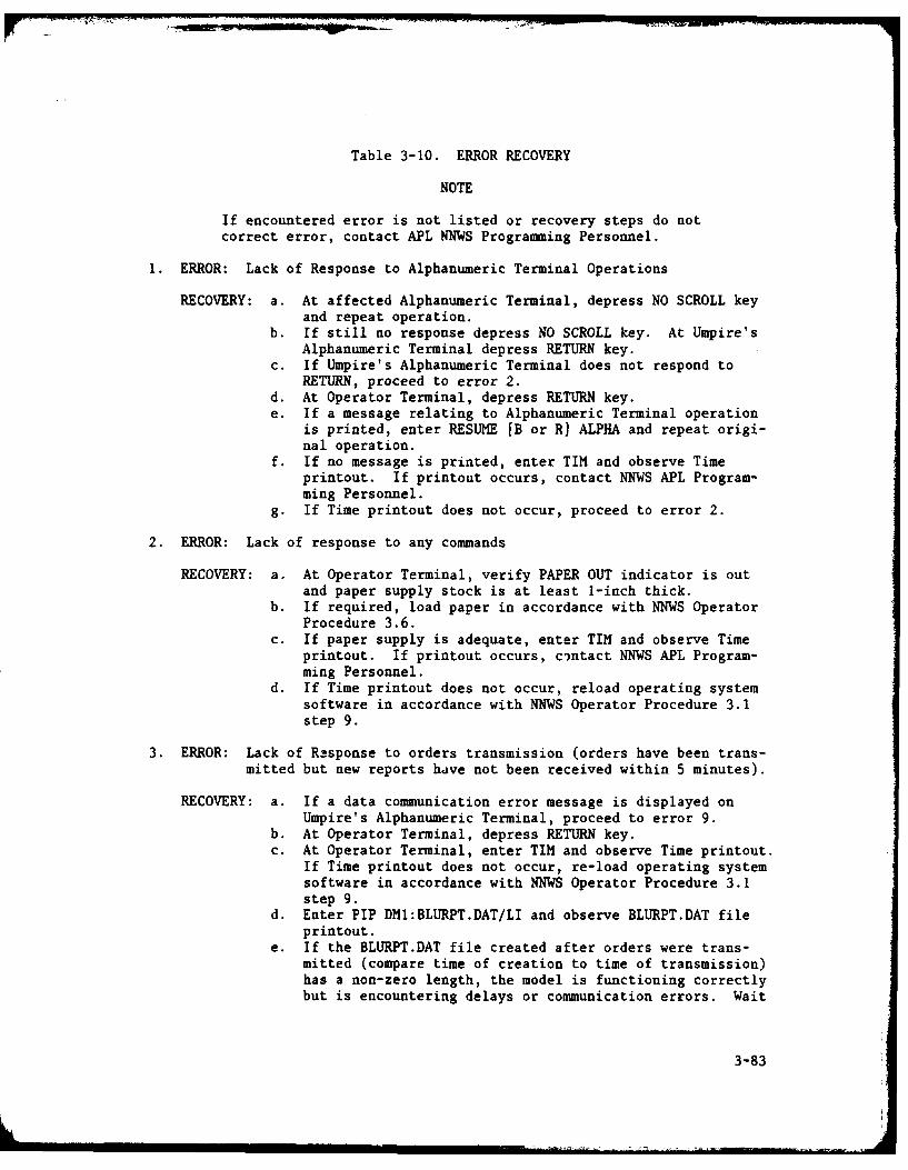
Table 3-10. ERROR RECOVERY
NOTE
If encountered error is not listed or recovery steps do notcorrect error, contact APL NNWS Programming Personnel.
1. ERROR: Lack of Response to Alphanumeric Terminal Operations
RECOVERY: a. At affected Alphanumeric Terminal, depress NO SCROLL keyand repeat operation.
b. If still no response depress NO SCROLL key. At Umpire'sAlphanumeric Terminal depress RETURN key.
c. If Umpire's Alphanumeric Terminal does not respond toRETURN, proceed to error 2.
d. At Operator Terminal, depress RETURN key.e. If a message relating to Alphanumeric Terminal operation
is printed, enter RESUME [B or R] ALPHA and repeat origi-nal operation.
f. If no message is printed, enter TIM and observe Timeprintout. If printout occurs, contact NNWS APL Program-ming Personnel.
g. If Time printout does not occur, proceed to error 2.
2. ERROR: Lack of response to any commands
RECOVERY: a. At Operator Terminal, verify PAPER OUT indicator is outand paper supply stock is at least 1-inch thick.
b. If required, load paper in accordance with NNWS OperatorProcedure 3.6.
c. If paper supply is adequate, enter TIM and observe Timeprintout. If printout occurs, cintact NNWS APL Program-ming Personnel.
d. If Time printout does not occur, reload operating systemsoftware in accordance with NNWS Operator Procedure 3.1step 9.
3. ERROR: Lack of Response to orders transmission (orders have been trans-mitted but new reports have not been received within 5 minutes).
RECOVERY: a. If a data communication error message is displayed onUmpire's Alphanumeric Terminal, proceed to error 9.
b. At Operator Terminal, depress RETURN key.c. At Operator Terminal, enter TIM and observe Time printout.
If Time printout does not occur, re-load operating systemsoftware in accordance with NNWS Operator Procedure 3.1step 9.
d. Enter PIP DM1:BLURPT.DAT/LI and observe BLURPT.DAT fileprintout.
e. If the BLURPT.DAT file created after orders were trans-mitted (compare time of creation to time of transmission)has a non-zero length, the model is functioning correctlybut is encountering delays or communication errors. Wait
3-83

Table 3-10. ERROR RECOVERY (Continued)
for report of transmission completion or failure. If adata communication error message is displayed on Umpire'sAlphanumeric Terminal, proceed to error 9.
f. In the BLURPT.DAT file is zero length (empty), the modelmay be looping. If no message is received within 5minutes send a break signal to terminate the models execu-tion by performing the following on the EIA RS232 Break-out Box connected between the DL 11/E and the Bell 209Amodem):
(1) Move slide switch for pin 2 to OFF.(2) If not already in place, connect jumper wire to pin
20.(3) Touch free end of jumper wire to the pin 2 closest to
red lights.(4) Verify light for pin 2 flickers.(5) Retract wire and return pin 2 slide switch to ON.(6) If communication fails or model execution is aborted,
perform Abnormal Shutdown in accordance with NNWSOperator Procedure 3.4 Part 2 step 4.
5. ERROR: Order generator error
RECOVERY: a. At Operator Terminal, enterPIP IBLU or RED] ORD.DAT=UMPINT.DAT
b. Verify RED (BLUE) Alphanumeric Terminal displays AlphaMenu.
c. If Alpha Menu is not displayed, enterRESUME [B or RI ALPHA
d. Re-enter affected player's orders.
6. ERROR: Graphic Scope situation map error
RECOVERY: a. At Operator Terminal, enter RES [SITBL or SITRD]b. If error is not corrected, enter RUN [SITBL or SITRD]
(display will not be reinstated until after next REPORTSRECEIVED message).
7. ERROR: Graphic Map blanks during Copy operation.
RECOVERY: At Printer/Plotter, open Highed Front Panel and depress RESETpushbutton.
8. ERROR: Operator Terminal FORTRAN error messages printed in the followingformat:
task name--EXITING DUE TO ERROR numberIN subroutine AT offset
FROM subroutine AT offset
3-84i

Table 3-10. ERROR RECOVERY (Continued)
RECOVERY: Refer to appropriate error number listed below. If printederror number is not listed, refer to IAS/RSX FORTRAN IV User'sGuide (DEC publication number AA-1963D-TC).
ERRORNUMBER RECOVERY
24 End-of-file During Read error usually occursduring the processing of reports and is usuallydue to an empty unit file created by a prior tasl.failure. To recover, locate the failing unit byrunning the RED or BLUE unit summary program.Delete the current copy of the corresponding unitfile.
30 To receover from Open File error, check availablefile space. Run FILEUNLK procedure.
41 No FCS Buffer Room error usually occurs duringorder generation. To recover, re-initiate theorders tasks.
64 Input Conversion error is usually caused by aninvalid character in the received reports. Torecover, attempt to locate the failing reportusing the PIP utility program. If failing reportis found, halt and restart the simulation. Iffailing report cannot be found or error recursafter restart, notify APL NNWS ProgrammingPersonnel.
9. ERROR: Data Communication Error Messages displayed on Umpire's Alpha-numeric Terminal.
RECOVERY: Refer to appropriate CC number listed below- If printed CCnumber is not listed, contact APL NNWS Programming Personnel.
CCNUMBER RECOVERY
The Non-recoverable Transmission Error could bea result of electromagnetic interference to thetelephone trunk connecting the two computers. Torecover, conduct normal shutdown and restartof NNWS and Minicomputer. Prior to re-initiatinggame play, thoroughly test communications byissuing simple TSO commands.
10 PDP Communications Software not initialized erroris usually caused by a late CNTL Z entry (after5 seconds) on Umpire's Alphanumeric Terminal.To recover, conduct normal shutdown and restart.
3-85

Table 3-10. ERROR RECOVERY (Continued)
10. ERROR: Disasters
RECOVERY: When conditions deteriorate beyond Operator's control, theOperator should conduct shutdown and restart procedures.
3-86

DISTRIBUTION LIST
ACTIVITY COPY NO.
Office of the Chief of Naval OperationsDepartment of the NavyWashington, D.C. 20350
Attn: OP-654D 1-2/40AOP-009 3/40AOP-02 4/40AOP-96 5/40AOP-981 6/40AOP-950 7/40AOP-953B1 8/40A
Naval Sea Systems CommandDepartment of the NavyWashington, D.C. 20362
Attn: NSEA-03 9/40ANSEA-06J3 10/40ANSEA-643 11/40A
Office of the Chief of Naval MaterielDepartment of the NavyWashington, D.C. 20360
Attn: PM-23 12/40A
David W. TaylorNaval Ship Research and Development CenterBethesda, Maryland 20034
Attn: Code 1750, J. W. Sykes 13/40A
Center for War GamingNaval War CollegeNewport, Rhode Island 02840
Attn: LCDR John Corsey 14/40A
Commanding OfficerNaval Underwater Systems CenterNewport, Rhode Island 02840
Attn: Code 3602 15/40A
DL-1

ACTIVITY COPY NO.
Center for Naval Analyses2000 N. BeauregardAlexandria, Virginia 22311
Attn: Document Center 16/40A
The Johns Hopkins UniversityApplied Physics LaboratoryJohns Hopkins RoadLaurel, Maryland 20810
Attn: Ray Guenther 17/40A45-48/40A
Joint Strategic Target Planning Staff
Building 500Offutt Air Force Base, Nebraska 68113
Attn: War Gaming Division 18/40A
Studies Analysis and Gaming AgencyThe Joint Chiefs of StaffWashington, D.C. 20301 19/40A
DirectorDefense Nuclear AgencyWashington, D.C. 20305
Attn: Capt. D. W. West, RATN 20/40ACDR. A. Hughes, NATD 21/40ATechnical Library Division 22/40A
U.S. Naval Post Graduate SchoolMonterey, California 93940
Attn: Center for War GamingDepartment of Operations ResearchFor: Prof. R. N. Forrest 23/40A
Institute for Defense Analyses400 Army-Navy DriveArlington, Virginia 22202
Attn: Documents Acquisitions 24/40A
DL-2

ACTIVITY COPY NO.
U.S. Naval Surface Weapons CenterWhite Oak LaboratorySilver Springs, Maryland 20910
Attn: Technical Library & InformationServices Branch 25/40A
R-14 26/40AF-30 27/4-)A
Defense Advanced Research Projects Agency1400 Wilson BoulevardArlington, Virginia 22209
Attn: Tactical Technology Office 28/40A
CommanderTraining Command PacificSan Diego, California 92147 29/40A
CINCLANTNorfolk, Virginia
Attn: TCRP Mgr. 30/40A
CINCPACPearl Harbor, Hawaii 31/40A
Kaman Sciences CorporationP.O. Box 7463Colorado Springs, Colorado 80933
Attn: D. L. Choate, KSC Washington Operations 32/40AW. J. Rudy 33/40A
TRW7600 Colshire Drive
McLean, Virginia 22101
Attn: Mr. R. Anspach W2/B225 34/40A
Wagner AssociatesStation Square OnePaoli, Pennsylvania 19301
Attn: Mr. L. D. Stone 35/40A
DL-3

ACTIVITY COPY NO.
Automation IndustriesVitro Laboratories14000 Georgia AvenueSilver Spring, Maryland 20910
Attn: Mr. N. Wolfson 36/40A
Anti-Submarine Warfare System Project OfficeDepartment of the NavyWashington, D.C. 20360
Attn: Mr. R. Flum, Jr. ASW-115 37/40A
Defense Documentation CenterBuilding 5Cameron StationAlexandria, Virginia 22314 38-42/40A
BDM Corporation7915 Jones Branch RoadMcLean, Virginia 22101 43-44/40A
DL-4-1.