
Baffelle - DTIC
521
DEVELOPMENT OF REPAIR PROCESSES AND SOURCES FOR C/KC-135 AIRCRAFT WINDOWS/WINDSHIELDS Baffelle Putting Technology To Work RICHARD J. OLSON BATTELLE 505 KING AVENUE COLUMBUS, OH 43201 SEPTEMBER 1994 V\ "- J La £=) ka %e& SX DEC 0 8 1994' FT TECHNICAL REPORT FOR 09/91 - 01/94 C/KC-135 FINAL REPORT CONTRACT NUMBER FO9603-90-D-2217-SD02 DISTRIBUTION AUTHORIZATION: APPROVED FOR PUBLIC RELEASE; DISTRIBUTION IS UNLIMITED PREPARED FOR OKLAHOMA CITY AIR LOGISTICS CENTER •""" f'Til'-»" TINKER AFB, OK 73145 19941129 087
-
Upload
khangminh22 -
Category
Documents
-
view
2 -
download
0
Transcript of Baffelle - DTIC

DEVELOPMENT OF REPAIR PROCESSES AND SOURCES FOR C/KC-135 AIRCRAFT WINDOWS/WINDSHIELDS
Baffelle Putting Technology To Work
RICHARD J. OLSON
BATTELLE 505 KING AVENUE COLUMBUS, OH 43201
SEPTEMBER 1994
V\ "-J La £=) ka %e&
SX DEC 0 8 1994'
FT
TECHNICAL REPORT FOR 09/91 - 01/94 C/KC-135 FINAL REPORT CONTRACT NUMBER FO9603-90-D-2217-SD02
DISTRIBUTION AUTHORIZATION: APPROVED FOR PUBLIC RELEASE; DISTRIBUTION IS UNLIMITED
PREPARED FOR OKLAHOMA CITY AIR LOGISTICS CENTER •"""■ f'Til'-»"
TINKER AFB, OK 73145
19941129 087

This report is a work prepared for the United States Government by Battelle. In no event shall either the United States Government or Battelle have any responsibility or liability for any consequences of any use, misuse, inability to use, or
t reliance upon the information contained herein, nor does either * warrant or otherwise represent in any way the accuracy,
adequacy, efficacy, or applicability of the contents hereof.
11

REPORT DOCUMENTATION PAGE Form Approved
OMB No. 0704-0188 Public reporting burden for this collection of information is estimated to average 1 hour per response, including the time for reviewing instructions, searching existing data sources, gathering and maintaining the data needed, and completing and reviewing the collection of information. Send comments regarding this burden estimate or any other aspect of this collection of information, including suggestions for reducing this burden, to Washington Headquarters Services, Directorate for information Operations and Reports, 1215 Jefferson Davis Highway, Suite 1204, Arlington. VA. 22202-4302. and to the Office of Management and Budget, Paperwork Reduction Project (0704-0188), Washington. DC 20503.
1. AGENCY USE ONLY {Leave blank) 2. REPORT DATE
September 1994 3. REPORT TYPE AND DATES COVERED
Technical, C/KC-135 Final Report, 9/01/91 - 01/31/94
4. TITLE AND SUBTITLE
Development of Repair Processes and Sources for C/KC-135 Aircraft Windows/Windshields
5. FUNDING NUMBERS
6. AUTHOR(S)
Richard J. Olson 7. PERFORMING ORGANIZATION NAME(S) AND ADDRESS(ES)
Battelle 505 King Avenue Columbus, Ohio 43201-2693
8. PERFORMING ORGANIZATION REPORT NUMBER
Contract FO9603-90- D-2217-SD02
9. SPONSORING/MONITORING AGENCY NAME'S) AND ADDRESS(ES)
Oklahoma City Air Force Logistics Center OC-ALC/TIETR 3001 Staff Drive, Suite 2AF66A Tinker AFB, OK 73145-3040
Technology Transition Office ASC/SMT 2690 C, Suite 5 Wright-Patterson AFB, OH 45433-7412
10. SPONSORING/MONITORING AGENCY REPORT NUMBER
VEP87CR52R1
11. SUPPLEMENTARY NOTES
12a. DISTRIBUTION/AVAILABILITY STATEMENT
Approved for public release; distribution is unlimited 12b. DISTRIBUTION CODE
13. ABSTRACT (Maximum 200 Words)
The U.S. Air Force has historically rejected the notion of using repaired windows/windshields (W/WS). With increasing pressure to reduce fleet operating costs and based on the favorable experience that commercial fleets have had, interest in using repaired W/WS is receiving greater attention. To ensure that repaired W/WS are safe and that they provide similar benefits for the Air Force, a program of evaluation and testing was undertaken to compare new and repaired C/KC-135 W/WS. Optical and electrical properties, pressure integrity, and bird impact resistance of repaired and new W/WS have been evaluated. The bird impact test results are the first data that the Air Force has collected for C/KC-135 W/WS. The functional testing indicated that repaired W/WS are not equal to new W/WS; the new W/WS outperform the repaired W/WS. In terms of removal for cause criteria and absolute performance requirements, however, the repaired W/WS appear to be "good enough." Concerning costs, the direct costs for repair of the W/WS in this program ranged from 65-75% of new W/WS cost, suggesting that money can be saved. 14. SUBJECT TERMS
Aircraft Transparencies, C/KC-135, Windows/Windshields, Repairs, Pressure Cycle Testing, Falling Ball Impact Testing, Bird Impact Testing, Repaired Window/Windshield Costs Analysis
15. NUMBER OF PAGES
264 16. PRICE CODE
17. SECURITY CLASSIFICATION OF REPORT
Unclassified
18. SECURITY CLASSIFICATION OF THIS PAGE
Unclassified
19. SECURITY CLASSIFICATION OF ABSTRACT
Unclassified
20. LIMITATION OF ABSTRACT
Unlimited NSN 754Ö-Ö1-26Ö-55ÖÖ __ „ ^, Standard Form 298 (Rev. 2-89)
Prescribed by ANSI Std. Z39.18 298-102

This page intentionally left blank.
IV

TABUE OF CONTENTS
REPORT DOCUMENTATION PAGE iii
TABLE OF CONTENTS v LIST OF TABLES vi LIST OF FIGURES vii SUMMARY x PREFACE xii
1.0 INTRODUCTION 1 1.1 Background 1 1.2 Objective 1 1.3 Approach 1 1.4 Report Contents 2
2.0 PROTOTYPE SELECTION 3 2.1 C/KC-135 WAYS 3 2.2 Program Prototypes 5 2.3 C/KC-135 #1 and #4 WAYS 5
3.0 WAYS REPAIRS 6 3.1 Aircraft WAYS Damage 6 3.2 Repair Vendors 8
3.2.1 NORDAM Transparency Division 8 3.2.2 Perkins Aircraft Services, Lie 8 3.2.3 The Glass Doctor 9
3.3 Repair Details 9
4.0 PERFORMANCE TESTING 10 4.1 Test Philosophy 10 4.2 Quality Assurance 12 4.3 General Inspection 12
4.3.1 Test Procedures 12 4.3.1.1 General Visual Examination 13 4.3.1.2 WAYS Dimensional Measurements 14 4.3.1.3 Basic Electrical Measurements 14 ~ 4.3.1.4 Heater Operation Tests 14 4.3.1.5 Optical Performance 15 a
4.3.2 General Inspection Test Results 16 Q
4.4 Pressure Integrity 17 4.4.1 Test Procedures 17
4.4.1.1 Proof Pressure Test 17 4.4.1.2 Cyclic Durability Test 17
M

TABLE OF CONTENTS (Continued)
4.4.2 Test Facility 18 4.4.3 Test Results 19
4.5 Residual Strength Assessment 20 4.5.1 Test Procedures 20 4.5.2 Test Facility 20 4.5.3 Test Results 20
4.6 Bird Impact Testing 21 4.6.1 Test Procedures 21 4.6.2 Test Facility 21 4.6.3 Test Results 22
4.7 Performance Testing Summary 23
5.0 COST ANALYSIS 24 5.1 Repair Costs 24 5.2 Costs of New W/WS 24 5.3 Cost Comparison 24
6.0 CONCLUSIONS, RECOMMENDATIONS, and DISCUSSION 25 6.1 Conclusions 25 6.2 Recommendations 27 6.3 Discussion 29
7.0 REFERENCES 31
APPENDK A. REPAIR VENDOR AIR AGENCY CERTIFICATES A-l APPENDIX B. GENERAL MSPECTION DATA SHEETS B-l APPENDIX C. BIRD IMPACT DATA SHEETS C-l
LIST OF TABLES
Table 2.1 C/KC-135 WAYS Part Numbers 33 Table 2.2 C/KC-135 Program W/WS 33 Table 2.3 C/KC-135 #1 and #4 W/WS Dimensions 36 Table 3.1 C/KC-135 Repaired and Not Repaired #1 W/WS in the Test Program ... 37 Table 3.2 C/KC-135 Repaired and Not Repaired #4 W/WS in the Test Program ... 38 Table 4.1 C/KC-135 #1 W/WS General Examination and Dimensional Measurements
Test Results 39 Table 4.2 C/KC-135 #4 W/WS General Examination and Dimensional Measurements
Test Results 41 Table 4.3 C/KC-135 #1 W/WS Basic Electrical Measurements Test Results 43
VI

Table 4.4 Table 4.5 Table 4.6 Table 4.7 Table 4.8 Table 4.9 Table 4.10 Table 4.11 Table 4.12 Table 4.13 Table 4.14 Table 4.15 Table 4.16 Table 4.17 Table 4.18 Table 4.19
Test Table 5.1 Table 5.2 Table 5.3 Table 5.4 Table 5.5 Table 5.6
LIST OF TABLES (Continued)
C/KC-135 #4 W/WS Basic Electrical Measurements Test Results 44 C/KC-135 #1 W/WS Heater Operation Test Results 45 C/KC-135 #4 W/WS Heater Operation Test Results 46 C/KC-135 #1 W/WS Optical Performance Test Results 47 C/KC-135 #4 W/WS Optical Performance Test Results 48 C/KC-135 #1 W/WS Pressure Integrity Test Results 49 C/KC-135 #4 W/WS Pressure Integrity Test Results . . 50 C/KC-135 #1 W/WS Residual Strength Ball Drop Test Results 51 C/KC-135 #4 W/WS Residual Strength Ball Drop Test Results 52 C/KC-135 #1 W/WS Bird Impact Test Results 53 C/KC-135 #4 W/WS Bird Impact Test Results 54 C/KC-135 W/WS General Inspection Summary 55 C/KC-135 W/WS Pressure Integrity Test Summary 56 C/KC-135 W/WS Ball Drop Residual Strength Test Summary 56 C/KC-135 W/WS Bird Impact Test Summary 57 C/KC-135 #1 W/WS Mounting Edge Measurements and Bird Impact
Results 58 Initial C/KC-135 W/WS Repair Estimates 59 C/KC-135 #1 W/WS Actual Repair Costs 60 C/KC-135 #4 W/WS Actual Repair Costs 61 Cost Quotes for All Prototype Repair Candidate C/KC-135 W/WS 62 C/KC-135 New W/WS Costs 65 Repair Cost Comparison Data for C/KC-135 W/WS 65
LIST OF FIGURES
Figure 2.1 C/KC-135 W/WS Identification 66 Figure 2.2 C/KC-135 W/WS Construction 67 Figure 2.3 W/WS Construction Showing Location of Slip Planes 68 Figure 2.4 C/KC-135 #1 W/WS Cross-Section 69 Figure 2.5 C/KC-135 #4 W/WS Cross-Section 70 Figure 3.1 The Glass Doctor Patented Technique for Repair of Conical Cracks in
Laminated Glass, U.S. Patent # 3,841,932 71 Figure 3.2 The Glass Doctor Patented Technique for Repair of Delaminations,
U.S. Patent # 4,780,162 72 Figure 4.1 C/KC-135 #1 W/WS Thermal Images From the Heater Test 73 Figure 4.2 C/KC-135 #4 W/WS Thermal Images From the Heater Test 74 Figure 4.3 Worst Optical Distortion Found in Any C/KC-135 #1 W/WS
(S/N 83-H-11-7-432) 75
Vll

LIST OF FIGURES (Continued)
Figure 4.4 Worst Optical Distortion Found in Any C/KC-135 #4 W/WS (S/N 87-H-04-20-130) 76
Figure 4.5 Pressure Integrity Testing Facility 77 Figure 4.6 C/KC-135 #1 W/WS Pressure Integrity Mounting Frame 78 Figure 4.7 C/KC-135 #4 W/WS Pressure Integrity Mounting Frame 79 Figure 4.8 C/KC-135 W/WS Mounting Details 80 Figure 4.9 Typical C/KC-135 #1 W/WS Pressure Integrity Test Set Up 81 Figure 4.10 Typical C/KC-135 #4 W/WS Pressure Integrity Test Set Up 82 Figure 4.11 Worst Delamination Observed in a C/KC-135 #1 W/WS From Pressure
Cycling (Repaired W/WS, S/N 82-H-09-06-537) 83 Figure 4.12 Worst Delamination Observed in a C/KC-135 #4 W/WS From Pressure
Cycling (Repaired W/WS, S/N 5-H-12-16-47) 84 Figure 4.13 Residual Strength Falling Ball Test 85 Figure 4.14 #1 W/WS Residual Strength Falling Ball Impact Test Showing Test
Set Up and Consequences of Two Ball Drops (New W/WS, S/N 86-H-10-06-062)86 Figure 4.15 #1 W/WS Residual Strength Falling Ball Impact Test Result for a
Repaired and Subsequently Delaminated W/WS, Single Ball Drop, Outboard View (S/N 82-H-9-6-537) 87
Figure 4.16 #1 W/WS Residual Strength Falling Ball Impact Test Result for a Repaired and Subsequently Delaminated W/WS, Single Ball Drop, Inboard View (S/N 82-H-9-6-537) 88
Figure 4.17 #4 W/WS Residual Strength Falling Ball Impact Test Showing Test Set Up and Test Result (New W/WS, S/N 92-093-HO-388) 89
Figure 4.18 #4 W/WS Residual Strength Falling Ball Impact Test Result for a Repaired and Subsequently Delaminated W/WS, Outboard View (S/N 5-H-12-16-47) 90
Figure 4.19 #4 W/WS Residual Strength Falling Ball Impact Test Result for a Repaired and Subsequently Delaminated W/WS, Inboard View (S/N 5-H-12-16-47) 91
Figure 4.20 C/KC-135 #1 W/WS Bird Impact Mounting Frame 92 Figure 4.21 C/KC-135 #4 W/WS Bird Impact Mounting Frame 93 Figure 4.22 C/KC-135 #1 W/WS Mounting Hardware Details 94 Figure 4.23 Schematic of the PPG Bird Cannon 95 Figure 4.24 Support Frame Used for Bird Impact Testing for C/KC-135 W/WS ... 96 Figure 4.25 Typical Pre-Test View of C/KC-135 #1 W/WS (Copilot) Prior to
Bird Impact Testing 97 Figure 4.26 Typical Pre-Test View of C/KC-135 #4 W/WS (Pilot) Prior to
Bird Impact Testing 98 Figure 4.27 Bird Impact Test Set Up Showing Impact Velocity Timing Trap (Right)
and Front High Speed Film Camera Equipment (Center) 99 Figure 4.28 Bird Impact Spall Sheet Viewed From Behind a C/KC-135 #1 W/WS 100
vm

LIST OF FIGURES (Continued)
Figure 4.29 C/KC-135 #1 W/WS Showing No Damage From a 4-Pound Bird Impact at 250.8 Knots (Repaired W/WS, S/N 89-286-HO-697) 101
Figure 4.30 C/KC-135 #1 W/WS Showing Outboanl Ply Failure From a 4-Pound Bird Impact at 251.7 Knots, Front View (New W/WS, S/N 86-H-10-06-007) 102
Figure 4.31 C/KC-135 #1 W/WS Showing Outboard Ply Failure From a 4-Pound Bird Impact at 251.7 Knots, Rear View (New W/WS, S/N 86-H-10-06-007) . 103
Figure 4.32 C/KC-135 #1 W/WS Showing All Glass Plies Failed From a 4-Pound Bird Impact at 249.4 Knots, Front View (Repaired W/WS, S/N 82-H-10-18-107)104
Figure 4.33 C/KC-135 #1 W/WS Showing All Glass Plies Failed From a 4-Pound Bird Impact at 249.4 Knots, Rear View (Repaired W/WS, S/N 82-H-10-18-107) 105
Figure 4.34 Spall Sheet Condition From a 4-Pound Bird Impact at 249.4 Knots on a C/KC-135 #1 W/WS With All Glass Plies Failed (Repaired W/WS, S/N 82-H-10-18-107) 106
Figure 4.35 C/KC-135 #4 W/WS Showing No Damage From a 4-Pound Bird Impact at 248.7 Knots (Not Repaired W/WS, S/N 4-H-10-9-69) 107
Figure 4.36 C/KC-135 #4 W/WS Showing Outboard Ply Failure From a 4-Pound Bird Impact at 247.5 Knots, Front View (Repaired W/WS, S/N B75-1149) . . 108
Figure 4.37 C/KC-135 #4 W/WS Showing Outboard Ply Failure From a 4-Pound Bird Impact at 247.5 Knots, Rear View (Repaired W/WS, S/N B75-1149) . . 109
Figure 4.38 C/KC-135 #4 W/WS Showing a Catastrophic All Glass Plies Failure From a 4-Pound Bird Impact at 250.8 Knots, Front View (Not Repaired W/WS, S/N 7-H-2-4-35) 110
Figure 4.39 C/KC-135 #4 W/WS Showing a Catastrophic All Glass Plies Failure From a 4-Pound Bird Impact at 250.8 Knots, Rear View (Not Repaired W/WS, S/N 7-H-2-4-35) Ill
Figure 4.40 Spall Sheet and W/WS Condition From a Catastrophic 4-Pound Bird Impact at 250.8 Knots on a C/KC-135 #4 W/WS (Not Repaired W/WS, S/N 7-H-2-4-35) 112
Figure 6.1 Heat Strengthened Glass Residual Stresses 113
IX

SUMMARY
The Air Force, in trying to reduce fleet maintenance costs, is considering using repaired windows/windshields (W/WS). Based on reported cost savings and favorable experience that commercial fleets have had with repaired W/WS, the use of repaired W/WS seems very attractive. Before adopting an operating policy to use repaired W/WS, however, the Air Force decided that structural performance testing of repaired W/WS and a cost analysis were required.
The approach followed for evaluating whether the use of repaired W/WS is justified was to procure some used C/KC-135 W/WS, make repairs on them, and then subject the repaired W/WS to a series of tests to determine the difference in performance when compared with new W/WS. The cost to make the repairs provides the data for the cost benefit analysis. The test results provide the data for an evaluation of fitness for purpose of repaired W/WS.
The testing conducted for this program represents the first full-range, systematic testing of the structural integrity of repaired W/WS for transport-type aircraft. Optical and electrical properties, pressure integrity, and bird impact resistance have been evaluated. In addition, the bird impact test results are the first data that the Air Force has collected for C/KC-135 W/WS.
The test results indicate that repaired W/WS have been restored to a condition better than the prevailing C/KC-135 Technical Order replacement criteria, but they do not perform as well as new W/WS. Many of the repaired W/WS still contain defects that would not pass an OEM quality assurance inspection. Some delamination occurred in a few of the repaired W/WS during pressure cycling, but it was not severe. The residual strength of the pressure cycled W/WS tends to suggest that the repaired W/WS are not quite as good as new W/WS. The bird impact test results are quite clear - new W/WS outperform either repaired or unrepaired W/WS. At the 250 knot impact velocity used in this program, all of the new and repaired #1 and #4 W/WS do, however, meet the no bird penetration requirement, while two of the repaired #1 W/WS technically failed the no spall criterion. From a practical viewpoint, the spall was very modest. One W/WS that was not repaired because of an out of specification heater resistance, failed catastrophically in the bird impact test.
Although repaired W/WS do not perform as well as new W/WS, they were, in fact, restored to a condition better than the prevailing C/KC-135 Technical Order W/WS replacement criteria. On the basis of the fact that they would not be removed from service if found on an aircraft, and the fact that they prevented bird penetration, repaired W/WS appear to be "good enough," at least at a 250 knot bird impact velocity.
The cost analysis indicates that savings may be realized. For this program, the cost of making the repairs was 75-percent of the new W/WS purchase price for #1 W/WS and 65- percent for the #4 W/WS. Considering all five of the C/KC-135 W/WS types and the full

range of estimates, quotes, and actual costs, repairing a C/KC-135 W/WS might cost as little as 41-percent of a new W/WS, but it could also cost as much as 132-percent.
The cost savings are only the direct repair costs. To this must be added the direct cost of transportation and the indirect costs of procuring the service (contracting), administrating it (accounts payable, records management, etc.) and operating it (storage, shipping and handling, outgoing/incoming inspection, etc.). Offsetting these items are a reduced burden, both economic and environmental, from lower landfill costs for W/WS that are taken out of service. These factors will certainly impact the economics and to ignore them would be a false economy. The Air Force should do a complete cost/benefit analysis to satisfy themselves that there is a true economic advantage to using repaired W/WS.
A significant peripheral finding from this study is that a blanket 10-year transport-type aircraft W/WS replacement policy cannot be justified, if W/WS manufacture date is used as the indicator of age. The new W/WS used in this program were manufactured in 1986, and they showed no evidence of degradation due to being in storage for 7 years. To remove and replace these W/WS in 1996, solely on the basis of age, Would be wasting operating and maintenance dollars. A better scheme for tracking service history and a service-history-based replacement criterion must be devised for a blanket W/WS replacement policy.
Recommendations that can be made as a result of the work performed on this program are contingent upon the Air Force making a decision, based on the available data, that the performance of repaired W/WS is acceptable. If, in the opinion of the Air Force, the performance of repaired W/WS is deemed "good enough," recommendations are made for approved W/WS repair vendors and repair processes. Recommendations for operating a W/WS repair program are also made.
XI

PREFACE
The work reported herein was performed by Bauteile, Columbus, Ohio, under Air Force Contract FO9603-90-D-2217-SD02, "Development of Repair Processes and Sources for C/KC-135 and B-52 Aircraft Windows/Windshields." The program was directed by the Oklahoma City Air Logistics Center (OC-ALC) at Tinker Air Force Base. Air Force administrative direction was provided by Ms. Cindy Cooper, OC-ALC/LADCB. Air Force technical direction was provided by Mr. Robert Koger, OC-ALC/TIETR.
The work was performed during the period of September 1991 to January 1994. The technical program at Batteile was directed by Mr. Richard Olson of Batteile's Engineering Mechanics Department and Mr. Dennis Miller of Battelle's Polymer Center. The author wishes to acknowledge Mr. Herb Goodrich of PPG Industries, Inc. Aircraft Products Division in Huntsville, Alabama for coordinating and conducting the W/WS testing, and Mr. Ryan Rice at Bauteile for preparation of the manuscript.
•
xu

1.0 INTRODUCTION
1.1 Background
Several facilities exist for repairing aircraft windows/windshields (W/WS), and with U.S. Federal Aviation Authority (FAA) approval, many commercial airlines are currently utilizing these services. The cost of repairing a W/WS is substantially less than the purchase price of a new W/WS for commercial fleets, so the incentive for them to use repaired W/WS is large. The favorable experience that the commercial fleet has had with repaired W/WS suggests that they will continue to use repaired W/WS in the foreseeable future.
The U.S. Air Force has historically rejected the notion of using repaired W/WS. With decreasing Congressional funding for the military, measures to reduce fleet operating costs are receiving greater scrutiny. Based on the experience that the commercial fleet has had with repaired W/WS, the issue of using repaired W/WS on military aircraft is now being systematically considered. To ensure that repaired W/WS are safe and that they provide a similar cost savings benefit to the Air Force, a program of thorough evaluation and testing was required.
In September 1991, the Air Force contracted with Battelle to investigate the consequences and impact of using repaired W/WS. The program was to evaluate feasibility by testing the functional performance of repaired W/WS and by performing an economic analysis. Adequate functional performance and a favorable economic analysis would then provide the justification for a recommendation to use repaired W/WS.
The maintainability of Air Force fleet aircraft is an on-going concern because many of the aircraft in the current inventory are projected to have significant roles for many more years (10 to 20 years). By decreasing the lead time and procurement costs for W/WS, the maintainability of the fleet is enhanced. Furthermore, by gaining more control over the spare parts inventory, fewer new parts will be required and the costs of the W/WS program will be reduced.
1.2 Objective
The objective of this program was to provide a rationale for either accepting or rejecting the use of repaired W/WS in Air Force fleet aircraft.
1.3 Approach
The approach followed for evaluating whether use of repaired W/WS is a viable option for the Air Force was to procure some used W/WS, make prototypical repairs on them, and then subject the repaired W/WS to a battery of tests to see if there is any difference in performance when compared with new W/WS. Making prototypical repairs provides

baseline data for repair costs. The battery of tests provides an evaluation of fitness for purpose of the repaired W/WS.
The W/WS selected for evaluation in this program were from C/KC-135 aircraft. These W/WS are of typical laminated glass and plastic construction and include integral heaters. Repairs considered in this program included surface damage, delamination, electrical heater problems, broken layers, and seal/mounting problems. Repairs were subcontracted to commercial fleet W/WS repair stations with instructions to return repairable W/WS to Original Equipment Manufacturer (OEM) specifications per the approved processes in the repair vendor's FAA W/WS Air Agency Certificates. The direct costs for performing the repairs on the test prototypes forms the foundation of the economic analysis.
The approach to evaluating the functional performance of the repaired W/WS involved a rigorous set of tests designed to determine if the repair processes have degraded the W/WS when compared with new W/WS. Both repaired and new W/WS were subjected to pressure, impact, optical, and heater operation tests, similar in spirit to W/WS qualification tests. Provided that the repaired and new W/WS perform the same, the use of repaired W/WS can, at least on a performance basis, be justified.
1.4 Report Contents
In the sections that follow, the results of this 2%-year study are presented. The report begins with a discussion of the selection of repair candidate prototypes for the program and ends with recommendations for the Air Force on implementing a W/WS repair program. Topics presented include:
• C/KC-135 W/WS construction details
• Selection and condition of the W/WS repaired in this program
• A generic discussion of glass-laminate aircraft W/WS repairs, identification of the repair vendors that were involved with this program, and details of the actual repairs made to the W/WS
• Repaired W/WS performance evaluation, including test procedures, pass/fail criteria, and test results
• A cost analysis
• Conclusions and recommendations.
2.0 PROTOTYPE SELECTION
The C/KC-135 aircraft was selected as the prototype for evaluating the feasibility of using repaired W/WS because the number of aircraft in the fleet is fairly high, the C/KC-135 is projected to be in service for many more years, and because the repair vendors have direct experience repairing the essentially equivalent Boeing 707 W/WS. The C/KC-135 has 10 cockpit W/WS identified in Figure 2.1, 5 on the pilot side and 5 on the copilot side. The set of five W/WS on the copilot side are a mirror image of the pilot side W/WS. W/WS #1 is the forward W/WS, #2 and #3 are side W/WS, and #4 and #5 are eyebrow W/WS. All of the W/WS except #2 are fixed in position. W/WS #2 opens to provide ventilation and ground communication by sliding aft on a track. Table 2.1 lists the current part numbers for the C/KC-135 W/WS.
2.1 C/KC-135 W/WS
Figure 2.2 shows the general construction of the C/KC-135 W/WS. The C/KC-135 W/WS have a three-part glass and vinyl laminate construction. The inner layer is thick, heat-strengthened plate glass designed to withstand cabin pressure forces. A transparent, plasticized, polyvinyl butyral core layer acts as the "fail-safe" load carrying member and prevents shattering in the event of inner ply failure. The outer ply is a relatively thin layer of heat-strengthened glass with no structural significance, but it provides rigidity and a scratch-resistant surface. A phenolic or masonite filler strip, located around the edge of the W/WS, and a metal filler strip embedded in the vinyl provide the means to attach the W/WS to the airframe. Vinyl or vinyl and rubber bumpers protect the sides of the outer ply.
The structural integrity design of C/KC-135 cockpit W/WS is based on two requirements: "fail-safe" pressure integrity and bird impact resistance. The "fail-safe" pressure integrity is founded on two redundant systems, an inner glass ply that can sustain the full rated cabin pressure in the absence of all other layers, and a polymeric core ply that can maintain pressure integrity if the inner and outer glass plies are cracked. The bird impact structural integrity of W/WS is either characterized as "bird bagging" or "bird bounce." Bird bagging W/WS, typically two glass layers with a polymeric core ply, stop bird penetration by large ductile deformation of the core ply, i.e., "bagging" the bird. Bird bounce W/WS are typically multilaminates and cause the bird to "bounce" off the W/WS. The C/KC-135 W/WS main cockpit W/WS are "bird bagging" W/WS.
The glass used in C/KC-135 W/WS is heat strengthened to provide resistance to cracking. The glass is heated to near the softening point and then quenched to produce compressive residual stresses that extend from the outer surface into a depth of about 1/6* of the glass thickness. Below the compressive stress layer lies tensile residual stresses. As long as surface defects do not penetrate into the tensile layer, the glass will exhibit a high resistance to fracture. Once a crack does fully penetrate the tensile layer, the glass will shatter as the tensile stresses are relieved.

The vinyl core, which acts as the "fail-safe" pressure boundary and means for controlling glass fragments in the event of a glass ply failure, is highly plasticized polyvinyl butyral. The vinyl is relatively brittle at low temperatures (-65° F), and unable to absorb much energy per unit volume. At temperatures approaching 130° F, the vinyl becomes very ductile and can absorb a relatively large amount of energy as it is loaded. W/WS heaters, which not only de-fog and de-ice the glass, ensure that the vinyl remains ductile.
An integral part of the C/KC-135 W/WS construction is slip planes or a parting medium at the edges of the glass. A slip plane is located between both the inner glass ply and the vinyl and the outer glass ply and the vinyl as shown in Figure 2.3. The slip planes are thin strips of material at the glass-vinyl interface that keep the glass from bonding to the vinyl. This allows the various plys to move independently at these locations in response to pressure loads and differential thermal expansion. Without the slip planes, the glass at the edges of the W/WS would be prone to fracture because it would exceed its strain limit as it tried to move with the underlying vinyl. The slip planes form a "softer" connection that promotes a more gradual build up of strains in the glass so that it does not exceed its strain capacity. Although the slip planes look similar to delamination, they are not defects but an intentional part of the W/WS design.
The C/KC-135 cockpit W/WS contain heating systems for anti-icing and/or anti- fogging. An electrically conductive film of pyrolytic tin oxide between the outer ply and vinyl core ply is used to heat the #1 and #2 W/WS to reduce ice/frost formation. A similar conductive film between the inner ply and core ply is used on #3, #4, and #5 W/WS for defogging only. The W/WS heating system, so called NESA® coated glass, uses the resistivity of the film to provide the heating. The #1 W/WS also contain fine wires at the W/WS edges between the outer glass ply and vinyl, so-called edge heaters, to correct a heating power deficiency in the corner. The temperature of the #1 and #2 W/WS is controlled with an integral sensor. Externally applied thermal switches control the temperature of #3, #4, and #5 W/WS.
A temperature sensor embedded in the laminate of the #1 W/WS regulates the temperature of the #1 and #2 W/WS when the heater is on. The sensor, a negative temperature coefficient (NTC) thermistor, exhibits increasing resistance with increasing temperature. When wired in an appropriate power amplifier control circuit, as the W/WS and sensor temperature rises, the sensor resistance increases. This causes the control amplifier to shut off current to the W/WS, and hence power dissipated by the heater film, thus reducing the temperature. When the temperature drops below a lower setpoint, the control amplifier turns power back on to the W/WS.
Seals on the W/WS keep cabin pressure in and moisture out. In addition, they act as vibration and shock absorbers and help to compensate for differential thermal expansion. W/WS #3, #4, and #5 utilize a silicone rubber molded-in-place pressure seal that is molded to the W/WS mounting surface. Drawing the W/WS tight to the airframe with its mounting bolts effects the seal. On the #2 W/WS, a bellcrank mechanism presses the W/WS against the airframe when it is closed and latched. The #1 W/WS uses a molded-in-place seal similar the other W/WS, except that a stainless steel Z-channel is sandwiched between a

Silicon rubber cushion and a beaded pressure seal. The mounting bolts provide the pressure to hold the W/WS tight against the airframe. All of the C/KC-135 W/WS mount from the inside of the aircraft.
2.2 Program Prototypes
OC-ALC made arrangements to have C/KC-135 W/WS that were removed from fleet aircraft at Tinker AFB shipped to Bauteile. Over 100 W/WS were screened to find 75 prototype repair candidates. All five C/KC-135 W/WS types were included in the 75 W/WS population. At the time of their removal, the W/WS were judged not serviceable per the criteria of the applicable C/KC-135 Fuselage Window Tech Order, Section 8 of T.O. lC-135(K)A-2-2. Indicated reasons for removal from service included: failed heaters, bubbles, scratches, separation, leaks, old, discolored, and corrosion.
The service history of the prototype repair candidates is not known because: 1) very few of the W/WS had airframe numbers, 2) W/WS are not tracked by serial number, and 3) planes are moved from location to location as a part of normal squadron rotation. In most instances, the date of removal from service was not noted. The installation date is not known for any of the W/WS. All that is known for certain is the year the W/WS was made; the first one or two digits of the serial number indicate the year the W/WS was made - a single digit is a 1970's vintage W/WS.
Table 2.2 lists the type, serial number, and condition of the 75 C/KC-135 repair candidates. W/WS that have serial numbers that begin with numbers were made by PPG, while those that start with letters were made by Libbey-0wens-Ford.
At the outset of the program, the plan was to repair and test some of each of the five different C/KC-135 W/WS. A large number of the repair prototype candidate W/WS, however, were judged not repairable by virtue of out-of-specification or open circuit heaters. In conjunction with OC-ALC, the decision was made to proceed with repairing and testing only #1 and #4 W/WS. Although other repair candidates could have been obtained, it was felt that the program objectives could be adequately met if only two of the five W/WS types were evaluated. The #1 and #4 W/WS were selected because they have construction (and consequently repairs) that is typical of all of the C/KC-135 W/WS, there was enough W/WS in the population to conduct all of the tests in the test matrix, and the #1 and #4 W/WS are the only reasonable bird impact test candidates.
2.3 C/KC-135 #1 and #4 W/WS
Table 2.3 lists the general dimensions for the #1 and #4 W/WS. The #1 W/WS is a flat, nearly rectangular W/WS. The #4 W/WS, on the other hand, is roughly square in the plan view and has curvature (approximately 0.65 inches out of plane across the largest diagonal in the viewing area). The general construction was noted in Section 2.1. Figures 2.4 and 2.5 show detailed cross-sections of the #1 and #4 W/WS.

In general, because the #1 W/WS is flat, it is one of the easiest W/WS to manufacture and repair. Being flat, the optics of #1 W/WS are very good. The curvature on the #4 W/WS tends to result in some degree of optical distortion, and the curvature makes it somewhat more difficult than a #1 to repair, in spite of its small size.
3.0 W/WS REPAIRS
3.1 Aircraft W/WS Damage
The most common failure modes of laminated transparencies are:
• Delamination: separation of vinyl from the glass
• Cracks and chipping: glass breakage due to high stress
• Arcing: unbalanced electrical potential within the conductive coating
• Heater Failure: loss of continuity in the heater or heater sensor circuit
• Impaired Vision: surface scratches, contaminates, or internal defects
• Contamination: air or water leaks caused by defective seals
• Vinyl cracking.
Delamination is separation of the glass surface of the inner or outer ply from the vinyl core ply to which it is bonded. Delamination generally starts at the slip planes and moves inward, although it may occur anywhere in the W/WS. It mainly occurs between the outer ply and the vinyl ply. Delamination does not dramatically reduce the strength of the W/WS, but may interfere with vision or W/WS heating if the delamination occurs at the interface where the heating film is located.
Cracks and chips may occur in either of the glass plys and may be caused by impacts or by high stresses at the edges of the glass. Single cracks in the outer ply are unlikely because the temper in this layer precludes a single crack. After the momentary appearance of a crack in the outer layer, the entire layer shatters very abruptly. Small cracks very near the edges of the W/WS may not be cause for removal, provided the crack is not directed toward the center of the pane. Cracks that adversely affect the functioning of the heater would not be acceptable. Chips may occur internally or externally. Internal chips are caused by the glass-vinyl bond strength exceeding the strength of the glass. External chips are generally caused by impacts. Chips usually have a clamshell shape, are rough, and white powdered glass is often in evidence. Chips are detrimental to the strength of the pane.

W/WS busbar breakdown and faults in the heater film cause arcing. Basically, the insulation breaks down and the heater electrical current short circuits to the airframe. Arcing is evidenced by burned areas around electrical braid and along the busbar.
The failure of the W/WS heater to de-ice or defog satisfactorily is one of the most serious failure modes. Arcing, chips, cracks, or lack of continuity in the heater film that render the heater inoperative are cause for W/WS replacement. Uneven heating or hot spots caused by delamination at the glass-vinyl interface with the heating film or chips may also be a cause for removal.
Satisfactory optical properties of the W/WS are paramount. Foggy or cloudy areas may appear in areas where moisture has penetrated the vinyl and has begun to degrade it. Scratches may occur on both the inner and outer plys that may interfere with visibility. Likewise, delamination may become serious enough to warrant replacement of the W/WS on the basis of reduced visibility. Bubbles may occur in the vinyl core ply in W/WS that have been exposed to elevated temperatures. Bubbles are caused by gas liberated from the vinyl, and grow in size and number with increased temperature or longer exposures. Needless operation of the heaters on the ground is a prime cause of bubbles. Bubbles do not have a large effect on strength of the W/WS, but may become serious enough to impair visibility. Although other failure modes may not be evident, poor optical performance is always a sufficient cause for W/WS replacement.
The bumpers on the edge of the outer glass form a moisture barrier. Degradation of the bumper in the form of cracking or separation from the edge of the outer glass ply can allow moisture and air to get into the slip planes. Moisture can degrade the heater film with consequent initiation of heater failure, arcing, delamination, and contamination.
As a result of aging, cracks may occur in the vinyl. Over time, attack by ultraviolet radiation and high temperatures also causes the vinyl to lose ductility. Eventually, cracks may form around the periphery of the W/WS in proximity to the metal insert as the glass and vinyl try to move relative to one another. Vinyl cracks significantly weaken the structure of the W/WS by putting flaws directly in the load path between the transparency and the airframe for bird impact loads. Per Figures 2.4 and 2.5, only the vinyl extends out to the mounting holes, not the glass. Therefore, if the vinyl is cracked near the metal insert, the W/WS could just "punch out" of the frame into the cabin. The vinyl layer is also the pressure "fail-safe" layer, so vinyl cracks are quite important.
In addition to cracking, the vinyl layer may discolor or darken if it is subjected to temperature in excess of 225 F. Foreign substances in the glass-vinyl interface, either from in-service conditions or introduced as a part of a repair process, may also cause discoloration.

3.2 Repair Vendors
3.2.1 NORD AM Transparency Division
NORDAM Transparency Division is one of the world's largest, privately-held, FAA- approved transparency repair stations. They provide comprehensive overhaul capabilities on glass and acrylic W/WS. Located in Tulsa, Oklahoma, NORDAM has more than 15 years experience in the repair and overhaul of aircraft W/WS.
Repairs that NORDAM is authorized to make include relaminating, surface polishing, and seal rehabilitation. Autoclave curing of delamination, bubbles, voids and interlayer vinyl cracking is done with the same laminating cycles, times and methods utilized in the original manufacture of the W/WS. Polishing includes removal of scratches, chips and pits from the outer glass or acrylic plies. Original optimum optics are restored with the least amount of surface removal, in accordance with strict adherence to OEM manual limits for removal. Seal rehabilitation includes cleaning, repairing, or replacing of seals as required. NORDAM is authorized by the FAA under Air Agency Certificate EZ22812K to make the W/WS repairs. Appendix A has a copy of the certificate.
In addition to their W/WS repair business, NORDAM also manufactures W/WS, cockpit side panels, canopies, cabin windows, wing tip lenses and landing light covers for commercial, regional, military, helicopter, and general aviation aircraft. Products made from stretched and cast acrylic, polycarbonate, and glass are made in either monolithic or laminated configurations.
3.2.2 Perkins Aircraft Services, Inc.
Perkins Aircraft Services, Inc. specializes in the overhaul and repair of both monolithic and laminated aircraft transparencies made of glass or acrylic. Located in Ft. Worth, Texas, Perkins is an FAA-approved repair facility authorized to make in-plant and "on the aircraft" repairs.
A five-step process is used by Perkins to restore damaged W/WS to an FAA- serviceable condition. First, all incoming W/WS are given a thorough inspection to determine whether the W/WS can be repaired. W/WS with out-of-specification electrical systems or that are otherwise judged unrepairable are rejected and returned. The second step of the process is repair of delamination. Using a proprietary autoclave process, the W/WS are heated and pressed to rebond the W/WS layers. Polishing, the third step in the W/WS repair process, is done to remove scratches, chips, and in the case of plastic W/WS, crazing, using automated polishing machines. The fourth step is reassembly. In this step, the transparencies are matched up to their original frames, as applicable, and seals and gaskets are replaced. The final step in Perkins' W/WS repair process is to perform a quality assurance inspection to ensure that all of the necessary repairs have been made and that the

W/WS has been restored to OEM specifications. Perkins holds FAA Air Agency Certificate JKQR257L, see Appendix A, which authorizes them to operate their W/WS repair station.
3.2.3 The Glass Doctor
The Glass Doctor of St. Petersburg, Florida got into the aircraft transparency repair business in 1979 after working in the automobile windshield repair business for 10 years. Starting with cabin window repairs, the business has expanded to also include FAA-approved repair of all cockpit W/WS as well as cabin windows.
The Glass Doctor has developed special techniques for repairing chips, nicks, and delaminations in W/WS. Unlike the other aircraft W/WS repair vendors, The Glass Doctor does not rely solely upon polishing and re-autoclaving of the W/WS to effect the repairs. As described in U.S. patents #3,841,932, #3,914,145, and #4,780,162, The Glass Doctor repairs conical cracks by filling the crack with a polymerizable resin that is vibrated into place by motion of the conical plug, see Figure 3.1. Delamination repairs are made by injecting an adhesive between the delaminated plys per Figure 3.2. Polishing for scratch and distortion removal is also done. Using experience gained from their delamination repair techniques, The Glass Doctor has also developed the unique capability to replace failed W/WS heater sensors and can repair open or arcing busbars. Failed heater sensors are replaced by drilling into the vinyl and potting a new sensor in the hole. Open or arcing busbars are repaired by injecting a conductive adhesive material at the glass-vinyl interface where the busbar defect is located. Although there is some controversy in the aircraft W/WS repair industry associated with the repairs that The Glass Doctor makes, repairs are under warranty for up to 3 years (scratches excluded), and the reported rate of warranty work is very low.
The Glass Doctor operates its W/WS repair station under FAA Air Agency Certificate OX4R430M. A copy of The Glass Doctor's certificate is attached in Appendix A.
3.3 Repair Details
Some of the damage described in Section 3.1 can be repaired. To test the capabilities of the repair vendors to return W/WS to a serviceable condition, contacts at the three repair vendors were established to solicit their interest in participating in this program. Participation in the program was on a paid basis, with the stipulation that the Air Force, through Bauteile, had to know something about the repair processes for quality control reasons. In particular, if the repair processes deviate from the processes used in the original manufacture of the W/WS, the Air Force felt that they needed a specification to ensure that they get the same product each time they buy.
In making arrangements for the repairs, Batteile was to sign confidential disclosure agreements with the repair vendors that would prohibit Bauteile from disclosing trade secrets and process details. From their advertising literature, it is clear that the W/WS repair

processes used by NORD AM and Perkins are consistent with the original manufacture of the W/WS. The repairs made by The Glass Doctor, on the other hand, because they involve injection of adhesives and resins into the W/WS, are different than the OEM processes.
Terms and conditions for a site visit and repair of a number of W/WS were successfully negotiated only with NORD AM and Perkins. Thus, only NORD AM and Perkins made W/WS repairs for this program.
The set of 75 C/KC-135 W/WS Battelle had to work with was divided, and half sent to NORD AM and half sent to Perkins. Each vendor evaluated the repairability of the W/WS that they were sent and provided an estimate of the repair costs for each W/WS. In conjunction with Battelle engineers, a subset of the 75 W/WS was selected for repair. Perkins repaired 7 #1 W/WS and 2 #4 W/WS. NORDAM repaired 8 #l's and 8 #4's.
Tables 3.1 and 3.2 provide details of the prototype repairs made to the #1 and #4 W/WS that were subsequently tested. To fill out the test matrix, unrepaired W/WS were included in the test program, one #1 and six #4's. The original intent was to have a balanced number of repairs from each vendor and a balance in the types of repairs made. Unfortunately, it did not work out this way, because Perkins got a disproportionately large number of unrepairable W/WS. Because the performance of unrepaired W/WS provides a baseline for as-removed condition, including them in the test matrix was essential.
4.0 PERFORMANCE TESTING
4.1 Test Philosophy
The fitness for purpose of the repaired C/KC-135 W/WS was evaluated using a rigorous test program. In formulating the test program, the plan was to select a set of tests that would assess the critical performance elements of the W/WS: general electrical/optical/mechanical characteristics, pressure integrity, residual strength, and impact resistance. Performing these types of tests at limiting load or operational conditions, failures would be encouraged in repaired W/WS that would not occur in new W/WS unless the repaired W/WS were degraded either by virtue of their age or by virtue of having undergone the repair process.
The test plan was developed as a joint effort between Battelle, OC-ALC, and the Flight Dynamics Laboratory at Wright-Patterson AFB. Because the Air Force does not own the Boeing 707 airframe design on which the C/KC-135 is based, they do not have W/WS drawings and the W/WS design specifications or W/WS vendor qualification test protocols. Consequently, the test plan was developed from the C/KC-135 Tech Orders and the open literature on W/WS testing.[M0]
10

In order to assess whether the performance of the repaired W/WS is satisfactory, a standard for comparison must be defined. Obviously, the performance of new W/WS should be the basis for the comparison. Simply stated, the repaired W/WS should perform just like new W/WS. In an ideal situation, information for new W/WS would be available to define the required tests for the repaired W/WS and the existing new W/WS data would form the basis for the comparisons. The information available from Boeing and OC-ALC suggested that data on prior C/KC-135 W/WS testing was sparse or very difficult to retrieve, so the scope of the testing program had to include tests of new W/WS to generate the baseline new W/WS performance data. In addition, because of uncertainty in setting some of the parameter selections for the tests (load levels, primarily), the test program included a methodology phase verification to establish that the new W/WS would pass the tests. Although testing of new W/WS was primarily a response to the lack of readily available new W/WS test data, it does facilitate the process of making the comparisons because both new and repaired W/WS were tested under absolutely identical conditions.
The new W/WS used in this program were supplied by OC-ALC from stock at Tinker AFB. The new #l's were copilot side W/WS. All of the other W/WS in the program were from the pilot side. Copilot side #1 W/WS were used because the stock of these W/WS was higher. The pilot and copilot side W/WS are mirror images of one another, so they should perform identically.
The test program was originally to be conducted at OC-ALC or other Air Force test facilities, with Battelle providing oversight and test data analysis. After the test program was defined, an attempt was made to locate Air Force facilities to perform the prescribed tests. The test plan required facilities for general W/WS optical/electrical/mechanical inspection, pressure and thermal cycling, and bird impact testing. Although portions of the testing could be performed at various Air Force facilities, no single site had all of the capabilities, and in many cases, substantial modifications or upgrades would be required to accommodate the specific needs of this program at sites where portions of the work could be done. In addition, quoted costs at the Air Force facilities were quite high. To fulfill the testing requirement, therefore, an outside vendor, PPG Industries, Inc. Aircraft Products Division was subcontracted to do all of the C/KC-135 W/WS testing.
PPG's Aircraft Products Division, located in Huntsville, Alabama, has been in the aircraft transparency business since 1926 and is an OEM supplier for C/KC-135 W/WS as well as other Boeing 777 series aircraft. The Huntsville plant is America's largest and most modern facility for producing aircraft transparencies. It fabricates W/WS with heat strengthened and chemically tempered glasses, as-cast and stretched acrylics, and polycarbonates for commercial, military, and general aviation aircraft. As a leader in the field of aircraft transparency technology, PPG has built an impressive W/WS qualification testing facility. The facility includes bird impact testing, environmental testing, high strain rate material evaluation, dynamic deflection analysis with high speed photography, dynamic stress analysis with strain gages, and ballistic testing for transparent armor. In performing the tests for this program, PPG used the same test fixtures, test procedures, and QA
11

requirements in use today to make new OEM W/WS for C/KC-135's. These capabilities at a single site, coupled with their intimate knowledge of the C/KC-135 W/WS and the functionally equivalent Boeing 777 series products, proved valuable to this program.
4.2 Quality Assurance
The testing conducted at PPG was performed in accordance with specifications defined in contract deliverable Data Item A046 to OC-ALC entitled "Final Master Test Plan/Program Test Plan on Development of Repair Processes and Sources for C/KC-135 Aircraft Windows/Windshields." This document was submitted to PPG as "Program Test Plan on Testing of Repaired C/KC-135 Aircraft Windows/Windshields" for preparation of their proposal bid. The corresponding PPG document, "Verification Test Procedure on C/KC-135 Aircraft Repaired Transparencies #1, #4, and #5 Windows, Revision A," was reviewed and approved by Bauteile and defined the detailed scope of work.
PPG is an OEM supplier for C/KC-135 W/WS and consequently, they have a vested interest in selling new W/WS. Because using repaired W/WS would reduce sales of new W/WS, PPG could be perceived as having an inherent bias against repaired W/WS which might be reflected in the test results. PPG offered, and Battelle frequently exercised, the option to witness the tests. No indication was ever detected that they were attempting to influence the outcome of the tests. Their work was always done to the highest of professional standards. Fixture fabrication, minor deviations from the prescribed test procedures to accommodate instrumentation problems, etc., were all done with Battelle's concurrence. Suggestions that Battelle made to enhance the value of the test program were willingly implemented. Their final report is presented as a factual record of their observations and does not attempt to bias the conclusions of this report.
All instrumentation used in the conduct of this program was calibrated in accordance with PPG Quality Control procedures which guarantees that all significant instrumentation was in calibration when used and that adequate records are kept to document such calibrations.
4.3 General Inspection
4.3.1 Test Procedures
General electrical/optical/mechanical testing of repaired W/WS was performed to ensure that the W/WS is in specification electrically, that the repair operations have not adversely affected optical qualities, and that the fit and finish is correct. All of the W/WS tested in this program were initially given a thorough 14-item inspection by the PPG Quality Control Department. The inspection included:
12

1) Locating and recording the customer part number
2) Locating and recording the W/WS serial number
3) General visual inspection
4) Gasket/seal evaluation
5) Thickness measurements at prescribed locations
6) Physical tolerance check
7) Bus-to-bus resistance
8) Sensing element resistance
9) Electrical insulation integrity test
10) Heater operation test
11) Heating film scratch test
12) Luminous transmittance and haze measurement
13) Optical deviation measurement
14) Optical distortion photograph.
With little exception, the indication of which W/WS were new, repaired, or unrepaired was difficult to determine from a superficial visual examination. Only a detailed technical examination, equivalent to an OEM post-production quality control check, was able to uncover differences between the W/WS.
4.3.1.1 General Visual Examination
A visual examination was performed on each W/WS to assess its general condition. During this inspection, the part number and serial number were located and recorded, the W/WS was checked for delaminations and vinyl cracks, and the condition of the seal was evaluated. Criteria for the various aspects of the visual examination were based on PPG experience as an OEM for these W/WS. A rating of accept or reject was employed.
13

4.3.1.2 W/WS Dimensional Measurements
The repair of delaminations involves re-autoclaving of the W/WS to rebond the vinyl inner layer to the glass. Because the vinyl layer is pressed at an elevated temperature and consequently may flow, the overall thickness of the W/WS may be reduced and the location of power/sensor terminals and bolt holes may shift. To determine if the repair processes cause such changes, some dimensional measurements of the W/WS were made.
To assess the extent of thickness reduction caused by re-autoclaving, total thickness of the W/WS was measured at selected locations. For the #1 W/WS, a 12-point grid was used, while a 2 by 2 grid was used for #4 W/WS. Measurements were made to the nearest 0.001 inch using a micrometer.
The physical tolerance check was made to see if critical dimensions, including proper fit dimensions, location of electrical connections, and bolt hole locations, had been changed by the repairs. Each W/WS was checked using check fixtures used in the original manufacture of these W/WS. An overall dimensional trim check was requested, but the OEM check tool was designed to be used prior to application of the edge coating material. Removal of the edge coating to make the measurements did not seem justified, in light of the fact that part of the repair process entails replacement of the edge coating, so the overall dimensional trim measurement was abandoned. A go-no go rating was used for the check fixture tests that could be made.
4.3.1.3 Basic Electrical Measurements
Electrical resistance measurements were made using the standard electrical resistance measurement function on Fluke digital multimeters to determine if the heaters and sensors were within acceptable tolerances. Both bus-to-bus resistance and sensor resistance (#1 W/WS only) were measured. From the Boeing overhaul manual, the bus-to-bus resistance should be 31-58 ohms for the #1 W/WS and 60-100 ohms for #4 W/WS. Sensor resistance for #1 W/WS is temperature dependent, and should be 305 to 320 ohms at 70° F. The #4 W/WS does not have an integral sensor.
Electrical insulation integrity was checked using a Hipotronics 300 Series Hipot and Megohmmeter at 2500 volts A.C. On #1 W/WS, insulation integrity was checked between the power bus and the sensor element, sensor element and the metal frame retainers, and from sensor element to sensor element. On #4 W/WS, the integrity was checked between the power bus and the metal frame retainers. Only a pass or fail rating is considered.
4.3.1.4 Heater Operation Tests
Sensor operation and heating uniformity were evaluated by infrared imaging. In this test, the W/WS was powered with 60 Hertz power at a voltage appropriate to the W/WS heater resistance. During the power up, the ability of the W/WS sensor to regulate the
14

temperature was established. When thermal equilibrium was attained, an infrared imaging system was used to make a photograph of the thermal contours on the glass.
To supplement the thermal imaging heater test, a scratch test of the heater film was performed. In this test, the heater is powered up (350 volts A.C. for #1 W/WS, 81 volts A.C. for #4 W/WS) and the W/WS is viewed using polarized light. Although the vinyl core ply of the W/WS is birefringent, scratches in the heater film show up dramatically as black- gray starbursts. A pass-fail rating on the scratch test is given.
4.3.1.5 Optical Performance
The optical performance of each W/WS was assessed in three ways; a haze and luminous transmittance test, an optical deviation measurement, and an optical distortion test.
Haze and luminous transmittance measurements were performed in accordance with ASTM D-1003-92, "Standard Test Method for Haze and Luminous Transmittance of Transparent Plastics." The luminous transmittance test measures how transparent a body is, and is the ratio of the light transmitted through a body to the light incident upon it. The haze test measures the cloudy appearance of an otherwise transparent specimen caused by light scattered from within the specimen or from its surfaces. Haze and luminous transmittance measurements will detect whether the repair processes have adversely affected the clarity and/or coloring of the vinyl and whether the glass surfaces have been adequately polished. The haze and luminous transmittance measurements were made using a Pacific Scientific XL- 211 Hazegard System hazemeter at the center of each W/WS. Per MÜ-G-25871B (Military Specification: Glass, Monolithic, Aircraft Glazing) Paragraph 3.7, the original luminous transmittance should be greater than 72 percent and 78.4 percent for #1 and #4 W/WS, respectively. The original haze of a transparency greater than 0.62 inches thick should be less than 2.5 percent, per MÜ-G-25871B Paragraph 3.9.
Optical deviation measures the flatness of a transparency. In the case of a repaired W/WS, grinding, polishing, and/or uneven pressing to remove delaminations may cause the front and back surfaces of the W/WS to deviate from a parallel condition, causing images to be deformed. PPG's "German Light," measures the flatness of a transparency using the distance between the front surface reflection of a normally directed beam of light and the light reflected from the back surface of the transparency to calculate the angular deviation from parallel. Measurements are given in terms of minutes of angular arc.
Optical deviation was measured using MIL-G-25871B Paragraph 4.4.6.2.1 as a reference at 8 locations on #1 W/WS and at 4 locations on #4 W/WS. The measurement locations were principally around the edges of the W/WS where deviation is expected to be most severe in a relaminated W/WS. Deviations under 4.5 arc minutes are considered acceptable anywhere 2 inches in from the forward edge, top and inboard edges and 4 inches in from the aft edge on #1 W/WS. Deviations of up to 9 arc minutes are acceptable in the
15

#1 W/WS edges. Deviation for the #4 W/WS is much less stringent than for #1 W/WS, 18 arc minutes anywhere 2 inches in from the edges.
Optical distortion was assessed using MIL-G-25871B Paragraph 4.4.6.3 as a reference. The distortion was determined by a single-exposure photograph of a grid viewed through the W/WS. Photographs were made with the W/WS parallel to the grid board. There is no reference specification for distortion for these W/WS. A distortion of greater than 1 part in 40 is essentially no distortion. As a reference, MIL-W-81752A sets a distortion limit of 1:15 for Navy fighter/attack aircraft. A 1 part in 4 distortion would probably be considered unacceptable for the #4 C/KC-135 W/WS.
4.3.2 General Inspection Test Results
Tables 4.1 through 4.8 summarize the results of the general inspections. In a number of areas, the repaired W/WS are the equivalent of new W/WS - dimensional fit, optical properties, and heater operation. There are, however, some troublesome areas - seals, unremoved delaminations, some insulation integrity faults, and a few out of specification heater resistances that suggest that the repaired W/WS are not quite up to OEM standards for a new W/WS. As indicated, most of the general inspection tests had an accept/reject criterion. For the heater tests and optical distortion, there are no established criteria. Figures 4.1 and 4.2 show thermal images from the heater tests. Figures 4.3 and 4.4 show the worst optical distortion found during the inspections. Appendix B contains the data sheets for the general inspections.
In addition to the general inspection data summarized in the tables and figures, two interesting items worth noting came to light. First, there was one commercial fleet W/WS in the program, and second, the new #1 W/WS were surprisingly old.
One of the #1 W/WS, S/N 83-H-l 1-7-432, has a commercial part number, 5-89354- 3096, instead of the expected military part number 5-89354-501 (pilot side #1). Superficially, the two W/WS look identical and can be interchanged. The commercial #1 W/WS, however, unlike the military #1 W/WS, does not have slip planes and edge heaters. Rather,' the slip planes and edge heaters of the military #1 W/WS have been replaced by a PPG-proprietary urethane ply. From the discussion in Section 2.1 about the construction of the C/KC-135 W/WS, the slip planes are areas around the edge of the W/WS where the glass has been prevented from bonding to the vinyl so that the edge of the glass does not become overstressed during thermal expansion. The urethane ply in the commercial W/WS accommodates the differential thermal expansion with a fully bonded W/WS structure. The edge heaters keep the vinyl "soft" in the W/WS corners. According to PPG, the urethane layer in the commercial W/WS reduces the tendency for delamination and edge chipping, and does not degrade any of the other properties of the W/WS. PPG feels that the commercial W/WS is superior to the military counterpart.
The new #1 W/WS were manufactured in 1986. This suggests that either the W/WS inventory at Tinker AFB is not maintained on a first-in first-out basis, or that reorder
16

quantities are large and that it takes a long time to deplete the stock. In any event, because of the potential time lag between manufacture and installation, manufacture date is not a good indicator of possible service life. Some of the new #1 W/WS were made several years before some of the W/WS that were repaired, and so it is not appropriate to assume that W/WS with older serial numbers have seen more service. Whether or not this is common to all of the W/WS in the inventory is not known, but it is something to consider if a service life limitation is imposed that does not track actual use.
4.4 Pressure Integrity
4.4.1 Test Procedures
Pressure integrity was evaluated with a three-step sequence. The first step was a proof pressure test. Samples which passed the proof pressure test then went on to a cyclic pressure durability test. Finally, samples which passed the cyclic durability test were proof pressure tested again.
4.4.1.1 Proof Pressure Test
This test was performed as an initial acceptance and final test on all pressure integrity test articles. The test candidates were mounted in a test fixture and pressurized at a rate not exceeding 0.84 psi per minute to 1.33 times the C/KC-135 relief valve setting of 9.42 psi (12.59 psig). The maximum pressure was held for 15 minutes and then released at a rate not greater than 0.84 psi per minute. The test was conducted at ambient temperature. At completion of the test, the W/WS was inspected for delamination and electrical resistance.
The data requirements for the proof pressure test consisted of pressure-time records and the post-test delamination inspection and electrical resistance measurements. For test articles that did not hold pressure due to breakage or cracking, a photograph of the failed W/WS was required.
The criterion for failure of the test was inability to hold pressure due to cracking or breakage. Delamination or failure of the heater to operate were to be noted, but were not sufficient to disqualify the specimen from further testing.
4.4.1.2 Cyclic Durability Test
This test was performed on all W/WS that passed the initial proof pressure test. The test was conducted with an outward-acting constant amplitude cyclic pressure varying from 0.00 to 9.42 psig, applied at a rate not greater than 0.84 psi per minute. The inboard side of the W/WS was to be held at room temperature (72° F + 10° F) and the outboard side was to be at -65° F + 10° F with the heater energized. The cyclic pressure was to be applied until failure was observed or run out, with run out calculated to simulate a 10 year life for a
17

C/KC-135 (520 cycles). Test article inspections were to be performed at 5 years of simulated service and at the conclusion of the test.
The data requirements for the cyclic durability test consisted of pressure, inboard side air temperature, outboard side air temperature, and bus-to-bus resistance, all as a function of time. Marking of delaminations on the surface of the outer ply and then photographing the W/WS served to document any visual damage to the W/WS. Mode of failure and a photograph of the failed test article were to be used to document specimens that did not survive this test.
The criterion for failure in the cyclic durability test was inability to hold pressure due to cracking or breakage. Failure of the heater was to be noted, but was not sufficient cause to stop the pressure cycling.
4.4.2 Test Facility
The test facility for conducting the pressure integrity testing utilized PPG's Environmental Qualification Test Facility. This facility has three walk-in environmentally controlled chambers that can be used to expose transparencies to temperatures as low as -100° F and as high as +185° F. Pressure chambers with mounting flanges for transparencies fit into the wall of the environmental chambers to permit simultaneous pressure and temperature control, per Figure 4.5. Internal heating and cooling capacity, as well as small fans inside the pressure chambers ensure that the transparency inboard side conditions can be maintained, independent of the outboard side conditions. The facility is controlled by 16-bit Macsym 350 process control computers that manage the temperature and pressure in real time, and perform data acquisition.
Each W/WS was instrumented with 4 thermocouples, two inboard and two outboard, one directly on the glass surface and one 1-inch off the surface. A strain-gage-based pressure transducer was used to measure the pressure chamber pressure.
The #1 W/WS heaters were powered by a 400 Hertz 0-500 volt A.C. motor-generator set adjusted to generate an output voltage consistent with the W/WS bus-to-bus resistance. On the #1 W/WS, the integral sensor was used to control the temperature. The #4 W/WS were powered by 70 volts A.C. 60 Hertz power derived from 120 volt A.C. building power. This voltage is consistent with T.O. lC-135(K)A-2-2 Paragraph 8-9. The temperature of the #4 W/WS was controlled using a thermocouple-based temperature controller set to have the same operating characteristics as the thermal snap switch that is found on C/KC-135's per T.O. lC-135(K)A-2-2 Paragraph 8-10: control point about 100° F, switch closure at 90° + 10° F, switch opening at 110° + 10° F.
The pressure integrity test W/WS were mounted in simulated frames per the drawings shown in Figures 4.6 and 4.7. The rationale for using simulated frames was; 1) less expensive than using an actual fuselage section, and 2) a simulated frame could be made
18

much suffer than the sheet metal fuselage section and thus would maximize potentially damaging deformation in the W/WS.
The #1 W/WS were bolted to the frame shown in Figure 4.6 using hardware equivalent to that used in the actual aircraft W/WS installation kit, per Figure 4.8a. Unlike the actual aircraft installation, Grade 8 socket head cap screws and nuts were used. Aluminum washers similar to the ones in the installation kit were used. No curtain clips or wire clamps were installed. Bolt torques and tightening sequences followed T.O. lC-135(K)A-2-2 Paragraph 8-55. One #1 W/WS was tested at a time. Figure 4.9 shows a #1 W/WS in the pressure test facility.
The #4 W/WS were installed using 16-gauge sheet metal retainers and silicone rubber gasket strips fabricated to simulate those used in the aircraft, Figure 4.8b. Grade 8 socket head caps screws and nuts were used instead of actual aircraft bolts and nuts, with no curtain clips or wire clamps. Bolt torques and tightening sequences followed the prescriptions in T.O. lC-135(K)A-2-2 Paragraph 8-61. Two #4 W/WS were pressure tested at a time, as shown in Figure 4.10.
4.4.3 Test Results
The results of the pressure integrity testing are presented in Tables 4.9 and 4.10. None of the W/WS, repaired, not repaired, or new, exhibited any catastrophic failures. Two of the repaired W/WS did experience delaminations, while no evidence of delamination was detected in the new W/WS. Figure 4.11 shows the worst delamination observed in a #1 W/WS. Figure 4.12 shows the worst delamination observed in a #4 W/WS. In these figures, the edge of the delamination has been outlined with a black marker. The delamination in the #1 W/WS would not interfere with pilot vision, and may not even be noticed. The delamination in the #4 W/WS, would, most likely, be noticed and reported by a pilot.
A curious "healing" phenomenon was noted in some of the W/WS. Immediately after the pressure cycling, the W/WS were examined for delamination and a marker was used to outline its edge. Some time later, after the W/WS had returned to room temperature, the extent of the delamination was observed to have reduced. Residual stresses in the W/WS cause the delaminations to close up. Discussing this point with the PPG staff confirmed that the "healing" phenomenon is not unique to our tests. PPG indicated that they occasionally get W/WS back on warranty that do not appear to be damaged in any way. Applying some thermal and pressure cycles to the W/WS is generally sufficient to open the delaminations. Although the consequences of this phenomenon for this program are nil, it does suggest that a pilot or copilot could report diminished vision in a W/WS that may not be detectable by the ground crew.
19

4.5 Residual Strength Assessment
4.5.1 Test Procedures
The residual strength of a selected subset of the W/WS that passed the pressure integrity tests was assessed with a falling ball impact test. In this test, a spherical steel ball was dropped onto the W/WS using MÜ-G-25871B Paragraph 4.4.3 as a reference, see Figure 4.13. Unlike MÜ-G-25871B where the purpose is to make certain that no separation or delamination of glass from the vinyl occurs, the purpose of this test was to see if repaired W/WS that have been pressure cycled have a reduced capacity for moderate impacts.
The procedure for conducting the falling ball impact tests was to establish a suitable ball weight and drop height to cause significant outboard ply damage without breaking the core ply of a new W/WS that had passed the pressure integrity tests, and then test a few of the remaining W/WS under these conditions.
In the case of the #1 W/WS, a 2-pound ball dropped from a height of 15 feet broke the outer glass ply and crushed the glass in the impact area with a web of cracks emanating from the impact site. Because of the size of the #1 W/WS, two ball drops could be performed, in some cases. For the #4 W/WS, a 1-pound ball dropped from 15 feet did similar damage. A single drop was done on #4 W/WS.
4.5.2 Test Facility
The test facility for conducting the ball drop consisted of a drop tower with ball guide tube and electromagnetic ball release mechanism, and a support frame for the W/WS. Because the PPG ball drop facility was designed only to accommodate small test panels and not full W/WS, boundary conditions at the W/WS edges could not be freely prescribed and a center drop on the #1 W/WS could not be done. Rather, the W/WS were supported by a square frame with a 1-foot by 1-foot opening on the face of the bottom (inboard) glass ply. Due to a space restriction, approximately half of the #1 W/WS extended beyond the support frame, but was supported at the same height as the impact target area. Because all W/WS were treated consistently, the somewhat imprecise nature of the boundary is not as issue.
4.5.3 Test Results
Tables 4.11 and 4.12 detail the results of the falling ball residual strength impact testing, while Figures 4.14 through 4.19 show the test set-ups and selected consequences of the impacts. The results of the ball drop are not conclusive because only a single new W/WS was tested of each type. The worst damage occurred in repaired W/WS with delamination, so there appears to be a suggestion that the ball drops do more damage to the repaired W/WS than the new W/WS.
• 20

•
4.6 Bird Impact Testing
4.6.1 Test Procedures
The bird impact testing was conducted using ASTM F330-89, "Bird Impact Testing of Aerospace Transparent Enclosures" as a model. The W/WS were mounted in a simulated frame placed at the correct inclination and sweepback angles for level flight and impacted with a real 4-pound bird in the center at 250 knots. Testing was done at room temperature, performing a single shot on each W/WS. A spall sheet was placed behind the W/WS.
The simulated frames used in the bird impact tests were similar to the ones used in the pressure integrity tests, Figures 4.20 and 4.21. The rationale for using simulated frames was the same as in the case of the pressure integrity tests. Mounting hardware and installation procedures were consistent with the applicable C/KC-135 Tech Order, T.O. lC-135(K)A-2- 2. Figure 4.22 shows the bolts, O-rings, washers, and nuts used to secure a #1 W/WS in the test frame.
The #1 W/WS were inclined 45 degrees with a sweepback angle of 30 degrees, while the #4 W/WS were inclined 58.12 degrees with a sweepback angle of 35.3 degrees, per information obtained from Boeing and verified by measurement on a C/KC-135 by OC-ALC. The reference for the inclination angle is a vertical line. The reference for the sweepback angle is a horizontal line normal to the centerline of the aircraft. The #1 W/WS as installed presents a fairly large target for the bird package. Because of the size and oblique installed angle, the bird package nearly fills the #4 W/WS.
The data requirements for the bird impacts tests consisted of a pre-test photograph, bird weight, high speed film of the impact, impact velocity, a post-test photograph, a record of the disposition of the spall sheet, and written comments from a post-test examination of the W/WS.
4.6.2 Test Facility
PPG's bird impact test facility is one of the most advanced in the world, capable of shooting one to eight pound birds at impact velocities from 29 to 751 knots, depending on the bird weight. The pneumatic cannon has a 40-foot long barrel with a nominal 10-inch diameter. A pressurized reservoir provides compressed air to propel a metal can, called a sabot, containing the bird to the target. When the sabot reaches the end of the barrel after firing, it is collected by a stripper and spring system that absorbs the sabot's kinetic energy. As the bird continues to the target, approximately 10 feet away, it passes through a timing trap system to measure its velocity. Figure 4.23 shows a schematic of the important elements of the bird cannon.
The velocity of the bird at impact is a calibrated function of the air pressure pushing the sabot down the barrel. A dual rupture diaphragm system fires the gun. Assuming that
21

Diaphragms 1 and 2 in Figure 4.23 are rated to burst at Pb psi and that test pressure, Pt, is greater than Pb but less than 2Pb, putting V&Pt in the Step Chamber keeps both diaphragms from bursting. Opening the Solenoid Exhaust Valve vents the Step Chamber to atmosphere and causes Diaphragms 1 and 2 to burst almost simultaneously applying test pressure in the reservoir to the sabot.
A massive frame support system, adjustable for inclination angles from 25 to 85 degrees was use to hold the simulated W/WS frame. Figure 4.24 shows the support frame with a #1 W/WS mounted. Figures 4.25 and 4.26 show views of W/WS mounted and ready for testing. To ensure that the test article is in its proper position, the impact point is identified with a helium/neon laser centered in the end of the barrel. Installation angles were measured with a precision clinometer.
High speed photographic records of the impacts were made with up to three 16- millimeter cameras operating at up to 11,000 frames per second. The cameras and lighting system are tied into the cannon firing system so that when the fire button is depressed, the lighting is switched on, the cameras come up to speed, and an internal camera speed signal fires the gun. Typically, two cameras recorded the impact from the front, while the third camera recorded the impact from the rear.
Bird speed is measured in three axes and averaged to compensate for minor deviations in the bird package's flight pattern prior to impact. Basically, the time for the bird package to traverse a fixed distance is measured and converted to velocity. Because the timing system requires more than 50-percent of the timing system lights to be obscured, false time readings and consequent incorrect speed indications triggered by small particles or moisture clouds that precede the bird package are eliminated. Figure 4.27 shows the velocity timing trap and front camera positioning.
A spall sheet was placed at the pilot's head position to determine if any glass fragments or bird residue comes through the W/WS in the event of a failure. In Figure 4.25, the spall sheet can be seen behind the W/WS as a black rectangular sheet slightly left of center. Figure 4.28 shows the spall sheet from behind a #1 W/WS.
4.6.3 Test Results
A summary of the bird impact test results is presented in Tables 4.13 and 4.14. A gradation in impact damage for #1 W/WS is shown in Figures 4.29 to Figure 4.34, ranging from no damage to all glass plies failed. A similar gradation of bird impact results for #4 W/WS is shown in Figures 4.35 to 4.40. Other W/WS with similar damage look about the same as these figures. The bird impact data sheets are attached as Appendix C.
Concerning the test comments about bird residue on the spall sheet, it must be noted that the simulated frame had no aerosmoother sealant between the frame and the transparency. Furthermore, there was no cosmetic trim pieces on the inside of the W/WS.
22

Either one or both of these would probably have prevented bird residue from squeezing between the W/WS and the frame. Ply breakage would not be affected by the presence of aerosmoother or trim pieces.
4.7 Performance Testing Summary
The performance testing data have been summarized in Tables 4.15 to 4.18. From these summaries, the obvious conclusion is that used W/WS do not perform as well as new W/WS. Although trends are difficult to identify in the data because there always seem to be exceptions and because the data base is so small, the performance of W/WS that have been in service, whether repaired or not, is below that of new W/WS.
In a number of categories, the repaired W/WS were the equal of new W/WS: dimensional fit, optical properties, and heater performance. In other cases, they were not: residual delamination, seals and bumpers, delamination during pressure cycling, more damage in the ball drop test, and poorer performance in the bird impact testing. Some of the issues such as seal and bumper problems and residual delamination can easily be rectified. The delamination during pressure cycling is merely annoying because it is an impaired vision issue that would develop over time and is not a serious structural failure.
The bird impact test results are conclusive. The new W/WS performed significantly better than the repaired and not repaired W/WS. At worst, the outboard ply of a new W/WS was broken. For the repaired #1 W/WS, fully half of the samples had all three plies fail, although none had bird penetrations. For the repaired #4 W/WS, only an outboard ply was broken. The unrepaired #4 W/WS performed the worst in the bird impact tests, with one whole W/WS punching out of the frame. This W/WS was rejected for repair, but it appears that it was for an out-of-specification heater and not for any unrepairable structural deficiency. Similarly, the other two unrepaired #4 W/WS that were damaged were also rejected for out-of-specification heaters. The fact that repaired W/WS performed somewhat better than unrepaired W/WS seems to indicate that the repairs themselves do not degrade the W/WS.
Some of the repaired #1 W/WS had a reduced thickness in the edge attachment area. The reduced mounting edge thickness was noticed when bolts that had previously worked satisfactorily for mounting new W/WS in the frames for bird impact tests appeared to be too long. Basically, the bolts would bottom-out on the aluminum spacers in the phenolic mounting block before the W/WS was tight to the frame (see Figure 2.4). The reduction in frame thickness could have been caused by extrusion of the vinyl inner layer during the relamination repair process, it could have occurred as a result of creep during service, or it could be an artifact of the original manufacturing processes. Table 4.19 summarizes edge measurements that were made on the #1 bird impact W/WS and a set of unrepaired W/WS that were not part of the rest of this program. Reduced mounting edge thickness appears to correlate with more severe impact damage, but does not correlate with age or whether or not the W/WS has been repaired.
23

5.0 COST ANALYSIS
The second element in the evaluation of the feasibility of using repaired W/WS in Air Force fleet aircraft was a cost analysis. The commercial fleet has a very favorable cost benefit using repaired WAVS. If using W/WS is to be a viable option for the Air Force, the costs for making the repairs has to be justifiably less than the cost of a new W/WS.
5.1 Repair Costs
During initial contacts with NORDAM, Perkins, and The Glass Doctor and prior to contracting for any repairs, an estimate was solicited for repairing small numbers of each of the five C/KC-135 W/WS types. NORDAM prices their repairs on the basis of how much work is required to do the repair, i.e., a W/WS that only needs polishing costs less than a W/WS that needs polishing and relaminating, and thus they could only give rough estimates. Perkins has a fixed price for repairing a given type of W/WS, regardless of the number of steps required to repair the W/WS, and offers up to a 30-percent discount for large volume customers. The Glass Doctor offered a fixed cost per W/WS type. All of the repair vendors perform incoming inspections and reject unserviceable W/WS, charging only for those that they successfully repair. Table 5.1 summarizes the initial repair quotations from the three vendors.
The actual costs for making the prototype repairs on the #1 and #4 W/WS that were performance tested are listed in Tables 5.2 and 5.3. Actual costs were consistent with the initial repair estimates. For reference, Table 5.4 summarizes the quoted repair cost for all 75 of the C/KC-135 repair candidate W/WS that were procured for this program. The latter table reflects the incoming W/WS inspections performed by NORDAM and Perkins.
5.2 Costs of New W/WS
OC-ALC provided costs for new C/KC-135 W/WS. The data in Table 5.5 is the Air Force purchase price as of January 1994.
5.3 Cost Comparison
The average cost for making the prototype repairs on the C/KC-135 #1 W/WS was $1,943, while the average cost of making the prototype repairs on the #4 W/WS was $899. Comparing these numbers to the current purchase price, the repairs cost 75-percent of the purchase price of a new #1 and 65-percent of the purchase price of a new #4.
Taking the extremes of the initial repair estimates, actual repair costs, or cost quotes from NORDAM and Perkins, and assuming a large enough volume so that Perkins would offer a 20-percent volume discount, the best-case, actual, and worst-case cost scenarios for repaired C/KC-135 W/WS are as shown in Table 5.6. Had The Glass Doctor participated in the program and repaired W/WS at the prices in their estimate, the low values in Table 5.6
24

would have gone to 51-percent for #1 W/WS, 62-percent for #2 W/WS, and 34-percent for #3 W/WS.
6.0 CONCLUSIONS, RECOMMENDATIONS, AND DISCUSSION
6.1 Conclusions
The Air Force, in an effort to reduce fleet maintenance costs, is considering the possibility of using repaired W/WS. Prior to adopting such an operating policy, however, the Air Force Redded that a systematic evaluation was required to ensure that repaired W/WS are safeiand that they provide a reasonable cost savings benefit. Based on the reported cost savings and favorable experience that the commercial fleet has had with repaired W/WS, the use of repaired W/WS seems very attractive.
The approach followed for evaluating whether the use of repaired W/WS is a viable option for the Air Force was to procure some used W/WS, make repairs on them, and then subject the repaired W/WS to a series of tests to determine the difference in performance when compared with new W/WS. The cost to make the repairs provides the data for the cost benefit analysis. The test results provide the data for an evaluation of fitness for purpose of the repaired W/WS.
The test results indicate that repaired W/WS are not equal to new W/WS. Many of the repaired W/WS still contain defects that would not pass an OEM quality assurance inspection. None of the W/WS, new, repaired, or not repaired, exhibited any dramatic differences in pressure integrity. Some delamination occurred in two of the repaired W/WS during pressure cycling, but it was not severe. The residual strength of the pressure cycled W/WS tends to suggest that the repaired W/WS are not quite as good as new W/WS. The bird impact test results are quite clear - the new W/WS outperform either repaired or unrepaired W/WS.
Having established that repaired W/WS are not equal to new W/WS, the question that remains to be answered is whether or not repaired W/WS are "good enough." The replacement criteria in the C/KC-135 W/WS Technical Order, T.O. lC-135(K)A-2-2, are founded on two major principles:
1) A W/WS that has any condition that impairs visibility must be replaced
2) The W/WS heater must function properly.
A number of specific inspection items, subordinate to these principles, provide additional criterion for W/WS replacement. According to the prevailing Tech Order inspection criteria, none of the repaired W/WS would have been removed for cause from service. The fact that they were removed and were subsequently restored to a condition better than the W/WS
25

replacement criterion suggests that they were in fact "good enough." The repair vendors do not claim that they can restore a W/WS to a brand new condition. Rather, they indicate that the repairs they perform return the W/WS to a fully acceptable and functional condition. Under this philosophy, the repaired W/WS do appear to be "good enough."
In terms of performance, the most demanding test is the bird impact. Using the criteria set forth in MIL-W-81752A (Windshield Systems, Fixed Wing Aircraft General Specifications For), Paragraph 3.7.2 specifies that the W/WS should be able to sustain a 4- pound bird impact at maximum achievable operational true airspeed in level flight at up to 5000 feet altitude without any spall. This is substantially the same requirement for commercial fleet W/WS set forth in "Part 25 - Airworthiness Standards: Transport Category Airplanes" of the U.S. Federal Aviation Regulations, Paragraph 25.775. The velocity prescription dictated by MIL-W-81752A and FAA 25.775 is operationally restricted, however, by Part 91, Paragraph 91.117 of the FAA Federal Aviation Regulations which states that 250 knots is the maximum allowable aircraft speed below 10,000 feet above mean sea level without special authorization. Assuming that the 250 knot impact velocity is the proper performance criterion, all of the new and repaired #1 and #4 W/WSmeet the no bird penetration requirement, while two of the repaired #1 W/WS technically faiPtheyno spall criterion. From a practical viewpoint, the spall was very modest, so the repaired W/WS appear to be "good enough."
The lone W/WS that experienced a catastrophic bird impact failure (#4 W/WS, S/N 7- H-2-4-35) was not repaired. Reviewing the repair vendor's report on the W/WS, it was rejected for repair due to a heater that was out of specification and not for any gross structural deficiency, such a vinyl cracking or delamination. The only other vendor-reported damage was scratches. The Air Force HOWMAL (how malfunctioned) comments on the removal tag indicated that it had a burnt discoloration in the corner at the edge of the heater. The fact that the heater was defective suggests that the W/WS may have been subjected to in- service pressure cycles with the vinyl unheated. This would have been hard on the glass- vinyl interface, because the vinyl would have been relatively brittle, predisposing the W/WS to fail in the bird impact test. On the other hand, if the heater had been satisfactory, the W/WS probably would have been polished and considered repaired. Because the vinyl itself failed, it is unlikely that polishing would have changed the outcome of the test.
The bird impacts done for this program represent the first ever C/KC-135 W/WS bird impact tests. In addition to demonstrating that repaired W/WS are probably "good enough," the work in this program has confirmed that the basic C/KC-135 W/WS design is adequate.
The new #1 W/WS used in this program were manufactured in 1986. The fact that they performed well in all of the tests, in spite of sitting in warehouse storage for 7 years, indicates that these W/WS do not degrade in storage. This is quite important when considered in the context of a possible blanket 10-year replacement policy, because the only method available now to track the 10 years is by manufacture date. To implement a
26

VAJIVAS.
meaningful 10-year W/WS replacement cycle policy, it would be necessary to track individual W/WS service history.
The cost analysis indicates that savings may be realized. For this program, the cost of making the repairs was 75-percent of the new W/WS purchase price for #1 W/WS and 65- percent for the #4 W/WS. Considering all five of the C/KC-135 W/WS types and the full range of estimates, quotes, and actual costs, repairing a W/WS might cost as little as 41- percent of a new W/WS, but it could also cost as much as ^32-percent. . t }L^_ ^ IJ-OAP
The costs quoted are only the direct repair costs. To this must be added the direct cost of transportation and the indirect costs of procuring the service (contracting - more vendors will be involved), admimstrating^^accounts payable, records management, QA inspection of the vendors, etc.) and operating BTstorage, shipping and handling, outgoing/incoming inspection, etc.). These items will certainly make the economics less favorable and to ignore them would be a false economy. On the positive side of the economic issue, the repair vendors do not directly charge for W/WS inspections or for any repair work that does not result in a shippable W/WS. The cost, both economic and environmental, of disposal of all of the W/WS that are currently removed and sent to a landfill cannot be ignored. Repaired W/WS would certainly have an advantage here.
A final consideration of an economic nature that must be factored into the decision to use repaired W/WS is new W/WS availability. There may be a persuasive economic reason to use repaired W/WS if new W/WS are in short supply. The repair vendors could probably be queued up to make repairs, basically on demand, and could provide a "just in time" service. As opposed to having aircraft out of service because new W/WS were not available, repaired W/WS could be used.
6.2 Recommendations
Recommendations that can be made as a result of the work performed on this program are contingent upon the Air Force making a decision, based on the available data, that the performance of repaired W/WS is acceptable.
If, in the opinion of the Air Force, the performance of repaired W/WS is deemed "good enough:"
1) NORD AM Transparency Division, and Perkins Aircraft Services, Inc. are recommended as vendors. No recommendation can be made regarding The Glass Doctor, because they supplied no test articles for this program.
27

2) Based on the results of this study, the repair processes that can be recommended are:
a) Relaminating using autoclave processes involving application of heat and pressure
b) Grinding and polishing of the external surfaces of the glass c) Seal/bumper maintenance d) Minor clean-up of electrical terminals
3) Repair processes that cannot be recommended at this time by virtue of not having been used in this program are:
a) Complete replacement of a glass ply b) Delamination or crack repair involving injection of adhesives or filling
with transparent polymerizable resins c) Sensor replacement d) Busbar/heater wire repair/replacement
4) A formal Air Force quality assurance (Q/A) program should be instituted to set forth requirements for the repair vendors. This will eliminate the annoying, but easily corrected, problems with wrong seals/bumpers on repaired W/WS. In addition, this Q/A program should also be charged with performing an incoming inspection of W/WS coming back from the repair vendors.
5) A policy that prevents a W/WS from undergoing more than one repair cycle should be instituted. The contractual requirements for the repair vendors should stipulate that all repaired W/WS must be marked to identify that they have been repaired and by whom. No data have been collected to support the use of re- repaired W/WS.
6) The Air Force should use the cost data in this report as the starting point for a complete cost/benefit analysis to satisfy themselves that there is an economic advantage to using repaired W/WS. Full costs, including all direct and indirect cost for labor, materials, and facilities must be included. This must be done on a W/WS by W/WS basis, because the data from this program suggest that some W/WS can be replaced at less cost than they can be repaired.
It is important to emphasize that all of the recommendations offered above are contingent on the Air Force deciding that the performance of the repaired W/WS is adequate.
28

6.3 Discussion
In reviewing the test data, the question of why one W/WS should perform better or worse than another in a structural test was considered. Four possible causes were identified:
• Vinyl degradation - Vinyl, being a plastic is subject to UV degradation and general aging due to loss of plasticizer. As a result of the aging, the vinyl may become brittle and crack, thus reducing its load carrying capacity in the laminate. The vinyl could also be preferentially squeezed from the edge of the W/WS during a relaminating repair process or in service. Because the vinyl is the only structural ply that carries the load into the W/WS frame for a bird impact, if this occurred, the load capacity of the W/WS would be degraded.
• Grinding/polishing of the glass - The C/KC-135 W/WS use heat-strengthened glass. In producing this type of glass, the ply is heated to near its softening point and then quenched to introduce compressive residual stresses in the surface layers as shown in Figure 6.1. Tensile stresses inside the glass exist to equilibrate the compressive surface stresses. Because glass only fails due to tensile stresses at the surface, the residual compressive stresses must be overcome to initiate a failure. Grinding and polishing remove some of the beneficial compressive stresses, and hence, the overall strength of the glass ply is reduced. Removal of the highest compressive stress layer, however, must be balanced against removal of flaws. In concert with the obvious effect of removal of the highest compressive stress layer, as far as flaw tolerance goes, the surface may also not be as smooth after grinding/polishing. Smoother surfaces have less flaws and a profoundly higher strength[11].
• Stress corrosion cracking of the glass - The surface of glass contains many microscopic cracks and fissures, and under a sustained load, the presence of moisture exacerbates the growth of these cracks[12"15]. Generally, water vapor in the air is sufficient to cause the degradation. Elevated temperatures and longer exposures accelerate the stress corrosion cracking effect. Although there is no direct evidence that aircraft W/WS degrade dramatically from this phenomenon, the fact that the W/WS are highly stressed due to thermal and pressure loading, they are exposed to atmospheric moisture, they are routinely heated in a high stress state, and that old W/WS performed below new W/WS in the structural tests suggests that there may be more than a casual cause-effect relationship.
• Fatigue - Glass exhibits a complex load rate-cyclic loading behavior. Under a constant maximum load, no effect of cyclic loading is observed, but under increasing maximum load, cyclic loading reduces the strength[16,17]. The net effect for a W/WS undergoing repeated pressure cycles is not clear, but it seems plausible that some amount of micro-crack propagation occurs.
29

There is no conclusive evidence that the results of this test program can be directly attributed to any of the mechanisms described above. However, it does not seem unreasonable to suggest that they might. As far as the implications for use of repaired W/WS, vinyl degradation, stress corrosion cracking, and fatigue affect both repaired and unrepaired W/WS. Only repaired W/WS would seem to be susceptible to the grinding/polishing degradation mechanism.
It would be nice to be able to make generalizations about some W/WS being better repair candidates than others, possibly based on age. Unfortunately, there is just too little data to support such generalizations. There are enough inconsistencies in the data, i.e., new W/WS older than some of the repaired ones, some very old W/WS performing just as well as new W/WS (1971 manufacture #1 W/WS S/N l-H-10-5-480 pressure cycle and ball drop, 1974 manufacture #4 W/WS S/N 4-H-10-9-69 bird strike), etc., that one cannot readily see trends in the data. To try to treat the test results in a statistical manner, looking for correlations, just does not make any sense with such small sample populations. The best that one can say is that repaired W/WS are not equivalent to new W/WS.
It is unfortunate that The Glass Doctor declined to participate in this program. The repairs that The Glass Doctor makes are unique, and based on their cost estimates, quite inexpensive. The long-term performance of the materials that The Glass Doctor injects into the W/WS may be a concern, particularly in terms of extended exposure to ultra-violet radiation. The quality assurance aspect of not being certain of what is being injected in any given repair is also of concern. On the other hand, The Glass Doctor does warranty repairs, other than improper handling, for up to three years.
The issue of commercial construction W/WS versus military construction W/WS deserves some comment. According to PPG, back when Boeing 707's were first coming into service, chipping of the outer ply glass in the corners was common and was attributed to uneven W/WS heating causing differential thermal expansion/contraction of the glass and the underlying vinyl. The slip planes in the current C/KC-135 W/WS are there to help control this problem. To completely eliminate the problem, Boeing tried sewing fine wires in with the vinyl, so-called edge heaters, to keep the vinyl "soft" in the W/WS corners. This was not very successful, because no additional power was applied to the W/WS and failure of the edge heaters was common. A second solution, was to put external glue-on edge heaters on the inside of the W/WS. This approach, unfortunately, does not put the heat where it is needed - at the outer glass ply to vinyl interface. The final solution, which is the current commercial W/WS standard, was to put a thin layer of polyurethane between the vinyl and the outer glass ply. Because the polyurethane is more ductile and does not bond as tightly to the glass as vinyl, the glass and vinyl can move somewhat independently. The polyurethane layer, which could simply be added to the existing W/WS because of the large tolerances on glass and overall assembly thickness, eliminated the edge cracking problems and did away with the need for slip planes and edge heaters. The cost of a polyurethane layer W/WS is something less than 10-percent higher than the cost of a vinyl-only W/WS. The polyurethane is itself significantly more expensive, but this is balanced against less labor because the slip
30

planes and edge heaters are eliminated. For commercial fleets, the higher cost is justified on the basis of more flight hours between W/WS replacements. For C/KC-135's, because they do not see nearly the flight hours per year that commercial planes see, the cost to benefit ratio for the technically superior polyurethane layer W/WS may not be low enough.
7.0 REFERENCES
1) MIL-W-81752A, "Windshield Systems, Fixed Wing Aircraft General Specification For."
2) Kelley, M.E., "Aircraft Transparency Testing Methodology," Conference on Aerospace Materials and Enclosures, Scottsdale AZ, July 11-14, 1983.
3) Bain, P.H., "An Industry Test Program for Interlayer Equivalency," Conference on Aerospace Materials and Enclosures, Scottsdale AZ, July 11-14, 1983.
4) King, R.D., and Wright, R.W., "Glass in High Speed Transport," Glass Technology, Vol 28 No 2, April 1987, pp. 73-81.
5) Hornsey, W.W., Rome, W.F., "New Aircraft Windshield Applications Using Ion Exchange Glass," Conference on Aerospace Materials and Enclosures, Scottsdale AZ, July 11-14, 1983.
6) MIL-G-25871B, "Military Specification; Glass, Laminated, Aircraft Glazing."
7) Campbell, L.G., and Marshall, J.W., "Windshield Flight Environment Simulator," Aircraft Engineering, March 1976, pp. 4-9.
8) Lawrence, J.H., "Windshield Weight Reduction Through Use of High-Strength Glass and Polyurethane Interlayers," Conference on Aerospace Materials and Enclosures, Scottsdale AZ, July 11-14, 1983.
9) U.S. Federal Aviation Regulations, Paragraph 25.775, "Part 25 - Airworthiness Standards: Transport Category Airplanes."
10) U.S. Federal Aviation Regulations, Paragraph 91.117, "Part 91 - General Operating and Flight Rules."
11) McLellan G.W. and Shand, E.B., Glass Engineering Handbook, McGraw-Hill, New York, 1984, pp. 6-4.
12) Phillips, C.J., Glass, Its Industrial Applications, Reinhold Publishing Corporation, New York, 1960, pp. 82-85.
31

13) Greene, C.H., Modern Glass Practice, Cahners Books, Boston, 1975, pp.358-359.
14) Weidehorn, S.M., and Bolz, L.H., "Stress Corrosion and Static Fatigue of Glass," Journal of the American Ceramic Society, Vol 53, 1970, pp. 543-548.
15) Freiman, S.W., "Effects of Chemical Environment on Slow Crack Growth in Glasses and Ceramics," Journal of Geophysical Research, Vol 89, 1984, pp.4072-4076.
16) Stanworth, J.E., Physical Properties of Glass, Oxford Press, London, 1950, pp. 100- 101.
17) McLellan G.W. and Shand, E.B., Glass Engineering Handbook, McGraw-Hill, New York, 1984, pp. 6-4 to 6-6.
32

Table 2.1 C/KC-135 W/WS Part Numbers
Type of Windshield NSN Part Number
#1 Pilot 1560-01-048-1885 FL 5-89354-501
#1 Copilot 1560-01-048-1786 FL 5-89354-502
#2 Pilot 1560-01-009-3320 FL 5-89355-501
#2 Copilot 1560-01-008-7396 FL 5-89355-502
#3 Pilot 1560-00-575-6302 FL 5-89356-501
#3 Copilot 1560-00-575-6297 FL 5-89356-502
#4 Pilot 1560-00-575-6299 FL 5-71764-501
#4 Copilot 1560-00-575-6298 FL 5-71764-502
#5 Pilot 1560-00-575-6300 FL 5-89358-501
#5 Copilot 1560-00-575-6301 FL 5-89358-502
Table 2.2 C/KC-135 Program W/WS
Type of Windshield (1-5) S/N Condition
82-H-9-6-537 repairable
84-H-3-19-220 repairable
l-H-10-5-480 repairable
83-H-9-19-294 not repairable 83-H-9-19-282 repairable
83-H-8-15-756 repairable
82-H-10-18-107 repairable
83-H-l 1-7-432 repairable
82-H-9-6-235 repairable
83-H-l 1-21-325 repairable
86-H-12-01-146 repairable
88-H-02-08-436 repairable
6-H-8-4-26 repairable
89-286-HO-697 repairable
82-H-10-105 repairable
83-H-9-19-459 repairable
82-H-12-6-431 repairable
33

Table 2.2 C/KC-135 Program W/WS continued
Type of Windshield (1-5) S/N Condition
2 4-H-9-27-168 repairable
2 6-H-1-15-28 repairable
2 85-H-06-03-722 repairable
2 6-H-2-27-57 not repairable
2 6-H-2-20-23 not repairable
3 5-H-3-2-730 not repairable
3 6-H-3-18-28 not repairable
3 6-H-4-6-25 not repairable
3 6-H-12-10-30 not repairable
3 B73-2815 not repairable
3 B73-3439 not repairable
3 B73-3565 not repairable
3 B73-2462 not repairable
3 85-H-01-07-725 not repairable
3 O-H-9-1-1140 not repairable
3 B73-2509 not repairable
3 5-H-2-16-042 not repairable
3 B73-3955 not repairable
3 4-H-10-4-02 not repairable
3 4-H-9-18-15 not repairable
3 7-H-12-13-67 not repairable
34

Table 2.2 C/KC-135 Program W/WS continued
Type of Windshield (1-5) S/N Condition
4 4-H-10-15-108 not repairable
4 4-H-10-9-75 not repairable
4 4-H-9-28-87 repairable
4 5-H-12-16-47 repairable
4 6-H-4-29-50 not repairable
4 8-H-2-06-585 repairable
4 87-H-04-20-130 repairable
4 7-H-1-25-01 not repairable
4 3-H-4-26-45 repairable
4 82-H-12-6-392 not repairable
4 B75-1149 repairable
4 6-H-12-02-36 not repairable
4 85-H-07-01-276 repairable
4 7-H-2-4-35 not repairable
4 90-173-HO-721 repairable
4 4-H-10-9-69 not repairable
4 4-C-02-12-10 not repairable
4 84-H-10-15-1225 repairable
4 85-H-07-01-366 repairable
4 85-H-09-02-795 not repairable
4 5-H-5-23-84 not repairable
35

Table 2.2 C/KC-135 Program W/WS continued
Type of Windshield (1-5) S/N Condition
5 4-C-5-16-11 not repairable
5 4-C-5-28-16 not repairable
5 4-H-8-30-95 repairable
5 5-H-2-5-75 not repairable
5 2-H-12-15-58 not repairable
5 H-30-67 not repairable
5 7-H-10-14-56 repairable
5 2-H-6-20-70 not repairable
5 2-H-4-24-49 not repairable
5 4-C-7-12-22 repairable
5 4-H-8-33-64 not repairable
5 5-H-12-5-05 repairable
5 4-C-6-12-13 not repairable
5 2-H-6-29-06 not repairable
5 3-H-5-23-79 repairable
Table 2.3 C/KC-135 #1 and #4 W/WS Dimensions
Length (approx), inches Height (approx), inches
Thickness (approx), inches Weight (approx), pounds
#1 W/S
35 18
46
#4 W/S
13 10
36

Table 3.1 C/KC-135 Repaired and Not Repaired #1 W/WS in the Test Program
S/N Repair Vendor
Vendor Damage Comments Vendor Repair Comments
83-H-l 1-7-432 Perkins delaminated 82-H-10-18-105 Perkins delaminated, scratched 88-H-02-08-436 NORDAM scratches polish, replace bumper and
pressure seal 82-H-12-6-431 NORDAM scratches and chips polish, replace bumper and
pressure seal l-H-10-5-480 Perkins delaminated, scratched
83-H-9-19-294 Perkins delaminated not repairable 82-H-9-6-537 NORDAM scratches polish, replace bumper and
pressure seal 83-H-9-19-459 NORDAM scratches and chips polish, replace bumper and
pressure seal 83-H-9-19-282 Perkins delaminated 83-H-8-15-756 Perkins delaminated 84-H-3-19-220 Perkins delaminated, scratched 86-H-12-01-146 NORDAM scratches and chips polish, replace bumper and
pressure seal 82-H-10-18-107 Perkins delaminated
82-H-9-6-235 NORDAM scratches polish, replace bumper and pressure seal
83-H-l 1-21-325 NORDAM scratches and chips polish, replace bumper and pressure seal
89-286-HO-697 NORDAM scratches polish, replace bumper and pressure seal
37

Table 3.2 C/KC-135 Repaired and Not Repaired #4 W/WS in the Test Program
S/N Repair Vendor
Vendor Damage Comments Repair Comments
B75-1149 NORDAM scratches polish, replace bumper and pressure seals
85-H-07-01-276 NORDAM scratches polish, replace bumper and pressure seals
90-173-HO-721 Perkins bad terminal block 5-H-5-23-84 NORDAM delamination, scratches,
bad resistance not repairable
7-H-2-4-35 NORDAM scratches, bad resistance not repairable 4-H-10-9-69 Perkins contaminated not repairable
82-H-12-6-392 Perkins contaminated not repairable 6-H-12-02-36 Perkins bad resistance not repairable
87-H-04-20-130 NORDAM scratches polish, replace bumper and pressure seals
8-H-2-06-585 Perkins delamination, scratches 85-H-07-01-366 NORDAM scratches polish, replace bumper and
pressure seals 5-H-12-16-47 NORDAM delamination, scratches polish, autoclave, replace
bumper and pressure seals 84-H-10-15-1225 NORDAM delamination, scratches polish, autoclave, replace
bumper and pressure seals 4-H-9-28-87 NORDAM scratches polish, replace bumper and
pressure seals 3-H-4-26-45 NORDAM delamination, scratches,
and chips polish, autoclave, replace bumper and pressure seals
4-H-10-15-108 NORDAM delamination, scratches, bad resistance
not repairable
38

Table 4.1 C/KC-135 #1 W/WS General Examination and Dimensional Measurements Test Results (ace=acceptable, REJ= reject)
S/N Type Visual
Examination Seal Vinyl Dimensional
Check Comments
86-H-10-06-062 new ace ace ace ace
86-H-10-06-092 new ace ace ace ace
86-H-10-06-013 new ace ace ace ace
86-H-10-06-048 new ace ace ace ace 83-H-l 1-7-432 repaired REJ REJ ace ace l,a 82-H-10-18-105 repaired REJ REJ ace ace l,2,b 88-H-02-08-436 repaired REJ REJ ace ace l,b 82-H-12-6-431 repaired REJ ace ace ace 1 l-H-10-5-480 repaired REJ REJ ace ace l,c
83-H-9-19-294 not repaired
REJ REJ REJ ace l,2,d
82-H-9-6-537 repaired REJ REJ ace ace l,c 83-H-9-19-459 repaired REJ REJ ace ace l,2,b
Key to Comments
1 - air and delamination at edges a 2 - surface scratch(es) b 3 - delamination at edges c 4 - air and delamination throughout d 5 - delamination in corners e 6 - surface chip f
air and water breach seal seal needs to be trimmed wrong seal on outboard side seal falling apart bad seal bad bumper
g - no outboard seal h - no outboard bumper i - inboard bumper bad
39

Table 4.1 C/KC-135 #1 W/WS General Examination and Dimensional Measurements Test Results continued (ace=acceptable, REJ= reject)
S/N ^ Type Visual
Examination Seal Vinyl Dimensional
Check Comments
86-H-10-06-007 new ace ace ace ace
86-H-10-06-030 new ace ace ace ace
86-H-10-06-022 new ace ace ace ace
86-H-10-06-096 new ace ace ace ace
83-H-9-19-282 repaired REJ REJ ace ace 3,c
83-H-8-15-756 repaired ace REJ ace ace c
84-H-3-19-220 repaired REJ REJ ace ace 4,b
86-H-12-01-146 repaired ace REJ ace ace c
82-H-10-18-107 repaired REJ REJ ace ace 5,b
82-H-9-6-235 repaired REJ REJ ace ace l,2,6,b
83-H-l 1-21-325 repaired REJ REJ ace ace l,b
89-286-HO-697 repaired REJ REJ ace ace 2,b
Key to Comments
1 - air and delamination at edges a - air and water breach seal 2 - surface scratch(es) b - seal needs to be trimmed 3 - delamination at edges c - wrong seal on outboard side 4 - air and delamination throughout d - seal falling apart 5 - delamination in corners e - bad seal 6 - surface chip f - bad bumper
g - no outboard seal h - no outboard bumper i - inboard bumper bad
40

Table 4.2 C/KC-135 #4 W/WS General Examination and Dimensional Measurements Test Results (ace=acceptable, REJ= reject)
S/N Type Visual
Examination Seal Vinyl Dimensional
Check Comments
B75-1149 repaired REJ REJ ace ace 3,c 92-064-HO-471 new ace ace ace ace 92-064-HO-473 new ace ace ace ace 92-059-HO-350 new ace ace ace ace 92-025-HO-006 new ace ace ace ace
92-119-HO-186 new ace ace ace ace
85-H-07-01-276 repaired REJ REJ ace no data l,c 90-173-HO-721 repaired ace REJ ace ace c
5-H-5-23-84 not repaired REJ REJ REJ ace l,2,e,f 7-H-2-4-35 not repaired REJ REJ no data ace U,f
4-H-10-9-69 not repaired REJ REJ REJ ace l,g,h 82-H-12-6-392 not repaired REJ REJ REJ ace l,g,h 6-H-12-02-36 not repaired REJ REJ ace ace l,h
Key to Comments
1 - air and delamination at edges a 2 - surface scratch(es) b 3 - delamination at edges c 4 - air and delamination throughout d 5 - delamination in corners e 6 - surface chip f
air and water breach seal seal needs to be trimmed wrong seal on outboard side seal falling apart bad seal bad bumper
g - no outboard seal h - no outboard bumper i - inboard bumper bad
41

Table 4.2 C/KC-135 #4 W/WS General Examination and Dimensional Measurements Test Results continued (ace=acceptable, REJ= reject)
S/N Type Visual
Examination Seal Vinyl Dimensional
Check Comments
87-H-04-20-130 repaired REJ REJ ace ace 6,c
8-H-2-06-585 repaired REJ REJ ace no data l,c,i
85-H-07-01-366 repaired REJ REJ ace ace l,c,f
92-064-HO-470 new ace ace ace ace
92-098-HO-591 new ace ace ace ace
92-093-HO-392 new ace ace ace ace
92-093-HO-388 new ace ace ace ace
5-H-12-16-47 repaired REJ REJ ace ace l,c
84-H-10-15-1225 repaired REJ REJ REJ ace l,2,c
4-H-9-28-87 repaired REJ ace ace ace 1
3-H-4-26-45 repaired REJ REJ REJ ace l,2,f,g
4-H-10-15-108 not repaired
REJ REJ REJ ace 1,2,
Key to Comments
1 - air and delamination at edges a 2 - surface scratch(es) b 3 - delamination at edges c 4 - air and delamination throughout d 5 - delamination in corners e 6 - surface chip f
g h
■ air and water breach seal ■ seal needs to be trimmed wrong seal on outboard side
• seal falling apart bad seal bad bumper
• no outboard seal • no outboard bumper
i - inboard bumper bad
42

Table 4.3 C/KC-135 #1 W/WS Basic Electrical Measurements Test Results (ace=acceptable, REJ= reject)
S/N Type Bus
Resistance Sensor
Resistance
Insulation Integrity
bus-to- sensor
sensor-to- frame
sensor-to- sensor
86-H-10-06-062 new ace ace ace ace ace
86-H-10-06-092 new ace ace ace ace ace
86-H-10-06-013 new ace ace ace ace ace
86-H-10-06-048 new ace ace ace ace ace
83-H-l 1-7-432 repaired ace ace ace ace ace
82-H-10-18-105 repaired ace ace ace ace REJ
88-H-02-08-436 repaired ace ace ace ace REJ
82-H-12-6-431 repaired ace ace ace ace ace
l-H-10-5-480 repaired ace ace ace ace ace
83-H-9-19-294 not repaired
ace ace ace ace REJ
82-H-9-6-537 repaired ace ace ace ace REJ
83-H-9-19-459 repaired ace ace ace ace REJ
86-H-10-06-007 new ace ace ace ace ace
86-H-10-06-030 new ace ace ace ace ace
86-H-10-06-022 new ace ace ace ace ace
86-H-10-06-096 new ace ace ace ace ace
83-H-9-19-282 repaired ace ace ace ace ace
83-H-8-15-756 repaired ace ace ace ace ace
84-H-3-19-220 repaired ace ace ace ace REJ
86-H-12-01-146 repaired ace ace ace ace ace
82-H-10-18-107 repaired ace ace ace ace REJ
82-H-9-6-235 repaired ace ace ace ace REJ
83-H-l 1-21-325 repaired ace ace ace ace REJ
89-286-HO-697 repaired ace ace ace ace REJ
43

Table 4.4 C/KC-135 #4 W/WS Basic Electrical Measurements Test Results (ace=acceptable, REJ= reject)
S/N Type Bus
Resistance
Insulation Integrity
bus-to-frame
B75-1149 repaired ace ace
92-064-HO-471 new ace ace
92-064-HO-473 new ace ace
92-059-HO-350 new ace ace
92-025-HO-006 new ace ace
92-119-HO-186 new ace ace
85-H-07-01-276 repaired REJ no data
90-173-HO-721 repaired REJ ace
5-H-5-23-84 not repaired REJ ace
7-H-2-4-35 not repaired REJ ace
4-H-10-9-69 not repaired ace ace
82-H-12-6-392 not repaired ace ace
6-H-12-02-36 not repaired ace ace
87-H-04-20-130 repaired ace ace
8-H-2-06-585 repaired ace ace
85-H-07-01-366 repaired ace ace
92-064-HO-470 new ace ace
92-098-HO-591 new ace ace
92-093-HO-392 new ace ace
92-093-HO-388 new ace ace
5-H-12-16-47 repaired REJ ace
84-H-10-15-1225 repaired ace ace
4-H-9-28-87 repaired ace ace
3-H-4-26-45 repaired ace ace
4-H-10-15-108 not repaired REJ ace
44

Table 4.5 C/KC-135 #1 W/WS Heater Operation Test Results (ace=acceptable, REJ= reject)
S/N Type Heater
Operation Hot/Cold
Spots Heater Film Scratch Test
86-H-10-06-062 new 90-110° F no ace
86-H-10-06-092 new 90-115° F no ace
86-H-10-06-013 new 90-110° F no ace
86-H-10-06-048 new 90-110° F no ace
83-H-l 1-7-432 repaired 85-115° F no ace
82-H-10-18-105 repaired 85-110° F no ace
88-H-02-08-436 repaired 90-110° F no ace
82-H-12-6-431 repaired 95-120° F no ace
l-H-10-5-480 repaired 90-115° F no ace
83-H-9-19-294 not repaired no test - ace
82-H-9-6-537 repaired 80-140° F no ace
83-H-9-19-459 repaired 90-110° F no ace
86-H-10-06-007 new 90-115° F no ace
86-H-10-06-030 new 90-115° F no ace
86-H-10-06-022 new missing photo - ace
86-H-10-06-096 new 90-110° F no ace
83-H-9-19-282 repaired 90-115° F no ace
83-H-8-15-756 repaired 90-115° F no ace
84-H-3-19-220 repaired 90-110° F no ace
86-H-12-01-146 repaired 95-120° F no ace
82-H-10-18-107 repaired 90-115° F no ace
82-H-9-6-235 repaired 90-115° F no ace
83-H-l 1-21-325 repaired 90-115° F no ace
89-286-HO-697 repaired 90-115° F no ace
45

Table 4.6 C/KC-135 #4 W/WS Heater Operation Test Results (ace=acceptable, REJ= reject)
S/N Type Heater
Operation Hot/Cold
Spots Heater Film Scratch Test
B75-1149 repaired 95-115° F no ace
92-064-HO-471 new 95-110° F no ace
92-064-HO-473 new 95-120° F no ace
92-059-HO-350 new 95-110° F no ace
92-025-HO-006 new 95-110° F no ace
92-119-HO-186 new missing photo - ace
85-H-07-01-276 repaired no test - REJ
90-173-HO-721 repaired no test - ace
5-H-5-23-84 not repaired 95-115° F no ace
7-H-2-4-35 not repaired 95-115° F no ace
4-H-10-9-69 not repaired 95-110° F no ace
82-H-12-6-392 not repaired 95-115° F no ace
6-H-12-02-36 not repaired 95-110° F no ace
87-H-04-20-130 repaired 95-110° F no ace
8-H-2-06-585 repaired 95-110° F no ace
85-H-07-01-366 repaired missing photo - ace
92-064-HO-470 new 95-110° F no ace
92-098-HO-591 new 95-115° F no ace
92-093-HO-392 new 95-135° F no ace
92-093-HO-388 new 95-110° F no ace
5-H-12-16-47 repaired 95-110° F no ace
84-H-10-15-1225 repaired 95-110° F no ace
4-H-9-28-87 repaired 95-110° F no ace
3-H-4-26-45 repaired 95-110° F no ace
4-H-10-15-108 not repaired 95-115° F no ace
46

Table 4.7 C/KC-135 #1 W/WS Optical Performance Test Results (ace=acceptable, REJ= reject)
S/N Type Luminous
Transmittance Haze Deviation Distortion, center/edge
86-H-10-06-062 new ace ace ace none/1:30
86-H-10-06-092 new ace ace ace none/none
86-H-10-06-013 new ace ace ace none/none
86-H-10-06-048 new ace ace ace none/none
83-H-l 1-7-432 repaired ace ace ace none/1:20
82-H-10-18-105 repaired ace ace ace none/none
88-H-02-08-436 repaired ace ace ace none/none
82-H-12-6-431 repaired ace ace ace none/none
l-H-10-5-480 repaired ace ace ace none/none
83-H-9-19-294 not repaired ace ace ace none/none
82-H-9-6-537 repaired ace ace ace none/none
83-H-9-19-459 repaired ace ace ace none/none
86-H-10-06-007 new ace ace ace none/none
86-H-10-06-030 new ace ace ace none/none
86-H-10-06-022 new ace ace ace none/none
86-H-10-06-096 new ace ace ace none/none
83-H-9-19-282 repaired ace ace ace none/none
83-H-8-15-756 repaired ace ace ace none/none
84-H-3-19-220 repaired ace ace ace none/none
86-H-12-01-146 repaired ace ace ace none/1:30
82-H-10-18-107 repaired ace ace ace none/1:40
82-H-9-6-235 repaired ace ace ace none/none
83-H-l 1-21-325 repaired ace ace ace none/none
89-286-HO-697 repaired ace ace ace none/none
47

Table 4.8 C/KC-135 #4 W/WS Optical Performance Test Results (ace=acceptable, REJ=reject)
S/N Type Luminous
Transmittance Haze Deviation Distortion, center/edge
B75-1149 repaired ace ace ace none/1:18
92-064-HO-471 new ace ace ace none/l:ll
92-064-HO-473 new ace ace ace none/l:14
92-059-HO-350 new ace ace ace none/1:7
92-025-HO-006 new ace ace ace none/1:8
92-119-HO-186 new ace ace ace missing photo
85-H-07-01-276 repaired ace ace ace none/1:12
90-173-HO-721 repaired ace ace ace none/l:10
5-H-5-23-84 not repaired ace ace ace none/none
7-H-2-4-35 not repaired ace ace ace none/1:25
4-H-10-9-69 not repaired ace ace ace none/1:21
82-H-12-6-392 not repaired ace ace ace none/1:7
6-H-12-02-36 not repaired ace ace ace none/none
87-H-04-20-130 repaired ace ace ace 1:16/1:5
8-H-2-06-585 repaired ace ace ace none/1:22
85-H-07-01-366 repaired ace ace ace none/1:8
92-064-HO-470 new ace ace ace none/l:12
92-098-HO-591 new ace ace ace none/1:9
92-093-HO-392 new ace ace ace none/l:10
92-093-HO-388 new ace ace ace none/1:9
5-H-12-16-47 repaired ace ace ace none/none
84-H-10-15-1225 repaired ace ace ace none/1:6
4-H-9-28-87 repaired ace ace ace none/1:16
3-H-4-26-45 repaired ace ace ace none/none
4-H-10-15-108 not repaired ace ace ace 1:16/1:22
48

Table 4.9 C/KC-135 #1 WAYS Pressure Integrity Test Results
S/N Type Initial Proof
Pressure Test Damage from
Pressure Cycling Final Proof
Pressure Test
86-H-10-06-062 new passed no apparent damage passed
86-H-10-06-092 new passed no apparent damage passed
86-H-10-06-013 new passed no apparent damage passed
86-H-10-06-048 new passed no apparent damage passed
83-H-l 1-7-432 repaired passed no apparent damage passed
81-H-10-18-105 repaired passed no apparent damage passed
88-H-02-08-436 repaired passed no apparent damage passed
82-H-12-6-431 repaired passed no apparent damage passed
l-H-10-5-480 repaired passed no apparent damage passed
83-H-9-19-294 not repaired passed no apparent damage passed
82-H-9-6-537 repaired passed delamination near slip plane areas
passed
83-H-9-19-459 repaired passed delamination near slip plane areas
passed
49
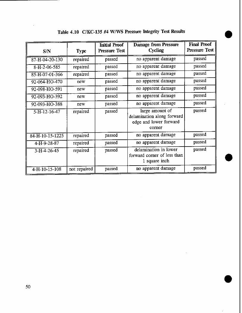
Table 4.10 C/KC-135 #4 W/WS Pressure Integrity Test Results
S/N Type Initial Proof
Pressure Test Damage from Pressure
Cycling Final Proof
Pressure Test
87-H-04-20-130 repaired passed no apparent damage passed
8-H-2-06-585 repaired passed no apparent damage passed
85-H-07-01-366 repaired passed no apparent damage passed
92-064-HO-470 new passed no apparent damage passed
92-098-HO-591 new passed no apparent damage passed
92-093-HO-392 new passed no apparent damage passed
92-093-HO-388 new passed no apparent damage passed
5-H-12-16-47 repaired passed large amount of delamination along forward
edge and lower forward corner
passed
84-H-10-15-1225 repaired passed no apparent damage passed
4-H-9-28-87 repaired passed no apparent damage passed
3-H-4-26-45 repaired passed delamination in lower forward corner of less than
1 square inch
passed
4-H-10-15-108 not repaired passed no apparent damage passed
50

Table 4.11 C/KC-135 #1 WAYS Residual Strength Ball Drop Test Results
W/WS S/N Type Damage from
Pressure Cycling Comments
86-H-10-06-062 new no apparent damage Two ball drops. Outboard glass ply broken. Crushing in impact area. No delamination created by cracking of the outer ply.
83-H-9-19-459 repaired delamination near slip plane areas
Two ball drops. Outboard glass ply broken. Core ply intact. No delamination from glass breakage.
l-H-10-5-480 repaired no apparent damage Two ball drops. Outboard glass ply broken. No delamination from outer ply cracking.
81-H-10-18-105 repaired no apparent damage One ball drop only. Both glass plies failed. Large amount of spall driven from core ply inboard surface.
82-H-9-6-537 repaired delamination near slip plane areas
One ball drop only. Both glass plies failed. Large amount of spall removed from core ply surface.
51

Table 4.12 C/KC-135 #4 W/WS Residual Strength Ball Drop Test Results
W/WS S/N Type Damage from Pressure
Cycling Comments
92-093-HO-388 new no apparent damage Outboard glass ply broken. Core ply intact. No delamination associated with glass breaking.
87-H-04-20-130 repaired no apparent damage Outboard glass ply broken. Core ply intact. No delamination associated with glass breaking.
8-H-2-06-585 repaired no apparent damage Outboard glass ply broken. Core ply intact. No delamination associated with glass breaking.
3-H-4-26-45 repaired delamination in lower forward corner of less
than 1 square inch
Both glass plies failed. Large area of core ply inboard surface spalled in impact area.
5-H-12-16-47 repaired large amount of delamination along
forward edge and lower forward corner
Both glass plies failed. Large area of core ply inboard surface spalled in impact area.
52

3 en
H->
8.
'S S
=*fc
CO fH
2 u ro
TT <U
I
•a — ■g
c es
es OH
3 o
o ■s tu
co
G e O 6
es 3 o
CU
co O
(U cu
13 co bJO cd'
13 OH
J3 co s
e CO
CD
+H
OH co
CO
co co
«—H
CS
es OH co
xs 6 G o
es l-H
OH co x> co
co 4-J +j •*-* ÖO G •3 cS cu o >> bß 0) <u CU 4-J es H-J J3 es kH .s |
co CU S-i
<u Sä O O o Xl
CU X3
"bb o co
£ i^
tu 1
"-4-J
G 3 o
X5 co
13
XS co
"ÖS
z 13 OH co
cS
'S
o U
O cS
"S <D kH
o U
13 OH CO 'S
0) kH
o u
-t—1 (ü CD
X5 CO
13
e G 4)
T3 kH
<4-H
O
c o
co
c o u 3
co
c O
CD 3
-H • *-< H-H
'S
co co
JS "bb
S-H
o
kH <u G es 1) kH
3 O
s es kH
O
G O
'S OH
d OH CO
T3
0)
s es
."2 co CU
3 co <L)
tu 1-1
o G
•d cu
kH es
X>
G .«-4 4-1 *T< CU Ä <D cu
o Z
o kH
1) o
,*H H-H S
CS •3 kn U
',eS N X3 . co i* .
X) eS VI k* kH . T3 C*-l T3 — CkH "O
'S CO CO
JS 'S) "3
OH
CD
."2 'co
CD kn
"2 X2
ply
and
W/W
, ir
esse
d.
age.
Smal
l Sh
ot 7
83.
o z cu 00 es
x> o Z
cu" bO es
o
G • »-<
X> S< T3
,«* <+—l
CO
.Sä 'S co
'S co co
_eS
"bb
bO es
es CD kH
Xi co s
plie
s fa
ile
ply
on s
pal
'S co CO es
bO
T3
cu
,s M-H
CO
.Sä 'S co
cu bO es
o G co G CS es
s es
E es
es O
co _cS
i-i es O
co
11 gl
as
boar
d kH es O
co es s
CS
o rS 3
co e- co G
JS s •3 <U
o 1 O T3
O 3 (U
"bb rS 3
"bb O 3
bO *3 O
U o <1-H
o t-ar CS Ä co Z Z < o Z < .5 o < z
1 Vel
ocit
y (k
nots
)
1-H
T—(
1—1
00
es VO
es VO
ON'
1—1
d es ON
q l-H
00
d in *r> >n v-> ■* Ti- m «n Ti- >n Tt m es CS es es es es es es es es es es
•o T3 T3 T3 ■o "3 •3 "Ö
ä CD cu CU cu cu <D CU CU £ £ £ £ >- S-H _fcH _kH kH _kH #kH _kH
£ u CD tu D 'S es 'S 'S 'S 'S 'S 'S c G G G OH OH OH OH OH OH OH OH
cu CU CD CD CU <D CU CU U, l-H kH kH kH kH kH kH
5
o o 1
VO o o 1—1
O co O
i
vo o 1
o l-H
es es vo o
l o l-H
1
VO ON
I VO o
1 o 1—1
1
es 00 es es
i Q\ T—1
1 OS
VO in
i
«n i—i
i 00
o es es
I
1
m i
VO "ej- i—i
i i—i
O i
es !-H
o i—i
i 00 l-H
6 l-H
co es
i
VO i o 1
X i
es 00
<n es co
i l-H
es l-H
l-H
o VO
i
O X
1
VO 1
X 1
X 1 1
1
X K X ffi
1
X ffi 00 es
i
VO oo 00
vo 00
VO 00
i co 00
co 00 00 VO
00
1
es 00
CO 00
ON 00
b
21 co Tt >n VO es CO -* >n VO f- 00 O oo 00 00 00 o\ ON ON ON o ON ON ON
r- r^ r- r~ r- 1-- (^ r~ t^ t-- 1^ r-
Z
CO co co co CO co co co CO co CO co
-ö ON ON o\ ON o> ON o ON ON o o\ ON
es es es co CO TF ON o O O o i-H es p es es es es es l-H l-H es es es es es
Co Co VO Co VO r^ r^ r^ t^ r^ r^ r~ 53

T3 x> c In Cö 'S, kl
T3 J_t o IZ1 cö 0)
-4—•
1-.
k-i kH cö O
3
1) a 3
to _cö •4H
CO
4)
ffl O
G "Bß 1) ■4-1
o O
■4-"
O
G 0)
lH 4) 4)
bß cö O
Xj
-H
CS k- o
CO
u CO 4)
-4-» 4) o CD 4> es 1—1 -^H
4> XI
4> 3
HG
X 0)
T3 • i—i co
*J cö
bß 3
^3
d _o
CO
1 cö CH
lH 4)
4>
12 'co 4>
o 4) kH
k*
CO
o ',3 «4-1
CÖ kl
s 4)
4) -t—» CO G
G
bß^
3 en
T3 • -H
m
c cö
t> (SO
-o <u *!
Cö
bß c o
13
u -*: co cö bß
• —H
X «4-1
o
G" G o e cö
13 E
1) bß cö
X
eS 0) X o Z
4>
.1—1
<u kH
J-H
4)
s eö o o
3
-o kj
o Z
s 4) k-
'Is w
G 5 ^H CO
l-H CO
G J2 •T bß ^ 4)
es
O.
.1 'S s
i«3
"E. co
*■—1
bß
T3
&6
'S cö
kH
o es
4> bß cö
T3 <u k-l
s es g DO
cö
1) bß cö
1) bß eö
bß cö
d 4)
o kH
X
x> "E. -a
8 lH O o
kj CO
«2
4) k-i
,eö «4H
Ü •T-H 4)
bß cö
4> bß cö
. E -a o • 1-H
«*-l kH
CO 4>
x> £ & § CO
kn cö O
■e G o
kH E k* E eö 'S E s s B kH CO
o kl B B 2 *o
CO kH
o .G eö
in X)
cö
O
z .B
S3 ■*-»
0) u
cö T3 O z PQ u
cö
O z
cö T3
O
Z
cö T3 O z
cö •o O Z
O
e3 O
(H 4)
^O
1 ti cö S2 U -B
cö T3 O z
cö
O
Z S3 >H
< «2
g UM X <o co ON T-H ■* 00 r- T-H es oo q 00 co t~- ,_J 00 in 00 r^ oö r-' T-H Ö T-H d d
TT Tt IT) Tt cN ■* ■<t -* ■* m >n m in in =tfc
l
es es CS CS es es es es es es es es es
T3 T3 ■a T3 T> 4) 4) 4) 4) 4)
& _kH £ ^ £ ^ ^ T3
4H
T3 0) k-i
• —H
k-i • -H
CO
kH
'cö Cu
k-i
"c3 '3 CH
kH • -H
CO
£ '3 (U ?i 32 32 32 'cö cö 4) 4) 4) 4) 4)
'^1 OH 4)
c es es es es <L)
kH VH
■4-1
k- -4-»
C ■u
k-i
-4->
TH S-i i-H IH o o o o o TT e G G G G
4)
s 1—1 cn O \D o MD T-H es MD 73 t> r~ >o O 00 r- es TH^ ON ON H ON
"d- Tt- co 1
o T-H 1
es i
r^ 00 ID CO MD co CO
1
T—I
I
m
6 6 O 6 o T-H
o l> o
6 1
CO i ON NO es o
i i i ON
X i
ON co
es i
>n i
es X
i
O T-H
1
es T-H
1
i es T-H
03 MD o
1
CM
O 1
CN
IT) o
t
es
es o
1
es
T—H
T-H 1
es X
r-
o a
i in
X I
X 1
es 00
X 1
MD o\ OS o\ ON ON 00 ON
V) MD c^ oo >n NO t> 00 ON o T-H es co T-H T-H T-H co co CO co CO ■<* Tf ""* ■n* 00 00 00 oo oo oo 00 00 OO 00 oo 00 00
Z
co co co co co CO co CO CO
i co ON
CO ON
co ON
co 0\ ON ON ON ON ON O; ON ON ON
'—. "*^- ON" ON ON ON O o O o T—( T-H
OS
T-H
OS ON es ON
es ON
es ON
es ON
co ON
co o\
co ON
co ON
d T-H
54

Table 4.15 C/KC-135 W/WS General Inspection Summary
#1 W/WS #4 W/WS
Category New Repaired Not
Repaired New Repaired Not
Repaired
Number Tested 8 15 1 9 10 6
Number with delamination, scratches, or chips
0 13 1 0 9 6
Number with seal deficiencies
0 14 1 0 8 6
Number with vinyl cracks 0 0 1 0 2 4
Number with bad dimensional check
0 0 0 0 0 0
Number with bad bus resistance
0 0 0 0 3 3
Number with bad sensor resistance
0 0 0 - - -
Number with bad insulation 0 9 1 0 0 0
Number with poor heater performance
0 0 1 0 1 0
Number with bad optics 0 0 0 0 0 0
55

Table 4.16 C/KC-135 W/WS Pressure Integrity Test Summary
#1 W/WS #4 W/WS
Category New Repaired Not
Repaired New Repaired Not
Repaired
Number Tested 4 7 1 4 7 1
Number failing initial proof pressure test
0 0 0 0 0 0
Number failing during pressure cycling
0 0 0 0 0 0
Number failing final proof pressure test
0 0 0 0 0 0
Number delaminated 0 2 0 0 2 0
Table 4.17 C/KC-135 W/WS Ball Drop Residual Strength Test Summary
#1 W/WS #4 W/WS
Category New Repaired New Repaired
Number Tested 1 4 1 4
Number with initial delamination
0 2 0 2
Number with outboard ply failure only
1 2 1 2
Number with both glass plys failed
0 2 0 2
56

Table 4.18 C/KC-135 W/WS Bird Impact Test Summary
#1 W/WS #4 W/WS
Category New Repaired New Repaired Not
Repaired
Number Tested 4 8 5 3 5
Number undamaged 3 2 4 2 2
Number with outboard ply broken only
1 2 1 1 1
Number with inboard ply broken only
0 1 0 0 0
Number with all glass plies failed
0 3 0 0 2
Number with no inner ply glass spall
4 6 5 3 3
Number with minor inner ply glass spall
0 2 0 0 1
Number with major inner ply glass spall
0 0 0 0 1
Number with no bird penetration
4 8 5 3 4
Number with minor bird penetration
0 0 0 0 0
Number with major bird penetration
0 0 0 0 1
57

Table 4.19 C/KC-135 #1 W/WS Mounting Edge Measurements and Bird Impact Test Results
S/N Type Edge Thickness,
inches Bird Impact Comments
86-H-10-06-007 new 0.936 0.943 0.942
Outboard glass ply broken. Core ply intact.
82-H-10-18-107 repaired 0.843 0.852 0.838
All glass plies failed. Minor amount of glass spall from inboard ply on spall sheet.
83-H-9-19-282 repaired similar to 82-H-10-18-107
Core ply failed. No glass spall on spall sheet.
83-H-8-15-756 repaired similar to 82-H-10-18-107
All glass plies failed. Minor glass spall on spall sheet.
83-H-l 1-21-325 repaired 0.927 0.936 0.939
All glass plies failed. No spall on spall sheet.
86-H-06-030 86-H-10-06-22 86-H-10-06-96
new 0.908 min 0.940 max
No damage.
84-H-3-19-220
repaired
Outboard glass ply failed.
86-H-12-01-146 No glass breakage.
82-H-9-6-235 Outboard glass ply failed.
89-286-HO-697 No damage.
91-010-HO-206
unrepaired
0.850 min 0.909 max
Not bird impact tested.
87-H-06-29-758 0.893 min 0.920 max
87-H-09-21-671 0.886 min 0.922 max
90-180-HO-139 0.839 min 0.887 max
82-H-9-20-127 0.902 min 0.918 max
58

Table 5.1 Initial C/KC-135 W/WS Repair Estimates
Type of W/WS NORDAM3 Perkins0 The Glass Doctor0
1 $1,890 $2,000 $l,327c
2 glass only $1,512 $1,500 $896
frame and glass $6,700 - -
3 $735 Category P $945 Category II $945 Category III
$1,280 Category IV
$750 $516
4 $975 $875 $667
5 $750 $875 $484
Notes:
a) Estimate, actual price quote based on specific repairs required as determined by incoming inspection.
b) Fixed price. c) Sensor repair or replacement, $437 additional. d) NORD AM #3 W/WS Repair/Overhaul Categories:
All repair categories include complete disassembly, inspection, and reassembly with new seal and new grommets.
Category Transparency Repair
I Polish inner and outer panes II Polish outer pane, replace inner pane
III Polish inner pane, replace outer pane IV Replace inner and outer panes
59

Table 5.2 C/KC-135 #1 W/WS Actual Repair Costs (NR=not repairable)
S/N Repair Vendor
Vendor Damage Comments Repair Cost
83-H-l 1-7-432 Perkins delaminated $2,000
82-H-10-18-105 Perkins delaminated, scratched $2,000
88-H-02-08-436 NORDAM scratches $1,695
82-H-12-6-431 NORDAM scratches and chips $2,090
l-H-10-5-480 Perkins delaminated, scratched $2,000
83-H-9-19-294 Perkins delaminated $0, NR
82-H-9-6-537 NORDAM scratches $1,893
83-H-9-19-459 NORDAM scratches and chips $1,893
83-H-9-19-282 Perkins delaminated $2,000
83-H-8-15-756 Perkins delaminated $2,000
84-H-3-19-220 Perkins delaminated, scratched $2,000
86-H-12-01-146 NORDAM scratches and chips $1,695
82-H-10-18-107 Perkins delaminated $2,000
82-H-9-6-235 NORDAM scratches $1,695
83-H-l 1-21-325 NORDAM scratches and chips $2,090
89-286-HO-697 NORDAM scratches $2,090
60

Table 5.3 C/KC-135 #4 W/WS Actual Repair Costs (NR=not repairable)
S/N Repair Vendor
Vendor Damage Comments Repair Cost
B75-1149 NORDAM scratches $559
85-H-07-01-276 NORDAM scratches $954
90-173-HO-721 Perkins bad terminal block $875
5-H-5-23-84 NORDAM delamination, scratches, bad resistance
$0, NR
7-H-2-4-35 NORDAM scratches, bad resistance
$0, NR
4-H-10-9-69 Perkins contaminated $0, NR
82-H-12-6-392 Perkins contaminated $0, NR
6-H-12-02-36 Perkins bad resistance $0, NR
87-H-04-20-130 NORDAM scratches $954
8-H-2-06-585 Perkins delamination, scratches $875
85-H-07-01-366 NORDAM scratches $559
5-H-12-16-47 NORDAM delamination, scratches $1,151
84-H-10-15-1225 NORDAM delamination, scratches $1,151
4-H-9-28-87 NORDAM scratches $559
3-H-4-26-45 NORDAM delamination, scratches, and chips
$1,349
4-H-10-15-108 NORDAM delamination, scratches, bad resistance
$0, NR
61

Table 5.4 Cost Quotes for All Prototype Repair Candidate C/KC-135 WAYS (NR=not repairable)
TypeofW/WS (1-5) S/N Repair Vendor Cost of Repair
82-H-9-6-537 NORDAM $1,893
84-H-3-19-220 Perkins $2,000
l-H-10-5-480 Perkins $2,000
83-H-9-19-294 Perkins $0, NR
83-H-9-19-282 Perkins $2,000
83-H-8-15-756 Perkins $2,000
82-H-10-18-107 Perkins $2,000
83-H-l 1-7-432 Perkins $2,000
82-H-9-6-235 NORDAM $1,695
83-H-l 1-21-325 NORDAM $2,090
86-H-12-01-146 NORDAM $2,090
88-H-02-08-436 NORDAM $1,695
6-H-8-4-26 NORDAM $2,683
89-286-HO-697 NORDAM $2,090
82-H-10-105 Perkins $2,000
83-H-9-19-459 NORDAM $1,893
82-H-12-6-431 NORDAM $2,090
2 4-H-9-27-168 NORDAM $1,919
2 6-H-1-15-28 NORDAM $1,524
2 85-H-06-03-722 NORDAM $1,721
2 6-H-2-27-57 Perkins $0, NR
2 6-H-2-20-23 Perkins $0, NR
3 5-H-3-2-730 NORDAM $0, NR
3 6-H-3-18-28 NORDAM $0, NR
3 6-H-4-6-25 NORDAM $0, NR
3 6-H-12-10-30 NORDAM $0, NR
3 B73-2815 Perkins $0, NR
3 B73-3439 Perkins $0, NR
62

Table 5.4 Cost Quotes for All Prototype Repair Candidate C/KC-135 WAYS continued (NR=not repairable)
Type of W/WS (1-5) S/N Repair Vendor Cost of Repair
3 B73-3565 Perkins $0, NR
3 B73-2462 NORDAM $0, NR
3 85-H-01-07-725 Perkins $0, NR
3 O-H-9-1-1140 NORDAM $0, NR
3 B73-2509 Perkins $0, NR
3 5-H-2-16-042 NORDAM $0, NR
3 B73-3955 Perkins $0, NR
3 4-H-10-4-02 Perkins $0, NR
3 4-H-9-18-15 Perkins $0, NR
3 7-H-12-13-67 NORDAM $0, NR
4 4-H-10-15-108 NORDAM $0, NR
4 4-H-10-9-75 Perkins $0, NR
4 4-H-9-28-87 NORDAM $559
4 5-H-12-16-47 NORDAM $1,151
4 6-H-4-29-50 Perkins $0, NR
4 8-H-2-06-585 Perkins $875
4 87-H-04-20-130 NORDAM $954
4 7-H-1-25-01 Perkins $0, NR
4 3-H-4-26-45 NORDAM $1,349
4 82-H-12-6-392 Perkins $0, NR
4 B75-1149 NORDAM $559
4 6-H-12-02-36 Perkins $0, NR
4 85-H-07-01-276 NORDAM $954
4 7-H-2-4-35 NORDAM $0, NR
4 90-173-HO-721 Perkins $875
4 4-H-10-9-69 Perkins $0, NR
4 4-C-02-12-10 Perkins $0, NR
4 84-H-10-15-1225 NORDAM $1,151
• 63

Table 5.4 Cost Quotes for All Prototype Repair Candidate C/KC-135 WAYS continued (NR=not repairable)
TypeofW/WS (1-5)
S/N Repair Vendor Cost of Repair
4 85-H-07-01-366 NORDAM $559
4 85-H-09-02-795 Perkins $0, NR
4 5-H-5-23-84 NORDAM $0, NR
5 4-C-5-16-11 Perkins $0, NR
5 4-C-5-28-16 NORDAM $0, NR
5 4-H-8-30-95 NORDAM $486
5 5-H-2-5-75 Perkins $0, NR
5 2-H-12-15-58 NORDAM $0, NR
5 H-30-67 NORDAM $0, NR
5 7-H-10-14-56 NORDAM $1,079
5 2-H-6-20-70 Perkins $0, NR
5 2-H-4-24-49 Perkins $0, NR
5 4-C-7-12-22 NORDAM $881
5 4-H-8-33-64 Perkins $0, NR
5 5-H-12-5-05 NORDAM $486
5 4-C-6-12-13 Perkins $0, NR
5 2-H-6-29-06 Perkins $0, NR
5 3-H-5-23-79 NORDAM $881
64

Table 5.5 C/KC-135 New W/WS Costs
Designation NSN Part Number USAF Cost
#1 Pilot 1560-01-048-1885 FL 5-89354-501 $2,582 #1 Copilot 1560-01-048-1786 FL 5-89354-502
#2 Pilot 1560-01-009-3320 FL 5-89355-501 $1,445 #2 Copilot 1560-01-008-7396 FL 5-89355-502
#3 Pilot 1560-00-575-6302 FL 5-89356-501 $1,479 #3 Copilot 1560-00-575-6297 FL 5-89356-502
#4 Pilot 1560-00-575-6299 FL 5-71764-501 $1,372 #4 Copilot 1560-00-575-6298 FL 5-71764-502
#5 Pilot 1560-00-575-6300 FL 5-89358-501 $1,078 #5 Copilot 1560-00-575-6301 FL 5-89358-502
Table 5.6 Repair Cost Comparison Data for C/KC-135 W/WS
Type of W/WS
Cost as a Percentage of New Purchase Price
High- Actual Low*
1 Si 75 61
2 132 - 83
3 87 - 41
4 71 65 41
5 100 - 45
Based on Extremes of Estimates, Actual Costs, and Quotes from NORD AM and Perkins Aircraft Services, assuming a 20-percent volume discount from Perkins
65

Copilot # 3
Copilot sliding w/ws (#2)
Copilot # 1
Figure 2.1 C/KC-135 W/WS Identification
66

TYPICAL WINDOW CROSS
NO. SECTION
OUTSIDE
OUTSIDE 1
MATERIAL THICKNESS
-GLASS JSO -CONDUCTIVE COATING -VINYL .300 •GLASS .129
GLASS .250 CONDUCTIVE COATING VINYL JOO GLASS .125
: -
OUTSIDE
OUTSIDE
GLASS .380
CONDUCTIVE COATING VINYL J80 GLASS ' .180
■GLASS JOO
•VINYL J50 . CONDUCTIVE COATING
GLASS .1875
0UT5I0E
GLASS .800
VINYL J80 CONOUCTIVE COATING GLASS .1878
Figure 2.2 C/KC-135 W/WS Construction
67

Filler (phenolic or masonite)
Metal insert
Slip planes (parting medium)
y//MW>J//;////A V//X/,W///////77>
Bumper
Figure 2.3 W/WS Construction Showing Location of Slip Planes
68

Stainless steel Z-channel
Silicone gasket
Aluminum insert
H.V. silicone bumper
Aluminum spacer
PR1440 sealant
m Phenolic block
S^
NESA coated surface
Heat tempered outer ply
Polyvinyl butyral
Heat tempered inner ply
Figure 2.4 C/KC-135 #1 W/WS Cross-Section
69

Heat tempered outer ply
Polyvinyl butyral
NESA coated surface
Heat tempered inner ply
H.V. silicone bumper
Silicone seal
Aluminum insert
Figure 2.5 C/KC-135 #4 W/WS Cross-Section
70

Figure 3.1 The Glass Doctor Patented Technique for Repair of Conical Cracks in Laminated Glass, U.S. Patent # 3,841,932
71
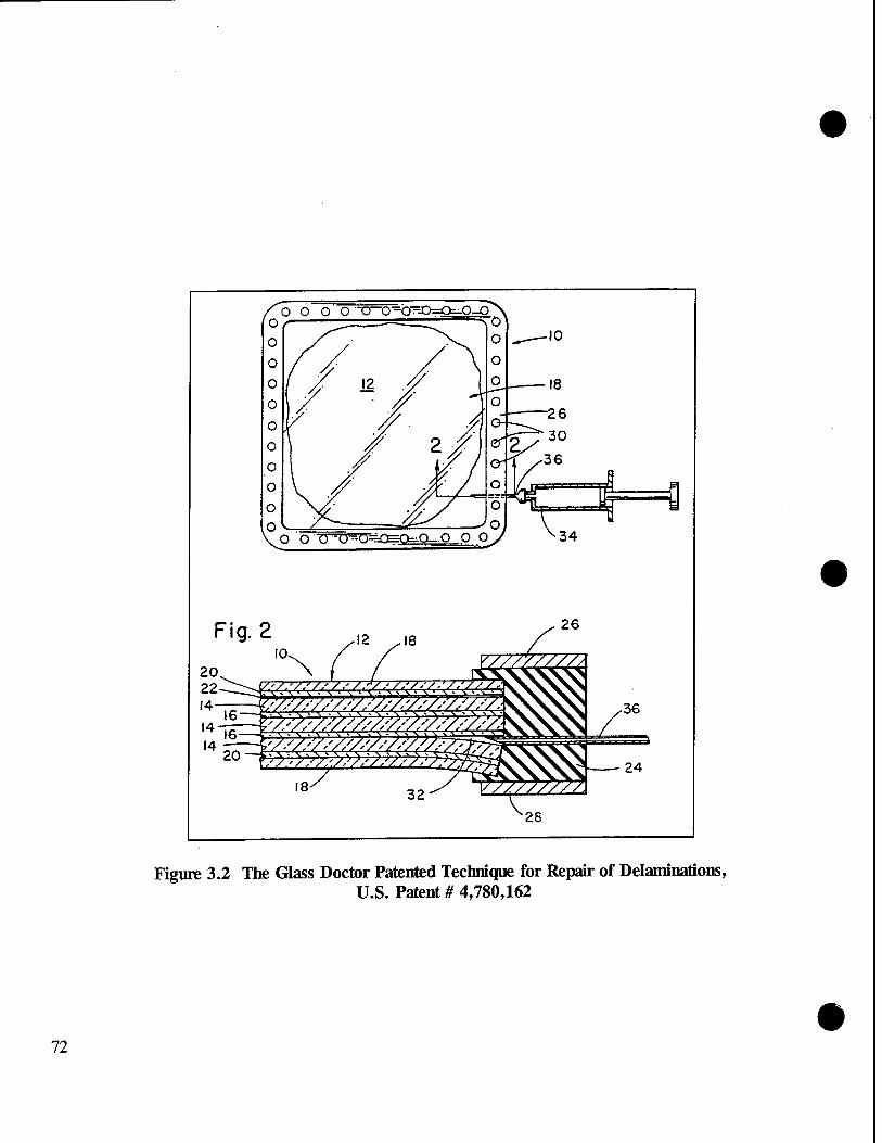
o o o -0-0=0=0=0^0 o o 34
Figure 3.2 The Glass Doctor Patented Technique for Repair of Delaminations, U.S. Patent # 4,780,162
72

a) Typical (S/N 86-H-10-06-062)
b) Most Out-of-the-Ordinary (S/N 82-H-9-6-537)
Figure 4.1 C/KC-135 #1 Thermal Images From the Heater Test
73

a) Typical (S/N 92-064-HO-471)
b) Most Out-of-the-Ordinary (S/N 92-093-HO-392)
Figure 4.2 C/KC-135 #4 W/WS Thermal Images From the Heater Test
74

■ <?£*«?« sB«xKs»aB*»sa»saK«iiB«Ba
' r (;c f« r I: K C E K »'** ÄKS ■wBBsa
»■K »*««»;»* B«B*»*S»»«SB»»B»: »■»■■« nmi
nsmianmniRnaninBU] EttEmmnnamaBiiiim^ Hininmn«uiHinn«n(BCl HnnmnnaniininMnmq
BnanmiHanmnnnniBn umssanssnBsannunNnarsMMSun BBSBBCSBSSBKaBSS EIBES*»S*I KBSM nnnmniaHnnimnnnHi nnmncimwmnnaiiiia] •BB*««»»«««»«B»»*BBB«mW««i^B«i BE32BB»B»E»B*BBtKm»E:SBB»««BB»a»** B«SXB*SSaaaBEa>aanESMSSB«aBaan9] twavBaaaBaaKBaaaMaancanuHmaaaaaaa B8BEBEBBB»I»BaEBa»EX«BB3SB!BBBaBB»l iraBBBaaBBrclSBBatBaBBaBBaBBKBBaBaa ci;RBtKiiBr.ZczBrczESczEa«Eazc«ir4 »tSW!«BS»«BB»8Bn»BBBjmS««BBa«aB»l L-nnuittsKitcr-iuiiKzusiM »tsrcuiimittctiixiiiiiaiin]
-■S*B«B«»*«BaUM»B*«B«BaBa«aaMHBBi
£s«KCSCBBSs*aeaixBEsesxBBmBBSB«l SSBKUBBBBBSSSBBBSBBSZaBSSSBSSXaa tr»tc«tMtir«tm«iiti«J«i;iJ c»nntt»>cuiiitiMC»»i)»ri ICCCt(CStXrCMI»IC»»»UM>] .tErrrtittnini»»>rifniiuM :»»«i»un«ntnMnfHiHl :rrcrt!i»ixBB»Bat»M»ra»BBBjx;B«aj rrc«trr«!er««BBi;-B«CTBB«ajBiaj«j :rrprrri:«riiBBBrxEB«»«EBi»»«BB;j
tllJCUetrCrMMtMIKIIIIMMllJ ictrnncttccctiniitriiiifmiH] SffiEJSlSJ5EB;EBB«B»««B»E*a«B»Ba*BBaBi !BBB«BBBB«»IEM5EBBB«»B»a»BB«B»BBi ilSBBKBaBXBBBBBKiiaaCSBBBBSZSSBBBi :BBBBBBBaaaa»BBBiBa«B»gaeK
!BBBBB»BB«OBa»«!«BB»«B«»«BBB««5Bi ERBRCrCSKEBECBIBEtCBSSZtZZBZSaa
mutate! EBKRBr BBEBB^BBieBB» *B« CM. *£;«£>■
SBSftBBBBa« JEB»BB«KBJ BB*«B«B«a IBBBjl»!BB»jnBBBE«»BB: 仫«1EBEBI8K«E1EB«*B*KB******BaBB»a ctnontrmsBciirtuJinjii*;»'"
i»153aBBB*B«B3*Bi»aB»»B«B*«B«a«J lB«««BBBa»«BB««BBBBBBBBBa««B«JWJ !»BBBBaB««BBBBBaBBB*ls**B«aB«BB»l iBBBKBKBBSBeBBSSBBBaaBZZSXBXSaal ::*BECBBB«BCBBSBBBB*BBB»BBaaBatB»a IsiliicCBEKBBBBltBSiBBBBSBaaSaBBai :txrtr«cti:KCfiBBsi:KJfi»B<»*B«Baai mB»Ba»«B«BaBB«Bea*B«|BB«BBa(B!Bia
KIKICttHtintllttK'tlllMnl ;icsEE«c»EBaaBzaataEE»»aBBaiBa4
:CE|^Ba*aEXB»EZCBCCI.E*Ba£IBIBZ94 :tr>rrtii>«iiKnifii>»asiiul
CBS« «•»»«»•»»■•• HH2555S1 »BBaB»B»a»B»BB«aBaBB»aBBaBB»aiaai Si«£«e«.»55«»««i»«»*B«B«B»««B»«BBl lBB»5fiBeS«»BBBBi«BB«*«Ba»aBaBB»fa
• irtlSS»»« EI«*»B»*««*a««*«»«BBBJ
r«ir>nrr«»H»«i«««»;«"M»M I«E»«*««BB»»BB»B«B«B*****»a«*5i SBBBBB««aBBi*«BBB«B»B«S ■»««.« BBBBJ
,a««ictii»r»iiaiiiMttt(Tniil M«««B»BBBB«iaa*tBBBaaBa»BB»BB«gi
äB»«ES»*C«»B«BB«»««E»»«£JBj;£MB S«»»Kr**l»*IiB»»Beal!«BE«e«JBE«B«»BBI e»»*««B«*»B»BBB«BB»BBBBBB«BBBBBBaj[BB«J
in» catif« SB»»«H««»SBBB;B «Baa—-a
eamusee»« Bases» »«■BBaaaaaaBBi B8«»S*BSEE»BBB«BBSBBBBBB«»£B| «BBBBam*BBBBBBB«BaBBBBBa»BBa|
.:;::..:.'.:».£.:..;::::;:::■ B»ti;-«»»»««««*»BBBB»B»B*;«*B«
I»tl *BB»B »■■«*«« «fSBBBBB;«*« | «BBBB1 aBBBBBBBal SaaB«aBBB«B*B»BBBBa»B»B«BiHw| »«»»«««IM»««««»«»*««*«*»«*»!
^•BiBiiaaaaaauaB]
■aaaäjKSl iäüaaaaaja BaawBaBBsa
tairrrra::
■■■aBBBasaaBB
iaaaasBBBBaaBBBi (■•■•■•■••■•■•■■■•■■■I f ■■»■ ■■■••■•■■»••■■■
iiBBa«aaBBaaa»aaaBBBBaaa«a:BBa» §■■■■ «»•■••■••••••••■■•■•••■■■•■■
=*fc
(■■•■■••■••■••••■■■•■■■••■•■■■•••■•I , ^■•■■•»•■■••■•■•■■•••■•■■■■•■••»■■•Bn ;.,r„.,tr....,.......iiii...iiiimmwii-
75

EBBBBBBBBBBBBBBBI ■■■■■■■■■■■■■■■■a ■■■■■■■■■r■■■■■■■ E!iI!!E!5E!E!!SB5ISLi ■■■■■■■■■■■BBBBBBBBBBB
■■■■■■■■»■■■■■■■■■■■■I
»■■■■■■■■■■■■■■■■■■■■■■■s IHBBBBBBr.aHHBBBBBBBBBBBI IBIBBflBBBBBBBBBIIHIIIir IBBBBflflBBBBBBBBBBflBBBBJ IBBBBBBBBBBBBBBBBBBBBBB «■■■■■■■■■■■■■■■■Illlf ■■■■■■■■■: ■■■■■■■■■I !■■■■■■■■■■■■■■■■
IIIIIIIIL. - - ■■■■■■■■■»■■■■"■■■■■■■■■■■■""I ■■■■■■■■■■■■■■■■■■■■■■■■■■■■■■■■I
76

Environmental chamber
Pressure chamber /
Test w/ws
Motor-generator set for w/ws power
Air pressurizing hose
Shop air
Pressure control valve
Process control and data acquisition computer
Figure 4.5 Pressure Integrity Testing Facility
77

¥ I ■■ -.1! !
! ! UNIT !
fcfcp-l-- Section A-A
UNIT :i± H^- ~rr
~ ■ -
f Section B-B
Figure 4.6 C/KC-135 #1 WAYS Pressure Integrity Mounting Frame
78

-t, t 1* t -t -t t.
.■».A.-t.-t.A.-t.t:
>- -V
^y -Vvv
••; v.* 111
S v-.v\ ••■■>>:■• ■•-•■■ k, v.,i % 1 -. ■, >i ■;■ ■ i.
jp z
i i UNIT ';
Section A-A
Figure 4.7 C/KC-135 #4 W/WS Pressure Integrity Mounting Frame
79

Skin-
O-ring
Sleeve / , Nut
'imiiiiin _
J Window-
• Washer
Bolt
a) #1 W/WS
Window -
Bolt
Metal retainer strip
Silicone gasket
^Nut
b) #4 W/WS
Figure 4.8 C/KC-135 WAYS Mounting Details
80

Figure 4.9 Typical C/KC-135 #1 W/WS Pressure Integrity Test Set Up
81

a
41 CO
as
•c CD
I as as
%
=tfc
•a
82

IHM* 83

ri- ve
r*
84 OD

Itl Plastic guide tube
Steel ball
Figure 4.13 Residual Strength Falling Ball Test
85

s.
86 DC

08
1» 35
m
87

88
NO
•SP

89

a»
> tu S
«fr =5fc
90 1—1
9>.
Cß

W
.8
OS
■<*
I S
91

Section B-B
i
Section A-A
UNIT
<»
1 i 1r .. • ■■:\ 1 fVV-i ...
! UNIT 1
^/yy/y.••■■■•'///.■ * T T
Figure 4.20 C/KC-135 #1 W/WS Bird Impact Mounting Frame
92 •

♦ ♦♦♦♦♦♦ ♦ ♦
'it. ."t. ."t .it-It.-*. .t~
■+ f- f f -y t T-
♦ ♦♦♦♦♦♦♦♦♦
A
i
ir-.;-|il:iy-.N UNIT t <7-*r^ii-'.Vv>\'..\^ '-.'■ V-V- WA.I
Section A-A
Figure 4.21 C/KC-135 #4 W/WS Bird Impact Mounting Frame
93

•5" • > * i * *• .
v*T.a*^ *»*'*'■:*:£.*■'*• -*#■■" ■■■■■ ?L *> ,*"^ Viff;v/
P«
Im
So
^sufrag
94

95

96

Figure 4.25 Typical Pre-Test View of C/KC-135 #1 W/WS (Copilot) Prior to Bird Impact Testing
97
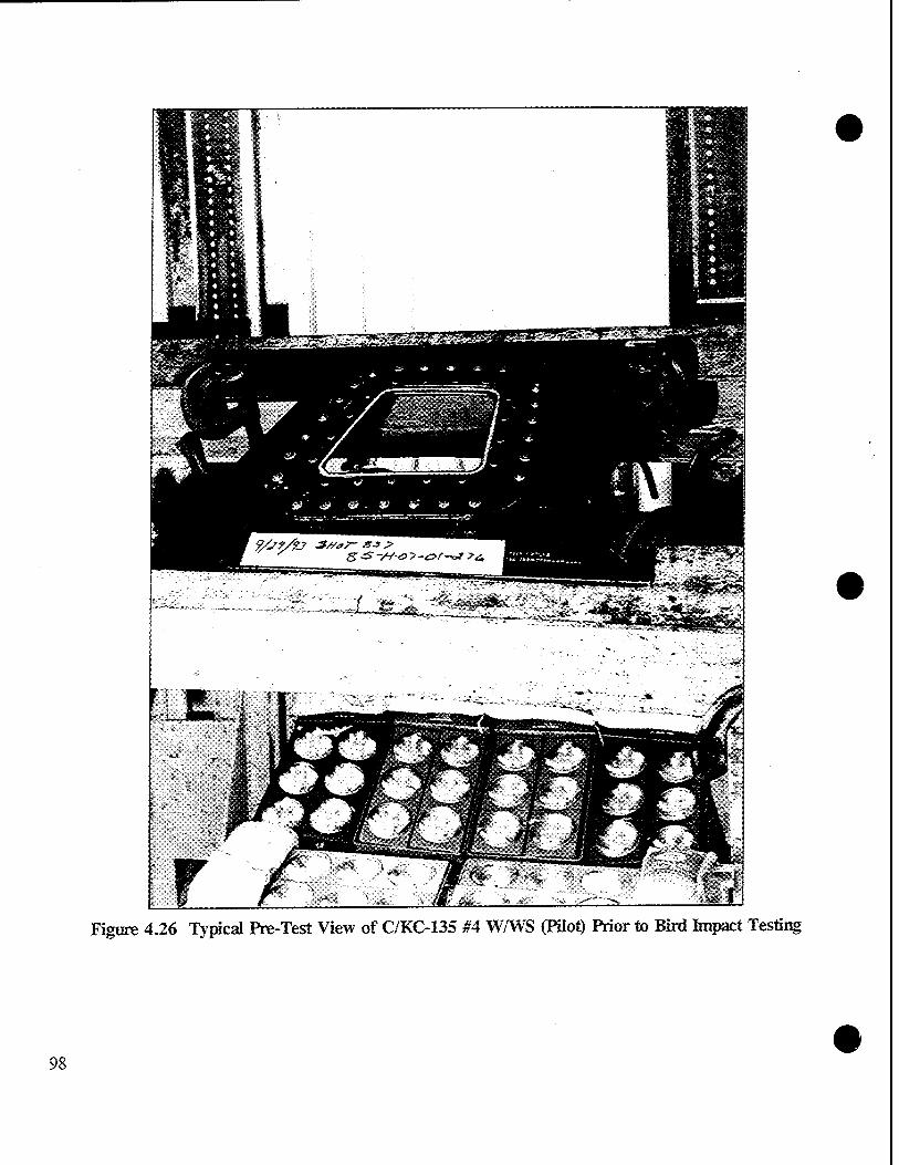
Figure 4.26 typical Pre-Test View of C/KC-135 #4 WAYS (Pilot) Prior to Bird Impact Testing
98

99

; , ^»
100

Figure 4.29 C/KC-135 #1 W/WS Showing No Damage From a 4-Pound Bird Impact at 250.8 Knots (Repaired W/WS, S/N 89-286-HO-697)
101

.. „. ■ - :&L,//tJOl.<*r, -TBS^ • • ^IIIK^S
Figure 4.30 C/KC-135 #1 W/WS Showing Outboard Ply Failure From a 4-Pound Bird Impact at 251.7 Knots, Front View (New W/WS, S/N 86-H-10-06-007)
102
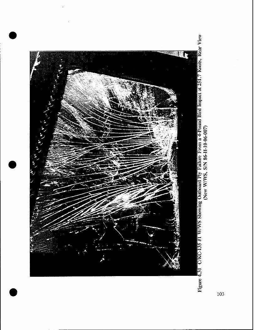
103

Fi<mre 4.32 C/KC-135 #1 W/WS Showing AH Glass Plies Failed From a 4-Pound Bird Impact at 249.4 Knots, Front View (Repaired W/WS, S/N 82-H-10-18-107)
104

105

Figure 4.34 Spall Sheet Condition From a 4-Pound Bird Impact at 249.4 Knots on a C/KC-135 #1 W/WS With All Glass PHes Failed (Repaired W/WS, S/N 82-H-10-18-107)
106

Figure 4.35 C/KC-135 #4 W/WS Showing No Damage From a 4-Pound Bird Impact at 248.7 Knots (Not Repaired WAYS, S/N 4-H-10-9-69)
107

Figur« 4.36 C/KC-135 #4 W/WS Showing Outboard Ply Failure From a 4-Pound Bird Impact at 247.5 Knots, Front View (Repaired W/WS, S/N B75-1149)
108

• 109

Hli!*Illiliil
:-» .^.v.'},',.': .»'-■ - . ■ * -*-. ■ J
ps5^»«sä
JMEJB
Figure 4.38 C/KC-135 #4 WAVS Showing a Catastrophic AH Glass Plies Failure From a 4-Pound Bird Impact at 250.8 Knots, Front View (Not Repaired WAVS, S/N 7-H-2-4-35)
110

Ill

o
o
112 9> 2 Si fa

Tension, 1000 psi
20 o
Compression, 1000 psi
-20 -40 -60
Figure 6.1 Heat Strengthened Glass Residual Stresses
113


APPENDIX A REPAIR VENDOR AIR AGENCY CERTIFICATES


DEPARTMENT OF TRANSPORTATION FEDERAL AVIATION ADMINISTRATION
Mir Mgeticp Certificate </VcC#?Z<lLeo<' EZ22812K
NORDAM TRANSPARENCIES DIVISION
510 S. LANSING TULSA, OKLAHOMA 74120
A^/u>Wei<ec6/b>A)ft^'Kz/&'XZ^ REPAIR ßTATION
LIMITED - SPECIALIZED SERVICE
A/utU'Aö*vG*UWJörVA$M>6 INDEFINITELY
^ABOT.n D. WRT&HT Fphrnarj' ?1 - iqqO ACTING MANAGER, SW-FSDO-15
Xüi Gxxtifaxt to not '^JBnsfaflbk, uo ua HUM CHAMCE IK TOE MSIC nauncs. OR IN we LOCATION THEREOF, SHMJL K WKEDWTaT KTCHITO) TO TOE MT«OH<t»TE «ECIOKU. OFflCE Of TOE FEDCRAI. MUTKW «DMIMSIMTIOK
Any alteration o/ AU certificate £5 ptadshatlc by « fine «/ not <x^^$l/M,4>rinVm^meMMut<Icc4^ing3yc«r%orbolh
TAA foim 8000-4 <I-«7) SUPERSEDES FAA FORM 390.
A-l

UNITED STATES OF AMERICA
DEPARTMENT OF TRANSPORTATION FEDERAL AV.AT.ON ADMINISTRATION
Hepair Station Operation* gpeafteatfoius
„S^srfr>^-(&>*q!^jV"*ni~' EZ22812K -■ M^rtiCocCr X>r
LIKITSD RATING:
Specialized Service Transparency inspection ana xep^i -,- accordance with Aircarrier nngan««ring O-ders, O.E.M Manuals, and N* 0^-301.
^depüüdr/acU/u»UÜei':
wiy 3. 1990 .
FAA F»"- 8000-4-1 ti-rui
7 ~M^ fcnJk ROY C. WIEDEN
POrtwtC"^- v •' '
—PRINCIPAL MAINTENANCE INSPECTOR , ,-c.« *>«■< «•»<■•■•■ •• A;;u-vsi)0-.l.r>
A-2

UNITED STATES OF AMERICA
DEPARTMENT OF TRANSPORTATION FEDERAL AVIATION ADMINISTRATION
&tr Hgencp Certificate tA'wmveov JKQR257L
<J/vc&><cewG£tca£e>*&•ÄAitced/,io'
PERKINS AIRCRAFT SERVICES, INC.
5001 NORTH FREEWAY, SUITE B FORT WORTH, TEXAS 76106
At/tow JtTudöna/ Mvctö ä&' /ti'aa.'yLvxa.tco'ri' xxmifuiek ärv xzlv /^e&fiecd'
/vela-tona,1 ,£o' Mve- A&£ecMi&n/men,t xw xxav S&öw SOMcnou', xzaid' /&'
^eTn/voiaeo'eci'&>'afie'XCüCexMV.afifvxowzcO Repair Station;
A/iöi/i' JGV&Jollowirta/ /xcc&nxzi':
LIMITED SPECIALIZED SERVICE (10-08-93)
<J/uA' x&w&fbccc&i Mattete.' xxorvceiecC, Aub/iettdedi w/xeitofz&d;
A/IAZU.'/C&n/vruce>Äw/effiec6 indefinitely.
SOy x&mecüotv xv /Ac SxcbrUnilCfCuCo*'
May 2, 1991 Kenneth D. Robinson Acting Manager, *TW rsuu
TCtis CatiSntt tt not Transferable, w «or HAK» CHWCE IN THE ustc HOUTIQ, O« IN THE locnto« THCKEOF,
SHUi K nuuouTaT Krcma TO THE ArntoraiATE RECIOKM. omcE OF THE FEDEML MOTKM uaiMsnwTioN
Any alteration of thU certificate ü punishable by a fine of not exceeding $IJ)00. or imprisonment not exceeding 3 yean, or both
FAA Fonti MOO-4 (1-67) SUPERSEDES FAA FORM 390.
A-3

UNITED STATES OF AMERICA
DEPARTMENT OF TRANSPORTATION FEDERAL AVIATION ADMINISTRATION
■Repair Station Operations Specifications
LIMITED RATINGS:
( V>07l/oTVU-a/c09U j
.s^^™yY™ty~SrjV<™t<~- JKQR257L * jUettifrd' Xo-
SPECIALIZED SERVICE Repair of aircraft windows, transparent enclosures, structural and non-structural composite panels, cores, flaps, ailerons and radoroes.
Above repairs will be performed in accordance with aircraft manufacturer's repair procedures, air carrier approved instructions and Perkins Aircraft Services, Inc., Process Specification PPS0001, Revision A, dated 09-15-93, as revised.
Q)e/eaaü>ct, *udA-o*&<»>: NONE
GficUc, Suit*/- w .—'wftt«w/:
October 8, 1993 Standley H.' Cobb
FAA Form 8000—4-1 I1-73- PMI, FTW FSDO
FORMERLY FA* FORM 3»0.1 PACE 2
A-4

UNITED STATES OF AMERICA
DEPARTMENT OF TRANSPORTATION FEDERAL AVIATION ADMINISTRATION
&tr &gemp Certificate .A'amiew OX4R430M
<JAifr .certificate/&' iteued,tc
THE GLASS DOCTOR
.irJioie' ,6aAineiA> Äöl^Wit' .ifr 2390 26th AVENUE NORTH St. Petersburg, Florida 33713
.a/ion- Andinw .t/iatifo x)va,ccni^a.tion' com/i/iei .in' xt/l .vei/iecä'
x&itA'/Ae■ .veyttirements'.of.t/ie' ^edeva/' Mnia-ticn' Meptttationi.
/ve/atiny .to- ,tAe .eitaUäAment .of an Sui*' S^.ency,; and M'
wnhoweved'.fa ^fiewfe aw aft/ivov-ed REPAIR STATION
,mitA' ,tA& fMcfviria,' .vetting*v LIMITED - SPECIALIZED SERVICE
^/iä- .certificate, wnlete .cance/ed; 6uä/iended, ,or-/*<mo&<id',
JiaU.continue .in .effect' INDEFINITELY
September 27, 1979 William J. Truebe, Manager Replacement May 1, 1990 North Florida FSDO-15
Tin« Ctrtificatt is not Ttaiufrrablt, AND «NT MAX» CHAWSE I» THE MSIC FACILITIES, O« m THE LOCATION THEIEOF. SHAU. BF. IMMEDIATELY REMITTED 70 THE APPROPRIATE REGIONAL OFFICE OF THE FEDERAL AVIATION ADMINISTRATION
Any alteration of this certificate U punishable by a fin* of not exceeding $1.000. or imprisonment not exceeding 3 year,, or both
FAA Form 80O0-« (1-67) SUPERSEDES FAA FORM 390.
A-5

UNITED STATES OF AMERICA
DEPARTMENT OF TRANSPORTATION FEDERAL AVIATION ADMINISTRATION
TElepair Station Operations Specifications
jfimUa&cynd/■:
¥A* .**&■*$,(*) «^ /^<- ^ Stür Sfyoncy '^/WV JL-mi~- OX4R430M * I ™» -<4~iW Ar
LIMITED RATINGS:
SPECIALIZED SERVICE - Refurbish and repair aircraft plastic and glass windows, windshields, canopies, navigation light lenses, and other miscellaneous small transparencies,including nicks, chips, delamination, electrical busses and temperature sensor installation.
All inspections and rework will be accomplished in accordance with the following data as applicable to the unit being worked.
Aircraft Manufacturer's Maintenance Manuals/ Instruction.
FAA Approved process Specification, #1979 Cabin" and Cockpit Windows dated 12-31-84 (as amended).
Air Carrier's Approved Specifications.
FAA Advisory Circular 43.13-1A, Acceptable Methods, Techniques, and Practices, Chapter 9. windshields, Enclosures and Exits.
fyeteaateci'.au/Jtovi/iel': NONE
QkUe, <iW- ~- **~W: &~ *» SU^^U^Uor-
May 1/ 1990 ^^ Kenneth ST^CrocKett — " "~ Principal Maintenance Inspector FAA Form 8000-4-1 11-731 FORMERLY FAA FORM 3»».l PACE 2
Page 1 of 1
A-6

APPENDIX B GENERAL INSPECTION DATA SHEETS

This page intentionally left blank.
B-l

KC-135 Transparency Review Data Sheet Pllot/Co-Pilot Main windshield
Customer* Part Number: J -" 01 JJ 7 ~* J<) 1—-
Unit Serial Number: ft '// "/Q-OJD -QL
Acc/Rej
'Bus to Bus Resistance:
Thermal Image:
.^■^ Ohms
3*7 S.E. Resistance: _v * ;••*'-■? »
Insulation 'Test^vf-" Power to S.E.: (2500\VAC).::-:;:,-""'''' S.E. to Metal:
''.: _ • '"' S.E. to S.E. :•■
Nesa Scratch Test (356 VAC) : •'
Light Transmittance:
Haze:
Photo (Single Exposure):
Deviation Inspection: (German Light per Template)- \:3,D 2:Z,d 3:/£ s-.hb ■ e-.&.Q 1-.2JL-
[if*-
fift,]
1:3-0 8: Q,d
Date Inspector
.r-v-te 22 PP3 28
/f-3.5-0 8ZS33ZZ
"f-A»-93 '8Z^^
MAY 251993. 22 PfS J*
MAY 2 5 1993 >2 pP6 Ä
MAY 2 5 1993 22 PPG 77
MAY 2 5 1993 22 PPG77
KAY 2 S 1993 22 PPG 4
f-M-9z> 22 P.P3 22
Dimensional Inspection:
Unit Thickness: (Per Template)
1,106 6:
/,/<?-.f -10: './iff ■/ff
Seal Evaluation: (Comments)
7 11
/■/a? MPf UÜLi
<^
8 12
/,/lJ ),/o3 M/)fl
-A£.
Visual Inspection: (Place comments on attached sheet)
JUN 02W93 »PPG??
ß&&, JUN Q2T993 n^Ti
B-2

}*
Check for vinyl cracks ■•
Visual Inspection. Map & Comments
(h* _£±£?] |PW*
Thickness Template
1-10$ D A/o3 </•)
©A'»3 ©A/ftS"
©•A/9*- .©/ft* ®A/'3
Ql,ioo ©h/b{ ©1.100
Deviation Template
@40 (5)&o .
0Äö -Q)UD ©0<D
B-3

KC-135 Transparency Review Data Sheet Pilot/Co-Pllot Main Windshield
Customer Part Number: V-X/ ?5V ~ > ^ *-"—
Unit Serial Number: 0 4-H — /°- 67 d— O 72—
Acc/Rej Pate
Bus to Bus Resistance: 3M-, <9 Ohms
/^v-- f--a/-g?
Inspector
JLees^—
Thermal Image:
S.E. Resistance: iO D'
J- X.
Insulation Test: Power to S.E.: (2500 VAC) S.E. to Metal:
S.E. to S.E.:
Nesa Scratch Test (350 VAC):
Light Transmittance: fJ>J
<7 Haze:
Photo (Single Exposure):
Deviation Inspection: (German Light per Template)^
5: Q..V 6:0^ T: h 0 S-ÄJL
± g&
-.I'D
JUN 041993 ^tfr
JUN 0 8 89J
JUN 0 9 1993
JUN ü a 1393
,»111141833
ß.VJJä
# ̂
<£PJ>G2S
Dimensional Inspection:
Unit Thickness: (Per Template) l:i.l6d 2:1,100
1,100 10: ),lfif>. HE
3: /\l0t> 4 8
12
M^
Seal Evaluation: (Comments)
Ä1
/^y, S-7-S-93 Wz;
JUN 041993 22 pPa JP
Visual inspection: /&*£ JUN 041993 « *» * (Place comments on attached sheet)
B-4

•
Cteck for »< nyl cracks A<^ ■")"41393
Visual inspection Map & Comments
22 PP« 77
Thickness Template
^fr^
©.//"> 0//^ ®/7^
Deviation Template
©*?
Q/,tf "©' *"
©
B-5

Kf!-135 Transparency Review Data Sheet Pilot/Co-Pilot Main Windshield
Customer Part Number: 3"fl /ia/,/-;
Unit Serial Number: /I o-" H^ /O- 0 L - 11 A
Acc/Rej Date,
Bus to Bus Resistance: . ^ V/Ctj -T'^^'A? Jll
Inspector
Ohms
Thermal Image:
S.E. Resistance: 3lf Insulation Test: Power to S.E. (2500 VAC) S.E. to Metal
S.E. to S.E.:
Nesa Scratch Test (350 VAC) :
Light Transmittance:
Haze:
Photo (Single Exposure):
Deviation Inspection: (German Light per Template) l:pX 2-.1.D 3:Q.f 5: 1,0 6: /, Ö 7: 1-0
C-lD^l 22PP3»
.JT-M-13 »At 251893
gf.PG U
iZ PPtt ft.
NlAr25l993 22PP6 77
fljf>jfi// WAV 2 5 1993 22 *»*
fifi£J^_ MAY 2 5 1993 .<*•**
4: A? 8: 0,f
MiT 2 22 PPG 4
/£>.> A-ÄT-9J ffsi=zz
Dimensional Inspection:
Unit Thickness: (Per Template) 1: l-KO 2: l,!0b 5:HnH. 6: 9--!<ft1*f 10:
A 0*3 /«Of?
T.17ÖW 11:/.gf/
Seal Evaluation: (Comments) _
^ S^
4:_Li£l
Visual Inspection: rM?"ff- (Place comments on attached sheet)
f'l£43 «5* ■id 72
JUN02WSÜ 22PPG77
JUN02U93 22PPG77
1.107
B-6

Check for vinyl cracks 10^\ fo~3-'^'
Visual Inspection Map & Comments a-ppp
Thickness Template
1,093 (ft
. ©./•'# ©I.tf* ®''W
Q/M &Uo?3 @ficff&
Deviation Template
(D 0*5" ' ©A/9
■0<^ '©/.£
©#0
B-7

KC-135 Transparency Review Data Sheet Pilot/Co-Pilot Main Windshield
Customer Part Number: 5 - K 1 3 S V- S * *-^
Unit Serial Number: yfe-/r- /O- O k- 0 Vft—
Acc/Rej Pate
Bus to Bus Resistance:
Thermal Image:
S.E. Resistance:
J/p.fr Ohms
3/£
Insulation Test: (2500 VAC)
Power to S.E.: S.E. to Metal: S.E. to S.E.:
Nesa Scratch Test (350 VAC):
Light Transmittance:
Haze:
Photo (Single Exposure):
Deviation inspection: (German Light per Template) 1:-Z,P 2: 1,0 3:%0 5: hi) 6: Q,f 7:.Ap
fa
Inspector
22P.FG2S
22PPG77
^g^_ MAT 25 Wa3 22PP6 77
ffl,? MAY 2 5^933 22PPG77
1,1 MAY 2 5 1993 u PPG 77
4:^£ 8: 1-0
MAY 2 S 1993 22 PPG 4
■ **&„ -,f-^--^ f^± 77
Dimensional Inspection:
Unit Thickness: (Per Template) l://»Sr 2:i, 3:Jj£
1:1.161
^k^
UM H:J.(?f7 12
i^' /■/flo Mf7
Seal Evaluation: (Comments)
&ZMP
visual Inspection: nh*^-"~ (Place comments on attached sheet)
f-2-f'fJ &5ddZZ
JUN o 2 1993 22 PPG 77
JUN 02 1993 22 PPG ?:>
B-8

\~
Check for vinyl cracks 0&@- &~'2^f y ** ?7
Visual inspection Map & Comments
Thickness Template
©A 0*3 I Jos (ft
(75) £077
QI.G&- ©I'D?0 ©/,/?7
Deviation Template
B-9

KC-135 Transparency Review Data Sheet Pilot/Co-Pilot Main Windshield
Customer Part Number: *\ ~ 0l3> -> 7— 3 OlP
Unit Serial Number: a3~H~ I/' 7'~ Y-j3——
Acc/Rej
Bus to Bus Resistance
Thermal Image:
S.E. Resistance:
Insulation Test: (2500 VAC)
///,£> Ohms
Power to S.E.: S.E. to Metal: S.E. to S.E.:
&CL.
£ &^_
fH^^
do Nesa Scratch Test (350 VAC):
Light Transmittance: /«• Y
Haze:
Photo (Single Exposure):
i_ A.
I 4-
Deviation Inspection: (German Light per Template) 1: 1,0 2:0,V 3://2) 5:/id 6: Ud 7: Z> 0
$4U!s
4:J< J 8: hö
Date Inspector
22 PPG 28
:jfcE?G 2S
22 m 2%
... Q41993 22PP8H
JUNO9 «93 &.VJJ9
JUNO» 1993
WW1419S3
.J9
ZL er « ä
VPPQl
22P.F1?:
Dimensional Inspection:
Unit Thickness: (Per Template)
5:/,/03 6:
9:1,102. 10: I'lOi- Lo32
3: 1,10 Ö 4-././01 7: htiZ- 6: /./Ä2.
11:/,//>0a 12:252Z
-£
/^w A~4A43
eS JUN 041993
22 ?PG 23
22P?8 wa Seal Evaluation: .. _£LS_o— — —^_—_^_ (Comments) 7** #'&£ '*£*&' £e°£s rf*rM fi^i ^/^-
&Asf*n. LJnJl-f
Visual Inspection: (Place comments on attached sheet)
o _ JUN 041993 ZZPHTT
B-10

z>
Check for vinyl cracks ß^ JUN Gil^3 22 PH 7t
Visual Inspection Map & Comments
LUA-C4 /ffi-Q-/-«*-# tiAJt~f . —
Thickness Template
Quo? ©//*?" ©ffif'
Deviation Template
(D/,0' ' ©3.0 ®/^
©34) ®2'0 ..
• B-ll

KC-135 Transparency Review Data Sheet Pilot/Co-Pilot Main Windshield
Customer Part Number:
Unit Serial Number:
Bus to Bus Resistance:
Thermal Image:
S.E. Resistance:
S-X93Sl/-'£e>J
Acc/Rej Date Inspector
Ohms
Insulation Test: (2500 VAC)
Power to S.E.: S.E. to Metal: S.E. to S.E.:
Nesa Scratch Test (350 VAC):
Light Transmittance: 'J^'C-
Haze: , y
Photo (Single Exposure):
Deviation Inspection: (German Light per Template) l:UL 2:20_ 3:_A£_ 5: 2.D 6: I. !> T-JUL-
ML.
.4
A-
/3&
£L -to-K
JUN 041993
JUN 09 1993
JUN o 9 1593
JUN o a um
22f?f5 28
CPrijS
CL era J!*
tcf.r* ^
mas ** >C8
x-m,-?3 BM3Z*
Dimensional Inspection:
Unit Thickness: (Per Template) l:/.P?7 2-.U2Z
L4l
JA '?*.*
3 : l,/pt> i:l,lö7> T.M2L 8:^
uyty Xlit./ftf r2.-.\,t>fS 5 9
Seal Evaluation: / &C^_ (Comments)
</T-26-93 SZs6dZE
JUN041993 tzvnn
Visual inspection: p3 (Place comments on attached sheet)
JUN 041993 22PP«7>
B-12

Check for vinyl cracks
Visual Inspection Map & Comments M£ n JUN041993^pP677
/i»W . f—
Thickness Template
(fo ©fit6
(D/off ®f*f „ Q)ID99 ©iW' ©/pf*
Deviation Template
Q/> ;(D: 2^
B-13

KC-135 Transparency Review Data Sheet Pilot/Co-Pllot Main windshield
Customer Part Number: f— $J 3 S"^" <3° I ' ,:-j.
Unit Serial Number: flß—H- fi 2.- b S- VJL
Acc/Rej Pate Inspector
Bus to Bus Resistance: S'JD-93 jgPPfl2S— IjXff Ohms
Thermal Image:
S.E. Resistance: _ ~ #k^ ^/-?? %UidU
Insulation Test: Power to S.E.: P^ (2500 VAC) S.E. to Metal: /y«?*-^
S.E. to S.E.
JUN 041993 22 Pi?»« n
1/2. y A.;/ it ft , m tt ?rG JS Nesa scratch Test (350 VAC): ft JU""8 ra
r. 73- t -A Light Transmittance
9 "7. /I JUN 0 * !993
JUN ü a 1993 a. ,Vo jd
Haze:
Photo (Single Exposure):
CL f.c'* jy
JUN14iSS3 ^/»c*
Deviation Inspection: (German Light per Template) 1: n,f 2:0,, f 3:g»fl 4:AA_ 5: l,>$ 6:P„f 7:^.0 8:^^
Dimensional Inspection:
.^ ^^3 aa*a
Unit Thickness: (Per Template) , ltf.flfl 2:/,/Jfl 3:J,/<W 4:/,/tf2. 5:1.101- 6:/,IPX 7: /,//9^ 8: //A?*1
91 LUX. lOzlitäL ■U---I>I°V tt:U0Z>
/2rs; S--&43 22PfG2S
Seal Evaluation: (Comments)
$.5- JUN041993 22PP67y,
fr^ y •7 ^ JUN 041993 ,2 pp-r.
Visual Inspection: _£eo — Kra ^ (Place comments on attached sheet)
B-14

Check for vinyl cracks /fe^JUN041993 „ pP> v
visual Inspection Map & Comments
n«/)l
Thickness Template
\ ®"** © \ A ©//^ ©//Ö> \
v © ^ <gy/^ ©//^ \
Deviation Template ,-- •
\ 0^D' ' ©A? (D \ \ @fl£ ©^ . \
A ©o^ ©^ ©^ \
B-15

gc-135 Transparency Review Data Sheet Pilot/Co-Pilot Hain Windshield
Customer Part Number: 5 - <?<r ^TV -S* 0 /
Unit Serial Number: £3-//- /-3--* - </3 /
Acc/Rej Date
Bus to Bus Resistance:
Thermal Image:
S.E. Resistance:
Insulation Test: (2500 VAC)
Ml. 4 Ohms
3IH
Power to S.E.: S.E. to Metal: S.E. to S.E.:
1^-2/-??
tw-93
4&f MAY 2 5 1993
Nesa Scratch Test (350 VAC):
Light Transmittance:
Haze:
Photo (Single Exposure):
Deviation Inspection: (German Light per Template)-.
fl04~~ MAY 25 1993
pj^g WAY 2 5 1993
f.% MAY 2 5 1993
«AY 2 S 1993
A "Ac
2: 3.D 3:.£ 6& 7:XiÄ.
£x.
4: Z.Q 8: 3/D
5~-'lJ-l'93
Inspector
&.EPG28
22 pPe "
Win
22 PPG 23
Dimensional Inspectxon:
Unit Thickness: (Per Template) ^' \: !,(>/,% 2:hDW 5:1,06S 6: 9:1,0L% 10:
t. U 1 I, Ql
Seal Evaluation: (Comments)
7 11
AM?
du<.
LüAl^
4 8
12
LML hfiiH hoM fU*~
5-2H-93 '22FF^?~
JUN o 2 1993 22 PPG 77
„. n T ,._ /^T JUN 021993 22 PPS y visual Inspection: l\c^J— (Place comments on attached sheet)
B-16

Check for vinyl cracks
Visual Inspection Map & Comments
&-3~ ft7 n oP« 77
( peL*~~ »JUMC
n*/&m^ at/)*-* r?P ^L pjf^ ^ U/v &L
Thickness Template
^
©A 066
(D/-^3 (D 1:0 ft
Deviation Template
(D o^o* ' ©&o (DA«
@^D .©$.6
\ ©^° ©&Ö (gUfc>
B-17

KC-135 Transparency Review Data Sheet Pilot/Co-Pilot Main Windshield
Customer Part Number: S~ % 7 3S~M 'SO'
tyQiCL Ohms
Unit Serial Number:
■J Bus to Bus Resistance:
^Thermal Image:
vs.E. Resistance:
Insulation Test: Power to S.E.: (250 0 VAC) S.E. to Metal:
S.E. to S.E.;"
Nesa Scratch Test (350 VAC):
Light Transmittance:'
Haze:
Photo (Single Exposure):
■ Deviation Inspection: (German Light per Template) l:ft.Q 2: 3.0 3: g. 0
Acc/Rej Date Inspector
&-2I-93 22 Er G 28
,W9'?3 ;■■? ??n ?.-
^^* , WAY 2 5 1993 ^ppatl;
1993
^,4, MAY 2 5 1993 a2PP>:
/, 3^, MAY 2 5 1993 -< »*■**
22?PG4 MAY 2 8 1993
i&^ f-vt-tf
8: 7, Ö
Dimensional ..Inspection:
j Unit Thickness: (Per Template) 1: J,/g? 2: /./flfr ,, 3 : /, / ftf S:I,IOV 6: lilt f 7:/,/Of
Seal Evaluation: _•- (Comment s) ]
^
8 12
A/M' AI£C /./a*
Ä o
W_ 6~M-?~3
JUN 021993 22PP8 7>i
/•xi fLo-^ ^ £t« ,aX- ftp QJtM S>Jfi
Visual Inspection: (Place comments on attached sheet)
o _• JUN 021993 22P?«r7
B-18

Check for vinyl cracks frÜL. If^'H '»PPG 77
Visual Inspection Map & Comments
A, 17 Ml AL,*^ 7Z« Zfh* St- n^77
Thickness Template
/!£$ (D hit* w
© I-ID? ®/J°*
0/,/53 ©A/ö* @//^
Deviation Template
B-19

KC-135 Transparency Review Data Sheet Pilot/Co-Pllot Main Windshield
Customer Part Number: 3 — */35<f— JO I
Unit Serial Number: X.5-M- 7- / 7 ~ ß-9y—
Bus to Bus Resistance:
Thermal Image:
S.E. Resistance:
Acc/Rej Date Inspector
M&. Ohms
,3^ Insulation Test: Power to S.E. (2500 VAC) S.E. to Metal
sk S.E. to S.E. :
Nesa Scratch Test (350 VAC):
d>. ■£<L.
Light Transmittance:
Haze:
Photo (Single Exposure):
77.0 1-1
Deviation Inspection: (German Light per Template)
2: 1,1)- 3: 1>U 6: 1.Ö 7: ?. Ü
JUN 041993
JUN 0 9 «93
» JUN 0 s 1993
h
8: ?,b
JUN 0 s 1993
fats frM-43
•PST*
«r?3o9
V. fr* 3S
a Pf« A
JUU141993 Zpptrt
22 £F5 28
Dimensional Inspection:
Unit Thickness: (Per Template) l:L£S. 2: Vf9
i-/^ 10 /'/a<S JJ2^
7 11
JjPff Ulo±
Seal Evaluation: (Comments) _
&
//A?*. 12
iiMl fr/**- />g?E
*>• Z-M-13 zm*
fte-S JUN Q4S33 22 P?9 yß
\\r\,:-n /jjplJe+*s 7Z fi-r d&~*^. AA*^
9^1 JUN 041993 22PP«W Visual Inspection: JL±^.— _ _ cc yr* " (Place comments on attached sheet)
B-20

!?«3 JUN 041993 B — Check for vinyl cracks Ago 22 PPg 7P
Visual Inspection Map & Comments
at(L £x^J noLar^ gjLovfi'J- lU> u**X*
y ,/W —
Thickness Template
"'S
©/off ©jvofc" @'^
Deviation Template
**
@^. .©** '
©^ CD' #
© tf
B-21
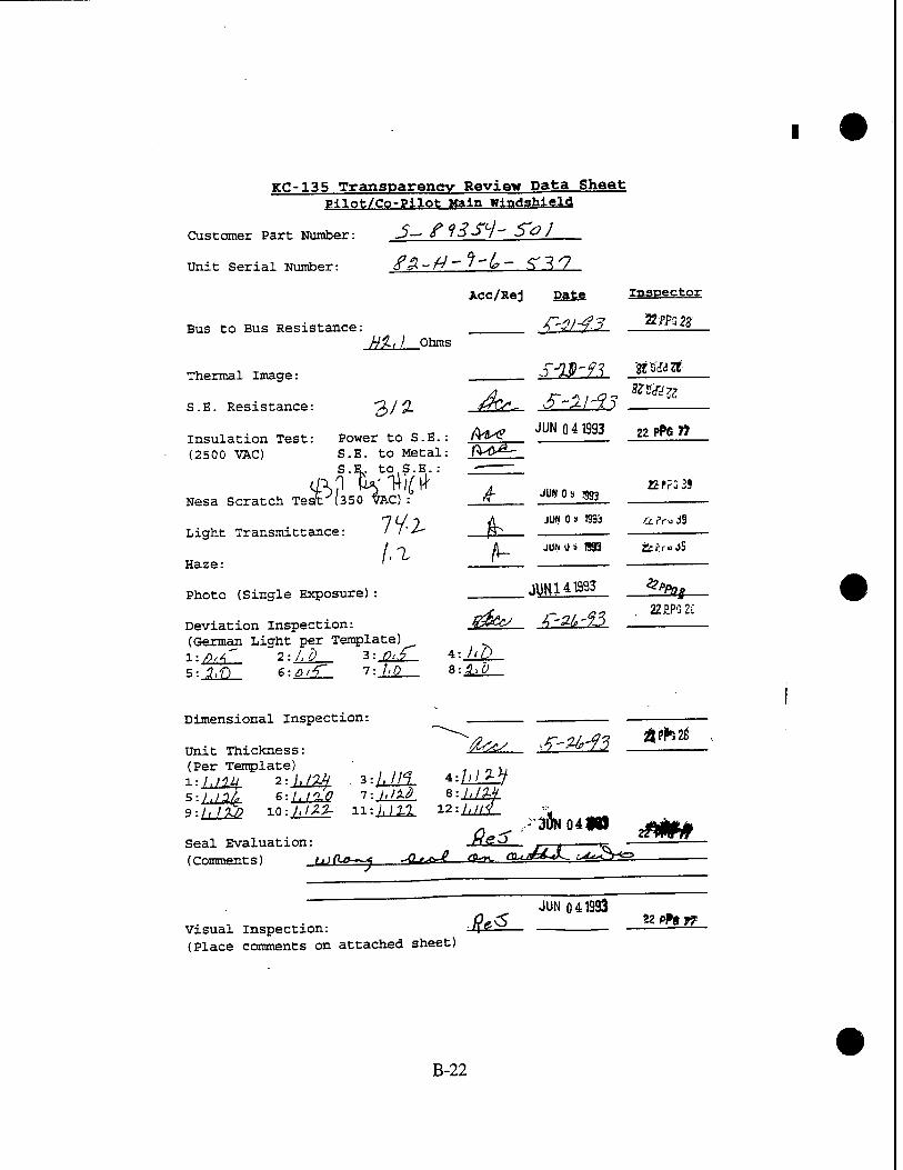
KC-135 Transparency Review Data Sheet Pilot/Co-Pilot Main windshield
Customer Part Number: 3— 6°3->l~ bOJ
Unit Serial Number: tf£> ~& ~ ' ~~v> ~~ f\"^^7
Acc/Rej Date Inspector
Bus to Bus Resistance: tf~21-^.3 ilif?— Hi.,) Ohms
Thermal Image: SWft ^iiZt
A, /T -5/ Q- ****** S.E. Resistance: 3/2- £rO- O "J-l 3 3
insulation Test: Power to S.E.: (H* ^Q4Bg 22 P»» (2500 VAC) S.E. to Metal: fVt>"--
Nesa Scratch wiPfesöfcc) > _£ JUW0^^ 7 £/ T V\ JUN 0 9 1993 a ?ru d9
Light Transmittance: ' 7"/- fr- JUM3 893 2t«V«j9
Haze:
Photo (Single Exposure) : «±M_ *3fo
Deviation Inspection: |%z&y /? -^-%? (German Light per Template) 1:/?^" 2:1,0 3: ^.f 4: Aft 5: 3,f) 6:^r£l 7: /,Q S:^^
22£PG2ii
Dimensional inspection:
/j5l 6:AlS 7:/,/^ 8:i^
Unit Thickness (Per Template) , ,,
9 r3ÖN o4** z*m Seal Evaluation: ff^^— _/y~T "Ö^JT (Comments) i.)(l»—j UL,^£—<y~. auJ*-*^. -^^r^
JUN 041933 Visual inspection: 'IP — — — £- (Place comments on attached sheet)
B-22

Check for vinyl cracks /QtxL-JUN Q4T993 g<f>T*
Visual Inspection Map & Comments
J& ,7? j^ T)»Zz^ Lao^d OIL m*<*J U"c7\
Thickness Template
©■"* ©/^ ®',;*
Deviation Template
©*r ' ®/*p ® @/0 ©A*
0fto ©^
B-23

KC-135 Transparency Review Data Sheet Pilot/Co-Pilot Hain Windshield
Customer Part Number: ^—tf^lT^- $~ü /
Unit Serial Number: fi ?-/? - ?-* /? — YSj
Acc/Rej Date Inspector
Bus to Bus Resistance: 'T'.^'A? 2PPGffl— Hh$- Ohms
r-Q.d-4? 22L°52i Thermal Image: J—"^ 7v __
S.E. Resistance: '2)J3 ■'" /? '^i3
insulation Test: Power to S.E.: $&P— ^041993 _2Z*±21_ (2500 VAC) S.E. to Metal: p&ts*
o "p +-Q S E "
y2.^> Pf*- F»j>+txfaJA~>£ m**m a PPG 39 Nesa Scratch Test (350 VAC) : /T :
77 p A JUNO. 1SS3 ^...0 Light Transmittance: / /, & /» . *•'' °JJ
Haze: ' ^ £ JUN 0» TO £ P.- -i 3ü
Photo (Single Exposure): JUN14 <993 UPPCS
Deviation Inspection: //^w ^ **?-/~J ;__ (German Light per Template) \ l: %,Q 2:1,1) 3:I,Q *• $-'U
5: hO $:/><<>' T-JLlL- S:Jjd_
Dimensional Inspection: .
Unit Thickness: (hc^ .{'Zftt gPFG2r
(Per Template) l 5 9
1.10%. 2 hi*?- 6 /i?02- 10
|.£?7 3:hlO0- 4:JJ1±L I.IM T.j.lnl B:h/6% \l\0C> 11: )'<0) V2.:),)0 0
, „ , ... /^S' JUN 041993 22PP6F? Seal Evaluation: /P*-7— ■ — (Comments)
tStr/»^ /V<«J<; -ears', k.*. /^?6 2Z. 2-r
Visual Inspection: (Place comments on attached sheet)
fe^ JUN 041993 " °»fl #
B-24

i-
•
Check for vinyl cracks ßu^lW*^ n Mf
visual Inspection Map & Comments
#,)l J- 0*/^~ JLDQ*7!>ri 4-fLO»*'* 7<L* o^T?
/SA u AOJ snnM*&- •&*■ s*'**"* thnm^ MJ' &?b
Thickness Template
©
®//t)i
Deviation Template
B-25

KT-135 Transparency Review Data Sheet ff-l lot/Co-Pilot Mai^ windshield
Customer Part Number: , ,V~ X ft *>'"■} .
unit Serial Number: ? I'M-/*-*(«-0*7
Acc/Rej Pate Inspector
id. 4~-3/-%? &P.PS2S Bus to Bus Resistance: _ /*V^- ■? *' ^ ■ 2—
^£2i_0tois . .*
22P.rG28 Thermal Image:
S.E. Resistance: 7#f ■■■ (Zr.«~* jls2£l$3 V
MAY 2 5 1993 22 PP« 7?
MAY 2 5 1993 a2PPG77
Insulation Test: Power to S.E.: (2500 VAC) S.E. to Metal:
S.E. to S.E.:
Nesa Scratch Test (350 VAC) :
•Light Transmittance:
Haze :
Photo (Single Exposure):
Deviation Inspection: ■ tf.rt'— '" ^y ' (German Light per Template) . _• . • ?
X-.n.r 2:ldL- 3:44_- I: ML. . . ;• S:£ZI 6:A_£_ T-£lV- *'-Jh£--
?U,3 MAY 2 5 1993 g2 PPa 77
/,^ MAY 2 5 1393 a PPs 77
V.E.Y Z 5 T99"1 22pPG4
Dimensional Inspection: .
Unit Thickness: (Per Template) a ■■ :IH/3f •L-.u&L *--L&L r-lML 4:-^-- s-JAW B-.LHIL T-L22L ■ 8:^|V 9:/M 10-.LJ22. H:il4li ^'iML
••• ,/foc Seal Evaluation: (Comments) _
^v- .T-if-?3 gwaa.
JUN 021993 22PPS77
/L,* JUN 02 1993 g *>s 77 Visual Inspection: /Tv<-^— ■ — ■ " (Place comments on attached sheet) ---•
B-26

Check for vinyl cracks Visual inspection Mag & Comments
&*■ ^J ttP»T7
Thickness Template
LOW &
©i,0?£ ®AC*3
©/<<??<) ' ©/.<**. @Ao*/
Deviation Template
V © ** ■ ©^ ©0-A
\ ©AC ©<>,o . \
A ©>•$ :©^ ©AD \
B-27

TCC-135 Transparency Review Data Sheet
Customer Part Number:
Unit Serial Number:
Bus to Bus Resistance:
Thermal Image:
S.E. Resistance:
Acc/Rej pate
W$ Obms
/ 3J*- Insulation Test: (2500 VAC)
Power to S.E.: S.E. to Metal: S.E. to S.E.:
Nesa Scratch Test (350 VAC) :
Light Transmittance:
Haze:
Photo (Single Exposure):
Deviation Inspection: (German Light per Template) 1: a, A" 2;.3,g 3:J^2_ 5: Q,< 6: D,A~ T.JuIL—
Dimensional Inspection:
MAY 2 5 1993 .32 PPG 77
inspector
22 PPG 22
^25 1993 y^r,
MAY 2 5 1993
/ -3, MAY 2 5 1993
.?? PPs 77
JLPft,
/^^ ■*"-*■<•-£? 22 PPG 28
8:_&i;
MAY 2 3 1893
Unit Thickness: (Per Template) - • Z.-.LM1 2:/^C 3:M 5:LÄZ 9
dec/ *-2f'f3 22EFG28.
,,^7 «:ts? '=Ä r-^|f Seal Evaluation: (Comments) _
/4m JUN 0 2 1993 * PP" ™
*W JUN 02 T993 g*Pg" Visual Inspection: £aa^— — (Place comments on attached sheet)
B-28

Check for vinyl cracks fi^L, &Mk***_
Visual T^^prrion Mao & Comments
Thickness Template
UOfn ©
. (&.t*& .mow ®y* G).ho?n (Dhow
Qi.093- ©A***. @/.öf/
Deviation Template
©J.D * • ©"AD . ■ ®** @3& -®/'ö .
Q0& ■■© ^ © ft*
• B-29

ice-135 Transparency Review Data Sheet TH-lnfc/Co-Pilot Main WlndsMgld
Customer Part Number: J-^ol 3 Sl"^d
Unit Serial Number: 1^ -}4 -( O - QVo-—±i_
Acc/Rej pate Inspector
^2 /r«j/.^ 22PpG2?
Bus to Bus Resistancer • •■'• ^Cc -J "^ 7-^ „ \7.6> Ohms .'_. _' -=•
T-HD-fä Tamil. Thermal image: •< ^ *' ■
S.E.Resistance:' * &} .-£&,_ &2£ä3 -W&*—. U MAY 251993 22 PP» W
Insulation Test: Power to S.E.: gtV.— >- -^ (2500 VAC) S.E. to Metal: &iK, ■ "-•---•.-. -- . ..
S.E. toS.E.: /9/T- ■■ ••■" -
Nesa Scratch Test (350 VAC) : J>$L- .MAY 25*93 , « *» » _
Light Transmittance: _ .. . jZ^_ MAY 25 1993 „ •* *"* ??
Haze:
Photo (Single Exposure):
A3 MAY 25 1993 22PPC77
A / Jr-*r-£3 22EPG2S- Deviation Inspection: . w^/— ." n7 ^ — (German Light per Template) ..-■■' l:^£ 2: ^>,0 • 3t A0 -4:^- "- S:7Z 6: /, 0 7: g'fl 8:j2j2_
^(v^ ^3rtö ^£PG28
Dimensional Inspection:
Unit Thickness:
S/ITST 6:/<M T-LdJl£ *:L1£1 9:t/£r 10:£S 11 :iü2Sl 12=LMfi-
/j^, JUN 021993 22PPG77 Seal Evaluation: . P"v— (Comments) :-
/I. JUN 021393 apftW Visual Inspection: . - Hly°^ ■ (Place comments on attached sheet)
• B-30

Check for vinyl cracks #*- , &2Z2L JZJ**1 Visual xnsneetion Map & Comments
Thickness Template
(ft
•&L**1 ßXJ* ®A •
OA^OO' ©/./*■* @/./^°
Deviation Template
00^ '© ty /
B-31

Kg-135 Trananareney Review Data Sheet m^f/m-Pilo«; "ri^ «Undahield
Customer Part Number: ,? - fl"/.53(/-' j
Unit Serial Number: ftf°-tf-/Gr'()k'0?<B
Aec/Hej Da£e
Bus to Bus Resistance: -• Jztks.. <5..9 Ohms
Inspector
Thermal Image:
S.E. Resistance: 3 0$ fac/,.
insulation Test: Power to S.E (2500 VAC) S.E. to Metal:
S.E. to S.E.:
Nesa Scratch Test (350 VAC):
Light Transmittance:
Haze:
Photo (Single Exposure) :
Deviation Inspection: (German Light per Template) l-a,/9 2:g,2> 3: %.(/
:-m- 0JL . 77. g
1,3
4: 1>2> 8: ,2-d
.m-fe **iU
X-XM-43 2?PG2g
MAY 2 5 1993 22PPat>
MAY 2 5 1993 « pPe W
MAY 2 5 1993 22 *» w
MAY 2 5 1993 22 PP6 77
HJW2S1993 22 PPG 4
.f-lf-f1} &P?GX>
Dimensional Inspection:
Unit Thickness (Per Template)
LJd£ urn hip*
2 6
10
1,100
Seal Evaluation: (Comments)
^=cV ' ^gjZZZfr. ap*". ^
TTT^r 11:/Jg* 12:Jii_!? JUN Q21993 22ppG77
A^ JUN 021993 22^7?_ visual Inspection: r ^— * (Place comments on attached sheet)
B-32

Check for vinyl cracks 0tut &-2-£? & f*rrr
Visual inspection Map & Comments
Tnickness Template
@/V
01,of* ©Ä/*5". ©/•/«*
Deviation Template
B-33

vr-135 Transparency Review Data Sheet ^irtt/Co-PiT-ofc Main Windshield
Customer Part Number: —5-17 J5~V - S~Q f
Unit Serial Number: '■*" //- f-' 7" ^0
Acc/Rej Eä£e.
Bus to Bus Resistance: ,r-2/-9l
inspector
Thermal Image:
S.E. Resistance:
Insulation Test: (2500 VAC)
jf/,7 Obms
j 3/V Power to S.E.: S.E. to Metal: S.E. to S.E.:
Nesa Scratch Test (350 VAC):
Light Transmittance:
Haze:
Photo (Single Exposure):
Deviation Inspection: (German Light per Template)
5:iT 6:/.& 7: 2.0
&r
LI
4: A £ 8:3,/>
/T-rf-9.3 fl*33%
MAY 2 • 1993
^- _£äa=fl
22 PPG 4
.22^22
Dimensional Inspection:
Unit Thickness: (Per Template) _
S-.JjJLSX 7
10: /.fl?/* 11
1: /. tf^-v 5: /,^" 9: /, •■>■'>/
ii£^ A2££ './/?<?
^ i£i_
4: A/ll I'.l.lbd
>r-34-<3 a? pp-'j •>?
jUN 021393 Seal Evaluation: ■-n - ■-— —i—-n- (Comments) „.MffP'vfl f*<*f <"» a<>™d St4<!
pPSTf
<?-<" JUN Q2 1993 22 P?g 77
visual inspection: i\<f>*— (Place comments on attached sheet)
B-34

Check for vinyl cracks ML- &^. **?J?
Visual inspection Map & Comments
Tnickness Template
® /-d?fr ©
®M* an
Deviation Template
©so- • ®/.ö ®*°
©?.» :©{' © /.*
B-35
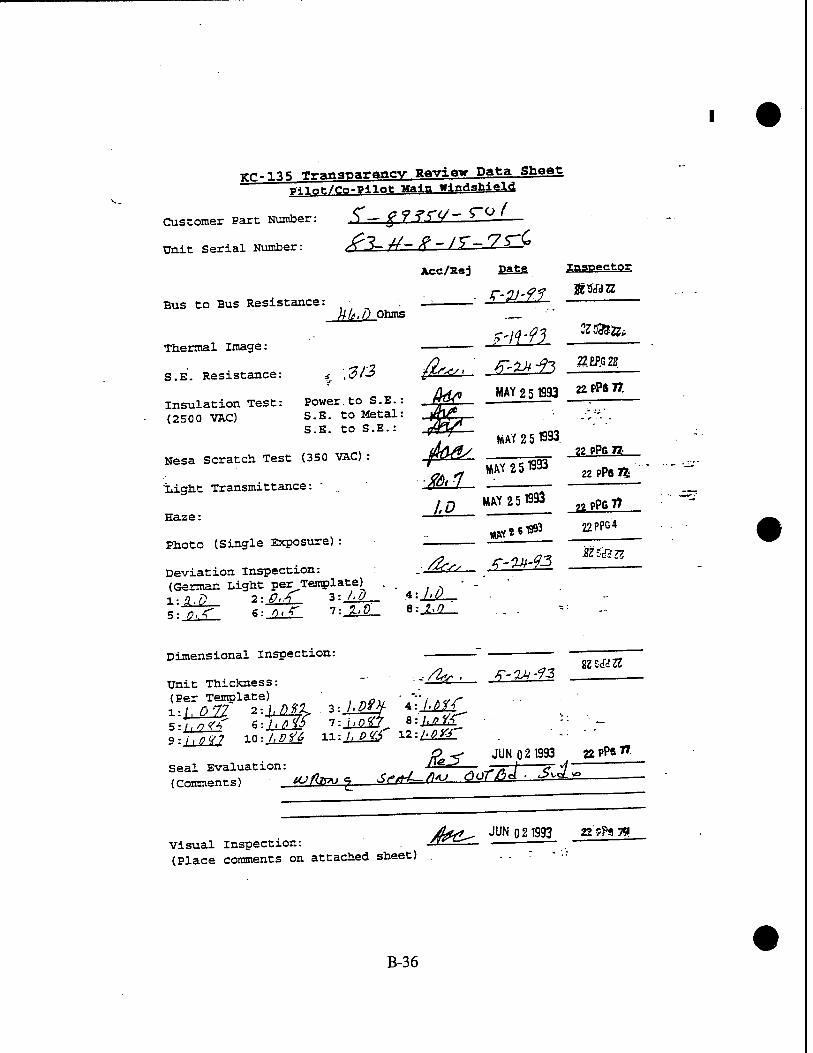
KC-135 Transparency Review Data Sheet p-nnt/Co-Filot Main Windshield
Customer Part Number: f) — gfSf*/" ^-
Unit Serial Number: &3- r¥~ 0 ~ I*> ' ^-
Acc/Hej ES±S
Bus to Bus Resistance: kle.D Ohms
f-fl-gf
Thermal Image:
S.E. Resistance:
Insulation Test: (2500 VAC)
f'H'93
■3/3 fir«, ' f'*» ft
Inspector
22 £P.G 22
Power.to S.E.: S.E. to Metal: S.E. to S.E.:
Nesa Scratch Test (350 VAC) :
'Light Transmittance:
Haze:
Photo (Single Exposure):
Deviation inspection: (German Light per Template) l;3.g 2:0,/T 3:-44r 5: 0,< €:..0-r 7:-2^_
(fa* MAY 2 5 1993 n^ft.
MAY 2 5 «3.
MAY 2 51993 n pPfi n
IQ MAY 25 1993
■ /&:. 22_ /T-24-%3
B: 1.0
22 PPS 7%
22PP6 77
22PPG4
ÄfS&ZZ
Per Template) ' .:i,_^27 2:1^1 3:-^|£ ;:T7^W 6:hßH5 l:j_jm^
Dimensional Inspection:
Unit Thickness: " ' ^ ' (Per Template) 1:
V-^LJM Ü\AB& mJTwf n-.tMl
41 i.bVf
Seal Evaluation: (Comments) tCJ/bvu <Z
&5L
K-QA-13 sz E<W u
JUN 021993 22PP8 7»
A+ähL-fiAJ rlor/bd ■ S^Zi
jägfff, JUN 021993 n&* n Visual Inspection: .n^1 ■ " (Place comments on attached sheet) .. . :
B-36

Check for vinyl cracks J^L- £±£ «Ä
Visual rnmectlon Map & Comments
i.,» rti~^. **?* ~, M-- /- -"^r
Thickness Template
©/-of-*
Q>/.ö7l ®Jo& ©A**?
Deviation Template
©^ .£ Y&0J^
B-37

ICC-135 Tranaparanev Raviev Data Sheet p4,lot/Co-Pilafc Main Windshield
Customer Part Number:
Unit Serial Number:
Bus to Bus Resistance:
Thermal Image:
S.E. Resistance:
c- tcra-So / jpy,A/..7-/f-.3-ao
Acc/Eej pate
HHA Ohms
\3)({-
Insulation Test: (2500 VAC)
Power to S. E. : S.E. to Metal:
%,."&. to S.E. :
Nesa Scratch Test (350 VAC) :
Light Transmittance: /'O
Haze:
Photo (Single Exposure):
Deviation Inspection: (German Light per Template)N !-/,„ 2: l.P 3: 1>0 SJ^T «:5Z2I T-±V-
jk*. '^L
A4* jUN 041393 22PF8 77
inspector
#Pj>G28 .
H9cf32Z
^_ JUN 0 8 «3 KPFS39
_A
J&L }££L
JUN 0 a 1893
JU~N 0 9 1993
JUU14J993
4: £.3 8: l.P
?2FPG39
äPru39
22. £PG 28
Dimensional Inspection:
Unit Thickness: (Per Template) v
S:/,0^ 6: 1^25r- )>P^/
. 3:AM5 T.hstli.
Seal Evaluation (Comments)
^-^ J2*£^_
8;/>0f/ :
JUNO 41S93
,^/ X/^* /? 6f77Z-.fi
visual Inspection: (Place comments on attached sheet)
-&£.
Sfr3?S
?P«?7
JUN 0 41933 22 PPS 77
B-38

Check for vinyl cracks . JUN 041993
/L^ 22 PPfl 77
Visual Traction Map & Comments
ja** y rx^u^ i^cfi-6,1 TUM <HK-
Tnickness Template
.„ ©
Deviation Template
©^ ' ' ©^ @K>
©' /0 ©
B-39

Tri-.-ns Transparency Review Data Sheet p-Mnt/eo-Pil?«- Main windshield
Customer Part Number: V- £4 JT'j - T V I
Unit Serial Number: dh"//~ '*• ~°' "* /? ^—
Ace/Sej Date
Bus to Bus Resistance:
Thermal Image:
S.E. Resistance:
insulation Test: (2SO0 VAC)
3d,-A Ohms
- %309
Power to S.E.: S.E. to Metal: S.E. to S.E.:
&~ f'P-?3
fcrf *W 25 1993
inspector
gg£PG28
22 PPG 77
Nesa Scratch Test (350 VAC):
Light Transmittance:
Haze:
Photo (Single Exposure):
Deviation Inspection: (German Light per Template) l: 3,Z> 2-.J.D 3'-^4r- 5: JL.Q 6: />.<" 7: >W
Dimensional Inspection:
MAY 2 5 1993
MAY**«03
"4: At-9 8:_^A
Unit Thickness: (Per Template) Z.-.UQ23. 2-./.P94-
LU3- 12: UO/
tmv p ** ion?
5 9
Seal Evaluation: jfe0— , d f (Comments) /,»./»A~* iTCft? <^ <W^ ,,,.AXL^J 5-frft-^—<&=ö_J&!
Visual inspection: . JaMis» (Place comments on attached sheet)
22 pPSl*
MAY 2 5 1993 22 PPG 77
7r MAY 251993 »*•* ^PPG4'-
/£>•. S.M-93 22 p?as.
22RP6 28
JUN Oi öij 22 PPG 77
JUN02Ua3 22f?i6 77
B-40

Check for vinyl cracks J^L_ izlf? «ÄU* Visual inspection Map & Comments_
Thickness Template
Deviation Template
B-41

KC-135 Transparency Review Data Shaat mi^/eo-P-"?* Main Windshield
Customer Part Number: -> ~<?7-.7 J/.l—.
Unit Serial Number: <f 7- H~ /° ' J %~ '° '
Acc/Kej pate Inspector
Bus to Bus Resistance: n_: ° *' h ' ij / _ 'S /"WlTTIC " -T-,. // //O Ohms
Thermal Image: JSSfcfZ?
S.E. Resistance: ^// ' -J^-. JLZ2L33
Xnsulation Test: Power to S.E.: ^_ Ä-flUSS _**i» (2500 VAC) S.E. to Metal: /fg£ _ _ . ~ ;
•^ S.E. tÖS.E.: ~- ^-0 0,cf fH/ßCB/ukr iuue^ V. JUN 09 993 »PrSJa
Nesa Scratch Test (350 VAC) : P ■- "^ .
Light Transmittance: // ^ &■ — cc«i,usS
- - 1 Haze:
Photo (Single Exposure): .
Deviation Inspection: ßtel— 6-Z5-— (German Light per Template) , 1- ■? A 2: 3.^ 3:Ä^_ «i^d—
A^ JUNO-!) 893 SE^ff -
r.3uUl 41393 Z'Pc* £
5: 1,T)
Dimensional Inspection:
Unit Thickness: . (Per Template) • " -■_ o;
l;/.pfj 2:/,gJ? 3:^4^ t "f^T 5:ük 6:AÄ 7:1@L *:-^f|-
Ot^ ST-25--95 2ZÄF-J28
#e5 Seal Evaluation: J (Comments)
JUM 0 41-93 22 J^«7?
5^< ^.A /y^-» ^ *~^
Visual Inspectxon: -U (Place comments on attached sheet)
jijtt ö :: -533 , .»8 ^
B-42

• 1 -«.ri« /l/,rt ^ JUNO 41993 :2PPa« Check for vi nyl cracks yfrr"-^ - "O—*. , ,—
Visual r^^ction Map & Comments
;3EEZ^g' -•'" ■»"■ ^T~^^
Thickness Template
tf«)
Deviation Template
®^
^ ©
B-43

KC-135 Transparency Review Data Sheet Pilot/Co-Pllot Main windshield
Customer Part Number: J~ ffV-55°f~ Jg /
Unit Serial Number: jO,-hj~ Y~\fi~^-^^— -
Acc/Kej Date Inspector
Bus to Bus Resistance: ——L= -T -V 7- ' A^,# Ohms _■" ■•£
r-üfi-^S »EPS 28 Thermal Image: ,-. V r~—i-^-
„,, ,/ rLiijJf EtfcUZZ S.E. Resistance: £«5// /KV-- ■■ -v i*-' / ?
Insulation Test: Power to S.E.: _^3dH. xuauxauxvw * w-w- —
(2500 VACL-W3 S.E. to Metal: Ytya^ r°^Fj^ . S.E. to S.E. : ^
Nesa'^sSratch Test (350 VAC) : (T^ C
Light Transmittance: _ / J*0
JW 0 9 1993 &?K&
IUNQ9 1993 ÄrräiS
2 A- * JUN 09 UN? -fe?rojS .2, A- " JU(* 0,9 1533 Haze: " '^--
Photo (Single Exposure)
Deviation inspection: ' 1"^'° v?-ftfc-?-> _ (German Light per Template) ... 1- £.0 2: 3.. fl 3:g.D :. 4:_/iÜ - _ ~ .
Dimensional Inspection: :— —
/2ss, S-U-13 22PPG28 Unit Thickness: • &£&£— ° ■ " 'D (Per Template) .'. .„ , T* , „,- .
9 yßC S:I>097S l:hfi47 :.8: I'tfif
\ToTfT io:/i£i£ u.-.hef( M-M2L ■ . .;„.
Seal Evaluation: (\^-> _ . (Comments)
<^,U- /i/^^S Gi^^J-^ /9^> f*.*-6d £3Z
Visual inspection: (Place comments on attached sheet)
JUN 041993 ^5 vpPiJF
B-44

,..^-
Check for vinyl cracks ^^~ £~ Visual inspection Map & Comments
Thickness Template
:—" to9S
O/rfö ©Z^.' @-fi**
Deviation Template
"©' ^
B-45

KC-135 Tranaparencv Review Data Sheet ytlafc/Co-Pllofc Main Windshield
Customer Part Number:
Unit Serial Number:
Bus to Bus Resistance:
Thermal Image:
S.E. Resistance:
Insulation Test:
r- £9i<v-r*i
Acc/Rej pate
}f$, 7 Ohms
.213 Power to S.E.:
(2500 VAC) .S,E. to Metal: S.E. to S.E.:
Nesa'Scratch Test (350 VAC):
Light Transmittance: //"/
Haze: """
Photo (Single Exposure): t
Deviation Inspection: (German Light per Template) 1- /, Q -z-.i.u. I'-ldl— 5:775" 6: f>..*> . 7:_^£_
JL
Ä3^
4:^£_
^-^9J
inspector
JZPPC2S
JUN 09 893
JUN a » 893
«PPSi
h?r-ja
A JUI> 0.» 893 ..?ru39
J?^ 22EF5 28
Dimensional Inspection:
Unit Thickness: (Per Template) • 1:/Ük 2; /.Of2- . 3:MIL 5:1,090 6:i^% 7:^|. 9:S 10:/,of^ l^il«
Seal Evaluation (Comments)
4: /,/>?/
12: /,<3«7
/fts^ .r-ara a^2S
JUN 041393 22PP8 7T
<r^ „/^7 ^ /^ 7Jft**v/ */^ ~
Visual Inspection: (Place comments on attached sheet)
'€? JUN 0 -C"?
22 ??s I?3
B-46

Check for vinyl cracks
Visual Tn«n«cciaa Map & Comments
„ , JUNO 41993 fa«S «JSM*-
ZJ-//t UJ n,Lor*~ L2>Q<V7#J /fftaj^ Tli U**0.
•Shi c3cn.es s Template
ri- @t#r
Deviation Template
B-47

yr-135 Transparency Review Data Sheet p-Mot:/Co-Pi1«fc Main Wind3bield
Customer Part Number: > - if 7 7i ^7 " ^
Unit Serial Number: £7 3-frC» #? . ^ 7" 7
Bus to Bus Resistance: Zf.Q Ohms
Thermal Image:
S.E. Resistance:
insulation Test: (2500 VAC)
A'? Power to S.E•: S.E. to Metal: S.E. to S.E.:
NeslScratch Te2t (350 VAC) :
■Light Transmittance: ;■//-/
7 Haze: ■ ' '
Photo (Single Exposure):
Deviation inspection: (German Light per Template)
" * 3: X...P
Acc/Rej pate inspector
z-1)-?3 wm
'^-K . gEPG2S
_A il
S:JJ£ &:0. ■ T:JjD__ 8: 2.0
JUN 041993 22^«^
JUNfcS «93 J£Pr5 39
JUN as 1993
JUN 0,9 1993
JUNI 41993' *pPor
Dimensional Inspection:
unit Thickness: - (Per Template) ... .. . .' ■ --■=■; 1:/,*«» 2:A^2 3:i^. 4:^
9ilJW 10: /.flf & ll:AÄ^. ■ 12 :M1Z
Seal Evaluation: (Comment: s)
-/fco
^ -^'?3 2ZP.PG2S
JUN 041993 Z2PP«W
f*K>J- A/++J* fiurr/^ -^^ nu77hri sU~_
Visual inspection: fiVZv (Place comments on attached sheet)
JUN 04 £33 "">. 'PS 7f
B-48

Check for vinyl cracks
Visual Inspection Map & Comments
A. JUN 0 41993 /Qtk* «<yi»
,<?nlLte<! '+ *>g*//>«*^ & #H*<h<f'
Tnickness Template
H3**
Deviation Template
©***'© 3» _ ©^
.©«55 ' .
rf tf
B-49

r lVi T„wafarftnev P—<-» nafca Sheet ~ ■ p^^ga-PUTT f*. window
Customer Part Number: J2 2-£ —
/ins- ///^ Unit Serial Number: '<>'-> *—*—'
Acc/Kej Ea££ SaaESSiSE
Bus to Bus Resi- ^nce:7/ / ohms ;
Thermal Irige: .*- .. -^— ^ MAY 2 6 199b 22PPG43
Insulation Tesc- -x-wer to Metal: JB, ■
(2500VÄC) ' ■" oK «*231SSJ "*« Nesa Scratch Test (81 VAC) : _^
*2.l? MAY 2 6 1993 gP?63 Light Transmittance:. . . — -
A Sf MAY 2 6 1983 _ gP-*S_
22PPS« JUU14TB33. V"PG8 Photo (Single Exposure) : - *.?r;j3
>4 JW0 9 B93 _ Deviation inspection: —t^S. - -
£52 ""^Ä^Sk «Ma* Dimensional inspection:
Unit Thickness:
iSS*1^!^... 3:^Z - 4-^ Check for Vinyl Cracks: Jfc*-
JUN03ÜS3 22PP8 77
JUN 031993 ,pgygi Seal Evaluatxon-
(Comments)
p v- JUN öo la33 22 pftg SB Visual Inspection: . . -£ ■ " (Place comments on attached sheet)
B-50

Visual Inspection Map & Comments
y^jL.
\/^lu S*Pfir*J*7/o*j -Ada**- £"/*<£. /0.„ *ii StofJ
Thickness Template
©?*/ ©
© Vf° ©#*
Deviation Template
B-51

ice-13 5 Tra^ap^ancv Review Data Sheet Pilot/Co-Pllot #4 Window
Customer Part Number: £" 7/ /°7W ^0/.—
Unit Serial Number: 5U 0 4y tfO V"? /
Aec/Rej Pate Inspector
Bus to Bus Resistance: - -/? ' -■- ct-cc o w -<i -; ■ /? 7' <> Ohms
Thermal Image: ."
insulation Test: Power to Metal: £<k^_ J*Lü*i3 *»UL (2500 VAC) • --■
Nesa Scratch Test (8X VAC) : MdL- J^i^ ^^L nfy MAY 2 6 1933 . .2 PPa 77
Light Transmittance: _ fr '— ■
Haze: -L±£—
Photo (Single Exposure) : . —;,-~"
Deviation Inspection: - fftf/ (German Light per Template) ... 1: 3 2: ? 3:^Z_ 4:_^_
Dimensional Inspection:
MAY 26 "S33 . .-'ZPPttj?.
2 6 MAY 1993 22 PP^*7
MAY 26 1993 22 pPe y,
Unit Thickness: ^? (f4C', n ^° *-■> (Per Template) -3- -~v ' ..._ !:,/,?< 2:.tü£_ 3:^S- 4:^^= ...
• , ^ v ■ • jfe^ JUM2TS93 &'?*"' Check for Vinyl Cracks: J(W. ■ — ■ fa/i JUNQ2SS3 Mj.n Seal Evaluation: JW"~ ■ «p™ "
(Comments)
A*/" JUN 0 21S93 22 PP6 : visual inspection: . fW<?— f — (Place comments on attached sheet) . ■-••
B-52

Visual Inspection Map & Comments
Thickness Template
©*^ ©#7
(Drf^ ®bf
Deviation Template
@3 dP
©3 ®;J
B-53

KC-135 Transparency Review Data Sheet Pilot/Co-Pllnt »4 Window . .
< r7)1 ^ */ — S"0 / Customer Part Number: _2_Z—L' ' ° ' d 1—
Unit Serial Number: 7rP» ~ Ovi" "—_Z_P
Bus to Bus Resistance: f)9,U Ohms
Thermal Image:
Ace/Rej Date jngpectQg
* IAJI jt/ MAY 2 6 1993 insulation Test: Power to Metal: AT"^ (2500 VAC) . "'•-'■'"
Nesa scratch Test (81 VAC):
Light Transmittance: _
Haze: ■"
Photo (Single Exposure):
Deviation Inspection: (German Light per Template) 1:, 3 2: 3 3:^L
/V^g MflY^R 1993
9#5> MAY 26 1993 . MAY 2 S 1993
A 7^
jj*fr
J2PP677
22 PPG 77
22 PPG 77
22 PP« 77
2 6 MAY 1993 22PP*47
MAY 26 1993 *PPG»
Dimensional Inspection:
Unit Thickness: (Per Template) 1:^11 2:^Ül -3:^fL
Check for Vinyl Cracks:
Seal Evaluation:
(Comments) 1_
JUN 021993
ftsdazz
22 PP6 77'
. ^^ JUN 021993 22PP6 77
XL*** JUN o 21993 22 PPs 77 Visual Inspection: £2^ — — (Place comments on attached sheet) '-'-■
B-54

Visual Inspection Map & Comments
V
Thickness Template
@^ <D**>
@tf* ®6f/
Deviation Template
B-55

TCC-135 Transparency Review Data Sheet piiot/Co-Pjiot: »4 window
Customer Part Number: • ■ <)" ' ' 'b7 1
Unit Serial Number: f% fl*? H* 3*0
Acc/Rej Pate Jnspgctpr
22.EPG28 Bus to Bus Resistance: -fi&LL— ^"ZA-f?
■ 70, I Ohms _ '■'•-"=
Thermal Image: , . . ' £^£l -M^L.
„ . -, AJIJJ MAY 2 6 1993 « pPe II. insulation Test: Power to Metal: JfB^ . • •-— ^— {2500 VAC)
AAJA MAY 26 199$ -^ PPG ?7 Nesa Scratch Test (81 VAC) : /H^tt^
Light Transmittance:
Haze: '"■ —
Photo (Single Exposure) :
rjf y MAY 26 1993 a pPG 77
HAY 26 1993 a«w
I.7S .2 6 MAY 1993 22PP&«.
Deviation Inspection: (German Light per Template) 1: *\_ 2: ^ 3: «3» 4:_^
Dimensional Inspection
Unit Thickness:
/fog^ MAY 2 6 1993 a pPG "
..^ T-*f-?3 ,«*"* (Per Template) ■ '—■ -; l:./^ 2:^&L 3:,i£L 4:^M^ .. - -
A JUN02S33 *2ppG^ Check for Vinyl Cracks: - P**- ~ »'S 77
VLp. JUN 021993 22 PP« 17 Seal Bvaluatxon: /,ya^ , — :
(Comments) —: — — ■ —
Visual Inspection: (Place comments on attached sheet)
fin*' JUN 021993 22PPG77
B-56

Visual Inspection. Map & Comments
Thickness Template
@4ftf ®b?f
Q)6ff 0^/;
Deviation Template
@3 OP
©:
• B-57

KC-135 Transparency Rev?A» Data Sheet pq^t/Co-PM^ *4 Window
Customer Part Number: ..4- 7/7^/4^ ■'7~£ /
Unit Serial Number: _7 V* ~ £>~ ^~ W " ~0 &
Acc/Rej Date inspector
Bus to Bus Resistance: - - - S^- Ä^tll »£»28 /%3 Ohms _ -•-
f-SM-fS 22-.mzi Thermal Image: . * ■ •■ — -^ l^L- —
.„Moral. /kW» WAY26-^3 22.PPS77 insulation Test: Power to Metal, /we-— ; (2500 VAC) ■■•'"' '""'""• „„ K MAY 2 6 1993 Nesa Scratch Test (81 VAC) : &&£* : —« &« "
ZM «. MAY 26 1993 22 PPG 77 Light Transmittance: JSu'r — —=
, , MAY 2 S 1933 ^ , /, / & ??PPB7?—
2 6MAY1S93 ^V_ Photo (Single Exposure) : - T
x, MAY 26 1993 n#%7f Deviation Inspection: (TXy^~ ■ — (German Light per Template) '.'.'-■- 1: 5 2:_3_ 3:_3-
Haze
4:
Dimensional Inspection:
Unit Thickness: - ■■--/*•, S=&23- K&Z
-^ JUN 021993 .3 apPG77_ Check for Vinyl Cracks: JL^
/r^. JUNÖÜS93 ?PPa# Seal Evaluation: /rv*—^.. ■ —
(comment s) _ —-—
fa^ 'JU*CfcSS 22ppsy7 visual Inspection: . OZL (Place comments on attached sheet)
B-58

Visual Inspection Map & Comments
Thickness Template
©^ ©*f>
<b'f* ©f V
Deviation Template
@
®'-
B-59

ice-13 5 Tra"gparencv Review Data Sheet Pilot/Ca-Pilot *4 Window
r 11 7 LH- T» I Customer Part Number: S-—' ' '
Unit Serial Number: ■ <jn."-ll5 J/9 ttL
Bus to Bus Resistance: Ohms kii.
Acc/Rej Date Inspector,
k,o tä/0 ■ 2PPGH
Thermal Image: . ■•.-■-• ' ' •' / /— "~~"
, tkis GnJ£l 22PPGI5 Insulation Test: Power to Metal: tV^ .. 1!"/I _ (2500 VAC) . - - ■ ;■:-'"•'
Nesa Scratch Test (81 VAC):
Light Transmittance: _'
Haze:
Photo (Single Exposure)
J&k-ShM. 22 P^G 15
-u.< te. m
,f M Ihm
Deviation inspectxon: (German Light per Template)
l:_JL_ *-^Z— 3:^— *-■■-£-
*cr. */l/** JL2*^
Dimensional Inspection: 1I_ —- —. ——
Unit Thickness: "' _^X |^LI TfRjj 88 (Per Template) . .- . . --"• l;.£/i. 2: Lft, ..3;jilL . 4;.<£ff ■ «: . _
22 PPG 15
Check for Vinyl Cracks: . ., fc-'<- f'l/7.s —;
Seal Evaluation
(Comments)
visual Inspection: ■&<■<*— y*1- '■? (Place comments on attached sheet)
111'-
B-60 •
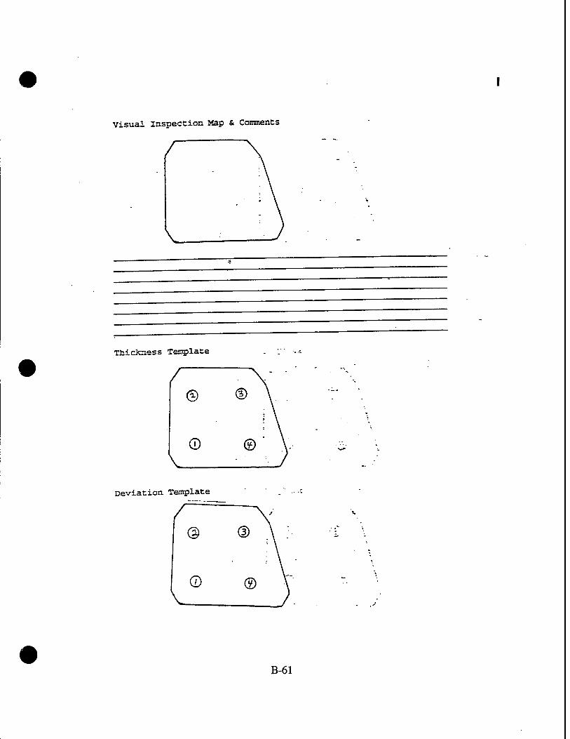
Visual inspection Map & Comments
Tnickness Template
©
©
Deviation Template
@
©
B-61

KC-13 5 Transparency Review Data Sheet Pilot/CQ-Pilot «4 Window
Customer Part Number: ..?"" '''&TZ 9-1
Unit Serial Number: ft- H~ * 7~ 6 I '* %
Bus to Bus Resistance: Ohms
Acc/Rej Date IsaEfiStSS
^_2e^_ MAY26 1993"22PP»77
Thermal Image:
Insulation Test: (2500 VAC)
Nesa Scratch Test (81 VAC) :
Light Transmittance: _
Haze: ' -
Photo (Single Exposure):
Deviation Inspection: (German Light per Template) 1: 4 2:_2£_ 3:_JZL
Dimensional Inspection:
Unit Thickness: (Per Template)
Power to Metal: ;—1^_ —
-* Re5 »AY261993 22 PP6 Tf
ffä .<? MAY 26 1S33 ,22 &S I»
tfi MAY 2 3 ^533 22PP«77
26UW1833 22PFÜ47
KAY 2 5 '•S33 22 pPe M
(Per Template; /'/?>- "" //?/j ■L:JZ£&tf3 2:.70>i) 3:.ifZ£- - *-^JLL
JUN 021993 22PPG77 „fir6*—
%eJ JUN Q21993 ., 22 PPS 77
Check for Vinyl Cracks:
Seal Evaluation:
(Comments) ^L-ü2^0 CiftloY , ,
r,<-,J ^ Q/^<^/
Visual Inspection: _ LLZ.— (Place comments on attached sheet)
JUN 02 1233 ,2,^,7.
B-62

Visual Inspection Map & Comments
9- /?*,/),>, (j^r^J 1_
,l«n< h*2 ^'^ AU- ROe?"/i n> Ü"<±-
Thickness Template
©** ®*
Qtfl @kf'
Deviation Template
@'c (D?
l ©f ®^
B-63

ICC-135 Tranaparenev Review Data Sheet p-Mnt/eo-P-n,"*- ** Window
Customer Part Number: 5~ I I IbL/- 5° ' —
Unit Serial Number: • -tyo ~/7.3 M° 73-/ '-.-
Acc/Rej Date Inspector.
Bus to Bus Resistance: j3S2g£^_ ?? pPtt ^ h>f-*f' Ohms £->**•' .
Thermal Image: ^ _ ' __ • — - - A./} HAY 26 1993 22 PPe 7>
insulation Test: Power to Metal: fjiS*- —= . : '-*- (2500 vac) ■ ■■->"*■
A** MAY 26 1993 ~ pPr „ Nesa Scratch Test (81 VAC) : fifr*" a PPG n
?AO MAY 261993 22PPsy> Light Transmittance: __ ,0UI t— ■ "-
MAY 26 1993 a2PPs# -L2-
Photo (Single Exposure): _ -i—
Deviation Inspection: ftiP^ (German Light per Template) ^ . l:_2 2: 7 3: -3 -4>-*—
MAY 2 «1993 ^Pft*
MAY 26 1993 a ppG „
Dimensional Inspection: . _—z— —
Unit Thickness: •- dc*s< J? J-?'vJ (Per Template) - - . 1:./,^ l-.Jd^ l:Ää- *:A<q-
22CPG22
.fyfi/L JUN 021993 22PPG7?
%ej JUN 021993 22 pPe ^ Check for Vinyl Cracks:
Seal Evaluation:
(Comments) M-U> "/ ? L 'ye av sT^^. "~ <"" ~ 7—=--~.
/W- JUNo21993 22 p& if visual Inspection: (Place comments on attached sheet.)
B-64

Visual Inspection Map & Comments
(Tpju~ P~i)iA, CJAJ-A.ATT
U,A*~< ^,o, of .<s+<L A«I rxJt&l 6^-*
Thickness Template
0<^~ ®6
©^ ©£,
Deviation Template
B-65

KC-135 Transparency Review Data Sheet p-tlot/Co-Pl7nfc «4 window
Customer
Unit Serial Number
Part Number: ^inUf-Hct* F
Bus to Bus Resistance:
Thermal Image:
1/4.1) Ohms
Acc/Eej pate
Insulation Test: Power to Metal: (2500 VAC)
Nesa Scratch Test (81 VAC): •
Light Transmittance:
Haze: "
Photo (Single Exposure):
Jcc MAY 2 6 1993
inspector
ffiflddZZ
22PP643.
QH MAY 2 6 1993 ^PW
£{)t 7 MAY 2 S 1S53
if MAY £ 3 1SS2
Deviation Inspection: (German Light per Template) li <- 3 2:^ 3 3:^1 3 4:^,1
?*fc 4*-
Dimensional Inspection:
Unit Thickness: (Per Template)
Check for Vinyl Cracks
Seal Evaluation:
(Comments)
&c, M-tt ***** (Per xempxate; ,. . , 1...MU 2:.t,<K i-.'&W •■ *-.,M :
£s£-
JUN 031993
JUN031GS3
22 PP6 77
«PP«77
/W .9^/-^- ß^jj^
visual Inspection: 'J(aK0 (Place comments on attached sheet) .
JUN0S1S33 - #?;?**?•
B-66 •

Visual Inspection Map & Comments S/5.
\Z\«jl~j tSL-^cJL km*f*J *-* rn(W><L
-s\3iLto*j* .«*JI fM/*A ** ima^J
Thickness Template
®b0 ®ffi
©^ ©^
Deviation Template
B-67

rr-135 Transparency Review Data Sheet yilQt/Co-Pilot »4 Window
Customer Part Number: <t- 7 f7W~ ?<> / d&t/'
unit Serial Number: . ? ~ r*" -*- ~ 7 " -* J ■ ' -' :
_,„v Acc/Rej Date Jngpcgtor
Bus to Bus Resistance: . • :_^— ^ VV /• . //y«f Ohms . ' "i
/•-a;-*? 8Z3jjZZ j
Thermal Image: »„ MAY 2 6 1993 22PPG43'
Insulation Test: Power to Metal: ffCfr — (2500 VAC) ■■<■
Nesa Scratch Test (81 VAC, : _^_ Mil** _^L_
Light Transmittance: . *j.t> JUOJUSS3 ^
Haze: —— —^—-^^
Photo (Single Exposure) 22 PPG*7 JUU14TSSS 2PP08
Deviation Inspection: —<* _fc-^ ".3-. <>■ (German Light per Template) " - l; ^ "*> 2: ^ 3 3:_i_3 .4:^-3 -
'<?
Dimensional Inspection:
Unit Thickness: (Per Template) .-_ :^r _ l:,/^ ar^ifiL 3:^f^ 4:^1
JUNO 3 1993 22PP6 7T Check for Vinyl Cracks: . .
O < JUN03SS3 22PPGJ7 Seal Evaluation: ne'*P • —
(Comments) M^- ff ™-frC
,7 - JUN031S23 ^^^ visual inspection: -/■'■^ — s (Place comments on attached sheet)
• B-68

Visual Inspection Map & Comments
Thickness Template
©fef* ©^
©^ ©£/S V
Deviation Template
B-69
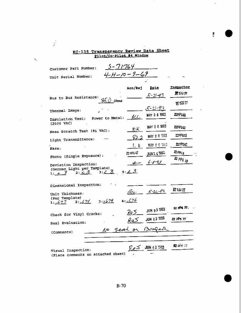
TCC-135 Transparency Review Data Sheet p^lnfe/Co-Pilot »4 Window
Customer Part Number: ->~ I iHtoJ. .
Unit Serial Number: Lf~H~ JQ ~ 7 — £>?
Bus to Bus Resistance: täö Ohms
Acc/Rej pate
Thermal Image:
insulation Test: Power to Metal: (2500 VAC)
Nesa Scratch Test (81 VAC):
Light Transmittance:
Haze:
Photo (Single Exposure):
Deviation Inspection: (German Light per Template) l; ^ 3 2: ^-3 3:^ 3 . 4
fCJL m 2 6 1"3
Inspector
»SS!!?
22PPG43
HJL MAY 2 6 1993 22PPQ43
fä%£ MAY 2 6 1SS3
f, ö MAY 2 6 t;a
22 PPG 47 JMH141SSS
_4-~- C-£~9J
JL 3
22PPG43
22PPG43
2?Pft;g
£/>/><? 20
Dimensional Inspection:
Unit Thickness: (Per Template)
Check for Vinyl Cracks:
Seal Evaluation:
(comments) ___
/&<.. Z-V.-** mm
(Per Template; . , l:i77 2:,^ 3:«479 4:,/^
&I. JUNO 31993 22PPS77,
ddS JUNO 31993 22PP8 77
/t^ 'p^iA-L fry Q^A^-A^
t7^ JUNOST-2 visual inspection: jx±. (Place comments on attached sheet) ,
! !?r£ "7
B-70

Visual Inspection Map & Comments
AM*,» A h*,-if '
Thickness Template
©6^ ®W
®6>tf ©^6
Deviation Template
B-71

ge-135 Transparency Review Data Sheet Pilot/Co-P-Hot «4 window
Customer Part Number: -5~ /J7^7 ^-S 0/
Unit Serial Number: q£~ H~ /A - (e~~-^ '"^—
Aec/Rej Date " Inspectqr
Bus to Bus Resistance: ^ \JZsJ.—i— /117 Ohms _
Thermal Image: ,- ^-=—^-- _ „^-i ATI MAY 2 61993 22PPG43
insulation Test: Power to Metal: —fM-i _ (2500 VAC)
Nesa Scratch Test (81 VAC)
Light Transmittance:
Haze:
OK MAY 2 6 1993 22PPG43
MAY 2 6 1993 22PPS43
/, g MAY 2 6 1993 22PPG43
2ZPFS« «1H1418S3 ' ***• Photo (Single Exposure) : : JW1^"— -
Deviation Inspection: . (German Light per Template] ^ l:Z_^ 2:_^jir 3:_^_1 *= Z
Dimensional inspection:
Unit Thickness: (Per Template) . !:./,/,£ 2:,/U^ 3:J^L 4:^£1
fatS J?&'f* &PPG2S
Check for Vinyl Cracks:
Seal Evaluation:
O ^ JUN 031893 22 >P«"
-7 ^- JUN 0 3 IS93 22 F?8 W \i.^-J> —
(Comments) /L>6 Snal—fa f\f?l>r%-*^\
visual Inspection: (Place comments on attached sheet)
vj^ JüNGST: tz%nvh
B-72

Visual Inspection Map & Comments
ara Os/*™ OKJ VIIL? j»*i«ri t-oeS&f A-A^-
$jt ftc^J ÜtcH"
Tnictaiess Template
0^ ©'
V (DttL ®
Deviation Template
B-73

TCC-135 Trangparenev Review Data Sheet iHi0fc/Co-P*l«fc «4 window
Customer Part Number: ? ~ 7/7"7~ ^° '
unit Serial Number: _, £>~ " " f ^-"" ^4 ~ 3 P
Bus to Bus Resistance: gt-i Ohms
Acc/Rej Date
Thermal Image:
Insulation Test: (2500 VAC)
S-2M3
Power to Metal:
Nesa Scratch Test (81 VAC):
Light Transmittance:
Haze:
Photo (Single Exposure) :
Deviation inspection: - (German Light per Template) 1: ^} 2:__£i 3:_±L.
Dimensional Inspection:
Unit Thickness: (Per Template) . - l:/4^7 2:,/^ 3:^fy,
JtfcC MAY 2 6 1993
OK MAY 2 6 1SS3
£2.X iiav 9 J icai
Inspector
22PPG43.
22PPG43
ÄPP643
. # KAY_2SJS3'
22PF5A7 j^V14^P_
A__ JUN as B93
4:. AM
fl&+ JUN 031993
visual Inspection: /f <" .7 (Place comments on attached sheet)
Z1PPS43
£?rS38
^,, X-tetl aiayar
?2PP<?77 Check for Vinyl Cracks:
, „• yßL^ JUN 031993 „ pp« & Seal Evaluatxon: ,fli£s — •'
(Comments) po ^^"^ <^ rtc/TVtJ *»fi*"» :
JUN QcJ<3 '-w^
B-74 •

Visual Inspection Map & Comments 0*«P 5/5
$/Äß*L. ms jgujL/j*t TX Ms*$i xr p;o pLL JMau«J 1 4-tuv',-1 a^J nJ-so PeA
Thickness Template
<§üä ®*w
®£/7 ®U*
Deviation Template
B-75

KC-135 Transparency Review Data Sheet Pilot/Co-Pilot »4 Window
Customer Part Number: A ~ J)ty//>ti-S'& I
Unit Serial Number: fl-J^l-blt -2 h ~l3~d
Acc/Rej Date Inspector
Bus to Bus Resistance: /&>•*. ^-^M-93 8Zsdc*z* 73,1 Ohms
Thermal Image: S'^f'f-3 3Z9cJ2Z
insulation Test: Power to Metal: fa* MAY261993 22 pPS» (2500 vac)
Nesa scratch Test (81 VAC) : JfcQd=? MAY2g1993 22 PPG 77
$%>,$ MAY 26 1993 22 PPS 77
MAY 2ö 1993 zz PPG It Light Transmittance:
Haze: AJL
Photo (Single Exposure): 2-6 MAY 1993 22 PP^
Deviation Inspection: tftJU MAY 26 1993 a pPfi 77 (German Light per Template) l: 4 2: T 3: 7 4: ^
Dimensional Inspection:
Unit Thickness: ^/v, K'7£-43 11.^.77. (Per Template) X-../.9C 1-..7Ö7 2:.7/2 4:,7#2-
Check for Vinyl Cracks: /V*-<L "KrB "
Seal Evaluation:
(Comments)
o ^ JUN 021993 22PFS77
Visual Inspection: '(€" " yif15'•" (Place comments on attached sheet)
B-76

Visual Inspection Map & Comments
/
Sofiaer <?/,'(? Aö<'*£J <&*■ /» Jd,u~> /V~J I AflölM. fud-pJte^ P,^ of/Lea sot-four Vc-/eci% /-bertSecf g«j^/g,t a-f Q/^il
Thickness Template
Q7ü 7 d)^
^
(D^ ®9°
Deviation Template
@5 ®7
©f
B-77

KC-135 Transparency Review Data Sheet Pilot/Co-Pilot #4 Window
Customer Part Number: ■-* ~ 7/y fo7 -jQf ^J- **
Unit Serial Number: Q-H'X ~ <3fo ~-TlP b
Acc/Rej Date Inspector
Bus to Bus Resistance: -y 7' Jc Ohms
Thermal Image: <fr-2l~%J U&lä.
insulation Test: Power to Metal: jftC MAY 2 6 1993 mP^ (2500 VAC)
22PPG43 Nesa Scratch Test (81 VAC) : f)K MAY " fi 1AR3
Light Transmittance: &M JiAYJ^JSO £°?cg
Haze: /. / say £ - ra
Photo (Single Exposure) : UYr J^±l °
Deviation Inspection: ■A<'<— /&■~y_3 AiL (German Light per Template) l:A, ?> 2:^£&3> 3: ^? 4:±Z2L
Dimensional Inspection:
Unit Thickness: (Per Template)
Check for vinyl Cracks: JUN 031993
rf-» JÜN03V333 22PW77 Seal Evaluation: /ceo
(Comment s) (iVkjPn^. SofJi r$<~ &<*&-. Ä-V—S^ J^LA
Qe<* JUN031ES3 22 ^ n Visual inspection: reeo^ _ *• -f»" (Place comments on attached sheet)
B-78

Visual Inspection Map & Comments
A,y /h^J ß+l&~ teufet JML M!d^3 CJAJI\
Thickness Template
©6?/ ®fo
V 0£# ©^
Deviation Template
B-79
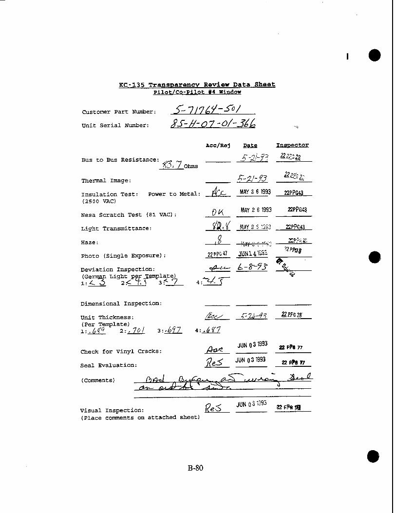
KC-135 Transparency Review Data Sheet Pilot/Co-Pilot #4 Window
Customer Part Number: J)" ///fc>/ ~"—> /
Unit Serial Number: /fS~n~ Ö 7 " Of~-Jb(o
Bus to Bus Resistance: tö.7
Acc/Rej Date
Ohms
Nesa Scratch Test (81 VAC) :
Light Transmittance:
Haze:
Photo (Single Exposure):
Deviation Inspection: (German Light per ^Template) 1:^3 2< f.S 3:< 7
OK
4 MAY 2 6 1993
MAY 2 S 3S3
"AY £; ra 22 PPG 47 ^U14^'-
Thermal Image: *?-%l~?3 " ~--
insulation Test: Power to Metal: ffjC MAY 2 6 1993 22PPG43 (2500 VAC)
22PPG43
2PPG43
22Pyi;jr,
^Pfttf
Dimensional Inspection:
Check for vinyl Cracks:
Seal Evaluation:
(Comments)
Unit Thickness: (Per Template) 1 ;./,<<? 2;,7fl/ 3 = ^77 4;,lf7
JUM 031393 appa77
ffejT JUN03W3 22PP8 77
.^a^ ,giS> tiJZ ^^T
-3U^-
Visual Inspection: l<cO (Place comments on attached sheet)
JUNO 3 1393 ^ n
B-80

Visual Inspection Map & Comments
/ova /3^J DOLAT» I>> uixutfej M-iL anzü^J-
■f^'-r-
Thickness Template
©0/ ®W
Qtfi ®M
Deviation Template
B-81

KC-135 Transparency Review Data Sheet Pilot/Co-Pilot #4 Window
Customer Part Number: .^- 7/V h f - ^°/
Unit Serial Number: QA 0^7- A/0 ^70
Acc/Rej Date inspector
Bus to Bus Resistance: ,^tcV^> *)~.$.h / 7 ^ 7M>H Ohms
Thermal Image:
insulation Test: Power to Metal: IW MAY 26 1993 22 PPG » (2500 VAC)
Nesa scratch Test (81 VAC) : ^t HAY 2 6 «ft _KPPBW.
Light Transmittance: flff * MAY 26 1"3 »PPG 77
, , MAY2G 1993 22 PPG 77
2 6 MAY 1993 22 PPG 47
Haze:
Photo (Single Exposure):
Deviation Inspection: M&& (German Light per Template) 1:_3_ 2:_3_ 3:_2 4:_J
Dimensional Inspection:
MAY 26 1993 22PPG7?
Unit Thickness: /2r^S f-Zf-93 22PPR2g (Per Template) _
■L:*t,n -2---ÄH- 3:M *: M6
/fa* JUN 02 1993 22PPG77 Check for Vinyl Cracks:
Seal Evaluation: *Uf JUN Q2 IS93 ZZftfifT
(Comment s) —
Visual Inspection: j#-<£g_- (Place comments on attached sheet)
JUM 021993 22 PPG n
B-82

Visual Inspection Map & Comments
Thickness Template
©^7 <fM
L ©6P ©
Deviation Template
B-83

KC-135 Transparency Review Data Sheet Pilot/Co-Pilot #4 Window
5- 7/7^y-jro / Customer Part Number:
Unit Serial Number: /A- Q 70 ht° 59 (
Acc/Rej Date Inspector
Bus to Bus Resistance: -&&» <*r S/-f ^ 2ZP.?ß22 k 7, V Ohms
rtjtJt MAY 26 WO 22PP6" Insulation Test: Power to Metal: AkMS 1 II (2500 VAC)
Nesa Scratch Test (81 VAC) : UA~ W M& * I» ti
n<jq MAY 26 1993 22 PPG w Light Transmittance: *ö- /
I2S MAY 26 13^3 22 PPG .>
2 6MWW3 22ppG47_
Thermal Image:
Haze:
Photo (Single Exposure)
Deviation inspection: (German Light per Template) l: 5 2: Jf 3: 3 4:_3
Dimensional Inspection:
ftids W 26,1993 22PP6 7»
• «u- , /?,* A--2C-& 8ÖJS28 Unit Thickness: t/SSs< _2 ■^v» r-3 — (Per Template) . ^ X:.M% 2:,/,<{$ 3:-6U 4: ./tfQ
/^, * JUN 0 2 1993 ,? pPfi 77 Check for Vinyl Cracks: fik^ » " & pre
rf^, JÜN 021993 22 PPS yy. Seal Evaluation:
(Comments) SeA-L J-ooi^ (hv?
Visual Inspection: iQ^j^ m o21393 nvfcn- (Place comments on attached sheet)
B-84

Visual Inspection Map & Comments
^
-e>
V^ S<ra^L L-crtSSt A& /HlwM-tA
Thickness Template
© 4*3 QV
©tf ©k?D
V Deviation Template
@:
©^
B-85

KC-135 Transparency Review Data Sheet Pilot/Co-Pilot »4 Window
Customer Part Number: 3 — ///»7 ■> 0 /
Unit Serial Number: ^- 0 f-1 //o -?f-l^
Acc/Rej Date Inspector
Bus to Bus Resistance: ,/? -, uS/t J* „r^f"/!/ _ fr y' 0 Ohms
Thermal Image: J >7 /Ji
insulation Test: Power to Metal: f^j/ß/ ___HJ§?3 '_ (2500 VAC)
AJ,JI MAY 26 1993 n PPG ft Nesa scratch Test (81 VAC) : H^lAi,
14 d MM261833 22PPG77 Light Transmittance: //> ° "' . —
/,# MAY 26 1993 *** Haze: /; ^
, . , „ , 2 6 MAY 1993 22PPG« Photo (Single Exposure) : " u '
. . &Us MAY 2fi 1993 22PPS77 Deviation Inspection: My*/ "ftl *b 13JJ (German Light per Template) 1: _r 2:_5_ 3: 3 4:_ü_
Dimensional Inspection:
Unit Thickness: Ode J-tftt _3El®_ (Per Template) 1:,^ 2:,/o^ 3:«^r 4:^JH
A^ JUN 021993 22 PPG „ Check for Vinyl Cracks: n^ _ZZM.
„,„,,.. /&/HL- JUN 021993 22 PPC 7? Seal Evaluation: '^^ _
(Comments) . —
Visual Inspection: (Place comments on attached sheet)
&y^ JW Q2TS» 22PP6T7
B-86

Visual Inspection Map & Comments
Thickness Template
©^ ©I»
©^ -01,
Deviation Template
B-87

KC-135 Transparency Review Data Sheet Pilot/Co-Pilot »4 Window
Customer Part Number: -S 17V7 o Y ~" O 0 /
Unit Serial Number: ft-3 - O ?i - //0- j'cfcP
Acc/Rej Date Inspector
Bus to Bus Resistance: //xkS A-'^H'VO 73,7 Ohms
Thermal Image:
insulation Test: Power to Metal: j££g_ M£2£J993_ 22 ^ V
(2500 VAC)
Nesa Scratch Test (81 VAC) .- /&€4* MAY 26 1993 ffi P—ll_
Light Transmittance: ^,£ ^25 1393 22 PPG 77
Haze: /.^ «AY 2? 53 22 PPs »
« £ MAY 1993 -. Photo (Single Exposure) : & ""lt" — 22PPSaf—
Deviation Inspection: ^A^t/ MAY P.ft 1393 (German Light per Template) 1: 5" 2: 5 3: -5~ 4: 7
22PPC #
Dimensional Inspection:
Unit Thickness: A», /^! «**« (Per Template) .
Check for Vinyl Cracks: &dA JUNO 2 KM J£j*fi_0_
, _ . _ fo&f JUN 021393 ?PsW Seal Evaluation: /er"^ —
(Comments) ___
Visual Inspection: (Place comments on attached sheet)
fat JUN°21993 a.*»*,
B-88

Visual Inspection Map & Comments
Thickness Template
©&*s d)£?/
©£sV (£)&?/
Deviation Template
@5" ®>
®5 ®?
B-89

KC-135 Transparency Review Data Sheet Pilot/Co-Pilot »4 Window
Customer Part Number: S- 7/ 7^ H ~ ^°' CJy. ^
Unit Serial Number: 5 — //- /3--/b ~~ 7/
Bus to Bus Resistance:
Acc/Rej Date Inspector
-f-2W UUiU
!DhO Ohms
.f-2ht1 M^K
Insulation Test: Power to Metal: /ICC MAY ?. fi 1993 2PPG43 (2500 VAC)
Thermal Image:
Nesa Scratch Test (81 VAC):
Light Transmittance:
Haze:
Photo (Single Exposure):
Deviation Inspection: (German Light per Template)
OK MAY 2 6 1353 22PPG4o.
ILL «Y ?. S liiJ MAY 2 r?1 ?G43
i£ •WY £ 3 %83' 22PPG43
JUNO8 «93 ÄPPG39 ^
4: ^3
Dimensional Inspection:
Check for Vinyl Cracks
Seal Evaluation:
(Comments)
Unit Thickness: (Per Template) ^ \:M_ 2-.A21. 1-iML. *--'67f
fit*
fo~. r-u-13 ten*»
JUN 0 3 1993 » PPG n
fej- JUN Q31933 apN„
visual Inspection: (Place comments on attached sheet)
^5- JUN 03 1993 » #« V
B-90

Visual inspection Map & Comments
Aft a*J foJ*~ AM Ato,i+sJ $J** *t -Ji*»y
Thickness Template
©*'f ©Ä
V Deviation Template
B-91

KC-135 Transparency Review Data Sheet Pilot/Co-Pllot »4 Window
Customer Part Number: J~ f ' f & r ~ So I
Unit Serial Number: iY- H-/0- 7S- /X^j 3
Acc/Rej Date Inspector
Bus to Bus Resistance: /??£___ ^ •* 7T-~> Ohms
r~Ak-4? g£PG2? Thermal Image: ■*■:—^ f -'
insulation Test: Power to Metal: fat ^U61933 n*>" (2500 VAC)
22 PPG " Nesa Scratch Test (81 VAC) : jIUS * MAY 26 1333
C/Q J MAY 2 £ :?^3 22PPG77 Light Transmittance: ° / J .
A ^ *«Y^£ ---^ 22 PPS 7?
2 6 WAY 1993 22ppG47
Haze:
Photo (Single Exposure):
$*€/ Deviation Inspection: (German Light per Template) l: y, 2: 1 3: 3 4:_X
Dimensional Inspection:
MAY 2 8 1S1I 22 PPG 77
Unit Thickness: (Per Template)
&15-93 8Z323Z?
l:.7/?2. 2:« 7^ 3:,7?f 4:, 7,?,?
Check for Vinyl Cracks: _££^—
Seal Evaluation:
JUN 021993 22 pPe 77
(Comments) &//T*uc JTr^6 C7^ QvtfiJ fj^ A-**L /^/J* ^J^7 t/'/W ß*U. si*«P
Visual Inspection: (Place comments on attached sheet)
fle^ JUN Q 2 1993 22 3*8 &
B-92

Visual Inspection Map & Comments
^ ^
O-fTl L?**f<>A AZ./- Zoo^A o^/^ plus A £#+-c<>. An,..,.^ UsAAfsA ■tbtAePj/PuiX ■ A-Lo^t *,,vX r/f/W
Thickness Template
©7*f ®wf
©107 ©
V Deviation Template
B-93

KC-135 Transparency Review Data Sheet Pilot/Co-Pilot #4 Window
Customer Part Number: J ~~ J> //" l"~/3^i-J~~
Unit Serial Number: 7- rf- J —Jj-R ~~ a/
Bus to Bus Resistance:
Thermal Image:
%£~<b Ohms
Insulation Test: Power to Metal: (2500 VAC)
Nesa Scratch Test (81 VAC):
Light Transmittance:
Haze:
Photo (Single Exposure):
Acc/Rej Date
MAY 2 6 1993 JC£_
Inspector
22P.PG28
22PPG43
Deviation Inspection: (German Light per Template) 1: <-.} 2:_6J_ 3: *-*
ö ^ MAY 2 6 1993 22PPG43
<g7, l MAY 2 S 1563 gPPS«
/.J _JtfY_LU^J __£^L 22 PFG 47 jMUMA-IBBa 22Ppc/t
A, m ft» «3 &r,-a#
4: ^
Dimensional Inspection:
Unit Thickness: (Per Template)
Check for Vinyl Cracks:
Seal Evaluation:
(Comments)
4:^Zi
JUN 0 3 1933 a 9dd »
,gft£ JUN Q31993 u 9d<* ^
Visual inspection: (Place comments on attached sheet)
JUN 0 ol993 •32
B-94

Visual Inspection Map & Comments
T)fi £&rr^ A~J fi~ra #£L &ßOU>~d tjfaf
Thickness Template
Deviation Template
B-95

KC-135 Transparency Review Data Sheet Pilot/Co-Pilot #4 Window
Customer Part Number: 3 "C /Jj-i / — /
Unit Serial Number: _?- H — 7 ~ °*- £ *" 7a?
Acc/Rej Date Inspector
Bus to Bus Resistance:
Thermal Image:
$7, ftohms
Insulation Test: Power to Metal: (2500 VAC)
Nesa Scratch Test (81 VAC):
Light Transmittance:
Haze:
Photo (Single Exposure):
tec
Deviation Inspection: (German Light per Template) 1: 2-~h 2: ^ 3 3: ^ 3
Al
4:_^3
MAY 2 fi 1993 B&W
22PPG43. Dji MAY 2 6 1S93
f|, | MAY £ Ö :3b
MW n ■* '*".
£->?3
2P?fi4S
22P?q^
22 PPG 47. JUNIU?^ ^
'* ^~
Dimensional Inspection:
Unit Thickness: ^v- -C-^-ff?— &£PG?g (Per Template) 1:,£7? 2:^71 3:^7L ^zMl
Check for Vinyl Cracks:
Seal Evaluation
(Comments)
jfe^ JUN 031993 '«PPST?
Visual inspection: c^~>
(Place comments on attached sheet)
JUN 031993 m^
B-96

Visual Inspection Map & Comments
/v^' v" ,JL
Q^jL/Urr\ A-a, m-fi^Ce -^
SvtlM*-* £2JL &-* ft* \/i *,/--, CflAold d-9, /MMJLe
Thickness Template
(ä&9? ©aj
(Dttf ®6&
Deviation Template
B-97

KC-13 5 Transparency Review Data Sheet Pilot/Co-Pilot #4 Window
Customer Part Number: 5 — 1l/v9 ~ /3 ^hJ.F
Unit Serial Number: T-//->/0~ f%~- /OX
^
Acc/Rej Date
Bus to Bus Resistance: /37. 7 Ohms
Thermal Image:
Insulation Test: (2500 VAC)
Inspector
22 £8*28
m, -■H4J&
Power to Metal: iff., ^ 2 6 W3 ^43
Nesa Scratch Test (81 VAC):
Light Transmittance:
Haze:
Photo (Single Exposure):
Deviation Inspection: (German Light per Template) 1: Z. 3 2:_43 3:>C 3
OK
22 PfG«
j£±: o-
4: ^ 3
MAY 2 8 1993 ZPPG43
MAY 2 S 1SÖ3 22PPGÖ
22PFS4?
*«te*
2/>/>G ifl
Dimensional Inspection:
Unit Thickness: (Per Template) l:,/;7f 2:,/57 3:.^
Check for Vinyl Cracks:
Seal Evaluation:
ß&cs
±:JM±
JUU14 1993
--a> -f 3 82^628
&* JW 031993 appay7
•7 ^- JUN 031993 K^5 ggpygyy
(Comments) /W OXJ^ Vh*J &Uy^^^-
(}„< JUN031SS3 ..*<■ Visual Inspection: \\e~> ■ ^ ■"»■ (Place comments on attached sheet)
B-98 •

Visual Inspection Map & Comments
rtnYL
/Q-/ß~ /W D*/s4~< ls^n#&f/ &//. /MÜOK.J UUif
Thickness Template
r ©&&? d)^
(Dfitf &ty
Deviation Template
B-99


APPENDIX C BIRD IMPACT DATA SHEETS

PPG Industries-Bird Impact Data Sheet KC-135 Test Program
for Battelle
sample i.D. S-89344-5oi s/N 84-H-lQ-c><o-oc.7 Date (olTZlcfi
Bus to Bus "31. 5 g>HrAS Delamination chk. OK
Requirements:
High Speed Film (3 cameras) N£S Spall Shield Installed V£S
Test Conditions Requested Actual
Temperature I.B. U.T. 7©"F Temperature O.B. fc-T- 7o°p Bird Wt. (lbs) 4-0 4-OT.O Bird Speed (kts) l^o-o 151-7
7o°F Ambient *F ■
lmpact Loc. CgHTg't~
Installation Ac o Angle — Sweep Back Angle ?of
N£u> "*! 1^J5 g.U.
Shot No. : 783 Test Date: (QITU93 Tested By: //<T<S.
Test Results:
op fcim> IMPACT««/) osirwfirr PcArtr. "B/M SMTSJL^O ov/e/-
OtV«£"fl- Ö><&<£ »F uM^Oöco *=w /iwPiVcr. COM PAcü/OA» o/=
PPG Witness: a,>—<L Date: C,hz/??
C-l

PPG Industries-Bird Impact Data Sheet KC-135 Test Program
for Battelle
Sample i - P. 5- GThSQ-^eZ- s/N «Sfa- H-\*>-Q(, -3o Date U-Z-Z/93
Bus to Bus 34- D Delamination chk. OK-
Requirements:
High Speed Film (3 cameras) NCS Spall Shield Installed SCf£
Test Conditions Requested Actual
Temperature I.B. G..T- 7Z°P Temperature O.B. fc.T 7**F Bird Wt. (lbs) 4.0 4-ovo Bird Speed (kts) 7.<5©-o "2SI-I
M£^ fr I 1^5 S.u.
Ambient *F -
Impact Loc. - Installation Angle Sweep Back Angle
72°F
3o»
Shot No.: 7^4 Test Date: C»/Zti^3 Tested By: H€<£
Test Results:
»s|o ^A-M^Vä.e. SMIMJU A-»vtcu^roF 81 to <EHT€*«:P e»/®L
PPG Witness : ^vQftc^O^X, Date: £/z?/9?
m C-2

PPG Industries-Bird Impact Oata Sheet KC-135 Test Program
for Battelle
Sample I .D. S-W3S4- Sol S/N Qlo-H-tO-O^-2TL Date UZ3l93
Bus to Bus Jj'Ca Oelamination chk. QIC
Requirements:
High Speed Film (3 cameras) NCi Spall Shield Installed 1^-5
Test Conditions Requested Actual
Temperature 1.B. tt.T* 1Z°P Temperature O.B. q..T- ItV Bird Wt. (lbs) 4.0 4.o|o Bird Speed (kts) 25o.0 ■252-ft
Kg.^ *l iJS ft-H-
Ambient *F
Impact Loc. ■ Installation Angle Sweep Back Angle
7Z°F
<zenrefi- 41
.2+.
Shot No. "7S5 Test Date:_Ulll32_ Tested By: Hg^
Test Results:
PPG Witness: pf^^/V&i^N^^L Date: W??/??
C-3

PPG Industries-Bird Impact Data Sheet KC-135 Test Program
for Battelle
Sample I -P. S-fe*? 3 54-Sb ? S/N SC-Vf-<Q -Ol-oUpate Cll4h3
Bus to Bus 33> 5 Delamination chk. OK-
Requirements:
High Speed Film (3 cameras) ^fSif Spall Shield Installed N€i
Test Conditions Requested Actual
Temperature I.B. £-T- 73 °f Temperature O.B. fU. 73 V Bird Wt. (lbs) 4-.0 4-. 0(0
Bird Speed (kts) ^So 2-S^C»
rAglfr*! u^/s R.l-V.
7?°5 Ambient *F -
Impact Loc. Cg^re*. Installation AC ° Angle Sweep Back 3o° Angle
Shot No.: "7&Q Test Date: (J2<(lct3 Tested By: Htg<S
Test Results:
PPG Witness :jM*»& Date: C/Zffoj
C-4

PPG Industries-Bird Impact Data Sheet KC-135 Test Program
for Battelle
Sample I.D. Z-ttZSl-Svf S/N g3-ft-°HS- IG1 Date 7lHfr?
Bus to Bus 41 i Delamination chk. ^<-
Requirements:
High Speed Film (3 cameras) ^<£S Spall Shield Installed T<fS
Test Conditions Requested Actual
Temperature I.B. %T. 7^0F Temperature O.B. fcx. 71V Bird Wt. (lbs) 4.a 4.co| Bird Speed (kts) l5o ^4■c^o»
ftg9Mft£P ^l uls L.H-
7*°F Ambient *F
Impact Loc. Installation 4-C° Angle Sweep Back — o Angle *^
Shot No.: T^T- Test Date: llllllj Tested By: HS"<5-
Test Results:
PPG Witness: A CUJL Date: llfi/93
C-5

PPG Industries-Bird Impact Data Sheet KC-135 Test Program
for Battelle
Sample I.D. 5-ftq354-5of s/N 83-H-g-lS -15Q> Date 7/15113
Bus to Bus T(»'0 Delamination chk. Oft»
Requirements:
High Speed Film (3 cameras) M€5 Spall Shield Installed *t€S
Test Conditions Requested Actual
Temperature I.B. <LT- 7 3°F Temperature O.B. (LT. 1?F Bird Wt. (lbs) 4o 4<3oS Bird Speed (kts) iSo 1A°iA
9*fPAiJLeO I u>ls L-H-
Ambient *F -
Impact Loc. - Instal1ation Angle Sweep Back Angle
73°r
45°
Test Date: lll<?l<?3 Tested By: r+£&_ Shot No.: "1^3
Test Results:
PPG Witness: ^^^—«- Date: "Wflto
C-6

PPG Industries-Bird Impact Data Sheet KC-135 Test Program
for Battelle
Sample I -P. 5- fe^S^t -5^1 S/N_%±üfcV15l3^ Date 7feoJ93
Bus to Bus 44'« 5 Delamination chk. <afc-
Requ i rements:
High Speed Film (3 cameras) M^ES Spall Shield Installed VfiSTJ
Test Conditions Requested Actual
Temperature I.B. (L.T 73V
Temperature O.B. P-T- 73 °F Bird Wt. (lbs) 4.Ö 4-.COO
Bird Speed (kts) •Z-«?o 25*. 1
3eP»tieü *' Uli L.H-.
Ambient "F -
Impact Loc. - Installation Angle Sweep Back Angle
73 >
CffNTC/l-
-4£ 3o'
Shot No.: 1?4 Test Date: 7'2x>l 93 Tested By: Hlg^-
Test Results:
PPG Witness: 6{>Q£r*a !*<*£— Date: l/2o(^
C-7

PPG Industries-Bird Impact Data Sheet KC-135 Test Program
for Battelle
Sample I .0.5-6335^-Sb/ S/N »>- H-/2 -Ol -/<r4» Date 7/?o/<??
Bus to Bus J&S Delamination chk. <£»-
Requirements:
High Speed Film (3 cameras) V<£* Spall Shield Installed V€/
Test Conditions Requested Actual
Temperature I.B. 9-T- 75 °F Temperature O.B. CT. 7S°f= Bird Wt. (lbs) 4o 4.010 Bird Speed (kts) IS* xsi.q
fePAueo *l ujf L-ff-
Ambient -F ^fiftSfe-TS"
Impact Loc. -OöfflEfc:— Installation A.<° Angle ^^ Sweep Back s.o Angle —
Shot No
Test Results:
: 795 Test Date: 7/^o/9J Tested By: Mg<a-
. ^^>. „exults:
PPG Witness: USLA~*- Date: 7/?o/9j
C-8

PPG Industries-Bird Impact Data Sheet KC-135 Test Program
for Battelle
Sample I .n. 5-Gft 354* 5>=>( s/N Sl'W- U»ft-tcT7 Date 7^9?
Bus to Bus 4| -3 Delamination chk. OlC
Requirements:
High Speed Film (3 cameras) S€^ Spall Shield Installed fE-?
Test Conditions Requested Actual
Temperature I.B. fc-T- 75 °r Temperature O.B. SLT. 7S°F Bird Wt. (lbs) 4.0 4.010 Bird Speed (kts) T-?o **M ftgPftMUfO ^|U^ bti-
Ambient *F
Impact Loc. - Installation Angle Sweep Back Angle
7S>
3o»
Shot No.: "7^U Test Date: lltol?3 Tested By: H-CG-
Test Results:
PPG Witness: //i^ü^jL— Date: l/Zo/<?3
C-9

PPG Industries-Bird Impact Data Sheet KC-135 Test Program
for Battelle
Sample ■ .0. 5-^354- Sol S/M <&Z-tt-4-1 "135 DateJZhil^
Bus to Bus ^3'*V De lamination chk . Cfc-
Requirements:
High Speed Film (3 cameras) N€S Spall Shield Installed ^€3
Test Conditions Requested Actual
Temperature I.B. ^T- -I<>0F Temperature O.B. U.T- lo°F Bird Wt. (lbs) 4.o 4.0C.5 Bird Speed (kts) TSo 2SLÖ
Ambient *F
Impact Loc. ■ Instal1 ation Angle Sweep Back Angle
7*°F CCHTgH.
3P°
Shot No.: TV? Test Date:_2hlt52_ Tested By: &&<Z
Test Results:
PPG Witness: Dat e: ylllH?
C-10

PPG Industries-Bird Impact Data Sheet KC-135 Test Program
for Battelle
le I.D.?-S<>3S^-So« S/K^^tl^L?il53£ Datel/Zjly
Delamination chk. (^K—
Samp
Bus to Bus 4S'"7
Requirements:
High Speed Film (3 cameras) *\€S Spall Shield Installed **/££
Test Conditions Requested Actual
Temperature I.B. OX- 7ö°F Temperature O.B. flu- 1*°F Bird Wt. (lbs) 4.0 4.00S Bird Speed (kts) z<;o TATS
ftgp»>lgQ *t <**S L-H.
Jl^F. Ambient *F
Impact Loc. CfiKTCP- Installation A »O Angle -" Sweep Back Angle 3xS
Shot No.: "79^ Test Date:7l3j/*?7 Tested By: t4g*&
Test Results:
/Vu- PciCf ^McSO. (io/L^ PC-/ S P/K-i-CP But- A/oAjf 0#->
U>iTrJer«r PO-TC
v PPG Witness: tf\Qfr*£U-~><- Date: il-uhy
c-11

PPG Industries-Bird Impact Data Sheet KC-135 Test Program
for Battelle
Sample I -P. S-&l3S*S*t s/M W-^-HO'W Date?/?*)??
Bus to Bus 3^'Q Delamination chk. OK_
Requirements:
High Speed Film (3 cameras) iCJ Spall Shield Installed "^€3
Test Conditions Requested Actual
Temperature I.B. <Lr t.5'F Temperature O.B. «LT. <*SV Bird Wt. (lbs) 4.o 4.000
Bird Speed (kts) "LS"o 7^0%
Amb i ent * F
Impact Loc. - Instal1ation Angle Sweep Back Angle
CS°F
3o°
ftc P Ant <CO
Shot No.:_2i5__ Test Date: ~?l2.ti?3 Tested By: 14-g~<5-
Test Results:
Nlo DA^M.fV<se
PPG Witness: ^ ^»O^X Date: il-z-U^y
c-12

PPG Industries-Bird Impact Data Sheet KC-135 Test Program
for Battelle
Sample I -P. 5-^*? 35*?- I
Bus to Bus ~n-l
S/N 'S 75-11 ^ Date_3iil33
Delamination chk. Sgg "DfcTfr S tfggT*
Requirements:
High Speed Film (3 cameras) *j C i Spall Shield Installed VC-f
Test Conditions Requested Actual
Temperature 1.B. tt-T. 11°-*
Temperature O.B. tt-7. lf°F
Bird Wt. (lbs) 4.a 4.0/5 Bird Speed (kts) l?o 7.47.5
71°»= Ambient *F
Impact Loc. C^TS<L
Installation 5^.7.° Angle Sweep Back Angle 35
to/unco wq izitiöou* U.U-
Shot No.i^lS Test Datet^l I I*?*? Tested Bv:H~g*G
Test Results:
OoTBcv^t) Gufc**- FAiceO- SiM> 9fi«o*l*W-ivo#»» Ben*«""«0
PPG Witness: ffiQp*>Q* «^ Date: ^i\foz
C-13

PPG Industries-Bird Impact Data Sheet KC-135 Test Program
for Battelle
Sample < n S-lllH-Sof *'» QT--CX-4-ÜQ-411 Date «Mlh3
Bus to Bus Lafi\iQ Delamination chk. &|C
Requirements:
High Speed Film (3 cameras) ^fS Spall Shield Installed l^S
Test Conditions Requested Actual
Temperature I.B. a*. 1l°f Temperature O.B. a.T- -ir-F Bird Wt. (lbs) 40 4. or© Bird Speed (kts) IS* 2SI3
Ambient *F ■
Impact Loc. - Installation Angle Sweep Back Angle
OJi
3S°
Shot Ho.: ^Uo Test Date: ^lU93 Tested By: tf€"<S
Test Results:
PPG Witness: 4.PU-*- Date: <?///??
C-14

PPG Industries-Bird Impact Data Sheet KC-135 Test Program
for Battelle
Sample I .P. S-IHM- 50l S/N *(l-tiL&- V40 -<P3 Datef/lly
Bus to Bus U^«4- Delamination chk. Q|fc_
Requirements:
High Speed Film (3 cameras) S€5 Spall Shield Installed l€£
Test Conditions Requested Actual
Temperature I.B. (Lx. n°r Temperature O.B. «.T. 7^*F Bird Wt. (lbs) Ar.O 4.01S Bird Speed (kts) ISo X4*.^
Meu* M-u><oflp^ LH-
Ambient *F -
Impact Loc. - Installation Angle Sweep Back Angle 35°
Shot No. : %H
Test Results:
Test Date: Q(t/TS Tested By: 14(S<£
PPG Witness: ^\CLt^*-^^-^ Date: <?///?,?
C-15

PPG Industries-Bird Impact Data Sheet KC-135 Test Program
for Battelle
Sample I .P. g- 7HJ.4-gol S/uQZ-CS*' UQ-35O 0ate5Ül33
Bus to Bus "?&« \ De lamination chk. OK—
Requirements:
High Speed Film (3 cameras) N<£^ Spall Shield Installed cCJ
Test Conditions Requested Actual
Temperature I.B. (LT- l^r Temperature O.B. M-.- niTr Bird Wt. (lbs) 4.0 4ä1O
Bird Speed (kts) -2-5o OXS"-/
Ti°F Ambient *F — .. . a&iTcft— Impact Loc.
Installation ro -5 o Angle ^S-t Sweep Back Angle 35'
Shot No.: €\t Test Date: S/l/9J Tested By: HC<MT
Test Results:
PPG Witness: ■ /3L^>. Date: 9///9>
C-16

PPG Industries-Bird Impact Data Sheet KC-135 Test Program
for Battelle
Sample I .D.5-"71164- ?»/
Bus to Bus voS,«3
S/N^-Cftg-HO-OPl Date *?/ 2?%
De lamination chk. OiC
Requirements:
High Speed Film (* cameras) V£j Spall Shield Installed t€J
Test Conditions Requested Actual
Temperature I.B. tu- 73 V Temperature O.B. (Lr. 77 IF Bird Wt. (lbs) 4.o 4A/5 Bird Speed (kts) "iro Z48-4
Ambient *F
Impact Loc. • Instal1ation Angle Sweep Back Angle
Genre*-
35°
hlfeu^M ouDo«^ L-H-
Shot No.: $3S Test Date: ^7.9193 Tested By: i-^£C
Test Results:
Klo ^JUi^d. .
PPG Witness -Jl Date : IM?*
C-17

PPG Industries-Bird Impact Data Sheet KC-135 Test Program
for Battelle
Sample I .D.5^TM^L. S/N °,1-\&- Ho - lS<o Date IM??
Bus to Bus t^pQ Delamination chk. Q(C
Requirements:
High Speed Film (9-cameras) v£j Spall Shield Installed l^S
Test Conditions Requested Actual
Temperature I.B. <LT- 13 °c Temperature O.B. «-T. -73 V Bird Wt. (lbs) 4.o 4-.CK>S
Bird Speed (kts) TSo 2*7. s
Ambient *F
Impact Loc. - Instal1 ation Angle Sweep Back Angle
CJEMT€.*-
?£'
Shot No.:_63^_ Test Date: ^hsljj Tested By: #££
Test Results:
PPG Witness: ^2ja*&0*~=*==- Date: %llfifo
C-18

PPG Industries-Bird Impact Data Sheet KC-135 Test Program
for Battelle
Sample I -of-HlkA- Sal
Bus to Bus Q>VCn
S/N feS-H-on-Dt-ni Date Sfl^J
De lamination chk. S6C ftfrTtl 3U€gT"
Requirements:
High Speed Film (-3" cameras) ,N{CS Spall Shield Installed */C^
Test Conditions Requested Actual
Temperature I.B. SLT 13 °F Temperature O.B. *~T. -I3~f Bird Wt. (lbs) 4.o 4.0/5 Bird Speed (kts) IS* 74-Ä7
Ambient *F
Impact Loc. Instal1 ation Angle Sweep Back Angle -
Jl^.
3r°
RaAiigo 4 u*og&<^ en.
Shot No. : &3T Test Date: 5 I"*-*?/ ?3 Tested By: 14 C^
Test Results:
l\lo "DA-M-fcfie-
PPG Witness : ^jU^—*—~ Date: V*?/??
C-19

PPG Industries-Bird Impact Data Sheet KC-135 Test Program
for Battelle
Sample I -P. S-lllH-So«
Bus to Bus <=>PC.N>
S/nVn3-HO -1Z I DateS/Hto
Delamination chk. Ofr—
Requirements:
High Speed Film £3 cameras) SC$ Spall Shield Installed fCS
"?4&r Test Conditions Requested Actual
Temperature I.B. der- i<Tr Temperature O.B. (LT. TtV Bird Wt. (lbs) 4.o 4-ooS Bird Speed (kts) 2.<To •**?•!
Amb i ent * F
Impact Loc. -£*fc*E?9t=- Installation £%.7_° Angle — ■ Sweep Back -a^ m
Angle =2
fc£?A-lUg-Q *4- L&n*Pa<j> i*->4.
Shot No.: %3fe Test Date:_5i2^i3l_ Tested By: /fe<5
Test Results:
NUt)MA.A-G»e
PPG Witness: 14%^^J Date: S123133
C-20

PPG Industries-Bird Impact Data Sheet KC-135 Test Program
for Battelle
Sample I .oS-lMM-ttCS*.?- s/M S-t4-5-73-S<r Date ^afo
Bus to Bus Uft-O De lamination chk. Sflg" frATA- StfggT
Requirements:
High Speed Film (^"cameras) N^5 Spall Shield Installed f£S
Test Conditions Requested Actual
Temperature I.B. KT- 7o°r Temperature O.B. W i**r Bird Wt. (lbs) q.a 4ois Bird Speed (kts) -LSO TJSl'X
Ambient *F ■
Impact Loc. ■ Installation Angle Sweep Back Angle
%€>*ti.g-o *4 uExooa«^ i-H-
Shot No. fe3S Test Date:5*il±i32_ Tested Byil+CS.
Test Results:
PPG Witness: Date: ?/*>/??
c-21

PPG Industries-Bird Impact Data Sheet KC-135 Test Program
for Battelle
Samp 1 e I .D VtfM -^ «»&• H- z/ul'H'Z-*'3S DateSfcofej'
Bus to Bus U^'*S Delamination chk. S£C "PM*ft Stt€teT"
Requirements:
High Speed Film (J- cameras) ^^5 Spall Shield Installed *j£S
Test Conditions Requested Actual
Temperature I.B. tLT- 1I°P Temperature O.B. UT- 11 v Bird Wt. (lbs) 4.0 4..005" Bird Speed (kts) 1£o 15o>%
Ambient *F -
Impact Loc. - Installation Angle Sweep Back Angle
JL1>
3^
toMKCQ *<V C^IM>0«.* • L-fr^-
Shct No.: _f£^_ Test Date:_5l2^1i Tested By: 1*1*0;
Test Results:
£*jrnLe C<-Arr itfcno^ r^^ ©or- A-r //uj-«r*-r.
PPG Witness: d£L>&~^ Date: g/?d/9>
C-22

PPG Industries-Bird Impact Data Sheet KC-135 Test Program
for Battelle
Sample I .P. 5-*?n&4
Bus to Bus fe<a. &
S/M 4-tV- to-^-fc^ Date Sfoto
Delamination chk. 3C€ DATA 5tf€feT
Requirements:
High Speed Film (2 cameras) ^€S Spall Shield Installed [C
Test Conditions Requested Actual
Temperature I.B. tt-x 7z°F Temperature O.B. ?LT. -l-L-f- Bird Wt. (lbs) 4.o 4'öio Bird Speed (kts) 75"o 7-S|.o
Ambient *F
Impact Loc. ■ Installation Angle Sweep Back Angle
JLL!ü
SLcPMllgfl 4 i-S^POu-a U.U.
Shot No.: f4*> Test Date: ^/3Q/*?3 Tested By: tf&&
Test Results:
PPG Witness: ^QjLȣ~^- Date: 9/W9?
C-23

PPG industries-Bird Impact Data Sheet KC-135 Test Program
for Battelle
Sample I -P. S-ll U4 -£*1 S/N ttl-tt- tlrl'ST*- Date «tfjofrj
Bus to Bus 7S«7 De lamination chk. 5£C ^ATfr Stte.C.1
Requirements:
High Speed Film C* cameras) "^{jSj Spall Shield Installed ^C/
Test Conditions Requested Actual
Temperature I.B. %JT> ii*r Temperature O.B. ALT- n°F Bird Wt. (lbs) 4-0 4.0(0 Bird Speed (kts) T£* ISa-fc
Ambient *F ■
Impact Loc. - Installation Angle Sweep Back Angle
n*r
s<r
toA-itgQ fy UW^POc^ L-^.
Shot No . :_£^3L^_ Test Date:J5jfj^22_ Tested By: ttgS
Test Results:
PPG Witness: l/^yicx ►£U~-c Date : <?//a/S7
C-24

PPG Industries-Bird Impact Data Sheet KC-135 Test Program
for Battelle
Sample I -P. S-HTL^ S*t
Bus to Bus ^U* o
S/NL«H-U-<tt.-?fc> pate (fellHU
Delamination chk. 3CC VM^r SN&tr~
Requirements:
High Speed Film (i cameras) Ntf"f Spall Shield Installed ^£3-
Test Conditions Requested Actual
Temperature I.B. ^*r- I^V Temperature O.B. U> 7*V Bird Wt. (lbs) 4.0 4.etf Bird Speed (kts) T?« 7&>3
toAitcfl #<f u*//4fl««> L.H.
Amb i ent * F
Impact Loc. Instal1 ation Angle Sweep Back Angle
7^
Shot No.: £&L Test Date HWf/97 Tested By: rtec Test Results:
At&0*>0 iAv-a-C*- fcAUkA*** C&JLM«JI.
PPG Witness: flfclLgWg. Date: />//to
C-25

DEVELOPMENT OF REPAIR PROCESSES AND SOURCES FOR C/KC-135 AIRCRAFT ^g% WINDOWS/WINDSHIELDS ^&#
Baneiie . . . Putting Technology To Work
RICHARD J. OLSON
BATTELLE 505 KING AVENUE COLUMBUS, OH 43201
SEPTEMBER 1994
TECHNICAL REPORT FOR 09/91 - 01/94 C/KC-135 FINAL REPORT CONTRACT NUMBER FO9603-90-D-2217-SD02
DISTRIBUTION AUTHORIZATION: APPROVED FOR PUBLIC RELEASE; DISTRIBUTION IS UNLIMITED
PREPARED FOR OKLAHOMA CITY AIR LOGISTICS CENTER TINKER AFB, OK 73145

This report is a work prepared for the United States Government by Battelle. In no event shall either the United States Government or Battelle have any responsibility or liability for any consequences of any use, misuse, inability to use, or reliance upon the information contained herein, nor does either warrant or otherwise represent in any way the accuracy, adequacy, efficacy, or applicability of the contents hereof.
11

REPORT DOCUMENTATION PAGE Form Approved
OMB No. 0704-0188 Public reporting burden for this collection of information is estimated to average 1 hour per response, including the time for reviewing instructions, searching existing data sources, gathering and maintaining the data needed, and completing and reviewing the collection of information. Send comments regarding this burden estimate or any other aspect of this collection of information, including suggestions for reducing this burden, to Washington Headquarters Services. Directorate for information Operations and Reports, 1215 Jefferson Davis Highway, Suite 1204, Arlington, VA. 22202-4302, and to the Office of Management and Budget, Paperwork Reduction Project (0704-0188), Washington, DC 20503.
1. AGENCY USE ONLY {Leave blank) 2. REPORT DATE
September 1994 3. REPORT TYPE AND DATES COVERED
Technical, C/KC-135 Final Report, 9/01/91 01/31/94
4. TITLE AND SUBTITLE
Development of Repair Processes and Sources for C/KC-135 Aircraft Windows/Windshields 6. AUTHOR(S)
Richard J. Olson
5. FUNDING NUMBERS
7. PERFORMING ORGANIZATION NAME(S) AND ADDRESS(ES)
Battelle 505 King Avenue Columbus, Ohio 43201-2693
8. PERFORMING ORGANIZATION REPORT NUMBER
Contract FO9603-90- D-2217-SD02
9. SPONSORING/MONITORING AGENCY NAME(S) AND ADDRESS(ES)
Oklahoma City Air Force Logistics Center OC-ALC/TIETR 3001 Staff Drive, Suite 2AF66A Tinker AFB, OK 73145-3040
Technology Transition Office ASC/SMT 2690 C, Suite 5 Wright-Patterson AFB, OH 45433-7412
10. SPONSORING/MONITORING AGENCY REPORT NUMBER
VEP87CR52R1
11. SUPPLEMENTARY NOTES
12a. DISTRIBUTION/AVAILABILITY STATEMENT
Approved for public release; distribution is unlimited 12b. DISTRIBUTION CODE
13. ABSTRACT (Maximum 200 Words)
The U.S. Air Force has historically rejected the notion of using repaired windows/windshields (W/WS). With increasing pressure to reduce fleet operating costs and based on the favorable experience that commercial fleets have had, interest in using repaired W/WS is receiving greater attention. To ensure that repaired W/WS are safe and that they provide similar benefits for the Air Force, a program of evaluation and testing was undertaken to compare new and repaired C/KC-135 W/WS. Optical and electrical properties, pressure integrity, and bird impact resistance of repaired and new W/WS have been evaluated. The bird impact test results are the first data that the Air Force has collected for C/KC-135 W/WS. The functional testing indicated that repaired W/WS are not equal to new W/WS; the new W/WS outperform the repaired W/WS. In terms of removal for cause criteria and absolute performance requirements, however, the repaired W/WS appear to be "good enough." Concerning costs, the direct costs for repair of the W/WS in this program ranged from 65-75% of new W/WS cost, suggesting that money can be saved. 14. SUBJECT TERMS
Aircraft Transparencies, C/KC-135, Windows/Windshields, Repairs, Pressure Cycle Testing, Falling Ball Impact Testing, Bird Impact Testing, Repaired Window/Windshield Costs Analysis 17. SECURITY CLASSIFICATION
OF REPORT
Unclassified ksN 7Ö4Ö-Ö1-2ÖÖ-S6ÖÖ
18. SECURITY CLASSIFICATION OF THIS PAGE
Unclassified
19. SECURITY CLASSIFICATION OF ABSTRACT
Unclassified
15. NUMBER OF PAGES
264 16. PRICE CODE
20. LIMITATION OF ABSTRACT
Unlimited Standard Form 298 (Rev. 2-89)
Prescribed by ANSI Std. Z39.18 298-102

This page intentionally left blank.
IV

TABLE OF CONTENTS
REPORT DOCUMENTATION PAGE iii
TABLE OF CONTENTS v LIST OF TABLES vi LIST OF FIGURES vii SUMMARY x PREFACE xii
1.0 INTRODUCTION 1 1.1 Background 1 1.2 Objective 1 1.3 Approach 1 1.4 Report Contents 2
2.0 PROTOTYPE SELECTION 3 2.1 C/KC-135 W/WS 3 2.2 Program Prototypes 5 2.3 C/KC-135 #1 and #4 W/WS 5
3.0 W/WS REPAIRS 6 3.1 Aircraft W/WS Damage 6 3.2 Repair Vendors 8
3.2.1 NORDAM Transparency Division 8 3.2.2 Perkins Aircraft Services, Inc 8 3.2.3 The Glass Doctor 9
3.3 Repair Details 9
4.0 PERFORMANCE TESTP^G 10 4.1 Test Philosophy 10 4.2 Quality Assurance 12 4.3 General Inspection 12
4.3.1 Test Procedures 12 4.3.1.1 General Visual Examination 13 4.3.1.2 W/WS Dimensional Measurements 14 4.3.1.3 Basic Electrical Measurements 14 4.3.1.4 Heater Operation Tests 14 4.3.1.5 Optical Performance 15
4.3.2 General Inspection Test Results 16 4.4 Pressure Integrity 17
4.4.1 Test Procedures 17 4.4.1.1 Proof Pressure Test 17 4.4.1.2 Cyclic Durability Test 17

TABLE OF CONTENTS (Continued)
4.4.2 Test Facility 18 4.4.3 Test Results 19
4.5 Residual Strength Assessment 20 4.5.1 Test Procedures 20 4.5.2 Test Facility 20 4.5.3 Test Results 20
4.6 Binl Impact Testing 21 4.6.1 Test Procedures 21 4.6.2 Test Facility 21 4.6.3 Test Results 22
4.7 Performance Testing Summary 23
5.0 COST ANALYSIS 24 5.1 Repair Costs 24 5.2 Costs of New W/WS 24 5.3 Cost Comparison 24
6.0 CONCLUSIONS, RECOMMENDATIONS, and DISCUSSION 25 6.1 Conclusions 25 6.2 Recommendations 27 6.3 Discussion 29
7.0 REFERENCES 31
APPENDIX A. REPAIR VENDOR AIR AGENCY CERÜFICATES Al APPENDIX B. GENERAL F^SPECTTON DATA SHEETS B-l APPENDK C. BIRD FMPACT DATA SHEETS C-1
LIST OF TABLES
Table 2.1 C/KC-135 WAYS Part Numbers 33 Table 2.2 C/KC-135 Program WAYS 33 Table 2.3 C/KC-135 #1 and #4 WAYS Dimensions 36 Table 3.1 C/KC-135 Repaired and Not Repaired #1 WAYS in the Test Program ... 37 Table 3.2 C/KC-135 Repaired and Not Repaired #4 W/WS in the Test Program ... 38 Table 4.1 C/KC-135 #1 WAYS General Examination and Dimensional Measurements
Test Results 39 Table 4.2 C/KC-135 #4 WAYS General Examination and Dimensional Measurements
Test Results 41 Table 4.3 C/KC-135 #1 WAYS Basic Electrical Measurements Test Results 43
VI

LIST OF TABLES (Continued)
Table 4.4 C/KC-135 #4 W/WS Basic Electrical Measurements Test Results 44 Table 4.5 C/KC-135 #1 W/WS Heater Operation Test Results 45 Table 4.6 C/KC-135 #4 W/WS Heater Operation Test Results 46 Table 4.7 C/KC-135 #1 W/WS Optical Performance Test Results 47 Table 4.8 C/KC-135 #4 W/WS Optical Performance Test Results 48 Table 4.9 C/KC-135 #1 W/WS Pressure Integrity Test Results 49 Table 4.10 C/KC-135 #4 W/WS Pressure Integrity Test Results 50 Table 4.11 C/KC-135 #1 W/WS Residual Strength Ball Drop Test Results 51 Table 4.12 C/KC-135 #4 W/WS Residual Strength Ball Drop Test Results 52 Table 4.13 C/KC-135 #1 W/WS Bird Impact Test Results 53 Table 4.14 C/KC-135 #4 W/WS Bird Impact Test Results 54 Table 4.15 C/KC-135 W/WS General Inspection Summary 55 Table 4.16 C/KC-135 W/WS Pressure Integrity Test Summary 56 Table 4.17 C/KC-135 W/WS Ball Drop Residual Strength Test Summary 56 Table 4.18 C/KC-135 W/WS Bird Impact Test Summary 57 Table 4.19 C/KC-135 #1 W/WS Mounting Edge Measurements and Bird Impact
Test Results 58 Table 5.1 Initial C/KC-135 W/WS Repair Estimates 59 Table 5.2 C/KC-135 #1 W/WS Actual Repair Costs 60 Table 5.3 C/KC-135 #4 W/WS Actual Repair Costs 61 Table 5.4 Cost Quotes for All Prototype Repair Candidate C/KC-135 W/WS 62 Table 5.5 C/KC-135 New W/WS Costs 65 Table 5.6 Repair Cost Comparison Data for C/KC-135 W/WS 65
LIST OF FIGURES
Figure 2.1 C/KC-135 W/WS Identification 66 Figure 2.2 C/KC-135 W/WS Construction 67 Figure 2.3 W/WS Construction Showing Location of Slip Planes 68 Figure 2.4 C/KC-135 #1 W/WS Cross-Section 69 Figure 2.5 C/KC-135 #4 W/WS Cross-Section 70 Figure 3.1 The Glass Doctor Patented Technique for Repair of Conical Cracks in
Laminated Glass, U.S. Patent # 3,841,932 71 Figure 3.2 The Glass Doctor Patented Technique for Repair of Delaminations,
U.S. Patent # 4,780,162 72 Figure 4.1 C/KC-135 #1 W/WS Thermal Images From the Heater Test 73 Figure 4.2 C/KC-135 #4 W/WS Thermal Images From the Heater Test 74 Figure 4.3 Worst Optical Distortion Found in Any C/KC-135 #1 W/WS
(S/N 83-H-11-7-432) 75
Vll

LIST OF FIGURES (Continued)
Figure 4.4 Worst Optical Distortion Found in Any C/KC-135 #4 W/WS (S/N 87-H-04-20-130) 76
Figure 4.5 Pressure Integrity Testing Facility 77 Figure 4.6 C/KC-135 #1 WAYS Pressure Integrity Mounting Frame 78 Figure 4.7 C/KC-135 #4 W/WS Pressure Integrity Mounting Frame 79 Figure 4.8 C/KC-135 W/WS Mounting Details 80 Figure 4.9 Typical C/KC-135 #1 W/WS Pressure Integrity Test Set Up 81 Figure 4.10 Typical C/KC-135 #4 W/WS Pressure Integrity Test Set Up 82 Figure 4.11 Worst Delamination Observed in a C/KC-135 #1 W/WS From Pressure
Cycling (Repaired W/WS, S/N 82-H-09-06-537) 83 Figure 4.12 Worst Delamination Observed in a C/KC-135 #4 W/WS From Pressure
Cycling (Repaired W/WS, S/N 5-H-12-16-47) 84 Figure 4.13 Residual Strength Falling Ball Test 85 Figure 4.14 #1 W/WS Residual Strength Falling Ball Impact Test Showing Test
Set Up and Consequences of Two Ball Drops (New W/WS, S/N 86-H-10-06-062)86 Figure 4.15 #1 W/WS Residual Strength Falling Ball Impact Test Result for a
Repaired and Subsequently Delaminated W/WS, Single Ball Drop, Outboard View (S/N 82-H-9-6-537) 87
Figure 4.16 #1 W/WS Residual Strength Falling Ball Impact Test Result for a Repaired and Subsequently Delaminated W/WS, Single Ball Drop, Inboard View (S/N 82-H-9-6-537) 88
Figure 4.17 #4 W/WS Residual Strength Falling Ball Impact Test Showing Test Set Up and Test Result (New W/WS, S/N 92-093-HO-388) 89
Figure 4.18 #4 W/WS Residual Strength Falling Ball Impact Test Result for a Repaired and Subsequently Delaminated W/WS, Outboard View (S/N 5-H-12-16-47) 90
Figure 4.19 #4 W/WS Residual Strength Falling Ball Impact Test Result for a Repaired and Subsequently Delaminated W/WS, Inboard View (S/N 5-H-12-16-47) 91
Figure 4.20 C/KC-135 #1 W/WS Bird Impact Mounting Frame 92 Figure 4.21 C/KC-135 #4 W/WS Bird Impact Mounting Frame 93 Figure 4.22 C/KC-135 #1 W/WS Mounting Hardware Details 94 Figure 4.23 Schematic of the PPG Bird Cannon 95 Figure 4.24 Support Frame Used for Bird Impact Testing for C/KC-135 W/WS ... 96 Figure 4.25 Typical Pre-Test View of C/KC-135 #1 W/WS (Copilot) Prior to
Bird Impact Testing 97 Figure 4.26 Typical Pre-Test View of C/KC-135 #4 W/WS (Pilot) Prior to
Bird Impact Testing 98 Figure 4.27 Bird Impact Test Set Up Showing Impact Velocity Timing Trap (Right)
and Front High Speed Film Camera Equipment (Center) 99 Figure 4.28 Bird Impact Spall Sheet Viewed From Behind a C/KC-135 #1 W/WS 100
viu

LIST OF FIGURES (Continued)
Figure 4.29 C/KC-135 #1 WAYS Showing No Damage From a 4-Pound Bird Impact at 250.8 Knots (Repaired W/WS, S/N 89-286-HO-697) 101
Figure 4.30 C/KC-135 #1 W/WS Showing Outboard Ply Failure From a 4-Pound Bird Impact at 251.7 Knots, Front View (New W/WS, S/N 86-H-10-06-007) 102
Figure 4.31 C/KC-135 #1 W/WS Showing Outboard Ply Failure From a 4-Pound Bird Impact at 251.7 Knots, Rear View (New W/WS, S/N 86-H-10-06-007) . 103
Figure 4.32 C/KC-135 #1 W/WS Showing All Glass Plies Failed From a 4-Pound Bin! Impact at 249.4 Knots, Front View (Repaired W/WS, S/N 82-H-10-18-107)104
Figure 4.33 C/KC-135 #1 W/WS Showing All Glass Plies Failed From a 4-Pound Bird Impact at 249.4 Knots, Rear View (Repaired W/WS, S/N 82-H-10-18-107) 105
Figure 4.34 Spall Sheet Condition From a 4-Pound Bird Impact at 249.4 Knots on a C/KC-135 #1 W/WS With All Glass Plies Failed (Repaired W/WS, S/N 82-H-10-18-107) 106
Figure 4.35 C/KC-135 #4 W/WS Showing No Damage From a 4-Pound Bird Impact at 248.7 Knots (Not Repaired W/WS, S/N 4-H-10-9-69) 107
Figure 4.36 C/KC-135 #4 W/WS Showing Outboard Ply Failure From a 4-Pound Bird Impact at 247.5 Knots, Front View (Repaired W/WS, S/N B75-1149) . . 108
Figure 4.37 C/KC-135 #4 W/WS Showing Outboard Ply Failure From a 4-Pound Bird Impact at 247.5 Knots, Rear View (Repaired W/WS, S/N B75-1149) . . 109
Figure 4.38 C/KC-135 #4 W/WS Showing a Catastrophic All Glass Plies Failure From a 4-Pound Bird Impact at 250.8 Knots, Front View (Not Repaired W/WS, S/N 7-H-2-4-35) 110
Figure 4.39 C/KC-135 #4 W/WS Showing a Catastrophic All Glass Plies Failure From a 4-Pound Bird Impact at 250.8 Knots, Rear View (Not Repaired W/WS, S/N 7-H-2-4-35) Ill
Figure 4.40 Spall Sheet and W/WS Condition From a Catastrophic 4-Pound Bird Impact at 250.8 Knots on a C/KC-135 #4 W/WS (Not Repaired W/WS, S/N 7-H-2-4-35) 112
Figure 6.1 Heat Strengthened Glass Residual Stresses 113
IX

SUMMARY
The Air Force, in trying to reduce fleet maintenance costs, is considering using repaired windows/windshields (W/WS). Based on reported cost savings and favorable experience that commercial fleets have had with repaired W/WS, the use of repaired W/WS seems very attractive. Before adopting an operating policy to use repaired W/WS, however, the Air Force decided that structural performance testing of repaired W/WS and a cost analysis were required.
The approach followed for evaluating whether the use of repaired W/WS is justified was to procure some used C/KC-135 W/WS, make repairs on them, and then subject the repaired W/WS to a series of tests to determine the difference in performance when compared with new W/WS. The cost to make the repairs provides the data for the cost benefit analysis. The test results provide the data for an evaluation of fitness for purpose of repaired W/WS.
The testing conducted for this program represents the first full-range, systematic testing of the structural integrity of repaired W/WS for transport-type aircraft. Optical and electrical properties, pressure integrity, and bird impact resistance have been evaluated. In addition, the bird impact test results are the first data that the Air Force has collected for C/KC-135 W/WS.
The test results indicate that repaired W/WS have been restored to a condition better than the prevailing C/KC-135 Technical Order replacement criteria, but they do not perform as well as new W/WS. Many of the repaired W/WS still contain defects that would not pass an OEM quality assurance inspection. Some delamination occurred in a few of the repaired W/WS during pressure cycling, but it was not severe. The residual strength of the pressure cycled W/WS tends to suggest that the repaired W/WS are not quite as good as new W/WS. The bird impact test results are quite clear - new W/WS outperform either repaired or unrepaired W/WS. At the 250 knot impact velocity used in this program, all of the new and repaired #1 and #4 W/WS do, however, meet the no bird penetration requirement, while two of the repaired #1 W/WS technically failed the no spall criterion. From a practical viewpoint, the spall was very modest. One W/WS that was not repaired because of an out of specification heater resistance, failed catastrophically in the bird impact test.
Although repaired W/WS do not perform as well as new W/WS, they were, in fact, restored to a condition better than the prevailing C/KC-135 Technical Order W/WS replacement criteria. On the basis of the fact that they would not be removed from service if found on an aircraft, and the fact that they prevented bird penetration, repaired W/WS appear to be "good enough," at least at a 250 knot bird impact velocity.
The cost analysis indicates that savings may be realized. For this program, the cost of making the repairs was 75-percent of the new W/WS purchase price for #1 W/WS and 65- percent for the #4 W/WS. Considering all five of the C/KC-135 W/WS types and the full

range of estimates, quotes, and actual costs, repairing a C/KC-135 W/WS might cost as little as 41-percent of a new W/WS, but it could also cost as much as 132-percent.
The cost savings are only the direct repair costs. To this must be added the direct cost of transportation and the indirect costs of procuring the service (contracting), administrating it (accounts payable, records management, etc.) and operating it (storage, shipping and handling, outgoing/incoming inspection, etc.). Offsetting these items are a reduced burden, both economic and environmental, from lower landfill costs for W/WS that are taken out of service. These factors will certainly impact the economics and to ignore them would be a false economy. The Air Force should do a complete cost/benefit analysis to satisfy themselves that there is a true economic advantage to using repaired W/WS.
A significant peripheral finding from this study is that a blanket 10-year transport-type aircraft W/WS replacement policy cannot be justified, if W/WS manufacture date is used as the indicator of age. The new W/WS used in this program were manufactured in 1986, and they showed no evidence of degradation due to being in storage for 7 years. To remove and replace these W/WS in 1996, solely on the basis of age, would be wasting operating and maintenance dollars. A better scheme for tracking service history and a service-history-based replacement criterion must be devised for a blanket W/WS replacement policy.
Recommendations that can be made as a result of the work performed on this program are contingent upon the Air Force making a decision, based on the available data, that the performance of repaired W/WS is acceptable. If, in the opinion of the Air Force, the performance of repaired W/WS is deemed "good enough," recommendations are made for approved W/WS repair vendors and repair processes. Recommendations for operating a W/WS repair program are also made.
XI

PREFACE
The work reported herein was performed by Batteile, Columbus, Ohio, under Air Force Contract FO9603-90-D-2217-SD02, "Development of Repair Processes and Sources for C/KC-135 and B-52 Aircraft Windows/Windshields." The program was directed by the Oklahoma City Air Logistics Center (OC-ALC) at Tinker Air Force Base. Air Force administrative direction was provided by Ms. Cindy Cooper, OC-ALC/LADCB. Air Force technical direction was provided by Mr. Robert Koger, OC-ALC/TIETR.
The work was performed during the period of September 1991 to January 1994. The technical program at Batteile was directed by Mr. Richard Olson of Battelle's Engineering Mechanics Department and Mr. Dennis Miller of Battelle's Polymer Center. The author wishes to acknowledge Mr. Herb Goodrich of PPG Industries, Inc. Aircraft Products Division in Huntsville, Alabama for coordinating and conducting the W/WS testing, and Mr. Ryan Rice at Bauteile for preparation of the manuscript.
Xll

1.0 INTRODUCTION
1.1 Background
Several facilities exist for repairing aircraft windows/windshields (W/WS), and with U.S. Federal Aviation Authority (FAA) approval, many commercial airlines are currently utilizing these services. The cost of repairing a W/WS is substantially less than the purchase price of a new W/WS for commercial fleets, so the incentive for them to use repaired W/WS is large. The favorable experience that the commercial fleet has had with repaired W/WS suggests that they will continue to use repaired W/WS in the foreseeable future.
The U.S. Air Force has historically rejected the notion of using repaired W/WS. With decreasing Congressional funding for the military, measures to reduce fleet operating costs are receiving greater scrutiny. Based on the experience that the commercial fleet has had with repaired W/WS, the issue of using repaired W/WS on military aircraft is now being systematically considered. To ensure that repaired W/WS are safe and that they provide a similar cost savings benefit to the Air Force, a program of thorough evaluation and testing was required.
In September 1991, the Air Force contracted with Battelle to investigate the consequences and impact of using repaired W/WS. The program was to evaluate feasibility by testing the functional performance of repaired W/WS and by performing an economic analysis. Adequate functional performance and a favorable economic analysis would then provide the justification for a recommendation to use repaired W/WS.
The maintainability of Air Force fleet aircraft is an on-going concern because many of the aircraft in the current inventory are projected to have significant roles for many more years (10 to 20 years). By decreasing the lead time and procurement costs for W/WS, the maintainability of the fleet is enhanced. Furthermore, by gaining more control over the spare parts inventory, fewer new parts will be required and the costs of the W/WS program will be reduced.
1.2 Objective
The objective of this program was to provide a rationale for either accepting or rejecting the use of repaired W/WS in Air Force fleet aircraft.
1.3 Approach
The approach followed for evaluating whether use of repaired W/WS is a viable option for the Air Force was to procure some used W/WS, make prototypical repairs on them, and then subject the repaired W/WS to a battery of tests to see if there is any difference in performance when compared with new W/WS. Making prototypical repairs provides

baseline data for repair costs. The battery of tests provides an evaluation of fitness for purpose of the repaired W/WS.
The W/WS selected for evaluation in this program were from C/KC-135 aircraft. These W/WS are of typical laminated glass and plastic construction and include integral heaters. Repairs considered in this program included surface damage, delamination, electrical heater problems, broken layers, and seal/mounting problems. Repairs were subcontracted to commercial fleet W/WS repair stations with instructions to return repairable W/WS to Original Equipment Manufacturer (OEM) specifications per the approved processes in the repair vendor's FAA W/WS Air Agency Certificates. The direct costs for performing the repairs on the test prototypes forms the foundation of the economic analysis.
The approach to evaluating the functional performance of the repaired W/WS involved a rigorous set of tests designed to determine if the repair processes have degraded the W/WS when compared with new W/WS. Both repaired and new W/WS were subjected to pressure, impact, optical, and heater operation tests, similar in spirit to W/WS qualification tests. Provided that the repaired and new W/WS perform the same, the use of repaired W/WS can, at least on a performance basis, be justified.
1.4 Report Contents
In the sections that follow, the results of this 2J/2-year study are presented. The report begins with a discussion of the selection of repair candidate prototypes for the program and ends with recommendations for the Air Force on implementing a W/WS repair program. Topics presented include:
• C/KC-135 W/WS construction details
• Selection and condition of the W/WS repaired in this program
• A generic discussion of glass-laminate aircraft W/WS repairs, identification of the repair vendors that were involved with this program, and details of the actual repairs made to the W/WS
• Repaired W/WS performance evaluation, including test procedures, pass/fail criteria, and test results
• A cost analysis
• Conclusions and recommendations.
•

2.0 PROTOTYPE SELECTION
The C/KC-135 aircraft was selected as the prototype for evaluating the feasibility of using repaired W/WS because the number of aircraft in the fleet is fairly high, the C/KC-135 is projected to be in service for many more years, and because the repair vendors have direct experience repairing the essentially equivalent Boeing 707 W/WS. The C/KC-135 has 10 cockpit W/WS identified in Figure 2.1, 5 on the pilot side and 5 on the copilot side. The set of five W/WS on the copilot side are a mirror image of the pilot side W/WS. W/WS #1 is the forward W/WS, #2 and #3 are side W/WS, and #4 and #5 are eyebrow W/WS. All of the W/WS except #2 are fixed in position. W/WS #2 opens to provide ventilation and ground communication by sliding aft on a track. Table 2.1 lists the current part numbers for the C/KC-135 W/WS.
2.1 C/KC-135 W/WS
Figure 2.2 shows the general construction of the C/KC-135 W/WS. The C/KC-135 W/WS have a three-part glass and vinyl laminate construction. The inner layer is thick, heat-strengthened plate glass designed to withstand cabin pressure forces. A transparent, plasticized, polyvinyl butyral core layer acts as the "fail-safe" load carrying member and prevents shattering in the event of inner ply failure. The outer ply is a relatively thin layer of heat-strengthened glass with no structural significance, but it provides rigidity and a scratch-resistant surface. A phenolic or masonite filler strip, located around the edge of the W/WS, and a metal filler strip embedded in the vinyl provide the means to attach the W/WS to the airframe. Vinyl or vinyl and rubber bumpers protect the sides of the outer ply.
The structural integrity design of C/KC-135 cockpit W/WS is based on two requirements: "fail-safe" pressure integrity and bird impact resistance. The "fail-safe" pressure integrity is founded on two redundant systems, an inner glass ply that can sustain the full rated cabin pressure in the absence of all other layers, and a polymeric core ply that can maintain pressure integrity if the inner and outer glass plies are cracked. The bird impact structural integrity of W/WS is either characterized as "bird bagging" or "bird bounce." Bird bagging W/WS, typically two glass layers with a polymeric core ply, stop bird penetration by large ductile deformation of the core ply, i.e., "bagging" the bird. Bird bounce W/WS are typically multilaminates and cause the bird to "bounce" off the W/WS. The C/KC-135 W/WS main cockpit W/WS are "bird bagging" W/WS.
The glass used in C/KC-135 W/WS is heat strengthened to provide resistance to cracking. The glass is heated to near the softening point and then quenched to produce compressive residual stresses that extend from the outer surface into a depth of about 1/6* of the glass thickness. Below the compressive stress layer lies tensile residual stresses. As long as surface defects do not penetrate into the tensile layer, the glass will exhibit a high resistance to fracture. Once a crack does fully penetrate the tensile layer, the glass will shatter as the tensile stresses are relieved.

The vinyl core, which acts as the "fail-safe" pressure boundary and means for controlling glass fragments in the event of a glass ply failure, is highly plasticized poly vinyl butyral. The vinyl is relatively brittle at low temperatures (-65° F), and unable to absorb much energy per unit volume. At temperatures approaching 130° F, the vinyl becomes very ductile and can absorb a relatively large amount of energy as it is loaded. W/WS heaters, which not only de-fog and de-ice the glass, ensure that the vinyl remains ductile.
An integral part of the C/KC-135 W/WS construction is slip planes or a parting medium at the edges of the glass. A slip plane is located between both the inner glass ply and the vinyl and the outer glass ply and the vinyl as shown in Figure 2.3. The slip planes are thin strips of material at the glass-vinyl interface that keep the glass from bonding to the vinyl. This allows the various plys to move independently at these locations in response to pressure loads and differential thermal expansion. Without the slip planes, the glass at the edges of the W/WS would be prone to fracture because it would exceed its strain limit as it tried to move with the underlying vinyl. The slip planes form a "softer" connection that promotes a more gradual build up of strains in the glass so that it does not exceed its strain capacity. Although the slip planes look similar to delamination, they are not defects but an intentional part of the W/WS design.
The C/KC-135 cockpit W/WS contain heating systems for anti-icing and/or anti- fogging. An electrically conductive film of pyrolytic tin oxide between the outer ply and vinyl core ply is used to heat the #1 and #2 W/WS to reduce ice/frost formation. A similar conductive film between the inner ply and core ply is used on #3, #4, and #5 W/WS for defogging only. The W/WS heating system, so called NESA® coated glass, uses the resistivity of the film to provide the heating. The #1 W/WS also contain fine wires at the W/WS edges between the outer glass ply and vinyl, so-called edge heaters, to correct a heating power deficiency in the corner. The temperature of the #1 and #2 W/WS is controlled with an integral sensor. Externally applied thermal switches control the temperature of #3, #4, and #5 W/WS.
A temperature sensor embedded in the laminate of the #1 W/WS regulates the temperature of the #1 and #2 W/WS when the heater is on. The sensor, a negative temperature coefficient (NTC) thermistor, exhibits increasing resistance with increasing temperature. When wired in an appropriate power amplifier control circuit, as the W/WS and sensor temperature rises, the sensor resistance increases. This causes the control amplifier to shut off current to the W/WS, and hence power dissipated by the heater film, thus reducing the temperature. When the temperature drops below a lower setpoint, the control amplifier turns power back on to the W/WS.
Seals on the W/WS keep cabin pressure in and moisture out. In addition, they act as vibration and shock absorbers and help to compensate for differential thermal expansion. W/WS #3, #4, and #5 utilize a silicone rubber molded-in-place pressure seal that is molded to the W/WS mounting surface. Drawing the W/WS tight to the airframe with its mounting bolts effects the seal. On the #2 W/WS, a bellcrank mechanism presses the W/WS against the airframe when it is closed and latched. The #1 W/WS uses a molded-in-place seal similar the other W/WS, except that a stainless steel Z-channel is sandwiched between a

Silicon rubber cushion and a beaded pressure seal. The mounting bolts provide the pressure to hold the W/WS tight against the airframe. All of the C/KC-135 W/WS mount from the inside of the aircraft.
2.2 Program Prototypes
OC-ALC made arrangements to have C/KC-135 W/WS that were removed from fleet aircraft at Tinker AFB shipped to Bauteile. Over 100 W/WS were screened to find 75 prototype repair candidates. All five C/KC-135 W/WS types were included in the 75 W/WS population. At the time of their removal, the W/WS were judged not serviceable per the criteria of the applicable C/KC-135 Fuselage Window Tech Order, Section 8 of T.O. lC-135(K)A-2-2. Indicated reasons for removal from service included: failed heaters, bubbles, scratches, separation, leaks, old, discolored, and corrosion.
The service history of the prototype repair candidates is not known because: 1) very few of the W/WS had airframe numbers, 2) W/WS are not tracked by serial number, and 3) planes are moved from location to location as a part of normal squadron rotation. In most instances, the date of removal from service was not noted. The installation date is not known for any of the W/WS. All that is known for certain is the year the W/WS was made; the first one or two digits of the serial number indicate the year the W/WS was made - a single digit is a 1970's vintage W/WS.
Table 2.2 lists the type, serial number, and condition of the 75 C/KC-135 repair candidates. W/WS that have serial numbers that begin with numbers were made by PPG, while those that start with letters were made by Libbey-Owens-Ford.
At the outset of the program, the plan was to repair and test some of each of the five different C/KC-135 W/WS. A large number of the repair prototype candidate W/WS, however, were judged not repairable by virtue of out-of-specification or open circuit heaters. In conjunction with OC-ALC, the decision was made to proceed with repairing and testing only #1 and #4 W/WS. Although other repair candidates could have been obtained, it was felt that the program objectives could be adequately met if only two of the five W/WS types were evaluated. The #1 and #4 W/WS were selected because they have construction (and consequently repairs) that is typical of all of the C/KC-135 W/WS, there was enough W/WS in the population to conduct all of the tests in the test matrix, and the #1 and #4 W/WS are the only reasonable bird impact test candidates.
2.3 C/KC-135 #1 and #4 W/WS
Table 2.3 lists the general dimensions for the #1 and #4 W/WS. The #1 W/WS is a flat, nearly rectangular W/WS. The #4 W/WS, on the other hand, is roughly square in the plan view and has curvature (approximately 0.65 inches out of plane across the largest diagonal in the viewing area). The general construction was noted in Section 2.1. Figures 2.4 and 2.5 show detailed cross-sections of the #1 and #4 W/WS.

In general, because the #1 W/WS is flat, it is one of the easiest W/WS to manufacture and repair. Being flat, the optics of #1 W/WS are very good. The curvature on the #4 W/WS tends to result in some degree of optical distortion, and the curvature makes it somewhat more difficult than a #1 to repair, in spite of its small size.
3.0 W/WS REPAIRS
3.1 Aircraft W/WS Damage
The most common failure modes of laminated transparencies are:
Delamination: separation of vinyl from the glass
Cracks and chipping: glass breakage due to high stress
Arcing: unbalanced electrical potential within the conductive coating
Heater Failure: loss of continuity in the heater or heater sensor circuit
Impaired Vision: surface scratches, contaminates, or internal defects
Contamination: air or water leaks caused by defective seals
Vinyl cracking.
Delamination is separation of the glass surface of the inner or outer ply from the vinyl core ply to which it is bonded. Delamination generally starts at the slip planes and moves inward, although it may occur anywhere in the W/WS. It mainly occurs between the outer ply and the vinyl ply. Delamination does not dramatically reduce the strength of the W/WS, but may interfere with vision or W/WS heating if the delamination occurs at the interface where the heating film is located.
Cracks and chips may occur in either of the glass plys and may be caused by impacts or by high stresses at the edges of the glass. Single cracks in the outer ply are unlikely because the temper in this layer precludes a single crack. After the momentary appearance of a crack in the outer layer, the entire layer shatters very abruptly. Small cracks very near the edges of the W/WS may not be cause for removal, provided the crack is not directed toward the center of the pane. Cracks that adversely affect the functioning of the heater would not be acceptable. Chips may occur internally or externally. Internal chips are caused by the glass-vinyl bond strength exceeding the strength of the glass. External chips are generally caused by impacts. Chips usually have a clamshell shape, are rough, and white powdered glass is often in evidence. Chips are detrimental to the strength of the pane.

W/WS busbar breakdown and faults in the heater film cause arcing. Basically, the insulation breaks down and the heater electrical current short circuits to the airframe. Arcing is evidenced by burned areas around electrical braid and along the busbar.
The failure of the W/WS heater to de-ice or defog satisfactorily is one of the most serious failure modes. Arcing, chips, cracks, or lack of continuity in the heater film that render the heater inoperative are cause for W/WS replacement. Uneven heating or hot spots caused by delamination at the glass-vinyl interface with the heating film or chips may also be a cause for removal.
Satisfactory optical properties of the W/WS are paramount. Foggy or cloudy areas may appear in areas where moisture has penetrated the vinyl and has begun to degrade it. Scratches may occur on both the inner and outer plys that may interfere with visibility. Likewise, delamination may become serious enough to warrant replacement of the W/WS on the basis of reduced visibility. Bubbles may occur in the vinyl core ply in W/WS that have been exposed to elevated temperatures. Bubbles are caused by gas liberated from the vinyl, and grow in size and number with increased temperature or longer exposures. Needless operation of the heaters on the ground is a prime cause of bubbles. Bubbles do not have a large effect on strength of the W/WS, but may become serious enough to impair visibility. Although other failure modes may not be evident, poor optical performance is always a sufficient cause for W/WS replacement.
The bumpers on the edge of the outer glass form a moisture barrier. Degradation of the bumper in the form of cracking or separation from the edge of the outer glass ply can allow moisture and air to get into the slip planes. Moisture can degrade the heater film with consequent initiation of heater failure, arcing, delamination, and contamination.
As a result of aging, cracks may occur in the vinyl. Over time, attack by ultraviolet radiation and high temperatures also causes the vinyl to lose ductility. Eventually, cracks may form around the periphery of the W/WS in proximity to the metal insert as the glass and vinyl try to move relative to one another. Vinyl cracks significantly weaken the structure of the W/WS by putting flaws directly in the load path between the transparency and the airframe for bird impact loads. Per Figures 2.4 and 2.5, only the vinyl extends out to the mounting holes, not the glass. Therefore, if the vinyl is cracked near the metal insert, the W/WS could just "punch out" of the frame into the cabin. The vinyl layer is also the pressure "fail-safe" layer, so vinyl cracks are quite important.
In addition to cracking, the vinyl layer may discolor or darken if it is subjected to temperature in excess of 225 F. Foreign substances in the glass-vinyl interface, either from in-service conditions or introduced as a part of a repair process, may also cause discoloration.

3.2 Repair Vendors
3.2.1 NORDAM Transparency Division
NORD AM Transparency Division is one of the world's largest, privately-held, FAA- approved transparency repair stations. They provide comprehensive overhaul capabilities on glass and acrylic W/WS. Located in Tulsa, Oklahoma, NORDAM has more than 15 years experience in the repair and overhaul of aircraft W/WS.
Repairs that NORDAM is authorized to make include relaminating, surface polishing, and seal rehabilitation. Autoclave curing of delamination, bubbles, voids and interlayer vinyl cracking is done with the same laminating cycles, times and methods utilized in the original manufacture of the W/WS. Polishing includes removal of scratches, chips and pits from the outer glass or acrylic plies. Original optimum optics are restored with the least amount of surface removal, in accordance with strict adherence to OEM manual limits for removal. Seal rehabilitation includes cleaning, repairing, or replacing of seals as required. NORDAM is authorized by the FAA under Air Agency Certificate EZ22812K to make the W/WS repairs. Appendix A has a copy of the certificate.
In addition to their W/WS repair business, NORDAM also manufactures W/WS, cockpit side panels, canopies, cabin windows, wing tip lenses and landing light covers for commercial, regional, military, helicopter, and general aviation aircraft. Products made from stretched and cast acrylic, polycarbonate, and glass are made in either monolithic or laminated configurations.
3.2.2 Perkins Aircraft Services, Inc.
Perkins Aircraft Services, Inc. specializes in the overhaul and repair of both monolithic and laminated aircraft transparencies made of glass or acrylic. Located in Ft. Worth, Texas, Perkins is an FAA-approved repair facility authorized to make in-plant and "on the aircraft" repairs.
A five-step process is used by Perkins to restore damaged W/WS to an FAA- serviceable condition. First, all incoming W/WS are given a thorough inspection to determine whether the W/WS can be repaired. W/WS with out-of-specification electrical systems or that are otherwise judged unrepairable are rejected and returned. The second step of the process is repair of delamination. Using a proprietary autoclave process, the W/WS are heated and pressed to rebond the W/WS layers. Polishing, the third step in the W/WS repair process, is done to remove scratches, chips, and in the case of plastic W/WS, crazing, using automated polishing machines. The fourth step is reassembly. In this step, the transparencies are matched up to their original frames, as applicable, and seals and gaskets are replaced. The final step in Perkins' W/WS repair process is to perform a quality assurance inspection to ensure that all of the necessary repairs have been made and that the
•
•
W/WS has been restored to OEM specifications. Perkins holds FA A Air Agency Certificate JKQR257L, see Appendix A, which authorizes them to operate their W/WS repair station.
3.2.3 The Glass Doctor
The Glass Doctor of St. Petersburg, Florida got into the aircraft transparency repair business in 1979 after working in the automobile windshield repair business for 10 years. Starting with cabin window repairs, the business has expanded to also include FAA-approved repair of all cockpit W/WS as well as cabin windows.
The Glass Doctor has developed special techniques for repairing chips, nicks, and delaminations in W/WS. Unlike the other aircraft W/WS repair vendors, The Glass Doctor does not rely solely upon polishing and re-autoclaving of the W/WS to effect the repairs. As described in U.S. patents #3,841,932, #3,914,145, and #4,780,162, The Glass Doctor repairs conical cracks by filling the crack with a polymerizable resin that is vibrated into place by motion of the conical plug, see Figure 3.1. Delamination repairs are made by injecting an adhesive between the delaminated plys per Figure 3.2. Polishing for scratch and distortion removal is also done. Using experience gained from their delamination repair techniques, The Glass Doctor has also developed the unique capability to replace failed W/WS heater sensors and can repair open or arcing busbars. Failed heater sensors are replaced by drilling into the vinyl and potting a new sensor in the hole. Open or arcing busbars are repaired by injecting a conductive adhesive material at the glass-vinyl interface where the busbar defect is located. Although there is some controversy in the aircraft W/WS repair industry associated with the repairs that The Glass Doctor makes, repairs are under warranty for up to 3 years (scratches excluded), and the reported rate of warranty work is very low.
The Glass Doctor operates its W/WS repair station under FAA Air Agency Certificate OX4R430M. A copy of The Glass Doctor's certificate is attached in Appendix A.
3.3 Repair Details
Some of the damage described in Section 3.1 can be repaired. To test the capabilities of the repair vendors to return W/WS to a serviceable condition, contacts at the three repair vendors were established to solicit their interest in participating in this program. Participation in the program was on a paid basis, with the stipulation that the Air Force, through Battelle, had to know something about the repair processes for quality control reasons. In particular, if the repair processes deviate from the processes used in the original manufacture of the W/WS, the Air Force felt that they needed a specification to ensure that they get the same product each time they buy.
In making arrangements for the repairs, Battelle was to sign confidential disclosure agreements with the repair vendors that would prohibit Battelle from disclosing trade secrets and process details. From their advertising literature, it is clear that the W/WS repair

processes used by NORD AM and Perkins are consistent with the original manufacture of the W/WS. The repairs made by The Glass Doctor, on the other hand, because they involve injection of adhesives and resins into the W/WS, are different than the OEM processes.
Terms and conditions for a site visit and repair of a number of W/WS were successfully negotiated only with NORD AM and Perkins. Thus, only NORD AM and Perkins made W/WS repairs for this program.
The set of 75 C/KC-135 W/WS Battelle had to work with was divided, and half sent to NORD AM and half sent to Perkins. Each vendor evaluated the repairability of the W/WS that they were sent and provided an estimate of the repair costs for each W/WS. In conjunction with Battelle engineers, a subset of the 75 W/WS was selected for repair. Perkins repaired 7 #1 W/WS and 2 #4 W/WS. NORD AM repaired 8 #l's and 8 #4's.
Tables 3.1 and 3.2 provide details of the prototype repairs made to the #1 and #4 W/WS that were subsequently tested. To fill out the test matrix, unrepaired W/WS were included in the test program, one #1 and six #4's. The original intent was to have a balanced number of repairs from each vendor and a balance in the types of repairs made. Unfortunately, it did not work out this way, because Perkins got a disproportionately large number of unrepairable W/WS. Because the performance of unrepaired W/WS provides a baseline for as-removed condition, including them in the test matrix was essential.
4.0 PERFORMANCE TESTING
4.1 Test Philosophy
The fitness for purpose of the repaired C/KC-135 W/WS was evaluated using a rigorous test program. In formulating the test program, the plan was to select a set of tests that would assess the critical performance elements of the W/WS: general electrical/optical/mechanical characteristics, pressure integrity, residual strength, and impact resistance. Performing these types of tests at limiting load or operational conditions, failures would be encouraged in repaired W/WS that would not occur in new W/WS unless the repaired W/WS were degraded either by virtue of their age or by virtue of having undergone the repair process.
The test plan was developed as a joint effort between Battelle, OC-ALC, and the Flight Dynamics Laboratory at Wright-Patterson AFB. Because the Air Force does not own the Boeing 707 airframe design on which the C/KC-135 is based, they do not have W/WS drawings and the W/WS design specifications or W/WS vendor qualification test protocols. Consequently, the test plan was developed from the C/KC-135 Tech Orders and the open literature on W/WS testing.[M0]
10

In order to assess whether the performance of the repaired W/WS is satisfactory, a standard for comparison must be defined. Obviously, the performance of new W/WS should be the basis for the comparison. Simply stated, the repaired W/WS should perform just like new W/WS. In an ideal situation, information for new W/WS would be available to define the required tests for the repaired W/WS and the existing new W/WS data would form the basis for the comparisons. The information available from Boeing and OC-ALC suggested that data on prior C/KC-135 W/WS testing was sparse or very difficult to retrieve, so the scope of the testing program had to include tests of new W/WS to generate the baseline new W/WS performance data. In addition, because of uncertainty in setting some of the parameter selections for the tests (load levels, primarily), the test program included a methodology phase verification to establish that the new W/WS would pass the tests. Although testing of new W/WS was primarily a response to the lack of readily available new W/WS test data, it does facilitate the process of making the comparisons because both new and repaired W/WS were tested under absolutely identical conditions.
The new W/WS used in this program were supplied by OC-ALC from stock at Tinker AFB. The new #l's were copilot side W/WS. All of the other W/WS in the program were from the pilot side. Copilot side #1 W/WS were used because the stock of these W/WS was higher. The pilot and copilot side W/WS are mirror images of one another, so they should perform identically.
The test program was originally to be conducted at OC-ALC or other Air Force test facilities, with Batteile providing oversight and test data analysis. After the test program was defined, an attempt was made to locate Air Force facilities to perform the prescribed tests. The test plan required facilities for general W/WS optical/electrical/mechanical inspection, pressure and thermal cycling, and bird impact testing. Although portions of the testing could be performed at various Air Force facilities, no single site had all of the capabilities, and in many cases, substantial modifications or upgrades would be required to accommodate the specific needs of this program at sites where portions of the work could be done. In addition, quoted costs at the Air Force facilities were quite high. To fulfill the testing requirement, therefore, an outside vendor, PPG Industries, Inc. Aircraft Products Division was subcontracted to do all of the C/KC-135 W/WS testing.
PPG's Aircraft Products Division, located in Huntsville, Alabama, has been in the aircraft transparency business since 1926 and is an OEM supplier for C/KC-135 W/WS as well as other Boeing 777 series aircraft. The Huntsville plant is America's largest and most modern facility for producing aircraft transparencies. It fabricates W/WS with heat strengthened and chemically tempered glasses, as-cast and stretched acrylics, and polycarbonates for commercial, military, and general aviation aircraft. As a leader in the field of aircraft transparency technology, PPG has built an impressive W/WS qualification testing facility. The facility includes bird impact testing, environmental testing, high strain rate material evaluation, dynamic deflection analysis with high speed photography, dynamic stress analysis with strain gages, and ballistic testing for transparent armor. In performing the tests for this program, PPG used the same test fixtures, test procedures, and QA
11

requirements in use today to make new OEM W/WS for C/KC-135's. These capabilities at a single site, coupled with their intimate knowledge of the C/KC-135 W/WS and the functionally equivalent Boeing 777 series products, proved valuable to this program.
4.2 Quality Assurance
The testing conducted at PPG was performed in accordance with specifications defined in contract deliverable Data Item A046 to OC-ALC entitled "Final Master Test Plan/Program Test Plan on Development of Repair Processes and Sources for C/KC-135 Aircraft Windows/Windshields." This document was submitted to PPG as "Program Test Plan on Testing of Repaired C/KC-135 Aircraft Windows/Windshields" for preparation of their proposal bid. The corresponding PPG document, "Verification Test Procedure on C/KC-135 Aircraft Repaired Transparencies #1, #4, and #5 Windows, Revision A," was reviewed and approved by Battelle and defined the detailed scope of work.
PPG is an OEM supplier for C/KC-135 W/WS and consequently, they have a vested interest in selling new W/WS. Because using repaired W/WS would reduce sales of new W/WS, PPG could be perceived as having an inherent bias against repaired W/WS which might be reflected in the test results. PPG offered, and Battelle frequently exercised, the option to witness the tests. No indication was ever detected that they were attempting to influence the outcome of the tests. Their work was always done to the highest of professional standards. Fixture fabrication, minor deviations from the prescribed test procedures to accommodate instrumentation problems, etc., were all done with Battelle 's concurrence. Suggestions that Battelle made to enhance the value of the test program were willingly implemented. Their final report is presented as a factual record of their observations and does not attempt to bias the conclusions of this report.
All instrumentation used in the conduct of this program was calibrated in accordance with PPG Quality Control procedures which guarantees that all significant instrumentation was in calibration when used and that adequate records are kept to document such calibrations.
4.3 General Inspection
4.3.1 Test Procedures
General electrical/optical/mechanical testing of repaired W/WS was performed to ensure that the W/WS is in specification electrically, that the repair operations have not adversely affected optical qualities, and that the fit and finish is correct. All of the W/WS tested in this program were initially given a thorough 14-item inspection by the PPG Quality Control Department. The inspection included:
12

1) Locating and recording the customer part number
2) Locating and recording the W/WS serial number
3) General visual inspection
4) Gasket/seal evaluation
5) Thickness measurements at prescribed locations
6) Physical tolerance check
7) Bus-to-bus resistance
8) Sensing element resistance
9) Electrical insulation integrity test
10) Heater operation test
11) Heating film scratch test
12) Luminous transmittance and haze measurement
13) Optical deviation measurement
14) Optical distortion photograph.
With little exception, the indication of which W/WS were new, repaired, or unrepaired was difficult to determine from a superficial visual examination. Only a detailed technical examination, equivalent to an OEM post-production quality control check, was able to uncover differences between the W/WS.
4.3.1.1 General Visual Examination
A visual examination was performed on each W/WS to assess its general condition. During this inspection, the part number and serial number were located and recorded, the W/WS was checked for delaminations and vinyl cracks, and the condition of the seal was evaluated. Criteria for the various aspects of the visual examination were based on PPG experience as an OEM for these W/WS. A rating of accept or reject was employed.
13

4.3.1.2 W/WS Dimensional Measurements
The repair of delaminations involves re-autoclaving of the W/WS to rebond the vinyl inner layer to the glass. Because the vinyl layer is pressed at an elevated temperature and consequently may flow, the overall thickness of the W/WS may be reduced and the location of power/sensor terminals and bolt holes may shift. To determine if the repair processes cause such changes, some dimensional measurements of the W/WS were made.
To assess the extent of thickness reduction caused by re-autoclaving, total thickness of the W/WS was measured at selected locations. For the #1 W/WS, a 12-point grid was used, while a 2 by 2 grid was used for #4 W/WS. Measurements were made to the nearest 0.001 inch using a micrometer.
The physical tolerance check was made to see if critical dimensions, including proper fit dimensions, location of electrical connections, and bolt hole locations, had been changed by the repairs. Each W/WS was checked using check fixtures used in the original manufacture of these W/WS. An overall dimensional trim check was requested, but the OEM check tool was designed to be used prior to application of the edge coating material. Removal of the edge coating to make the measurements did not seem justified, in light of the fact that part of the repair process entails replacement of the edge coating, so the overall dimensional trim measurement was abandoned. A go-no go rating was used for the check fixture tests that could be made.
4.3.1.3 Basic Electrical Measurements
Electrical resistance measurements were made using the standard electrical resistance measurement function on Fluke digital multimeters to determine if the heaters and sensors were within acceptable tolerances. Both bus-to-bus resistance and sensor resistance (#1 W/WS only) were measured. From the Boeing overhaul manual, the bus-to-bus resistance should be 31-58 ohms for the #1 W/WS and 60-100 ohms for #4 W/WS. Sensor resistance for #1 W/WS is temperature dependent, and should be 305 to 320 ohms at 70° F. The #4 W/WS does not have an integral sensor.
Electrical insulation integrity was checked using a Hipotronics 300 Series Hipot and Megohmmeter at 2500 volts A.C. On #1 W/WS, insulation integrity was checked between the power bus and the sensor element, sensor element and the metal frame retainers, and from sensor element to sensor element. On #4 W/WS, the integrity was checked between the power bus and the metal frame retainers. Only a pass or fail rating is considered.
4.3.1.4 Heater Operation Tests
Sensor operation and heating uniformity were evaluated by infrared imaging. In this test, the W/WS was powered with 60 Hertz power at a voltage appropriate to the W/WS heater resistance. During the power up, the ability of the W/WS sensor to regulate the
14

temperature was established. When thermal equilibrium was attained, an infrared imaging system was used to make a photograph of the thermal contours on the glass.
To supplement the thermal imaging heater test, a scratch test of the heater film was performed. In this test, the heater is powered up (350 volts A.C. for #1 W/WS, 81 volts A.C. for #4 W/WS) and the W/WS is viewed using polarized light. Although the vinyl core ply of the W/WS is birefringent, scratches in the heater film show up dramatically as black- gray starbursts. A pass-fail rating on the scratch test is given.
4.3.1.5 Optical Performance
The optical performance of each W/WS was assessed in three ways; a haze and luminous transmittance test, an optical deviation measurement, and an optical distortion test.
Haze and luminous transmittance measurements were performed in accordance with ASTM D-1003-92, "Standard Test Method for Haze and Luminous Transmittance of Transparent Plastics." The luminous transmittance test measures how transparent a body is, and is the ratio of the light transmitted through a body to the light incident upon it. The haze test measures the cloudy appearance of an otherwise transparent specimen caused by light scattered from within the specimen or from its surfaces. Haze and luminous transmittance measurements will detect whether the repair processes have adversely affected the clarity and/or coloring of the vinyl and whether the glass surfaces have been adequately polished. The haze and luminous transmittance measurements were made using a Pacific Scientific XL- 211 Hazegard System hazemeter at the center of each W/WS. Per MÜ-G-25871B (Military Specification: Glass, Monolithic, Aircraft Glazing) Paragraph 3.7, the original luminous transmittance should be greater than 72 percent and 78.4 percent for #1 and #4 W/WS, respectively. The original haze of a transparency greater than 0.62 inches thick should be less than 2.5 percent, per MÜ-G-25871B Paragraph 3.9.
Optical deviation measures the flatness of a transparency. In the case of a repaired W/WS, grinding, polishing, and/or uneven pressing to remove delaminations may cause the front and back surfaces of the W/WS to deviate from a parallel condition, causing images to be deformed. PPG's "German Light," measures the flatness of a transparency using the distance between the front surface reflection of a normally directed beam of light and the light reflected from the back surface of the transparency to calculate the angular deviation from parallel. Measurements are given in terms of minutes of angular arc.
Optical deviation was measured using MIL-G-25871B Paragraph 4.4.6.2.1 as a reference at 8 locations on #1 W/WS and at 4 locations on #4 W/WS. The measurement locations were principally around the edges of the W/WS where deviation is expected to be most severe in a relaminated W/WS. Deviations under 4.5 arc minutes are considered acceptable anywhere 2 inches in from the forward edge, top and inboard edges and 4 inches in from the aft edge on #1 W/WS. Deviations of up to 9 arc minutes are acceptable in the
15

#1 W/WS edges. Deviation for the #4 W/WS is much less stringent than for #1 W/WS, 18 arc minutes anywhere 2 inches in from the edges.
Optical distortion was assessed using MIL-G-25871B Paragraph 4.4.6.3 as a reference. The distortion was determined by a single-exposure photograph of a grid viewed through the W/WS. Photographs were made with the W/WS parallel to the grid board. There is no reference specification for distortion for these W/WS. A distortion of greater than 1 part in 40 is essentially no distortion. As a reference, MIL-W-81752A sets a distortion limit of 1:15 for Navy fighter/attack aircraft. A 1 part in 4 distortion would probably be considered unacceptable for the #4 C/KC-135 W/WS.
4.3.2 General Inspection Test Results
Tables 4.1 through 4.8 summarize the results of the general inspections. In a number of areas, the repaired W/WS are the equivalent of new W/WS - dimensional fit, optical properties, and heater operation. There are, however, some troublesome areas - seals, unremoved delaminations, some insulation integrity faults, and a few out of specification heater resistances that suggest that the repaired W/WS are not quite up to OEM standards for a new W/WS. As indicated, most of the general inspection tests had an accept/reject criterion. For the heater tests and optical distortion, there are no established criteria. Figures 4.1 and 4.2 show thermal images from the heater tests. Figures 4.3 and 4.4 show the worst optical distortion found during the inspections. Appendix B contains the data sheets for the general inspections.
In addition to the general inspection data summarized in the tables and figures, two interesting items worth noting came to light. First, there was one commercial fleet W/WS in the program, and second, the new #1 W/WS were surprisingly old.
One of the #1 W/WS, S/N 83-H-l 1-7-432, has a commercial part number, 5-89354- 3096, instead of the expected military part number 5-89354-501 (pilot side #1). Superficially, the two W/WS look identical and can be interchanged. The commercial #1 W/WS, however, unlike the military #1 W/WS, does not have slip planes and edge heaters. Rather, the slip planes and edge heaters of the military #1 W/WS have been replaced by a PPG-proprietary urethane ply. From the discussion in Section 2.1 about the construction of the C/KC-135 W/WS, the slip planes are areas around the edge of the W/WS where the glass has been prevented from bonding to the vinyl so that the edge of the glass does not become overstressed during thermal expansion. The urethane ply in the commercial W/WS accommodates the differential thermal expansion with a fully bonded W/WS structure. The edge heaters keep the vinyl "soft" in the W/WS corners. According to PPG, the urethane layer in the commercial W/WS reduces the tendency for delamination and edge chipping, and does not degrade any of the other properties of the W/WS. PPG feels that the commercial W/WS is superior to the military counterpart.
The new #1 W/WS were manufactured in 1986. This suggests that either the W/WS inventory at Tinker AFB is not maintained on a first-in first-out basis, or that reorder
16

quantities are large and that it takes a long time to deplete the stock. In any event, because of the potential time lag between manufacture and installation, manufacture date is not a good indicator of possible service life. Some of the new #1 W/WS were made several years before some of the W/WS that were repaired, and so it is not appropriate to assume that W/WS with older serial numbers have seen more service. Whether or not this is common to all of the W/WS in the inventory is not known, but it is something to consider if a service life limitation is imposed that does not track actual use.
4.4 Pressure Integrity
4.4.1 Test Procedures
Pressure integrity was evaluated with a three-step sequence. The first step was a proof pressure test. Samples which passed the proof pressure test then went on to a cyclic pressure durability test. Finally, samples which passed the cyclic durability test were proof pressure tested again.
4.4.1.1 Proof Pressure Test
This test was performed as an initial acceptance and final test on all pressure integrity test articles. The test candidates were mounted in a test fixture and pressurized at a rate not exceeding 0.84 psi per minute to 1.33 times the C/KC-135 relief valve setting of 9.42 psi (12.59 psig). The maximum pressure was held for 15 minutes and then released at a rate not greater than 0.84 psi per minute. The test was conducted at ambient temperature. At completion of the test, the W/WS was inspected for delamination and electrical resistance.
The data requirements for the proof pressure test consisted of pressure-time records and the post-test delamination inspection and electrical resistance measurements. For test articles that did not hold pressure due to breakage or cracking, a photograph of the failed W/WS was required.
The criterion for failure of the test was inability to hold pressure due to cracking or breakage. Delamination or failure of the heater to operate were to be noted, but were not sufficient to disqualify the specimen from further testing.
4.4.1.2 Cyclic Durability Test
This test was performed on all W/WS that passed the initial proof pressure test. The test was conducted with an outward-acting constant amplitude cyclic pressure varying from 0.00 to 9.42 psig, applied at a rate not greater than 0.84 psi per minute. The inboard side of the W/WS was to be held at room temperature (72° F ± 10° F) and the outboard side was to be at -65° F ± 10° F with the heater energized. The cyclic pressure was to be applied until failure was observed or run out, with run out calculated to simulate a 10 year life for a
17

C/KC-135 (520 cycles). Test article inspections were to be performed at 5 years of simulated service and at the conclusion of the test.
The data requirements for the cyclic durability test consisted of pressure, inboard side air temperature, outboard side air temperature, and bus-to-bus resistance, all as a function of time. Marking of delaminations on the surface of the outer ply and then photographing the W/WS served to document any visual damage to the W/WS. Mode of failure and a photograph of the failed test article were to be used to document specimens that did not survive this test.
The criterion for failure in the cyclic durability test was inability to hold pressure due to cracking or breakage. Failure of the heater was to be noted, but was not sufficient cause to stop the pressure cycling.
4.4.2 Test Facility
The test facility for conducting the pressure integrity testing utilized PPG's Environmental Qualification Test Facility. This facility has three walk-in environmentally controlled chambers that can be used to expose transparencies to temperatures as low as -100° F and as high as +185° F. Pressure chambers with mounting flanges for transparencies fit into the wall of the environmental chambers to permit simultaneous pressure and temperature control, per Figure 4.5. Internal heating and cooling capacity, as well as small fans inside the pressure chambers ensure that the transparency inboard side conditions can be maintained, independent of the outboard side conditions. The facility is controlled by 16-bit Macsym 350 process control computers that manage the temperature and pressure in real time, and perform data acquisition.
Each W/WS was instrumented with 4 thermocouples, two inboard and two outboard, one directly on the glass surface and one 1-inch off the surface. A strain-gage-based pressure transducer was used to measure the pressure chamber pressure.
The #1 W/WS heaters were powered by a 400 Hertz 0-500 volt A.C. motor-generator set adjusted to generate an output voltage consistent with the W/WS bus-to-bus resistance. On the #1 W/WS, the integral sensor was used to control the temperature. The #4 W/WS were powered by 70 volts A.C. 60 Hertz power derived from 120 volt A.C. building power. This voltage is consistent with T.O. lC-135(K)A-2-2 Paragraph 8-9. The temperature of the #4 W/WS was controlled using a thermocouple-based temperature controller set to have the same operating characteristics as the thermal snap switch that is found on C/KC-135's per T.O. lC-135(K)A-2-2 Paragraph 8-10: control point about 100° F, switch closure at 90° + 10° F, switch opening at 110° + 10° F.
The pressure integrity test W/WS were mounted in simulated frames per the drawings shown in Figures 4.6 and 4.7. The rationale for using simulated frames was; 1) less expensive than using an actual fuselage section, and 2) a simulated frame could be made
18

much suffer than the sheet metal fuselage section and thus would maximize potentially damaging deformation in the W/WS.
The #1 W/WS were bolted to the frame shown in Figure 4.6 using hardware equivalent to that used in the actual aircraft W/WS installation kit, per Figure 4.8a. Unlike the actual aircraft installation, Grade 8 socket head cap screws and nuts were used. Aluminum washers similar to the ones in the installation kit were used. No curtain clips or wire clamps were installed. Bolt torques and tightening sequences followed T.O. lC-135(K)A-2-2 Paragraph 8-55. One #1 W/WS was tested at a time. Figure 4.9 shows a #1 W/WS in the pressure test facility.
The #4 W/WS were installed using 16-gauge sheet metal retainers and silicone rubber gasket strips fabricated to simulate those used in the aircraft, Figure 4.8b. Grade 8 socket head caps screws and nuts were used instead of actual aircraft bolts and nuts, with no curtain clips or wire clamps. Bolt torques and tightening sequences followed the prescriptions in T.O. lC-135(K)A-2-2 Paragraph 8-61. Two #4 W/WS were pressure tested at a time, as shown in Figure 4.10.
4.4.3 Test Results
The results of the pressure integrity testing are presented in Tables 4.9 and 4.10. None of the W/WS, repaired, not repaired, or new, exhibited any catastrophic failures. Two of the repaired W/WS did experience delaminations, while no evidence of delamination was detected in the new W/WS. Figure 4.11 shows the worst delamination observed in a #1 W/WS. Figure 4.12 shows the worst delamination observed in a #4 W/WS. In these figures, the edge of the delamination has been outlined with a black marker. The delamination in the #1 W/WS would not interfere with pilot vision, and may not even be noticed. The delamination in the #4 W/WS, would, most likely, be noticed and reported by a pilot.
A curious "healing" phenomenon was noted in some of the W/WS. Immediately after the pressure cycling, the W/WS were examined for delamination and a marker was used to outline its edge. Some time later, after the W/WS had returned to room temperature, the extent of the delamination was observed to have reduced. Residual stresses in the W/WS cause the delaminations to close up. Discussing this point with the PPG staff confirmed that the "healing" phenomenon is not unique to our tests. PPG indicated that they occasionally get W/WS back on warranty that do not appear to be damaged in any way. Applying some thermal and pressure cycles to the W/WS is generally sufficient to open the delaminations. Although the consequences of this phenomenon for this program are nil, it does suggest that a pilot or copilot could report diminished vision in a W/WS that may not be detectable by the ground crew.
19

4.5 Residual Strength Assessment
4.5.1 Test Procedures
The residual strength of a selected subset of the W/WS that passed the pressure integrity tests was assessed with a falling ball impact test. In this test, a spherical steel ball was dropped onto the W/WS using MM-G-25871B Paragraph 4.4.3 as a reference, see Figure 4.13. Unlike MU-G-25871B where the purpose is to make certain that no separation or delamination of glass from the vinyl occurs, the purpose of this test was to see if repaired W/WS that have been pressure cycled have a reduced capacity for moderate impacts.
The procedure for conducting the falling ball impact tests was to establish a suitable ball weight and drop height to cause significant outboard ply damage without breaking the core ply of a new W/WS that had passed the pressure integrity tests, and then test a few of the remaining W/WS under these conditions.
In the case of the #1 W/WS, a 2-pound ball dropped from a height of 15 feet broke the outer glass ply and crushed the glass in the impact area with a web of cracks emanating from the impact site. Because of the size of the #1 W/WS, two ball drops could be performed, in some cases. For the #4 W/WS, a 1-pound ball dropped from 15 feet did similar damage. A single drop was done on #4 W/WS.
4.5.2 Test Facility
The test facility for conducting the ball drop consisted of a drop tower with ball guide tube and electromagnetic ball release mechanism, and a support frame for the W/WS. Because the PPG ball drop facility was designed only to accommodate small test panels and not full W/WS, boundary conditions at the W/WS edges could not be freely prescribed and a center drop on the #1 W/WS could not be done. Rather, the W/WS were supported by a square frame with a 1-foot by 1-foot opening on the face of the bottom (inboard) glass ply. Due to a space restriction, approximately half of the #1 W/WS extended beyond the support frame, but was supported at the same height as the impact target area. Because all W/WS were treated consistently, the somewhat imprecise nature of the boundary is not as issue.
4.5.3 Test Results
Tables 4.11 and 4.12 detail the results of the falling ball residual strength impact testing, while Figures 4.14 through 4.19 show the test set-ups and selected consequences of the impacts. The results of the ball drop are not conclusive because only a single new W/WS was tested of each type. The worst damage occurred in repaired W/WS with delamination, so there appears to be a suggestion that the ball drops do more damage to the repaired W/WS than the new W/WS.
20

4.6 Bird Impact Testing
4.6.1 Test Procedures
The bird impact testing was conducted using ASTM F330-89, "Bird Impact Testing of Aerospace Transparent Enclosures" as a model. The W/WS were mounted in a simulated frame placed at the correct inclination and sweepback angles for level flight and impacted with a real 4-pound bird in the center at 250 knots. Testing was done at room temperature, performing a single shot on each W/WS. A spall sheet was placed behind the W/WS.
The simulated frames used in the bird impact tests were similar to the ones used in the pressure integrity tests, Figures 4.20 and 4.21. The rationale for using simulated frames was the same as in the case of the pressure integrity tests. Mounting hardware and installation procedures were consistent with the applicable C/KC-135 Tech Order, T.O. lC-135(K)A-2- 2. Figure 4.22 shows the bolts, O-rings, washers, and nuts used to secure a #1 W/WS in the test frame.
The #1 W/WS were inclined 45 degrees with a sweepback angle of 30 degrees, while the #4 W/WS were inclined 58.12 degrees with a sweepback angle of 35.3 degrees, per information obtained from Boeing and verified by measurement on a C/KC-135 by OC-ALC. The reference for the inclination angle is a vertical line. The reference for the sweepback angle is a horizontal line normal to the centerline of the aircraft. The #1 W/WS as installed presents a fairly large target for the bird package. Because of the size and oblique installed angle, the bird package nearly fills the #4 W/WS.
The data requirements for the bird impacts tests consisted of a pre-test photograph, bird weight, high speed film of the impact, impact velocity, a post-test photograph, a record of the disposition of the spall sheet, and written comments from a post-test examination of the W/WS.
4.6.2 Test Facility
PPG's bird impact test facility is one of the most advanced in the world, capable of shooting one to eight pound birds at impact velocities from 29 to 751 knots, depending on the bird weight. The pneumatic cannon has a 40-foot long barrel with a nominal 10-inch diameter. A pressurized reservoir provides compressed air to propel a metal can, called a sabot, containing the bird to the target. When the sabot reaches the end of the barrel after firing, it is collected by a stripper and spring system that absorbs the sabot's kinetic energy. As the bird continues to the target, approximately 10 feet away, it passes through a timing trap system to measure its velocity. Figure 4.23 shows a schematic of the important elements of the bird cannon.
The velocity of the bird at impact is a calibrated function of the air pressure pushing the sabot down the barrel. A dual rupture diaphragm system fires the gun. Assuming that
21
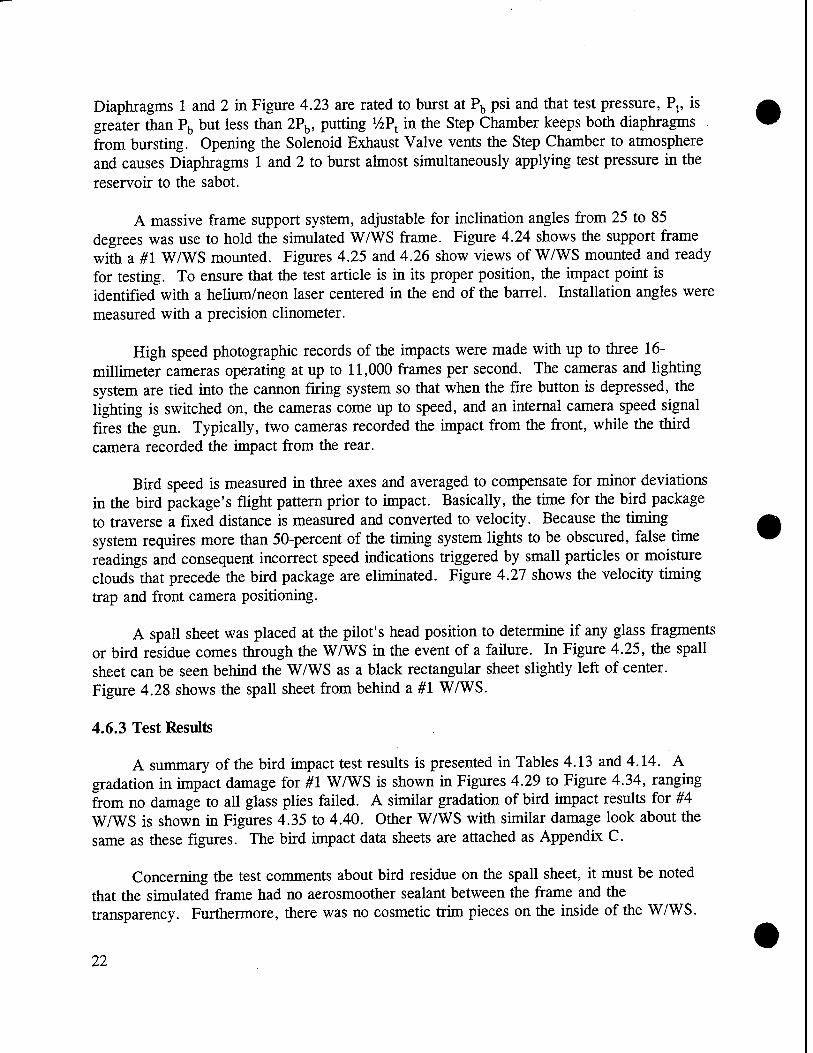
Diaphragms 1 and 2 in Figure 4.23 are rated to burst at Pb psi and that test pressure, Pt, is greater than Pb but less than 2Pb, putting %Pt in the Step Chamber keeps both diaphragms from bursting. Opening the Solenoid Exhaust Valve vents the Step Chamber to atmosphere and causes Diaphragms 1 and 2 to burst almost simultaneously applying test pressure in the reservoir to the sabot.
A massive frame support system, adjustable for inclination angles from 25 to 85 degrees was use to hold the simulated W/WS frame. Figure 4.24 shows the support frame with a #1 W/WS mounted. Figures 4.25 and 4.26 show views of W/WS mounted and ready for testing. To ensure that the test article is in its proper position, the impact point is identified with a helium/neon laser centered in the end of the barrel. Installation angles were measured with a precision clinometer.
High speed photographic records of the impacts were made with up to three 16- millimeter cameras operating at up to 11,000 frames per second. The cameras and lighting system are tied into the cannon firing system so that when the fire button is depressed, the lighting is switched on, the cameras come up to speed, and an internal camera speed signal fires the gun. Typically, two cameras recorded the impact from the front, while the third camera recorded the impact from the rear.
Bird speed is measured in three axes and averaged to compensate for minor deviations in the bird package's flight pattern prior to impact. Basically, the time for the bird package to traverse a fixed distance is measured and converted to velocity. Because the timing system requires more than 50-percent of the timing system lights to be obscured, false time readings and consequent incorrect speed indications triggered by small particles or moisture clouds that precede the bird package are eliminated. Figure 4.27 shows the velocity timing trap and front camera positioning.
A spall sheet was placed at the pilot's head position to determine if any glass fragments or bird residue comes through the W/WS in the event of a failure. In Figure 4.25, the spall sheet can be seen behind the W/WS as a black rectangular sheet slightly left of center. Figure 4.28 shows the spall sheet from behind a #1 W/WS.
4.6.3 Test Results
A summary of the bird impact test results is presented in Tables 4.13 and 4.14. A gradation in impact damage for #1 W/WS is shown in Figures 4.29 to Figure 4.34, ranging from no damage to all glass plies failed. A similar gradation of bird impact results for #4 W/WS is shown in Figures 4.35 to 4.40. Other W/WS with similar damage look about the same as these figures. The bird impact data sheets are attached as Appendix C.
Concerning the test comments about bird residue on the spall sheet, it must be noted that the simulated frame had no aerosmoother sealant between the frame and the transparency. Furthermore, there was no cosmetic trim pieces on the inside of the W/WS.
22

Either one or both of these would probably have prevented bird residue from squeezing between the W/WS and the frame. Ply breakage would not be affected by the presence of aerosmoother or trim pieces.
4.7 Performance Testing Summary
The performance testing data have been summarized in Tables 4.15 to 4.18. From these summaries, the obvious conclusion is that used W/WS do not perform as well as new W/WS. Although trends are difficult to identify in the data because there always seem to be exceptions and because the data base is so small, the performance of W/WS that have been in service, whether repaired or not, is below that of new W/WS.
In a number of categories, the repaired W/WS were the equal of new W/WS: dimensional fit, optical properties, and heater performance. In other cases, they were not: residual delamination, seals and bumpers, delamination during pressure cycling, more damage in the ball drop test, and poorer performance in the bird impact testing. Some of the issues such as seal and bumper problems and residual delamination can easily be rectified. The delamination during pressure cycling is merely annoying because it is an impaired vision issue that would develop over time and is not a serious structural failure.
The bird impact test results are conclusive. The new W/WS performed significantly better than the repaired and not repaired W/WS. At worst, the outboard ply of a new W/WS was broken. For the repaired #1 W/WS, fully half of the samples had all three plies fail, although none had bird penetrations. For the repaired #4 W/WS, only an outboard ply was broken. The unrepaired #4 W/WS performed the worst in the bird impact tests, with one whole W/WS punching out of the frame. This W/WS was rejected for repair, but it appears that it was for an out-of-specification heater and not for any unrepairable structural deficiency. Similarly, the other two unrepaired #4 W/WS that were damaged were also rejected for out-of-specification heaters. The fact that repaired W/WS performed somewhat better than unrepaired W/WS seems to indicate that the repairs themselves do not degrade the W/WS.
Some of the repaired #1 W/WS had a reduced thickness in the edge attachment area. The reduced mounting edge thickness was noticed when bolts that had previously worked satisfactorily for mounting new W/WS in the frames for bird impact tests appeared to be too long. Basically, the bolts would bottom-out on the aluminum spacers in the phenolic mounting block before the W/WS was tight to the frame (see Figure 2.4). The reduction in frame thickness could have been caused by extrusion of the vinyl inner layer during the relamination repair process, it could have occurred as a result of creep during service, or it could be an artifact of the original manufacturing processes. Table 4.19 summarizes edge measurements that were made on the #1 bird impact W/WS and a set of unrepaired W/WS that were not part of the rest of this program. Reduced mounting edge thickness appears to correlate with more severe impact damage, but does not correlate with age or whether or not the W/WS has been repaired.
23

5.0 COST ANALYSIS
The second element in the evaluation of the feasibility of using repaired W/WS in Air Force fleet aircraft was a cost analysis. The commercial fleet has a very favorable cost benefit using repaired W/WS. If using W/WS is to be a viable option for the Air Force, the costs for making the repairs has to be justifiably less than the cost of a new W/WS.
5.1 Repair Costs
During initial contacts with NORD AM, Perkins, and The Glass Doctor and prior to contracting for any repairs, an estimate was solicited for repairing small numbers of each of the five C/KC-135 W/WS types. NORDAM prices their repairs on the basis of how much work is required to do the repair, i.e., a W/WS that only needs polishing costs less than a W/WS that needs polishing and relaminating, and thus they could only give rough estimates. Perkins has a fixed price for repairing a given type of W/WS, regardless of the number of steps required to repair the W/WS, and offers up to a 30-percent discount for large volume customers. The Glass Doctor offered a fixed cost per W/WS type. All of the repair vendors perform incoming inspections and reject unserviceable W/WS, charging only for those that they successfully repair. Table 5.1 summarizes the initial repair quotations from the three vendors.
The actual costs for making the prototype repairs on the #1 and #4 W/WS that were performance tested are listed in Tables 5.2 and 5.3. Actual costs were consistent with the initial repair estimates. For reference, Table 5.4 summarizes the quoted repair cost for all 75 of the C/KC-135 repair candidate W/WS that were procured for this program. The latter table reflects the incoming W/WS inspections performed by NORDAM and Perkins.
5.2 Costs of New W/WS
OC-ALC provided costs for new C/KC-135 W/WS. The data in Table 5.5 is the Air Force purchase price as of January 1994.
5.3 Cost Comparison
The average cost for making the prototype repairs on the C/KC-135 #1 W/WS was $1,943, while the average cost of making the prototype repairs on the #4 W/WS was $899. Comparing these numbers to the current purchase price, the repairs cost 75-percent of the purchase price of a new #1 and 65-percent of the purchase price of a new #4.
Taking the extremes of the initial repair estimates, actual repair costs, or cost quotes from NORDAM and Perkins, and assuming a large enough volume so that Perkins would offer a 20-percent volume discount, the best-case, actual, and worst-case cost scenarios for repaired C/KC-135 W/WS are as shown in Table 5.6. Had The Glass Doctor participated in the program and repaired W/WS at the prices in their estimate, the low values in Table 5.6
24

would have gone to 51-percent for #1 W/WS, 62-percent for #2 W/WS, and 34-percent for #3 W/WS.
6.0 CONCLUSIONS, RECOMMENDATIONS, AND DISCUSSION
6.1 Conclusions
The Air Force, in an effort to reduce fleet maintenance costs, is considering the possibility of using repaired W/WS. Prior to adopting such an operating policy, however, the Air Force decided that a systematic evaluation was required to ensure that repaired W/WS are safeiand that they provide a reasonable cost savings benefit. Based on the reported cost savings and favorable experience that the commercial fleet has had with repaired W/WS, the use of repaired W/WS seems very attractive.
The approach followed for evaluating whether the use of repaired W/WS is a viable option for the Air Force was to procure some used W/WS, make repairs on them, and then subject the repaired W/WS to a series of tests to determine the difference in performance when compared with new W/WS. The cost to make the repairs provides the data for the cost benefit analysis. The test results provide the data for an evaluation of fitness for purpose of the repaired W/WS.
The test results indicate that repaired W/WS are not equal to new W/WS. Many of the repaired W/WS still contain defects that would not pass an OEM quality assurance inspection. None of the W/WS, new, repaired, or not repaired, exhibited any dramatic differences in pressure integrity. Some delamination occurred in two of the repaired W/WS during pressure cycling, but it was not severe. The residual strength of the pressure cycled W/WS tends to suggest that the repaired W/WS are not quite as good as new W/WS. The bird impact test results are quite clear - the new W/WS outperform either repaired or unrepaired W/WS.
Having established that repaired W/WS are not equal to new W/WS, the question that remains to be answered is whether or not repaired W/WS are "good enough." The replacement criteria in the C/KC-135 W/WS Technical Order, T.O. lC-135(K)A-2-2, are founded on two major principles:
1) A W/WS that has any condition that impairs visibility must be replaced
2) The W/WS heater must function properly.
A number of specific inspection items, subordinate to these principles, provide additional criterion for W/WS replacement. According to the prevailing Tech Order inspection criteria, none of the repaired W/WS would have been removed for cause from service. The fact that they were removed and were subsequently restored to a condition better than the W/WS
25

replacement criterion suggests that they were in fact "good enough." The repair vendors do not claim that they can restore a W/WS to a brand new condition. Rather, they indicate that the repairs they perform return the W/WS to a fully acceptable and functional condition. Under this philosophy, the repaired W/WS do appear to be "good enough."
In terms of performance, the most demanding test is the bird impact. Using the criteria set forth in MIL-W-81752A (Windshield Systems, Fixed Wing Aircraft General Specifications For), Paragraph 3.7.2 specifies that the W/WS should be able to sustain a 4- pound bird impact at maximum achievable operational true airspeed in level flight at up to 5000 feet altitude without any spall. This is substantially the same requirement for commercial fleet W/WS set forth in "Part 25 - Airworthiness Standards: Transport Category Airplanes" of the U.S. Federal Aviation Regulations, Paragraph 25.775. The velocity prescription dictated by MIL-W-81752A and FAA 25.775 is operationally restricted, however, by Part 91, Paragraph 91.117 of the FAA Federal Aviation Regulations which states that 250 knots is the maximum allowable aircraft speed below 10,000 feet above mean sea level without special authorization. Assuming that the 250 knot impact velocity is the proper performance criterion, all of the new and repaired #1 and #4 W/WS4neet the no bird penetration requirement, while two of the repaired #1 W/WS technically faiPüi^no spall criterion. From a practical viewpoint, the spall was very modest, so the repaired W/WS appear to be "good enough."
The lone W/WS that experienced a catastrophic bird impact failure (#4 W/WS, S/N 7- H-2-4-35) was not repaired. Reviewing the repair vendor's report on the W/WS, it was rejected for repair due to a heater that was out of specification and not for any gross structural deficiency, such a vinyl cracking or delamination. The only other vendor-reported damage was scratches. The Air Force HOWMAL (how malfunctioned) comments on the removal tag indicated that it had a burnt discoloration in the corner at the edge of the heater. The fact that the heater was defective suggests that the W/WS may have been subjected to in- service pressure cycles with the vinyl unheated. This would have been hard on the glass- vinyl interface, because the vinyl would have been relatively brittle, predisposing the W/WS to fail in the bird impact test. On the other hand, if the heater had been satisfactory, the W/WS probably would have been polished and considered repaired. Because the vinyl itself failed, it is unlikely that polishing would have changed the outcome of the test.
The bird impacts done for this program represent the first ever C/KC-135 W/WS bird impact tests. In addition to demonstrating that repaired W/WS are probably "good enough," the work in this program has confirmed that the basic C/KC-135 W/WS design is adequate.
The new #1 W/WS used in this program were manufactured in 1986. The fact that they performed well in all of the tests, in spite of sitting in warehouse storage for 7 years, indicates that these W/WS do not degrade in storage. This is quite important when considered in the context of a possible blanket 10-year replacement policy, because the only method available now to track the 10 years is by manufacture date. To implement a
26

V/JiV^S.
meaningful 10-year W/WS replacement cycle policy, it would be necessary to track individual W/WS service history.
The cost analysis indicates that savings may be realized. For this program, the cost of making the repairs was 75-percent of the new W/WS purchase price for #1 W/WS and 65- percent for the #4 W/WS. Considering all five of the C/KC-135 W/WS types and the full range of estimates, quotes, and actual costs, repairing a W/WS might cost as little as 41- percent of a new W/WS, but it could also cost as much as "^52-percent. , . 4^_ ^ IJSAP
The costs quoted are only the direct repair costs. To this must be added the direct cost of transportation and the indirect costs of procuring the service (contracting - more vendors will be involved), admimstratingll^accounts payable, records management, QA inspection of the vendors, etc.) and operating ^storage, shipping and handling, outgoing/incoming inspection, etc.). These items will certainly make the economics less favorable and to ignore them would be a false economy. On the positive side of the economic issue, the repair vendors do not directly charge for W/WS inspections or for any repair work that does not result in a shippable W/WS. The cost, both economic and environmental, of disposal of all of the W/WS that are currently removed and sent to a landfill cannot be ignored. Repaired W/WS would certainly have an advantage here.
A final consideration of an economic nature that must be factored into the decision to use repaired W/WS is new W/WS availability. There may be a persuasive economic reason to use repaired W/WS if new W/WS are in short supply. The repair vendors could probably be queued up to make repairs, basically on demand, and could provide a "just in time" service. As opposed to having aircraft out of service because new W/WS were not available, repaired W/WS could be used.
6.2 Recommendations
Recommendations that can be made as a result of the work performed on this program are contingent upon the Air Force making a decision, based on the available data, that the performance of repaired W/WS is acceptable.
If, in the opinion of the Air Force, the performance of repaired W/WS is deemed "good enough:"
1) NORD AM Transparency Division, and Perkins Aircraft Services, Inc. are recommended as vendors. No recommendation can be made regarding The Glass Doctor, because they supplied no test articles for this program.
27

2) Based on the results of this study, the repair processes that can be recommended are:
a) Relaminating using autoclave processes involving application of heat and pressure
b) Grinding and polishing of the external surfaces of the glass c) Seal/bumper maintenance d) Minor clean-up of electrical terminals
3) Repair processes that cannot be recommended at this time by virtue of not having been used in this program are:
a) Complete replacement of a glass ply b) Delamination or crack repair involving injection of adhesives or filling
with transparent pölymerizable resins c) Sensor replacement d) Busbar/heater wire repair/replacement
4) A formal Air Force quality assurance (Q/A) program should be instituted to set forth requirements for the repair vendors. This will eliminate the annoying, but easily corrected, problems with wrong seals/bumpers on repaired W/WS. In addition, this Q/A program should also be charged with performing an incoming inspection of W/WS coming back from the repair vendors.
5) A policy that prevents a W/WS from undergoing more than one repair cycle should be instituted. The contractual requirements for the repair vendors should stipulate that all repaired W/WS must be marked to identify that they have been repaired and by whom. No data have been collected to support the use of re- repaired W/WS.
6) The Air Force should use the cost data in this report as the starting point for a complete cost/benefit analysis to satisfy themselves that there is an economic advantage to using repaired W/WS. Full costs, including all direct and indirect cost for labor, materials, and facilities must be included. This must be done on a W/WS by W/WS basis, because the data from this program suggest that some W/WS can be replaced at less cost than they can be repaired.
It is important to emphasize that all of the recommendations offered above are contingent on the Air Force deciding that the performance of the repaired W/WS is adequate.
28

6.3 Discussion
In reviewing the test data, the question of why one W/WS should perform better or worse than another in a structural test was considered. Four possible causes were identified:
• Vinyl degradation - Vinyl, being a plastic is subject to UV degradation and general aging due to loss of plasticizer. As a result of the aging, the vinyl may become brittle and crack, thus reducing its load carrying capacity in the laminate. The vinyl could also be preferentially squeezed from the edge of the W/WS during a relaminating repair process or in service. Because the vinyl is the only structural ply that carries the load into the W/WS frame for a bird impact, if this occurred, the load capacity of the W/WS would be degraded.
Grinding/polishing of the glass - The C/KC-135 W/WS use heat-strengthened glass. In producing this type of glass, the ply is heated to near its softening point and then quenched to introduce compressive residual stresses in the surface layers as shown in Figure 6.1. Tensile stresses inside the glass exist to equilibrate the compressive surface stresses. Because glass only fails due to tensile stresses at the surface, the residual compressive stresses must be overcome to initiate a failure. Grinding and polishing remove some of the beneficial compressive stresses, and hence, the overall strength of the glass ply is reduced. Removal of the highest compressive stress layer, however, must be balanced against removal of flaws. In concert with the obvious effect of removal of the highest compressive stress layer, as far as flaw tolerance goes, the surface may also not be as smooth after grinding/polishing. Smoother surfaces have less flaws and a profoundly higher strength111].
Stress corrosion cracking of the glass - The surface of glass contains many microscopic cracks and fissures, and under a sustained load, the presence of moisture exacerbates the growth of these cracks[12"15]. Generally, water vapor in the air is sufficient to cause the degradation. Elevated temperatures and longer exposures accelerate the stress corrosion cracking effect. Although there is no direct evidence that aircraft W/WS degrade dramatically from this phenomenon, the fact that the W/WS are highly stressed due to thermal and pressure loading, they are exposed to atmospheric moisture, they are routinely heated in a high stress state, and that old W/WS performed below new W/WS in the structural tests suggests that there may be more than a casual cause-effect relationship.
Fatigue - Glass exhibits a complex load rate-cyclic loading behavior. Under a constant maximum load, no effect of cyclic loading is observed, but under increasing maximum load, cyclic loading reduces the strength[16'17]. The net effect for a W/WS undergoing repeated pressure cycles is not clear, but it seems plausible that some amount of micro-crack propagation occurs.
29

There is no conclusive evidence that the results of this test program can be directly attributed to any of the mechanisms described above. However, it does not seem unreasonable to suggest that they might. As far as the implications for use of repaired W/WS, vinyl degradation, stress corrosion cracking, and fatigue affect both repaired and unrepaired W/WS. Only repaired W/WS would seem to be susceptible to the grinding/polishing degradation mechanism.
It would be nice to be able to make generalizations about some W/WS being better repair candidates than others, possibly based on age. Unfortunately, there is just too little data to support such generalizations. There are enough inconsistencies in the data, i.e., new W/WS older than some of the repaired ones, some very old W/WS performing just as well as new W/WS (1971 manufacture #1 W/WS S/N l-H-10-5-480 pressure cycle and ball drop, 1974 manufacture #4 W/WS S/N 4-H-10-9-69 bird strike), etc., that one cannot readily see trends in the data. To try to treat the test results in a statistical manner, looking for correlations, just does not make any sense with such small sample populations. The best that one can say is that repaired W/WS are not equivalent to new W/WS.
It is unfortunate that The Glass Doctor declined to participate in this program. The repairs that The Glass Doctor makes are unique, and based on their cost estimates, quite inexpensive. The long-term performance of the materials that The Glass Doctor injects into the W/WS may be a concern, particularly in terms of extended exposure to ultra-violet radiation. The quality assurance aspect of not being certain of what is being injected in any given repair is also of concern. On the other hand, The Glass Doctor does warranty repairs, other than improper handling, for up to three years.
The issue of commercial construction W/WS versus military construction W/WS deserves some comment. According to PPG, back when Boeing 707's were first coming into service, chipping of the outer ply glass in the corners was common and was attributed to uneven W/WS heating causing differential thermal expansion/contraction of the glass and the underlying vinyl. The slip planes in the current C/KC-135 W/WS are there to help control this problem. To completely eliminate the problem, Boeing tried sewing fine wires in with the vinyl, so-called edge heaters, to keep the vinyl "soft" in the W/WS corners. This was not very successful, because no additional power was applied to the W/WS and failure of the edge heaters was common. A second solution, was to put external glue-on edge heaters on the inside of the W/WS. This approach, unfortunately, does not put the heat where it is needed - at the outer glass ply to vinyl interface. The final solution, which is the current commercial W/WS standard, was to put a thin layer of polyurethane between the vinyl and the outer glass ply. Because the polyurethane is more ductile and does not bond as tightly to the glass as vinyl, the glass and vinyl can move somewhat independently. The polyurethane layer, which could simply be added to the existing W/WS because of the large tolerances on glass and overall assembly thickness, eliminated the edge cracking problems and did away with the need for slip planes and edge heaters. The cost of a polyurethane layer W/WS is something less than 10-percent higher than the cost of a vinyl-only W/WS. The polyurethane is itself significantly more expensive, but this is balanced against less labor because the slip
30 •

planes and edge heaters are eliminated. For commercial fleets, the higher cost is justified on the basis of more flight hours between W/WS replacements. For C/KC-135's, because they do not see nearly the flight hours per year that commercial planes see, the cost to benefit ratio for the technically superior polyurethane layer W/WS may not be low enough.
7.0 REFERENCES
1) MIL-W-81752A, "Windshield Systems, Fixed Wing Aircraft General Specification For."
2) Kelley, M.E., "Aircraft Transparency Testing Methodology," Conference on Aerospace Materials and Enclosures, Scottsdale AZ, July 11-14, 1983.
3) Bain, P.H., "An Industry Test Program for Interlayer Equivalency," Conference on Aerospace Materials and Enclosures, Scottsdale AZ, July 11-14, 1983.
4) King, R.D., and Wright, R.W., "Glass in High Speed Transport," Glass Technology, Vol 28 No 2, April 1987, pp. 73-81.
5) Hornsey, W.W., Rome, W.F., "New Aircraft Windshield Applications Using Ion Exchange Glass," Conference on Aerospace Materials and Enclosures, Scottsdale AZ, July 11-14, 1983.
6) MIL-G-25871B, "Military Specification; Glass, Laminated, Aircraft Glazing."
7) Campbell, L.G., and Marshall, J.W., "Windshield Flight Environment Simulator," Aircraft Engineering, March 1976, pp. 4-9.
8) Lawrence, J.H., "Windshield Weight Reduction Through Use of High-Strength Glass and Polyurethane Interlayers," Conference on Aerospace Materials and Enclosures, Scottsdale AZ, July 11-14, 1983.
9) U.S. Federal Aviation Regulations, Paragraph 25.775, "Part 25 - Airworthiness Standards: Transport Category Airplanes."
10) U.S. Federal Aviation Regulations, Paragraph 91.117, "Part 91 - General Operating and Flight Rules."
11) McLellan G.W. and Shand, E.B., Glass Engineering Handbook, McGraw-Hill, New York, 1984, pp. 6-4.
12) Phillips, C.J., Glass, Its Industrial Applications, Reinhold Publishing Corporation, New York, 1960, pp. 82-85.
31

13) Greene, C.H., Modern Glass Practice, Cahners Books, Boston, 1975, pp.358-359.
14) Weidehorn, S.M., and Bolz, L.H., "Stress Corrosion and Static Fatigue of Glass," Journal of the American Ceramic Society, Vol 53, 1970, pp. 543-548.
15) Freiman, S.W., "Effects of Chemical Environment on Slow Crack Growth in Glasses and Ceramics," Journal of Geophysical Research, Vol 89, 1984, pp.4072-4076.
16) Stanworth, J.E., Physical Properties of Glass, Oxford Press, London, 1950, pp. 100- 101.
17) McLellan G.W. and Shand, E.B., Glass Engineering Handbook, McGraw-Hill, New York, 1984, pp. 6-4 to 6-6.
32

Table 2.1 C/KC-135 W/WS Part Numbers
Type of Windshield NSN Part Number
#1 Pilot 1560-01-048-1885 FL 5-89354-501 #1 Copilot 1560-01-048-1786 FL 5-89354-502
#2 Pilot 1560-01-009-3320 FL 5-89355-501 #2 Copilot 1560-01-008-7396 FL 5-89355-502
#3 Pilot 1560-00-575-6302 FL 5-89356-501 #3 Copilot 1560-00-575-6297 FL 5-89356-502
#4 Pilot 1560-00-575-6299 FL 5-71764-501 #4 Copilot 1560-00-575-6298 FL 5-71764-502
#5 Pilot 1560-00-575-6300 FL 5-89358-501 #5 Copilot 1560-00-575-6301 FL 5-89358-502
Table 2.2 C/KC-135 Program W/WS
•
Type of Windshield (1-5) S/N Condition
82-H-9-6-537 repairable
84-H-3-19-220 repairable
l-H-10-5-480 repairable
83-H-9-19-294 not repairable 83-H-9-19-282 repairable
83-H-8-15-756 repairable 82-H-10-18-107 repairable 83-H-l 1-7-432 repairable 82-H-9-6-235 repairable
83-H-l 1-21-325 repairable
86-H-12-01-146 repairable
88-H-02-08-436 repairable 6-H-8-4-26 repairable
89-286-HO-697 repairable 82-H-10-105 repairable
83-H-9-19-459 repairable
1 82-H-12-6-431 repairable
33

Table 2.2 C/KC-135 Program W/WS continued
Type of Windshield (1-5) S/N Condition
2 4-H-9-27-168 repairable
2 6-H-1-15-28 repairable
2 85-H-06-03-722 repairable
2 6-H-2-27-57 not repairable
2 6-H-2-20-23 not repairable
3 5-H-3-2-730 not repairable
3 6-H-3-18-28 not repairable
3 6-H-4-6-25 not repairable
3 6-H-12-10-30 not repairable
3 B73-2815 not repairable
3 B73-3439 not repairable
3 B73-3565 not repairable
3 B73-2462 not repairable
3 85-H-01-07-725 not repairable
3 O-H-9-1-1140 not repairable
3 B73-2509 not repairable
3 5-H-2-16-042 not repairable
3 B73-3955 not repairable
3 4-H-10-4-02 not repairable
3 4-H-9-18-15 not repairable
3 7-H-12-13-67 not repairable
34

Table 2.2 C/KC-135 Program W/WS continued
Type of Windshield (1-5) S/N Condition
4 4-H-10-15-108 not repairable
4 4-H-10-9-75 not repairable
4 4-H-9-28-87 repairable
4 5-H-12-16-47 repairable
4 6-H-4-29-50 not repairable
4 8-H-2-06-585 repairable
4 87-H-04-20-130 repairable
4 7-H-1-25-01 not repairable
4 3-H-4-26-45 repairable
4 82-H-12-6-392 not repairable
4 B75-1149 repairable
4 6-H-12-02-36 not repairable
4 85-H-07-01-276 repairable
4 7-H-2-4-35 not repairable
4 90-173-HO-721 repairable
4 4-H-10-9-69 not repairable
4 4-C-02-12-10 not repairable
4 84-H-10-15-1225 repairable
4 85-H-07-01-366 repairable
4 85-H-09-02-795 not repairable
4 5-H-5-23-84 not repairable
35

Table 2.2 C/KC-135 Program W/WS continued
Type of Windshield (1-5) S/N Condition
5 4-C-5-16-11 not repairable
5 4-C-5-28-16 not repairable
5 4-H-8-30-95 repairable
5 5-H-2-5-75 not repairable
5 2-H-12-15-58 not repairable
5 H-30-67 not repairable
5 7-H-10-14-56 repairable
5 2-H-6-20-70 not repairable
5 2-H-4-24-49 not repairable
5 4-C-7-12-22 repairable
5 4-H-8-33-64 not repairable
5 5-H-12-5-05 repairable
5 4-C-6-12-13 not repairable
5 2-H-6-29-06 not repairable
5 3-H-5-23-79 repairable
Table 2.3 C/KC-135 #1 and #4 W/WS Dimensions
#1 W/S I4W/S
Length (approx), inches 35 13
Height (approx), inches 18 10
Thickness (approx), inches 1 1
Weight (approx), pounds 46 8
36

Table 3.1 C/KC-135 Repaired and Not Repaired #1 W/WS in the Test Program
S/N Repair Vendor
Vendor Damage Comments Vendor Repair Comments
83-H-l 1-7-432 Perkins delaminated 82-H-10-18-105 Perkins delaminated, scratched 88-H-02-08-436 NORDAM scratches polish, replace bumper and
pressure seal 82-H-12-6-431 NORDAM scratches and chips polish, replace bumper and
pressure seal l-H-10-5-480 Perkins delaminated, scratched
83-H-9-19-294 Perkins delaminated not repairable 82-H-9-6-537 NORDAM scratches polish, replace bumper and
pressure seal 83-H-9-19-459 NORDAM scratches and chips polish, replace bumper and
pressure seal 83-H-9-19-282 Perkins delaminated 83-H-8-15-756 Perkins delaminated 84-H-3-19-220 Perkins delaminated, scratched 86-H-12-01-146 NORDAM scratches and chips polish, replace bumper and
pressure seal 82-H-10-18-107 Perkins delaminated
82-H-9-6-235 NORDAM scratches polish, replace bumper and pressure seal
83-H-l 1-21-325 NORDAM scratches and chips polish, replace bumper and pressure seal
89-286-HO-697 NORDAM scratches polish, replace bumper and pressure seal
• 37

Table 3.2 C/KC-135 Repaired and Not Repaired #4 WAYS in the Test Program
S/N Repair Vendor
Vendor Damage Comments Repair Comments
B75-1149 NORDAM scratches polish, replace bumper and pressure seals
85-H-07-01-276 NORDAM scratches polish, replace bumper and pressure seals
90-173-HO-721 Perkins bad terminal block 5-H-5-23-84 NORDAM delamination, scratches,
bad resistance not repairable
7-H-2-4-35 NORDAM scratches, bad resistance not repairable 4-H-10-9-69 Perkins contaminated not repairable
82-H-12-6-392 Perkins contaminated not repairable 6-H-12-02-36 Perkins bad resistance not repairable
87-H-04-20-130 NORDAM scratches polish, replace bumper and pressure seals
8-H-2-06-585 Perkins delamination, scratches 85-H-07-01-366 NORDAM scratches polish, replace bumper and
pressure seals 5-H-12-16-47 NORDAM delamination, scratches polish, autoclave, replace
bumper and pressure seals
84-H-10-15-1225 NORDAM delamination, scratches polish, autoclave, replace bumper and pressure seals
4-H-9-28-87 NORDAM scratches polish, replace bumper and pressure seals
3-H-4-26-45 NORDAM delamination, scratches, and chips
polish, autoclave, replace bumper and pressure seals
4-H-10-15-108 NORDAM delamination, scratches, bad resistance
not repairable
38

Table 4.1 C/KC-135 #1 W/WS General Examination and Dimensional Measurements Test Results (ace=acceptable, REJ=reject)
S/N Type Visual
Examination Seal Vinyl Dimensional
Check Comments
86-H-10-06-062 new ace ace ace ace
86-H-10-06-092 new ace ace ace ace
86-H-10-06-013 new ace ace ace ace
86-H-10-06-048 new ace ace ace ace
83-H-l 1-7-432 repaired REJ REJ ace ace l,a
82-H-10-18-105 repaired REJ REJ ace ace l,2,b
88-H-02-08-436 repaired REJ REJ ace ace l,b
82-H-12-6-431 repaired REJ ace ace ace 1
l-H-10-5-480 repaired REJ REJ ace ace l,c 83-H-9-19-294 not
repaired REJ REJ REJ ace l,2,d
82-H-9-6-537 repaired REJ REJ ace ace l,c
83-H-9-19-459 repaired REJ REJ ace ace U,b
Key to Comments
1 - air and delamination at edges a - air and water breach seal 2 - surface scratch(es) b - seal needs to be trimmed 3 - delamination at edges c - wrong seal on outboard side 4 - air and delamination throughout d - seal falling apart 5 - delamination in corners e - bad seal 6 - surface chip f - bad bumper
g - no outboard seal h - no outboard bumper i - inboard bumper bad
39

Table 4.1 C/KC-135 #1 W/WS General Examination and Dimensional Measurements Test Results continued (ace=acceptable, REJ= reject)
S/N Type j Visual
Examination Seal Vinyl Dimensional
Check Comments
86-H-10-06-007 new ace ace ace ace
86-H-10-06-030 new ace ace ace ace 86-H-10-06-022 new ace ace ace ace 86-H-10-06-096 new ace ace ace ace 83-H-9-19-282 repaired REJ REJ ace ace 3,c 83-H-8-15-756 repaired ace REJ ace ace c
84-H-3-19-220 repaired REJ REJ ace ace 4,b
86-H-12-01-146 repaired ace REJ ace ace c
82-H-10-18-107 repaired REJ REJ ace ace 5,b
82-H-9-6-235 repaired REJ REJ ace ace l,2,6,b
83-H-l 1-21-325 repaired REJ REJ ace ace l,b 89-286-HO-697 repaired REJ REJ ace ace 2,b
Key to Comments
1 - air and delamination at edges 2 - surface scratch(es) 3 - delamination at edges 4 - air and delamination throughout d 5 - delamination in corners e 6 - surface chip f
g h
a - air and water breach seal b - seal needs to be trimmed c - wrong seal on outboard side
seal falling apart bad seal bad bumper no outboard seal no outboard bumper
i - inboard bumper bad
40

Table 4.2 C/KC-135 #4 WAYS General Examination and Dimensional Measurements Test Results (ace=acceptable, REJ= reject)
S/N Type Visual
Examination Seal Vinyl Dimensional
Check Comments
B75-1149 repaired REJ REJ ace ace 3,c
92-064-HO-471 new ace ace ace ace
92-064-HO-473 new ace ace ace ace
92-059-HO-350 new ace ace ace ace
92-025-HO-006 new ace ace ace ace
92-119-HO-186 new ace ace ace ace
85-H-07-01-276 repaired REJ REJ ace no data l,c
90-173-HO-721 repaired ace REJ ace ace c
5-H-5-23-84 not repaired REJ REJ REJ ace l,2,e,f
7-H-2-4-35 not repaired REJ REJ no data ace l,2,f
4-H-10-9-69 not repaired REJ REJ REJ ace l,g,h
82-H-12-6-392 not repaired REJ REJ REJ ace l,g,h 6-H-12-02-36 not repaired REJ REJ ace ace l,h
Key to Comments
1 - air and delamination at edges a - air and water breach seal 2 - surface scratch(es) b - seal needs to be trimmed 3 - delamination at edges c - wrong seal on outboard side 4 - air and delamination throughout d - seal falling apart 5 - delamination in corners e - bad seal 6 - surface chip f - bad bumper
g - no outboard seal h - no outboard bumper i - inboard bumper bad
41

Table 4.2 C/KC-135 #4 WAYS General Examination and Dimensional Measurements Test Results continued (ace=acceptable, REJ= reject)
S/N Type Visual
Examination Seal Vinyl Dimensional
Check Comments
87-H-04-20-130 repaired REJ REJ ace ace 6,c
8-H-2-06-585 repaired REJ REJ ace no data l,c,i
85-H-07-01-366 repaired REJ REJ ace ace l,c,f
92-064-HO-470 new ace ace ace ace
92-098-HO-591 new ace ace ace ace
92-093-HO-392 new ace ace ace ace
92-093-HO-388 new ace ace ace ace
5-H-12-16-47 repaired REJ REJ ace ace l,c
84-H-10-15-1225 repaired REJ REJ REJ ace l,2,c
4-H-9-28-87 repaired REJ ace ace ace 1
3-H-4-26-45 repaired REJ REJ REJ ace l,2,f,g
4-H-10-15-108 not repaired
REJ REJ REJ ace 1,2,
Key to Comments
1 - air and delamination at edges 2 - surface scratches) 3 - delamination at edges 4 - air and delamination throughout d 5 - delamination in corners e 6 - surface chip
a - air and water breach seal b - seal needs to be trimmed c - wrong seal on outboard side
seal falling apart bad seal
f - bad bumper g - no outboard seal h - no outboard bumper i - inboard bumper bad
42

Table 4.3 C/KC-135 #1 WAYS Basic Electrical Measurements Test Results (ace=acceptable, REJ=reject)
S/N Type Bus
Resistance Sensor
Resistance
Insulation Integrity
bus-to- sensor
sensor-to- frame
sensor-to- sensor
86-H-10-06-062 new ace ace ace ace ace
86-H-10-06-092 new ace ace ace ace ace
86-H-10-06-013 new ace ace ace ace ace
86-H-10-06-048 new ace ace ace ace ace
83-H-l 1-7-432 repaired ace ace ace ace ace
82-H-10-18-105 repaired ace ace ace ace REJ
88-H-02-08-436 repaired ace ace ace ace REJ
82-H-12-6-431 repaired ace ace ace ace ace
l-H-10-5-480 repaired ace ace ace ace ace
83-H-9-19-294 not repaired
ace ace ace ace REJ
82-H-9-6-537 repaired ace ace ace ace REJ
83-H-9-19-459 repaired ace ace ace ace REJ
86-H-10-06-007 new ace ace ace ace ace
86-H-10-06-030 new ace ace ace ace ace
86-H-10-06-022 new ace ace ace ace ace
86-H-10-06-096 new ace ace ace ace ace
83-H-9-19-282 repaired ace ace ace ace ace
83-H-8-15-756 repaired ace ace ace ace ace
84-H-3-19-220 repaired ace ace ace ace REJ
86-H-12-01-146 repaired ace ace ace ace ace
82-H-10-18-107 repaired ace ace ace ace REJ
82-H-9-6-235 repaired ace ace ace ace REJ
83-H-l 1-21-325 repaired ace ace ace ace REJ
89-286-HO-697 repaired ace ace ace ace REJ
43

Table 4.4 C/KC-135 #4 W/WS Basic Electrical Measurements Test Results (ace=acceptable, REJ= reject)
S/N Type Bus
Resistance
Insulation Integrity
bus-to-frame
B75-1149 repaired ace ace
92-064-HO-471 new ace ace
92-064-HO-473 new ace ace
92-059-HO-350 new ace ace
92-025-HO-006 new ace ace
92-119-HO-186 new ace ace
85-H-07-01-276 repaired REJ no data
90-173-HO-721 repaired REJ ace
5-H-5-23-84 not repaired REJ ace
7-H-2-4-35 not repaired REJ ace
4-H-10-9-69 not repaired ace ace
82-H-12-6-392 not repaired ace ace
6-H-12-02-36 not repaired ace ace
87-H-04-20-130 repaired ace ace
8-H-2-06-585 repaired ace ace
85-H-07-01-366 repaired ace ace
92-064-HO-470 new ace ace
92-098-HO-591 new ace ace
92-093-HO-392 new ace ace
92-093-HO-388 new ace ace
5-H-12-16-47 repaired REJ ace
84-H-10-15-1225 repaired ace ace
4-H-9-28-87 repaired ace ace
3-H-4-26-45 repaired ace ace
4-H-10-15-108 not repaired REJ
ace
44 •

Table 4.5 C/KC-135 #1 W/WS Heater Operation Test Results (ace=acceptable, REJ= reject)
S/N Type Heater
Operation Hot/Cold
Spots Heater Film Scratch Test
86-H-10-06-062 new 90-110° F no ace
86-H-10-06-092 new 90-115° F no ace
86-H-10-06-013 new 90-110° F no ace
86-H-10-06-048 new 90-110° F no ace
83-H-l 1-7-432 repaired 85-115° F no ace
82-H-10-18-105 repaired 85-110° F no ace
88-H-02-08-436 repaired 90-110° F no ace
82-H-12-6-431 repaired 95-120° F no ace
l-H-10-5-480 repaired 90-115° F no ace
83-H-9-19-294 not repaired no test - ace
82-H-9-6-537 repaired 80-140° F no ace
83-H-9-19-459 repaired 90-110° F no ace
86-H-10-06-007 new 90-115° F no ace
86-H-10-06-030 new 90-115° F no ace
86-H-10-06-022 new missing photo - ace
86-H-10-06-096 new 90-110° F no ace
83-H-9-19-282 repaired 90-115° F no ace
83-H-8-15-756 repaired 90-115° F no ace
84-H-3-19-220 repaired 90-110° F no ace
86-H-12-01-146 repaired 95-120° F no ace
82-H-10-18-107 repaired 90-115° F no ace
82-H-9-6-235 repaired 90-115° F no ace
83-H-l 1-21-325 repaired 90-115° F no ace
89-286-HO-697 repaired 90-115° F no ace
45

Table 4.6 C/KC-135 #4 W/WS Heater Operation Test Results (ace=acceptable, REJ= reject)
S/N Type Heater
Operation Hot/Cold
Spots Heater Finn Scratch Test
B75-1149 repaired 95-115° F no ace
92-064-HO-471 new 95-110° F no ace
92-064-HO-473 new 95-120° F no ace
92-059-HO-350 new 95-110° F no ace
92-025-HO-006 new 95-110° F no ace
92-119-HO-186 new missing photo - ace
85-H-07-01-276 repaired no test - REJ
90-173-HO-721 repaired no test - ace
5-H-5-23-84 not repaired 95-115° F no ace
7-H-2-4-35 not repaired 95-115° F no ace
4-H-10-9-69 not repaired 95-110° F no ace
82-H-12-6-392 not repaired 95-115° F no ace
6-H-12-02-36 not repaired 95-110° F no ace
87-H-04-20-130 repaired 95-110° F no ace
8-H-2-06-585 repaired 95-110° F no ace
85-H-07-01-366 repaired missing photo - ace
92-064-HO-470 new 95-110° F no ace
92-098-HO-591 new 95-115° F no ace
92-093-HO-392 new 95-135° F no ace
92-093-HO-388 new 95-110° F no ace
5-H-12-16-47 repaired 95-110° F no ace
84-H-10-15-1225 repaired 95-110° F no ace
4-H-9-28-87 repaired 95-110° F no ace
3-H-4-26-45 repaired 95-110° F no ace
4-H-10-15-108 not repaired 95-115° F no ace
46

Table 4.7 C/KC-135 #1 W/WS Optical Performance Test Results (ace=acceptable, REJ= reject)
S/N Type Luminous
Transmittance Haze Deviation Distortion, center/edge
86-H-10-06-062 new ace ace ace none/1:30
86-H-10-06-092 new ace ace ace none/none
86-H-10-06-013 new ace ace ace none/none
86-H-10-06-048 new ace ace ace none/none
83-H-l 1-7-432 repaired ace ace ace none/1:20
82-H-10-18-105 repaired ace ace ace none/none
88-H-02-08-436 repaired ace ace ace none/none
82-H-12-6-431 repaired ace ace ace none/none
l-H-10-5-480 repaired ace ace ace none/none
83-H-9-19-294 not repaired ace ace ace none/none
82-H-9-6-537 repaired ace ace ace none/none
83-H-9-19-459 repaired ace ace ace none/none
86-H-10-06-007 new ace ace ace none/none
86-H-10-06-030 new ace ace ace none/none
86-H-10-06-022 new ace ace ace none/none
86-H-10-06-096 new ace ace ace none/none
83-H-9-19-282 repaired ace ace ace none/none
83-H-8-15-756 repaired ace ace ace none/none
84-H-3-19-220 repaired ace ace ace none/none
86-H-12-01-146 repaired ace ace ace none/1:30
82-H-10-18-107 repaired ace ace ace none/1:40
82-H-9-6-235 repaired ace ace ace none/none
83-H-l 1-21-325 repaired ace ace ace none/none
89-286-HO-697 repaired ace ace ace none/none
47

Table 4.8 C/KC-135 #4 W/WS Optical Perfonnance Test Results (ace=acceptable, REJ= reject)
S/N Type Luminous
Transmittance Haze Deviation Distortion, center/edge
B75-1149 repaired ace ace ace none/1:18
92-064-HO-471 new ace ace ace none/1:11
92-064-HO-473 new ace ace ace none/l:14
92-059-HO-350 new ace ace ace none/1:7
92-025-HO-006 new ace ace ace none/1:8
92-119-HO-186 new ace ace ace missing photo
85-H-07-01-276 repaired ace ace ace none/l:12
90-173-HO-721 repaired ace ace ace none/l:10
5-H-5-23-84 not repaired ace ace ace none/none
7-H-2-4-35 not repaired ace ace ace none/1:25
4-H-10-9-69 not repaired ace ace ace none/1:21
82-H-12-6-392 not repaired ace ace ace none/1:7
6-H-12-02-36 not repaired ace ace ace none/none
87-H-04-20-130 repaired ace ace ace 1:16/1:5
8-H-2-06-585 repaired ace ace ace none/1:22
85-H-07-01-366 repaired ace ace ace none/1:8
92-064-HO-470 new ace ace ace none/l:12
92-098-HO-591 new ace ace ace none/1:9
92-093-HO-392 new ace ace ace none/l:10
92-093-HO-388 new ace ace ace none/1:9
5-H-12-16-47 repaired ace ace ace none/none
84-H-10-15-1225 repaired ace ace ace none/1:6
4-H-9-28-87 repaired ace ace ace none/1:16
3-H-4-26-45 repaired ace ace ace none/none
4-H-10-15-108 not repaired ace ace ace 1:16/1:22
48

Table 4.9 C/KC-135 #1 W/WS Pressure Integrity Test Results
S/N Type Initial Proof
Pressure Test Damage from
Pressure Cycling Final Proof
Pressure Test
86-H-10-06-062 new passed no apparent damage passed
86-H-10-06-092 new passed no apparent damage passed
86-H-10-06-013 new passed no apparent damage passed
86-H-10-06-048 new passed no apparent damage passed
83-H-l 1-7-432 repaired passed no apparent damage passed
81-H-10-18-105 repaired passed no apparent damage passed
88-H-02-08-436 repaired passed no apparent damage passed
82-H-12-6-431 repaired passed no apparent damage passed
l-H-10-5-480 repaired passed no apparent damage passed
83-H-9-19-294 not repaired passed no apparent damage passed
82-H-9-6-537 repaired passed delamination near slip plane areas
passed
83-H-9-19-459 repaired passed delamination near slip plane areas
passed
49

Table 4.10 C/KC-135 #4 W/WS Pressure Integrity Test Results
S/N Type Initial Proof
Pressure Test Damage from Pressure
Cycling Final Proof
Pressure Test
87-H-04-20-130 repaired passed no apparent damage passed
8-H-2-06-585 repaired passed no apparent damage passed
85-H-07-01-366 repaired passed no apparent damage passed
92-064-HO-470 new passed no apparent damage passed
92-098-HO-591 new passed no apparent damage passed
92-093-HO-392 new passed no apparent damage passed
92-093-HO-388 new passed no apparent damage passed
5-H-12-16-47 repaired passed large amount of delamination along forward
edge and lower forward corner
passed
84-H-10-15-1225 repaired passed no apparent damage passed
4-H-9-28-87 repaired passed no apparent damage passed
3-H-4-26-45 repaired passed delamination in lower forward corner of less than
1 square inch
passed
4-H-10-15-108 not repaired passed no apparent damage passed
50

Table 4.11 C/KC-135 #1 W/WS Residual Strength Ball Drop Test Results
W/WSS/N Type Damage from
Pressure Cycling Comments
86-H-10-06-062 new no apparent damage Two ball drops. Outboard glass ply broken. Crushing in impact area. No delamination created by cracking of the outer ply.
83-H-9-19-459 repaired delamination near slip plane areas
Two ball drops. Outboard glass ply broken. Core ply intact. No delamination from glass breakage.
l-H-10-5-480 repaired no apparent damage Two ball drops. Outboard glass ply broken. No delamination from outer ply cracking.
81-H-10-18-105 repaired no apparent damage One ball drop only. Both glass plies failed. Large amount of spall driven from core ply inboard surface.
82-H-9-6-537 repaired delamination near slip plane areas
One ball drop only. Both glass plies failed. Large amount of spall removed from core ply surface.
51

Table 4.12 C/KC-135 #4 W/WS Residual Strength Ball Drop Test Results
W/WS S/N Type Damage from Pressure
Cycling Comments
92-093-HO-388 new no apparent damage Outboard glass ply broken. Core ply intact. No delamination associated with glass breaking.
87-H-04-20-130 repaired no apparent damage Outboard glass ply broken. Core ply intact. No delamination associated with glass breaking.
8-H-2-06-585 repaired no apparent damage Outboard glass ply broken. Core ply intact. No delamination associated with glass breaking.
3-H-4-26-45 repaired delamination in lower forward corner of less
than 1 square inch
Both glass plies failed. Large area of core ply inboard surface spalled in impact area.
5-H-12-16-47 repaired large amount of delamination along
forward edge and lower forward corner
Both glass plies failed. Large area of core ply inboard surface spalled in impact area.
52

-82 3 VI
Cfl
■E S
S
m
ä u cn i—i
<W
1
T3 ^3
■g 03 03
3 O H-» CO
O
e o3
•B 3 O
0) 0) X
C O -4-*
CD
E o ,<H
—j C (ZI TM "03 X , 03 u bß 03 CM CO 13
Ol CO
s 00
1)
4^
e • *-* CO
GO 00 "03
tu 6 C o J2 OH CO xf CO
CO
■u* (U
■4-J -M «M bo C ^O ca 0)
Ü >> bO CD <u CD -t-j 03 •M X 03 Ul C 3 SJ CD O O o X
-M
"bb o CO
c £ Ü ."2 X CO
x CO Z -H 03 CM 03
•M --H
1) CO 03 c c O c rt j>> 3 <U £il ÜH cx • ^H (U -t-H
<H OH O Ui o3 a T3 CO
"a,
o U
X C >^ CO *E <U Ul o U
CO
*ö3
E c
T3 Ui
»M
X
O
OH co
3 o CD 3
a. CO
e o a) 3
CD
CM
CO CO
"bb
o
Ui U .5 'o3 -*H <u Ui
3 O S 03
Ui O
0) Ui O U
3 O
"03
C/3
d 3
OH co
CD
6 es
C
o • pH
CO CD
<U in o •d
<u
Ui 03 X
B M <i 0)
o Z
o u X
3 o 03
,SH
C/5
E 03
Ui
Ul u U
■d Ct-I N X
. CO
T3 T-, 1=3 CM •d
co CO
.5 "Hfl "3
OH
CD 3
• M co CD
x
ply
and
W/W
; ir
esse
d.
age.
Sm
all
Shot
783
.
• T^
X) o
0) bO o3
X) o
0)
03
o 03
.s "EH
C|-(
CO
cl CO
"a, CO oo 03
be T3
bß 03
03 0) Ui X
CO s pl
ies
faile
pl
y on
spa
l
X>
CO CO
*bb
"2
—H
I* CM
CO
.M
"E, co
<u b0 CO
Ui
O
3
03 6 03
s 03
03 O
CO Ul
O
CO
T2
11 gl
as
boar
d Ui a o CO
TM E
o CO G es 5
•a a) T3
O
T3
O 1 ts 3 a
"bb 3
'S) O 3
"bb T3
O
o CM o —( O bO O
^-7- 03 l<Ci CO 2 Z o -S < o z < .5 o < z
HM
ST,
51 r- TM 00 VO VO ■* T-H Tf -3- o u-i 00
es
1 T—i T-H CN CN ON ON o CN ON TH r- o in <r> <r> m Tt ^ </-> >n ■* m ■* >n
^Ä CN CN CN CN CN CN CN CN CN CN CN CN
T3 T3 T3 T3 T3 T3 T3 ■o
& 1) 1) <U D 0) (U <U Ü
£ £ £ ^ _tH _!-( _Ui _Ui _Ui Ul • H
_u Ui
£ D u 1) 1) '03 '03 '3 '3 "S CO "o3 'S S c c C O- a, a, dl Ol OH OH OH
<U 0) a> 0) (U <D <U CD u. u. Ui Ul Ui Ul Ui Ui
o o o en o
CN CN
i
VO
i
CN 00 CN
i
VO O CN CN
VO
T-H o T-H cn
CN
VO 1
ON 1
X 1
CN 00
CN cn
ON VO
1
VO o 1
o 1—1
1
VO o 1
o TM
VO o t o
l-H 1
VO o 6
i
CN
ON T—1
1 ON
<n ■
00 i
i ON
I cn
i
T-H o
1
CN T-H
oö TM
1 o CN
1
6 X
i vo
1
X 1
X X i
1
i i ffi ffi ffi 00 CN
1
00
1
VD 00
VO 00
vo 00
1
en 00
cn 00 00 VO
00 CN 00
cn 00
ON 00
u cn Tf >n VO CN cn Tt *n vo t^ 00 ON 00 00 00 00 ON ON ON ON ON ON ON ON t^ e'- r^ r~ r- t- r^ r- r^ t»- t^ t^
Z
cn en cn cn cn cn cn cn cn cn cn cn
i CN
as c3
ON
cn ON
cn ON ON
ON
ON
ON
ON
O
ON
O
ON
O
ON
TM
ON
CN
Q es CN CN CN cN i—i T-H CN CN CN CN CN
VO vo VO VD VO C^ ^ r^ r^ r^ r^ r^ 53

42 3
"2
=tfc
1
54
T3 >> • —H i-i rrt o< |H
T3 O V) IH l-l
o -1 CO 03
•1—•
|H 03 CD
ffl O bß 1) 3
£ 1 C T3 03 o 4-*
O
G (1)
CD c
0) CD bfl
l-l 03 O 1 C
IH O
03
IH CO CD
4-» CD o fl) <u C H-1
CD TO
o -t-J T£3
.£? CO
CO
si 3
ai t-i ,2
C .2 03
03 CM
i-, CD >. -5 "IH
CD T3 •»H
CO 0) TH
T3 l-l
ex o
T3
CD
l-l CO
o J3
C*-l
cö l-l
■I-»
8 CD
CD
03 G bJO-3
<-»—i
O -O •M 3 s
|H
B G « o CX
-^ CO
i
-a" u
CTH
"Ei CO «3
>2 "tob •o IH
o
o
bO *o
CD
*! 03
bO G O
"3
a M
co S3 (50 l-l
O
CO
*3 6
oo
aJ bO a F
Ö 0) X) o Z
•a 03
co u l-l
T3 l-i
.—H TO
TH
1) bO
anno
n m
isfi
re d
ue t
o c
d. CO
e bo 03
E
bO a G
1) bO CO
s
o Z
d M O |H
TO
_>. "Si •o IH C«
u U C |H O o
T3 IH 03
IH
CD |H
w CD'
»t3 M-l
o TC a, o IH
CD bO 03
s
CD bO cs s ass
plys
fai
led.
4-in
ch
rd c
orne
r. S
ome
glas
s
o U
e1 • .S co 03
O z
3 •4-*
CD t-i
03
O z
-a ex
CQ u
03 •a o Z
03
O z
03 T3 O z
03
O Z
O •E
o
lH 1)
o S 0) CO co
U .S
io3 -o O Z
03
O Z < £
-4-> >n CO o\ T-H Tf 00 l> T-H <M 00 o 00 co r^ T—1 00 in 00 r^ 00 r^ r—1 o T—1 o o Tf IT) Tf (S Tf Tf Tf Tf «n in m V) in
> Ä CM CM CM <N CM CN CN (N CN CM CM CM CM
TJ •a T3 *a •a 1) CD (1J <i> CD
&
T3 CD IH £ £ ^ t5 ^ VH
T3 |H
»TH
• —H
io3 o3 CX
'3 CM
_I-I
'3 IH
'3
$ cä 0) a> a> ?2 Ü 03 io3 1) CD CD CD CD a, C e c C c OH LH u, >H IH IH
l-l O Ö s O
c s o G
T-H ro o vo NO NO ^H IN NO r- 1-- m o 00 l~- cN Tf ON OS
ON Tf TJ- co o T-H CM
i 00 in co NO CO l
Tf T-H T-H
o o O O O T-H o o co i
TH- ON NO CM
O Z ffi X
i i i as CN
i m
i
1 CM O CM
T—1
i CM
on in Tf Tf ON m ON o co i
i *0 o o O o
T-H
T-H a T—1 a i 1 X CM (N (N <N CN wo 6 in Tf CM
oo NO ON Os ON ON ON 00 ON
in MO r^ 00 >n NO r^ 00 ON o T—I CM co i—< i—i co CO ro CO CO Tf Tf Tf Tf
00 00 00 00 00 00 OO 00 00 00 OO 00 00
Z
CO co co CO CO co co co CO co ON
CO as
co C7\
CO 0\ ON ON ON OS ON ON ON ON ON
'—. ON as OS ON O O O <_> T-H
r—I C4 (S <N c co co co co o as o\ o\ o\ OS ON ON ON ON ON ON ON T-H

Table 4.15 C/KC-135 WAYS General Inspection Summary
#1 WAYS #4 W/WS
Category New Repaired Not
Repaired New Repaired Not
Repaired
Number Tested 8 15 1 9 10 6
Number with delamination, scratches, or chips
0 13 1 0 9 6
Number with seal deficiencies
0 14 1 0 8 6
Number with vinyl cracks 0 0 1 0 2 4
Number with bad dimensional check
0 0 0 0 0 0
Number with bad bus resistance
0 0 0 0 3 3
Number with bad sensor resistance
0 0 0 - - -
Number with bad insulation 0 9 1 0 0 0
Number with poor heater performance
0 0 1 0 1 0
Number with bad optics 0 0 0 0 0 0
55

Table 4.16 C/KC-135 W/WS Pressure Integrity Test Summaiy
#1 W/WS #4 W/WS
Category New Repaired Not
Repaired New Repaired Not
Repaired
Number Tested 4 7 1 4 7 1
Number failing initial proof pressure test
0 0 0 0 0 0
Number failing during pressure cycling
0 0 0 0 0 0
Number failing final proof pressure test
0 0 0 0 0 0
Number delaminated 0 2 0 0 2 0
Table 4.17 C/KC-135 W/WS Ball Drop Residual Strength Test Summary
#1 W/WS #4 W/WS
Category New Repaired New Repaired
Number Tested 1 4 1 4
Number with initial delamination
0 2 0 2
Number with outboard ply failure only
1 2 1 2
Number with both glass plys failed
0 2 0 2
56

Table 4.18 C/KC-135 W/WS Bird Impact Test Summary
#1 W/WS #4 W/WS
Category New Repaired New Repaired Not
Repaired
Number Tested 4 8 5 3 5
Number undamaged 3 2 4 2 2
Number with outboard ply broken only
1 2 1 1 1
Number with inboard ply broken only
0 1 0 0 0
Number with all glass plies failed
0 3 0 0 2
Number with no inner ply glass spall
4 6 5 3 3
Number with minor inner ply glass spall
0 2 0 0 1
Number with major inner ply glass spall
0 0 0 0 1
Number with no bird penetration
4 8 5 3 4
Number with minor bird penetration
0 0 0 0 0
Number with major bird penetration
0 0 0 0 1
57

Table 4.19 C/KC-135 #1 W/WS Mounting Edge Measurements and Bird Impact Test Results
S/N Type Edge Thickness,
inches Bird Impact Comments
86-H-10-06-007 new 0.936 0.943 0.942
Outboard glass ply broken. Core ply intact.
82-H-10-18-107 repaired 0.843 0.852 0.838
All glass plies failed. Minor amount of glass spall from inboard ply on spall sheet.
83-H-9-19-282 repaired similar to 82-H-10-18-107
Core ply failed. No glass spall on spall sheet.
83-H-8-15-756 repaired similar to 82-H-10-18-107
All glass plies failed. Minor glass spall on spall sheet.
83-H-l 1-21-325 repaired 0.927 0.936 0.939
All glass plies failed. No spall on spall sheet.
86-H-06-030 86-H-10-06-22 86-H-10-06-96
new 0.908 min 0.940 max
No damage.
84-H-3-19-220
repaired
Outboard glass ply failed.
86-H-12-01-146 No glass breakage.
82-H-9-6-235 Outboard glass ply failed.
89-286-HO-697 No damage.
91-010-HO-206
unrepaired
0.850 min 0.909 max
Not bird impact tested.
87-H-06-29-758 0.893 min 0.920 max
87-H-09-21-671 0.886 min 0.922 max
90-180-HO-139 0.839 min 0.887 max
82-H-9-20-127 0.902 min 0.918 max
58

Table 5.1 Initial C/KC-135 W/WS Repair Estimates
Type of W/WS NORDAM3 Perkins0 The Glass Doctor0
1 $1,890 $2,000 $l,327c
2 glass only $1,512 $1,500 $896
frame and glass $6,700 - -
3 $735 Category P $945 Category II $945 Category III
$1,280 Category IV
$750 $516
4 $975 $875 $667
5 $750 $875 $484
Notes:
a) Estimate, actual price quote based on specific repairs required as determined by incoming inspection.
b) Fixed price. c) Sensor repair or replacement, $437 additional. d) NORDAM #3 W/WS Repair/Overhaul Categories:
All repair categories include complete disassembly, inspection, and reassembly with new seal and new grommets.
Category Transparency Repair
I Polish inner and outer panes II Polish outer pane, replace inner pane III Polish inner pane, replace outer pane IV Replace inner and outer panes
59

Table 5.2 C/KC-135 #1 W/WS Actual Repair Costs (NR=not repairable)
S/N Repair Vendor
Vendor Damage Comments Repair Cost
83-H-l 1-7-432 Perkins delaminated $2,000
82-H-10-18-105 Perkins delaminated, scratched $2,000
88-H-02-08-436 NORDAM scratches $1,695
82-H-12-6-431 NORDAM scratches and chips $2,090
l-H-10-5-480 Perkins delaminated, scratched $2,000
83-H-9-19-294 Perkins delaminated $0, NR
82-H-9-6-537 NORDAM scratches $1,893
83-H-9-19-459 NORDAM scratches and chips $1,893
83-H-9-19-282 Perkins delaminated $2,000
83-H-8-15-756 Perkins delaminated $2,000
84-H-3-19-220 Perkins delaminated, scratched $2,000
86-H-12-01-146 NORDAM scratches and chips $1,695
82-H-10-18-107 Perkins delaminated $2,000
82-H-9-6-235 NORDAM scratches $1,695
83-H-l 1-21-325 NORDAM scratches and chips $2,090
89-286-HO-697 NORDAM scratches $2,090
60

Table 5.3 C/KC-135 #4 W/WS Actual Repair Costs (NR=not repairable)
S/N Repair Vendor
Vendor Damage Comments Repair Cost
B75-1149 NORDAM scratches $559
85-H-07-01-276 NORDAM scratches $954
90-173-HO-721 Perkins bad terminal block $875
5-H-5-23-84 NORDAM delamination, scratches, bad resistance
$0, NR
7-H-2-4-35 NORDAM scratches, bad resistance
$0, NR
4-H-10-9-69 Perkins contaminated $0, NR
82-H-12-6-392 Perkins contaminated $0, NR
6-H-12-02-36 Perkins bad resistance $0, NR
87-H-04-20-130 NORDAM scratches $954
8-H-2-06-585 Perkins delamination, scratches $875
85-H-07-01-366 NORDAM scratches $559
5-H-12-16-47 NORDAM delamination, scratches $1,151
84-H-10-15-1225 NORDAM delamination, scratches $1,151
4-H-9-28-87 NORDAM scratches $559
3-H-4-26-45 NORDAM delamination, scratches, and chips
$1,349
4-H-10-15-108 NORDAM delamination, scratches, bad resistance
$0, NR
61

Table 5.4 Cost Quotes for AH Prototype Repair Candidate C/KC-135 W/WS (NR=not repairable)
Type of W/WS (1-5) S/N Repair Vendor Cost of Repair
82-H-9-6-537 NORDAM $1,893
84-H-3-19-220 Perkins $2,000
l-H-10-5-480 Perkins $2,000
83-H-9-19-294 Perkins $0, NR
83-H-9-19-282 Perkins $2,000
83-H-8-15-756 Perkins $2,000
82-H-10-18-107 Perkins $2,000
83-H-l 1-7-432 Perkins $2,000
82-H-9-6-235 NORDAM $1,695
83-H-l 1-21-325 NORDAM $2,090
86-H-12-01-146 NORDAM $2,090
88-H-02-08-436 NORDAM $1,695
6-H-8-4-26 NORDAM $2,683
89-286-HO-697 NORDAM $2,090
82-H-10-105 Perkins $2,000
83-H-9-19-459 NORDAM $1,893
82-H-12-6-431 NORDAM $2,090
2 4-H-9-27-168 NORDAM $1,919
2 6-H-1-15-28 NORDAM $1,524
2 85-H-06-03-722 NORDAM $1,721
2 6-H-2-27-57 Perkins $0, NR
2 6-H-2-20-23 Perkins $0, NR
3 5-H-3-2-730 NORDAM $0, NR
3 6-H-3-18-28 NORDAM $0, NR
3 6-H-4-6-25 NORDAM $0, NR
3 6-H-12-10-30 NORDAM $0, NR
3 B73-2815 Perkins $0, NR
3 B73-3439 Perkins $0, NR
• 62
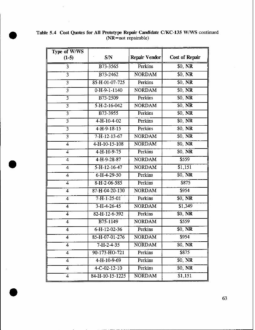
Table 5.4 Cost Quotes for All Prototype Repair Candidate C/KC-135 WAYS continued (NR=not repairable)
Type of W/WS (1-5) S/N Repair Vendor Cost of Repair
3 B73-3565 Perkins $0, NR
3 B73-2462 NORDAM $0, NR
3 85-H-01-07-725 Perkins $0, NR
3 O-H-9-1-1140 NORDAM $0, NR
3 B73-2509 Perkins $0, NR
3 5-H-2-16-042 NORDAM $0, NR
3 B73-3955 Perkins $0, NR
3 4-H-10-4-02 Perkins $0, NR
3 4-H-9-18-15 Perkins $0, NR
3 7-H-12-13-67 NORDAM $0, NR
4 4-H-10-15-108 NORDAM $0, NR
4 4-H-10-9-75 Perkins $0, NR
4 4-H-9-28-87 NORDAM $559
4 5-H-12-16-47 NORDAM $1,151
4 6-H-4-29-50 Perkins $0, NR
4 8-H-2-06-585 Perkins $875
4 87-H-04-20-130 NORDAM $954
4 7-H-1-25-01 Perkins $0, NR
4 3-H-4-26-45 NORDAM $1,349
4 82-H-12-6-392 Perkins $0, NR
4 B75-1149 NORDAM $559
4 6-H-12-02-36 Perkins $0, NR
4 85-H-07-01-276 NORDAM $954
4 7-H-2-4-35 NORDAM $0, NR
4 90-173-HO-721 Perkins $875
4 4-H-10-9-69 Perkins $0, NR
4 4-C-02-12-10 Perkins $0, NR
4 84-H-10-15-1225 NORDAM $1,151
63

Table 5.4 Cost Quotes for All Prototype Repair Candidate C/KC-135 W/WS continued (NR=not repairable)
Type of WAYS (1-5)
S/N Repair Vendor Cost of Repair
4 85-H-07-01-366 NORDAM $559
4 85-H-09-02-795 Perkins $0, NR
4 5-H-5-23-84 NORDAM $0, NR
5 4-C-5-16-11 Perkins $0, NR
5 4-C-5-28-16 NORDAM $0, NR
5 4-H-8-30-95 NORDAM $486
5 5-H-2-5-75 Perkins $0, NR
5 2-H-12-15-58 NORDAM $0, NR
5 H-30-67 NORDAM $0, NR
5 7-H-10-14-56 NORDAM $1,079
5 2-H-6-20-70 Perkins $0, NR
5 2-H-4-24-49 Perkins $0, NR
5 4-C-7-12-22 NORDAM $881
5 4-H-8-33-64 Perkins $0, NR
5 5-H-12-5-05 NORDAM $486
5 4-C-6-12-13 Perkins $0, NR
5 2-H-6-29-06 Perkins $0, NR
5 3-H-5-23-79 NORDAM $881
64

Table 5.5 C/KC-135 New W/WS Costs
Designation NSN Part Number USAF Cost
#1 Pilot 1560-01-048-1885 FL 5-89354-501 $2,582 #1 Copilot 1560-01-048-1786 FL 5-89354-502
#2 Pilot 1560-01-009-3320 FL 5-89355-501 $1,445 #2 Copilot 1560-01-008-7396 FL 5-89355-502
#3 Pilot 1560-00-575-6302 FL 5-89356-501 $1,479 #3 Copilot 1560-00-575-6297 FL 5-89356-502
#4 Pilot 1560-00-575-6299 FL 5-71764-501 $1,372 #4 Copilot 1560-00-575-6298 FL 5-71764-502
#5 Pilot 1560-00-575-6300 FL 5-89358-501 $1,078 #5 Copilot 1560-00-575-6301 FL 5-89358-502
Table 5.6 Repair Cost Comparison Data for C/KC-135 W/WS
Type of W/WS
Cost as a Percentage of New Purchase Price
High' Actual Low*
1 81 75 61
2 132 - 83
3 87 - 41
4 71 65 41
5 100 - 45
Based on Extremes of Estimates, Actual Costs, and Quotes from NORD AM and Perkins Aircraft Services, assuming a 20-percent volume discount from Perkins
• 65

Copilot # 3
Copilot sliding w/ws (#2)
Copilot # 1
Figure 2.1 C/KC-135 W/WS Identification
66

TYPICAL WINDOW CROSS
NO. SECTION
4
1
, 1
-—• OUTSIDE
_
1 OUTSIDE
'
3 :
OUTSIDE
F , '
OUTSIDE
■
' 1 1 i OUTSIDE
MATERIAL THICKNESS
•GLASS .250 -CONDUCTIVE COATING •VINYL .300 -GLASS .129
■ GLASS .250 -CONDUCTIVE COATING • VINYL JOO GLASS .125
■ GLASS .380
■ CONDUCTIVE COATING • VINYL .280 GLASS ' .180
GLASS JOO
VINYL J50 CONDUCTIVE COATING GLASS .1875
GLASS A»
VINYL -380 CONOUCTIVE COATING GLASS .1878
Figure 2.2 C/KC-135 W/WS Construction
67

Filler (phenolic or masonite)
Metal insert
Bumper
Slip planes (parting medium)
Outer pane
Figure 2.3 W/WS Construction Showing Location of Slip Planes
68

Stainless steel Z-channel
Silicone gasket
Aluminum insert
H.V. silicone bumper
Aluminum spacer
PR1440 sealant \ j§g'
Phenolic block
SM
NESA coated surface
Heat tempered outer ply
Polyvinyl butyral
Heat tempered inner ply
Figure 2.4 C/KC-135 #1 W/WS Cross-Section
69

Heat tempered outer ply
Polyvinyl butyral
NESA coated surface
Heat tempered inner ply
H.V. silicone bumper
Silicone seal
Aluminum insert
Figure 2.5 C/KC-135 #4 W/WS Cross-Section
70

Figure 3.1 The Glass Doctor Patented Technique for Repair of Conical Cracks in Laminated Glass, U.S. Patent # 3,841,932
71

Figure 3.2 The Glass Doctor Patented Technique for Repair of Delaminations, U.S. Patent # 4,780,162
72

a) Typical (S/N 86-H-10-06-062)
b) Most Out-of-the-Ordinary (S/N 82-H-9-6-537)
Figure 4.1 C/KC-135 #1 Thermal Images From the Heater Test
73

a) Typical (S/N 92-064-HO-471)
b) Most Out-of-fhe-Ordinary (S/N 92-093-HO392)
Figure 4.2 C/KC-135 #4 W/WS Thermal Images From the Heater Test
74

■ i CM« »us« s*fta»B«Eam«i«aji nnmiMannj
» K Mras s* ttascBB* »»»«»»»I»: ■msa
s-*sm»»!sss»*ai»RB««»««»BaB*»aBB»Bi
r c t BS st »ntimtnnimamM itannuauiiniiannnMr
KSK »B*«B»B«l8imil»»**»(»«««»»*»»«3 ■ ■(«ninuaniinnmilinM
■ SB«BBBBSBMaM««B»»B««B»'B««JBBJBJj ■nimananminMnnni] aninHianinnnatimi**»] ecctcai[cccEsrur:t»s>si>«tx]
iiuBixctiuiuiuninnsiniraf KtrtKtE»t:BCtXI.-XTErri:i«IB«M»X£J BE5£B»BB«B»aB»«EK««B3W:B»»lEB*aBI*a3 aesssBssssssaKxsxsiKSZBSSBaBisa] «BBani«BjnMBBaaBBaaaaMBnHi»aB«aBf«»j
»BBBBBaBBMaSBaWtBBfBaia «■ •■»•■«£23 J t rrrsIZCSBBBBBBBXXSXKBBBBBS;»t
T.Z CKtlimitltlUMttmilJIlMJJ
&R«»BKZEB»at»«BEa»BSBB*z««aras»3»a«a Utctct»«»aai«<«ai»tis»il rCBBcraiBBCBiBBrBBBBBaitTxijijaiaiJ iSBBESSBIKaEBBBBSalaaaillBBBBZSaSflli Bnarr«»rj:aE«BaBBBB»B«r*«*aisaiBataiaJ
.«EEBZaEZEBEZ»BB«BBrS»XB*«B,»aBBJl
.I!a;^^Bea:IEeBBBa■BBlEB«^l«*I!BalBalB'■ rccESEssrxasnataiBECBBBaiaiBcaBaiaiai :EEEZEirrzBBBBXBBX»T»aaBBXJ!BBBB rCCBBBCZIBSBBBBEaBtZZBZZXMiaiaaial reiTrrserBBBBB»ZB«*«z«z»BJ!|B«B3 uciMTtrtnaatiaixaaaaaaiMaaa' i»j:r»cttcr!'t«iaa«Mtat£i;««a
pEssEBBBSBSBBBamBaaBaaaBBBBaiaBiaji : Eiter rstriEa^rsac Bar z»BBBB«BBBaaaa] :Ersri!Et»£rerrc"Bg!C5;«XB""M äBBß«S»BB»B»»BBBJB«aBBB««a95al»aaBaaJ ttceataianatanam ~—~
■a »BaB»BaiB**»«BB«aMB»aaaaua;«BaBaBBBaBi laaaaaBaaaaaaaaaaaaaaiaaaBaBiaaaaa
^IBlBBBBBBBBaUaMi
■■■aaaaaaaaai
B:SSSB: ■■■■a aaaa
suss:
aaaaaaaaaaa
l^
u 'Rreraaaaguccaafaaaaaiaaiiaaca t«!BRB!BBBBB«BBB«*aiBBaBBSBB5«JlB;ilJ gcDBCEaaccaBtciEctcirtEtccttaa] iEBBeBBBBBBaaamBBSCCBBSBBxasBaaaa cr.cr:cfiiEEa:E»!rcre«CBrni«B«aiaiBJ
!aa«Ba»EaB«aiBaiBaa«Bi»B^B»|BHj«aM jäsB»t!äKß»;cKa:af*^CBs3J)a:iBKBm»«z»BBBaa iBBEalBaBaBaBBBiaaBBaaaaaaatBaia»3
3BSEBiEBEIHSKEEEB»«Ba :x3«««aKifii»B»*BKSw»»»»i»*am«aiB»«a
ia«älS«Ba»iiSaraSa»»BBm««B«Maiji«fl ■aEtEEitrriraaitEaEttaEaiiMjjjJ ■ cccEiaattaataaattacataiiaat»« satBaE«»B««««»E»»»B:BB»as*«**a*atB«»B :taM«atti«r«EtaaatiKri«aKa;J •rtztarei»ei;EizBrt»zrEBJ»*»BZBBBJ] iBSIBtSttSBCISKEBaaaSKBBBBBBaBSBBaaa S«Ba!BBt««»B«BaifiaBB»**BB»;«B«B«Baia trEi:rt»r»:iK*iz«EZTr«Taaj»»a!aia»BBa1
iBBaBBBBBBBBaBa*«aBaaaBB»ajBaBBBBjaj !CTrrEcerr«»«B«ai«£VE«»«»jB»aaBBJ ;»«a.E.E»n««ar«E»am:t:i«£t:ic«a!aaEai1 nciicaitcctaaaaiiafiaaaaaauaH !B»BBBBBBBBBB««BBai«a!BaBB«lBBBIBB| ,«OK«BE*Eare«««B»«»»»«»«»ai«aia!Biiaii !Braceaaaaita»aaaaataaaaaiaiia4 t»*#»«s»»«EB«»ar»ai«»»zBaai»»«BJlliBl iEtaaaitaiaaa»aaaaaaiiiaa»»aJ f Karat «a»«»««»«araEa «»»» * as« »■■ * «ana« a ;i::;icc«»i><»«a«as*aaiaBa«sail äB«B»«B«S«BKBB»BBBBBBB»«B»Ba»BB| "tkEttiaaaataiafiaaaiaaaaMaaj
■«r««B«i«ri!r»«Baiai**«**»»**«aiaiBa| i8JiB»8aWBaaJawa»B«BBB«BBaEBBBaHi»l •«f>*«aiE««««aaaas«««*««J«;;«asaiai;l sB««asat«at«»»asasB»»*B««B«»a!aä*asaa«a ,"«"tz3«cis«aBaBE>ttEz«icarBSB] a«BBaB»BBBBasBBaaa«i»iBaBaBBBaB*jiaiB .iti.RECcacKBEt*«scBE*ce»«.a:xacxsi ;re»E«ii»«»«ai»««Eai«aia)i:E»»»»;ji;asj ä*«B«B*»»B««»«a«»B«s«««i«**t»a!«iasBal saiitaitccaaacaaaaaiaaaiiiitiaa s«»»ace»i**i<B««BEBE»aEBBB«B»BBB)aBai »■«••»«•«■»■••«"«■■aaaaiaiEaraiaasBBaaBBal laaaaaaaaaaaaaaaaaaaaBH;;;;»""™™ ea«.«:*t««pt.4i«;E:i.i«*a!BB«BBSa«*x; »»«»««BBBEBBBBBBBBBBaSBBBBBBB M»ai*i!Bii<ii;i>s9aiEBBiiSB«>i>x*;aaiaEB. BI,K»B«B»»E«»aiaiBS»»B»»»«*«»BasS( K«is»BB««BaBaiaiBBB»BBasB*»«*JsaaB| "ai'laaBtaaaaaiaiacaaaataali alar ■«»•«»aas-sS BBBBawasBaMBBaaasaaaaa «»«»*»**«»»] ,.r«a.t«*«aBr,«>caaB«s**««atr«*a) «B»BBaaBB»eaa»«BMa««BjwB)BaawI
^"►.►»t anaaa..«../ *R»«««BB»»B«a>»BrBM««a»BasBI<M>'<ij"
■BBBBBaaaaa
■•Baaaaaaaaaaa
..SUE
iiaaiBBBBaaBaa EaaaaaaaaaBBaa _ iBaaaaaaaaaaaaB* laaaaaaBBBBaaaaa laaaa. BBaaaBaaaaaa EaaaiBaaaaaaaaaaaBaaasBaa [»■»■■BaaaaaaaaaaaaaB— EaaaaaaBBaaaaaaBaaaa— liaaaaaaaaaaMaaaaaa {■•aaxaaaaaBBaaaaBaaasBaa iiaaa ataiaaiaaiHiaiaiHaiaaiaiUM EaaaaaaaaaaBaaBaaaaaaaaaBaaaaaaaaaaaa^
JiääaaiiBaBaaBBBBBBBBaiBaBBBBBBaBaaiBBaEBBa naaaaaaBBaaaaaaaaaaBBaaaaBaaBuaunnaB
■r..i-.».iIIt»r»iMaaaaaaaaaaaaaaaMailHHII
75

?■■■■■■■■■■■■■■■■ !■■■■■■■■■■■■■■■■ ■■■■■■■■»■■■■■■■
!■■■■■■■■■■■■■■■■■■■■■■ ^■■■■■■■■■■■■■■■■■■■■■_ !■■«■■■■■(• ■■■■!■■■■■!■■■
::::::::::::::::::::::
I:::::::::::::::::::::::::::.. :::::::::.::::::::::::::r :::::::::::::::::::::::::
>■■■■■■■■■■■■■■■■■■!! !■■■■■■■■:■■■■■■■■■ !■■■■■■■■■■■■■■■■ !■■■■■■■■■■■■■■■■: ■■■■■■■■■■■■■■■a ■■■»■■■■■■■■■■■a !■»■■■■■-■■■■■■
■■■■L. _ ■■■■■■■■■■■■■■■■■■■■■■■■■■■■■BaHBBHBI
ssssssssssssassassssassaasasssr ■■■■■■■■■■■■■■■■■■■■■■■■■■■■■■■■■■■■
■■■■■■■■■■■■■■■■■■■■■■■■■■■■■■■a
76

Environmental chamber
Pressure chamber /
Test w/ws
Motor-generator set for w/ws power
Air pressurizing hose
Shop air
Pressure control valve
Process control and data acquisition computer
Figure 4.5 Pressure Integrity Testing Facility
• 77

B :u
JZ
¥ TTTTr^ |! I ( | i i i i U=34—■
UNIT
Section A-A
S UNIT
f
Pi
T-'"'■'"''f C3-
Section B-B
Figure 4.6 C/KC-135 #1 W/WS Pressure Integrity Mounting Frame
78
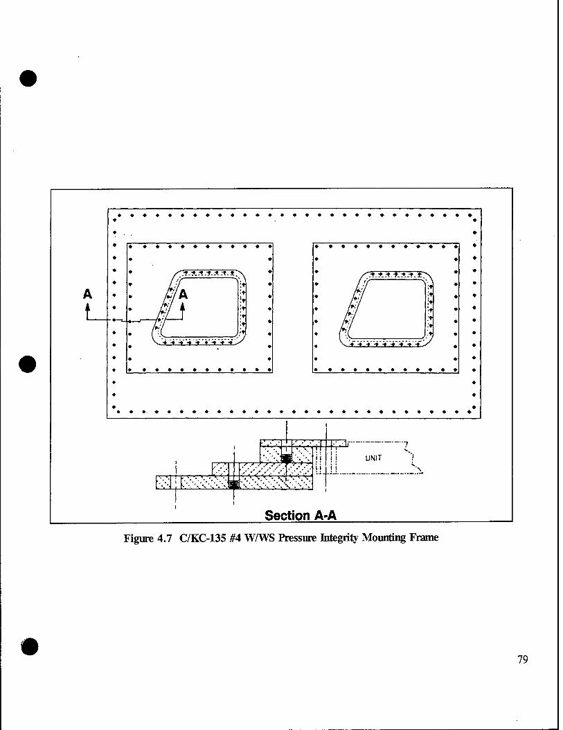
.i-A.-t.-f.A.-t.t:
■tt-t-t t.t -t t -
:■*-■?.*.LASTS'. ;t ;t !t ;t it >
111 -*7 -t t t i 11/
K'--.'''.'v\'--'v'.'
"T*^
f
Vf
:\\5Ä::-.^l5,\>.;" ■^'•■'' \\ •.'•.•-
11 E=*
UNIT
Section A-A
Figure 4.7 C/KC-135 #4 W/WS Pressure Integrity Mounting Frame
79

Skin-
O-ring
Sleeve / ,Nut
/ i„J ."■'■"■ 3-
Window-
' Washer
Bolt
a) #1 W/WS
Window
Bolt
Metal retainer strip
Silicone gasket
-Nut
Window frame
b) #4 W/WS
Figure 4.8 C/KC-135 WAYS Mounting Details
80

Figure 4.9 Typical C/KC-135 #1 W/WS Pressure Integrity Test Set Up
• 81

/ .H
*£-.-w&i
liPlllH a
c« CO
•c OX)
I
s rr =tfc «r>
ä ■a u a
en
82 #

3D 83

rr !
c*
.• ■'*•••:•: •?...;: „sSs* •;- ./.l" :!„.V"''-;.-'- -.'.'.:«i
84 s

Itl Plastic guide tube
Steel ball
Figure 4.13 Residual Strength Falling Ball Test
85

SS
£
«0
86

cc
"3> t»
So
87

13 »
"3D
88 l 3b

89

4>
> V B 2
TT =**:
90
ft»

> ts SS 2
I—<
■<*
=s • KM
fa
91

?
^
UNIT T TT
S-L
JZ^: "^TT
■::■■: ii 11 ; . i : ! I I I I I ,f
UNIT
Section B-B
Section A-A
Figure 4.20 C/KC-135 #1 WAYS Bird Impact Mounting Frame
92

♦ ♦♦♦♦♦♦
f. ."t. ^.it.lt.lt. .t".
♦ ♦
■■t-f1>--f-y-f-f-T--y-
♦ ♦♦♦♦♦♦♦♦♦
A
i
11 'in U r'.■'■' +' W UNIT 44 g
Section A-A
Figure 4.21 C/KC-135 #4 WAVS Bini Impact Mounting Frame
93

i
k T;H"#*':i*a* X« - ■■■■■ ■■
^•■^?&5?i'<> - •iit*"**!f''«»'if SIP1-'- w,*^x;;:»",-.4'C&..^->&. v, ,.
■' :
I«
Wl
s=*fc J1^
je-»
94

© > m , > CM
CO O 3 (0 z X ©
F CD •o
u Q c CO CD O
Q CO
95

96

Figure 4.25 Typical Pre-Test View of C/KC-135 #1 W/WS (Copilot) Prior to Bird Impact Testing
97

Figure 4.26 Typical Pre-Test View of C/KC-135 #4 W/WS (Hlot) Prior to Bird Impact Testing
98

99

SK^ir.-: ■—
100

Figure 4.29 C/KC-135 #1 W/WS Showing No Damage From a 4-Pound Bird Impact at 250.8 Knots (Repaired W/WS, S/N 89-286-HO-697)
101

§§ ■*: * '-m * *■ ■*• *
A ' ^ V.---'" . . !
"""•■." .'.T9*:—' "
Figure 4.30 C/KC-135 #1 W/WS Showing Outboard Ply Failure From a 4-Pound Bird Impact at 251.7 Knots, Front View (New W/WS, S/N 86-H-10-06-007)
102

103

Figure 4.32 C/KC-135 #1 W/WS Showing All Glass Plies Failed From a 4-Pound Bird Impact at 249.4 Knots, Front View (Repaired W/WS, S/N S2-H-10-18-107)
104

105

Figure 4.34 Spall Sheet Condition From a 4-Pound Bird Impact at 249.4 Knots on a C/KC-135 #1 W/WS With All Glass Plies Failed (Repaired W/WS, S/N S2-H-10-18-107)
106

Figure 4.35 C/KC-135 #4 W/WS Showing No Damage From a 4-Pound Bird Impact at 248.7 Knots (Not Repaired W/WS, S/N 4-H-10-9-69)
107

Figure 4.36 C/KC-135 #4 W/WS Showing Outboard Ply Failure From a 4-Pound Bird Impact at 247.5 Knots, Front View (Repaired W/WS, S/N B75-1149)
108

109

-* - . . . • . - ,-*Z -■ •"* '- ' *. . .»:*aiftg. ."!..Ai»..JMJ3ga.|
Figure 4.38 C/KC-135 #4 W/WS Showing a Catastrophic AH Glass Plies Failure From a 4-Pound Bird Impact at 250.8 Knots, Front View (Not Repaired W/WS, S/N 7-H-2-4-35)
110

ac 111

o
©
112 9> a
S

Tension, 1000 psi
20 0
Compression, 1000 psi
-20 -40 -60
»»
Mmg
Figure 6.1 Heat Strengthened Glass Residual Stresses
113


APPENDIX A REPAIR VENDOR AIR AGENCY CERTIFICATES


iiNiri f> :-.T/VTI-T'. or AMI-IIIO
DEPARTMENT OE TRANSPORTATION FEDERAL AVIATION ADMINISTRATION
Kir Kgencp Certiftcate <jVcC7nwetK' EZ22812K
NORDAM TRANSPARANCIES DIVISION
510 S. LANSING TULSA, OKLAHOMA 74120
^um/fincf/M^r/ //ux6 Ab A*<jwnZga£on' /xyni/vlteL< Än< *Ul /*edfiecä<
Ace/a&rur/ Jo- //ve- <e*£cMü/i'm*<n£ x^'ton/ S&>« S&pevuy, xzW M>
x^^^^^^Y^^^'^W^yz^W^ MPAIR STATION
LIMITED - SPECIALIZED SERVICE
£^<xzz9cGfica/&,x^te^xxz^^
t/utä'wnävizwxm/se/P^ INDEFINITELY
Pchmary 71 . 1<)qo _HftttOT.n T). WRISHT ACTING MANAGER, SW-FSDO-15
■53M Gotitotr is nor "Sjransfaabfe, *w «or mw» en«« 1« TOE «*sic «aunts.« IN TOE IXKCTKW uereof. SHMI. «£ IKKGDUTCLT «WWTCO TO TOE «TfHOfSUlTt «ClOWU. OFHCE Of TOE KKML MUSKM «MUMSUMTON
TAA Tom. «XX>-< (1-67) SUPCRSCOCS FAA FORM 390.
A-l

UNITED STATES OF AMERICA
DEPARTMENT OF TRANSPORTATION FEDERAL AV.ATION ADM.NISTRATION
TEtepair Station Operations Specifications OoniimuaCUm/J
„S^sfyt^y'V^qtl^-M*"*"- EZ22SI2K ' ^Wuj^ £r
LIMITED RATIIvG :
Specialized Service Transparency inspection and repair in accordance with Aircarrier Engineering Orders, O.E.M Manuals, and NH 0101-301.
Q^eOaXBC^^u^Aoviäei':
T„1y 3. 1990
FAA Fo.™ 8000—«-» li-«' F01>Mt',l-v
ROY G. WIEDEN "PRINCIPAL MAINTENANCE INSPECTOR
ASW-FSHO-lfj
A-2

UNITED STATES OF AMERICA
DEPARTMENT OF TRANSPORTATION FEDERAL AVIATION ADMINISTRATION
Mix &gencj> Certificate <J\wm.m ew JKQR257L
PERKINS AIRCRAFT SERVICES, INC.
5001 NORTH FREEWAY, SUITE B FORT WORTH, TEXAS 76106
MIM/U £/te- /xecrMOxemeizu' /dMie? ^fedeo^zv S&iria&o'n/ *Aeg,u>la.£öo7i6
/velccfoza/ .to- d/te- A&ta6/ii/i'me?i6 /)ß xzn' S&öw SMaen-cw', xzvid' xA'
y&mAoweved&>'^cfveo<c^Ce,cun'.a/ifwcued Repair Station;
Mf-tU/i/ /ifb&^oltowvrLO/ /xa,&n,a&':
LIMITED SPECIALIZED SERVICE (10-08-93)
zJ/ufc /c&fdcfcccc/e, Mottete' xxxmceted, Aui/veizded^ w/xewofced;
A/UZCC'/xmM#htc&an,'/effecd indefinitely.
vu- *jtc*eoCiorv j& /Ac S&£m*mZU*a£o*'
v juueetr :
May 2, 1991 Kenneth D. Robinson Acting Manager, FTW Jrbuu
IBis Grtifatt is not Transferable, AND ua MAW* ounce m tut usic FACILITIES, ot IN ire LOCATION THEREOF,
SHALL K IMMEDIATELY «crams TO THE Armor KIATE KGIOKU. omce or THE FEDERAL AVIATION ADMINISTRATION
Any alteration of this certificate is punishable by a fine of not exceeding SlfiOO, or imprisonment not exceeding 3 years, or both
FAA Form «O00-« (1-67) SUPERSEDES FAA FORM 3SO.
A-3

UNITED STATES OF AMERICA
DEPARTMENT OF TRANSPORTATION FEDERAL AVIATION ADMINISTRATION
■Repair Station Operations Specifications
LIMITED RATINGS:
I vxyn&viucUi&ns J
vj^j^cy/^cy^rJCn^ JKQR257L ÄA- I szwr Mertittdr £>•
SPECIALIZED SERVICE Repair of aircraft windows, transparent enclosures, structural and non-structural composite panels, cores, flaps, ailerons and radomes.
Above repairs will be performed in accordance with aircraft manufacturer's repair procedures, air carrier approved instructions and Perkins Aircraft Services, Inc., Process Specification PPS0001, Revision A, dated 09-15-93, as revised.
Qle/4aaCe<6/cuUAov&<».- NONE
tyaCe> i'utl**/- ■**" .»'»»itat/'.-
October 8, 1993 Standley H.Cobb %^^
FAA Form 8000—<-t it-73' PMI, FTW FSDO
FORMERLY FAA FORM 3*0.1 PACE 2
A-4

UNITED STATES OF AMERICA
DEPARTMENT OF TRANSPORTATION FEDERAL AVIATION ADMINISTRATION
&tr ggemp Certificate .Act>rn6ew OX4R430M
z//iik .certificate'M'AMued ,tc'
THE GLASS DOCTOR
.te-AcSe' .^ctAtneii' ,add<*eä&' ür 2390 26th AVENUE NORTH St. Petersburg, Florida 33713
u/wn finding -t/iatM<,o<xg,aniyzticn> com/dirt .in- att .vei/iect*
.wit/v,t/ie .veyuivenienä'of ,t/i& ^Federal' sdnioticw Me^ulationA
/xe/ating.' ,tv .t/ie .eltal/äAment .of'an A' agency.; and Mr
ainfioweved ,tc rfiewzte arv afifiwved REPAIR STATION
■t/i/ .tAe- Joäcutina/ .votitig* : MITED - SPECIALIZED SERVICE LIMITED
$Ä& .certificate, .unlete .canceled, iiafiended, w .vewo&ed',
Jiccä-continue .in .effect INDEFINITELY
S8y- *&■*&/""<■■ *ß &* S!£dminu6>a6ne
Olafo issued .- . ~* A /«.•',* &*■- ,- ^ v. ,- «■'*-* •* ^—
September 27, 1979 William J. Truebe, Manager Replacement May 1, 1990 North Florida FSDO-15
This Grtilkatt il not Tramftratilt, «HO WT nuat awn i» THE usie FACILITI£J. O« m THE LOCATIO» THEIEOF. SHALL K HH.ED.ATUY MK>«TtD TO THE ArMOPRIATI «ES.0HAL OFFICE OF THE FEDEUL AVIAT.0N ADI.miSTMT.OI.
Any alteration of this certificate is punishable by a fine o/ m>< exceeding tl.000. or imprisonment not exceeding 3 years, or both
FA* Form 8000-« (1-67) SUPERSEDES FAA FORM 390.
A-5

UNITED STATES OF AMERICA
DEPARTMENT OF TRANSPORTATION FEDERAL AVIATION ADMINISTRATION
'Repair Station Operations Specifications (Toom&ruui&ovi'J
JA* raü-nr(^) ** fi^*> "~ S&r S^oncy '&~&/u~/e jVu*nt~> OX4R430M *" / <*"> .<fa~W Ä-
LIMITED RATINGS:
SPECIALIZED SERVICE - Refurbish and repair aircraft plastic and glass windows, windshields, canopies, navigation light lenses, and other miscellaneous "small transparencies, including nicks, chips, delamination, electrical busses and temperature sensor installation.
All inspections and rework will be accomplished in accordance with the following data as applicable to the unit being worked.
Aircraft Manufacturer's Maintenance Manuals/ Instruction.
FAA Approved process Specification, #1979 Cabin*and Cockpit Windows dated 12-31-84 (as amended).
Air Carrier's Approved Specifications.
FAA Advisory Circular 43.13-1A, Acceptable Methods, Techniques, and Practices, Chapter 9. Windshields, Enclosures and Exits.
Z/feJeaaled> auS/iovf/ief: NONE
QlaU «U-W o*- ««W.- &» <*» SlUmdmut™6>~ :
May 1, 1990 ___^_ Kenneth sTTrocKett Principal Maintenance Inspector FAA Form 8000-4-1 11-751 FORMERLY FAA FORM 3SO.I PAGE 2
Page 1 of 1
A-6

Visual Inspection Map & Comments
£h\ /Q^J I)*>JLAr» /"-> KXL+7*J &IL /Mlno^J.
■u^:r-
Thickness Template
©#?/ (D^
©*tf ®ti)
Deviation Template
B-81

KC-135 Transparency Review Data Sheet Pilot/Co-Pilot #4 Window
Customer Part Number: .T- 7/V !b 'f *~ ^°/
Unit Serial Number: 9A 0^7- //O 1/70
Acc/Rej Date Inspector
Bus to Bus Resistance: ptc&i ^'.JLU7? ___1_E_ '7M>H Ohms
Thermal Image: .f-^fJ ^jg
insulation Test: Power to Metal: &W MAY 26 1993 22 PPG 77 (2500 VAC)
Nesa Scratch Test (81 VAC) fo/t MAY26 13& Z2 pp6;/?
• ,_ m ^^^ MAY 26 1993 22 PPG V Light Transmittance: /Qi <P " "
Haze: // 3
Photo (Single Exposure):
MAY 26 1993 22 PPG-r
2 6 MAY 1993 22PFS47
Deviation Inspection: (German Light per Template) l:_3_ 2: 3 3:_i 4:^
M&L. MAY 26 1993 22 PPG 7?
Dimensional Inspection:
Unit Thickness: ßfiss f-?S~-?3 2LftPR28 (Per Template) _ l:£Ül 2: AH 2:M I: Ate
Check for Vinyl Cracks: ,/d* &* Q21B33 * PPs 77
Seal Evaluation: /£*■** JUN 021588 22 Ppfi y
(Comments)
Z^^V JUH02E93 22PPG77 visual Inspection: /¥±S=— H1L. (Place comments on attached sheet)
B-82

Visual Inspection Map & Comments
Thickness Template
©it? §jpL
0*P © V
Deviation Template
B-83

KC-135 Transparency Review Data Sheet Pilot/Co-Pilot »4 Window
Customer Part Number: S- ' 'Q 7 ~ -S Q /
Unit Serial Number: /A- ° 9 0 n° S? f
Acc/Hej Date Inspector
Bus to Bus Resistance: $€/>> <*r VJ--17 2ZPJ52Z v> % V Ohms
Thermal Image: Jr-^li^ &!&&
insulation Test: Power to Metal: MA MY 26 A93 22PP6W
.(2500 VAC)
Nesa Scratch Test (81 VAC) .-
Light Transmittance:
Haze:
Photo (Single Exposure):
Deviation inspection: frO/lS (German Light per Template) ^ 1: 5* 2: X" 3: 3 4: 3
Dimensional Inspection:
#^ MAY 26 1993 22 PPQ ;?
rjjj^ MAY 26 1993 22 PPG 77
/ p^ "AY 25 1333 22PPG r
slWW 22PPG47
MAY 26,1993 a PpG 77
22£PG28 Unit Thickness: l/SSs, 4 ~Xj>-{3 _^_ (Per Template) > 1:,£93- 2:,/,^3 3:.6n ±:_J£L
Check for Vinyl Cracks: fi^L JUN"21993 a PP6 W
Seal Evaluatxon: F±4^K
(Comments) StA^L J-crti^ (hvf
iZLstsL- JUN 0 2 1393 a pft» ^ visual Inspection: A^^^ . "^ ■ (Place comments on attached sheet)
B-84

Visual Inspection Map & Comments
t
-=>
S<raJL L-o-ast A£ MMO^A
Thickness Template
06*3 @y
Qtf* ®(s?D
V Deviation Template
B-85

KC-135 Transparency Review Data Sheet Pilot/Co-Pilot «4 Window
Customer Part Number: 3— ///o Y ~~ -^0'
Unit Serial Number: '7JI-0 9.1 t/o -?f-l^
Acc/Rej Date Inspector
Bus to Bus Resistance: * ,. tl-6?J- 7vr7J _ bTi'U Ohms
Thermal Image: -? ^7 fji
insulation Test: Power to Metal: A4A< mUWZ _JÜ^_
d^„ ^ 26 1993 22PPG77
?ff/ WAX 26 B33 22 PPG T7
j,d MAY 261993 &f?^
(2500 VAC)
Nesa Scratch Test (81 VAC)
Light Transmittance:
Haze:
Photo (Single Exposure):
Deviation Inspection: (German Light per Template) 1: »T 2: ? 3: 3 4:_i_
Dimensional Inspection:
2 6 MAY 1993 22PP647
/^/ MAY 26 1993 * ^ "
Unit Thickness: #&> 1-tfU JW*28_ (Per Template) . l-.iÄÜL 2:,/»Xb 3:.M *'-.f?W
Check for Vinyl Cracks:
Seal Evaluation:
(Comments)
fy^ JUN Q21993 & PpG „
/Q^KL- JUN Q21993 22 PP6 ff
Visual Inspection: (Place comments on attached sheet)
fl»^ JW O2^3 22PP677
B-86

Visual inspection Map & Comments
Thickness Template
©tf* (D*
©Wfr 01,
Deviation Template
©$■ dP
©j
B-87

KC-135 Transparency Review Data Sheet Pilot/Co-Pilot #4 Window
Customer Part Number: S> ~ OVC7 & V ~~ So /
Unit Serial Number: 9.-3. - Ö 73 - //0- 3$£
Ace/Rej Date Inspector
Bus to Bus Resistance: //xZC/ ,^-A-y "VÖ '731 / Ohms
Thermal Image: -r> -/-V-7J '
insulation Test: Power to Metal: AtA MAY 26 1993 & &*V
(2500 VAC)
Nesa Scratch Test (81 VAC) .- Ü€>f m 26 1993 « pPG 7*
Light Transmittance: *&£ M^ 2 £1993 22 PPG 77
Haze: /«^ «AY 2^:;=? 22 PPs »
r, ,? MAY 1993 Photo (Single Exposure) : " " "lt" w ??PPSä;
Deviation Inspection: j^tvt^/ MAY 9.ft 1933 (German Light per Template) l: 5 2:_5_ 3: S 4: 7
Dimensional Inspection:
22 PPC 7*
Unit Thickness: /Z* s ftt4l ^EPG28
(Per Template) . 1:JL£*1 2:^Ai£ 3:^^/ 4:,^
Check for Vinyl Cracks: &6A JUNQ21393 ^PP*»
tu^r JUN 021^3 ?p«w Seal Evaluation: /feK3-£ v rq"
(Comments)
A** JUN 02 1993 ,,,*««i Visual Inspection: rWB g1"" (Place comments on attached sheet)
B-88

Visual Inspection Map & Comments
Thickness Template
©b& ®6?i
(Dbrt <§>&?!
Deviation Template
@r
®^ ©?
B-89

KC-135 Transparency Review Data Sheet Pilot/Co-Pilot #4 Window
Customer Part Number: S- 7/7^ V--£"<> / (Jj,. "■
Unit Serial Number: S — n - JlX~/o ~" 7/
Bus to Bus Resistance: ',0h0 Ohms
Acc/Sej Date Inspector
<r-M3 ftg*g
Thermal Image: .^2/-t3 B^B
insulation Test: Power to Metal: /ICC MAY i> 6 1993 22PPS4^— (2500 VAC)
Ql{ MAY 2 S 1353 gpp^
y| ^ MAY 2 S 13S3 2PPG43
Nesa Scratch Test (81 VAC):
Light Transmittance:
Haze:
Photo (Single Exposure):
Deviation Inspection: (German Light per Template) l:^WtX>*>2: ^? 3: ^>
/,jf -WY £3 %83' 22PPG43
.ppg 47 J«U«a W A, JUN 0 8 «93 fefPG39
Dimensional Inspection:
Check for vinyl Cracks:
Seal Evaluation:
(Comments)
Unit Thickness: (Per Template) ^ X-.MJL- 2: .179 3:^14 4:«£7f
xw?
<&v^ C-Zd-93 &mn
JUN 03 1993 »PPG/7
/?gJT J^N 0 3 1993 a»Pp«m
Visual Inspection: (Place comments on attached sheet)
^g5~ JUN c 3 1993 ° "^ 77
B-90

Visual Inspection Map & Comments
A/fi a*J !k/*~ ALU APsi,lAsJ 2J** *t ^r^
Thickness Template
©*^ ©£,
b9? (DM* ©
V Deviation Template
B-91

KC-135 Transparency Review Data Sheet Pilot/Co-Pilot #4 Window
Customer Part Number: _5~ f J 71> r ~~ S& I
unit Serial Number: /Y- l-f- /O — /S- /3-£. 3
Acc/Rej Date Inspector
Bus to Bus Resistance: /£*/_ J~'M'93 _JE_____ 7 7-3 Ohms
-, T r~2M-4l 22EPG2," Thermal Image: J> s+t 7~ -
insulation Test: Power to Metal: fail MU6 «3 a "P°" (2500 VAC)
22 Nesa scratch Test (61 VAC) : j&dJ, ^ MAY 26 1933
y/\ J MAY2e:r=3 22PPG?; Light Transmittance: oui i «_rr»_
Haze:
Photo (Single Exposure) 2 sWAY 1993 22ppG47
Deviation Inspection: (German Light per Template) 1: --? 2: ? 3: 3 4:_=5_
Dimensional Inspection:
jfaf/ HAU 8 A® 22PPS77
Unit Thickness: ■A-^AJ&Z &2S-93 (Per Template) l:.7/>0. 2:* 7b» 2:. 7*9 4: ,7/?/)
Check for vinyl Cracks: $<e3
Seal Evaluation:
JUN 021993
82933 Z?
22 PP6 n
t,X JUN021"3 22PP8 77
(Comments) &//ffl>uc ^<-/»£ tfo> övrßJ fx,M A^ /^^/J^
Visual inspection: J^^ JUM21S93_ « tfj p (Place comments on attached sheet)
B-92
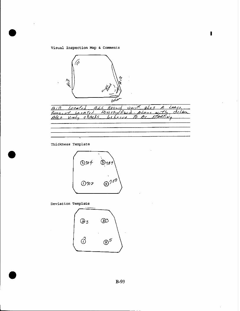
Visual Inspection Map & Comments
0<f; U**~
Thickness Template
©70 f ®1l>?
(±)107 ©
Deviation Template
B-93

KC-135 Transparency Review Data Sheet Pilot/Co-Pilot »4 window
Customer Part Number: 3 — 3 // o l~ J3 Wj-J
Unit Serial Number: j- f-f- I —J4-6 — n /
Bus to Bus Resistance:
Thermal Image:
tfStfr Ohms
Acc/Rej Date Inspector
22 PPG 28
Insulation Test: Power to Metal: {HCJL (2500 VAC)
Nesa Scratch Test (81 VAC)
Light Transmittance:
Haze:
Photo (Single Exposure):
Deviation Inspection: (German Light per Template) l: f. 1 2: 6 ? 3:_£i_ 4: <-J
MAY 2 6 1993 22PPG43
0 £ MAY 2 6 1993 22PPG43
<g7, i MAY 2 S 1563 gPPSC
22 PFG 47 ^14^ Zppcx
£. JUN ft 9 1893 tt r.-a ja
Dimensional Inspection:
Unit Thickness: (Per Template) l;,^7* 2:,^/ 3:^j7.
Check for Vinyl Cracks:
Seal Evaluation:
(Comments)
4:^zi JUN 0 3 1993 a 9d<» «*
£jf-j& JUN Q31993 _f^ 9d<»#
Visual Inspection: /ycO (Place comments on attached sheet)
JUNO ol933 >r3
•-i.'.o "*
B-94

Visual Inspection Map & Comments
T)P /,&rr^ A~J //-/~ß /hU. ##ot*"<i trfk^f
Thickness Template
Deviation Template
B-95

KC-135 Transparency Review Data Sheet Pllot/Co-Pllot »4 Window
Customer Part Number: b "a K3-> /" /
Unit Serial Number: _$— M~~ 7 ~ «■*• &" /«ay
Acc/Rej Date Inspector
Bus to Bus Resistance:
Thermal Image:
#7/ ftohms
Insulation Test: Power to Metal: (2500 VAC)
Nesa Scratch Test (81 VAC):
Light Transmittance:
Haze:
Photo (Single Exposure):
ike.
Deviation Inspection: (German Light per Template) l:_A3 2: ^ S 3: •*- 3
0Ä
fl, Id.
4: 2_.
r-2/-& ***** MAY 2 6 1993 ^P^
MAY 2 6 1S93
MAY
•v'>V «■> - 1"V
£->?3
22PPG43
22PPS45
TOP'- w
22 PPG 47. JUNli/?^ ^
^ **"
Dimensional Inspection:
Unit Thickness: tic*. ?'&& SffCffl (Per Template) l:,£7f 2:^71 3:^_ 4:W^£i
Check for vinyl Cracks:
Seal Evaluation:
(Comments) _
feg JUNO 31993 '«PEST?
SfyU. APJ fbfhd 3o/?*fi><*A <£>*- OofA«-
visual Inspection: (Place comments on attached sheet)
fi*5 JUN 0 31993 Kjf8SF
B-96

Visual Inspection Map & Comments
fleJ-AvT\ .4-3 rv^n^JCe ■£>
Thickness Template
(5&9? ©^
©*w ©*ö
Deviation Template
B-97

KC-135 Transparency Review Data Sheet Pilot/Co-Pilot »4 Window
Customer Part Number: S— / l/Vy ~ /3 ^f-^
Unit Serial Number: V-//- JO- / S~"_ /Q%
\~
Bus to Bus Resistance:
Thermal Image:
Insulation Test: (2500 VAC)
ftf. 7 Ohms
Power to Metal:
Nesa Scratch Test (81 VAC):
Light Transmittance:
Haze:
Photo (Single Exposure) :
Deviation Inspection: (German Light per Template) l: i- 3 2: ^2) 3:^ 3
Acc/Rej Date
_____ ,f#-f? Inspector
22.EEA28
22^1»'
22PPQ43
0 ^ MAY 2 6 1993 appQ«,
22 pfG 47
tf-c-C"
^ 3,
MAY 2 6 1S83 22PPG«!
.mm-1993
zy?$4
ZPPCi
ZPPG 10
Check for Vinyl Cracks:
Seal Evaluation:
Dimensional Inspection:
Unit Thickness: (Per Template) l:,/;7f 2:,Ay} 3:- U& 4:,/^4
fite^
JUKI A 1993
(Comments) ftd--^ •£r,oyC ifr^/ (buyfS^f-
■■X-f?) &e&n
fa JW 031993 app877
^ ^ JUN 031993 ggp^y?
Visual inspection: ifcT JUN<>31S53 ■ ■* » (Place comments on attached sheet)
B-98

Visual Inspection Map & Comments
LöartTZ. J -7J&) o c/z)07" rfe L"Vt 7"
/Q-ffL /W DeZsfr« J^n*&s{ &// /MZJO^cJ Ul",7
Thickness Template
©frZ? ©bti
(D6tf &>#
Deviation Template
B-99

APPENDIX C BIRD IMPACT DATA SHEETS

PPG Industries-Bird Impact Data Sheet KC-135 Test Program
for Battelle
Sample I.D. 5 - 89 36,4 - Sol S/N Si- H~\Q -Q<.-OC>7 Date 4>/2Z/<H
Bus to Bus "3*7-5 OHtAS De lamination chk. OK
Requirements:
High Speed Film (3 cameras) NSS Spall Shield Installed VSS
Test Conditions Requested Actual
Temperature I.B. U.T. 7©'F Temperature O.B. ^^T• 7o°p
Bird Wt. (lbs) 4.o 4.0T-0
Bird Speed (kts) "iSo-O •2.51-7
Ambient *F 7o°P
4S° impact Loc. - Installation Angle Sweep Back -z_ O Angle Je!
N£u> *l 1^1* g.U.
Shot No. : "783 Test Date: (*/ZlJ?3 Tested By: //€*<?•
Test Results:
ftt£«*JL0 M.t>o*Tt»<Z O-^MÄJ PAoßfißLG *AoS£-,
PPG Witness: A Date: (.hi/??
C-l

PPG Industries-Bird Impact Data Sheet KC-135 Test Program
for Battelle
Sample 1 .p. 5- S?354-^ol. s/N <80H-l«>-OU-3o Date (~l?.7.fo3
Bus to Bus OT O Delamination chk. Ofc-
Requirements:
High Speed Film (3 cameras) NCS Spall Shield Installed ~JZZ£
Test Conditions Requested Actual
Temperature I.B. G..T- 7Z°P Temperature O.B. fc.T 72*F Bird Wt. (lbs) 4-0 4-ovo Bird Speed (kts) iSo-o "2SI-I
ti£L± fr I 1^3 E-U.
Ambient *F
Impact Loc. ■ Installation Angle Sweep Back Angle
72 °F
4S° 3o
Shot No.:_TS4_ Test Date:_k/2Zifl3_ Tested By: Hgg-
Test Results:
ToV eoae-. ^ftr^e fcfAs*AJ.r ^ Stf*r# 7S3.
PPG Witness: ^V^i^^X- Date: 4/Z?/9?
C-2

PPG Industries-Bird Impact Data Sheet KC-135 Test Program
for Battelle
Sample I .P. 5-W 354~ Sol S/N gl-H-tO-OC»-27. Date U^3l93
Bus to Bus 33»Co Delamination chk. OK-
Requirements:
High Speed Film (3 cameras) H<£S Spall Shield Installed TfS*
Test Conditions Requested Actual
Temperature I.B. tt.T* IZ'P Temperature O.B. l.T- 1Z. F Bird Wt. (lbs) 4.0 4'0|0 Bird Speed (kts) 2?o.c 1SZ. fe
H£^ *l c^/5 R-H.
Ambient *F
Impact Loc. - Installation Angle Sweep Back Angle
7Z°F ceKrcA-
4S*
Shot No. : 7%>5
Test Results:
Test Date: 4»/Z3J93 Tested By: Hg^
Jslo t>^M/v<j.er . l4o B/H0 JLes/ßoe- C*J oarnvffsr FcATE".
PPG Witness: %^r»^N^-^ Date: &fa/97
C-3

PPG Industries-Bird Impact Data Sheet KC-135 Test Program
for Battelle
Sample I .D. S-Sl 3 54-Sb 1 S/M SC-H--JO -Ol-oUpate Cll4h3
Bus to Bus 33> S Delamination chk. OIL.
Requirements:
High Speed Film (3 cameras) ^6^ Spall Shield Installed "H€.S
Test Conditions Requested Actual
Temperature I.B. fc-T- 13 °F Temperature O.B. SLT. 73 V Bird Wt. (lbs) 4--0 4-. o(o Bird Speed (kts) 2So 2.si,c
rA£U> l u^/s £.u.
7?V Ambient *F
lmpact Loc. CgMTTsr/L Installation AC ° Angle — Sweep Back 3©° Angle
Shot No.:_7_S£e_ Test Date; (j74lQ3 Tested By: 1"*6<S
Test Results:
PPG Witness: HÜLa. Date: Uzffa?
C-4

PPG Industries-Bird Impact Data Sheet KC-135 Test Program
for Battelle
le i.D. S-SS354- Ce>/ S/N_e3z]±r£LIiS^lß"2- Date_2il3i93
Delamination chk. ^<-
Samp
Bus to Bus T1!- I
Requirements:
High Speed Film (3 cameras) ^ (£S Spall Shield Installed l€S
Test Conditions Requested Actual
Temperature I.B. Vt/c. 7^0F Temperature O.B. H.T. 71V Bird Wt. (lbs) 4.o 4.co| Bird Speed (kts) 15 o 14- <*.<•
toftioeo *"i uls L.H-
72°F Ambient *F
e€MT£(L Impact Loc. Installation 4^° Angle Sweep Back — o Angle *=
Shot No.: "7^1 Test Date: l/l?l<?3 Tested By: Hg"g-
Test Results:
PPG Witness: diL Q+*JL Date: lltf/93
C-5

PPG Industries-Bird Impact Data Sheet KC-135 Test Program
for Battelle
Sample I.D. 5-ftq354-5of S/N 83-H-g-lS -19c Date7/l£!23
Bus to Bus T"t»-0 Delamination chk. OK>
Requirements:
High Speed Film (3 cameras) M^S Spall Shield Installed *i€l
Test Conditions Requested Actual
Temperature 1.B. (L.T- -73°F Temperature O.B. (L.T- 13*f Bird Wt. (lbs) 4o 4,<3©S Bird Speed (kts) •zs<* 1A1A
4fe
Ambient *F
Impact Loc. - Installation Angle Sweep Back Angle
73°r CgMTg<-
4S°
Test Date: lll9J?3 Tested By: HfeCr Shot No.: T*3
Test Results:
PPG Witness : ^/^ffrC^^- Date: ilfttoj
C-6

PPG Industries-Bird Impact Data Sheet KC-135 Test Program
for Battelle
Sample I-P. 5-&^3>9^t ~5o| s/N «B^-fr-VI S-T2.Q Date7/-Zo/9^
Bus to Bus 44*» 5 Delamination chk. <att-
Requirements:
High Speed Film (3 cameras) W£5 Spall Shield Installed VfiTJ
Test Conditions Requested Actual
Temperature I.B. d.T. 13°ip
Temperature O.B. J-T- 73 °F Bird Wt. (lbs) 4.o A-coo Bird Speed (kts) -L^o 2S«-M
9eP»ti.eo ^< Ui L.H-.
Ambient *F -
Impact Loc. - Installation Angle Sweep Back Angle
73°/*
3o°
Shot No.:_254— Test Date: 7'2AI 93 Tested By: Hlg^-
Test Results:
PPG Witness : U>Q£rt£l '***•£- Date: 7/2c/9?
C-7

PPG Industries-Bird Impact Data Sheet KC-135 Test Program
for Battelle
Sample I .0.5-&\3S+- Sb/ S/N »>- H--/2 -Ql ~l<Ko p«t«2^(g_?
Bus to Bus SC+'S Delamination chk. <£^C-
Requirements:
High Speed Film (3 cameras) ^g* Spall Shield Installed V€Lf
Test Conditions Requested Actual
Temperature I.B. fc,T- 75 °F Temperature O.B. CT. 15°F Bird Wt. (lbs) 4o 4.0IO Bird Speed (kts) IS* vsz.q
tofrmeo *1 ulf L-R.
Ambient .F QQ»^>> TS*
Impact Loc. _QÖÜS*=— Installation A.c° Angle -i> Sweep Back 3c*° Angle ^^
Shot No.: 7?5 Test Date: 7/2Q/9J Tested By: WSGr
Test Results:
PPG Witness: l/JUn—^ Date: 7/?o/?J
C-8

PPG Industries-Bird Impact Data Sheet KC-135 Test Program
for Battelle
Sample I .P. 5-tt 2<5*\" 5o( S/N fel->V-lC-lft-(Ol Date 7/?ofo?
Bus to Bus 4l-*3 Delamination chk. OlC
Requirements:
High Speed Film (3 cameras) S^S Spall Shield Installed i€.£
Test Conditions Requested Actual
Temperature I.B. fc-T- is °r Temperature O.B. 9-T. ■75°F Bird Wt. (lbs) 4.0 4.e>lo Bird Speed (kts)
^0 •*<M
toftMUfO *l ^3> L M-
Ambient *F
Impact Loc. Installation Angle Sweep Back Angle
7£>
45° 3ö'
Shot No. : "Mt- Test Date: "lllo!^ Tested By: H-CG-
Test Results:
PPG Witness: //.HcreO^-* Date: lfeo/qS
• C-9

PPG Industries-Bird Impact Data Sheet KC-135 Test Program
for Battelle
Sample < n 5-^354-5oi S/uJ^M^±k^^5_ Date 7/?]/"K
Bus to Bus 43»^ Delamination chk. Ofc-
Requirements:
High Speed Film (3 cameras) N€S Spall Shield Installed t€?
Test Conditions Requested Actual
Temperature I.B. %x- i«rr Temperature O.B. &T. lo-F Bird Wt. (lbs) 4.o 4.o^5 Bird Speed (kts) T-So 7_St-0
7o°F Ambient *F - «. , C€HT€IL.
Impact Loc. Instal1 ation Angle Sweep Back 3&0
Angle
Jfc£
ftg?M(ugp *1 ids L.H-
Shot No. : "HI
Test Results:
Test Date: ifal*?? Tested By: \MSG
CL>rs**-M> Pe/ F«^csO- ^vtC ^<-V /"r/v^
PPG Witness: Date: 7faftfr
C-10

PPG Industries-Bird Impact Data Sheet KC-135 Test Program
for Battelle
Sample I .D.5-B1 35<j- Sex
Bus to Bus 45 '"7
s/Nfe3-H""-*A-3Z5- Datelfal<%
Oelamination chk. ^^K—
Requirements:
High Speed Film (3 cameras) ^€5 Spall Shield Installed ^^
Test Conditions Requested Actual
Temperature I.B. OX- 7>°P Temperature O.B. Ox l*mF Bird Wt. (lbs) 4.0 4.00S Bird Speed (kts) TJZo TA15
ylgp»H_eo *1 MS L-H.
Ambient "F IsZL C&X&- Impact Loc.
Installation A.C0
Angle -"— Sweep Back Angle i*
Shot No.: *7?f Test Date: 7»^l f?T Tested By: t4C&
Test Results:
/UA. PciCf f^H-20. CJ»A^ ?L-i £P**-<~<£0 But- A/C*J6" O*>
udfl>ie-<ff POT«-
V
PPG Witness: jl^r^* * Date: il-uhi
c-11

PPG Industries-Bird Impact Data Sheet KC-135 Test Program
for Battelle
Sample I -P. S-tt3MS*>f s/N W-lCh-HO-W Date?/?*7<??
Bus to Bus J Q'O De lamination chk. StL-
Requirements:
High Speed Film (3 cameras) 1C; Spall Shield Installed "/CS
Test Conditions Requested Actual
Temperature I.B. «JT US-F Temperature O.B. fLr- <*?V Bird Wt. (lbs) 4-.o 4.o»o Bird Speed (kts) ISO 2^0%
9<£P*tt «o
Ambient *F
Impact Loc. - Instal1ation Angle Sweep Back Angle
US°F
3©°
Shot No. 79* Test Date: "?l2rt_l 93 Tested By: 1+F5-
Test Results:
PPG Witness: ^ TSÜ*«-**^ Date : 7/Z2/S?
C-12

PPG Industries-Bird Impact Data Sheet KC-135 Test Program
for Battelle
Sample I .D. 5-^? 3S~? - I
Bus to Bus t \'[
S/N B75~U<^ Date gill*»
De lamination chk. SSg ."OfcTA S HggT"
Requirements:
High Speed Film (3 cameras) ^fi Spall Shield Installed Y€S
Test Conditions Requested Actual
Temperature I.B. O.T. ll°F Temperature O.B. ILT. "?i°F Bird Wt. (lbs) 4.a 4.0/5 Bird Speed (kts) ZSo ^<r"?.5
7!^ Ambient *F
lmpact Loc. CgHTS^ Installation £SJ.T_° Angle Sweep Back Angle 35
toftnuso *4 iad&>^ U.U-
Shot No. :^5 Test Date:^! I ll3 Tested Bv:H-g"<a
Test Results:
PPG .« ^u^ Date: q/>/?5
C-13

PPG Industries-Bird Impact Data Sheet KC-135 Test Program
for Battelle
Sample l.D.b"-1l1t.4-5o| s/H Ql-blatte-41) Date^llh?
Bus to Bus (xfi\t ^ Delamination chk. Q|C
Requirements:
High Speed Film (3 cameras) ^CS Spall Shield Installed *J&
Test Conditions Requested Actual
Temperature l.B. fc*T- 1l°f Temperature O.B. a.T. -ir-F Bird Wt. (lbs) 4.0 4.ÖZ.O
Bird Speed (kts) IS* ZSI-3
ll°F Amb i ent * F -
Impact Loc. C&fiTGk- Installation eoi° Angle Sweep Back Angle 35
ls\gt-o.^^ LfrlriOot-» L-H-
Shot No. : ^H*> Test Date: ^11/93 Tested By: fl€"<S
Test Results:
PPG Witness: ä.QU^ Date: <?///??
• C-14
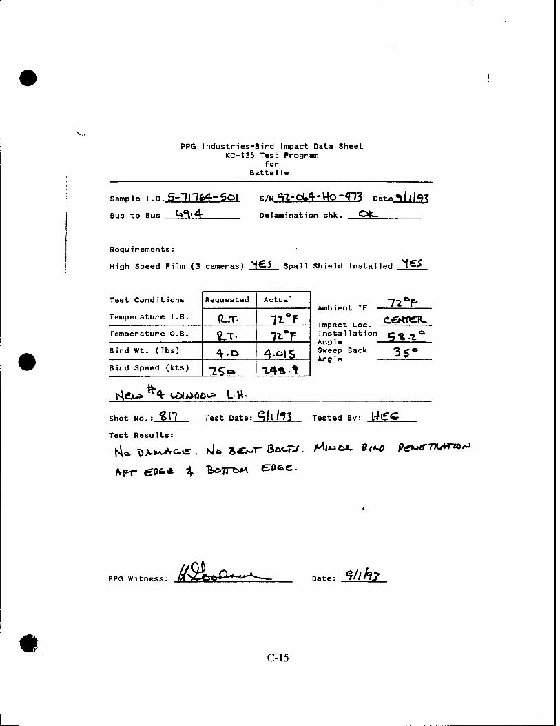
PPG Industries-Bird Impact Data Sheet KC-135 Test Program
for Battelle
Sample 1.0.5-111^4-501 S/W CtZ-tiLA- UP -WZ Date"l/lly
Bus to Bus (■*^'*T De lamination chk. Ofc.
Requirements:
High Speed Film (3 cameras) N€5 Spall Shield Installed |€>
Test Conditions Requested Actual
Temperature I.B. (LT. ii°r Temperature O.B. «LT- l-LmT Bird Wt. (lbs) 4.o 4.^5 Bird Speed (kts) 1S«=> T4*-*l
4t
Amb i ent * F
Impact Loc. - Instal1ation Angle Sweep Back Angle
7i°P
35°
Shot No. Jgjl Test Date: Qll f?3 Tested By: l4(£"^
Test Results:
PPG Witness: fl2Lo~^_ Date: Vihy
C-15

PPG Industries-Bird Impact Data Sheet KC-135 Test Program
for Battelle
Sample I -P. S- 1\1L^ Soi S/tiQZ-OS^'WaSS* Date5Üll3
Bus to Bus "7&* \ Delamination chk. Ql^-
Requirements:
High Speed Film (3 cameras) N<£> Spall Shield Installed {SJ
Test Conditions Requested Actual
Temperature I.B. (LT- 72.V Temperature O.B. M-.- -ixV Bird Wt. (lbs) 4.0 4ä1O
Bird Speed (kts) "2-So 1.7S-I
Ambient *F
Impact Loc.
m^r- CaaTCJl-.
Installation co -» ° Ang1e 5g'1 Sweep Back 7c © Angle —
Shot No.: €l% Test Date: Sfl/9? Tested By: #€<«•
Test Results:
PPG Witness: •aL £. grfc*» Date: 5///9?
C-16

PPG Industries-Bird Impact Data Sheet KC-135 Test Program
for Battelle
Sample I .D.5-"7I"144- S«>f
Bus to Bus >oS.«3
S/NOn-OlS-HO-aoL Date *?/*?/<%
Delamination chk. QIC
Requirements:
High Speed Film (•» cameras) Vfcj Spall Shield Installed \^>J
Test Conditions Requested Actual
Temperature I.B. <u- 7? v Temperature O.B. ILT 77-/= Bird Wt. (lbs) 4.o 4^/5 Bird Speed (kts) 15-0 Z4S-4
Ambient *F
Impact Loc. Instal1ation Angle Sweep Back Angle
35°
HfcL^>M QM0OQ* L.H-
Shot No. $3S Test Date:^ilSii2_ Tested By: H<£C
Test Results:
l4c> t)AHM.^-<be
PPG Witness: ^WSW*-. Date: ql79l?J
C-17

PPG Industries-Bird Impact Data Sheet KC-135 Test Program
for Battelle
Sample . .D.S'll ~7fc<t- 5o( S/M q?-UQ- Bo - ISO, Date_3/*Sft?
Bus to Bus C^pQ Delamination chk. Otv
Requirements:
High Speed Film (3-cameras) v&> Spall Shield Installed l&S
Test Conditions Requested Actual
Temperature I.B. «.T. 13 °r Temperature O.B. «-T. 13 V Bird Wt. (lbs) 4.0 4-.00S Bird Speed (kts) ISo 747-S
Ambient *F -
Impact Loc. - Installation Angle Sweep Back Angle
13 V
islQ-**1- can>*»^ L-H. - ftgtufcosraeM" pad s&r ff8t8
Shot No. : 85^»
Test Results:
Test Date : <*to/?J Tested By: <*£&
PPG Witness: ^^saöfc-^. Date: %l7Ah>
C-18

PPG Industries-Bird Impact Data Sheet KC-135 Test Program
for Battelle
Sample I .D.7-TP&/f-5of
Bus to Bus C>V£n
S/N feS-U-0-7-01-111 Date ^/iq/9J
De lamination chk. 5GC "DftTA 3tJ€gT
Requirements:
•
High Speed Film (-»-cameras) ,N/CS Spall Shield Installed TfcJ
Test Conditions Requested Actual
Temperature I.B. *LT> 13 aF Temperature O.B. i-T." I3~f Bird Wt. (lbs) 4.0 4.0/S Bird Speed (kts) ^ro ifirin
Amb i ent * F
Impact Loc. Installation Angle Sweep Back Angle
J13L
3r°
RaMifo 4 ü^»&«^ L.H.
Shot No.:S3T Test Pater Ml*}! ?3 Tested By: HE"<a
Test Results:
l\lo DA-M.^«c-
PPG Witness : //>%UlV-*^ Date: ?fc?fo
C-19

PPG Industries-Bird Impact Data Sheet KC-135 Test Program
for Battelle
Sample I -P. S-1hfc4-SP<
Bus to Bus OpQA
S/N^oMT3räO£77j_ Date^/lSf??
Delamination chk. OK—
Requirements:
High Speed Film £-3 cameras) SC? Spall Shield Installed "f€15
~H°r Test Conditions Requested Actual
Temperature I.B. e.cr- "?«•> Temperature O.B. ILT. "74-V Bird Wt. (lbs) 4.» 4-oc5 Bird Speed (kts) Zfo "*47-/
Ambient *F -
Impact Loc. Q^-^^ks- Installation 5^«7_° Angle — '■ Sweep Back Angle 3S
U£>A-lLg-Q *4 L&n*POto» Uri.
Shot No. : €3& Test Date: ^f^^J Tested By: //CG
Test Results:
NUT>MA,A-&<S
PPG Witness: tf$!L&s Date: f/?9/<?3
C-20 •

PPG Industries-Bird Impact Data Sheet KC-135 Test Program
for Battelle
Sample ■ .P.9-H"M-flOH? S/N S-H-5-23-S4 Date Sl3ohj
Bus to Bus US-O Delamination chk. Sflg" ftATAr StfCgT
Requirements:
High Speed Film (^cameras) "H& Spall Shield Installed ^£S
Test Conditions Requested Actual
Temperature 1.B. ILT 7o°r Temperature O.B. i-r i**r Bird Wt. (lbs) «..o 4-oiS Bird Speed (kts) iSö •LSl'-L
Ambient *F
Impact Loc. - Installation Angle Sweep Back Angle
Shot No.:_S33_ Test Date:^(3S ft?3 Tested Bv:H"C<a
Test Results:
O*<c%&f\i-o P<-y 'Sxuaicei^ . ^ö Bet* poaöT7T»-^-r/o<o
PPG Witness: pf^>Qf&&l Date: ?/&/?.?
C-21

PPG Industries-Bird Impact Data Sheet KC-135 Test Program
for Battelle
s-ni. i.pVirM-''»* c*&-H- s/ul-tt'l-^-35 Date Si Jah 3
Bus to Bus ll^,«^ Delamination chk. SS£ Dftflfft Stt€&r~
Requirements:
High Speed Film (J- cameras) ^£5 Spall Shield Installed ^SS
Test Conditions Requested Actual
Temperature I.B. \L,T- 1I°P Temperature O.B. |UT. -11 °F Bird Wt. (lbs) 4.o 4.«=«jr Bird Speed (kts) ISo "ISo-S
to*Hu£Q *^ U>l~PO«^ • <-.H
Jlli. Ambient *F
Impact Loc. Installation 58 »Z° Angle Sweep Back jr* Angle £-*
Shot No. :_|[££_ Test Date:_3i2^3i Tested Bv: rfl£<S-
Test Results:
£*jrnu- ccArr 5^cno/o re><c*-> ©or- >a-r /A^T cfTcr.
PPG Witness: A/S&*&~~^- Date: C/?*/9>
C-22

PPG Industries-Bird Impact Data Sheet KC-135 Test Program
for Battelle
Sample I.D.5-*?nfc4
Bus to Bus fe<ä. S
S/M 4-rt~ t&-^-fe^ Date Wohl
Delamination chk. 2>€€. DATA 5tf^ST"
Requirements:
High Speed Film (^ cameras) ^6S Spall Shield Installed l^S
Test Conditions Requested Actual
Temperature 1.B. SLx li°r Temperature O.B. ?L-T. TL-f- Bird Wt. (lbs) 4.o 4-öjo Bird Speed (kts) 7^0 2SI.O
Amb i ent * F J3Ä.
o Impact Loc. installation CÄO Angle ——— Sweep Back 3C * Angle =^
tLg?<Hl€fl 4 ia|#a&Oua U.H-
Shot No. f<H Test Date: 5/3^/^3 Tested By: H"&GZ
Test Results:
Mo X>A-M.lVC<r
PPG Witness: Date: 9/W9?
C-23

PPG industries-Bird Impact Data Sheet KC-135 Test Program
for Battelle
Sample ■ P. S-1114,4-S^l S/N Sl-ft-nH.-3SX Date «*/3*frj
Bus to Bus iS'"7 Delamination chk. J£€T V)ATfr SHfeCI
Requirements:
High Speed Film C* cameras) ^^"Z Spall Shield Installed ^/EX
Test Conditions Requested Actual
Temperature I.B. *L>T- ■7t°r Temperature O.B. \LT- U°F Bird Wt. (lbs) 4-o 4.o»o Bird Speed (kts) TTo Z£ö.fc
toA-it€0 4 U^gOo* L^.
Ambient *F
Impact Loc. - Installation Angle Sweep Back Angle
ii?r
Shot Mo.: %^Z^ Test Date: S/&>/^3 Tested By: tf€S
Test Results:
PPG Witness: Date: ?/?<>/&
C-24

PPG Industries-Bird Impact Data Sheet KC-135 Test Program
for Battelle
Sample I P. S-1H14 -g*/ s/N WM2-*V-ffc Datelfcllfa
Bus to Bus ^U« & Delamination chk. 3CC DATfr SUOtf
Requirements:
High Speed Film (3. cameras) *Vtf"l Spall Shield Installed *f£J
Test Conditions Requested Actual
Temperature I.B. £*r. ^°* Temperature O.B. U> 7lV Bird Wt. (lbs) 4.a 4.otf Bird Speed (kts) XS~ 2JZ»»$
Ra*neo *«t ijtoftäe** L.U.
7l°f Ambient *F CCWTÖL.
Impact Loc. v-w*"—~— Installation Cft.T,0
Angle ____^_ Sweep Back 9r ° Angle ^*
Shot No.:_£S&_
Test Results:
Test Date idihli? Tested By: Uec
Ai60i30 L&u*e*- fatotiAkp <va *»«*..
PPG Witness: l>JLß~l Date: A///*?
C-25

APPENDIX B GENERAL INSPECTION DATA SHEETS

This page intentionally left blank.
B-l

KC-135 Transparency Review Data Sheet Pilot/Co-Pilot Main Windshield
Customer Part Number: S-" fff JSV - S'd 3_
Unit Serial Number: fib "n'/Q-Ojo-Ob
Acc/Kej Date
"Bus to Bus Resistance
Thermal Image:
S.E. Resistance:
.'Vf.^ Ohms
307
W-
Insulatiori Test^?f-* Power to S.E.: (2500\VAC)/.;:S--""'"'' S.E. to Metal:
. " ■'".: '_• ■'"' S.E. to S.E. : •■
Nesa Scratch Test (358 VAC) : •'
Light Transmittance:
Haze:
Photo (Single Exposure):
Deviation inspection: (German Light per Template) 1:.3,£ 2:11,0 3:/,d 4:3<6>
8: 3,d
py-93
/r-2.r,-%3
Inspector
22 PPG 22
MW 251993.
MAY 2 5 1993
22 PPS 17
ppaÄ
MAY 2 5 1993 22 Pps n
MAY 2 5 1993 22 PPG 77
MAY 2 5 1993 22 PPG 4
/£»■> 4~^-?5 22RPS2C
Dimensional Inspection:
Unit Thickness: (Per Template) \:IM0 2:l.j/)3L S:1,I04 6: 9 iUoS -10 :
'./iff
Seal Evaluation: (Comments)
7 11
IdAl l.rit Ljai.
^at ̂ i.
8 12
/,/^J ;./o3 AIM
fad, JUN 021993 ^PPcyy
i -r <-'• i£W*- JUN 021933 äff«» Visual Inspection: WW^ u 1,w (Place comments on attached sheet)
B-2

\.
Check for vinyl cracks ■' ft** (r^?-?* -k
Visual Inspection Map & Comments
Tnickness Template
I-1 öS
©Afa^ ©A/fliö"
©M*^ .©/ft* ®IJ°*
©|,./oO ©W ©1-100
Deviation Template
©4,0 ©&o .
■03.Ö ©A0 ©3-Ö
B-3

KC-135 Transparency Review Data Sheet Pilot/Co-Pilot Main Windshield
Customer Part Number:
Unit Serial Number:
Bus to Bus Resistance:
Thermal Image:
S.E. Resistance:
$L-H- /0-nU-O72—
3M> f Ohms
30? Insulation Test: (2500 VAC)
Power to S.E.: S.E. to Metal: S.E. to S.E.:
Nesa Scratch Test (350 VAC):
Light Transmittance: 7J>/
•7 Haze:
Photo (Single Exposure):
Deviation inspection: (German Light per Template)^. 1://Z> 2: 2,0 3:&JJL
5: 1.V S:0^ 1-J'O
Acc/Rej Date Inspector
MlB^s
K'-ln-fß 22EP-S28
Ml-ZS ***** JUN 041993 „„^Tlr
4 = AP
JUN 0 9 1993
JUN 0 9 1993
JUN ü a 1993
JUNI 41933
<*fefe> r-zf-fl
tt"
-aj9
-".?,• Job
r; IY- JÜ
# ̂
^EPG2£
Dimensional Inspection:
Unit Thickness: (Per Template)
i.lOD
wob 6
10
1,10b lil/)/>. '1.0M
3 7
11
/2cc. S-7S-93
Seal Evaluation: (Comments) _
I,/üb 4: /./^
l,/02a 12:1,100
JUN 041993
Visual inspection: >&*g MM™L (Place comments on attached sheet)
j£££ü
22 PP« 7?
22 PP« n
B-4

Check for vinyl crocks J<^JUNJ)4W3
Visual Tnanection Map & Comments
22 PP« ~n
Thickness Template
I 0
d)//o° © 116° ©///*>
.©.//* .<&>* Q'"" (5)110 7~ <&//**
Q/./ri ©//>*'. £
Deviacion Template
©0$' ' 0/0 0) @*9
Q/,0 ■©' %P
B-5

KC-135 Transparency Review Data Sheet Pilot/Co-Pilot Main Windshield
Customer Part Number: 5^0/ 3 87 " J
Unit Serial Number: K^Q" H" /O- 0 L ~ 013,
Acc/Rej Date
Bus to Bus Resistance: ?5,ff
,^yy f'^-ff Ohms
Thermal Image:
S.E. Resistance: 3lf
Insulation Test: Power to S (2500 VAC)
&b>"
S.E. to Metal: S.E. to S.E
.E.:Mgt- MAT 251933
Inspector
22P.F328
gf.?C2S
iz PP« n
Nesa Scratch Test (350 VAC) :
Light Transmittance:
Haze:
Photo (Single Exposure):
Deviation Inspection: (German Light per Template) l:flX_ 2-.SJL- 3: Q.f 5: 1,0 6: /, Ö 7: 3,- U
MAt &5^93 22PP6 77
faf *)?,*/ WAV 25 1993 22 ****
fot£_A, MAY 2 5 1993 .,*•*
4://-9 B:_£j£_
m i ■ 8§3 22 P?G 4
/#>.» s-tt-93 town
Dimensional Inspection:
Unit Thickness: (Per Template) 1-1.110 2: \,!0b
/•0V i, on
Seal Evaluation: (Comments)
7-.17ÖW
& Ov
4:_Ll£l 8:/.£>fV
12:L_ßl£
Visual Inspection: ntyHs (Place comments on attached sheet)
^apg3 9Z5iä^
JUNQ^iaaJ 22PPG77
JUN02W33 22PPfi77
l.lOl
B-6

Check for vinyl cracks iQ^ £>'~2~'^'
Visual Inspection Map & Comments «■f?"
Thickness Template
1.093 fa
■ ©./•'# ©1.^ ®At>f/
O/ffl G)ltf3. ©ficffS
Deviation Template
© 0*5" ©AC ©
©«£© ©^
© <*£" ©/.£ ©/*
B-7

KC-135 Transparency Review Data Sheet Pilot/Co-Pilot Main Windshield
Customer Part Number:
Unit Serial Number:
Bus to Bus Resistance:
Thermal Image:
S.E. Resistance:
Acc/Rej
,^/p</f> Ohms
3I1>
Insulation Test: (2500 VAC)
Power to S.E.: S.E. to Metal: S.E. to S.E.:
Nesa Scratch Test (350 VAC):
Light Transmittance:
Haze:
Photo (Single Exposure):
Deviation Inspection: (German Light per Template) 1:-2,P 2: 1L,0 3:£J>_ 5: hi) 6: Qif T-J.'P
Date
■ST-Jtt-$3 „MI 25 19»
Inspector
.K.3iT«fZ?
■22 PPG 23
22PPG77
MAT 2 5 iaa3 22PP6 77
4: 0, 6' 8: 1.1 b
MAY 2 5 1993 22 PPG 77
MAY 2 5 1993 22PPG77
HAY 2 8 1993 22 PPG 4
r^ -f-^"^3 fe --'•■' ^
Dimensional Inspection:
Unit Thickness: (Per Template)
5 9
/ iiy/^i -■ i-^^u- 3: /i^ —
/TJTI 6: Z.^,7 7:/./^ 8 M/>P 10: MAT H: h Of 7 12
ft/OP
LitZ
Seal Evaluation: (Comments) _
Lätf
%ium
JUN o 2 1993 22 PPG 77
fl^- JUN 021933 a PPG 7? visual Inspection: KP^-^ — — (Place comments on attached sheet)
B-8

Check for vinyl cracks 0^- ft"^* 82 Pff>
Visual inspection Map & Comments
Thickness Template
(DA 0*3 I Jo* (ft
©A/0& .©/./fl?-
0/.<?**" ©/^ @//f7
Deviation Template
© ^o" ' © ^ (*:
©3tO ■ ©Ao
©2-0 ©/<?
B-9

KC-135 Transparency Review Data Sheet Pilot/Co-Pllot Main Windshield
Customer Part Number: .^ — 0 93 -> l—3dl *>
Unit Serial Number: a3~H- l/~ ?" lj2——
Acc/Rej
Bus to Bus Resistance
Thermal Image:
S.E. Resistance:
Insulation Test: (2500 VAC)
)-/LD Ohms
Power to S.E.: S.E. to Metal: S.E. to S.E.:
d*L
&
fr*^
Nesa scratch Test (350 VAC):
Light Transmittance: /a. T
Haze: ' 0
Photo (Single Exposure):
Deviation Inspection: (German Light per Template) 1: 3,0 2:0,0 3:/i2> 5:/±d_ 6: hü 7: Z> l)
A. -t-
<&<^
4:J. J 8: hö
Date Inspector
22 PPG 28
22 PF" 2?
,041993 22PP«H
JUN 0 9 1993
JUN 0 * 1993
JUN ü a 1993
.1WUT333
£.*,--33
4i .J9
rj. .V ■« Jü
*?to, »*
22.V;.r
Dimensional Inspection:
Unit Thickness: (Per Template)
1M*. UU& hlbl. io
ii/ii. 3:1,100 7: /./J2- 8: /./02.
Afl99 ll:/./6l> *2:hM
Seal Evaluation: JS e3 JUN 041993
,^_ ,^^ g?f"a
22PP8??l
(Comments) 7^ ,^>/»Z / rtsZfjloo fdj ^ ^^ fiZ^ fiuyp^.
visual Inspection: (Place comments on attached sheet)
o - JUN 0 41993 Pe.S &pKn
B-10

I>"-^-
Check for vinyl cracks &**- jUNGi"&33
22 PP« 71*
Visual Inspection Map & Comments
tjUArtj Xftfl /^ ,)fJi"f _ —
Thickness Template
Quo* ©/'*?" ©ftf'
Deviation Template
©*ö ®il0 ®u'°
B-ll

KC-135 Transparency Review Data Sheet Pilot/Co-Pilot Main Windshield
Customer Part Number: J*" 8 73<5 y-'Ste J
Unit Serial Number: <%3-//-A3-■ /<?-^ /OcfT—
Acc/Rej Date
Bus to Bus Resistance: ^_ 4-^/-A?
Thermal Image:
S.E. Resistance:
Insulation Test: (2500 VAC)
/j% fP Ohms
Power to S.E.: S.E. to Metal: S.E. to S.E.:
Nesa Scratch Test (350 VAC):
Light Transmittance: ^S". (^
Haze: , Y
Photo (Single Exposure):
Deviation Inspection: (German Light per Template) 1: 4,/f 2:7. .' 3: },t< 5: 2.0 6: /. h 7: ,yp
A_
A-
^i
4:0,^ 8:#"f
£
JUN 041993
JUN 09 1993
JUN o » T933
JUN pa mw
1993 mn X-u-92
Inspector
22PPS28
g URS 28
at*»??
«PriJS
Zppt '08
8Z9d3ZZ
Dimensional Inspection:
Unit Thickness: (Per Template)
■I'QfA 10
\:h/l>'t>
Ms >•*■■
VW(. ll:A^2i 12
/./4Z» M£2 A^T
sf-26-93 KStizz
JUN 041993 Blfi|j| Seal Evaluation: / rff&--* - (Comments) Jfco/ At'*<aris v"/»> &_€ Qyf ?C"? T^«3 •
Visual Inspection: fi€Q (Place comments on attached sheet)
JUN 041993 22PP8Ö.
B-12

"i^"
Check for vinyl cracks
Visual Inspection Map & Comments M£
„ JUN041993^pP877
/<»W : r—
Thickness Template
0)1099 ®/<^ ^
Deviation Template
®/i0 ' ' ©C^ <?
■©/> ©: **
B-13

KC-135 Transparency Review Data Sheet Pilot/Co-Pilot Kain Windshield
Customer Part Number: C— &J 3 S6/" <*° ' '',>/,
Unit Serial Number: fl~£—n- 0 2.- d Y- H3L
Acc/Rej Date Inspector
Bus to Bus Resistance: S'A)-93 —jgPPR2g— fjfrff Ohms
tr.nrj.ai 32EP.S28 Thermal Image: _____ 0 ->-6/ '•-> m
S.E. Resistance: 4_> r-v-K KSJ^ "of insulation Test: Power to S.E.: M* JUNQ41993 _^^U. (2500 VAC) S.E. to Metal: iQ^0^
S.E. to S.E. : ■
Nesa scratch Test (350 VAC): fl~ m°8 "»
73. t -A lUN 0 B 1993 _ ,Vo Jil Light Transmittance:
Haze:
Photo (Single Exposure):
Deviation inspection: (German Light per Template) 1: p,< 2:^„r 3: *./) 4:___ 5: l„5 6:/)«^ 7:____ 8:__1
Dimensional Inspection:
/h*s fi*W nm*
/5> j r iC-4?, 2ZP.F2 2S Unit Thickness: j&OC' ^ «•"? /J (Per Template) . 1 :__£_. 2:1,10Ü 3:1,100 A:i,l0^L 5:1,/fit- 6:/, 107. 7: I.IO'Xy 8: {.)OV 9: I,Jit- 10:h/M) -LX-.I.IOV 12: UQJ>
Q< JUN 041993 22PP6 77 Seal Evaluation: feo . zz p™ " (Comments) . -—4-, —-y /
,^^L Jü„J-S (Lu>rrtZ^ fiftoJC /D^ /9v£&4 ^y^ J
0 - JUN 041993 ,2 pp.- Visual Inspection: Kud - "z ppg ^ ■■ (Place comments on attached sheet)
B-14

^ s.
Check for vinyl cracks /^^^JUN Q41993 ;9 pP>17
visual Inspection Map & Comments
/w/1 -e_
Thickness Template
.©.^ .0//^ ®v°q
Deviation Template
®/>v ®J8
■00$ '©^
B-15

Kg-135 Transparency Review Data Sheet Pilot/Co-Pilot Hatn Windshield
Customer Part Number: 5 - g f ?T(f - S~ 0 /
Unit Serial Number: ,£?-//- /2.-A - </■? /
Acc/Rej Date
Bus to Bus Resistance: ' Hl.ti Ohms
.^/-gf
Thermal Image:
S.E. Resistance:
Insulation Test: (2500 VAC)
3IH
Power to S.E.: S.E. to Metal: S.E. to S.E.:
&
. toe-9-3
Ab? MAY 25 1993
C£s
Nesa Scratch Test (350 VAC):
Light Transmittance:
Haze:
Photo (Single Exposure):
Deviation Inspection: (German Light per Template)-. 1:3.0 2: 3. 0 . 3=^4- 5:J2^_ 6:2ETO 7:^j2_
A&&- WAY 2 5 1993
yj^ MAY 2 5 1993
_£_> MAY 2 5 1993
MAY 2 S 1993
JL £J^
8: 3/D
£r-'±M-v3
Inspector
gffG2g
22 PPG 23
Dimensional Inspection:
a- • Unit Thickness (Per Template)
1,0 6% h<?4? I,0M
2 6
10
LA
hJlklr 1X
Seal Evaluation: (Comments)
hMl
LM2^ i2
bQltb I,#61 hol3
(U*-
/£>... Z-2H-93 JgPF"-
JUN 02 1993 22PPG77
. , ff„ -f JUN 021993 22 PP« 77 Visual Inspection: Mfi^J— (Place comments on attached sheet)
B-16

■i?~.
Check for vinyl cracks
Visual Inspection Map & Comments
6>-3-& n ppn 77
pef-fi-"*— CkL*™.
n^/zh»^ #{*^> r$y &J Prlf^ eff Ü/vtf
Thickness Template
(f) A0^3 '«T\ ©Ao6&
(D/.06* \
©/.obl ® A^3
O /-c%^ ©/oti. @ /- ^63
Deviation Template
0^° :(D<Uo ®li?
B-17

KC-135 Transparency Review Data Sheet Pilot/Co-Pilot Main Windshield
Customer Part Number: J) ~ %/ 3£~¥ ~S@ '
Unit Serial Number: t-H-lo-S-^VD
JfH i ^L Ohms ■J Bus to Bus Resistance:
^Thermal Image:
■JS.'E. Resistance:
insulation Test: Power to S.E.:
Acc/Sej Date Inspector
22P.FG28
J-/9-93
^r* WAY 2 5 1993 app»tt
(2500 VAC) S.E. to Mefcal: S.EL. to S.E.';"
Nesa Scratch Test (350 VAC):
Light Transmittance:'
Haze:
Photo (Single Exposure):
/ Deviation Inspection: (German Light per Template) l:ft«fl 2: 1,0 3: 3. 0 S:K,T S- Q-S 7: /. 0
filWy ;1£ 2 51993 22 pp677
f^fo MAY 2 5 1993 lZ PP6 th
I g_^ MAY 2 5 1993 i zz pP6 *
22??S4 MAY 2 6 1993
fr</ S=2£33 4: 1>7>
8: ,7, Ö
Dimensional.. Inspection:
j Unit Thickness: (Per Template) l:>/./g? 2: 1,1 OH ., *-Ll hf
\l,fO</ S-.titbf n:l<>0<? ■ I,lot 10;/./0.4" ll:///*f
Seal Evaluation: (Comments) _
/£
8 12
/■/<>/
ILÜÜC /WAT
&^:
'^ A~-2H-?3
JUN 021993 22pp87fc
r^ ft.6-»^- ^ b-e /aX~ ftp QiXTfiA SJP
Visual Inspection: /fe ^ (Place comments on attached sheet)
_ JUN 021993 22PP8 77
B-18

Check for vinyl cracks /&L l,-?^ '»PPG 77
Visual Inspection Map & Comments
Thickness Template
©
(D/vW ®//^ CDA/C-S ©A/ö*\ @/>^
Deviation Template
B-19

KC-13S Transparency Review Data Sheet Pilot/Co-Pilot Main Windshield
Customer Part Number: -T- ^f35^-— 5~0 /
Unit Serial Number: fi$-H~ 7~ If ~~ **■ ? 1—
Acc/Rej Date Inspector
J-», qz ,. I2PPC2C Bus to Bus Resistance: .-n ,TV~-<» i
K'D,% Ohms
r-ih-43- 2Za&n Thermal Image: ■ ' -- - ' «y, BSi«iS
S.E. Resistance: ^j^ ^4V ■"> "^/~f 7
x;^ JUN 041993 -Pa If insulation Test: Power to S.E. : /&<X J^ll (2500 VAC) S.E. to Metal: A0d-/
ttJk\Ja^'-'^^ JUN 0 9 W3 »r?3o9
-. "7 n yl iliN 0 s* IS93 V. PHÜ 3S Light Transmxttance: //■<-' fi
/- 7 r m °"B93 a Pfj ^ Haze:
Photo (Single Exposure):
Deviation Inspection: (German Light per Template) 1: <L,d 2: 1,1)- 3: 7'fr 4://<£ 5:"^ZT 6:_2il_ 7: ?■ U *'-3J±-
Dimensional Inspection:
Unit Thickness (Per Template)
/fas r-M-13 z-wz
UM°I 2 M 6 i^f2 //^ff 4:1,IPO
Seal Evaluation: (Comments) _
/,/OX. mi >0% tf^-$ JUN Q41S33 22 P?S jf
t//i/,^7 /W*WIS 7^ /?^ /&2^ /Z4<^
/2^-T JUN 041993 22PPe»_ visual inspection: ./££=>— _ _ -"■ TP n (Place comments on attached sheet)
B-20

Check for vinyl cracks ,fkr JUN 041993 22PP«7f
Visual Inspection Map i Comments
7f
at(L c^A polare adöv^J- 7U> i*"Z_
y , /^^
Thickness Template
\ ©lot?
\ <Dilo4 © /7f)fc '
(D fi<# \
Deviation Template —...
\ ®^ • ©<° ®*'° •. \
©^ (D9 #
B-21

KC-135 Transparency Review Data Sheet Pllot/Co-Pilot Main windshield
Customer Part Number:
Unit Serial Number:
Bus to Bus Resistance:
Thermal image:
S.E. Resistance:
Acc/Rej Date
Hi-, I Ohms
3/2- Insulation Test: (2500 VAC)
Power to S.E.: S.E. to Metal:
Nesa Scratch Te.
Light Transmittance:
Haze:
Photo (Single Exposure)
S.E. to S.E :
at (350 VAC):
7Y-2-
Deviation Inspection: (German Light per Template)
■L-.fOrA" 2:1,0 1-.,C>>J 5: H,n 6:£><T 7: f,0
h
4:i^_
JUN 041993
JUMP* B93
JUN 0 a 1993
JUN 0 ü 1993
JUHX4T993
9&V /T-2f.-$3
Inspector
22EPS 2?
'■stanzt
22 PP6 77
22fF3 3S
Z: i'.c a dS
#ft !äZ$_ 22 EPS 28
Dimensional Inspection:
Unit Thickness: (Per Template)
lilTJ? 10
i^£ 1.11.0 J.IZ7- ll
/JZS /,/4J
A i n
Seal Evaluation: (Comments)
8 12
ILLH /7^
Ä eO •3ÖN04
^^ ^^,9 <»*
2zWtw ,j)(l0-^ ^QtxJL e*~- aujMJk ■^•'Ta
visual Inspection: 'l^ (Place comments on attached sheet)
JUN 041993 & pfti yy
B-22

<^~ • » ■ ■■■■■■■■■j,a>'j
Check for vinyl cracks /hXL-3W 041993 glf» **
Visual Inspection Map & Comments
*htt J_ Tl^Z/Wry. LjifLAfeci &LL /&?/)<S*J UrtTTT
Thickness Template
<D//# Q))\»
Deviation Template
Q#° (D^
B-23

KC-135 Transparency Raviev Data Sheet Pilot/Co-Pilot Hain Windshield
Customer Part Number: S — X*?!^~ S~ü /
Unit Serial Number: Q V-/7 - j-~ /7 — yS 7
Acc/Rej Date Inspector
Bus to Bus Resistance: f'M'/S ^2 PPG 28— HhH- Ohms
Thermal Image: St—"^u 7-v
S.E. Resistance: '2>J3 ■^' —^— -'«J
insulation Test: Power to S.E. : fo* ^041993 2Z#6 7T (2500 VAC) S.E. to Metal: p&t^4
0 T? f A S E •
«/!.*> i^- ^^Ä-^-X jUH0,«n 22PP3 39 Nesa Scratch Test (350 VAC) : /T ;
Light Transmittance: / /, ä ßi *■-" "J3
Haze: ' "I & JUI» 0» 1883 £P.-ö3i)
Photo (Single Exposure): JUN141993 «Pflcj
Deviation inspection: (German Light per Template) \ 1: hO 2:1,1) 3: hö 4: &,^ 5: /.£ 6:/>/4~ 7: l'& 8:^^_
Dimensional inspection:
^ .^f-?-3 *«*a
Unit Thickness: ^2L^ ■'T^ff? gPFG2r
(Per Template) f.l0£ 2 hlöZ- 6 /i/02- 10
l.flf? 2:1,10%. 4:JdLL I.I 01 7 :/,/(? 2. 8=iiZi^- f,/fl£ 11: )'/0) \1:\,)DQ
Seal Evaluation: fy*"? (Comments)
JUN 041993 22PPG??
,5^/»^ /V-e^Js ruT-r/X-j: >»Z?6 gVZ-r
Visual Inspection: /fe-3 (Place comments on attached sheet)
Jl»! 041993
B-24

i< Check for vinyl cracks ^^^°4^ ujSsJL
Visual Inspection Map & Comments
ßtxLs/i
■e Qf^t '•
•j/„A» AXIJ snnUne- .<&*- tosjttt'J rhmf~~ -fed- &k*
Thickness Template
T-" Il6(o (R)
Deviation Template
(n)//0l
B-25

irr-T3 5 Transparency Review Data Sheet TjHiQt/Co-Pilot MaJ^ windshield
Cuscomer Part Number: , 7)~ ft f f *>'" J°
Unit Serial Number: # <*~H-/*-«{-0*7
Acc/Rej Date Inspector
Bus to Bus Resistance: . ^_ -£Zt$L .^^L Z7.A Ohms . u
22 Pr G 28 Thermal Image:
S.E. Resistance: f o^ ' '"' {^^" \4~-Vf~$3
Insulation Test: Power to S.E.: (2500 VAC) S.E. to Metal:
S.E. to S.E.:
Nesa Scratch Test (350 VAC) :
■Light Transmittance:
Haze:
Photo (Single Exposure)
MAY 2 5 1993 22 PP« 19
MAY 2 5 1993 tZPPGTT
f(f,3 MAY 2 5 1993 a PP« T7
/,4 MAY 25 1393 -gift 77
BS.Y !5_S93 22 PPG 4
yP j~-lC-43 8Z3&Z? Deviation inspection: ■•-.• ^2b^— «,? ^y ' (German Light per Template) . _■ .>,■"•'"
i: o,r 2:^^- 3:-44-' t:iiip- - • S:t^r 6:^Ä_ 7:-^2_ 8=-ß^_-
Dimensional inspection:
Unit Thickness: ^y- SzMdl 8Z3(flZ3
9:/Sü 10:/^2 ll:iü2li "i^fifZ.
Seal Evaluation: (Comments)
JUN 021993 22PPS77
/L,s, JUN 021993 m *>s 77 Visual Inspection: /TL><^— ■ — ■ (Place comments on attached sheet) .--_.
B-26

Check for vinyl cracks ffiQ- k"^
Visual inspection Map & Comments
ZtV>9*71
Tnictaaess Template
Deviation Template
<D& '■<&>' ©ho
B-27

TCC-125 Transparency Review Data Sheet ?-Mi?fr/ca-Pll<rt **in windshield
Customer Part Number:
Unit Serial Number:
Bus to Bus Resistance:
Thermal Image:
S.E. Resistance:
Acc/Sej gatS
ÄOto
/ 3J2- Insulation Test: (2S00 VAC)
Power to S.E.: S.E. to Metal: S.E. to S.E.:
Nesa Scratch Test (350 VAC) :
Light Transmittance:
Haze:
Photo (Single Exposure):
Deviation Inspection: (Ge^-man Light per Template) 1: Q,A" 2X3,0^ 3= X'V 5: 0<*r 6: OiA T-JjJl—
Dimensional Inspection:
inspector
22PFG2S
MAY 2 5 1993 .8 PPG 77
WAY25^ ttPPfi*
n%^ MAY 25 1993
/ -^ MAY 2 5 1993
ttppg 77
JLBBs^
22 PPG 28
«AY 2 3 1993 ?VG4
Unit Thickness: (Pergmplate) ^^'^1^.
s'.tm s-.uk T.USBL *■■¥%& IJiZIl 10:t2I ll:ZÄ W-MU Seal Evaluation: (Comments) ; ■—
/JUc/ X-2f'f3 22EPG28
find ^021993 «Pft»^
&U JUN 02 7993 «**" visual Inspection: fr^w"— (Place comments on attached sheet)
B-28

Check for vinyl cracks /fa- &£&**$- Visual inspection Mao & Comments _
Thickness Template
urn
®uoh
Q)J>o91 (bbdfff Quote' ®H>**m ©WZ
Deviation Template
<D^ * " 0'AO . ■ <&»
0O-Ö :©*> © D$
B-29

wr-135 Transparency Reviev Data Sheet F^nfe/Co-Pllot Main WlndS^gld
Customer Part Number: __J ° ' J -> 7:
Unit Serial Number: f4-//-^ - Q<o~ <^^
Aec/Rej E䣣 Inspector
,*2 >m/-^ 22PPG2? Bus to Bus Resistancer • ■ ■ ^22£ ■."I -^ 7s? ,
\i,(ff Ohms . _ . ... ■---
Thermal Image: = - _ -y ^ ^ ' '
8.B. Resistance:' * ^ -~&><« ^l2^S2 *™* ^U MAY 251993 22 PPB 71
insulation Test: Power to S.E.: ffiV— — —- (2500 VAC) S.E. to Metal: &\, -•—:: -~ , ..
S.E. toS.E.: . ßf\- ■■ ■- -
Nesa Scratch Test (350 VAC) : J^^L J£^ J»*2--
Light Transmittance: . .. . Mk- MJ^®*- ... * *»?' /* MAY 25 1993 « PPe " -
Haze- " -- — ~~
Photo (Single Exposure) : «****>. VW
Deviation Inspection: . (A,r^/— - n> ^ (German Light per Template) . . l:<?/i"" 2: 0.0 ' 3:Afl .4:^j2_:: :' s-rZHL e-.MA- T-1&- 1---2JL-
Dimensional Inspection:
Unit Thickness:
S/^zSl 6=/'^V 7:Ali£ 8:/^
^v^ .f-arfj 22EPG28
Seal Evaluation: (Comments)
^t JUN 021993 a pPG 77
Visual Inspection: (Place comments on attached sheet)
M^. JUN 0 2 TS93 ,2??« 77
B-30

Check for vinyl cracks 4*. &2ZL JH**1 Visual Tnsaectioa Map & Conments_
Tbiclciess Template
Qht>o*' ©A/ft*. @/./^
Deviacion Template
00^
©o^ (D ^. /
B-31

KC-135 Transparency Review Data Sheet m1/?t-/Po-Pilo*; ™?JT\ windshield
Customer Part Number:
Unit Serial Number:
Bus to Bus Resistance:
Aec/Rej Dafee
(4/ ,r*J~93
inspector
%3:0 Ohms
Thermal Image:
S.E. Resistance:
Insulation Test: (2500 VAC)
.fej>-43 «Mazt
i, $0% <&*<•/.,.
Power to S.E S.E. to Metal: S.E. to S.E.:
■=Ä
Nesa Scratch Test (350 VAC) :
Light Transmittance:
Haze:
Pboto (Single Exposure) :
Deviation Inspection: (German Light per Template)
5:£vL 6:AA_ 7:^^_
Ä 7^7 /3
4: S..2> 8: 3-d
MAY 2 5 1993 22PPS77
MAY 25 1993 « pPs n
MAY 2 5 1993 22 PP6 77
MAY 2 5 1993 22 p|>6 77
HAY 2 * 1993 22PPG 4
_ .^2<--f1 J*?El 22-
Dimensional Inspection:
Unit Thickness: (Per Template)
ud£ urn /.//>?
6 10
/,/JJ
1.10S
Seal Evaluation: (Comments)
2:l,lOJ> T:LUt£
12: M a.?
r'tS-13 gPFGar
JUN 0 2 1993 a ppe 7,
/U^ JUN Q21993 gtW>?
Visual Inspection: r ^ " (Place comments on attached sheet)
B-32

\. Check for vinyl cracks J^__ ±B^^^L
Visual Inspection Map & Comments
Thickness Template
®/V
Oi^f* ®^3'. @//fl3
Deviation Template
2,0 cur • @^o (D @3.p • ©^° ' .
00.0 "(D^ ©A*
B-33

gr-135 TratiaparanCY Review Data Sheet fi-iffij/co-vlln*-- Main windshield
Customer Part Number:
unit Serial Number:
Bus to Bus Resistance:
Thermal Image:
S.E. Resistance:
■T- ?f 7S-V- ro (
Acc/Kej Pate Xnspgctqj.
8? 933 ZZ
ft/,7 Ohms
/r-tf-?.3 ttWft
3/V ^- .f-^-fe
Insulation Test: (2S00 VAC)
Power to S.E.: S.E. to Metal: S.E. to S.E.:
Nesa Scratch Test (350 VAC):
Light Transmittance:
Haze:
Photo (Single Exposure):
Deviation inspection: (German Light per Template)
5:/~T^ f.hJL- 7:221
A/
4: A £ 8; a./)
NAY 2» «S3
/^- f-a»-**
22EPG28
22PPG4
KEFS 28
Dimensional inspection:
Unit Thickness: (Per Template) 1: l-O9» 2
5: /,WJ 6 9: /- -?o/ 10
Z^£L Aü22, /■fl?/* ii
^a
4: A/ll
/r-'zn^ VPP*I2
JUN02W93 Seal Evaluation: ■ xi " ^— —-j —TT- (Comments) f,t*/>Joy **+f. fits 00 fff* f*W«
PPST*
/?«3" JUNQ21933 »pP* V Visual Inspection: AffV— — (Place comments on attached sheet)-
B-34

Check for vinyl cracks f™-^- <£ Ä-E1—
Visual ^«Tu.egion Map & Comments
Tnickness Template . . . .._■'-
— ; T^7
GUBtv Q)/./ro Quaff ®W<>. ©ftff
Deviation Template
3.c :©^ © /.»
B-35

\_
KC-135 Transparancv Review Data Sheet p-i lot/Co-Pilot Maiu windshield
Customer Part Number: .,?— g7S,f</~' *-
Unit Serial Number: £f 7-7Y - fl ~f>— '* —
Acc/aej P»te Inspector
Bus to Bus Resistance: Hied Ohms
s-n-ft Thermal Image:
v3 &^ ' fr*»-ft S.E. Resistance: * , i? 22EP.G2?
.. o » . ;&*/* MAY 251993 22Fp&77- insulation Test: Power, to S.E.: HG£L 1— j- (2500 VAC) S.E. to Metal:
S.E. to S.E.: MAY 2 5 1993.
Nesa Scratch Test (350 VAC) : _ß&L ^ *2 "PS * WAY 2 5«*» 22PP6 7J
'Light Transmittance:
Haze: /,Q M^ 251993 ^pPGT?
^2 81993 22PPG4 Photo (Single Exposure) : T-!
Deviation Inspection: .■/*Cfs— -2-^- ■ (German Light per Template) . , ,-v " - l-a.g 2:^£1 3: f.d 4-MU. S-JhjT 6:TTr 7: E, 0 8:^2_
Dimensional Inspection:
Unit Thickness: (Per^empla-) 3 -^
5;frf# «:£3T *qst _!M**ST 9
- - /Zv ■ *-1M43 ÜZS&ZZ
i < Q V 10 Ag73 ll:/,gyy 12:hM£ O^ JUNQ 2 1993 tt PP« w
Seal Evaluation: . ^ „?X~f ^"^l (Comments) ^^ * ^^ *«> *H77*cf - ^,
/k^ JUN021993 atf» n visual Inspection: ■ y ~— (Place comments on attached sheet) ..."
B-36

Check for vinyl cracks fce &■*-& g^
Visual Tncpi»eeloa Map & Comments
■>,» ?r~jLLXi «nw, rJf^-f^-
Thickness Template
©/■of*
hoSX» (72)
G)£ifO
G)/.ö77 ©M& ©/■*&
Deviation Template
© M?" ©AC ®
© o* ■ ®*°'
• B-37

TCC-135 Tranaparancv Raviav Data Sheet f^lnt/Co-pnat Main Windshield
Customer Part Number:
Unit Serial Number:
Bus to Bus Resistance:
Thermal Image:
S.E. Resistance:
<r- yf?r</-^ /
Acc/Rej Pate
. T-zü-93 HH A Obms
%st(( ■
Insulation Test (2500 VAC)
Power to S.E.: S.E. to Metal:
ffe.E. to S.E.:
ü hit cz*\-cr w*t Nesa Scratch Test (350 VAC):
Light Transmittance: /'O
n Haze:
Photo (Single Exposure):
Deviation inspection: (German Light per Template)s
Jk± •*s
inspector
^ JVW 041393 22Pfa77
7: /.P
A
J& toll
JUN 0,9 IS93
JUN 0 a 093
JUNO 9 1993
JUKI4^93
«PF339
% PPG 39
2£PrS3S
22EFG28
Dimensional Inspection:
Unit Thickness: (Per Template) , l-.noM 2:hOfO,
I. OlH 6:1,»I' hOlZ. 10:4ü2lZ 11
hm MIL bQll
Seal Evaluation (Comments)
Ä Oi/
12: I,of7
q.~s. &'~J- /frjrru^
Visual Inspection: " /b££_ (Place comments on attached sheet)
.r-'js-f* &E®**
^ JUN 041593 .< PP« 77
JUN 0 41393 22 PPS 77
B-38 •

Check for vinyl cracks A JUM 041993
/%^i 22 PPa 77
Visual ^«pgetian Map & Comments
,,.,fY /-^ ^ ' r.^U^ f fifi+zj rUM *&
THickness Template
CD."f A>?'
Deviation Template
©' 10
it*1
©
B-39
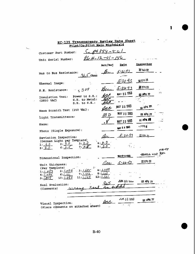
yr?-135 Transparency Review Data Sheet mlot/Co-Pilot Main windshield
Customer Part Number: V- tf^ ST^ ~T ^ I
Unit Serial Number: Kin" ft- H~ ~"°' "" IT*"— - ■ - • -
Aec/Rej Date Inspector
Bus to Bus Resistance: ^ fiffs ? ^ '^ ■ Md Ohms _--—
Thermal Image: w ^ —
S.K.Resistance: -,3^ -^-'^^^-^^ ^ es /Jriy* MAI 251993 a PP6 77 insulation Test: Power to S.E.: fi^T ..-r—r-.—:—
(2500 VAC) S.E. to Metal S.E. to S.E.:
Nesa scratch Test (350 VAC):
tight Transmittance:
Haze:
Photo (Single Exposure):
JML
,/ MAY 251993
si a,'/) ~6-JLL£— "i;-JtJL- *•-£■?
Dimensional Inspection:
Unit Thickness:
nwy a s ioa»
(Per Template) ,. ' -■■ 0
!,n^L 6:/,/g/ Ti .... JMT , IO:MS. U.-.U&3. V---LW-
l./dX -. 8:/.M/)
MAY 2 5 1993 ,,pP6l»
^ p MAY 25 1993 22 PPS 77
22PPeÄ
wriiflB ^pPG4
Deviation Inspection: ^ ^^^ -&*&- (German Light per Template)
22 PPM ■ v{>)0 ■*f2c
/^^ -r-au-ft 22EPG28..
.- ^ JUN 0^ ö=J 22 PPG 77 Seal Evaluation: Jv3° # AJ " (Comments) I,,.»A^_J Ser\f fa $<&&■ -———-
visual Inspection: . Mr^C^— ■ ■— —' " (Place comments on attached sheet) .. '"
B-40

Check for vinyl cracks J^L_ ill© &S121 Visual inspection Map & Comments^
Tnickness Template
Idtf
Q)l, Ott <£>?>'°i' ©Pol
Deviation Template
B-41

irr-135 Transparency Review Data Sheet P41ofc/Co-Pllot Ma^T windshield
Customer Part Number: ^'0/3^7' ,.
Unit Serial Number: f ?■ -V- /tf-/J>- /0 7
Acc/Bej pate Inspector
Bus to Bus Resistance: M /'Q Obms
$?TW"«fZ? Thermal Image:
S.E. Resistance: ^/y ' ,$fa^ J-^d£3
insulation Test: Power to S.E.: fa* jülUliU22 ■« »»" (2500 VAC) S.E. to Metal: jP&f ~
■^ S.E. to S.E.: ' - H^'1^ Qi<f-FH/pczdzr iuut-^ V, JUN09IS93 ß?r3J9
Nesa Scratch Test (350 VAC): ,. ■ P 7 "- .
-77.JT A JW0 8 1393 ***"** Light Transmittance: // O ft — —
Haze:
Photo (Single Exposure)
Deviation Inspection: -/Mtl— -^ ■■ (German Light per Template) ' l-*fr 2: %.U l-.Z'Q *}&£- 5r£rr 6:7J- l:%0_ B:JL0_ .
Dimensional Inspection:
Unit Thickness: . "" '-" '"' (Per Template) ' " -•■ '"-':-:
ff'flfj 2-.LÜ1L 3:/4i J=id$L 5:/M2f£ 6:/.fl*K 7:,/,0fc 8:-^r 9:A0^- 10;^/ H:iÄ 12:^222,
£^ .^--ar-f.? 22?."J28
Seal Evaluation: (Comments)
ffg5 JUM. 04^393 22 #8 7?
visual Inspection: .. JJ. (Place comments on attached sheet)
JUKÖ4 333 :'»» «":
B-42

- i rr»ri« /Lm^-" JUNO 41993 .apPB« Check for vi nyl cracks /^r"^- "■ü— =—
Visual T^grtion Map & Comments
-te^ZSFtZT >~ ^U^t^^ZM. %^J&r-—
Thickness Template
tf»)
Deviation Template
B-43

ice-135 Tr3"«pagflncv Review Data Sheet Pilot/Co-Pilot Main windshield
Customer Part Number: $~ S/35cf- 5c* (
Unit Serial Number: J3 - H~ Y'C-"-^-^-^ • -
Acc/Bej pate Inspector
Bus to Bus Resistance: ——_= S> ~■<('".J. HZ.if Onms _"" -.5
'-£$43 »EP32S Thermal Image: • ^ T-V <S..
S.E. Resistance: %3\) /he Z^^f
Insulation Test: Power to S.E.: A0^ ... -.: " ' ■■— ' (2500 VACL„^> S.E. to Metal: jßQgzZ
7°' jr-y, S.E. to S.E. : *^
Nesa'scratch Test (350 VAC) : vjßj €—
Light Transmittance: _ /("o ^—& .^ A- "JUÜI0 9IS93 \ytf<*&
JUlü o 9 m g?F339
'UN 0 9 1993 £rräJ9
Haze: " -■'
Photo (Single Exposure). _. ^<^ _ . a<. ■ 22£?3 2S
Deviation Inspection: • ,,f"^v, v?-**-?-? ._ (German Light per Template) .... l-ii£_ 2-.4..Ö 3:M— ■ *-M— _ 5: g.<" 6: lit) 7: 1,0 • 8:J^_ . .
Dimensional Inspection:
Unit Thickness: (Per Template) .". _ T>
^^ vf-^-f3 2ZPPS28
SS' 10:/'g*£ H:AJ2£Z. .^:hll£ juttO
0993 22PF8 77
Seal Evaluation: - fl^r3 (comment s) : :—. ——* **.,<*/ c (1
■ JUN 041993
visual Inspection: /C£^ (Place comments on attached sheet) —•■•
B-44

Check for vinyl cracks ^^— __-« Visual inspection Map & Comments^
-„ J 7>*L*~ /»«+7,J '/ML /Hic^S u***L
^n£**o—Ok^
Tui.ckr.es s Template
Deviation Template
B-45

KC-135 Tranaparencv Review Data Sheet T-Mr,<-/eo-P-tlpfr Main Windshield
Customer Part Number:
Unit Serial Number:
Bus to Bus Resistance:
Thermal Image:
S.E. Resistance:
7- jc??cv-r»'
Acc/Rej pate
•- X-ll-43
ynsoector
)f£, 7 Ohms
^^9J *"»*»
.2/5 Insulation Test: Power to S.E.: (2S00 VAC) ,S,E. to Metal:
S.E. to S.E.:
Nesa'Scratch Test (350 VAC):
Light Transmittance: / ) ' I
Haze: ~"
Photo (Single Exposure):
Deviation inspection: (German Light per Template) 1- /, Q 2:?,V 3: ///) 5:1m 6:j2ii_ . 7:-2^-
Jut* - :.' .
±_ JUN 0.9 1993
JUN a » 893
fat'
4:-AA. 8:Aß-
»PF3-
k Pr« JS
fr JUN 0* 893 ..?ro39
^fifiz '■9- 22EF2 28
Dimensional Inspection:
Unit Thickness: (Per Template) l:/,g?2> 2: I.Of3- 3. 5:1,010 6:1.09?- 7 9: I,Oft 10: i,o<S 11 Mit Seal Evaluation: (Comments)
4: \.DH B-.l.pfd
12:hälft
j?«. .r-zr-43 _1¥E-
JUN 041393 ?2Pp8 5?
,c^ «^V ^ ^V 7?/^ *W* -
visual Inspection: (Place comments on attached sheet)
■fk '€? Jlffl
Tu> 22 ??s 5?3
B-46
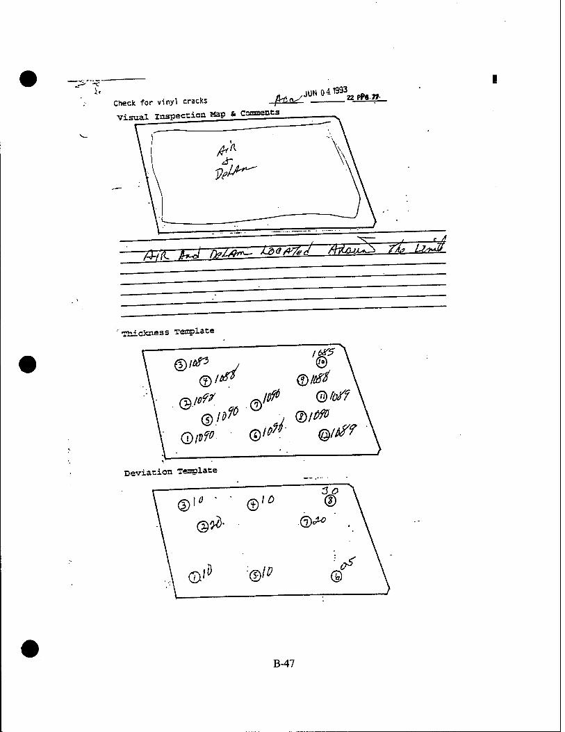
Check for vinyl cracks Visual inspeccionHapJJomfflts
,UN 041993
T&IC g /UJ 1)?/^°™- L6Q#7"< fH&»-^ I*" ^^
Tnickn.es s Template
©It*3 J ©
Q/rfP. ©"?' @/#f
Deviation Template
B-47

■EC-135 Transparency Reviev Data Sheet m-^/m-Pllof Wffi" windshield
Customer Part Number: ? - ijw ?i ^V" *
Unit Serial Number: 5? 3-^ jf? . ' —
Bus to Bus Resistance: ^F,£> Ohms
Thermal Image:
S.E. Resistance:
insulation Test: (2500 VAC)
v3>7 Power to S.E.: S.E. to Metal: S.E. to S.E.:
NeslScratch f^st (350 VAC) :
Light Transmittance: ;■//-/
Haze: -if
Photo (Single Exposure) :
Deviation Inspection: (German Light per Template)
1:1.0 2--UI- 3=44" 5: I/O 6:0'.* 7=JL<2_
Acc/Rej Eafifi Inspector
f-it-to . gEpG2S
J_ JUN ft» 993
^ JUN ft» 1S93
Jt
Oo
JJL' B:AdL
JUN 0,9 1993
JUN14B93
^, JUN 041993 aPP<7?
»Pr639
&Pr339
22 PPG28
Dimensional inspection:
Unit Thickness: •- (Per Template) .... . Jy-~\
s-./.om e:j,o& T.jJtti- 8:^£L
/^ . f-2f-?S - ***«
Seal Evaluation (Comments)
j^ JUN 041993 22 pp8 *
Visual inspection: ' JNTPZY
(Place comments on attached sheet)
JUNG 41333 T? "PS 7f
B-48

Check for vinyl cracks
Visual inspection Map & ComnenCS_
A. JUN 041993 fHO gpP«77
Thickness Template
tf*
Of"*
Deviation Template
B-49

-„.,« T^naoar y »™ri«r Pata Sheet. ^ f^^^ro.PUT«; #« window
Customer Part Number: J2. Ö_Z
Unit Serial Number: .. V '-* ~~ ' ' '-
Acc/Rej Eafis lassestes.
Bus to Bus Resi- -^«-7/> y ohms
Thermal Irige: .4 .. -^.— • Tnerm* a MAY 2 6 199i 22PPG43 insulation Test.- -wer to Metal: Jc^ (2500 VAC)
Nesa Scratch Test (81 VAC) :
Light Transmittance:
Haze:
0^ m 2 6 ISSo 22PPG43
tf3.g MAY 2 6 1993 gP?G43
/, $ MAY 2 6 1983 _"&&&,_
22PPS« JUUI41893. ^"^g Photo (Single Exposure) : - &?ri33
A JW09 I893 S-rr«.» Deviation inspection: —CtS
Dimensional Inspection:
Unit Thicknes (Per Template ltiZ^i 2:
unit Thickness: (Per Template) ^ 3:^£Z 4A-^M
JUNO 31353 22 PP8 77
Check for Vinyl Cracks: -4±± —-
Seal Evaluation: .
(Comments) ,.^„,,< s**J. <>*- O'-CAX
Q^ JUKQ3Ö33 22P^8 55 visual Inspection: . -& (Place comments on attached sheet)
B-50

Visual Inspection Map & Comments
tzl^s A/~ +££ *i*Z2
Thickness Template
©9^/ ®&y
© H& ®#*
Deviation Template
B-51
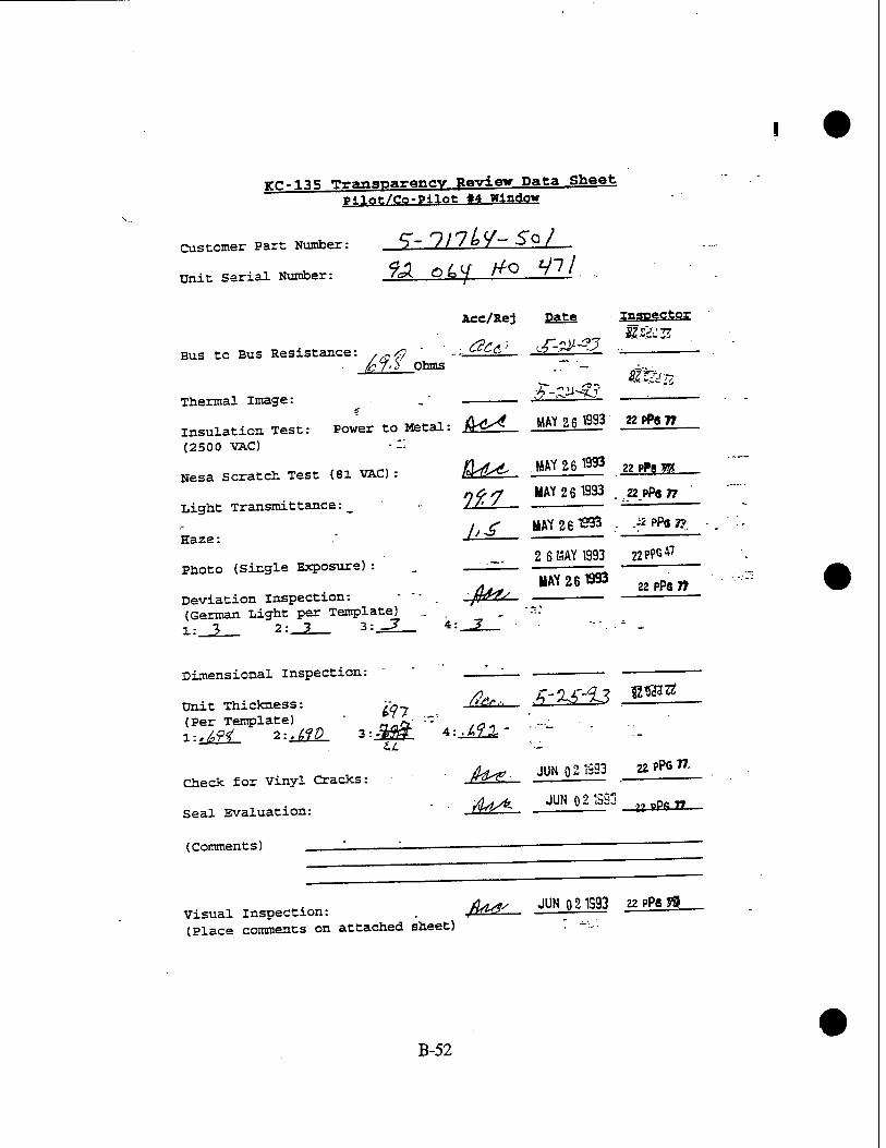
KC-135 Transparency Review Data Sheet Pilot/Co-Pilot «4 Window
Customer Part Number: S~ // /P7W
-> ° /—
Unit Serial Number: 9A O L </ H-Q—HJJ. -
Acc/Rej Pate inspector
Bus to Bus Resistance: /(Stf ' ' -:-Jz±£L. ^"^ ^ - . /?7.h Ohms ." - i,;. #3ZH
Thermal Image: ■ . .' ■■"' ^
insulation Test: Power to Metal: M^- MM**' J*if?2?_ (2500 VAC) - --
Nesa scratch Test (81 VAC) : M^- «f **Ü2L_ nfrt MAY 26 1993 . n PPs 77
Light Transmittance: _ //' .'-— — -— jt£ HAY 26 TS93 . .gPPiP,
2 6 MAY 1993 22PPG47
Haze:
Photo (Single Exposure) : . - MAY 26 1993 22 PPG n
Deviation Inspection: - -/fW (German Light per Template) ... . '--: 1: 3 2: 3 3:^Z_ 4-_-2_ ~\.*-
Dimensional Inspection:
^,... £2£33 .^U Unit Thickness: £„- (Per Template) ' -^ -'■ ' ..._ l:^f< 2:s^D_ 3--30L *--J£2* -
-,0V • ^^ JUN Q2T993 22PP677- Check for Vinyl Cracks: JT^^. — •
■JU*. JUNQ219SG „rttrt Seal Evaluation: Jw^"- ■ " 9m " ~
(Comments) I 1 —-— '
-•«„ /Us" JUN 0 21S93 22 PP6 n visual inspection: . /KW— f — (Place comments on attached sheet) • --.
B-52

Visual inspection Map & Comments
•raickness Template
®*^ <D#7
(Dtf? ®is?
Deviation Template
@:
©3
B-53

KC-135 Transparency Review Data Sheet PilQt/Co-PjInfc »4 window . ..
Customer Part Number: _JJL—f' ' ° ' d. 1—
Unit Serial Number: 7rA ~ O^l" "—~—L—
Acc/Rej Date Inspector
Bus to Bus Resistance: -~ $±j & M A? =^— i,7<^ Ohms ' - - ^^ Ohms
Thermal image: ^"^~7J
„,.1 ÄtfL^/ MAY26 1933 »P^77
insulation Test: Power to Metal: E^SL- — (2500 VAC) -"-'■'"
Nesa scratch Test (81 VAC) : fa* MAY ?,fi 1993 /- » PPS " 22 PPG 77 .,,„,„. 9^y MAY 261393 Light Transmttance. . / 7/ ^
/, P"^ , 22 j>Pa w
. . 2 6 MAY B33 22?P647 Haze:
Photo (Single Exposure):
Deviation Inspection: (German Light per Template) 1:, 3 2: 3 3:^L_ 4:_3
MAY 2 ß 1993 .*PP6»
Dimensional Inspection:
Unit Thickness: (Per Template)
^ J1MÜ1 föödazz
i:!HT 2-kiL 3:^^. /*:^/
Check for Vinyl Cracks:
Seal Evaluation:
(Comments) 'L.
JUN 021993 atP6T9>
rfj^_ JUN 021993 22PP6?7
visual Inspection: (Place comments on attached sheet)
/fog^ JUN 021993 22 PP6 77
B-54

Visual Inspection Map & Comments
V
Thickness Template
@^" <£)**>
©<J^ ®6?/
Deviation Template
B-55

TTf!-135 Transparency Review Data Sheet piiQt/eo-p^nt *4 window
Customer Part Number: ■ ,Y~ ' ' ' °7 — L
Unit serial Number: 9% h 5 f (*> 3 STO
Acc/Rej Date inspector
Bus to Bus Resistance: ^ . " -fit^_ £^tlL _M^L_ ■ r7ß,) Ohms
Thermal Image: , . . ' £^£i ^^—
„ .. , zLr^ MAY 2 6 1993 « f>P6 77 insulation Test: Power to Metal: ftd«^ 2 ■-_ ■- {2500 VAC) --^'-
fiAsit MAY 26 1993 u PPS 77 Nesa Scratch Test (81 VAC) : fW^L'
na> rr BAY 26 1993 n pP6 77 Light Transmittance: _ /"• —^—
. - . HAY 26 1993 ß«" Haze: A^
.2 6 BAY 1393 22pPG*7" Photo (Single Exposure) : i^_- —
/lt^. MAY 26 1993 a pPG " Deviation inspection: f ><^'-^ . ■ ■ (German Light per Template) l: ^ 2:_J2_ 3=J2_ 4:-^- - " -
Dimensional Inspection:
Unit Thickness: (Per Template) . _-._..-=; l:./,«9 2:.lfl» 3:,£f/ 4=^1±
<£^_ _£^£fl &9d<lZ£
Check for Vinyl Cracks:
Seal Evaluation:
(Comment s) .—
yrCW JUN Q21993 22 PPS 77
/U- JUN Q 2 1993 22 PPs 77 visual Inspection: ßEHLn— — ^ (Place comments on attached sheet) " •
B-56

Visual Inspection Map & Comments
Thickness Template
<§/,?<! ©fr 57
(D&fi <£
Deviation Template
©=> ®3
©;
• B-57

KC-135 Transparency Review Data Sheet P^nt/Co-PHIo* «4 Window
Customer Part Number: .4- 7/^44"-n~S /
unit Serial Number: <?<?-/>&*-&,1-/>D &
Acc/Rej Date Inspector
Bus to Bus Resistance: ■ - - -gee*- I^tSl ■ »**« £9,J> Qtos _ --•-
K-3Ji-f3 U£?ßZ8 Thermal Image: - ■••— -^ '"■'-
t- *Mi. y4*d m**M 22*6 77 Insulation Test: Power to Metal: /±&c,— . (2500 VAC) ■'■' ' 'r:"~" „„ 1 MAY 26 1993 Nesa Scratch Test (81 VAC) : £k&. : g «** TT
^ MAY 26 1993 2Z PPG 77 Light Transmittance: _ • JSV>^ - —=
, / MAY 2S1993 „„-._- Haze: -Lt-L VftoT?
2 6MAY1S93 22PP6*1
Photo (Single Exposure): '
/. MAY 2 6 1993 nif%rf Deviation Inspection: frvS^._ - — ■■ (German Light per Template) . -
Dimensional Inspection:
Unit Thickness: (Per Template) '~/jr-"T' /a*
Check for Vinyl Cracks: J}*^
Seal Evaluation: /r^*^
(Comment s) . ——
JUNQ21993.3 jjppe^
JUN OS 393 "- PP8 T>
Xfafl- JWCk-^ 22PP6 77 Visual Inspection: . (T^^ ■ (Place comments on attached sheet)
B-58

Visual Inspection Map & Comments
Thickness Template
©^ ©*?>
&'* ©^
Deviation Template
B-59

KC-135 Transparency Review Data Sheet Pilot/Co-Pilot «4 Window
r 117 Li- T " I Customer Part Number: S - ' ' ' °
Unit Serial Number: -fls-lfi** tH
Bus to Bus Resistance: Ohms
Thermal Image:
ilJdl_
Acc/Kej Date inspector
k^ <?k/0 - apW15
Tnermax image: ■■.:■-. —< i ,—
insulation Test: Power to Metal: tV^ 11u{1— _ (2500 VAC) .--• :■-:-'";> , . •
Nesa Scratch Test (81 VAC) : Jfc. */Mj '
Light Transmittance: _ fj, b M-.— —'// ' . - —-;——
Photo (Single Exposure) : ■- ' — ;—
Deviation inspection: . £c_£ f/Z/f^ -Ü (German Light per Template) 1: .5 2: JT 3: 5 4:_C _ - -' "■-
Dimensional Inspection: 'Z— —
Unit Thickness: " Pit, f/T-^i TR"0Jrf gg (Per Template) ..-..' --"... H.CfL 2:JJ±_ 3: .1X1 . *-JLA1L =• - -
Check for Vinyl Cracks: .. /h-<- ul/fu
Seal Evaluation: • /?<{■ —?/%/ *
22PPG15
2^£Pil5
(Comments)
visual Inspection: V^'C— /«^ ' ■? (Place comments on attached sheet)
#£'-'-
B-60

Visual Inspection Map & Comments
Thickness Template
©
© V
Deviation Template
@
©
B-61

KC-13 5 Transparency Review Data Sheet Pilot/Co-Pilot «4 Window
Customer Part Number: J~—'' 'QJ~ 9-L
tinit Serial Number: fo J/- C7- 4 /-*76
Bus to Bus Resistance: Ohms
Acc/Rej Date IsSES£t2S
* Q&tf MAY 2 6 1993" 22 PP8 77
Tbermal Image:
insulation Test: (2500 VAC)
Power to Metal:
Nesa Scratch Test (81 VAC):
Light Transmittance:_
Haze: —
Photo (Single Exposure) :
Deviation inspection: (German Light per Template) 1: 4 2: fO 3:_2_
Dimensional Inspection:
Unit Thickness: (Per Template)
-t fteS BAY26t933 22 PPS 77-
MAY 2 6 1S33 22 P?S 7* J&2-
26MWT393
22 PP6 77.
22PFÜ47
/<^> KAY 2 51S33 22 pPe 58
-t
(Per TenpiutBi /ä/^ "' /Q*)
Check for Vinyl Cracks:
Seal Evaluation:
/f^- JUN 021993 22PPG77
— ffe-^ JUN 021993 .. 22 PPG n
(Comments) % <?<?<?«> ^0'/ j ,
Visual inspection: _ 112— (Place comments on attached sheet)
JUN 02 1033 ,zmyj.
B-62

Visual Inspection Map & Comments
ßp. ,.-, P/m),*, fa/^7..
i\n\i A,** firiV» &U- 1?.Do«Jfi n» Ü">1
Thickness Template
®^ ©^
© & ©^ V
Deviation Template
)0 @
®f ®^
B-63

KC-135 Trangpayanev Review Data Sheet pllot/Co-Pllot «4 Window
Customer Part Number: 3— HI /k> /- So I
Unit Serial Number: ■ - 3 O -/72 //Q 73-/ . _..
Ace/Rej pate Inspector.
Bus to Bus Resistance: rE&Mf.n ??pF87y
Thermal Image: /i->; MAY 26 1993 22 pPe »
insulation Test: Power to Metal: ^Ä^ ^ . ** prs ^ (2500 VAC)
fa* MAY 261993 Äpft. Nesa Scratch Test (81 VAC) : fW** - a PPG 77
«fa? MAY 26 1993 a pps Light Transmxttance: _ -tf^' '— "-
/£ MAY 261993 ttPPaft
MAY 2 «1393 BPK* . Haze:
Photo (Single Exposure): _ ±_
Deviation Inspection: frfr*^. (German Light per Template) ^ . :_£ 2: 7 3: -3 A: ■?
MAY 26 1993 22PPö77
l
Dimensional Inspection: . —;—z— .
Unit Thickness: - ßS&L*. h 'ty'93 (Per Template) - - . Z.:.JdL 2:.Ml* 3:ill 4:^£.
2ZPIQ2S
.fiflA_ JUN 021993 22PPG77
fei JUN 021993 22pPi7r,
(Comments) W */<>< fit .W *~ fioT&l S&
Check for Vinyl Cracks:
Seal Evaluation:
J
Visual Inspection ^^ JUN 021993 22 m 7?
(Place comments on attached sheet) .-• • ■:•
B-64

Visual Inspection Map & Comments
V. (7J)J^ P^OtA. (°;X/^*T>:
ü)-\&-n^e. YcPs c4 SsA^L /OA/ rnJfAJ- gtJ'
Thickness Template _
©fcp- ®&
©^ ©/^f
Deviation Template
@i ®3;
©•■5
B-65

KC-135 Transparency Review Data Sheet TtiBt/Co-P<iat! «4 window
Customer Part Number: >- 7 17h^- 'i CA '
Unit Serial Number: ^- H' 5 ~ ^--*~ ^ Y—
Bus to Bus Resistance: . . !/%,D Ohms
Thermal Image: ^
Insulation Test: Power to Metal: (2500 VAC)
Nesa Scratch Test (81 VAC) : •
Light Transmittance:
Haze: - ■ ...
Photo (Single Exposure):
Deviation inspection: (German Light per Template) It <- 3 2:^ 3 3:^1 3 4:
Acc/Rej Date ..JS3BS££2£.
,JT-ll-i3 SZS&K
ficc MAY 2 61993 BPPSfl,
Qt( MAY 2 6 1993 B^
ff^ 7 MAY 2 S TS53 BPPBfl
^ MAY £ 3 1SS3 2PPS43
22PPS« "J»14«a gfft7j?
?^ -fr-
Dimensional Inspection:
Unit Thickness: (Per Template) /iih:""='! /e// ±:A£=. 2:^H 3:>*W ■ * = '*!**
Check for Vinyl Cracks:
Seal Evaluation
(Comments)
**, M-n agBar
/?^ £
JUN 031993
JUN03TS3 «-i
22PP«77
»PP8 77
^^ <SMU-J- ß^j^.—r<— <<u4X# .?+£%.
-$* visual inspection: ~{(aKQ (Place comments on attached sheet)
JUN GS1S33 - ® &*.-*?
B-66

Visual Inspection Map & Comments S/5.
asa jk D*J-4~ * 200*7^; /u± a-fo-J u»±L
l/iWf ts^xUC kra*f*± A-* mVwA^
£'<J<L£A«^ <fiJl //>&*7-*A *-* rvrt*«xJ
Ttiictaiess Template
©b0 ©IM
(Dipt* <§>& , V . -.'J ÄT. • ••' *
Deviation Template
B-67

KC-135 Transparency Review Data Sheet Pilot/Co-Pilot #4 window
Customer Part Number: , ^~ 7 jlt>L}-$01 dJj, ft'-
Unit Serial Number: . ? " ^" ^~ ~ 7" -^ S
Acc/Rej
Bus to Bus Resistance:
Thermal Image:
H^if OYms
Insulation Test: Power to Metal: (2500 VAC) ■■■•-•
Nesa Scratch Test (81 VAC) :
Light Transmittance:
Haze:
Photo (Single Exposure):
4a <
Date Inspector
JT-Zl-tl iZSiiU
MAY 2 6 1993 22PPG43"
.?
Deviation inspection: —^1 (German Light per Template) " l:Aj, 2:_±A 3:_±A ..* ■ ^ 3
Q(( MAY 2 S1983 ^PStt
fU _MÜUL2JLC3 gPPW
22 PPG »7 JUU14TSSa 22PP08
<?
Dimensional inspection: ' " . _—_
Unit Thickness: - &k&.— f>'2-*<t" (Per Template) .-_ :.*r l;,^ 2:^V 3:,/^ 4:^7^ ... ■
Check for Vinyl Cracks:
Seal Evaluation:
(Comments)
& PPG 28
JUNO 31993 22PP6 7T
Q^ JUN03S33 22PPS77
M^ff-«™^*.-
Visual Inspection: (Place comments on attached sheet)
£ ■<?-^ JUN031S23 22??aw
B-68

Visual Inspection Map & Comments
S<tf2<
'tt<i.frr*fi-
Thictaiess Template
<§m ©#
<£>&>% <§)W
Deviation Template
B-69
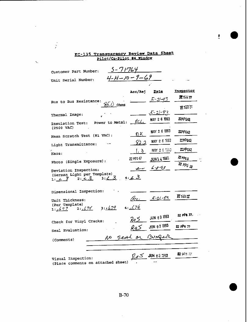
V.
Kc-135 Transparency Review Data Sheet p^lnt/Co-Pilot »4 Window
Customer Part Number: ->~ ' ' '<°J _
Unit Serial Number: ^-H—SO" 7—6"
Bus to Bus Resistance: MA
Acc/Rej pate
Ohms
Thermal Image:
Insulation Test: (2500 VAC)
Power to Metal: iCJL m Z 6 1"3
inspector
»«Hü?
22PPG43
Nesa Scratch Test (81 VAC):
Light Transmittance:
Haze:
Photo (Single Exposure):
Deviation Inspection: (German Light per Template) 1: ^ ? 2: ^.3 3:^ 3
JUL MAY 2 6 1993 22PPG43
fätX MAY 2 6 1SS3
f, Ö JflY_2£j3b3
22 PPG 47 JUH141SS5'
z. 3
22PPG43
22PPG43
&PPC8
■PPG 10
Dimensional Inspection:
Unit Thickness: (Per Template) X-..47 7 2:.£7? ?:±A2£
Check for Vinyl Cracks:
Seal Evaluation:
(Comments)
ML
JT-U-f* g93ag
JUNO 31993 22PPS77,
ßojZ JUNO 31993 22P?8 77
visual Inspection: JL£ (Place comments on attached sheet) ,
22 !?i?"C
B-70

Visual Inspection Map & Comments
Ai-(\ /'/W/K^/i/'Ag*- OH'H*'? tna+Ut' VJ^ &ß»<»A h„,'lf
Thickness Template
®L1* ®W
©^ %M
Deviation Template
B-71

KG-135 Transparency Review Data Sheet Pilot/Co-?-t|Qfc «4 Window
Customer Part Number: -J ~ 9/7^7 - S 0 /
Unit Serial Number: <&3~H- /<1-£?"-*^^^-—
Acc/Rej
Bus to Bus Resistance 722. Ohms
Thermal Image:
Insulation Test: (2500 VAC)
Power to Metal:
Nesa Scratch Test (81 VAC) :
Light Transmittance:
Haze:
Photo (Single Exposure):
Deviation inspection: (German Light per Template) „ l;j-"b 2: 2- y.:T 3:_^_L
AL
OK
Eat«
Lt Csi £i«t-
MAY 2 6 1993
MAY 2 6 1993
inspector
22PP643
22PPG43
MAY 2 6 1993 2PP543
: V
I, Q MAY 2 6 1S93 22PPG«
^ is
Dimensional Inspection:
Unit Thickness: (Per Template) 1:. UM 2:J_MJL :Mf 4:J££_.
Check for Vinyl Cracks:
Seal Evaluation:
(Comments) A)h ***£ <M. f\f?n<(-^\
JUN 0 3 IS93
Visual Inspection: (Place comments on attached sheet)
!?*£
Qmix
JUN 031993 22 PP«*7
22FP8 77
JUK OSTES £2 iH Vh
B-72

Visual Inspection Map & Comments
SS ßff AcW ^r?"
n*l&m /a»J i/iitl«. <*»"<f<; /■oes&f &&Z
Thickness Template
©6^ <D'
©#£ ©
Deviation Template
B-73

KC-135 Transparency Review Data Sheet pllot/Co-P<1nfc «4 Window
Customer Part Number: 5~ 7/7» 7~* *° '
Unit Serial Number: £- n" I ^"" ^«2 ~ 3 fc
Acc/Rej
Bus to Bus Resistance:
Thermal Image:
y&-$ Ohms
insulation Test: . Power to Metal: (2500 VAC) ■ >r
Nesa Scratch Test (61 VAC):
Light Transmittance:
Haze:
Photo (Single Exposure) :
Deviation Inspection: (German Light per Template) l:_Äl 2:, C-3 y-±L- *
Date inspector
ML
S-2M3 2VMZZ
MAY 2 6 1993 mpW
OK MAY 2 6 1SS3 22PPG43
JEPPG43
ftiAr & <J .;*■; -
22PFS47
^3
<^
J1W<X9"B93 £?rfi39
Dimensional Inspection:
Unit Thickness: (Per Template) . » 1:^11 2:^^. 3:^yy
Check for Vinyl Cracks:
Seal Evaluation:
fa, .f-2/,-n 22Hya
4:,/.&
JUN 0 3 1993
^
?2PP<?77
„c/ JUNO 3 1993 ?? pp« ^
(Comments) ^0 Ao^(^>^ g*^ rtr/frfflJ ^c^
visual Inspection: /fV.7 (Place comments on attached sheet)
JUN 0 £ ^=- P?9 7?
B-74

Visual Inspection Map & Comments 0««P 5/5
ff/Ä.tf/4.. iiss dp** LJ»« T.T. 4/,.ff@Z T,r
-A7(l ALL IM«»*, 1 4L-xU»\1 fi^4 ff-^o *W*~~~
Thickness Template
®&d ®Mf
Q4S7 qfiS
Deviation Template
B-75

KC-135 Transparency Review Data Sheet Pilot/Co-Pilot «4 Window
Customer Part Number: A ~ Jfy6>U-<S& '
Unit Serial Number: ^l~i4-t>k -2 b -13 O
Acc/Rej Date Inspector
Bus to Bus Resistance: ßv~> T-liH-93 KMJg 73, 1 Ohms
Thermal Image: S'^'fj 3Z9C-JZZ
insulation Test: Power to Metal: AW MAY 86 «93 22 *» » (2500 vac)
Nesa Scratch Test (81 VAC) : MA-^ MAY261993 22 PPG »
tf>,$ MAY 26 1993 22 PPS 7?
, ^ MAY 26 393 iz PPG J? A^
Light Transmittance:
Haze:
Photo (Single Exposure) 2-6 WAY 1993 22 PP^'
Deviation Inspection: (German Light per Template) l:_|L 2:_^_ 3:JZ_ 4:_^£
Dimensional Inspection:
tfoto m^mi v pPn „
Unit Thickness: ft*.. f'?<f-$3 ffifft3ft (Per Template) l:.^?r 2:. 7^7 3 :. 7/3 4:_L2£2r
Check for Vinyl Cracks: AH^L "pr""
„' JUN 021993 22P?9?r Seal Evaluation:
(Comments)
„• , T „. JfcvT JUN 021993 n m JJ Visual Inspection: 'tv ÜJ3Ü (Place comments on attached sheet)
B-76

Visual Inspection Map & Comments
/q-uri oTleO. soT-f&er ff°->4»<*7» /-bartSed de«jr£.p. g-f Q/^il
Thickness Template
(§701 <D^
Q)btf @7»
V Deviation Template
B-77

KC-135 Transparency Review Data Sheet Pilot/Co-Pilot #4 Window
Customer Part Number: ->'7 J^bJ- JO / ^J- "
Unit Serial Number: Q-n-Ji ~ 6h ~S*$ b
Bus to Bus Resistance:
Thermal Image:
£*?, Z Ohms
Acc/Rej Date
f-2h?3
Insulation Test: Power to Metal: (2500 VAC)
Nesa Scratch Test (81 VAC):
Light Transmittance:
Haze:
Photo (Single Exposure):
Deviation Inspection: (German Light per Template) l: .L 2>
OK
U-
-Ae-c
4:
Inspector
Q^~3Z28
MAY 2 6 1993 ^^
MAY ?. fi 1^B3
MAY 2 s :sm
22PPG43
;;opqjg
V?*&^
22PPG47 JVJH1419S3 &PPQ8
ys-%s ^ ̂ _
Dimensional Inspection:
Unit Thickness: (Per Template)
Check for Vinyl Cracks:
Seal Evaluation:
(Comments)
i-.ML
/&*- JUN 031993 22PP8T7
l?ecf m ^^ 22 PN n
"*&
Visual Inspection: UeSi* (Place comments on attached sheet)
JUN031SS3 22??
B-78

Visual Inspection Map & Comments
A,y /h^J ßo±#~ k£>fl^7Cc$ &tt AHCbtJö- UAM\
Thickness Template
®Cf/ ®t?J
V ©£# ©^
Deviation Template
B-79

KC-135 Transparency Review Data Sheet Pilot/Co-Pilot #4 Window
Customer Part Number: J)-^ // / £=>/ ~—> /
Unit Serial Number: SfS~f7~0 7'öf~Jjblo
Bus to Bus Resistance:
Thermal Image:
^5,7
Acc/Rej Date Inspector
S-2.1-ft &&& Ohms
Insulation Test: Power to Metal: (2500 VAC)
Nesa Scratch Test (81 VAC):
Light Transmittance:
Haze:
Photo (Single Exposure):
Deviation Inspection: (German Light per template)
2<J±S 3*7 (German
fajL. MAY 2 6 1993 22PPG43
OK MAY 2 6 1993 22PPG43
$ftY MAY 2 S 13S3 22PPG43
—& %A;> z: ra 22PP5A7 ^H14^'"
22Pp;-.ff
VPPB8
Dimensional Inspection:
Unit Thickness: (Per Template)
Check for Vinyl Cracks:
Seal Evaluation:
(Comments) g*-7"-
X-.JÄ9 2:,7öl 3:.697 *:,6?7
At*.
fass f-U-^
JUN 031993
22F.FG28'
22 PP« 77
fteS JUN031"3 22PFS77
I» - T~y-
ftrtW ßu^^^g-^M^^^ <^*^°-
Visual Inspection: l(gQ (Place comments on attached sheet)
JUN 0 3 'i393 22FHM
B-80


