Pressure Independent Control Valve Technical manual
80
Pressure Independent Control Valve Technical manual R 9.2 STE0101 R9.2 - Mar. 2020
-
Upload
khangminh22 -
Category
Documents
-
view
1 -
download
0
Transcript of Pressure Independent Control Valve Technical manual

Pressure Independent Control Valve
Technical manual R 9.2
STE
0101
R9.
2 -
Mar
. 202
0

EvoPICV
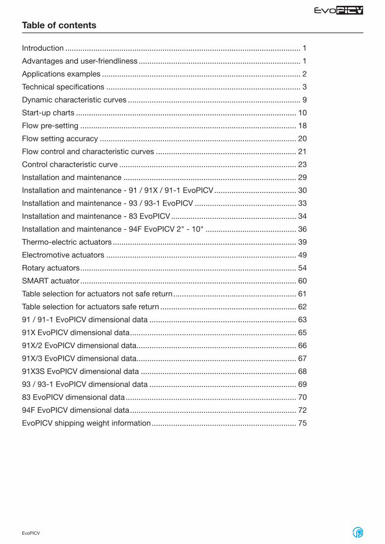
Table of contents
Introduction ............................................................................................................. 1
Advantages and user-friendliness ........................................................................... 1
Applications examples ............................................................................................ 2
Technical specifications .......................................................................................... 3
Dynamic characteristic curves ................................................................................ 9
Start-up charts ...................................................................................................... 10
Flow pre-setting .................................................................................................... 18
Flow setting accuracy ........................................................................................... 20
Flow control and characteristic curves ................................................................. 21
Control characteristic curve .................................................................................. 23
Installation and maintenance ................................................................................ 29
Installation and maintenance - 91 / 91X / 91-1 EvoPICV ...................................... 30
Installation and maintenance - 93 / 93-1 EvoPICV ............................................... 33
Installation and maintenance - 83 EvoPICV .......................................................... 34
Installation and maintenance - 94F EvoPICV 2" - 10" .......................................... 36
Thermo-electric actuators ..................................................................................... 39
Electromotive actuators ........................................................................................ 49
Rotary actuators .................................................................................................... 54
SMART actuator .................................................................................................... 60
Table selection for actuators not safe return ......................................................... 61
Table selection for actuators safe return ............................................................... 62
91 / 91-1 EvoPICV dimensional data .................................................................... 63
91X EvoPICV dimensional data ............................................................................. 65
91X/2 EvoPICV dimensional data .......................................................................... 66
91X/3 EvoPICV dimensional data .......................................................................... 67
91X3S EvoPICV dimensional data ........................................................................ 68
93 / 93-1 EvoPICV dimensional data .................................................................... 69
83 EvoPICV dimensional data ............................................................................... 70
94F EvoPICV dimensional data ............................................................................. 72
EvoPICV shipping weight information ................................................................... 75

1EvoPICV STE0101 R9.2 - Mar. 2020
Introduction
The EvoPICV Pressure Independent Control Valve “PICV” is a combined adjustable constant flow limiter and full stroke, full authority equal percentage temperature control valve.The EvoPICV is suitable for use in variable and constant temperature systems and may be used as constant flow limiter in constant volume systems (without an actuator head) or as a true PICV in variable volume systems.
Operating principle
EvoPICV valve is made by three main parts: 1. differential pressure regulator 2. regulating valve for flow adjustment 3. flow pre-setting knob
1. Differential pressure regulatorThe differential pressure regulator is the heart of the pressure independent control valve. By keeping a constant differential pressure across the valve seats constant flow and full authority temperature control can be achieved.Incoming pressure P1 is transmitted to the top face of the diaphragm, outgoing pressure P3 is transmitted to the underside of this same diaphragm. A constant effective differential pressure is maintained between P2 and P3. As P1 increases relative to P3 it acts on the diaphragm closing the shutter (A) against a seat (B) thereby lowering the effective differential pressure. As P1 decreases relative to P3 the diaphragm acts to open the shutter (A) from the seat (B) thus increasing the effective differential pressure. The diaphragm acts against a spring in order to balance the pressure control and stop the diaphragm oscillating.
2. Regulation valveWater flow through a valve varies as a function of the area of passage and the pressure differential across that valve. Due to the incorporation of the differential pressure regulator the differential pressure across the valve seats P2 – P3 is constant meaning that flow is now only a function of area of passage.Setting any flow rate value and maintaining it stable is also possible. The regulation valve presents an equal percentage characteristic.
Functional schematic
Advantages and user-friendliness
1. Advantages– EvoPICV is a full authority temperature control valve. This means that each individual terminal receives on the flow required even in part load conditions.– The regulator corrects any differential pressure variation. This leads to a considerable reduction in temperature variations and adjustment movements and to the extension of the life of the moving devices connected to it.– EvoPICV valves offer a remarkable adjustment flexibility. They can be accurately set to a specific flow rate value and they allow precise modulating control.– The valves always guarantee a suitable flow rate thanks to equalpercentage characteristic, therefore avoiding too high energy consumption.– Since EvoPICV valve performs the functions of two valves (balancing and adjustment), the installation costs are considerably reduced.– The automatic flow rate limitation eliminates system commissioning costs.– Since commissioning is very easy to perform, design flow rates can be modified at any time and at low costs.– Since it is not necessary to commission the valve after its installation, the valve can work immediately after it has been
assembled, for example, on the floors where works are already finished.
2. User-friendlinessIn order to adjust the flow rate, just set the selected value using the adjustment knob.Since flow rate is the only parameter to be considered, choosing the suitable valve is easy and fast.EvoPICV valve maximum adjustment matches the maximum flow rate allowed by the pipe size, on the basis of the values established by international standards. – Setting ratio calculation is not necessary. – Valve authority calculation is not required. – Specific devices or knowledge are not necessary. – Compact design that allows installing the valve also in small
spaces such as fan-coils or narrow supply spaces. – The special adjustment knob allows the flow rate to be set
without disassembling the actuator.
3. Adjustment knobThe maximum value of the flow can be preset, choking the outlet section of the control valve, using the graduated adjustment knob. The percentage value, indicated on the scale, matches the maximum flow rate percentage. This value can be changed turning the adjustment knob until it reaches the selected position (matching the percentage indicated on the scale). A locking mechanism avoids the valve set values from being changed inadvertently.
P1 P2 P3A
1 2
3
B

2EvoPICV STE0101 R9.2 - Mar. 2020
1. Systems with variable thermal powerThe use of a motorised control valve that automatically limits the flow rate, ensures stable energy supply, independently from the available pressures and, at the same time, thanks to the possibility of controlling the flow rate regulator, it allows effective adjustment of ambient temperature.
PICV is used as a constant flow limiter and control valve.
Applications examples
2. Systems with constant thermal powerIf the valve is used to adjust fan-coil flow, it ensures the required flow rate to the equipment and it favours the hydraulic balance of the system. The exchanger always works in the best conditions possible with any differential pressure and the system is split into hydraulically separated areas.
PICV is used as a constant flow limiter.
3. Single-pipe heating systemsAn automatic valve placed on the system return line ensures a stable flow rate on the main branches at any thermostatic valve opening, thus reducing the possible sudden changes due to pressure variations in the system.
PICV is used as a constant flow limiter.
Flus
hing
by-
pas
s
DV
IV
IV
TP TP
TP
DV
IV
IV
TP TP
TP

3EvoPICV STE0101 R9.2 - Mar. 2020
Technical specifications
Material list
Regulating valve (A) Brass CW614NStainless steel 18/8
Diaphragm (B) High resistance polymer - EPDMStainless steel AISI 303
Presetting (D) High resistance polymerBrass CW614N
Body (C) Corrosion resistant brass CW602N
Gaskets EPDM-x
91VL ½” 91L ½” 91H ½” 91L ¾” 91H ¾” 91H 1”
Flow rate max. 150 l/h0,042 l/s
600 l/h0,167 l/s
780 l/h0,217 l/s
1000 l/h0,278 l/s
1500 l/h0,417 l/s
1500 l/h0,417 l/s
Start-up max. 20 kPa0,20 bar
25 kPa0,25 bar
35 kPa0,35 bar
30 kPa0,30 bar
35 kPa0,35 bar
35 kPa0,35 bar
Connections Rp ½" FEN 10226-1
Rp ½" FEN 10226-1
Rp ½" FEN 10226-1
Rp ¾" FEN 10226-1
Rp ¾” FEN 10226-1
Rp 1” FEN 10226-1
ΔP max. * Close off pressure ** Temperature Working pressure max. Stroke Rangeability Leakage
600 kPa / 6 bar 600 kPa / 6 bar -10 ÷ 120 °C 2500 kPa / 25 bar 3 mm50÷100
IEC 60534-2-3Class IV
IEC 60534-4
A
D
C
B
91-1 EvoPICV Material list
Regulating valve (A) Brass CW614NStainless steel 18/8
Diaphragm (B) High resistance polymer - EPDMStainless steel AISI 303
Presetting (D) High resistance polymerBrass CW614N
Body (C) Corrosion resistant brass CW602N
Gaskets EPDM-x
91VL1 ½” 91L1 ½” 91H1 ½” 91L1 ¾” 91H1 ¾” 91H1 1”
Flow rate max. 150 l/h0,042 l/s
600 l/h0,167 l/s
780 l/h0,217 l/s
1000 l/h0,278 l/s
1500 l/h0,417 l/s
1500 l/h0,417 l/s
Start-up max. 20 kPa0,20 bar
25 kPa0,25 bar
35 kPa0,35 bar
30 kPa0,30 bar
35 kPa0,35 bar
35 kPa0,35 bar
Connections Rp ½" FEN 10226-1
Rp ½" FEN 10226-1
Rp ½" FEN 10226-1
Rp ¾" FEN 10226-1
Rp ¾” FEN 10226-1
Rp 1” FEN 10226-1
ΔP max. * Close off pressure ** Temperature Working pressure max. Stroke Rangeability Leakage
600 kPa / 6 bar 600 kPa / 6 bar -10 ÷ 120 °C 2500 kPa / 25 bar 3 mm50÷100
IEC 60534-2-3Class IV
IEC 60534-4
* see product technical specification for further information ** closing the valve by means of the actuator
A
D
C
B
91 EvoPICV
NPT version available
NPT version available

4EvoPICV STE0101 R9.2 - Mar. 2020
91X EvoPICV Material list
Regulating valve Brass CW614NStainless steel 18/8
Diaphragm High resistance polymer - EPDMStainless steel AISI 303
Presetting High resistance polymerBrass CW614N
Body Brass CW617N
Gaskets EPDM-x
91XVL ½” 91XL ½” 91XH ½”
Flow rate max. 150 l/h0,042 l/s
600 l/h0,167 l/s
900 l/h0,250 l/s
Start-up max. 20 kPa0,20 bar
25 kPa0,25 bar
30 kPa0,30 bar
Connections Rp ½" FEN 10226-1
Rp ½" FEN 10226-1
Rp ½" FEN 10226-1
91X/2 EvoPICV Material list
Regulating valve Brass CW614NStainless steel 18/8
Diaphragm High resistance polymer - EPDMStainless steel AISI 303
Presetting High resistance polymerBrass CW614N
Body Brass CW617N
Gaskets EPDM-x
91XVL/2 ½” 91XL/2 ½” 91XL/2 ¾” 91XH/2 ¾”
Flow rate max. 150 l/h0,042 l/s
600 l/h0,167 l/s
600 l/h0,167 l/s
900 l/h0,250 l/s
Start-up max. 20 kPa0,20 bar
25 kPa0,25 bar
25 kPa0,25 bar
30 kPa0,30 bar
Connections G ½"M (flat face)EN 10226-1
G ½"M (flat face)EN 10226-1
G ¾"M (flat face)EN 10226-1
G ¾"M (flat face)EN 10226-1
ΔP max. * Close off pressure ** Temperature Working pressure max. Stroke Rangeability Leakage
600 kPa / 6 bar 600 kPa / 6 bar -10 ÷ 120 °C 2500 kPa / 25 bar 3 mm50÷100
IEC 60534-2-3Class IV
IEC 60534-4
ΔP max. * Close off pressure ** Temperature Working pressure max. Stroke Rangeability Leakage
600 kPa / 6 bar 600 kPa / 6 bar -10 ÷ 120 °C 2500 kPa / 25 bar 3 mm50÷100
IEC 60534-2-3Class IV
IEC 60534-4
* see product technical specification for further information ** closing the valve by means of the actuator
5EvoPICV STE0101 R9.2 - Mar. 2020
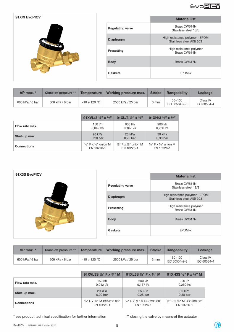
91X/3 EvoPICV Material list
Regulating valve Brass CW614NStainless steel 18/8
Diaphragm High resistance polymer - EPDMStainless steel AISI 303
Presetting High resistance polymerBrass CW614N
Body Brass CW617N
Gaskets EPDM-x
91XVL/3 ½” x ½” 91XL/3 ½” x ½” 91XH/3 ½” x ½”
Flow rate max. 150 l/h0,042 l/s
600 l/h0,167 l/s
900 l/h0,250 l/s
Start-up max. 20 kPa0,20 bar
25 kPa0,25 bar
30 kPa0,30 bar
Connections ½" F x ½" union MEN 10226-1
½" F x ½" union MEN 10226-1
½" F x ½" union MEN 10226-1
91X3S EvoPICV Material list
Regulating valve Brass CW614NStainless steel 18/8
Diaphragm High resistance polymer - EPDMStainless steel AISI 303
Presetting High resistance polymerBrass CW614N
Body Brass CW617N
Gaskets EPDM-x
91XVL3S ½” F x ¾” M 91XL3S ½” F x ¾” M 91XH3S ½” F x ¾” M
Flow rate max. 150 l/h0,042 l/s
600 l/h0,167 l/s
900 l/h0,250 l/s
Start-up max. 20 kPa0,20 bar
25 kPa0,25 bar
30 kPa0,30 bar
Connections ½" F x ¾" M BS5200 60°EN 10226-1
½" F x ¾" M BS5200 60°EN 10226-1
½" F x ¾" M BS5200 60°EN 10226-1
ΔP max. * Close off pressure ** Temperature Working pressure max. Stroke Rangeability Leakage
600 kPa / 6 bar 600 kPa / 6 bar -10 ÷ 120 °C 2500 kPa / 25 bar 3 mm50÷100
IEC 60534-2-3Class IV
IEC 60534-4
ΔP max. * Close off pressure ** Temperature Working pressure max. Stroke Rangeability Leakage
600 kPa / 6 bar 600 kPa / 6 bar -10 ÷ 120 °C 2500 kPa / 25 bar 3 mm50÷100
IEC 60534-2-3Class IV
IEC 60534-4
* see product technical specification for further information ** closing the valve by means of the actuator

6EvoPICV STE0101 R9.2 - Mar. 2020
Material list
Regulating valve (A) Brass CW614NStainless steel 18/8
Diaphragm (B) Brass CW614N - EPDMStainless steel AISI 303
Presetting (D) High resistance polymerBrass CW614N
Body (C) Brass CW602N
Gaskets EPDM-x
93L ¾” 93H ¾” 93L 1” 93H 1” 93L 1 1/4” 93H 1 1/4”
Flow rate max. 2200 l/h0,611 l/s
2700 l/h0,750 l/s
2200 l/h0,611 l/s
2700 l/h0,750 l/s
2700 l/h0,750 l/s
3000 l/h0,833 l/s
Start-up max. 25 kPa0,25 bar
30 kPa0,30 bar
25 kPa0,25 bar
30 kPa0,30 bar
30 kPa0,30 bar
35 kPa0,35 bar
Connections Rc ¾" union FEN 10226-1
Rc ¾” union FEN 10226-1
Rc 1” union FEN 10226-1
Rc 1” union FEN 10226-1
Rc 1 1/4” union FEN 10226-1
Rc 1 1/4” union FEN 10226-1
ΔP max. * Close off pressure ** Temperature Working pressure max. Stroke Rangeability Leakage
600 kPa / 6 bar 600 kPa / 6 bar -10 ÷ 120 °C 2500 kPa / 25 bar 6 mm100÷150
IEC 60534-2-3Class IV
IEC 60534-4
* see product technical specification for further information ** closing the valve by means of the actuator
A
D
C
B
93-1 EvoPICV Material list
Regulating valve (A) Brass CW614NStainless steel 18/8
Diaphragm (B) Brass CW614N - EPDMStainless steel AISI 303
Presetting (D) High resistance polymerBrass CW614N
Body (C) Brass CW602N
Gaskets EPDM-x
93L1 ¾” 93H1 ¾” 93L1 1” 93H1 1” 93L1 1 1/4” 93H1 1 1/4”
Flow rate max. 2200 l/h0,611 l/s
2700 l/h0,750 l/s
2200 l/h0,611 l/s
2700 l/h0,750 l/s
2700 l/h0,750 l/s
3000 l/h0,833 l/s
Start-up max. 25 kPa0,25 bar
30 kPa0,30 bar
25 kPa0,25 bar
30 kPa0,30 bar
30 kPa0,30 bar
35 kPa0,35 bar
Connections Rc ¾" union FEN 10226-1
Rc ¾” union FEN 10226-1
Rc 1” union FEN 10226-1
Rc 1” union FEN 10226-1
Rc 1 1/4” union FEN 10226-1
Rc 1 1/4” union FEN 10226-1
ΔP max. * Close off pressure ** Temperature Working pressure max. Stroke Rangeability Leakage
600 kPa / 6 bar 600 kPa / 6 bar -10 ÷ 120 °C 2500 kPa / 25 bar 6 mm100÷150
IEC 60534-2-3Class IV
IEC 60534-4
A
D
C
B
93 EvoPICV
A
D
C
B
93 EvoPICV
NPT version available
NPT version available
7EvoPICV STE0101 R9.2 - Mar. 2020
A
C
B
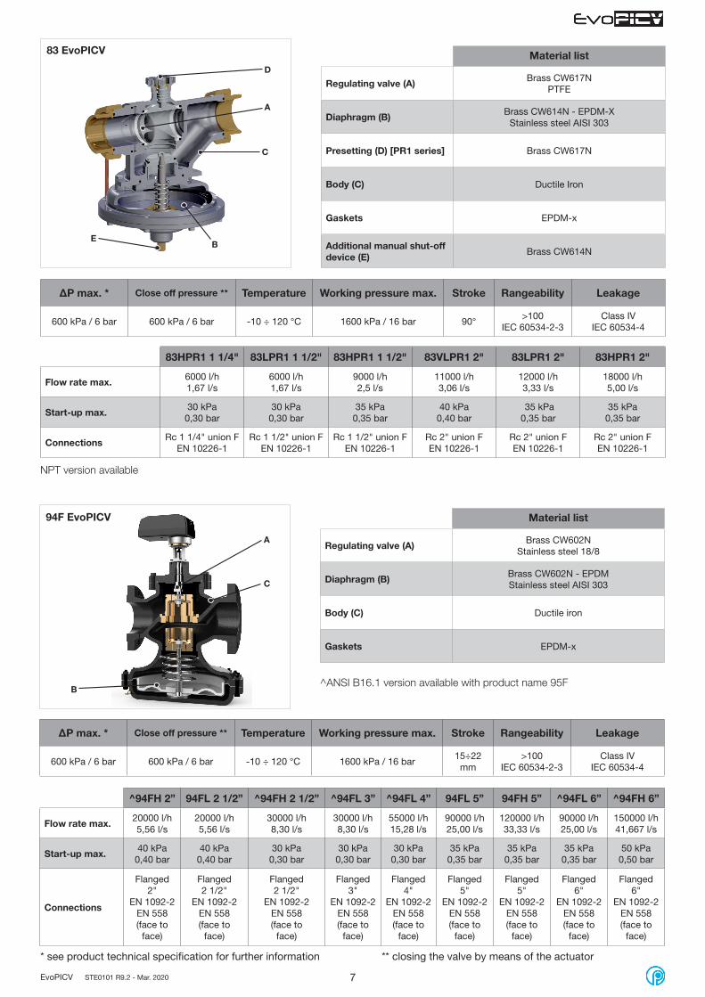
94F EvoPICV Material list
Regulating valve (A) Brass CW602NStainless steel 18/8
Diaphragm (B) Brass CW602N - EPDMStainless steel AISI 303
Body (C) Ductile iron
Gaskets EPDM-x
ΔP max. * Close off pressure ** Temperature Working pressure max. Stroke Rangeability Leakage
600 kPa / 6 bar 600 kPa / 6 bar -10 ÷ 120 °C 1600 kPa / 16 bar15÷22
mm>100
IEC 60534-2-3Class IV
IEC 60534-4
* see product technical specification for further information ** closing the valve by means of the actuator
^94FH 2” 94FL 2 1/2” ^94FH 2 1/2” ^94FL 3” ^94FL 4” 94FL 5” 94FH 5” ^94FL 6” ^94FH 6”
Flow rate max. 20000 l/h5,56 l/s
20000 l/h5,56 l/s
30000 l/h8,30 l/s
30000 l/h8,30 l/s
55000 l/h15,28 l/s
90000 l/h25,00 l/s
120000 l/h33,33 l/s
90000 l/h25,00 l/s
150000 l/h41,667 l/s
Start-up max. 40 kPa0,40 bar
40 kPa0,40 bar
30 kPa0,30 bar
30 kPa0,30 bar
30 kPa0,30 bar
35 kPa0,35 bar
35 kPa0,35 bar
35 kPa0,35 bar
50 kPa0,50 bar
Connections
Flanged2"
EN 1092-2EN 558(face to
face)
Flanged2 1/2"
EN 1092-2EN 558(face to
face)
Flanged2 1/2"
EN 1092-2EN 558(face to
face)
Flanged3"
EN 1092-2EN 558(face to
face)
Flanged4"
EN 1092-2EN 558(face to
face)
Flanged5"
EN 1092-2EN 558(face to
face)
Flanged5"
EN 1092-2EN 558(face to
face)
Flanged6"
EN 1092-2EN 558(face to
face)
Flanged6"
EN 1092-2EN 558(face to
face)
A
D
C
B
83 EvoPICV Material list
Regulating valve (A) Brass CW617NPTFE
Diaphragm (B) Brass CW614N - EPDM-XStainless steel AISI 303
Presetting (D) [PR1 series] Brass CW617N
Body (C) Ductile Iron
Gaskets EPDM-x
Additional manual shut-offdevice (E) Brass CW614N
83HPR1 1 1/4" 83LPR1 1 1/2" 83HPR1 1 1/2" 83VLPR1 2" 83LPR1 2" 83HPR1 2"
Flow rate max. 6000 l/h1,67 l/s
6000 l/h1,67 l/s
9000 l/h2,5 l/s
11000 l/h3,06 l/s
12000 l/h3,33 l/s
18000 l/h5,00 l/s
Start-up max. 30 kPa0,30 bar
30 kPa0,30 bar
35 kPa0,35 bar
40 kPa0,40 bar
35 kPa0,35 bar
35 kPa0,35 bar
Connections Rc 1 1/4" union FEN 10226-1
Rc 1 1/2" union FEN 10226-1
Rc 1 1/2" union FEN 10226-1
Rc 2" union FEN 10226-1
Rc 2" union FEN 10226-1
Rc 2" union FEN 10226-1
ΔP max. * Close off pressure ** Temperature Working pressure max. Stroke Rangeability Leakage
600 kPa / 6 bar 600 kPa / 6 bar -10 ÷ 120 °C 1600 kPa / 16 bar 90°>100
IEC 60534-2-3Class IV
IEC 60534-4
E
NPT version available
^ANSI B16.1 version available with product name 95F

8EvoPICV STE0101 R9.2 - Mar. 2020
A
C
B
94F EvoPICV 8" - 10" Material list
Regulating valve (A) Brass CW602NStainless steel 18/8
Diaphragm (B) Brass CW602N - EPDMStainless steel AISI 304
Body (C) Ductile iron
Gaskets EPDM-x
ΔP max. * Close off pressure ** Temperature Working pressure max. Stroke Rangeability Leakage
400 kPa / 4 bar 400 kPa / 4 bar -10 ÷ 120 °C 1600 kPa / 16 bar15÷22
mm>100
IEC 60534-2-3Class IV
IEC 60534-4
* see product technical specification for further information. Additional tests reports available upon request.
94FL 8” 94FH 8” 94FL 10” 94FH 10”
Flow rate max. 200000 l/h55,56 l/s
300000 l/h83,33 l/s
300000 l/h83,33 l/s
500000 l/h138.8 l/s
Start-up max. 40 kPa0,40 bar
60 kPa0,60 bar
40 kPa0,40 bar
65 kPa0,65 bar
Connections
Flanged 8"EN 1092-2
EN 558(face to face)
Flanged 8"EN 1092-2
EN 558(face to face)
Flanged 10"EN 1092-2
EN 558(face to face)
Flanged 10"EN 1092-2
EN 558(face to face)
Allowed medium in all PICV range
Water / Water+glycol 30%
** closing the valve by means of the actuator. Not suitable to be used for end of line service. Additional tests reports available upon request.

9EvoPICV STE0101 R9.2 - Mar. 2020
Dynamic characteristic curves
Using a differential pressure gauge to measure the pressure drop the valve absorbs, allows to check whether the valve is in the operating range (and, therefore, whether the flow is constant) by simply verifying that the measured value P1 - P2 is higher than the start-up value.If the ΔP measured value is lower than the start-up value, then the valve works as a fixed orifice valve.Start-up value varies with flow setting of the valve, as shown by the example below:
P1 - P2
Flow rate
100%
70%
50%
kPa start-up
% knob opening
Q≠CONST Q=CONST
Q
P1 - P2
START-UPPRESSURE
HYSTERESISP1
P2
P1 - P2
15 kPa 30 kPa 400 kPa
Working range at 100%
Working range at 50%
When the valve is set at 100% of nominal (maximum) flow, the curve begins to remain constant at 30 kPa, therefore the working range of the valve is 30 ÷ 400 kPa;
When the valve is set at 50% of nominal flow, the curve begins to remain constant at 15 kPa, therefore the working range of the valve is 15 ÷ 400 kPa.
Over 400 kPa the fluid velocity through the valve is extremely high and cavitation may happen due to extreme turbolence of the flow.Because of these phenomena the valve can get demaged. For energy saving reasons, we suggest to continuosly work the valve under 400 kPa.

10EvoPICV STE0101 R9.2 - Mar. 2020
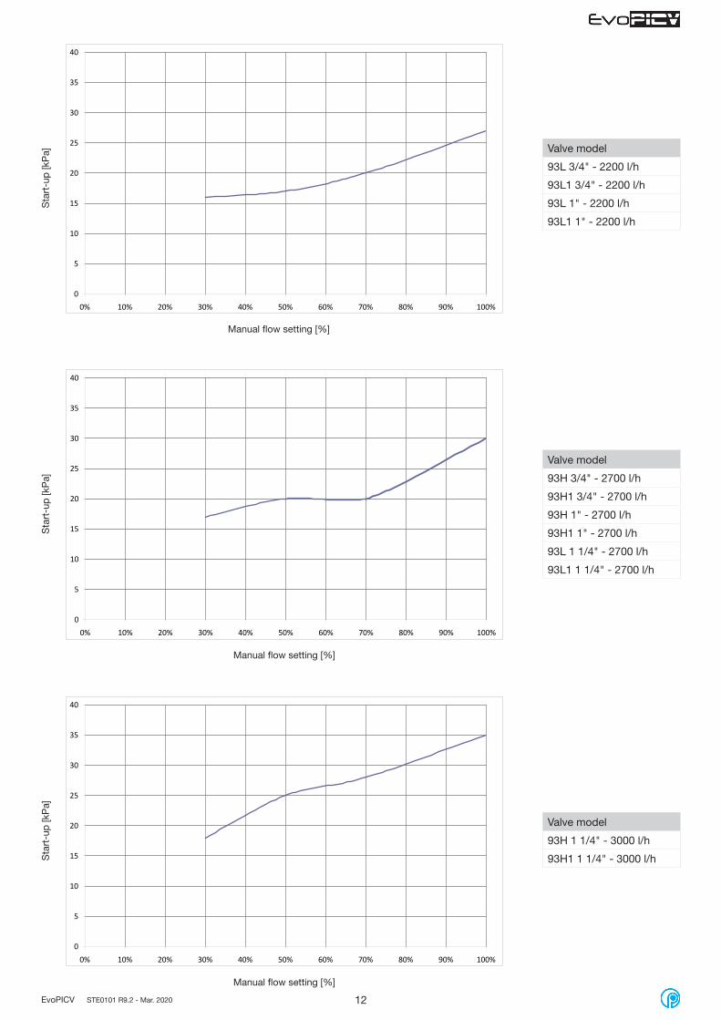
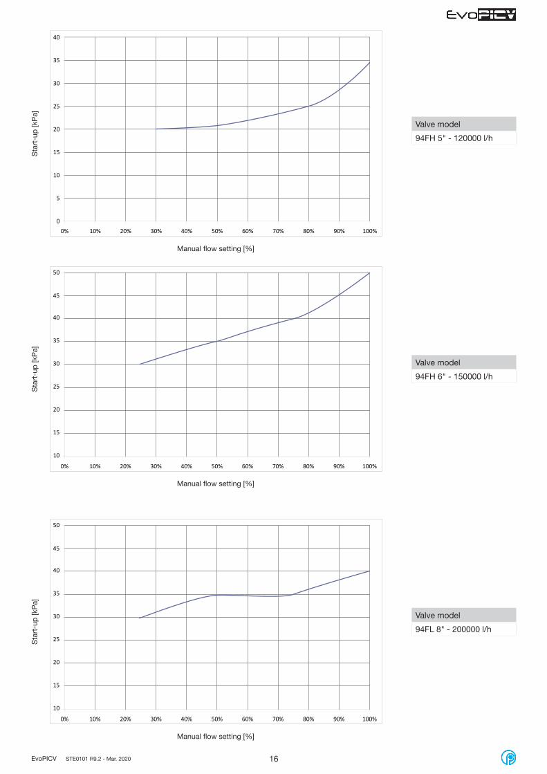
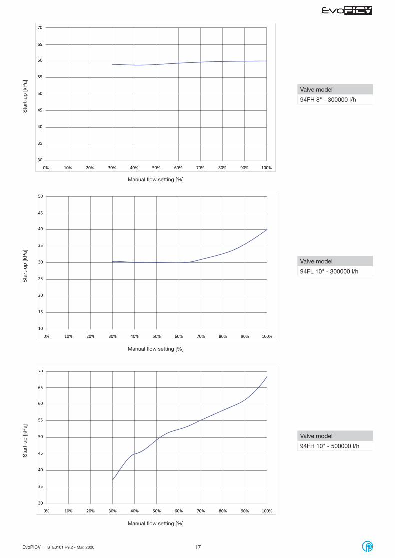
The following charts show how start-up pressure changes for each modelsS
tart
-up
[kP
a]S
tart
-up
[kP
a]S
tart
-up
[kP
a]
Manual flow setting [%]
Manual flow setting [%]
Manual flow setting [%]
0
5
10
15
20
25
30
35
40
0% 10% 20% 30% 40% 50% 60% 70% 80% 90% 100%
0
5
10
15
20
25
30
35
40
0% 10% 20% 30% 40% 50% 60% 70% 80% 90% 100%
Valve model
91VL 1/2" - 150 l/h
91VL1 1/2" - 150 l/h
91XVL 1/2" - 150 l/h
91XVL/3 1/2" - 150 l/h
91XVL3S 1/2" - 150 l/h
91XVL/2 1/2" - 150 l/h
Valve model
91L 1/2" - 600 l/h
91L1 1/2" - 600 l/h
91XL 1/2" - 600 l/h
91XL/2 1/2" - 600 l/h
91XL/3 1/2" - 600 l/h
91XL3S 1/2" - 600 l/h
91XL/2 3/4" - 600 l/h
Valve model
91H 1/2" - 780 l/h
91H1 1/2" - 780 l/h
0
5
10
15
20
25
30
35
40
0% 10% 20% 30% 40% 50% 60% 70% 80% 90% 100%

11EvoPICV STE0101 R9.2 - Mar. 2020
Sta
rt-u
p [k
Pa]
Manual flow setting [%]
Sta
rt-u
p [k
Pa]
Manual flow setting [%]
0
5
10
15
20
25
30
35
40
0% 10% 20% 30% 40% 50% 60% 70% 80% 90% 100%
0
5
10
15
20
25
30
35
40
0% 10% 20% 30% 40% 50% 60% 70% 80% 90% 100%
Valve model
91L 3/4" - 1000 l/h
91L1 3/4" - 1000 l/h
Valve model
91H 3/4" - 1500 l/h
91H1 3/4" - 1500 l/h
91H 1" - 1500 l/h
91H1 1" - 1500 l/h
Sta
rt-u
p [k
Pa]
Manual flow setting [%]
0
5
10
15
20
25
30
35
40
0% 10% 20% 30% 40% 50% 60% 70% 80% 90% 100%
Valve model
91XH 1/2" - 900 l/h
91XH/2 3/4" - 900 l/h
91XH/3 1/2" - 900 l/h
91XH3S 1/2" - 900 l/h
12EvoPICV STE0101 R9.2 - Mar. 2020
Sta
rt-u
p [k
Pa]
Manual flow setting [%]
Sta
rt-u
p [k
Pa]
Manual flow setting [%]
0
5
10
15
20
25
30
35
40
0% 10% 20% 30% 40% 50% 60% 70% 80% 90% 100%
Valve model
93H 3/4" - 2700 l/h
93H1 3/4" - 2700 l/h
93H 1" - 2700 l/h
93H1 1" - 2700 l/h
93L 1 1/4" - 2700 l/h
93L1 1 1/4" - 2700 l/h
Valve model
93H 1 1/4" - 3000 l/h
93H1 1 1/4" - 3000 l/h
0
5
10
15
20
25
30
35
40
0% 10% 20% 30% 40% 50% 60% 70% 80% 90% 100%
Sta
rt-u
p [k
Pa]
Manual flow setting [%]
0
5
10
15
20
25
30
35
40
0% 10% 20% 30% 40% 50% 60% 70% 80% 90% 100%
Valve model
93L 3/4" - 2200 l/h
93L1 3/4" - 2200 l/h
93L 1" - 2200 l/h
93L1 1" - 2200 l/h

13EvoPICV STE0101 R9.2 - Mar. 2020
Sta
rt-u
p [k
Pa]
Manual flow setting [%]
Valve model
83HPR1 1 1/4" - 6000 l/h
83LPR1 1 1/2" - 6000 l/h
Sta
rt-u
p [k
Pa]
Manual flow setting [%]
Sta
rt-u
p [k
Pa]
Manual flow setting [%]
0
5
10
15
20
25
30
35
40
0% 10% 20% 30% 40% 50% 60% 70% 80% 90% 100%
0
5
10
15
20
25
30
35
40
0% 10% 20% 30% 40% 50% 60% 70% 80% 90% 100%
Valve model
83HPR1 1 1/2" - 9000 l/h
Valve model
83VLPR1 2" - 11000 l/h
0
5
10
15
20
25
30
35
40
0% 10% 20% 30% 40% 50% 60% 70% 80% 90% 100%

14EvoPICV STE0101 R9.2 - Mar. 2020
Sta
rt-u
p [k
Pa]
Valve model
83HPR1 2" - 18000 l/h
0
5
10
15
20
25
30
35
40
0% 10% 20% 30% 40% 50% 60% 70% 80% 90% 100%
Sta
rt-u
p [k
Pa]
Manual flow setting [%]
0
5
10
15
20
25
30
35
40
0% 10% 20% 30% 40% 50% 60% 70% 80% 90% 100%
Valve model
94FH 2" - 20000 l/h
94FL 2 1/2" - 20000 l/h
Manual flow setting [%]
Sta
rt-u
p [k
Pa]
Manual flow setting [%]
Valve model
83LPR1 2" - 12000 l/h
0
5
10
15
20
25
30
35
40
0% 10% 20% 30% 40% 50% 60% 70% 80% 90% 100%

15EvoPICV STE0101 R9.2 - Mar. 2020
Sta
rt-u
p [k
Pa]
Manual flow setting [%]
Valve model
94FH 2 1/2" - 30000 l/h
94FL 3" - 30000 l/h
0
5
10
15
20
25
30
35
40
0% 10% 20% 30% 40% 50% 60% 70% 80% 90% 100%
Sta
rt-u
p [k
Pa]
Valve model
94FL 4" - 55000 l/h
0
5
10
15
20
25
30
35
40
0% 10% 20% 30% 40% 50% 60% 70% 80% 90% 100%
Sta
rt-u
p [k
Pa]
Manual flow setting [%]
0
5
10
15
20
25
30
35
40
0% 10% 20% 30% 40% 50% 60% 70% 80% 90% 100%
Valve model
94FL 5" - 90000 l/h
94FL 6" - 90000 l/h
Manual flow setting [%]
16EvoPICV STE0101 R9.2 - Mar. 2020
Sta
rt-u
p [k
Pa]
Manual flow setting [%]
Valve model
94FH 6" - 150000 l/h
10
15
20
25
30
35
40
0% 10% 20% 30% 40% 50% 60% 70% 80% 90% 100%
45
50
Sta
rt-u
p [k
Pa]
Manual flow setting [%]
0
5
10
15
20
25
30
35
40
0% 10% 20% 30% 40% 50% 60% 70% 80% 90% 100%
Valve model
94FH 5" - 120000 l/h
Sta
rt-u
p [k
Pa]
Manual flow setting [%]
Valve model
94FL 8" - 200000 l/h
10
15
20
25
30
35
40
0% 10% 20% 30% 40% 50% 60% 70% 80% 90% 100%
45
50
17EvoPICV STE0101 R9.2 - Mar. 2020
Sta
rt-u
p [k
Pa]
Manual flow setting [%]
Valve model
94FL 10" - 300000 l/h
10
15
20
25
30
35
40
0% 10% 20% 30% 40% 50% 60% 70% 80% 90% 100%
45
50
Sta
rt-u
p [k
Pa]
Manual flow setting [%]
Valve model
94FH 8" - 300000 l/h
Sta
rt-u
p [k
Pa]
Manual flow setting [%]
Valve model
94FH 10" - 500000 l/h
30
35
40
45
50
55
60
0% 10% 20% 30% 40% 50% 60% 70% 80% 90% 100%
65
70
30
35
40
45
50
55
60
0% 10% 20% 30% 40% 50% 60% 70% 80% 90% 100%
65
70

18EvoPICV STE0101 R9.2 - Mar. 2020
Flow pre-setting 91 - 91-1 EvoPICV
Presetting %
100
90
80
70
60
50
40
30
20
10
91VL-91VL1 ½"
Flow rate *
l/h l/s
150 0,042
135 0,038
120 0,033
105 0,029
90 0,025
75 0,021
60 0,017
45 0,013
30 0,008
15 0,004
91L-91L1 ½"
Flow rate
l/h l/s
600 0,167
540 0,150
480 0,133
420 0,117
360 0,100
300 0,083
240 0,067
180 0,050
120 0,033
60 0,017
91H-91H1 ½"
Flow rate
l/h l/s
780 0,217
702 0,195
624 0,173
546 0,152
468 0,130
390 0,108
312 0,087
234 0,065
156 0,043
78 0,022
91L-91L1 ¾"
Flow rate
l/h l/s
1000 0,278
900 0,250
800 0,222
700 0,194
600 0,167
500 0,139
400 0,111
300 0,083
200 0,056
100 0,028
91H-91H1 ¾"
Flow rate
l/h l/s
1500 0,417
1350 0,375
1200 0,333
1050 0,292
900 0,250
750 0,208
600 0,167
450 0,125
- -
- -
91H-91H1 1"
Flow rate
l/h l/s
1500 0,417
1350 0,375
1200 0,333
1050 0,292
900 0,250
750 0,208
600 0,167
450 0,125
- -
- -
* at 0% position the valve regulates betweem 10 - 13 l/h
Presetting %
100
90
80
70
60
50
40
30
20
10
93L-93L1 ¾"
Flow rate
l/h l/s
2200 0,611
1980 0,550
1760 0,489
1540 0,428
1320 0,367
1100 0,306
880 0,244
660 0,183
440 0,122
220 0,061
93H-93H1 ¾"
Flow rate
l/h l/s
2700 0,750
2430 0,675
2160 0,600
1890 0,525
1620 0,450
1350 0,375
1080 0,300
810 0,225
540 0,150
270 0,075
93L-93L1 1"
Flow rate
l/h l/s
2200 0,611
1980 0,550
1760 0,489
1540 0,428
1320 0,367
1100 0,306
880 0,244
660 0,183
440 0,122
220 0,061
93H-93H1 1"
Flow rate
l/h l/s
2700 0,750
2430 0,675
2160 0,600
1890 0,525
1620 0,450
1350 0,375
1080 0,300
810 0,225
540 0,150
270 0,075
93L-93L1 1 1/4"
Flow rate
l/h l/s
2700 0,750
2430 0,675
2160 0,600
1890 0,525
1620 0,450
1350 0,375
1080 0,300
810 0,225
540 0,150
270 0,075
93H-93H1 1 1/4"
Flow rate
l/h l/s
3000 0,833
2700 0,750
2400 0,667
2100 0,583
1800 0,500
1500 0,417
1200 0,333
900 0,250
600 0,167
300 0,083
Flow pre-setting 93 EvoPICV
Flow pre-setting 91X - 91X/2 - 91X/3 - 91X3S EvoPICV
Presetting %
100
90
80
70
60
50
40
30
20
10
150 l/h
Flow rate *
l/h l/s
150 0,042
135 0,038
120 0,033
105 0,029
90 0,025
75 0,021
60 0,017
45 0,013
30 0,008
15 0,004
600 l/h
Flow rate
l/h l/s
600 0,167
540 0,150
480 0,133
420 0,117
360 0,100
300 0,083
240 0,067
180 0,050
120 0,033
60 0,017
900 l/h
Flow rate
l/h l/s
900 0,250
810 0,225
720 0,200
630 0,175
540 0,150
450 0,125
360 0,100
270 0,075
180 0,050
90 0,025 * at 0% position the valve regulates betweem 10 - 13 l/h

19EvoPICV STE0101 R9.2 - Mar. 2020
Presetting %
100
90
80
70
60
50
40
30
20
10
94FH 2"
Flow rate
l/h l/s
20000 5,556
18000 5,000
16000 4,444
14000 3,889
12000 3,333
10000 2,778
8000 2,222
6000 1,667
4000 1,111
- -
94FL 2 1/2"
Flow rate
l/h l/s
20000 5,556
18000 5,000
16000 4,444
14000 3,889
12000 3,333
10000 2,778
8000 2,222
6000 1,667
4000 1,111
- -
94FH 2 1/2"
Flow rate
l/h l/s
30000 8,333
27000 7,500
24000 6,667
21000 5,833
18000 5,000
15000 4,167
12000 3,333
9000 2,500
6000 1,667
- -
94FL 3"
Flow rate
l/h l/s
30000 8,333
27000 7,500
24000 6,667
21000 5,833
18000 5,000
15000 4,167
12000 3,333
9000 2,500
6000 1,667
- -
94FL 4"
Flow rate
l/h l/s
55000 15,278
49500 13,750
44000 12,222
38500 10,694
33000 9,167
27500 7,639
22000 6,111
16500 4,583
- -
- -
94FL 5"
Flow rate
l/h l/s
90000 25,000
81000 22,500
72000 20,000
63000 17,500
54000 15,000
45000 12,500
36000 10,000
27000 7,500
18000 5,000
- -
Flow pre-setting 94F EvoPICV 2" - 6"
Presetting %
100
90
80
70
60
50
40
30
20
10
94FH 5"
Flow rate
l/h l/s
120000 33,333
108000 30,000
96000 26,667
84000 23,333
72000 20,000
60000 16,667
48000 13,333
36000 10,000
24000 6,667
12000 3,333
94FL 6"
Flow rate
l/h l/s
90000 25,000
81000 22,500
72000 20,000
63000 17,500
54000 15,000
45000 12,500
36000 10,000
27000 7,500
18000 5,000
- -
94FH 6"
Flow rate
l/h l/s
150000 41,667
135000 37,500
120000 33,333
105000 29,167
90000 25,000
75000 20,833
60000 16,667
45000 12,500
30000 8,333
15000 4,167
Presetting %
100
90
80
70
60
50
40
30
20
10
83HPR1 1 1/4"
Flow rate
l/h l/s
6000 1,667
5400 1,500
4800 1,333
4200 1,167
3600 1,000
3000 0,833
2400 0,667
1800 0,500
- -
- -
83LPR1 1 1/2"
Flow rate
l/h l/s
6000 1,667
5400 1,500
4800 1,333
4200 1,167
3600 1,000
3000 0,833
2400 0,667
1800 0,500
- -
- -
83HPR1 1 1/2"
Flow rate
l/h l/s
9000 2,500
8100 2,250
7200 2,000
6300 1,750
5400 1,500
4500 1,250
3600 1,000
2700 0,750
- -
- -
Flow pre-setting 83 EvoPICV
83VLPR1 2"
Flow rate
l/h l/s
11000 3,056
9900 2,750
8800 2,444
7700 2,139
6600 1,833
5500 1,528
4400 1,222
3300 0,917
- -
- -
83LPR1 2"
Flow rate
l/h l/s
12000 3,333
10800 3,000
9600 2,667
8400 2,333
7200 2,000
6000 1,667
4800 1,333
3600 1,000
- -
- -
83HPR1 2"
Flow rate
l/h l/s
18000 5,000
16200 4,500
14400 4,000
12600 3,500
10800 3,000
9000 2,500
7200 2,000
5400 1,500
- -
- -

20EvoPICV STE0101 R9.2 - Mar. 2020
Presetting %
100
90
80
70
60
50
40
30
20
10
94FL 8"
Flow rate
l/h l/s
200000 55,56
180000 50,00
160000 44,44
140000 38,89
120000 33,33
100000 27,78
80000 22,22
60000 16,67
- -
- -
94FH 8"
Flow rate
l/h l/s
300000 83,33
270000 75,00
240000 66,67
210000 58,33
180000 50,00
150000 41,67
120000 33,33
90000 25,00
- -
- -
94FL 10"
Flow rate
l/h l/s
300000 83,33
270000 75,00
240000 66,67
210000 58,33
180000 50,00
150000 41,67
120000 33,33
90000 25,00
60000 16,67
- -
94FH 10"
Flow rate
l/h l/s
500000 138,8
450000 124,9
400000 111
350000 97,1
300000 83,2
250000 69,3
200000 55,4
150000 41,5
- -
- -
Flow pre-setting 94F EvoPICV 8" - 10"
± 20
± 10
100%90%80%70%60%50%40%30%20%10%0%
Flow setting accuracyMax flow deviation at different settings over 1 bar differential pressure.
Ԑ [± %]
Adjusted flow
Some models, in the presetting range between 0-30%, might work with a higher deviation.Please contact technical department for further infomation.
21EvoPICV STE0101 R9.2 - Mar. 2020
Flow control and characteristic curves
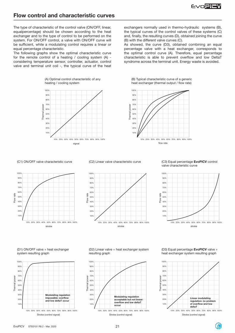
The type of characteristic of the control valve (ON/OFF, linear, equalpercentage) should be chosen according to the heat exchanger and to the type of control to be performed on the system. For ON/OFF control, a valve with ON/OFF curve will be sufficient, while a modulating control requires a linear or equal percentage characteristic.The following graphs show the optimal characteristic curve for the remote control of a heating / cooling system (A) - considering temperature sensor, controller, actuator, control valve and terminal unit coil -, the typical curve of the heat
10%
20%
30%
40%
50%
60%
70%
80%
90%
100%
10% 20% 30% 40% 50% 60% 70% 80% 90% 100%
10%
20%
30%
40%
50%
60%
70%
80%
90%
100%
10% 20% 30% 40% 50% 60% 70% 80% 90% 100%
(A) Optimal control characteristic of any heating / cooling system
(B) Typical characteristic curve of a generic heat exchanger (thermal output / flow rate)
Ther
mal
pow
er
signal flow rate
10%
20%
30%
40%
50%
60%
70%
80%
90%
100%
10% 20% 30% 40% 50% 60% 70% 80% 90% 100%
stroke stroke stroke
(C3) Equal percentage EvoPICV control valve characteristic curve
(C1) ON/OFF valve characteristic curve (C2) Linear valve characteristic curve
10%
20%
30%
40%
50%
60%
70%
80%
90%
100%
10% 20% 30% 40% 50% 60% 70% 80% 90% 100%
10%
20%
30%
40%
50%
60%
70%
80%
90%
100%
10% 20% 30% 40% 50% 60% 70% 80% 90% 100%
10%
20%
30%
40%
50%
60%
70%
80%
90%
100%
10% 20% 30% 40% 50% 60% 70% 80% 90% 100%
Stroke (control signal)
(D3) Equal percentage EvoPICV valve + heat exchanger system resulting graph
(D1) ON/OFF valve + heat exchanger system resulting graph
(D2) Linear valve + heat exchanger system resulting graph
10%
20%
30%
40%
50%
60%
70%
80%
90%
100%
10% 20% 30% 40% 50% 60% 70% 80% 90% 100%
10%
20%
30%
40%
50%
60%
70%
80%
90%
100%
10% 20% 30% 40% 50% 60% 70% 80% 90% 100%
Modulating regulation impossible: overflow and low deltaT occur
Modulating regulation acceptable but not linear: overflow and low deltaT occur
Linear modulating regulation: no problem of overflow and low deltaT
Stroke (control signal) Stroke (control signal)
exchangers normally used in thermo-hydraulic systems (B), the typical curves of the control valves of these systems (C) and, finally, the resulting curves (D), obtained joining the curve (B) with the different valve curves (C).As showed, the curve (D3), obtained combining an equal percentage valve with a heat exchanger, corresponds to the optimal control curve (A). Therefore, equal percentage characteristic is able to prevent overflow and low DeltaT syndrome across the terminal unit. Energy waste is avoided.
Ther
mal
pow
er
Flow
rat
e
Flow
rat
e
Flow
rat
eTh
erm
al p
ower
Ther
mal
pow
er
Ther
mal
pow
er
22EvoPICV STE0101 R9.2 - Mar. 2020
10%
20%
30%
40%
50%
60%
70%
80%
90%
100%
10% 20% 30% 40% 50% 60% 70% 80% 90% 100%
10%
20%
30%
40%
50%
60%
70%
80%
90%
100%
10% 20% 30% 40% 50% 60% 70% 80% 90% 100%
10%
20%
30%
40%
50%
60%
70%
80%
90%
100%
10% 20% 30% 40% 50% 60% 70% 80% 90% 100%
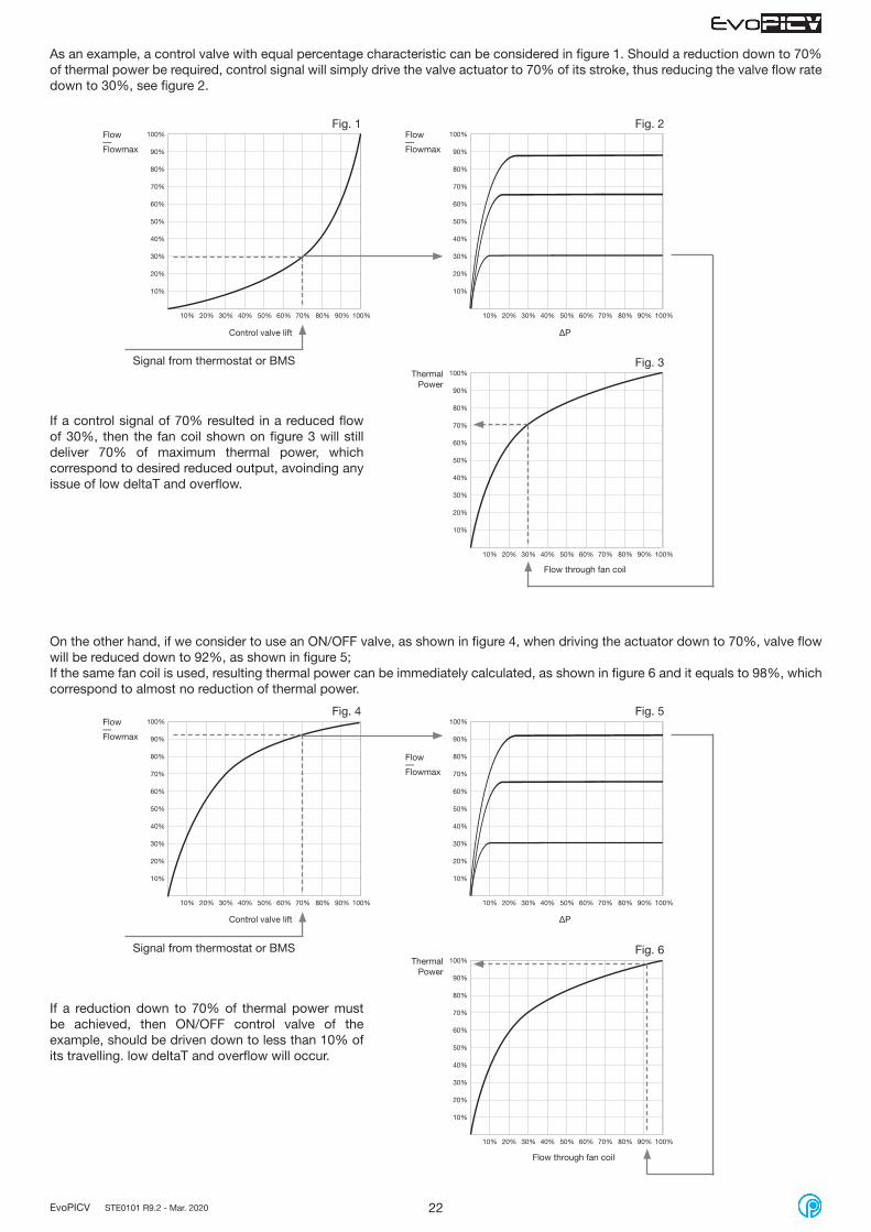
As an example, a control valve with equal percentage characteristic can be considered in figure 1. Should a reduction down to 70% of thermal power be required, control signal will simply drive the valve actuator to 70% of its stroke, thus reducing the valve flow rate down to 30%, see figure 2.
If a control signal of 70% resulted in a reduced flow of 30%, then the fan coil shown on figure 3 will still deliver 70% of maximum thermal power, which correspond to desired reduced output, avoinding any issue of low deltaT and overflow.
If a reduction down to 70% of thermal power must be achieved, then ON/OFF control valve of the example, should be driven down to less than 10% of its travelling. low deltaT and overflow will occur.
Signal from thermostat or BMS
ΔP
Flow through fan coil
Flow—Flowmax
ThermalPower
Fig. 1 Fig. 2
Fig. 3
10%
20%
30%
40%
50%
60%
70%
80%
90%
100%
10% 20% 30% 40% 50% 60% 70% 80% 90% 100%
10%
20%
30%
40%
50%
60%
70%
80%
90%
100%
10% 20% 30% 40% 50% 60% 70% 80% 90% 100%
10%
20%
30%
40%
50%
60%
70%
80%
90%
100%
10% 20% 30% 40% 50% 60% 70% 80% 90% 100%
Signal from thermostat or BMS
ΔP
ThermalPower
Fig. 4 Fig. 5
Fig. 6
Flow—Flowmax
Flow—Flowmax
Flow—Flowmax
Control valve lift
Control valve lift
Flow through fan coil
On the other hand, if we consider to use an ON/OFF valve, as shown in figure 4, when driving the actuator down to 70%, valve flow will be reduced down to 92%, as shown in figure 5;If the same fan coil is used, resulting thermal power can be immediately calculated, as shown in figure 6 and it equals to 98%, which correspond to almost no reduction of thermal power.

23EvoPICV STE0101 R9.2 - Mar. 2020
A
Operating on the position of the regulating valve control stem A will modify the valve Kv, hence the flow rate.The relation between Kv and stroke is shown in the graph below.
90%
80%
70%
60%
50%
40%
30%
20%
10%
0%100%90%80%70%60%50%40%30%20%10%0%
100%
Kv % = Kv/Kvmax
ON-OFF ZONE
MODULATING ZONE
Good control characteristic
theoretical equipercentage curven(eq) = 3.9
Bad control characteristic
Execellent controlcharacteristic
Stroke % = H/H0
Combining the EvoPICV valve characteristic with heat exchanger results in a linear control system.Control curve characteristic may change according to valve version.
Control characteristic curve
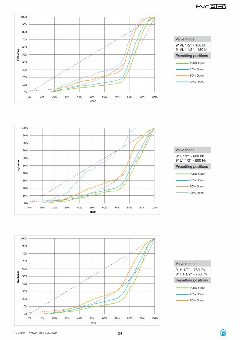
Typical control valve characteristic curves
H = current lift (opening) of the control valve; H varies from 0 to H0
H0 = maximum lift of the control valve;Kv = valve flow factor at lift = HKvmax = valve flow factor at lift = H0
Thus, H/H0 and Kv/Kvmax ratios state respectively the opening percentage of the control valve and the flow rate percentage with respect to the maximum one set by the presetting knob.In the next pages, control curves for each valve model are shown. All valves control characteristic have been tested and plotted according to VDI/VDE 2173 guidelines; valves were driven by following actuators:
- VA7482 0-10V actuator
- SN08CC 0-10V actuator
- M94F2 0-10V actuator - Eq mode and Linear mode
24EvoPICV STE0101 R9.2 - Mar. 2020
0%
10%
20%
30%
40%
50%
60%
70%
80%
90%
100%
0% 10% 20% 30% 40% 50% 60% 70% 80% 90% 100%
H/H0
Kv/K
vmax
0%
10%
20%
30%
40%
50%
60%
70%
80%
90%
100%
0% 10% 20% 30% 40% 50% 60% 70% 80% 90% 100%
H/H0
Kv/K
vmax
0%
10%
20%
30%
40%
50%
60%
70%
80%
90%
100%
0% 10% 20% 30% 40% 50% 60% 70% 80% 90% 100%
H/H0
kv/k
vmax
Valve model
91VL 1/2" - 150 l/h91VL1 1/2" - 150 l/h
Presetting positions
25% Open
50% Open
75% Open
100% Open
Valve model
91L 1/2" - 600 l/h91L1 1/2" - 600 l/h
Presetting positions
25% Open
50% Open
75% Open
100% Open
Valve model
91H 1/2" - 780 l/h91H1 1/2" - 780 l/h
Presetting positions
50% Open
75% Open
100% Open

25EvoPICV STE0101 R9.2 - Mar. 2020
0%
10%
20%
30%
40%
50%
60%
70%
80%
90%
100%
0% 10% 20% 30% 40% 50% 60% 70% 80% 90% 100%
H/H0
Kv/K
vmax
0%
10%
20%
30%
40%
50%
60%
70%
80%
90%
100%
0% 10% 20% 30% 40% 50% 60% 70% 80% 90% 100%
H/H0
Kv/K
vmax
0%
10%
20%
30%
40%
50%
60%
70%
80%
90%
100%
0% 10% 20% 30% 40% 50% 60% 70% 80% 90% 100%
H/H0
Kv/K
vmax
Valve model
91L 3/4" - 1000 l/h91L1 3/4" - 1000 l/h
Presetting positions
50% Open
75% Open
100% Open
Valve model
91H 3/4" - 1500 l/h91H1 3/4" - 1500 l/h91H 1" - 1500 l/h91H1 1" - 1500 l/h
Presetting positions
50% Open
75% Open
100% Open
Valve model
93L 3/4" - 2200 l/h
93L1 3/4" - 2200 l/h
93L 1" - 2200 l/h
93L1 1" - 2200 l/h
Presetting positions
50% Open
75% Open
100% Open

26EvoPICV STE0101 R9.2 - Mar. 2020
Valve model
83HPR1 1 1/4" - 6000 l/h
83LPR1 1 1/2" - 6000 l/h
Presetting positions
100% Open
0%
10%
20%
30%
40%
50%
60%
70%
80%
90%
100%
0% 10% 20% 30% 40% 50% 60% 70% 80% 90% 100%
H/H0
Kv/K
vmax
0%
10%
20%
30%
40%
50%
60%
70%
80%
90%
100%
0% 10% 20% 30% 40% 50% 60% 70% 80% 90% 100%
H/H0
Kv/K
vmax
Valve model
93H 3/4" - 2700 l/h
93H1 3/4" - 2700 l/h
93H 1" - 2700 l/h
93H1 1" - 2700 l/h
93L 1 1/4" - 2700 l/h
93L1 1 1/4" - 2700 l/h
Presetting positions
50% Open
75% Open
100% Open
Valve model
93H 1 1/4" - 3000 l/h
93H1 1 1/4" - 3000 l/h
Presetting positions
50% Open
75% Open
100% Open
0%
10%
20%
30%
40%
50%
60%
70%
80%
90%
100%
0% 10% 20% 30% 40% 50% 60% 70% 80% 90% 100%
H/H0
Kv/K
vmax

27EvoPICV STE0101 R9.2 - Mar. 2020
Valve model
83HPR1 1 1/2" - 9000 l/h
Presetting positions
100% Open
Valve model
83VLPR1 2" - 11000 l/h
Presetting positions
100% Open
Valve model
83LPR1 2" - 12000 l/h
Presetting positions
100% Open
0%
10%
20%
30%
40%
50%
60%
70%
80%
90%
100%
0% 10% 20% 30% 40% 50% 60% 70% 80% 90% 100%
H/H0
Kv/K
vmax
0%
10%
20%
30%
40%
50%
60%
70%
80%
90%
100%
0% 10% 20% 30% 40% 50% 60% 70% 80% 90% 100%
H/H0
Kv/K
vmax
0%
10%
20%
30%
40%
50%
60%
70%
80%
90%
100%
0% 10% 20% 30% 40% 50% 60% 70% 80% 90% 100%
H/H0
Kv/K
vmax

28EvoPICV STE0101 R9.2 - Mar. 2020
0%
10%
20%
30%
40%
50%
60%
70%
80%
90%
100%
0% 10% 20% 30% 40% 50% 60% 70% 80% 90% 100%
H/H0
Kv/K
vmax
Valve model
83HPR1 2" - 18000 l/h
Presetting positions
100% Open
0%
10%
20%
30%
40%
50%
60%
70%
80%
90%
100%
0% 10% 20% 30% 40% 50% 60% 70% 80% 90% 100%
H/H0
Kv/K
vmax
Valve model
94FH 2" - 20000 l/h
94FL 2 1/2" - 20000 l/h
94FH 2 1/2" - 30000 l/h
94FL 3" - 30000 l/h
94FL 4" - 55000 l/h
94FL 5" - 90000 l/h
94FH 5" - 120000 l/h
94FL 6" - 90000 l/h
94FH 6" - 150000 l/h
94FL 8" - 200000 l/h
94FH 8" - 300000 l/h
94FL 10" - 300000 l/h
94FH 10" - 500000 l/h
Presetting positions
Any
0%
10%
20%
30%
40%
50%
60%
70%
80%
90%
100%
0% 10% 20% 30% 40% 50% 60% 70% 80% 90% 100%
H/H0
Kv/K
vmax
Equal percenteage mode
Linear mode

29EvoPICV STE0101 R9.2 - Mar. 2020
Installation and maintenance
Before filling the terminal unit system with water, make sure main pipeline has been flushed and most of dirt and debris have been flushed away. Always comply with local or applicable flushing, however, in order to get the longest life and the best performance from a PICV, Pettinaroli does not accept any liability for improper or wrong use of this product.Always protect the pressure regulator by using strainers upstream of the valve and, in any case, make sure water quality complies with UNI 8065 standards (Fe < 0.5 mg/kg and Cu < 0.1 mg/Kg).Furthermore, maximum iron oxide in the water passing through control valve (PICV) should not exceed 25 mg/Kg (25 ppm).To ensure the main pipework is cleaned appropriately, flushing by-passes should be used without flushing through the pressure regulator of the PICV thereby preventing debris that might clog the valve.
Here is an example, explaining the safest installation arrangement and filling/flushing methods:
Flushing of maine pipe line Reverse back flushing
Direct back flushing Ready for commissioning
A
B
C
A
B
C
A
B
C
A
B
C
A: Bypass mode B: Closed C: Closed D: Open A: Bypass mode B: Open C: Open D: Closed
A: Normal mode B: Open C: Open D: Closed A: Normal mode B: Open C: Closed D: Open
D
D
D
D
TE
RM
INA
LU
NIT
TE
RM
INA
LU
NIT
TE
RM
INA
LU
NIT
TE
RM
INA
LU
NIT

30EvoPICV STE0101 R9.2 - Mar. 2020
Installation and maintenance - 91 / 91X / 91-1 EvoPICV
1. Use conditionsThe valve has to be mounted with the arrow in the direction of the flow. Mounting it in the wrong direction may damage the system and the valve itself.If flow reversal is possible, a non-return valve should be mounted.Minimum differential pressure above which the valve begins to exercise its regulating effect:
91VL ½” 91L ½” 91H ½” 91L ¾” 91H ¾” 91H 1”
Start-upΔP
20 kPa0,20 bar
25 kPa0,25 bar
35 kPa0,35 bar
30 kPa0,30 bar
35 kPa0,35 bar
35 kPa0,35 bar
2. Flow presetTo set the selected flow, follow these steps:
3. Operating controlIt is necessary to be sure that the valve is actually working in the operating range. In order to verify it, just measure the differential pressure across the valve, as shown in the picture.If the measured differential pressure is higher than the start-up pressure, the valve is actually keeping the flow constant at the set value.This paragraph does not apply to 91X series. We suggest to use Fratelli Pettinaroli devices MDP and MDPS.
Lift the lock pin to unlock the selector Turn the selector to the target position
Press the lock pin to lock the selector in the final position
5. Actuator assemblyThe valve can be equipped with a series of thermal-electric or electro-mechanical actuators, according to the requirements of the system. Actuators come along with an adaptor for proper mounting on the valve and for proper functioning of the whole device.
4. Maintenance and cleaningDuring valve cleaning operations, use a damp cloth. DO NOT use any detergent or chemical product that may seriously damage or compromise the proper functioning and the reliability of the valve.
1 2 3
Rounded values. At 100% preset. See also pages 10-11
Selector can be adjusted also with the mounted actuator. Patented (EP2488994-B1 and US8985140-B2).

31EvoPICV STE0101 R9.2 - Mar. 2020
6. Replacement of the diaphragm of EVOPICV valve - 091SET maintenance kitFor further information please refer to instruction 208 - 091SET
Step 1:remove completely the knob
Step 1a: remove the actuator and the adapter. Step 2: using the 26mm adaptor key provided to remove the headwork. Align latches.
Step 3: using a 26mm spanner unscrew the headwork.
Step 4: remove the headwork.
091SET maintenance kit
26 mm adaptor Key
Nose Plier

32EvoPICV STE0101 R9.2 - Mar. 2020
Step 6: open the plier and pull the cartridge up out of the body
Step 7: Insert the new cartridge Step 8: Replace the headwork
Step 9: Screw the headwork with 15/20 Nm torque reaching the initial position of the lock pin
Step 10: remove the 26 mm adapter key and replace the actuator a adapter
Initial position
Step 5: Insert the nose pliers through the center of the cartridge

33EvoPICV STE0101 R9.2 - Mar. 2020
93L ¾” 93H ¾” 93L 1” 93H 1” 93L 1 1/4” 93H 1 1/4”
Start-upΔP
25 kPa0,25 bar
30 kPa0,30 bar
25 kPa0,25 bar
30 kPa0,30 bar
30 kPa0,30 bar
35 kPa0,35 bar
Installation and maintenance - 93 / 93-1 EvoPICV
1. Use conditionsThe valve has to be mounted with the arrow in the direction of the flow. Mounting it in the wrong direction may damage the system and the valve itself.If flow reversal is possible, a non-return valve should be mounted.Minimum differential pressure above which the valve begins to exercise its regulating effect:
2. Flow presetTo set the selected flow, follow these steps:
3. Operating controlIt is necessary to be sure that the valve is actually working in the operating range. In order to verify it, just measure the differential pressure across the valve, as shown in the picture.If the measured differential pressure is higher than the start-up pressure, the valve is actually keeping the flow constant at the set value. We suggest to use Fratelli Pettinaroli devices MDP and MDPS.
Lift the lock pin to unlock the selector Turn the selector to the target position
Press the lock pin to lock the selector in the final position
5. Diaphragm replacement and flushingIf the Diaphragm ( ΔP regulator ) needs to be replaced or when flushing the pipework during pre-commissioning, follow instructions below.
4. Maintenance and cleaningDuring valve cleaning operations, use a damp cloth. DO NOT use any detergent or chemical product that may seriously damage or compromise the proper functioning and the reliability of the valve.
1 2 3
Unscrew bottom cap Unscrew the Diaphragm using an hexagonal socket wrench
Manually pull out the Diaphragm.Wear gloves.
Rounded values. At 100% preset. See also pages 12
Selector can be adjusted also with the mounted actuator. Patented (EP2488994-B1 and US8985140-B2).
34EvoPICV STE0101 R9.2 - Mar. 2020
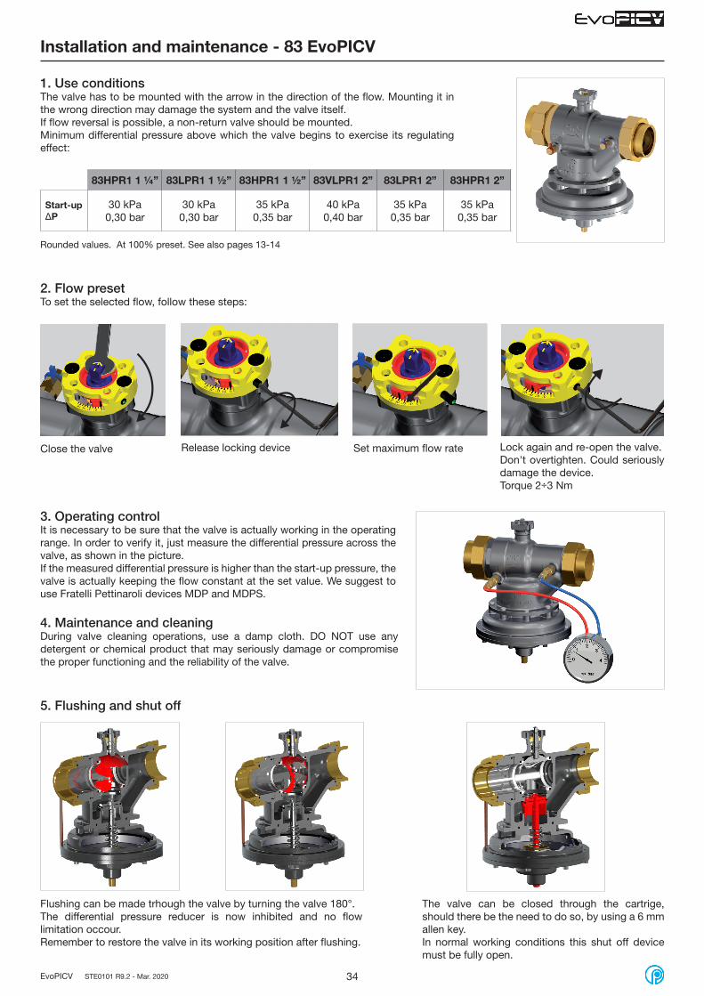
Installation and maintenance - 83 EvoPICV
1. Use conditionsThe valve has to be mounted with the arrow in the direction of the flow. Mounting it in the wrong direction may damage the system and the valve itself.If flow reversal is possible, a non-return valve should be mounted.Minimum differential pressure above which the valve begins to exercise its regulating effect:
83HPR1 1 ¼” 83LPR1 1 ½” 83HPR1 1 ½” 83VLPR1 2” 83LPR1 2” 83HPR1 2”
Start-upΔP
30 kPa0,30 bar
30 kPa0,30 bar
35 kPa0,35 bar
40 kPa0,40 bar
35 kPa0,35 bar
35 kPa0,35 bar
2. Flow presetTo set the selected flow, follow these steps:
3. Operating controlIt is necessary to be sure that the valve is actually working in the operating range. In order to verify it, just measure the differential pressure across the valve, as shown in the picture.If the measured differential pressure is higher than the start-up pressure, the valve is actually keeping the flow constant at the set value. We suggest to use Fratelli Pettinaroli devices MDP and MDPS.
4. Maintenance and cleaningDuring valve cleaning operations, use a damp cloth. DO NOT use any detergent or chemical product that may seriously damage or compromise the proper functioning and the reliability of the valve.
Close the valve Release locking device Set maximum flow rate Lock again and re-open the valve.Don't overtighten. Could seriously damage the device.Torque 2÷3 Nm
5. Flushing and shut off
Flushing can be made trhough the valve by turning the valve 180°.The differential pressure reducer is now inhibited and no flow limitation occour.Remember to restore the valve in its working position after flushing.
The valve can be closed through the cartrige, should there be the need to do so, by using a 6 mm allen key.In normal working conditions this shut off device must be fully open.
Rounded values. At 100% preset. See also pages 13-14
35EvoPICV STE0101 R9.2 - Mar. 2020
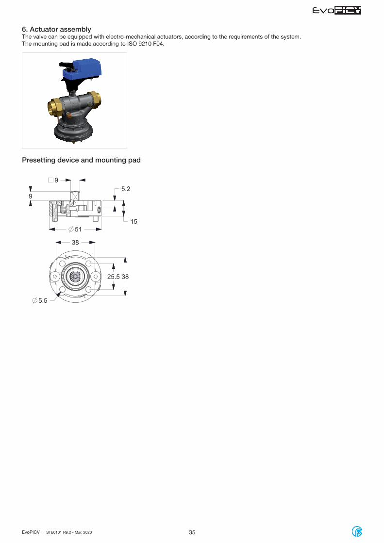
6. Actuator assemblyThe valve can be equipped with electro-mechanical actuators, according to the requirements of the system.The mounting pad is made according to ISO 9210 F04.
15
5.2
38
38
5.5
9
25.5
9
51
Presetting device and mounting pad

36EvoPICV STE0101 R9.2 - Mar. 2020
94FH 2" 94FL 2 1/2" 94FH 2 1/2" 94FL 3” 94FL 4”
Start-upΔP
40 kPa0,40 bar
40 kPa0,40 bar
30 kPa0,30 bar
30 kPa0,30 bar
30 kPa0,30 bar
94FL 5” 94FH 5” 94FL 6” 94FH 6”
Start-upΔP
35 kPa0,35 bar
35 kPa0,35 bar
35 kPa0,35 bar
50 kPa0,50 bar
Installation and maintenance - 94F EvoPICV 2" - 10"
1. Use conditionsThe valve has to be mounted with the arrow in the direction of the flow. Mounting it in the wrong direction may damage the system and the valve itself.If flow reversal is possible, a non-return valve should be mounted.Minimum differential pressure above which the valve begins to exercise its regulating effect:
94FL 8" 94FH 8" 94FL 10" 94FH 10”
Start-upΔP
40 kPa0,40 bar
60 kPa0,60 bar
40 kPa0,40 bar
65 kPa0,65 bar
2. Flow presetThe 94F is set up using the Smart Actuator:When first powered ‘GO 0’ is displayed on the LCD. Then wait for ‘0’ to appear. Pressing the ‘MODE’ button for 2 seconds or longer turns to setting mode. You can then choose the detail indication that’s suitable for your on-site installations. When in ‘set’ mode, press the MODE button again and you can choose another set mode (set 1 - set 14).
SET1 - Selecting input indication in direct internal control modeSET2 - Selecting an input signalSET3 - Min. flow settingSET4 - Max. flow settingSET5 - Selecting parameters display mode during operationSET6 - Rotation angle compensationSET7 - Flow offset compensationSET8 - Power failure mode (not available)SET9 - Flow rate units selectionSET10 - Control curve selection (LIN - EQ)SET11 - Min voltage signal in PID control modeSET12 - Max voltage signal in PID control modeSET13 - Actuator rotation speedSET14 - Feedback signal selection
3. Operating controlIt is necessary to be sure that the valve is actually working in the operating range. In order to verify it, just measure the differential pressure across the valve, as shown in the picture.If the measured differential pressure is higher than the start-up pressure, the valve is actually keeping the flow constant at the set value. We suggest to use Fratelli Pettinaroli devices MDP and MDPS.
4. Maintenance and cleaningDuring valve cleaning operations, use a damp cloth. DO NOT use any detergent or chemical product that may seriously damage or compromise the proper functioning and the reliability of the valve.
1 Display
2 Up button
3 Mode button
4 Down button
5 Manual override
Actuator M94F2
Rounded values. At 100% preset. See also pages 14-17
43
21
5

37EvoPICV STE0101 R9.2 - Mar. 2020
Valve 94FH 2” 94FL 2 ½” 94FH 2 ½” 94FL 3” 94FL 4” 94FL 5” 94FH 5” 94FL 6” 94FH 6”
Max presetting flow rate [m3/h] 20 20 30 30 55 90 120 90 150
Min presetting flow rate [m3/h] 4 4 6 6 16.5 18 12 18 15
Model code F-50 F-64 F-65 F-80 F-100 F-125 F-126 F-150 F-151
Setting of parameter SET 4: FLOW RATE PRESETTINGThe presetting flow rate of valve 94F can be set through the parameter SET 4 of the M94F2 actuator: the parameter should set between the max and min presetting flow rate of the valve. SET 3 should be left at 0.
Valve 94FL 8” 94FH 8" 94FL 10” 94FH 10”
Max presetting flow rate [m3/h] 200 300 300 500
Min presetting flow rate [m3/h] 60 90 60 150
Model code F-200 F-201 F-250 F-251
5. Manual override1. Open the rubber cover on the actuator and insert the 6mm Allen key.2. Turn the key keeping the released button pushed under the actuator.
6. Actuator fitting1. Insert the three pins in specific buttonholes on the fixing plate2. Turn the fixing ring
Setting procedure
SET 9 SET 2 SET 10SET 4
Other parameters can be set, if necessary, without a preferential path.
1 2

38EvoPICV STE0101 R9.2 - Mar. 2020
7. Parameters of actuatorThe table below explains all the parameters that are configurable on M94F2.
Display indication Meaning Operating
SET 1PErc Input internal control in % Selection with UP/DOWN buttons and confirmation with
MODE buttonFlo (default) Input internal control in flow rate
SET 2
0-10 Voltage control signal Control with voltage signal
2-10 (default) Voltage control signal Control with voltage signal
0-20 Current control signal Control with current signal
4-20 Current control signal Control with current signal
on-F ON/OFF 24 V: open; 0 V: close;
3-FL 3 points floatingopening giving white wire 24 Vclosing giving green wire 24 V
rT Remote control Not available
P-05 PWM 5 s PWM (0.1 – 5 s)
P-25 PWM 25 s PWM (0.1 – 25 s)
Int Internal input
Flow rate set by on board display and buttons.Push MODE, wait until “Set” is replaced by flow rate indication (or flow rate %, depending on SET 1), set the flow rate with UP/DOWN buttons and confirm with MODE.
SET 3 Flow rate on display Min flow rate selection (default: 0)Selection with UP/DOWN buttons and confirmation with MODE button
SET 4 Flow rate on displayMax flow rate selection (default: depending on model)
Selection with UP/DOWN buttons and confirmation with MODE button
SET 5
St-P Set flow rate in “%” Selection with UP/DOWN buttons and confirmation with MODE buttonDisplay option during operation: St allows to see the flow rate value required by the controller; Fd allows to see the current flow rate value given by the valve (the progressive change of flow rate values is displayed during valve stem motion)
St-F Set flow rate in “flow rate”
Fd-P Current flow rate in “%”
Fd-F (default) Current flow rate in “flow rate”
SET 6* Value on display Rotation angle compensationSelection with UP/DOWN buttons and confirmation with MODE button
SET 7 Value on display % flow rate offset (default: 0)Selezione con tasti SU/GIÙ e conferma con tasto MODE.
SET 8oPEn Valve open at power failure Selection Fail-CLOSE or Fail-OPEN option. Additional
battery M94FB needed.CLoS (default) Valve close at power failure
SET 9LIt (default) Unit SI (m3/h) Selection with UP/DOWN buttons and confirmation with
MODE buttonGAL Unit GPM (gal/min)
SET 10LIn (default) Linear control curve Selection with UP/DOWN buttons and confirmation with
MODE buttonEPEr Equal percentage control curve
SET 11* Value on display Min voltage control signal (signal noise)Selection min voltage control value with UP/DOWN buttons and confirmation with MODE button
SET 12* Value on display Max voltage control signal (signal noise)Selection min voltage control value with UP/DOWN buttons and confirmation with MODE button
SET 13
PE15 (default) Actuator rotation speed 1.5 RPMSelection of actuator rotation speed with UP/DOWN buttons and confirmation with MODE button
PE01 Actuator rotation speed 1 RPM
Auto Actuator rotation speed automatic
SET 14
0-10 Voltage feedback signal
Selection of feedback signal type with UP/DOWN buttons and confirmation with MODE button
2-10 (default) Voltage feedback signal
0-20 Currentfeedback signal
4-20 Current feedback signal
* Contact the manufacturer to modify.

39EvoPICV STE0101 R9.2 - Mar. 2020
Thermo-electric actuators for 91 series
Technical features
Supply voltage 24 AC / DC, +20% ÷ -10%
Absorbed power 1 W
Max current <300 mA max. 2 min.
Max fluid temperature 0 - 100 °C
Max ambient temperature 0 - 60 °C
Degree of protection IP 54 ( EN 60529 )
Class of protection II ( IEC 60730 ) ( with cable connector only )
Actuating force 100 N ± 5 %
Stroke 4 mm
1. Art. A544O224V AC/DC ON-OFF, normally closed (NC)
Mounting positions: any positions between vertical and horizontal. Upside down mounting ( actuator underneath the valve ) must be avoided.
Overall dimensionsDimensions (mm)
Characteristic curves Wiring diagrams
24 V ACL1 L2
brown blue
thermostat
start stop

40EvoPICV STE0101 R9.2 - Mar. 2020
Technical features
Supply voltage 24 AC / DC, +20% ÷ -10%
Absorbed power 1 W
Max current <300 mA max. 2 min.
Max fluid temperature 0 - 100 °C
Max ambient temperature 0 - 60 °C
Degree of protection IP 54 ( EN 60529 )
Class of protection III ( IEC 60730 ) ( with cable connector only )
Actuating force 100 N ± 5 %
Stroke 4 mm
2. Art. A544O424V AC/DC ON-OFF with integrated micro switch, normally closed (NC)
Mounting positions: any positions between vertical and horizontal. Upside down mounting ( actuator underneath the valve ) must be avoided.
Overall dimensionsDimensions (mm)
Characteristic curves Wiring diagrams
start stop
switching point - end switch
24 V ACL1 L2
24 V max.3 A ohm resistive load
1 A inductive loadFree contact
thermostat
brown
blue
black
grey
Pump

41EvoPICV STE0101 R9.2 - Mar. 2020
Technical features
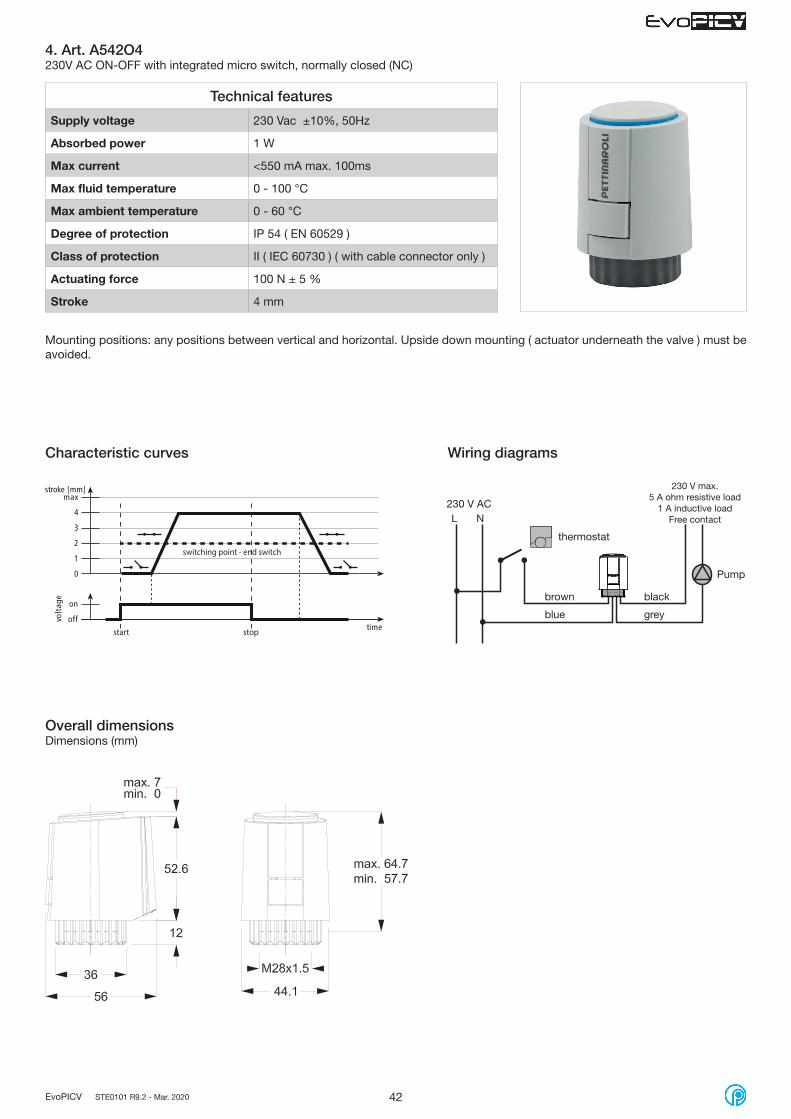
Supply voltage 230 Vac ±10%, 50Hz
Absorbed power 1 W
Max current <550 mA max. 100ms
Max fluid temperature 0 - 100 °C
Max ambient temperature 0 - 60 °C
Degree of protection IP 54 ( EN 60529 )
Class of protection II ( IEC 60730 ) ( with cable connector only )
Actuating force 100 N ± 5 %
Stroke 4 mm
3. Art. A542O2230V AC ON-OFF, normally closed (NC)
Mounting positions: any positions between vertical and horizontal. Upside down mounting ( actuator underneath the valve ) must be avoided.
Overall dimensionsDimensions (mm)
Characteristic curves Wiring diagrams
230 V ACL N
brown blue
thermostat
start stop
42EvoPICV STE0101 R9.2 - Mar. 2020
Technical features
Supply voltage 230 Vac ±10%, 50Hz
Absorbed power 1 W
Max current <550 mA max. 100ms
Max fluid temperature 0 - 100 °C
Max ambient temperature 0 - 60 °C
Degree of protection IP 54 ( EN 60529 )
Class of protection II ( IEC 60730 ) ( with cable connector only )
Actuating force 100 N ± 5 %
Stroke 4 mm
4. Art. A542O4230V AC ON-OFF with integrated micro switch, normally closed (NC)
Mounting positions: any positions between vertical and horizontal. Upside down mounting ( actuator underneath the valve ) must be avoided.
Overall dimensionsDimensions (mm)
Characteristic curves Wiring diagrams
start stop
switching point - end switch
230 V ACL N
230 V max.5 A ohm resistive load
1 A inductive loadFree contact
thermostat
brown
blue
black
grey
Pump
43EvoPICV STE0101 R9.2 - Mar. 2020
Technical features
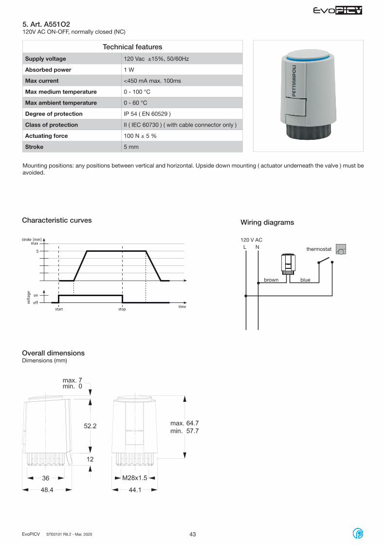
Supply voltage 120 Vac ±15%, 50/60Hz
Absorbed power 1 W
Max current <450 mA max. 100ms
Max medium temperature 0 - 100 °C
Max ambient temperature 0 - 60 °C
Degree of protection IP 54 ( EN 60529 )
Class of protection II ( IEC 60730 ) ( with cable connector only )
Actuating force 100 N ± 5 %
Stroke 5 mm
5. Art. A551O2120V AC ON-OFF, normally closed (NC)
Mounting positions: any positions between vertical and horizontal. Upside down mounting ( actuator underneath the valve ) must be avoided.
Overall dimensionsDimensions (mm)
Characteristic curves Wiring diagrams
120 V ACL N
brown blue
thermostat5
start stop

44EvoPICV STE0101 R9.2 - Mar. 2020
BlueRedBlack
0-10 V DC
GND
24 V ACL1 L2
Technical features
Supply voltage 24V AC/DC -10% ÷ +20%
Absorbed power 1 W
Max current < 320 mA max. 2 min.
Operating voltage 0 – 10 V DC 100 kΩ
Max fluid temperature 0 - 100 °C
Max ambient temperature 0 - 60 °C
Degree of protection IP 54 ( EN 60529 )
Class of protection III ( IEC 60730 )
Actuating force 100 N ± 5 %
Stroke 4 mm
Travelling time 30 s/mm
6. Art. A544P324V AC/DC proportional 0-10V, normally closed (NC)
Mounting positions: any positions between vertical and horizontal. Upside down mounting ( actuator underneath the valve ) must be avoided.
Characteristic curves Wiring diagrams
Overall dimensionsDimensions (mm)
valveopen
valvestroke2,7 mm
valvecloseOver-elevation range
active voltage control range (V)
[mm]
actu
ator
stro
ke
Red
Blue
Black
0-10 V DC
GND
24 V ACL1 L2

45EvoPICV STE0101 R9.2 - Mar. 2020
Thermo-electric actuators for 93 series
Technical features
Supply voltage 24 AC / DC, +20% ÷ -10%
Absorbed power 1,2 W
Max current <300 mA max. 2 min.
Max fluid temperature 0 - 100 °C
Max ambient temperature 0 - 60 °C
Degree of protection IP 54 ( EN 60529 )
Class of protection III ( IEC 60730 ) ( with cable connector only )
Actuating force 100 N ± 5 %
Stroke 6,5 mm
1. Art. A564O224V AC/DC ON-OFF, normally closed (NC)
Mounting positions: any positions between vertical and horizontal. Upside down mounting ( actuator underneath the valve ) must be avoided.
Overall dimensionsDimensions (mm)
Characteristic curves Wiring diagrams
on
offVolta
ge
time
[mm]
0
1
2
3
4
5
6
start stop
stroke24 V ACL1 L2
brown blue
thermostat

46EvoPICV STE0101 R9.2 - Mar. 2020
Technical features
Supply voltage 230 Vac ±10%, 50Hz
Absorbed power 1,2 W
Max current <550 mA max. 100 ms
Max fluid temperature 0 - 100 °C
Max ambient temperature 0 - 60 °C
Degree of protection IP 54 ( EN 60529 )
Class of protection II ( IEC 60730 ) ( with cable connector only )
Actuating force 100 N ± 5 %
Stroke 6,5 mm
2. Art. A562O2230V AC ON-OFF, normally closed (NC)
Mounting positions: any positions between vertical and horizontal. Upside down mounting ( actuator underneath the valve ) must be avoided.
Overall dimensionsDimensions (mm)
Characteristic curves Wiring diagrams
on
offVolta
ge
time
[mm]
0
1
2
3
4
5
6
start stop
stroke 230 V ACL N
brown blue
thermostat

47EvoPICV STE0101 R9.2 - Mar. 2020
Technical features
Supply voltage 120 Vac ±10%, 50/60Hz
Absorbed power 1,2 W
Max current <450 mA max. 100 ms
Max fluid temperature 0 - 100 °C
Max ambient temperature 0 - 60 °C
Degree of protection IP 54 ( EN 60529 )
Class of protection II ( IEC 60730 ) ( with cable connector only )
Actuating force 125 N ± 5 %
Stroke 6,5 mm
3. Art. A561O2120V AC ON-OFF, normally closed (NC)
Mounting positions: any positions between vertical and horizontal. Upside down mounting ( actuator underneath the valve ) must be avoided.
Overall dimensionsDimensions (mm)
Characteristic curves Wiring diagrams
on
offVolta
ge
time
[mm]
0
1
2
3
4
5
6
start stop
stroke 120 V ACL N
brown blue
thermostat

48EvoPICV STE0101 R9.2 - Mar. 2020
Technical features
Supply voltage 24V AC/DC -10% ÷ +20%
Absorbed power 1,2 W
Max current < 320 mA max. 2 min.
Operating voltage 0 – 10 V DC 100 kΩ
Max fluid temperature 0 - 100 °C
Max ambient temperature 0 - 60 °C
Degree of protection IP 54 ( EN 60529 )
Class of protection III ( IEC 60730 )
Actuating force 100 N ± 5 %
Stroke 6,5 mm
Travelling time 30 s/mm
4. Art. A564P324V AC/DC proportional 0-10V, normally closed (NC)
Mounting positions: any positions between vertical and horizontal. Upside down mounting ( actuator underneath the valve ) must be avoided.
Characteristic curves Wiring diagrams
Overall dimensionsDimensions (mm)
valveopen
valvestroke6 mm
valvecloseOver-elevation range
active voltage control range (V)
[mm]
actu
ator
stro
ke
BlueRedBlack
0-10 V DC
GND
24 V ACL1 L2

49EvoPICV STE0101 R9.2 - Mar. 2020
Technical features
Supply voltage 24 Vac ± 15%, 50...60 Hz
Absorbed power 1,5 W / 2,5VA
Max fluid temperature 95 °C
Max ambient temperature 0 - 50 °C
Degree of protection IP 43
Actuating force 120 N +30% -20%
Max mechanical stroke 6,3 mm
Travelling time 8 sec/mm
1. Art. VA748124V Vac floating model
Electromotive actuators
Mounting positions: any positions between vertical and horizontal. Upside down mounting ( actuator underneath the valve ) must be avoided.
Operating status indication Connections
OFF No power supply
GREEN BLINKING Moving to position
GREEN BLINKING End stroke confirmation
GREEN STEADY ON
End Stroke reached
79,5mm
49 mm
80 mm
Overall dimensions
For proper installation of VA7481 - 24V electromotive actuator, the right adapting ring has to be defined (and ordered separately), referring to codes below:
· 0A7010 for EVOPICV series 91 valves· 0A748X for EVOPICV series 93 valves

50EvoPICV STE0101 R9.2 - Mar. 2020
Technical features
Supply voltage 230 Vac ± 10%, 50...60 Hz
Absorbed power 2,2 W / 6,5VA
Max fluid temperature 95 °C
Max ambient temperature 0 - 50 °C
Degree of protection IP 43
Actuating force 120 N +30% -20%
Max mechanical stroke 6,3 mm
Travelling time 8 sec/mm
2. Art. VA7481230V Vac floating model
BLU BRN
N L1 230VAC
BLU BRN
N L1 230VAC
Mounting positions: any positions between vertical and horizontal. Upside down mounting ( actuator underneath the valve ) must be avoided.
Operating status indication Connections
OFF No power supply
GREEN BLINKING Moving to position
GREEN BLINKING End stroke confirmation
GREEN STEADY ON
End Stroke reached
79,5mm
49 mm
80 mm
Overall dimensions
For proper installation of VA7481 - 230V electromotive actuator, the right adapting ring has to be defined (and ordered separately), referring to codes below:
·· 0A7010 for EVOPICV series 91 valves· 0A748X for EVOPICV series 93 valves
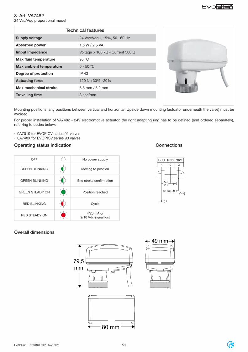
51EvoPICV STE0101 R9.2 - Mar. 2020
Technical features
Supply voltage 24 Vac/Vdc ± 15%, 50...60 Hz
Absorbed power 1,5 W / 2,5 VA
Imput Impedance Voltage > 100 kΩ - Current 500 Ω
Max fluid temperature 95 °C
Max ambient temperature 0 - 50 °C
Degree of protection IP 43
Actuating force 120 N +30% -20%
Max mechanical stroke 6,3 mm / 3,2 mm
Travelling time 8 sec/mm
3. Art. VA748224 Vac/Vdc proportional model
BLU
AC
(-)
(+)
Mounting positions: any positions between vertical and horizontal. Upside down mounting (actuator underneath the valve) must be avoided.
Operating status indication Connections
OFF No power supply
GREEN BLINKING Moving to position
GREEN BLINKING End stroke confirmation
GREEN STEADY ON
Position reached
RED BLINKING Cycle
RED STEADY ON
4/20 mA or 2/10 Vdc signal lost
79,5mm
49 mm
80 mm
Overall dimensions
For proper installation of VA7482 - 24V electromotive actuator, the right adapting ring has to be defined (and ordered separately), referring to codes below:
· 0A7010 for EVOPICV series 91 valves· 0A748X for EVOPICV series 93 valves

52EvoPICV STE0101 R9.2 - Mar. 2020
Dip switch settings for Proportional model only (VA7482)All the proportional models have 6 dip switches which allow the user to field configure the actuator.The actuator is factory released with all the dip switches in OFF position expect dip switch n. 4 which is ON.
Dip Switch 1 – 2 – 3 – 6The dip switch 1-2-3 allows the user to change the analogue input ranges. To switch from voltage analog input to current analog input the dip switch 6 has to be set accordingly.
Dip Switch4The dip switch 4 allows the user to change the action of the actuator in relation of the analog input. Be aware the EvoPICV valve is normally open. Select the action according to the choosen BSM.
The dip switch 4 OFF (Direct Acting – DA)When the signal increases the actuator stem extends.
The dip switch 4 ON (Reversing Acting – RA) - DefaultWhen the signal increases the actuator stem retracts.
Dip Switch 5The dip switch 5 allows the user to change the control characteristic of the actuator in order to obtain a combination of valve and actuator linear or almost equal percentage.The dip switch 5 OFF (Linear)The dip switch 5 ON (almost EqualPercentage)
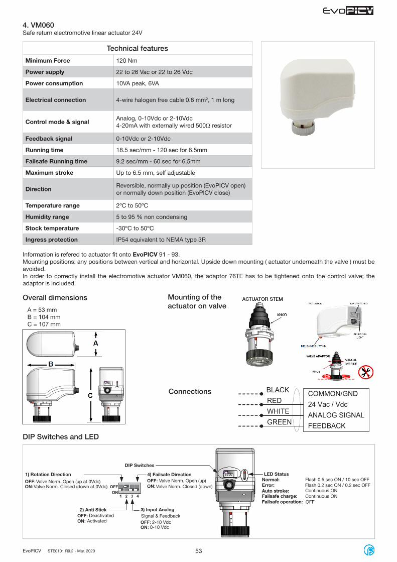
53EvoPICV STE0101 R9.2 - Mar. 2020
Technical features
Minimum Force 120 Nm
Power supply 22 to 26 Vac or 22 to 26 Vdc
Power consumption 10VA peak, 6VA
Electrical connection 4-wire halogen free cable 0.8 mm2, 1 m long
Control mode & signal Analog, 0-10Vdc or 2-10Vdc4-20mA with externally wired 500Ω resistor
Feedback signal 0-10Vdc or 2-10Vdc
Running time 18.5 sec/mm - 120 sec for 6.5mm
Failsafe Running time 9.2 sec/mm - 60 sec for 6.5mm
Maximum stroke Up to 6.5 mm, self adjustable
Direction Reversible, normally up position (EvoPICV open) or normally down position (EvoPICV close)
Temperature range 2ºC to 50ºC
Humidity range 5 to 95 % non condensing
Stock temperature -30ºC to 50ºC
Ingress protection IP54 equivalent to NEMA type 3R
4. VM060Safe return electromotive linear actuator 24V
Connections
Overall dimensions
BLACK COMMON/GNDRED 24 Vac / VdcWHITE ANALOG SIGNAL
FEEDBACKGREEN
DIP Switches and LED
1 2 3 4
OFF:ON:
OFF: ON:
OFF: ON:
OFF: ON: OFF
ON
Information is refered to actuator fit onto EvoPICV 91 - 93.Mounting positions: any positions between vertical and horizontal. Upside down mounting ( actuator underneath the valve ) must be avoided.In order to correctly install the electromotive actuator VM060, the adaptor 76TE has to be tightened onto the control valve; the adaptor is included.
A = 53 mmB = 104 mmC = 107 mm
Mounting of the actuator on valve
Valve Norm. Closed (down)Valve Norm. Open (up)
Valve Norm. Closed (down at 0Vdc)Valve Norm. Open (up at 0Vdc)
1) Rotation Direction
2) Anti Stick
ActivatedDeactivated
3) Input AnalogSignal & Feedback
2-10 Vdc0-10 Vdc
DIP Switches
4) Failsafe DirectionNormal:Error:Auto stroke:Failsafe charge:Failsafe operation:
LED Status
Continuous ONContinuous ON
Flash 0.5 sec ON / 10 sec OFFFlash 0.2 sec ON / 0.2 sec OFF
OFF

54EvoPICV STE0101 R9.2 - Mar. 2020
Rotary actuators for 83 series
Technical features
Operating torque 8 Nm Min.
Running time 31 s - 90°
Supply Voltage 24V AC/DC ±20% - 50/60Hz
Consumption 4.5 W - Stand-by 0.3 W
Control Signal 2 point and 3 point
Total rotation 0~90º
Angle limitation 5~85º (5º increment)
Life cycle 60,000 cycle
Protection Class III
IP protection class IP54
Temperature range -20~+50ºC
Humidity range 5~95% RH
Stock temperature -40~+70ºC
Certificate CE
1. SN08 24V3 point floating control signal
ConnectionsOverall dimensions
132
145.5
185
100.
5
0(2)...10Vfrom control
1 2 3 1 2 3
N L1 N L1AC 230 V ±10%
1 2 3
-
AC24V
DC24V-
1 2 3
±20%
±20%
S1 OFF: see wiring

55EvoPICV STE0101 R9.2 - Mar. 2020
Technical features
Operating torque 8 Nm Min.
Running time 31 s - 90°
Supply Voltage 110...230V AC ±10% - 50/60Hz
Consumption 4.5 W - Stand-by 0.5 W - 6.5 VA
Control Signal 2 point and 3 point
Total rotation 0~90º
Angle limitation 5~85º (5º increment)
Life cycle 60,000 cycle
Protection Class II
IP protection class IP54
Temperature range -20~+50ºC
Humidity range 5~95% RH
Stock temperature -40~+70ºC
Certificate CE
2. SN08 110/240V3 point floating control signal
ConnectionsOverall dimensions
132
145.5
185
100.
5
0(2)...10Vfrom control
1 2 3 1 2 3
N L1 N L1AC 230 V ±10%
1 2 3
-
AC24V
DC24V-
1 2 3
±20%
±20%
S1 OFF: see wiring

56EvoPICV STE0101 R9.2 - Mar. 2020
Technical features
Operating torque 8 Nm Min.
Running time 31 s - 90°
Supply Voltage 24V AC/DC ±20% - 50/60Hz
Consumption 4.5 W - Stand-by 0.5 W
Control Signal 0(2)-10 VDC 0(4)-20 mA
Total rotation 0~90º
Angle limitation 5~85º (5º increment)
Life cycle 60,000 cycle
Protection Class II
IP protection class IP54
Temperature range -20~+50ºC
Humidity range 5~95% RH
Stock temperature -40~+70ºC
Certificate CE
3. SN08CC 24VProportional control signal
Connections
Overall dimensions
132
145.5
185
100.
5
Master/slave control
DIP-Switch setting
Dip-Switch 1: feedback signal type
Dip-Switch 2: control signal range
Dip-Switch 3: control signal type
Dip-Switch 4: rotation direction
Factory setting
OFF: voltage signal 0(2)-10 V
OFF: 0-10 V o 0-20 mA
OFF: voltage signal 0(2)-10 V
OFF: signal increases, counter clockwise rot.
Input: 0-10VFeedback: 0-10VWhile the signal increases,the actuator rotates clockwise
ON: current signal 0(4)-20 mA
ON: 2-10 V o 4-20 mA
ON: current signal 0(4)-20 mA
ON: signal increases, clockwise rotation
0(2)...10Vfrom control
1 2 3 1 2 3
N L1 N L1AC 230 V ±10%
1 2 3
-
AC24V
DC24V-
1 2 3
±20%
±20%
0(2)...10Vfrom control
1 2 3 1 2 3
N L1 N L1AC 230 V ±10%
1 2 3
-
AC24V
DC24V-
1 2 3
±20%
±20%

57EvoPICV STE0101 R9.2 - Mar. 2020
4. VA9208 24VON/OFF control spring return
Technical features
Operating torque 8 Nm power ON - 6÷8 power OFF
Running time 55÷71 s power ON - 13÷26 s power OFF
Supply Voltage 24V AC/DC - 50/60Hz
Consumption 6.1 VA - Stand-by 1.2 VA
Control Signal ON/OFF
Total rotation 0 - 95º
Life cycle 60,000 cycle
IP protection class IP54
Temperature range -20 ÷ +60ºC
Humidity range 5~90% RH
Stock temperature -40 ÷ +85ºC
Certificate CE
Connections
Overall dimensions
AC 230 V 50/60 Hz
L1N
BLU BRN21
AC 24 V 50/60DC 24 V
REDBLK21
+-~

58EvoPICV STE0101 R9.2 - Mar. 2020
5. VA9208 230VON/OFF control spring return
Technical features
Operating torque 8 Nm power ON - 6÷8 power OFF
Running time 55÷71 s power ON - 13÷26 s power OFF
Supply Voltage 230V AC - 50/60Hz
Consumption 0.04 A - Stand-by 0.03 A
Control Signal ON/OFF
Total rotation 0 - 95º
Life cycle 60,000 cycle
IP protection class IP54
Temperature range -20 ÷ +60ºC
Humidity range 5~90% RH
Stock temperature -40 ÷ +85ºC
Certificate CE
Connections
Overall dimensions
AC 230 V 50/60 Hz
L1N
BLU BRN21
AC 24 V 50/60DC 24 V
REDBLK21
+-~
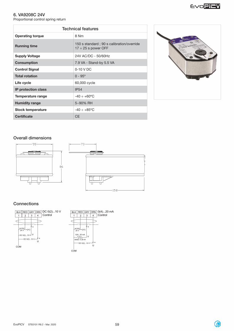
59EvoPICV STE0101 R9.2 - Mar. 2020
6. VA9208C 24VProportional control spring return
Technical features
Operating torque 8 Nm
Running time 150 s standard ; 90 s calibration/override17 ÷ 25 s power OFF
Supply Voltage 24V AC/DC - 50/60Hz
Consumption 7.9 VA - Stand-by 5.5 VA
Control Signal 0-10 V DC
Total rotation 0 - 95º
Life cycle 60,000 cycle
IP protection class IP54
Temperature range -40 ÷ +60ºC
Humidity range 5~90% RH
Stock temperature -40 ÷ +85ºC
Certificate CE
Overall dimensions
Connections

60EvoPICV STE0101 R9.2 - Mar. 2020
Technical features
Operating duration 170 sec. ( Full Open <-> Full Closed )
Power supply 24V AC/DC - 50/60Hz
Power consuption 1.8 W
Emergency operation Manual override by means of an Allen key, access on the upper face of the actuator. Button release
Control input
PID Control 0(2)-10VDCPID Control 0(4) – 20mAON/OFF Control mode3 point floatingPWM Control ( 0.1 ~ 5 sec/20ms or 25 sec/100ms depending on switch setting )
Torque 10 Nm max. Auto limitated at 7 Nm.
Position feedback 0(4)-20mA or 0(2)-10VDC, selectable
Ambient temp. -20°C ~ 65°C
Wire 18AWG
Cover material Steel + Plastic
Protection class II - IP54
Certificate CE - UL
Lifetime 10.000 hours (tested 50.000 cycles)
Optional battery For Fail-safe function: rechargeable Lithium-ion battery, 2 x NCR 18650 - 2600 mAh
Flow rate can be easily set from the on-board user interface.Compatible with most used control signals:
Analogue (current or voltage control)PWMON/OFF3 points floating
Position feedback signal, for a total remote management.Manual override available.Safe Return function if battery M94FB is connected (optional).Easy fitting system.
M94F2 - SMART actuators for 94F series 2" - 10"
Overall dimensionsDimensions (mm)
Valve wiring
1
2
3
4
5
Black
Red
White
Green
Blue
Common
24VAC/DC
Control Signal 1
Control Signal 2
Feedback Signal
* Optional battery M94FB
InputNumber 1 2 3 4 5
RemarksColor Black Red White Green Blue
Internal control Common 24VAC/DCPower: cable 1 - 2
Voltage signal Common 24VAC/DC0 ~10VDC
2 ~10VDC
Feedback(0)2-10 V
(0)4-20 mA
Power: cable 1 - 2
Voltage signal: cable 1 - 3
Current signal Common 24VAC/DC0 ~ 20mA
4 ~ 20mA
Feedback(0)2-10 V
(0)4-20 mA
Power: cable 1 - 2
Current signal: cable 1 - 3
ON / OFF signal Common 24VAC/DC24DCV (open) Power: cable 1 - 2
0V(close) ON/OFF signal: cable 1 - 3
3 Points floating Common 24VAC/DCOpening 24V
AC/DCClosing 24V
AC/DC
Power: cable 1 - 2
Floating 3 points: cable 3 - 4
PWM control Common 24VAC/DC PWM signalPower: cable 1 - 2
PWM control: cable 1 - 3

61EvoPICV STE0101 R9.2 - Mar. 2020
Table selection for actuators not safe return
91Series
91XSeries
93Series
83Series
94FSeries
TY
PE
OF
CO
NT
RO
L S
IGN
AL
ON
/OF
F C
ON
TR
OL
230V
Thermo-electric A542O2 A542O2 A562O2 --- ---
ElectromotiveVA7481
+0A7010
VA7481+
0A7010
VA7481+
0A748XSN08 230V ---
24V
Thermo-electric A544O2 A544O2 A564O2 --- ---
ElectromotiveVA7481
+0A7010
VA7481+
0A7010
VA7481+
0A748XSN08 24V M94F2
FLO
ATIN
G C
ON
TR
OL 230V
Thermo-electric --- --- --- --- ---
ElectromotiveVA7481
+0A7010
VA7481+
0A7010
VA7481+
0A748XSN08 230V ---
24V
Thermo-electric --- --- --- --- ---
ElectromotiveVA7481
+0A7010
VA7481+
0A7010
VA7481+
0A748XSN08 24V M94F2
PR
OP
OR
TIO
NA
L C
ON
TR
OL
( 0-1
0 V
)
230V
Thermo-electric --- --- --- --- ---
Electromotive --- --- --- --- ---
24V
Thermo-electric A544P3 A544P3 A564P3 --- ---
Electromotive
VA74823,2 mm
+0A7010
VA74823,2 mm
+0A7010
VA74826,3 mm
+0A748X
SN08CC 24V M94F2

62EvoPICV STE0101 R9.2 - Mar. 2020
Table selection for actuators safe return
91Series
91XSeries
93Series
83Series
94FSeries
TY
PE
OF
CO
NT
RO
L S
IGN
AL
ON
/OF
F C
ON
TR
OL
230V
Thermo-electric A542O2 A542O2 A562O2 --- ---
Electromotive --- --- --- VA9208 230V ---
24V
Thermo-electric A544O2 A544O2 A564O2 --- ---
Electromotive --- --- --- VA9208 230VM94F2 + M94FB
FLO
ATIN
G C
ON
TR
OL 230V
Thermo-electric --- --- --- --- ---
Electromotive --- --- --- --- ---
24V
Thermo-electric --- --- --- --- ---
Electromotive --- --- --- ---M94F2 + M94FB
PR
OP
OR
TIO
NA
L C
ON
TR
OL
( 0-1
0 V
)
230V
Thermo-electric --- --- --- --- ---
Electromotive --- --- --- --- ---
24V
Thermo-electric A544P3 A544P3 A564P3 --- ---
ElectromotiveVM060
+76TE
VM060+
76TE
VM060+
76TEVA9208C
M94F2 + M94FB

63EvoPICV STE0101 R9.2 - Mar. 2020
91 EvoPICV dimensional data
62
Manual valve
Art.Flow rate
[ l/h ]A (mm) B (mm) C (mm) D (mm) E (mm)
91VL ½" 150 47 115 25 99 120
91L ½" 600 47 115 25 99 120
91H ½" 780 47 115 25 99 120
91L ¾" 1000 47 115 25 108 127
91H ¾" 1500 47 115 25 108 127
91H 1" 1500 47 115 25 130 134
C
B
DE
A
62
62
Valve with electromotive actuator
Art.Flow rate
[ l/h ]A (mm) B (mm) C (mm) D (mm) E (mm)
91VL ½" 150 82 164 25 99 137
91L ½" 600 82 164 25 99 137
91H ½" 780 82 164 25 99 137
91L ¾" 1000 82 164 25 108 137
91H ¾" 1500 82 164 25 108 137
91H 1" 1500 82 164 25 130 138
Valve with thermo-electric actuator
Art.Flow rate
[ l/h ]A (mm) B (mm) C (mm) D (mm) E (mm)
91VL ½" 150 68 137,5 25 99 127
91L ½" 600 68 137,5 25 99 127
91H ½" 780 68 137,5 25 99 127
91L ¾" 1000 68 137,5 25 108 127
91H ¾" 1500 68 137,5 25 108 127
91H 1" 1500 68 137,5 25 130 134
Valve with VM060
Art.Flow rate
[ l/h ]A (mm) B (mm) C (mm) D (mm) E (mm)
91VL ½" 150 116 201 25 99 159
91L ½" 600 116 201 25 99 159
91H ½" 780 116 201 25 99 159
91L ¾" 1000 116 201 25 108 166
91H ¾" 1500 116 201 25 108 166
91H 1" 1500 116 201 25 130 173
A
D
C
E
B

64EvoPICV STE0101 R9.2 - Mar. 2020
C
B
D
A
62
62
Valve with thermo-electric actuator
Art.Flow rate
[ l/h ]A (mm) B (mm) C (mm) D (mm)
91VL1 ½" 150 68 137,5 25 99
91L1 ½" 600 68 137,5 25 99
91H1 ½" 780 68 137,5 25 99
91L1 ¾" 1000 68 137,5 25 108
91H1 ¾" 1500 68 137,5 25 108
91H1 1" 1500 68 137,5 25 130
Valve with electromotive actuator
Art.Flow rate
[ l/h ]A (mm) B (mm) C (mm) D (mm) E (mm)
91VL1 ½" 150 82 164 25 99 116
91L1 ½" 600 82 164 25 99 116
91H1 ½" 780 82 164 25 99 116
91L1 ¾" 1000 82 164 25 108 116
91H1 ¾" 1500 82 164 25 108 116
91H1 1" 1500 82 164 25 130 134
91-1 EvoPICV dimensional data
62
Manual valve
Art.Flow rate
[ l/h ]A (mm) B (mm) C (mm) D (mm)
91VL1 ½" 150 47 137,5 25 99
91L1 ½" 600 47 137,5 25 99
91H1 ½" 780 47 137,5 25 99
91L1 ¾" 1000 47 137,5 25 108
91H1 ¾" 1500 47 137,5 25 108
91H1 1" 1500 47 137,5 25 130
Valve with VM060
Art.Flow rate
[ l/h ]A (mm) B (mm) C (mm) D (mm) E (mm)
91VL1 ½" 150 116 201 25 99 139
91L1 ½" 600 116 201 25 99 139
91H1 ½" 780 116 201 25 99 139
91L1 ¾" 1000 116 201 25 108 141
91H1 ¾" 1500 116 201 25 108 141
91H1 1" 1500 116 201 25 130 156D
A
C
B
E
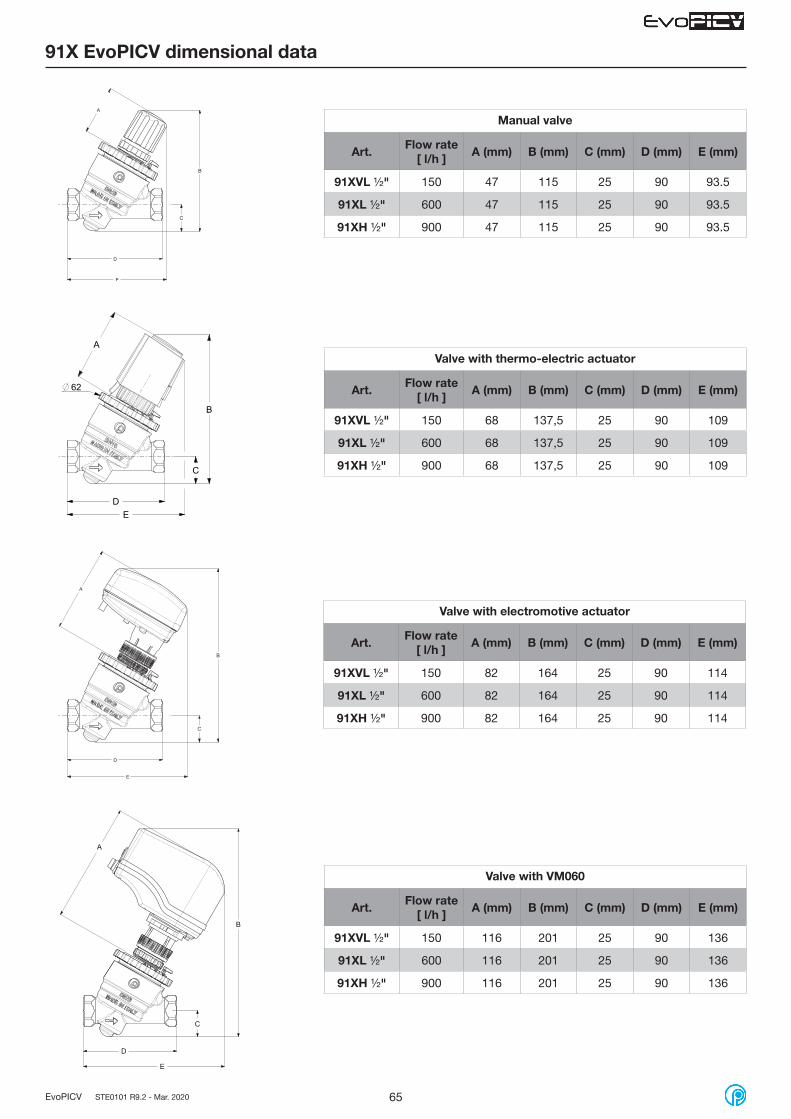
65EvoPICV STE0101 R9.2 - Mar. 2020
DE
C
B
A
62
Valve with thermo-electric actuator
Art.Flow rate
[ l/h ]A (mm) B (mm) C (mm) D (mm) E (mm)
91XVL ½" 150 68 137,5 25 90 109
91XL ½" 600 68 137,5 25 90 109
91XH ½" 900 68 137,5 25 90 109
91X EvoPICV dimensional data
D
E
C
B
A
Manual valve
Art.Flow rate
[ l/h ]A (mm) B (mm) C (mm) D (mm) E (mm)
91XVL ½" 150 47 115 25 90 93.5
91XL ½" 600 47 115 25 90 93.5
91XH ½" 900 47 115 25 90 93.5
D
E
C
B
A
Valve with electromotive actuator
Art.Flow rate
[ l/h ]A (mm) B (mm) C (mm) D (mm) E (mm)
91XVL ½" 150 82 164 25 90 114
91XL ½" 600 82 164 25 90 114
91XH ½" 900 82 164 25 90 114
Valve with VM060
Art.Flow rate
[ l/h ]A (mm) B (mm) C (mm) D (mm) E (mm)
91XVL ½" 150 116 201 25 90 136
91XL ½" 600 116 201 25 90 136
91XH ½" 900 116 201 25 90 136
D
E
C
A
B
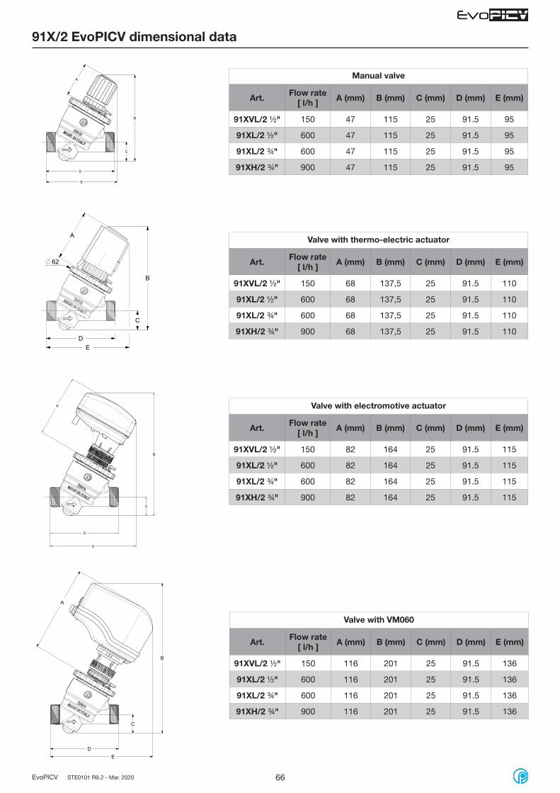
66EvoPICV STE0101 R9.2 - Mar. 2020
91X/2 EvoPICV dimensional data
D
E
C
B
A Manual valve
Art.Flow rate
[ l/h ]A (mm) B (mm) C (mm) D (mm) E (mm)
91XVL/2 ½" 150 47 115 25 91.5 95
91XL/2 ½" 600 47 115 25 91.5 95
91XL/2 ¾" 600 47 115 25 91.5 95
91XH/2 ¾" 900 47 115 25 91.5 95
ED
C
B
A
62
D
B
A
C
E
Valve with thermo-electric actuator
Art.Flow rate
[ l/h ]A (mm) B (mm) C (mm) D (mm) E (mm)
91XVL/2 ½" 150 68 137,5 25 91.5 110
91XL/2 ½" 600 68 137,5 25 91.5 110
91XL/2 ¾" 600 68 137,5 25 91.5 110
91XH/2 ¾" 900 68 137,5 25 91.5 110
Valve with electromotive actuator
Art.Flow rate
[ l/h ]A (mm) B (mm) C (mm) D (mm) E (mm)
91XVL/2 ½" 150 82 164 25 91.5 115
91XL/2 ½" 600 82 164 25 91.5 115
91XL/2 ¾" 600 82 164 25 91.5 115
91XH/2 ¾" 900 82 164 25 91.5 115
Valve with VM060
Art.Flow rate
[ l/h ]A (mm) B (mm) C (mm) D (mm) E (mm)
91XVL/2 ½" 150 116 201 25 91.5 136
91XL/2 ½" 600 116 201 25 91.5 136
91XL/2 ¾" 600 116 201 25 91.5 136
91XH/2 ¾" 900 116 201 25 91.5 136
B
DE
C
A

67EvoPICV STE0101 R9.2 - Mar. 2020
91X/3 EvoPICV dimensional data
D
A
B
C
Manual valve
Art.Flow rate
[ l/h ]A (mm) B (mm) C (mm) D (mm)
91XVL/3 ½" 150 47 115 25 117
91XL/3 ½" 600 47 115 25 117
91XH/3 ½" 900 47 115 25 117
D
C
B
A
62
D
B
C
A
Valve with thermo-electric actuator
Art.Flow rate
[ l/h ]A (mm) B (mm) C (mm) D (mm)
91XVL/3 ½" 150 68 137,5 25 117
91XL/3 ½" 600 68 137,5 25 117
91XH/3 ½" 900 68 137,5 25 117
Valve with electromotive actuator
Art.Flow rate
[ l/h ]A (mm) B (mm) C (mm) D (mm)
91XVL/3 ½" 150 82 164 25 117
91XL/3 ½" 600 82 164 25 117
91XH/3 ½" 900 82 164 25 117
Valve with VM060
Art.Flow rate
[ l/h ]A (mm) B (mm) C (mm) D (mm) E (mm)
91XVL/3 ½" 150 116 201 25 117 136
91XL/3 ½" 600 116 201 25 117 136
91XH/3 ½" 900 116 201 25 117 136
D
B
C
A
E
B

68EvoPICV STE0101 R9.2 - Mar. 2020
D
C
B
A
62
E
D
B
C
A
ED
B
C
A
E
Valve with thermo-electric actuator
Art.Flow rate
[ l/h ]A (mm) B (mm) C (mm) D (mm) E (mm)
91XVL3S ½" 150 68 137,5 25 90 109
91XL3S ½" 600 68 137,5 25 90 109
91XH3S ½" 900 68 137,5 25 90 109
Valve with electromotive actuator
Art.Flow rate
[ l/h ]A (mm) B (mm) C (mm) D (mm) E (mm)
91XVL3S ½" 150 82 164 25 90 114
91XL3S ½" 600 82 164 25 90 114
91XH3S ½" 900 82 164 25 90 114
91X3S EvoPICV dimensional data
D
E
B
A
CD
E
B
A
C
Manual valve
Art.Flow rate
[ l/h ]A (mm) B (mm) C (mm) D (mm) E (mm)
91XVL3S ½" 150 47 115 25 90 93.5
91XL3S ½" 600 47 115 25 90 93.5
91XH3S ½" 900 47 115 25 90 93.5
Valve with VM060
Art.Flow rate
[ l/h ]A (mm) B (mm) C (mm) D (mm) E (mm)
91XVL3S ½" 150 82 201 25 90 136
91XL3S ½" 600 82 201 25 90 136
91XH3S ½" 900 82 201 25 90 136
DE
C
BA

69EvoPICV STE0101 R9.2 - Mar. 2020
93 / 93-1 EvoPICV dimensional data
Manual valve
Art.Flow rate
[ l/h ]A (mm) B (mm) C (mm) D (mm) E (mm)
93L ¾" 93L1 ¾" 2200 47 152 38 176 17
93H ¾" 93H1 ¾" 2700 47 152 38 176 17
93L 1" 93L1 1" 2200 47 152 38 184 21,5
93H 1" 93H1 1" 2700 47 152 38 184 21,5
93L 1 ¼" 93L1 1 ¼" 2700 47 152 38 209 22
93H 1 ¼" 93H1 1 ¼" 3000 47 152 38 209 22
C
E E
D
A
B
80
Valve with thermo-electric actuator
Art.Flow rate
[ l/h ]A (mm) B (mm) C (mm) D (mm) E (mm)
93L ¾" 93L1 ¾" 2200 79,5 187 38 176 17
93H ¾" 93H1 ¾" 2700 79,5 187 38 176 17
93L 1" 93L1 1" 2200 79,5 187 38 184 21,5
93H 1" 93H1 1" 2700 79,5 187 38 184 21,5
93L 1 ¼" 93L1 1 ¼" 2700 79,5 187 38 209 22
93H 1 ¼" 93H1 1 ¼" 3000 79,5 187 38 209 22
C
B
A
E E D
80
E E D
C
B
A
80
Valve with electromotive actuator
Art.Flow rate
[ l/h ]A (mm) B (mm) C (mm) D (mm) E (mm)
93L ¾" 93L1 ¾" 2200 83 196 38 176 17
93H ¾" 93H1 ¾" 2700 83 196 38 176 17
93L 1" 93L1 1" 2200 83 196 38 184 21,5
93H 1" 93H1 1" 2700 83 196 38 184 21,5
93L 1 ¼" 93L1 1 ¼" 2700 83 196 38 209 22
93H 1 ¼" 93H1 1 ¼" 3000 83 196 38 209 22
Valve with VM060
Art.Flow rate
[ l/h ]A (mm) B (mm) C (mm) D (mm) E (mm)
93L ¾" 93L1 ¾" 2200 117 233 38 176 17
93H ¾" 93H1 ¾" 2700 117 233 38 176 17
93L 1" 93L1 1" 2200 117 233 38 184 21,5
93H 1" 93H1 1" 2700 117 233 38 184 21,5
93L 1 ¼" 93L1 1 ¼" 2700 117 233 38 209 22
93H 1 ¼" 93H1 1 ¼" 3000 117 233 38 209 22
A
C
D
E E
B
80

70EvoPICV STE0101 R9.2 - Mar. 2020
83 EvoPICV dimensional data
D
C
A
E E
B
Manual valve with presetting
Art. DNFlow rate
[ l/h ]A (mm) B (mm) C (mm) D (mm) E (mm)
83HPR1 1 1/4" 40 6000 232 89 176 158 23,6
83LPR1 1 1/2" 40 6000 231 89 176 158 23,6
83HPR1 1 1/2" 40 9000 231 89 176 158 23,6
83VLPR1 2" 40 11000 278 89 176 158 28,5
83LPR1 2" 50 12000 267 97 221 198 28
83HPR1 2" 50 18000 267 97 221 198 28
15
5.2
38
38
5.5
9
25.5
9
51
mounting pad 83 PR1 series
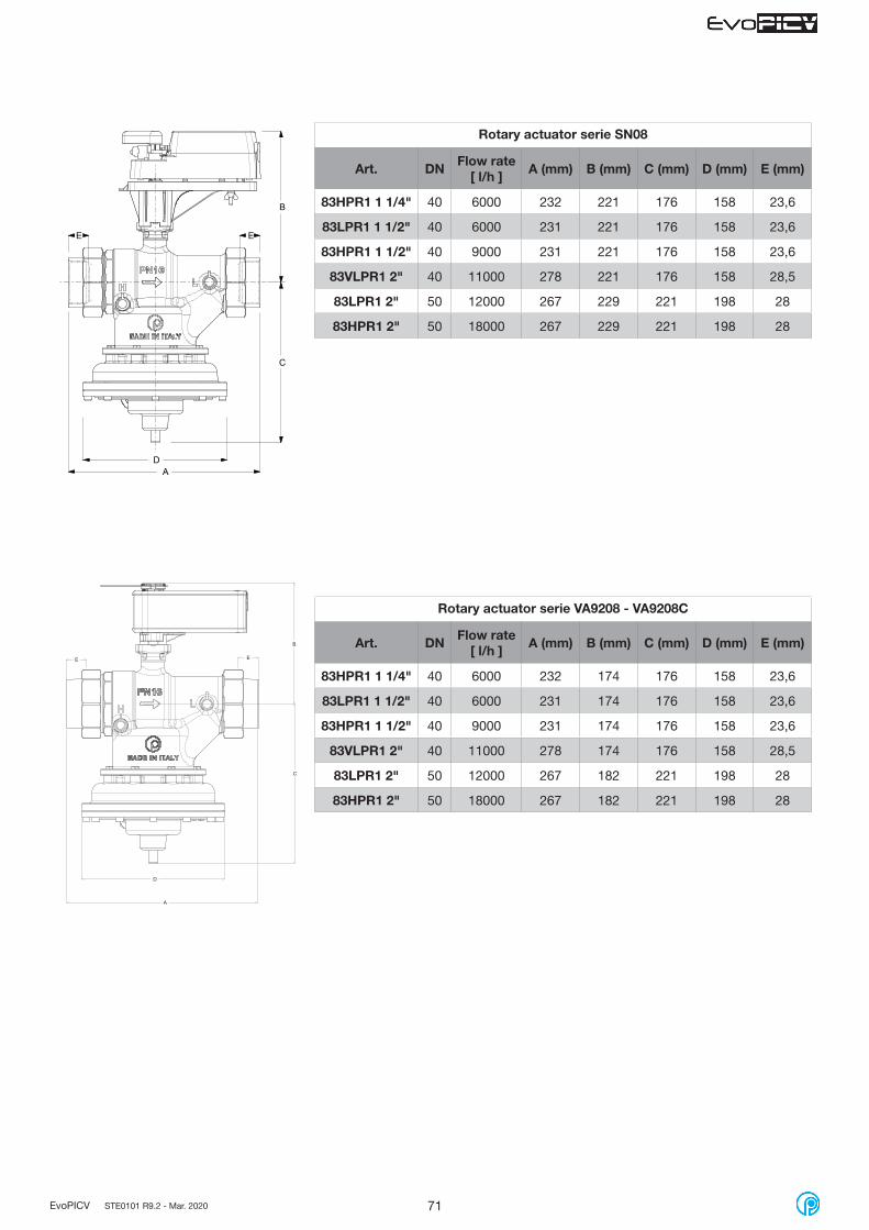
71EvoPICV STE0101 R9.2 - Mar. 2020
D
C
A
E E
B
Rotary actuator serie SN08
Art. DNFlow rate
[ l/h ]A (mm) B (mm) C (mm) D (mm) E (mm)
83HPR1 1 1/4" 40 6000 232 221 176 158 23,6
83LPR1 1 1/2" 40 6000 231 221 176 158 23,6
83HPR1 1 1/2" 40 9000 231 221 176 158 23,6
83VLPR1 2" 40 11000 278 221 176 158 28,5
83LPR1 2" 50 12000 267 229 221 198 28
83HPR1 2" 50 18000 267 229 221 198 28
Rotary actuator serie VA9208 - VA9208C
Art. DNFlow rate
[ l/h ]A (mm) B (mm) C (mm) D (mm) E (mm)
83HPR1 1 1/4" 40 6000 232 174 176 158 23,6
83LPR1 1 1/2" 40 6000 231 174 176 158 23,6
83HPR1 1 1/2" 40 9000 231 174 176 158 23,6
83VLPR1 2" 40 11000 278 174 176 158 28,5
83LPR1 2" 50 12000 267 182 221 198 28
83HPR1 2" 50 18000 267 182 221 198 28
C
D
E E
B
A

72EvoPICV STE0101 R9.2 - Mar. 2020
Valve with actuator 24V
Art.Flow rate
[ l/h ]H1
(mm)H2
(mm)L
(mm)DN
(mm)W1
(mm)W2
(mm)O.D
(mm)P.D.C(mm)
G(mm)
T(mm)
N-ØH(mm)
94FH 2" 20000 190 291 254* 50 155 139 165 125 102 16 4-18
94FL 2 1/2" 20000 190 291 254* 65 155 139 185 145 122 18 4-18
94FH 2 1/2" 30000 183 300 272 65 155 139 185 145 122 18 4-18
94FL 3" 30000 183 300 272 80 155 139 200 160 138 18 8-18
94FL 4" 55000 247 318 352* 100 213 198 220 180 158 18 8-18
94FL 5" 90000 264 347 400*** 125 213 198 250 210 188 20 8-18
94FH 5" 120000 264 347 400*** 125 213 198 250 210 188 20 8-18
94FL 6" 90000 264 346 400** 150 213 198 285 240 212 22 8-22
94FH 6" 150000 348 397 451* 150 213 198 285 240 212 22 8-22
94F EvoPICV dimensional data
* EN558 ( IEC 60534-3-2 Table 1 )** EN558 ( DIN 3202 Part.1 - Series F6 )*** EN558 ( DIN 3202 Part.1 - Series F1 )

73EvoPICV STE0101 R9.2 - Mar. 2020
Valve with actuator 24V
Art.Flow rate
[ l/h ]H1
(mm)H2
(mm)L*
(mm)DN
(mm)W1
(mm)W2
(mm)O.D
(mm)P.D.C(mm)
G(mm)
T(mm)
N-ØH(mm)
94FL 8" 200000 393 440 543 200 216 200 340 295 268 22 12-22
94FH 8" 300000 393 440 543 200 216 200 340 295 268 22 12-22
* EN558 ( IEC 60534-3-2 Table 1 )
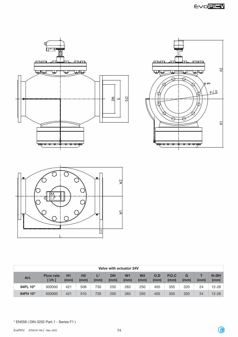
74EvoPICV STE0101 R9.2 - Mar. 2020
Valve with actuator 24V
Art.Flow rate
[ l/h ]H1
(mm)H2
(mm)L*
(mm)DN
(mm)W1
(mm)W2
(mm)O.D
(mm)P.D.C(mm)
G(mm)
T(mm)
N-ØH(mm)
94FL 10" 300000 421 508 730 250 283 250 405 355 320 24 12-26
94FH 10" 500000 421 510 730 250 283 250 405 355 320 24 12-26
* EN558 ( DIN 3202 Part.1 - Series F1 )

75EvoPICV STE0101 R9.2 - Mar. 2020
Fratelli Pettinaroli Spa reserve the right to change the described products and the relative technical data at any time and without prior notice. Please check the latest update on our web site www.pettinaroli.com
Fratelli Pettinaroli Spa has aimed to ensure that all information within this document is accurate. However, mistakes can happen and the company does not accept any liability for incorrect information published within the document.Should you have any queries, please contact [email protected]
EvoPICV shipping weight information
Art. Weight (Kg)
91VL ½" 0,88
91L ½" 0,88
91H ½" 0,88
91L ¾" 0,95
91H ¾" 0,95
91VL1 ½" 0,84
91L1 ½" 0,84
91H1 ½" 0,84
91L1 ¾" 0,91
91H1 ¾" 0,91
91H 1" 1,05
91H1 1" 1,01
Art. Weight (Kg)
83HJP 1 ¼" 8,30
83LJP 1 ½" 8,30
83HJP 1 ½" 8,30
83VLJP 2" 9,00
83LJP 2" 15,50
83HJP 2" 15,50
83HPR1 1 ¼" 8,46
83LPR1 1 ½" 8,46
83HPR1 1 ½" 8,46
83VLPR1 2" 9,16
83LPR1 2" 15,66
83HPR1 2" 15,66
Art. Weight (Kg)
91XVL ½" 0,77
91XL ½" 0,77
91XH ½" 0,77
91XVL/2 ½" 0,76
91XL/2 ½" 0,76
91XL/2 ¾" 0,76
91XH/2 ¾" 0,76
91XVL/3 ½" 0,84
91XL/3 ½" 0,84
91XH/3 ½" 0,84
91XVL3S ½" 0,77
91XL3S ½" 0,77
91XH3S ½" 0,77
Art. Weight (Kg)
A544O2 0,137
A544O4 0,137
A542O2 0,137
A542O4 0,137
A544P3 0,137
A564O2 0,137
A562O2 0,137
A564P3 0,137
VA7481 0,266
VA7482 0,266
SN08 1,55
SN08CC 1,55
VM060 0,383
VA9208 1,50
VA9208C 1,844
M94F2 0,975
M94FB 0,140
Art. Weight (Kg)
94FH 2" 33,00
94FL 2 ½" 40,00
94FH 2 ½" 40,00
94FL 3" 43,00
94FL 4" 74,00
94FL 5" 93,00
94FH 5" 93,00
94FL 6" 98,00
94FH 6" 140,00
94FL 8" 280,00
94FH 8" 280,00
94FL 10" 385,00
94FH 10" 385,00
Art. Weight (Kg)
93L ¾" 2,30
93H ¾" 2,30
93L 1" 2,40
93H 1" 2,40
93L 1 ¼" 2,60
93H 1 ¼" 2,60


Fratelli Pettinaroli SpaVia Pianelli, 38 - 28017 San Maurizio d’Opaglio (NO) - ItalyTel. +39 0322 96217 - +39 0322 96545 - Fax +39 0322 [email protected] - www.pettinaroli.com