Modular Valve Series
93
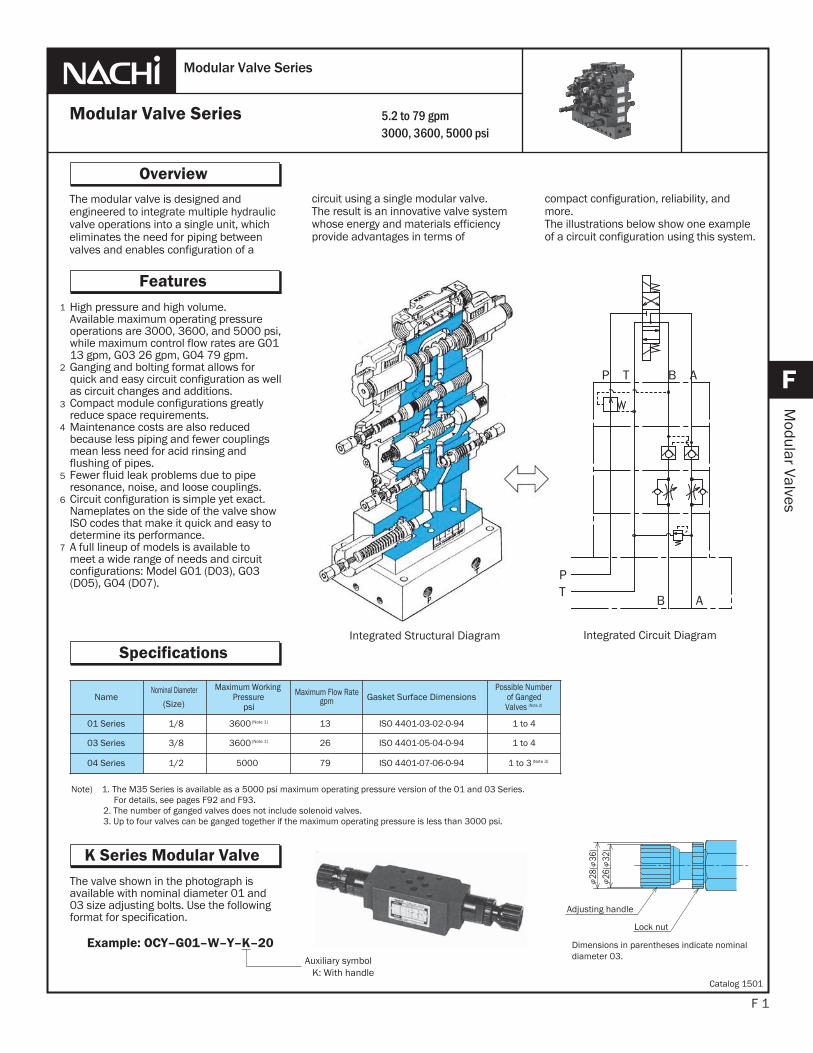
The modular valve is designed and engineered to integrate multiple hydraulic valve operations into a single unit, which eliminates the need for piping between valves and enables configuration of a F 1 Overview F Modular Valves circuit using a single modular valve. The result is an innovative valve system whose energy and materials efficiency provide advantages in terms of High pressure and high volume. Available maximum operating pressure operations are 3000, 3600, and 5000 psi, while maximum control flow rates are G01 13 gpm, G03 26 gpm, G04 79 gpm. Ganging and bolting format allows for quick and easy circuit configuration as well as circuit changes and additions. Compact module configurations greatly reduce space requirements. Maintenance costs are also reduced because less piping and fewer couplings mean less need for acid rinsing and flushing of pipes. Fewer fluid leak problems due to pipe resonance, noise, and loose couplings. Circuit configuration is simple yet exact. Nameplates on the side of the valve show ISO codes that make it quick and easy to determine its performance. A full lineup of models is available to meet a wide range of needs and circuit configurations: Model G01 (D03), G03 (D05), G04 (D07). 1 2 3 Modular Valve Series Modular Valve Series Features 4 5 5.2 to 79 gpm 3000, 3600, 5000 psi compact configuration, reliability, and more. The illustrations below show one example of a circuit configuration using this system. Integrated Structural Diagram Integrated Circuit Diagram B A P T P T B A Specifications The valve shown in the photograph is available with nominal diameter 01 and 03 size adjusting bolts. Use the following format for specification. K Series Modular Valve Dimensions in parentheses indicate nominal diameter 03. Adjusting handle Lock nut 26( 32) 28( 36) Ƶ Ƶ Ƶ Ƶ Auxiliary symbol K: With handle Example: OCY–G01–W–Y–K–20 Note) 1. The M35 Series is available as a 5000 psi maximum operating pressure version of the 01 and 03 Series. For details, see pages F92 and F93. 2. The number of ganged valves does not include solenoid valves. 3. Up to four valves can be ganged together if the maximum operating pressure is less than 3000 psi. Name Nominal Diameter (Size) Maximum Working Pressure psi Maximum Flow Rate gpm Gasket Surface Dimensions Possible Number of Ganged Valves (Note 2) 01 Series 1/8 3600 (Note 1) 13 ISO 4401-03-02-0-94 1 to 4 03 Series 3/8 3600 (Note 1) 26 ISO 4401-05-04-0-94 1 to 4 04 Series 1/2 5000 79 ISO 4401-07-06-0-94 1 to 3 (Note 3) 6 7 Catalog 1501
-
Upload
khangminh22 -
Category
Documents
-
view
0 -
download
0
Transcript of Modular Valve Series
The modular valve is designed and engineered to integrate multiple hydraulic valve operations into a single unit, which eliminates the need for piping between valves and enables configuration of a
F 1
Overview
F
Modular Valves
circuit using a single modular valve.The result is an innovative valve systemwhose energy and materials efficiency provide advantages in terms of
High pressure and high volume.Available maximum operating pressureoperations are 3000, 3600, and 5000 psi, while maximum control flow rates are G0113 gpm, G03 26 gpm, G04 79 gpm.Ganging and bolting format allows forquick and easy circuit configuration as well as circuit changes and additions.Compact module configurations greatlyreduce space requirements.Maintenance costs are also reducedbecause less piping and fewer couplingsmean less need for acid rinsing and flushing of pipes.Fewer fluid leak problems due to piperesonance, noise, and loose couplings.Circuit configuration is simple yet exact. Nameplates on the side of the valve show ISO codes that make it quick and easy to determine its performance.A full lineup of models is available tomeet a wide range of needs and circuitconfigurations: Model G01 (D03), G03 (D05), G04 (D07).
1
2
3
Modular Valve Series
Modular Valve Series
Features
4
5
5.2 to 79 gpm3000, 3600, 5000 psi
compact configuration, reliability, and more.The illustrations below show one example of a circuit configuration using this system.
Integrated Structural Diagram Integrated Circuit Diagram
B A
PT
P T B A
Specifications
The valve shown in the photograph isavailable with nominal diameter 01 and 03 size adjusting bolts. Use the following format for specification.
K Series Modular Valve
Dimensions in parentheses indicate nominaldiameter 03.
Adjusting handle
Lock nut
2
6(
32)
2
8(
36)
Auxiliary symbol K: With handle
Example: OCY–G01–W–Y–K–20
Note) 1. The M35 Series is available as a 5000 psi maximum operating pressure version of the 01 and 03 Series. For details, see pages F92 and F93.
2. The number of ganged valves does not include solenoid valves. 3. Up to four valves can be ganged together if the maximum operating pressure is less than 3000 psi.
NameNominal Diameter
(Size)
Maximum WorkingPressure
psi
Maximum Flow Rategpm Gasket Surface Dimensions
Possible Number of Ganged Valves (Note 2)
01 Series 1/8 3600 (Note 1) 13 ISO 4401-03-02-0-94 1 to 4
03 Series 3/8 3600 (Note 1) 26 ISO 4401-05-04-0-94 1 to 4
04 Series 1/2 5000 79 ISO 4401-07-06-0-94 1 to 3 (Note 3)
6
7
Catalog 1501
P T B AP T B A
P T B A
F 2
F
Modular Valves
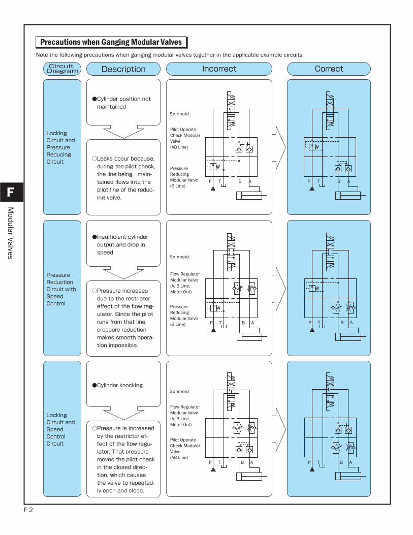
Note the following precautions when ganging modular valves together in the applicable example circuits.
Solenoid
Pilot Operate Check Modular Valve (AB Line)
Pressure Reducing Modular Valve (B Line)
Solenoid
Flow Regulator Modular Valve (A, B Line, Meter Out)
Pressure Reducing Modular Valve (B Line)
Solenoid
Flow Regulator Modular Valve (A, B Line, Meter Out)
Pilot Operate Check Modular Valve (AB Line)
P T B A P T B A
P T B A
Precautions when Ganging Modular Valves
F 3
Valve Ganging Configuration Examples
F
Modular Valves
0103
0103
0103
Forward
High-speed Low-speed
deeps-woLdeeps-hgiH
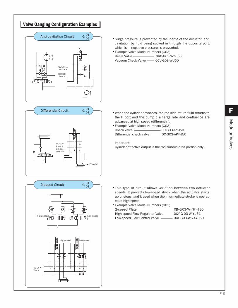
•Surge pressure is prevented by the inertia of the actuator, andcavitation by fluid being sucked in through the opposite port,which is in negative pressure, is prevented.
•Example Valve Model Numbers (G03) Relief Valve 0R0-G03-W*-J50 Vacuum Check Valve 0CV-G03-W-J50
•When the cylinder advances, the rod side return fluid returns tothe P port and the pump discharge rate and confluence areadvanced at high speed (differential).
•Example Valve Model Numbers (G03) Check valve 0C-G03-A*-J50 Differential check valve 0C-G03-AP*-J50
Important:Cylinder effective output is the rod surface area portion only.
•This type of circuit allows variation between two actuatorspeeds. It prevents low-speed shock when the actuator startsup or stops, and it used when the intermediate stroke is operat-ed at high speed.
•Example Valve Model Numbers (G03) 03J-)H(-W-30G-B0etalP deeps-2
High-speed Flow Regulator Valve 0CY-G-03-W-Y-J51 Low-speed Flow Control Valve 0CF-G03-W60-Y-J50
F 4
F
Modular Valves
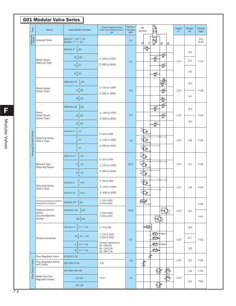
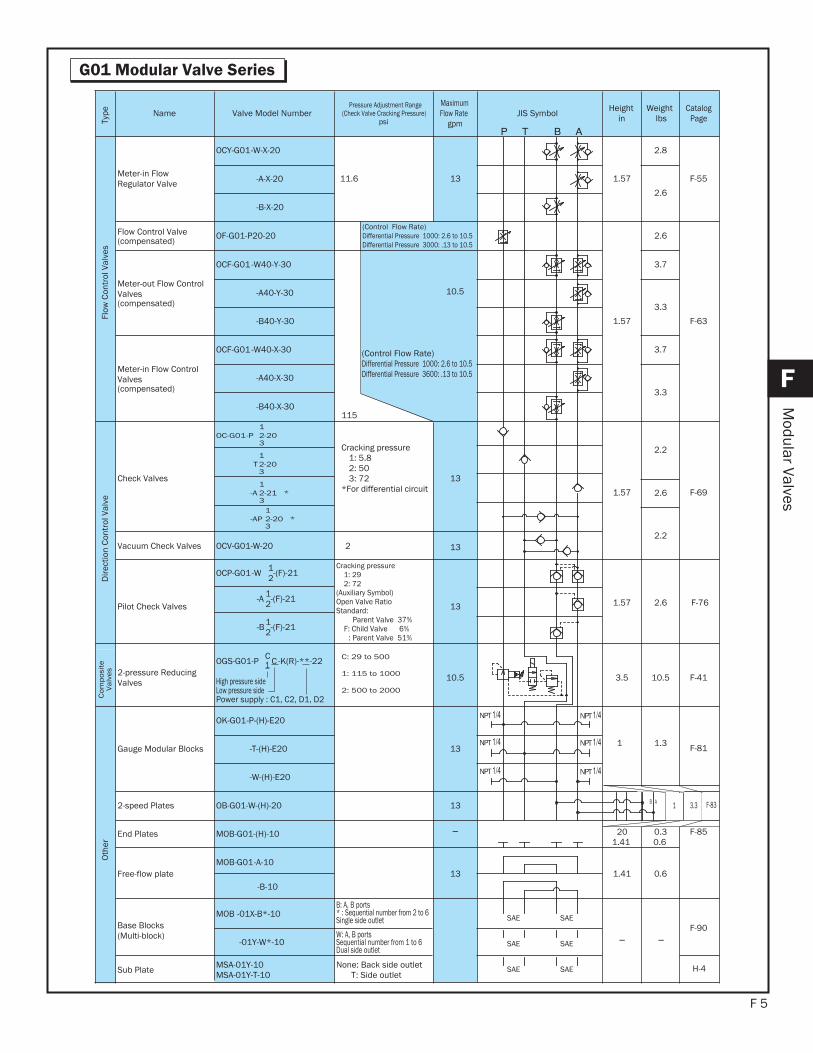
G01 Modular Valve Series
Type Name Valve Model Number
Pressure Adjustment Range (Check Valve Cracking Pressure)
psi
MaximumFlow Rate
gpm
JISSymbol
Heightin
Weightlbs
CatalogPage
Sole
noid
Valv
es
Solenoid Valve SS-G01-**-R-**-31SA-G01-**-**-31 13 D-4
D-16
Pres
sure
Con
trol
Val
ves
Relief Valves (Balance Type)
OR-G01-P 1-203
1: 145 to 1000
3: 500 to 36001.5713
3.3
F-10
-W 1-2035.0
-A 1-213
3.5-B 1-213
Brake Valves (Direct Type)
ORO-G01-W 1-203
1: 115 to 1000
3: 500 to 36001.575.2
3.3
F-16-A 1-203
3.0-B 1-203
DirectRelief Valves (Direct Type)
ORD-G01-W 1-203
1: 115 to 1000
3: 500 to 36001.57
3.3
F-20-A 1-203
3.0-B 1-203
Reducing Valves (Direct Type)
OG-G01-PC
-2112 C: 20 to 500
1: 115 to 1000
2: 500 to 3000
2.81.5713 F-25C
-2112
C-211
2
Balance Type Reducing Valves
OGB-G01-PC
-2013 C: 20 to 500
1: 115 to 1000
3: 500 to 3000
F-324.11.5710.5-AC
-2013
-BC
-2013
Pressure Control Valves (Sequence Valves) OQ-G01-P2 1-203
1: 115 to 10003: 500 to 3000
2.41.5710.5
F-44
Pressure ControlValves (Counter BalanceValves)
OCQ-G01 -A1 1-202 1: 115 to 10002: 500 to 2000 F-47
-B11-202
Pressure Switches
OW-G01-PC
-R-**-3013
C: 72 to 500
1: 115 to 10003: 500 to 3000
Contact CapacitanceAC 125V:5ADC 12V:2.2ADC 24V:1.1A
1.5713
3.9
F-52-W
C-R-**-301
3 5.7
-AC
-R-**-3013
3.9-B
C-R-**-301
3
Flow
Con
trol
Val
ve
Flow Regulator Valve OY-G01-T-20
F-552.21.5713Flow Regulator Valveswith Check OCY-G01-P-20 5.8
Meter-Out FlowRegulator Valves
OCY-G01-W-Y-20
11.6 1.5713
2.8
F-63-A-Y-20
2.6
-B-Y-20
5.2
F-342.81.57Reducing Valves (Direct Type)
OG-G01-AC
-E2112
OG-G01-BC
-E2112
C: 20 to 500
1: 115 to 1000
2: 500 to 3000
F-55
F 5
G01 Modular Valve Series
F
Modular Valves
Type Name Valve Model Number
Pressure Adjustment Range (Check Valve Cracking Pressure)
psi
MaximumFlow Rate
gpmJIS Symbol Height
inWeight
lbsCatalog
Page
Flow
Con
trol
Val
ves
Meter-in FlowRegulator Valve
OCY-G01-W-X-20
11.6 1.5713
2.8
F-55-A-X-20
2.6
-B-X-20
Flow Control Valve(compensated)
OF-G01-P20-20(Control Flow Rate)Differential Pressure 1000: 2.6 to 10.5Differential Pressure 3000: .13 to 10.5
1.57
2.6
F-63
Meter-out Flow ControlValves(compensated)
OCF-G01-W40-Y-30
10.5
(Control Flow Rate)Differential Pressure 1000: 2.6 to 10.5Differential Pressure 3600: .13 to 10.5
115
3.7
-A40-Y-30
3.3
-B40-Y-30
Meter-in Flow ControlValves(compensated)
OCF-G01-W40-X-30 3.7
-A40-X-30
3.3
-B40-X-30
Dire
ctio
n Co
ntro
l Val
ve
Check Valves
OC-G01-P1
-2023 Cracking pressure
1: 5.82: 503: 72
*For differential circuit13
1.57
2.2
F-69
T1
-2023
-A1
-21 *23
2.6
-AP1
-20 *23
2.2Vacuum Check Valves OCV-G01-W-20 2 13
Pilot Check Valves
OCP-G01-W 1-(F)-212Cracking pressure
1: 292: 72
(Auxiliary Symbol) Open Valve RatioStandard:
Parent Valve 37% F: Child Valve 6%
: Parent Valve 51%
F-762.61.5713-A 1-(F)-212
-B 1-(F)-212
Com
pos
ite
Va
lves 2-pressure Reducing
Valves
OGS-G01-P C C -K(R)-**-221
High pressure sideLow pressure sidePower supply : C1, C2, D1, D2
C: 29 to 500
1: 115 to 1000
2: 500 to 2000
F-4110.53.510.5
Oth
er
Gauge Modular Blocks
OK-G01-P-(H)-E20
131 1.3 F-81-T-(H)-E20
-W-(H)-E20
2-speed Plates OB-G01-W-(H)-20 13 F-83
End Plates MOB-G01-(H)-10 201.41
0.30.6
F-85
Free-flow plateMOB-G01-A-10
6.01.4113-B-10
Base Blocks (Multi-block)
MOB -01X-B*-10B: A, B ports * : Sequential number from 2 to 6Single side outlet
F-90
-01Y-W*-10W: A, B ports Sequential number from 1 to 6Dual side outlet
Sub Plate MSA-01Y-10MSA-01Y-T-10
None: Back side outletT: Side outlet
H-4
1 3.3B A
SAE SAE
SAE SAE
SAE SAE
NPT
NPT
NPT
NPT
NPT
NPT
F 6
F
Modular Valves
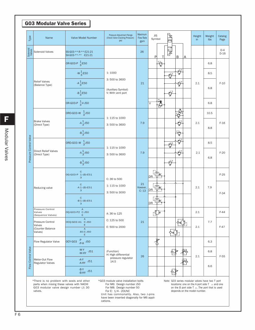
G03 Modular Valve SeriesTy
pe Name Valve Model NumberPressure Adjustment Range
(Check Valve Cracking Pressure)psi
MaximumFlow Rate
gpm
JISSymbol
Heightin
Weightlbs
CatalogPage
Sole
noid
Valv
es Solenoid Valves SS-G03-**-R-**-E21-21SA-G03-**-** -E21-21
26 D-4D-16
Pres
sure
Con
trol
Val
ve
Relief Valves (Balance Type)
OR-G03-P 1-E503
1: 1000
3: 500 to 3600
(Auxiliary Symbol) V: With vent port
2.121
6.8
F-10
-W 1-E503 8.5
-A 1-E5036.8
-B 1-E503
OR-G03-P 1-V-J503 6.8
Brake Valves (Direct Type)
ORO-G03-W 1-J5031: 115 to 1000
3: 500 to 3600 2.17.9
10.5
F-16-A 1-J5038.8
-B 1-J503
Direct Relief Valves (Direct Type)
ORD-G03 -W 1-J5031: 115 to 1000
3: 500 to 3600 2.17.9
8.5
F-20-A 1-J5036.8
-B 1-J503
Reducing valve
OG-G03-PC
-(B)-E5113 C: 36 to 500
1: 115 to 1000
3: 500 to 3000
21However,
C: 132.1 7.9
F-25
-AC
-(B)-E5113
F-34
-BC
-(B)-E5113
Pressure ControlValves (Sequence Valves)
OQ-G03-P2A
-J50CE A: 36 to 125
C: 125 to 500
E: 500 to 2000
21
2.1
7.7
F-44
Pressure ControlValves (Counter BalanceValves)
OCQ-G03-A1A
-J50CE
2.1 F-47
-B1A
-J50CE
Flow
Con
trol
Val
ve
Flow Regulator Valve OCY-G03 -P-P-H -J50
(Function)H: High differential
pressure regulator14.5
2.126
6.3
F-55Meter-Out FlowRegulator Valves
-W-Y-W-HY -J51 6.8
-A-Y-A-HY -J51
6.6-B-Y-B-HY -J51
*There is no problem with seals and otherparts when mixing these valves with NACHIG03 modular valve design number (J) 30valves.
*G03 module valve installation bolts For M6: Design number J50 For M8: Design number 50For E: 1/4 - 20UNC
Unit has commonality. Also, two J-pinshave been inserted diagonally for M6 appli-cations.
Note: G03 series modular valves have two T portlocations: one on the A port side T (A) and oneon the B port side T (B) . The port that is useddepends on the model number.
F 7
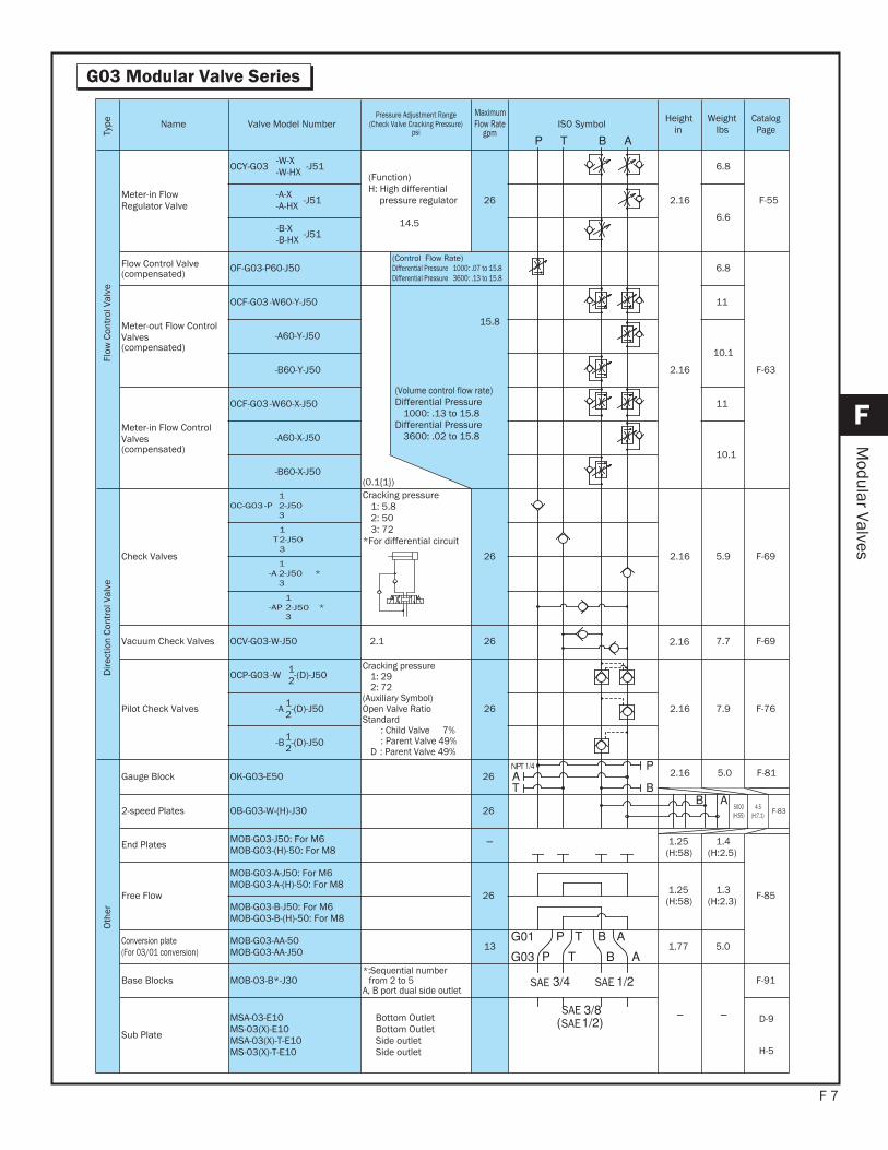
G03 Modular Valve Series
F
Modular Valves
Type Name Valve Model Number
Pressure Adjustment Range (Check Valve Cracking Pressure)
psi
MaximumFlow Rate
gpmISO Symbol Height
inWeight
lbsCatalog
Page
Flow
Con
trol
Val
ve
Meter-in FlowRegulator Valve
OCY-G03 -W-X-W-HX -J51
(Function)H: High differential
pressure regulator
14.5
2.1626
6.8
F-55-A-X-A-HX -J51
6.6-B-X-B-HX -J51
Flow Control Valve(compensated)
OF-G03-P60-J50(Control Flow Rate)Differential Pressure 1000: .07 to 15.8Differential Pressure 3600: .13 to 15.8
2.16
6.8
F-63
Meter-out Flow ControlValves(compensated)
OCF-G03-W60-Y-J50
15.8
(Volume control flow rate)Differential Pressure
1000: .13 to 15.8Differential Pressure
3600: .02 to 15.8
(0.1{1})
11
-A60-Y-J50
10.1
-B60-Y-J50
Meter-in Flow ControlValves(compensated)
OCF-G03-W60-X-J50 11
-A60-X-J50
10.1
-B60-X-J50
Dire
ctio
n Co
ntro
l Val
ve
Check Valves
OC-G03 -P1
-J5023
Cracking pressure1: 5.82: 503: 72
*For differential circuit
F-695.92.1626
T1
-J5023
-A1
-J50 *23
-AP1
-J50 *23
Vacuum Check Valves OCV-G03-W-J50 2.1 F-697.72.1626
Pilot Check Valves
OCP-G03 -W 1-(D)-J502
Cracking pressure1: 292: 72
(Auxiliary Symbol) Open Valve RatioStandard
: Child Valve 7%: Parent Valve 49%
D : Parent Valve 49%
F-767.92.1626-A 1-(D)-J502
-B 1-(D)-J502
Oth
er
Gauge Block OK-G03-E50 26 2.16 5.0 F-81
2-speed Plates OB-G03-W-(H)-J30 26 F-83
End Plates MOB-G03-J50: For M6MOB-G03-(H)-50: For M8
1.25(H:58)
1.4(H:2.5)
F-85Free Flow
MOB-G03-A-J50: For M6MOB-G03-A-(H)-50: For M8
26 1.25(H:58)
1.3(H:2.3)MOB-G03-B-J50: For M6
MOB-G03-B-(H)-50: For M8
Conversion plate(For 03/01 conversion)
MOB-G03-AA-50MOB-G03-AA-J50 5.01.7713
Base Blocks MOB-03-B*-J30*:Sequential number
from 2 to 5A, B port dual side outlet
F-91
Sub Plate
MSA-03-E10MS-03(X)-E10MSA-03(X)-T-E10MS-03(X)-T-E10
Bottom OutletBottom OutletSide outletSide outlet
D-9
H-5
4.5(H:7.1)
5000(H:55)
SAESAE
SAESAE
NPT
F 8
F
Modular Valves
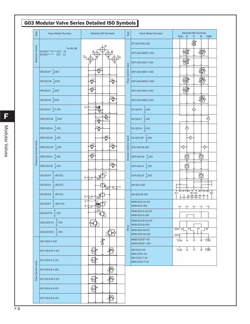
G03 Modular Valve Series Detailed ISO Symbols
Type Valve Model Number Detailed ISO Symbols
Flow
Con
trol
Val
ve
OF-G03-P60-J50
OCF-G03-W60-Y-J50
OCF-G03-A60-Y-J50
OCF-G03-B60-Y-J50
OCF-G03-W60-X-J50
OCF-G03-A60-X-J50
OCF-G03-B60-X-J50
Dire
ctio
n Co
ntro
l Val
ve
OC-G03-P1
-J5023
OC-G03-T1
-J5023
OC-G03-A1
-J5023
OC-G03-AP1
-J5023
OCV-G03-W-J50
OCP-G03-W 1-J502
OCP-G03-A 1-J502
OCP-G03-B 1-J502
OK-G03-J50
Oth
er
OB-G03-W-J30
MOB-G03-(H)-50
MOB-G03-J50
MOB-G03-A-(H)-50
MOB-G03-A-J50
MOB-G03-B-(H)-50
MOB-G03-B-J50
MOB-G03-AA-50
MOB-G03-AA-J50
MOB-03X-B*-50
MOB-03X-B*-J50
MS-03(X)-30
MSA-03(X)-10
MS-03(X)-T-10
MSA-03(X)-T-10
Type Valve Model Number Detailed ISO Symbols
Sole
noid
Val
ves
For M6, M8 SS-G03-**-R-**-E21 -21SA-G03-**-** -E21 -21
Pres
sure
Con
trol
Val
ve
OR-G03-P 1-E503
OR-G03-W 1-E503
OR-G03-A 1-E503
OR-G03-B 1-E503
OR-G03-P 1-V-J503
ORO-G03-W 1-E503
ORO-G03-A 1-J503
ORO-G03-B 1-J503
ORD-G03-W 1-J503
ORD-G03-A 1-J503
ORD-G03-B 1-J503
OG-G03-PC
-(B)-E5113
OG-G03-AC
-(B)-E5113
OG-G03-BC
-(B)-E5113
OG-G03-PC
-(B)V-J5113
OQ-G03-P2A
-J50CE
OCQ-G03-A1A
-J50CE
OCQ-G03-B1A
-J50CE
Flow
Con
trol
Val
ve
OCY-G03-P-J50
OCY-G03-W-Y-J51
OCY-G03-A-Y-J51
OCY-G03-B-Y-J51
OCY-G03-W-X-J51
OCY-G03-A-X-J51
OCY-G03-B-X-J51
F 9
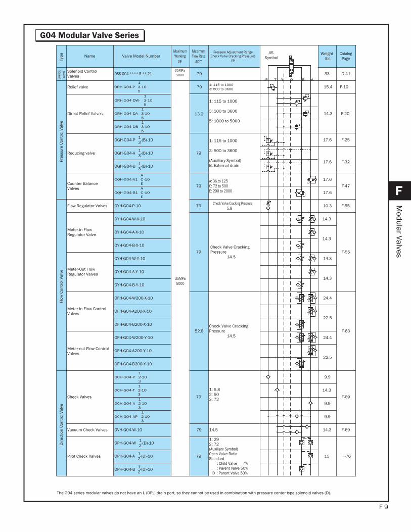
G04 Modular Valve Series
F
Modular Valves
Type Name Valve Model Number
MaximumWorking
psi
MaximumFlow Rate
gpm
Pressure Adjustment Range (Check Valve Cracking Pressure)
psi
JISSymbol
Weightlbs
CatalogPage
Solen
oidVa
lves Solenoid Control
Valves DSS-G04-****-R-**-2135MPa5000 79 33 D-41
Pres
sure
Con
trol
Val
ve
Relief valve ORH-G04-P1
-1035
35MPa5000
79 1: 115 to 10003: 500 to 3600 15.4 F-10
Direct Relief Valves
ORH-G04-DW-1
-1035
13.2
1: 115 to 1000
3: 500 to 3600
5: 1000 to 5000
14.3 F-20ORH-G04-DA1
-1035
ORH-G04-DB1
-1035
Reducing valve
OGH-G04-P 1-(B)-103
79
1: 115 to 1000
3: 500 to 3600
(Auxiliary Symbol) B: External drain
17.6 F-25
OGH-G04-A 1-(B)-103
17.6 F-32OGH-G04-B 1-(B)-103
Counter BalanceValves
OQH-G04-A1A
-10CE
79A: 36 to 125C: 72 to 500E: 290 to 2000
17.6
F-47
OQH-G04-B1A
-10CE
17.6
Flow
Con
trol
Val
ve
Flow Regulator Valves OYH-G04-P-10 79 Check Valve Cracking Pressure5.8 10.3 F-55
Meter-in FlowRegulator Valve
OYH-G04-W-X-10
79Check Valve CrackingPressure
14.5
14.3
F-55
OYH-G04-A-X-10
14.3
OYH-G04-B-X-10
Meter-Out FlowRegulator Valves
OYH-G04-W-Y-10 14.3
OYH-G04-A-Y-10
14.3
OYH-G04-B-Y-10
Meter-in Flow ControlValves
OFH-G04-W200-X-10
52.8Check Valve CrackingPressure
14.5
24.4
F-63
OFH-G04-A200-X-10
22.5
OFH-G04-B200-X-10
Meter-out Flow ControlValves
OFH-G04-W200-Y-10 24.4
OFH-G04-A200-Y-10
22.5
OFH-G04-B200-Y-10
Dire
ctio
n Co
ntro
l Val
ve
Check Valves
OCH-G04-P1
-1023
79
1: 5.82: 503: 72
9.9
F-69
OCH-G04-T1
-1023
14.3
OCH-G04-A1
-1023
9.9
OCH-G04-AP1
-1023
9.9
Vacuum Check Valves OVH-G04-W-10 F-6914.314.579
Pilot Check Valves
OPH-G04-W 1-(D)-102
79
1: 292: 72(Auxiliary Symbol) Open Valve RatioStandard
: Child Valve 7%: Parent Valve 50%
D : Parent Valve 50%
15 F-76OPH-G04-A 1-(D)-102
OPH-G04-B 1-(D)-102
The G04 series modular valves do not have an L (DR2) drain port, so they cannot be used in combination with pressure center type solenoid valves (D).
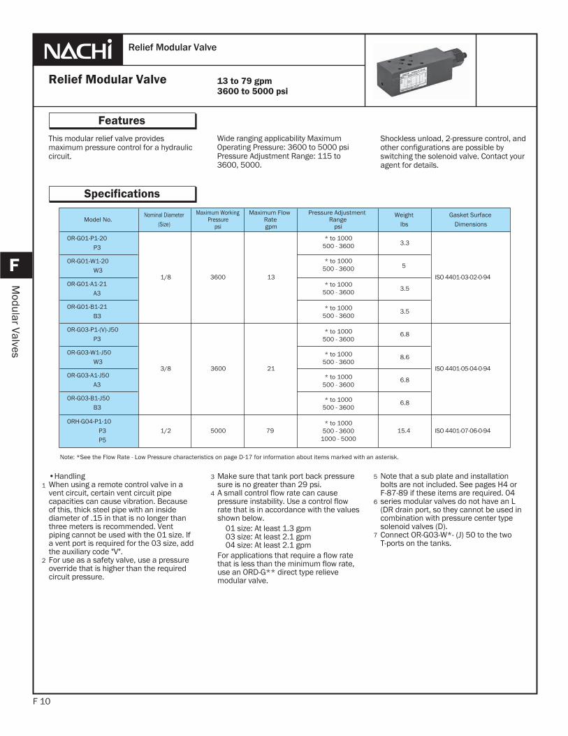
Make sure that tank port back pressuresure is no greater than 29 psi. A small control flow rate can cause pressure instability. Use a control flow rate that is in accordance with the values shown below. 01 size: At least 1.3 gpm 03 size: At least 2.1 gpm 04 size: At least 2.1 gpmFor applications that require a flow rate that is less than the minimum flow rate, use an ORD-G** direct type relieve modular valve.
This modular relief valve provides maximum pressure control for a hydraulic circuit.
F 10
Features
F
Modular Valves
Wide ranging applicability Maximum Operating Pressure: 3600 to 5000 psiPressure Adjustment Range: 115 to 3600, 5000.
Shockless unload, 2-pressure control, and other configurations are possible by switching the solenoid valve. Contact your agent for details.
•HandlingWhen using a remote control valve in a vent circuit, certain vent circuit pipe capacities can cause vibration. Because of this, thick steel pipe with an inside diameter of .15 in that is no longer than three meters is recommended. Vent piping cannot be used with the 01 size. If a vent port is required for the 03 size, add the auxiliary code "V".For use as a safety valve, use a pressure override that is higher than the required circuit pressure.
1
2
3
Relief Modular Valve
Relief Modular Valve
Specifications
Note that a sub plate and installation bolts are not included. See pages H4 or F-87-89 if these items are required. 04 series modular valves do not have an L (DR drain port, so they cannot be used in combination with pressure center type solenoid valves (D).Connect OR-G03-W*- (J) 50 to the two T-ports on the tanks.
5
6
7
13 to 79 gpm3600 to 5000 psi
4
Note: *See the Flow Rate - Low Pressure characteristics on page D-17 for information about items marked with an asterisk.
Model No.Nominal Diameter
(Size)
Maximum WorkingPressure
psi
Maximum FlowRategpm
Pressure AdjustmentRange
psi
Weightlbs
Gasket SurfaceDimensions
OR-G01-P1-20P3
1/8 3600 13
3.3
ISO 4401-03-02-0-94
OR-G01-W1-20W3
5
OR-G01-A1-21A3
3.5
OR-G01-B1-21B3
3.5
OR-G03-P1-(V)-J50P3
3/8 3600 21
6.8
ISO 4401-05-04-0-94
OR-G03-W1-J50W3
8.6
OR-G03-A1-J50A3
6.8
OR-G03-B1-J50B3
6.8
ORH-G04-P1-10P3P5
1/2 5000 79 15.4 ISO 4401-07-06-0-94
* to 1000500 - 3600
* to 1000500 - 3600
* to 1000500 - 3600
* to 1000500 - 3600
* to 1000500 - 3600
* to 1000500 - 3600
* to 1000500 - 3600
* to 1000500 - 3600
* to 1000500 - 3600
1000 - 5000
J50– (K) – 1P–03G–OR
F 11
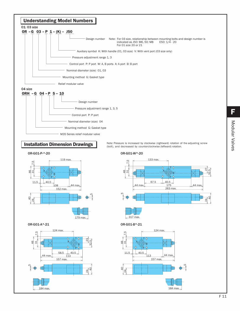
Understanding Model Numbers
F
Modular Valves
Pressure adjustment range 1, 3
Control port P: P port W: A, B ports A: A port B: B port
Nominal diameter (size) 01, 03
Mounting method G: Gasket type
Relief modular valve
Design number Note: For 03 size, relationship between mounting bolts and design number is indicated as J50: M6, 50: M8 E50: 1/4 - 20For 01 size 20 or 21
Auxiliary symbol K: With handle (01, 03 size) V: With vent port (03 size only)
10– 5 P – 04 G–ORH
Pressure adjustment range 1, 3, 5
Control port P: P port
Nominal diameter (size) 04
Mounting method G: Gasket type
M35 Series relief modular valve
Design number
T
P
AB3
17
.54
6
119 max.
40.511.5108 44 max.
152 max.
5
244
0
179 max.
T
P
AB
40.5
7.5
31
46
133 max.
67.544 max. 175
263 max.44 max.
27
32
.52
4 40
5
317 max.
OR-G01-P-*-20 OR-G01-W*-20
01: 03 size
T
P
AB
40.5
7.5
31
46
58.5
23
32
.52
4 40
5
184 max.
11344 max.157 max.
124 max.
T
P
AB3
17
.54
6
124 max.
40.511.5113 44 max.
157 max.
5
244
0
184 max.
OR-G01-A*-21 OR-G01-B*-21
Note: Pressure is increased by clockwise (rightward) rotation of the adjusting screw (bolt), and decreased by counterclockwise (leftward) rotation.Installation Dimension Drawings
04 size
F 12
F
Modular Valves
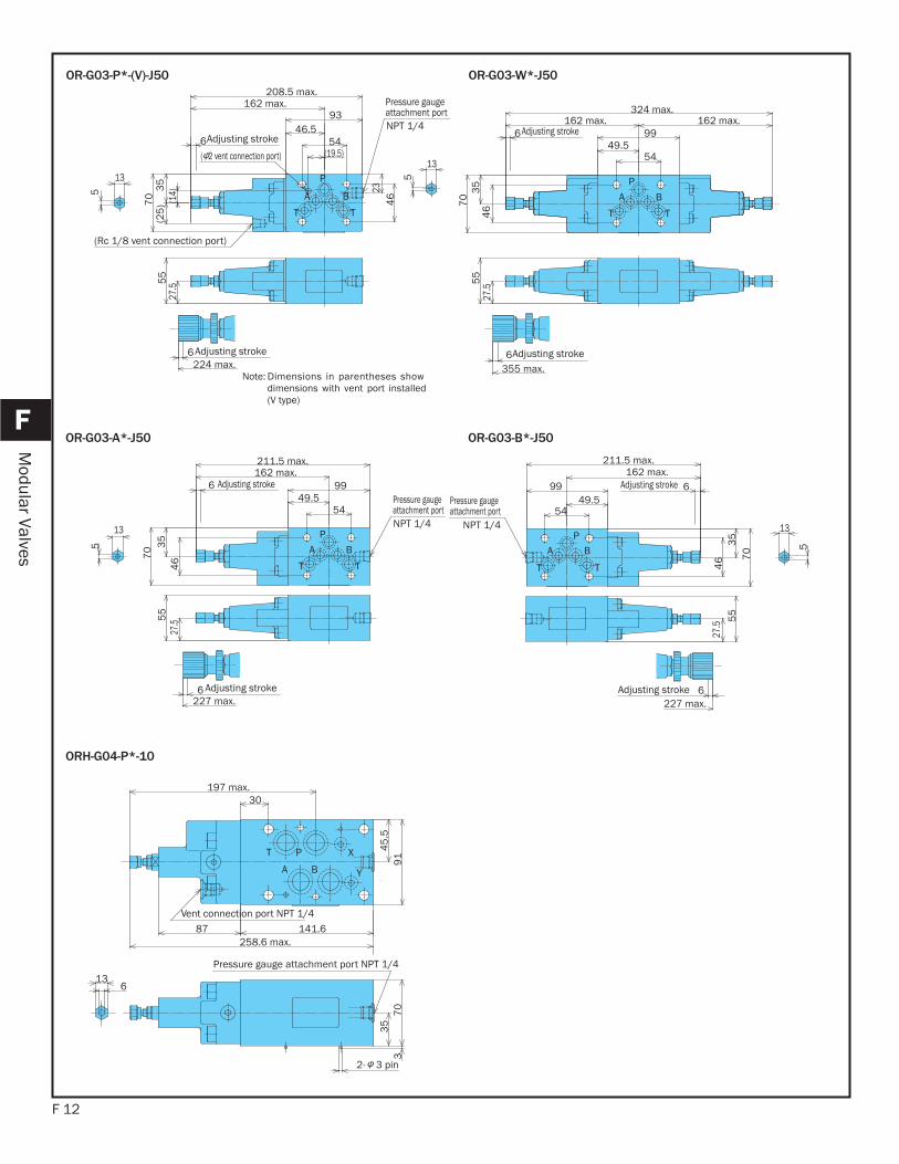
OR-G03-P*-(V)-J50 OR-G03-W*-J50
OR-G03-A*-J50 OR-G03-B*-J50
ORH-G04-P*-10
P
A B
T T
Pressure gauge attachment portNPT 1/4
Adjusting stroke
( 2 vent connection port)
(Rc 1/8 vent connection port)
Adjusting stroke224 max.
6
55
27.5
5
13
67
03
5(2
5) (1
4)
46
23
208.5 max.162 max.
46.593
54(19.5)
13
5 P
A B
T T
Adjusting stroke
Adjusting stroke
324 max.162 max.
6162 max.
9949.5
54
70
35
46
55
6355 max.
27.5
P
A B
T T
Pressure gauge attachment portNPT 1/4
Adjusting stroke
Adjusting stroke6
211.5 max.162 max.
9949.5
54
70 3
54
6
6227 max.
55
27.5
5
13 PA B
TT
NPT 1/4
Adjusting stroke
Adjusting stroke 6
211.5 max.162 max.
9949.5
54
70
35
46
13
55
6227 max.
5
27.5
Pressure gauge attachment port
T P X
A B Y
Vent connection port NPT 1/4
Pressure gauge attachment port NPT 1/4
30197 max.
87 141.6258.6 max.
45
.59
1
613
2- 3 pin
35
70
3
Note: Dimensions in parentheses showdimensions with vent port installed(V type)
(Handle fully open)
Flow rate gpm
0
Min
imum
pre
ssur
eps
i
435
362
5.2 7.9 10.5 13.22.6
290
217
145
72
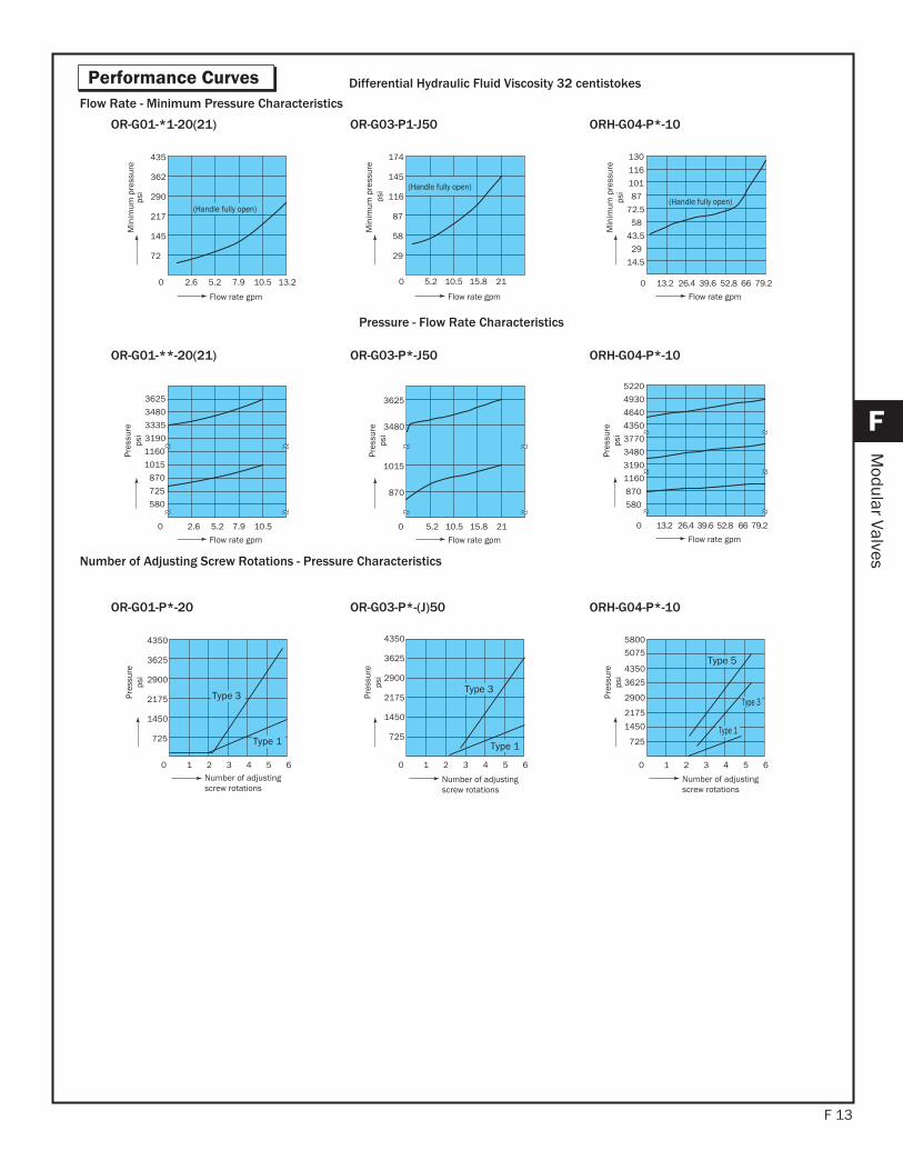
Differential Hydraulic Fluid Viscosity 32 centistokes
(Handle fully open)
0
174
145
10.5 15.8 215.2
116
87
58
29
Flow rate gpm
Min
imum
pre
ssur
e
OR-G01-*1-20(21) OR-G03-P1-J50
725
3190
0 5.2 7.9 10.5
580
1160
3335
2.6
3480
870
1015
3625
Flow rate gpm
Pres
sure
psi
OR-G01-**-20(21)
0
101
116
130
72.5
26.4 39.6 52.8 66 79.2
58
43.5
29
14.5
87
13.2
Flow rate gpm
Min
imum
pre
ssur
e
(Handle fully open)
ORH-G04-P*-10
0 5.2 10.5 15.8 21
3480
870
1015
3625
Flow rate gpm
OR-G03-P*-J50
0
580
3480
4640
3190
13.2 26.4 39.6 52.8 66 79.2
1160
4350
5220
870
3770
4930
Flow rate gpm
ORH-G04-P*-10
0 1 2 3 4 5 6
Type 1
Type 3
725
2900
2175
1450
3625
4350
Number of adjusting screw rotations
OR-G01-P*-20
1 2 3 4 5 60
Type 1
Type 3
Number of adjusting screw rotations
OR-G03-P*-(J)50
1 2 3 4 5 60
Number of adjusting screw rotations
Type 1
Type 3
Type 5
ORH-G04-P*-10
Pressure - Flow Rate Characteristics
Flow Rate - Minimum Pressure Characteristics
Number of Adjusting Screw Rotations - Pressure Characteristics
F 13
Performance Curves
F
Modular Valves
psi
psi
Pres
sure
psi
Pres
sure
psi
Pres
sure
psi
Pres
sure
psi
Pres
sure
psi
725
2900
2175
1450
3625
4350
725
2900
2175
1450
3625
4350
5075
5800
F 14
F
Modular Valves
OR-G01-P*-20
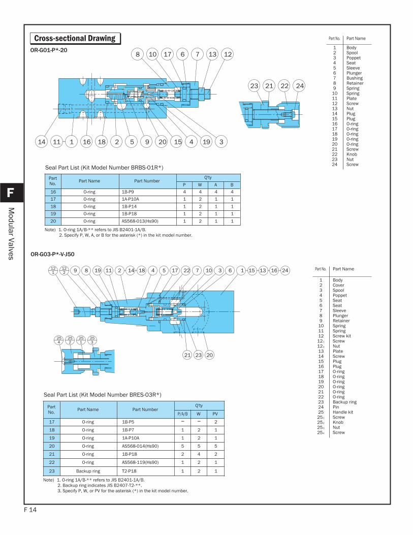
Cross-sectional Drawing
6289 19 14 22
21
122
121 15 2413 161718 511 4 7 10 3 1
2023
254
253
251
252
OR-G03-P*-V-J50
PartNo. Part Name Part Number
Q'ty
P/A/B W PV
17 O-ring 1B-P5 2
18 O-ring 1B-P7 1 2 1
19 O-ring 1A-P10A 1 2 1
20 O-ring AS568-014(Hs90) 5 5 5
21 O-ring 1B-P18 2 4 2
22 O-ring AS568-119(Hs90) 1 2 1
23 Backup ring T2-P18 1 2 1
Seal Part List (Kit Model Number BRES-03R*)
Note) 1. O-ring 1A/B-** refers to JIS B2401-1A/B.2. Backup ring indicates JIS B2407-T2-**. 3. Specify P, W, or PV for the asterisk (*) in the kit model number.
Part No. Part Name
123456789
10111212-1
12-2
1314151617181920212223242525-1
25-2
25-3
25-4
BodyCover SpoolPoppet Seat Seat SleevePlungerRetainerSpringSpringScrew kit ScrewNutPlate ScrewPlugPlugO-ringO-ringO-ringO-ringO-ringO-ringBackup ringPinHandle kit ScrewKnob NutScrew
18 2 5 9 20 1516
21 22 2423
7 13 12
391411141
617108
PartNo. Part Name Part Number
Q'ty
P W A B
16 O-ring 1B-P9 4 4 4 4
17 O-ring 1A-P10A 1 2 1 1
18 O-ring 1B-P14 1 2 1 1
19 O-ring 1B-P18 1 2 1 1
20 O-ring AS568-013(Hs90) 1 2 1 1
Seal Part List (Kit Model Number BRBS-01R*)
Note) 1. O-ring 1A/B-** refers to JIS B2401-1A/B.2. Specify P, W, A, or B for the asterisk (*) in the kit model number.
Part No. Part Name
123456789
101112131415161718192021222324
BodySpoolPoppet Seat SleevePlungerBushingRetainerSpringSpringPlate ScrewNutPlugPlugO-ringO-ringO-ringO-ringO-ringScrewKnob NutScrew
F 15
F
Modular Valves
26284
13 15
8 19216 310221723 928151121027 14 2725
16
24
2
1
9
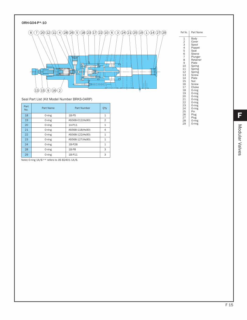
ORH-G04-P*-10
PartNo. Part Name Part Number Q'ty
18 O-ring 1B-P5 1
19 O-ring AS568-012(Hs90) 2
20 O-ring 1A-P11 1
21 O-ring AS568-118(Hs90) 4
22 O-ring AS568-122(Hs90) 1
23 O-ring AS568-127(Hs90) 1
24 O-ring 1B-P28 1
28 O-ring 1B-P8 3
29 O-ring 1B-P11 3
Seal Part List (Kit Model Number BRKS-04RP)
Note) O-ring 1A/B-** refers to JIS B2401-1A/B.
Part No. Part Name
123456789
1011121314151617181920212223242526272829
BodyCover SpoolPoppet Seat SleevePlungerRetainerPlate SpringSpringSpringScrewPlate NutScrewChokeO-ringO-ringO-ringO-ringO-ringO-ringO-ringPinPlugPlugO-ringO-ring
Note that a sub plate and installation bolts are not included. See pages H4 and F87-89 if these items are required.
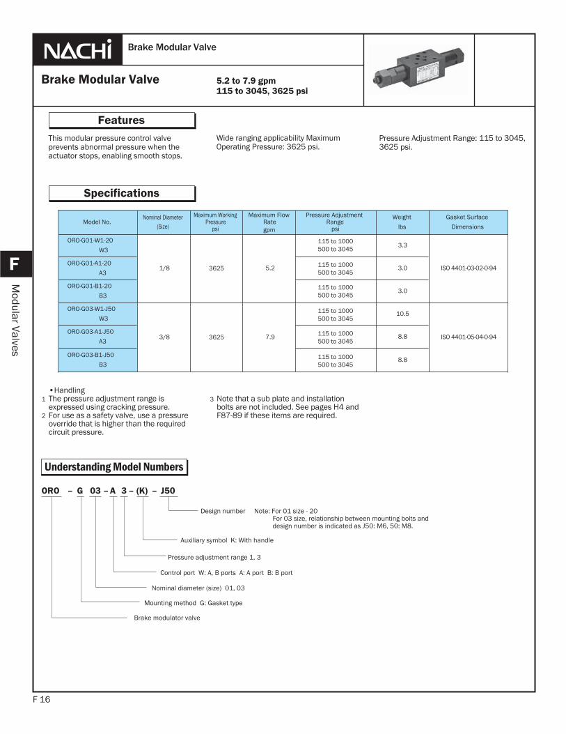
This modular pressure control valve prevents abnormal pressure when the actuator stops, enabling smooth stops.
F 16
Features
F
Modular Valves
Wide ranging applicability Maximum Operating Pressure: 3625 psi.
Pressure Adjustment Range: 115 to 3045, 3625 psi.
•HandlingThe pressure adjustment range is expressed using cracking pressure. For use as a safety valve, use a pressure override that is higher than the required circuit pressure.
1
2
3
Brake Modular Valve
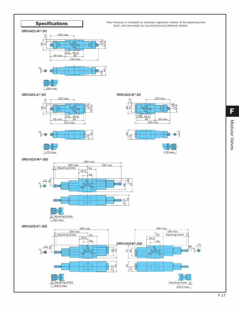
Specifications
5.2 to 7.9 gpm115 to 3045, 3625 psi
Model No.Nominal Diameter
(Size)
Maximum WorkingPressure
psi
Maximum FlowRategpm
Pressure AdjustmentRange
psi
Weight
lbs
Gasket Surface
Dimensions
ORO-G01-W1-20
W3
1/8 3625 5.2
115 to 1000500 to 3045
115 to 1000500 to 3045
115 to 1000500 to 3045
115 to 1000500 to 3045
115 to 1000500 to 3045
115 to 1000500 to 3045
3.3
ISO 4401-03-02-0-94ORO-G01-A1-20
A33.0
ORO-G01-B1-20
B33.0
ORO-G03-W1-J50
W3
3/8 3625 7.9
10.5
ISO 4401-05-04-0-94ORO-G03-A1-J50
A38.8
ORO-G03-B1-J50
B38.8
J50–(K)–3A–03G– ORO
Pressure adjustment range 1, 3
Control port W: A, B ports A: A port B: B port
Nominal diameter (size) 01, 03
Mounting method G: Gasket type
Brake modulator valve
Design number Note: For 01 size - 20 For 03 size, relationship between mounting bolts and design number is indicated as J50: M6, 50: M8.
Auxiliary symbol K: With handle
Understanding Model Numbers
Brake Modular Valve
F 17
F
Modular Valves
Specifications
T
P
AB
105 max.
40.518.58065 max.
210 max.
23
32
.5
31
7.5
46
21 4
05
264 max.
ORO-G01-W*-20
T
P
AB4
67
.53
1
65 max. 8018.5 40.5
105 max.
5
179 max.
23
32
.5
152 max.
21 4
0
T
P
AB
214
0
179 max.
5
152 max.
105 max.
80 65 max.40.518.5
23
32
.5
31
7.5
46
ORO-G01-A*-20 ORO-G01-B*-20
PA B
T T
Adjusting stroke
Adjusting stroke
13
5
5446.5
93180 max.180 max.
360 max.
39 28
46 70
27
.5 55
10391 max.
10
ORO-G03-W*-J50
PA B
T T
Adjusting stroke
Adjusting stroke
5
13
5446.5
93180 max.
39
10305.5 max.
10
290 max.
46
70
27
.5 55
PA B
T T
Adjusting stroke
Adjusting stroke
13
5
54
93
27.55
54
6
10305.5 max.
70
46.5
290 max.180 max.
10
28
ORO-G03-A*-J50
ORO-G03-B*-J50
Note: Pressure is increased by clockwise (rightward) rotation of the adjusting screw (bolt), and decreased by counterclockwise (leftward) rotation.
F 18
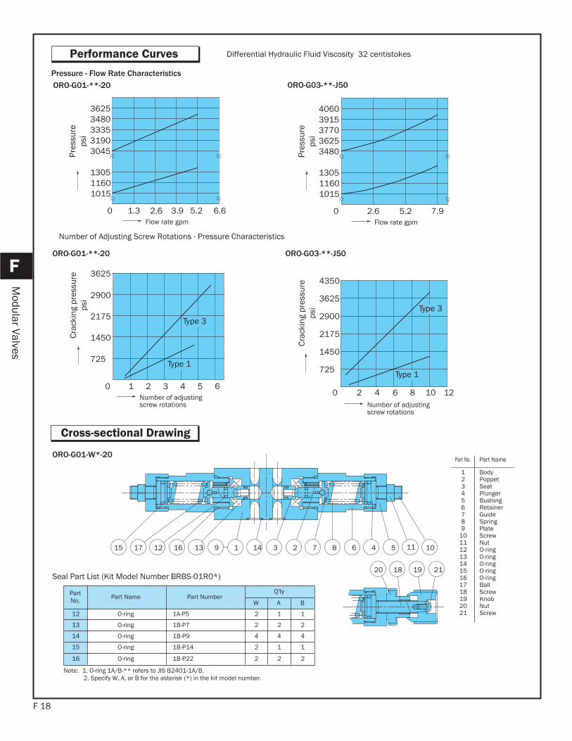
Performance Curves
F
Modular Valves
Cross-sectional Drawing
725
1450
2175
2900
0 1 2 3 4 5 6
Type 3
Type 1
Number of adjusting screw rotations
Crac
king
pre
ssur
eps
i
Differential Hydraulic Fluid Viscosity 32 centistokes
4350
725
1450
2175
2900
0 2 4 6 128 10
3625Type 3
Type 1
Number of adjusting screw rotations
Crac
king
pre
ssur
eps
i
ORO-G01-**-20 ORO-G03-**-J50
0 1.3
1015
3045
Flow rate gpm
1160
3190
1305
333534803625
2.6 3.9 5.2 6.6
Pres
sure
psi
7.95.2 0 2.6Flow rate gpm
Pres
sure
psi
ORO-G01-**-20 ORO-G03-**-J50Pressure - Flow Rate Characteristics
Number of Adjusting Screw Rotations - Pressure Characteristics
15 17 12 16 13 149 1 3 2 7 8 6 4 5 11
20 19 2118
10
ORO-G01-W*-20
PartNo. Part Name Part Number
Q'ty
W A B
12 O-ring 1A-P5 2 1 1
13 O-ring 1B-P7 2 2 2
14 O-ring 1B-P9 4 4 4
15 O-ring 1B-P14 2 1 1
16 O-ring 1B-P22 2 2 2
Seal Part List (Kit Model Number BRBS-01R0*)
Note: 1. O-ring 1A/B-** refers to JIS B2401-1A/B.2. Specify W, A, or B for the asterisk (*) in the kit model number.
Part No. Part Name
123456789
101112131415161718192021
BodyPoppet Seat PlungerBushingRetainerGuideSpringPlate ScrewNutO-ringO-ringO-ringO-ringO-ringBallScrewKnob NutScrew
1015
3480
1160
3625
1305
377039154060
3625
F 19
F
Modular Valves
19102
101 18 16 15 21 11
2020 20 20
65 17 13 9 7 8 141243
34 2 1
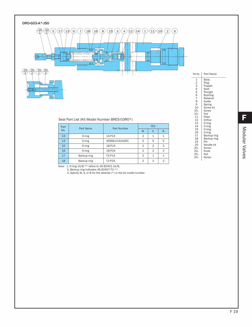
ORO-G03-A*-J50
PartNo. Part Name Part Number
Q'ty
W A B
13 O-ring 1A-P14 2 1 1
14 O-ring AS568-014(Hs90) 5 5 5
15 O-ring 1B-P14 2 2 2
16 O-ring 1B-P24 2 2 2
17 Backup ring T2-P14 2 1 1
18 Backup ring T2-P24 2 2 2
Seal Part List (Kit Model Number BRES-03R0*)
Note: 1. O-ring 1A/B-** refers to JIS B2401-1A/B.2. Backup ring indicates JIS B2407-T2-**. 3. Specify W, A, or B for the asterisk (*) in the kit model number.
Part No. Part Name
123456789
1010-1
10-2
1112131415161718192020-1
20-2
20-3
20-4
BodyPlugPoppet Seat PlungerBushingRetainerGuideSpringScrew kit ScrewNutPlate OrificeO-ringO-ringO-ringO-ringBackup ringBackup ringPinHandle kit ScrewKnob NutScrew
Tank port back pressure changes cracking pressure by the corresponding amount.Note that a sub plate and installation bolts are not included. See pages H4 and F87-89 if these items are required.
This modular relief valve provides maximum pressure control for a hydraulic circuit.
F 20
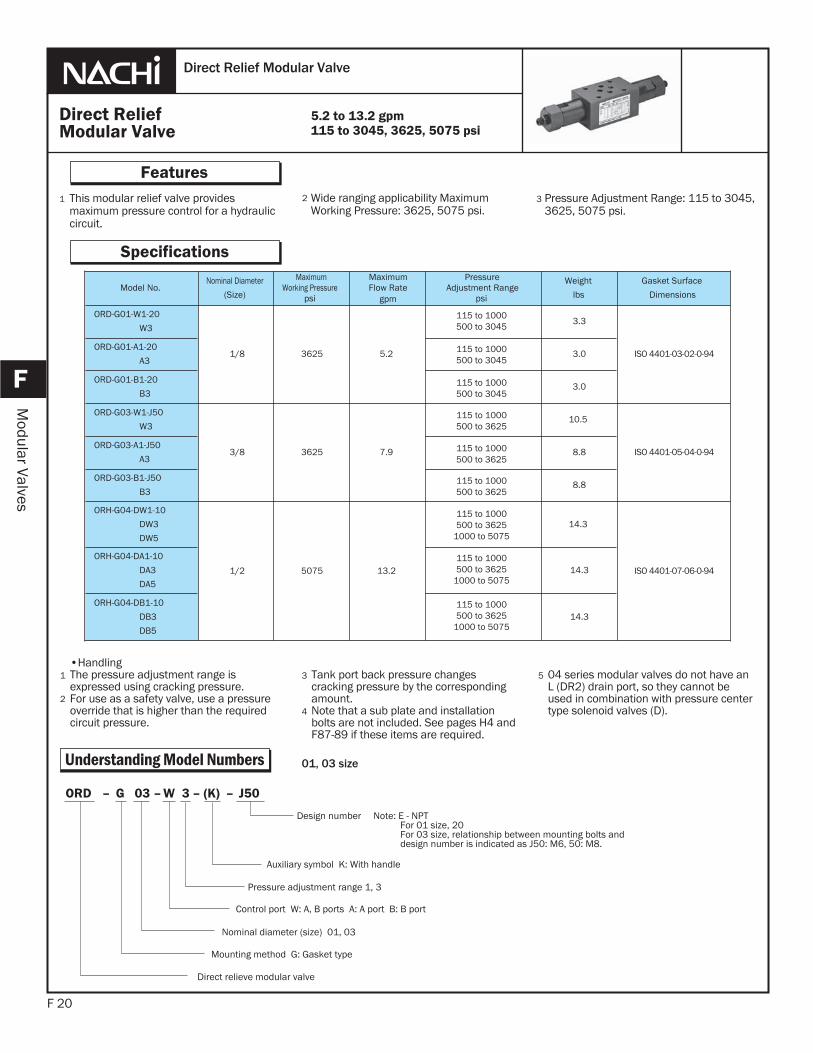
Features
F
Modular Valves
Wide ranging applicability Maximum Working Pressure: 3625, 5075 psi.
Pressure Adjustment Range: 115 to 3045, 3625, 5075 psi.
•HandlingThe pressure adjustment range is expressed using cracking pressure. For use as a safety valve, use a pressure override that is higher than the required circuit pressure.
1
2
3
Direct Relief Modular Valve
Specifications
5.2 to 13.2 gpm115 to 3045, 3625, 5075 psi
1 2 3
Understanding Model Numbers
Direct ReliefModular Valve
Model No.Nominal Diameter
(Size)
Maximum Working Pressure
psi
MaximumFlow Rate
gpm
PressureAdjustment Range
psi
Weight
lbs
Gasket Surface
Dimensions
ORD-G01-W1-20
W3
1/8 3625 5.2
3.3
ISO 4401-03-02-0-94ORD-G01-A1-20
A33.0
ORD-G01-B1-20
B33.0
ORD-G03-W1-J50
W3
3/8 3625 7.9
10.5
ISO 4401-05-04-0-94ORD-G03-A1-J50
A38.8
ORD-G03-B1-J50
B38.8
ORH-G04-DW1-10
DW3
DW5
1/2 5075 13.2
14.3
ISO 4401-07-06-0-94
ORH-G04-DA1-10
DA3
DA5
14.3
ORH-G04-DB1-10
DB3
DB5
14.3
04 series modular valves do not have an L (DR2) drain port, so they cannot be used in combination with pressure center type solenoid valves (D).
5
4
J50–(K)–3W–03G–ORD
Pressure adjustment range 1, 3
Control port W: A, B ports A: A port B: B port
Nominal diameter (size) 01, 03
Mounting method G: Gasket type
Direct relieve modular valve
Design number Note: E - NPT For 01 size, 20 For 03 size, relationship between mounting bolts and design number is indicated as J50: M6, 50: M8.
Auxiliary symbol K: With handle
01, 03 size
115 to 1000500 to 3045
115 to 1000500 to 3045
115 to 1000500 to 3045
115 to 1000500 to 3625
115 to 1000500 to 3625
115 to 1000500 to 3625
115 to 1000500 to 3625
1000 to 5075
115 to 1000500 to 3625
1000 to 5075
115 to 1000500 to 3625
1000 to 5075
F 21
F
Modular Valves
Understanding Model Numbers
Understanding Model Numbers
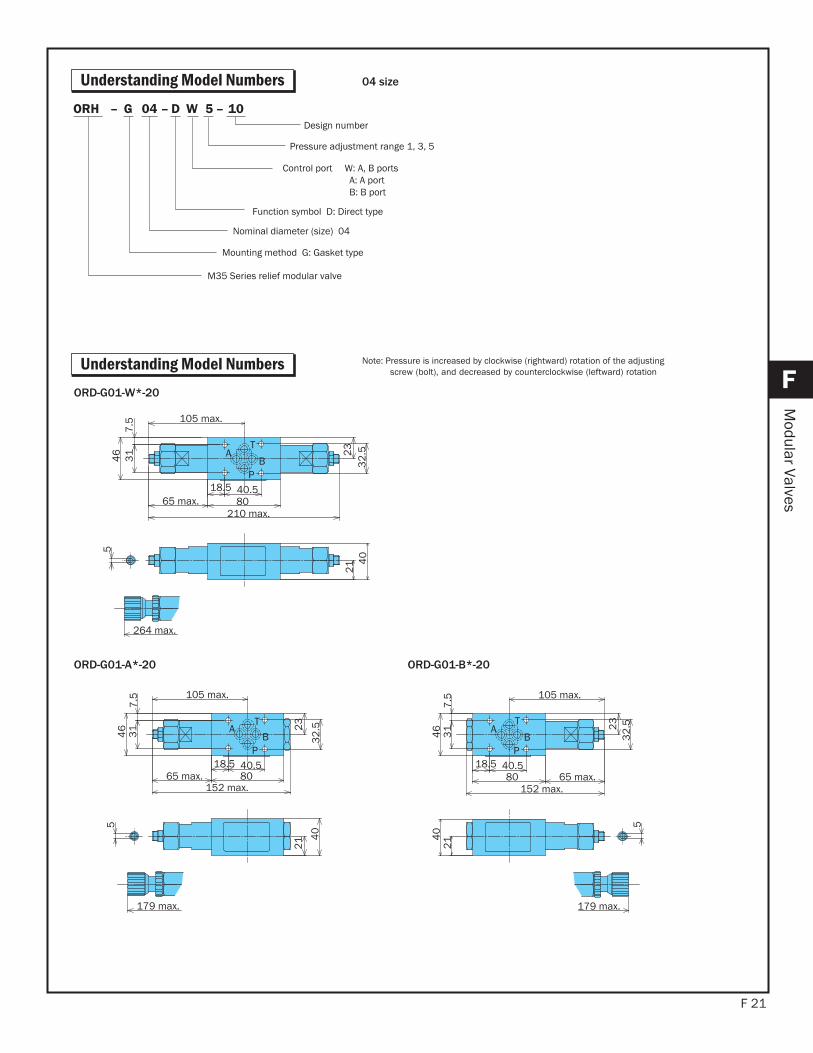
10–5WD–04G–ORH
Pressure adjustment range 1, 3, 5
Control port W: A, B portsA: A portB: B port
Nominal diameter (size) 04
Function symbol D: Direct type
Mounting method G: Gasket type
M35 Series relief modular valve
Design number
04 size
T
P
AB
105 max.
40.518.58065 max.
210 max.
23
32
.5
31
7.5
46
21 4
05
264 max.
Note: Pressure is increased by clockwise (rightward) rotation of the adjusting screw (bolt), and decreased by counterclockwise (leftward) rotation
ORD-G01-W*-20
T
P
AB4
67
.53
1
65 max. 8018.5 40.5
105 max.
5
179 max.
23
32
.5
152 max.
21 4
0
T
P
AB
214
0
5
152 max.
105 max.
80 65 max.40.518.5
23
32
.5
31
7.5
46
179 max.
ORD-G01-A*-20 ORD-G01-B*-20
F 22
F
Modular Valves
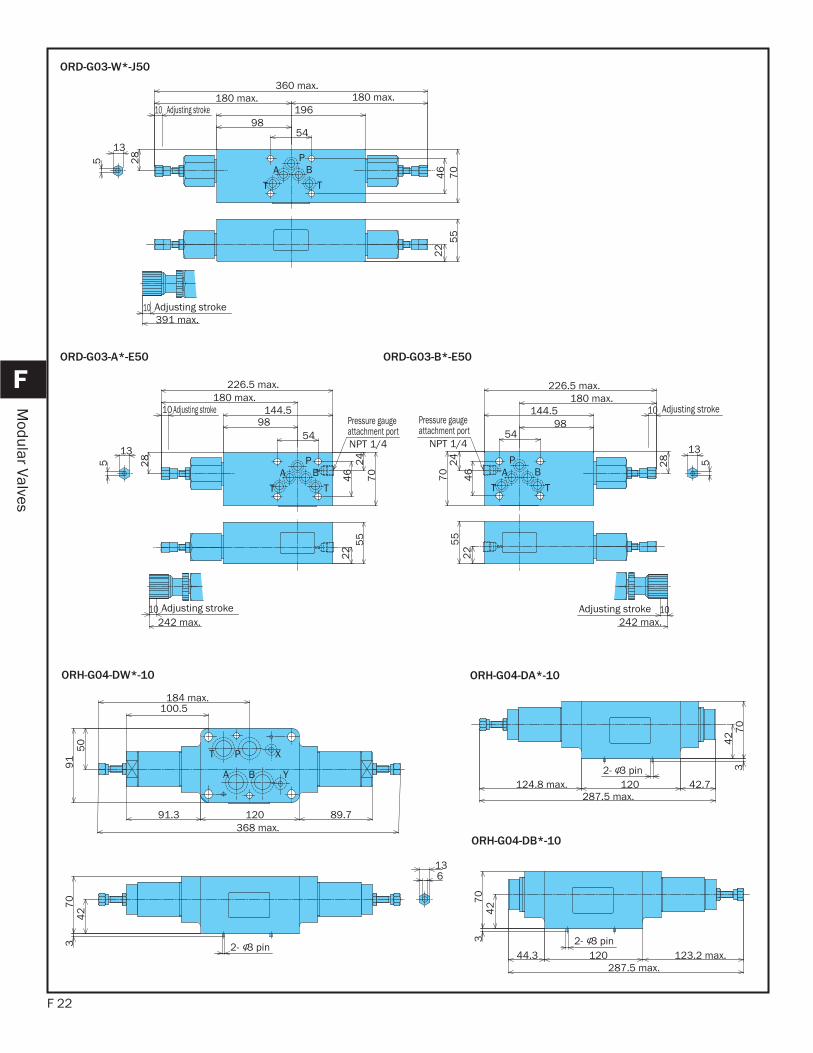
PBA
TT
Adjusting stroke
Adjusting stroke
13
5
46
70
28
5498
196180 max. 180 max.
22
55
10391 max.
10
360 max.
ORD-G03-W*-J50
PBA
TT
Adjusting stroke
Adjusting strokePressure gauge attachment portNPT 1/4
13
5 28
5498
180 max.
10242 max.
10 144.5
226.5 max.
46
24
70
22
55
PBA
T T
Adjusting stroke
Adjusting stroke
Pressure gauge attachment port
NPT 1/45
5
10
242 max.10
144.5
24
70
22
180 max.
9854
46
28
226.5 max.
5
13
ORD-G03-A*-E50 ORD-G03-B*-E50
T P X
A B Y
50
91
100.5184 max.
91.3 120 89.7368 max.
2- 3 pin
427
03
613
ORH-G04-DW*-10 ORH-G04-DA*-10
2- 3 pin
42 7
03
120 42.7124.8 max.287.5 max.
2- 3 pin
427
03
44.3 120 123.2 max.287.5 max.
ORH-G04-DB*-10
F 23
F
Modular Valves
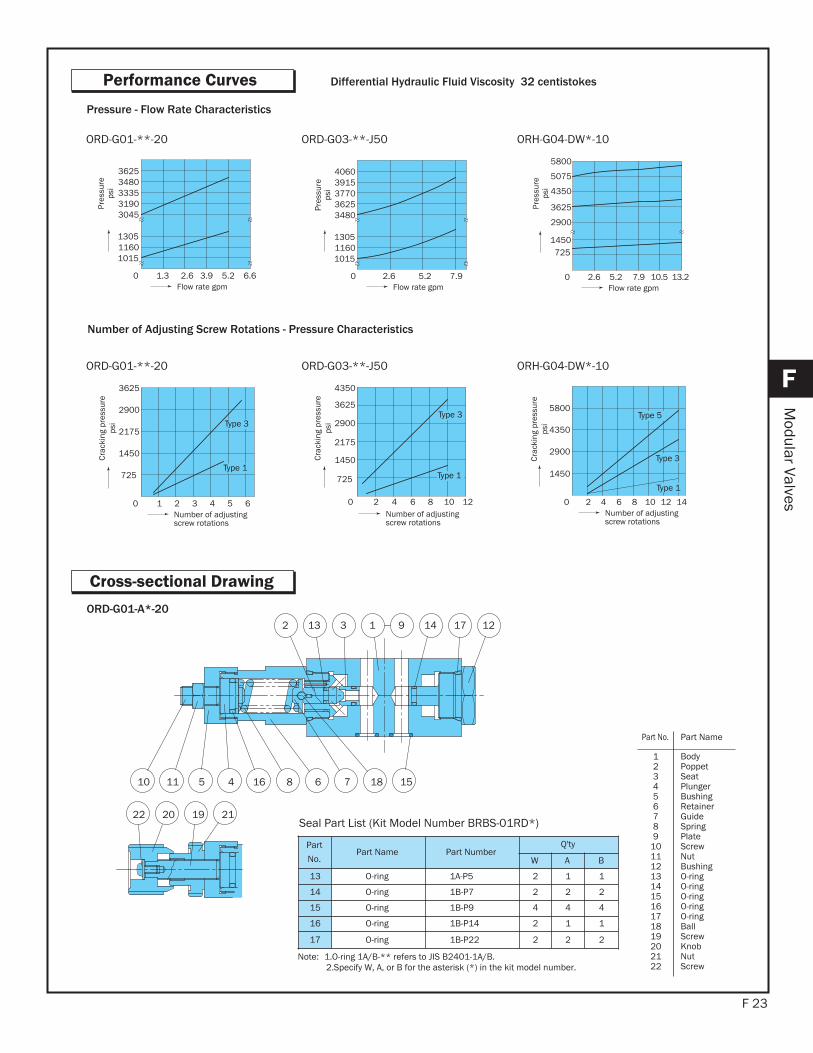
Performance Curves
Cross-sectional Drawing
10
3132 1
11
9
5 4
14 17
16 8
12
6 7 18 15
22 20 19 21
ORD-G01-A*-20
Part
No.Part Name Part Number
Q'ty
W A B
13 O-ring 1A-P5 2 1 1
14 O-ring 1B-P7 2 2 2
15 O-ring 1B-P9 4 4 4
16 O-ring 1B-P14 2 1 1
17 O-ring 1B-P22 2 2 2
Seal Part List (Kit Model Number BRBS-01RD*)
Note: 1.O-ring 1A/B-** refers to JIS B2401-1A/B.2.Specify W, A, or B for the asterisk (*) in the kit model number.
Part No. Part Name
123456789
10111213141516171819202122
BodyPoppet Seat PlungerBushingRetainerGuideSpringPlate ScrewNutBushingO-ringO-ringO-ringO-ringO-ringBallScrewKnob NutScrew
725
1450
2175
2900
0 1 2 3 4 5 6
Type 1
Type 3
3625
Number of adjusting screw rotations
Crac
king
pre
ssur
eps
i
Differential Hydraulic Fluid Viscosity 32 centistokes
0 2 4 6 128 10
Type 1
Type 3
Number of adjusting screw rotations
ORD-G01-**-20 ORD-G03-**-J50
0 1.3
1015
3045
Flow rate gpm
1160
3190
1305
333534803625
2.6 3.9 5.2 6.6
Pres
sure
psi
7.95.2 0 2.6Flow rate gpm
ORD-G01-**-20 ORD-G03-**-J50
0 2 4 6 8 10 12 14
Type 1
Type 3
Type 5
Number of adjusting screw rotations
ORH-G04-DW*-10
2.6 0 7.9 10.5 13.25.2Flow rate gpm
ORH-G04-DW*-10
Number of Adjusting Screw Rotations - Pressure Characteristics
Pressure - Flow Rate Characteristics
Pres
sure
psi
Pres
sure
psi
1015
3480
1160
3625
1305
377039154060
725
2900
3625
1450
4350
5075
5800
Crac
king
pre
ssur
eps
i
Crac
king
pre
ssur
eps
i
725
1450
2175
2900
4350
3625
1450
2900
4350
5800
F 24
F
Modular Valves
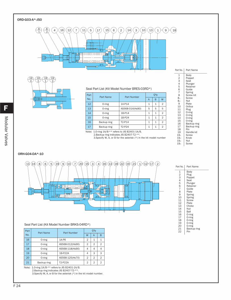
13 456 79 10 2211 31615141 9191 211202 2188 17
ORH-G04-DA*-10
Part
No.Part Name Part Number
Q'ty
W A B
16 O-ring 1A-P6 2 1 1
17 O-ring AS568-012(Hs90) 2 2 2
18 O-ring AS568-118(Hs90) 4 4 4
19 O-ring 1B-P22A 4 3 3
20 O-ring AS568-125(Hs70) 2 2 2
21 Backup ring T2-P22A 2 2 2
Seal Part List (Kit Model Number BRKS-04RD*)
Note) 1.O-ring 1A/B-** refers to JIS B2401-1A/B.2.Backup ring indicates JIS B2407-T2-**. 3.Specify W, A, or B for the asterisk (*) in the kit model number.
Part No. Part Name
123456789
10111213141516171819202122
BodyPlugPoppet Seat PlungerRetainerGuidePlate SpringSpringScrewPlate ChokeNutBallO-ringO-ringO-ringO-ringO-ringBackup ringPin
16 11 15 131082
81 5 17 14 1
1919 19 19
9 183267124
34 2 1
ORD-G03-A*-J50
Part
No.Part Name Part Number
Q'ty
A B W
12 O-ring 1A-P14 1 1 2
13 O-ring AS568-014(Hs90) 5 5 5
14 O-ring 1B-P14 1 1 2
15 O-ring 1B-P24 1 1 2
16 Backup ring T2-P14 1 1 2
17 Backup ring T2-P24 1 1 2
Seal Part List (Kit Model Number BRES-03RD*)
Note) 1.O-ring 1A/B-** refers to JIS B2401-1A/B.2.Backup ring indicates JIS B2407-T2-**.3.Specify W, A, or B for the asterisk (*) in the kit model number
Part No. Part Name
123456788-1
8-2
91011121314151617181919-1
19-2
19-3
19-4
BodyPoppet Seat PlungerRetainerGuideSpringScrew kit ScrewNutPlate OrificePlugO-ringO-ringO-ringO-ringBackup ringBackup ringPinHandle kit ScrewKnob NutScrew
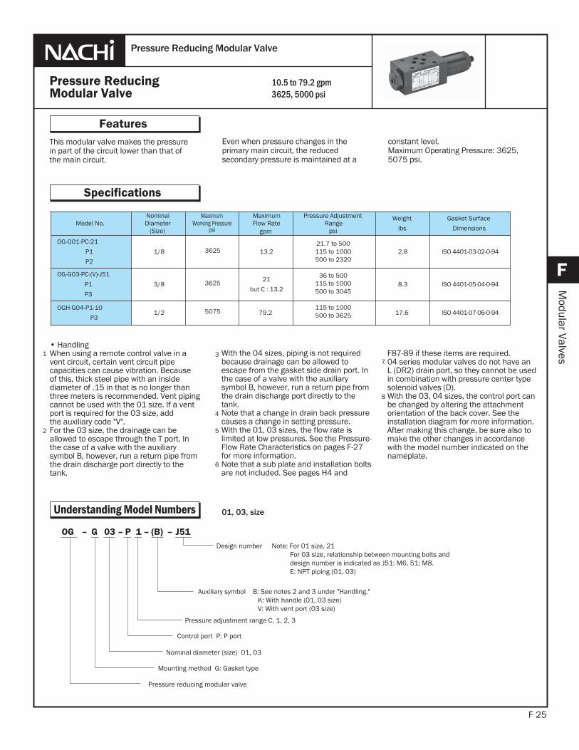
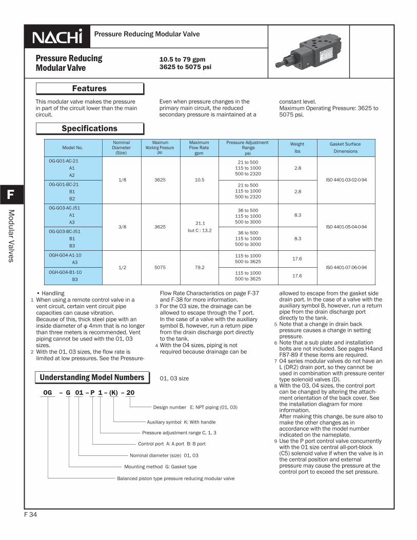
This modular valve makes the pressurein part of the circuit lower than that ofthe main circuit.
F 25
Features
F
Modular Valves
Even when pressure changes in theprimary main circuit, the reduced secondary pressure is maintained at a
• HandlingWhen using a remote control valve in avent circuit, certain vent circuit pipecapacities can cause vibration. Becauseof this, thick steel pipe with an insidediameter of .15 in that is no longer thanthree meters is recommended. Vent pipingcannot be used with the 01 size. If a vent port is required for the 03 size, addthe auxiliary code "V".For the 03 size, the drainage can beallowed to escape through the T port. Inthe case of a valve with the auxiliary symbol B, however, run a return pipe from the drain discharge port directly to the tank.
1
2
3
Pressure ReducingModular Valve
Pressure Reducing Modular Valve
Specifications
4
10.5 to 79.2 gpm3625, 5000 psi
constant level.Maximum Operating Pressure: 3625, 5075 psi.
Understanding Model Numbers
Model No.NominalDiameter
(Size)
Maximum Working Pressure
psi
MaximumFlow Rate
gpm
Pressure AdjustmentRange
psi
Weight
lbs
Gasket Surface
Dimensions
OG-G01-PC-21
P1
P2
1/8 3625 13.221.7 to 500115 to 1000500 to 2320
36 to 500115 to 1000500 to 3045
115 to 1000500 to 3625
2.8 ISO 4401-03-02-0-94
OG-G03-PC-(V)-J51
P1
P3
3/8 3625 21
but C : 13.28.3 ISO 4401-05-04-0-94
OGH-G04-P1-10
P31/2 5075 79.2 17.6 ISO 4401-07-06-0-94
With the 04 sizes, piping is not requiredbecause drainage can be allowed toescape from the gasket side drain port. Inthe case of a valve with the auxiliary symbol B, however, run a return pipe from the drain discharge port directly to the tank.Note that a change in drain back pressurecauses a change in setting pressure.With the 01, 03 sizes, the flow rate is limited at low pressures. See the Pressure-Flow Rate Characteristics on pages F-27for more information.Note that a sub plate and installation boltsare not included. See pages H4 and
F87-89 if these items are required.04 series modular valves do not have anL (DR2) drain port, so they cannot be usedin combination with pressure center typesolenoid valves (D).With the 03, 04 sizes, the control port canbe changed by altering the attachment orientation of the back cover. See the installation diagram for more information. After making this change, be sure also to make the other changes in accordance with the model number indicated on the nameplate.
J51–(B)–1P–03G–OG
Pressure adjustment range C, 1, 2, 3
Control port P: P port
Nominal diameter (size) 01, 03
Mounting method G: Gasket type
Pressure reducing modular valve
Design number Note: For 01 size, 21 For 03 size, relationship between mounting bolts and design number is indicated as J51: M6, 51; M8. E: NPT piping (01, 03)
Auxiliary symbol B: See notes 2 and 3 under "Handling."K: With handle (01, 03 size)V: With vent port (03 size)
01, 03, size
5
6
7
8
F 26
F
Modular Valves
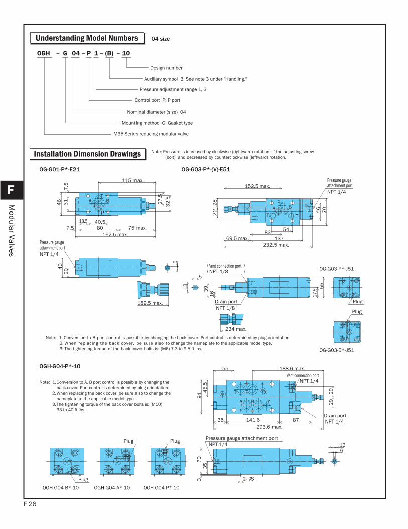
Understanding Model Numbers
10–(B)–1P–04G–OGH
Auxiliary symbol B: See note 3 under "Handling."
Pressure adjustment range 1, 3
Control port P: P port
Nominal diameter (size) 04
Mounting method G: Gasket type
M35 Series reducing modular valve
Design number
04 size
Note: Pressure is increased by clockwise (rightward) rotation of the adjusting screw (bolt), and decreased by counterclockwise (leftward) rotation.
T
P
A B
Pressure gauge attachment portNPT 1/4
115 max.
7.5
31
46 27
.53
2.5
5
204
0
18.5 40.5807.5 75 max.
162.5 max.
189.5 max.
OG-G01-P*-E21
T P X
A B Y
Pressure gauge attachment portNPT 1/4
Vent connection portNPT 1/4
Drain portNPT 1/4
Plug
Plug Plug
2- 3
35
70
136
39
1 2945
.5
55 188.6 max.
29
87141.635293.6 max.
OGH-G04-P*-10
Note: 1. Conversion to B port control is possible by changing the back cover. Port control is determined by plug orientation. 2. When replacing the back cover, be sure also to change the nameplate to the applicable model type. 3. The tightening torque of the back cover bolts is: (M6) 7.3 to 9.5 ft lbs.
Note: 1.
2.
3.
Conversion to A, B port control is possible by changing theback cover. Port control is determined by plug orientation.When replacing the back cover, be sure also to change thenameplate to the applicable model type.The tightening torque of the back cover bolts is: (M10)33 to 40 ft lbs.
BAT
P
T
( )
Pressure gauge attachment portNPT 1/4
Drain portNPT 1/8
Vent connection portNPT 1/8
Plug
Plug
5
13
234 max.
152.5 max.
548313769.5 max.
232.5 max.
28
22 46
70
27.5
55
163
9
OG-G03-P*-(V)-E51
OG-G03-P*-J51
OG-G03-B*-J51
OGH-G04-B*-10 OGH-G04-A*-10 OGH-G04-P*-10
Installation Dimension Drawings
F 27
F
Modular Valves
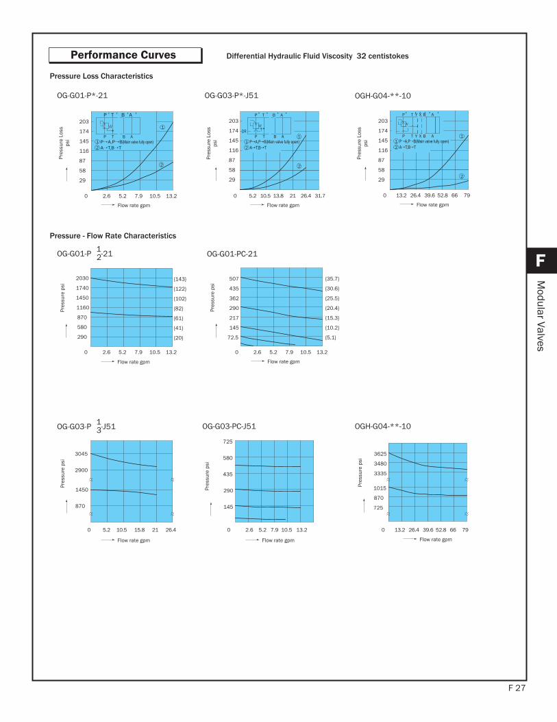
Performance Curves Differential Hydraulic Fluid Viscosity 32 centistokes
870
1450
2900
3045
Flow rate gpm
Pres
sure
psi
OG-G03-P 1-J513
580
435
290
145
725
Flow rate gpm
Pres
sure
psi
3625
3335
3480
870
1015
725
Flow rate gpm
Pres
sure
psi
OG-G03-PC-J51 OGH-G04-**-10
2
Flow rate gpm
0 2.6 5.2 7.9 10.5 13.2
203
29
58
87
116
145
174TP B A
P T B A
1
1
2
Pres
sure
Los
sps
i TP B A
P T B A
DR
2
1
21
0 5.2 10.5 13.8 21 26.4 31.7
Flow rate gpm
OG-G01-P*-21 OG-G03-P*-J51
Pressure Loss Characteristics
12
1
2
0 13.2 26.4 39.6 52.8 66 79
P T Y X B A
P T Y X B A
Flow rate gpm
OGH-G04-**-10
{41}
{61}
{82}
{122}
{143}
{102}
{20}
1450
1740
2030
1160
870
580
290
Flow rate gpm
Pres
sure
psi
{10.2}
{15.3}
{20.4}
{30.6}
{35.7}
{25.5}
507
362
435
{5.1}
145
290
217
72.5
Flow rate gpm
Pres
sure
psi
OG-G01-P 1-212 OG-G01-PC-21
Pressure - Flow Rate Characteristics
Pres
sure
Los
sps
i
Pres
sure
Los
sps
i
203
29
58
87
116
145
174
203
29
58
87
116
145
174
0 2.6 5.2 7.9 10.5 13.2 0 2.6 5.2 7.9 10.5 13.2
0 2.6 5.2 7.9 10.5 13.2 0 5.2 10.5 15.8 21 26.4 0 13.2 26.4 39.6 52.8 66 79
F 28
F
Modular Valves
6.1
12.2
18.3
24.4
0 725 1450 2175 2900 3625
Supply pressurepsi
Dra
in fl
ow ra
te in
³OG-G01-P*-21
30.5
36.6
42.7
48.8
Setting pressurepsi
Dra
in fl
ow ra
te in
³
OG-G03-P*-J51
80 2 4 6 10 12 14Number of adjusting screw rotations
Type 2
Type 1
Type C
23202030
1740
1450
1160
870
580
290
OG-G01-P*-21
40 1 2 3 5 6
4350
3625
2900
2175
1450
725
Number of adjusting screw rotations
Type 3
Type 1
Type C
OG-G03-P*-51
0 21 3 54 6Number of adjusting screw rotations
Type 1
Type 3
Pres
sure
psi
OGH-G04-P*-10
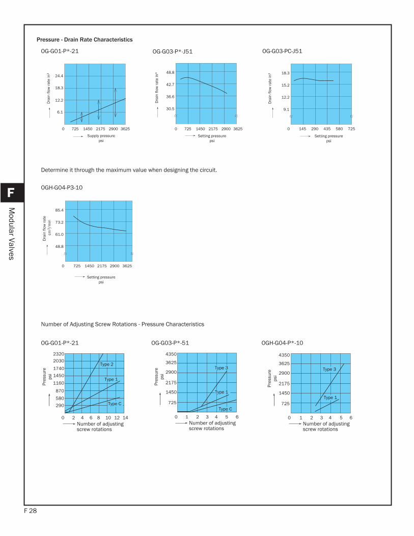
Pressure - Drain Rate Characteristics
0 145 290 435 580 725
12.2
9.1
15.2
18.3
Setting pressurepsi
Dra
in fl
ow ra
te in
³
OG-G03-PC-J51
Number of Adjusting Screw Rotations - Pressure Characteristics
Determine it through the maximum value when designing the circuit.
0 725 1450 2175 2900 3625
85.4
73.2
61.0
48.8
Setting pressurepsi
Dra
in fl
ow ra
tecm
3 /m
in
OGH-G04-P3-10
Pres
sure
psi
Pres
sure
psi
0 725 1450 2175 2900 3625
4350
3625
2900
2175
1450
725
F 29
F
Modular Valves
76 5 32 1 16 1413 011151 8412
10 18 19 17
9
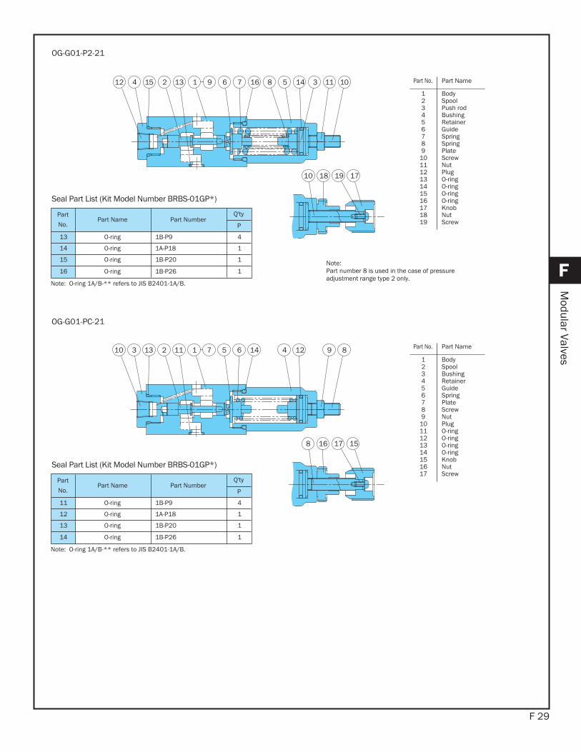
OG-G01-P2-21
65 42 1 14 1211 8931310
8 16 17 15
7
OG-G01-PC-21
Part
No.Part Name Part Number
Q'ty
P
13 O-ring 1B-P9 4
14 O-ring 1A-P18 1
15 O-ring 1B-P20 1
16 O-ring 1B-P26 1
Seal Part List (Kit Model Number BRBS-01GP*)
Note: O-ring 1A/B-** refers to JIS B2401-1A/B.
Part
No.Part Name Part Number
Q'ty
P
11 O-ring 1B-P9 4
12 O-ring 1A-P18 1
13 O-ring 1B-P20 1
14 O-ring 1B-P26 1
Seal Part List (Kit Model Number BRBS-01GP*)
Note: O-ring 1A/B-** refers to JIS B2401-1A/B.
Note:Part number 8 is used in the case of pressure adjustment range type 2 only.
Part No. Part Name
123456789
10111213141516171819
BodySpoolPush rodBushingRetainerGuideSpringSpringPlate ScrewNutPlugO-ringO-ringO-ringO-ringKnob NutScrew
Part No. Part Name
123456789
1011121314151617
BodySpoolBushingRetainerGuideSpringPlate ScrewNutPlugO-ringO-ringO-ringO-ringKnob NutScrew

F 30
F
Modular Valves
27 98701621 1141 492 5112221 35
16
19212 20 8142 2528 26 13
23
17 30
Drain portNPT 1/8 "P" plug
OG-G03-P*-E51
2628 12 27
024231
23
221 1851715 12212 4 1192 941 87106
25
16
19
30 3
OG-G03-PC-E51
Part
No.Part Name Part Number
Q'ty
P
20 O-ring 1B-P6 2
21 O-ring 1A-P10A 1
22 O-ring 1B-P12 1
23 O-ring AS568-014(Hs90) 5
24 O-ring 1B-P18 1
25 O-ring AS568-023(Hs90) 1
Seal Part List (Kit Model Number BRES-03GP-1A)
Note) O-ring 1A/B-** refers to JIS B2401-1A/B.
Part
No.Part Name Part Number
Q'ty
P
20 O-ring 1B-P6 2
21 O-ring 1A-P10A 1
22 O-ring 1B-P12 1
23 O-ring AS568-014(Hs90) 5
24 O-ring 1B-P18 1
25 O-ring AS568-023(Hs90) 1
Seal Part List (Kit Model Number BRES-03GP*-1A)
Note) O-ring 1A/B-** refers to JIS B2401-1A/B.
Part No. Part Name
1415161718192021222324252627282930
NutScrewPlugPlugPlugPlugO-ringO-ringO-ringO-ringO-ringO-ringKnob NutScrewPinPin
Note) Draining through the escape valve piped to thedrain discharge port is standard. : OG-GO3-P*-B-J51
Position the end plate (TPHA-1/8) to the draindischarge port, then connection is made to theT port if the "P" plug (TPUA-1/16) is removed.
:OG-GO3-P*-J51.
Part No. Part Name
123456789
10111213
BodyCoverSpoolPoppet SeatBushingRetainerChokeSpringSpringPlate ScrewNut
Part No. Part Name Part No. Part Name
123456789
101112131415
BodyCoverSpoolPoppet Seat BushingRetainerChokeSpringSpringPlate ScrewNutNutScrew
161718192021222324252627282930
PlugPlugPlugPlugO-ringO-ringO-ringO-ringO-ringO-ringKnob NutScrewPinPin
F 31
F
Modular Valves
2 5 13 721 9 81611 123192527 0142422023 12 6 14 17 1526 1828
Drain portNPT 1/4P
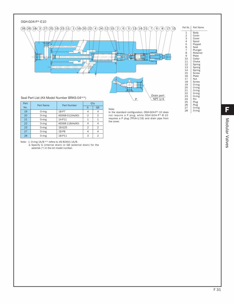
OGH-G04-P*-E10
Part
No.Part Name Part Number
Q'ty
G GB
19 O-ring 1B-P7 4 4
20 O-ring AS568-012(Hs90) 2 2
21 O-ring 1A-P11 1 1
22 O-ring AS568-118(Hs90) 4 4
23 O-ring 1B-G25 2 2
27 O-ring 1B-P8 4 4
28 O-ring 1B-P11 3 2
Seal Part List (Kit Model Number BRKS-04**)
Note: 1. O-ring 1A/B-** refers to JIS B2401-1A/B.2. Specify G (internal drain) or GB (external drain) for the
asterisk (*) in the kit model number.
Note:In the standard configuration, OGH-G04-P*-10 doesnot require a P plug, while OGH-G04-P*-B-10requires a P plug (TPUA-1/16) and drain pipe fromthe cover.
Part No. Part Name
123456789
10111213141516171819202122232425262728
BodyCover Cover SpoolPoppet Seat PlungerRetainerPlate CollarChokeSpringSpringSpringScrewPlate NutScrewO-ringO-ringO-ringO-ringO-ringPinPlugPlugO-ringO-ring
This modular valve makes the pressure in part of the circuit lower than the main circuit.Even when pressure changes in the primary main circuit, the reduced
F 32
Features
F
Modular Valves
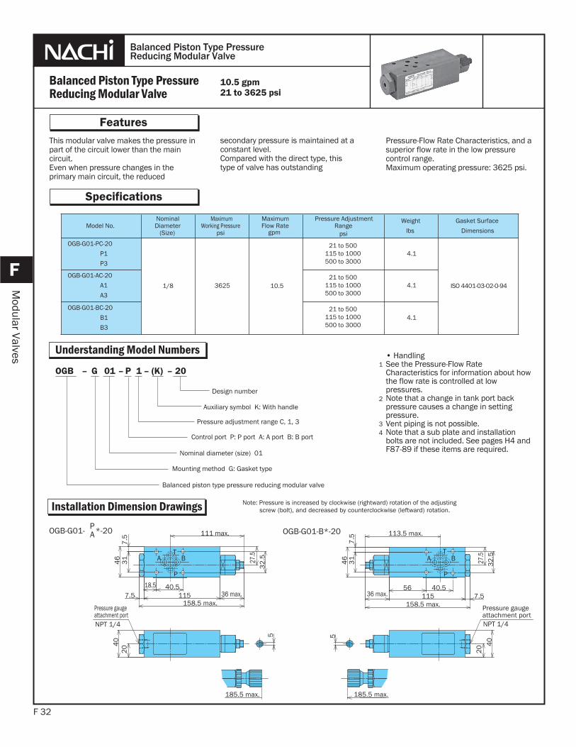
secondary pressure is maintained at a constant level.Compared with the direct type, this type of valve has outstanding
Pressure-Flow Rate Characteristics, and a superior flow rate in the low pressure control range.Maximum operating pressure: 3625 psi.
Balanced Piston Type PressureReducing Modular Valve
Balanced Piston Type PressureReducing Modular Valve
Specifications
• HandlingSee the Pressure-Flow RateCharacteristics for information about how the flow rate is controlled at low pressures.Note that a change in tank port back pressure causes a change in setting pressure.Vent piping is not possible.Note that a sub plate and installationbolts are not included. See pages H4 and F87-89 if these items are required.
1
2
3
10.5 gpm21 to 3625 psi
Model No.NominalDiameter
(Size)
Maximum Working Pressure
psi
Maximum Flow Rate
gpm
Pressure AdjustmentRange
psi
Weight
lbs
Gasket Surface
Dimensions
OGB-G01-PC-20
P1
P3
1/8 3625 10.5
4.1
ISO 4401-03-02-0-94
OGB-G01-AC-20
A1
A3
4.1
OGB-G01-BC-20
B1
B3
4.1
Understanding Model Numbers
Installation Dimension Drawings
20–(K)–1P–01G–OGB
Auxiliary symbol K: With handle
Pressure adjustment range C, 1, 3
Control port P: P port A: A port B: B port
Nominal diameter (size) 01
Mounting method G: Gasket type
Balanced piston type pressure reducing modular valve
Design number
4
Note: Pressure is increased by clockwise (rightward) rotation of the adjustingscrew (bolt), and decreased by counterclockwise (leftward) rotation.
T
P
A B
Pressure gauge attachment portNPT 1/4
111 max.
40.518.57.5 115 36 max.
158.5 max.
27.5
32
.531
7.5
46
204
0
5
185.5 max.
T
P
A B
Pressure gauge attachment portNPT 1/4
27.5
32
.5
31
7.5
46
113.5 max.
185.5 max.
5
40
20
158.5 max.
36 max. 115 7.540.556
OGB-G01- P*-20A OGB-G01-B*-20
21 to 500115 to 1000500 to 3000
21 to 500115 to 1000500 to 3000
21 to 500115 to 1000500 to 3000
F 33
F
Modular Valves
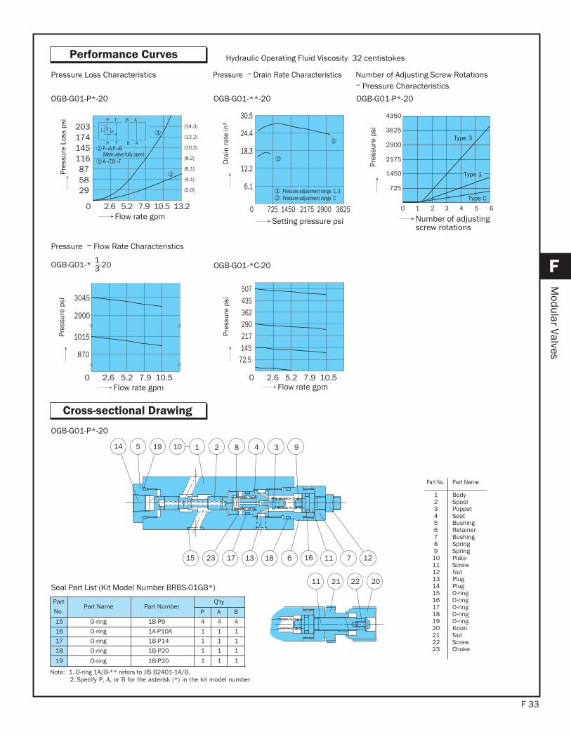
Performance CurvesPr
essu
re L
oss
psi
{4.1}
{6.1}
{8.2}
{12.2}
{14.3}
{10.2}
Flow rate gpm 0 2.6 5.2 7.9 10.5 13.2
203
295887
116145174
TP B A
P T B A
1
2
{2.0}
1
2
Hydraulic Operating Fluid Viscosity 32 centistokes
30.5
6.1
12.2
18.3
24.4
0 725 1450 2175 2900 3625
1
2
1 Pressure adjustment range 1, 3Pressure adjustment range C2
Dra
in ra
te in
³Setting pressure psi
OGB-G01-P*-20 OGB-G01-**-20
507
72.5145217290362435
Pres
sure
psi
Flow rate gpm
OGB-G01-*C-20
Pressure Loss Characteristics
11 21 22 20
13
2 8 4 3 911019514
127111661815 23 17
OGB-G01-P*-20
Pressure Drain Rate Characteristics
0 1 2 3 4 5 6
4350
3625
2900
2175
1450
725
Type 3
Type 1
Pres
sure
psi
Number of adjusting screw rotations
Type C
OGB-G01-P*-20
Number of Adjusting Screw RotationsPressure Characteristics
0 2.6 5.2 7.9 10.5
870
1015
2900
3045
Pres
sure
psi
Flow rate gpm
OGB-G01-* 1-203
Pressure Flow Rate Characteristics
Part
No.Part Name Part Number
Q'ty
P A B
15 O-ring 1B-P9 4 4 4
16 O-ring 1A-P10A 1 1 1
17 O-ring 1B-P14 1 1 1
18 O-ring 1B-P20 1 1 1
19 O-ring 1B-P20 1 1 1
Seal Part List (Kit Model Number BRBS-01GB*)
Note: 1. O-ring 1A/B-** refers to JIS B2401-1A/B.2. Specify P, A, or B for the asterisk (*) in the kit model number.
Part No. Part Name
123456789
1011121314151617181920212223
BodySpoolPoppet Seat BushingRetainerBushingSpringSpringPlate ScrewNutPlugPlugO-ringO-ringO-ringO-ringO-ringKnob NutScrewChoke
Cross-sectional Drawing
0 2.6 5.2 7.9 10.5
This modular valve makes the pressurein part of the circuit lower than the main circuit.
F 34
Features
F
Modular Valves
Even when pressure changes in theprimary main circuit, the reducedsecondary pressure is maintained at a
constant level.Maximum Operating Pressure: 3625 to 5075 psi.
Pressure Reducing Modular Valve
Pressure Reducing Modular Valve
Specifications
allowed to escape from the gasket sidedrain port. In the case of a valve with the auxiliary symbol B, however, run a return pipe from the drain discharge port directly to the tank.Note that a change in drain back pressure causes a change in setting pressure.Note that a sub plate and installationbolts are not included. See pages H4and F87-89 if these items are required.04 series modular valves do not have anL (DR2) drain port, so they cannot beused in combination with pressure centertype solenoid valves (D).With the 03, 04 sizes, the control portcan be changed by altering the attach-ment orientation of the back cover. Seethe installation diagram for more information.After making this change, be sure also to make the other changes as in accordance with the model numberindicated on the nameplate.Use the P port control valve concurrentlywith the 01 size central all-port-block(C5) solenoid valve if when the valve is in the central position and external pressure may cause the pressure at thecontrol port to exceed the set pressure.
5
6
7
10.5 to 79 gpm3625 to 5075 psi
Understanding Model Numbers
20–(K)–1P–01G–OG
Auxiliary symbol K: With handle
Pressure adjustment range C, 1, 3
Control port A: A port B: B port
Nominal diameter (size) 01, 03
Mounting method G: Gasket type
Balanced piston type pressure reducing modular valve
Design number E: NPT piping (01, 03)
8
• HandlingWhen using a remote control valve in avent circuit, certain vent circuit pipecapacities can cause vibration.Because of this, thick steel pipe with an
than three meters is recommended. Vent piping cannot be used with the 01, 03 sizes.With the 01, 03 sizes, the flow rate is limited at low pressures. See the Pressure-
Flow Rate Characteristics on page F-37 and F-38 for more information.For the 03 size, the drainage can beallowed to escape through the T port. In the case of a valve with the auxiliarysymbol B, however, run a return pipefrom the drain discharge port directly to the tank.With the 04 sizes, piping is notrequired because drainage can be
Model No.NominalDiameter
(Size)
Maximum Working Pressure
psi
Maximum Flow Rate
gpm
Pressure AdjustmentRange
psi
Weight
lbs
Gasket Surface
Dimensions
OG-G01-AC-21
A1
A21/8 3625 10.5
21 to 500115 to 1000500 to 2320
21 to 500115 to 1000500 to 2320
36 to 500115 to 1000500 to 3000
36 to 500115 to 1000500 to 3000
115 to 1000500 to 3625
115 to 1000500 to 3625
2.8
ISO 4401-03-02-0-94OG-G01-BC-21
B1
B2
2.8
OG-G03-AC-J51
A1
A33/8 3625
21.1
but C : 13.2
8.3
ISO 4401-05-04-0-94OG-G03-BC-J51
B1
B3
8.3
OGH-G04-A1-10
A31/2 5075 79.2
17.6
ISO 4401-07-06-0-94OGH-G04-B1-10
B317.6
1
2
3
4
9
01, 03 size
F 35
F
Modular Valves
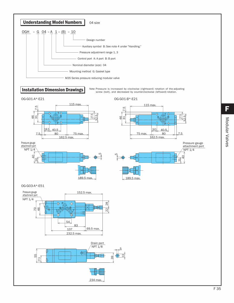
Understanding Model Numbers
Installation Dimension Drawings
10–(B)–1A–04G–OGH
Auxiliary symbol B: See note 4 under "Handling."
Pressure adjustment range 1, 3
Control port A: A port B: B port
Nominal diameter (size) 04
Mounting method G: Gasket type
M35 Series pressure reducing modular valve
Design number
04 size
Note: Pressure is increased by clockwise (rightward) rotation of the adjusting screw (bolt), and decreased by counterclockwise (leftward) rotation.
T
P
A B
Pressure gauge attachment port
NPT 1/4
115 max.
7.5
31
46 27
.5
32
.55
204
0
18.5 40.5807.5 75 max.
162.5 max.
189.5 max.
T
P
A B
Pressure gauge attachment portNPT 1/4
115 max.
7.5
31
46 27
.53
2.5
5
204
0
18.5 40.580 7.575 max.
162.5 max.
189.5 max.
OG-G01-A*-E21 OG-G01-B*-E21
BAT
P
T
Drain portNPT 1/8
Pressure gauge attachment portNPT 1/4
5
234 max.
152.5 max.
5483
137 69.5 max.
232.5 max.
28
2246
70
27.55
5
39 13
OG-G03-A*-E51
F 36
F
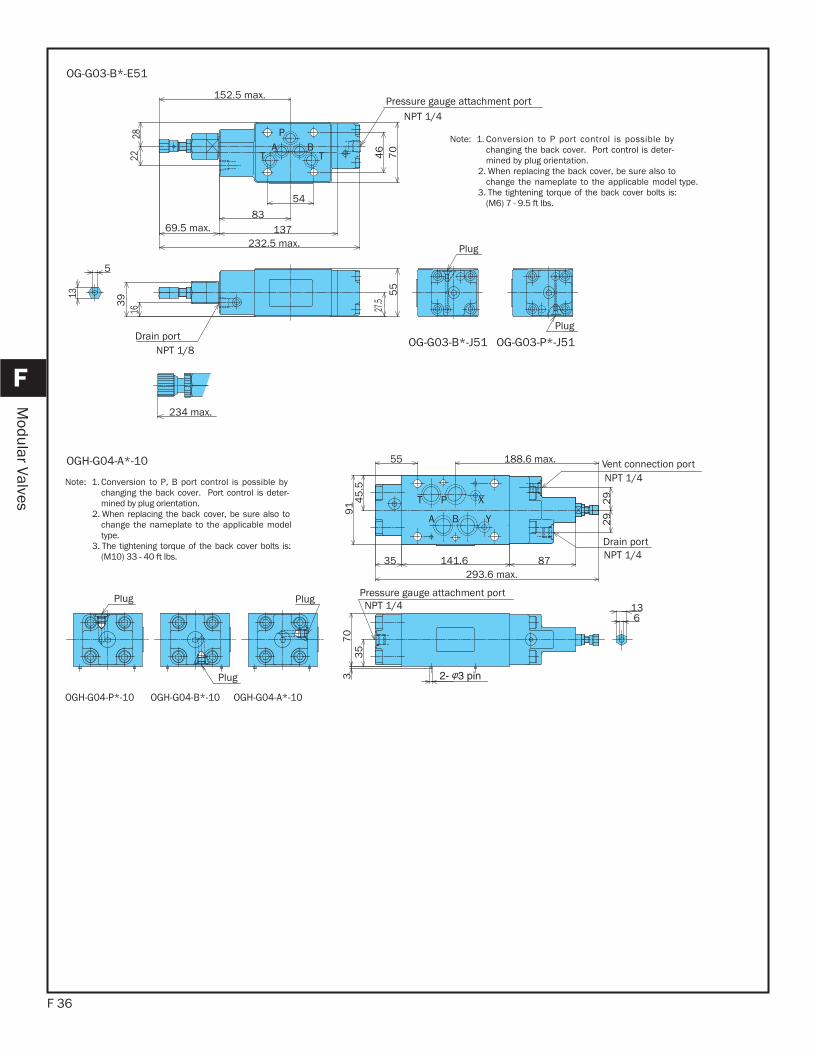
Modular Valves
BAT
P
T
Pressure gauge attachment portNPT 1/4
Drain portNPT 1/8
Plug
Plug
5
13
234 max.
152.5 max.
54
8313769.5 max.
232.5 max.
2822 4
67
027
.55
5
163
9
OG-G03-B*-E51
T P X
A B Y
Pressure gauge attachment portNPT 1/4
Vent connection portNPT 1/4
Drain portNPT 1/4
Plug
PlugPlug
35
70
136
39
1 2945
.5
55 188.6 max.
29
87141.635293.6 max.
OGH-G04-A*-10
Note: 1. Conversion to P port control is possible bychanging the back cover. Port control is deter-mined by plug orientation.
2. When replacing the back cover, be sure also tochange the nameplate to the applicable model type.
3. The tightening torque of the back cover bolts is:(M6) 7 - 9.5 ft lbs.
Note: 1. Conversion to P, B port control is possible bychanging the back cover. Port control is deter-mined by plug orientation.
2. When replacing the back cover, be sure also tochange the nameplate to the applicable modeltype.
3. The tightening torque of the back cover bolts is:(M10) 33 - 40 ft lbs.
OG-G03-B*-J51 OG-G03-P*-J51
OGH-G04-P*-10 OGH-G04-B*-10 OGH-G04-A*-10

F 37
F
Modular Valves
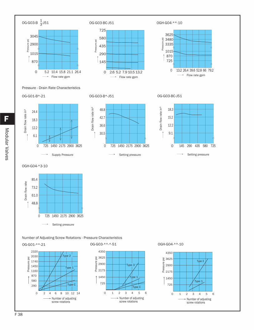
Performance Curves Hydraulic Operating Fluid Viscosity 32 centistokes.
Pressure Loss Curve
2
0 2.6 5.2 7.9 10.5 13.2
203
29
58
87
116
145
174TP B A
P T B A
1
1
2
Flow rate gpm
Pres
sure
Los
s ps
i
TP B A
P T B A
DR
2
1
21
0 5.2 10.5 15.8 21.1 26.4 31.7
Flow rate gpm
Pres
sure
Los
s ps
i
OG-G01-B*-21 OG-G03-B*-J51
12
1
2
P T Y X B A
P T Y X B A
0 13.2 26.4 39.6 52.8 66 79.2
Flow rate gpm
Pres
sure
Los
s ps
i
OGH-G04-**-10
1450
1740
2030
1160
870
580
290
Flow rate gpm
Pres
sure
psi
507
362
435
145
290
217
72.5
Flow rate gpm
Pres
sure
psi
OG-G01-B 1-212 OG-G01-BC-21
Pressure Flow Rate Characteristics
203
29
58
87
116
145
174
0 2.6 5.2 7.9 10.5 13.2 0 2.6 5.2 7.9 10.5 13.2
203
29
58
87
116
145
174
F 38
F
Modular Valves
0 5.2 10.4 15.8 21.1 26.4
870
1015
2900
3045
Flow rate gpm
Pres
sure
psi
2.6 5.2 7.9 10.5 13.2 0
580
435
290
145
725
Flow rate gpm
Pres
sure
psi
OG-G03-B 1-J513 OG-G03-BC-J51
0 13.2 26.4 39.6 52.8 66 79.2
3625
33353480
870 1015
725
Flow rate gpm
Pres
sure
psi
OGH-G04-**-10
6.1
12.2
18.3
24.4
Supply Pressure
Dra
in fl
ow ra
te in
³
Setting pressure
30.5
36.6
42.7
48.8
0 725 1450 2175 2900 3625
Dra
in fl
ow ra
te in
³OG-G01-B*-21 OG-G03-B*-J51
Pressure - Drain Rate Characteristics
145 290 435 580 725 0
12.2
9.1
15.2
18.3
Setting pressure
Dra
in fl
ow ra
te in
³
OG-G03-BC-J51
0 2 4 6 8 10 12 14
Number of adjusting screw rotations
2320
2030
1740
1450
1160
870
580
290
Pres
sure
psi
Type 2
Type C
Type 1
OG-G01-**-21
0 1 2 3 4 5 6
Number of adjusting screw rotations
Pres
sure
psi
Type 1
Type 3
OGH-G04-**-10
0 1 2 3 4 5 6
4350
3625
2900
2175
1450
725
Number of adjusting screw rotations
Pres
sure
psi
Type 3
Type 1
Type C
OG-G03-**-*-51
Number of Adjusting Screw Rotations - Pressure Characteristics
85.4
73.2
61.0
48.8
Setting pressure
Dra
in fl
ow ra
te
OGH-G04-*3-10
0 725 1450 2175 2900 3625
0 725 1450 2175 2900 3625
4350
3625
2900
2175
1450
725

F 39
F
Modular Valves
Cross-sectional Drawing
76 5 32 1 16 1413 011151 8412
10 18 19 17
9OG-G01-A2-21
65 42 1 14 1211 8931310
8 16 17 15
7OG-G01-AC-21
27 987621 1141 492 1012 51122 35
16
212 20 8142 2528 26 13
23
17 30 19
Drain portNPT 1/8 "P" plug
OG-G03-B*-J51
Part No. Part Name Part Number Q'ty
13 O-ring 1B-P9 414 O-ring 1A-P18 115 O-ring 1B-P20 1
16 O-ring 1B-P26 1
Seal Part List (Kit Model Number BRBS-01GP*)
Note: O-ring 1A/B-** refers to JIS B2401-1A/B.
Note:Draining through the escape valve piped to the drain discharge portis standard. : OG-GO3-B*-B-J51 Position the end plate (TPHA-1/8)to the drain discharge port, then connection is made to the T port ifthe "P" plug (TPUA-1/16) is removed. :OG-GO3-B*-J51.
Part No. Part Name Part Number Q'ty
11 O-ring 1B-P9 412 O-ring 1A-P18 113 O-ring 1B-P20 1
14 O-ring 1B-P26 1
Seal Part List (Kit Model Number BRBS-01GP*)
Note: O-ring 1A/B-** refers to JIS B2401-1A/B.
Seal Part List (Kit Model Number BRES-03G*-1A)
Note: 1. O-ring 1A/B-** refers to JIS B2401-1A/B.2. Specify A or B for the asterisk (*) in the kit model number.
Note: Part number 8 is used in the case of pressure adjustment range type 2 only.
Part No. Part Name
123456789
10111213141516171819
BodySpoolPush rodBushingRetainerGuideSpringSpringPlate ScrewNutPlugO-ringO-ringO-ringO-ringKnob NutScrew
Part No. Part Name
123456789
1011121314151617
BodySpoolBushingRetainerGuideSpringPlate ScrewNutPlugO-ringO-ringO-ringO-ringKnob NutScrew
Part No. Part Name
11121314151617181920
Plate ScrewNutNutScrewPlugPlugPlugPlugO-ring
Part No. Part Name
21222324252627282930
O-ringO-ringO-ringO-ringO-ringKnob NutScrewPinPin
Part No. Part Name
123456789
10
BodyCoverSpoolPoppetSeat BushingRetainerChokeSpringSpring
Part
No.Part Name Part Number
Q'tyA B
20 O-ring 1B-P6 2 221 O-ring 1A-P10A 1 122 O-ring 1B-P12 1 123 O-ring AS568-014(Hs90) 5 524 O-ring 1B-P18 1 125 O-ring AS568-023(Hs90) 1 1
F 40
F
Modular Valves
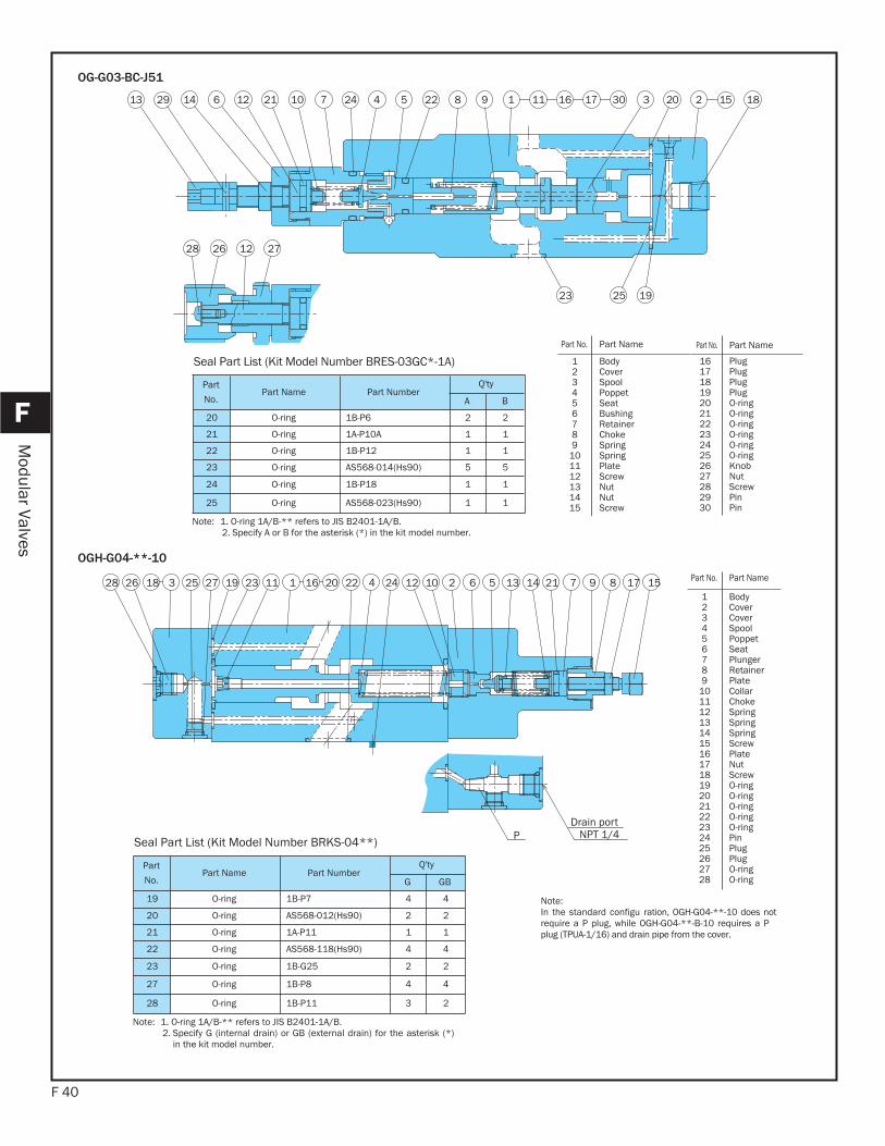
OG-G03-BC-J51
2 5 13 721 9 81611 123192725 0142422023 12 6 14 17 1526 1828
Drain portNPT 1/4P
OGH-G04-**-10
Part
No.Part Name Part Number
Q'ty
A B
20 O-ring 1B-P6 2 2
21 O-ring 1A-P10A 1 1
22 O-ring 1B-P12 1 1
23 O-ring AS568-014(Hs90) 5 5
24 O-ring 1B-P18 1 1
25 O-ring AS568-023(Hs90) 1 1
Seal Part List (Kit Model Number BRES-03GC*-1A)
Note: 1. O-ring 1A/B-** refers to JIS B2401-1A/B.2. Specify A or B for the asterisk (*) in the kit model number.
Note:In the standard configu ration, OGH-G04-**-10 does notrequire a P plug, while OGH-G04-**-B-10 requires a Pplug (TPUA-1/16) and drain pipe from the cover.
Part
No.Part Name Part Number
Q'ty
G GB
19 O-ring 1B-P7 4 4
20 O-ring AS568-012(Hs90) 2 2
21 O-ring 1A-P11 1 1
22 O-ring AS568-118(Hs90) 4 4
23 O-ring 1B-G25 2 2
27 O-ring 1B-P8 4 4
28 O-ring 1B-P11 3 2
Seal Part List (Kit Model Number BRKS-04**)
Note: 1. O-ring 1A/B-** refers to JIS B2401-1A/B.2. Specify G (internal drain) or GB (external drain) for the asterisk (*)
in the kit model number.
Part No. Part Name
123456789
10111213141516171819202122232425262728
BodyCover Cover SpoolPoppet Seat PlungerRetainerPlate CollarChokeSpringSpringSpringScrewPlate NutScrewO-ringO-ringO-ringO-ringO-ringPinPlugPlugO-ringO-ring
Part No. Part Name
161718192021222324252627282930
PlugPlugPlugPlugO-ringO-ringO-ringO-ringO-ringO-ringKnob NutScrewPinPin
Part No. Part Name
123456789
101112131415
BodyCoverSpoolPoppetSeat BushingRetainerChokeSpringSpringPlate ScrewNutNutScrew
2628 12 27
024231
23
221 1851715 12242129 11941 87106
25
16
19
30 3
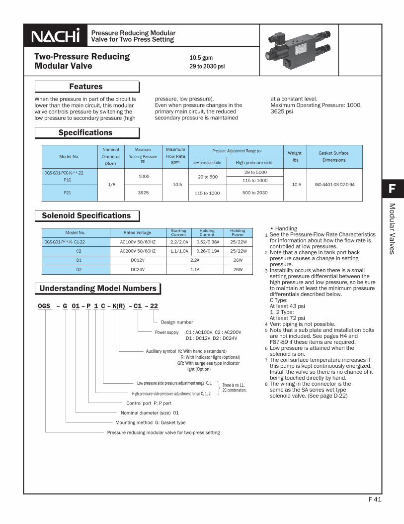
When the pressure in part of the circuit islower than the main circuit, this modular valve controls pressure by switching the low pressure to secondary pressure (high
F 41
Features
F
Modular Valves
pressure, low pressure).Even when pressure changes in theprimary main circuit, the reduced secondary pressure is maintained
• HandlingSee the Pressure-Flow Rate Characteristics for information about how the flow rate is controlled at low pressures.Note that a change in tank port backpressure causes a change in settingpressure.Instability occurs when there is a small setting pressure differential between the high pressure and low pressure, so be sure to maintain at least the minimum pressure differentials described below.C Type:At least 43 psi1, 2 Type:At least 72 psiVent piping is not possible.Note that a sub plate and installation bolts are not included. See pages H4 and F87-89 if these items are required.Low pressure is attained when the solenoid is on.The coil surface temperature increases if this pump is kept continuously energized. Install the valve so there is no chance of it being touched directly by hand.The wiring in the connector is thesame as the SA series wet typesolenoid valve. (See page D-22)
1
2
3
Two-Pressure ReducingModular Valve
Pressure Reducing ModularValve for Two Press Setting
Specifications
45
10.5 gpm29 to 2030 psi
at a constant level.Maximum Operating Pressure: 1000, 3625 psi
Understanding Model Numbers
6
7
Solenoid Specifications
Model No.
Nominal
Diameter
(Size)
Maximum
Working Pressurepsi
Maximum
Flow Rategpm
Pressure Adjustment Range psi Weight
lbs
Gasket Surface
DimensionsLow pressure side High pressure side
OGS-G01-PCC-K-**-22
P1C1/8
1000
10.5
29 to 50029 to 5000
10.5 ISO 4401-03-02-0-94115 to 1000
P21 3625 115 to 1000 500 to 2030
Model No. Rated Voltage StartingCurrent
HoldingCurrent
HoldingPower
OGS-G01-P**-K- C1-22 AC100V 50/60HZ 2.2/2.0A 0.52/0.38A 25/22W
C2 AC200V 50/60HZ 1.1/1.0A 0.26/0.19A 25/22W
D1 DC12V 2.2A 26W
D2 DC24V 1.1A 26W
Power supply C1 : AC100V, C2 : AC200VD1 : DC12V, D2 : DC24V
Auxiliary symbol K: With handle (standard)R: With indicator light (optional)
GR: With surgeless type indicatorlight (Option)
Control port P: P port
Low pressure side pressure adjustment range C, 1
High pressure side pressure adjustment range C, 1, 2
Nominal diameter (size) 01
Mounting method G: Gasket type
Pressure reducing modular valve for two-press setting
Design number
There is no 11, 2C combination.
22–C1–K(R)–C1P–01G–OGS
8
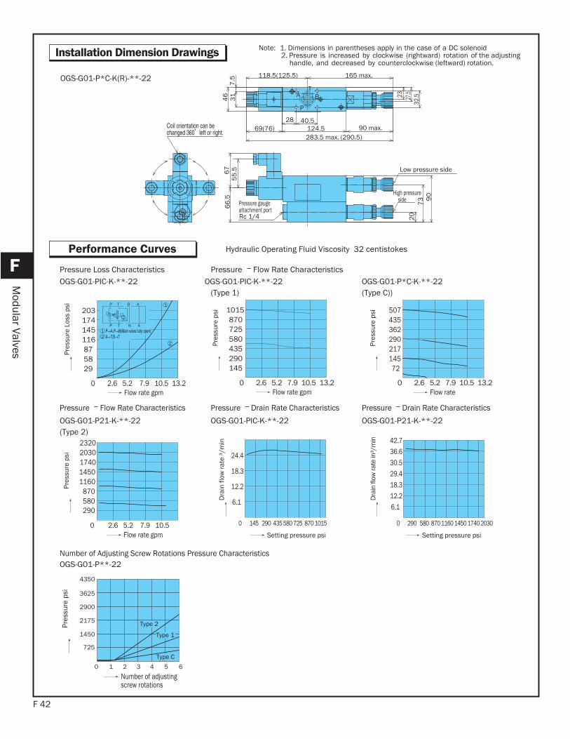
F 42
F
Modular Valves
Installation Dimension Drawings
Performance Curves
P
TBA
Pressure gauge attachment portRc 1/4
High pressure side
Low pressure side
66
.56
75
5.5
32.527
.52346
31
7.5
90
73
20
283.5 max. (290.5)
40.590 max.
165 max.
124.528
118.5(125.5)
69(76)
OGS-G01-P*C-K(R)-**-22
203
295887116145174
TP B A
P T B A
Pres
sure
Los
s ps
i
Flow rate gpm 0 2.6 5.2 7.9 10.5 13.2
12
2
1
Hydraulic Operating Fluid Viscosity 32 centistokes
0 2.6 5.2 7.9 10.5 13.2
870725580435290145
1015
Pres
sure
psi
Flow rate gpm
OGS-G01-PIC-K-**-22 OGS-G01-PIC-K-**-22(Type 1)
507
72145217290362435
Pres
sure
psi
Flow rate
OGS-G01-P*C-K-**-22(Type C))
Pressure Loss Characteristics Pressure Flow Rate Characteristics
0 2.6 5.2 7.9 10.5
23202030174014501160
870580
Pres
sure
psi
Flow rate gpm
6.1
12.2
18.3
24.4
Dra
in fl
ow ra
te ³
/min
Setting pressure psi
OGS-G01-P21-K-**-22(Type 2)
OGS-G01-PIC-K-**-22
6.1
0 290 580 870 1160 1450 1740 2030
12.218.329.430.536.642.7
Dra
in fl
ow ra
te in
³/m
in
Setting pressure psi
OGS-G01-P21-K-**-22
Pressure Flow Rate Characteristics
0 1 2 3 4 5 6
4350
3625
2900
2175
1450
725
Type 2
Type 1
Type C
Pres
sure
psi
Number of adjusting screw rotations
OGS-G01-P**-22 Number of Adjusting Screw Rotations Pressure Characteristics
Pressure Drain Rate Characteristics Pressure Drain Rate Characteristics
Note: 1. Dimensions in parentheses apply in the case of a DC solenoid 2. Pressure is increased by clockwise (rightward) rotation of the adjusting handle, and decreased by counterclockwise (leftward) rotation.
0 145 290 435 580 725 870 1015
290
0 2.6 5.2 7.9 10.5 13.2
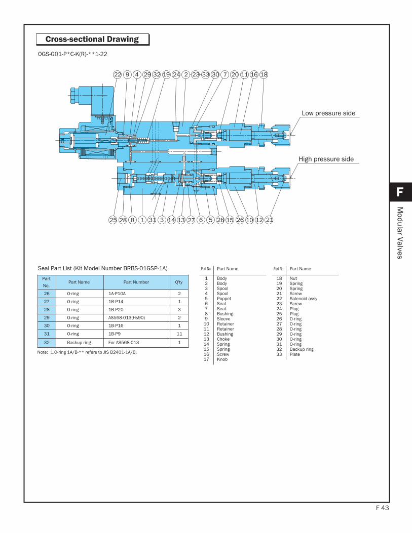
F 43
F
Modular Valves
Cross-sectional Drawing
Low pressure side
13 21121026152856271433118
9 186122 112073033232241932294
25 28
High pressure side
OGS-G01-P*C-K(R)-**1-22
Part
No.Part Name Part Number Q'ty
26 O-ring 1A-P10A 2
27 O-ring 1B-P14 1
28 O-ring 1B-P20 3
29 O-ring AS568-013(Hs90) 2
30 O-ring 1B-P16 1
31 O-ring 1B-P9 11
32 Backup ring For AS568-013 1
Seal Part List (Kit Model Number BRBS-01GSP-1A)
Note: 1.O-ring 1A/B-** refers to JIS B2401-1A/B.
Part No. Part Name
18192021222324252627282930313233
NutSpringSpringScrewSolenoid assyScrewPlugPlugO-ringO-ringO-ringO-ringO-ringO-ringBackup ringPlate
Part No. Part Name
123456789
1011121314151617
BodyBodySpoolSpoolPoppetSeatSeatBushingSleeveRetainerRetainerBushingChokeSpringSpringScrewKnob
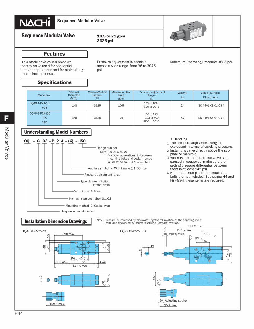
This modular valve is a pressurecontrol valve used for sequentialactuator operations and for maintainingmain circuit pressure.
F 44
Features
F
Modular Valves
Pressure adjustment is possibleacross a wide range, from 36 to 3045 psi.
Maximum Operating Pressure: 3625 psi.
Sequence Modular Valve
Sequence Modular Valve
Specifications
• HandlingThe pressure adjustment range isexpressed in terms of cracking pressure.Install this valve directly above the sub plate or manifold.When two or more of these valves are ganged in sequence, make sure the setting pressure differential between them is at least 145 psi.Note that a sub plate and installationbolts are not included. See pages H4 and F87-89 if these items are required.
1
2
3
10.5 to 21 gpm3625 psi
Understanding Model Numbers
4
Installation Dimension Drawings
Model No.NominalDiameter
(Size)
Maximum WorkingPressure
psi
Maximum FlowRategpm
Pressure AdjustmentRange
psi
Weight
lbs
Gasket Surface
Dimensions
OQ-G01-P21-20
P231/8 3625 10.5
115 to 1000500 to 3045 2.4 ISO 4401-03-02-0-94
OQ-G03-P2A-J50
P2C
P2E
3/8 3625 2136 to 123
123 to 500500 to 2030
7.7 ISO 4401-05-04-0-94
J50–(K)–A 2P–03G–OQ
Pressure adjustment range
Type 2: Internal pilot External drain
Control port P: P port
Nominal diameter (size) 01, 03
Mounting method G: Gasket type
Sequence modular valve
Design numberNote: For 01 size, 20 For 03 size, relationship between mounting bolts and design number is indicated as J50: M6, 50: M8.
Auxiliary symbol K: With handle (01, 03 size)
Note: Pressure is increased by clockwise (rightward) rotation of the adjusting screw(bolt), and decreased by counterclockwise (leftward) rotation.
T
P
A B
90 max.
40.518.580 11.550 max.
141.5 max.
27.5
32
.5
46
20 4
0
5
168.5 max.
7.5
31
PA B
T T
Adjusting stroke
Adjusting stroke
46 70
27.5
55
5454
108157.5 max.
10
237.5 max.
13
5
10
253 max.
OQ-G01-P2*-20 OQ-G03-P2*-J50
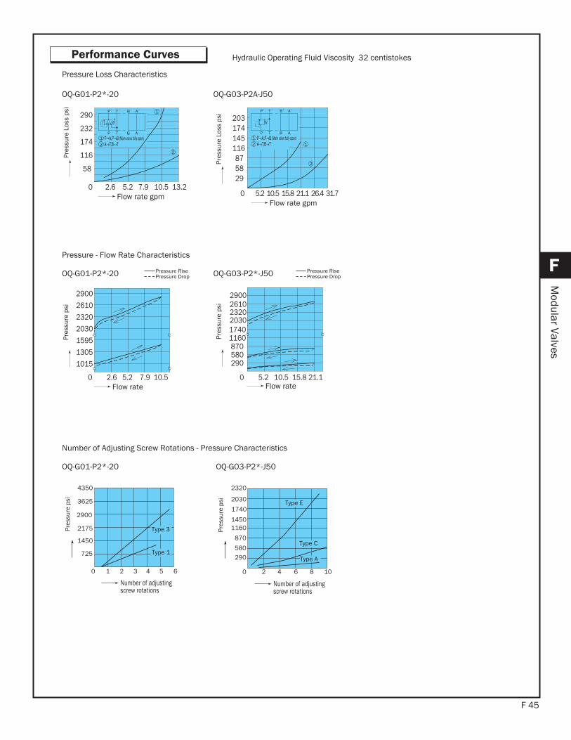
F 45
F
Modular Valves
Performance Curves
0 2.6 5.2 7.9 10.5
2900
1015
1305
1595
2030
2320
2610
Flow rate
Pres
sure
psi
290580
870 11601740
Flow rate
Pres
sure
psi
OQ-G01-P2*-20
Pressure - Flow Rate Characteristics
0 2.6 5.2 7.9 10.5 13.2
58
116
174
232
290
Flow rate gpm
Pres
sure
Los
s ps
i
1 (Main valve fully open)
ABTP
ABP T
2
1
2
Hydraulic Operating Fluid Viscosity 32 centistokes
0 5.2 10.5 15.8 21.1 26.4 31.7
203
295887
116145174
1
ABTP
ABP T
2 1
2
Flow rate gpm
Pres
sure
Los
s ps
i
(Main valve fully open)
OQ-G01-P2*-20 OQ-G03-P2A-J50
Pressure Loss Characteristics
Pressure RisePressure Drop
Number of Adjusting Screw Rotations - Pressure Characteristics
0 1 2 3 4 5 6
Number of adjusting screw rotations
4350
3625
2900
2175
1450
725
Pres
sure
psi
Type 1
Type 3
OQ-G01-P2*-20
0 2 4 6 8 10
2320
2030
1740
14501160
870
580290
Number of adjusting screw rotations
Pres
sure
psi Type E
Type C
Type A
OQ-G03-P2*-J50
OQ-G03-P2*-J50 Pressure RisePressure Drop
2900
203023202610
0 5.2 10.5 15.8 21.1
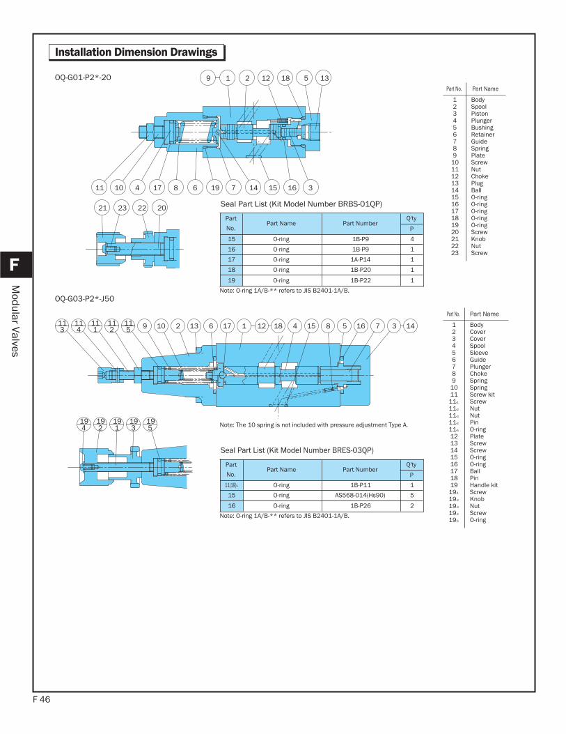
F 46
F
Modular Valves
Installation Dimension Drawings
113
115
111
114 1011
2 132
19 19191919
14371658154181211769
4 5312
OQ-G03-P2*-J50
9 1 2 12 18 5 13
3161514719681741011
21 23 22 20
OQ-G01-P2*-20
Part
No.Part Name Part Number
Q'ty
P
15 O-ring 1B-P9 4
16 O-ring 1B-P9 1
17 O-ring 1A-P14 1
18 O-ring 1B-P20 1
19 O-ring 1B-P22 1
Seal Part List (Kit Model Number BRBS-01QP)
Note: O-ring 1A/B-** refers to JIS B2401-1A/B.
Part
No.Part Name Part Number
Q'ty
P
11(19)-5 O-ring 1B-P11 1
15 O-ring AS568-014(Hs90) 5
16 O-ring 1B-P26 2
Seal Part List (Kit Model Number BRES-03QP)
Note: O-ring 1A/B-** refers to JIS B2401-1A/B.
Note: The 10 spring is not included with pressure adjustment Type A.
Part No. Part Name
123456789
1011121314151617181920212223
BodySpoolPistonPlungerBushingRetainerGuideSpringPlate ScrewNutChokePlugBallO-ringO-ringO-ringO-ringO-ringScrewKnob NutScrew
Part No. Part Name
123456789
101111-1
11-2
11-3
11-4
11-5
121314151617181919-1
19-2
19-3
19-4
19-5
BodyCover Cover SpoolSleeveGuidePlungerChokeSpringSpringScrew kit ScrewNutNutPinO-ringPlate ScrewScrewO-ringO-ringBallPinHandle kit ScrewKnob NutScrewO-ring
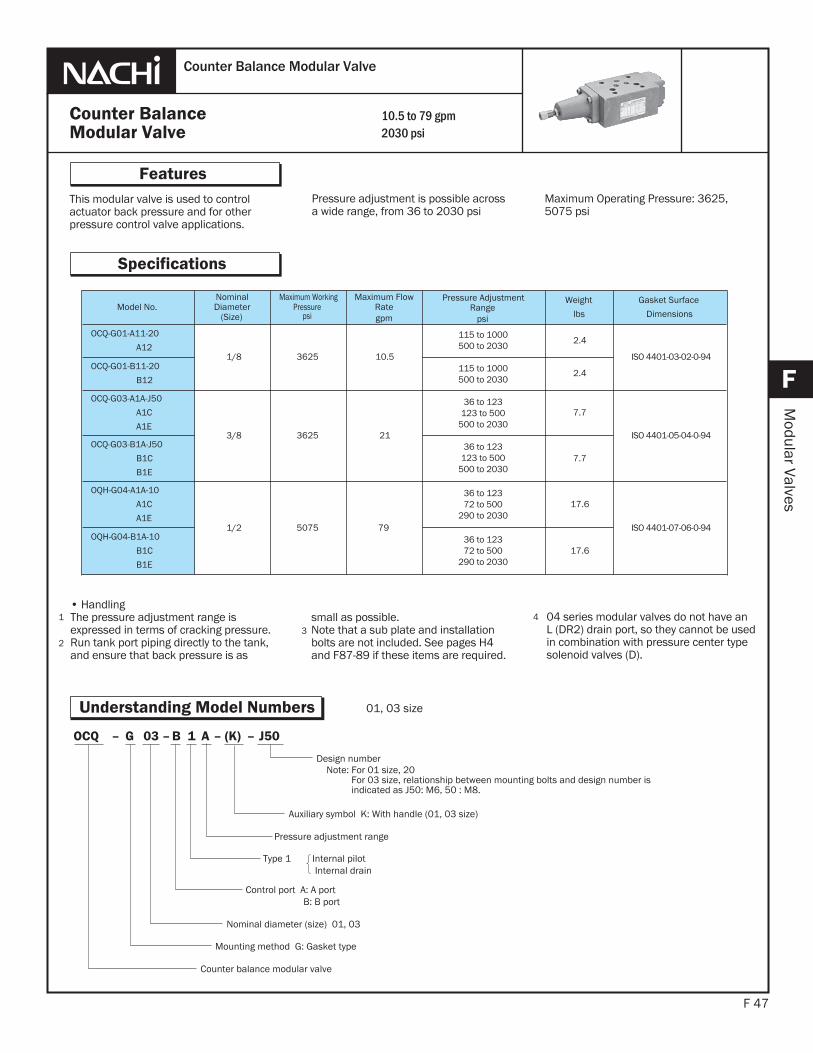
This modular valve is used to controlactuator back pressure and for otherpressure control valve applications.
F 47
Features
F
Modular Valves
Pressure adjustment is possible acrossa wide range, from 36 to 2030 psi
1
23
Counter BalanceModular Valve
Counter Balance Modular Valve
Specifications
4
10.5 to 79 gpm2030 psi
Maximum Operating Pressure: 3625, 5075 psi
Understanding Model Numbers
Model No.NominalDiameter
(Size)
Maximum WorkingPressure
psi
Maximum FlowRategpm
Pressure AdjustmentRange
psi
Weight
lbs
Gasket Surface
Dimensions
OCQ-G01-A11-20
A121/8 3625 10.5
2.4
ISO 4401-03-02-0-94OCQ-G01-B11-20
B122.4
OCQ-G03-A1A-J50
A1C
A1E3/8 3625 21
7.7
ISO 4401-05-04-0-94OCQ-G03-B1A-J50
B1C
B1E
7.7
OQH-G04-A1A-10
A1C
A1E1/2 5075 79
17.6
ISO 4401-07-06-0-94OQH-G04-B1A-10
B1C
B1E
17.6
• HandlingThe pressure adjustment range isexpressed in terms of cracking pressure.Run tank port piping directly to the tank, and ensure that back pressure is as
small as possible.Note that a sub plate and installationbolts are not included. See pages H4 and F87-89 if these items are required.
04 series modular valves do not have an L (DR2) drain port, so they cannot be used in combination with pressure center type solenoid valves (D).
J50–(K)–A1B–03G–OCQ
Pressure adjustment range
Type 1 Internal pilotInternal drain
Control port A: A portB: B port
Nominal diameter (size) 01, 03
Mounting method G: Gasket type
Counter balance modular valve
Design numberNote: For 01 size, 20 For 03 size, relationship between mounting bolts and design number is indicated as J50: M6, 50 : M8.
Auxiliary symbol K: With handle (01, 03 size)
01, 03 size
115 to 1000500 to 2030
115 to 1000500 to 2030
36 to 123123 to 500
500 to 2030
36 to 123123 to 500
500 to 2030
36 to 12372 to 500
290 to 2030
36 to 12372 to 500
290 to 2030
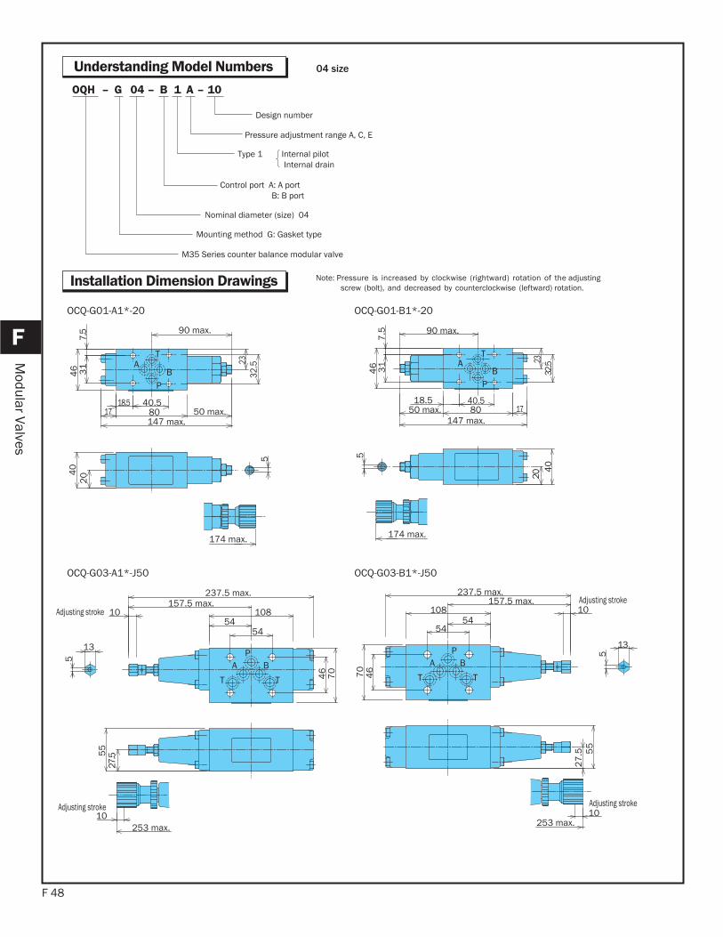
F 48
F
Modular Valves
Understanding Model Numbers
Installation Dimension Drawings
10–A1B–04G–OQH
Pressure adjustment range A, C, E
Control port A: A port B: B port
Nominal diameter (size) 04
Mounting method G: Gasket type
M35 Series counter balance modular valve
Design number
Type 1 Internal pilotInternal drain
04 size
Note: Pressure is increased by clockwise (rightward) rotation of the adjusting screw (bolt), and decreased by counterclockwise (leftward) rotation.
T
P
AB
5
174 max.
90 max.
40.518.517 80 50 max.
147 max.
32.523
31
7.5
46
204
0
T
P
AB
40
20
147 max.50 max. 80 17
90 max.
174 max.
5
2332
.531
7.5
46
18.5 40.5
OCQ-G01-A1*-20 OCQ-G01-B1*-20
PA B
T T
Adjusting stroke
Adjusting stroke
46
70
27.55
5
5454
108157.5 max.
237.5 max.
10
13
5
10253 max.
PA B
TT
Adjusting stroke
Adjusting stroke
70
27
.5
46
55
5454
108157.5 max.
237.5 max.
10
13
5
10253 max.
OCQ-G03-A1*-J50 OCQ-G03-B1*-J50
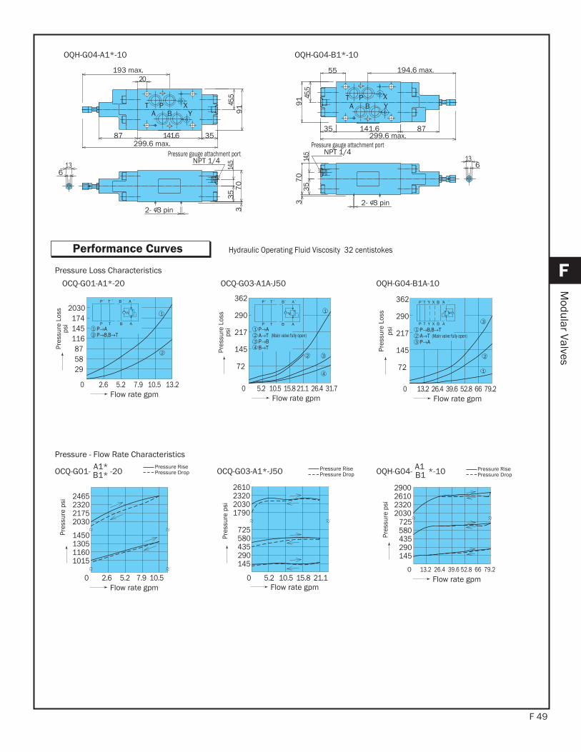
F 49
F
Modular Valves
Performance Curves
B YAXPT
Pressure gauge attachment portNPT 1/4
613
2- 3 pin
70
33
59
114
.5
299.6 max.
45.5
87 141.6 35
193 max.20
OQH-G04-A1*-10
T P XA B Y
Pressure gauge attachment portNPT 1/4
55 194.6 max.
35 141.6 87299.6 max.
45.5
91
14.5
35
70
3 2- 3 pin
136
OQH-G04-B1*-10
0 2.6 5.2 7.9 10.5
2465
1015 116013051450
203021752320
Pres
sure
psi
Flow rate gpm
145
435 580 725
290
1790203023202610
Flow rate gpm
Pressure - Flow Rate Characteristics
Hydraulic Operating Fluid Viscosity 32 centistokes
OCQ-G01-A1*-20 OCQ-G03-A1A-J50 OQH-G04-B1A-10
Pressure Loss Characteristics
OCQ-G01- A1* -20B1*Pressure RisePressure Drop OCQ-G03-A1*-J50 Pressure Rise
Pressure DropPressure RisePressure Drop
2
Pres
sure
Los
sps
i
Flow rate gpm 0 2.6 5.2 7.9 10.5 13.2
2030
295887
116145174
TP B A
P T B A
1
1
2
217
0 5.2 10.5 15.8 21.1 26.4 31.7
72
362
145
290
1
ABTP
ABP T
234
(Main valve fully open)
1
2 3
4
Flow rate gpm 0 13.2 26.4 39.6 52.8 66 79.2
123
2
1
3
(Main valve fully open)
P T Y X B A
P T Y X B A
Flow rate gpm
0 13.2 26.4 39.6 52.8 66 79.2
145290435
580725
2030232026102900
Flow rate gpm
OQH-G04- A1 *-10B1
Pres
sure
psi
Pres
sure
Los
sps
i
Pres
sure
psi
Pres
sure
Los
sps
i
217
72
362
145
290
0 5.2 10.5 15.8 21.1
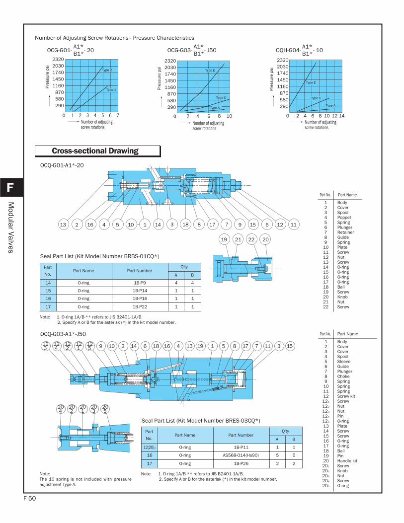
OCG-G01- - 20A1*B1*
F 50
F
Modular Valves
Cross-sectional Drawing
12 3 654 78 9 1101 12514131 16 1718
19 2021 22
OCQ-G01-A1*-20
31 5 511186 18123
125
122
124
121 10 919 416 13 771412
20 202020204 5312
OCQ-G03-A1*-J50
Part
No.Part Name Part Number
Q'ty
A B
14 O-ring 1B-P9 4 4
15 O-ring 1B-P14 1 1
16 O-ring 1B-P16 1 1
17 O-ring 1B-P22 1 1
Seal Part List (Kit Model Number BRBS-01CQ*)
Note: 1. O-ring 1A/B-** refers to JIS B2401-1A/B.2. Specify A or B for the asterisk (*) in the kit model number.
Part No. Part Name
123456789
10111213141516171819202122
BodyCover SpoolPoppet SpringPlungerRetainerGuideSpringPlate ScrewNutScrewO-ringO-ringO-ringO-ringBallScrewKnob NutScrew
Part No. Part Name
123456789
10111212-1
12-2
12-3
12-4
12-5
131415161718192020-1
20-2
20-3
20-4
20-5
BodyCover Cover SpoolSleeveGuidePlungerChokeSpringSpringSpringScrew kit ScrewNutNutPinO-ringPlate ScrewScrewO-ringO-ringBallPinHandle kit ScrewKnob NutScrewO-ring
Part
No.Part Name Part Number
Q'ty
A B
12(20)-5 O-ring 1B-P11 1 1
16 O-ring AS568-014(Hs90) 5 5
17 O-ring 1B-P26 2 2
Seal Part List (Kit Model Number BRES-03CQ*)
Note: 1. O-ring 1A/B-** refers to JIS B2401-1A/B.2. Specify A or B for the asterisk (*) in the kit model number.
Note:The 10 spring is not included with pressureadjustment Type A.
Type 1
Type 2
23202030174014501160
870580290
Pres
sure
psi
Number of adjusting screw rotations
108
Type A
Type C
Type E
Number of adjusting screw rotations
0 2 84 10 126 14
Type A
Type C
Type E
Number of adjusting screw rotations
Number of Adjusting Screw Rotations - Pressure Characteristics
Pres
sure
psi
Pres
sure
psi
OCG-G03- - J50A1*B1*
OQH-G04- - 10A1*B1*
23202030174014501160
870580290
23202030174014501160
870580290

F 51
F
Modular Valves
24143 65 119 712117 8172 20 615251312291324212 0162 8
OQH-G04-B1*-10
Part
No.Part Name Part Number
Q'ty
A B
18 O-ring AS568-012(Hs90) 2 2
19 O-ring 1B-P14 1 1
20 O-ring AS568-118(Hs90) 4 4
21 O-ring 1B-G35 2 2
22 Backup ring T2-P14 1 1
27 O-ring 1B-P11 1 1
Seal Part List (Kit Model Number BRKS-04CQ*)
Note: 1. O-ring 1A/B-** refers to JIS B2401-1A/B.2. Backup ring indicates JIS 2407-T2-**. 3. Specify A or B for the asterisk (*) in the kit model number.
Note: The illustration shows the configurationfor pressure adjustment ranges Type Cand Type E. For Type A, there is no #8 piston or #10 choke.
Part No. Part Name
123456789
101112131415161718192021222324252627
BodyCover Cover SpoolSleeveGuidePlate PlungerChokeChokeSpringSpringScrewPlate NutNutScrewO-ringO-ringO-ringO-ringBackup ringBallPinPinPlugO-ring
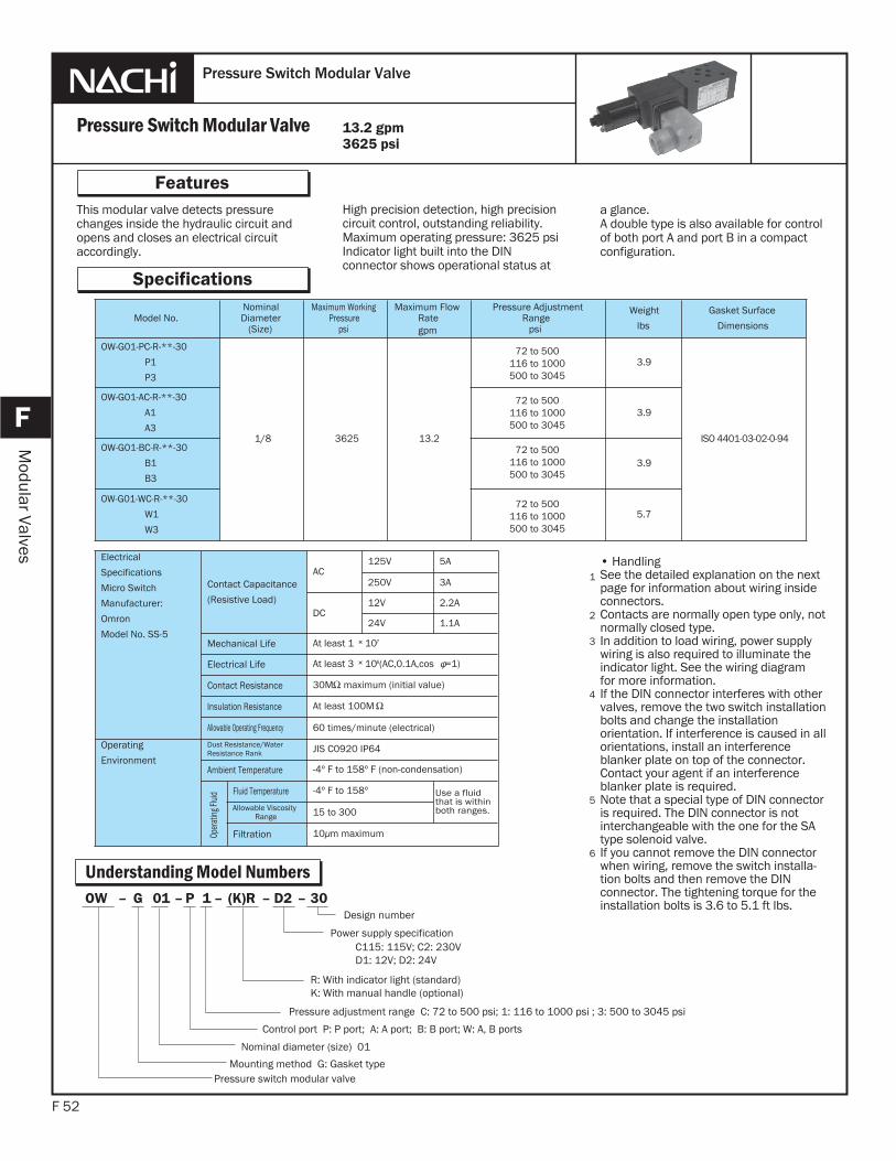
This modular valve detects pressurechanges inside the hydraulic circuit andopens and closes an electrical circuitaccordingly.
F 52
Features
F
Modular Valves
High precision detection, high precisioncircuit control, outstanding reliability.Maximum operating pressure: 3625 psiIndicator light built into the DIN connector shows operational status at
a glance.A double type is also available for controlof both port A and port B in a compactconfiguration.
Pressure Switch Modular Valve
Pressure Switch Modular Valve
Specifications
• HandlingSee the detailed explanation on the nextpage for information about wiring inside connectors.Contacts are normally open type only, not normally closed type.In addition to load wiring, power supplywiring is also required to illuminate theindicator light. See the wiring diagramfor more information.If the DIN connector interferes with other valves, remove the two switch installation bolts and change the installation orientation. If interference is caused in all orientations, install an interference blanker plate on top of the connector. Contact your agent if an interference blanker plate is required.Note that a special type of DIN connectoris required. The DIN connector is not interchangeable with the one for the SA type solenoid valve.If you cannot remove the DIN connectorwhen wiring, remove the switch installa-tion bolts and then remove the DIN connector. The tightening torque for the installation bolts is 3.6 to 5.1 ft lbs.
1
2
3
13.2 gpm3625 psi
Understanding Model Numbers
4
Model No.NominalDiameter
(Size)
Maximum WorkingPressure
psi
Maximum FlowRategpm
Pressure AdjustmentRange
psi
Weight
lbs
Gasket Surface
Dimensions
OW-G01-PC-R-**-30
P1
P3
1/8 3625 13.2
72 to 500116 to 1000500 to 3045
72 to 500116 to 1000500 to 3045
72 to 500116 to 1000500 to 3045
72 to 500116 to 1000500 to 3045
3.9
ISO 4401-03-02-0-94
OW-G01-AC-R-**-30
A1
A3
3.9
OW-G01-BC-R-**-30
B1
B3
3.9
OW-G01-WC-R-**-30
W1
W3
5.7
Power supply specificationC115: 115V; C2: 230VD1: 12V; D2: 24V
R: With indicator light (standard) K: With manual handle (optional)
Control port P: P port; A: A port; B: B port; W: A, B ports
Pressure adjustment range C: 72 to 500 psi; 1: 116 to 1000 psi ; 3: 500 to 3045 psi
Nominal diameter (size) 01
Mounting method G: Gasket typePressure switch modular valve
Design number30–D2–(K)R– 1P–01G–OW
Electrical
Specifications
Micro Switch
Manufacturer:
Omron
Model No. SS-5
Contact Capacitance
(Resistive Load)
AC125V 5A
250V 3A
DC12V 2.2A
24V 1.1A
Mechanical Life At least 1 × 10⁷
Electrical Life At least 3 × 10⁶(AC,0.1A,cos =1)
Contact Resistance 30M maximum (initial value)
Insulation Resistance At least 100M
Allowable Operating Frequency 60 times/minute (electrical)
Operating
Environment
Dust Resistance/WaterResistance Rank JIS C0920 IP64
Ambient Temperature -4º F to 158º F (non-condensation)
Oper
ating
Fluid
Fluid Temperature -4º F to 158º Use a fluidthat is withinboth ranges.Allowable Viscosity
Range 15 to 300
Filtration 10 m maximum
5
6
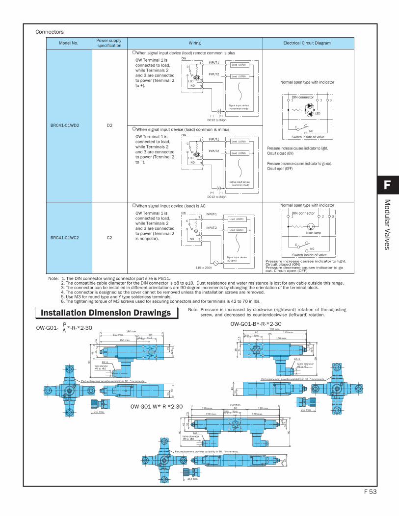
F 53
F
Modular Valves
Installation Dimension Drawings Note: Pressure is increased by clockwise (rightward) rotation of the adjustingscrew, and decreased by counterclockwise (leftward) rotation.
Valve diameter 8 to 10
T
P
A B
110 max.
46
150 max.18.5
31
80
7.5
40.5
217 max.
190 max.
23
32
.52
04
0
PG1199
Part replacement provides variability in 90 ° increments.
5
BA
P
T
Cable diameter 8 to 10
99
110 max.
46
150 max.18.5
31
80
7.5
40.5
190 max.
23
32
.5
PG11
217 max.
20
40
5
Part replacement provides variability in 90 ° increments.
OW-G01- P*-R-*2-30AOW-G01-B*-R-*2-30
BA
P
T
Valve diameter 8 to 10
354 max.
7.5
PG11
23
Part replacement provides variability in 90 ° increments.
5
110 max.
150 max.18.5
8040.5
110 max.
150 max.
300 max.
99
32
.52
0 40
99
46
31
OW-G01-W*-R-*2-30
Model No. Power supplyspecification Wiring Electrical Circuit Diagram
BRC41-01WD2 D2
When signal input device (load) remote common is plus
OW Terminal 1 isconnected to load,while Terminals 2and 3 are connectedto power (Terminal 2to +).
Normal open type with indicator
Pressure increase causes indicator to light.Circuit closed (ON)
Pressure decrease causes indicator to go out. Circuit open (OFF)
When signal input device (load) common is minus
OW Terminal 1 isconnected to load,while Terminals 2and 3 are connectedto power (Terminal 2to ).
BRC41-01WC2 C2
When signal input device (load) is AC
OW Terminal 1 isconnected to load,while Terminals 2and 3 are connectedto power (Terminal 2is nonpolar).
Normal open type with indicator
Pressure increase causes indicator to light.Circuit closed (ON)Pressure decrease causes indicator to goout. Circuit open (OFF)
Connectors
Note: 1. The DIN connector wiring connector port size is PG11. 2. The compatible cable diameter for the DIN connector is Dust resistance and water resistance is lost for any cable outside this range. 3. The connector can be installed in different orientations are 90-degree increments by changing the orientation of the terminal block. 4. The connector is designed so the cover cannot be removed unless the installation screws are removed. 5. Use M3 for round type and Y type solderless terminals. 6. The tightening torque of M3 screws used for securing connectors and for terminals is 42 to 70 in lbs.
Load (LOAD)
Load (LOAD)
Signal input device(+) common mode
OWINPUT-11
2
DC12 to 24(V)
C
3NOLED
INPUT-2
(–) (+)
Load (LOAD)
Load (LOAD)
Signal input device(–) common mode
OWINPUT-11
2
DC12 to 24(V)
C
3NOLED
INPUT-2
(+) (–)
Switch inside of valve
DIN connector
CNO
LED
1 2 3
Load (LOAD)
Load (LOAD)
Signal input device(AC spec)
OW INPUT-11
2
115 to 230V
C
3NO
INPUT-2
Switch inside of valve
DIN connector
CNO
Neon lamp
1 2 3
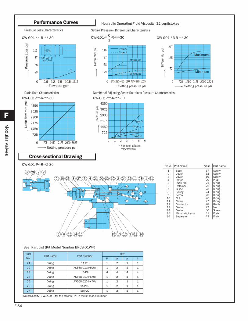
F 54
F
Modular Valves
Performance Curves
Flow rate gpm 0 2.6 5.2 7.9 10.5 13.2
29
58
87
116
Pres
sure
Los
s ps
i
Setting pressure psi 0 145 290 435 580 725 870 1015
Type CType 1
Diff
eren
tial p
si
Maximum
Minimum
OW-G01-**-R-**-30 OW-G01-* C -R-**-301
OW-G01-**-R-**-30 OW-G01-**-R-**-30
Pressure Loss Characteristics Setting Pressure - Differential Characteristics
Drain Rate Characteristics Number of Adjusting Screw Rotations Pressure Characteristics
0 725 1450 2175 2900 3625
72
145
217
Diff
eren
tial p
si
Maximum
Minimum
OW-G01-*3-R-**-30
Dra
in fl
ow ra
te p
si
725 1450 2175 2900 3625 0
725
Setting pressure psi
1450
2175
2900
3625
4350
0 1 2 3 4 5 6
Number of adjusting screw rotations
Pres
sure
psi
Type 1
Type 3
Type C
14255 126
9 27 324262 22
30
1112
1615 13 17
9
3
0201 4 2 17
18
8
28 29
3132 19
OW-G01-P*-R-*2-30
Part
No.Part Name Part Number
Q'ty
P W A B
21 O-ring 1A-P3 1 2 1 1
22 O-ring AS568-011(Hs90) 1 2 1 1
23 O-ring 1B-P9 4 4 4 4
24 O-ring AS568-019(Hs70) 1 2 1 1
25 O-ring AS568-022(Hs70) 1 2 1 1
26 O-ring 1A-P15 1 2 1 1
27 O-ring 1B-P22 1 2 1 1
Seal Part List (Kit Model Number BRCS-01W*)
Note: Specify P, W, A, or B for the asterisk (*) in the kit model number.
Part No. Part Name Part No. Part Name
123456789
10111213141516
BodyCoverCover PistonPush rodRetainerGuideSpringScrewNutChokeConnector GasketGasketMicro switch assySeparator
17181920212223242526272829303132
ScrewScrewScrewPlugO-ringO-ringO-ringO-ringO-ringO-ringO-ringKnobNutScrewPlatePlate
Cross-sectional Drawing
Hydraulic Operating Fluid Viscosity 32 centistokes
Setting pressure psi
29
58
87
116
725
1450
2175
2900
3625
4350
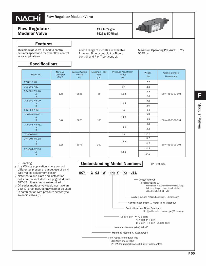
This modular valve is used to controlactuator speed and for other flow controlvalve applications.
F 55
Features
F
Modular Valves
A wide range of models are availablefor A and B port control, A or B portcontrol, and P or T port control.
1
2
Flow RegulatorModular Valve
Flow Regulator Modular Valve
Specifications
13.2 to 79 gpm3625 to 5075 psi
Maximum Operating Pressure: 3625, 5075 psi
Understanding Model Numbers• HandlingIn a 03 size application where controldifferential pressure is large, use of an H type makes adjustment easier.Note that a sub plate and installationbolts are not included. See pages H4 and F87-89 if these items are required.04 series modular valves do not have an L (DR2) drain port, so they cannot be used in combination with pressure center type solenoid valves (D).
Model No.NominalDiameter
(Size)
Maximum WorkingPressure
psi
Maximum FlowRategpm
Pressure AdjustmentRange
psi
Weight
lbs
Gasket Surface
Dimensions
OY-G01-T-20
1/8 3625 50
2.2
ISO 4401-03-02-0-94
OCY-G01-P-20 5.7 2.2
OCY-G01-W-X-20AB
11.42.8
2.6
OCY-G01-W-Y-20AB
11.42.8
2.6
OCY-G03-P-J50
3/8 3625 100
5.7 6.4
ISO 4401-05-04-0-94
OCY-G03-W-X-J51AB
14.36.8
6.6
OCY-G03-W-Y-J51AB
14.36.8
6.6
OYH-G04-P-10
1/2 5075 300
5.7 10.3
ISO 4401-07-06-0-94
OYH-G04-W-X-10AB
14.314.3
14.3
OYH-G04-W-Y-10AB
14.314.3
14.3
3
J51–(K)–Y (H)–W–03G–OCY
Control mechanism X: Meter-in Y: Meter-out
Control function None: Standard H: High-differential pressure type (03 size only)
Nominal diameter (size) 01, 03
Mounting method G: Gasket type
Flow regulator modular typeOCY: With check valveOY : Without check valve (01 size T port control)
Design numberNote: For 01 size, 20 For 03 size, relationship between mounting bolts and design number is indicated as J50, J51: M6, 50, 51 : M8.
Auxiliary symbol K: With handle (01, 03 size only)
Control port W: A, B ports A: A port P: P portB: B port T: T port (01 size only)
01, 03 size
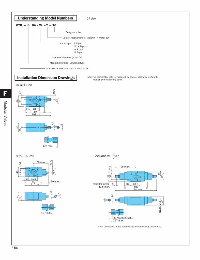
F 56
F
Modular Valves
Understanding Model Numbers
Installation Dimension Drawings
10–Y–W–04G–OYH
Control mechanism X: Meter-in Y: Meter-out
Control port P: P port W: A, B portsA: A portB: B port
Nominal diameter (size) 04
Mounting method G: Gasket type
M35 Series flow regulator modular valve
Design number
04 size
Note: The control flow rate is increased by counter clockwise (leftward)rotation of the adjusting screw.
T
P
A B
204
03
17
.54
6
107 max.80
40.518.5
32.5
16
.5
134 max.
513
OY-G01-T-20
T
P
A B
137 max.
18.5 40.580
46
7.5
31
40
20
27
.532
.5
110 max.30 max.
70 max.
513
T
P
AB
Adjusting stroke
Adjusting stroke227 max.
(15.
5)
24.
5 40
2332
.5
31
7.5
46
40.53210741.5 max.
190 max.
95 max.
6
6
5
13
OCY-G01-P-20 OCY-G01-W- X -20Y
Note: Dimensions in the parentheses are for the OCY-G01-W-X-20.
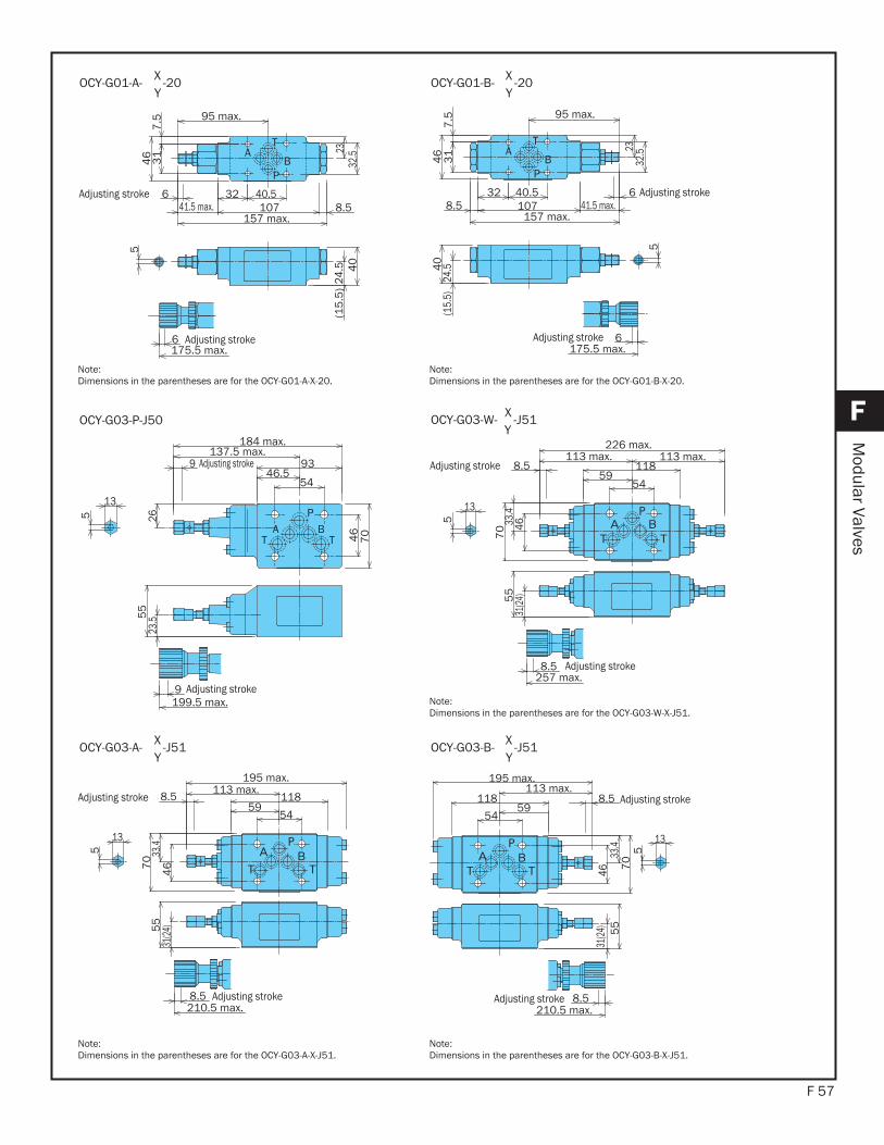
F 57
F
Modular Valves
T
P
AB
Adjusting stroke
Adjusting stroke(1
5.5
) 24
.5175.5 max.
32 40.5107 8.541.5 max.
157 max.
95 max.
2332
.5
31
7.5
46
40
6
5
6
OCY-G01-A- X -20Y
Note:Dimensions in the parentheses are for the OCY-G01-A-X-20.
T
P
AB
Adjusting stroke
Adjusting stroke
5
6
40
(15.
5)
24.
5
95 max.
41.5 max.157 max.
8.5
175.5 max.
107
2332
.5
31
7.5
46
40.532
6
OCY-G01-B- X -20Y
Note:Dimensions in the parentheses are for the OCY-G01-B-X-20.
PBA
TT
Adjusting stroke
Adjusting stroke9199.5 max.
13
5 2623
.555
46
70
5446.5
93137.5 max.
184 max.
9
OCY-G03-P-J50
Adjusting stroke
Adjusting stroke
8.5257 max.
5
13
5459
118113 max.113 max.
226 max.
8.5
4633.4
70
55
31(24
)
OCY-G03-W- X -J51Y
Note:Dimensions in the parentheses are for the OCY-G03-W-X-J51.
Adjusting stroke
Adjusting stroke
13
5
210.5 max.8.5
31(24
)55
33.4
46
59118
54
113 max.8.5
70
195 max.
OCY-G03-A- X -J51Y
Note:Dimensions in the parentheses are for the OCY-G03-A-X-J51.
Adjusting stroke
Adjusting stroke
13
5
210.5 max.8.5
31(24
)5
533
.446
59
113 max.118
54
8.5
70
195 max.
OCY-G03-B- X -J51Y
Note:Dimensions in the parentheses are for the OCY-G03-B-X-J51.
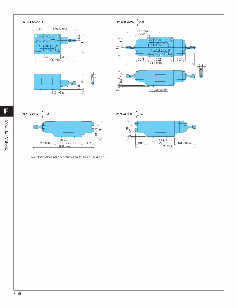
F 58
F
Modular Valves
APT
B
X
Y
136
2- 3 pin
120 34190 max.
9.2 130.8 max.
30.5
91
287
03
OYH-G04-P-10
YBAXPT
136
2- 3 pin
43
(27
)7
03
48
91
66.5157 max.
55.3 122 55.7314 max.
OYH-G04-W- X -10Y
43(2
7) 70
32- 3 pin51.212295.8 max.
269 max.
OYH-G04-A- X -10Y
Note: Dimensions in the parentheses are for the OYH-G04-*-X-10.
43(2
7)70
3
50.8 122 96.2 max.269 max.
2- 3 pin
OYH-G04-B- X -10Y
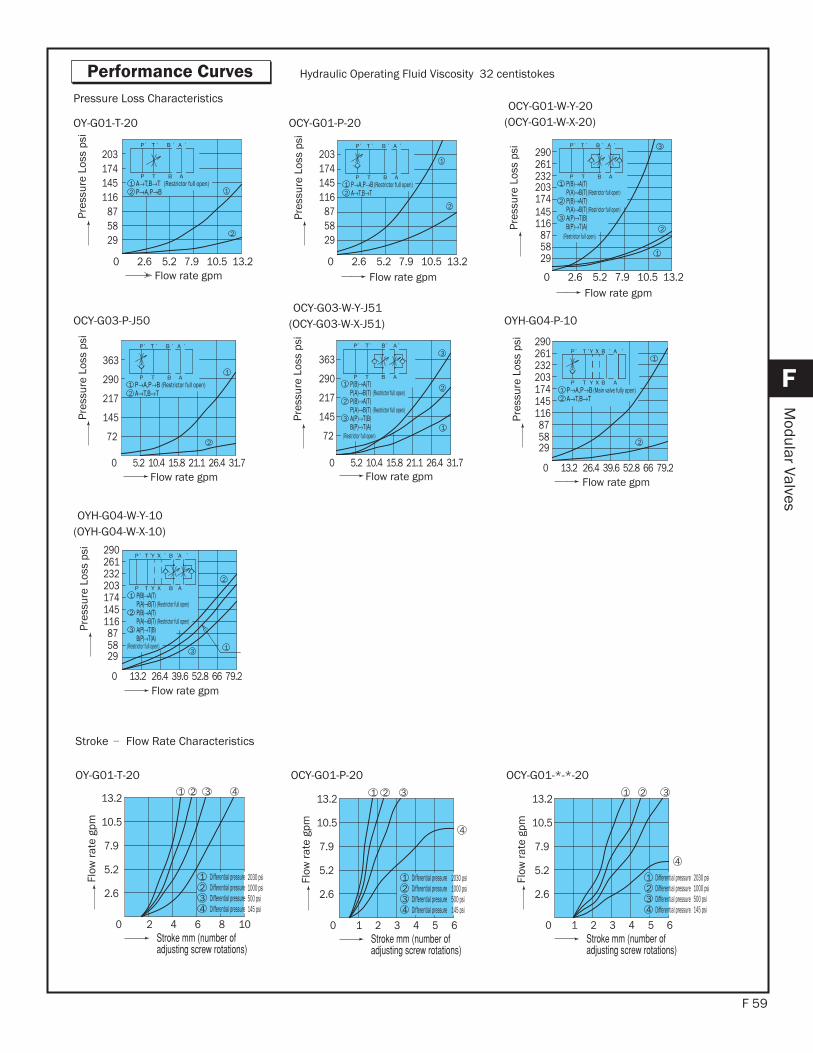
F 59
F
Modular Valves
Hydraulic Operating Fluid Viscosity 32 centistokes
OY-G01-T-20 OCY-G01-P-20OCY-G01-W-Y-20
(OCY-G01-W-X-20)
Pressure Loss Characteristics
2
0 2.6 5.2 7.9 10.5 13.2
203
295887
116145174
TP B A
P T B A
(Restrictor full open)11
2
Pres
sure
Los
s ps
i
Flow rate gpm
2
TP B A
P T B A
(Restrictor full open)1
1
2
Pres
sure
Los
s ps
i
Flow rate gpm
232
(Restrictor full open)
261TP B A
P T B A
(Restrictor full open)1
290
2(Restrictor full open)
3
3
1
2Pres
sure
Los
s ps
i
Flow rate gpm
OCY-G03-P-J50OCY-G03-W-Y-J51
(OCY-G03-W-X-J51) OYH-G04-P-10
2
217
145
290
72
3631
2
TP B A
P T B A
(Restrictor full open)1
0 5.2 10.4 15.8 21.1 26.4 31.7
Pres
sure
Los
s ps
i
Flow rate gpm
1(Restrictor full open)
ABTP
ABP T
(Restrictor full open)
(Restrictor full open)3
2
3
2
1
Pres
sure
Los
s ps
i
Flow rate gpm
174145116
203
1
2
1 (Main valve fully open)2
290261232
875829
0 13.2 26.4 39.6 52.8 66 79.2
P T Y X B A
P T Y X B A
Pres
sure
Los
s ps
i
Flow rate gpm
OYH-G04-W-Y-10(OYH-G04-W-X-10)
(Restrictor full open)
3
1
2
(Restrictor full open)
(Restrictor full open)3
2
P T Y X B A
P T Y X B A
1
Pres
sure
Los
s ps
i
Flow rate gpm
Performance Curves
OY-G01-T-20 OCY-G01-P-20 OCY-G01-*-*-20
Stroke -- Flow Rate Characteristics
0
10.5
4 Differential pressure3 Differential pressure2 Differential pressure
4
Differential pressure
10
5.2
7.9
13.2
2.6
2 4 6 8
1
1 2 3
Flow
rate
gpm
54321
321
1
6
4
234
0Differential pressureDifferential pressureDifferential pressureDifferential pressureFl
ow ra
te g
pm
32 5 0432
4
641
1
1 2 3
Differential pressureDifferential pressureDifferential pressureDifferential pressureFl
ow ra
te g
pm
203
295887
116145174
0 2.6 5.2 7.9 10.5 13.2 0 2.6 5.2 7.9 10.5 13.2
203
295887
116145174
0 5.2 10.4 15.8 21.1 26.4 31.7
217
145
290
72
363
174145116
203
290261232
875829
0 13.2 26.4 39.6 52.8 66 79.2
10.5
5.2
7.9
13.2
2.6
10.5
5.2
7.9
13.2
2.6
2030 psi1000 psi500 psi145 psi
2030 psi1000 psi500 psi145 psi
2030 psi1000 psi500 psi145 psi
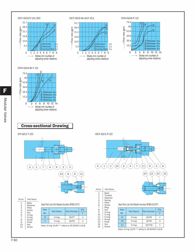
F 60
F
Modular Valves
OCY-G03-P-(H)-J50 OCY-G03-W-(H)Y-J51 OYH-G04-P-10
1 83 0 42 5 976
1
3 2
1
23 H type: Pressure differential
Differential pressureDifferential pressure
Flow
rate
gpm
80 1 3 42 5 976
2
3
1
21
3 H type: Pressure differentialDifferential pressureDifferential pressure
Flow
rate
gpm
Flow
rate
gpm
OYH-G04-W-Y-10
Flow
rate
gpm
1 23 4 57 6
11910 8
OY-G01-T-20
15131214
8391174610215
OCY-G01-P-20
Part
No.Part Name Part Number
Q'ty
T
6 O-ring 1B-P7 1
7 O-ring 1B-P9 4
Seal Part List (Kit Model Number BFBS-01YT)
Note: O-ring 1A/B-** refers to JIS B2401-1A/B.
Part
No.Part Name Part Number
Q'ty
T
9 O-ring 1B-P8 1
10 O-ring 1B-P9 4
11 O-ring 1B-P18 1
Seal Part List (Kit Model Number BFBS-01CYP)
Note: O-ring 1A/B-** refers to JIS B2401-1A/B.
Part No. Part Name
123456789
101112131415
BodyThrottle RetainerSpringPlate ScrewRingNutO-ringO-ringO-ringScrewKnob NutScrew
Part No. Part Name
123456789
1011
BodyRetainerPlate ScrewNutO-ringO-ringScrewKnob NutScrew
Cross-sectional Drawing
2030 psi1000 psi500 psi145 psi
2030 psi1000 psi500 psi145 psi
145 psi217 psi725 psi
145 psi217 psi725 psi
79.2
66
52.8
39.6
26.4
13.2
79.2
66
52.8
39.6
26.4
13.2
31.7
26.4
21.1
15.8
10.5
5.2
31.7
26.4
21.1
15.8
10.5
5.2
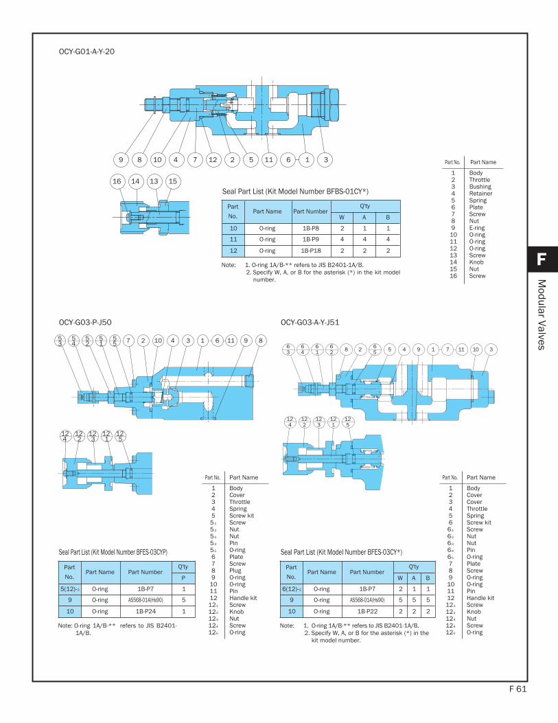
F 61
F
Modular Valves14 891127 10 35
352
54
55
51 6
124
123
122
125
121
OCY-G03-P-J50
18 4 01563
65
61
64
62 9 7 3112
124
125
121
123
122
OCY-G03-A-Y-J51
4 2 11 1 312 5 6789 10
14 1516 13
OCY-G01-A-Y-20
Part
No.Part Name Part Number
Q'ty
W A B
10 O-ring 1B-P8 2 1 1
11 O-ring 1B-P9 4 4 4
12 O-ring 1B-P18 2 2 2
Seal Part List (Kit Model Number BFBS-01CY*)
Note: 1. O-ring 1A/B-** refers to JIS B2401-1A/B.2. Specify W, A, or B for the asterisk (*) in the kit model
number.
Part
No.Part Name Part Number
Q'ty
P
5(12)-5 O-ring 1B-P7 1
9 O-ring AS568-014(Hs90) 5
10 O-ring 1B-P24 1
Seal Part List (Kit Model Number BFES-03CYP)
Note: O-ring 1A/B-** refers to JIS B2401-1A/B.
Part
No.Part Name Part Number
Q'ty
W A B
6(12)-5 O-ring 1B-P7 2 1 1
9 O-ring AS568-014(Hs90) 5 5 5
10 O-ring 1B-P22 2 2 2
Seal Part List (Kit Model Number BFES-03CY*)
Note: 1. O-ring 1A/B-** refers to JIS B2401-1A/B.2. Specify W, A, or B for the asterisk (*) in the
kit model number.
Part No. Part Name
123456789
10111213141516
BodyThrottle BushingRetainerSpringPlate ScrewNutE-ringO-ringO-ringO-ringScrewKnob NutScrew
Part No. Part Name
123455-1
5-2
5-3
5-4
5-5
6789
10111212-1
12-2
12-3
12-4
12-5
BodyCover Throttle SpringScrew kit ScrewNutNutPinO-ringPlate ScrewPlugO-ringO-ringPinHandle kit ScrewKnob NutScrewO-ring
Part No. Part Name
1234566-1
6-2
6-3
6-4
6-5
789
10111212-1
12-2
12-3
12-4
12-5
BodyCover Cover Throttle SpringScrew kit ScrewNutNutPinO-ringPlate ScrewO-ringO-ringPinHandle kit ScrewKnob NutScrewO-ring
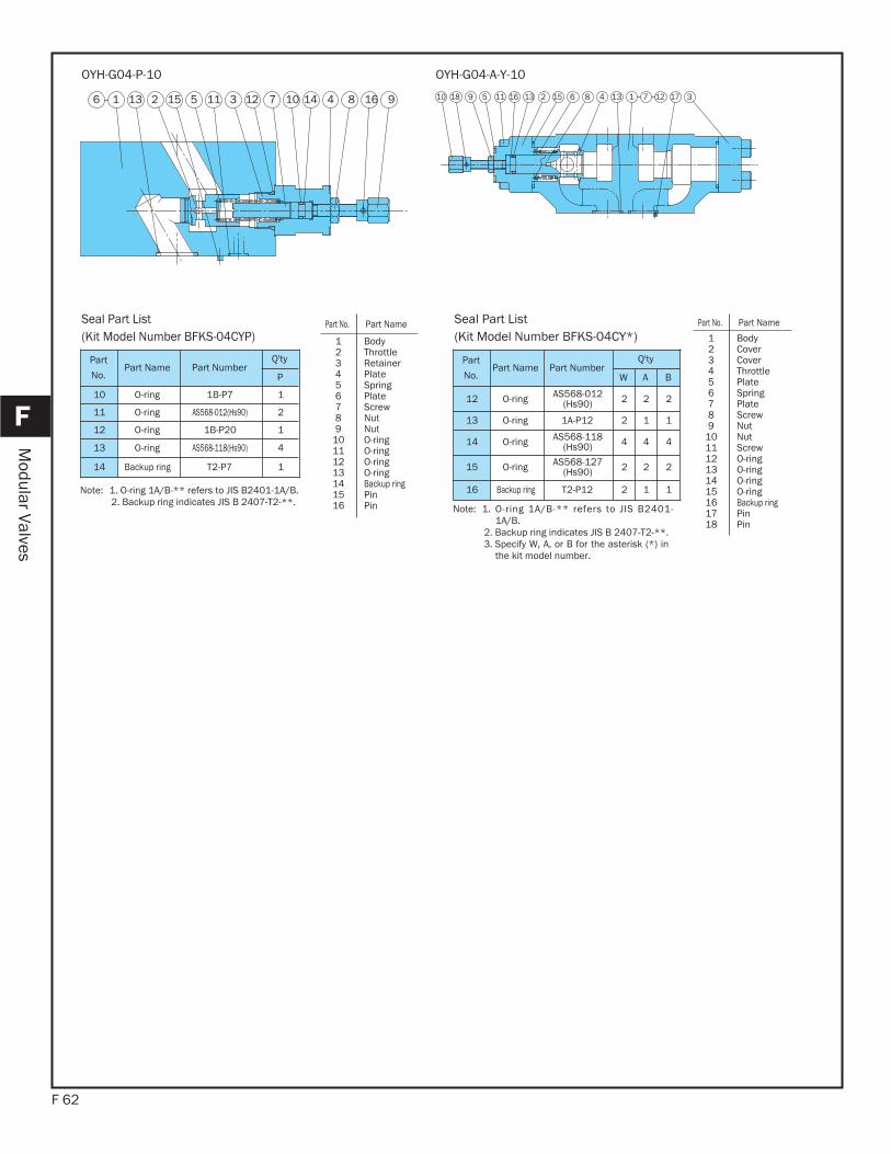
F 62
F
Modular Valves
13 2116 2 5 3 7 10 8 16 914 415 11
OYH-G04-P-10
72 46 8 1910 11 13 13151618 35 12 17
OYH-G04-A-Y-10
Part
No.Part Name Part Number
Q'ty
P
10 O-ring 1B-P7 1
11 O-ring AS568-012(Hs90) 2
12 O-ring 1B-P20 1
13 O-ring AS568-118(Hs90) 4
14 Backup ring T2-P7 1
Seal Part List(Kit Model Number BFKS-04CYP)
Note: 1. O-ring 1A/B-** refers to JIS B2401-1A/B.2. Backup ring indicates JIS B 2407-T2-**.
Part
No.Part Name Part Number
Q'ty
W A B
12 O-ring AS568-012(Hs90) 2 2 2
13 O-ring 1A-P12 2 1 1
14 O-ring AS568-118(Hs90) 4 4 4
15 O-ring AS568-127(Hs90) 2 2 2
16 Backup ring T2-P12 2 1 1
Seal Part List(Kit Model Number BFKS-04CY*)
Note: 1. O-ring 1A/B-** refers to JIS B2401-1A/B.
2. Backup ring indicates JIS B 2407-T2-**. 3. Specify W, A, or B for the asterisk (*) in
the kit model number.
Part No. Part Name
123456789
10111213141516
BodyThrottle RetainerPlate SpringPlate ScrewNutNutO-ringO-ringO-ringO-ringBackup ringPinPin
Part No. Part Name
123456789
101112131415161718
BodyCover Cover Throttle Plate SpringPlate ScrewNutNutScrewO-ringO-ringO-ringO-ringBackup ringPinPin
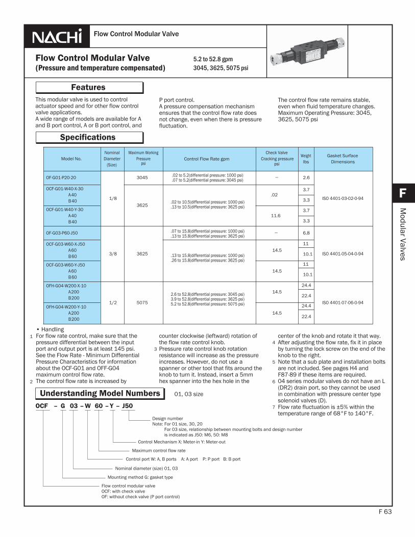
This modular valve is used to controlactuator speed and for other flow controlvalve applications.A wide range of models are available for Aand B port control, A or B port control, and
F 63
Features
F
Modular Valves
P port control.A pressure compensation mechanismensures that the control flow rate doesnot change, even when there is pressurefluctuation.
1
2
Flow Control Modular Valve(Pressure and temperature compensated)
Flow Control Modular Valve
Specifications
5.2 to 52.8 gpm3045, 3625, 5075 psi
The control flow rate remains stable,even when fluid temperature changes.Maximum Operating Pressure: 3045, 3625, 5075 psi
Understanding Model Numbers
• HandlingFor flow rate control, make sure that the pressure differential between the input port and output port is at least 145 psi. See the Flow Rate - Minimum Differential Pressure Characteristics for information about the OCF-G01 and OFF-G04maximum control flow rate.The control flow rate is increased by
3
Model No.NominalDiameter
(Size)
Maximum WorkingPressure
psiControl Flow Rate gpm
Check ValveCracking pressure
psi
Weightlbs
Gasket SurfaceDimensions
OF-G01-P20-20
1/8
3045 .02 to 5.2(differential pressure: 1000 psi).07 to 5.2(differential pressure: 3045 psi)
.02 to 10.5(differential pressure: 1000 psi)
.13 to 10.5(differential pressure: 3625 psi)
.07 to 15.8(differential pressure: 1000 psi)
.13 to 15.8(differential pressure: 3625 psi)
.13 to 15.8(differential pressure: 1000 psi)
.26 to 15.8(differential pressure: 3625 psi)
2.6 to 52.8(differential pressure: 3045 psi)3.9 to 52.8(differential pressure: 3625 psi)5.2 to 52.8(differential pressure: 5075 psi)
-- 2.6
ISO 4401-03-02-0-94
OCF-G01-W40-X-30A40B40
3625
.023.7
3.3
OCF-G01-W40-Y-30A40B40
11.63.7
3.3
OF-G03-P60-J50
3/8 3625
-- 6.8
ISO 4401-05-04-0-94
OCF-G03-W60-X-J50A60B60
14.511
10.1
OCF-G03-W60-Y-J50A60B60
14.511
10.1
OFH-G04-W200-X-10A200B200
1/2 5075
14.524.4
ISO 4401-07-06-0-9422.4
OFH-G04-W200-Y-10A200B200
14.5
24.4
22.4
counter clockwise (leftward) rotation of the flow rate control knob.Pressure rate control knob rotation resistance will increase as the pressure increases. However, do not use a spanner or other tool that fits around the knob to turn it. Instead, insert a 5mm hex spanner into the hex hole in the
center of the knob and rotate it that way.After adjusting the flow rate, fix it in place by turning the lock screw on the end of the knob to the right.Note that a sub plate and installation bolts are not included. See pages H4 and F87-89 if these items are required.04 series modular valves do not have an L(DR2) drain port, so they cannot be used in combination with pressure center type solenoid valves (D).Flow rate fluctuation is ±5% within the temperature range of 68°F to 140°F.
4
5
7
6
J50–Y–60W–03G–OCF
01, 03 size
Design numberNote: For 01 size, 30, 20 For 03 size, relationship between mounting bolts and design number is indicated as J50: M6, 50: M8
Control Mechanism X: Meter-in Y: Meter-out
Maximum control flow rate
Control port W: A, B ports A: A port P: P port B: B port
Nominal diameter (size) 01, 03
Mounting method G: gasket type
Flow control modular valveOCF: with check valveOF: without check valve (P port control)
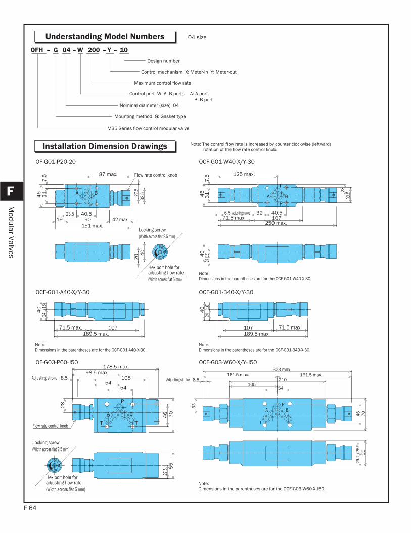
F 64
F
Modular Valves
10– Y–200W–04G–OFH
Control mechanism X: Meter-in Y: Meter-out
Maximum control flow rate
Control port W: A, B ports A: A portB: B port
Nominal diameter (size) 04
Mounting method G: Gasket type
M35 Series flow control modular valve
Design number
04 size
Note: The control flow rate is increased by counter clockwise (leftward)rotation of the flow rate control knob.
T
P
A B31
7.5
46 27
.532
.5
87 max.
40.523.519 90 42 max.
Locking screw (Width across flat 2.5 mm)
Flow rate control knob
Hex bolt hole for adjusting flow rate (Width across flat 5 mm)
151 max.
20 4
0
B
T
PA
Adjusting stroke
2332
.5
31
7.5
46
125 max.
40.53271.5 max. 107
250 max.
6.524
(16)40
OF-G01-P20-20 OCF-G01-W40-X/Y-30
24 (
16)
40
10771.5 max.189.5 max.
24 (
16)
189.5 max.71.5 max.107
40
OCF-G01-A40-X/Y-30 OCF-G01-B40-X/Y-30
P
A B
T T
Adjusting stroke
Locking screw (Width across flat 2.5 mm)
Flow rate control knob
Hex bolt hole for adjusting flow rate (Width across flat 5 mm)
28
46 70
5454
10898.5 max.
178.5 max.
8.5
27.5 5
5
PA B
T T
Adjusting stroke
54105
210161.5 max. 161.5 max.
323 max.
8.5
46
70
33
29.1
(25
.9)
55
OF-G03-P60-J50 OCF-G03-W60-X/Y-J50
Note:Dimensions in the parentheses are for the OCF-G01-A40-X-30.
Note:Dimensions in the parentheses are for the OCF-G03-W60-X-J50.
Note:Dimensions in the parentheses are for the OCF-G01-B40-X-30.
Note:Dimensions in the parentheses are for the OCF-G01-W40-X-30.
Understanding Model Numbers
Installation Dimension Drawings

F 65
F
Modular Valves
Hydraulic Operating Fluid Viscosity 32 centistokes
Pressure Loss Characteristics
PA B
T T
Adjusting stroke
Flow rate control knob
33
8.5 210105
161.5 max.
54
279.5 max.
46
70
29.1
(25.9)
55
PA B
T T
Adjusting stroke
55
54
279.5 max.161.5 max.
105210 8.5
70
46
33
29.1
(25.9)
OCF-G03-A60-X/Y-J50 OCF-G03-B60-X/Y-J50
PA
TB
XY
11.2193 max.
95.3 122 95.7
Locking screw (Width across flat 2.5 mm)
Hex bolt hole for adjusting flow rate (Width across flat 5 mm)
Flow rate control knob
48
91
51 (
34)
85
3
386 max.
2-3 pin
2-3 pin122 112.2131.8 max.366 max.
51 (
34)
85
3
51 (
34)
2-3 pin
366 max.
85
3
122 132.2 max.111.8
OFH-G04-W200-X/Y-10 OFH-G04-A200-X/Y-10
Note:Dimensions in the parentheses are for the OCF-G03-A60-X-J50.
Note:Dimensions in the parentheses are for the OCF-G03-B60-X-J50.
Note:Dimensions in the parentheses are for the OFH-G04-W200-X-10.
OF-G01-P20-20 OCF-G01-A40-Y-30 OF-G03-P60-J50
203
295887
116145174
Pres
sure
Los
s ps
i
Flow rate gpm 0 1.3 2.6 3.9 5.2 6.6 7.9 9.2
0 2.6 5.2 7.9 10.4 13.2
Pres
sure
Los
s ps
i
Flow rate gpm 0
217
145
72
5.2 10.4 15.8 21.1 26.4 31.7
Pres
sure
Los
s ps
i
Flow rate gpm
OCF-G03-W60-Y-J50 OFH-G04-W200-Y-10 OF-G01-P20-20
2{5.2
1{5.1
5{5.0
40 80 0
1.0
2.0
10060 12020
3.0
Pres
sure
Los
s ps
i
Flow rate gpm 30050 200 0 250150100
3.62.3
4.0
2.82.4
0.26.1
1.28.0
0.4
Pres
sure
Los
s ps
i
Flow rate gpm 5 1510 0
20
15
25
20
10
5
25
Flow
rate
gpm
30
30Pressure psi
Pressure - Control Flow Rate Characteristics
Note:Dimensions in the parentheses are for the OFH-G04-B200-X-10.
Note:Dimensions in the parentheses are for the OCF-G04-A200-X-10
OFH-G04-B200-X/Y-10
Performance Curves
203
295887
116145174
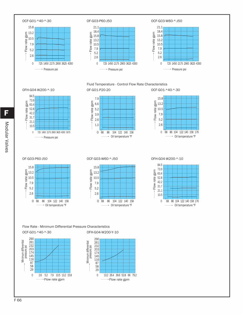
F 66
F
Modular Valves
OCF-G01-*40-*-30 OF-G03-P60-J50 OCF-G03-W60-*-J50
0 725 1450 2175 2900 3625 4350
10.5
7.9
13.2
5.2
2.6
15.8Fl
ow ra
te g
pm
Pressure psi
21.118.415.813.210.57.95.22.6
Flow
rate
gpm
Pressure psi
Flow
rate
gpm
Pressure psi
OFH-G04-W200-*-10 OF-G01-P20-20 OCF-G01-*40-*-30
10.521.131.742.252.863.473.984.5
Flow
rate
gpm
Pressure psi
68 86 104 122 140 158 0
5.2
3.9
6.6
7.9
2.6
1.3
Flow
rate
gpm
13.2
7.9
2.6
15.8
5.2
10.5
Flow
rate
gpm
Fluid Temperature - Control Flow Rate Characteristics
OF-G03-P60-J50 OCF-G03-W60-*-J50 OFH-G04-W200-*-10
Flow
rate
gpm
Flow
rate
gpm
52.8
73.963.4
31.721.1
84.5
10.5
42.2
Flow
rate
gpm
OCF-G01-*40-*-30 OFH-G04-W200-Y-10
203
295887
116145174
0 2.6 5.2 7.9 10.5 13.2 15.8
232261290
Flow rate gpm
Mini
mum
diff
eren
tial
pres
sure
psi
Flow rate gpm
Mini
mum
diff
eren
tial
Flow Rate - Minimum Differential Pressure Characteristics
pres
sure
psi
21.118.415.813.210.57.95.22.6
0 725 1450 2175 2900 3625 4350 0 725 1450 2175 2900 3625 4350
Oil temperature ºF Oil temperature ºF 0 725 1450 2175 2900 3625 4350 5075 0 68 86 104 122 140 158 176
13.2
7.9
2.6
15.8
5.2
10.5
0 68 86 104 122 140 158 176
13.2
7.9
2.6
15.8
5.2
10.5
68 86 104 122 140 158 0 68 86 104 122 140 158 0Oil temperature ºF Oil temperature ºF Oil temperature ºF
203
295887
116145174
232261290
0 13.2 26.4 39.6 52.8 66 79.2
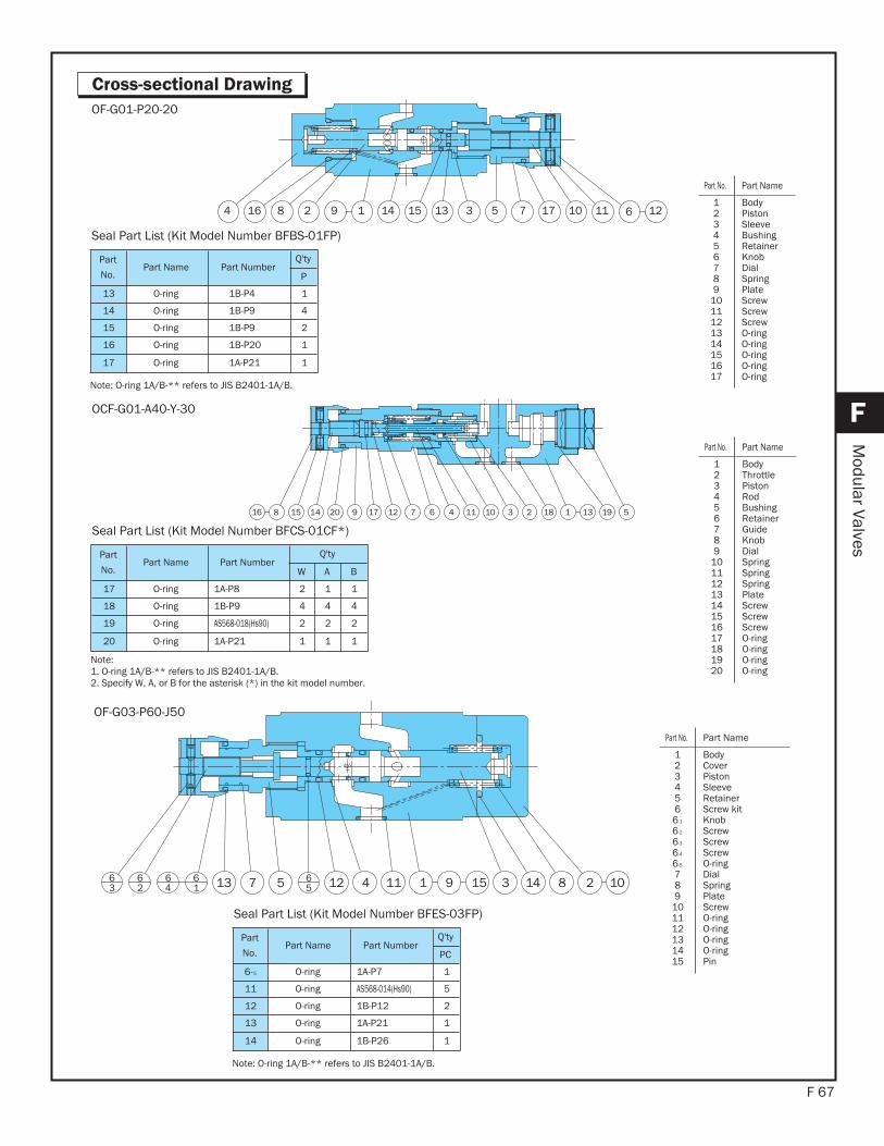
F 67
F
Modular Valves
Cross-sectional Drawing
12101751 3131592816 114 741 6
OF-G01-P20-20
Part
No.Part Name Part Number
Q'ty
P
13 O-ring 1B-P4 1
14 O-ring 1B-P9 4
15 O-ring 1B-P9 2
16 O-ring 1B-P20 1
17 O-ring 1A-P21 1
Seal Part List (Kit Model Number BFBS-01FP)
Note: O-ring 1A/B-** refers to JIS B2401-1A/B.
158 138137161 521 1 9146 27 11 0192014
OCF-G01-A40-Y-30
Part
No.Part Name Part Number
Q'ty
W A B
17 O-ring 1A-P8 2 1 1
18 O-ring 1B-P9 4 4 4
19 O-ring AS568-018(Hs90) 2 2 2
20 O-ring 1A-P21 1 1 1
Seal Part List (Kit Model Number BFCS-01CF*)
Note:1. O-ring 1A/B-** refers to JIS B2401-1A/B.2. Specify W, A, or B for the asterisk (*) in the kit model number.
23 01415713 65
616
462
63 12 4 11 1 159 8
OF-G03-P60-J50
Part
No.Part Name Part Number
Q'ty
PC
6-5 O-ring 1A-P7 1
11 O-ring AS568-014(Hs90) 5
12 O-ring 1B-P12 2
13 O-ring 1A-P21 1
14 O-ring 1B-P26 1
Seal Part List (Kit Model Number BFES-03FP)
Note: O-ring 1A/B-** refers to JIS B2401-1A/B.
Part No. Part Name
123456789
1011121314151617
BodyPistonSleeveBushingRetainerKnob DialSpringPlate ScrewScrewScrewO-ringO-ringO-ringO-ringO-ring
Part No. Part Name
123456789
1011121314151617181920
BodyThrottle PistonRodBushingRetainerGuideKnob DialSpringSpringSpringPlate ScrewScrewScrewO-ringO-ringO-ringO-ring
Part No. Part Name
1234566-1
6-2
6-3
6-4
6-5
789
101112131415
BodyCover PistonSleeveRetainerScrew kit Knob ScrewScrewScrewO-ringDialSpringPlate ScrewO-ringO-ringO-ringO-ringPin
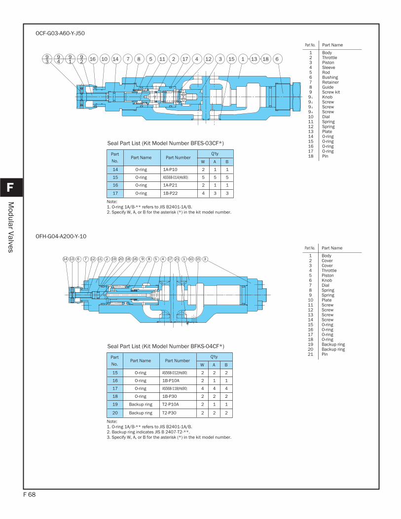
F 68
F
Modular Valves
12 157 58 421161 7141 613131091
94
92 189
3
OCF-G03-A60-Y-J50
Part
No.Part Name Part Number
Q'ty
W A B
14 O-ring 1A-P10 2 1 1
15 O-ring AS568-014(Hs90) 5 5 5
16 O-ring 1A-P21 2 1 1
17 O-ring 1B-P22 4 3 3
Seal Part List (Kit Model Number BFES-03CF*)
Note:1. O-ring 1A/B-** refers to JIS B2401-1A/B.2. Specify W, A, or B for the asterisk (*) in the kit model number.
2120 816 9 7191217 18 514116 2 3531 1 0141
OFH-G04-A200-Y-10
Part
No.Part Name Part Number
Q'ty
W A B
15 O-ring AS568-012(Hs90) 2 2 2
16 O-ring 1B-P10A 2 1 1
17 O-ring AS568-118(Hs90) 4 4 4
18 O-ring 1B-P30 2 2 2
19 Backup ring T2-P10A 2 1 1
20 Backup ring T2-P30 2 2 2
Seal Part List (Kit Model Number BFKS-04CF*)
Note:1. O-ring 1A/B-** refers to JIS B2401-1A/B.2. Backup ring indicates JIS B 2407-T2-**. 3. Specify W, A, or B for the asterisk (*) in the kit model number.
Part No. Part Name
123456789
101112131415161718192021
BodyCover Cover Throttle PistonKnob DialSpringSpringPlate ScrewScrewScrewScrewO-ringO-ringO-ringO-ringBackup ringBackup ringPin
Part No. Part Name
1234567899-1
9-2
9-3
9-4
101112131415161718
BodyThrottle PistonSleeveRodBushingRetainerGuideScrew kit Knob ScrewScrewScrewDialSpringSpringPlate O-ringO-ringO-ringO-ringPin
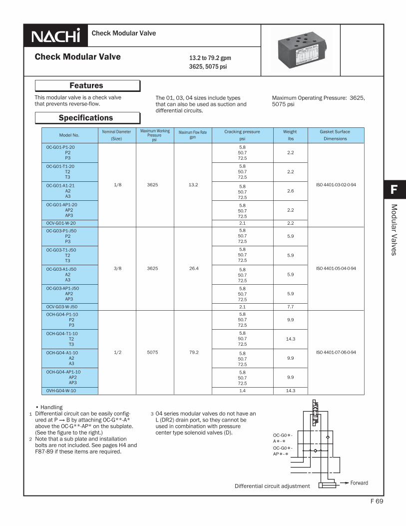
This modular valve is a check valvethat prevents reverse-flow.
F 69
Features
F
Modular Valves
The 01, 03, 04 sizes include typesthat can also be used as suction anddifferential circuits.
1
2
Check Modular Valve
Check Modular Valve
Specifications
13.2 to 79.2 gpm3625, 5075 psi
Maximum Operating Pressure: 3625, 5075 psi
• HandlingDifferential circuit can be easily config-
(See the figure to the right.)Note that a sub plate and installationbolts are not included. See pages H4 and F87-89 if these items are required.
3 04 series modular valves do not have an L (DR2) drain port, so they cannot be used in combination with pressure center type solenoid valves (D).
ForwardDifferential circuit adjustment
Model No.Nominal Diameter
(Size)
Maximum WorkingPressure
psi
Maximum Flow Rategpm psi
Weight
lbs Dimensions
P2P3
1/8 3625 13.2
5.850.772.5
5.850.772.5
5.850.772.5
5.850.772.52.1
5.850.772.5
5.850.772.5
5.850.772.5
5.850.772.5
2.1
5.850.772.5
5.850.772.5
5.850.772.5
5.850.772.5
1.4
2.2
ISO 4401-03-02-0-94
T2T3
2.2
2.6
2.2
2.2
P2P3
3/8 3625 26.4
5.9
ISO 4401-05-04-0-94
T2T3
5.9
5.9
5.9
7.7
-P1-10P2P3
1/2 5075 79.2
9.9
ISO 4401-07-06-0-94
-T1-10T2T3
14.3
-9.9
-9.9
14.3

F 70
F
Modular Valves
Understanding Model Numbers
J50–1P–03G–(OCV)OC
01, 03 size
10–1P–04G–(OVH)OCH
04 size
Design number Note: For 01 size, 20,21 For 03 size, relationship between mounting bolts and design number is indicated as J50: M6, 50: M8
Cracking pressure 1, 2, 3
Control port P: P port T: T port W: A, B ports (01, 03 vacuum check) A: A port AP: A, P ports Differential circuit at set
Nominal diameter (size) 01, 03
Mounting method G: gasket type
Vacuum check modular valve (01, 03 size)
Check modular valve (01, 03 size)
Design number
Cracking pressure 1, 2, 3
Control port P: P port T: T port W: A, B ports (01, 03 vacuum check) A: A port AP: A, P ports Differential circuit at set
Nominal diameter (size) 04
Mounting method G: gasket type
M35 Series vacuum check modular valve
M35 Series check modular valve
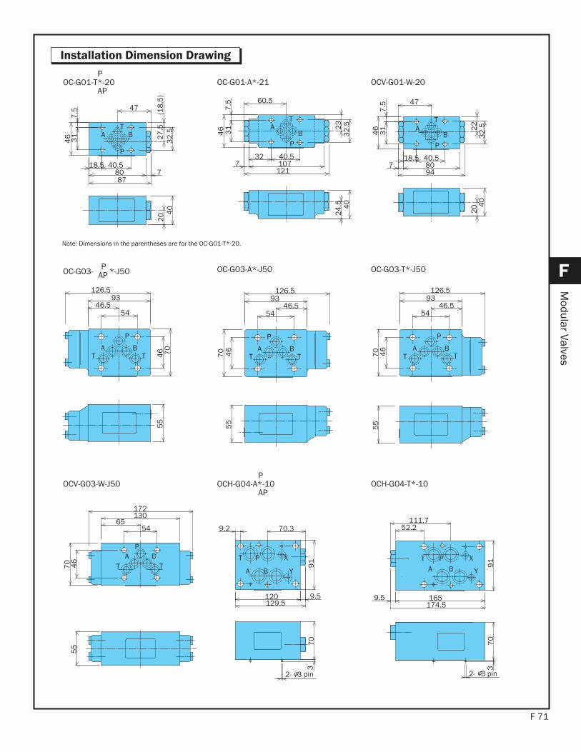
F 71
F
Modular Valves
Installation Dimension Drawing
T
P
A B
47
40.518.58087
73
2.5
27
.5
(1
8.5
)
31
7.5
46
20 4
0
T
P
AB
60.5
40.532107
1217
23
32
.5
31
7.5
46
24
.5 40
POC-G01-T*-20
APOC-G01-A*-21
T
P
AB
47
40.518.580794
22
32
.5
31
7.5
46
20 4
0
OCV-G01-W-20
P
BATT 4
6 70
55
5446.5
93126.5
P
BAT T
5446.5
93126.5
46
70
55
OC-G03- P *-J50AP
P
BATT
5446.5
93126.5
46
70
55
OC-G03-A*-J50 OC-G03-T*-J50
T P X
A B Y
9.2 70.3
120129.5
9.5
2- 3 pin
37
09
1
PB
T TA
5465
130172
46
70
55
POCH-G04-A*-10
APOCV-G03-W-J50
Y
XB
T PA
2- 3 pin
52.2111.7
1659.5174.5
91
70
3OCH-G04-T*-10
Note: Dimensions in the parentheses are for the OC-G01-T*-20.
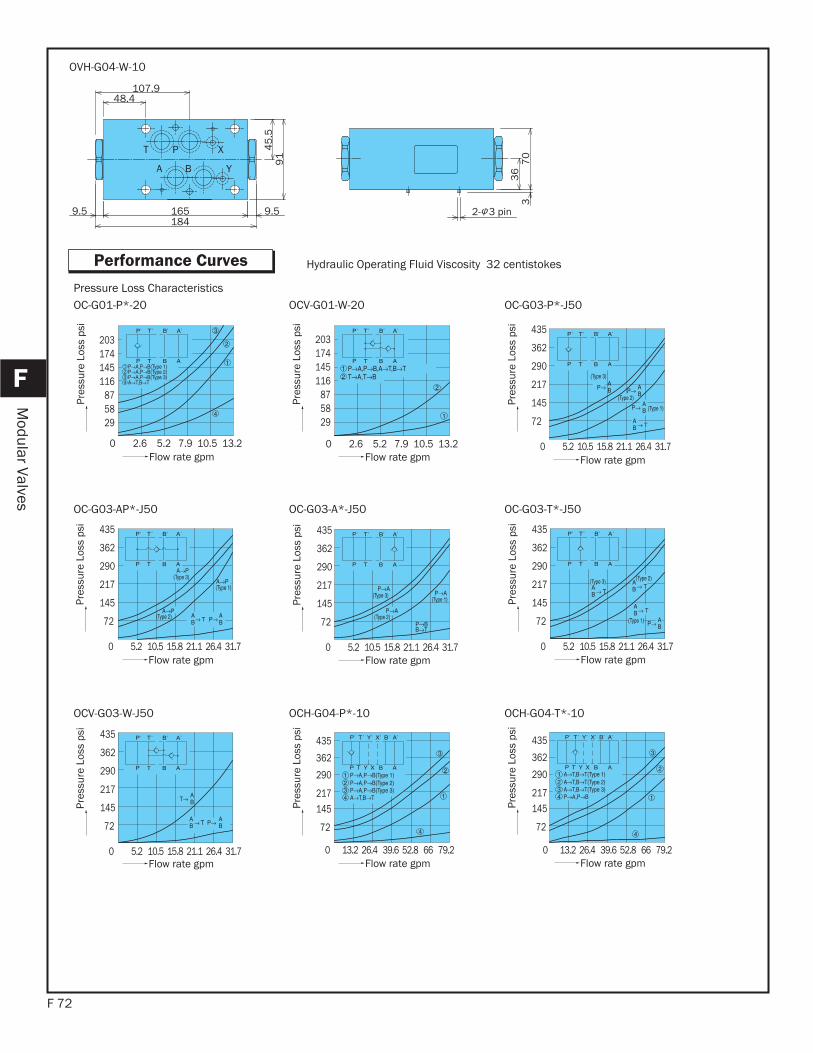
F 72
F
Modular Valves
Performance Curves
B Y
P X
A
T
48.4107.9
165 9.59.5184
45
.59
1
36
70
3
2- 3 pin
OVH-G04-W-10
203
295887
116145174
0 2.6 5.2 7.9 10.5 13.2Flow rate gpm
Pres
sure
Los
s ps
i
Hydraulic Operating Fluid Viscosity 32 centistokes
Flow rate gpm
Pres
sure
Los
s ps
iOC-G01-P*-20 OCV-G01-W-20
435
362
290
217
145
72
0 5.2 10.5 15.8 21.1 26.4 31.7Flow rate gpm
Pres
sure
Los
s ps
i
OC-G03-P*-J50Pressure Loss Characteristics
435
362
290
217
145
72
0 5.2 10.5 15.8 21.1 26.4 31.7Flow rate gpm
Pres
sure
Los
s ps
i
Flow rate gpm
Pres
sure
Los
s ps
i
OC-G03-AP*-J50 OC-G03-A*-J50
Flow rate gpm
Pres
sure
Los
s ps
iOC-G03-T*-J50
Flow rate gpm
Pres
sure
Los
s ps
i
0 13.2 26.4 39.6 52.8 66 79.2Flow rate gpm
Pres
sure
Los
s ps
i
OCV-G03-W-J50 OCH-G04-P*-10
Flow rate gpm
Pres
sure
Los
s ps
i
OCH-G04-T*-10
203
295887
116145174
0 2.6 5.2 7.9 10.5 13.2
435
362
290
217
145
72
0 5.2 10.5 15.8 21.1 26.4 31.7
435
362
290
217
145
72
0 5.2 10.5 15.8 21.1 26.4 31.7
435
362
290
217
145
72
0 5.2 10.5 15.8 21.1 26.4 31.7
435
362
290
217145
72
435
362
290
217145
72
0 13.2 26.4 39.6 52.8 66 79.2
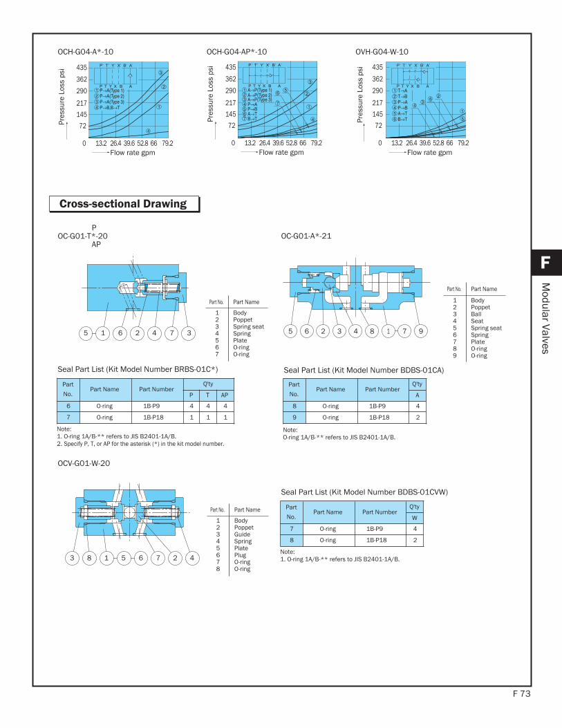
F 73
F
Modular Valves
Cross-sectional Drawing
0 13.2 26.4 39.6 52.8 66 79.2
435
362
290
217
145
72
Flow rate gpm Flow rate gpm
OCH-G04-A*-10 OCH-G04-AP*-10
Flow rate gpm
Pres
sure
Los
s ps
i
OVH-G04-W-10
1 2 345 6 7 9185 432 76
POC-G01-T*-20
APOC-G01-A*-21
Part
No.Part Name Part Number
Q'ty
P T AP
6 O-ring 1B-P9 4 4 4
7 O-ring 1B-P18 1 1 1
Seal Part List (Kit Model Number BRBS-01C*)
Note:1. O-ring 1A/B-** refers to JIS B2401-1A/B.2. Specify P, T, or AP for the asterisk (*) in the kit model number.
Part
No.Part Name Part Number
Q'ty
A
8 O-ring 1B-P9 4
9 O-ring 1B-P18 2
Seal Part List (Kit Model Number BDBS-01CA)
Note:O-ring 1A/B-** refers to JIS B2401-1A/B.
1 2 43 5 6 78
OCV-G01-W-20
Part
No.Part Name Part Number
Q'ty
W
7 O-ring 1B-P9 4
8 O-ring 1B-P18 2
Seal Part List (Kit Model Number BDBS-01CVW)
Note:1. O-ring 1A/B-** refers to JIS B2401-1A/B.
Part No. Part Name
1234567
BodyPoppet Spring seatSpringPlate O-ringO-ring
Part No. Part Name
123456789
BodyPoppet BallSeat Spring seatSpringPlate O-ringO-ring
Part No. Part Name
12345678
BodyPoppet GuideSpringPlate PlugO-ringO-ring
0 13.2 26.4 39.6 52.8 66 79.2
435
362
290
217
145
72
0 13.2 26.4 39.6 52.8 66 79.2
435
362
290
217
145
72
Pres
sure
Los
s ps
i
Pres
sure
Los
s ps
i
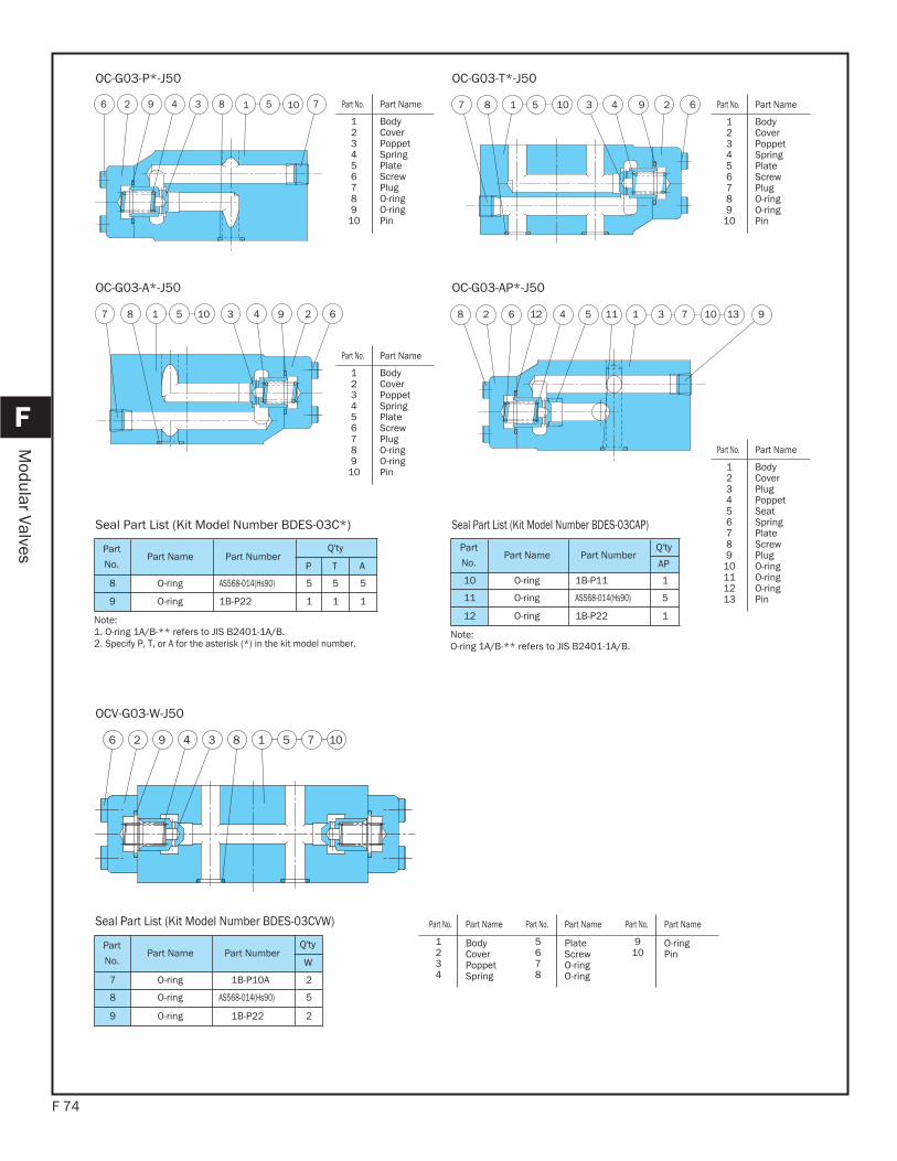
F 74
F
Modular Valves
710183492 56
OC-G03-P*-J50
7 8 1 5 10 3 4 9 2 6
OC-G03-T*-J50
10 23 61 9487 5
OC-G03-A*-J50
7312 316 9218 4 11 105
OC-G03-AP*-J50
Part
No.Part Name Part Number
Q'ty
P T A
8 O-ring AS568-014(Hs90) 5 5 5
9 O-ring 1B-P22 1 1 1
Seal Part List (Kit Model Number BDES-03C*)
Note:1. O-ring 1A/B-** refers to JIS B2401-1A/B.2. Specify P, T, or A for the asterisk (*) in the kit model number.
Part
No.Part Name Part Number
Q'ty
AP
10 O-ring 1B-P11 1
11 O-ring AS568-014(Hs90) 5
12 O-ring 1B-P22 1
Seal Part List (Kit Model Number BDES-03CAP)
Note:O-ring 1A/B-** refers to JIS B2401-1A/B.
12 34 5 76 8 019
OCV-G03-W-J50
Part
No.Part Name Part Number
Q'ty
W
7 O-ring 1B-P10A 2
8 O-ring AS568-014(Hs90) 5
9 O-ring 1B-P22 2
Seal Part List (Kit Model Number BDES-03CVW)
Part No. Part Name
123456789
10
BodyCover Poppet SpringPlate ScrewPlugO-ringO-ringPin
Part No. Part Name
123456789
10
BodyCover Poppet SpringPlate ScrewPlugO-ringO-ringPin
Part No. Part Name
123456789
10
BodyCover Poppet SpringPlate ScrewPlugO-ringO-ringPin
Part No. Part Name
123456789
10111213
BodyCover PlugPoppet Seat SpringPlate ScrewPlugO-ringO-ringO-ringPin
Part No. Part Name Part No. Part Name Part No. Part Name
1234
BodyCoverPoppetSpring
5678
PlateScrewO-ringO-ring
910
O-ringPin

F 75
F
Modular Valves
8 1 5 6 32 4 79
OCH-G04-P*-10
7 3 4 2 619 8 5
OVH-G04-W-10
Part
No.Part Name Body
Q'ty
P T A AP
6 O-ring AS568-012(Hs90) 2 2 2 2
7 O-ring 1B-P20 1 1 1 1
8 O-ring AS568-118(Hs90) 4 4 4 4
Seal Part List (Kit Model Number BDKS-04C*)
Note: 1. O-ring 1A/B-** refers to JIS B2401-1A/B.2. Specify P, T, A, or AP for the asterisk (*) in the kit model
number.
PartNo. Part Name Part Number Q'ty
6 O-ring AS568-012(Hs90) 2
7 O-ring 1B-P32 2
8 O-ring AS568-118(Hs90) 4
Seal Part List (Kit Model Number BDKS-04CVW)
Note: O-ring 1A/B-** refers to JIS B2401-1A/B.
Part No. Part Name
123456789
BodyPoppetSpring seatSpringPlate O-ringO-ringO-ringPin
Part No. Part Name
123456789
BodyPoppet Spring seatSpringPlate O-ringO-ringO-ringPin
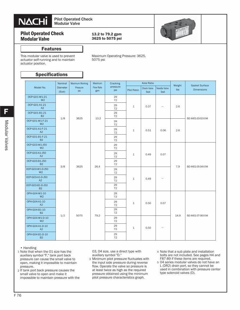
This modular valve is used to preventactuator self-running and to maintainactuator position.
F 76
Features
F
Modular Valves
Maximum Operating Pressure: 3625, 5075 psi
Pilot Operated CheckModular Valve
Pilot Operated CheckModular Valve
Specifications
Note that a sub plate and installationbolts are not included. See pages H4 and F87-89 if these items are required.04 series modular valves do not have an L (DR2) drain port, so they cannot be used in combination with pressure center type solenoid valves (D).
4
3
13.2 to 79.2 gpm3625 to 5075 psi
5
• HandlingNote that when the 01 size has the auxiliary symbol "F," tank port backpressure can cause the small valve to open, making it impossible to maintain pressure.If tank port back pressure causes thesmall valve to open and make itimpossible to maintain pressure with the
03, 04 size, use a direct type with auxiliary symbol "D."Minimum pilot pressure fluctuates with the input side pressure during reverse flow. Operate the valve so pressure is at least twice as high as the required pressure obtained using the minimum pilot pressure characteristics graph.
Model No.
Nominal
Diameter
(Size)
Maximum Working
Pressurepsi
Maximum
Flow Rategpm
Cracking pressure
psi
Area Ratio Weight
lbs
Gasket Surface
DimensionsPilot PistonCheck Valve
SeatNeedle Valve
Seat
OCP-G01-W1-21W2
1/8 3625 13.2
2972
2972
2972
2972
2972
2972
2972
2972
2972
2972
2972
2972
2972
2972
2972
2972
2972
2972
1 0.37 -- 2.6
ISO 4401-03-02-0-94
OCP-G01-A1-21A2
OCP-G01-B1-21B2
OCP-G01-W1-F-21W2
1 0.51 0.06 2.6OCP-G01-A1-F-21A2
OCP-G01-B1-F-21B2
OCP-G03-W1-J50W2
3/8 3625 26.4
1 0.49 0.07
7.9 ISO 4401-05-04-0-94
OCP-G03-A1-J50A2
OCP-G03-B1-J50B2
OCP-G03-W1-D-J50W2
1 0.49 --OCP-G03-A1-D-J50A2
OCP-G03-B1-D-J50B2
OPH-G04-W1-10W2
1/2 5075 79.2
1 0.50 0.07
14.9 ISO 4401-07-06-0-94
OPH-G04-A1-10A2
OPH-G04-B1-10B2
OPH-G04-W1-D-10W2
1 0.50 --OPH-G04-A1-D-10A2
OPH-G04-B1-D-10B2
1
2
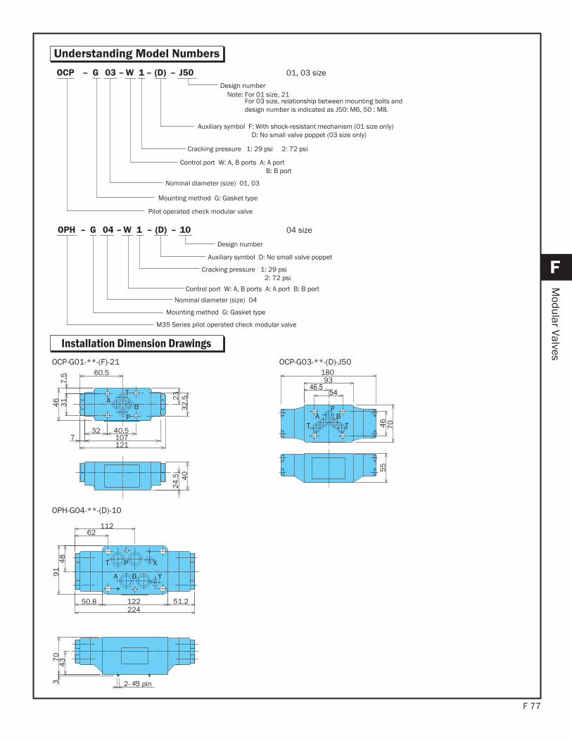
F 77
F
Modular Valves
Understanding Model Numbers
Installation Dimension Drawings
T
P
AB
60.5
40.5321077121
23
32
.5
31
7.5
46
24
.5 40
T T
PA B
93180
46
70
55
OCP-G01-**-(F)-21 OCP-G03-**-(D)-J50
YBA
XPT
2- 3 pin
62112
50.8224122 51.2
48
91
437
03
OPH-G04-**-(D)-10
10–(D)–1W–04G–OPH
Auxiliary symbol D: No small valve poppet
Cracking pressure 1: 29 psi2: 72 psi
Control port W: A, B ports A: A port B: B port
Nominal diameter (size) 04
Mounting method G: Gasket type
M35 Series pilot operated check modular valve
Design number
04 size
J50–(D)–1W–03G–OCP
Cracking pressure 1: 29 psi 2: 72 psi
Control port W: A, B ports A: A portB: B port
Nominal diameter (size) 01, 03
Mounting method G: Gasket type
Pilot operated check modular valve
Design numberNote: For 01 size, 21 For 03 size, relationship between mounting bolts and design number is indicated as J50: M6, 50 : M8.
Auxiliary symbol F: With shock-resistant mechanism (01 size only) D: No small valve poppet (03 size only)
01, 03 size
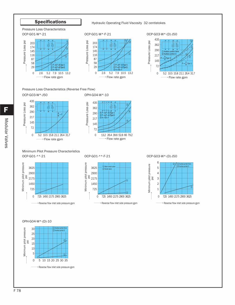
F 78
F
Modular Valves
Specifications
Pressure Loss Characteristics (Reverse Free Flow)
Hydraulic Operating Fluid Viscosity 32 centistokes
OCP-G01-W*-21 OCP-G01-W*-F-21 OCP-G03-W*-(D)-J50Pressure Loss Characteristics
0 2.6 5.2 7.9 10.5 13.2
2
1
174145116875829
203
3
Flow rate gpm
Pres
sure
Los
s ps
i
1
23
Flow rate gpm
Pres
sure
Los
s ps
i
1
72AB
2
P (Type 1)
2
1
145
217
290
362
435
Flow rate gpm
Pres
sure
Los
s ps
i
OCP-G03-W*-J50 OPH-G04-W*-10
Flow rate gpm
Pres
sure
Los
s ps
i
1
2
3
Flow rate gpm
Pres
sure
Los
s ps
i
Minimum Pilot Pressure CharacteristicsOCP-G01-**-21 OCP-G01-**-F-21 OCP-G03-W*-(D)-J50
0 725 1450 2175 2900 3625
2900
2175
3625
1450
725
Reverse flow inlet side pressure gpm
Small valve21 Main check valve
1
2
Reverse flow inlet side pressure gpm
Auxiliary symbol: D21 Auxiliary symbol: None
1
2
3
4
6
5
1
2
Reverse flow inlet side pressure gpm
OPH-G04-W*-(D)-10
1
2
0
20
15
25
30
10
5
2010 155 25 30 35
Auxiliary symbol: D21 Auxiliary symbol: None
Reverse flow inlet side pressure gpm
Min
imum
pilo
t pre
ssur
eps
i
0 2.6 5.2 7.9 10.5 13.2
174145116875829
203
Min
imum
pilo
t pre
ssur
eps
i
Min
imum
pilo
t pre
ssur
eps
i
Min
imum
pilo
t pre
ssur
eps
i
0 5.2 10.5 15.8 21.1 26.4 31.7
72
145
217
290
362
435
0 5.2 10.5 15.8 21.1 26.4 31.7
72
145
217
290
362
435
0 13.2 26.4 39.6 52.8 66 79.2
2900
2175
3625
1450
725
0 725 1450 2175 2900 3625 0 725 1450 2175 2900 3625
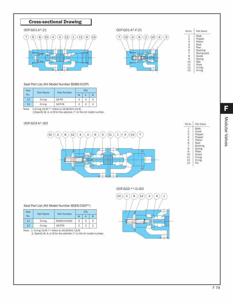
F 79
F
Modular Valves
Cross-sectional Drawing
13 647 89 10 1112 13
OCP-G01-A*-21
5301 74 6 118 12 31912
OCP-G03-A*-J50
Part
No.Part Name Part Number
Q'ty
W A B
12 O-ring 1B-P9 4 4 4
13 O-ring 1B-P18 2 2 2
Seal Part List (Kit Model Number BDBS-01CP)
Note: 1.O-ring 1A/B-** refers to JIS B2401-1A/B.2.Specify W, A, or B for the asterisk (*) in the kit model number.
Part
No.Part Name Part Number
Q'ty
W A B
11 O-ring AS568-014(Hs90) 5 5 5
12 O-ring 1B-P29 2 2 2
Seal Part List (Kit Model Number BDES-03CP*)
Note: 1. O-ring 1A/B-** refers to JIS B2401-1A/B.2. Specify W, A, or B for the asterisk (*) in the kit model number.
2 4 57 89 1013
OCP-G01-A*-F-21
110 4 68 122
OCP-G03-**-D-J50
Part No. Part Name
123456789
10111213
BodyPoppet PistonSeat RodBushingSpring seatGuideSpringBallPlate O-ringO-ring
Part No. Part Name
123456789
10111213
BodyCover Poppet Poppet PistonSeat BushingSpringPlate ScrewO-ringO-ringPin
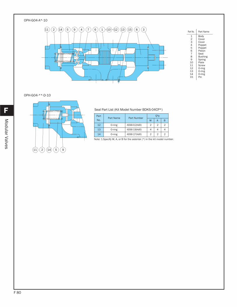
F 80
F
Modular Valves
102 4 15 79 6 2111 3841 13 15
OPH-G04-A*-10
Part
No.Part Name Part Number
Q'ty
W A B
12 O-ring AS568-012(Hs90) 2 2 2
13 O-ring AS568-118(Hs90) 4 4 4
14 O-ring AS568-127(Hs90) 2 2 2
Seal Part List (Kit Model Number BDKS-04CP*)
Note: 1.Specify W, A, or B for the asterisk (*) in the kit model number.
2 5 911 14
OPH-G04-**-D-10
Part No. Part Name
123456789
101112131415
BodyCover Cover Poppet Poppet PistonSeat BushingSpringPlate ScrewO-ringO-ringO-ringPin
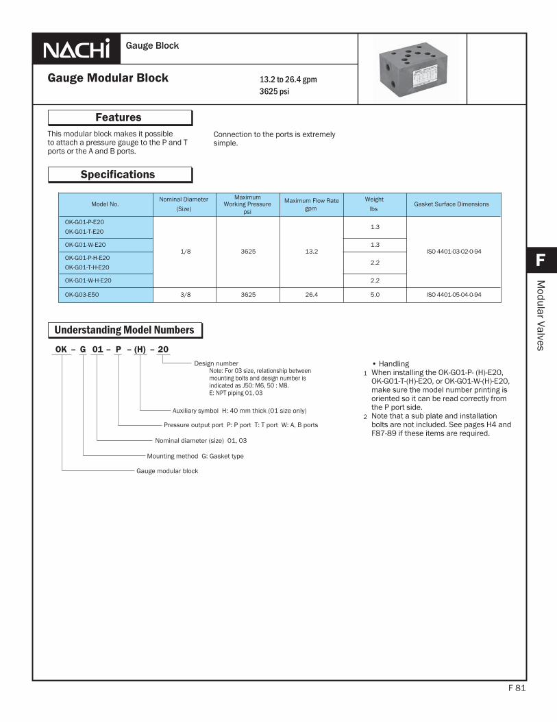
This modular block makes it possibleto attach a pressure gauge to the P and T ports or the A and B ports.
F 81
Features
F
Modular Valves
Connection to the ports is extremelysimple.
1
2
Gauge Modular Block
Gauge Block
Specifications
13.2 to 26.4 gpm3625 psi
• HandlingWhen installing the OK-G01-P- (H)-E20, OK-G01-T-(H)-E20, or OK-G01-W-(H)-E20, make sure the model number printing is oriented so it can be read correctly from the P port side.Note that a sub plate and installationbolts are not included. See pages H4 and F87-89 if these items are required.
Model No.Nominal Diameter
(Size)
Maximum Working Pressure
psi
Maximum Flow Rategpm
Weight
lbsGasket Surface Dimensions
OK-G01-P-E20
OK-G01-T-E20
1/8 3625 013.2
1.3
ISO 4401-03-02-0-94OK-G01-W-E20 1.3
OK-G01-P-H-E20
OK-G01-T-H-E202.2
OK-G01-W-H-E20 2.2
OK-G03-E50 3/8 3625 26.4 5.0 ISO 4401-05-04-0-94
Understanding Model Numbers20–(H)–P–01G–OK
Auxiliary symbol H: 40 mm thick (01 size only)
Pressure output port P: P port T: T port W: A, B ports
Nominal diameter (size) 01, 03
Mounting method G: Gasket type
Gauge modular block
Design numberNote: For 03 size, relationship betweenmounting bolts and design number isindicated as J50: M6, 50 : M8.E: NPT piping 01, 03

F 82
F
Modular Valves
Installation Dimension Drawings
OK-G01-P-20
BT
P
A
25
12.5
7.5
2-NPT 1/4
46 31
32
.52318.5
8040.5
40
OK-G01-T-20
BT
P
A
2512
.5
2-NPT 1/4
46 31
32.523
18.580
40.5
40
OK-G01-P-E20 OK-G01-T-E20
OK-G01-P-H-20
P
TBA
2-NPT1/4
46 31
32.523
18.580
40.5
40
40
20
P
TBA
OK-G01-T-H-20
2-NPT1/4
46 31
32.523
18.580
40.5
40
40
20
OK-G01-P-H-E20 OK-G01-T-H-E20
TA P
B
PA B
T T
2-NPT 1/4 2-NPT 1/4
513
46
35
70
513
1540
1540
55
5449.5
99
OK-G03-E50
OK-G01-W-20
T
P
A B
40
40.518.580
23
32
.5
31
7.5
46
2-NPT 1/4
12
.52
5
OK-G01-W-E20
OK-G01-W-H-20
BT
P
A
2-NPT1/44
67
.53
1
32
.523
18.580
40.5
40
40
20
OK-G01-W-H-E20
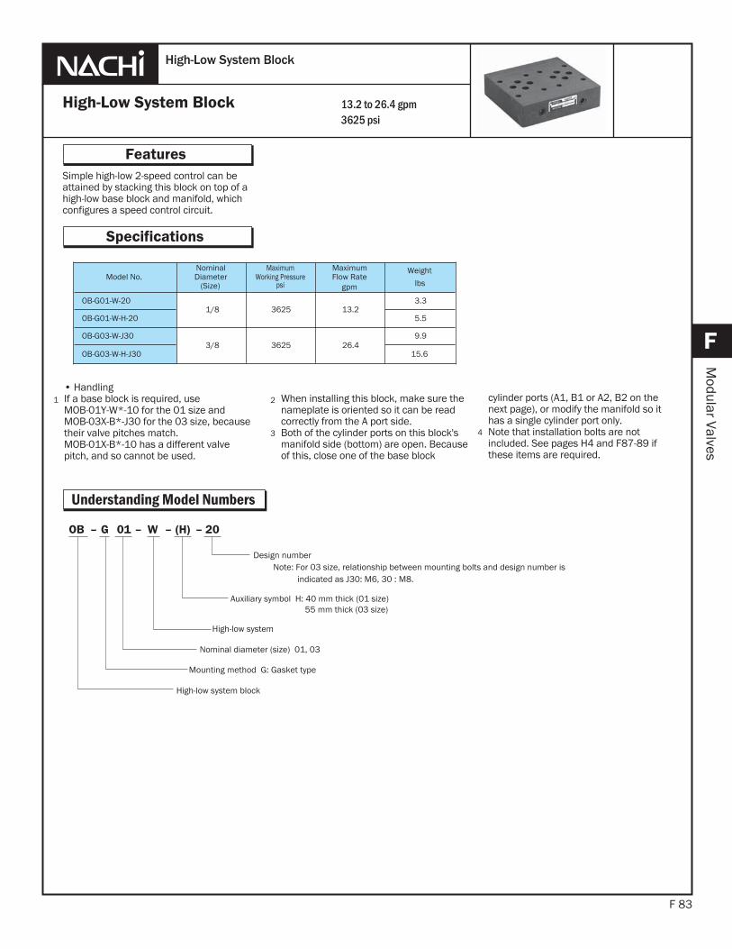
Simple high-low 2-speed control can be attained by stacking this block on top of a high-low base block and manifold, which configures a speed control circuit.
F 83
Features
F
Modular Valves
4
High-Low System Block
High-Low System Block
Specifications
13.2 to 26.4 gpm3625 psi
cylinder ports (A1, B1 or A2, B2 on the next page), or modify the manifold so it has a single cylinder port only.Note that installation bolts are notincluded. See pages H4 and F87-89 if these items are required.
Understanding Model Numbers
Model No.NominalDiameter
(Size)
MaximumWorking Pressure
psi
Maximum Flow Rate
gpm
Weight
lbs
OB-G01-W-201/8 3625 013.2
3.3
OB-G01-W-H-20 5.5
OB-G03-W-J303/8 3625 26.4
9.9
OB-G03-W-H-J30 15.6
2
3
When installing this block, make sure the nameplate is oriented so it can be read correctly from the A port side.Both of the cylinder ports on this block's manifold side (bottom) are open. Because of this, close one of the base block
1• HandlingIf a base block is required, use MOB-01Y-W*-10 for the 01 size and MOB-03X-B*-J30 for the 03 size, because their valve pitches match. MOB-01X-B*-10 has a different valve pitch, and so cannot be used.
20–(H)–W–01G–OB
Auxiliary symbol H: 40 mm thick (01 size)55 mm thick (03 size)
High-low system
Nominal diameter (size) 01, 03
Mounting method G: Gasket type
High-low system block
Design numberNote: For 03 size, relationship between mounting bolts and design number is
indicated as J30: M6, 30 : M8.
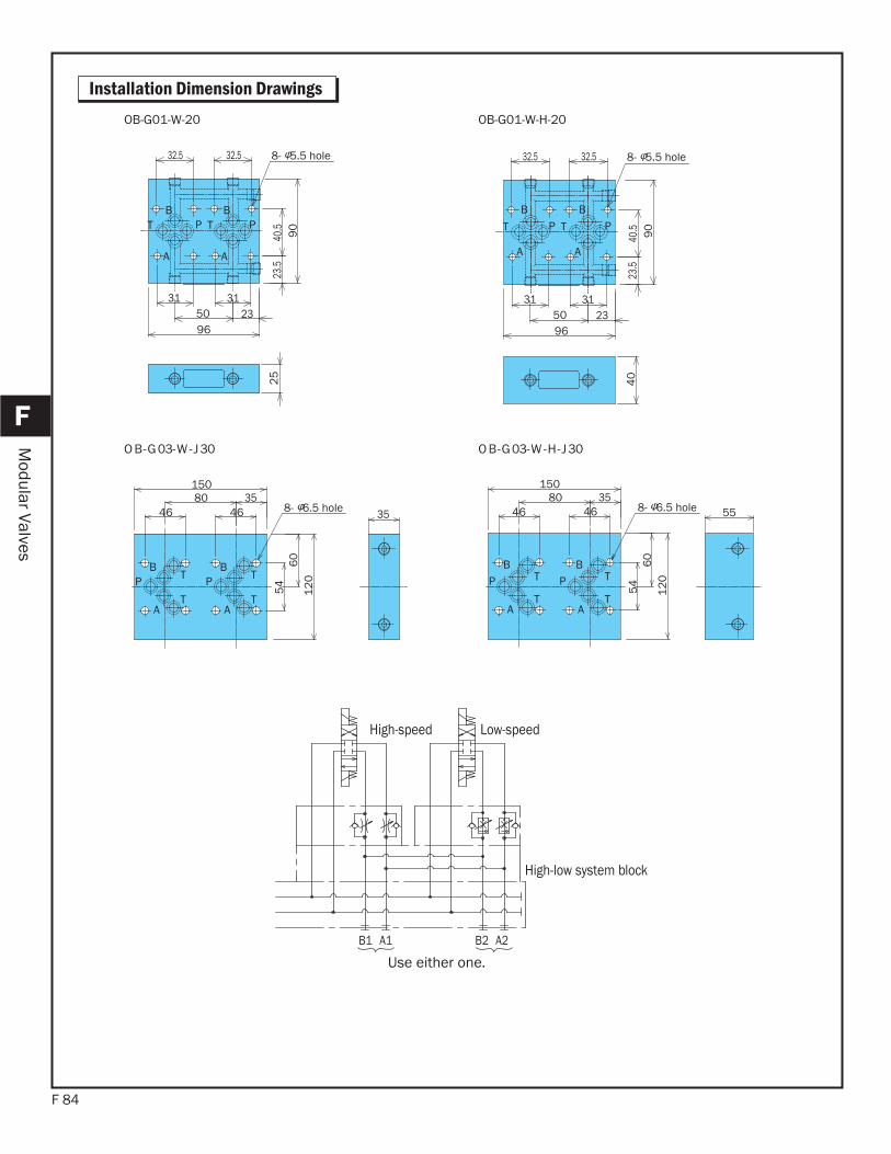
F 84
F
Modular Valves
Installation Dimension Drawings
PT
A
BPT
A
B
8- 5.5 hole32.532.5
313150 2396
40.5
23.5
90
25
OB-G01-W-20
PT
A
BPT
A
B
40
8- 5.5 hole32.532.5
313150 2396
40.5
23.5
90
OB-G01-W-H-20
P
A
B
T
T P
A
B
T
T
8- 6.5 hole
54
60
12
0
464680 35
150
35
P
A
B
T
T P
A
B
T
T
558- 6.5 hole
54
60
12
0
464680 35
150
03J-H-W-30G-BO03J-W-30G-BO
High-speed Low-speed
B1 A1 B2 A2
Use either one.
High-low system block

The end plate is a modular valve plate used to close off a circuit that is not required, and when using a relief modular valve in a standalone configuration.The free flow plate is a modular valve
F 85
Features
F
Modular Valves
End Plate, Free Flow Plate,03/01 Change Plate
End Plate • Free Flow Plate • 03/01 Change Plate
Specifications
13.2 to 26.4 gpm3625 psi
Understanding Model Numbers
1• HandlingInstallation bolts are not included. Use the table to the right to specify bolts for stand-alone use.
The 06/04 change plate makes it possible to use an 04 size modular valve with an 06 size sub-plate and base block.
plate is used in a one-way circuit that does not require a solenoid valve.The 03/01 change plate makes itpossible to use an 01 size modular valve with an 03 size sub-plate and base block.
Model No.Nominal
Diameter(Size)
Maximum WorkingPressure
psi
Maximum Flow Rategpm
Weight
lbs
MOB-G01-10
1/8 3625
.6
MOB-G01-H-10 1.3
MOB-G01-A-10
MOB-G01-B-10013.2 1.3
MOB-G03-J50
3/8 3625
3.0
MOB-G03-H-50 5.5
MOB-G03-A-J50
MOB-G03-B-J5026.4
2.8
MOB-G03-A-H-50
MOB-G03-B-H-505.0
MOB-G03-AA-J50 013.2 5.0
MOB-G06-AA-5411A 3/4 3045 52.8 17.6
J50–(H)–A–03G–MOB
Port connection status
Nominal diameter (size) 01, 03
Mounting method G: Gasket type
Modular valve plate
Design number Note:Auxiliary symbol (tightening height) and design number (G03 size)J50: M6 type 26.5mm50: M8 type 23.4mmH-50: M8 type 58mm (stop plate and relief low plate only)5411A: 06/04 conversion plate (special item)
Auxiliary symbol H: Tightening height 36mm (01 size), 58mm (03 size)
Model No. Bolt Dimensions Q'ty
MOB-G01-10 M5 × 25 4
MOB-G01-*-10 M5 × 45 4
MOB-G03-J50
AMOB-G03- -J50BMOB-G03-AA-J50
M6 × 35 4
MOB-G03-50
AMOB-G03- -50BMOB-G03-AA-50
M8 × 35 4
MOB-G03-H-50
AMOB-G03- -H-50BM8 × 70 4
MOB-G06-AA-5411A M12 × 70 6
(Free-flow plate)
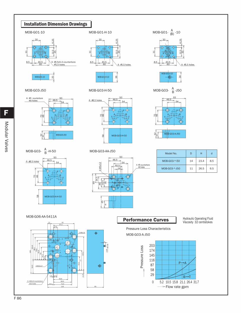
F 86
F
Modular Valves
Installation Dimension Drawings
MOB-G01-A-10
P
A B
T
36
4- 5.5 holes
30
40.58.560
32.5
6.2
54
5
31
PA B
T
MOB-G01-H-10 36
4- 5.5 holes
30
40.58.560
32.5
6.2
54
5
31
P
A B
T
MOB-G01-10
4- 9.5x5.4 counterbore5.5 holes
30
40.58.560
32.5
6.2
54
5
31
20
MOB-G01-H-10MOB-G01-10
P
BATT
MOB-G03-A-J50
70
46
9346.5
54
H32
P
BATT
MOB-G03-H-50
4- 8.5 holes7
04
6
9346.5
545
8
MOB-G03- A -J50B
P
BATT
MOB-G03-J50
4- D counterbored holes
5446.5
93
46
70
32
H
MOB-G03-H-50MOB-G03-J50
MOB-G01- A -10(B)
P
BATT
MOB-G03-A-H-50
4- 8.5 holes
70
46
9346.5
54
58
TA
BP
4- D counterbore d holes
4-M
5x1
2
1440.5
5446.5
93
32
.53
1
46
34
.56
9
H4
5
MOB-G03- A -H-50B MOB-G03-AA-J50Model No. D H d
MOB-G03-*-50 14 23.4 8.5
MOB-G03-*-J50 11 26.5 6.5
13 holes
6- 19x13 counterbore
18
.334
.1
65
.95
0
88
.17
6.61
01
.65
2.5
16
9
2-
6
6
12 92
11
.9
53
.27
7
4-M10x17
13
0.2
65
2-M6x16
15.957.2
1.6 14.3
55.6
69.9
71.523.1
116
Hydraulic Operating FluidViscosity 32 centistokes
Pressure Loss Characteristics
MOB-G03-A-J50
203
295887
116145174
0 5.2 10.5 15.8 21.1 26.4 31.7
P A
B T
Flow rate gpm
Pres
sure
Los
s
MOB-G06-AA-5411APerformance Curves
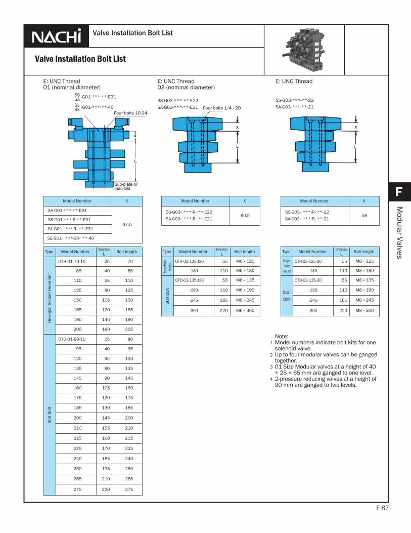
F 87
F
Modular Valves
Valve Installation Bolt List
Valve Installation Bolt List
Note:Model numbers indicate bolt kits for onesolenoid valve.Up to four modular valves can be gangedtogether.01 Size Modular valves at a height of 40 + 25 = 65 mm are ganged to one level.2-pressure reducing valves at a height of90 mm are ganged to two levels.
1
2
SS -G01-***-**-E31SASL -G01-***-**-40SE
E: UNC Thread01 (nominal diameter)
E: UNC Thread03 (nominal diameter)
SS-G03-***-**-E22SA-G03-***-**-E21
Type Model Number DimensionL Bolt length
Hex
agon
Soc
ket H
ead
Bol
t
OTH-01-70-10 25 70
85 40 85
110 65 110
125 80 125
150 105 150
165 120 165
190 145 190
205 160 205
Stat
Bol
t
OTD-01-80-10 25 80
95 40 95
120 65 120
135 80 135
145 90 145
160 105 160
175 120 175
185 130 185
200 145 200
210 155 210
215 160 215
225 170 225
240 185 240
250 195 250
265 210 265
275 220 275
Type Model Number DimensionL Bolt length
Hexag
on Soc
ketHe
ad Bol
t OTH-03-125-J30 55 M6 × 125
-180- 110 M6 × 180
Stat
Bol
t
OTD-03-135-J30 55 M6 × 135
-190- 110 M6 × 190
-245- 165 M6 × 245
-300- 220 M6 × 300
SS-G03-***-**-22SA-G03-***-**-21
Type Model Number DimensionL Bolt length
HexagonSocket
Head Bolt
OTH-03-125-30 55 M8 × 125
-180- 110 M8 × 180
Stat
Bolt
OTD-03-135-30 55 M8 × 135
-190- 110 M8 × 190
-245- 165 M8 × 245
-300- 220 M8 × 300
Model Number X
SS-G03- ***-R- **-E22
SA-G03- ***-R- **-E2160.5
Model Number X
SS-G03- ***-R- **-22
SA-G03- ***-R- **-2158
Model Number X
SA-G01-***-**-E31
37.5SS-G01-***-R-**-E31
SL-G01- ***-R- **-E31
SE-G01- ***-GR- **-40
E: UNC Thread
3
4
Four bolts 10-24Four bolts 1/4 - 20
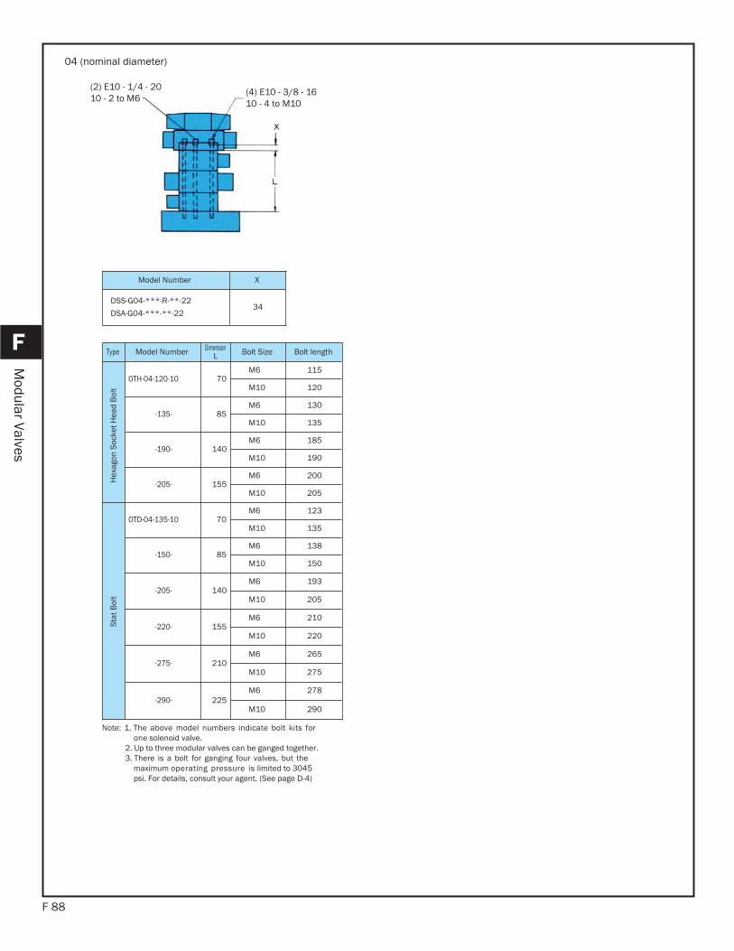
F 88
F
Modular Valves
04 (nominal diameter)
Model Number X
DSS-G04-***-R-**-22
DSA-G04-***-**-2234
Note: 1. The above model numbers indicate bolt kits for one solenoid valve. 2. Up to three modular valves can be ganged together. 3. There is a bolt for ganging four valves, but the maximum operating pressure is limited to 3045 psi. For details, consult your agent. (See page D-4)
Type Model Number DimensionL Bolt Size Bolt length
Hex
agon
Soc
ket H
ead
Bol
t
OTH-04-120-10 70M6 115
M10 120
-135- 85M6 130
M10 135
-190- 140M6 185
M10 190
-205- 155M6 200
M10 205
Stat
Bol
t
OTD-04-135-10 70M6 123
M10 135
-150- 85M6 138
M10 150
-205- 140M6 193
M10 205
-220- 155M6 210
M10 220
-275- 210M6 265
M10 275
-290- 225M6 278
M10 290
toto(2) E10 - 1/4 - 2010 - 2 to M6
(4) E10 - 3/8 - 1610 - 4 to M10
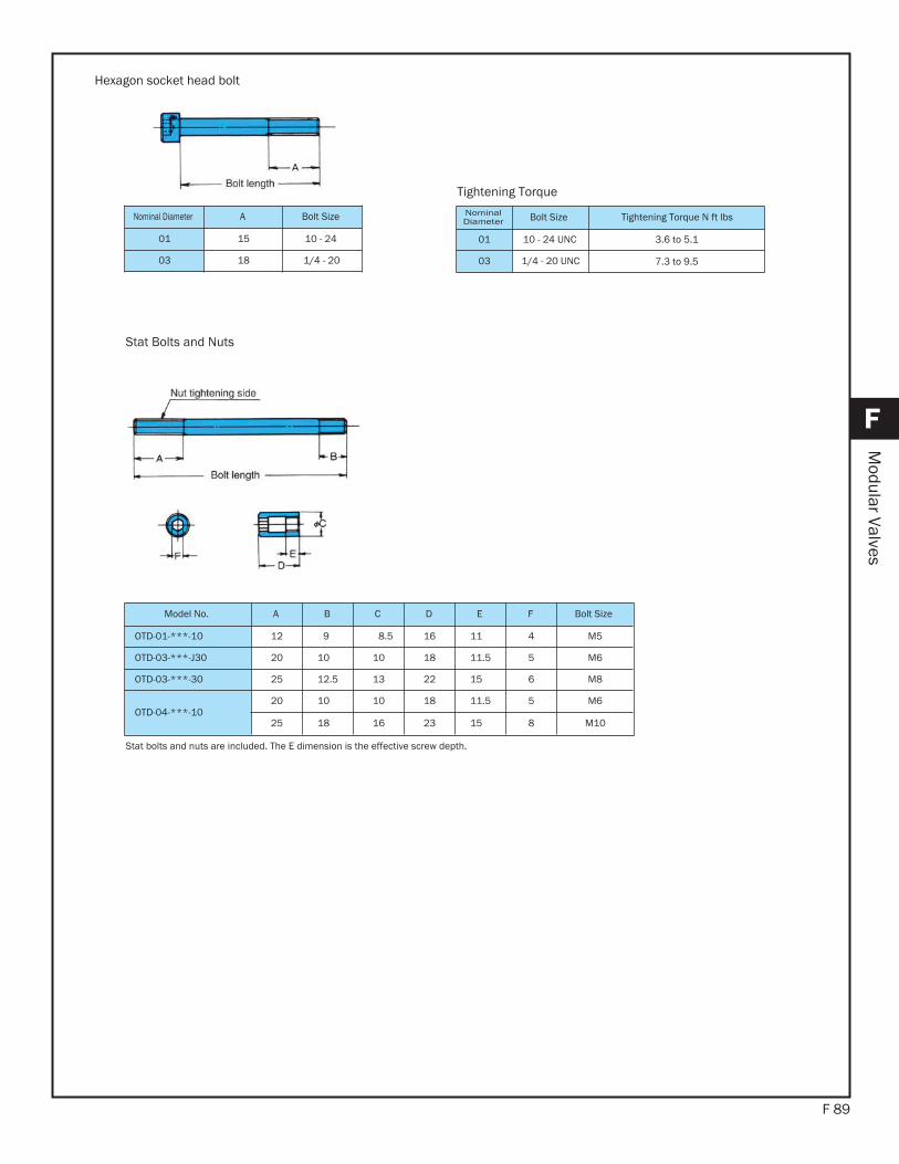
F 89
F
Modular Valves
Hexagon socket head bolt
Stat Bolts and Nuts
Tightening Torque
NominalDiameter Bolt Size Tightening Torque N ft lbs
01 10 - 24 UNC
03 1/4 - 20 UNC
Nominal Diameter A Bolt Size
01 15 10 - 24
03 18 1/4 - 20
Model No. A B C D E F Bolt Size
OTD-01-***-10 12 09.0 8.5 16 11.0 4 M5
OTD-03-***-J30 20 10.0 10 18 11.5 5 M6
OTD-03-***-30 25 12.5 13 22 15.0 6 M8
OTD-04-***-1020 10.0 10 18 11.5 5 M6
25 18.0 16 23 15.0 8 M10
Stat bolts and nuts are included. The E dimension is the effective screw depth.
3.6 to 5.1
7.3 to 9.5
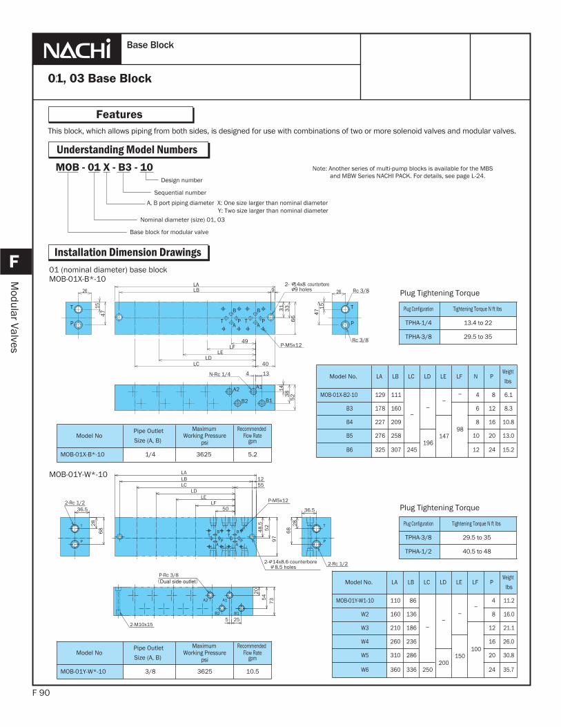
MOB - 01 X - B3 - 10
This block, which allows piping from both sides, is designed for use with combinations of two or more solenoid valves and modular valves.
F 90
Features
F
Modular Valves
01, 03 Base Block
Base Block
Understanding Model NumbersNote: Another series of multi-pump blocks is available for the MBS
and MBW Series NACHI PACK. For details, see page L-24.
A1
B1
A2
B2
A
B
T PA
B
T P
T T
PP
N-Rc 1/4
P-M5x12
2- 14x8 counterbore9 holes
Rc 3/8
Rc 3/8
49LF
LELD
LC
LB 9LA
31
33
66
26
15
47
26
154
7
40
143
85
2
4 13
01 (nominal diameter) base blockMOB-01X-B*-10
A2
B1
A1
B2
PA
TB
T
P
T
P
BT
AP
48
.55
29
7
28
68
36.550LF
LELD
LCLBLA
1255
28
68
36.5
20
54
73
5 25
P-Rc 3/8
2-Rc 1/2
2- 14x8.6 counterbore8.5 holes
2-Rc 1/2
P-M5x12
2-M10x15
MOB-01Y-W*-10
Model NoPipe Outlet
Size (A, B)
Maximum Recommended
MOB-01X-B*-10 1/4 3625 5.2
Model No. LA LB LC LD LE LF N PWeight
lbs
MOB-01X-B2-10 129 111 04 08 6.1
B3 178 160
98
06 12 8.3
B4 227 209
147
08 16 10.8
B5 276 258196
10 20 13.0
B6 325 307 245 12 24 15.2
Model No. LA LB LC LD LE LF PWeight
lbs
MOB-01Y-W1-10 110 086 04 011.2
W2 160 136 08 016.0
W3 210 186
100
12 021.1
W4 260 236
150
16 26.0
W5 310 286200
20 30.8
W6 360 336 250 24 35.7
Model NoPipe Outlet
Size (A, B)
Maximum Working Pressure
psi
RecommendedFlow Rate
gpm
MOB-01Y-W*-10 3/8 3625 10.5
Plug Tightening Torque
Plug Configuration Tightening Torque N ft lbs
TPHA-1/4 13.4 to 22
TPHA-3/8 29.5 to 35
Plug Tightening Torque
Plug Configuration Tightening Torque N ft lbs
TPHA-3/8 29.5 to 35
TPHA-1/2 40.5 to 48
Installation Dimension Drawings
Design number
Sequential number
A, B port piping diameter X: One size larger than nominal diameter Y: Two size larger than nominal diameter
Nominal diameter (size) 01, 03
Base block for modular valve
Working Pressurepsi
Flow Rategpm
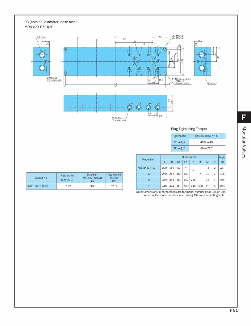
F 91
F
Modular Valves
A1B1A2B2
T
AP
B
AP
B
T
P
T
P
T
LCLD
LELF
LBLA
60
23.8
54
60
10
01
01
20
1531
32
60
88
1.516.59.5
46 8
52
70
202060
1531
2-Rc 3/4
2-M10x18(For hanging bolt) 4- 8.5 counterbore
M10x15(From back surface)
NX4-M6x13(NX4-M8x13)
2-Rc 3/4
M-Rc 1/2
10.3
10.3
03 (nominal diameter) base blockMOB-03X-B*-(J)30
Model NoPipe Outlet
Size (A, B)
Maximum Working Pressure
psi
RecommendedFlow Rate
gpm
MOB-03X-B*-(J) 30 1/2 3625 21.1
Model No.Dimensions Weight
lbsLA LB LC LD LE LF M N
MOB-03X-B2 -(J) 30 200 184 80 08 2 22.7
B3 280 264 80 160 12 3 31.5
B4 360 344 80 160 240 16 4 40.5
B5 440 424 80 160 240 320 20 5 49.3
Note: Dimensions in parentheses are for model number MOB-03X-B*-30,which is the model number when using M8 valve mounting bolts.
Plug Tightening Torque
Plug Configuration Tightening Torque N ft lbs
TPHA-1/2 40.5 to 48
TPHA-3/4 66 to 73.7
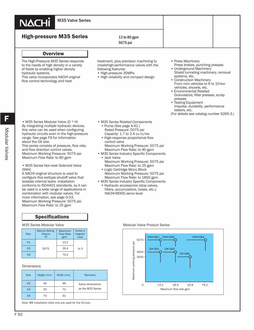
SizeMaximum Working
Pressurepsi
MaximumFlow Rate
gpm
Number ofIntegration
Levels
01
5075
013.2
to 303 26.4
04 79.2
M35 Series Modular Valve
Size Height (mm) Width (mm) Remarks
01 40 46 Same dimensions
as the M25 Series03 55 70
04 70 91
Dimensions
Modular Valve Product Series
3000
3625
5075
0 13.2 26.4 52.8 79.2Maximum flow rate gpm
Max
imum
wor
king
pre
ssur
e ps
i
Note: M8 installation bolts only are used for the 03 size.
The High-Pressure M35 Series respondsto the needs of high density in a varietyof fields by enabling higher densityhydraulic systems.This valve incorporates NACHI originalflow control technology and heat
F 92
Overview
F
Modular Valves
High-pressure M35 Series
M35 Valve Series
Specifications
treatment, plus precision machining to createhigh-performance valves with thefollowing features:• High-pressure 35MPa• High reliability and compact design
13 to 80 gpm5075 psi
• Press Machinery Press brakes, punching presses• Underground Machinery Shield tunneling machinery, removal systems, etc.• Construction Machinery From mini vehicles to 6 to 10-ton vehicles, shovels, etc.• Environmental Related Granulators, filter presses, scrap presses• Testing Equipment Impulse, durability, performance testers, etc.(For details see catalog number 9265-3.)
• M35 Series Modular Valve (O * H)By integrating multiple hydraulic devices, this valve can be used when configuring hydraulic circuits even in the high-pressure range. See page F9 for informationabout the 04 size.This series consists of pressure, flow rate, and flow direction control valves.Maximum Working Pressure: 5075 psiMaximum Flow Rate: to 80 gpm
• M35 Series Non-leak Solenoid Valve (SNH)A NACHI original structure is used to configure this wettype shutoff valve that isolates internal leaks. Installation conforms to ISO4401 standards, so it can be used in a wide range of applications in combination with modular valves. For more information, see page D-53.Maximum Working Pressure: 5075 psiMaximum Flow Rate: to 25 gpm
• M35 Series Related Components • Pump (See page A-42.) Rated Pressure: 5075 psi Capacity: 1.7 to 2.4 cu in/rev • High-response proportional flow control valve Maximum Working Pressure: 5075 psi Maximum Flow Rate: to 90 gpm• M35 Series Industry Specific Components • Jack Valve Maximum Working Pressure: 5075 psi Maximum Flow Rate: to 25 gpm • Logic Cartridge Mono Block Maximum Working Pressure: 5075 psi Maximum Flow Rate: to 1850 gpm• M35 Series Industry Specific Components • Hydraulic accessories (stop valves, filters, accumulators, hoses, etc.); NACHI-MOOG servo level
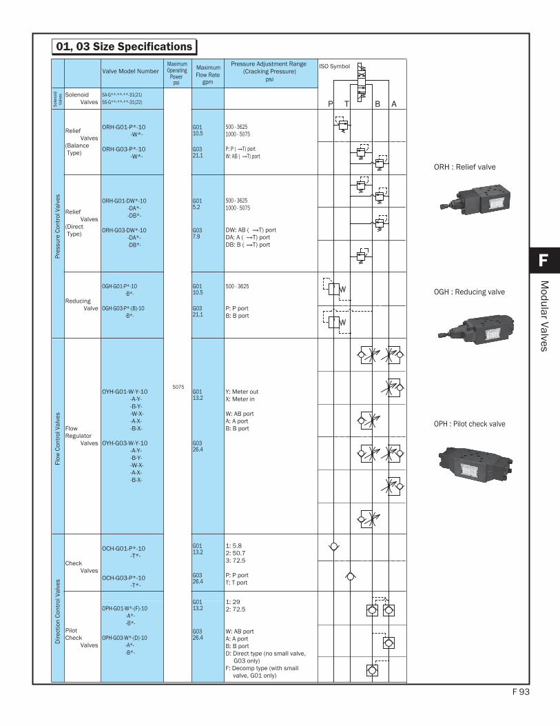
F 93
F
Modular Valves
01, 03 Size Specifications
ORH : Relief valve
OGH : Reducing valve
OPH : Pilot check valve
Type Name Valve Model Number
MaximumOperating
Powerpsi
MaximumFlow Rate
gpm
Pressure Adjustment Range(Cracking Pressure)
psi
ISO Symbol
Sole
noid
Va
lves Solenoid
ValvesSA-G**-**-**-31(21)SS-G**-**-**-31(22)
5075
Pres
sure
Con
trol
Val
ves
Relief Valves
(Balance Type)
ORH-G01-P*-10-W*-
ORH-G03-P*-10-W*-
G0110.5
G0321.1
500 - 36251000 - 5075
P: P ( T) portW: AB ( T) port
Relief Valves
(DirectType)
ORH-G01-DW*-10-DA*--DB*-
ORH-G03-DW*-10-DA*--DB*-
G015.2
G037.9
500 - 36251000 - 5075
DW: AB ( T) portDA: A ( T) portDB: B ( T) port
ReducingValve
OGH-G01-P*-10-B*-
OGH-G03-P*-(B)-10-B*-
G0110.5
G0321.1
500 - 3625
P: P portB: B port
Flow
Con
trol
Val
ves
Flow Regulator
Valves
OYH-G01-W-Y-10-A-Y--B-Y--W-X--A-X--B-X-
OYH-G03-W-Y-10-A-Y--B-Y--W-X--A-X--B-X-
G0113.2
G0326.4
Y: Meter outX: Meter in
W: AB portA: A portB: B port
Dire
ctio
n Co
ntro
l Val
ves
CheckValves
OCH-G01-P*-10-T*-
OCH-G03-P*-10-T*-
G0113.2
G0326.4
1: 5.82: 50.73: 72.5
P: P portT: T port
PilotCheck
Valves
OPH-G01-W*-(F)-10-A*--B*-
OPH-G03-W*-(D)-10-A*--B*-
G0113.2
G0326.4
1: 292: 72.5
W: AB portA: A port B: B portD: Direct type (no small valve,
G03 only) F: Decomp type (with small
valve, G01 only)