SM6 modular units
180
se.com/sm6 SM6 modular units Catalog 2020 Air insulated switchgear Up to 36 kV
-
Upload
khangminh22 -
Category
Documents
-
view
0 -
download
0
Transcript of SM6 modular units

SM6 modular unitsAir insulated switchgear up to 36 kV
Draft v3 - Full re
brand
April 21
Medium Voltage Distribution
???
se.com/sm6se.com/sm6
SM6modular unitsCatalog 2020
Air insulated switchgear Up to 36 kV

schneider-electric.com | 3SM6 Catalog
General contents
General presentation10
General characteristics28
Characteristics of the functional units54
Protection, control and monitoring88
Connections116
Installation130
Schneider Electric services144
Appendices - Order form150
SM6
PM10
8603
Your concerns
Flexibility
Safety
Reliability
Connectivity
schneider-electric.com4 | SM6 Catalog
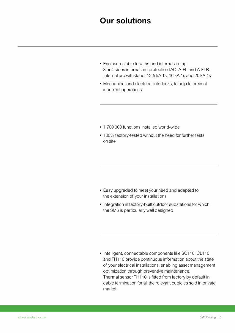
Our solutions
• Easy upgraded to meet your need and adapted to the extension of your installations
• Integration in factory-built outdoor substations for which the SM6 is particularly well designed
• Enclosures able to withstand internal arcing 3 or 4 sides internal arc protection IAC: A-FL and A-FLR. Internal arc withstand: 12.5 kA 1s, 16 kA 1s and 20 kA 1s
• Mechanical and electrical interlocks, to help to prevent incorrect operations
• 1 700 000 functions installed world-wide
• 100% factory-tested without the need for further tests on site
• Intelligent, connectable components like SC110, CL110 and TH110 provide continuous information about the state of your electrical installations, enabling asset management optimization through preventive maintenance. Thermal sensor TH110 is fitted from factory by default in cable termination for all the relevant cubicles sold in private market.
schneider-electric.com | 5SM6 Catalog
schneider-electric.com6 | SM6 Catalog
PM10
8604
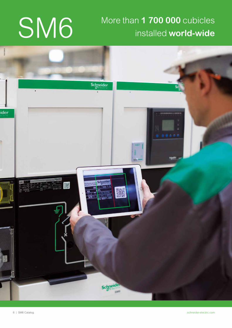
SM6 More than 1 700 000 cubicles installed world-wide
schneider-electric.com | 7SM6 Catalog
Schneider Electric has developed protection, monitoring and control solutions specifically dedicated to Medium Voltage networks for over 40 years.
SM6 switchgear has been specifically designed on the basis of that extensive experience.
It also incorporates some very new solutions, giving the best in terms of continuity of service and operators’ safety.
A comprehensive solutionSM6 switchgear is fully compatible with
• PowerMeter metering units.
• Easergy P3 relay and Easergy Sepam multi-function protection relays- Protection- Measurements and diagnosis.
• VIP protection self powered relay for protection.SM6 swithchboards can thus be easily integrated into any monitoring and control system.- Local & remote indication and operation.
PM10
8605
PM10
8606
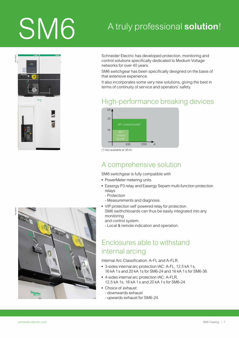
High-performance breaking devices
630
16
25
kA
1250 A
SF1 or/and Evolis*
SF1 or/and Evolis*
(*) Not available at 36 kV.
Enclosures able to withstand internal arcingInternal Arc Classification: A-FL and A-FLR.
• 3-sides internal arc protection IAC: A-FL, 12.5 kA 1 s, 16 kA 1 s and 20 kA 1s for SM6-24 and 16 kA 1 s for SM6-36.
• 4-sides internal arc protection IAC: A-FLR, 12.5 kA 1s, 16 kA 1 s and 20 kA 1 s for SM6-24.
• Choice of exhaust:- downwards exhaust - upwards exhaust for SM6-24.
SM6 A truly professional solution!
schneider-electric.com8 | SM6 Catalog
BIM models
What is BIM • BIM is an evolution of the Computer Aided Design (CAD) and modeling software
market and key to digitization
• It improves on traditional CAD drawings by not only including geometry, but also
information that helps in technical and budget calculations
• BIM also refers broadly to the collaborative processes between and or within
companies to leverage the value of the models throughout the building design &
lifecycle
• Helps create, construct, manage and operate projects more economically and with
less environmental impact
A unique opportunity to improve the key driver of the Building marketStill Interoperability is a challenge
Traditional process
Pre-design
Des
ign
Eff
ort
/ Eff
ect
Detaileddesign
Implementationon documents
Construction
Cost of design changes
Ability to impact cost andfunctional capabilities
BIM process
DM
1053
06
Benefits of BIM
Customer requirements
Business
• High value business
Efficiency
• Reduce time and effort required for work.
• Pain: disconnected tools and incapability to share and interact with each other
Collaboration
• Project management across multiple design environment, colleagues and stakeholders is inefficient and not productive.
• Pain: no collaborative platform to support seamless experience for electrical industry to perform electrical tasks and share across companies and geographies.
Des
ign
Operate
Conceptual design
Detaileddesign
Analysis
Fabrication
Construction4D / 5D
Constructionlogistics
Operation& Maintenance
Renovation& Retrofit
Documentation
Build
DM
1053
07
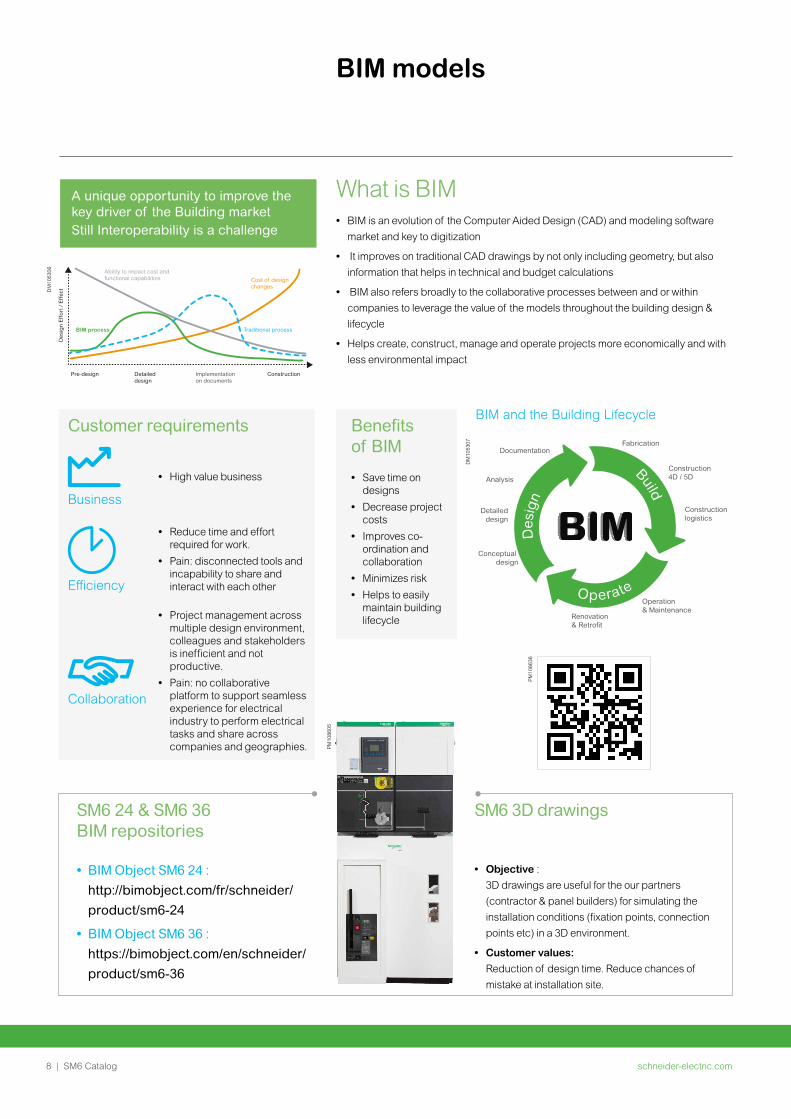
BIM and the Building Lifecycle
• Save time on designs
• Decrease project costs
• Improves co-ordination and collaboration
• Minimizes risk
• Helps to easily maintain building lifecycle
• Objective :
3D drawings are useful for the our partners
(contractor & panel builders) for simulating the
installation conditions (fixation points, connection
points etc) in a 3D environment.
• Customer values:
Reduction of design time. Reduce chances of
mistake at installation site.
SM6 24 & SM6 36 BIM repositories
• BIM Object SM6 24 :
http://bimobject.com/fr/schneider/
product/sm6-24
• BIM Object SM6 36 :
https://bimobject.com/en/schneider/
product/sm6-36
PM10
8605
SM6 3D drawings
PM
1086
36
schneider-electric.com | 9SM6 Catalog
TracePartOnline application
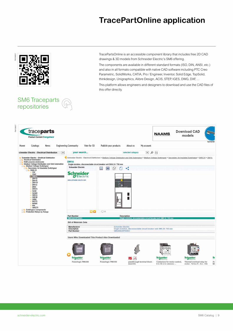
TracePartsOnline is an accessible component library that includes free 2D CAD
drawings & 3D models from Schneider Electric's SM6 offering.
The components are available in different standard formats (ISO, DIN, ANSI, etc.)
and also in all formats compatible with native CAD software including PTC Creo
Parametric, SolidWorks, CATIA, Pro / Engineer, Inventor, Solid Edge, TopSolid,
thinkdesign, Unigraphics, Alibre Design, ACIS, STEP, IGES, DWG, DXF, ...
This platform allows engineers and designers to download and use the CAD files of
this offer directly.
PM10
8607
PM
1086
37

schneider-electric.com10 | SM6 Catalog
General presentation
schneider-electric.com | 11SM6 Catalog
General presentation
The experience of a world leader 12
The references of a leader 13
The range’s advantages 14
EcoStruxtureTM ready solutions 15
Protecting the environment 24
Quality assurance 25
Schneider Electric services 26
QRcode for SM6 functions 27
schneider-electric.com12 | SM6 Catalog
General presentation The experience of a world leader
This experience means that today Schneider Electric can propose
a complementary range: vacuum type circuit breaker cubicles up to 24 kV
and standard or enhanced internal arc withstand cubicles to reinforce
the safety of people according to the IEC standard.
This gives you the advantage of unique experience, that of a world leader,
with over 2,500 000 SF6 Medium Voltage units installed throughout
the world.
Putting this experience at your service and remaining attentive to your
requirements is the spirit of active partnership that we want to develop
in offering you the SM6.
The modular SM6 is a range of harmonised cubicles equipped with SF6
or vacuum breaking technology switchgear with 30 years life span.
These cubicles allow you to produce all your Medium Voltage substation
requirements up to 36 kV by superposing their various functions.
The result of in-depth analysis of your requirements, both now and in the
future, SM6 cubicles mean that you can take advantage of all the features
of both a modern and proven technology.
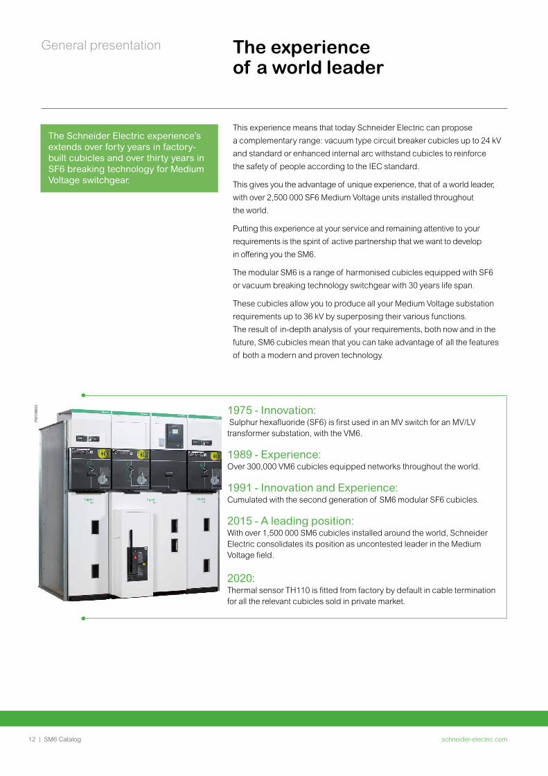
1975 - Innovation: Sulphur hexafluoride (SF6) is first used in an MV switch for an MV/LV transformer substation, with the VM6.
1989 - Experience: Over 300,000 VM6 cubicles equipped networks throughout the world.
1991 - Innovation and Experience: Cumulated with the second generation of SM6 modular SF6 cubicles.
2015 - A leading position: With over 1,500 000 SM6 cubicles installed around the world, Schneider Electric consolidates its position as uncontested leader in the Medium Voltage field.
2020: Thermal sensor TH110 is fitted from factory by default in cable termination for all the relevant cubicles sold in private market.
PM10
8602
The Schneider Electric experience’s extends over forty years in factory-built cubicles and over thirty years in SF6 breaking technology for Medium Voltage switchgear.
schneider-electric.com | 13SM6 Catalog
General presentation The references of a leaderSM6, a world-wide product
Asia/Middle East • Canal Electrical Distribution
Company - Egypt • General Motors Holden - Australia • Pasteur Institute - Cambodia • Tian he City - China • Sanya Airport - China • Bank of China, Beijing, Jv Yanta -
China • Plaza Hotel - Jakarta, Indonesia • Bali Airport - Indonesia • Wakasa Control Center - Japan • Otaru Shopping center - Japan
• New City of Muang, Thong Than, Kanjanapas - Thailand
• Danang and Quinhon Airport, Vanad - Vietnam
• British Embassy - Oman • KBF Palace Riyadh - Saudi Arabia • Raka Stadium - Saudi Arabia • Bilkent University - Turkey • TADCO, BABOIL development -
United Arab Emirates • Melbourne Tunnel City Link -
Australia • Campus KSU Qassim Riyad -
Saudi Arabia
Africa • ONAFEX, Hilton Hotel - Algeria • Yaounde University - Cameroon • Karoua Airport - Cameroon • Libreville Airport - Gabon • Ivarto Hospital, CORIF - Madagascar • Central Bank of Abuja, ADEFEMI -
Nigeria
• OCI Dakar, Oger international, CGE - Senegal
• Bamburi cement Ltd - Kenya • Ivory Electricity Company - Ivory
Coast • Exxon, New Headquarters -
Angola
South America/Pacific • Lamentin Airport, CCIM - Martinique • Space Centre, Kourou - Guyana • Mexico City Underground System -
Mexico • Santiago Underground System -
Chile • Cohiba Hotel, Havana - Cuba • Iberostar Hotel, Bavaro - Dominican
Republic
• Aluminio Argentino Saic SA - Argentina
• Michelin Campo Grande - Rio de Janeiro, Brazil
• TIM Data Center - São Paulo, Brazil
• Light Rio de Janeiro - Brazil • Hospital Oswaldo Cruz -
São Paulo, Brazil
Europe • Stade de France - Paris, France • EDF - France • Eurotunnel - France • Nestlé company headquarters -
France • TLM Terminal , Folkestone - Great
Britain • Zaventem Airport - Belgium • Krediebank Computer Centre -
Belgium • Bucarest Pumping station - Romania
• Prague Airport - Czech Republic • Philipp Morris St Petersburg -
Russia • Kremlin Moscow - Russia • Madrid airport - Spain • Dacia Renault - Romania • Lafarge cement Cirkovic - Czech
Republic • Caterpillar St Petersburg - Russia • Ikea Kazan - Russia • Barajas airport - Spain • Coca-cola Zurich - Switzerland
schneider-electric.com14 | SM6 Catalog
General presentation The range’s advantages•
• .
• .
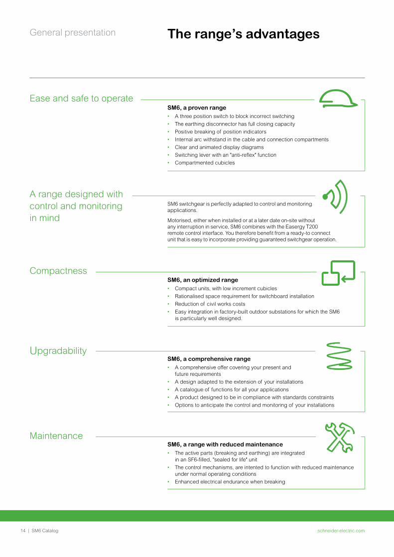
MaintenanceSM6, a range with reduced maintenance• The active parts (breaking and earthing) are integrated
in an SF6-filled, "sealed for life" unit• The control mechanisms, are intented to function with reduced maintenance
under normal operating conditions• Enhanced electrical endurance when breaking
CompactnessSM6, an optimized range • Compact units, with low increment cubicles• Rationalised space requirement for switchboard installation• Reduction of civil works costs• Easy integration in factory-built outdoor substations for which the SM6
is particularly well designed.
A range designed with control and monitoring in mind
SM6 switchgear is perfectly adapted to control and monitoring applications.
Motorised, either when installed or at a later date on-site without any interruption in service, SM6 combines with the Easergy T200 remote control interface. You therefore benefit from a ready-to connect unit that is easy to incorporate providing guaranteed switchgear operation.
Ease and safe to operateSM6, a proven range• A three position switch to block incorrect switching• The earthing disconnector has full closing capacity• Positive breaking of position indicators• Internal arc withstand in the cable and connection compartments• Clear and animated display diagrams• Switching lever with an "anti-reflex" function• Compartmented cubicles
UpgradabilitySM6, a comprehensive range • A comprehensive offer covering your present and
future requirements• A design adapted to the extension of your installations• A catalogue of functions for all your applications• A product designed to be in compliance with standards constraints• Options to anticipate the control and monitoring of your installations
schneider-electric.com | 15SM6 Catalog
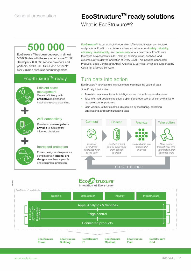
General presentation EcoStruxture ready solutionsWhat is EcoStruxure ?
EcoStruxure™ is our open, interoperable, IoT-enabled system architecture and platform. EcoStruxure delivers enhanced value around safety, reliability, efficiency, sustainability, and connectivity for our customers. EcoStruxure leverages advancements in IoT, mobility, sensing, cloud, analytics, and cybersecurity to deliver Innovation at Every Level. This includes Connected Products, Edge Control, and Apps, Analytics & Services, which are supported by Customer Lifecycle Software.
Turn data into actionEcoStruxure™ architecture lets customers maximize the value of data.
Specifically, it helps them:
• Translate data into actionable intelligence and better business decisions
• Take informed decisions to secure uptime and operational efficiency thanks to real-time control platforms
• Gain visibility to their electrical distribution by measuring, collecting, aggregating, and communicating data
Connect Collect Analyze Take action
Connect everything
from shop floor to top floor
Capture critical data at every level,
from sensor to cloud
Convert data into meaningful analytics
Drive action through real-time information and business logic
CLOSE THE LOOP
DM
1072
33
End
-to-
end
cybe
rsec
urity
Clo
ud a
nd/o
r on
-pre
mis
e
Building
EcoStruxure architectureTM
EcoStruxurePower
EcoStruxureBuilding
EcoStruxureIT
EcoStruxureMachine
EcoStruxurePlant
EcoStruxureGrid
Apps, Analytics & Services
Edge control
Connected products
Data center Industry Infrastructure
EcoStruxureTM has been deployed in almost 500 000 sites with the support of some 20 000 developers, 650 000 service providers and partners, and 3 000 utilities, and connects over 2 million assets under management.
Efficient asset management Greater efficiency with predictive maintenance helping to reduce downtime.
24/7 connectivity
Real-time data everywhere anytime to make better informed decisions.
Increased protection
Proven design and experience combined with internal arc designs to enhance people and equipment protection.
schneider-electric.com16 | SM6 Catalog
General presentation
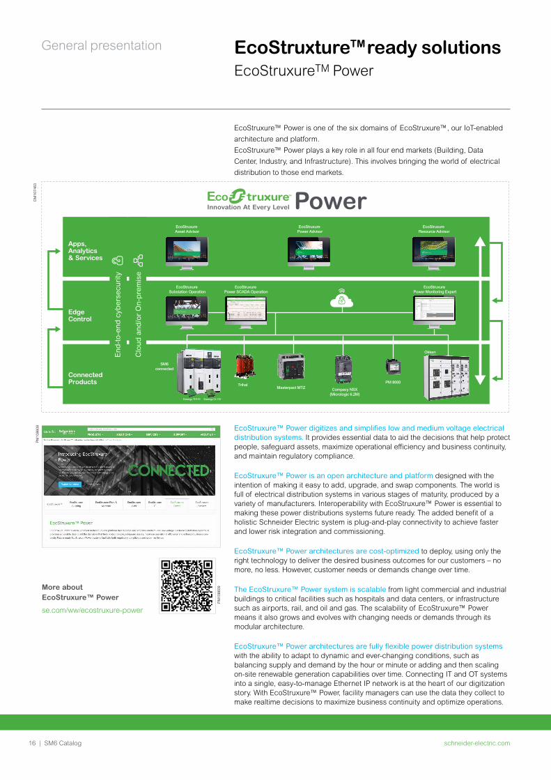
EcoStruxure™ Power is one of the six domains of EcoStruxure™, our IoT-enabled architecture and platform.EcoStruxure™ Power plays a key role in all four end markets (Building, Data Center, Industry, and Infrastructure). This involves bringing the world of electrical distribution to those end markets.
EcoStruxure™ Power digitizes and simplifies low and medium voltage electrical distribution systems. It provides essential data to aid the decisions that help protect people, safeguard assets, maximize operational efficiency and business continuity, and maintain regulatory compliance.
EcoStruxure™ Power is an open architecture and platform designed with the intention of making it easy to add, upgrade, and swap components. The world is full of electrical distribution systems in various stages of maturity, produced by a variety of manufacturers. Interoperability with EcoStruxure™ Power is essential to making these power distributions systems future ready. The added benefit of a holistic Schneider Electric system is plug-and-play connectivity to achieve faster and lower risk integration and commissioning.
EcoStruxure™ Power architectures are cost-optimized to deploy, using only the right technology to deliver the desired business outcomes for our customers – no more, no less. However, customer needs or demands change over time.
The EcoStruxure™ Power system is scalable from light commercial and industrial buildings to critical facilities such as hospitals and data centers, or infrastructure such as airports, rail, and oil and gas. The scalability of EcoStruxure™ Power means it also grows and evolves with changing needs or demands through its modular architecture.
EcoStruxure™ Power architectures are fully flexible power distribution systems with the ability to adapt to dynamic and ever-changing conditions, such as balancing supply and demand by the hour or minute or adding and then scaling on-site renewable generation capabilities over time. Connecting IT and OT systems into a single, easy-to-manage Ethernet IP network is at the heart of our digitization story. With EcoStruxure™ Power, facility managers can use the data they collect to make realtime decisions to maximize business continuity and optimize operations.
EcoStruxture ready solutions EcoStruxureTM Power
DM
1074
63
Power
End
-to-
end
cybe
rsec
urity
Clo
ud a
nd/o
r O
n-pr
emis
e
Apps, Analytics & Services
Edge Control
Connected Products
EcoStruxure Asset Advisor
EcoStruxure Power Advisor
EcoStruxure Resource Advisor
EcoStruxure Power Monitoring Expert
EcoStruxure Power SCADA Operation
EcoStruxure Substation Operation
Easergy TH110 Easergy CL110
SM6connected
Masterpact MTZ
Okken
PM 8000
Compacy NSX(Micrologic 6.2M)
Trihal
PM10
8608
More about EcoStruxure™ Power
se.com/ww/ecostruxure-power
PM10
8609
schneider-electric.com | 17SM6 Catalog
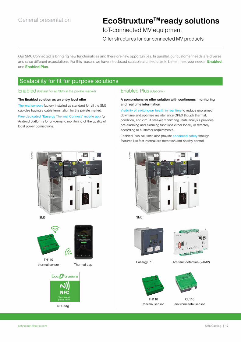
General presentation EcoStruxture ready solutions IoT-connected MV equipmentOffer structures for our connected MV products
Our SM6 Connected is bringing new functionalities and therefore new opportunities. In parallel, our customer needs are diverse and raise different expectations. For this reason, we have introduced scalable architectures to better meet your needs: Enabled, and Enabled Plus.
(Default for all SM6 in the private market) (Optional)
Scalability for fit for purpose solutions
Enabled Enabled Plus
The Enabled solution as an entry level offer
Thermal sensors factory installed as standard for all the SM6 cubicles having a cable termination for the private market.
Free dedicated “Easergy Thermal Connect” mobile app for Android platforms for on-demand monitoring of the quality of local power connections.
A comprehensive offer solution with continuous monitoring and real time information
Visibility of switchgear health in real time to reduce unplanned downtime and optimize maintenance OPEX though thermal, condition, and circuit breaker monitoring. Data analysis provides pre-alarming and alarming functions either locally or remotely according to customer requirements.
Enabled Plus solutions also provide enhanced safety through features like fast internal arc detection and nearby control.
NFCTo connectplace here
NFC tag
Thermal app
TH110
thermal sensor
SM6
DM
1074
64
CL110
environmental sensor
TH110
thermal sensor
SM6
Arc fault detection (VAMP)Easergy P3
DM
1074
65
schneider-electric.com18 | SM6 Catalog
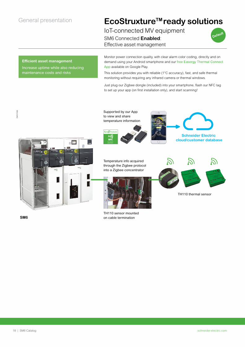
General presentation EcoStruxture ready solutions IoT-connected MV equipmentSM6 Connected Enabled: Effective asset management
Monitor power connection quality, with clear alarm color coding, directly and on demand using your Android smartphone and our free Easergy Thermal Connect App available on Google Play.
This solution provides you with reliable (1°C accuracy), fast, and safe thermal monitoring without requiring any infrared camera or thermal windows.
Just plug our Zigbee dongle (included) into your smartphone, flash our NFC tag to set up your app (on first installation only), and start scanning!
Efficient asset management
Increase uptime while also reducing maintenance costs and risks
NFCTo connectplace here
Temperature info acquired through the Zigbee protocol into a Zigbee concentrator
Supported by our App to view and sharetemperature information
TH110 sensor mounted on cable termination
TH110 thermal sensor
SM6
Schneider Electric cloud/customer database
DM
1074
66
Default
schneider-electric.com | 19SM6 Catalog
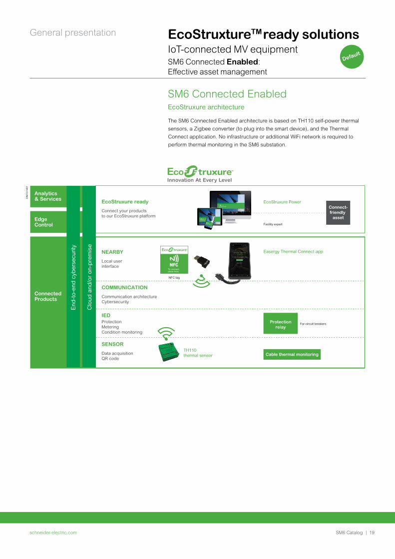
General presentation EcoStruxture ready solutions IoT-connected MV equipmentSM6 Connected Enabled: Effective asset management
Default
The SM6 Connected Enabled architecture is based on TH110 self-power thermal sensors, a Zigbee converter (to plug into the smart device), and the Thermal Connect application. No infrastructure or additional WiFi network is required to perform thermal monitoring in the SM6 substation.
SM6 Connected EnabledEcoStruxure architecture
NFC tag
Easergy Thermal Connect app
TH110thermal sensor
NEARBY
Local user interface NFC
To connectplace here
End
-to-
end
cybe
rsec
urity
Clo
ud a
nd/o
r on
-pre
mis
e
EcoStruxure ready
Connect your products to our EcoStruxure platform
EcoStruxure Power
Facility expert
For circuit breakers
COMMUNICATION
Communication architectureCybersecurity
IEDProtectionMeteringCondition monitoring
SENSOR
Data acquisitionQR code
Analytics
& Services
Edge
Control
Connected Products
Connect-friendly
asset
Protectionrelay
Cable thermal monitoring
DM
1074
67
schneider-electric.com20 | SM6 Catalog
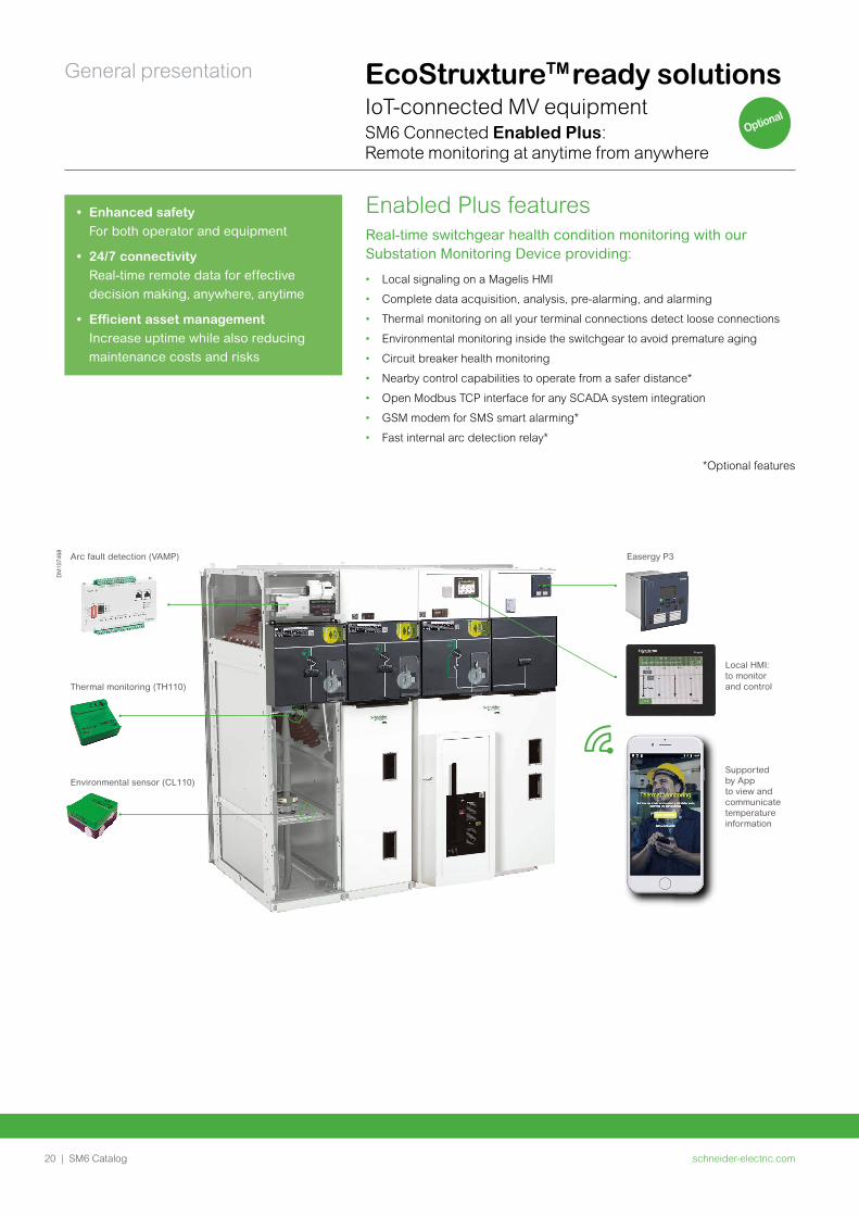
General presentation EcoStruxture ready solutions IoT-connected MV equipmentSM6 Connected Enabled Plus: Remote monitoring at anytime from anywhere
Enabled Plus features Real-time switchgear health condition monitoring with our Substation Monitoring Device providing:
• Local signaling on a Magelis HMI
• Complete data acquisition, analysis, pre-alarming, and alarming
• Thermal monitoring on all your terminal connections detect loose connections
• Environmental monitoring inside the switchgear to avoid premature aging
• Circuit breaker health monitoring
• Nearby control capabilities to operate from a safer distance*
• Open Modbus TCP interface for any SCADA system integration
• GSM modem for SMS smart alarming*
• Fast internal arc detection relay*
*Optional features
• Enhanced safety For both operator and equipment
• 24/7 connectivity Real-time remote data for effective decision making, anywhere, anytime
• Efficient asset management Increase uptime while also reducing maintenance costs and risks
DM
1074
68 Arc fault detection (VAMP)
Thermal monitoring (TH110)
Environmental sensor (CL110)
Easergy P3
Local HMI: to monitor and control
Supported by Appto view andcommunicatetemperature information
Optional
schneider-electric.com | 21SM6 Catalog
General presentation
Local user interface
End
-to-
end
cybe
rsec
urity
Clo
ud a
nd/o
r on
-pre
mis
e
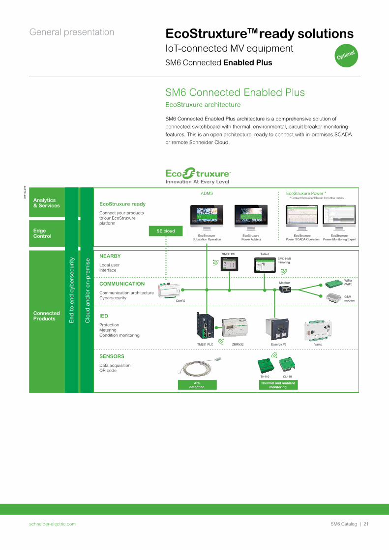
EcoStruxure ready
Connect your products to our EcoStruxureplatform
ADMS EcoStruxure Power ** Contact Schneider Electric for further details
COMMUNICATION
Communication architectureCybersecurity
IED
ProtectionMeteringCondition monitoring
SENSORS
Data acquisitionQR code
Analytics
& Services
Edge
Control
Connected Products
SE cloud
Arcdetection
Thermal and ambientmonitoring
EcoStruxure Power Advisor
EcoStruxure Substation Operation
SMD HMI
Com’X
Modbus
SMD HMI mirroring
TM251 PLC ZBRN32 Easergy P3 Vamp
Tablet
GSMmodem
Wifier(WiFi)
EcoStruxure Power Monitoring Expert
EcoStruxure Power SCADA Operation
NEARBY
TH110 CL110
DM
1074
69
EcoStruxture ready solutions IoT-connected MV equipmentSM6 Connected Enabled Plus
SM6 Connected Enabled Plus architecture is a comprehensive solution of connected switchboard with thermal, environmental, circuit breaker monitoring features. This is an open architecture, ready to connect with in-premises SCADA or remote Schneider Cloud.
SM6 Connected Enabled PlusEcoStruxure architecture
Optional

schneider-electric.com22 | SM6 Catalog
General presentation EcoStruxture ready solutions EcoStruxure Power Advisor
Maximize your system investment by making your data work for you
Electrical network reliability, efficiency, and compliance throughout your facility’s life cycle Power Advisor is a unique, affordable and fast-to-deploy service that leverages your power system data. Fueled by analytics and expert engineers, it finds and prioritizes electrical network and data quality issues anywhere in your system, recommending ways to correct them. These automated, expert recommendations shift your team from non-productive hours to high value work via two core categories of analytics:
Data quality Insights and recommendations that establish a trustworthy data foundation and facilitate ongoing electrical network health
Electrical network Detailed system and trend summaries that identify weaknesses and propose mitigation solutions to prevent a detrimental impact on your business
Power Advisor digital service plans
Power Advisor digital service plans are designed to pair targeted maintenance with expert support and cutting-edge analytics for measurable improvement of your power system performance. Our plans are offered at different levels to meet your business needs and can be customized with optional services.
Data-driven decisions enable you to maximize your system investment. In fact, IoT-enabled condition-based services can cut unplanned outages in half and reduce maintenance costs by up to 25%, extending the life of your power-related assets.
How Power Advisor works
Power Advisor analytics are run multiple times per year, dynamically adjusting to changes in your system to ensure optimal system performance.
• Data collection
Power system data is collected and
uploaded to our secure cloud.
• Single-line diagram
(recommended for extended analytics) A digital representation of your power
system hierarchy can be developed.
Although this requires an initial setup, only
minor adjustments are needed as your
system evolves.
• Data quality and electric network analyses
Our service experts perform analyses
based on your power system and facility
configuration.
• Expert consultation
Backed by patented analytics, our service
experts consult with you to prioritize site
issues and review findings.
• Targeted corrective services
Based on the results of your expert
consultation, prioritized site issues are
assessed for mitigation and optimization
solutions.
• Follow-up
Corrective actions are reviewed to ensure
issues are properly resolved with additional
guidance provided as needed.
Contact us for more information about how to move to efficient, proactive maintenance with Power Advisor.
PM10
8610
PM10
8611
schneider-electric.com | 23SM6 Catalog
General presentation
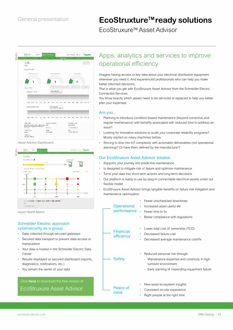
Apps, analytics and services to improve operational efficiency
Imagine having access to key data about your electrical distribution equipment whenever you need it. And experienced professionals who can help you make better informed decisions.That is what you get with EcoStruxure Asset Advisor from the Schneider Electric Connected Services.You know exactly which assets need to be serviced or replaced to help you better plan your expenses.
Are you...• Planning to introduce condition-based maintenance (beyond corrective and
regular maintenance) with benefits associated with reduced time to address an
issue?
• Looking for innovative solutions to scale your corporate reliability programs?
Mostly started on rotary machines before.
• Striving to dive into IoT complexity with actionable deliverables (not operational
alarming)? Or have them defined by the manufacturer?
Our EcoStruxure Asset Advisor solution• Supports your journey into predictive maintenance
• Is designed to mitigate risk of failure and optimize maintenance
• Turns your data into short-term actions and long-term decisions
• Our platform is ready to use by plug-in connectable electrical assets under our
flexible model
• EcoStruxure Asset Advisor brings tangible benefits on failure risk mitigation and
maintenance optimization
Asset Advisor Dashboard
Asset Health Matrix
Schneider Electric approach cybersecurity as a group...• Data collected through secured gateways
• Secured data transport to prevent data access or
manipulation
• Your data is hosted in the Schneider Electric Data
Center
• Results displayed on secured dashboard (reports,
diagnostics, notifications, etc.)
• You remain the owner of your data
PM10
6675
PM10
6676
Click here to download the free version of
EcoStruxure Asset Advisor
EcoStruxture ready solutions EcoStruxure Asset Advisor
• Fewer unscheduled downtimes
• Increased asset useful life
• Fewer time to fix
• Better compliance with regulations
• Lower total cost of ownership (TCO)
• Decreased failure cost
• Decreased average maintenance cost/fix
• Reduced personal risk through:
- Maintenance expertise and continuity in high
turnover environment
- Early warning of impending equipment failure
• New asset ecosystem insights
• Consistent on-site experience
• Right people at the right time
Operational performance
Financial efficiency
Safety
Peace of mind
schneider-electric.com24 | SM6 Catalog
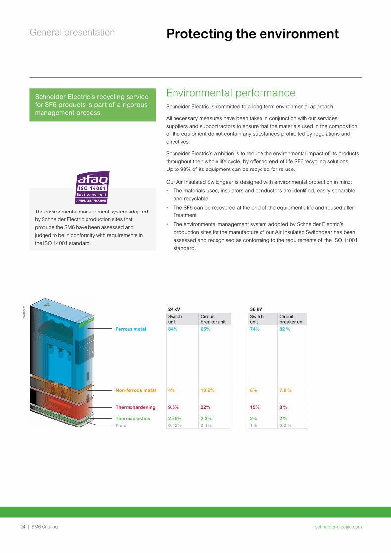
General presentation Protecting the environment
Schneider Electric is committed to a long-term environmental approach.
All necessary measures have been taken in conjunction with our services, suppliers and subcontractors to ensure that the materials used in the composition of the equipment do not contain any substances prohibited by regulations and directives.
Schneider Electric’s ambition is to reduce the environmental impact of its products throughout their whole life cycle, by offering end-of-life SF6 recycling solutions. Up to 98% of its equipment can be recycled for re-use.
Our Air Insulated Switchgear is designed with environmental protection in mind:
• The materials used, insulators and conductors are identified, easily separable
and recyclable
• The SF6 can be recovered at the end of the equipment’s life and reused after
Treatment
• The environmental management system adopted by Schneider Electric’s
production sites for the manufacture of our Air Insulated Switchgear has been
assessed and recognised as conforming to the requirements of the ISO 14001
standard.
Environmental performance
DM
1074
70 24 kV 36 kVSwitch unit
Circuit breaker unit
Switch unit
Circuit breaker unit
Ferrous metal 84% 65% 74% 82 %
Non-ferrous metal 4% 10.6% 8% 7.8 %
Thermohardening 9.5% 22% 15% 8 %
Thermoplastics 2.35% 2.3% 2% 2 %Fluid 0.15% 0.1% 1% 0.2 %
Schneider Electric’s recycling service for SF6 products is part of a rigorous management process.
The environmental management system adopted by Schneider Electric production sites that produce the SM6 have been assessed and judged to be in conformity with requirements in the ISO 14001 standard.
schneider-electric.com | 25SM6 Catalog
General presentationP
M10
8612
PM
1086
13
A major advantageSchneider Electric has integrated a functional organisation into each of its units. The main mission of this organisation is to check the quality and the compliance with standards. This procedure is:
• Uniform throughout all departments
• Recognised by many customers and approved organisations.
But it is above all its strict application that has enabled recognition to be obtained by an independent organisation: The French Quality Assurance Association (FQAA).
The quality system for the design and manufacture of SM6 units has been certified in conformity with the requirements of the ISO 9001: 2000 quality assurance model.
Quality assuranceQuality certified to ISO 9001
Meticulous and systematic controls
During manufacture, each SM6 is subject to systematic routine testing which aims to check the quality and conformity:
• Sealing testing
• Filling pressure testing
• Opening and closing rate testing
• Switching torque measurement
• Dielectric testing
• Conformity with drawings and plans.
The results obtained are written and reported on the test certificate for each device by the quality control department.
Mean Operating Time To Failure (MTTF)As result of Schneider Electric quality assurance system, SM6 has negligible "Mean Down Time (MDT)" in comparison to the "Mean Up Time (MUT)", thus "Mean Operating Time Between Failures (MTBF)" is as similar as to the MTTF.
• MTTF (cumulative) = 3890 years for SM6-24
• MTTF (cumulative) = 6259 years for SM6-36.
schneider-electric.com26 | SM6 Catalog
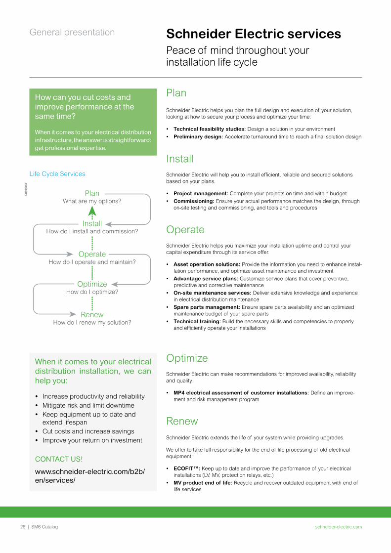
General presentation Schneider Electric servicesPeace of mind throughout your installation life cycle
How can you cut costs and improve performance at the same time?
When it comes to your electrical distribution infrastructure, the answer is straightforward: get professional expertise.
PlanSchneider Electric helps you plan the full design and execution of your solution, looking at how to secure your process and optimize your time:
• Technical feasibility studies: Design a solution in your environment• Preliminary design: Accelerate turnaround time to reach a final solution design
InstallSchneider Electric will help you to install efficient, reliable and secured solutions based on your plans.
• Project management: Complete your projects on time and within budget• Commissioning: Ensure your actual performance matches the design, through
on-site testing and commissioning, and tools and procedures
OperateSchneider Electric helps you maximize your installation uptime and control your capital expenditure through its service offer.
• Asset operation solutions: Provide the information you need to enhance instal-lation performance, and optimize asset maintenance and investment
• Advantage service plans: Customize service plans that cover preventive, predictive and corrective maintenance
• On-site maintenance services: Deliver extensive knowledge and experience in electrical distribution maintenance
• Spare parts management: Ensure spare parts availability and an optimized maintenance budget of your spare parts
• Technical training: Build the necessary skills and competencies to properly and efficiently operate your installations
OptimizeSchneider Electric can make recommendations for improved availability, reliability and quality.
• MP4 electrical assessment of customer installations: Define an improve-ment and risk management program
Life Cycle Services
PlanWhat are my options?
InstallHow do I install and commission?
OperateHow do I operate and maintain?
OptimizeHow do I optimize?
RenewHow do I renew my solution?
Life Cycle Services
DB
4088
43
RenewSchneider Electric extends the life of your system while providing upgrades.
We offer to take full responsibility for the end of life processing of old electrical equipment.
• ECOFIT™: Keep up to date and improve the performance of your electrical installations (LV, MV, protection relays, etc.)
• MV product end of life: Recycle and recover outdated equipment with end of life services
When it comes to your electrical distribution installation, we can help you:
• Increase productivity and reliability• Mitigate risk and limit downtime• Keep equipment up to date and
extend lifespan • Cut costs and increase savings • Improve your return on investment
CONTACT US!
www.schneider-electric.com/b2b/en/services/
schneider-electric.com | 27SM6 Catalog
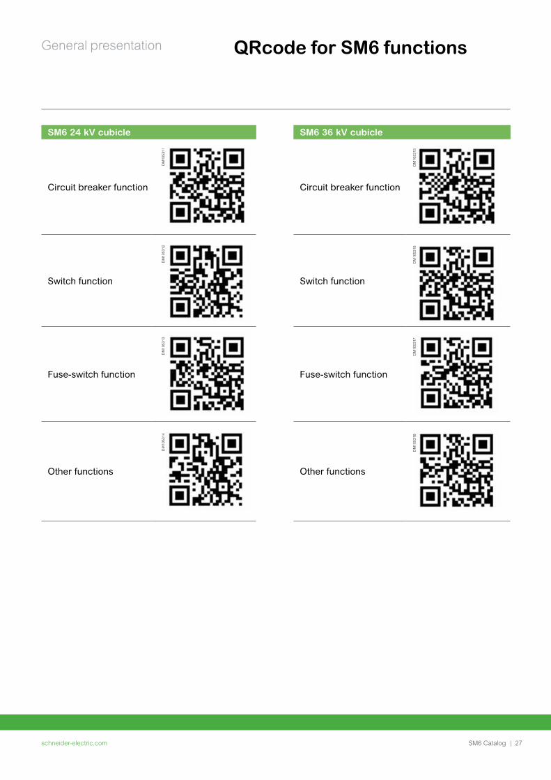
General presentation QRcode for SM6 functions
SM6 24 kV cubicle
Circuit breaker function
Switch function
Fuse-switch function
Other functions
DM
1053
11D
M10
5312
DM
1053
13D
M10
5314
SM6 36 kV cubicle
Circuit breaker function
Switch function
Fuse-switch function
Other functions
DM
1053
15D
M10
5316
DM
1053
17D
M10
5318

schneider-electric.com28 | SM6 Catalog
General characteristics
schneider-electric.com | 29SM6 Catalog
Field of application 30
Units for switching function 32
Units for protection function 33
Units for metering function 36
Units for other functions 37
Operating conditions 38
Standards 39
Main characteristics 40
Factory-built cubicles description 43
Compartments and devices description 46
Safety of people 49By switchgear 49
By operating mechanism safety 51
By internal arc protection 52
General characteristics
schneider-electric.com30 | SM6 Catalog
General characteristics
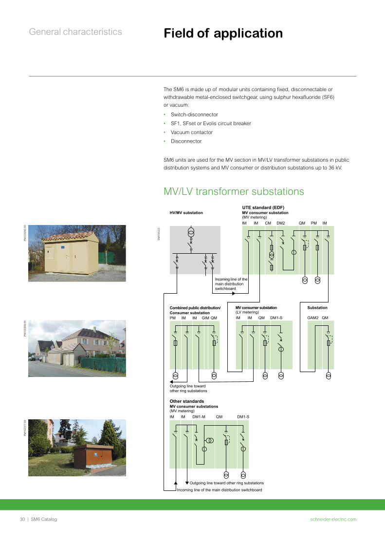
MV consumer substation(MV metering)IM
Incoming line of the main distribution switchboard
Outgoing line towardother ring substations
IM CM DM2 QM PM IM
Other standardsMV consumer substations(MV metering)IM
Outgoing line toward other ring substations
Incoming line of the main distribution switchboard
IM DM1-M QM DM1-S
Combined public distribution/Consumer substationPM IM IM GIM QM
MV consumer substation(LV metering)
Substation
IM IM GAM2 QMQM DM1-S
UTE standard (EDF)HV/MV substation
The SM6 is made up of modular units containing fixed, disconnectable or withdrawable metal-enclosed switchgear, using sulphur hexafluoride (SF6) or vacuum:
• Switch-disconnector
• SF1, SFset or Evolis circuit breaker
• Vacuum contactor
• Disconnector.
SM6 units are used for the MV section in MV/LV transformer substations in public distribution systems and MV consumer or distribution substations up to 36 kV.
MV/LV transformer substations
DM
1053
22
PM10
2377
-55
PM10
3309
-55
PM10
3350
-55
Field of application
schneider-electric.com | 31SM6 Catalog
General characteristics Field of application
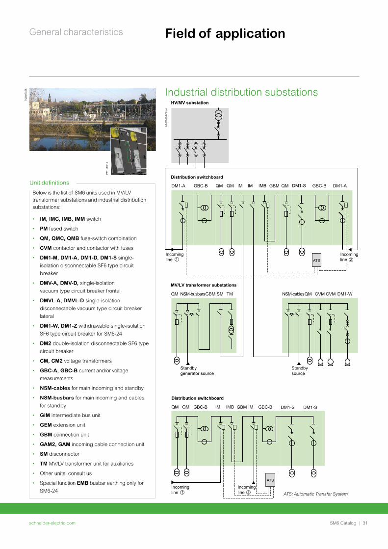
Industrial distribution substations
PM10
5368
QM QM
NSM-busbarsGBM SM TMQM NSM-cablesQM CVM CVM DM1-W
Distribution switchboard
DM1-A DM1-S
DM1-S DM1-SGBC-B
GBC-B
GBC-B
GBC-BQM QMQM IM
IM IMIMB
IM IMB GBM
GBM
DM1-A
Incoming line
ATS
ATS
MV/LV transformer substations
Distribution switchboard
HV/MV substation
Standby generator source
Standby source
Incoming line
Incoming line
Incoming line
DE5
9200
EN-L
G
ATS: Automatic Transfer System
Below is the list of SM6 units used in MV/LV transformer substations and industrial distribution substations:
• IM, IMC, IMB, IMM switch
• PM fused switch
• QM, QMC, QMB fuse-switch combination
• CVM contactor and contactor with fuses
• DM1-M, DM1-A, DM1-D, DM1-S single-
isolation disconnectable SF6 type circuit
breaker
• DMV-A, DMV-D, single-isolation
vacuum type circuit breaker frontal
• DMVL-A, DMVL-D single-isolation
disconnectable vacuum type circuit breaker
lateral
• DM1-W, DM1-Z withdrawable single-isolation
SF6 type circuit breaker for SM6-24
• DM2 double-isolation disconnectable SF6 type
circuit breaker
• CM, CM2 voltage transformers
• GBC-A, GBC-B current and/or voltage
measurements
• NSM-cables for main incoming and standby
• NSM-busbars for main incoming and cables
for standby
• GIM intermediate bus unit
• GEM extension unit
• GBM connection unit
• GAM2, GAM incoming cable connection unit
• SM disconnector
• TM MV/LV transformer unit for auxiliaries
• Other units, consult us
• Special function EMB busbar earthing only for
SM6-24
Unit definitions
PM10
8614
schneider-electric.com32 | SM6 Catalog
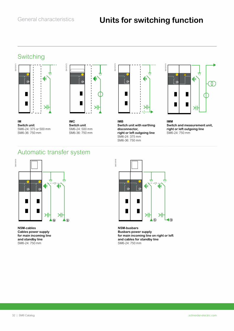
General characteristics Units for switching function
Switching
DM
1074
71
DM
1074
72
DM
1074
73
DM
1074
74
IMSwitch unitSM6-24: 375 or 500 mm SM6-36: 750 mm
IMCSwitch unitSM6-24: 500 mm SM6-36: 750 mm
IMB Switch unit with earthing disconnector, right or left outgoing lineSM6-24: 375 mm SM6-36: 750 mm
IMMSwitch and measurement unit, right or left outgoing lineSM6-24: 750 mm
Automatic transfer system
DM
1074
75
DM
1074
76
NSM-cables Cables power supply for main incoming line and standby lineSM6-24: 750 mm
NSM-busbarsBusbars power supply for main incoming line on right or left and cables for standby lineSM6-24: 750 mm
schneider-electric.com | 33SM6 Catalog
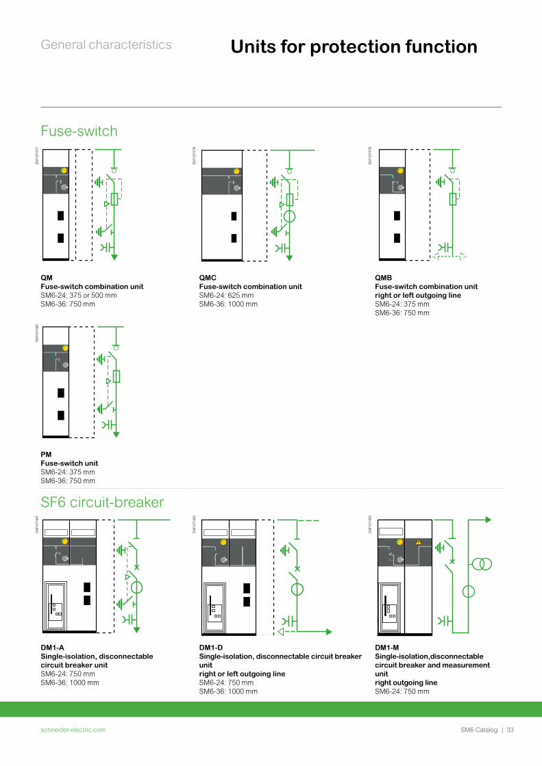
General characteristics Units for protection function
Fuse-switch
DM
1074
77
DM
1074
78
DM
1074
79
QM Fuse-switch combination unitSM6-24: 375 or 500 mm SM6-36: 750 mm
QMC Fuse-switch combination unitSM6-24: 625 mm SM6-36: 1000 mm
QMB Fuse-switch combination unit right or left outgoing line SM6-24: 375 mm SM6-36: 750 mm
DM
1074
80
PM Fuse-switch unitSM6-24: 375 mm SM6-36: 750 mm
SF6 circuit-breaker
DM
1074
81
DM
1074
82
DM
1074
83
DM1-ASingle-isolation, disconnectable circuit breaker unitSM6-24: 750 mm SM6-36: 1000 mm
DM1-DSingle-isolation, disconnectable circuit breaker unit right or left outgoing lineSM6-24: 750 mm SM6-36: 1000 mm
DM1-MSingle-isolation,disconnectable circuit breaker and measurement unitright outgoing lineSM6-24: 750 mm
schneider-electric.com34 | SM6 Catalog
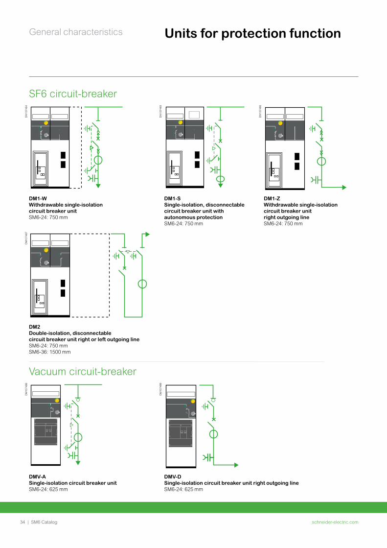
General characteristics Units for protection function
SF6 circuit-breaker
DM
1074
84
DM
1074
85
DM
1074
86
DM1-WWithdrawable single-isolation circuit breaker unitSM6-24: 750 mm
DM1-SSingle-isolation, disconnectable circuit breaker unit with autonomous protectionSM6-24: 750 mm
DM1-ZWithdrawable single-isolation circuit breaker unit right outgoing lineSM6-24: 750 mm
DM
1074
87
DM2Double-isolation, disconnectable circuit breaker unit right or left outgoing lineSM6-24: 750 mm SM6-36: 1500 mm
Vacuum circuit-breaker
DM
1074
88
DM
1074
89
DMV-ASingle-isolation circuit breaker unitSM6-24: 625 mm
DMV-DSingle-isolation circuit breaker unit right outgoing line SM6-24: 625 mm
schneider-electric.com | 35SM6 Catalog
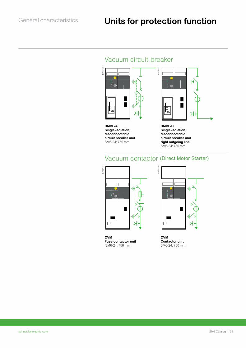
General characteristics Units for protection function
Vacuum circuit-breaker
DM
1074
90
DM
1074
91
DMVL-A Single-isolation, disconnectable circuit breaker unitSM6-24: 750 mm
DMVL-D Single-isolation, disconnectable circuit breaker unit right outgoing line SM6-24: 750 mm
Vacuum contactor (Direct Motor Starter)
DM
1074
92
DM
1074
93
CVM Fuse-contactor unit SM6-24: 750 mm
CVMContactor unitSM6-24: 750 mm
schneider-electric.com36 | SM6 Catalog
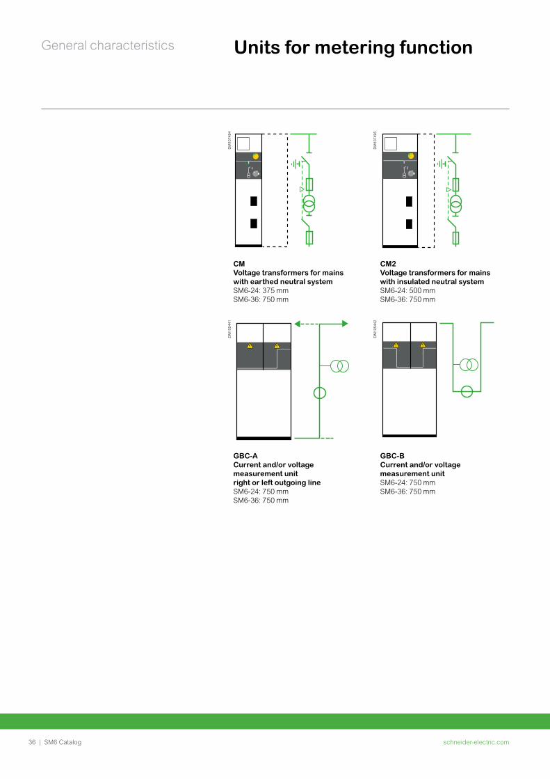
General characteristics Units for metering function
DM
1074
94
DM
1074
95
CMVoltage transformers for mains with earthed neutral systemSM6-24: 375 mm SM6-36: 750 mm
CM2 Voltage transformers for mains with insulated neutral systemSM6-24: 500 mm SM6-36: 750 mm
DM
1054
41
DM
1054
42
GBC-A Current and/or voltage measurement unit right or left outgoing line SM6-24: 750 mmSM6-36: 750 mm
GBC-BCurrent and/or voltage measurement unitSM6-24: 750 mmSM6-36: 750 mm
schneider-electric.com | 37SM6 Catalog
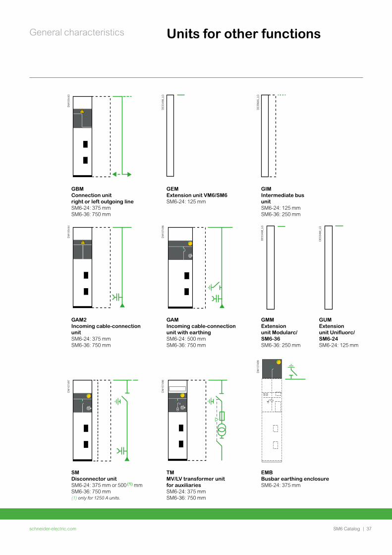
General characteristics Units for other functions
DM
1054
43
DE5
3498
_LG
DE5
9685
_LG
GBM Connection unit right or left outgoing lineSM6-24: 375 mm SM6-36: 750 mm
GEMExtension unit VM6/SM6SM6-24: 125 mm
GIM Intermediate bus unit SM6-24: 125 mm SM6-36: 250 mm
DM
1054
44
DM
1074
96
DE5
3498
_LG
DE5
3498
_LG
GAM2Incoming cable-connection unitSM6-24: 375 mm SM6-36: 750 mm
GAMIncoming cable-connection unit with earthingSM6-24: 500 mm SM6-36: 750 mm
GMMExtension unit Modularc/ SM6-36SM6-36: 250 mm
GUMExtension unit Unifluorc/ SM6-24SM6-24: 125 mm
DM
1074
97
DM
1074
98
DM
1074
99
SMDisconnector unitSM6-24: 375 mm or 500 (1) mm SM6-36: 750 mm(1) only for 1250 A units.
TMMV/LV transformer unit for auxiliariesSM6-24: 375 mm SM6-36: 750 mm
EMBBusbar earthing enclosureSM6-24: 375 mm
schneider-electric.com38 | SM6 Catalog
General characteristicsPM
1086
15
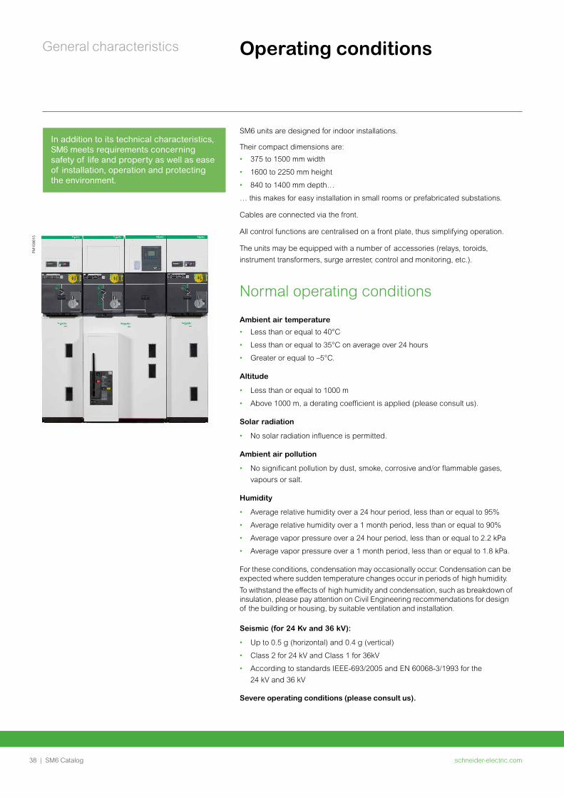
SM6 units are designed for indoor installations.
Their compact dimensions are:
• 375 to 1500 mm width
• 1600 to 2250 mm height
• 840 to 1400 mm depth…
… this makes for easy installation in small rooms or prefabricated substations.
Cables are connected via the front.
All control functions are centralised on a front plate, thus simplifying operation.
The units may be equipped with a number of accessories (relays, toroids, instrument transformers, surge arrester, control and monitoring, etc.).
Normal operating conditions
Ambient air temperature
• Less than or equal to 40°C
• Less than or equal to 35°C on average over 24 hours
• Greater or equal to –5°C.
Altitude
• Less than or equal to 1000 m
• Above 1000 m, a derating coefficient is applied (please consult us).
Solar radiation
• No solar radiation influence is permitted.
Ambient air pollution
• No significant pollution by dust, smoke, corrosive and/or flammable gases,
vapours or salt.
Humidity
• Average relative humidity over a 24 hour period, less than or equal to 95%
• Average relative humidity over a 1 month period, less than or equal to 90%
• Average vapor pressure over a 24 hour period, less than or equal to 2.2 kPa
• Average vapor pressure over a 1 month period, less than or equal to 1.8 kPa.
For these conditions, condensation may occasionally occur. Condensation can be expected where sudden temperature changes occur in periods of high humidity.
To withstand the effects of high humidity and condensation, such as breakdown of insulation, please pay attention on Civil Engineering recommendations for design of the building or housing, by suitable ventilation and installation.
Seismic (for 24 Kv and 36 kV):
• Up to 0.5 g (horizontal) and 0.4 g (vertical)
• Class 2 for 24 kV and Class 1 for 36kV
• According to standards IEEE-693/2005 and EN 60068-3/1993 for the
24 kV and 36 kV
Severe operating conditions (please consult us).
Operating conditions
In addition to its technical characteristics, SM6 meets requirements concerning safety of life and property as well as ease of installation, operation and protecting the environment.
schneider-electric.com | 39SM6 Catalog
General characteristics Standards
IEC standards62271-200 High-voltage switchgear and controlgear - Part 200:
A.C. metal-enclosed switchgear and controlgear for rated voltage above 1 kV and up to and including 52 kV.
62271-1 High-voltage switchgear and controlgear - Part 1: Common specifications.
62271-103 High voltage switches - Part 1: switches for rated voltages above 1 kV and less or equal to 52 kV.
62271-105 High-voltage switchgear and controlgear - Part 105: High voltage alternating current switch-fuse combinations.
60255 Electrical relays.
62271-100 High-voltage switchgear and controlgear - Part 100: High-voltage alternating current circuit breakers.
62271-102 High-voltage switchgear and controlgear - Part 102: High-voltage alternating current disconnectors and earthing switches.
61869-2 Instrument transformers - Part 1: Current transformers.
61869-3 Instrument transformers - Part 2: Voltage transformers.
60044-8 Instrument transformers - Part 8: Low Power Current Transducers.
62271-206 High-voltage prefabricated switchgear and controlgear assemblies - Voltage presence indicating systems.
62271-304 High-voltage switchgear and controlgear - Part 304: Design classes for indoor enclosed switchgear and controlgear for rated voltages above 1 kV up to and including 52 kV to be used in severe climatic conditions.
SEISMIC standards for 24kVIEE-693 2005 IEEE Recommended Practice for Seismic Design of
Substations
EN600068-3-3 1993 Environmental testing-Part 3: guidance, Seismic test methods for equipments
UTE standards for 24 kVNFC 13.100 Consumer substation installed inside a building and fed by
a second category voltage public distribution system.
NFC 13.200 High voltage electrical installations requirements.
NFC 64.130 High voltage switches for rated voltage above 1 kV and less than 52 kV.
NFC 64.160. Alternating current disconnectors and earthing switches
SM6 units meet all the following standards and specifications:• IEC standards
• UTE standards for SM6-24
• EDF specifications for SM6-24
• SEISMIC standards for 24 kV
schneider-electric.com40 | SM6 Catalog
General characteristics Main characteristics
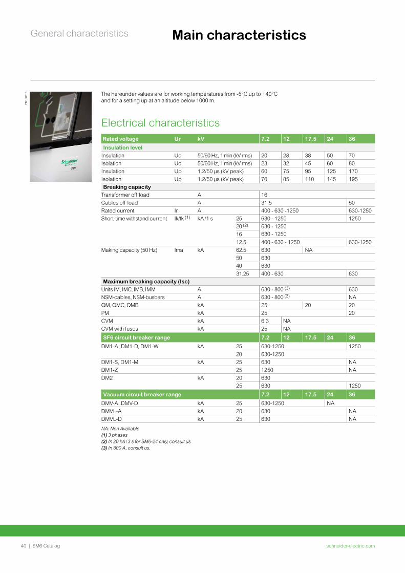
Rated voltage Ur kV 7.2 12 17.5 24 36
Insulation levelInsulation Ud 50/60 Hz, 1 min (kV r ms) 20 28 38 50 70Isolation Ud 50/60 Hz, 1 min (kV r ms) 23 32 45 60 80Insulation Up 1.2/50 µs (kV peak) 60 75 95 125 170Isolation Up 1.2/50 µs (kV peak) 70 85 110 145 195Breaking capacity
Transformer off load A 16Cables off load A 31.5 50Rated current Ir A 400 - 630 -1250 630-1250Short-time withstand current Ik/tk (1) kA /1 s 25 630 - 1250 1250
20 (2) 630 - 1250630 - 125016
12.5 400 - 630 - 1250 630-1250Making capacity (50 Hz) Ima kA 62.5 630 NA
50 630 40 630 31.25 400 - 630 630
Maximum breaking capacity (Isc)Units IM, IMC, IMB, IMM A 630 - 800 (3) 630NSM-cables, NSM-busbars A 630 - 800 (3) NAQM, QMC, QMB kA 25 20 20PM kA 25 20CVM kA 6.3 NACVM with fuses kA 25 NA
SF6 circuit breaker range 7.2 12 17.5 24 36
DM1-A, DM1-D, DM1-W kA 25 630-1250 125020 630-1250
DM1-S, DM1-M kA 25 630 NADM1-Z 25 1250 NADM2 kA 20 630
25 630 1250
Vacuum circuit breaker range 7.2 12 17.5 24 36
DMV-A, DMV-D kA 25 630-1250 NADMVL-A kA 20 630 NADMVL-D kA 25 630 NA
NA: Non Available (1) 3 phases(2) In 20 kA / 3 s for SM6-24 only, consult us(3) In 800 A, consult us.
The hereunder values are for working temperatures from -5°C up to +40°C and for a setting up at an altitude below 1000 m.
PM10
8616
Electrical characteristics
schneider-electric.com | 41SM6 Catalog
General characteristics Main characteristics
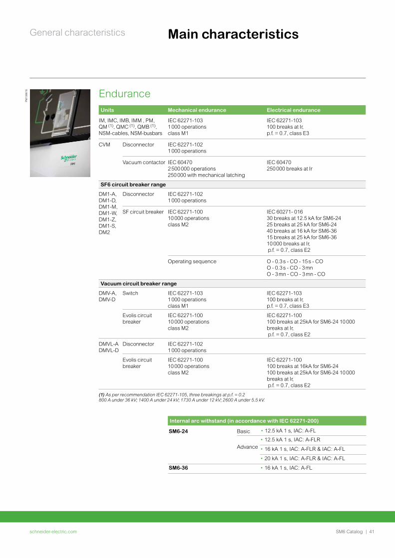
EnduranceUnits Mechanical endurance Electrical endurance
IM, IMC, IMB, IMM , PM, QM (1), QMC (1), QMB (1), NSM-cables, NSM-busbars
IEC 62271-103 1 000 operations class M1
IEC 62271-103 100 breaks at Ir, p.f. = 0.7, class E3
CVM Disconnector IEC 62271-1021 000 operations
Vacuum contactor IEC 60470 2 500 000 operations 250 000 with mechanical latching
IEC 60470 250 000 breaks at Ir
SF6 circuit breaker range
DM1-A, DM1-D, DM1-M, DM1-W, DM1-Z, DM1-S, DM2
Disconnector IEC 62271-102 1 000 operations
SF circuit breaker IEC 62271-100 10 000 operationsclass M2
IEC 60271- 016 30 breaks at 12.5 kA for SM6-24 25 breaks at 25 kA for SM6-2440 breaks at 16 kA for SM6-36 15 breaks at 25 kA for SM6-36 10 000 breaks at Ir, p.f. = 0.7, class E2
Operating sequence O - 0.3 s - CO - 15 s - CO O - 0.3 s - CO - 3 mnO - 3 mn - CO - 3 mn - CO
Vacuum circuit breaker range
DMV-A, DMV-D
Switch IEC 62271-103 1 000 operations class M1
IEC 62271-103 100 breaks at Ir, p.f. = 0.7, class E3
Evolis circuit breaker
IEC 62271-100 10 000 operations class M2
IEC 62271-100 100 breaks at 25kA for SM6-24 10 000 breaks at Ir, p.f. = 0.7, class E2
DMVL-A DMVL-D
Disconnector IEC 62271-102 1 000 operations
Evolis circuit breaker
IEC 62271-100 10 000 operations class M2
IEC 62271-100 100 breaks at 16kA for SM6-24 100 breaks at 25kA for SM6-24 10 000 breaks at Ir, p.f. = 0.7, class E2
(1) As per recommendation IEC 62271-105, three breakings at p.f. = 0.2800 A under 36 kV; 1400 A under 24 kV; 1730 A under 12 kV; 2600 A under 5.5 kV.
Internal arc withstand (in accordance with IEC 62271-200)
SM6-24 Basic
Advance
• 12.5 kA 1 s, IAC: A-FLR
• 16 kA 1 s, IAC: A-FLR & IAC: A-FL
• 20 kA 1 s, IAC: A-FLR & IAC: A-FL
SM6-36 • 16 kA 1 s, IAC: A-FL
• 12.5 kA 1 s, IAC: A-FL
PM10
8616
schneider-electric.com42 | SM6 Catalog
General characteristics
Protection index
• Classes: PI (insulating partition)
• Loss of service continuity classes: LSC2A (LSC1 for metering GAM/GBM
functions)
• Units in switchboard: IP3X
• Between compartments: IP2X for SM6-24, IP2XC for SM6-36
• Cubicle: IK08 for SM6-24, IK07 for SM6-36.
Electro-magnetic compatibility
• Relays: 4 kV withstand capacity, as per recommendation IEC 60801.4
• Compartments:
Electrical field: • 40 dB attenuation at 100 MHz• 20 dB attenuation at 200 MHz
Magnetic field: • 20 dB attenuation below 30 MHz
According to standards IEEE-693/2005 and EN 60068-3/1993
• For 36 kV (please contact us).
Temperatures
The cubicles must be stored and installed in a dry area free from dust and with limited temperature variations.
• For storage: from -40°C to +70°C
• For working: from -5°C to +40°C
• Other temperatures, consult us.
Seismic for 24 kV (option)
• Up to 0.5 g (horizontal) and 0.4 g (vertical)
• Class 2
Main characteristics
schneider-electric.com | 43SM6 Catalog
General characteristics Factory-built cubicles description
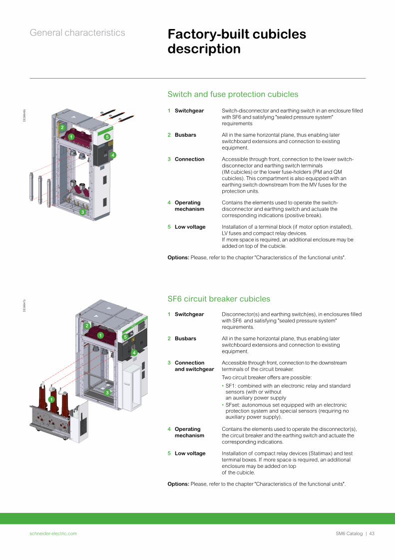
Switch and fuse protection cubicles
1 Switchgear Switch-disconnector and earthing switch in an enclosure filled with SF6 and satisfying "sealed pressure system" requirements
2 Busbars All in the same horizontal plane, thus enabling later switchboard extensions and connection to existing equipment.
3 Connection Accessible through front, connection to the lower switch-disconnector and earthing switch terminals (IM cubicles) or the lower fuse-holders (PM and QM cubicles). This compartment is also equipped with an earthing switch downstream from the MV fuses for the protection units.
4 Operating mechanism
Contains the elements used to operate the switch-disconnector and earthing switch and actuate the corresponding indications (positive break).
5 Low voltage Installation of a terminal block (if motor option installed), LV fuses and compact relay devices.If more space is required, an additional enclosure may be added on top of the cubicle.
Options: Please, refer to the chapter "Characteristics of the functional units".
SF6 circuit breaker cubicles
1 Switchgear Disconnector(s) and earthing switch(es), in enclosures filled with SF6 and satisfying "sealed pressure system" requirements.
2 Busbars All in the same horizontal plane, thus enabling later switchboard extensions and connection to existing equipment.
3 Connection and switchgear
Accessible through front, connection to the downstream terminals of the circuit breaker.
Two circuit breaker offers are possible:
• SF1: combined with an electronic relay and standard sensors (with or without an auxiliary power supply
• SFset: autonomous set equipped with an electronic protection system and special sensors (requiring no auxiliary power supply).
4 Operating mechanism
Contains the elements used to operate the disconnector(s), the circuit breaker and the earthing switch and actuate the corresponding indications.
5 Low voltage Installation of compact relay devices (Statimax) and test terminal boxes. If more space is required, an additional enclosure may be added on top of the cubicle.
Options: Please, refer to the chapter "Characteristics of the functional units".
DE5
8646
b
1
2
3
4
5
DE5
8647
b
1
1
2
3
4
5
schneider-electric.com44 | SM6 Catalog
General characteristics Factory-built cubicles description
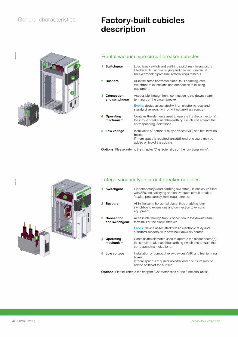
Frontal vacuum type circuit breaker cubicles
1 Switchgear Load break switch and earthing switch(es), in enclosure filled with SF6 and satisfying and one vacuum circuit breaker, "sealed pressure system" requirements
2 Busbars All in the same horizontal plane, thus enabling later switchboard extensions and connection to existing equipment.
3 Connection and switchgear
Accessible through front, connection to the downstream terminals of the circuit breaker.
Evolis: device associated with an electronic relay and standard sensors (with or without auxiliary source).
4 Operating mechanism
Contains the elements used to operate the disconnector(s), the circuit breaker and the earthing switch and actuate the corresponding indications.
5 Low voltage Installation of compact relay devices (VIP) and test terminal boxes. If more space is required, an additional enclosure may be added on top of the cubicle
Options: Please, refer to the chapter "Characteristics of the functional units".
Lateral vacuum type circuit breaker cubicles
1 Switchgear Disconnector(s) and earthing switch(es), in enclosure filled with SF6 and satisfying and one vacuum circuit breaker, "sealed pressure system" requirements.
2 Busbars All in the same horizontal plane, thus enabling later switchboard extensions and connection to existing equipment.
3 Connection and switchgear
Accessible through front, connection to the downstream terminals of the circuit breaker.
Evolis: device associated with an electronic relay and standard sensors (with or without auxiliary source).
4 Operating mechanism
Contains the elements used to operate the disconnector(s), the circuit breaker and the earthing switch and actuate the corresponding indications.
5 Low voltage Installation of compact relay devices (VIP) and test terminal boxes. If more space is required, an additional enclosure may be added on top of the cubicle.
Options: Please, refer to the chapter "Characteristics of the functional units".
DE5
8648
b
1
1
2
3
4
5
DE5
8649
b
1
1
2
3
4
5
schneider-electric.com | 45SM6 Catalog
General characteristics Factory-built cubicles description
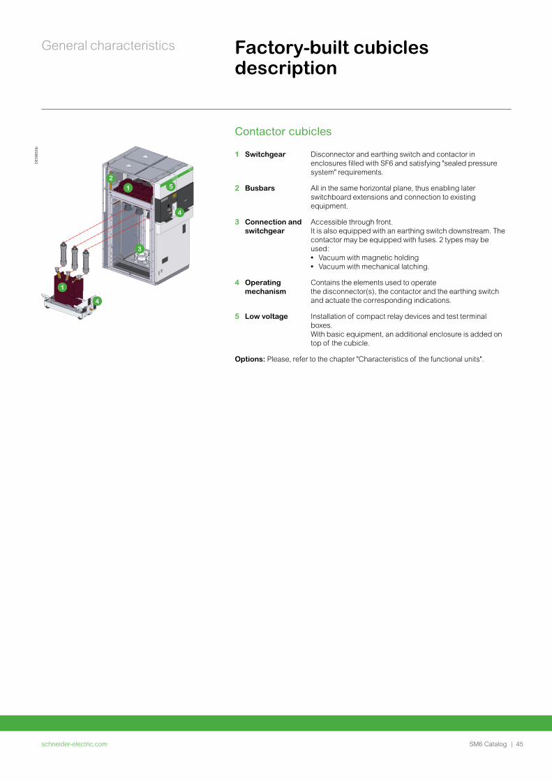
Contactor cubicles
1 Switchgear Disconnector and earthing switch and contactor in enclosures filled with SF6 and satisfying "sealed pressure system" requirements.
2 Busbars All in the same horizontal plane, thus enabling later switchboard extensions and connection to existing equipment.
3 Connection and switchgear
Accessible through front.It is also equipped with an earthing switch downstream. The contactor may be equipped with fuses. 2 types may be used: • Vacuum with magnetic holding • Vacuum with mechanical latching.
4 Operating mechanism
Contains the elements used to operate the disconnector(s), the contactor and the earthing switch and actuate the corresponding indications.
5 Low voltage Installation of compact relay devices and test terminal boxes.With basic equipment, an additional enclosure is added on top of the cubicle.
Options: Please, refer to the chapter "Characteristics of the functional units".
DE5
8650
b
1
1
2
3
4
4
5
schneider-electric.com46 | SM6 Catalog
General characteristics Compartments and devices description
DE5
3507
_LG
PM10
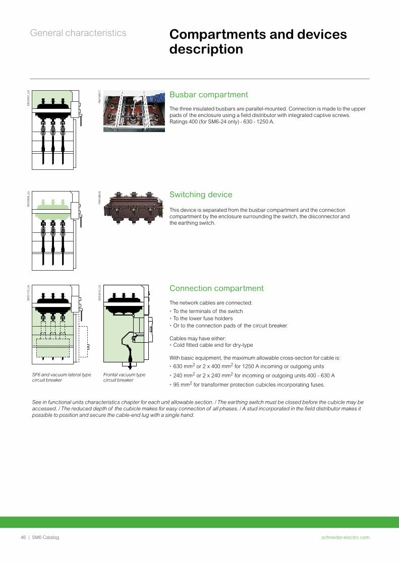
8617 Busbar compartment
The three insulated busbars are parallel-mounted. Connection is made to the upper pads of the enclosure using a field distributor with integrated captive screws.Ratings 400 (for SM6-24 only) - 630 - 1250 A.
DE5
3508
_LG
PM10
8618 Switching device
This device is separated from the busbar compartment and the connection compartment by the enclosure surrounding the switch, the disconnector and the earthing switch.
DE5
7172
_LG
DE5
3510
_LG Connection compartment
The network cables are connected:
• To the terminals of the switch • To the lower fuse holders • Or to the connection pads of the circuit breaker.
Cables may have either:• Cold fitted cable end for dry-type
With basic equipment, the maximum allowable cross-section for cable is:
• 630 mm2 or 2 x 400 mm2 for 1250 A incoming or outgoing units
• 240 mm2 or 2 x 240 mm2 for incoming or outgoing units 400 - 630 A
• 95 mm2 for transformer protection cubicles incorporating fuses.
SF6 and vacuum lateral type circuit breaker
Frontal vacuum type circuit breaker
See in functional units characteristics chapter for each unit allowable section. / The earthing switch must be closed before the cubicle may be accessed. / The reduced depth of the cubicle makes for easy connection of all phases. / A stud incorporated in the field distributor makes it possible to position and secure the cable-end lug with a single hand.
schneider-electric.com | 47SM6 Catalog
General characteristics Compartments and devices description
DE5
7173
_LG
PM10
8620
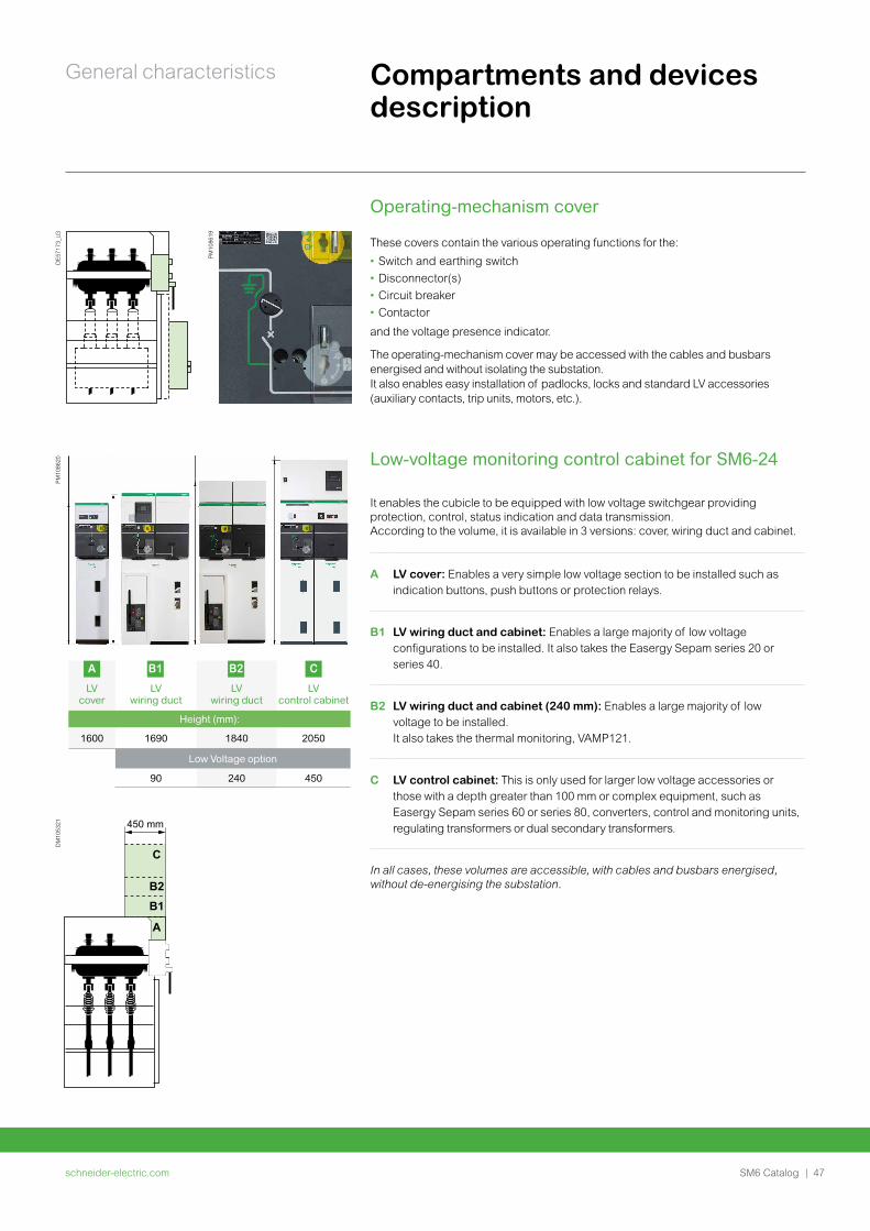
A B1 B2 C
LV cover
LV wiring duct
LV wiring duct
LV control cabinet
Height (mm):
1600 1690 1840 2050
Low Voltage option
90 240 450
PM10
8619
Operating-mechanism cover
These covers contain the various operating functions for the:
• Switch and earthing switch
• Disconnector(s)
• Circuit breaker
• Contactor
and the voltage presence indicator.
The operating-mechanism cover may be accessed with the cables and busbars energised and without isolating the substation.It also enables easy installation of padlocks, locks and standard LV accessories (auxiliary contacts, trip units, motors, etc.).
Low-voltage monitoring control cabinet for SM6-24
It enables the cubicle to be equipped with low voltage switchgear providing protection, control, status indication and data transmission. According to the volume, it is available in 3 versions: cover, wiring duct and cabinet.
A LV cover: Enables a very simple low voltage section to be installed such as indication buttons, push buttons or protection relays.
B1 LV wiring duct and cabinet: Enables a large majority of low voltage configurations to be installed. It also takes the Easergy Sepam series 20 or series 40.
B2 LV wiring duct and cabinet (240 mm): Enables a large majority of low voltage to be installed. It also takes the thermal monitoring, VAMP121.
C LV control cabinet: This is only used for larger low voltage accessories or those with a depth greater than 100 mm or complex equipment, such as Easergy Sepam series 60 or series 80, converters, control and monitoring units, regulating transformers or dual secondary transformers.
In all cases, these volumes are accessible, with cables and busbars energised, without de-energising the substation.
DM
1053
21
C
B2B1
A
450 mm
schneider-electric.com48 | SM6 Catalog
General characteristics Compartments and devices description
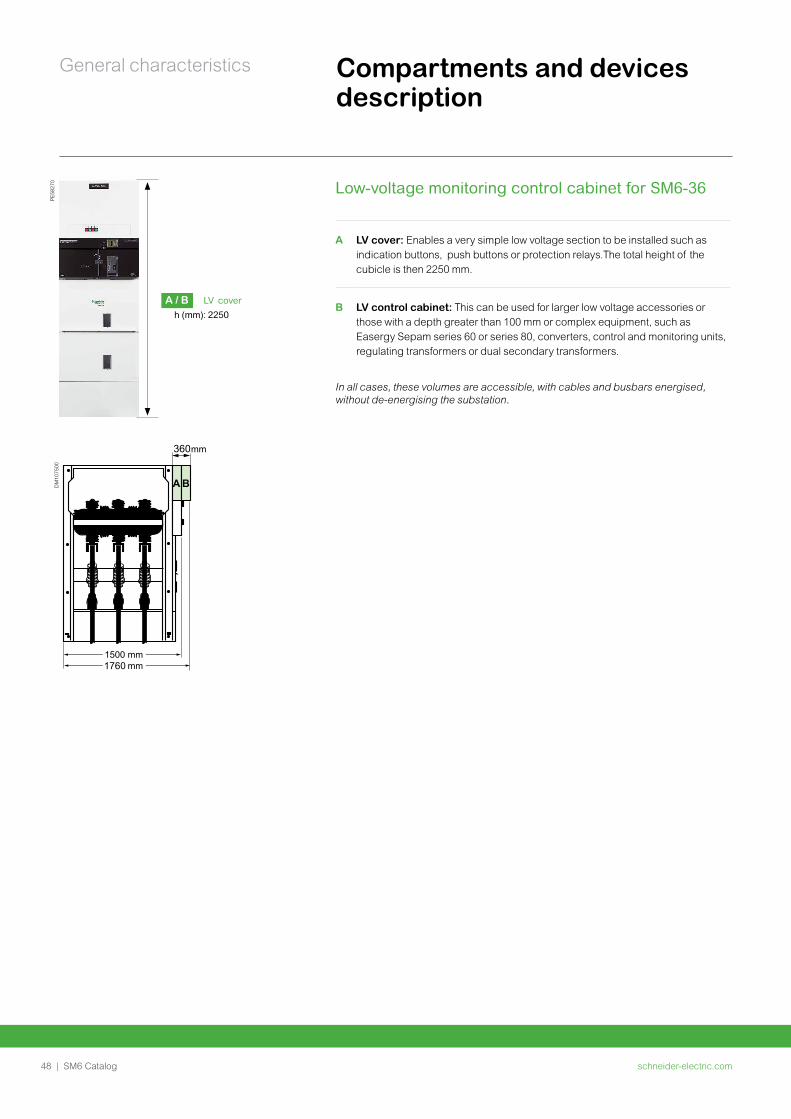
In all cases, these volumes are accessible, with cables and busbars energised, without de-energising the substation.
Low-voltage monitoring control cabinet for SM6-36
A LV cover: Enables a very simple low voltage section to be installed such as indication buttons, push buttons or protection relays.The total height of the cubicle is then 2250 mm.
B LV control cabinet: This can be used for larger low voltage accessories or those with a depth greater than 100 mm or complex equipment, such as Easergy Sepam series 60 or series 80, converters, control and monitoring units, regulating transformers or dual secondary transformers.
1760
360
DM
1075
00PE
5827
0
A / B LV cover
h (mm): 2250
schneider-electric.com | 49SM6 Catalog
General characteristics Safety of peopleBy switchgear
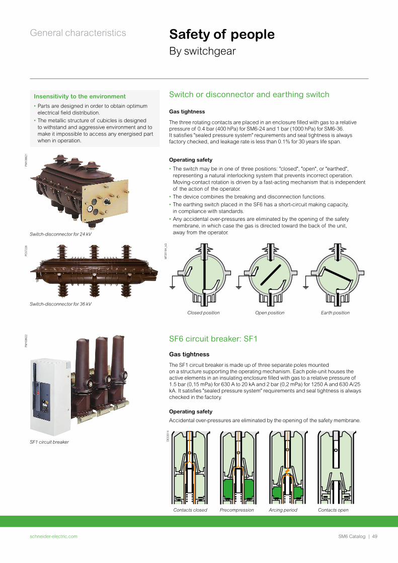
Switch or disconnector and earthing switch
Gas tightness
The three rotating contacts are placed in an enclosure filled with gas to a relative pressure of 0.4 bar (400 hPa) for SM6-24 and 1 bar (1000 hPa) for SM6-36. It satisfies "sealed pressure system" requirements and seal tightness is always factory checked, and leakage rate is less than 0.1% for 30 years life span.
Operating safety
• The switch may be in one of three positions: "closed", "open", or "earthed", representing a natural interlocking system that prevents incorrect operation. Moving-contact rotation is driven by a fast-acting mechanism that is independent of the action of the operator.
• The device combines the breaking and disconnection functions.
• The earthing switch placed in the SF6 has a short-circuit making capacity, in compliance with standards.
• Any accidental over-pressures are eliminated by the opening of the safety membrane, in which case the gas is directed toward the back of the unit, away from the operator.
PM10
8621
Switch-disconnector for 24 kV
Switch-disconnector for 36 kV
PE57
226
MT2
0184
_LG
Closed position Open position Earth position
PM10
8622
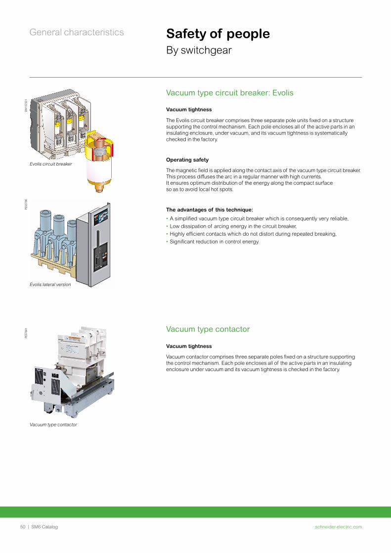
SF1 circuit breaker
Insensitivity to the environment• Parts are designed in order to obtain optimum
electrical field distribution.
• The metallic structure of cubicles is designed to withstand and aggressive environment and to make it impossible to access any energised part when in operation.
SF6 circuit breaker: SF1
Gas tightness
The SF1 circuit breaker is made up of three separate poles mounted on a structure supporting the operating mechanism. Each pole-unit houses the active elements in an insulating enclosure filled with gas to a relative pressure of 1.5 bar (0,15 mPa) for 630 A to 20 kA and 2 bar (0,2 mPa) for 1250 A and 630 A/25 kA. It satisfies "sealed pressure system" requirements and seal tightness is always checked in the factory.
Operating safety
Accidental over-pressures are eliminated by the opening of the safety membrane.
DE5
3514
Contacts closed Precompression Arcing period Contacts open
schneider-electric.com50 | SM6 Catalog
General characteristics Safety of peopleBy switchgear
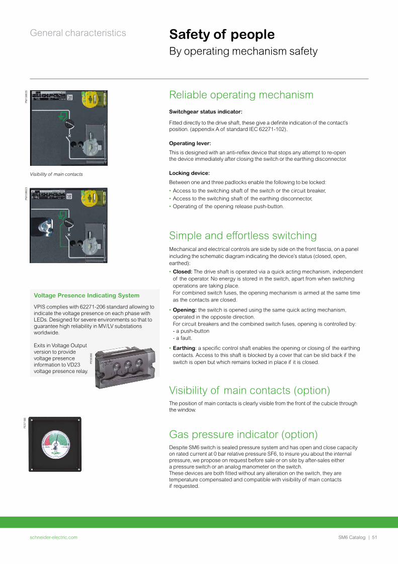
Vacuum type circuit breaker: Evolis
Vacuum tightness
The Evolis circuit breaker comprises three separate pole units fixed on a structure supporting the control mechanism. Each pole encloses all of the active parts in an insulating enclosure, under vacuum, and its vacuum tightness is systematically checked in the factory.
Operating safety
The magnetic field is applied along the contact axis of the vacuum type circuit breaker.This process diffuses the arc in a regular manner with high currents. It ensures optimum distribution of the energy along the compact surface so as to avoid local hot spots.
The advantages of this technique:
• A simplified vacuum type circuit breaker which is consequently very reliable,
• Low dissipation of arcing energy in the circuit breaker,
• Highly efficient contacts which do not distort during repeated breaking,
• Significant reduction in control energy.
DM
1075
01
Evolis circuit breaker
PE50
798
Evolis lateral version
PE57
841
Vacuum type contactor
Vacuum type contactor
Vacuum tightness
Vacuum contactor comprises three separate poles fixed on a structure supporting the control mechanism. Each pole encloses all of the active parts in an insulating enclosure under vacuum and its vacuum tightness is checked in the factory.
schneider-electric.com | 51SM6 Catalog
General characteristics Safety of peopleBy operating mechanism safety
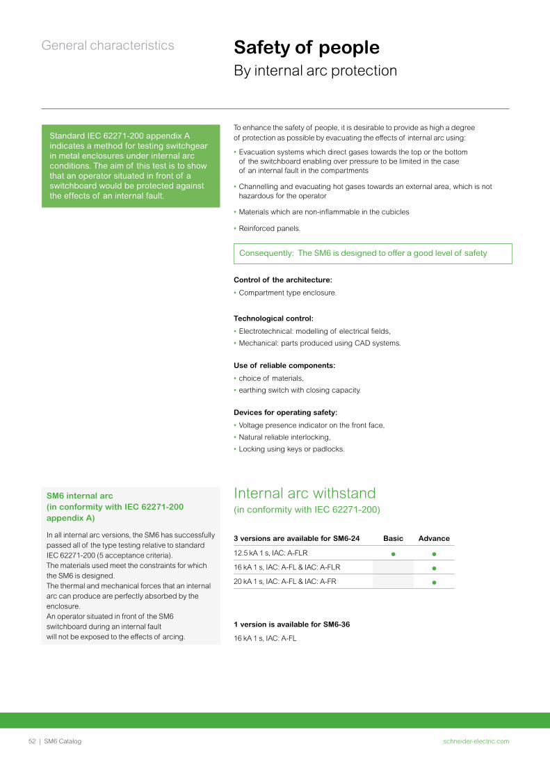
Reliable operating mechanismSwitchgear status indicator:
Fitted directly to the drive shaft, these give a definite indication of the contact’s position. (appendix A of standard IEC 62271-102).
Operating lever:
This is designed with an anti-reflex device that stops any attempt to re-open the device immediately after closing the switch or the earthing disconnector.
Locking device:
Between one and three padlocks enable the following to be locked:
• Access to the switching shaft of the switch or the circuit breaker,
• Access to the switching shaft of the earthing disconnector,
• Operating of the opening release push-button.
Simple and effortless switchingMechanical and electrical controls are side by side on the front fascia, on a panel including the schematic diagram indicating the device’s status (closed, open, earthed):
• Closed: The drive shaft is operated via a quick acting mechanism, independent of the operator. No energy is stored in the switch, apart from when switching operations are taking place. For combined switch fuses, the opening mechanism is armed at the same time as the contacts are closed.
• Opening: the switch is opened using the same quick acting mechanism, operated in the opposite direction. For circuit breakers and the combined switch fuses, opening is controlled by: - a push-button - a fault.
• Earthing: a specific control shaft enables the opening or closing of the earthing contacts. Access to this shaft is blocked by a cover that can be slid back if the switch is open but which remains locked in place if it is closed.
Visibility of main contacts (option)The position of main contacts is clearly visible from the front of the cubicle through the window.
Gas pressure indicator (option) Despite SM6 switch is sealed pressure system and has open and close capacity on rated current at 0 bar relative pressure SF6, to insure you about the internal pressure, we propose on request before sale or on site by after-sales either a pressure switch or an analog manometer on the switch. These devices are both fitted without any alteration on the switch, they are temperature compensated and compatible with visibility of main contacts if requested.
Visibility of main contacts
PM10
8623
PE57
166
Voltage Presence Indicating System
VPIS complies with 62271-206 standard allowing to indicate the voltage presence on each phase with LEDs. Designed for severe environments so that to guarantee high reliability in MV/LV substations worldwide.
Exits in Voltage Output version to provide voltage presence information to VD23 voltage presence relay.
PE56
366
PM10
8635
schneider-electric.com52 | SM6 Catalog
General characteristics Safety of peopleBy internal arc protection
To enhance the safety of people, it is desirable to provide as high a degree of protection as possible by evacuating the effects of internal arc using:
• Evacuation systems which direct gases towards the top or the bottom of the switchboard enabling over pressure to be limited in the case of an internal fault in the compartments
• Channelling and evacuating hot gases towards an external area, which is not hazardous for the operator
• Materials which are non-inflammable in the cubicles
• Reinforced panels.
Standard IEC 62271-200 appendix A indicates a method for testing switchgear in metal enclosures under internal arc conditions. The aim of this test is to show that an operator situated in front of a switchboard would be protected against the effects of an internal fault.
Consequently: The SM6 is designed to offer a good level of safety
Control of the architecture:
• Compartment type enclosure.
Technological control:
• Electrotechnical: modelling of electrical fields,
• Mechanical: parts produced using CAD systems.
Use of reliable components:
• choice of materials,
• earthing switch with closing capacity.
Devices for operating safety:
• Voltage presence indicator on the front face,
• Natural reliable interlocking,
• Locking using keys or padlocks.
Internal arc withstand (in conformity with IEC 62271-200)
3 versions are available for SM6-24 Basic Advance
12.5 kA 1 s, IAC: A-FLR
16 kA 1 s, IAC: A-FL & IAC: A-FLR
20 kA 1 s, IAC: A-FL & IAC: A-FR
1 version is available for SM6-36
16 kA 1 s, IAC: A-FL
SM6 internal arc (in conformity with IEC 62271-200 appendix A)
In all internal arc versions, the SM6 has successfully passed all of the type testing relative to standard IEC 62271-200 (5 acceptance criteria).The materials used meet the constraints for which the SM6 is designed. The thermal and mechanical forces that an internal arc can produce are perfectly absorbed by the enclosure.An operator situated in front of the SM6 switchboard during an internal fault will not be exposed to the effects of arcing.
schneider-electric.com | 53SM6 Catalog
General characteristics Safety of peopleBy internal arc protection
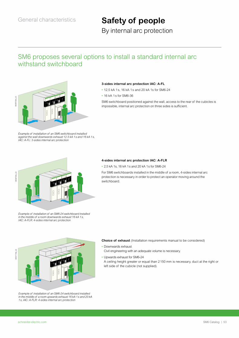
SM6 proposes several options to install a standard internal arc withstand switchboard
DE5
9732
b_LG
Example of installation of an SM6 switchboard installed against the wall downwards exhaust 12.5 kA 1 s and 16 kA 1 s, IAC: A-FL: 3-sides internal arc protection
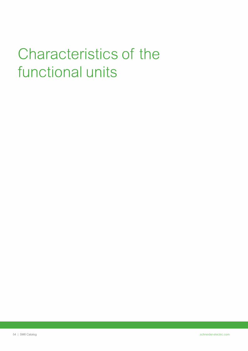
Example of installation of an SM6-24 switchboard installed in the middle of a room downwards exhaust 16 kA 1 s, IAC: A-FLR: 4-sides internal arc protection
DE5
9734
b_LG
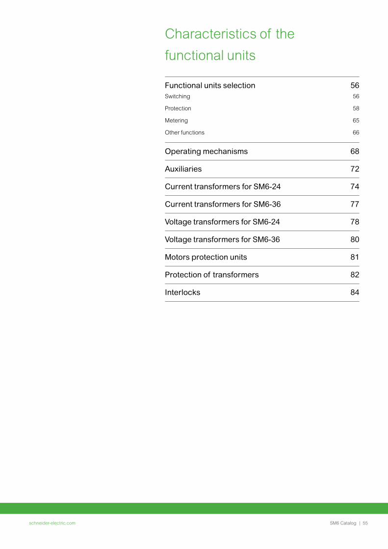
Example of installation of an SM6-24 switchboard installed in the middle of a room upwards exhaust 16 kA 1 s and 20 kA 1 s, IAC: A-FLR: 4-sides internal arc protection
DE5
7174
b_LG
3-sides internal arc protection IAC: A-FL
• 12,5 kA 1 s, 16 kA 1 s and 20 kA 1s for SM6-24
• 16 kA 1 s for SM6-36
SM6 switchboard positioned against the wall, access to the rear of the cubicles is impossible, internal arc protection on three sides is sufficient.
4-sides internal arc protection IAC: A-FLR
• 2,5 kA 1s, 16 kA 1 s and 20 kA 1 s for SM6-24
For SM6 switchboards installed in the middle of a room, 4-sides internal arc protection is necessary in order to protect an operator moving around the switchboard.
Choice of exhaust (Installation requirements manual to be considered)
• Downwards exhaust Civil engineering with an adequate volume is necessary.
• Upwards exhaust for SM6-24 A ceiling height greater or equal than 2 150 mm is necessary, duct at the right or left side of the cubicle (not supplied).
schneider-electric.com54 | SM6 Catalog
Characteristics of the functional units
schneider-electric.com | 55SM6 Catalog
Characteristics of the
functional units
Functional units selection 56Switching 56
Protection 58
Metering 65
Other functions 66
Operating mechanisms 68
Auxiliaries 72
Current transformers for SM6-24 74
Current transformers for SM6-36 77
Voltage transformers for SM6-24 78
Voltage transformers for SM6-36 80
Motors protection units 81
Protection of transformers 82
Interlocks 84
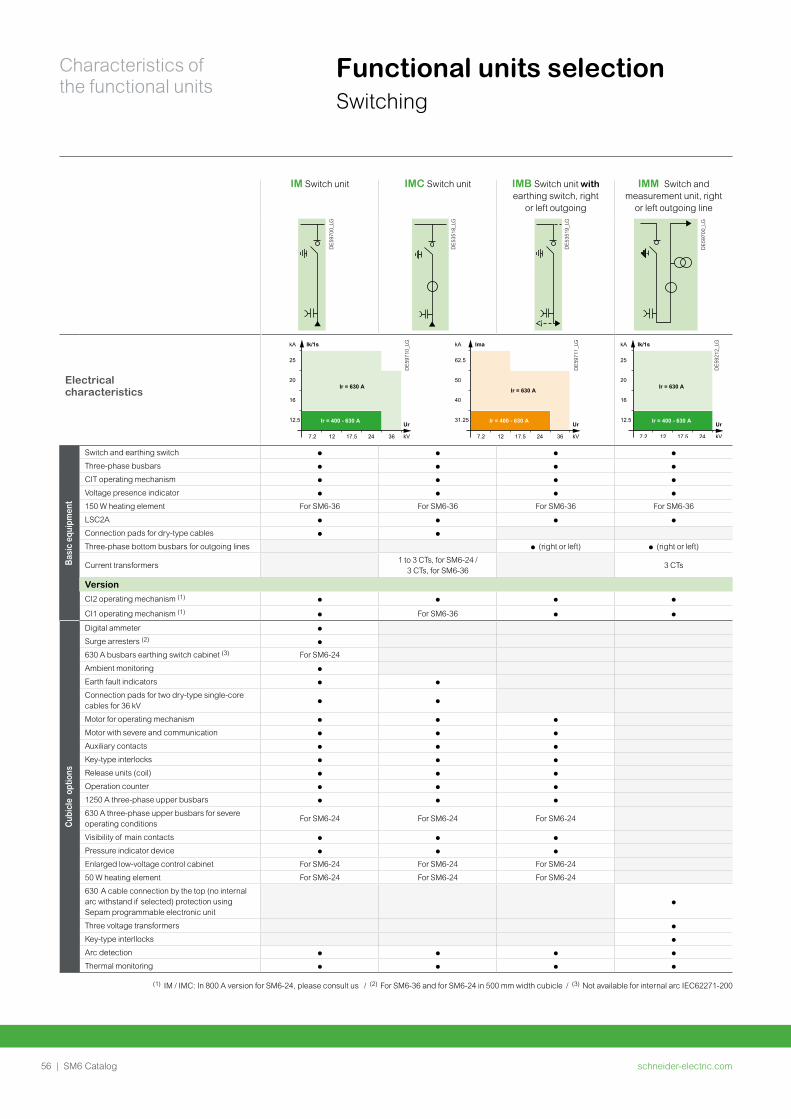
schneider-electric.com56 | SM6 Catalog
Characteristics of the functional units
Functional units selection Switching
IM Switch unit IMC Switch unit IMB Switch unit with earthing switch, right
or left outgoing
IMM Switch and measurement unit, right
or left outgoing line
DE5
9700
_LG
DE5
3518
_LG
DE5
3519
_LG
DE5
9700
_LG
Electrical characteristics
Ir = 400 - 630 A
25
20
16
12.5
7.2 12 17.5 24 36
Ir = 630 A
kA Ik/1s
kV
Ur
DE5
9710
_LG
DE5
9711
_LG
Ir = 400 - 630 A
62.5
50
40
31.25
7.2 12 17.5 24 36
Ir = 630 A
kA Ima
kV
Ur
DE5
9212
_LG
Basi
c eq
uipm
ent
Switch and earthing switch p p p p
Three-phase busbars p p p p
CIT operating mechanism p p p p
Voltage presence indicator p p p p
150 W heating element For SM6-36 For SM6-36 For SM6-36 For SM6-36
LSC2A p p p p
Connection pads for dry-type cables p p
Three-phase bottom busbars for outgoing lines p (right or left) p (right or left)
Current transformers1 to 3 CTs, for SM6-24 /
3 CTs, for SM6-363 CTs
VersionCI2 operating mechanism (1) p p p p
CI1 operating mechanism (1) p For SM6-36 p p
Cub
icle
opt
ions
Digital ammeter p
Surge arresters (2) p
630 A busbars earthing switch cabinet (3) For SM6-24
Ambient monitoring p
Earth fault indicators p p
Connection pads for two dry-type single-core cables for 36 kV
p p
Motor for operating mechanism p p p
Motor with severe and communication p p p
Auxiliary contacts p p p
Key-type interlocks p p p
Release units (coil) p p p
Operation counter p p p
1250 A three-phase upper busbars p p p
630 A three-phase upper busbars for severe operating conditions
For SM6-24 For SM6-24 For SM6-24
Visibility of main contacts p p p
Pressure indicator device p p p
Enlarged low-voltage control cabinet For SM6-24 For SM6-24 For SM6-24
50 W heating element For SM6-24 For SM6-24 For SM6-24
630 A cable connection by the top (no internal arc withstand if selected) protection using Sepam programmable electronic unit
p
Three voltage transformers p
Key-type interllocks p
Arc detection p p p p
Thermal monitoring p p p p
(1) IM / IMC: In 800 A version for SM6-24, please consult us / (2) For SM6-36 and for SM6-24 in 500 mm width cubicle / (3) Not available for internal arc IEC62271-200
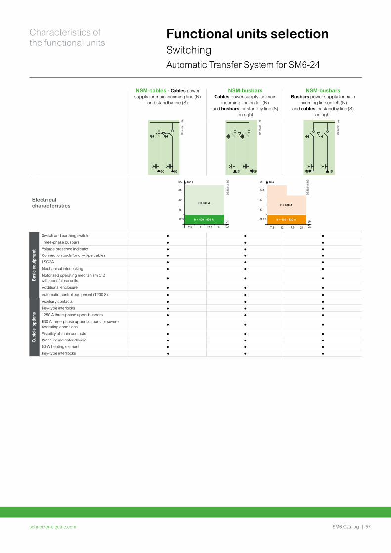
schneider-electric.com | 57SM6 Catalog
Characteristics of the functional units
Functional units selectionSwitchingAutomatic Transfer System for SM6-24
NSM-cables - Cables power supply for main incoming line (N)
and standby line (S)
NSM-busbarsCables power supply for main
incoming line on left (N) and busbars for standby line (S)
on right
NSM-busbarsBusbars power supply for main
incoming line on left (N) and cables for standby line (S)
on right
DE5
3559
_LG
DE5
8401
_LG
DE5
3561
_LG
Electrical characteristics
Ir = 400 - 630 A
62.5
50
40
31.25
7.2 12 17.5 24
Ir = 630 A
kA Ima
kV
Ur
DE5
9218
_LG
DE5
9212
_LG
Basi
c eq
uipm
ent
Switch and earthing switch p p p
Three-phase busbars p p p
Voltage presence indicator p p p
Connection pads for dry-type cables p p p
LSC2A p p p
Mechanical interlocking p p p
Motorized operating mechanism CI2 with open/close coils
p p p
Additional enclosure p p p
Automatic-control equipment (T200 S) p p p
Cub
icle
opt
ions
Auxiliary contacts p p p
Key-type interlocks p p p
1250 A three-phase upper busbars p p p
630 A three-phase upper busbars for severe operating conditions
p p p
Visibility of main contacts p p p
Pressure indicator device p p p
50 W heating element p p p
Key-type interllocks p p p
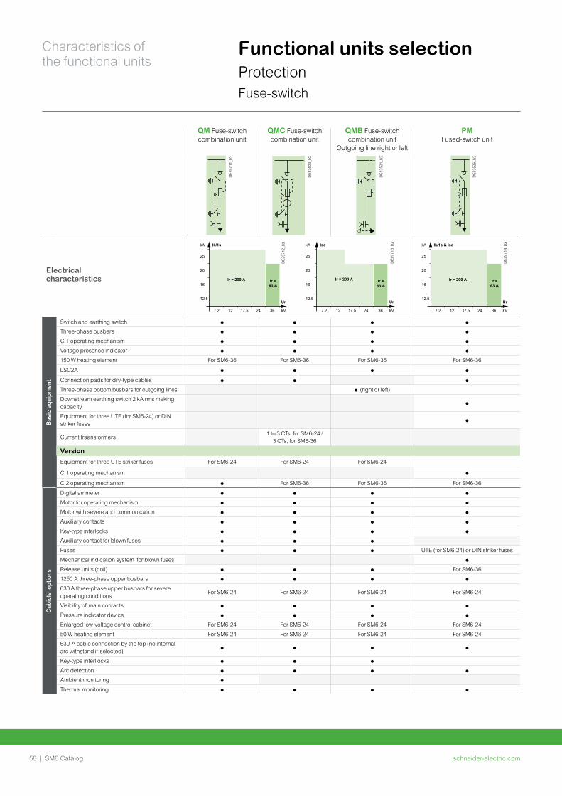
schneider-electric.com58 | SM6 Catalog
Characteristics of the functional units
Functional units selectionProtectionFuse-switch
QM Fuse-switch combination unit
QMC Fuse-switch combination unit
QMB Fuse-switch combination unit
Outgoing line right or left
PM Fused-switch unit
DE5
9701
_LG
DE5
3523
_LG
DE5
3524
_LG
DE5
3526
_LG
Electrical characteristics
DE5
9712
_LG
25
20
16
12.5
7.2 12 17.5 24 36
Ir = 200 A
kA Ik/1s
kV
Ur
Ir = 63 A
Ir = 63 A
25
20
16
12.5
7.2 12 17.5 24 36
Ir = 200 A
kA Isc
kV
Ur
DE5
9713
_LG
DE5
9714
_LG
25
20
16
12.5
7.2 12 17.5 24 36
Ir = 200 A
kA Ik/1s & Isc
kV
Ur
Ir = 63 A
Basi
c eq
uipm
ent
Switch and earthing switch p p p p
Three-phase busbars p p p p
CIT operating mechanism p p p p
Voltage presence indicator p p p p
150 W heating element For SM6-36 For SM6-36 For SM6-36 For SM6-36
LSC2A p p p p
Connection pads for dry-type cables p p p
Three-phase bottom busbars for outgoing lines p (right or left)
Downstream earthing switch 2 kA rms making capacity
p
Equipment for three UTE (for SM6-24) or DIN striker fuses
p
Current traansformers1 to 3 CTs, for SM6-24 /
3 CTs, for SM6-36
Version
Equipment for three UTE striker fuses For SM6-24 For SM6-24 For SM6-24
CI1 operating mechanism p
CI2 operating mechanism p For SM6-36 For SM6-36 For SM6-36
Cub
icle
opt
ions
Digital ammeter p p p p
Motor for operating mechanism p p p p
Motor with severe and communication p p p p
Auxiliary contacts p p p p
Key-type interlocks p p p p
Auxiliary contact for blown fuses p p p
Fuses p p p UTE (for SM6-24) or DIN striker fuses
Mechanical indication system for blown fuses p
Release units (coil) p p p For SM6-36
1250 A three-phase upper busbars p p p p
630 A three-phase upper busbars for severe operating conditions
For SM6-24 For SM6-24 For SM6-24 For SM6-24
Visibility of main contacts p p p p
Pressure indicator device p p p p
Enlarged low-voltage control cabinet For SM6-24 For SM6-24 For SM6-24 For SM6-24
50 W heating element For SM6-24 For SM6-24 For SM6-24 For SM6-24
630 A cable connection by the top (no internal arc withstand if selected)
p p p p
Key-type interllocks p p p
Arc detection p p p p
Ambient monitoring p
Thermal monitoring p p p p
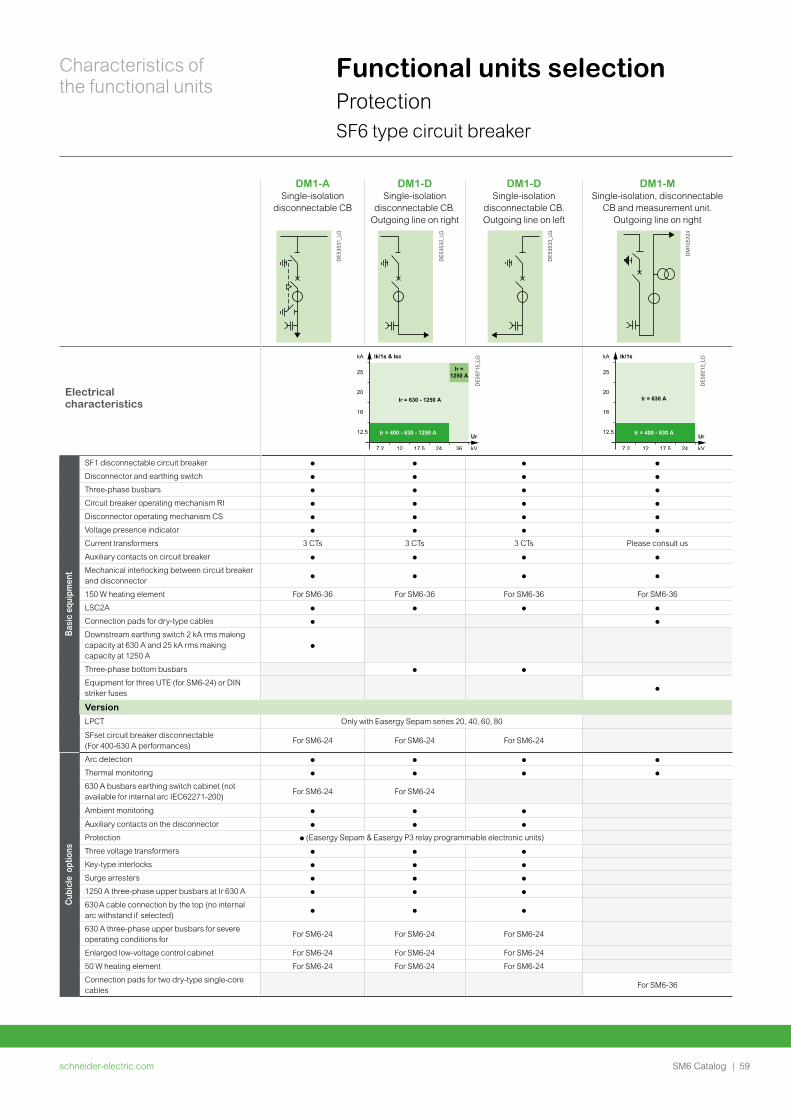
schneider-electric.com | 59SM6 Catalog
Characteristics of the functional units
Functional units selectionProtection SF6 type circuit breaker
DM1-A Single-isolation
disconnectable CB
DM1-D Single-isolation
disconnectable CB. Outgoing line on right
DM1-D Single-isolation
disconnectable CB. Outgoing line on left
DM1-MSingle-isolation, disconnectable
CB and measurement unit. Outgoing line on right
DE5
3531
_LG
DE5
3532
_LG
DE5
3533
_LG
DM
1053
24
Electrical characteristics
DE5
9715
_LG
DE5
9212
_LG
Basi
c eq
uipm
ent
SF1 disconnectable circuit breaker p p p p
Disconnector and earthing switch p p p p
Three-phase busbars p p p p
Circuit breaker operating mechanism RI p p p p
Disconnector operating mechanism CS p p p p
Voltage presence indicator p p p p
Current transformers 3 CTs 3 CTs 3 CTs Please consult us
Auxiliary contacts on circuit breaker p p p p
Mechanical interlocking between circuit breaker and disconnector
p p p p
150 W heating element For SM6-36 For SM6-36 For SM6-36 For SM6-36
LSC2A p p p p
Connection pads for dry-type cables p p
Downstream earthing switch 2 kA rms making capacity at 630 A and 25 kA rms making capacity at 1250 A
p
Three-phase bottom busbars p p
Equipment for three UTE (for SM6-24) or DIN striker fuses
p
VersionLPCT Only with Easergy Sepam series 20, 40, 60, 80
SFset circuit breaker disconnectable (For 400-630 A performances)
For SM6-24 For SM6-24 For SM6-24
Cub
icle
opt
ions
Arc detection p p p p
Thermal monitoring p p p p
630 A busbars earthing switch cabinet (not available for internal arc IEC62271-200)
For SM6-24 For SM6-24
Ambient monitoring p p p
Auxiliary contacts on the disconnector p p p
Protection p (Easergy Sepam & Easergy P3 relay programmable electronic units)
Three voltage transformers p p p
Key-type interlocks p p p
Surge arresters p p p
1250 A three-phase upper busbars at Ir 630 A p p p
630 A cable connection by the top (no internal arc withstand if selected)
p p p
630 A three-phase upper busbars for severe operating conditions for
For SM6-24 For SM6-24 For SM6-24
Enlarged low-voltage control cabinet For SM6-24 For SM6-24 For SM6-24
50 W heating element For SM6-24 For SM6-24 For SM6-24
Connection pads for two dry-type single-core cables
For SM6-36
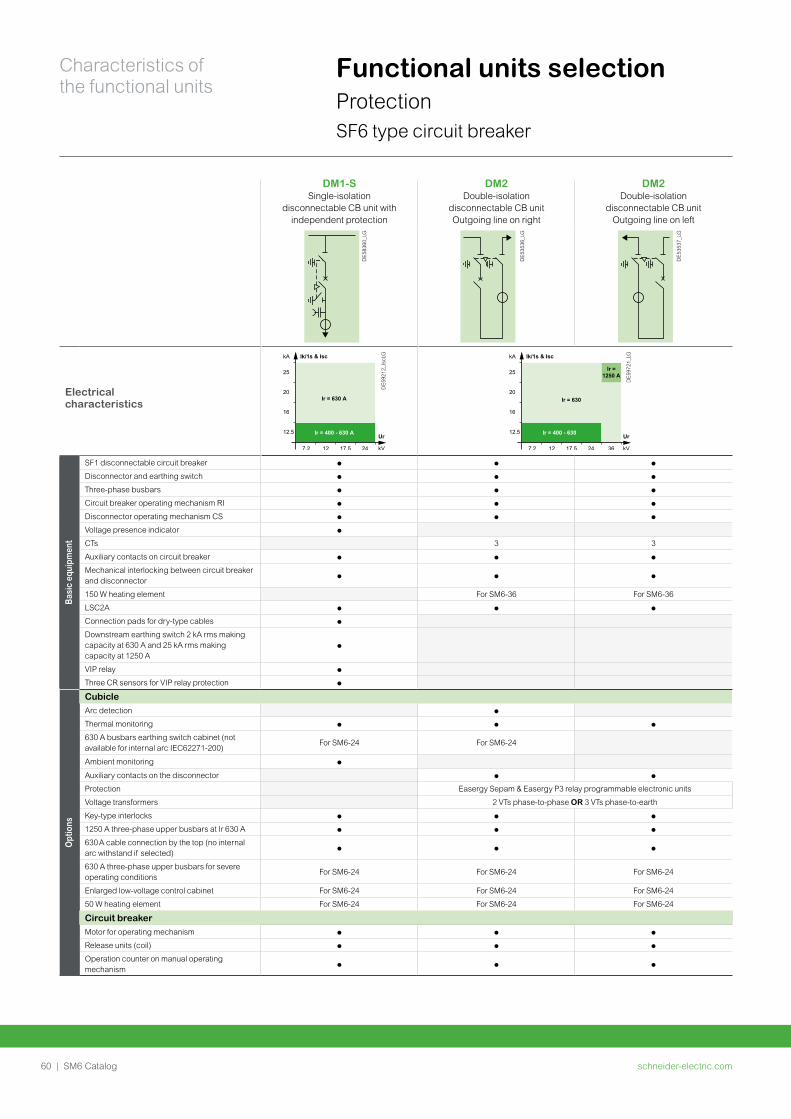
schneider-electric.com60 | SM6 Catalog
Characteristics of the functional units
Functional units selectionProtection SF6 type circuit breaker
DM1-S Single-isolation
disconnectable CB unit with independent protection
DM2 Double-isolation
disconnectable CB unit Outgoing line on right
DM2 Double-isolation
disconnectable CB unitOutgoing line on left
DE5
8360
_LG
DE5
3536
_LG
DE5
3537
_LG
Electrical characteristics
DE5
9212
_Isc
LG
DE5
9721
_LG
Basi
c eq
uipm
ent
SF1 disconnectable circuit breaker p p p
Disconnector and earthing switch p p p
Three-phase busbars p p p
Circuit breaker operating mechanism RI p p p
Disconnector operating mechanism CS p p p
Voltage presence indicator p
CTs 3 3
Auxiliary contacts on circuit breaker p p p
Mechanical interlocking between circuit breaker and disconnector
p p p
150 W heating element For SM6-36 For SM6-36
LSC2A p p p
Connection pads for dry-type cables p
Downstream earthing switch 2 kA rms making capacity at 630 A and 25 kA rms making capacity at 1250 A
p
VIP relay p
Three CR sensors for VIP relay protection p
Opt
ions
CubicleArc detection p
Thermal monitoring p p p
630 A busbars earthing switch cabinet (not available for internal arc IEC62271-200)
For SM6-24 For SM6-24
Ambient monitoring p
Auxiliary contacts on the disconnector p p
Protection Easergy Sepam & Easergy P3 relay programmable electronic units
Voltage transformers 2 VTs phase-to-phase OR 3 VTs phase-to-earth
Key-type interlocks p p p
1250 A three-phase upper busbars at Ir 630 A p p p
630 A cable connection by the top (no internal arc withstand if selected)
p p p
630 A three-phase upper busbars for severe operating conditions
For SM6-24 For SM6-24 For SM6-24
Enlarged low-voltage control cabinet For SM6-24 For SM6-24 For SM6-24
50 W heating element For SM6-24 For SM6-24 For SM6-24
Circuit breakerMotor for operating mechanism p p p
Release units (coil) p p p
Operation counter on manual operating mechanism
p p p
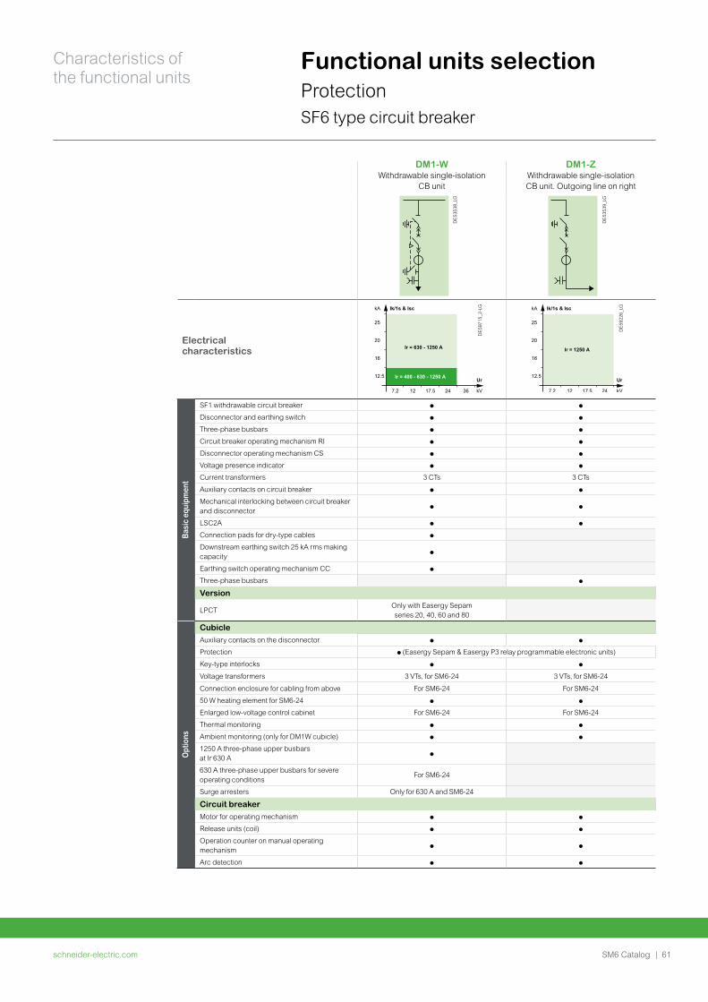
schneider-electric.com | 61SM6 Catalog
Characteristics of the functional units
Functional units selectionProtection SF6 type circuit breaker
DM1-W Withdrawable single-isolation
CB unit
DM1-Z Withdrawable single-isolation CB unit. Outgoing line on right
DE5
3538
_LG
DE5
3539
_LG
Electrical characteristics
DE5
9715
_2-L
G
Ir = 400 - 630 - 1250 A
25
20
16
12.5
7.2 12 17.5 24 36
Ir = 630 - 1250 A
kA Ik/1s & Isc
kV
Ur
DE5
9226
_LG
Basi
c eq
uipm
ent
SF1 withdrawable circuit breaker p p
Disconnector and earthing switch p p
Three-phase busbars p p
Circuit breaker operating mechanism RI p p
Disconnector operating mechanism CS p p
Voltage presence indicator p p
Current transformers 3 CTs 3 CTs
Auxiliary contacts on circuit breaker p p
Mechanical interlocking between circuit breaker and disconnector
p p
LSC2A p p
Connection pads for dry-type cables p
Downstream earthing switch 25 kA rms making capacity
p
Earthing switch operating mechanism CC p
Three-phase busbars p
Version
LPCTOnly with Easergy Sepam series 20, 40, 60 and 80
Opt
ions
CubicleAuxiliary contacts on the disconnector p p
Protection p (Easergy Sepam & Easergy P3 relay programmable electronic units)
Key-type interlocks p p
Voltage transformers 3 VTs, for SM6-24 3 VTs, for SM6-24
Connection enclosure for cabling from above For SM6-24 For SM6-24
50 W heating element for SM6-24 p p
Enlarged low-voltage control cabinet For SM6-24 For SM6-24
Thermal monitoring p p
Ambient monitoring (only for DM1W cubicle) p p
1250 A three-phase upper busbars at Ir 630 A
p
630 A three-phase upper busbars for severe operating conditions
For SM6-24
Surge arresters Only for 630 A and SM6-24
Circuit breakerMotor for operating mechanism p p
Release units (coil) p p
Operation counter on manual operating mechanism
p p
Arc detection p p
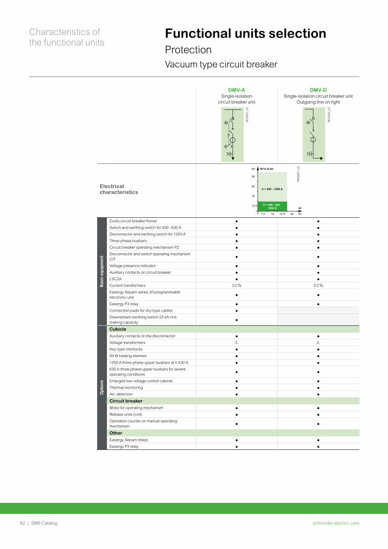
schneider-electric.com62 | SM6 Catalog
Characteristics of the functional units
Functional units selectionProtectionVacuum type circuit breaker
DMV-A Single-isolation
circuit breaker unit
DMV-D Single-isolation circuit breaker unit
Outgoing line on right
DE5
3541
_LG
DE5
3542
_LG
Electrical characteristics
DE5
9227
_LG
Basi
c eq
uipm
ent
Evolis circuit breaker frontal p p
Switch and earthing switch for 400 - 630 A p p
Disconnector and earthing switch for 1250 A p p
Three-phase busbars p p
Circuit breaker operating mechanism P2 p p
Disconnector and switch operating mechanism CIT
p p
Voltage presence indicator p p
Auxiliary contacts on circuit breaker p p
LSC2A p p
Current transformers 3 CTs 3 CTs
Easergy Sepam series 20 programmable electronic unit
p p
Easergy P3 relay p p
Connection pads for dry-type cables p
Downstream earthing switch 25 kA rms making capacity
p
Opt
ions
CubicleAuxiliary contacts on the disconnector p p
Voltage transformers 3, 3,
Key-type interlocks p p
50 W heating element p p
1250 A three-phase upper busbars at Ir 630 A p p
630 A three-phase upper busbars for severe operating conditions
p p
Enlarged low-voltage control cabinet p p
Thermal monitoring p p
Arc detection p p
Circuit breakerMotor for operating mechanism p p
Release units (coil) p p
Operation counter on manual operating mechanism
p p
OtherEasergy Sepam relays p p
Easergy P3 relay p p
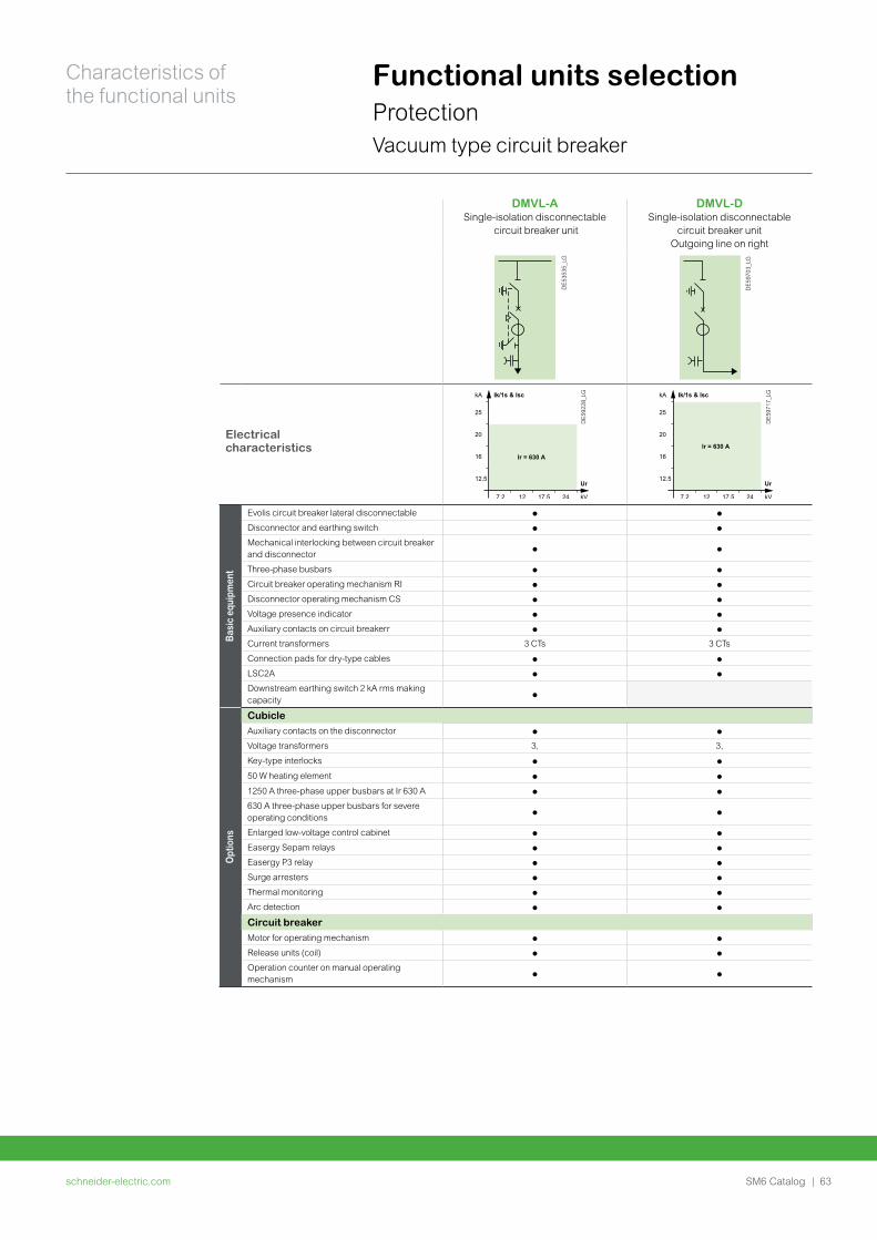
schneider-electric.com | 63SM6 Catalog
Characteristics of the functional units
Functional units selectionProtectionVacuum type circuit breaker
DMVL-A Single-isolation disconnectable
circuit breaker unit
DMVL-D Single-isolation disconnectable
circuit breaker unitOutgoing line on right
DE5
3535
_LG
DE5
9703
_LG
Electrical characteristics
DE5
9228
_LG
DE5
9717
_LG
Basi
c eq
uipm
ent
Evolis circuit breaker lateral disconnectable p p
Disconnector and earthing switch p p
Mechanical interlocking between circuit breaker and disconnector
p p
Three-phase busbars p p
Circuit breaker operating mechanism RI p p
Disconnector operating mechanism CS p p
Voltage presence indicator p p
Auxiliary contacts on circuit breakerr p p
Current transformers 3 CTs 3 CTs
Connection pads for dry-type cables p p
LSC2A p p
Downstream earthing switch 2 kA rms making capacity
p
Opt
ions
CubicleAuxiliary contacts on the disconnector p p
Voltage transformers 3, 3,
Key-type interlocks p p
50 W heating element p p
1250 A three-phase upper busbars at Ir 630 A p p
630 A three-phase upper busbars for severe operating conditions
p p
Enlarged low-voltage control cabinet p p
Easergy Sepam relays p p
Easergy P3 relay p p
Surge arresters p p
Thermal monitoring p p
Arc detection p p
Circuit breakerMotor for operating mechanism p p
Release units (coil) p p
Operation counter on manual operating mechanism
p p
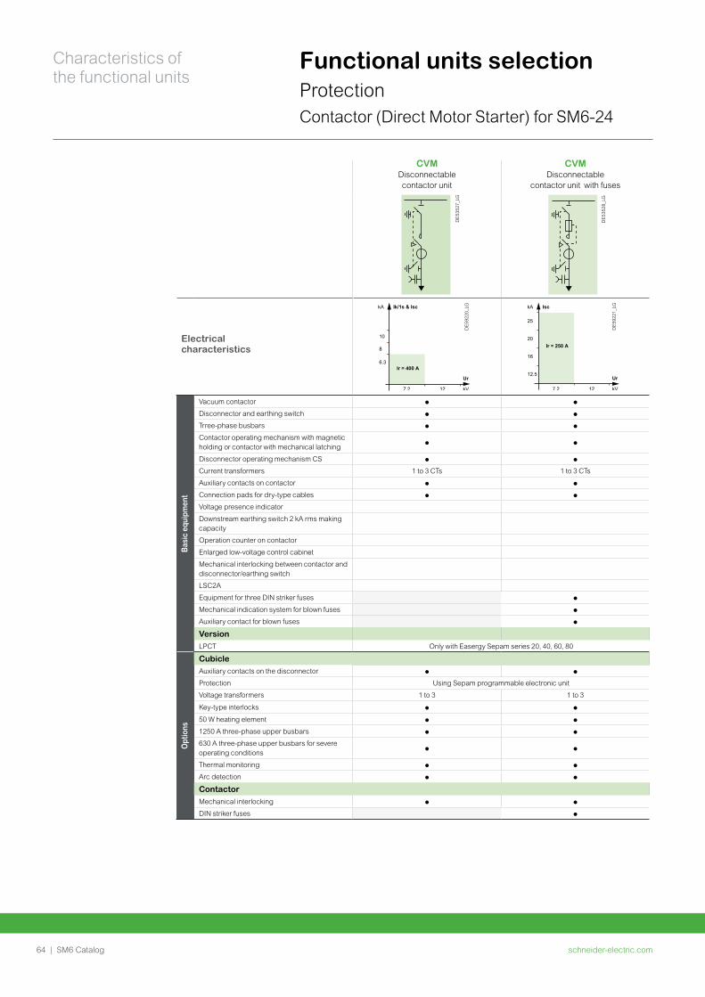
schneider-electric.com64 | SM6 Catalog
Characteristics of the functional units
Functional units selectionProtectionContactor (Direct Motor Starter) for SM6-24
CVM Disconnectable contactor unit
CVMDisconnectable
contactor unit with fuses
DE5
3527
_LG
DE5
3528
_LG
Electrical characteristics
DE5
9220
_LG
DE5
9221
_LG
Basi
c eq
uipm
ent
Vacuum contactor p p
Disconnector and earthing switch p p
Trree-phase busbars p p
Contactor operating mechanism with magnetic holding or contactor with mechanical latching
p p
Disconnector operating mechanism CS p p
Current transformers 1 to 3 CTs 1 to 3 CTs
Auxiliary contacts on contactor p p
Connection pads for dry-type cables p p
Voltage presence indicator
Downstream earthing switch 2 kA rms making capacity
Operation counter on contactor
Enlarged low-voltage control cabinet
Mechanical interlocking between contactor and disconnector/earthing switch
LSC2A
Equipment for three DIN striker fuses p
Mechanical indication system for blown fuses p
Auxiliary contact for blown fuses p
VersionLPCT Only with Easergy Sepam series 20, 40, 60, 80
Opt
ions
CubicleAuxiliary contacts on the disconnector p p
Protection Using Sepam programmable electronic unit
Voltage transformers 1 to 3 1 to 3
Key-type interlocks p p
50 W heating element p p
1250 A three-phase upper busbars p p
630 A three-phase upper busbars for severe operating conditions
p p
Thermal monitoring p p
Arc detection p p
ContactorMechanical interlocking p p
DIN striker fuses p
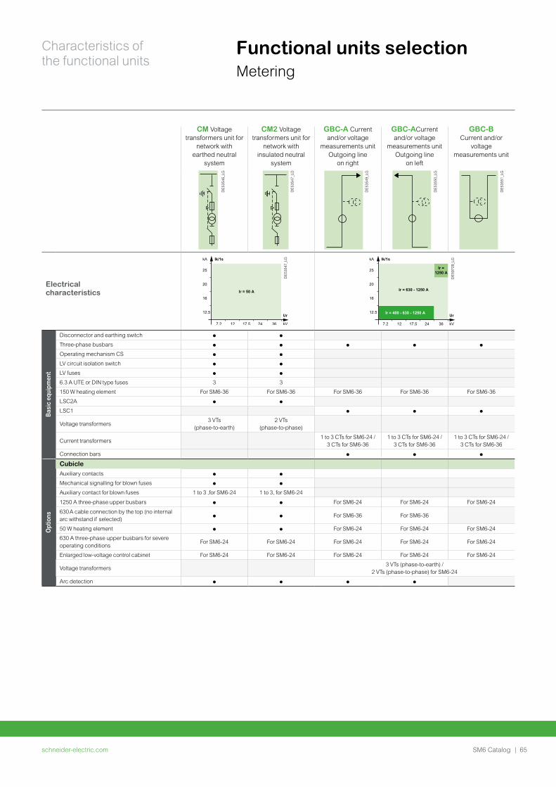
schneider-electric.com | 65SM6 Catalog
Characteristics of the functional units
Functional units selectionMetering
CM Voltage transformers unit for
network with earthed neutral
system
CM2 Voltage transformers unit for
network with insulated neutral
system
GBC-A Current and/or voltage
measurements unitOutgoing line
on right
GBC-ACurrent and/or voltage
measurements unitOutgoing line
on left
GBC-B Current and/or
voltage measurements unit
DE5
3546
_LG
DE5
3547
_LG
DE5
3549
_LG
DE5
3550
_LG
DE5
3551
_LG
Electrical characteristics
DE5
3547
_LG
DE5
9709
_LG
Ir = 400 - 630 - 1250 A
25
20
16
12.5
7.2 12 17.5 24 36
Ir = 630 - 1250 A
Ir = 1250 A
kA Ik/1s
kV
Ur
Basi
c eq
uipm
ent
Disconnector and earthing switch p p
Three-phase busbars p p p p p
Operating mechanism CS p p
LV circuit isolation switch p p
LV fuses p p
6.3 A UTE or DIN type fuses 3 3
150 W heating element For SM6-36 For SM6-36 For SM6-36 For SM6-36 For SM6-36
LSC2A p p
LSC1 p p p
Voltage transformers 3 VTs
(phase-to-earth)2 VTs
(phase-to-phase)
Current transformers1 to 3 CTs for SM6-24 /
3 CTs for SM6-361 to 3 CTs for SM6-24 /
3 CTs for SM6-361 to 3 CTs for SM6-24 /
3 CTs for SM6-36
Connection bars p p p
Opt
ions
CubicleAuxiliary contacts p p
Mechanical signalling for blown fuses p p
Auxiliary contact for blown fuses 1 to 3 ,for SM6-24 1 to 3, for SM6-24
1250 A three-phase upper busbars p p For SM6-24 For SM6-24 For SM6-24
630 A cable connection by the top (no internal arc withstand if selected)
p p For SM6-36 For SM6-36
50 W heating element p p For SM6-24 For SM6-24 For SM6-24
630 A three-phase upper busbars for severe operating conditions
For SM6-24 For SM6-24 For SM6-24 For SM6-24 For SM6-24
Enlarged low-voltage control cabinet For SM6-24 For SM6-24 For SM6-24 For SM6-24 For SM6-24
Voltage transformers 3 VTs (phase-to-earth) /
2 VTs (phase-to-phase) for SM6-24
Arc detection p p p p
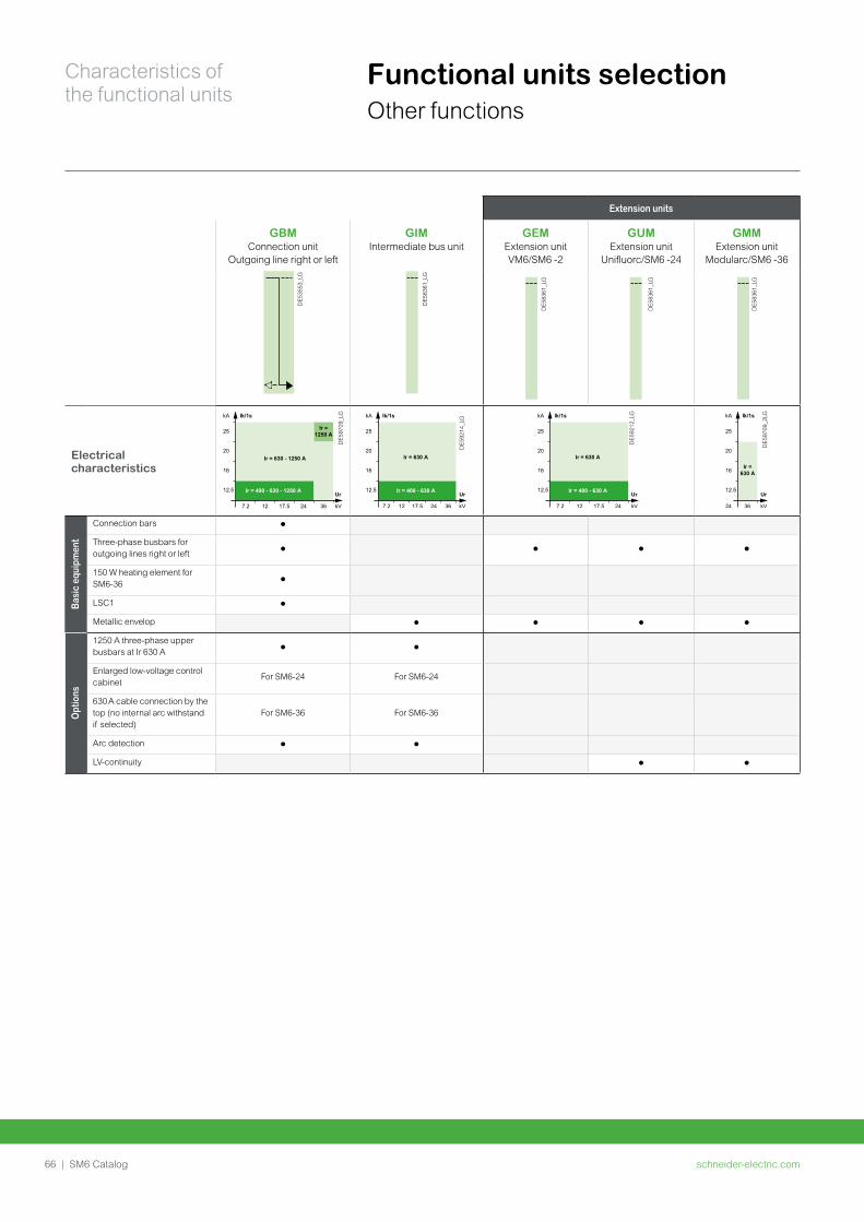
schneider-electric.com66 | SM6 Catalog
Characteristics of the functional units
Functional units selectionOther functions
Extension units
GBM Connection unit
Outgoing line right or left
GIM Intermediate bus unit
GEM Extension unit VM6/SM6 -2
GUM Extension unit
Unifluorc/SM6 -24
GMMExtension unit
Modularc/SM6 -36
DE5
3553
_LG
DE5
8361
_LG
DE5
8361
_LG
DE5
8361
_LG
DE5
8361
_LG
Electrical characteristics
DE5
9709
_LG
Ir = 400 - 630 - 1250 A
25
20
16
12.5
7.2 12 17.5 24 36
Ir = 630 - 1250 A
Ir = 1250 A
kA Ik/1s
kV
Ur
DE5
9214
_LG
DE5
9212
_LG
DE5
9709
_2LG
Basi
c eq
uipm
ent
Connection bars p
Three-phase busbars for outgoing lines right or left
p p p p
150 W heating element for SM6-36
p
LSC1 p
Metallic envelop p p p p
Opt
ions
1250 A three-phase upper busbars at Ir 630 A
p p
Enlarged low-voltage control cabinet
For SM6-24 For SM6-24
630 A cable connection by the top (no internal arc withstand if selected)
For SM6-36 For SM6-36
Arc detection p p
LV-continuity p p
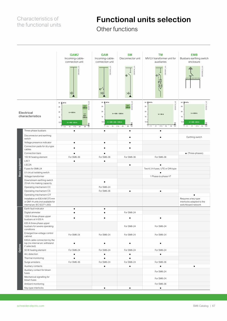
schneider-electric.com | 67SM6 Catalog
Characteristics of the functional units
Functional units selectionOther functions
GAM2Incoming-cable-connection unit
GAMIncoming-cable-connection unit
SM Disconnector unit
TM MV/LV transformer unit for
auxiliaries
EMB Busbars earthing switch
enclosure
DE5
3554
_LG
DE5
3555
_LG
DE5
9704
_LG
DE5
3557
_LG
DE5
3558
_N_L
G
Electrical characteristics
DE5
9719
_LG
DE5
9709
_LG
Ir = 400 - 630 - 1250 A
25
20
16
12.5
7.2 12 17.5 24 36
Ir = 630 - 1250 A
Ir = 1250 A
kA Ik/1s
kV
Ur
DE5
9722
_LG
DE5
9212
_LG
Basi
c eq
uipm
ent
Three-phase busbars p p p p
Disconnector and earthing switch
p p Earthing switch
Voltage presence indicator p p p
Connection pads for dry-type cables
p p p
Connection bars p p p (Three-phases)
150 W heating element For SM6-36 For SM6-36 For SM6-36 For SM6-36
LSC1 p p
LSC2A p p
Fuses for SM6-24 Two 6.3 A fuses, UTE or DIN type
LV circuit isolating switch p
Voltage transformer 1 Phase-to-phase VT
Downstream earthing switch 25 kA rms making capacity
p
Operating mechanism CC For SM6-24
Operating mechanism CS For SM6-36 p p
Operating mechanism CIT p
Installation on 630 A IM 375 mm or DM1-A units (not available for internal arc IEC 62271-200)
Requires a key-type interlocks adapted to the switchboard network
Opt
ions
Earth fault indicator p p
Digital ammeter p p For SM6-24
1250 A three-phase upper busbars at Ir 630 A
p p p p
630 A three-phase upper busbars for severe operating conditions
For SM6-24 For SM6-24
Enlarged low-voltage control cabinet
For SM6-24 For SM6-24 For SM6-24 For SM6-24
630 A cable connection by the top (no internal arc withstand if selected)
p p p p
50 W heating element For SM6-24 For SM6-24 For SM6-24 For SM6-24
Arc detection p p p p
Thermal monitoring p p p
Surge arresters For SM6-36 For SM6-24 For SM6-24 For SM6-36
Auxiliary contacts p p p p
Auxiliary contact for blown fuses
For SM6-24
Mechanical signalling for blown fuses
For SM6-24
Ambient monitoring For SM6-36
Key-type interlocks p p p
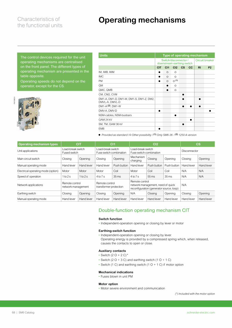
schneider-electric.com68 | SM6 Catalog
Characteristics of the functional units
Operating mechanismsPM
1086
24
Units Type of operating mechanism
Switch/disconnector /downstream earthing switch
Circuit breaker
CIT CI1 CI2 CS CC RI P2
IM, IMB, IMM
IMC
PM (1)
QM
QMC, QMB
CM, CM2, CVM
DM1-A, DM1-D, DM1-M, DM1-S, DM1-Z, DM2, DMVL-A, DMVL-D DM1-A (2), DM1-W
DMV-A, DMV-D
NSM-cables, NSM-busbars
GAM 24 kV
SM, TM, GAM 36 kV
EMB
Provided as standard / Other possibility / (1) Only SM6-36 / (2) 1250 A version
The control devices required for the unit operating mechanisms are centralised on the front panel. The different types of operating mechanism are presented in the table opposite.
Operating speeds do not depend on the operator, except for the CS.
Operating mechanism types CIT CI1 CI2 CS
Unit applicationsLoad-break switch Fused switch
Load-break switch Fuse switch combination
Load-break switch Fuse switch combination
Disconnector
Main circuit switch Closing Opening Closing OpeningMechanism charging
Closing Opening Closing Opening
Manual operating mode Hand lever Hand lever Hand lever Push button Hand lever Push button Push button Hand lever Hand lever
Electrical operating mode (option) Motor Motor Motor Coil Motor Coil Coil N/A N/A
Speed of operation 1 to 2 s 1 to 2 s 4 to 7 s 35 ms 4 to 7 s 55 ms 35 ms N/A N/A
Network applicationsRemote controlnetwork management
Remote control transformer protection
Remote control network management, need of quick reconfiguration (generator source, loop)
N/A
Earthing switch Closing Opening Closing Opening N/A Closing Opening Closing Opening
Manual operating mode Hand lever Hand lever Hand lever Hand lever Hand lever Hand lever Hand lever Hand lever Hand lever
Double-function operating mechanism CIT
Switch function • Independent-operation opening or closing by lever or motor
Earthing-switch function • Independent-operation opening or closing by lever.
Operating energy is provided by a compressed spring which, when released, causes the contacts to open or close.
Auxiliary contacts• Switch (2 O + 2 C) *
• Switch (2 O + 3 C) and earthing switch (1 O + 1 C)
• Switch (1 C) and earthing switch (1 O + 1 C) if motor option
Mechanical indications• Fuses blown in unit PM
Motor option• Motor severe environment and communication
(*) Included with the motor option
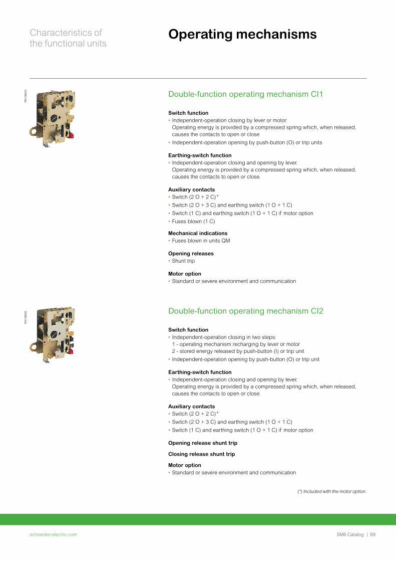
schneider-electric.com | 69SM6 Catalog
Characteristics of the functional units
Operating mechanismsPM
1086
26PM
1086
25 Double-function operating mechanism CI1
Switch function • Independent-operation closing by lever or motor.
Operating energy is provided by a compressed spring which, when released, causes the contacts to open or close
• Independent-operation opening by push-button (O) or trip units
Earthing-switch function • Independent-operation closing and opening by lever.
Operating energy is provided by a compressed spring which, when released, causes the contacts to open or close.
Auxiliary contacts• Switch (2 O + 2 C) *
• Switch (2 O + 3 C) and earthing switch (1 O + 1 C)
• Switch (1 C) and earthing switch (1 O + 1 C) if motor option
• Fuses blown (1 C)
Mechanical indications• Fuses blown in units QM
Opening releases• Shunt trip
Motor option• Standard or severe environment and communication
Double-function operating mechanism CI2
Switch function • Independent-operation closing in two steps:
1 - operating mechanism recharging by lever or motor 2 - stored energy released by push-button (I) or trip unit
• Independent-operation opening by push-button (O) or trip unit
Earthing-switch function• Independent-operation closing and opening by lever.
Operating energy is provided by a compressed spring which, when released, causes the contacts to open or close.
Auxiliary contacts• Switch (2 O + 2 C) *
• Switch (2 O + 3 C) and earthing switch (1 O + 1 C)
• Switch (1 C) and earthing switch (1 O + 1 C) if motor option
Opening release shunt trip
Closing release shunt trip
Motor option• Standard or severe environment and communication
(*) Included with the motor option.
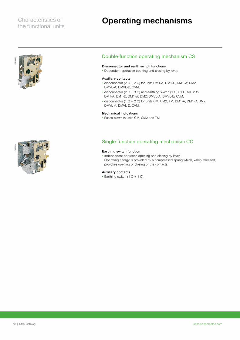
schneider-electric.com70 | SM6 Catalog
Characteristics of the functional units
Double-function operating mechanism CS
Disconnector and earth switch functions• Dependent-operation opening and closing by lever.
Auxiliary contacts• disconnector (2 O + 2 C) for units DM1-A, DM1-D, DM1-W, DM2,
DMVL-A, DMVL-D, CVM,
• disconnector (2 O + 3 C) and earthing switch (1 O + 1 C) for units DM1-A, DM1-D, DM1-W, DM2, DMVL-A, DMVL-D, CVM,
• disconnector (1 O + 2 C) for units CM, CM2, TM, DM1-A, DM1-D, DM2, DMVL-A, DMVL-D, CVM.
Mechanical indications • Fuses blown in units CM, CM2 and TM.
PM10
8627
PM10
8628
Single-function operating mechanism CC
Earthing switch function• Independent-operation opening and closing by lever.
Operating energy is provided by a compressed spring which, when released, provokes opening or closing of the contacts.
Auxiliary contacts• Earthing switch (1 O + 1 C).
Operating mechanisms
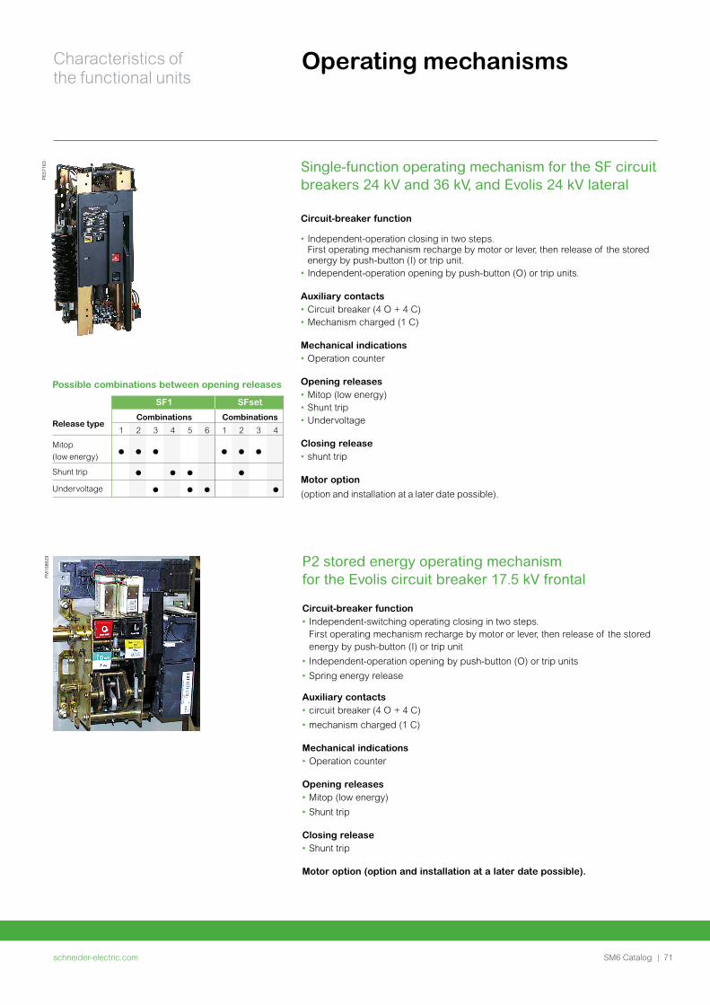
schneider-electric.com | 71SM6 Catalog
Characteristics of the functional units
Operating mechanisms
P2 stored energy operating mechanism for the Evolis circuit breaker 17.5 kV frontal
Circuit-breaker function• Independent-switching operating closing in two steps.
First operating mechanism recharge by motor or lever, then release of the stored energy by push-button (I) or trip unit
• Independent-operation opening by push-button (O) or trip units
• Spring energy release
Auxiliary contacts• circuit breaker (4 O + 4 C)
• mechanism charged (1 C)
Mechanical indications• Operation counter
Opening releases• Mitop (low energy)
• Shunt trip
Closing release • Shunt trip
Motor option (option and installation at a later date possible).
PE57
163 Single-function operating mechanism for the SF circuit
breakers 24 kV and 36 kV, and Evolis 24 kV lateral
Circuit-breaker function
• Independent-operation closing in two steps. First operating mechanism recharge by motor or lever, then release of the stored energy by push-button (I) or trip unit.
• Independent-operation opening by push-button (O) or trip units.
Auxiliary contacts• Circuit breaker (4 O + 4 C)• Mechanism charged (1 C)
Mechanical indications• Operation counter
Opening releases• Mitop (low energy)• Shunt trip• Undervoltage
Closing release • shunt trip
Motor option (option and installation at a later date possible).
Possible combinations between opening releases
SF1 SFset
Release typeCombinations Combinations
1 2 3 4 5 6 1 2 3 4
Mitop (low energy)
Shunt trip
Undervoltage
PM10
8629
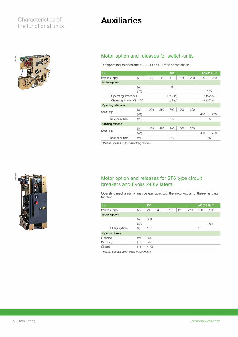
schneider-electric.com72 | SM6 Catalog
Characteristics of the functional units
Auxiliaries
Motor option and releases for switch-units
The operating mechanisms CIT, CI1 and CI2 may be motorised.
Un DC AC (50 Hz)*
Power supply (V) 24 48 110 125 220 120 230
Motor option
(W) 200
(VA) 200
Operating time for CIT 1 to 2 (s) 1 to 2 (s)
Charging time for CI1, CI2 4 to 7 (s) 4 to 7 (s)
Opening releases
Shunt trip(W) 200 250 300 300 300
(VA) 400 750
Response time (ms) 35 35
Closing release
Shunt trip(W) 200 250 300 300 300
(VA) 400 750
Response time (ms) 55 55
* Please consult us for other frequencies.
PM10
8630
PE57
164
Motor option and releases for SF6 type circuit breakers and Evolis 24 kV lateral
Operating mechanism RI may be equipped with the motor option for the recharging function.
Un DC AC (50 Hz)*
Power supply (V) 24 48 110 125 220 120 230
Motor option
(W) 300
(VA) 380
Charging time (s) 15 15
Opening times
Opening (ms) <60Breaking (ms) <75
Closing (ms) <100
* Please consult us for other frequencies.
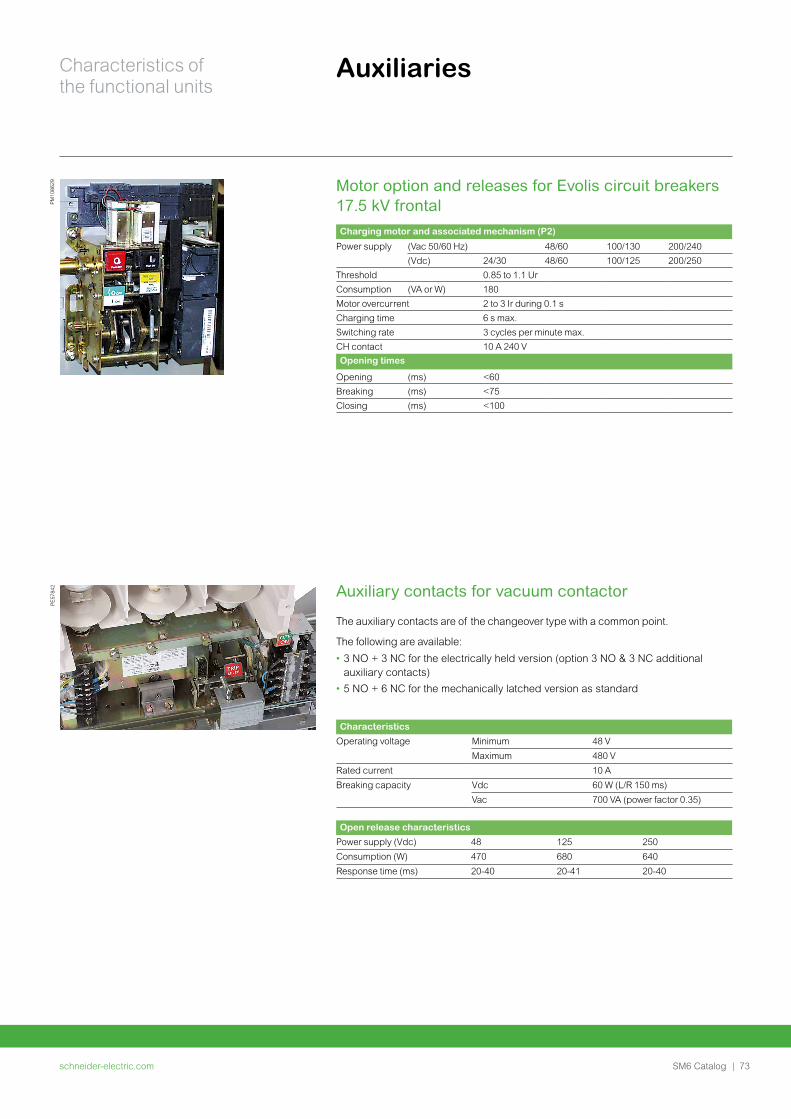
schneider-electric.com | 73SM6 Catalog
Characteristics of the functional units
Auxiliaries
Motor option and releases for Evolis circuit breakers 17.5 kV frontalCharging motor and associated mechanism (P2)
Power supply (Vac 50/60 Hz) 48/60 100/130 200/240(Vdc) 24/30 48/60 100/125 200/250
Threshold 0.85 to 1.1 UrConsumption (VA or W) 180Motor overcurrent 2 to 3 Ir during 0.1 sCharging time 6 s max.Switching rate 3 cycles per minute max.CH contact 10 A 240 VOpening times
Opening (ms) <60Breaking (ms) <75Closing (ms) <100
PE57
842
PM10
8629
Characteristics
Operating voltage Minimum 48 V
Maximum 480 V
Rated current 10 A
Breaking capacity Vdc 60 W (L/R 150 ms)
Vac 700 VA (power factor 0.35)
Open release characteristics
Power supply (Vdc) 48 125 250
Consumption (W) 470 680 640
Response time (ms) 20-40 20-41 20-40
Auxiliary contacts for vacuum contactor
The auxiliary contacts are of the changeover type with a common point.
The following are available:
• 3 NO + 3 NC for the electrically held version (option 3 NO & 3 NC additional auxiliary contacts)
• 5 NO + 6 NC for the mechanically latched version as standard
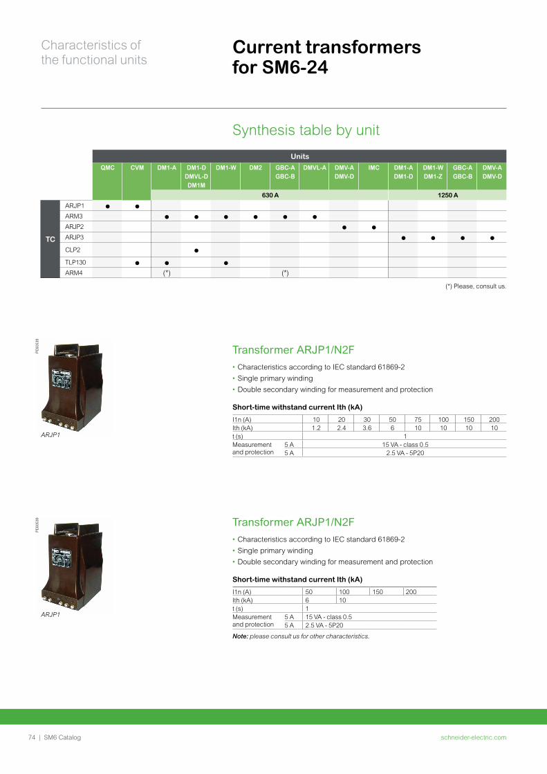
schneider-electric.com74 | SM6 Catalog
Characteristics of the functional units
Current transformers for SM6-24
Synthesis table by unit
PE60
539
ARJP1
PE60
539
ARJP1
Transformer ARJP1/N2F• Characteristics according to IEC standard 61869-2
• Single primary winding
• Double secondary winding for measurement and protection
Short-time withstand current Ith (kA)
I1n (A) 10 20 30 50 75 100 150 200Ith (kA) 1.2 2.4 3.6 6 10 10 10 10t (s) 1Measurement and protection
5 A 15 VA - class 0.55 A 2.5 VA - 5P20
Units
QMC CVM DM1-A DM1-DDMVL-D DM1M
DM1-W DM2 GBC-A GBC-B
DMVL-A DMV-A DMV-D
IMC DM1-A DM1-D
DM1-W DM1-Z
GBC-A GBC-B
DMV-A DMV-D
630 A 1250 A
TC
ARJP1
ARM3
ARJP2
ARJP3
CLP2
TLP130
ARM4 (*) (*)
(*) Please, consult us.
Transformer ARJP1/N2F• Characteristics according to IEC standard 61869-2
• Single primary winding
• Double secondary winding for measurement and protection
Short-time withstand current Ith (kA)
I1n (A) 50 100 150 200Ith (kA) 6 10t (s) 1Measurement and protection
5 A 15 VA - class 0.55 A 2.5 VA - 5P20
Note: please consult us for other characteristics.
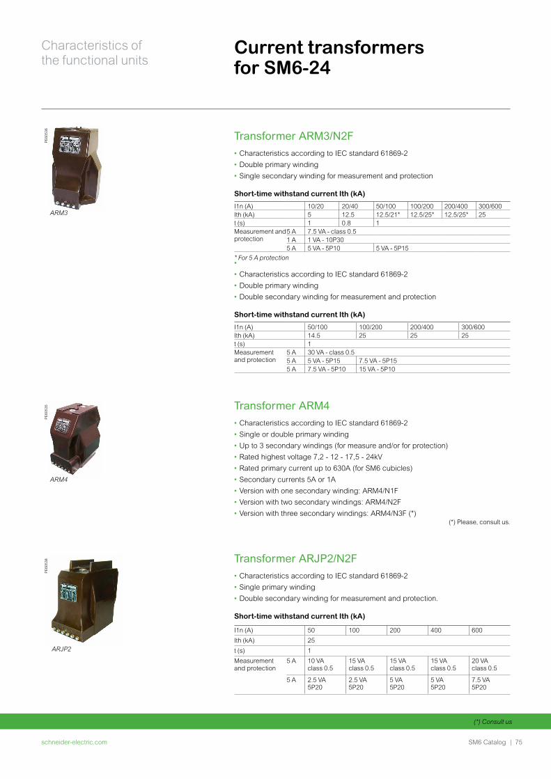
schneider-electric.com | 75SM6 Catalog
Characteristics of the functional units
(*) Consult us
PE60
536
ARM3
PE60
535
ARM4
Transformer ARM3/N2F• Characteristics according to IEC standard 61869-2
• Double primary winding
• Single secondary winding for measurement and protection
Short-time withstand current Ith (kA)
I1n (A) 10/20 20/40 50/100 100/200 200/400 300/600Ith (kA) 5 12.5 12.5/21* 12.5/25* 12.5/25* 25t (s) 1 0.8 1Measurement and protection
5 A 7.5 VA - class 0.51 A 1 VA - 10P305 A 5 VA - 5P10 5 VA - 5P15
* For 5 A protection •
• Characteristics according to IEC standard 61869-2
• Double primary winding
• Double secondary winding for measurement and protection
Short-time withstand current Ith (kA)
I1n (A) 50/100 100/200 200/400 300/600Ith (kA) 14.5 25 25 25t (s) 1Measurement and protection
5 A 30 VA - class 0.55 A 5 VA - 5P15 7.5 VA - 5P155 A 7.5 VA - 5P10 15 VA - 5P10
Transformer ARM4• Characteristics according to IEC standard 61869-2
• Single or double primary winding
• Up to 3 secondary windings (for measure and/or for protection)
• Rated highest voltage 7,2 - 12 - 17,5 - 24kV
• Rated primary current up to 630A (for SM6 cubicles)
• Secondary currents 5A or 1A
• Version with one secondary winding: ARM4/N1F
• Version with two secondary windings: ARM4/N2F
• Version with three secondary windings: ARM4/N3F (*)
Transformer ARJP2/N2F• Characteristics according to IEC standard 61869-2
• Single primary winding
• Double secondary winding for measurement and protection.
Short-time withstand current Ith (kA)
I1n (A) 50 100 200 400 600
Ith (kA) 25
t (s) 1
Measurement and protection
5 A 10 VA class 0.5
15 VA class 0.5
15 VA class 0.5
15 VA class 0.5
20 VA class 0.5
5 A 2.5 VA 5P20
2.5 VA 5P20
5 VA 5P20
5 VA 5P20
7.5 VA 5P20
(*) Please, consult us.
PE60
538
ARJP2
Current transformers for SM6-24
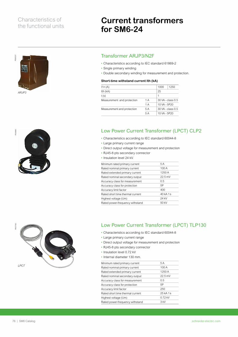
schneider-electric.com76 | SM6 Catalog
Characteristics of the functional units
PE55
661
Transformer ARJP3/N2F• Characteristics according to IEC standard 61869-2
• Single primary winding
• Double secondary winding for measurement and protection.
Short-time withstand current Ith (kA)
I1n (A) 1000 1250
Ith (kA) 25
t (s) 1
Measurement and protection 1 A 30 VA - class 0.5
1 A 10 VA - 5P20
Measurement and protection 5 A 30 VA - class 0.5
5 A 10 VA - 5P20
PE60
537
ARJP3
PE57
162
LPCT
Low Power Current Transformer (LPCT) CLP2• Characteristics according to IEC standard 60044-8
• Large primary current range
• Direct output voltage for measurement and protection
• RJ45-8 pts secondary connector
• Insulation level 24 kV.
Minimum rated primary current 5 A
Rated nominal primary current 100 A
Rated extended primary current 1250 A
Rated nominal secondary output 22.5 mV
Accuracy class for measurement 0.5
Accuracy class for protection 5P
Accuracy limit factor 400
Rated short time thermal current 40 kA 1 s
Highest voltage (Um) 24 kV
Rated power-frequency withstand 50 kV
Low Power Current Transformer (LPCT) TLP130• Characteristics according to IEC standard 60044-8
• Large primary current range
• Direct output voltage for measurement and protection
• RJ45-8 pts secondary connector
• Insulation level 0.72 kV
• Internal diameter 130 mm.
Minimum rated primary current 5 A
Rated nominal primary current 100 A
Rated extended primary current 1250 A
Rated nominal secondary output 22.5 mV
Accuracy class for measurement 0.5
Accuracy class for protection 5P
Accuracy limit factor 250
Rated short time thermal current 25 kA 1 s
Highest voltage (Um) 0.72 kV
Rated power-frequency withstand 3 kV
Current transformers for SM6-24
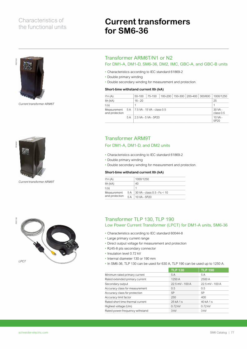
schneider-electric.com | 77SM6 Catalog
Characteristics of the functional units
Current transformers for SM6-36
PE57
222
Current transformer ARM6T
Transformer ARM6T/N1 or N2 For DM1-A, DM1-D, SM6-36, DM2, IMC, GBC-A, and GBC-B units
• Characteristics according to IEC standard 61869-2
• Double primary winding
• Double secondary winding for measurement and protection.
Short-time withstand current Ith (kA)
I1n (A) 50-100 75-150 100-200 150-300 200-400 300/600 1000/1250Ith (kA) 16 - 20 25t (s) 1 1Measurement and protection
5 A 7.5 VA - 15 VA - class 0.5 30 VA - class 0.5
5 A 2.5 VA - 5 VA - 5P20 10 VA - 5P20
PE58
391
Current transformer ARM9T
PE57
162
LPCT
Transformer ARM9T For DM1-A, DM1-D, and DM2 units
• Characteristics according to IEC standard 61869-2
• Double primary winding
• Double secondary winding for measurement and protection.
Short-time withstand current Ith (kA)
I1n (A) 1000/1250Ith (kA) 40t (s) 1Measurement and protection
5 A 30 VA - class 0.5 - Fs < 105 A 10 VA - 5P20
Transformer TLP 130, TLP 190Low Power Current Transformer (LPCT) for DM1-A units, SM6-36
• Characteristics according to IEC standard 60044-8
• Large primary current range
• Direct output voltage for measurement and protection
• RJ45-8 pts secondary connector
• Insulation level 0.72 kV
• Internal diameter 130 or 190 mm
• In SM6-36, TLP 130 can be used for 630 A, TLP 190 can be used up to 1250 A.
TLP 130 TLP 190Minimum rated primary current 5 A 5 ARated extended primary current 1250 A 2500 A
Secondary output 22.5 mV - 100 A 22.5 mV - 100 AAccuracy class for measurement 0.5 0.5Accuracy class for protection 5P 5PAccuracy limit factor 250 400Rated short time thermal current 25 kA 1 s 40 kA 1 sHighest voltage (Um) 0.72 kV 0.72 kVRated power-frequency withstand 3 kV 3 kV
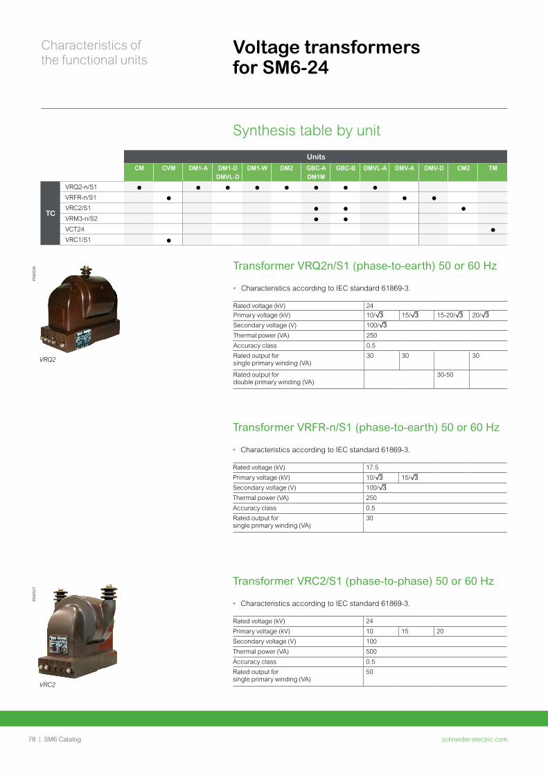
schneider-electric.com78 | SM6 Catalog
Characteristics of the functional units
Voltage transformers for SM6-24
PE60
526
VRQ2
PE60
527
VRC2
Synthesis table by unit
Units
CM CVM DM1-A DM1-DDMVL-D
DM1-W DM2 GBC-A DM1M
GBC-B DMVL-A DMV-A DMV-D CM2 TM
TC
VRQ2-n/S1
VRFR-n/S1
VRC2/S1
VRM3-n/S2
VCT24
VRC1/S1
Transformer VRQ2n/S1 (phase-to-earth) 50 or 60 Hz
• Characteristics according to IEC standard 61869-3.
Rated voltage (kV) 24
Primary voltage (kV) 10/3 15/3 15-20/3 20/3
Secondary voltage (V) 100/3
Thermal power (VA) 250
Accuracy class 0.5
Rated output forsingle primary winding (VA)
30 30 30
Rated output fordouble primary winding (VA)
30-50
Transformer VRFR-n/S1 (phase-to-earth) 50 or 60 Hz
• Characteristics according to IEC standard 61869-3.
Rated voltage (kV) 17.5
Primary voltage (kV) 10/3 15/3
Secondary voltage (V) 100/3
Thermal power (VA) 250
Accuracy class 0.5
Rated output forsingle primary winding (VA)
30
Transformer VRC2/S1 (phase-to-phase) 50 or 60 Hz
• Characteristics according to IEC standard 61869-3.
Rated voltage (kV) 24
Primary voltage (kV) 10 15 20
Secondary voltage (V) 100
Thermal power (VA) 500
Accuracy class 0.5
Rated output forsingle primary winding (VA)
50
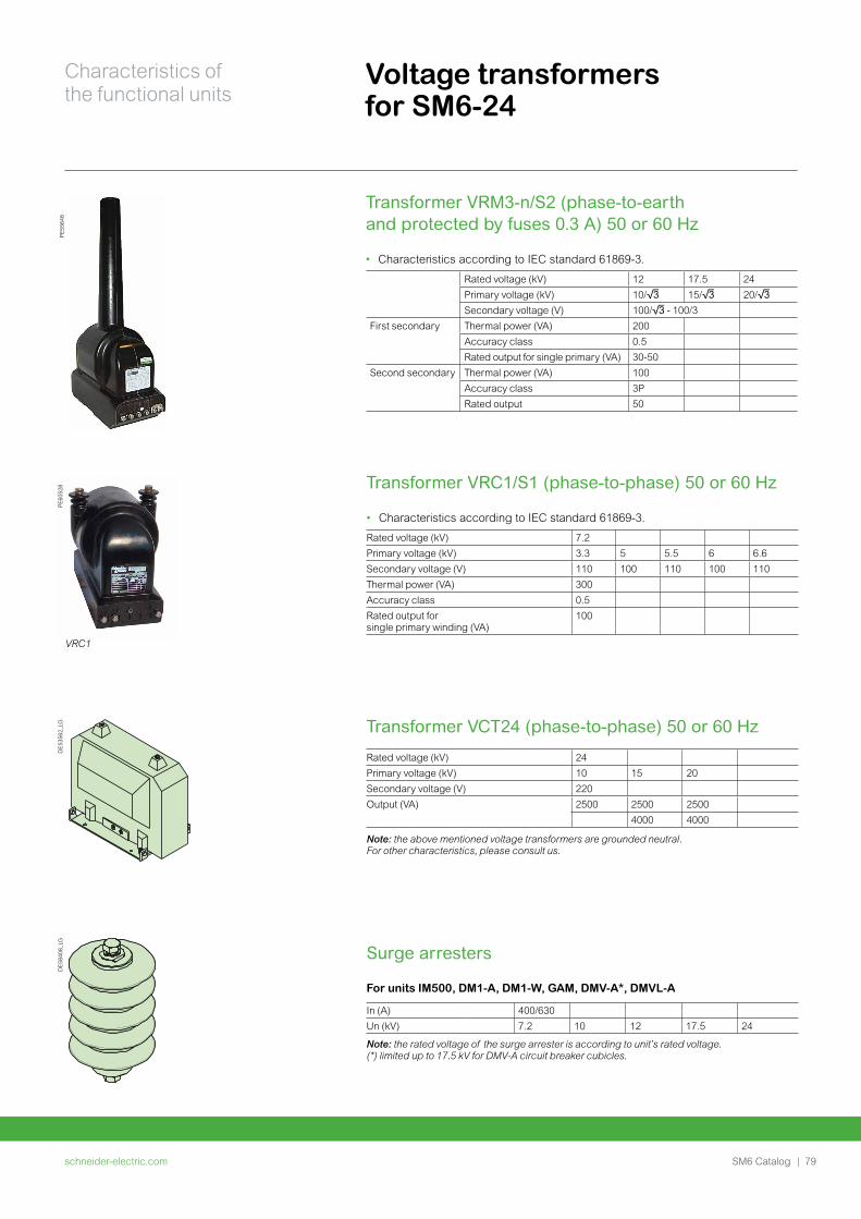
schneider-electric.com | 79SM6 Catalog
Characteristics of the functional units
Voltage transformers for SM6-24
DE
5356
2_LG
DE
5840
8_LG
Transformer VRM3-n/S2 (phase-to-earth and protected by fuses 0.3 A) 50 or 60 Hz
• Characteristics according to IEC standard 61869-3.
Rated voltage (kV) 12 17.5 24
Primary voltage (kV) 10/3 15/3 20/3
Secondary voltage (V) 100/3 - 100/3
First secondary Thermal power (VA) 200
Accuracy class 0.5
Rated output for single primary (VA) 30-50
Second secondary Thermal power (VA) 100
Accuracy class 3P
Rated output 50
PE
6052
8
VRC1
PE
5564
8
Transformer VRC1/S1 (phase-to-phase) 50 or 60 Hz
• Characteristics according to IEC standard 61869-3.
Rated voltage (kV) 7.2
Primary voltage (kV) 3.3 5 5.5 6 6.6
Secondary voltage (V) 110 100 110 100 110
Thermal power (VA) 300
Accuracy class 0.5
Rated output forsingle primary winding (VA)
100
Transformer VCT24 (phase-to-phase) 50 or 60 Hz
Rated voltage (kV) 24
Primary voltage (kV) 10 15 20
Secondary voltage (V) 220
Output (VA) 2500 2500 2500
4000 4000
Note: the above mentioned voltage transformers are grounded neutral. For other characteristics, please consult us.
Surge arresters
For units IM500, DM1-A, DM1-W, GAM, DMV-A*, DMVL-A
In (A) 400/630
Un (kV) 7.2 10 12 17.5 24
Note: the rated voltage of the surge arrester is according to unit’s rated voltage. (*) limited up to 17.5 kV for DMV-A circuit breaker cubicles.
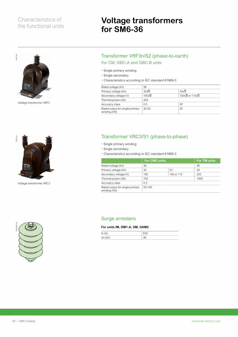
schneider-electric.com80 | SM6 Catalog
Characteristics of the functional units
Voltage transformers for SM6-36
PE57
223
Voltage transformer VRF3
Transformer VRF3n/S2 (phase-to-earth)For CM, GBC-A and GBC-B units
• Single primary winding
• Single secondary
• Characteristics according to IEC standard 61869-3
Rated voltage (kV) 36Primary voltage (kV) 303 333
Secondary voltage (V) 1003 1003 or 1103
Thermal power (VA) 450Accuracy class 0.5 3PRated output for single primary winding (VA)
30-50 30
PE57
224
Voltage transformer VRC3
Transformer VRC3/S1 (phase-to-phase)• Single primary winding
• Single secondary
• Characteristics according to IEC standard 61869-3
For CM2 units For TM units
Rated voltage (kV) 36 36Primary voltage (kV) 30 33 30Secondary voltage (V) 100 100 or 110 220Thermal power (VA) 700 1000Accuracy class 0.5Rated output for single primary winding (VA)
50-100
DE5
8408
_LG
Surge arresters
For units IM, DM1-A, SM, GAM2
In (A) 630Un (kV) 36
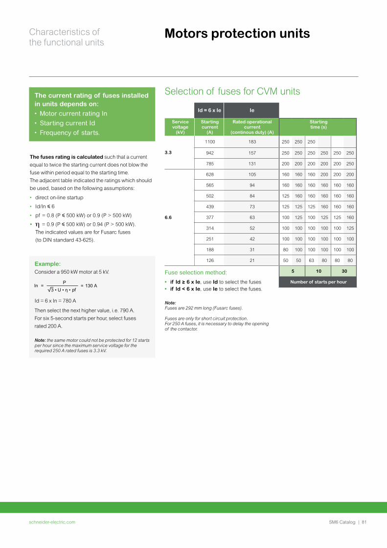
schneider-electric.com | 81SM6 Catalog
Characteristics of the functional units
Motors protection units
The fuses rating is calculated such that a current
equal to twice the starting current does not blow the
fuse within period equal to the starting time.
The adjacent table indicated the ratings which should
be used, based on the following assumptions:
• direct on-line startup
• Id/In y 6
• pf = 0.8 (P y 500 kW) or 0.9 (P > 500 kW)
• = 0.9 (P y 500 kW) or 0.94 (P > 500 kW).
The indicated values are for Fusarc fuses
(to DIN standard 43-625).
Selection of fuses for CVM units
Id = 6 x Ie Ie
Service voltage
(kV)
Starting current
(A)
Rated operational current
(continous duty) (A)
Starting time (s)
3.3
1100 183 250 250 250
942 157 250 250 250 250 250 250
785 131 200 200 200 200 200 250
6.6
628 105 160 160 160 200 200 200
565 94 160 160 160 160 160 160
502 84 125 160 160 160 160 160
439 73 125 125 125 160 160 160
377 63 100 125 100 125 125 160
314 52 100 100 100 100 100 125
251 42 100 100 100 100 100 100
188 31 80 100 100 100 100 100
126 21 50 50 63 80 80 80
Fuse selection method:
• if Id ≥ 6 x Ie, use Id to select the fuses• if Id < 6 x Ie, use Ie to select the fuses.
Note:Fuses are 292 mm long (Fusarc fuses).
Fuses are only for short circuit protection.For 250 A fuses, it is necessary to delay the opening of the contactor.
5 10 30
Number of starts per hour
The current rating of fuses installed in units depends on:• Motor current rating In• Starting current Id• Frequency of starts.
Example: Consider a 950 kW motor at 5 kV.
In =P
= 130 pf
A
Id = 6 x In = 780 A
Then select the next higher value, i.e. 790 A.
For six 5-second starts per hour, select fuses
rated 200 A.
Note: the same motor could not be protected for 12 starts per hour since the maximum service voltage for the required 250 A rated fuses is 3.3 kV.
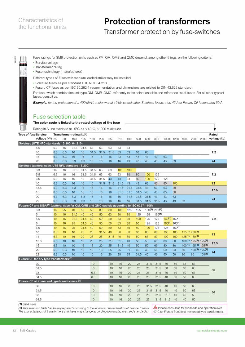
schneider-electric.com82 | SM6 Catalog
Characteristics of the functional units
Protection of transformersTransformer protection by fuse-switches
PE57
161 Fuse ratings for SM6 protection units such as PM, QM, QMB and QMC depend, among other things, on the following criteria:
• Service voltage• Transformer rating• Fuse technology (manufacturer)
Different types of fuses with medium loaded striker may be installed:
• Solefuse fuses as per standard UTE NCF 64.210• Fusarc CF fuses as per IEC 60.282.1 recommendation and dimensions are related to DIN 43.625 standard.
For fuse-switch combination unit type QM, QMB, QMC, refer only to the selection table and reference list of fuses. For all other type of fuses, consult us.
Example: for the protection of a 400 kVA transformer at 10 kV, select either Solefuse fuses rated 43 A or Fusarc CF fuses rated 50 A.
Type of fuseService voltage (kV)
Transformer rating (kVA) Rated voltage (kV)25 50 100 125 160 200 250 315 400 500 630 800 1000 1250 1600 2000 2500
Solefuse (UTE NFC standards 13.100. 64.210)
5.5 6.3 16 31.5 31.5 63 63 63 63 637.210 6.3 6.3 16 16 31.5 31.5 31.5 63 63 63 63
15 6.3 6.3 16 16 16 16 16 43 43 43 43 43 6320 6.3 6.3 6.3 6.3 16 16 16 16 43 43 43 43 43 63 24
Solefuse (general case, UTE NFC standard 13.200)
3.3 16 16 31.5 31.5 31.5 63 63 100 1007.25.5 6.3 16 16 31.5 31.5 63 63 63 80 80 100 125
6.6 6.3 16 16 16 31.5 31.5 43 43 63 80 100 125 12510 6.3 6.3 16 16 16 31.5 31.5 31.5 43 43 63 80 80 100 1213.8 6.3 6.3 6.3 16 16 16 16 31.5 31.5 31.5 43 63 63 80
17.515 6.3 6.3 16 16 16 16 16 31.5 31.5 31.5 43 43 63 8020 6.3 6.3 6.3 6.3 16 16 16 16 31.5 31.5 31.5 43 43 63
2422 6.3 6.3 6.3 6.3 16 16 16 16 16 31.5 31.5 31.5 43 43 63
Fusarc CF and SIBA (1) (general case for QM, QMB and QMC cubicle according to IEC 62271-105)
3.3 16 25 40 50 50 80 80 100 125 125 160(1) 200(1)
7.25 10 16 31.5 40 40 50 63 80 80 125 125 160(1)
5.5 10 16 31.5 31.5 40 50 50 63 80 100 125 125 160(1) 160(1)
6 10 16 25 31.5 40 50 50 63 80 80 125 125 160(1) 160(1)
6.6 10 16 25 31.5 40 50 50 63 80 80 100 125 125 160(1)
10 6.3 10 16 20 25 31.5 40 50 50 63 80 80 100 100 125(1) 200(1)12
11 6.3 10 16 20 25 25 31.5 40 50 50 63 80 100 100 125(1) 160(1)
13.8 6.3 10 16 16 20 25 31.5 31.5 40 50 50 63 80 80 100(1) 125(1) 125(1)17.5
15 6.3 10 10 16 16 20 25 31.5 40 50 50 63 80 80 100(1) 125(1) 125(1)
20 6.3 6.3 10 10 16 16 25 25 31.5 40 40 50 50 63 80 100(1) 125(1)24
22 6.3 6.3 10 10 10 16 20 25 25 31.5 40 40 50 50 80 80 100(1)
Fusarc CF for dry type transformers (2)
30 10 10 16 20 25 31.5 31.5 50 50 63 63
3631.5 10 10 16 20 25 25 31.5 50 50 63 6333 6.3 10 16 20 25 25 31.5 40 50 50 6334.5 6.3 10 16 20 25 25 31.5 40 50 50 63
Fusarc CF oil immersed type transformers (2)
30 10 10 16 20 25 31.5 31.5 40 40 50 63
3631.5 10 10 16 20 25 31.5 31.5 40 40 50 6333 10 10 16 20 25 25 31.5 31.5 40 40 5034.5 10 10 16 20 25 25 31.5 31.5 40 40 50
(1) SIBA fuses(2) This selection table has been prepared according to the technical characteristics of France Transfo.The characteristics of transformers and fuses may change according to manufactures and standards.
Fuse selection tableThe color code is linked to the rated voltage of the fuse
Rating in A - no overload at –5°C < t < 40°C, ≤1000 m altitude.
d Please consult us for overloads and operation over 40°C for France Transfo oil immersed type transformers.
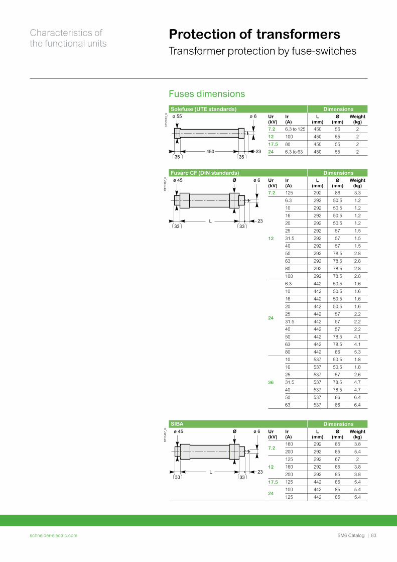
schneider-electric.com | 83SM6 Catalog
Characteristics of the functional units
Solefuse (UTE standards) Dimensions
DE5
3563
_G Ur (kV)
Ir (A)
L (mm)
Ø (mm)
Weight (kg)
7.2 6.3 to 125 450 55 2
12 100 450 55 2
17.5 80 450 55 2
24 6.3 to 63 450 55 2
Fusarc CF (DIN standards) Dimensions
DE5
7467
_G Ur (kV)
Ir (A)
L (mm)
Ø (mm)
Weight (kg)
7.2 125 292 86 3.3
12
6.3 292 50.5 1.2
10 292 50.5 1.2
16 292 50.5 1.2
20 292 50.5 1.2
25 292 57 1.5
31.5 292 57 1.5
40 292 57 1.5
50 292 78.5 2.8
63 292 78.5 2.8
80 292 78.5 2.8
100 292 78.5 2.8
24
6.3 442 50.5 1.6
10 442 50.5 1.6
16 442 50.5 1.6
20 442 50.5 1.6
25 442 57 2.2
31.5 442 57 2.2
40 442 57 2.2
50 442 78.5 4.1
63 442 78.5 4.1
80 442 86 5.3
36
10 537 50.5 1.8
16 537 50.5 1.8
25 537 57 2.6
31.5 537 78.5 4.7
40 537 78.5 4.7
50 537 86 6.4
63 537 86 6.4
SIBA Dimensions
DE5
7467
_G Ur (kV)
Ir (A)
L (mm)
Ø (mm)
Weight (kg)
7.2160 292 85 3.8
200 292 85 5.4
12
125 292 67 2
160 292 85 3.8
200 292 85 3.8
17.5 125 442 85 5.4
24100 442 85 5.4
125 442 85 5.4
Protection of transformersTransformer protection by fuse-switches
Fuses dimensions
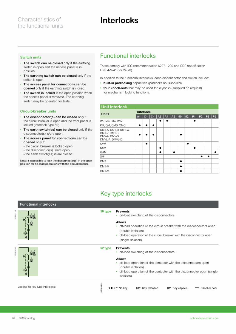
schneider-electric.com84 | SM6 Catalog
Characteristics of the functional units
Interlocks
Functional interlocks
DE
5357
1_LG
OO
O
50 type Prevents • on-load switching of the disconnectors.
Allows • off-load operation of the circuit breaker with the disconnectors open
(double isolation).• off-load operation of the circuit breaker with the disconnector open
(single isolation).
DE
5920
3_LG
OO
O
52 type Prevents • on-load switching of the disconnectors.
Allows • off-load operation of the contactor with the disconnectors open
(double isolation).• off-load operation of the contactor with the disconnector open (single
isolation).
Legend for key-type interlocks:
MT2
0240
EN
No key Key released Key captive Panel or door
Key-type interlocks
Switch units
• The switch can be closed only if the earthing switch is open and the access panel is in position.
• The earthing switch can be closed only if the switch is open.
• The access panel for connections can be opened only if the earthing switch is closed.
• The switch is locked in the open position when the access panel is removed. The earthing switch may be operated for tests.
Circuit-breaker units
• The disconnector(s) can be closed only if the circuit breaker is open and the front panel is locked (interlock type 50).
• The earth switch(es) can be closed only if the disconnector(s) is/are open.
• The access panel for connections can be opened only if: - the circuit breaker is locked open, - the disconnector(s) is/are open, - the earth switch(es) is/are closed.
Note: it is possible to lock the disconnector(s) in the open position for no-load operations with the circuit breaker.
Functional interlocksThese comply with IEC recommendation 62271-200 and EDF specification HN 64-S-41 (for 24 kV).
In addition to the functional interlocks, each disconnector and switch include:
• built-in padlocking capacities (padlocks not supplied)
• four knock-outs that may be used for keylocks (supplied on request) for mechanism locking functions.
Unit interlock
UnitsInterlockA1 C1 C4 A3 A4 A5 50 52 P1 P2 P3 P5
IM, IMB, IMC, IMM
PM, QM, QMB, QMC,
DM1-A, DM1-D, DM1-W, DM1-Z, DM1-S, DMV-A, DMV-D, DMVL-A, DMVL-DCVMNSMGAMSM
DM2
DM1-M
DM1-M
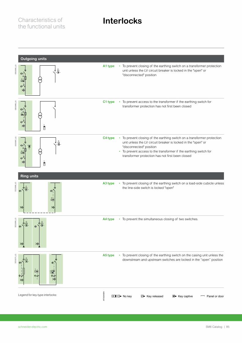
schneider-electric.com | 85SM6 Catalog
Characteristics of the functional units
Interlocks
Outgoing units
DE
5356
5_LG
O
O
A1 type • To prevent closing of the earthing switch on a transformer protection unit unless the LV circuit breaker is locked in the "open" or "disconnected" position
DE
5356
6_LG
S
S
C1 type • To prevent access to the transformer if the earthing switch for transformer protection has not first been closed
DE
5356
7_LG
S
SO
O
C4 type • To prevent closing of the earthing switch on a transformer protection unit unless the LV circuit breaker is locked in the "open" or "disconnected" position
• To prevent access to the transformer if the earthing switch for transformer protection has not first been closed
Ring units
DE
5356
8_LG
O
O
A3 type • To prevent closing of the earthing switch on a load-side cubicle unless the line-side switch is locked "open"
DE
5356
9_LG A4 type • To prevent the simultaneous closing of two switches.
DE
5357
0_LG
O
OS
S
A5 type • To prevent closing of the earthing switch on the casing unit unless the downstream and upstream switches are locked in the “open” position
Legend for key-type interlocks:
MT2
0240
EN
No key Key released Key captive Panel or door
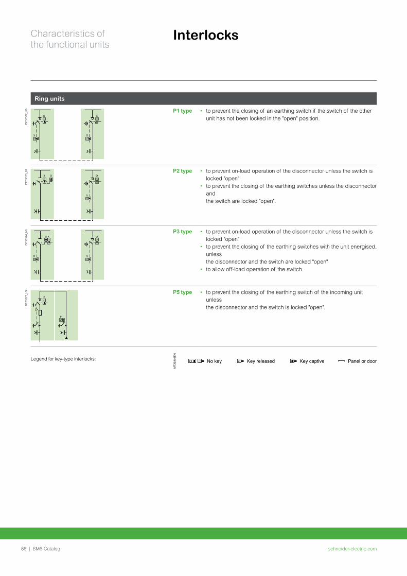
schneider-electric.com86 | SM6 Catalog
Characteristics of the functional units
Interlocks
Ring units
DE
5357
2_LG
X
O
O
X
P1 type • to prevent the closing of an earthing switch if the switch of the other unit has not been locked in the "open" position.
DE
5357
3_LG
X
X
OOP2 type • to prevent on-load operation of the disconnector unless the switch is
locked "open"• to prevent the closing of the earthing switches unless the disconnector
and the switch are locked "open".
DE
5357
4_LG
O X
OA X
P3 type • to prevent on-load operation of the disconnector unless the switch is locked "open"
• to prevent the closing of the earthing switches with the unit energised, unless the disconnector and the switch are locked "open"
• to allow off-load operation of the switch.
DE
5357
5_LG
P
P
P5 type • to prevent the closing of the earthing switch of the incoming unit unless the disconnector and the switch is locked "open".
Legend for key-type interlocks:
MT2
0240
EN
No key Key released Key captive Panel or door

schneider-electric.com | 87SM6 Catalog
Notes
schneider-electric.com88 | SM6 Catalog
Protection, monitoring and control
schneider-electric.com | 89SM6 Catalog
Protection, monitoring
and control
Protection 90Easergy P3 relay 90
Easergy Sepam selection guide 91
Easergy P5 protection relay 94
VIP 40 and VIP 45 relays 95
VIP 400 and VIP 410 relays 96
Protection and sensor selection table 97
LPCT protection chain 98
Fault passage indicators 100
Ammeter 103
Arc fault detectors Easergy Vamp 104
Control 105Motorization control 105
Easergy T200 S for SM6-24 106
Easergy T200 I 107
Automation systems 108
PS100 high-availability power supply 114
Monitoring 115Thermal monitoring Easergy TH110 115
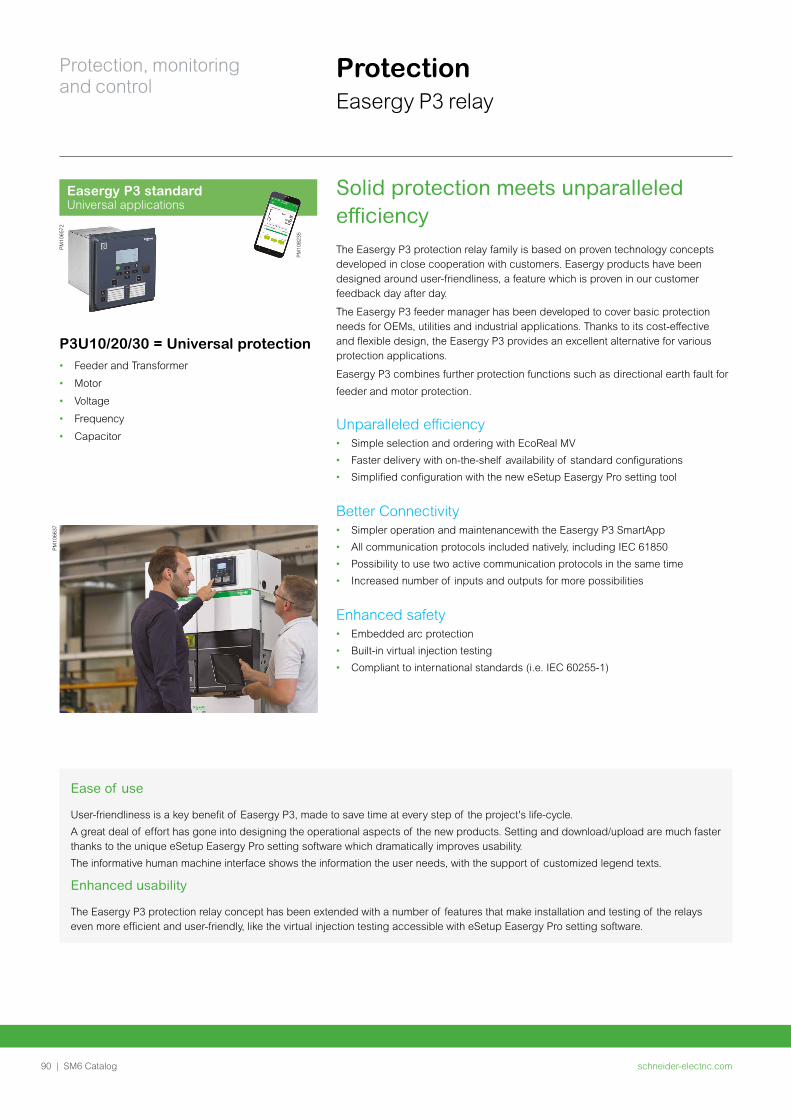
schneider-electric.com90 | SM6 Catalog
Protection, monitoring and control
ProtectionEasergy P3 relay
PM10
6637
Ease of use
User-friendliness is a key benefit of Easergy P3, made to save time at every step of the project's life-cycle.
A great deal of effort has gone into designing the operational aspects of the new products. Setting and download/upload are much faster thanks to the unique eSetup Easergy Pro setting software which dramatically improves usability.
The informative human machine interface shows the information the user needs, with the support of customized legend texts.
Enhanced usability
The Easergy P3 protection relay concept has been extended with a number of features that make installation and testing of the relays even more efficient and user-friendly, like the virtual injection testing accessible with eSetup Easergy Pro setting software.
Solid protection meets unparalleled efficiencyThe Easergy P3 protection relay family is based on proven technology concepts developed in close cooperation with customers. Easergy products have been designed around user-friendliness, a feature which is proven in our customer feedback day after day.
The Easergy P3 feeder manager has been developed to cover basic protection needs for OEMs, utilities and industrial applications. Thanks to its cost-effective and flexible design, the Easergy P3 provides an excellent alternative for various protection applications.
Easergy P3 combines further protection functions such as directional earth fault for
feeder and motor protection.
Unparalleled efficiency• Simple selection and ordering with EcoReal MV
• Faster delivery with on-the-shelf availability of standard configurations
• Simplified configuration with the new eSetup Easergy Pro setting tool
Better Connectivity• Simpler operation and maintenancewith the Easergy P3 SmartApp
• All communication protocols included natively, including IEC 61850
• Possibility to use two active communication protocols in the same time
• Increased number of inputs and outputs for more possibilities
Enhanced safety• Embedded arc protection
• Built-in virtual injection testing
• Compliant to international standards (i.e. IEC 60255-1)
Easergy P3 standardUniversal applications
PM10
6572
P3U10/20/30 = Universal protection• Feeder and Transformer
• Motor
• Voltage
• Frequency
• Capacitor
PM
1082
35
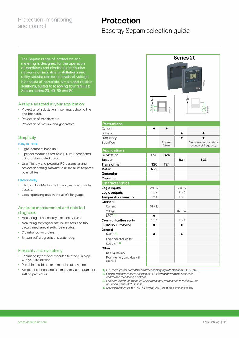
schneider-electric.com | 91SM6 Catalog
Protection, monitoring and control
Protection Easergy Sepam selection guide
A range adapted at your application• Protection of substation (incoming, outgoing line
and busbars).
• Protection of transformers.
• Protection of motors, and generators.
Simplicity
Easy to install
• Light, compact base unit.
• Optional modules fitted on a DIN rail, connected using prefabricated cords.
• User friendly and powerful PC parameter and protection setting software to utilize all of Sepam’s possibilities.
User-friendly
• Intuitive User Machine Interface, with direct data access.
• Local operating data in the user’s language.
Accurate measurement and detailed diagnosis• Measuring all necessary electrical values.
• Monitoring switchgear status: sensors and trip circuit, mechanical switchgear status.
• Disturbance recording.
• Sepam self-diagnosis and watchdog.
Flexibility and evolutivity• Enhanced by optional modules to evolve in step
with your installation.
• Possible to add optional modules at any time.
• Simple to connect and commission via a parameter setting procedure.
The Sepam range of protection and metering is designed for the operation of machines and electrical distribution networks of industrial installations and utility substations for all levels of voltage. It consists of complete, simple and reliable solutions, suited to following four families: Sepam series 20, 40, 60 and 80.
Series 20
ProtectionsCurrent
Voltage
Frequency
Specifics Breaker failure
Disconnection by rate of change of frequency
ApplicationsSubstation S20 S24Busbar B21 B22Transformer T20 T24Motor M20GeneratorCapacitor
CharacteristicsLogic inputs 0 to 10 0 to 10
Logic outputs 4 to 8 4 to 8
Temperature sensors 0 to 8 0 to 8
ChannelCurrent 3 I + Io
Voltage 3V + Vo
LPCT (1)
Communication ports 1 to 2 1 to 2
IEC61850 Protocol
ControlMatrix (2)
Logic equation editor
Logipam (3)
OtherBackup battery
Front memory cartridge with settings
(1) LPCT: low-power current transformer complying with standard IEC 60044-8.(2) Control matrix for simple assignment of information from the protection,
control and monitoring functions.(3) Logipam ladder language (PC programming environment) to make full use
of Sepam series 80 functions.(4) Standard lithium battery 1/2 AA format, 3.6 V, front face exchangeable.
DE
5920
5
DE
5920
6
PE
8802
2
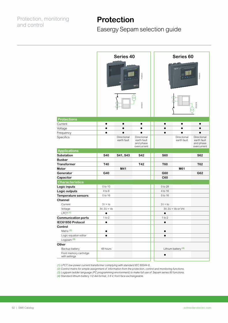
schneider-electric.com92 | SM6 Catalog
Protection, monitoring and control
Protection Easergy Sepam selection guide
Series 40 Series 60
ProtectionsCurrent
Voltage
Frequency
Specifics Directional earth fault
Directional earth fault and phase overcurrent
Directional earth fault
Directional earth fault and phase overcurrent
ApplicationsSubstation S40 S41, S43 S42 S60 S62BusbarTransformer T40 T42 T60 T62Motor M41 M61Generator G40 G60 G62Capacitor C60
CharacteristicsLogic inputs 0 to 10 0 to 28
Logic outputs 4 to 8 4 to 16
Temperature sensors 0 to 16 0 to 16
ChannelCurrent 3 I + Io 3 I + Io
Voltage 3V, 2U + Vo 3V, 2U + Vo or Vnt
LPCT (1)
Communication ports 1 to 2 1 to 2
IEC61850 Protocol
ControlMatrix (2)
Logic equation editor
Logipam (3)
OtherBackup battery 48 hours Lithium battery (4)
Front memory cartridge with settings
(1) LPCT: low-power current transformer complying with standard IEC 60044-8.(2) Control matrix for simple assignment of information from the protection, control and monitoring functions.(3) Logipam ladder language (PC programming environment) to make full use of Sepam series 80 functions.(4) Standard lithium battery 1/2 AA format, 3.6 V, front face exchangeable.
PE
8802
2D
E59
207
DE
5920
8
PE
8802
3
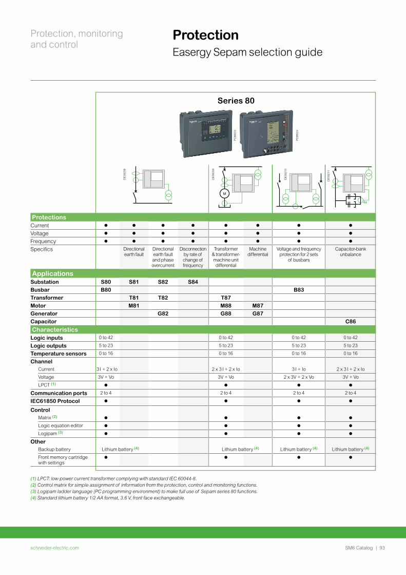
schneider-electric.com | 93SM6 Catalog
Protection, monitoring and control
Protection Easergy Sepam selection guide
Series 80
M
ProtectionsCurrent
Voltage
Frequency
Specifics Directional earth fault
Directional earth fault and phase overcurrent
Disconnection by rate of change of frequency
Transformer & transformer-machine unit differential
Machine differential
Voltage and frequency protection for 2 sets
of busbars
Capacitor-bank unbalance
ApplicationsSubstation S80 S81 S82 S84Busbar B80 B83Transformer T81 T82 T87Motor M81 M88 M87Generator G82 G88 G87Capacitor C86
CharacteristicsLogic inputs 0 to 42 0 to 42 0 to 42 0 to 42
Logic outputs 5 to 23 5 to 23 5 to 23 5 to 23
Temperature sensors 0 to 16 0 to 16 0 to 16 0 to 16
ChannelCurrent 3 I + 2 x Io 2 x 3 I + 2 x Io 3 I + Io 2 x 3 I + 2 x Io
Voltage 3V + Vo 3V + Vo 2 x 3V + 2 x Vo 3V + Vo
LPCT (1)
Communication ports 2 to 4 2 to 4 2 to 4 2 to 4
IEC61850 Protocol
ControlMatrix (2)
Logic equation editor
Logipam (3)
OtherBackup battery Lithium battery (4) Lithium battery (4) Lithium battery (4) Lithium battery (4)
Front memory cartridge with settings
(1) LPCT: low-power current transformer complying with standard IEC 60044-8.(2) Control matrix for simple assignment of information from the protection, control and monitoring functions.(3) Logipam ladder language (PC programming environment) to make full use of Sepam series 80 functions.(4) Standard lithium battery 1/2 AA format, 3.6 V, front face exchangeable.
DE
5920
8
DE
5920
9
DE
5921
0
DE
5921
1
PE
8802
3
PE
8802
4
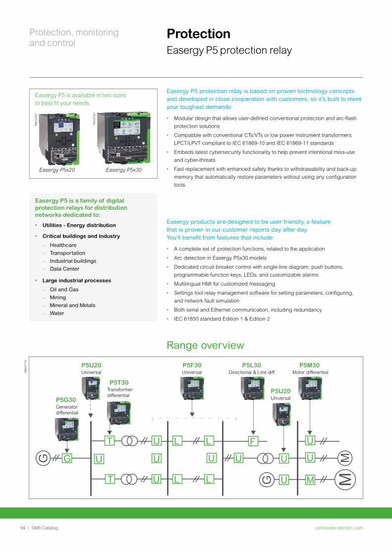
schneider-electric.com94 | SM6 Catalog
Protection, monitoring and control
Protection Easergy P5 protection relay
Easergy P5 protection relay is based on proven technology concepts and developed in close cooperation with customers, so it’s built to meet your toughest demands:
• Modular design that allows user-defined conventional protection and arc-flash
protection solutions
• Compatible with conventional CTs/VTs or low power instrument transformers
LPCT/LPVT compliant to IEC 61869-10 and IEC 61869-11 standards
• Embeds latest cybersecurity functionality to help prevent intentional miss-use
and cyber-threats
• Fast replacement with enhanced safety thanks to withdrawability and back-up
memory that automatically restore parameters without using any configuration
tools
Easergy P5 is a family of digital protection relays for distribution networks dedicated to:
• Utilities - Energy distribution
• Critical buildings and Industry
– Healthcare
– Transportation
– Industrial buildings
– Data Center
• Large industrial processes
– Oil and Gas
– Mining
– Mineral and Metals
– Water
Easergy P5x20 Easergy P5x30
PM10
7451
PM10
7437
Easergy P5 is available in two sizes to best fit your needs
Easergy products are designed to be user friendly, a feature that is proven in our customer reports day after day. You’ll benefit from features that include:
• A complete set of protection functions, related to the application
• Arc detection in Easergy P5x30 models
• Dedicated circuit breaker control with single-line diagram, push buttons,
programmable function keys, LEDs, and customizable alarms
• Multilingual HMI for customized messaging
• Settings tool relay management software for setting parameters, configuring,
and network fault simulation
• Both serial and Ethernet communication, including redundancy
• IEC 61850 standard Edition 1 & Edition 2
Range overview
G
MM
G U
U
U
M
U U
F
UG
T U
U
L L
U
T U L L
Universal
Transformer di�erential
Generatordi�erential
Motor di�erentialUniversal Directional & Line di�.P5U20
UniversalP5U20
P5G30
P5T30
P5F30 P5L30 P5M30
DM
1071
10
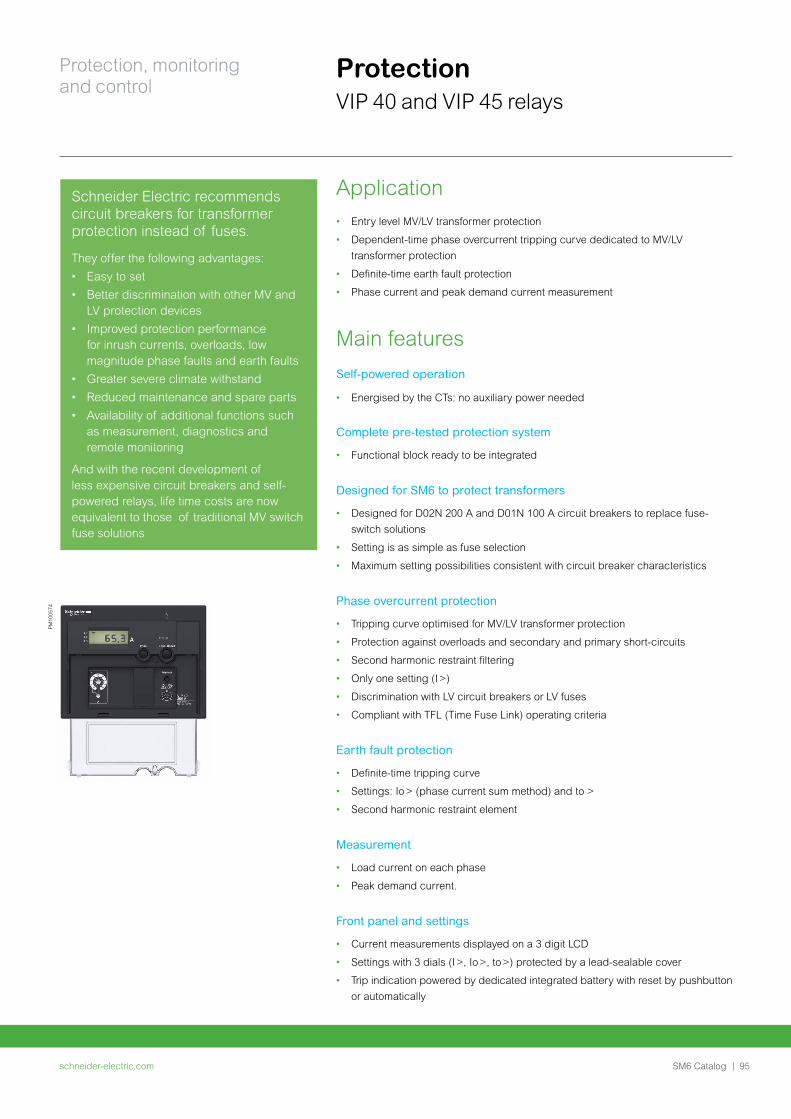
schneider-electric.com | 95SM6 Catalog
Protection, monitoring and control
ProtectionVIP 40 and VIP 45 relays
Application• Entry level MV/LV transformer protection
• Dependent-time phase overcurrent tripping curve dedicated to MV/LV
transformer protection
• Definite-time earth fault protection
• Phase current and peak demand current measurement
Main featuresSelf-powered operation
• Energised by the CTs: no auxiliary power needed
Complete pre-tested protection system
• Functional block ready to be integrated
Designed for SM6 to protect transformers
• Designed for D02N 200 A and D01N 100 A circuit breakers to replace fuse-
switch solutions
• Setting is as simple as fuse selection
• Maximum setting possibilities consistent with circuit breaker characteristics
Phase overcurrent protection
• Tripping curve optimised for MV/LV transformer protection
• Protection against overloads and secondary and primary short-circuits
• Second harmonic restraint filtering
• Only one setting (I >)
• Discrimination with LV circuit breakers or LV fuses
• Compliant with TFL (Time Fuse Link) operating criteria
Earth fault protection
• Definite-time tripping curve
• Settings: Io > (phase current sum method) and to >
• Second harmonic restraint element
Measurement
• Load current on each phase
• Peak demand current.
Front panel and settings
• Current measurements displayed on a 3 digit LCD
• Settings with 3 dials (I >, Io >, to >) protected by a lead-sealable cover
• Trip indication powered by dedicated integrated battery with reset by pushbutton
or automatically
PM10
0574
Schneider Electric recommends circuit breakers for transformer protection instead of fuses.
They offer the following advantages:
• Easy to set
• Better discrimination with other MV and LV protection devices
• Improved protection performance for inrush currents, overloads, low magnitude phase faults and earth faults
• Greater severe climate withstand
• Reduced maintenance and spare parts
• Availability of additional functions such as measurement, diagnostics and remote monitoring
And with the recent development of less expensive circuit breakers and self-powered relays, life time costs are now equivalent to those of traditional MV switch fuse solutions
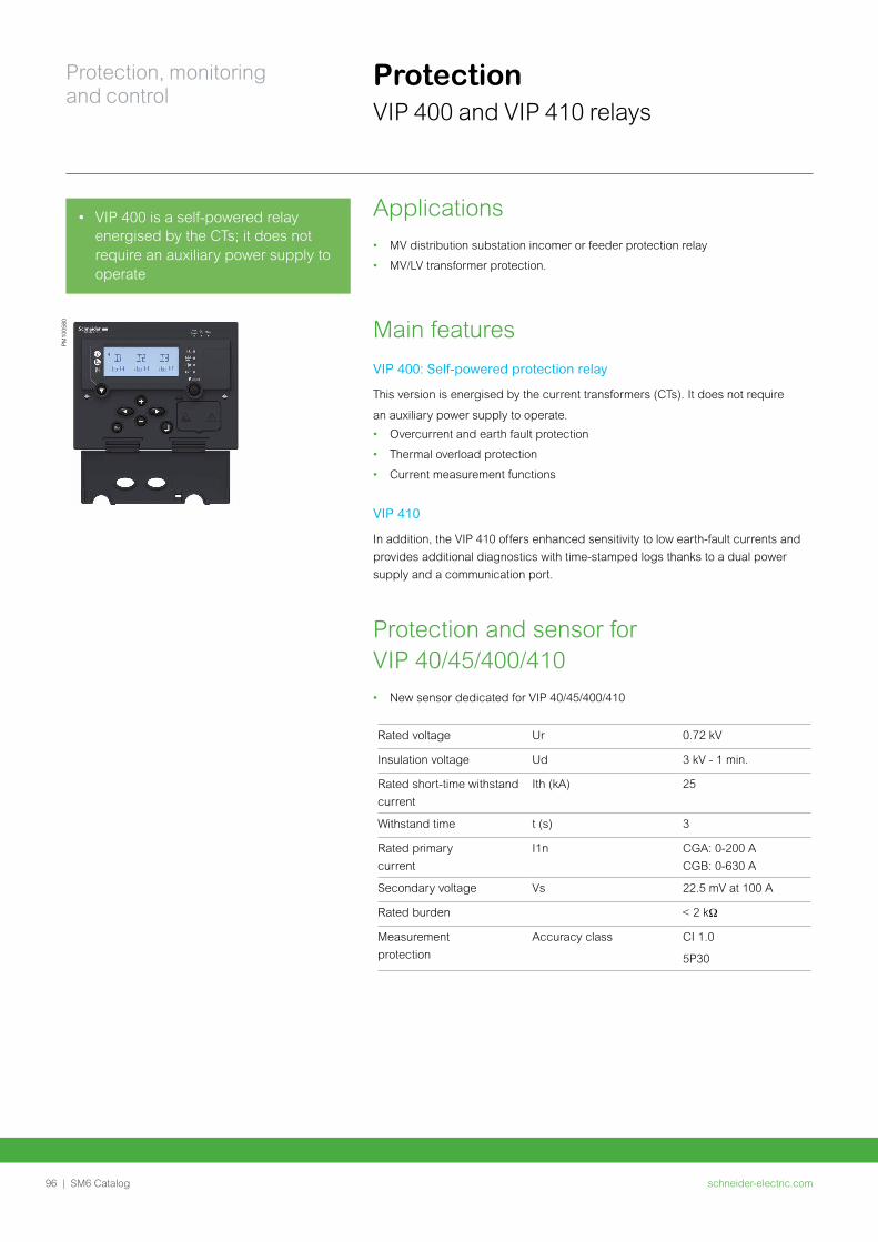
schneider-electric.com96 | SM6 Catalog
Protection, monitoring and control
Applications• MV distribution substation incomer or feeder protection relay
• MV/LV transformer protection.
Main featuresVIP 400: Self-powered protection relay
This version is energised by the current transformers (CTs). It does not require
an auxiliary power supply to operate.
• Overcurrent and earth fault protection
• Thermal overload protection
• Current measurement functions
VIP 410
In addition, the VIP 410 offers enhanced sensitivity to low earth-fault currents and
provides additional diagnostics with time-stamped logs thanks to a dual power
supply and a communication port.
Protection and sensor for VIP 40/45/400/410• New sensor dedicated for VIP 40/45/400/410
PM10
0580
ProtectionVIP 400 and VIP 410 relays
• VIP 400 is a self-powered relay energised by the CTs; it does not require an auxiliary power supply to operate
Rated voltage Ur 0.72 kV
Insulation voltage Ud 3 kV - 1 min.
Rated short-time withstand current
Ith (kA) 25
Withstand time t (s) 3
Rated primary current
I1n CGA: 0-200 A CGB: 0-630 A
Secondary voltage Vs 22.5 mV at 100 A
Rated burden
Measurement protection
Accuracy class CI 1.0
5P30
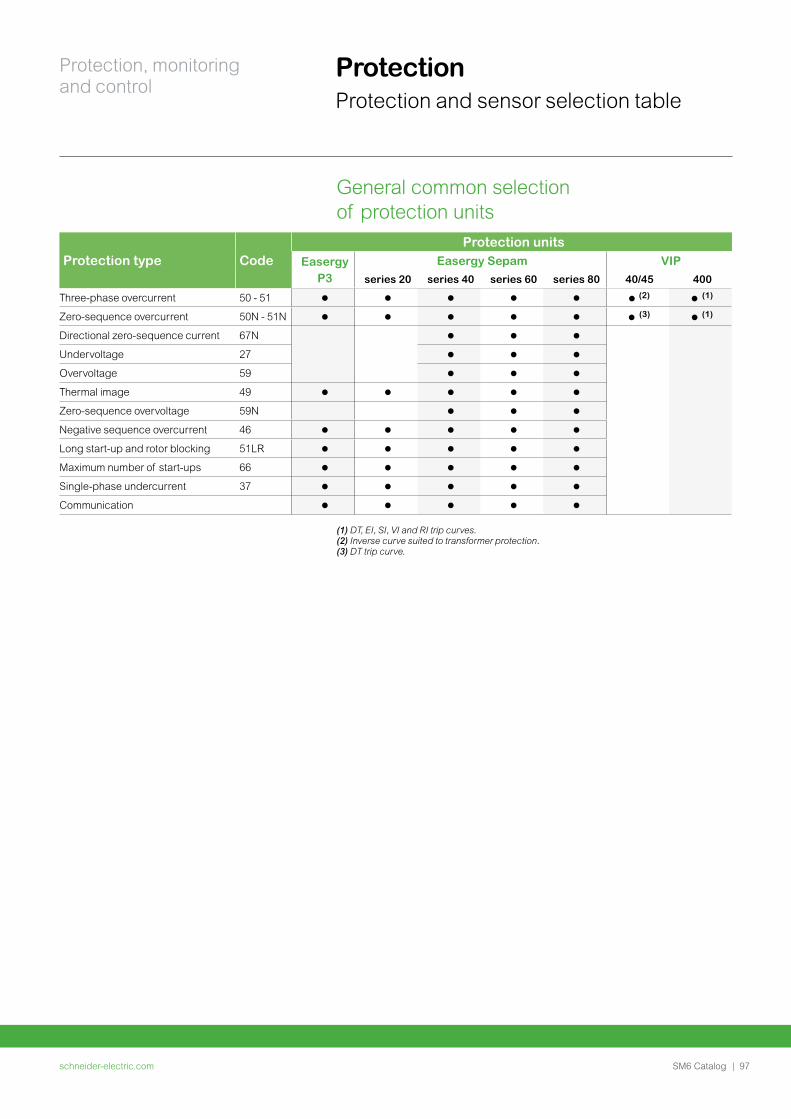
schneider-electric.com | 97SM6 Catalog
Protection, monitoring and control
Protection Protection and sensor selection table
General common selection of protection units
(1) DT, EI, SI, VI and RI trip curves. (2) Inverse curve suited to transformer protection.(3) DT trip curve.
Protection type CodeProtection units
EasergyP3
Easergy Sepam VIP
series 20 series 40 series 60 series 80 40/45 400
Three-phase overcurrent 50 - 51 (2) (1)
Zero-sequence overcurrent 50N - 51N (3) (1)
Directional zero-sequence current 67N
Undervoltage 27
Overvoltage 59
Thermal image 49
Zero-sequence overvoltage 59N
Negative sequence overcurrent 46
Long start-up and rotor blocking 51LR
Maximum number of start-ups 66
Single-phase undercurrent 37
Communication
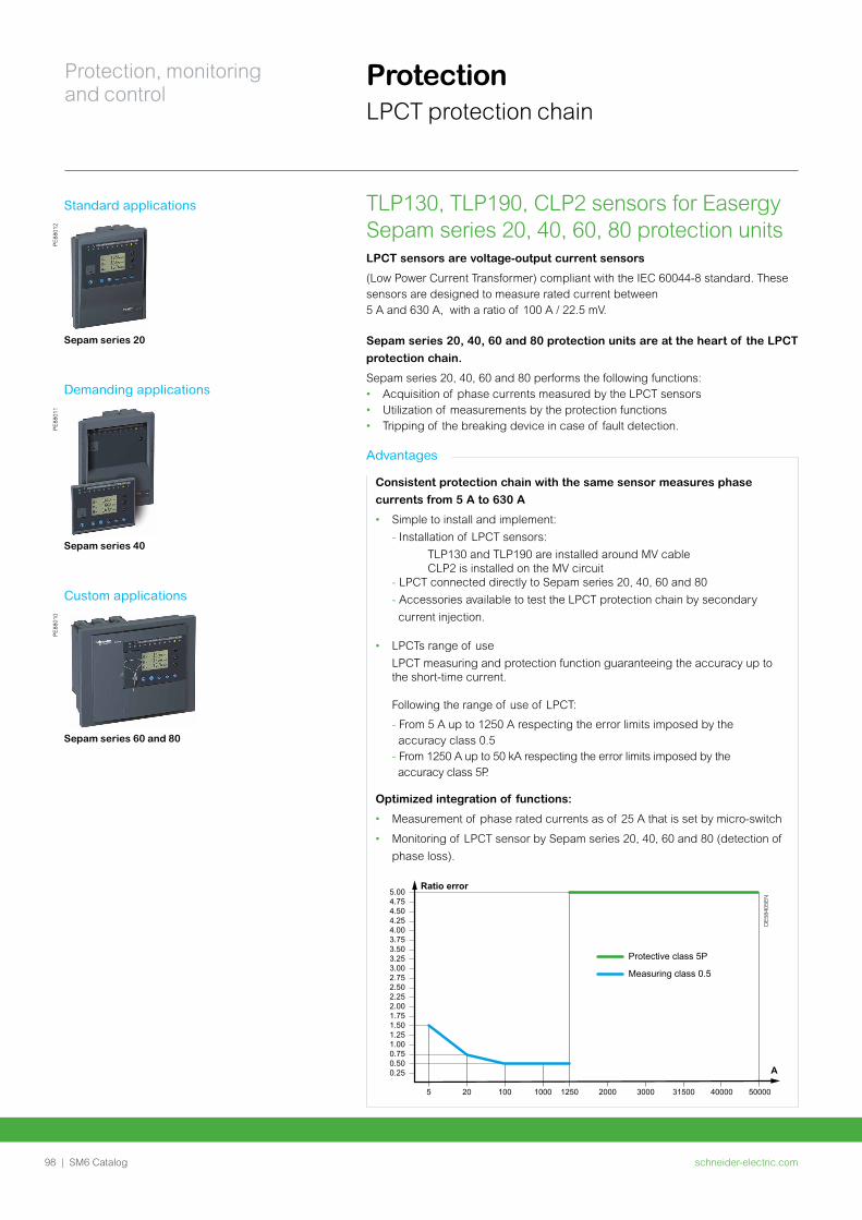
schneider-electric.com98 | SM6 Catalog
Protection, monitoring and control
Protection LPCT protection chain
TLP130, TLP190, CLP2 sensors for Easergy Sepam series 20, 40, 60, 80 protection unitsLPCT sensors are voltage-output current sensors
(Low Power Current Transformer) compliant with the IEC 60044-8 standard. These sensors are designed to measure rated current between 5 A and 630 A, with a ratio of 100 A / 22.5 mV.
Sepam series 20, 40, 60 and 80 protection units are at the heart of the LPCT
protection chain.
Sepam series 20, 40, 60 and 80 performs the following functions:• Acquisition of phase currents measured by the LPCT sensors• Utilization of measurements by the protection functions• Tripping of the breaking device in case of fault detection.
Standard applications
PE
8801
2
Sepam series 20
Demanding applications
PE
8801
1
Sepam series 40
Custom applications
PE
8801
0
Sepam series 60 and 80
Advantages
Consistent protection chain with the same sensor measures phase
currents from 5 A to 630 A
• Simple to install and implement:
- Installation of LPCT sensors:
TLP130 and TLP190 are installed around MV cable CLP2 is installed on the MV circuit - LPCT connected directly to Sepam series 20, 40, 60 and 80
- Accessories available to test the LPCT protection chain by secondary
current injection.
• LPCTs range of use
LPCT measuring and protection function guaranteeing the accuracy up to the short-time current. Following the range of use of LPCT:
- From 5 A up to 1250 A respecting the error limits imposed by the accuracy class 0.5 - From 1250 A up to 50 kA respecting the error limits imposed by the accuracy class 5P.
Optimized integration of functions:
• Measurement of phase rated currents as of 25 A that is set by micro-switch
• Monitoring of LPCT sensor by Sepam series 20, 40, 60 and 80 (detection of
phase loss).
DE
5840
5EN
Ratio error
A
5.004.754.504.254.003.753.503.253.002.752.502.252.001.751.50
Protective class 5P
Measuring class 0.5
1.251.000.750.500.25
5 20 100 1000 1250 2000 3000 31500 40000 50000
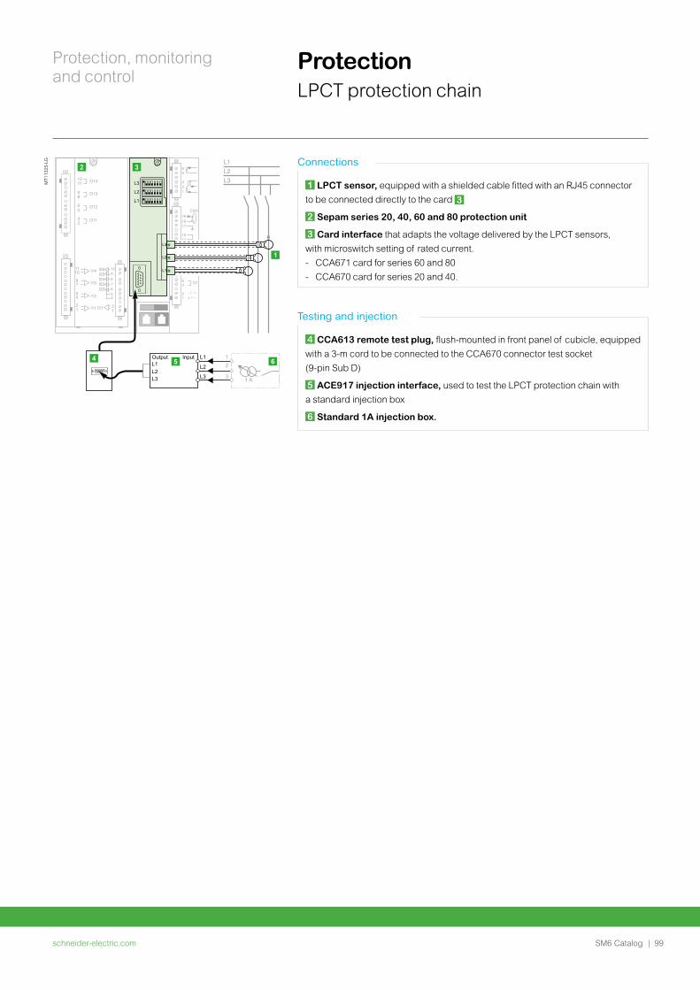
schneider-electric.com | 99SM6 Catalog
Protection, monitoring and control
Protection LPCT protection chain
MT1
1325
-LG Connections
1 LPCT sensor, equipped with a shielded cable fitted with an RJ45 connector
to be connected directly to the card 3
2 Sepam series 20, 40, 60 and 80 protection unit
3 Card interface that adapts the voltage delivered by the LPCT sensors,
with microswitch setting of rated current.
- CCA671 card for series 60 and 80
- CCA670 card for series 20 and 40.
Testing and injection
4 CCA613 remote test plug, flush-mounted in front panel of cubicle, equipped
with a 3-m cord to be connected to the CCA670 connector test socket
(9-pin Sub D)
5 ACE917 injection interface, used to test the LPCT protection chain with
a standard injection box
6 Standard 1A injection box.
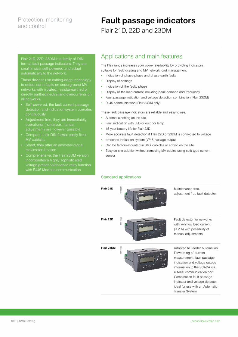
schneider-electric.com100 | SM6 Catalog
Protection, monitoring and control
Fault passage indicatorsFlair 21D, 22D and 23DM
Applications and main features The Flair range increases your power availability by providing indicators
suitable for fault locating and MV network load management.
• Indication of phase-phase and phase-earth faults
• Display of settings
• Indication of the faulty phase
• Display of the load current including peak demand and frequency
• Fault passage indication and voltage detection combination (Flair 23DM)
• RJ45 communication (Flair 23DM only).
These fault passage indicators are reliable and easy to use.
• Automatic setting on the site
• Fault indication with LED or outdoor lamp
• 15-year battery life for Flair 22D
• More accurate fault detection if Flair 22D or 23DM is connected to voltage
• presence indication system (VPIS) voltage output
• Can be factory-mounted in SMX cubicles or added on the site
• Easy on-site addition without removing MV cables using split-type current
sensor.
Flair 21D, 22D, 23DM is a family of DIN format fault passage indicators. They are small in size, self-powered and adapt automatically to the network.
These devices use cutting-edge technology to detect earth faults on underground MV networks with isolated, resistor-earthed or directly earthed neutral and overcurrents on all networks.
• Self-powered, the fault current passage detection and indication system operates continuously
• Adjustment-free, they are immediately operational (numerous manual adjustments are however possible)
• Compact, their DIN format easily fits in MV cubicles
• Smart, they offer an ammeter/digital maximeter function
• Comprehensive, the Flair 23DM version incorporates a highly sophisticated voltage presence/absence relay function with RJ45 Modbus communication
Standard applications
Flair 21D
PM
1083
31 Maintenance-free,
adjustment-free fault detector
Flair 22D
PM
1083
32 Fault detector for networks
with very low load current
(< 2 A) with possibility of
manual adjustments
Flair 23DM
PM
1060
82 Adapted to Feeder Automation.
Forwarding of current
measurement, fault passage
indication and voltage outage
information to the SCADA via
a serial communication port.
Combination fault passage
indicator and voltage detector,
ideal for use with an Automatic
Transfer System
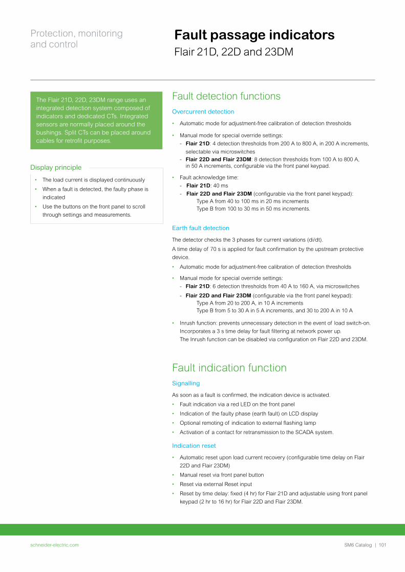
schneider-electric.com | 101SM6 Catalog
Protection, monitoring and control
Fault passage indicatorsFlair 21D, 22D and 23DM
Fault detection functions Overcurrent detection
• Automatic mode for adjustment-free calibration of detection thresholds
• Manual mode for special override settings:
- Flair 21D: 4 detection thresholds from 200 A to 800 A, in 200 A increments,
selectable via microswitches- Flair 22D and Flair 23DM: 8 detection thresholds from 100 A to 800 A, in 50 A increments, configurable via the front panel keypad.
• Fault acknowledge time:
- Flair 21D: 40 ms
- Flair 22D and Flair 23DM (configurable via the front panel keypad): Type A from 40 to 100 ms in 20 ms increments Type B from 100 to 30 ms in 50 ms increments.
Earth fault detection
The detector checks the 3 phases for current variations (di/dt).
A time delay of 70 s is applied for fault confirmation by the upstream protective
device.
• Automatic mode for adjustment-free calibration of detection thresholds
• Manual mode for special override settings:
- Flair 21D: 6 detection thresholds from 40 A to 160 A, via microswitches
- Flair 22D and Flair 23DM (configurable via the front panel keypad): Type A from 20 to 200 A, in 10 A increments Type B from 5 to 30 A in 5 A increments, and 30 to 200 A in 10 A
• Inrush function: prevents unnecessary detection in the event of load switch-on.
Incorporates a 3 s time delay for fault filtering at network power up.
The Inrush function can be disabled via configuration on Flair 22D and 23DM.
Fault indication function Signalling
As soon as a fault is confirmed, the indication device is activated.
• Fault indication via a red LED on the front panel
• Indication of the faulty phase (earth fault) on LCD display
• Optional remoting of indication to external flashing lamp
• Activation of a contact for retransmission to the SCADA system.
Indication reset
• Automatic reset upon load current recovery (configurable time delay on Flair
22D and Flair 23DM)
• Manual reset via front panel button
• Reset via external Reset input
• Reset by time delay: fixed (4 hr) for Flair 21D and adjustable using front panel
keypad (2 hr to 16 hr) for Flair 22D and Flair 23DM.
The Flair 21D, 22D, 23DM range uses an integrated detection system composed of indicators and dedicated CTs. Integrated sensors are normally placed around the bushings. Split CTs can be placed around cables for retrofit purposes.
Display principle
• The load current is displayed continuously
• When a fault is detected, the faulty phase is
indicated
• Use the buttons on the front panel to scroll
through settings and measurements.
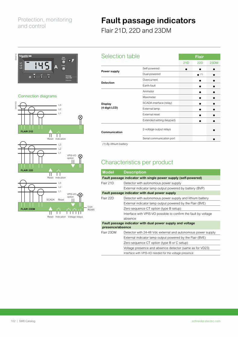
schneider-electric.com102 | SM6 Catalog
Protection, monitoring and control
Characteristics per product Model DescriptionFault passage indicator with single power supply (self-powered)
Flair 21D Detector with autonomous power supply
External indicator lamp output powered by battery (BVP)
Fault passage indicator with dual power supply
Flair 22D Detector with autonomous power supply and lithium battery
External indicator lamp output powered by the Flair (BVE)
Zero sequence CT option (type B setup)
Interface with VPIS-VO possible to confirm the fault by voltage
absence
Fault passage indicator with dual power supply and voltage presence/absence
Flair 23DM Detector with 24-48 Vdc external and autonomous power supply
External indicator lamp output powered by the Flair (BVE)
Zero sequence CT option (type B or C setup)
Voltage presence and absence detector (same as for VD23)
Interface with VPIS-VO needed for the voltage presence
Fault passage indicatorsFlair 21D, 22D and 23DM
Flair 22DEasergy
L1L2L3
I max.
EMS58352
AEsc
TestResetD
E58
715
Connection diagrams
DM
1075
02
-+
L3
L2
L1
L3
L2
L1
Reset Indication
Reset Indication
Reset Indication
Reset
Voltage relays
Com RS485
FLAIR 21D
FLAIR 22D
FLAIR 23DM
SCADA
VPIS-VOoption
VPIS-VOoption
L3
L2
L1
Flair21D 22D 23DM
Power supplySelf-powered
Dual-powered (1)
DetectionOvercurrent
Earth-fault
Display(4 digit LCD)
Ammeter
Maximeter
SCADA interface (relay)
External lamp
External reset
Extended setting (keypad)
Communication2-voltage output relays
Serial communication port
(1) By lithium battery
Selection table
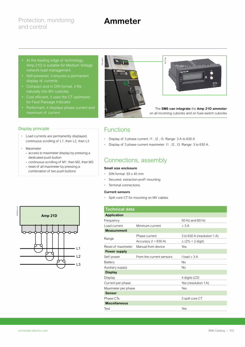
schneider-electric.com | 103SM6 Catalog
Protection, monitoring and control
Ammeter
Technical dataApplication
Frequency 50 Hz and 60 Hz
Load current Minimum current ≥ 3 A
Measurement
RangePhase current 3 to 630 A (resolution 1 A)
Accuracy (I < 630 A) ± (2% + 2 digit)
Reset of maximeter Manual from device Yes
Power supply
Self power From the current sensors I load ≥ 3 A
Battery No
Auxiliary supply No
Display
Display 4 digits LCD
Current per phase Yes (resolution 1 A)
Maximeter per phase Yes
Sensor
Phase CTs 3 split core CT
Miscellaneous
Test Yes
Functions• Display of 3 phase current: I1 , I2 , I3. Range: 3 A to 630 A
• Display of 3 phase current maximeter: I1 , I2 , I3. Range: 3 to 630 A.
Connections, assemblySmall size enclosure
• DIN format: 93 x 45 mm
• Secured, extraction-proff mounting
• Terminal connections.
Current sensors
• Split core CT for mounting on MV cables.
DE
5840
4_LG
Amp 21D
L1
L2
L3
• At the leading edge of technology, Amp 21D is suitable for Medium Voltage network load management.
• Self-powered, it ensures a permanent display of currents.
• Compact and in DIN format, it fits naturally into MV cubicles.
• Cost efficient, it uses the CT optimised for Fault Passage Indicator.
• Performant, it displays phase current and maximum of current
The SM6 can integrate the Amp 21D ammeter on all incoming cubicles and on fuse-switch cubicles
PE
5778
6
PM
1086
31
Display principle
• Load currents are permanently displayed,
continuous scrolling of L1, then L2, then L3
• Maximeter - access to maximeter display by pressing a dedicated push button - continuous scrolling of M1, then M2, then M3 - reset of all maximeter by pressing a combination of two push buttons
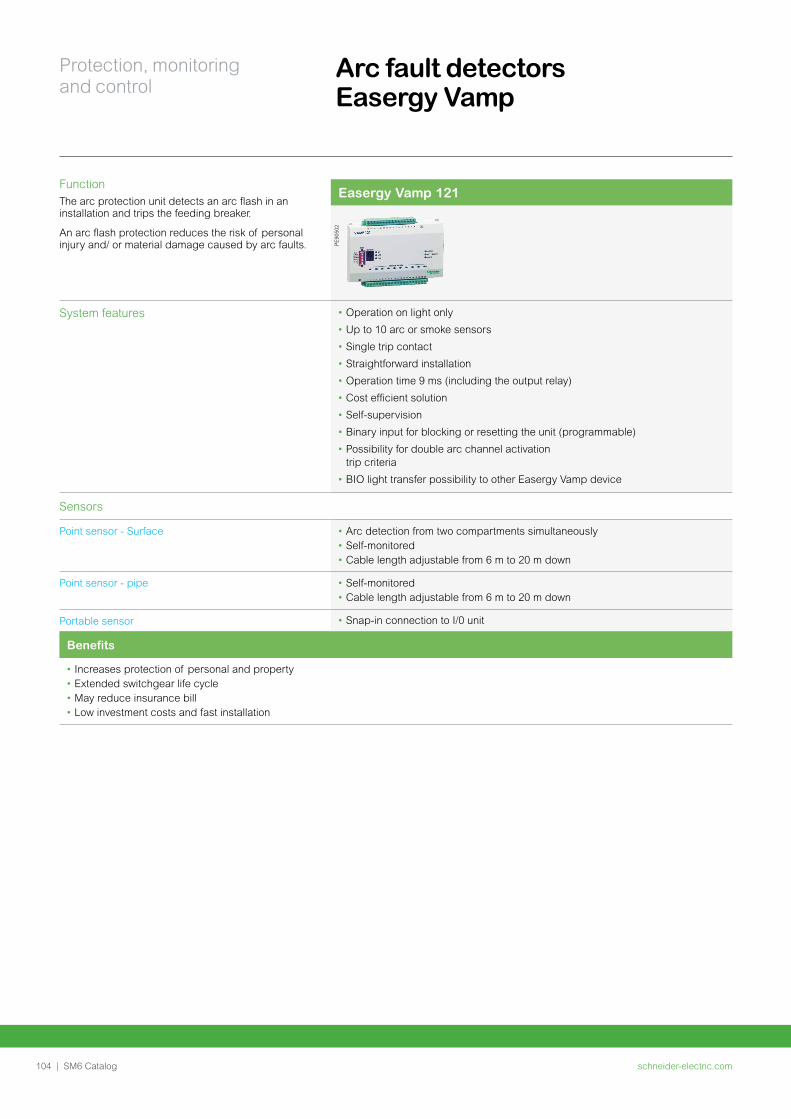
schneider-electric.com104 | SM6 Catalog
Protection, monitoring and control
Arc fault detectors Easergy Vamp
FunctionThe arc protection unit detects an arc flash in an installation and trips the feeding breaker.
An arc flash protection reduces the risk of personal injury and/ or material damage caused by arc faults.
Easergy Vamp 121
PE90
502
System features • Operation on light only
• Up to 10 arc or smoke sensors
• Single trip contact
• Straightforward installation
• Operation time 9 ms (including the output relay)
• Cost efficient solution
• Self-supervision
• Binary input for blocking or resetting the unit (programmable)
• Possibility for double arc channel activation trip criteria
• BIO light transfer possibility to other Easergy Vamp device
Sensors
Point sensor - Surface • Arc detection from two compartments simultaneously• Self-monitored• Cable length adjustable from 6 m to 20 m down
Point sensor - pipe • Self-monitored• Cable length adjustable from 6 m to 20 m down
Portable sensor • Snap-in connection to I/0 unit
Benefits
• Increases protection of personal and property• Extended switchgear life cycle• May reduce insurance bill• Low investment costs and fast installation
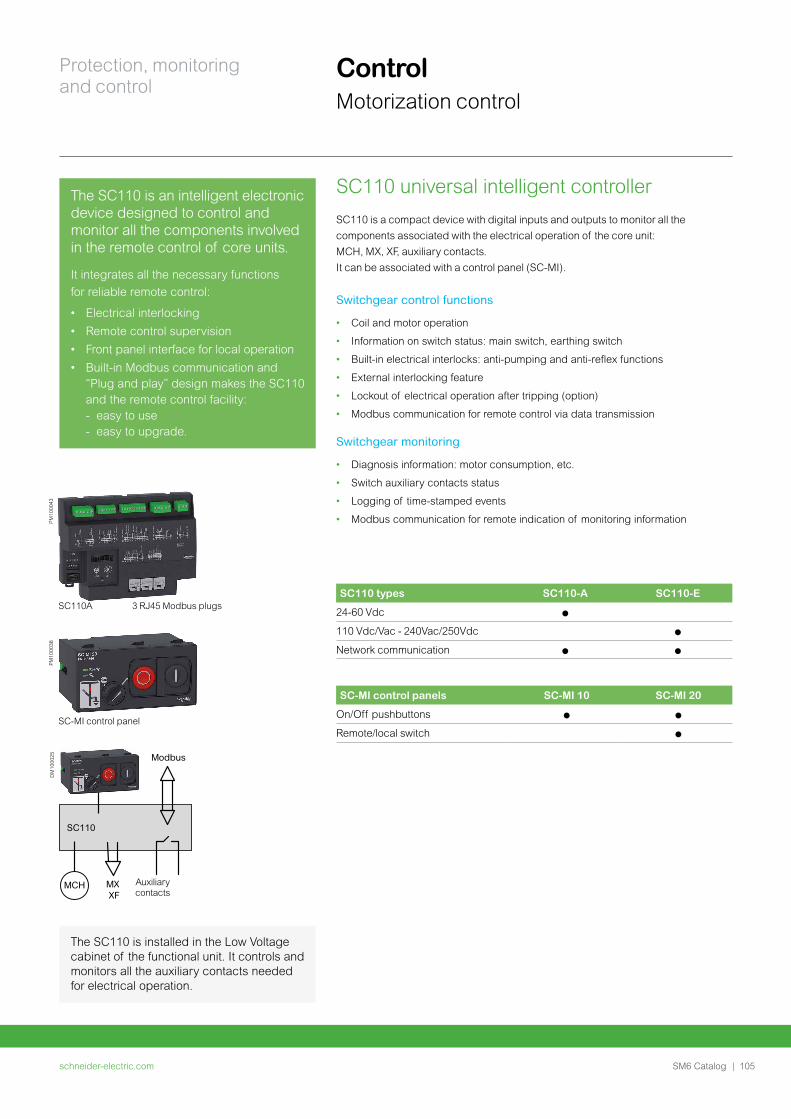
schneider-electric.com | 105SM6 Catalog
Protection, monitoring and control
Control Motorization control
The SC110 is an intelligent electronic device designed to control and monitor all the components involved in the remote control of core units.
It integrates all the necessary functions
for reliable remote control:
• Electrical interlocking
• Remote control supervision
• Front panel interface for local operation
• Built-in Modbus communication and “Plug and play” design makes the SC110 and the remote control facility: - easy to use - easy to upgrade.
SC110 types SC110-A SC110-E
24-60 Vdc p
110 Vdc/Vac - 240Vac/250Vdc p
Network communication p p
SC-MI control panels SC-MI 10 SC-MI 20
On/Off pushbuttons p p
Remote/local switch p
SC110 universal intelligent controllerSC110 is a compact device with digital inputs and outputs to monitor all the
components associated with the electrical operation of the core unit:
MCH, MX, XF, auxiliary contacts.
It can be associated with a control panel (SC-MI).
Switchgear control functions
• Coil and motor operation
• Information on switch status: main switch, earthing switch
• Built-in electrical interlocks: anti-pumping and anti-reflex functions
• External interlocking feature
• Lockout of electrical operation after tripping (option)
• Modbus communication for remote control via data transmission
Switchgear monitoring
• Diagnosis information: motor consumption, etc.
• Switch auxiliary contacts status
• Logging of time-stamped events
• Modbus communication for remote indication of monitoring information
SC-MI control panel
PM10
0038
SC110A 3 RJ45 Modbus plugs
PM10
0043
SC110
Modbus
MCH MX XF
DM
1000
25
Auxiliary contacts
The SC110 is installed in the Low Voltage cabinet of the functional unit. It controls and monitors all the auxiliary contacts needed for electrical operation.
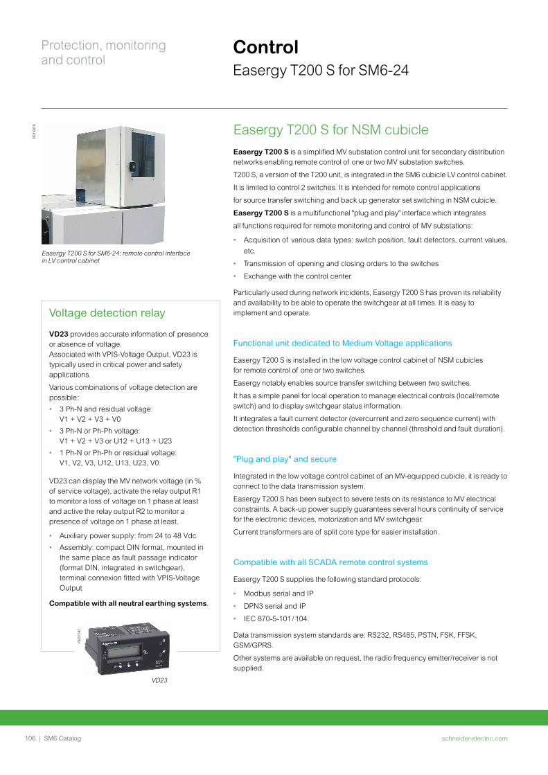
schneider-electric.com106 | SM6 Catalog
Protection, monitoring and control
Control Easergy T200 S for SM6-24
Easergy T200 S for NSM cubicleEasergy T200 S is a simplified MV substation control unit for secondary distribution networks enabling remote control of one or two MV substation switches.
T200 S, a version of the T200 unit, is integrated in the SM6 cubicle LV control cabinet.
It is limited to control 2 switches. It is intended for remote control applications
for source transfer switching and back up generator set switching in NSM cubicle.
Easergy T200 S is a multifunctional "plug and play" interface which integrates
all functions required for remote monitoring and control of MV substations:
• Acquisition of various data types: switch position, fault detectors, current values,
etc.
• Transmission of opening and closing orders to the switches
• Exchange with the control center.
Particularly used during network incidents, Easergy T200 S has proven its reliability and availability to be able to operate the switchgear at all times. It is easy to implement and operate.
Functional unit dedicated to Medium Voltage applications
Easergy T200 S is installed in the low voltage control cabinet of NSM cubicles for remote control of one or two switches.
Easergy notably enables source transfer switching between two switches.
It has a simple panel for local operation to manage electrical controls (local/remote switch) and to display switchgear status information.
It integrates a fault current detector (overcurrent and zero sequence current) with detection thresholds configurable channel by channel (threshold and fault duration).
"Plug and play" and secure
Integrated in the low voltage control cabinet of an MV-equipped cubicle, it is ready to connect to the data transmission system.
Easergy T200 S has been subject to severe tests on its resistance to MV electrical constraints. A back-up power supply guarantees several hours continuity of service for the electronic devices, motorization and MV switchgear.
Current transformers are of split core type for easier installation.
Compatible with all SCADA remote control systems
Easergy T200 S supplies the following standard protocols:
• Modbus serial and IP
• DPN3 serial and IP
• IEC 870-5-101 / 104.
Data transmission system standards are: RS232, RS485, PSTN, FSK, FFSK, GSM/GPRS.
Other systems are available on request, the radio frequency emitter/receiver is not supplied.
PE15
074
Easergy T200 S for SM6-24: remote control interface in LV control cabinet
PE57
787
VD23
Voltage detection relay
VD23 provides accurate information of presence or absence of voltage. Associated with VPIS-Voltage Output, VD23 is typically used in critical power and safety applications.
Various combinations of voltage detection are possible:
• 3 Ph-N and residual voltage: V1 + V2 + V3 + V0
• 3 Ph-N or Ph-Ph voltage: V1 + V2 + V3 or U12 + U13 + U23
• 1 Ph-N or Ph-Ph or residual voltage: V1, V2, V3, U12, U13, U23, V0.
VD23 can display the MV network voltage (in % of service voltage), activate the relay output R1 to monitor a loss of voltage on 1 phase at least and active the relay output R2 to monitor a presence of voltage on 1 phase at least.
• Auxiliary power supply: from 24 to 48 Vdc
• Assembly: compact DIN format, mounted in the same place as fault passage indicator (format DIN, integrated in switchgear), terminal connexion fitted with VPIS-Voltage Output
Compatible with all neutral earthing systems.
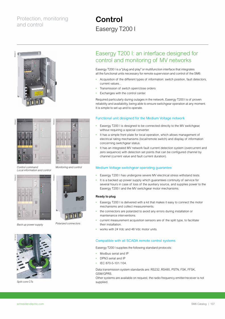
schneider-electric.com | 107SM6 Catalog
Protection, monitoring and control
PE56
421
PE56
422
Control command Local information and control
Monitoring and control
PE56
423
PE56
824
Back up power supply Polarized connectors
PE15
078
Split core CTs
Easergy T200 I: an interface designed for control and monitoring of MV networksEasergy T200 I is a "plug and play" or multifunction interface that integrates all the functional units necessary for remote supervision and control of the SM6:
• Acquisition of the different types of information: switch position, fault detectors, current values...
• Transmission of switch open/close orders
• Exchanges with the control center.
Required particularly during outages in the network, Easergy T200 I is of proven reliability and availability, being able to ensure switchgear operation at any moment. It is simple to set up and to operate.
Functional unit designed for the Medium Voltage network
• Easergy T200 I is designed to be connected directly to the MV switchgear, without requiring a special converter.
• It has a simple front plate for local operation, which allows management of electrical rating mechanisms (local/remote switch) and display of information concerning switchgear status.
• It has an integrated MV network fault current detection system (overcurrent and zero sequence) with detection set points that can be configured channel by channel (current value and fault current duration).
Medium Voltage switchgear operating guarantee
• Easergy T200 I has undergone severe MV electrical stress withstand tests.
• It is a backed up power supply which guarantees continuity of service for several hours in case of loss of the auxiliary source, and supplies power to the Easergy T200 I and the MV switchgear motor mechanisms.
Ready to plug
• Easergy T200 I is delivered with a kit that makes it easy to connect the motor mechanisms and collect measurements.
• the connectors are polarized to avoid any errors during installation or maintenance interventions.
• current measurement acquisition sensors are of the split type, to facilitate their installation.
• works with 24 Vdc and 48 Vdc motor units.
Compatible with all SCADA remote control systems
Easergy T200 I supplies the following standard protocols:
• Modbus serial and IP
• DPN3 serial and IP
• IEC 870-5-101 / 104.
Data transmission system standards are: RS232, RS485, PSTN, FSK, FFSK, GSM/GPRS. Other systems are available on request, the radio frequency emitter/receiver is not supplied.
ControlEasergy T200 I
PE56
311
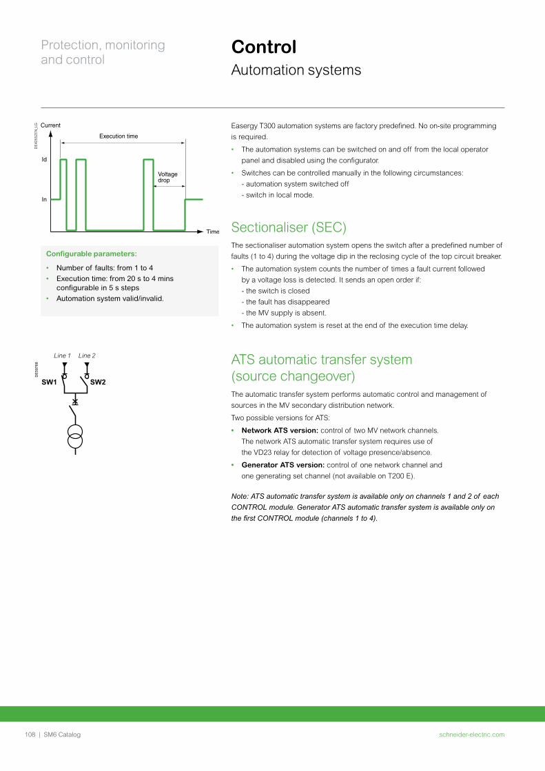
schneider-electric.com108 | SM6 Catalog
Protection, monitoring and control
ControlAutomation systems
Configurable parameters:
• Number of faults: from 1 to 4
• Execution time: from 20 s to 4 mins configurable in 5 s steps
• Automation system valid/invalid.
Easergy T300 automation systems are factory predefined. No on-site programming
is required.
• The automation systems can be switched on and off from the local operator
panel and disabled using the configurator.
• Switches can be controlled manually in the following circumstances:
- automation system switched off
- switch in local mode.
Sectionaliser (SEC)The sectionaliser automation system opens the switch after a predefined number of
faults (1 to 4) during the voltage dip in the reclosing cycle of the top circuit breaker.
• The automation system counts the number of times a fault current followed
by a voltage loss is detected. It sends an open order if:
- the switch is closed
- the fault has disappeared
- the MV supply is absent.
• The automation system is reset at the end of the execution time delay.
ATS automatic transfer system (source changeover)The automatic transfer system performs automatic control and management of
sources in the MV secondary distribution network.
Two possible versions for ATS:
• Network ATS version: control of two MV network channels.
The network ATS automatic transfer system requires use of
the VD23 relay for detection of voltage presence/absence.
• Generator ATS version: control of one network channel and
one generating set channel (not available on T200 E).
Note: ATS automatic transfer system is available only on channels 1 and 2 of each CONTROL module. Generator ATS automatic transfer system is available only on the first CONTROL module (channels 1 to 4).
DE
4055
2EN
_LG
SW1 SW2
DE
5976
8
Line 1 Line 2
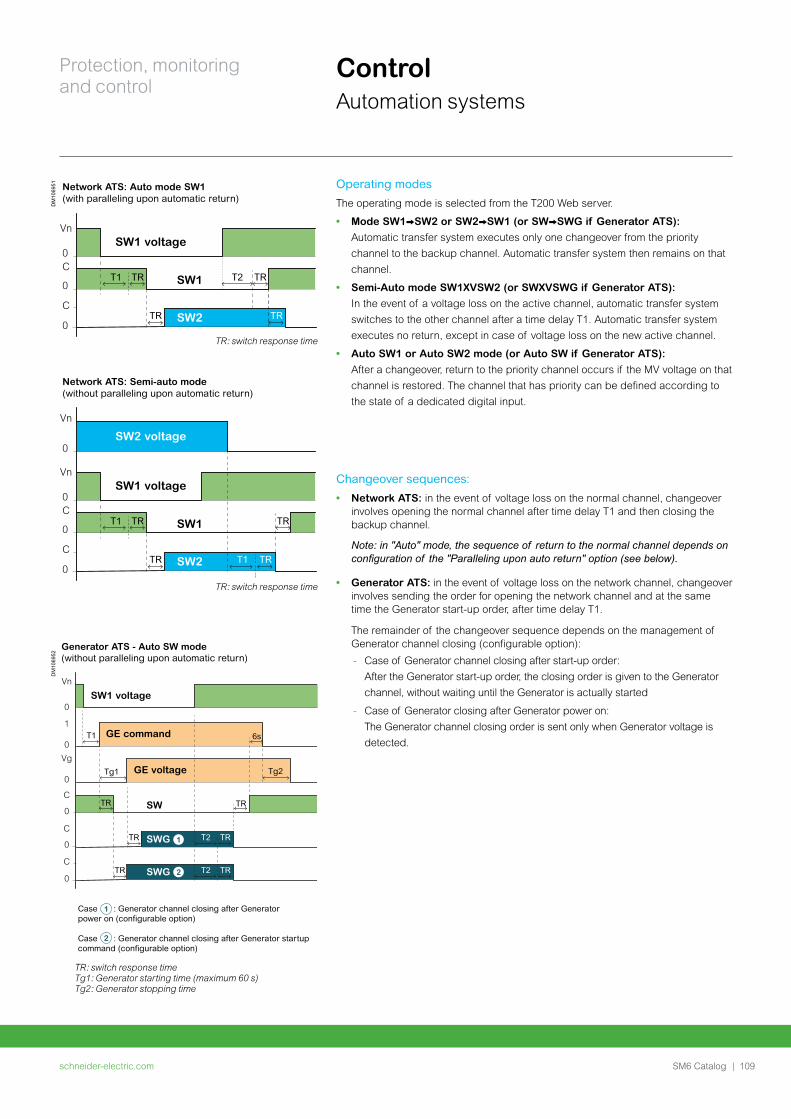
schneider-electric.com | 109SM6 Catalog
Protection, monitoring and control
ControlAutomation systems
Changeover sequences:
• Network ATS: in the event of voltage loss on the normal channel, changeover involves opening the normal channel after time delay T1 and then closing the backup channel.
Note: in "Auto" mode, the sequence of return to the normal channel depends on configuration of the "Paralleling upon auto return" option (see below).
• Generator ATS: in the event of voltage loss on the network channel, changeover involves sending the order for opening the network channel and at the same time the Generator start-up order, after time delay T1.
The remainder of the changeover sequence depends on the management of Generator channel closing (configurable option):
- Case of Generator channel closing after start-up order:
After the Generator start-up order, the closing order is given to the Generator
channel, without waiting until the Generator is actually started
- Case of Generator closing after Generator power on:
The Generator channel closing order is sent only when Generator voltage is
detected.
Operating modes
The operating mode is selected from the T200 Web server.
• Mode SW1VSW2 or SW2VSW1 (or SWVSWG if Generator ATS):
Automatic transfer system executes only one changeover from the priority
channel to the backup channel. Automatic transfer system then remains on that
channel.
• Semi-Auto mode SW1XVSW2 (or SWXVSWG if Generator ATS):
In the event of a voltage loss on the active channel, automatic transfer system
switches to the other channel after a time delay T1. Automatic transfer system
executes no return, except in case of voltage loss on the new active channel.
• Auto SW1 or Auto SW2 mode (or Auto SW if Generator ATS):
After a changeover, return to the priority channel occurs if the MV voltage on that
channel is restored. The channel that has priority can be defined according to
the state of a dedicated digital input.
DM
1069
51
SW2 voltage
SW1 voltage
SW1
SW2
SW1 voltage
SW1
SW2
Vn
0
Vn
0C
0
C
0
T1 TR
TR TRT1
TR
Vn
0C
0
C
0
T1 TR
TR
Network ATS: Auto mode SW1(with paralleling upon automatic return)
Network ATS: Semi-auto mode (without paralleling upon automatic return)
TR
TRT2
TR: switch response time
TR: switch response time
DM
1069
52
GE voltage
GE command
SW
SWG
SWG
SW1 voltage
2
1
Vn
0
Vg
0
C
0
C
0
C
0
1
0
TR
Tg1 Tg2
T1
TR TRT2
TR TRT2
TR
6s
Generator ATS - Auto SW mode(without paralleling upon automatic return)
2
1Case : Generator channel closing after Generatorpower on (configurable option)
Case : Generator channel closing after Generator startupcommand (configurable option)
TR: switch response timeTg1: Generator starting time (maximum 60 s)Tg2: Generator stopping time
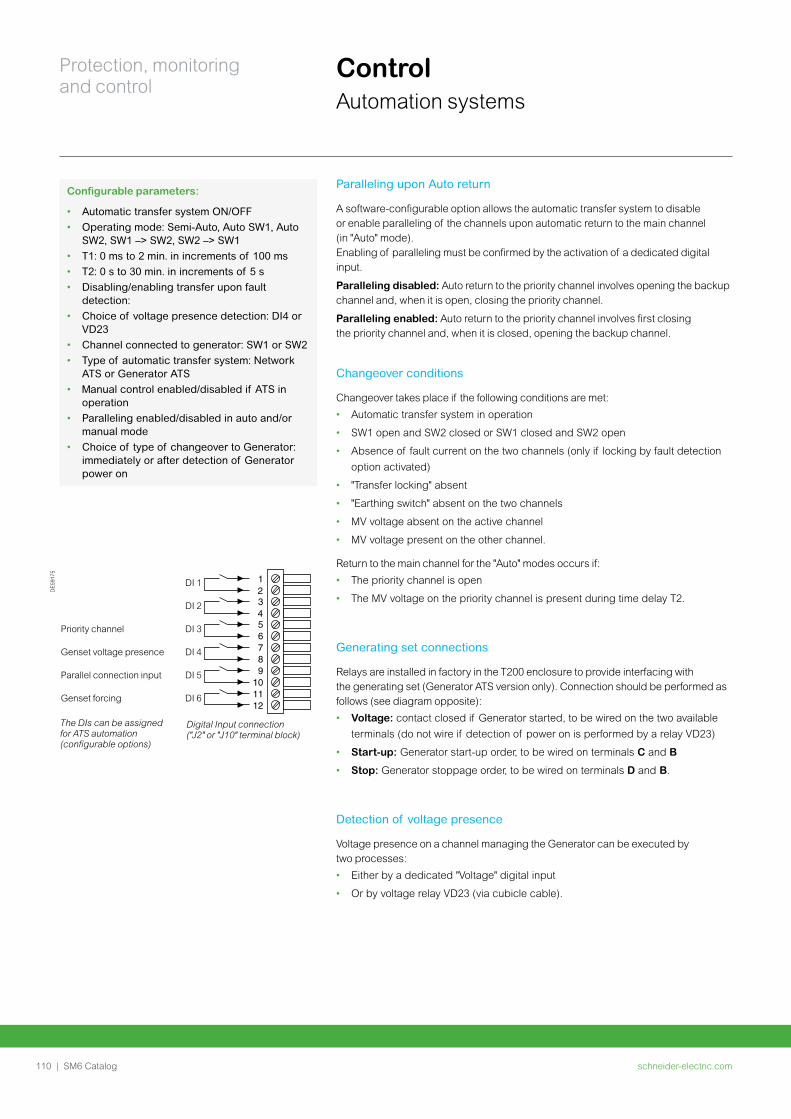
schneider-electric.com110 | SM6 Catalog
Protection, monitoring and control
ControlAutomation systems
Digital Input connection ("J2" or "J10" terminal block)
The DIs can be assigned for ATS automation (configurable options)
DE
5917
5
DI 1
DI 2
Priority channel DI 3
Genset voltage presence DI 4
Parallel connection input DI 5
Genset forcing DI 6
123456789
101112
Paralleling upon Auto return
A software-configurable option allows the automatic transfer system to disable or enable paralleling of the channels upon automatic return to the main channel (in "Auto" mode).Enabling of paralleling must be confirmed by the activation of a dedicated digital input.
Paralleling disabled: Auto return to the priority channel involves opening the backup channel and, when it is open, closing the priority channel.
Paralleling enabled: Auto return to the priority channel involves first closing the priority channel and, when it is closed, opening the backup channel.
Changeover conditions
Changeover takes place if the following conditions are met:
• Automatic transfer system in operation
• SW1 open and SW2 closed or SW1 closed and SW2 open
• Absence of fault current on the two channels (only if locking by fault detection
option activated)
• "Transfer locking" absent
• "Earthing switch" absent on the two channels
• MV voltage absent on the active channel
• MV voltage present on the other channel.
Return to the main channel for the "Auto" modes occurs if:
• The priority channel is open
• The MV voltage on the priority channel is present during time delay T2.
Generating set connections
Relays are installed in factory in the T200 enclosure to provide interfacing with the generating set (Generator ATS version only). Connection should be performed as follows (see diagram opposite):
• Voltage: contact closed if Generator started, to be wired on the two available
terminals (do not wire if detection of power on is performed by a relay VD23)
• Start-up: Generator start-up order, to be wired on terminals C and B
• Stop: Generator stoppage order, to be wired on terminals D and B.
Detection of voltage presence
Voltage presence on a channel managing the Generator can be executed by two processes:
• Either by a dedicated "Voltage" digital input
• Or by voltage relay VD23 (via cubicle cable).
Configurable parameters:
• Automatic transfer system ON/OFF
• Operating mode: Semi-Auto, Auto SW1, Auto SW2, SW1 –> SW2, SW2 –> SW1
• T1: 0 ms to 2 min. in increments of 100 ms
• T2: 0 s to 30 min. in increments of 5 s
• Disabling/enabling transfer upon fault detection:
• Choice of voltage presence detection: DI4 or VD23
• Channel connected to generator: SW1 or SW2
• Type of automatic transfer system: Network ATS or Generator ATS
• Manual control enabled/disabled if ATS in operation
• Paralleling enabled/disabled in auto and/or manual mode
• Choice of type of changeover to Generator: immediately or after detection of Generator power on
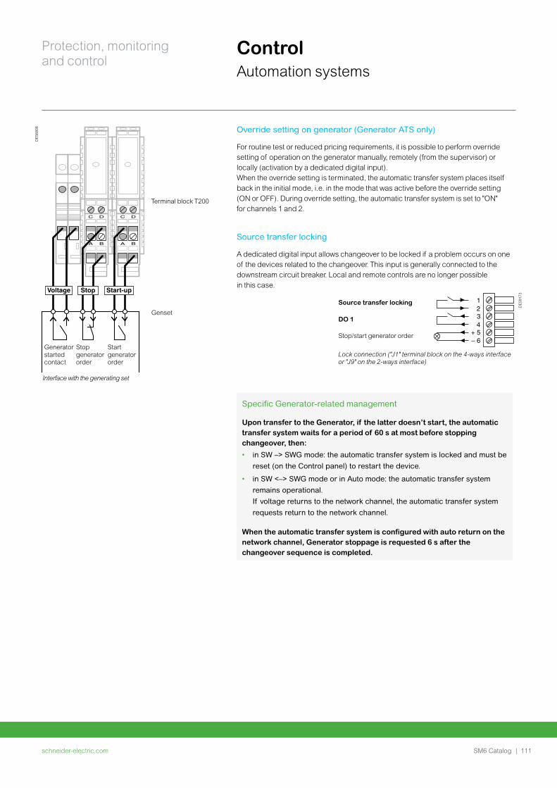
schneider-electric.com | 111SM6 Catalog
Protection, monitoring and control
ControlAutomation systems
Lock connection ("J1" terminal block on the 4-ways interface or "J9" on the 2-ways interface)
DE
5917
3
Source transfer locking
DO 1
Stop/start generator order
1234
+ 5– 6
Interface with the generating set
DE
5680
6
C D
A B
C D
A B
Voltage Stop Start-up
G
Generator started contact
Stop generator order
Start generator order
Terminal block T200
Genset
Override setting on generator (Generator ATS only)
For routine test or reduced pricing requirements, it is possible to perform override setting of operation on the generator manually, remotely (from the supervisor) or locally (activation by a dedicated digital input).When the override setting is terminated, the automatic transfer system places itself back in the initial mode, i.e. in the mode that was active before the override setting (ON or OFF). During override setting, the automatic transfer system is set to "ON" for channels 1 and 2.
Source transfer locking
A dedicated digital input allows changeover to be locked if a problem occurs on one of the devices related to the changeover. This input is generally connected to the downstream circuit breaker. Local and remote controls are no longer possible in this case.
Specific Generator-related management
Upon transfer to the Generator, if the latter doesn’t start, the automatic transfer system waits for a period of 60 s at most before stopping changeover, then:
• in SW –> SWG mode: the automatic transfer system is locked and must be
reset (on the Control panel) to restart the device.
• in SW <–> SWG mode or in Auto mode: the automatic transfer system
remains operational.
If voltage returns to the network channel, the automatic transfer system
requests return to the network channel.
When the automatic transfer system is configured with auto return on the network channel, Generator stoppage is requested 6 s after the changeover sequence is completed.
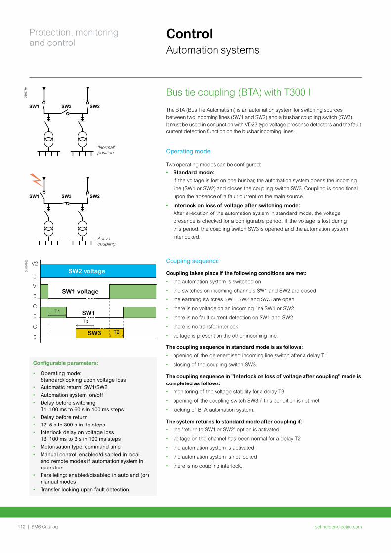
schneider-electric.com112 | SM6 Catalog
Protection, monitoring and control
ControlAutomation systems
Bus tie coupling (BTA) with T300 I The BTA (Bus Tie Automatism) is an automation system for switching sources between two incoming lines (SW1 and SW2) and a busbar coupling switch (SW3).It must be used in conjunction with VD23 type voltage presence detectors and the fault current detection function on the busbar incoming lines.
Operating mode
Two operating modes can be configured:
• Standard mode:
If the voltage is lost on one busbar, the automation system opens the incoming
line (SW1 or SW2) and closes the coupling switch SW3. Coupling is conditional
upon the absence of a fault current on the main source.
• Interlock on loss of voltage after switching mode:
After execution of the automation system in standard mode, the voltage
presence is checked for a configurable period. If the voltage is lost during
this period, the coupling switch SW3 is opened and the automation system
interlocked.
Coupling sequence
Coupling takes place if the following conditions are met:
• the automation system is switched on
• the switches on incoming channels SW1 and SW2 are closed
• the earthing switches SW1, SW2 and SW3 are open
• there is no voltage on an incoming line SW1 or SW2
• there is no fault current detection on SW1 and SW2
• there is no transfer interlock
• voltage is present on the other incoming line.
The coupling sequence in standard mode is as follows:
• opening of the de-energised incoming line switch after a delay T1
• closing of the coupling switch SW3.
The coupling sequence in "Interlock on loss of voltage after coupling" mode is completed as follows:
• monitoring of the voltage stability for a delay T3
• opening of the coupling switch SW3 if this condition is not met
• locking of BTA automation system.
The system returns to standard mode after coupling if:
• the "return to SW1 or SW2" option is activated
• voltage on the channel has been normal for a delay T2
• the automation system is activated
• the automation system is not locked
• there is no coupling interlock.
DE
5977
0
SW1 SW2SW3
SW1 SW2SW3
"Normal" position
Active coupling
DM
1075
03
SW1
SW3
V2
0
C
0
C
0
V1
0
T1
T3
T2
SW2 voltage
SW1 voltage
Configurable parameters:
• Operating mode: Standard/locking upon voltage loss
• Automatic return: SW1/SW2
• Automation system: on/off
• Delay before switching T1: 100 ms to 60 s in 100 ms steps
• Delay before return
• T2: 5 s to 300 s in 1 s steps
• Interlock delay on voltage loss T3: 100 ms to 3 s in 100 ms steps
• Motorisation type: command time
• Manual control: enabled/disabled in local and remote modes if automation system in operation
• Paralleling: enabled/disabled in auto and (or) manual modes
• Transfer locking upon fault detection.
schneider-electric.com | 113SM6 Catalog
Protection, monitoring and control
ControlAutomation systems
Coupling interlock
A dedicated digital input allows changeover to be locked if a problem occurs
on one of the devices related to the changeover. This input is generally connected to
the downstream circuit breaker. Local and remote controls are no longer possible
in this case.
Locking the automation system
The BTA automation system is locked if one of the following conditions is met during the coupling process:
• Failure of a command to open or close a switch
• Indication that an earthing switch has closed
• Appearance of a fault current
• Switch power supply fault
• Appearance of the coupling interlock
• Manual or remote ON/OFF command from the automation system.
Paralleling upon Auto return
A software-configurable option allows the automation system to disable or enable
paralleling of the channels upon automatic return to the main channel (in "Auto" mode).
Enabling of paralleling must be confirmed by the activation of a dedicated digital
input.
• If paralleling is disabled: Auto return to the normal channel involves opening
the coupling channel (SW3) and, when it is open, closing the normal channel.
• If paralleling is enabled: Auto return to the normal channel involves first
closing the normal channel and, when it is closed, opening the coupling channel
(SW3).
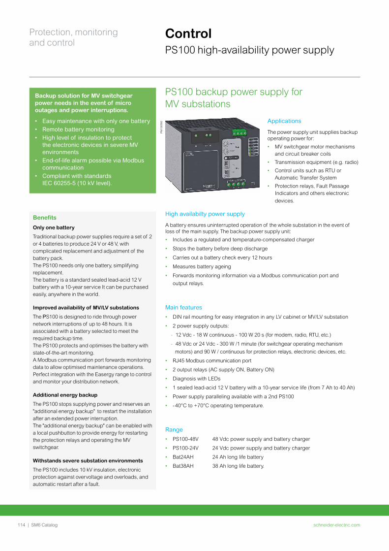
schneider-electric.com114 | SM6 Catalog
Protection, monitoring and control
ControlPS100 high-availability power supply
PS100 backup power supply for MV substations
PM
1005
92
Backup solution for MV switchgear power needs in the event of micro outages and power interruptions.
• Easy maintenance with only one battery • Remote battery monitoring• High level of insulation to protect
the electronic devices in severe MV environments
• End-of-life alarm possible via Modbus communication
• Compliant with standards IEC 60255-5 (10 kV level).
Benefits
Only one battery
Traditional backup power supplies require a set of 2 or 4 batteries to produce 24 V or 48 V, with complicated replacement and adjustment of the battery pack. The PS100 needs only one battery, simplifying replacement.The battery is a standard sealed lead-acid 12 V battery with a 10-year service It can be purchased easily, anywhere in the world.
Improved availability of MV/LV substations
The PS100 is designed to ride through power network interruptions of up to 48 hours. It is associated with a battery selected to meet the required backup time.The PS100 protects and optimises the battery with state-of-the-art monitoring.A Modbus communication port forwards monitoring data to allow optimised maintenance operations. Perfect integration with the Easergy range to control and monitor your distribution network.
Additional energy backup
The PS100 stops supplying power and reserves an "additional energy backup" to restart the installation after an extended power interruption.The "additional energy backup" can be enabled with a local pushbutton to provide energy for restarting the protection relays and operating the MV switchgear.
Withstands severe substation environments
The PS100 includes 10 kV insulation, electronic protection against overvoltage and overloads, and automatic restart after a fault.
Applications
The power supply unit supplies backup operating power for:
• MV switchgear motor mechanisms and circuit breaker coils
• Transmission equipment (e.g. radio)
• Control units such as RTU or Automatic Transfer System
• Protection relays, Fault Passage Indicators and others electronic
devices.
High availabilty power supply
A battery ensures uninterrupted operation of the whole substation in the event of loss of the main supply. The backup power supply unit:
• Includes a regulated and temperature-compensated charger
• Stops the battery before deep discharge
• Carries out a battery check every 12 hours
• Measures battery ageing
• Forwards monitoring information via a Modbus communication port and
output relays.
Main features
• DIN rail mounting for easy integration in any LV cabinet or MV/LV substation
• 2 power supply outputs:
- 12 Vdc - 18 W continuous - 100 W 20 s (for modem, radio, RTU, etc.)
- 48 Vdc or 24 Vdc - 300 W /1 minute (for switchgear operating mechanism
motors) and 90 W / continuous for protection relays, electronic devices, etc.
• RJ45 Modbus communication port
• 2 output relays (AC supply ON, Battery ON)
• Diagnosis with LEDs
• 1 sealed lead-acid 12 V battery with a 10-year service life (from 7 Ah to 40 Ah)
• Power supply paralleling available with a 2nd PS100
• - 40°C to +70°C operating temperature.
Range
• PS100-48V 48 Vdc power supply and battery charger
• PS100-24V 24 Vdc power supply and battery charger
• Bat24AH 24 Ah long life battery
• Bat38AH 38 Ah long life battery.
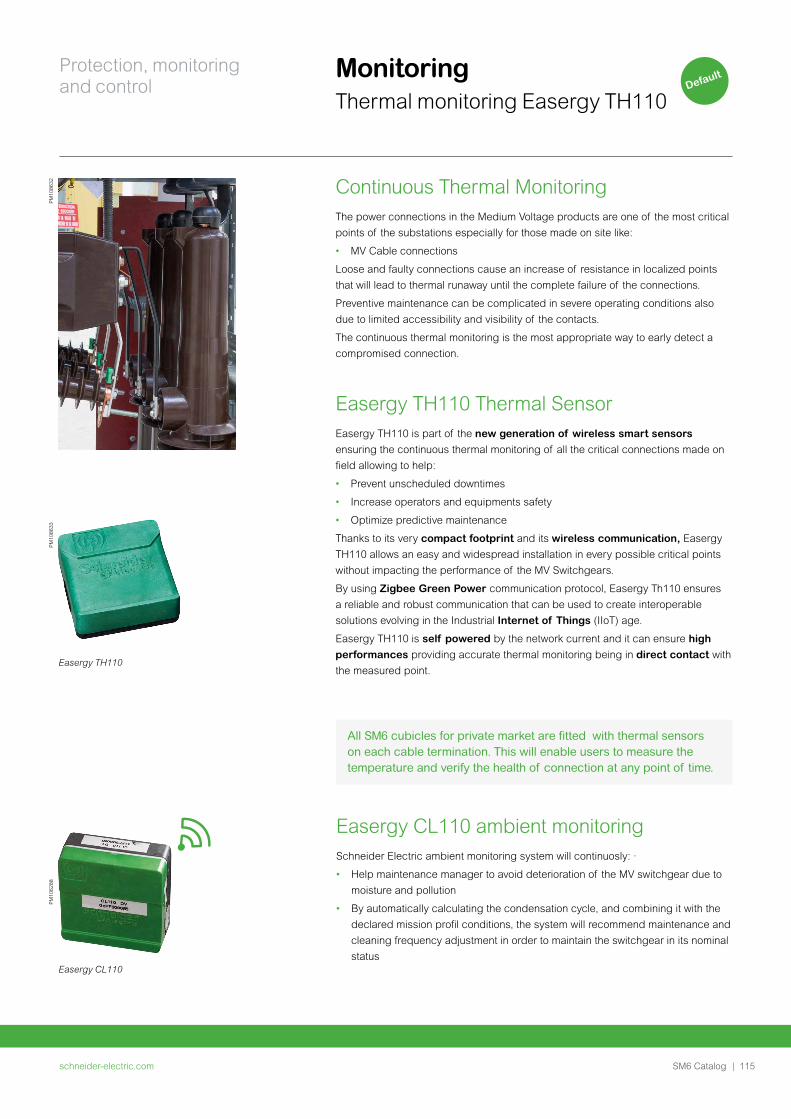
schneider-electric.com | 115SM6 Catalog
Protection, monitoring and control
Monitoring Thermal monitoring Easergy TH110
Continuous Thermal MonitoringThe power connections in the Medium Voltage products are one of the most critical
points of the substations especially for those made on site like:
• MV Cable connections
Loose and faulty connections cause an increase of resistance in localized points
that will lead to thermal runaway until the complete failure of the connections.
Preventive maintenance can be complicated in severe operating conditions also
due to limited accessibility and visibility of the contacts.
The continuous thermal monitoring is the most appropriate way to early detect a
compromised connection.
Easergy TH110 Thermal SensorEasergy TH110 is part of the new generation of wireless smart sensors
ensuring the continuous thermal monitoring of all the critical connections made on
field allowing to help:
• Prevent unscheduled downtimes
• Increase operators and equipments safety
• Optimize predictive maintenance
Thanks to its very compact footprint and its wireless communication, Easergy
TH110 allows an easy and widespread installation in every possible critical points
without impacting the performance of the MV Switchgears.
By using Zigbee Green Power communication protocol, Easergy Th110 ensures
a reliable and robust communication that can be used to create interoperable
solutions evolving in the Industrial Internet of Things (IIoT) age.
Easergy TH110 is self powered by the network current and it can ensure high
performances providing accurate thermal monitoring being in direct contact with
the measured point.Easergy TH110
PM
1086
33P
M10
8632
PM
1062
88
Easergy CL110
Easergy CL110 ambient monitoringSchneider Electric ambient monitoring system will continuosly: ·
• Help maintenance manager to avoid deterioration of the MV switchgear due to
moisture and pollution
• By automatically calculating the condensation cycle, and combining it with the
declared mission profil conditions, the system will recommend maintenance and
cleaning frequency adjustment in order to maintain the switchgear in its nominal
status
All SM6 cubicles for private market are fitted with thermal sensors on each cable termination. This will enable users to measure the temperature and verify the health of connection at any point of time.
Default

schneider-electric.com116 | SM6 Catalog
Connections
schneider-electric.com | 117SM6 Catalog
Connections
Connections with dry-type cables for SM6-24 118Selection table 118
Cable-connection from below for SM6-24 120Cable positions 120
Trenches depth 121
Trench diagrams example 123
Trench diagrams and floor void drawings 125
Connections with dry-type cables for SM6-36 126Selection table 126
Cable-connection from below for SM6-36 128Cable positions 128
Cabling from above for SM6-24 and SM6-36 129
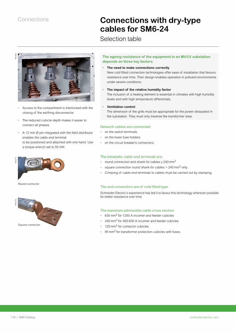
schneider-electric.com118 | SM6 Catalog
Connections Connections with dry-type cables for SM6-24Selection table
PE
5077
6
Square connector
Network cables are connected:• on the switch terminals
• on the lower fuse holders
• on the circuit breaker’s connectors.
The bimetallic cable end terminals are:• round connection and shank for cables y 240
• square connection round shank for cables > 240 only.
• Crimping of cable end terminals to cables must be carried out by stamping.
The end connectors are of cold fitted type
Schneider Electric’s experience has led it to favour this technology wherever possible for better resistance over time.
The maximum admissible cable cross section: • 630 for 1250 A incomer and feeder cubicles
• 240 for 400-630 A incomer and feeder cubicles
• 120 for contactor cubicles
• 95 for transformer protection cubicles with fuses.
PE
5784
0P
E50
775
Round connector
The ageing resistance of the equipment in an MV/LV substation depends on three key factors:
• The need to make connections correctly
New cold fitted connection technologies offer ease of installation that favours
resistance over time. Their design enables operation in polluted environments
under severe conditions.
• The impact of the relative humidity factor
The inclusion of a heating element is essential in climates with high humidity
levels and with high temperature differentials.
• Ventilation control
The dimension of the grills must be appropriate for the power dissipated in
the substation. They must only traverse the transformer area.
• Access to the compartment is interlocked with the
closing of the earthing disconnector.
• The reduced cubicle depth makes it easier to
connect all phases.
• A 12 mm Ø pin integrated with the field distributor
enables the cable end terminal
to be positioned and attached with one hand. Use
a torque wrench set to 50 mN.
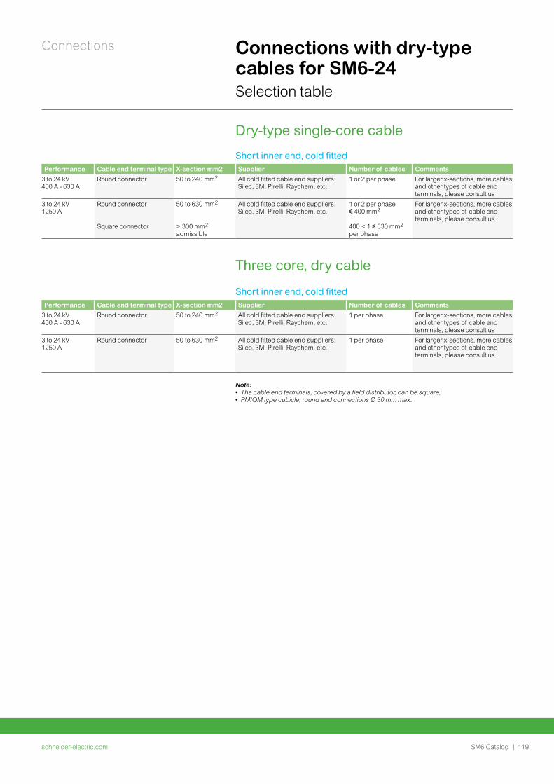
schneider-electric.com | 119SM6 Catalog
Connections Connections with dry-type cables for SM6-24Selection table
Dry-type single-core cable
Short inner end, cold fittedPerformance Cable end terminal type X-section mm2 Supplier Number of cables Comments
3 to 24 kV 400 A - 630 A
Round connector 50 to 240 mm2 All cold fitted cable end suppliers: Silec, 3M, Pirelli, Raychem, etc.
1 or 2 per phase For larger x-sections, more cables and other types of cable end terminals, please consult us
3 to 24 kV 1250 A
Round connector
Square connector
50 to 630 mm2
> 300 mm2 admissible
All cold fitted cable end suppliers: Silec, 3M, Pirelli, Raychem, etc.
1 or 2 per phase y 400 mm2
400 < 1 y 630 mm2 per phase
For larger x-sections, more cables and other types of cable end terminals, please consult us
Three core, dry cable
Short inner end, cold fittedPerformance Cable end terminal type X-section mm2 Supplier Number of cables Comments
3 to 24 kV 400 A - 630 A
Round connector 50 to 240 mm2 All cold fitted cable end suppliers: Silec, 3M, Pirelli, Raychem, etc.
1 per phase For larger x-sections, more cables and other types of cable end terminals, please consult us
3 to 24 kV 1250 A
Round connector 50 to 630 mm2 All cold fitted cable end suppliers: Silec, 3M, Pirelli, Raychem, etc.
1 per phase For larger x-sections, more cables and other types of cable end terminals, please consult us
Note: • The cable end terminals, covered by a field distributor, can be square, • PM/QM type cubicle, round end connections Ø 30 mm max.
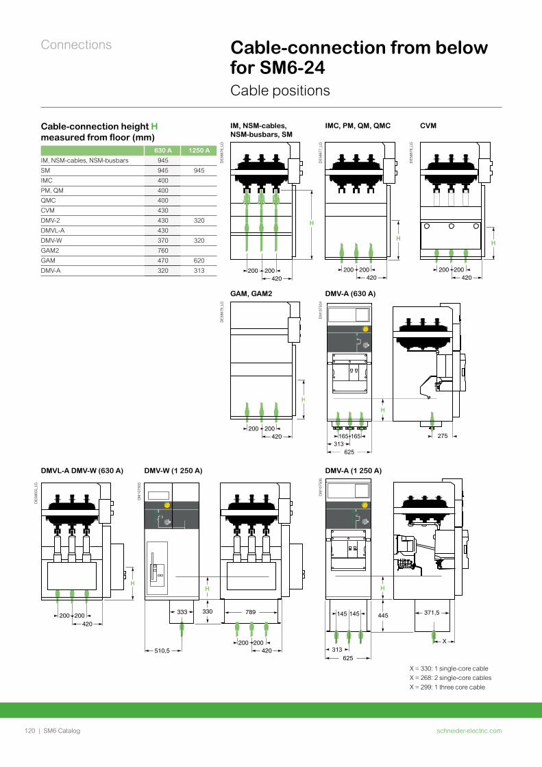
schneider-electric.com120 | SM6 Catalog
Connections Cable-connection from below for SM6-24Cable positions
Cable-connection height H measured from floor (mm)
630 A 1250 A
IM, NSM-cables, NSM-busbars 945
SM 945 945
IMC 400
PM, QM 400
QMC 400
CVM 430
DMV-2 430 320
DMVL-A 430
DMV-W 370 320
GAM2 760
GAM 470 620
DMV-A 320 313
IM, NSM-cables, NSM-busbars, SM
IMC, PM, QM, QMC CVM
DE
5867
6_LG
DE
5867
7_LG
DE
5867
8_LG
GAM, GAM2 DMV-A (630 A)
DE
5867
9_LG
DM
1075
04
H
165313
165
625
275
DMVL-A DMV-W (630 A) DMV-W (1 250 A) DMV-A (1 250 A)
DE
5865
5_LG
DM
1075
05
DM
1075
06
445 371,5
H
X
145
313
145
625
X = 330: 1 single-core cable
X = 268: 2 single-core cables
X = 299: 1 three core cable
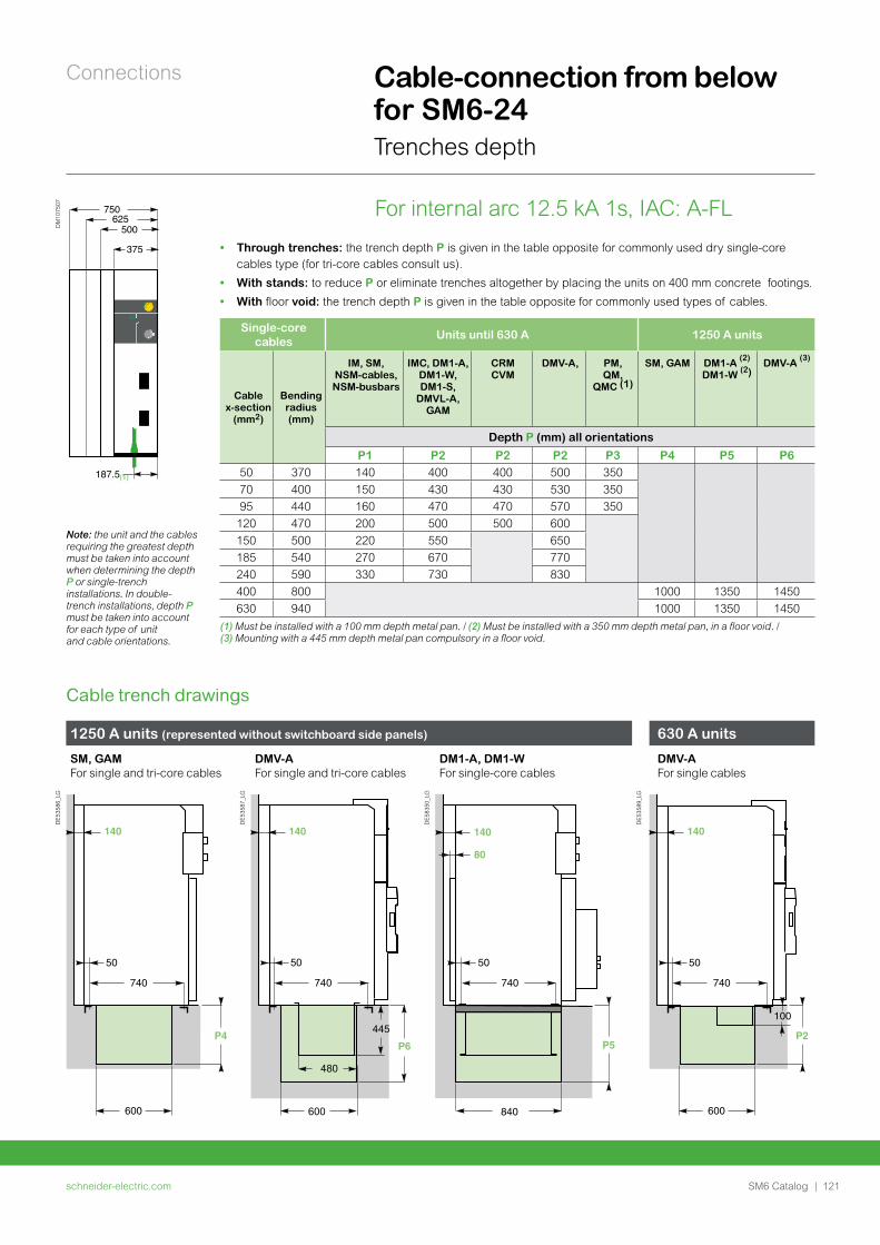
schneider-electric.com | 121SM6 Catalog
Connections Cable-connection from below for SM6-24Trenches depth
• Through trenches: the trench depth P is given in the table opposite for commonly used dry single-core cables type (for tri-core cables consult us).
• With stands: to reduce P or eliminate trenches altogether by placing the units on 400 mm concrete footings.
• With floor void: the trench depth P is given in the table opposite for commonly used types of cables.
750
500
375
187.5
625
DM
1075
07
(1)
Note: the unit and the cables requiring the greatest depth must be taken into account when determining the depth P or single-trench installations. In double-trench installations, depth P must be taken into account for each type of unit and cable orientations.
Single-core cables
Units until 630 A 1250 A units
Cable x-section
(mm2)
Bending radius (mm)
IM, SM, NSM-cables, NSM-busbars
IMC, DM1-A, DM1-W, DM1-S,
DMVL-A, GAM
CRMCVM
DMV-A, PM, QM,
QMC (1)
SM, GAM DM1-A (2)
DM1-W (2) DMV-A (3)
Depth P (mm) all orientations
P1 P2 P2 P2 P3 P4 P5 P650 370 140 400 400 500 350
70 400 150 430 430 530 350
95 440 160 470 470 570 350
120 470 200 500 500 600
150 500 220 550 650
185 540 270 670 770
240 590 330 730 830
400 800 1000 1350 1450
630 940 1000 1350 1450
(1) Must be installed with a 100 mm depth metal pan. / (2) Must be installed with a 350 mm depth metal pan, in a floor void. / (3) Mounting with a 445 mm depth metal pan compulsory in a floor void.
Cable trench drawings
For internal arc 12.5 kA 1s, IAC: A-FL
1250 A units (represented without switchboard side panels) 630 A units
SM, GAM For single and tri-core cables
DMV-AFor single and tri-core cables
DM1-A, DM1-W For single-core cables
DMV-AFor single cables
DE
5358
6_LG
DE
5358
7_LG
DE
5835
0_LG
DE
5358
9_LG
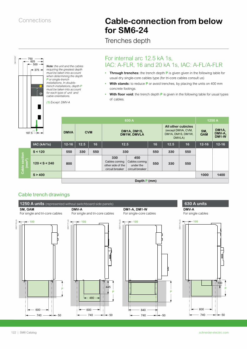
schneider-electric.com122 | SM6 Catalog
Connections Cable-connection from below for SM6-24Trenches depth
For internal arc 12.5 kA 1s, IAC: A-FLR, 16 and 20 kA 1s, IAC: A-FL/A-FLR• Through trenches: the trench depth P is given given in the following table for
usual dry single-core cables type (for tri-core cables consult us)
• With stands: to reduce P or avoid trenches, by placing the units on 400 mm
concrete footings.
• With floor void: the trench depth P is given in the following table for usual types
of cables.
630 A 1250 A
DMVA CVM DM1A, DM1S, DM1W, DMVLA
All other cubicles (except DMVA, CVM, DM1A, DM1S, DM1W,
DMVLA)
SM, GAM
DM1A, DMV-A, DM1-W
IAC (kA/1s) 12-16 12.5 16 12.5 16 12.5 16 12-16 12-16
Cab
le s
ec
tio
n
(mm
2)
S < 120 550 330 550 330 550 330 550
120 < S < 240 800
330 Cables coming other side of the circuit breaker
450 Cables coming
under the circuit breaker
550 330 550
S > 400 1000 1400
Depth P (mm)
1250 A units (represented without switchboard side panels) 630 A unitsSM, GAM For single and tri-core cables
DMV-AFor single and tri-core cables
DM1-A, DM1-W For single-core cables
DMV-AFor single cables
DE
5717
6_LG
600
100
740 50
P
DE
5717
7_LG
P
480
600
445
740 50
100
DE
5717
8_LG
840
P
740 50
100
DE
5717
9_LG
600
100
P
740 50
100
Cable trench drawings
750
500
375
187.5
625
DM
1075
07
(1)
Note: the unit and the cables requiring the greatest depth must be taken into account when determining the depth P or single-trench installations. In double-trench installations, depth P must be taken into account for each type of unit and cable orientations.
(1) Except DMV-A
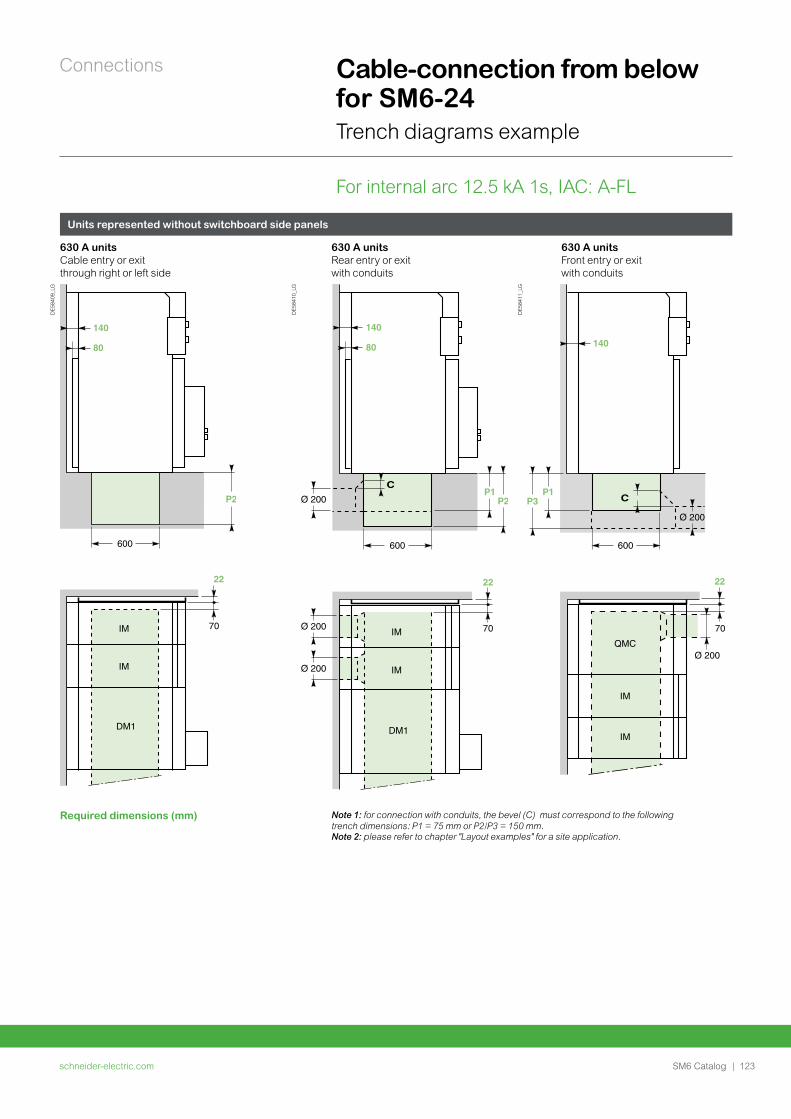
schneider-electric.com | 123SM6 Catalog
Connections
Units represented without switchboard side panels
630 A unitsCable entry or exit through right or left side
630 A unitsRear entry or exit with conduits
630 A unitsFront entry or exit with conduits
DE
5840
9_LG
DE
5841
0_LG
DE
5841
1_LG
Required dimensions (mm) Note 1: for connection with conduits, the bevel (C) must correspond to the following trench dimensions: P1 = 75 mm or P2/P3 = 150 mm.Note 2: please refer to chapter "Layout examples" for a site application.
Cable-connection from below for SM6-24Trench diagrams example
For internal arc 12.5 kA 1s, IAC: A-FL
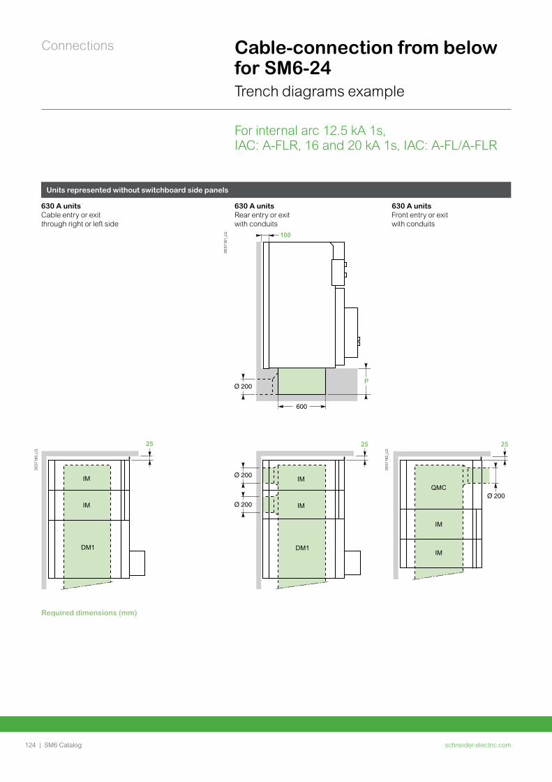
schneider-electric.com124 | SM6 Catalog
Connections Cable-connection from below for SM6-24Trench diagrams example
For internal arc 12.5 kA 1s, IAC: A-FLR, 16 and 20 kA 1s, IAC: A-FL/A-FLR
Units represented without switchboard side panels
630 A unitsCable entry or exit through right or left side
630 A unitsRear entry or exit with conduits
630 A unitsFront entry or exit with conduits
DE
5718
0_LG
600
P2
IM
IM
DM1
25
100
DE
5718
1_LG
P
25
IM
IM
DM1
100
DE
5718
2_LG
P1P3
25
QMC
IM
IM
100
Required dimensions (mm)
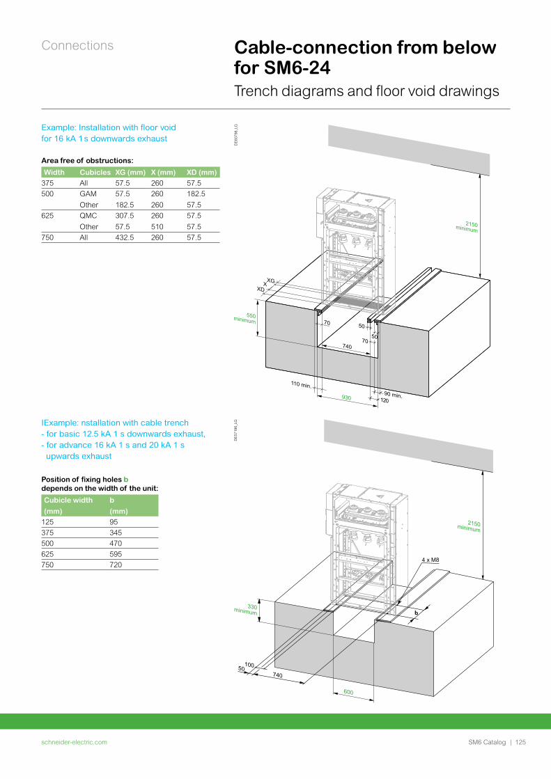
schneider-electric.com | 125SM6 Catalog
Connections Cable-connection from below for SM6-24Trench diagrams and floor void drawings
740
b
50100
4 x M8
600
330minimum
2150minimum
DE
5719
6_LG
Example: Installation with floor void for 16 kA 1 s downwards exhaust
IExample: nstallation with cable trench - for basic 12.5 kA 1 s downwards exhaust, - for advance 16 kA 1 s and 20 kA 1 s upwards exhaust
Position of fixing holes b depends on the width of the unit:
Cubicle width
(mm)
b
(mm)125 95
375 345
500 470
625 595
750 720
DE
6079
8_LG
Area free of obstructions:
Width Cubicles XG (mm) X (mm) XD (mm)375 All 57.5 260 57.5
500 GAM
Other
57.5
182.5
260
260
182.5
57.5
625 QMC
Other
307.5
57.5
260
510
57.5
57.5
750 All 432.5 260 57.5
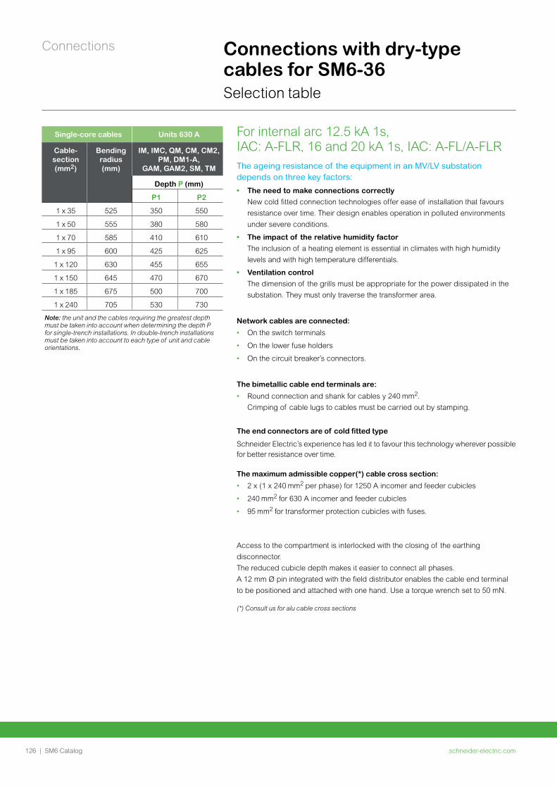
schneider-electric.com126 | SM6 Catalog
Connections Connections with dry-type cables for SM6-36Selection table
The ageing resistance of the equipment in an MV/LV substation depends on three key factors:
• The need to make connections correctly
New cold fitted connection technologies offer ease of installation that favours
resistance over time. Their design enables operation in polluted environments
under severe conditions.
• The impact of the relative humidity factor
The inclusion of a heating element is essential in climates with high humidity
levels and with high temperature differentials.
• Ventilation control
The dimension of the grills must be appropriate for the power dissipated in the
substation. They must only traverse the transformer area.
Network cables are connected:
• On the switch terminals
• On the lower fuse holders
• On the circuit breaker’s connectors.
The bimetallic cable end terminals are:
• Round connection and shank for cables y 240 .
Crimping of cable lugs to cables must be carried out by stamping.
The end connectors are of cold fitted type
Schneider Electric’s experience has led it to favour this technology wherever possible for better resistance over time.
The maximum admissible copper(*) cable cross section:
• 2 x (1 x 240 per phase) for 1250 A incomer and feeder cubicles
• 240 for 630 A incomer and feeder cubicles
• 95 for transformer protection cubicles with fuses.
Access to the compartment is interlocked with the closing of the earthing disconnector. The reduced cubicle depth makes it easier to connect all phases. A 12 mm Ø pin integrated with the field distributor enables the cable end terminal to be positioned and attached with one hand. Use a torque wrench set to 50 mN.
(*) Consult us for alu cable cross sections
For internal arc 12.5 kA 1s, IAC: A-FLR, 16 and 20 kA 1s, IAC: A-FL/A-FLR
Single-core cables Units 630 A
Cable-section(mm2)
Bending radius (mm)
IM, IMC, QM, CM, CM2, PM, DM1-A,
GAM, GAM2, SM, TM
Depth P (mm)
P1 P2
1 x 35 525 350 550
1 x 50 555 380 580
1 x 70 585 410 610
1 x 95 600 425 625
1 x 120 630 455 655
1 x 150 645 470 670
1 x 185 675 500 700
1 x 240 705 530 730
Note: the unit and the cables requiring the greatest depth must be taken into account when determining the depth P for single-trench installations. In double-trench installations must be taken into account to each type of unit and cable orientations.
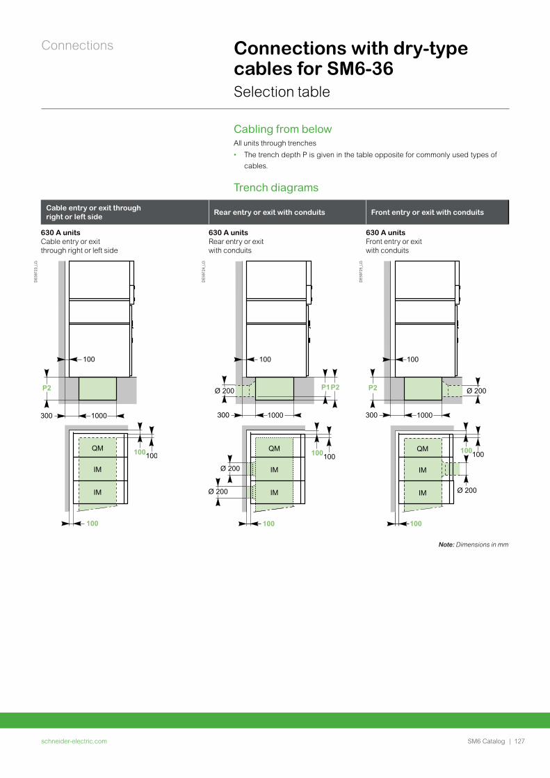
schneider-electric.com | 127SM6 Catalog
Connections Connections with dry-type cables for SM6-36Selection table
Cabling from belowAll units through trenches
• The trench depth P is given in the table opposite for commonly used types of
cables.
Trench diagrams
Cable entry or exit through right or left side Rear entry or exit with conduits Front entry or exit with conduits
630 A unitsCable entry or exit through right or left side
630 A unitsRear entry or exit with conduits
630 A unitsFront entry or exit with conduits
DE5
9723
_LG
DE5
9724
_LG
DE5
9725
_LG
Note: Dimensions in mm
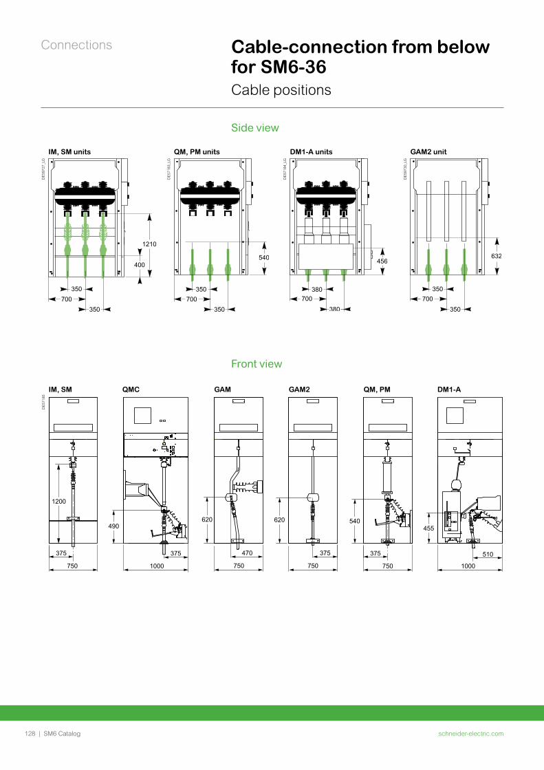
schneider-electric.com128 | SM6 Catalog
Connections Cable-connection from below for SM6-36Cable positions
IM, SM units QM, PM units DM1-A units GAM2 unit
DE5
9727
_LG
DE5
7183
_LG
DE5
7184
_LG
DE5
9730
_LG
Side view
Front view
IM, SM QMC GAM GAM2 QM, PM DM1-A
DE5
7185
375
750
470
750
375
750
375
750
375
1000
510
1000
1200
490620 620 540
455
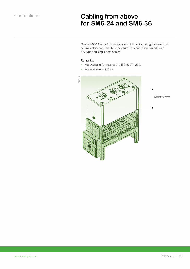
schneider-electric.com | 129SM6 Catalog
Connections Cabling from above for SM6-24 and SM6-36
On each 630 A unit of the range, except those including a low-voltage control cabinet and an EMB enclosure, the connection is made with dry-type and single-core cables.
Remarks:
• Not available for internal arc IEC 62271-200.
• Not available in 1250 A.
Height: 450 mm
PE
5079
7_G

schneider-electric.com130 | SM6 Catalog
Installation
schneider-electric.com | 131SM6 Catalog
Installation
Dimensions and weights for SM6-24 132
Units dimensions for SM6-24 133
Civil engineering for SM6-24 137
Layout examples for SM6-24 138
Dimensions and weights for SM6-36 140
Civil engineering for SM6-36 141
Layout examples for SM6-36 142
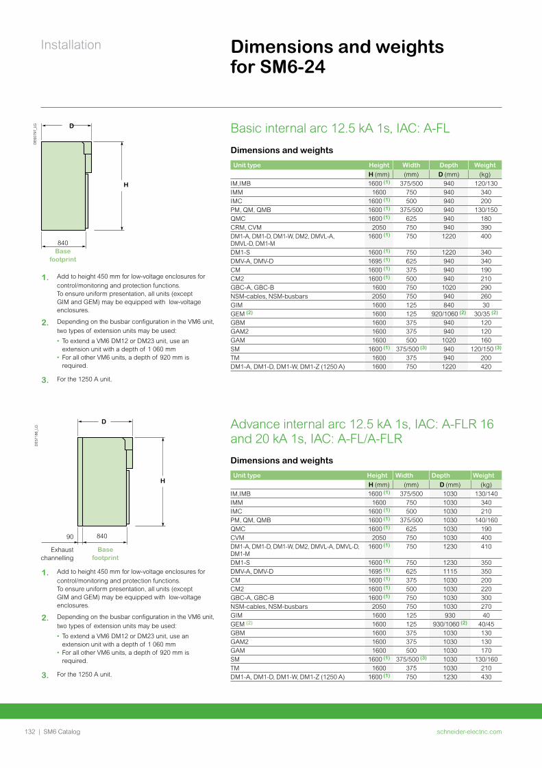
schneider-electric.com132 | SM6 Catalog
Installation Dimensions and weights for SM6-24
Dimensions and weights
Unit type Height Width Depth WeightH (mm) (mm) D (mm) (kg)
IM,IMB 1600 (1) 375/500 1030 130/140IMM 1600 750 1030 340IMC 1600 (1) 500 1030 210PM, QM, QMB 1600 (1) 375/500 1030 140/160QMC 1600 (1) 625 1030 190CVM 2050 750 1030 400DM1-A, DM1-D, DM1-W, DM2, DMVL-A, DMVL-D, DM1-M
1600 (1) 750 1230 410
DM1-S 1600 (1) 750 1230 350DMV-A, DMV-D 1695 (1) 625 1115 350CM 1600 (1) 375 1030 200CM2 1600 (1) 500 1030 220GBC-A, GBC-B 1600 (1) 750 1030 300NSM-cables, NSM-busbars 2050 750 1030 270GIM 1600 125 930 40GEM (2) 1600 125 930/1060 (2) 40/45GBM 1600 375 1030 130GAM2 1600 375 1030 130GAM 1600 500 1030 170SM 1600 (1) 375/500 (3) 1030 130/160TM 1600 375 1030 210DM1-A, DM1-D, DM1-W, DM1-Z (1250 A) 1600 (1) 750 1230 430
DE
6079
7_LG D
H
840Base
footprint
Dimensions and weights
Unit type Height Width Depth WeightH (mm) (mm) D (mm) (kg)
IM,IMB 1600 (1) 375/500 940 120/130IMM 1600 750 940 340IMC 1600 (1) 500 940 200PM, QM, QMB 1600 (1) 375/500 940 130/150QMC 1600 (1) 625 940 180CRM, CVM 2050 750 940 390DM1-A, DM1-D, DM1-W, DM2, DMVL-A, DMVL-D, DM1-M
1600 (1) 750 1220 400
DM1-S 1600 (1) 750 1220 340DMV-A, DMV-D 1695 (1) 625 940 340CM 1600 (1) 375 940 190CM2 1600 (1) 500 940 210GBC-A, GBC-B 1600 750 1020 290NSM-cables, NSM-busbars 2050 750 940 260GIM 1600 125 840 30GEM (2) 1600 125 920/1060 (2) 30/35 (2)
GBM 1600 375 940 120GAM2 1600 375 940 120GAM 1600 500 1020 160SM 1600 (1) 375/500 (3) 940 120/150 (3)
TM 1600 375 940 200DM1-A, DM1-D, DM1-W, DM1-Z (1250 A) 1600 750 1220 420
Advance internal arc 12.5 kA 1s, IAC: A-FLR 16 and 20 kA 1s, IAC: A-FL/A-FLR
Basic internal arc 12.5 kA 1s, IAC: A-FL
DE
5718
6_LG
D
H
90 840
Exhaust channelling
Base footprint
1. Add to height 450 mm for low-voltage enclosures for
control/monitoring and protection functions. To ensure uniform presentation, all units (except GIM and GEM) may be equipped with low-voltage enclosures.
2. Depending on the busbar configuration in the VM6 unit,
two types of extension units may be used:
• To extend a VM6 DM12 or DM23 unit, use an extension unit with a depth of 1 060 mm
• For all other VM6 units, a depth of 920 mm is required.
3. For the 1250 A unit.
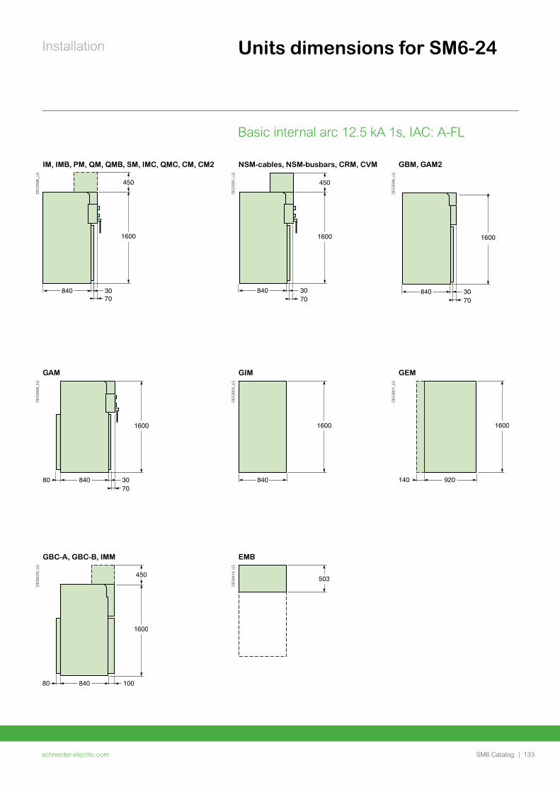
schneider-electric.com | 133SM6 Catalog
Installation Units dimensions for SM6-24
IM, IMB, PM, QM, QMB, SM, IMC, QMC, CM, CM2 NSM-cables, NSM-busbars, CRM, CVM GBM, GAM2
DE5
3596
_LG
DE5
3597
_LG
DE5
3598
_LG
GAM GIM GEM
DE5
3599
_LG
DE5
3600
_LG
DE5
3601
_LG
GBC-A, GBC-B, IMM EMB
DE5
9229
_LG
DE5
8414
_LG
Basic internal arc 12.5 kA 1s, IAC: A-FL
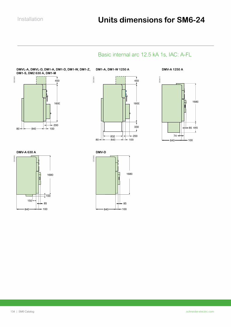
schneider-electric.com134 | SM6 Catalog
Installation
DMVL-A, DMVL-D, DM1-A, DM1-D, DM1-W, DM1-Z, DM1-S, DM2 630 A, DM1-M
DM1-A, DM1-W 1250 A DMV-A 1250 A
DE5
3603
DE5
3604
DE5
8415
DMV-A 630 A DMV-D
DE5
3605
DE5
3606
Units dimensions for SM6-24
Basic internal arc 12.5 kA 1s, IAC: A-FL
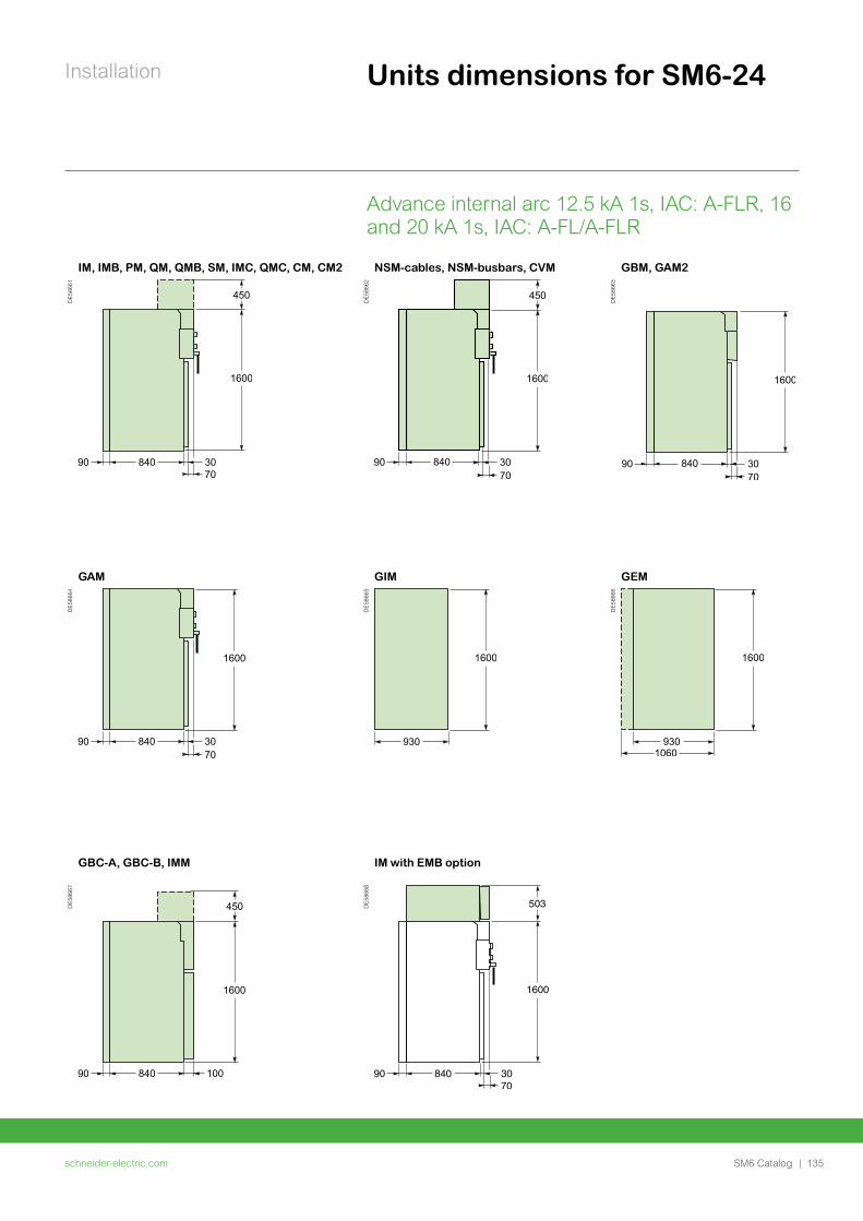
schneider-electric.com | 135SM6 Catalog
Installation
Advance internal arc 12.5 kA 1s, IAC: A-FLR, 16 and 20 kA 1s, IAC: A-FL/A-FLR
Units dimensions for SM6-24
IM, IMB, PM, QM, QMB, SM, IMC, QMC, CM, CM2 NSM-cables, NSM-busbars, CVM GBM, GAM2
DE5
8661
DE5
8662
DE5
8663
GAM GIM GEM
DE5
8664
DE5
8665
DE5
8666
GBC-A, GBC-B, IMM IM with EMB option
DE5
8667
DE5
8668
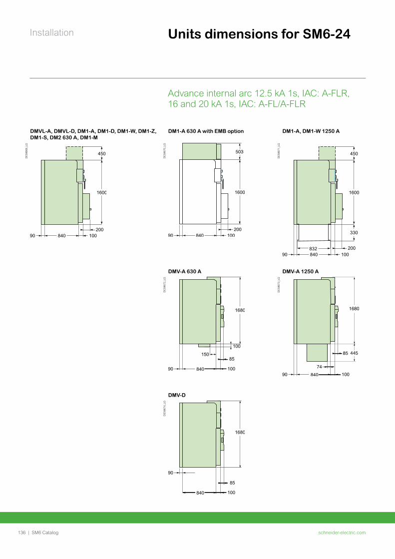
schneider-electric.com136 | SM6 Catalog
Installation
DMVL-A, DMVL-D, DM1-A, DM1-D, DM1-W, DM1-Z, DM1-S, DM2 630 A, DM1-M
DM1-A 630 A with EMB option DM1-A, DM1-W 1250 A
DE5
8669
_LG
DE5
8670
_LG
DE5
8671
_LG
DMV-A 630 A DMV-A 1250 A
DE5
8672
_LG
DE5
8673
_LG
DMV-D
DE5
8674
_LG
Units dimensions for SM6-24
Advance internal arc 12.5 kA 1s, IAC: A-FLR, 16 and 20 kA 1s, IAC: A-FL/A-FLR
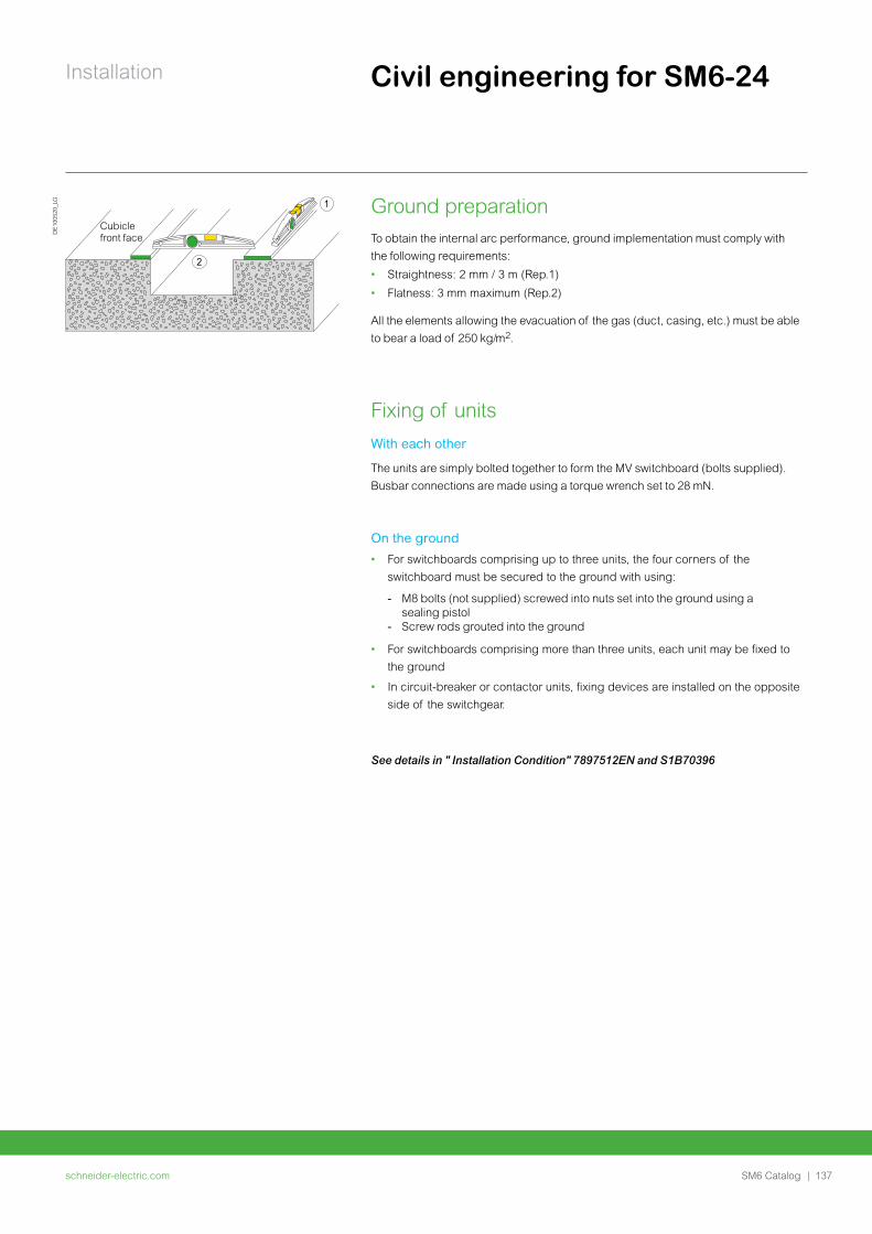
schneider-electric.com | 137SM6 Catalog
Installation Civil engineering for SM6-24
See details in " Installation Condition" 7897512EN and S1B70396
Ground preparationTo obtain the internal arc performance, ground implementation must comply with
the following requirements:
• Straightness: 2 mm / 3 m (Rep.1)
• Flatness: 3 mm maximum (Rep.2)
All the elements allowing the evacuation of the gas (duct, casing, etc.) must be able
to bear a load of 250 kg/ .
Fixing of unitsWith each other
The units are simply bolted together to form the MV switchboard (bolts supplied).
Busbar connections are made using a torque wrench set to 28 mN.
On the ground
• For switchboards comprising up to three units, the four corners of the
switchboard must be secured to the ground with using:
- M8 bolts (not supplied) screwed into nuts set into the ground using a sealing pistol - Screw rods grouted into the ground
• For switchboards comprising more than three units, each unit may be fixed to
the ground
• In circuit-breaker or contactor units, fixing devices are installed on the opposite
side of the switchgear.
1
2
Cubicle front face
DE
1005
20_L
G
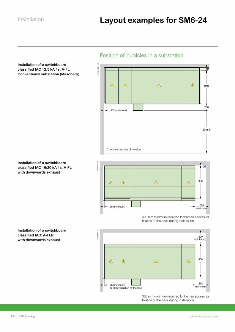
schneider-electric.com138 | SM6 Catalog
Installation Layout examples for SM6-24
Position of cubicles in a substation
DE5
8416
EN_L
GInstallation of a switchboard classified IAC 12.5 kA 1s: A-FL Conventional substation (Masonery)
Installation of a switchboard classified IAC 16/20 kA 1s: A-FL with downwards exhaust
DE5
8657
_LG
300 mm minimum required for human access for fixation of the back during installation.
Installation of a switchboard classified IAC: A-FLR with downwards exhaust D
E586
58EN
_LG
300 mm minimum required for human access for fixation of the back during installation.
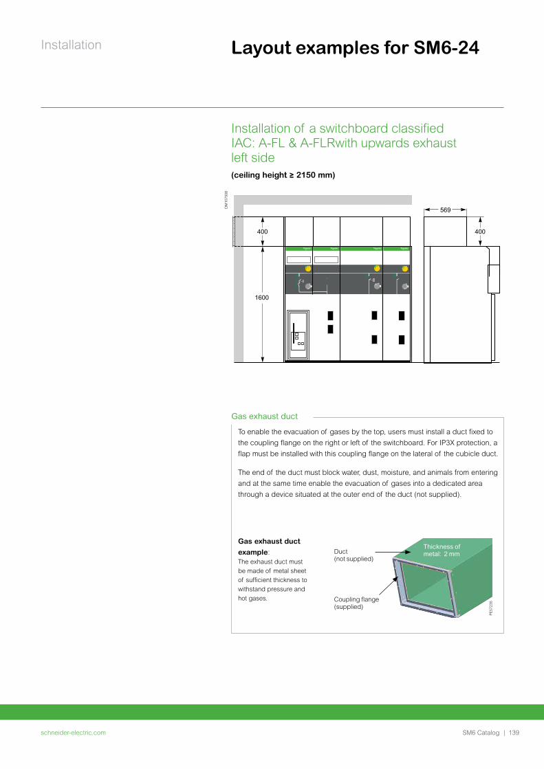
schneider-electric.com | 139SM6 Catalog
Installation Layout examples for SM6-24
DM
1075
08
To enable the evacuation of gases by the top, users must install a duct fixed to
the coupling flange on the right or left of the switchboard. For IP3X protection, a
flap must be installed with this coupling flange on the lateral of the cubicle duct.
The end of the duct must block water, dust, moisture, and animals from entering
and at the same time enable the evacuation of gases into a dedicated area
through a device situated at the outer end of the duct (not supplied).P
E57
235Coupling flange
(supplied)
Duct (not supplied)
Thickness of metal: 2 mm
Gas exhaust duct
example: The exhaust duct must
be made of metal sheet
of sufficient thickness to
withstand pressure and
hot gases.
Gas exhaust duct
Installation of a switchboard classified IAC: A-FL & A-FLRwith upwards exhaust left side(ceiling height ≥ 2150 mm)
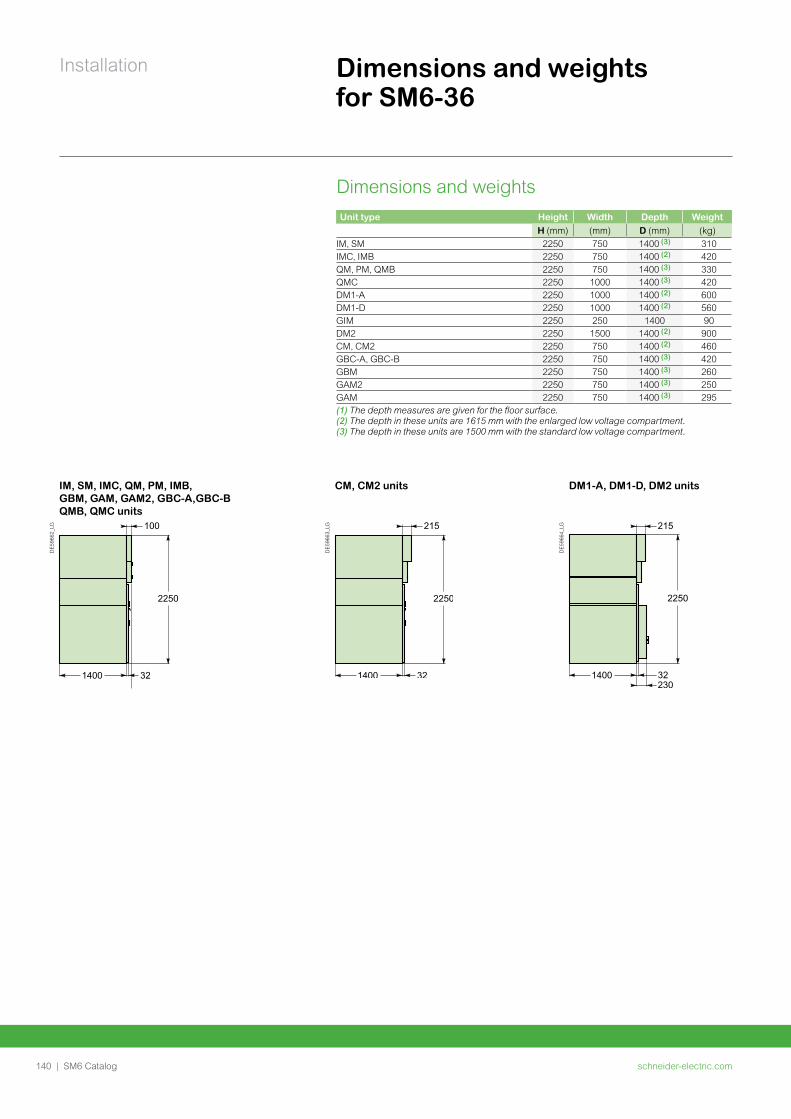
schneider-electric.com140 | SM6 Catalog
Installation Dimensions and weights for SM6-36
Dimensions and weightsUnit type Height Width Depth Weight
H (mm) (mm) D (mm) (kg)IM, SM 2250 750 1400 (3) 310IMC, IMB 2250 750 1400 (2) 420QM, PM, QMB 2250 750 1400 (3) 330QMC 2250 1000 1400 (3) 420DM1-A 2250 1000 1400 (2) 600DM1-D 2250 1000 1400 (2) 560GIM 2250 250 1400 90DM2 2250 1500 1400 (2) 900CM, CM2 2250 750 1400 (2) 460GBC-A, GBC-B 2250 750 1400 (3) 420GBM 2250 750 1400 (3) 260GAM2 2250 750 1400 (3) 250GAM 2250 750 1400 (3) 295(1) The depth measures are given for the floor surface.(2) The depth in these units are 1615 mm with the enlarged low voltage compartment.(3) The depth in these units are 1500 mm with the standard low voltage compartment.
IM, SM, IMC, QM, PM, IMB, GBM, GAM, GAM2, GBC-A,GBC-B QMB, QMC units
CM, CM2 units DM1-A, DM1-D, DM2 units
DE5
9662
_LG
DE5
9663
_LG
DE5
9664
_LG
schneider-electric.com | 141SM6 Catalog
Installation Civil engineering for SM6-36
Ground preparationUnits may be installed on ordinary concrete grounds, with or without trenches
depending on the type and cross-section of cables.
Required civil works are identical for all units.
Fixing of unitsWith each other
The units are simply bolted together to form the MV switchboard (bolts supplied).
Busbar connections are made using a torque wrench set to 28 mN.
On the ground
• For switchboards comprising up to three units, the four corners of the
switchboard must be secured to the ground with using:
- M8 bolts (not supplied) screwed into nuts set into the ground using a sealing pistol - Screw rods grouted into the ground
• For switchboards comprising more than three units, each unit may be fixed to
the ground
• In circuit-breaker or contactor units, fixing devices are installed on the opposite
side of the switchgear.
See details in " Installation Condition" 7897512EN and S1B70396
See "Installation Condition" EAV4899801
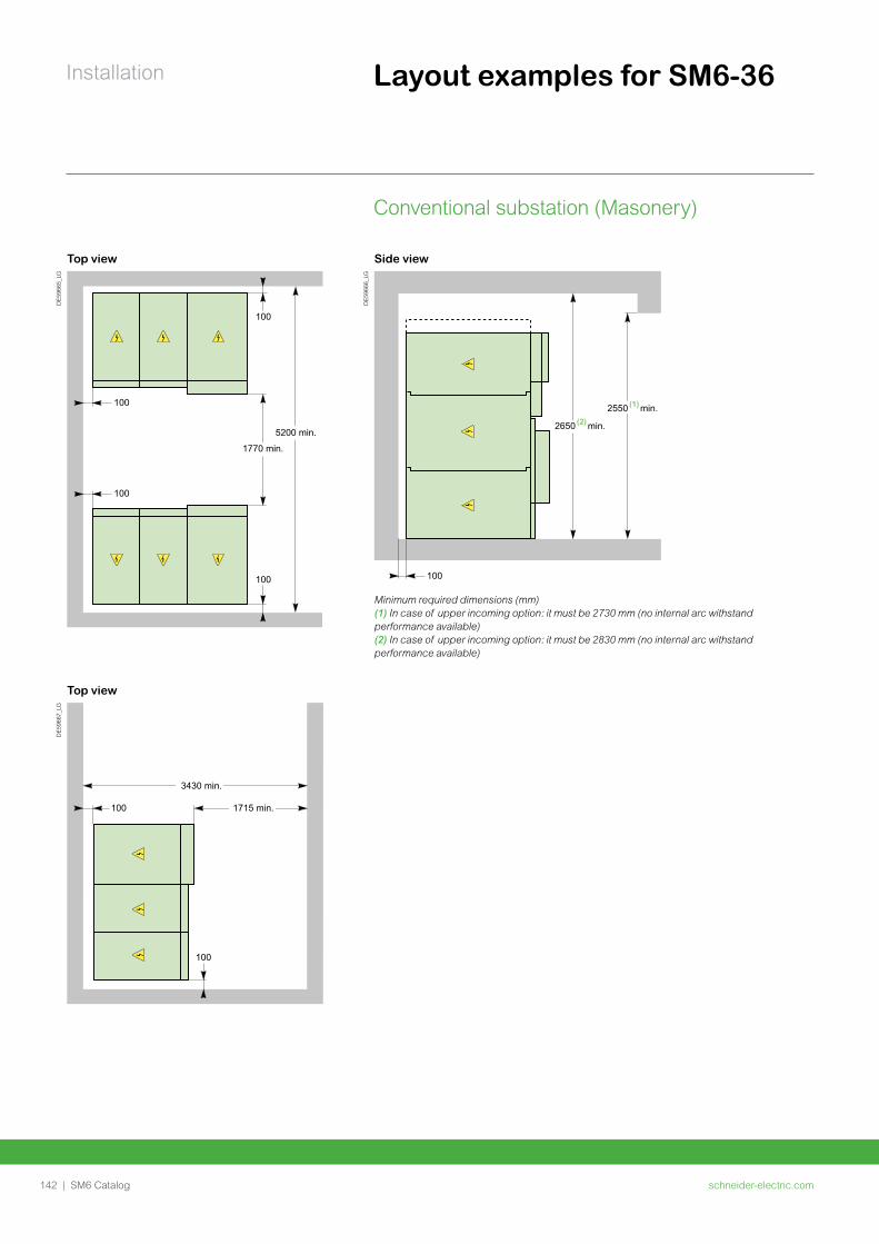
schneider-electric.com142 | SM6 Catalog
Installation Layout examples for SM6-36
Conventional substation (Masonery)
Top view Side view
DE5
9665
_LG
DE5
9666
_LG
Minimum required dimensions (mm)(1) In case of upper incoming option: it must be 2730 mm (no internal arc withstand performance available)(2) In case of upper incoming option: it must be 2830 mm (no internal arc withstand performance available)
Top view
DE5
9667
_LG

schneider-electric.com | 143SM6 Catalog
Notes

schneider-electric.com144 | SM6 Catalog
Schneider Electric services
schneider-electric.com | 145SM6 Catalog
Schneider Electric services
ProDiag Breaker 146Diagnosis of MV and LV Circuit Breakers 146
ProDiag Corona 147Diagnostics of partial discharges 147
ProDiag Fuse 148Proprietary and standards diagnostics tools 148
161
164
166
168
168
171
175

schneider-electric.com146 | SM6 Catalog
Schneider Electric services
ProDiag BreakerDiagnosis of MV and LV Circuit Breakers
What is ProDiag Breaker?ProDiag Breaker is a Schneider Electric diagnosis tool which compares the mechanical and electrical parameters measured during the full operation of circuit breakers with the data collected from our production facilities. This allows detecting possible failure in advance. It measures, records and displays on a screen the key electrical parameters in MV and LV circuit breakers, relating to opening, closing and springloading operations.
All this data is automatically compared with the criteria for the circuit breaker designated in the software, which indicates which values are within the acceptable range, which are on the limit and which are outside it.
Two tests are always performed on each circuit breakers, one at minimum voltage and one at nominal voltage. A written report is generated and provided by Schneider Electric so that the customer can use it as a tool to define the necessary corrective action (maintenance, repair or replacement).
ProDiag Breaker is part is part of ProDiag preventive maintenance plan
Evaluation of circuit breakers using ProDiag Breaker includes:
• Evaluation of the operating mechanism.• Measurement and comparison of the actual contact resistance with that specified
by the manufacturer.• Measurement and comparison of the insulation resistance.• Evaluation of the general circuit breaker conditions based on the captured data.
Moreover, analysis of the ProDiag Breaker time/ travel curve combined with the current curve of the coil and phase contact detects possible faults, such as:
• Worn out latches and operating mechanisms.• Faulty coils.• Mechanical wear and tear and hardening of lubricating grease.• Defective shock absorbers.• Defective simultaneous contact operation (opening/closing).
Some maintenance programmes involve dismantling the circuit breaker mechanism to check its condition. ProDiag Breaker using signals captured from the circuit breaker operation, reduces maintenance costs compared with programs which check the circuit breakers manually.
Where can ProDiag Breaker reduce costs?
• ProDiag Breaker significantly reduces the time taken to identify potential faults in a circuit breaker, using operational analysis rather than inspection and mechanical re-sets.
• The software analyses the captured data and identifies the specific problem area.
• A device’s normal operating life is increased by timely diagnostics of when and what repairs are necessary.
• The tool comprises both hardware and software, resulting in a highly efficient predictive maintenance program.
PE60
531
Diagnostics and advice for
improvement and optimisation
Report onProDiag
Breaker Test
6
Check Evaluation
of corrective action results
Collect and
measure data
Install ProDiag
Breaker on site
Check data for the diagnostic test
1 2 3 4 5
Improvedswitchingefficiency
7
ProDiag Breaker Objectives
Your priority is to enhance the reliability of your installation:• to ensure its continuity of service,• to minimize the time for maintenance & repair• to perform maintenance• Only on the equipment requiring it and only
when necessary (conditional preventive maintenance)
Results
ProDiag Breaker provides a report of the complete nature of the circuit breaker, detailing: closing / opening time, contact simultaneity, bounce and resistance, mechanical closing and opening forces.This report enables any required maintenance to be targeted and time in order to optimize the customer’s maintenance plan.
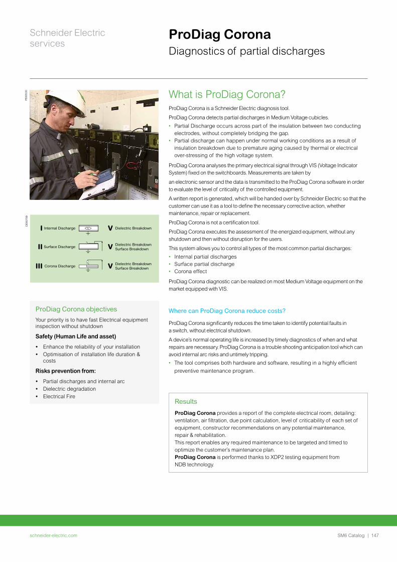
schneider-electric.com | 147SM6 Catalog
Schneider Electric services
ProDiag CoronaDiagnostics of partial discharges
What is ProDiag Corona?ProDiag Corona is a Schneider Electric diagnosis tool.
ProDiag Corona detects partial discharges in Medium Voltage cubicles.
• Partial Discharge occurs across part of the insulation between two conducting electrodes, without completely bridging the gap.
• Partial discharge can happen under normal working conditions as a result of insulation breakdown due to premature aging caused by thermal or electrical over-stressing of the high voltage system.
ProDiag Corona analyses the primary electrical signal through VIS (Voltage Indicator System) fixed on the switchboards. Measurements are taken by
an electronic sensor and the data is transmitted to the ProDiag Corona software in order to evaluate the level of criticality of the controlled equipment.
A written report is generated, which will be handed over by Schneider Electric so that the customer can use it as a tool to define the necessary corrective action, whether maintenance, repair or replacement.
ProDiag Corona is not a certification tool.
ProDiag Corona executes the assessment of the energized equipment, without any shutdown and then without disruption for the users.
This system allows you to control all types of the most common partial discharges:
• Internal partial discharges• Surface partial discharge• Corona effect
ProDiag Corona diagnostic can be realized on most Medium Voltage equipment on the market equipped with VIS.
Where can ProDiag Corona reduce costs?
ProDiag Corona significantly reduces the time taken to identify potential faults in a switch, without electrical shutdown.
A device’s normal operating life is increased by timely diagnostics of when and what repairs are necessary. ProDiag Corona is a trouble shooting anticipation tool which can avoid internal arc risks and untimely tripping.
• The tool comprises both hardware and software, resulting in a highly efficient
preventive maintenance program.
Internal DischargeI
Surface DischargeII
Corona DischargeIII
V Dielectric BreakdownSurface Breakdown
V Dielectric Breakdown
V Dielectric BreakdownSurface Breakdown
PE60
530
DE6
0799
Results
ProDiag Corona provides a report of the complete electrical room, detailing: ventilation, air filtration, due point calculation, level of criticability of each set of equipment, constructor recommendations on any potential maintenance, repair & rehabilitation.This report enables any required maintenance to be targeted and timed to optimize the customer’s maintenance plan. ProDiag Corona is performed thanks to XDP2 testing equipment from NDB technology.
ProDiag Corona objectives
Your priority is to have fast Electrical equipment inspection without shutdown
Safety (Human Life and asset)
• Enhance the reliability of your installation • Optimisation of installation life duration &
costs
Risks prevention from:
• Partial discharges and internal arc• Dielectric degradation• Electrical Fire

schneider-electric.com148 | SM6 Catalog
Schneider Electric services
ProDiag FuseProprietary and standards diagnostics tools
Customer needsElectrical power installations protected by MV switchgear with fuse protection should be regularly checked (for correct assembly, electrical parameters, etc.) to confirm that their characteristics correspond to the original specification. Regular diagnosis of fuse performance (electrical parameters, resistance) according to the manufacturer’s recommendations is necessary to secure the ED installation and its service continuity, which are important for customers.
The ProDiag Fuse diagnostic solution can be used on MV switchgear protected by fuses that have not received any maintenance intervention in the last four years (under normal operating conditions, and less if operating in severe environments or depending on their criticality in the installation).
The purpose of ProDiag Fuse (a proprietary hardware-software solution) is to mitigate the risks on MV switchgear and equipment by fuses of faults or drifts causing unwanted effects. The result of fuse ageing is the destruction of filaments that can lead to thermal runaway, partial damage, complete destruction of MV switchgear and equipment, or
even destruction of the electrical room.
"Unique value for customer vs standard market tools"Electrical parameter measurements (resistance, etc.) on MV switchgear fuses at customer sites are taken by a test tool and transmitted to the Schneider Electric FSRs' ProDiag Fuse software. Data are compared to those of a fuse manufacturers’ technical database.
The aim is to determine whether recorded measurements are within the acceptable range, at the limit, or fall outside it, as criteria for MV switchgear fuse conformity.
As an ED equipment manufacturer, Schneider Electric is uniquely positioned to develop and invest in specific tests tools, proprietary software, and testing methodology to collect reliable measurements from MV switchgears fuses.
ProDiag Fuse measures a larger number of parameters than standard market tools. It delivers best-in-class MV switchgear fuse diagnostics.
Schneider Electric scope: Schneider Electric fuses and main market fuses players.
PE60
532
PE60
533
Customer benefits
ProDiag Fuse helps customers visualise, discover, and understand MV switchgear fuse ageing and wear and tear as compared to the original fuse manufacturers’ technical specification.
ProDiag Fuse monitors the performance of MV switchgear fuses. Thanks to ProDiag Fuse, maintenance managers can implement, manage, and enrich their maintenance plans. Schneider Electric FSRs conclude their on-site interventions with an exhaustive report on the MV switchgear fuses conformity/non-conformity. If a MV fuse is declared non-conforming, Schneider Electric suggests a corrective plan that includes fuse replacement to regain original performance in safety and service continuity.
Customers can augment their preventive maintenance plans with this corrective action at the most convenient time for each ED device.

schneider-electric.com | 149SM6 Catalog
Notes

schneider-electric.com150 | SM6 Catalog
Appendices and Order Form
schneider-electric.com | 151SM6 Catalog
Appendices and Order form
Appendices
Order form
VIP tripping curves 152VIP 40 and VIP 45 tripping curve 152
VIP 400 tripping curves 153
VIP 410 tripping curves 155
Fusarc CF fuses 156
Solefuse fuses 157
SM6 switching 158Switching 158
Automatic Transfer System 160
SM6 protection 162Circuit breaker 162
Fuse switch 165
SM6 metering 169
SM6 other functions 171
SF1 lateral / frontal fixed 172
SFset 173Lateral / frontal fixed 173
Lateral disconnectable for SM6-24 174
Evolis 175Frontal fixed version for SM6-24 (up to 17.5 kV) 175
Lateral disconnectable version for SM6-24 (up to 24 kV) 176
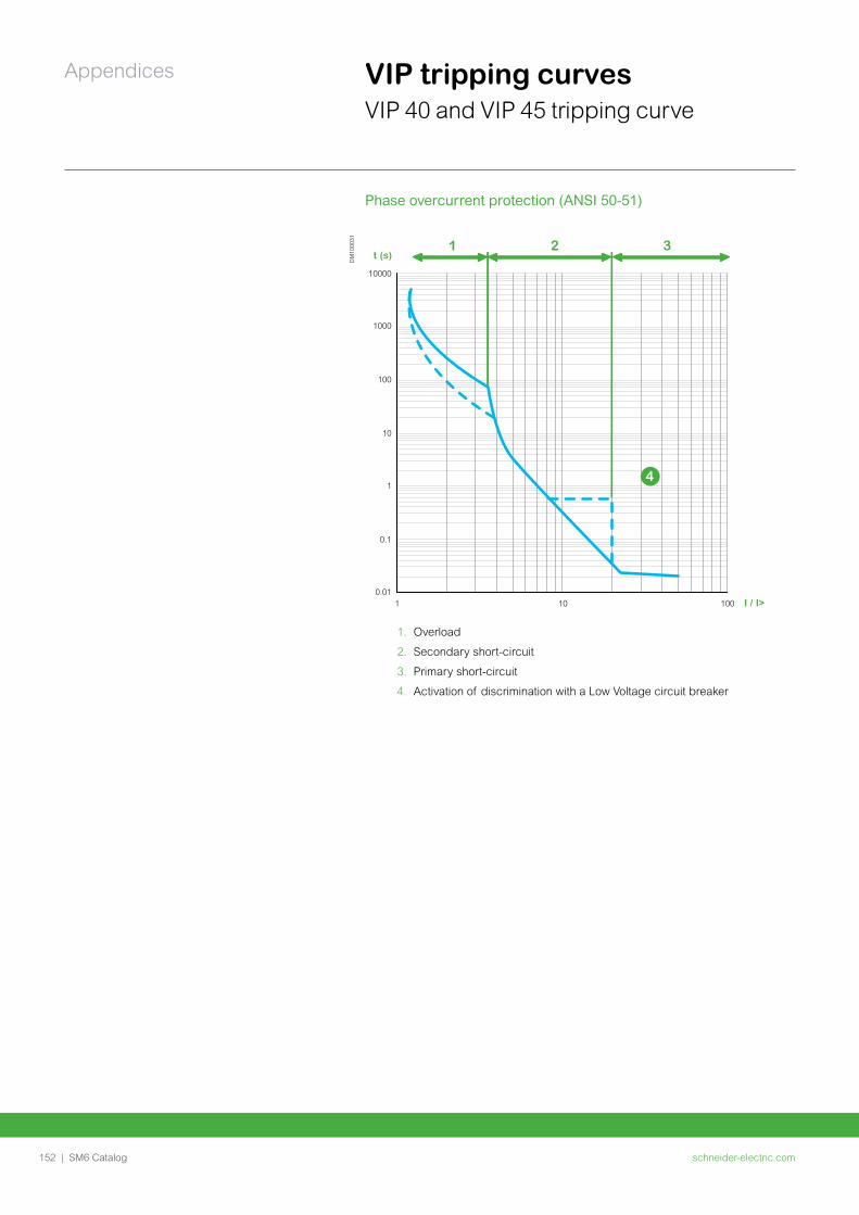
schneider-electric.com152 | SM6 Catalog
Appendices VIP tripping curvesVIP 40 and VIP 45 tripping curve
DM
1000
31
1. Overload
2. Secondary short-circuit
3. Primary short-circuit
4. Activation of discrimination with a Low Voltage circuit breaker
1 2 3
I / I>
t (s)
10000
1000
100
10
1
1 10 100
0.1
0.01
4
Phase overcurrent protection (ANSI 50-51)
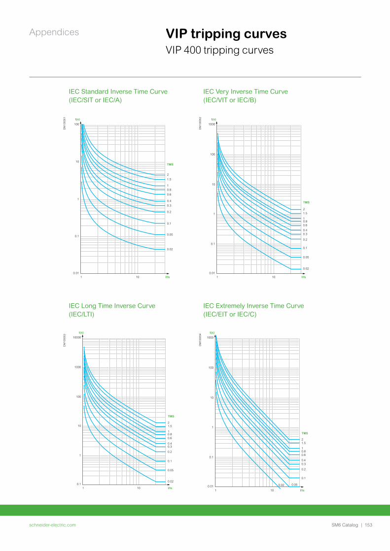
schneider-electric.com | 153SM6 Catalog
Appendices VIP tripping curvesVIP 400 tripping curves
IEC Standard Inverse Time Curve (IEC/SIT or IEC/A)
IEC Very Inverse Time Curve (IEC/VIT or IEC/B)
DM
1000
51
10.8
0.6
100
10
1
0.1
0.011 10
2
1.5
0.1
0.05
0.02
0.4
0.3
0.2
t(s)
I/Is
TMS
DM
1000
52
10.80.6
1000
100
10
1
0.1
0.011 10
21.5
0.1
0.05
0.02
0.40.3
0.2
t(s)
I/Is
TMS
IEC Long Time Inverse Curve (IEC/LTI)
IEC Extremely Inverse Time Curve (IEC/EIT or IEC/C)
DM
1000
53
DM
1000
54
10.80.6
1000
100
10
1
0.1
0.011 10
21.5
0.1
0.050.02
0.40.3
0.2
t(s)
I/Is
TMS10.80.6
10000
1000
100
10
1
0.11 10
21.5
0.1
0.05
0.02
0.40.3
0.2
t(s)
I/Is
TMS
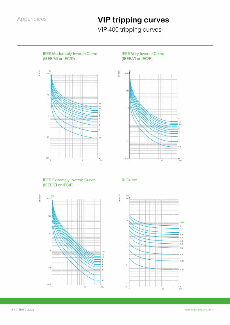
schneider-electric.com154 | SM6 Catalog
Appendices
IEEE Moderately Inverse Curve (IEEE/MI or IEC/D)
IEEE Very Inverse Curve (IEEE/VI or IEC/E)
DM
1000
55
108
6
100
10
1
0.1
0.011 10
1512
1
2
0.5
54
3
t(s)
I/Is
TD
DM
1000
56
1086
1000
100
10
1
0.1
0.011 10
1512
2
1
0.5
543
t(s)
I/Is
TD
IEEE Extremely Inverse Curve (IEEE/EI or IEC/F)
RI Curve
DM
1000
57
1086
1000
100
10
1
0.1
0.011 10
1512
2
1
0.5
543
t(s)
I/Is
TD
DM
1000
58
10.8
0.6
t(s)
100
10
1
0.1
0.011 10 I/Is
TMS
21.5
0.1
0.05
0.02
0.4
0.3
0.2
VIP tripping curvesVIP 400 tripping curves
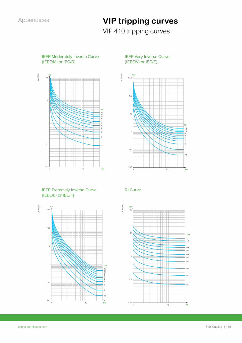
schneider-electric.com | 155SM6 Catalog
Appendices
IEEE Moderately Inverse Curve (IEEE/MI or IEC/D)
IEEE Very Inverse Curve (IEEE/VI or IEC/E)
DM
1000
55
108
6
100
10
1
0.1
0.011 10
1512
1
2
0.5
54
3
t(s)
I/Is
TD
DM
1000
56
1086
1000
100
10
1
0.1
0.011 10
1512
2
1
0.5
543
t(s)
I/Is
TD
IEEE Extremely Inverse Curve (IEEE/EI or IEC/F)
RI Curve
DM
1000
57
1086
1000
100
10
1
0.1
0.011 10
1512
2
1
0.5
543
t(s)
I/Is
TD
DM
1000
58
10.8
0.6
t(s)
100
10
1
0.1
0.011 10 I/Is
TMS
21.5
0.1
0.05
0.02
0.4
0.3
0.2
VIP tripping curvesVIP 410 tripping curves
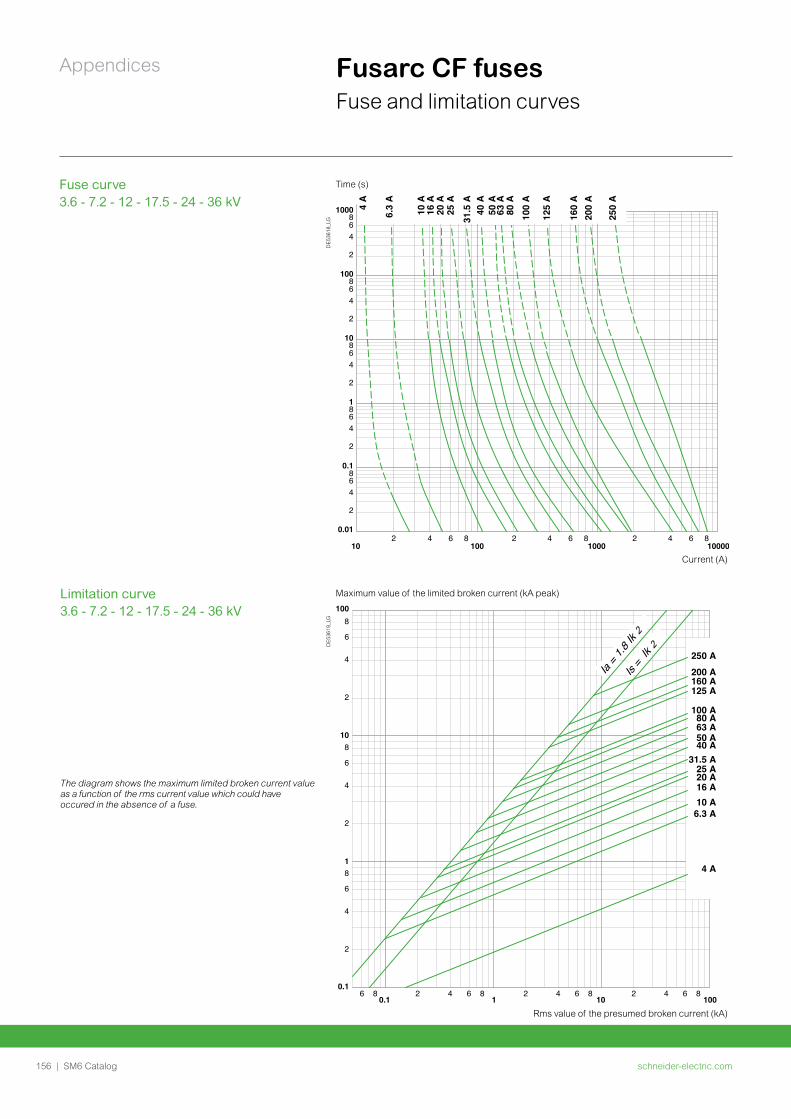
schneider-electric.com156 | SM6 Catalog
Appendices Fusarc CF fusesFuse and limitation curves
Time (s)Fuse curve 3.6 - 7.2 - 12 - 17.5 - 24 - 36 kV
102 4 6 8 2 4 6 8 2 4 86
100001000100
0.01
2
468
2
468
2
46
0.1
10
1
8
86
100
4
2
1000864
2
10 A
6.3
A
16 A
20 A
25 A
31.5
A
50 A
63 A
80 A
100
A
160
A20
0 A
250
A
4 A
125
A
40 A
Current (A)
DE5
3618
_LG
Limitation curve 3.6 - 7.2 - 12 - 17.5 - 24 - 36 kV
Maximum value of the limited broken current (kA peak)
0.12
100
2
4
1
10
1010.1
6
8
2
4
6
8
100
2
4
8
6
4 6 86 8 2 4 6 8 2 4 6 8
50 A
250 A
200 A160 A125 A
4 A
100 A
63 A80 A
40 A
16 A20 A
6.3 A
25 A
10 A
31.5 A
Is =
Ik 2
Ia = 1
.8 Ik 2
The diagram shows the maximum limited broken current value as a function of the rms current value which could have occured in the absence of a fuse.
DE5
3619
_LG
Rms value of the presumed broken current (kA)
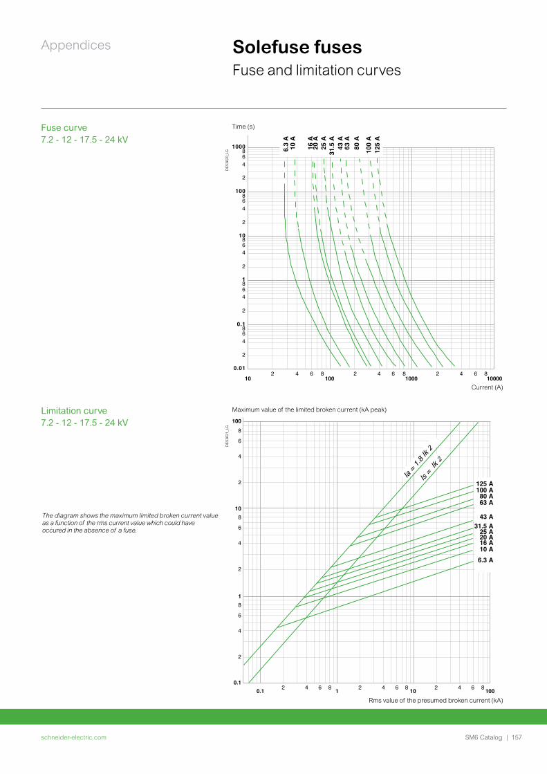
schneider-electric.com | 157SM6 Catalog
Appendices Solefuse fuses Fuse and limitation curves
Fuse curve 7.2 - 12 - 17.5 - 24 kV
Time (s)
Current (A)10
2 4 6 8100
2 4 6 81000
2 4 6 810000
1000864
2
100864
2
10864
2
1864
2
0.1864
2
0.01
6.3
A
10 A
20 A
25
A
16 A
31.5
A
43 A
63
A
80 A
100
A
125
A
DE5
3620
_LG
Limitation curve 7.2 - 12 - 17.5 - 24 kV
Maximum value of the limited broken current (kA peak)
The diagram shows the maximum limited broken current value as a function of the rms current value which could have occured in the absence of a fuse.
6 84 62 842 84 620.10.1
1 10 100
108
6
4
2
8
6
4
2
8
6
4
2
1
100
125 A100 A80 A63 A
43 A31.5 A
10 A16 A20 A25 A
6.3 A
Is =
Ik 2
Ia = 1
.8 Ik 2D
E536
21_L
G
Rms value of the presumed broken current (kA)
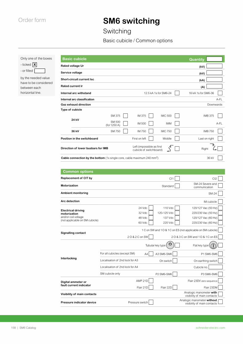
schneider-electric.com158 | SM6 Catalog
Order form SM6 switchingSwitchingBasic cubicle / Common options
Common options
Replacement of CIT by CI1 CI2
Motorization Standard SM-24 Severe and communication
Ambient monitoring SM-24
Arc detection IM cubicle
Electrical driving motorization and/or coil voltage (not applicable on SM cubicle)
24 Vdc
32 Vdc
48 Vdc
60 Vdc
110 Vdc
120-125 Vdc
137 Vdc
220 Vdc
120/127 Vac (50 Hz)
220/230 Vac (50 Hz)
120/127 Vac (60 Hz)
220/230 Vac (60 Hz)
Signalling contact1 C on SW and 1 O & 1 C on ES (not applicable on SM cubicle)
2 O & 2 C on SW 2 O & 3 C on SW and 1 O & 1 C on ES
Interlocking
Tubular key type Flat key type
For all cubicles (except SM) A4 A3 SM6-SM6 P1 SM6-SM6
Localisation of 2nd lock for A3 On switch On earthing switch
Localisation of 2nd lock for A4 Cubicle no.
SM cubicle only P2 SM6-SM6 P3 SM6-SM6
Digital ammeter or fault current indicator
AMP 21D Flair 23DV zero sequence
Flair 21D Flair 22D Flair 23DM
Visibility of main contacts Analogic manometer with visibility of main contacts
Pressure indicator device Pressure switch Analogic manometer without
visibility of main contacts
Only one of the boxes
- ticked X
- or filled
by the needed value have to be considered between each horizontal line.
Basic cubicle Quantity
Rated voltage Ur (kV)
Service voltage (kV)
Short-circuit current Isc (kA)
Rated current Ir (A)
Internal arc withstand 12.5 kA 1s for SM6-24 16 kA 1s for SM6-36
Internal arc classification A-FL
Gaz exhaust direction Downwards
Type of cubicle
24 kVSM 375 IM 375 IMC 500 IMB 375
SM 500 (for 1250 A) IM 500 IMM A-FL
36 kV SM 750 IM 750 IMC 750 IMB 750
Position in the switchboard First on left Middle Last on right
Direction of lower busbars for IMB
Left (impossible as first cubicle of switchboard) Right
Cable connection by the bottom (1x single core, cable maximum 240 mm2) 36 kV
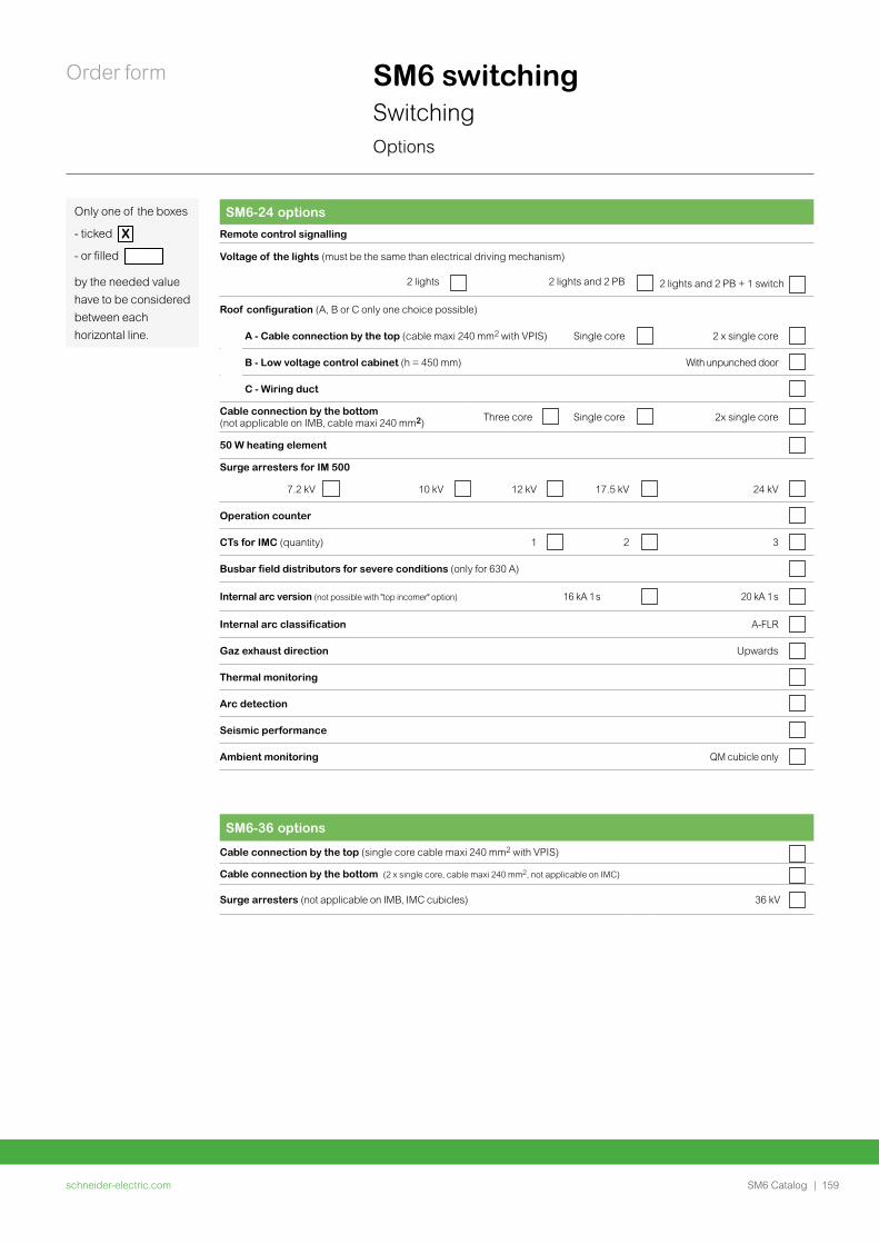
schneider-electric.com | 159SM6 Catalog
Order form SM6 switchingSwitchingOptions
Only one of the boxes
- ticked X
- or filled
by the needed value have to be considered between each horizontal line.
SM6-36 options
Cable connection by the top (single core cable maxi 240 mm2 with VPIS)
Cable connection by the bottom (2 x single core, cable maxi 240 mm2, not applicable on IMC)
Surge arresters (not applicable on IMB, IMC cubicles) 36 kV
SM6-24 options
Remote control signalling
Voltage of the lights (must be the same than electrical driving mechanism)
2 lights 2 lights and 2 PB 2 lights and 2 PB + 1 switch
Roof configuration (A, B or C only one choice possible)
A - Cable connection by the top (cable maxi 240 mm2 with VPIS) Single core 2 x single core
B - Low voltage control cabinet (h = 450 mm) With unpunched door
C - Wiring duct
Cable connection by the bottom (not applicable on IMB, cable maxi 240 mm2) Three core Single core 2x single core
50 W heating element
Surge arresters for IM 500
7.2 kV 10 kV 12 kV 17.5 kV 24 kV
Operation counter
CTs for IMC (quantity) 1 2 3
Busbar field distributors for severe conditions (only for 630 A)
Internal arc version (not possible with "top incomer" option) 16 kA 1 s 20 kA 1 s
Internal arc classification A-FLR
Gaz exhaust direction Upwards
Thermal monitoring
Arc detection
Seismic performance
Ambient monitoring QM cubicle only
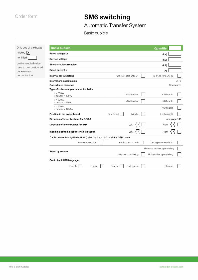
schneider-electric.com160 | SM6 Catalog
Order form
Only one of the boxes
- ticked X
- or filled
by the needed value have to be considered between each horizontal line.
SM6 switchingAutomatic Transfer SystemBasic cubicle
Basic cubicle Quantity
Rated voltage Ur (kV)
Service voltage (kV)
Short-circuit current Isc (kA)
Rated current Ir (A)
Internal arc withstand 12.5 kA 1s for SM6-24 16 kA 1s for SM6-36
Internal arc classification A-FL
Gaz exhaust direction Downwards
Type of cubicle/upper busbar for 24 kV
Ir = 630 A, Ir busbar = 400 A NSM busbar NSM cable
Ir = 630 A, Ir busbar = 630 A NSM busbar NSM cable
Ir = 630 A, Ir busbar = 1250 A NSM cable
Position in the switchboard First on left Middle Last on right
Direction of lower busbars for GBC-A see page 169
Direction of lower busbar for IMM Left Right
Incoming bottom busbar for NSM busbar Left Right
Cable connection by the bottom (cable maximum 240 mm2) for NSM cable
Three core on both Single core on both 2 x single core on both
Stand by sourceGenerator without paralleling
Utility with paralleling Utility without paralleling
Control unit HMI language
French English Spanish Portuguese Chinese
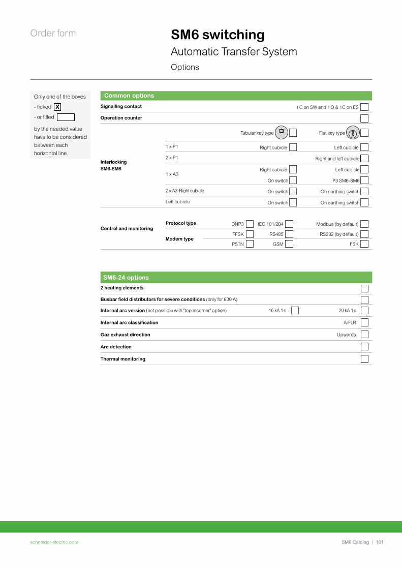
schneider-electric.com | 161SM6 Catalog
Order form
Common options
Signalling contact 1 C on SW and 1 O & 1C on ES
Operation counter
Interlocking SM6-SM6
Tubular key type Flat key type
1 x P1 Right cubicle Left cubicle
2 x P1 Right and left cubicle
1 x A3Right cubicle Left cubicle
On switch P3 SM6-SM6
2 x A3 Right cubicle On switch On earthing switch
Left cubicle On switch On earthing switch
Control and monitoringProtocol type DNP3 IEC 101/204 Modbus (by default)
Modem typeFFSK RS485 RS232 (by default)
PSTN GSM FSK
Only one of the boxes
- ticked X
- or filled
by the needed value have to be considered between each horizontal line.
SM6 switchingAutomatic Transfer SystemOptions
SM6-24 options
2 heating elements
Busbar field distributors for severe conditions (only for 630 A)
Internal arc version (not possible with "top incomer" option) 16 kA 1 s 20 kA 1 s
Internal arc classification A-FLR
Gaz exhaust direction Upwards
Arc detection
Thermal monitoring
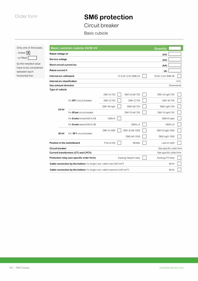
schneider-electric.com162 | SM6 Catalog
Order form SM6 protectionCircuit breakerBasic cubicle
Basic common cubicle 24/36 kV Quantity
Rated voltage Ur (kV)
Service voltage (kV)
Short-circuit current Isc (kA)
Rated current Ir (A)
Internal arc withstand 12.5 kA 1s for SM6-24 16 kA 1s for SM6-36
Internal arc classification A-FL
Gaz exhaust direction Downwards
Type of cubicle
24 kV
For SF1 circuit breaker
DM1-A 750 DM1-D left 750 DM1-D right 750
DM1-S 750 DM1-Z 750 DM1-W 750
DM1-M right DM2 left 750 DM2 right 750
For SFset circuit breaker DM1-D left 750 DM1-D right 750
For Evolis frontal 630 A CB DMV-A DMV-D right
For Evolis lateral 630 A CB DMVL-A DMVL-D
36 kV For SF1 circuit breakerDM1-A 1000 DM1-D left 1000 DM1-D right 1000
DM2 left 1500 DM2 right 1500
Position in the switchboard First on left Middle Last on right
Circuit breaker See specific order form
Current transformers (CT) and LPCTs See specific order form
Protection relay (see specific order form) Easergy Sepam relay Easergy P3 relay
Cable connection by the bottom (1x single core, cable maxi 240 mm2) 36 kV
Cable connection by the bottom (1x single core, cable maximum 240 mm2) 36 kV
Only one of the boxes
- ticked X
- or filled
by the needed value have to be considered between each horizontal line.
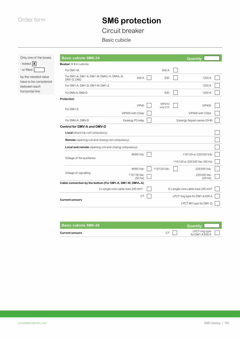
schneider-electric.com | 163SM6 Catalog
Order form SM6 protectionCircuit breakerBasic cubicle
Basic cubicle SM6-36 Quantity
Current sensors CT LPCT ring type for DM1-A 630 A
Basic cubicle SM6-24 Quantity Busbar (Ir u Ir cubicle)
For DM1-M 630 A
For DM1-A, DM1-S, DM1-W, DMVL-A, DMVL-D, DM1-D, DM2 400 A 630 1250 A
For DM1-A, DM1-D, DM1-W, DM1-Z 1250 A
For DMV-A, DMV-D 630 1250 A
Protection
For DM1-SVIP45 VIP410
only D1SVIP400
VIP400 with CGas v VIP400 with CGbs
For DMV-A, DMV-D Easergy P3 relay Easergy Sepam series 20/40
Control for DMV-A and DMV-D
Local (shunt trip coil compulsory)
Remote (opening coil and closing coil compulsory)
Local and remote (opening coil and closing compulsory)
Voltage of the auxiliaries48/60 Vdc 110/125 or 220/250 Vdc
110/130 or 220/240 Vac (50 Hz)
Voltage of signalling48/60 Vdc 110/125 Vdc 220/250 Vdc
110/130 Vac (50 Hz)
220/240 Vac (50 Hz)
Cable connection by the bottom (For DM1-A, DM1-W, DMVL-A)
3 x single core cable maxi 240 mm2 6 x single core cable maxi 240 mm2
Current sensorsCT LPCT ring type for DM1-A 630 A
LPCT MV type for DM1-D
Only one of the boxes
- ticked X
- or filled
by the needed value have to be considered between each horizontal line.
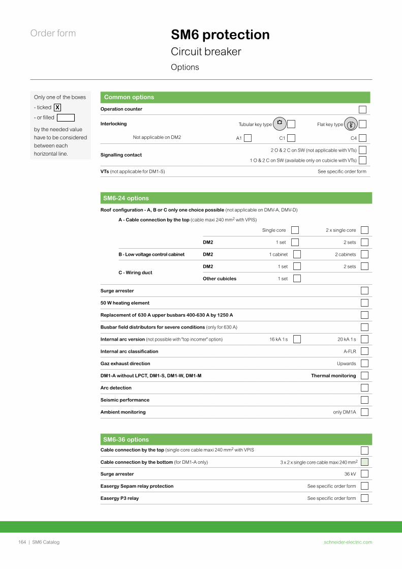
schneider-electric.com164 | SM6 Catalog
Order form SM6 protectionCircuit breakerOptions
Common options
Operation counter
Interlocking Tubular key type Flat key type
Not applicable on DM2 A1 C1 C4
Signalling contact2 O & 2 C on SW (not applicable with VTs)
1 O & 2 C on SW (available only on cubicle with VTs)
VTs (not applicable for DM1-S) See specific order form
SM6-24 options
Roof configuration - A, B or C only one choice possible (not applicable on DMV-A, DMV-D)
A - Cable connection by the top (cable maxi 240 mm2 with VPIS)
Single core 2 x single core
DM2 1 set 2 sets
B - Low voltage control cabinet DM2 1 cabinet 2 cabinets
C - Wiring ductDM2 1 set 2 sets
Other cubicles 1 set
Surge arrester
50 W heating element
Replacement of 630 A upper busbars 400-630 A by 1250 A
Busbar field distributors for severe conditions (only for 630 A)
Internal arc version (not possible with "top incomer" option) 16 kA 1 s 20 kA 1 s
Internal arc classification A-FLR
Gaz exhaust direction Upwards
DM1-A without LPCT, DM1-S, DM1-W, DM1-M Thermal monitoring
Arc detection
Seismic performance
Ambient monitoring only DM1A
Only one of the boxes
- ticked X
- or filled
by the needed value have to be considered between each horizontal line.
SM6-36 options
Cable connection by the top (single core cable maxi 240 mm2 with VPIS
Cable connection by the bottom (for DM1-A only) 3 x 2 x single core cable maxi 240 mm2
Surge arrester 36 kV
Easergy Sepam relay protection See specific order form
Easergy P3 relay See specific order form
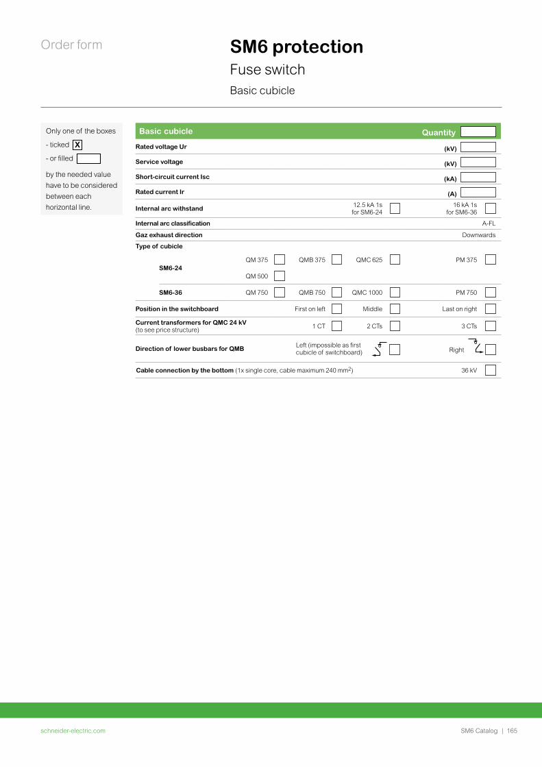
schneider-electric.com | 165SM6 Catalog
Order form SM6 protectionFuse switchBasic cubicle
Only one of the boxes
- ticked X
- or filled
by the needed value have to be considered between each horizontal line.
Basic cubicle Quantity
Rated voltage Ur (kV)
Service voltage (kV)
Short-circuit current Isc (kA)
Rated current Ir (A)
Internal arc withstand 12.5 kA 1s for SM6-24
16 kA 1s for SM6-36
Internal arc classification A-FL
Gaz exhaust direction Downwards
Type of cubicle
SM6-24QM 375 QMB 375 QMC 625 PM 375
QM 500
SM6-36 QM 750 QMB 750 QMC 1000 PM 750
Position in the switchboard First on left Middle Last on right
Current transformers for QMC 24 kV (to see price structure) 1 CT 2 CTs 3 CTs
Direction of lower busbars for QMB
Left (impossible as first cubicle of switchboard) Right
Cable connection by the bottom (1x single core, cable maximum 240 mm2) 36 kV
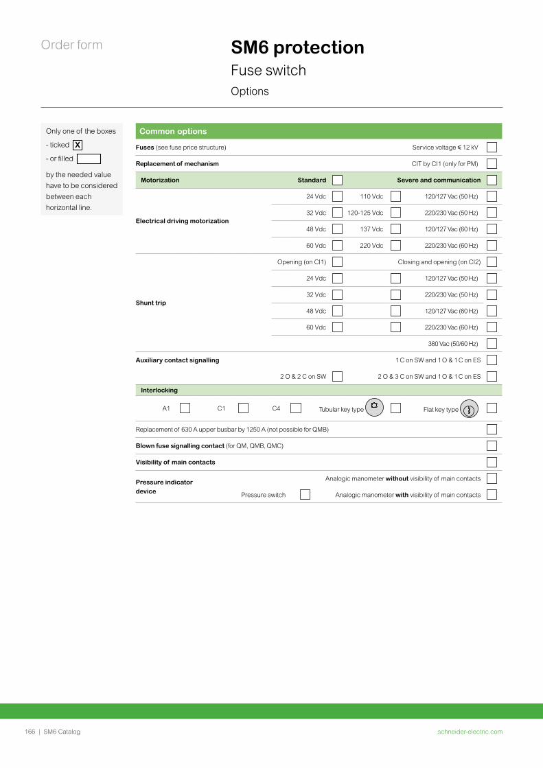
schneider-electric.com166 | SM6 Catalog
Order form SM6 protectionFuse switchOptions
Common options
Fuses (see fuse price structure) Service voltage y 12 kV
Replacement of mechanism CIT by CI1 (only for PM)
Motorization Standard Severe and communication
Electrical driving motorization
24 Vdc 110 Vdc 120/127 Vac (50 Hz)
32 Vdc 120-125 Vdc 220/230 Vac (50 Hz)
48 Vdc 137 Vdc 120/127 Vac (60 Hz)
60 Vdc 220 Vdc 220/230 Vac (60 Hz)
Shunt trip
Opening (on CI1) Closing and opening (on CI2)
24 Vdc 120/127 Vac (50 Hz)
32 Vdc 220/230 Vac (50 Hz)
48 Vdc 120/127 Vac (60 Hz)
60 Vdc 220/230 Vac (60 Hz)
380 Vac (50/60 Hz)
Auxiliary contact signalling 1 C on SW and 1 O & 1 C on ES
2 O & 2 C on SW 2 O & 3 C on SW and 1 O & 1 C on ES
Interlocking
A1 C1 C4 Tubular key type Flat key type
Replacement of 630 A upper busbar by 1250 A (not possible for QMB)
Blown fuse signalling contact (for QM, QMB, QMC)
Visibility of main contacts
Pressure indicator device
Analogic manometer without visibility of main contacts
Pressure switch Analogic manometer with visibility of main contacts
Only one of the boxes
- ticked X
- or filled
by the needed value have to be considered between each horizontal line.
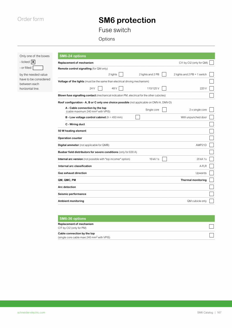
schneider-electric.com | 167SM6 Catalog
Order form SM6 protectionFuse switchOptions
Only one of the boxes
- ticked X
- or filled
by the needed value have to be considered between each horizontal line.
SM6-36 optionsReplacement of mechanism CIT by CI2 (only for PM)
Cable connection by the top (single core cable maxi 240 mm2 with VPIS)
SM6-24 options
Replacement of mechanism CI1 by CI2 (only for QM)
Remote control signalling (for QM only)
2 lights 2 lights and 2 PB 2 lights and 2 PB + 1 switch
Voltage of the lights (must be the same than electrical driving mechanism)
24 V 48 V 110/125 V 220 V
Blown fuse signalling contact (mechanical indication PM, electrical for the other cubicles)
Roof configuration - A, B or C only one choice possible (not applicable on DMV-A, DMV-D)
A - Cable connection by the top (cable maximum 240 mm2 with VPIS)
Single core 2 x single core
B - Low voltage control cabinet (h = 450 mm) With unpunched door
C - Wiring duct
50 W heating element
Operation counter
Digital ammeter (not applicable for QMB) AMP21D
Busbar field distributors for severe conditions (only for 630 A)
Internal arc version (not possible with "top incomer" option) 16 kA 1 s 20 kA 1 s
Internal arc classification A-FLR
Gaz exhaust direction Upwards
QM, QMC, PM Thermal monitoring
Arc detection
Seismic performance
Ambient monitoring QM cubicle only
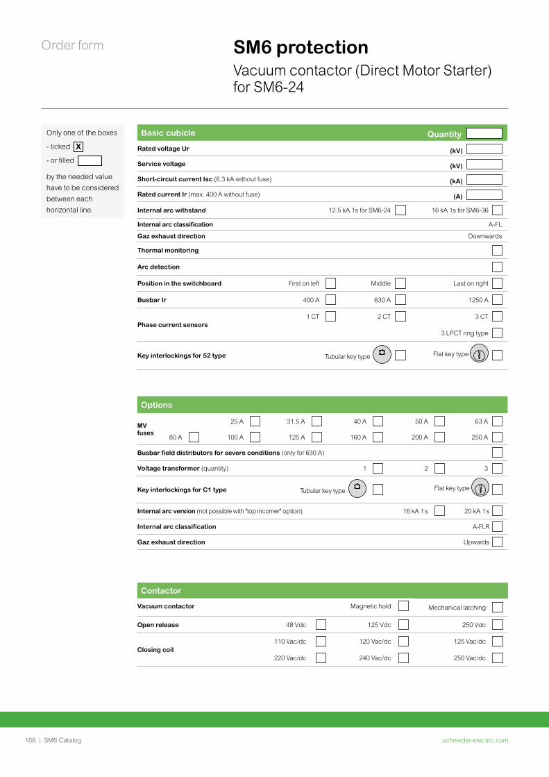
schneider-electric.com168 | SM6 Catalog
Order form SM6 protectionVacuum contactor (Direct Motor Starter) for SM6-24
Only one of the boxes
- ticked X
- or filled
by the needed value have to be considered between each horizontal line.
Contactor
Vacuum contactor Magnetic hold Mechanical latching
Open release 48 Vdc 125 Vdc 250 Vdc
Closing coil110 Vac/dc 120 Vac/dc 125 Vac/dc
220 Vac/dc 240 Vac/dc 250 Vac/dc
Options
MV fuses
25 A 31.5 A 40 A 50 A 63 A
80 A 100 A 125 A 160 A 200 A 250 A
Busbar field distributors for severe conditions (only for 630 A)
Voltage transformer (quantity) 1 2 3
Key interlockings for C1 type Tubular key type Flat key type
Internal arc version (not possible with "top incomer" option) 16 kA 1 s 20 kA 1 s
Internal arc classification A-FLR
Gaz exhaust direction Upwards
Basic cubicle Quantity
Rated voltage Ur (kV)
Service voltage (kV)
Short-circuit current Isc (6.3 kA without fuse) (kA)
Rated current Ir (max. 400 A without fuse) (A)
Internal arc withstand 12.5 kA 1s for SM6-24 16 kA 1s for SM6-36
Internal arc classification A-FL
Gaz exhaust direction Downwards
Thermal monitoring
Arc detection
Position in the switchboard First on left Middle Last on right
Busbar Ir 400 A 630 A 1250 A
Phase current sensors1 CT 2 CT 3 CT
3 LPCT ring type
Key interlockings for 52 type Tubular key type Flat key type
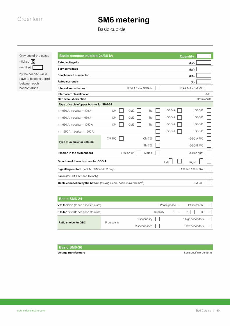
schneider-electric.com | 169SM6 Catalog
Order form SM6 meteringBasic cubicle
Only one of the boxes
- ticked X
- or filled
by the needed value have to be considered between each horizontal line.
Basic common cubicle 24/36 kV Quantity
Rated voltage Ur (kV)
Service voltage (kV)
Short-circuit current Isc (kA)
Rated current Ir (A)
Internal arc withstand 12.5 kA 1s for SM6-24 16 kA 1s for SM6-36
Internal arc classification A-FL
Gaz exhaust direction Downwards
Type of cubicle/upper busbar for SM6-24
Ir = 630 A, Ir busbar = 400 A CM CM2 TM GBC-A GBC-B
Ir = 630 A, Ir busbar = 630 A CM CM2 TM GBC-A GBC-B
Ir = 630 A, Ir busbar = 1250 A CM CM2 TM GBC-A GBC-B
Ir = 1250 A, Ir busbar = 1250 A GBC-A GBC-B
Type of cubicle for SM6-36CM 750 CM 750 GBC-A 750
TM 750 GBC-B 750
Position in the switchboard First on left Middle Last on right
Direction of lower busbars for GBC-A Left Right
Signalling contact (for CM, CM2 and TM only) 1 O and 1 C on SW
Fuses (for CM, CM2 and TM only)
Cable connection by the bottom (1x single core, cable maxi 240 mm2) SM6-36
Basic SM6-36Voltage transformers See specific order form
Basic SM6-24
VTs for GBC (to see price structure) Phase/phase Phase/earth
CTs for GBC (to see price structure) Quantity 1 2 3
Ratio choice for GBC Protections1 secondary 1 high secondary
2 secondaries 1 low secondary
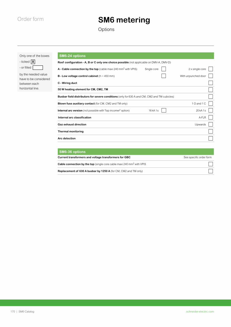
schneider-electric.com170 | SM6 Catalog
Order form SM6 meteringOptions
SM6-36 options
Current transformers and voltage transformers for GBC See specific order form
Cable connection by the top (single core cable maxi 240 mm2 with VPIS
Replacement of 630 A busbar by 1250 A (for CM, CM2 and TM only)
SM6-24 options
Roof configuration - A, B or C only one choice possible (not applicable on DMV-A, DMV-D)
A - Cable connection by the top (cable maxi 240 mm2 with VPIS) Single core 2 x single core
B - Low voltage control cabinet (h = 450 mm) With unpunched door
C - Wiring duct
50 W heating element for CM, CM2, TM
Busbar field distributors for severe conditions (only for 630 A and CM, CM2 and TM cubicles)
Blown fuse auxiliary contact (for CM, CM2 and TM only) 1 O and 1 C
Internal arc version (not possible with "top incomer" option) 16 kA 1 s 20 kA 1 s
Internal arc classification A-FLR
Gaz exhaust direction Upwards
Thermal monitoring
Arc detection
Only one of the boxes
- ticked X
- or filled
by the needed value have to be considered between each horizontal line.
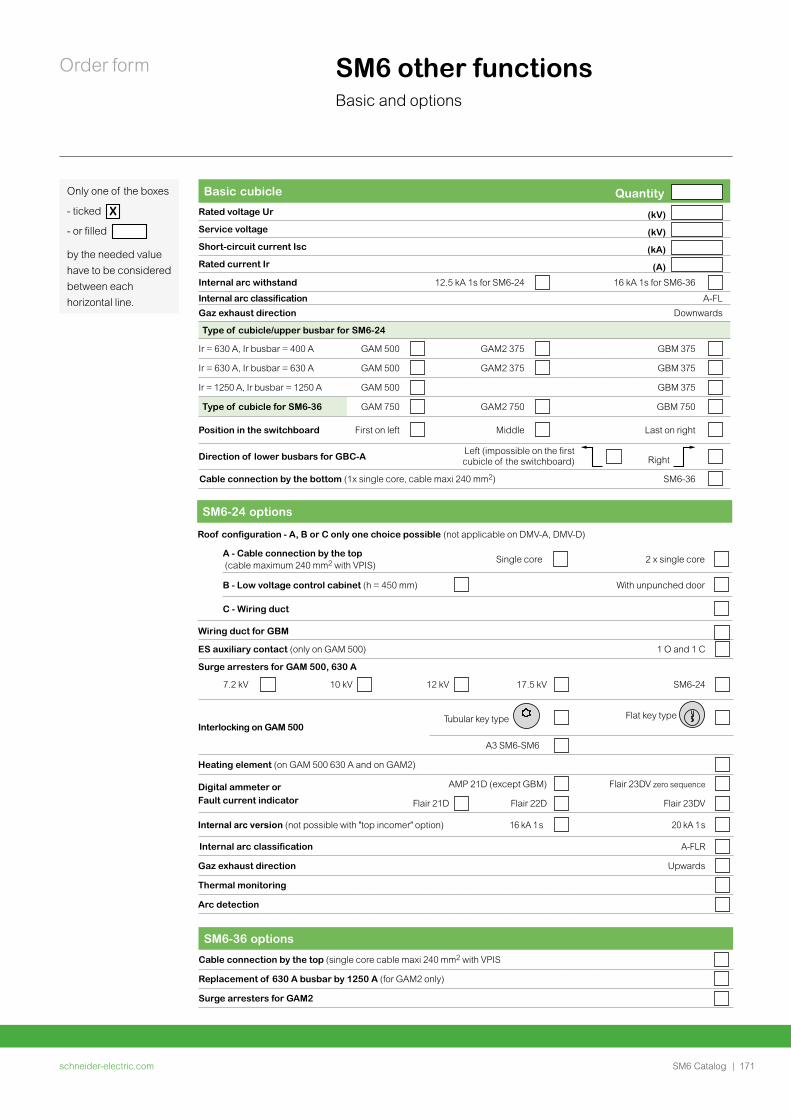
schneider-electric.com | 171SM6 Catalog
Order form SM6 other functionsBasic and options
Only one of the boxes
- ticked X
- or filled
by the needed value have to be considered between each horizontal line.
Basic cubicle Quantity Rated voltage Ur (kV)
Service voltage (kV)
Short-circuit current Isc (kA)
Rated current Ir (A)
Internal arc withstand 12.5 kA 1s for SM6-24 16 kA 1s for SM6-36
Internal arc classification A-FL
Gaz exhaust direction Downwards
Type of cubicle/upper busbar for SM6-24
Ir = 630 A, Ir busbar = 400 A GAM 500 GAM2 375 GBM 375
Ir = 630 A, Ir busbar = 630 A GAM 500 GAM2 375 GBM 375
Ir = 1250 A, Ir busbar = 1250 A GAM 500 GBM 375
Type of cubicle for SM6-36 GAM 750 GAM2 750 GBM 750
Position in the switchboard First on left Middle Last on right
Direction of lower busbars for GBC-A Left (impossible on the first cubicle of the switchboard) Right
Cable connection by the bottom (1x single core, cable maxi 240 mm2) SM6-36
SM6-36 options
Cable connection by the top (single core cable maxi 240 mm2 with VPIS
Replacement of 630 A busbar by 1250 A (for GAM2 only)
Surge arresters for GAM2
SM6-24 options
Wiring duct for GBM
ES auxiliary contact (only on GAM 500) 1 O and 1 C
Surge arresters for GAM 500, 630 A
7.2 kV 10 kV 12 kV 17.5 kV SM6-24
Interlocking on GAM 500Tubular key type Flat key type
A3 SM6-SM6
Heating element (on GAM 500 630 A and on GAM2)
Digital ammeter or Fault current indicator
AMP 21D (except GBM) Flair 23DV zero sequence
Flair 21D Flair 22D Flair 23DV
Internal arc version (not possible with "top incomer" option) 16 kA 1 s 20 kA 1 s
Internal arc classification A-FLR
Gaz exhaust direction Upwards
Thermal monitoring
Arc detection
Roof configuration - A, B or C only one choice possible (not applicable on DMV-A, DMV-D)
A - Cable connection by the top (cable maximum 240 mm2 with VPIS)
Single core 2 x single core
B - Low voltage control cabinet (h = 450 mm) With unpunched door
C - Wiring duct
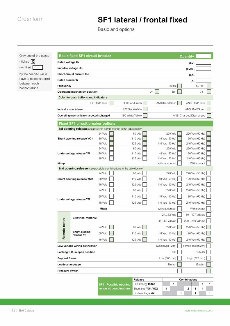
schneider-electric.com172 | SM6 Catalog
Order form SF1 lateral / frontal fixedBasic and options
Only one of the boxes
- ticked X
- or filled
by the needed value have to be considered between each horizontal line.
Basic fixed SF1 circuit breaker Quantity
Rated voltage Ur (kV)
Impulse voltage Up (kVbil)
Short-circuit current Isc (kA)
Rated current Ir (A)
Frequency 50 Hz 60 Hz
Operating mechanism position A1 B1 C1
Color for push buttons and indicators
IEC Red/Black IEC Red/Green ANSI Red/Green ANSI Red/Black
Indicator open/close IEC Black/White ANSI Red/Green
Operating mechanism charged/discharged IEC White/Yellow ANSI Charged/Discharged
Fixed SF1 circuit breaker options1st opening release (see possible combinations in the table below)
Shunt opening release YO1
24 Vdc 60 Vdc 220 Vdc 220 Vac (50 Hz)
30 Vdc 110 Vdc 48 Vac (50 Hz) 120 Vac (60 Hz)
48 Vdc 125 Vdc 110 Vac (50 Hz) 240 Vac (60 Hz)
Undervoltage release YM
24 Vdc 60 Vdc 220 Vdc 220 Vac (50 Hz)
30 Vdc 110 Vdc 48 Vac (50 Hz) 120 Vac (60 Hz)
48 Vdc 125 Vdc 110 Vac (50 Hz) 240 Vac (60 Hz)
Mitop Without contact With contact
2nd opening release (see possible combinations in the table below)
Shunt opening release YO2
24 Vdc 60 Vdc 220 Vdc 220 Vac (50 Hz)
30 Vdc 110 Vdc 48 Vac (50 Hz) 120 Vac (60 Hz)
48 Vdc 125 Vdc 110 Vac (50 Hz) 240 Vac (60 Hz)
Undervoltage release YM
24 Vdc 60 Vdc 220 Vdc 220 Vac (50 Hz)
30 Vdc 110 Vdc 48 Vac (50 Hz) 120 Vac (60 Hz)
48 Vdc 125 Vdc 110 Vac (50 Hz) 240 Vac (60 Hz)
Mitop Without contact With contact
Electrical motor M24…32 Vdc 110…127 Vdc/ac
48…60 Vdc/ac 220…250 Vdc/ac
Shunt closing release YF
24 Vdc 60 Vdc 220 Vdc 220 Vac (50 Hz)
30 Vdc 110 Vdc 48 Vac (50 Hz) 120 Vac (60 Hz)
48 Vdc 125 Vdc 110 Vac (50 Hz) 240 Vac (60 Hz)
Low voltage wiring connection Male plug (1.2 m) Female socket (2 m)
Locking C.B. in open position Flat Tubular
Support frame Low (560 mm) High (775 mm)
Leaflets language French English
Pressure switch
Rem
ote
con
trol
SF1 - Possible opening releases combinations
Release Combinations
Low energy Mitop 1 1 1
Shunt trip YO1/YO2 1 2 1 1
Undervoltage YM 1 1 1
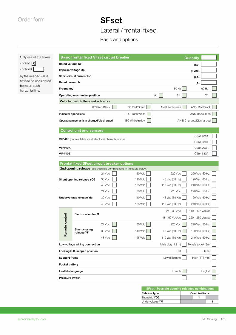
schneider-electric.com | 173SM6 Catalog
Order form
Only one of the boxes
- ticked X
- or filled
by the needed value have to be considered between each horizontal line.
SFset Lateral / frontal fixedBasic and options
Basic frontal fixed SFset circuit breaker Quantity
Rated voltage Ur (kV)
Impulse voltage Up (kVbil)
Short-circuit current Isc (kA)
Rated current Ir (A)
Frequency 50 Hz 60 Hz
Operating mechanism position A1 B1 C1
Color for push buttons and indicators
IEC Red/Black IEC Red/Green ANSI Red/Green ANSI Red/Black
Indicator open/close IEC Black/White ANSI Red/Green
Operating mechanism charged/discharged IEC White/Yellow ANSI Charged/Discharged
Control unit and sensors
VIP 400 (not available for all electrical characteristics)CSa4 200A
CSb4 630A
VIP410A CSa4 200A
VIP410E CSb4 630A
Frontal fixed SFset circuit breaker options2nd opening release (see possible combinations in the table below)
Shunt opening release YO2
24 Vdc 60 Vdc 220 Vdc 220 Vac (50 Hz)
30 Vdc 110 Vdc 48 Vac (50 Hz) 120 Vac (60 Hz)
48 Vdc 125 Vdc 110 Vac (50 Hz) 240 Vac (60 Hz)
Undervoltage release YM
24 Vdc 60 Vdc 220 Vdc 220 Vac (50 Hz)
30 Vdc 110 Vdc 48 Vac (50 Hz) 120 Vac (60 Hz)
48 Vdc 125 Vdc 110 Vac (50 Hz) 240 Vac (60 Hz)
Electrical motor M24…32 Vdc 110…127 Vdc/ac
48…60 Vdc/ac 220…250 Vdc/ac
Shunt closing release YF
24 Vdc 60 Vdc 220 Vdc 220 Vac (50 Hz)
30 Vdc 110 Vdc 48 Vac (50 Hz) 120 Vac (60 Hz)
48 Vdc 125 Vdc 110 Vac (50 Hz) 240 Vac (60 Hz)
Low voltage wiring connection Male plug (1.2 m) Female socket (2 m)
Locking C.B. in open position Flat Tubular
Support frame Low (560 mm) High (775 mm)
Pocket battery
Leaflets language French English
Pressure switch
Rem
ote
con
trol
SFset - Possible opening releases combinationsRelease type CombinationsShunt trip YO2 1Undervoltage YM 1
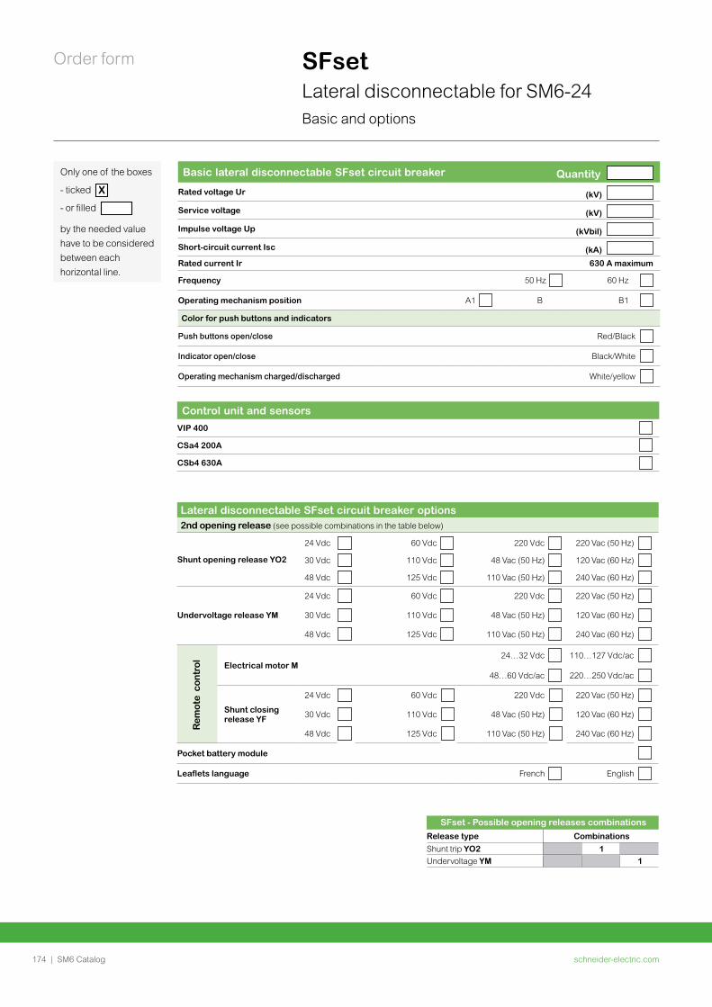
schneider-electric.com174 | SM6 Catalog
Order form SFsetLateral disconnectable for SM6-24Basic and options
Only one of the boxes
- ticked X
- or filled
by the needed value have to be considered between each horizontal line.
Basic lateral disconnectable SFset circuit breaker Quantity
Rated voltage Ur (kV)
Service voltage (kV)
Impulse voltage Up (kVbil)
Short-circuit current Isc (kA)
Rated current Ir 630 A maximum
Frequency 50 Hz 60 Hz
Operating mechanism position A1 B B1
Color for push buttons and indicators
Push buttons open/close Red/Black
Indicator open/close Black/White
Operating mechanism charged/discharged White/yellow
Control unit and sensors
VIP 400
CSa4 200A
CSb4 630A
Lateral disconnectable SFset circuit breaker options2nd opening release (see possible combinations in the table below)
Shunt opening release YO2
24 Vdc 60 Vdc 220 Vdc 220 Vac (50 Hz)
30 Vdc 110 Vdc 48 Vac (50 Hz) 120 Vac (60 Hz)
48 Vdc 125 Vdc 110 Vac (50 Hz) 240 Vac (60 Hz)
Undervoltage release YM
24 Vdc 60 Vdc 220 Vdc 220 Vac (50 Hz)
30 Vdc 110 Vdc 48 Vac (50 Hz) 120 Vac (60 Hz)
48 Vdc 125 Vdc 110 Vac (50 Hz) 240 Vac (60 Hz)
Electrical motor M24…32 Vdc 110…127 Vdc/ac
48…60 Vdc/ac 220…250 Vdc/ac
Shunt closing release YF
24 Vdc 60 Vdc 220 Vdc 220 Vac (50 Hz)
30 Vdc 110 Vdc 48 Vac (50 Hz) 120 Vac (60 Hz)
48 Vdc 125 Vdc 110 Vac (50 Hz) 240 Vac (60 Hz)
Pocket battery module
Leaflets language French English
Rem
ote
con
trol
SFset - Possible opening releases combinationsRelease type CombinationsShunt trip YO2 1Undervoltage YM 1
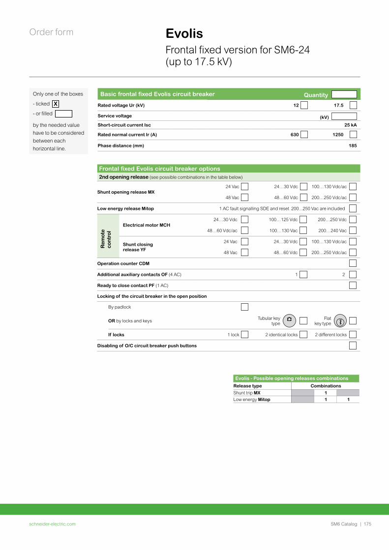
schneider-electric.com | 175SM6 Catalog
Order form
Only one of the boxes
- ticked X
- or filled
by the needed value have to be considered between each horizontal line.
EvolisFrontal fixed version for SM6-24 (up to 17.5 kV)
Basic frontal fixed Evolis circuit breaker Quantity
Rated voltage Ur (kV) 12 17.5
Service voltage (kV)
Short-circuit current Isc 25 kA
Rated normal current Ir (A) 630 1250
Phase distance (mm) 185
Frontal fixed Evolis circuit breaker options2nd opening release (see possible combinations in the table below)
Shunt opening release MX24 Vac 24…30 Vdc 100…130 Vdc/ac
48 Vac 48…60 Vdc 200…250 Vdc/ac
Low energy release Mitop 1 AC fault signalling SDE and reset 200...250 Vac are included
Electrical motor MCH24…30 Vdc 100…125 Vdc 200…250 Vdc
48…60 Vdc/ac 100…130 Vac 200…240 Vac
Shunt closing release YF
24 Vac 24…30 Vdc 100…130 Vdc/ac
48 Vac 48…60 Vdc 200…250 Vdc/ac
Operation counter CDM
Additional auxiliary contacts OF (4 AC) 1 2
Ready to close contact PF (1 AC)
Locking of the circuit breaker in the open position
By padlock
OR by locks and keys Tubular key type
Flat key type
If locks 1 lock 2 identical locks 2 different locks
Disabling of O/C circuit breaker push buttons
Rem
ote
co
ntro
l
Evolis - Possible opening releases combinationsRelease type CombinationsShunt trip MX 1Low energy Mitop 1 1
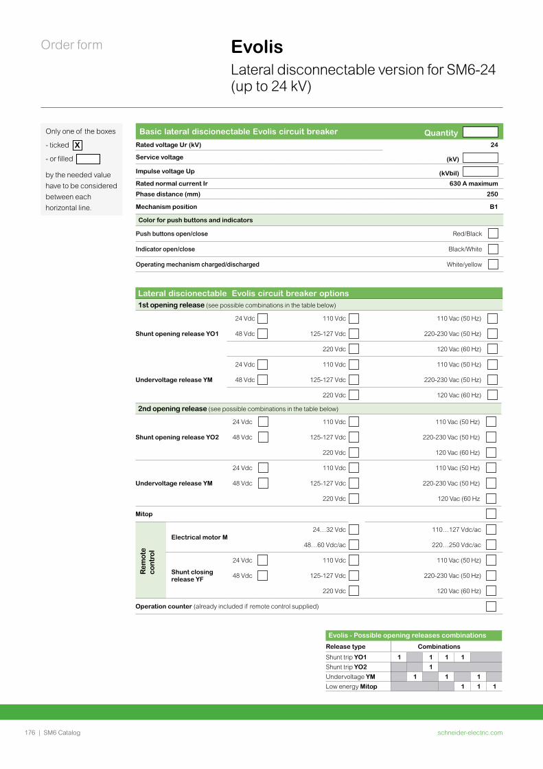
schneider-electric.com176 | SM6 Catalog
Order form Evolis Lateral disconnectable version for SM6-24 (up to 24 kV)
Only one of the boxes
- ticked X
- or filled
by the needed value have to be considered between each horizontal line.
Basic lateral discionectable Evolis circuit breaker Quantity Rated voltage Ur (kV) 24
Service voltage (kV)
Impulse voltage Up (kVbil)
Rated normal current Ir 630 A maximum
Phase distance (mm) 250
Mechanism position B1
Color for push buttons and indicators
Push buttons open/close Red/Black
Indicator open/close Black/White
Operating mechanism charged/discharged White/yellow
Lateral discionectable Evolis circuit breaker options1st opening release (see possible combinations in the table below)
Shunt opening release YO1
24 Vdc 110 Vdc 110 Vac (50 Hz)
48 Vdc 125-127 Vdc 220-230 Vac (50 Hz)
220 Vdc 120 Vac (60 Hz)
Undervoltage release YM
24 Vdc 110 Vdc 110 Vac (50 Hz)
48 Vdc 125-127 Vdc 220-230 Vac (50 Hz)
220 Vdc 120 Vac (60 Hz)
Electrical motor M24…32 Vdc 110…127 Vdc/ac
48…60 Vdc/ac 220…250 Vdc/ac
Shunt closing release YF
24 Vdc 110 Vdc 110 Vac (50 Hz)
48 Vdc 125-127 Vdc 220-230 Vac (50 Hz)
220 Vdc 120 Vac (60 Hz)
Operation counter (already included if remote control supplied)
Rem
ote
cont
rol
2nd opening release (see possible combinations in the table below)
Shunt opening release YO2
24 Vdc 110 Vdc 110 Vac (50 Hz)
48 Vdc 125-127 Vdc 220-230 Vac (50 Hz)
220 Vdc 120 Vac (60 Hz)
Undervoltage release YM
24 Vdc 110 Vdc 110 Vac (50 Hz)
48 Vdc 125-127 Vdc 220-230 Vac (50 Hz)
220 Vdc 120 Vac (60 Hz
Mitop
Evolis - Possible opening releases combinations
Release type Combinations
Shunt trip YO1 1 1 1 1Shunt trip YO2 1Undervoltage YM 1 1 1Low energy Mitop 1 1 1
PM
1086
34
SM6 all-in-one

schneider-electric.com178 | SM6 Catalog
This international web site allows you to access all the Schneider Electric solutions and product information via:• Comprehensive descriptions• Range datasheets• A download area• Product selectors
You can also access information dedicated to your business and contact your Schneider Electric country support.
PM
1036
87
TOOLS
schneider-electric.com | 179SM6 Catalog
Web selector
Training
This site allows you to access the Schneider Electric products in just two clicks via a comprehensive range of datasheets, with direct links to:• Complete libraries: technical documents, catalogs,
FAQs, brochures• Selection guides from the e-catalog• Product discovery sites and their animationsYou will also find illustrated overviews, news to which you can subscribe, and a list of country contacts
Training allows you to acquire the expertise (installation design, work with power on, etc.) to increase efficiency and improve customer service.
The training catalog includes beginner’s courses in electrical distribution, knowledge of MV and LV switchgear, operation and maintenance of installations, and design of LV installations to give a few examples.
TOOLS

ART16044
Schneider Electric Industries SAS
35 rue Joseph Monier92500 Rueil-Malmaison, FranceTel : +33 (0)1 41 29 70 00
www.schneider-electric.com
10, July, 2020
©2020 Schneider Electric SE. All rights reserved. All Schneider Electric trademarks and service marks are the property of Schneider Electric SE, its subsidiaries and affiliated companies.
AMTED398078EN