SM6 modular units - more-energy.com.mx
144
SM6 modular units Air insulated switchgear up to 36 kV Medium Voltage Distribution schneider-electric.com Catalogue 2015
-
Upload
khangminh22 -
Category
Documents
-
view
1 -
download
0
Transcript of SM6 modular units - more-energy.com.mx
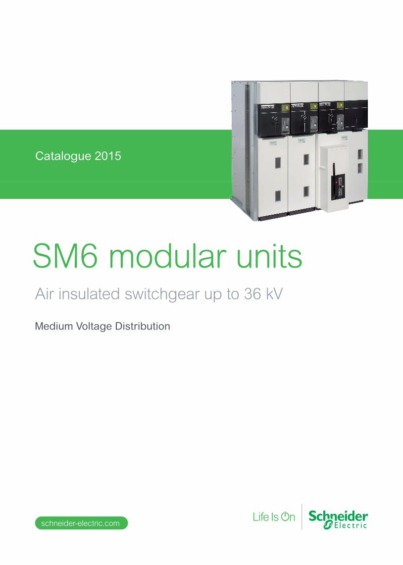
SM6 modular unitsAir insulated switchgear up to 36 kV
Medium Voltage Distribution
schneider-electric.com
Catalogue 2015

schneider-electric.com SM6 catalogue 3
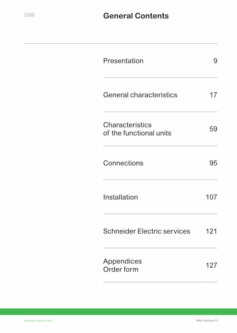
General ContentsSM6
Presentation 9
General characteristics 17
Characteristics of the functional units 59
Connections 95
Installation 107
Schneider Electric services 121
Appendices Order form 127
4 schneider-electric.com
Your requirementsSM6
Reliability
Safety
Flexibility
4 SM6 catalogue schneider-electric.com
Our solutions SM6
• 1,400,000 functions installed world-wide
• 100% factory-tested without the need for further tests on site.
•Enclosures able to withstand internal arcing 3 or 4 sides internal arc protection IAC: A-FL and A-FLR. Internal arc withstand: 12.5 kA 1s, 16 kA 1s and 20 kA 1s
•Mechanical and electrical interlocks, to prevent incorrect operations.
• Easy upgraded to meet your need and adapted to the extension of your installations
• Integration in factory-built outdoor substations for which the SM6 is particularly well designed.
schneider-electric.com SM6 catalogue 5

6 SM6 catalogue schneider-electric.com
SM6, a truly professional solution!More than 1,400,000 cubicles installed world-wide.
schneider-electric.com SM6 catalogue 7
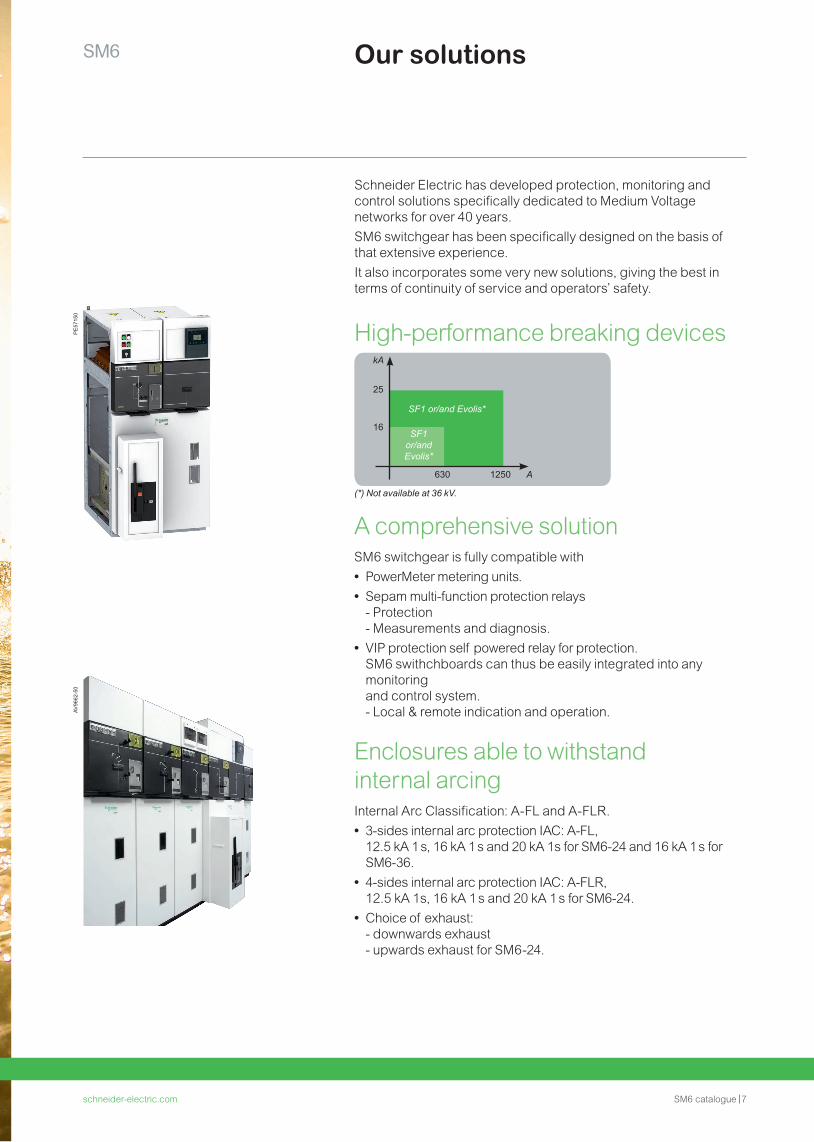
Our solutions
Schneider Electric has developed protection, monitoring and control solutions specifically dedicated to Medium Voltage networks for over 40 years. SM6 switchgear has been specifically designed on the basis of that extensive experience. It also incorporates some very new solutions, giving the best in terms of continuity of service and operators’ safety.
A comprehensive solutionSM6 switchgear is fully compatible with • PowerMeter metering units. • Sepam multi-function protection relays- Protection- Measurements and diagnosis.
• VIP protection self powered relay for protection.SM6 swithchboards can thus be easily integrated into any monitoring and control system.- Local & remote indication and operation.
Enclosures able to withstand internal arcingInternal Arc Classification: A-FL and A-FLR. • 3-sides internal arc protection IAC: A-FL, 12.5 kA 1 s, 16 kA 1 s and 20 kA 1s for SM6-24 and 16 kA 1 s for SM6-36.
• 4-sides internal arc protection IAC: A-FLR, 12.5 kA 1s, 16 kA 1 s and 20 kA 1 s for SM6-24.
• Choice of exhaust:- downwards exhaust - upwards exhaust for SM6-24.
High-performance breaking devicesPE
5715
0AV
9662
-50
630
16
25
kA
1250 A
SF1 or/and Evolis*
SF1 or/and Evolis*
(*) Not available at 36 kV.
SM6

8 SM6 catalogue schneider-electric.com8
Presentation
schneider-electric.com SM6 catalogue 9
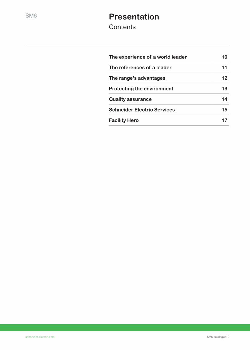
SM6 PresentationContents
The experience of a world leader 10
The references of a leader 11
The range’s advantages 12
Protecting the environment 13
Quality assurance 14
Schneider Electric Services 15
Facility Hero 17
10 SM6 catalogue schneider-electric.com10
SM6Presentation
The experience of a world leader
This experience means that today Schneider Electric can propose a complementary range: vacuum type circuit breaker cubicles up to 24 kV and standard or enhanced internal arc withstand cubicles to reinforce the safety of people according to the IEC standard.
This gives you the advantage of unique experience, that of a world leader, with over 2,500 000 SF6 Medium Voltage units installed throughout the world.
Putting this experience at your service and remaining attentive to your requirements is the spirit of active partnership that we want to develop in offering you the SM6.
The modular SM6 is a range of harmonised cubicles equipped with SF6 or vacuum breaking technology switchgear with 30 years life span.
These cubicles allow you to produce all your Medium Voltage substation requirements up to 36 kV by superposing their various functions. The result of in-depth analysis of your requirements, both now and in the future, SM6 cubicles mean that you can take advantage of all the features of both a modern and proven technology.
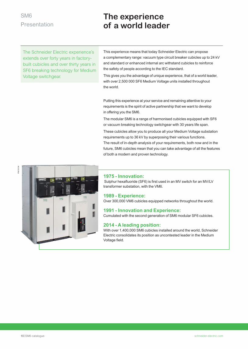
1975 - Innovation: Sulphur hexafluoride (SF6) is first used in an MV switch for an MV/LV transformer substation, with the VM6.
1989 - Experience: Over 300,000 VM6 cubicles equipped networks throughout the world.
1991 - Innovation and Experience: Cumulated with the second generation of SM6 modular SF6 cubicles.
2014 - A leading position: With over 1,400,000 SM6 cubicles installed around the world, Schneider Electric consolidates its position as uncontested leader in the Medium Voltage field.
The Schneider Electric experience’s extends over forty years in factory-built cubicles and over thirty years in SF6 breaking technology for Medium Voltage switchgear.
PM
1031
94
schneider-electric.com SM6 catalogue 11
SM6Presentation
Asia/Middle East • Canal Electrical Distribution Company, Egypt • General Motors Holden, Australia • Pasteur Institute, Cambodia • Tian he City, China • Sanya Airport, China • Bank of China, Beijing, Jv Yanta, China • Plaza Hotel, Jakarta, Indonesia • Bali Airport, Indonesia • Wakasa Control Center, Japan • Otaru Shopping center, Japan • New City of Muang, Thong Than, Kanjanapas, Thailand • Danang and Quinhon Airport, Vanad, Vietnam • British Embassy, Oman • KBF Palace Riyadh, Saudi Arabia • Raka Stadium, Saudi Arabia • Bilkent University, Turkey • TADCO, BABOIL development, United Arab Emirates • Melbourne Tunnel City Link, Australia • Campus KSU Qassim Riyad, Saudi Arabia
Africa • ONAFEX, Hilton Hotel, Algeria • Yaounde University, Cameroon • Karoua Airport, Cameroon • Libreville Airport, Gabon • Ivarto Hospital, CORIF, Madagascar • Central Bank of Abuja, ADEFEMI, Nigeria • OCI Dakar, Oger international, CGE, Senegal • Bamburi cement Ltd, Kenya • Ivory Electricity Company, Ivory Coast • Exxon, New Headquarters, Angola
South America/Pacific • Lamentin Airport, CCIM, Martinique • Space Centre, Kourou, Guyana • Mexico City Underground System, Mexico • Santiago Underground System, Chile • Cohiba Hotel, Havana, Cuba • Iberostar Hotel, Bavaro, Dominican Republic • Aluminio Argentino Saic SA, Argentina • Michelin Campo Grande, Rio de Janeiro, Brazil • TIM Data Center, São Paulo, Brazil • Light Rio de Janeiro, Brazil • Hospital Oswaldo Cruz, São Paulo, Brazil
Europe • Stade de France, Paris, France • EDF, France • Eurotunnel, France • Nestlé company headquarters, France • TLM Terminal , Folkestone, Great Britain • Zaventem Airport, Belgium • Krediebank Computer Centre, Belgium • Bucarest Pumping station, Romania • Prague Airport, Czech Republic • Philipp Morris St Petersburg, Russia • Kremlin Moscow, Russia • Madrid airport, Spain • Dacia Renault, Romania • Lafarge cement Cirkovic, Czech Republic • Caterpillar St Petersburg, Russia • Ikea Kazan, Russia • Barajas airport, Spain • Coca-cola Zurich, Switzerland
The references of a leaderSM6, a world-wide product
12 SM6 catalogue schneider-electric.com
SM6Presentation
The range’s advantages
Ease and safe to operateSM6, a proven range • A three position switch to block incorrect switching • The earthing disconnector has full closing capacity • Positive breaking of position indicators • Internal arc withstand in the cable and connection compartments • Clear and animated display diagrams • Switching lever with an "anti-reflex" function • Compartmented cubicles.
SM6: a range designed with control and monitoring in mindSM6 switchgear is perfectly adapted to control and monitoring applications. Motorised, either when installed or at a later date on-site without any interruption in service, SM6 combines with the Easergy T200 remote control interface. You therefore benefit from a ready-to connect unit that is easy to incorporate providing guaranteed switchgear operation.
CompactnessSM6, an optimised range • Compact units, with low increment cubicles • Rationalised space requirement for switchboard installation • Reduction of civil works costs • Easy integration in factory-built outdoor substations for which the SM6 is particularly well designed.
UpgradabilitySM6, a comprehensive range • A comprehensive offer covering your present and future requirements • A design adapted to the extension of your installations • A catalogue of functions for all your applications • A product designed to be in compliance with standards constraints • Options to anticipate the control and monitoring of your installations.
MaintenanceSM6, a range with reduced maintenance • The active parts (breaking and earthing) are integrated in an SF6-filled, "sealed for life" unit
• The control mechanisms, are intented to function with reduced maintenance under normal operating conditions
• Enhanced electrical endurance when breaking.
schneider-electric.com SM6 catalogue 13
SM6Presentation
Protecting the environment
6101
6N
Schneider Electric is committed to a long-term environmental approach.All necessary measures have been taken in conjunction with our services, suppliers and subcontractors to ensure that the materials used in the composition of the equipment do not contain any substances prohibited by regulations and directives.
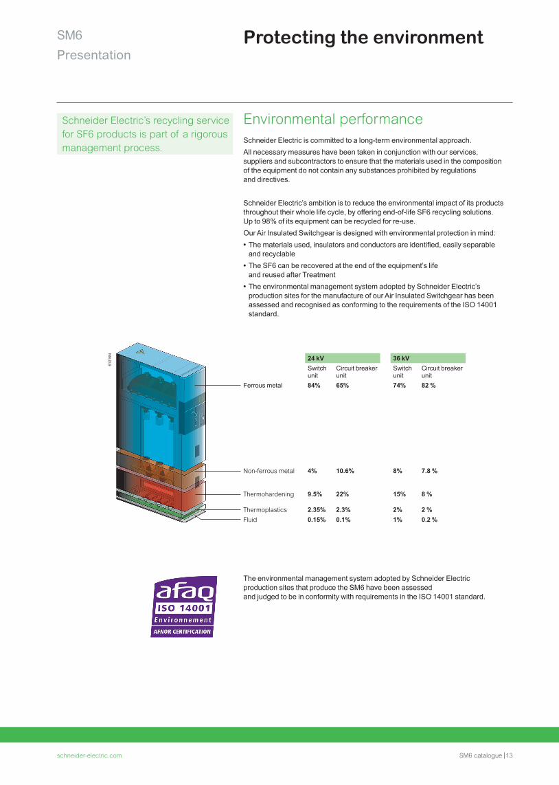
Schneider Electric’s ambition is to reduce the environmental impact of its products throughout their whole life cycle, by offering end-of-life SF6 recycling solutions. Up to 98% of its equipment can be recycled for re-use. Our Air Insulated Switchgear is designed with environmental protection in mind: • The materials used, insulators and conductors are identified, easily separable and recyclable
• The SF6 can be recovered at the end of the equipment’s life and reused after Treatment
• The environmental management system adopted by Schneider Electric’s production sites for the manufacture of our Air Insulated Switchgear has been assessed and recognised as conforming to the requirements of the ISO 14001 standard.
The environmental management system adopted by Schneider Electric production sites that produce the SM6 have been assessed and judged to be in conformity with requirements in the ISO 14001 standard.
Environmental performance
24 kV 36 kVSwitch unit
Circuit breaker unit
Switch unit
Circuit breaker unit
Ferrous metal 84% 65% 74% 82 %
Non-ferrous metal 4% 10.6% 8% 7.8 %
Thermohardening 9.5% 22% 15% 8 %
Thermoplastics 2.35% 2.3% 2% 2 %Fluid 0.15% 0.1% 1% 0.2 %
Schneider Electric’s recycling service for SF6 products is part of a rigorous management process.
14 SM6 catalogue schneider-electric.com14
SM6Presentation
AV95
26-6
8AV
9503
-68
A major advantageSchneider Electric has integrated a functional organisation into each of its units. The main mission of this organisation is to check the quality and the compliance with standards. This procedure is: • Uniform throughout all departments • Recognised by many customers and approved organisations.
But it is above all its strict application that has enabled recognition to be obtained by an independent organisation: The French Quality Assurance Association (FQAA).
The quality system for the design and manufacture of SM6 units has been certified in conformity with the requirements of the ISO 9001: 2000 quality assurance model.
Meticulous and systematic controlsDuring manufacture, each SM6 is subject to systematic routine testing which aims to check the quality and conformity: • Sealing testing • Filling pressure testing • Opening and closing rate testing • Switching torque measurement • Dielectric testing • Conformity with drawings and plans.
The results obtained are written and reported on the test certificate for each device by the quality control department.
Mean Operating Time To Failure (MTTF)As result of Schneider Electric quality assurance system, SM6 has negligible "Mean Down Time (MDT)" in comparison to the "Mean Up Time (MUT)", thus "Mean Operating Time Between Failures (MTBF)" is as similar as to the MTTF. • MTTF (cumulative) = 3890 years for SM6-24 • MTTF (cumulative) = 6259 years for SM6-36.
Quality assuranceQuality certified to ISO 9001
schneider-electric.com SM6 catalogue 15
SM6Presentation
Schneider Electric ServicesPeace of mind throughout your installation life cycle
When it comes to your electrical distribution installation, we can help you: • Increase productivity, reliability, and safety
• Mitigate risk and limit downtime
• Keep equipment up to date and extend lifespan
• Cut cost and increase savings
• Improve your return on investment.
New improve the efficiency on maintenance:Access automatically to your SM6 equipment maintenance planning by flashing the QR code. Find the QR codes on your products or on the catalogue product data sheet.
Flash only with Facility Hero appFree Download:
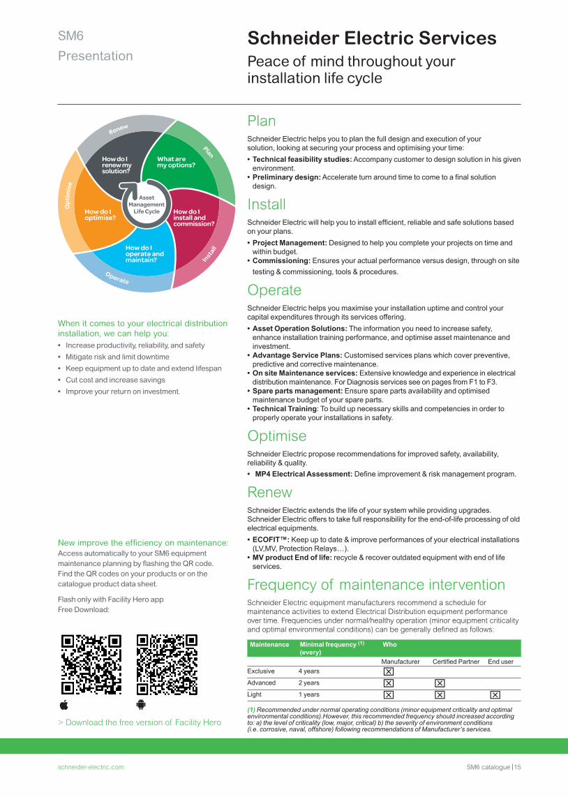
PlanSchneider Electric helps you to plan the full design and execution of yoursolution, looking at securing your process and optimising your time: • Technical feasibility studies: Accompany customer to design solution in his given environment.
• Preliminary design: Accelerate turn around time to come to a final solution design.
InstallSchneider Electric will help you to install efficient, reliable and safe solutions based on your plans. • Project Management: Designed to help you complete your projects on time and within budget.
• Commissioning: Ensures your actual performance versus design, through on site testing & commissioning, tools & procedures.
OperateSchneider Electric helps you maximise your installation uptime and control your capital expenditures through its services offering. • Asset Operation Solutions: The information you need to increase safety, enhance installation training performance, and optimise asset maintenance and investment.
• Advantage Service Plans: Customised services plans which cover preventive, predictive and corrective maintenance.
• On site Maintenance services: Extensive knowledge and experience in electrical distribution maintenance. For Diagnosis services see on pages from F1 to F3.
• Spare parts management: Ensure spare parts availability and optimised maintenance budget of your spare parts.
• Technical Training: To build up necessary skills and competencies in order to properly operate your installations in safety.
OptimiseSchneider Electric propose recommendations for improved safety, availability, reliability & quality. • MP4 Electrical Assessment: Define improvement & risk management program.
RenewSchneider Electric extends the life of your system while providing upgrades.Schneider Electric offers to take full responsibility for the end-of-life processing of old electrical equipments. • ECOFIT™: Keep up to date & improve performances of your electrical installations (LV,MV, Protection Relays…).
• MV product End of life: recycle & recover outdated equipment with end of life services.
Frequency of maintenance interventionSchneider Electric equipment manufacturers recommend a schedule for maintenance activities to extend Electrical Distribution equipment performance over time. Frequencies under normal/healthy operation (minor equipment criticality and optimal environmental conditions) can be generally defined as follows:
Renew
Plan
Opt
imis
e
Operate
Install
How do I renew mysolution?
What aremy options?
How do Iinstall andcommission?
How do Ioptimise?
How do Ioperate andmaintain?
AssetManagement
Life Cycle
Maintenance Minimal frequency (1) (every)
Who
Manufacturer Certified Partner End userExclusive 4 years Advanced 2 years Light 1 years (1) Recommended under normal operating conditions (minor equipment criticality and optimal environmental conditions).However, this recommended frequency should increased according to: a) the level of criticality (low, major, critical) b) the severity of environment conditions (i.e. corrosive, naval, offshore) following recommendations of Manufacturer’s services.
> Download the free version of Facility Hero

16 SM6 catalogue schneider-electric.com
SM6Presentation
Facility HeroPreventive & predictive maintenance using QR codes
What is Facility Hero?Facility Hero is a smart maintenance log book that can be accessed from any smartphone, tablet, or computer. This 100% collaborative, connected system keeps maintenance technicians in the field in constant contact with their maintenance community: manager, customer, contractors and peers for fast and effective interventions.Accessible by anyone, anywhere, anytime
Facility Hero works on 3G, 4G, and Wi-fi networks and can also be used offline.Simply download the application right to your smartphone or tablet, set up an account, and get started.
The right information, fast
• Overall view of equipment (status, tasks, the week's reminders) • Full maintenance logs (breakdowns, maintenance reports) • Fast access to history equipment maintenance logs via the QR code on the equipment
• Rich maintenance reports including voice memos, notes, photos, and measurements.
The right decision and the right action at the right time
• Quickly add a new piece of equipment • Access periodic reading measurements, recent malfunctions, etc. • Locate equipment by GPS in real time • Monitor equipment remotely and in real time
Manage your maintenance teams and interventions effectively
• Real-time work orders sharing, and reporting with selected users • Get inspection reports by mail and share them in just two clicks • Monitor all regular operations such as scheduling, and incomplete or upcoming tasks.
> Download the free version of Facility Hero
Facility Hero benefitsEnhance the efficiency of maintenance operations and insure your uptime:• Access automatically to the
maintenance recommendations of your equipments by flashing the QR codes
• Cloud Logbook to organise and follow your maintenance
• Remote alarming on connected equipments.
PE
6052
9
schneider-electric.com SM6 catalogue 17
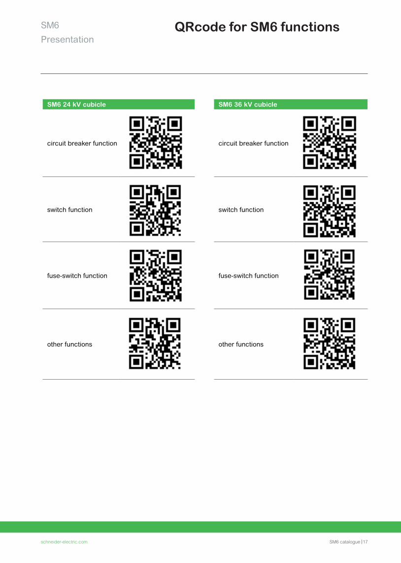
QRcode for SM6 functions
SM6 24 kV cubicle
circuit breaker function
switch function
fuse-switch function
other functions
SM6 36 kV cubicle
circuit breaker function
switch function
fuse-switch function
other functions
SM6Presentation

18 SM6 catalogue schneider-electric.com
General characteristics
schneider-electric.com SM6 catalogue 19
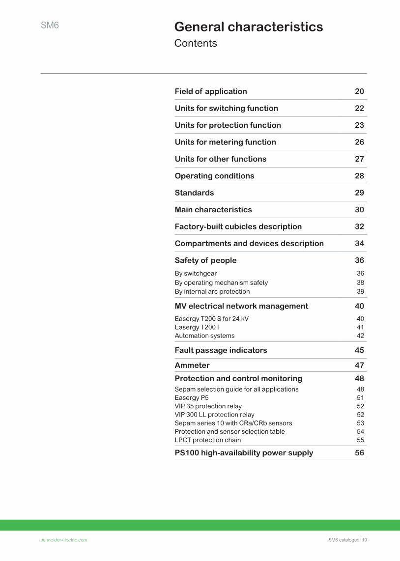
General characteristicsContents
SM6
Field of application 20
Units for switching function 22
Units for protection function 23
Units for metering function 26
Units for other functions 27
Operating conditions 28
Standards 29
Main characteristics 30
Factory-built cubicles description 32
Compartments and devices description 34
Safety of people 36
By switchgear 36By operating mechanism safety 38By internal arc protection 39
MV electrical network management 40
Easergy T200 S for 24 kV 40Easergy T200 I 41Automation systems 42
Fault passage indicators 45
Ammeter 47
Protection and control monitoring 48Sepam selection guide for all applications 48Easergy P5 51VIP 35 protection relay 52VIP 300 LL protection relay 52Sepam series 10 with CRa/CRb sensors 53Protection and sensor selection table 54LPCT protection chain 55
PS100 high-availability power supply 56
20 SM6 catalogue schneider-electric.com
SM6General characteristics
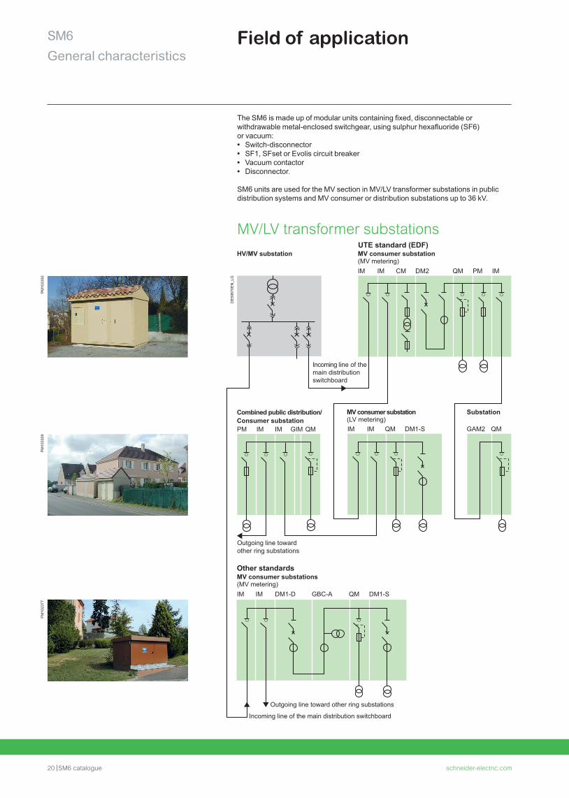
MV consumer substation(MV metering)IM
Incoming line of the main distribution switchboard
Outgoing line towardother ring substations
IM CM DM2 QM PM IM
Other standardsMV consumer substations(MV metering)IM
Outgoing line toward other ring substations
Incoming line of the main distribution switchboard
IM DM1-D GBC-A QM DM1-S
Combined public distribution/Consumer substationPM IM IM GIM QM
MV consumer substation(LV metering)
Substation
IM IM GAM2 QMQM DM1-S
UTE standard (EDF)HV/MV substation
The SM6 is made up of modular units containing fixed, disconnectable or withdrawable metal-enclosed switchgear, using sulphur hexafluoride (SF6) or vacuum: • Switch-disconnector • SF1, SFset or Evolis circuit breaker • Vacuum contactor • Disconnector.
SM6 units are used for the MV section in MV/LV transformer substations in public distribution systems and MV consumer or distribution substations up to 36 kV.
MV/LV transformer substationsD
E59
670E
N_L
G
PM
1023
77P
M10
3309
PM
1033
50Field of application
schneider-electric.com SM6 catalogue 21
SM6General characteristics
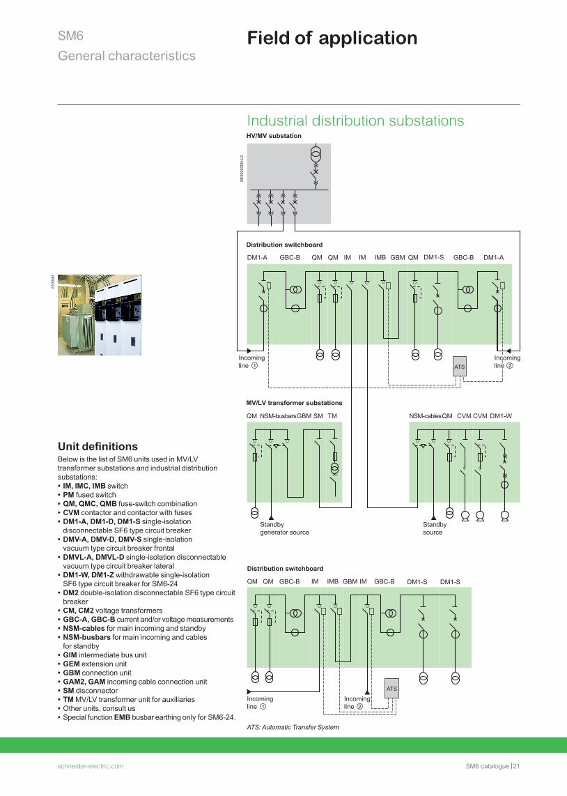
QM QM
NSM-busbarsGBM SM TMQM NSM-cablesQM CVM CVM DM1-W
Distribution switchboard
DM1-A DM1-S
DM1-S DM1-SGBC-B
GBC-B
GBC-B
GBC-BQM QMQM IM
IM IMIMB
IM IMB GBM
GBM
DM1-A
Incoming line
ATS
ATS
MV/LV transformer substations
Distribution switchboard
HV/MV substation
Standby generator source
Standby source
Incoming line
Incoming line
Incoming line
Industrial distribution substations
6100
4N
DE
5920
0EN
-LG
Unit definitionsBelow is the list of SM6 units used in MV/LV transformer substations and industrial distribution substations: • IM, IMC, IMB switch • PM fused switch • QM, QMC, QMB fuse-switch combination • CVM contactor and contactor with fuses • DM1-A, DM1-D, DM1-S single-isolation disconnectable SF6 type circuit breaker
• DMV-A, DMV-D, DMV-S single-isolation vacuum type circuit breaker frontal
• DMVL-A, DMVL-D single-isolation disconnectable vacuum type circuit breaker lateral
• DM1-W, DM1-Z withdrawable single-isolation SF6 type circuit breaker for SM6-24
• DM2 double-isolation disconnectable SF6 type circuit breaker
• CM, CM2 voltage transformers • GBC-A, GBC-B current and/or voltage measurements • NSM-cables for main incoming and standby • NSM-busbars for main incoming and cables for standby
• GIM intermediate bus unit • GEM extension unit • GBM connection unit • GAM2, GAM incoming cable connection unit • SM disconnector • TM MV/LV transformer unit for auxiliaries • Other units, consult us • Special function EMB busbar earthing only for SM6-24.
Field of application
ATS: Automatic Transfer System
22 SM6 catalogue schneider-electric.com
SM6General characteristics
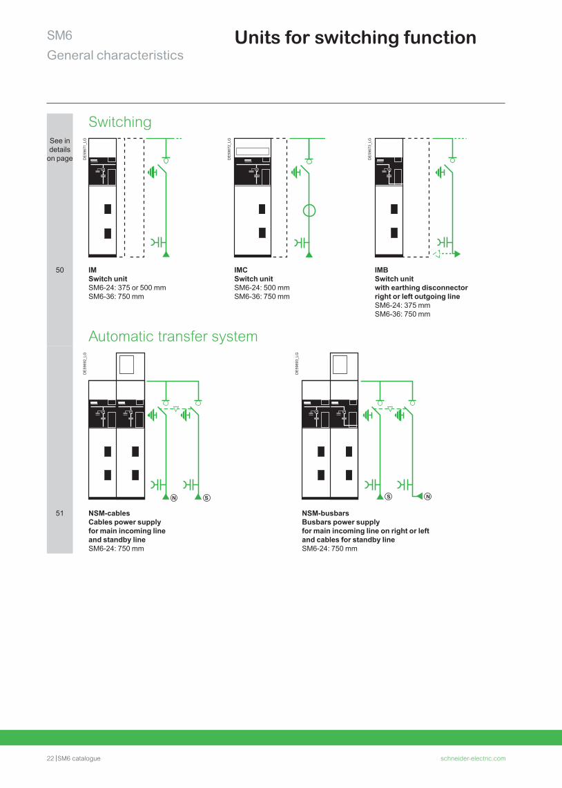
Units for switching function
SwitchingSee in details
on page DE
5967
1_LG
DE
5967
2_LG
DE
5967
3_LG
50 IMSwitch unitSM6-24: 375 or 500 mm SM6-36: 750 mm
IMCSwitch unitSM6-24: 500 mm SM6-36: 750 mm
IMB Switch unit with earthing disconnector right or left outgoing lineSM6-24: 375 mm SM6-36: 750 mm
Automatic transfer system
DE
5969
2_LG
DE
5969
3_LG
51 NSM-cables Cables power supply for main incoming line and standby lineSM6-24: 750 mm
NSM-busbarsBusbars power supply for main incoming line on right or left and cables for standby lineSM6-24: 750 mm
schneider-electric.com SM6 catalogue 23
SM6General characteristics
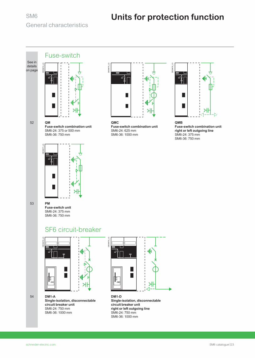
Units for protection function
Fuse-switchSee in details
on page
DE
5967
4_LG
DE
5967
5_LG
DE
5967
6_LG
52 QM Fuse-switch combination unitSM6-24: 375 or 500 mm SM6-36: 750 mm
QMC Fuse-switch combination unitSM6-24: 625 mm SM6-36: 1000 mm
QMB Fuse-switch combination unit right or left outgoing line SM6-24: 375 mm SM6-36: 750 mm
DE
5967
7_LG
53 PM Fuse-switch unitSM6-24: 375 mm SM6-36: 750 mm
SF6 circuit-breaker
DE
5967
8_LG
DE
5967
9_LG
54 DM1-ASingle-isolation, disconnectable circuit breaker unitSM6-24: 750 mm SM6-36: 1000 mm
DM1-DSingle-isolation, disconnectable circuit breaker unit right or left outgoing lineSM6-24: 750 mm SM6-36: 1000 mm
24 SM6 catalogue schneider-electric.com2424
SM6General characteristics
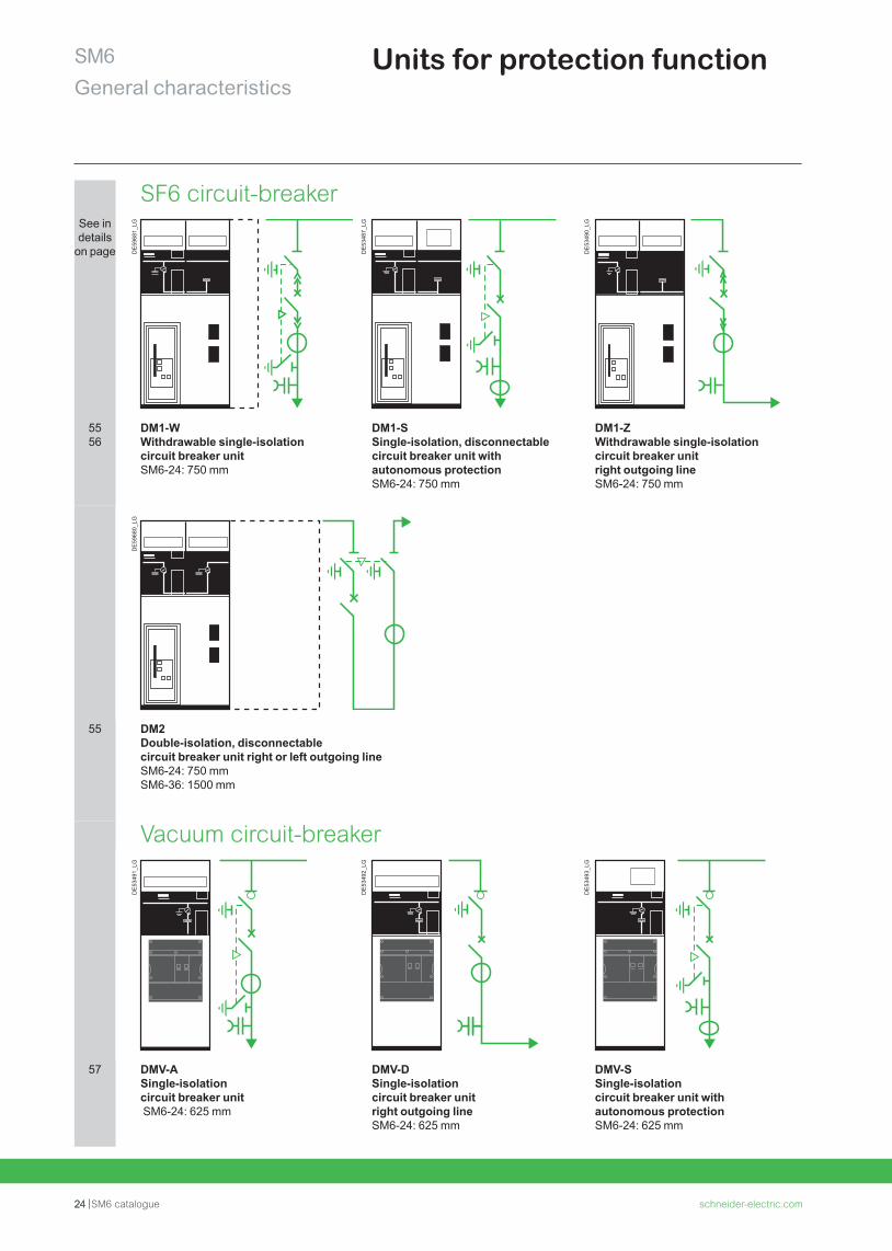
Units for protection function
SF6 circuit-breakerSee in details
on page DE
5968
1_LG
DE
5348
7_LG
DE
5349
0_LG
5556
DM1-WWithdrawable single-isolation circuit breaker unitSM6-24: 750 mm
DM1-SSingle-isolation, disconnectable circuit breaker unit with autonomous protectionSM6-24: 750 mm
DM1-ZWithdrawable single-isolation circuit breaker unit right outgoing lineSM6-24: 750 mm
DE
5968
0_LG
55 DM2Double-isolation, disconnectable circuit breaker unit right or left outgoing lineSM6-24: 750 mm SM6-36: 1500 mm
Vacuum circuit-breaker
DE
5349
1_LG
DE
5349
2_LG
DE
5349
3_LG
57 DMV-ASingle-isolation circuit breaker unit SM6-24: 625 mm
DMV-DSingle-isolation circuit breaker unit right outgoing line SM6-24: 625 mm
DMV-SSingle-isolation circuit breaker unit with autonomous protectionSM6-24: 625 mm
schneider-electric.com SM6 catalogue 25
SM6General characteristics
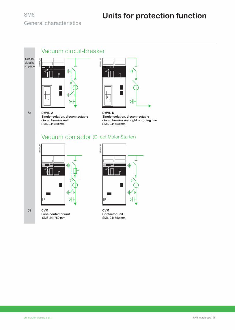
Units for protection function
Vacuum circuit-breakerSee in details
on page DE
5348
5_LG
DE
5969
4_LG
58 DMVL-A Single-isolation, disconnectable circuit breaker unitSM6-24: 750 mm
DMVL-D Single-isolation, disconnectable circuit breaker unit right outgoing line SM6-24: 750 mm
Vacuum contactor (Direct Motor Starter)
DE
5923
1_LG
DE
5923
2_LG
59 CVM Fuse-contactor unit SM6-24: 750 mm
CVMContactor unitSM6-24: 750 mm
26 SM6 catalogue schneider-electric.com
SM6General characteristics
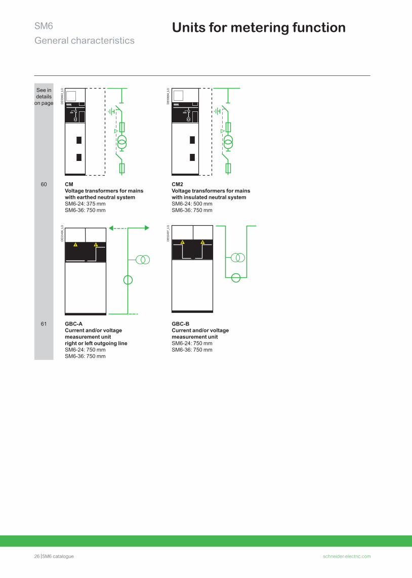
Units for metering function
See in details
on page DE
5986
3_LG
DE
5968
4_LG
60 CMVoltage transformers for mains with earthed neutral systemSM6-24: 375 mm SM6-36: 750 mm
CM2 Voltage transformers for mains with insulated neutral systemSM6-24: 500 mm SM6-36: 750 mm
DE
5349
6_LG
DE
5349
7_LG
61 GBC-A Current and/or voltage measurement unit right or left outgoing line SM6-24: 750 mmSM6-36: 750 mm
GBC-BCurrent and/or voltage measurement unitSM6-24: 750 mmSM6-36: 750 mm
schneider-electric.com SM6 catalogue 27
SM6General characteristics
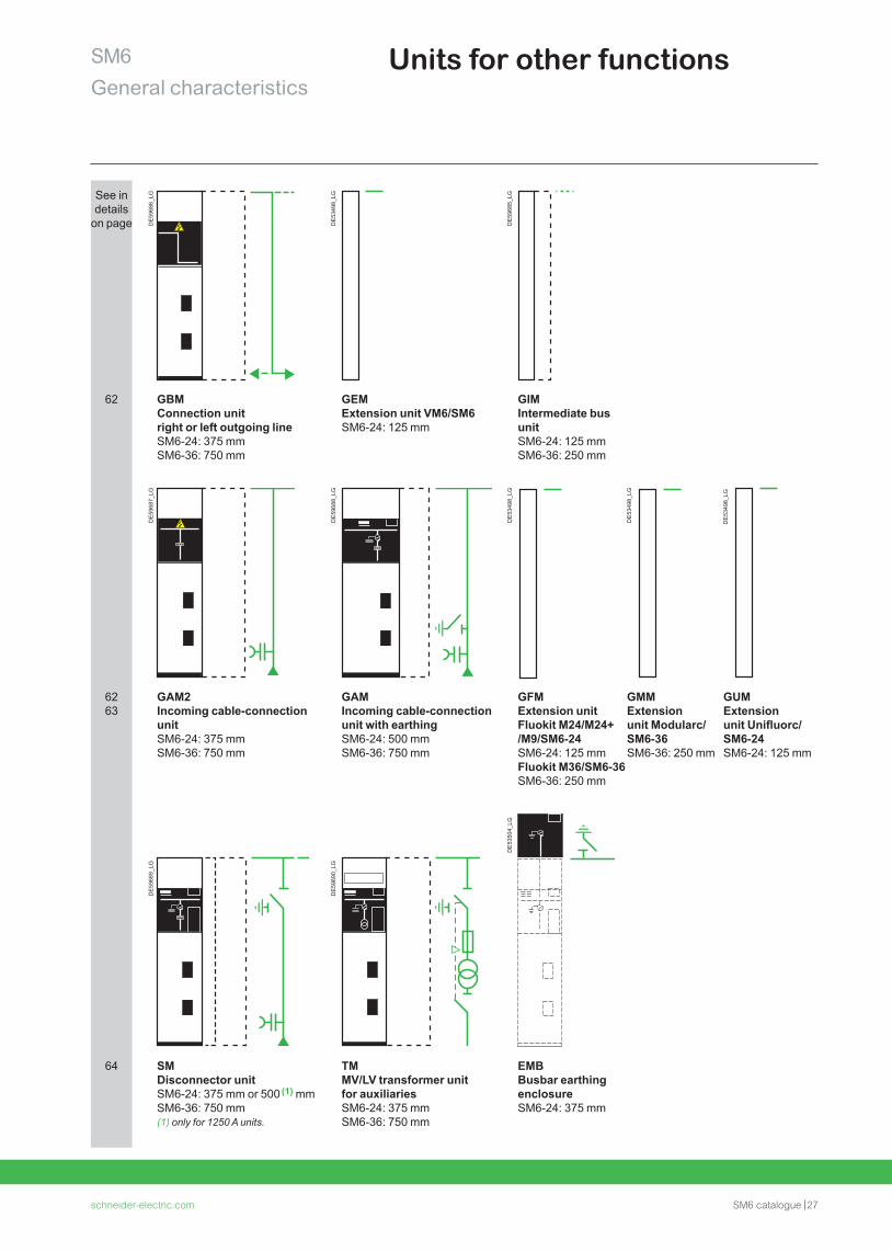
Units for other functions
See in details
on page DE
5968
6_LG
DE
5349
8_LG
DE
5968
5_LG
62 GBM Connection unit right or left outgoing lineSM6-24: 375 mm SM6-36: 750 mm
GEMExtension unit VM6/SM6SM6-24: 125 mm
GIM Intermediate bus unit SM6-24: 125 mm SM6-36: 250 mm
DE
5968
7_LG
DE
5968
8_LG
DE
5349
8_LG
DE
5349
8_LG
DE
5349
8_LG
6263
GAM2Incoming cable-connection unitSM6-24: 375 mm SM6-36: 750 mm
GAMIncoming cable-connection unit with earthingSM6-24: 500 mm SM6-36: 750 mm
GFMExtension unit Fluokit M24/M24+ /M9/SM6-24SM6-24: 125 mmFluokit M36/SM6-36SM6-36: 250 mm
GMMExtension unit Modularc/SM6-36SM6-36: 250 mm
GUMExtension unit Unifluorc/ SM6-24SM6-24: 125 mm
DE
5968
9_LG
DE
5969
0_LG
DE
5350
4_LG
64 SMDisconnector unitSM6-24: 375 mm or 500 (1) mm SM6-36: 750 mm(1) only for 1250 A units.
TMMV/LV transformer unit for auxiliariesSM6-24: 375 mm SM6-36: 750 mm
EMBBusbar earthing enclosureSM6-24: 375 mm
28 SM6 catalogue schneider-electric.com
SM6General characteristics
PE
5715
2
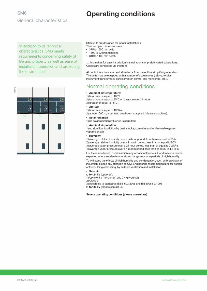
SM6 units are designed for indoor installations. Their compact dimensions are: • 375 to 1500 mm width • 1600 to 2250 mm height • 840 to 1400 mm depth…
… this makes for easy installation in small rooms or prefabricated substations.Cables are connected via the front.
All control functions are centralised on a front plate, thus simplifying operation. The units may be equipped with a number of accessories (relays, toroids, instrument transformers, surge arrester, control and monitoring, etc.).
Normal operating conditions • Ambient air temperature:
1) less than or equal to 40°C2) less than or equal to 35°C on average over 24 hours3) greater or equal to –5°C. • Altitude
1) less than or equal to 1000 m2) above 1000 m, a derating coefficient is applied (please consult us). • Solar radiation
1) no solar radiation influence is permitted. • Ambient air pollution
1) no significant pollution by dust, smoke, corrosive and/or flammable gases, vapours or salt. • Humidity
1) average relative humidity over a 24 hour period, less than or equal to 95%2) average relative humidity over a 1 month period, less than or equal to 90%3) average vapor pressure over a 24 hour period, less than or equal to 2.2 kPa4) average vapor pressure over a 1 month period, less than or equal to 1.8 kPa.For these conditions, condensation may occasionally occur. Condensation can be expected where sudden temperature changes occur in periods of high humidity.To withstand the effects of high humidity and condensation, such as breakdown of insulation, please pay attention on Civil Engineering recommendations for design of the building or housing, by suitable ventilation and installation. • Seismic: v for 24 kV (optional):
1) Up to 0.5 g (horizontal) and 0.4 g (vertical)2) Class 23) According to standards IEEE-693/2005 and EN 60068-3/1993
v for 36 kV (please contact us).
Severe operating conditions (please consult us).
Operating conditions
In addition to its technical characteristics, SM6 meets requirements concerning safety of life and property as well as ease of installation, operation and protecting the environment.
schneider-electric.com SM6 catalogue 29
SM6General characteristics
Standards
IEC standards62271-200 High-voltage switchgear and controlgear - Part 200:
A.C. metal-enclosed switchgear and controlgear for rated voltage above 1 kV and up to and including 52 kV.
62271-1 High-voltage switchgear and controlgear - Part 1: Common specifications.
62271-103 High voltage switches - Part 1: switches for rated voltages above 1 kV and less or equal to 52 kV.
62271-105 High-voltage switchgear and controlgear - Part 105: High voltage alternating current switch-fuse combinations.
60255 Electrical relays.
62271-100 High-voltage switchgear and controlgear - Part 100: High-voltage alternating current circuit breakers.
62271-102 High-voltage switchgear and controlgear - Part 102: High-voltage alternating current disconnectors and earthing switches.
61869-2 Instrument transformers - Part 1: Current transformers.
61869-3 Instrument transformers - Part 2: Voltage transformers.
60044-8 Instrument transformers - Part 8: Low Power Current Transducers.
62271-206 High-voltage prefabricated switchgear and controlgear assemblies - Voltage presence indicating systems.
62271-304 High-voltage switchgear and controlgear - Part 304: Design classes for indoor enclosed switchgear and controlgear for rated voltages above 1 kV up to and including 52 kV to be used in severe climatic conditions.
SEISMIC standards for 24kVIEE-693 2005 IEEE Recommended Practice for Seismic Design of
Substations
EN600068-3-3 1993 Environmental testing-Part 3: guidance, Seismic test methods for equipments
UTE standards for 24 kVNFC 13.100 Consumer substation installed inside a building and fed by
a second category voltage public distribution system.
NFC 13.200 High voltage electrical installations requirements.
NFC 64.130 High voltage switches for rated voltage above 1 kV and less than 52 kV.
NFC 64.160. Alternating current disconnectors and earthing switches
EDF specifications for 24 kVHN 64-S-41 A.C. metal-enclosed swichgear and controlgear for rated voltages
above 1 kV and up to and including 24 kV.
HN 64-S-43 Electrical independent-operating mechanism for switch 24 kV - 400 A.
SM6 units meet all the following standards and specifications:
- IEC standards
- UTE standards for SM6-24
- EDF specifications for SM6-24
- SEISMIC standards for 24 kV
30 SM6 catalogue schneider-electric.com
SM6General characteristics
Main characteristicsP
E57
150
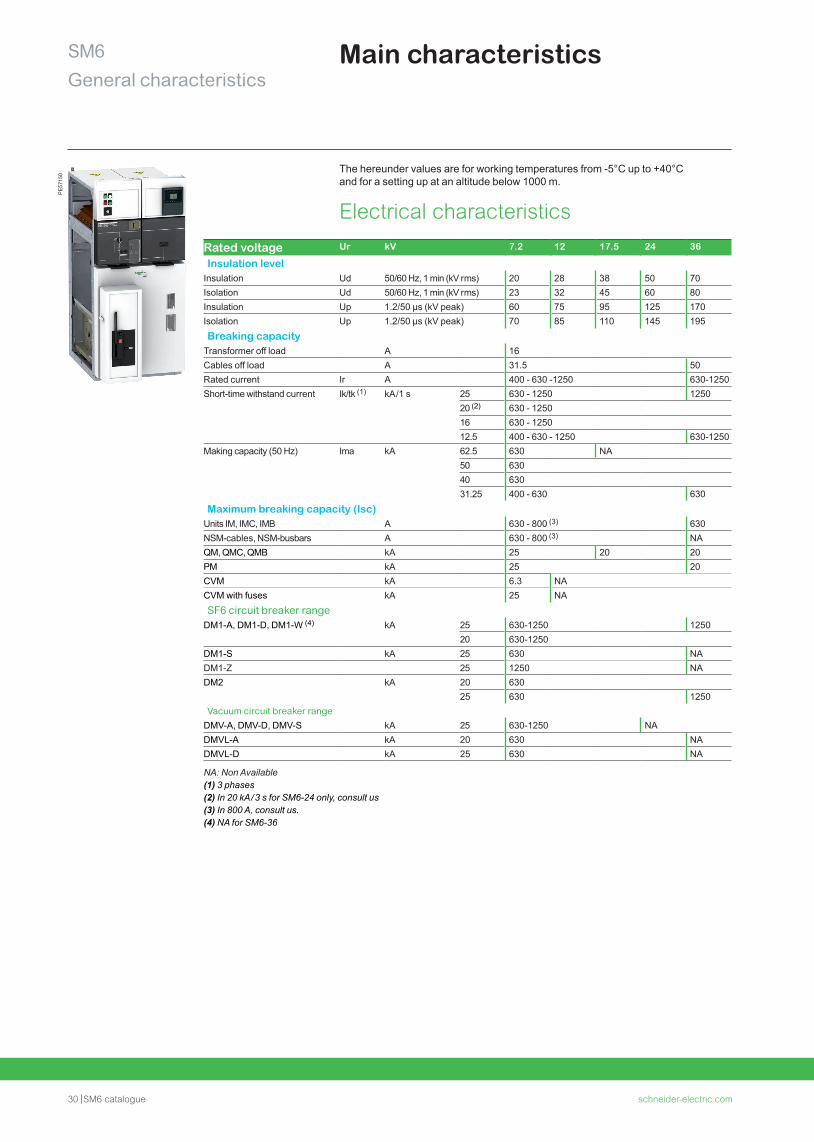
Rated voltage Ur kV 7.2 12 17.5 24 36
Insulation levelInsulation Ud 50/60 Hz, 1 min (kV r ms) 20 28 38 50 70Isolation Ud 50/60 Hz, 1 min (kV r ms) 23 32 45 60 80Insulation Up 1.2/50 µs (kV peak) 60 75 95 125 170Isolation Up 1.2/50 µs (kV peak) 70 85 110 145 195Breaking capacity
Transformer off load A 16Cables off load A 31.5 50Rated current Ir A 400 - 630 -1250 630-1250Short-time withstand current Ik/tk (1) kA /1 s 25 630 - 1250 1250
20 (2) 630 - 125016 630 - 125012.5 400 - 630 - 1250 630-1250
Making capacity (50 Hz) Ima kA 62.5 630 NA50 630 40 630 31.25 400 - 630 630
Maximum breaking capacity (Isc)Units IM, IMC, IMB A 630 - 800 (3) 630NSM-cables, NSM-busbars A 630 - 800 (3) NAQM, QMC, QMB kA 25 20 20PM kA 25 20CVM kA 6.3 NACVM with fuses kA 25 NASF6 circuit breaker range
DM1-A, DM1-D, DM1-W (4) kA 25 630-1250 125020 630-1250
DM1-S kA 25 630 NADM1-Z 25 1250 NADM2 kA 20 630
25 630 1250Vacuum circuit breaker range
DMV-A, DMV-D, DMV-S kA 25 630-1250 NADMVL-A kA 20 630 NADMVL-D kA 25 630 NA
NA: Non Available (1) 3 phases(2) In 20 kA / 3 s for SM6-24 only, consult us(3) In 800 A, consult us.(4) NA for SM6-36
The hereunder values are for working temperatures from -5°C up to +40°C and for a setting up at an altitude below 1000 m.
Electrical characteristics
schneider-electric.com SM6 catalogue 31
SM6General characteristics
Main characteristicsP
E57
150 Endurance
Units Mechanical endurance Electrical enduranceUnits IM, IMC, IMB, PM, QM (5), QMC (5), QMB (5), NSM-cables, NSM-busbars
IEC 62271-103 1 000 operations class M1
IEC 62271-103 100 breaks at Ir, p.f. = 0.7, class E3
CVM Disconnector IEC 62271-1021 000 operations
Vacuum contactor IEC 60470 2 500 000 operations 250 000 with mechanical latching
IEC 60470 250 000 breaks at Ir
SF6 circuit breaker rangeDM1-A, DM1-D, DM1-W, DM1-Z, DM1-S, DM2
Disconnector IEC 62271-102 1 000 operations
SF circuit breaker IEC 62271-100 10 000 operationsclass M2
IEC 62271-100 30 breaks at 12.5 kA for SM6-24 25 breaks at 25 kA for SM6-2440 breaks at 16 kA for SM6-36 15 breaks at 25 kA for SM6-36 10 000 breaks at Ir, p.f. = 0.7, class E2
Operating sequence O - 0.3 s - CO - 15 s - CO O - 0.3 s - CO - 3 mnO - 3 mn - CO - 3 mn - CO
Vacuum circuit breaker rangeDMV-A, DMV-D, DMV-S
Switch IEC 62271-103 1 000 operations class M1
IEC 62271-103 100 breaks at Ir, p.f. = 0.7, class E3
Evolis circuit breaker
IEC 62271-100 10 000 operations class M2
IEC 62271-100 100 breaks at 25kA for SM6-24 10 000 breaks at Ir, p.f. = 0.7, class E2
DMVL-A DMVL-D
Disconnector IEC 62271-102 1 000 operations
Evolis circuit breaker
IEC 62271-100 10 000 operations class M2
IEC 62271-100 100 breaks at 16kA for SM6-24 100 breaks at 25kA for SM6-24 10 000 breaks at Ir, p.f. = 0.7, class E2
(5) As per recommendation IEC 62271-105, three breakings at p.f. = 0.2800 A under 36 kV; 1400 A under 24 kV; 1730 A under 12 kV; 2600 A under 5.5 kV.
Internal arc withstand (in accordance with IEC 62271-200): • SM6-24: v 12.5 kA 1 s, IAC: A-FLR & IAC: A-FL
v 16 kA 1 s, IAC: A-FLR & IAC: A-FL v 20 kA 1 s, IAC: A-FLR & IAC: A-FL
• SM6-36: v 16 kA 1 s, IAC: A-FL.
Protection index: • Classes: PI (insulating partition) • Loss of service continuity classes: LSC2A (LSC1 for metering GAM/GBM functions) • Units in switchboard: IP3X • Between compartments: IP2X for SM6-24, IP2XC for SM6-36 • Cubicle: IK08 for SM6-24, IK07 for SM6-36.
Electro-magnetic compatibility: • Relays: 4 kV withstand capacity, as per recommendation IEC 60801.4 • Compartments: v electrical field:
- 40 dB attenuation at 100 MHz - 20 dB attenuation at 200 MHz v magnetic field: 20 dB attenuation below 30 MHz.
Temperatures:The cubicles must be stored and installed in a dry area free from dust and with limited temperature variations. • For stocking: from -40°C to +70°C • For working: from -5°C to +40°C • Other temperatures, consult us. • Seismic: v for 24 kV (optional):
1) Up to 0.5 g (horizontal) and 0.4 g (vertical)2) Class 23) According to standards IEEE-693/2005 and EN 60068-3/1993
v for 36 kV (please contact us).
32 SM6 catalogue schneider-electric.com
SM6General characteristics
Factory-built cubicles description
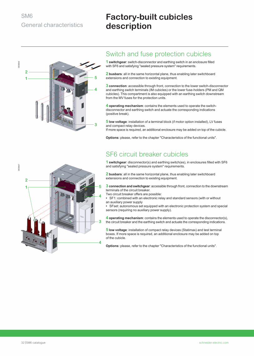
Switch and fuse protection cubicles1 switchgear: switch-disconnector and earthing switch in an enclosure filled with SF6 and satisfying "sealed pressure system" requirements.
2 busbars: all in the same horizontal plane, thus enabling later switchboard extensions and connection to existing equipment.
3 connection: accessible through front, connection to the lower switch-disconnector and earthing switch terminals (IM cubicles) or the lower fuse-holders (PM and QM cubicles). This compartment is also equipped with an earthing switch downstream from the MV fuses for the protection units.
4 operating mechanism: contains the elements used to operate the switch-disconnector and earthing switch and actuate the corresponding indications (positive break).
5 low voltage: installation of a terminal block (if motor option installed), LV fuses and compact relay devices.If more space is required, an additional enclosure may be added on top of the cubicle.
Options: please, refer to the chapter "Characteristics of the functional units".
SF6 circuit breaker cubicles1 switchgear: disconnector(s) and earthing switch(es), in enclosures filled with SF6 and satisfying "sealed pressure system" requirements.
2 busbars: all in the same horizontal plane, thus enabling later switchboard extensions and connection to existing equipment.
3 connection and switchgear: accessible through front, connection to the downstream terminals of the circuit breaker.Two circuit breaker offers are possible: • SF1: combined with an electronic relay and standard sensors (with or without
an auxiliary power supply • SFset: autonomous set equipped with an electronic protection system and special
sensors (requiring no auxiliary power supply).
4 operating mechanism: contains the elements used to operate the disconnector(s), the circuit breaker and the earthing switch and actuate the corresponding indications.
5 low voltage: installation of compact relay devices (Statimax) and test terminal boxes. If more space is required, an additional enclosure may be added on top of the cubicle.
Options: please, refer to the chapter "Characteristics of the functional units".
DE
5864
7
2
1 5
4
3
4
DE
5864
6
21 5
4
3
schneider-electric.com SM6 catalogue 33
SM6General characteristics
Factory-built cubicles description
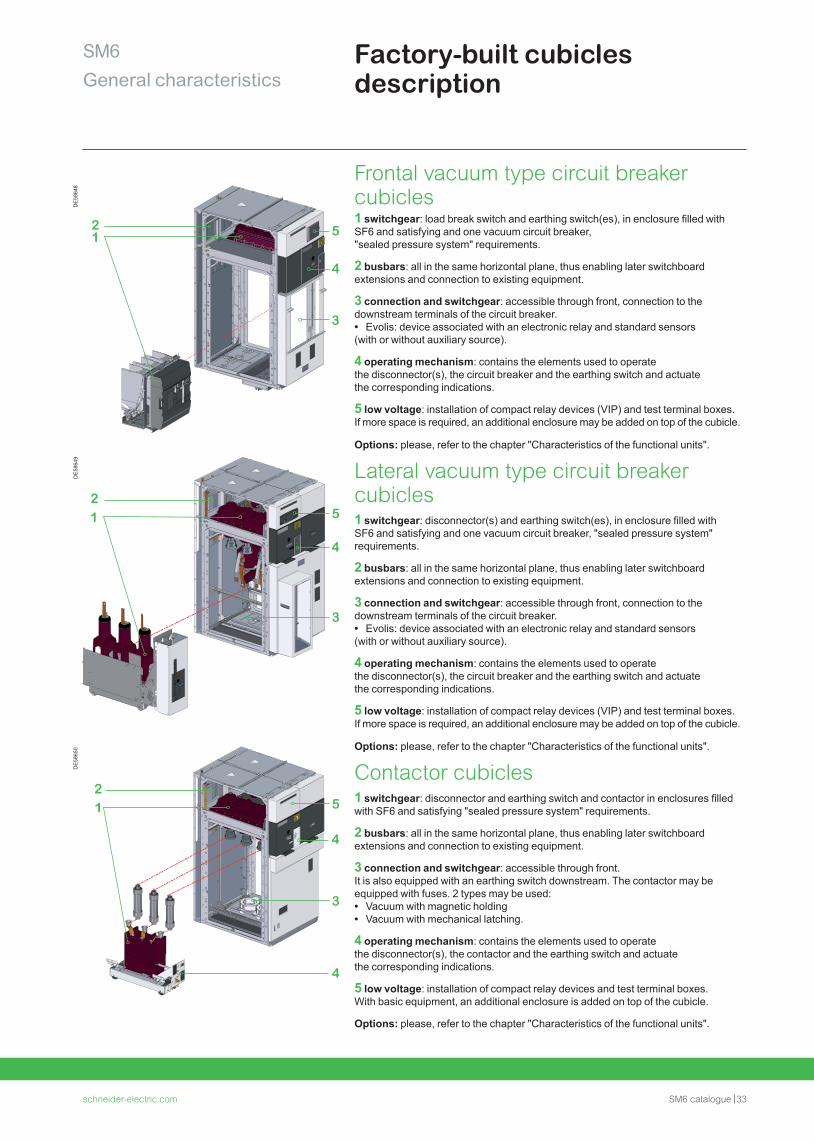
Frontal vacuum type circuit breaker cubicles1 switchgear: load break switch and earthing switch(es), in enclosure filled with SF6 and satisfying and one vacuum circuit breaker, "sealed pressure system" requirements.
2 busbars: all in the same horizontal plane, thus enabling later switchboard extensions and connection to existing equipment.
3 connection and switchgear: accessible through front, connection to the downstream terminals of the circuit breaker. • Evolis: device associated with an electronic relay and standard sensors
(with or without auxiliary source).
4 operating mechanism: contains the elements used to operate the disconnector(s), the circuit breaker and the earthing switch and actuate the corresponding indications.
5 low voltage: installation of compact relay devices (VIP) and test terminal boxes. If more space is required, an additional enclosure may be added on top of the cubicle.
Options: please, refer to the chapter "Characteristics of the functional units".
Lateral vacuum type circuit breaker cubicles1 switchgear: disconnector(s) and earthing switch(es), in enclosure filled with SF6 and satisfying and one vacuum circuit breaker, "sealed pressure system" requirements.
2 busbars: all in the same horizontal plane, thus enabling later switchboard extensions and connection to existing equipment.
3 connection and switchgear: accessible through front, connection to the downstream terminals of the circuit breaker. • Evolis: device associated with an electronic relay and standard sensors
(with or without auxiliary source).
4 operating mechanism: contains the elements used to operate the disconnector(s), the circuit breaker and the earthing switch and actuate the corresponding indications.
5 low voltage: installation of compact relay devices (VIP) and test terminal boxes. If more space is required, an additional enclosure may be added on top of the cubicle.
Options: please, refer to the chapter "Characteristics of the functional units".
Contactor cubicles1 switchgear: disconnector and earthing switch and contactor in enclosures filled with SF6 and satisfying "sealed pressure system" requirements.
2 busbars: all in the same horizontal plane, thus enabling later switchboard extensions and connection to existing equipment.
3 connection and switchgear: accessible through front.It is also equipped with an earthing switch downstream. The contactor may be equipped with fuses. 2 types may be used: • Vacuum with magnetic holding • Vacuum with mechanical latching.
4 operating mechanism: contains the elements used to operate the disconnector(s), the contactor and the earthing switch and actuate the corresponding indications.
5 low voltage: installation of compact relay devices and test terminal boxes.With basic equipment, an additional enclosure is added on top of the cubicle.
Options: please, refer to the chapter "Characteristics of the functional units".
DE
5864
8
21 5
4
3
DE
5864
9
21 5
4
3
DE
5865
0
21 5
4
3
4
34 SM6 catalogue schneider-electric.com
SM6General characteristics
Compartments and devices description
DE
5350
7_LG
6100
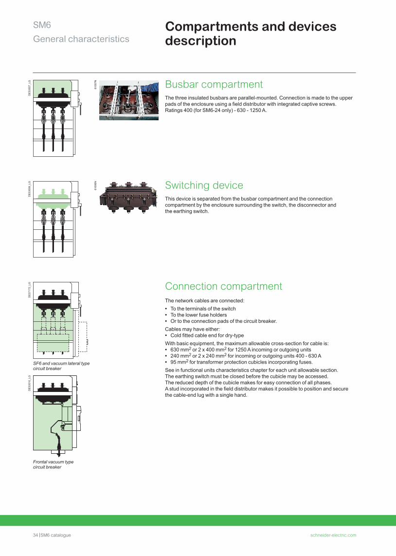
7N Busbar compartmentThe three insulated busbars are parallel-mounted. Connection is made to the upper pads of the enclosure using a field distributor with integrated captive screws.Ratings 400 (for SM6-24 only) - 630 - 1250 A.
DE
5350
8_LG
6100
6N Switching deviceThis device is separated from the busbar compartment and the connection compartment by the enclosure surrounding the switch, the disconnector and the earthing switch.
DE
5717
2_LG Connection compartment
The network cables are connected: • To the terminals of the switch • To the lower fuse holders • Or to the connection pads of the circuit breaker.
Cables may have either: • Cold fitted cable end for dry-type
With basic equipment, the maximum allowable cross-section for cable is: • 630 mm2 or 2 x 400 mm2 for 1250 A incoming or outgoing units • 240 mm2 or 2 x 240 mm2 for incoming or outgoing units 400 - 630 A • 95 mm2 for transformer protection cubicles incorporating fuses.
See in functional units characteristics chapter for each unit allowable section.The earthing switch must be closed before the cubicle may be accessed.The reduced depth of the cubicle makes for easy connection of all phases.A stud incorporated in the field distributor makes it possible to position and secure the cable-end lug with a single hand.
SF6 and vacuum lateral type circuit breaker
DE
5351
0_LG
Frontal vacuum type circuit breaker
schneider-electric.com SM6 catalogue 35
SM6General characteristics
Compartments and devices description
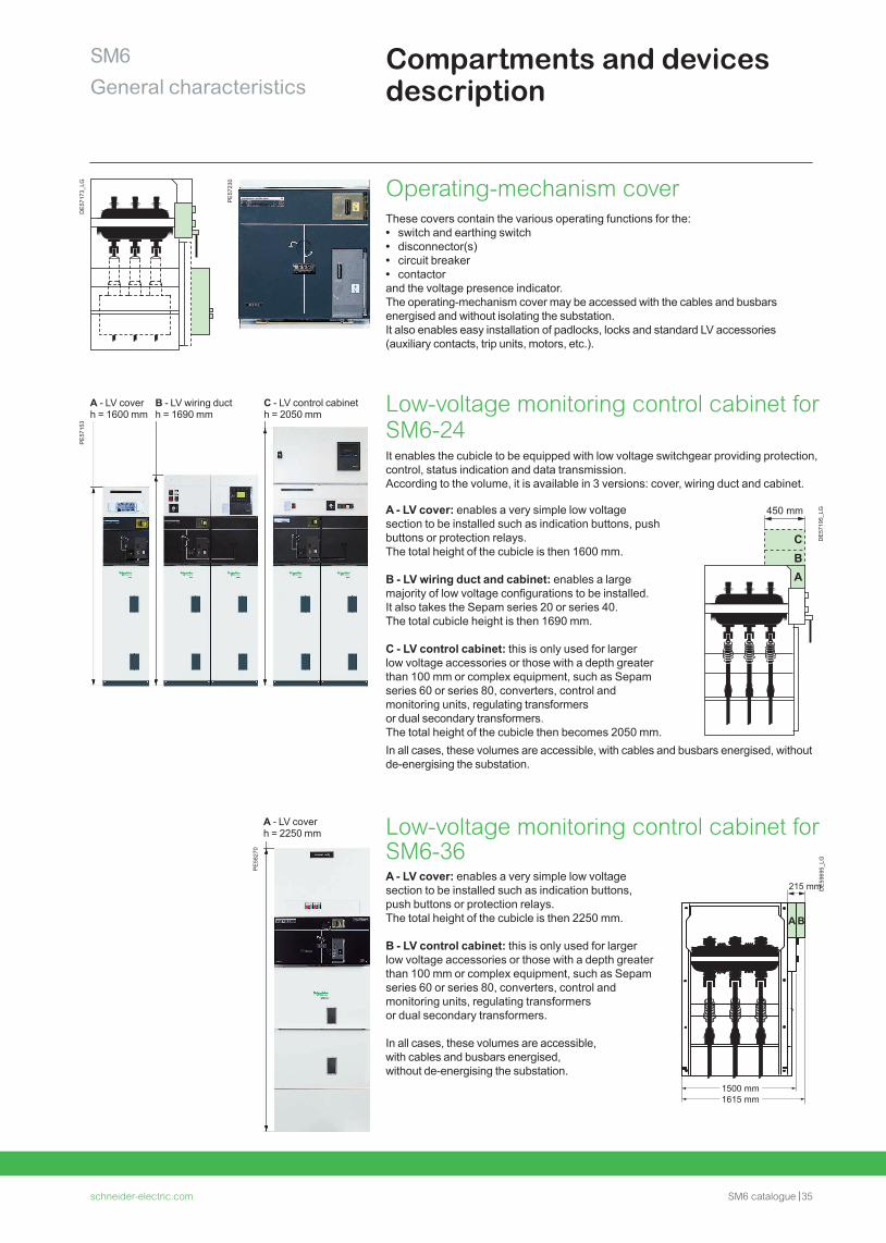
Operating-mechanism coverThese covers contain the various operating functions for the: • switch and earthing switch • disconnector(s) • circuit breaker • contactor
and the voltage presence indicator.The operating-mechanism cover may be accessed with the cables and busbars energised and without isolating the substation.It also enables easy installation of padlocks, locks and standard LV accessories (auxiliary contacts, trip units, motors, etc.).
PE
5715
3
PE
5827
0
Low-voltage monitoring control cabinet for SM6-24It enables the cubicle to be equipped with low voltage switchgear providing protection, control, status indication and data transmission. According to the volume, it is available in 3 versions: cover, wiring duct and cabinet.
Low-voltage monitoring control cabinet for SM6-36
A - LV cover: enables a very simple low voltage section to be installed such as indication buttons, push buttons or protection relays.The total height of the cubicle is then 1600 mm.
B - LV wiring duct and cabinet: enables a large majority of low voltage configurations to be installed. It also takes the Sepam series 20 or series 40. The total cubicle height is then 1690 mm.
C - LV control cabinet: this is only used for larger low voltage accessories or those with a depth greater than 100 mm or complex equipment, such as Sepam series 60 or series 80, converters, control and monitoring units, regulating transformers or dual secondary transformers. The total height of the cubicle then becomes 2050 mm.
A - LV cover: enables a very simple low voltage section to be installed such as indication buttons, push buttons or protection relays.The total height of the cubicle is then 2250 mm.
B - LV control cabinet: this is only used for larger low voltage accessories or those with a depth greater than 100 mm or complex equipment, such as Sepam series 60 or series 80, converters, control and monitoring units, regulating transformers or dual secondary transformers.
In all cases, these volumes are accessible, with cables and busbars energised, without de-energising the substation.
A - LV cover B - LV wiring duct C - LV control cabineth = 1600 mm h = 1690 mm h = 2050 mm
A - LV coverh = 2250 mm
DE
5969
5_LG
DE
5717
3_LG
PE
5723
0
DE
5719
5_LG
CBA
450 mm
In all cases, these volumes are accessible, with cables and busbars energised, without de-energising the substation.
36 SM6 catalogue schneider-electric.com
SM6General characteristics
Safety of peopleBy switchgear
6101
0N
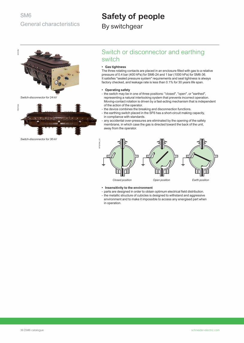
Switch-disconnector for 24 kV
Switch-disconnector for 36 kV
Switch or disconnector and earthing switch • Gas tightness
The three rotating contacts are placed in an enclosure filled with gas to a relative pressure of 0.4 bar (400 hPa) for SM6-24 and 1 bar (1000 hPa) for SM6-36. It satisfies "sealed pressure system" requirements and seal tightness is always factory checked, and leakage rate is less than 0.1% for 30 years life span.
• Operating safety - the switch may be in one of three positions: "closed", "open", or "earthed", representing a natural interlocking system that prevents incorrect operation. Moving-contact rotation is driven by a fast-acting mechanism that is independent of the action of the operator.
- the device combines the breaking and disconnection functions. - the earthing switch placed in the SF6 has a short-circuit making capacity, in compliance with standards.
- any accidental over-pressures are eliminated by the opening of the safety membrane, in which case the gas is directed toward the back of the unit, away from the operator.
MT2
0184
_LG
Closed position Open position Earth position
• Insensitivity to the environment - parts are designed in order to obtain optimum electrical field distribution. - the metallic structure of cubicles is designed to withstand and aggressive environment and to make it impossible to access any energised part when in operation.
PE
5722
6
schneider-electric.com SM6 catalogue 3737
SM6General characteristics
6101
2N
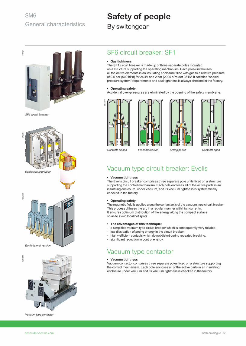
SF1 circuit breaker
SF6 circuit breaker: SF1 • Gas tightness
The SF1 circuit breaker is made up of three separate poles mounted on a structure supporting the operating mechanism. Each pole-unit houses all the active elements in an insulating enclosure filled with gas to a relative pressure of 0.5 bar (500 hPa) for 24 kV and 2 bar (2000 hPa) for 36 kV. It satisfies "sealed pressure system" requirements and seal tightness is always checked in the factory.
• Operating safetyAccidental over-pressures are eliminated by the opening of the safety membrane.
DE
5351
4
Vacuum type circuit breaker: Evolis • Vacuum tightness
The Evolis circuit breaker comprises three separate pole units fixed on a structure supporting the control mechanism. Each pole encloses all of the active parts in an insulating enclosure, under vacuum, and its vacuum tightness is systematically checked in the factory.
• Operating safetyThe magnetic field is applied along the contact axis of the vacuum type circuit breaker.This process diffuses the arc in a regular manner with high currents. It ensures optimum distribution of the energy along the compact surface so as to avoid local hot spots.
• The advantages of this technique: - a simplified vacuum type circuit breaker which is consequently very reliable, - low dissipation of arcing energy in the circuit breaker, - highly efficient contacts which do not distort during repeated breaking, - significant reduction in control energy.
Vacuum type contactor • Vacuum tightness
Vacuum contactor comprises three separate poles fixed on a structure supporting the control mechanism. Each pole encloses all of the active parts in an insulating enclosure under vacuum and its vacuum tightness is checked in the factory.
Contacts closed Precompression Arcing period Contacts open
6105
8N
Evolis circuit breaker
PE
5079
8
Safety of peopleBy switchgear
Evolis lateral version
PE
5784
1
Vacuum type contactor
38 SM6 catalogue schneider-electric.com
SM6General characteristics
Safety of peopleBy operating mechanism safety
Reliable operating mechanism • Switchgear status indicator:
Fitted directly to the drive shaft, these give a definite indication of the contact’s position. (appendix A of standard IEC 62271-102). • Operating lever:
This is designed with an anti-reflex device that stops any attempt to re-open the device immediately after closing the switch or the earthing disconnector. • Locking device:
Between one and three padlocks enable the following to be locked: - access to the switching shaft of the switch or the circuit breaker, - access to the switching shaft of the earthing disconnector, - operating of the opening release push-button.
Simple and effortless switchingMechanical and electrical controls are side by side on the front fascia, on a panel including the schematic diagram indicating the device’s status (closed, open, earthed): • Closed: the drive shaft is operated via a quick acting mechanism, independent of the operator. No energy is stored in the switch, apart from when switching operations are taking place. For combined switch fuses, the opening mechanism is armed at the same time as the contacts are closed.
• Opening: the switch is opened using the same quick acting mechanism, operated in the opposite direction. For circuit breakers and the combined switch fuses, opening is controlled by:
- a push-button, - a fault. • Earthing: a specific control shaft enables the opening or closing of the earthing contacts. Access to this shaft is blocked by a cover that can be slid back if the switch is open but which remains locked in place if it is closed.
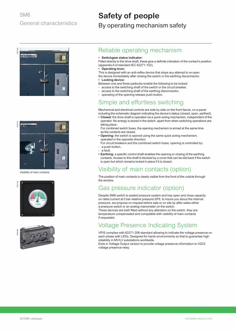
Visibility of main contacts (option)The position of main contacts is clearly visible from the front of the cubicle through the window.
Gas pressure indicator (option) Despite SM6 switch is sealed pressure system and has open and close capacity on rated current at 0 bar relative pressure SF6, to insure you about the internal pressure, we propose on request before sale or on site by after-sales either a pressure switch or an analog manometer on the switch. These devices are both fitted without any alteration on the switch, they are temperature compensated and compatible with visibility of main contacts if requested.
Voltage Presence Indicating SystemVPIS complies with 62271-206 standard allowing to indicate the voltage presence on each phase with LEDs. Designed for harsh environments so that to guarantee high reliability in MV/LV substations worldwide. Exits in Voltage Output version to provide voltage presence information to VD23 voltage presence relay.
PE
5716
6
Visibility of main contacts
PE
5636
6P
E57
230
PE
5723
1
schneider-electric.com SM6 catalogue 39
SM6General characteristics
Safety of peopleBy internal arc protection
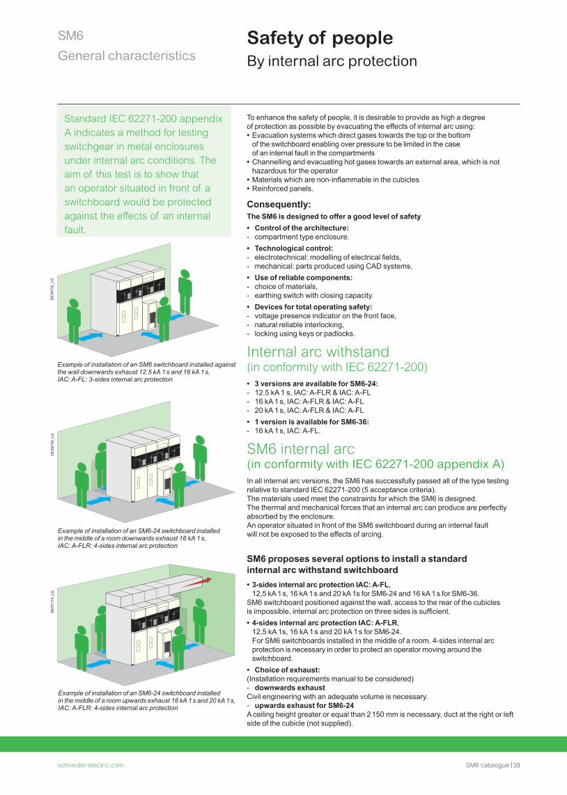
Standard IEC 62271-200 appendix A indicates a method for testing switchgear in metal enclosures under internal arc conditions. The aim of this test is to show that an operator situated in front of a switchboard would be protected against the effects of an internal fault.
DE
5973
2_LG
To enhance the safety of people, it is desirable to provide as high a degree of protection as possible by evacuating the effects of internal arc using: • Evacuation systems which direct gases towards the top or the bottom of the switchboard enabling over pressure to be limited in the case of an internal fault in the compartments
• Channelling and evacuating hot gases towards an external area, which is not hazardous for the operator
• Materials which are non-inflammable in the cubicles • Reinforced panels.
Consequently: The SM6 is designed to offer a good level of safety • Control of the architecture: - compartment type enclosure. • Technological control: - electrotechnical: modelling of electrical fields, - mechanical: parts produced using CAD systems. • Use of reliable components: - choice of materials, - earthing switch with closing capacity. • Devices for total operating safety: - voltage presence indicator on the front face, - natural reliable interlocking, - locking using keys or padlocks.
Internal arc withstand (in conformity with IEC 62271-200) • 3 versions are available for SM6-24: - 12.5 kA 1 s, IAC: A-FLR & IAC: A-FL - 16 kA 1 s, IAC: A-FLR & IAC: A-FL - 20 kA 1 s, IAC: A-FLR & IAC: A-FL • 1 version is available for SM6-36: - 16 kA 1 s, IAC: A-FL.
SM6 internal arc (in conformity with IEC 62271-200 appendix A)In all internal arc versions, the SM6 has successfully passed all of the type testing relative to standard IEC 62271-200 (5 acceptance criteria).The materials used meet the constraints for which the SM6 is designed. The thermal and mechanical forces that an internal arc can produce are perfectly absorbed by the enclosure.An operator situated in front of the SM6 switchboard during an internal fault will not be exposed to the effects of arcing.
SM6 proposes several options to install a standard internal arc withstand switchboard • 3-sides internal arc protection IAC: A-FL, 12,5 kA 1 s, 16 kA 1 s and 20 kA 1s for SM6-24 and 16 kA 1 s for SM6-36.
SM6 switchboard positioned against the wall, access to the rear of the cubicles is impossible, internal arc protection on three sides is sufficient. • 4-sides internal arc protection IAC: A-FLR, 12,5 kA 1s, 16 kA 1 s and 20 kA 1 s for SM6-24. For SM6 switchboards installed in the middle of a room, 4-sides internal arc protection is necessary in order to protect an operator moving around the switchboard.
• Choice of exhaust: (Installation requirements manual to be considered) - downwards exhaust
Civil engineering with an adequate volume is necessary. - upwards exhaust for SM6-24
A ceiling height greater or equal than 2 150 mm is necessary, duct at the right or left side of the cubicle (not supplied).
Example of installation of an SM6 switchboard installed against the wall downwards exhaust 12.5 kA 1 s and 16 kA 1 s, IAC: A-FL: 3-sides internal arc protection
Example of installation of an SM6-24 switchboard installed in the middle of a room upwards exhaust 16 kA 1 s and 20 kA 1 s, IAC: A-FLR: 4-sides internal arc protection
Example of installation of an SM6-24 switchboard installed in the middle of a room downwards exhaust 16 kA 1 s, IAC: A-FLR: 4-sides internal arc protection
DE
5973
4_LG
DE
5717
4_LG
40 SM6 catalogue schneider-electric.com
SM6General characteristics
MV electrical network management Easergy T200 S for SM6-24
PE
1507
4
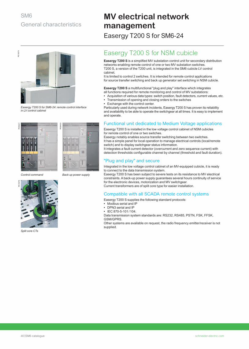
Easergy T200 S for SM6-24: remote control interface in LV control cabinet
Easergy T200 S for NSM cubicleEasergy T200 S is a simplified MV substation control unit for secondary distribution networks enabling remote control of one or two MV substation switches.T200 S, a version of the T200 unit, is integrated in the SM6 cubicle LV control cabinet. It is limited to control 2 switches. It is intended for remote control applications for source transfer switching and back up generator set switching in NSM cubicle.
Easergy T200 S a multifunctional "plug and play" interface which integrates all functions required for remote monitoring and control of MV substations: • Acquisition of various data types: switch position, fault detectors, current values, etc. • Transmission of opening and closing orders to the switches • Exchange with the control center.
Particularly used during network incidents, Easergy T200 S has proven its reliability and availability to be able to operate the switchgear at all times. It is easy to implement and operate.
Functional unit dedicated to Medium Voltage applicationsEasergy T200 S is installed in the low voltage control cabinet of NSM cubicles for remote control of one or two switches.Easergy notably enables source transfer switching between two switches.It has a simple panel for local operation to manage electrical controls (local/remote switch) and to display switchgear status information.It integrates a fault current detector (overcurrent and zero sequence current) with detection thresholds configurable channel by channel (threshold and fault duration).
"Plug and play" and secureIntegrated in the low voltage control cabinet of an MV-equipped cubicle, it is ready to connect to the data transmission system.Easergy T200 S has been subject to severe tests on its resistance to MV electrical constraints. A back-up power supply guarantees several hours continuity of service for the electronic devices, motorization and MV switchgear.Current transformers are of split core type for easier installation.
Compatible with all SCADA remote control systemsEasergy T200 S supplies the following standard protocols: • Modbus serial and IP • DPN3 serial and IP • IEC 870-5-101 / 104.
Data transmission system standards are: RS232, RS485, PSTN, FSK, FFSK, GSM/GPRS. Other systems are available on request, the radio frequency emitter/receiver is not supplied.
PE
5642
1
PE
5642
3
Control command Back up power supply
PE
1507
8
Split core CTs
schneider-electric.com SM6 catalogue 41
SM6General characteristics
PE
5631
1 Easergy T200 I: an interface designed for control and monitoring of MV networksEasergy T200 I is a "plug and play" or multifunction interface that integrates all the functional units necessary for remote supervision and control of the SM6: • Acquisition of the different types of information: switch position, fault detectors, current values...
• Transmission of switch open/close orders • Exchanges with the control center.
Required particularly during outages in the network, Easergy T200 I is of proven reliability and availability, being able to ensure switchgear operation at any moment.It is simple to set up and to operate.
Functional unit designed for the Medium Voltage network • Easergy T200 I is designed to be connected directly to the MV switchgear, without requiring a special converter.
• It has a simple front plate for local operation, which allows management of electrical rating mechanisms (local/remote switch) and display of information concerning switchgear status.
• It has an integrated MV network fault current detection system (overcurrent and zero sequence) with detection set points that can be configured channel by channel (current value and fault current duration).
Medium Voltage switchgear operating guarantee • Easergy T200 I has undergone severe MV electrical stress withstand tests. • It is a backed up power supply which guarantees continuity of service for several hours in case of loss of the auxiliary source, and supplies power to the Easergy T200 I and the MV switchgear motor mechanisms.
• Ready to plug - Easergy T200 I is delivered with a kit that makes it easy to connect the motor mechanisms and collect measurements.
- the connectors are polarized to avoid any errors during installation or maintenance interventions.
- current measurement acquisition sensors are of the split type, to facilitate their installation.
- works with 24 Vdc and 48 Vdc motor units.
Compatible with all SCADA remote control systemsEasergy T200 I supplies the following standard protocols: • Modbus serial and IP • DPN3 serial and IP • IEC 870-5-101 / 104.
Data transmission system standards are: RS232, RS485, PSTN, FSK, FFSK, GSM/GPRS. Other systems are available on request, the radio frequency emitter/receiver is not supplied.
Voltage detection relayVD23 provides accurate information of presence or absence of voltage. Associated with VPIS-Voltage Output, VD23 is typically used in critical power and safety applications.Various combinations of voltage detection are possible: • 3 Ph-N and residual voltage: V1 + V2 + V3 + V0 • 3 Ph-N or Ph-Ph voltage: V1 + V2 + V3 or U12 + U13 + U23 • 1 Ph-N or Ph-Ph or residual voltage: V1, V2, V3, U12, U13, U23, V0.
VD23 can display the MV network voltage (in % of service voltage), activate the relay output R1 to monitor a loss of voltage on 1 phase at least and active the relay output R2 to monitor a presence of voltage on 1 phase at least. • Auxiliary power supply: from 24 to 48 Vdc • Assembly: compact DIN format, mounted in the same place as fault passage indicator (format DIN, integrated in switchgear), terminal connexion fitted with VPIS-Voltage Output
• Compatible with all neutral earthing systems.
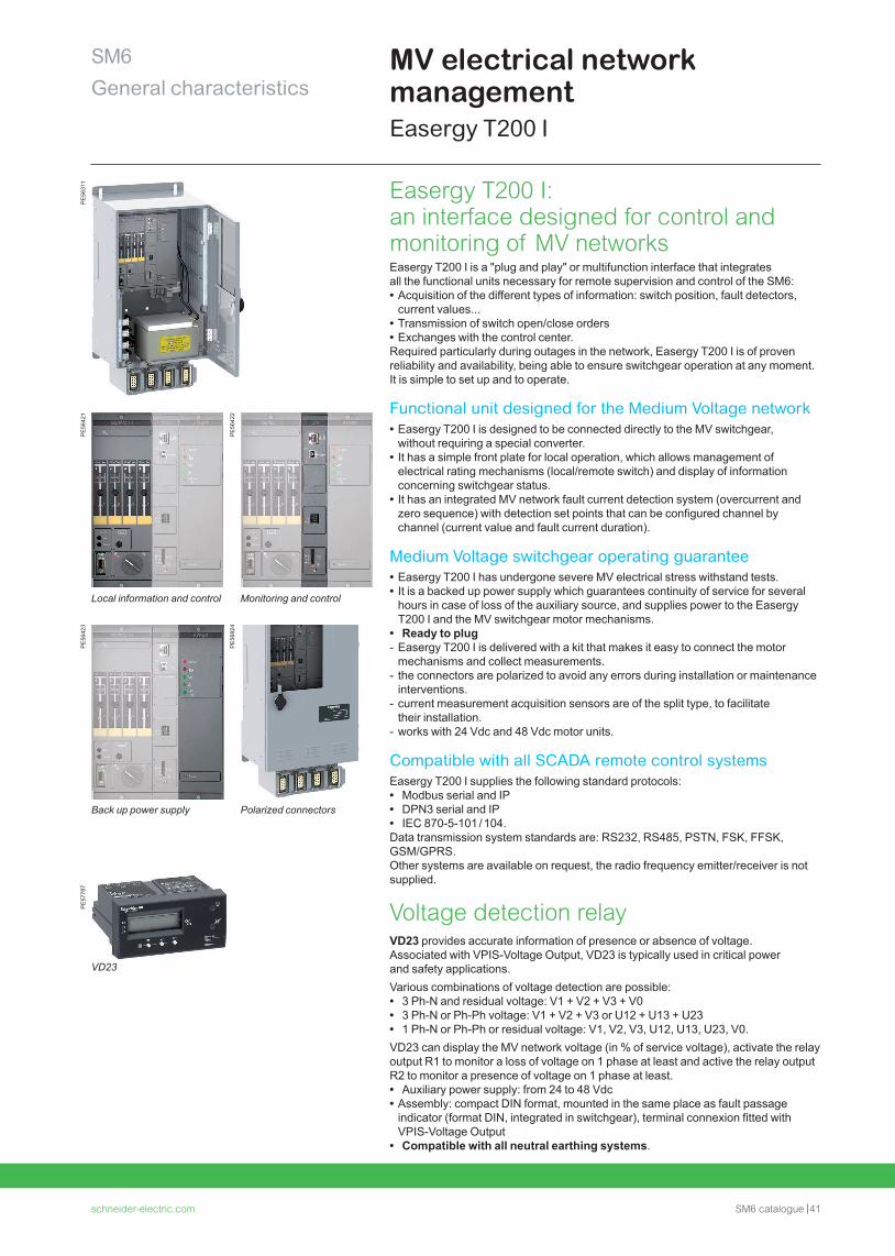
Local information and control Monitoring and control
Back up power supply Polarized connectors
PE
5642
1
PE
5642
2
PE
5642
3
MV electrical network managementEasergy T200 I
PE
5682
4
PE
5778
7
VD23
42 SM6 catalogue schneider-electric.com
SM6General characteristics
MV electrical network managementAutomation systems
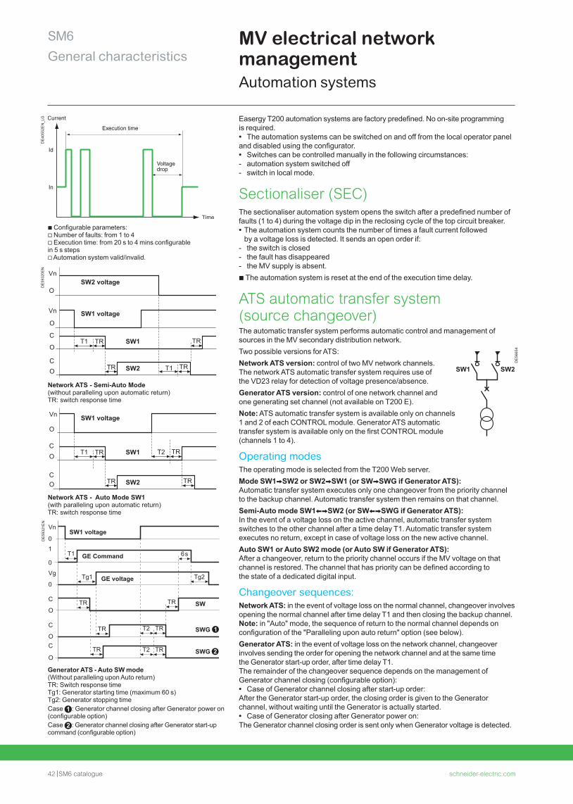
b Configurable parameters:v Number of faults: from 1 to 4v Execution time: from 20 s to 4 mins configurable in 5 s stepsv Automation system valid/invalid.
Easergy T200 automation systems are factory predefined. No on-site programming is required. • The automation systems can be switched on and off from the local operator panel
and disabled using the configurator. • Switches can be controlled manually in the following circumstances: - automation system switched off - switch in local mode.
Sectionaliser (SEC)The sectionaliser automation system opens the switch after a predefined number of faults (1 to 4) during the voltage dip in the reclosing cycle of the top circuit breaker. • The automation system counts the number of times a fault current followed by a voltage loss is detected. It sends an open order if:
- the switch is closed - the fault has disappeared - the MV supply is absent.
b The automation system is reset at the end of the execution time delay.
ATS automatic transfer system (source changeover)The automatic transfer system performs automatic control and management of sources in the MV secondary distribution network. Two possible versions for ATS:Network ATS version: control of two MV network channels.The network ATS automatic transfer system requires use of the VD23 relay for detection of voltage presence/absence.Generator ATS version: control of one network channel and one generating set channel (not available on T200 E).Note: ATS automatic transfer system is available only on channels 1 and 2 of each CONTROL module. Generator ATS automatic transfer system is available only on the first CONTROL module (channels 1 to 4).
Operating modesThe operating mode is selected from the T200 Web server.Mode SW1VSW2 or SW2VSW1 (or SWVSWG if Generator ATS):Automatic transfer system executes only one changeover from the priority channel to the backup channel. Automatic transfer system then remains on that channel.Semi-Auto mode SW1XVSW2 (or SWXVSWG if Generator ATS):In the event of a voltage loss on the active channel, automatic transfer system switches to the other channel after a time delay T1. Automatic transfer system executes no return, except in case of voltage loss on the new active channel.Auto SW1 or Auto SW2 mode (or Auto SW if Generator ATS):After a changeover, return to the priority channel occurs if the MV voltage on that channel is restored. The channel that has priority can be defined according to the state of a dedicated digital input.
Changeover sequences:Network ATS: in the event of voltage loss on the normal channel, changeover involves opening the normal channel after time delay T1 and then closing the backup channel.Note: in "Auto" mode, the sequence of return to the normal channel depends on configuration of the "Paralleling upon auto return" option (see below).Generator ATS: in the event of voltage loss on the network channel, changeover involves sending the order for opening the network channel and at the same time the Generator start-up order, after time delay T1. The remainder of the changeover sequence depends on the management of Generator channel closing (configurable option): • Case of Generator channel closing after start-up order:
After the Generator start-up order, the closing order is given to the Generator channel, without waiting until the Generator is actually started. • Case of Generator closing after Generator power on:
The Generator channel closing order is sent only when Generator voltage is detected.
DE
4055
2EN
_LG
SW2 voltage
SW1 voltage
Network ATS - Semi-Auto Mode (without paralleling upon automatic return)TR: switch response time
T1
Vn
Vn
O
O
CO
O
C
SW2 TRTR
SW1 voltage
Network ATS - Auto Mode SW1(with paralleling upon automatic return)TR: switch response time
SW1
SW2 TR
Vn
O
CO
CO
T1 T2
TR
TR TR
SW1T1 TR TR
DE
5932
0EN
Tg1
Vn
01
0
Vg
0Tg2
T1 6s
TRTR
TR
TR SWG
C
O
T2
TRT2
SWTR
SWG
C
OC
O
SW1 voltage
GE Command
GE voltage
DE
5932
1EN
SW1 SW2
DE
5665
4
Generator ATS - Auto SW mode(Without paralleling upon Auto return)TR: Switch response timeTg1: Generator starting time (maximum 60 s)Tg2: Generator stopping timeCase : Generator channel closing after Generator power on (configurable option)Case : Generator channel closing after Generator start-up command (configurable option)
schneider-electric.com SM6 catalogue 43
SM6General characteristics
MV electrical network managementAutomation systems
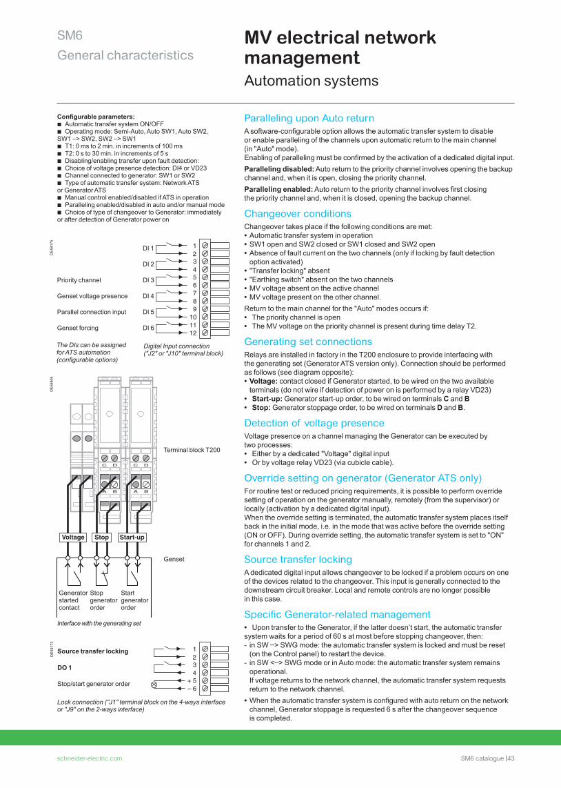
Lock connection ("J1" terminal block on the 4-ways interface or "J9" on the 2-ways interface)
DE
5917
3
Source transfer locking
DO 1
Stop/start generator order
1234
+ 5– 6
Interface with the generating set
Digital Input connection ("J2" or "J10" terminal block)
The DIs can be assigned for ATS automation (configurable options)
DE
5917
5
DI 1
DI 2
Priority channel DI 3
Genset voltage presence DI 4
Parallel connection input DI 5
Genset forcing DI 6
123456789
101112
DE
5680
6
C D
A B
C D
A B
Voltage Stop Start-up
G
Generator started contact
Stop generator order
Start generator order
Terminal block T200
Genset
Paralleling upon Auto returnA software-configurable option allows the automatic transfer system to disable or enable paralleling of the channels upon automatic return to the main channel (in "Auto" mode).Enabling of paralleling must be confirmed by the activation of a dedicated digital input.Paralleling disabled: Auto return to the priority channel involves opening the backup channel and, when it is open, closing the priority channel.Paralleling enabled: Auto return to the priority channel involves first closing the priority channel and, when it is closed, opening the backup channel.
Changeover conditions Changeover takes place if the following conditions are met: • Automatic transfer system in operation • SW1 open and SW2 closed or SW1 closed and SW2 open • Absence of fault current on the two channels (only if locking by fault detection option activated)
• "Transfer locking" absent • "Earthing switch" absent on the two channels • MV voltage absent on the active channel • MV voltage present on the other channel.
Return to the main channel for the "Auto" modes occurs if: • The priority channel is open • The MV voltage on the priority channel is present during time delay T2.
Generating set connections Relays are installed in factory in the T200 enclosure to provide interfacing with the generating set (Generator ATS version only). Connection should be performed as follows (see diagram opposite): • Voltage: contact closed if Generator started, to be wired on the two available terminals (do not wire if detection of power on is performed by a relay VD23)
• Start-up: Generator start-up order, to be wired on terminals C and B • Stop: Generator stoppage order, to be wired on terminals D and B.
Detection of voltage presence Voltage presence on a channel managing the Generator can be executed by two processes: • Either by a dedicated "Voltage" digital input • Or by voltage relay VD23 (via cubicle cable).
Override setting on generator (Generator ATS only) For routine test or reduced pricing requirements, it is possible to perform override setting of operation on the generator manually, remotely (from the supervisor) or locally (activation by a dedicated digital input).When the override setting is terminated, the automatic transfer system places itself back in the initial mode, i.e. in the mode that was active before the override setting (ON or OFF). During override setting, the automatic transfer system is set to "ON" for channels 1 and 2.
Source transfer locking A dedicated digital input allows changeover to be locked if a problem occurs on one of the devices related to the changeover. This input is generally connected to the downstream circuit breaker. Local and remote controls are no longer possible in this case.
Specific Generator-related management • Upon transfer to the Generator, if the latter doesn’t start, the automatic transfer
system waits for a period of 60 s at most before stopping changeover, then: - in SW –> SWG mode: the automatic transfer system is locked and must be reset (on the Control panel) to restart the device.
- in SW <–> SWG mode or in Auto mode: the automatic transfer system remains operational. If voltage returns to the network channel, the automatic transfer system requests return to the network channel.
• When the automatic transfer system is configured with auto return on the network channel, Generator stoppage is requested 6 s after the changeover sequence is completed.
Configurable parameters: b Automatic transfer system ON/OFF b Operating mode: Semi-Auto, Auto SW1, Auto SW2,
SW1 –> SW2, SW2 –> SW1 b T1: 0 ms to 2 min. in increments of 100 ms b T2: 0 s to 30 min. in increments of 5 s b Disabling/enabling transfer upon fault detection: b Choice of voltage presence detection: DI4 or VD23 b Channel connected to generator: SW1 or SW2 b Type of automatic transfer system: Network ATS
or Generator ATS b Manual control enabled/disabled if ATS in operation b Paralleling enabled/disabled in auto and/or manual mode b Choice of type of changeover to Generator: immediately
or after detection of Generator power on
44 SM6 catalogue schneider-electric.com
SM6General characteristics
MV electrical network managementAutomation systems
DE
5665
5_LG
SW1 SW2SW3
SW1 SW2SW3
SW1 SW2SW3
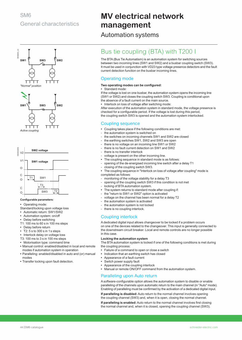
"Normal" position
Active coupling
DE
5932
2EN
Configurable parameters:
• Operating mode: Standard/locking upon voltage loss • Automatic return: SW1/SW2 • Automation system: on/off • Delay before switching
T1: 100 ms to 60 s in 100 ms steps • Delay before return • T2: 5 s to 300 s in 1 s steps • Interlock delay on voltage loss
T3: 100 ms to 3 s in 100 ms steps • Motorisation type: command time • Manual control: enabled/disabled in local and remote modes if automation system in operation
• Paralleling: enabled/disabled in auto and (or) manual modes
• Transfer locking upon fault detection.
Bus tie coupling (BTA) with T200 I The BTA (Bus Tie Automatism) is an automation system for switching sources between two incoming lines (SW1 and SW2) and a busbar coupling switch (SW3).It must be used in conjunction with VD23 type voltage presence detectors and the fault current detection function on the busbar incoming lines.
Operating modeTwo operating modes can be configured: • Standard mode:
If the voltage is lost on one busbar, the automation system opens the incoming line (SW1 or SW2) and closes the coupling switch SW3. Coupling is conditional upon the absence of a fault current on the main source. • Interlock on loss of voltage after switching mode:
After execution of the automation system in standard mode, the voltage presence is checked for a configurable period. If the voltage is lost during this period, the coupling switch SW3 is opened and the automation system interlocked.
Coupling sequence • Coupling takes place if the following conditions are met: - the automation system is switched on - the switches on incoming channels SW1 and SW2 are closed - the earthing switches SW1, SW2 and SW3 are open - there is no voltage on an incoming line SW1 or SW2 - there is no fault current detection on SW1 and SW2 - there is no transfer interlock - voltage is present on the other incoming line. • The coupling sequence in standard mode is as follows: - opening of the de-energised incoming line switch after a delay T1 - closing of the coupling switch SW3. • The coupling sequence in "Interlock on loss of voltage after coupling" mode is
completed as follows: - monitoring of the voltage stability for a delay T3 - opening of the coupling switch SW3 if this condition is not met - locking of BTA automation system. • The system returns to standard mode after coupling if: - the "return to SW1 or SW2" option is activated - voltage on the channel has been normal for a delay T2 - the automation system is activated - the automation system is not locked - there is no coupling interlock.
Coupling interlockA dedicated digital input allows changeover to be locked if a problem occurs on one of the devices related to the changeover. This input is generally connected to the downstream circuit breaker. Local and remote controls are no longer possible in this case.Locking the automation systemThe BTA automation system is locked if one of the following conditions is met during the coupling process: • Failure of a command to open or close a switch • Indication that an earthing switch has closed • Appearance of a fault current • Switch power supply fault • Appearance of the coupling interlock • Manual or remote ON/OFF command from the automation system.
Paralleling upon Auto returnA software-configurable option allows the automation system to disable or enable paralleling of the channels upon automatic return to the main channel (in "Auto" mode).Enabling of paralleling must be confirmed by the activation of a dedicated digital input.If paralleling is disabled: Auto return to the normal channel involves opening the coupling channel (SW3) and, when it is open, closing the normal channel.If paralleling is enabled: Auto return to the normal channel involves first closing the normal channel and, when it is closed, opening the coupling channel (SW3).
SW2 voltage
SW1 voltage
SW1
SW3 T2
V1
V2
O
CO
CO
T1
T3
schneider-electric.com SM6 catalogue 45
SM6General characteristics
Fault passage indicatorsFlair 21D, 22D and 23DM
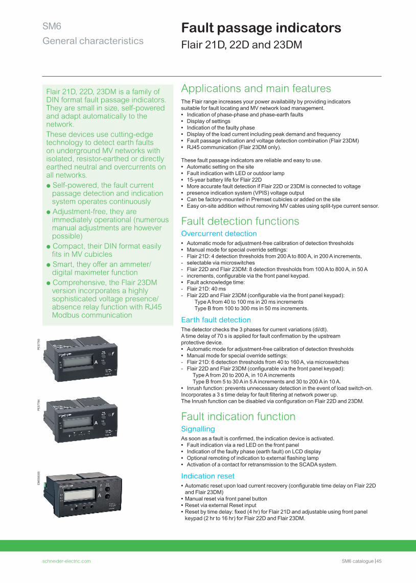
Flair 21D, 22D, 23DM is a family of DIN format fault passage indicators. They are small in size, self-powered and adapt automatically to the network.These devices use cutting-edge technology to detect earth faults on underground MV networks with isolated, resistor-earthed or directly earthed neutral and overcurrents on all networks.p Self-powered, the fault current
passage detection and indication system operates continuously
p Adjustment-free, they are immediately operational (numerous manual adjustments are however possible)
p Compact, their DIN format easily fits in MV cubicles
p Smart, they offer an ammeter/digital maximeter function
p Comprehensive, the Flair 23DM version incorporates a highly sophisticated voltage presence/absence relay function with RJ45 Modbus communication
PE
5778
3P
E57
784
EM
S58
355
Applications and main features The Flair range increases your power availability by providing indicatorssuitable for fault locating and MV network load management. • Indication of phase-phase and phase-earth faults • Display of settings • Indication of the faulty phase • Display of the load current including peak demand and frequency • Fault passage indication and voltage detection combination (Flair 23DM) • RJ45 communication (Flair 23DM only).
These fault passage indicators are reliable and easy to use. • Automatic setting on the site • Fault indication with LED or outdoor lamp • 15-year battery life for Flair 22D • More accurate fault detection if Flair 22D or 23DM is connected to voltage • presence indication system (VPIS) voltage output • Can be factory-mounted in Premset cubicles or added on the site • Easy on-site addition without removing MV cables using split-type current sensor.
Fault detection functions Overcurrent detection • Automatic mode for adjustment-free calibration of detection thresholds • Manual mode for special override settings: - Flair 21D: 4 detection thresholds from 200 A to 800 A, in 200 A increments, - selectable via microswitches - Flair 22D and Flair 23DM: 8 detection thresholds from 100 A to 800 A, in 50 A - increments, configurable via the front panel keypad. • Fault acknowledge time: - Flair 21D: 40 ms - Flair 22D and Flair 23DM (configurable via the front panel keypad):
Type A from 40 to 100 ms in 20 ms incrementsType B from 100 to 300 ms in 50 ms increments.
Earth fault detection The detector checks the 3 phases for current variations (di/dt).A time delay of 70 s is applied for fault confirmation by the upstreamprotective device. • Automatic mode for adjustment-free calibration of detection thresholds • Manual mode for special override settings: - Flair 21D: 6 detection thresholds from 40 to 160 A, via microswitches - Flair 22D and Flair 23DM (configurable via the front panel keypad):
Type A from 20 to 200 A, in 10 A incrementsType B from 5 to 30 A in 5 A increments and 30 to 200 A in 10 A.
• Inrush function: prevents unnecessary detection in the event of load switch-on.Incorporates a 3 s time delay for fault filtering at network power up.The Inrush function can be disabled via configuration on Flair 22D and 23DM.
Fault indication function SignallingAs soon as a fault is confirmed, the indication device is activated. • Fault indication via a red LED on the front panel • Indication of the faulty phase (earth fault) on LCD display • Optional remoting of indication to external flashing lamp • Activation of a contact for retransmission to the SCADA system.
Indication reset • Automatic reset upon load current recovery (configurable time delay on Flair 22D and Flair 23DM)
• Manual reset via front panel button • Reset via external Reset input • Reset by time delay: fixed (4 hr) for Flair 21D and adjustable using front panel keypad (2 hr to 16 hr) for Flair 22D and Flair 23DM.
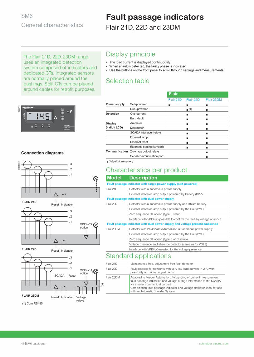
46 SM6 catalogue schneider-electric.com
SM6General characteristics
The Flair 21D, 22D, 23DM range uses an integrated detection system composed of indicators and dedicated CTs. Integrated sensors are normally placed around the bushings. Split CTs can be placed around cables for retrofit purposes.
Display principle • The load current is displayed continuously • When a fault is detected, the faulty phase is indicated • Use the buttons on the front panel to scroll through settings and measurements.
Selection table
FlairFlair 21D Flair 22D Flair 23DM
Power supply Self-powered b b bDual-powered b (1) b
Detection Overcurrent b bEarth-fault b b
Display(4 digit LCD)
Ammeter b bMaximeter b bSCADA interface (relay) b bExternal lamp b bExternal reset b bExtended setting (keypad) b b
Communication 2-voltage output relays bSerial communication port b
(1) By lithium battery
Characteristics per product Model DescriptionFault passage indicator with single power supply (self-powered)
Flair 21D Detector with autonomous power supply
External indicator lamp output powered by battery (BVP)
Fault passage indicator with dual power supply
Flair 22D Detector with autonomous power supply and lithium battery
External indicator lamp output powered by the Flair (BVE)
Zero sequence CT option (type B setup)
Interface with VPIS-VO possible to confirm the fault by voltage absence
Fault passage indicator with dual power supply and voltage presence/absence
Flair 23DM Detector with 24-48 Vdc external and autonomous power supply
External indicator lamp output powered by the Flair (BVE)
Zero sequence CT option (type B or C setup)
Voltage presence and absence detector (same as for VD23)
Interface with VPIS-VO needed for the voltage presence
Standard applications Flair 21D Maintenance-free, adjustment-free fault detector
Flair 22D Fault detector for networks with very low load current (< 2 A) with possibility of manual adjustments
Flair 23DM Adapted to Feeder Automation. Forwarding of current measurement,fault passage indication and voltage outage information to the SCADAvia a serial communication port.Combination fault passage indicator and voltage detector, ideal for usewith an Automatic Transfer System
Fault passage indicatorsFlair 21D, 22D and 23DM
Flair 22DEasergy
L1L2L3
I max.
EMS58352
AEsc
TestReset
L3
L2
L1
L3
L2
L1
L3
L2
L1
Reset
Reset
Reset
Indication
Indication
Indication
Reset
Voltage relays
VPIS-VOoption
VPIS-VOoption
(1) Com RS485
(1)
+ -
FLAIR 21D
FLAIR 22D
FLAIR 23DM
SCADA
Connection diagrams
DE
5871
5D
M10
0004
8
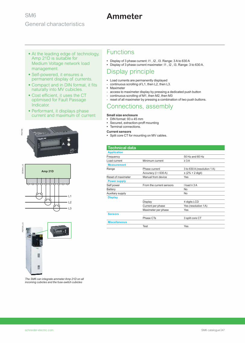
schneider-electric.com SM6 catalogue 47
SM6General characteristics
Ammeter
• At the leading edge of technology, Amp 21D is suitable for Medium Voltage network load management.
• Self-powered, it ensures a permanent display of currents.
• Compact and in DIN format, it fits naturally into MV cubicles.
• Cost efficient, it uses the CT optimised for Fault Passage Indicator.
• Performant, it displays phase current and maximum of current
Functions • Display of 3 phase current: I1 , I2 , I3. Range: 3 A to 630 A • Display of 3 phase current maximeter: I1 , I2 , I3. Range: 3 to 630 A.
Display principle • Load currents are permanently displayed - continuous scrolling of L1, then L2, then L3. • Maximeter - access to maximeter display by pressing a dedicated push button - continuous scrolling of M1, then M2, then M3 - reset of all maximeter by pressing a combination of two push buttons.
Connections, assemblySmall size enclosure • DIN format: 93 x 45 mm • Secured, extraction-proff mounting • Terminal connections.
Current sensors • Split core CT for mounting on MV cables.
Technical dataApplication
Frequency 50 Hz and 60 HzLoad current Minimum current ≥ 3 AMeasurement
Range Phase current 3 to 630 A (resolution 1 A)Accuracy (I < 630 A) ± (2% + 2 digit)
Reset of maximeter Manual from device YesPower supply
Self power From the current sensors I load ≥ 3 ABattery NoAuxiliary supply NoDisplay
Display 4 digits LCDCurrent per phase Yes (resolution 1 A)Maximeter per phase Yes
SensorsPhase CTs 3 split core CT
MiscellaneousTest Yes
The SM6 can integrate ammeter Amp 21D on all incoming cubicles and the fuse-switch cubicles
DE
5840
4_LG
Amp 21D
L1
L2
L3
PE
5778
6P
E57
233_
LG
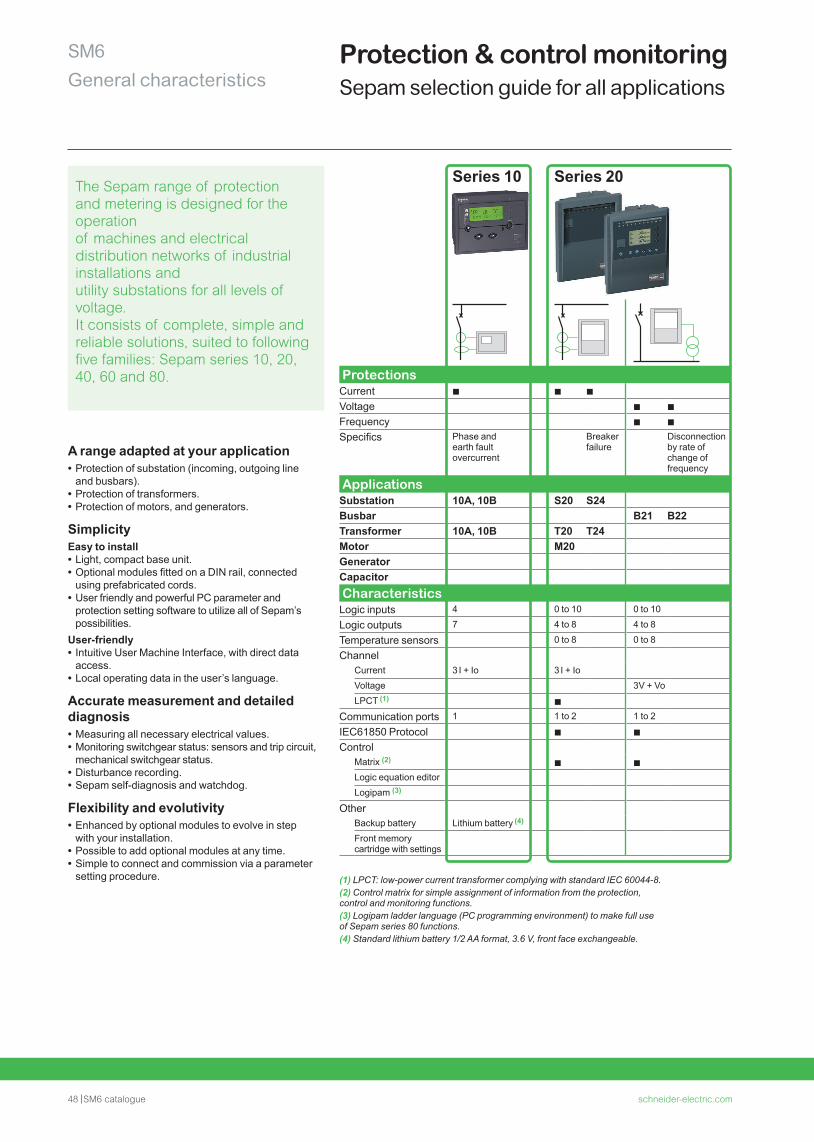
48 SM6 catalogue schneider-electric.com
SM6General characteristics
Protection & control monitoringSepam selection guide for all applications
Series 10 Series 20
ProtectionsCurrent b b b
Voltage b b
Frequency b b
Specifics Phase and earth fault overcurrent
Breaker failure
Disconnection by rate of change of frequency
ApplicationsSubstation 10A, 10B S20 S24Busbar B21 B22Transformer 10A, 10B T20 T24Motor M20GeneratorCapacitor CharacteristicsLogic inputs 4 0 to 10 0 to 10
Logic outputs 7 4 to 8 4 to 8
Temperature sensors 0 to 8 0 to 8
ChannelCurrent 3 I + Io 3 I + IoVoltage 3V + VoLPCT (1) b
Communication ports 1 1 to 2 1 to 2
IEC61850 Protocol b b
ControlMatrix (2) b bLogic equation editorLogipam (3)
OtherBackup battery Lithium battery (4)
Front memory cartridge with settings
(1) LPCT: low-power current transformer complying with standard IEC 60044-8.(2) Control matrix for simple assignment of information from the protection, control and monitoring functions.(3) Logipam ladder language (PC programming environment) to make full use of Sepam series 80 functions.(4) Standard lithium battery 1/2 AA format, 3.6 V, front face exchangeable.
A range adapted at your application • Protection of substation (incoming, outgoing line and busbars).
• Protection of transformers. • Protection of motors, and generators.
SimplicityEasy to install • Light, compact base unit. • Optional modules fitted on a DIN rail, connected using prefabricated cords.
• User friendly and powerful PC parameter and protection setting software to utilize all of Sepam’s possibilities.
User-friendly • Intuitive User Machine Interface, with direct data access.
• Local operating data in the user’s language.
Accurate measurement and detailed diagnosis • Measuring all necessary electrical values. • Monitoring switchgear status: sensors and trip circuit, mechanical switchgear status.
• Disturbance recording. • Sepam self-diagnosis and watchdog.
Flexibility and evolutivity • Enhanced by optional modules to evolve in step with your installation.
• Possible to add optional modules at any time. • Simple to connect and commission via a parameter setting procedure.
The Sepam range of protection and metering is designed for the operation of machines and electrical distribution networks of industrial installations and utility substations for all levels of voltage. It consists of complete, simple and reliable solutions, suited to following five families: Sepam series 10, 20, 40, 60 and 80.
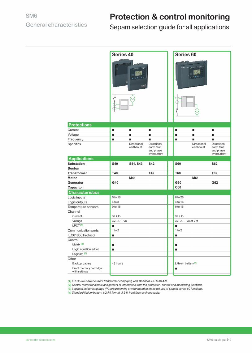
schneider-electric.com SM6 catalogue 49
SM6General characteristics
Series 40 Series 60
ProtectionsCurrent b b b b b b
Voltage b b b b b b
Frequency b b b b b b
Specifics Directional earth fault
Directional earth fault and phase overcurrent
Directional earth fault
Directional earth fault and phase overcurrent
ApplicationsSubstation S40 S41, S43 S42 S60 S62BusbarTransformer T40 T42 T60 T62Motor M41 M61Generator G40 G60 G62Capacitor C60 CharacteristicsLogic inputs 0 to 10 0 to 28
Logic outputs 4 to 8 4 to 16
Temperature sensors 0 to 16 0 to 16
ChannelCurrent 3 I + Io 3 I + IoVoltage 3V, 2U + Vo 3V, 2U + Vo or VntLPCT (1) b b
Communication ports 1 to 2 1 to 2
IEC61850 Protocol b b
ControlMatrix (2) b bLogic equation editor b bLogipam (3)
OtherBackup battery 48 hours Lithium battery (4)
Front memory cartridge with settings
b
(1) LPCT: low-power current transformer complying with standard IEC 60044-8.(2) Control matrix for simple assignment of information from the protection, control and monitoring functions.(3) Logipam ladder language (PC programming environment) to make full use of Sepam series 80 functions.(4) Standard lithium battery 1/2 AA format, 3.6 V, front face exchangeable.
Protection & control monitoringSepam selection guide for all applications
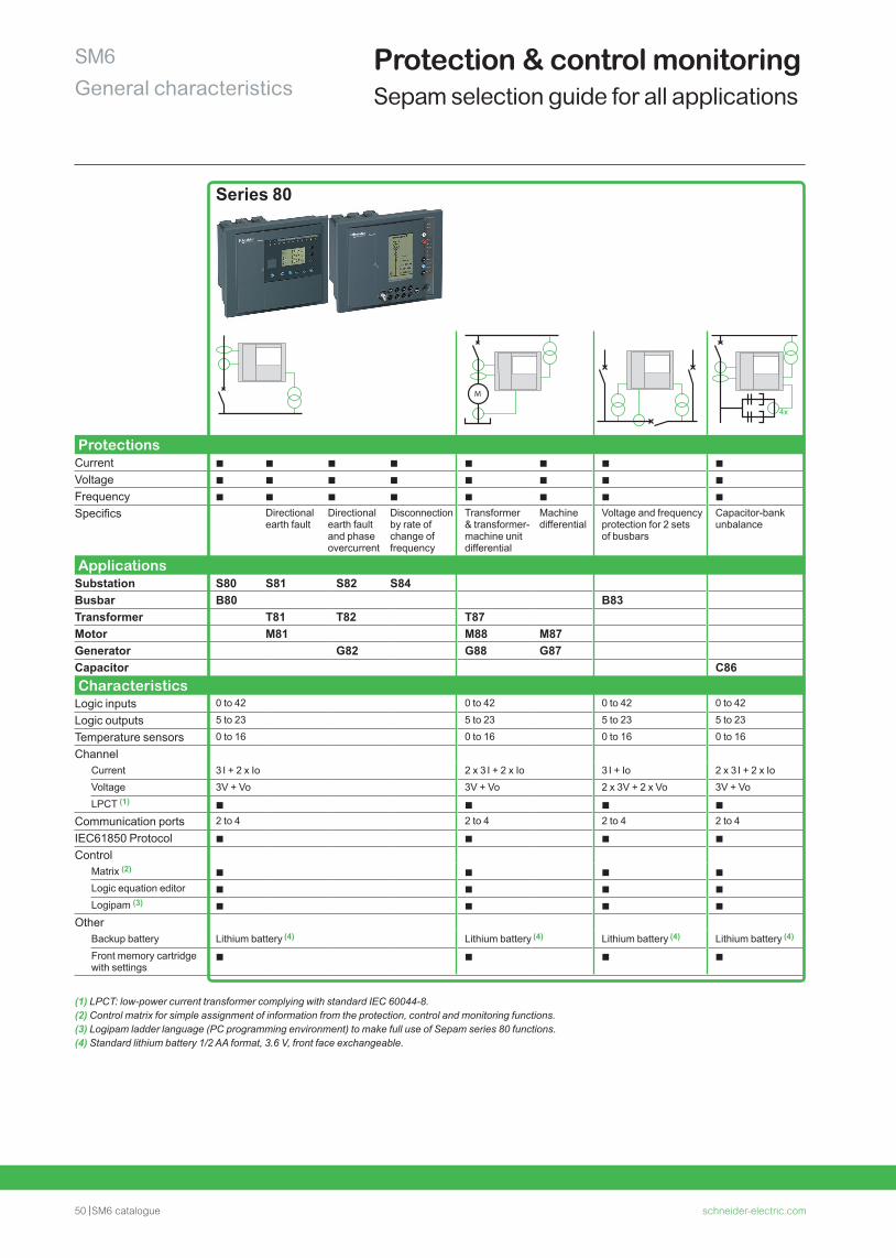
50 SM6 catalogue schneider-electric.com
SM6General characteristics
Series 80
M
ProtectionsCurrent b b b b b b b b
Voltage b b b b b b b b
Frequency b b b b b b b b
Specifics Directional earth fault
Directional earth fault and phase overcurrent
Disconnection by rate of change of frequency
Transformer & transformer-machine unit differential
Machine differential
Voltage and frequency protection for 2 sets of busbars
Capacitor-bank unbalance
ApplicationsSubstation S80 S81 S82 S84Busbar B80 B83Transformer T81 T82 T87Motor M81 M88 M87Generator G82 G88 G87Capacitor C86 CharacteristicsLogic inputs 0 to 42 0 to 42 0 to 42 0 to 42
Logic outputs 5 to 23 5 to 23 5 to 23 5 to 23
Temperature sensors 0 to 16 0 to 16 0 to 16 0 to 16
ChannelCurrent 3 I + 2 x Io 2 x 3 I + 2 x Io 3 I + Io 2 x 3 I + 2 x IoVoltage 3V + Vo 3V + Vo 2 x 3V + 2 x Vo 3V + VoLPCT (1) b b b b
Communication ports 2 to 4 2 to 4 2 to 4 2 to 4
IEC61850 Protocol b b b b
ControlMatrix (2) b b b bLogic equation editor b b b bLogipam (3) b b b b
OtherBackup battery Lithium battery (4) Lithium battery (4) Lithium battery (4) Lithium battery (4)
Front memory cartridge with settings
b b b b
(1) LPCT: low-power current transformer complying with standard IEC 60044-8.(2) Control matrix for simple assignment of information from the protection, control and monitoring functions.(3) Logipam ladder language (PC programming environment) to make full use of Sepam series 80 functions.(4) Standard lithium battery 1/2 AA format, 3.6 V, front face exchangeable.
Protection & control monitoringSepam selection guide for all applications
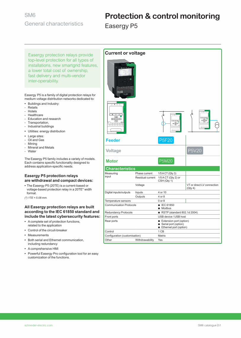
schneider-electric.com SM6 catalogue 51
SM6General characteristics
Protection & control monitoringEasergy P5
Easergy P5 is a family of digital protection relays for medium voltage distribution networks dedicated to: • Buildings and Industry: - Retails - Hotels - Healthcare - Education and research - Transportation, - Industrial buildings • Utilities: energy distribution • Large sites: - Oil and Gas - Mining - Mineral and Metals - Water
The Easergy P5 family includes a variety of models. Each contains specific functionality designed to address application-specific needs.
Easergy P5 protection relays are withdrawal and compact devices: • The Easergy P5 (20TE) is a current-based or voltage-based protection relay in a 20TE* width format.
(*) 1TE = 5.08 mm.
All Easergy protection relays are built according to the IEC 61850 standard and include the latest cybersecurity features: • A complete set of protection functions,
related to the application • Control of the circuit-breaker • Measurements • Both serial and Ethernet communication,
including redundancy • A comprehensive HMI • Powerful Easergy Pro configuration tool for an easy
customization of the functions.
Current or voltage
Feeder P5F20
Voltage P5V20
Motor P5M20
CharacteristicsMeasuring input
Phase current 1/5 A CT (Qty 3) Residual current 1/5 A CT (Qty 2) or
CSH (Qty 1)Voltage VT or direct LV connection
(Qty 4)Digital inputs/outputs Inputs 4 or 10
Outputs 4 or 8Temperature sensors 0 or 8Communication Protocols b IEC 61850
b ModbusRedundancy Protocols b RSTP (standard 802.1d 2004)Front ports USB device / USB hostRear ports b Extension port (option)
b Serial port (option) b Ethernet port (option)
Control 1 CBConfiguration (customisation) MatrixOther Withdrawability Yes
Easergy protection relays provide top-level protection for all types of installations, new smartgrid features, a lower total cost of ownership, fast delivery and multi-vendor inter-operability.
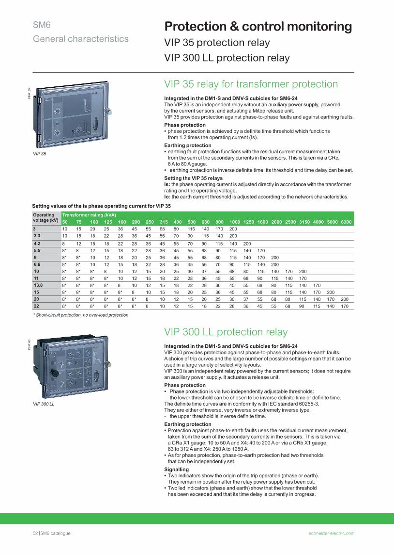
52 SM6 catalogue schneider-electric.com
SM6General characteristics
Protection & control monitoringVIP 35 protection relayVIP 300 LL protection relay
PE
5715
9
VIP 35
PE
5716
0
VIP 300 LL
VIP 35 relay for transformer protectionIntegrated in the DM1-S and DMV-S cubicles for SM6-24The VIP 35 is an independent relay without an auxiliary power supply, powered by the current sensors, and actuating a Mitop release unit. VIP 35 provides protection against phase-to-phase faults and against earthing faults.Phase protection • phase protection is achieved by a definite time threshold which functions from 1.2 times the operating current (Is).
Earthing protection • earthing fault protection functions with the residual current measurement taken from the sum of the secondary currents in the sensors. This is taken via a CRc, 8 A to 80 A gauge.
• earthing protection is inverse definite time: its threshold and time delay can be set.Setting the VIP 35 relaysIs: the phase operating current is adjusted directly in accordance with the transformer rating and the operating voltage.Io: the earth current threshold is adjusted according to the network characteristics.
Setting values of the Is phase operating current for VIP 35Operating voltage (kV)
Transformer rating (kVA)50 75 100 125 160 200 250 315 400 500 630 800 1000 1250 1600 2000 2500 3150 4000 5000 6300
3 10 15 20 25 36 45 55 68 80 115 140 170 2003.3 10 15 18 22 28 36 45 56 70 90 115 140 200
4.2 8 12 15 18 22 28 36 45 55 70 90 115 140 2005.5 8* 8 12 15 18 22 28 36 45 55 68 90 115 140 1706 8* 8* 10 12 18 20 25 36 45 55 68 80 115 140 170 2006.6 8* 8* 10 12 15 18 22 28 36 45 56 70 90 115 140 20010 8* 8* 8* 8 10 12 15 20 25 30 37 55 68 80 115 140 170 20011 8* 8* 8* 8* 10 12 15 18 22 28 36 45 55 68 90 115 140 17013.8 8* 8* 8* 8* 8 10 12 15 18 22 28 36 45 55 68 90 115 140 17015 8* 8* 8* 8* 8* 8 10 15 18 20 25 36 45 55 68 80 115 140 170 20020 8* 8* 8* 8* 8* 8* 8 10 12 15 20 25 30 37 55 68 80 115 140 170 20022 8* 8* 8* 8* 8* 8* 8 10 12 15 18 22 28 36 45 55 68 90 115 140 170
* Short-circuit protection, no over-load protection
VIP 300 LL protection relayIntegrated in the DM1-S and DMV-S cubicles for SM6-24 VIP 300 provides protection against phase-to-phase and phase-to-earth faults. A choice of trip curves and the large number of possible settings mean that it can be used in a large variety of selectivity layouts.VIP 300 is an independent relay powered by the current sensors; it does not require an auxiliary power supply. It actuates a release unit.Phase protection • Phase protection is via two independently adjustable thresholds: - the lower threshold can be chosen to be inverse definite time or definite time.
The definite time curves are in conformity with IEC standard 60255-3. They are either of inverse, very inverse or extremely inverse type. - the upper threshold is inverse definite time.
Earthing protection • Protection against phase-to-earth faults uses the residual current measurement, taken from the sum of the secondary currents in the sensors. This is taken via a CRa X1 gauge: 10 to 50 A and X4: 40 to 200 A or via a CRb X1 gauge: 63 to 312 A and X4: 250 A to 1250 A.
• As for phase protection, phase-to-earth protection had two thresholds that can be independently set.
Signalling • Two indicators show the origin of the trip operation (phase or earth). They remain in position after the relay power supply has been cut.
• Two led indicators (phase and earth) show that the lower threshold has been exceeded and that its time delay is currently in progress.
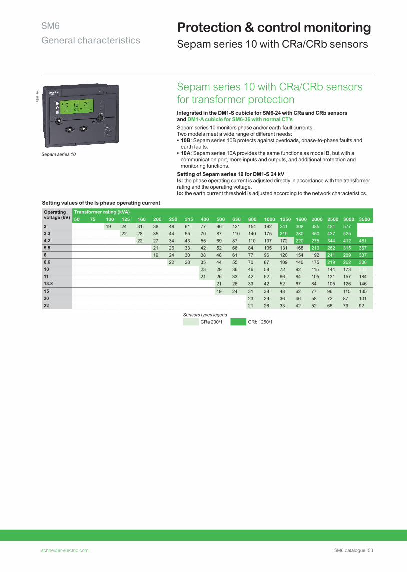
schneider-electric.com SM6 catalogue 53
SM6General characteristics
Protection & control monitoringSepam series 10 with CRa/CRb sensors
Sepam series 10 with CRa/CRb sensors for transformer protectionIntegrated in the DM1-S cubicle for SM6-24 with CRa and CRb sensors and DM1-A cubicle for SM6-36 with normal CT’sSepam series 10 monitors phase and/or earth-fault currents. Two models meet a wide range of different needs: • 10B: Sepam series 10B protects against overloads, phase-to-phase faults and earth faults.
• 10A: Sepam series 10A provides the same functions as model B, but with a communication port, more inputs and outputs, and additional protection and monitoring functions.
Setting of Sepam series 10 for DM1-S 24 kVIs: the phase operating current is adjusted directly in accordance with the transformer rating and the operating voltage.Io: the earth current threshold is adjusted according to the network characteristics.
Setting values of the Is phase operating currentOperating voltage (kV)
Transformer rating (kVA)
50 75 100 125 160 200 250 315 400 500 630 800 1000 1250 1600 2000 2500 3000 35003 19 24 31 38 48 61 77 96 121 154 192 241 308 385 481 5773.3 22 28 35 44 55 70 87 110 140 175 219 280 350 437 5254.2 22 27 34 43 55 69 87 110 137 172 220 275 344 412 4815.5 21 26 33 42 52 66 84 105 131 168 210 262 315 3676 19 24 30 38 48 61 77 96 120 154 192 241 289 3376.6 22 28 35 44 55 70 87 109 140 175 219 262 30610 23 29 36 46 58 72 92 115 144 173 20211 21 26 33 42 52 66 84 105 131 157 18413.8 21 26 33 42 52 67 84 105 126 14615 19 24 31 38 48 62 77 96 115 13520 23 29 36 46 58 72 87 10122 21 26 33 42 52 66 79 92
Sensors types legendCRa 200/1 CRb 1250/1
Sepam series 10
PE
5717
0
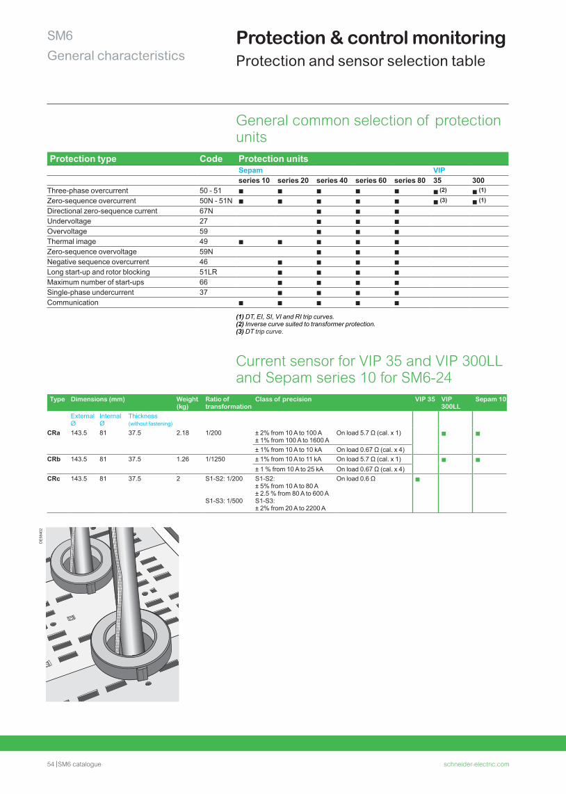
54 SM6 catalogue schneider-electric.com
SM6General characteristics
Protection & control monitoringProtection and sensor selection table
CRa, CRb, CRc current sensor
DE
5840
2
Protection type Code Protection unitsSepam VIPseries 10 series 20 series 40 series 60 series 80 35 300
Three-phase overcurrent 50 - 51 b b b b b b (2) b (1)
Zero-sequence overcurrent 50N - 51N b b b b b b (3) b (1)
Directional zero-sequence current 67N b b bUndervoltage 27 b b bOvervoltage 59 b b bThermal image 49 b b b b bZero-sequence overvoltage 59N b b bNegative sequence overcurrent 46 b b b bLong start-up and rotor blocking 51LR b b b bMaximum number of start-ups 66 b b b bSingle-phase undercurrent 37 b b b bCommunication b b b b b
General common selection of protection units
(1) DT, EI, SI, VI and RI trip curves. (2) Inverse curve suited to transformer protection.(3) DT trip curve.
Type Dimensions (mm) Weight (kg)
Ratio of transformation
Class of precision VIP 35 VIP 300LL
Sepam 10
External Ø
Internal Ø
Thickness(without fastening)
CRa 143.5 81 37.5 2.18 1/200 ± 2% from 10 A to 100 A± 1% from 100 A to 1600 A
On load 5.7 Ω (cal. x 1) b b
± 1% from 10 A to 10 kA On load 0.67 Ω (cal. x 4)CRb 143.5 81 37.5 1.26 1/1250 ± 1% from 10 A to 11 kA On load 5.7 Ω (cal. x 1) b b
± 1 % from 10 A to 25 kA On load 0.67 Ω (cal. x 4)CRc 143.5 81 37.5 2 S1-S2: 1/200
S1-S3: 1/500
S1-S2:± 5% from 10 A to 80 A± 2.5 % from 80 A to 600 AS1-S3:± 2% from 20 A to 2200 A
On load 0.6 Ω b
Current sensor for VIP 35 and VIP 300LL and Sepam series 10 for SM6-24
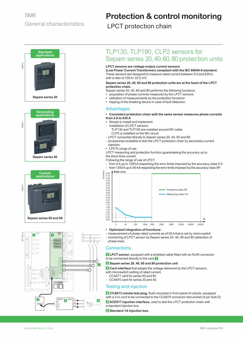
schneider-electric.com SM6 catalogue 55
SM6General characteristics
Protection & control monitoring LPCT protection chain
MT1
1325
_LG
TLP130, TLP190, CLP2 sensors for Sepam series 20, 40, 60, 80 protection unitsLPCT sensors are voltage-output current sensors (Low Power Current Transformer) compliant with the IEC 60044-8 standard.These sensors are designed to measure rated current between 5 A and 630 A, with a ratio of 100 A / 22.5 mV.Sepam series 20, 40, 60 and 80 protection units are at the heart of the LPCT protection chain.Sepam series 20, 40, 60 and 80 performs the following functions: • acquisition of phase currents measured by the LPCT sensors • utilization of measurements by the protection functions • tripping of the breaking device in case of fault detection.
Advantages • Consistent protection chain with the same sensor measures phase currents
from 5 A to 630 A • Simple to install and implement: - installation of LPCT sensors
TLP130 and TLP190 are installed around MV cableCLP2 is installed on the MV circuit
- LPCT connected directly to Sepam series 20, 40, 60 and 80 - accessories available to test the LPCT protection chain by secondary current injection.
• LPCTs range of useLPCT measuring and protection function guaranteeing the accuracy up to the short-time current. Following the range of use of LPCT: - from 5 A up to 1250 A respecting the error limits imposed by the accuracy class 0.5 - from 1250 A up to 50 kA respecting the error limits imposed by the accuracy class 5P.
DE
5840
5EN Ratio error
A
5.004.754.504.254.003.753.503.253.002.752.502.252.001.751.50
Protective class 5P
Measuring class 0.5
1.251.000.750.500.25
5 20 100 1000 1250 2000 3000 31500 40000 50000
• Optimized integration of functions: - measurement of phase rated currents as of 25 A that is set by micro-switch - monitoring of LPCT sensor by Sepam series 20, 40, 60 and 80 (detection of phase loss).
Connections1 LPCT sensor, equipped with a shielded cable fitted with an RJ45 connector to be connected directly to the card 32 Sepam series 20, 40, 60 and 80 protection unit3 Card interface that adapts the voltage delivered by the LPCT sensors, with microswitch setting of rated current. - CCA671 card for series 60 and 80 - CCA670 card for series 20 and 40.
Testing and injection4 CCA613 remote test plug, flush-mounted in front panel of cubicle, equipped with a 3-m cord to be connected to the CCA670 connector test socket (9-pin Sub D)5 ACE917 injection interface, used to test the LPCT protection chain with a standard injection box6 Standard 1A injection box.
PE
8801
2
Standard applications
Sepam series 20
Custom applications
Sepam series 60 and 80
Demanding applications
Sepam series 40
PE
8801
1P
E88
010
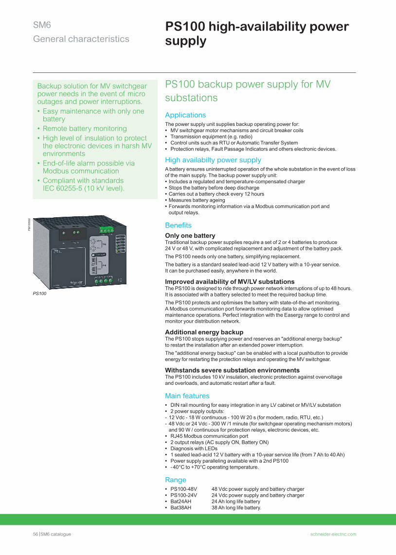
56 SM6 catalogue schneider-electric.com
SM6General characteristics
PS100 high-availability power supply
Backup solution for MV switchgear power needs in the event of micro outages and power interruptions.• Easy maintenance with only one
battery • Remote battery monitoring• High level of insulation to protect
the electronic devices in harsh MV environments
• End-of-life alarm possible via Modbus communication
• Compliant with standards IEC 60255-5 (10 kV level).
PS100 backup power supply for MV substations
ApplicationsThe power supply unit supplies backup operating power for: • MV switchgear motor mechanisms and circuit breaker coils • Transmission equipment (e.g. radio) • Control units such as RTU or Automatic Transfer System • Protection relays, Fault Passage Indicators and others electronic devices.
High availabilty power supplyA battery ensures uninterrupted operation of the whole substation in the event of loss of the main supply. The backup power supply unit: • Includes a regulated and temperature-compensated charger • Stops the battery before deep discharge • Carries out a battery check every 12 hours • Measures battery ageing • Forwards monitoring information via a Modbus communication port and output relays.
BenefitsOnly one batteryTraditional backup power supplies require a set of 2 or 4 batteries to produce 24 V or 48 V, with complicated replacement and adjustment of the battery pack. The PS100 needs only one battery, simplifying replacement.The battery is a standard sealed lead-acid 12 V battery with a 10-year service. It can be purchased easily, anywhere in the world.
Improved availability of MV/LV substationsThe PS100 is designed to ride through power network interruptions of up to 48 hours. It is associated with a battery selected to meet the required backup time.The PS100 protects and optimises the battery with state-of-the-art monitoring. A Modbus communication port forwards monitoring data to allow optimised maintenance operations. Perfect integration with the Easergy range to control and monitor your distribution network.
Additional energy backupThe PS100 stops supplying power and reserves an "additional energy backup" to restart the installation after an extended power interruption.The "additional energy backup" can be enabled with a local pushbutton to provide energy for restarting the protection relays and operating the MV switchgear.
Withstands severe substation environmentsThe PS100 includes 10 kV insulation, electronic protection against overvoltage and overloads, and automatic restart after a fault.
Main features • DIN rail mounting for easy integration in any LV cabinet or MV/LV substation • 2 power supply outputs: - 12 Vdc - 18 W continuous - 100 W 20 s (for modem, radio, RTU, etc.) - 48 Vdc or 24 Vdc - 300 W /1 minute (for switchgear operating mechanism motors) and 90 W / continuous for protection relays, electronic devices, etc.
• RJ45 Modbus communication port • 2 output relays (AC supply ON, Battery ON) • Diagnosis with LEDs • 1 sealed lead-acid 12 V battery with a 10-year service life (from 7 Ah to 40 Ah) • Power supply paralleling available with a 2nd PS100 • - 40°C to +70°C operating temperature.
Range • PS100-48V 48 Vdc power supply and battery charger • PS100-24V 24 Vdc power supply and battery charger • Bat24AH 24 Ah long life battery • Bat38AH 38 Ah long life battery.
PM
1005
92
PS100

schneider-electric.com SM6 catalogue 57
Notes
58 SM6 catalogue schneider-electric.com
Characteristics of the functional units
schneider-electric.com SM6 catalogue 59
General characteristicsContents
SM6
Functional units selection 60
Switching 60Protection 62Metering 70Other functions 72
Operating mechanisms 76
Auxiliaries 79
Current transformers for SM6-24 81
Current transformers for SM6-36 82
Voltage transformers for SM6-24 84
Voltage transformers for SM6-36 86
Motors protection units 87
Protection of transformers 88
Interlocks 90
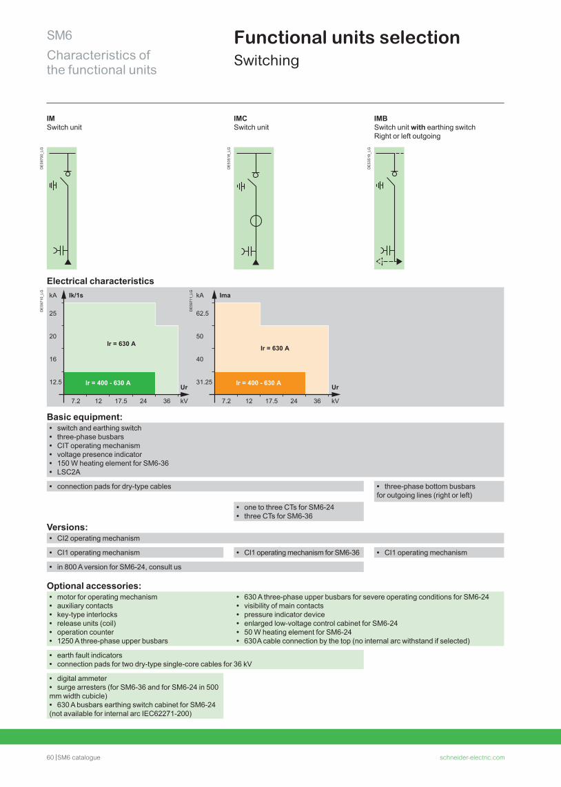
60 SM6 catalogue schneider-electric.com
SM6Characteristics of the functional units
Functional units selection Switching
IM, IMC, IMB
IM Switch unit
IMC Switch unit
IMB Switch unit with earthing switch Right or left outgoing
DE
5970
0_LG
DE
5351
8_LG
DE
5351
9_LG
Electrical characteristics
DE
5971
0_LG
Ir = 400 - 630 A
25
20
16
12.5
7.2 12 17.5 24 36
Ir = 630 A
kA Ik/1s
kV
Ur
DE
5971
1_LG
Ir = 400 - 630 A
62.5
50
40
31.25
7.2 12 17.5 24 36
Ir = 630 A
kA Ima
kV
Ur
Basic equipment: • switch and earthing switch • three-phase busbars • CIT operating mechanism • voltage presence indicator • 150 W heating element for SM6-36 • LSC2A
• connection pads for dry-type cables • three-phase bottom busbars for outgoing lines (right or left)
• one to three CTs for SM6-24 • three CTs for SM6-36
Versions: • CI2 operating mechanism
• CI1 operating mechanism • CI1 operating mechanism for SM6-36 • CI1 operating mechanism
• in 800 A version for SM6-24, consult us
Optional accessories: • motor for operating mechanism • auxiliary contacts • key-type interlocks • release units (coil) • operation counter • 1250 A three-phase upper busbars
• 630 A three-phase upper busbars for severe operating conditions for SM6-24 • visibility of main contacts • pressure indicator device • enlarged low-voltage control cabinet for SM6-24 • 50 W heating element for SM6-24 • 630 A cable connection by the top (no internal arc withstand if selected)
• earth fault indicators • connection pads for two dry-type single-core cables for 36 kV
• digital ammeter • surge arresters (for SM6-36 and for SM6-24 in 500
mm width cubicle) • 630 A busbars earthing switch cabinet for SM6-24
(not available for internal arc IEC62271-200)
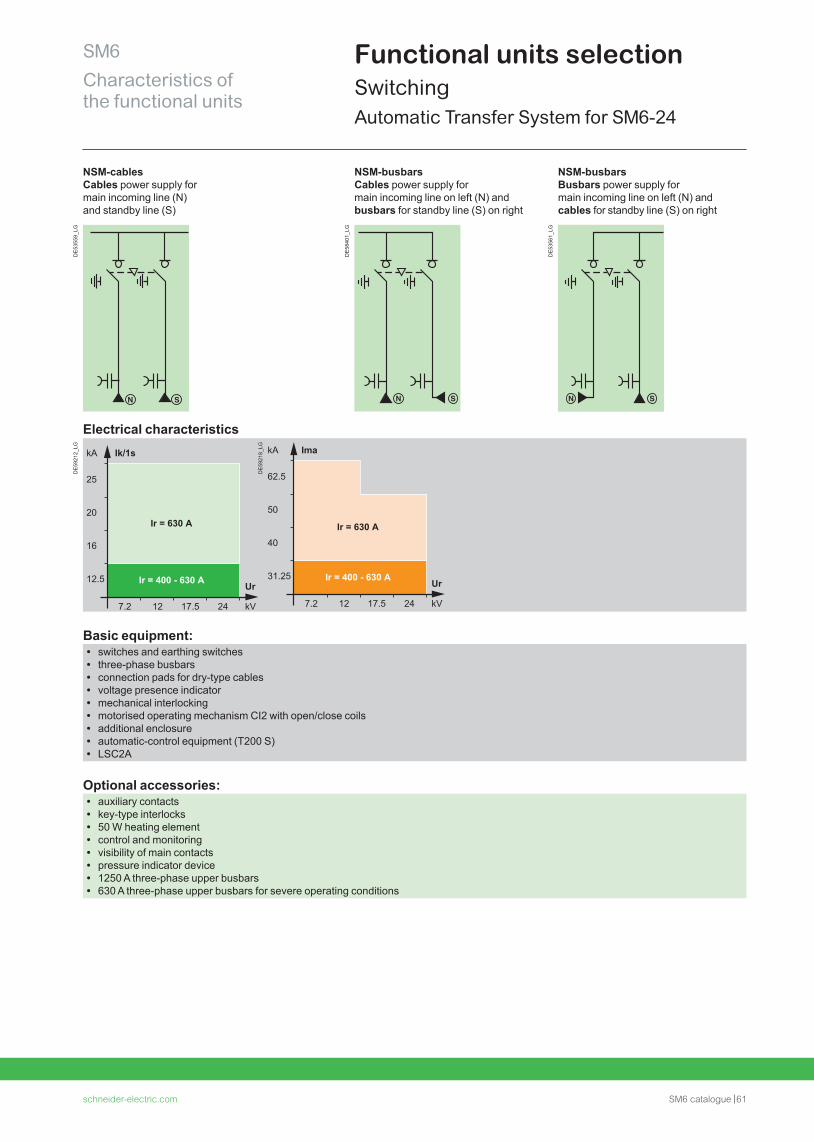
schneider-electric.com SM6 catalogue 61
SM6Characteristics of the functional units
Functional units selectionSwitchingAutomatic Transfer System for SM6-24
NSM 24
NSM-cables Cables power supply for main incoming line (N)and standby line (S)
NSM-busbarsCables power supply for main incoming line on left (N) andbusbars for standby line (S) on right
NSM-busbarsBusbars power supply for main incoming line on left (N) and cables for standby line (S) on right
DE
5355
9_LG
DE
5840
1_LG
DE
5356
1_LG
Electrical characteristics
DE
5921
2_LG
Ir = 400 - 630 A
62.5
50
40
31.25
7.2 12 17.5 24
Ir = 630 A
kA Ima
kV
Ur
DE
5921
8_LG
Basic equipment: • switches and earthing switches • three-phase busbars • connection pads for dry-type cables • voltage presence indicator • mechanical interlocking • motorised operating mechanism CI2 with open/close coils • additional enclosure • automatic-control equipment (T200 S) • LSC2A
Optional accessories: • auxiliary contacts • key-type interlocks • 50 W heating element • control and monitoring • visibility of main contacts • pressure indicator device • 1250 A three-phase upper busbars • 630 A three-phase upper busbars for severe operating conditions
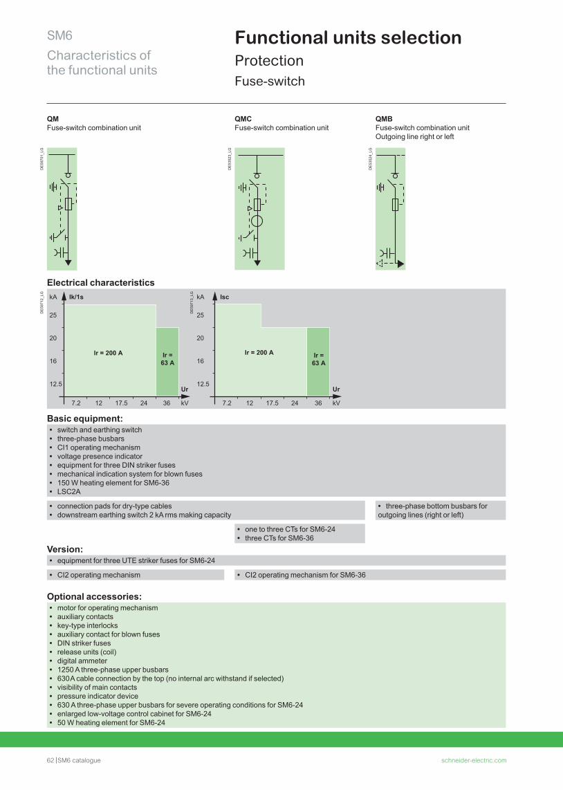
62 SM6 catalogue schneider-electric.com
SM6Characteristics of the functional units
Functional units selectionProtectionFuse-switch
QM Fuse-switch combination unit
QMC Fuse-switch combination unit
QMB Fuse-switch combination unit Outgoing line right or left
DE
5970
1_LG
DE
5352
3_LG
DE
5352
4_LG
Electrical characteristics
DE
5971
2_LG
25
20
16
12.5
7.2 12 17.5 24 36
Ir = 200 A
kA Ik/1s
kV
Ur
Ir = 63 A
Ir = 63 A
25
20
16
12.5
7.2 12 17.5 24 36
Ir = 200 A
kA Isc
kV
Ur
DE
5971
3_LG
Basic equipment: • switch and earthing switch • three-phase busbars • CI1 operating mechanism • voltage presence indicator • equipment for three DIN striker fuses • mechanical indication system for blown fuses • 150 W heating element for SM6-36 • LSC2A
• connection pads for dry-type cables • downstream earthing switch 2 kA rms making capacity
• three-phase bottom busbars for outgoing lines (right or left)
• one to three CTs for SM6-24 • three CTs for SM6-36
Version: • equipment for three UTE striker fuses for SM6-24
• CI2 operating mechanism • CI2 operating mechanism for SM6-36
Optional accessories: • motor for operating mechanism • auxiliary contacts • key-type interlocks • auxiliary contact for blown fuses • DIN striker fuses • release units (coil) • digital ammeter • 1250 A three-phase upper busbars • 630 A cable connection by the top (no internal arc withstand if selected) • visibility of main contacts • pressure indicator device • 630 A three-phase upper busbars for severe operating conditions for SM6-24 • enlarged low-voltage control cabinet for SM6-24 • 50 W heating element for SM6-24
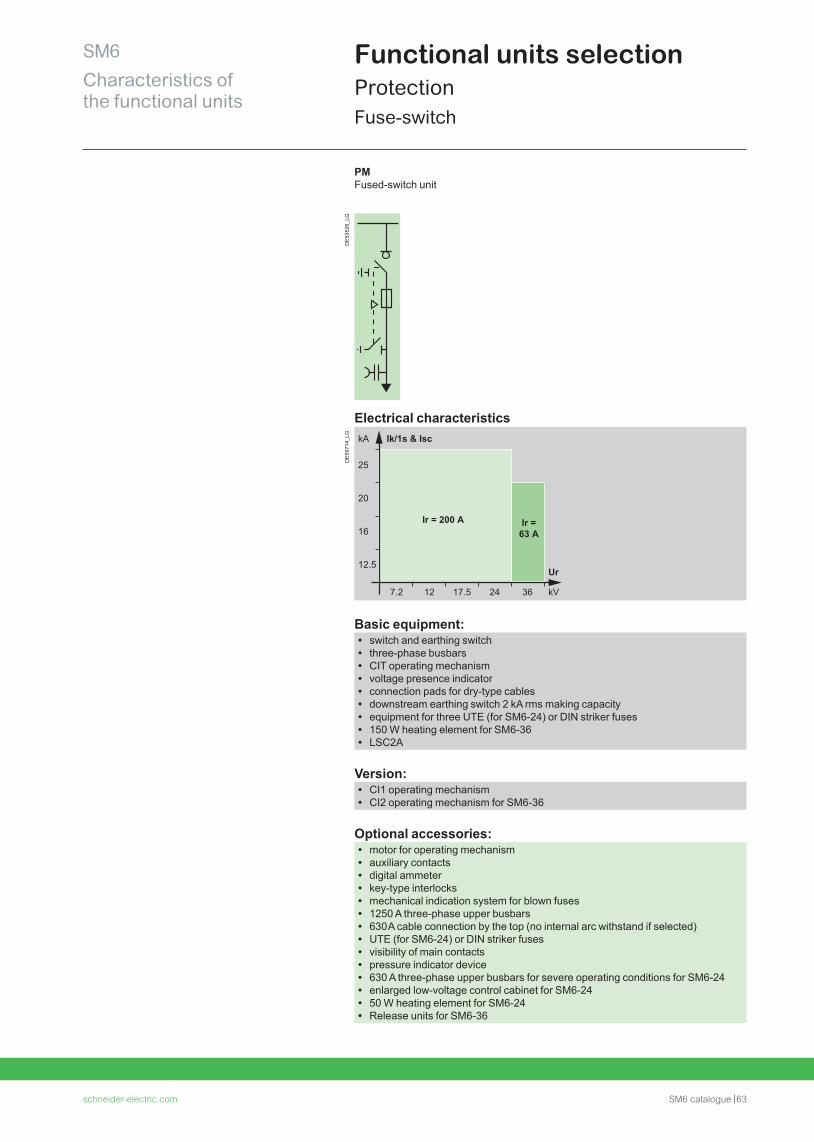
schneider-electric.com SM6 catalogue 63
SM6Characteristics of the functional units
Functional units selectionProtectionFuse-switch
PM
PM Fused-switch unit
DE
5352
6_LG
Electrical characteristics
DE
5971
4_LG
25
20
16
12.5
7.2 12 17.5 24 36
Ir = 200 A
kA Ik/1s & Isc
kV
Ur
Ir = 63 A
Basic equipment: • switch and earthing switch • three-phase busbars • CIT operating mechanism • voltage presence indicator • connection pads for dry-type cables • downstream earthing switch 2 kA rms making capacity • equipment for three UTE (for SM6-24) or DIN striker fuses • 150 W heating element for SM6-36 • LSC2A
Version: • CI1 operating mechanism • CI2 operating mechanism for SM6-36
Optional accessories: • motor for operating mechanism • auxiliary contacts • digital ammeter • key-type interlocks • mechanical indication system for blown fuses • 1250 A three-phase upper busbars • 630 A cable connection by the top (no internal arc withstand if selected) • UTE (for SM6-24) or DIN striker fuses • visibility of main contacts • pressure indicator device • 630 A three-phase upper busbars for severe operating conditions for SM6-24 • enlarged low-voltage control cabinet for SM6-24 • 50 W heating element for SM6-24 • Release units for SM6-36
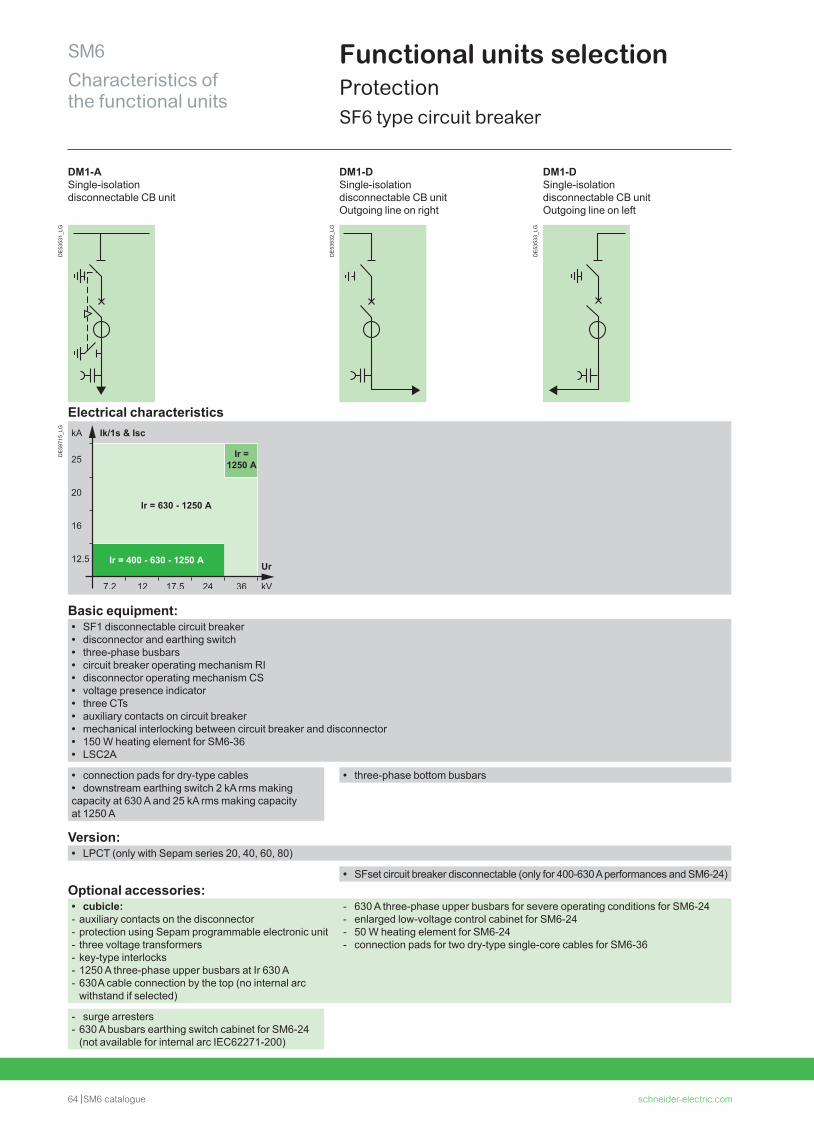
64 SM6 catalogue schneider-electric.com
SM6Characteristics of the functional units
Functional units selectionProtection SF6 type circuit breaker
DM1-A Single-isolation disconnectable CB unit
DM1-D Single-isolation disconnectable CB unitOutgoing line on right
DM1-D Single-isolation disconnectable CB unitOutgoing line on left
DE
5353
1_LG
DE
5353
2_LG
DE
5353
3_LG
Electrical characteristics
DE
5971
5_LG
Basic equipment: • SF1 disconnectable circuit breaker • disconnector and earthing switch • three-phase busbars • circuit breaker operating mechanism RI • disconnector operating mechanism CS • voltage presence indicator • three CTs • auxiliary contacts on circuit breaker • mechanical interlocking between circuit breaker and disconnector • 150 W heating element for SM6-36 • LSC2A
• connection pads for dry-type cables • downstream earthing switch 2 kA rms making
capacity at 630 A and 25 kA rms making capacity at 1250 A
• three-phase bottom busbars
Version: • LPCT (only with Sepam series 20, 40, 60, 80)
• SFset circuit breaker disconnectable (only for 400-630 A performances and SM6-24)Optional accessories:
• cubicle: - auxiliary contacts on the disconnector - protection using Sepam programmable electronic unit - three voltage transformers - key-type interlocks - 1250 A three-phase upper busbars at Ir 630 A - 630 A cable connection by the top (no internal arc withstand if selected)
- 630 A three-phase upper busbars for severe operating conditions for SM6-24 - enlarged low-voltage control cabinet for SM6-24 - 50 W heating element for SM6-24 - connection pads for two dry-type single-core cables for SM6-36
- surge arresters - 630 A busbars earthing switch cabinet for SM6-24 (not available for internal arc IEC62271-200)
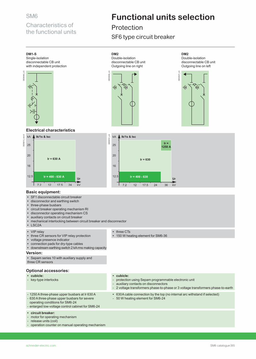
schneider-electric.com SM6 catalogue 65
SM6Characteristics of the functional units
Functional units selectionProtection SF6 type circuit breaker
DM1-S, DM2
DM1-S Single-isolation disconnectable CB unit with independent protection
DM2 Double-isolation disconnectable CB unit Outgoing line on right
DM2 Double-isolation disconnectable CB unitOutgoing line on left
DE
5836
0_LG
DE
5353
6_LG
DE
5353
7_LG
Electrical characteristics
DE
5921
2_Is
cLG
DE
5972
1_LG
Basic equipment: • SF1 disconnectable circuit breaker • disconnector and earthing switch • three-phase busbars • circuit breaker operating mechanism RI • disconnector operating mechanism CS • auxiliary contacts on circuit breaker • mechanical interlocking between circuit breaker and disconnector • LSC2A
• VIP relay • three CR sensors for VIP relay protection • voltage presence indicator • connection pads for dry-type cables • downstream earthing switch 2 kA rms making capacity
• three CTs • 150 W heating element for SM6-36
Version: • Sepam series 10 with auxiliary supply and
three CR sensors
Optional accessories: • cubicle: - key-type interlocks
• cubicle: - protection using Sepam programmable electronic unit - auxiliary contacts on disconnectors - 2 voltage transformers phase-to-phase or 3 voltage transformers phase-to-earth
- 1250 A three-phase upper busbars at Ir 630 A - 630 A three-phase upper busbars for severe operating conditions for SM6-24
- enlarged low-voltage control cabinet for SM6-24
• 630 A cable connection by the top (no internal arc withstand if selected) - 50 W heating element for SM6-24
• circuit breaker: - motor for operating mechanism - release units (coil) - operation counter on manual operating mechanism
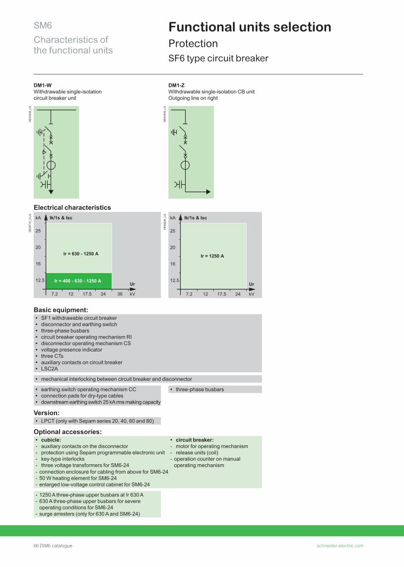
66 SM6 catalogue schneider-electric.com
SM6Characteristics of the functional units
Functional units selectionProtection SF6 type circuit breaker
DM1-W Withdrawable single-isolation circuit breaker unit
DM1-Z Withdrawable single-isolation CB unitOutgoing line on right
DE
5353
8_LG
DE
5353
9_LG
Electrical characteristics
DE
5971
5_2-
LG
Ir = 400 - 630 - 1250 A
25
20
16
12.5
7.2 12 17.5 24 36
Ir = 630 - 1250 A
kA Ik/1s & Isc
kV
Ur
DE
5922
6_LG
Basic equipment: • SF1 withdrawable circuit breaker • disconnector and earthing switch • three-phase busbars • circuit breaker operating mechanism RI • disconnector operating mechanism CS • voltage presence indicator • three CTs • auxiliary contacts on circuit breaker • LSC2A
• mechanical interlocking between circuit breaker and disconnector
• earthing switch operating mechanism CC • connection pads for dry-type cables • downstream earthing switch 25 kA rms making capacity
• three-phase busbars
Version: • LPCT (only with Sepam series 20, 40, 60 and 80)
Optional accessories: • cubicle: - auxiliary contacts on the disconnector - protection using Sepam programmable electronic unit - key-type interlocks - three voltage transformers for SM6-24
• circuit breaker: - motor for operating mechanism - release units (coil) - operation counter on manual operating mechanism
- connection enclosure for cabling from above for SM6-24 - 50 W heating element for SM6-24 - enlarged low-voltage control cabinet for SM6-24
- 1250 A three-phase upper busbars at Ir 630 A - 630 A three-phase upper busbars for severe operating conditions for SM6-24
- surge arresters (only for 630 A and SM6-24)
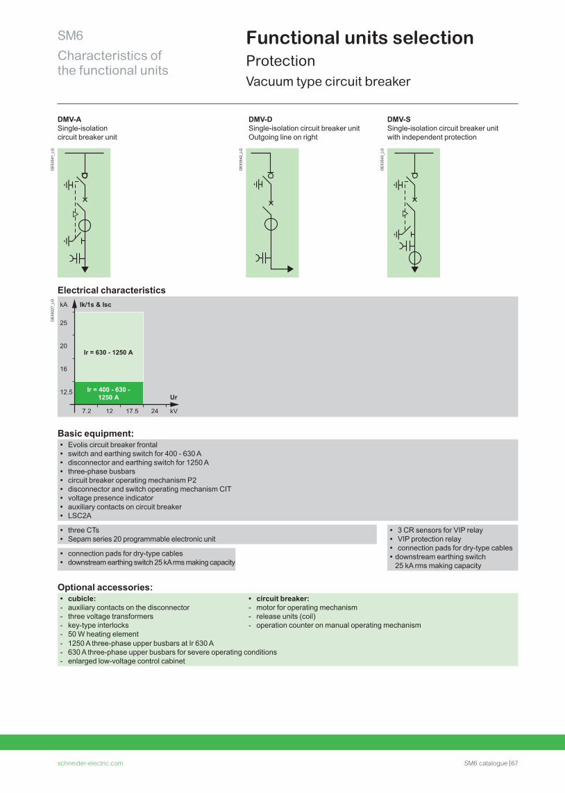
schneider-electric.com SM6 catalogue 67
SM6Characteristics of the functional units
Functional units selectionProtectionVacuum type circuit breaker
DMV-A, DMV-D, DMV-S
DMV-A Single-isolation circuit breaker unit
DMV-D Single-isolation circuit breaker unitOutgoing line on right
DMV-S Single-isolation circuit breaker unitwith independent protection
DE
5354
1_LG
DE
5354
2_LG
DE
5354
3_LG
Electrical characteristics
DE
5922
7_LG
Basic equipment: • Evolis circuit breaker frontal • switch and earthing switch for 400 - 630 A • disconnector and earthing switch for 1250 A • three-phase busbars • circuit breaker operating mechanism P2 • disconnector and switch operating mechanism CIT • voltage presence indicator • auxiliary contacts on circuit breaker • LSC2A
• three CTs • Sepam series 20 programmable electronic unit
• 3 CR sensors for VIP relay • VIP protection relay • connection pads for dry-type cables • downstream earthing switch 25 kA rms making capacity
• connection pads for dry-type cables • downstream earthing switch 25 kA rms making capacity
Optional accessories: • cubicle: - auxiliary contacts on the disconnector - three voltage transformers - key-type interlocks - 50 W heating element
• circuit breaker: - motor for operating mechanism - release units (coil) - operation counter on manual operating mechanism
- 1250 A three-phase upper busbars at Ir 630 A - 630 A three-phase upper busbars for severe operating conditions - enlarged low-voltage control cabinet
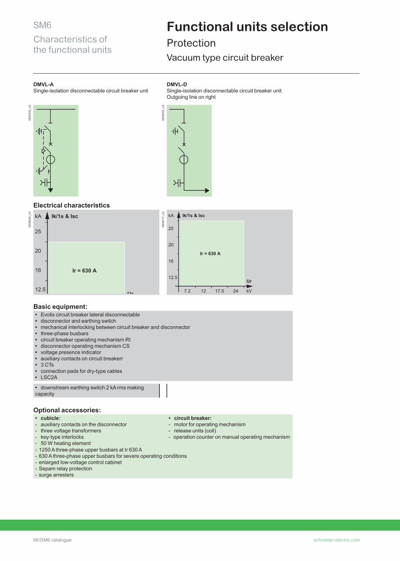
68 SM6 catalogue schneider-electric.com
SM6Characteristics of the functional units
Functional units selectionProtectionVacuum type circuit breaker
DMVL-A Single-isolation disconnectable circuit breaker unit
DMVL-D Single-isolation disconnectable circuit breaker unitOutgoing line on right
DE
5353
5_LG
DE
5970
3_LG
Electrical characteristics
DE
5922
8_LG
DE
5971
7_LG
Basic equipment: • Evolis circuit breaker lateral disconnectable • disconnector and earthing switch • mechanical interlocking between circuit breaker and disconnector • three-phase busbars • circuit breaker operating mechanism RI • disconnector operating mechanism CS • voltage presence indicator • auxiliary contacts on circuit breakerr • 3 CTs • connection pads for dry-type cables • LSC2A
• downstream earthing switch 2 kA rms making capacity
Optional accessories: • cubicle: - auxiliary contacts on the disconnector - three voltage transformers - key-type interlocks - 50 W heating element
• circuit breaker: - motor for operating mechanism - release units (coil) - operation counter on manual operating mechanism
- 1250 A three-phase upper busbars at Ir 630 A - 630 A three-phase upper busbars for severe operating conditions - enlarged low-voltage control cabinet - Sepam relay protection - surge arresters
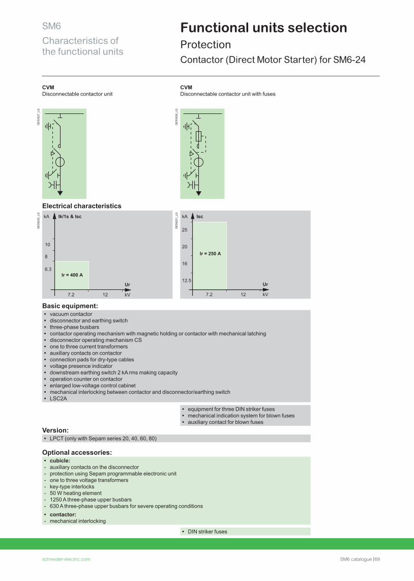
schneider-electric.com SM6 catalogue 69
SM6Characteristics of the functional units
Functional units selectionProtectionContactor (Direct Motor Starter) for SM6-24
CVM
CVM Disconnectable contactor unit
CVM Disconnectable contactor unit with fuses
DE
5352
7_LG
DE
5352
8_LG
Electrical characteristics
DE
5922
0_LG
DE
5922
1_LG
Basic equipment: • vacuum contactor • disconnector and earthing switch • three-phase busbars • contactor operating mechanism with magnetic holding or contactor with mechanical latching • disconnector operating mechanism CS • one to three current transformers • auxiliary contacts on contactor • connection pads for dry-type cables • voltage presence indicator • downstream earthing switch 2 kA rms making capacity • operation counter on contactor • enlarged low-voltage control cabinet • mechanical interlocking between contactor and disconnector/earthing switch • LSC2A
• equipment for three DIN striker fuses • mechanical indication system for blown fuses • auxiliary contact for blown fuses
Version: • LPCT (only with Sepam series 20, 40, 60, 80)
Optional accessories: • cubicle: - auxiliary contacts on the disconnector - protection using Sepam programmable electronic unit - one to three voltage transformers - key-type interlocks - 50 W heating element - 1250 A three-phase upper busbars - 630 A three-phase upper busbars for severe operating conditions • contactor: - mechanical interlocking
• DIN striker fuses
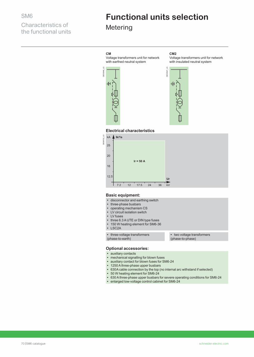
70 SM6 catalogue schneider-electric.com
SM6Characteristics of the functional units
Functional units selectionMetering
CM Voltage transformers unit for network with earthed neutral system
CM2 Voltage transformers unit for network with insulated neutral system
DE
5354
6_LG
DE
5354
7_LG
Electrical characteristics
DE
5972
2_LG
Basic equipment: • disconnector and earthing switch • three-phase busbars • operating mechanism CS • LV circuit isolation switch • LV fuses • three 6.3 A UTE or DIN type fuses • 150 W heating element for SM6-36 • LSC2A
• three-voltage transformers (phase-to-earth)
• two voltage transformers (phase-to-phase)
Optional accessories: • auxiliary contacts • mechanical signalling for blown fuses • auxiliary contact for blown fuses for SM6-24 • 1250 A three-phase upper busbars • 630 A cable connection by the top (no internal arc withstand if selected) • 50 W heating element for SM6-24 • 630 A three-phase upper busbars for severe operating conditions for SM6-24 • enlarged low-voltage control cabinet for SM6-24
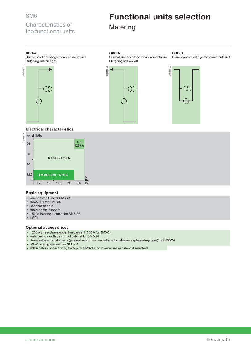
schneider-electric.com SM6 catalogue 71
SM6Characteristics of the functional units
Functional units selectionMetering
GBC-A, GBC-B
GBC-A Current and/or voltage measurements unitOutgoing line on right
GBC-ACurrent and/or voltage measurements unitOutgoing line on left
GBC-B Current and/or voltage measurements unit
DE
5354
9_LG
DE
5355
0_LG
DE
5355
1_LG
Electrical characteristics
DE
5970
9_LG
Ir = 400 - 630 - 1250 A
25
20
16
12.5
7.2 12 17.5 24 36
Ir = 630 - 1250 A
Ir = 1250 A
kA Ik/1s
kV
Ur
Basic equipment: • one to three CTs for SM6-24 • three CTs for SM6-36 • connection bars • three-phase busbars • 150 W heating element for SM6-36 • LSC1
Optional accessories: • 1250 A three-phase upper busbars at Ir 630 A for SM6-24 • enlarged low-voltage control cabinet for SM6-24 • three voltage transformers (phase-to-earth) or two voltage transformers (phase-to-phase) for SM6-24 • 50 W heating element for SM6-24 • 630 A cable connection by the top for SM6-36 (no internal arc withstand if selected)
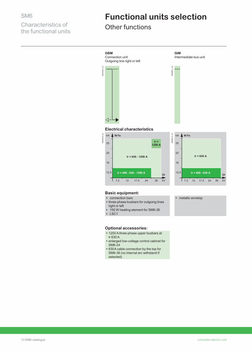
72 SM6 catalogue schneider-electric.com
SM6Characteristics of the functional units
Functional units selectionOther functions
GBM Connection unitOutgoing line right or left
GIM Intermediate bus unit
DE
5355
3_LG
DE
5836
1_LG
Electrical characteristics
DE
5970
9_LG
Ir = 400 - 630 - 1250 A
25
20
16
12.5
7.2 12 17.5 24 36
Ir = 630 - 1250 A
Ir = 1250 A
kA Ik/1s
kV
UrD
E59
214_
LG
Basic equipment: • connection bars • three-phase busbars for outgoing lines right or left
• 150 W heating element for SM6-36 • LSC1
• metallic envelop
Optional accessories: • 1250 A three-phase upper busbars at Ir 630 A
• enlarged low-voltage control cabinet for SM6-24
• 630 A cable connection by the top for SM6-36 (no internal arc withstand if selected)
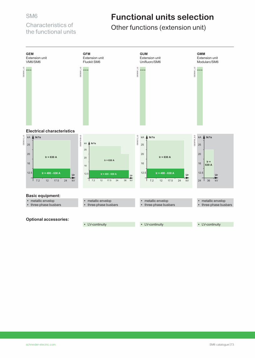
schneider-electric.com SM6 catalogue 73
SM6Characteristics of the functional units
Functional units selectionOther functions (extension unit)
GEM Extension unit VM6/SM6
GFMExtension unit Fluokit SM6
GUM Extension unit Unifluorc/SM6
GMMExtension unit Modularc/SM6
DE
5836
1_LG
DE
5836
1_LG
DE
5836
1_LG
DE
5836
1_LG
Electrical characteristics
DE
5921
2_LG
DE
5971
0-B
-LG
Ir = 400 - 630 A
25
20
16
12.5
7.2 12 17.5 24 36
Ir = 630 A
kA Ik/1s
kV
Ur
DE
5921
2_LG
DE
5970
9_2L
GBasic equipment:
• metallic envelop • three-phase busbars
• metallic envelop • three-phase busbars
• metallic envelop • three-phase busbars
• metallic envelop • three-phase busbars
Optional accessories: • LV-continuity • LV-continuity • LV-continuity
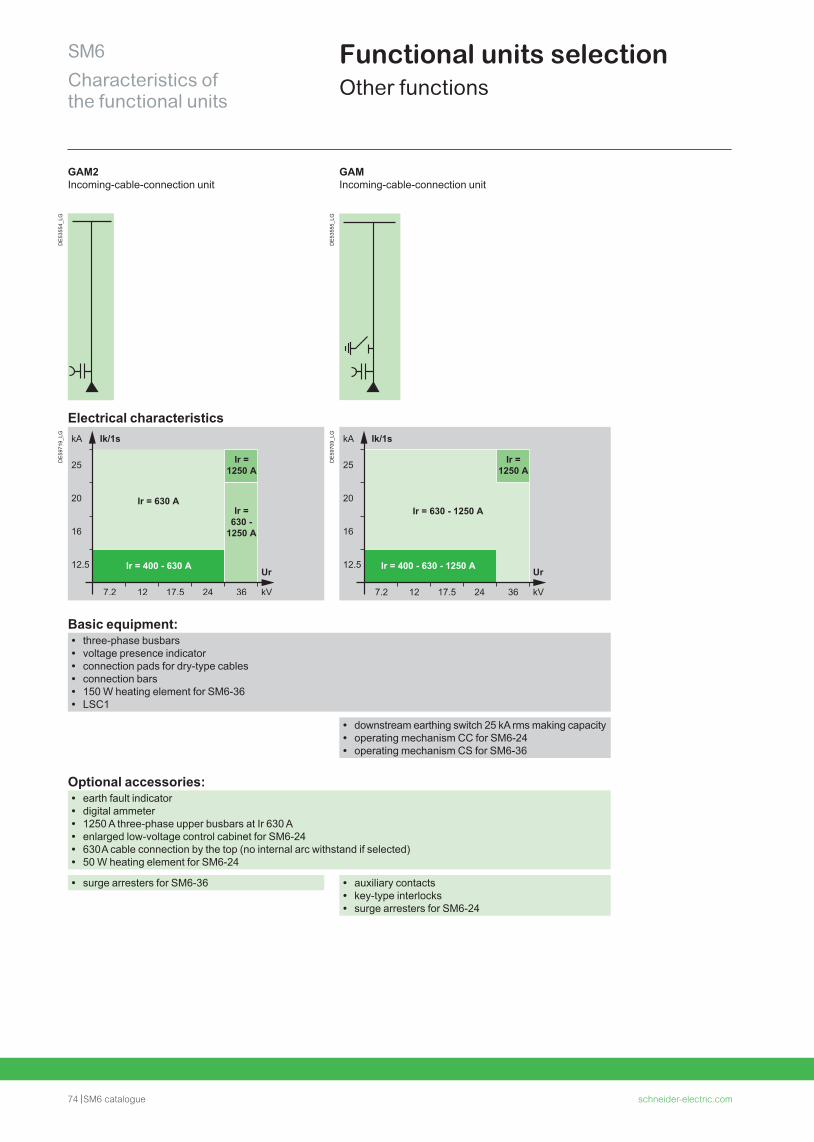
74 SM6 catalogue schneider-electric.com
SM6Characteristics of the functional units
Functional units selectionOther functions
GAM2Incoming-cable-connection unit
GAMIncoming-cable-connection unit
DE
5355
4_LG
DE
5355
5_LG
Electrical characteristics
DE
5971
9_LG
DE
5970
9_LG
Ir = 400 - 630 - 1250 A
25
20
16
12.5
7.2 12 17.5 24 36
Ir = 630 - 1250 A
Ir = 1250 A
kA Ik/1s
kV
Ur
Basic equipment: • three-phase busbars • voltage presence indicator • connection pads for dry-type cables • connection bars • 150 W heating element for SM6-36 • LSC1
• downstream earthing switch 25 kA rms making capacity • operating mechanism CC for SM6-24 • operating mechanism CS for SM6-36
Optional accessories: • earth fault indicator • digital ammeter • 1250 A three-phase upper busbars at Ir 630 A • enlarged low-voltage control cabinet for SM6-24 • 630 A cable connection by the top (no internal arc withstand if selected) • 50 W heating element for SM6-24
• surge arresters for SM6-36 • auxiliary contacts • key-type interlocks • surge arresters for SM6-24
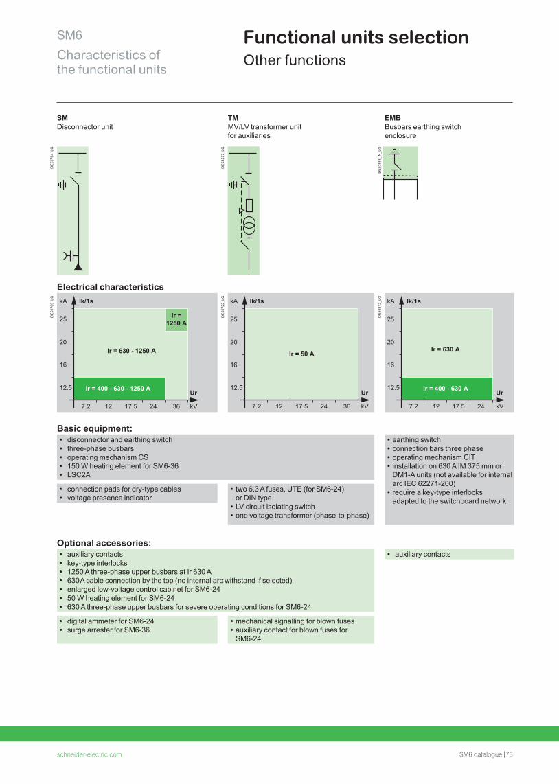
schneider-electric.com SM6 catalogue 75
SM6Characteristics of the functional units
Functional units selectionOther functions
SM Disconnector unit
TM MV/LV transformer unit for auxiliaries
EMB Busbars earthing switch enclosure
DE
5970
4_LG
DE
5355
7_LG
DE
5355
8_N
_LG
Electrical characteristics
DE
5970
9_LG
Ir = 400 - 630 - 1250 A
25
20
16
12.5
7.2 12 17.5 24 36
Ir = 630 - 1250 A
Ir = 1250 A
kA Ik/1s
kV
Ur
DE
5972
2_LG
DE
5921
2_LG
Basic equipment: • disconnector and earthing switch • three-phase busbars • operating mechanism CS • 150 W heating element for SM6-36 • LSC2A
• earthing switch • connection bars three phase • operating mechanism CIT • installation on 630 A IM 375 mm or DM1-A units (not available for internal arc IEC 62271-200)
• require a key-type interlocks adapted to the switchboard network
• connection pads for dry-type cables • voltage presence indicator
• two 6.3 A fuses, UTE (for SM6-24) or DIN type
• LV circuit isolating switch • one voltage transformer (phase-to-phase)
Optional accessories: • auxiliary contacts • key-type interlocks • 1250 A three-phase upper busbars at Ir 630 A • 630 A cable connection by the top (no internal arc withstand if selected) • enlarged low-voltage control cabinet for SM6-24 • 50 W heating element for SM6-24 • 630 A three-phase upper busbars for severe operating conditions for SM6-24
• auxiliary contacts
• digital ammeter for SM6-24 • surge arrester for SM6-36
• mechanical signalling for blown fuses • auxiliary contact for blown fuses for SM6-24
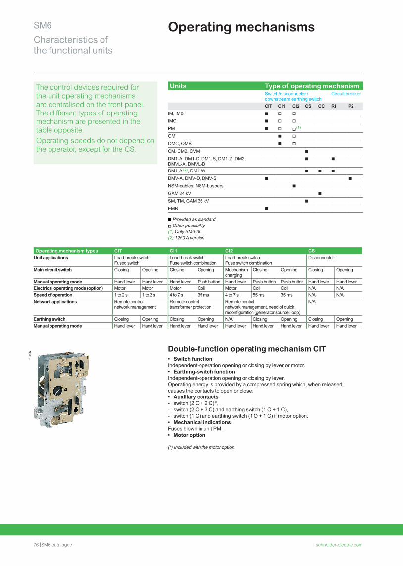
76 SM6 catalogue schneider-electric.com
SM6Characteristics of the functional units
Operating mechanisms61
029N
The control devices required for the unit operating mechanisms are centralised on the front panel. The different types of operating mechanism are presented in the table opposite. Operating speeds do not depend on the operator, except for the CS.
Units Type of operating mechanismSwitch/disconnector /downstream earthing switch
Circuit breaker
CIT CI1 CI2 CS CC RI P2IM, IMB b v vIMC b v vPM b v v (1)
QM b vQMC, QMB b vCM, CM2, CVM b DM1-A, DM1-D, DM1-S, DM1-Z, DM2, DMVL-A, DMVL-D
b b
DM1-A (2), DM1-W b b bDMV-A, DMV-D, DMV-S b bNSM-cables, NSM-busbars bGAM 24 kV bSM, TM, GAM 36 kV bEMB b
b Provided as standardv Other possibility(1) Only SM6-36(2) 1250 A version
Operating mechanism types CIT CI1 CI2 CSUnit applications Load-break switch
Fused switchLoad-break switch Fuse switch combination
Load-break switch Fuse switch combination
Disconnector
Main circuit switch Closing Opening Closing Opening Mechanism charging
Closing Opening Closing Opening
Manual operating mode Hand lever Hand lever Hand lever Push button Hand lever Push button Push button Hand lever Hand leverElectrical operating mode (option) Motor Motor Motor Coil Motor Coil Coil N/A N/ASpeed of operation 1 to 2 s 1 to 2 s 4 to 7 s 35 ms 4 to 7 s 55 ms 35 ms N/A N/ANetwork applications Remote control
network managementRemote control transformer protection
Remote control network management, need of quick reconfiguration (generator source, loop)
N/A
Earthing switch Closing Opening Closing Opening N/A Closing Opening Closing OpeningManual operating mode Hand lever Hand lever Hand lever Hand lever Hand lever Hand lever Hand lever Hand lever Hand lever
Double-function operating mechanism CIT • Switch function
Independent-operation opening or closing by lever or motor. • Earthing-switch function
Independent-operation opening or closing by lever.Operating energy is provided by a compressed spring which, when released, causes the contacts to open or close. • Auxiliary contacts - switch (2 O + 2 C) *, - switch (2 O + 3 C) and earthing switch (1 O + 1 C), - switch (1 C) and earthing switch (1 O + 1 C) if motor option. • Mechanical indications
Fuses blown in unit PM. • Motor option
(*) Included with the motor option
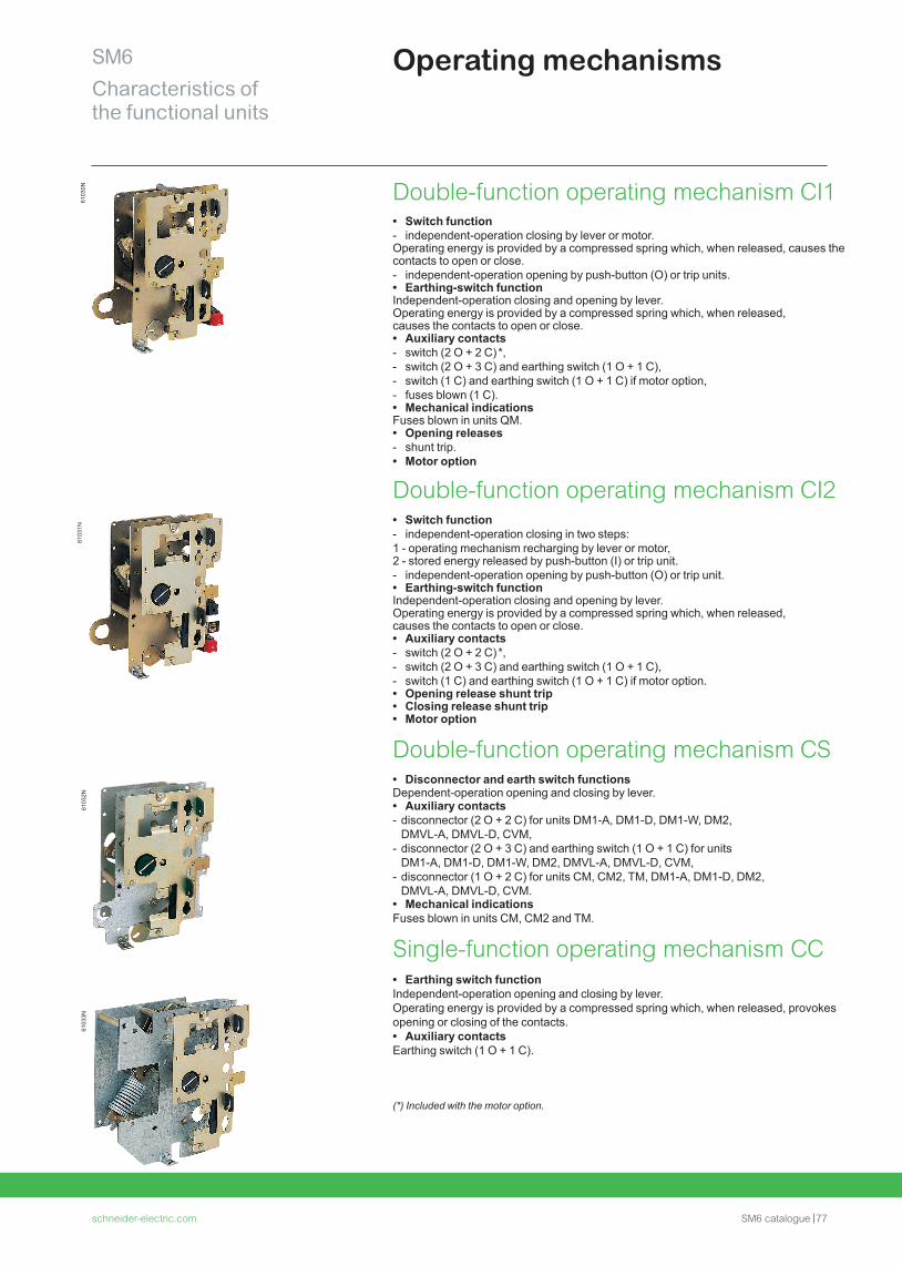
schneider-electric.com SM6 catalogue 77
SM6Characteristics of the functional units
Operating mechanisms61
032N
6103
1N61
033N
6103
0N Double-function operating mechanism CI1 • Switch function - independent-operation closing by lever or motor.
Operating energy is provided by a compressed spring which, when released, causes the contacts to open or close. - independent-operation opening by push-button (O) or trip units. • Earthing-switch function
Independent-operation closing and opening by lever.Operating energy is provided by a compressed spring which, when released, causes the contacts to open or close. • Auxiliary contacts - switch (2 O + 2 C) *, - switch (2 O + 3 C) and earthing switch (1 O + 1 C), - switch (1 C) and earthing switch (1 O + 1 C) if motor option, - fuses blown (1 C). • Mechanical indications
Fuses blown in units QM. • Opening releases - shunt trip. • Motor option
Double-function operating mechanism CI2 • Switch function - independent-operation closing in two steps:
1 - operating mechanism recharging by lever or motor,2 - stored energy released by push-button (I) or trip unit. - independent-operation opening by push-button (O) or trip unit. • Earthing-switch function
Independent-operation closing and opening by lever.Operating energy is provided by a compressed spring which, when released, causes the contacts to open or close. • Auxiliary contacts - switch (2 O + 2 C) *, - switch (2 O + 3 C) and earthing switch (1 O + 1 C), - switch (1 C) and earthing switch (1 O + 1 C) if motor option. • Opening release shunt trip • Closing release shunt trip • Motor option
Double-function operating mechanism CS • Disconnector and earth switch functions
Dependent-operation opening and closing by lever. • Auxiliary contacts - disconnector (2 O + 2 C) for units DM1-A, DM1-D, DM1-W, DM2, DMVL-A, DMVL-D, CVM,
- disconnector (2 O + 3 C) and earthing switch (1 O + 1 C) for units DM1-A, DM1-D, DM1-W, DM2, DMVL-A, DMVL-D, CVM,
- disconnector (1 O + 2 C) for units CM, CM2, TM, DM1-A, DM1-D, DM2, DMVL-A, DMVL-D, CVM.
• Mechanical indications Fuses blown in units CM, CM2 and TM.
Single-function operating mechanism CC • Earthing switch function
Independent-operation opening and closing by lever.Operating energy is provided by a compressed spring which, when released, provokes opening or closing of the contacts. • Auxiliary contacts
Earthing switch (1 O + 1 C).
(*) Included with the motor option.
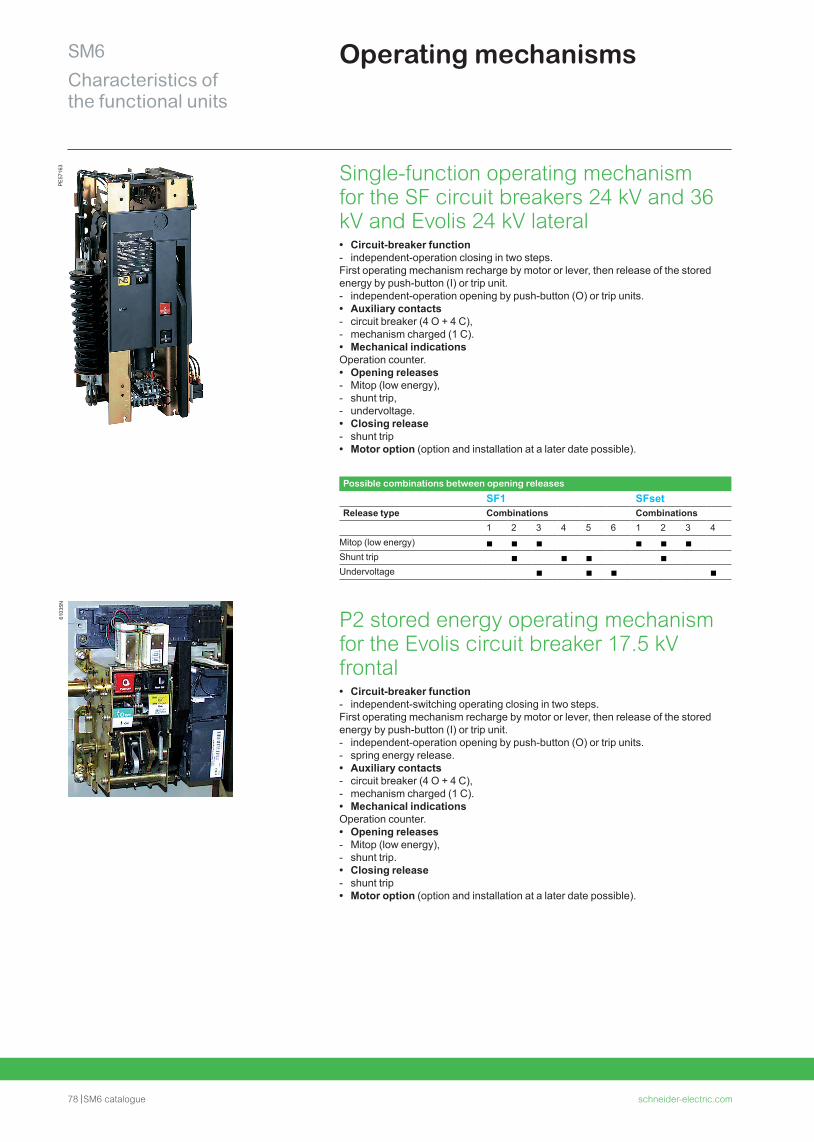
78 SM6 catalogue schneider-electric.com
SM6Characteristics of the functional units
Operating mechanisms61
035N
PE
5716
3 Single-function operating mechanism for the SF circuit breakers 24 kV and 36 kV and Evolis 24 kV lateral • Circuit-breaker function - independent-operation closing in two steps.
First operating mechanism recharge by motor or lever, then release of the stored energy by push-button (I) or trip unit. - independent-operation opening by push-button (O) or trip units. • Auxiliary contacts - circuit breaker (4 O + 4 C), - mechanism charged (1 C). • Mechanical indications
Operation counter. • Opening releases - Mitop (low energy), - shunt trip, - undervoltage. • Closing release - shunt trip • Motor option (option and installation at a later date possible).
Possible combinations between opening releases
SF1 SFsetRelease type Combinations Combinations
1 2 3 4 5 6 1 2 3 4Mitop (low energy) b b b b b b
Shunt trip b b b b
Undervoltage b b b b
P2 stored energy operating mechanism for the Evolis circuit breaker 17.5 kV frontal • Circuit-breaker function - independent-switching operating closing in two steps.
First operating mechanism recharge by motor or lever, then release of the stored energy by push-button (I) or trip unit. - independent-operation opening by push-button (O) or trip units. - spring energy release. • Auxiliary contacts - circuit breaker (4 O + 4 C), - mechanism charged (1 C). • Mechanical indications
Operation counter. • Opening releases - Mitop (low energy), - shunt trip. • Closing release - shunt trip • Motor option (option and installation at a later date possible).
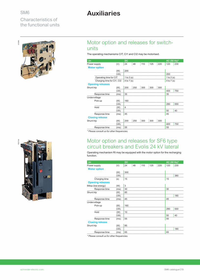
schneider-electric.com SM6 catalogue 79
SM6Characteristics of the functional units
Auxiliaries
Motor option and releases for switch-unitsThe operating mechanisms CIT, CI1 and CI2 may be motorised.
Un DC AC (50 Hz)*Power supply (V) 24 48 110 125 220 120 230Motor option
(W) 200(VA) 200
Operating time for CIT 1 to 2 (s) 1 to 2 (s)Charging time for CI1, CI2 4 to 7 (s) 4 to 7 (s)
Opening releasesShunt trip (W) 200 250 300 300 300
(VA) 400 750Response time (ms) 35 35
UndervoltagePick-up (W) 160
(VA) 280 550Hold (W) 4
(VA) 50 40Response time (ms) 45 45
Closing releaseShunt trip (W) 200 250 300 300 300
(VA) 400 750Response time (ms) 55 55
* Please consult us for other frequencies.
Motor option and releases for SF6 type circuit breakers and Evolis 24 kV lateralOperating mechanism RI may be equipped with the motor option for the recharging function.
Un DC AC (50 Hz)*Power supply (V) 24 48 110 125 220 120 230Motor option
(W) 300(VA) 380
Charging time (s) 15 15Opening releases
Mitop (low energy) (W) 3Response time (ms) 30 30
Shunt trip (W) 85(VA) 180
Response time (ms) 45 45Undervoltage
Pick-up (W) 160(VA) 280 550
Hold (W) 10(VA) 50 40
Response time (ms) 55 55Closing release
Shunt trip (W) 85(VA) 180
Response time (ms) 65 65
* Please consult us for other frequencies.
6103
6NP
E57
164
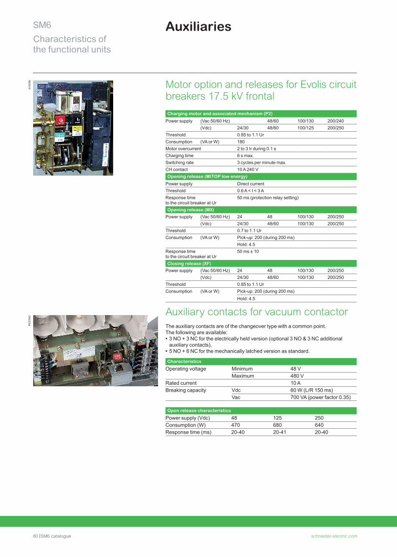
80 SM6 catalogue schneider-electric.com
SM6Characteristics of the functional units
Auxiliaries61
035N Motor option and releases for Evolis circuit
breakers 17.5 kV frontal Charging motor and associated mechanism (P2)
Power supply (Vac 50/60 Hz) 48/60 100/130 200/240(Vdc) 24/30 48/60 100/125 200/250
Threshold 0.85 to 1.1 UrConsumption (VA or W) 180Motor overcurrent 2 to 3 Ir during 0.1 sCharging time 6 s max.Switching rate 3 cycles per minute max.CH contact 10 A 240 VOpening release (MITOP low energy)
Power supply Direct currentThreshold 0.6 A < I < 3 AResponse time to the circuit breaker at Ur
50 ms (protection relay setting)
Opening release (MX)Power supply (Vac 50/60 Hz) 24 48 100/130 200/250
(Vdc) 24/30 48/60 100/130 200/250Threshold 0.7 to 1.1 UrConsumption (VA or W) Pick-up: 200 (during 200 ms)
Hold: 4.5Response time to the circuit breaker at Ur
50 ms ± 10
Closing release (XF)Power supply (Vac 50/60 Hz) 24 48 100/130 200/250
(Vdc) 24/30 48/60 100/130 200/250Threshold 0.85 to 1.1 UrConsumption (VA or W) Pick-up: 200 (during 200 ms)
Hold: 4.5
Auxiliary contacts for vacuum contactorThe auxiliary contacts are of the changeover type with a common point.The following are available: • 3 NO + 3 NC for the electrically held version (optional 3 NO & 3 NC additional auxiliary contacts),
• 5 NO + 6 NC for the mechanically latched version as standard.
Characteristics
Operating voltage Minimum 48 V Maximum 480 V
Rated current 10 A Breaking capacity Vdc 60 W (L/R 150 ms) Vac 700 VA (power factor 0.35)
Open release characteristics
Power supply (Vdc) 48 125 250Consumption (W) 470 680 640Response time (ms) 20-40 20-41 20-40
PE
5784
2
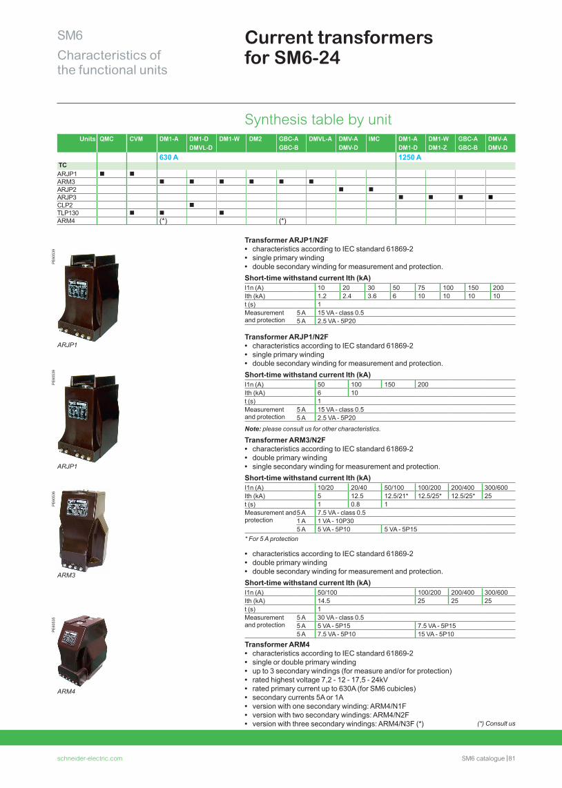
schneider-electric.com SM6 catalogue 81
SM6Characteristics of the functional units
Current transformers for SM6-24
Synthesis table by unitUnits QMC CVM DM1-A DM1-D
DMVL-DDM1-W DM2 GBC-A
GBC-BDMVL-A DMV-A
DMV-DIMC DM1-A
DM1-DDM1-W DM1-Z
GBC-A GBC-B
DMV-A DMV-D
630 A 1250 ATCARJP1 b bARM3 b b b b b bARJP2 b bARJP3 b b b bCLP2 bTLP130 b b bARM4 (*) (*)
Transformer ARJP1/N2F • characteristics according to IEC standard 61869-2 • single primary winding • double secondary winding for measurement and protection.
Short-time withstand current Ith (kA)I1n (A) 10 20 30 50 75 100 150 200Ith (kA) 1.2 2.4 3.6 6 10 10 10 10t (s) 1Measurement and protection
5 A 15 VA - class 0.55 A 2.5 VA - 5P20
Transformer ARJP1/N2F • characteristics according to IEC standard 61869-2 • single primary winding • double secondary winding for measurement and protection.
Short-time withstand current Ith (kA)I1n (A) 50 100 150 200Ith (kA) 6 10t (s) 1Measurement and protection
5 A 15 VA - class 0.55 A 2.5 VA - 5P20
Note: please consult us for other characteristics.
Transformer ARM3/N2F • characteristics according to IEC standard 61869-2 • double primary winding • single secondary winding for measurement and protection.
Short-time withstand current Ith (kA)I1n (A) 10/20 20/40 50/100 100/200 200/400 300/600Ith (kA) 5 12.5 12.5/21* 12.5/25* 12.5/25* 25t (s) 1 0.8 1Measurement and protection
5 A 7.5 VA - class 0.51 A 1 VA - 10P305 A 5 VA - 5P10 5 VA - 5P15
* For 5 A protection
• characteristics according to IEC standard 61869-2 • double primary winding • double secondary winding for measurement and protection.
Short-time withstand current Ith (kA)I1n (A) 50/100 100/200 200/400 300/600Ith (kA) 14.5 25 25 25t (s) 1Measurement and protection
5 A 30 VA - class 0.55 A 5 VA - 5P15 7.5 VA - 5P155 A 7.5 VA - 5P10 15 VA - 5P10
Transformer ARM4 • characteristics according to IEC standard 61869-2 • single or double primary winding • up to 3 secondary windings (for measure and/or for protection) • rated highest voltage 7,2 - 12 - 17,5 - 24kV • rated primary current up to 630A (for SM6 cubicles) • secondary currents 5A or 1A • version with one secondary winding: ARM4/N1F • version with two secondary windings: ARM4/N2F • version with three secondary windings: ARM4/N3F (*)
PE
6053
9P
E60
539
PE
6053
6
(*) Consult us
PE
6053
5
ARJP1
ARJP1
ARM3
ARM4
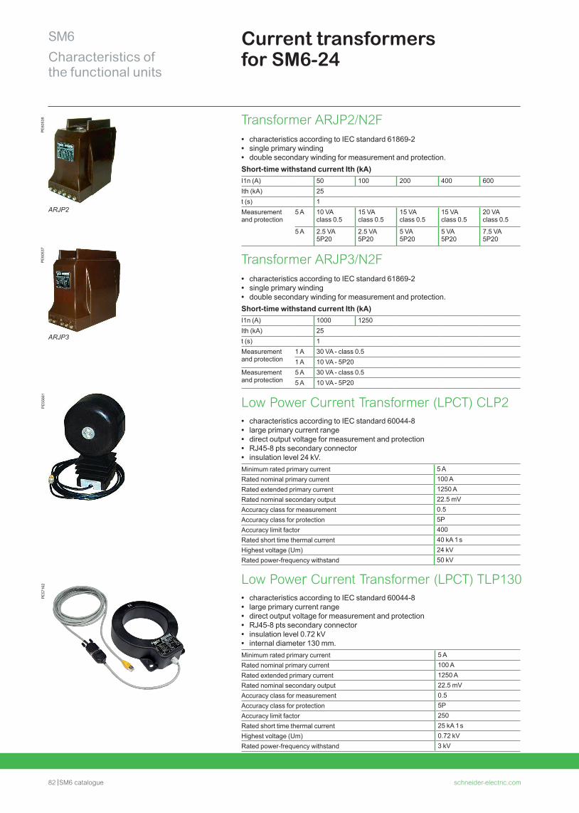
82 SM6 catalogue schneider-electric.com
SM6Characteristics of the functional units
Current transformers for SM6-24
PE
5566
1P
E57
162
Transformer ARJP2/N2F • characteristics according to IEC standard 61869-2 • single primary winding • double secondary winding for measurement and protection.
Short-time withstand current Ith (kA)I1n (A) 50 100 200 400 600Ith (kA) 25t (s) 1Measurement and protection
5 A 10 VA class 0.5
15 VA class 0.5
15 VA class 0.5
15 VA class 0.5
20 VA class 0.5
5 A 2.5 VA 5P20
2.5 VA 5P20
5 VA 5P20
5 VA 5P20
7.5 VA 5P20
Transformer ARJP3/N2F • characteristics according to IEC standard 61869-2 • single primary winding • double secondary winding for measurement and protection.
Short-time withstand current Ith (kA)I1n (A) 1000 1250Ith (kA) 25t (s) 1Measurement and protection
1 A 30 VA - class 0.51 A 10 VA - 5P20
Measurement and protection
5 A 30 VA - class 0.55 A 10 VA - 5P20
Low Power Current Transformer (LPCT) CLP2 • characteristics according to IEC standard 60044-8 • large primary current range • direct output voltage for measurement and protection • RJ45-8 pts secondary connector • insulation level 24 kV.
Minimum rated primary current 5 ARated nominal primary current 100 ARated extended primary current 1250 ARated nominal secondary output 22.5 mVAccuracy class for measurement 0.5Accuracy class for protection 5PAccuracy limit factor 400Rated short time thermal current 40 kA 1 sHighest voltage (Um) 24 kVRated power-frequency withstand 50 kV
Low Power Current Transformer (LPCT) TLP130 • characteristics according to IEC standard 60044-8 • large primary current range • direct output voltage for measurement and protection • RJ45-8 pts secondary connector • insulation level 0.72 kV • internal diameter 130 mm.
Minimum rated primary current 5 ARated nominal primary current 100 ARated extended primary current 1250 ARated nominal secondary output 22.5 mVAccuracy class for measurement 0.5Accuracy class for protection 5PAccuracy limit factor 250Rated short time thermal current 25 kA 1 sHighest voltage (Um) 0.72 kVRated power-frequency withstand 3 kV
PE
6053
8P
E60
537
ARJP2
ARJP3
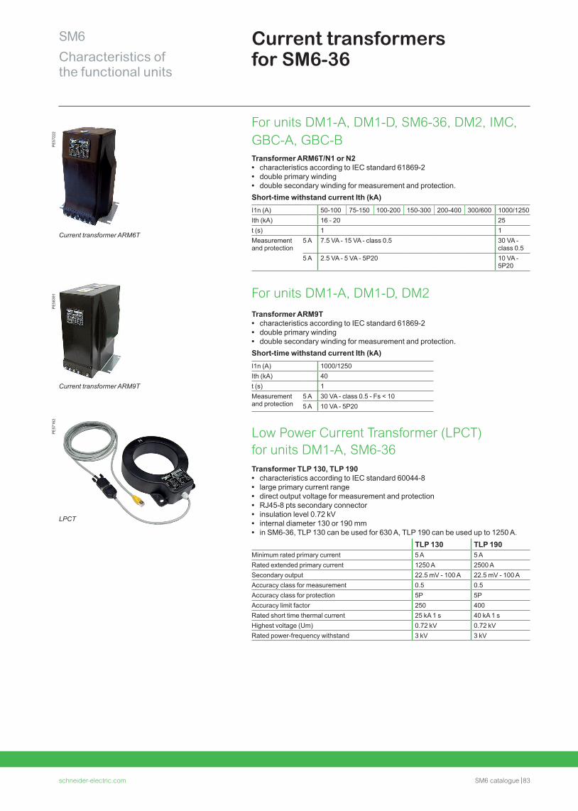
schneider-electric.com SM6 catalogue 83
SM6Characteristics of the functional units
Current transformers for SM6-36
PE
5722
2P
E58
391
Current transformer ARM6T
Current transformer ARM9T
PE
5716
2
For units DM1-A, DM1-D, SM6-36, DM2, IMC, GBC-A, GBC-BTransformer ARM6T/N1 or N2 • characteristics according to IEC standard 61869-2 • double primary winding • double secondary winding for measurement and protection.
Short-time withstand current Ith (kA)I1n (A) 50-100 75-150 100-200 150-300 200-400 300/600 1000/1250Ith (kA) 16 - 20 25t (s) 1 1Measurement and protection
5 A 7.5 VA - 15 VA - class 0.5 30 VA - class 0.5
5 A 2.5 VA - 5 VA - 5P20 10 VA - 5P20
For units DM1-A, DM1-D, DM2Transformer ARM9T • characteristics according to IEC standard 61869-2 • double primary winding • double secondary winding for measurement and protection.
Short-time withstand current Ith (kA)I1n (A) 1000/1250Ith (kA) 40t (s) 1Measurement and protection
5 A 30 VA - class 0.5 - Fs < 105 A 10 VA - 5P20
Low Power Current Transformer (LPCT) for units DM1-A, SM6-36Transformer TLP 130, TLP 190 • characteristics according to IEC standard 60044-8 • large primary current range • direct output voltage for measurement and protection • RJ45-8 pts secondary connector • insulation level 0.72 kV • internal diameter 130 or 190 mm • in SM6-36, TLP 130 can be used for 630 A, TLP 190 can be used up to 1250 A.
TLP 130 TLP 190Minimum rated primary current 5 A 5 ARated extended primary current 1250 A 2500 ASecondary output 22.5 mV - 100 A 22.5 mV - 100 AAccuracy class for measurement 0.5 0.5Accuracy class for protection 5P 5PAccuracy limit factor 250 400Rated short time thermal current 25 kA 1 s 40 kA 1 sHighest voltage (Um) 0.72 kV 0.72 kVRated power-frequency withstand 3 kV 3 kV
LPCT
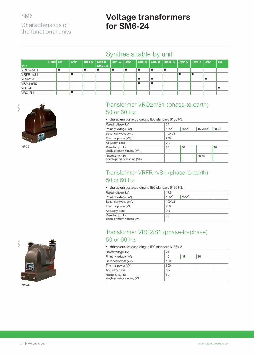
84 SM6 catalogue schneider-electric.com
SM6Characteristics of the functional units
Voltage transformers for SM6-24
Synthesis table by unitUnits
VTsCM CVM DM1-A DM1-D
DMVL-DDM1-W DM2 GBC-A GBC-B DMVL-A DMV-A DMV-D CM2 TM
VRQ2-n/S1 b b b b b b b b
VRFR-n/S1 b b b
VRC2/S1 b b b
VRM3-n/S2 b b
VCT24 b
VRC1/S1 b
Transformer VRQ2n/S1 (phase-to-earth) 50 or 60 Hz • characteristics according to IEC standard 61869-3.
Rated voltage (kV) 24Primary voltage (kV) 10/3 15/3 15-20/3 20/3Secondary voltage (V) 100/3Thermal power (VA) 250Accuracy class 0.5Rated output forsingle primary winding (VA)
30 30 30
Rated output fordouble primary winding (VA)
30-50
Transformer VRFR-n/S1 (phase-to-earth) 50 or 60 Hz • characteristics according to IEC standard 61869-3.
Rated voltage (kV) 17.5Primary voltage (kV) 10/3 15/3Secondary voltage (V) 100/3Thermal power (VA) 250Accuracy class 0.5Rated output forsingle primary winding (VA)
30
Transformer VRC2/S1 (phase-to-phase) 50 or 60 Hz • characteristics according to IEC standard 61869-3.
Rated voltage (kV) 24Primary voltage (kV) 10 15 20Secondary voltage (V) 100Thermal power (VA) 500Accuracy class 0.5Rated output forsingle primary winding (VA)
50
PE
6052
6P
E60
527
VRQ2
VRC2
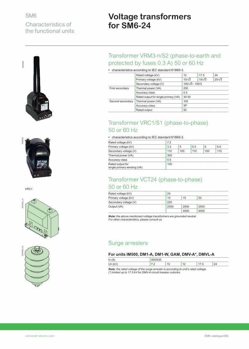
schneider-electric.com SM6 catalogue 85
SM6Characteristics of the functional units
Voltage transformers for SM6-24
DE
5356
2_LG
PE
6052
8D
E58
408_
LG
Transformer VRM3-n/S2 (phase-to-earth and protected by fuses 0.3 A) 50 or 60 Hz • characteristics according to IEC standard 61869-3.
Rated voltage (kV) 12 17.5 24Primary voltage (kV) 10/3 15/3 20/3Secondary voltage (V) 100/3 - 100/3
First secondary Thermal power (VA) 200Accuracy class 0.5Rated output for single primary (VA) 30-50
Second secondary Thermal power (VA) 100Accuracy class 3PRated output 50
Transformer VRC1/S1 (phase-to-phase) 50 or 60 Hz • characteristics according to IEC standard 61869-3.
Rated voltage (kV) 7.2Primary voltage (kV) 3.3 5 5.5 6 6.6Secondary voltage (V) 110 100 110 100 110Thermal power (VA) 300Accuracy class 0.5Rated output forsingle primary winding (VA)
100
Transformer VCT24 (phase-to-phase) 50 or 60 HzRated voltage (kV) 24Primary voltage (kV) 10 15 20Secondary voltage (V) 220Output (VA) 2500 2500 2500
4000 4000
Note: the above mentioned voltage transformers are grounded neutral. For other characteristics, please consult us.
Surge arresters
For units IM500, DM1-A, DM1-W, GAM, DMV-A*, DMVL-AIn (A) 400/630Un (kV) 7.2 10 12 17.5 24
Note: the rated voltage of the surge arrester is according to unit’s rated voltage. (*) limited up to 17.5 kV for DMV-A circuit breaker cubicles.
VRC1
PE
5564
8
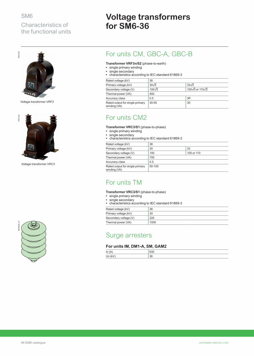
86 SM6 catalogue schneider-electric.com
SM6Characteristics of the functional units
Voltage transformers for SM6-36
DE
5840
8_LG
PE
5722
3P
E57
224
Voltage transformer VRF3
Voltage transformer VRC3
For units CM, GBC-A, GBC-BTransformer VRF3n/S2 (phase-to-earth) • single primary winding • single secondary • characteristics according to IEC standard 61869-3
Rated voltage (kV) 36Primary voltage (kV) 303 333
Secondary voltage (V) 1003 1003 or 1103
Thermal power (VA) 450Accuracy class 0.5 3PRated output for single primary winding (VA)
30-50 30
For units CM2Transformer VRC3/S1 (phase-to-phase) • single primary winding • single secondary • characteristics according to IEC standard 61869-3
Rated voltage (kV) 36Primary voltage (kV) 30 33Secondary voltage (V) 100 100 or 110Thermal power (VA) 700Accuracy class 0.5Rated output for single primary winding (VA)
50-100
For units TMTransformer VRC3/S1 (phase-to-phase) • single primary winding • single secondary • characteristics according to IEC standard 61869-3
Rated voltage (kV) 36Primary voltage (kV) 30Secondary voltage (V) 220Thermal power (VA) 1000
Surge arresters
For units IM, DM1-A, SM, GAM2In (A) 630Un (kV) 36
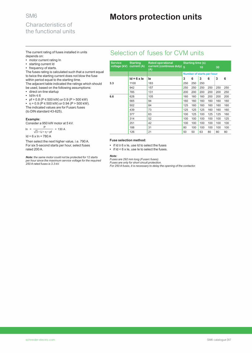
schneider-electric.com SM6 catalogue 87
SM6Characteristics of the functional units
Motors protection units
The current rating of fuses installed in units depends on: • motor current rating In • starting current Id • frequency of starts.
The fuses rating is calculated such that a current equal to twice the starting current does not blow the fuse within period equal to the starting time.The adjacent table indicated the ratings which should be used, based on the following assumptions: • direct on-line startup • Id/In y 6 • pf = 0.8 (P y 500 kW) or 0.9 (P > 500 kW) • η = 0.9 (P y 500 kW) or 0.94 (P > 500 kW).
The indicated values are for Fusarc fuses (to DIN standard 43-625).
Example: Consider a 950 kW motor at 5 kV.
In =P
= 130 pf
A
Id = 6 x In = 780 AThen select the next higher value, i.e. 790 A. For six 5-second starts per hour, select fuses rated 200 A.
Note: the same motor could not be protected for 12 starts per hour since the maximum service voltage for the required 250 A rated fuses is 3.3 kV.
Selection of fuses for CVM units
Fuse selection method: • if Id ≥ 6 x Ie, use Id to select the fuses • if Id < 6 x Ie, use Ie to select the fuses.
Note:Fuses are 292 mm long (Fusarc fuses). Fuses are only for short circuit protection.For 250 A fuses, it is necessary to delay the opening of the contactor.
Service voltage (kV)
Starting current (A)
Rated operational current (continous duty) (A)
Starting time (s)5 10 30
Number of starts per hourId = 6 x Ie Ie 3 6 3 6 3 6
3.3 1100 183 250 250 250942 157 250 250 250 250 250 250785 131 200 200 200 200 200 250
6.6 628 105 160 160 160 200 200 200565 94 160 160 160 160 160 160502 84 125 160 160 160 160 160439 73 125 125 125 160 160 160377 63 100 125 100 125 125 160314 52 100 100 100 100 100 125251 42 100 100 100 100 100 100188 31 80 100 100 100 100 100126 21 50 50 63 80 80 80
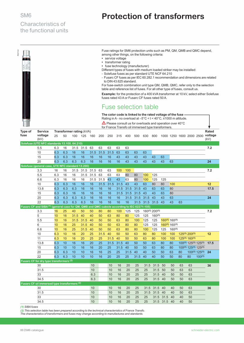
88 SM6 catalogue schneider-electric.com
SM6Characteristics of the functional units
Protection of transformersP
E57
161 Fuse ratings for SM6 protection units such as PM, QM, QMB and QMC depend,
among other things, on the following criteria: • service voltage • transformer rating • fuse technology (manufacturer)
Different types of fuses with medium loaded striker may be installed: - Solefuse fuses as per standard UTE NCF 64.210 - Fusarc CF fuses as per IEC 60.282.1 recommendation and dimensions are related to DIN 43.625 standard.
For fuse-switch combination unit type QM, QMB, QMC, refer only to the selection table and reference list of fuses. For all other type of fuses, consult us.Example: for the protection of a 400 kVA transformer at 10 kV, select either Solefuse fuses rated 43 A or Fusarc CF fuses rated 50 A.
Fuse selection tableThe color code is linked to the rated voltage of the fuse Rating in A - no overload at –5°C < t < 40°C, ≤1000 m altitude. d Please consult us for overloads and operation over 40°C for France Transfo oil immersed type transformers.
Type of fuse
Service voltage (kV)
Transformer rating (kVA) Rated voltage (kV)
25 50 100 125 160 200 250 315 400 500 630 800 1000 1250 1600 2000 2500
Solefuse (UTE NFC standards 13.100. 64.210)
5.5 6.3 16 31.5 31.5 63 63 63 63 63 7.210 6.3 6.3 16 16 31.5 31.5 31.5 63 63 63 6315 6.3 6.3 16 16 16 16 16 43 43 43 43 43 6320 6.3 6.3 6.3 6.3 16 16 16 16 43 43 43 43 43 63 24
Solefuse (general case, UTE NFC standard 13.200)
3.3 16 16 31.5 31.5 31.5 63 63 100 100 7.25.5 6.3 16 16 31.5 31.5 63 63 63 80 80 100 1256.6 6.3 16 16 16 31.5 31.5 43 43 63 80 100 125 12510 6.3 6.3 16 16 16 31.5 31.5 31.5 43 43 63 80 80 100 1213.8 6.3 6.3 6.3 16 16 16 16 31.5 31.5 31.5 43 63 63 80 17.515 6.3 6.3 16 16 16 16 16 31.5 31.5 31.5 43 43 63 8020 6.3 6.3 6.3 6.3 16 16 16 16 31.5 31.5 31.5 43 43 63 2422 6.3 6.3 6.3 6.3 16 16 16 16 16 31.5 31.5 31.5 43 43 63
Fusarc CF and SIBA (1) (general case for QM, QMB and QMC cubicle according to IEC 62271-105)
3.3 16 25 40 50 50 80 80 100 125 125 160(1) 200(1) 7.25 10 16 31.5 40 40 50 63 80 80 125 125 160(1)
5.5 10 16 31.5 31.5 40 50 50 63 80 100 125 125 160(1) 160(1)
6 10 16 25 31.5 40 50 50 63 80 80 125 125 160(1) 160(1)
6.6 10 16 25 31.5 40 50 50 63 80 80 100 125 125 160(1)
10 6.3 10 16 20 25 31.5 40 50 50 63 80 80 100 100 125(1) 200(1) 1211 6.3 10 16 20 25 25 31.5 40 50 50 63 80 100 100 125(1) 160(1)
13.8 6.3 10 16 16 20 25 31.5 31.5 40 50 50 63 80 80 100(1) 125(1) 125(1) 17.515 6.3 10 10 16 16 20 25 31.5 40 50 50 63 80 80 100(1) 125(1) 125(1)
20 6.3 6.3 10 10 16 16 25 25 31.5 40 40 50 50 63 80 100(1) 125(1) 2422 6.3 6.3 10 10 10 16 20 25 25 31.5 40 40 50 50 80 80 100(1)
Fusarc CF for dry type transformers (2)
30 10 10 16 20 25 31.5 31.5 50 50 63 63 3631.5 10 10 16 20 25 25 31.5 50 50 63 6333 6.3 10 16 20 25 25 31.5 40 50 50 6334.5 6.3 10 16 20 25 25 31.5 40 50 50 63
Fusarc CF oil immersed type transformers (2)
30 10 10 16 20 25 31.5 31.5 40 40 50 63 3631.5 10 10 16 20 25 31.5 31.5 40 40 50 6333 10 10 16 20 25 25 31.5 31.5 40 40 5034.5 10 10 16 20 25 25 31.5 31.5 40 40 50
(1) SIBA fuses(2) This selection table has been prepared according to the technical characteristics of France Transfo.The characteristics of transformers and fuses may change according to manufactures and standards.
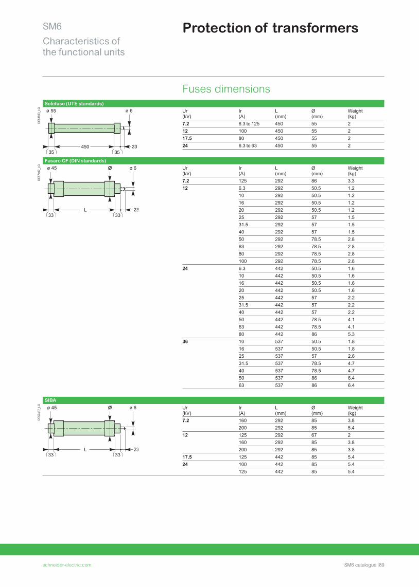
schneider-electric.com SM6 catalogue 89
SM6Characteristics of the functional units
Protection of transformers
Fuses dimensionsSolefuse (UTE standards)
DE
5356
3_LG Ur
(kV)Ir (A)
L (mm)
Ø (mm)
Weight (kg)
7.2 6.3 to 125 450 55 212 100 450 55 217.5 80 450 55 224 6.3 to 63 450 55 2
Fusarc CF (DIN standards)
DE
5746
7_LG Ur
(kV)Ir (A)
L (mm)
Ø (mm)
Weight (kg)
7.2 125 292 86 3.312 6.3 292 50.5 1.2
10 292 50.5 1.216 292 50.5 1.220 292 50.5 1.225 292 57 1.531.5 292 57 1.540 292 57 1.550 292 78.5 2.863 292 78.5 2.880 292 78.5 2.8100 292 78.5 2.8
24 6.3 442 50.5 1.610 442 50.5 1.616 442 50.5 1.620 442 50.5 1.625 442 57 2.231.5 442 57 2.240 442 57 2.250 442 78.5 4.163 442 78.5 4.180 442 86 5.3
36 10 537 50.5 1.816 537 50.5 1.825 537 57 2.631.5 537 78.5 4.740 537 78.5 4.750 537 86 6.463 537 86 6.4
SIBA
DE
5746
7_LG Ur
(kV)Ir (A)
L (mm)
Ø (mm)
Weight (kg)
7.2 160 292 85 3.8200 292 85 5.4
12 125 292 67 2160 292 85 3.8200 292 85 3.8
17.5 125 442 85 5.424 100 442 85 5.4
125 442 85 5.4
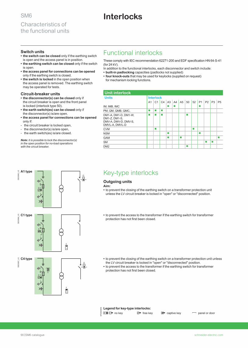
90 SM6 catalogue schneider-electric.com
SM6Characteristics of the functional units
Interlocks
Switch units • the switch can be closed only if the earthing switch is open and the access panel is in position.
• the earthing switch can be closed only if the switch is open.
• the access panel for connections can be opened only if the earthing switch is closed.
• the switch is locked in the open position when the access panel is removed. The earthing switch may be operated for tests.
Circuit-breaker units • the disconnector(s) can be closed only if the circuit breaker is open and the front panel is locked (interlock type 50).
• the earth switch(es) can be closed only if the disconnector(s) is/are open.
• the access panel for connections can be opened only if:
- the circuit breaker is locked open, - the disconnector(s) is/are open, - the earth switch(es) is/are closed.
Note: it is possible to lock the disconnector(s) in the open position for no-load operations with the circuit breaker.
DE
5356
5_LG A1 type
O
OKey-type interlocksOutgoing unitsAim: • to prevent the closing of the earthing switch on a transformer protection unit unless the LV circuit breaker is locked in "open" or "disconnected" position.
DE
5356
6_LG C1 type
S
S
• to prevent the access to the transformer if the earthing switch for transformer protection has not first been closed.
DE
5356
7_LG C4 type
S
SO
O
• to prevent the closing of the earthing switch on a transformer protection unit unless the LV circuit breaker is locked in "open" or "disconnected" position.
• to prevent the access to the transformer if the earthing switch for transformer protection has not first been closed.
MT2
0240
EN Legend for key-type interlocks:
no key free key captive key panel or door
Functional interlocksThese comply with IEC recommendation 62271-200 and EDF specification HN 64-S-41 (for 24 kV).In addition to the functional interlocks, each disconnector and switch include: • built-in padlocking capacities (padlocks not supplied) • four knock-outs that may be used for keylocks (supplied on request) for mechanism locking functions.
Unit interlockUnits Interlock
A1 C1 C4 A3 A4 A5 50 52 P1 P2 P3 P5IM, IMB, IMC b b b
PM, QM, QMB, QMC, b b b
DM1-A, DM1-D, DM1-W, DM1-Z, DM1-S, DMV-A, DMV-D, DMV-S, DMVL-A, DMVL-D
b b b b
CVM b b
NSM b b
GAM b b b
SM b b
DM2 b
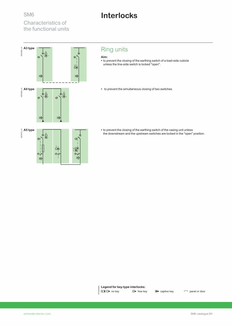
schneider-electric.com SM6 catalogue 91
SM6Characteristics of the functional units
InterlocksD
E53
568_
LG A3 typeO
O
Ring unitsAim: • to prevent the closing of the earthing switch of a load-side cubicle unless the line-side switch is locked "open".
DE
5356
9_LG A4 type • to prevent the simultaneous closing of two switches.
DE
5357
0_LG A5 type
O
OS
S
• to prevent the closing of the earthing switch of the casing unit unless the downstream and the upstream switches are locked in the "open" position.
MT2
0240
EN Legend for key-type interlocks:
no key free key captive key panel or door
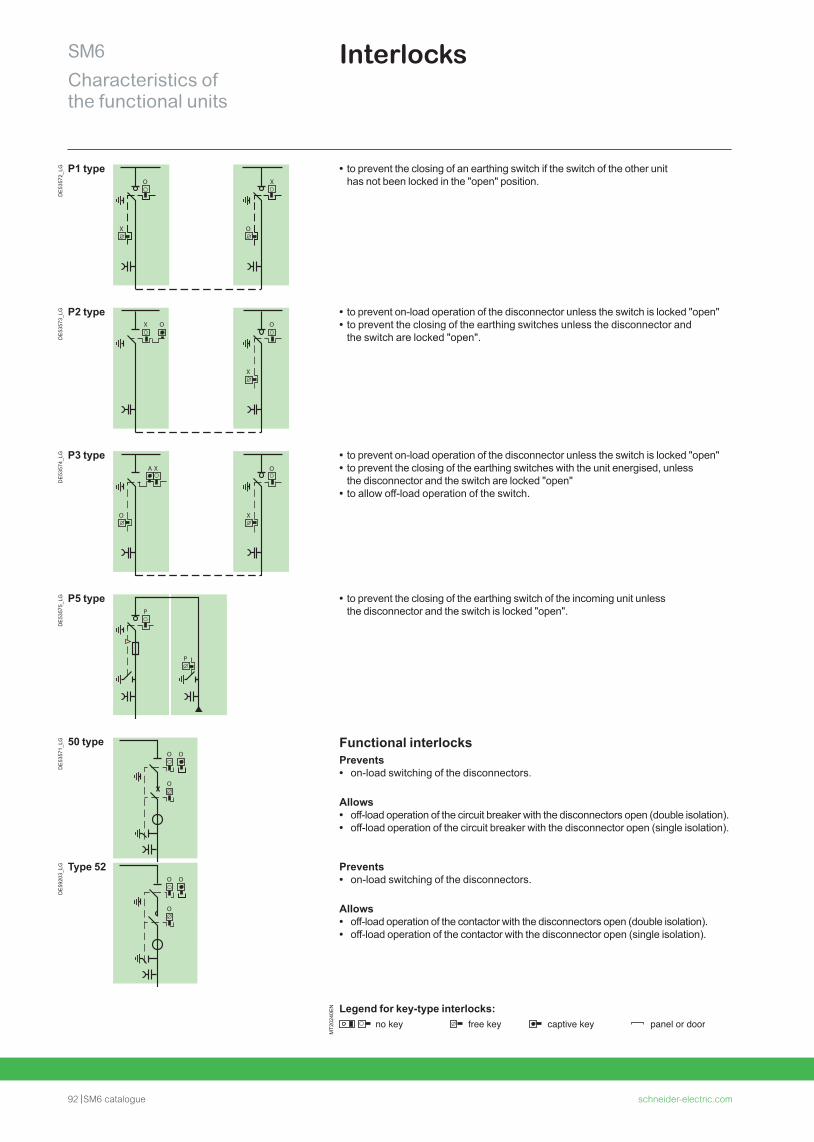
92 SM6 catalogue schneider-electric.com
SM6Characteristics of the functional units
InterlocksD
E53
572_
LG P1 type
X
O
O
X
• to prevent the closing of an earthing switch if the switch of the other unit has not been locked in the "open" position.
DE
5357
3_LG P2 type
X
X
OO
• to prevent on-load operation of the disconnector unless the switch is locked "open" • to prevent the closing of the earthing switches unless the disconnector and the switch are locked "open".
DE
5357
4_LG P3 type
O X
OA X
• to prevent on-load operation of the disconnector unless the switch is locked "open" • to prevent the closing of the earthing switches with the unit energised, unless the disconnector and the switch are locked "open"
• to allow off-load operation of the switch.
DE
5357
5_LG P5 type
P
P
• to prevent the closing of the earthing switch of the incoming unit unless the disconnector and the switch is locked "open".
DE
5357
1_LG 50 type
OO
O
Functional interlocks Prevents • on-load switching of the disconnectors.
Allows • off-load operation of the circuit breaker with the disconnectors open (double isolation). • off-load operation of the circuit breaker with the disconnector open (single isolation).
DE
5920
3_LG Type 52
OO
O
Prevents • on-load switching of the disconnectors.
Allows • off-load operation of the contactor with the disconnectors open (double isolation). • off-load operation of the contactor with the disconnector open (single isolation).
MT2
0240
EN Legend for key-type interlocks:
no key free key captive key panel or door

schneider-electric.com SM6 catalogue 93
Notes

94 SM6 catalogue schneider-electric.com
Connections
schneider-electric.com SM6 catalogue 95
SM6 ConnectionsContents
Connections with dry-type cables for SM6-24 96
Selection table 96
Cable-connection from below for SM6-24 97
Cable positions 97Trenches depth 98Trench diagrams example 100Trench diagrams and floor void drawings example 102
Connections with dry-type cables for SM6-36 103
Selection table 103
Cable-connection from below for SM6-36 104
Cable positions 104
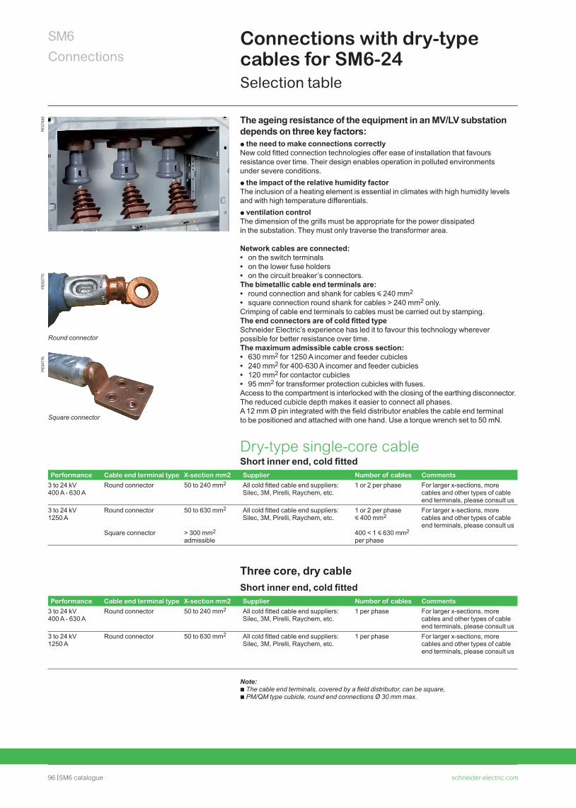
96 SM6 catalogue schneider-electric.com
SM6Connections
Connections with dry-type cables for SM6-24Selection table
PE
5077
5P
E50
776
Round connector
Square connector
The ageing resistance of the equipment in an MV/LV substation depends on three key factors:p the need to make connections correctlyNew cold fitted connection technologies offer ease of installation that favours resistance over time. Their design enables operation in polluted environments under severe conditions.p the impact of the relative humidity factor The inclusion of a heating element is essential in climates with high humidity levelsand with high temperature differentials.p ventilation control The dimension of the grills must be appropriate for the power dissipatedin the substation. They must only traverse the transformer area.
Network cables are connected: • on the switch terminals • on the lower fuse holders • on the circuit breaker’s connectors.
The bimetallic cable end terminals are: • round connection and shank for cables y 240 mm2 • square connection round shank for cables > 240 mm2 only.
Crimping of cable end terminals to cables must be carried out by stamping.The end connectors are of cold fitted typeSchneider Electric’s experience has led it to favour this technology wherever possible for better resistance over time.The maximum admissible cable cross section: • 630 mm2 for 1250 A incomer and feeder cubicles • 240 mm2 for 400-630 A incomer and feeder cubicles • 120 mm2 for contactor cubicles • 95 mm2 for transformer protection cubicles with fuses.
Access to the compartment is interlocked with the closing of the earthing disconnector. The reduced cubicle depth makes it easier to connect all phases. A 12 mm Ø pin integrated with the field distributor enables the cable end terminal to be positioned and attached with one hand. Use a torque wrench set to 50 mN.
PE
5784
0
Dry-type single-core cableShort inner end, cold fitted
Performance Cable end terminal type X-section mm2 Supplier Number of cables Comments3 to 24 kV 400 A - 630 A
Round connector 50 to 240 mm2 All cold fitted cable end suppliers: Silec, 3M, Pirelli, Raychem, etc.
1 or 2 per phase For larger x-sections, more cables and other types of cable end terminals, please consult us
3 to 24 kV 1250 A
Round connector
Square connector
50 to 630 mm2
> 300 mm2 admissible
All cold fitted cable end suppliers: Silec, 3M, Pirelli, Raychem, etc.
1 or 2 per phase y 400 mm2
400 < 1 y 630 mm2 per phase
For larger x-sections, more cables and other types of cable end terminals, please consult us
Three core, dry cableShort inner end, cold fitted
Performance Cable end terminal type X-section mm2 Supplier Number of cables Comments3 to 24 kV 400 A - 630 A
Round connector 50 to 240 mm2 All cold fitted cable end suppliers: Silec, 3M, Pirelli, Raychem, etc.
1 per phase For larger x-sections, more cables and other types of cable end terminals, please consult us
3 to 24 kV 1250 A
Round connector 50 to 630 mm2 All cold fitted cable end suppliers: Silec, 3M, Pirelli, Raychem, etc.
1 per phase For larger x-sections, more cables and other types of cable end terminals, please consult us
Note:b The cable end terminals, covered by a field distributor, can be square,b PM/QM type cubicle, round end connections Ø 30 mm max.
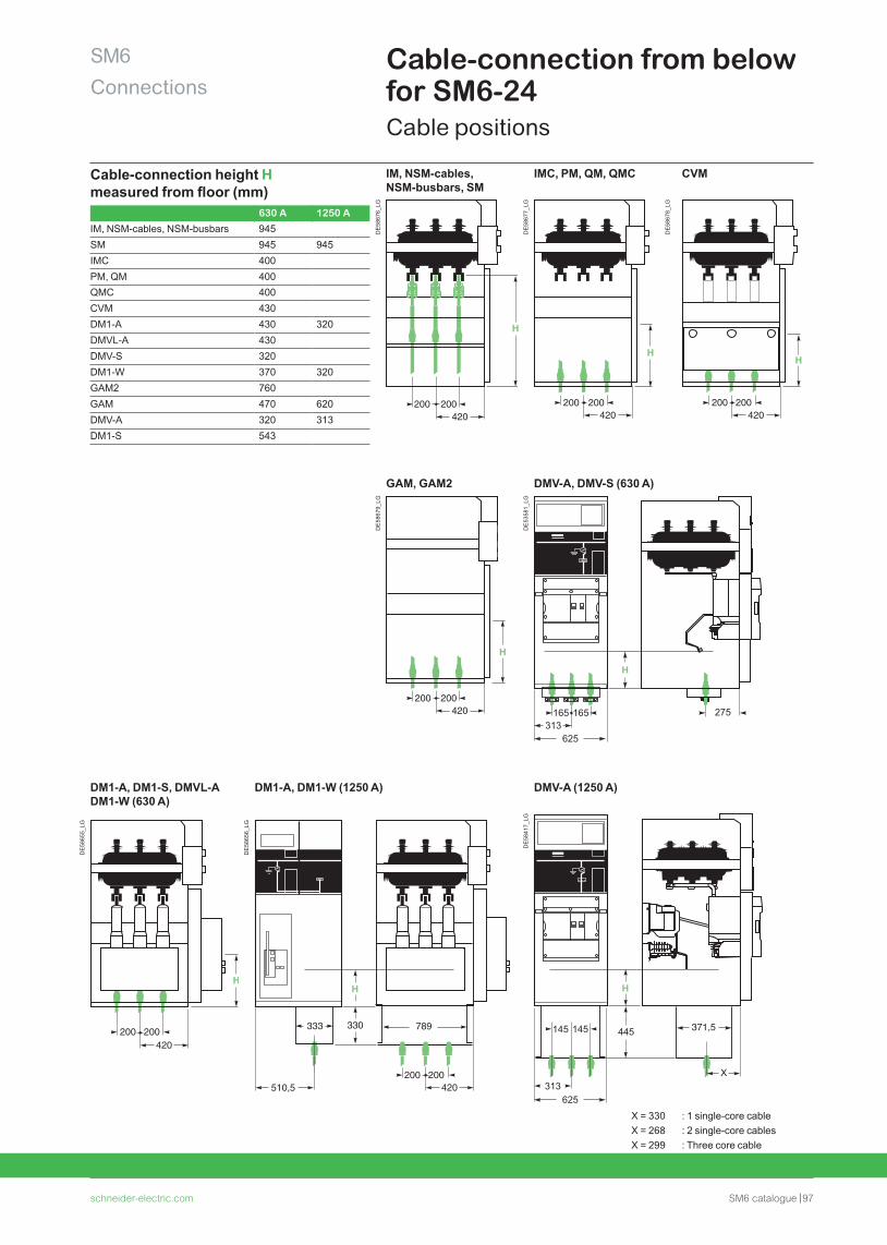
schneider-electric.com SM6 catalogue 97
SM6Connections
Cable-connection from below for SM6-24Cable positions
Cable-connection height H measured from floor (mm)
630 A 1250 A
IM, NSM-cables, NSM-busbars 945SM 945 945IMC 400PM, QM 400QMC 400CVM 430DM1-A 430 320DMVL-A 430DMV-S 320DM1-W 370 320GAM2 760GAM 470 620DMV-A 320 313DM1-S 543
IM, NSM-cables, NSM-busbars, SM
IMC, PM, QM, QMC CVM
DE
5867
6_LG
DE
5867
7_LG
DE
5867
8_LG
GAM, GAM2 DMV-A, DMV-S (630 A)
DE
5867
9_LG
DE
5358
1_LG
H
165313
165 275
625
DM1-A, DM1-S, DMVL-A DM1-W (630 A)
DM1-A, DM1-W (1250 A) DMV-A (1250 A)
DE
5865
5_LG
DE
5865
6_LG
DE
5841
7_LG
445 371,5
H
X
145
313
145
625
X = 330 : 1 single-core cableX = 268 : 2 single-core cablesX = 299 : Three core cable
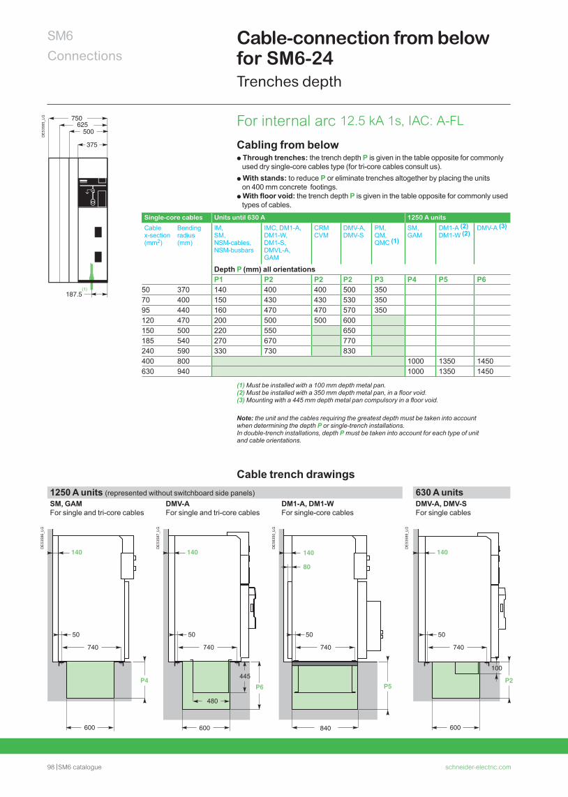
98 SM6 catalogue schneider-electric.com
SM6Connections
Cable-connection from below for SM6-24Trenches depth
Cabling from belowp Through trenches: the trench depth P is given in the table opposite for commonly
used dry single-core cables type (for tri-core cables consult us).p With stands: to reduce P or eliminate trenches altogether by placing the units
on 400 mm concrete footings. p With floor void: the trench depth P is given in the table opposite for commonly used
types of cables.Single-core cables Units until 630 A 1250 A units
Cable x-section (mm2)
Bending radius (mm)
IM, SM, NSM-cables, NSM-busbars
IMC, DM1-A, DM1-W, DM1-S, DMVL-A, GAM
CRMCVM
DMV-A, DMV-S
PM, QM, QMC (1)
SM, GAM
DM1-A (2) DM1-W (2)
DMV-A (3)
Depth P (mm) all orientationsP1 P2 P2 P2 P3 P4 P5 P6
50 370 140 400 400 500 35070 400 150 430 430 530 35095 440 160 470 470 570 350120 470 200 500 500 600150 500 220 550 650185 540 270 670 770240 590 330 730 830400 800 1000 1350 1450630 940 1000 1350 1450
(1) Must be installed with a 100 mm depth metal pan.(2) Must be installed with a 350 mm depth metal pan, in a floor void.(3) Mounting with a 445 mm depth metal pan compulsory in a floor void.
Note: the unit and the cables requiring the greatest depth must be taken into account when determining the depth P or single-trench installations. In double-trench installations, depth P must be taken into account for each type of unit and cable orientations.
Cable trench drawings1250 A units (represented without switchboard side panels) 630 A unitsSM, GAM For single and tri-core cables
DMV-AFor single and tri-core cables
DM1-A, DM1-W For single-core cables
DMV-A, DMV-SFor single cables
DE
5358
6_LG
DE
5358
7_LG
DE
5835
0_LG
DE
5358
9_LG
For internal arc 12.5 kA 1s, IAC: A-FL750
500
375
187.5
625
DE
5358
5_LG
(1)
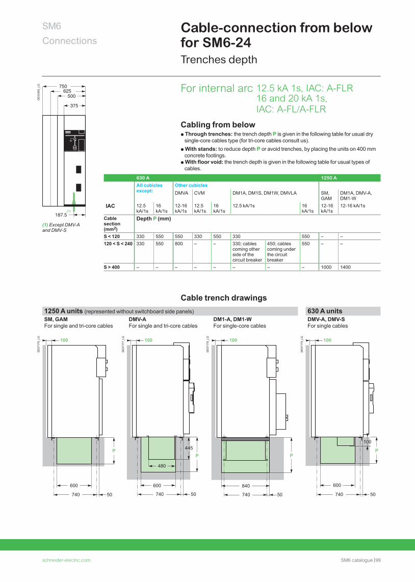
schneider-electric.com SM6 catalogue 99
SM6Connections
Cable-connection from below for SM6-24Trenches depth
Cabling from belowp Through trenches: the trench depth P is given in the following table for usual dry
single-core cables type (for tri-core cables consult us).p With stands: to reduce depth P or avoid trenches, by placing the units on 400 mm
concrete footings. p With floor void: the trench depth is given in the following table for usual types of
cables.
630 A 1250 A
All cubicles except:
Other cubiclesDMVA CVM DM1A, DM1S, DM1W, DMVLA SM,
GAMDM1A, DMV-A, DM1-W
IAC 12.5 kA/1s
16 kA/1s
12-16 kA/1s
12.5 kA/1s
16 kA/1s
12.5 kA/1s 16 kA/1s
12-16 kA/1s
12-16 kA/1s
Cable section (mm2)
Depth P (mm)
S < 120 330 550 550 330 550 330 550 – –120 < S < 240 330 550 800 – – 330; cables
coming other side of the circuit breaker
450; cables coming under the circuit breaker
550 – –
S > 400 – – – – – – – – 1000 1400
Cable trench drawings1250 A units (represented without switchboard side panels) 630 A unitsSM, GAM For single and tri-core cables
DMV-AFor single and tri-core cables
DM1-A, DM1-W For single-core cables
DMV-A, DMV-SFor single cables
DE
5717
6_LG
600
100
740 50
P
DE
5717
7_LG
P
480
600
445
740 50
100
DE
5717
8_LG
840
P
740 50
100
DE
5717
9_LG
600
100
P
740 50
100
750
500
375
187.5
625
DE
5358
5_LG
(1)
(1) Except DMV-A and DMV-S
For internal arc 12.5 kA 1s, IAC: A-FLR 16 and 20 kA 1s, IAC: A-FL/A-FLR
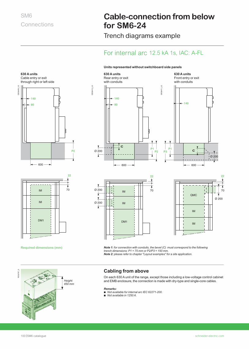
100 SM6 catalogue schneider-electric.com
SM6Connections
Cable-connection from below for SM6-24Trench diagrams example
Cabling from aboveOn each 630 A unit of the range, except those including a low-voltage control cabinet and EMB enclosure, the connection is made with dry-type and single-core cables.
Remarks: b Not available for internal arc IEC 62271-200. b Not available in 1250 A.
PE
5079
7_G
Height: 450 mm
Units represented without switchboard side panels
630 A unitsCable entry or exit through right or left side
630 A unitsRear entry or exit with conduits
630 A unitsFront entry or exit with conduits
DE
5840
9_LG
DE
5841
0_LG
DE
5841
1_LG
Required dimensions (mm) Note 1: for connection with conduits, the bevel (C) must correspond to the following trench dimensions: P1 = 75 mm or P2/P3 = 150 mm.Note 2: please refer to chapter "Layout examples" for a site application.
For internal arc 12.5 kA 1s, IAC: A-FL
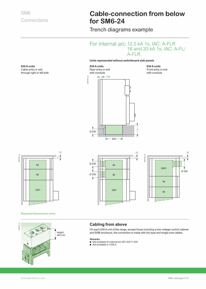
schneider-electric.com SM6 catalogue 101
SM6Connections
Cable-connection from below for SM6-24Trench diagrams example
Units represented without switchboard side panels
630 A unitsCable entry or exit through right or left side
630 A unitsRear entry or exit with conduits
630 A unitsFront entry or exit with conduits
DE
5718
0_LG
600
P2
IM
IM
DM1
25
100
DE
5718
1_LG
P
25
IM
IM
DM1
100
DE
5718
2_LG
P1P3
25
QMC
IM
IM
100
Required dimensions (mm)
Cabling from aboveOn each 630 A unit of the range, except those including a low-voltage control cabinet and EMB enclosure, the connection is made with dry-type and single-core cables.
Remarks: b Not available for internal arc IEC 62271-200. b Not available in 1250 A.
PE
5079
7_G
Height: 450 mm
For internal arc 12.5 kA 1s, IAC: A-FLR 16 and 20 kA 1s, IAC: A-FL/A-FLR
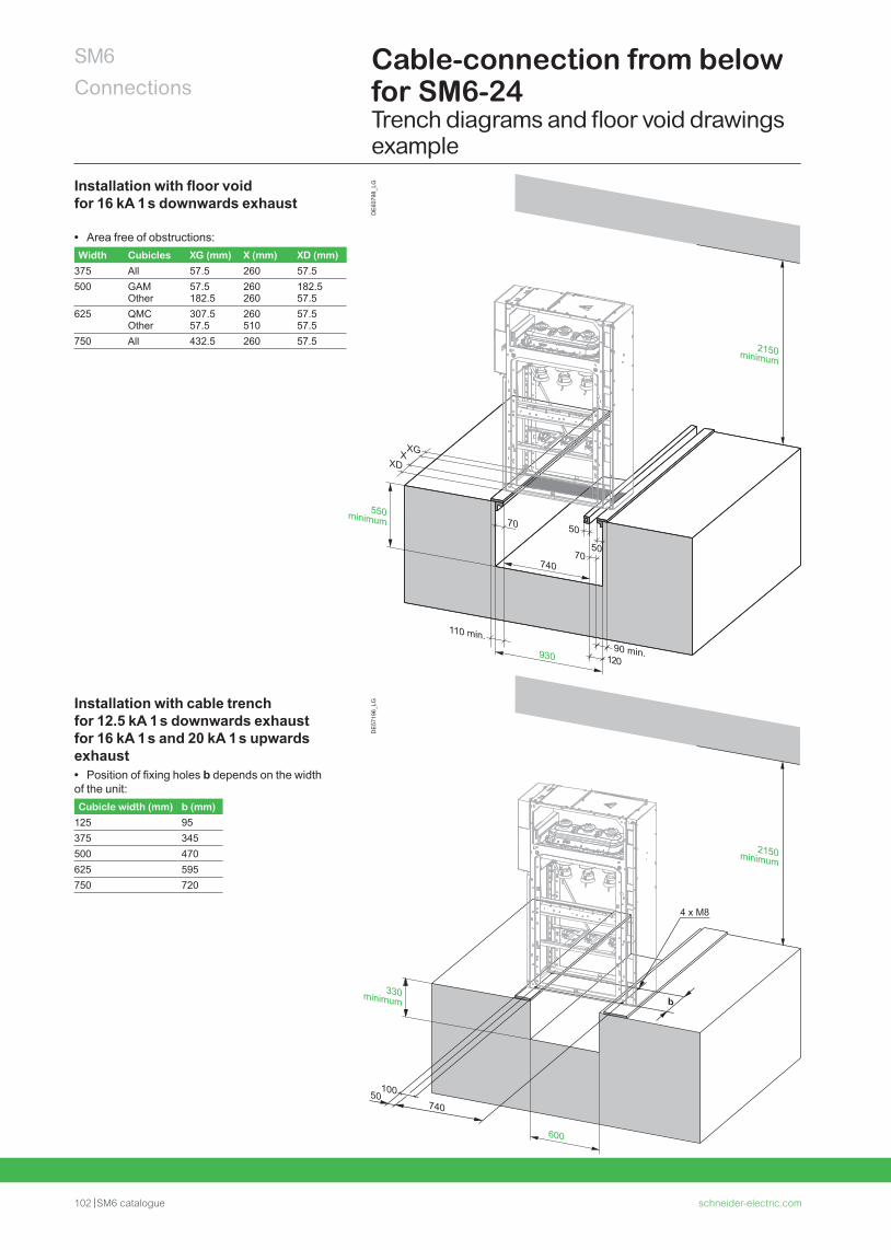
102 SM6 catalogue schneider-electric.com
SM6Connections
Cable-connection from below for SM6-24Trench diagrams and floor void drawings example
DE
6079
8_LG
740
b
50100
4 x M8
600
330minimum
2150minimum
DE
5719
6_LG
Installation with floor void for 16 kA 1 s downwards exhaust
• Area free of obstructions:Width Cubicles XG (mm) X (mm) XD (mm)
375 All 57.5 260 57.5500 GAM
Other57.5182.5
260260
182.557.5
625 QMC Other
307.557.5
260510
57.557.5
750 All 432.5 260 57.5
Installation with cable trench for 12.5 kA 1 s downwards exhaust for 16 kA 1 s and 20 kA 1 s upwards exhaust • Position of fixing holes b depends on the width
of the unit:Cubicle width (mm) b (mm)
125 95375 345500 470625 595750 720
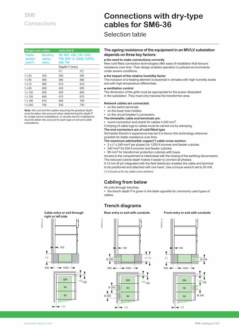
schneider-electric.com SM6 catalogue 103
SM6Connections
Connections with dry-type cables for SM6-36Selection table
The ageing resistance of the equipment in an MV/LV substation depends on three key factors:p the need to make connections correctlyNew cold fitted connection technologies offer ease of installation that favours resistance over time. Their design enables operation in polluted environments under severe conditions.p the impact of the relative humidity factor The inclusion of a heating element is essential in climates with high humidity levelsand with high temperature differentials.p ventilation control The dimension of the grills must be appropriate for the power dissipatedin the substation. They must only traverse the transformer area.
Network cables are connected: • on the switch terminals • on the lower fuse holders • on the circuit breaker’s connectors.
The bimetallic cable end terminals are: • round connection and shank for cables y 240 mm2.
Crimping of cable lugs to cables must be carried out by stamping.The end connectors are of cold fitted typeSchneider Electric’s experience has led it to favour this technology wherever possible for better resistance over time.The maximum admissible copper(*) cable cross section: • 2 x (1 x 240 mm2 per phase) for 1250 A incomer and feeder cubicles • 240 mm2 for 630 A incomer and feeder cubicles • 95 mm2 for transformer protection cubicles with fuses.
Access to the compartment is interlocked with the closing of the earthing disconnector. The reduced cubicle depth makes it easier to connect all phases. A 12 mm Ø pin integrated with the field distributor enables the cable end terminal to be positioned and attached with one hand. Use a torque wrench set to 50 mN.(*) Consult us for alu cable cross sections
Cabling from belowAll units through trenches • the trench depth P is given in the table opposite for commonly used types of
cables.
Trench diagramsCable entry or exit through right or left side
Rear entry or exit with conduits Front entry or exit with conduits
DE
5972
3_LG
DE
5972
4_LG
DE
5972
5_LG
Single-core cables Units 630 A
Cable-section(mm2)
Bending radius (mm)
IM, IMC, QM, CM, CM2, PM, DM1-A, GAM, GAM2, SM, TMDepth P (mm)P1 P2
1 x 35 525 350 5501 x 50 555 380 5801 x 70 585 410 6101 x 95 600 425 6251 x 120 630 455 6551 x 150 645 470 6701 x 185 675 500 7001 x 240 705 530 730
Note: the unit and the cables requiring the greatest depth must be taken into account when determining the depth P for single-trench installations. In double-trench installations must be taken into account to each type of unit and cable orientations.
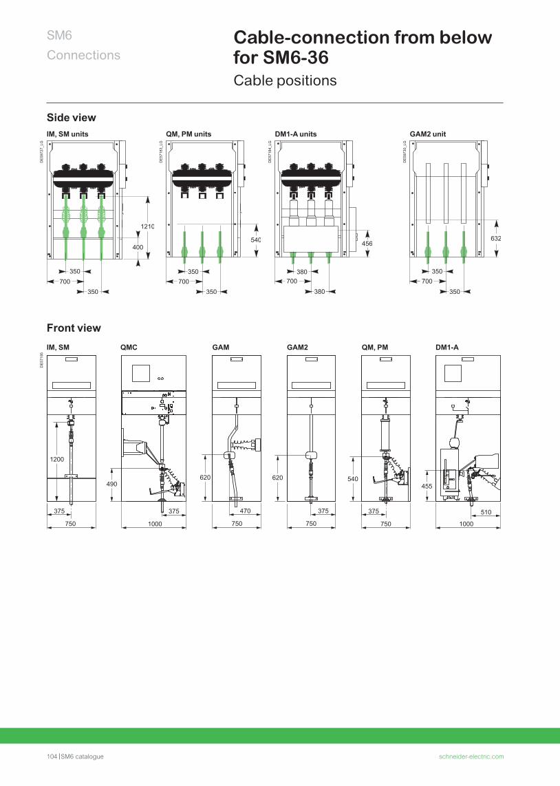
104 SM6 catalogue schneider-electric.com
SM6Connections
Cable-connection from below for SM6-36Cable positions
Side viewIM, SM units QM, PM units DM1-A units GAM2 unit
DE
5972
7_LG
DE
5718
3_LG
DE
5718
4_LG
DE
5973
0_LG
Front viewIM, SM QMC GAM GAM2 QM, PM DM1-A
DE
5718
5
375
750
470
750
375
750
375
750
375
1000
510
1000
1200
490620 620 540
455

schneider-electric.com SM6 catalogue 105
Notes

106 SM6 catalogue schneider-electric.com
Installation
schneider-electric.com SM6 catalogue 107
SM6 InstallationContents
Dimensions and weights for SM6-24 108
Units dimensions for SM6-24 109
Civil engineering for SM6-24 113
Layout examples for SM6-24 114
Dimensions and weights for SM6-36 116
Civil engineering for SM6-36 117
Layout examples for SM6-36 118
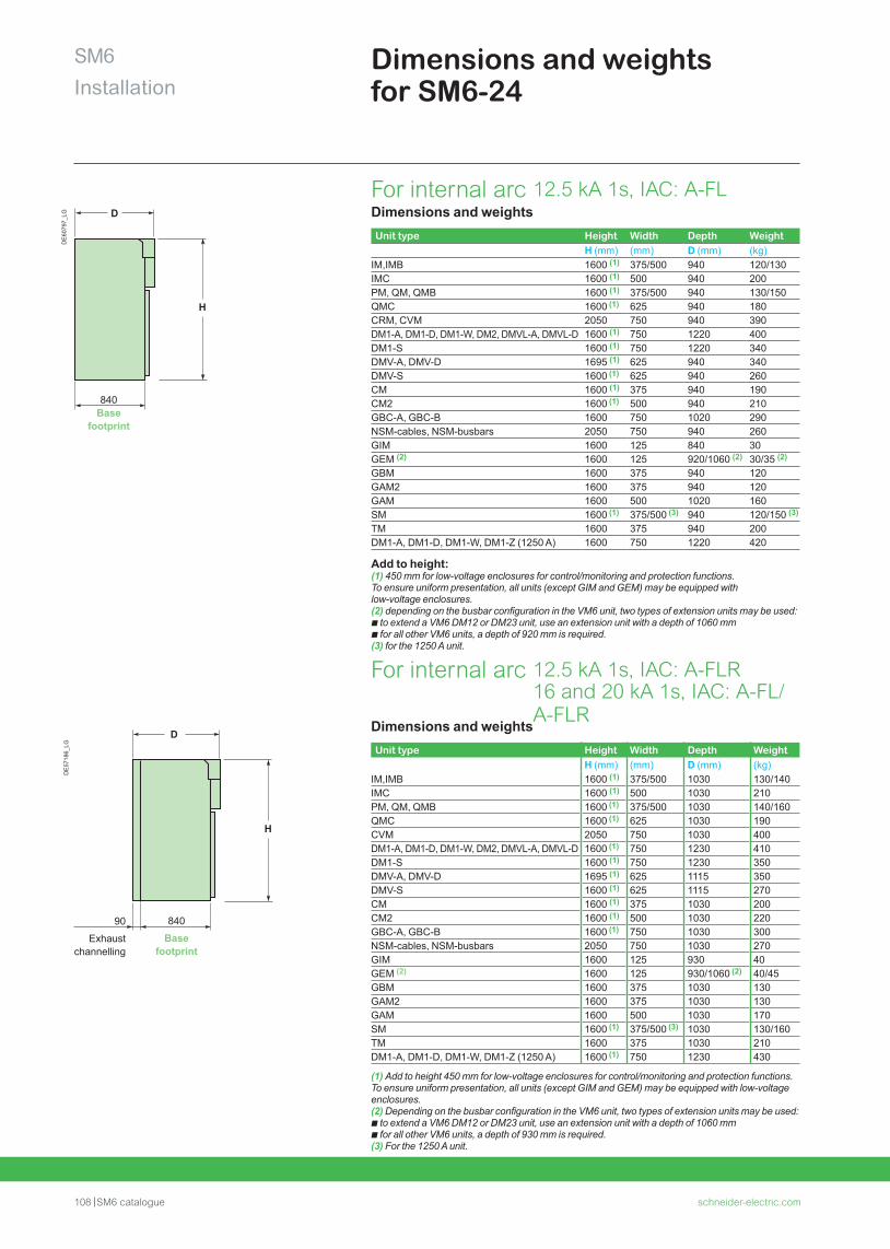
108 SM6 catalogue schneider-electric.com
SM6Installation
Dimensions and weights for SM6-24
Dimensions and weightsUnit type Height Width Depth Weight
H (mm) (mm) D (mm) (kg)IM,IMB 1600 (1) 375/500 1030 130/140IMC 1600 (1) 500 1030 210PM, QM, QMB 1600 (1) 375/500 1030 140/160QMC 1600 (1) 625 1030 190CVM 2050 750 1030 400DM1-A, DM1-D, DM1-W, DM2, DMVL-A, DMVL-D 1600 (1) 750 1230 410DM1-S 1600 (1) 750 1230 350DMV-A, DMV-D 1695 (1) 625 1115 350DMV-S 1600 (1) 625 1115 270CM 1600 (1) 375 1030 200CM2 1600 (1) 500 1030 220GBC-A, GBC-B 1600 (1) 750 1030 300NSM-cables, NSM-busbars 2050 750 1030 270GIM 1600 125 930 40GEM (2) 1600 125 930/1060 (2) 40/45GBM 1600 375 1030 130GAM2 1600 375 1030 130GAM 1600 500 1030 170SM 1600 (1) 375/500 (3) 1030 130/160TM 1600 375 1030 210DM1-A, DM1-D, DM1-W, DM1-Z (1250 A) 1600 (1) 750 1230 430
(1) Add to height 450 mm for low-voltage enclosures for control/monitoring and protection functions. To ensure uniform presentation, all units (except GIM and GEM) may be equipped with low-voltage enclosures. (2) Depending on the busbar configuration in the VM6 unit, two types of extension units may be used:b to extend a VM6 DM12 or DM23 unit, use an extension unit with a depth of 1060 mmb for all other VM6 units, a depth of 930 mm is required.(3) For the 1250 A unit.
DE
6079
7_LG D
H
840Base
footprint
Dimensions and weightsUnit type Height Width Depth Weight
H (mm) (mm) D (mm) (kg)IM,IMB 1600 (1) 375/500 940 120/130IMC 1600 (1) 500 940 200PM, QM, QMB 1600 (1) 375/500 940 130/150QMC 1600 (1) 625 940 180CRM, CVM 2050 750 940 390DM1-A, DM1-D, DM1-W, DM2, DMVL-A, DMVL-D 1600 (1) 750 1220 400DM1-S 1600 (1) 750 1220 340DMV-A, DMV-D 1695 (1) 625 940 340DMV-S 1600 (1) 625 940 260CM 1600 (1) 375 940 190CM2 1600 (1) 500 940 210GBC-A, GBC-B 1600 750 1020 290NSM-cables, NSM-busbars 2050 750 940 260GIM 1600 125 840 30GEM (2) 1600 125 920/1060 (2) 30/35 (2)
GBM 1600 375 940 120GAM2 1600 375 940 120GAM 1600 500 1020 160SM 1600 (1) 375/500 (3) 940 120/150 (3)
TM 1600 375 940 200DM1-A, DM1-D, DM1-W, DM1-Z (1250 A) 1600 750 1220 420
Add to height:(1) 450 mm for low-voltage enclosures for control/monitoring and protection functions. To ensure uniform presentation, all units (except GIM and GEM) may be equipped with low-voltage enclosures. (2) depending on the busbar configuration in the VM6 unit, two types of extension units may be used:b to extend a VM6 DM12 or DM23 unit, use an extension unit with a depth of 1060 mmb for all other VM6 units, a depth of 920 mm is required.(3) for the 1250 A unit.
For internal arc 12.5 kA 1s, IAC: A-FLR 16 and 20 kA 1s, IAC: A-FL/A-FLR
For internal arc 12.5 kA 1s, IAC: A-FL
DE
5718
6_LG
D
H
90 840
Exhaust channelling
Base footprint
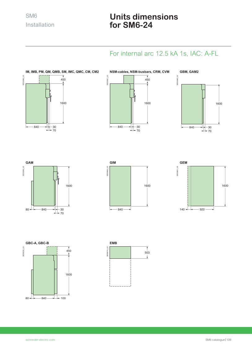
schneider-electric.com SM6 catalogue 109
SM6Installation
Units dimensions for SM6-24
For internal arc 12.5 kA 1s, IAC: A-FL
IM, IMB, PM, QM, QMB, SM, IMC, QMC, CM, CM2 NSM-cables, NSM-busbars, CRM, CVM GBM, GAM2
DE
5359
6_LG
DE
5359
7_LG
DE
5359
8_LG
GAM GIM GEM
DE
5359
9_LG
DE
5360
0_LG
DE
5360
1_LG
GBC-A, GBC-B EMB
DE
5922
9_LG
DE
5841
4_LG
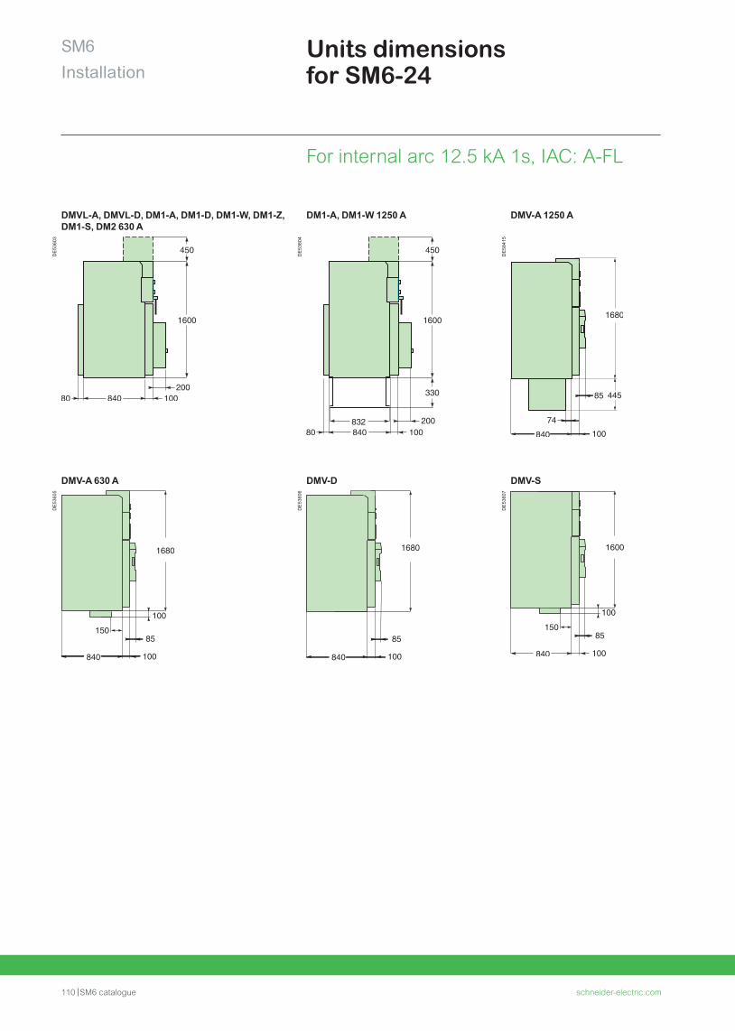
110 SM6 catalogue schneider-electric.com
DMVL-A, DMVL-D, DM1-A, DM1-D, DM1-W, DM1-Z, DM1-S, DM2 630 A
DM1-A, DM1-W 1250 A DMV-A 1250 A
DE
5360
3
DE
5360
4
DE
5841
5
DMV-A 630 A DMV-D DMV-S
DE
5360
5
DE
5360
6
DE
5360
7
SM6Installation
Units dimensions for SM6-24
For internal arc 12.5 kA 1s, IAC: A-FL
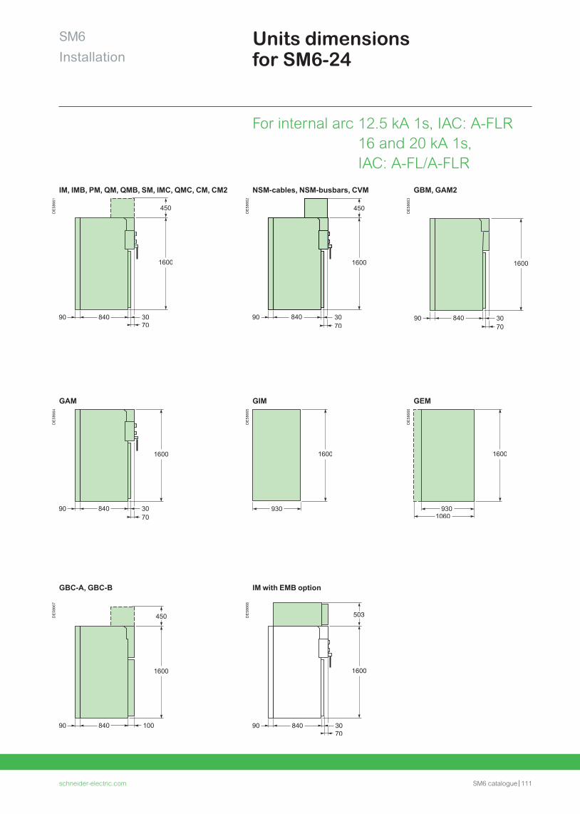
schneider-electric.com SM6 catalogue 111
SM6Installation
For internal arc 12.5 kA 1s, IAC: A-FLR 16 and 20 kA 1s, IAC: A-FL/A-FLR
Units dimensions for SM6-24
IM, IMB, PM, QM, QMB, SM, IMC, QMC, CM, CM2 NSM-cables, NSM-busbars, CVM GBM, GAM2
DE
5866
1
DE
5866
2
DE
5866
3GAM GIM GEM
DE
5866
4
DE
5866
5
DE
5866
6
GBC-A, GBC-B IM with EMB option
DE
5866
7
DE
5866
8
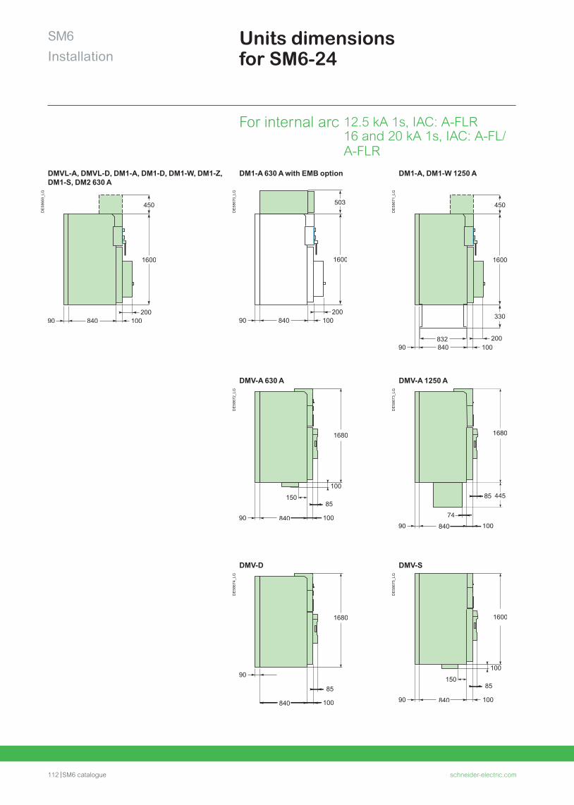
112 SM6 catalogue schneider-electric.com
DMVL-A, DMVL-D, DM1-A, DM1-D, DM1-W, DM1-Z, DM1-S, DM2 630 A
DM1-A 630 A with EMB option DM1-A, DM1-W 1250 A
DE
5866
9_LG
DE
5867
0_LG
DE
5867
1_LG
DMV-A 630 A DMV-A 1250 A
DE
5867
2_LG
DE
5867
3_LG
DMV-D DMV-S
DE
5867
4_LG
DE
5867
5_LG
SM6Installation
Units dimensions for SM6-24
For internal arc 12.5 kA 1s, IAC: A-FLR 16 and 20 kA 1s, IAC: A-FL/A-FLR
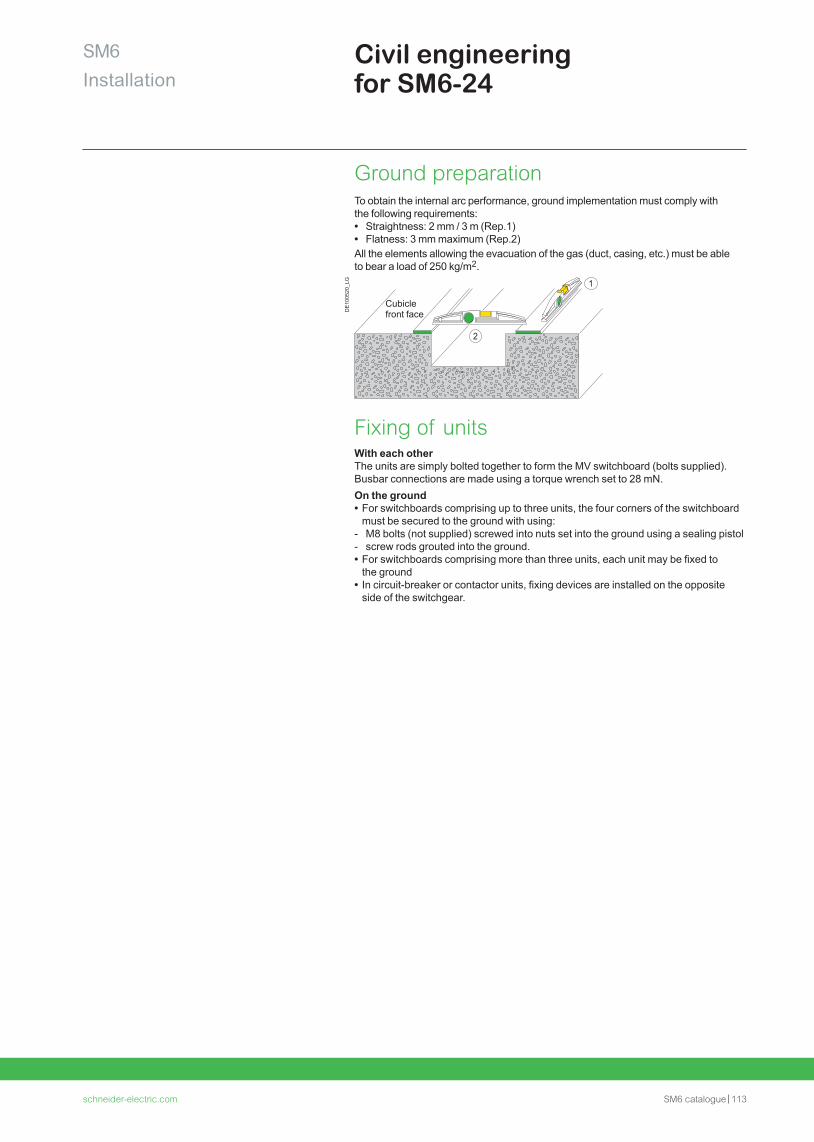
schneider-electric.com SM6 catalogue 113
SM6Installation
Civil engineering for SM6-24
Ground preparationTo obtain the internal arc performance, ground implementation must comply with the following requirements: • Straightness: 2 mm / 3 m (Rep.1) • Flatness: 3 mm maximum (Rep.2)
All the elements allowing the evacuation of the gas (duct, casing, etc.) must be able to bear a load of 250 kg/m2.
DE
1005
20_L
G 1
2
Cubicle front face
Fixing of unitsWith each otherThe units are simply bolted together to form the MV switchboard (bolts supplied). Busbar connections are made using a torque wrench set to 28 mN.On the ground • For switchboards comprising up to three units, the four corners of the switchboard must be secured to the ground with using:
- M8 bolts (not supplied) screwed into nuts set into the ground using a sealing pistol - screw rods grouted into the ground. • For switchboards comprising more than three units, each unit may be fixed to the ground
• In circuit-breaker or contactor units, fixing devices are installed on the opposite side of the switchgear.
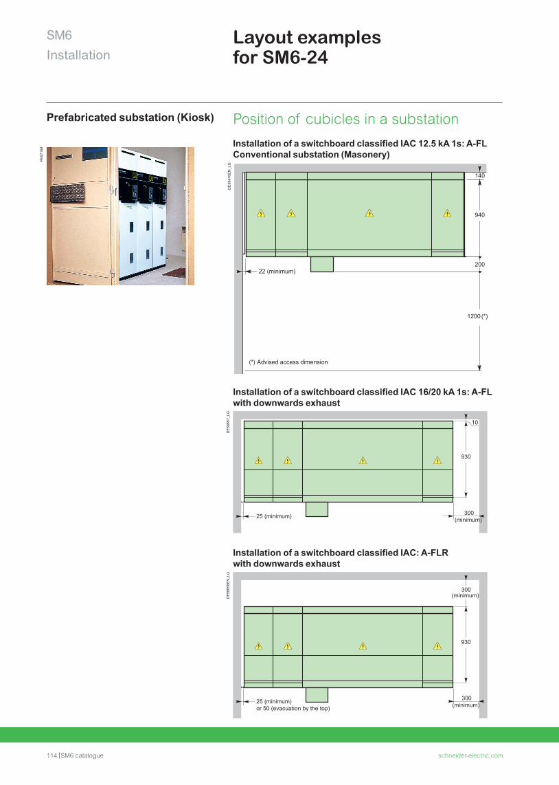
114 SM6 catalogue schneider-electric.com
SM6Installation
Layout examples for SM6-24
Prefabricated substation (Kiosk)
PE
5716
8
Installation of a switchboard classified IAC 16/20 kA 1s: A-FL with downwards exhaust
DE
5865
7_LG
Installation of a switchboard classified IAC: A-FLR with downwards exhaust
DE
5865
8EN
_LG
Position of cubicles in a substation
Installation of a switchboard classified IAC 12.5 kA 1s: A-FL Conventional substation (Masonery)
DE
5841
6EN
_LG
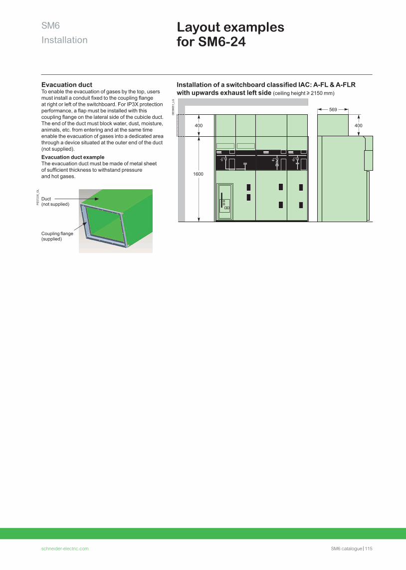
schneider-electric.com SM6 catalogue 115
SM6Installation
Layout examples for SM6-24
Evacuation ductTo enable the evacuation of gases by the top, users must install a conduit fixed to the coupling flange at right or left of the switchboard. For IP3X protection performance, a flap must be installed with this coupling flange on the lateral side of the cubicle duct. The end of the duct must block water, dust, moisture, animals, etc. from entering and at the same time enable the evacuation of gases into a dedicated area through a device situated at the outer end of the duct (not supplied).Evacuation duct exampleThe evacuation duct must be made of metal sheet of sufficient thickness to withstand pressure and hot gases.
Installation of a switchboard classified IAC: A-FL & A-FLR with upwards exhaust left side (ceiling height u 2150 mm)
DE
5865
1_LG
Coupling flange(supplied)
Duct (not supplied)P
E57
235_
GL
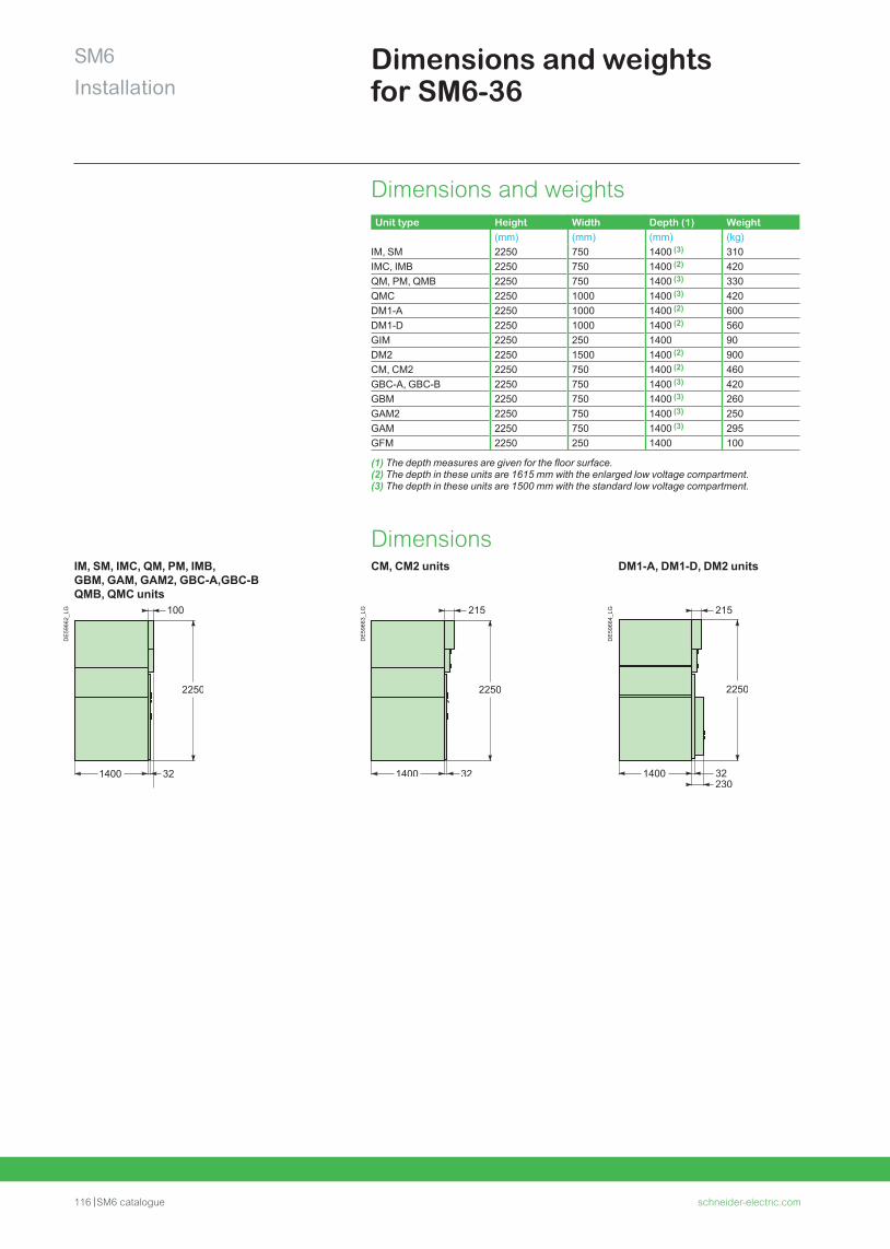
116 SM6 catalogue schneider-electric.com
SM6Installation
Dimensions and weights for SM6-36
Dimensions and weightsUnit type Height Width Depth (1) Weight
(mm) (mm) (mm) (kg)IM, SM 2250 750 1400 (3) 310IMC, IMB 2250 750 1400 (2) 420QM, PM, QMB 2250 750 1400 (3) 330QMC 2250 1000 1400 (3) 420DM1-A 2250 1000 1400 (2) 600DM1-D 2250 1000 1400 (2) 560GIM 2250 250 1400 90DM2 2250 1500 1400 (2) 900CM, CM2 2250 750 1400 (2) 460GBC-A, GBC-B 2250 750 1400 (3) 420GBM 2250 750 1400 (3) 260GAM2 2250 750 1400 (3) 250GAM 2250 750 1400 (3) 295GFM 2250 250 1400 100
(1) The depth measures are given for the floor surface.(2) The depth in these units are 1615 mm with the enlarged low voltage compartment.(3) The depth in these units are 1500 mm with the standard low voltage compartment.
DimensionsIM, SM, IMC, QM, PM, IMB, GBM, GAM, GAM2, GBC-A,GBC-B QMB, QMC units
CM, CM2 units DM1-A, DM1-D, DM2 units
DE
5966
2_LG
DE
5966
3_LG
DE
5966
4_LG
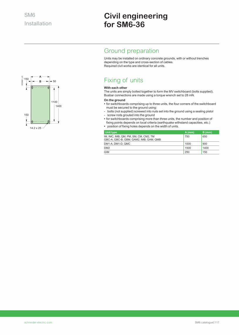
schneider-electric.com SM6 catalogue 117
SM6Installation
Civil engineering for SM6-36
DE
5966
1_LG
Ground preparationUnits may be installed on ordinary concrete grounds, with or without trenches depending on the type and cross-section of cables.Required civil works are identical for all units.
Fixing of unitsWith each otherThe units are simply bolted together to form the MV switchboard (bolts supplied). Busbar connections are made using a torque wrench set to 28 mN.On the ground • for switchboards comprising up to three units, the four corners of the switchboard must be secured to the ground using:
- bolts (not supplied) screwed into nuts set into the ground using a sealing pistol - screw rods grouted into the ground • for switchboards comprising more than three units, the number and position of fixing points depends on local criteria (earthquake withstand capacities, etc.)
• position of fixing holes depends on the width of units.
Unit type A (mm) B (mm)IM, IMC, IMB, QM, PM, SM, CM, CM2, TM GBC-A, GBC-B, GBM, GAM2, IMB, GAM, QMB
750 650
DM1-A, DM1-D, QMC 1000 900DM2 1500 1400GIM 250 150
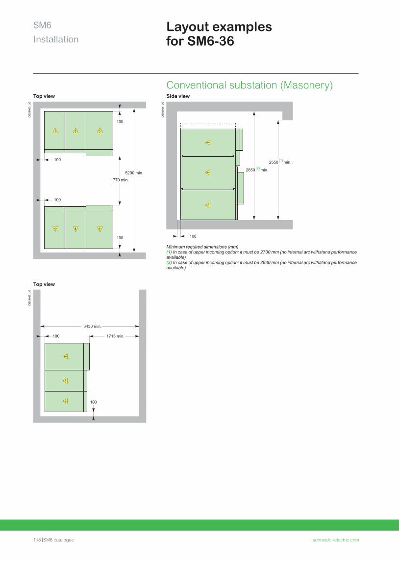
118 SM6 catalogue schneider-electric.com
SM6Installation
Layout examples for SM6-36
Conventional substation (Masonery)Top view Side view
DE
5966
5_LG
DE
5966
6_LG
Minimum required dimensions (mm)(1) In case of upper incoming option: it must be 2730 mm (no internal arc withstand performance available)(2) In case of upper incoming option: it must be 2830 mm (no internal arc withstand performance available)
Top view
DE
5966
7_LG

schneider-electric.com SM6 catalogue 119
Notes

120 SM6 catalogue schneider-electric.com
Schneider Electric services
schneider-electric.com SM6 catalogue 121
SM6 Schneider Electric servicesContents
ProDiag Breaker 122
ProDiag Corona 123
ProDiag Fuse 124
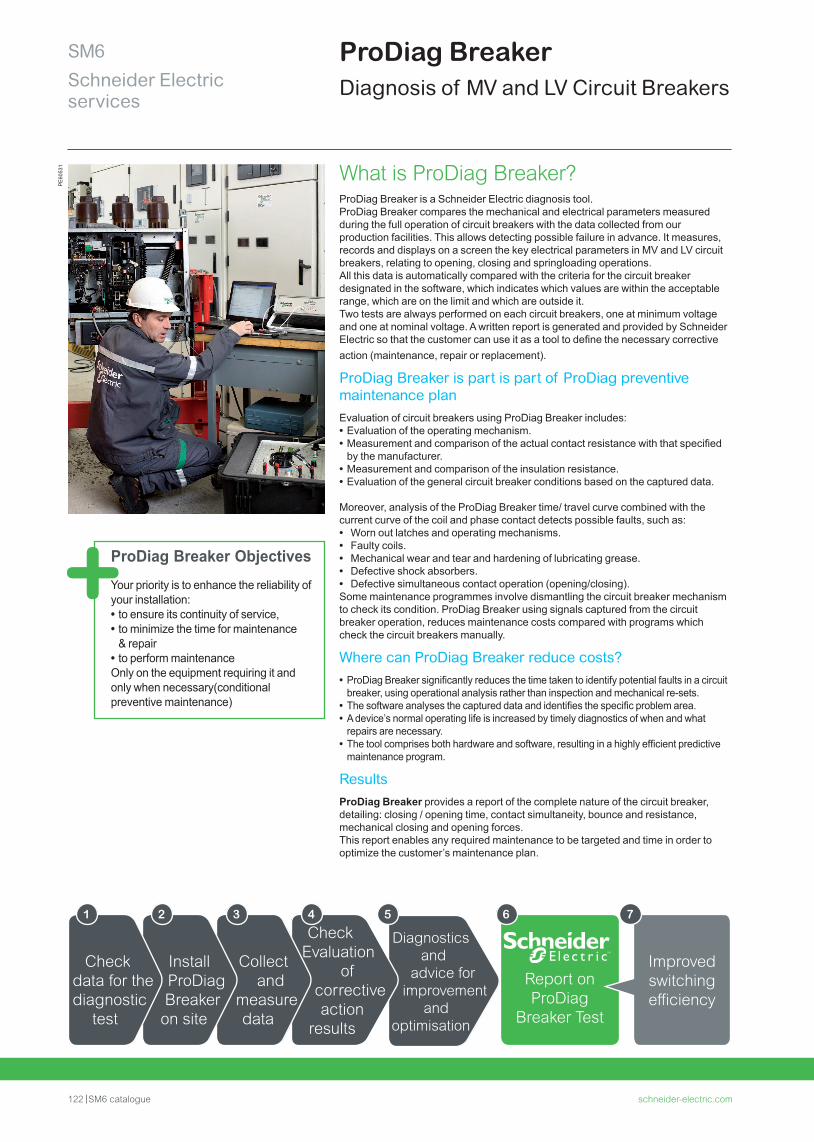
Diagnostics and
advice for improvement
and optimisation
122 SM6 catalogue schneider-electric.com
SM6Schneider Electric services
ProDiag BreakerDiagnosis of MV and LV Circuit Breakers
Report onProDiag
Breaker Test
What is ProDiag Breaker?ProDiag Breaker is a Schneider Electric diagnosis tool.ProDiag Breaker compares the mechanical and electrical parameters measured during the full operation of circuit breakers with the data collected from our production facilities. This allows detecting possible failure in advance. It measures, records and displays on a screen the key electrical parameters in MV and LV circuit breakers, relating to opening, closing and springloading operations.All this data is automatically compared with the criteria for the circuit breaker designated in the software, which indicates which values are within the acceptable range, which are on the limit and which are outside it.Two tests are always performed on each circuit breakers, one at minimum voltage and one at nominal voltage. A written report is generated and provided by Schneider Electric so that the customer can use it as a tool to define the necessary corrective action (maintenance, repair or replacement).
ProDiag Breaker is part is part of ProDiag preventive maintenance plan Evaluation of circuit breakers using ProDiag Breaker includes: • Evaluation of the operating mechanism. • Measurement and comparison of the actual contact resistance with that specified by the manufacturer.
• Measurement and comparison of the insulation resistance. • Evaluation of the general circuit breaker conditions based on the captured data.
Moreover, analysis of the ProDiag Breaker time/ travel curve combined with the current curve of the coil and phase contact detects possible faults, such as: • Worn out latches and operating mechanisms. • Faulty coils. • Mechanical wear and tear and hardening of lubricating grease. • Defective shock absorbers. • Defective simultaneous contact operation (opening/closing).
Some maintenance programmes involve dismantling the circuit breaker mechanism to check its condition. ProDiag Breaker using signals captured from the circuit breaker operation, reduces maintenance costs compared with programs which check the circuit breakers manually.
Where can ProDiag Breaker reduce costs? • ProDiag Breaker significantly reduces the time taken to identify potential faults in a circuit breaker, using operational analysis rather than inspection and mechanical re-sets.
• The software analyses the captured data and identifies the specific problem area. • A device’s normal operating life is increased by timely diagnostics of when and what repairs are necessary.
• The tool comprises both hardware and software, resulting in a highly efficient predictive maintenance program.
ResultsProDiag Breaker provides a report of the complete nature of the circuit breaker, detailing: closing / opening time, contact simultaneity, bounce and resistance, mechanical closing and opening forces.This report enables any required maintenance to be targeted and time in order to optimize the customer’s maintenance plan.
6
™
ProDiag Breaker ObjectivesYour priority is to enhance the reliability of your installation: • to ensure its continuity of service, • to minimize the time for maintenance & repair
• to perform maintenanceOnly on the equipment requiring it and only when necessary(conditional preventive maintenance)
Check Evaluation
of corrective action
results
Collect and
measure data
Install ProDiagBreaker
on site
Check data for the diagnostic
test
1 2 3 4 5
Improvedswitchingefficiency
7
PE
6053
1
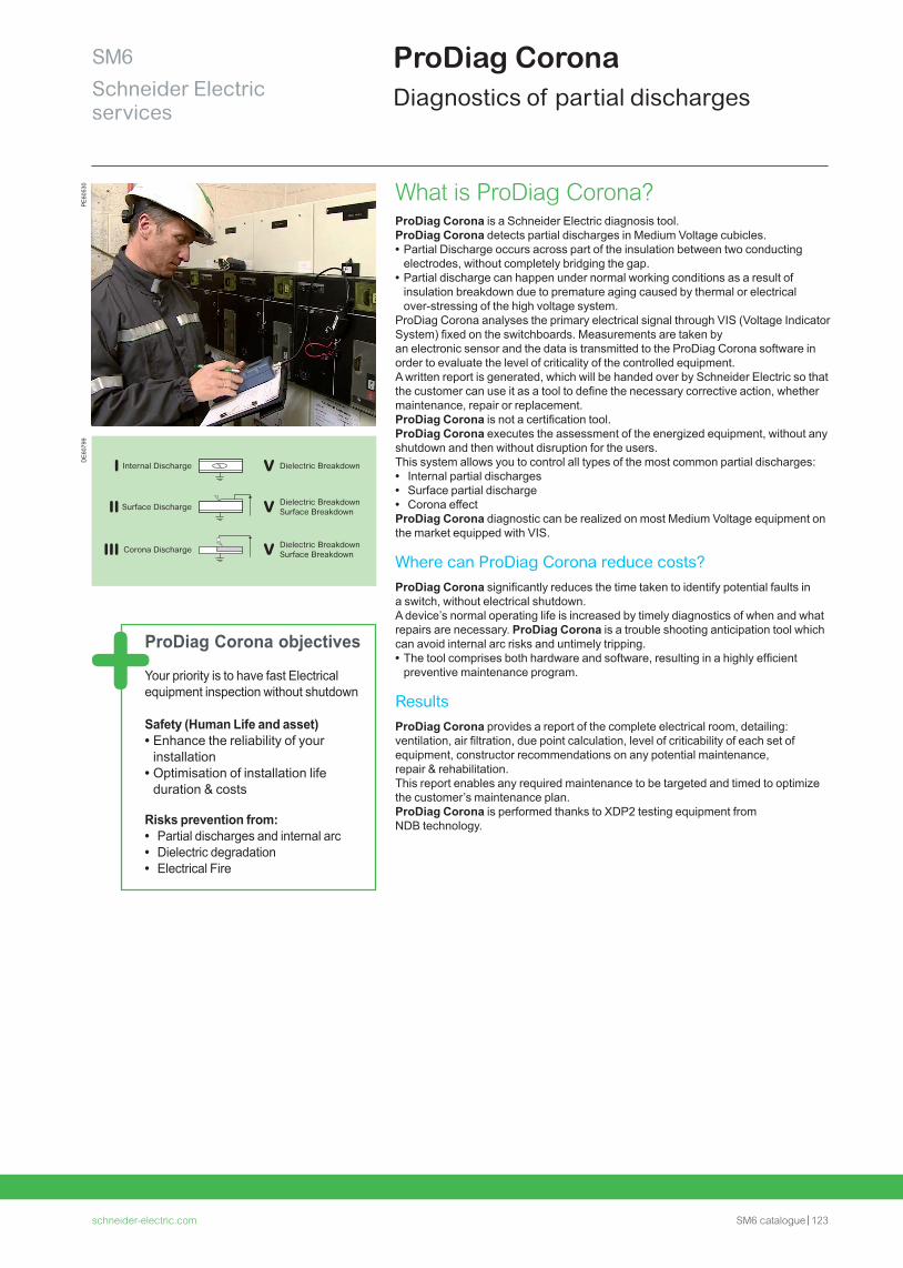
schneider-electric.com SM6 catalogue 123
SM6Schneider Electric services
ProDiag Corona objectives
Your priority is to have fast Electrical equipment inspection without shutdown
Safety (Human Life and asset) • Enhance the reliability of your installation • Optimisation of installation life duration & costs
Risks prevention from: • Partial discharges and internal arc • Dielectric degradation • Electrical Fire
ProDiag CoronaDiagnostics of partial discharges
What is ProDiag Corona?ProDiag Corona is a Schneider Electric diagnosis tool.ProDiag Corona detects partial discharges in Medium Voltage cubicles. • Partial Discharge occurs across part of the insulation between two conducting electrodes, without completely bridging the gap.
• Partial discharge can happen under normal working conditions as a result of insulation breakdown due to premature aging caused by thermal or electrical over-stressing of the high voltage system.
ProDiag Corona analyses the primary electrical signal through VIS (Voltage Indicator System) fixed on the switchboards. Measurements are taken byan electronic sensor and the data is transmitted to the ProDiag Corona software in order to evaluate the level of criticality of the controlled equipment.A written report is generated, which will be handed over by Schneider Electric so that the customer can use it as a tool to define the necessary corrective action, whether maintenance, repair or replacement.ProDiag Corona is not a certification tool.ProDiag Corona executes the assessment of the energized equipment, without any shutdown and then without disruption for the users.This system allows you to control all types of the most common partial discharges: • Internal partial discharges • Surface partial discharge • Corona effect
ProDiag Corona diagnostic can be realized on most Medium Voltage equipment on the market equipped with VIS.
Where can ProDiag Corona reduce costs?ProDiag Corona significantly reduces the time taken to identify potential faults in a switch, without electrical shutdown.A device’s normal operating life is increased by timely diagnostics of when and what repairs are necessary. ProDiag Corona is a trouble shooting anticipation tool which can avoid internal arc risks and untimely tripping. • The tool comprises both hardware and software, resulting in a highly efficient preventive maintenance program.
ResultsProDiag Corona provides a report of the complete electrical room, detailing: ventilation, air filtration, due point calculation, level of criticability of each set of equipment, constructor recommendations on any potential maintenance, repair & rehabilitation.This report enables any required maintenance to be targeted and timed to optimize the customer’s maintenance plan. ProDiag Corona is performed thanks to XDP2 testing equipment from NDB technology.
Internal DischargeI
Surface DischargeII
Corona DischargeIII
V Dielectric BreakdownSurface Breakdown
V Dielectric Breakdown
V Dielectric BreakdownSurface Breakdown
PE
6053
0D
E60
799

124 SM6 catalogue schneider-electric.com
SM6Schneider Electric services
ProDiag FuseProprietary and standards diagnostics tools
Customer needs
Electrical power installations protected by MV switchgear with fuse protection should be regularly checked (for correct assembly, electrical parameters, etc.) to confirm that their characteristics correspond to the original specification. Regular diagnosis of fuse performance (electrical parameters, resistance) according to the manufacturer’s recommendations is necessary to secure the ED installation and its service continuity, which are important for customers.The ProDiag Fuse diagnostic solution can be used on MV switchgear protected by fuses that have not received any maintenance intervention in the last four years (under normal operating conditions, and less if operating in severe environments or depending on their criticality in the installation).
The purpose of ProDiag Fuse (a proprietary hardware-software solution) is to mitigate the risks on MV switchgear and equipment by fuses of faults or drifts causing unwanted effects. The result of fuse ageing is the destruction of filaments that can lead to thermal runaway, partial damage, complete destruction of MV switchgear and equipment, or even destruction of the electrical room.
Customer benefits
ProDiag Fuse helps customers visualise, discover, and understand MV switchgear fuse ageing and wear and tear as compared to the original fuse manufacturers’ technical specification.
ProDiag Fuse monitors the performance of MV switchgear fuses. Thanks to ProDiag Fuse, maintenance managers can implement, manage, and enrich their maintenance plans. Schneider Electric FSRs conclude their on-site interventions with an exhaustive report on the MV switchgear fuses conformity/non-conformity. If a MV fuse is declared non-conforming, Schneider Electric suggests a corrective plan that includes fuse replacement to regain original performance in safety and service continuity.
Customers can augment their preventive maintenance plans with this corrective action at the most convenient time for each ED device.
"Unique value for customer vs standard market tools"Electrical parameter measurements (resistance, etc.) on MV switchgear fuses at customer sites are taken by a test tool and transmitted to the Schneider Electric FSRs' ProDiag Fuse software. Data are compared to those of a fuse manufacturers’ technical database.
The aim is to determine whether recorded measurements are within the acceptable range, at the limit, or fall outside it, as criteria for MV switchgear fuse conformity.
As an ED equipment manufacturer, Schneider Electric is uniquely positioned to develop and invest in specific tests tools, proprietary software, and testing methodology to collect reliable measurements from MV switchgears fuses.
ProDiag Fuse measures a larger number of parameters than standard market tools. It delivers best-in-class MV switchgear fuse diagnostics.
Schneider Electric scope: Schneider Electric fuses and main market fuses players.
PE
6053
2P
E60
533

schneider-electric.com SM6 catalogue 125
Notes

126 SM6 catalogue schneider-electric.com
Appendices &Order Form
schneider-electric.com SM6 catalogue 127
SM6 Appendices & Order formContents
Appendices 128
Trip curves for VIP 300 LL or LH relays 128
Trip curves for VIP 35 relays 129
Fusarc CF fuses 130
Solefuse fuses 131
Order form 132
SM6 - Switching 132
Switching 132
Automatic Transfer System 133
SM6 - Protection 135
Circuit breaker 135
Fuse switch 136
Vacuum contactor (Direct Motor Starter) for 24 kV 137
SM6 - Metering 138
SM6 - Other functions 139
SF1 - Lateral disconnectable or withdrawable 140
SFset - Lateral disconnectable for SM6-24 141
Evolis - Frontal fixed version for SM6-24 (up to 17.5 kV) 142
Evolis - Lateral disconnectable version for SM6-24 (up to 17.5 kV) 143
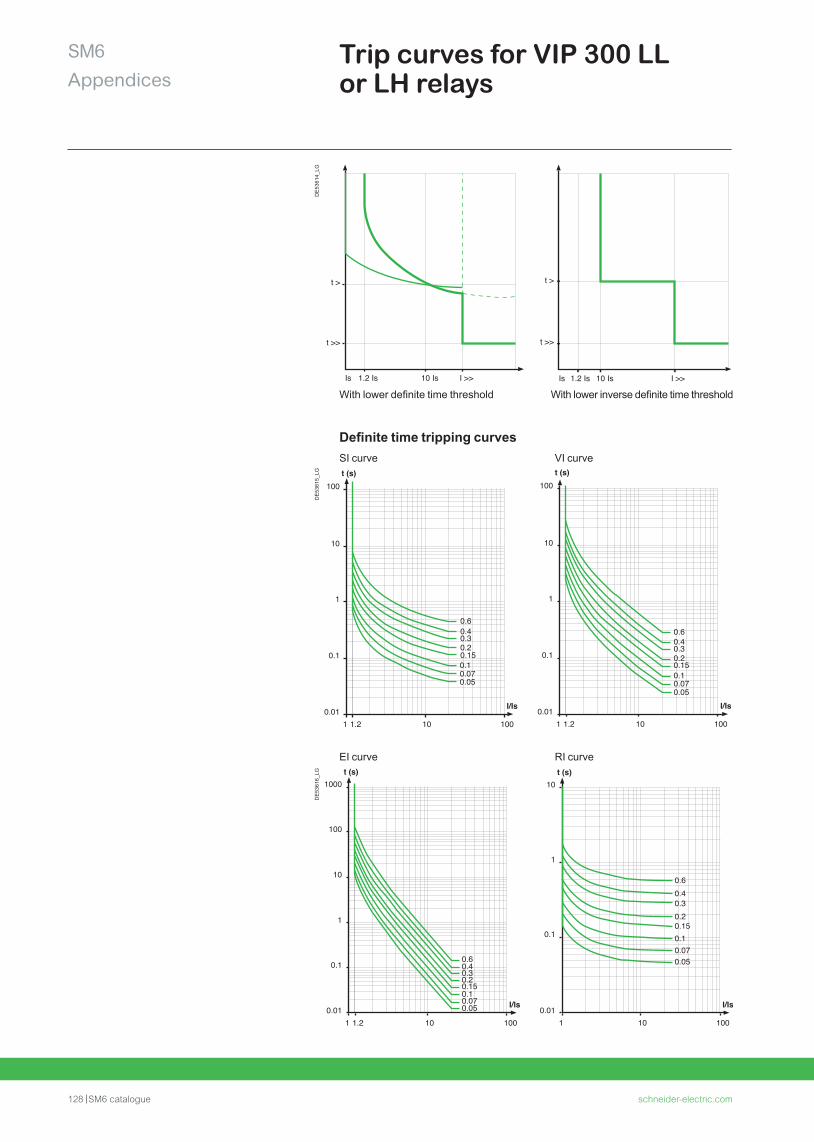
128 SM6 catalogue schneider-electric.com
SM6Appendices
Trip curves for VIP 300 LL or LH relays
Is 1.2 Is 10 Is I >>
t >>
t >
Is 1.2 Is 10 Is I >>
t >>
t >
DE
5361
4_LG
Definite time tripping curves
With lower definite time threshold With lower inverse definite time threshold
1000.01
0.1
1
10
100
101.2
I/Is
t (s)
1
0.60.40.30.2
0.10.070.05
0.15
1000.01
0.1
1
10
100
101.2
I/Is
t (s)
1
0.60.40.30.20.150.10.070.05
SI curve VI curve
EI curve RI curve
1000.01
0.1
1
10
100
1000
101.2
I/Is
t (s)
1
0.60.40.30.20.150.10.070.05
1000.01
0.1
1
10
10
I/Is
t (s)
1
0.60.40.30.20.150.10.070.05
DE
5361
5_LG
DE
5361
6_LG
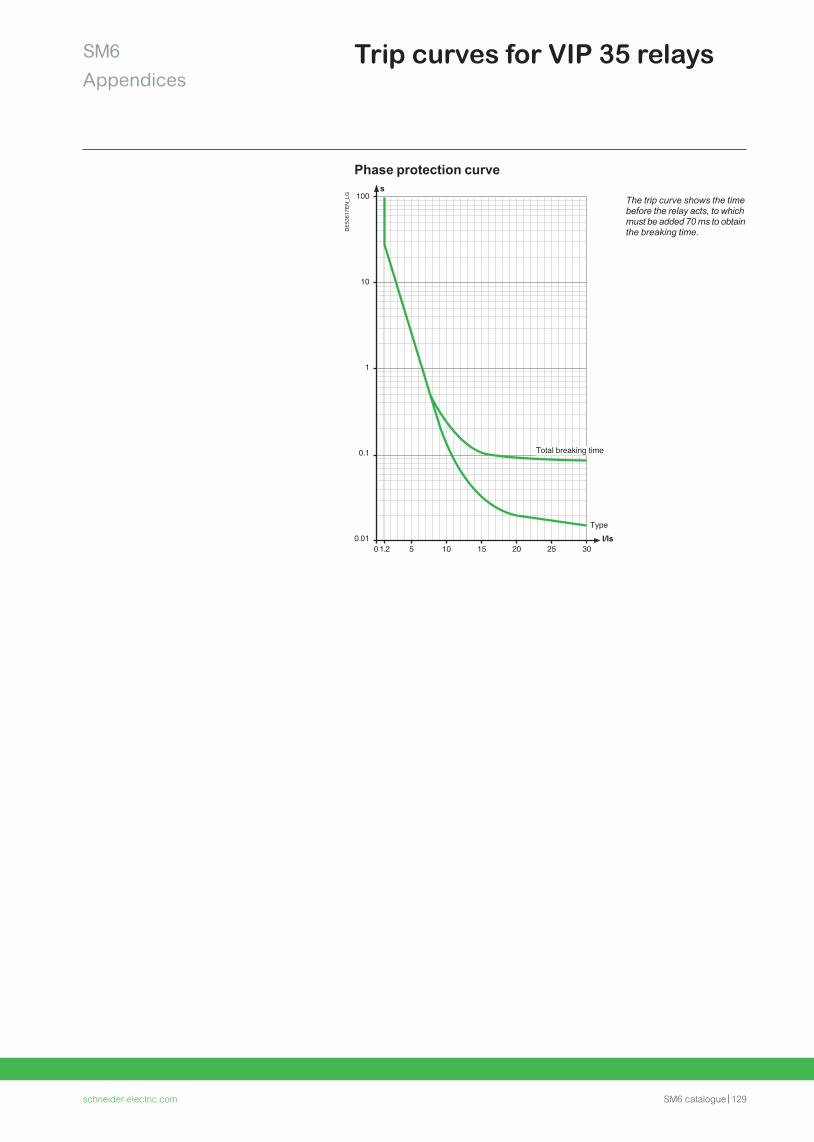
schneider-electric.com SM6 catalogue 129
SM6Appendices
Trip curves for VIP 35 relays
Phase protection curve
The trip curve shows the time before the relay acts, to which must be added 70 ms to obtain the breaking time.D
E53
617E
N_L
G 100s
I/Is
10
1
0.1
0.010 1.2 5 1510 20 25 30
Type
Total breaking time
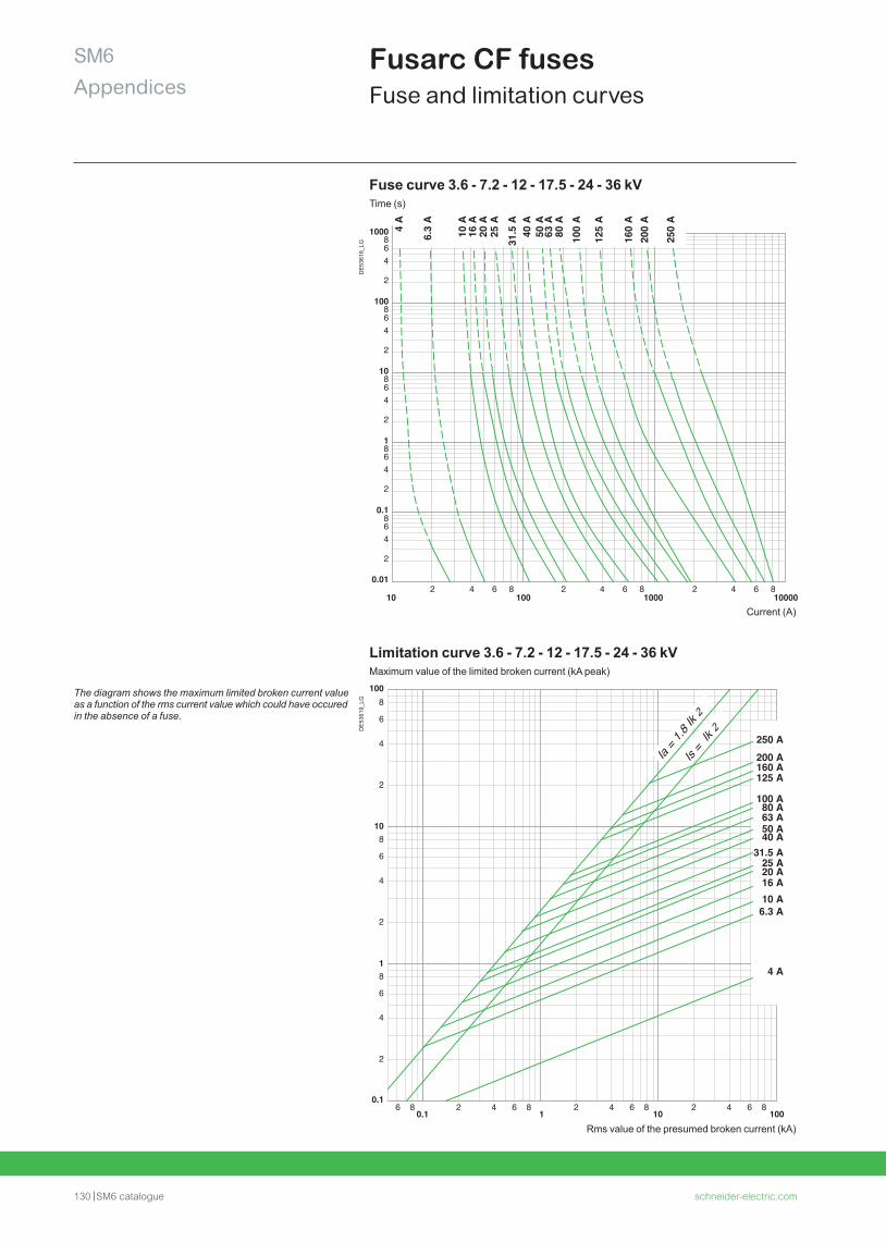
130 SM6 catalogue schneider-electric.com
SM6Appendices
Fusarc CF fusesFuse and limitation curves
Fuse curve 3.6 - 7.2 - 12 - 17.5 - 24 - 36 kVTime (s)
102 4 6 8 2 4 6 8 2 4 86
100001000100
0.01
2
468
2
468
2
46
0.1
10
1
8
86
100
4
2
1000864
2
10 A
6.3
A
16 A
20 A
25 A
31.5
A
50 A
63 A
80 A
100
A
160
A20
0 A
250
A
4 A
125
A
40 A
Current (A)
Limitation curve 3.6 - 7.2 - 12 - 17.5 - 24 - 36 kVMaximum value of the limited broken current (kA peak)
0.12
100
2
4
1
10
1010.1
6
8
2
4
6
8
100
2
4
8
6
4 6 86 8 2 4 6 8 2 4 6 8
50 A
250 A
200 A160 A125 A
4 A
100 A
63 A80 A
40 A
16 A20 A
6.3 A
25 A
10 A
31.5 A
Is =
Ik 2
Ia = 1
.8 Ik 2
The diagram shows the maximum limited broken current value as a function of the rms current value which could have occured in the absence of a fuse.
DE
5361
8_LG
DE
5361
9_LG
Rms value of the presumed broken current (kA)
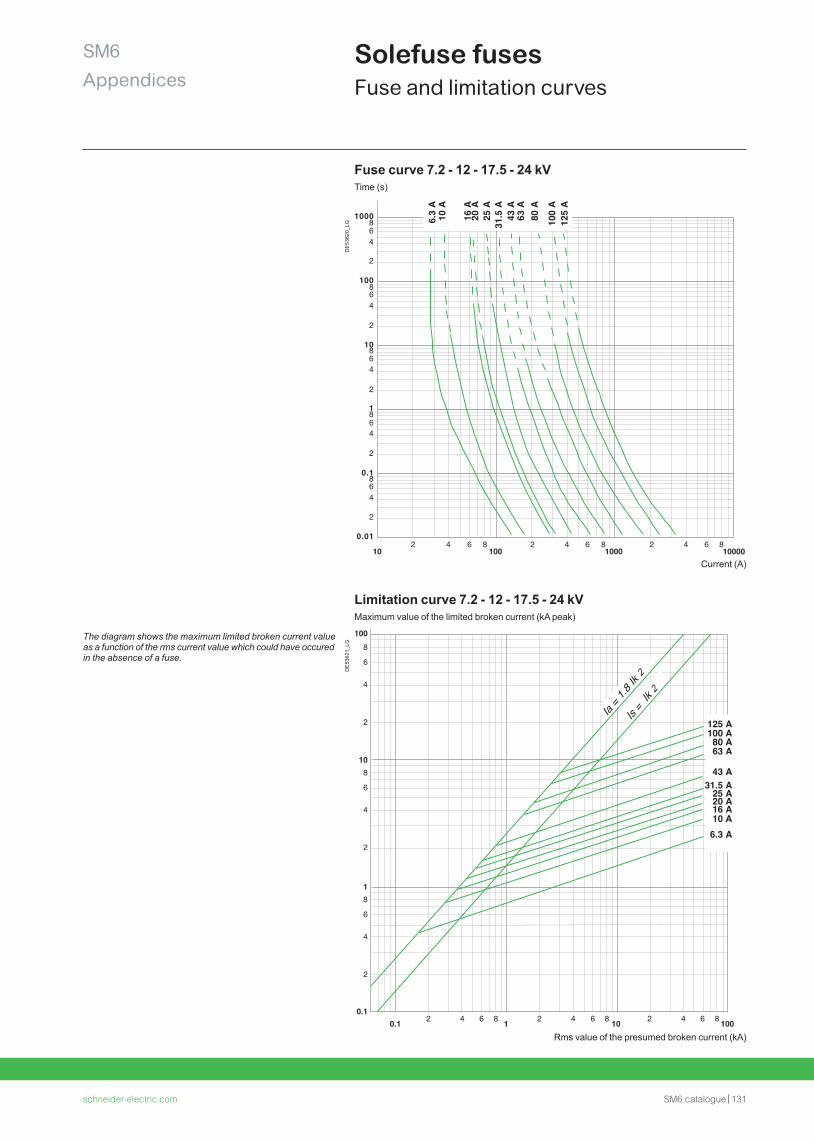
schneider-electric.com SM6 catalogue 131
SM6Appendices
Solefuse fuses Fuse and limitation curves
Fuse curve 7.2 - 12 - 17.5 - 24 kVTime (s)
Current (A)
Limitation curve 7.2 - 12 - 17.5 - 24 kVMaximum value of the limited broken current (kA peak)
The diagram shows the maximum limited broken current value as a function of the rms current value which could have occured in the absence of a fuse.
102 4 6 8
1002 4 6 8
10002 4 6 8
10000
1000864
2
100864
2
10864
2
1864
2
0.1864
2
0.01
6.3
A
10 A
20 A
25
A
16 A
31.5
A
43 A
63
A
80 A
100
A
125
A
6 84 62 842 84 620.10.1
1 10 100
108
6
4
2
8
6
4
2
8
6
4
2
1
100
125 A100 A80 A63 A
43 A31.5 A
10 A16 A20 A25 A
6.3 A
Is =
Ik 2
Ia = 1
.8 Ik 2
DE
5362
0_LG
DE
5362
1_LG
Rms value of the presumed broken current (kA)
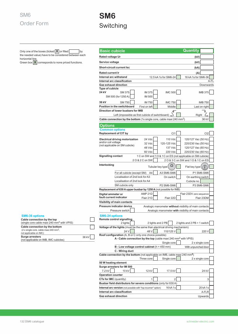
132 SM6 catalogue schneider-electric.com
SM6Order Form
SM6Switching
Basic cubicle Quantity Rated voltage Ur (kV)
Service voltage (kV)
Short-circuit current Isc (kA)
Rated current Ir (A) Internal arc withstand 12.5 kA 1s for SM6-24 16 kA 1s for SM6-36 Internal arc classification A-FLGaz exhaust direction DownwardsType of cubicle24 kV SM 375 IM 375 IMC 500 IMB 375
SM 500 (for 1250 A) IM 500
36 kV SM 750 IM 750 IMC 750 IMB 750 Position in the switchboard First on left Middle Last on right Direction of lower busbars for IMB
Left (impossible as first cubicle of switchboard) Right Cable connection by the bottom (1x single core, cable maxi 240 mm2) 36 kV
OptionsCommon optionsReplacement of CIT by CI1 CI2
Electrical driving motorization 24 Vdc 110 Vdc 120/127 Vac (50 Hz) and/or coil voltage (not applicable on SM cubicle)
32 Vdc 120-125 Vdc 220/230 Vac (50 Hz) 48 Vdc 137 Vdc 120/127 Vac (60 Hz) 60 Vdc 220 Vdc 220/230 Vac (60 Hz)
Signalling contact 1 C on SW and 1 O & 1 C on ES (not applicable on SM cubicle) 2 O & 2 C on SW 2 O & 3 C on SW and 1 O & 1 C on ES
InterlockingTubular key type Flat key type
For all cubicle (except SM) A4 A3 SM6-SM6 P1 SM6-SM6 Localisation of 2nd lock for A3 On switch On earthing switch Localisation of 2nd lock for A4 Cubicle no. SM cubicle only P2 SM6-SM6 P3 SM6-SM6
Replacement of 630 A upper busbar by 1250 A (not possible for IMB) Digital ammeter or fault current indicator
AMP 21D Flair 23DV zero sequence Flair 21D Flair 22D Flair 23DM
Visibility of main contacts Pressure indicator device Analogic manometer without visibility of main contacts
Pressure switch Analogic manometer with visibility of main contacts
SM6-24 optionsRemote control signalling
2 lights 2 lights and 2 PB 2 lights and 2 PB + 1 switch Voltage of the lights (must be the same than electrical driving mechanism)
24 V 48 V 110/125 V 220 V Roof configuration (A, B or C only one choice possible)
A - Cable connection by the top (cable maxi 240 mm2 with VPIS)Single core 2 x single core
B - Low voltage control cabinet (h = 450 mm) With unpunched door C - Wiring duct
Cable connection by the bottom (not applicable on IMB, cable maxi 240 mm2)Three core Single core 2 x single core
50 W heating element Surge arresters for IM 500
7.2 kV 10 kV 12 kV 17.5 kV 24 kV Operation counter CTs for IMC (quantity) 1 2 3 Busbar field distributors for severe conditions (only for 630 A) Internal arc version (not possible with "top incomer" option) 16 kA 1 s 20 kA 1 s Internal arc classification A-FLR Gaz exhaust direction Upwards
Only one of the boxes (ticked X or filled bythe needed value) have to be considered between each horizontal line. Green box X corresponds to none priced functions.
SM6-36 optionsCable connection by the top (single core cable maxi 240 mm2 with VPIS) Cable connection by the bottom (2 x single core, cable maxi 240 mm2, not applicable on IMC)Surge arresters (not applicable on IMB, IMC cubicles)
36 kV
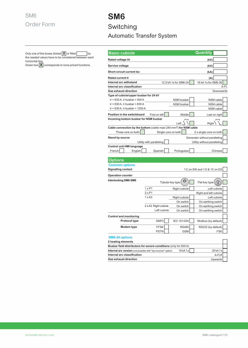
schneider-electric.com SM6 catalogue 133
SM6Order Form
SM6Switching Automatic Transfer System
Only one of the boxes (ticked X or filled bythe needed value) have to be considered between each horizontal line. Green box X corresponds to none priced functions.
Basic cubicle Quantity
Rated voltage Ur (kV)
Service voltage (kV)
Short-circuit current Isc (kA)
Rated current Ir (A) Internal arc withstand 12.5 kA 1s for SM6-24 16 kA 1s for SM6-36 Internal arc classification A-FLGaz exhaust direction DownwardsType of cubicle/upper busbar for 24 kV Ir = 630 A, Ir busbar = 400 A NSM busbar NSM cable Ir = 630 A, Ir busbar = 630 A NSM busbar NSM cable Ir = 630 A, Ir busbar = 1250 A NSM cable
Position in the switchboard First on left Middle Last on right Incoming bottom busbar for NSM busbar Left Right Cable connection by the bottom (cable maxi 240 mm2) for NSM cable
Three core on both Single core on both 2 x single core on both
Stand by source Generator without paralleling Utility with paralleling Utility without paralleling
Control unit HMI languageFrench English Spanish Portuguese Chinese
OptionsCommon optionsSignalling contact 1 C on SW and 1 O & 1C on ES
Operation counter
Interlocking SM6-SM6Tubular key type Flat key type
1 x P1 Right cubicle Left cubicle 2 x P1 Right and left cubicle 1 x A3 Right cubicle Left cubicle
On switch On earthing switch 2 x A3 Right cubicle On switch On earthing switch
Left cubicle On switch On earthing switch
Control and monitoring Protocol type DNP3 IEC 101/204 Modbus (by default)
Modem type FFSK RS485 RS232 (by default) PSTN GSM FSK
SM6-24 options2 heating elements Busbar field distributors for severe conditions (only for 630 A) Internal arc version (not possible with "top incomer" option) 16 kA 1 s 20 kA 1 s Internal arc classification A-FLR Gaz exhaust direction Upwards

134 SM6 catalogue schneider-electric.com
SM6Order Form
SM6ProtectionCircuit breaker
Only one of the boxes (ticked X or filled bythe needed value) have to be considered between each horizontal line. Green box X corresponds to none priced functions.
Basic cubicle Quantity Common 24/36 kV
Rated voltage Ur (kV)
Service voltage (kV)
Short-circuit current Isc (kA)
Rated current Ir (A) Internal arc withstand 12.5 kA 1s for SM6-24 16 kA 1s for SM6-36 Internal arc classification A-FLGaz exhaust direction Downwards24 kV For SF1 circuit breaker DM1-A 750 DM1-D left 750 DM1-D right 750
DM1-S 750 DM1-Z 750 DM1-W 750 DM2 left 750 DM2 right 750
For SFset circuit breaker DM1-D left 750 DM1-D right 750 For Evolis frontal 630 A CB DMV-A DMV-S DMV-D right For Evolis lateral 630 A CB DMVL-A DMVL-D
36 kV For SF1 circuit breaker DM1-A 1000 DM1-D left 1000 DM1-D right 1000 DM2 left 1500 DM2 right 1500
Position in the switchboard First on left Middle Last on right Circuit breaker See specific order formCurrent transformers (CT) and LPCTs See specific order formCable connection by the bottom (1x single core, cable maxi 240 mm2)
36 kV
Basic SM6-24Busbar (Ir u Ir cubicle) For DM1-A, DM1-S, DM1-W, DMVL-A, DMVL-D ,DM1-D, DM2 400 A 630 A 1250 A For DM1-A, DM1-D, DM1-W, DM1-Z 1250 A For DMV-A, DMV-D 630 A 1250 A For DMV-S 630 A Protection For DM1-S, DMV-S VIP35 with CRc VIP300LL with CRa
VIP300LL with CRb For DM1-S Sepam series 10 with CRa Sepam series 10 with CRb For DMV-A, DMV-D Sepam series 20/40 Control for DMV-A and DMV-D Local (shunt trip coil compulsory) Remote (opening coil and closing coil compulsory) Local and remote (opening coil and closing compulsory) Voltage of the auxiliaries 48/60 Vdc 110/125 or 220/250 Vdc
110/130 or 220/240 Vac (50 Hz) Voltage of signalling 48/60 Vdc 110/125 Vdc 220/250 Vdc
110/130 Vac (50 Hz) 220/240 Vac (50 Hz) Cable connection by the bottom For DM1-A, DM1-W, DMVL-A
3 x single core cable maxi 240 mm2 6 x single core cable maxi 240 mm2 Current sensors CT LPCT ring type for DM1-A 630 A
LPCT MV type for DM1-D
Basic SM6-36Current sensors CT LPCT ring type for DM1-A 630 A
Options See following page
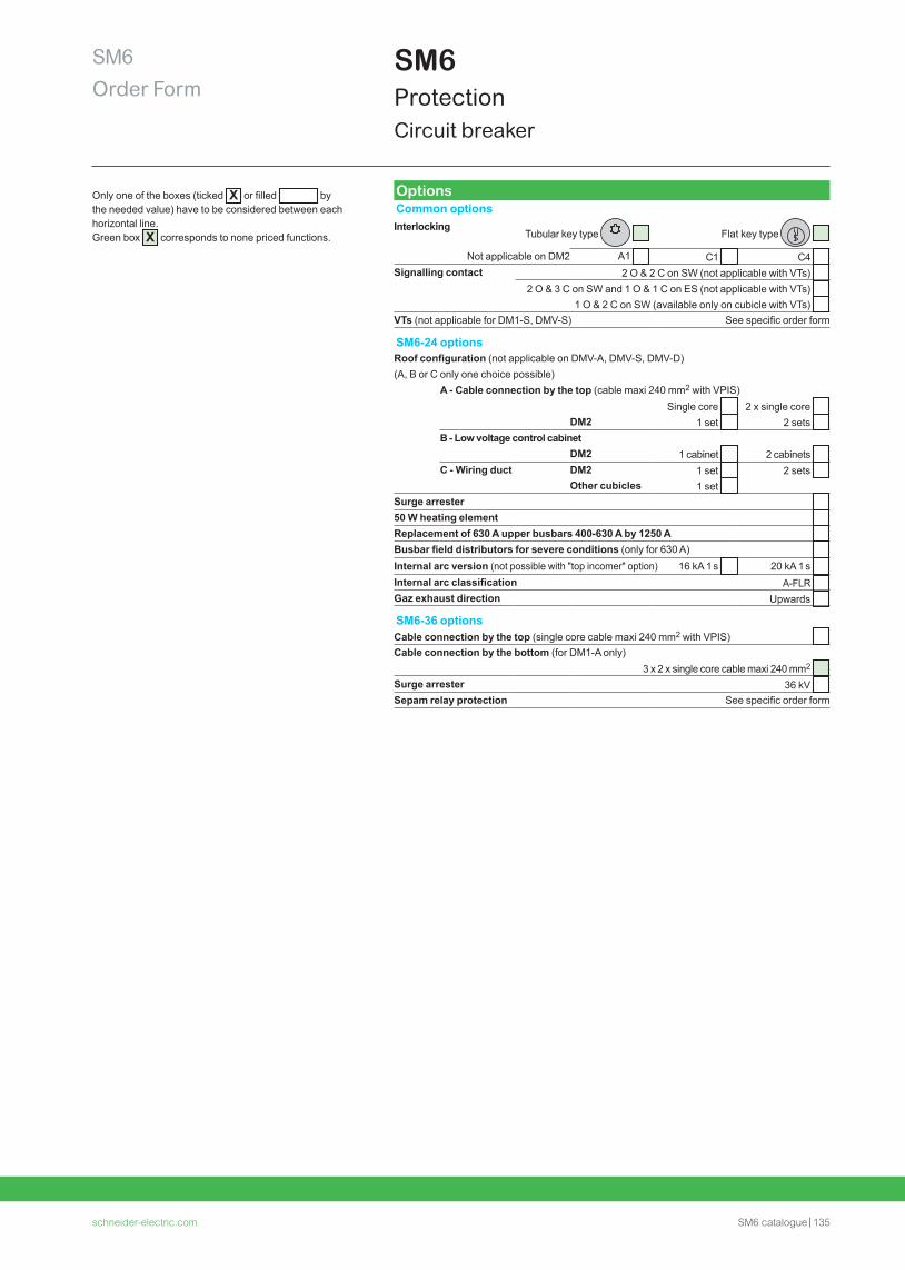
schneider-electric.com SM6 catalogue 135
SM6Order Form
SM6ProtectionCircuit breaker
Only one of the boxes (ticked X or filled bythe needed value) have to be considered between each horizontal line. Green box X corresponds to none priced functions.
OptionsCommon optionsInterlocking
Tubular key type Flat key type
Not applicable on DM2 A1 C1 C4 Signalling contact 2 O & 2 C on SW (not applicable with VTs)
2 O & 3 C on SW and 1 O & 1 C on ES (not applicable with VTs) 1 O & 2 C on SW (available only on cubicle with VTs)
VTs (not applicable for DM1-S, DMV-S) See specific order form
SM6-24 optionsRoof configuration (not applicable on DMV-A, DMV-S, DMV-D) (A, B or C only one choice possible)
A - Cable connection by the top (cable maxi 240 mm2 with VPIS)Single core 2 x single core
DM2 1 set 2 sets B - Low voltage control cabinet
DM2 1 cabinet 2 cabinets C - Wiring duct DM2 1 set 2 sets
Other cubicles 1 set Surge arrester 50 W heating element Replacement of 630 A upper busbars 400-630 A by 1250 A Busbar field distributors for severe conditions (only for 630 A) Internal arc version (not possible with "top incomer" option) 16 kA 1 s 20 kA 1 s Internal arc classification A-FLR Gaz exhaust direction Upwards
SM6-36 optionsCable connection by the top (single core cable maxi 240 mm2 with VPIS) Cable connection by the bottom (for DM1-A only)
3 x 2 x single core cable maxi 240 mm2 Surge arrester 36 kV Sepam relay protection See specific order form
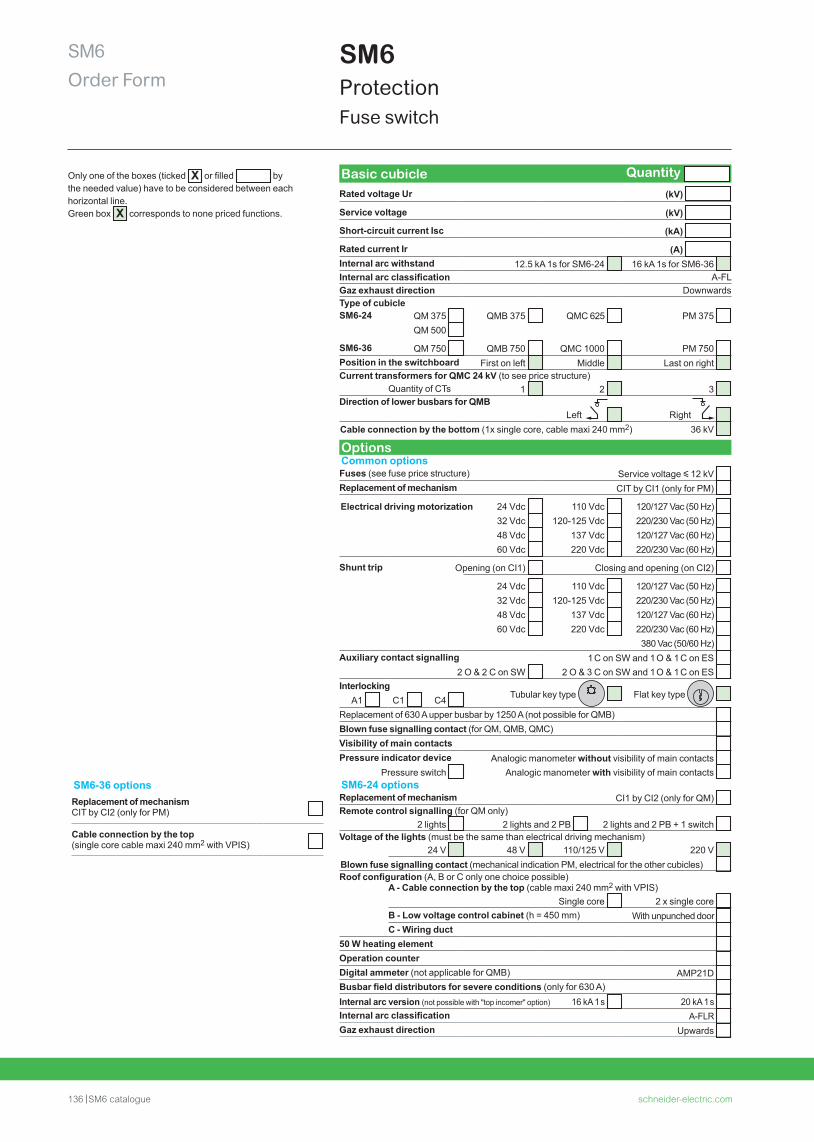
136 SM6 catalogue schneider-electric.com
SM6Order Form
SM6ProtectionFuse switch
Basic cubicle Quantity Rated voltage Ur (kV)
Service voltage (kV)
Short-circuit current Isc (kA)
Rated current Ir (A) Internal arc withstand 12.5 kA 1s for SM6-24 16 kA 1s for SM6-36 Internal arc classification A-FLGaz exhaust direction DownwardsType of cubicleSM6-24 QM 375 QMB 375 QMC 625 PM 375
QM 500
SM6-36 QM 750 QMB 750 QMC 1000 PM 750 Position in the switchboard First on left Middle Last on right Current transformers for QMC 24 kV (to see price structure)
Quantity of CTs 1 2 3 Direction of lower busbars for QMB
Left Right Cable connection by the bottom (1x single core, cable maxi 240 mm2) 36 kV
OptionsCommon optionsFuses (see fuse price structure) Service voltage y 12 kV Replacement of mechanism CIT by CI1 (only for PM)
Electrical driving motorization 24 Vdc 110 Vdc 120/127 Vac (50 Hz) 32 Vdc 120-125 Vdc 220/230 Vac (50 Hz) 48 Vdc 137 Vdc 120/127 Vac (60 Hz) 60 Vdc 220 Vdc 220/230 Vac (60 Hz)
Shunt trip Opening (on CI1) Closing and opening (on CI2)
24 Vdc 110 Vdc 120/127 Vac (50 Hz) 32 Vdc 120-125 Vdc 220/230 Vac (50 Hz) 48 Vdc 137 Vdc 120/127 Vac (60 Hz) 60 Vdc 220 Vdc 220/230 Vac (60 Hz)
380 Vac (50/60 Hz) Auxiliary contact signalling 1 C on SW and 1 O & 1 C on ES
2 O & 2 C on SW 2 O & 3 C on SW and 1 O & 1 C on ES Interlocking
A1 C1 C4 Tubular key type Flat key type
Replacement of 630 A upper busbar by 1250 A (not possible for QMB) Blown fuse signalling contact (for QM, QMB, QMC) Visibility of main contacts Pressure indicator device Analogic manometer without visibility of main contacts
Pressure switch Analogic manometer with visibility of main contacts SM6-24 optionsReplacement of mechanism CI1 by CI2 (only for QM) Remote control signalling (for QM only)
2 lights 2 lights and 2 PB 2 lights and 2 PB + 1 switch Voltage of the lights (must be the same than electrical driving mechanism)
24 V 48 V 110/125 V 220 V Blown fuse signalling contact (mechanical indication PM, electrical for the other cubicles) Roof configuration (A, B or C only one choice possible)
A - Cable connection by the top (cable maxi 240 mm2 with VPIS)Single core 2 x single core
B - Low voltage control cabinet (h = 450 mm) With unpunched door C - Wiring duct
50 W heating element Operation counter Digital ammeter (not applicable for QMB) AMP21D Busbar field distributors for severe conditions (only for 630 A) Internal arc version (not possible with "top incomer" option) 16 kA 1 s 20 kA 1 s Internal arc classification A-FLR Gaz exhaust direction Upwards
Only one of the boxes (ticked X or filled bythe needed value) have to be considered between each horizontal line. Green box X corresponds to none priced functions.
SM6-36 optionsReplacement of mechanismCIT by CI2 (only for PM)
Cable connection by the top (single core cable maxi 240 mm2 with VPIS)
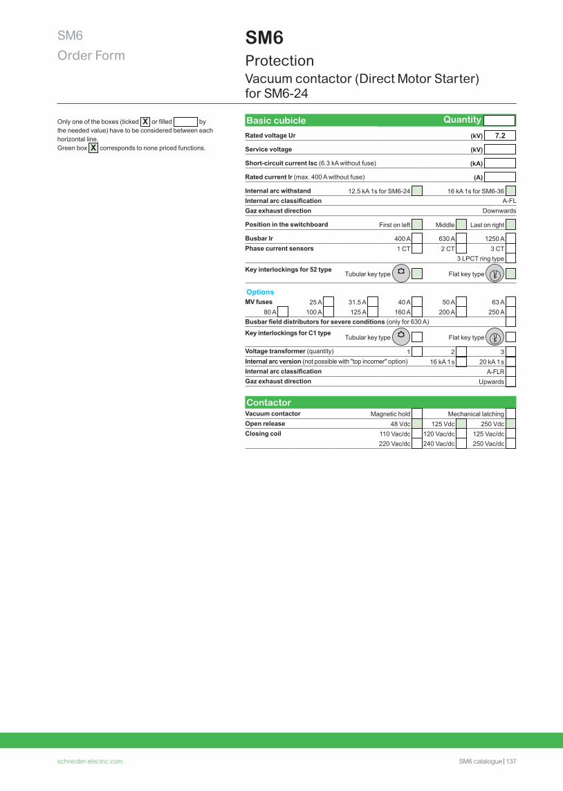
schneider-electric.com SM6 catalogue 137
SM6Order Form
SM6ProtectionVacuum contactor (Direct Motor Starter) for SM6-24
Only one of the boxes (ticked X or filled bythe needed value) have to be considered between each horizontal line. Green box X corresponds to none priced functions.
Basic cubicle Quantity
Rated voltage Ur (kV) 7.2
Service voltage (kV)
Short-circuit current Isc (6.3 kA without fuse) (kA)
Rated current Ir (max. 400 A without fuse) (A)
Internal arc withstand 12.5 kA 1s for SM6-24 16 kA 1s for SM6-36 Internal arc classification A-FLGaz exhaust direction Downwards
Position in the switchboard First on left Middle Last on right
Busbar Ir 400 A 630 A 1250 A Phase current sensors 1 CT 2 CT 3 CT
3 LPCT ring type
Key interlockings for 52 typeTubular key type Flat key type
OptionsMV fuses 25 A 31.5 A 40 A 50 A 63 A
80 A 100 A 125 A 160 A 200 A 250 A Busbar field distributors for severe conditions (only for 630 A)
Key interlockings for C1 typeTubular key type Flat key type
Voltage transformer (quantity) 1 2 3 Internal arc version (not possible with "top incomer" option) 16 kA 1 s 20 kA 1 s Internal arc classification A-FLR Gaz exhaust direction Upwards
ContactorVacuum contactor Magnetic hold Mechanical latching Open release 48 Vdc 125 Vdc 250 Vdc Closing coil 110 Vac/dc 120 Vac/dc 125 Vac/dc
220 Vac/dc 240 Vac/dc 250 Vac/dc
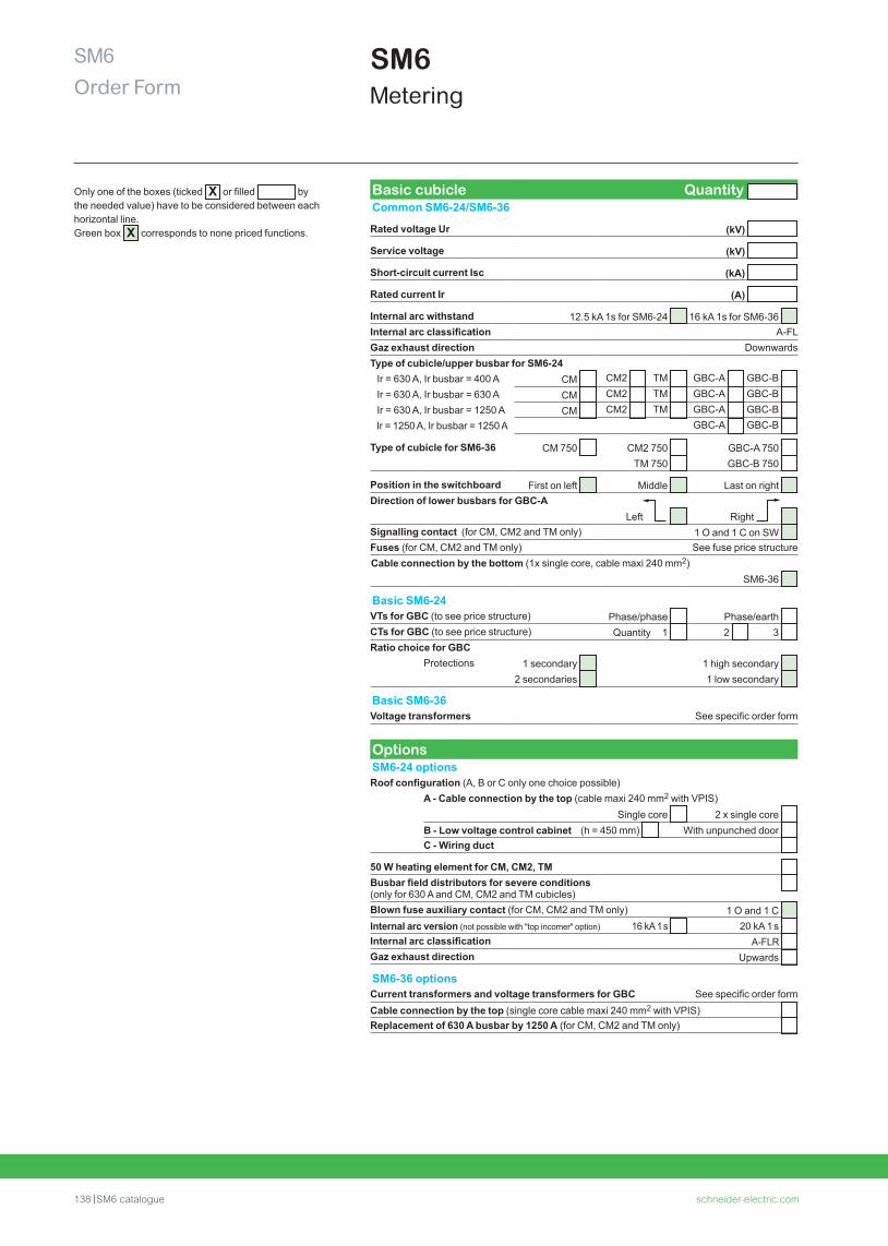
138 SM6 catalogue schneider-electric.com
SM6Order Form
SM6Metering
Only one of the boxes (ticked X or filled bythe needed value) have to be considered between each horizontal line. Green box X corresponds to none priced functions.
Basic cubicle Quantity Common SM6-24/SM6-36
Rated voltage Ur (kV)
Service voltage (kV)
Short-circuit current Isc (kA)
Rated current Ir (A)
Internal arc withstand 12.5 kA 1s for SM6-24 16 kA 1s for SM6-36 Internal arc classification A-FLGaz exhaust direction DownwardsType of cubicle/upper busbar for SM6-24 Ir = 630 A, Ir busbar = 400 A CM CM2 TM GBC-A GBC-B Ir = 630 A, Ir busbar = 630 A CM CM2 TM GBC-A GBC-B Ir = 630 A, Ir busbar = 1250 A CM CM2 TM GBC-A GBC-B Ir = 1250 A, Ir busbar = 1250 A GBC-A GBC-B
Type of cubicle for SM6-36 CM 750 CM2 750 GBC-A 750 TM 750 GBC-B 750
Position in the switchboard First on left Middle Last on right Direction of lower busbars for GBC-A
Left Right Signalling contact (for CM, CM2 and TM only) 1 O and 1 C on SW Fuses (for CM, CM2 and TM only) See fuse price structureCable connection by the bottom (1x single core, cable maxi 240 mm2)
SM6-36
Basic SM6-24VTs for GBC (to see price structure) Phase/phase Phase/earth CTs for GBC (to see price structure) Quantity 1 2 3 Ratio choice for GBC
Protections 1 secondary 1 high secondary 2 secondaries 1 low secondary
Basic SM6-36Voltage transformers See specific order form
OptionsSM6-24 optionsRoof configuration (A, B or C only one choice possible)
A - Cable connection by the top (cable maxi 240 mm2 with VPIS)Single core 2 x single core
B - Low voltage control cabinet (h = 450 mm) With unpunched door C - Wiring duct
50 W heating element for CM, CM2, TM Busbar field distributors for severe conditions (only for 630 A and CM, CM2 and TM cubicles)
Blown fuse auxiliary contact (for CM, CM2 and TM only) 1 O and 1 C Internal arc version (not possible with "top incomer" option) 16 kA 1 s 20 kA 1 s Internal arc classification A-FLR Gaz exhaust direction Upwards
SM6-36 optionsCurrent transformers and voltage transformers for GBC See specific order formCable connection by the top (single core cable maxi 240 mm2 with VPIS) Replacement of 630 A busbar by 1250 A (for CM, CM2 and TM only)
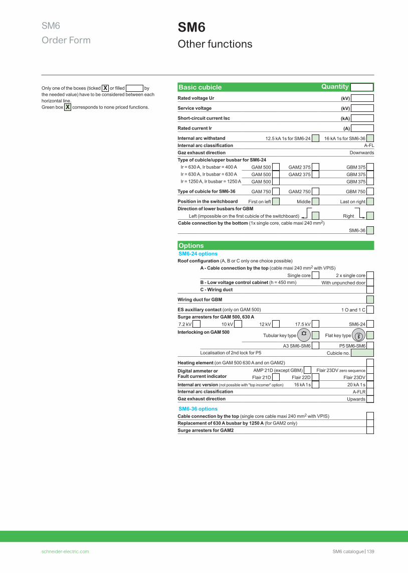
schneider-electric.com SM6 catalogue 139
SM6Order Form
SM6Other functions
Only one of the boxes (ticked X or filled bythe needed value) have to be considered between each horizontal line. Green box X corresponds to none priced functions.
Basic cubicle Quantity
Rated voltage Ur (kV)
Service voltage (kV)
Short-circuit current Isc (kA)
Rated current Ir (A)
Internal arc withstand 12.5 kA 1s for SM6-24 16 kA 1s for SM6-36 Internal arc classification A-FLGaz exhaust direction DownwardsType of cubicle/upper busbar for SM6-24 Ir = 630 A, Ir busbar = 400 A GAM 500 GAM2 375 GBM 375 Ir = 630 A, Ir busbar = 630 A GAM 500 GAM2 375 GBM 375 Ir = 1250 A, Ir busbar = 1250 A GAM 500 GBM 375
Type of cubicle for SM6-36 GAM 750 GAM2 750 GBM 750
Position in the switchboard First on left Middle Last on right Direction of lower busbars for GBM
Left (impossible on the first cubicle of the switchboard) Right Cable connection by the bottom (1x single core, cable maxi 240 mm2)
SM6-36
OptionsSM6-24 optionsRoof configuration (A, B or C only one choice possible)
A - Cable connection by the top (cable maxi 240 mm2 with VPIS) Single core 2 x single core
B - Low voltage control cabinet (h = 450 mm) With unpunched door C - Wiring duct
Wiring duct for GBM
ES auxiliary contact (only on GAM 500) 1 O and 1 C Surge arresters for GAM 500, 630 A7.2 kV 10 kV 12 kV 17.5 kV SM6-24
Interlocking on GAM 500Tubular key type Flat key type
A3 SM6-SM6 P5 SM6-SM6 Localisation of 2nd lock for P5 Cubicle no.
Heating element (on GAM 500 630 A and on GAM2)
Digital ammeter or Fault current indicator
AMP 21D (except GBM) Flair 23DV zero sequence Flair 21D Flair 22D Flair 23DV
Internal arc version (not possible with "top incomer" option) 16 kA 1 s 20 kA 1 s Internal arc classification A-FLR Gaz exhaust direction Upwards
SM6-36 optionsCable connection by the top (single core cable maxi 240 mm2 with VPIS) Replacement of 630 A busbar by 1250 A (for GAM2 only) Surge arresters for GAM2
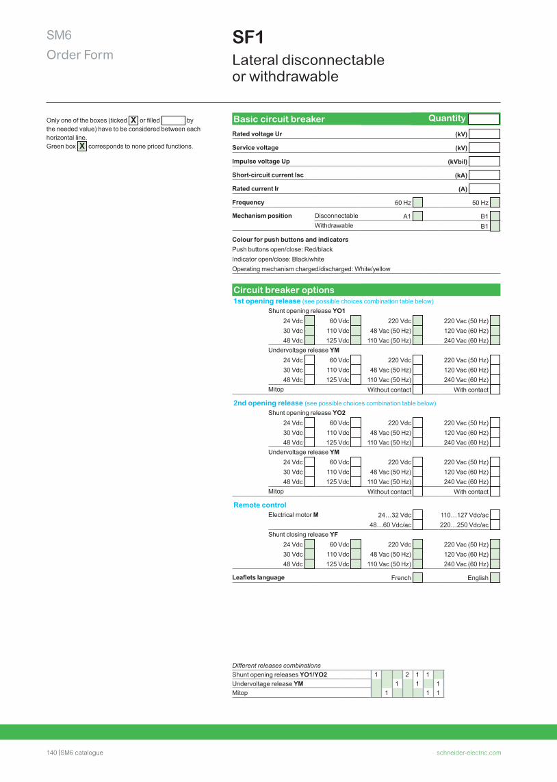
140 SM6 catalogue schneider-electric.com
SM6Order Form
SF1 Lateral disconnectable or withdrawable
Different releases combinationsShunt opening releases YO1/YO2 1 2 1 1Undervoltage release YM 1 1 1Mitop 1 1 1
Only one of the boxes (ticked X or filled bythe needed value) have to be considered between each horizontal line. Green box X corresponds to none priced functions.
Basic circuit breaker Quantity
Rated voltage Ur (kV)
Service voltage (kV)
Impulse voltage Up (kVbil)
Short-circuit current Isc (kA)
Rated current Ir (A)
Frequency 60 Hz 50 Hz
Mechanism position Disconnectable A1 B1 Withdrawable B1
Colour for push buttons and indicatorsPush buttons open/close: Red/black Indicator open/close: Black/white Operating mechanism charged/discharged: White/yellow
Circuit breaker options1st opening release (see possible choices combination table below)
Shunt opening release YO124 Vdc 60 Vdc 220 Vdc 220 Vac (50 Hz) 30 Vdc 110 Vdc 48 Vac (50 Hz) 120 Vac (60 Hz) 48 Vdc 125 Vdc 110 Vac (50 Hz) 240 Vac (60 Hz)
Undervoltage release YM24 Vdc 60 Vdc 220 Vdc 220 Vac (50 Hz) 30 Vdc 110 Vdc 48 Vac (50 Hz) 120 Vac (60 Hz) 48 Vdc 125 Vdc 110 Vac (50 Hz) 240 Vac (60 Hz)
Mitop Without contact With contact
2nd opening release (see possible choices combination table below)Shunt opening release YO2
24 Vdc 60 Vdc 220 Vdc 220 Vac (50 Hz) 30 Vdc 110 Vdc 48 Vac (50 Hz) 120 Vac (60 Hz) 48 Vdc 125 Vdc 110 Vac (50 Hz) 240 Vac (60 Hz)
Undervoltage release YM24 Vdc 60 Vdc 220 Vdc 220 Vac (50 Hz) 30 Vdc 110 Vdc 48 Vac (50 Hz) 120 Vac (60 Hz) 48 Vdc 125 Vdc 110 Vac (50 Hz) 240 Vac (60 Hz)
Mitop Without contact With contact
Remote controlElectrical motor M 24…32 Vdc 110…127 Vdc/ac
48…60 Vdc/ac 220…250 Vdc/ac Shunt closing release YF
24 Vdc 60 Vdc 220 Vdc 220 Vac (50 Hz) 30 Vdc 110 Vdc 48 Vac (50 Hz) 120 Vac (60 Hz) 48 Vdc 125 Vdc 110 Vac (50 Hz) 240 Vac (60 Hz)
Leaflets language French English
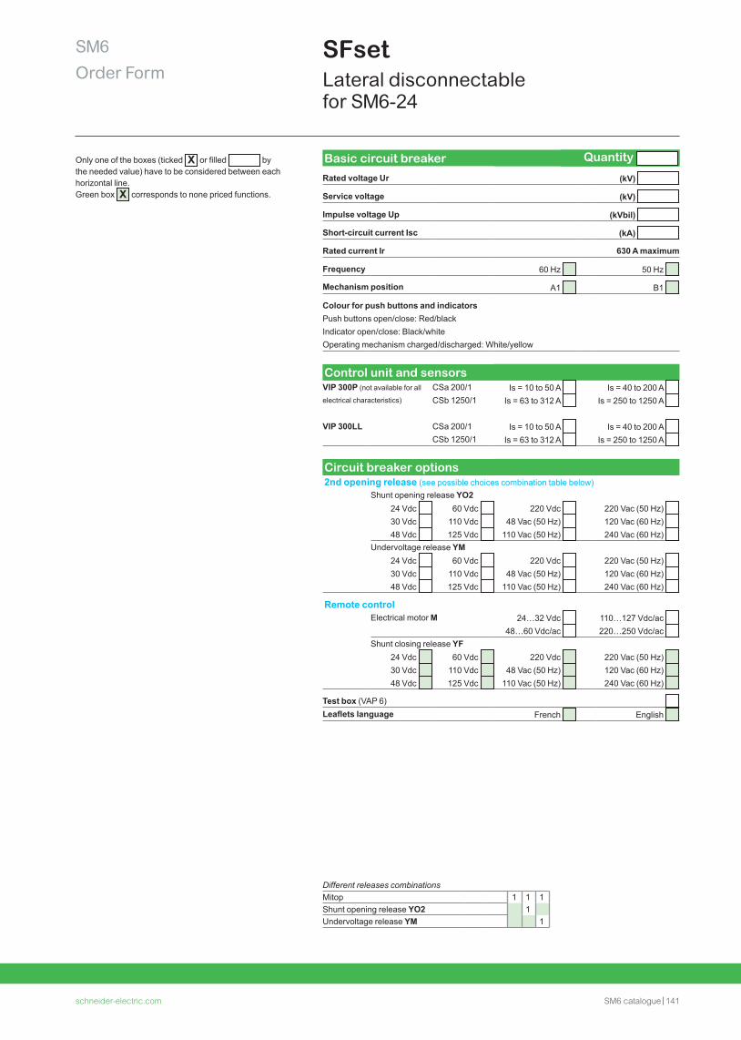
schneider-electric.com SM6 catalogue 141
SM6Order Form
SFset Lateral disconnectable for SM6-24
Different releases combinationsMitop 1 1 1Shunt opening release YO2 1Undervoltage release YM 1
Only one of the boxes (ticked X or filled bythe needed value) have to be considered between each horizontal line. Green box X corresponds to none priced functions.
Basic circuit breaker Quantity
Rated voltage Ur (kV)
Service voltage (kV)
Impulse voltage Up (kVbil)
Short-circuit current Isc (kA)
Rated current Ir 630 A maximum
Frequency 60 Hz 50 Hz
Mechanism position A1 B1
Colour for push buttons and indicatorsPush buttons open/close: Red/black Indicator open/close: Black/white Operating mechanism charged/discharged: White/yellow
Control unit and sensorsVIP 300P (not available for all CSa 200/1 Is = 10 to 50 A Is = 40 to 200 A electrical characteristics) CSb 1250/1 Is = 63 to 312 A Is = 250 to 1250 A
VIP 300LL CSa 200/1 Is = 10 to 50 A Is = 40 to 200 A CSb 1250/1 Is = 63 to 312 A Is = 250 to 1250 A
Circuit breaker options2nd opening release (see possible choices combination table below)
Shunt opening release YO224 Vdc 60 Vdc 220 Vdc 220 Vac (50 Hz) 30 Vdc 110 Vdc 48 Vac (50 Hz) 120 Vac (60 Hz) 48 Vdc 125 Vdc 110 Vac (50 Hz) 240 Vac (60 Hz)
Undervoltage release YM24 Vdc 60 Vdc 220 Vdc 220 Vac (50 Hz) 30 Vdc 110 Vdc 48 Vac (50 Hz) 120 Vac (60 Hz) 48 Vdc 125 Vdc 110 Vac (50 Hz) 240 Vac (60 Hz)
Remote controlElectrical motor M 24…32 Vdc 110…127 Vdc/ac
48…60 Vdc/ac 220…250 Vdc/ac Shunt closing release YF
24 Vdc 60 Vdc 220 Vdc 220 Vac (50 Hz) 30 Vdc 110 Vdc 48 Vac (50 Hz) 120 Vac (60 Hz) 48 Vdc 125 Vdc 110 Vac (50 Hz) 240 Vac (60 Hz)
Test box (VAP 6) Leaflets language French English
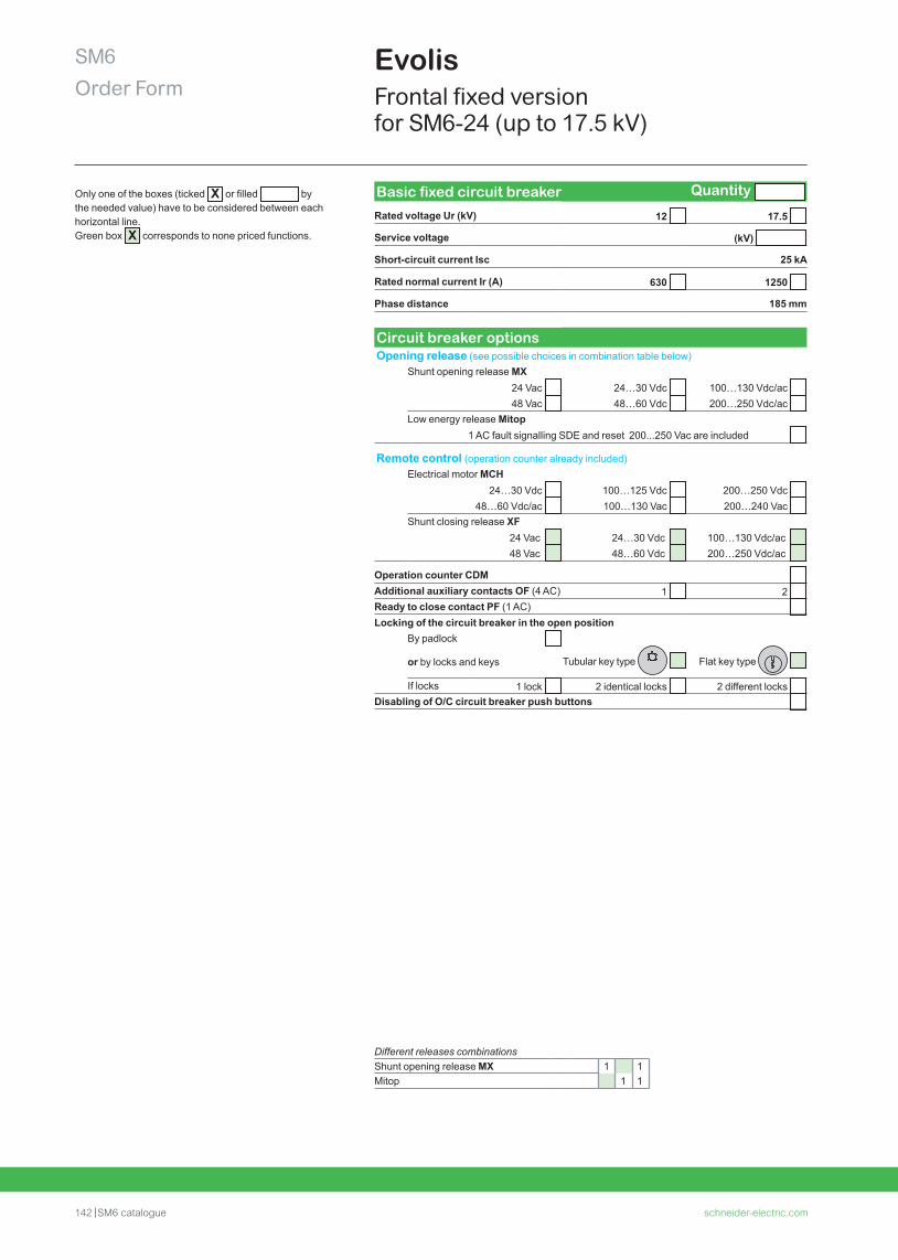
142 SM6 catalogue schneider-electric.com
SM6Order Form
Evolis Frontal fixed version for SM6-24 (up to 17.5 kV)
Different releases combinationsShunt opening release MX 1 1Mitop 1 1
Basic fixed circuit breaker Quantity
Rated voltage Ur (kV) 12 17.5
Service voltage (kV)
Short-circuit current Isc 25 kA
Rated normal current Ir (A) 630 1250
Phase distance 185 mm
Circuit breaker optionsOpening release (see possible choices in combination table below)
Shunt opening release MX24 Vac 24…30 Vdc 100…130 Vdc/ac 48 Vac 48…60 Vdc 200…250 Vdc/ac
Low energy release Mitop 1 AC fault signalling SDE and reset 200...250 Vac are included
Remote control (operation counter already included)Electrical motor MCH
24…30 Vdc 100…125 Vdc 200…250 Vdc 48…60 Vdc/ac 100…130 Vac 200…240 Vac
Shunt closing release XF24 Vac 24…30 Vdc 100…130 Vdc/ac 48 Vac 48…60 Vdc 200…250 Vdc/ac
Operation counter CDM Additional auxiliary contacts OF (4 AC) 1 2 Ready to close contact PF (1 AC) Locking of the circuit breaker in the open position
By padlock
or by locks and keys Tubular key type Flat key type
If locks 1 lock 2 identical locks 2 different locks Disabling of O/C circuit breaker push buttons
Only one of the boxes (ticked X or filled bythe needed value) have to be considered between each horizontal line. Green box X corresponds to none priced functions.
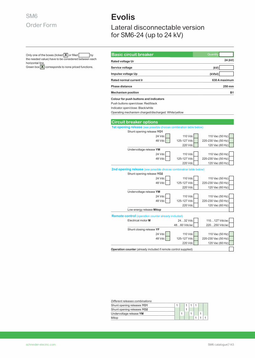
schneider-electric.com SM6 catalogue 143
SM6Order Form
Evolis Lateral disconnectable version for SM6-24 (up to 24 kV)
Different releases combinations Shunt opening releases YO1 1 1 1 1Shunt opening releases YO2 1Undervoltage release YM 1 1 1Mitop 1 1 1
Basic circuit breaker Quantity
Rated voltage Ur 24 (kV)
Service voltage (kV)
Impulse voltage Up (kVbil)
Rated normal current Ir 630 A maximum
Phase distance 250 mm
Mechanism position B1
Colour for push buttons and indicatorsPush buttons open/close: Red/black Indicator open/close: Black/white Operating mechanism charged/discharged: White/yellow
Circuit breaker options1st opening release (see possible choices combination table below)
Shunt opening release YO124 Vdc 110 Vdc 110 Vac (50 Hz) 48 Vdc 125-127 Vdc 220-230 Vac (50 Hz)
220 Vdc 120 Vac (60 Hz) Undervoltage release YM
24 Vdc 110 Vdc 110 Vac (50 Hz) 48 Vdc 125-127 Vdc 220-230 Vac (50 Hz)
220 Vdc 120 Vac (60 Hz)
2nd opening release (see possible choices combination table below)Shunt opening release YO2
24 Vdc 110 Vdc 110 Vac (50 Hz) 48 Vdc 125-127 Vdc 220-230 Vac (50 Hz)
220 Vdc 120 Vac (60 Hz) Undervoltage release YM
24 Vdc 110 Vdc 110 Vac (50 Hz) 48 Vdc 125-127 Vdc 220-230 Vac (50 Hz)
220 Vdc 120 Vac (60 Hz) Low energy release Mitop
Remote control (operation counter already included)Electrical motor M 24…32 Vdc 110…127 Vdc/ac
48…60 Vdc/ac 220…250 Vdc/ac Shunt closing release YF
24 Vdc 110 Vdc 110 Vac (50 Hz) 48 Vdc 125-127 Vdc 220-230 Vac (50 Hz)
220 Vdc 120 Vac (60 Hz)
Operation counter (already included if remote control supplied)
Only one of the boxes (ticked X or filled bythe needed value) have to be considered between each horizontal line. Green box X corresponds to none priced functions.
AMTED398078EN_02201601-2016
©2016 Schneider Electric. All Rights Reserved.All trademarks are owned by Schneider Electric Industries SAS or its affiliated companies. A
RT1
6044
- Li
fe Is
On
Sch
neid
er E
lect
ric is
a tr
adem
ark
and
the
pro
per
ty o
f Sch
neid
er E
lect
ric S
E, i
ts s
ubsi
dia
ries
and
aff
iliat
ed c
omp
anie
s. A
ll rig
hts
rese
rved
.
Schneider Electric Industries SAS
35 rue Joseph Monier92500 Rueil-Malmaison, FranceTel : +33 (0)1 41 29 70 00
www.schneider-electric.com
SAS capital social 928 298 512 € 954 503 439 RCS Nanterre