Appendix I: Optical Units
54
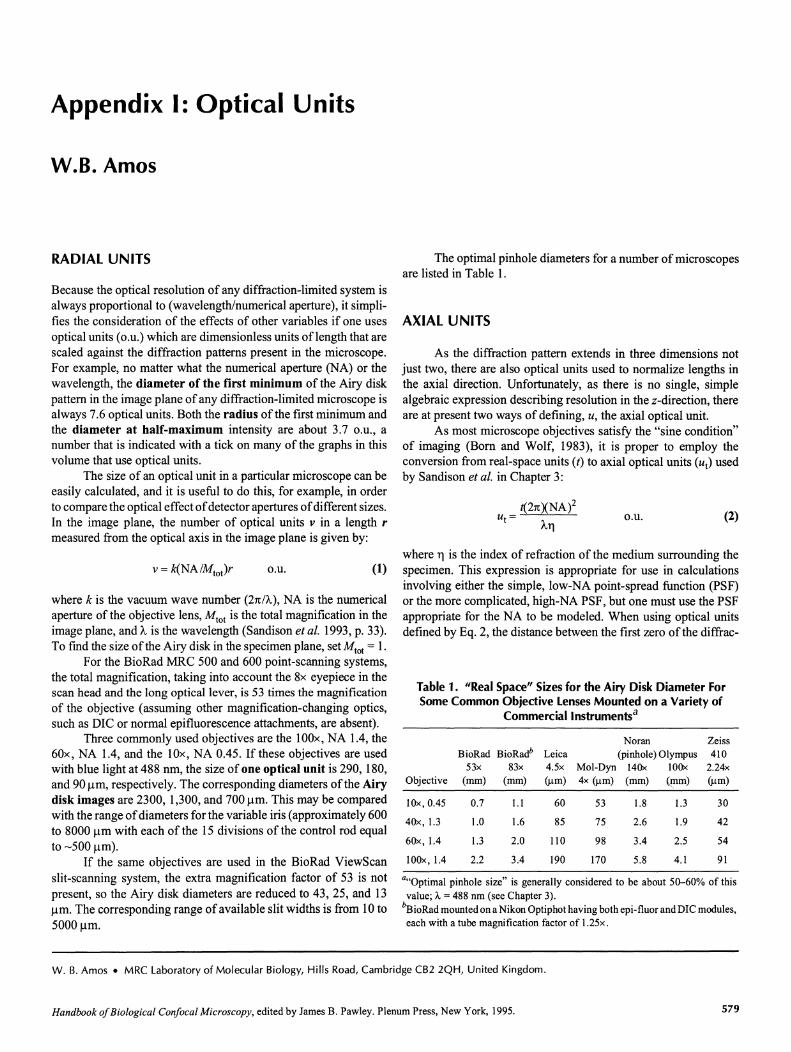
Appendix I: Optical Units W.B. Amos RADIAL UNITS The optimal pinhole diameters for a number of microscopes are listed in Table I. AXIAL UNITS As the diffraction pattern extends in three dimensions not just two, there are also optical units used to normalize lengths in the axial direction. Unfortunately, as there is no single, simple algebraic expression describing resolution in the z-direction, there are at present two ways of defining, u, the axial optical unit. As most microscope objectives satisfy the "sine condition" of imaging (Born and Wolf, 1983), it is proper to employ the conversion from real-space units (t) to axial optical units (u I ) used by Sandison et at. in Chapter 3: Because the optical resolution of any diffraction-limited system is always proportional to (wavelength/numerical aperture), it simpli- fies the consideration of the effects of other variables if one uses optical units (o.u.) which are dimensionless units oflength that are scaled against the diffraction patterns present in the microscope. For example, no matter what the numerical aperture (NA) or the wavelength, the diameter of the first minimum of the Airy disk pattern in the image plane of any diffraction-limited microscope is always 7.6 optical units . Both the radius of the first minimum and the diameter at half-maximum intensity are about 3.7 o.u., a number that is indicated with a tick on many of the graphs in this volume that use optical units. The size of an optical unit in a particular microscope can be easily calculated, and it is useful to do this, for example, in order to compare the optical effect of detector apertures of different sizes. In the image plane, the number of optical units v in a length r measured from the optical axis in the image plane is given by: o.u. (2) where k is the vacuum wave number (21t /A.), NA is the numerical aperture of the objective lens, M lol is the total magnification in the image plane, and A. is the wavelength (Sandison et al. 1993, p. 33). To fmd the size of the Airy disk in the specimen plane, set M lol = I. For the BioRad MRC 500 and 600 point-scanning systems, the total magnification, taking into account the 8x eyepiece in the scan head and the long optical lever, is 53 times the magnification of the objective (assuming other magnification-changing optics, such as DIC or normal epifluorescence attachments, are absent). Three commonly used objectives are the 100x, NA lA, the 60x, NA lA, and the lOx, NA 0045. If these objectives are used with blue light at 488 nm, the size of one optical unit is 290, 180, and 90 urn, respectively. The corresponding diameters ofthe Airy disk images are 2300, 1,300, and 700 urn , This may be compared with the range of diameters for the variable iris (approximately 600 to 8000 urn with each of the 15 divisions of the control rod equal to -500 urn) . If the same objectives are used in the BioRad ViewScan slit-scanning system, the extra magnification factor of 53 is not present, so the Airy disk diameters are reduced to 43 ,25 , and 13 urn. The corresponding range of available slit widths is from 10 to 5000 urn. o.u. (1) where 1'] is the index of refraction of the medium surrounding the specimen. This expression is appropriate for use in calculations involving either the simple, low-NA point-spread function (PSF) or the more complicated, high-NA PSF, but one must use the PSF appropriate for the NA to be modeled. When using optical units defined by Eq. 2, the distance between the first zero of the diffrac- Table 1. "Real Space" Sizes for the Airy Disk Diameter For Some Common Objective Lenses Mounted on a Variety of Commercial Instruments" Noran Zeiss BioRad BioRad b Leica (pinhole) Olympus 410 53x 83x 4.5x Mol-Dyn 140x 100x 2.24x Objective (mm) (mm) (urn) 4x (urn) (mm) (!TIm) (urn) lOx, 0.45 0.7 1.1 60 53 1.8 1.3 30 40x, 1.3 1.0 1.6 85 75 2.6 1.9 42 6Ox, 1.4 1.3 2.0 110 98 3.4 2.5 54 100x, 1.4 2.2 3.4 190 170 5.8 4.1 91 a"Optimal pinhole size" is generally considered to be about 50-60% of this value ; A. = 488 nm (see Chapter 3). bBioRad mounted on a Nikon Optiphot having both epi-fluor and DIC modules, each with a tube magnification factor of 1.25x . W. B. Amos. MRC Laboratory of Molecular Biology, Hills Road, Cambridge CB2 2QH , United Kingdom. Handbook of Biological Confocal Microscopy, edited by James B. Pawley. Plenum Press, New York, 1995. 579
-
Upload
khangminh22 -
Category
Documents
-
view
0 -
download
0
Transcript of Appendix I: Optical Units
Appendix I: Optical Units
W.B. Amos
RADIAL UNITS The optimal pinhole diameters for a number of microscopesare listed in Table I .
AXIAL UNITS
As the diffraction pattern extends in three dimensions notjust two, there are also optical units used to normalize lengths inthe axial direction. Unfortunately, as there is no single, simplealgebraic expression describing resolution in the z-direction, thereare at present two ways of defining, u, the axial optical unit.
As most microscope objectives satisfy the "sine condition"of imaging (Born and Wolf, 1983), it is proper to employ theconversion from real-space units (t) to axial optical units (uI ) usedby Sandison et at. in Chapter 3:
Because the optical resolution of any diffraction-limited system isalways proportional to (wavelength/numerical aperture), it simplifies the consideration of the effects of other variables if one usesoptical units (o.u.) which are dimensionless units oflength that arescaled against the diffraction patterns present in the microscope.For example, no matter what the numerical aperture (NA) or thewavelength, the diameter of the first minimum of the Airy diskpattern in the image plane of any diffraction-limited microscope isalways 7.6 optical units . Both the radius of the first minimum andthe diameter at half-maximum intensity are about 3.7 o.u ., anumber that is indicated with a tick on many of the graphs in thisvolume that use optical units.
The size of an optical unit in a particular microscope can beeasily calculated, and it is useful to do this, for example, in orderto compare the optical effect ofdetector apertures ofdifferent sizes.In the image plane, the number of optical units v in a length r
measured from the optical axis in the image plane is given by:
o.u. (2)
where k is the vacuum wave number (21t/A.), NA is the numericalaperture of the objective lens, M lo l is the total magnification in theimage plane, and A. is the wavelength (Sandison et al. 1993, p. 33).To fmd the size of the Airy disk in the specimen plane, set Mlol = I.
For the BioRad MRC 500 and 600 point-scanning systems,the total magnification, taking into account the 8x eyepiece in thescan head and the long optical lever, is 53 times the magnificationof the objective (assuming other magn ification-changing optics,such as DIC or normal epifluorescence attachments, are absent) .
Three commonly used objectives are the 100x, NA lA, the60x, NA lA, and the lOx, NA 0045. If these objectives are usedwith blue light at 488 nm, the size of one optical unit is 290, 180,and 90 urn, respectively. The corresponding diameters ofthe Airydisk images are 2300, 1,300, and 700 urn , This may be comparedwith the range ofdiameters for the variable iris (approximately 600to 8000 urn with each of the 15 divisions of the control rod equalto -500 urn) .
If the same objectives are used in the BioRad ViewS canslit-scanning system, the extra magnification factor of 53 is notpresent, so the Airy disk diameters are reduced to 43,25, and 13urn. The corresponding range ofavailable slit widths is from 10 to5000 urn.
o.u. (1)where 1'] is the index of refraction of the medium surrounding thespecimen. This expression is appropriate for use in calculationsinvolving either the simple, low-NA point-spread function (PSF)or the more complicated, high-NA PSF, but one must use the PSFappropriate for the NA to be modeled. When using optical unitsdefined by Eq. 2, the distance between the first zero of the diffrac-
Table 1. "Real Space" Sizes for the Airy Disk Diameter ForSome Common Objective Lenses Mounted on a Variety of
Commercial Instruments"
Noran ZeissBioRad BioRadb Leica (pinhole) Olympus 410
53x 83x 4.5x Mol-Dyn 140x 100x 2.24xObjective (mm) (mm) (urn) 4x (urn) (mm) (!TIm) (urn)
lOx, 0.45 0.7 1.1 60 53 1.8 1.3 30
40x, 1.3 1.0 1.6 85 75 2.6 1.9 42
6Ox, 1.4 1.3 2.0 110 98 3.4 2.5 54
100x, 1.4 2.2 3.4 190 170 5.8 4.1 91
a"Optimal pinhole size" is generally considered to be about 50-60% of thisvalue ; A. = 488 nm (see Chapter 3).
bBioRad mounted on a Nikon Optiphot having both epi-fluor and DIC modules,each with a tube magnification factor of 1.25x .
W. B. Amos. MRC Laboratory of Molecular Biology, Hills Road, Cambridge CB2 2QH , United Kingdom.
Handbook ofBiological Confocal Microscopy, edited by James B. Pawley. Plenum Press , New York, 1995. 579
580 Chapter 1 • Appendix 1
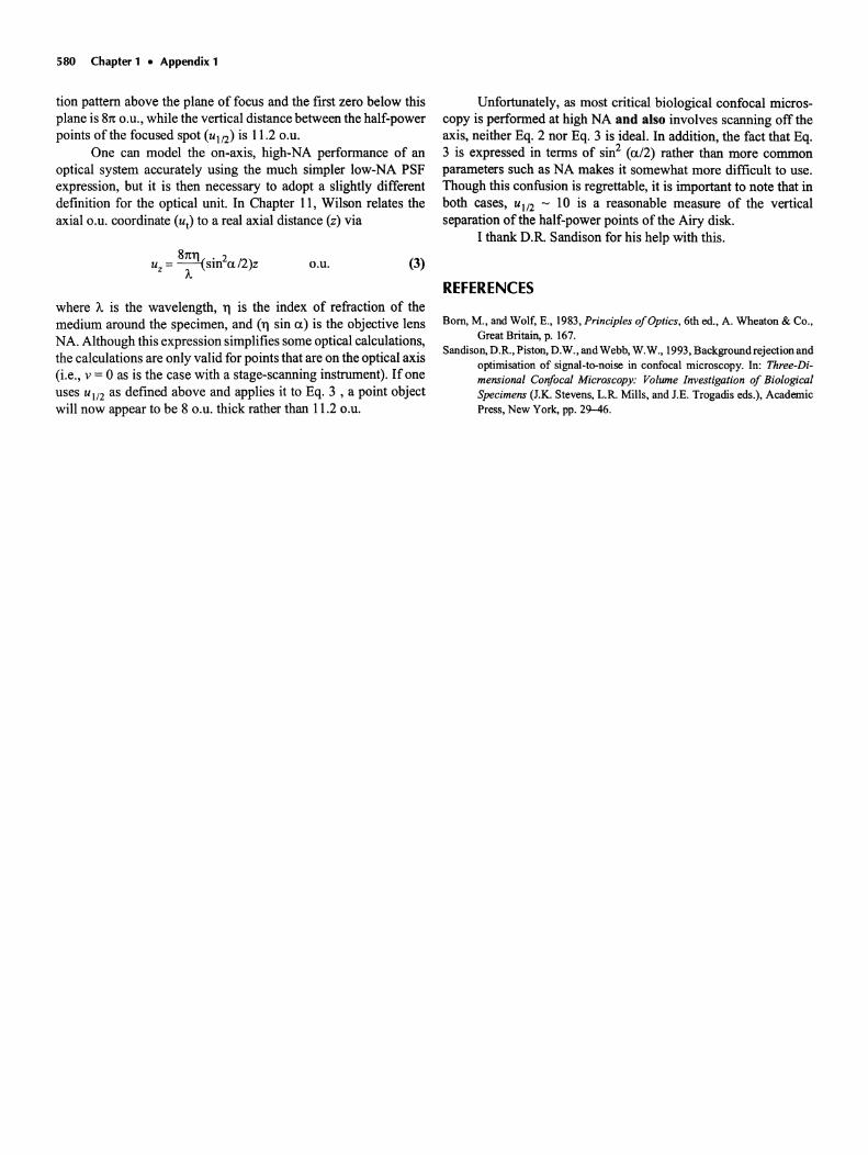
tion pattern above the plane of focus and the first zero below thisplane is 81t O.U., while the vertical distance between the half-powerpoints of the focused spot (u1/2) is 11.2o.u.
One can model the on-axis, high-NA performance of anoptical system accurately using the much simpler low-NA PSFexpression, but it is then necessary to adopt a slightly differentdefinition for the optical unit. In Chapter II, Wilson relates theaxial o.u. coordinate (ut) to a real axial distance (z) via
Unfortunately, as most critical biological confocal microscopy is performed at high NA and also involves scanning off theaxis, neither Eq. 2 nor Eq. 3 is ideal. In addition, the fact that Eq.3 is expressed in terms of sin2 (a/2) rather than more commonparameters such as NA makes it somewhat more difficult to use.Though this confusion is regrettable, it is important to note that inboth cases, ul /2 - 10 is a reasonable measure of the verticalseparation of the half-power points of the Airy disk.
I thank D.R. Sandison for his help with this .
o.u. (3)
REFERENCESwhere /... is the wavelength, II is the index of refraction of themedium around the specimen, and (ll sin a) is the objective lensNA. Although this expression simplifies some optical calculations,the calculations are only valid for points that are on the optical axis(i.e., v = 0 as is the case with a stage-scanning instrument) . If oneuses u1/2 as defined above and applies it to Eq. 3 , a point objectwill now appear to be 8 o.U. thick rather than 11.2o.U.
Born, M., and Wolf, E., 1983, Principles of Optics, 6th ed., A. Wheaton & Co.,Great Britain, p. 167.
Sandison, D.R., Piston, D.W., and Webb, W.W., 1993, Background rejection andoptimisation of signal-to-noise in confocal microscopy. In: Three-Dimensional Confocal Microscopy: Volume Investigation of BiologicalSpecimens (J.K. Stevens, L.R. Mills, and J.E. Trogadis eds.), AcademicPress, New York, pp. 29-46.
Appendix 2: Light Paths of Current Commercial ConfocalLight Microscopes for Biology
James Pawley
INTRODUCTION
Since biologists became aware of the confocal microscope in thelate 1980s, numerous optical designs have been introduced bymanufacturers to try to meet the often-contradictory requirementsof the biological microscopist. Although several of these designsare discussed at greater length in other chapters of this Handbook,it was thought that it might be both useful to the reader, and fairerto those designs not discussed elsewhere, to provide the reader witha concise compilation of all the designs now available.
To that end I requested optical diagrams, captions: andtabular information from all of the major suppliers of instrumentsused by biologistst and the items that they provided make up thebulk of this Appendix. Often manufacturers were hesitant to provide specific information about details such as PMTs or scanningspeeds because they realized that there was a good chance that suchdata would go out of date with their next product announcement.However, I tried to apply the same criteria to all the contributors
and this is as good a place as any to thank the manufacturers fortheir splendid cooperation.
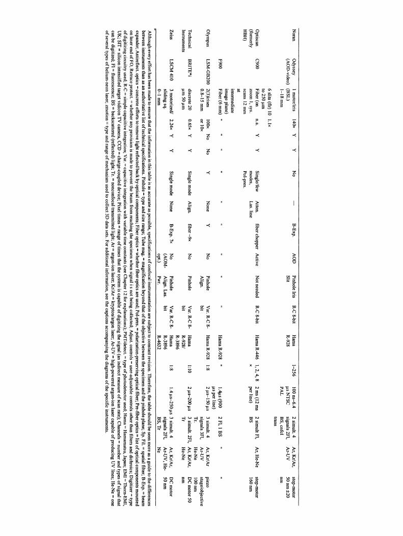
To assist the reader, some ofthe information considered mostrelevant to the optical performance of these instruments has beencollected in Table I. Although such a table cannot contain all ofthe relevant information about such complex instruments, the headings have been chosen to reflect those specifications indicated tobe of prime importance in the other chapters of this Handbook.Abbreviations are explained in the footnote.
More up-to-date information can often be obtained from theConfocal (LISTSERVER) Email Network. This network supportsactive, informal, and informative discussions of current topics inconfocal microscopy by several hundred scientists having a widevariety of experience. Anyone on "The Net" can subscribe to thisservice by sending the message "subscribe confocal <your name>"to the address "[email protected]." Youwill then receive a message describing the rules and purpose ofthegroup as well as future postings to it.
The information in the captionswasprovidedby the manufacturers with the understanding that theseareclaimsthat they arewillingto standbehind. Contributionshave been edited for form and clarity, but no other effort has been made to verify the claims therein.I recognize that the definition of "major" is necessarilyarbitraryand I apologizeto those manufacturers who were not included for one reason or another. Thereader should consult the exhibitor's brochurefrom any recent meeting on confocalmicroscopyfor a more up-to-datelist of suppliers.
James Pawley. Zoology Department, Un iversity of Wisconsin , Madison , Wisconsin 53706.
Handbook ofBiological Confocal Microscopy, edited by James B. Pawley. PlenumPress, New York, 1995. 581
Noran
Odyssey
Im
otor/iris140x
YY
No
-B
-Exp
.A
OD
PinholeIris
R-C
8-bitH
ama
1-256100
ns-6.42
simult.
4A
r,K
r/Ar,
step-motor
(AO
D-video)
(BS
L)
SlitR
-928ll sN
TS
Csignals
2FI,A
r-UV
50n
m±
20
l-18
mm
PAL
BS
,cnfelnm
trans
6slits
(flr)10
l.lxto
25011m
Optiscan
C900
Fiber
{onn.a.
YY
Single/few
Allen
.fiber
chopperA
ctiveN
otneeded
R-C
8-bitH
ama
R-446
1,2
,4,8
2m
s{12
ms
2sim
ultFI,
Ar,H
e-Ne
step-motor
(formerly
zoomI,sys.
modes,
Las.line
xper
line)B
S1
60
nm
HB
H)
scans12
mm
Pol-pres.atinterm
ediateim
ageplane)
F900F
iber{6
mm
)"
""
""
""
""
Ham
aR-9
28
"1.4lls
(9002
FI,1B
Su
sper
line)O
lympus
LSM
-GB
2002(3)irises
100xN
oN
oY
Non
eY
No
Pinhole
Var.R
-C8-
Ham
aR-9
28
1:8211S-
150us
3sim
ult.4A
r,K
r/Ar
piezo0.8-15
mm
or
lOx
Align
.bit
signals3FI,
Ar-U
Vstage/objec
tiveT
r.H
e-Ne
10
0n
mT
echnicalB
RIT
Pi
discrete20
0.65xY
YS
inglem
odeA
lign.fiber
-9x
No
Pinhole
Var.R
-C8-
Ham
a1:10
211S -2o
oliS
3sim
ult.2FI,
Ar,
Kr/A
r,D
Cm
otor50
Instruments
11m50
11mbit
R-928/
Tr
He-N
enm
R-3896
Zeiss
LSC
M410
3m
otorized!2.24x
YY
Single
mode
None
B-E
xp.7
xN
oPinhole
Var.R
-C8-
Ham
a1:8
1.4llS-250
liS3
simult.
4A
r,K
r/Ar,
DC
motor
slidingsq.
(AO
M-
Align.
Las.
bitR
-3896sign
als2Ft,
Ar -U
V,H
e-5
0n
m0-1
mm
opt.)Pw
r.R
-4632B
S,
Tr
Ne
Although
everyeffon
hasbeen
made
toensure
thattheinform
ationin
thistable
isas
accurateas
possible,specificationsofconfocalinstrum
entationare
subjecttoconstantrevision.T
herefore,the
tableshould
beseen
more
asa
guideto
thedifferences
between
instruments
thanas
anau
thoritativelistof
technicalspecifications.Pinhole
=type
andsize
range;Tube
mag
.=m
agnificationbeyo
ndthat
oftheobjective
between
thespecim
enand
thepinh
oleplane;
Sp.Fil.=spatial
filter;B
-Exp.=
beamexpander;A
ntireflect.optics=
concrete
effortsto
remove
lightreflectedback
byopticalcom
ponents;F
iberoptics=
whether
fiberoptics
areused;Pol-pres.=
polarization-preserving
opticalfiber;Pre-fiberoptics=
listofopticalco
mponents
mounted
onlaser
endofF
O;R
etraceprotect.=
whether
anyprovision
ism
adeto
preventthebeam
fromreaching
thespecim
enw
hensignal
isnot
beingcollected;
Adjust.controls
=user-adjustable
controlsother
thanfilters
anddichroics;D
igitizer=type
ofdigitizing
circuitryused
;R-C
=sim
plecapacitive
integration;V
ar.=capacitive
integrationw
ithvariable
time
constants(see
Chapter
12for
explanations);PMT
/detect.=type
ofphoto
detectorused
;Ham
a=
Ham
amatsu,Japan
;EM
I=T
horn-E
MI,
UK
;SIT=
siliconintensified
targetvidicon
TV
camera,
CC
D=
charge-coupleddev
ice;P
ixeltim
es=
range
oftim
esthat
thesystem
iscapable
ofdigitizing
thesig
nal(anindirect
measure
ofscan
rate);Ch
annels=
number
andtypes
ofsignal
thatcan
bedigitized;
FI=
fluorescence;B
S=
backscattered(reflected)
light;Tr,=
nonconfocal
transmitted
light;Ar=
argon-ion
laser;K
r/Ar=
krypton/argon
laser;A
r-UV
=high-pow
eredargon-ion
lasercap
ableof
producingU
Vlines;
He-N
e=
oneof
severaltypes
ofhelium
-neonlaser;
zmotio
n=
typeand
rangeo
fmech
anismused
tocolle
ct3D
datasets.
Foradditionalinform
ation,see
thecaptions
accompanying
thediagram
sof
thespecific
instruments.
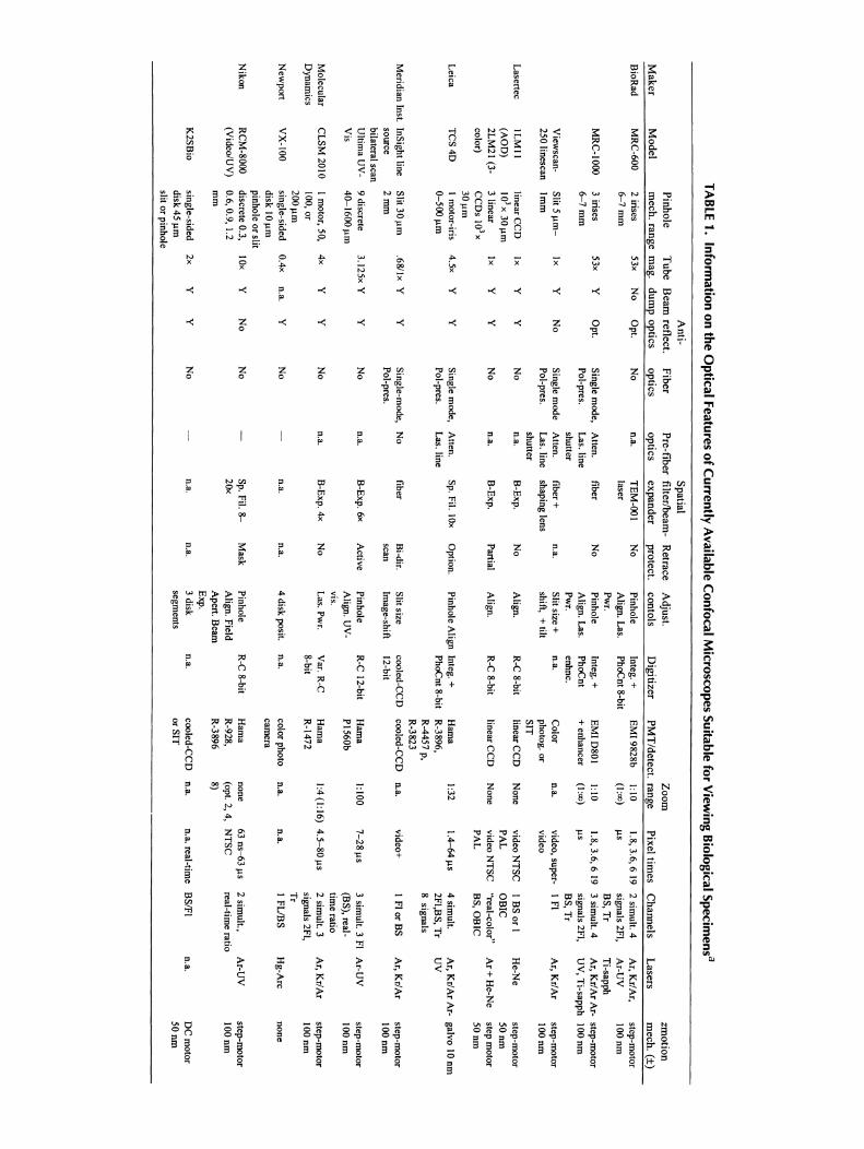
TABLE1.
Information
onthe
OpticalFeatures
ofC
urrentlyA
vailableC
onfocalMicroscopesSuitablefor
View
ingB
iologicalSpecimens"
An
ti-S
patial
Pin
ho
leT
ub
eB
eamreflect.
Fib
er
Pre-fib
erfilter/b
eam-
Retrace
Ad
just.Z
oo
mzm
otio
n
Mak
er
Mo
de
lm
ech.
ran
ge
mag
.d
um
po
ptics
op
ticso
ptics
exp
and
erp
rote
ct.co
nto
isD
igitizer
PM
T/d
etect.
ran
ge
Pixel
times
Ch
ann
els
Lase
rsm
ech
.(±)
Bio
Rad
MR
C-600
2irises
53x
No
Op
t.N
on
.a.T
EM
-ootN
oP
inhole
Integ.+
EM
I98
28
b1:10
1.8,3.6,
619
2sim
ult.4A
r,K
r/Ar,
step
-mo
tor6
-7m
mlaser
Align
.L
as.Ph
oCn
t8-bit
(I:00)liS
signals2F
I,A
r-UV
IOO
nm
Pwr.
BS
,Tr
Ti-sapp
hM
RC
-IOoo
3irises
53xY
Opt.
Single
mode
,A
llen.
fiberN
oPin
holeInteg
.+E
MI
08
01
1:101.8,3
.6,61
93
simult.4
Ar,
Kr/A
rA
r-step-m
otor
6-7m
mPo
l-pres.L
as.lineA
lign.
Las.
PhoC
nt+
enhancer(1:00)
liSsign
als2F
I,U
V,
Ti-sapph
100nm
shutterPw
r.enh
nc.B
S,T
rV
iewscan-
Slit5
IIm-
Ixy
No
Single
mode
Atten
.fiber
+n.a,
Slitsize
+0
.3.
Co
lor0
.3.
video,super-
IF
IA
r,K
r/Ar
step
-mo
tor250
linescanlrnm
Pol-pres.L
as.lineshaping
lensshift,
+tilt
photog.or
videoIO
Onm
shutterSIT
Lasertec
ILM
II
linearCC
Olx
YY
No
n.a.
B-E
xp.
No
Align
.R
-C8-bit
linearCC
ON
onevideo
NT
SC
IB
Sor
IH
e-Ne
step-m
otor(A
OO
)10
3x30
llmP
AL
OB
IC50
nm
2LM
21(3-
3linear
Ixy
yN
on
.a.B
-Ex
p.Partial
Align
.R
-C8-bit
linearC
CO
None
videoN
TS
C"real-co
lor "
Ar
+H
e-Ne
stepm
otorco
lor)C
CO
s10 3x
PAL
BS
,O
BIC
50n
m30
11mL
eicaT
CS
4D
Im
otor-iris4.5x
Yy
Single
mode
,A
tten.
Sp.
Fil.lOx
Op
tion.Pin
holeA
lignInteg
.+H
ama
1:321. 4
-64liS
4sim
ult.A
r,K
r/Ar
Ar-
galvo
10nm
0-50
011m
Po
l-pres.L
as.line
PhoC
nt8-bit
R-3896
,2F
I,BS
,Tr
UV
R-4457
p,8
signalsR
-3823
Merid
ianInst.
InSigh
tline
Slit3
0llm
.681lx
YY
Single-m
ode,N
ofiber
Bi-dir.
Slit
sizecooled-C
CO
cooled-CC
O0
.3.
video+I
Flo
rBS
Ar,
Kr/A
rste
p-m
otor
source2
mm
Pol-p
res.scan
Image-shift
12-bitIOO
nm
bilateralscanU
ltima
UV
-9
discrete3
.125xY
YN
on
.a.B
-Exp.6
xA
ctiveP
inhole
R-C
12-bit
Ham
a1:100
7-2
8lis
3sim
ult.
3F
IA
r-UV
step-mo
torV
is40
-1600
11mA
lign.U
V-
PI5
60b(B
S),
real-I OO
nmvis.
time
ratioM
olecu
larC
LSM
2010I
motor,
50,
4xY
YN
on
.a,B
-Exp.4x
No
Las.Pw
r.V
ar.R
-CH
ama
1:4(1:16)
4.5-80
us
2sim
ult.3
Ar, K
r/Ar
step-mo
torD
ynam
ics100,
or8-bit
R-1472
signals2F
l,100
nm
20011m
Tr
New
port
VX
-IOOsin
gle-sidedO
Ax
0.3
.Y
No
-n.a.
n.a.4
diskposit.
0.3
.co
lorphoto
n.a,n.a.
IF
US
SH
g-Arc
non
edisk
1011m
camera
pinhole
or
slit
Nikon
RC
M-8000
discrete
0.3,
lOx
YN
oN
o-
Sp.Fil.
8-
Mask
Pinhole
R-C
8-bitH
ama
none63
ns-63
l1s
2sim
ult.,A
r-UV
step-m
otor(V
ideo/U
V)
0.6,0
.9,1.2
20xA
lign.Field
R-92
8,(opt.2,4
,N
TSC
real-time
ratio100
nmm
mA
pert.Beam
R-3
896
8)E
xp.
K2SB
iosingle-sided
2xY
YN
o-
n.a.
n.a.3
disk0
.3.
cooled-CC
On
.a.n.a.real-tim
eB
SlFt0
.3.
DC
moto
rd
isk4
511m
segments
orSIT
5 0n
mslit
orpinh
ole
galvo mirror
584 Chapter 1 • Appendix 2
detector
assembly 2
,! PhotO~Ultlplier
prismatic enhancerI
servo-controlled
/ :motorised
7
detector assemblyII
galvo mirror (Y-axis)
mirror 4
mirror 2
second dichroicposition
:J Single-mode• optical fibre
I/'t'".--........)
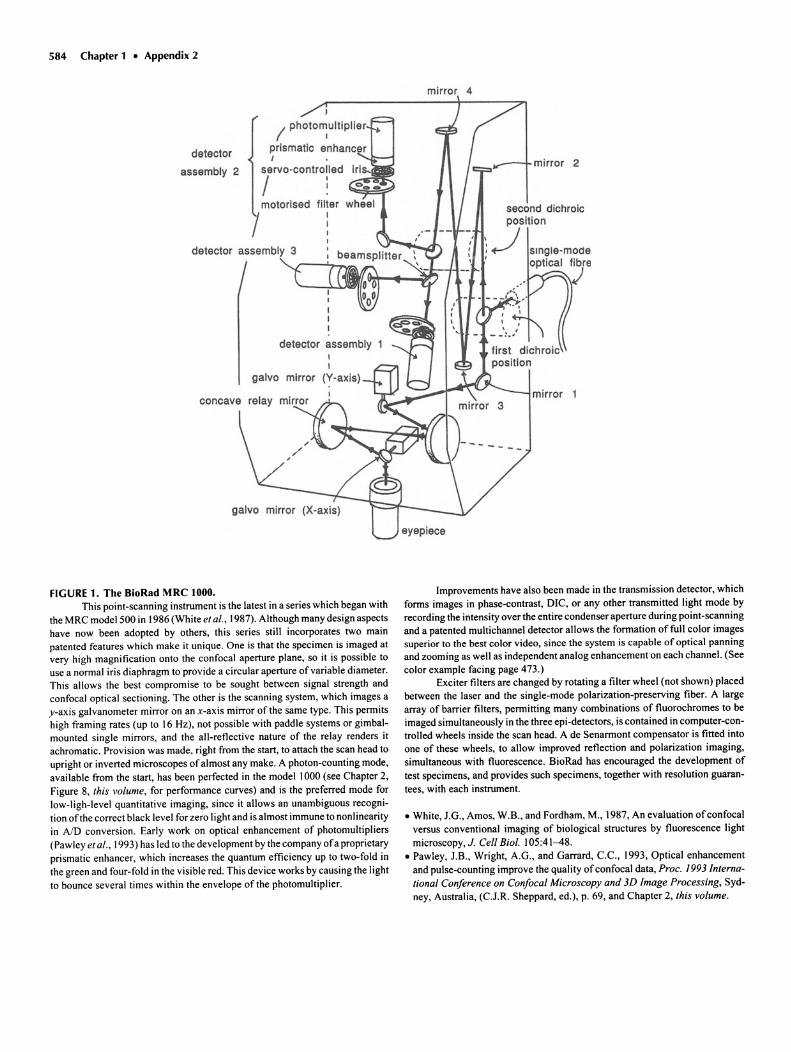
FIGURE 1. The BioRad MRC 1000.This point-scanning instrument is the latest in a series which began with
the MRC model 500 in 1986 (White et al., 1987). Although many design aspectshave now been adopted by others, this series still incorporates two mainpatented features which make it unique . One is that the specimen is imaged atvery high magnification onto the confocal aperture plane, so it is possible touse a normal iris diaphragm to provide a circular aperture of variable diameter.This allows the best compromise to be sought between signal strength andconfocal optical sectioning. The other is the scanning system, which images ay-axis galvanometer mirror on an x-axis mirror of the same type. This permitshigh framing rates (up to 16 Hz), not possible with paddle systems or gimbalmounted single mirrors. and the all-reflective nature of the relay renders itachromatic. Provision was made, right from the start, to attach the scan head toupright or inverted microscopes ofalmost any make . A photon-counting mode,available from the start, has been perfected in the model 1000 (see Chapter 2,Figure 8, this volume, for performance curves) and is the preferred mode forlow-ligh-level quant itat ive imaging, since it allows an unambiguous recogni tion ofthe correct black level for zero light and is almost immune to nonlinearityin AID conversion. Early work on optical enhancement of photomult ipliers(Pawley et al., 1993) has led to the development by the company ofa proprietaryprismatic enhancer, which increases the quantum efficiency up to two-fold inthe green and four-fold in the visible red. This device works by causing the lightto bounce several times within the envelope of the photomultiplier.
Improvements have also been made in the transmission detector, whichforms images in phase-contrast, DIC, or any other transmitted light mode byrecording the intensity over the entire condenser aperture during point-scanningand a patented mult ichannel detector allows the formation of full color imagessuperior to the best color video, since the system is capable of optical pann ingand zooming as well as independent analog enhancement on each channel. (Seecolor example facing page 473.)
Exciter filters are changed by rotating a filter wheel (not shown) placedbetween the laser and the single-mode polarization-preserving fiber . A largearray of barrier filters, permitting many combinat ions of fluorochromes to beimaged simultaneously in the three epi-detectors, is contained in computer-controlled wheels inside the scan head. A de Senarmont compensator is fitted intoone of these wheels, to allow improved reflection and polarization imaging,simultaneous with fluorescence. BioRad has encouraged the development oftest specimens, and provide s such specimens, together with resolution guarantees, with each instrumen t.
• White, J.G., Amos, W.B., and Fordham , M., 1987, An evaluation ofconfocalversus convent ional imaging of biological structures by fluorescence lightmicroscopy, 1. Cell BioI. 105:41-48.
• Pawley, 1.B., Wright, A.G., and Garrard , C.c., 1993, Optical enhancementand pulse-counting improve the quality ofconfocal data , Proc. 1993 International Conference on Confocal Microscopy and 3D Image Processing, Sydney, Australia, (C.J.R. Sheppard, ed.), p. 69, and Chapter 2, this volume.
concave mirror
oscillatingconvex mirror
slit aperture ofadjustable width
image
field lens
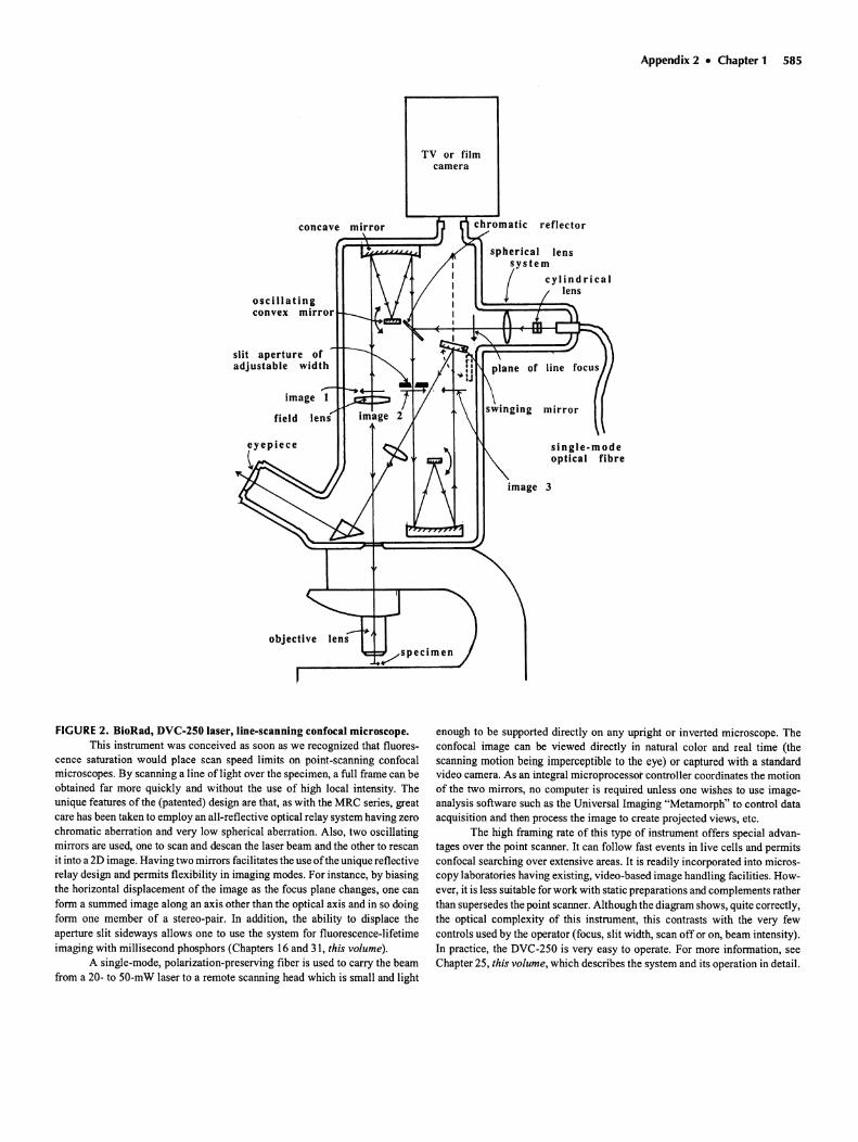
FIGURE 2. BioRad, DVC-250 laser, line-scanning confocal microscope.This instrument was conceived as soon as we recognized that fluore s
cence saturation would place scan speed limits on point-s canning confocalmicroscopes. By scanning a line oflight over the specimen, a full frame can beobtained far more quickly and without the use of high local intensity. Theunique features of the (patented) design are that, as with the MRC series, greatcare has been taken to employ an all-reflective optical relay system having zerochromatic aberration and very low spherica l aberration. Also , two oscillatingmirrors are used, one to scan and descan the laser beam and the other to rescanit into a 2D image. Having two mirro rs facili tates the use ofthe unique reflectiverelay design and perm its flex ibility in imaging modes. For instance, by biasingthe horizontal displacement of the image as the focus plane changes, one canform a summed image along an axis other than the opt ical axis and in so doingform one member of a ste reo-pair. In addit ion, the ability to displace theaperture slit side ways allows one to use the system for fluorescence-lifetimeimaging with millisecond phosphors (Chapters 16 and 31, this volume).
A single-mode, polarization-preserving fiber is used to carry the beamfrom a 20- to 50-mW laser to a remote scanning head which is small and light
Ap pendix 2 • Chapt er 1 585
TV or filmcamera
reflector
spherical lenssystem
/
cylin d ricallens
mirror
single -modeoptical fibre
3
enough to be supported directly on any upright or inverted microscope. Theconfocal image can be viewed directly in natural color and real time (thescann ing motion being imperceptible to the eye) or captured with a standardvideo camera. As an integral microprocessor controller coordinates the motionof the two mirrors, no computer is required unless one wishes to use imageanalysis software such as the Universal Imag ing "Metamorph" to control dataacqu isition and then proce ss the image to create projected views, etc .
The high fram ing rate of this type of instrument offers special advantages over the point scanner. It can follow fast events in live cells and perm itsconfocal searching over exten sive areas. It is readily incorporated into micros cop y laboratories having exi sting, video-b ased image hand ling facilities. How ever, it is less suitable for work with static preparations and complements ratherthan supersedes the point scann er. Although the diagram shows, quite correctly,the optical complexity of this instrum ent, this contrasts with the very fewcontrols used by the operator (focus, slit width , scan off or on, beam intens ity).In practice, the DVC-250 is very easy to operate. For more information, seeChapter 25, this volume, which describes the sys tem and its operation in detai l.
586 Chapter 1 • Appendix 2
one-dimensional CCD
len.
lena f-S .Oem
deflector
pel.rised be_ o~ quarter "ave plate
ion. t-5.2e1l ~t-1D .5"" o objective
cyl.lens
.....-l,..'''---- .couatic-optical
t-6.DeIl
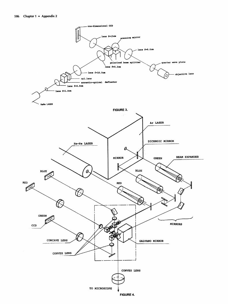
FIGURE 3.
CCD
CONVEX LENS
Ar LASER
DICHROIC MIRROR
BEAM EXPANDER
----/-----y-MIRRORS
GALVANO MIRROR
LENS
TO MICROSCOPE
FIGURE 4.
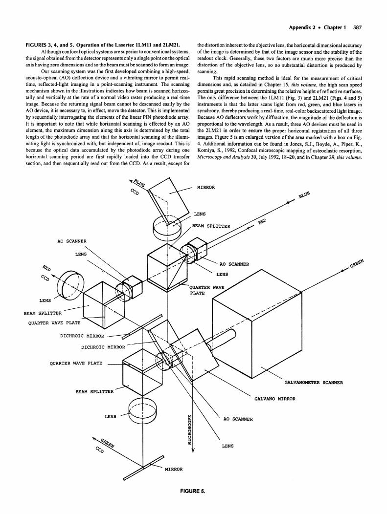
FIGURES 3, 4, and 5. Operation of the Lasertec lLMll and 2LM21.Although confocal optical systems are superior to conventional systems,
the signal obtained from the detector represents only a single point on the opticalaxis having zero dimensions and so the beam must be scanned to form an image.
Our scanning system was the first developed combining a high-speed,acousto-opt ical (AO) deflection device and a vibrating mirror to permit realtime, reflected-light imaging in a point-scanning instrument. The scanningmechanism shown in the illustrations indicates how beam is scanned horizontally and vertically at the rate of a normal video raster producing a real-timeimage. Because the returning signal beam cannot be descanned easily by theAO device, it is necessary to, in effect, move the detector. This is implementedby sequentially interrogating the elements of the linear PIN photodiode array.It is important to note that while horizontal scanning is effected by an AOelement, the maximum dimension along this axis is determined by the totallength of the photodiode array and that the horizontal scanning of the illuminating light is synchronized with, but independent of, image readout. This isbecause the optical data accumulated by the photodiode array during onehorizontal scanning period are first rapidly loaded into the CCD transfersection, and then sequentially read out from the CCD. As a result, except for
AO SCANNER
LEN~<,
LENS
BEAM SPLITTER
QUARTER WAVE PLATE
DICHROIC MIRROR __---7~
DICHROIC
QUARTER WAVE PLATE
BEAM SPLITTER
LENS
MIRROR
Appendix 2 • Chapter 1 587
the distortion inherent to the objective lens, the horizontal dimensional accuracyof the image is determined by that of the image sensor and the stability of thereadout clock. Generally, these two factors are much more precise than thedistortion of the objective lens, so no substantial distortion is produced byscanning.
This rapid scanning method is ideal for the measurement of criticaldimensions and, as detailed in Chapter 15, this volume, the high scan speedpermits great precision in determining the relative height of reflective surfaces.The only difference between the lLMl1 (Fig. 3) and 2LM2l (Figs. 4 and 5)instruments is that the latter scans light from red, green, and blue lasers insynchrony, thereby producing a real-time, real-color backscattered light image.Because AO deflectors work by diffraction, the magnitude of the deflection isproportional to the wavelength . As a result, three AO devices must be used inthe 2LM2l in order to ensure the proper horizontal registration of all threeimages. Figure 5 is an enlarged version of the area marked with a box on Fig.4. Additional information can be found in Jones, S.J., Boyde, A., Piper, K.,Komiya, S., 1992, Confocal microscopic mapping of osteoclastic resorption,Microscopy and Analysis 30, July 1992, 18-20, and in Chapter 29, this volume .
MIRROR
AO SCANNER
GALVANOMETER SCANNER
GALVANO MIRROR
AO SCANNER
FIGURE 5.
588 Chapter 1 • Appendix 2
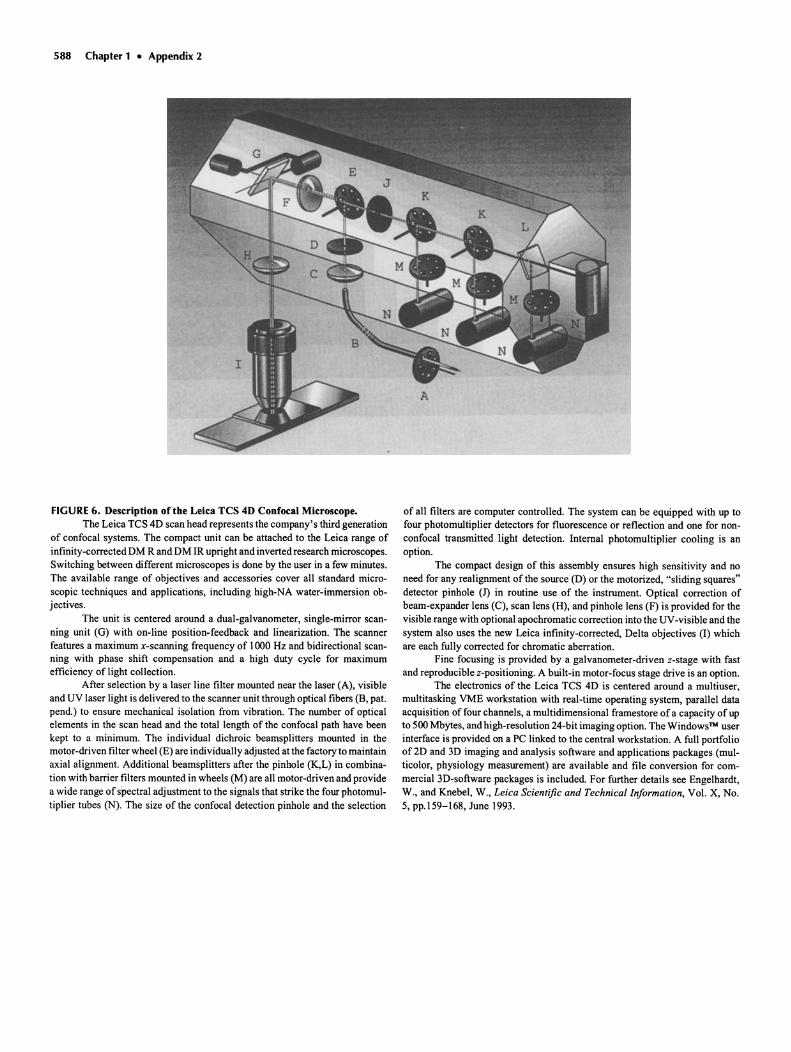
FIGURE G. Description of the Leica TCS 4D Confocal Microscope.The Leica TCS 4D scan head represents the company's third generation
of confocal systems. The compact unit can be attached to the Leica range ofinfinity-corrected DM Rand DM lR upright and inverted research microscopes.Switch ing between different microscopes is done by the user in a few minutes.The available range of objectives and accessories cover all standard microscop ic techniques and applications, including high-NA water-immersion objectives.
The unit is centered around a dual-galvanometer, single-mirror scanning unit (G) with on-line position-feedback and linearization. The scannerfeatures a maximum x-scanning frequency of 1000 Hz and bidirectional scanning with phase shift compensation and a high duty cycle for maximumefficiency of light collection.
After selection by a laser line filter mounted near the lase r (A) , visibleand UV laser light is delivered to the scanner unit through optical fibers (B, pat.pend.) to ensure mechanical isolation from vibration. The number of opticalelements in the scan head and the total length of the confocal path have beenkept to a minimum. The individual dichroic beamsplitters mounted in themotor-driven filter wheel (E) are individually adjusted at the factory to maintainaxial alignment. Additional beamsplitters after the pinhole (K,L) in combination with barrier filters mounted in wheels (M) are all motor-driven and providea wide range of spectral adjustment to the signals that strike the four photomultiplier tubes (N). The size of the confocal detection pinhole and the selection
of all filters are computer controlled. The system can be equipped with up tofour photomultiplier detectors for fluorescence or reflection and one for nonconfocal transmitted light detection. Internal photomultiplier cooling is anoption.
The compact design of this assembly ensures high sensitivity and noneed for any realignment of the source (D) or the motorized, "sliding squares"detector pinhole (1) in routine use of the instrument. Optical correction ofbeam-expander lens (C) , scan lens (H), and pinhole lens (F) is provided for thevisible range with optional apochromatic correction into the UV-visible and thesystem also uses the new Leica infinity-corrected, Delta objectives (I) whichare each fully corrected for chromatic aberration.
Fine focusing is provided by a galvanometer-driven a-stage with fastand reproducible z-positioning, A built-in motor-focus stage drive is an option.
The electronics of the Leica TCS 4D is cen tered around a multiuser,multitasking VME workstation with real -time operating system, parallel dataacquisition of four channels, a multidimensional framestore of a capacity of up
to 500 Mbytes , and high-resolution 24-bit imaging option. The Windows™ userinterface is provided on a PC linked to the central workstation. A full portfolioof2D and 3D imaging and analysis software and applications packages (multicolor, physiology measurement) are available and file conversion for com mercial 3D-software packages is included. For further details see Engelhardt,W., and Knebel, W., Leica Scientific and Technical Information, Vol. X, No .5, pp.159-168, June 1993.
Appendix 2 • Chapter 1 589
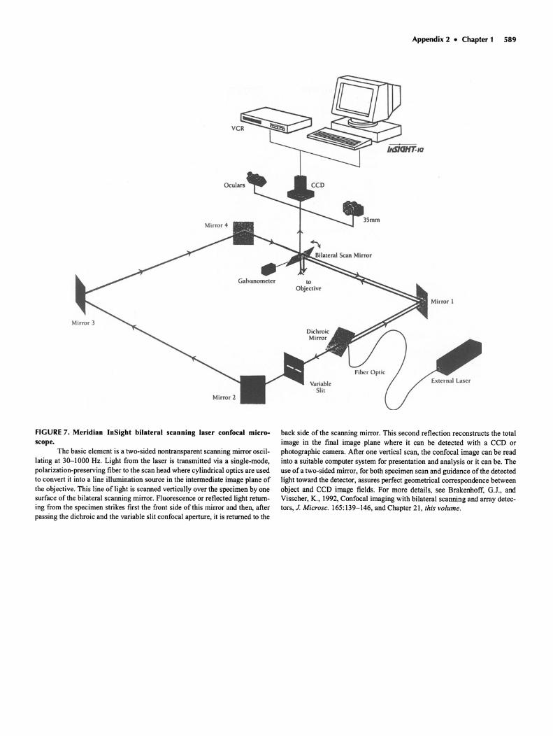
FIGURE 7. Meridian InSight bilateral scanning laser confocal microscope.
The basic element is a two-sided nontransparent scanning mirror oscillating at 30-1000 Hz. Light from the laser is transmitted via a single-mode,polarization-preserving fiber to the scan head where cylindrical optics are usedto convert it into a line illumination source in the intermediate image plane ofthe object ive. This line of light is scanned vertically over the specimen by onesurface of the bilateral scanning mirror. Fluore scence or reflected light returning from the specimen strikes first the front side of this mirror and then, afterpassing the dichroic and the variable slit confocal aperture, it is return ed to the
back side of the scann ing mirror. This second reflection reconstructs the totalimage in the final image plane where it can be detected with a CCD orphotographic camera. After one vertical scan, the confocal image can be readinto a suitable computer system for presentation and analysis or it can be. Theuse of a two- sided mirror, for both specimen scan and guidance of the detectedlight toward the detector, assures perfect geometrical correspondence betwe enobject and CCD image fields . For more details, see Brakenhoff, GJ., andVisscher , K., 1992, Confocal imaging with bilateral scanning and array detectors, J. Microsc. 165:139-146, and Chap ter 2 1, this volume.
590 Chapter 1 • Appendix 2
Sample
EmlulonFilter 3
EmilalonFlIlIr 1
PMT--...I.----4H 3Olclnolc2
PMTHI-__~2
LaserLineBarrier
EmluionFlIer 2
ExcitaUonlFluorescence
SeparationDichroic
VISibleExciter
VISibleAOM -+
MicroSteppingStage
UVMsible .Recombining
Dichroic
\I
/,.
•\
ScanRelay
WMsibie SplittingDichroic
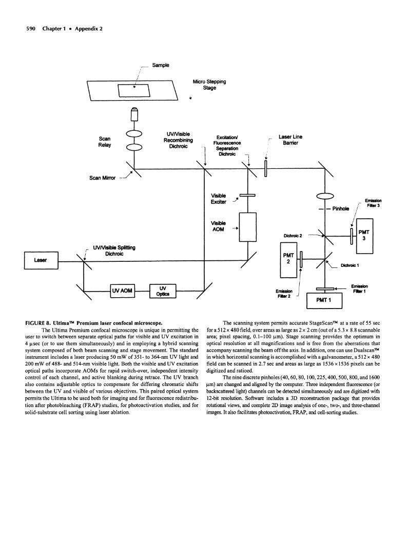
FIGURE 8. Ultima™ Premium laser confocal microscope.The Ultima Premium confocal microscope is unique in permitting the
user to switch between separate optical paths for visible and UV excitation in4 use e (or to use them simultaneously) and in employing a hybrid scanningsystem composed of both beam scanning and stage movement. The standardinstrument includes a laser producing 50 mW of 351- to 3M-nm UV light and200 mW of 488- and 514-nm visible light. Both the visible and UV excitationoptical paths incorporate AOMs for rapid switch-over, independent intensitycontrol of each channel , and active blanking during retrace. The UV branchalso contains adjustable optics to compensate for differing chromat ic shiftsbetween the UV and visible of various objecti ves. This paired optical systempermits the Ultima to be used both for imaging and for fluorescence redistribution after photobleaching (FRAP) studies, for photoactivation studies, and forsolid-substrate cell sorting using laser ablation .
The scanning system permits accurate StageScan™ at a rate of 55 secfor a 512 x 480 field , over areas as large as 2 x 2 em (out ofa 5.3 x 8.8 scannablearea; pixel spacing , 0.1-100 11m). Stage scanning provides the optimum inoptical resolution at all magnificat ions and is free from the aberrations thataccompany scanning the beam offthe axis. In addition, one can use Dualscan'P'in which horizontal scanning is accompl ished with a galvanometer, a 512 x 480field can be scanned in 2.7 sec and areas as large as 1536 x 1536 pixels can bedigitized and ratioed .
The nine discrete pinholes (40,60,80, 100,225,400,500, 800, and 160011m) are changed and aligned by the computer. Three independent fluorescence(orbackscatteredlight) channels can be detected simultaneously and are digitized withl2-bit resolution. Software includes a 3D reconstruction package that providesrotational views, and complete 2D image analysis of one-, two-, and three-ehannelimages. It also facilitatesphotoactivation, FRAP, and cell-sortingstudies.
Appendix 2 • Chapter 1 591
Externallaser port
/Internallaser
, Secondary\ dichroic, beam- .p,+-f-----i
0/ splitter
c Jj (1 °0... "Barrier V Emissionfiller filters
r:V
Achromallens
Y Laser waverenglhselechon !ilter wheel
~ ~
;:~~~~~"'~~ §r~B\CUSlom Pnmary dichroIc ( (~Jocular beam-spliner Whee~
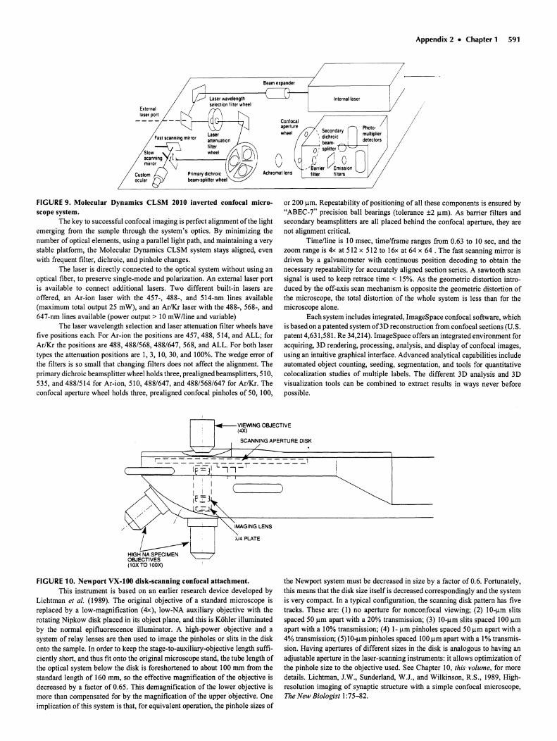
FIGURE 9. Molecular Dynamics CLSM 2010 inverted confocal microscope system.
The key to successful confocal imaging is perfect alignment of the lightemerging from the sample through the system's optics. By minimizing thenumber of optical elements , using a parallel light path, and maintaining a verystable platform, the Molecular Dynamics CLSM system stays aligned, evenwith frequent filter, dichroic, and pinhole changes.
The laser is directly connected to the optical system without using anoptical fiber, to preserve single-mode and polarization. An external laser portis available to connect additional lasers. Two different built-in lasers areoffered, an Ar-ion laser with the 457-, 488-, and 514-nm lines available(maximum total output 25 mW), and an Ar/Kr laser with the 488-,568-, and647-nm lines available (power output > 10 mWlline and variable)
The laser wavelength selection and laser attenuation filter wheels havefive positions each. For Ar-ion the positions are 457, 488,514, and ALL; forAr/Kr the positions are 488, 488/568, 488/647, 568, and ALL. For both lasertypes the attenuation positions are I, 3, 10, 30, and 100%. The wedge error ofthe filters is so small that changing filters does not affect the alignment. Theprimary dichroic beamsplitter wheel holds three, prealigned beamsplitters , 5 I0,535, and 488/514 for Ar-ion, 510,488/647, and 488/568/647 for Ar/Kr. Theconfocal aperture wheel holds three, prealigned confocal pinholes of 50, 100,
or 200 urn. Repeatability of positioning of all these components is ensured by"ABEC-7" precision ball bearings (tolerance ±2 urn) . As barrier filters andsecondary beamsplitters are all placed behind the confocal aperture, they arenot alignment critical.
Time/line is 10 msec, time/frame ranges from 0.63 to 10 sec, and thezoom range is 4x at 512 x 512 to 16x at 64 x 64 . The fast scanning mirror isdriven by a galvanometer with continuous position decoding to obtain thenecessary repeatability for accurately aligned section series. A sawtooth scansignal is used to keep retrace time < 15%. As the geometric distortion introduced by the off-axis scan mechanism is opposite the geometric distortion ofthe microscope, the total distortion of the whole system is less than for themicroscope alone.
Each system includes integrated, ImageSpace confocal software, whichis based on a patented system ofJD reconstruction from confocal sections (U.S.patent 4,631,581. Re 34,214). ImageSpace offers an integrated environment foracquiring, 3D rendering, processing, analysis, and display of confocal images,using an intuitive graphical interface. Advanced analytical capabilities includeautomated object counting, seeding, segmentat ion, and tools for quantitativecolocalization studies of multiple labels. The different 3D analysis and 3Dvisualization tools can be combined to extract results in ways never beforepossible.
FIGURE 10. Newport VX-IOO disk-scanning confocal attachment.This instrument is based on an earlier research device developed by
Lichtman et al. (1989). The original objective of a standard microscope isreplaced by a low-magnification (4x) , low-NA auxiliary objective with therotating Nipkow disk placed in its object plane, and this is Kohler illuminatedby the normal epifluorescence illuminator . A high-power objective and asystem of relay lenses are then used to image the pinholes or slits in the diskonto the sample. In order to keep the stage-to-auxiliary-objective length sufficiently short, and thus fit onto the original microscope stand, the tube length ofthe optical system below the disk is foreshortened to about 100 mm from thestandard length of 160 mm, so the effective magnification of the objective isdecreased by a factor of 0.65. This demagnification of the lower objective ismore than compensated for by the magnification of the upper objective. Oneimplication of this system is that, for equivalent operation, the pinhole sizes of
the Newport system must be decreased in size by a factor of 0.6. Fortunately ,this means that the disk size itself is decreased correspondingly and the systemis very compact. In a typical configuration, the scanning disk pattern has fivetracks. These are: (I) no aperture for nonconfocal viewing; (2) IO-J.lm slitsspaced 50 urn apart with a 20% transmission ; (3) IO-J.lm slits spaced 100 urnapart with a 10% transmission ; (4) 1- urn pinholes spaced 50 urn apart with a4% transmission; (5) IO-J.lm pinholes spaced 100urn apart with a I% transmission. Having apertures of different sizes in the disk is analogous to having anadjustable aperture in the laser-scanning instruments : it allows optimization ofthe pinhole size to the objective used. See Chapter 10, this volume, for moredetails. Lichtman, J.W., Sunderland, W.J., and Wilkinson, R.S., 1989, Highresolution imaging of synaptic structure with a simple confocal microscope,The New Biologist 1:75-82.
592 Chapter 1 • Appendix 2
'--------...r....------j
Lens
LaserDiode
PhotoDetector
Lens
Mirror
Lasers
I~Barrler
I AlterPMT I
--11 t-~ Dlc!"rolc-L-J -~ MirrorI
Barrler LConfocalFilter c ....Pinhole
III
[::fl LensIIIII
<:::t>LensI
~Barrler-.-- Filter
I
ConjugateImage Plane
I
_ _ _ Emmislon ray
-- Exc/latlon ray
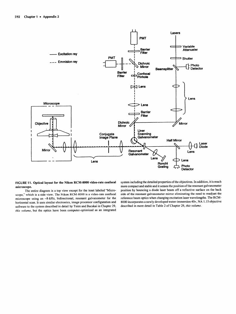
FIGURE 11. Opticatlayout for the Nikon ReM-SOOO video-rate confocalmicroscope.
The entire diagram is a top view except for the inset labeled "Microscope," which is a side view. The Nikon ReM-SOOO is a video-rate confocalmicroscope using an -8-kHz, bidirectional, resonant galvanometer for thehorizontal scan. It uses similar electronics, image processor configuration andsoftware to the system described in detail by Tsien and Bacskai in Chapter 29,this volume, but the optics have been computer-optimized as an integrated
system including the detailed properties ofthe objectives . In addition, it is muchmore compact and stable and it senses the position ofthe resonant galvanometerposition by bouncing a diode laser beam off a reflective surface on the backside of the resonant galvanometer mirror eliminating the need to readjust thereference beam optics when changing excitation laser wavelengths . The RCM8000 incorporates a newly developed water-immersion 4Ox, NA 1.15 objectivedescribed in more detail in Table 2 of Chapter 29, this volume .
Appendix 2 • Chapter 1 593
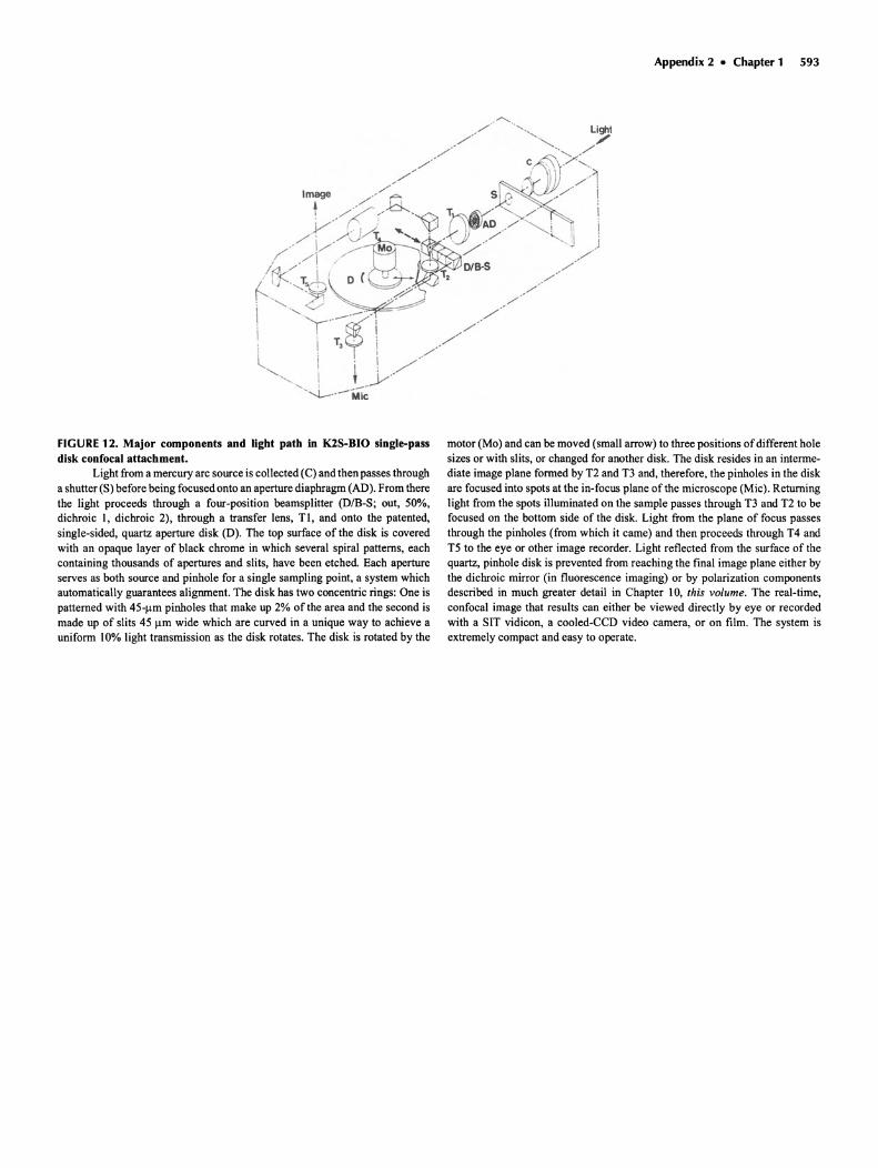
FIGURE 12 . Major components and light path in laS-BIO single-passdisk confocal attachment.
Light from a mercury arc source is collected (C) and then passes througha shutter (S) before being focused onto an aperture diaphragm (AD). From therethe light proceeds through a four-position beamsplitter (D/B-S; out. 50%,dichroic I, dichroic 2), through a transfer lens, TI , and onto the patented,single-sided, quartz aperture disk (D). The top surface of the disk is coveredwith an opaque layer of black chrome in which several spiral patterns, eachcontaining thousands of apertures and slits, have been etched. Each apertureserves as both source and pinhole for a single sampling point, a system whichautomatically guarantees alignment. The disk has two concentric rings: One ispatterned with 45-flm pinholes that make up 2% of the area and the second ismade up of slits 45 urn wide which are curved in a unique way to achieve auniform 10% light transmission as the disk rotates. The disk is rotated by the
motor (Mo) and can be moved (small arrow) to three positions ofdifferent holesizes or with slits, or changed for another disk. The disk resides in an intermediate image plane formed by T2 and T3 and, therefore, the pinholes in the diskare focused into spots at the in-focus plane of the microscope (Mic) . Returninglight from the spots illuminated on the sample passes through T3 and T2 to befocused on the bottom side of the disk. Light from the plane of focus passesthrough the pinholes (from which it came) and then proceeds through T4 andT5 to the eye or other image recorder. Light reflected from the surface of thequartz, pinhole disk is prevented from reaching the final image plane either bythe dichroic mirror (in fluorescence imaging) or by polarization componentsdescribed in much greater detail in Chapter 10, this volume. The real-time,confocal image that results can either be viewed directly by eye or recordedwith a SIT vidicon, a cooled-CCD video camera, or on film. The system isextremely compact and easy to operate.
594 Chapter 1 • Appendix 2
BeamShapingOptics
BeamExpander
2
Field LensQuarter Wave Plate---..:-",.--..-.--L...J
FocusingLens
Reflected PMTAcousto-OpticDeflector
Beam
Shaping \Optics
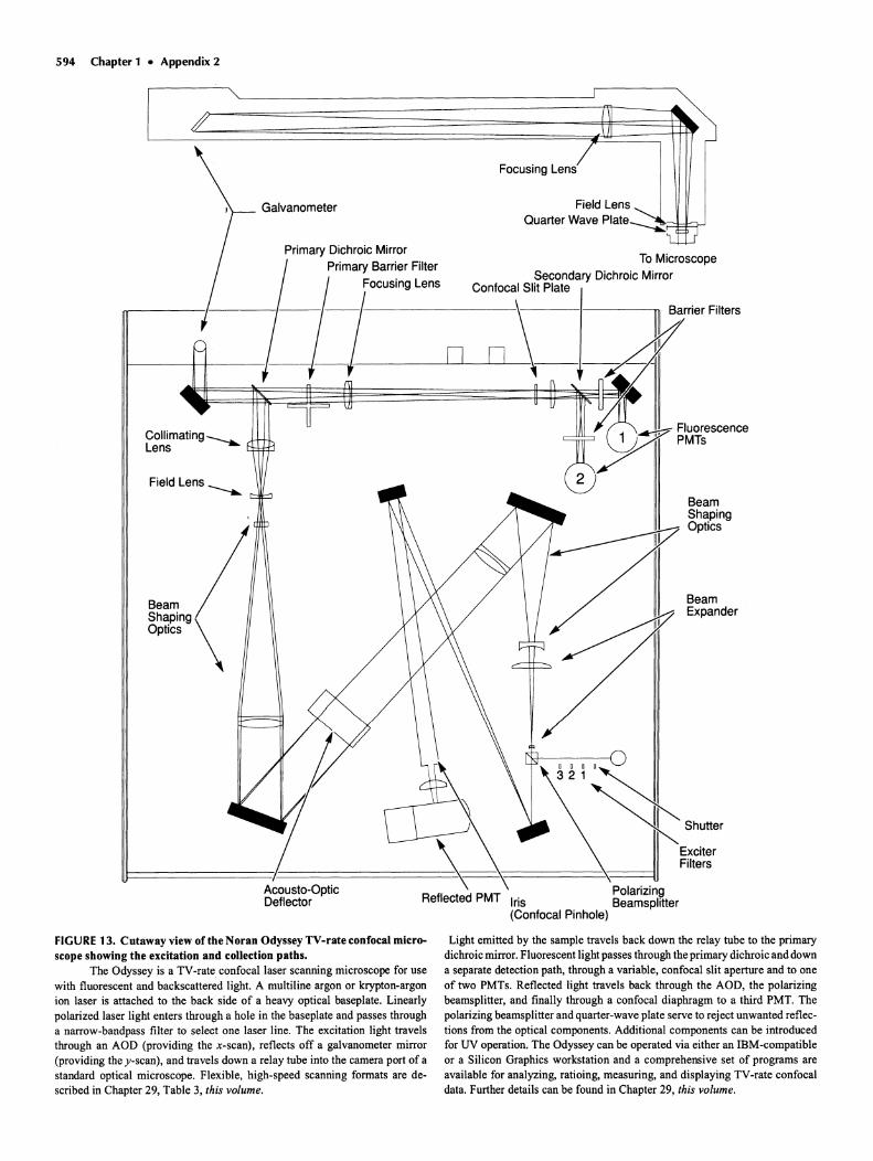
FIGURE 13. Cutaway view of the Noran Odyssey TV-rate confocal microscope showing the excitation and collection paths.
The Odyssey is a TV-rate confocal laser scanning microscope for usewith fluorescent and backscattered light. A multiline argon or krypton-argonion laser is attached to the back side of a heavy optical baseplate. Linearlypolarized laser light enters through a hole in the baseplate and passes througha narrow-bandpass filter to select one laser line. The excitation light travelsthrough an ADD (providing the x-scan), reflects off a galvanometer mirror(providing the j-scan), and travels down a relay tube into the camera port of astandard optical microscope. Flexible, high-speed scanning formats are described in Chapter 29, Table 3, this volume.
Light emitted by the sample travels back down the relay tube to the primarydichroic mirror. Fluorescent light passes through the primary dichroic and downa separate detection path, through a variable, confocal slit aperture and to oneof two PMTs. Reflected light travels back through the ADD, the polarizingbeamsplitter, and finally through a confocal diaphragm to a third PMT. Thepolarizing beamsplitter and quarter-wave plate serve to reject unwanted reflections from the optical components . Additional components can be introducedfor UV operation. The Odyssey can be operated via either an ffiM-compatibleor a Silicon Graphics workstation and a comprehensive set of programs areavailable for analyzing, ratioing , measuring, and displaying TV-rate confocaldata. Further details can be found in Chapter 29, this volume.
Appendix 2 • Chapter 1 595
FilterConfocalApertures
Photomultiplier 1
Photomultiplier 2
Photomultiplier 3
: : . :
BeamSpliter 3
BeamSpllter 2
Slider Block : : :' :~9~ Non-Confocal Singlet f=l OOmm
• : I"
BeamSpliter1
x-vScanner
ObjectiveImagePlane
»<
ObjectiveLens
Specimen ~
Z-Drive
CondenserLens
Confocal Tele-Phot Lens f=4000mm(Tele-Photo Ratio 10)
Argon Laser
Transmission Detectorr.-----.....A.....- __-- "'\
Photodiode A
Photodiode B
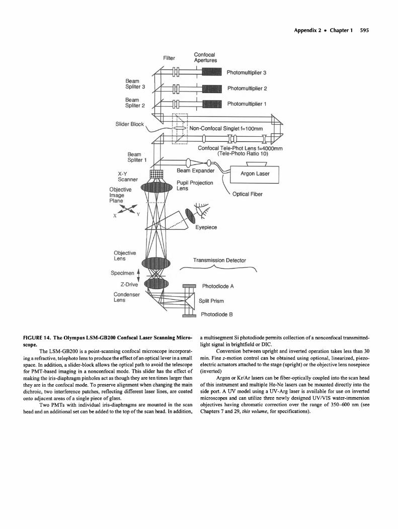
FIGURE 14. The Olympus LSM-GB200 Confocal Laser Scanning Microscope.
The LSM-GB200 is a point-scanning confocal microscope incorporating a refractive, telephoto lens to produce the effect ofan optical lever in a smallspace. In addition, a slider-block allows the optical path to avoid the telescopefor PMT-based imaging in a nonconfocal mode. This slider has the effect ofmaking the iris-diaphragm pinholes act as though they are ten times larger thanthey are in the confocal mode. To preserve alignment when changing the maindichroic , two interference patches, reflecting different laser lines, are coatedonto adjacent areas of a single piece of glass.
Two PMTs with individual iris-diaphragms are mounted in the scanhead and an additional set can be added to the top of the scan head. In addition ,
a multisegment Si photodiode permits collection of a nonconfocal transmittedlight signal in brightfield or DIC.
Conversion between upright and inverted operation takes less than 30min. Fine z-motion control can be obtained using optional, linearized, piezoelectric actuators attached to the stage (upright) or the objective lens nosepiece(inverted)
Argon or Kr/Ar lasers can befiber-optically coupled into the scan headof this instrument and multiple He-Ne lasers can be mounted directly into theside port. A UV model using a UV-Arg laser is available for use on invertedmicroscopes and can utilize three newly designed UV/VIS water-immersionobjectives having chromatic correction over the range of 350-600 nm (seeChapters 7 and 29, this volume, for specifications).
596 Chapter 1 • Appendix 2
LAUNCH/DETECTIONUNIT
beamchopper
laser
4: 3 pos. filter slide: ch 2 dichroic(lyp. blank. 52()vn bandpass)
5: 3 pos. filler slide: ch 1barrier(lyp. 515nm & 540nm cutoff. blank)
2: 3 pos. filter slide: loser line(typ.488nm. 514.5nm. fIJ/fIJ)
1: 3 poe. niter side: IaseI' altenua110n(typ. blank. r.D1.N02)
3: nbel' launch lens
,,;-OPTICFIBER
BEAMSTEERING
LENS(f.I.=6O'nm)
--I-------JI---f--IMAGE PlANE
OBJECTIve FOCAlPlANE
20mm
TUBELENGTHtypically160mm
FIBER OUTPUTLENS
,.-.....-'1----,/ lOX.O.25NA
ORTHOGONALSCANNING MIRRORS(line rate C900: 80Hz
F900: 1.1kHz)
SCANNING HEAD
6: 3 pos, niter sIde : ch 2 barrier(typ . 515nm & 540nm cutoff. blank)
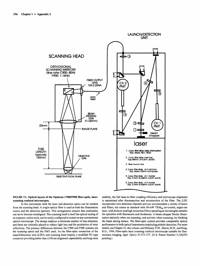
FIGURE 15 . Optical layout of the Optiscan C900/F900 fiber-optic, laserscanning confocal microscopes.
In this instrument , both the laser and detection optics can be isolatedfrom the scanning head. A single optical fiber is used as both the illuminationsource and the detection aperture . This arrangement ensures that confocalitycan never become misaligned. The scanning head is itself the optical analog ofan eyepiece, and as such, can be easily configured to mount on any conventionaloptical microscope . The design employs a minimum number of lens elements,and these are critically placed to reduce light loss and the production of strayreflections . The primary differences between the C900 and F900 systems arethe scanning speed and the PMT used. As the fiber-optic connection of thelaunch/detect ion unit (LOU) and scanning head employ a modified Fe-typeconnector provid ing better than ±I00 nm alignment repeatability and long-term
stability, the fulliaser-to-fiber coupling efficiency and microscope alignmentis maintained after disconnection and reconnection of the fiber. The LOUincorporates twin detection channels and can accommodate a variety of lasersand filters, but comes as standard with 50-mW TEMoo air-cooled , argon-ionlaser, with dichroic and high extinct ion filters operating at wavelengths suitablefor operation with fluorescein and rhodamine. A beam-chopper blocks illumination statically when not scanning, and actively when scanning, by blankingthe beam during retrace. The fiber-optic system provides comparable opticalperformance to bulk optical instruments employing pinhole detection. For moredetails, see Chapter 33, this volume, and Delaney, P.M., Harris, M.H., and King,R.G., 1994, Fiber-optic laser scanning confocal microscope suitable for fluorescence imaging, Appl. Optics 33:573-577. (U.S. Patent Number 5,120,953pending.)
Appendix 2 • Chapter 1 597
PMT 2
laser
To microscopephoto port
,- ---------- --- ---- --- - --;, 0 ,&;----T"
mirror
"
II
: pinholesoooo
o dichroic: mirrorsIoIoooo
: dichroicI mirrorsooooooooo
: mirrorI
oooooo 0 ,
: _ _ _ .I- : \y
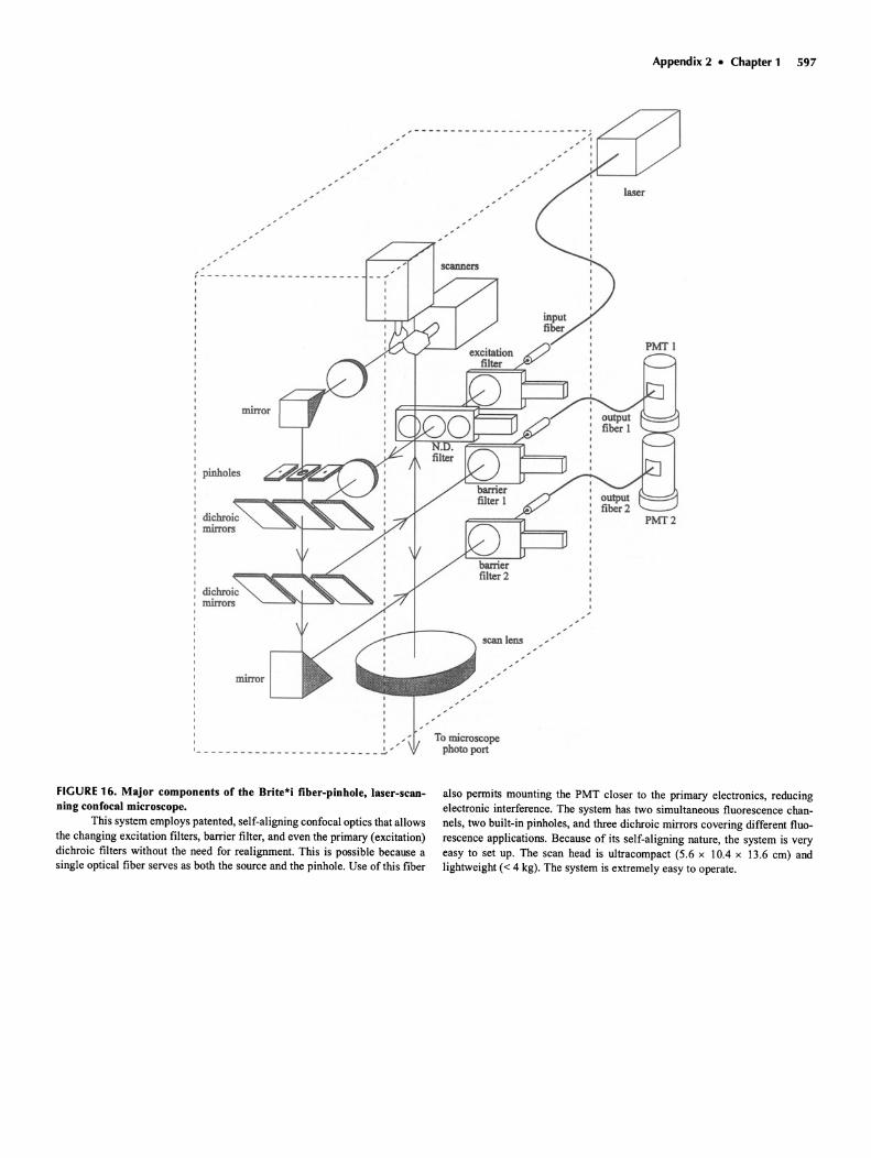
FIGURE 16. Major components of the Brite*i fiber-pinhole, laser-scanning confocal microscope.
This system employs patented, self-aligning confocal optics that allowsthe changing excitation filters, barrier filter, and even the primary (excitation)dichroic filters without the need for realignment. This is possible because asingle optical fiber serves as both the source and the pinhole. Use of this fiber
also permits mounting the PMT closer to the primary electronics, reducingelectronic interference. The system has two simultaneous fluorescence channels, two built-in pinholes, and three dichroic mirrors covering different fluorescence applications . Because of its self-alignin g nature, the system is veryeasy to set up. The scan head is ultracompact (5.6 x 10.4 x 13.6 em) andlightweight « 4 kg). The system is extremely easy to operate.
598 Chapter 1 • Appendix 2
51NF L5F
~X~+-51NF L5F...--...,
HBO
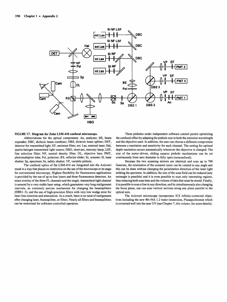
FIGURE17. Diagram for Zeiss LSM-410 confocal microscope.Abbreviations for the optical components: An, analyzer; BE, beam
expander ; DBC, dichro ic beam combiner; DBS, dichroic beam splitter ; DET,detector for transmitted light; EF, emiss ion filter ; ext. Las, extemallaser; Hal,quartz-halogen transmitted light source; HBO, short-arc, mercury lamp; LSF,line selection filter; NF, neutral density filter; OL, objective lens; PMT,photomultiplier tube; Pol, polarizer; RS, reflector slider; Sc, scanner ; SI, lasershutter ; Sp, specimen; Ss, safety shutter; VP, variable pinhole .
The confocal optics of the LSM-410 are integrated into the Axiovertstand in a way that places no restriction on the use of the microscope or its stagefor conventional microscopy. Highest flexibility for fluorescence applicationsis provided by the use of up to four lasers and three fluorescence detectors . Anexact overlay of the three FL channels and the single. transmitted-light channelis assured by a very stable laser setup, which guarantees very long realignmentintervals, an extremely precise mechanism for changing the beamsplitters(DBS 1-3) , and the use of high-precision filters with very low wedge error forlaser-line select ion and attenuation. As a result, there is no need ofrealignmentafter changing laser, beamsplitter, or filters. Nearly all filters and beamsplitterscan be motorized for software-controlled operation .
Three pinholes under independent software control permit optimizingthe confocal effect by adapting the pinhole size to both the emission wavelengthand the objective used. In addition, the user can choose a different compromisebetween z-resolution and sensitivity for each channel. The setting for optimaldepth resolution occurs automatically whenever the objective is changed . Thesize of the motor-driven, sliding squares pinhole mechan isms can be setcontinuously from zero diameter to fully open (nonconfocal) .
Because the two scanning mirrors are identical and scan up to 700Iines/sec, the orientation of the scanned raster can be rotated to any angle andthis can be done without changing the polarization direction of the laser lightstriking the specimen . In addition, the size of the scan field can be reduced (anyrectangle is possible) and it is even possible to scan only interesting regions,thus reducing both scan time and the volume ofdata that must be stored. Finally,it is possible to scan a line in any direction, and by simultaneously also changingthe focus plane, one can scan vertical sections along any plane parallel to theoptical axis.
The Axiovert microscope incorporates ICS infinity-corrected objectives including the new 40xINA 1.2 water-immersion, Planapochromat whichis corrected well into the near UV (see Chapter 7, this volume , for more details).
Index
3-color, specimen-scanning confocal microscopediagram, 509performance, 510stereo image, 512
3D direct imaging, chapter, 3553D graphics, 203image analysis, 203image overlay, 207multidimensional display : see 3D image visualiza
tionchapters, 197, 211
of living embryo using two-photon excitation, 456real-time stereo confocal microscopy, chapters ,
255,355using chromatic aberration. 120,263,264using slit-scanning confocal microscopes, 358using widefield/deconvolution, prospects, 399
signal-to-noise ratio considerations, 370software system, 207, 208specimen preparation for, chapter, 311stereo display systems, 205
figure, 206volume rendering, 203, 211
3D image processing, chapter, 197camera calibration, 199
results, figure, 200correct ion for bleaching, 269, 550, 551correction of chromatic shifts , 20 Ideconvolution, blind
biological results , 396image reconstruction, 394iterative , constrained, 200number of iterations, 397, 398simulated results, 394, 395speed, 201
image enhancement, 201isometric projection, 167possibility of correcting for specimen shrinkage,
322stereo image of reconstructed MDCK cell, 322
3D image visualization, chapters, 197,211absorption, 214, 243, 249; see also Opacity"alpha" blending, 239animations , 226annotated references on, 577calibrating image space, 222choosing a system, 211coding height information, 240color display space, 225; see also Pseudocolorcommercial systems , tables
addresses, 254basic data, 212data-handling capabilities, 218data value mapping options, 232image and view dimensions, 220image-space to view-space mapping options,
230mapping options , 227
3D image visualization (cont.)commercial systems, tables (cont.)
multidimensional measurement tools, 216realistic visualization capabilities , 246standard file formats, 223
contrast of data, 24, 306, 373correction for bleaching, 200, 550, 551data reduction , 190-202, 213depth-weighting, 243
exponential, 242linear, 242
dimensional reduction, 213dimensionality, definition, 2, 211gradient filters, 202-203hidden object removal, 242, 243, 244
z-buffering, 242-244highlighting, 214How are views generated?, 224for identifying known structures
images, 215, 219image, definition of, 211image size, 219image-space to view-space transformations, dia
gram, 231importance of contrast in data set, 304importance of signal-to-noise in data set, 24, 304,
373Phong-shaded example, 309
information theory-based approach, 304-308intensity calibration, 215
table, 218interactive, 213iso-intensity surface, 242isometric projection, example, 168Kalman averaging , 240, 243, 244, 560, 566lighting models, 237, 238, 239
Gourard models, 247implementation, 245
example, 245shading examples, 247
Phong and Blinn models, 245Phong models, 247
effect on noisy data, 309realistic visualization techniques, 203
examples, 248table of capabilities of commercial products,
246mapping, conventions, 229
data value mapping options ofcommercial systems, table, 232
data values into the display, 237image-space to view-space mapping
diagram, 234, 235options of commercial systems, table, 230
options, 224of commercial systems, table, 227
rotating displays, 205, 206, 229-231, 237examples, 233
3D image visualization (cont.)mapping , convention (cont.)
stereo view generation, 233, 234, 235image , 235, 236motion parallax, 237
measurement capabilitiesin 2D views oDD data, 237on reconstructed views, 250
examples, 251stereo view, 252
table, 216model building, 206movies, 205, 206, 226, 229, 342multidimensional measurement, commercial tools
available, 214examples, 251stereo view, 252
multichannel color display, 226objective vs. subjective, 214opacity, 204, 214, 238, 240, 249, 250, 306
example of effects, 308outline of steps, diagram, 304, 308overlay, 207, 226perspective, 237
diagram, 238possibilities, images, 213, 214precision , 214preprocessing, 198, 199
reasons, 224tools, table, 216
projection and compositing rules, 239examples, 241, 242, 243hidden object removal, 243, 244local projections, 243
examples , 244maximum, 244minimum , 244
z-buffering, 243, 244pseudocolor,9, 10,64, 167,204,207,225purpose of, 211, 213reconstruction
definition , 211generation, 224
rendering, 203-205, 214, 231-245definition , 211image-order rendering, 306realistic, 245speed,206,222,224See also Rendering
resolution of data, 306rotations, 205, 206, 229, 230sampling concerns, 58, 59, 64scan conversion, 239
segmentation oDD data to choose an "object,"238,304-308
examples , 240march ing cubes, 239
software suppliers, addresses, 254
599
600 Index
3D image visualization (cont.)standard file formats, 222
table , 223stereo viewing systems compared, images , 205-
207,234-237thresholding, 2 I4using fluorescence lifetime data, 50 Iview, definition of, 2 I Ivisual fidelity, 305
role of pinhole diameter, 306plot , 308
voxelrendering, 203-204, 214, 231, 238,306grad ient cues for lighting, 203, 249hidden object removal, 244interactive cursor, 250
examples, 206 , 25 Istereo view, 252
light ingabsorption and transparency, models, 245emission model, 249, 250excitation model, 249, 250
realistic visualization techniquesexamples, 208 , 248table of capabilities of commercial products,
246speed, 224
z-buffering, 243, 244z-coordinate rules , 242See also Opacity
3D mappingfrom stereo pairs, 255using chromatic effects, 256using mechanical focus, 255
3D microscopybrightfield algorithm, 393comparison ofwidefieldldeconvolution with con
focal , chapters, 363, 373, 389constraints, diagram, 392flowchart, 392
confocal fluorescence algorithm, 392widefield fluorescence algorithm, 391
3D reconstructioneffect of scan nonl inearity, 45importance of contrast in data set, 304importance of signal-to-noise in data set, 304
Phong-shaded example, 309outline of steps, diagram, 304, 308visual fidelity, 305
3D test specimen, diatom in fluorescent oil, 469,470,560,562
image , 471
4-color immunofluorescence possibilities, 2744D microscopy
imaging of brain slicesdata-handling problems, 341results , 343
of sea urchin fertilization, 33 I4Pi microscopy, using two opposed objectives, chap
ter, 45, 417axial resolution measurements, 42 I
with complementary interference, 424coherence requirements, 4 I9, 420combined with Theta microscopy, plots , 427, 428complementary interference, 420 , 424, 426defin ition, 418diagram, 418images, 425importance of phase, plots, 425in conjunction with confocal microscopy, 449
diagram, 429point-spread function
backscattered light, 420 , 42 Ifluorescence, 423two-photon, 422
4Pi microscopy, using two opposed objectives(cont.)
phase effects, 425results, 422, 423, 424table of resolution, 420two-photon absorption, 422typeA,419type B, 420typeC, 421
5D image display space: see 3D image visualization,225
images , 228optimal use of, 228, 229rotating displays, 229, 23 I
Abbe , Ernst, IAberrations, 116
astigmatism, 136, 171, 172,551,556definition, 116diagram, 118
chromatic, 13axial
definition, 118, 119See also longitudinal
correction for UV-apo objecti veplot, 298
diagram, 563field of view limited by, 122lateral
diagram, 563effects on different types of confocal micro
scope, 435in UV correction methods, 435-438
longitudinalcorrection system in 3-color confocal micro
scope , 509, 510in UV correction methods, 435-438
use for height coding, 120Seealso Chromatic aberration
comadefinition, 116, 117figure, 117effect on confocal spot, 171intensity distribution, figure, 117
curvature of field, 45, 46, 564measurement, 46
definition, 112defocusing, 112distortion
definition, I I 8effect of, 12
effect ofRII mismatch, figure, 43effect on fluorescence efficiency, 45effect on focal spot, 171effect on two-photon confocal microscopy, 452,
453flatness of field
diagram, 118specifications, table , 126
monochromatic, I I 2in UV,436
off-axis, in beam-scanning confocal, 436pupil function expression, 17Ireduced by stage-scanning, 5, 45, 134spherical, 13
correction elements , 133magnitude of focus errors for different media,
table, 439operation of correction collar, diagram, 125produced by refractive index mismatch, chapter,
347theory, 348variational method, figure, 348
sphero-achromatism, 437
Aberrations (cont.)tutorial about effect on resolution and signal loss,
562,563See alsoentries under individual aberrations
Absorption, opticalchanges with milieu : see Ion imagingchanges with two-photon excitation, 454contrast, 281,288, 296, 393, 396,397,434,449-
454,479,486heating effects, 20,148,184,327,328,340,450,
454in 3D image visualization, 214 , 243, 249; see
alsoOpacityof caged compounds, 453rate constant, 269reduced by saturation, 2 Ishift, when conjugated, 273spectral, of dyes, 100, 268two-photon, 417, 422, 423, 427,428, 445,446,
448,449,450,454in UV, higher for proteins and nucleic acids ,
296,434,449,451of water, 451
limits it places on imaging depth, 566photon efficiency reduction, 22, 136, 143
Absorption contrast in confocal microscopy, 288Achromat,119
performance, figure, 118, 119, 120Acousto-optical deflector (ADD)
commercial systems, optical layout and descrip-tion, 586, 587, 594
comparison with resonant galvanometer, table, 462in intermediate optics, 152motor-driven control of a correction optics, 474theory, 460, 48 Iuse in video -rate confocal, 473UV optimization, 442See also Acousto-optical modulator (ADM)
Acousto-optical modulator (ADM), 10for beam-blanking, 44difficulties when used for two-photon excitation,
75horizontal scanning for video microscopy, 460limitations in two-photon confocal microscopy,
453for pulsing illumination, 49for stabilizing and attenuating laser output, 75theory, 460, 484for use in frequency domain fluorescence lifetime
imaging, 494Acrylodan, a fluorescent label for fatty acids, 276
Active cavity stabilization to improve laser stability,75
Active medium , of laser, 70ADC : see Analog-to-digital-converterAddresses
of3D image visualization software suppliers, 254of laser manufacturers, 97of non-laser light source suppliers, 108for stereo equipment, 254of suppliers of culture chambers for live cell mi-
croscopy, 329AGC: see Video, effect of, 66Air bubbles in the immersion oil , effects of, 565Airy disk, 1,41,112
degradation produced by specimen inhomogeneity, 284, 294, 289, 320
correction, 482, 484 , 490diagram, 112diameter in the image plane, 142dimensions in optical units, 579in presence of noise, figure, 63real image visible at pinhole plane, 551
CCD image, 134image, 553
Airy disk (cont.)related to optical units, 169
Appendixand calculations, 579size measurement,555
plot, 555real space sizes for various equipment, table,
579as trade-off between "biological reliability" and
optical resolution, 553Alexandritecrystal for tunable lasers, 81Aliasing
in digital printing of images, figure, 544special considerations with stage-scanningconfo
cal, 134undersampling, 60See also Sampling
Alignmentbasic trouble-shooting,552of confocal microscope, 137
3-color confocal microscope, 512importanceoffor imaging colloidal gold la
bels,513advantages of optical fiber as source and detec
tor, 519, 520effect in transmission confocal, 482, 484, 512
image, 484for Kohler illumination, Appendix on, 569oflaser to optical fiber, 137not needed in two-photon fluorescencemicros
copy,449of "pre-chirping" optics to reduce group velocity
dispersion (GVD), 448realimageof Airydiskisvisibleat pinholeplane,551
image, 553tutorial on, 551
Anaglyphdisplayexample, 236, facing page 232 (color, Figure
14.lOa,b)of stereoscopic pair images, 226, 234, 235, 236
Analog-to-digital converter (ADC), 58,191bandwidthconsiderations,62dynamic range required, 64electronic crosstalk, 150for full integration, 28, 61, 190intensity resolution, 62operation, 27, 57, 58, 191-193setting black level, 551use as a voltmeter, 29variableclock rate needed with sinusoidal scan,
465video, 476
Angle tuning in optical parametric amplifiers (OPA),84
Animation for 3D image visualization,205, 206,226,320
Annotated bibliography: see References, annotatedAntibleachingagents, 200, 269, 272, 273, 3J5, 328
use in specimen preparation, 318, 319Antireflectioncoating
diagrams, 124, 125for UV operation, 434, 435, 436importanceof, 144, 146method, 124objectives, 124wavelength limitations, 124
Antifade agents, 200, 269, 315, 318, 319mechanism, 269, 272for living cells, review,328
ascorbic acid, 328carotenoids, 273Oxyrase, 328
Antiflex optics, 125for illumination of single-sided disk confocal mi
croscopes, 105diagram, 104
Antiflex optics (cont.)for simultaneousdetectionof fluorescenceand
backscatteredlight, 553in single-sideddisk-scanning, 156
AOD: see Acousto-optical deviceAperture-scanningfor improvedphase-contrast, 11Apochromat
definition, 119performance, figure, 120, 121super, table oflenses, 437UV performance, 124,437
Apodizationin 4Pi confocal microscopy, 426definition, 128, 129effect ofnonunifonnity in the objective BFP,169semi-circular in scanning mirror/slit microscope,
533sizing disk-scanningpinhole to fill objective BFP,
161 ,163Apparent height, 350; see also Height measurementsArcs: see Light sources, non-laser,99Argon-ion laser, 76
detailed description, 77specifications, 91,92
Argon-krypton-ion laser, 76detailed description, 78specifications, 91
Ascorbic acid, a photoprotectiveagent for livingcells, 328
Aspect ratio, problems when using video printers,31,546
Astigmatismdefinition, 116detection, 136diagram, 118effect on focal spot, 171
plot, 172produced by beamsplitters, 136produced in semiconductor lasers, 79viewingeffects in the pinhole plane, 551, 556
image, 553Auto-focus imaging
3D mapping, 255, 256definition, 167,242for height measurement, 173images, 168, 175, 219, 258
example, 258with Lasertec, ILMII video-rate microscope,
261using chromatic aberration to focus at several
planes simultaneously, 264a maximum intensityprojection, 239
Autofluorescenceas source of intrinsiccontrast, 282
of moving hemocyte in livingspider leg, 438X-T UV-confocal image
definition, 128, 129discrimination against
on the basis of lifetime, 499, 500on the basis of wavelength, 405
glutaraldehyde, quenchingwith NaBH4,313mechanism, 269of chlorophyll
photobleaching, image, 300stereo image, 295, 296
ofNADH, FAD,and other flavoproteins,269effects on cell viability in two-photonexcita
tion,454images with two-photonexcitation,456photobleaching,image, 298
Ramanscattering, 268, 269discrimination against, 277, 282, 405
Avalanchephotodiodesoperation, 185vacuum, diagram, 186
Index 601
Axial beamstop to reduce stray light, 532Axial resolution, 3,162,167-169,418,419,579,580
2-wavelength, for rnis-registration errors, 136comparison of confocal-widefield/deconvolution,
images, 383, 386measurement, figure, 137
in backscattered light imaging, diagram, 286fluorescence, 11,47,177-179,403,419,423,449,
451in optical units, 579, 580in presence of spherical aberration
dry objectives, 348importanceof numerical aperture, figure, 351measurements, 350, 351tables, 350, 351
in transmission confocal, 486diagram, 486
in two-photon confocal fluorescence microscopy,446,448,449,452
measurement,45, 129, 130, 131 , 177-179for laser confocal, figure, 45in slit-scanners, 405, 408
plot, 411results, 409, 410
reduced by fluorescence saturation, 567See also Resolution,axial, and Optical sectioning
Back focal plane (BFP)images of, effect of misalignment, 552importanceof filling, 564
equation, 142introducingelements to produce contrast in trans
mission confocal, 291size for variousobjectives
table, 140See also Apodization
Backgroundsignaldefinition, figure, 41measured level,40, figure, 41rejection reduces shot noise, 42related to black-level setting, 551. .signals from Raman and Rayleigh scattering, 268,
269,274,277,285,508from a thick, featureless volume vs, pinhole size,
plot, 365two different types, definiiions, 364. 365See also Autofluorescence
Backscattered lightAntiflex optics, 105, 125, 156,553in color
commercial instrument, 586-587disk scanning, 258, 265three-color laser confocal, 51(}-512
contrast formation, 255, 282absorption, 288image compared to transmission, 292
imaging living specimens. image, 287, 288imaging voids, 285interferenceeffects, 285
image, 287, 288from living specimens. 285magnitude calculation, 283metallic reflection, 285
image, 287, 288penetration depthdependson self-shadowing, 291Raman and Rayleigh scattering, 285, 510reflective signal losses, diagram, 284refractive index step, image, 287, 288, 289refractive signal losses, diagram, 283from stained specimens, 285
image, 284metallic reflection image, 286
colloidal gold particles, 508, 509images, 511stereo image, 512
602 Index
Backscattered light (cont.)generation of BSL signal, 22height imaging, 168
missing data zones,compensation, 261, 262role of numerical aperture, 261, 262
with Lasertec, ILM II video-rate confocal mi-croscope , 261
internal reflection in disk-scanning , 164, 165light sources , 101stray light, reduction of, 125,301
example, 303reflections in objective, 125
surface imaging, metal surface coatings, 168, 260system for simultaneous detection of, diagram, 23used for surface mapping , 255
Backscattered light imagingmeasuring the size of the Airy disk, 555
plot, 555of diatom, stereo image, 562origin of missing data zones, diagram, 264patterned reflections from the rear elements of the
objective in line-scanners , 409polarizing elements for, 151precision height measurements, in disk-scanning ,
156signal levels, 355, 357stray reflections in objective, 125with 4Pi confocal microscopy, results, 425with Noran Odyssey video-rate confocal micro
scope, 474with simultaneous detection of fluorescence , 553with TSM, 155
Bandwidthdiagram oflimit for widefield microscopy, 392electronic
limitations on resolution, 134for proper sampling , 27, 62, 190
Gerchberg Saxton iteration, 392ofdigitization system, 190of light source, related to coherence length, 103multiplexing as a cause of cross-talk between two
image channels, 150of optical fiber, 516for photon counting, 191problems with capacitive integration, 191, 193relevance to blind deconvolution, 392sampling aperture uncertainty, diagram, 192spatial, in terms in image information content, 370
Barium borate, nonlinear crystal, for frequency-doubling and optical parametric amplifiers(OPA),80
Beam blankingto avoid photoactivation, 463importance of, 22, 550methods for, 22on commercial instruments , table, 582, 583using AOD, 44when using sinusoidal scanners, 152See also Acousto-optical modulator (AOM)
Beam dump, 143as found in commercial instruments , table, 582,
583reduction in stray light by the use of, 553relevance to measurement of actual pinhole size,
556Beam expander
optical formula, 132See also Spatial filter
Beamsplitter, 103, 133, 144, 144, 156,273,275,509broadband, 133dichroic, 103, 133, 144, 156,273,275,298,405,
427,452,462,464,474construction, 144, 276, 298fiberoptic, 522, 523
Beamsplitter (cont.)dichroic (cont.)
for multifluorescence experiments, 150,273,275,298,299,319
optical effects of, 143polarization by, 72,133,143, 151, 164See also Filters, dichroic
glass, 276for fluorescence and backscattered light, 22,
553permitting multi-wavelength use with no re-
alignment, 103, 143, 150,340,509,276made using optical fibers, 522for measuring light source, 199narrow band, 419polarizing type, 133, 144, 151as a source of astigmatism, 136, 553, 556two-photon, long-reflecting, 427, 452, 460wedge effects in, 133
Bernoulli drives, 538comparison table, 539cost, 539See also Mass storage, removable media
Bertrand lens, for seeing air bubbles in the immersion oil, 565
Beryllium-oxide (BeO), for fabricating laser tubes,85,86
Bi-directional imaging in transmission confocal microscopy, 484, 485
Bibliography, annotated: see References,annotated
Bilateral scanning, 358description, 359, 589diagram, 360, 589multibeam imaging, 361See also Line-scanning
"Biological reliability"living-cell microscopy, 21
brain slices, 341reducing resolution to preserve, in living-cell mi
croscopy, 31related to signal-to-noise ratio and phototoxicity,
553Biomicroscope for ophthalmology
description, 525diagram, 526
BioRadaddress, 254DYC-250
description, 405diagram, 407image of copepod, 408optical layout and description, 407, 585photo, 408See also BioRad ViewScan, chapter, 403
MRC 500/600calibration of detector system, 3D,31calibration of optimal pinhole setting, 555improvements between, 45measurements on, 28, 29, 39, 555, 559-562optical layout, figure, 40optical transfer efficiency, 29, 44optimal pinhole sizes, 42system for fluorescencelbackscattered light, fig
ure,23photon-counting performance, 28setup, 553
setup procedures, 553photon-counting performance, 28ray diagram, 40tube factor, 40
MRC 1000, 584photon-counting performance, 28
MRC-IOOO-UV, 438, 440optical layout and description , 585
Black level settingdetermination for data compression, 537importance when measuring photon efficiency, 22,
537proper adjustment, tutorial , 551
Bleach-rate imaging, a contrast mechanism, 298Bleaching, 47, 49-51, 200, 273, 549-553
as a limitation on system optical performance,368,549
antifade agents, ~OO, 269, 315, 328antioxidants, 51, 200, 268, 272, 273carotenoids, 273mechanism, 272from scan overshoot , 152,550
bleach-rate imaging, 298difficulty in correcting for, 550, 551lifetimes of several dyes, 356phycobiliprotein, most robust fluorescent dye, 274quantum efficiency of bleaching, 272, 356relation to light intensity, 272, 328shape of damaged zone, 449, 463
diagram, 550variation with excitation wavelength, 273"Why it sometimes appears worse in confocal ,"
549,550See also Photobleaching
Blind deconvolution, chapter, 389advantages and limitations , 390biological results, 396brightfield algorithm, 393confocal fluorescence algorithm, 392difficulty of measuring PSF, 390future developments, 399image reconstruction, 394, 395number of iterations, 397, 398simulated results, 395stopping criteria, 391, 399widefield fluorescence algorthm , 391
BODlPY, a vital stain for DNA, 198, 199, 274Bone resorption , images, 259Brain slice, living-cell microscopy
maintaining viability, 340, 341methods, 338, 339preparation chamber, diagram, 341results, 342, 343staining, 338, 339
BrDU, bromo-deoxyuridine as a DNA stain , image,304,305
Brewster windowfor tuning a dye laser, 79lifetime of, in argon-ion laser, 77, 85produces laser polarization, 71
diagram, 70Brightfield, 378, 480
absorption, 288, 393algorithm for 3D blind deconvolution, 393
results, 397, 398, 486color in, 512confocal imaging in transmission confocal
images,486,487,488,489in "brightfield" reflection, 156, 157, 167, 178
deconvolution algorithm, 389, 397depth of field, 3, 10DlC, 6, 482; see also Differential interference con-
trast (DIe)Kohler illuminations, 105, 156,569optical transfer efficiency measurement, 30point-spread function, 393, 397 .various modes, 378transmission confocal , 479-489transmission fluorescence, 291wavelengths best for, 99, 101
Brite*i fiber-pinhole, laser scanning confocal microscope, optical layout and description, 597
c-SNAFL, pH-sensitive dyeintensity ratio data, 502lifetime ratio data, 502
C6-NBD-ceramide, 316, 318Caged compounds, 85, 344, 431, 435, 440, 443, 453,
454two-photon excitation, 453
Calcium fluoriteas an optical material, 124as detector window, 187optical uses, 119, 120
Calcium imaging, 7, 33, 275, 276, 330, 331, 411,470-473
advantages of line-scanning, 411advantages of widefield, 378, 452instrumentation for, 440, 462-469photodynamic effects, 276, 470suitable dyes, 276
Fura,2, 78,189,276,277,387,440,453,460,466
table of properties, 271for two-photon, 455
UV-video-rate confocal, 470results, 471, 472
with fluorescence lifetime, 493, 500image with Fluo-3, 502
Indo-I, 78,189,276,440-442,452-455,460,470,471
images, 441, 455, 460, 472two-photon, 453, 455, 471
with Indo-I , 455, 472See a/so Living-cell confocal
Calibrationcooled-CCD, 198, 199, 379,380, 393, 394
table, 198for lifetime-ratio measurements, 471, 493, 495,
497curve for SNAFL- I, 500in vivo, 504
measuring size of Airy disk, 555of image data values for 3D visualization, 215, 219oflinear chromatic dispersion objectives, 263of photodetector system gain, 29, 30, 31of pinhole size, method, 555
plot, 555000 visualization system, 213-215See a/so Measurement
cAMP imaging, 276, 473suitable dyes, 276
table of properties , 271UV-video-rate, 470, 472, 476
CCD camera, 10,27,31,32,61,153,159,1 94,198,199,256,257,364,370,375,379,380,393,405,413
binning pixels, 198calibration, 199, 379, 380, 393, 394for checking focal spot in transmission confocal ,
482color camera for recording fluorescent light, 413cooled, 10, 27, 31, 32,61, 153,1 59, 194,1 98,
199,257, 361,364, 370,375, 379,380,393,405,413
attached to disk-scanning confocal, 257, 258dark current, 199,380, 394description, 27, 194performance, 198, 199,364, 370,380
table, 198quantum efficiency, 380results, 258
dark current, 199,380measurement of, 380correction, 199,394
description, 27, 186diagram, 186for detecting specimen inhomogeneity, 482
CCD camera (cant.)for detecting orientation-dependent reflection con
trast, 284dynamic range, 10, 191, 194, 198, 199,347,379,
413future developments, 195gain-modulated, for fluorescence lifetime micros
copy, 85, 86gated, as phase-sensitive detector in lifetime imag
ing 195,495for use in line-scanning 3D microscopy, 359
high-speed imagingfor optical correction in transmission confocal,
482,484noise levels, 359, 361partial readout, 359, 361
integrated 3D imaging software system, 207, 208integration of extended-focus image, 359, 360intensified, 84, 85,187,495
description, 195disadvantages, 195,361dynamic range, 195for video-rate confocal, 460See a/so Microchannel plate
intensity range of optimal operation, 27for line-scanning confocal, 413
diagram, 368high sensitivity for fluorescence, 414plot, 368
linear detector for line-scanning confocal, diagramand plot, 368
necessity for widefield/deconvolution imaging,197,198, 375,376
comparison with confocal, 379noise sources, 27, 198,380operation, 27,1 86partial readout possible, 3, 59, 361performance , 198, 199, 364, 370,380
Kodak KAF1400, 379Optronics VI470, color, 413Photometries, OMI/OMO, 198Spectra source MCD, 220, 393table of censor chips/uses, 198Wright Instruments, 257
pixelation fixed, 32, 34, 61, 107, 198, 367, 368,380,390,396,437
possible use in beam-scanning confocal microscopy, 5, 27
quantum efficiency, 380intensified, 195, 361standard, 197, 199,361,379
for real-time stereo confocal imaging, 361relation of area to data tranmission rate, 107using to check focal spot, 130, 135
figure, 131, 136See a/so Detector
CD-ROM, 540; see a/so Mass storage, removablemedia, random access
Cell culture chambers: see Living-cell microscopydesign considerations, 327table listing features of commerc ial chambers,
329table of methods used so far, 332, 333
Cell viabilityduring two-photon confocal fluorescence micros
copy, 454, 455dyes for determining, 335requirements for, 337
brain slices, 339See a/so Living-cell microscopy
CF optics, 121; see a/so NikonCharge-coupled device; see a/so CCD cameraChromatic aberration, 13,46
as a source of signal loss, 121as limitation on field of view, 122
Index 603
Chromatic aberration (cant.)axial, 136
definition, 118, 119, 120,563distortion produced by, 45linear chromatic dispersion for height coding,
120measurements, 46, 435, figure, 47performance , 46
conventional optics, figure, 121ICS optics, figure, 121
signal loss, figure, 46See a/so longitudinal, below
effect of mismatched optical components , 46, 122in UV,47lateral
definition , 121, 563effect on detection efficiency, diagram, 563effect on different types of confocal micro-
scope, 435importance in disk-scann ing, 156in UV correction methods, 436, 437
special eyepiece, 438diagram, 435
widefield image alignment, 201longitudinal, 118
for 3D mapping of surfaces, 255, 256, 263, 264with 3-line lasers, 136,510correction for UV-apo objective , plot, 298correction system in 3-color confocal micro-
scope, 509results, 510
diagram, 136, 563height coding, diagram, 256in UV, correction methods , 436, 437
special eyepiece, 438diagram, 435
See a/so Chromatic aberration, axialmeasurement, 46, 47Nikon CF optics, 121signal loss, measurement s, figure, 46use of for 3D imaging
corneal studies, 527linear chromatic dispersion objectives, 255,
256,263,264Zeiss ICS optics, performance, 121
role of tube lens, 121See a/so Aberrations, chromatic
Chromophor : see Dyes, fluorescentChromosome s
living Drosophila embryos , 197, 198,334transmission confocal images, 480-484See a/so DNA stains
Cleaning optical surfaces, procedures, 564, 565photo, 565
Clearing agents, 566glycerol, 301methyl salicate, 288, 290, 293, 299, 301table of properties, 320See a/so Mounting medium
Coherence, 7, 8, 69, 71-73, 76, 88, 99-103,105for 4Pi confocal, 419-421for confocal microscopy, 88, 156, 290, 410control of: see Light-scramblerin disk-scanning illumination systems, 162fiberoptics properties, 517, 518, 520in imaging theory, 178in laser light, 69-72
origin , 71reduction, 72, 73length, definition, 72
light scramblingfiber, 8, 73, 106, 150of laser light, 72, 73optical wedge, 106rotating wedge, 106
604 Index
Coherence (cont.)of non-laser light sources, 101in phase-dependent imaging, II , 180, 181, 480,
494,520,5284Piconfocal,419,420,424,425
spatial, 101, 103definition, 72speckle,apparentsize,7, 8,103,156,164,355,367
figure, 104surface, definition, 72
temporal, 101definition, 72limited by scrambler motion, 106
types, definitions, 72, 73,101 ,103volume, definition, 72of Xenon arcs, 103
Coherence length, 7effect on laser frequency bandwith, 103Xenon arcs, 103
Coherent imagingwith backscattered light, 168See alsoDifferential interference contrast (DlC)
Collectoroptics of non-laser light sources, 103, 105Colliding-pulsepulsed dye laser, description, 82
for two-photon excitation, 451Colloidal-goldlabeling, 285, chapter, 507
comparison with silver, 508, 512confocal images, 511, 512detection
color confocal microscopy,285, 320, 385, 421,511
darkfield, 507importanceof spatial resolution, 508scanning electron microscopy, 507video-enhancedpolarization-reflectionmicros-
copy, 507, 512visibility depends on cleared specimen, 30I, 509wavelength ratioing, 285, 320, 421, 511
for in situ hybridization, 507scattering, dependence on particle size, 508scattering dependence on wavelength, 285, 320,
421,507,508,512Color centers, formation of, 86, 87Color confocal microscopy, 285, 510, chapter, 507
color CCD for direct view confocals, 413commercial instruments, 586, 587detecting gold labels, 285, 507, 510detector requirements, 64, 510height coding for, using chromatic aberration, 120,
263-5lasers for, 78, 509reduces coherence, 72
Color correction: see Chromatic aberrationColor images
additive vs. subtractive, 544displays, 64, 225, 540, 541hardcopy problems, 543, 544in transmission confocal, 509, 584video camera, 413
Color LUT,9,10,466definition, 226useful when aligning microscope, 551, 552See also Look-up table and Pseudocolor
Color monitor, 64, 540, 541; see also Monitor, videoresolution
Color-coding, 306for depth in TSM, 263, 264
with filters, 264for fluorescence lifetime, 499for height, 240
chapter, 255image, 260
for ion imaging, 466, 471pseudocolor, 9, 10, 64, 225, 466of surfaces, 245
Comadefinition, 116, 117calculated effect on focal spot, 171intensitydistribution, figure, 117
Commercial instrumentdescriptionsAppendix,581-98BioRad
DVC-250, 585MRC-IOOO, 584
Britesi fiber-pinhole,laser confocalmicroscope, 597comparisontable, 582, 583Lasertec, lLMll and, 2LM21, 586, 587Leica TCS 4D Confocal System, 588Meridian
InSight Bilateral scanning confocal microscope,589
Ultima Premium confocal Microscope, 590MolecularDynamicsCLSM 2010 Confocal Micro
scope, 591Newport VX-I00 disk-scanningconfocal attach
ment, 591Nikon
K2S-BIO single-passdisk confocal attachment,593
RCM-8000video-rateconfocalmicroscope, 592Noran Odyssey TV-rateconfocalmicroscope, 594OlympusLSM-GB200Confocal Laser Scanning
Microscope, 595Optiscan C9001F900 fiberoptic, laser confocal mi
croscopes,596Zeiss LSM-410 confocal microscope,598
Comparativeperformanceof various microscopicalmethods, 368
fluorescence,chapters, 363, 373, 389Summary,370, 371theory,363, 409
Compression,dataJPEG, Joint PhotographicExperts Group, 535,
536,537See alsoData compression
Computerdata storage, chapter, 535data compression,535, 536, 537for living-cellconfocal microscopy, 337, 341, 342,
343mass storage, 535
removablemedia, 537comparisontable, 539cost, 539non-erasable, 337, 540random access, 538sequential, 538
special considerationsfor video-rateconfocal,466,476,477
flowchart,466optical memory disk recorder (OMDR), 329,
336,337,339-342,466Computer image display:see 3D image visualization,
chapter, 197, 211Computerprinters for hardcopyoutput, 547Computingrequirements
3D image processing,208blind deconvolution
future developments,397table, 390
deconvolutionalgorithms,377, 378for 3D image visualization,222
plot, 224for fluorescencelifetime measurement
using phase-fluorometry, 495, 496using time-basedmethods, 498
for video-rate, ratiometric imaging,467Condenser,substage, role in Kohler illumination, 1,
569Confocal fluorescencemicroscopy:see Fluorescence
imaging and Confocalmicroscopy
Confocal imagingcoherent vs. incoherent, 178
plot, 180improvementby blind deconvolution, 392
examples, 396See alsoConfocal microscopy
Confocal LISTSERV, how to subscribe, 328, 547,568,581
Confocal microscope: see additional listings under individual headings and under Confocal microscopy
3-color, specimen-scanningconfocal microscopediagram, 509performance, 510stereo image, 512
alignmentof, 136, 510, 551attachment of confocal system to microsope,
149commercial instruments, 152,440,581-599comparison of different methods, 403, 404
chapters, 139, 355, 363, 403figure,367,581 -599diagrams, 406photobleachingrate in point- vs. line-scanning,
409comparison tables, 165,583detectors, assessment, 192;see alsoDetectorsdiagram, 168,554
after Minsky,5divided aperture microsope, 527early developments, 8EMBL confocal, diagram, 145epi-illuminated,8fiber-scanningendomicroscope,diagram, 522fluorescent light, diagram, 554backscattered/fluorescent, 553merit functions, 149miniature, scanning-fiber confocal microscope,
521,522optical arrangements in laser scanning
class I description, 144diagram, 146
class 2 description, 144diagram, 146
class 3 description, 144diagram, 146
optical design, chapter, 139summary, 153diagrams, 140, 141, 142
purpose-built for live cell imaging, 340slit aperture causes asymetrical response, 174time-gated, fluorescence lifetime microscope, dia-
gram, 498transmission, chapter, 479
contrast formation,485,486,487differential interference contrast, 482, 483double-passoptics, 293, 479, 480optical sectioning, 486,487,488
diagram, 486phase-contrast, 480scanning beam
diagram, 486images, 487, 488
signal strength compared to backscattered light,487,489
trouble-shooting,552University of Sydney microscope, 480-484
diagram, 481effect of misalignment, 482, 484images, 482--484
University of Waterloomicroscopes, 484--489bidirectional, description, 484--486
diagram, 485, 486scanning-beammicroscope, diagram, 486, 488
video-rate, diagram, 475
Confocal microscope (coni .)video-rate , uv,462
diagram , 463, 470performance, 467results, 471, 472
Confocal microscopes, commercial instruments: seeCommercial instrument descriptions
Confocal microscopy, 94Pi, chapter, 417annotated references
applications, 575reference books, 571fiberoptic instruments, 576historical papers, 571other confocal instruments, 575profilometry, 577technical articles , 573, 574theory, 572
annular aperture , 9; see alsoApodizationbackscattered light imaging, as a sampling process, 19coherent, 14,88,99-103,180,181,419-425,480,
494,520,528compared with widefield/deconvolution, chapters,
363,373,389,403importance of staining sparcity, 24, 379practical differences, 19, 378signal-to-background ratio, 404some extreme conditions, 24
data rate limitations , 355less in line-scanning confocal , 357See also Saturation
deconvolution of confocal dataimage of pea root, 383, 384image of point object, 383, 384
disk-scanning, chapters, 155,255early development, 4e-mail network, how to subscribe, 568extended focus imaging, 9,168
field of view, 107,557limited by chromatic aberration, 122
fluorescencetypical situation, figure, 21Seealso Fluorescence, Fluorescence lifetime
imaging and image contrastfluorescence photobleaching recovery (FPR) , 50focal spot
checking with CCD camera , 130, 135, 136figure, 131, 136
confocal and widefield measurement, 374, 376size and shape, 128, 129
fundamental parameters, diagram, 20high resolution techniques, chapter, 417image contrast, 281
absorption, 281, 288backscattered light, 282-288
interference effects, 285-287living specimens, 287, 288magnitude calculation, 283metallic reflection , 285, 287, 288Raman and Rayleigh scattering, 285reflect ive losses, diagram, 284refract ive index step, image, 287, 288, 289stained specimens image, 284voids, 285
definition, 28 1extrinsic, 282
fluorescence, 282negative contrast, 293
fluorescence , 281fluorescence lifetime contrast, 495images, 294
intrinsic , 282-298related to 3D reconstruction, 304sources of, 281
diagram, 282
Confocal microscopy (coni.)image contrast (coni .)
transmission imaging, 281, 484, 485, 487visual fidelity, 305, 306
confocal microscope as an information channel, diagram, 308
versus pinhole size, diagram, 308See alsoContrast , chapter
informat ion-to-damage ratio, 21, 550, 551laser requirements for, table, 88laser-scanning microscope, 9, 40, 554lens-scanning, 10limits on, chapter, 19line scanning, chapters, 255, 403non-laser light sources, chapter, 99
advantages, 99, 108objective lenses, chapter, IIIoptical transfer efficiency : see Optical transfer effi-
ciencypinhole, role of, chapter, 167quantitative fluorescence imaging, chapter, 39penetration depth depends on self-shadowing, 295point spread function
calculations, 127,128,348,375,376,381-384,392,418,579
complementary interference, 424plots, 421-424tables, 419, 420See also Point spread function
position measurement, limitations, 34, 35, 60, 61,66
refractive signal losses diagram, 283rejection of out-of-focus background, 40; see also
Axial resolutionresolution , 57shot noise : see Noisesignal levels, 365
signal-to-noise ratio, chapter, 363calculations, 366role of pinhole , figures, 366, 367
slit-scanning, II, chapters , 155, 255stage-scanning, 14, 510
DIClNomarski, 133, 482, 483statistical limitations : see Poisson statistics and
SamplingTheta microscopy, using three objectives, chapter,
426diagram , 427, 428, 429
transmiss ion, 11,281,509-511 , chapter, 479tutorial chapter, 549two-photon fluorescence microscope, chapter, 445
diagram, 447PSF expressions, table, 424theoretical framework, 446
using non-laser light, 101Confocal pinhole , 167
optimal size, 14,28,40-42,366,554See also Pinhole, chapter
Conjugate plane definition, 141Continuum generator for pulsed laser light, 83Contrast in confocal microsopy, chapter, 281
absorption , 281, 288, 296, 393, 396, 397, 434,449-454,479,486
in uv,296, 434, 448-454backscattered light, 284-288, 562
absorpt ion, 288calculation, 283interference effects, 285-287magnitude , 283metallic reflection , 285-288
missing data zones, 261compensation, 262
ofcolloidal gold labels, 509of voids, 285orientation-dependent reflection contrast, 284
Index 605
Contrast in confocal microsopy (coni .)backscattered light (coni .)
origin of missing data zones, diagram, 264penetration depth depends on self-shadowing,
291,292image, 297
produced by voids , 285Raman and Rayleigh scattering, 285, 508,
520detection, 285
refract ive index step, 288, 289reflective losses, diagram, 284from stained specimens, 284
bleach-rate imaging , 298definition of, 281, 566extrinsic, 282fluorescence, 281, 293 chapter, 267
penetration depth depends on self-shadowing,295,296
photobleaching, 47-51 , 269-274, 549images, 298, 550
staining ratio, 24, 364, 373interference: see Differential interference contrast
(DIC), 282, 285,335interference reflection contrast, 335intrinsic, 282
autofluorescence, 282backscattered light: see above
refract ive index step, image, 288, 289interference effects, 282, 285, 335; see also Dif-
ferential interference contrast (DIe)ion imaging : see Ion imaginglower for small features , 565-567ofcolloidal gold labels, chapter, 507
images, 511scattering properties, 508, 509stereo image, 512
optical beam induced current (OBle), 449Raman scattering, 285, 520ratio imaging of calcium: see Calcium imagingreflection : see backscattered light, above
reflection-interference, 335related to 3D reconstruction, 304related to staining sparcity, 24, 379relation to resolution, 33Rose Criterion and visibility, 566
images, 567sources of, diagram, 281, 282staining ratio, 364transmitted light confocal, 281, 293, 509-511,
chapter, 479image, 481, 482table of types, 484, 485
two-photon confocal fluorescence microscopy,449,450
absorption crossections, 453, 454detector strategies , 452
visual fidelity, 305, 306, 566confocal microscope as an information channel,
diagram, 308versus pinhole size, diagram , 308
with phase-sensitive detect ion, 180, 181,424,425,520,528
Contrast transfer function (CTF)confocal , 14
plot, 32, 559definition, 32measured, confocal/nonconfocal, figure, 13,
560of a confocal microscope, measurement, 558of a resolution test target, diagram, 559of axial step function, diagram , 308widefield , 392See also Point-spread-function, 32, 308, 560
Cooled CCO : see CCO, cooled
606 Index
Correction collar for spherical aberration , 115, 135,512,563
adjustment method, 172-3description, 115-119, 135,563
figure, 125Nikon, 13, 116Zeiss, 115, 116
Correction lenses for spherical aberration, 133Cost of
digital storage media, table, 539digital printers, 547lasers, 91- 96
Coulter-type cell, separator, 6Coverslip
CYTOP plastic, 115, 135,320effect of dispersion, 135, 352effect of thickness, 135
intensity, figure, 115, 116resolution, figure, 115, 116
particular importance with dry objectives, 351specifications , 114, 135use of two for confocal transmission, 291
Critical illumination, figure, 105Cross-correlat ion
for phase fluorimetry, 84, 85for stereo measurements , 257
Cross-talk, in double labeling studies, 150, 168, 274,298
Crossection, absorption, 267, 453, 454of Fluorescein, 69, 267, 269, 272, 356, 357, 410
Crosslinking fixatives: see Fixatives, 312CTF, 14,308,560; see also Contrast transfer functionCulture chambers for live cell microscopy
review, 327, 328, 339-341table of commercial suppliers, 329
Curvature of field, 45, 117effect on photon efficiency, images and plot, 564in UV optics, 435measurement, 45
figure, 46test specimen , homogenized milk, 46tutorial on distortion produced , 564
Custom optics for UV confocal microscopy, 437CYTOP plastic coverslips for wet specimens, 115,
135,320
DABCO, anti-bleaching agent, 315, 318, 319DAC, 58,191
use as part of ADC, 191See also Digital to analog converter
DAP1, stain for DNA, 205, 298, 378, 410Dark current : see CCD camera and Photomultiplier
tubeDarkfield microscopy, 4
divided-aperture confocal microscope, 534Data collection model, 390Data compression
adjustable information loss, 535example, 536
for 3D image visualization, 213, 214fractal compression, 536importance on setting baseline, example, 537JPEG, Joint Photographic Experts Group algo-
rithm, 535example , 536, 537at video rate, 476
lossless, 537run-length encoding, 535
example, 536at video rate, 476
Data ratecalculations involving laser power, 40, 49, 69, 70,
356-358, 411comparison of slit and pinhole systems, 532in line-scanning confocal, 358, 411
Data rate (cant.)in point-scanning confocal, 40, 49, 69, 70, 357See also Saturation
Data reduction: see Data compressionData storage, 535
optical memory disc recorder (OMDR)calcium imaging, 466time-lapse video recording from ER, 336-337
from brain slices, 342removable media, 537-540See also Mass storage, chapter
Deblurring: see Deconvolut ionDeconvolution , 200, 376
blind,389advantages and limitations, 390See also Blind deconvolution, chapter
computing requirements , 208, 377, 378, 390, 397confocal comparison, chapters, 363, 373, 389
3D performance, figure, 43biological results, 396constraints, diagram, 392flowchart, 392importance of sparse data, 24, 379number of iterations, 397, 398practical differences
convenience , 378integration of fluorescence intensity, 379temporal resolution, 10,22,34,356-358,378
simulated results, 394, 395importance of staining sparcity, 24some extreme conditions, 24, 379
constrained, 200, 201, 374description of process, 376importance of noise, 363, 366, 367, 377iterative, constrained, 200, 20 I, 377Jansson method, 377
results, 383, 384limitations, 51nearest-neighbor algorithm, 377of confocal data
image ofpea root, 383, 384image of point object, 383, 384
requires linear, shift-invariant imaging, 374, 375Defocus, 112
as a function of coverslip thickness, figure, 115as a function of penetration into water, figure, 116
for 40x Planapo Zeiss, figure, 120at the disk, 156, diagram, 163caused by inhomogeneity in specimen, 284, 294,
289,320,380,390,566degrades Airy disk, CCD image, 134reduces signal level, 294
caused by mismatched media, 13, 113-116plot for different RI, figures, 352tables for water and glycerol, 349, 350
See also Focus shiftDepth cueing
rotational mapping, 203, 205, 233stereo display, 226
Depth of field, 3, 389brightfield, 3, 4, 389
color, 264defocusing : see Defocusdepends on spatial frequency in the specimen, 373in DIC, II, 12,525extended focus, 9; see also Autofocus imagingfluorescent objects, 4, 39, 49,phase-dependent imaging, 8, 11related to NA, 256relation to chromatic correction, 120relation to flatness of field, 117of widefield microscope, 389
Depth weighting in 3D image visualizationweighting schemes, 242examples, 243
Detectabilitydefinition, 367of feature in presence of noise, 366optimal pinhole size, 367visibility, 558, 559vs. resolution, 533
Detection path light lossesoptical diagram, 40, 141tables, 45, 150See also Photon efficiency
Detectors for confocal microscopy, chapter, 183assessment of, 192avalanche photodiode, 185, 186, 452charge-coupled device (CCD)
camera calibration , 199,379,393cooled, advantages, 150intensified, for video-rate confocal, 195,361,
460,496for line-scanning confocal, 413
high sensitivity for fluorescence, 414necessity for widefield/deconvolution imaging,
375,376pixelation, 57, 61quantum efficiency, 197, 199,361,379,380for real-time stereo confocal imaging, 361sampling, 32, 34, 61; see also Sampl ingwidefield/deconvolution, confocal comparison,
198,379,380See also CCD camera, 45,61 , 186, 197, 199,379
comparison, 187, 188digital conversion techniques, 191
comparison images, 194sampling aperture uncertainty, 192problems, 190, 192See also Digitization and Sampling
direct photoelectric effects, 184, 186dynamic range, 10, 191, 192, 194, 195, 198, 199,
347,374,413,for line-scanning confocal , 368for orientation-dependent reflection contrast , 284for video-rate confocal microscopy, 460future developments , 195 .gated, for use in fluorescence lifetime microscop y,
496,497gain modulated, 85, 495, 497image dissector tube, 50,186,187,479image intensifier, 85, 195, 361, 495, 497; see also
microchannel plate, belowlaser power feedback as a detector, 181microchannel plate, 85, 195
description, 187disadvantages, 195,361
noise, 27, 187; see also Noisenoise sources, table, 189nonopt ica1, vibration, 452optimal system, 193opto-acoustical ,452phase-sens itive, 180, 520
4Pi confocal , 424, 425interferometric , 528for use in fluorescence lifetime microscopy, 494
CCD,495PMT,496
for use in transmission confocal , 480using laser feedback, 181
photoconducti vity, 184, 186diagrams and circuits, 185
photodiode, 185, 186, 188; see also Photodiodephotographic : see Photographic image recordingphotomultipl ier tube, 45
calibrat ion, 29, 30, 31noise sources, 26, 27, 62,188,195,380,391 ,566pixelation, 61; see also digitizationquantum efficiency, 25, 45, 188, 380See also Photomultiplier tube (PMT)
Detectors for confocal microscopy (coni.)photon statistics, 19, 189, 363, 380, 498, 566photovoltaic work functions of common materials,
table , 184propert ies of various detectors, table , 188quantal nature of light, 183quantification methods, 190; see a/so Digitization,
diagram, 190quantum efficiency, 25, 45, 197, 199,361,379for Raman scattering, 187sensitivity of, 380spectral response , plots, 25, 188table of noise sources, 189table of properties, 188thermal , 184time-gated for fluorescence lifetime microscopy,
496--498two-photon confocal microscopy, 449
descanned detection, 452diagram , 447ion-current detection, 452, 455--457opto-acoustic detection, 452whole area detection, 452widefield detection, 452
use of an optical fiber as a, 520difficulties with stray light, 521
video, 10color CCD camera , 256, 405, 413comparison, 194, 195for direct view confoc al microscopes, 405SIT for disk scanning, 158, 159
Detergents, use in specimen preparation, 318Diatom in fluore scent oil 3D test specimen, 469 ,
470image , 471stereo image , 562
Dichro ic beamsplitter, 22, 40, 78, 103, 144, 164,268,275,298,405,427,462,464,474
affected by humidity, 45construction, 144double dichroics , 143, 150,201,340,509narrow band, 419polarization effects, 72, 133, 143, 151ratio imaging, 275, 442, 460triple dichroics, 143,201 ,273,509two-photon, 276, 427, 552wedge errors to reduce interference, 133, 143See a/so Beamsplitter and Filters
Differential inteference contrast (DIC), 6, 7, 11,282,431, 482, 484
3D-rendering problems, 482as a method of optical sectioning, 525confocal Nomarski, 131, 133, 480--482contrast, 282depth of'field, II, 12image of diatom frustule , 13imaging in transmission confocal, 480
axial resolution , 481images, 482, 483,484
prisms , posit ioning , 123rectified optics image , 11Wollaston prisms , 133
DiffractionAiry disk shape , 112, 130,421 ,424at the edges of square pinholes, 176-based deflection, acousto-optical deflector
(AOD) , 460, 473effects on pinhole size in 3-color confocal micros-
copy, 512from colloidal gold particles, 507importance of coherrence, 101limit, Ipattern, 1Rayleigh criterion, 1,22,57,112,113,128See a/so Airy disk and Focal spot
Diffraction-limited fluorescence microscopy, 395optical conditions for, 139, 140resolution, 127use of fiberoptic components, 518, 519, 521See a/so Fluorescence imaging
Digital image printerscomparison images , 546
aspect-ratio problems 31, 546halftoning vs. dithering
images , 543operation, 543mesh size, 543video printer, 31, 547See a/so Hardcop y
Digital audio tape (DATIDC-6000)comparison table, 539cost, 539See a/so Mass storage , 538
Digital-to-analog converter (DAC) , image reconstruction, 58; see a/so Sampling
Digitization, 55digital conversion techniques described, 27, 61
63,191sampling aperture uncertainty, diagram, 192
gray level : see Gray levelimportance of full integration, 26, 27, 63, 190importance of setting black-le vel properly, 22,
537,551time-domain fluorescence lifetime measurement,
496multiplexing causes cross-talk between image
channels, 150multiplicative noise in photomultiplier tubes
(PMT),26, 189, 190,336Nyquist sampling and why, 33, 58, 556-557photon counting compared with capac itive integra
tion,193images, 194
proper adjustment of the PMT black level, 22,537,551
proper adjustment of the PMT gain, 552quantification methods, diagram , 190sampling aperture uncertainty, diagram, 192systems found in commercial instruments, table,
582,583variable clock rate for resonant galvanometer, 465See a/so Sampling
Oil , (1,1 ' -dioctadecyl-3,3,3' ,3 ' -tetramethylindocarbo-cyanine perchlorate)
for labeling living cells , 328, 330for vital staining of brain slices, 338, 339for vital staining of endoplasmic reticulum, 335saturation measurement, 49
DIN standard microscope specifications, figure, 122Diode lasers, 80
damage by static electricity, 79detailed description, 79diagram, 80output modulation, 80specifications, 94, 96tunability, 79See a/so Lasers, semiconductor
Diode-pumped solid state lasersspecifications, 94, 96tunability, 80, 81See also Lasers
Direct field microscopy, 358comparison of video detectors , 194intensified-CCD cameras , 195multibeam imaging, 361See a/so Line-scanning or TSM
Disk scanning confocal microscopy, 103-105, chapter,155
as a method for video-rate fluorescence microscopy, 459
Index 607
Disk scanning confocal microscopy (coni .)commercial system optical layout and description,
591,593crosstalk between adjacent pinholes, 176, 179fluorescence image, low signal levels , 459fluorescence lifetime imaging, 495illumination optics , 104, 105
thermal limits at disk, 148intensity limits on data collection, 164light loss, 103match ing pinhole size to objective, 148, 149, 161Nipkow disk, 103
figure, 104optical system description, 148, 149optical transfer effic iency of, 162, 164Petraii-type , 5, 10, 103-105, 148, 155, 156, 176,
327,335,358,378; see a/so Petraiisingle-sided,6, 103, 155
illumination system, 105pinhole size, 156
tandem scanning microscope (TSM) , 103, lOS,155,156
using laser illumination, 108Dispersion, of optical materials
in 3D modeling, 247abnormal , 119of AOD deflectors, 75,152,461calcium fluorite , 119, 120, 124,434chromatic effects of tilted filters , 143of coverslips, 135, 352definition, 119,201group velocity dispersion (GVD) , 83
compensation by "chirping," 447, 448diagram , 448lengthens optical pulses, 447using mirrors for video-rate scanning to avoid ,
463values for selected optical glasses, 447
importance of, 119in the UV,434
of immersion med ia, 435linear chromatic dispersion (LCD) objectives,
120,263,264multi-wavelength alignment, 201specimen medium, 3, 13, 352, 435tilt of flat elements causes beam displacement, 143use of prisms in real-time confocal stereo, 264
Display systemscolor , 64, 540, 541
anaglyph displays, 226, 234--237characteristics, 225
dynamic range, 62-{)4, 347, 542image enhancement for, 201intensity of light emitted by
"3/2 power" law, 64related to the human eye, 64
intensity windowing, figure, 64movie , 206multidimensional images: see 3D image visualiza
tion, chapters, 197, 211refresh rate, 205, 226, 235 , 541, 542stereo, 205
anaglyph displays, 226, 234, 237figure , 206, 207LCD shutter displays, 237real-time line-scanning confocal images, 360
Distortionof Airy disk produced by specimen inhomogenei
ties, 285, 289, 290, 294, 320, 390, 482, 566correction, 482 , 484, 490
aspect ratio problems when using video printers,31,546
caused by scanning, 35, 46,151 ,152related to photon efficiency, 143sinusoidal scanning, 152
608 Index
Distortion (cont.)definition , 118, 143in digital video printers, 31, 546measurement of, 35, 46produced by field curvature, 564produced by inaccuracy in scanning mirror mo-
tion, 35, 36, 152in relation to display oDD data, 238in single-sided disk-scanning , 156of specimen caused by improper mounting, 316,
317Dithering
for image rendering on digital printers , 542, 543vs. halftoning in digital printers , images, 543
Divided-aperture confocal microscopebasis of absolute optical sectioning , 528design, 527diagram, 527operates in darkfield, 534
DNA labeling, 274, 298, 299, 304, 334, 375, 395,410,455
annotated bibliography, 575green fluorescent protein, 275fluorescent analog histories, 334to measure damage , 493, 496quantum yield, 493, 496replication, 298of specific sequences using green fluorescent pro
tein, 275total cell content, 379two-photon , 449, 450, 455, 456
heating effects, 450stereo image, 455, 456high speed sensing ofkinetics, 85
useful stains, 205, 274, 275, 298, 299, 304, 378,395, 410, 455
BODIPY, 198, 199,274BrdU,298DAPI, 205, 298, 378, 410Feulgen, 298-302Hoechst, 344
#33342, 455#33358,356
table, 270using fluorescence in-situ hybridization (FISH) ,
275,382annotated references , 567colloidal gold labeled, 507example, 283fixation for, 312, 323
UV excitation, 100,378,410,443,455wide field, 197, 198,395
Dot-matrix printer: see Hardcopy, digital printer,545,546
Double labeling , 150,274,298-299, 319,150cross-talk, electronic , 150
from Raman scattering, 268, 269, 277, 282,285,520
differential photobleaching, 299instrumental complexity, 150interference , spectral, 274, 298, 299, 319registration, 150specimen preparat ion, 319, 320using colloidal gold markers , 512
Double-reflect ion confocal transmiss ion microscope ,293,479,487,488
Dry objectives: see Objecti ve lens, dry, 114, 115,351
for living-cell work, 340for surface imaging , 262for transmission confocal, .488importance of coverslip , 135,257,351Nikon 20Ox, 0.95, 135,257,351
Dwell time related to signal-to-noise ratio , plot ,369
Dyes, fluorescent, chapter, 267absorption
calculat ions for different confocals , 356-358changes with two-photon excitation, 454crossections for two-photon excitation, 453, 454crossection for one-photon excitation, 69, 268,
410differences in two-photon excitation, 446plot, 268reduced by saturation, 21spectra of common fluorophors, 100, 268table of properties , 270, 271
analog staining, 198, 334as used in dye lasers, 79background signals
autofluorescence, more serious at high laserpower, 269
Raman and Rayleigh scattering, 268, 269BODIPY, 198, 199,274calcium indicators, 470
results, 471, 472calculations to determine laser power, 70cAMP indicator, 276, 470, 472, 473, 476choice of fluorophore , 274concentration affects fluorescence efficiency, 273colloidal gold: see Colloidal gold labelingCY3, CY5, 274DAPI, 205, 298, 378,410differences in requriements between widefield and
confocal, 378diffusion coefficient of, measurement, 49DNA stains, 205, 274, 298, 299, 304, 334, 395,
378,410,455colloidal gold, 507FISH technique , 275, 382green fluorescent protein, 275kinetics, 85pulse-chase , 298quantum yield, 493, 496total content, 379two-photon absorption , 449, 450, 455UV excited, 100,274,378,410,443,455See also DNA labeling
fatty acid concentration, acrylodan, 276Feulgen stain for DNA, 297-299, 301, 302Fluorescein, 69, 70,198,276
demage crossection, 269, 272specific data, 267,268, 272See also Fluorescein
fluorescence intensity ratiodata for c-SNAFL, 502data tables, 503, 504
fluorescence lifetime as a contrast mechanism,492,493
fluorescence lifetime ratiodata for Fluo-3, 502data for c-SNAFL, 502data tables, 503, 504
fluorescence saturationdependence on fluorescence lifetime, 20may affect bleach rate, 20
for ratio imagingalternative methods, 277based on fluorescence lifetimes, 277future developments in dye design, 277of ion concentrat ion, 276
Fura, 2,276,277,339, 460,466genetic markers
fluorescence in-situ hybridization (FISH), 275,382,383,507,567
See also DNA stains, abovegreen fluorescent protein, 274Hoechst DNA stains, 344, 356, 455immunofluorescence, 315
staining, 314
Dyes, fluorescent (cont.)Indo-I ,78,276,277,441 ,454,455,468,472in situ hybridization (FISH), 275, 382
annotated references , 567colloidal gold labeled, 507examples, 383fixation for, 313
inter-system crossing , 47, 49, 50, 267, 268ion concentration
calcium concentrationFluo-3,276Fura-2,276Indo-I ,276
membrane potent ial, 275pH, 275, 276
BCECF,276SNAFL, 276, 502
liquid, used for bleach-res istant test specimens,46,350
diagram, 559diatom, 471, 560
measuring viabilityCalcein AM, 334fluorescent dextrans, 334
membrane-labeling, 316, 318, 334rnRNA probes , 334PAS-Schiff reaction, for starch , images, 297phosphor particles , 277photoactivatable, table of probes , 432; see also
Caged compoundsphotobleaching, 39, 47, 49-51, 200, 273, 328,
368,549-553antifade agents, 200, 269-273, 328; see alsoAn-
tifade agentsin lifetime imaging, 471limits on total signal, 356mechanism, 269, 328phycobiliprotein, most robust fluorescent dye,
274quantum efficiency, 272relation to light intensity, 272role of oxygen, mechanism, 272, 273, 328
phycobiliproteins, 274quantum efficiency, 267, 268, 269, 272, 274, 276
and fluorescence lifetime, 491Rhodamine , 198, 268, 274, 318, 319, 350, 449,
470,472advantages of, 197, 473derivatives,276,318,410,472,473for dye lasers, 80, 86efficiency loss on conjugation, 273parameters, 48, 472,Rhodamine 1-2-3, vital dye , 318, 328, 334,
472test specimen, 46, 47, 350, 449two-photon excitation, 449, 451, 470
saturation , 20, 49, 299, 356, 369, 379, 567in two-photon confocal , 446, 447inter-system crossing, 267, 268See also Saturation
table of fluorescent properties, 270, 271triplet state saturat ion, 268two-photon excitation, 453 , 454UV excited, 431, 432
BODIPY, 198, 199,274BrdU, 298confocal images, 297DAPI, 205, 298, 378, 410Feulgen-staining, 298-302Hoechst, 344, 356, 455spectral leakage, 298
countermeasures, 299different cutoff filters, 300example, 299
two-photon excitation, 150
Dyes, fluorescent (cont.)vital dyes
fluorescent analogactin , 334histones , 334tubulin, 328, 334
membrane potential, 334membrane-labeling dyes
ceramide and other dyes, 316, 318, 334data on Oil, 48Oil , DiA, and Fast Oil, 331DiOC6,331FM,I-43,334
methods used so far, by tissue , table , 332, 333mRNA probes , 328, 334neutral red, 413review, 328Rhodamine 1-2-3,318,328,334,472table of confocal studies, 330
wavelengths, 100, 268widefield
choice of dyes, 197, 198, 199photobleaching, 197
Dye lasersdetailed description, 79for two-photon excitation, 451maintenance, 86specifications, 95tunable , 79
Dye-sublimation printer, 545, 546video printers , 547See a/so Hardcopy
Dynamic Scan Control in video-rate confocal, 476,477
Edge enhancement, for data display, figure, 202Ellis, Gordon , illumination systems, 7, 72, 106Endom icroscope , confocal scann ing fiber design, 522Endoplasmic reticulum, of sea urchin at fertilization
detailed study, 335results, 337, 338specific changes , 336imaged in living cel1s with confocal microscope,
331suitable dyes , 334
Excimer lasers, energy level diagram, 82, 83Extended focus imaging
compared to auto-focus imaging, 173definition, 167, 242example as an isomorphic projection, 168images obta ined with different pinhole sizes, 174line-scanning, integrated on CCD camera, 359,
360,413real-time, 360, 414
Eyepiece, UV-correcting for UV confocal microscopy,438
Fabry-Perot interferometer, as used in lasers , 71Fatty acids, acrylodan, a fluorescent label, 276Fertilization, imaging the calcium wavefront in con-
focal,330Feulgen stain for DNA, 297-299, 301, 302Fiberoptics, 73, 515
beamsplitters, 522coherence properties, 517in confocal microscopy, chapter, 515cost, 520face-plate , sampling limitations, 57few-moded fiber, as a phase -sensitive detector,
180,520fiber bundle , miniature confocal microscope, dia-
gram, 522fundamental principles, 515, 516fused bicon ical taper couplers, 522gradient index fibers , diagram, 516
Fiberoptics (cont.)GRIN (graded index) lenses used in reducing laser
coherence; 72illumination systems in line scanners , 410
line generation optics, 411integrated lenses , 522laser coupling, 8, 517
laser launching efficiency, 517to reduce vibration, 131, 136, 137,518,519
as a lasing medium , 83limitations when used with very short pulses , 137light scrambler, 8, 72, 73, 106
light loss in, 73widefield, for uniformity 8, 199
loss ofpolarization, 137mode patterns, diagram, 519modes in fibers, 516multi-mode fiber as a source, 518, 519as phase-randomizers, 8, 72, 73, 106photometer, 107as a pinhole, 180, 520
optimal size, 520phase-sensitive detection, 180, 520
projection optics , 518diagram, 519
scanning-fiber confocal microscopy, 521single-mode fiber, 516
as a source , 518as a spatial filter, 518diagram , 516, 517in line scanners, 410
line generation optics, 411laser launching efficiency, 517launching optics, diagram, 517, 518UV performance, 517
used instead of pinhole, 180See a/so Optical fiber
Fiberoptic confocal microscopesannotated references, 576commerc ial instruments, 595, 596, 597
Fiberopticlasercoupling,8,13I,136,137,151,518,519
Fiberoptical confocal microscope, commercial system, 596, 597
Field diaphragm, role in Kohler illumination, 569Field of view
limited by chromatic aberration, 122limited by Nyquist sampling, 118, 166relation to data rate and source brightness, 107,
557table of diameter for various object ives, 126trade-off with adequate sampling density, 557
File formats for 3D image image data, 222commercial 3D image visualization, table, 223
Film recorders, for high-resolution digital image recording , 542, 543
Film, photographic, for recording color fluorescentimages, 405
Filters , optical, 144degradation of image path, 131, 132dichroic, 22, 40,78, 103, 143, 144, 164,268,273,
275,298,319,405,427,462,464,474construction, 144double and triple band, 143, 150,201 ,298,299,
340,509effect ofhumidity, 45fiberoptic, 522for illumination systems , 106optical effic iency, 29, 45polarizing effect, 72, 133, 143, 151, 164special purpose, 275, 419, 427, 428, 452, 460,
462,474,522,523effect of different cutoff frequencies
images, 300effect of tilting , 143
Index 609
Filters , optical (cant.)effect of wedge errors , 132, 143for double labeling , 150light losses in, 144, 146placement on optical system, 123polarizing, interference effects, 133spectral properties, 144, 146tilted filter displaces beams because of dispersion,
143tilted , light loss, 107transmission effic iency, 44
Fine-focus mechan isms compared, 262, 263, 588;see also Piezoelectric drives
Finite conjugate optics, 122FISH: see Fluorescence in-situ hybridizationFixation , chapter, 311
cryo-methods, 312formaldehyde, action, 313for in-situ hybridization, 313glutaraldehyde
action , 312fixat ion protocol, 313stock solutions, 313storage, 312
microwave methods, 312pH shift/formaldehyde
fixation protocol, 314, 315shrinkage, 315, 316, 317stock solutions, 314
Fixed-pattern noise , reducing its effectby photon counting, 336in CCDs : see CCC cameras, calibrationin confocal stereo pairs , 263
Flareanti-reflection coatings, 124in detected signal, 256
fluorescent, 293, 341, 376, 384, 431vs. pinhole diameter for different flare ratios,
plot , 178vs. slit width for different flare ratios, plot, 178
Kohler illumination, 569pinhole size
optimal removal , plot, 177reduction by, 176
produced by laser plasma, 518produced by Telan lenses , 123reduced by scanned illumination, 6related to pinhole size, 176, 256transmission confocal, 481in UV operation, 431, 434, 443See a/so Stray light
Flatne ss of field, 117diagram, 118plan objecti ves, 120
diagram, 118for chromatic dispersion imaging, 263specifications table, 126
See a/so Curvature of fieldFloppy disks, 538
comparison table, 539cost, 539See a/so Mass storage, removable media
Floptical disks , 538comparison table, 539cost, 539See a/so Mass storage, removable media
Fluo-J, as an indicator of calcium concentration, 276lifetime ratio data, 502used for calcium imaging results , 471
Fluorescein, 198,267,272,276,356,470absorption crossection, 69, 267, 410caged Fluorescein, 454damage crossection, 269, 272, 356decay time, 70, 356, 357derivatives, 276, 378, 470, 473
610 Index
Fluorescein (cont .)effect of pH, 319optimal exposure , 69, 269quantum efficiency, 269, 273saturation, 69, 269, 357, 358; see also Saturat iontwo-photon excitat ion, 453, 552
Fluorescence, 267absorption
changes with two-photon excitation , 454of common fluorophors , plots, 100, 268description, 47, 297spectra, I00with two-photon excitation, 417, 422, 423, 449,
450,454,See also Absorpt ion
analog molecule stains, 334autofluorescen ce, 128, 129,269,282
worse at high laser power, 269background signals
chlorophyll, 295, 296, 300NADH, 269, 298,456quenching, 313Raman and Rayleigh scattering, 268, 269
caged compounds, 85, 344, 431, 435, 453, 454instrumentation, 440, 442
choice of fluorophor, 274decay
mono-exponential, 494, 496, 497mechanism, Jablonski diagrams, 47, 492 ,
493time, 40, 69, 70, 269, 356, 357, 358measurement , 49See also Fluorescence lifetime
dyes, 27table of propert ies, 270, 271See also Dyes, fluorescent , chapter
efficiency, and dye concentration, 273extinction coefficients , effect on saturation, 48, 69,
267-269extrinsic contrast, 282fluorescence in situ hybridization (FISH), 275fraction in the excited state, figure, 49future developmen ts in dye design, 277genetic marker, green fluorescent protein , 274as indicator of calcium concent ration
Fluo-3, 276, 471,502Fura-2: see Fura-2, 276Indo-I : see Indo-I, 276
as indicator of cAMP, 276, 470, 472, 473, 476as indicator of fatty acid concentration, acrylodan,
276as indicator of membrane potential, 275as indicator of pH, 275, 276, 502in-situ hybridization (FISH) , 275, 313, 382, 383,
507,567inter-system crossing, 267, 268; see also triplet
state, belowJablonski diagram, 47, 48, 492, 493lifetime
data tables of dye lifetime, 69, 70, 269, 356358,503,504
effect on saturation , 48imaging with
Jablonski diagrams , 492, 493lifetime and quantum efficiency, 491See also Fluorescence lifetime imaging
See also Fluorescence lifetimechapter, 491
measurement methods, 491, 492, 493maximum emission rates, 47, 356mechanism, 47, 267, 268negative contrast , 293
image, 294penetration depth vs. self-shadowing, image, 295,
296
Fluorescence (cont.)photobleaching , 165,269,549-551
antifadeagents,200,269,272, 273,315,318,319, 328mechanism, 200, 272phycobiliprotein, most robust fluorescent dye, 274relation to light intensity, 272role of oxygen, mechanism, 272, 273, 328See also Photobleaching
photodynamic effects, 11,39,47,50,51phycobiliproteins, 274quantitative imaging, chapter, 39ratio imaging: see Ratio imaging and Ion imaging
alternative methods, 277based on fluorescence lifetimes, 277
saturationmeasurement, 49measurement , table, 48theory, 47See also Saturation
singlet state, 47, 51description , 267saturation, 267, 268
theory, 47, 267, 268triplet state, 40, 49-51
description, 268in dye lasers, 79effect of oxygen on, 268, 328efficiency, 50reduction of effective dye concentration, 47role in photobleaching, 40, 49, 70, 200, 272saturation, 49, 50, 70, 267-269
UV excited, 431confocal images, 297dyes: see DNA labeling and Ion imagingFeulgen-stained
com images, 300pollen images, 298sea urchin images, 301, 302
special considerations, 298spectral leakage, 298
countermeasures, 299example, 299different cutoff filters, 300
See also UV confocal microscopy and Dyes,UV, chapter
See also Dyes, fluorescent, chapterFluorescence efficiency: see Quantum efficiency
duty cycle, 44Fluorescence energy transfer, efficiency, 50Fluorescence imaging, 267
axial resolution, 11,43, 46comparison of disk- and beam-scanning, 164
confocal microscope, diagram, 554dye levels required, 356, 357high speed in line-scanning confocal, 414lifetime imaging: see Fluorescence lifetime imag-
ing, chapter, 491is linear and shift invariant, 374, 375line-scanning confocals, chapters, 355, 403maximum data rate calculation
line-scanning, 358point-scanning , 357
multiwavelength, optical requirements for, 150,275,298,299,319,340,509
noise limitations on 3D imaging, 355, 356less in line-scanning confocal, 357
point-spread function, 423; see also Point-spreadfunction
quantitative imaging, chapter, 39using fluorescence lifetime, 493, 500, 501
resolutionrelated to pinhole size, 177, 179depends on Stokes shift, 178, 179, 274,403,
423,449,472See also Resolution, fluorescence
Fluorescence imaging (cont .)specimen preparation , chapters , 311, 327with disk-scanning, figure, 158with simultaneous detection of backscattered light,
553diagram, 23
with transmitted excitation, 291See also Fluorescence, chapter
Fluorescence in situ hybridization (FISH)for labeling specific DNA sequences, 275, 385
fixation for, 313gold labeling, 507results, 383
Fluorescence lifetimenot affected by bleaching , 497, 498affects fluorescence saturat ion, 20affects quantum efficiency, 491as a basis of ratio-imaging, 277of calcium dyes Fura 2 and Indo I, 227dye concentration , 273dynamic range, 492, 496effect on axial resolution, 567effects recorded signal intensity, near saturation , 20imaging: see Fluorescence lifetime imagingmeasurements , 46-48
data tables of dye lifetime, 503, 504on bulk samples, 491on micro-samples, 492
diagram, 493example, 500used for image segmentation, 501
oxygen concentration reduces lifetime , 51, 268,493
singlet state, 51, 268, 493Fluoroscein data, 267saturation , 267
triplet stateFluoroscein data, 268saturation, 268See also individual dyes
Fluorescence lifetime imaging , chapter, 491absorption , effect of, 497, 501acquisition time, 499compared to wavelength discrimination, 500 ,
501comparison of methods, 497
acquisition time, 499cost, 499examples, 499photon economy, 498
cost, 499data tables of dye lifetime, 503, 504decay times table, 503, 504detectors , recent trends, 84, 85DNA kinetic studies , 85, 493, 496dyes for, 277examples, 499, 500
images using Indo 1,455,472future developments in dye design, 277lifetime and quantum efficiency, 491, 492, 493measurements on bulk samples , 491, 492, 493
of intra-cellular milieu, 85microchannel plate detectors, 84-85, 495, 497phase fluorometry
diagram, 494imaging, 495
photobleaching, effect of, 497photon economy, 498ratio-imaging possibilities, 277recent trends, detect ion methods , 84, 85time-domain methods
applicat ions, 497correlated, single-photon counting , 496diagram, 496
used for image segmentation, 501
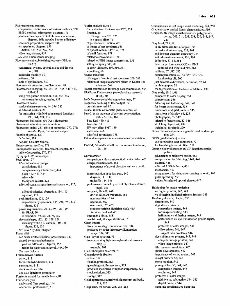
Fluorescence microscopycomparative performance of various methods, 368EMBL confocal microscope, diagram, 145photon efficiency, effect of chromatic aberration,
diagram, 563; see also Photon efficiencyspecimen preparation, chapter, 311test specimen, diagram, 559
diatom, 471, 560, 562, 564video rate, chapter, 459Seealso Fluorescence imaging
Fluorescence photobleaching recovery (FPR orFRAP)
commercial system, optical layout and descrip-tion, 581
molecular mobility, 50patterned , 50table of applications, 332
Fluorescence saturation: see Saturation , 40Fluorescence uncaging, 85, 344,431 ,435, 440, 443,
453-457using two-photon excitation, 451, 453-457
ion-current imaging, results , 457Fluorescent beads
confocal measurements, 44, 376, 383as fiducial markers, 20 Ifor measuring widefield point spread functions,
198,364,374,375Fluorescent indicators : see Dyes, fluorescentFluorescent saturation: see SaturationFluorescent stains , 267, table of properties, 270, 271;
see also Dyes, fluorescent, chapterFluorite objective, 120
definition, 119See alsoCalcium fluorite
Fluorochrome: see Dye, 378Fluorophores: see Dyes, fluorescent, chapter, 267
table of properties, 270, 271Flying spot UV microscope, 6Focal spot, 127
4Pi confocal microscopycalculations, 418 ·complementary interference, 424plots, 422, 423, 424table, 424theory and results, 423
effect of coma, astigmatism and aberration, 117,118
effect of spherical aberration, 114, 115equation, 171
peak irradiance , 128, 129degradation by specimen, 135, 294, 390, 435
figure, 136power requirements, 20, 40, 69,128,129
forFRAP,50at saturation, 49, 69, 70, 74, 357
size and shape , 112, 113, 128, 129checking with CCD camera , 130, 135
figure, 131, 136See also Airy disk, chapter
Focus shiftcan cause artifacts in time-lapse studies, 341caused by mismatched media
plot for different RI, figures, 352tables for water and glycerol , 349, 350
See also DefocusFormaldehyde fixation
action , 313for in situ hybridization, 313penetration, 313stock solutions , 314See also Specimen preparation
Forsterite crystal for tunable lasers, 81Fourier analysis
analysis of filter coatings, 144of confocal performance, 33
Fourier analysis (cont.)for evaluation of microscope CTF, 555filtering, 60
of image data, 201, 525in a spatial filter, 76
of galvanometer motion, 461of image of test specimen, 558of optical system, 349, 352, 374of pupil function, 178related to convolutions, 374related to JPEG image compression, 535setting sampling rate, 58to show vibration , 307, 560, 561smoothing, 60
Fourier transformof images of confocal test specimen, 560, 561relation of image to aperture planes in Kohler illu
mination, 569Fractal compression for image data compress ion, 536FRAP: see Fluorescence photobleaching recovery
(FPR),50FreD frequency-doubled argon-ion laser, 77Frequency doubling of laser output , 77
crystals involved , 80Fresnel rhomb, achromatic phase retarder, 72Fura-Z, as an indicator of calcium concentration,
276,277,339,460Fura Red, 440, 416lasers for, 78UV may affect PMT, 189video rate, 466widefield advantages , 378
Future developments in microscope instrumentation,153
FWHM, full width at half maximum: see Resolution,128,129
Galvanometercomparison with acousto-optical device, table, 462design considerations, 151
importance of size of objective entrance pupil ,151
mirror position in optical path, 140diagram, 141, 142tradeoffs, 144, 146
performance limited by size of objective entrancepupil,151
resonant , 10, 461, 462drift in resonant frequency, 462nonlinearities of, 46operation, 462overshoot, 152, 463requires variable digitizing clock, 465for video confocal , 461
specimen z-drive, 588wobble and jitter specifications, 151
Ghost imagesfrom the substage illuminator, 302, 304produced by 60 hz laboratory illumination
image, 304, 305Glari-Taylor polarizer, 73
to remove stray light in single-sided disk-scanning, 301
example, 303Glan-Thompson polarizer, 73Glutaraldehyde fixation
action, 312fixation protocol, 313quenching autofluorescence, 313produces specimens with poor antigenicity, 320stock solutions, 313storage, 312
Golgi apparatus, stained with fluorescent antibody,318,322
Golgi stain, for nerves , 255, 283-285
Index 611
Gradient cues , in 3D image voxel rendering, 249, 250Gradient-index optical fibers , characteristics, 516Graphic s, 3D image visualization: see polygon ren-
dering, 203, 214, 233, 238, 239, 244, 247,249
Gray level, 225, 541in 3D simulated test of object, 394in confocal microscopy, 357, 364and detector quantum efficiency, 364and information content, 361, 364definition, 57, 58, 364detector performance, CCD vs. PMT
confocal and widefield plot , 364halftone, 57, 542, 543human perception, 62, 64, 357, 363, 364
for showing pH, 500just detectable difference , definition, 62-64in photography, 58for segmentation on the basis of lifetime, 499
Gray scale, 10, II, 66compared to color display, 551compression, 536dithering and halftoning, 542, 543for image data storage, 535limitations of digital printers, 545limitations of display, 64, 225photographic, 55, 542related to feature size, 32, 566stretching, figure, 64, 489weighting , for depth, 229
Green fluorescent protein, a genetic marker, description, 274
GRIN (graded index) lensesuse in reducing laser coherence, 72for launching laser into fiber, 518
Group velocity dispersion (GVD) lengthens opticalpulses
advantages of reflective optics , 463compensation by "chirping," 447, 448diagram, 448effect of AOD deflector, 461mechanism, 447using mirrors for video-rate scanning to avoid, 463pulse spreading , 553values for selected optical glasses , 447
Halfton ing for image renderingon digital printers , 542, 543vs. dithering , in digital printers, images , 543
Hardcopy devices, chapter, 535description, 540digital laser printers
comparison images, 546for image recording, 543halftoning vs. dithering images, 543performance vs. dye-sublimation printer, figure,
545problems of color images, 544video printer, 546, 547
aspect ratio problems, 546dye-sublimation printers, 545, 546
computer image printers, 547video image printers , 547
film recorder, resolution, 542future developments, 547importance of testing system, 547ink-jet printers, 58, 545photo monitor, 542photographic, 55, 541, 542
comparison images, 546resolution , 543
problems of color imagesadditive vs. subtractive, 544, 545digital printers , 544
sampling problems : see Sampling
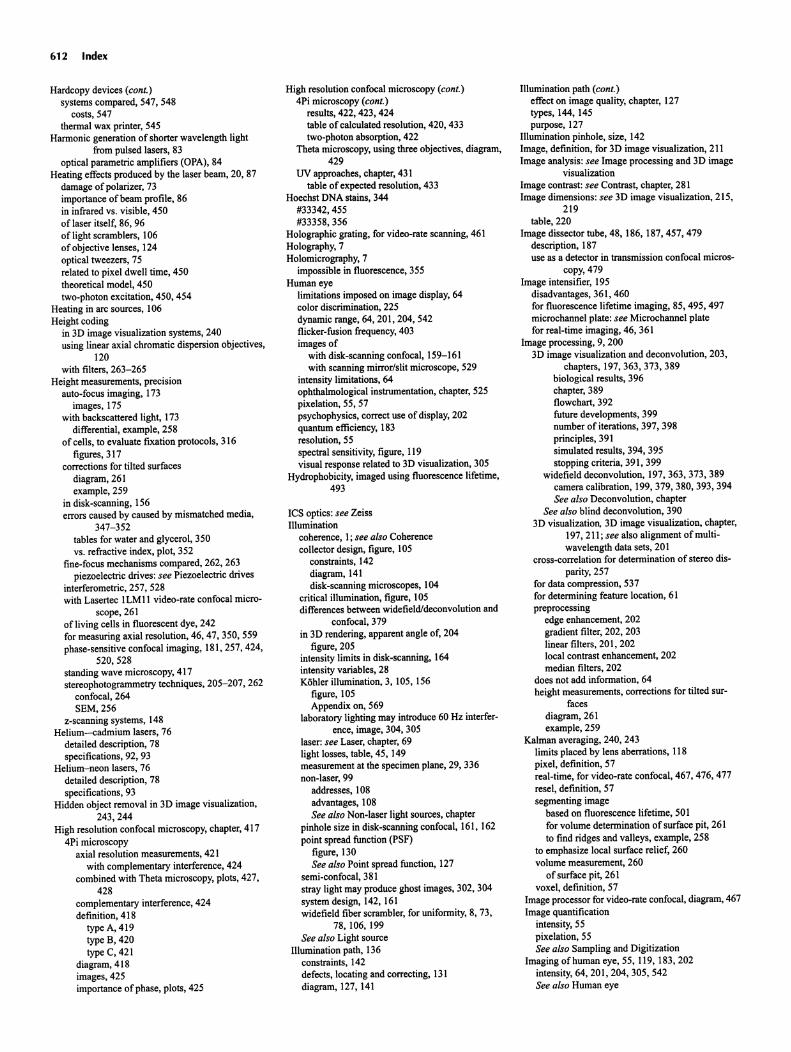
612 Index
Hardcopy devices (cont.)systems compared, 547, 548
costs , 547thermal wax printer, 545
Harmonic generat ion of shorter wavelength lightfrom pulsed lasers, 83
optical parametric amplifiers (OPA), 84Heating effects produced by the laser beam, 20, 87
damage of polarizer, 73importance ofbeam profile, 86in infrared vs. visible, 450oflaser itself, 86, 96of light scramblers, 106of objective lenses , 124optical tweezers , 75related to pixel dwell time , 450theoretical model , 450two-photon excitation, 450, 454
Heating in arc sources , 106Height coding
in 3D image visualization systems, 240using linear axial chromatic dispersion object ives,
120with filters, 263-265
Height measurements, precis ionauto-focus imaging , 173
images , 175with backscattered light, 173
differential, example, 258of cells , to evaluate fixation protocols , 316
figures , 317corrections for tilted surfaces
diagram , 261example , 259
in disk-scanning, 156errors caused by caused by mismatched media ,
347-352tables for water and glycerol, 350vs. refractive index, plot, 352
fine-focus mechanisms compared, 262, 263piezoelectric drives : see Piezoelectric drives
interferometric, 257,528with Lasertec ILM II video-rate confocal micro-
scope, 261ofliving cells in fluorescent dye, 242for measuring axial resolution, 46, 47, 350, 559phase-sensitive confocal imaging, 181, 257, 424,
520,528standing wave microscopy, 417stereophotogrammetry techniques , 205-207, 262
confocal, 264SEM,256
z-scann ing systems , 148Helium-cadmium lasers , 76
detailed description, 78specifications, 92, 93
Helium-neon lasers , 76detailed descript ion, 78specifications, 93
Hidden object removal in 3D image visualization,243,244
High resolution confocal microscopy, chapter, 4174Pi microscopy
axial resolution measurements, 421with complementary interference, 424
combined with Theta microscopy, plots , 427,428
complementary interference, 424definition, 418
type A, 419type B,420type C, 421
diagram, 418images , 425importance of phase , plots , 425
High resolution confocal microscopy (cont.)4Pi microscopy (cont.)
results, 422, 423, 424table ofcalculated resolution, 420, 433two-photon absorption, 422
Theta microscopy, using three objectives, diagram,429
UV approaches, chapter, 431table of expected resolution, 433
Hoechst DNA stains, 344#33342, 455#33358 ,356
Holographic grating, for video-rate scanning, 461Holography, 7Holomicrography, 7
impossible in fluorescence , 355Human eye
limitations imposed on image display, 64color discrimination, 225dynamic range, 64, 201, 204, 542flicker-fusion frequency, 403images of
with disk-scanning confocal , 159-161with scanning mirror/slit microscope, 529
intensity limitations , 64ophthalmological instrumentation, chapter, 525pixelation, 55, 57psychophysics, correct use of display, 202quantum efficiency, 183resolution, 55spectral sensitivity, figure, 119visual response related to 3D visualizat ion, 305
Hydrophob icity, imaged using fluorescence lifetime,493
ICS optics: see ZeissIllumination
coherence, I; see alsoCoherencecollector design, figure, 105
constraints, 142diagram, 141disk-scanning microscopes, 104
critical illumination, figure, 105differences between widefield/deconvolution and
confocal , 379in 3D rendering, apparent angle of, 204
figure , 205intensity limits in disk-scanning, 164intensity variables, 28Kohler illuminat ion, 3, 105, 156
figure, 105Appendix on, 569
laboratory lighting may introduce 60 Hz interfer-ence, image, 304, 305
laser: see Laser, chapter, 69light losses, table, 45, 149measurement at the specimen plane, 29, 336non-laser, 99
addresses , 108advantages, 108See alsoNon-laser light sources, chapter
pinhole size in disk-scanning confocal, 161, 162point spread function (PSF)
figure, 130See also Point spread function, 127
semi-confocal, 381stray light may produce ghost images, 302, 304system design, 142, 161widefield fiber scrambler, for uniformity, 8, 73,
78,106,199See also Light source
Illuminat ion path, 136constraints, 142defects, locating and correcting, 131diagram, 127, 141
Illumination path (cont.)effect on image quality, chapter, 127types, 144, 145purpose, 127
Illumination pinhole, size, 142Image, definition, for 3D image visualization, 211Image analysis : see Image processing and 3D image
visualizationImage contrast: see Contrast, chapt er, 28 IImage dimensions : see 3D image visualization, 215,
219table , 220
Image dissector tube , 48,186,187,457,479description, 187use as a detector in transmission confocal micros
copy, 479Image intensifier, 195
disadvantages, 361, 460for fluorescence lifetime imaging, 85,495, 497microchannel plate : see Microchannel platefor real-time imaging, 46, 361
Image process ing, 9, 2003D image visualization and deconvolution, 203,
chapters , 197,363,373,389biolog ical results , 396chapter, 389flowchart , 392future developments, 399number of iterations, 397, 398principles, 391simulated results , 394, 395stopping criteria, 391, 399
widefield deconvolution, 197, 363, 373, 389camera calibration, 199,379,380,393,394See also Deconvolution, chapter
See also blind deconvolution, 3903D visualization, 3D image visualization, chapter,
197, 211; see also alignment of multiwavelength data sets, 20 I
cross-correlation for determination of stereo dis-parity, 257
for data compression, 537for determ ining feature location , 61preprocessing
edge enhancement, 202gradient filter, 202, 203linear filters , 20 I , 202local contrast enhancement, 202median filters, 202
does not add information, 64height measurements, corrections for tilted sur
facesdiagram, 261example, 259
Kalman averaging, 240, 243limits placed by lens aberrations, 118pixel, definit ion, 57real-time, for video-rate confocal, 467, 476, 477resel , defin ition, 57segmenting image
based on fluorescence lifetime, 50 Ifor volume determination of surface pit, 261to find ridges and valleys , example, 258
to emphasize local surface relief, 260volume measurement, 260
of surface pit, 261voxel, definition, 57
Image processor for video-rate confocal , diagram , 467Image quantification
intensity, 55pixelat ion, 55See also Sampling and Digitizat ion
Imaging of human eye, 55, 119, 183,202intensity, 64, 201, 204, 305, 542See also Human eye
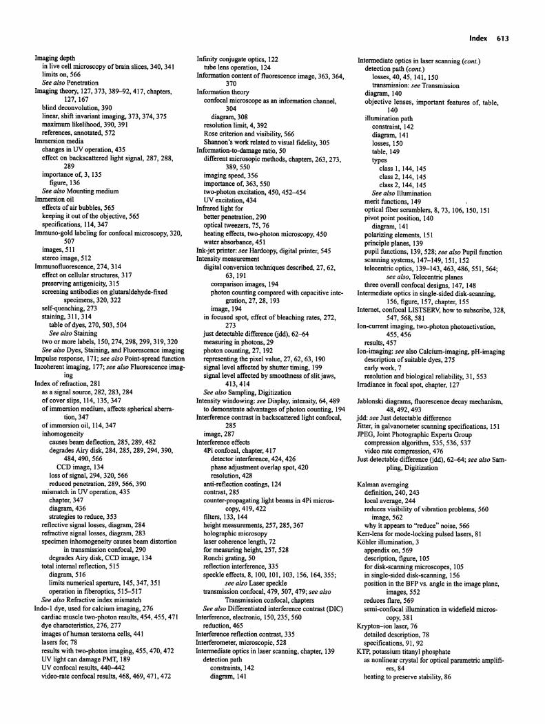
Imaging depthin live cell microscopy of brain slices, 340, 341limits on, 566See also Penetration
Imaging theory, 127,373,389-92,417, chapters ,127, 167
blind deconvolution, 390linear, shift invariant imaging , 373, 374, 375maximum likelihood, 390, 391references , annotated, 572
Immersion mediachanges in UV operation, 435effect on backscattered light signal , 287, 288,
289importance of, 3, 135
figure, 136See alsoMounting medium
Immersion oileffects of air bubbles, 565keeping it out of the objective, 565specifications, 114,347
Immuno-gold labeling for confocal microscopy, 320,507
images, 511stereo image, 512
Immunofluorescence, 274, 314effect on cellular structures, 317preserv ing antigenicity, 315screening antibodies on glutaraldehyde-fixed
specimens, 320, 322self-quenching, 273staining , 311, 314
table of dyes, 270, 503, 504See alsoStaining
two or more labels, 150,274,298,299,319,320See alsoDyes, Staining, and Fluorescence imaging
Impulse response , 171; see also Point-spread functionIncoherent imaging, 177; see alsoFluorescence imag
ingIndex of refraction , 281
as a signal source, 282, 283, 284of cover slips, 114, 135,347of immersion medium , affects spherical aberra
tion, 347of immersion oil, 114,347inhomogeneity
causes beam deflection, 285, 289, 482degrades Airy disk, 284, 285, 289, 294, 390,
484,490,566CCD image, 134
loss of signal, 294, 320, 566reduced penetration, 289, 566, 390
mismatch in UV operation, 435chapter, 347diagram , 436strategies to reduce, 353
reflective signal losses, diagram , 284refractive signal losses , diagram , 283specimen inhomogeneity causes beam distortion
in transmission confocal , 290degrades Airy disk, CCD image, 134
total internal reflection , SISdiagram, 516limits numerical aperture , 145,347,351operation in fiberoptics , 515-517
See also Refractive index mismatchIndo-I dye, used for calcium imaging, 276
cardiac muscle two-photon results, 454, 455, 471dye characteristics, 276, 277images of human teratoma cells , 441lasers for, 78results with two-photon imaging, 455, 470, 472UV light can damage PMT, 189UV confocal results , 440-442video-rate confocal results, 468, 469, 471, 472
Infinity conjugate optics, 122tube lens operation , 124
Information content of fluorescence image, 363, 364,370
Information theoryconfocal microscope as an information channel ,
304diagram, 308
resolution limit, 4, 392Rose criterion and visibility, 566Shannon 's work related to visual fidelity, 305
Information-to-damage ratio, 50different microsop ic methods, chapters, 263, 273,
389,550imaging speed, 356importance of, 363, 550two-photon excitation, 450, 452-454UV excitation, 434
Infrared light forbetter penetration, 290optical tweezers, 75, 76heating effects, two-photon microscopy, 450water absorbance , 451
Ink-jet printer: see Hardcopy, digital printer, 545Intensity measurement
digital convers ion techniques described , 27, 62,63,191
comparison images, 194photon counting compared with capacitive inte
gration, 27, 28, 193image , 194
in focused spot, effect of bleach ing rates, 272,273
just detectable difference (jdd), 62--Mmeasuring in photons, 29photon counting, 27,192representing the pixel value, 27, 62, 63,190signal level affected by shutter timing, 199signal level affected by smoothness of slit jaws,
413,414See also Sampling , Digitization
Intensity windowing: see Display, intensity, 64, 489to demonstrate advantages ofphoton counting, 194
Interference contrast in backscattered light confocal ,285
image, 287Interference effects
4Pi confocal, chapter, 4 I7detector interference, 424, 426phase adjustment overlap spot, 420resolution , 428
anti-reflection coatings, 124contrast, 285counter-propagating light beams in 4Pi micros-
copy, 419, 422filters, 133, 144height measurements, 257,285,367holographic microsopylaser coherence length, 72for measuring height, 257, 528Ronchi grating, 50reflect ion interference, 335speckle effects, 8,100,101 ,103,156,164,355;
see also Laser speckletransmission confocal , 479, 507,479; see also
Transmission confocal , chaptersSee also Differentiated interference contrast (DiC)
Interference, electronic, 150,235,560reduction , 465
Interference reflection contrast, 335Interferometer, microscopic , 528Intermed iate optics in laser scanning, chapter, 139
detection pathconstraints, 142diagram, 141
Index 613
Intermediate optics in laser scanning (cant.)detection path (cant.)
losses , 40, 45, 141, ISOtransmission: see Transmission
diagram, 140objective lenses, important features of, table,
140illumination path
constraint, 142diagram , 141losses, ISOtable, 149types
class I, 144, 145class 2, 144, 145class 2, 144, 145
See also Illuminationmerit functions , 149optical fiber scramblers, 8, 73,106, ISO, lSIpivot point position, 140
diagram, 141polarizing elements, lSIprinciple planes , 139pupil functions , 139, 528; see also Pupil functionscanning systems , 147-149, lSI , 152telecentric optics, 139-143,463,486,551 ,564;
see also, Telecentric planesthree overall confocal designs, 147, 148
Intermed iate optics in single-sided disk-scann ing,156, figure , 157, chapter, ISS
Internet , confocal LlSTSERV, how to subscribe, 328,547,568,581
Ion-current imaging, two-photon photoactivation,455,456
results , 457lon-imaging: see also Calcium-imaging , pH-imaging
description of suitable dyes, 275early work, 7resolution and biological reliability, 31, 553
Irradiance in focal spot, chapter, 127
Jablonski diagrams , fluorescence decay mechanism,48,492,493
jdd: see Just detectable differenceJitter, in galvanometer scanning specifications, lSIJPEG, Joint Photographic Experts Group
compression algorithm, 535, 536, 537video rate compression, 476
Just detectable difference (jdd), 62--M; see also Sampling, Digitization
Kalman averagingdefinit ion, 240, 243local average, 244reduces visibility of vibration problems, 560
image, 562why it appears to "reduce" noise , 566
Kerr-lens for mode-locking pulsed lasers, 81Kohler illumination , 3
appendix on, 569description, figure, 105for disk-scanning microscopes, 105in single-sided disk-scanning, 156position in the BFP vs. angle in the image plane,
images, 552reduces flare, 569semi-confocal illumination in widefield micros
copy, 381Krypton-ion laser, 76
detailed description, 78specifications, 91, 92
KTP, potass ium titanyl phosphateas nonlinear crystal for optical parametric amplifi
ers,84heating to preserve stability, 86
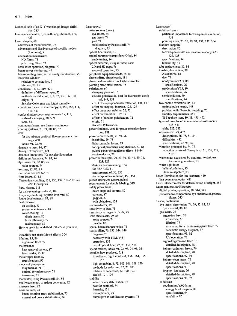
614 Index
Lamb xel , unit of an X-Y-wavelength image, defin ition, 285
Lanthan ide chel ates, dyes with long lifetim es, 277,423
Laser, chapter, 69addresses of manufacturers, 97adva ntage s and disadvantage of speci fic models
(footnotes), 9 1attenuation mechanisms
NO filters, 73polarizing filters, 73
basic laser operat ion , diagr am, 70beam power monitoring, 49beam-p ointin g error, ac tive cav ity stabilizatio n, 75Brewster window
relat ion to polarization, 71lifetime, 77, 85
coherence, 72, 73,41 9-421definition of different types, 72methods for reduction, 7, 8, 72, 73, 106, 108origin, 71See also Coherence and Light scrambler
conditions for use in microscopy, 7, 156, 355 ,411 ,419,421
confocal microscopy, requirem ents for, 4 11,real-color imaging, 78, 509table, 88
continuous lasers: see Laser s, continuouscooling systems , 73, 79, 80, 86, 87cost
for two-ph oton confocal fluorescen ce microscopy, 450
tables, 91, 92, 96damage to laser, 86, 87damage of obj ective, 124data rate limitat ions, 70 ; see also Saturationdrift in perform ance, 74 , 92 , 94dye laser s, 79, 82, 83, 95
noise sources, 74excimer, 82, 83, 95exci tation sources for, 70fibe r lasers, 83, 84fiberoptical cou pling, 131, 136, 137,51 7-5 19; see
also Fiberopticsflare, plasma , 5 18for disk-scanning confocal, 108frequ ency doubl ing, crystals involved, 80future developments, 87, 88heat removal
air cooli ng, 73system maintenance, 87water cool ing , 73
diode lasers , 80laser effi ciency, 77maintenance, 86
How to use it for widefield if that's all you have,108
instabil ity can cause Mo ire effects, 304lifet ime, 85, 86
argo n-ion laser, 77maintenance
heat removal syst em, 87laser med ia, 85, 86
metal vapor laser, 82speci fications, 95
modes of prop agat ionlongitudinal, 71optimal for microscop y, 71transvers e, 7 1
modu lator, using Pocke ls ce ll, 84, 86mult iwavelength, to reduce co herence, 72nitrogen laser, 82noise sources, 74
beam-pointing error, stabilization, 75current and power stabilizat ion, 74
Laser (conI.)noise sources (conI.)
dye lasers, 74gas lasers, 74plot, 74stabilization by Pockels cell , 74
diagram, 75optical fiber lasers , 83optical parametric ampl ifiers (OPA), 84
angle tuning, 84optical tweezers, using infrared lasers
20 and 30 traps , 76mode of operation, 75
peripheral equipment needs, 85, 86phase shift er, piezoelectric, 181phase randomizat ion : see Light scramble rpoint ing error, stabilization, 75polarization of
changing plane of, 131circular polarization, best for fluorescent confo-
cal, 144, 151effect of nonperpendicular reflect ion , 131, 133effect on imagi ng, footnote, 128, 129effect on output stab ility, 72, 73effec t on resolution, 169, 171effects of rand om polarizat ion, 72origi n, 7 1See also Polarization
power feedback, used for phase-sensitive detec tion , 181
power requirements, 71, 91-96instability, 29, 73light scrambler losses, 73for optical parametric amp lificat ion, 83-84pu lsed power for non linear effects , 81-84semiconductor, 79
power in focal spot, 20, 29, 30, 40 , 49 , 69-71,128,129
disk- vs. laser-scanning, 164for FRAP, 50, 51measurement of, 30, 336for two-photon excitat ion, 450-454
pulsed lasers: see Lasers , pulsedrequ irements for double labelin g, 319sa fety precaut ions
beam stops and screens, 87curtains, 87goggles, 87with objectives, 124
semico nductor, 79sensitivity to dust , 73sensitivity to magnetic fields, 73solid state lasers , 79-83
noise sources, 74tunable, 80
spatial beam characteri stics, 76spatial filter, 76, 132, 144, 146
diagram, 76necessity with IEM, 146operation, 132use of optical fiber, 72, 73,1 50,51 8
specifications, tables , 91, 92, 93, 94, 95, 96speckle, how produced, 7, 8
in reflected light confocal , 156, 164 ,355,367
light scrambler, 8, 73, 103, 106, 108, 150methods for reduction, 72, 73, 103relation to coherence, 72, 100, 103size of, 10 1, 104
stabilityact ive cavity stab ilizat ion, 75best for confocal, 74intensity, 131microphonics, 73output pow er stabi lization systems, 75
Laser (conI.)stability (cont.)
part icular import ance for two-ph oton exci tation,451
pointi ng error, 73, 75, 79, 9 1,13 1, 132, 304tita nium-sapphi re
descript ion, 80for two-ph oton 4Pi confoc al microscopy, 423,
427,428specifications, 94tunab ilil ity, 83
tube replac ement, 85, 86tunable, descript ion, 79
Ale xandrite, 8 1dye, 79neodym iumNAG, 80
speci fications, 96neodymium/Yl.F, 80
specifications, 96sem iconductor, 79
spec ifications, 94two-photon excitation, 85, 451
optima l pulse length , 448problem with fiberoptic coupl ing, 75stability requirements , 45 1Ti-Sapphire laser, 80, 8 1, 451, 472
type s of laser found in commercial instruments,438-441
table , 582, 583ultraviolet (UV) , 432
descripti ons , 76-78, 81-84difficult ies, 432speci ficatio ns, 92, 93, 96
vibration produced by, 74, 77reduct ion by use of fiberoptics , 131, 136, 518 ,
519wavelength expansion by non line ar techniques ,
harmonic generation, 83white light laser
hel ium/c admium, 83titanium-sapphire, 83
Laser illum inat ion for line scanners , 410line generation optics, 4 11
Laser interferometer for determination of he ight , 257Laser print ers: see Hardcopy
digital printer , ope ration, 58, 544 , 545performance compared to dye-sublimation printer,
figure, 545Lasers, continuous
dye lasers, description, 74, 79, 82, 83, 95dye material, 80, 86
gas lasers, 76argon-ion laser , 76
effic iency, 77lifetime, 77as a pump for a titan ium-sapphire laser, 77schematic energy diagram, 77spec ifications, 91 , 92UV operation, 77
argo n-krypton-ion laser , 76deta iled des crip tion, 78
hel ium-cadm ium lasers, 76deta iled des cription, 78specifications, 92, 93
helium-neon lasers, 76detailed description, 78speci fications, 93
krypton-ion laser, 76deta iled description , 78specific ations, 9 1, 92
solid sta teneodymiumNAG lase r
energy level diagram, 81specifications, 94tunab ility, 80
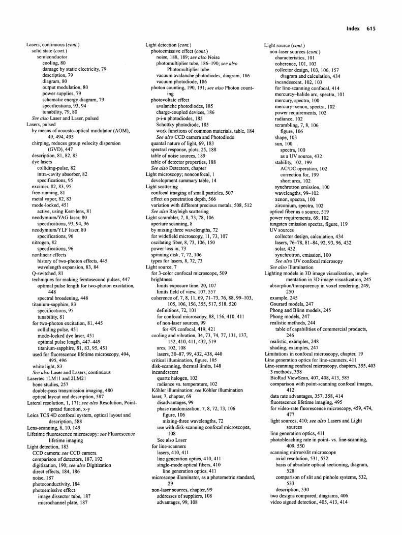
Lasers, continuous (conI.)solid state (conI.)
semiconductorcooling, 80damage by static electric ity, 79description, 79diagram, 80output modulat ion, 80power supplies, 79schematic energy diagram , 79specifications, 93, 94tunability, 79, 80
See also Laser and Laser, pulsedLasers, pulsed
by means of acousto-optical modulator (AOM),49,494,495
chirping , reduces group velocity dispersion(GVD), 447
description, 81, 82, 83dye lasers
colliding-pulse, 82intra-cavity absorber, 82specifications, 95
excimer, 82, 83, 95free-running, 81metal vapor, 82, 83mode-locked, 451
active , using Kerr-lens , 81neodym iumlYAG laser, 80
specifi cations , 93, 94, 96neodymiumlYLF laser, 80
specifications, 96nitrogen , 82
specificat ions, 96nonlinear effect s
history of two-photon effec ts, 445wavelength expansion, 83, 84
Q-switched, 81techniques for making femtose cond pulses, 447
optimal pulse length for two-photon excitation,448
spectral broadening, 448titanium- sapphi re, 83
specifications, 95tunability, 81
for two-photon excitation, 81, 445colliding pulse , 451mode-locked dye laser, 451optim al pulse length, 447--449titanium-sapphire, 81, 83, 95, 451
used for fluorescence lifetime microscopy, 494,495,496
white light, 83See also Laser and Lasers, continuous
Lasertec 1LM II and 2LM21bone studies, 257double-pass transmission imaging, 480optical layout and description, 587
Lateral resoluti on, I, 171; see also Resolution, Pointspread function, x-y
Leica TCS 4D confocal system, optical layout anddescription, 588
Lens-scanning, 8, 10, 149Lifetime fluorescence microscopy: see Fluorescence
lifetime imagingLight detect ion, 183
CCD camera : see CCD cameracompari son of detectors , 187, 192digitization, 190; see also Digitizationdirect effects , 184, 186noise , 187photoconductivity, 184photoemissive effect
image dissector tube, 187microchannel plate, 187
Light detect ion (conI.)photoemissive effect (conI.)
noise, 188, 189; see also Noisephotomultipl ier tube, 186--190; see also
Photomultiplier tubevacuum avalanch e photodiodes, diagram, 186vacuum photodiode, 186
photon counting, 190, 191; see also Photon counting
photovoltaic effectavalanche photodi odes, 185charge-coupled devices , 186p-i-n photodiodes, 185Schottky photodiode, 185work function s of common materials , table, 184See also CCD camera and Photodiode
quantal nature of light, 69, 183spectral response , plots, 25, 188table of noise sources , 189table of detector properties, 188See also Detectors , chapter
Light microscopy; nonconfo cal, Idevelopment summary table, 14
Light scatteringconfocal imaging ofsmall particles, 507effect on penetration depth , 566variation with different precious metals, 508, 512See also Rayleigh scattering
Light scrambler, 7, 8, 73, 78,106aperture scanning, 8by mixing three wavelength s, 72for widefield microscopy, II, 73, 107oscilating fiber, 8, 73, 106, 150power loss in, 73spinning disk, 7, 72, 106types for lasers, 8, 72, 73
Light source , 7for 3-color confocal microscope, 509brightness
limits exposure time, 20, 107limits field of view, 107,557
coherence of, 7, 8, 11,69,71-73,76,88,99-103,105,106,156,355,517,518,520
definitions, 72, 101for confocal microscopy, 88, 156, 410, 411of non-laser sources , 99
for 4Pi confocal, 419, 421cooling and vibration, 34, 73, 74, 77,131 ,137,
152,410,411,432,519arcs, 102, 108lasers, 30-87, 99, 432, 438, 440
critical illumination, figure, 105disk-scanning, therrnallimits, 148incandescent
quartz halogen , 102radiance vs. temperature, 102
Kohler illumination: see Kohler illuminat ionlaser, 7, chapter, 69
disadvantages, 99phase random ization, 7, 8, 72, 73, 106
figure , 106mixing-three wavelengths, 72
use with disk-scanning confocal microscopes ,108
See also Laserfor line-scanners
lasers, 410, 411line generation optics, 410, 411single-mode optical fibers, 410
line generation optics, 411microscope illuminator, as a photometric standard,
29non-laser sources, chapter, 99
addresses of suppliers, 108advantages, 99, 108
Index 615
Light source (conI.)non-laser sources (conI.)
characteristics, 101coherence, 10I, 103collector design, J03, 106, 157
diagram and ca lculation, 434incandescent, 102, 103for line-scannin g confocal, 414mercurc y-halide arc, spectra, 101mercu ry, spectra, 100mercury-xenon, spectra, 102power requirements, 102radian ce, 102scrambling, 7, 8, 106
figure, 106shape, 103sun, 100
spectra, 100as a UV source, 432
stability , 102, 199AC/DC operation, 102correction for, 199short arcs, 102
synchrotron emission, 100wavelengths, 99-102xenon, spectra, 100zirconium, spectra, 102
optical fiber as a source, 519power requirements, 69, 102tungsten emiss ion spectra , figure , 119UV sources
collector design, calculation, 434lasers , 76--78, 81- 84, 92, 93, 96, 432solar, 432synchrotron, emission, 100See also UV confocal micro sopy
See also IlluminationLighting model s in 3D image visualization, imple
mentation in 3D image visual ization , 245absorpt ion/transparency in voxel rendering, 249,
250example , 245Gourard mode ls, 247Phong and Blinn models , 245Phong models, 247realistic methods, 244
table of capabilities of commercial products,246
realistic , examples, 248shading , examples, 247
Limitations in confocal microscopy, chapter, 19Line generation optics for line-scanners, 411Line-scanning confocal microscopy, chapters , 355, 403
3 methods, 358BioRad ViewScan, 407, 408 , 413, 585compa rison with point-scanning confocal images,
412data rate advantages, 357, 358, 414fluorescence lifetime imaging, 495for video-rate fluorescence microscopy, 459, 474,
477light sources , 410 ; see also Lasers and Light
sourcesline generation optics, 411photobleaching rate in point- vs. line-scanning,
409 ,550scanning mirror/slit microscope
axia l resolut ion, 531, 532basis of absolute optical sectioning, diagram,
528comparison of slit and pinhole systems , 532,
533description, 530
two designs compared, diagrams, 406video signed detection, 405, 413 , 414
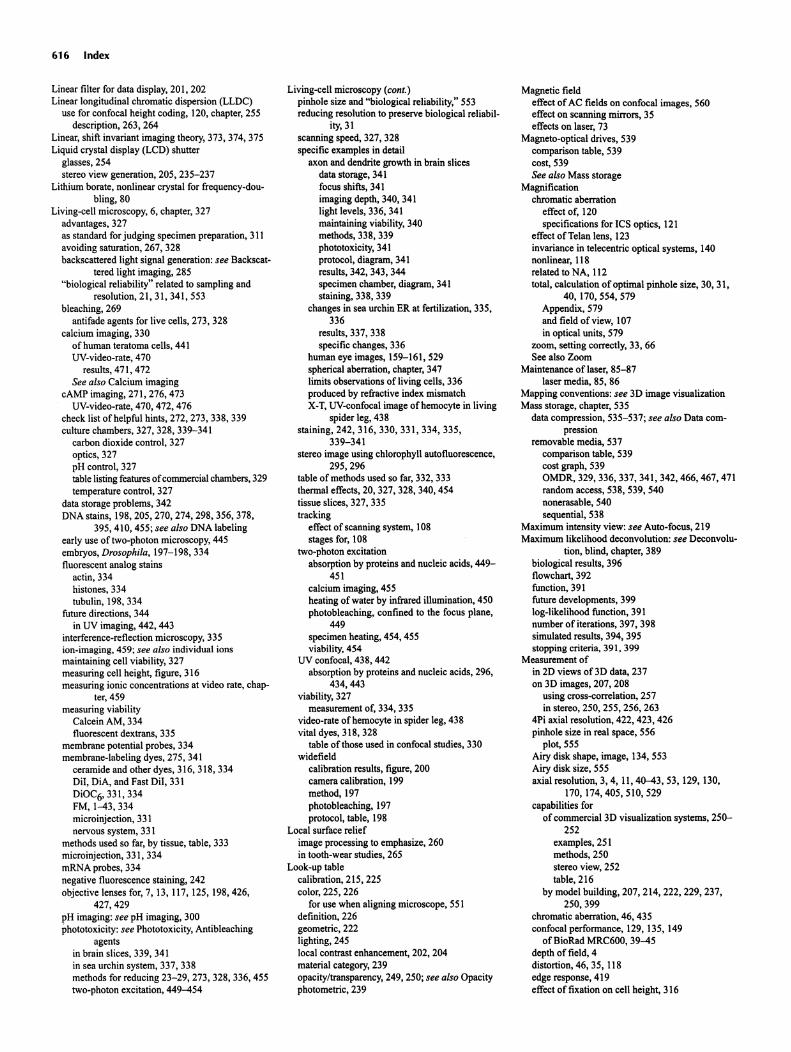
616 Index
Linear filter for data display, 20 I, 202Linear longitudinal chromatic dispersion (LLDC)
use for confocal height coding, 120, chapter, 255description, 263, 264
Linear, shift invariant imaging theory, 373, 374, 375Liquid crystal display (LCD) shutter
glasses, 254stereo view generat ion, 205, 235-237
Lithium borate, nonlinear crystal for frequency-donbling,80
Living-cell microscopy, 6, chapter, 327advantages, 327as standard for judging specimen preparation , 311avoiding saturation, 267, 328backscattered light signal generation : see Backseat
tered light imaging, 285"biological reliability" related to sampling and
resolution, 21, 31, 341, 553bleaching , 269
antifade agents for live cells, 273, 328calcium imaging, 330
of human teratoma cells, 441UV-video-rate, 470
results, 471, 472See alsoCalcium imaging
cAMP imaging, 271, 276, 473UV-video-rate, 470, 472,476
check list of helpful hints, 272, 273, 338, 339culture chambers, 327, 328, 339-341
carbon dioxide control , 327optics, 327pH control, 327table listing features of commercial chambers, 329temperature control , 327
data storage problems, 342DNA stains, 198,205,270,274,298,356,378,
395, 410, 455; see also DNA labelingearly use of two-photon microscopy, 445embryos, Drosophila, 197-198,334fluorescent analog stains
actin, 334histones, 334tubulin, 198, 334
future directions, 344in UV imaging, 442, 443
interference-reflection microscopy, 335ion-imaging, 459; see also individual ionsmaintaining cell viability, 327measuring cell height, figure, 316measuring ionic concentrations at video rate, chap
ter, 459measuring viability
Calcein AM, 334fluorescent dextrans, 335
membrane potential probes, 334membrane-labeling dyes, 275, 341
ceramide and other dyes , 316, 318, 334Dil, DiA, and Fast Dil , 331DiOC6, 331, 334FM, 1--43,334microinjection, 331nervous system, 331
methods used so far, by tissue, table, 333microinjection , 331, 334mRNA probes, 334negative fluorescence staining, 242objective lenses for, 7,13,117,125,198,426,
427,429pH imaging: see pH imaging, 300phototoxicity: see Phototoxicity, Antibleaching
agentsin brain slices, 339, 341in sea urchin system, 337, 338methods for reducing 23-29, 273, 328, 336, 455two-photon excitation, 449--454
Living-cell microscopy (cont.)pinhole size and "biological reliability," 553reducing resolution to preserve biological reliabil
ity,31scanning speed, 327, 328specific examples in detail
axon and dendrite growth in brain slicesdata storage, 341focus shifts, 341imaging depth, 340, 341light levels, 336, 341maintaining viability, 340methods, 338, 339phototoxicity, 341protocol, diagram, 341results, 342, 343, 344specimen chamber, diagram, 341staining, 338, 339
changes in sea urchin ER at fertilization, 335,336
results, 337, 338specific changes, 336
human eye images, 159-161,529spherical aberration, chapter, 347limits observations ofliving cells, 336produced by refractive index mismatchX-T, UV-confocal image of hemocyte in living
spider leg, 438staining, 242, 316, 330 , 331 , 334, 335,
339-341stereo image using chlorophyll autofluorescence,
295,296table of methods used so far, 332, 333thermal effects, 20,327,328,340,454tissue slices, 327, 335tracking
effect of scanning system, 108stages for, 108
two-photon excitationabsorption by proteins and nucleic acids, 449-
451calcium imaging, 455heating of water by infrared illumination, 450photobleaching, confined to the focus plane,
449specimen heating, 454, 455viability, 454
UV confocal, 438, 442absorption by proteins and nucleic acids, 296,
434,443viability, 327
measurement of, 334, 335video-rate of hemocyte in spider leg, 438vital dyes, 318, 328
table of those used in confocal studies, 330widefield
calibration results, figure, 200camera calibration, 199method, 197photobleaching, 197protocol, table, 198
Local surface reliefimage processing to emphasize, 260in tooth-wear studies, 265
Look-up tablecalibration, 215, 225color, 225, 226
for use when aligning microscope, 551definition, 226geometric, 222lighting, 245local contrast enhancement, 202, 204material category, 239opacity/transparency, 249, 250; see also Opacityphotometric, 239
Magnetic fieldeffect of AC fields on confocal images, 560effect on scanning mirrors, 35effects on laser, 73
Magneto-optical drives, 539comparison table, 539cost, 539See also Mass storage
Magnificationchromatic aberration
effect of, 120specifications for ICS optics, 121
effect of Telan lens, 123invariance in telecentric optical systems , 140nonlinear, 118related to NA, 112total, calculation of optimal pinhole size, 30, 31,
40, 170, 554, 579Appendix, 579and field of view, 107in optical units, 579
zoom, setting correctly, 33, 66See also Zoom
Maintenance of laser, 85-87laser media, 85, 86
Mapping conventions : see 3D image visualizationMass storage, chapter, 535
data compression, 535-537; see also Data compression
removable media, 537comparison table, 539cost graph, 539OMDR, 329, 336, 337, 341, 342, 466, 467, 471random access, 538, 539, 540nonerasable , 540sequential, 538
Maximum intensity view: see Auto-focus, 219Maximum likelihood deconvolution: see Deconvolu-
tion, blind, chapter, 389biological results, 396flowchart, 392function, 391future developments, 399log-likelihood function, 391number of iterations, 397, 398simulated results, 394, 395stopping criteria, 391, 399
Measurement ofin 2D views oOD data, 237on 3D images, 207, 208
using cross-correlation, 257in stereo, 250, 255, 256, 263
4Pi axial resolution, 422, 423, 426pinhole size in real space, 556
plot, 555Airy disk shape, image, 134, 553Airy disk size, 555axial resolution, 3, 4, 11,40--43, 53, 129, 130,
170, 174,405, 510, 529capabilities for
of commercial 3D visualization systems, 250-252
examples, 251methods, 250stereo view, 252table, 216
by model building, 207, 214, 222, 229, 237,250,399
chromatic aberration, 46, 435confocal performance, 129, 135, 149
ofBioRad MRC600, 39--45depth of field, 4distortion, 46, 35, 118edge response, 419effect of fixation on cell height, 316
Measurement of (cant.)fluorescence saturation, 40, 49
diagram, 49fluorescence lifetime, 85, 491, 494--499fluorescent beads, 44,198,364,374-376height, 157,255-259,587intensified, 84, 85, 195ionic milieu, 275-277, 334, 493, 455, 456 , 470-
475,500light source stability, 199laser power, at specimen, 30, 336merit functions, 149objective lens transmission, I, 12,22, 125, 129,
figure, 125, 129operator performance, 558optical transfer efficiency, 22, 23, 30, 44, 45, 107,
129pixel size, 557photometric stability requirements, 8, 102PMT output, diagram, 555position , 34-36, 60-62, 66resolution
axial, 129, 135, 149with diatom in oil, 560, 562, 564
lateral (xy) using a calibrated test specimen, 14,557-560
automatic, 558backscattered light images , 560, 561fluorescent images, 562Fourier transforms, 561diagram, 559images , 558, 560pixel size when imaging periodic objects , im
ages, 563undersampling, 563
saturat ion, 47-49speed of light, 461spherical aberration, 172stage drift, 35stray light, 556surface shape, chapter, 255
measuring height, 257 , 262measuring volume, 260, 528using chromatic aberrations, 256
Mechan ical tolerances, higher in UV opt ics, 436Median filter, for data display, 202Membrane potential measurement, 275
dyes , table of properties, 270, 503, 504imaging with fluorescence lifetime, 493
Membrane-labeling dyes, 275C6-NBD-ceramide, 316, 318, 334Oil , DiA, Fast Oil , 331DiOC6, 331, 334FM,I-43,334
Mercury arcbrightness, 100modulated,loospectra , 100
Mercury-halide arc, spectra, 101Mercury-xenon arc , spectra, 102Merid ian Instruments
address , 254bilateral scanning, 358, 359, 360
description, 359,405diagram , 360, 406multibeam imaging, 361optical layout and description, 589
Ultima Premium Laser confocal Microscope, 581features , 440
Mesh size (screen mesh)in images from digital printers, 543oflaser printers, 545
Metal coatingof the specimen surface for backscattered light im
aging , 260
Metal coating (cant.)use of several metals to code surface slope, 264test pattern etched into, 558, 559
Metal vapor lasersdescription, 82specifications, 95
Metallic reflectionas a source of signal, 168, 264, 285
image , 286from colloidal gold particles, 508, 509
Methyl-salicilate, as a specimen clearing agent, 288,290,293,299,301
image, 294optical properties, 288
Microchannel plate (MCP) photodetectoradded to CCD, 85, 195description, 187disadvantages, 195, 361for lifetime imaging, 84, 85
Microphonics, affect laser stability, 73Microscopes, nonconfocal
commercial instruments, Appendix, 581-599DIN standard specifications, 122darkfield, 4gated, for fluorescence lifetime microscopy, 494historical table, 2holographic, 7living-cell: see Living-cell microscopySee alsoConfocal microscopy
Microsurveyingbiological results , 258See also Height measurements
Mineral deposits in biological tissueimaging with backscattered light, 288image , 290
Miniature , scann ing-fiber confocal microscope, diagram, 521, 522
Minsky confocal microscope, 4, 5, 10, 149,255,403,525
arc illumination, 101Mirrors, 133,461
effect ofhumidity on, 45effect of nonperpendicular reflection on polariza
tion, 131, 133high reflectivity, 44optical effects of, 133
depolarization, 133reflectivity, 23
affected by humidity, 45scanning and descanning, 405
diagram, 406, 407total internal reflect ion mirrors, 441translating concave mirror scanning, 461transmission efficiency, 28, 44
Mitochondrial label, Rhodam ine 1-2-3,318,328,334,472
Mode-locking for pulsed lasers, 8I, 82Model building in 3D images , 207, 214, 222, 229,
237,250,399Models of microscopic imaging processes, 364Modulation frequency
ofdetector, in fluorescence lifetime microscopy, 494of laser, in fluorescence lifetime microscopy, 494
relation to fluorescence lifetime , 495, 496, 497Modulation transfer function
of individual steps in confocal microscopy, diagram, 308
See alsoContrast transfer function (CTF)Moire effects, 59
from AC interference, 304at display CRT, 226, 542, 546from laser pointing error, 304
Molar extinction coefficientof Fluorescein, 69See also Absorption, crossections
Index 617
Molecular Dynamics CLSM 20 I0 Confocal Micro-scope , 582
address, 254off-axis scanning, 147optical layout and description, 582
Molecular mobility, imagingwith fluorescence lifetime, 493with FRAP, 50, 51
Monitor, video , 64, 541characteristics, 540
needed for 3D image visualization, 225color, 64, 540, 541
for viewing anaglyph stereo images , 234, 235,237
monochrome, 541refresh rate, 226, 541
for stereo display, 235stereo display systems compared, 206, 207, 234,
235with LCD shutters, 237for viewing stereo images, 237
refresh rate, 235See also Display systems
Motion parallax for 3D data display, diagram, 237Motor-driven
control of acousto-optical scanning correction optics, 474
filter wheels, 340, 584, 588, 598focus, 413
compared to other axial motions, 148for height determination, 258, 262for X-Z imaging, 413 , 414to measure widefield resolution, 11,389pinhole drive , 474,584,590See also Piezoelectric drives
spherical aberration correction collar, I I I , 125UV compensation optics , 440, 442Mounting medium
effect of pH, 319effect on cell measured height, 316
table of axial distance errors, 439table of refractive index, 318
glycerol , 30 Iimportance of, 299, 320methyl salicilate, 288, 290, 293, 299refractive index, 288
table, 320use of water, 350
Movie display systems, 205, 206, 229, 230, 237,342
using an OMDR, 342, 466, 467mRNA fluorescent probes. 301 , 328, 334Multichannel fluorescence imaging
cross-talk, 150, 168registration, 150requirements for, 150
Multid imens ional image display: see 3D image visualizat ion, chapter, 211
Mult imode fiberoptics, 517as a light source , 518, 519as a pinhole , 520, 521
Multiple labeling : see Staining, Double labeling, andImmunofluorescence
Multiplexing, source of crosstalk between two images, 168
Mult iplicative noise in photomultiplier tubes (PMT) ,26, 189, 190, 336
N-propyl-gallate, antifade agent, 319NA : see Numerical aperture, 127NADH as a source of autofluorescence, 269
effects on cell viability in two-photon excitation,454
images with two-photon excitation, 456Nearest-neighbor algorithm: see Deconvolution, 377
618 Index
NeodymiumfYAG lasersenergy level diagram, 81specifications, 93, 94, 96tunability, 80
NeodymiumfYLF lasersspecifications, 96tunability, 80
Newport VX-I00 disk-scanningconfocal attachment,158
description, 404optical layout and description, 582, 591
NikonCF optics, 121K2S-BIO, single-sideddisk confocalmicroscope
diagram, 157fluorescent images, figure, 158optical layout and description, 593
RCM-8000 video-rate UV confocalmicroscopedescription, 467diagram, 470features,440, 441optical layout and description, 583, 592
water-immersion objectives, performance, tables,464
Nipkowdisk, 5, 6diagram, 5, 155use in disk-scanning, 103, 127, 157, 158, 164,
176, 358, 403, 404, 410, 459, chapter, 155use in TSM, figure, 103high-speed confocal, 10
Nitrogen laserdescription,82specifications, 96
Noise, in photodetectors, 189caused by digitization,27, 192CCD
calculation, 27,198,380comparedwith PMT, 27See also CCD camera
effecton 3D visualization, 304, 305fixed-pattern, reducing its effect
by photon counting, 336in confocal stereo pairs, 263
how it is "reduced" by Kalman averaging, 566in confocal theory,363,intrinsic, 19; see also Poisson statistics, belowin laser light, 73, 74
current and power stabilization,74, 75from power supply, 74plasma flare, 518plot, 74pointingerror, 73, 75, 79, 91,131 ,132,304reduced by Pockels cell, 74
diagram, 75limitationson 3D imaging in real-time,355, 357limitations placed on deconvolution, 377in photodetectors
CCD cameras, 27, 198,380digitizing problems, 27, 190internaldevices, 187photoemissivedevices, 188photomultipliertubes, 25-28, 62, 188,380,
391,566photon statistics, 189; see also Poisson statis
tics, belowtable of noise sources, 189See also individualdetectors
photomultipliertube, 380as a function of accelerating voltage, 192dark current, 25, 26, 188,391 ,566
noise producedby statistical variations in, 62reduce by cooling, 150related to photocathodematerial,28related to quantum efficiency, 28
multiplicative, 26, 189, 190,336
Noise, in photodetectors (coni.)Poissonstatistics, II , 19,62 ,356,380,566,567
effecton visibility,33, 42, 566reductionof, 20, 566"removal" is reallyaveraging, 566shot noise: see Poissonstatisticsin signalsof about, 25 photons/pixel, 27, 28in slit aperturemicroscopes, 403
backscatteredlight, 404statistical: see Poissonstatisticstwo noise models,364, 366
relatedto signal-to-noise ratio, table, 369widefield/deconvolution, confocalcomparison,
379,380importanceof specimen, 382out offocus light, 24, 381
Nonconfocal optical sectioning, 525semi-confocal illumination in widefield, 318
Non-laserlight sources: see Light sources,non-laserNonlinearoptical crystals,84, 445
table of properties,84Nonlinearoptical effects, 83, 84
two-photonexcitation, 355, chapter, 445effects of group velocity dispersion(GVD), 447
compensation, 447, 448diagram, 448
importance of relaxationtime, 446photobleaching, confinedto the focusplane, im
age, 449photodamage, types of effect, 269, 450quadraticdependenceof excitationon peak in
tensity, 448sum and differencemixing,446two-photonadvantage, definition, 446
nonlinearcrystals, table, 84optical parametricamplifiers(OPA)for up-con
verting lasers, 84wavelengthexpansion,83
Noran InstrumentsOdyssey, video-rateconfocalmicroscope
description, 473, 474double-passtransmissionimaging, 480DynamicScan Controlhardware,476, 477optical layoutand description, 475, 594scanningoptions, table,476, 477
OdysseyXL, UV confocalmicroscopefeatures,441, 442
Numericalaperture(NA)choiceof, to reducemissingdata zones, 261, 262diffraction-limited resolution, 127effectof decreasedperipheraltransmission, 169effecton optical sectioning,3,167,169,170,418 ,
419effecton shape of bleachingpattern diagram, 550entrancepupil, relationof size to galvanometer
size, 151limited by total internal reflection, 125,347,351opticalperformanceat high,43, 128, 129,579,580relation to resolution, I, 112, 128-129,418,419,
433,579,580relationto samplingrate, 21requirements imposedby Kohler illumination,
564,569sphericalaberrationfrom RI mismatch, less at low
NA,351treatmentwhen 128, 129,580treatmentwhen 0.5, 128, 129,579,580z-resolution,3,162,167-169,418 ,419,579,580;
see alsoAxial resolutionSee alsoResolution, Airy disk, Focalspot, and Pu
pil functionNyquistsampling,21, 32-34, 58--{iI, 556, 557, chap
ter, 55affects resolution,368bandwidthconsiderations,27, 62, 190
Nyquist sampling (coni .)with CCD camera, 107, 166,367,368,380,437higher samplingrates needed in UV, 437higher samplingrates when imaging periodic ob
jects, 560diagram, 561images,563
measuringpixel size for optimal resolution, 557table of zoom magnification settings, 556
related to field of view, 107, 166,557samplingaperture uncertainty,diagram, 192See also Samplingand Digitization
Nyquist Theorem,21, 33, 58circumstances where ignoring it would be proper
oversampling, 60, 390, 396, 557undersampling, 34, 59, 557
practicalanalogy, 33, 34, 61, 62relation to field of view, 118, 166"Why ignoring it sometimes seems to work," 34
Objectivelens, chapter, IIIaberrrations,definitions, 112-121, 563
Zeiss ICS optics, performance, 121See alsoAberrations
achromat,definition, 119performance, 118-120
antireflectioncoatings, 124, 125, 144, 146effect of, diagram, 124, 125UV considerations,434, 435, 436
apochromat, definition, 119performance, 115-117, 119-121semi-apochromat, 119super-apochromat, performancetable, 437in UV confocal,437
astigmatism, definition, 116detection, 136, 553diagram, 118effecton spot, 118, 171, 172
auxiliary lens, in single-sided disk-scanning, 158,591
avoiding damageby laser, 124chromaticaberration, 13,46 , 117- 121
axial, definition, 118, 119examples, 46, 47, 119-121use for height coding, 120,263,264
lateral, definition, 119,563measurement, plot, 47, 510correctionsof various objectives, table, 123, 125See also Chromaticaberration
cleaningimportance, 336photo, 565tutorial, 564, 565
collectionefficiency, 44; see also Numericalaperture and Transmission
coma, definition, I16, 117intensity distribution, figure, 117
correction collars for spherical aberration, III ,115,116,125, 135,172-173,512,563
curvatureof field: see flatnessof field, belowdamage by lasers, 124damage by mechanicalshock, 112defocusingby spherical aberration, 112,350distortion,definition, 118, 143dry objectives, 114, 115,351
effectof coverslip, 135,257,351effectof immersion medium, 113for living-cellwork, 340Nikon 200>< , NA, 95, 257performance, 262, 340, 351for surface imaging, 262used in transmissionconfocal, 488
effectof decreasedperipheral transmission, 169effecton confocaldesign, 140effects of dirt, 564, 565
Object ive lens (cont.)entrance pupil , relation of size to galvanometer
size, 151flatness offield, 117, diagram, 46,118,435,564
measured , 45plan objective, 118, 120specifications, table, 126
fluorite objective, definition, 119, 120for 4Pi confocal microscopy, 428for beam-scanning vs. stage-scann ing, 134for Theta confocal microscopy, 426, 427future developments, 125general considerations fo confocal use, IIIinfinity vs, finite conjugates, 122
constraints on illumination system, 142table, 123
internal focusing mechani sm, 124keeping immersion oil out of it, 565limitations placed on confocal design , 139
table, 140linear axial chromat ic dispersion (LLCD), use for
height coding, 120numerical aperture : see Numerical aperture , lim
ited by total internal reflection, 125,347,351
oil-immersion, performance in water, figure, 114,348,350
optical materials , 124polarization effects, 112, 169, 171pupil size for various lenses, table, 140reflecting , 122resolution as a function ofNA, table, 140,433semi-apochromat, definition, 119Sine Condit ion, 128, 129spherical aberration, 347
effect on focal spot, plot, 172, 348, 350operation of correction collar, III, 115,125,
135, 172, 173, 563table ofposit ion errors for RII mismatches , 439See also Spherical aberration, chapter
super-apochromat, water immersion objectivesin UV confocal, 437table of specifications, 125,437
Telan lens, 123transmission
definition , 125effect of, 128, 129measurement, figure, 129
method, figure, 25, 28, 30, 124, 125table, 125See alsoTransmission
tube length, table of specifications, 123UV performance, 120
magnitude of focus errors for different media,table, 439
plot, 298table of available object ives, 437, 464
water-immersion, 13, 125advantages, 117for 4Pi confocal microscopy, 428for Theta confocal microscopy, 426, 427, 429improved objectives will help live cell confo-
cal, 344magnitude of focus errors for different media ,
table, 439performance, 120, 159, 160
tables, 125,437,464pinhole energy vs. penetration, 40>< Planapo
Zeiss, figure, 121super-apochromat,437
table of specifications, 125,437table of position errors for RlI mismatches, 439for 3-color confocal microscopy, 512UV performance comparison, 298, 433, 437,
444
Objective lens (cont.)widefield , living-cell, 198, 199,374working distance
definition, 123, 124limits penetrat ion depth, 566tables, 123, 124,437,464
Olympus , LSM-GB200 UV confocal microscope ,features, 442
optical layout and descript ion, 595super-apochromat water objectives, 437
Opacityin 3D visualization, 204, 214, 238, 240, 249example of effects, 308of specimen, effect on image, 285, 288, 566
Optical beam induced current (OBle), two-photonexcitat ion, 449
Optical design of confocal microscope, 139conjugate planes, 141, 569custom optics, 437detection path
constraints , 142diagram, 40, 141light losses, tables, 45, 150
effects of objective on confocal design, table, 140illumination path, 155-157
constraints , 131, 142diagram, 127, 141, 144, 145See also Illumination
layout diagram , 142, 147, 148,584--598merit functions, 149pivot point placement , 140principle planes, 139pupil functions , 139; see also Pupil functionsthree designs of scanning system, 147, 148optical units, definition , 579, 580ray-tracing programs, 437summary, 153telecentric plane : see Telecentric opticsUV custom optics, 437See also Intermediate optics, chapter
Optical fiber, 137multimode, for remote siting ofPMT, 150,520single-mode, for illumination, 150,518
diagram, 151replaces spatial filter, 150
diagram , 151use as a pinhole, 520use for light scrambling, 8, 72, 73, 106use of in commerc ial instruments
table, 582, 583used as a lasing medium, 71See also Fiberopt ics
Optical materials, 124calcium fluorite, 119cements, absorbance by, 73, 124,434dispers ion, 119, 120, 135, 143,352flint glass, 121fluorite, 121, 124fluorocrown glass, 124group velocity dispersion (GVD), plot, 448used in optical fiber: see FiberopticsUV performance, 434 '
dispersion , 119, 120, 124,434,437immersion media, 435optical cements, 73, 434, 436radiation damage, 434, 435reflection and antireflection coatings, 434for super-apochromatic lenses, 437transmission of, 120, 124
Optical memory disc recorder (OMDR)automatic operation, 337calcium imaging, 466, 467, 471from ER,336pseudocolor, processing for, 467table ofprevious use, 329
Index 619
Optical memory disc recorder (OMDR) (cont.)time-lapse video recording from brain slices, 339-342
Optical methods to increase PMT quantum efficiencydiagram, 25
Optical parametric amplifiers, produce short-wavelength laser light, 84
Optical performanceform factors, 136higher tolerances in UV, 437merit function, 149WF vs. confocal, figure , 43See also Optical design and Optical materials
Optical pulse lengthoptimal for two-photon excitation, 448propagation effects, 447, 448, 553
group velocity dispersion (GVD), 447, 448, 553Optical resonator, as part of a laser, 70Optical sectioning, 167
in scanning mirror/slit microscopecomparison of slit and pinhole systems, 531,
532,533method of measurement, diagram, 530, 531, 532results, 528, 530, 531, 532
in transmission confocal, 486diagram , 486 .
nonconfocal optical sectioning, 525role of pinhole , 167
measured , 170various optical methods compared, chapter, 525vs. size of pinhole, chapter, 167
diagram, 169measured, 170, 173
See also Resolution , axial, and Axial resolutionOptical transfer efficiency (OTE)
absorbance losses, 22, 136, 143comparison ofdisk- and beam-scanning
vs. pinhole size, figure, 162design considerations related to distortion, 143importance of, 22, 273, 549in UV systems , 434losses in optical system, 22, 25-29, 45
tables, 45, 150measurement method, 22, 23, 29, 44, 45, 125, 129
diagram, 29, 125, 129using photon counting, 30
methods for improving for studies ofliving cells,273,336
mirror losses, 23, 44of detection system, table, 45, 150of disk-scanning confocal microscopes, 20, 162,
164of illumination system
fiberoptic illumination systems, 410, 517losses in light scrambler, 73measurement, 107table, 149
oflaser launch optics into an optical fiber, 517,518
ofobjective, 22, 125, 129optimizing for live cell observation, 327
avoiding saturation, 328reflection losses: see Antireflection coatings, 22relation ofCCD size to, 107, 164table of typical losses , 45,150transmission of optical materials: see TransmissionSee also Photon efficiency, 22-29, 40, 44, 45
Optical transfer function (OTF)as effected by Nyquist sampling, plot, 368derived from point spread -function, diagram, 198,
364,376definition, 376effect of noise, 377for widefield microscopy, diagram , 392relevance to blind deconvolution, 392See also Point-spread function and Resolution
620 Index
Optical tweezers2D and 3D traps, 76mode of operation, 75related to two-photon excitation, 450
Optical units, definition, 40, 167Appendix, 579, 580relative size of Airy disk, 169
Optical wedge, for light scrambling, 7, 72, 106Optimal performance, necessary compromises, 31,
43,59,370,414,425,553,554,557Optiscan C9001F900 fiberoptic, confocal micro-
scopes, 596Opto-acoustic light detection , 452Orientation-dependent reflection contrast, 284Osteoclast resorption pit growth rate
findings , 264, 265images , 259, 260, 262
Out-of-focus lightin fluorescence, 176, 177,256,293,341,376,384,
431,434widefield/deconvolution, confocal comparison,
23,380,381importance of specimen, 23, 382, 383, 384
Out-of-focus structure, effect of, 568; see also Penetration depth
Oversampling, reasons for, 557when imaging periodic objects, 60, 390, 397, 557,
560diagram, 561images, 563
Oxygen concentrationbrain slices, 340effect ofdeprivation on living cells, 273, 339, 553effect on triplet state, 268, 328imaging with fluorescence lifetime, 493reduces fluorescent lifetime, 493role in photodegradation mechanism, 51, 200,
268,272,273,277,553
P-i-n photodiodes, operation, 185PAS stain for starch, 297-298
image, 304Patterned reflections from the objective in line-scan
ners, 409Peltier cooling
erccncamera, 413uf laser, 80, 87, 94of stage , 328
'.table, 329Penetnitiqn depth , 566
absorption by specimen, 288, 290, 566depends on self-shadowing, images, 291, 292imaging in living brain slices, 340, 341in homogeneity in specimen, reduces signal level,
285,289,320,390,289,482,566degrades Airy disk, CCD image, 134
clearing the specimen, 288, 290, 293, 299, 301,56~
table of;tt10unting media, 320table ofiieight errors , 439
objective lens working distance , 123, 124,566table oflens specifications, 123, 124,437,464
opacity. 566overlaying structures, 285, 291, 292, 295, 566
image, 296, 297reduced Rayleigh scattering at longer wavelength,
290spherical aberration, 349, 353, 566wavelength as a variable, 290See also Imaging depth
Permeabi1ization agents, use in fixation, 318Perspective, in 3D image visualization, 237Petrali disk-scanning confocal microscope, 5, 10, 39,
100--105,148,155,156,176,225,327,335,358,378,404,532
Petrill\ disk-scanning confocal microscope (cont.)light source, 103, 104diagram, 156
pH imagingdyes, table of properties, 271suitable dyes, 276, 319using SNAFL, 502
calibration curve, 500with fluorescence lifetime, 500, 502
pH shift/formaldehyde fixation: see Formaldehyde,314
evaluation, 315, 316, 318evaluation using structure of cell organelles, fig
ures,317fixation protocol, 314, 315stock solutions, 314
Phase contrast, 282images compared to DIC, 12
Phase effects in 4Pi confocal , 425Phase fluorometry
for detecting fluorescence lifetime, 84, 495,496
for measuring fluorescence lifetime, 494Phase-contrast, 7, 8, 10, 11Phase-dependent imaging in transmission confocal
microscopy, 479Phase-randomization, oflaser light, 72, 73; see also
Light scramblerPhase-sensitive confocal imaging
contrast, 282for precision height measurement, 181use oflaser feedback detector, 181using an optical fiber as a pinhole, 520, 521
Phong shading , example of effect on noisy 3D dataset, 309
Photoactivation (uncaging) of fluorescent compounds,455,463
caged compounds, 85, 344, 431, 435, 440, 443,453,454
table of properties, 432commercial equipment for, 590laser power requirements, 59, 435two-photon excitation, 453, 454
applications, 455, 456ion-current imaging
results, 457Photobleaching, 22, 47, 49,51 ,200,272,273,454,
549-553advantages of photon counting, 195advantages of Rhodamine, 197advantages of undersampling, 30, 336, 341, 553,
557antifade agents, 200, 269, 315, 328
DABCO, 318N-propyl-gallate, 319antioxidants, 273carotenoids, 273living cells, review, 328mechanism, 269, 272Oxyrase, 328
as a limitation on system optical performance, 39,368
"biological reliability," 21, 31, 553bleach-rate imaging, 298calcium imaging, 276, 470can be avoided in test specimens using liquid
fluorophorsdiagram, 559diatom, 467-470image, 471, 560, 562
can effect measurement of fluorescence lifetime,497
colloidal gold labels do not bleach, 507comparison of confocal vs. widefield, 368, 550,
chapters, 363, 373
Photobleaching (cant.)correction for, 269, 551
figure, 200damage
lifetimes, 269-356mechanisms, 269, 272-273
dependence on dose rate, 152, 550differential in two-channel fluorescence, 299disk- vs. beam-scanning, 165does not effect fluorescence lifetime, 497does not saturate, 567during retrace , 550 (caption)effect of excitation wavelength, 273effect of oversampling, 557effect of scan nonlinearity, 46, 465effect of zoom magnification, 557
table ofNyquist zoom settings, 556excitation wavelength, 273from scan overshoot, 152,550limits imposed by, 39limits on total fluorescence photons, 51, 356, 549living-cell widefield, 197mechanism, 200, 269, 272oxygen, role of, 51, 200, 268, 273patterns formed when scanning a planar raster
image, 449, 550photon efficiency: see Photon efficiencyphycobiliprotein, most robust fluorescent dye, 274rate for Fluoroscein, 269in point- versus line-scanning, 409proportional to square of magnification, 30, 336,
341,553,557reasonable expectations, 550, 568reduction strategies, 336
by undersampling, 557relation to light intensity, 269, 272role of oxygen, mechanism, 272, 273,
Oxyrase, 328shape of damaged zone, 550
diagram, 449triplet state , role of, 40, 49, 70, 200, 267, 268,
272two-photon confocal fluorescence microscopy
"advantage," 446damage confined to focus plane, 449image, 449, 450temperature effects, 450
UV,298,3OOfaster than in visible images, 298
why it sometimes appears to be worse with confocal, 549, 550
See also BleachingPhotoconductivity
definition, 184diagrams and circuits, 185See alsoCCD camera
Photodegradation: see PhotobleachingPhotodetectors: see DetectorPhotodiode
avalanche photodiodes, operation, 185vacuum photodiode, diagram, 186use in spectrometer, 452
charge-coupled devicesdiagram, 187, 188intensified, 85, 195,460, 495
disadvantages, 195,361,460operation, 186See also CCD camera
disadvantages nr, 195,361,460for measuring I-Ioton efficiency of microscope,
23,107for monitoring laser, 49for stabilizing laser, 74, 94imaging (IPD) for modulated detection, 85linear array in video confocal, 587
Photodiode (cont.)p-i-n photodiodes, 185
transmitted light detector, II , 595quadrant, for laser alignment, 75Schottky photodiode, operation , 185transmitted light detector, II , 595
Photodynamic effects, 11,39,47,50,51in calcium imaging, 276,470damage,272,273,327
singlet state, 51, 267, 268, 493triplet state, 40, 49, 70, 200, 268, 272
reducing, 328, 334, 336; see alsoAntibleachingagents
two-photon effects, 471See also Saturation , Photobleaching, and Photo
toxicityPhotoemissive devices , 186
image dissector tube, 48,186,187,457,479microchannel plate, 84, 85, 187, 195,361photomultiplier tube: see Photomultiplier tube
(PMT)Photographic image recording , 2, 57, 263
choice of film, 264, 413, 542comparison images, 546direct color recording of fluorescent light, 413film recorders, digital, 542, 543from video monitor, 541high resolution of, in direct-view confocal, 404,
405,409,413image, 408
photo monitor, 542reciprocity failure, 413, 550stereo image recorded directly from disk scanner,
263,264Photomonitor, for recording images, 542Photomultiplier tube (PMT)
calibration of analog output to photons, 29-31dark current, 25, 26, 62,188,189,195,391 ,566
affected by exposure to UV, 189related to photocathode material , 26related to quantum efficiency, 28, 189photon counting , 195temperature effect, 26, 150, 188, 195, 588
dynamic range, 10future developments , 28, 195gain modulated, for fluorescence lifetime micros
copY,494gated, as phase-sensitive detector in lifetime imag-
ing, 496-498gray level behavior, 364importance of high first-stage gain, 195measuring output
diagram, 555plot for refection signal vs. pinhole diameter,
555multiplicative noise, 26, 189, 190, 336noise, 26, 188, 380
as a function of accelerat ing voltage, 193dark current, 25, 26, 28, 62,1 88, 189,391,
566express ions describing , 188multiplicative, 26, 189, 190,336
diagram, 27reduced by cooling, 26, 150, 188, 195, 588
operat ion, 27, 186optical methods to increase quantum efficiency,
25,45optimal operating voltage, 193photon counting , 3, 27, 28, 190, 191-194; see also
Photon countingprismatic window, 25proper black level adjustment , 21, 551proper gain adjustment, 552protecting from light overload, 553 (caption)protection of, 552, 555
Photomultiplier tube (PMT) (cont.)quantum efficiency, 45
increased, effectively, by photon counting, 26,27, 189
side-window, 26variation with wavelength, diagram, 25, 188
remote siting possible with optical fibers, 150transmission losses in photocathode , 26used in commercial instruments, table, 582, 583
Photon counting (with a PMT), 26--28, 62,183,186,190-194
advantages compared with capacitive integration,27,28,183, 186, 190-193,566
circuitry,27,191commercial system, 584
performance plot, 28comparison images, 194for fluorescence lifetime measurements on living
cells, 336increases effective quantum efficiency, 26, 27
images, 194for measuring efficiency, 30, 62for measuring photon efficiency directly, 30for measuring fluorescence lifetime, 84, 500methods, diagram, 27for observations of living cells, 336optimal system, 193pulse pile-up, 27
circuitry, 27, 191plot, 28
related to gray levels, 566sometimes mimicked by analog circuits, 28suitable PMTs, 26various methods, 27video-rate confocal problems, 465
Photon efficiency, 22, 40, 273, 498, 549, 551, 553absorption losses, 22, 136, 143advantages of photon counting, 26, 27, 31"biological reliability," 22, 31, 336, 553
in brain slices, 341related to visibility, 553
detector effects: see Detectordetection and measurement losses, 25, 26, 27, 29
table, 45, 150disk-scanning vs. pinhole size, plot, 162effect of chromatic aberration, diagram, 563effect of curvature of field, images and plot, 564effect of optical inhomogeneity on penetration
depth,285,289,390,482,566clearing agents, 288, 290, 293, 299, 30 I; see
also Mounting mediadegrades Airy disk, CCD image. 134table of optical properties of mounting media, 320
illumination light losses, table, 149effect of aberrations , 22, 45, 114,320importance of pinhole size, 44, 170, 549, 579importance of proper digitization, 27, 190
"biological reliability," 553diagram, 161
losses in filters, 44, 45, 144, 146measurement of, 28of fluorescence lifetime imaging, 498, 499in ophthalmolog ical instruments, 526, 527, 532optical methods for increasing PMT quantum effi-
ciency,25optimizing for live cell observation, 22, 28, 44,
45,273,327avoiding saturation, 269, 328
overriding importance of, 31,153,273,293,341,376,549,550,551 ,553
related to scanning distortion, 143resolution effects, 542, 558sensitivity of human eye, 542, 550, 558transmission losses: see TransmissionSee alsoOptical transfer efficiency (OTE)
Index 621
Photon interactions, 184diagrams, and circuits, 185photoconductivity, 184
interactions with semiconductors, 185, 186See also CCD camera
photoemissive, 186, 187work functions of common materials, table,
184,1 85See also Photomultiplier tube
photovolta ic, 185, 186; see also Photodiodesquantal nature of light, 184quantification methods, 190, 191thermal effects, 184See also Detectors and individual devices
Photon-limited imaging, optimal strategies , 44, 45,273,327,369
Photon statistics, small features need more signal,565,566
images, 567Phototoxic ity
comparison of widefield with confocal, chapters,363, 373, 389
damage mechan isms do not saturate, 269,567
in brain slice system, 339, 341, 342, 343in live cell confocal, 327
antioxidants, 328carotenoids , 273oxyrase, 328
in sea urchin system, 337, 338resolution and "biological reliability," 31, 553thermal effects, 20,327,328,340,454two-photon excitat ion, 450-454
absorbance by proteins and nucleic acids, 449-451
compared to UV excitation, 454future developments, 457thermal damage, 455
UV absorbance by proteins and nucleic acids, 296,434
widefield, protocols, table, 198See also Bleaching and Photobleaching
Photovoltaic effect, definition , 184devices, 185work functions of common materials, table, 184,
185Phycobiliprotein, description , 274Piezoelectric drives
for aligning detector objective in transmission confocal, 290, 293, 484
for aligning laser mirrors, 75for aligning laser to fiber-launch optics. 151
use as a phase changer, 181, 420, 428for focus control, 148,262,263,290,389,418,
420, 510, 595for three-color confocal microscope, 510
mirror controlsfor transmission confocal, 484Theta microscopy, 420, 428
role in AOD/AOM , 474of scanning stage
4Pi confocal, 420fine z-motion , 595
scanning tip microscope , 257scanning system, 521for scrambling light, 76, 106of objective, for z-scanning, 148,595
Pinhole, chapter, 167adjustment of spherical aberration correction col
lar, 172, 173alignment not needed in two-photon , 449, 450alignment not needed with fiberoptic source/detec
tor, 520, 596, 597"benchm ark" settings , 554
table, 580
622 Index
Pinhole (conI.)circular, 168, 169
detectability of feature in presence of noise, 33,366,567
diameter related to visual fidelity, 306, plot, 308effect-of size on x-y resolution, 171, image, 174importance of it being adjustable, 41-43 , 403signal level vs. position of planar object, 365
for different pinhole sizes, plot, 169, 170for different pinhole sizes, high NA, 173
disk-scanningcalculation, 161crosstalk between pinholes, 161, 176, 179difficulty in matching pinhole size to objective,
148,149,161optimal size, 161single-sided, 156spacing, 161, 176, 179
calculation, 163, 164special considerations for disk scanning, 176to fill objective BFP, 161, 163TSM optical layout, 155, 156
divided-aperture confocal microscope, 531, 532,533
effect of shape, 174-176scanning mirror/slit microscope, 531, 532, 533
image, 177plot, 175square, 174, 176
flare removal, 176, 177,256,293,341 ,364,376,384,431 ,433
for illumination, proper size, equation, 142"Is the pinhole a good thing?", 24mechanisms found in commercial instruments, ta
ble, 582, 583optical arrangements of
class I, description, 144diagram, 146
class 2, description, 144diagram, 146
class 3, description, 144diagram, 146
optical fiber as a pinhole, 180, 520, 596, 597difficulties with reflections, 521
optical sectioning as function of size, 170, 171optical transfer efficiency of disk- and beam-scan
ning, 20,162,164,optimal size, 14,28,40-43,142,161 ,366,554
calculations, 363, 365depends on total magnification, 30, 40, 170, 554effect ofNA and magnification seen by imaging
focal spot, 553measurement of, plot, 555in optical units, 579optimal detectability, 367pinhole plane, image, 553related to wavelength, 555trade-off between "biological reliability" and
resolution, 43, 44, 425, 553performance at minimum size, 47, 170, 17Iphoton efficiency, 161,549,551 ,554
as a function of penetration into water, figure,116
for 40x Planapo Zeiss, figure, 120See also Photon efficiency
post-pinhole optics for orientation contrast, 284proper position in optical path, 141, 510recent developments in pinhole design
detector arrays, 175, 361double pinholes, 175optical fiber, 180, 520, 596, 597phase-sensitive, 180, 424, 425, 520, 528semiconductors with inhomogenious sensitivity,
175spatial filter, role of pinhole, proper size, 132
Pinhole (conI.)size
adjustability, importance of, 41-43, 403depends on objective, 170, table, 580diffraction effects in 3-color confocal micros-
copy, 512effect on signal-to-noise ratio, 3, 41, 43, 366measurement of, method plot, 555
diagram, 30, 31optimal: see Pinhole, optimal sizerange on commercial instruments, table, 582,
583requirement for adequate signal, 181signal level as a functionof shape, plot, 365, 366
square, 174, 176summary, 181,556slit, 174, 531, 532
asymmetrical response, 174,404detectability of feature from noise, 366, 567performance compared to a circular pinhole, 175
image, 176, 177signal level, 365
square, 174detectability offeature from noise, 366, 567signal level, 365unusual diffraction effects, 176
trade-off between resolution and signal level, 43,44,554
volume fidelity, 308transmission efficiency vs. defocus and coverslip,
figure, 115transmission confocal, effect of misalignment,
482,484in two-photon confocal fluorescence microscopy,
452Pixel
chapter, 55definition, 55dwell time, 28, 50, 69,106,134,190-193,268,
357-359lifetime confocal, 496related to signal-to-noise ratio, 191,357,369related to specimen heating in two-photon mi-
croscopy, 450two-photon, 450, 451,454variable, 464-466, 476video-rate and above, 357-359, 459, 465
effect of averaging, 35, 62representing the pixel value, 190
sampling aperture uncertainty, 192shape distortion, 34, 60size
effect on resolution, 59, 556in three dimensions, 557
measurement of pixel size, 557table of Nyquist zoom setting for several instru
ments,556variable in video-rate UVconfocal microscope,
463when imaging periodic objects, 560
diagram, 561See also Sampling and Nyquist sampling
time: see dwell time, above, calculation, 28widefield/CCO, 32, 34, 61, 107,367,368,380,
390,396,437effect of binning, 198
See also Sampling and Nyquist samplingPixel-shift stereo pair generation and display, 235Pixelation, 61, chapter, 55
effect of zoom, 55gray level: see Gray scale, Gray level, 55, 57in the human eye, 55, 57Nyquist Theorem, 21, 32-34, 58, 61, 437, 556,
557,560practical analogy, 33, 34, 61, 62
Pixelation (conI.)problems when using digital video printers, 546resel, definition, 55undersampling, aliasing, 34, 60See also Digitization and Sampling
Plan objectivesdiagram, 118specifications, table, 126See also Flatness of field
Plan-Apochrornat water-immersion, performance, figure, 115, 117, 119-121
Pockels cellfor beam-blanking of two-photon excitation, 453for modulating lasers, 84, 86for stabilizing lasers, 75
Point spread function (PSF), 26, 200, 348-350, 356,373,390
4Pi confocal microscopy, 417-421backscattered light, 420, 421calculated, 418, 419complementary interference, 424fluorescence, 419, 423
depends on Stokes shift, 178, 179, 274, 403,423,449,472
phase effects, 425plot, 422, 423, 424two-photon expressions, 422
table, 424aberrated, 113-115,353blind deconvolution, chapter, 389
brightfield, 393, 397expected PSF, 394PSF need not be measured, 390
blurred, 377calculation of confocal PSF
Addendix, 579in presence of mismatched immersion media,
348comparison, different microscopical methods, 375,
376,381 -384confocal, 127, 128,376,392
images, 375images before and after deconvolution, 383,
384deconvolution
blind deconvolution: see above, 390-400constancy condition, 374difficulty in measuring PSF, 390iterative, constrained, 200, 373simulated, 394
definition ofPSF, 127,348,356,373figures, 374, 375
degradation by specimen, 135, 294, 390figure, 136
expressions for all confocal microscopies, calculations, 418
plot, 423table, 419
fluorescence, 1774Pi,419,423asymmetrical in line-scanning, 403depends on Stokes shift, 178, 179, 274, 403,
423,449,472two-photon, 449, 451
images of, figure, 374, 375measurements
4Pi,350widefield, 200, 374, 375confocal, 129-131,375
paraxial approximation, 41reconstructed, 396Theta microscopy, 426-429usually inhomogeneous, 390UV confocal, 423, 436
table, 433
Point spread function (PSF) (cont.)widefield microscopy, 374-376, 379, 391
measurement of, 200diagram of limit of, 392images, 374, 375
See also Resolution and Contrast transfer functionPoisson statistics , 19, 189, 190, 363, 380, 498, 566
3D fluorescence microscopy, 356effect on intensity sampling, 62, 63, 66, 191fundamental limitations imposed by, 19, 190,363,
380,382,391,393-395,566related to staining contrast and visibility, 24, 33,
379,566images, 567
simulations, 393, 498, 499when using a CCD detector, 380"Why averaging improves them," 566
PolarizationAntiflex techniques : see Antiflex opticsbeam splitters, polarizing type, 133, 144, 151circular, optical advantages of, 144, 151considerations in the optics of the illumination sys-
tern, 143damage to polarizers by lasers, 73damage of objective , loss of "strain-free" perform-
ance, 112effect of dichroic mirrors on, 72, 133, 143, 151effect on aperture function, 169effect on pupil function , 169, 171effects of dielectric components on, 143elements in confocal optics, 151filters for laser attenuation, 73for removing stray backscattered light, 156, 30 I,
553example, 303diagram, 23
Glan-Taylor polarizer, 73, 30 Iperformance, 301
G1an-Thompson polarizer, 73in laser light
Brewster window, 70, 71, 77, 79, 85effects of random polarization, 72, 73origin , 71
in Pockels cell, 75, 84, 85,453; see also Pockelscell
in single-sided disk-scanning, 156, 157loss of, in optical fiber, 137to reduce stray light in transmission confocal, 290,
291,484,485as a source of contrast, 281use in stereo display systems, 237
Position measurement, 34, 35, 60, 61is limited by scanning accuracy, 35, 36, 152improved by oversampling, 61, 62, 66
Posterizing in digital printing, examples , 544Power levels at specimen
calculations based on saturation, 20, 29, 40, 49,69-71, 128, 129
disk- and laser-scanning, 164needed for FRAP, 50-51needed for fluorescence microscopy, 49, 69, 70,
74,357,567saturation , 49, 69, 70, 74, 357for two-photon, 446, 447for UV photoactivation, 435
Power supply, for laser, 69, 71, 91-96heat removal, 73, 79effect of instabilities on lasers, 29, 73losses in light scramblers, 73for optical parametric amplification, 83, 84for other nonlinear effects, 81-84for semiconductor lasers, 79
Practical confocal microscopy, tutorial chapter, 549information-to-damage ratio, 550
Precision of image data values, 19,20,62,215,219
Preparation of specimens , 311; see also Specimenpreparation, chapter
Priism/Deltavision, 3D image process ing system,207
Processing speed oDD image visualization systems ,223,224,390
Profilometry, 264annotated references , 577
Projection and compositing rules for 3D image visualization, 239
examples, 241, 242local projections, 243, 244
examples, 243, 244Prometrix, single-sided disk confocal microscope,
figure, 157Pseudo-color, for 3D image visualization, 9, 10, 64,
167,204,207,214,225color display space, 225for fluorescence lifetime, 499operation of, 225-226video rate, 466-467See also Lookup table
Pseudo-holograms, for display of 3D data, 263PSF: see Point spread function, definition , 127Pupil function
aberrated, 169excitation, 29,139,528,551 ,564of eye, 525, 526fiberoptic as a pinhole, 518in design of confocal optics, 139, 140in disk-scanning, 157, 161-163large with low-mag, high-NA objectives, 352
table of aperture sizes of common objectives,140
modulus and phase, plot, 171nonuniformity of, 169polarization effects that reduce effective pupil
size, 169, 171position in telecentric imaging, 139, 140, 144related to measuring objective lens transmission,
125related to mirror location, 359related to operation of Zeiss ICS optics, 121related to pinhole size, 169, 170, 178related to NA, 57,124size, for various common objectives, table, 140in transmission confocal microscope design, 486in UV confocal microscope design, 462, 463in video confocal microscope design, 474See also Numerical aperture
Q-switching of pulsed lasers, 81, 82Quadrant detector, for laser alignment, 75Quadratic dependence of excitation on intensity in
two-photon, 445, 446, 448Quantum efficiency
in lighting models for 3D image rendering , 250ofCCD camera, 197-199,379,380,361 ,393
Metachrome-coated,379of fluorescent dyes, 267-269of human eyes, 183of ion indicator dyes, 274, 276of photobleaching, 272of photomultiplier tube, 25, 188, 189
optical methods for increasing quantum efficiency, diagram, 25
photon counting effectively increases QE, 26,193,194
prismatic window increases QE, 25, 45side-window, 26variation with wavelength, plots, 25, 188
relation to optimal imaging, 363, 364of various photodetectors, table, 188variation with wavelength, diagram, 188See also Detector, quantum efficiency
Index 623
Quantum mechanics, of two-photon confocal, 446quantum state, 47, 71, 79, 80,446,507,508vibrational quantum states, 47, 71, 79, 80,446,
507,508Quantum vibrational state, 47, 71, 79, 80,446,507,508Quartz halogen : see Light sources, 102
Radiancedefinition of irradiance, footnote, 127non-laser light sources, 102short arcs, 102See also Light sources
Raman effect, 268, 285as source of background signal , 268, 269as source ofcontrast, 285, 520detector for, 187discrimination against, 277, 282does not saturate , 274more serious at high laser power, 269
Raster patternseffects of different scanning patterns, 152of aperture plane, 8Nipkow, 5, 6NTSC vs. high definition TV, 477pseudo-random, 456, 491rectangular, 28, 50, 69, 106, 190, 193, 268, 357
359sinusoidal vs. sawtooth scanning, 4, 10, 152,461 ,
462Ratio imaging, 27, 33, 275
applications, 441, 471, 455, 502based on fluorescence lifetimes, 277,493, 499,
500,502difficulties, 277future developments in dye design , 277
based on wavelength differences in Rayleigh scattering, 285, 510, 513
cAMP, 270, 276, 470, 472, 473, 476calcium, 33
instrumentation for, 440, 462-469slit scanning advantages, 411with two-photon excitation, 453, 455widefie ld advantages, 378See also Calcium imaging
colloidal-gold, imaged in 3-color backscatteredlight, 285, 511
fatty acids, 276fluorescent dyes for reporting ion concentration,
271,276future developments in dye design , 277other forms, 277pH,271,276,319; 500, 502pseudo color system for, 466, 467, 471resolution and "biological reliabili ty," 31, 32theory, 275for use with ratiometric ionic indicator dyes
computer requirements, 467diagram , 466results , 471, 472, 473
UV confocal results, 440-442, 471, 472See also Calcium imaging, pH imaging
Ray-tracing programs for custom optical design, 437Rayleigh criterion
compared to Sparrow criterion, 14, 419definition , 1,3,33,57,112, 128,391,508relation to detection of colloidal gold labels, 508sampling concerns , 57, 391surpassing this limit, 396in terms of contrast transfer function , 32z-direction , 112,391,395
units, 113Rayleigh scattering, 268, 285
as source ofbackground, 268, 269, 274, 285does not saturate , 269wavelength effect , 285, 508
624 Index
Rayleigh scattering (cont .)as a chemical signal, 285, 508contrast , 285, 520does not saturate, 274from colloidal gold labels, 285, 320, 421,507,
508,511relation to particle size, 508relation to wavelength, 508as a resolution test object , 421, 507
images, 511stereo image, 512
reason for increased penetration at longer wavelength, 290
strong wavelength dependence, 508more serious at high laser power, 269
Read-only digital storage, 540; see also Mass storageReal-color confocal imaging, 64, 405
color displays, 64confocal backscattered light imaging, chapter, 255
commercial system, optical layout and description,587
detector requirements for, 64, 411, 413, 543, 544color CCO camera , 413, 414film, 413nonconfocal , transmitted light detector, 584
illuminat ion, 165in disk scanning, 164, 258, 543display requirements, 226fluorescence imaging, 585, 589lasers for, 79perception of final, displayed image, 55, 235
Real-space size of Airy disk in commercial microscopes, table, 579
Real-time confocalaxial resolution, 404color imaging, 413disk-scanning, chapter, 155fluorescence imaging, 360, 412image processor for video-rate confocal, diagram,
467line-scanning, chapters , 355, 403
advantages of, 414BioRad ViewScan, 407, 408, 585comparison with point-scanning, 412detector slit movable , 404light sources for, 410Meridian InSite, 360, 589moving slit apertures , 404photobleaching rate in point- vs. line-scanning,
409resolution of, 403
diagram, 404saturation less than point-scanning, 403scanning and descanning mirrors, 405signal-to-noise, 403stationary slit apertures, 405two designs compared, diagrams, 406
scanning laser ophthalmoscope, description, 526diagram, 526
scanning mirror/slit microscope, description , 527basis of absolute optical sectioning, diagram,
528diagram, 527results, 528, 529, 530, 531, 532
slit aperture microscopes : see line-scanning, abovevideo-rate : see Video-rate confocal, 459See also individual subheadings and Video-rate
confocalReal-time stereo confocal microscopy, chapter, 355
direct viewing system, 358, 360, 414prospects , using widefiledldeconvolution, 399stereo image, 360using tilted illumination, 257using chromatic -dispersion objectives , 120, 263,
264
Reconstruction. 3D image visualization, definition,211; see also 3D image visualization
References, annotated3D image display, 577applications , 575confocal books, 571fiberoptic instruments, 576historical papers, 571, 572other confocal instruments, 575profilometry, 577technical articles, 573, 574theory, 572
Reflected light signal, 125reflectivity of various materials, 283for surface mapping, chapter, 255as a source of signal loss in backscattered light im
aging, 284as a source of stray light in backscattered light im
aging, 301example, 303
from small gold particles, 285, 507-510performance of metals vs. dielectrics, 282, 294,
508,509See also Backscattered light
Reflecting objective lenses, 122Refraction
as a signal source, 282, 294magnitude calulation, 283reflective losses, 284, 289
at coverslip/immersion medium boundary, 347causes distortion of focus plane, 289, 348conditions for fiberoptical function, 515
diagram, 516inhomogeneity in specimen reduces signal level,
134,283,294,390,482,484,490,566Snell 's law of refraction, 282, 283, 284
Refractive indexof embedding media, table, 320variation with temperature, 352variation with wavelength, 352See also Index of refraction
Refractive index mismatch, 281causes distortion of image plane, 289chapter, 347demonstration of effect on a spherical feature, 289inhomogeneity in specimen reduces signal level,
281-284,289,294,390,482,484,490,566degrades Airy disk, CCO image, 134
magnitude of focus errors for different media, table,439
source of backscattered light signal, 282, 284magnitude, 283
spherical aberration, chapter, 347strategies to avoid, 353
See also Index of refractionRefresh rate, of video monitors , 235, 541Registration ofmultifluorescence images, require
ments, 136, 150Rendering. 3D image visualization, rendering
for 20 display of 3D data, chapters, 197,211algorithms , 231compositing rules, 238ofDIC data, difficulties, 482hidden object removal, 243image-order rendering, 306model building, 207, 250polygon, 244realistic, 245rotations, 205, 206, 229, 230sampling concerns, 58, 59, 64speed,206,222,224voxel rendering, 203-205,211-214, 231, 238,
244,249-252,306-308z-buffer, 244See also 3D image visualization
Resel, a pixel related to the object, definition, 55, 57Resolution
3-dimensional, 57, 112,350,374,375,420-4254Pi microscopy : see high-resolution techniques,
belowastigmatism , 118
viewing effects in the pinhole plane, 553axial, 3, 112
4Pi confocal microscopy, 418, 421in backscattered light imaging, diagram, 286comparison of confocal-widefieldldeconvolu-
tion, 383, 386comparison ofpoint-, line-, and disk-scanning,
43,162,408-411,531-533effect of pinhole, 167; see also Pinholeinformation theory limit, 4interference effects, 426-428measurement of, 40-43,128-130,374,375,
409-4112-wavelength, figure, 136for 4Pi confocal, plots, 421results, 44, 130, 131using a fluorescent plane, 46with spherical aberration, 350, 351
in optical units, 579, 580for planar objects vs. NA, 170for point, line, and planar objects , plot, 169reduced by fluorescence saturation, 567in slit aperture microscopes, 403, 404spherical aberration present, chapter, 347, 350,
351dry objectives, 351effects, 114, 348importance of numerical aperture , figure, 351measurements, 350, 351tables, 350, 351
in transmission confocal, 481, 482, 486diagram, 486images, 483
in two-photon confocal microscopy, 448, 449,450
Theta microscopy, using three objectives, tableof results, 429
of various objective lenses, table, 140various optical methods compared, chapter, 525video-rate UV confocal, 467vs. pinhole size for planar object, plot, 169, 173widefield microscope, 170, 381See also Axial resolution
confocal full width at halfmaxirnum (FWHM),128,129
measurement , 129, 130, 131and contrast transfer function, 32degradation by nonuniform illumination, 169, 171depends on specimen contrast, 24, 32, 373, 390,
469,566vs. detectability in scanning mirror/slit micro
scope, 533vs. detection of colloidal gold labels, 507, 508disk-scanning , 159, 162, 404
calculation , 163, 164pinhole spacing, 161plot, 178
effect of aberrations, equation, 171astigmatism, 118, 551, 553, 556chromatic, 119, 120, 121coma, 117defocus, 16, 117field flatness, 118spherical, figures ,43,114, 115, 117,350,351
effect of laser beam-pointing error caused by laserinstability, 75
effect of numerical aperture, 3, 112, 128, 129, 170,351
effect of stray magnetic field, 35, 560
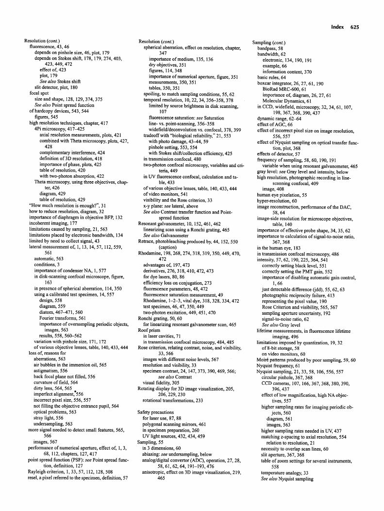
Resolution (conI.)fluorescence , 43, 46
depends on pinhole size, 46, plot, 179depends on Stokes shift, 178, 179, 274, 403,
423,449,472effect of, 423plot, 179See also Stokes shift
slit detector, plot, 180focal spot
size and shape, 128, 129,374,375See also Point spread function
of hardcopy devices , 543, 544figures, 545
high resolution techniques, chapter, 4174Pi microscopy, 417-425
axial resolution measurements , plots, 421combined with Theta microscopy, plots, 427,
428complementary interference , 424definition of3D resolution, 418importance of phase, plots, 425table of resolution, 420with two-photon absorpt ion, 422
Theta microscopy, using three objectives, chapter, 426
diagram, 429table of resolution, 429
"How much resolution is enough?", 31how to reduce resolution, diagram, 32importance of diaphragm in objective BFP, 132incoherent imaging, 177limitations caused by sampling , 21, 563limitations placed by electronic bandwidth, 134limited by need to collect signal, 43lateral measurement of, I, 13, 14,57, 112,559,
561automatic , 563conditions, 3importance of condenser NA, I, 577in disk-scanning confocal microscope , figure,
163in presence of spherical aberration , 114,350using a calibrated test specimen , 14,557
design, 558diagram, 559diatom, 467-471,560Fourier transforms, 561importance of oversampling periodic objects,
images, 563results, 558, 560-562
variation with pinhole size, 171, 172of various objective lenses, table, 140,433,444
loss of, reasons foraberrations, 563air bubbles in the immersion oil, 565astigmatism, 556back focal plane not filled, 556curvature of field, 564dirty lens, 564, 565imperfect alignment:556incorrect pixel size, 556, 557not filling the objective entrance pupil, 564optical problems , 563stray light, 556undersampling, 563
more signal needed to detect small features, 565,566
images, 567performance of numerical aperture , effect of, I, 3,
68,112, chapters, 127,417point spread function (PSF): see Point spread func
tion, definition , 127Rayleigh criterion, 1,33,57, 112, 128,508resel, a pixel referred to the specimen, definition, 57
Resolution (conI.)spherical aberration, effect on resolution, chapter,
347importance of medium, 135, 136dry objectives, 351figures, 114, 348importance of numerical aperture, figure, 351measurements, 350, 351tables, 350, 351
spoiling, to match sampling conditions , 55, 62temporal resolution, 10, 22, 34, 356-358, 378
limited by source brightness in disk scanning,107
fluorescence saturation : see Saturationline- vs. point-scanning , 356-358widefield/deconvolution vs. confocal, 378, 399
tradeoff with "biological reliability," 21, 553with photo damage, 43-44, 59pinhole setting, 553, 554with Stokes shift/collection efficiency, 425
in transmission confocal, 480two-photon confocal microscopy, variables and cri
teria, 449in UV fluorescence confocal, calculation and ta-
ble, 433of various objective lenses, table, 140,433,444of video monitors, 541visibility and the Rose criterion, 33x-y plane: see lateral, aboveSee also Contrast transfer function and Point
spread functionResonant galvanometer, 10, 152,461,462
linearizing scan using a Ronchi grating, 465See also Galvanometer
Retrace, photobleaching produced by, 44, 152, 550(caption)
Rhodamine , 198,268,274,318,319,350,449,470,472
advantages of, 197, 473derivatives, 276, 318, 410, 472, 473for dye lasers, 80, 86efficiency loss on conjugation , 273fluorescence parameters, 48, 472fluorescence saturation measurement , 49Rhodamine, 1-2-3, vital dye, 318, 328, 334,472test specimen, 46, 47, 350, 449two-photon excitation, 449, 451, 470
Ronchi grating, 50, 60for linearizing resonant galvanometer scan, 465
Roof prismin laser cavities, 71in transmission confocal microscopy, 484, 485
Rose criterion, relating contrast, noise, and visibility,33,566
images with different noise levels, 567resolution and visibility, 33specimen contrast, 24, 147,373,390,469,566;
see also Contrastvisual fidelity, 305
Rotating display for 3D image visualization, 205,206,229,230
rotational transformations, 233
Safety precautionsfor laser use, 87, 88polygonal scanning mirrors, 461in specimen preparation, 260UV light sources, 432, 434, 459
Sampling, 55in 3 dimensions, 60abiasing: see undersampling , belowanalog/digital convertor (ADC), operation, 27, 28,
58,61,62,64, 191-193,476anisotropic, effect on 3D image visualization, 219,
465
Index 625
Sampling (conI.)bandpass, 58bandwidth , 62
electronic, 134, 190, 191example, 66information content, 370
basic rules, 64boxcar integrator, 26, 27, 61, 190
BioRad MRC-600, 61importance of, diagram, 26, 27, 61Molecular Dynamics , 61
in CCD, widefield , microscopy, 32, 34, 61, 107,198,367,368,390,437
dynamic range, 62-64effect ofAGC, 66effect of incorrect pixel size on image resolution,
556, 557effect of Nyquist sampling on optical transfer func
tion, plot, 368effects of detector, 57frequency of sampling, 58, 60,190,191
variable when using resonant galvanometer, 465gray level: see Gray level and intensity, belowhigh resolution, photographic recording in line
scanning confocal, 409image, 408
human eye pixelation , 55hyper-resolution, 60image reconstruction, performance of the DAC,
58,64image-side resolution for microscope objectives,
table, 140importance of effective probe shape, 34, 35, 62importance to calculation of signal-to-noise ratio,
367,368in the human eye, 183in transmission confocal microscopy, 486intensity, 57, 62, 190,225,364,541
correctly setting black level, 551correctly setting the PMT gain, 552importance of disabling automat ic gain control,
1,66just detectable difference (jdd), 55, 62, 63photographic reciprocity failure, 413representing the pixel value, 190Rose Criterion and visibility, 565, 567sampling aperture uncertainty, 192signal-to-noise ratio, 62See also Gray level
lifetime measurements , in fluorescence lifetimeimaging, 496
limitations imposed by quantization, 19,32of 8-bit storage, 58on video monitors , 60
Moire patterns produced by poor sampling, 59, 60Nyquist frequency, 61Nyquist sampling, 21, 33, 58, 106, 556, 557
circular pinhole, 367, 368CCD cameras, 107, 166,367,368,380,390,
396,437effect of low magnification, high NA objec
tives, 557higher sampling rates for imaging periodic ob
jects, 560diagram, 561images, 563
higher sampling rates needed in uv. 437matching z-spacing to axial resolution, 554
relation to resolution, 21necessity to overlap scan lines, 60slit aperture, 367, 368table of zoom settings for several instruments,
558temperature analogy, 33See also Nyquist sampling
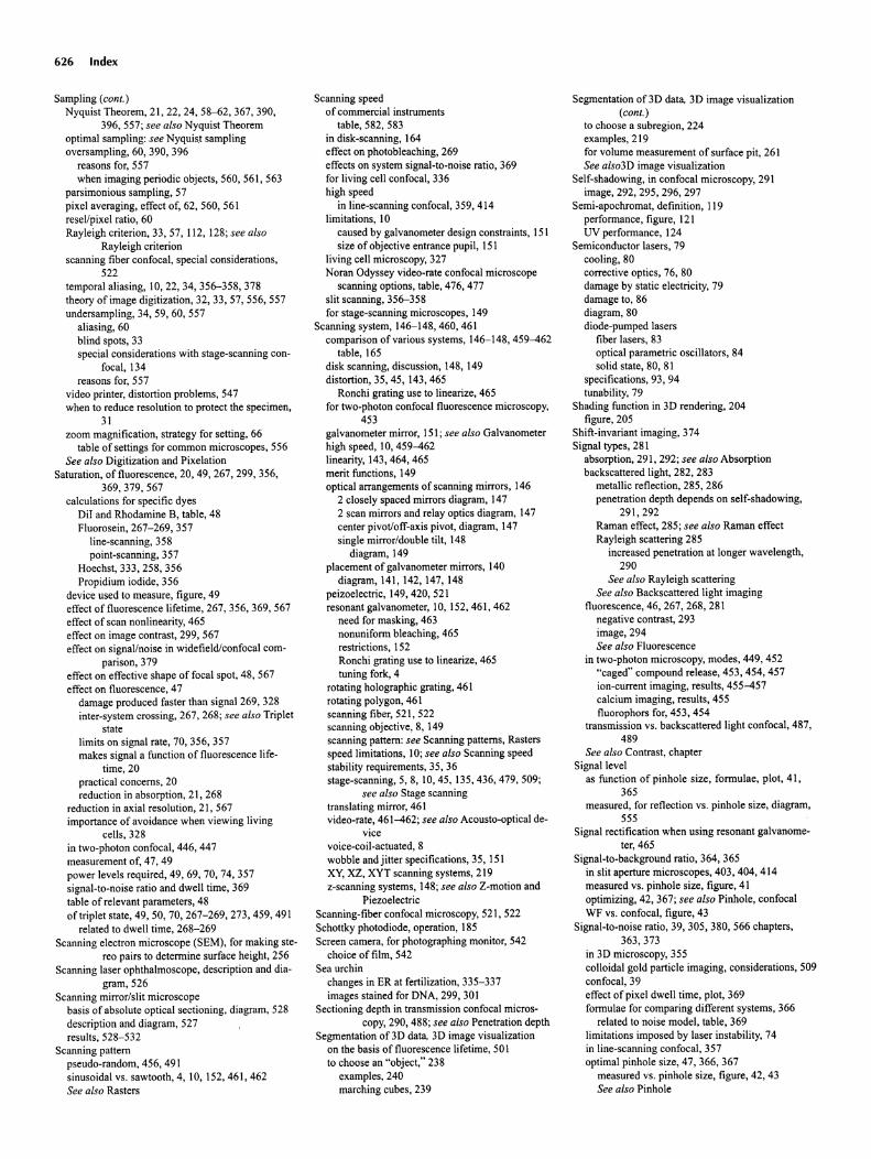
626 Index
Sampling (coni.)Nyquist Theorem, 21, 22, 24, 58-62, 367, 390,
396, 557; see also Nyquist Theoremoptimal sampling: see Nyquist samplingoversampling, 60, 390, 396
reasons for, 557when imaging periodic objects, 560, 561, 563
parsimonious sampling, 57pixel averag ing, effect of, 62, 560, 561resel/pixel ratio, 60Rayleigh crite rion, 33, 57,11 2, 128; see also
Rayleigh criterionscanning fiber confoc al, spec ial considerations,
522temporal aliasing, 10,22,34, 356-358, 378theory of image digitization, 32, 33, 57, 556, 557undersampling, 34, 59, 60, 557
aliasing, 60blind spots , 33special considerations with stage-scanning con
focal, 134reasons for, 557
video printer, distort ion problems, 547when to reduce resolut ion to protect the specimen,
31zoom magni fication, strategy for setting, 66
table of settings for common microscopes, 556See also Digitizat ion and Pixelat ion
Saturation, of fluorescence, 20, 49, 267, 299, 356,369, 379, 567
calculations for specific dyesOil and Rhodamine B, table, 48Fluorose in, 267-269, 357
line-scanning, 358point- scanning, 357
Hoechst , 333, 258, 356Propid ium iodide , 356
device used to measure, figure , 49effect of fluorescence lifetime, 267, 356, 369, 567effect of scan non linearity, 465effect on image cont rast, 299, 567effect on signal/noise in widefield/confocal com
parison , 379effect on effective shape offocal spot, 48, 567effect on fluorescence, 47
damage produced faster than signal 269, 328inter-system crossing , 267, 268; see also Triplet
statelimits on signal rate, 70, 356, 357makes signal a funct ion of fluorescence life
time, 20practical concerns, 20reduction in absorpt ion, 21, 268
reduction in axial resolution, 21, 567importance of avoidance when viewing living
cells , 328in two-photon confocal, 446 , 447measurement of, 47, 49power levels required , 49, 69, 70, 74, 357signal-to-noise ratio and dwell time, 369table of relev ant parameters, 48of triplet state, 49, 50, 70, 267-269, 273, 459 , 491
related to dwell time, 268-269Scanning elect ron microscope (SEM), for making ste
reo pai rs to determine surface height, 256Scanning laser ophthalmoscope , description and dia
gram , 526Scanning mirro r/slit microscope
basis of absolute optical sectioning, diagram, 528description and diagram , 527results, 528- 532
Scanning patternpseudo-random, 456, 491sinusoida l vs. sawtooth, 4, 10, 152, 461, 462See also Raster s
Scann ing speedof commercial instruments
table , 582, 583in disk-scanning, 164effect on photobleach ing, 269effects on system signal-to-noise ratio, 369for living cell confoca l, 336high speed
in line-scanning confoca l, 359, 414limitations, 10
caused by galvanometer design constraints, 151size of objec tive entrance pupil, 151
living cell microscopy, 327Noran Odyssey video-rate confoc al microscope
scanning options, table , 476 , 477slit scanning, 356-358for stage-scanning microscopes, 149
Scanni ng system , 146-148,460,461comparison of various systems , 146-148, 459-462
table , 165disk scanning, discussion , 148, 149distortio n, 35, 45, 143,465
Ronch i grating use to linearize, 465for two-photon confocal fluorescence microscopy,
453galvanometer mirror, 151; see also Galvanometerhigh speed, 10,459-462linearity, 143,464,465merit functions, 149opt ical arrangements of scanning mirrors, 146
2 close ly spaced mirrors diagram, 1472 scan mirrors and relay optics diagram , 147center pivot/off-axis pivot, diagram, 147single mirror/double tilt, 148
diagram, 149placement of galvanometer mirrors , 140
diagram, 141, 142, 147, 148peizoelectric, 149,420,521resonant galvanometer, 10, 152, 461, 462
need for masking, 463nonuniform bleaching, 465restrictions, 152Ronchi grating use to linearize, 465tuning fork, 4
rotating holographic grating, 461rotating polygon , 461scanning fiber, 521, 522scanning objective, 8, 149scanning pattern : see Scanni ng patterns, Rastersspeed limitations, 10; see also Scann ing speedstability requirements, 35, 36stage-scanning, 5, 8, 10,45, 135,436,479,509;
see also Stage scann ingtranslating mirror, 461video-rate, 461-462; see also Acousto -optical de-
vicevoice-co il-actuated, 8wobble and j itter specifications, 35, 151XY, XZ, XYT scanning systems, 219z-scanning systems , 148; see also Z-motion and
PiezoelectricScanning-fiber confocal microscopy, 521, 522Schottky photodiode, operat ion, 185Screen camera , for photographing monitor, 542
choice of film, 542Sea urchin
changes in ER at fertilization , 335-337images stained for DNA, 299, 301
Section ing depth in transm ission confocal microscopy, 290, 488; see also Penetration depth
Segmentation of 3D data, 3D image visualizationon the basis of fluorescence lifetime, 50 Ito choose an "object," 238
examples, 240marching cubes, 239
Segmentation oD D data, 3D image visualization(cant .)
to choose a subregion, 224examples, 219for volume measu rement of surface pit , 261See also3D image visualization
Self-shadowing, in confocal microscopy, 291image, 292, 295, 296, 297
Semi-apochromat, definition, 119performance, figure , 121UVperformance, 124
Semiconductor lasers, 79cooling, 80correct ive optics, 76, 80damage by static electricity, 79damage to, 86diagram, 80diode-pumped lasers
fiber lasers, 83optical parametric oscillators, 84solid state, 80, 81
specifications, 93, 94tunability, 79
Shading funct ion in 3D renderi ng, 204figure , 205
Shift-invariant imaging, 374Signal types , 28 1
absorption, 291, 292 ; see also Absorptionbackscattered light , 282, 283
metallic reflect ion, 285, 286penetra tion depth depends on self-shadowing,
291,292Raman effect, 285 ; see also Raman effectRayleigh scatte ring 285
increased penetration at longer wave length,290
See also Rayleigh scatteringSee also Backscattered light imaging
fluorescence, 46, 267, 268, 281negative contrast, 293image, 294See also Fluorescence
in two-photon micro scopy, modes, 449, 452"caged" compound release, 453, 454 , 457ion-current imaging, results, 455-457calcium imaging, results, 455fluorophors for, 453, 454
transmission vs. backscattered light confocal, 487,489
See also Contra st, chapterSignal level
as function of pinhole size , formulae, plot, 41,365
measured, for reflection vs. pinhole size , diagram,555
Signal rectification when using resona nt galvanome ter,465
Signal-to-background ratio, 364, 365in slit aperture microscopes, 403, 404 , 414measured vs. pinhole size, figure, 41optimizing, 42, 367 ; see also Pinhol e, confoca lWF vs. confocal, figure, 43
Signal-to -noise ratio , 39, 305, 380, 566 chapters,363,373
in 3D micro scopy, 355colloidal gold particle imaging, considerations, 509confoc al, 39effect of pixel dwell time, plot , 369formulae for comparing different systems, 366
related to noise model , table , 369limitations imposed by laser instability, 74in line-scann ing confocal, 357optimal pinhole size, 47, 366 , 367
measured vs. pinhole size, figure, 42, 43See also Pinhole
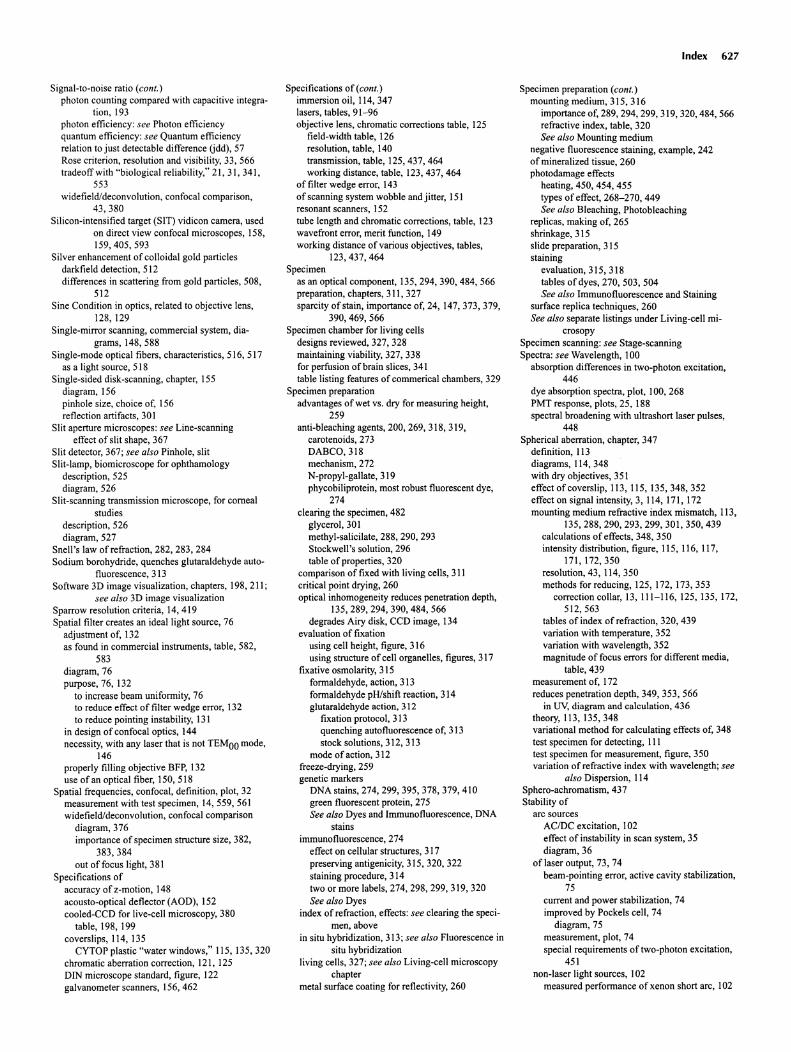
Signal-to-noise ratio (conI .)photon counting compared with capacitive integra-
tion, 193photon efficiency: see Photon effic iencyquantum efficiency: see Quantum efficiencyrelation to just detectable difference (jdd), 57Rose criterion, resolution and visibility, 33, 566tradeoff with "biological reliability," 21, 31, 341,
553widefield/deconvolution, confocal comparison,
43,380Silicon-intensified target (SIT) vidicon camera , used
on direct view confocal microscopes, 158,159,405,593
Silver enhancement of colloidal gold particlesdarkfield detection, 512differences in scattering from gold particles, 508,
512Sine Condition in optics, related to objective lens,
128,129Single-mirror scanning, commercial system, dia
grams, 148, 588Single-mode optical fibers , characteristics, 516, 517
as a light source , 518Single-sided disk-scanning, chapter, 155
diagram , 156pinhole size, choice of, 156reflection artifacts , 301
Slit aperture microscopes: see Line-scanningeffect of slit shape, 367
Slit detector, 367; see also Pinhole, slitSlit-lamp, biomicroscope for ophthamology
description, 525diagram, 526
Slit-scanning transmission microscope, for cornealstudies
description, 526diagram , 527
Snell's law of refraction, 282, 283, 284Sodium borohydride, quenche s glutaraldehyde auto
fluorescence, 313Software 3D image visualization, chapters , 198, 211;
see also 3D image visualizationSparrow resolution criteria , 14,419Spatial filter creates an ideal light source , 76
adjustment of, 132as found in commercial instruments, table, 582,
583diagram, 76purpose , 76, 132
to increase beam uniformity, 76to reduce effect of filter wedge error, 132to reduce pointing instability, 131
in design of confocal optics , 144necessity, with any laser that is not TEMOO mode,
146properly filling objective BFP, 132use of an optical fiber, 150, 518
Spatial frequencies, confocal, definition, plot, 32measurement with test specimen, 14,559,561widefield/deconvolution, confocal comparison
diagram, 376importance of specimen structure size, 382,
383,384out offocus light, 381
Specifications ofaccuracy of z-motion, 148acousto-optical deflector (AOD), 152cooled-CCD for live-cell microscopy, 380
table, 198, 199covers lips, 114, 135
CYTOP plastic "water windows," 115, 135,320chromatic aberration correction, 121, 125DIN microscope standard, figure, 122galvanometer scanners, 156, 462
Specifications of (conI.)immersion oil, 114, 347lasers, tables, 91-96objective lens, chromatic corrections table, 125
field-width table, 126resolution , table, 140transmission, table, 125,437,464working distance, table, 123,437,464
of filter wedge error, 143of scanning system wobble and jitter, 151resonant scanners , 152tube length and chromatic corrections, table, 123wavefront error, merit function, 149working distance of various objectives , tables,
123,437,464Specimen
as an optical component, 135,294,390,484,566preparation, chapters, 311, 327sparcity of stain, importance of, 24,147,373,379,
390,469,566Specimen chamber for living cells
designs reviewed , 327, 328maintaining viability, 327, 338for perfusion of brain slices, 341table listing features of commerical chambers, 329
Specimen preparationadvantages of wet vs. dry for measuring height,
259anti-bleaching agents, 200, 269, 318, 319,
carotenoids , 273DABCO,318mechanism, 272N-propyl-gallate,319phycobiliprotein, most robust fluorescent dye,
274clearing the specimen, 482
glycerol, 301methyl-salicilate, 288, 290, 293Stockwell's solution, 296table of properties, 320
comparison of fixed with living cells, 311critical point drying, 260optical inhomogeneity reduces penetration depth ,
135,289,294,390,484,566degrades Airy disk, CCD image, 134
evaluation of fixationusing cell height, figure, 316using structure of cell organelles , figures , 317
fixative osmolarity, 315formaldehyde, action, 313formaldehyde pH/shift reaction , 314glutaraldehyde action, 312
fixation protocol, 313quenching autofluorescence of, 313stock solutions, 312, 313
mode of action, 312freeze-drying , 259genetic markers
DNA stains, 274, 299, 395, 378, 379,410green fluorescent protein, 275See also Dyes and Immunofluorescence, DNA
stainsimmunofluorescence, 274
effect on cellular structures , 317preserving antigenicity, 315, 320, 322staining procedure, 314two or more labels, 274, 298, 299, 319, 320See also Dyes
index of refraction, effects : see clearing the specimen, above
in situ hybridization, 313; see also Fluorescence insitu hybridization
living cells, 327; see also Living-cell microscopychapter
metal surface coating for reflectivity, 260
Index 627
Specimen preparation (conI .)mounting medium, 315, 316
importance of, 289, 294, 299, 319, 320, 484, 566refractive index, table, 320See also Mounting medium
negative fluorescence staining, example , 242of mineralized tissue , 260photodamage effects
heating, 450, 454, 455types of effect, 268-270, 449See also Bleaching, Photobleaching
replicas, making of, 265shrinkage, 315slide preparation, 315staining
evaluation, 315, 318tables of dyes, 270, 503, 504See also Immunofluorescence and Staining
surface replica techniques, 260See also separate listings under Living-cell mi
crosopySpecimen scanning : see Stage-scanningSpectra: see Wavelength, 100
absorpt ion differences in two-photon excitation,446
dye absorption spectra, plot, 100, 268PMT response , plots, 25, 188spectral broadening with ultrashort laser pulses,
448Spherical aberration, chapter, 347
definition, 113diagrams, 114,348with dry objectives , 351effect of coverslip, 113, 115, 135, 348, 352effectonsignalintensity,3, 114, 171, 172mounting medium refractive index mismatch, 113,
135,288,290,293,299,301 ,350,439calculations of effects, 348, 350intensity distribution, figure, 115, 116, 117,
171,172,350resolution, 43, 114,350methods for reducing, 125, 172, 173, 353
correction collar, 13, 111-116, 125,135, 172,512,563
tables of index of refraction, 320, 439variation with temperature, 352variation with wavelength, 352magnitude of focus errors for different media,
table, 439measurement of, 172reduces penetration depth , 349, 353, 566
in UV, diagram and calculation, 436theory, 113, 135,348variational method for calculating effects of, 348test specimen for detect ing, IIItest specimen for measurement, figure, 350variation of refractive index with wavelength; see
also Dispersion, 114Sphero-achromatism, 437Stability of
arc sourcesACIDC excitation, 102effect of instability in scan system, 35diagram, 36
of laser output , 73, 74beam-pointing error, active cavity stabilization,
75current and power stabilization, 74improved by Pockels cell, 74
diagram , 75measurement, plot, 74special requirements of two-photon excitation ,
451non-laser light sources , 102
measured performance of xenon short arc, 102
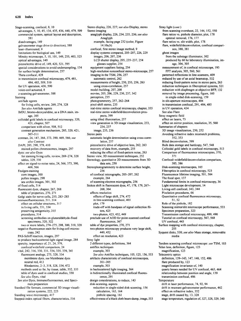
628 Index
Stage-scanning, confocal, 8, 10advantages, 5, 10, 45, 134,435,436,440,479, 509comm ercial system, optical layout and description,
581disadvantages, 149galvanometer stage drive (z direct ion), 588laser-illuminated, 9limitat ions for biological use, 149Minsky microscope , 5.10,101,149,255,403,525optical advantages, 149piezoelectric drive of, 149, 420, 521, 595special considerations to avoid undersampling, 134for surface height determination, 257Theta confocal , 428in transmission confocal microscopy, 479, 481,
484,485,509,510for UV operation. 436, 590voice-coil actuated, 8z-scanning galvanometer, 588
Stainingantifade agents
for living cells, review, 269, 274, 328See a/so Antifade agents
BrDU, brorno-deoxyuridine, as a DNA stain, image, 305
colloidal gold labels in confocal microscopy, 320,421, chapter, 507
comparison with silver, 508, 512contrast generation mechanism, 285, 320, 421,
507-511contrast, 24. 147,364,373,390,469,566; see
also Contra stDAPI, 205. 298, 378, 410
stained pollen chromosomes, images, 297dyes : see a/so Dyes
for staining living cells, review, 269-274, 328tables, 329, 330
effect on signal-to-noise ratio, 24, 366, 373, 390,469,566
Feulgen-stainingcom images, 300pollen images , 298sea urchin images, 30 I, 302
of fixed cells , 314fluorescent dyes , chapter, 267, 268
table of properties. 270, 271Golgi stain for nerve cells , 255, 283-285immunofluorescence, 311. 314
effect on cellular structures. 317in living cells, 331,334preserv ing antigenicity, 315procedures, 314screening antibodies on glutaraldehyde-fixed
specimens, 320, 322two or more labels, 274--275, 298, 300, 319, 320
negative fluorescence stain for living-cell micros-copy, 242
PAS-Schiff reaction, images , 297to produce backscattered light signal image, 284sparcity, importance of, 21, 24, 379,
confocal /widefield comparison, 24vital, 242. 316, 330, 331, 334, 335. 339, 341
fluorescent analogs, 275, 328. 334membrane dyes, see Membrane dyesneutral red, 413Rhodamine, 2-3 ,318, 328,334,472
methods used so far, by tissue, table, 332, 333table of dyes used in confocal studies , 330See a/so Dyes, vital
See also Dyes, Immunofluorescence, and Specimen preparation
Standard file formats , commercial 3D image visualization systems, 222, 223
Standing wave microscopy, 417Stepped-index optical fibers, characteristics, 516
Stereo display, 226, 227; see a/so Display, stereoStereo imaging
anaglyph display, 226, 234, 235, 236; see a/soAnaglyph
example , facing page 232 (color, Figure14.lOa,b)
confocal , first stereo image method, 9display systems compared, 205-207, 226, 229
images,206,207,236LCD shutter display, 205, 235-237, 254
glasses supplie r, 254equipment suppl iers listing, 254high-resolution nonconfocal stereo-microscope, 257imaging in the TSM, 256, 257
automatic control, 262measurements of height, 250, 255, 256, 263
using cross-correlation, 257model-building, 207, 208movies, 205, 206, 229, 230, 237, 342perception , 235photograrnmetry, 257, 262-264pixel-shift stereo , 235real-time stereo confocal microscopy, chapter, 355real-time stereo widefield/deconvolution pros-
pects, 399using tilted illumination , 257view generation in 3D image visualization, 233,
234,237image, 235, 236
Stereo pairsautomatic height determination using cross-corre-
lation, 257piezoelectric drive of objective lens, 262, 263recovery of data from, example, 255reducing the effect of fixed-pattern noise, 263
Stereo view, 3D measurement techniques , 252Stereology, quantitative 2D measurements from 3D
data sets, 250Stereophotogrammetry to determine surface height,
256of confocal micrographs, 205-207, 262
example , 264of scanning electron micrographs, 256
Stokes shift in fluorescent dyes, 47,178,179,267268,364
affects resolutioneffects of large shift, 274,472in line-scanning confocal, 403plot, 179trade-off with bandpass of signal collection fil
ters, 425two-photon, 423, 452, 449
preclude use of ADD for point-scanned confocalfluorescence, 367
table of dye properties, 270, 271two-photon microscopy produces very large shift,
449,452effect on resolution, 423
Stray light2 different types, defin itions, 364anti flex techniques
example , 303See also Antiflex techniques, 105, 125, 156,553
artifacts characteristic of confocal microscopes,301-305
example , 303in backscattered light imaging, 364in bidirectionally illuminated confocal fluores
cence, 291design considerations, to reduce, 143disk-scanning, aspects
reduct ion in single-sided disk-scanning, 156calculation, 163, 164pinhole spacing , 161
effectiveness ofa black cloth beam-dump, image, 553
Stray light (conI.)from scanning overshoot, 22, 144, 152, 550flare ratios vs. pinhole diameter, plot, 178
optimal removal, 176, 177flare ratios vs. slit width, plot , 178flare, widefield/deconvolution, confocal compari
son, 380, 381ghost images
from the substage illuminator, 302produced by 60 hz laboratory illumination, im
age, 304, 305measurement of, in confocal microscope, 193
FFT analysis, 305, 560, 561patterned reflections in line-scanners, 409reduced by use of an axial beamstop, 532reducing fixed-pattern noise in stereo pairs, 263reduction techniques in fiberoptical systems, 521reduction with diaphragm at objective BFP, 132removal by image processing, figure, 160
in single-sided disk-scanning, 159in slit-aperture microscopes, 404in transmission confocal, 291,484, 485in UV operation, 434See also Flare
Stray magnetic fieldeffect on lasers, 73effect on mirror position , resolution, 35, 560
Summaries of chapters3D image visualization, 250, 252Avoiding refractive index mismatch problems,
352,353Blind deconvolution, 399Bulk data storage and hardcopy, 547, 548Colloidal gold labels in confocal microscopy, 513Comparison of fluorescence microscopies, 370,
371Confocal-widefield/deconvolution comparison,
385,386Disk-scanning microscopes, 165Fiberoptics in confocal microscopy, 523Fluorescence lifetime imaging, 501, 504The focal spot, 137Fundamental limits in confocal microscopy, 36Light microscope development, 14Living-cell confocal, 343, 344Pixelation procedures, 66Quantitative confocal fluorescence microscopy,
51,52Role of the pinhole , 182Scanning mirror/slit microscope performance, 533Specimen preparat ion, 323Transmission confocal microscopy, 489, 490Tutorial on confocal microscopy, 567, 568UV confocal , 443
Surface mapping with confocal microscopy, chapter,255
Syquest disks , 538; see a/so Mass storage, removablemedia
Tandem scanning confocal microscope: see TSM, 103Telan lens, definition, figure , 123
magnification, 123Telecentric optics
definition, 139-143, 147, 148, 152,486flare produced by, J23magnification invariance of, 140quartz lenses needed for UV confocal, 463, 464relationship between position and angle, 139transmission confocal, 486
Temperaturedrift in laser performance, 74, 92, 94drift in resonant galvanometer performance, 462effect on refractive index, 352stage , drift caused by, 13, 328stage temperature, regulation of, 327, 328, 329, 340
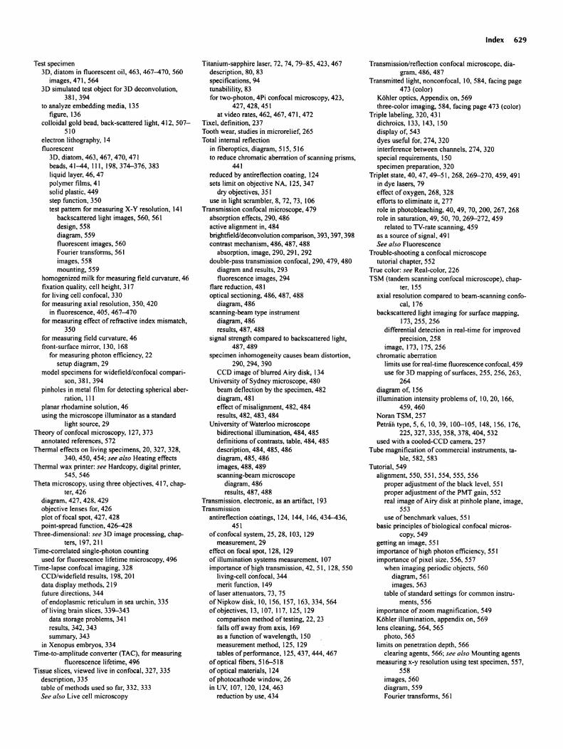
Test specimen3D, diatom in fluorescent oil, 463, 467-470,560
images, 471, 5643D simulated test object for 3D deconvolut ion,
381,394to analyze embedding media, 135
figure, 136colloidal gold bead, back-scattered light, 412, 507
510electron lithography, 14fluorescent
3D. diatom, 463, 467, 470,471beads, 41-44, III, 198, 374-376, 383liquid layer, 46, 47polymer films, 41solid plastic, 449step function, 350test pattern for measuring X-Y resolution , 141
backscattered light images, 560. 561design , 558diagram, 559fluorescent images, 560Fourier transforms, 561images. 558mounting, 559
homogenized milk for measuring field curvature, 46fixation quality, cell height, 317for living cell confocal , 330for measuring axial resolution, 350, 420
in fluorescence. 405. 467-470for measuring effect of refractive index mismatch,
350for measuring field curvature. 46front-surface mirror, 130, 168
for measuring photon efficiency, 22setup diagram, 29
model specimens for widefield/confocal comparison, 381, 394
pinholes in metal film for detecting spherical aberration, III
planar rhodamine solution, 46using the microscope illuminator as a standard
light source, 29Theory of confocal microscopy, 127, 373
annotated references , 572Thermal effects on living specimens, 20, 327, 328,
340, 450, 454; see a/so Heating effectsThermal wax printer : see Hardcopy, digital printer,
545,546Theta microscopy, using three object ives, 417, chap-
ter,426diagram, 427, 428, 429objective lenses for, 426plot offocal spot, 427. 428point-spread function, 426-428
Three-dimensional: see 3D image processing, chapters, 197,211
Time-correlated single-photo n countingused for fluorescence lifetime microscopy, 496
Time-lapse confocal imaging, 328CCO/widefield results. 198, 20 Idata display methods, 219future directions, 344of endoplasm ic reticulum in sea urchin, 335of living brain slices, 339-343
data storage problems, 34 Iresults, 342, 343summary, 343
in Xenopus embryos, 334Time-to-amplitude converter (TAC). for measuring
fluorescence lifetime, 496Tissue slices, viewed live in confocal, 327, 335
description , 335table of methods used so far, 332, 333See a/so Live cell microscopy
Titanium-sapphire laser, 72, 74, 79-85 ,423, 467description, 80, 83specifications, 94tunabilility, 83for two-photon, 4Pi confocal microscopy, 423,
427,428,451at video rates, 462, 467, 471, 472
Tixel, definition, 237Tooth wear, studies in microrelief, 265Total internal reflection
in fiberoptics, diagram, 515, 516to reduce chromatic aberration of scanning prisms,
441reduced by antireflection coating, 124sets limit on objective NA, 125, 347
dry objectives, 351use in light scrambler, 8, 72, 73, 106
Transmission confocal microscope, 479absorption effects, 290, 486active alignment in, 484brightfieldldeconvolutioncomparison,393, 397, 398contrast mechanism , 486, 487, 488
absorption, image, 290. 291, 292double-pass transmission confocal, 290, 479, 480
diagram and results, 293fluorescence images, 294
flare reduction, 481optical sectioning, 486, 487, 488
diagram, 486scanning-beam type instrument
diagram, 486results, 487, 488
signal strength compared to backscattered light,487,489
specimen inhomogeneity causes beam distortion,290,294,390
CCO image of blurred Airy disk, 134University of Sydney microscope, 480
beam deflection by the specimen, 482diagram, 481effect of misalignment , 482, 484results, 482, 483, 484
University of Waterloo microscopebidirectional illumination, 484, 485definitions of contrasts, table, 484, 485description, 484, 485, 486diagram, 485, 486images, 488, 489scanning-beam microscope
diagram, 486results, 487, 488
Transmission, electronic, as an artifact, 193Transmission
antireflection coatings, 124, 144, 146, 434-436,451
ofconfocal system, 25, 28, 103, 129measurement, 29
effect on focal spot, 128, 129of illumination systems measurement, 107importance of~igh transmission , 42, 51, 128, 550
living-cell confocal, 344merit function, 149
of laser attenuators , 73, 75of Nipkow disk, 10, 156, 157, 163,334,564of objectives, 13, 107, 117, 125, 129
comparison method of testing, 22, 23falls off away from axis, 169as a function of wavelength, 150measurement method, 125, 129tables of performance , 125,437,444,467
of optical fibers, 516-518ofoptical materials, 124of photocathode window, 26in UV, 107, 120, 124,463
reduction by use, 434
Index 629
Transmission/reflection confocal microscope, diagram, 486, 487
Transmitted light, nonconfocal , 10, 584, facing page473 (color)
Kohler optics, Appendix on, 569three-color imaging, 584, facing page 473 (color)
Triple labeling, 320, 431dichroics , 133, 143, 150display of, 543dyes useful for, 274, 320interference between channels, 274, 320special requirements, 150specimen preparation , 320
Triplet state, 40, 47, 49-51 , 268, 269-270,459,491in dye lasers, 79effectofoxygen,268,328efforts to eliminate it, 277role in photobleaching, 40, 49, 70, 200, 267, 268role in saturation, 49, 50, 70, 269-272, 459
related to TV-rate scanning, 459as a source of signal, 491See also Fluorescence
Trouble-shooting a confocal microscopetutorial chapter, 552
True color: see Real-color, 226TSM (tandem scanning confocal microscope), chap
ter,155axial resolution compared to beam-scanning confo
cal, 176backscattered light imaging for surface mapping.
173,255,256differentia l detect ion in real-t ime for improved
precision, 258image, 173, 175, 256
chromatic aberrationlimits use for real-time fluorescence confocal, 459use for 3D mapping of surfaces. 255, 256, 263,
264diagram of, 156illumination intensity problems of, 10,20, 166,
459,460Noran TSM, 257Petraii type, 5, 6,10,39,100-105,148,156.176,
225,327,335,358,378,404,532used with a cooled-CCO camera, 257
Tube magnificat ion of commerc ial instruments, table, 582, 583
Tutorial, 549alignment, 550, 55 I, 554, 555, 556
proper adjustment of the black level, 551proper adjustment of the PMT gain, 552real image of Airy disk at pinhole plane, image,
553use of benchmark values, 551
basic principles of biological confocal micros-copy,549
getting an image, 551importance of high photon efficiency, 551importance of pixel size, 556, 557
when imaging periodic objects, 560diagram, 561images, 563
table of standard settings for common instru-ments, 556
importance of zoom magnification , 549Kohler illumination, appendix on, 569lens cleaning, 564, 565
photo, 565limits on penetration depth, 566
clear ing agents. 566; see also Mounting agentsmeasuring x-y resolution using test specimen, 557,
558images, 560diagram , 559Fourier transforms, 561
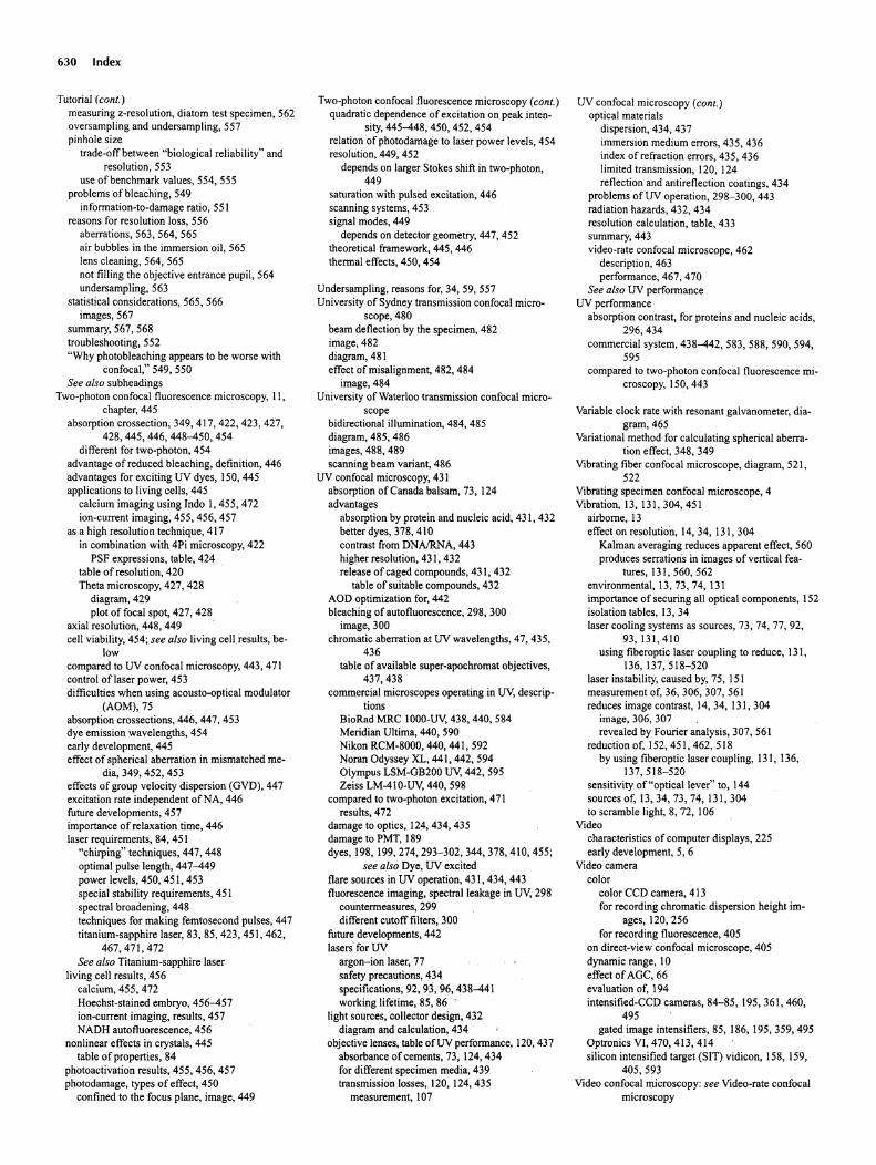
630 Index
Tutorial (cant.)measuring z-resolution , diatom test specimen, 562oversarnpling and undersampling, 557pinhole size
trade-off between "biological reliability" andresolution, 553
use of benchmark values, 554, 555problems of bleaching , 549
informat ion-to-damage ratio, 551reasons for resolution loss, 556
aberrations , 563, 564, 565air bubbles in the immersion oil, 565lens cleaning, 564, 565not filling the objective entrance pupil, 564undersampling, 563
statistical considerations, 565, 566images, 567
summary, 567, 568troubleshooting , 552"Why photobleaching appears to be worse with
confocal," 549, 550See also subheadings
Two-photon confocal fluorescence microscop y, II,chapter, 445
absorption crossection , 349, 417, 422, 423, 427,428,445,446,448-450,454
different for two-photon , 454advantage of reduced bleaching , definition , 446advantages for exciting UV dyes, 150,445applications to living cells, 445
calcium imaging using Indo 1,455,472ion-current imaging, 455, 456, 457
as a high resolution technique , 417in combination with 4Pi microscopy, 422
PSF expressions, table, 424table of resolution, 420Theta microscopy, 427, 428
diagram, 429plot offocal spot, 427, 428
axial resolution, 448, 449 .cell viability, 454; see also living cell results, be-
lowcompared to UV confocal microscopy, 443, 471control oflaser power, 453difficulties when using acousto-optical modulator
(AOM),75absorpt ion crossections, 446, 447, 453dye emission wavelengths, 454early development, 445effect of spherical aberrat ion in mismatched me-
dia, 349, 452, 453effects of group velocity dispersion (GVD), 447excitation rate independent ofNA, 446future developments, 457importance of relaxation time, 446laser requirements , 84, 451
"chirping" techniques, 447, 448optimal pulse length, 447-449power levels, 450, 451, 453special stability requirements, 451spectral broadening, 448techniques for making femtosecond pulses, 447titanium-sapphire laser, 83, 85, 423, 451, 462,
467,471,472See a/soTitanium-sapphire laser
living cell results , 456calcium, 455, 472Hoechst-stained embryo, 456-457ion-current imaging, results, 457NADH autofluorescence, 456
nonlinear effects in crystals, 445table of properties, 84
photoactivation results , 455, 456, 457photodamage, types of effect, 450
confined to the focus plane, image, 449
Two-photon confocal fluorescence microscopy (cant .)quadratic dependence of excitation on peak inten
sity, 445-448, 450, 452, 454relation of photodamage to laser power levels, 454resolution, 449, 452
depends on larger Stokes shift in two-photon,449
saturation with pulsed excitation, 446scanning systems, 453signal modes, 449
depends on detector geometry, 447, 452theoretical framework, 445, 446thermal effects, 450, 454
Undersampling , reasons for, 34, 59, 557University of Sydney transmission confocal micro-
scope, 480beam deflection by the specimen, 482image, 482diagram, 481effect of misalignment, 482, 484
image, 484University of Waterloo transmission confocal micro-
scopebidirectional illumination, 484, 485diagram, 485, 486images, 488, 489scanning beam variant, 486
UV confocal microscopy, 431absorption of Canada balsam, 73,124advantages
absorption by protein and nucleic acid, 431, 432better dyes, 378, 410contrast from DNAlRNA, 443higher resolution, 431, 432release of caged compounds, 431, 432
table of suitable compounds, 432AOD optimization for, 442bleaching of autofluorescence , 298, 300
image, 300chromatic aberration at UV wavelengths, 47, 435,
436table of available super-apochromat objectives,
437,438commercial microscopes operating in uv, descrip-
tionsBioRad MRC 1000-uv, 438, 440, 584Meridian Ultima, 440, 590Nikon RCM-8000, 440, 441, 592Noran Odyssey XL, 441, 442, 594Olympus LSM-GB200 UV, 442, 595Zeiss LM-410-UV, 440, 598
compared to two-photon excitation, 471results, 472
damage to optics, 124,434,435damage to PMT, 189dyes, 198, 199,274,293-302,344,378,410,455;
see a/so Dye, UV excitedflare sources in UV operation, 431, 434, 443fluorescence imaging, spectral leakage in uv, 298
countermeasures, 299different cutoff filters, 300
future developments, 442lasers' for UV
argon-ion laser, 77safety precautions, 434specifications , 92, 93,96, 438-441working lifetime, 85, 86 '
light sources, collector design, 432diagram and calculation, 434
objective lenses, table ofUV performance, 120,437absorbance of cements, 73, 124,434for different specimen media, 439transmission losses, 120, 124,435
measurement , 107
UV confocal microscopy (cant .)optical materials
dispersion, 434, 437immersion medium errors, 435, 436index of refraction errors , 435 , 436limited transmiss ion, 120, 124reflection and antireflection coatings , 434
problems ofUV operation, 298-300, 443radiation hazards, 432, 434resolution calculation, table, 433summary, 443video-rate confocal microscope, 462
description, 463performance, 467, 470
See also UV performanceUV performance
absorption contrast, for proteins and nucleic acids,296,434
commercial system, 438-442, 583, 588, 590, 594,595
compared to two-photon confocal fluorescence microscopy, 150, 443
Variable clock rate with resonant galvanometer, diagram, 465
Variational method for calculating spherical aberration effect, 348, 349
Vibrating fiber confocal microscope , diagram, 521,522
Vibrating specimen confocal microscope , 4Vibration, 13, 131, 304, 451
airborne , 13effect on resolution, 14, 34, 131, 304
Kalman averaging reduces apparent effect, 560produces serration's in images of vertical fea-
tures, 131, 560, 562environmental, 13, 73, 74, 131importance of securing all optical components , 152isolation tables, 13,34laser cooling systems as sources , 73, 74, 77, 92,
93,131 ,410using fiberoptic laser coupling to reduce, 131,
136,137,518-520laser instability, caused by, 75, 151measurement of, 36, 306, 307, 561reduces image contrast, 14,34,131,304
image, 306, 307revealed byFourier analysis, 307, 561
reduction of, 152, 451 , 462, 518by using fiberoptic laser coupl ing, 131, 136,
137,518-520sensitivity of "optical lever" to, 144sources of, 13,34,73,74,131 ,304to scramble light, 8, 72, 106
Videocharacteristics of compute r displays, 225early development, 5, 6
Video cameracolor
color CCD camera, 413for recording chromatic dispersion height im
ages, 120, 256for recording fluorescence , 405
on direct-view confocal microscope, 405dynamic range, 10effect ofAGC, 66evaluat ion of, 194intensified-CCD cameras, 84-85,195,361 ,460,
495gated image intensifiers, 85, 186, 195,359,495
Optronics VI, 470, 413, 414silicon intensified target (SIT) vidicon, 158, 159,
405,593Video confocal microscopy : see Video-rate confocal
microscopy
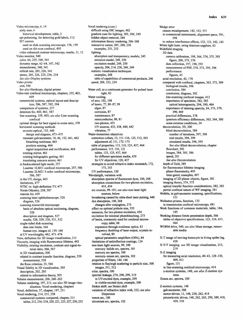
Video microscopy, 6, 14early uses, 6
historical developmen t, table, 2epi-polarizing, for detecting gold labels, 5 12SIT camera
used on disk-scanning microscope, 158, 159used on slit-scan confocal.'40 5
video enhanced contrast microscopy, results, I I, 12Video monitor, 540
color, 64, 225, 540, 54 1dynamic range, 62-64, 347, 542monochrome, 540, 541refresh rate, 205, 226, 541stereo. 205, 226, 229, 236, 254See also Display systems
Video printercost, 546See also Hardcopy, digital printer
Video-rate confocal microscopy, chapters, 355, 403,459
commerc ial systems, optical layout and descrip-tion, 586, 587, 592, 594
comparison of systems, 257detectors for, 460, 461, 587line-scanning, 359, 403 ; see also Line-scanning
confocaloptimal design for best signal-to-noise ratio, 370horizontal scanning methods
acousto-optical, 152, 460design and diagram , 473--475
resonant galvanometer, 10, 46, 152,461, 462bleaching nonlinear, 465position sensing, 464signal acquisition and rectification, 464
rotating mirror, 46 1rotating holographic grating, 461translating concave mirror, 461
in backscattered light mode, 257Lasertec I LM II confocal microscope , 257, 586Lasertec 2LM21 3-colo r confocal microscope,
586,587in the UV, design, 463limitations, 477NTSC vs. high-definition TV, 477Noran Odyssey, 258, 587reasons for, 459scanning laser ophthalmoscope, 526
diagram, 526scanning mirror/slit microscope
basis of absolute opt ical sectioning , diagram,528
description and diagram , 527results, 528, 529, 530, 531, 532
single-sided disk-scanningdata rate limits, 164human eye, images of, 159, 160
at UV wavelengths, 462, 471--474View, definition for 3D image visualization, 211Viscosity, imaging with fluorescence lifetime, 493Visibility, relating resolut ion, contrast and signal-to-
noise ratio, 566, 567in 3D visualization, 308related to contrast transfer function , diagram, 559
measurement, 558the Rose criterion, 33, 566
Visual fidelity in 3D visualization, 305descript ion, 202, 205related to information theory, 305
Volume measurement, 206, 260-262Volume rendering , 197,211 ; see also 3D image visu
alizat ion; Voxel rendering, chaptersVoxel, definit ion, 57, chapter, 197, 211Voxel rendering , 214, 231, 238
commercial systems compared, chapter, 211tables, 212, 216-218, 220, 221, 223, 227, 230, 232
Voxel rendering (conI.)difficult using DIC images, 482gradient cues for lighting, 202, 204, 249hidden object removal, 244information theory rendering, 306-3 08interactive cursor, 207, 208, 250
examples, 251, 252lighting
absorption and transparency, models, 245emission model, 249, 250excitation model, 249, 250opacity, 204, 214, 238, 240, 249
realistic visualization techniquesexamples, 248table ofcapabilities of commercial products, 246
speed, 206,222,224
Water cell, as a continuum generator for pulsed laserlight, 83
Water cooling,of arcs, 102, 108oflasers, 77, 80-87, 99
algae; 87corrosion , 87 .maintenance , 87semiconductor, 80, 81two-photon , 451UV sources , 432, 438, 440, 442vibration, 77
Water-immersio~ objectivescorrection collars, 13, 111 -116, 125,512,563
adjustment of, Ill , 172-173table of propertie s, 115, 116, 125,437,464performance , 115, 116, 121
tables, 123, 125,437,464for different specimen media, 439for UV objectives , 120, 437
strategies to avoid refractive index mismatch, 172,173,353
UV performance, 120Wavelength, variation with
absorption spectra of fluorescent dyes, 100, 268absorption crossections for two-photon excitation,
453,454arc sources, 99-101 ; see also non-laser light
sources, belowbroadening caused by ultra-short laser pulsing, 448dye absorption, 100, 268
changes after conjugtion , 273effect on optimal pinhole size, 555emission, for two-photon excitation, 454excitation for minimal photobleaching, 273of lasers, commonly used for confocal micros
copy, table, 88expansion through nonlinear optics , 83frequency doubling of laser output , crystals in
volved,80optical parametric amplifiers (OPA), 84
limitations of antireflect ion coatings , 124non-laser light sources, 99, 100
mercury-halide arc, spectra, 10Imercury arc 'spectra, 100mercury-xenon arc, spectra, 102
properties of filters, 144, 146relation to Rayleigh scattering to particle size, 508
images, 511, 512 ·solar, spectra, 100spectral leakage, 274, 298, 299, 319
in UV-excited dyes, example , 299in visible-excited dyes, example , 300
Stokes shift: see Stokes shiftvariation of refractive index with, 352; see also
Dispersionxenon arc, 100zirconium arc, spectra, 102
Index 631
Wedge errorcauses misalignment, 142, 143, 551in commercial instrumen ts, alignment specs, 591,
598to reduce interference effects, 132, 133, 142, 143
White light laser, using titanium-sapphire, 83Widefield imaging
3D datacamera calibrat ion, 199,364,374,375, 393
figure, 200, 375, 376data collection, 197, 198,393measurement of PSF, 374, 375, 395, 396performance
figures, 43axial resolution, 42, 170compared with confocal, chapters, 363, 373, 389
biological results, 396conclusion, 384constraints , diagram , 392line-scanning confocal images, 412importance of specimen, 382, 383
optical heterogeneity, 294, 390, 484importance of staining sparcity, 24, 373, 379,
390, 469practical differences, 378quantum efficiency difference s, 363, 364, 380some extreme conditions , 24
deconvolution, 3D, 200blind deconvolut ion, 389
number of iterations, 397, 398real results, 394, 399simulated results , 394, 395See also Blind deconvolut ion, chapter
flowchart, 392images, 384, 385, 386speed,201See also Deconvolut ion
depth of field, 389for fluorescence lifetime imaging
phase-fluorometry, 495time-gated, examples, 497
imaging of 2D planar objects , figure, 381imaging theory, 374, 375optical transfer function considerations, 382, 383partial confocal nature of WF imaging, 381
Wobble, in galvanometer scann ing, specifications,151
Wollaston prisms, function, 133in transmission confocal microscopy, 481
Work functions of common materials, table, 184,185
Working distance limits penetration depth , 566tables of objective specifications, 123, 124,437,
464WORM drive, 540; see also Mass storage , remov
able media
X-T image of moving hemocyte in living spider leg,438
X-Y-T imaging: see 3D image visualization, 213,2 19
X-Z imagingfor measuring axial resolut ion, 40--43, 128- 130,
409,411figure, 131
in line-scanning confocal microscopy, 414z-motion systems , 148; see also Z-motion sys
temsXenon arc, spectra, 100
Z-motion systems , 148galvanometer, 588motor-driven, 11, 148,258,262,414piezoelectric drives, 148,262,263,290,389,418,
420,510

632 Index
Z·motionsystems (cont.)types found in commercialinstruments
table, 582, 583Z-resolution: see Axial resolution and Resolution,
axialZeiss
Antiflexoptics, 125ICS optics, figure, 122
performance,figures, 121LSM-410confocalmicroscope
featuresofLM410·UV, 440optical layoutand description,589
Zirconiumare, spectra, 102Zoom
correctsetting,66, 557for studiesof livingcells, 336tableof settingsfor commoninstruments, 556when imagingperiodicobjects,560
diagram,561images,563
effectof low magnification, highNA objectives,557
largepupil sizes requiresmall scan angles,table,I40
Zoom (cont.)effecton photobleaching rate, 557Nyquistzoomsettings for several instruments,32
34,58-61table, 556
off-axisaberrations degrade imagequality, 551,555
image,553optimalsetting is a compromise, 21, 549, 550price of setting magnification too low, 33rangeof commercialinstruments,table, 582, 583