APPENDIX C
151
APPENDIX C RPZ Analysis and Obstruction Evaluation
-
Upload
khangminh22 -
Category
Documents
-
view
1 -
download
0
Transcript of APPENDIX C
APPENDIX C
RPZ Analysis and Obstruction Evaluation
Runway Protection Zone Analysis & Obstruction Evaluation Of
“Title 14 CFR Part 77 – Safe, Efficient Use, and Preservation of Navigable Airspace”
TRENTON-MERCER AIRPORT MERCER COUNTY
TOWNSHIP of EWING, NEW JERSEY
C&S ENGINEERS, INC. 499 Col. Eileen Collins Blvd.
Syracuse, New York 13212
(FINAL)
March 2015
Trenton Mercer Airport
i
Table of Contents EXECUTIVE SUMMARY ......................................................................................................... iii CHAPTER 1 INTRODUCTION
1.1 Purpose of Report ................................................................................................ 1-1 CHAPTER 2 DESCRIPTION OF SURFACES & RUNWAY PROTECTION ZONES
2.1 Title 14 CFR Part 77 Surfaces ............................................................................. 2-1 2.2 Runway End Siting Surface(s) (RESS) ………………………………….……...2-3 2.3 Terminal Instrument Procedures (TERPS) ……………………………………2-7 2.4 Medium Intensity Approach Light System
w/ Runway Alignment Indicator Lights (MALSR) ……………………………2-8 2.5 Precision Approach Path Indicator System (PAPI) ……………………………2-9 2.6 Runway Protection Zone (RPZ) ......................................................................... 2-10 2.7 Summary ............................................................................................................ 2-14
CHAPTER 3 SURFACE ANALYSIS & OBSTRUCTION IDENTIFICATION
3.1 Introduction .......................................................................................................... 3-1 3.2 Title 14 CFR Part 77 Obstruction Descriptions and
Recommended Actions ........................................................................................ 3-1 3.2-1 Runway 6-24 Primary and Transitional Surfaces ................................... 3-3 3.2-2 Runway 16-34 Primary and Transitional Surfaces ................................. 3-4 3.2-3 Approach and Transitional Surfaces (Runway 6) .................................... 3-5 3.2-4 Approach and Transitional Surfaces (Runway 24) .................................. 3-6 3.2-5 Approach and Transitional Surfaces (Runway 16) .................................. 3-6 3.2-6 Approach and Transitional Surfaces (Runway 34) .................................. 3-7 3.3 Runway End Siting Surface Analysis .................................................................. 3-8 3.3-1 Approach Surface..................................................................................... 3-8 3.3-2 Departure Surface .................................................................................... 3-9 3.4 TERPS Analysis................................................................................................. 3-10 3.5 MALSR Analysis ............................................................................................... 3-12 3.6 PAPI Analysis .................................................................................................... 3-12 3.7 Runway Protection Zone (RPZ) Analysis .......................................................... 3-12 3.8 Opinion of Probable Cost & Project Phasing .................................................... 3-13 3.9 Conclusions/Recommendations ......................................................................... 3-15
Trenton Mercer Airport
ii
LIST of TABLES 3-1 Summary of Probable Avigation Easement Acquisition Costs 3-2 On-Airport Obstruction Removal Opinion of Probable Cost
3-3 Off-Airport Obstruction Removal Opinion of Probable Cost
LIST of APPENDICES
APPENDIX A
Obstruction Evaluation Drawings
APPENDIX B
Runway End Panoramic Views
APPENDIX C
Random Photographs of Identified Obstructions
APPENDIX D
Airport Layout Plan – Pen & Ink Change No. 11 dated August 2014
APPENDIX E
Exhibit “A” Airport Property Inventory Map, dated 3/31/’14
APPENDIX F
National Ocean Service (NOS) Trenton Mercer Airport Airport Obstruction Chart (OC 982), 9th Edition, dated April 2005
APPENDIX G
Federal Aviation Administration As-Built Drawing Aea-E-25125, dated 2/25/85

Trenton Mercer Airport
iii
EXECUTIVE SUMMARY This report provides the results of an analysis of the navigable airspace as defined in Title 14 Code of Federal Regulations (CFR) Part 77-Safe, Efficient Use, and Preservation of the Navigable Airspace established for the Trenton - Mercer Airport (TTN). In addition to the Part 77 airspace analysis, an analysis of the Runway End Siting Surface (both the approach and the departure surfaces), the US Standard for Terminal Instrument Procedures (TERPS) surface, the Medium Intensity Approach Lighting System w/Runway Alignment Indicator Lights (MALSR), and the Precision Approach Path Indicator (PAPI) System was performed. A detailed description of objects that conflict with these surfaces and recommendations regarding the treatment of these obstructions to ensure compliance with Federal Aviation Administration (FAA) regulations pertaining to objects that conflict with these surfaces has been provided. A detailed opinion of probable easement acquisition costs, construction costs, and FAA Grant project phasing is referenced in Sections 3.4 and 3.5, and in Tables 3-1 thru 3-3 of this report. In conjunction with this evaluation project and under FAA AIP Grant No. 3-34-0042-43-13 an Obstruction Evaluation/Airport Airspace Analysis (OE/AAA) was performed and uploaded to the FAA A-GIS website. Following is a summary of information contained in this report: ON-AIRPORT OBSTRUCTIONS (Highest Priority Actions) To insure compliance with regulations pertaining to Obstacle Clearance Surfaces for each of the above described surfaces, this report is recommending Removal/Mitigation actions of the identified on-airport obstructions as described in detail in the Obstruction Evaluation Plans & Profiles and as discussed in Chapter 3 of this report. Actions summarized below are this reports opinion of the order of importance to the airport owner: 1) Rwy 06 TERPS Obstructions and MALSR Obstructions:
Note: The Rwy 06 TERPS and MALSR Obstructions as identified in detail in the Obstruction Evaluation Plans & Profiles overlap the Part 77 obstructions, but not the RESS (approach or departure) obstructions. This report considers the Rwy 06 TERPS and MALSR obstructions a higher priority for removal than Part 77.
2) Runway End Siting Surface RESS Obstructions (in order of priority):
Rwy 06 - Approach Surface, and Rwy 24 – Departure Surface; Note: Rwy 24 departure obstructions overlap Part 77 obstructions, but not to the extent in height as Part 77.
Rwy 24 – Approach Surface, and Rwy 6 Departure Surface; Note: Rwy 06 departure obstructions overlap Part 77 obstructions, but not to the extent in height as Part 77.

Trenton Mercer Airport
iv
Rwy 34 – Approach Surface; Rwy 16 – Approach Surface.
3) Title 14 CFR Part 77 Obstructions (in order of priority):
Rwy 06-24 – Primary and Transitional to the Primary Surfaces; Rwy 06 – Approach and Transitional to the Approach Surfaces; Rwy 24 – Approach and Transitional to the Approach Surfaces; Rwy 34 – Approach and Transitional to the Approach Surfaces; Rwy 16 – Approach and Transitional to the Approach Surfaces; Rwy 16-34 – Primary and Transitional to the Primary Surfaces;
As of the date of the aerial survey there are no penetrations to the On-Airport Obstacle Clearance Surface (OCS) of the Precision Approach Path Indicator (PAPI) System(s), at runway ends 16, 24, and 34. The opinion of probable construction cost for the treatment of these on-airport obstructions is estimated to be $2 M which would include costs for obstruction removal/treatment, mobilization, surveying, and engineering/construction administration costs. More detailed cost estimates are provided in section 3.2 and 3.8 of this report. OFF-AIRPORT AVIGATION EASEMENTS In order to remove/treat off-airport obstructions to the Title 14 CFR Part 77 surfaces, it is recommended that the airport owner first acquire avigation easements to gain access and removal rights to the affected parcels. This includes a total of 104 parcels. Avigation easement costs have been estimated from tax rolls of the year prior to the evaluation, are based on a percentage of the tax parcel land assessment value only, and are subject to the opinions of professional Real Estate appraisal reports. Based on professional experience with similar projects, a reasonable increase in the estimated compensation cost is merited. This report recommends that permanent avigation easement costs (property owner compensation only) be estimated at a rounded value of $1.5M to be used for budgeting purposes of future acquisitions. OFF-AIRPORT OBSTRUCTIONS 1) Runway End Siting Surface RESS Obstructions (in order of priority):
Rwy 06 - Approach Surface, and Rwy 24 – Departure Surface; Note: Rwy 24 departure obstructions overlap Part 77 obstructions, but not to the extent as Part 77.
Rwy 24 – Approach Surface, and Rwy 6 Departure Surface; Note: Rwy 06 departure obstructions overlap Part 77 obstructions, but not to the extent as Part 77.
Rwy 34 – Approach Surface; Rwy 16 - (No Off-Airport Obstructions).

Trenton Mercer Airport
v
2) Title 14 CFR Part 77 Obstructions (in order of priority):
Rwy 06-24 – Primary and Transitional to the Primary Surfaces; Rwy 06 – Approach and Transitional to the Approach Surfaces; Rwy 24 – Approach and Transitional to the Approach Surfaces; Rwy 34 – Approach and Transitional to the Approach Surfaces; Rwy 16 – (No Off-Airport Obstructions); Rwy 16-34 – Primary and Transitional to the Primary Surfaces;
As of the date of the aerial survey there are no penetrations to the Off-Airport Obstacle Clearance Surface (OCS) of the Precision Approach Path Indicator (PAPI) System(s), at runway ends 16, 24, and 34. The opinion of probable construction cost for the treatment of these off-airport obstructions is estimated at $2.6 M , which would include costs for obstruction removal/treatment, mobilization, surveying, and Engineering / Construction Administration costs. More detailed cost estimates are provided in section 3.3 and 3.8 of this report. .

Trenton Mercer Airport
1-1
CHAPTER 1 – INTRODUCTION
1.1 Purpose of Report This report was written for the Trenton-Mercer Airport, Mercer County, New Jersey. The purpose of this report is to provide an analysis of incompatible land use in the runway protection zone and to identify and evaluate obstructions to air navigation, and determine their effect on the safe and efficient use of airspace at the airport. Also discussed within this report, is the purpose and application of Runway End Siting requirements and the evaluation considerations when a penetration of the siting surface is identified. In addition, terminal instrument procedures, departures surfaces, medium intensity approach lighting, and precision approach path indicator surfaces were analyzed. This report provides a description of the Federal Aviation Regulations Title 14 CFR Part 77 Civil Airport Imaginary Surfaces used in the obstruction evaluation, and the standard shape, dimension, and surface slope of the appropriate runway end siting surface along with each of the other above mentioned surfaces as described in the FAA Airport Design Advisory Circular 150/5300-13A. Recommendations for treating identified obstructions and an opinion of cost for acquiring property interests and for removal or lighting of the obstructions, as recommended, are also included.
Safe and efficient landing and takeoff operations at an airport require certain areas on and near the airport be clear of objects or restrictions to objects with a certain function, composition, and/or height. These clearing standards and criteria are established to create a safer environment for aircraft operating at the airport. The airport operator is not required to prevent or clear penetrations to the Part 77, Subpart C, imaginary surfaces when the FAA determines these penetrations are not hazards. However, for purposes of this report, any existing object whether man-made or of natural growth that penetrates these surfaces is classified as an “obstruction” and is presumed to be a hazard to air navigation. These identified obstructions are subject to an FAA aeronautical study, after which the FAA issues a determination stating whether the obstruction is in fact considered a hazard.
The Runway Protection Zone and Obstruction Analysis drawings accompanying this report consist of the following: 1. GI001 TITLE SHEET 2. GI002 OBSTRUCTION DATA TABLES, NOTES AND LEGEND 3. GI003 OBSTRUCTION DATA TABLES 4. GI004 OBSTRUCTION DATA TABLES 5. GI005 OBSTRUCTION DATA TABLES 6. GI006 OBSTRUCTION DATA TABLES 7. GI007 OBSTRUCTION DATA TABLES 8. GC100 OVERALL NAVIGABLE AIRSPACE PLAN 9. CG101 RUNWAY 6-24 PART 77 PLAN 10. CG102 RUNWAY 6 PART 77 PLAN 11. CG103 RUNWAY 24 DEPARTURE SURFACE PLAN 12. CG104 RUNWAY 6 END SITING PLAN 13. CG105 RUNWAY 6 PROTECTION ZONE PLAN 14. CG106 RUNWAY 6 TERMINAL INSTRUMENT PROCEDURES (TERPS) PLAN
Trenton Mercer Airport
1-2
15. CG107 RUNWAY 24 PART 77 PLAN (1 OF 2) 16. CG108 RUNWAY 24 PART 77 PLAN (2 OF 2) 17. CG109 RUNWAY 6 DEPARTURE SURFACE PLAN 18. CG110 RUNWAY 24 END SITING PLAN 19. CG111 RUNWAY 24 PROTECTION ZONE PLAN 20. CG112 RUNWAY 16-34 PART 77 PLAN 21. CG113 RUNWAY 16 PART 77 PLAN 22. CG114 RUNWAY 16 END SITING PLAN 23. CG115 RUNWAY 16 PROTECTION ZONE PLAN 24. CG116 RUNWAY 34 PART 77 PLAN 25. CG117 RUNWAY 34 END SITING PLAN 26. CG118 RUNWAY 34 PROTECTION ZONE PLAN 27. CG201 RUNWAY 6 PART 77 AND RESS PROFILES 28. CG202 RUNWAY 24 DEPARTURE SURFACE PROFILE 29. CG203 RUNWAY 6 MALSR PLAN AND PROFILE 30. CG204 RUNWAY 24 PART 77 AND RESS PROFILES 31. CG205 RUNWAY 6 DEPARTURE SURFACE PROFILE 32. CG206 RUNWAY 16 PART 77 AND RESS PROFILES 33. CG207 RUNWAY 34 PART 77 AND RESS PROFILES 34. CG208 RUNWAY 24 PAPI OCS PLAN AND PROFILE 35. CG209 RUNWAY 16 PAPI OCS PLAN AND PROFILE 36. CG210 RUNWAY 34 PAPI OCS PLAN AND PROFILE A reduced-size set of the Obstruction Evaluation Drawings is included in Appendix A. “The mapping for the obstruction evaluation was prepared from a combination of ground survey efforts combined with georeferenced aerial photography in stereo pairs taken at the Trenton-Mercer Airport. Title 14 CFR Part 77 surface obstructions were determined by aerial photographic methods obtained by: Woolpert, Inc. Photogrammetrists in August 2014. Image ground control was established by global positioning system (GPS) static observation methods and processed utilizing national geodetic survey (NGS) online positioning user service (OPUS). The geodetic control utilized on this project consisted of primary airport control station (PACS) TTN ARP (KV1102), and secondary airport control stations (SACS) AP STA A2 TTN (AA9216), and KTTN AP STA B (AA9217).” ( Woolpert, Inc. ) Property lines and parcel ID numbers have been obtained from Mercer County Geo-access-GIS mapping and are approximate only. Property lines as shown are not the result of an actual boundary survey. Wetland areas identified are approximate only and are not the result of actual wetland delineation. Wetland areas were placed on the drawings using available on-line wetland mapping.

Trenton Mercer Airport
2-1
CHAPTER 2 – DESCRIPTION OF SURFACES & RUNWAY PROTECTION ZONES
This chapter will discuss the surfaces that were analyzed as part of this evaluation, which consist of the following: 1) FAR Part 77 Primary
Transitional to the Primary; Approach; Transitional to the Approach; A portion of Horizontal Surface within the approach surface limits;
2) Runway End Siting Surfaces - Approach and Departure 3) Terminal Instrument Procedures TERPS
Glide Path Qualification GQS; 4) NAVAIDS
Medium Intensity Approach Lights w/Rails MALSR Precision Approach Path Indicator System PAPI OCS
2.1 Title 14 CFR Part 77 Surfaces The purpose of an analysis of the Title 14 CFR Part 77 Surfaces is to establish:
- The standards used to determine obstructions to air navigation; - The process for aeronautical studies of obstructions to air navigation or navigational
facilities to determine the effect on the safe and efficient use of navigable airspace; - The requirements to provide notice to the FAA of existing man-made structures or natural
vegetation features penetrating the standards; and - The process to petition the FAA for discretionary review of determination, revisions, and
extensions of determinations. The Obstruction Plans and Profiles for the airport are presented in Appendix A, and provide detailed obstruction information depicting the FAR Part 77 imaginary surfaces on and around Trenton-Mercer Airport, through which no object should penetrate. The dimensions and criteria employed in determining obstructions penetrating or within 12.5 feet of penetrating (for natural vegetation) the imaginary surfaces for the airport as outlined in Federal Aviation Regulations Title 14 CFR Part 77, Safe, Efficient Use, and Preservation of the Navigable Airspace are detailed within the following paragraphs. Natural vegetation located within a 12.5 feet buffer zone of Title 14 CFR Part 77 surfaces is also considered an obstruction, per FAA Engineering Brief No. 91, Management of Vegetation in the Airport Environment.

Trenton Mercer Airport
2-2
Although, for clarification purposes, only obstacles actually penetrating the primary surface have been identified. A buffer zone to the primary surface was not included in the primary surface model for that analysis. The primary surface of a runway is defined as an area longitudinally centered on the runway for a width dependent on the type of runway, and extending 200 feet beyond each end of the landing threshold. At Trenton-Mercer Airport, Runway 6-24 is a transport category runway with a precision instrument approach. This corresponds to a primary surface width of 1,000 feet. Runway 16-34 is defined as a transport category runway with a non-precision instrument approach. Therefore, its primary surface width is 500 feet. Primary surface widths vary with the classification of the runway end; however, the width is uniform throughout and is based on the most precise approach for either end of that runway.
The Part 77 approach surface is longitudinally centered on the extended runway centerline and extends outward and upward from each end of the primary surface. The slope and configuration of each runway approach surface varies as a function of runway type and availability of instrument approaches.
As previously mentioned, Runway 6-24 is a runway with a precision instrument approach. Runway 6 has a precision approach surface that consists of an inner width of 1,000 feet, extends outward and upward at a slope of 50 feet (horizontal) to 1 foot (vertical) for a distance of 10,000 feet, and then a slope of 40 feet (horizontal) to 1 foot (vertical) for a distance of 40,000 feet to an outer width of 16,000 feet. Runway 24 has a non-precision (other than utility) approach surface that consists of an inner width of 1,000 feet, extending outward and upward at a slope of 34 feet (horizontal) to 1 foot (vertical) for a distance of 10,000 feet, to an outer width of 3,500 feet.
Runways 16 and 34 each have non-precision instrument approach surfaces that consist of an inner width of 500 feet, extending outward and upward at a slope of 34 feet (horizontal) to 1 foot (vertical) for a distance of 10,000 feet to an outer width of 3,500 feet. The transitional surfaces extend outward and upward from the runway primary surface and each of the runway approach surfaces to the airport horizontal surface at right angles to the runway centerline at a slope of 7 feet (horizontal) to 1 foot (vertical). Obstructions to the airport's FAR Part 77 transitional surfaces have been identified. The horizontal surface is a horizontal plane 150 feet above the established airport elevation. The published airport elevation for Trenton-Mercer Airport is 212.6 feet above mean sea level (MSL). For this report, we will be referencing the horizontal surface elevation as 363 feet above mean sea level, for simplification purposes. The perimeter of the horizontal surface is delineated by arcs with a radius of 10,000 feet from the center of each end of the primary surface of each of the runway ends for Runways 6 & 24, and Runways 16 & 34. Adjacent arcs from each runway are connected by lines tangent to these arcs .

Trenton Mercer Airport
2-3
For purposes of this report, only that portion of the horizontal surface contained within the limits of the Part 77 approach surface and transitional to the approach surface will be analyzed An obstruction to the airport's horizontal surface has been identified within the horizontal limits of the Runway 24 approach. Airports that have received federal funds have an obligation through grant assurances to identify and mitigate hazards to navigable airspace at their airport. AIP grant assurances are obligations associated with a grant that require the sponsors to maintain and operate their facilities safely and efficiently and in accordance with specified conditions. Many of the assurances are based on 49 USC sect. 47105, 47106 and 47107. (http://www.faa.gov/airportssipgrant_assurances/). The critical areas at an airport that need to be secured and protected from a preservation of navigable airspace standpoint include the primary, and the approach and departure paths of the runways. The Part 77 imaginary surfaces should be protected through height limitations on development both on and around the airport. It is best to maintain obstruction-free airspace and a reasonable amount of vacant land at both ends of each runway. Federal Regulation Title 14 CFR Part 77 establishes standards and notification requirements for objects affecting navigable airspace. This notification serves as the basis for:
Evaluating the effect of the construction or alteration on operating procedures Determining the potential hazardous effect of the proposed construction on air navigation Identifying mitigating measures to either return or enhance safe air navigation Charting of new objects.
Notification allows the FAA to identify potential aeronautical hazards in advance thus preventing or minimizing the adverse impacts to the safe and efficient use of navigable airspace. For Analysis of the Title 14 CFR Part 77 Surfaces and Identification of obstructions, see Chapter 3.2 of this report.
2.2 Runway End Siting Surfaces (RESS)
FAA AC 150/5300-13A, Airport Design, paragraph 303 has established standards for identifying obstacle penetrations to approach and departure surfaces that may affect the location of runway thresholds and departure ends. Runway end siting requirements, provides guidance on the establishment of runway thresholds and departure ends. The threshold is ideally located at the beginning of the runway. The threshold is located to provide proper clearance for landing aircraft over existing obstacles while on approach landing. When an

Trenton Mercer Airport
2-4
object beyond the airport owner’s power to remove, relocate, or lower obstructs the airspace required for aircraft to land at the beginning of the runway for arriving aircraft, the threshold may be located farther down the runway. Such a threshold is called a “displaced threshold”. Thresholds can also be displaced to provide:
additional RSA prior to the threshold additional ROFA prior to the threshold location of the RPZ to mitigate unacceptable incompatible land uses; and mitigation of environmental impacts
The portion of the runway behind a displaced threshold may be available for takeoffs and, depending on the reason for displacement, may be available for takeoffs and landings from the opposite direction. Displacement of a threshold reduces the length of runway available for landings. There are no displaced thresholds at any of the runway ends at Trenton-Mercer Airport. Displacement of the threshold often introduces disruptions to the design of the airport. Approach light systems, NAVAIDS, and runway/taxiway markings may need to be relocated while threshold displacement is often used as a solution for constrained airspace, the airport operator will need to weigh the trade-offs of a displaced threshold. Threshold displacement should only be undertaken after a full evaluation reveals that displacement is the best alternative. A portion of the scope of this report is to analyze the need to displace the runway threshold based upon obstacles penetrating the approach and the departure surfaces as identified within the parameters of the Runway End Siting requirements, as described in paragraph 303, AC 150/5300-13A. As directed by FAA on previous obstruction evaluation projects, once on-airport obstacles penetrating the RESS have been identified, the FAA considers removal of these obstacles the owner’s responsibility, and that the airport owner should be taking immediate actions to remove those obstacles. Therefore, any threshold displacement shown on the Plans & Profiles is the result of identified off-airport obstructions where the airport owner does not have rights to remove them. Approach Surfaces The approach surfaces defined in this section (2.2) are not the approach surfaces defined in FAR Part 77. RESS approach surfaces are designed to protect the use of the runway in both visual and instrument meteorological conditions near the airport. The runway end siting approach surface typically has a trapezoidal shape that extends away from the runway, centered along the centerline, and at a specific slope, expressed in horizontal feet by vertical feet. The specific size, slope and starting point of the trapezoid depends upon the visibility minimums and the type of procedure associated with the runway end. Approach surface threshold establishment should be positioned so that there are no obstacle penetrations to the appropriate surface specified in the airport design AC, in Table 3-2, and that TERPS, Departure Surfaces, and RSA and RPZ standards are met. Runway end siting approach surfaces were analyzed and obstruction identification at each runway end was performed using the applicable Runway Type Category based on Table 3-2 of the FAA Advisory

Trenton Mercer Airport
2-5
Circular 150/5300-13A. Runway End Siting Surface (RESS) shape, dimensions and slope are keyed to the related runway end, as described below: Runway 6: The Runway End Siting – Runway Type Category for Runway 6 is a “Precision Instrument Runway” Type 7 Siting Surface, having a Runway Type identified as “Approach end of runways expected to accommodate instrument approaches having visibility minimums <3/4 statute mile or precision approach (ILS, or GLS) day or night”. This runway type has been determined to be the appropriate surface for determining the location of the threshold after identifying obstacles penetrating this RESS. The Type 7 surface starts 200 feet beyond the runway end of pavement at the elevation of the runway centerline and slopes upward from the starting point at a slope of 34 feet (horizontal) to 1 foot (vertical) for a distance of 10,000 feet. The inner width of the surface is 800 feet and the outer width is 3,800 feet centered on the runway centerline. Refer to table 3-2 of the airport design advisory circular for additional information. Runway 24; 16 and 34: The Runway End Siting – Runway Type Category for Runway(s) 24; 16 and 34 is a “Non-Precision (other than utility) Instrument Runway” Type 5 Siting Surface, having a Runway Type identified as “Approach end of runways expected to support instrument night operations serving greater than Category B aircraft. (Note: Marking and lighting of obstacles to this surface or the use of a Visual Guidance Slope Indicator (VGSI), as defined by Order 8260.3, may avoid displacing the threshold.) This runway type has been determined to be the appropriate surface for determining the location of the threshold after identifying obstacles penetrating this RESS. The surface starts 200 feet beyond the runway end of pavement at the elevation of the runway centerline and slopes upward from the starting point at a slope 20 feet (horizontal) to 1 foot (vertical) for a distance of 10,000 feet. The inner width of the surface is 800 feet and the outer width is 3,800 feet centered on the runway centerline. Refer to table 3-2 of the airport design advisory circular for additional information.
In accordance with FAA AC 150-5300-13A, when a penetration to the approach surface is identified, one or more of the following steps must be implemented
the obstacle is removed or lowered the runway land threshold is displaced the glide path angle (GPA) and/or threshold crossing height (TCH) is to be modified the instrument approach visibility minimums are to be raised to comply with specified
criteria Departure Surfaces “Instrument Departure Runway. A runway identified by the airport operator, through the appropriate FAA Airports Office, to the FAA Regional Airspace Procedures Team intended primarily for instrument departures” (AC 150/5300-13A, Airport Design, paragraph 102.rr ) As stated in (AC 150/5300-13A, Airport Design, paragraph 303.a.(2)(4) Establishing and Protecting Runway Ends, “The 40:1 instrument departure surface associated with the ends of designated instrument departure runways should be clear of obstacles. The FAA recommends the 40:1
Trenton Mercer Airport
2-6
departure surface be clear at all other departure ends. When it is not possible to keep the departure surface clear of obstacles, obstacles must be evaluated through the Obstruction Evaluation/Airport Airspace Analysis (OE/AAA) process. The Geodetic Control, Remote Sensing, Data Collection and Geographic Information for this project were obtained following the requirements of the FAA Airport-GIS Website according to AC No. 150/5300-16A, AC No. 150/5300-17C, and AC No. 150/5300-18B. The 40:1 instrument departure surface OCS starts at the stop end of runway, has a 1,000-foot inner width and 6,466-foot outer width for a length of 10,200 feet. Departure surfaces, when clear, allow pilots to follow standard departure procedures. The departure surface is a trapezoid shape that begins at the end of the Takeoff Distance Available (TODA), and extends along the extended runway centerline with a slope of 1 unit vertically for every 40 units horizontally (40:1), as identified in figure 3-4 of the Airport Design AC, and as shown in Plan and Profile in the Obstruction Evaluation drawings (refer to CG103 and CG202). Obstacles penetrating the departure surface will affect runway departure procedures. These procedures may require:
non- standard climb rates non-standard (higher) departure minimums; or reduction in the length of the TODA
Runway end siting departure (OCS) surfaces were analyzed and obstruction identification for Runway 24 Departure (at runway 6 end) and Runway 06 Departure (at runway 24 end) was performed using the guidance listed in Table 3-2, Approach/Departure Standards Table, runway type 9, and as shown in Figure 3-4, Departure for Instrument Runways (40:1) of paragraph 303 of the FAA Advisory Circular 150/5300-13A. Runway End Siting Departure Surface shape, dimensions and slope are keyed to the related runway end. For Runways 06 and 24, the 40:1 OCS starts at the stop end of runway, i.e. the runway end of pavement, and at the elevation of the runway centerline, slopes upward from the starting point at a slope 40 feet (horizontal) to 1 foot (vertical) for a distance of 10,200 feet. The inner width of the 40:1 OCS is 1,000 feet and the outer width is 6,466 feet centered on the runway centerline. When a penetration to a specified departure surface is identified, one or more of the following steps must be implemented.
the obstacle is removed, lowered, or relocated reduce the takeoff distance available (TODA) modify standard instrument departure procedures by raising departure minimums and/or
increasing specified climb gradients In conjunction with this evaluation project and under FAA AIP Grant No. 3-34-0042-43-13 an Obstruction Evaluation/Airport Airspace Analysis (OE/AAA) was performed and uploaded to the FAA A-GIS website.

Trenton Mercer Airport
2-7
For Analysis of the RESS Approach & Departure Surfaces and Identification of obstructions, see Chapter 3.3 of this report.
2.3 Terminal Instrument Procedures (TERPS) Surfaces GQS Surface (30:1) An analysis was performed for a Runway Type 8 End Siting Surface Category. This type siting surface is identified as “Approach end of runways expected to accommodate approaches with vertical guidance (Glide Path Qualification Surface [GQS]). The GQS is applicable to approach procedures providing vertical path guidance. This runway type siting surface is also applicable to a Localizer Performance with Vertical Guidance (LPV) surface. The surface starts at the runway end of pavement at the elevation of the runway centerline and slopes upward from the starting point at a slope 30 feet (horizontal) to 1 foot (vertical) for a distance of 10,000 feet. The inner width of the surface is runway width plus 200 feet and the outer width is 1,520 feet centered on the runway centerline. When an object exceeds the height of the GQS, an Approach with Vertical Guidance APV (ILS,PAR,LPV,LNAV/VNAV) is not authorized. This is critical to Trenton-Mercer Airport, since penetrations to the GQS may mean that the airport will lose their GQS Approach. TERPS Approach Surfaces (“W”, “X” and “Y”)
The Purpose of the United States Standard for Terminal Instrument Procedures (FAA Order 8260.3B CHG 20) is to prescribe the criteria for the formulation, review, approval and the publishing of procedures for IFR (Instrument Flight Rules) operations to and from civil airports. TERPS criteria have been established for the following Instrument Procedures: Precision Approach (PAR, ILS, MLS), Non-Precision Approach (VOR, TACAN, LNAV, NDB, ASR), Approach with Vertical Guidance (LDA, LPV, VNAV), Required Navigation Performance (RNP) and for Departure Procedures (DP). The key considerations for developing Terminal Instrument Approach and Departure Procedures include but are not limited to, existing obstructions, ground/satellite based equipment, lighting and aircraft category. TERPS criteria specify the minimum measure of obstacle clearance that is considered by the Federal Aviation Administration (FAA) to supply a satisfactory level of vertical protection from obstructions and are predicated on normal aircraft operations.
Trenton Mercer Airport
2-8
“Establishing and Protecting Runway Ends. Runway ends are established whenever an existing runway is extended or shortened, thresholds are relocated or displaced, or a new runway is constructed. When establishing runway ends, all TERPS approach surfaces and approach surfaces in Table 3-4 and Table 3-5 associated with the threshold should be clear of obstacles” (AC 150/52300-13A, Airport Design, paragraph 303.a.(2) (4)). The Precision Obstacle Clearance Surface Final Segment
The area originates 200 feet from the Landing Threshold Point (LTP) and ends at the Precision Final Approach Fix. The primary area consists of the “W” and “X” OCS, and the secondary area consists of the “Y” OCS.
The width of the “W” OCS is 400 feet either side of runway centerline extended, at the beginning, and expands uniformly to 2,200 feet either side of C.L. at 50,200 feet from LTP. The “W” surface gradient is 34:1.
The “X” OCS bounds the outside edge of the “W” surface. The width is 300 feet at the beginning, and expands uniformly to 3,876 feet at 50,200 feet from LTP. The “X” OCS begins at the height of the “W” surface, and rises at a slope of 4 (horizontal) to 1(vertical) in a direction perpendicular to the final approach course.
The “Y” OCS bounds the outside edge of the “X” surface. The width is 300 feet at the beginning, and expands uniformly to 2,500 feet at 50,200 feet from LTP. The “Y” OCS begins at the height of the “X” surface, and rises at a slope of 7 (horizontal) to 1(vertical) in a direction perpendicular to the final approach course.
For Analysis of the TERPS Surface and Identification of Obstructions, see Chapter 3.5 of this report.
2.4 Medium Intensity Approach Light System w/ Rails ( MALSR ) Surfaces
The MALSR consists of a MALS plus RAIL. The RAIL portion of the facility consists of five sequenced flashers located on the extended runway centerline, the first being located 200 feet beyond the approach ends of the MALS with successive units being located at each 200-foot intervals out to 2400. Feet from the runway threshold. All lights are aimed into the approach to the runway and establish the “Approach Light Plane”. Reference: FAA ORDER JO6850.2B.

Trenton Mercer Airport
2-9
The ideal installation, and obstruction clearance, of an approach lighting system, which shall be accomplished whenever practicable, is accomplished when the following requirement is met:
The approach light plane is 400 feet wide centered on the extended runway centerline, and must be clear of any obstacles blocking the view of the approach lights from landing aircraft.
The ideal installation, and obstruction clearance, of the RAIL portion is that all sequence flashing lights be in a horizontal light plane with no obstruction penetrating the primary and the secondary RAIL plane(s). The Primary Plane of the RAIL system begins at the last steady-burning light of the MALS portion and extends 200 feet beyond the last flashing light in the RAIL portion of the MALSR system. Where required to meet visibility, obstruction clearances, or access requirements, the width may be increased to a maximum of 100 feet, 50 feet each side of the runway centerline extended, and at a gradient that follows the plane of the RAIL system, or in this case the profile of the light plane as designed and shown on Federal Aviation Administration As-Built drawing AEA-E-25125, dated 2/25/85. The Secondary Plane begins at the edge of the of the primary plane, has a slope of 7 feet horizontal to 1 foot vertical, extending outward from the edge of the primary plane for a distance of 150 feet. Both primary and secondary planes begin at the last steady-burning lights of the MALS system and extend 200 feet beyond the last flashing light in the RAIL portion of the MALSR system. An additional secondary plane underlies the 7:1 plane, with a longitudinal slope of 50 feet horizontal to 1 foot vertical, beginning at the height of the last steady-burning light and extending outward (laterally) to 150 feet from the edge of the primary plane at zero gradient. The surface extends longitudinally to 200 feet beyond the last flashing light in the RAIL system. No object shall penetrate either the primary or the secondary plane(s). The MALSR light plane elevations and slopes are shown as depicted on Federal Aviation Administration As-Built drawing AEA-E-25125, dated 2/25/85. For Analysis of the MALSR Surface and Identification of Obstructions, see Chapter 3.6 of this report.
2.5 Precision Approach Path Indicator System (PAPI) Surfaces PAPI Obstacle Clearance Surface (OCS)
Runways 16, 24 and 34 are equipped with a Precision Approach Path Indicator (PAPI) system. An analysis was performed in accordance with FAA Design & Installation Details for Airport Visual Aids, Advisory Circular 150/5340-30D and FAA Advisory Circular Airport Design, Advisory Circular 150/5300-13A, for each respective PAPI system to determine if any Title 14 CFR Part 77 obstructions also penetrate the PAPI obstacle clearance surface (OCS) at each location. The PAPI

Trenton Mercer Airport
2-10
OCS is established to provide the pilot with a minimum clearance over obstacles during approach. The PAPI must be positioned and aimed so that no obstacles penetrate this surface. The surface begins 300 feet (90 m) in front of the PAPI system ( closer to the threshold) and proceeds outward into the approach zone at an angle 1 degree less than the aiming angle of the third LHA from the runway. Research of the Federal Aviation Administration - Internet Datasheet Viewer revealed that the VGSI Com. Angle for runways 16, 24, and 34 is 3.00 degrees. For a 3 degree glide path and 20 minute separation between LHA’s, the third LHA from the runway would be aimed at 2 degrees, 50 minutes elevation. The configuration and location of each OCS, in addition to the above stated FAA Guidance, was determined based on the criteria stated in Federal Aviation Administration Air Traffic Organization Policy “ORDER JO 6850.2B, effective date 8/20/’10. The OCS surface proceeds outward into the approach zone at an angle of one degree less than LHA # 3 on-course aiming angle, which would be at 1.83 degrees. The surface extends 10 degrees on either side of the runway centerline extended, and extends 4 statute miles from its point of origin. If a site survey determines that there is an obstacle, which penetrates the obstacle clearance surface and cannot be removed, then the glide path angle must be changed or the PAPI system moved further from the threshold. By moving or re-aiming the PAPI, the PAPI obstacle clearance surface is repositioned so it will not be penetrated by an obstacle.
2.6 Runway Protection Zone (RPZ) Surfaces As defined by A/C 150/5300-13A, Airport Design, the function of the RPZ is "to enhance the protection of people and property on the ground." This is best achieved through airport owner control in order to clear RPZs of incompatible objects and activities. It is desirable to clear the entire RPZ of all above-ground objects where this is impractical airport owners at a minimum should maintain RPZs clear of all facilities supporting incompatible activities. Overview Runway protection zones are a trapezoidal area “off the end of the runway end that serves to enhance the protection of people and property on the ground” in the even that an aircraft lands or crashes beyond the runway end. Runway Protection Zones underlie a portion of the approach closest to the airport. Many people have confused the RPZ with the need for Object Free Areas (OFA), Obstacle Free Zones (OFZ), Object clearing criteria, and Part 77 requirements. Each of these serves distinct purposes and are not all coincident. While the RPZ also has limitations on obstructions (because it lies below the approach surface and because it includes safety areas and obstacle free areas), the primary purpose of the RPZ is the protection of people and property on the ground.

Trenton Mercer Airport
2-11
Airport Property and the RPZ Under FAA design criteria (which applies to all obligated airports), airports must own the landing area. Secondly the airport owner must have sufficient interest in the Runway Protection Zones to protect the Runway Protection Zones from both obstructions and incompatible land use. Finally the airport owner must strive to attain compatible zoning around the airport in order to prevent incompatible land uses that:
Could cause sufficient conflict that endangers the airport Cause it to be closed or Required substantial remedial investment to purchase conflicting developed
property.
Land and/or easement acquisitions are considered necessary to assure the airport some form of control over current and future objects and obstructions in these areas, which is critical to the continued safe operation of the airport. Sufficient interest in the RPZs can be accomplished in three primary ways. The first and the preferred method is for the airport to purchase the approach areas in fee. The second is through adequate zoning. The third alternative is though purchase of an easement (or a combination of easement and zoning). Ownership in fee is preferred because it provides maximum control for the airport. FAA Advisory Circular 150/5300-13 states this ownership policy as follows: “All…existing and planned airport elements including the following should be on airport property. (A) Object Free Areas, (B) Runway Protection Zones (C) Areas under…Part 77… imaginary surfaces out where the surfaces obtain a height of at least 35 feet above the primary surface; and (D) Areas, other than those which can be adequately controlled by zoning, easements, or other means to mitigate potential incompatible uses…Such control includes clearing RPZ areas (and maintaining them clear) of incompatible uses and activities.” Through experience we have learned that it is usually less expensive in the long run to acquire the RPZ in fee rather than acquiring an easement. This is because an easement must be very restrictive in order to provide adequate control unless zoning is also very restrictive. Compatible Land Use
FAA AC 150/5300-13A and FAA's memorandum on "Interim Guidance on Land Uses within a Runway Protection Zone" were used to identify land uses that are permissible and those that require further evaluation. Land uses that require further coordination with the FAA APP-400 include:

Trenton Mercer Airport
2-12
Buildings and structures (e.g., but not limited to): residences, schools, churches, hospitals, or other medical care facilities, commercial/industrial buildings, etc.;
Recreational land use (e.g. but not limited to): golf courses. sports fields, amusement parks, other places of public assembly, etc.;
Transportation facilities (e.g., but not limited to): Rail facilities – light or heavy, passenger or freight, public roads, Vehicular parking facilities;
Fuel storage facilities; Hazardous material storage; Wastewater treatment facilities; Above ground utility infrastructure, i.e. electrical substations, including solar panel
installations.
The FAA expects sponsors to take all possible measures to protect against, remove, or mitigate incompatible land uses. Compatible land use within the RPZ is generally restricted to such land uses as agricultural, golf course, and similar uses that do not involve congregations of people or construction of building or other improvements that may be obstructions. “The following land use criteria apply within the RPZ: Prohibited Land uses from the RPZ are residences and places of public assembly. Public assembly facilities include, but are not limited to, schools, churches, office buildings, conference or convention facilities, employment and shopping centers, arenas, athletic fields, stadiums, clubhouses, museums, and similar facilities and places, but do not include parks or similar facilities unless used in a manner where people are concentrated in reasonably close quarters. Golf Courses are no longer permitted within the RPZ unless a Wildlife Hazard Assessment determines that it will not pose a hazard as a wildlife attractant. Automobile parking facilities, although discouraged, may be permitted, provided the parking facilities and any associated appurtenances are located outside of the Object Free Area (OFA) extension. While it is desirable to clear all objects from the RPZ, some uses are permitted, provided they do not attract wildlife, are outside the Runway OFA, and do not interfere with navigational aids.” In cases where the land is already developed and it would be expensive to acquire the existing development, this policy is a recommendation to the land owner. (i,e. it is a notice to the land owner that the FAA considers such as incompatible) “Where it is determined to be impractical for the airport owner to acquire
and plan the land uses within the entire RPZ, the RPZ land use standards have recommendation status for that portion of the RPZ not controlled by the Airport Owner.”
Where such land if vacant, it is rarely impractical to acquire the land in the RPZ. Even if the cost of the land seems to be prohibitive the airport owner is expected to exercise sufficient control through zoning or easements to prevent prohibited land uses.

Trenton Mercer Airport
2-13
It is FAA policy to object to incompatible land uses that are proposed for property within the RPZ whether or not the airport owns the land and such objection should be anticipated. In particular when the FAA receives a proposal for an airspace study under FAR Part 157 (14 CFR 157) for the RPZ, they will likely object when that proposal conflicts with an airport planning or design standard or recommendation. FAA recommends that Airport owners and managers review the Airport Layout Plan for conformity with the above statement. Airports that do not own the entire RPZ should consider the need to acquire such that if there is any possibility that incompatible land uses could occur with the RPZ. In particular, easements should be reviewed to ensure that land uses are restricted not just obstructions. Where necessary requests should be made to the appropriate zoning authority to rezone such land to prevent future incompatible use. Where neither zoning nor easements are adequate the RPZ should be acquired in fee. The Airport layout plan should be revised to show such future land acquisition so that it is eligible under the Airport Improvement Program. An airport can acquire such land and be reimbursed at a later date from a future AIP grant, if funds become available, if such land acquisition is shown on an approved ALP, and the FAA determines that such land is eligible. (AIP Sponsor Guide – 500)
RPZ Dimensions The RPZ is trapezoidal in shape and centered on the extended runway centerline. The dimensions of the RPZ are determined by the type of aircraft that the facility expects to serve, and by the approach visibility minimums for each runway end. For Runway 6, with approach visibility minimums of lower than 3/4 mile, the RPZ length is 2,500 feet and the outer width of the RPZ is 1,750 feet. The RPZ begins at the end of the primary surface with an inner width of 1000 feet. For Runway 24, with approach visibility minimums of not lower than one mile, the RPZ length is 1,700 feet and the outer width of the RPZ is 1,010 feet. The RPZ begins at the end of the primary surface with an inner width of 1000 feet. Runways 16 and 34 have approach visibility minimums not lower than 1 mile. Therefore, the RPZ length is 1,700 feet and the outer width of the RPZ is 1,010 feet. The RPZ begins at the end of the primary surface with an inner width of 500 feet. The RPZ dimensional Approach and Departure standards for the runway ends are as follows: Inner Width
(Feet) Outer Width
(Feet) Length (Feet)
Approach Departure Approach Departure Approach Departure Runway 6 1,000 500 1,750 1,010 2,500 1,700 Runway 16 500 500 1,010 1,010 1,700 1,010 Runway 24 500 500 1,010 1,010 1,700 1,700 Runway 34 500 500 1,010 1,010 1,700 1,010

Trenton Mercer Airport
2-14
An Analysis of the incompatible land uses for each of the runway ends is provided in Chapter 3.4 of this report. For Analysis of the RPZ Surfaces and Identification of obstructions, see Chapter 3.4.
2.7 Summary The surfaces as described above were analyzed for determination of obstructions to the navigable airspace surrounding Trenton - Mercer Airport, with a listing of the analysis identifying those obstructions in Section 3 of this report. In order to control future development and construction of obstacles which may hamper the Safe, Efficient Use, and Preservation of the Navigable Airspace in the operation of aircraft using Trenton - Mercer Airport, it is recommended that this Obstruction Evaluation be incorporated into the zoning ordinances of the municipalities surrounding the airport. Existing land uses and objects/obstacles have been identified by this report as being within the RPZ trapezoidal area for each runway end. Their presence is being questioned as far as the FAA’s definition of incompatible land use within a Runway Protection Zone. By submittal of this report the airport owner is petitioning the FAA for discretionary review of determination, revisions, and extensions of determinations concerning the acceptability of these existing land uses and objects/obstacles being within each runway Runway Protection Zone.

Trenton Mercer Airport
3-1
CHAPTER 3 – SURFACE ANALYSIS & OBSTRUCTION IDENTIFICATION
3.1 Introduction This chapter will identify obstructions and discuss recommendations for treatment of obstructions located within the limits of the various surfaces and protection zones as described in Chapter 2. The chapter will conclude with opinions of cost for all recommended obstruction removal and acquisition of property interests through avigation easements. Obstruction Data Tables, shown in Appendix A, lists obstructions to the Title 14 CFR Part 77 Imaginary Surfaces. Also tabulated are their locations and elevations, the Part 77 surface elevation which they penetrate, if within RPZ or wetland areas, if located on-airport or off-airport property, and recommended actions to be taken. Obstruction numbers listed in the obstruction data coincide with the obstructions shown on the plans.
3.2 Title 14 CFR Part 77 Obstruction Descriptions and Recommended Actions
As discussed in Section 2.1, Title 14 CFR Part 77 Surfaces, there are five imaginary surfaces through which no object should penetrate except those required by function. Four of these surfaces were analyzed in this study: the primary, transitional to the primary, approach, and transitional to the approach. Portions of the horizontal surface within limits of the approach were also analyzed. For purpose of this study, trees (natural vegetation) penetrating or within twelve and one-half (12.5) feet of penetrating the Part 77 imaginary surfaces are considered obstructions. Individual tree obstructions are identified where possible; otherwise, groups of tree canopy areas and forested areas have been outlined and identified as tree canopy area obstructions. Significantly taller tree top elevations within the canopy area contours are also shown. Obstructions are discussed under the various surfaces through which they penetrate, and under the respective section of each runway primary surface and within each runway end approach, in sections 3.2-1 thru 3.2-6 of this report. Recommended Actions are listed in Obstruction Data Tables, shown in Appendix A within this report. The Recommended Actions have been categorized into eight (8) types as follows:
a) “Clearing & Grubbing” of the natural vegetation, such as individual tree canopy’s and canopy areas, involves cutting the tree trunk to ground level, grubbing out the stumps to below ground surface, re-grading the ground surface with topsoil, and seeding and mulching the disturbed area;

Trenton Mercer Airport
3-2
b) “Wetland Clearing” of individual tree canopy’s or canopy areas would involve cutting
the tree trunk to approximately 1 foot from the ground surface, and removal of the woody material without the use of mechanical equipment and only during periods of frozen ground conditions. These procedures thereby creating minimal surface disturbance to environmentally sensitive areas such as wetlands;
c) “Crown Reduction” - involves an accepted method of reducing the tree canopy heights
by proper pruning methods. Generally speaking, tree top crown reduction greater than ten feet is not recommended. The concept of whether or not individual tree canopy removal (crown reduction) is an option consists of three scenarios: 1) Tree canopy of slight penetration into the 12.5 foot buffer would be a recommendation of “No Action”. 2) Tree canopy partially extending into the 12.5 foot buffer, but not penetrating the Part 77 surface would be a recommendation to consider “Crown Reduction” dependent on various factors about the tree. This would typically be recommended for residential areas only. 3) Tree canopy significantly penetrating the Part 77 surface, requiring top canopy removal of more than 12.5 feet to be beneath the buffer zone, is not recommended for crown reduction;
d) “Light Obstruction” would consist of complying with standards as outlined in Federal
Aviation Administration Advisory Circular AC 70/7460-1K, Obstruction Marking and Lighting, and in the case of natural vegetative growth, lighting would involve erecting Tower(s) with red obstruction lights in tree canopy areas, or installing red obstruction lights directly on the fixed obstruction. This report acknowledges that there may be instances where the identified obstruction presently has an obstruction light attached to it, but determination of the condition, age, antiquated technology, or remaining useful life is not part of this obstruction analysis, and therefore the comment to “Install Obstruction Light” is the recommended action at this juncture of the project;
e) “Remove/Relocate Poles” generally refers to (utility poles, flag poles and light poles)
and would involve burying the utility and removing or relocating the poles;
f) “Acquire Property/Remove Obstruction” refers to private property located within the FAR Part 77 primary surface. The property would be acquired in fee simple, the property owner would be provided relocation assistance, and any or all Part 77 obstructions would be removed;
g) “Terrain Obstruction” identifies a ground area that has been determined (within
tolerances of this project’s aerial photographic methods) to be a penetration of a Part 77 surface. Through field topographic survey methods, the extent of the penetration or the limit of grading requirements can be more accurately determined. The recommended action for this type of obstruction is “grading”;

Trenton Mercer Airport
3-3
h) “No Action” would suggest that the object may be so located with respect to other objects or terrain, removed from general flow of air traffic, or may be so conspicuous by its shape, size, or color that marking or lighting would serve no useful purpose. (FAA AC 70/7460-1K)
Section 2.3, Runway Protection Zone, recommends that the airport owner acquire control over the area within the RPZ. This control is preferably exercised through actual fee simple acquisition, although the acquisition of sufficient property interest in the RPZ in the form of an Avigation Easement is acceptable. In the case of Trenton-Mercer Airport, it is recommended that the airport owner acquire avigation easements over off-airport land within the approach surface and RPZ to provide the control for clearing, removing or marking incompatible objects. Avigation easements should also be acquired over land outside of the RPZ where objects penetrate the Part 77 transitional surfaces. Parcel numbers of lands where avigation easements should be acquired are shown on each of the primary plan and approach plan drawings. The following recommended actions are based on an analysis of the Title 14 CFR Part 77 surfaces to Runway 6-24 and Runway 16-34, and were developed to ensure compliance with FAA requirements regarding object penetrations to these surfaces. The recommendations are made with the intent that all stated recommendations will at some point be implemented by the Sponsor, such that obstruction lighting and removal will ensure compliance with FAA regulations.
3.2-1 Primary Surface and Transitional to Primary Surface (Runway 6-24)
Runway 6-24 Primary Surface & Transitional to Primary Surface On-Airport Refer to sheet CG101 for a plan view of the obstructions. There are 29.4 acres of upland tree canopy and 1.2 acres of wetland tree canopy area that penetrate the primary surface and the transitional to primary surface. There are thirteen (13) individual trees, four (4) fence locations, various NAVAIDS, and two (2) areas of terrain obstructions which penetrate the on-airport primary surface for runway 6-24. A topographic survey of each of the terrain obstructions is required to verify elevations and for determination of the limits of terrain grading. Obstruction 6/24-38 is a line of sight obstruction from the RW 6 end to the Air Traffic Control Tower (ATCT) .

Trenton Mercer Airport
3-4
For more information and recommended actions, refer to sheets GI002 and GI003 of the Obstruction Data Tables.
Runway 6-24 Primary Surface & Transitional to Primary Surface Off-Airport Refer to sheet CG101 for a plan view of the obstructions. There are 2.54 acres of upland tree canopy area that penetrate runway 6-24 primary surface and transitional to primary surface(s). There are sixty three (63) individual trees, a portion of airport encing, NAVAIDS, roadway vertical clearance, one (1) communications tower, and eight (8) utility poles penetrating these surface(s) off-airport. In addition, there are nine (9) residences that penetrate the transitional surface, with a portion of one dwelling also within the primary surface. A topographic survey of the roadway vertical clearance obstruction is required to verify elevations and to determination the limits of the obstruction. For more information and recommended actions, refer to sheets GI002 and GI003 of the Obstruction Data Tables.
3.2-2 Primary Surface and Transitional to Primary Surface (Runway 16-34)
Runway 16-34 Primary Surface & Transitional to Primary Surface On-Airport Refer to sheet CG112 for a plan view of the obstructions. There are 2.6 acres of upland tree canopy area, two (2) individual trees, various NAVAIDS, two (2) areas of terrain obstruction, a hangar and an Air Traffic Control Tower that penetrate the runway 16-34 on-airport primary surface and transitional to primary surfaces. A topographic survey of the terrain obstructions is required to verify elevations and to determine the limits of terrain grading. For more information and recommended actions, refer to sheet GI006 of the Obstruction Data Tables.

Trenton Mercer Airport
3-5
Runway 16-34 Primary Surface & Transitional to Primary Surface Off-Airport Refer to sheet CG112 for a plan view of the obstructions. There are 0.7 acre of upland tree canopy area and six (6) individual trees penetrating the primary and transitional to primary surface(s) off-airport for runway 16-34. For more information and recommended actions, refer to sheet GI006 of the Obstruction Data Tables.
3.2-3 Approach & Transitional Surfaces (Runway 6)
Runway 6 Approach Surface & Transitional to Approach Surface (At 50:1 Approach Slope, 7:1 Transitional Slope) On-Airport Refer to sheet CG102 for a plan view of the obstructions. Located on-airport are 0.7 acre of upland tree canopy area, 4.5 acres of wetland tree canopy area, twenty two (22) individual upland trees, all recommended to be removed. For more information and recommended actions, refer to sheets GI003, GI004 and GI005 of the Obstruction Data Tables.
Runway 6 Approach Surface & Transitional to Approach Surface
(At 50:1 Approach Slope, 7:1 Transitional Slope) Off-Airport Refer to sheets CG102 for a plan view of the obstructions. Located off-airport at runway 6 are 34 acres of upland tree canopy area, 3.6 acres of wetland tree canopy area, and one hundred sixteen (116) individual upland trees that are recommended to be removed. A house, a utility pole, and roadway vertical clearance have been identified as obstructions to the runway 6 approach and transitional to approach surface(s) (off-airport) and are recommended to be lighted. For more information and recommended actions, refer to sheets GI003, GI004 and GI005 of the Obstruction Data Tables .

Trenton Mercer Airport
3-6
3.2-4 Approach & Transitional Surfaces (Runway 24)
Runway 24 Approach Surface & Transitional to Approach Surface (At 34:1 Approach Slope, 7:1 Transitional Slope) On-Airport Refer to sheet CG107 and CG108 for a plan view of obstructions. There are 3.29 acres of upland tree canopy area, and 18.54 acres of wetland tree canopy area on-airport. There are six (6) individual trees within wetland areas, and one (1) communications antenna that penetrate the runway 24 approach and transitional to approach surface(s) on-airport.
For more information and recommended actions, refer to sheet GI005 of the Obstruction Data Tables.
Runway 24 Approach Surface & Transitional to Approach Surface
(At 34:1 Approach Slope, 7:1 Transitional Slope) Off-Airport Refer to sheet CG107 and CG108 for a plan view of obstructions
There are 5 acres of upland tree canopy area and 4.3 acres of wetland tree canopy area. There are seventeen (17) individual trees within upland areas and 2 trees within wetland areas. Two (2) utility poles have been identified as obstructions to the approach surface and transitional to approach surface off-airport for runway 24, and have a recommended action to “install obstruction light”. For more information and recommended actions, refer to sheet GI005 of the Obstruction Data Tables.
3.2-5 Approach & Transitional Surfaces (Runway 16)
Runway 16 Approach Surface & Transitional to Approach Surface (At 20:1 Approach Slope, 7:1 Transitional Slope) On-Airport Refer to sheet CG113 for a plan view of the obstructions. There are 2.0 acres of upland tree canopy area and 0.5 acre of wetland tree canopy that penetrate the approach surface and transitional to approach surface on-airport for runway 16. There are no individual trees or other features that have been identified as penetrations.

Trenton Mercer Airport
3-7
For more information and recommended actions, refer to sheet GI006 of the Obstruction Data Tables.
Runway 16 Approach Surface & Transitional to Approach Surface
(At 20:1 Approach Slope, 7:1 Transitional Slope) Off-Airport Refer to sheets CG113 for a plan view of the obstructions. There are no tree canopy areas or individual trees that penetrate the approach and transitional to the approach surface(s) off-airport for runway 16. There are no other features within these surfaces, located off-airport that are penetrations. For more information and recommended actions, refer to sheet GI006 of the Obstruction Data Tables.
3.2-6 Approach & Transitional Surfaces (Runway 34)
Runway 34 Approach Surface & Transitional to Approach Surface (At 20:1 Approach Slope; 7:1 Transitional Slope) On-Airport Refer to sheet CG116 for a plan view of obstructions. There are 3.6 acres of upland tree canopy area, 3.2 acres of wetland tree canopy area, and one (1) individual tree which penetrate the approach and the transitional to approach surface(s) on-airport for runway 34. For more information and recommended actions, refer to sheet GI007 of the Obstruction Data Tables.
Runway 34 Approach Surface & Transitional to Approach Surface
(At 20:1 Approach Slope, 7:1 Transitional Slope) Off-Airport Refer to sheet CG116 for a plan view of obstructions. There are 5.37 acres of upland tree canopy area and one (1) individual tree that penetrate the approach and transitional to approach surface(s) off-airport for runway 34. In addition there are two locations of railroad vertical clearance where the recommended action is to install obstruction lighting.
Trenton Mercer Airport
3-8
For more information and recommended actions, refer to sheet GI007 of the Obstruction Data Tables.
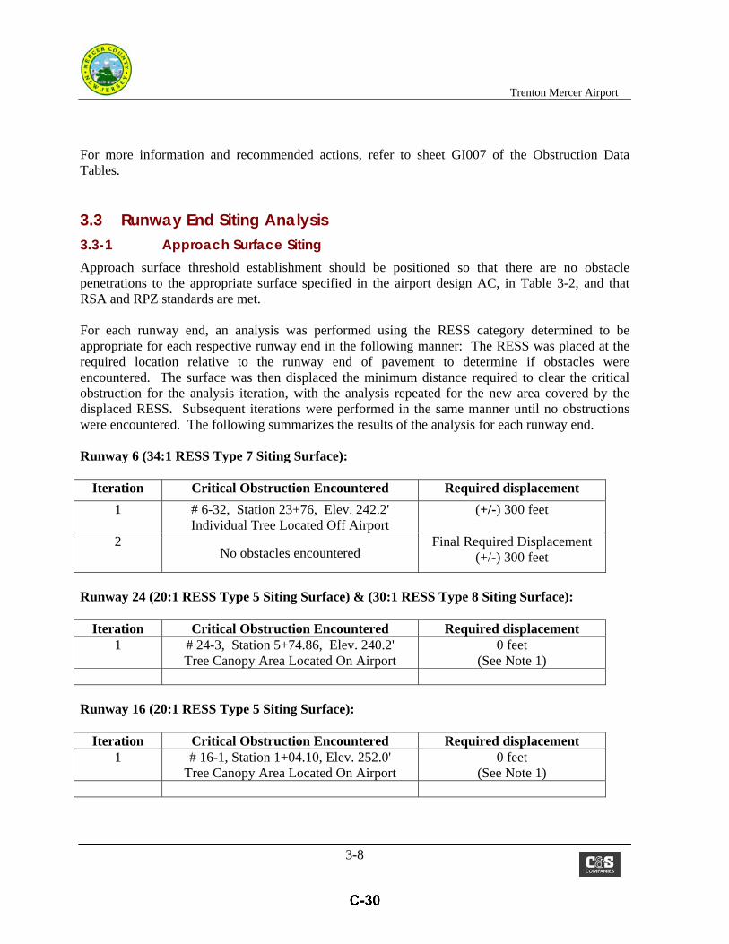
3.3 Runway End Siting Analysis 3.3-1 Approach Surface Siting Approach surface threshold establishment should be positioned so that there are no obstacle penetrations to the appropriate surface specified in the airport design AC, in Table 3-2, and that RSA and RPZ standards are met. For each runway end, an analysis was performed using the RESS category determined to be appropriate for each respective runway end in the following manner: The RESS was placed at the required location relative to the runway end of pavement to determine if obstacles were encountered. The surface was then displaced the minimum distance required to clear the critical obstruction for the analysis iteration, with the analysis repeated for the new area covered by the displaced RESS. Subsequent iterations were performed in the same manner until no obstructions were encountered. The following summarizes the results of the analysis for each runway end. Runway 6 (34:1 RESS Type 7 Siting Surface):
Iteration Critical Obstruction Encountered Required displacement
1 # 6-32, Station 23+76, Elev. 242.2' Individual Tree Located Off Airport
(+/-) 300 feet
2 No obstacles encountered
Final Required Displacement (+/-) 300 feet
Runway 24 (20:1 RESS Type 5 Siting Surface) & (30:1 RESS Type 8 Siting Surface):
Iteration Critical Obstruction Encountered Required displacement 1 # 24-3, Station 5+74.86, Elev. 240.2'
Tree Canopy Area Located On Airport 0 feet
(See Note 1)
Runway 16 (20:1 RESS Type 5 Siting Surface):
Iteration Critical Obstruction Encountered Required displacement 1 # 16-1, Station 1+04.10, Elev. 252.0'
Tree Canopy Area Located On Airport 0 feet
(See Note 1)

Trenton Mercer Airport
3-9
Runway 16 (30:1 RESS Type 8 Siting Surface):
Iteration Critical Obstruction Encountered Required displacement 1 No obstructions encountered 0 feet
Runway 34 (20:1 RESS slope, Runway Type 5):
Iteration Critical Obstacle Encountered Required displacement 1 #34-5, Station 1+22.30, Elev. 189.3'
Tree Canopy Area Located Off Airport (+/-) 150 feet
2 #34-5, Station 0+22.95, Elev. 196.0' Tree Canopy Area Located Off Airport
(+/-) 550 feet
3 No obstacles encountered
Final Required displacement = (+/-) 550 feet
Runway 34 (30:1 Glide Path Qualification Surface):
Iteration Critical Obstacle Encountered Required displacement 1 34 – 5 (Tree Canopy Area) (+/-) 110 feet 2
No obstacles encountered Final Required displacement =
(+/-) 110 feet
Note: 1. The critical obstruction to this surface is located on-airport property. As directed by FAA
on previous obstruction evaluation projects, once on-airport obstacles penetrating the RESS have been identified, the FAA considers removal of these obstacles the owner’s responsibility, and that the airport owner should be taking immediate actions to remove those obstacles. Therefore, this report considers that obstacles penetrating RESS surfaces, which are located within the airport owners control to remove, are not considered ‘an obstruction that would require future displacement of the threshold’.
3.3-2 Departure Surface Obstructions & Siting Departure surfaces, when clear, allow pilots to follow standard departure procedures. Runway 24 Departure Surface (runway 06 end) Drawing CG103 identifies 46 obstructions to the RW 24 Departure Surface, all contained within the obstruction areas identified for the FAR Part 77 Approach and the Transitional Surfaces, and within areas on-airport or within proposed Part 77 off-airport easements. No additional removal costs beyond FAR Part 77 removals would be incurred to have the runway 24 departure surface cleared of obstructions.

Trenton Mercer Airport
3-10
Runway 06 Departure Surface (runway 24 end) Drawing CG103 identifies 46 obstructions to the RW 24 Departure Surface, of which all are also FAR Part77 approach and transitional surface obstructions with the exception of:
Obstruction 6-5 Additional (1) tree Obstruction 6-6 An additional Light Pole Obstruction 6-7 An additional 0.12 ac of tree canopy area Obstruction 6-8 An additional 0.44 ac of tree canopy area Obstructions 6-13 & 14 Additional (13) trees Obstruction 6-16 An additional 0.14 ac of tree canopy area Obstruction 6-17 (2) Communication Towers/Antennas
It should be noted that departure obstruction 6-17 consists of two (2) communications tower/antennas that are not FAR Part 77 obstructions and that are located off airport property. The tower/antennas have been identified as penetrating the 40:1 departure surface by 6.0 feet and by 13.9 feet. Refer to sheet CG 109 for a Plan and sheet CG 205 for a detailed departure surface profile of each tower. Presently the airport is in negotiations with the tower owner concerning removal of the tower or lowering of the top sections of each to an elevation that is safely below the departure surface. The vertical tolerances of the aerial photography are approximately 2.5 feet for non-hard surface objects that were visible at the altitude the photography was flown. This report recommends that a field survey be performed to accurately determine the top elevations of each tower/antenna and the 40:1 departure surface elevation over each, for a more accurate determination of the extent of penetration. With the exception of departure obstruction 6-17, no additional easements are required for the airport owner to remove the above described departure obstructions beyond what is required for removal of the identified FAR Part 77 obstructions. An opinion of probable construction cost (only) for the above described obstructions is $23,500. A 40:1 OCS departure surface analysis was performed at runway ends 6 and 24 using the departure standards as listed for runway type 9 in Table 3.2 of the Airport Design AC 150/5300-13A. The 40:1 OCS departure surface was placed at the required location relative to the runway end of pavement as defined in chapter 2 of this report, to determine if obstacles penetrated the 40:1 OCS surface. The surface was then displaced the minimum distance required to clear the critical obstruction noting the remaining Take Off Distance Available (TODA). The following summarizes the results of the 40:1 OCS departure surface analysis at runways 6 and 24.

Trenton Mercer Airport
3-11
Runway 6 Departure (40:1 OCS): (Runway 6-24 Landing Length = 6,006 feet)
Iteration Critical Obstruction Encountered Remaining TODA/TORA
1 #Departure 6-7, Station 19+00, Elev. 273' Tree Canopy Area Located Off Airport
Approximate Location (+/-) 4,769 feet
(See Note)
Runway 24 Departure (40:1 OCS): (Runway 6-24 Landing Length = 6,006 feet)
Iteration Critical Obstruction Encountered Remaining TODA/TORA
1 #Departure24-15, Station 18+30, Elev.272.7’ Tree Canopy Area Located Off Airport
Approximate Location (+/-) 3,789 feet
(See Note)
Note: TODA/TORA Dimension shown considers runway gradient and actual OCS runway intersection. As previously stated in paragraphs above, “When it is not possible to keep the departure surface clear of obstacles, obstacles must be evaluated through the Obstruction Evaluation/Airport Airspace Analysis (OE/AAA) process”. For this reason, it is recommended that the FAA be contacted requesting their directive on the extent and/or need of removal prior to the airport doing so.
3.4 Terminal Instrument Procedures (TERPS) Analysis The intent in providing a TERPS analysis is to identify those obstacles that penetrate the Final Segment of the OEA/OCS, i.e. “W”, “X”, and “Y” Obstacle Clearance Surfaces, as identified in United States Standard for Terminal Instrument Procedures (TERPS), ORDER 8260.3B CHG 26, Chapter 3, Section 3. The surfaces, as modeled, identify the presence of three (3) tree canopy areas located within the “W” Obstacle Clearance Surface, as shown in Plan view on drawing CG106. The obstacle clearance surface data table, also shown on the drawing, identifies the locations of three areas, the extent of penetration into the “W” surface, the associated acreage of each, and lisis the recommended mitigation action as “Wetland Clearing”. These areas are also Title 14 CFR Part 77 obstructions and are included in the recommended mitigation actions for that surface. These three areas are listed as being located on-airport, allowing the Sponsor the right to remove these obstructions without further delay .
Trenton Mercer Airport
3-12
3.5 Medium Intensity Approach Light System w/Rails (MALSR) Analysis The intent in providing a MALSR analysis is to identify those obstacles that penetrate the Final Segment of the OEA/OCS, i.e. “W”, “X”, and “Y” Obstacle Clearance Surfaces, as identified in United States Standard for Terminal Instrument Procedures (TERPS), ORDER 8260.3B CHG 26, Chapter 3, Section 3. The surfaces, as modeled, identify the presence of three (3) tree canopy areas
3.6 Precision Approach Path Indicator (PAPI) Analysis PAPI Obstacle Clearance Surface The results of the analysis revealed that no obstructions to the PAPI obstacle clearance surface for runways 16, 24, or 34 exist. Although the PAPI units for each of the three runways are considered obstructions to their associated Primary Surface, they are considered a “fixed-by-function navigational aid”, requiring no action be taken.
3.7 Runway Protection Zone Analysis Runway 6 End: The airport controls a large portion of the land in the Runway Protection Zones off Runways 6, however not all of the land. Approximately 13.4 acres of the 78.9 acre Approach Runway Protection Zone is privately owned. The privately owned portion consists of portions of eleven private properties, a portion of Lands of State of New Jersey Department of Human Services, and two public highways containing utilities. There are six residential dwellings within the RPZ. A Runway Protection Zone Data Table, shown on sheet CG105, indicates this reports recommended action for each of the affected properties. The recommend actions range from the portion of the parcel within the RPZ being insignificant, therefore “no action”, to acquiring an avigation easement with ‘right of first refusal’, should the present property owner have intensions of selling the property in the future, or acquiring the property in FEE and relocating the present owner (if the owner is amicable to doing that). With submittal of this report to the FAA-Harrisburg ADO, the owner is anticipating that detailed guidance and direction will be provided to them concerning existing land uses within the Runway 6 RPZ. Runway 24 End: The airport currently owns the entire 29.5 acre Approach Runway Protection Zone, with the exception of Scotch Road, which is located diagonally through the central portion of the RPZ, at a distance of 300 to 500 feet from the end of runway. In addition, a railroad (Consolidated Rail Corp.) is also located diagonally through the central portion of the RPZ at a distance of 1,300 feet to 1,900 feet from the end of runway. A Runway Protection Zone Data
Trenton Mercer Airport
3-13
Table, shown on sheet CG111, indicates this reports recommended action for each of these existing land uses as “Mark & Light”. Detailed guidance and direction from the FAA-Harrisburg ADO, is anticipated concerning these two existing land uses within the central portion of the Runway 24 RPZ. Runway 16 End: The airport currently owns the entire 29.5 acre Approach Runway Protection Zone, with the exception of Sam Weinroth Road, which is located directly beyond the EMAS system recently constructed at this runway end. In addition, the divided highway designated as Interstate 95 is located diagonally through the central portion of the RPZ at a distance of approximately 500 feet from the end of the EMAS. The Central Portion of the RPZ extends onto airport property, presently used for recreational purposes as Mountain View Golf & Country Club. A Runway Protection Zone Data Table, shown on sheet CG115, indicates this reports recommended action for each of these existing land uses as “Mark & Light”. Detailed guidance and direction from the FAA-Harrisburg ADO, is anticipated concerning these existing land uses within the central portion of the Runway 16 RPZ. Runway 34 End: The Exhibit “A” Airport Property Inventory Map indicates that approximately 34% of the 29.5 acre RPZ is on airport lands. The Mercer County tax mapping lists this 34% area as County of Mercer County Library, with present land usage being for School Recreational – Athletic Fields. The aerial photography on sheet CG118 shows markings of athletic fields in this area. The privately owned portion of the RPZ (19.4 acres) consists of 1) First Presbyterian Church Ewing - Ewing Cemetery & Crematory, and 2) Consolidated Rail Corp. The Cemetery lands extend into the Central Portion of the RPZ consisting of paved roadways leading to areas of anticipated future expansion. In addition, field observation noted above ground construction of a new mausoleum extending into the Controlled Activity portion of the RPZ. The Conrail parcel extends diagonally through the Central Portion of the RPZ at a distance of 200 feet to 600 feet from the runway end. A Runway Protection Zone Data Table, shown on sheet CG118, lists the recommended action for each of these existing land uses as 1) obtain avigation easements over the cemetery lands, and 2) “Mark & Light” the railroad. Detailed guidance and direction from the FAA-Harrisburg ADO, is anticipated concerning these two existing land uses within the central portion of the Runway 24 RPZ.

Trenton Mercer Airport
3-13
3.8 Opinion of Probable Cost & Project Phasing (Title 14 CFR Part 77 Compliance) An opinion of probable cost was prepared for the acquisition of property interests in the form of avigation easements, obstruction removal, or lighting of obstructions associated with the evaluation of Title 14 CFR Part 77 surfaces. Tables 3-1, 3-2, and 3-3 provide a summary of the results. The unit costs were based on bid prices of similar work at other airport facilities. Recommended actions to cut and remove trees would include various options, which would be discussed and negotiated with the property owner. Tree removal options could consist of the following:
-Cutting and removing the trees to ground level but not grinding the stumps (Environmental Wetland areas);
-Cutting and removing the trees to ground level, grinding the stumps, and if requested, replanting with a low growing species;
-Installation of obstruction lights and obstruction light towers;
-Cutting and removing only that portion of the tree that penetrates the Title 14 CRF Part 77 surface (Crown Reduction). A routine trimming program by the airport would be required for this option as re-growth occurred.
In general, natural vegetation identified as being a penetration or being within 12.5 feet of penetrating the various 14 CFR Part 77 Navigable Airspace surfaces have been recommended for removal to ground. Small tree canopy areas in residential wooded areas or individual trees in residential areas, where the majority of the canopy height penetrates the ‘Buffer Airspace’ by approximately 6 to 8 feet were considered for ‘crown reduction’, rather than complete removal to ground level. Random or isolated penetrating natural vegetation within residential areas is recommended for ‘crown reduction’, commonly due to property owner resistance to total tree removal if reducing the height of the tree canopy of the offending tree is at all possible. Obviously, fixed features where the airport owner will not have rights to remove, or where removal would be cost prohibitive, are recommended to be lighted & marked per the appropriate FAA Design Advisory Circular. Due to the cost involved with acquisition of property interests and obstruction removal, it is recommended that the project be prioritized into three phases. Costs were developed for each runway providing opinion of costs to acquire property interests via acquisition of avigation easements, and for obstruction removal, both on and off airport, to assist in determining the phasing. The following provides a summary of the results:

Trenton Mercer Airport
3-13
PHASE I: $3,400,000
Removal/Treatment of all On-Airport Obstructions to the primary, transitional to primary, approach, and transitional to approach surfaces for Runways 6/24 and 16/34: $961,000 (constr.cost);
Acquisition of Avigation Easements for Runway 6/24 primary and transitional surfaces: $75,000 (esm’t cost);
Acquisition of Land/Avigation Easements for Runway 6 (Includes obtaining Right of First Refusal and/or fee acquisition for six residential properties within the Rwy 6 RPZ): $1.5M (esm’t cost)
Acquisition of Avigation Easements for Runway 24: $429,000 (esm’t cost); Obtain On- Airport Environmental Coordination permitting and mitigation for both design
and for construction; $435,000
PHASE II: $2,763,000 Removal of Off-Airport Obstructions to Runway 6/24 primary and transitional surfaces:
$702,000 (constr. cost); Removal of Off-Airport Obstructions to Runway 6 approach and transitional surfaces:
$725,000 (constr. cost); Removal of Off-Airport Obstructions to Runway 24 approach and transitional surfaces:
$172,000 (constr. cost); Acquisition of Avigation Easements for Runway 16/34: $15,000
Acquisition of Avigation Easements for Runway 16: $0 Acquisition of Avigation Easements for Runway 34: $149,000 Obtain Off-Airport Environmental Coordination permitting and mitigation for both design
and for construction $1.0M
PHASE III: $221,000 Removal of Off-Airport Obstructions to Runway 16/34 transitional surfaces:
$24,000 (constr. cost); Removal of Off-Airport Obstructions to Runway 34 approach and transitional to approach
surfaces: $197,000 (constr. cost); It is worth noting that some avigation easement acquisition costs may be reduced or eliminated, depending on the nature of the obstruction treatment actually performed. The above easement acquisition costs represent a worse-case scenario based on the obstruction treatment recommendations outlined in this report developed from information currently available. Alternative treatments may be developed information obtained from ground survey.
Trenton Mercer Airport
3-13
3.9 Conclusions/Recommendations This chapter has summarized the obstructions to the Title 14 CFR Part 77 Surfaces, Approach and Departure Runway Protection Zones, Runway End Siting Surfaces and PAPI Obstacle Clearance Surfaces as identified on the accompanying set of drawings. Recommendations were made for addressing each of the obstructions, as shown on the Data Table sheets within the set of drawings. An opinion of probable cost has also been presented. The quantities used to calculate project costs were determined from the Obstruction Evaluation Drawings. Unit costs were developed from past bid experience of similar projects at other New York State airports. All costs provided are Engineer’s opinions of probable construction cost and are based upon 2014 dollars. Construction Administration & Observation costs are anticipated to be within the allowed percentage of the total Construction costs. Engineering Design costs have not been included, since project scope of work cannot be determined at this juncture. In conclusion, the airport owner should consider addressing the runway end siting obstructions at the earliest opportunity, to protect the existing location of the thresholds. Removal of “highest priority” obstructions should also be accomplished at the airport owner’s first opportunity. Highest priority obstructions are considered to be located within the primary and the “close-in” approach surfaces. Previous communications with FAA in similar circumstances have revealed the FAA’s willingness to provide airport owners with grant assistance for these types of obstruction mitigation

Trenton Mercer Airport
3-16
projects, possibility resulting in improved approach visibility minimums for that runway end. In the long term, airport compliance to 14 CFR Part 77 obstruction mitigation will enhance the operational effectiveness of the facility and improve safety. FAA eligible projects to mitigate obstructions should be added to the Airport’s Capital Improvement Program. Recommended next steps may include the following:
1) Perform an Environmental Assessment 2) Acquisition of Land and/or Avigation Easements 3) Obstruction Mitigation (Design) 4) Obstruction Mitigation (Construction)
-END-
Trenton Mercer Airport
TABLE 3-1
SUMMARY OF PROBABLE AVIGATION EASEMENT ACQUISITION COSTS (Title 14 CFR Part 77 compliance)
TABLE 3-2
ON-AIRPORT OBSTRUCTION TREATMENT OPINION OF PROBABLE COST (Title 14 CFR Part 77 Compliance)
TABLE 3-3
OFF-AIRPORT OBSTRUCTION TREATMENT OPINION OF PROBABLE COST (Title 14 CFR Part 77 Compliance)
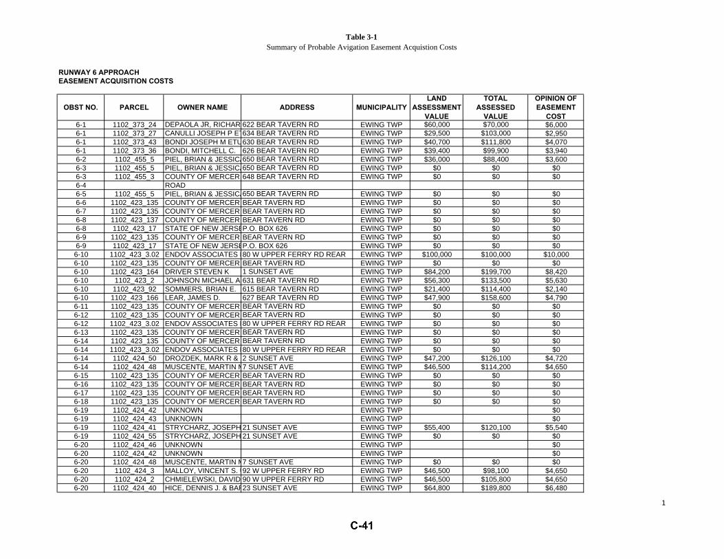
Table 3-1Summary of Probable Avigation Easement Acquistion Costs
RUNWAY 6 APPROACHEASEMENT ACQUISITION COSTS
OBST NO. PARCEL OWNER NAME ADDRESS MUNICIPALITYLAND
ASSESSMENTVALUE
TOTALASSESSED
VALUE
OPINION OFEASEMENT
COST6-1 1102_373_24 DEPAOLA JR, RICHARD A & DAVID/NEMEC622 BEAR TAVERN RD EWING TWP $60,000 $70,000 $6,0006-1 1102_373_27 CANULLI JOSEPH P ETUX634 BEAR TAVERN RD EWING TWP $29,500 $103,000 $2,9506-1 1102_373_43 BONDI JOSEPH M ETUX630 BEAR TAVERN RD EWING TWP $40,700 $111,800 $4,0706-1 1102_373_36 BONDI, MITCHELL C. 626 BEAR TAVERN RD EWING TWP $39,400 $99,900 $3,9406-2 1102_455_5 PIEL, BRIAN & JESSICA650 BEAR TAVERN RD EWING TWP $36,000 $88,400 $3,6006-3 1102_455_5 PIEL, BRIAN & JESSICA650 BEAR TAVERN RD EWING TWP $0 $0 $06-3 1102_455_3 COUNTY OF MERCER 648 BEAR TAVERN RD EWING TWP $0 $0 $06-4 ROAD6-5 1102_455_5 PIEL, BRIAN & JESSICA650 BEAR TAVERN RD EWING TWP $0 $0 $06-6 1102_423_135 COUNTY OF MERCER BEAR TAVERN RD EWING TWP $0 $0 $06-7 1102_423_135 COUNTY OF MERCER BEAR TAVERN RD EWING TWP $0 $0 $06-8 1102_423_137 COUNTY OF MERCER BEAR TAVERN RD EWING TWP $0 $0 $06-8 1102_423_17 STATE OF NEW JERSEY C/O R.CALDERONEP.O. BOX 626 EWING TWP $0 $0 $06-9 1102_423_135 COUNTY OF MERCER BEAR TAVERN RD EWING TWP $0 $0 $06-9 1102_423_17 STATE OF NEW JERSEY C/O R.CALDERONEP.O. BOX 626 EWING TWP $0 $0 $06-10 1102_423_3.02 ENDOV ASSOCIATES LIMITED LIA.80 W UPPER FERRY RD REAR EWING TWP $100,000 $100,000 $10,0006-10 1102_423_135 COUNTY OF MERCER BEAR TAVERN RD EWING TWP $0 $0 $06-10 1102_423_164 DRIVER STEVEN K 1 SUNSET AVE EWING TWP $84,200 $199,700 $8,4206-10 1102_423_2 JOHNSON MICHAEL A 631 BEAR TAVERN RD EWING TWP $56,300 $133,500 $5,6306-10 1102_423_92 SOMMERS, BRIAN E. 615 BEAR TAVERN RD EWING TWP $21,400 $114,400 $2,1406-10 1102_423_166 LEAR, JAMES D. 627 BEAR TAVERN RD EWING TWP $47,900 $158,600 $4,7906-11 1102_423_135 COUNTY OF MERCER BEAR TAVERN RD EWING TWP $0 $0 $06-12 1102_423_135 COUNTY OF MERCER BEAR TAVERN RD EWING TWP $0 $0 $06-12 1102_423_3.02 ENDOV ASSOCIATES LIMITED LIA.80 W UPPER FERRY RD REAR EWING TWP $0 $0 $06-13 1102_423_135 COUNTY OF MERCER BEAR TAVERN RD EWING TWP $0 $0 $06-14 1102_423_135 COUNTY OF MERCER BEAR TAVERN RD EWING TWP $0 $0 $06-14 1102_423_3.02 ENDOV ASSOCIATES LIMITED LIA.80 W UPPER FERRY RD REAR EWING TWP $0 $0 $06-14 1102_424_50 DROZDEK, MARK R & DEBRA A2 SUNSET AVE EWING TWP $47,200 $126,100 $4,7206-14 1102_424_48 MUSCENTE, MARTIN M7 SUNSET AVE EWING TWP $46,500 $114,200 $4,6506-15 1102_423_135 COUNTY OF MERCER BEAR TAVERN RD EWING TWP $0 $0 $06-16 1102_423_135 COUNTY OF MERCER BEAR TAVERN RD EWING TWP $0 $0 $06-17 1102_423_135 COUNTY OF MERCER BEAR TAVERN RD EWING TWP $0 $0 $06-18 1102_423_135 COUNTY OF MERCER BEAR TAVERN RD EWING TWP $0 $0 $06-19 1102_424_42 UNKNOWN EWING TWP $06-19 1102_424_43 UNKNOWN EWING TWP $06-19 1102_424_41 STRYCHARZ, JOSEPH P JR UX21 SUNSET AVE EWING TWP $55,400 $120,100 $5,5406-19 1102_424_55 STRYCHARZ, JOSEPH P JR UX21 SUNSET AVE EWING TWP $0 $0 $06-20 1102_424_46 UNKNOWN EWING TWP $06-20 1102_424_42 UNKNOWN EWING TWP $06-20 1102_424_48 MUSCENTE, MARTIN M7 SUNSET AVE EWING TWP $0 $0 $06-20 1102_424_3 MALLOY, VINCENT S. UX92 W UPPER FERRY RD EWING TWP $46,500 $98,100 $4,6506-20 1102_424_2 CHMIELEWSKI, DAVID R. UX90 W UPPER FERRY RD EWING TWP $46,500 $105,800 $4,6506-20 1102_424_40 HICE, DENNIS J. & BARBARA F.23 SUNSET AVE EWING TWP $64,800 $189,800 $6,480
1
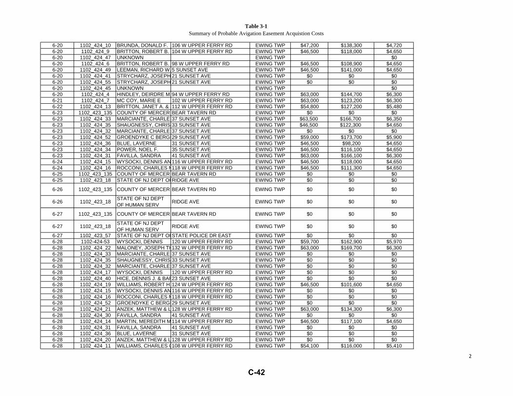
Table 3-1Summary of Probable Avigation Easement Acquistion Costs
6-20 1102_424_10 BRUNDA, DONALD F. 106 W UPPER FERRY RD EWING TWP $47,200 $138,300 $4,7206-20 1102_424_9 BRITTON, ROBERT B. ETUX104 W UPPER FERRY RD EWING TWP $46,500 $118,000 $4,6506-20 1102_424_47 UNKNOWN EWING TWP $06-20 1102_424_6 BRITTON, ROBERT B. JR.98 W UPPER FERRY RD EWING TWP $46,500 $108,900 $4,6506-20 1102_424_49 LEEMAN, RICHARD W. 5 SUNSET AVE EWING TWP $46,500 $141,000 $4,6506-20 1102_424_41 STRYCHARZ, JOSEPH P JR UX21 SUNSET AVE EWING TWP $0 $0 $06-20 1102_424_55 STRYCHARZ, JOSEPH P JR UX21 SUNSET AVE EWING TWP $0 $0 $06-20 1102_424_45 UNKNOWN EWING TWP $06-20 1102_424_4 HINDLEY, DEIRDRE M.94 W UPPER FERRY RD EWING TWP $63,000 $144,700 $6,3006-21 1102_424_7 MC COY, MARIE E 102 W UPPER FERRY RD EWING TWP $63,000 $123,200 $6,3006-22 1102_424_13 BRITTON, JANET A. & JOSEPH R.112 W UPPER FERRY RD EWING TWP $54,800 $127,200 $5,4806-23 1102_423_135 COUNTY OF MERCER BEAR TAVERN RD EWING TWP $0 $0 $06-23 1102_424_33 MARCIANTE, CHARLES H. ETUX37 SUNSET AVE EWING TWP $63,500 $166,700 $6,3506-23 1102_424_35 SHAUGNESSY, CHRISTOPHER J.33 SUNSET AVE EWING TWP $46,500 $122,300 $4,6506-23 1102_424_32 MARCIANTE, CHARLES H. ETUX37 SUNSET AVE EWING TWP $0 $0 $06-23 1102_424_52 GROENDYKE C BERGEN29 SUNSET AVE EWING TWP $59,000 $173,700 $5,9006-23 1102_424_36 BLUE, LAVERNE 31 SUNSET AVE EWING TWP $46,500 $98,200 $4,6506-23 1102_424_34 POWER, NOEL F. 35 SUNSET AVE EWING TWP $46,500 $116,100 $4,6506-23 1102_424_31 FAVILLA, SANDRA 41 SUNSET AVE EWING TWP $63,000 $166,100 $6,3006-24 1102_424_15 WYSOCKI, DENNIS ANTHONY UX116 W UPPER FERRY RD EWING TWP $46,500 $118,000 $4,6506-24 1102_424_16 ROCCONI, CHARLES M. ETAL118 W UPPER FERRY RD EWING TWP $46,500 $111,300 $4,6506-25 1102_423_135 COUNTY OF MERCER BEAR TAVERN RD EWING TWP $0 $0 $06-25 1102_423_18 STATE OF NJ DEPT OF HUMAN SERVRIDGE AVE EWING TWP $0 $0 $0
6-26 1102_423_135 COUNTY OF MERCER BEAR TAVERN RD EWING TWP $0 $0 $0
6-26 1102_423_18 STATE OF NJ DEPTOF HUMAN SERV RIDGE AVE EWING TWP $0 $0 $0
6-27 1102_423_135 COUNTY OF MERCER BEAR TAVERN RD EWING TWP $0 $0 $0
6-27 1102_423_18 STATE OF NJ DEPTOF HUMAN SERV RIDGE AVE EWING TWP $0 $0 $0
6-27 1102_423_57 STATE OF NJ DEPT OF TREASURYSTATE POLICE DR EAST EWING TWP $0 $0 $06-28 1102-424-53 WYSOCKI, DENNIS 120 W UPPER FERRY RD EWING TWP $59,700 $162,900 $5,9706-28 1102_424_22 MALONEY, JOSEPH THOMAS UX132 W UPPER FERRY RD EWING TWP $63,000 $169,700 $6,3006-28 1102_424_33 MARCIANTE, CHARLES H. ETUX37 SUNSET AVE EWING TWP $0 $0 $06-28 1102_424_35 SHAUGNESSY, CHRISTOPHER J.33 SUNSET AVE EWING TWP $0 $0 $06-28 1102_424_32 MARCIANTE, CHARLES H. ETUX37 SUNSET AVE EWING TWP $0 $0 $06-28 1102_424_17 WYSOCKI, DENNIS 120 W UPPER FERRY RD EWING TWP $0 $0 $06-28 1102_424_40 HICE, DENNIS J. & BARBARA F.23 SUNSET AVE EWING TWP $0 $0 $06-28 1102_424_19 WILLIAMS, ROBERT H. UX124 W UPPER FERRY RD EWING TWP $46,500 $101,600 $4,6506-28 1102_424_15 WYSOCKI, DENNIS ANTHONY UX116 W UPPER FERRY RD EWING TWP $0 $0 $06-28 1102_424_16 ROCCONI, CHARLES M. ETAL118 W UPPER FERRY RD EWING TWP $0 $0 $06-28 1102_424_52 GROENDYKE C BERGEN29 SUNSET AVE EWING TWP $0 $0 $06-28 1102_424_21 ANZEK, MATTHEW & LOIS128 W UPPER FERRY RD EWING TWP $63,000 $134,300 $6,3006-28 1102_424_30 FAVILLA, SANDRA 41 SUNSET AVE EWING TWP $0 $0 $06-28 1102_424_14 MARTIN, MEREDITH M. & GEORGE114 W UPPER FERRY RD EWING TWP $46,500 $117,100 $4,6506-28 1102_424_31 FAVILLA, SANDRA 41 SUNSET AVE EWING TWP $0 $0 $06-28 1102_424_36 BLUE, LAVERNE 31 SUNSET AVE EWING TWP $0 $0 $06-28 1102_424_20 ANZEK, MATTHEW & LOIS128 W UPPER FERRY RD EWING TWP $0 $0 $06-28 1102_424_11 WILLIAMS, CHARLES G. UX108 W UPPER FERRY RD EWING TWP $54,100 $116,000 $5,410
2

Table 3-1Summary of Probable Avigation Easement Acquistion Costs
6-28 1102_424_13 BRITTON, JANET A. & JOSEPH R.112 W UPPER FERRY RD EWING TWP $0 $0 $06-28 1102_424_37 GROENDYKE C BERGEN29 SUNSET AVE EWING TWP $59,000 $173,700 $5,9006-28 1102_424_34 POWER, NOEL F. 35 SUNSET AVE EWING TWP $0 $0 $06-28 1102_424_54 HICE, DENNIS J. & BARBARA F.23 SUNSET AVE EWING TWP $0 $0 $06-29 1102_423_52 BRAMBLE, ROBERT & LISA148 W UPPER FERRY RD EWING TWP $51,400 $102,300 $5,1406-29 1102_423_65 BRAMBLE, ROBERT & LISA148 W UPPER FERRY RD EWING TWP $0 $0 $06-29 1102_424_22 MALONEY, JOSEPH THOMAS UX132 W UPPER FERRY RD EWING TWP $0 $0 $06-29 1102_423_54 MESSICK, CHRISTOPHER152 W UPPER FERRY RD EWING TWP $55,900 $136,700 $5,5906-29 1102_424_28 JONES, ANTHONY J. & SUSAN E.47 SUNSET AVE EWING TWP $46,500 $139,900 $4,6506-29 1102_424_24 FLETCHER JAY SHAHN Y PATRICIA COYLE134 W UPPER FERRY RD EWING TWP $46,500 $95,600 $4,6506-29 1102_423_19 SHEARER, CHAD E. H/W142 W UPPER FERRY RD EWING TWP $69,800 $167,700 $6,9806-29 1102_424_25 KEENAN, JAMES A. III UX136 W UPPER FERRY RD EWING TWP $46,500 $110,800 $4,6506-29 1102_424_29 LALLY, MADALYN & JOHN43 SUNSET AVE EWING TWP $46,500 $138,000 $4,6506-29 1102_423_62 MESSICK, CHRISTOPHER152 W UPPER FERRY RD EWING TWP $55,900 $136,700 $5,5906-29 1102_423_43 KILCOYNE PHILLIP & DIGIACOMANTONIO146 W UPPER FERRY RD EWING TWP $50,000 $138,500 $5,0006-29 1102_423_63 UNKNOWN EWING TWP $06-29 1102_423_64 UNKNOWN EWING TWP $06-30 1102_424_22 MALONEY, JOSEPH THOMAS UX132 W UPPER FERRY RD EWING TWP $0 $0 $06-30 1102_423_135 COUNTY OF MERCER BEAR TAVERN RD EWING TWP $0 $0 $06-30 1102_424_28 JONES, ANTHONY J. & SUSAN E.47 SUNSET AVE EWING TWP $0 $0 $06-30 1102_424_24 FLETCHER JAY SHAHN Y PATRICIA COYLE134 W UPPER FERRY RD EWING TWP $0 $0 $06-30 1102_423_19 SHEARER, CHAD E. H/W142 W UPPER FERRY RD EWING TWP $0 $0 $06-30 1102_424_25 KEENAN, JAMES A. III UX136 W UPPER FERRY RD EWING TWP $0 $0 $06-30 1102_423_218 ANDERSON, MICHAEL T. & DONNA3 RIDGE AVE EWING TWP $67,500 $164,600 $6,7506-30 1102_424_26 ORNDORFF, WAYNE 51 SUNSET AVE EWING TWP $46,500 $108,900 $4,6506-30 1102_424_27 CHMIELEWSKI, DAVID R. & ANNE E.49 SUNSET AVE EWING TWP $46,500 $99,400 $4,6506-31 1102_423_110 BUCK, GARY P. UX 1 RIDGE AVE EWING TWP $60,000 $120,800 $6,0006-31 1102_423_18.01 HARTER, THOMAS A. & LISA E.99 RIDGE AVE EWING TWP $53,100 $130,500 $5,3106-31 1102_423_18 STATE OF NJ DEPT OF HUMAN SERVRIDGE AVE EWING TWP $0 $0 $06-31 1102_423_218 ANDERSON, MICHAEL T. & DONNA3 RIDGE AVE EWING TWP $0 $0 $06-32 1102_423_72 TRAMONTANA, RICHARD UX154 W UPPER FERRY RD EWING TWP $47,300 $135,900 $4,730
3

Table 3-1Summary of Probable Avigation Easement Acquistion Costs
6-32 1102_423_18.01 HARTER, THOMAS A. & LISA E.99 RIDGE AVE EWING TWP $0 $0 $06-32 1102_423_71 KIRILUK, TRACEY 158 W UPPER FERRY RD EWING TWP $64,500 $144,800 $6,4506-32 1102_423_18 STATE OF NJ DEPT OF HUMAN SERVRIDGE AVE EWING TWP $0 $0 $06-32 1102_423_43 KILCOYNE PHILLIP & DIGIACOMANTONIO146 W UPPER FERRY RD EWING TWP $0 $0 $06-33 1102_423_65 BRAMBLE, ROBERT & LISA148 W UPPER FERRY RD EWING TWP $0 $0 $06-33 1102_423_54 MESSICK, CHRISTOPHER152 W UPPER FERRY RD EWING TWP $0 $0 $06-33 1102_423_72 TRAMONTANA, RICHARD UX154 W UPPER FERRY RD EWING TWP $0 $0 $06-33 1102_423_18.01 HARTER, THOMAS A. & LISA E.99 RIDGE AVE EWING TWP $0 $0 $06-33 1102_423_71 KIRILUK, TRACEY 158 W UPPER FERRY RD EWING TWP $0 $0 $06-33 1102_423_159 STATE OF NJ W UPPER FERRY RD EWING TWP $0 $0 $06-33 1102_423_62 MESSICK, CHRISTOPHER152 W UPPER FERRY RD EWING TWP $0 $0 $06-33 1102_423_43 KILCOYNE PHILLIP & DIGIACOMANTONIO146 W UPPER FERRY RD EWING TWP $0 $0 $06-33 1102_423_76 HOWELL, RICHARD H. 162 W UPPER FERRY RD EWING TWP $64,500 $139,200 $6,4506-34 1102_423_72 TRAMONTANA, RICHARD UX154 W UPPER FERRY RD EWING TWP $0 $0 $06-34 1102_423_71 KIRILUK, TRACEY 158 W UPPER FERRY RD EWING TWP $0 $0 $06-35 1102_423_159 STATE OF NJ W UPPER FERRY RD EWING TWP $0 $0 $06-35 1102_423_18 STATE OF NJ DEPT OF HUMAN SERVRIDGE AVE EWING TWP $0 $0 $06-35 1102_423_57 STATE OF NJ DEPT OF TREASURYSTATE POLICE DR EAST EWING TWP $0 $0 $06-35 1102_423_76 HOWELL, RICHARD H. 162 W UPPER FERRY RD EWING TWP $0 $0 $06-36 1102_423_85 HADGE, JOSEPH 170 W UPPER FERRY RD EWING TWP $54,800 $123,600 $5,4806-36 1102_423_50 WOOLVERTON, TERRY L.166 W UPPER FERRY RD EWING TWP $54,800 $128,900 $5,4806-36 1102_423-159 STATE OF NJ W UPPER FERRY RD EWING TWP $0 $0 $06-36 1102_423_57 STATE OF NJ DEPT OF TREASURYSTATE POLICE DR EAST EWING TWP $0 $0 $06-36 1102_423_76 HOWELL, RICHARD H. 162 W UPPER FERRY RD EWING TWP $0 $0 $06-37 1102_423_99 PATAKI, KAMIL UX 184 W UPPER FERRY RD EWING TWP $63,000 $146,100 $6,3006-37 1102_423_88 SHELLY, SUSAN E. & PAUL178 W UPPER FERRY RD EWING TWP $54,800 $133,600 $5,4806-37 1102_423_86 POLEO, JOSEPH 1. 172 W UPPER FERRY RD EWING TWP $54,900 $107,200 $5,4906-37 1102_423_103 SNYDER, HAROLD R. 188 W UPPER FERRY RD EWING TWP $63,000 $130,500 $6,3006-37 1102-423_49 SMARTWOOD, NEIL R. UX182 W UPPER FERRY RD EWING TWP $54,800 $128,300 $5,4806-37 1102_423_87 RACIOPPI, KATHERINE V. & ANTHONY176 W UPPER FERRY RD EWING TWP $54,800 $119,200 $5,4806-37 1102_423_57 STATE OF NJ DEPT OF TREASURYSTATE POLICE DR EAST EWING TWP $0 $0 $06-38 1102_423_57 STATE OF NJ DEPT OF TREASURYSTATE POLICE DR EAST EWING TWP $0 $0 $06-39 1102_423_57 STATE OF NJ DEPT OF TREASURYSTATE POLICE DR EAST EWING TWP $0 $0 $0
4

Table 3-1Summary of Probable Avigation Easement Acquistion Costs
6-39 1102_423_186 RAVINE CLUB P.O. BOX 7201 EWING TWP $26,800 $63,300 $2,6806-40 1102_423_186 RAVINE CLUB P.O. BOX 7201 EWING TWP $0 $0 $06-40 1102_423_17 STATE OF NEW JERSEY C/O R.CALDERONEP.O. BOX 626 EWING TWP $0 $0 $06-41 1102_422.02_34 GLENN, EDWARD N. & MORAN, PATRICIA E.177 W UPPER FERRY RD EWING TWP $61,200 $157,500 $6,1206-41 1102_422.02_35 SAMAYOA, ALEXANDER & CHRISTINE181 W UPPER FERRY RD EWING TWP $60,900 $129,000 $6,0906-41 1102_422.02_36 AMENT JR, JOHN D. 185 W UPPER FERRY RD EWING TWP $61,400 $147,800 $6,1406-42 1102_422.01_49 COLEMAN, JANET M. 199 W UPPER FERRY RD EWING TWP $60,000 $125,600 $6,0006-42 1102_422.01_48 MILLER, RUTH GIBSON195 W UPPER FERRY RD EWING TWP $60,000 $137,200 $6,0006-43 1102_422.01_48 MILLER, RUTH GIBSON195 W UPPER FERRY RD EWING TWP $0 $0 $06-43 1102_422.01_49 COLEMAN, JANET M. 199 W UPPER FERRY RD EWING TWP $0 $0 $06-44 1102_422.01_48 MILLER, RUTH GIBSON195 W UPPER FERRY RD EWING TWP $0 $0 $06-45 1102_423_125 FEDERAL HOME LOAN MORTGAGE GROUP8250 JONES BRANCH DR EWING TWP $62,800 $157,200 $6,2806-45 1102_423_124 ANDREOLI, THERESA 214 W UPPER FERRY RD EWING TWP $63,000 $171,500 $6,3006-46 1102-423_220 DELAWARE RIVER BASIN COMMISSIONP.O. BOX 7360 EWING TWP $411,300 $2,667,900 $41,1306-46 1102_423_77 COLLEEN ENTERPRISES LLC234 W UPPER FERRY RD EWING TWP $121,600 $288,100 $12,160
State and Municipal entities are assumed to be amicable and are also shown as $0 $436,240RUNWAY 6 TOTAL NOTE: Property Owner easement costs are listed only once. Duplication due to multiple obstructions are shown as $0
5

Table 3-1Summary of Probable Avigation Easement Acquistion Costs
RUNWAY 24 APPROACHEASEMENT ACQUISITION COSTS
OBST NO. PARCEL OWNER NAME ADDRESS MUNICIPALITYLAND
ASSESSMENTVALUE
TOTALASSESSED
VALUE
OPINION OFEASEMENT
COST24-1 1102_368_7 TOWNSHIP OF EWING 2 JAKE GARZIO DR EWING TWP $024-2 RAILROAD EWING TWP $024-3 RAILROAD EWING TWP $024-4 AIRPORT24-5 1102_368_7 TOWNSHIP OF EWING 2 JAKE GARZIO DR EWING TWP $0 $0 $024-5 1102_368_3 BROMBERG, CHRISTOPHER1457 LOWER FERRY RD. EWING TWP $368,300 $754,400 $36,83024-5 1102_368_30 1445 LOWER FERRY, LLC414 ESSEX STREET EWING TWP $731,300 $3,100,000 $73,13024-524-6 AIRPORT24-7 1102_371_3.03 AMERICAN PROP AT SCOTCH RD LLC517 RT 1 SO,SUITE 2100 EWING TWP $1,100,000 $7,198,800 $110,00024-8 1102_371_3.05 HERRING LAND GROUP23 ORCHARD ROAD EWING TWP $857,900 $857,900 $85,79024-8 1102_371_3.03 AMERICAN PROP AT SCOTCH RD LLC517 RT 1 SO,SUITE 2100 EWING TWP $0 $0 $024-9 1102_371_3.03 AMERICAN PROP AT SCOTCH RD LLC517 RT 1 SO,SUITE 2100 EWING TWP $0 $0 $0
24-10 1102_371_3.03 AMERICAN PROP AT SCOTCH RD LLC517 RT 1 SO,SUITE 2100 EWING TWP $0 $0 $024-11 RAILROAD EWING TWP $024-12 1102_368_3 BROMBERG, CHRISTOPHER1457 LOWER FERRY RD. EWING TWP $0 $0 $024-13 AIRPORT EWING TWP $024-14 1102_371_3.03 AMERICAN PROP AT SCOTCH RD LLC517 RT 1 SO,SUITE 2100 EWING TWP $0 $0 $024-14 1102_371_3.05 HERRING LAND GROUP23 ORCHARD ROAD EWING TWP $0 $0 $024-15 1102_368_3 BROMBERG, CHRISTOPHER1457 LOWER FERRY RD. EWING TWP $0 $0 $024-15 1102_225.02_52 CENLAR FSB ATTN: A/PP O BOX 77415 EWING TWP $0 $0 $024-16 1102_225.02_52 CENLAR FSB ATTN: A/PP O BOX 77415 EWING TWP $568,500 $4,528,800 $56,85024-16 1102_225.01_6 MERCER FERRY C/O TRILLIUM REALTY83 PRINCETON AV SUITE 3C EWING TWP $0 $0 $024-17 AIRPORT EWING TWP $024-17 1102_368_10 SHIVKRUPA FAMILY LP/MAHADEV MGMT5 BEL AIR COURT EWING TWP $360,800 $669,700 $36,08024-18 1102_368_1 FVHD, LLC. 1515 LOWER FERRY RD EWING TWP $300,000 $625,000 $30,000
State and Municipal entities are assumed to be amicable and are also shown as $0 $428,680RUNWAY 24 TOTAL NOTE: Property Owner easement costs are listed only once. Duplication due to multiple obstructions are shown as $0
6

Table 3-1Summary of Probable Avigation Easement Acquistion Costs
RUNWAY 34 APPROACHEASEMENT ACQUISITION COSTS
OBST NO. PARCEL OWNER NAME ADDRESS MUNICIPALITYLAND
ASSESSMENTVALUE
TOTALASSESSED
VALUE
OPINION OFEASEMENT
COST34-1 1102_366_2 STATE OF NJ DEPT OF DEFENSEUPPER FERRY ROAD EWING TWP $0 $0 $034-2 RAILROAD EWING TWP $0 $0 $034-3 RAILROAD EWING TWP $0 $0 $034-4 EWING CEMETARY EWING TWP $034-5 1102_366_2 STATE OF NJ DEPT OF DEFENSEUPPER FERRY ROAD EWING TWP $0 $0 $034-5 1102-366_1 CONSOLIDATED RAIL CORPORATION1818 MARKET STREET EWING TWP $0 $0 $034-6 1102_365_2 FIRST PRESBYTERIAN CHURCH OF EWING100 SCOTCH RD EWING TWP $1,493,300 $2,006,500 $149,33034-7 1102_365_2 FIRST PRESBYTERIAN CHURCH OF EWING100 SCOTCH RD EWING TWP $0 $0 $034-8 1102_366_1 CONSOLIDATED RAIL CORPORATION1818 MARKET STREET EWING TWP $0 $0 $034-9 1102_366_1 CONSOLIDATED RAIL CORPORATION1818 MARKET STREET EWING TWP $0 $0 $0
34-10 1102_366_1 CONSOLIDATED RAIL CORPORATION1818 MARKET STREET EWING TWP $0 $0 $034-11 1102_366_1 CONSOLIDATED RAIL CORPORATION1818 MARKET STREET EWING TWP $0 $0 $034-12 1102_366_1 CONSOLIDATED RAIL CORPORATION1818 MARKET STREET EWING TWP $0 $0 $034-12 1102_365_1 COUNTY OF MERCER-COUNTY LIBRARY2751 BRUNSWICK PIKE EWING TWP $0 $0 $034-13 1102_366_1 CONSOLIDATED RAIL CORPORATION1818 MARKET STREET EWING TWP $0 $0 $034-13 1102_365_1 COUNTY OF MERCER-COUNTY LIBRARY2751 BRUNSWICK PIKE EWING TWP $0 $0 $034-14 AIRPORT EWING TWP $0 $0 $034-15 AIRPORT EWING TWP $0 $0 $034-16 AIRPORT EWING TWP $0 $0 $034-17 AIRPORT EWING TWP $0 $0 $034-18 AIRPORT EWING TWP $0 $0 $034-18 1102_366_1 CONSOLIDATED RAIL CORPORATION1818 MARKET STREET EWING TWP $0 $0 $034-19 AIRPORT EWING TWP $0 $0 $0
State and Municipal entities are assumed to be amicable and are also shown as $0 $149,330RUNWAY 34 TOTAL NOTE: Property Owner easement costs are listed only once. Duplication due to multiple obstructions are shown as $0
7

Table 3-1Summary of Probable Avigation Easement Acquistion Costs
RUNWAY 16-34 APPROACHEASEMENT ACQUISITION COSTS
OBST NO. PARCEL OWNER NAME ADDRESS MUNICIPALITYLAND
ASSESSMENTVALUE
TOTALASSESSED
VALUE
OPINION OFEASEMENT
COST16/34-1 AIRPORT $0 $0 $016/34-2 AIRPORT $0 $0 $016/34-3 AIRPORT $0 $0 $016/34-4 AIRPORT $0 $0 $016/34-5 AIRPORT $0 $0 $016/34-6 AIRPORT $0 $0 $016/34-7 AIRPORT $0 $0 $016/34-8 AIRPORT $0 $0 $016/34-9 AIRPORT $0 $0 $0
16/34-10 AIRPORT $0 $0 $016/34-11 AIRPORT $0 $0 $016/34-12 AIRPORT $0 $0 $016/34-13 AIRPORT $0 $0 $016/34-14 1102_374_2 SCRATCH ASSOCIATES LLC299 UPPER FERRY RD EWING TWP $59,300 $5,786 $5,93016/34-14 1102_374_6 SILVA GUARD INC. 299 UPPER FERRY RD EWING TWP $89,800 $173,500 $8,98016/34-15 RAILROAD EWING TWP $016/34-16 1102_365_2 FIRST PRESBYTERIAN CHURCH OF EWING100 SCOTCH RD EWING TWP $0 $0 $016/34-17 1102_365_2 FIRST PRESBYTERIAN CHURCH OF EWING100 SCOTCH RD EWING TWP $0 $0 $016/34-17 RAILROAD EWING TWP $0 $0 $0
State and Municipal entities are assumed to be amicable and are also shown as $0 $14,910
(see rwy 34 approach table)
RUNWAY 16/34 TOTAL NOTE: Property Owner easement costs are listed only once. Duplication due to multiple obstructions are shown as $0
8
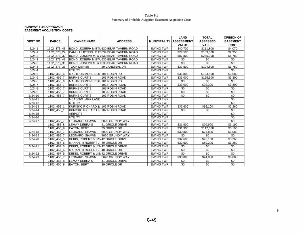
Table 3-1Summary of Probable Avigation Easement Acquistion Costs
RUNWAY 6-24 APPROACHEASEMENT ACQUISITION COSTS
OBST NO. PARCEL OWNER NAME ADDRESS MUNICIPALITYLAND
ASSESSMENTVALUE
TOTALASSESSED
VALUE
OPINION OFEASEMENT
COST6/24-1 1102_373_43 BONDI JOSEPH M ETUX630 BEAR TAVERN ROAD EWING TWP $40,700 $111,800 $4,0706/24-1 1102_373_27 CANULLI JOSEPH P ETUX634 BEAR TAVERN ROAD EWING TWP $29,500 $103,000 $2,9506/24-2 1102_373_30 BONDI, JOSEPH M. & CAROLINE630 BEAR TAVERN ROAD EWING TWP $87,800 $235,900 $8,7806/24-3 1102_373_43 BONDI JOSEPH M ETUX630 BEAR TAVERN ROAD EWING TWP $0 $0 $06/24-3 1102_373_30 BONDI, JOSEPH M. & CAROLINE630 BEAR TAVERN ROAD EWING TWP $0 $0 $06/24-3 1102_373_33 TOCK DENISE 29 CARDINAL DR EWING TWP $37,500 $104,800 $3,7506/24-4 UTILITY EWING TWP $06/24-5 1102_455_6 MASTROSIMONE DOLORES F101 ROBIN RD EWING TWP $36,800 $103,500 $3,6806/24-5 1102_455_7 BURNS CURTIS 103 ROBIN ROAD EWING TWP $33,000 $125,300 $3,3006/24-6 1102_455_6 MASTROSIMONE DOLORES F101 ROBIN RD EWING TWP $0 $0 $06/24-7 1102_455_7 BURNS CURTIS 103 ROBIN ROAD EWING TWP $33,000 $92,300 $3,3006/24-8 1102_455_7 BURNS CURTIS 103 ROBIN ROAD EWING TWP $0 $0 $06/24-9 1102_455_7 BURNS CURTIS 103 ROBIN ROAD EWING TWP $0 $0 $06/24-10 1102_455_7 BURNS CURTIS 103 ROBIN ROAD EWING TWP $0 $0 $06/24-11 MEADOW LARK LANE EWING TWP $06/24-12 UTILITY EWING TWP $06/24-13 1102_456_1 KURISKO RICHARD & DENACI JANET102 ROBIN ROAD EWING TWP $32,600 $95,100 $3,2606/24-14 1102_456_1 KURISKO RICHARD & DENACI JANET102 ROBIN ROAD EWING TWP $0 $0 $06/24-15 AIRPORT EWING TWP $06/24-16 UTILITY EWING TWP $06/24-17 1102_456_7 LEONARD, SHAWN 5020 GRUNDY WAY EWING TWP $0
1102_456_8 LEMAY DEBRA S 41 ORIOLE DRIVE EWING TWP $31,900 $99,900 $3,1901102_456_9 EATON, BERT 39 ORIOLE DR EWING TWP $31,900 $117,300 $3,190
6/24-18 1102_456_7 LEONARD, SHAWN 5020 GRUNDY WAY EWING TWP $30,800 $74,800 $3,0806-24-19 1102_456_7 LEONARD, SHAWN 5020 GRUNDY WAY EWING TWP $0 $0 $06/24-20 1102_457_5 DEKIS, ROBERT & LISA42 ORIOLE DRIVE EWING TWP $32,600 $76,100 $3,260
1102_457_6 MAHAN, III ROBERT J. 40 ORIOLE DR EWING TWP $32,600 $89,200 $3,2606/24-21 1102_457_5 DEKIS, ROBERT & LISA42 ORIOLE DRIVE EWING TWP $0 $0 $0
1102_457_6 MAHAN, III ROBERT J. 40 ORIOLE DR EWING TWP $0 $0 $06/24-22 1102_457_5 DEKIS, ROBERT & LISA42 ORIOLE DRIVE EWING TWP $0 $0 $06/24-23 1102_456_7 LEONARD, SHAWN 5020 GRUNDY WAY EWING TWP $30,800 $44,000 $3,080
1102_456_8 LEMAY DEBRA S 41 ORIOLE DRIVE EWING TWP $0 $0 $01102_456_9 EATON, BERT 39 ORIOLE DR EWING TWP $0 $0 $0
9

Table 3-1Summary of Probable Avigation Easement Acquistion Costs
6/24-24 1102_457_5 DEKIS, ROBERT & LISA42 ORIOLE DRIVE EWING TWP $32,600 $43,500 $3,2601102_457_6 MAHAN, III ROBERT J. 40 ORIOLE DR EWING TWP $0 $0 $01102_457_7 UHLER GLEN A & MARILYN APPLEGATE38 ORIOLE DRIVE EWING TWP $32,600 $114,900 $3,260
6/24-25 1102_457_7 UHLER GLEN A & MARILYN APPLEGATE38 ORIOLE DRIVE EWING TWP $0 $0 $01102_457_8 MORENCY, ANTOINETTE36 ORIOLE DRIVE EWING TWP $32,600 $104,400 $3,260
6/24-26 1102_457_8 MORENCY, ANTOINETTE36 ORIOLE DRIVE EWING TWP $0 $0 $01102_457_9 BERGSTROM, JEREMIAH34 ORIOLE DR. EWING TWP $32,600 $93,600 $3,260
6/24-27 UTILITY EWING TWP $06/24-28 AIRPORT EWING TWP $06/24-29 1102_456_12 KACZMAREK, ELZBIETA & HOMER,TERRANC31 ORIOLE DR EWING TWP $31,900 $115,400 $3,190
1102_456_13 BURNS ROBERT W UX29 ORIOLE DRIVE EWING TWP $31,900 $138,000 $3,1901102_457_11 BERGSTROM, JEREMIAH & KRISTINA30 ORIOLE DRIVE EWING TWP $33,700 $111,100 $3,370
6/34-30 AIRPORT EWING TWP $06/24-31 AIRPORT EWING TWP $06/24-32 1102_373_3 STATE OF NJ DEPT OF HUMAN SERV222 SOUTH WARREN ST. EWING TWP $06/24-33 AIRPORT EWING TWP $06/24-34 AIRPORT EWING TWP $06/24-35 AIRPORT EWING TWP $06/24-36 AIRPORT EWING TWP $06/24-37 AIRPORT EWING TWP $06/24-38 AIRPORT EWING TWP $06/24-39 AIRPORT EWING TWP $06/24-40 AIRPORT EWING TWP $06/24-41 AIRPORT EWING TWP $06/24-42 AIRPORT EWING TWP $06/24-43 AIRPORT EWING TWP $06/24-44 AIRPORT EWING TWP $06/24-45 AIRPORT EWING TWP $06/24-46 AIRPORT EWING TWP $06/24-47 AIRPORT EWING TWP $06/24-48 1102_368_7 TOWNSHIP OF EWING 2 JAKE GARZIO DR EWING TWP $0
$74,940RUNWAY 6/24 TOTAL NOTE: Property Owner easement costs are listed only once. Duplication due to multiple obstructions are shown as $0
State and Municipal entities are assumed to be amicable and are also shown as $0
10

Table 3-1Summary of Probable Avigation Easement Acquistion Costs
RUNWAY 16 APPROACHEASEMENT ACQUISITION COSTS
OBST NO. PARCEL OWNER NAME ADDRESS MUNICIPALITYLAND
ASSESSMENTVALUE
TOTALASSESSED
VALUE
OPINION OFEASEMENT
COST16-1 AIRPORT EWING TWP $0 $0 $016-2 AIRPORT $0 $0 $016-2 INTERSTATE $0 $0 $016-3 AIRPORT $0 $0 $016-3 INTERSTATE $0 $0 $016-4 AIRPORT $0 $0 $016-5 AIRPORT $0 $0 $016-6 AIRPORT $0 $0 $016-7 AIRPORT $0 $0 $016-8 AIRPORT $0 $0 $016-9 AIRPORT $0 $0 $0
16-10 AIRPORT $0 $0 $0
$0
RUNWAY 16-24 $74,940.00RUNWAY 6 $436,240.00RUNWAY 24 $428,680.00RUNWAY 16-34 $14,910.00RUNWAY 34 $149,330.00RUNWAY 16 $0.00
TOTAL: $1,104,100.00Source: C&S Engineers, Inc.Opinion of Cost Based on 2014 Dollars and is subjectto an actual Real Estate Appraisal
State and Municipal entities are assumed to be amicable and are also shown as $0
SUMMARY
RUNWAY 16 TOTAL
NOTE: Property Owner easement costs are listed only once. Duplication due to multiple obstructions are shown as $0
11


Trenton Mercer Airport
APPENDIX A
OBSTRUCTION EVALUATION DRAWINGS

[THIS PAGE INTENTIONALLY LEFT BLANK]
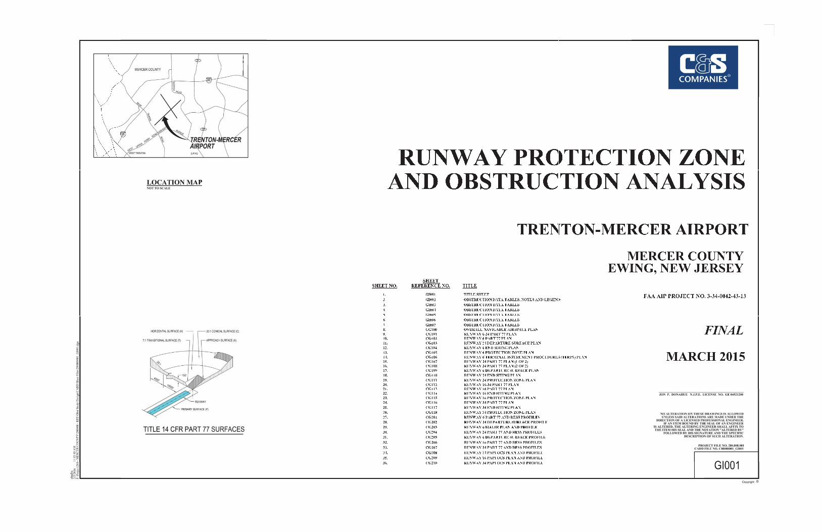
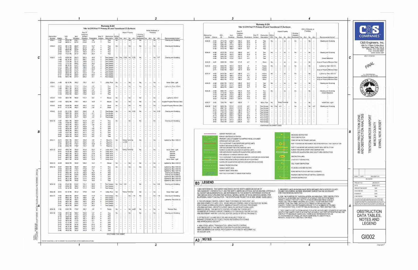


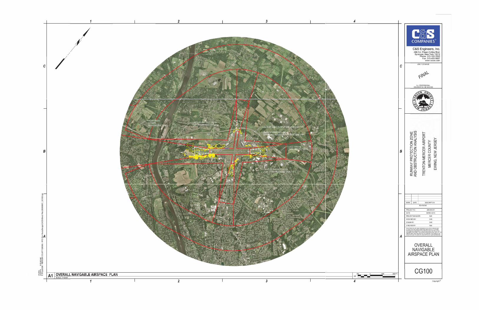

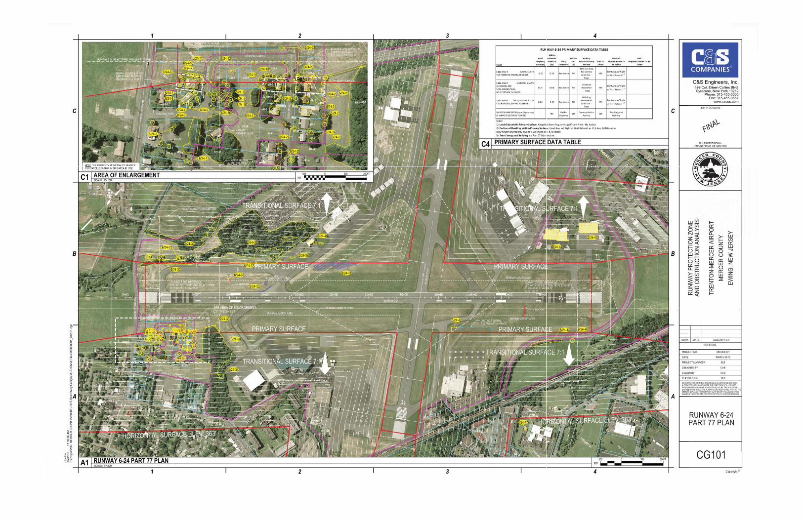


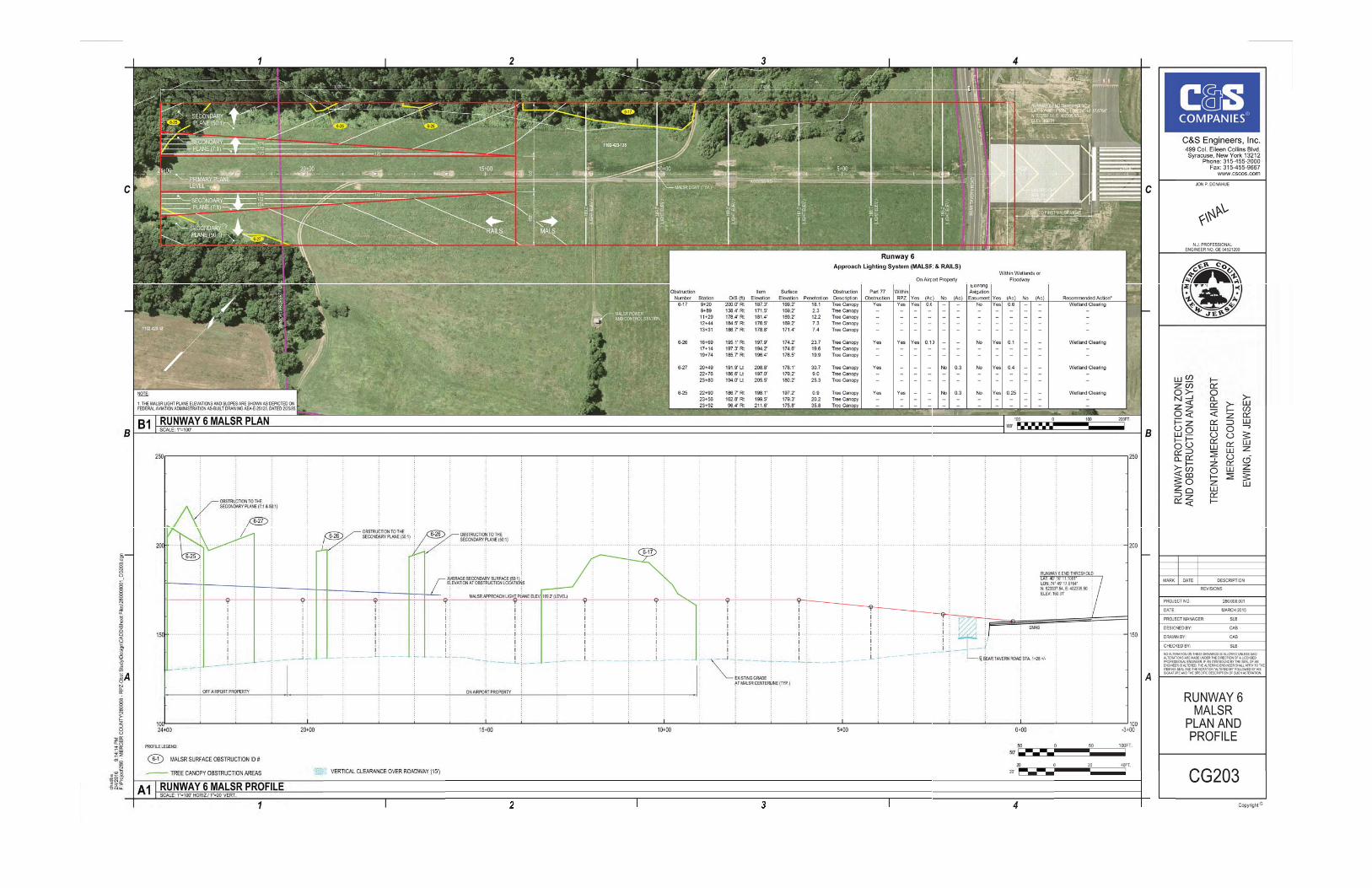

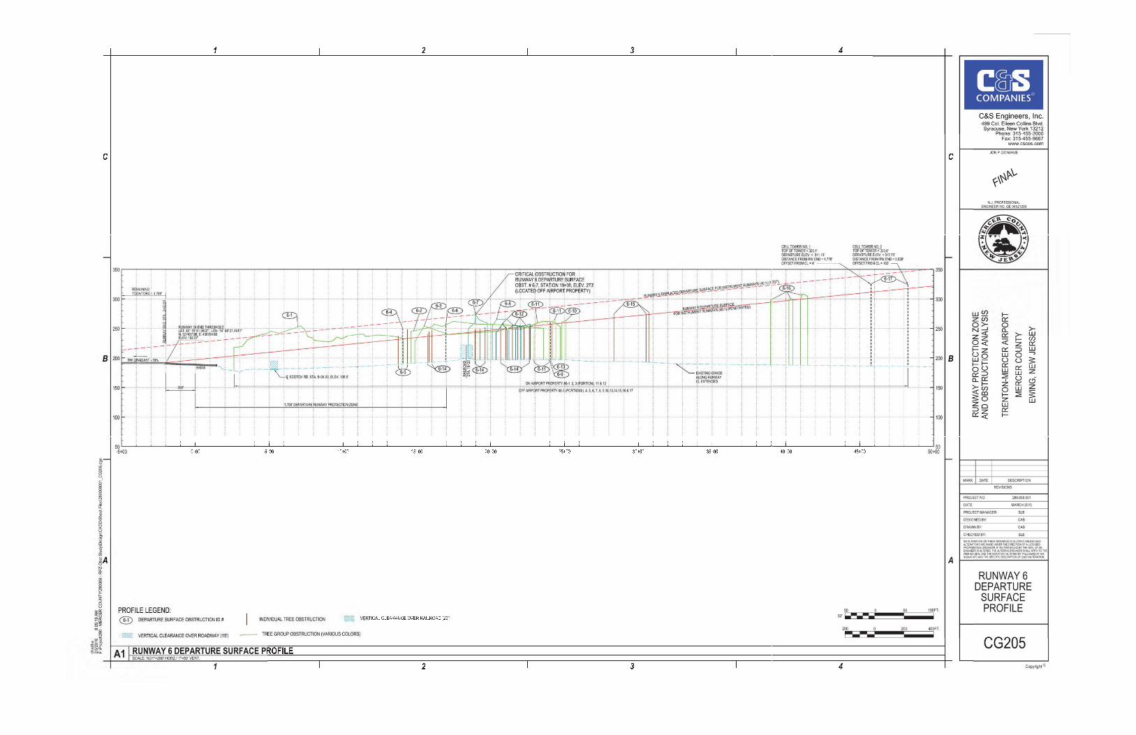

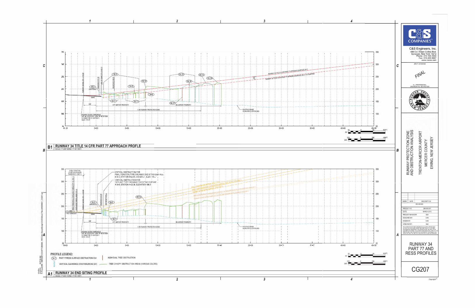
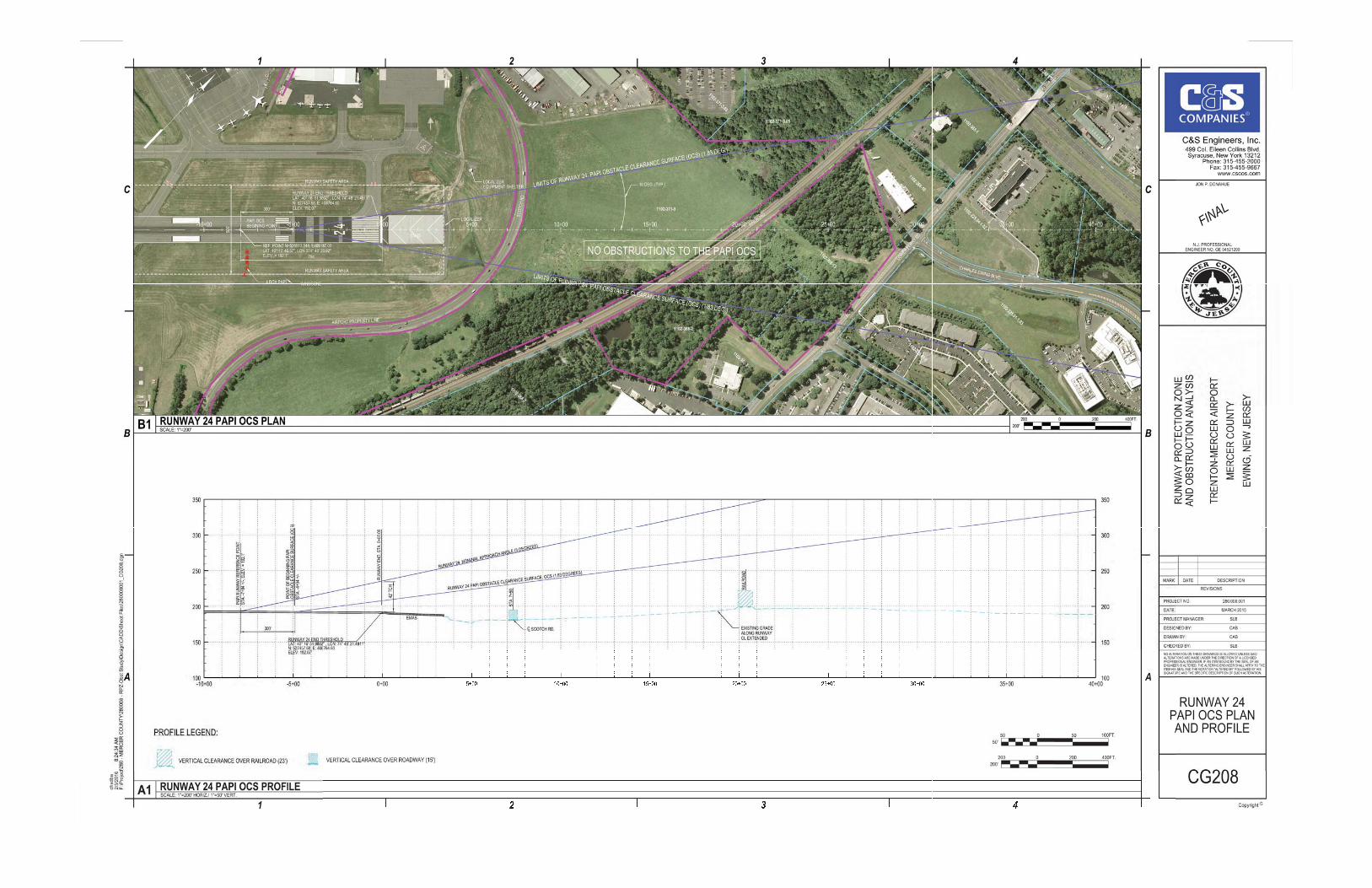


[THIS PAGE INTENTIONALLY LEFT BLANK]

Trenton Mercer Airport
APPENDIX B
RUNWAY END PANORAMIC VIEWS

[THIS PAGE INTENTIONALLY LEFT BLANK]

Trenton Mercer AirportRunway End Photos
Appendix A
Runway 24 End
Runway 6 End

Trenton Mercer AirportRunway End Photos
Appendix A
Runway 34 End
Runway 16 End

Trenton Mercer Airport
APPENDIX C
RANDOM PHOTGRAPHS OF IDENTIFIED OBSTRUCTIONS

[THIS PAGE INTENTIONALLY LEFT BLANK]

APPENDIX C
RANDOM PHOTOGRAPHS OFIDENTIFICED OBSTRUTION

RUNWAY 6

Runway 6
Obstruction No. 6-9 Obstruction Nos. 6-8 & 6-9
Obstruction No. 6-8 Bear Tavern Road ; Obstruction No. 6-10
RW 6-1

Runway 6
Obstruction Nos. 6-17; -18; -26 & -39
Obstruction Nos. 6-13; 6-17
RW 6-2

Runway 6
Bear Tavern Road ; Obstruction No. 6-7 MALSR Light Towers
Obstruction No. 6-16 Obstruction No. 6-2 w/O.L.
RW 6-3

Runway 6
ARFF Building ; Obstruction No. 6/24-40
ARFF Building; Obstruction No. 6/24 -40 Obstruction Nos. 6/24-37 & -39
RW 6-4

Runway 6
Obstruction Nos. 6/24 -37 & -38
Obstruction Nos. 6/24-37 & -38
RW 6-5

Runway 6
Obstruction No. 6/24 - 30
Obstruction No. 6/24-36
RW 6-6

Runway 6
Obstruction 6/24 - 28
Obstruction No. 6/24 - 28
Obstruction No. 6/24- 34
RW 6-7

Runway 6
Obstruction No. 6/24 -12 Meadow Ln. Subdivision
RW 6-8

RUNWAY 24

Runway 24
Obstruction No. 24-4
Obstruction No. 24-3
Obstruction No. 24-6
RW 24-1

Runway 24
Obstruction Nos. 6/24 – 43 and -46
Communications Towerat Scotch Rd/Upper Ferry Rd.
Obstr. No 6/24-47
RW 24-2
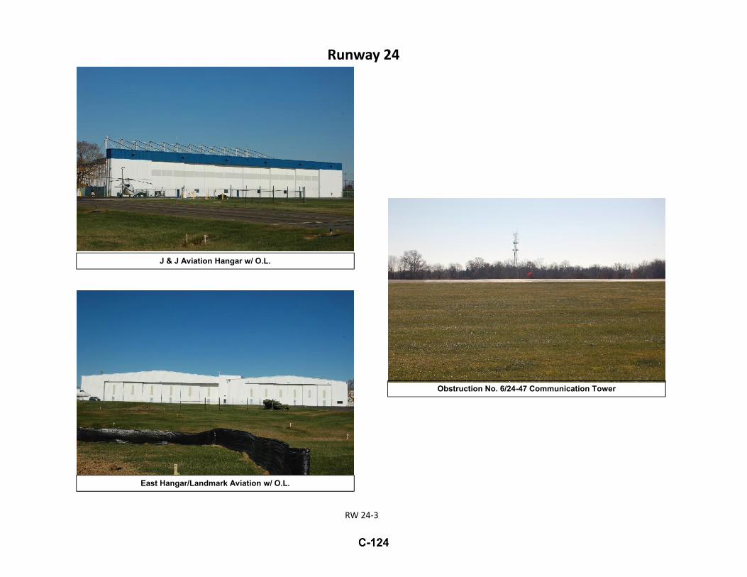
Runway 24
East Hangar/Landmark Aviation w/ O.L.
J & J Aviation Hangar w/ O.L.
Obstruction No. 6/24-47 Communication Tower
RW 24-3

Runway 24
Obstruction No. 6/24-42
On- Airport Features – “ Fixed-By-Function”
Obstruction No. 6/24-42
RW 24-4
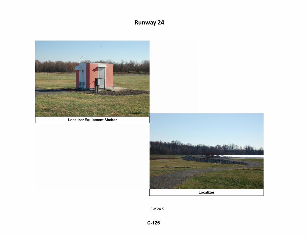
Runway 24
Localizer Equipment Shelter
Localizer
RW 24-5

Runway 24
Obstruction No 24-19 Powerline Tower
RW 24-6
Obstruction No.24-19 Powerline Tower

Runway 24
Obstruction No. 24-15
RW 24-7
Obstruction Nos. 24-15 and -16
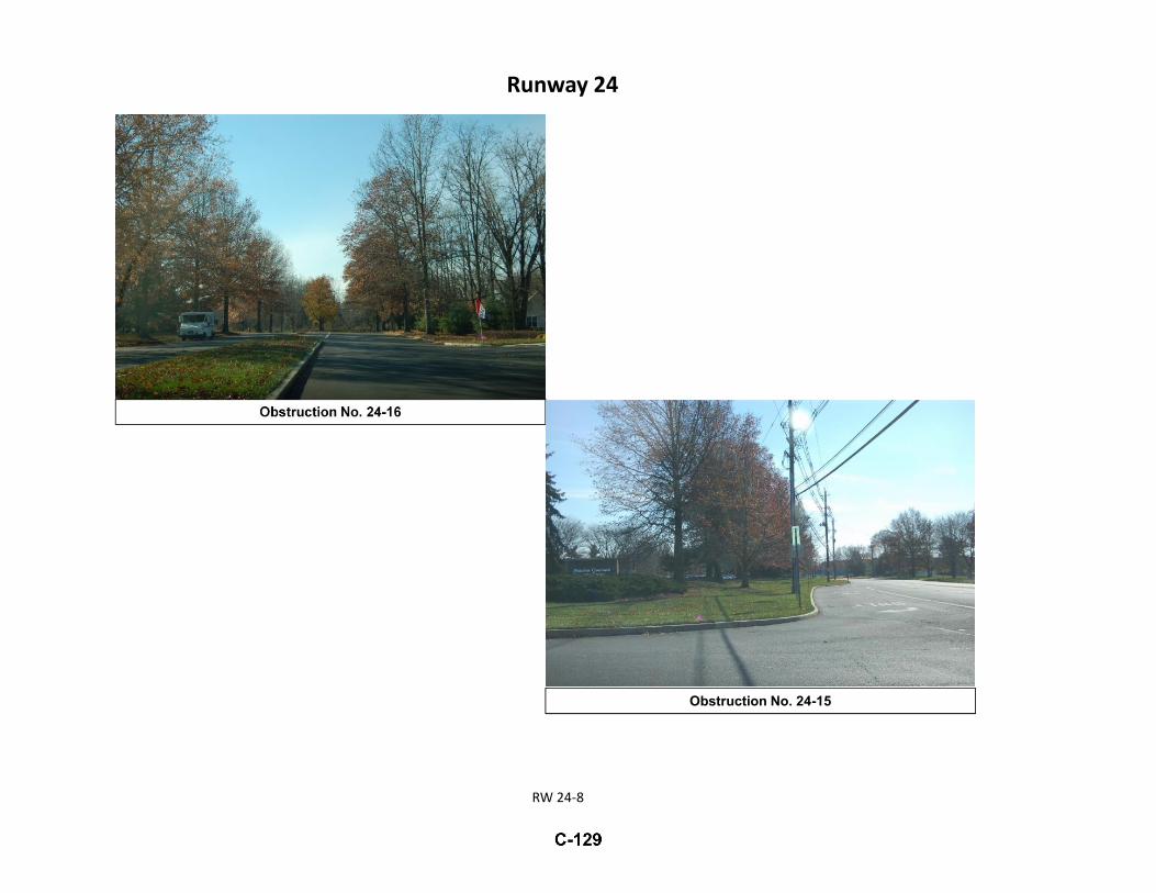
Runway 24
Obstruction No. 24-15
Obstruction No. 24-16
RW 24-8
RUNWAY 16

Runway 16
Obstruction No. 16-10
Obstruction No. 16-8Obstruction No. 16-10
Obstruction No. 16-10
RW 16-1

Runway 16
Obstruction No. 16-10 Obstruction No. 16-5
Obstruction Nos. 16-7 & -9 Obstruction No. 16-9
RW 16-2
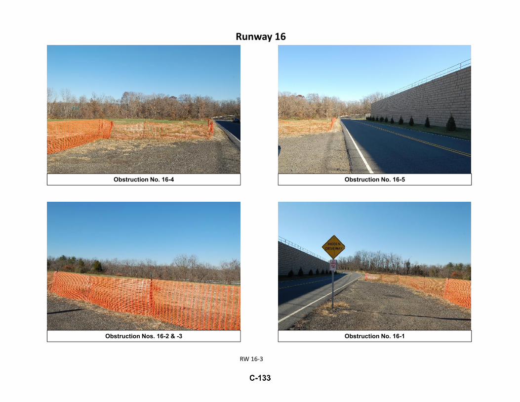
Runway 16
Obstruction No. 16-4
Obstruction No. 16-1Obstruction Nos. 16-2 & -3
Obstruction No. 16-5
RW 16-3
RUNWAY 34

Runway 34
Obstruction No. 34-18
Mausoleum Construction Within RPZ
Obstruction Nos. 34-10 & -11
RW 34-1

Runway 34
Obstruction No. 34-11
Obstruction No. 34-5
Obstruction No. 34-17; Athletic Fields Within RPZ
RW 34-2

Runway 34
Obstruction No. 34-18
State Police/ARNG Building w/ O.L. – Obstruction No. 16/34-10
RW 34-3
Obstruction Light Pole (Wooden) along west side of Railroad
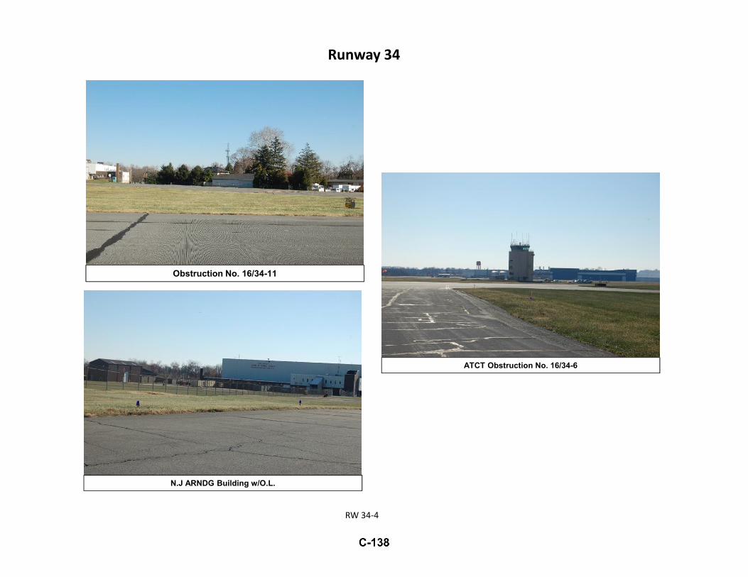
Runway 34
Obstruction No. 16/34-11
RW 34-4
N.J ARNDG Building w/O.L.
ATCT Obstruction No. 16/34-6

PRECISION APPROACHPATH INDICATOR SYSTEM
(PAPI)

PAPI
RWY 16 End
RWY 34 End
P-1

MISCELLANEOUSPHOTOGRAPHS
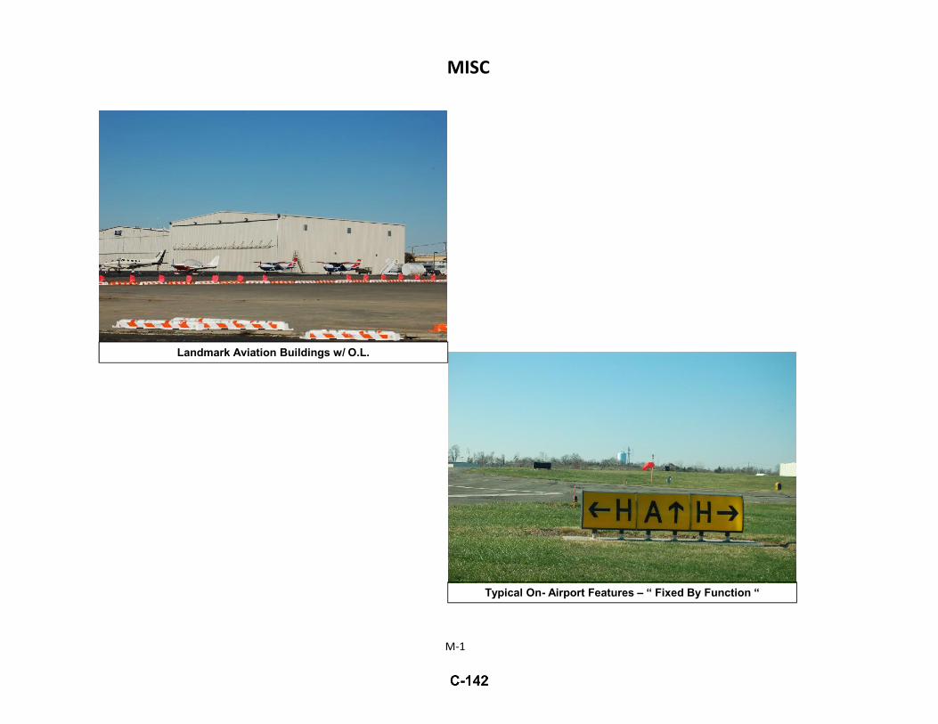
MISC
Landmark Aviation Buildings w/ O.L.
Typical On- Airport Features – “ Fixed By Function “
M-1

MISC
PFIZER Corp Hangar w / O.L. Terminal w/ O.L.
PFIZER Tanks w/ O.L.
M-2
Abandoned Power Substation Tower, w/ O.L.

[THIS PAGE INTENTIONALLY LEFT BLANK]

Trenton Mercer Airport
APPENDIX D
AIRPORT LAYOUT PLAN – PEN AND INK CHANGE NO. 11, AUGUST 2013


Trenton Mercer Airport
APPENDIX E
EXHIBIT “A” AIRPORT PROPERTY INVENTORY MAP Dated 3/31/’14

Trenton Mercer Airport
APPENDIX F
NATIONAL OCEAN SERVICE (NOS), TRENTON MERCER AIRPORT AIRPORT OBSTRUCTION CHART (OC 982), 9TH EDITION, DATED APRIL 2005

74î€
74î€
74î€
74î€
74î€
74î€
74î€
74î€
74î€
74î€
74î€
74î€
74î€
74î€
40î€ ï»¿40î€
40î€ ï»¿40î€
40î€ ï»¿40î€
40î€ ï»¿40î€
40î€ ï»¿40î€
221
AMOM
258
ANT
173FENCE
222
HGR
MM
368
OL ANT
267
OL ON HGR
(245)
433
OL ON TWR
219
OL WSK
193
POLE
REIL
REIL
REIL
REIL
193
RD(N)
240
TREE
187
TREE
217
TREE
231
TREE
271
TREE
221
TREE
212
TREE
242
TREE
222
TREE211
TREE
256
TREE
224
TREE
239
TREE
201
TREE
264
TREE
VASI
VASI
VASI
249
HGR
264
TREE
245
TREE
234
TREE 233
TREE237
TREE
230
TREE
240
TREE
244
TREE
254
TREE
231
TREE
218
TREE
200
TREE205
TREE
223
TREE
235
OL HGR
215
TREE 217
TREE
218
WSK
250
POLE
257
TREE
265
TREE
227
TREE 228
TREE268
TREE
253
TREE
260
TREE
262
TREE
271
TREE
253
TREE
264
TREE
207
TREE
214
TREE
210
TREE
199
WSK
256
TREE
266
TREE
238
TREE
171
BLDG
244
TREE
240
TREE
256
TREE
255
TREE
244
TREE
220
TREE
227
TREE
228
TREE
228
TREE
242
TREE
195
TREE
197
TREE
224
TREE
174
TREE
248
TREE
250
TREE
217
TREE
264
TREE
232
TREE196
TREE
218
TREE241
TREE
265
212.0
16
4800 X 150 PAVED
174.0
34
 3
208.3
189.9
160.3
6
6006 X 1
50 P
AVED
192.0
24
 2
165.2
178.3
192.2
100 100
200 200
300 300
070008000900010000
0 7000 8000 9000
34:1
50:1
34:1
EL 165.2
EL 178.3
EL 189.9 EL 192.2
EL 160.3
EL 192.0
6006
228
TREE
228
TREE
239
TREE240
TREE
224
TREE
242
TREE
244
TREE
227
TREE
231
TREE
220
TREE
242
TREE
197
TREE
195
TREE
174
TREE
222
TREE
210
OL ON GS186
FENCE
219
OL WSK
221
AMOM
199
WSK
193
RD(N)
194
OL LOC
214
TREE
210
TREE
227
TREE
228
TREE
260
TREE
253
TREE
265
TREE
256
TREE
268
TREE
266
TREE
100 100
200 200
300 300
0500060007000
0 5000 6000 7000
34:1
34:1
EL 212.0 EL 208.3
EL 189.9
EL 212.0
EL 174.0
4800
234
TREE
233
TREE
205
TREE
211
TREE215
TREE
212
TREE
217
TREE
RUNWAY PLANS AND PROFILES
AIRPORT PLAN
Published at Washington, D.C.U.S. Department of Commerce
National Oceanic and Atmospheric AdministrationNational Ocean Service
Airport Obstruction Chart data is available onthe Internet in the Universal Data Delivery Format
at http://www.ngs.noaa.gov/
0 01
1 0
Surveyed and compiled by the National Ocean Service (NOS), U.S.
Department of Commerce in accordance with specifications and
standards of accuracy of the Federal Aviation Administration,
Department of Transportation and NOS.
DIMENSIONS AND ELEVATIONS ARE IN FEET
AIRPORT OBSTRUCTION CHART
AMENDMENT DATA
STATUTE MILES
NAUTICAL MILES
1 MILE
1 MILE
10000 FEET
3000 METERS
5000
1500
5001000
5009th Edition
NATIONAL OCEAN SERVICE
Field Surveys
Published
•
•
PROFILE SCALE
HORIZONTAL .......1 INCH EQUALS 1000 FEET
VERTICAL .......... 1 INCH EQUALS 100 FEET
See WEBSITE - http://www.ngs.noaa.gov for "CORRECTIONS and DATES
OF LATEST EDITIONS." PUBLISHED CHARTS are available through FAA,
National Aeronautical Charting Office, Distribution Division AVN-530,
Greenbelt, MD 20770. Telephone: (301) 436-8301.
400
100
300
75
200
50
100
25
00
FEET METERS
VERTICAL SCALE
...... ...... ...... ...... ...... ...... ...... ...... ...... ...... ...... ...... ...... ......
Airport Reference Point (ARP) Official Airport Elevation With elevation - object does not penetratespecified or supplemental surface;Without elevation - position only Object penetrates specified surface Wooded area penetrates specified surface Ground area penetrates specified surface Object penetrates supplemental surface only Wooded area penetrates supplemental surface only Ground area penetrates supplemental surface only Water Supplemental surface Feet above ground level Interstate road Noninterstate road
LEGEND
S
( )
RD(I)
RD(N)
AIRPORT OBSTRUCTION CHART
HORIZONTAL SCALE...........1:12,000
HORIZONTAL DATUM..........North American Datum of 1983
VERTICAL DATUM ..............North American Vertical Datum of 1988
PROJECTION .....................
The Airport Obstruction Chart (AOC) depicts Federal Aviation
Regulations Part 77 (FAR-77) surfaces, a representation of
objects that penetrate these surfaces, aircraft movement
and apron areas, navigational aids, prominent airport build-
ings, and a selection of roads and other planimetric detail in
the airport vicinity, also included are tabulations of runway
and other operational data.
AOC content, format, and accuracy conform to the standards
specified in FAR-77, "Objects Affecting Navigable Airspace"
and FAA NO. 405, "Standards for Aeronautical Surveys and
Related Products."
TABULATED OPERATIONAL DATA
AIRPORT LOCATION POINT LAT. 17' LONG. 49'
AIRPORT REFERENCE POINT LAT. 16'36.1" LONG. 48'48.5"
RUNWAY LATITUDE LONGITUDE TDZE *GEODETIC AZIMUTH
6 16'11.1101" 49'17.6782" 185.7 28'21"
24 16'51.9810" 48'21.4918" 192.3 228'58"
16 17'01.3748" 49'04.6966" 212.0 139'36"
34 16'22.2086" 48'29.7652" 201.7 339'59"
*Geodetic azimuth reckoned clockwise from north
Fifteen feet added to noninterstate road elevations
Seventeen feet added to interstate road elevations
Twenty three feet added to railroad track elevations
Transitional surface slopes are 7:1 unless otherwise indicated
Obstructing area limits are approximate
See FAA NO. 405 for a complete set of abbreviations
Underlined elevations determined photogrammetrically with
a vertical accuracy +/- 50 feet
NOTES
200
TREE
OC 982
AIRPORT ELEVATION 212.0 FEET
OC 982
TRENTON MERCER AIRPORT
TRENTON, NEW JERSEY
TRENTON MERCER AIRPORT, TRENTON, NEW JERSEY
DEP
AR
TMENT OF COM
MER
CE
UNIT
E
D STATES O
F A
ME
RIC
A
TREE
ARP
(2004)
�»¿
1
6
24
16 3
4
0
30
60
90
120
150
180
210
240
27
0
300
330

VAR 1
2.
8
�»¿
�»¿
�»¿
�»¿
�»¿
�»¿
�»¿
�»¿
�»¿�»¿
�»¿
�»¿
�»¿
October 2004
D E L A W A R E R I V E R
1
1
23
4
5
67
8
9
1011
12
13
14
15 16
17 18
19 20 21
22 23
24
25
26
27
28
29 30
2
3
4
5
6
7
8
9
10
11 12
13
14
15
16
17
18
19
20
21
22
23
24
25
26
27
28
29
30
1 2
3 4 56 7 8
9
1
2
4
56 7
89
3
TREE
200
ANT ON
OL TK
357
OL ON
LT POLE
192
OL
HGR
234
OL
ON TK
214
ANT ON
OL TWR
364
OL ON
POLE
238
A
LETTERED OBJECTS
B
C
D
OL
ON TK
275
TREE
228
TRMSN
TWR
360
TRMSN
TWR
364
ROD ON
OL TWR
321
E
F
OL ON
POLE
185
ANT ON
BLDG
200
OL ON
POLE
238
Transverse Mercator
OL
LOC
194
G
212.0
RESTRICTED
AREA
A. ANT ON OL HGR 244
B. ANT ON BLDG 200
C. ANT + APBN ON OL ATCT 275 ATCT FLOOR 244
D. ANT ON BLDG 248
E. OL ON GS 210
F. OL ON POLE 185
G. FENCE 186
April 2005
N
N
ALS
4000 FEET
LI
MIT
OF
HO
RIZ
ONT
AL S
URF
ACE
LI
MIT
OF
CO
NIC
AL S
URF
ACE
CL
CL
CL
x
x
x
x
TT
T
CL
CL CL
CLCL
[THIS PAGE INTENTIONALLY LEFT BLANK]