motor-units - -> RadioManual.eu
15
-
Upload
khangminh22 -
Category
Documents
-
view
2 -
download
0
Transcript of motor-units - -> RadioManual.eu

MOTOR-UNITS
New Motor Units use now a very exclusive and performing mechanics.The Variable Reeling System (VRS) designed and produced by UltraBeam, now makes theMotor-Units unquestionably durable and highly reliable under any weather conditions andThrough the years.All antenna models (vertical,rigid dipole and yagi) are now equipped with the VRS system
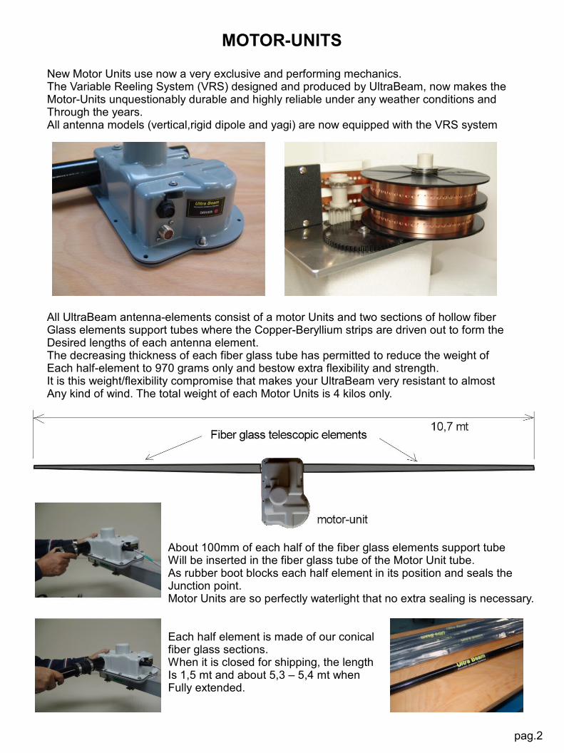
All UltraBeam antenna-elements consist of a motor Units and two sections of hollow fiberGlass elements support tubes where the Copper-Beryllium strips are driven out to form theDesired lengths of each antenna element.The decreasing thickness of each fiber glass tube has permitted to reduce the weight ofEach half-element to 970 grams only and bestow extra flexibility and strength.It is this weight/flexibility compromise that makes your UltraBeam very resistant to almostAny kind of wind. The total weight of each Motor Units is 4 kilos only.
About 100mm of each half of the fiber glass elements support tubeWill be inserted in the fiber glass tube of the Motor Unit tube. As rubber boot blocks each half element in its position and seals theJunction point. Motor Units are so perfectly waterlight that no extra sealing is necessary.
Each half element is made of our conicalfiber glass sections.When it is closed for shipping, the lengthIs 1,5 mt and about 5,3 – 5,4 mt when Fully extended.
pag.2

pag.3
THE BOOM
UltraBeam Yagis use square-section aluminium boom only.Yagi antennas operating in the 6-20 mtr range use 60x60x3 mm booms.3-element Yagis operating in the 6-30mtr and 6-40mtr ranges use 80x80x3 mm booms.Extra reliable 80x80x4 mm booms are used for the 4-element Yagis operating in the6-40 mtr range.UltraBeam joint-system uses four 3mm steel plates and sixteen M8 bolts and is used onAll booms.
The mechanical strength at each boom-joint point is even stronger than any other point acrossEach boom-section.This unique joint system gives the boom the same mechanical stability as if were made of aSingle length.The 3 element 6-20mtrs antenna models do not need a truss and the remaining models areProvided with very effective trusses made of 6mm MastrAnt line.
3el 6-20mt Boom-to-Mast plate 4el 6-40mt Boom-to-Mast plate
Mast-to-Boom plates (eccept the one for the 2el 6-20 mtr) are made stainless steel andDimensioned in accordance with the antenna model.Stainless steel U-bolts have the following diameters:
2 elements 6-20mtr = N° 2 x 50mm 3 elements 6-20mtr = N° 4 x 50mm3 elements 6-40mtr = N° 4 x 50/60/65*mm 4 elements 6-20mtr = N° 4 x 50/60/65*mm4 elements 6-40mtr = N° 4 x 65mm or more**
* One of the diameters has to be specified in the order.** To be specified in the order.

MOTOR UNITS ASSEMBLYNo HF antenna has ever been so easy and speedy to assemble as UltraBeamYou can install your UltraBeam very easily, quickly and,above all, without the need of reading useless pages and pages of installation instructions.The exact positions of each Motor Unit is indicated by coloured labels on the boom.
Each Motor Unit is fixed on the boom by 4mm aluminium plate.Motor Unit plates are fixed by four M6 bolts and two stainless plates (stirrups) on thebottom side of the boom.This effective method avoids to perforate the boom and,aboveall, it guarantees that theBoom-plate remains firmily fixed to the boom.
All Motor Units are fixed to its aluminium support plate by eight stainless M5 bolts.As all nuts are self-blocking,just tighten each bolt untill a light pressure is noticed on the gasket.Do not over tight.
Unlike the Motor Units for the passive-elements, the Driven Element Unit is provided with isan efficient 2:1 Balun (25-50 Ohms). As the typical antenna impedance is 25 Ohms, a BalunIs essential in order to have a perfect match (SWR 1:1) between the antenna and its the feed-line.
Motor Units used in each passive-element are indicated. Although they are distinguished byColoured labels they are perfectly identical both eletronically and mechanically.
The presence of a multi-pin IP68 panel-socket on every Motor Unit makes its removal extremelyspeedy and confortable in any moment.
All connectors are perfectly waterproof and do not need any extra sealing.UltraBeam does not recommend any extra sealing materials.
pag.4

PLUG-IN ANTENNA CONTROL WIRING CABLE
IP68 connectors used in the Plug-in Antenna Control Wiring Cable permit a quick connection between the Antenna Controller and the antenna. You only need to insert each IP68 connector to its related Motor Unit, the DB25 Connector to the Antenna Controller and your antenna is ready to be used.
Each Plug-in Antenna Control Wiring Cable is made and tested by UltraBeam. For this reason the control cable is delivered with the DB25 connector soldered to its end. If removing the DB25 is necessary to get the cable to your radio-room, be careful when taking note of each coloured wire and its related pin-numbers. To avoid any mistake we suggest to cut the cable a few centimeters from the DB25 and re-solder the wires one by one. Unsolder one piece of wire from the DB25 connector and solder the wire with same colour to the same pin. Repeat this operation for each wire of the control cable.
The connection wiring between the antenna control cable and each four-conductor cable from each Motor Unit is made at the UltraBeam factory and sealed by a special "Y" thermo-shrinkable material. This connection between Motor Units and control cable isperfectly watertight and no extra sealing is necessary.As each control cable has its own length, you only need to lay each cable along the boom and fix by tape or tie wraps. Each connector is marked by a colour, therefore, the connections are both easy and inequivocable.
NOTE : Connector are the excellent IP68 made in USA bySwitchCraft. As these connectors are absolutely watertight at and temperature and weather condition, UltraBem does not recomment to use any sealing material either on the connectors or on any part of the Motor Units.Although each Motor Unit is accurately tested at the factory, we
highly recommend you to carry out an electrical check to verifythat no damage has occurred during transportation.
NOTE :Do not insert the rubber boots on the Motor Units until you run the test.MOTOR UNIT ELECTRICAL TESTSwitch ON the Antenna Controller and wait until "ELEMENT RETRACTED" is displayed.Press "MENU" and confirm by "YES" (30m button).Press again "MENU" to retract.
IMPORTANT:Before running the test and especially before you use theantenna, be sure to have the DB25 connector firmelyscrewed to the Antenna controller.

YAGI ELEMENTS OPERATING ON 6-40 MTRSElements used by Yagis antennas operating in the 7-50 MHz range are about 21,5 meters long. For these types of antennas UltraBeam has designed an adequate and very reliable element support mechanics. Elements are not supported by the Motor Units, but simply by a very strong aluminium structure fixed on the boom. Unlike the 6-20mtrs types, the only task of the Motor Units used for the 6-40mtr antennas is to drive the Copper-Beryllium strips along the fiber-glass tubes. As each element supporting structure is the only part in charge of holding up the whole weight and the mechanical stress of the related antenna-element (Motor Units are not involved with any mechanical stress), it makes the removal of the Motor Units extremely easy and speedy.The unique boom-to-element support system, designed and developped by UltraBeam, gives you the possibility to assemble each antenna-element on the ground and fix them very confortably to the boom successively. This important possibility, at times, becomes particularly decisive when space is very limited.
Each half antenna-element (Left and right) consists of three pieces: a fiber-glass telescopic tube (1) (also used on the 6-20mtr yagis) and two 2,7 mt cylindrical fiber-glass tubes. The fiber-glass tubes are joint together by a short stainless-steel tube also used as an anchorage point for the vertical Trusses (furnished with the antenna) of the antenna elements.
pag.6

6-20 MTR & 6-40 MTR VERTICAL ANTENNAS
UltraBeam vertical antennas use a single Motor Unit and a vertical telescopic fiber-glass tube.Both antenna types operate as full-size 1/ 4 wave lambda on any frequency.Unlike rigid dipoles or Yagis, the impedance is determined by the ground (radials). Radials must be made of copper wires and have a length of 1/4 lambda on each operating band. Remember: the more the radials, the higher the efficiency of the antenna.The Motor Unit will be fixed to a aluminium tube (delivered with the antenna) provided with a lathed bush. The aluminium tube is 1 meter long and can be installed anywhere. The 6-20mtr vertical antenna can be assembled and installed very quickly because it has a single 5,4 meter telescopic element and therefore no guys are needed.
The 6-40 mtr vertical antenna, instead, uses four further 1,3mt fiber-glass tube sections and its total length is slightly over 10 meters.This antenna needs one set of 4 guys anchored to its middle. The guys can be made t of 3-4mm nylon strings or any other non-conductive material. The element is e provided with a fifth wheel to anchor the set of guys.
Like all other UltraBeam antennas, the Motor Units for the vertical antennas are alsoequipped with the Variable Reeling System (VRS). The Antenna Controller for the vertical antenna is identical to that used for Yagiantennas, but equipped with a single Drive-Board and a dedicated Software.
All default lengths are purely indicative and, depending on the location, they alwayse need to be modified for best resonance.
Nylon strings
Radials
tubes pag.7

YAGI 6-20 METERS
Pag.8

YAGI 6-30 / YAGI 6-40 METERS
pag.9


1) RS-232 : firmware up-grade and interface to RTX .2) DB-25 : connection to Motor Units.3) 24-35 DCV input.
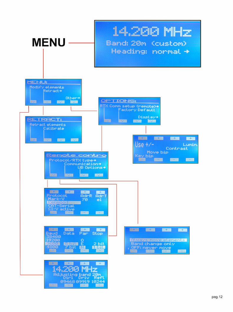
Well aware that the most effective dynamic antenna system can only be possible primarily through the effectiveness of its dedicated antenna controller, major priority has been given to utmost performance and reliability of this very important device. This is well evidenced by the discrete components used in lieu of common and, consequently, cheap integrated circuits. Each Motor Unit, in fact, is driven by a very reliable driver-board equipped with eight transistors capable of handling 10 Amps in case of accidental short-circuit. The RS-232 port permits to upgrade the firmware for free at any moment. You can download the latest upgrade from: http://www.ultrabeam.it/download1.html by simply connecting a pin-to-pin serial cable between the Antenna Controller and your computer.Furthermore, you can use the RS-232 port to interface your RTX to the Antenna Controller. By a dedicated cable (optional) your antenna can now track the frequency you tune on on your RTX. By entering the Menu, you can also select either the Band-Switching or the Band-&-Frequency function.While an easy and very intuitive software interface permits anyone to use the Antenna Controller without the need of reading its Instruction Manual, its large LCD display shows each Menu-page and its related functions. In accordance with the antenna-type (vertical, rigid-dipole or yagi), an appropriate software will be installled in the Antenna Controller. This will permit the antenna element (in the case of a vertical or a rigid-dipole) or elements (in the case of a yagi) to reach the default lengths for perfect resonance on the operating frequency. In most cases, however, the owesome 50 Ohms impedance necessary to obtain an SWR of 1:1 can only be obtained by slightly modifying the default lengths (normally by very few centimetres) of the driven element. You can perform this operation within a couple of seconds only and while sitting confortably in front of your radio equipment. Once the operation has been completed, the CPU can now store the optimized length for ideal antenna-resonance on the whole antenna operating range.The time necessary to band-changes is very short. When starting from its fully-retracted condition, the antenna only needs 18 seconds to reach the due length on the 20 metre-band. Apart the shorter time needed to switch from an operating band to another, the movement of the antenna is signalled by a bar-graph, a flashing band-led and an acoustic signal (bip) you can either switch-off or adjust through the Menu
pag.11

De Ultrabeams worden standaard met antenne controller geleverd, voorzien van een, twee ofdrie driver boards (afhankelijk van model) en krachtige besturingssoftware. Hiermee wordende elementen van de beam c.q. de lengte van de vertical automatisch op de gewenste fre-quentie en beste SWR afgestemd.
The Ultrabeams are supplied with antenna controller with one, two or three driverboards (depending on model) and powerful software. With this combination the elements ofthe beams and the length of the verticals will be automatically tuned on the best frequencyand SWR.
Nieuw in ons leveringsprogramma zijn de kwalitatiefhoogwaardige "Ultrabeam" HF antennes.
New in our program are the high quality"Ultrabeam" HF antennas.
Bij de beams heeft de motor unit van de dipool een highpower 2:1 balun ingebouwd.
The motor unit of the beam dipole has an integratedhigh-power 2:1 balun.
Exterieur/OutsideMotor Unit
Interieur/InsideMotor Unit
In verband met overweldigende navraag is er bij de fabriek helaas een achterstand in deproductie ontstaan. Dit houdt in, dat u tijdelijk met een langere levertijd rekening moethouden. Wij zullen er alles aan doen, om zo spoedig mogelijk een buffervoorraad inRoermond op te bouwen.
Due to large demand there is a delay in production at the factory at the moment. This means,that you have to take a longer delivery time into account. We will do our utmost, to build abuffer stock in our warehouse in Roermond (NL) as soon as possible.
Roermond - The NetherlandsTel. +31 475 327390
Mönchengladbach- GermanyTel. +49 2166 33061
www.classicinternational.eu