Prairie Island, Units 1 and 2, Point Beach, Units 1 and 2, and ...
181
Committed to Nuclear Excellence Nuclear Management Company, LLC L-HU-06-001 10 CFR 50.90 February 16,2006 U. S. Nuclear Regulatory Commission Document Control Desk Washington, DC 20555-0001 Prairie Island Nuclear Generating Plant Units I and 2 Palisades Nuclear Plant Dockets 50-282 and 50-306 Docket 50-255 License Nos. DPR-42 and DPR-60 License No. DPR-20 Point Beach Nuclear Plant Units I and 2 Dockets 50-266 and 50-301 Renewed License Nos. DPR-24 and DPR-27 Application For Technical Specification Improvement Renardinn Steam Generator Tube Integrity In accordance with the provisions of Section 50.90 of Title 10 of the Code of Federal Regulations (10 CFR), the Nuclear Management Company, LLC (NMC) is submitting a request for an amendment to the technical specifications (TS) for the above identified facilities. The proposed amendment would revise the TS requirements related to steam generator tube integrity. The change is consistent with NRC-approved Revision 4 to Technical Specification Task Force (TSTF) Standard Technical Specification Change Traveler, TSTF-449, "Steam Generator Tube Integrity." The availability of this TS improvement was announced in the Federal Register on May 6,2005 (70 FR 24126) as part of the consolidated line item improvement process (CLIIP). Enclosure 1 provides a description of the proposed change and confirmation of applicability. Enclosures 2A, 2B and 2C provide plant specific clarifications of TSTF- 449 with respect to each facility's TS and Bases. Enclosures 3A, 3B and 3C provide unit specific steam generator information. Enclosures 4A, 4B and 4C provide the existing TS and Bases pages marked-up to show the proposed change. Enclosures 5A, 5B and 5C provide the revised TS pages. NMC requests approval of the proposed License Amendment within one year of the submittal date, with the amendment being implemented within 90 days of approval. 700 First Street Hudson, Wisconsin 54016 Telephone: 715-377-3300
-
Upload
khangminh22 -
Category
Documents
-
view
2 -
download
0
Transcript of Prairie Island, Units 1 and 2, Point Beach, Units 1 and 2, and ...

Committed to Nuclear Excellence Nuclear Management Company, LLC
L-HU-06-001 10 CFR 50.90
February 16,2006
U. S. Nuclear Regulatory Commission Document Control Desk Washington, DC 20555-0001
Prairie Island Nuclear Generating Plant Units I and 2 Palisades Nuclear Plant Dockets 50-282 and 50-306 Docket 50-255 License Nos. DPR-42 and DPR-60 License No. DPR-20
Point Beach Nuclear Plant Units I and 2 Dockets 50-266 and 50-301 Renewed License Nos. DPR-24 and DPR-27
Application For Technical Specification Improvement Renardinn Steam Generator Tube Integrity
In accordance with the provisions of Section 50.90 of Title 10 of the Code of Federal Regulations (10 CFR), the Nuclear Management Company, LLC (NMC) is submitting a request for an amendment to the technical specifications (TS) for the above identified facilities.
The proposed amendment would revise the TS requirements related to steam generator tube integrity. The change is consistent with NRC-approved Revision 4 to Technical Specification Task Force (TSTF) Standard Technical Specification Change Traveler, TSTF-449, "Steam Generator Tube Integrity." The availability of this TS improvement was announced in the Federal Register on May 6,2005 (70 FR 24126) as part of the consolidated line item improvement process (CLIIP).
Enclosure 1 provides a description of the proposed change and confirmation of applicability. Enclosures 2A, 2B and 2C provide plant specific clarifications of TSTF- 449 with respect to each facility's TS and Bases. Enclosures 3A, 3B and 3C provide unit specific steam generator information. Enclosures 4A, 4B and 4C provide the existing TS and Bases pages marked-up to show the proposed change. Enclosures 5A, 5B and 5C provide the revised TS pages.
NMC requests approval of the proposed License Amendment within one year of the submittal date, with the amendment being implemented within 90 days of approval.
700 First Street Hudson, Wisconsin 54016 Telephone: 71 5-377-3300

Document Control Desk Page 2
In accordance with 10 CFR 50.91, NMC is providing a copy of this letter and enclosures to each facility's designated State Official.
Summary of Commitments
This letter contains no new commitments and no revisions to existing commitments.
I declare under penalty of perjury that the foregoing is true and correct. Executed on pL L. ;I d4 J U 0 6 O.
I
G f i / d + I ~ r J. W. inkam
~ i r e c t o r w l e a r Licensing and Regulatory Services Nuclear Management Company, LLC
Enclosures (1 3)
cc: Administrator, Region Ill, USNRC Project Manager, Palisades Nuclear Plant, Point Beach Nuclear Plant, and
Prairie Island Nuclear Generating Plant, USNRC Senior Resident Inspector, Palisades Nuclear Plant, Point Beach Nuclear Plant,
and Prairie Island Nuclear Generating Plant, USNRC State Official, Lou Brandon - Chief - NFUIHWRSNVHMD, Ms. Ave M. Bie -
Public Service Commission of WI, Minnesota Department of Commerce

ENCLOSURE I
Description and Assessment
1.0 INTRODUCTION
The proposed license amendment revises the requirements in Technical Specifications (TS) related to steam generator tube integrity. The changes are consistent with NRC approved Technical Specification Task Force (TSTF) Standard Technical Specification Change Traveler, TSTF-449, "Steam Generator Tube Integrity," Revision 4. The availability of this technical specification improvement was announced in the Federal Register (FR) on May 6,2005 as part of the consolidated line item improvement process (CLIIP).
2.0 DESCRIPTION OF PROPOSED AMENDMENT
Consistent with the NRC-approved Revision 4 of TSTF-449, the proposed TS changes include (Each facility's unique TS Section identification is provided in Table 1 below and exceptions, if any, are provided in enclosure 2):
Revised TS definition of LEAKAGE Revised TS, "RCS [Reactor Coolant System] Operational Leakage" New TS, "Steam Generator (SG) Tube Integrity" Revised TS, "Steam Generator (SG) Program" Revised TS, "Steam Generator Tube Inspection Report"
Proposed revisions to the TS Bases are also included in this application. As noted in Enclosure 2 for each facility, the TSTF-449, Revision 4 approved Bases have been modified to incorporate plant specific analyses and TS requirements. As discussed in the NRC's model safety evaluation, adoption of the revised TS Bases associated with TSTF-449, Revision 4 is an integral part of implementing this TS improvement. The changes to the affected TS Bases pages will be incorporated in accordance with the TS Bases Control Program.
3.0 BACKGROUND
The background for this application is adequately addressed by the NRC Notice of Availability published on May 6, 2005 (70 FR 24126), the NRC Notice for Comment published on March 2, 2005 (70 FR 10298), and TSTF-449, Revision 4.
4.0 REGULATORY REQUIREMENTS AND GUIDANCE
The applicable regulatory requirements and guidance associated with this application are adequately addressed by the NRC Notice of Availability published
Page 1 of 4

Enclosure 1 SG Program
NMC
on May 6,2005 (70 FR 24126) the NRC Notice for Comment published on March 2, 2005 (70 FR 10298), and TSTF-449, Revision 4.
5.0 TECHNICAL ANALYSIS
The Nuclear Management Company, LLC (NMC) has reviewed the safety evaluation (SE) published on March 2, 2005 (70 FR 10298) as part of the CLllP Notice for Comment. This included the NRC staffs SE, the supporting information provided to support TSTF-449, and the changes associated with Revision 4 to TSTF-449. NMC has concluded that the justifications presented in the TSTF proposal and the SE prepared by the NRC staff are applicable to each of the facilities identified in this license amendment request and justify this amendment for the incorporation of the changes to each facility's TS. Clarifications for each facility are identified in Enclosure 2 for the TS and Bases which incorporate plant specific analyses and TS requirements.
6.0 REGULATORY ANALYSIS
A description of this proposed change and its relationship to applicable regulatory requirements and guidance was provided in the NRC Notice of Availability published on May 6, 2005 (70 FR 24126), the NRC Notice for Comment published on March 2, 2005 (70 FR 10298), and TSTF-449, Revision 4.
6.1 Verification and Commitments
The information in Enclosure 3 is provided to support the NRC staff's review of this amendment application.
7.0 NO SIGNIFICANT HAZARDS CONSIDERATION
NMC has reviewed the proposed no significant hazards consideration determination published on March 2, 2005 (70 FR 10298) as part of the CLIIP. NMC has concluded that the proposed determination presented in the notice is applicable to each of the facilities identified in this license amendment request and the determination is hereby incorporated by reference to satisfy the requirements of 10 CFR 50.91 (a).
8.0 ENVIRONMENTAL EVALUATION
NMC has reviewed the environmental evaluation included in the model SE published on March 2,2005 (70 FR 10298) as part of the CLIIP. NMC has concluded that the staffs findings presented in that evaluation are applicable to each of the facilities identified in this license amendment request and the evaluation is hereby incorporated by reference for this application.
Page 2 of 4

Enclosure 1 SG Program
NMC
9.0 PRECEDENT
This application is being made in accordance with the CLIIP. NMC is not proposing variations or deviations from the TS changes described in TSTF-449, Revision 4 (except as noted in Sections 2 and 5), or the NRC staff's model SE published on March 2, 2005 (70 FR 10298). However, unique characteristics of each facility's TS and Bases in relationship to TSTF-449 are identified in Enclosure 2. The differences between each facility's proposed TS and TSTF-449 do not affect the no significant hazards consideration determination and environmental evaluation included in the model SE published on March 2, 2005 (70 FR 10298) as part of the CLIIP.
10.0 REFERENCES
Federal Register Notices:
Notice for Comment published on March 2, 2005 (70 CFR 10298) Notice of Availability published on May 6, 2005 (70 FR 24126)
Page 3 of 4

Enclosure 1 SG Program
NMC
Table I
Facility Unique TS Section
TSTF-449 TS Section Description
Definition of LEAKAGE
RCS [Reactor Coolant System] Operational ~ e a kag e'
Steam Generator (SG) Tube Integrity
Palisades Nuclear Plant
1.1
3.4.13
1 PCS [Primary Coolant System] Operational Leakage in Palisades Nuclear Plant Technical Specifications
Point Beach Nuclear Plant Units I and 2
1 .I
3.4.13
Steam Generator (SG) Program
Steam Generator Tube Inspection Report
Page 4 of 4
Prairie Island Nuclear Generating Plant Units 1 and 2
1 .I
3.4.14
5.5.8
5.6.8
5.5.8
5.6.8

ENCLOSURE 2
The following Plant Specific Clarifications Of TSTF-449 With Respect To Each Facility's Technical Specifications and Bases are contained within Enclosure 2:
Enclosure 2A - Palisades Nuclear Plant
Enclosure 2B - Point Beach Nuclear Plant Units 1 and 2
Enclosure 2C - Prairie Island Nuclear Generating Plant Units 1 and 2
Page 1 of 1

ENCLOSURE 2A
Plant Specific Clarifications Of TSTF-449 With Respect To Each Facility's Technical Specifications and Bases
Palisades Nuclear Plant (PNP)
1. NUREG-1432, Standard Technical Specifications, Combustion Engineering Plants 2. Limiting Condition for Operation
Page 1 of 1
Basis
PNP TS is currently consistent with TS as described in TSTF-449 and no change is required
PNP TS do not currently include 1 gpm and no change is required
PNP TSlBases
3.4.13
B 3.4.13
Location
L C O ~ statement
LC0 discussion
ISTS'
3.4.13
B 3.4.13
Description of TSlBases
No changes proposed to remove 1 gpm primary to secondary LEAKAGE
No changes proposed to remove 1 gpm primary to secondary LEAKAGE

ENCLOSURE 2B
Plant Specific Clarifications Of TSTF-449 With Respect To Each Facility's Technical Specifications and Bases
Point Beach Nuclear Plant (PBNP)
1. NUREG-1431, Standard Technical Specifications, Westinghouse Plants 2. Limiting Condition for Operation 3. Applicable Safety Analyses
Page 1 of 1
Basis
PBNP TS is currently consistent with TS as described in TSTF-449 and no change is required
Unit 2 SG tubes are different materials than Unit 1 SG, thus different inspection requirements are proposed for each unit
Plant specific analyses are based on per SG limit
PBNP TS do not currently include 1 gpm and no change is required
Plant specific analyses are based on per SG limit
PBNP TSlBases
3.4.13
5.5.8
B 3.4.13
B3.4.13
B 3.4.1 3
ISTS'
3.4.13
5.5.9
B 3.4.1 3
B3.4.13
B 3.4.13
Location
L C O ~ statement
SG Program
A S A ~ discussion
LC0 discussion
ASA and LC0 discussion
Description of TSIBases
No changes proposed to remove 1 gpm primary to secondary LEAKAGE
Included two SG tube inspection paragraphs in 5.5.8.d.2
Discusses accident analyses based on primary to secondary leakage per SG
No changes proposed to remove 1 gpm primary to secondary LEAKAGE
Discusses accident analyses based on primary to secondary leakage per SG

ENCLOSURE 2C
Plant Specific Clarifications Of TSTF-449 With Respect To Each Facility's Technical Specifications and Bases
Prairie Island Nuclear Generating Plant (PINGP)
Page 1 of 2
Basis
PlNGP TS is currently consistent with TS as described in TSTF-449 and no change is required
Unique PlNGP TS requirements
Current TS requirements
TSTF change not applicable due to unique PlNGP TS requirements
TSTF change not applicable due to unique PlNGP TS requirements
TSTF change not applicable due to unique PlNGP TS requirements
Plant specific information
Description of TSIBases
No changes proposed to remove 1 gallons per minute primary to secondary LEAKAGE, add 150 gallons per day
PlNGP made changes similar to TSTF- 449 in 3.4.14 Conditions C and D
Included PlNGP specific report requirements for implementation of voltage-based repair criteria to tube support plate intersections
No change
No change
No change
Discusses PlNGP SGTR~ and SLB' accident analyses
PlNGP TSIBases
3.4.14
3.4.14
5.6.7
B 3.4.5
B 3.4.6
B 3.4.7
B 3.4.14
ISTS'
3.4.13
3.4.13
5.6.9
B 3.4.5
B 3.4.6
B 3.4.7
B 3.4.13
Location
LCO* statement
Conditions A and B
Paragraph b
LC0 discussion
LC0 discussion
LC0 discussion
A S A ~ discussion

1. NUREG-1431, Standard Technical Specifications, Westinghouse Plants 2. Limiting Condition for Operation 3. Applicable Safety Analyses 4. Steam Generator Tube Rupture 5. Steam Line Break
Page 2 of 2
Basis
PlNGP TS do not currently include 1 gpm and no change is required
Unique PlNGP TS requirements
- PlNGP
TSIBases
B 3.4.14
B 3.4.14
ISTS'
B 3.4.13
B 3.4.1 3
Location
LC0 discussion
Conditions A and B discussion
Description o f TSIBases
No changes proposed to remove 1 gpm primary to secondary LEAKAGE
PlNGP made changes similar to TSTF- 449 in 3.4.14 Conditions C and D

ENCLOSURE 3
The following Unit Specific Steam Generator Information is contained within Enclosure 3:
Enclosure 3A - Palisades Nuclear Plant
Enclosure 3B - Point Beach Nuclear Plant Units 1 and 2
Enclosure 3C - Prairie Island Nuclear Generating Plant Units 1 and 2
Page I of 1

ENCLOSURE 3A
Unit Specific Steam Generator lnformation
Palisades Nuclear Plant
Page 1 of 2
Required Steam Generator (SG) Information
Steam Generator (SG) Model(s):
Effective Full Power Years (EFPY) of service for currently installed SGs
Tubing Material (e.g., 600M, 600l7, 660TT)
Number of tubes per SG
Number and percentage of tubes plugged in each SG
Number of tubes repaired in each SG
Degradation mechanism(s) identified
Palisades Nuclear Plant
Combustion Engineering CE 2530
11.5 (Through cycle 18)
600 Mill Annealed
821 9
SG A
380
4.62 %
SG A
0
SG B
363
4.42 %
SG B
0
ODSCC top of tubesheet, eggcrates, dentsidings PWSCC tubesheet, eggcrates
Wear vertical straps, diagonal bars and eggcrates Wear from loose parts

Required Steam Generator (SG) Information
Current primary -to-secondary leakage limits: per SG; Total; Leakage is evaluated at what temperature condition?
Approved Alternate Tube Repair Criteria (ARC): (Provide for each) Approved by [amendment number dated 1; Applicability (e.g., degradation mechanism, location); any special limits on allowable accident leakage; any exceptions or clarifications to the structural performance criteria that apply to the ARC
Approved SG Tube Repair Methods (Provide for each): Approved by [amendment number dated 1; Applicability limits, if any; Sleeve repair criteria (e.g., 40% of the initial sleevewall thickness)
Performance criteria for accident leakage (Primary to secondary leak rate values assumed in licensing basis accident analysis, including assumed temperature conditions)
Palisades Nuclear Plant
0.3 gallons per minute per SG, 0.3 gallons per minute total; leakage evaluated at Primary Coolant System (PCS) normal
operating temperatures
None
None
0.3 gallons per minute per at PCS normal operating temperatures
Page 2 of 2

ENCLOSURE 3B
Unit Specific Steam Generator lnformation
Point Beach Nuclear Plant Units 1 and 2 (PBNP)
Page 1 of 2
Required Steam Generator (SG) Information
Steam Generator (SG) Model(s):
Effective Full Power Years (EFPY) of service for currently installed SGs
Tubing Material (e.g., 600M, 600l7, 660TT)
Number of tubes per SG
Number and percentage of tubes plugged in each SG
Number of tubes repaired in each SG
Degradation mechanism(s) identified
PBNP Unit 2
Westinghouse Series D47F
6.4 at U2R27 (Replaced 1011 996)
690 Thermally Treated
3499
PBNP Unit 1
Westinghouse Series 44F
17.7 at UlR29 (Replaced 1011 983)
600 Thermally Treated
3214
A SG
0
0%
A SG
0
A SG
4
0.1%
A SG
0
B SG
4
0.1%
B SG
0
B SG
6
0.2%
B SG
0
None None except minor anti-vibration bar and cold leg support wear

Page 2 of 2
Required Steam Generator (SG) Information
Current primary -to-secondary leakage limits: per SG; Total; Leakage is evaluated at what temperature condition?
Approved Alternate Tube Repair Criteria (ARC): (Provide for each) Approved by [amendment number dated 1; Applicability (e.g., degradation mechanism, location); any special limits on allowable accident leakage; any exceptions or clarifications to the structural performance criteria that apply to the ARC
Approved SG Tube Repair Methods (Provide for each): Approved by [amendment number dated 1; Applicability limits, if any; Sleeve repair criteria (e.g., 40% of the initial sleevewall thickness)
Performance criteria for accident leakage (Primary to secondary leak rate values assumed in licensing basis accident analysis, including assumed temperature conditions)
PBNP Unit 1
500 gallons per day per SG; 1000 gallons per day total; leakage is evaluated at Reactor Coolant System (RCS) operating temperature (Tave)
None
None
0.35 gallons per minute per SG at RCS operating temperature (Tave)
PBNP Unit 2
500 gallons per day per SG; 1000 gallons per day total; leakage is evaluated at RCS operating temperature (Tave)
None
None
0.35 gallons per minute per SG at RCS operating temperature (Tave)
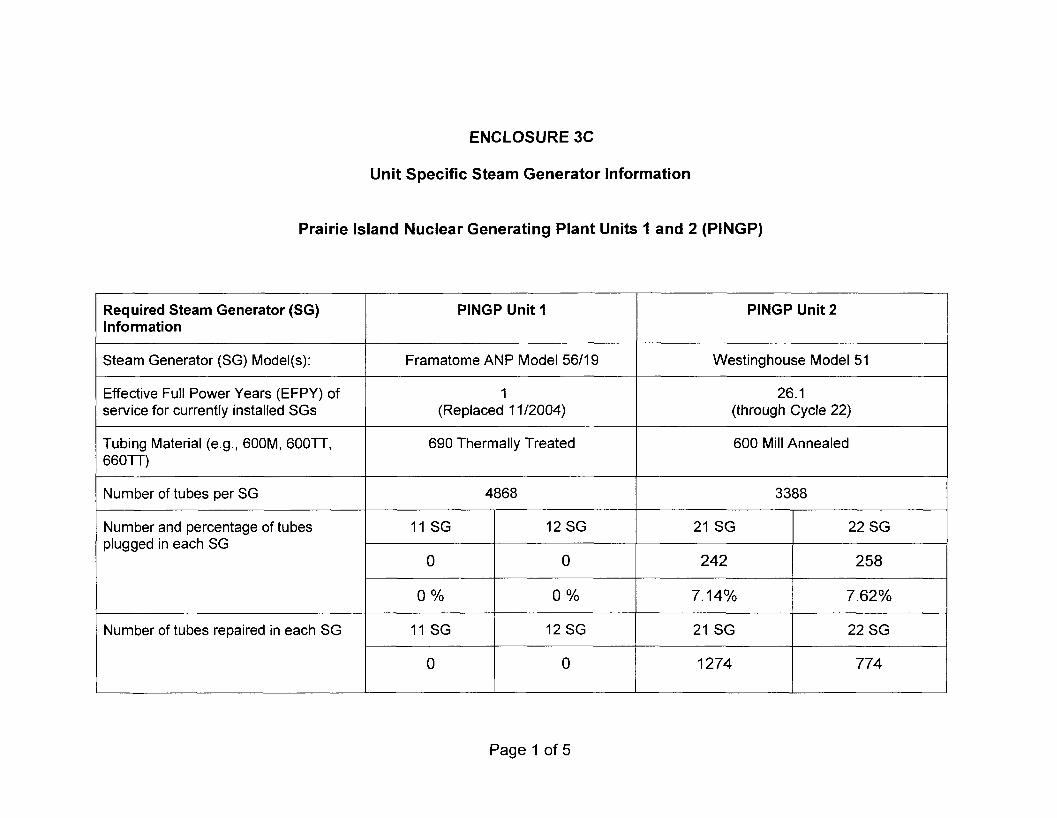
ENCLOSURE 3C
Unit Specific Steam Generator lnformation
Prairie Island Nuclear Generating Plant Units 1 and 2 (PINGP)
Page 1 of 5
Required Steam Generator (SG) lnformation
Steam Generator (SG) Model(s):
Effective Full Power Years (EFPY) of service for currently installed SGs
Tubing Material (e.g., 600M, 600l7, 660TT)
Number of tubes per SG
Number and percentage of tubes plugged in each SG
Number of tubes repaired in each SG
PlNGP Unit 2
Westinghouse Model 51
26.1 (through Cycle 22)
600 Mill Annealed
3388
PlNGP Unit 1
Framatome ANP Model 5611 9
1 (Replaced 1 1/2004)
690 Thermally Treated
4868
21 SG
242
7.14%
21 SG
1274
11 SG
0
0 %
11 SG
0
22 SG
258
7.62%
22 SG
774
12 SG
0
0 %
12 SG
0

Page 2 of 5
Required Steam Generator (SG) Information
Degradation mechanism(s) identified
Current primary -to-secondary leakage limits: per SG; Total; Leakage is evaluated at what temperature condition?
Approved Alternate Tube Repair Criteria (ARC): (Provide for each) Approved by [amendment number dated 1; Applicability (e.g., degradation mechanism, location); any special limits on allowable accident leakage; any exceptions or clarifications to the structural performance criteria that apply to the ARC
PlNGP Unit 1
None
150 gallons per day per SG; 300 gallons per day total; leakage evaluated at room temperature
None are applicable to the Replacement Steam Generators. The existing Prairie Island Alternate Tube Repair Criteria apply to only Westinghouse Model 51 Steam Generators (Unit 2 steam generators)
PlNGP Unit 2
Primary water stress corrosion cracking, secondary side intergranular and stress corrosion cracking and wear due to loose parts, cold leg thinning at tube support plates (TSP), wear at antivibration bars.
150 gallons per day per SG; 300 gallons per day total; leakage evaluated at room temperature
1. F* Steam Generator Tube Repair Criteria: License Amendment (LA) - 1 1811 1 1 dated May 15, 1995; Applicable to all degradation mechanisms below the F* hard roll; Due to tubesheet flexure assumptions in WCAP-14225, the uppermost location height of the top of the F* hard roll distance is the middle of the tubesheet. The middle of the tubesheet is 10.72 inches above the tube end. Acceptable distance (not including eddy current measurement uncertainty) is 1.07 inches; Site specific leakages are assigned to each F* tube and included in the total main steam line break (MSLB) leakage for all degradation mechanisms for the operational assessment.; No special limits on allowable accident leakage and no clarification to the structural performance criteria.

Required Steam Generator (SG) Information
PlNGP Unit 1 PlNGP Unit 2
2. Voltage Based, LA - 13311 25 dated November 18, 1997; applies to degradation due to predominantly axially oriented outside diameter stress corrosion cracking confined within the tube to tube support plate locations; Indication specific leakages are assigned per Generic Letter 95-05 and Nuclear Energy Institute follow-on guidance for each indication and included in the total MSLB leakage for all degradation mechanisms for the operational assessment.; special limit on allowable primary to secondary MSLB accident leakage of 1.42 gallons per minute (at 578 OF); no clarification to the structural performance criteria.
3. EF* SG alternate repair criteria, LA - 13711 28 dated August 13, 1998 and LA - 1491140; Due to tubesheet flexure assumptions in WCAP-14225, the uppermost location height of the top of the EF* hard roll distance is 2 inches from the top of the tubesheet. The top of the tubesheet is 21.44 inches above the tube end. Acceptable distance (not including eddy current measurement uncertainty) is 1.67 inches above the tube end; Site specific leakages are assigned to each EF* tube and included in the total MSLB leakage for all degradation mechanisms for the o~erational assessment.: No
Page 3 of 5

Required Steam Generator (SG) Information
Approved SG Tube Repair Methods (Provide for each): Approved by [amendment number dated 1; Applicability limits, if any; Sleeve repair criteria (e.g., 40% of the initial sleevewall thickness)
PlNGP Unit 1 PlNGP Unit 2
None
special limits on allowable accident leakage and no clarification to the structural performance criteria.
1. a. Tube sleeving; LA - 76169 dated October I I , 1985 (superceded by LA 13211 24); Tubesheet Sleeves, 50%.
b. Welded sleeving improvements; LA - 13211 24 dated November 4, 1997; Tubesheet and TSP locations, Sleeve repair criteria, 31 %.
c. Incorporate Combustion Engineering Topical Report CEN 629-P, "Repair of Westinghouse Series 44 and 51 Steam Generator Tubes Using Leak Tight Sleeves," Revision 3 Repair criteria, LA - 14411 35 dated April 15, 1999; Applicable to Sleeve Joints, 25%.
2. Additional Roll Expansion (F* reroll): LA- 1 1811 1 1 dated May 15, 1995; incorporate Westinghouse report WCAP- 14225, "F* and L* Plugging Criteria for Tubes with Degradation in the Tubesheet Roll Expansion Region of the Prairie Island Units 1 and 2 Steam Generators", the basis document for rerolling is Combustion Engineering CEN-620-P; Applicable only below midplane of the tubesheet. Reroll must satisfy F* criteria.
Page 4 of 5

Page 5 of 5
Required Steam Generator (SG) Information
Performance criteria for accident leakage (Primary to secondary leak rate values assumed in licensing basis accident analysis, including assumed temperature conditions)
PlNGP Unit 1
I .O gallon per minute at 70 OF
PlNGP Unit 2
3. Additional Roll Expansion (EF* reroll): LA-1 3711 28 dated August 13, 1998 and LA - 1491140; incorporate Westinghouse report WCAP-14255, Revision 2, "F* and Elevated F* Tube Plugging Criteria for Tubes with Degradation in the Tubesheet Region of the Prairie Island Units 1 and 2 Steam Generators", the basis document for rerolling is Combustion Engineering CEN-620-P; Applicable anywhere below 2 inches from the top of the tubesheet which allows use of the EF* criteria.
1 .O gallon per minute at 70 OF

ENCLOSURE 4
The following Proposed Technical Specification and Bases Pages (markup) are contained within Enclosure 4:
Enclosure 4A - Palisades Nuclear Plant
Enclosure 48 - Point Beach Nuclear Plant Units 1 and 2
Enclosure 4C - Prairie Island Nuclear Generating Plant Units 1 and 2
Page 1 of 1

ENCLOSURE 4A
Proposed Technical Specification and Bases Pages (markup)
Palisades Nuclear Plant
Technical Specification Pages
Bases pages
32 pages follow

Definitions 1.1
1.1 Definitions
LEAKAGE
MODE
a. Identified LEAKAGE (continued)
2. LEAKAGE into the containment atmosphere from sources that are both specifically located and known not to interfere with the operation of leakage detection systems and not to be pressure boundary LEAKAGE; and
3. Primary Coolant System (PCS) LEAKAGE through a Steam Generator (SSjto the Secondary System brimarv to secondary LEAKAGE).
b. Unidentified LEAKAGE
All LEAKAGE (except Primary Coolant Pump seal leakoff) that is not identified LEAKAGE;
c. Pressure Boundary LEAKAGE
LEAKAGE (except primary to secondary =LEAKAGE) through a nonisolable fault in an PCS component body, pipe wall, or vessel wall.
A MODE shall correspond to any one inclusive combination of core reactivity condition, power level, average primary coolant temperature, and reactor vessel head closure bolt tensioning specified in Table 1 .I-1 with fuel in the reactor vessel.
OPERABLE - OPERABILITY A system, subsystem, train, component, or device shall be OPERABLE or have OPERABILITY when it is capable of performing its specified safety function(s) and when all necessary attendant instrumentation, controls, normal or emergency electrical power, cooling and seal water, lubrication, and other auxiliary equipment that are required for the system, subsystem, train, component, or device to perform its specified safety function(s) are also capable of performing their related support function(s).
Palisades Nuclear Plant 1.1-4 Amendment No. 4%

PCS Operational LEAKAGE 3.4.13
3.4 PRIMARY COOLANT SYSTEM (PCS)
3.4.1 3 PCS Operational LEAKAGE
LC0 3.4.13 PCS operational LEAKAGE shall be limited to:
a. No pressure boundary LEAKAGE;
b. 1 gpm unidentified LEAKAGE;
c. 10 gpm identified LEAKAGE; and
d. Jl&W gallons per day primary to secondary LEAKAGE through any one steam aenerator (SG).
APPLICABILITY: MODES 1, 2, 3, and 4.
A. PCS o~erational LEAKAGE not within limits for reasons other than pressure boundary LEAKAGE or primary t~ secondary leakage.
ACTIONS
A. 1 Reduce LEAKAGE to within limits.
CONDITION
4 hours
B. Required Action and associated Completion Time not met.
REQUIRED ACTION
Pressure boundary LEAKAGE exists.
COMPLETION TIME
OR
Primarv to secondary LEAKAGE not within limit.
B. 1 Be in MODE 3.
AND
8.2 Be in MODE 5.
6 hours
36 hours
Palisades Nuclear Plant 3.4.13-1 Amendment No. 4-843

PCS Operational LEAKAGE 3.4.13
SURVEILLANCE REQUIREMENTS
SURVEILLANCE 1 FREQUENCY
SR 3.4.13.1 ............................... NOTES ......................... L N o t required to be performed in MODE 3 or 4 -
until 12 hours of steady state operation.
2. N ot a~plicable to primary to seco n d a y 4mKeE
................................................................
Verify PCS operational LEAKAGE is within limits by performance of PCS water inventory balance.
---------- NOTE -------- Only required to be performed during steady state operation ...........................
72 hours
SR 3.4.13.2 ............................... ........................... Not required to be performed until 12 hours after establ~shment of steadv state o~eration.
Verify . . .
Reyamprimary to secondary LEAKAGE is < 150 II ga ons per dav throuah anv one SG.
Palisades Nuclear Plant Amendment No. 4%

SG Tube integrity 3.4.17
3.4 PRIMARY COOLANT SYSTEM [PCS)
3.4.17 Steam Generator (SG) Tube I n t e r n
LC0 3.4.17 SG tube integrity shall be maintained.
AND
All SG tubes satisfving the tube repair criteria shall be plugged in accordance with the Steam Generator Program.
APPLICABILITY: MODES 1 ! 2. 3. and 4.
ACTIONS ............................................................ NOTE ........................................................... Sepa
, . rate Cond~t~on entry is allowed for each SG tube.
...............................................................................................................................
CONDITION REQUIRED ACTION
-
COMPLETION TIME
A. One or more SG tubes satisfying the tube repair criteria and not plugged in accordance with the Seam Gene& Program.
B. Required Action and associated Completion Time of Condition A not met.
SG tube integrity not rnaindmed
A. 1 Verifv tube integrity of the affected tube(s) is maintained until the next refueling outage or SG tube inspection.
A.2 Plug the affected tube!sl in accordance with the Steam Generator Proaram.
B . l Be in MODE 3.
B.2 Be in MODE 5.
Prior to entering MODE 4 following the next refuelina outage or SG tube inspection
36 hours
Palisades Nuclear Plant 3.4.17-1 Amendment No.

SG Tube lntearity 3.4.17
SR - 3.4.17.1 Ve rif v SG tube intearitv in acco r dance with th e S t e a m a ~ r o a r a m .
SURVEILLANCE REQUIREMENTS
In accordance with the Steam Generator Proaram
SURVEILLANCE FREQUENCY
Palisades Nuclear Plant 3.4.17-2 Amendment No.
SR 3.4.17.2 Verifv that each inspected SG tube that satisfies the tube repair criteria is plugged in accordance with the S-%
Prior to entering MODE 4 following w inspection

Programs and Manuals 5.5
5.5 Programs and Manuals
5.5.7 lnservice Testing Program
This program provides controls for inservice testing of ASME Code Class 1, 2, and 3 components. The program shall include the following:
a. Testing frequencies specified in Section XI of the ASME Boiler and Pressure Vessel Code and applicable Addenda (B&PV Code) as follows:
B&PV Code terminology for inservice testing activities Weekly Monthly Quarterly or every 3 months Semiannually or every 6 months Every 9 months Yearly or annually Biennially or every 2 years
Required interval for performing inservice testing activities 1 7 days 1 31 days I 92 days 1 184 days 1276 days 5366 days 1731 days
b. The provisions of SR 3.0.2 are applicable to the above required intervals for performing inservice testing activities;
c. The provisions of SR 3.0.3 are applicable to inservice testing activities; and
d. Nothing in the B&PV Code shall be construed to supersede the requirements of any Technical Specification.
5.5.8 Steam Generator m T l l k . l P r o g r a m
A Steam Generator Proaram shall be established and implemented to ensu that SG tube intearltv 1s ma
. . re intained . . . In addition, the Steam Generator Proaram
shall include the followina provlslons;
a. Provisions for cond~t~on monbr~nq assessments. Cond . . . . ition monitoring . . assessment means an evaluation of the "as found" condhm of the tubing w~th res~ect to the ~erformance criteria for structural lnte.guly and acc . . ident rnduced leakaae. The "as found" cond~t~on refers to the condition of the tubing durina an SG inspection outaae, as determined from the inservice
spection results or bv other m e ~ r i o r to the p gg in lu ina of tubes, hall be conducted durina each outage Condition monitorina assessments s
du rin a which the SG tubes are inspected o pluqqed to confirm that the . . r performance cnterla are being met
b. Performance criteria for SG tube integritv. SG tube i . . . . ntearitv shall be malntalned bv meetlng the ~erformance cr~ter~a for tube structural integrity, accident induced leakage: and operational LEAKAGE.
Palisades Nuclear Plant 5.0-1 1 Amendment No. 4-8Q

Programs and Manuals 5.5
5.5 Programs and Manuals
1. Structural intearity performance criterion: All in-service SG tubes shall retain structural intearitv over the full ranae of normal operating conditions (includina startup opemtion in the power range, hot
ndbv, and cool down and all anticipated transients included in the i . . des an specification) and desian basis acc'dents I . This includes
retalnlna a safetv factor of 3.0 aaainst burst under normal steadv state full power operation primary-to-secondarv pressure differential and a safetv factor of 1.4 a a n s t burst w ~ l i e d to the desian basis accide n t primary - to - seco ndarv pressure differentials. Apart from the above requirements. additional loadina c~nditions associated with the desian
IS accldents, or combination of accldents In accordance wlth the design and licensing basis, shall also be evaluated to determine if the associa ted I oads contribute sianificantlv to burst or collapse. In the
I h . . . assessment of tube intearitv, those oads t at do slan~flcantlv affect burst or collapse shall be determined and assessed In combination with the loads due to pressure with a safetv factor of 1.2 on the combined primary loads and 1.0 on axial secondary loads.
2. Accident induced leakage performance criterion: The primary to seco ndary accident induced leakaae rate for anv desian basis B cclde ' n t. ot h er than a SG tube rupture. sha I I n ot exceed t h e I eakaae . . rate assumed in the accident analvs~s In terms of total leakaae rate for all SGs and leakage rate for an individual SG. Leakage is not to exceed 0.3 aDm,
3. The operational LEAKAGF performance criterion is s~ecified in LC0 3.4.1 3, "PCS O~erational LEAKAGE."
found by i c. Provisions for SG tube re~a i r criteria. Tubes nservlce inspect~on to contain flaws with a depth equal to or exceeding 40% of the nominal tube wall thickness shall be oluaaed*
d. Provisions for SG tube inspections. Periodic SG tube inspections shall be performed. The number and portions of the tubes inspected and methods of
sha II be performed with the obiective of detect ing flaws of an v in spect i n o . . ri fl tvpe (e a . volumet c aws. axial and circumferential cracks) t hat m av be
present along the lenath of the tube, f r m the tube - to - tubesheet we Id at the t ube in1 et to the tube - to - tubesheet weld at the tube outlet, and that may satisfv the applicable tube repair criteria. The tube - to - tubes heet weld is not part of the tube. In addition to meetina the requirements of d.1, d.2: and d.3
I in i n scope, inspection methods, and i nspect ion i nterva I s be ow. the spect o . . shall be such as to ensure that SG tube intearitv is ma~ntalned until the next SG inspection. An assessment of dearadation shall be performed to determine the tvpe and location of flaws to which the tubes mav be susceptible and, based on this assessment, to determine which inspection methods need to be emeloved and at what locations.
Palisades Nuclear Plant 5.0-1 2 Amendment No. 4-89

Programs and Manuals 5.5
5.5 Programs and Manuals
1. lnspect 100% of the tubes in each SG durina the first refueling outage following SG replacement.
2. Inspect 100% of the tubes at seauential periods of 60 effective full power months. The first sequential period shall be considered to begin after the first inservice inspection of the SGs. No SG shall operate for more than 24 effective full po w mont h s or one refuelina outaae (whicheve r i s I ess) without being inspected.
3. If crack indications are found in anv SG tube, then the next inspection for each SG for the dea ad . . .
r ation mechanism that caused the crack lndlcat~on shall not exceed 24 effective full power months or one refuelina outaae (whichever is less). If definitive information: such as from examination of
i U k d tube. d~aanost c non-destructwe testina, or enatnee r' I n Q evaluation indicates that a crack-like indication is not associated with a crack(s). then the indication need not be treated as a crack.
e. Provisions for monitorina operational primary to secondary LEAKAGE,
Palisades Nuclear Plant 5.0-1 3 Amendment No. 44%

Programs and Manuals 5.5
5.5 Programs and Manuals
Palisades Nuclear Plant 5.0-14 Amendment No.

Programs and Manuals 5.5
5.5 Programs and Manuals
In-
Palisades Nuclear Plant 5.0-1 5 Amendment No. 4-89

Programs and Manuals 5.5
5.5 Programs and Manuals
Palisades Nuclear Plant 5.0-16 Amendment No. 44%

Programs and Manuals 5.5
5.5 Programs and Manuals
5.5.8 Steam Generator 0 - T l l k P P r o c l r a m
Palisades Nuclear Plant 5.0-1 7 Amendment No. 4433

Programs and Manuals 5.5
PICA l PICA PICA
NA
PICA
PICA
PICA
PICA I
PICA
TCC. I L V . I
Palisades Nuclear Plant Amendment No. 4-89

Reporting Requirements 5.6
5.6 Reporting Requirements
5.6.6 Post Accident Monitoring Report
When a report is required by LC0 3.3.7, "Post Accident Monitoring Instrumentation," a report shall be submitted within the following 14 days. The report shall outline the preplanned alternate method of monitoring, the cause of the inoperability, and the plans and schedule for restoring the instrumentation channels to OPERABLE status.
5.6.7 Containment Structural Intesritv Surveillance Report
Reports shall be submitted to the NRC covering Prestressing, Anchorage, and Dome Delamination tests within 90 days after completion of the tests.
5.6.8 Steam Generator Tube Inspection- Report
A report shall be submitted within 180 davs after the initial entrv into MODE 4 f o II o win a co m let i on o f an in s~ection ~erformed in acco rdance with the
ifi i n . Spec cat o 5 5.8. Steam Generator (SG) Proaram. The report s h a II in c I ude :
a. The scope of inspections performed on each SG,
b. Active degradation mechanisms found,
c. Nondestructive examination technia ues utilized for each dearadation mechanism,
d. Location, orientation (if linear], and measured sizes (if available) of service induced indications,
I h in Number of tubes p u aaed dur~ng t e e. spection outage for each active dearadation mechanism,
f. Total number and percentage of tubes plugged to date,
. Th g e results of condition monitoring, includina the results of tube pulls and in- situ testing! and
A a i n g in each SG.
Palisades Nuclear Plant Amendment No. 4-89

Reporting Requirements 5.6
5.6 Reporting Requirements
Palisades Nuclear Plant Amendment No. 4-80

PCS Loops - MODES 1 and 2 B 3.4.4
BASES
APPLICABLE Both transient and steady state analyses have been performed to SAFETY ANALYSES establish the effect of flow on DNB. The transient or accident analysis
(continued) for the plant has been performed assuming four PCPs are in operation. The majority of the plant safety analyses are based on initial conditions at high core power or zero power. The accident analyses that are of most importance to PCP operation are the Loss of Forced Primary Coolant Flow, Primary Coolant Pump Rotor Seizure and Uncontrolled Control Rod Withdrawal events (Ref. 1).
Steady state DNB analysis had been performed for the four pump combination. The steady state DNB analysis, which generates the pressure and temperature and Safety Limit (i.e., the Departure from Nucleate Boiling Ratio (DNBR) limit), assumes a maximum power level of 110.4% RTP. This is the design overpower condition for four pump operation. The 110.4% value is the accident analysis setpoint of the trip and is based on an analysis assumption that bounds possible instrumentation errors. The DNBR limit defines a locus of pressure and temperature points that result in a minimum DNBR greater than or equal to the critical heat flux correlation limit.
PCS Loops - MODES 1 and 2 satisfy Criteria 2 and 3 of 10 CFR 50.36(~)(2).
The purpose of this LC0 is to require adequate forced flow for core heat removal. Flow is represented by having both PCS loops with both PCPs in each loop in operation for removal of heat by the two SGs. To meet safety analysis acceptance criteria for DNB, four pumps are required at rated power.
Each OPERABLE loop consists of two PCPs providing forced flow for heat transport to an SG that is OPERABLE-
n Dr q e m . SG, and hence PCS loop OPERABILITY with regards to SG water level is ensured by the Reactor Protection System (RPS) in MODES 1 and 2. A reactor trip places the plant in MODE 3 if any SG water level is I 25.9% (narrow range) as sensed by the RPS. The minimum level to declare the SG OPERABLE is 25.9% (narrow range).
In MODES 1 and 2, the reactor can be critical and thus has the potential to produce maximum THERMAL POWER. Thus, to ensure that the assumptions of the accident analyses remain valid, all PCS loops are required to be in operation in these MODES to prevent DNB and core damage.
Palisades Nuclear Plant B 3.4.4-2 Revised €lW#XM

PCS Loops - MODE 3 B 3.4.5
BASES
LC0 d. SG secondary temperature is < 100 O F above Tc, and shutdown (continued) cooling is isolated from the PCS, and pressurizer level is 5 57%.
Satisfying any of the above conditions will preclude a large pressure surge in the PCS when the PCP is started. Energy additions from the steam generators could occur if a PCP was started when the steam generator secondary temperature is significantly above the PCS temperature. The maximum pressurizer level at which credit is taken for having a bubble (57%, which provides about 700 cubic feet of steam space) is based on engineering judgement and verified by LTOP analysis. This level provides the same steam volume to dampen pressure
transients as would be available at full power.
An OPERABLE PCS loop consists of any one (of the four) OPERABLE PCP and an SG that is O P E R A B L E W
pam and has the minimum water level specified in SR 3.4.5.2. A PCP is OPERABLE if it is capable of being powered and is able to provide forced flow if required.
APPLICABILITY In MODE 3, the heat load is lower than at power; therefore, one PCS loop in operation is adequate for transport and heat removal. A second PCS loop is required to be OPERABLE but is not required to be in operation for redundant heat removal capability.
Operation in other MODES is covered by:
LC0 3.4.4, "PCS Loops-MODES 1 and 2";
LC0 3.4.6, "PCS Loops-MODE 4";
LC0 3.4.7, "PCS Loops-MODE 5, Loops Filled";
LC0 3.4.8, "PCS Loops-MODE 5, Loops Not Filled";
LC0 3.9.4, "Shutdown Cooling (SDC) and Coolant Circulation-High Water Level" (MODE 6); and
LC0 3.9.5, "Shutdown Cooling (SDC) and Coolant Circulation-Low Water Level" (MODE 6)
Palisades Nuclear Plant - Revised '2tMW%W

PCS Loops - MODE 4 B 3.4.6
BASES
LC0 Note 2 requires that one of the following conditions be satisfied before (continued) forced circulation (starting the first PCP) may be started:
a. SG secondary temperature is I Tc;
b. SG secondary temperature is < 100°F above Tc, and shutdown cooling is isolated from the PCS, and PCS heatup/cooldown rate is I 1 O°F/hour; or
c. SG secondary temperature is < 100°F above Tc, and shutdown cooling is isolated from the PCS, and pressurizer level is 5 57%.
Satisfying any of the above conditions will preclude a large pressure surge in the PCS when the PCP is started. Energy additions from the steam generators could occur if a PCP was started when the steam generator secondary temperature is significantly above the PCS temperature. The maximum pressurizer level at which credit is taken for having a bubble (57%, which provides about 700 cubic feet of steam space) is based on engineering judgement and verified by LTOP analysis. This level provides the same steam volume to dampen pressure
transients as would be available at full power.
Note 3 specifies a limitation on the simultaneous operation of primary coolant pumps P-50A and P-50B which allows the pressure limits in LC0 3.4.3, "PCS Pressure and Temperature Limits," and LC0 3.4.12, "Low Temperature Overpressure Protection System," to be higher than they would be without this limit. This is because the pressure in the reactor vessel downcomer region when primary coolant pumps P-50A and P-50B are operated simultaneously is higher than the pressure for other two primary coolant pump combinations.
An OPERABLE PCS loop consists of any one (of the four) OPERABLE PCP and an SG that has the minimum water level specified in SR 3.4.6.2 and is O P E R A B L E W c,,,,,;ll,,,,n,,,,,,. PCPs are OPERABLE if they are capable of being powered and are able to provide forced flow through the reactor core.
An OPERABLE SDC train is composed of an OPERABLE SDC pump and an OPERABLE SDC heat exchanger. SDC pumps are OPERABLE if they are capable of being powered and are able to provide forced flow through the reactor core.
- Palisades Nuclear Plant B 3.4.6-3 Revised "3/13/3""1

PCS Loops - MODE 5, Loops Filled B 3.4.7
BASES
LC0 Satisfying any of the above conditions will preclude a large pressure (continued) surge in the PCS when the PCP is started. Energy additions from the
steam generators could occur if a PCP was started when the steam generator secondary temperature is significantly above the PCS temperature. The maximum pressurizer level at which credit is taken for having a bubble (57%, which provides about 700 cubic feet of steam space) is based on engineering judgement and verified by LTOP analysis. This level provides the same steam volume to dampen pressure transients as would be available at full power.
Note 4 specifies a limitation on the simultaneous operation of primary coolant pumps P-50A and P-50B which allows the pressure limits in LC0 3.4.3, "PCS Pressure and Temperature Limits," and LC0 3.4.12, "Low Temperature Overpressure Protection System," to be higher than they would be without this limit.
Note 5 provides for an orderly transition from MODE 5 to MODE 4 during a planned heatup by permitting SDC trains to not be in operation when at least one PCP is in operation. This Note provides for the transition to MODE 4 where a PCP is permitted to be in operation and replaces the PCS circulation function provided by the SDC trains.
An OPERABLE SDC train is composed of an OPERABLE SDC pump and an OPERABLE SDC heat exchanger. SDC pumps are OPERABLE if they are capable of being powered and are able to provide forced flow through the reactor core.
An SG can perform as a heat sink via natural circulation when:
a. SG has the minimum water level specified in SR 3.4.7.2.
SG is OPERABLE P b. - c. SG has available method of feedwater addition and a controllable
path for steam release.
d. Ability to pressurize and control pressure in the PCS.
If both SGs do not meet the above provisions, then LC0 3.4.7 item b (i.e. the secondary side water level of each SG shall be 2 -84%) is not met.
Palisades Nuclear Plant B 3.4.7-4 Revised 13/"7'7nnn

PCS Operational LEAKAGE B 3.4.13
BASES
BACKGROUND As defined in 10 CFR 50.2, the PCPB includes all those pressure- (continued) containing components, such as the reactor pressure vessel, piping,
pumps, and valves, which are:
(1) Part of the primary coolant system, or
(2) Connected to the primary coolant system, up to and including any and all of the following:
(i) The outermost containment isolation valve in system piping which penetrates the containment,
(ii) The second of two valves normally closed during normal reactor operation in system piping which does not penetrate the containment,
(iii) The pressurizer safety valves and PORVs.
APPLICABLE Except for primary to secondary LEAKAGE, the safety analyses do not SAFETY ANALYSES address operational LEAKAGE. However, other operational LEAKAGE
is related to the safety analyses for LOCA; the amount of leakage can affect the probability of such an event. The safety analysis for all events resulting in a discharge of steam from the steam generators to the atmosphere assumes $hat primary to secondary LEAKAGE from all steam aenerators (SGs) IS 0.3 apm or Increases to 0.3 gpm as a - . . result of acc~dent ~nduced cond~t~ons. The LC0 re~ l rement to limit primarv to secondary LEAKAGE through anv one SG to less than or equal to 150
I i b n t l y less tha gal ons per dav IS s an n the conditions assumed ~n the safetv a n a l v s i s € L = z
. . .
Primary to secondary LEAKAGE is a factor in the dose releases outside containment resulting from a Main Steam Line Break (MSLB), Steam Generator Tube Rupture (SGTR) and the Control Rod Ejection (CRE) accident analyses. The leakage contaminates the secondary fluid.
The FSAR (Ref. 2 and 5) analysis for SGTR assumes the contaminated secondary fluid is released via the Main Steam Safety Valves and Atmospheric Dump Valves. The 0.3 gpm primary to secondary LEAKAGE safetv analvsis assumption is inconsequential, relative to the dose contribution from the affected SG.
The MSLB (Ref 3 and 5) is more limiting than SGTR for site radiation releases. The safety analysis for the MSLB accident assumes the entire
ffectech-cm 0.3 gpm primary to secondary LEAKAGE is through the a steam generator as an initial condition.
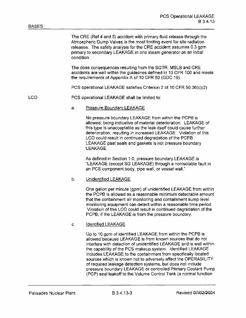
Palisades Nuclear Plant B 3.4.13-2 Revised €l#GXXM
PCS Operational LEAKAGE B 3.4.13
BASES
The CRE (Ref 4 and 5) accident with primary fluid release through the Atmospheric Dump Valves is the most limiting event for site radiation releases. The safety analysis for the CRE accident assumes 0.3 gpm primary to secondary LEAKAGE in one steam generator as an initial condition.
The dose consequences resulting from the SGTR, MSLB and CRE accidents are well within the guidelines defined in 10 CFR 100 and meets the requirements of Appendix A of 10 CFR 50 (GDC 19).
PCS operational LEAKAGE satisfies Criterion 2 of 10 CFR 50.36(~)(2).
PCS operational LEAKAGE shall be limited to:
a. Pressure Boundary LEAKAGE
No pressure boundary LEAKAGE from within the PCPB is allowed, being indicative of material deterioration. LEAKAGE of this type is unacceptable as the leak itself could cause further deterioration, resulting in increased LEAKAGE. Violation of this LC0 could result in continued degradation of the PCPB. LEAKAGE past seals and gaskets is not pressure boundary LEAKAGE.
As defined in Section 1 .O, pressure boundary LEAKAGE is "LEAKAGE (except SG LEAKAGE) through a nonisolable fault in an PCS component body, pipe wall, or vessel wall."
b. Unidentified LEAKAGE
One gallon per minute (gpm) of unidentified LEAKAGE from within the PCP0 is allowed as a reasonable minimum detectable amount that the containment air monitoring and containment sump level monitoring equipment can detect within a reasonable time period. Violation of this LC0 could result in continued degradation of the PCPB, if the LEAKAGE is from the pressure boundary.
c. Identified LEAKAGE
Up to 10 gpm of identified LEAKAGE from within the PCPB is allowed because LEAKAGE is from known sources that do not interfere with detection of unidentified LEAKAGE and is well within the capability of the PCS makeup system. ldentified LEAKAGE includes LEAKAGE to the containment from specifically located sources which is known not to adversely affect the OPERABILITY of required leakage detection systems, but does not include pressure boundary LEAKAGE or controlled Primary Coolant Pump (PCP) seal leakoff to the Volume Control Tank (a normal function
Palisades Nuclear Plant B 3.4.1 3-3 Revised (JZQZXH

PCS Operational LEAKAGE B 3.4.13
BASES
not considered LEAKAGE). Violation of this LC0 could result in continued degradation of a component or system.
LC0 3.4.14, "PCS Pressure Isolation Valve (PIV) Leakage," measures leakage through each individual PIV and can impact this LCO. Of the two PlVs in series in each isolated line, leakage measured through one PIV does not result in PCS LEAKAGE when the other is leaktight. If both valves leak and result in a loss of mass from the PCS, the loss must be included in the allowable identified LEAKAGE.
LC0 d. Primarv to Secondarv LEAKAGE Rhrouah Anv One SG (continued)
The limit of 150 gallons per dav per SG is based on the operational LEAKAGE performance criterion in NEI 97-06: Steam Generator Program Guidelines !Ref. 6). The Steam Generator Program operational LEAKAGE performance criterion in NEI 97- 06 states, "The RCS operational primarv to secondary leakage throuah anv one SG shall be limited to 150 gallons per dav." The limit is based on operating experience with SG tube degradation mechanisms that result in tube leakage. The operational leakage rate criterion in coniunction with the imolementation of the Steam Generator Proaram is an effective measure for minimizina the freauencv of steam generator tube ruptu res. -
APPLICABILITY In MODES 1, 2, 3, and 4, the potential for PCPB LEAKAGE is greatest when the PCS is pressurized.
In MODES 5 and 6, LEAKAGE limits are not required because the primary coolant pressure is far lower, resulting in lower stresses and reduced potentials for LEAKAGE.
ACTIONS - A. 1
Unidentified LEAKAGES identified LEAKAGE, or lAEMAG€ in excess of the LC0 limits must be reduced to within limits within 4 hours. This Completion Time allows time to verify leakage rates
Palisades Nuclear Plant B 3.4.13-4 Revised "7/"3/3"""

PCS Operational LEAKAGE B 3.4.13
BASES
and either identify unidentified LEAKAGE or reduce LEAKAGE to within limits before the reactor must be shut down. This action is necessary to prevent further deterioration of the PCPB.
B . l and B.2
If any pressure boundary LEAKAGE from within the PCPB ex is ts~r grimarv to secondary LEAKAGE is not within limit, or if unidentified,~r identified- LEAKAGE cannot be reduced to within limits within 4 hours, the reactor must be brought to lower pressure conditions to reduce the severity of the LEAKAGE and its potential consequences. The reactor must be brought to MODE 3 within 6 hours and to MODE 5 within 36 hours. This action reduces the LEAKAGE and also reduces the factors that tend to degrade the pressure boundary.
The allowed Completion Times are reasonable, based on operating experience, to reach the required conditions from full power conditions in an orderly manner and without challenging plant systems. In MODE 5, the pressure stresses acting on the PCPB are much lower, and further deterioration is much less likely.
SURVEILLANCE SR 3.4.1 3.1 REQUIREMENTS
Verifying PCS LEAKAGE to be within the LC0 limits ensures the integrity of the PCPB is maintained. Pressure boundary LEAKAGE would at first appear as unidentified LEAKAGE and can only be positively identified by inspection. Unidentified LEAKAGE and identified LEAKAGE are determined by performance of an PCS water inventory balance. Pwwy
The PCS water inventory balance must be performed with the reactor at steady state operating conditions and near operating pressure.
ifi . .
rveillance i wo Notes. E t e 1..."'̂ *tZP,: t:it ?: SR is not r< MODES 3 and 4, until 12 hours of steady state operation have elapsed.
Steady state operation is required to perform a proper water inventory balance; calculations during maneuvering are not useful and a Note requires the Surveillance to be met only when steady state is established. For PCS operational LEAKAGE determination by water inventory balance, steady state is defined as stable PCS pressure, temperature, power level, pressurizer and makeup tank levels, makeup and letdown, and PCP seal leakoff.
An early warning of pressure boundary LEAKAGE or unidentified LEAKAGE is provided by the automatic systems that monitor the
Palisades Nuclear Plant B 3.4.13-5 Revised QWQXXQ4

PCS Operational LEAKAGE B 3.4.13
BASES
containment atmosphere radioactivity and the containment sump level. These leakage detection systems are specified in LC0 3.4.15, "PCS Leakage Detection Instrumentation."
Note 2 states that this SR is not applicable to primary to secondary LEAKAGE because LEAKAGE of 150 aallons per day cannot be measured accuratelv bv an RCS water inventory balance.
The 72 hour Frequency is a reasonable interval to trend LEAKAGE and recognizes the importance of early leakage detection in the prevention of accidents. A Note under the Frequency column states that this SR is required to be performed during steady state operation.
This SR verifies that primary to secondarv LEAKAGE is less or equal to 150 gallons Der day through anv one SG. Satisfvina the ~r imary to secondary LEAKAGE limit ensures that the operational LEAKAGE performance criterion in the Steam Generator Program is met. If this SR is not met, compliance with LC0 3.4.17, "Steam Generator Tube Intearity," should be evaluated. The 150 gallons per dav limit is measured at room temperature as described in Reference 7. The operational LEAKAGE rate limit applies to I FAKAGE throuah any one SG. If it is not practical to assign the LEAKAGE to an individual SG! all lhe primarv to secondary LEAKAGE should be conservatively assumed to be from one SG.
The Surveillance is modified by a Note which states that the Surveillance is not reauired to be performed until 12 hours after establishment of steady state operation. For RCS primary to secondary LEAKAGE determination, steadv state is defined as stable RCS pressure, temperature, power level: pressurizer and makeup ta . . . nk levels: makeug and letdown, and RCP seal ~nject~on and return flows.
The Surveillance Freauencv of 72 hours is a reasonable interval to trend primary to secondary LEAKAGF and rec~anizes the importance of early leakaae detection in the prevention of accidents. The ~r imary to
n I seco darv LEAKAGE 's determined usina cont in uous p r ocess r ad i at i n o monitors or radiochemical arab sampling in accordance with the EPRl auidelines (Ref. 7).
Palisades Nuclear Plant B 3.4.13-6 Revised €W@EW4

PCS Operational LEAKAGE B 3.4.13
BASES
REFERENCES 1. FSAR, Section 5.1.5
2. FSAR, Section 14.15
3. FSAR, Section 14.14
4. FSAR, Section 14.16
5. FSAR, Section 14.24
6. NEI 97-06, "Steam Generator Program Guidelines."
7. EPRI, "Pressurized Water Reactor Primary-to-Secondary Leak Guidelines."
Palisades Nuclear Plant Revised "7/"3/3"""

SG Tube lntearity B 3.4.17
B 3.4 PRIMARY COOLANT SYSTEM (PCS)
B 3.4.17 Steam Generator (SG) Tube lntearity
BASES
BACKGRBUND---. Steam generator (SG) tubes are small diameter, thin walled tubes that Carry primary coolant throuah the primary to secondarv heat exchanaers. The SG tubes have a number of important safetv functions. Steam generator tubes are an intearal Dart of the ~rimarv coolant pressure boundary (PCPB) and, as such: are relied on to maintain the primary svste m's pressure and inventory. The SG tubes isolate t he radioactive fission products in the primarv coolant from the secondary svstem. In addition, as part of the PCPB: the SG tubes are unique in that thev act as the heat transfer surface between the primary and secondary svstems ta remove heat from the primary system. This Specification addresses only the PCPB intearitv function of the SG. The SG heat removal function is addressed bv LC0 3.4.4, "PCS Loops - MODES 1 and 2." LC0 3.4.5, "PCS Loops - MODE 3." LC0 3.4.6, "PCS Loops - MODE 4:" and LC0 3.4.7, "PCS Loops - MODE 5! Loops Filled."
SG tube intearitv means that the tubes are ca~able of performing their intended PCPB safety function consistent with the licensing basis, including applicable reaulatory reauirements.
Steam generator tubing is subiect to a varietv of degradation mechanisms. Steam aenerat~r tubes mav experience tube dearadation related to corrosion phenomena, such as wastage, pitting, interaranular attack, and stress corrosion cracking. alona with other mechanicallv induced phenomena such as dentina and wear. These degradation mechanisms can impair tube integrity if thev are not managed effectivelv. The SG performance criteria are used to manage SG tube degradation,
Specification 5.5.8, "Steam Generator [SG) Proaram." requires that a proaram be established and ~mplemented to ensure that SG tube intearib. is maintained. Pursuant to Specification 5.5.8, tube intearitv is maintained when the SG performance criteria are met. There are three SG performance criteria: structural intearitv, accident induced leakaae, and operational LEAKAGE. The SG performance criteria are described in Specification 5.5.8. Meeting the SG performance criteria provides reasonableasranceof-aintalnlna tube integrity.& normal and accident conditions.
The processes used to meet the SG performance criteria are defined by the Steam Generator Program Guidelines [Ref. 1).
Palisades Nuclear Plant B 3.4.17-1 Amendment No.

SG Tube Integrity B 3.4.17
BASES (continued)
APPLICABLE - The steam aenerator tube rupture (SGTR) accident is the limitina design SAFETY basis event for SS tubes and avoiding an SGTR is the basis for this ANALYSES Specification. The analvsis of a SGTR event assumes a bounding
primary to secondarv LEAKGEA rate equal to the operational LEAKAGE rate limits in LC0 3.4.1 3: "PCS Operational LEAKAGE," plus the leakage r i with a g accident analvsis for a SGTR assumes the contaminated secondary fluid is released to the atmosphere via the Main Steam Safetv Valves and Atmospheric Dump Valves.
The analvsis for design basis accidents and transients other than a SGTR assume the SG tubes retain their structural intearitv ke., thev are assumed not to rupture.! In these analyses. the steam discharge to the g SGs of 0.3 apm or is assumed to increase to 0.3 apm as a result of accident induced conditions. For accidents that do not involve fuel damage, the primary coolant activitv level of DOSE EQUIVALENT 1-131 IS assumed to be equal to the LC0 3.4.16, "PCS S pecific Activitv," limits. For accidents that assume fuel damage, the primary coolant activitv is a function of the amount of activitv released from the damaaed fuel. The dose consequences of these events are within the limits of GDC 19 (Ref, 2): 10 CFR 100 [Ref. 3) or the NRC approved licensina basis (e.g.? a small fraction of these limits).
Steam generator tube integritv satisfies Criterion 2 of I 0 CFR
LC0 The LC0 requires that SG tube integritv be maintained. The LC0 also requires that all SG tubes that satisfv the repair criteria be plugged in accordance with the Steam Generator Proaram.
During an SG inspection, anv inspected tube that satisfies the Ste.a..m n r rPr oaram repair criteria is removed from se rvi ce bv ~ l u a a ina. If Ge e ato
;um the tube mav still have tube intearitv.
In t h e co n te xt o f t hi s Specification. a SG tube is defined as t he entir e I_enqth of the tube, including the tube wall . between the tube - to - tubes heet weld at the tube inlet and the tube-to-tubesheet weld at the tube outlet. The tube-to-tubesheet weld is not considered part of the tube.
A SG tube has tube integritv when it satisfies the SG performance criteria. The SG performance criteria are defined in Specification 5.5.8: "Steam Generator Program," and describe acceptable SG tube performance. P r determinina conformance with the SG performance criteria.
Palisades Nuclear Plant B 3.4.1 7-2 Amendment No.
SG Tube Integrity B 3.4.17
BASES
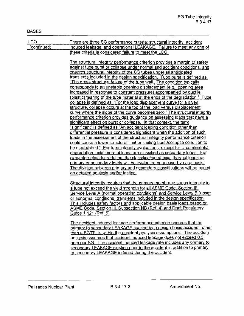
_.!=!LC! There are three SG performance criteria: structural integritv! accident (continued) induced leakage, and operational LEAKAGE. Failure to meet anv one of
ihese criteria is considered failure to meet the LCO.
The structural intearitv performance criterion provides a margin of safetv against tube burst or collapse under normal and accident conditions, and ensures structural integritv of the SG tubes under all anticipated transients included in the design specification. Tube burst is defined as, "The gross structural failure of the tube wall. The condition tvpically corresponds to an unstable openina displacement (e.g.. openina area increase in res on s e .(plastic) tearing of the tube material at the ends of the degradation." Tube collapse is defined as! "For the load displacement curve for a aiven structure, collapse occurs at the top of the load versus displacement w r e v 1 f a c , y rv m p e r f o r m a n c e E d e s guidance on assessing loads that have a significant effect on burst or colla~se. In that context, the term
s defined as "An accident loadina condition other than - differential pressure is considered significant when the addition of such loads in the assessment of the structural intearitv performance criterion mad cause a lower structural limit or limitina burstlcollapse condition ta be established." For tube intearity evaluations. except for circumferential e r circumferential dearadation, the classification of axial thermal loads as primary or secondary loads will be evaluated on a case-by-case basis. Th ivi i n w n rim y on detailed analvsis andlor testina.
Structural integrity reauires that the primary membrane stress intensitv in a tube not exceed the vield strength for all ASME Code. Section Ill, Service Level A (normal operating conditions) and Service Level B (upset . . .or abnormal conditions) transients included in the design specification. This includes safety factors and applicable desian basis loads based on ASME Code. Section Ill. Subsection NB (Ref. 4) and Draft Reaulatory Guide 1.121 1-1.
Th cid nt in I k 1 prlrnary to secorlSa~v LEAW\GE..mused by a design basis accident, a k r than a SGTR. is within the accident analvsis assumptions. The accident analvsis assumes that accident induced leakage does not exceed 0.3
m per SG. The accident induced leakaae rate includes any primarv to gcondarv LEAKAGE existing prior to the accident in addition to primaty t f t
Palisades Nuclear Plant B 3.4.17-3 Amendment No.

SG Tube Integrity B 3.4.17
BASES
C-CXQ--..- The operational LEAKAGE performance criterion provides an observable (continued) indication of SG tube conditions during plant operation. The limit on
operational LEAKAGE is contained in LC0 3 . . .4.13, "PCS Operational
LEAKAGE," and l ~ m ~ t s primary to secondary LEAKAGE through any one SG to 150 aallons per dav. This limit is based on the assumption that a single crack leaking this amount would not p r o p a ~ t e to a . . SGTR under the stress cond~t~ons of a LOCA or a main steam line break. If this amount of LEAKAGE is due to more than one crack, the cracks are very small, and the above assumption is conservative.
APPLICABILITY Steam generator tube integritv is challenged when the pressure differential across.the tubes is large. Large differential pressures across SG tubes can onlv be experienced in MODE 1,2. 3. or 4.
PCS cond~t . . ions-are far less challenging in MODES 5 and 6 than during
MODES 1.2: 3: and 4. In MODES 5 and 6, primarv to secondary differential pressure is low, resulting in lower stresses and reduced
ial for LEAKAGE.
ACTIONS The ACTIONS are modified bv a Note clarifving that the Conditions may be entered independentlv for each SG tube. This is a c c ~ t a b l e because the Required Actions provide appropriate compensatorv actions for each affected SG tube. Complving with the Reauired Actions mav allow for ,mntinued operation! and subsequent affected SG tubes are aoverned by subsequent Condition entry and application of associated Reauired Actions.
A. l and A.2
Condition A applies if it is discovered that one or more SG tubes examined in an inservice inspection satisfv the tube repair criteria but were not pluaaed in accordance with the Steam Generator Program as required by SR 3.4.17.3. An evaluation of SG tube intearity of the affected tube(s) must be made. Steam aenerator tube intearitv is based on meetina the SG pe -- rformance criteria described in the Steam Generator Program. The SG repair criteria define limits on SG tube degradation that allow for flaw arowth between insoections while still . . grov~dlna assurance that the SG performance criteria will continue to be met. In order to determine if a SG tube that should have been plugged has tube intearity, an evaluation must be completed that demonstrates _hat the SG performance criteria will continue to be met until the next refueling outage or SG tube ins~ection. The tube intearitv determination is based on the estimated condition of the tube at the time the situation is discovered and the estimated growth of the degradation orior to the next SG tube inspection. If it is determined that tube intearity is not being maintained, Condition B applies.
Palisades Nuclear Plant B 3.4.17-4 Amendment No.

SG Tube Integrity B 3.4.17
BASES
.zAI;.T:IiQNS NSNSNSNSNS A. 1 and A..2 !continuedl
A Completion Time of 7 davs is sufficient to complete the evaluation while minimizing the risk of plant o~eration with a SG tube that mav not have tube integritv.
If the evaluation determines that the affected tube(s) have tube integrity+ Required Action A.2 allows plant operation to continue until the next refueling outage or SG inspection provided the inspection interval continues to be supported bv an operational assessment that reflects the affected tubes. However, the affected tube(s) must be ~luaaed prior to enterina MODE 4 f o I1 o win a the next refuelina outaae or SG inspection. This Completion Time is acceptable since operation until the next inspection is supported bv the operational assessment.
B. l and 8.2
If the Required Actions and associated Completion Times of Condition A are not met or if SG tube intearity is not beina maintained. the reactor must be brouaht to MODE 3 within 6 hours and MODE 5 within 36 hours.
The allowed Com~letion Times are reasonable, based on operating experience, to reach the desired plant conditions from full power conditions in -an orderly man - ner and without challenaina plant svstems.
SURVEILLANCE SR 3.4.17.1 REQUIREMENTS
During shutdown periods the SGs are ins~ected as required bv this SR and the Steam Generator Program. NEI 97-06! Steam Generator Proaram Guidelines (Ref. I ) , and its referenced EPRl Guidelines, es..?ablish the content of the Steam Generator Program. Use of the Steam Generator Prowam ensures that the inspection is a ~ p r o ~ r i a k and consistent with accepted industry practices.
Durina SG inspections a condition monitorina assessment of the SG tubes is performed. The condition monitorina assessment determines the a f o u n d " condition-of the SG tubes. The purpose of the condition monitoring assessment is to ensure that the SG performance criteria have been met for the previous operating period.
Palisades Nuclear Plant B 3.4.1 7-5 Amendment No.

SG Tube Integrity B 3.4.17
BASES
. S S m L A J - C E SR 3.4.17.1 (continued) REQUIREMENTS
The Steam Generator Program determines the scope of the inspection and the methods used to determine whether the tubes contain flaws satisfving the tube repair criteria. Inspection scope (i.e.. which tubes or areas of tubina within the SG are to be inspected! is a function of existing and potential degradation locations. The Steam Generator Proaram also s n e c i f i e s m e t h o d s to be used to find potential degradation. In s D e c t i o n m e t h o d s e o . o f d e a r a d a t i o n non- destructive examination (NDE) technique capabilities, and inspestion locations.
The Steam Generator Program defines the Frequency of SR 3.4.17.1. The Frequencv is determined bv the operational assessment and other limits in the SG examination auidelines (Ref. 6). The Steam Generator Proaram uses information on existina degradati~ns and arowth rates to determine an inspection Freauencv that provides reasonable assurance !hat the tubing will meet theSG performance criteria at the next scheduled inspection. In addition, Specification 5.5.8 contains prescriptive requirements concerning inspection intervals to p rovi de added assurance that the SG performance criteria will be met between scheduled inspections.
Durinq an SG inspection. anv inspected tube that satisfies the Steam Generator Proaram repair criteria is removed from service by pluaaina. The tube repair criteria delineated in Specification 5.5.8 are intended to ensure that tubes accepted for continued service satisfv the SG performance criteria with allowance for error in the flaw size measurement and for future flaw arowth. In addition. the tube repair criteria, in conjunction w i t h otherelements of the Stea m Gene rator Proaram. ensure that the SG performance crite ria will continue to be met Qides guidance for performing operational assessments to verify that the tubes r emaining in service will continue to meet the SG performance criteria.
IThe Freauencv of prior to enterina MODE 4 followina a SG inspection e n g th e r ena ir c ri te ri a a r e p I ugaed nrior to subiecting the SG tubes to significant primarv to secondary pressure differential.
Palisades Nuclear Plant B 3.4.17-6 Amendment No

SG Tube Integrity B 3.4.17
BASES (continued)
REFERENCES - 1. NEI 97-06. "Steam Generator Program Guide lines."
2. 10 CFR 50 Appendix A: GDC 19.
3. 10 CFR 100.
ASME Boiler and Pressure Vessel Code, Section Ill! Subsection NB.
. Dr f R ul a t 5 ea atory Guide 1.121 ! "-or Pluagina Dearaded Steam Generator Tubes." Auaust 1976.
6. EPRI, "Pressur ........... .......... ized Water Reactor Ste am Generator Examination Guidelines."
Palisades Nuclear Plant Amendment No.

ENCLOSURE 4 8
Proposed Technical Specification and Bases Pages (markup)
Point Beach Nuclear Plant Units 1 and 2
Technical Specification Pages
Bases pages
32 pages follow

Definitions 1 . I
1.1 Definitions
LEAKAGE
The maximum allowable primary containment leakage rate, La, shall be 0.4% of primary containment air weight per day at the peak design containment pressure (P,).
LEAKAGE shall be:
a. Identified LEAKAGE
1. LEAKAGE, such as that from pump seals or valve packing (except reactor coolant pump (RCP) seal water injection or leakoff), that is captured and conducted to collection systems or a sump or collecting tank;
2. LEAKAGE into the containment atmosphere from sources that are both specifically located and known either not to interfere with the operation of leakage detection systems or not to be pressure boundary LEAKAGE; or
3. Reactor Coolant System (RCS) LEAKAGE through a steam generator 0 - t o the Secondary System [primarv to secondary LEAKAGE);
b. Unidentified LEAKAGE
All LEAKAGE (except RCP seal water injection or leakoff) that is not identified LEAKAGE;
c. Pressure Boundarv LEAKAGE
LEAKAGE (except primary to secondary SG LEAKAGE) through a nonisolable fault in an RCS component body, pipe wall, or vessel wall.
MASTER RELAY TEST A MASTER RELAY TEST shall consist of energizing all master relays in the channel required for OPERABILITY and verifying the OPERABILITY of each required master relay. The MASTER RELAY TEST shall include a continuity check of each associated required slave relay. The MASTER RELAY TEST may be performed by means of any series of sequential, overlapping, or total channel steps.
Point Beach 1.1-3 Unit 1 - Amendment No. .281 Unit 2 - Amendment No. 206

RCS Operational LEAKAGE 3.4.13
3.4 REACTOR COOLANT SYSTEM (RCS)
3.4.13 RCS Operational LEAKAGE
L C 0 3.4.13 RCS operational LEAKAGE shall be limited to:
a. No pressure boundary LEAKAGE;
b. 1 gpm unidentified LEAKAGE;
c. 10 gpm identified L E A K A G E ; m
d. mW gallons per day primary to secondary LEAKAGE through any one steam aenerator (SGl.
APPLICABILITY: MODES 1, 2, 3, and 4.
A. RCS operational LEAKAGE not within limits for reasons other than pressure boundary LEAKAGE or primarv to secondary LEAKAGE.
ACTIONS
A. 1 Reduce LEAKAGE to within limits.
4 hours
COMPLETION TIME CONDITION
Required Action and associated Completion Time of Condition A not met.
REQUIRED ACTION
Pressure boundary LEAKAGE exists.
Primarv to secondary LEAKAGE not within limit.
B. 1 Be in MODE 3.
AND
B.2 Be in MODE 5.
6 hours
36 hours
-
Point Beach 3.4.13-1 Unit 1 - Amendment No. 204 Unit 2 - Amendment No. 226

RCS Operational LEAKAGE 3.4.13
SR 3.4.13.1 ........................... NOTES------------------------- L N o t required to be performed until 12 hours
after establishment of steady state operation.
SURVEILLANCE REQUIREMENTS
2. Not applicable to primarv to secondarv LEAKAGE.
SURVEILLANCE
Verify RCS Operational LEAKAGEeahge is within limits by performance of RCS water inventory balance.
FREQUENCY
72 hours
SR 3.4.1 3.2 ---------------------------NOTE--------------------------- Not required to be ~er fo rmed until 12 hours after establishment of steadv state operation. ..............................................................
V e r i f y r . . .
primarv t~ secondarv LEAKAGE is < 150 gallons per dav through anv a.
72 hours
Point Beach Unit 1 - Amendment No. 204- Unit 2 - Amendment No. XX3

SG Tube integrity 3.4.17
3.4 REACTOR COOLANT SYSTEM (RCS)
3L4417 Steam Generator [SG) Tube Integrity
LC0 3.4.17 SG tube integrity shall be maintained.
AND ... .............................................................. ,-
All SG tubes satisfving the tube repair criteria shall be plugged in accordance with the Steam Generator Proaram.
APPLICABILITY: , MODES 1, 2. 3. and 4.
............................................................ NOTE ...........................................................
.S.~~,a_r_&..C-g_r!~(;i~~t~i.~:~. g:ni;r.y..i.s-allowed..f~.~:.-e&..SG-.t_~h_e.~
A. One or more SG tubes s.atisfyi.n.g .. the ... t.u .he... r.e.pa-iir criteria and n.ot pIu& in accordance ,with the St:k.a:m ..:.: ~.:g..n:g.~:.a.t:o:r Program,
CONDITION
B. Required Action and -- associated Completion T.i..m.:. ...: 0.f ..:: CCgg.di.ffi.5;,Anot met. .
SG -. tube integrity not
REQUIRED ACTION
A. l Verify tube integrity of the &fected-Ub.e.1.sS)-iis -. ............... maintained until the next refuelina outage or SG Lkb:s..::.l:n:sec;ti.o:n.!.
COMPLETION TIME
A.2 Plug the affected tube(s) in accordance with the Steam
8.1 BeinMODE3.
,CIIV.D.
8.2 Be in MODE 5.
7 days
Prior to entering MODE 4 following the r n ~ . . ~ e l i n a ~ . ~ : or SG tube inspection
6 hours
36 hours
SURVEILLANCE REQUIREMENTS
E ! ~ h ! J k a c h - _ - =--- 3.4.17-1 Unit 1 - Amendment No. Unit 2 - Amendment No.

SG Tube Integrity
SURVEILLANCE FREQUENCY
SR 3.4.17.1 -- Verify SG tube integrity in accordance with the Steam Generator Program.
In accordance with the Steam Generat~r Program
Point Beach 3.4.17-2 Unit 1 - Amendment No.
Verify that each inspected SG tube that satisfies the tube repair criteria is pluaaed in accordance with the S-tcsm ..... G-eneratorator .... ................ Pr .~gam~?
Prior to entering MODE 4 following -- ~.G. . . . t ube inspection

Programs and Manuals 5.5
5.5 Programs and Manuals
5.5.8 Steam Generator (SG) -Program
b.=Steam Generator Program shall be established and implemented to ensure that SG tube intearitv is maintained. In addition, the Steam Generator Program shall include the followina p rovisions:
.a. Provisions for condition monitoring assessments. Condition monitorinp assessment means an evaluation of the "as found" condition of the tubing with respect to the p e r f o r m ce criteria for structural intearitv and accident induced leakage. The "as found1' condition refers to the condition of the iubina during an SG inspection outaae, as determined from the inservice inspection results or bv other means. prior to the pluggina of tubes. Condition monitoring assessments shall be conducted durina each outage during which the SG tubes are inspected or ~ luaged to confirm that the performance criteria are being met.
b. Performance criteria for SG tube intearitv. SG tube integrity shall be bv meeting the performance criteria for tube structural integrity,
accident induced leakaae, and operational LEAKAGE.
Structural intearitv performance criterion: All in-service steam aenerator tubes shall retain structural integritv over the full ranaeqf normal operating conditions (including startup, operation in the power m a e ! - hot &ndbv. and cool dow n and all anticipated transients included in the desian specification) and design basis accidents. This
f 3.0 against bu includes -- retaining a safety factor o rst under normal steady state full power operation primary-to-secondary pressure differential and a safety factor of 1.4 against burst aowlied to the design basis accident primary-to-secondary pressure differentials. Apart from th e above reauirements , additional loadina conditions associated with the design basis accidents, or combination of a i d e n t s in accordance with the desian and licensina basis, shall a l s ~ be evaluated to determine if the associated loads contribute significantly to burst or collaose. In the assessment o f t ube intearitv. those loads that do significantly affect burst or collapse shall be determined and assessed in combination with the loads due t~ pressure with a safetv factor of 1.2 on the combined primary loads and 1.0 on axial secondary IQ-
2. Accident induced leakaae perfo rmance criterion: The primary tp S eco n dary accident induced leakaae rate for anv desian basis accident, other t h a n G A h % r upture, shall not exceed t h e I eakaae rate assumed in the accident analysis in terms of the leakage rate for
Point Beach 5.5-7 Unit 1 - Amendment No. 204- Unit 2 - Amendment No. 206
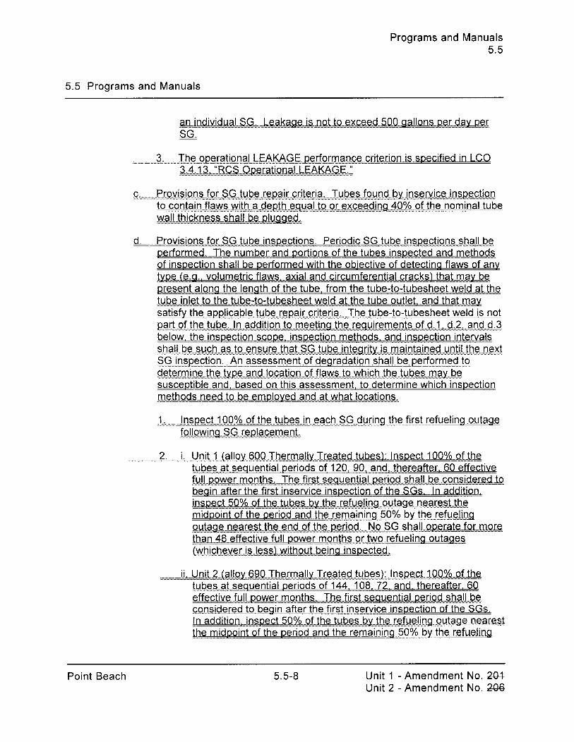
Programs and Manuals 5.5
5.5 Programs and Manuals
3. The operational LEAKAGE performance criterion is specified in LC0 2.+4.,..1.3, .... :.:.RR.-ger~li~~&~.A,A,KA.-G-GEIl
G.: .................. P.r.~v1~~.i.~n~G~t~~air..cr~Tuk.e.s._f.ound bv in s~_r?liceins.pe~cti~n_ .........
to contain flaws with a depth equal to or exceedin! 40% of the nominal tube
d. Provisions for SG tube inspections. Periodic SG tube inspections shall be performed . _Iha..~umbe:~..ar?dag_~.~p~sfthe~b~Jn~~.p~~c;f &an-d.meth_Pd-s. of inspection shall be performed with the obiective of detecting flaws of any J:y.~=r=.~I~e. a. v o h m e ~ ~ i c f l a . ~ . ~ :,-.. a~-~.n.cl.~s;!.~~en_~~~~~.~-z;f~~~cksth~f.~.m:~.y_~~. present along the length of the tube. from the tube-to-tubesheet weld at the
.... 1~l:b.g. ..j.nl!eJ...W ~:I;!.g.~~t~b.~s.h&.w:geI.d ::=: gLjW-ojJ.Ie . f , a t h a t ..:= v:s.gc: satisfy the applicable tube repair criteria. The tube-to-tubesheet weld is not Q . . ... h - ~ . . . ? . : ~ =::. ~~iitl.~g.g~hbt:t:t:t:~&~~e~btsts~.f. . f~z~~-&z~ . . .aa~O~I I .~ . below. the inspection scope, inspection methods. and inspection intervals sh.a!!. ..b. e ..... s..u.~h~.~itst~~..e~n~s.u.re~.~h._a.t .... SGU.e .... i..n.t.e.~rit.us.m_a.in_ta~nDD~~...~~~hbg.eee.n~~ ...................................................
SG inspection. An assessment of degradation shall be performed to d:g.J:g.r .m :.i.n.:g. ..fhhhgT::Q&-~g.n~I-~m~q.n :::: 9.f. f l a w . ~ ~ ~ g ~ ~ . ~ h ~ ~ ~ . h ~ ~ ~ ~ s . ~ ~ m ~ ~ h . ~ susceptible and, based on this assessment? to determine which inspection methQ&--n.e.ed ....... ...'c.sr.. he_e.m.p.!.~.y.e.d.~~..n.cl .............. ..................................... .... a.t ....w hattI.~.cCat.ii~.nn~.~. .....................................
1. Inspect 100% of the tubes in each SG during the first refueling outage
..i,.-Ynfi(a!l:gI~Y,Y,~.00Th..e.r00m~.~-Tr.~~~.t.edt.ub~.~I~ .... !.:n.sg.gc.t .QO%=gf .Jhg tubes at sequential periods of 120: 90: and, thereafter, 60 effective f-u!.! . . .g.~ .wer_months.Th&firstsequ-en~..a!-~r~h__a1!.-be-consi~:g.~epJp .. . begin after the first inservice inspection of the SGs. In addition, insPect5.000/~ .ofthe...tu.Phrtshrtsh.y.YYYj~hb~..B~&Lin~.9o~~u~~4s:~.~~ee~~~~J~h~ midpoint of the period and the remaining 50% bv the refueling
..... .~.:uta%mesA-thee-~.d ~ftheeerigd N ~ - W ! . - g . p g ~ a k f g r :::: m:o-@: than 48 effective full power months or two refuelina outages ~~h .~ . y .g . r~=~ . :~~ ._w j&~ .u~ : : . be . . i . ~~ .g i ns~e~~ed .~ .
iiUnlt.[.a!!.~y.M.J-h-rna!!.y. Y.Tre.at_.tube.s~..;-!.tl.s.p~-~U.D.Q%..~~.f...f.he .. .- . . ....... tubes at sequential periods of 144. 108? 72: and, thereafter, 60 e f f e c t l v . e . . ~ f u l b . ~ e . ~ . . ~ p ~ ~ ~ ~ ~ ~ ~ . ~ ~ ~ ~ f . ~ . ~ ~ ~ ~ ~ ~ e u e n t i . a ~ ~ . ~ ~ j . Q b ~ ~ ~ ! ~ . ~ p . ~ considered to begin after the first inservice inspection of the SGs. .!.~-add1tln.,..~:i.ns~.~5:8..% :::: g f f f f j : h U s . k ~ . . . th~ .::: ~~ffu..r31ina~.~!:~.~:.e~~.s.r.~.si the midpoint of the period and the remaining 50% by the refueling
Point Beach 5.5-8 Unit 1 - Amendment No. XH Unit 2 - Amendment No. 24%

'y3eJ3 " ES&"'p-3@eJI"" 3qro..00 PmUuorF&'31"P"ur"sq " y... " -' .................................... 3eJmY = ,.iTiT,.,~,.,.~.,.,.,.,..,.,.,.,......-~.~.~.,.,.,.,..,~~.,.,.,.~~-~ t!M osse . .. - - IOU s! uo!geapu! ay~l-y~~:, e ~eqg sale31pu! uo!genjeAa ouyaaupua JO
+ mq7ggr3- -- gF.:Lc6-u.::: - L3zr$g ro5rmQ-q :p..g .,,h- -mT.zu .5~wrm-=a:.pI, . . - - se yms 'uo!lewJoju! an!g!u!jap 41 yssal s! ~anayyqnn) apelno DuyanjaJ
8-u-oo-S'qr-~ .o-. ....,3fi- - - 3:J7fc6=2T a-s57g:g"" rm-e=qr .?.? ij .:6,j7E5@j:, . .. - y3e~3 ay4 pasne:, ley1 us!uey~aur uo!lepeJDap ayl JOJ 9s y3ea ~oj 'a cT3..sdg:G!-T xTgYluayT'aq::~-i::9S::.~uB"iim- E8,B,J"EmmF 33 !?j:m ,=: 93:s: jj5::::r:::::::::::::::::::::::::::.~::::::::::::::.~:: '6
S'S slenueyy pue SU~J~OJ~

Programs and Manuals 5.5
5.5 Programs and Manuals
Point Beach 5.5-1 0 Unit 1 - Amendment No. 204- Unit 2 - Amendment No. L436

Programs and Manuals 5.5
5.5 Programs and Manuals
Point Beach 5.5-1 1 Unit 1 - Amendment No. ZW- Unit 2 - Amendment No. 206

Programs and Manuals 5.5
5.5 Programs and Manuals
Point Beach 5.5-12 Unit 1 - Amendment No. 24U Unit 2 - Amendment No. Z36

slenueyy pue sure~6o~d S'S
S.G slenueyy pue SU~J~OJ~

Programs and Manuals 5.5
5.5 Programs and Manuals -
POINT BEACH 5.5-1 4 Unit 1 -Amendment No. 24H Unit 2 - Amendment No. 2-06

Reporting Requirements 5.6
5.6 Reporting Requirements
5.6.7 Tendon Surveillance Report (continued)
Nuclear Regulatory Commission pursuant to the requirements of 10 CFR 50.4 within thirty days of that determination. Other conditions that indicate possible effects on the integrity of two or more tendons shall be reportable in the same manner. Such reports shall include a description of the tendon condition, the condition of the concrete (especially at tendon anchorages), the inspection procedure and the corrective action taken.
5.6.8 Steam Generator Tube Inspection Report
A~..~r.e.p~o,fl~~.s,~~~be~.~~~e~d~hi.,n..~..l.~y~..~;iif fer .... Lh-e- .inltlalry...i.nt~...M~E..4 following completion of an inspection performed in accordance with the S..~~~:r;.!.f.~~~ti4n-5~5~8~~~~St~m_~..G.~~n~aIr~!~.~~~~.~~~Progr.g.:m .,..: ....T.he ..~_egert-=s_:h:g..I:~ .:.= ~2]..ud.:e:;.:
~ , , , ~ : : Q . Q ~ . : ~ : ~ . ~ ~ . ~ : ~ ~ : ~ . ~ ~ . ~ ~ ~ . X . ~ : . ~ . ~ ~ ~ . ~ Q : ~ .::: ~t;~=€h.QDi..~.~:~.:~. ::::1!~Ilzed-~.9:r.. ..: %.:a.$h. ...dearild.a.j:l. :QE mechanism,
d. Location, orientation (if linear)! and measured sizes (if available) of service In.d..u..~e.d .... i.n.di.cCa_ti~..r!..s ..,:
..d ...I. uhes "" ................ " .... ...glwgg. B.Q ::;; d~r~.g..::~hg:@~~.l>:~:~~.j:o:n::~-gt~.f ~ . , r ~ : ~ . : ~ = $ . ~ . ~ ~ ~ . ~ : ~ e . . degradation mechanism,
f. Total number and percentage of tubes plugged to date,
g ~ u l l s and i . n ~ ~ i ~ ~ ~ ~ . n ~ . ..t.z.~-.-r_ and
Point Beach 5.6-6 Unit 1 - Amendment No. 207 Unit 2 - Amendment No. 2-42

Reporting Requirements 5.6
5.6 Reporting Requirements
Point Beach Unit 1 - Amendment No. 2Q3- Unit 2 - Amendment No. 2-44

RCS Loops - MODES 1 and 2 B 3.4.4
BASES
APPLICABLE the plant safety analyses are based on initial conditions at high core SAFETY ANALYSES power or zero power. The accident analyses that are most important to (continued) RCP operation are the two pump coastdown, single pump locked rotor,
single pump (broken shaft or coastdown), and rod withdrawal events (Ref. 1).
Steady state DNB analysis has been performed for the two RCS loop operation. For two RCS loop operation, the steady state DNB analysis, which generates the pressure and temperature Safety Limit (SL) (i.e., the departure from nucleate boiling ratio (DNBR) limit) assumes a maximum power level of 120% RTP. This is the design overpower condition for two RCS loop operation. The value for the accident analysis setpoint of the nuclear overpower (high flux) trip is 118% and is based on an analysis assumption that bounds possible instrumentation errors. The DNBR limit defines a locus of pressure and temperature points that result in a minimum DNBR greater than or equal to the critical heat flux correlation limit.
The plant is designed to operate with all RCS loops in operation to maintain DNBR above the SL, during all normal operations and anticipated transients. By ensuring heat transfer in the nucleate boiling region, adequate heat transfer is provided between the fuel cladding and the reactor coolant.
RCS Loops - MODES 1 and 2 satisfy Criterion 2 of the NRC Policy Statement.
The purpose of this LC0 is to require an adequate forced flow rate for core heat removal. Flow is represented by the number of RCPs in operation for removal of heat by the SGs. To meet safety analysis acceptance criteria for DNB, two pumps are required at rated power.
In MODES 1 and 2, an OPERABLE RCS loop consists of an OPERABLE RCP in operation providing forced flow for heat transport and an OPERABLE S G S
APPLICABILITY In MODES 1 and 2, the reactor is critical and thus has the potential to produce maximum THERMAL POWER. Thus, to ensure that the assumptions of the accident analyses remain valid, all RCS loops are required to be OPERABLE and in operation in these MODES to prevent DNB and core damage.
Point Beach B 3.4.4-2 Unit 1 -Amendment No. 2434 Unit 2 - Amendment No. 336

RCS Loops - MODE 3 B 3.4.5
BASES
LC0 (continued) b. Core outlet temperature is maintained at least 10°F below saturation temperature, so that no vapor bubble may form and possibly cause a natural circulation flow obstruction; and
c. The Rod Control System is not capable of rod withdrawal, to preclude the possibility of an inadvertent control rod withdrawal and associated power excursion.
An OPERABLE RCS loop consists of one OPERABLE RCP and one OPERABLE S G S
n nrn V , I - yaw, which has the minimum water level specified in
SR 3.4.5.2. The OPERABLE RCP and SG must be in the same loop for the RCS loop to be considered OPERABLE. An RCP is OPERABLE if it is capable of being powered and is able to provide forced flow if required.
APPLICABILITY In MODE 3, this LC0 ensures forced circulation of the reactor coolant to remove decay heat from the core and to provide proper boron mixing. One RCS loop provides sufficient circulation for these purposes. However, one additional RCS loop is required to be OPERABLE to ensure redundant capability for decay heat removal.
Operation in other MODES is covered by:
LC0 3.4.4, "RCS Loops - MODES 1 and 2"; LC0 3.4.6, "RCS Loops - MODE 4"; LC0 3.4.7, "RCS Loops - MODE 5, Loops Filled"; LC0 3.4.8, "RCS Loops - MODE 5, Loops Not Filled"; LC0 3.9.4, "Residual Heat Removal (RHR) and Coolant Circulation -
High Water Level" (MODE 6); and LC0 3.9.5, "Residual Heat Removal (RHR) and Coolant Circulation -
Low Water Level" (MODE 6).
ACTIONS
If one required RCS loop is inoperable, redundancy for heat removal is lost. The Required Action is restoration of the required RCS loop to OPERABLE status within the Completion Time of 72 hours. This time allowance is a justified period to be without the redundant, nonoperating loop because a single loop in operation has a heat transfer capability greater than that needed to remove the decay heat produced in the reactor core and because of the low probability of a failure in the remaining loop occurring during this period.
Point Beach B 3.4.5-3 Unit 1 -Amendment No. 281- Unit 2 - Amendment No. 24%

RCS Loops - MODE 4 B 3.4.6
BASES
LC0 (continued) that are designed to validate various accident analyses values. An example of one of the tests is validation of the pump coastdown curve used as input to a number of accident analyses including a loss of flow accident. This test is generally performed during the initial startup testing program, and as such should only be performed once. If changes are made to the RCS that would cause a change to the flow characteristics of the RCS, the input values must be revalidated by conducting the test again. The 1 hour time period is adequate to perform the test, and operating experience has shown that boron stratification is not a problem during this short period with no forced flow.
Utilization of Note 1 is permitted provided the following conditions are met along with any other conditions imposed by initial startup test procedures:
a. No operations are permitted that would dilute the RCS boron concentration, therefore maintaining the margin to criticality. Boron reduction is prohibited because a uniform concentration distribution throughout the RCS cannot be ensured when in natural circulation; and
b. Core outlet temperature is maintained at least 10°F below saturation temperature, so that no vapor bubble may form and possibly cause a natural circulation flow obstruction.
Note 2 requires that the secondary side water temperature of each SG be r 50°F above each of the RCS cold leg temperatures before the start of an RCP with any RCS cold leg temperature I the Low Temperature Overpressure Protection (LTOP) enabling temperature specified in the PTLR. This restraint is to prevent a low temperature overpressure event due to a thermal transient when an RCP is started. SG secondary side water temperature can be approximated by using the SG metal temperature indicator.
An OPERABLE RCS loop comprises an OPERABLE RCP and an OPERABLE S G S c,,,,,,ll,,,,, which has the minimum water level specified in SR 3.4.6.2. The OPERABLE RCP and SG must be in the same loop for the RCS loop to be considered OPERABLE.
Similarly for the RHR System, an OPERABLE RHR loop comprises an OPERABLE RHR pump capable of providing forced flow to an OPERABLE RHR heat exchanger. RCPs and RHR pumps are OPERABLE if they are capable of being powered and are able to provide forced flow if required.
Point Beach B 3.4.6-2 Unit 1 -Amendment No. 2434 Unit 2 - Amendment No.

RCS Loops - MODE 5, Loops Filled B 3.4.7
BASES
LC0 (continued) Note 2 allows one RHR loop to be inoperable for a period of up to 2 hours, provided that the other RHR loop is OPERABLE and in operation. This permits periodic surveillance tests to be performed on the inoperable loop during the only time when such testing is safe and possible.
Note 3 requires that the secondary side water temperature of each SG be I 50°F above each of the RCS cold leg temperatures before the start of a reactor coolant pump (RCP) with an RCS cold leg temperature I Low Temperature Overpressure Protection (LTOP) arming temperature specified in the PTLR. This restriction is to prevent a low temperature overpressure event due to a thermal transient when an RCP is started.
Note 4 provides for an orderly transition from MODE 5 to MODE 4 during a planned heatup by permitting removal of RHR loops from operation when at least one RCS loop is in operation. This Note provides for the transition to MODE 4 where an RCS loop is permitted to be in operation and replaces the RCS circulation function provided by the RHR loops. Note 4 also allows both RHR loops to be removed from operation when at least one RCS loop is in operation to allow for the performance of leakage or flow testing, as required by Technical Specifications or by regulation. This allowance is necessary based on the design of the Point Beach RHR System configuration, which requires the system to be removed from service to perform the required PIV testing.
RHR pumps are OPERABLE if they are capable of being powered and are able to provide flow if required. An €W€FW&&SG can perform as a heat sink via natural circulation (Ref. I) when it has an adequate water level and is O P E R A B L E W
APPLICABILITY In MODE 5 with RCS loops filled, this LC0 requires forced circulation of the reactor coolant to remove decay heat from the core and to provide proper boron mixing. One loop of RHR provides sufficient circulation for these purposes.
However, one additional RHR loop is required to be OPERABLE, or the secondary side water level of at least one SGs is required to be 2 30% narrow range.
Point Beach B 3.4.7-3 Unit 1 -Amendment No. 281 Unit 2 - Amendment No. 2%
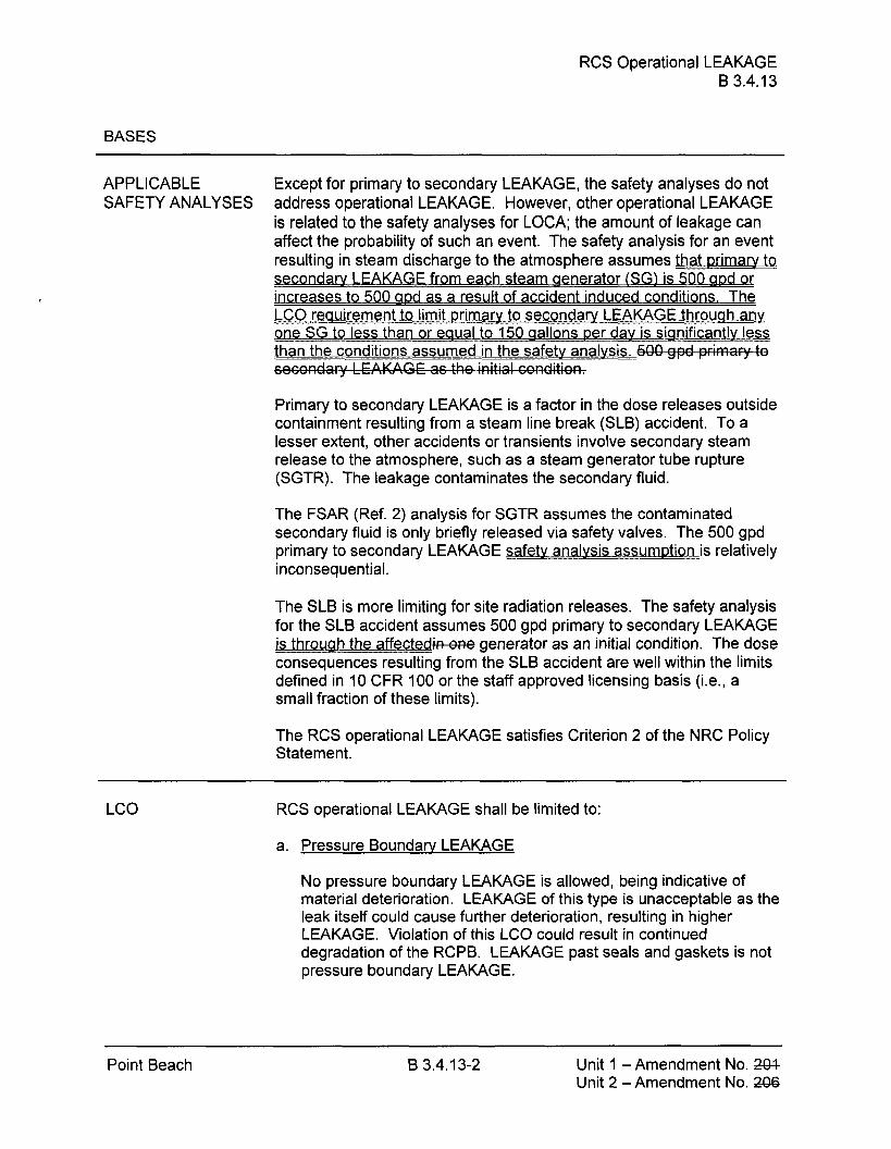
RCS Operational LEAKAGE B 3.4.13
BASES
APPLICABLE Except for primary to secondary LEAKAGE, the safety analyses do not SAFETY ANALYSES address operational LEAKAGE. However, other operational LEAKAGE
is related to the safety analyses for LOCA; the amount of leakage can affect the probability of such an event. The safety analysis for an event resulting in steam discharge to the atmosphere assumes that primary tn secondarv LEAKAGF from each steam generator (SG! is 500 apd or increases to 500 gpd as a result of accident induced conditions. The L C 0 re gu ir e m ent to limit primary to secondarv L EAKA GE th ro ua h a n v m e SG to less than or eaua l t o 1 50 aallons per dav is sianificantlv less than the conditions assumed in the safetv analvsis.
Primary to secondary LEAKAGE is a factor in the dose releases outside containment resulting from a steam line break (SLB) accident. To a lesser extent, other accidents or transients involve secondary steam release to the atmosphere, such as a steam generator tube rupture (SGTR). The leakage contaminates the secondary fluid.
The FSAR (Ref. 2) analysis for SGTR assumes the contaminated secondary fluid is only briefly released via safety valves. The 500 gpd primary to secondary LEAKAGE safetv analysis assumption is relatively inconsequential.
The SLB is more limiting for site radiation releases. The safety analysis for the SLB accident assumes 500 gpd primary to secondary LEAKAGE is through the affectedkcme generator as an initial condition. The dose consequences resulting from the SLB accident are well within the limits defined in 10 CFR 100 or the staff approved licensing basis (i.e., a small fraction of these limits).
The RCS operational LEAKAGE satisfies Criterion 2 of the NRC Policy Statement.
RCS operational LEAKAGE shall be limited to:
a. Pressure Boundary LEAKAGE
No pressure boundary LEAKAGE is allowed, being indicative of material deterioration. LEAKAGE of this type is unacceptable as the leak itself could cause further deterioration, resulting in higher LEAKAGE. Violation of this LC0 could result in continued degradation of the RCPB. LEAKAGE past seals and gaskets is not pressure boundary LEAKAGE.
Point Beach B 3.4.1 3-2 Unit 1 -Amendment No. 2434 Unit 2 - Amendment No. 2%

RCS Operational LEAKAGE B 3.4.13
BASES
LC0 (continued) b. Unidentified LEAKAGE
One gallon per minute (gpm) of unidentified LEAKAGE is allowed as a reasonable minimum detectable amount that the containment air monitoring and containment sump level monitoring equipment can detect within a reasonable time period. Violation of this LC0 could result in continued degradation of the RCPB, if the LEAKAGE is from the pressure boundary.
c. Identified LEAKAGE
Up to 10 gpm of identified LEAKAGE is considered allowable because LEAKAGE is from known sources that do not interfere with detection of unidentified LEAKAGE and is well within the capability of the RCS Makeup System. ldentified LEAKAGE includes LEAKAGE to the containment from specifically known and located sources, but does not include pressure boundary LEAKAGE or controlled reactor coolant pump (RCP) seal leakoff (a normal function not considered LEAKAGE). Violation of this LC0 could result in continued degradation of a component or system.
d. Primary to Secondary LEAKAGE through Any One SG
The limit of 150 gallons per dav per SG is based on the operational LEAKAGE performance criterion in NEI 97-06. Steam Generator Program Guidelines (Ref. 3). The Steam Generator Proaram aperational LEAKAGE performance criterion in NEI 97-06 states, "The RCS operational primary to secondary leakaae through any one SG shall be limited to 150 gallons per dav." The limit is based gn operating experience with SG tube dearadation mechanisms that result in tube leakage. The operational leakage rate criterion in conjunction with the implementation of the Steam Generator Proaram is an effective measure for minimizina the freauencv of steam generator tube ruptures.
APPLICABILITY In MODES 1, 2, 3, and 4, the potential for RCPB LEAKAGE is greatest when the RCS is pressurized.
In MODES 5 and 6, LEAKAGE limits are not required because the
Point Beach B 3.4.13-3 Unit I -Amendment No. 281. Unit 2 - Amendment No. 2Q6

RCS Operational LEAKAGE B 3.4.13
reactor coolant pressure is far lower, resulting in lower stresses and reduced potentials for LEAKAGE.
LC0 3.4.14, "RCS Pressure Isolation Valve (PIV) Leakage," measures leakage through each individual PIV and can impact this LCO. Of the two PlVs in series in each isolated line, leakage measured through one PIV does not result in RCS LEAKAGE when the other is leak tight. If both valves leak and result in a loss of mass from the RCS, the loss must be included in the allowable identified LEAKAGE.
ACTIONS &l
Unidentified LEAKAGE? =identified LEAKAGE,-er-Cmwtaq(-le in excess of the LC0 limits must be reduced to
within limits within 4 hours. This Completion Time allows time to verify leakage rates and either identify unidentified LEAKAGE or reduce LEAKAGE to within limits before the reactor must be shut down. This action is necessary to prevent further deterioration of the RCPB.
Point Beach B 3.4.1 3-4 Unit 1 -Amendment No. 204- Unit 2 - Amendment No. 2-06

RCS Operational LEAKAGE B 3.4.1 3
BASES
ACTIONS (continued) B . l and B.2
If any pressure boundary LEAKAGE exists, or primary to secondary LEAKAGF is not within limit, or if unidentified L&BWG& identified LEAKAGE, v; )nE-cannot be reduced to within limits within 4 hours, the reactor must be brought to lower pressure conditions to reduce the severity of the LEAKAGE and its potential consequences. It should be noted that LEAKAGE past seals and gaskets is not pressure boundary LEAKAGE. The reactor must be brought to MODE 3 within 6 hours and MODE 5 within 36 hours. This action reduces the LEAKAGE and also reduces the factors that tend to degrade the pressure boundary.
The allowed Completion Times are reasonable, based on operating experience, to reach the required plant conditions from full power conditions in an orderly manner and without challenging plant systems. In MODE 5, the pressure stresses acting on the RCPB are much lower, and further deterioration is much less likely.
SURVEILLANCE SR 3.4.13.1 REQUIREMENTS
Verifying RCS LEAKAGE to be within the LC0 limits ensures the integrity of the RCPB is maintained. Pressure boundary LEAKAGE would at first appear as unidentified LEAKAGE and can only be positively identified by inspection. It should be noted that LEAKAGE past seals and gaskets is not pressure boundary LEAKAGE. Unidentified LEAKAGE and identified LEAKAGE are determined by performance of an RCS water inventory balance.
The RCS water inventory balance must be met with the reactor at steady state operating conditions (i.e., stable temperature, power level, pressurizer and makeup tank levels, makeup and letdown, and RCP seal injection and return flows). The Surveillance is modified bv t w ~ Notes. -Nftote 1 states- that this SR is not required to be performed until 12 hours after establishing steady state operation.
The 12 hour allowance provides sufficient time to collect and process all necessary data after stable plant conditions are established.
Point Beach 6 3.4.13-5 Unit 1 -Amendment No. 24% Unit 2 - Amendment No. 2W

RCS Operational LEAKAGE B 3.4.13
BASES
SURVEILLANCE Steady state operation is required to perform a proper inventory REQUIREMENTS balance since calculations during maneuvering are not useful. For RCS (continued) operational LEAKAGE determination by water inventory balance,
steady state is defined as stable RCS pressure, temperature, power level, pressurizer and makeup tank levels, makeup and letdown, and RCP seal injection and return flows.
An early warning of pressure boundary LEAKAGE or unidentified LEAKAGE is provided by the automatic systems that monitor the containment atmosphere radioactivity and the containment sump level. It should be noted that LEAKAGE past seals and gaskets is not pressure boundary LEAKAGE. These leakage detection systems are specified in LC0 3.4.15, "RCS Leakage Detection Instrumentation."
Note 2 states that this SR is not applicable to ~r imary to secondary LEAKA b ca ~ measured accurately bv an RCS water inventory balance,
The 72 hour Frequency is a reasonable interval to trend LEAKAGE and recognizes the importance of early leakage detection in the prevention of accidents.
T h i s h a t primarv to secondarv LEAKAGE is less o eaua to . . r I 150 gallons per dav throuah anv one SG. Sat~sfv~na the primarv tP secondarv LEAKAGE limit ensures that the operational LEAKAGE p P e r a t o r rf rm Proaram is met . If thi s SR is not met: compliance with LC0 3.4.17: "Steam Generator Tube Intearity," should be evaluated. The 150 gallons per dav limit is m ur r ~perational LEAKAGE rate limit applies to LEAKAGE throuah anv one SG. If it is not practical to assian the L E A P the primarv to secondarv LEAKAGE should be conservativelv assumed to be from one SG.
The Surveillance is mod ified bv a Note which states that t h e Surveillance is not required to be oerfor med until 12 hours after establishment of steadv state operation. For RCS primary to secondary LEAKAGE determination, steadv state is defined as stable RCS pressure, temperature, power level. pre ssur~zer and makeup t an k kvels: makeup and letdown, and RCP seal injection and return flows.
The Surveillance Frequency of 72 hours is a reasonable interval to tr e n d p rim ary to secondary LEAKAGE and recoanizes the importance nf earlv leakage detect ion in the prevention of accidents, The primary to secondary LEAKAGE is determined using continuous process radiation
Point Beach B 3.4.13-6 Unit 1 -Amendment No. 204 Unit 2 - Amendment No. 2-06

RCS Operational LEAKAGE B 3.4.13
monitors or radiochemical a r ab samplina in accordance with the FPR I auidelines (Ref. 4).
REFERENCES 1. FSAR Section 1.3.3.
2. FSAR, Section 14.
3. NEI 97-06, "Steam Generator Proaram Guidelines."
4_ EPRI: "Pressurized Water Reactor Primary-to-Secondary Leak Guidelines."
Point Beach Unit 1 -Amendment No. 224 Unit 2 - Amendment No. XMS
SG Tube lntearity
y 1
B 3.4.17 Steam Generator (SG) Tube Integrity
BASES
BACKGROUND Steam aenerator (SG) tubes are small diameter, thin walled tubes that
The SG tubes have a number of important safety functions. Steam e n r r t g ubes are an integral part o f the r eacto r coolant pressure e ato
boundarv (RCPB) and, as such? are relied on to maintain the primarv svstem's pressure and inventory. The SG tubes isolate the radioactive fission products in the primarv coolant from the secondary svstem. In addition, as part of the RCPB, the SG tubes are unique in that thev act as the heat transfer surface between the primary and secondary svstems ta remove heat from the primary svstem. This Specification addresses only the RCPB intearitv function of the SG. The SG heat removal function is addressed by LC0 3.4.4. "RCS Loops - MODES 1 and 7 " LC0 3.4.5, "RCS Loaps - MODE 3:" LC0 3.4.6. "RCS Loops - MODE 4." and LC0 3.4.7. "RCS Loops - MODE 5: Loops Filled."
SG tube i n t e g g i n a their intended RCPB safetv function consistent with the licensing basis, rn fl i reaurrements.
. . Steam generator tub~na IS subject to a varietv of degradation mechanisms. Steam aenerator tubes mav experience tube dearadation related to corrosion phenomena, such as wastaae. pittina, interaranular attack, and stress corrosion cracking, along with other mechanicallv ~nduced phenomena such as dentina and wear. These degradation mechanisms can impair tube intearitv if thev are not managed effectivelv. The SG performance cr&ria are used to manaae SG tube degradation.
Specification 5.5.8. "Steam Generator (SG) Program," requires that a hat SG tube intea ram be established and ~mplemented to ensure t rity
is maintained. Pursuant to Specification 5.5.8, tube intea- maintained when the SG performance criteria are met. There are three S G pe r f r o ma n ce cr i ter i . a, structural integritv. accident induced I eakage. 1 Specification 5.5.8. Meeting the SG performance criteria ~rovides reasonable assurance of maintaining tube intearity at normal and accident conditions.
The Drocesses used to meet the SG performance criteria are defined by the Steam Generator Program Guidelines (Ref. 1).
Point Beach B 3.4.17-1 Unit 1 -Amendment No, Unit 2 - Amendment No.

SG Tube lntearity
BASES
APPLICABLE The steam aenerator tube rupture (SGTR) accident is the limiting design SAFETY basis event for SG tubes and avoiding an SGTR is the basis for this A N A L E ES........ .=:z...7.~:::::z:z::.=::::..::: S . . . ~ ~ e ~ i . f i ~ ~ ~ - .~Th~~.si .s .S. .~f a....SGT.R~::ey.Ye.x~'ras s u me s a ; - b . ~ : ~ : . n ~ ~
primarv to secondary LEAKAGE rate equal to the operational LEAKAGE rate limits in LC0 3.4.13: "RCS Operational LEAKAGE." plus the leakage rate ..aaso~~:~k~i~.hhhhhha:::d.:o-sll&1.1~-:e.~BBde_lJ,_lJ,,r&Ur:.~ .::: 2f .:::a .:::: ssiii~.g.II~==tubetubeTh:~ accident analvsis for a SGTR assumes the contaminated secondary fluid is released to the atmosphere via safety valves.
The analysis for design basis accidents and transients other than a SGTR m-ma.Ihe .::: S=G..~wSSr,ee~ther. .st~. .~~w=~i._t_t~Y:Y:S.i2. . =e,. ..lL_eu_re assumed not to rupture.) In these analyses! the steam discharae to the atmosphere is based on primarv to secondary LEAKAGE from each SG d..5 ~QD....g.ailonsperdavor.-i.~.~!~m_.~dto1n~~~.e..ts-5~a!!onser_d.~y as a result of accident induczed conditions. For accidents that do not involve fuel damage. the primary coolant activity level of DOSE .EQ.U.!VALENI.!.:1.31ismd.-t~Q.k~eaual.t~-..Jh.~ ..... !&XXL34,16.,XS -" "--" Specific Activity:" limits. For accidents that assume fuel damaae, the primary coolant activity is a function of the amount of activitv released f.c..:mmJh:e ... damaqe.df u.ei .-:: I.h.&s-e ..: e ~ ~ m ~ e f : ~ : c ; . g . .s...s~.f.these.esee.~Y~are within the limits of GDC 19 (Ref. 2). 10 CFR 100 (Ref. 3) or the NRC approved licensing basis (e.g., a small fraction of these limits).
Steam aenerator tube integritv satisfies Criterion 2 of 10 CFR 50,36(~)(2)(ii).
LC0 The LC0 requires that SG tube integrity be maintained. The LC0 also reauires that all SG tubes that satisfv the repair criteria be pluaed in accordance with t h e Steam Generator Program.
D.ur.i.:ng..~.~..SCj_-i~.:~.pg~~~~~..~ :::: ~ . ~ a ~ Y Y & ~ ~ R ~ B ~ t e ~ ::.: ~eBBtthaL.sa~.1sf i ,~ :::: 5.keam. nerat r Ge o Proaram repair criteria is removed from service by plugging. If
a tube was determined to satisfy the repair criteria but was not plugaedL ~hhee:.t.ubemii!.~5!.~~i!.!Ih;i.~.e.t.u~~..!nte..~~~
In t h e co n te x t of t hi s Specification. an SG tube is defined as the entire le.ngj:h..-~f~M~h.e &... iindud-m.thetu.he...wa 11, between the_Ww.:k~. .UJ -
The tube-to-tubesheet weld is not considered t art of the tube.
A SG tube has tube integritv when it satisfies the SG ~erformance criteria. The SG performance c r i t e r j Generator Proaram," and describe acceptable SG tube performance.
Point Beack,- - B 3.4.17-2 Unit 1 -- Amendment No, Unit 2 -Amendment No.

SG Tube Integrity B 3.4.17
BASES
LC0 (continued) The Steam Generator Proaram also provides the evaluation process for determining conformance with the SG performance criteria. There are aree SG performance criteria: structural integrity! accident induced leakage, and operational LEAKAGE. Failure to meet anv one of these criteria is considered failure to meet the LCO.
The structural intearitv ~erformance criterion provides a marain of safety aaainst tube burst or collapse under normal and accident conditions, and ensures structural intearity of the SG tubes under all anticipated transients included in the desian specification. Tube burst is defined as, "The aross structural failure of the tube wall. The condition tvpically corresponds to an unstable ogenlna displacement (e . a .. ope ning area increased in response to constant pressure) accompanied by ductile blastic) te ari n a o f t h e tube m aterial at the ends of the dearadauo Il n. Tube collapse is defined as, "For the load d isplacement curve for a given structure, collapse occurs at the top of the load versus displacement
f the curve becomes zero." The structural integrity curve where the slope o performance criterion provides auidance on assessing loads that have a sianificant effect on burst or collapse. In that context, the term "significant" is def
. . ined as "An accident loadina cond~t~on other than
differential pressure is considered significant when the addition of such t h e assessment of the structural intearitv performance criterion I oads 'n I
could cause a lower str uctural limit or limitina burst/collapse condition to be established." For tube integrity evaluations, except for circumferential dearadation, axial thermal loads are classified as secondary loads. For circumferential dearadation: the classification of axial thermal loads as primary or secondarv loads will be evaluated on a case-bv-case basis. The division between ~r imary and secondarv classifications will be based on detailed an& s i s and/or testina.
Structural intearitv requires that the primarv memb r ane st ress i ntens itv - in a tube not exceed the vield strength for all ASME-+ Service Level A (normal operatina conditions) and Service Level B [upset . . or abnormal cond~t~ons) transients included in the des~an specification, This includes safety factors and applicable desian basis loads based on ASME Code, Section Ill, Subsection NB (Ref. 4) and Draft Regulatory Guide 1 .I21 !Ref. 5).
The accident induced leakaae performance criterion ensures that the primary to secondary LEAKAGE caused bv a desian basis accident: other than a SGTR, is within the accident analvsis assumptions. The accident analvsis assumes that accident induced leakage does not exceed 500
I I he acc ga ons per day per SG. T ident induced leakaae rate includes anv primarv to secondary LEAKAGE existina prior to the accident in addition ta
Point Beach B 3.4.17-3 Unit 1 -Amendment No. Unit 2 -Amendment No.

SG Tube lntegritv B 3.4.17
BASES
LC0 (continued) primary to secondary LEAKAGE induced durina the accident. The goerationat LEAKAGE performance criterion provides an observable indication of.SG tube conditions durina plant operat . .
ion. The l ~ m ~ t on operational LEAKAGE is contained in LC0 3.4.13, "RCS Operational LEAKAGE." and limits primarv to secondary LEAKAGE throuah any one SG to 150 gallons per day. This limit is based on the assumption that a single crack leakina this amount would not propaaate to a SGTR under the stress conditions of a LOCA or a main steam line break. If this
A m KAGE is due to more than one crack. the c r ac k s a r v e a ount of LE erz small, and the above assumption is conservative.
APPLICABILITY Steam aenerator tube intearitv is challenged when the pressure differential across the tubes is larae. Large differential pressures across SG tubes can on1 .-y-exDeriencedE I 1: 2: 3: or 4.
RCS conditions are far less challenaina in MODES 5 and 6 than during MODES, 2: 3: and 4. In MODES 5 and 6: primary to secondary differential pressure is low, resulting in lower stresses and reduced potential for LEAKAGE.
ACTIONS The ACTIONS are modified bv a Note clarifying that the Conditions may be entered independentlv for each SG tube. This is acceptable because the Required Actions provide appropriate compensatorv actions for each affected SG tube. Complvina with the Required Actions may allow for continued operation, and subseaue nt affected SG tubes are aoverned bv subsequent Condition entrv and ap~lication of associated Reauired Actions.
A. l and A.2
Condition A applies if it is d' . . iscovered that one or more SG tubes examined in an inservlce Inspection satisfv the tube repair criteria but were n ot p lu aaed in accordance with the Steam Generator Proaram as
4.17.2. An evaluation of SG tube intea required by SR 3. ritv of the . . affected tubefs) must be made. Steam generator tube ~ntegr~tv IS based on meetina the SG performance criteria described in the Steam Generator Program. The SG repair criteria define limits on SG tube dearadation that allow for flaw growth between inspections while still providing assurance that the SG performance criteria will continue to be met. In order to determine if a SG t &e that should have been ~ luaaed has tube integritv, an evaluation must be completed that demonstrates that the SG performance criteria will continue to be met until the next . . refuelma outage or SG tube ~nspection. The tube integrrty determinatlon is based on the estimated condition of the tube at the time the situation is discovered and the estimated growth of the degradation
Point Beach B 3.4.17-4 Unit 1 -Amendment No. Unit 2 -Amendment No.

SG Tube Integrity B 3.4.17
BASES
ACTIONS (continued) prior to the next SG tube insp ect i o n. If it i s determined that tube intearity is not being maintained. Condition B applies.
A Completion Time of 7 davs is sufficient to complete the evaluation while minimizing the risk of ~ l a n t operation with a SG tube that mav not have tube intearik
If the evaluation determines that the affected tubefs) have tube intearity, Required Action A.2 allows plant operation to continue until the next refuelina outage or SG inspection provided the inspection interval continues to be supported bv an operational assessment that reflects the f f e However, the affected tube!s) m ust be pluaqed prior to a ect d tubes.
entering MODE 4 followina the next refuelina outaae or SG inspection. This Completion Time is acceptable since operation until the next ~nspestion is sup~orted by the o~erational assessment.
5.1 and 8.2
If the Required Actions and associated Completion Times of Condition A are not met or if SG tube i n tea r' I ~ Y is n ot beina maintained. t h e r eacto r must be brouaht to MODE 3 within 6 hours and MODE 5 within 36 hours.
The allowed Completion Ti mes are reasonable. based on operating experience. to reach the desired plant conditions from full power conditions in an orderlv manner and without challenging plant svstems.
SURVEILLANCE SR 3.4.17.1 REQUIREMENTS
Durina shutdown periods the SGs are insgected as required bv this SR and the Steam Generator Proaram. NEI 97-06, Steam Generator Proaram Guidelines [Ref. I ) ! and its referenced FPRl Guidelines, establish the content of the Steam Generator Program. Use of the Steam
roa am ensures that the ' n s m o IS app opriate and Generator P r I i n ' r consistent with accepted industry practices.
Durina SG inspections a condition monitorina assessment of the SG tubes is performed. The condition monitoring assessment determines the "as found" condition of the SG tubes. The purpose of the condition monitorina assessment is to ensure that the SG performance criteria have been met for the previous operating period.
Point Beach B 3.4.17-5 Unit 1 - Amendment No, Unit 2 - Amendment No.

SG Tube Integrity B 3.4.17
BASES
V I NC Th e m h i SUR E LL A E e St a Generator Proaram determines the scope o f t e nspectio n REQUIREMENTS and the methods used to determine whether the tubes contain flaws 1-dd1- satisfvina the tube repair crite r' la . Inspect ion scope (i.e., which tubes or
areas of tubina within the SG are to be inspected) is a function of existing an 3~ rator Program al s o e c i f i e s b b o n . In spe cti o n m et h ods are a function of dearadation morphology, non- destructive examination (NDE) techniaue capabilities. and inspect ion locations.
The Steam Ge nerator Proaram defines the Freauenc~ of SR 3.4.17.1, The Freauencv is determined by the operational assessment and other limits in the SG examination guidelines (Ref. 6). The Steam Generator
information on e Pagram uses xistina degradations and growth rates to determine an inspection Frequency that provides reasonable assurance that the tubing will meet the SG performance criteria at the next sch- .- I n ition, Specification 5.5.8 contains prescriptive requirements concernina inspection intervals to provide added assurance that the SG ~erformance criteria will be met between scheduled inspections,
During an SG inspection, anv inspected tube that satisfies the Steam s g a i n g . The tube regair criteria delineated in Specification 5.5.8 are intended to ensure that tubes acce~ted for continued service satisfv the SG performance criteria with allowance for error in the flaw size measurement and for future flaw arowth. In addition, the tube repair p r Program, e - nsure that the SG performance criteria will continue to be met
1 orovides n il u t the next inseection of the subiect tube(s1. Reference guidance for performina op e rati o nal assessments to verifv that the tubes remainina in se -- rvice will continue to meet the SG performance criteria.
The Freauencv of prior to entering MODE 4 followina a SG inspection ensures th h ill n I m in t?e repair c c o i nifi n im r 0
Point Beach B 3.4.17-6 Unit 1 -Amendment No, Unit 2 -Amendment No.

SG Tube lntearitv
BASES (continued)
REFERENCES 1. NEI 97-06, "Steam Generator Program Guidelines."
2. 10 CFR 50 Appendix A. GDC 19.
3. 10 CFR 100.
4. ASME Boiler and Pressure Vessel Code, Section Ill. Subsection NB.
Draft Reaulatory Guide 1.171 : "Basis for Plu~aina Degraded Steam 5. Generator Tubes." August 1976.
6. EPRI, "Pressurized Water Reactor Steam Generator Examination Guidelines."
Point Beach B 3.4.17-7 Unit 1 -Amendment No. Unit 2 -Amendment No.

ENCLOSURE 4C
Proposed Technical Specification and Bases Pages (markup)
Prairie Island Nuclear Generating Plant Units 1 and 2
Technical Specification Pages
Basespages
44 pages follow

Definitions 1.1
1.1 Definitions (continued)
- - E -AVERAGE E shall be the average (weighted in proportion to the concentration DISINTEGRATION of each radionuclide in the reactor coolant at the time of sampling) ENERGY of the sum of the average beta and gamma energies per
disintegration (in MeV) for isotopes, other than iodines, with half lives > 15 minutes, making up at least 95% of the total noniodine activity in the coolant.
LEAKAGE LEAKAGE from the Reactor Coolant System (RCS) shall be:
a. Identified LEAKAGE
1. LEAKAGE, such as that from pump seals or valve packing (except reactor coolant pump (RCP) seal water injection or leakoff), that is captured and conducted to collection systems or a sump or collecting tank;
2. LEAKAGE into the containment atmosphere from sources that are both specifically located and known either not to interfere with the operation of leakage detection systems or not to be pressure boundary LEAKAGE; or
3. RCS LEAKAGE through a steam generator tSG)to the Secondary System (primary to secondary LEAKAGE);
b. Unidentified LEAKAGE
All LEAKAGE (except RCP seal water injection or leakoff) that is not identified LEAKAGE;
c. Pressure Boundary LEAKAGE
LEAKAGE (except primary to sec,ondary %-LEAKAGE) through a nonisolable fault in an RCS component body, pipe wall, or vessel wall.
Prairie Island Units 1 and 2
Unit 1 - Amendment No. 448 1.1-3 Unit 2 - Amendment No. 4-49

RCS Operational LEAKAGE 3.4.14
C. RCS identified LEAKAGE not within limit for reasons other than pressure boundary LEAKAGE .... ~rpri.~.ary.to secondary LEAKAGE.
ACTIONS (continued)
AND
CONDITION
C .2.1 Reduce LEAKAGE to within limits.
C.2.2 Be in MODE 5 .
REQUIRED ACTION
6 hours
14 hours
COMPLETION TIME
44 hours
D. Pressure boundary LEAKAGE exists.
Primary to sec,ondarv SG LEAKAGE not within limit.
D.l BeinMODE3.
AND
D.2 BeinMODE5.
6 hours
36 hours
Prairie Island Units 1 and 2
Unit 1 - Amendment No. 4443 3.4.14-2 Unit 2 - Amendment No. 4-49

RCS Operational LEAKAGE 3.4.14
SURVEILLANCE REQUIREMENTS
SURVEILLANCE I FREQUENCY
SR 3.4.14.1 ............................ NOTES ......................... ...... -
1. Not required to be performed until 12 hours ................. --
after establishment of steady state operation. 2. Not applicable to priinary to secondary
LEAKAGE.
Verify RCS operationallC_E.AK,A=GE- within limits by performance of RCS water inventory balance.
24 hours
Not required to be performed until 12 hours after establishment of steady state operation.
. . . .. < Verify fi
) rima o seco~lda 1,T:AKAC;E is < 150 -P ..................... P.Pr\...r\..t ..... ..t..t.t..t.t.t.t.t .... - ........................... r?l .............................. .....-.....
gallons per day through anv one SG..
Prairie Island Units 1 and 2
Unit 1 - Amendment No. 458 3.4.14-3 Unit 12 - - Amendment No. 4-49

3.4 REAC'IOR O N SY S'I'EM (KC>)
3.4.19 Steam Generator (SG) I'ttbe Integrity
1,CO - - --. - 3.4.19 -- --- SG tube integrity shall be rniiintai~~ed.
AND --- - -
--
CONDITION
Oneor more - SCi tubes satisfyin.2 -- --- the tube rcpaircritcriii and not plu-ggcd or rcjaircd in accordance with the Steal3 (knerator l'rogranl.
REQUIRED ACTION COMPLETION TIME
- A: 1- Verib tube - ..- -- int%ri~ of the affected -- ti~beLsL& ~naintained until the nexl refueling -- outage or S(3 tube inspection.
A. 3. _ -Plug or. repair l_b__e a&cted l ~ i ~ l r ~ ~ ~ ~ _ r ~ t ~ n g tu'OGs1 in acc<)rck~ncc M(IL!E-+-@l lo~vinin with the Steam (;enerator the rlcxt refueling I'rogra~n. o~ttagc or S(; tube
ir~spection
15. Ke yuired A s ~ i o r ~ and associgtgcj Ccjlnpletion r b n c 3 f:'gnsi itionmA not --- mct. --
ACTIONS (continued)
COMPLETION 1 TI"" CONDITION REQUIRED ACTION
SURVEILLANCE FREQUENCY
Verify S(i tube intcorit 1 in accordancc with the s R 3.6B.1- -_--- _____ - 1 - - - -
Steam (icncrator Program. I11 accol:dance with the Steain Gcncr:itor l'rogrrn~
SK 3.4.19.2 - V e r i S ~ h a t -- each inspected-SG tube that satisfjqs the -- tube repair criteria - -- --- is p l~~g~qcd or rcpairqdin accordance with the Stcan-1 Generator Program.
Prior &-entering MODE 4
t~lbc inspection

Programs and Manuals 5.5
5.5 Programs and Manuals (continued)
5.5.8 Steam Generator (SG) , , % Program
A Steam Generator Program shall be established and implementgm ensure that SG tube integrity is maintained. In addition. the Steam Generator Program shall incl~ldc the fiAlowing provisions:
a. Provisions for condition monitoring asscssmcnts. Condition monitoring asscssnient lncans an evaluation of thc-"as found" condition of the tubing with respect to the performance criteria for -- -
structural integrity ag.accident kduced leaka.ge,'l'he "as f o u a condition refers to the condition of the - tubin!: during an SG inspection outage, axdcter_l~iied frointhc-inservice inspection results or by other means, prior t o h e dugging or repair of tubes. Condition monil~ring assessments shaxbe-conducted-diligg each out~,tscc1urin~which thc SG tubcs - art. -- inspecgi, - - p l~ lged , - - or rq3ired to confirgthat thc performance criteria are being met,
b. Performance criteria for SG tube integrity. SC; tube integrity shall be maintd.i.ncd.by ...m ect.ngth.c..per.li;,rmanc~.. .crlt:ri.a .... fix . tub.~ .... structu~al int~.grity a.c.~.id.c.nt~i.nd~rce.d!c~kage ..... an(1_cr~~.e~r:at.i~1.n!LA.F;.A~~.E.,
generator tubes shall retaln structural inteirrlty over of normal operatino, conditions (including startup. operation in the -- -
power r a n g ~ ~ hot standby2 and cool down and all anticipated transients included in he design specification) -- and desi-gn basis -
pressure differentials. Apart from the above re-. additional loading conditions associated with the design basis accidents. or combination ofaccidents in accardance with t& &sign andkens ing biisis, shall also be cvalua~ed to dete~minef' the asso&ed lo-ads congibutc sig~~ificantly to burst_or collapsc. Iii* assessment of gbc_in tegr j t~~ those loads that do significantly affect burstor collapse shall be determined and assessed in combination with the loads due to pressure bit11 a -- -
Prairie Island Units 1 and 2
Unit 1 - Amendment No. 1 5 8 5 .O- 13 Unit 2 - Amendment No. 149

Programs and Manuals 5.5
-- safety. ..fa$ to~ofi-01, tlle..com binedpriln arv loads7ancl~.00n ax.k!. .. ~ c . o n m a &
2. Accident induced leakage performance criterion: 'l'he primary to secoj~-da~y accident induced lcakage rate for any design basis - -
accidenttl_othcr than a SG tubs ruptLirc, sl~all-not exceed the leakage ra te~ss~imed in the accident-analysis in tcrins-ofltotal leakage rate for all SGs and leakase rate for an individual SGL 1,eakage is not to exceed I g p ~ n per SG, except during the implementation of steam generator repairson Unit 2 utilizing the voltage-based repair criteria. During the imple~nentation of st&& gcncrator-cepairs on lJnit 2 utdiziny: the voltambased r~pa i r c;ritcria,the totg1 calculgt~d primary to- secondary .;%LC leakage from the faulted stcam generator, undcr main steam line break conditions (outside containment and upstream of the main steam isolation valves)? will not exceed 1.43 gallons p-basecl --
on -- a reactor - coolant - systenl tein~erature of 578"E'1,
3 ._ lrhc operational LEAKAGE perl'ortnance criterion-is spccilic& Z,CO 3.4.14, - " W S Operational 1,EAICACIE.''
c. Provisions for SG tube repair criteri~:. . . . . . ...................... .... . . . . .. . . ... ......................... . . . . .. ... ........ .. ........... ..... ...... .. .... ... .,...... ..
1. Unit 1 steam generator tubes found bv inservice inspection to contain flaws with a depth equal to or exceedin-g 40% of the nominal tube wall ~h_i_ckness sl~all bc plugged.
2 llnit 2 stcam generator -- tub~~- tha t meet - t l ~ e following critcria shall be plugged or repaired.
Prairie Island Units 1 and 2
Unit 1 - Amendment No. 1 5 8 5.0-14 Unit 2 - Amendment No. 149

Programs and Manuals 5.5
4 ; _ . k L > ->, . L 3 3 .> . , < - -> 7 7 , ,<T (if- . . W c r , 5 . 5 . g ! er 5.5.8 2) &&-b & . , . ,
Prairie Island Units 1 and 2
Unit 1 - Amendment No. 1 5 8 5.0-15 Unit 2 - Amendment No. 149

Programs and Manuals 5.5
Prairie Island Units 1 and 2
Unit 1 - Amendment No. 158 5.0-16 Unit 2 - Amendment No. 149

Programs and Manuals 5.5
Prairie Island Units 1 and 2
Unit 1 - Amendment No. 1 5 8 5.0-17 Unit 2 - Amendment No. 149

Programs and Manuals 5.5
Prairie Island Units 1 and 2
Unit 1 - Amendment No. 1 5 8 5.0-18 Unit 2 - Amendment No. 149

Programs and Manuals
Prairie Island Units 1 and 2
Unit 1 - Amendment No. 1 5 8 5.0-19 Unit 2 - Amendment No. 149

Programs and Manuals
(0 R c M l : - - . . .
,< 3 h . .
\,- '>,. 1 -
(a) 'l'uhes fo- inservice inspection containing flaws with a depth equal to Cjr - exceedin& 50% of the nominal tube wall thickness. If significant general tube thinning occurs, this . . . , < -criterion is reduced to 40% wall penetration. 'Ihis criterion does not *ply to tube support plate i~~tersections to which the voltage based repair criteria apply.
-H does not apply to the portion of the tube in the tubesheet below the F* or I'F* distance provided the tube is not degraded (i.e., no indications of cracks) within the F* or EF* distance 4- I , L:* ,, - , L L + _ / I I,- , . L
7 . .#
Thc F* distance is thedistancc from the bottom ofthe upp~z - -- -- -- -- - - - -- --- - - - -- -- -- - --
been conservatively dcternlincd to be 1.07 inches (pot including edciy current uncertainty). The P* distance anplies -
to roll ex~anded re-gions belo~f~ the midplane of the tuJbgsl~gt,
The EFVistance is the distance from thc bottom ofthe upper hardroll transition ton ardjhe hc)tton~ of' thet ubcshect thiit iliis -- --
been conservatively detcrrnincci to be 1.67 inches (not including eddy current ~lnccrtainty). The EIT* distancc ag~lics to roll-espanded regions when-the top of the aait ional roll ex~ansi011_&~2.~inches~or greater dow~from the to_ of the ~ubgsheg. -- - - -- -- - -- -. .
IbJ 'I'ubcs fo>mdby inscr~c_c_inspcction containingflaws in& ~ep&it.-l~t-ft)l^-the pressure boundary region of any sleeve \I it11 a depth equal to or excccingki 25% of the nominal sleeve wall thickness.
1 r e v , - - . . u -
Prairie Island Units 1 and 2
Unit 1 - Amendment No. 1 5 8 5 .O-20 Unit 2 - Amendment No. 149

Programs and Manuals
b b w 7 -.'., - - . - . . .
'lubes found by inser&inspection that are expgriencing @l-.-. ___ - -
prodon~-rmtghA~x~dly -- o&ntc&ou~sie ctLi+n~c~(;rs~rcss corrosion cracking cc!n ti~lc.d\zi~l~in thc thickn~bs o l ' r~~hc support plates:
Prairie Island Units 1 and 2
Unit 1 - Amendment No. 158 5 .O-2 1 Unit 2 - Amendment No. 149

Programs and Manuals 5.5
Prairie Island Units 1 and 2
Unit 1 - Amendment No. 1 5 8 5.0-22 Unit 2 - Amendment No. 149

Programs and Manuals
t*- ,, " e t b .
i whese-with indications of p-ote~itiaJ degradation is attributed to p_rcdorni_n_ateIy axially oriented outside diameter stress corrosion cracking within the bounds of the tube support plate with a bobbin voltage greater than 2.0 Volts~u~l~~no_~egradation is dctected \%it11 a rotating pancake coil (or comnparablc examination technique) inspection
5T54kM-
. , . . . e---e :i a
. . . f - v w k 3 - ' w
* . . 11 - - with indications of prcdon~inakb giigllk oricntcd
outside diameter stress corrosion cracking degradation with a bobbin voltage greater than the upper voltage repair limit. wi!l.-- 3 ~irepaiwd~
5.5 Programs and Manuals
5.5.8 Steam Generator (SG) -Program (continued)
Prairie Island Units 1 and 2
Unit 1 - Amendment No. 158 5 .O-23 Unit 2 - Amendment No. 149

Programs and Manuals 5.5
. . . 13. _fa)----inspect_ed &u_l.ingH an unscheduled mid-cycle
inspection-wpe&md, the following mid-cycle repair limits apply instead of the limits in Specifications 5.5.8.~.2.(c).iWit-)+) and 5.5.8.~.2.(c).ii above(@. The mid-cycle repair limits are determined from the following equations:
Where:
VURL = upper voltage repair limit
VLRL = lower voltage repair limit
VMuRL = mid-cycle upper voltage repair limit based on time into cycle
VMLRL = mid-cycle lower voltage repair limit based on VMURL and time into cycle
At = length of time since last scheduled inspection during which VURL and VLRL were implemented
Prairie Island Units 1 and 2
Unit 1 - Amendment No. 1 5 8 5.0-24 Unit 2 - Amendment No. 149

Programs and Manuals
5.5 Programs and Manuals
7 .
5.5.8 Steam Generator (SG) -Program (continued)
CL = cycle length (time between two scheduled steam generator inspections)
VSL = structural limit voltage
Gr = average growth rate per cycle length
NDE = 95 percent cumulative probability allowance for nondestructive examination uncertainty (i.e., a value of 20 percent has been approved by the NRC)
Implementation of these mid-cycle repair limits should follow the same approach as described in Specifications 5.5.8.c.2.(c).i -and 5.5.8.c.2.(c).ii a b o ~ w .
Note: The upper voltage repair limit is calculated according to the methodology in Generic Letter 95-05 as supplemented.
d, l'rovisions for SG tube inst?ections, l'eriodic SG tube inspections shall b-rformed. - - - 'l'he - -. number - - - and - - gortions of the tubes inspected and methods of inspection shallbe perI'orined with the obiecti\/eof detecting l l~ws_oS any tjlpc (c.g., volumetric flaws, axial and circ~lmfcr~cntial cracks) that may bepresent along the length oLhe tube, f r c ~ l the tube-to-tubcshcct w_ew at the t~ibe _inlet to the_tubc-to- tub-exsleet wclci-at-the t.lbq outlet, and th@~gzgy: satisfy t& appligblc tube repair criteria. 'I'he tube-to-tubesheet weld is not part of the tube. In addition to meeting the requirements of d. 1, d.2, d.3 and d.4 below, the inspection scoDe. inspection methods, and inspection intervals --
shall be such as to-ensure that SG tube i n t e g r i ~ is maintained-until the next SC;inspcction, An asscssmcnt oS degradation shall be performed to_ deteyn~inc thctype andlocation of'flaws t_o which the t ~ ~ h c s may be susceptible and, b g 2 s b n this asscssecnt, to dctcrlninc which inspection methods need to be e~nployed and at what locations.
Prairie Island Units 1 and 2
Unit 1 - Amendment No. 1 5 8 5 .O-25 Unit 2 - Amendment No. 149

Programs and Manuals 5.5
Inspect 100% of the tubes in each SG during the first reflieling I . outage follotvin SG~eplacement.
2. For Unit 1 SC;s. inspect 100% of the tubes at sequential periods of 144. 108, 72..lnd, thcreaftcr, 60 effective- fullpower m__c,~lths. Th_e_firs t-s~c~cnti~pcr@ shall be considcrcd_to begin-after thc first inscrvicc inspection ofthcSCjs. _In addition, il13pcct 50% of the tubes by the reftieling outage nearest the midpoint of the w i o d and the remaining 50% by the ref~ieling outage nearest the end of the period. No S(; shall operate for more than 72 effective full power months or three refueling- outages [wh_ichever is less) pjthout beiag inspected.
For 1Jnit 2 SGs, inspect 100-%I Gthctubcs at scyucntjal pcriods of 60 effective full power months. '1"he first sequential period shall be considered to begin after the first inservice inspection of the SGs. No - SG - - shall - operate inore than 24 effective fbll power months or one reheline; ogae;s (whichever is less) without being inspecled. Each ti~nc-a SC; is inspected, all tubcs within lhat S(; - --
which have - - had -- thc F;k or EF* -- criteria - applied y ith b e inspected int& r* and EF* rgions ol'ihc roll g?(pandjxl-regjon. -- Thc region of these tub& below the F* and liF* regions may he excluded froin the inspectiorequirements.
4. If crack indications are foundinany SG tube, then the next inspectign
- fbr each SG f'or the dcgpdgticy n~cchanis~nn_tl?at caused the crack . --- - - -- - - - - - indication - shall - . not A cxcccd - - -- -- - 24 cfSc~ti~efi11 power months or one refueling outage (whichever is less). If definitive inf'om~ation, such as from examination of ulled tube, cliagnostic non: destructive testing. or en-gineeringevaluation indicates that a crack-like indication is not associated ~ ~ i t l 1 a craclc[s). then- .--
indication need -- not be treated as a crack.
f', f'rovisiot~s for SG tube repair ~methods. Steam generator tube rep- methods shall provide the means to reestablish the IiCS pressure boundarv integrity of SG tubes without removinrr the tube from servicec &or the puml)ses of t l~ex-S~~cificalions. tube pluggingis_not a rqair. All_acgtgble t_ube~cpar mcthods are listcci- b-elow.
Prairie Island Units 1 and 2
Unit 1 - Amendment No. 158 5 .O-26 Unit 2 - Amendment No. 149

Programs and Manuals
1. There argno ap~roved SG tub-air methods for the Unit I SGs. - --
2. a. An approired -- SG t u b ~ repair -- ~ncthod for Be llnit 2 SGs is thc use of weldcd slecvcs in accordance with thc neth hods described i n CEN-629-P, Revision 03-P,"Rcpair of Wcstinghousc Sc~ies 44 and 5 1 Steain Generator 'l'ubes 1Jsing 1,eak 'I'ight SleevesSS. --
b. 'I'he installation of an additional hard roll expansion greater than -
m ~ t h and belocv the Inidplane of the tubesheet allows the usc of F* _citeria,
c. The installation - of - -- an -- additional -- - hard roll expansion -- grsater than the 1F* length and anywhere below 2 inches from the tog of the tubesheet allows the use ofthe EF* criteria.
5.5 Programs and Manuals (continued)
5.5.9 Ventilation Filter Testing Program (VFTP)
A program shall be established to implement the following required testing of the Control Room Special Ventilation System, Auxiliary Building Special Ventilation System, Shield Building Ventilation System, and the Spent Fuel Pool Special and Inservice Purge Ventilation System each operating cycle (1 8 months for shared systems).
Demonstrate for the Auxiliary Building Special Ventilation, Shield Building Ventilation, Control Room Special Ventilation, and Spent Fuel Pool Special and Inservice Purge Ventilation Systems that:
a. An inplace DOP test of the high efficiency particulate air (HEPA) filters shows a penetration and system bypass < 0.05% (for DOP, particles having a mean diameter of 0.7 microns);
b. A halogenated hydrocarbon test of the inplace charcoal adsorber shows a penetration and system bypass < 0.05% (for DOP, particles having a mean diameter of 0.7 microns);
Prairie Island Units 1 and 2
Unit 1 - Amendment No. 158 5 .O-27 Unit 2 - Amendment No. 149
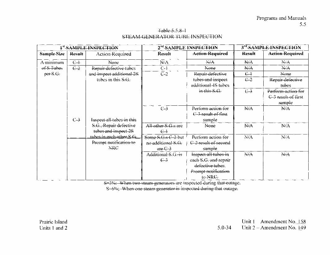
Programs and Manuals 5.5
Prairie Island Units 1 and 2
Unit 1 - Amendment No.-% -
5.0-34 Unit 2 - Amendment No._+&

Programs and Manuals 5.5
Prairie Island Units 1 and 2
Unit 1 - Amendment No.-= 5.0-35 Unit 2 - Amendment NO.-& -- --

Reporting Requirements 5.6
5.6 Reporting Requirements
5.6.6 Reactor Coolant System (RCS) PRESSURE AND TEMPERATURE LIMITS REPORT (PTLR) (continued)
b. The analytical methods used to determine the RCS pressure and temperature limits and Cold Overpressure Mitigation System setpoints shall be those previously reviewed and approved by the NRC, specifically those described in the following document:
WCAP- 14040-NP-A, Revision 2, "Methodology Used to Develop Cold Overpressure Mitigating System Setpoints and RCS Heatup and Cooldown Limit Curves" (includes any exemption granted by NRC to ASME Code Case N-5 14).
c. The PTLR shall be provided to the NRC upon issuance for each reactor vessel fluence period and for any revision or supplement thereto. Changes to the curves, setpoints, or parameters in the PTLR resulting from new or additional analysis of beltline material properties shall be submitted to the NRC prior to issuance of an updated PTLR.
Steam Generator Tube Inspection Report
Prairie Island Units 1 and 2
Unit 1 - Amendment No. 4-5%-#2 4-68 5.0-38Unit 2 - Amendment No. 44-943 44-8

Reporting Requirements 5.6
5.6 Reporting Requirements
5.6.7 Steam Generator Tube Inspection Report (continued)
a. A report shall be sub mitted within 180 days a fter the initial entry into MO DE 4 followina completion of an inspection performed in accordance with the
ification 5 . 5 . 8: Stea m Generator (SG) Program. The report sha! E l d e :
1. The scope of i - nspecbns perfprmed on each SG,
2. Active degradation mechanisms found,
3. Nondestructive examination techniques utilized for each degradation mechanism,
4. Location, orientation (if linear). and measured sizes (if available) of service induced indications,
5. Number of tubes plugged or repaired during the inspection outage for each active dearadation mechanism,
6. Total number and percentage of tubes plugged or repaired to date,
7 . The results of condition monitoring, including the results of tube pulls and in-situ testing,
Prairie Island Units 1 and 2
Unit 1 - Amendment No. l-58462 4-68 5.0-39Unit 2 - Amendment No. 449 4-53 158

Reporting Requirements 5.6
8. The effective pluaaing percentage for all plugging and tube repairs in each SG, and
9. Repair method utilized and the number of tubes repaired bv each repair method. -
L5. For implementation of the voltage-based repair criteria to tube support plate intersections, notifl the NRC staff prior to returning the steam generators to service should any of the following conditions arise:
1 a. If estimated leakage based on the projected end-of-cycle (or if -
not practical, using the actual measured end-of-cycle) voltage distribution exceeds the leak limit (determined from the licensing basis dose calculation for the postulated main steamline break) for the next operating cycle,;
2k. If circumferential crack-like indications are detected at the -
tube support plate intersections,;
3e. If indications are identified that extend beyond the confines of - .... .
the tube support plate,:
4.4. - If indications are identified at the tube support plate elevations that are attributable to primary water stress corrosion cracking, ?...and
Prairie Island Units 1 and 2
Unit 1 - Amendment No. 448462 4-64! 5 .O-40Unit 2 - Amendment No. 4-49 4-53 448

Reporting Requirements 5.6
5.6 Reporting Requirements
5.6.7 Steam Generator Tube Inspection Report (continued)
5e. If the calculated conditional burst probability based on the - -
projected end-of-cycle (or if not practical, using the actual measured end-of-cycle) voltage distribution exceeds 1 E-02, notify the NRC and provide an assessment of the safety significance of the occurrence.
EM Report
When a report is required by Condition C or I of L C 0 3.3.3, "Event Monitoring (EM) Instrumentation," a report shall be submitted within the following 14 days. The report shall outline the preplanned alternate method of monitoring, the cause of the inoperability, and the plans and schedule for restoring the instrumentation channels of the Function to OPERABLE status.
Prairie Island Units 1 and 2
Unit 1 - Amendment No. - l S 4 Z M 2 4423 Unit 2 - Amendment No. 4-49 ! 53 ! 54 44%
5 .O-4 1

RCS Loops - MODES 1 and 2 B 3.4.4
BASES
APPLICABLE forced flow rate, which is represented by the number of RCS loops SAFETY in service. ANALYSES
(continued) Both transient and steady state analyses include the effect of flow on the departure fkom nucleate boiling ratio (DNBR). The transient and accident analyses for the plant have been performed assuming both RCS loops are in operation. The majority of the plant safety analyses are based on initial conditions at high core power or zero power. The accident analyses that are most important to RCP operation are the two pump coastdown, single pump locked rotor, and rod withdrawal events (Ref. 1).
The plant is designed to operate with both RCS loops in operation to maintain DNBR within limits during all normal operations and anticipated transients. By ensuring heat transfer in the nucleate boiling region, adequate heat transfer is provided between the fuel cladding and the reactor coolant.
RCS Loops - MODES 1 and 2 satisfies Criterion 2 of 10 CFR 50.36(~)(2)(ii).
LC0 The purpose of this LC0 is to require an adequate forced flow rate for core heat removal. Flow is represented by the number of RCPs in operation for removal of heat by the SGs. To meet safety analysis acceptance criteria for DNB, two pumps are required at power.
An OPERABLE RCS loop consists of an OPERABLE RCP in operation providing forced flow for heat transport and an OPERABLE SGL C b ~
APPLICABILITY In MODES 1 and 2, the reactor is critical and thus has the potential to produce maximum THERMAL POWER. Thus, to ensure that the
Prairie Island Units 1 and 2
Unit 1 - Revision 4-72 Unit 2 - Revision 472

RCS Operational LEAKAGE B 3.4.14
BASES
APPLICABLE Except for primary to secondary LEAKAGE, the safety analyses SAFETY do not address operational LEAKAGE. However, other operational ANALYSES LEAKAGE is related to the safety analyses for LOCA; the amount
of leakage can affect the probability of such an event. The safety analysis for an event resulting in steam discharge to the atmosphere assumes thatp_in~.arq'.~.tosecond~.~..~LEAK_P?.G.FFFf1:~~~nn~iI..ste.a~n gg:n~~lo_rs~S.SCJsLi.s!m:g :::. gt~I~.~~.:=p.g~~~n~~~.utg~~~,r~.ingr.g~g.s:g.s .::: to oneggl1bn p.~.~~:minut~.~~.~rcsu!t::o.f..a~~~iiddg.~ttt~.n~.~~~.~s1 ~cc~.nd&i:c!n.s, :.._ T.k,.I,,,CQ rea_u.iren!.ent .. .tn....!in?i t .. prima r?;....t. o..ss.co.ndarv I:,F??Q!G!:. through anv one SG to less than or equal to 150 gallons per day is significantly less than the conditions assumed in the safety analysis.a+p
-1 . . . < ,,<,, , ULII
Primary to secondary LEAKAGE is a factor in the dose releases outside containment resulting from a steam line break (SLB) accident. To a lesser extent, other accidents or transients involve secondary steam release to the atmosphere, such as a steam generator tube rupture (SGTR). The leakage contaminates the secondary fluid.
The USAR (Ref. 2) analysis for SGTR assumes the plant has been operating with a 5 gpm primary to secondary leak rate for a period of time sufficient to establish radionuclide equilibrium in the secondary loop. Following the tube rupture, the initial primary to secondary LEAKAGE safety analysis assumption is relatively inconsequential when compared to the mass transfer through the ruptured tube.
The SLB is more limiting for site radiation releases. The safety analysis for the SLB accident assumes the-gntirc 1 gpm (at 70°F) primary to secondary LEAKAGE is through the af'fected- generator as an initial condition. The dose consequences resulting from the SLB accident are well within the limits defined in 10 CFR 100 or the staff approved licensing basis (i.e., a small fraction of these limits).
The RCS operational LEAKAGE satisfies Criterion 2 of 10 CFR 50.36(~)(2)(ii).
Prairie Island Units 1 and 2
Unit 1 - Revision- . - B 3 -4.14-2 Unit 2 - Revisio-

RCS Operational LEAKAGE B 3.4.14
BASES
LC0 RCS operational LEAKAGE shall be limited to:
a. Pressure Boundary LEAKAGE
No pressure boundary LEAKAGE is allowed, being indicative of material deterioration. LEAKAGE of this type is unacceptable as the leak itself could cause further deterioration, resulting in higher LEAKAGE. Violation of this L C 0 could result in continued degradation of the reactor coolant pressure boundary (RCPB). LEAKAGE past seals and gaskets is not pressure boundary LEAKAGE.
Seal welds are provided at the threaded joints of all reactor vessel head penetrations (spare penetrations, full-length Control Rod Drive Mechanisms, and thermocouple columns). Although these seals are part of the RCPB as defined in 10CFR5O Section 50.2, minor leakage past the seal weld is not a fault in the RCPB or a structural integrity concern. Pressure retaining components are differentiated from leakage barriers in the ASME Boiler and Pressure Vessel Code. In all cases, the joint strength is provided by the threads of the closure joint.
b. Unidentified LEAKAGE
One gallon per minute (gpm) of unidentified LEAKAGE is allowed as a reasonable minimum detectable amount that the containment air monitoring and containment sump level monitoring equipment can detect within a reasonable time period. Violation of this LC0 could result in continued degradation of the RCPB, if the LEAKAGE is from the pressure boundary.
c. Identified LEAKAGE
Up to 10 gpm of identified LEAKAGE is considered allowable because LEAKAGE is from known sources that do not interfere
Prairie Island Units 1 and 2
Unit 1 - Revisio-& B 3.4.14-3 Unit 2 - Revision-. !? 9

RCS Operational LEAKAGE B 3.4.14
BASES
c. Identified LEAKAGE (continued)
with detection of unidentified LEAKAGE and is well within the capability of the RCS Makeup System. Identified leakage must be evaluated to assure that continued operation is safe. Identified LEAKAGE includes LEAKAGE to the containment from specifically known and located sources, but does not include pressure boundary LEAKAGE or controlled reactor coolant pump (RCP) seal leakoff (a normal function not considered LEAKAGE). Violation of this L C 0 could result in continued degradation of a component or system.
d. Primary to Secondary LEAKAGE through Any One Steam 6 e m ~ & ~ 4 S G j
?'he limit of 1 5 0 m e r . . V S G is based on implementation of the Steam Generator Voltage Based Alternate Repair Criteria and is+mxe
c t h e operational LEAKAGE performance criterion in NEI 97-06. Steam (;enerator I'rogram Guidelines (Ref'. 3J,_ The Steam Generator-Pr_ogr:d~n _ogcratiod -- -
LEAKAGE performance criterion in NEI97-06 statea "The RCS-opcy_ational prjrnary togecondary Icakdge througl! any onc SG - shall linlitql to 150 galkms per day." The limit is bascd on operatingexperience with SG tube degradation mechanisms that result in tube leakage. 'The o~erational leakage rate criterion in coniitnction with the implenlentation of the Steam (;mcrator Program Is an cfl'ectivg-measure for minimizing the frequency ~l'steam generator tube ruptures.
Prairie Island Units 1 and 2
Unit 1 - Tievision- . .. B 3.4.14-4 Unit 2 - Revision-

RCS Operational LEAKAGE B 3.4.14
BASES
APPLICABILITY In MODES 1,2,3, and 4, the potential for RCPB LEAKAGE is greatest when the RCS is pressurized.
In MODES 5 and 6, LEAKAGE limits are not required because the reactor coolant pressure is far lower, resulting in lower stresses and reduced potentials for LEAKAGE.
LC0 3.4.15, "RCS Pressure Isolation Valve (PIV) Leakage," measures leakage through each individual PIV and can impact this LCO. Of the two PIVs in series in each isolated line, leakage measured through one PIV does not result in RCS LEAKAGE when the other is leak tight. If both valves leak and result in a loss of mass from the RCS, the loss must be included in the allowable identified LEAKAGE.
ACTIONS &l
Unidentified LEAKAGE in excess of the LC0 limits must be identified or reduced to within limits within 4 hours. This Completion Time allows time to verifL leakage rates and either identify unidentified LEAKAGE or reduce LEAKAGE to within limits before the reactor must be shut down. This action is necessary to prevent hrther deterioration of the RCPB.
B.l, B.2.1, and B.2.2
If unidentified LEAKAGE cannot be identified or cannot be reduced to within limits within 4 hours, the reactor must be brought to lower pressure conditions to reduce the severity of the LEAKAGE and its potential consequences. It should be noted that LEAKAGE past seals, gaskets, and pressurizer safety valves seats is not pressure boundary LEAKAGE. The reactor must be brought to MODE 3 within 6 hours. If the LEAKAGE source cannot be identified within 54 hours, then the reactor must be placed in MODE 5 within
Prairie Island Units 1 and 2
Unit 1 - Kevisio- B 3.4.14-5 Unit 2 - Revisio-

RC S Operational LEAKAGE B 3.4.14
84 hours. This action reduces the LEAKAGE and also reduces the factors that tend to degrade the pressure boundary.
BASES
ACTIONS (continued) The allowed Completion Times are reasonable, based on operating experience, to reach the required plant conditions from h l l power conditions in an orderly manner and without challenging plant systems. In MODE 5, the pressure stresses acting on the RCPB are much lower, and hrther deterioration is much less likely.
C.1, C.2.1, and C.2.2
If RCS identified LEAKAGE, other than pressure boundary LEAKAGEhkage or primary to secondary LEAKAGE, is not within limits, then the reactor must be placed in MODE 3 within 6 hours. In this condition, 14 hours are allowed to reduce the identified leakage to within limits. If the identified LEAKAGE is not within limits within this time, the reactor must be placed in MODE 5 within 44 hours.
The allowed Completion Times are reasonable, based on operating experience, to reach the required plant conditions in an orderly manner without challenging plant systems.
D.l and D.2
If RCS pressure boundary LEAKAGE exists or if primary to secondaryS4.3 LEAKAGE (1 50 gpd limit) is not within limits, the reactor must be placed in MODE 3 within 6 hours and in MODE 5 within 36 hours.
The allowed Completion Times are reasonable, based on operating experience, to reach the required plant conditions in an orderly manner without challenging plant systems.
Prairie Island Units 1 and 2
Unit 1 - Revision- B 3.4.14-6 Unit 2 - Revision-

RCS Operational LEAKAGE B 3.4.14
BASES
SURVEILLANCE SR 3.4.14.1 REQ-
Verifying RCS LEAKAGE to be within the L C 0 limits ensures the integrity of the RCPB is maintained. Pressure boundary LEAKAGE would at first appear as unidentified LEAKAGE and can only be positively identified by inspection. It should be noted that LEAKAGE past seals and gaskets is not pressure boundary LEAKAGE. Unidentified LEAKAGE and identified LEAKAGE are determined by performance of an RCS water inventory balance.
The RCS water inventory balance must be met with the reactor at steady state operating conditions (stable temperature, power level, equilibrium xenon, pressurizer and makeup tank levels, makeup and letdown, and RCP seal injection and return flows). The Surveillance is modified- bv two No&&- - Note 1 states W akbvmg-that this SR is not required to be performed until 12 hours after establishing steady state operation. The 12 hour allowance provides sufficient time to collect and process all necessary data after stable plant conditions are established.
Steady state operation is required to perform a proper inventory balance since calculations during maneuvering are not useful. For RCS operational LEAKAGE determination by water inventory balance, steady state is defined as stable RCS pressure, temperature, power level, pressurizer and makeup tank levels, makeup and letdown, and RCP seal injection and return flows.
An early warning of pressure boundary LEAKAGE or unidentified LEAKAGE is provided by monitoring containment atmosphere radioactivity. It should be noted that LEAKAGE past seals and gaskets is not pressure boundary LEAKAGE. These leakage
Prairie Island Units 1 and 2
Unit 1 - Revision-4 B 3.4.14-7 Unit 2 - Revision-

RCS Operational LEAKAGE B 3.4.14
detection systems are specified in L C 0 3.4.16, "RCS Leakage Detection Instrumentation."
BASES
SURWZLLANCE SR 3.4.14.1 (continued) REQ-
NoL..c..!st~l.e.s. that ..t~~~~.SRis.~~o~.~p.lica.b.!.e....to...~.ri.m.ar~....t~~...~.~~~~.nd~~y L.,EAK~~Erh.g.~~~.s_eJ:J:E..AAKKAGE.of.f.l~5:Q :::: g a . ~ I ~ ~ ~ ~ g g s . . S p F ~ ~ r . y ~ . ~ n n ~ t . . b ! : ~~.c.gis.~~gs d,~.g:gy.~.gte! y . _bq'r.m.,R.CSyst,.gr .::= ~ I n n v V ~ E n ~ ~ ~ ~ y Y Y Y Y ~ h ~ ~ . ~ ~ ~ ~ ~ S ~ . ~ .
The 24 hour Frequency is a reasonable interval to trend LEAKAGE and recognizes the importance of early leakage detection in the prevention of accidents.
., . . u 7 - This SR yerifics that primary to secondary I ,EAKAGTl: is less or equal to 150 gallons per day through any one SG. Satisfying the primary tosecondary LEAKAGE limit ensures that the operational LEAKAGE performance criterion in the Steam (jencrator P~ograrn is met. If this SR is not m ~ t , compliance with LC()-3.4.19, ':Stcam (icnerator Tube Integrity ,?should be e\~aluatcd. The 15~gal lons pcr day limit is measurcd at soom tcmperaturcas dcscribcd in Kefcr-ncc 4. Thc operational 1,EAKACiE rate limit applies to I .I'AKAGI: throuzh any one SG. If it is-not practical to assign the LEAKAGE to an individual SG. all the ~rin1ai-y to - -
secondary LEAKAGE should be conservatiyely assu~nedlg be from --
om SG. --
The Sury-lance isjnodified_by_a Note which stgtcs that thc S~irveillance is not rguired to be performed until 12 hours after establishment of steady state operation. For KCS primary to secondary LEAKAGE determination. steady state is defined as
Prairie Island Units 1 and 2
Unit 1 - Revisic)n- . - B 3.4.14-8 Unit 2 - Revision-

RCS Operational LEAKAGE B 3.4.14
stable RCS pressure, temperature? power levelspressuri7er and makeup tank levels. makeup and letdown, and RCP seal injection and return -- flows. -
The .... S uK~.~iI!ae.~.e~.Er.~qu~n.cr_~.f..72.. ho.urs..is..ar.e.as.o-n-ibl.c ..i.ntcrv&g ~gnd:::~.~..iimmary.t~~.ec.~~:ndary.Ll.,EAKACJ.~::~~~.d._rec~:g~.~:..~h: i.mporta.nc.c ....of .ear!.y...!.%ak~c"...d~t.~.ctior1..in. t h ~ r . ~ . v . n ~ t i . o ~ ~ o f ac~idcnts~ . . . -.. - .. . ......
The .. ..... primary ................................ ......... to secondarv .- I..,E.AKAGI? is deter.mi.nedusing cont~~?uo.u.s~~qc.e.$.s ... rad.i.a.tion....n~.on.i.tors or radj. .och.e.mi.ca!....grclb sampling in accordance with the EPKl guidelines (Ref. 4).
BASES
REFERENCES 1. AEC "General Design Criteria for Nuclear Power Plant Construction Permits," Criterion 16, issued for comment July 10, 1967, as referenced in USAR, Section 1.2.
2. USAR, Section 14.5.
NEI 97-06, "Stea~n Generator Program Guidelines." 3. ,--
4. 1~PKI,~'Press~1ri7~:~1 Watcr Kcactor Prirnary-to-Sccondarj I ,eak
Prairie Island Units 1 and 2
Unit 1 - revision^ . I - 58 B 3.4.14-9 Unit 2 - Revision-

S(; l'ubc Integrity I3 3.4.19
B 3.4 REACTOR COOLANT SYSTEM (RCS)
H 3.4.19 Steam Generator (SG) 'I'i~be Intggr& -- - -- --- - . ...
BASES
BACK(iR0IJND Steam gcprator (SG) tubes are small diamctgr,-t& walled tubes that Sarry primary coolant t h ro~~gh the primary to secondarj heat cxcl-tangers. The SG tubes have a nun~bcr of important safety functions. Stearngalerator tubes are an i~~tegral part of the_re;ctor --- -- - -
coolant pressure boundary (JiCI'H) and, as suctl, arerelied on-to -- - - . -- - - - -- - . -- -- - - -- -- - -. - .
mngint~in thc pr imar~_sys ten~~s pressure and inyento=,_ 'Ihe Sctybes isolate3e radioagive ission products in t l q r i n ~ i i r y c~)~)l i i t~t lrom the scconcar3, systcn~. In addition, as part ol'thc IICPB, t l~e S(3 tubcs arc unique in that the), act as the heat transfer surf'ace bctcqeen thc primary and secondary systcrns topcn~ovc hcat from the primary sjTste~rl. 'Ihis Specification addresses o11Iy the fiKCI'H integrity fimction of the SCT.-~1'he SC; heat removal function isadctressed by - .-
LC(> 3.4.4: 'YIICS Loops - MOIXS I and 2." L C 0 3.4.5. "RCS Loops --MODE 3,'. L C 0 3.46, "RCS Loops - MODE 4:> and l,W 3.4.7, "RCS I,oo~>s -- - MODE 5 , Loops 17illcd."
SG tube integrity means that the tubes are capable of pcrti~rlning their intended KCI'H s a fe~ junc t ion consistent with the licensing bax~Fs, i n c l u d i ~ ~ applicable re,qillatory-requiren~~nts.
Steam_gcncriitor - - -- - - -- - tubino -- - ZB i\ ~ ~ _ - l - - sttb'ect to a - varict - 4--- of'deg-adation geghanisn1s2 Stteam generator -- tubes lnay cxpcrienqctu& degradatio~~ related to corrosion pheno~ncna, sucll as c\ast;.gc: pitting, intergranular attack, and strccs corrosion cracking, along with_~tll_er mgc_l~_anicaIly i!~cluce_d.pher~ome~~a such as de~ltingald \\_a__rl Ifiqse degradg~ticjnn~echaniws can impair tubgintegritb if tllev are not nlg~laged esfectively . The SG g e r _ f s ~ g a c e gritgria2r- used to manage SC; tube degracia1ixg.
Specification j.5.8, "Stea~n Gcncrator (SCi) Progranl," rccluires that a program be csgblishcd and in-tplcmentcd to ensure that-SG tube integrity is maintained. f'ursuant to Specification 5.5.8, tutze integrity is maintained when the SG p e r h ~ n ~ a t ~ c e _ d t ~ r m e t . -
Prairie Island _ _. Unit 1 Keyision - - --- -- - - -. - - --
urlitp l-_a!ld-:! - - - -- -- - - U 3.4.19-1 --- - - - -- -- - -. .-- . Unit 2 -- 1Ievisig1-t
. -- -- -

S(; Tube Integrity _B 3.4.19
BASES ---
BACKGROIINI) Thcrc arc thrcc SG parformance critcria: structural integrity? _(continued) accident induced leakage? and operational 1,I:AKAGI:. ' r l~e SG
perl'ormance criteria are described in Specii7cation 5.5.8. Meeting the SG ~erl'ormance criteria provides reasonable assurance of rnaintainingtube -- - intc~ritv at norinaland.ac_cidenLconditions.
AF'I'I ,ICAHI ,E --- 'I'he stearn generator tube rupture (SG'TR) accident is the limiting SNEIY design basis event for SC; tubes and avoiding an SG'l'K is the basis ANALYSES for this Specification. 'Phe analysis of a SG'I'R event assumes a
bounding p-riinary-to secoj~dary LEAKAGE rate greats than thc opcrationgl I,EAI(AGE rate limits in L C 0 3.4.14, "RCS Operational
the contaminated secondarytfhid-is released to the atmosphere via atinospheric stearn dumps.
The ... a.na1y.si.s .. i611r ... .cL.c".sign..ba.sis....ac.c.i.d.~r?t~...a.nd~tr'~insie.n_ts..~oth~r..tI~zn a SGTR ... ~~.ssun?.c .. the ... S..G. t~.b.e.s....retain th.~irstr.u.ctura! .... int~gritv__(1.?..e.!.. r l.L t h q ... .. - ..
8r.e .::: a.ssu.m.e.d .. notto . ru.pt.~rc..L..T~~ .::: t!?.e~e ana!.yse.s,::.h.s ::.. ~tsa.md...is~dl.grge to .. the....~zt.n?.osph.ere .... b.. based ... o!! ... the. .. total ...,rimarlv . tqsecondax~ I.,T;AKACJE ... ................ .. ... .. . ..... .......... from all .. SGsof l gallon. . ~e~..minute-o!: .js...ass.umed.tp increase to 1 ,gallon per inintde as a result of accident i n d u d conditions except during the implementation steam e n e r g m~ifirs..oni~.it...2...2utiili.~iing...thheeeevo1ti~~g.e-b:ns.edddr~~ir. .c.rite.ria, ..During !&,i.m:p:!.g:m.cn tqt.io.n:.c~fs.~agl.n :... ggn.gr.mt.gr .::: r.gpgi.rso.n.1:Inn.i_t: 2. uti!.z.ingth e v.9 l t age-h.gsc..<!:..~gp.ai~ ..:: s~&e,rj:~~~~:th::: tot a!..zc~l.g~rliit:gd:::pri!.Gg ..t, sec.0nci.a.q. side ... !.e.&a;efi.oln thefault ed... $Ci undel-mai!,..steam line breakconditi ons!cltsi.de.. c ontai!l.m.enta lid... _upstreamof the ~nain steam isolation valves), will not exceed 1.42, gallons per minute (based an .... a...r.eactor .co~l.an t .syste.~n...t.e~.n~~e_ri1.1:.u.~.e...c1.-f.~...5.7.8~~~.I~
Prairie Island -- Unit 1 -- Revision lJt i i tsland2 , L b L E k 2 - Unit 2 - Revision

APIJI .ICADI ,E For accidents that do not involve fuel da~nagc, thc pri~nary coolant SAfJl<l'Y .- activity level of I>OSI3 IK.)UlVAI,l<N'I' 1- 13 1 is assunled to be equal ANA1,YSES -
- - -- - - . - . - to or greater than the - LCO -- 3.4.lJ'+"KC'S Specific Activity:" l i n r s . c o n t i n u e d For accidents that assixme rue1 damape. the primary coolant acti>ri&
is a functiotl of the amount osactivity released from the damaged fuel. 'The close consequences of thcsc events lire c1 itllin the limits oS GrlC 19 [Rcf. 21, 10 CFR 100 (Ref. 3) or the NRC approved licensing basis (c.g.> a small fi-action of these limits).
I ,C'O - --- - - -- The - - -- L C 0 -- requires that SC; tube -- -. integrity be ~naintained, 'lhc L C 0
also rcquircs that all SC; tubes that satisfy the repair criteria be plugged or rcpaircd in accordance with tlie Steam Gcncrator l'rogram.
m r i n g an SG inspection. an>vJnspectedt~~be that sa t i~t~iesthe~ Stegfil Generator t'roprarn repair criteria is repaired-or removed Srorg -- - -
service by plugging. If tl tube w e deternlincd to satisfy the repair
integrity .
111 tl~e__cor&ext of this .Speciticati~n,~aj~ SCitube is defined as the ~ t h of the-tu_bc includin&e tube \vdl and at14xepait.s e n l i r e l e ~ .... - _ .._ _ _ _, ___, __
rn&- tcr it, b e t ~ e e n the &be-to-tubcshegt !veld at tlle tubginletand tke t~ibc-to-&bcshect-\yfid at thetube - outlet. --- :l:hq tube-to-tubcxgcct ~ c l d is not considerecl part of the tube, nor is the region of'ti~be bclow the F* and 131:" distances.
An SG tube has tube integfit~ w l l e ~ ~ it satisfies the SG.perSosma~lce criteria. 'I'he SG performance criteria-are delined in Speciiicatign 5.5.8, "Steam G e ~ r a t o r Program," and dcscribe acceptable S G tube --
pqrSornlancel Thc Stgx--g (icneriltc~r I'rograin also provictcs tllc
....... ... . . . . .... -... --- ......... . ... . . . . . . . . . . . . . . . . . . . . . . . . . . . . LJnit 1 Revision FYair i e I s !_ad-- . _ - - ;..
-- ..-. Unit 2 -- I<evisic>t~ H 3.4.19-3 . - -. IJ nits--!L:~!1&1.2 -...7y . - . ._ . ... - - - -

'!'here arc threeSC;pe~fctrnlance critgia; structural integ~jt?i;ac_c_ident induced -- --- leakage, - - allci operational LEAKAGE. I 3 i k e to ~ncct any one of these criteria is considered fiiilure to lncct the LCO.
Thc structural i~~tcgrity_pcrforrna~~ce critcrion provides a margin of safety against tube burst or collapse under normal ancl accident conditions, and ensures structural integrity of the SG tubes underdl ggticipated transientsincluded in tlze design speciikation. ' l 'uk burst is defined as, "'The gross structural fkilure the tube wall. 'Thc condition typically corresponds to i1n ~~nstable opetling
material at the ends of the degradation.'' --- -
'lube g ~ l l a g s e ~ is- deened 3s: bbt;~)r the load dis~laceinen~c~rrve - !'or-a given structureL cc~llapse cJccurs at the top o f tile load versus di-glaccment - - - curve -- - -- \\. h ~ r e &c;l(~-c dthc 5 - g ~ 13ecomes zero.-* The structural integrity pcrf'or~nancc critcrion provides guidance on assessing loads that have a significant effect on burst or collapse. In that context! the term "&nificar?t': is d.etinedils:hl accidnt
s&nificiint - when the - - addition -- -- -- -- of - such loads in~heassessment oS the --
structural integrity perforinance criterion could cause a l o y g structural linlit or limiting burst/collapse condition to be -
establishe$." -For tube integrity evaluations, cxcept for
ion --
of axial thermal loads as prinlary or seconclarv loadswill be eyaluated_on a case-by-case basis. 'I'he division between primi~ry and;eccn&irjl cli~ssiliciltions \i i l l bc bascct on detuilud u ~ ~ i i l ~ ~ ~ i s

Service Level B (upset or abnormal cc>nditionsns) transients includgl in ..tb.cs. dws@~ .... s.p.e..ci 1i.ca tior! ... .T'r:& .includ.c.sls2fcty Iitctors and
'I'he accident induced leakage perfi>r~nance criterion ensures that the . - --
primary -- to s e c o n d a ~ - -- LEAKAGE -- .- - caused - by a design - basis accident. other t&m an SCr'l:I<. is within the accident analvsis assu~nptions. - __ _- _ - .. - ._--- .- ---_=-= =- = -==-_ -
111e ccicknt ;~nalysis i1sst11ncs t11ilt iiccidcnt bnu;cd leakage does not exceed those discussed in the APPLICABLE SAFETY -- -- - - .- - - -. - - . - - - - - -- --
ANA1,YSI:S section above. 'I'hc accident induccd leakage rate includes any primary to sccondari\ I,EAKAC;I< existing prior to the acciclent - - in - -- addition - - -- to primary t ~ _ s ~ c ~ > n d i q 1 1 ,I;AKACil< indtrce~l duringtk accident.
The o1>_crational LEAKAGE performance criterion provides an obscrvablc indication oS SC; tube conditions d u r i n ~ plant operation. The limit on operational 1,EAKAGE is co!~tained i11 I,CO 3.4.14, "RCS Operational Id13AI<AGE," and limits primary to secondgry 1.11AKACillthrough any one SG to 150 gallons per day. 'l'llis liinit is - - based - on the assunlption that a sin.-- youi-n~~ro~at~o an SG'lII ~ ~ n d e r the stress conditions ~f a 1,OCA or a main steam line break. I f this moun t of' LEAKAGE is - --
d ~ i c t o n o r e than onccrack,the cracks arc very smal1,and t11e aboc7e assunlption is conservatic c.
A P l I ' A l I I l Y Steam generator tube integrity is challcrlgcd when the pressurc diftkrential i~cross the tubes is. laxge. Ia-g,c diffesential pressures acroys S(; tubes can only-be cxj>crienc_c_d in MOI)l< 1,2,.3, o-r 4.
RCS conditions are Piirlcss challenging in MODES 5 m d 6 than during M()L)ES 1,2,3,and 4. In MODES 5 and 6, prinli~rlr to
F'raillle Island - -. - -. ... - -- - - - - .. .. LJnit 1 Revision - -- -
Units - A 1 and 3 - _ - . --- - - pp -- .- -- lJnit 2 - !<evision 34.19-5 ___-; - -- - -

APPI,ICABII.ITY secondary di t'fcrential pressure is low, resulting in lo~vcr stresses and (cor!tinued) reduced potential for 1 ,l!AKAGll:,.
A 1 N - I ~ K ACrf'IONS are ~nodified by &Note clarif>:ing tliat the__Conditi_ons mav - bcentered - incJepenctetitly for - - each - SG -- tube.-'l'liis is accgptaue - -- - - - --
b_ec_iise the Iieyuirecl Actions - - - provide iipprc)riate compensatoa actions li)r each affected S(; tube. Complying with the Iicc~~&ed -
Actions niay allow for continued operation, and subsequcnt aff'cctcd SG tubes are g~vcrrlcd by s~lbscyuent Conciition crltry and applic-tion of associated Key~lired Action-s.
A. 1 and . A,2
C'ondition - - A applies if it is discoverecilhat one or more SG tuber, exainined in an inservkc inspection satisfy the tubc rcpair criteria but wcrc not pl~igged or repaired in accordance with the Stearn (ier~erator__1-'1.og-m as required by SK 3.4.192,- An e~raluation of S(; tube integrity of the affect4 tube(s) must be rnade. Stear!? gczsrgor tube 3lt eyrit_)i is based <)il-n~eet&t& S(;~39r332~nce cri&ril;t describedin the -- Steam -- - - Generator - - - -- - - l'rcgrani. - - - 'l'he - SC; --- - repair criteria1 ciefine limits y;;(;_tube degrii~i~tjon that -- allocc- forflag
has tube integrity, an evaluation n u t be cc)~npIetecl that ge~nonstrates that the SG perfc)rniance criteria will cotitin~ie to be met lintil the next refueling outage or-S(; tube i n s p @ & ~ n ~ L l ~ t ~ & integrity determinatic>n is based on the estin~atecf condition of t11c tube at the time - - the situation is <iscovered-and the estinlatcd growth of'thedegradiltion prior to the next SQ tubc inspection. I f it is determined that tube integrity is not beir1gm_aintai2ec17 ConditLo~B applies.
A Coinpl&ion Tinlc ol'7 days is sufficient to complgtc_~he evaluation while nl inin~i~ing tlie risk ofplant opsratiog wit11 an SG t u b ~ that may not hare t u b ~ integrity.

S(; -- Tube InZegri~ 13 3.4.19
BASES - -- .
If the evaluation determines that theai'fected tube{s) ..- have tube - -
irltegrity, Re-tion A.2 allows p l an~pe ra t i on to contii~ug unt il.. the ..n .c.xt...r.~lu:liag outage .... o r S<i Irrspestion..pro.vi&~.dtl~a
ConluIetion'I'ime is acl:
11' the Rcquircd Actions and associated Co~nplction Times of Cor~dition A are not met or if SG tube integrity is not 13eing n~aintained. t h ~ reactor m~rst be b~ought to MODe 3 ~ i&iaf iha~l r s and MODE 5 within 36 hours. - - -
The allowed Co~npletion Times are reasoi~ablc~ based on c ) p c r a J j ~ -
expcriencc, tp reach the desired plant conditions fioni fi111 power conditions in an ordcrly manner and without challerlgir~g plant systems. .- -
sr nivl ;II ,I ,ANC:I : SR 3.4.19.1 IUQIJIIU1Mf.N'lS
iods the S G s are
Psairie 1 s l a n d - _ _ - - - - - . . - - _ Unit 1 Ks~ision -- - ---
- ilnits 1 ~ X I 2 -- ~ 3 . 4 ~ 1 9 - 7 - - _ . _ - - _ - Unit __ 2 - ~<evjs i~)s

S G Tube l n t e x r i ~ B 3.4.19
LI~1rirwSq - - insl,ectic,ns . - a - condition -- . - - nionitori~ig - assessment oftfie S(i tub&mfrmed. '1'hg :on-nm&qring gssgssmn_t detcrini~les the '.as Sound" condition of the SCi tubcs. 7 lie purpose of the cor~dijion lno~litoring assessn~en t is to cnsure that the S(> pcrfi)r~nance criteria have been met for the prc\i:lous operating pcriod.
'I'lie Stean~GeneratorJ'ro~rai~deterinii~es -- the scope of ths inspection_and the ineihods used to deterniine M hether h e tubes contain flaws satislying the tube repair criteria. Inspection scopc -
(i.e., which tubes or areas ofiubing ctithin thcSCi are to bc
Ii~spectic>n - methods - - -- are t -- func@tion of d%rgdl:ig4 g o r p l l o l m ~ ?-no_n- ctestructici~' g i g i l l a t icz INIlk:) tt:ch~_riqi~-cgpab~ities.a& -
inspection locations,
'I'lie Steam (icnerator I'rogranl defines the Freyucncj of' SK 3.4.19.1 . The I;requcncj~ is clctcrlnirted by the operational asscssnicnt and other limits in the SC; e?<ami~~iti(~~~~~~ideli~i~s ('kf. 61_.!'heStean1 Generator - -- - Pro & >ran1 uses inforniatic)~~ ._ 011 existino d e ~ a d a t i o n s ~ m d =--
g~) \v th rates to determine an inspection Freuuellcy that ~rovides esona13le assurance that the tubing will 11lcct thc S(;pcrSormancc critcria at the next scheciulcd i s p c t i n 1 addition% Specillcation 5.5.8 contains prescriptive - - requirements qonccrnir.ng inspection i~itervals to provide added assurance that the SG perftsrniancc criteria wil l be met between scliecfuied inspectio~~s.
t'r-airie Island - - - - - - - .- -- -- - - - -- Llnit 1 - Ke~t.')io_n_ Llrtiits 1 a g d _ - A - _ - -_ _- - -- - E2.4.198- __ -__ _____ __UnitZI:&via - - - -- - . -

S(; Tube Integrity I3 3.4.19
SIRVEII,I.ANCE SR 3.4.19.2 1<1<(21 Jr Kl {MI 'N'I s J'c~i~~i~niieci)
Q&in an SG inspection. any insp~cted tube that satisliesthe Stean~ Cjcncrator Program repair critcria is repaireci cn.cn~ovcd Sronl service by plugging,. 'The&bcrcpair critcria del inea~eim Specification 5.5.8 are intended to ensure that tubcs accepted Ibr co~~tinued scrvicc satisrj the S(i perfosn~ance criteria \+lit11 allo\vancc for - error in the flaky size mmsuwnent and tbr future tliilv go\~tIz . In addili~n. the tybg rgpair criteria. i11 conju~~ctiqn ~yith~qth-gr --
el_~elr~ents of the Ste~l_n~ GGe_nnerator !Lrcypm, ensure that the SG per$)rinance - - -- criteria -- -- will - -- continue - - -- to be - ingt unt-dllhe ncxt inspe~tiog of ~ h c subject tu~lx(s). Rcfescncc 1 provides guid:ince lor perfc>snling .-
opcratio~~al assessmcnts to verify that the tubes remaining in servicc will continue to rnect the S(i perfornlancc critcria.
Steain -- generator tgb~repairs-are only perlor~ned using_apprc)ved repair methods as described in @ Steam Gei~erator I'rogra~n~
Thc Frequency ol'prior to entering MODE 4 Sollowing an S G insgeetion ensures that the Surveillance has been co~npletcd and all tubes nlccting t l ~ c repair critcria are plugged or rcpaircd prior to sul~iecting the SG tubes to significant primnary to secondarypressure diSSerentihlL -- --
........................ . . . . . . . . . . . . . . . . . . . . . . . . . . . . . . . . . . Illzit 1 ------ Revision I.?rairiel.sland ----._.--.-..---.-....-.-----y. -.
l in its - - 1 - -. . . .. -. - LJn i t ? . .~&.~ . i%i~

SG Tube Integrity B 3.4.19
. -- . - - - -- - - - 5 , Draft Regulatorv - Guide -- 1.12 1 "Basis for 1'111ggi11g Llegriidea Steam Generator -- - - ?'ubes,.. -- -- A ~ ~ l s t -- 1976. -
6. EPRI, "Pressurized Water Iieactor Steam (jenerator - -- - - -- - - - - -

ENCLOSURE 5
The following Proposed Technical Specification Pages (revised) are contained within Enclosure 5:
Enclosure 5A - Palisades Nuclear Plant
Enclosure 5B - Point Beach Nuclear Plant Units 1 and 2
Enclosure 5C - Prairie Island Nuclear Generating Plant Units 1 and 2
Page I of 1

ENCLOSURE 5A
Proposed Technical Specification Pages (revised)
Palisades Nuclear Plant
Technical Specification Pages
12 pages follow

Definitions 1.1
1.1 Definitions
LEAKAGE
MODE
a. Identified LEAKAGE (continued)
2. LEAKAGE into the containment atmosphere from sources that are both specifically located and known not to interfere with the operation of leakage detection systems and not to be pressure boundary LEAKAGE; and
3. Primary Coolant System (PCS) LEAKAGE through a Steam Generator to the Secondary System (primary to secondary LEAKAGE).
b. Unidentified LEAKAGE
All LEAKAGE (except Primary Coolant Pump seal leakoff) that is not identified LEAKAGE;
c. Pressure Boundarv LEAKAGE
LEAKAGE (except primary to secondary LEAKAGE) I through a nonisolable fault in an PCS component body, pipe wall, or vessel wall.
A MODE shall correspond to any one inclusive combination of core reactivity condition, power level, average primary coolant temperature, and reactor vessel head closure bolt tensioning specified in Table 1.1-1 with fuel in the reactor vessel.
OPERABLE - OPERABILITY A system, subsystem, train, component, or device shall be OPERABLE or have OPERABILITY when it is capable of performing its specified safety function(s) and when all necessary attendant instrumentation, controls, normal or emergency electrical power, cooling and seal water, lubrication, and other auxiliary equipment that are required for the system, subsystem, train, component, or device to perform its specified safety function(s) are also capable of performing their related support function(s).
Palisades Nuclear Plant 1.1-4 Amendment No. 1Q9

PCS Operational LEAKAGE 3.4.13
3.4 PRIMARY COOLANT SYSTEM (PCS)
3.4.13 PCS Operational LEAKAGE
LC0 3.4.13 PCS operational LEAKAGE shall be limited to:
a. No pressure boundary LEAKAGE;
b. 1 gpm unidentified LEAKAGE;
c. 10 gpm identified LEAKAGE; and
d. 150 gallons per day primary to secondary LEAKAGE through any one steam generator (SG).
APPLICABILITY: MODES 1, 2, 3, and 4.
A. PCS operational LEAKAGE not within limits for reasons other than pressure boundary LEAKAGE or primary to secondary leakage.
ACTIONS
A. 1 Reduce LEAKAGE to within limits.
4 hours
COMPLETION TIME CONDITION
B. Required Action and associated Completion Time not met.
REQUIRED ACTION
Pressure boundary LEAKAGE exists.
Primary to secondary LEAKAGE not within limit.
B. 1 Be in MODE 3.
AND
B.2 Be in MODE 5.
6 hours
36 hours
Palisades Nuclear Plant 3.4.13-1 Amendment No. 4-80

PCS Operational LEAKAGE 3.4.13
SURVEILLANCE REQUIREMENTS
SURVEILLANCE I FREQUENCY
SR 3.4.13.1 ............................... NOTES ......................... I. Not required to be performed in MODE 3 or 4
until 12 hours of steady state operation.
2. Not applicable to primary to secondary LEAKAGE.
................................................................
Verify PCS operational LEAKAGE is within limits by performance of PCS water inventory balance.
---------- NOTE -------- Only required to be performed during steady state operation ...........................
72 hours
SR 3.4.13.2 ............................... NOTE ........................... Not required to be performed until 12 hours after establishment of steady state operation. ....................................................................
Verify primary to secondary LEAKAGE is 5 150 gallons per day through any one SG.
72 hours
Palisades Nuclear Plant Amendment No. 4-8.Q

SG Tube lntegrity 3.4.17
3.4 PRIMARY COOLANT SYSTEM (PCS)
3.4.17 Steam Generator (SG) Tube Integrity
LC0 3.4.17 SG tube integrity shall be maintained.
All SG tubes satisfying the tube repair criteria shall be plugged in accordance with the Steam Generator Program.
APPLICABILITY: MODES 1, 2, 3, and 4.
ACTIONS ............................................................ NOTE ........................................................... Separate Condition entry is allowed for each SG tube.
CONDITION REQUIRED ACTION COMPLETION TIME
A. One or more SG tubes satisfying the tube repair criteria and not plugged in accordance with the Steam Generator Program.
B. Required Action and associated Completion Time of Condition A not met.
SG tube integrity not maintained.
A. l Verify tube integrity of the affected tube(s) is maintained until the next refueling outage or SG tube inspection.
A.2 Plug the affected tube(s) in accordance with the Steam Generator Program.
7 days
Prior to entering MODE 4 following the next refueling outage or SG tube ins~ection
B. l Be in MODE 3.
AND
B.2 Be in MODE 5.
6 hours
36 hours
Palisades Nuclear Plant 3.4.17-1 Amendment No.

Palisades Nuclear Plant
SG Tube Integrity 3.4.17
SURVEILLANCE REQUIREMENTS
SURVEILLANCE
SR 3.4.17.1 Verify SG tube integrity in accordance with the Steam Generator Program.
SR 3.4.17.2 Verify that each inspected SG tube that satisfies the tube repair criteria is plugged in accordance with the Steam Generator Program.
FREQUENCY
In accordance with the Steam Generator Program
Prior to entering MODE 4 following a SG tube inspection
Amendment No.

Programs and Manuals 5.5
5.5 Programs and Manuals
lnservice Testinq Program
This program provides controls for inservice testing of ASME Code Class 1, 2, and 3 components. The program shall include the following:
a. Testing frequencies specified in Section XI of the ASME Boiler and Pressure Vessel Code and applicable Addenda (B&PV Code) as follows:
B&PV Code terminology for inservice testing activities Weekly Monthly Quarterly or every 3 months Semiannually or every 6 months Every 9 months Yearly or annually Biennially or every 2 years
Required interval for performing inservice testing activities I 7 days r 31 days I 92 days r 184 days I 276 days r 366 days 5731 days
b. The provisions of SR 3.0.2 are applicable to the above required intervals for performing inservice testing activities;
c. The provisions of SR 3.0.3 are applicable to inservice testing activities; and
d. Nothing in the B&PV Code shall be construed to supersede the requirements of any Technical Specification.
Steam Generator (SG) Program
A Steam Generator Program shall be established and implemented to ensure that SG tube integrity is maintained. In addition, the Steam Generator Program shall include the following provisions:
a. Provisions for condition monitoring assessments. Condition monitoring assessment means an evaluation of the "as found" condition of the tubing with respect to the performance criteria for structural integrity and accident induced leakage. The "as found" condition refers to the condition of the tubing during an SG inspection outage, as determined from the inservice inspection results or by other means, prior to the plugging of tubes. Condition monitoring assessments shall be conducted during each outage during which the SG tubes are inspected or plugged to confirm that the performance criteria are being met.
b. Performance criteria for SG tube integrity. SG tube integrity shall be maintained by meeting the performance criteria for tube structural integrity, accident induced leakage, and operational LEAKAGE.
Palisades Nuclear Plant 5.0-1 1 Amendment No. 4-W

Programs and Manuals 5.5
5.5 Proarams and Manuals
5.5.8 Steam Generator (SG) Program
b. Performance criteria for SG tube integrity. (continued)
1. Structural integrity performance criterion: All in-service SG tubes shall retain structural integrity over the full range of normal operating conditions (including startup, operation in the power range, hot standby, and cool down and all anticipated transients included in the design specification) and design basis accidents. This includes retaining a safety factor of 3.0 against burst under normal steady state full power operation primary-to-secondary pressure differential and a safety factor of 1.4 against burst applied to the design basis accident primary-to-secondary pressure differentials. Apart from the above requirements, additional loading conditions associated with the design basis accidents, or combination of accidents in accordance with the design and licensing basis, shall also be evaluated to determine if the associated loads contribute significantly to burst or collapse. In the assessment of tube integrity, those loads that do significantly affect burst or collapse shall be determined and assessed in combination with the loads due to pressure with a safety factor of 1.2 on the combined primary loads and 1.0 on axial secondary loads.
2. Accident induced leakage performance criterion: The primary to secondary accident induced leakage rate for any design basis accident, other than a SG tube rupture, shall not exceed the leakage rate assumed in the accident analysis in terms of total leakage rate for all SGs and leakage rate for an individual SG. Leakage is not to exceed 0.3 gpm.
3. The operational LEAKAGE performance criterion is specified in LC0 3.4.13, "PCS Operational LEAKAGE."
c. Provisions for SG tube repair criteria. Tubes found by insewice inspection to contain flaws with a depth equal to or exceeding 40% of the nominal tube wall thickness shall be plugged.
d. Provisions for SG tube inspections. Periodic SG tube inspections shall be performed. The number and portions of the tubes inspected and methods of inspection shall be performed with the objective of detecting flaws of any type (e.g., volumetric flaws, axial and circumferential cracks) that may be present along the length of the tube, from the tube-to-tubesheet weld at the tube inlet to the tube-to-tubesheet weld at the tube outlet, and that may satisfy the applicable tube repair criteria. The tube-to-tubesheet weld is not part of the tube. In addition to meeting the requirements of d.1, d.2, and d.3 below, the inspection scope, inspection methods, and inspection intervals shall be such as to ensure that SG tube integrity is maintained until the next SG inspection. An assessment of degradation shall be performed to
Palisades Nuclear Plant 5.0-1 2 Amendment No. 44.Q
Programs and Manuals 5.5
5.5 Programs and Manuals
5.5.8 Steam Generator (SG) Program
d. Provisions for SG tube inspections. (continued)
determine the type and location of flaws to which the tubes may be susceptible and, based on this assessment, to determine which inspection methods need to be employed and at what locations.
1. lnspect 100% of the tubes in each SG during the first refueling outage following SG replacement.
2. Inspect 100% of the tubes at sequential periods of 60 effective full power months. The first sequential period shall be considered to begin after the first inservice inspection of the SGs. No SG shall operate for more than 24 effective full power months or one refueling outage (whichever is less) without being inspected.
3. If crack indications are found in any SG tube, then the next inspection for each SG for the degradation mechanism that caused the crack indication shall not exceed 24 effective full power months or one refueling outage (whichever is less). If definitive information, such as from examination of a pulled tube, diagnostic non-destructive testing, or engineering evaluation indicates that a crack-like indication is not associated with a crack(s), then the indication need not be treated as a crack.
e. Provisions for monitoring operational primary to secondary LEAKAGE.
Palisades Nuclear Plant 5.0-1 3 Amendment No. 4-89

Programs and Manuals 5.5
5.5 Programs and Manuals
This page retained for page numbering
Palisades Nuclear Plant 5.0-14 Amendment No. 4-W

Programs and Manuals 5.5
5.5 Programs and Manuals
This page retained for page numbering
Palisades Nuclear Plant 5.0-1 5 Amendment No. 4-89

Programs and Manuals 5.5
5.5 Programs and Manuals
This page retained for page numbering
Palisades Nuclear Plant 5.0-16 Amendment No. 4-W

Reporting Requirements 5.6
5.6 Reporting Requirements
5.6.6 Post Accident Monitoring Report
When a report is required by LC0 3.3.7, "Post Accident Monitoring Instrumentation," a report shall be submitted within the following 14 days. The report shall outline the preplanned alternate method of monitoring, the cause of the inoperability, and the plans and schedule for restoring the instrumentation channels to OPERABLE status.
5.6.7 Containment Structural lnteqritv Surveillance Report
Reports shall be submitted to the NRC covering Prestressing, Anchorage, and Dome Delamination tests within 90 days after completion of the tests.
5.6.8 Steam Generator Tube Inspection Report
A report shall be submitted within 180 days after the initial entry into MODE 4 following completion of an inspection performed in accordance with the Specification 5.5.8, Steam Generator (SG) Program. The report shall include:
a. The scope of inspections performed on each SG,
b. Active degradation mechanisms found,
c. Nondestructive examination techniques utilized for each degradation mechanism,
d. Location, orientation (if linear), and measured sizes (if available) of service induced indications,
e. Number of tubes plugged during the inspection outage for each active degradation mechanism,
f. Total number and percentage of tubes plugged to date,
g. The results of condition monitoring, including the results of tube pulls and in- situ testing, and
h. The effective plugging percentage for all plugging in each SG.
Palisades Nuclear Plant Amendment No. 4-89

ENCLOSURE 5B
Proposed Technical Specification Pages (revised)
Point Beach Nuclear Plant Units I and 2
Technical Specification Pages
11 pages follow

Definitions 1 . I
1.1 Definitions
LEAKAGE
The maximum allowable primary containment leakage rate, La, shall be 0.4% of primary containment air weight per day at the peak design containment pressure (P,).
LEAKAGE shall be:
a. Identified LEAKAGE
1. LEAKAGE, such as that from pump seals or valve packing (except reactor coolant pump (RCP) seal water injection or leakoff), that is captured and conducted to collection systems or a sump or collecting tank;
2. LEAKAGE into the containment atmosphere from sources that are both specifically located and known either not to interfere with the operation of leakage detection systems or not to be pressure boundary LEAKAGE; or
3. Reactor Coolant System (RCS) LEAKAGE through a steam generator to the Secondary System (primary to secondary LEAKAGE);
b. Unidentified LEAKAGE
All LEAKAGE (except RCP seal water injection or leakoff) that is not identified LEAKAGE;
c. Pressure Boundarv LEAKAGE
LEAKAGE (except primary to secondary LEAKAGE) through a nonisolable fault in an RCS component body, pipe wall, or vessel wall.
MASTER RELAY TEST A MASTER RELAY TEST shall consist of energizing all master relays in the channel required for OPERABILITY and verifying the OPERABILITY of each required master relay. The MASTER RELAY TEST shall include a continuity check of each associated required slave relay. The MASTER RELAY TEST may be performed by means of any series of sequential, overlapping, or total channel steps.
Point Beach 1.1-3 Unit 1 - Amendment No. Unit 2 - Amendment No.

RCS Operational LEAKAGE 3.4.13
3.4 REACTOR COOLANT SYSTEM (RCS)
3.4.13 RCS Operational LEAKAGE
L C 0 3.4.13 RCS operational LEAKAGE shall be limited to:
a. No pressure boundary LEAKAGE;
b. 1 gpm unidentified LEAKAGE;
c. 10 gpm identified LEAKAGE; and
d. 150 gallons per day primary to secondary LEAKAGE through any one steam generator (SG).
APPLICABILITY: MODES 1, 2, 3, and 4.
A. RCS operational LEAKAGE not within limits for reasons other than pressure boundary LEAKAGE or primary to secondary LEAKAGE.
ACTIONS
A. 1 Reduce LEAKAGE to within limits.
4 hours
COMPLETION TIME CONDITION
B. Required Action and associated Completion Time of Condition A not met.
REQUIRED ACTION
Pressure boundary LEAKAGE exists.
Primary to secondary LEAKAGE not within limit.
B. 1 Be in MODE 3.
AND
B. 2 Be in MODE 5.
6 hours
36 hours
Point Beach 3.4.13-1 Unit 1 - Amendment No. Unit 2 - Amendment No.

RCS Operational LEAKAGE 3.4.13
SURVEILLANCE REQUIREMENTS I
SR 3.4.13.1 ........................... NOTES------------------------- 1. Not required to be performed until 12 hours
after establishment of steady state operation.
SURVEILLANCE
2. Not applicable to primary to secondary LEAKAGE.
..............................................................
FREQUENCY
SR 3.4.13.2 ........................... NOTE--------------------------- Not required to be performed until 12 hours after establishment of steady state operation. ..............................................................
Verify RCS Operational LEAKAGE is within limits by performance of RCS water inventory balance.
72 hours
Point Beach
Verify primary to secondary LEAKAGE is 5 150 gallons per day through any one SG.
Unit 1 - Amendment No. Unit 2 - Amendment No.
72 hours

SG Tube lntegrity 3.4.17
3.4 REACTOR COOLANT SYSTEM (RCS)
3.4.17 Steam Generator (SG) Tube Integrity
LC0 3.4.17 SG tube integrity shall be maintained.
All SG tubes satisfying the tube repair criteria shall be plugged in accordance with the Steam Generator Program.
APPLICABILITY: MODES 1, 2, 3, and 4.
ACTIONS ............................................................ NOTE ........................................................... Separate Condition entry is allowed for each SG tube.
A. One or more SG tubes satisfying the tube repair criteria and not plugged in accordance with the Steam Generator Program.
CONDITION
A. l Verify tube integrity of the affected tube@) is maintained until the next refueling outage or SG tube inspection.
7 days
REQUIRED ACTION COMPLETION TIME
B. Required Action and associated Completion Time of Condition A not met.
A.2 Plug the affected tube(s) in accordance with the Steam Generator Program.
SG tube integrity not maintained.
Prior to entering MODE 4 following the next refueling outage or SG tube inspection
B. l Be in MODE 3.
AND
B.2 Be in MODE 5.
6 hours
36 hours
I I
SURVEILLANCE REQUIREMENTS
Point Beach 3.4.17-1 Unit 1 - Amendment No. Unit 2 - Amendment No.

SG Tube Integrity 3.4.17
SR 3.4.17.1 Verify SG tube integrity in accordance with the Steam Generator Program.
SURVEILLANCE
In accordance with the Steam Generator Program
FREQUENCY
Point Beach
SR 3.4.17.2 Verify that each inspected SG tube that satisfies the tube repair criteria is plugged in accordance with the Steam Generator Program.
Unit 1 - Amendment No. Unit 2 - Amendment No.
Prior to entering MODE 4 following a SG tube inspection

Programs and Manuals 5.5
5.5 Programs and Manuals
Steam Generator (SG) Prosram
A Steam Generator Program shall be established and implemented to ensure that SG tube integrity is maintained. In addition, the Steam Generator Program shall include the following provisions:
a. Provisions for condition monitoring assessments. Condition monitoring assessment means an evaluation of the "as found" condition of the tubing with respect to the performance criteria for structural integrity and accident induced leakage. The "as found" condition refers to the condition of the tubing during an SG inspection outage, as determined from the inservice inspection results or by other means, prior to the plugging of tubes. Condition monitoring assessments shall be conducted during each outage during which the SG tubes are inspected or plugged to confirm that the performance criteria are being met.
b. Performance criteria for SG tube integrity. SG tube integrity shall be maintained by meeting the performance criteria for tube structural integrity, accident induced leakage, and operational LEAKAGE.
1. Structural integrity performance criterion: All in-service steam generator tubes shall retain structural integrity over the full range of normal operating conditions (including startup, operation in the power range, hot standby, and cool down and all anticipated transients included in the design specification) and design basis accidents. This includes retaining a safety factor of 3.0 against burst under normal steady state full power operation primary-to-secondary pressure differential and a safety factor of 1.4 against burst applied to the design basis accident primary-to-secondary pressure differentials. Apart from the above requirements, additional loading conditions associated with the design basis accidents, or combination of accidents in accordance with the design and licensing basis, shall also be evaluated to determine if the associated loads contribute significantly to burst or collapse. In the assessment of tube integrity, those loads that do significantly affect burst or collapse shall be determined and assessed in combination with the loads due to pressure with a safety factor of 1.2 on the combined primary loads and 1.0 on axial secondary loads.
2. Accident induced leakage performance criterion: The primary to secondary accident induced leakage rate for any design basis accident, other than a SG tube rupture, shall not exceed the leakage rate assumed in the accident analysis in terms of the leakage rate
Point Beach 5.5-7 Unit 1 - Amendment No. Unit 2 - Amendment No.

Programs and Manuals 5.5
5.5 Programs and Manuals
Steam Generator (SG) Prosram (continued)
for an individual SG. Leakage is not to exceed 500 gallons per day per SG.
3. The operational LEAKAGE performance criterion is specified in LC0 3.4.13, "RCS Operational LEAKAGE."
c. Provisions for SG tube repair criteria. Tubes found by inservice inspection to contain flaws with a depth equal to or exceeding 40% of the nominal tube wall thickness shall be plugged.
d. Provisions for SG tube inspections. Periodic SG tube inspections shall be performed. The number and portions of the tubes inspected and methods of inspection shall be performed with the objective of detecting flaws of any type (e.g., volumetric flaws, axial and circumferential cracks) that may be present along the length of the tube, from the tube-to-tubesheet weld at the tube inlet to the tube-to-tubesheet weld at the tube outlet, and that may satisfy the applicable tube repair criteria. The tube-to-tubesheet weld is not part of the tube. In addition to meeting the requirements of d.1, d.2, and d.3 below, the inspection scope, inspection methods, and inspection intervals shall be such as to ensure that SG tube integrity is maintained until the next SG inspection. An assessment of degradation shall be performed to determine the type and location of flaws to which the tubes may be susceptible and, based on this assessment, to determine which inspection methods need to be employed and at what locations.
1. lnspect 100% of the tubes in each SG during the first refueling outage following SG replacement.
2. i. Unit 1 (alloy 600 Thermally Treated tubes): lnspect 100% of the tubes at sequential periods of 120, 90, and, thereafter, 60 effective full power months. The first sequential period shall be considered to begin after the first inservice inspection of the SGs. In addition, inspect 50% of the tubes by the refueling outage nearest the midpoint of the period and the remaining 50% by the refueling outage nearest the end of the period. No SG shall operate for more than 48 effective full power months or two refueling outages (whichever is less) without being inspected.
ii. Unit 2 (alloy 690 Thermally Treated tubes): lnspect 100% of the tubes at sequential periods of 144, 108, 72, and, thereafter, 60 effective full power months. The first sequential period shall be
Point Beach 5.5-8 Unit 1 - Amendment No. Unit 2 - Amendment No.

Programs and Manuals 5.5
5.5 Programs and Manuals
Steam Generator (SG) Proqram (continued)
considered to begin after the first inservice inspection of the SGs. In addition, inspect 50% of the tubes by the refueling outage nearest the midpoint of the period and the remaining 50% by the refueling outage nearest the end of the period. No SG shall operate for more than 72 effective full power months or three refueling outages (whichever is less) without being inspected.
3. If crack indications are found in any SG tube, then the next inspection for each SG for the degradation mechanism that caused the crack indication shall not exceed 24 effective full power months or one refueling outage (whichever is less). If definitive information, such as from examination of a pulled tube, diagnostic non-destructive testing, or engineering evaluation indicates that a crack-like indication is not associated with a crack(s), then the indication need not be treated as a crack.
e. Provisions for monitoring operational primary to secondary LEAKAGE.
Point Beach 5.5-9 Unit 1 - Amendment No. Unit 2 - Amendment No.

Programs and Manuals 5.5
5.5 Programs and Manuals
This page retained for page numbering
Point Beach 5.5-1 0 Unit 1 - Amendment No. Unit 2 - Amendment No.

Programs and Manuals 5.5
5.5 Programs and Manuals
This page retained for page numbering
Point Beach 5.5-1 1 Unit 1 - Amendment No. Unit 2 - Amendment No.

Reporting Requirements 5.6
5.6 Reporting Requirements
5.6.7 Tendon Surveillance Report (continued)
Nuclear Regulatory Commission pursuant to the requirements of 10 CFR 50.4 within thirty days of that determination. Other conditions that indicate possible effects on the integrity of two or more tendons shall be reportable in the same manner. Such reports shall include a description of the tendon condition, the condition of the concrete (especially at tendon anchorages), the inspection procedure and the corrective action taken.
5.6.8 Steam Generator Tube Inspection Report
A report shall be submitted within 180 days after the initial entry into MODE 4 following completion of an inspection performed in accordance with the Specification 5.5.8, Steam Generator (SG) Program. The report shall include:
a. The scope of inspections performed on each SG,
b. Active degradation mechanisms found,
c. Nondestructive examination techniques utilized for each degradation mechanism,
d. Location, orientation (if linear), and measured sizes (if available) of service induced indications,
e. Number of tubes plugged during the inspection outage for each active degradation mechanism,
f. Total number and percentage of tubes plugged to date,
g. The results of condition monitoring, including the results of tube pulls and in-situ testing, and
h. The effective plugging percentage for all plugging in each SG
Point Beach Unit 1 - Amendment No. Unit 2 - Amendment No.

ENCLOSURE 5C
Proposed Technical Specification Pages (revised)
Prairie Island Nuclear Generating Plant Units I and 2
Technical Specification Pages
20 pages follow

Definitions 1.1
1.1 Definitions (continued)
- E -AVERAGE E shall be the average (weighted in proportion to the concentration DISINTEGRATION of each radionuclide in the reactor coolant at the time of sampling) ENERGY of the sum of the average beta and gamma energies per
disintegration (in MeV) for isotopes, other than iodines, with half lives > 15 minutes, making up at least 95% of the total noniodine activity in the coolant.
LEAKAGE LEAKAGE from the Reactor Coolant System (RCS) shall be:
a. Identified LEAKAGE
1. LEAKAGE, such as that from pump seals or valve packing (except reactor coolant pump (RCP) seal water injection or leakoff), that is captured and conducted to collection systems or a sump or collecting tank;
2 . LEAKAGE into the containment atmosphere from sources that are both specifically located and known either not to interfere with the operation of leakage detection systems or not to be pressure boundary LEAKAGE; or
3. RCS LEAKAGE through a steam generator to the Secondary System (primary to secondary LEAKAGE);
b. Unidentified LEAKAGE
All LEAKAGE (except RCP seal water injection or leakoff) that is not identified LEAKAGE;
c. Pressure Boundary LEAKAGE
LEAKAGE (except primary to secondary LEAKAGE) I through a nonisolable fault in an RCS component body, pipe wall, or vessel wall.
Prairie Island Units 1 and 2
Unit 1 - Amendment No. 438 1.1-3 Unit 2 - Amendment No. 449

RCS Operational LEAKAGE 3.4.14
C. RCS identified LEAKAGE not within limit for reasons other than pressure boundary LEAKAGE or primary to secondary LEAKAGE.
ACTIONS (continued)
AND
C.2.1 Reduce LEAKAGE to within limits.
CONDITION
C.2.2 Be in MODE 5.
6 hours
14 hours
REQUIRED ACTION
44 hours
COMPLETION TIME
D. Pressure boundary LEAKAGE exists.
Primary to secondary LEAKAGE not within limit.
D.l BeinMODE3.
AND
D.2 Be in MODE 5.
6 hours
36 hours
Prairie Island Units 1 and 2
Unit 1 - Amendment No. 2% 3.4.14-2 Unit 2 - Amendment No. 4-49

RCS Operational LEAKAGE 3.4.14
SR 3.4.14.1 --------------------------NOTES-------------------------- 1. Not required to be performed until 12 hours
after establishment of steady state operation.
SURVEILLANCE REQUIREMENTS
2. Not applicable to primary to secondary LEAKAGE.
SURVEILLANCE
Verify RCS operational LEAKAGE within limits by performance of RCS water inventory balance.
FREQUENCY
24 hours
SR 3.4.14.2 --------------------------NOTE---------------- Not required to be performed until 12 hours after establishment of steady state operation. ..............................................................
Verify primary to secondary LEAKAGE is < 150 gallons per day through any one SG. -
72 hours
Prairie Island Units 1 and 2
Unit 1 - Amendment No. 448 Unit 2 - Amendment No. 4-49

SG Tube Integrity 3.4.19
3.4 REACTOR COOLANT SYSTEM (RCS)
3.4.19 Steam Generator (SG) Tube Integrity
LC0 3.4.19 SG tube integrity shall be maintained.
AND
All SG tubes satisfying the tube repair criteria shall be plugged or repaired in accordance with the Steam Generator Program
APPLICABILm MODES 1, 2, 3, and 4.
ACTIONS
.................................................. NOTE .................................................. Separate Condition entry is allowed for each SG tube. ............................................................................................................
Prairie Island Units 1 and 2
Unit 1 - Amendment No. 3.4.19-1 Unit 2 - Amendment No.
COMPLETION TIME
7 days
Prior to entering MODE 4 following the next refbeling outage or SG tube inspection
CONDITION
A. One or more SG tubes satisfying the tube repair criteria and not plugged or repaired in accordance with the Steam Generator Program.
REQUIRED ACTION
A. 1 Verify tube integrity of the affected tube(s) is maintained until the next refbeling outage or SG inspection.
AND
A.2 Plug or repair the affected tube(s) in accordance with the Steam Generator Program.

SG Tube Integrity 3.4.19
ACTIONS (continued)
SG tube integrity not maintained.
B. Required Action and associated Completion Time of Condition A not met.
6 hours
36 hours
COMPLETION TIME
CONDITION
B.l BeinMODE3.
AND
B.2 Be in MODE 5.
REQUIRED ACTION
SR 3.4.19.1 Verify SG tube integrity in accordance with the Steam Generator Program.
SURVEILLANCE REQUIREMENTS
In accordance with the Steam Generator Program
SURVEILLANCE FREQUENCY
Prairie Island Units 1 and 2
SR 3.4.19.2 Verify that each inspected SG tube that satisfies the tube repair criteria is plugged or repaired in accordance with the Steam Generator Program.
Unit 1 - Amendment No. 3.4.19-2 Unit 2 - Amendment No.
Prior to entering MODE 4 following an SG tube inspection

Programs and Manuals 5.5
5.5 Programs and Manuals (continued)
5.5.8 Steam Generator (SG) Program I A Steam Generator Program shall be established and implemented to ensure that SG tube integrity is maintained. In addition, the Steam Generator Program shall include the following provisions:
a. Provisions for condition monitoring assessments. Condition monitoring assessment means an evaluation of the "as found" condition of the tubing with respect to the performance criteria for structural integrity and accident induced leakage. The "as found condition refers to the condition of the tubing during an SG inspection outage, as determined from the inservice inspection results or by other means, prior to the plugging or repair of tubes. Condition monitoring assessments shall be conducted during each outage during which the SG tubes are inspected, plugged, or repaired to confirm that the performance criteria are being met.
b. Performance criteria for SG tube integrity. SG tube integrity shall be maintained by meeting the performance criteria for tube structural integrity, accident induced leakage, and operational LEAKAGE.
Structural integrity performance criterion: All inservice SG tubes shall retain structural integrity over the full range of normal operating conditions (including startup, operation in the power range, hot standby, and cooldown and all anticipated transients included in the design specification) and design basis accidents. This includes retaining a safety factor of 3.0 against burst under normal steady state full power operation primary to secondary pressure differential and a safety factor of 1.4 against burst applied to the design basis accident primary to secondary pressure differentials. Apart from the above requirements, additional loading conditions associated with the design basis accidents, or combination of accidents in accordance with the design and
Prairie Island Units 1 and 2
Unit 1 - Amendment No. 44-8 5.0-13 Unit 2 - Amendment No. 4-49

Programs and Manuals 5.5
5.5 Programs and Manuals
5.5.8 Steam Generator (SG) Program (continued) I
licensing basis, shall also be evaluated to determine if the associated loads contribute significantly to burst or collapse. In the assessment of tube integrity, those loads that do significantly affect burst or collapse shall be determined and assessed in combination with the loads due to pressure with a safety factor of 1.2 on the combined primary loads and 1 .O on axial secondary loads.
2. Accident induced leakage performance criterion: The primary to secondary accident induced leakage rate for any design basis accident, other than a SG tube rupture, shall not exceed the leakage rate assumed in the accident analysis in terms of total leakage rate for all SGs and leakage rate for an individual SG. Leakage is not to exceed 1 gpm per SG, except during the implementation of steam generator repairs on Unit 2 utilizing the voltage-based repair criteria. During the implementation of steam generator repairs on Unit 2 utilizing the voltage-based repair criteria, the total calculated primary to secondary side leakage from the faulted steam generator, under main steam line break conditions (outside containment and upstream of the main steam isolation valves), will not exceed 1.42 gallons per minute (based on a reactor coolant system temperature of 578°F).
3. The operational LEAKAGE performance criterion is specified in LC0 3.4.14, "RCS Operational Leakage".
c. Provisions for SG tube repair criteria:
1. Unit 1 steam generator tubes found by inservice inspection to contain flaws with a depth equal to or exceeding 40% of the nominal tube wall thickness shall be plugged.
Prairie Island Units 1 and 2
Unit 1 - Amendment No. 4-58 5.0-14 Unit 2 - Amendment No. 449

Programs and Manuals 5.5
5.5 Programs and Manuals
5.5.8 Steam Generator (SG) Program (continued) I 2 . Unit 2 steam generator tubes that meet the following criteria shall
be plugged or repaired.
(a) Tubes found by inservice inspection containing flaws with a depth equal to or exceeding 50% of the nominal tube wall thickness. If significant general tube thinning occurs, this criterion is reduced to 40% wall penetration. This criterion does not apply to tube support plate intersections to which the voltage-based repair criteria apply. This criterion does not apply to the portion of the tube in the tubesheet below the F* or EF* distance provided the tube is not degraded (i.e., no indications of cracks) within the F* or EF* distance.
The F* distance is the distance from the bottom of the upper hardroll transition toward the bottom of the tubesheet that has been conservatively determined to be 1.07 inches (not including eddy current uncertainty). The F* distance applies to roll expanded regions below the midplane of the tubesheet.
The EF* distance is the distance from the bottom of the upper hardroll transition toward the bottom of the tubesheet that has been conservatively determined to be 1.67 inches (not including eddy current uncertainty). The EF* distance applies to roll expanded regions when the top of the additional roll expansion is 2.0 inches or greater down from the top of the tubesheet.
(b) Tubes found by inservice inspection containing flaws in the pressure boundary region of any sleeve with a depth equal to or exceeding 25% of the nominal sleeve wall thickness.
(c) Tubes found by inservice inspection that are experiencing predominately axially oriented outside diameter stress corrosion cracking confined within the thickness of the tube support plates:
Prairie Island Units 1 and 2
Unit 1 - Amendment No. 448 5.0-15 Unit 2 - Amendment No. 4-49

Programs and Manuals
5.5 Programs and Manuals
5.5.8 Steam Generator (SG) Program (continued) I i. with indications of potential degradation attributed to
predominately axially oriented outside diameter stress corrosion cracking within the bounds of the tube support plate with a bobbin voltage greater than 2.0 Volts unless no degradation is detected with a rotating pancake coil (or comparable examination technique) inspection.
. . 11. with indications of predominately axially oriented
outside diameter stress corrosion cracking degradation I
with a bobbin voltage greater than the upper voltage repair limit. I
iii. inspected during an unscheduled mid-cycle inspection, I the following mid-cycle repair limits apply instead of the limits in Specifications 5.5.8.c.2.(c).i and 5.5.8.c.2.(c).ii above. The mid-cycle repair limits are determined from the following equations:
Where:
VURL = upper voltage repair limit
VLRL = lower voltage repair limit
VMURL = mid-cycle upper voltage repair limit based on time into cycle
Prairie Island Units 1 and 2
Unit 1 - Amendment No. 44% 5.0-16 Unit 2 - Amendment No. 4-49

Programs and Manuals 5.5
5.5 Programs and Manuals
5.5.8 Steam Generator (SG) Program (continued) I VMLRL = mid-cycle lower voltage repair limit based on
VMURL and time into cycle
At = length of time since last scheduled inspection during which VURL and VLRL were implemented
CL = cycle length (time between two scheduled steam generator inspections)
VSL = structural limit voltage
Gr = average growth rate per cycle length
NDE = 95 percent cumulative probability allowance for nondestructive examination uncertainty (i.e., a value of 20 percent has been approved by the NRC)
Implementation of these mid-cycle repair limits should follow the same approach as described in Specifications 5.5.8.c.2.(c).i and 5.5.8.c2.(c).ii above. I
Note: The upper voltage repair limit is calculated according to the methodology in Generic Letter 95-05 as supplemented.
Prairie Island Units 1 and 2
Unit 1 - Amendment No. 44% 5.0-17 Unit 2 - Amendment No. 4-49

Programs and Manuals 5.5
5.5 Programs and Manuals
5.5.8 Steam Generator (SG) Program (continued) I d. Provisions for SG tube inspections. Periodic SG tube inspections shall
be performed. The number and portions of the tubes inspected and methods of inspection shall be performed with the objective of detecting flaws of any type (e.g., volumetric flaws, axial and circumferential cracks) that may be present along the length of the tube, from the tube-to-tubesheet weld at the tube inlet to the tube-to-tubesheet weld at the tube outlet, and that may satisfy the applicable tube repair criteria. The tube-to-tubesheet weld is not part of the tube. In addition to meeting the requirements of d.1, d.2, d.3, and d.4 below, the inspection scope, inspection methods, and inspection intervals shall be such as to ensure that SG tube integrity is maintained until the next SG inspection. An assessment of degradation shall be performed to determine the type and location of flaws to which the tubes may be susceptible and, based on this assessment, to determine which inspection methods need to be employed and at what locations.
1. Inspect 100% of the tubes in each SG during the first refueling outage following SG replacement.
2. For the Unit 1 SGs, inspect 100% of the tubes at sequential periods of 144, 108, 72, and thereafter, 60 effective full power months. The first sequential period shall be considered to begin after the first inservice inspection of the SGs. In addition, inspect 50% of the tubes by the refueling outage nearest the midpoint of the period and the remaining 50% by the refueling outage nearest the end of the period. No SG shall operate for more than 72 effective full power months or three refueling outages (whichever is less) without being inspected.
Prairie Island Units 1 and 2
Unit 1 - Amendment No. 4443 5.0-18 Unit 2 - Amendment No. 4-49

Programs and Manuals 5.5
5.5 Programs and Manuals
5.5.8 Steam Generator (SG) Program (continued) I 3. For the Unit 2 SGs, inspect 100% of the tubes at sequential periods
of 60 effective full power months. The first sequential period shall be considered to begin after the first inservice inspection of the SGs. No SG shall operate for more than 24 effective full power months or one refueling outage (whichever is less) without being inspected. Each time a SG is inspected, all tubes within that SG which have had the F* or EF* criteria applied will be inspected in the F* and EF* regions of the roll expanded region. The region of these tubes below the F* and EF* regions may be excluded from the inspection requirements.
4. If crack indications are found in any SG tube, then the next inspection for each SG for the degradation mechanism that caused the crack indication shall not exceed 24 effective full power months or one refueling outage (whichever is less). If definitive information, such as from examination of a pulled tube, diagnostic non-destructive testing, or engineering evaluation indicates that a crack-like indication is not associated with a crack(s), then the indication need not be treated as a crack.
e. Provisions for monitoring operational primary to secondary LEAKAGE.
f. Provisions for SG tube repair methods. Steam generator tube repair methods shall provide the means to reestablish the RCS pressure boundary integrity of SG tubes without removing the tube from service. For the purposes of these Specifications, tube plugging is not a repair. All acceptable tube repair methods are listed below.
1. There are no approved SG tube repair methods for the Unit 1 SGs. I
Prairie Island Units 1 and 2
Unit 1 - Amendment No. 448 5.0-19 Unit 2 - Amendment No. 4-49

Programs and Manuals 5.5
5.5 Programs and Manuals
5.5.8 Steam Generator (SG) Program (continued) I
2. a. An approved SG tube repair method for the Unit 2 SGs is the use of welded sleeves in accordance with the methods described in CEN-629-P7 Revision 03-P,"Repair of Westinghouse Series 44 and 5 1 Steam Generator Tubes Using Leak Tight Sleeves".
b. The installation of an additional hard roll expansion greater than the F* length and below the midplane of the tubesheet allows the use of F* criteria.
c. The installation of an additional hard roll expansion greater than the EF* length and anywhere below 2 inches from the top of the tubesheet allows the use of the EF* criteria.
Prairie Island Units 1 and 2
Unit 1 - Amendment No. 44% 5 .O-20 Unit 2 - Amendment No. 149
Programs and Manuals
5.5 Programs and Manuals (continued)
This page retained for page numbering
Prairie Island Units 1 and 2
Unit 1 - Amendment No. 44-8 5 .O-2 1 Unit 2 - Amendment No. 149

Programs and Manuals 5.5
5.5 Programs and Manuals (continued)
This page retained for page numbering
Prairie Island Units 1 and 2
Unit 1 - Amendment No. 448 5 .O-22 Unit 2 - Amendment No. 4-49

Programs and Manuals
5.5 Programs and Manuals (continued)
This page retained for page numbering
Prairie Island Units 1 and 2
Unit 1 - Amendment No. 44-8 Unit 2 - Amendment No. 4-49

Programs and Manuals 5.5
5.5 Programs and Manuals (continued)
This page retained for page numbering
Prairie Island Units 1 and 2
Unit 1 - Amendment No. 44-24 5 .O-3 1 Unit 2 - Amendment No. 449

Reporting Requirements 5.6
5.6 Reporting Requirements
5.6.6 Reactor Coolant System (RCS) PRESSURE AND TEMPERATURE LIMITS REPORT (PTLR) (continued)
b. The analytical methods used to determine the RCS pressure and temperature limits and Cold Overpressure Mitigation System setpoints shall be those previously reviewed and approved by the NRC, specifically those described in the following document:
WCAP- 14040-NP-A, Revision 2, "Methodology Used to Develop Cold Overpressure Mitigating System Setpoints and RCS Heatup and Cooldown Limit Curves" (includes any exemption granted by NRC to ASME Code Case N-5 14).
c. The PTLR shall be provided to the NRC upon issuance for each reactor vessel fluence period and for any revision or supplement thereto. Changes to the curves, setpoints, or parameters in the PTLR resulting from new or additional analysis of beltline material properties shall be submitted to the NRC prior to issuance of an updated PTLR.
Steam Generator Tube Inspection Report
a. A report shall be submitted within 180 days after the initial entry into MODE 4 following completion of an inspection performed in accordance with the Specification 5.5.8, Steam Generator (SG) Program. The report shall include:
1. The scope of inspections performed on each SG, I
2. Active degradation mechanisms found, I
3. Nondestructive examination techniques utilized for each degradation mechanism,
4. Location, orientation (if linear), and measured sizes (if available) of service induced indications,
Prairie Island Units 1 and 2
Unit 1 - Amendment No. 4-62 4-68 5 .O-3 8 Unit 2 - Amendment No. 443 MS

Reporting Requirements 5.6
5.6 Reporting Requirements
5.6.7 Steam Generator Tube Inspection Report (continued)
5 . Number of tubes plugged or repaired during the inspection outage for each active degradation mechanism,
6. Total number and percentage of tubes plugged or repaired to date,
7 . The results of condition monitoring, including the results of tube pulls and in-situ testing,
8. The effective plugging percentage for all plugging and tube repairs in each SG, and
9. Repair method utilized and the number of tubes repaired by each repair method.
b. For implementation of the voltage-based repair criteria to tube 1 support plate intersections, noti@ the NRC staff prior to returning the steam generators to service should any of the following conditions arise:
1. If estimated leakage based on the projected end-of-cycle (or if 1 not practical, using the actual measured end-of-cycle) voltage distribution exceeds the leak limit (determined from the licensing basis dose calculation for the postulated main steamline break) for the next operating cycle, I
2. If circumferential crack-like indications are detected at the tube support plate intersections,
Prairie Island Units 1 and 2
Unit 1 - Amendment No. 42 4-68 5 .O-39 Unit 2 - Amendment No. 433 4-58

Reporting Requirements 5.6
5.6 Reporting Requirements
5.6.7 Steam Generator Tube Inspection Report (continued)
3. If indications are identified that extend beyond the confines of the tube support plate,
4. If indications are identified at the tube support plate 1 elevations that are attributable to primary water stress corrosion cracking, and I
5. If the calculated conditional burst probability based on the I projected end-of-cycle (or if not practical, using the actual measured end-of-cycle) voltage distribution exceeds 1E-02, notify the NRC and provide an assessment of the safety significance of the occurrence.
EM Report
When a report is required by Condition C or I of L C 0 3.3.3, "Event Monitoring (EM) Instrumentation," a report shall be submitted within the following 14 days. The report shall outline the preplanned alternate method of monitoring, the cause of the inoperability, and the plans and schedule for restoring the instrumentation channels of the Function to OPERABLE status.
Prairie Island Units 1 and 2
Unit 1 - Amendment No. 4-63 4-68 5 .O-40 Unit 2 - Amendment No. 4% 4.48