
Dresden Station Units 2 and 3, 99-4025 Penetration Seal ...
216
AMENDMENT 13 99-4025 Penetration Seal Assessment Revision 0 December 17, 1999 Attachment A, Page 1 of 2 ATTACHMENT A Letter from W. R. Sohiman to R. Bishop, dated 07/29/1992, "RE: Use of Grout as a Fire Sea/' III.2.G-129
-
Upload
khangminh22 -
Category
Documents
-
view
3 -
download
0
Transcript of Dresden Station Units 2 and 3, 99-4025 Penetration Seal ...

AMENDMENT 13
99-4025 Penetration Seal Assessment
Revision 0 December 17, 1999
Attachment A, Page 1 of 2
ATTACHMENT A
Letter from W. R. Sohiman to R. Bishop, dated 07/29/1992,
"RE: Use of Grout as a Fire Sea/'
III.2.G-129

AMENDMENT 13
99-4025 Revision 0
Penetration Seal Assessment December 17, 1999 Attachment A, Page 2 of 2
Suite 1200 71'N.; UJ ( L -EA R' Manufacturers HIaio.u''r Pl'.I,
N1 U T U A L 1201 .Market Strect N1 T U LWilm in~gtOn. DE 19*-;0
LIMITED L D.S E
TEL 302 988 *3000 July 29, 1992 F.X 302 ,38H3.0()hFiot:mce
FAX 302 88M~ 3008 1 misuriiict.
Mr. Robert Bishop Production Services Manager Commonwealth Edison 1400 Opus Place Downers Grove, IL 60515
RE: USE OF GROUT AS A FIRE SEAL
Dear Mr. Bishop:
I have received and reviewed your letter of July 8, 1992 along with DIT No. - ZI
ARCH-0002 concerning the use of Masterflow 713 and 816 non-shrink grout.
Based on the material contained in the DIT package, NML agrees with the engineering
judgement of Masterbuilders Inc. that Masterflow 713 and 816 non-shrink grout
possess the same characteristics of the masonry or concrete fire barrier when installed
to the full thickness of the barrier.
Concurrent with a review of "Fire Resistance Ratings Of Reinforced Concrete Walls"
by the American Insurance Association, NML will accept Ma-sterflow 713 and 816 as
a fire barrier seal material as long as the minimum thickness of the non-shrink grout
is as follows:
1 hour barrier requires 3 1/2" thickness 2 hour barrier requires 5" thickness 3 hour barrier requires 6" thickness 4 hour barrier requires 6 1/2" thickness
•* This acceptance will be generic for all six Commonwealth Edison Nuclear Stations.
Should you have any questions or need any additional information, please feel free to
contact me.
"* Very truly yo.urs,
" Wayne R. Sohlman * Loss Control RepresentativeProperty
cc: J. Pennock J. Abel
.-...- C,'1Di" III.2.G-1 30 hAhomeodmc~wsOO0108

99-4025 Penetration Seal Assessment
AMENDMENT 13 Revision 0
December 17, 1999 Attachment B, Page 1 of 209
ATTACHMENT B
ABB Impell Fire Seal Report No. 597-341-001 Rev. 0,
September 1992
III.2.G-131

99-4025 Penetration Seal Assessment
AMENDMENT 13 Revision 0
December 17, 1999 Attachment B, Page 2 of 209
ABB Impell Report No. 597-341-001
September 1992 Revision 0
111.2.G-132

99-4025 Penetration Seal Assessment
AMENDMENT 13 Revision 0
December 17, 1999
Attachment B, Page 3 of 209
TABLE OF CONTENTS
PAGESECTION TITLE
PURPOSE
DISCUSSION
2.1 BACKGROUND 2.2 FIRE TEST REVIEW 2.3 DESIGN DETAIL DEVELOPMENT
ASSUMPTIONS
FIRE TEST ANALYSIS
PENETRATION #1 PENETRATION #2
PENETRATION #3
PENETRATION #4
PENETRATION #5 PENETRATION #6
PENETRATION #7 PENETRATION #8
HOSE STREAM TEST
4.1 4.2 4.3 4.4 4.5 4.6 4.7 4.8 4.9
SUPPLEMENTAL FIRE TEST REVIEW
5.1 SUPPLEMENT #1 (FLOOR TEST #1, PENETRATION #14)
5.2 SUPPLEMENT #2 (FLOOR TEST #2, PENETRATION #7)
5.3 SUPPLEMENTAL TEST HOSE STREAM
DESIGN DETAIL ANALYSIS
6.1 DETAIL A 6.2 DETAIL B
6.3 DETAIL C
6.4 DETAIL D
REFERENCES
4
4
4 6 6
8
8
11 12 13 14 15 17 18 18 19
20
20
20
21
22
24 28 31 35
37
ABB Impell ReportRevision 0 September, 1992 III.2.G-133
1.0
2.0
3.0
4.0
5.0
6.0
7.0

99-4025 Penetration Seal Assessment
AMENDMENT 13 Revision 0
December 17, 1999 Attachment B, Page 4 of 209
TABLE OF CONTENTS (Contd)
ATTACHMENTS -
A DESIGN DETAIL A B DESIGN DETAIL B C DESIGN DETAIL C D DESIGN DETAIL D E U.L FILE NO. NC601-1 through -4
ABB Impell Report N•1-, CQ7-'.tA 1.-M1 Page 3
Revision 0 September, 1992 III.2.G-134
PAGE
A-1 B-1 C-1 D-1 E-1

AMENDMENT 13
99-4025 Revision 0
Penetration Seal Assessment December 17, 1999 Attachment B, Page 5 of 209
1.0 PURPOSE
The purpose of this analysis is to document the review of the Construction
Technology Laboratories (CTL) fire test report, "Fire and Hose Stream Tests of
Eight PenetratiorLSeat ,ystem," dated October 15, 1986 and verify that the
penetration seal configurations qualify for a specific fire rating when exposed to
the standard fire endurance test method. The original CTL test program was
intended to address penetration seals documented on drawings 12E-6508 and
12E-6508A for the Dresden Nuclear Plant and drawings 4E-6508 and 4E-6508A
for Quad Cities Nuclear Plant. In addition, the seal details were also used as
reference to the configurations used at Zion Station.
Although the results of this analysis will be applied to the seal details on Zion
Drawings 22E-0-3130, Sheet 1 in order to furnish a direct correlation to a
qualified fire test configuration for Details 1 through 10 the results can also be
applied to those similar details which are identified on the above referenced
drawings for Dresden and Quad Cities Plants.
Results of the fire test will be evaluated with respect to the acceptance criteria
prescribed in the test method and generally accepted industry standards. The
seal configuration will be evaluated with respect to the material composition,
penetration objects, fire withstand capability and integrity following hose stream
impact.
This analysis also documents the development of design detail configurations
for ceramic fiber penetration seals that are qualified to maintain a 3 hr. fire
endurance rating. Each design detail will be based on the results of the fire
tested penetration seal assemblies contained within the test. The critical
characteristic for each seal configuration were evaluated in order to establish
the bounding parameters for:
Seal Material Composition Opening Dimensions
Seal Thickness Penetrant Types and Sizes
Distance Between Multiple Penetrants
Seal Orientation (wall/floor)
2.0 DISCUSSION
2.1 Background
The review of Zion Plant's electrical cable penetration seal drawing 22E
0-3130, Sheet 1 identified that specific seal configuration parameters
were not detailed on this drawing to facilitate consistent seal installation
ABB Impell Report Revision 0
No 597-341-fl01 Page 4 September, 1992 III.2.G-135I V•I VV • • r m • g

AMENDMENT 13
99-4025 Revision 0
Penetration Seal Assessment December 17, 1999 Attachment B, Page 6 of 209
practices. Therefore, a review of existing qualified fire tested seal
.configurations were performed to provide required parameters.
As part of this process, Zion Plant's licensing documents were also
reviewed te-identify the historical background of commitments made
between CECo and the NRC. This historical review identified the following:
On March 10, 1978 the NRC issued Zion Fire Protection Safety Evaluation Report (SER) for Units 1 and 2. Section 4.9 indicates: 'The licensee will conduct tests of typical electrical penetration seals to
determine their fire resistance rating. A procedure for the test program
will be submitted for staff review prior to testing."
On April 14, 1978 CECo issued its proposed test procedure to the NRC
for review. On May 26, 1978 the NRC replied, stating the proposed test
program was acceptable, but recommended several items which should
be included in the test procedure, such as a hose stream test.
CECo made arrangements with the U.S. Gypsum Company to use their
test center located in Des Plaines, IL for the conduct of the fire tests.
Some of the NRC's recommendations were incorporated into the test
plan however other, were not, due to limitations with the test facilities and the test slab.
Some of the NRC recommended procedures not included were the lack
of performing a hose stream test, and a fire test for a cellular concrete
seal detail. On June 19, 1978 several floor penetrations installed in a
test slab were subjected to a 3-hour fire endurance test. The fire test
report prepared by the Consulting Engineers Group, dated July 27, 1978
documented the test results and were submitted to the NRC on
September 29, 1978. The NRC reviewed the results and stated in the
Fire Protection Program Safety Evaluation Report, Section 3.2, dated January 28, 1980 the following:
"We have reviewed the test procedure and results. Our consultant has witnessed the fire barrier test conducted at
the U.S. Gypsum facility. We find that the cable penetration fire barriers seals constructed in accordance with those test are acceptable.
In review of this correspondence, the NRC had determined that the fire
tests performed on June 19, 1978 were acceptable. Further to this, the
subsequent guidelines contained in Generic Letter 86-10 also stipulated
that previously approved features would be acceptable in satisfying
Appendix R requirements. The CTL test results however, clearly
ABB Impell Report Revision 0 III.2.G-136 ... ... ... .. 0__ ,- S.' ntember. 1992

AMENDMENT 13
99-4025 Revision 0
Penetration Seal Assessment December 17, 1999 Attachment B, Page 7 of 209
enhance the seal configuration parameter requirements and therefore
_provide the basis for the seal details discussed in this document.
2.2 Fire Test Review
The Fire Endurance and Hose Stream Tests (Ref. 1) consisted of a
horizontal slab with eight (8) distinct blockout configurations. The test
method utilized the following guidelines and pass/fail criteria:
The fire exposure, hose stream tests and thermocouple locations
were based on IEEE 634-1978, 'Cable Penetration Fire Stop
Qualification Test.*
Acceptance criteria regarding the passage of flame or hot gases,
unexposed side temperature, and the hose stream test were also
reviewed against the ASTM E-119 and NELPIA/MAERP (ANI)
guidelines.
Although the test method and acceptance criteria were based on several
guidance documents, i.e., ASTM, IEEE, and NELPIA, the qualification
criteria is generally consistent with established standards that have been
accepted by the nuclear industry and the NRC with minor exceptions.
The differences are discussed in detail in Section 4.0, Fire Test Analysis.
2.3 Design Detail Development
The design details contained in this calculation are based on the Fire
Endurance and Hose Stream Test (Ref. 1). This analysis examines the
critical characteristics associated with the tested configurations to
determine which seal features and parameters are necessary for
maintaining a 3 hr. fire rating. Table 1.0, provides a summary of the
eight configurations which were examined in the fire endurance and
hose stream test. In addition, the fire endurance of ceramic fiber in
building design has been investigated extensively as documented in the
Underwriters Laboratories (U.L) Building Materials Directory. In general,
ceramic fiber has demonstrated to be an effective material for fire rated
construction. Therefore, the design detail configurations contained in
this analysis are representative of typical electrical penetrations as
demonstrated by fire test results and generally accepted engineering
principles regarding the performance of ceramic fiber.
ABB Impell Report Revision 0 III.2.G-137 N,-n rQ7..--A..f--1 Paoe 6 September, 1992

AMENDMENT 13
99-4025 Penetration Seal Assessment
Revision 0 December 17, 1999
Attachment B, Page 8 of 209
TABLE 1.0
Test/ Seal Material(s) Opening Penetrating
Configuration # and Thickness Dimensions Objects
Penetration #1 12" Cerafiber Bulk Ceramic 45" x 7" 32" x 6" Cable Tray Fiber, 1/8" Vimasco Cable (315 in2) 40% Cable Fill Coating and 4" Nelson CMP Fix (both sides)
Penetration #2 10" Cerafiber Bulk Ceramic 33" x 8" 32" x 6" Cable Tray Fiber, 1" Ceraboard and 1/8" (264 in2) 5% Cable Fill Vimasco Cable Coating (both sides)
Penetration #3 12" Cerafiber Bulk Ceramic 33" x 8" 32" x 6" Cable Tray Fiber, 1/8" Vimasco Cable (264 in2) 30% Cable Fill Coating (both sides) n
Penetration #4 12" Cerafiber Bulk Ceramic 33" x 8" 32" x 6" Cable Tray Fiber, 1/8" Vimasco Cable (264 in2) 40% Cable Fill Coating and 3" C.T. Gypsum (both sides)
.letration #5 12" Cerafiber Bulk Ceramic 33" x 8" 32" x 6" Cable Tray Fiber, 1/8" Vimasco Cable (264 in2) 40% Cable Fill Coating (both sides) -
Penetration #6 1/4" Flamastic 77, 3" Cerafiber 5" Conduit 5" Conduit Bulk Ceramic Fiber, 4' G.E. 627 (19.6 in2) 41% Cable Fill Silicone Sealant and Ceramic Fiber Mix
Penetration #7 4' Cerafiber Bulk Ceramic Fiber 5" Conduit 5" Conduit and 1/8" G.E. RTV 133 Sealant (19.6 in2) 41% Cable Fill (both ends)
Penetration #8 12" Cerafiber Bulk 5" Sleeve 32% Cable Fill Ceramic Fiber (19.6 in2) L
ABB Impell Report No. 597-341-001
III.2.G-138Page 7
Revision 0 September, 1992

AMENDMENT 13
99-4025 Revision 0
Penetration Seal Assessment December 17, 1999 Attachment B, Page 9 of 209
3.0 ASSUMPTIONS
1. The intent of the fire test was to qualify the penetration seals for a 3 hr. fire endurance. Seals which serve multi-purposes such as fire, flood, radiation, ai:/4:ressure boundary etc. were not within the scope of the test or this evaluation.
2. The penetration seal materials were installed in accordance with the manufacturer's instructions and all gaps and voids, including penetrants and openings, were properly filled such that a minimum of 1/8' of seal material exists between closely spaced objects.
3. The location and spacing of the penetrating objects in the fire test reports are based on equi-distant spacing between multiple objects (eg., cable tray to cable tray, and the seal edge) unless otherwise documented by the actual dimensions listed in the test data.
4. The basis for ignitability temperatures of cable jacket insulation and cotton waste materials were derived from IEEE Standard 634-1978.
4.0 FIRE TEST ANALYSIS
The Fire Test Report includes a detailed description of the penetrating objects, the seal configuration, and the seal materials.
The test method was based on standard fire test documents which were in existence at the time the test was conducted in 1986. As noted previously, IEEE 634 was utilized to establish the criteria for furnace temperature, thermocouple locations and hose stream impingement.
In review of the ASTM and IEEE test criteria, it was noted that the number of unexposed side thermocouples varies in both methods. ASTM requires temperatures to be taken at nine (9) points, whereas, IEEE stipulates a minimum of three (3) thermocouple points. The reason for the nine thermocouples in ASTM is that this test method was developed primarily for large fire rated assemblies such as walls, floors, roofs, etc., whereas IEEE was written specifically for cable penetration fire stops.
The surface area of a penetration seal compared to the area of a wall or ceiling is obviously much smaller therefore, the difference between the number of thermocouples is relative to the size of the test specimen. It was also noted that the larger penetration (eg., 45" x 7) did utilize 9-12 thermocouples for recording unexposed side temperatures. Therefore, good engineering judgement was employed in determining the number of temperature probes to be used for the test. The IEEE guidance criteria regarding thermocouple placement was, therefore, appropriate for analyzing the cold side temperatures.
ABB Impell Report Revision 0 No 5Q7-"•41-00fl1 Page 8 September, 1992 III.2.G-139

AMENDMENT 13
99-4025 Penetration Seal Assessment
Revision 0 December 17, 1999
Attachment B, Page 10 of 209
The acceptance criteria, which followed the IEEE 634 guidelines, was also
compared to ASTM E-119 and NELPIA/MAERP criteria, and NRC guidelines.
The following chart illustrates the acceptance criteria from each test/guidance document:
CRITERION 1
Seal Integrity During Fire
NELPIA/MAERP
ASTM E-119
IEEE 634
No fire or flame propagation to unexposed side
No passage of flame or gases hot enough to ignite cotton waste (eg. 450"F)
T
CRITERION 2
Max. Cold Side Temperature
325"F plus ambient
250°F above initial temp.
-- I I No opening in fireNo passage of flame or gases hot enough to ignite the cable or fire stop material
700"F or self-ignition temp. of cable jacket, fire stop, or any material in., contact with seal
CRITERION 3
Hose Stream
No opening occurs in fire stop
No passage of hose stream through seal
No opening in fire
stop
NRC (Appendix A to BTP 9.5-1)
(10CFR50 Appendix R)
(GL 86-10)
References ASTM E-1 19 criteria for general guidance
No passage of flame or ignition of cables on unexposed side
References NFPA 251, Ch. 7 - no passage of flame or gases hot enough to ignite cotton waste
(Information Notice88-04)
No bum-through of seal nor hot gases sufficient to ignite cotton waste (eg. 450*F) -
Max. temp. is sufficiently below cable ignition temp.
I I
325"F
325"F
Seal remains intact with no projection of water beyond unexposed side
Not specifically addressed
Sea] remains intact with no projection of water beyond unexposed surface
ABB Impell Report No. 597-341-001
Revision 0 September, 1992
Page 9 111.2.G-140
i

AMENDMENT 13
99-4025 Revision 0
Penetration Seal Assessment December 17, 1999 Attachment B, Page 11 of 209
The acceptance criteria for the seal integrity during fire exposure is similar in
that no fire, flame, or burn-through of the seal is allowed. In addition, the
ASTM IEEE, and NRC guidance documents also require that there shall be no
passage of hot gases sufficient enough to ignite cotton waste or the cable
insulation on theunup2psed side of the seal.
During the test, Construction Technology Laboratories (CTL) documented the
physical conditions on the unexposed surface and noted the specific instances
where flame penetrated the seal or ignition of the cabling occurred. Smoke
was also observed coming from some of the penetrations and cabling,
however, this condition in itself was not considered a failure of the sealing
device. Temperatures recorded on the unexposed surface were utilized to
demonstrate that smoke or hot gases were not sufficient enough to ignite or
cause degradation of the cable insulation (i.e., approx. 650°F).
In this analysis, Criterion 1 incorporated ASTM, IEEE, and NRC qualification
criteria for seal integrity and was based on:
No passage of flame, burn-through of seal, or ignition of cable insulation
on the unexposed side.
Smoke (i.e., hot gases) observed on the unexposed side of the seal was
not sufficient enough to ignite cable insulation (as also demonstrated by
cold side surface/penetrant intaerface temperatures of less than 650"F).
In review of Criterion 2, (maximum cold side temperature), the IEEE 634 limit of
700°F is somewhat less restrictive than the ASTM and NRC limit of 250°F plus
ambient or 325"F maximum.
NRC Information Notice 88-04 states that 'The cold-side temperature should
not exceed 250"F above ambient during the test or 325F maximum, although
higher temperatures at through penetrations are permitted when justified in
terms of cable insulation ignitability."
In order to demonstrate seal qualification ASTM/NRC guidelines, this analysis
is based on meeting a maximum unexposed side surface temperature of 325F.
However, the higher temperature limits in the test report were evaluated on a
case by case basis to justify that the maximum recorded temperature was
sufficiently below the ignition temperature for each type of cable.
The final pass/fail criteria (Criterion 3) regarding hose stream testing, requires
that no opening occurs in the fire stop during hose stream impact. In addition,
this evaluation also incorporated ASTM and NRC guidance that stipulates that
there be no projection of water beyond the unexposed surface.
ABB Impell Report Revision 0
No. 597-341-001 Page 10 September, 1992 III.2.G-141

AMENDMENT 13
99-4025 Revision 0
Penetration Seal Assessment December 17, 1999 Attachment B, Page 12 of 209
Based on the discussion of the acceptance criteria outlined above, the
following Section describes the tested designs which successfully passed these
objectives as well as the designs which did not fully satisfy the qualification
criteria.
4.1 Penetration #1
Penetration #1 consisted of a 6" x 32" solid back cable tray with a 40%
cable fill installed in a 45" x 7' rectangular opening. A total of 13.98 lbs.
of Johns-Manville Cerafiber was installed along the full length of the
penetration to provide an average density of 9 lb/ft3. The void area
created between the cable tray and the left-hand side of the penetration
(approximately 12' x T) had a 1' thickness of Ceraboard placed flush
with the unexposed and exposed surfaces of the concrete slab. After
installation of the Ceraboard, a 1/8' thick coating of Vimasco Cable
Coating 31 was applied with a 1' overlap all around the penetration
opening on both the unexposed and exposed sides of the penetration.
Additionally, a 4" Nelson CMP fix was installed in the cable tray area over
the Vimasco cable coating on both the unexposed and exposed sides of the penetration.
For Penetration #1, the unexposed side temperatures were measured
using a total of eleven thermocouples. The highest temperature readings on wiie unexposed surface occurred at 180 min.*.J,*, when
thermocouples #49 and #50 both measured 172*F. Slightly higher
temperatures were measured at the interface between the penetrating
items and the unexposed surface of the seal. Thermocouple #48,
located at the cable tray/unexposed side interface, recorded the highest
temperature of the test which was 255°F at 180 minutes. In review of
the test data, it was noted that none of the unexposed side temperatures exceeded the 325"F limit.
A review of the test results for Penetration #1 indicate the following:
No passage of flame occurred through the penetration during the
3 hr. fire test.
Limiting end point temperatures, as defined by ASTM E-119, were
not exceeded during the 3 hr. fire test.
Therefore, this configuration is considered acceptable for withstanding
an ASTM E-119 3 hr. exposure.
ABB Impell Report Revision 0
No. 597-341-001 Page 11 September, 1992 I11.2.G-142

AMENDMENT 13
99-4025 Revision 0
Penetration Seal Assessment December 17, 1999 Attachment B, Page 13 of 209
4.2 Penetration #2
Penetration #2 consisted of a 6" x 32" solid back cable tray with a 5%
cable fill installed in a 33" x 8" rectangular opening. A total of 13.24 lbs. of Cerafiber-was-installed along the full length of the penetration to provide an average density of 9 lb/ft3. Ceraboard, 1" thick, was installed on both the unexposed and exposed sides of the penetration. Additionally, a 1/8" thick layer of Vimasco cable coating was applied to the Ceraboard with a 1" overlap around the penetration opening on both the unexposed and exposed sides of the penetration.
After seal material was allowed to cure, three repairs were installed. The first repair was a 4" diameter hole drilled through the Vimasco coating and Ceraboard on both the unexposed and exposed sides. The Ceraboard was replaced and recoated with a 1/8" thickness of Vimasco.
The second repair was created by making three overlapping circular holes through the Ceraboard approximately 1" diameter on both the exposed and unexposed sides. All three overlapping holes on the
exposed and unexposed sides lined up. One of the circular holes was repaired with Flamastic 77, one was repaired with Flamesafe S-100, and one was repaired with General Electric (G.E.) RTV 133 Silicone Adhesive Sealant. All three coatings were instal'l-' flush with the seal, as well as being in contact with one another and the original Vimasco cable coating.
The third repair was created by making a 2-1/4" diameter opening through the Ceraboard on both sides of the penetration. The 2-1/4" diameter opening was uncoated and exposed the underlying Cerafiber.
For Penetration #2, the unexposed side temperatures were measured using a total of eleven thermocouples. The highest temperature readings on the unexposed surface occurred at 180 minutes when thermocouple #6 measured 203F. Slightly higher temperatures were measured at the interface between the penetrating items and the unexposed surface of the seal. Thermocouple #1, located at the power cable/unexposed side interface, recorded the highest temperature of the, test which was 266"F at 180 minutes. In review of the test data, it was noted that none of the unexposed side temperatures exceeded the
-325*F limit.
A review of the test results for Penetration #2 indicate the following:
No passage of flame occurred through the penetration during the
3 hr. fire test.
ABB Impell Report Revision 0 III.2.G-143 No. 597-341-001 Page 12 September, 1992

AMENDMENT 13
99-4025 Revision 0
Penetration Seal Assessment December 17, 1999 Attachment B, Page 14 of 209
Umiting end point temperatures, as defined by ASTM E-119, were
not exceeded during the 3 hr. fire test.
Therefore, this configL --ion is considered acceptable for withstanding
an ASTM .E-1_19-3 hr. exposure.
4.3 Penetration #3
Penetration #3 consisted of a 6* x 32" solid back cable tray with a 30% cable fill installed in a 33" x 8" rectangular opening. A total of 12.9 lbs. of Cerafiber was installed along the full length of the penetration to provide an average density of 9 lb/ft3. Vimasco cable coating was applied in a 1/8" layer to the Cerafiber with a 1' overlap around the penetration opening on both the unexposed and exposed sides of the penetration. After the seal material was allowed to cure, four repairs were installed.
All four repairs were made on intentionally formed breaches. The breaches were formed to line up approximately on the opposite sides (exposed and unexposed). Breaches were of sufficient size to accommodate a #12-9/C cable which was placed in each opening prior to repair. The annular area in all four repair breaches was packed with Kaowool for the full depth of the penetration. Three of the breaches were repaired with either Ramastic 77, Flamesafe S-100, or G.E. 133 RTV sealants. These materials were applied on both sides of the penetration and in contact with the original Vimasco cable coating. The fourth repair was uncoated and exposed and underlying Cerafiber and Kaowool on both sides of the penetration.
For Penetration #3, the unexposed side temperatures were measured using a total of twelve thermocouples. The highest temperature readings on the unexposed surface occurred at 180 minutes when thermocouple #30 measured 210°F. Higher temperatures were measured at the interface between the penetrating items and the unexposed surface of the seal. Thermocouples #25, 73, 74 and 75 all exceeded the 325°F limit during the 180 minute fire test. Thermocouple #25, located on the 250-MCM-1/C power cables, reached 602"F at 180 minutes. Thermocouple #73, located on the Repair #2 interface, reached 397F at 180 minutes. Thermocouple #74, located on the repair #3 interface, reached 422"F at 180 minutes. Thermocouple #75,
Jocated on the repair #4 interface, reached 501'F at 180 minutes. All .other thermocouples remained below the 325"F limit.
In review of the thermocouple locations, it is evident that the higher
temperatures are associated with the penetrants and specific repair
configurations. The cable used in the fire test consisted of polyethylene insulation with PVC jacket, which is a more combustible form of cable
ABB Impell Report Revision 0 III.2.C-144 No. 597-341-001 Page 13 September, 1992

AMENDMENT 13
99-4025 Revision 0
Penetration Seal Assessment December 17, 1999 Attachment B, Page 15 of 209
insulation. The self ignition temperature of PE/PVC cable insulation and
-jacketing is approximately 6500F. Therefore, the penetration could be
considered acceptable for maintaining a 3 hr. exposure fire as defined
by IN 88-04. However, acceptance of this configuration would require a
review of the..materials which might be exposed to high heat transfer on
the unexposed side of the seal. Self ignition temperatures of any materials in contact with the seal would have to be in excess of 602"F.
A review of the test results for Penetration #3 indicates the following:
No passage of flame occurred through the penetration during the
3 hr. fire test.
Limiting end point temperatures, as defined by ASTM E-119, were
not exceeded on the unexposed surface during the 3 hr. fire test.
However, penetrating items and repair locations exceeded the 325°F limit and require a review of the materials in contact with the seal.
Therefore, this configuration is considered acceptable for withstanding an ASTM E-119 3 hr. exposure fire in accordance with IN 88-04. However, this acceptance is based on the condition that materials in
contact with the seal surface have a self ignition temperature in excess or 602"F.
4.4 Penetration #4
Penetration #4 consisted of a 6" x 32" solid back cable tray with a 40%
cable fill installed in a 33" x 8" rectangular opening. A total of 11.7 lbs. of
Cerafiber was installed along the full length of the penetration to provide
an average density of 9 lb/f 3 . On both the unexposed and exposed
sides of the penetration a 1/8" coating of Vimasco cable coating was applied to the Cerafiber with a 1" overlap around the penetration opening.
After the seal material was allowed to cure, temporary Styrofoam damming was secured and a 3" thickness of Firecode C.T. Gypsum material was placed on both exposed and unexposed surfaces on both
of the front and sides of the cable tray. Additionally, a 1/2" maximum
-bead of Nelson FSP Putty-was applied to the back side of the cable tray along with interface of the cable tray and the concrete test slab on both
surfaces.
ABB Impell Report Revision 0
No. 597-341-001 Page 14 September, 1992 III.2.G-145

AMENDMENT 13
99-4025 Revision 0
Penetration Seal Assessment December 17, 1999 Attachment B, Page 16 of 209
For Penetration #4, the unexposed side temperatures were measured
-using a total of twelve thermocouples. The highest temperature
readings on the unexposed surface occurred at 180 minutes when
thermocouple #17 measured 224F. Higher temperatures were
measured-at-the-interface between the penetrating items and the
unexposed surface of the seal. Thermocouples #13 and 15 both
exceeded the 325'F limit during the 180 minute fire test. Thermocouple
#13, located on the 250-MCM-1/C power cables, reached 400*F at 180
minutes. Thermocouple #15, located on the #16-2/C instrument cables, reached 332"F at 180 minutes. All other thermocouples remained below the 325"F limit.
In review of the thermocouple locations, it is evident that the higher
temperatures are associated with the cable penetrants. The cable used
in the fire test consisted of polyethylene insulation with PVC jacket,
which is a more combustible form of cable insulation. The self ignition
temperature of PE/PVC cable insulation/jacketing is approximately
650°F. In addition, the highest temperature recorded on the unexposed
side was well below the self ignition temperature of cotton waste (i.e., <
450"F). Therefore, the penetration integrity is considered acceptable for
maintaining a 3 hr. exposure fire in accordance with IN 88-04.
A review of the test results for Penetration #4 indicates the following:
No passage of flame occurred through the penetration during the
3 hr. fire test.
LUmiting end point temperatures, as defined by ASTM E-119, were
not exceeded on the unexposed surface during the 3 hr. fire test.
However, penetrating items and repair locations exceeded the
325°F limit and require a review of the materials in contact with the sea].
Therefore, this configuration is considered acceptable for withstanding
an ASTM E-119 3 hr. exposure fire in accordance with IN 88-04.
4.5 Penetration #5
Penetration #5 consisted of a 6' x 32" solid back cable tray with a 40%
-cable fill installed in a 33* x 8" rectangular opening. A total of 11.7 lbs. of
Cerafiber was installed along the full length of the penetration to provide
an average density of 9 lb/fi3. Vimasco cable coating was applied in a
1/8" thickness with a V overlap all round the penetration opening on
both the unexposed and exposed sides of the penetration.
ABB Impell Report Revision 0 III.2.G-146 -.... - . - ,- l Seotember, 1992

AMENDMENT 13
99-4025 Revision 0
Penetration Seal Assessment December 17, 1999 Attachment B, Page 17 of 209
After the seal material was allowed to cure, four repairs were installed in
_intentionally formed breaches. All four breaches were approximately
lined up on opposite sides (exposed and unexposed). Breaches were of
sufficient size to accommodate a #12-9/C cable which was placed in
each opepi;;g-pcior to repair. All four repair breaches were packed with
Kaowool around the new cable to the full depth of the penetration.
Either Flamastic 77, Flamesafe S-100, or G.E. 133 RTV sealants were
applied to these different repair breaches. Material was applied on both
surfaces of the penetration and in contact with the original Vimasco
cable coating. The fourth repair was uncoated and exposed the
underlying Cerafiber and Kaowool on both surfaces of the penetration.
For Penetration #5, the unexposed side temperatures were measured
using a total of twelve thermocouples. The highest temperature
readings on the unexposed surface occurred at 180 minutes when
thermocouple #42 measured 275°F. Higher temperatures were
measured at the interface between the penetrating items and the
unexposed surface of the seal. Thermocouples #33, 35, and 40 all
exceeded the 325°F limit during the 180 minute fire test. Thermocouple
#33, located on the 250-MCM-1/C power cables, reached 433"F at 180
minutes. Thermocouple #35, located on the #16-2/C instrument
cables, reached 341'F at 180 minutes. Thermocouple #40, located on
the repair #4 interface, reached 407"F at 180 minutes. All other
thermocouples remained below the 325'F limit:
In review of the thermocouple locations, it is evident that the higher
temperatures are associated with the penetrants and specific repair #4,
which was uncoated. The cable used in the fire test consisted of
polyethylene insulation with PVC jacket, which is a more combustible
form of cable insulation. The self ignition temperature of PE/PVC cable
insulation/jacketing is approximately 650"F. In addition, the highest
temperature recorded on the unexposed side was well below the self
ignition temperature of cotton waste (i.e., <450*F). Therefore, the
penetration integrity is considered acceptable for maintaining a 3 hr.
exposure fire.
A review of the test results for Penetration #5 indicates the following:
No passage of flame occurred through the penetration during the
3 hr. fire test.
Limiting end point temperatures, as defined by ASTM E-119, were
not exceeded on the unexposed surface during the 3 hr. fire test. However, penetrating items and repair locations exceeded the
325'F limit and require a review of the materials in contact with the
seal.
ABB Impell Report Revision 0
No. 597-341-001 Page 16 September, 1992 III.2.G-147

AMENDMENT 13
99-4025 Revision 0
Penetration Seal Assessment December 17, 1999 Attachment B, Page 18 of 209
Therefore, this configuration is considered acceptable for withstanding
-an ASTM E-119 3 hr. exposure fire in accordance with IN 88-04.
4.6 Penetration #6
Penetration #6 was constructed by installing a 5" diameter conduit into
an 8" diameter opening in the concrete test slab. Preinstallation of seal
material was performed while the conduit was maintained at a 5° angle
(to simulate wall installation in as-built plant conditions). A 41% cable fill
was installed in the 5' diameter rigid metal conduit. The space on the
exposed side of the conduit was sealed with a 3" thickness of Cerafiber
and a 1/4" thickness of Flamastic 77. The remaining space within the
conduit was sealed with G.E. 627 silicone sealant (unknown quantity).
The void area that the G.E. 627 silicone sealant did not fill (due to 5°
angle of conduit) was filled and packed with Cerafiber. A 1/2" thickness
of Flamastic 77 was then applied to cover the entire sleeve opening on
the unexposed end. After seal materials were allowed to cure, the
conduit was installed in the concrete test slab.
For Penetration #6, the unexposed side temperatures were measured
using a total of six thermocouples. The highest temperature readings on
the unexposed surface occurred at 180 minutes when thermocouple
#64 measured 98°F. Slightly higher temperatures were measured at the
interface between the penefating items and the unexposed surface of
the seal. Thermocouple #65, located at the pipe sleeve/unexposed side
interface, recorded the highest temperature of the test which was 163°F
at 180 minutes. In review of the test data, it was noted that none of the
unexposed side temperatures exceeded the 325°F limit.
A review of the test results for Penetration #6 indicates the following:
No passage of flame occurred through the penetration during the
3 hr. fire test.
Urmiting end point temperatures, as defined by ASTM E-1 19, were
not exceeded during the 3 hr. fire test.
Therefore, this configuration is considered acceptable for withstanding
an ASTM E-119 exposure fire.
ABB Impell Report Revision 0
No. 597-341-001 Page 17 September, 1992 III.2.G-148

AMENDMENT 13
99-4025 Revision 0
Penetration Seal Assessment December 17, 1999 Attachment B, Page 19 of 209
4.7 Penetration #7
Penetration #7 was lined with a 5" diameter rigid metal conduit. A 41%
cable fill was installed in the conduit. The annular space within the
conduit was-sealed with 2.91 lbs. of Cerafiber to provide an average
density of 9 lb/ft3 . Both the unexposed and exposed ends of the
conduit were then sealed with 1/8" of G.E. RTV 133.
For Penetration #7, the unexposed side temperatures were measured
using a total of six thermocouples. The highest temperature readings on
the unexposed surface occurred at 180 minutes when thermocouple
#70 measured 109"F. Slightly higher temperatures were measured at
the interface between the penetrating items and the unexposed surface
of the seal. Thermocouple #71, located at the pipe sleeve/unexposed
side interface, recorded the highest temperature of the test which was
146°F at 180 minutes. In review of the test data it was noted that none
of the unexposed side temperatures exceeded the 325"F limit.
A review of the test results for Penetration #7 indicates the following:
No passage of flame occurred through the penetration during the
3 hr. fire test.
Ur.iting end point temperatures, as defined by .CTM E-119, were
not exceeded during the 3 hr. fire test.
Therefore, this configuration is considered acceptable for withstanding
an ASTM E-119 3 hr. exposure fire.
4.8 Penetration #8
Penetration #8 was lined with a 5" diameter cast-in-place 1/4" thick steel
sleeve installed flush with both surfaces of the concrete slab. A 32%
cable fill was installed within the sleeve. The annular space within the
sleeve was sealed with a 12' thickness of Cerafiber weighing 0.83 lb.
Each face of the penetration was uncoated and exposed the Cerafiber.
For Penetration #8, the unexposed side temperatures were measured
using a total of six thermocouples. The highest temperature readings on
-the unexposed surface occurred at 180 minutes when thermocouple
#59 measured 331°F. It was noted that at 175 minutes thermocouple
#59 at the interface between the penetrating items and the unexposed
surface of the seal. Thermocouple #12, located on the 250-MCM-1/C
* power cables, reached 555!F at 180 minutes. All other thermocouples
remained below the 3257F limit.
ABB Impell Report Revision 0
It rV11 1 Pace 18 September, 1992 III.2.G-1491,40. O,,, I -,,--fI"J~

AMENDMENT 13
99-4025 Revision 0
Penetration Seal Assessment December 17, 1999 Attachment B, Page 20 of 209
In review of the thermocouple locations, it is evident that the higher
temperatures are associated with the penetrating cables. It was noted
that thermocouple #12, used to measure unexposed surface
temperature was located within 1/4" of the 250-MCM-1/C power cables.
The cablej.iue. in the fire test consisted of polyethylene insulation with
PVC jacket, which is a more combustible form of cable insulation. The
self ignition temperature of PE/PVC cable insulation/jacketing is
approximately 650"F. Therefore, the penetration could be considered
acceptable for maintaining a 3 hour exposure fire. However, acceptance
of this configuration would require a review of the materials which might
be exposed to high heat transfer on the unexposed side of the seal.
Self ignition temperatures of any cables in contact with the seal would
have to be in excess of 555°F.
A review of the test results for Penetration #8 indicates the following:
No passage of flame occurred through the penetration during the
3 hr. fire test.
Limiting end point temperatures, as defined by ASTM E-119, were
exceeded on the unexposed surface during the 3 hr. fire test. In
addition, penetrating items exceeded the 325°F limit and require a
review of the materials in contact with the seal.
Therefore, this configuration is considered acceptable for withstanding
an ASTM E-119 3 hr. exposure fire in accordance with IN 88-04.
However, this acceptance is based on the condition that materials in
contact with the seal surface have a self ignition temperature in excess
of 555°F.
4.9 Hose Stream Test
After the 3 hour fire exposure, the eight penetration configurations in the
test assembly were subjected to the IEEE 634 hose stream test. A 75
psi hose stream was delivered from a distance of 10 feet through a 1
1/2* diameter hose equipped with a fog nozzle set at a discharge angle
of 30% The spray was delivered over an exposed area of T-4' x 7-6" for
a duration of 1 minute 23 seconds. Although the duration of the hose
stream test met the requirements of ASTM E-1 19, the hose stream test
was not equivalent to the guidelines contained in NRC Information Notice
N1o. 88-04. IN 88-04 states that the hose stream shall be delivered in
one of the following ways:
a) A 1-1/2" nozzle set at a discharge angle of 30° with a nozzle
pressure of 75 psi and a minimum discharge of 75 gpm with the
tip of the nozzle a maximum of 5 ft. from the exposed face.
ABB Impell Report Revision 0
No. 597-341-001 Page 19 September, 1992 III.2.G-150

AMENDMENT 13
99-4025 Revision 0
Penetration Seal Assessment December 17, 1999 Attachment B, Page 21 of 209
b) A 1-1/2" nozzle set at a discharge angle of 15" with a nozzle pressure of 75 psi and a minimum discharge of 75 gpm with the tip of the nozzle a maximum of 10 ft. from the exposed face.
c) A 2-1/2 national standard playpipe equipped with 1-1/8" tip, nozzle pressure of 30 psi, located 20 ft. from the exposed face.
Therefore, although no opening developed during the IEEE 634 hose
stream test that permitted a projection of water beyond the unexposed surface of the test assembly, the nozzle was placed 10 feet away from
the test specimen and not 5 feet as required by IN 88-04. Although the
direct impact of a closer hose stream discharge was not demonstrated in this test, the significance is not considered sufficient to effect the
acceptance of the test specimens in meeting the ASTM El19 requirements for a 3 hour rated configuration.
5.0 SUPPLEMENTAL FIRE TEST REVIEW
In order to find further evidence of qualified 3 hour fire rated penetration sea]
assemblies, a review was performed of the tested configurations contained in
Underwriters Laboratories (U.L) Test Fire No. NC601-1 through -4 which was
performed on November 17, 1980 for Niagara Mohawk. This test report has
been included as Attachment E.
The test method for this supplemental U.L test report was similar to the CTL
test report in that it utilized IEEE 634 to establish the criteria for furnace
temperature, thermocouple locations and hose stream impingement. As
discussed earlier in Section 4.0, some differences exist between IEEE 634 and
NRC accepted standards. For the purpose of this analysis, the tested
configurations were reviewed to determine acceptability based on NRC guidance and accepted standards.
5.1 Supplement #1 (Floor Test #1. Penetration #14)
Penetration #14 of Floor Test No. 1 consisted of two 5" x 24' open
ladder cable trays each with 40.3% cable fill installed in a 52" x 12"
rectangular opening. A total of 29.15 lbs. of Kaowool bulk ceramic fiber
was installed along the full length of the penetration to provide an
average density of 7.7 lb./ft.3 . Additionally, a 1/2" thick layer of
Flamastic cable coating was applied to the ceramic fiber with a 1'
-overlap around the penetFation opening on both the unexposed and
exposed sides of the penetration. The mastic coating was tapered from
full thickness at the barrier surface to a thin brush coat at its termination
point approximately 12 in. from the seal surface on both sides.
ABB Impell Report Revision 0
No 597-3%41-Y001 Page 20 September, 1992 III.2.G-151I • V• J • W I vv w w

AMENDMENT 13
99-4025 Revision 0
Penetration Seal Assessment December 17, 1999 Attachment B, Page 22 of 209
For Penetration #14, the unexposed side temperatures were measured
using a total of sixteen thermocouples. The highest temperature reading
on the unexposed surface occurred at 180 minutes when thermocouple
#65 measured 321.2"F. Therefore, all of the thermocouples for
penetratio.A14remained below 325TF for the 3 hour duration of the fire
test.
A review of the test results for Penetration #14 indicate the following:
No passage of flame occurred through the penetration during the 3 hr. fire test.
Limiting end point temperatures, as defined by ASTIM E-119, were not exceeded during the 3 hr. fire test.
Therefore, this configuration is considered acceptable for withstanding
an ASTM E-119 3 hr. exposure.
5.2 Supplement #2 (Floor Test #2. Penetration #7)
Penetration #7 of floor test #2 consisted of a nominal 5" diameter metal
conduit sleeve with 31.2% cable fill. A total of .33 lbs. of Kaowool bulk
ceramic fiber was installed inside the sleeve to provide an average
density of 3.5 lb./ft.3. Additionally, a 1/4" thick layer of Flamastic cable
coating was applied to the ceramic fiber with a 1" overlap around the
penetration opening on both the unexposed and exposed sides of the
penetration. The mastic coating was tapered from full thickness at the
barrier surface to a thin brush coat at its termination point approximately 12 in. from the seal surface on both sides.
For Penetration #7, the unexposed side temperatures were measured
using a total of four thermocouples. The highest temperature reading on
the unexposed surface occurred at 180 minutes when thermocouple #31 measured 238.4"F. Therefore, all of the thermocouples for
Penetration #7 remained below 325"F for the 3 hour duration of the fire test
A review of the test results for Penetration #7 indicate the following:
_- No passage of flame occurred through the penetration during the
3 hr. fire test
Limiting end point temperatures, as defined by ASTM E-1 19, were
not exceeded during, the 3 hr. fire test.
ABB Impell Report Revision 0
No. 597-341-001 Page 21 September, 1992 I11.2.G-152

AMENDMENT 13
99-4025 Revision 0
Penetration Seal Assessment December 17, 1999 Attachment B, Page 23 of 209
Therefore, this configuration is considered acceptable for withstanding
an ASTM E-119 3 hr. exposure.
5.3 Supplemental Hose Stream Test
After the 3 hour fire exposure, the penetration configurations in the U.L
tested assemblies were subjected to the IEEE 634 hose stream test. A
75 psi hose stream was delivered from a distance of 10 feet through a 1
1/2" diameter hose equipped with a fog nozzle set at a discharge angle
of 30*. The spray was delivered over an exposed area of 8' x 14'-2' for
a duration of 2 minutes 43 seconds. Although the duration of the hose
stream test met the requirements of ASTM E-119, the hose stream test
was not equivalent to the guidelines contained in NRC Information Notice
No. 88-04. IN 88404 states that the hose stream shall be delivered in
one of the following ways:
a) A 1-1/2" nozzle set at a discharge angle of 30° with a nozzle
pressure of 75 psi and a minimum discharge of 75 gpm with the
tip of the nozzle a maximum of 5 ft. from the exposed face.
b) A 1-1/2" nozzle set at a discharge angle of 15° with a nozzle
pressure of 75 psi and a minimum discharge of 75 gpm with the
tip of the nozzle a maximum of 10 ft. from the exposed face.
c) A 2-1/2" national standard playpipe equipped with 1-1/8" tip,
nozzle pressure of 30 psi, located 20 ft. from the exposed face.
Therefore, although no opening developed during the IEEE 634 hose
stream test that permitted a projection of water beyond the unexposed
surface of the test assembly, the nozzle was placed 10 feet away from
the test specimen and not 5 feet as required by IN 88-04. Although the
direct impact of a closer hose stream discharge was not demonstrated
in this test, the significance is not considered sufficient to effect the
acceptance of the test specimens in meeting the ASTM El 19
requirements for a 3 hour rated configuration.
6.0 DESIGN DETAIL ANALYSIS
The design details in Attachments A through D consist of a thermal resistive
component (ceramic fiber) and one or more insulative/mechanical strength
components (damming board and/or mastic coating).
The ceramic fiber is an insulative material which reduces heat conduction
through the seal to the unexposed side. Kaowool, manufactured by Babcock
and Wilcox, and Cerafiber, manufactured by Johns-Manville, are two types of
ceramic fiber used for this purpose.
ABB Impell Report Revision 0
No 597-341-001 Page 22 September, 1992 III.2.G-153I IVO • ........

AMENDMENT 13
99-4025 Revision 0
Penetration Seal Assessment December 17, 1999 Attachment B, Page 24 of 209
The review of vendor literature for Kaowool and Cerafiber shows that both are
good insulators with similar thermal conductivities as detailed below:
Thermal Conductivity BTU-in/sq ft-hr'F @ mean
Material Densjy temp of 1,200°F
Cerafiber 9 lb/Ft2 - 1.40
Kaowool 9 Ib/Ft2 t 0.88
A comparison of the heat transfer rates for both materials at a constant cross
sectional area and mean temperature of 1,200"F also shows this:
Heat Transfer Rate Per Unit Area and Temperature Gradient
Material and Thickness (BTU/sq. ft-hyr-F
12 in. Cerafiber (9 lb/ft') .117
12 in. Kaowool (9 lb/ft3) .073
Based on the above similarities and the fact that both Cerafiber and Kaowool
were tested successfully in similar configurations, both Cerafiber or Kaowool
can be used separately or in combination as the primary seal material to form a
3 hr. rated sealing device.
The CTL test penetrations typically consisted of 9 lb./ft.3 Cerafiber with a 1/8"
thick mastic coating. Although the tests conducted by U.L showed that
openings could be sealed with between 3.5 lb./ft.3 and 7.7 lb./ft.3, the seal
configurations in the U.L test report were coated with 1/2" thick mastic which
extended 12" out from the seal surface on both ends. Since the CTL test is
more representative of penetrations at the Zion Station, the design details
include the more conservative 9 lb./ft.3 requirement
Cerafiber and Kaowool are the only two fiber products discussed here.
However, these may not be the only two ceramic fiber materials available today
or in the future. Others may become available with similar thermal
characteristics which are noncombustible. These materials could also be
appropriately substituted, if they have been fire tested and/or determined to be
at least equivalent to the ceramic fiber products discussed above with respect
to their performance to a standard 3 hr. fire exposure. Any substitution of the
fiber products should be performed by qualified individuals and documented,
ABB Impell Report Revision 0
No. 597-341-001 Page 23 September, 1992 111.2.G-154

AMENDMENT 13
99-4025 Revision 0
Penetration Seal Assessment December 17, 1999 Attachment B, Page 25 of 209
as to the reasons for the proposed substitution and the materials equivalency.
Non-combustible damming boards vary in material and density but are typically
a compressed form of ceramic fiber. Their primary function is to minimize the
direct flame exposure lo the primary seal material and increase the durability of
the configuration during fire exposure. Marinite XL Board and Ceraboard, produced by Johns-Manville, Kaowool M Board, produced by Babcock and
Wilcox, and Fiberfrax GH Board, produced by Carborundum are all types of
non-combustible damming boards which exhibit similar properties with respect
to thermal conductivity. Based on the use of damming boards as a strength
component and not a primary seal material, all types of non-combustible damming boards are acceptable provided that they exhibit similar thermal
conductivity properties to the damming boards addressed above.
Mastic coatings vary in the types of thermo plastic resins, flame retardant
chemicals and inorganic incombustible fibers which make them up. Their
primary function is to insulate flammable surfaces from heat and flame
exposures by reducing the heat transmission to the protected surface and
producing by-products which inhibit the combustion process. Flamastic 77,
Vimasco 31, Flamesafe S-100 (formerly Quelpyre) and GE RTV-133 are four types of mastic coatings currently being used.
Although all of these mastic coatings will help to reduce the exposure to the
primary seal material and keep cable insulation from contributing to the fire,
testing indicated that the best results were developed with the use of Vimasco
31 and Flamastic 77. These mastics will adhere to each other and can be
used separately or in combination. It should be noted that the four mastic
materials discussed are not the only materials on the market. These materials
are only being addressed because the testing performed evaluated the four
materials simultaneously, in addition to the use of the materials at the station.
Should other mastics may become available in the future, an evaluation by
qualified individuals should be performed to document the similarity of these materials to Vimasco 31 or Flamastic 77.
The design details generated by this calculation are included in Attachments A,
B, C, and D. The seal features and design parameters were derived by a
comparison of the qualified tested configurations and the analysis of material
composition. Each of the parameters is discussed below.
6.1 .Design Detail A
Seal Material Composition and Thickness
The seal material and thickness for Design Detail A is based on
CTL test Penetration #5 and provides an equivalency for Details 8
and 10 on CECo Drawings 22E-0-3130, Sheet 1. CTL test ...... 111.2.G-155
ABB Impell Report Revision 0

AMENDMENT 13
99-4025 Revision 0
Penetration Seal Assessment December 17, 1999 Attachment B, Page 26 of 209
Penetration #5 consisted of 12" of Cerafiber bulk ceramic fiber
with 1/8' Vimasco Cable Coating 31 on both sides. The Vimasco Cable Coating was applied with a minimum 1" overlap around the
entire seal edge. The density of the Cerafiber was an average of
9 lb.ft 3. This configuration maintained the unexposed surface temperature below 325'F for the duration of the 3 hr. exposure fire. In addition, the temperature of the unexposed side of the
penetrating objects was maintained below the self ignition temperature of the cable and below the self ignition temperature of cotton waste (i.e., < 450°F).
Design Detail A is also consistent with the results of U.L test Penetration #14 of Floor Test #1 which consisted of 12" of Kaowool bulk ceramic fiber with 1/2" Flamastic 77 on both sides. The density of the ceramic fiber was 7.7 lb./ft. 3 . This
configuration maintained the unexposed surface and penetrant temperatures below 325°F for the duration of the 3 hr. exposure fire. the primary difference between this configuration and CTL test Penetration #5 is that the mastic coating was applied to the
penetrating cables 12" beyond the barrier on both sides of the
penetration. Applying the mastic coating in this manner decreases the exposure to the penetrating cables and thus limits
the heat transfer through to the unexposed side. Since the results of CTL test Per'tration #5 show that penetrants coated with only 1/8" mastic are maintained at acceptable temperatures, 1/8" was specified as the minimum mastic coating thickness.
Therefore, the minimum material thickness included in Design Detail A is 12' of ceramic fiber with 1/8' mastic coating on both
sides to match the tested configurations and provide assurance that the seal design will result in a minimum 3 hr. fire rated assembly.
Opening Dimensions
The maximum opening size of 624 sq. in. in Design Detail A is
consistent with the maximum size tested in U.L Floor Test #1,
test Penetration #14. For the purpose of this calculation, the maximum size opening was selected based on the fire test data
for this test configuration. It is also reasonable to conclude, based on test resuls, that smaller size openings can also be fire
sealed with ceramic fiber material.
ABB Impell Report Revision 0
No. 597-341-001 Page 25 September, 1992 III.2.G-156

AMENDMENT 13
99-4025 Revision 0
Penetration Seal Assessment December 17, 1999 Attachment B, Page 27 of 209
U.L Floor Test No. 2, Penetration No. 11 consisted of an 18"
diameter pipe sleeve which was filled with Kaowool bulk ceramic
fiber coated with 1/4" Flamastic 77 on both sides. This 254 sq.
in. opening, without penetrating items, was capable of
witbJstding the 3 hour fire test and subsequent hose stream
test. It is generally accepted that the penetrating items add
structural support to the penetration seal materials and that
penetration seals which do not contain penetrants are more
susceptible to failed hose stream testing. Therefore, although 624
sq. in. is the largest acceptable opening size, 254 sq. in. is the
maximum unused seal area where penetrants do not exist.
Unused seal areas above 254 sq. in. should be provided with a 1"
damming board on both sides to increase the structural stability
of the seal.
Sleeves for openings in barriers are typically installed to provide
additional structural support to the opening. From a fire barrier
penetration seal standpoint, sleeves transmit additional heat
through and around the seal. However, the sleeves also provide
an interface between the seal material and the barrier, thus
providing a less restrictive path for heat to dissipate away from
the seal and into the barrier. This statement was verified by the
test results of CTL Penetration #5, thermocouple .#58, which
recorded a temperature of 225°F at the unprotected pipe sleeve
for this seal. Therefore, it is reasonable to conclude that an
opening without a sleeve would perform similar to the same size
sleeved opening.
Penetrant Types and Sizes
Design Detail A is intended to specify the requirements for
electrical cable tray penetrations only. Therefore, mechanical
penetration requirements have not been specified.
Cable Types: The cable used in the CTL fire test consisted of
polyethylene insulation with PVC jacketing. The intent of the test
was to qualify the most combustible type of cable so that the fire
test results could be applied to all types of cable. Therefore,
Design Detail A does not place a restriction on the types of cable
to be used.
ABB Impell Report Revision 0 III.2.G-157 kt r-0"7 -3A4 tf/4 P~nn 9F; September. 1992

AMENDMENT 13
99-4025 Revision 0
Penetration Seal Assessment December 17, 1999 Attachment B, Page 28 of 209
Cable Loading and Fill: Cable loading for a particular fire test
(total cross section area of cables divided by the inside cross
sectional area of tray/conduit) can be used to qualify
configurations with the same or less cable loading. CTL
Penetration #5 consisted of a tray with 40% cable fill. This is also
consistenT with U.L. Floor Test #1, Penetration #14 which
consisted of two trays each with 40.3% cable fill. Therefore, Design Detail A specifies a maximum 40% cable fill.
Cable Trays: Cable trays fire tested can be used to qualify cable
trays constructed from the same materials of the same or smaller
size. CTL test Penetration #5 consisted of a 32" x 6" solid back
steel cable tray. From a fire barrier penetration seal standpoint, solid back steel cable trays transmit more heat through the seal
than open ladder type cable trays. This is evident when reviewing
the results of U.L Floor Test #1, Penetration #14 which consisted
of two 24' x 5" steel ladder back cable trays. Observed
temperatures at the cable tray interface with the seal were slightly
lower than those recorded for CTL Penetration #5. Therefore,
Design Detail A specifies a maximum cable tray size of 32' x 6'
and does not place a restriction on the tray type.
Conduits: Design Detail A was developed to depict typical
configurations for electrical cb;•, tray penetrations only. Conduits were not considered.
Distance Between Penetrating Items
The minimum dimension between the penetrating item and the
wall/floor or between penetrating items is based on the
configuration of CTL test Penetration #5. In this configuration,
the cable tray was placed into the opening with a 1/2" space
between the tray and the seal opening edge. Cable trays
represent the worst case for testing spacing dimensions. The
ability of the seal material to be applied to an uneven annular
space has been demonstrated successfully by test Penetration
#5. U.L Floor Test #1, Penetration #14, which tested two 40.3%
filled cable trays approximately V apart also helps to verify the
acceptability of multiple penetrants in a single opening. Although
these trays were tested I' apart, temperatures on the unexposed
side between the cable trays and at the cable tray seal interface,
indicate that spacing at the 1/2' distance would not significantly
alter the test results. Therefore, Design Detail A specifies a
minimum distance of 1/2" between the penetrating items and
between the cable tray and the seal opening edge. This
requirement ensures that the penetrants are spaced sufficiently
ABB Impell Report Revision 0
No. 597-341-001 Page 27 September, 1992 III.2.G-158

AMENDMENT 13
99-4025 Revision 0
Penetration Seal Assessment December 17, 1999 Attachment B, Page 29 of 209
such that the seal material is evenly dispersed, thereby
maintaining adequate fire resistance.
Seal Orientation (wall/floor)
Peietratio-n seals tested in a horizontal configuration are
considered to be worst case scenarios, thus qualify for application
in either wall or floor/ceiling configurations, provided the designs
are symmetrical (e.g., damming material on both sides). Both
CTL Penetration #5 and U.L Penetration #14 were tested in the
horizontal position. Therefore, Design Detail A is valid for both
floor/ceiling and wall installations.
6.2 Design Detail B
Seal Material Composition and Thickness
The seal material and thickness for Design Detail B is based on
CTL test Penetration #5 and provides an equivalency for Details
1, 3, 4, 6, and 7 identified on CECo Drawing 22E-0-3130, Sheet 1.
CTL test Penetration #5 consisted of 12' of Cerafiber bulk
ceramic fiber with 1/8" Vimasco Cable Coating 31 on both sides.
The Vimasco Cable Coating was applied with a minimum 1"
overlap art-:. -d the entire seal edge. The density of the Cerafibfr
was an average of 9 lb/ft3. This configuration maintained the
unexposed surface temperature below 325°F for the duration of
the 3 hr. exposure fire. In addition, the temperature of the
unexposed side of the penetrating objects was maintained below
the self ignition temperature of the cable and below the self
ignition temperature of cotton waste (i.e., < 450*F).
Design Detail B is also consistent with the results of U.L test
Penetration #14 of Floor Test #1 which consisted on 12' Kaowool
bulk ceramic fiber with 1/2' Flamastic 77 on both sides. The
density of the ceramic fiber was 7.7 lb./ft. 3. This configuration
maintained the unexposed surface and penetrant temperature
below 325°F for the duration of the 3 hr. exposure fire. The
prmary difference between this configuration and CTL test
Penetration #5 is that the mastic coating was applied to the
penetrating cables 12" beyond the barrier on both sides of the
penetration. Applying the mastic coating in this manner
decreases the exposure to the penetrating cables and thus limits
the heat transfer through to the unexposed side. Since the
results of CTL test Penetration #5 show that penetrants coated
with only 1/8' mastic are maintained at acceptable temperatures,
1/8" was specified as the minimum mastic coating thickness.
ABB Impell Report Revision 0
No. 597-341-001 Page 28 September, 1992 111.2.G-159

AMENDMENT 13
99-4025 Revision 0
Penetration Seal Assessment December 17, 1999 Attachment B, Page 30 of 209
This design detail is also supported by the results of test Penetration #8 which consisted of a 5" diameter sleeve with 32% cable fill sealed with 12' of Cerafiber with a density of 9 lb./ft.3
only. This configuration maintained the unexposed surface temperature only slightly above the 325°F limit (thermocouple #12 reac-Ti 331"F) without the use of the mastic coating. It was also noted that thermocouple # 12 was located within 1/4' of the 250MCM-1/C power cables and was not representative of the average unexposed surface temperature.
For unused conduit sleeves which penetrate the seal, the internal opening of the sleeve shall also be filled with a minimum 12" of ceramic fiber. As an alternative to mastic coating on both ends, however, pipe caps may be used. The pipe caps serve the same purpose as the mastic coating by reducing the direct fire exposure to the primary seal material, wnich is the ceramic fiber. The transmission of heat to the unexposed side of the seal was demonstrated as being within the maximum cold side temperature of 325'F in CTL test Penetration #8. Thermocouple #58 indicated that the maximum temperature achieved was 225"F which is well within this temperature criteria.
Non-combustible damming boards vary in material and density but are typically a compressed form of ceramic fiber. Their primary function is to minimize the direct flame exposure to the primary seal material and increase the durability of the configuration during fire exposure. In this aspect they perform similar to mastic coatings. The primary advantage that mastics have over damming boards, however, is that mastics, when used on combustible penetrating objects, such as cable, are able to be applied to the surface of the combustible penetrant and thus, reduce the penetrants contribution to the fire. Therefore, mastics should be used to coat combustible penetrants, and damming boards may be provided in seal areas where no combustible penetrants exist. Design Detail B, which was developed to depict typical unused penetrations follows this criteria and allows the use of a 1' damming board in lieu of the mastic coating.
Therefore, the minimum material thickness included in Design Detail B is 12' of ceramic fiber at 9 lb./ft-3 with either a 1/8" thickness of mastic-coating or a V non-combustible damming board (pipe caps may be provided for conduits extending beyond the barrier) on both sides to match the tested configurations and provide assurance that the seal design will result in a minimum 3 hr. fire rated assembly.
ABB Impell Report Revision 0 III.2.G-160 No. 597-341-001 Paqe 29 September, 1992

AMENDMENT 13
99-4025 Revision 0 Penetration Seal Assessment December 17, 1999
Attachment B, Page 31 of 209
Opening Dimensions
The maximum opening size of 624 sq. in. in Design Detail B is consistent with the maximum size tested in U.L. Floor Test #1, test Penetration #14. For the purpose of this calculation, the maximum size opening was selected based on the fire test data for this tested configuration. It is also reasonable to conclude, based on test results, that smaller size openings can also be fire sealed with ceramic fiber material.
U.L Floor Test No. 2, Penetration No. 11 consisted of an 18" diameter pipe sleeve which was filled with Kaowool bulk ceramic fiber coated with 1/4" Flamastic 77 on both sides. This 254 sq. in. opening, without penetrating items, was capable of withstanding the 3 hour fire test and subsequent hose stream test. It is generally accepted that the penetrating items add structural support to the penetration seal materials and that penetration seals which do not contain penetrants are more susceptible to failed hose stream testing. Therefore, although 624 sq. in. is the largest acceptable opening size, 254 sq. in. is the maximum unused seal area where penetrants do not exist. Unused seal areas above 254 sq. in. should be provided with a V damming board on both sides to increase the structural stability of the seal.
Sleeves for openings in barriers are typically installed to provide additional structural support to the opening. From a fire barrier penetration seal standpoint, sleeves transmit additional heat through and around the seal. However, the sleeves also provide an interface between the seal material and the barrier, thus providing a less resistive path for heat to dissipate away from the seal and into the barrier. This statement was verified by the results of CTL test Penetration #8, thermocouple #58, which record a maximum temperature of 2225"F at the unprotected pipe sleeve for this seal. Therefore, it is reasonable to conclude that an opening without a sleeve would perform similar to the same size sleeved opening.
Penetrant Types and Sizes
Design Detail B is iiended to specify the requirements for unused electrical penetrations which include conduit sleeves. Based on the review of CTL Penetration #8 and U.L Floor Test #2, Penetration #7, the maximum penetrating item size requirements would be a 5' diameter metal conduit.
ABB Impell Report Revision 0 I1H.2.G-161 No. 597-341-001 Page 30 September, 1992

AMENDMENT 13
99-4025 Revision 0
Penetration Seal Assessment December 17, 1999 Attachment B, Page 32 of 209
Seal Orientation (wall/floor)
Penetration seals tested in a horizontal configuration are
considered to be worst case scenarios, thus qualify for application
in eithar-wall or floor/ceiling configurations, provided the designs
are symmetrical (e.g., damming material on both sides). CTL test
Penetrations #5 & 8 as well as U.L Floor Test #2, Penetration #7
were tested in the horizontal position. Therefore, Design Detail B
is valid for both floor/ceiling and wall installations.
6.3 Desiqn Detail C
Seal Material Composition and Thickness
The seal material and thickness for Design Detail C is based on
CTL test Penetrations #5 and provides an equivalency for details
2 and 5 as indicated on CECo Drawing 22E-0-3130, Sheet 1.
CTL test Penetration #5 consisted of 12" of Cerafiber bulk
ceramic fiber with 1/8' Vimasco Cable Coating 31 on both sides.
The Vimasco Cable Coating was applied with a minimum V
overlap around the entire seal edge. The density of the Cerafiber
was an average of 9 lb/ft3. This configuration maintained the
unexposed surface temperature below 325"F for the duration of
the 3 hr. exposure fire. In addition, the temperature of the
unexposed side of the penetrating objects was maintained below
the self ignition temperature of the cable and below th self
ignition temperature of cotton waste (i.e., < 450*F).
Design Detail C is also consistent with the results of U.L test
Penetration #14 of Floor Test #1 which consisted on 12' Kaowool
bulk ceramic fiber with 1/2 Flamastic 77 on both sides. The
density of the ceramic fiber was 7.7 lb./ft. 3. This configuration
maintained the unexposed surface and penetrant temperature
below 325'F for the duration of the 3 hr. exposure fire. The
primary difference between this configuration and CTL test
Penetration #5 is that the mastic coating was applied to the
penetrating cables 12" beyond the barrier on both sides of the
penetration. Applying the mastic coating in this manner
decreases the exposure to the penetrating cables and thus limits
the heat transfer through to the unexposed side. Since the
results of CTL test Penetration #5 show that penetrants coated
with only 1/8" mastic are maintained at acceptable temperatures,
1/8" was specified as the minimum mastic coating thickness.
ABB Impell Report Revision 0 III.2.G-162 -........ P;ne 31 September, 1992

AMENDMENT 13
99-4025 Revision 0
Penetration Seal Assessment December 17, 1999 Attachment B, Page 33 of 209
This design detail is also supported by the results of CTL test
Penetration #8 which consisted of a 5" diameter sleeve with 32%
cable fill sealed with 12" of Cerafiber with a density of 9 lb./ft.3
only. This configuration maintained the unexposed surface
temper.atuLre only slightly above the 325"F limit (thermocouple #12
reached 331"F) without the use of the mastic coating. It was also
noted that thermocouple #12 was located within 1/4" of the 250
MCM-1/C power cables and was not representative of the
average unexposed surface temperature.
Non-combustible damming boards vary in material and density
but are typically a compressed form of ceramic fiber. Their
primary function is to minimize the direct flame exposure to the
primary seal material and increase the durability of the
configuration during fire exposure. In this aspect they perform
similar to mastic coatings. The primary advantage that mastics
have over damming boards, however, is that mastics, when used
on combustible penetrating objects, such as cable, are able to be
applied to the surface of the combustible penetrant and thus,
reduce the penetrants contribution to the fire. Therefore, mastics
should be used to coat combustible penetrants, and damming
boards may be provided in seal areas where no combustible
penetrants exist. Design Detail C, which was developed to depict
typical conduit sleeve penetrations follows this criteria and allows
the use of a V damming board in lieu of the mastic coating.
Therefore, the minimum material thickness included in Design
Detail C is 12" of ceramic fiber at 9 lb./ft. 3 with either a 1/8"
thickness of mastic coating or a 1" non-combustible damming
board on both sides to match the test configuration and provide
reasonable assurance that the seal design will result in a minimum
3 hr. fire rated assembly.
For conduit sleeves which extend beyond the face of the barrier
and end in a conduit bushing or coupling with chase nipple, the
1/8" Vimasco cable coating should be applied to the exposed
cables and any exposed ceramic fiber at the conduit bushing. It
should be noted that for conduit sleeves which penetrate through
and extend past a barrier and then terminate in a cable pan, box,
panel, etc., may om'_t the Vimasco coating may be omitted on one
side based on the test results of CTL test Penetration #8.
ABB Impell Report Revision 0
No. 597-341-001 Page 32 September, 1992 III.2.G-163

AMENDMENT 13
99-4025 Revision 0
Penetration Seal Assessment December 17, 1999 Attachment B, Page 34 of 209
Opening Dimensions
The maximum opening size of 624 sq. in. in Design Detail C is
consistent with the maximum size tested in U.L. Floor Test #1,
Penetration #14. For the purpose of this calculation, the
maximUm-size opening was selected based on the fire test data
for this test configuration. It is also reasonable to conclude,
based on test results, that smaller size openings can also be fire
sealed with ceramic fiber material.
U.L Floor Test No. 2, Penetration No. 11 consisted of an 18'
diameter pipe sleeve which was filled with Kaowool bulk ceramic
fiber coated with 1/4' Flamastic 77 on both sides. This 254 sq.
in. opening, without penetrating items, was capable of
withstanding the 3 hour fire test and subsequent hose stream
test. It is generally accepted that the penetrating items add
structural support to the penetration seal materials and that
penetration seals which do not contain penetrants are more
susceptible to failed hose stream testing. Therefore, although 624
sq. in. is the largest acceptable opening size, 254 sq. in. is the
maximum unused seal area where penetrants do not exist
Unused seal areas above 254 sq. in. should be provided with a 1'
damming board on both sides to increase the structural stability.
of the seal.
Sleeves for openings in barriers are typically installed to provide
additional structural support to the opening. From a fire barrier
penetration seal standpoint, sleeves transmit additional heat
through and around the seal. However, the sleeves also provide
an interface between the seal material and the barrier, thus
providing a less resistive path for heat to dissipate away from the
seal and into the barrier. This statement was verified by the
results of CTL test Penetration #8, thermocouple #58, which
record a maximum temperature of 225°F at the unprotected pipe
sleeve for this seal. Therefore, it is reasonable to conclude that
an opening without a sleeve would perform similar to the same
size sleeved opening.
Penetrant Types and Sizes
Design Detail C is intended to specify the requirements for
electrical cable conduit sleeve penetrations only. Based in the
review of CTL test Penetrations #5 & 8 and U.L Floor Test #2,
Penetration #7, the maximum penetrating item size would be a 5"
metal conduit.
ABB Impell Report Revision 0 III.2.G-164 .,Pane 33 September, 1992
PJ f't .b't•"J i -•'•'• I -•U |

AMENDMENT 13
99-4025 Revision 0
Penetration Seal Assessment December 17, 1999 Attachment B, Page 35 of 209
Cable Types: The cable used in the CTL fire test consisted of
polyethylene insulation with PVC jacketing. The intent of the test
was to qualify the most combustible type of cable so that the fire
test results could be applied to all types of cable. Therefore,
DeskineJ..ail C does not place a restriction on the types of cable to be used.
Cable Loading and Fill: Cable loading for a particular fire test
(total cross sectional area of cables divided by the inside cross
sectional area of tray/conduit) can be used to qualify configurations with the same or less cable loading. Based on
CTL test Penetration #5 consisting of a tray with 40% cable fill
and CTL test Penetrations #7 and #8 having cable fills of 41 and
32% for conduits, Design Detail C specifies a maximum 40% cable fill.
Cable Trays: Design Detail C was developed to depict typical
configurations for electrical cable conduit sleeve penetrations only.
Cable trays were not considered.
Conduits: The maximum conduit/conduit sleeve size for Design
Detail C was developed based on the results of CTL test
Penetrations #6, 7, and 8 and U.L Floor Test #2, Penetration #7
which all consisted of 5" diameter conduit/condu', sieeves.
Therefore, a nominal 5' diameter maximum conduit/conduit sleeve size was shown in Design Detail C.
Distance Between Penetrating Items
The minimum dimension between the penetrating item and the
wail/floor or between penetrating items is based on the
configuration of CTL test Penetration #5. In this configuration,
the cable tray was placed into the opening with a 1/2" space
between the tray and the seal opening edge. Cable trays
represent the worst case for testing spacing dimensions. The
ability of the seal material to be applied to an uneven annular space has been demonstrated successfully by CTL test
Penetration #5. U.L Floor Test #1, Penetration #14 which tested
two 40.3% filled cable trays approximately 1' apart also helps to
verify the acceptability of multiple penetrants in a single opening.
Although these trays were tested 1" apart, temperatures on the
unexposed side between the cable trays and at the cable tray
seal interface, indicate that spacing at the 1/2" distance would not
significantly alter the-test results. Therefore, Design Detail C
specifies a minimum distance of 1/2' between the penetrating
items. This requirement ensure that the penetrants are spaced
ABB Impell Report Revision 0 III.2.G-165 Noq 597341-001 Page 34 September, 1992I'

AMENDMENT 13
99-4025 Revision 0
Penetration Seal Assessment December 17, 1999 Attachment B, Page 36 of 209
sufficiently such that the seal material is evenly dispersed, thereby
maintaining adequate fire resistance.
Seal Orientation (wall/floor)
Penetration seals tested in horizontal configuration are considered
to be worst case scenarios, thus qualify for application in either
wall or floor/ceiling configurations, provided the designs are
symmetrical (e.g., damming material on both sides). CTL test
Penetrations #5 & 8 as well as U.L Floor Test #2, Penetration #7
were tested in the horizontal position. Therefore, Design Detail C
is valid for both floor/ceiling and wall installations.
6.4 Design Detail D
Seal Material Composition and Thickness
The seal material and thickness for Design Detail D is based on
CTL test Penetration #5 and provides an equivalency for Detail 9
as indicated on CECo Drawing 22E-0-3130, Sheet 1. Test
Penetration #5 consisted of 12' of cerafiber bulk ceramic fiber
with 1/8' Vimasco Cable Coating 31 on both sides. The Vimasco
cable coating was applied with a minimum V overlap around the
entire seal edge. The density o, the cerafiber was an average of
9 Ibs/ft3. This configuration maintained the unexposed surface
temperature below 325°F for the duration of the 3 hr. exposure
fire. In addition, the temperature of the unexposed side of the
penetrating objects was maintained below the self ignition
temperature of the cable and below the self ignition temperature of cotton waste (i.e., < 450"F).
Design Detail D is also consistent with the results of U.L test
Penetration #14 of Floor Test #1 which consisted on 12' Kaowool
bulk ceramic fiber with 1/2" Flamastic 77 on both sides. The
density of the ceramic fiber was 7.7 lb./ft-3. This configuration
maintained the unexposed surface and penetrant temperature
below 325"F for the duration of the 3 hr. exposure fire. The
primary difference between this configuration and CTL test
Penetration #5 is that the mastic coating was applied to the
penetrating cables 1.2' beyond the barrier on both sides of the
penetration. Applying the mastic coating in this manner
decreases the exposure to the penetrating cables and thus limits
the heat transfer through to the unexposed side. Since the
results of CTL test Penetration #5 show that penetrants coated
with only 1/8" mastic are maintained at acceptable temperatures,
1/8" was specified as the minimum mastic coating thickness.
ABB Impell Report Revision 0 III.2.G-166 .I- Cn-, "IA4 r•.4 p;nR .'A5 September. 1992

AMENDMENT 13
99-4025 Revision 0
Penetration Seal Assessment December 17, 1999 Attachment B, Page 37 of 209
Therefore, the minimum material thickness included in Design
Detail D is 12" of ceramic fiber at 9 lb./ft.3 with 1/8' mastic coating
on both sides to match the tested configurations. This provides reasoaable assurance that the seal design will result in a reasonable fire break to limit flame propagation within a cable tray that is located in an open area.
Opening Dimensions
Design Detail D was developed to depict typical configurations for
electrical cable tray fire breaks. Therefore, the maximum opening size is defined by the maximum tray size for which the fire break
can be installed. In order to provide an enclosure, the cable tray must be provided with a cover.
Cable Types: The cable used in the CTL fire test consisted of polyethylene insulation with PVC jacketing. The intent of the test
was to qualify the most combustible type of cable so that the fire
test results could be applied to all types of cable. Therefore, Design Detail D does not place a restriction on the types of cable to be used.
Cable Loading and Fill: Cable loading for a particular fire test (total cross sectional area of cables dMded by the inside cross sectional area of tray/conduit) can be used to qualify configurations with the same or less cable loading. CTL test Penetration #5 consisted of a tray with 40% cable fill. Therefore, Design Detail D specifies a maximum 40% cable fill.
Cable Trays: Cable trays fire tested can be used to qualify cable trays constructed from the same materials of the same or smaller size. CTL test Penetration #5 consisted of a 32" x 6" solid back steel cable tray. Therefore, Design Detail D specifies a maximum cable tray fire break size of 32" x 6" x 12".
Conduits: Design Detail D was developed to depict typical configurations for electrical cable tray fire breaks only. Conduits are not applicable for this design.
III.2.G-167_ _ . __ lfl uABB Impell Report

AMENDMENT 13
99-4025 Revision 0 Penetration Seal Assessment December 17, 1999
Attachment B, Page 38 of 209
Seal Orientation (wall/floor)
Penetration seals tested in a horizontal configuration are considered to be worst case scenarios, thus qualify for application in eitbBLth rizontal or vertical configurations, provided the designs are symmetrical (e.g., damming material on both sides). CTL test Penetration #5 was tested in the horizontal position. Therefore, Design Detail D is valid for the horizontal and vertical positions.
Design Details A through D documented in the Attachments reflect the configuration of representative fire barrier penetrations based on the tested configurations and generally accepted engineering principles regarding the performance of ceramic fiber. The design details also document the various penetrant types/sizes, the minimum clearances between penetrating objects and the recommended composition of the seal material.
The parameters developed for Design Details A through D can also be applied when sealing voids/cracks in 3 hour rated fire barriers. Voids or cracks 1/4" and below, since they do not present a significant fire propagation hazard, can be sealed with a flame retardant material such as G.E. RTV 627. For cracks or voids larger than 1/4", the void should be filled with ceramic fiber for the entire thickness of the barrier or a minimum of 12". Mastic coating should then be applied on both sides to hold the loose fiber in place.
7.0 REFERENCES
1. Construction Technology Laboratories, Fire and Hose Stream Tests of Eight Penetration Seal Systems, 1788E, dated December, 1986.
2. IEEE 634-1978, IEEE Standard Cable Penetration Fire Stop Qualification Test.
3. 10CFR50, Appendix R.
4. NRC Information Notice No. 88-04, Inadequate Qualification and Documentation of Fire Barrier Penetration Seals.
5. NFPA 251-1990, Standard Methods of Fire Tests of Building Construction and Materials.
6. IEEE 383-1974, IEEE Standard for Type Test of Class 1E Electrical Cables, Field Splices, and Connections for Nuclear Power Generating Stations.
7. U.L Fire Test File No. NC601-1 through -4.
Revision 0 qnt~mher. 1992
ABB Impell Report 111.2.G-168

AMENDMENT 13
99-4025 Penetration Seal Assessment
Revision 0 December 17, 1999
Attachment B, Page 39 of 209
8. U.L Building Materials Director, 1991.
9. NRC Generic Letter 86-10.
10. NRC SER's and-Supplements Dated March 10, 1978, May 26, 1978 and
January 28, 1980.
11. CECo Letters Dated April 14, 1978, June 29, 1978 and
September 29, 1978.
12. The Consulting Engineers Group Fire Test Report Dated July 27, 1978.
III.2.G-169Revision 0ADD 1- 11,nI 0.1-1~+

AMENDMENT 13
99-4025 Revision 0
Penetration Seal Assessment December 17, 1999 Attachment B, Page 40 of 209
ATTACHMENT A
DESIGN DETAIL A
(CABLE TRAY PENETRATIONS)
ABB Impell Report Nn 'Q7.'!%1-flO1 Page A-1
Revision 0 September, 1992 III.2.G-170

AMENDMENT 13
99-4025 Revision 0
Penetration Seal Assessment December 17, 1999 Attachment B, Page 41 of 209
DESIGN A DETAIL
3 HOUR PENETRATION SEAL DE:A:- F*R
CABLE TRAY PENETRATIGNS IN TYP'CA
OPENING WITH CER.-4MC F1IBER AND
MASTIC COA:N "2 M CNIMUM
LtW .L O R F LO O R C C N F -. "C.A -::N I IB ER (K AOW OOL.
MAX .:XUM O P EN
FNI--R W
SIZE i24 •.N. FCABLE TRAY (32 CCERAFIBER, OR
APPROVED EQUAL)
1/8" MINIMUM F THICKNESS VIMASCO
CABLE COATING (BOTH SIDES)
MINIMUM 1" OVERLAP AROUND ENTIRE EDGE
M4AXIMUM CABLE FILL, 1 2"CNRT 40% (SEE NOTE 2)BARRIER
I. Ceramic fiber thickness: Minimum 12" thick, with a minimum density of 9 lbs per cubic foot,
covered w'th 1/8- minimum thickness mastic cable coating, over'apping a minimum of I
around the entire edge on both sides.
2. Tne number and types of penetrants and their locations may vary according to the following:
- r-aximum size cable tray may be 32- X 6- (192 SQ. in..) with up to 40% cable fill.
3. Free cables should be moved around during Installation to assure proper distribution of seal
material.
4. A minimum distance of 1/2l should be maintained between the penetrating Item(s) and the
seal edge to allow for proper distribution of seal material.
5. Design Detail A provides an equivalency for Details 8 and 10 identified on CECo Drawing
22E-0-3 130, Sheet I.
6. Design Detail A has been tested for the Installation as a 3 hour fire rated assembly under CTL
Test Report No. I 788E, Penetration No. 5.
7. Voids or cracks 1/4- or less may be sealed with G. E. RTV 625 Silicone Sealant or approved
equal.
a Voids or cracks larger than 1/4" may be sealed, as Indicated above, with 12" thick ceramic
fiber and coated with 1/8' mastic on both sides.
9. Unused openings above 254 sq. in. which do not contain penetrating items must also Include a
I- non-combustible damming board on both sides to ensure structural integrity. III.2.G-171

AMENDMENT 13
99-4025 Revision 0
Penetration Seal Assessment December 17, 1999 Attachment B, Page 42 of 209
ATTACHMENT B
DESIGN DETAIL B
(UNUSED CONDUIT/SLEEVE PENETRATIONS)
Revision 0ARR ImnAll Renort
III.2.G-172

AMENDMENT 13
99-4025 Penetration Seal Assessment
Revision 0 December 17, 1999
Attachment B, Page 43 of 209
DESIGN @B DETAIL
3 HOUR INTERNAL SLEEVE- PENET.:LR-ON
S SEAL DETAIL FOR SINGLE OR MULTIPLE
.NUSED PENETRATIONS -N TYP!ZAL
OPENINGS WITH CER.:MIC F:BER,
THERMALBOARD OR MASTIC COA:ING
WALL OR FLOOR CONFIGU7.ATION
M.AXIMUM 5" DIA.
METAL CONDUIT/SLEEVE OR WON-MOVING PIPE SLEEVE
FILL SLEEVE WITH CERAMIC FIBER TO A MINIMUM OF 12"
PIPE CAP OR 1/8MINIMUM THICKNESS MASTIC COATING
___(BOTH SIDES)
-12" MIN:.MUM T HICKNESS C ERA. M:
-I3ER (KAOWOOL,
CERAFIBER, OR
APPROVED tOUAL)
.1 /8" MINIMUM
THICKNESS MASTIC
CABLE COATING OR 1" THICKNESS NON-COMBUSTIBLE DAMMING BOARD
(BOTH SIDES)
- THREADLESS
CONDUIT CONNECTOR
-12" CONCRETE BARRIER
1. Ceramic fiber thickness: Minimum 12" thick, with a minimum density of 9 lbs per cubic foot,
covered with I/8- minimum thickness vimasco cable coating, Flamastic 77. or approved equal.
2. When 1/8- cable coating is used, it shall be applied with a minimum I- overlap around the
entire edge.
3. in lieu of providing the 1/8' thickness or mastic cable coating, a I- non-combustible
damming board may be used.
4. For unused metal conduit sleeves which extend beyond the race or the barrier, pipe caps may
be used in lieu of the I/8" r.astic cable coating.
5. Design Detail B provides an equivalency for Details 1, 3, 4, 6 and 7 identified on CECo Drawing
22E-0-3 130, Sheet I.
6. Design Detail B has been tested for the Installation as a 3 hour fire rated assembly, utilizing
the test results of CTL Test Report No. 1788E, Penetration Nos. 5 and 8, for penetrations with
conduit or pipe sleeves.
7. Voids or cracks 1/4" or less may be sealed with G. E. RTV 625 Silicone Sealant or approved
equal.
8. Voids or cracks larger than 1/4" may be sealed, as Indicated above, with 12" thick ceramic
fiber and coated with 1/8" mastic on both sides.
9. Unused openings above 254 sq. In. which do not contain penetrating items must also Include a
I' non-combustible damming board on both sides to ensure structural integrity.
ENCT TO
EXCEED
624 SO. IN.
III.2.G-173

AMENDMENT 13
99-4025 Penetration Seal Assessment
Revision 0 December 17, 1999
Attachment B, Page 44 of 209
ATTACHMENT C
DESIGN DETAIL C
(CONDUIT/SLEEVE PENETRATIONS)
ABB Impell Report No. 597-341-001 Page C-1
Revision 0 September, 1992 III.2.G-174

AMENDMENT 13
99-4025 Penetration Seal Assessment
Revision 0 December 17, 1999
Attachment B, Page 45 of 209
)ESIGN D DETAIL 3 :iOUR INTERNAL SLEEVE ?PZN-TAT:3N
SEAL DETAIL FCR SINGLE CR .ULT•IF'
SINETRATICNS IN TYPICAL OPENINGS
-- :T C:MIC Fr:3BER, THEtRI.AL 3CAR.D
OR XASTIC COATING
iWALL OR FLCOR CNIGU(.ATIN
MAXIMUM 5" DIA. METAL
CONDUIT/SLEEVE
FILL SLEEVE WITH
CERAMIC FIBER TO A MINIMUM OF 12"
PENETRATING ITEMS
(SEE NOTE 2)
CONDUIT BUSHING
OR COUPLING WITH
CHASE NIPPLE
V..
12- Z:NCRET
12" MINIMUM
THICKNESS CERAMIC
FIBER
/- 1/8" MINIMUM
THICKNESS VIMASCO
CABLE COATING OR
I" THICKNESS NON-COMBOSTIBLE
D A."4ING BOARD (BOTH SIDES)
.----- CONDUIT SLEEVES
MAY EXTEND PAST THE BARRIER
WITHOUT COATING
(SEE NOTE 7 )
I. Ceramic fiber thickness: Minimum 12" thick, with a minimum density or 9 lbs per Cubic foot,
covered with 1/4" minimum thickness Virnasco cable coating, Flamastic 77 or approved equal.
When 1/8" cable coating is used, It shall be applied with a minimum I- overlap around the
entire edge. In lieu of providing the 1/8" .ickness of mastic coating, a I- non-combustible
damming board may be used.
3. The number and types of penetrants and their locations may vary according to the following:
- raximum 5' nominal metal conduit/sleeve with up to 40P. cable fill.
4. A minimum distance of 1/2" should be maintained between the penetrating Item(s) and the
seal edge to allow for proper distribution of seal material. Free cables should be moved around
during installation to assure proper distribution of seal material.
5. For conduit sleeves that extend past the barrier and terminate In a cable pan, box, panel, etc.,
the internal I/8" vimasco cable coating may be omitted.
6 Design Detail C provides an equivalency for Details 2 and 5 Identified on CECo Drawing
22E-0-3.130. Sheet I.
7. Design Detail C has been tested for the Installation as a 3 hour fire rated assembly, utilizing the
test results of CTLTest Report No. 1 788E, Penjetration No. 5 and U. L. Test NC60 1-3,
Penetration No. 7..
8. Voids or cracks 1/4" or less may be sealed with G. E. RTV 625 Silicone Sealant or approved
equal.
Voids or cracks larger than 1/4" may be sealed, as Indicated above, with 12" thick ceramic
fiber and coated with 1/8" mastic on both sides.
10. Unused openings above 254 sq. in. which do not contain penetrating Items must also Include aIII.2.G-175

AMENDMENT 13
99-4025 Penetration Seal Assessment
Revision 0 December 17, 1999
Attachment B, Page 46 of 209
ATTACHMENT D
DESIGN DETAIL D
(CABLE TRAY FIRE BREAKS)
Revision 0ABB Impell Report
III.2.G-176

AMENDMENT 13
99-4025 Penetration Seal Assessment
Revision 0 December 17, 1999
Attachment B, Page 47 of 209
DESIGN @ DETAIL
CABLE TRAY FIRE BREAK WITH CERA.MZ
7I7R A- ND MASTIC COATING
SHORIZONTAL OR VE-tT:CAZ CONFIGURATION ) I-
1 2- x:N;~M'M THICKNESS CIrA.MIC F:BER (KACWOOL. CERAFiBER, OR
APPROVED EQUAL)
CABLE COATING (BOTH SIDES)
MINIMUM 1" OVERLAP AROUND
_ ENTIRE EDGE
40% (SEE NOTE 2)
I. Cerarric Fiber thickness: Minimum 12" thick, with a minimum density of 9 lbs per cubic foot,
.. ,ered with 1/8" minimum thickness Vimasco Cable Coating, Flamastic 77, or approved equal.
2. The number and types of penetrants and their locations may vary according to the following:
- r•aximum size cable tray may be 32" X 46- (192 sq. in..) with up to 40% cable fill.
3. Free cables should be moved around during Installation to assure proper distribution of seal
material.
4. Design Detail D provides an equivalency for Detail 9 Identifled on CECo Drawing
22E-0-3 130, Sheet I.
5. Design Detail D has been developed for the installation as a cable tray fire break assembly,
utilizing the results of CTL Test Report No. 1788E, Penetration No. 5.
III.2.G-177
I
AMENDMENT 13
99-4025 Penetration Seal Assessment
Revision 0 December 17, 1999
Attachment B, Page 48 of 209
ATTACHMENT E
SUPPLEMENTAL FIRE TEST
ABB Impell Report No. 597-341-001
III.2.G-178Page E-1
Revision 0 September, 1992

AMENDMENT 13
99-4025 Revision 0
Penetration Seal Assessment December 17, 1999 Attachment B, Page 49 of 209
N V NIAGARA u MOHWA W KICS92-0884
NIAGARA MOHAWK POWER CORPORATION 301 PA:NFELO RCAD SYRACUSE. NY 12212' TELEPHNE (315j 474-1I 511
September 16, 1992
Mr. David Kipley ABB Impell Corporation 300 TriState international Lincolnshire, illinois 60069
Subject: Underwriter's Laboratories Report on Flocr and Wall F.enetr&fion Fire.StCp= File NC601-l,-2,- 3 ,- 4
November 17, 1980
Dear Dave:
Per our telephone conversation on September 11, 1992, you are
authorized to utilize the subject report for comparison purposes
in engineering activities for Commonwealth Edison Company. The
original test report with photos is in my possession should you
require enhanced details of any portion of the test.
While not a prerequisite for this authorization, Niagara Mohawk
Power Corporation would appreciate a copy (or brief .synopsis) of
your comparison. Such an effort may be of benefit to us in
future documentation efforts. You should direct any such
information to my attention.
Steven D. Einbinder Fi*r.e Protac.t5Ion-Prcgrým Mgr.
SDE:st 001259AG
III.2.G-179

AMENDMENT 13
99-4025 Penetration Seal Assessment
Revision 0 December 17, 1999
Attachment B, Page 50 of 209
J 'UNDERWRITERS LABORATORIES INC.
an ind4pendmt. not-or-profn, or.andt-c:.•wi tstngfor pubiw safety
November 17, 1980
•E PORT
on
FLOOR AND WALL PENETRATION FIRE toroTM
Underwriters Laboratories Inc. authorizes the abovaz company to reproduce this Report provided it is rep
in its entirety.
The issuance of this Report in no way implies Listing,
Classification, or other Recognition by UL and does not
authorize the use of UL Listing or Classification Marks
or any other reference to Underwriters Laboratories Inc.
on or in connection with the materials used in this
investigation.
Underwriters Laboratories Inc., its employees, or its agents
shall not be responsible to anyone for the use or nonuse of
the informution contained in this Report, and shall not incur
any obligation or liability for damages, including consequen
tial damages, arising out of or in connection with the use
of, or inability tcf use, the information contained in this
Report.
III.2.G-180

99-4025 Penetration Seal Assessment
?a -e
AMENDMENT 13 Revision 0
December 17, 1999
Attachment B, Page 51 of 209
:ss�ed:
:.A B S A C "
:7is Report describes a testing program which was undertaken to
assess tne adequacy of various caole and pipe penetration fire
stops installed in concrete floor assemblies and in concrete and
masonry wall assemblies when tested in accordance with the appli
cable provisions outlined for power-generatilng stations in IEEE
Standard 634-1978 entitled 'Standard Cable Penetration Fire Stop
Qualification -est." The performance of the cable penetration
fire stops in each of the four test assemblies was found to meet
requirements for a 3 hr rating in accordance with the criteria
specified in IEEE 634-1978.
'he !EEE Standard 634-1978 does not address mechanical service
penetrations such as pipe. Accordingly, the criteria of no flame
passage during the fire endurance test and no water passage during
the hose stream test were imposed for the pipe penetration fire
stops. The performance of the pipe penetration fire stops in
each of the four test assemblies was found to meet the imposed
requirements. %
III.2.G-181
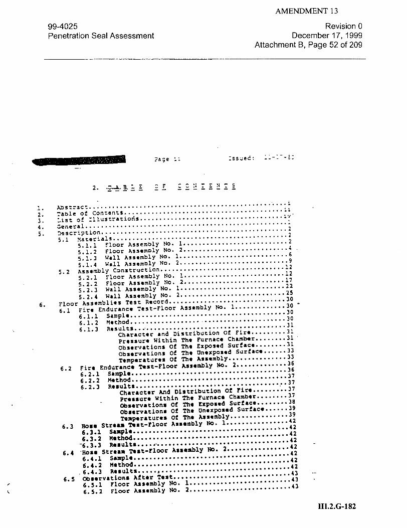
AMENDMENT 13
99-4025 Revision 0
Penetration Seal Assessment December 17, 1999 Attachment B, Page 52 of 209
-za g e :s- ss ed:
I. Abstract2.......... .........................................
2. -:able of Contents .......................................... 3. .ist o- :"iustration ....... ....................... 4. General .............................................
..........
5. scri.tion ................................................... 2
5.1 Mater-als .......... ................................... 5.1.1 Floor Assembly No. I ........................... 2
5.1.2 Floor Assembly NO. 2 ............................
5.1.3 Wall Assembly No. 1 ............................ 6
5.1.4 Wall Assembly No. 2 ............................ .9
5.2 Assembly Construction ................................ 12
5.2.1 Floor Assembly No. I .......................... .12
5.2.2 Floor Assembly No. 2 ........................... 17
5.2.3 wall Assembly No. 1 ........................... 22
5.2.4 Wall Assembly No. 2............................ 25
6. Floor Assemblies Test Record ............................... 30 6.1 Fire Endurance Test-Floor Assembly No. 1 ............. 30
6.1.1 Sample .......................................30
6.1.2 Method- ...................................... 30
6.1.3 Results... ....... ..................... 31
Character and Distribution Of Fire ......... 31
Pressure Within The Furnace Chamber ........ 31
Observations Of The Exposed Surface ........ 31
Observations Of The Unexposed Surface ...... 33
Temperatures Of The Assembly ............... 33
6.2 Fire Endurance Test-Floor Assembly No. 2 ............. 36
6.2.1 Sample ............. 36 6.2.2 method ............... . *..........37
6.2.3 Results ....................................... 37 Character And Distribution Of Fire ......... 37
Pressure Within The Furnace Chamber ........ 37
Observations Of The Exposed Surface ........ 38
Observations Of The Unexposed Surface ...... 39
Temperatures Of The Assembly ............... 39 6.3 Rose Stream Test-Floor Assembly No. 1 ............... 42
-6. 33 .au t .•...i...42
6.3.1 Sample ................................. ..... 6.3.2 Method ........................ ... 42
* e •t ". . .. . . . ........ 42 6.3 Results ............................... 42
6.4.2 Method... .......... ...... .. .... ..... 42 .6.4.3 Results .......................................
4
6.5 Observations After Test ........................... 43 .. .. ~.. . .43
6.5.1 Floor Assembly No. 1 ........................ 43
6.5.2 Floor Assembly No. 2 ........................
III.2.G-1 82
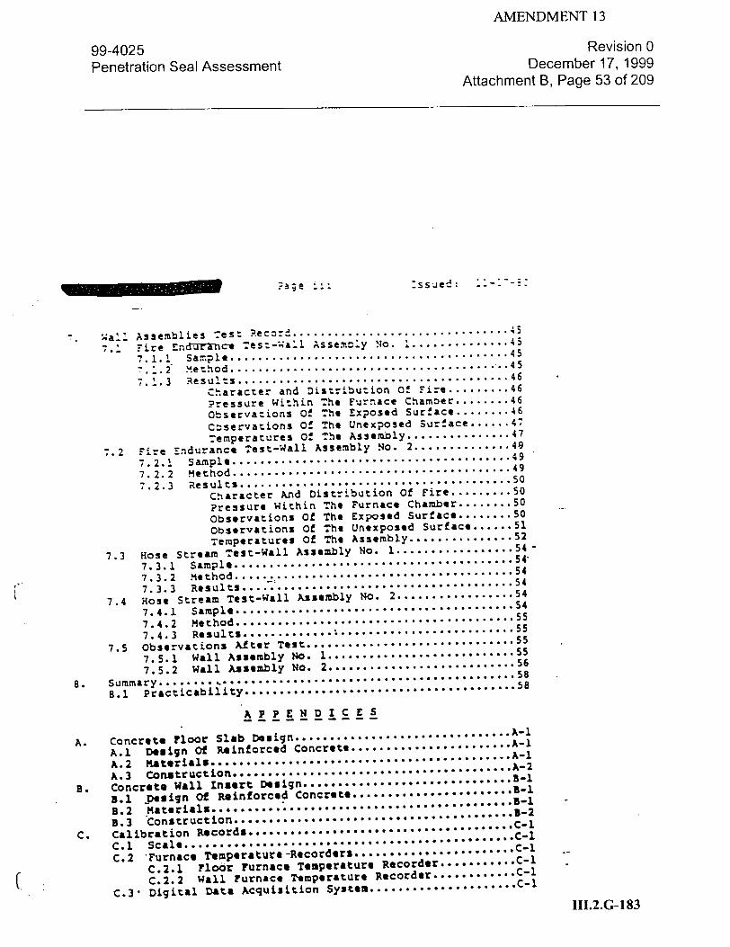
AMENDMENT 13
99-4025 Revision 0
Penetration Seal Assessment December 17, 1999 Attachment B, Page 53 of 209
-age - '-:ssjed .: " :--"
"Wall Assemblies Test R.ecord ................................. ,.i Fire £nd~rXInrct Test-wa'l Assem-.•y No. 1 ....... .... 45
7.1.1 Sample ..................................... .... 45
". .. 2 method ......................................... 45
7, _ 3 Results ....................................... 46
Character and Distribution Of Fire ......... 46
Pressure Within The Furnace Chamber........ 46 observations Of The Exposed Surface ........ 46
cOservations Of The Unexposed Surface ....... 47
Temperatures Of The Assembly ............... 47
,.2 Fire Endurance Test-Wall Assembly No. 2 .............. 49
7.2.1 Sample ........................................ 49
7.2.2 Method ........................................ 49
7.2.3 Results ....................................... 50
Character And Distribution Of Fire ......... 50
Pressure Within The Furnace Chamber ........ 50
Observations Of The Exposed Surface ........ 50
Observations Of The Unexposed Surface ...... 51
Temperatures Of The Assembly ............... 52
7.3 Hose Stream Test-Wall Assembly No. 1 ................. 54
7.3.1 Sample ........................................ 54.
7.3.2 Method ........................................ 54
7.3.3 Results ....................................... 54
7.4 Hose Stream Test-Wall Assembly No. 2 ................. 54
7.4.1 Sample ........................................ 54
7.4.2 Method ......................................... 55
7.4.3 Results ........................................ 5
7.5 Observations After Test ................................ 55
7.5.1 Wall Assembly No. 1 ........................... 55
7.5.2 Wall Assembly No. 2 ........................... 56
8. Summary .................................................... 58
8.1 practicability ........................................58
A P, P E N D I C__E S_
A. Concreto Floor Slab Design . ............. A-1
A.1 Design Of Reinforced Concrete ....................... A-i
A.2 Materials .......................................... A
A.3 Construction ........................................A-2
B. Concr~eteWall Insert Design ............................... a-,
3.1 Design Of Reinforced Concrete ......................
B.2 Materials................. ................. 1
B.3 construction....................... .... "............,-2
C. Calibration Records......................................C-1 C.1 Scale .................... :................. c-i
C.2 Furnace Temperature -Recorders, ....................... C-i
C.2.1 Floor Furnace Temperature Recorder ........... C-1
C.2.2 Wall Furnace Temperature Recorder ............ C-1
C.3- Digital Data Acquisition System ..................... C-1
III.2.G-1 83

99-4025 Penetration Seal Assessment
AMENDMENT 13 Revision 0
December 17, 1999
Attachment B, Page 54 of 209
:ss�e�:
3. L ST C F S. . - - .'RA ": c S S
:escriotion
Construction details-Floor Assembly No. I
Typical caole penetration fire stop installation procedure
Construction details-Floor Assembly No. 1, Penetration No. I
Construction details-Floor Assembly No. 1, Penetration No. 2
Construction details-Floor Assembly No. 1, Penetration No. 3
Construction details-Floor Assembly No. 1, Penetration No. 4
Construction details-Floor Assembly No. 1, Penetration No. 5
Construction details-Floor Assembly No. I, Penetration No. 6
Construction details-Floor Assembly No. 1, Penetration No. 7
Construction details-Floor Assembly No. 1, Penetration No. 8
Construction details-Floor Assembly No. 1, Penetration-No. 9
Construction details-Floor Assembly No. 1, Penetration No. 10
Construction details-Floor Assembly No. 1, Penetration No. 11
Construction details-Floor Assembly No. I, Penetration No. 12.
Construction details-Floor Assembly No. 1, Penetration No. 13
Constructiifn details-Floor Assembly No. 1, Penetration No. 14
Construction details-Floor Assembly No. 1, Penetration No. 15
Construction details-Floor Assembly No. 1, Penetration No. 16
Exposed surface before fire test, Floor Assembly No. 1
Unexposed surface before fire test, Floor Assembly No. 1
Furnace temperature, Floor Assembly No. 1 Construction details-Floor Assembly No. 2
Construction details-Floor Assembly No. 2, Penetration No. 1
Construction details-Floor Assembly No. 2, Penetration No. 2
Construction details-Floor Assembly No. 2, Penetration No. 3
Construction details-Floor Assembly No. 2, Penetration No. 4
Construction details-Floor Assembly No. 2, Penetration No. 5
Construction details-Floor Assembly No. 2, Penetertion No. 6
Construction details-Floor Assembly No. 2, Penetration No. 7
Construction details-Floor Assembly No. 2, Penetration No. 8
Construction details-Floor Assembly No. 2, Penetration No. 9
Construction details-Floor Assembly No. 2, Penetration No. 10
Construction details-Floor Assembly No. 2, Penetration No. 11
Construction details-Floor Assembly No. 2, Penetration No. 12
ConstructLon details-Floor Assembly No. 2, Penetration No. 13
Construction details-Floor Assembly No. 2, Penetration No. 14
Construction details-Floor Assembly No. 2, Penetration No. 15
Construction details-Floor Assembly No. 2, penetration NO. 16
Exposed surface before fire test, Floor Assembly No. 2
Unexposed surface before fire test, Floor Assembly No. 2
Furnace temperatures, Floor Assembly No. 2
III.2.G-184
No.
2 3 4 5 6 7 8 9
i0 11 12 13 14 15 16 17 18 19 20 21 22 23 24 25 26 27 28 29 30 31 32 33 34 35 36 37 38 39 40 41

AMENDMENT 13
99-4025 Penetration Seal Assessment
Revision 0 December 17, 1999
Attachment B, Page 55 of 209
:5ssed: -
.nstricticn detaels-Wall Assembly No. 1
Construction detailsrWall Assembly No. I, Penetration
:::=sruction details-Wall Assembly No. 1, Penetration -onstruction details-Wall Assembly No. 1, Penetration
Zonstruction details-Wall Assembly No. 1, Penetrat ion
Construction details-Wall Assembly No. 1, Penetration
Construction details-Wall Assembly No. 1, Penetration
Construction details-Wall Assembly No. 1, Penetration
Exposed surface before fire test, Wall Assembly No. 1
Unexposed surface before fire test, Wall Assembly No.
Furnace temperatures, Wall Assembly No. 1
Construction details-Wall Assembly No. 2
Construction details-Wall Assembly No. 2, Penetration
Construction details-Wall Assembly No. 2, Penetration
Construction details-Wall Assembly No. 2, Penetration
Construction details-wall Assembly No. 2, Penetration
Construction details-Wall Assembly No. 2, penetration
Construction details-Wall Assembly No. 2, Penetration
Construction details-Wall Assembly No. 2, penetration
Exposed surface before fire test, Wall Assembly No. 2
Unexposed surface before fire test, Wall Assembly No.
Furnace temperatures, Wall Assembly No. 2
Appearance of floor and wall assembly during hose str,
Appearance after fire and hose stream tests, Floor As
Appearance after fire and hose stream tests, Floor As
Appearance after fire and hose stream tests, Floor As
Appearance after fire and hose stream tests, Floor As
Appearance after fire and hose stream tests, Floor As
Appearance after fire and hose stream tests, Floor As
Appearance after fire and hose stream tests, Floor As
Appearance-after fire and hose stream tests, Wall Ass
Appearance after fire and hose stream tests, Wall Ass
Appearance after fire and hose stream tests, Wall Ass
Appearance after fire and hose stream tests, Wall Ass
Appearance after fire and hose stream tests, Wall Ass
Appearance after fire and hose stream tests, Wall Ass
Appearance after fire and hose stream tests, Wall APs
Appearance after fire and hose stream tests, Wall Ass
Appearance after fire and hose streamQtests, wall Asi
Appearance after fire and hose stream tests, Wall Asi
N.4. No. No. No. No. No. No.
1
No. No. No. No. No. No. No.
2
I 2 3 4 5 6 7"
1 2 3 4 5 6 7
No.
42 43 44
46 47 48 49 50 51 52 53 54 55 56 57 58 59 6U 61 62 63 64 65 66 67 68 69 70 71 72 73 74 75 76 77 78 79 80 81
III.2.G-185
tam tests sembly No. sembly No. sembly No. sembly No. sembly No. sembly No. sembly No. embly No. embly No. embly No. embly No. embly No. *ebly No. embly No. esbly No. Setbly No. setbly No.
2 I 2 2 2 2 2
1 1
2 2 2 •2 • 2. 2

AMENDMENT 13
99-4025 Penetration Seal Assessment
Revision 0 December 17, 1999
Attachment B, Page 56 of 209
Page vi
Description
:ssued: ::-:--5
Reinforcement details for concrete floor slab.
:.ocation and sizes of penetrations in concrete f:oor slab
welded wall sleeve !or Wall Assemblies I and 2
Reinforcement details for concrete wall inserts
N4o.
Al A2 B1 B2
III.2.G-1 86

AMENDMENT 13
99-4025 Revision 0
Penetration Seal Assessment December 17, 1999 Attachment B, Page 57 of 209
Page .
4. G E ER A L_
The subject cf tn! s Report is the fire test investig on 04o, various caole and pipe penetration fire stops instal 1eiqt -eoa
c:ete floors and in concrete and masonry walls. .ne 'poh r-ofo
this program was to evaluate the performance of these fire stops
when tested in general accordance with the method outlined in
7-- Standard 634-1978 entitled "Standard Cable Penetration Fire
Stop Qualification Test.' Since mechanical service penetrations
such as pipe are not addressed in IEEE Standard 634-1978, the
criteria of no flame passage during the fire endurance test and
no water passage diring the hose stream test were imposed for
:he pipe penetration fire stops.
The test program consisted of constructing two concrete floor
assemblies and two concrete and masonry wall assemblies, each
of which was provided with various cable and pipe penetrations.
One fire stop system (cables, pipes, or cable trays and the
associated materials used to fill the opening) was installed
in each through penetration. In addition to active penetrations,
spare or abandoned penetrations were included in three of the
four test assemblies. The floor and wall assembli-as were then
subjected to fire exposure with the furnace temperatures con
trolled in accordance with the standard Timei-Tmperature Curve
as described in IEEE 634-1978 (ASTM E119, UL 263, NFPA No. 251).
During each test, a positive pressure with respect to the atmos
phere was maintained within the furnace chamber. Temperatures on
the unexposed side of each assembly were recorded. Immediately
after fire exposure, a water spray stream hose stream test was
conducted in accordance with the provisions outlined for power
generating stations in the Standard, IEEE 634-1978. For Wall
Assembly No. 1 only, the water spray stream hose stream test
was immediately followed by a second hose stream test conducted
in accordance with the provisions outlined for industrial and
commercial establishments in the Standard, IEEE 634-1978.
Information was obtained during construction with respect to the
composition and physical properties of the materials used in each
assembly.-
111.2.G-187

AMENDMENT 13
99-4025 Revision 0
Penetration Seal Assessment December 17, 1999 Attachment B, Page 58 of 209
pace - :ss~ed: •-'•
5. DEs SC R 7 ZT•N
The !aollowing is a description of the materials used in the
test assemblies.
5.1.1 7F-COR ASSEMBLY NO. 1
Concrete Slab - The 12 in. (305 mm) thick reinforced concrete.
slab containing various through penetrations was constructed as
described in Appendix A. The location and sizes of the various
through penetrations are shown in Appendix A, ILL. A2.
Filler Slabs - Nominal 4 ft, 8 in. (1.42 m) wide by 13 ft,
8 in. (4.17 m) long by 12 in. (305 mm) thick reinforced vermicu
lite concrete slabs were used to fill the remaining test frame
openings at the north and south sides of the concrete slab.
Steel Supparts - The concrete slab and the two filler slabs
were suppored at the east and west walls of the test frame by 6
by 6 by 1/2 in.. (152 by 152 by 12.7 nim) structural steel angles.
?ioe - The 4 in. (102 mm) steel Schedule 40 pipe used as a
mechanical service penetration in Penetration No. 11 was 33 in.
(838 mm) long with an outside diameter of 4.500 in. (114.3 mm)
and a wall thickness of 0.237 in. (6.02 mm). One end of the steel
pipe was sealed by a 6 by 6 by 1/4 in. (152 by 152 by 6.4 mm)
thick steel plate welded to the pipe.
Cable Trasy - The nominal 24 in. (610 mm) wide open-ladder
cable trays used in Penetration No. 14 consisted of 5-1/4 in.
(133 mm) deep side rail members formed from 0.060 in. (1.52 mm)
thick galvanized steel with 1 in. (25.4 mm) deep by 5/8 in.
(15.9 mm) high box channel rungs formed from 0.060 in. (1.52 mm)
thick galvanized steel and spaced 9 in. (229 mm) on center. The
inside width of each cable tray, between side rail members, was
24 in. (610 Mi). The loading depth of each cable tray was 4 in.
(102 mm). The cable trays were supplied in nominal 12 ft (3.66 m)
lengths. -
III.2.G-1 88

AMENDMENT 13
99-4025 Revision 0
Penetration Seal Assessment December 17, 1999 Attachment B, Page 59 of 209
________ae 3_ :ss~eý:
"a-ies - The cable used in Penet:aticn !;os. ":hrougq 9. .n!..s/ve, and in P nration Nos. 4, 5, and 16 was manufactured
by General Electric Company, Bridgeport, = and designated Vulkene
F.amenol Control" Cable, 1000 v, 90 C. T-he cable had seven No. 12
AWG copper conductors, each of which consisted of seven 0.030 in.
(0.76 mm) diameter strands. The conductor insulation was cross
"inked polyethylene, the conductor wrap was mylar, the cable
ýacke: was polyvinyl chloride and the outside diameter of the cable was 0.705 in. (17.9 mm). Each spool of caole bore a meta!
tag imprinted with "79-101865.'
The cable used in Penetration No. 13 was manufactured by
Rockbesto5 Co., New Haven, CT. The cable had three No. 12 AWG
copper conductors, each of which consisted of seven 0.030 in.
(0.76 .mm) diameter strands. The conductor insulation was cross
linked polyethylene, the filler was stranded plastic, the con
ductor and filler wrap was treated paper, the cable jacket was
chlorosulphinated polyethylene (Hypalon), and the outside diameter
of the cable was 0.450 i (11.4 mm). The cable jacket was marked
"12 AWG 3/C ROCKBESTOS ý) COPPER XLPE 600 V XKHW TYPE TC (UL).
,IJP-88 1977-7A94 7."
Cable And Cable Tray Support Racks - The racks used *on the
unexposed surface to support and secure the cables and cable trays
consisted of 2 by 2 by 1/4 in. (51 by 51 by 6.4 mm) thick steel
angles, 36 in. (914 mm) high, welded to nominal 4 by 5 by 1/4 in.
1102 by 127 by 6.4 mm) thick steel base plates and with 3 in.
(76 mm) wide by 1/4 in. (6.4 mm) thick steel plate cross members
welded to the top of the steel angles. The support rack for the
cable trays in Penetration No. 14 was additionally provided with
a 3 by 3 by 3/16 in..(76 by 76 by 4.8 mm) thick steel angle cross
member near its midheight.
Cable Ties - The cable ties used to secure the cables to the
support racks and cable tray rungs were 0.056 in. (1.42 mm) diame
ter galvanized steel wire.
Ceramic Fiber - The loose alumina silica fiber material used
in Penetration Non. 1 through 9, inclusive, and in Penetration
Nos. 13 through 16, inclusive, was manufactured by Babcock &
Wilcox Company, Augusta, GA, and designated Xaowool Bulk A. The
fiber was iupplied in cardboard cartons containing approximately
50 lb (222.4 n) of product. The cartons were marked 'P.R. 4229
B-AF,- -P.R. 4229-C-JM,* and 08021 B-WA.0
III.2.G-189

AMENDMENT 13
99-4025 Revision 0
Penetration Seal Assessment December 17, 1999 Attachment B, Page 60 of 209
.:a=e 4 :ss~ed: "-'
:eramic Fiber Blanket - .he j-.faced :eramic fiber bl-nket -sed nn ?eneta-Lonlo-. 11 was manufactured by Babcock & Wilcox
Zompany, Augusaj GA, 3and designated "Kaowool Needled Blanket,'.
8 pc! (1.26 x !A n/m ) densi-y. The blanket was 1 in. (25.4 mm)
thick, 24 in. (610 =) wide, and was supplied in a 25 ft (7.62 m)
.ong roll. The carton containing the blanket was marked "PR9047BB-."
Mastic oating - -The mastic coating used on the exposed
and unexposed sides of the test assembly was manufactured by
The Flamemaster Corporation, Sun Valley, CA, and designated
-FlLamemastic 77.' The mastic coating was supplied in 5 gal
(18.9 -1) pails. The pails were marked with Serial Nos. 100068,
'00073, and 100078.
Concrete - The concrete used in Penetration Nos. 10, 11,
and 12 was 'Sakrete" brand gravel mix concrete supplied in 90 lb
(400.4 n) bags. ?er the directions on the bag, one gallon of
water was added for each bag of gravel mix concrete. The corn
pressive strength and unit weight of the concrete at 28 days,
as determined from two standard 6 by 12 i71--J152 by 305 mm)
cylinders, 4 averiged 4120 psi (2.84 x 10 n/rm ) and 149.4 pcf
(2.35 x 10 n/m ), respectively.
Anchors - The anchors used in penetration Nos. 10, 11, and
12 to -echanically secure the concrete fill in the pipe sleeves
were No. 3 deformed steel bars (ASTM A36 steel). The anchors
were 13 in. (330 i=) long with a 2 in. (51 mm) long, 90 dog bend
at one end. The other end of each anchor was bent into a hook,
in the opposing direction, to engage the lip of the floor sleeve.
5.1.2 FLOOR ASSEMBLY NO. 2
Floor Assembly No. 2 employed the previously fire tested
concrete slab, filler slabs, and steel supports from Floor
Assembly No. 1.
i *- The 4 in. (102 m) steel Schedule 40 pipe used as a
mechaiiTCil service penetration in penetration No. 10 was 60 in.
(1.52 m) long with an outside diameter of 4.500 in. (114.3 ma)
and a wall thicknesi of 0.237 in. (6.02 mm). One end of the steel
pipe was sealed by a 6 by 6 by 1/4 in. (152 by 152 by 6.4 ma)
thick steel plate welded to the pipe.
III.2.G-190

AMENDMENT 13
99-4025 Revision 0
Penetration Seal Assessment December 17, 1999 Attachment B, Page 61 of 209
_ _ _ _ _ _ _ _?a-e 5 :ss.ed:
zale Trays - The nOminal 24 in. -6 m) wide open-ladde:
can~e trays ased in--¢trator. No. 14 consisted of 4-1/4 in.
"::c8 mm) deep side rail members formed from 0.105 in. ?2.67 m.m)
thick galvan.zed-steel with 1.000 in. (25.4 mm) diameter
f .attened- tu,=! r ings formed from galvanized steel and spaced
9 in. (229 mm) on center.. The inside width of each cable tray,
zetween side rail members, was 24 in. (610 mm). The loading
deptn of each caole tray was 3 in. (76.2 mm). The cable trays,
.an-factured by T. J. Cope Inc. of Collegeville, PA, and desig
nated No. 3237-24SL-12-09 were supplied in nominal 12 !z (3.66 m)
lengths.
Cables - The cable used in the various penetrations were
manufactured by General Electric Company, Bridgeport, CT, and
designated Vulkene Flamenol Control Cable, 1000 v, 90 C. The
cable had seven No. 12 AWG copper conductors, each of which
consisted of seven 0.030 in. (0.76 mm) diameter strands. The
conductor insulation was cross-linked polyehtylene, the conductor
wrap was mylar, the cable jacket was polyvinyl chloride, and the
outside diameter of the cable was 0.705 in. (17.9 mm). Each spool
of cable bore a metal tag imprinted with "79-101865.0
Cable And Cable Tray Sup-jot Racks - Floor Assembly No. 2
employed the same cable and cable tray support racks from Floor
Assembly No. 1.
Cable Ties - The cable ties used to secure the cables to the
support racks and cable tray rungs were 0.056 in. (1.42 mm) diame
ter galvanized steel wire.
Ceramic Fiber - The loose alumina silica fiber material used
in Penetration Nos. 1 through 8, inclusive, and in Penetration
Nlos. 14, 15, and 16 was manufactured by Babcock a Wilcox Company,
Augusta, GA, and designated Kaowool Bulk A. The fiber was supplied
in cardboard cartons containing approximately 50 lb (222.4 n) of
product. The cartons were hand-marked ONE 50 La. OX BULK A
57#."
Ceramic Fiber Blanket - The untaced ceramic fiber blanket
used in Penetration Nos. 10 and 11 was manufactured by Babcock
& Wilcox Company, Augusta, 3 GA, Ind designated "Kaowool Needled
Blanket,w if pcf (1.26 x 10 n/rn ) density. The blankets were
1 in. (25.4 mm) thick, 24 in. (610 mm) wide, and were supplied
in 25 ft (7.62 m) long rolls. The cartons containing the blankets
were marked .PR0094CIM.
III.2.G-191

AMENDMENT 13
99-4025 Revision 0
Penetration Seal Assessment December 17, 1999 Attachment B, Page 62 of 209
?age 6 :ssuied: 7- :
Xastic Coatin - The mastic coating used on t•e exposed and
-. nexposed sides of Penetration Nos. 1, 3, 5, 7, 101, 14, 1-5,
and 16 was manufactured by .he Flamemaster Corporation, Sun
Va2.ey, CA, and designated "FlaemastL€ 77. The mastic coa.ing
was supplied in 5 gal (18.9 1) pails. The pails were marked wi:n
Serial Nos. 1.0068, 10073, and 10078.
The mastic coating used on the exposed and unexposed sides
of Penetration Nos. 2, 4, 6, and 8 was manufactured by the Flame
master Corporation, Sun Valley, CA, and designated "Flamemastic
71-A." The mastic coating was supplied in 5 gal (18.9 1) pails.
The pails were marked with Serial No. 050170.
Vermiculite Concrete - The vermiculite concrete used in
Penetration Nos. 9 and 13 consisted of six parts of vermiculite
aggregate to one part Portland cement, proportioned by volume,
mixed with water to form a thick slurry.
5.1.3 WAML ASSEMBLY NO. 1
Concrete 7iserts - The nominal 12 in. (305 mm) thick re
inforced concrete inserts containing various size and type
penetrations were constructed as described in Appendix B.
Concrete Blocks - The concrete blocks were nominally 8 by
16 by 12 1n. (203 by 406 by 305 mm) thick, formed with two core
holes and having a minimum 1-1/2 in. (38.1 mm) face shell and a
1-3/16 in. (30.2 mm) minimum web thickness.
Brick - The common clay bricks were nominally 2-1/2 by 8 by
4 in. ('075 by 203 by 102 mm) thick.
Mortar - The mortar consisted of three parts of clean sharp
sand to one part Portland cement (proportioned by volume) and 15
percent hydrated lime (by cement volume) mixed with water.
Split Sleeve - The two-piece sleeve used for penetration
No. 7wai--•-iT .(457 ma) long with an inside diamtr of 21.in
(533 mm) and a wall thickness of 0.250 in. (6.4 an). The coupling
flanges/,Jall anchors were 6-in. (152 an) wide by 18 in. (457 mm)
long. Each coupling flange was provided with two 9/16 in. (14.3
mm) diameter holes for bolt-attachment of the two sleeve sections
with 1/2 in. (12.7 mm) diameter by 1-1/2 in. (38.1 mm) long steel
machinebolts with nuts.
III.2.G-192

AMENDMENT 13
99-4025 Revision 0
Penetration Seal Assessment December 17, 1999 Attachment B, Page 63 of 209
?age :ss e "ed:
pi:e - 7he 18 in. (457 n'..) steel sc.ýeduie S: =ipe u;sel as a
-.ec.anTal service penetration in Penetration No. 7 was 30 in.
:762 mm) :ong wth an outside diameter of 18 in. (457 mm) and a
wall thickness of 0.375 in. (9.53 mm). One end of the pipe was
sealed by an .8 :y 18 by 1/4 in. (457 by 457 by 6.4 rum) thick
steel plate welded to the-pipe.
Cable --rays - The nominal 24 in. (610 mm) wide open-ladder
cable trays used in Penetration No. 4 consisted of 5-1/4 in.
(133 mm) deep side rail members formed from 0.060 in. (1.52 mm)
thick galvanized steel with 1 in. (25.4 mm) deep by 5/8 in.
(15.9 mm) high box channel rungs formed from 0.060 in. (1.52 mm)
thick galvanized steel and spaced 9 in. (229 mm) on center. T-he
inside width of each cable tray, between side rail members, was
24 in. (610 mm). The loading depth of each cable tray was 4 in.
(102 mm). The cable trays were supplied in nominal 12 ft (3.66 m) lengths.
Cables - The cable used in the various penetrations was
manufactjred by General Electric Company, Bridgeport, CT, and
designated Vulkene Flamenol Control Cable, 1000 v, 90 C. The
ca&.,6 had seven No. 12 AWG copper conductors, each of which
consisted of seven 0.030 in. (0.76 mm) diameter strands. The
conductor insulation was cross-linked polyethylene, the con
ductor wrap was mylar, the cable jacket was polyvinyl chloride,
and the outside diameter of the cable was 0.705 in. (17.9 mm).
Each spool of cable bore a metal tag imprinted with 079-101865.M
Cable And Cable Tray Support Racks - The racks used on the
exposed and unexposed sides to support the cables and cable trays
consisted of 2 by 2 by 1/4 in. (51 by 51 by 6.4 mm) thick steel
angles, 12 and 36 in. (305 and 914 mm) long, welded to nominal
4 by 5 by 1/4 in. (102 by 127 by 6.4 mm) thick steel base plates
and with 3 in. (76 mm) wide by 1/4 in. (6.4 mm) thick steel plate
cross members welded to the steel angles.
Ceramic Fiber - The loose alumina silica fiber material used
in Penetration 4os. 1, 2, 4, 5, and 6 was manufactured by Babcock
& Wilcox Company, Augusta, GA, and designated Kaowool Bulk A. The
fiber was supplied in cardboard cartons containing approximately
50 lb (222.4 n) of product. The cartons were marked "P.R. 4228-C-
III.2.G-193

AMENDMENT 13
99-4025 Revision 0
Penetration Seal Assessment December 17, 1999 Attachment B, Page 64 of 209
Page 8 :ssued: -'
Ceramic Fiber Blanket - The unfaced ceramic fiber blanket
zsed in ?ene~razion No. 7 was manufactured by Babcock & Wilcox
Company, Augusza I SA, and designated "Kaowool Needled Blanket,"
B ocf !1.26 x 10 n/m ) density. The blanket was I in. (25.4 mtm)
thick, 24 in. (610 mm) wide, and was supplied in a 25 ft
(7.62 m) long roll. The carton containing the blanket was
marked "P.R. 4229-B-AF."
mastic Coating - The mastic coating used on the exposed and
unerxposed sides of the test assembly was manufactured by The Flame
-aster Corporation, Sun Valley, CA, and designated "Flamemastic 77."
The mastic coating was supplied in 5 gal (18.9 1) pails. 7he pails
were marked with Serial No. 100078.
Ceramic Board - The ceramic board used on the exposed and
unexposed surfaces of Penetration No. 5 was manufactured by
Babcock & Wilcox Company, Augusta, GA, and was supplied in nominal
24 by 36 by 1 in. (610 by 914 3 by 25.4 mm) thick sheets having a
density of 16 pcf (2513.3 n/m ).
Concrete - The concrete used in Penetration No. 3 was
"Sakrete" brand gravel mix concrete supplied in 90 lb (400.4 n)
bags. Per the directions on the bag, one gallon of water was
added for each bag of gravel mix concrete. -.he compressive
strength and unit weight of the concrete at 28 days, as deter
mined from two standard 6 by 7 12 ig. (152 by 305 mm) cylinderj,
averaged 4120 psi (2.84 x 10 n/m ) and 149.4 pcf (2.35 x 10
n/m ) respectively.
Anchors - The anchors used in Penetration No. 3 to mechan
ically secure the concrete fill in the pipe sleeve were No. 3"
deformed steel bars (ASTM A36 steel). The anchors were 11 in.
(279 mm) long Vith a 2 in. (51 mm) long, 90 deg bend at one end.
The other end of each anchor was bent into a hook, in the opposing
direction, to engage the lip of the wall sleeve.
Cementitious Mixture - The cementitious mixture applied.to
the concrete blocks on the exposed surface consisted of a mixture
of MX-5 ceientitious mixture [manufactured by Zonolite Construction
Products,.Cambridge. MA) and hydrated lime mixed with water.
III.2.G-194

AMENDMENT 13
99-4025 Revision 0 Penetration Seal Assessment December 17, 1999
Attachment B, Page 65 of 209
-'ace 9 :s s ed:
T-.. 4 WAZL ASSEMBLY NO. 2
Concrete S-aos - The nominal 12 in. (305 mm) thick reinforced
concrete sla~s containlng various size and type penetrations were constructed as described'in Appendix 3. Tht concrete slao u;sed for Penetration No. 4 was the same slab previously used in Wall
Assembly No. 1. No concrete slab was used with the nominal 1. 45 .
(457 mm) diameter wall sleeve (Penetration No. 3). instead, the
steel Sleeve was "bricked" in.
Concrete Blocks - The concrete blocks were nominally 8 by
16 by a in. (203 oy 406 by 203 mm) thick, formed with two core
holes and having a minimum 1-1/4 in. (31.8 mm) face shell and
a 1-1/16 in. (27.0 mm) minimum web thickness.
Brick - The common clay bricks were nominally 2-1/2 by 8 by
4 in. (M-5 by 203 by 102 mm) thick.
Mortar - The mortar consisted of three parts of clean sharp
sand to one part Portland cement (proportioned by volume) and 15
percent hydrated lime (by cement volume) mixed with water.
Solit Sleeve - The same split-sleeve previously used for
Penetration No. 7 in Wall Assembly No. 1 was used in the test assembly.
Pi29 - The 18 in. (457 mm) steel Schedule ST pipe used as
a mechanical service penetration in Penetration No. 7 was 60 in.
(1.52 m) long with an outside diameter of 18 in. (457 mm) and a
wall thickness of 0.375 in. (9.53 mm). One end of the pipe was
sealed by an 18 in. (457 mm) diameter by 1/4 in. (6.4 mm) thick
steel plate welded to the pipe.
The 4 in. (102 mm) steel Schedule ST pipe used as a mechan
ical service penetration in Penetration No. 3 was 60 in. (1.52 m)
long with an outside diameter of 4.500 in. (114 mm) and a wall
thickness of 0.237 in. (6.02 mm). One end of the pipe was sealed
by a 6 by 6 by 1/4 in. (152 by 152 by 6.4 mm) thl steel plate
welded to the pipe.
The 2 in. (51 mm) steel Schedule ST pipe used as a mechanical
service penetration in Penetration No. 3 was 60 in. (1.52 a) long
with an outside diameter of 2.375 in. (60 mm) and a wall thickness
of 0.154 in. (3.9 mm). One end of the pipe was sealed by a 3 by
3 by 4 in. (76 by 76 by 6.4 mm) thick steel plate welded to the pipe.
III.2.G-195

AMENDMENT 13
99-4025 Revision 0
Penetration Seal Assessment December 17, 1999 Attachment B, Page 66 of 209
?age LO:SS~ed:
e 1-1/4 in. (32 mm) steel Schedule S: pipe used as a
mechanica! service penetration in Penetra:aon No. 3 was 60 in.
(1.52 m) long wi=n an outside diameter of 1.660 in. (42 ,m.) and
a wall thickness of 0.140 in. (3.6 mm). One end of the pipe was
sealed by a 2 by 2 by 1/4 in. (51 by 51 by 6.4 mm) thick steel
=1ate welded to the pipe.
-able Trays - The nominal 24 in. (610 mm) wide open-ladder
cable trays usea in Penetration No. 4 consisted of 4-i/4 in.
(108 mm) deep side rail members formed from 0.105 in. (2.67 mm)
thick galvanized steel with 1.000 in. (25.4 mm) diameter
flattened-tubing rungs formed from galvanized steel and spaced
9 in. (229 mm) on center. The inside width of each cable tray,
between side rail members, was 24 in. (610 mm). The loading
depth of each caole tray was 3 in. (76.2 mm). The cable trays,
manufactured by T. J. Cope Inc. of Collegeville, PA and desig
nated No. 3237-24SL-12-09 were supplied in nominal 12 ft (3.66 m)
lengths.
Cables - .The cable used in the various penetrations was
manufactured by General Electric Company, Bridgeport, CT and
designated Vulkene Control.Cable, 600 v. The cable had twelve
No. 19/25 AWG copper conductors, each of which consisted of nine
teen 0.018 in. (0.46 mm) diameter strands. The conductor insula
tion was cross-linked polyethylene, the conductor wrap was mylar,
the cable jacket was polyvinyl chloride, and the outside diameter
of the cable was 0.765 in. (19.4 mm). -.he cable jacket was marked
"GENER.AL ELECTRIC VULKENE CONTROL CABLE 12 COND 19/25 AWG 600 V.'
Cable, Cable Tray, And Pipe Support Racks - The racks used
on the exposed sides of Penetration NOe. 1, 3, 5, and 6 and on the
unexposed sides of Penetration Nos. 1, 2, 3, 5, and 6 to support
the cables, cable trays, and pipes consisted of 2 by 2 by 1/4 in.
(51 by 51 by 6.4 im) thick steel angles, 12 and 36 in. (305 and
914 mm) long, welded to nominal 4 by 5 by 1/4 in. (102 by 127 by
6.4 mm) thick steel base plates and with 3 in. (76 mm) wide by
1/4 in. (6.4 m=) thick steel plate cross members welded to the
steel angles.
The pipe support on the unexposed side of penetration No. 7
consisted of two 2 by 2 by.1/4 in. (51 by 51 by 6.4 mm) thick
steel angles used as struts between the end of the pipe and the
sill of the test frame. No support was provided for the pipe
on the exposed surface of Penetration No. 7 other than two small
steel shims welded between the pipe and the split sleeve to main
tain concentricity of the pipe in the sleeve.
III.2.G-196

AMENDMENT 13
99-4025 Revision 0
Penetration Seal Assessment December 17, 1999 Attachment B, Page 67 of 209
Pace "" :ss.ed:
,he cable tray support cn the exp=sed surface of Penetration
• 4 was designed__t L_.recot te Icng:tud-nal thermal ex:;,nsion
f=r:e exerted by the cable tray side rails toward the firs stop
&Zring the fire exposure. Nominal 3/4 in. (19.1 mm1 diameter
calvanized steel pipe with 90 deg elbows, collars, and hose
adaptors was asse-noled to form a yoke around the ends of both
caole trays. Steel angles7, 3 by 5 by 1/4 in. (76.2 by 127 by
6.4 -am) thick by 3 in. (76.2 Tm) long were welded to the pine at
the intersection o! the pipe and the cable tray side rails suoh
that no clearance was present between the restraining yoke and
the cable tray side rails and such that the cable tray side rails
were supported. The galvanized steel pipe was additionally stif
fened to resist thrust by clamping a 1 by 1 by 1/8 in. (25.4 oy
25.4 by 3.2 mm) thick steel angle to the pipe with the *V" of the
angle pointing toward the cable trays. Thne short runs of pipe
intersecting the wall were wrapped with two wraps of ceramic fiber
blanket. During the fire exposure, cold water flowed through the
pi;e to prevent the restraining yoke from heating and expanding.
Ceramic Fiber - The loose alumina silica fiber material used
in Penetration Nom. 1 through 6, inclusive, was manufactured by
Babcock & Wilcox Company, Augusta, GA, and designated Kaowool Bulk
A. The fiber was supplied in cardboard cartons containin¶.approx
imately 50 lb (222.4 n) of product. The cartons were marked "P.R.
7122-C-B.B."
Ceramic Fiber Blanket - The unfaced ceramic fiber blanket
used in Penetration No. 7 was manufactured by Babcock & Wilcox
Company, AugustaI GA, 3 and designated "Kaowool Needled Blanket,"
8 pcf (1.26 x 10 n/m ) density. The blanket was 1 in. (25.4 mm)
thick, 24 in. (610 mm) wide, and was supplied in a 25 ft (7.62 m)
long roll.
mastic, Catiný - The mastic coating used on the exposed and
unexposeTdides.of Penetration Nos. 1 and 6 was manufactured by
The Flamemaster Corporation, Sun Valley, CA, and designated "Flame
mastic F71-A." The mastic coating was supplied in 5 gal (18.9 1)
pails. The- pails were marked with Serial No. 050170.
The mastic coating used on the exposed and unexposed sides
of Penetration Nos. 2, 3, 4, and 5 was manufactured by The Flame
master Corlporation, Sun Valley, CA, and designat6d "plamamastic
F77.0 The mastic coating was supplied in 5 gal (19.9 1) pails.
The pails were marked with Serial No. 100069.
Ceramic Board - The ceramic board used on the exposed and
- unexposed iu-racei of Penetration No. 5 was manufactured by
Babcock & Wilcox Company, Augusta, GA, and was supplied in
nominal 24 by 36 by 1 in. (610 by 914 qy 25.4 mm) thick sheets
having a density of 16 pcf (2513.3 n/m-). III.2.G-197

AMENDMENT 13
99-4025 Revision 0
Penetration Seal Assessment December 17, 1999 Attachment B, Page 68 of 209
-Pae .2 :ssied:
k.-SSZX!_*Y CONSTRUCT:ON:
5.2.1 FLOOR ASSEMBLY NO. 1
-he test assembly was constructed in a test frame in accordance wLth the methods specified by the suomitter and as shown In ::,. 1. The test assembly was constructed by members of the
technical staff of Underwriters Laboratories Inc. under the supervision of the engineering staff of Underwriters Laboratories Inc.
The reinforced concrete slab was constructed as described in
Appendix A. Because the concrete slab was cast on the floor, it
was necessary to cut a 4 in. (102 mm) section from the sleeve for
Penetration No. 10 in order to install the sleeve with its top lip
flush with the top surface of the concrete slab.
On the same day the reinforced concrete slab was cast, gravel
mix concrete and anchors were placed in Penetration No. 12. The
anchors were hooked over the top lip of the steel sleeve such that
a 3 in. (76 mm) clearance was maintained between the bottom plane
of the 2 in' (51 mm) horizontal leg of the -'chor and the bottom
=lane of the sleeve. Four anchors were installed in the sleeve,
equally spaced around the perimeter. An 8 in. (203 mm) thickness
of gravel mix concrete was placed in the lower portion of the
sleeve and the concrete was tamped and finished to a smooth, flat
surface. .he top plane of the concrete was 4 in. (102 mm) below
the top plane of the concrete floor and 8 in. (203 mm) below the
top lip of the sleeve, as shown in ILL. 14. The steel support angles were placed along the east and
west walls of the test frame such that the top of the horizontal
leg was 12 in. (305 mm) below the top edges of the test frame.
Eleven days after it was cast, the reinforced concrete slab was
moved from the construction area and centered in the test frame
with the ends of the slab bearing 4-1/2 in. (114 mm) on the steel
support angles. On the same day that the slab was placed in the
test frame, the gravel mix concrete was installed in Penetration
Nos. 10 and 11.
III.2.G-198

AMENDMENT 13
99-4025 Revision 0 Penetration Seal Assessment December 17, 1999
Attachment B, Page 69 of 209
Sa:e 3 :ss-ec: . -. -.
:7 Penetration No. 10, t-e 4 _n. : 2m) secticn of sleeve
was cntLn~uous-we!-e-3-tO tne cast-in-place sleeve in its original
locarion. The anchors were hooked under the bottom lip Of t.e sleeve such tnat a 3 in. (76 mm) clearance was maintained between
:he ton plane of the 2 in. horizontal leg and the top plane of
the sleeve and concrete rlab. Four anchors were installed in the
sleeve, equally spaced around the perimter, and tack-welded to tne
bottom lip and interior of the sleeve. A removable plywood form
was ;nserted in the sleeve with its too plane 8 in. (203 mm) nelow
the top plane of the sleeve. Gravel mix concrete was placed in
the opening, tamped, and finished to a smooth, flat surface flush with the top plane of the sleeve and concrete slab as shown in
:iL. 12. The plywood form was removed from the sleeve two days
after the gravel mix concrete was placed.
In Penetration No. 11, the anchors were hooked over the top
lip of the sleeve such that a 3 in. (76 mm) clearance was main
tained between the bottom plane of the 2 in. (51 mm) horizontas
leg and the bottom plane of the sleeve. Four anchors were in
stalled in the sleeve, equally spaced around the perimeter. The
nominal 4 in. (102 mm) diameter pipe was installed in the center
of the sleeve opening with the bottom plane of its capped end
located 12 in. (305 mm) below Vhe bottom plane of the floor slab.
The pipe was secured in place by two steel bars spanning the
sleeve opening and tack-welded to two sides of the pipe and to
the top lip of the sleeve. The pipe was wrapped with two wraps
of ceramic fiber blanket, 12 in. (305 mm) wide, with the bottom
plane of the ceramic fiber blanket 4 in. below the bottom plane
of the floor slab. the blanket was held in position by two wraps
of No. 18 SW1 galvanized steel wire. A removable plywood form was placed under the penetration, with its top plane flush with
the underside of the concrete slab, and gravel mix concrete was
placed in the sleeve opening to a depth of 8 in. (203 mm), as
shown in ILL. 13. The plywood form was removed from beneath the
sleeve two days after the gravel mix concrete was placed.
Reinforced vermiculite concrete filler slabs were installed
along the north and south sides of the concrete slab to fill the
remainder of the test frame opening. Mineral wool batts were used
to fill the joints between the concrete slab and the filler slabs
and to fill the openings between the slabs and the test frame
walls around the periphery. Vermiculite concrete grout was applied
over the batt-filled joints on the unexposed surface.
1II.2.G-199

AMENDMENT 13
99-4025 Revision 0
Penetration Seal Assessment December 17, 1999 Attachment B, Page 70 of 209
ra ce :4:ssjed: i-
T.Ie cable and -- l tray supports 4ere secured to :he unex
rosed surface using 1/2 in. (12.7 m=) di:ameter expanscn-type
Masonry fasteners through the base piates. The s5pports were
centered over ?enetration Mos. 1 through 9, incluslve, and
?enetration Nos. 13, 15, and 16. The cable tray support for
?enetration No. '4 was offset from the longitudinal centerlne
Cf the penetration to a'low for centering of tne cable trays
tn the penetration.
Two 60 in. (1.52 m) lengths of cable tray were installed in
?enetration No. 14, centered in the penetration, and secured to
the cable tray supports with 1/4 in. (6.4 mm) diameter by I in.
(25.4 mm) long steel bolts, with washers and nuts, through the
side rail flanges. .he cable trays were positioned with 12 in.
(305 mm) of tne ladder protruding below the bottom plane of the
floor slab.
Cables were installed in Penetration los. I through 9, in
clusive, and in Penetration Nos. 13 through 16, inclusive. The
cables were secured to the cable tray rungs and cable supports
with cable ties. In Penetration No. 13, the cables were secured
to the cable supp'-t in groups of eighteen to twenty-one. In the
remainder of the penetrations, the cables were secured to the
cable tray rungs or cable supports in groups of three of four.
Vach cable was 60 in. (1.52 m) long and was installed such that
12 in. (305 mm) of the cable protruded beneath the bottom surface
o0 the floor and 36 in. (914 mm) extended above the top surface of
the floor. The number'of cables used in each penetration varied
with the size of the penetration, as shown in ILLS. 3 through 11,
inclusive, ILLS. 15 through 18, inclusive, and as summarized in
the following table:
Penetration ILL. Number Cable Diameter, Percent
No. .No Of Cables In. (mm) Fill*
1 3 16 0.705 (17.9) 31.2
2 4 16 0.705 (17.9) 31.2
3 5 16 0.705 (17.9) 31.2
4 6 16 0.705 (17.9) 31.2
5 _ 7 16 0.705 (17.9) 31.2
6 816 0.705 (17.9) 31.2
7 9 16 0.705 (17.9) 31.2
1 10 16 0.705 (17.9) 31.2
9 11 16 0.705 (17.9) 31.2
13 15 495 _ 0.450 (11.4) 43.7
14 16 99/Tray 0.705 (17.9) 40.3/Tray
15 17 138 0.705 (17.9) 8.6
16 18 138 0.705 (17.9) 8.6
III.2.G-200

AMENDMENT 13
99-4025 Revision 0
Penetration Seal Assessment December 17, 1999 Attachment B, Page 71 of 209
_ _ _ _ _ _ _a;e !5 :ss-eý:
- For Penet•-r4-o n No. 4, t e =ercent f•'i was zased on
the loading volume of the caoie trays. For the remain
I�• penetrations, tne percent fill was Zased on tne
,ol~e of the floor slab penetration. Penetration
,;os. 13, 15, ano 16 were intended to simulate the
:ermination of cable trays above and below the floor
with continuatlon of cables through the floor penetra
t on. Based on the submitter's proposed use of caole
trays with a loading depth of 3 Ln. (76.2 mm), the
following cable tray percent fills were simulated:
Simulated Cable Simulated Penetration No. Tray Cx.ofiuration Percent Fill
13 One 30 in. (762 mm) wide tray 87.5/tray Iso 24 in. (610 me)wide trays 37.4/tray
Two 24 in. (610 mm) wide trays 37.4/tray
After the cables were installed, loose ceramic fiber was
installed in all penetrations except Penetration Nos. 10, 11,
and 1.. First the cables in each penetration were spread apart
( and ceramic fiber was inserted between cables such that the cables
were separated from each other within the 12 in. depth of the
penetration. Next, ceramic fiber was placed in the penetration
to completely fill the 12 in. (305 mm) depth at the density shown
in the following table. Penetration Nos. 14, 15, and 16, it was
necessary to place removable plywood forms against the underside
of the floor to prevent the ceramic fiber from falling through when
the penetrations were filled from the top surface of the floor. For
Penetration Nos. 1 through 9, inclusive, and Penetration 13, no
forming was required on the underside of the floor. The ceramic
fiber was first pushed into the penetration from the underside such
that the bottom portion of the penetration was filled. The remainder
of the ceramic fiber for the penetrations was installed from the top
surface of the floor. The amount of ceramic fiber used in each pene
tration varied with the volume of the penetration and the volume
displaced by the penetrating cables, as shown in ILLS. 3 through 11,
inclusive, ILLS. 15 through 18, inclusive, and as summarized in the
following tablet
III.2.G-201

AMENDMENT 13
99-4025 Revision 0
Penetration Seal Assessment December 17, 1999
Attachment B, Page 72 of 209
7a~e ~6:ss--ed:..-.
Pen-tr--•rion Vole .Ion: f zeranm.c Fýber ?eneeaCatle I Zere: -:)er, :er.S., 3
- -:-( . 3c (
!:. on :LL. Less C ~ eý ,Xe nI:C-ý/
No. NC. -. n (- __(__________
1 3 :63.2 (2.'1xlO1) 0.65 (2.89) 6.8 (1068.1)
2 4 1-65.2 (2.71x10•) 0.65 (2.89) 6.8 (1068.1)
3 5 165.2 (2.7!Xi0 3) 0.65 (2.89) 6.8 (1068.1) 46 165.2 (2.71xl0-3) 0.65 (2.89) 6.8 (1068.1) 7 165.2 (2.7!xI0..) 0.99 (4.40) 10.4 (1633.6)
6 8 L65.2 (271X10 3) 0.99 (4.40) 10.4 (1633.6) 16 . " -2.714 160 _
3) 0.99 (4.40) 10.4 (1633.6)
7 9 165.2 (2.71X 0I0. 3 0.99 (4.40) 10.4 (1633.6)
8 i0 165.2 (2.71X10 - 0.65 (2.89) 6.8 (1068.1)
93 !5 1215.6 (1.99Xi0-.) 5.35 (23.80) 7.6 (1193.8)
14 16 6560.4 (1.08X10-.1) 29.15 (129.66) 7.7 (1209.5)
15 17 6841.6 (1.12%10 ) 30.75 (136.78) 7.8 (18225.)
16 18 6841.6 (1.12x10-. 46.12 (205.14) 11.6 1822.1)
After the ceramic fiber was installed, the mastic coating
was brush-apPlied to the ceramic fiber and cables on the exposed
and unexposed surfaces of all penetrations except Penetration
Nos. 10, 11, and 12. several coats of mastic coating were applies
to build-uP to the final dry thickness. The cables were spread
apart in order to coat each individual cable with mastic coating.
Because of the close proximity of the cables in the bundles, it
was not possible to coat all of the cables in the interior of
the bundles to the desired thickness. However, each cable was
coated on all sides with mastic coating to an elevation of 12 in.
(305 mm) above and below the unexposed and exposed surfaces of
the floor slab, respectively. The exterior of each cable bundle
was coated to the desired thickness at its interface with the
plane of the exposed and. unexposed surfaces of the ceramic fiber
fill. From the interface, the mastic coating wa tapered from
full thickness to a thickness of approximately 1/s to 1/4 in.
(3.2 to 6.4 mm) at its termination at approximately the 12 in.
(305 mm) elevation above and below the unexposed and exposed
surfaces of the assembly. The mastic coating on the thirteen
penetrations with cables lapped approximately 1 in. (25.4 mm)
on the concrete surface around the periphery of each penetration
on the exposed and unexposed- surfaces of the floor slab. The cut
end of each cable at the 36 in. (914 mm) elevation above the floor
was capped with a brush coat of mastic coating.
III.2.G-202

AMENDMENT 13
99-4025 Revision 0
Penetration Seal Assessment December 17, 1999 Attachment B, Page 73 of 209
ý3: e s s -:3 e
The -astic coat:nqg type a.d average -!ry -mastic :oa:-.•-.(
!ess for each pent-E.fon itn ca-'es are s.-own on :--.. 3 t-.ou;
, -. s~ve, ::LS. 15 through "8, inc':s.ve, and are su~n.ar=zed
-n e !oi:s: -.ng taole:
Average Dry Average Dry
.- a.memastic Thickness On T!tickness On
penet-ation Coating Exposed Surface, 2rnexposed Sur.ace,
No. * No. -Voe n. - .-*
1 3 F77 0.500 (12.7) 0.458 (11.6)
2 4 F77 0.500 (12.7) 0.479 (12.2)
3 5 F77 0.396 (10.1) 0.521 (13.2)
4 6 F77 0.396 (10.1) 0.500 (12.7)
5 7 F77 0.646 (16.4) 0.771 (19.6)
6 8 ,77 0.542 (13.8) 0.688 (17.5)
7 9 F77 0.729 (18.5) 0.688 (17.5)
8 10 F77 0.667 (16.9) 0.667 (16.9)
9 i1 F77 0.453 (11.5) 0.563 (14.3)
13 15 F77 0.583 (14.8) 0.844 (21.4)
14 16 F77 0.516 (13.1) 0.656 (16.7)
is 17 F77 0.547 (13.9) 0.550 (14.0)
16 18 F77 0.672 (17.1) 0.COO (20.3)
The typical cable penetration fire stop installation tech
nique is depicted in ILL. 2. The appearance of the exposed and
unexposed sufaces before the fire test is shown in ILLS. 19 and
20, respectively.
5.2.2 FLOOR ASSEMBLY NO. 2
The test assembly was constructed in a test frame in accor
dance with the methods specified by the submitter and as shown
in ILL. 22. The test assembly was constructed by members of the
technical staff of Underwriters Laboratories Inc. under the super
vision of the engineering staff of Underwriters Laboratories Inc.
The sa& floor assembly used for Floor Test No. 1 was used
for Floor Test No. 2. To prepare for the construction, the under
side of the floor slab was wire-brushed to remove loose concrete
from around the periphery of the floor penetrations. On the top
surface, the cable supports were removed from penetration Nos. 9
and 13, the cable tray supports for Penetration No. 14 were moved
to allow for centering of the shallower cable trays in the pens
tration, and the anchors inl Penetration No. 12 were cut and re
moved from the sleeve. With-the exception of Penetration No. 12,
all of the penetrations were cleaned tO remove all material from
the first fire test. I11.2.G-203

AMENDMENT 13
99-4025 Revision 0
Penetration Seal Assessment December 17, 1999 Attachment B, Page 74 of 209
--a ge 13 ss e •:
Removable plywood forms were =!aced aca~nst the inderside
c! the fLoor slab beneath Penetra:_cn sos. 3 and !3 and =otn
e=ereratiOn5 were ccom etely f ed wit- vertn;l:.:- concrete.
-"e =lywood forms were removed two days after the ver-miculite
concrete was placed.
:n penetration No. 11, a full roll (24 in. (610 mm) wide
z 25 ft (7.62 m) longl of ceramic fiber blanket was compressed
zn an aluminum foil/vinyl scrim wrap and the compressed roll was
inserted in the floor sleeve. After the roll was inserted, the
alu;mnjum foil/vinyl scrim wrap was pulled from the sleeve, allow
:ng the ceramic fiber blanket to lock itself inside the sleeve ty
friction. The excess blanket above and below the floor was cut
flush with the lips of the sleeve, as shown in ILL. 33. Loose
ceramic fiber was stuffed into the center of the rolled blanket
and at the end of the blanket at the sleeve wall to completely
fill all voids in the sleeve opening. A total of 16.2 lb (72.06 n)
of ceramic fiber blanket and 0.1 lb (0.44 n) of loose ceramic
fiber was used in the sleeve op1 ning to provide an average fill
density of 7.53 pcf (1182.8 n/rm ). The ceramic fiber blanket
was coated with FlLmemastic F77 mastic coating at the exposed
and unexposed surfaces of the assembly. The average dry coating
thickness on both the exposed and unexposed sides was 0.250 in.
(6.4 mm).
For Penetration No. 10, the nominal 4 in. (102 mm) pipe was
wrapped with four wraps of the 24 in. (610 mm) wide ceramic fiber
blanket, with the wraps secured by short pieces of paper masking
tape, and the pip* was suspended in the sleeve opening with the
bottom plane of its capped end located 12 in. (305 mm) below the
bottom plane of the sleeve. The pipe centerline was offset
2-3/8 in. (60.3 mm) from the sleeve centerline such that the
ceramic fiber blanket wrap was in contact with the inside of
the sleeve wall. The pipe was suspended in the sleeve opening
by a nominal 1 in. (25.4 "m) diameter steel rod inserted through
holes drilled near the top of the pipe such that the pipe was free
to pivot. The remainder of the sleeve opening was filled with
ceramic fiber blanket, inserted vertically, as shown in ILL. 32.
All voids in the penetration not filled by the ceramic fiber blan
ket were stuffed with loose ceramic fiber. The ceramic fiber blan
ket was cut flush with the top and bottom lips of the sleeve' A
total of 17.7 lb (7S.73 n) of ceramic fiber blanket and 1.8 lb
(8.01 n) r-f loose ceramic fiber was used in the sleeve opeaing
to provide an average fill density of 9.67 pcf (1519.0 n/m-].
The ceramic fiber blanket was coated with Flamemastic F77 mastic
coating at the exposed and unexposed surfaces of the assembly.
A I in. (25.4 mm) clearance was maintained between the mastic
coating and the 4 in. (102 mm) pipe to allow lateral movement
of the pipe within the sleeve. The average dry coating thick
ness on both the exposed and unexposed surfaces was 0.250 in.
( 6.4 m). III.2.G-204

AMENDMENT 13
99-4025 Revision 0
Penetration Seal Assessment December 17, 1999
Attachment B, Page 75 of 209
S•ace .9 :ss;ed:
-o 60 in. (1.52 -:er.hs of -atie --:av were .nsta::ed :n
?-neoration No. 14, centered in :he penetran,•.; and sec--:ed tc
?hece.. ray sun ...t with 1./4 in. ,6.4 :=) diameter by 1 in.
-,2.5.4 mm) long steel bolts, with washers and nuts, through the
side rail !Iangt. T:he cable trays were positioned with 12 in.
~305mm)of h~ *adder protruding below the bottom plane of tne
floor slab.
Cables were installed in Penetration !,os. I through 8, in
ci-sive, and in Penetration No,0. 14 through 16, inclusive. :he
cables were secured to the cable tray rungs and cable supports,
in groups of three of four cables, with cable ties. Each cable
was 60 in. (1.52 m) long and was installed such that 12 in.
(305 mm) of the cable protruded beneath the bottom surface of
t-e floor and 36 in. (914 mm) extended above the top surface of
the floor. The number of cables used in each penetration varied
with the size of the penetration, as shown in ILLS. 23 through 30,
inclusive, ILLS. 36 through 38, inclusive, and as summarized in
the following table:
Penetration ILL. Number Cable Diameter, Percent
No. No. Of Cables In. (mm) rill*
23 1 0.705 (17.9) ".
2 24 1 0.705 (17.9) 2.0
3 25 16 0.705 (17.9) 31.2
4 26 16 0.705 (17.9) 31.2
5 27 1 0.705 (17.9) 2.0
6 28 1 0.705 (17.9) 2.0
7 29 16 0.705 (17.9) 31.2
8 30 16 0.705 (17.9) 31.2
14 36 55/Tray 0.705 (17.9) 29.8/Tray
15 37 113 0.705 (17.9) 7.1
16 38 113 0.705 (17.9) 7.1
* - For Venstration No. 14, the percent fill was based on
the loading volume of the cable trays. For the remain
ing penetrations, the percent fill was based on the
volume of the floor slab penetration. Penetration
Nos. 15, and 16 were intended to simulate the ter
mination of cable trays above and below the floor
-with continuation o-f cables through the floor pene
.tration. Based on the submitter's proposed use of
cable trays with a loading depth of 3 in. (76.2 33),
the following cable tray percent fills were simulated:
Simulated Cable Simulated
Penetration No. Tray Configuratiofn Percent Fill
15 Two 24 in. (610 mm) wide trays 30.6/tray
16 Two 24 in. (610 mm) wide trays 30.6/tray 111.2.G-205

AMENDMENT 13
99-4025 Penetration Seal Assessment
Revision 0 December 17, 1999
Attachment B, Page 76 of 209
.z~e :0
;,!:er the cables were Ls:al'ed, jocse ceran:c f'ber 'as
.~s:a.ied in all penetrations except ?enerat~ Nos. 9, ,
12, and 13. First -n- cables in each penetration were spread
acart and ceramic fiber was inserted between cables such tnat
the cables were separated from each other within the 12 in.
(3C5 -L) depth of the penetration. Next, ceramic fiber was placed.
;n -he penetration to completely fill the 12 in. (305 mm) deptn at
the target density shown in the following table. For Penetration
Nos. 14, 15, and 16, it was necessary to place removable plywood
forms against the underside of the floor to prevent the ceram*c
fi.er from falling through when the penetrations were filled from
the top surface of the floor. For Penetration Nos. 1 through 8,
inclusive, no forming was required on the underside of the floor.
The ceramic fiber was first pushed into the penetration from the
underside such that the bottom portion of the penetration was
fi" ed. T-he remainder of the ceramic fiber for the penetrations
was installed from the top surface of the floor. vhe amount of
ceramic fiber used in each penetration varied with the volume
of the penetration and the volume displaced by the penetrating
cables, as shown in ILLS. 23 through 30, inclusive, ILLS. 36
through 38, inclusive, and as summarized in the following table:
Penetration Volume Less Ca.le 0olume 1
In. (m-)
235.4 (3.86X10⁻³) 235.4 (3.86xl0 _3) 165.2 (2.71x10_3) 165.2 (2.71x10_3) 235.4 (3.86110_:3) 235.4 (3.86x10._3) 165.2 (2.71x10.l3) 165.2 (2.71xl0._)
6972.7 (1.14X10-_) 6958.7 (1o14X10.1) 6958.7 (1.14X10
Amount Of Ceramic Fiber, Lb(n)
0.80 (3.56) 0.80 (3.56) 0.49 (2.18) 0.49 (2.18) 0.53 (2.36) 0.53 (2.36) 0.33 (1.47) 0.33 (1.47)
23.77 (105.73) 23.71 (105.46) 15.80 (70.28)
Ceramic Fiber Density, pcf (n/m3rn
5.9 5.9 5.1 5.1 3.9 3.9 3.5 3.5 5.9 5.9 3.9
(926.8) (926.8) (801.1) (801.1) (612.6) (612.6) (549.8) • (549.8) (926.8) (926.8) (612.6)
111.2.G-206
Penetration
NO.
1 2 3 4 5 6 7 8
14 15 16
No.
23 24 25 26 27 28 29 30 36 37 38

AMENDMENT 13
99-4025 Penetration Seal Assessment
?a~e -.
Revision 0 December 17, 1999
Attachment B, Page 77 of 209
:ss-sed: - _.:
i-f:er the ceramic fiber aS Le :ae -astt czatcng was
to he fer and ca:- c' the exposed and
=nexpcsed s:des of all penetrations except Pe.etraton Nos. 9,, 2,
.Several. "gtt coats of mastic ccating were applied to and :3.
ae '- •....s • a'swre spread
to d' fZhai t dry thickness. -he cables w
art= nr- er to oe -- , acli individual cable with mast.c coaing. a;- order to coat eac
4cv coatin.
Sezause of the close proximity of the cables in the bundles, it
eaS no: possible to coat all of the cables in the interior of the
--•.des to the desired thickness. However, each cable was coated
on all sides with mastic coating to 12 in. (305 -am) above and
below the unexposed and exposed surfaces of the floor slab. The
exterior of each cable bundle was coated to the desired thickness
at its interface with the plane of the exposed and unexposed sur
faces of the ceramic fiber fill. From the interface, the mastic
coating was tapered from full thickness to a thin brush coat at
ýts termination at approximately 12 in. (305 =) above and below
the unexposed and exposed surfaces of the assembly. The mastic
Coating on the penetrations with cables lapped approximately-1 in.
(25.4 -m) on the concrete surface around the periphery of each
penetration on the exposed and unexposed surfaces of the floor
slab. .h*e unexposed side end of each cable was capped with a
brush coat of mastic coating.
:he mastic coating type and average dry mastic coating
thickness for each penetration with cables are shown on ILLS. 23
through 30, ILLS. 36 through 38, and are summarized in the tol
lowing table:
penetration No.
1 2 3 4 5 6 7 8
14 15
FlaMelmastic ILL. Coating
No. Type
F77 r71-A F77 771-A t77 F71-A F77 r71-A F77 F7 L77
Avierage Dry Thickness On Exposed Surface,
In. (=)
0.271 (6.8) 0.229 (5.8) 0.250 (6.4) 0.250 (6.4) 0.229 (5.8) 0.250 (6.4) 0.271 (6.8) 0.250 (6.4) 0.307 (7.8) 0.263 (6.7) 0.244 (6.2)
Average Dry Thickness On Unexposed Surface,
In. LE)
0.229 (5.8) 0.229 (5.8) 0.229 (5.8) 0.250 (6.4) 0.229 (5.8) 0.250 (6.4) 0.271 (6.8) 0.271 (6.8) 0.302 (7.7) 0.256 (6-5) 0.288 (7.3)
The appearance of the exposed and unexposed surfaces before
the fire test is shownh in ILLS. 39 and 40, respectively.
III.2.G-207
23 24 25 26 27 28 29
_ 30 36 37 38

AMENDMENT 13
99-4025 Penetration Seal Assessment
=a:e :-
Revision 0 December 17, 1999
Attachment B, Page 78 of 209
:ss~e•: - - -- =:
5.2.3 WAL. ASS EBL*Y
The test assembly was constr-jted in a test frame in accor
d!ance wi.th the methods speci4fed by the suomntter and as shown
in :L.. 42. The test assembly was constructed by members of the
techncal staff of hnderwriters Laboratories Tnc. under the super
vision of the engineerilng s:alf of 2nderwriters Laboratories Tnc.
t.he reinforced concrete wall inserts with through penetra
t:ons were constructed as described in Appendix B. On the same
!ay the concrete wall inserts were poured, gravel mix concrete
and anchors we placed in Penetration No. 3. Two anchors were in-.
stalled in each end of the sleeve, with the anchors on each end
of the sleeve opposed 180 deg from each other and opposed 90 deg
from the anchors at the opposite end of the sleeve. The anchors
were hooked over the lip of the sleeve and tack-welded to the lip
and inside of the sleeve wall such that a 9 in. (229 mm) clearance
was maintained between the 2 in. (51 mm) leg of the anchor and the
opposite lip of the sleeve. A removable plywood form was placed
inside the sleeve and the center 8 in. (203 mm) of the sleeve was
filled with gravel mix concrete, tamped, and finished to a smooth,
flat surface, as shown in ILL. 45.
Each course of concrete blocks was set in a bed of mortar
with mortared joints. -.he reinforced concrete wall inserts with
through penetrations were set in a bed of mortar atop courses of
block. -.The split sleeve used for Penetration No. 7 was bricked
into the wall.
For Penetration No. 7, the 18 in. (457 mm) pipe was wrapped
with two wraps of 24 in. (610 mm) wide ceramic fiber blanket and
the two sections of'the split sleeve were placed around the ce
ramic fiber blanket wrap. The two sections of the split sleeve
were then drawn together, by. tightening the four bolts, thereby
compressing tho nominal 2 in. (51 mm) thickness of ceramic fiber
blanket to a thickness of 1-1/2 in. (38 mm), as shown in ILL. 49.
The 18 in. (457 =a) pipe with ceramic fiber blanket wrap was in
stalled in the split sleeve before the split sleeve was bricked
into the wall. The capped end of the 18 in. (457 mm) diameter
pipe protruded 12 in. (305 mm) from the exposed surface of the
wall assembly.
The cable and cable tray support racks were secured to the
exposed and unexposed surfaces of the wall using 1/2 in. (12.7 ma)
diameter expansion-type masonry fasteners through the base plates.
ThIe support racks for penetration Nos. 1, 2, 5, and 6 were orient
ed with their bearing surfaces even with the bottom plane of the
cable penetration. The cable tray support rack for penetration
No. 4 wa4 offset from the longitudinal centerline of the penetra
tion to allow centering of the cable trays in the penetration.III.2.G-208

AMENDMENT 13
99-4025 Revision 0
Penetration Seal Assessment December 17, 1999 Attachment B, Page 79 of 209
_____________?ace 23 :sse-: "-'
-- r penetration No. 5, two 7 ýy 36 in. (179 by 914 mm) and
:Wo 12 oy 36 in. 44-•.5by 914 •. peces of ceramic f!ber ooard
were installed on each side of the wall. The bottom 7 by 36 in.
I179 by 914 -..I).Piece and botn 12 by 36 in. (305 by 914 mm) pieces
were each provided with a 3 by 24 in. (76 by 610 mm) notch cen
tered in their top edge.. -he boards were sandwiched between the
concrete and 3 in. (76 mm) wide steel plates around the perimeter
c! the through penetration and were secured in place by 1/4 in.
(6.4 mm) diameter expansion-tYPe masonry fasteners through the
steel plates, as shown in ILL. 47.
Two 60 in. (1.52 m) lengths of cable tray were installed in
Penetration No. 4, centered in the penetration, and secured to
the cable tray support rack, on the unexposed surface only, with
tack-welds through the side rail flanges. .he cable trays were
nositioned with 12 in. (305 mm) of the ladder protruding beyond
t.he exposed surface of the wall.
Cables were installed in penetration Nos. 1, 2, 4, 5, and 6.
Each caole was 60 in. (1.52 m) long and was installed such that
12 in. (305 mm) of the cable protruded beyond the exposed surface
of the wall. The number of cables used in each penetration varied
with the size of the penetration, as shown in ILLS. 43, 44, 46,
47, and 48 and as summarized in the following table:
penetration ILL. Number Cable Diameter, Percent
No. No. Of Cables In. (m=) Fill*
1 43 59 0.705 (17.9) 39.2
2 44 59 0.705 (17.9) 39.2
4 46 99/Tray 0.705 (17.9) 40.3/Tray
5 47 59/Slot 0.705 (17.9) 32.0
6 48 16 0.705 (17.9) 31.2
- For Penetration No. 4, the percent fill was based on
the loading volume of the cable trays. For Penetration
No. 5, the percent fill was based on the loading volume
of the three 3 by 24 in. (76 by 610 m) slots. For the
resmaining penetrations, the percent fill waus based on
the voluae of the wall penetration.
III.2.G-209

AMENDMENT 13
99-4025 Revision 0
Penetration Seal Assessment December 17, 1999 Attachment B, Page 80 of 209
___________________?a= e 3 :Ss : e- ---
After the cables were .ns taied, !zcse ceraizc fi:er was
Lns:alled in all penetrat :ýs ex:e=: z'ene:raton Nos. 3 and 7.
7irst, the cables in each penetrat~cn were spread azart "'i
ceramic f ber was-i..4@-r:ed between ca=-es such t!a: tne cables
.ere separated from each other within the deoth of the peneNext, loose ceramic fiber was •3aced in the penetra~ton,
from both sides of the wall, to completely fill the depth at t•e
density shown in the following table. The amount of ceramic fiber
zsed in each penetration varied with the volume of the penetration
and the volume displaced by the penetrating cables, as shown :n
::LS. 43, 44, 46, 47, and 48 and as summarized in the following
table:
Penetration Volume Amount Of Ceramic Fiber
Penetra- ::.:. Less Caýle polume, Ceramic Fiber, Density,3
No. No. In. (m-) Lb(n) pcf (n/m
1 43 739.8 (l.21x10 2l ) 4.07 (18.10) 9.5 (1492.2)
2 44 739.8 (l.21x10 -) 4.07 (18.10) 9.5 (1492.2)
4 46 6560.4 (1.08xi0- 1 ) 27.55 (122.54) 7.3 (1146.7) 5 47 9970.8 (1.63xi0-_) 44.90 (199.72) 7.8 (1225.2)
6 48 165.2 (2.71x10- ) 0.65 (2.89) 6.8 (1068.1)
After the ceramic fiber was installed, the mastic coating-was
brush-applied to the ceramic fiber and cables on the exposed and
unexposed surfaces of all penetrations except Penetration Nos. 3
and 7. Several coats of mastic coating were applied to build-up
to the final dry thickness. The cables were spread apart in order
to coat each individual cable with mastic coating. Because of the
close proximity of the cables in the bundles, it was not possible
to coat all of the cables in the interior of the bundles to the
desired thickness. However, each cable was coated on all sides
with mastic coating from the wall to approximately 12 in. (305 mm)
beyond the wall on the exposed and unexposed surfaces. The
exterior of each cable bundle was coated to the desired thickness
at its interface with the plane of the exposed and unexposed
surfaces of the ceramic fiber fill. From the interface, the mastic
coating was tapered from full thickness to a thin brush coat at
its termination approximately 12 in. (305 =) beyond the unexposed
and exposed surfaces of the assembly. The mastic coating on the
penetrations with cables lapped approximately 1 in. (25.4 m) on
the concrete surface around the periphery of each penetration on
the exposed and unexpqsed surfaces of the wall. The unexposed
side end of each cable was capped with a brush coat of mastic
coating. For Penetration Nos. 1 and 2, the 6 in. (152 m) length
of the welded wall sleeve which protruded from the unexposed and
exposed surfaces of the wall, respectively, was also coated with
mastic coating. For Penetration No. 5, the steel plates and bolts
around the periphery* of the ceramic fiber boards and the joints
between the ceramic fiber boards were coated with mastic coating
in addition to the mastic coating applied to the cables and
exposed ceramic fiber in the three slots. 1II.2.G-21 0

AMENDMENT 13
99-4025 Revision 0
Penetration Seal Assessment December 17, 1999 Attachment B, Page 81 of 209
?aze -5 -s ~ ~ - ----
7ne mastic coating t ;=e and a:erace zry mas:c coating t_-z<
ness fzr each penetration witn :a=:es are shown on ::zS. 43, 44,
-47, and 48 and are sumMarized -n tne foowng :anle:
Average Dry Average Dry
F1maemastic Thickness On Thickness On
Penetration ::.L. Coating Exposed Surface, :nexposed Surface,
No. No. •foe In. (:r=) -!. *. i)
1 43 F77 0.234 {5.9) 0.219 (5.6)
2 44 F77 0.219 (5.6) 0.219 (5.6)
4 46 F77 0.234 (5.9) 0.211 (5.4)
5 47 F77 0.244 (6.2) 0.263 (6.7)
6 48 F77 0.229 (5.8) 0.250 (6.4)
Cement.tious mixture was trowel-applied to the concrete
blocks, to a thickness of approximately 1/4 in. (6.4 mm), on
the exposed surface of the assembly only. Cementitious mixture
was not applied on the concrete wall inserts.
The appearance of the exposed and unexposed surfaces before
the fire test is shown in !LLS. 50 and 51, respectively.
5.2.4 WALL ASSEMBLY NO. 2
,ne test assembly was constructed in a test frame in accor
dance with the methods specified by the submitter and as shown
in ILL. 53. The test assembly was constructed by members of the
technical staff of Underwriters Laboratories Inc. under the super
vision of the engineering staff of Underwriters Laboratories Inc.
The reinforced concrete wall inserts with through pene
trations were constructed as described in Appendix B. For
Penetration No. 3, the reinforced concrete wall insert contaihing
the 18 in. (457 mm) diameter sleeve was not in a useable condition
following its use in Wall Test No. 1. Instead, the sleeve was
"brickedO into the wall assembly. For penetration No. 4, the same
reinforced concrete wall insert used for Wall Test No. 1 was used
for Wall Test 140. 2. For Penetration No. 7, the same split-sleeve
used for Wall Test No. 1 was used for Wall Test No. 2. To prepare
for the construction, the concrete was removed from the interior
and exterior of the sleeve for Penetration No. 3 and new anchor
plates were welded to the exterior of the sleeve to replace the
old anchor plates. For penetration No. 4, the exposed surface of
the concrete was wire-brushed to remove loose concrete from around
the periphery of the penetration and the penetration was cleaned
to remove all material from the first fire test. For penetration
No. 7, the mortar was removed from the exterior of each sleeve
half and the interior of each sleeve half was cleaned to remove
all material from the first wall test. III.2.G-211

AMENDMENT 13
99-4025 Revision 0
Penetration Seal Assessment December 17, 1999 Attachment B, Page 82 of 209
.a~e :s :ssied:
rach course 6! -rrcks and concrete blocks was set in a bed cf
,,,tar with mortared 4oints. Te wall inserts were set in a oed cf
mortar amoo t-e masonry courses. The sleeve for Penetration No. 3
and the split sleeve for Penetration No. 7 were bricked into the
For penetration No. 7, the 18 in. (457 mm) pipe was wrapped
with two wraps of 24 in. (610 :rm) wide ceramic fiber blanket and
the two sections of the split sleeve were placed around the ceram
ic fiber blanket wrap. .he two sections of the split sleeve were
then drawn together by tightening the four bolts, thereby com
pressing the nominal 2 in. (51 mm) thickness of ceramic fiber
blanket to a thickness of 1-1/2 in. (38 mm), as shown in ILL. 60.
'he 18 in. (457 mm) pipe with ceramic fiber wrap was installed
in the split sleeve before the split sleeve was bricked into the
wall. The capped end of the pipe was 12 in. (305 = ) from the
exposed surface of the wall assembly. The open end of the pipe
was 36 in. (914 mm) from the unexposed surface of the wall
assembly and was supported, near the end, by two struts welded
to the oioe end and to the sill of the test frame.
T1he cable, cable tray, and pipe support racks were secured
to the exposed and unexposed surfaces of the wall using 1/2 in.
(12.7 mm) diameter expansion-type masonry fasteners through the
base plates. T-lhe support racks for Penetration Nos. 1, 2, 5,
and 6 were oriented with their bearing surfaces even with the
bottom plane of the cable penetration. The cable tray support
rack and the water-cooled restraining yoke for Penetration No. 4
were offset from the longitudinal centerline of the penetration
to allow centering of the cable trays in the penetration. The
pipe support racks for Penetration No. 3 were offset from the
centerline of the sleeve to allow centering of the 4 in. (102 mm)
pipe in the sleeve opening.
III.2.G-212

AMENDMENT 13
99-4025 Revision 0
Penetration Seal Assessment December 17, 1999 Attachment B, Page 83 of 209
ae -:ssue :
ro: ?enetration No. 3, t-e 4 in. ' .2 ) p;pe was centered :ne sleeve openzngwith its capped end 2 in. (305 =) "rcm the
exposed surface of the wall assemoly. The 1-1/4 :n. (31.8 mm) and
2 in. k5 mm) pipes were installed on either side of the 4 in.
l,02 =m) pipe with tie capped end of each pipe 12 in. (305 mm)
from the exposed surface of the wall asse.moly. The three pipes
were each secured to'the uhexposed surface support rack with a
steel bolt passing through holes drilled through the pipe near
their opfen end, thereby allowing each pipe to pivot laterally.
!oose ceramic fiber was packed into the seeve opening, from both
sides of the wall, to fill the center 8 in. of the sleeve deptn,
as shown in ILL. 56. A total of 7.80 lb (34.69 n) of loose cerae
- fiber was used in the sleevi opening to provide an average fill.
density of 7.9 pcf (1240.9 n/m-). -he ceramic fiber was coated
with Flamemastic F77 mastic coating on both the exposed and unex
posed surfaces. A I in. (25.4 mm) clearance was maintained between
the mastic coating and each of the three pipes on the exposed and
unexposed surfaces of the assembly to allow lateral movement of
the pipe within the sleeve. The average dry coating thickness on
both the exposed and unexposed surfaces was 0.250 in. (6.4 mm).
ror Penetration No. 5, two 7 by 36 in. (179 by 914 -m) and
two 12 by 36 in. (305 by 914 mm) pieces of ceramic fiber board
were installed on each side'of the wall. The bottom 7 by 3C io..
(179 by 914 mm) piece and both 12 by 36 in. (305 by 914 mm) pieces
were each provided with a 3 by 24 in. (76 by 610 mm) notch cen
tered in their top edge. T=he boards were sandwiched between the
concrete and 3 in. (76 mm) wide steel plates around the perimeter
of the through penetration and were secured in place by 1/2 in.
(12.7 mm) diameter expansion-type masonry fasteners through the
steel plates, as shown in ILL. 58.
Two 60 in. (1.52 m) lengths of cable tray were installed in
Penetration No. 4, centered in the penetration, and secured to
the cable tray support rack, on the unexposed surface only, with
tack-welds through the side rail flanges. The cable trays were
positioned with 12 in. (305 mm) of the ladder protruding beyond
the exposed surface of the wall. The end of each cable tray side
rail on the exposed surface of the wall was butted against and
"supported by the steel angle sections on the water-cooled
restraining yoke.
III.2.G-213

AMENDMENT 13
99-4025 Penetration Seal Assessment
-ace ^3
Revision 0 December 17, 1999
Attachment B, Page 84 of 209
:ss eý:
ca:les were 4 nsta.led -n ?enetration ;cs . I, 2, 4, 5 and 6.
Lach canle was 60.--r-l. .52 m) long and was installed such that
12 in. (305 mm) of the cable pro:ruded oeyond the exposed surface
of the wall. :he nu.mer of canles used in each penetra:ton varied
with the size of the penetration, as shown in :::S. 54, 55, 57, 58,
and 59 and as summarized -in tne following taole:
Penetration No.
1 2 4 5 6
No.
54 55 57 58 59
Number Cable Diameter, cf Cables In. (,=)
50 50
57/7:ray 56/Slot
17
0.765 0.765 0.765 0.765 0.765
(19.4) (19.4) (19.4) (19.4) (19.4)
- For Penetration No. 4, the percent fill was based on
the loading volume of the cable trays. For Penetration
No. 5, the percent fill was based on the loading volume
of the three 3 by 24 in. (76 by 610 rm) slots. For the.
remaining penetrations, the percent fill was based on
the volume of the wall penetration.
After the cables were installed, loose ceramic fiber was in
stalled in the five cable penetrations. First, the cables in each
oenetration were spread apart and ceramic fiber was inserted be
tween cables such that the cables were separated from each other
within the depth of the penetration. Next, loose ceramic fiber
was placed in the penetration, from both sides of the wall, to
completely fill the depth at the density shown in the following
table. The amount of ecramic fiber used in each penetration
varied with the volume of the penetration and the volume
displaced by the penetrating cables, as shown in ILLS. 54,
55, 57, 58, and 59 and as summarized in the following table:
penetra- ILL. No. NO.
1 2 4 5 6
54 -55 .57 58 59
Penetration Volume Amount Of Less Cable jolume, Ceramic Fiber,
In. (a ) Lb(n)
740.7 740.7
6859.2 9873.3
146.3
(I 21x10 -2) -2 (1. 21x10-1)
(l 12xlO_1) (1.62X10 3) (2.40x10-)
2.24 2.24 15.86 22.83 0.56
(9.96) (9.96) (70. 55) (101. 55) (2.49)
Ceramic Fiber Density, 3 pcf (n/um
5.2 (816.8) 5.2 (816.8) 4.0 (628.3) 4.0 (628.3) 6.6 (1036.7)
III.2.G-214
Percent
39.1 39.1
36.4/.'ray 35.7/Slot
39.1

AMENDMENT 13
99-4025 Revision 0
Penetration Seal Assessment December 17, 1999
Attachment B, Page 85 of 209
After the ceramic fiber .as insta..ed, tne masrzc coating was
sh-appi-ed to th-e __eXami fzner and catles on the exposed and
=nexposed surfaces of ail penetrations except Penetration No. 7
Several coats of mastic coating were applied to build-up to the
final dry tnickness. The cables were spread apart in order to
coat eacn individual cable with mastic coating. Because of the
lose proximity of the cables in the bundles, it was not possible
to coat all of the cables in the interior of the bundles to the
desired thickness. However, each cable was coated on all sides
with mastic coating from the wall to approximately 12 in. (305 mm)
beyond the wall on the exposed and unexposed surfaces. The exteri
or of each cable bundle was coated to the desired thickness at its
interface with the plane of the exposed and unexposed surfaces of
the ceramic fiber fill. From the interface, the mastic coating
was tapered from full thickness to a thin brush coat at its ter
mination approximately 12 in. (305 =) beyond the unexposed and
exposed surfaces of the assembly. T.e mastic coating on the pene
trations with cables lapped approximately 1 in. (25.4 mm) on the
concrete surface around the periphery of each penetration on the
exposed and unexposed surfaces of the wall. -.he cut end of each
cable at 36 in. (914 mm) beyond the unexposed surface was capped
with a brush coat of mastic coating. For Penetration Nos. 1 and
2, the 6 in. (152 mm) length of thw welded wall sleeve which
protruded from the unexposed and exposed surfaces of the wall,
respectively, were also coated with mastic coating. For Pent
tration No. 5, the steel plates and bolts around the periphery
of the ceramic fiber boards and the joints between the ceramic
fiber boards were coated with mastic coating in addition to the
mastic coating applied to the cables and exposed ceramic fiber
in the three slots.
The mastic coating type and average dry mastic coating thick
ness for each penetration with cables are shown on ILLS. 54, 55,
57, 58, and 59 and are summarized in the following table:
Average Dry Average Dry
Flasmeastic Thickness On Thickness On
Penetration ILL. Coating Exposed Surface, Unexposed-Surface, -- No. ý-o.__... Type _ In. (s In. (rn ý
1 54 771-A 0.250 (6.4) 0.250 (6.4)
2 - 55 F77 0.250 (6.4) 0.234 (5.9)
4 57 F77 0.242 (6.1) 0.234 (5.9)
5 58 F77 0.250 (6.4) 0.245 (6.2)
6 59 F71-A 0.250 (6.4) 0.250 (6.4)
The appearance of the exposed and unexposed surfaces before Sthe
fire test is shown in ILLS. 61 and 62, respectively.
III.2.G-215

AMENDMENT 13
99-4025 Revision 0
Penetration Seal Assessment December 17, 1999 Attachment B, Page 86 of 209
?ace 33 :sszeý:
6. F 0 0R A SS r M B L S 7 _ _
6.1 : M .. .,C- TEST-FLOOR ASS'EMBLY NO. 1:
The test was conducted in general accordance with provisions
outlined for power generiting stations in IEEE 634-1978 entitled
":Standard Cable Penetration Fire Stop Qualification Test" and in
accordance with the imposed provisions for pipe penetration fire
stops.
6.1.1 SAMPLE
The fire endurance test was conducted on Floor Assembly No. 1
as described previously in this Report under "5.2 Assembly Con
struction," constructed as shown in ILLS. 1 through 20.
At the time of the fire test, the concrete floor slab had
aged 163 days, 79 of which were at a temperature of 110-120 F
(43.3-48.9 C), four of which were at brief high-temperature expo
sures of 550-800 F (287.8-426.7 C), and the remaining 80 of which
were at room temperature. For 71 of the 79 days at 110-120 F
(43.3-48.9 C) ambient temperature, the floor slab was exposed
to the heating effect of industrial infrared lamps placed 12 in.
(305 mm) below the undersurface of the floor slab. The lamps
were periodically moved to different locations to obtain uniform drying.
At the time of the test the concrete had dried to an average
relative humidity of 80.3 percent at a depth of 6 in. (152 mm)
(wettest section). The humidity was measured by means of moisture
sensitive elements inserted into short lengths of galvanized steel
pipe buried in the concrete and attached to a measuring instrument
when measurements were taken.
The application of mastic coating on the exposed and unex
nosed surfaces of the test assembly was completed approximately
two weeks before the fire endurance test was conducted.
6.1.2 METHOD
The s-tandard equipment of Underwriters Laboratories Inc.
for testing floor and ceiling assemblies was used for the fire
endurance test.
III.2.G-216

AMENDMENT 13
99-4025 Revision 0
Penetration Seal Assessment December 17, 1999 Attachment B, Page 87 of 209
?age 21 :sszed: 1--3
-he temperatures of the furnace =nan-er were measured oy :6
:nermocouples whIch 10"-e placed 12 in. ;30s %-) oelow the exposed
surface, located as shown in !Ll. 21.
The temperatures of the fire stops, penetrating items, and
floor slab on the unexposed side of the assemoly were measured by
96 tnermocouples located as shown in ILL. 1 and in 1LLS. 3 through
18. .-he thermocouples were covered with dry asbestos pads.
The pressure within the furnace with respect to atmosphere
was measured at two locations along the north-south centerline of
the furnace, with the orifice of each stainless steel sampling
tube located approximately flush with the exposed surface of the
floor slab.
Throughout the fire test, observations were made of the
character of the fire and its control, the conditions of the
exposed and unexposed surfaces, and all developments pertaining
to the performance of the fire stops with special reference to
.ntegrity and flame passage through the assembly.
6.1.3 RESULTS
Character AMd Distribution Of Fire - The fire was luminous
and well-distributed, and the furnace temperatures followed the
Standard Time-Temperature Curve as outlined in Standard IEEE 634
1978 (ASTM E119, UL 263) and as shown in ILL. 21.
Pressure Within The Furnace Chamber - During the first 15 min
of fire exposure, the measured furnace pressure was slightly nega
tive to neutral. After 15 min and for the remainder of the fire
exposure, the measured furnace pressure fluctuated from neutral
to a positive pressure of 0.01 in. (0.25 mm) water column.
Observation Of The Exposed Surface - The following is a
chronological description of the observations made during the
fire endurance test.
I11.2.G-217

99-4025 Penetration Seal Assessment
Page 32
AMENDMENT 13
Revision 0 December 17, 1999
Attachment B, Page 88 of 209
":ssued:
":es-. ime,
2
8
14
21
34
43
54
65
78
105
124
149
180
Cbservations
Exposed cable insulation is flaming. Mastic coating is darkening to brown color.
.The concrete slab is black in color. The cables are flaming and smoking profusely.
Profuse smoking and flaming continues. Flaming material is dripping from cables.
Flaming, smoking, and dripping continues.
Smoke is very dense, limiting observations. Blue flames issuing from cables.
No apparent change.
The flaming, smoking, and dripping have diminished somewhat.
Smoking continues. Flaming and dripping has subsided.
Flaming prement at Penetration Nos. 1 through B. Smoking continues at a much diminished rate.
Smoking and flaming continues. Some mastic coating is delaminating from the concrete at the feathered edge of Penetration No. 15.
No apparent change.
Flaming and smoking greatly diminished. No further delamination of mastic coating is apparent.
Furnace fire extinguished.
III.2.G-218

99-4025 Penetration Seal Assessment
?aze 33
AMENDMENT 13 Revision 0
December 17, 1999 Attachment B, Page 89 of 209
:ssued: - .-- .
Cbservations-Of--T-e Unexzcsed Sjrface - :he following is
a chronologcal descr tion o! tne ooservt-•ons made durng :hi
fire endurance test. All observed dimensions are approximate.
Test TiMe, Observations Min
0.5 Smoke from cutting oil issuing from 4 in. (102 rm)
pipe in Penetration No. 11.
6 Smoking from pipe ceased.
30 Smoke issuing from cables and mastic coating in
Penetration No. 13.
35 Smoking has ceased.
49 Smoke once again issuing from Penetration No. 13.
75 water is seeping from concrete slab between Pene
tration Nos. 10 and 11 and between Penetration
Nos. 11 and 12.
128 Smoking continues from Penetration No. 13.
135 -.he maximum concrete slab deflection is approxi
mately 3/4 in. (19 mm).
155 Smoking continues from Penetration No. 13.
163 Water noted at 75 min is drying up.
180 Furnace fire extinguished.
Temperatures Of The Assembly - The temperatures measured by
the various thermocouples were recorded at 5 min intervals during
the fire test. The temperatures (dog F) recorded im•ediately be
fore the fire exposure and at 60, 120 and 180 min of fire exposure
are tabulated below:
III.2.G-219

AMENDMENT 13
99-4025 Penetration Seal Assessment
Revision 0 December 17, 1999
Attachment B, Page 90 of 209
:nermocouple No.
36 37 38 39 40
41 42 43 44 45
46 47 48 49 50
51 52 53 54 55
56 57 58 59 60
61 62 63 64 65
66 67 68 69 70
Pene .r a clon NO.
13 13 13 13 1 3
13 9 9 9 9
9 9 9 9 9
9 9 9
14 14
14 14 14 14 14
14 14 14 14 14
14 14 14 14 is
111.2.G-220
Page 35
0
71.3 69.4 71.0 69.5 70.4
70.1 70.7 71.1 70.9 70.6
71.1 70.9 68.8 69.0 70.2
70.9 71.0 71.2 71.8 71.7
71.8 72.1 71.7 71.3 72.1
70.4 70.5 70.8 71.2 71.1
70.4 70.0 70.0 71.9 72.8
60 MXJn
77.0 75.4 77.5 74.7
149.2
166.8 83.7 88.5 88.4 89.1
98.4 98.2 76.7 76.4 77.9
142.7 132.1
84.0 74.6 79.0
73.4 73.7 80.1 77.0 75.8
74.5 76.1 75.0
110.4 108.4
130.2 145.6 152.2 122.4
76.4
120 Min
.28. 2 93.0
114.8 97.1
278.5
313.4 121.3 125.7 131.6 136.7
154.7 151.4
91.2 93.3
103.5
223.6 216.2 122.6 121.9 146.7
101.4 109.0 151.7 119.9 116.5
91.3 103.6
93.4 205.1 213.3
186.7 215.1 225.9 184.3 105.5
:80 Min
173.5 109 .2 150.3 112.3 357.3
401.1 154.2 157.4 172.2 173.1
187.6 190.4 102.1 106.9 127.1
298.5 298.9 160.8 180.7 182.3
165.6 171.0 189.3 175.5 175.1
117.8 137.3 120.4 309.1 321.2
211.5 241.6 264.7 205.2 132.2
Issu.ed: i -r B

AMENDMENT 13
99-4025 Penetration Seal Assessment
Revision 0 December 17, 1999
Attachment B, Page 91 of 209
7nermocoUPli No.
71 72 73 74 75
76 77 78 79 80
81 82 83 84 85
86 87 88 89 90
91 92 93 94 95 96
Penetration No.
15 15 15 15 15
15 15 15 15 15
"15 15 16 16 16
16 16 16 16 16
16 16 16 16 16
Concrete
?age 26
0 Min
71.3 72.7 72.5 71.2 72.2
70.9 72.6 69.9 71.7 70.8
72. 5 72.4 72.2 71.7 72.6
72.5 71.6 72.8 71.7 71.3
73.0 71.9 72.0 72.7 72.3 72.5
:sszed: ::- -- :
60
75.5 77.0 81.7 78.1 79.8
76.7 75.5 76.0
121.1 110.5
76.5 77.0 74.4 74.0 75.1
73.9 77.2 75.5 74.6 75.5
75.5 91.2 93.4 74.5 74.5 72.9
"-20 Min
119.3 117.8 138.0 134.5 139.8
101.1 88.2 96.4
224.3 211.5
117.8 109.4
94.0 100.1
96.1
98.0 113.6
99.6 85.0 93.1
86.3 166.2 173.9 100.0 101.3 93.3
'80 !ýin
162.6 .69.4 1a4.0 180.4 190.8
123.C 114.4 126.5 287.1 262.5
168.3 148.8 139.6 136.7 134.8
147.5 161.5 145.0 100.9 116.4
95.5 211.4 216.2 151.1 137.0 132.1
6.2 FIRE ENDORANCE TEST-FLOOR ASSEMBLY NO. 2:
The test vas conducted in general accordance with provisions
outlined for power generating stations in IEEE 634-1978 entitled
"Standard Cable Penetration rire Stop Qualification Test" and in
accordance with the imposed provisions for pipe penetration fire
stops.
6.2.1 SAMPLE
The fire endurance test was conducted on Floor Assembly
No. 2 as described previously in this Report under "5.2 Assembly
Construction,' constructed as shown in ILLS. 22 through 40.
III.2.G-221

AMENDMENT 13
99-4025 Revision 0
Penetration Seal Assessment December 17, 1999 Attachment B, Page 92 of 209
?ace 37 "ss..ed:
Floor Assembly No. 2 employed the same conzrete floo7 slao
used in the fire e~n.a-rance and hose stream tests of Floor Assemoly ::o. I. No huniditymeasurements of the concrete floor slab were
oztained i;.%'ed-;atelY before the fire endurance test of Floor
Assemoly NO. 2.
The application of mastic coating on the exposed and unex
posed surfaces of the test assemlby was completed approximately
two week.s before the fire endurance test was conducted.
6.2.2 M4ETHOD
The standard equipment of Underwriters Laboratories Inc.
for testing floor and ceiling assemolies was used for the fire
endurance test.
The temperatures of the furnace chamber were measured by 16
thermocouples which were placed 12 in. (305 mm) below the exposed
surface, located as shown in ILL. 41.
The temperatures of the fire stops, penetrating items, ver
miculite concrete, and floor slab on the unexposed side of the
assembly were measured by 81 thermocouples, located as show6 in
ILLS. 22 through 38. Mhe thermocouples were covered with dry
asbestos pads.
The pressure within the furnace with respect to atmosphere
was measured at two locations along the north-south centerline of
the furnace, with the orifice of each stainless steel sampling
tube located approximately flush with the exposed surface of the
floor slab.
Throughout the fire, test, observations were made of the
character of the fire and its control, the conditions of the
exposed and unexposed surfaces, and all developments pertaining
to the performance of the fire stops with special reference to
integrity and flame passage through the assembly.
6.2.3 RESULTS
character And Distribution Of Fire - The fire was luminous
and we=l*-istributed, and th.. furnace temperatures followed the
Standard Time-Temperature Curve as outlined in Standard IEEE 634
1978 (ASTM E119, UL 263) and as shown in ILL. 41.
Pressure Within The Furnace Chamber - During the first 15 min
of fire exposure, the measured furnace pressure was slightly nega
tive to neutral. After 15 min and for the remainder of the fire
exposure, the measured furnace pressure fluctuated from neutral
to a positive pressure of 0.02 in. (0.51 mm) water column. lII.2.G-222

99-4025 Penetration Seal Assessment
?Pae 38
AMENDMENT 13 Revision 0
December 17, 1999
Attachment B, Page 93 of 209
:sse�:
C=Servation Of The Exposed Szrface - T"e fo sowing iz a
chonoogcal desctr__-ion o. =e omservai:izs made d-ring the
fire endurance test.
T'e 5T t"'M-trw Mmn
1
2
4
9
13
20
30
49
58
89
105
123
150
180
Observations
Cable ends in Penetration No. 14 are flaming.
Cable ends in all penetrations are flaming.
Cable ends are flaming profusely. Flaming droplets
are falling from cable bundles.
Profuse flaming continues. Dense smoke present in
the vicinity of Penetration No. 12, 13, and 14.
Heavy flame involvement of cables up to the plane
of the underside of the floor slab. Dense smoke making observations difficult.
Heavy cable flaming and smoking continues. Flaming
droplets continue to fall from cables.
Cable flaming continues at a diminished intensity. Smoking has greatly diminished.
Light cable flaming continues. Smoking is also quite light.
Light cable flaming and smoking continues. Mastic
coating appears to be delaminating from the con
crete at the east and west edges of Penetration
Nos. 14, 15, and 16.
Cable flaming continues. Mastic coating delamina
ting from concrete around periphery of Penetration
Has. 1, 3, 14, 15, and 16.
Light cable flaming and smoking continues.
Light cable flaming continues.
Cable flaming and smoking almost ceased.
Furnaqe fire extinguished.
III.2.G-223

AMENDMENT 13
99-4025 Penetration Seal Assessment
*ace -9
Revision 0 December 17, 1999
Attachment B, Page 94 of 209
:ss�ed.
Zmservations Of 7he Unexposed S•r-ace - The !o'v'.g .
a chronological desr-p.Ttcn of z:e ooservti:ons made d .ring the
fire endurance test.
Observations
Smoke from cutting oil issuing from 4 in. (102 -,%m)
pipe in Penetration No. 10.
Slight amount of smoke issuing from one of the
cable bundles (second from west end) in Penetration No. 13.
Slight smoking noted at 85 min continues.
Slight smoking noted at 85 min continues.
Furnace fire extinguished.
Temperatures Of The Assembly - The temperatures measured by
the various thermocouples were recorded at 5 min intervals during
the fire test. The temperatures (deg F) recorded immediately be
fore the fire exposure and at 60, 120 and 180 min of fire exposare
are tabulated below:
Thermocouple No.
1 2 3 4 5
6 7 8 9 10
11 12 13 14 15
penetration No.
1 2 5 6 1
2 2 6 1 2
S 6 1 2 S..
0 60 120 180 Min Min Min Min
82.9 83.0 83.4 83.2 83.9
83.8 84.3 84.1 82.9 83.9
84.4 84.2 83.9 83.4 84.0
84.8 85.8 88.1 86.6
144.4
148.7 142.4 136.5
82.8 121.6
110.6 114.7 105.9 103.1
98.9
87.2 89.0 93.5 92.4
197.6
197.8 188.6 188.8
84.8 169.4
151.3 162.5 157.4 154.3 138.1
89.8 92.8 99.8 98.1"
218.6
221.5 205.9 211.4 8S.7.
191.6
165.4 185.0 169.0 203.3 154.8
III.2.G-224
Test Time, Min
9
85
97
105
180

AMENDMENT 13
99-4025 Penetration Seal Assessment
Revision 0 December 17, 1999
Attachment B, Page 95 of 209
:TermocOuple NO.
16 ,7 18
19 20
21 22 23 24 25
26 27 28 29 30
31 32 33 34 35
36 37 38 39 40
41 42 43 44 45
46 47 48 49 50
Pene-a -ion NO.
6 3 4 7 8
3 4 7 8 3
4 7 8 3 4
1 8
10 10 10
10 11 11 12 14
14
14 14 14 14
14 14 14 14 14
-ace 43
0
83n
83.9 83.9 83.8 83.9 83.5
83.2 83.2 83. 2 83.5 83.0
83.1 83.2 83.3 83.0 84.1
84.4 84.3 84.9 84.8 84.7
85.3 85.8 84.7 84.4 83.4
83.7 84.4 84.1 84.2 83.9
63.9 - 82.9
82.5 82.9 84.7
60
98.6 92.6 90.5 93.2 90.5
124.4 133.5
97.7 128.6 106.3
118.2 105.5 110.5 110.0 117.8
128.3 117.0 320.2 208.8 132.7
90.9 85.4 95.8 94.2
139.7
175.3 131.5 133.0 123.8 118.2
134.7 89.4 85.8 89.8 93.8
:ssJed: -'-
"..20 "80 Min Min
144.1 171.5 126.4 143.1 113.9 129.6 123.9 144.0 111.4 128.7
202.0 261.1 223.4 284.4 121.9 145.0 204.1 264.6 166.1 219.0
194.8 .262.0 129.3 160.1 176.1 239.3 175.9 230.1 192.8 256.1
187.,; 238.4 186.6 250.3 492.2 591.1 331.2 413.3 207.1 269.8
111.1 121.0 88.7 97.7
127.7 157.0 196.1 249.3 175.7 207.1
234.0 275.1 226.0 294.3 216.8 261.3 207.8 269.9 177.2 222.7
229.9 288.8 104.8 118.1 93.4 102.3
109.0 125.7 126.6 164.7
111.2.G-225

AMENDMENT 13
99-4025 Penetration Seal Assessment
Revision 0 December 17, 1999
Attachment B, Page 96 of 209
ThermocouUPl NO.
51 52 53 54 55
56 57 58 59 60
61 62 63 64 65
66 67 68 69 70
71 72 73 74 75
76 77 78 79 80 81
Penetration
14 14 15 15 15
15 15 15 15 15
15 15 15 16 16
16 16 16 16 16
16 16 16 16 13
13 9
Concrete 11 11 11
III.2.G-226
Page 4"
0 .. n
84.4 84.2 83.6 84.8 84.0
84.5 84.5 84.6 84.1 83.8
83.6 84.0 84.3 83.3 84.0
83.7 83.9 84.0 83.9 84.5
84.0 83.4 84.0 83.8 83.4
83.5 83.6 83.7 83.5 83.5 83.4
60 .-I
95. 6 "107.5
87.9 107.7
95.6
127.8 158.9 136.3
91.1 92.6
92.1 103.0 120.0 93.0
110.0
100.2 "128.0 171.3 130.2
94.8
95.7 90.7
131.8 104.8
83.5
83.7 86.7 84.0
117.2 101.9
90.1
120
134.2 :50 .8 111.1 :50.6 131.2
224.9 272.4 236.4 109.7 125.1
123.0 154.2 189.7 123.6 140.8
136.8 199.4 259.2 173.1 116.1
126.9 104.8 187.3 149.7
84.9
84.9 111.4
93.8 185.9 158.1 130.3
mi.n
1I0. 3 .8 1.5
134.4 176.9 158. 9
289.2 351.4 298.0 122.7 147.7
145.8 196.7 232.3 152.2 171.0
167.8 232.5 337.5 202.6 125.5
143.4 117.6 220.2 187.6
94.7
92.0 182.3 125.8 249.8 222.5 194.2.

AMENDMENT 13
99-4025 Penetration Seal Assessment
Page 42
Revision 0 December 17, 1999
Attachment B, Page 97 of 209
:ss.e•e : - -
. .:5E STREAM' - -FLCOR NSSOM. ...
6.3,1 S IPLE
:he hose stream was applied to the exposed
Assenoly No. 1. The host stream test co-uienced
af:er the fire endurance test.
surface of Floor 4 min, 35 sac
6.3.2 HETHO0
The test was conducted in accordance with the provisions out
iined for power-generating stations in the Standard IEE, 634-1978.
T'he 2 assembly was subjected tO the action of a 75 psi (5.17 x 10'
n/m ) (at the nozzle base) 75 gpm (4.73 1/s) water stream applied
with a 1-1/2 in. (38.1 rm) spray nozzle (set at a 30 dog included
angle) at a distance of 10 ft (3.05 m) from the center of the con
crete slab. The water stream was applied for 163 sec and traversed
the concrete slab and all penetrations.
6.3.3 RESULTS
The penetration firq-.stops withstood the water hose stream
test without developing any openings that would permit the pene
tration of the water stream.
6.4 HOSE STREAM TEST-FLOOR ASSEMBLY NO. 2:
6.4.1 SAMPLE
The hose stream was applied to the exposed surface of Floor
Assembly No. 2. The hose stream test commenced 4 min, 36 sac
after the fire endurance test.
6.4.2 METHOD
.he test was conducted in accordance with the provisions out
lined for power-generating stations in the Standard, IEEE 634-1178.
The 2assemfbly was subjected to the action of a 75 psi (5.17 x 10
n/in )(at the nozzle base) 75 gpa (4.73 l/s) water stream applied
with a 1-1/2 in. (38.1 m) spray nozzle (set at a 30 deg included
angle) ata distance of 10 ft (3.05 a) from the center of the con
crete slab. The water stream was applied for 163 sec and traversed
the concrete slab and all penetrations. The appearance of the assem
bly before and during the hose stream test is shown in ILL. 64.
6.4.3 RESULTS
The penetration fire stops withstood the water hose stream
test without developing any openings that would permit the pene
tration of the water stream.I11.2.G-227
1.100

AMENDMENT 13
99-4025 Penetration Seal Assessment
Page 43
Revision 0 December 17, 1999
Attachment B, Page 98 of 209
:ss.ed:
5. 6BS.R1AFIONS AFASR BESN:
6.5.1 FLOOR ASSEMBLY NO. i
appearance of the exposed and unexposed No. I after the fire endurance and hose ILLS. 65 through 67.
surfaces of Floor stream tests is
On the exposed surface, the concrete within Penetration
Nos. 10, 11, and 12 and the concrete slab were powdery with the
gravel aggregate exposed. The mastic coating was off-white to
Gray in color with several small black areas. All of the mastic
coating remained in place, but was brittle. The cables protruding
from the mastic coating were devoid of insulation, and the copper
conductors were blackened.
Within the various penetrations, the ceramic fiber ranged
in color from black on the exposed surface to the original white
color on the unexposed surface. The depth of unaffected ceramic
fiber varied from penetration to penetration. Within the ceramic
fiber, the cable damage also varied from penetration to penetra
tion. -The av-rage depths of unaffected ceramic fiber, solid cable
;acket material, and solid conductor insulation for each penetra
tion, as measured from the top surface of the concrete, are shown
in the following table:
Penetration No.
1, 5,
2, 3, 4 6, 7, 8 0
9 11 13 14 15 16
Unaffected Ceramic Fiber
Depth, In. (rm)
4 (102Y 4-1/2 (114) 4 (102)
12 (305) z (51) 7 (178) 9 (229)
10 (254)
Solid Cable Jacket,
In. (m)"
5 (127) 6-1/ (165) 6 (152)
Not Applicable 9 (229) 3 (76) 2-1/2 (64) 4 (102)
solid Conductor Insulation, In. (am)
8 (203) 9 (229) 8 (203)
Not Applicable 9 (229) 6-1/2 (165) 5-1/2 (140) 8 (203)
On the unexposed surface, the cables and mastic coating
appeared unchanged.
6.5.2 FLOOR ASSEKDLY NO. 2
The appearance of the exposed and unexposed surfaces of Floor
Assembly No. 2fter the fire endurance and hose stream tests is
shown in ILLS. 68 through 71.
III.2.G-228
The Assembly shown in

AMENDMENT 13
99-4025 Penetration Seal Assessment
Revision 0 December 17, 1999
Attachment B, Page 99 of 209
-age 44
:n the exposed surface, tne c=ncrete wit-n penetration
.2 and the co."•L•slab were powdery witn the gravel aggre;ate exposed. .he • mastic coating was cff-wnite to vellowish n
coo~r, w :t- e.Fiaemastic 77 mastic coating having a bluish
tint turning tc black around the cables and with tne Flamemastic
7:-A mastic coating having a brownish tint turning to black around
"the cables. All of the dastic coating on the expcsed surface was
zrittle and all of the exposed cables were devo-d of insulation
with blackened copper conductors.
Within the various penetrations, the ceramic fiber ranged
in color from black on the exposed surface to the original white.
color on the unexposed surface. The depth of unaffected ceramic
fiber varied from penetration to penetration. Within the ceramic
fiber and, for some penetrations, within the 'cone* of mastic
coating above the unexposed surface, the cable damage also varied
from penetration to penetration. The average depths of unaffected
ceramic fiber, solid cable jacket material, and solid conductor
insulation for each penetration, as measured from the top surface
of the concrete, are shown in the following table:
Penetration No.
1 2 3 4 5 6 7 8
10 11 14 15 16
Unaffected Ceramic Fiber
Depth, In. (,m)
1 (25.4) 1 (25.4) 3 (76.2) 3-1/2 (88.9) 2 (50.8) 1-1/2 (38.1) 3-1/2 (88.9) 8 (203)
16 (406) 16 (406)
1-1/2 (36.1) 2-1/2 (63.5) 3 (76.2)
Solid Cable jacket, In. (mm)*
-2 (-50.8) -2-1/2 (-63.5)
0 1-3/4 (44.5) -2 (-50.8) -2 (-50.8) 1/2 (12.7) 1/2 (12.7) Not Applicable Not Applicable 4 (102)
-1-1/2 (-32.1) 1/2 (12.7)
solid Conductor Insulation, In. (mm)*
-5 (-127) -5-3/4 (-146) -5 (-127) -5 (-127) -5-1/4 (-133) -5-1/4 (-133) -5 (-127) -5-1/2 (-140) Not Applicable Not Applicable -3-1/4 (-82.6) -3 (-76.2) -3 (-76.2)
- Measurements prefaced with (-) indicate damage height
extending into acone" of mastic coating above unexposed
-surface.
On the unexposed surface, the cables and mastic coating
appeared unchanged.
III.2.G-229

AMENDMENT 13
99-4025 Revision 0
Penetration Seal Assessment December 17, 1999 Attachment B, Page 100 of 209
.age 43 :sszed:
A rALL ASS E M " S S T EC 0 R D
-:-.. EC TEST-WALL ASSEMBLY NO. 1:
-hte test was conducted in general accordance with provisions.
outlined for power generating stations in rEEE 634-1978 entitled "Standard Cable Penetration Fire Stop Qualification Test" and in accordance with the imposed provisions for pipe penetration fire stops.
7.1.1 SAMPLE
,he fire endurance test was conducted on Wall Assembly No. 1
as described previously in this Report under '5.2 Assembly Con
struction," constructed as shown in ILLS. 42 through 51.
At the time of the fire test, the concrete wall inserts had
aged 199 days, 96 of which were at a temperature of 110-120 r
(43.3-48.9 C), and the remaining 103 of which were at room
temperature.
At the time of the test the wettest of the five concrete wall
inserts had dried to a relative humidity of 76 percent at a deprh
of 6 in. (152 mm). The humidity was measured by means of moisture
sensitive elements inserted into short lengths of galvanized steel
pipe buried in the concrete and attached to a measuring instrument
when measurements were taken.
The application of mastic coating on the exposed and unex
posed surfaces of the test assembly was completed approximately
two weeks before the fire endurance tots was conducted.
7.1.2 METHOD
The standard equipment of Underwriters Laboratories Inc. for
testing wall asemsblies was used for the fire endurance test.
The temperatures of the furnace chamber were measured by 12
thermocouples which were placed 6 in. (152 m) from the exposed
surface, located as shown in ILL. 52.
The temperatures of the fire stops, penetrating items, con
crete wall inserts and concrete blocks on the unexposed side of
the assembly were measured by 45 thermocouples located as shown
in ILLS. 42 through 49. The thermocouples were covered with dry
asbestos pads.
III.2.G-230

AMENDMENT 13
99-4025 Revision 0
Penetration Seal Assessment December 17, 1999 Attachment B, Page 101 of 209
_______________- ace 46 :ss..ed: : - - :
-:he pressure within the furnace w~th respect tc a:morphere
was measured at four e-•vatLons along tne ver:'tal centerline of
:te asserz!Y, with the orifice of each stainless steel sampling
:ube located aporoximately !2 in. (305 -.1m) from the exposed sur
face of the wal assembly.
Throughout the fire test, observations were made of the
character of the fire and its control, the conditions of the
exposed and unexposed surfaces, and all developments pertaining
to the performance of the fire stops with special reference to
integrity and flame passage through the assembly.
7.1.3 RESULTS
Character And Distribution Of Fire - The fire was luminous
and wei -disrbuted, and the furnace temperatures followed the
Standard Time-Temperature Curve as outlined in Standard IEEE 634
1978 (ASTM E119, UL 263) and as shown in ILL. 52.
Pressure within The Furnace Chamber - The observed air pres-
sure within the furnace chamber approximately 12 in. (305 mm) away
from the exposed surface of the wall assembly and along the verti
cal centerline of the assembly ranged from a pcsitive pressure of
0.015 in. (0.38 mm) water column at the top of the assembly to a
negative pressure of 0.035 in. (0.89 mm) at the center of the
assembly to a negative pressure of 0.07 in. (1.78 mm) at the
bottom of the assembly. The neutral pressure zone was located
approximately 12 in. (305 mm) below the welded wall sleeves of
penetration Nos. 1 and 2.
Observation Of The Exposed Surface - The following is a
chronological description of the observations made during the
fire endurance test. All observed dimensions are approximate.
Test Time, Min Observations
3 Flames issuing from ends of cables in penetration
Nos. 5 and 6.
13 Flames issuing.-from ends of cables in all
penetrations.
55 Flaming of cables in penetration Nos. 5 and 6
engulfing cables to within 6 in. (152 mm) of wall
surface.
56-179 Cable flaming continues.
Furnace fire extinguished. 1I1.2.G-231leO

AMENDMENT 13
99-4025 Penetration Seal Assessment
Paze 47
Revision 0 December 17, 1999
Attachment B, Page 102 of 209
":ssued:
Otservations Of The Unexposed Surface - :he following is
a chronolog:a_ .description of the ooservations made during the
fire endurance test. All observed dimensions are approximate.
Observations
The concrete wall insert for Penetration No. 3.
has a hairline crack, with moisture present on
the concrete surface at the crack location. The
cap plate and pipe protruding into the furnace
chamber in Penetration No. 7 is glowing red.
A hairline crack is present in the top south corner
of the concrete wall insert for Penetration No. 1.
Moisture is present on the surface of the concrete
wall insert for Penetration No. 1 and on the sur
face of the concrete blocks along the top of the wall.
A 3 by 6 in. (76.2 by 152 mm) piece of concrete
appears to ba breaking away from the concrete wall
insert for Penetration No. 1.
Steam is issuing from mortar bed beneath the
concrete wall insert for Penetration No. 1.
The piece of concrete noted at 112 min fell from
the concrete wall insert. Steas is issuing from
the mortar bed above the concrete wall insert for penetration No. 1.
Furnace fire extinguished.
Temperatures Of The Assembly - The temperatures measured by
the various thermocouples were recorded at 5 min intervals during
the fire test. The temperatures (dog F) recorded immediately be
fore the fire exposure and at 60, 120 and 180 min of fire exposure
are tabulated below:
II1.2.G-232
-:e st Tme, MHin
56
112
120
134
180

AMENDMENT 13
99-4025 Penetration Seal Assessment
Revision 0 December 17, 1999
Attachment B, Page 103 of 209
:.ermocoupie NO.
1 2 3 4 5
6
7 8 9
10
11
12 13 14 15
16 17 18 19 20
21 22 23 24 25
26 27 28 29 30
31 32 33 34 35
No.
4 4 4 4 4
4 4 4 4 2
2 2 2 2 2
5
5 5 5 5
5 .5 5.5" 1
1 1 1 1 1
6 6
6 6
III.2.G-233
:ss,:ed : --- ' :-:,rage 48
0
77.4 77.1 76.4 75.9 74.2
74.4 76.4 75.2 73.7 78.3
79.0 78.3 73.0 78.5 74.0
76.1 74.0 73.0 74.9 75.3
72.9 72.5 75.8 73.3 78.0
77.8 78.1 74.4 75.0 73.1
74.2 - 74.3
74.3 70.6 70.3
60
87.1 100.7 103.8 162.9 164.6
83.2 89.8
145.2 103.2
89.1
93.0 88.0
107.8 96.0 95.3
82.1 79.9 79.2 84.6 80.0
83.0 83.7 77.9 74.7 84.8
85.3 85.2 87.4 86.2 94.8
82.1 85.6 83.6 90.9 82.5
*20 Min
119.8 144 . 3 148.5 248.6 254.2
127.4 151.1 242.4 170.8 116.4
117.6 119.8 196.8 116.1 189.7
111.4 111.9 109.7 140.9 116.7
146.7 143.9
89.5 88.9
113.4
115.1 114.9 144.0 130.8 169.3
104.7 118.5 107.9 140.4 127.1
,80
152.9 172.2 185.0 302.1 313.7
172.9 195.3 306.4 210.4 138.2
132.2 139.4 218.7 126.6 214.8
138.7 145.9 138.5 187.0 142.1
207.0 204.0 108.9 116.5 138.2
140.2 134.0 189.6 167.1 220.1
121.5 143.7 125.3 186.5 170.7

AMENDMENT 13
99-4025 Penetration Seal Assessment
'ace 43
Revision 0 December 17, 1999
Attachment B, Page 104 of 209
:ss.;eý:
Pen eýat ;ion NO.
6 3 3 3 3
7 7 7
Concrete Conc. Block
U. -' %d. -
70.8 72.5 72.3 72.5 72.1
70.7 72.2 74.0 71.7 73.3
89.8 97.9 98.2
:29 .7 -64 .0
168.4 184.4 544.8
81.0 97.0
7.2 FIRE ENDURANCE TEST-WALL ASSEMBLY NO. 2:
The test was conducted in general accordance with provisions
outlined for power generating stations in IEEE 634-1978 entitled
"Standard Cable Penetration Fire Stop Qualification Test" and in
accordance with the imposed provisions for pipe penetration fire
StopS.
"7.2.1 SAKPLE
The fire endurance test was conducted on Wall Assembly
No. 2 as described previously in this Report under '5.2 Assembly
Construction,u constructed as shown in ILLS. 53 through 62.
At the time of the fire test, the concrete wall inserts for
Penetration Nos. 1, 2, 5, and 6 had aged 358 days, 256 of which
were at a temperature of 110-120 F (43.3-48.9 C) and the remaining
102 of which were at room temperature. No humidity measurements
were made of the concrete wall inserts immediately before the fire
endurance test of Wall Assembly No. 2. However, it was felt that
the relative humidity of the concrete wall inserts was well below
75 percent at the time of the test. The concrete wall insert for
Penetration fo. 4 was the same concrete wall insert used in the
fire endurance and hose stream tests of Wall Assembly No. 1.
The application of mastic coating on the exposed and unex
posed surfaces of the test assembly was completed approximately
two weeks before the fire endurance test was conducted.
7.2.2 METHOD
The standard equipment of Underwriters Laboratories Inc. for
testing wall assemblies was used for the fire endurance test.
111.2.G-234
7nermococ.ple No.
36 37 38 39 40
41 42 43 44 45
146.7 209.2 208.9 215.1 235.5
301.7 314.0 763.6 115.7 181.1
n M3 r.
214.1 217.7 268.4 308.8
388.6 382.9 825.2 153.3 192.0

AMENDMENT 13
99-4025 Revision 0
Penetration Seal Assessment December 17, 1999 Attachment B, Page 105 of 209
The temperatuureL-of the f.:race aer were measured ty "2
thermocouples which were placed 6 in. ::52 7.) from the exposed
s..rface, 1:cated as snown in .L. 63.
he temperatures of the fire stops, penetrating items, con
-:ree wall inserts, and cbncrete blocks on the unexposed side of
t:ae assembly were measured by 49 thermocouples, located as shown
in 1:LS. 53 through 60. The thermocouples were covered with dry
asbestos pads.
The pressure within the furnace with respect to atmosphere
was measured at tour elevations along the vertical centerline of
the assembly, with the orifice of each stainless steel sampling
tube located approximately 12 in. (305 mm) from the exposed sur
face of the floor slab.
Throughout the fire test, observations were made of the
character of the fire and its control, the conditions of the
exposed and unexposed surfaces, and all developments pertaining
to the performance of the fire stops with special reference to
integrity and flame passage through the assembly.
7.2.3 RESULTS
Character And Distribution, Of Fire - The fire was luminous
and well-distributed, and the furnace temperatures followed the
Standard Time-Temperature Curve as outlined in Standard IEEE 634
1978 (ASTM E119, UL 263) and as shown in ILL. 63.
Pressure within The Furnace Chamber - The observed air
pressure ith~n the furnace chamber approximately 12 in. (305 ma)
away from the exposed surface of the wall assembly and along
the vertical centerline of the assembly ranged from a positive
pressure of 0.04 in. (1.02 mn) water column at the top of the
assembly to a positive pressure of 0.01 in. (0.25 m_) at the
center of th, assembly to a negative pressure of 0.015 In.
"(0.38 mm) at the bottom of the assembly. The neutral pressure
zone was located approximately even with top plan* o f the wall
sleeve of Penetration No. 7.
ObserVation Of The Exposed Surface - The following is a
chronological description of the observations made during the
fire endurance test.
II1.2.G-235

99-4025 Penetration Seal Assessment
AMENDMENT 13 Revision 0
December 17, 1999
Attachment B, Page 106 of 209
?age 5" :Sssed: :-: - -a:
est , Cbservat ons
3 Caole ends in Penetration Nos. I and 2 are flaming.
5 All cable ends are flaming.
9 Cables well-involved in flaming. The cable flaming
appears to have engulfed the entire cable protru
sion up to its interface with the wall and/or sleeve.
All cables well-involved in flaming.
105 Cable flaming greatly diminished.
120 Cable flaming almost ceased.
180 Furnace fire extinguished.
Observations Of 7he Unex osed Surface - 7he following is
a chronologica adescription o the observations made during the
fire endurance test.
Test Time, Min
Observations
8 Smoke from cutting oil issuing from the pipe in
10
15
20
25
Penetration No. 7.
Smoke issuing from ends of cables in Penetration
Nos. I and 2.
"Smoking noted at 8 min ceased. Smoking noted
at 10 min continues. Smoke issuing from ends
of cables in penetration No. 4.
Smoke issuing from all cable ends except for the
cables in penetration No. 6. The cap on the pipe
in penetration No. 7 is glowing red.
Smoke issuing from cable ends in penetration Nos. 1, 2, and 4 only.
III.2.G-236

AMENDMENT 13
99-4025 Penetration Seal Assessment
?age 52
Revision 0 December 17, 1999
Attachment B, Page 107 of 209
":ssued:
:est Time, Min
45
68
85
120
121-179
180
Cbservations
Smoking noted at 25 min continues. A yellowish
residue is present on the concrete at its inter
face with the mastic coating beneath the sleeve in Penetration No. 2.
Smoking noted at 25 min continues. No distress
is evident in the restrained cable trays in Penetration No. 4.
Smoking greatly diminished.
Smoking almost ceased.
No apparent damage.
Furnace fire extinguished.
Temperatures Of The Assembly - The temperatures measured by
ihe various thermocouples were recorded at 5 min intervals during
the fire test. The tempera.ures (deg F) recorded immediately be
fore the fire exposure and at 60, 120 and 180 min of fire exposure
are tabulated below:
Thermocouple No.
1 2 3 4 5
6 7 8 9 10
11 12 13 14 15
Penetration No.
4 4 4 4 4
4 4 4 4 2
2 2 2 2 2""
0 60 120 180 min Min Min Min
70.5 70.5 70.2 70.7 70.7
70.4 70.5 71.2 70.6 68.7
68.5 68.7 69.6 69.6 69.3
95.0 107.0 86.1
211.5 208.5
175.7 147.5 207.2 134.3
95.3
95.7 87.3
113.6 129.5 125.7
153.8 148.4 113.5 217.7 231.0
176.4 203.3 353.1 201.5 139.8
134.2 129.8 193.0 207.2 216.0
194.9 193.7 129.3 258.4 246.2
182.7 212.7 416.1 224.5. 161.9
166.4 154.8 249.9 240.6 265.2
I11.2.G-237

AMENDMENT 13
99-4025 Penetration Seal Assessment
Revision 0 December 17, 1999
Attachment B, Page 108 of 209
:ýe:rmocoQPle Penetration No. No.
16 5 17 5 18 5 i9 5 20 5
21 5 22 5 23 5 24 5 25 1
26 1 27 1 28 1 29 1 30 1
31 6 32 6 33 6 34 6 35 6
36 6 37 3 38 3. 39 3. 40
41 3 42 3 43 3 44 3 45 7
46 7 47 - 7 48 Concrete 49 Cone. Block
111.2.G-238
:ss�ed:?age "- 3
0
M~n
68.0 67.6 67.8 68.2 68.3
68.4 68.8 68.3 68.5 69.5
69.5 69.4 69.8 69.6 69.1
67.8 67.9 67.7 68.3 68.3
68.3 68.7 68.9 68.0 67.2
68.2 68.1 68.1 67.4 67.6
67.5 67.7 67.4 66.7
60
86.5 88.4 86.6
100.6 87.3
94.8 100.9
74.3 70.5 95.2
92.0 89.4
100.2 94.7
119.7
85.5 88.7 87.6
111.7 86.4
113.2 192.5 226.7 144.9 129.9
601.8 366.8 426.7 211.2 140.1
146.3 440.7
73.7 70.7
120 4. n
145.5 162.0 142.2 205.5 155.3
174.7 206.4
97.7 84.7
155.1
153.6 146.6 185.5 160.6 201.2
130.5 142.8 127.4 195.8 149.4
203.6 310.4 366.1 256.5 218.7
793.6 512.2 598.6 381.4 262.4
273.1 687.9 115.6 112.4
"30
189.9 219.6 180.3 280.0 347.7
276.6 294.8 123.0 116.2 187. 5
189.5 173.1 229.2 192.2 255.8
159.9 180.8 161.1 251.7 205.9
263.6 379.1 448.4 363.9 330.8
874.0 577.0 669.7 481.4 354.9
348.2 763.2 157.0 168.3

AMENDMENT 13
99-4025 Revision 0
Penetration Seal Assessment December 17, 1999 Attachment B, Page 109 of 209
=ace 5 4 .s..
-.. 3 TSE STREAM T---S.,,WALL ASSEMBLY NO..
7.3.1 SAMPLE
The hose stream was applied to the exposed surface of Wall
Assemoly No. 1. The hose stream test commenced 2 min, 35 sac
after the fire endurance test.
7.3.2 METHOD
The test was conducted in accordance with the provisions
outlined for power-generating stations in the Standard, IEEE 634
1978S The assembly was subjected to the action of a 75 psi (5.17
X 10 n/rmn) (at the nozzle base) 75 gpm (4.73 i/s) water stream
applied with a 1-1/2 in. (38.1 mm) spray nozzle (set at a 30 deg
included angle) at a distance of 10 ft (3.05 m) from the center
of the wall assembly. The water stream was applied for 198 sec
and traversed the wall assembly and all penetrations. The appear
ance of the assembly during the hose stream test is shown in
ILL. 64.
immediately following the water spray stream hose stream
test, a second hose stream was applied to the exposed surface.
The second hose stream test was conducted in accordance with the
provisions outlined for industrial and commercial establishments
in the Standard, IEEE 634-1971. Tt e assembly was subjected to the
action of a 30 psi (2.07 x 10 n/r ) (at the nozzle base) water
stream delivered through a 2-1/2 in. (63.5 mm) national standard
playpipe equipped with a 1-1/8 in. (28.6 mm) discharge tip of the
standard-taper, smooth-bore pattern without a shoulder at the orifice.
The orifice of the nozzle was located 20 ft (6.1 m) from the center
of the wall assembly. The water stream was applied for 198 sec and
traversed the wall assembly and all penetrations.
7.3.3 RESULTS
The penetration fire stops withstood both water hose stream
tests without developing any openings that would permit the pene
tration of the water atresa-.0 .I -.-..
7.4 HOSE STREAM TEST-WALL ASSEMBLY NO. 2t
7.4.1 SAMPLE
The hose stream was applied to thq exposed surface of Wall
Assembly No. 2. The bose stream test cot*asnced 2 min, 25 sac
after the fire endurance test.
11.2.G-239

AMENDMENT 13
99-4025 Revision 0
Penetration Seal Assessment December 17, 1999 Attachment B, Page 110 of 209
?age 55 :ssued: 11-:7-BC
7.4.2 METHOD
:he test wis conducted in accordance with the provisions
outlined for power-generating stations in the Standard, ZEEE 634
1.9784 :hl assembly was Subjected to the action of a 75 psi (5.17
X 10 D n/m ) (at the nozzle base) 75 gpm (4.73 I/s) water stream
applied with a 1-1/2 in. (38.1 mm) spray nozzle (set at a 30 deg
included angle) at a distance of 10 ft (3.05 m) from the center
of the wall assemnly. T.he water stream was applied for 163 sec
and traversed the wall assembly and all penetrations.
7.4.3 RESULTS
'he penetration fire stops withstood the water hose stream
test without developing any openings that would permit the pene
tration of the water stream.
7.5 OBSERVATIONS AFTER TEST:
7.5.1 WALL ASSE.BLY NO. 1
The appearance of the exposed and unexposed surfaces of Wall
Assembly No. 1 after the fire endurance and hose stream tests is
shown in ILLS. 72 through 75.
On the exposed surface, the concrete within penetration
No. 3 and each of the six concrete wall inserts were powdery
with the gravel aggregate exposed. Most of the mastic coating
was dislodged during the hose streams, as was the cementitious
mixture on the concrete blocks. The cables protruding from the
ceramic fiber were devoid of insulation, and the copper conductors
were blackened.
Within the various penetrations, the ceramic fib-r ranged
in color from black on the exposed surface to the original white
color on the unexposed surface. The depth of unaffected ceramic
fiber varied from penetration to penetration. Within the ceramic
fiber, the cable damage also varied from penetration to penetration.
The average depths of unaffected ceramic fiber, solid cable jacket
material,-and solid conductor insulation for each penetration, as
measured from the unexposed surface of the wall assembly, are shown
in the following tablet
III.2.G-240

AMENDMENT 13
99-4025 Penetration Seal Assessment
Revision 0 December 17, 1999
Attachment B, Page 111 of 209
?age 56
Ceramic Fiber Depth, 1n. (.-ftm))
0 (178) (127) (127) (76.2) 1/2 (88.9) (102) (152) (381)
Zable Jac*ket, :n . " I.m )
2 (50.8) 9 (229) 0 0 0 0 0 3-3/4 (95.3)
Not Applicable
:ss'.ed:
:.-sulat*.on, in- ( S =1
8 (203) 13 (330)
5 (127) 5 (127) 4 (102)
4-1/2 (114) 4-1/2 (114) 6-1/2 (165)
Not Applicable
On the unexposed surface, the cables and mastic coating
appeared unchanged.
7.5.2 WALL ASSEMBLY NO. 2
The appearance of the exposed and unexposed surfaces of Wall
Assembly No. 2 after the fire endurance and hose stream tests is
shown in ILLS. 76 through 81.
On the exposed surface, each of the five concrete wall
inserts were powdery with the gravel aggregate exposed. Much
of the mastic coating fell away during the fire and hose stream
tests. -he remaining mastic coating was off-white to yellowish in
color. Al•l of the mastic coating remaining on the exposed surface
was brittle and all of the exposed cables were devoid of insula
tion with blackened copper conductors.
Within the various penetrations, the ceramic fiber ranged
in color from black on the exposed surface to the original white
color on the unexposed surface. The depth of unaffected ceramic
fiber varied from penetration to penetration. Within the ceramic
fiber and, for sase penetrations, within the Ocones of mastic
coating beyond the unexposed surface, the cable damage also varied
from penetration to penetration. The average depths of unaffected
ceramic fiber, solid cable jacket material, and solid conductor
insulation for each penetration, as measured from the plane of the
unexposed surface of the wall assembly, are shown in the following
table: -
111.2.G-241
Penetration NO.
4 4 5 5 5
1 2
(south) (north) (top) (center) (ototom)
6 7
7 5 5 3 34 6
15

AMENDMENT 13
99-4025 Penetration Seal Assessment
Revision 0 December 17, 1999
Attachment B, Page 112 of 209
?age 5?
?enetration No.
4 4 5 5 5
1 2 3
•south) (north) (top) (center) (bottom)
6 7
Ceramic Fiber :ýept.W., in. .n
0 - 1-1/2 (-38.1) 8 (203) 3 (76.2) 2 (50.8) 3 (76.2) 2 (50.8) 2 (50.8) 4 (102)
15 (381)
Solid Cable jacket,
-9 (-229) -3-1/2 (-88.9) Not ApplicaolO -4 (-102) -5 (-127) -6-1/2 (-165) -6 (-152) -3 (-76.2) -5 (-127) Not Applicable
":ss3ed:
So:id Conductor :,su'at ion,
in. ' '')
5 (.27) 6 (152) Not Applicable 2 (50.8) 2-1/2 (63.5) 2 (50.8) 2 (50.8) 3 (76.2) 5 (127) Not Applicable
- Measurements prefaced with (-) indicate damage height
extending into 'cone" of mastic coating beyond unexposed
surface.
On the unexposed surface, the cables and mastic coating
appeared unchanged except for some discoloration of the mastic
coating.
III.2.G-242

AMENDMENT 13
99-4025 Penetration Seal Assessment
Revision 0 December 17, 1999
Attachment B, Page 113 of 209
:n Wall Assembly No. 2, a cIramic fi:er fill densi.t in the
neiqgnornood of 4 pcf 628.3 n/mr) was desired for Penetration ., 2, 4, 5, and 6. For Penetration *,os. 4 and 5, the desired ceramic !:,er 2i.l densi:y was achieved, although for Penetration
No. 4 he ow fill density made application of the mastic coating a slow process. For Penetration 110o. 1, 2, and 6, it was not
possible to achieve the desired ceramic fiber fill density because
the weight of the cables compressed the ceramic fiber between tne
sleeve and the cables and between successive layers of cables.
The ceramic fiber fill densities achieved for Penetration Nos. I,
2, and 6 in Wall Assembly No. 2 were the lowest practical fill
densities achievable by the installers with the cable fill employed
for the three penetrations.
Report by: C. J. JOHNSONt Senior Engineering Assistant Fire Protection Department
Reviewed t .
L. J. PRZYBY Senior Project Engineer
Fire Pro lction Department
K. w. HOwELL Associate Managing Engineer
Fire Protection Department
LJP/KW :sas
NOT FogCOmme ciAL
III.2.G-243

"1ALIIMJ A SigLtY -T•alE1 A.Sa 4LY "9). I (WC601-1 Wa~ted Harcli 4, 1980)
ration I b. Fenbtratliq Itim
I I
3* I
)* at 1
16 cable (31.2% fill)
16 cablem (31.2% fill) 16 cabls (31.21 fill) 16 cable (31.2& fill) 16 cable (31.21 fill) 16 ontlew (31-21 fill) 16 cebles (31.21 fill)p 16 cabes (31.21 filtl)
""s (cow. fill) Pipe N13M (aox. fill)
495 cabl" (43.71 fill)
,lo c~del.VtaY (41.31 fill/tray)
138 cables (8.6% fill) 138 cable (1.6% fill)
N.A.
Ceramic Fiber enasity 3
*6.0 (1068.1)
6.8 (1066.1) 6.8 (1060.1)
10.4 (1633.6) 10.4 (1633.6) 10.4 (1633.6) 10.4 (1633.6) 60 (16O.1)
N.A. N.A. N.A.
7.6 (1193.8) 7.7 (1209.5)
7.3 (1225.2) 11.6 (1822.1)
-N.A.
Ave raqje Dry Coat ilJ
Flamemastic mhickness, In. .(m.) maximu m hivihl.uai
(bat I nr rije Sit 10 tatui e
________ Sur f ace -- At 180 Mit t~
P77
r77 F77 P77 r77 r77 r71
`77 N. A. N.A. N.A. r77 M77
' 0.500 (12.7) 0.500 (12.7) 0.396 (10.1) 0.396 (10.1) 0.646 (16.4) 0.542 (13.8) 0.729 (18.5) 0.6"7 (16.9) 0.453 (11.5)
N.A. N.A. N.A.
0.583 (14.8) 0.516 (13.1)
P77 0.547 (13.9) r77 0.672 (17.1) N.A. N.A.
0. 458 0.479 0.521 0.500 0.771 0.688 0.608 0.667 0.563
(11.6) (12.2) (11.2) (12.7) (19.6) (11.5) (37.5) (16.9) (14.1)
N. A. N.A. N. A.
0.844 (2L.4) 0.656 (16.7)
0.550 (04.0) 0.000 (20.3)
N.A.
.0, 'I
(1I
C-
* - penetratLon Um. 13. I5, ao l were intended to siumlate the termination of
cable Ulym doe a&d below the floor with continuation of cables through
the flow pmmtratLon. Based on the wAamitter'e proizeod use of cable trays
with a lom•1q depth of 3 In." 176.2 I), the followirq cable tray percent
fills WK' lJ/AhAtl
Simulated Cable Tray Conf iuratlan
CMie 30 in. Two 24 In. 1W 24 in.
(762 I) wide tray (610 go) wide trays (610 W) wide trays
Simulated Percent Fill
87.5/tray 37.4/tray 37. 4Vtray
LA 5t.
I,
CD
3
FD CD
itm.tration lb.
13 i5 16
INJ
0,
CO
CD
0)
oB
CD CT _CD
0"
N)•(• (0 (D
CD
C,)
n (0
194.2 208. 1 262.0 205.5
"301.7 172.4 290.9 215.0 653.6 211.2 401.1 321.2
207. 1 216.2 132.1
I I

SAJ4iA.IY - FWODl ASSIlqr.J1.Y Ii). 2
(W6,01-3 Test~ed July 17, 1980)
t laI :_--- penetxat Lnq Item .
I cable (21 fill) 1 cable (2% fill) 16 cables (31.2n fill)
16 cabls (31.2% fill) 1 cable (2%f tIlI) I cable (9j% III) 16 cables (31.2% fill) 16 cable (31.2% till)
NneW (Vern. conc. fill) Pipe wins (c•r. fiber 1111) mom (conc. fill) . .m (viors° conc. fill)
55 caulu/trX (29.3 tll /tr&aY)
113 cables (7.1i fill)
113 cabled (7.11 fill) SM.A.
( Flameast ic watlng
F77
F71-A F777
F71-A F777
P71-A "77 71-A
N.A. 177 177 N.A. N.A. r77
AvCraije Dry (dtithOJ 1¶iickness, in. (lit )
Sui fe m Sur faceCeramic Fiber
Density,
5,9 (926.8) 5.9 (926.8) 5.1 (901.1) 5.1 (301.1) 3.1 (612.6) 3.9 (612.6)
1.5 (549.8) 3.5 (549.8)
H. A. 9.7 (1519.0) 7.5 (1182.0)
N.A. N. A.
5.9 (926.8)
5.9 (926.8) 3.9 (612.6)
N.A.
F77 0.26) (6.7) P77 0.244 (6.2)
N.A. N.A.
0.229 (5.0) 0.229 (5.8) 0.229 (5.8) 0.250 (6.4) 0.229 (5.8) 0.250 (6.4) 0.271 (6.0) 0.271 (6.8)
N.A. 0.250 (6.4) 0.250 (6.4)
N. A. N.A.
0.302 (7.7)
0.256 (6.5) 0.220 (7.3)
N.A.
LM 0. 6-A
penetration MIs. 13, 15, &m 16 wre Intendod to simulate the terminatlio of
cable trays aboe aid belw th floorC with continuation of cables tiwaouh
the fl3o penetration. Owed oi th submittsi proposed Loai of cable trays
with a Jodinl depth of 3 in. (76.2 m), the followingJ cable tray percent
tills VEL* Silated.
penstrat ion 1b.
15 16
Simlated Cable Tray (infi Uration
NC 24 in. (610 m) wide trays
7wa) 24 In. (610 oa) wide trays
Simulated
30.6/tray 30.6/tray
|IdXi-n hm lividuthl 1j4vlxwr.dt tit e At 180 _Mii, Mi ttJ'
218.h. 221.5 261. 1 284.4 205.9 I 211.4 218.4 264.6 182. 1 591- 1 249.8 249.)
94.7 294. 1
i !1. 5 222.5
LA I.
U'.
I (0 (.0
hi& .1) -I 3LW
0 C.)
2
0
0 (0
0) CD 0 CD
(0 M
-' CD
0
:3
W
CD 0n
En
CD =3
0.271 (6.8) 0.229 (5.8) 0.250 (6.4) 0.250 (6.4) 0.229 (5.8) 0.250 (6.4) 0.271 (6.8) 0.250 (6.4)
N.A. 0.250 (6.4) 0.250 (6.4)
N.A. N. A.
0.307 (7.8)

99-4025 Penetration Seal Assessment
AMENDMENT 13
Revision 0 December 17, 1999
Attachment B, Page 116 of 209
3:ge S2
".0 c c-i 0
0 IN
:ssed: -. -
0 -,49� IN O�INhd*� d�a - = -
'C
c-.
'a
'a
r- a-
-w -W -. - .-
0
4 4 d
-i4j
z z
I~ ILJ.J
-zdcA
Z%0
64I I
-i 4 %
C;
I 4 - I
4 2i
� A�dJ5 III.2.G-246
MEN=

99-4025 Penetration Seal Assessment
AMENDMENT 13 Revision 0
December 17, 1999 Attachment B, Page 117 of 209
1; J' z
0 q. 0. 0-
-i
v9
EN
r4 .0E0
-C . ~
EN 1
11
- a E a mm .�
� - EN EN me - 'a w - -
EN EN � 0 .* * . . en en
ID' A
C22 z a
17
'C z
z
'I'
'C U
-
*0 U, 4 - 0 0
-- JV' e" d --u• ,,4e-
�AJs �I.�,
g 4EN� hE"�
III.2.G-247
*� a.�
L'� U� w '.0 EN�EN�'q
�'. .0 � -
Ii
U
!hd
I
Z. z C i i 1z

99-4025 Penetration Seal Assessment
Catle n-~s ca=ed -41t! mastic Ccat-n \
.mastic Coating
CeraLic Fiber
Concrete Slab r: :
Mastic Coatinf.....
Fire Side
AMENDMENT 13 Revision 0
December 17, 1999 Attachment B, Page 118 of 209
IIII
Sectic% A-A
���*1
ii
36"
12"
S e
1405. 3" Il SleeveŽŽ
pEE T*ON voLuWI[- 240 inL3 FLOOR TEST NO. I
^W.. m -t, - IA (31.Zfln) NO.
CERAMIC FIBER AMAJT- .b6 l.h CERAMIC FIBER DENSITY- 6.8 Pd MASTIC COATMI TYPE - FLAMEM
-~~~~M" -- O 4A9I0 LIL V w
MC F77 - Kew, ft(5rea&-@I)
III.2.G-248I
120

AMENDMENT 13
99-4025 Revision 0
Penetration Seal Assessment December 17, 1999 Attachment B, Page 119 of 209
-;a!: S.eeve F
Fz-=e Si•e
e- : anr aZ:'- e
,, a3s2.c Ccatin;
Cable Ends Ca:-ed Mjas:.c Coat-7.g
Section A-A
I 3*---I I
." -I' • 24
A
r€• ,/,& . &W CA" %g4 * ¢ Xr/pS;€€.•jf C ~a•,•.
re.D eV ov Ass.C 4I'-s* .4r £-dc .E
-C,, o .. U C l'
w i" cOALSS A JJD £b4 Of gMH
PENETRATION VOLUME - 1154 in3- \qLL TEST NO--;
CABLE D0IAMETER - .765 fn. PENETRATION
NUMBER OF CABLES - 50 (39.1 /%fill) NO. E
CERAMIC FreER AMOUrNT- 2.24 lb.
CERAMIC FIBER DENSITY- 5.2 p• III.2.G-249 ... A,.., TY-P•PF - FLAME .• •STlC F77
.:nse:=
I

AMENDMENT 13
99-4025 Penetration Seal Assessment
Secured To Ends Of Pipe /O lt One
Support Rack H/Bolt At t
End. Pipes Free To Pivot
LaterallY On Fire Side. Sec__•
A
Revision 0 December 17, 1999
Attachment B, Page 120 of 209
tion A-A
Zi - -
-WM. i" Clearance maintained set•een pipes And Mastic
Coatinl' On Both Sides Of Wall.
Txrp=3l. aw sarm./ ,"S,"y wu=rW,=4"_
rxB4.ojs.•" ON €•&nuq1/M* 4 Ca4"" Wrsie0V lA" LJ£ AL
re T",40 -*A "AT0 I ,7T ..4 #0.0a.8 ... t• t C~~~r"Ms / No.AAI
N.A. h • . E.,A. 0.
NWBR OF CABLSL 7. O0 'Ob CERA FIER A'•M'" .s°' Ct FJBER' DENITY 7. 9 pd 1I.2.G-250
Ll 0

AMENDMENT 13
99-4025 Penetration Seal Assessment
mastic
Revision 0 December 17, 1999
Attachment B, Page 121 of 209
.- " -S ectic. A-A
Cable _-.s l¶c Fiber Capped W.":
C-a mastic Ccatinq mast•c C~a-:
.Cable Trays Centered In Penetration
K I
re-.1* 2, ,3 - od "*CA& ,J.AW.T/AAS71C C 74 r /A ' T* r A,¢ rACU
Tc.#,5, & - C- rAr 7WAVF/1hsr.c c&Ar/A;& WrJrAAC S..... ...... • m• P• A~f A• JA/,V4
•r.€. 'D N- U • •TCg.ATAI• -.r~r!CAA r4
PENTRATION VTC -74F88ME h3ML TEST NO.; kCAME IMAMETER .7.- hT' .- PE:NETRATION
NUMBER Of CAN E.S 11l4 M34%fill/tray) NO. 4.
" F.RAhjC FI-BF.R AmMWL- 1584• Lb, MACF.qh FIBE.R DE.NSITY- A.0 pdf MASTIC COATING TYPE . E•ATIC F77 III.2.G-251
S. . SK
I

AMENDMENT 13
99-4025 Penetration Seal Assessment
Revision 0 December 17, 1999
Attachment B, Page 122 of 209
- a
cccrze-* e
Mastic C~a
3-x33-x!/4" Steel Plate L4 Req'd) 0
rzi0 Al 6"(Typ.)
-0
Al 3"x24"
AV .i" hick, 16 P? '
Zenslity CeramiC F2;ier Board
- ::�s:�: :-�- -
- =-�-* - -a- --
____-
l~tIII~ 11111 ' Cable Ends Ca==ed
____________________ With Mastic Cc-at-.
I~ ~ 6-u.J,
A
I
I
A
A
3"x2O'xl/4' Steel _____36"_ _ ______ plate (4 Req'd)
rc.014,17bh'I- ONCA&a ,ACXV7/NisrfC-Ce*#r/A;. WIXfF41f. M024 .MW (fUA#IC PA"f &SAtI CsAiC 9E7 r.v.7A0#Cf. RIM.AIPII.M r.C*1'1 OMIAA0 ON/rD
[PENETRATION VOLUME -IqW8O rh?
ICABLE DIAMETER - .765 hi NUMBER OF CABLES -' I68 (35.7 %fillI/slat) CERAMIlC FiSER AMOUNT- 22,,13 lb.
-ICERAMIC FIBER DENSITY- 4.0 pef MASTIC COATING TYPE - FL.A`4EMASTIC F77
Hs
;. (1 Ant
VALL TEST NO. pENETRATION
NO. 5
% -14'
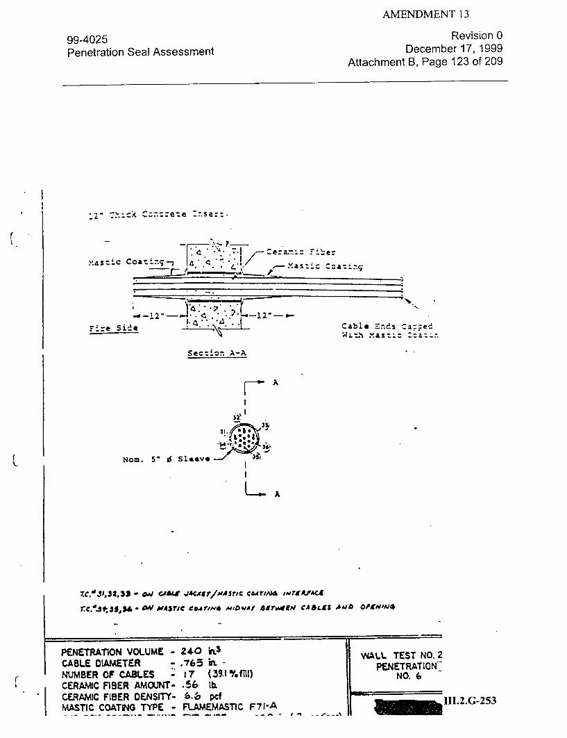
AMENDMENT 13
99-4025 Penetration Seal Assessment
Revision 0 December 17, 1999
Attachment B, Page 123 of 209
------ - "-. .- -
Fire Side ••Cabl a "Ends ca==ed MaszL- :zaz* -
Sec=ion A-A
F7 A
Nom. 5" 0 Sleeve
IA
TC.'1JD,32,$3 - 04 cASd, 4cr1,&At 43r1C C&4TwFJ; wrVVA-CL
-AV MAMATC COAT/Nd W10w~Af **asrvmx CASLSS AAJD CP1SN'vO
aTr
PENETRATION VOLUME CABLE DIAMETER NUMBER OF CABLES CERAMIC FIBER AMOUNTCERAMIC FIBER DENSITYMASTIC COATWIG TYPE -
240 h 3
.-765 h
q7 (39.1%finl) .56 lb. F. T pcI FLAMEMAs~iC F71-A
WALL TEST NO.2 PE.NETRATION
NO. 6
•111.2.G--253
- I
0 1 7ý_a

99-4025 Penetration Seal Assessment
AMENDMENT 13 Revision 0
December 17, 1999
Attachment B, Page 124 of 209
I 3 __- ___, ___-- ____ -__ 3
o.-..a -- ' " .r.... " -c .eramic Fiber
cap•ed Wi.:.h Blanket sec:t
:.u.ck Steel Plate 8- - Backer Block
n A"-A
E A-- Ceramic Fiber Bla-ket
2" I.D. Two-Piece Sleeve
NOM. 18"0 Pipe
L A
re - oM SrbE/CaoaI" ALS. ',TlUACEr
rc.'.,4,-,, sO , SW aW'4,O.#)M $ieA &,,Aw:T f,*IerTL*4Ur
rC. 04 7 -~ 4-"FtA/ CIX"OM~ )r'W&SU 8AW 'PR.AO r f-
T-.NS.. EXP SURF. -
1ý I 1.2.G-254

99-4025 Penetration Seal Assessment
AMENDMENT 13 Revision 0
December 17, 1999
Attachment B, Page 125 of 209
Cable 7nd Casced- _ Wit, Mastc Cza::zg
Ceramic Fiber
Concrete
Mastic Coating. Fire Side
A
26"
- Ui
Secticn A-A
12"
12'
A
.5 10 Sleeve
rc.'01 - amg& &#aCXgr1X48rr9 C*df-6~ 7N*9&"eZ
•.ea5 - gW nts c.ATm or &T*rr.•fA¢f wora SAI4% 00 A4A5?l C@ri^*J dC4-I
04r.*'3 A•I A I ,•&ATAOA
€•t ,l PLb.•J SP P IAXZ r &PU
p%~r R TION V OL M - 240 h' 3 -
FLOOR M'.S NO-
Z
CABLE 0(AMETER -. 705 PENETRATIONO.
CERAMIC FIBER AMOUNT-* .80 bT
CERAMIC FIBER DENSITY- !5.9 pd 1..-5 -- ~ v0C - 0I AUPAASTlCF7 H NE
I

99-4025 Penetration Seal Assessment
AMENDMENT 13 Revision 0
December 17, 1999 Attachment B, Page 126 of 209
xast~ic Ccatig-,9
cera~mic Fiber
concrete
Ma&stiC Coating.
Fire Side
A
36"Secticn A-A
I~*
12"
12"
A
!t-
Non-- Sc
fc.' -0W CA& wAiijCrttxMjdj-l coarav& ,'*'t'Ae
CABLE DIAMETER -. 705 h PNTRTO
(1NUMBER OF CABL.ES - I (1 %f, I NO. 2
CERAJM'C FIBER AMOJNT- .b0 QL
CERNAMC FIBER DENSITY- 5- PCf 1..-5 __%Mý -~ Cl AUFLA&,qTl F71-A i
Clzle 7nd Ca=ced
Xasz-c Ccaz-:,.g

99-4025 Penetration Seal Assessment
xastic
ceran~c Fiter
Cor-jcrotaSa-- 4
MastiC Caating-,
AMENDMENT 13 Revision 0
December 17, 1999 Attachment B, Page 127 of 209
Iiii-
A
L
oN=. 5.0 Sleeve
36"
12"
A
re.1017 - 4W CA&&E .,A~r1IT/M4ZTC CoAr/AJSIE ,TIWACZ
rcoi- wu mwic cwmPm or ,AvrxAtfA'd ,ww &44s so A~srlc (.Arn"6&
ic'2S- IX 1COIM i/410. pjiM .*#s ?P e ~ C Cj.EF7AJ4 C@*"L"
r.fq- oAD P44.5ic C...rlu* wA Piki sO oP PirS VP.
PENETRATION VOLUME Z4240 hn3 FLOO R TEST NO0.
CABLE D(AhtETER .705 'W PENETRATiON
NUMBER OF CABLES I lb (31.2 % MI) NO..3
CERAMIC FIBER AMOUNT- .49 lb. CERAMIC FIBER DENSITY- S.1 I c 112G-5
-- Pn CT ... tC E AWUfU&.T1(. V77

AMENDMENT 13
99-4025 Penetration Seal Assessment
Revision 0 December 17, 1999
Attachment B, Page 128 of 209
-- -..s - e
i_
mastic Ccat
c~ncret6 Slab
S.. *.4.i
Mastic Coating-~j
Fire side
A
L
- -I
I :2.
-1-
12"
A
No=. 5* 0 Sleeve
rc.OiS - o.m cABLE wc&r1^artM4vc CdrIArS ,AWT4r4CX
r..Izz - Oj ~.,IC ca•auxr ~ wflg*.AGVrw . ,sV r eEAst ,P.AZY/C ¢j7/N4 'C.oA .
r1C-2 - wJ *Aa~nC 4"cA~ud JIM. PXR0AC Liftj OP' .**3 CJI?7AJ* 'CdIAL"
r.c3o - ot- mtsvT/c cA AjPo o f, Po&. ri $i fc. P
PENETRATION VOLUME - 240 h. FLOOR TEST NO. 2 CABLE IAMETER - .705 h PENETRATIONO NUMBER OF CABLES - 1b (3L2%fill) NOL 4
CERAMIC FIBER AMOUNT- .A9 ltb
" CERA FIBER DENSITY- 5. i pcf 1.2.G-258 MASTIC COATUNG TYPE - FLAMEMASTIC F71-A

99-4025 Penetration Seal Assessment
AMENDMENT 13 Revision 0
December 17, 1999
Attachment B, Page 129 of 209
- -- -- -"•
Xastic I~ ig--'
Ceramc Fic er a
concreSt•-"
Mastic Coatinfg--e
Fire Side
36" Sectizn A-A
r
1
12"
A
Nom 5" Il Sleeve-
.cf7 . ONe ce* WleCxrTr/A •'r0C co, wri ffSA S,
. I- &at S C C.AM• d rA • ,'* wiTM "t1 OP * AAr/P CM4ZW40 "COPIS
PENETRATIN VOLUME Z40 hn3FORTETN
CABLE D0AMETER -. 705 in. -PENETRATION.
NUMBER OF CABLES I ( 5 %f13l) CERAMIC FIBER AMCUNT- .53 Ilb
CERAMIC FIBER DENSITY- 3.9 pc 111.2.G-259 MASTIC COATING TYPE - FLAMEMASTIC F77 ......
I

99-4025 Penetration Seal Assessment
:a'-'e 7n!
xas-'c Zai.
Cer&.. y~IN,
mast.C Coati"Lg
rir Sid*
AMENDMENT 13 Revision 0
December 17, 1999 Attachment B, Page 130 of 209
26"
*1�*'
& p...
* 4* 2"
12"
A A
No=. 51 0SeVe
c0,LCW CAW ,&ACA~t?/Az7C COA1.'O -@wr9#-"Ct
0,d' 5 - 4&My7C C&AVI'd* Or ,AI1t&P'ACZ WIVOA SC 001 MA4IC C~j?'r 'C.O1
--. &&4 bSTIC orIMH t.,paeA4" 00s eP MSM/ CMMfE -C.-V5f
dw'~-Oa AoASFIC C&Alm ?joi J p&LA. eP F/49 jr&P
PENETA~iO VOUE -. 240 CABLE DIAMETER -. 705 h PELO TRATISTNO
NUMBER OF CABLES - I ( 2 %fiII) PNETaTION .2G-6
CERAwc FisER AmouN NO3 bbL tI.2Gt6

AMENDMENT 13
99-4025 Penetration Seal Assessment
Revision 0 December 17, 1999
Attachment B, Page 131 of 209
Mastic Cczal;-~ 0.1
mastic Coating
rFire side
N-H1
/
I,
I,.
Sectlv 1-- .
- I36'
4.y
_2V
No=.. 5* 0 SleeVe
A
rc. ojq - 00 CA&& WKMVr1Ao*Sr1C ej0.4r/Ji IMet**rAc.
'c.,Z3. &j ~,37c cUPAW or ,wv7x*9AG wir.# LASI eP ,MsrVc CajVrn4 VC9O'
rcZ7 -w mfJ r M *ASIC ( Ej1,V. PAbM LIII Sr -IW7rg C0.Jfl 44 'CiIL"
rrcf31 - 0A1 H4qYIC COATIA'2 14 -*19". Cor PU Zrop
PENETRATION VOLUME Z40 h3 FLOOR TEST NO-
(CABLE DI.AMETER -. 705 hL PENETRATION
NUMBER OF CABLES - lb(1.2/fi NO.77
CERAMIC FfBER AMOUNT- .33 1b. 11.2.G-261 0-rOA11811 C10OD MONV~TY. TA =d_______
12"
I

AMENDMENT 13
99-4025 Penetration Seal Assessment
Revision 0 December 17, 1999
Attachment B, Page 132 of 209
i.
M~astic Ccat:i.g-%
Ceram~ic i e-
F-4ra side
Se��:z �
12!U
-12
4 T
12"
A U;.
Nom. 5 ~Sleeve'
A
re.102c- ow C.4&4 -WJKST/M4STC eC*.'rld 14FIROWAS
T~cozo - &q Aft" COAT/V4 jJff . Lal 00Sn C.0,0744 GIYA6CSA'L
rCf'3Z.0A OAJ ,0eri ca*Ti .,A*j xisa'. PeLvV
FPENETRATION VOLUME -240) hn3 -FLOOR TEST NO. -2
CABLE DIAMETER .75hPENETRATION NUMBER OF CABLYES 16l (3L.2%filI) NO. a CERAMIC FIBER AMOUNT- .33 tlb.2G-6 CERAMIC FIBER OENfY- -35 Pd .2G6
xas,::.: Zzat-
Ccncrete Slab

99-4025 Penetration Seal Assessment
AMENDMENT 13 Revision 0
December 17, 1999
Attachment B, Page 133 of 209
Verrmiculite Concrete
12"
----- L
Section A-A
A A
Nom. So 1 Sleeve-'J
,TKoN VAtUme
NUMBER OF c&R- CERAMIC FiB.R
C--•tl Iisco I'Mrmcry..
Concrete
Fire Side
:.G-263

AMENDMENT 13
99-4025 Penetration Seal Assessment
Revision 0 December 17, 1999
Attachment B, Page 134 of 209
rnd o! pj~e Secured 'Z-,11 Su~R ack Wizh Steel N
pinl
36'
. ."L
.4..
T
Section X-A
A
SM. Jim Sleeve-
'-NOm. 4' 0 Pipe Capped With 1/40 Thick Steel Plate On Fire Side Only. Pipe :s Free To Pivot Laterally.
onm. 1" Clearance Maintain
Between Pipe And Mastic 4~u&. e- Boethi Sides Of
rloor
" CERAMIC FIBER AMOUJNT- 19.5 lb. SCERAMC FIBER -ENY- 9.f 7 Ppf
-- . , ^,4. FC &P PulTSC 77
FLOOR TEST NO. Z PENETRATION _ NO.10
III.2.G-264
Concrete
Fire side 12= I

AMENDMENT 13
99-4025 Penetration Seal Assessment
Revision 0 December 17, 1999
Attachment B, Page 135 of 209
4ast-c Ccati-.g.-
Ceramic Fiber B1.anke ---t
Concrete
_I
12"
mastic Coating
Fire Side
A
����1A
Nor. 1110 0 Sleeve
PENETRATION VOLUME - 373.9 hn3
CABLE DIAMETER - N.A. h NUMBER OF CABLES - 0 ( O %Ul) CERAMIC FIBER AMOUNT- 14.3 lb. CERAMIC FIBER DENSITY- 7.53 Pc5
I -
FLOOR TEST NO. Z PENETRATION
NO. 11 III.2.G-265
II

AMENDMENT 13
99-4025 Penetration Seal Assessment
Revision 0 December 17, 1999
Attachment B, Page 136 of 209
Concre:e F7oor
Fire Side8- Thick Sakrete* Concrete
Section A-A
A
Nom. 13. J
A
t~~
*POCEAnTION VOLUME CABLE I"MET NUMBER OF CABLES... CERAM•C FIBER AMOUNTY-.--, C;R&MAMI FIBER DE0

AMENDMENT 13
99-4025 Penetration Seal Assessment
Revision 0 December 17, 1999
Attachment B, Page 137 of 209
Vervculite Con~crete
Cnrt i2" ""lo r V ' ' " " •. .. .. . . . ." ' '"
Fire Side
__ t: 36"
NUMBER OF CA5.ES.. CERAMIC FIBER AMOJN4T
1 . ft- OW *r
III.2.G-267
r
Section A-A
AA t-

AMENDMENT 13
99-4025 Penetration Seal Assessment
Revision 0 December 17, 1999
Attachment B, Page 138 of 209
S- l llII I I I Ii .. .i I Igi -li I I [ .
C:a m. C .- 1- M : . ~ ~ ii i i ' r<.' - I... ....
Fl"oor - "
L.--', - .,..,-1
tS
Section A-A
AA I
[.¢• 0•/ - *UaMf! • C MT € r'T~ A mdCA 5L ,e'r ,jriXF P• IC. V~Js4 J,4$- dk 4SV(ll C.4T iM4 Ef dM T fT•Tc E .sT ?H 64€$ 1 & V" A Ug.ST CD2",J *3"C guC J
rc.g'#5,'6 - . €•L'A4Tc C*AM f'P~t4Mid ' Srn ,e c7•T.M "ceuI
r~c.~fl~4i~t -o w l r c .,0 7 , s z4 - C ~ 4 4 7 / k l A 4i N C C 0 r j A Mu r " Ar
PENETRATION VOLUME -74.88 h3 CABLE DIAMETER - .705 h NUMBER OF CABLES - ;10 (29.8%fil/tray) CERAMIC FIBER AMOJNT- 23.77 lb.
ropaus Frmp nFNqITy- 5.q ocf
FLOOR TEST NO. PENETRATION
NO. 14-III.2.G-268
I °.

AMENDMENT 13
99-4025 Penetration Seal Assessment
Revision 0 December 17, 1999
Attachment B, Page 139 of 209
"a : .. .. L -... .. .. ... ... ..-.. ...-
rLZF. :er-.IM
concrete
C~noe~e"X " l
%,". .,
(pe x149 ar clsý% . 0 00 ý'.. :: 4. 00 00 *so ::" 000 Go*
.Cis x
o • Oe d,,
2
sect:ion A-A
A. t-
T.C.,'$3,f4S', S - dW ,&,,*rtg C*,*r,,*•O ,, LA 0,d0,)m PIt,•Srbp,
PEETRATION VOLUME -7488 irt.3 - lFLOOR TEST NO. Z
CABLE DIAMdETER -. "705 hl PENETRATION NUMBER OF C.ABL.ES -113 (7.1 %fill) NO. 15
SCERAMIC FIBER AMOUINT- 23.71/I l 111.2.G-269
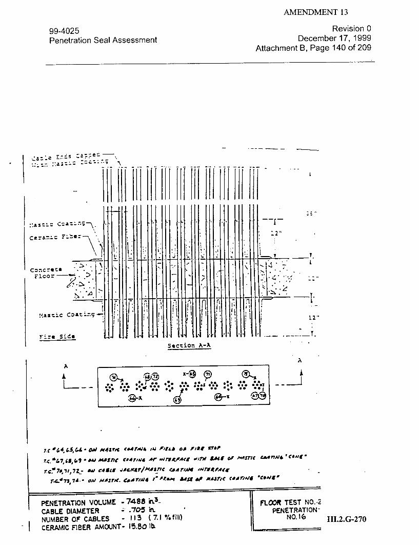
AMENDMENT 13
99-4025 Penetration Seal Assessment
Revision 0 December 17, 1999
Attachment B, Page 140 of 209
~a:e~S - .. 1:a;- A -
concrete Fi~co: -- . :
L
section A-A
A
lii
T.C. 19.7 5C, 480 D wM USfi C*4ft,'*4 Ar wrfour~ -Iw ff 6ftJO MTC~476*CM
rc:070,11,7Z2 A41 (4SIS jA"jqdTmAsric e4i 7Ap mrs-cewer
TX-73,74*- 00 H&AJO'. e~r0 "t 'c... AF. *Ajrlc "airlAIE06d1
PE.NETRATION VOLUME - 7488.h3- FLOOR TEST NO. -2 CABLE DIAMETER .75 n.PENETRATION
NUMBER OF CABLES: 113 (7.1 %/fill) NO. I G 111.2. G-2 70
A

AMENDMENT 13
99-4025 Penetration Seal Assessment
Revision 0 December 17, 1999
Attachment B, Page 141 of 209
Secti:- A-A
":o. 4 Steel Ears Welded ? :p And Sleeve -
:;a. 3 Steel Bar A.ch.=3r (4. Req'd)
Concrete Floor- "
8" Thick Sakrete-' concrete
Fire Side
9
12
Ceramic Fiber Blanket
Nom. 4" 0 Pipe Capped With" 1/4" Thick Steel Plate On Fire Side Only
*'J a.'1fT -amEEit arLs ep Age( SF3,
re.67' &VJ Pi.09/ eI*AMIC 0484 *..~gir m~rstrMce
rc049 oat P10jf /',0*w UJAdC '404 £&AdzW
~ENt1ATONVOLUME - rn3
CAMLE VDAME::ER NUMBER OF CABLES, CERAMIC FIBER Z CERAMIC FIBER DNST)'- .IAYq
I
A L
I.
12"

AMENDMENT 13
99-4025 Penetration Seal Assessment
Revision 0 December 17, 1999
Attachment B, Page 142 of 209
Sc. 3 Steel Bar Anc-Ors (4 :teq'd) z~
4"
4..-I-
/
V" Thick Sakrete - -3" Concrete
Section A-A
A
----I
NCO. 1J" 0 Sleeve.
CERW¢C FIBER CERAOMC FIBE.R
Concrete12"
Fire Side)
A

99-4025 Penetration Seal Assessment
AMENDMENT 13 Revision 0
December 17, 1999
Attachment B, Page 143 of 209
IV I
j• .•& - a ^ c&*r'* v* 4,"r AwLw wirm sA&t e' mu4ric €*sTAv6" Co
rc. 44,, 91.t- amv uSw 4cDu rrKS . or T/AA,. i • r.,
INTIAIOA 00 CAG&. S•DiN
PENETRATION VOLUME - ZI(a0 h3 CABLE DIAMETER - .450 Uh
NUMBER OF CABLES - 495 (43.7%ffll) CERAM•C FIBER AMOUNT- 5.35 Ilb CERAIC FIBER DENSITY- 7-.. pdc III.2.G-273
:a�.e �dS Ca::e�
A 4A
!

AMENDMENT 13
99-4025 Penetration Seal Assessment
Revision 0 December 17, 1999
Attachment B, Page 144 of 209
I - -I-I-- -
Va5ceran'1=
d .
Concre .
~nIE7 7 '147 - 2
.i~i:T
Section A-A
AA
- -L �qi
r~c.w34.SSJS,& - 0C4/ AfV4srlGcITI . IL PP~i
T(~5755,5 -4r .v, ,M nc j CA1AJ. wrx67c mr#f M 39 &S 09 "A~rl'c c.&7/N "COAJE
,c960 - em d'fArtc c&4rA4 j6% soDA mS NAs77t coAT/N4 'cois J
r eC . gI, j, - AV ed5ls .LJ.cxgAH7#nAfc 1*14artAMcX
r. c-. ,&5 - om AwirIc cAT/lm I w S &4s so "4&0 AV ThVW a'VW7WeX 0 CA6&L I4wJOLT
rre~,7 - wi Aoirm e7*44J/c4dcs 7LAP' AvutnLedC
rc.,6 & I - ..4 cosat -may, I"d4&.vs '0*#n C,0
PENETRATION VOLUME - 7488 h3rFL CABLE DIAMETER - .705 h m.TAI NUMBER OF CABLES - - 19 (40.3%f~h/t'dy)NO14 CERAJNiC FIBER AMCOUNT- 29.15 tLb CERAMIC FIBER DENSITY- 7.7 pcf MASTIC COATING TYPE - PLAMEMASTIC F77
- - ***'~W* PID ~ IL V I L r.tfd
111.2.G-274

AMENDMENT 13
99-402 5 Penetration Seal Assessment
Revision 0 December 17, 1999
Attachment B, Page 145 of 209
: =e-J
Section A-A
A
rCC. 70,,7I,7Z*o~J~aT '.rc 4rMJ4 WM .0D ooe F)0j 3TdP
7rC.Vr75,74~,75-d.VA4#3rtC cpwI'#J4 Ar l4J,7VAct '"rw BEse' cA. Arorv Ce4rv.m -C*Aj&
7rC. 074 77, 78- *.i CA5S5 4#cW/&/*#StIC CSAT** e.VrA.A4Fr9
rc.c 71, $40 - #A# bdS4IC C*TMr^W4 jAT op c.4&"k 1jM rXO 1Mr#UC14 aP CAGa&f NAJOL.
,~c.NSI,& - C qiM*17 Ci~EriAJE 11,orm A.4Sf As wiric, c.E7anm camuu
iTPEETRATIN VOLUME - 7488 h~3
CABLE DIAMETER - .705 hi NUMBER OF CABLES - 138 (&b %faI) CERAMIC FIBER AMOUNT- 30.75 a~ CERAMI~C FIBER DENSITY- -7.8 pd
ý'l f#%A'PMI/ Y'rVC L AuCUAlfivne C77
FLOOR TEST M~ PENET RATI(
NO. 15
111.2.G-275
A

AMENDMENT 13
99-4025 Penetration Seal Assessment
Revision 0 December 17, 1999
Attachment B, Page 146 of 209
- - -
- - - - . - - )-. j.fir
1 . ii.
.:\ j ;� I *1. -
� ...
rb..__ __
:'taztic-
F-r Sidesection~ A-A
AA
L
r4.-23184 ,85 c*AJ AwsIC CWflM A/i Nf&A CUP Pr/X&S7O
rC.*'81 MI MU7S8 "wathJ'~rao ir4r1rwrg#t# wa &wU ofwsl ~ir/cawrm 'cAe-l
rc.84 TOI/- &W. Cew&f JACCE71HiMr CdA7?J.4 /AJFJ*Ad
rr_0:, - AwV 17o ATJ4 or *Agg a.' cA5LL rwe 7W9 ,t&"Ad a'~ c d&" wcf
-oto fS ema7/( ~&~J4,'/A" LSAW SOAS17C C..*rYM4 ceWAIC
PENETRATION VOLUMEC -7488 h3 FLWR TEST NC
CABLE DIAMETER -. 705 hi PEN ETRAT IC NUMBER OF CABLES 13 38 (8.6 % n,1) NO. 16
CERAMIC FIBER AMOUNT- 46.iZ 1h1b.2G-7 CERAMIC FIBER DENSITY- I Lb 6 c WI..G7

AMENDMENT 13
99-4025 Penetration Seal Assessment
W. =.7.
xastic Ccatn-;-
c'cncete slab
Revision 0 December 17, 1999
Attachment B, Page 147 of 209
[VT
.�jj. .,�.
K
Xastic Coating
Fire Side
--. I
1
36"
12"
rc.'0 1
7. c.04
rc.0 7 7-.0. 10
No=. 5" 0 l*v
-O'd 43*wM C&*?DJjd oIMPIC4& ap Apgsrup
-ONV AWWK cmm *IP ,mrrR*~kj wrr T LCf 00 AfslC 004TlAf *cd ME
&V' CA"S *"S D Art AVruSgqMCI WrfW MAS?AC "4704'
~ , e 4i cserw"d or a.Usr co cosaLJA r/r /~ AJfmx0 *E P CA" 641SUb-
PENETRATION VOLUME Z 40 h~3 FLO TETN
CABLE DiAMETER *.705~ FLO TEESTRNO4
NUMBER OF CABLES -16 (3. % E)NERTO.
CERANIC FIBER AMOCUNT- .45 1b. N.
CERAMI~C FIBER DENSITY- 4.8 pcf11.G-7 ftJACTIt-rn& T YPE FLAMEMASTIC Fr77 II..-7

AMENDMENT 13
99-4025 Penetration Seal Assessment
Revision 0 December 17, 1999
Attachment B, Page 148 of 209
-- ..*js-: :::
Mas:.: Z:a:..;..
-::7 .a C F
a~..
V
Masric C=&t..-gn
.;re side
A
Nom. 5" 0 sleeve
- OA/ £A*Sh1 C0471A44 INd -*'CIO Or PRfSTDP
-. v om Ai eviuior AP I'rl*P-c1 wt. ootz so vjsjr.c cowdim& 'came
- AV C1545 jecwar Ar ,.'mo.4rcs* wr. MASM C A41A*.
- &i mwr7e C"41~ft Ar JA4s or c4&Lf- Av ME INMTUM OP 8 cA&.5 &JwbI~t
PENETRATION VOLUME - ZS0 hi3
CABLE DIAMETER .. .705 in NUMBER OF CASLES - 16 (31.2 %fM 1) CERAMIAC FIBER AMOUN4T- .& 1~5 b. CERAMIC FIBER DENSITY- 6..8 pcf MASTIC COATING TYPE - FL.AME-MAS71C F77
F LOCR TEST NOPENETRATiO-N
NO.OL
1I.2.G-278
[I I
F~i1. T
L
2"
L .TI.
A k
r C.,0 2
fc.0I
- I
ý-- = r. C

99-4025 Penetration Seal Assessment
AMENDMENT 13
Revision 0 December 17, 1999
Attachment B, Page 149 of 209
--
:re-: slat) - e~
Mastic C-Cating
7-res- S:e
A:7A :.Y.
~n esonm 'ir 4 .4rU lmrguyAcs lr ~A'f/V4js mr Asr.,c CoArINS 'c@&Us
* vcisa jAcxsr or avrgese wWIU PASTI Ce 41ff
- DP ~~ec..e*.4 Ar 84zruir c C48& lov TN, I/S?8'A1 OP cAut. BdJN"C.
(I
PENETRATION VOLUME -ZSO
CABLE DIAMETER - .705 NUMBER OF CABLES - 16 CERA.MIC FIBER AM.iv¶T- .399 rigAMIC FIBER DENSITY- to.4
hm (31.2 % nil1) lb. pdC
FLOOR TEST NO-~ PENETRATION
NO. 5 111.2.G-279
1* VT I'
-- I
I2
.1.
rc.i$09 7 C.'2Z
rc.'0 2.2
X!st-,
C--nc
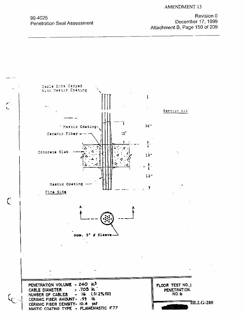
AMENDMENT 13
99-4025 Penetration Seal Assessment
Revision 0 December 17, 1999
Attachment B, Page 150 of 209
Ill. Mastic Coating-.
c nScab -4- .,"
mastic Coating -
:ire Side
I
36"
d12"
12"
A A
NMI. 5= 0 Sleeve\
PENETRATION VOLUME CABLE 0IAMETER . NUMBER OF CABLES CERAMIC FIBER AMOUNT_ CERAMIC FIBER DENsrrYMASTIC CoATMJG TYPE -
240 h,.3 .705 h
I1& (31.2 .99 lb.
10.4 pcf FLAMEMAS
FLOOR TEST NO. I PENETRATION
%ful) NO.(
TC F111.2.G-280
:---.-' :ra-n- _-s •-a; .-e .
SeCIZ::n .!.-,

AMENDMENT 13
99-4025 Penetration Seal Assessment
-- *.')5�� -
Ce:a-. :�6-.
ccncree S zan'� <1�
J. . ....
61A
3.. .-�.:I
Revision 0 December 17, 1999
Attachment B, Page 151 of 209
rUTi I
1.
&
I I
Masicc-*in
1;0M. 5"0 Sleeve,
*r~c."Zo - odJ Aefuic C81A*TdJ -M
7C.*23 amn ASOMC CwVmd Ar
* ~~*AL e~sa .m~rr jr mo
f*a -',,ar. re? *. er
PeNETRATION VOLUME -240
- CABLE DIAMETER - .705 NUBE OF CABLES: -l1
CERAJC FBERXAOLiT-.99 rIVASIIP 0-11L- Achery 'r% &
Aink or riesrvP
w?.RAS'C w4N 4Sxe AVAS a$ 14vc oArt'm o'co de
r~g.tV4e WflW AlA S7 COA4VP
L4 t co~L -q~ tA t /N7LIICM1 OF CAS4. &AN04-f
1'1.
(31.2 %.fill Ill
FLOOR TEST NO. F PENETRATION
WRTNO. 7,.
A
111.2.G-281

AMENDMENT 13
99-4025 Penetration Seal Assessment
Revision 0 December 17, 1999
Attachment B, Page 152 of 209
7nZe !-
- �1 -
Ccrcete Siab -- ',
mastic Coating--"
secticn !.-I
36"
.4 a 12'
12"
A 2.
mm..s ~sleeve.
A
-c OZI CO& j0aCr/A6#SjM (C0.rAI VMrcArT4Mcr aa ~ ~ ~ ~ ~~&s a,-?. m rwejs~ A P 'sc .eAW0'C'CD"C
CABLE OLAMETMr- - .705 k ENTRTIN NUMBER OF CABLES - lb (3L2%fdI) O8
CERAMIC FiER AMOUNT- .99 h -__J...-8
CERAMIC FIBER DENSITY- 10.4 Pcd MON- -
- -1,

99-4025 Penetration Seal Assessment
Xastic Ccatin.
Cerar-i F*iter
concrete Siab
A.
Mastic Coating-
Fire side
AMENDMENT 13 Revision 0
December 17, 1999 Attachment B, Page 153 of 209
i11X2.
1
36"
2
T .
A
Nom. so 0 Sleeve
rC.04,#,44 -03M coortoo drm "ELo i 0$'X $M. I z
rc.o4Sj,",'7- Am Im cJ1ma Ar 1mrwf*MLJ wirmv soza &w mozyr cpa?1AJ4 -ctv
rcA'#.,4150 - 0^p C4&".ji*fXr/MA3Vr/ C&Ar/A* 1WM19FAt~
44:,osi sz- A AeiIV'u e'A*1M or iisr-op cd" oi VWE A.vmxax wr cAf " umdLf
z C.0IS - a'V #.'ErC CuirIA* j -m. ;ts'4 sa~e .o *.svc c*4nv C'cam'
PENETRATION VOLUME - 24,0 h3. PCOABILE DIAMETER -. .705 h. NUMBER OF CABLES - 16 (~!I.Z %fi 1) ZERAMIC FIBER AMOUNT- .&~S lb.
CERAMiC FIBER DENSITY- 4.9 pci f-M1 IATrMV TY0V - 0l ArU~LAqTtr- P7-7
FLOR~ TEST NO. IFPENETRATION
NO. 9
111.2.G-283

AMENDMENT 13
99-4025 Penetration Seal Assessment
Revision 0 December 17, 1999
Attachment B, Page 154 of 209
:- " Thick Sakretez :=n-e:-.-
- -3" (Typ.)-
C=o:*ncete
No. 3 Steel Bar Anchors (4 Req'd)
. 4 12"
" I. SFTi
A
- - -
FLOOR TEST NO. ,._.p•IETRATION
NO" 1O
111.2.G-284
Section A-A
re Side
K
Nor. 11" 11 Slet
Ufll
If
L Mý h3
NUMB"
OF S
ER CERAMIC FIB ? CERAMIC FISEýR D 4YT-y '6ý mm-nc coam FLAMWAS

99-4025 Penetration Seal Assessment
W-*z *'asý.L Ccating
.Mastic Coat-':
cera~mic Fiber
concrete slab
.Mastic Coating
Fire Side
AMENDMENT 13 Revision 0
December 17, 1999 Attachment B, Page 155 of 209
N ____ a I111--�----- T~
' .2!
12"
12"
A
?Io. 5 ~sleeve
A
----3
rc.' 3 - 0,j CA&A ..4CK*TMo0StIC COjYbAr-48I ,AITUMCJ
- - ~ P winW~r &IV~V LStP MA"SIC CA47JN6 -C*Nr C. W r - 00 J-. I V.
NUvI8EROF CA5BLE - lb (31L2%fffl) CERAMIC FIBER AMOUNT_- I.S lb. CEAWC FiBER DENSITY- lJ P
,ýi f-ImATP.Mn YPV - FLAMEIAASTIC P~77
cis -a
FLOOR TEST NO. -1 pENETRATION
NO.Z
111.2.G-285
ISecticn

AMENDMENT 13
99-4025 Revision 0
Penetration Seal Assessment December 17, 1999
Attachment B, Page 156 of 209
N A ..,. M..-e:'.e"a f;;0 . 3,::-..-
A
4 ,6
- -I
10 01 1 00 30 0 • 0 o -
9~~ -r01 T- .
T.v4Q6 p" ; '
13 9
4 '11"v. _ -44 I
C44 •4
~,.J
__ __ __,_ __ _14' 2"
construction oetails Floor jisebly NO.1
fe-notra!E!OF ...... . *=r~ouP 4 Con5r~z-u"CL% bj.t-iS I n
No. 1N". ThJrIoCou.LocationlI
1 - LL. 4 2 3, 6, 9, 12 ILL. 5
3 1, 4, 7, 10 6
4 2, 5: 9, 1ILL. 5 19, 22, 25, 23
ILL. 9 6 " IL. 9 7 20, 23, 26, 29 .
a 21, 24, 27, 30 IL . 11
9 42-53 12
10 13 13 11 15, 16, 17, 13 ZLL. 14 12- 14 - ILL. 1s 13- 31--41 1"L. 16 14 54-69I ILL. 1.7 is 70-82 =L. 18
16. -3-95 see Above concret~e 96
111.2.G-286

AMENDMENT 13
99-4025 Penetration Seal Assessment
Revision 0 December 17, 1999
Attachment B, Page 157 of 209
r
�
0
I
V�1
C
C 0 -D
S
B
ii **J b.
i
II
I
U
III.2.G-287

AMENDMENT 13
99-4025 Penetration Seal Assessment
Revision 0 December 17, 1999
Attachment B, Page 158 of 209
__ 9
-- - L--• .-.- -•
S, , ~ ii~:lol ,-, : fe l . i. , • l !.9.•l i ,,. . , : - " *1' I1.1'- 1 • 1 1, I l t " l i ,, l: l '.
___ ,,____________i I ' ,:l i i l' i li"•' ii 'i ' __ __ _ ___: _
r ill 1 i, I i
111.2.G-288

99-4025 Penetration Seal Assessment
AMENDMENT 13 Revision 0
December 17, 1999
Attachment B, Page 159 of 209
¢, ex•.Csed s-:"-a:e
"-"- A
S1A
14 '10h
Fl'reS2ide
Section A-A
Construction Details - Wall Asemzbly No. 1
i~eneurau.of Th'r -COUPi Conltructicfn Utails And
No. NOU. ThermocouPlI Locations
1 2 3 4 S 6 7
Concrete Conc. slock
25-30 10-15 37-40
1-9 16-24 31-36 41-43
44 45
ILL. 43 ILL. 44 ILL. 45 ILL. 46 ILL. 47 ILL. 49
=LL. 49 See above see above
III.2.G-289I
ILL. 42

AMENDMENT 13
99-4025 DeebRevision 0
Penetration Seal Assessment Dcmer 17, 1999 Attachment B, Page 160 of 209
- .-.-1"--**~ -Mas-ic ccati~.q C-, :a'-'es
A --Aý.d Wielded WUSleeve
mastic Coating
-f77 42 6" Cable Ends Ca==ed-'
Section1 A-A
3'4- 2
r ,* Aosroc c64rv"& Jr or" *P SLJ4'19
NUMBER OFr CABLES -59 (322%0111NOL CERAMI1C FIBER AmouNT- 4.07 WL.
cERAM)C FIBER DENSMT- 9.5 Pcf ?OASTIC COATM4 TYPE - FLWOEMASTIC F77 d wI..-9

AMENDMENT 13
99-4025 Penetration Seal Assessment
.aSc Ccatinq On T j~ Cazles xnd welded 4 wrail S-,eeve
Revision 0 December 17, 1999
Attachment B, Page 161 of 209
- er~a.7 : --ibe.r
-Xast*.: Ccat-*rq
12"-.
sectiafl -)-A
op-t
Cable Ends Ca==ed W*.-mast~ic Coat:.nq
2 4
?C 1Z.JI - &vcA&84 kitwWT1#W~r19C'Fu .~tP4
NUMEROF ABES - 154 h31 TEST) NO. I_
ICERAMC, FIBER AmOJIT- 4.07 ML
ICERAMC FIBER DENTY 9.5 pd 111.2.G-291 MASTC COATIN TNYSPiET FLAMEMASliC F77
12" :,.=k c=n=:ete :nserz-
V

99-4025 Penetration Seal Assessment
AMENDMENT 13 Revision 0
December 17, 1999
Attachment B, Page 162 of 209
- - . . . . - -
12" Thick Concrete :.ser:
" .4
- .Sd b. • &
3 cryp.)
Fire Sde 4
-No. 3 Steel Bar Anchcrs p( 4 Req'd)
L 8* Thick Sakre-e'-)Ca ered
In 20" •onq Sleeve
Section A-A
iSm 4
T..*37- W OWNM 4"ra U*J'• $ s&AEg
sog.l.- U046TI rA P-9 1s &JVU-.,
t~g.,*-0. ON .i*W faN V Mr8XKr-
NUMBER Of CACERAhiC FIBER CERAMIC FIBER MASTIC COATI'(
III.2.G-292

99-4025 Penetration Seal Assessment
AMENDMENT 13 Revision 0
December 17, 1999 Attachment B, Page 163 of 209
!MastiC Coating-.-Cable 7n~s Cacced wl:
K A
I .l 52"
re- ~2,3 dw C4&'- jdCgfT/MAS?7C COA 7/MA#IAPC
r -. -1# oC.494 rWAV1/X4S r.C CeAPrAI& -A ,m P(ACf
re. doe. -00AKSrIC 40A VAM Ar 90 44 *f'Op00A0
_A I,$r SfrW&&A 2755
CERAMIC FIWA ENW 7.3 Pdf MASTIC COATING TPr- - PLAAEMASTIC F7 7
*. ~ EleraIP -l~ 234 In.e09I
e*r. O*�IJdN4 * - -e
V&* 2Nd. 1 -PENETRATION
-
111.2.G-293 A1 4
L

99-4025 Penetration Seal Assessment
AMENDMENT 13 Revision 0
December 17, 1999 Attachment B, Page 164 of 209
c eran*c :.:e:
y
CablEnd Capped With i4astic Coati-.
3rx33"xl/4" Steel. Plate L.4 Reqld)--.,,
F6" (Ty-P.
SlotTyp ,3 pics.
12"--9 A
A
A A
V nThic)ký 16 PC--- - --- II3x0xl4 t4
DesityCrai i j.. 3 2o 2 / ti
Fribe: soard 3 6 t 4Rq
CABLE DWETER -705 hIL PEESTRNO.
NUMBER OF CABLES -177 (32.0%fill/s') Na5
CERAMIC FIBER AMOUNT- A4.9 tlb
CERAMIC FIBER DENSrly- 7.8 pdf MAS11C COATING TYPE _ FLAAENASTIC F77 4 M 1..-9
tnI flD*e tn-nWTJ THKNS& EXP SkJRF* - .244 in (10 III.2G-29
I

99-4025 Penetration Seal Assessment
AMENDMENT 13 Revision 0
December 17, 1999 Attachment B, Page 165 of 209
12- -h~c n*'e rset
mastic Coati.:4-ý
Cerami.c 7iter ,- Ms~:cCoat nq
setin -A
31)
~40M. 5"~sleeve
Cable Ends Ca==e -. with Xjast:za..
A
It . 4La -. CJ A&d W4,"N?/A43C C&OVA4 1,r49JVc5
eJ7IPa NtbO Af WMEINff CA&LA5 "AJDOI
r~rM
CERAMI~C FIBER AMOUN~TCER~AMIC FIBER DENSITYMASTIC COATWJ TYPE _
.- - .PAnku- 9'1.IU
240 ir"WALL TEST NO. 1 .705 hpENETRATION-
Ito (3-mal)NO. 6
6.8 pd p A)AvAASTIC F*77 nm sUJr . - .2 29 h ( 3 r~oa&I 111.2.G-295
Tc. .7 31, ýV AIAS rC."31,35," OW MASTA
rT" PENEETRATION VOLLWE
6CABLE DW&M 'C ;Z ea eur ram 1rqa
C

99-4025 Penetration Seal Assessment
AMENDMENT 13 Revision 0
December 17, 1999
Attachment B, Page 166 of 209
Nom. Is" 0 24,ze--Capped with 1/4' .hick Steel plate
Fire Side
K-A
Now. is" 0 Pipe
-ceramic Yiler Blanket
:oncrete Block Wall
- Ceramic Fiber Blanket
210 I.D. Two-Piece Slae
LA7 C.04j. Ow PPS/"AAWl¢ 00"A 9"147ArmV
CERMAq FIBER CER•MIC FIBER OEHS -.Y
•" " " ---- 2 - -w, 6" ---
111I.2.G-296

99-4025 Penetration Seal Assessment
AMENDMENT 13 Revision 0
December 17, 1999 Attachment B, Page 167 of 209
t .�
Mr
a
III.2.G-297
a:'k. e•
,' .I.C..
°

99-4025 Penetration Seal Assessment
AMENDMENT 13 Revision 0
December 17, 1999
Attachment B, Page 168 of 209
0
U
III.2.G-298

99-4025 Penetration Seal Assessment
A° -
:"-9i.
Ia a a
I , * S
, 1*, . . '.
* ... aJa ... * JY S *, S.
• "I
I ~ 1 Ii'
I
Il
I I
* n
II, III I I II Ill .I,
AMENDMENT 13 Revision 0
December 17, 1999
Attachment B, Page 169 of 209

AMENDMENT 13
99-4025 Revision 0
Penetration Seal Assessment December 17, 1999 Attachment B, Page 170 of 209
I g , ..l ' 1 .
dr
I * * I I I I I I -.....
I -.
.1
I I I I . C - - - -I � r ; ;.: . *

99-4025 Penetration Seal Assessment
AMENDMENT 13 Revision 0
December 17, 1999
Attachment B, Page 171 of 209
s'---a.-e
- 7
I_'
Side
Sectin.o A-A
-_ 1 4 ' 1 0 h ,
construction p etail' Wall,1111 "I'ii l l'' ''o. 2 NO N1ar O CO TPe ,o~ u l I .,oca t-ion s
Noo s- T-rmocou l No.. ~
2 3 4 5 6 7
concrete Conc. Block"
ILL. 55 ILL. 57 ILL. So ILL. 59 ILL. 60 Se. above See above
III.2.G-301
-Th�
1.2' 11V'i
25-30 10-15 37-44
1-9 16-24 31-36 45-47
41 4,
Q
IL. 53

99-4025 Penetration Seal Assessment
AMENDMENT 13
Revision 0 December 17, 1999
Attachment B, Page 172 of 209
1�Mast.c C-Zat:n c:, a='-as And W4, ad *ea:: 5'_ae/S
Cable. Ends C&;=ed With Xas':2. ::
7jre Side
secti.On A-X
6" A
*
I
rcAB lE iA~mE - .&0 "" -"r^3ac "4 -"A
Ce&-RAMIC14 FIBER AJN-114 h3 lb.TSTN.
cERAMIC FIBER DC -...-- 6-_`2 p
::.. ::nc:ete :.-_se:t7

99-4025 Penetration Seal Assessment
AMENDMENT 13 Revision 0
December 17, 1999 Attachment B, Page 173 of 209
7 - -r•-" •d
0
.2.G-303

AMENDMENT 13
99-4025 Penetration Seal Assessment
Revision 0 December 17, 1999
Attachment B, Page 174 of 209
-U .j r
0
I1I.2.G-304

99-4025 Penetration Seal Assessment
I• 90
V_ I I J
_ 71.77T;ýIz:1
7. . i t
•I' I , . I I I I •d' ."
k .. • , . .- .• "'L .'.:i.".•,. ,,I Ai "
VI " 17
I. I . , I: * . ,('1 " ~ i, i 'li: i
II: 'II ,I I
* -J I. " *,)•I' , *. I•, ,, ,
* , . . .
I I •l. *I• * ' '
S . ", I I ' I • , . I I. ,
:• , "I." ' I -:- %!! -"" "" ' .. ' '
S... .... .- - .: ,, .,.,, i•,,• ,,@Oy I
AMENDMENT 13
Revision 0 December 17, 1999
Attachment B, Page 175 of 209
III.2.G-305

AMENDMENT 13
99-4025 Penetration Seal Assessment
Revision 0 December 17, 1999
Attachment B, Page 176 of 209
1;_______h__ :~j~~~ Ijj Hl I tI 1i' ; lj`ý Vjý~ iI l illlj~~
"All T~' I'!lC"71M Iý-- ilwn11 W;i
jFOw *i *AW
Tp i Ii Iiiii it
!li~.~lII~l i*,****~j*~*****~* Ihul I ti ll iI IlI l i "T 111 :
Ii jjjJ ~ ~~I~1l~
LDA0
111.2.G-306

99-4025 Penetration Seal Assessment
AMENDMENT 13 Revision 0
December 17, 1999 Attachment B, Page 177 of 209
III.2.G-307
e

99-4025 Penetration Seal Assessment
z
- .j . A
o .4
1-
S -c•
-I..
-ai
I.
AMENDMENT 13 Revision 0
December 17, 1999 Attachment B, Page 178 of 209
k~
h. -C
411.2.G-308
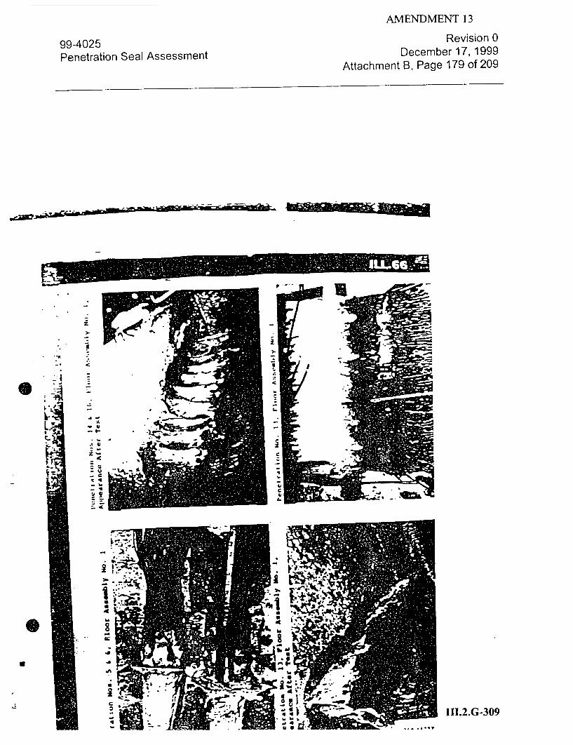
AMENDMENT 13
99-4025 Penetration Seal Assessment
Revision 0 December 17, 1999
Attachment B, Page 179 of 209
z j -i
A
., 4j
-u
-c
-q
111.2.G-309
-'�
4
L7�d

99-4025 Penetration Seal Assessment
AMENDMENT 13 Revision 0
December 17, 1999 Attachment B, Page 180 of 209
/
V 1* // �
I
-a
i "4'
"C
0
III.2.G-31 0
A
o . .
SI

AMENDMENT 13
99-4025 Penetration Seal Assessment
Revision 0 December 17, 1999
Attachment B, Page 181 of 209
III.2.G-311

AMENDMENT 13
99-4025 Penetration Seal Assessment
Revision 0 December 17, 1999
Attachment B, Page 182 of 209
r � �
4
s-f
ii � !j
E
* 61
�III.2.G-312
�1 a
C
C
7.
CI
C
-c Ii
�1
.1*
I
*1
�ri
A
J,.
U,
- a
-t
WIL

AMENDMENT 13
99-4025 Penetration Seal Assessment
Revision 0 December 17, 1999
Attachment B, Page 183 of 209
'.3 I-- -
I
0
I
U.
*1�
SI
4
I
'a �Ii CI
.2 � -c 44
-i
C- C71.2.G-313
U U 4
I
3
'a

99-4025 Penetration Seal Assessment
AMENDMENT 13 Revision 0
December 17, 1999
Attachment B, Page 184 of 209
7.5"
f Z)'63
S IO
.-.'._,) _,•
s!c7'oM •-cZ,
Is3 !:Alk
AS SAX%
-I .
-A z
!5c-!ON
21
-- -Ik� I.
.- l,°
,r-7* .÷-•
III.2.G-314
p I

AMENDMENT 13
99-4025 Penetration Seal Assessment
Revision 0 December 17, 1999
Attachment B, Page 185 of 209
1*
*3 SAM
SECTION -
III.2.G-315

99-4025 Penetration Seal Assessment
I-
I111.2.G-316
AMENDMENT 13
Revision 0 December 17, 1999
Attachment B, Page 186 of 209
..
SN
N
'I
---4' S.1
I
'-1F
iU ' !N
LLI

99-4025 Penetration Seal Assessment
AMENDMENT 13 Revision 0
December 17, 1999
Attachment B, Page 187 of 209
page •-:
WALL INS ER
3. C N:iE S I GN
-. :-S-N OF ZE-NFORC1 CCNCRETE:
:he nominal 12 in. (305 mm) thick reinforced concrete wall
inserts were designed in accordance with the recommendations of
:.e AmerLcan Concrete :nst;.-te to provide a minimum 3 hr ire
resistance.
3.2 MATERIALS:
Concrete - The ready-mixed concrete, obtained from a local
source, was composed of one part Type I Portland cement, 2.1
parts sand, and 3.2 parts gravel (siliceous aggregate) by bulk
volaZe, mixed with approximately 8.4 gal (31.5 1) of water per
bag of cement. V-e average strength and density of the concrete
as determined !rom four standard 6 by 12 in. (15- by 105 mm)
cylinders aged 28 daIS# w~re 4490 psi (3.10 x 10 n/m ) and
153.8 Pcf 42 x 10 n/r ), res0ectively. 7e streigtb ranged
from 4400 to 4560 psi (3.03 x 10 to 3.14 x 10 n(s ). The
dro 53.1 to 154.5 pcf (2.40 x 10 to 2.43 x
10 an/n ). rhe average slump during placement was 6-7/S in.
(175 mm).
Reinforcement - The reinforce**nt for the
inserts consisted of No. 3 deforsed steel bars
....-. •n.rm&.t bars were shop-fabricated by
concrete sarLe (x MST' A•36 mitral).
Sleeves - TwO sizes of pipe and welded rectan ' lar assesJhlies
were used as sleeves in the conirrete vall inserts. The sleeve for
Penetration~ tN@.* was a ntominal 5 in. (127 an) diaseter steel
Schedule 40 pipe# 12 In (305 ) long, baying an inside diameter
of 5.047 in. (121 an) and a vail thickress. of 0.258 in. (6.55 ima).
The sleeve was provided with three I by 1- '1/2 by 3/16 in. (203 by
38 by 4.76 M) thick steel anhor plates weldd to the outside of
the Sleeve at the sleeve 3mid-;ight WitbL 3/14 in. (4.76 M) fillet
welds. -
III.2.G-317

AMENDMENT 13
99-4025 Revision 0
Penetration Seal Assessment December 17, 1999 Attachment B, Page 188 of 209
Pa;? 3-1 "ss~ed:
-.h welded rectangu.ar sleeves !or Penetration .os. 1 and
2 .ere r•m.-ed from '--4-i•. (6.4 ,-m) ste: =:-to, as shown in
:--. :.. Each sleeve was provided wi.th two 2 by 6 by :/4 in.
(5! my 152 my 6.4 mrm) thick steel ancnor plates welded to the
oýtside oC! t..e s:eeve, at the sleeve mid-depth, with 3/16 in.
,4.76 ;fm) fillet welds. •
3.3 C NST'.CT:Z•
..,e concrete wall inserts were each constructed on the floor
in a lumber framewrk. For Penetration Nos. I and 2, the sleeves
were centered in the lumber framework with their splayed end down
such that 6 in. (152 m.m) of the narrow end would protrude from
the concrete. For Penetration No. 6, the pipe sleeve was placed,
vertically, in the center of the lumber framework and was filled
with sand so as to exclude concrete from the interior of the pipe
sleeve. For Penetration No. 3, a plywood platform was constructed
witnin the lumber framework such that the sleeve was centered in
the lumber framework and such that both ends of the pipe sleeve
would protrude 4 in. (102 ma) from the concrete wall insert. For
Penetration Nos. 4 and 5, lumber forms for the rectangular and
square openings, respectivelY, were fabricated and centered in
the lumOer frameworks.
--he concrete was placed in each lunber framework, internally
vibrated, and was finished to a smooth, flat surface with a trowel
and wood float. The reinforce•mt bare were embdded in the con
crete during its placejent such that a set of the reinforcement
bars was located approxiimtely 1-1/2 im. (38.1 ma) from the ex
posed and unexposed surfaces of each concrete wall inserts, as
shown in ILL. 32.
III.2.G-318

AMENDMENT 13
99-4025 Penetration Seal Assessment
Revision 0 December 17, 1999
Attachment B, Page 189 of 209
|ELýff WL.LI' SO.S!!A1
WSLDED ýYALL. SLILEVC F-OI FC?'-,TZAT'ICN NCS. % AI~ 2--WALL ASSEMB5LtS I AND2
111.2.G-319

AMENDMENT 13
99-4025 Penetration Seal Assessment
Revision 0 December 17, 1999
Attachment B, Page 190 of 209
A!O.J3 54-cs (/iA .J~ i
Tr J j
.O S. / A4iD I.
/ \ /
/ A N /
p1,j�reATI3iJ 'vo. 3 (wAU. ,4SSJ1� 18�Y NO. /
prAjfTLtnsAj" AJa8.
Perar," MVp 4
"II].2.G-320

AMENDMENT 13
99-4025 Revision 0
Penetration Seal Assessment December 17, 1999 Attachment B, Page 191 of 209
.. ":.R A " 0 N R E C C R 3 S
-te scale used throughou.t the investi-ation was "Toledo
Hmo.es.- . Model No. 4030, Serj-l No. 7043, UL -.ns-rntii ,-35S -se scale calizration was checked by a Toledo Scale No . 4: .. . .. Th scale
represen--aLve on July 23, 1979, January 4, 1980, Marc 1,-980,
an:, uay 28, !980.
F.2 •.•AC£ ERA'-'E RECORDERS:
C.2.1 FLOOR FURNACE .- mPE-RATUIE RECORDER
7he temperature recorded used !or both floor fira tests
was :.-ees & Northrup, Model No. G, Serial No. 56-32931-1-1, UL
Instrument No. 6FB5TR. The recorder calibration was checked by
a :Leds & Northrup representative on June 19, 1979, December 14,
1979, and October 16, 1900.
C. 2.2 WALL FURN/ACE PrMpERATURE RECORDER
The temperature recorder used for the first wall tire test
(NC601-2) was Honeywell, Model No. Y112.74180-58020-00000-00"
00000-(106)-18, UL 1nstrument No. 30OFDSTR. .he recorder cali
brate.on was checked.by a Honeywell representative on March 31,
May 1, and June 27, .1910.
The temperature recorder used fto the second wall fire test
(NC601-4) was the same recorder used for the two floor fire tests.
C.3 DIGITAL DATA ACQUISITION SYSTEMI
.he digital data acquisition system used throughout thi
investigation was AccuIeZ AutodaSt Nine, Serial No. 1-763. The
recorder calibration was checked by aft Accures representative on
soptember.ll, 1979, and ftbruary 27, 1950.
III.2.G-321

AMENDMENT 13
99-4025 Penetration Seal Assessment
Revision 0 December 17, 1999
Attachment B, Page 192 of 209
a. -.
A
-z0
1'
43-
Cgo-i STI
---'IH.2.G-322
C.--.'J'
L
; .
4

AMENDMENT 13
99-4025 Penetration Seal Assessment
Revision 0 December 17, 1999
Attachment B, Page 193 of 209
i
F
0.
-C
ii
A 'C
r
*I.
-1.
'C C
-c
II.2.G-323
I
6.�*
I
10d

AMENDMENT 13
99-4025 Penetration Seal Assessment
Revision 0 December 17, 1999
Attachment B, Page 194 of 209
v-.... ..' 'A--
7
-.
- .-. r- '.
vii.. 71�...
0
" .III.2.G-324

AMENDMENT 13
99-4025 Penetration Seal Assessment
Revision 0 December 17, 1999
Attachment B, Page 195 of 209
S....• .•-...-. --- " - . .
- - �
* 4 -
.1�
.2.G-325r7.
,.•. •D.
V-
I

AMENDMENT 13
99-4025 Penetration Seal Assessment
L
a
Revision 0 December 17, 1999
Attachment B, Page 196 of 209
.3
I
E
V- III.2.G-326 rvjS*
-V
0
I

AMENDMENT 13
99-4025 Penetration Seal Assessment
Revision 0 December 17, 1999
Attachment B, Page 197 of 209
12-C
111.2.G-327
¢ ,* •71
II 4
41
C C
i
U! 4
S
I
a

AMENDMENT 13
99-4025 Penetration Seal Assessment
Revision 0 December 17, 1999
Attachment B, Page 198 of 209
>r'- j - ° • Io , i '1
III.2.G-328

-AIVINIlvIIN I I 1
99-4025 Revision 0
Penetration Seal Assessment December 17, 1999
Attachment B, Page 199 of 209
Cl
1112.G32
U
-(• .- t•-

99-4025 Penetration Seal Assessment
Revision 0 December 17, 1999
Attachment B, Page 200 of 209
1 In •
2:
3
W1 V. dU
CI.'j*S4 -ff-•.2.G-330
C.
0
C"
>.
.a
3,
*1°
*1 4
.1
ft.j
i

Revision 0 99-4025Deebr1,99
Penetration Seal Assessment December 17, 1999
Attachment B, Page 201 of 209
I a
U
41
- C
4'
-q
C
-4
C I.1 I2.: _____ 111.2.G-331
V
,.
31o1
0

99-4025 Penetration Seal Assessment
Revision 0 December 17, 1999
Attachment B, Page 202 of 209
:1
z
'I t 0�
3
i
*1 A A
fr S
C U U
K
- I�L
03
�.1
C,
3 .
C.

99-4025 Penetration Seal Assessment
Revision 0 December 17, 1999
Attachment B, Page 203 of 209

99-4025 Revision 0
Penetration Seal Assessment December 17, 1999 Attachment B, Page 204 of 209
- * t
* -.. .,
Ui: M" '
O t . • ."
( 1-RI1.2.G-334

99-4025 Revision 0
Penetration Seal Assessment December 17, 1999
Attachment B, Page 205 of 209
C I J7I"fl ',OANP To ,
-Iti ; I i., ..
El , ! ;,,if '011 .
11,110 N O I~l 111 til .... . . . ... . .. .. ..
1' 191I
I f. I '- :7 ..... .. • , , *, , ...... .
:I- , ... .. .,.L-- •,I I ' " 'ill
'l';:!.,il ,li' •• •-'"•'l:11.1"2.G -33•5.

99-4025 Revision 0
Penetration Seal Assessment December 17, 1999 Attachment B, Page 206 of 209
* .4, Il I ti.
* **, 0 *0-I ...
--. .... . K " "I - I . , . 1
I, I _ -: A
r
III.2.G-336

99-4025 Penetration Seal Assessment
Revision 0 December 17, 1999
Attachment B, Page 207 of 209
A iera W901 Batt-~
"- ----- (t
-T.C. 18j, 80,79.
\ (1, t to ri,9'h-.)
* ,TC. $78 70
13 ~
14 '2
* b V
CI U I 1.
construct01% D~tails - Floor 1s "° Ii No. 22
ipiiEnFtrat., The ..rCOu~lO Chron~rc~ou tDctiAn.]
Nos. ______________
2 2, 6, 10, 14 24
17, 21, 25, 29 LL. 25
4 1i, 22, 26, 30 ILL. 27
5 3, , 1., 15 27
6 4, 3, 12, 1:. 28
7 19, 23, 27, 31 3LL.02
6 20. 24, 28, 32 ILL. 30
9 17I. 31
10 33-36 *zT. 33
11 37, 38 _ r. 34
12 3L. 3S
13 75, 76 .34
14 40-532 ILL. 37
is 53-43 nZ. 38
16 64-74 - Se
Concrete. 71-81
III.2.G-337
A
I
--- 7-
-1-
0*
I
I
1

99-4025 Penetration Seal Assessment
V°
I.
p
Revision 0 December 17, 1999
Attachment B, Page 208 of 209
A
t ~~~-- .• ! *•qb"•- Iq,
'•• q ::. 4 •.€; *-.
tA
4t-
III.2.G-338

Revision 0 99-4025Deebr1,99
Penetration Seal Assessment December 17, 1999
Attachment B, Page 209 of 209
* C2
I £ ,
' 2 * 0
III.2.G-339

AMENDMENT 13
DRESDEN 2&3
FIRE PROTECTION PROGRAM DOCUMENTATION PACKAGE
Test Reports
Page Title
III.5.A-1 June 1985, Southwest Research Institute Report entitled "Qualification
Fire Test of a Protective Envelope System," Volume I
III.5.A-3 June 1985, Southwest Research Institute Report entitled "Qualification
Fire Test of a Protective Envelope System," Volume II
III.5.B-1 December 31, 1999, 99-40540 3M Fire Wrap Qualification Evaluation
111.5-i

QUALIFICATION FIRE TEST OF A PROTECTIVE
ENELOPE SYSIEN
FINAL REPORT
SwRI PROJECT NO. 01-7912a[1]
FEBRUARY 1985
REVISED JUNE 1985
Prepared for
3M, INCORPORATED
3M CENTER
ST. PAUL, MINNESOTA 55144
FPDCC [-10o 1 INITIAL I/,•
SOUTHWEST RESEARCH SAN ANTONIO
INSTITUTE HOUSTON
III.5.A-1
ra "a I" fk cbt W -al t of t'f 1k. 3vi . It may. h "din m= mitm Iw to, &q ip w - * 1o f *ml owk..A* ap.jl awsrm Ito . " -~ w the mf t, sof 01. k1 sh" It. -w p.hho I - aI I M

AMENDMENT 13
DRESDEN 2&3
FIRE PROTECTION PROGRAM DOCUMENTATION PACKAGE
The document entitled "Qualification Fire Test of a Protective Envelope System," volume I,
dated June 1985, is found on microfiche following Tab IX of Volume 7.
111.5.A-2

QUALIFICATION FIRE TEST OF A PROTECTIVE
ENVELOPE SYSTEM
REVISED FINAL REPORT
SwRI PROJECT NO. 01-7912[2J
JUNE 1985
Prepared for
3M, INCORPORATED
3M CENTER
ST. PAUL, MINNESOTA 55144
RESEARCH INSTITUTE HOUSTON
111.5.A-3
" aIh wpl h fww k I.~ . 1 m ae S mm ' I i t °i us ;' mm a I a pinpmm of ww p. t hm -d Immm•d lip ~n lu bor~• nwq~,. ib ?pom¶ the .1 thuo•e I m~m,- .. u. be *w -m CW pe .'~
SOUTHWEST SAN ANTONIO
I=ua tvL

AMENDMENT 13
DRESDEN 2&3
FIRE PROTECTION PROGRAM DOCUMENTATION PACKAGE
The document entitled "Qualification Fire Test of a Protective Envelope System," volume II,
dated June 1985, is found on microfiche following Tab IX of Volume 7.
111.5.A-4