
Practical Web Penetration Testing - Open Directory Data Archive
Upload
khangminh22Category
view
0download
0
San Jose State UniversitySJSU ScholarWorks
Master's Projects Master's Theses and Graduate Research
Spring 2011
AUTOMATED PENETRATION TESTINGNeha SamantSan Jose State University
Follow this and additional works at: https://scholarworks.sjsu.edu/etd_projects
Part of the Other Computer Sciences Commons
This Master's Project is brought to you for free and open access by the Master's Theses and Graduate Research at SJSU ScholarWorks. It has beenaccepted for inclusion in Master's Projects by an authorized administrator of SJSU ScholarWorks. For more information, please [email protected].
Recommended CitationSamant, Neha, "AUTOMATED PENETRATION TESTING" (2011). Master's Projects. 180.DOI: https://doi.org/10.31979/etd.fxpj-pt6khttps://scholarworks.sjsu.edu/etd_projects/180
brought to you by COREView metadata, citation and similar papers at core.ac.uk
provided by SJSU ScholarWorks

i
AUTOMATED PENETRATION
TESTING
A Research Project
Presented to
The Faculty of the Department of Computer Science
San Jose State University
In Partial Fulfillment
Of the Requirements for the Degree
Master of Science
By
Neha Samant
Spring 2011

ii
© 2011
Neha Samant
ALL RIGHTS RESERVED

iii
SAN JOSÉ STATE UNIVERSITY
The Undersigned Project Committee Approves the Project Titled
AUTOMATED PENETRATION
TESTING
By
Neha Samant
APPROVED FOR THE DEPARTMENT OF Computer Science
Dr. Mark Stamp, Department of Computer Science Date:
Dr. Robert Chun, Department of Computer Science Date:
Dr. Johnny Martin, Department of Computer Science Date:
APPROVED FOR THE UNIVERSITY
Associate Dean Office of Graduate Studies and Research Date:

iv
ABSTRACT
AUTOMATED PENETRATION TESTING
Penetration testing is used to search for vulnerabilities that might exist in a
system. The testing usually involves simulating different types of attacks on the
target system. This type of testing provides an organized and controlled way to
identify security shortcomings. The resources and time required for
comprehensive testing can make penetration testing cost intensive.
Consequently, such tests are usually only performed during important
milestones.
In this project we have automated the penetration testing process for several
protocol-based attacks. Our automated penetration testing application covers
several attacks based on HTTP, SIP and TCP/IP. The objective of this work is to
offer a fast, reliable and automated testing tool, which is also easier to use than
existing tools.

v
ACKNOWLEDGEMENTS:
I would like to thank Dr. Mark Stamp, for giving me an opportunity to work on
this research project under his guidance. I would also like to thank him for his
patience and suggestions without which this research project would not have
been possible. I would also like to thank Dr. Robert Chun and Dr. Johnny
Martin for their guidance and suggestions while working on this project.

1
Table of Contents ABSTRACT ............................................................................................................................... iv
ACKNOWLEDGEMENTS: ......................................................................................................... v
List of Tables ........................................................................................................................... 4
1. INTRODUCTION .............................................................................................................. 5
2. BACKGROUND ................................................................................................................ 8
2.1 NEED FOR PENETRATION TESTING ....................................................................... 9
2.2 WHEN TO PERFORM PENETRATION TESTING .................................................. 10
2.3 TYPES OF PENETRATION TESTS ........................................................................... 11
2.4 PROCESS OF PENETRATION TESTING .................................................................. 12
2.5 MANUAL VS. AUTOMATED PENETRATION TEST ................................................ 15
3. DENIAL OF SERVICE ATTACKS (DoS) ............................................................................. 16
4. NETWORKING BACKGROUND ...................................................................................... 18
4.1 APPLICATION LAYER ......................................................................................... 18
4.2 TRANSPORT LAYER ........................................................................................... 19
4.3 NETWORK LAYER .............................................................................................. 19
4.4 LINK LAYER ....................................................................................................... 20
5. PROTOCOLS .................................................................................................................. 20
5.1 HYPER TEXT TRANSFER PROTOCOL (HTTP) .......................................................... 20
5.2 SESSION INITIATION PROTOCOL (SIP) .................................................................. 24
5.3 TRANSMISSION CONTROL PROTOCOL (TCP) ........................................................ 26
6. COMPARISON WITH EXISTING TOOLS .......................................................................... 27
6.1 NMAP ................................................................................................................... 27
6.2 Hping .................................................................................................................... 28
7. AUTOMATED PENETRATION TOOLKIT ......................................................................... 30
7.1 DESIGN AND ARCHITECTURE ............................................................................. 31
7.1.1 DATA FLOW .................................................................................................. 32
7.1.2 MULTI-TIERED ARCHITECTURE ..................................................................... 32
7.2 IMPLEMENTATION OF ATTACKS ........................................................................ 33

2
7.2.1 HTTP Protocol DoS Attacks ........................................................................ 34
7.2.2 SIP Protocol DoS Attack .............................................................................. 47
7.2.3 TCP/IP Protocol Attack ............................................................................... 50
8. AREAS OF IMPROVEMENT ........................................................................................... 58
9. CONCLUSION ................................................................................................................ 59
10. REFERENCES ............................................................................................................. 60

3
List of Figures
Figure 1: CERT incident graph 5
Figure 2: Phases of penetration testing 12
Figure 3: Layer interaction 18
Figure 4: HTTP request message 21
Figure 5: Sample HTTP response 23
Figure 6: Sample SIP message 25
Figure 7: TCP 3-Way handshake 26
Figure 8: Port scanning using hping3 30
Figure 9: Main page screenshot 32
Figure 10: Data flow diagram 33
Figure 11: Multi-Tiered architecture 34
Figure 12: HTTP DoS attack 35
Figure 13: dynamiclp.exe 37
Figure 14: Dynamic IP code 37
Figure 15: Invalid HTTP messages 38
Figure 16: HTTP client class 39
Figure 17: HTTP torture test log files 40
Figure 18: Graphical generation code 41
Figure 19: Graphical output 41
Figure 20: Apache server log 42
Figure 21: Slow DoS attack script 43
Figure 22: Nmap port scan before the attack 44
Figure 23: Slowloris output 45
Figure 24: Nmap port scan after the attack 45
Figure 25: hping3 output after the attack 46
Figure 26: Output after pinging the server using Nmap 47
Figure 27: Apache server log 47
Figure 28: SIP torture test UI 49
Figure 29: SIP torture test code 49
Figure 30: SIP Torture test log file 50
Figure 31: Port Scan attacks file 54
Figure 32: IP Record Route output 55
Figure 33: ICMP Timestamp option attack output 55
Figure 34: ICMP Unknown protocol attack output 56
Figure 35: SIP Broadcast attack output 56
Figure 36: SIP Multicast attack output 56
Figure 37: SYN Flood attack output 57

4
List of Tables
Table 1: Comparison of Manual VS Automated Testing…………………………….………….15
Table 2: HTTP Response Status Code……………………….……………………………………………24
Table 3: Exceptional Elements…………………………….……..…………………………………………36
Table 4: List of TCP/IP DoS attacks..…………………….……..…………………………………………36

5
AUTOMATED PENETRATION TESTING
1. INTRODUCTION
The rapid growth in the internet and web technologies has been
beneficial to businesses and people alike. With the rise of new
technologies comes the challenge of providing a secure environment.
A 2005 study conducted by the Federal Bureau of Investigation (FBI)
suggests that over 87 percent of US companies have fallen victim to
malicious attacks every year. The study further indicates that the
overall losses could be as high as $ 67 million a year [27]. The
occurrence of malicious attacks has increased tremendously as seen
in the graph below from the Computer Emergency Response Team
(CERT) data.
Figure 1: CERT incident graph
0
20,000
40,000
60,000
80,000
100,000
120,000
140,000
160,000
180,000
200,000
220,000
2000 2001 2002 2003 2004
No
of
inci
den
ts
Year

6
According to the data, the number of incidents recorded has increased
by 100 percent every year since 1998 [28]. The growth in attacks is a
troubling trend for businesses as most facets of the business
enterprise are connected to the internet [29]. The impact of these
attacks can affect the company in many ways such as data loss,
denial of service, liability claims, and loss of productivity. The serious
nature of the impacts has resulted in the growth of an entire industry
which addresses these security issues [30]. Network firewalls and
vulnerability scanners are two types of common security solutions
available today. These solutions address specific concerns: a firewall
setup will prevent an unauthorized access into the system, whereas
vulnerability scanners will spot the potential vulnerabilities in the
system. However, these tools cannot ensure the identification of all the
different modes of attacks. Penetration testing is an important,
additional tool for addressing the common security issues.
A penetration test not only identifies the existing vulnerabilities, but
also exploits them. The goal of penetration testing is to improve or
augment the security posture of a network or a system [31].
Penetration testing is performed by compromising the servers, wireless
networks, web applications, and other potential points of exposure to
identify and analyze security issues [1]. This enables fool proofing
against these issues to prevent future attacks. Penetration testing can

7
be conducted either manually or through an automated program.
Since the testing involves simulating varying levels of attack on the
system, it carries the risk of an attack being successful and damaging
the system. To minimize these risks companies utilize skilled
penetration testers who understand the limitations of the system.
In this paper, we propose a prototype application to provide a secure,
reliable, fast, and user-friendly way of performing penetration testing.
We have developed a web-based penetration testing application to
perform automated denial of service (DoS) attacks on the system. With
our application, the user can select from the different protocol based
attacks such as Hyper Text Transfer Protocol (HTTP), Transfer Control
Protocol/ Internet Protocol (TCP/IP), and Session Initiation Protocol
(SIP) attacks. The application provides the user with the ability to enter
the destination IP address and the port number. Once the user submits
the request the appropriate attack script is triggered and maliciously
crafted packets are sent to the specified system. The user also has the
option to stop sending packets at any point. Once the attack is
completed a report is generated in the form of log files and
graphs/metrics. This enables the user to identify, analyze and prioritize
the security threats and helps towards developing a security plan.
This paper is organized as follows:
• Section 2 explains the need for penetration testing and recommends

8
when testing should be conducted. It also covers the different types of
penetration tests and the process of penetration testing.
• Section 3 explains different modes of Denial of Service attacks (DoS).
• Section 4 covers the basics of networking and provides a description of
the different layers. In this layer we discuss the functionality of
Application, Network, Transport, and Link layer.
• Section 5 covers the basic information about all the different protocols
used in our application.
• Section 6 discusses the advantages and disadvantages of the existing
tools.
• Section 7 describes the architecture and functionality of our penetration
testing application and also covers the implementation details.
• Section 8 concludes the paper and provides scope for further study.
2. BACKGROUND
Penetration testing is a viable method for testing the security of the
system in a safe and reliable manner. It can be used to understand,
analyze, and address security issues. Additionally, test results can
highlight the strategic concerns and augment the development of
mitigation plans thereby allocating resources to the right areas. One of
the criticisms against penetration testing has been that the resources
and time required for completing comprehensive testing dwarf the

9
benefits derived. Hence, automation can be leveraged to provide a
better solution than the manual tests. The power of penetration testing
combined with the ease and speed of an automated application can
provide a potent tool.
2.1 NEED FOR PENETRATION TESTING
There are numerous benefits of penetration testing from the
business as well as technical perspective. Some of the principal
reasons for adopting penetration testing are presented below.
Security Issues
Security issues such as malware attacks, network intrusion,
and data theft can result in service interruption and unreliable
system processes. This could lead to potential loss of
customer loyalty and affect the company’s market value.
Penetration testing can work to avoid such occurrences by
weeding out persistent as well as unexpected threats.
Protect Information
Companies use different security mechanisms to safeguard
information like access control methods, firewalls,
cryptography, intrusion detection systems, etc [1]. However,
with new attacks being discovered everyday it is difficult to
protect user/system information constantly. Penetration testing

10
could address these concerns by simulating a variety of
attacks simultaneously.
Prioritize security risks
The use of penetration testing as a standard security practice
not only helps understand the security issues but it can also
help prioritize these issues. The issues identified during the
testing can be prioritized on the basis of severity. Also, these
efforts can lead to efficient budget allocation for information
security issues.
Financial Loss
Penetration testing helps to mitigate the loss of
revenues/capital due to service downtime arising from
malicious attacks. It can also prevent or reduce fines/lawsuits
resulting from security malpractices.
2.2 WHEN TO PERFORM PENETRATION TESTING
Penetration testing should be included as a standard process within
the security testing roadmap. Traditionally, organizations prefer to
perform penetration testing prior to a product release or a major
upgrade. However, it is also advisable to conduct this testing in the
following situations:
New infrastructure is added
Software is installed

11
System updates are applied
Security patches are applied
User policies are modified.
2.3 TYPES OF PENETRATION TESTS
Penetration testing can be segregated into the following classes
[4]:
1) Attack visibility: Blue-teaming or Red-teaming
2) System access- Internal testing or External testing
Blue-teaming is done with the consent of an entire organization. The
information security team is fully aware of the testing requirements
as well as resources needed. Blue-teaming is a more efficient way
to perform testing as the system availability is not an issue and
hence there is a considerable reduction in the overall time for
testing. The shorter test times mean lesser system idle time and
reduced testing costs.
Red-teaming refers to testing that is performed in a stealth manner
without the knowledge of IT staff [4]. Upper-level management
authorizes such an exercise. The objectives of the test are to judge
the strength of the network security, the awareness of IT
organization, and its ability to follow the standard protocols. The
entire test is done without the support of the organization’s resources

12
and hence requires a longer testing time. Hence, red- teaming is
usually a more expensive exercise than blue-teaming. However, red-
teaming provides a more accurate assessment of the company’s
security responses because the security administrators and staff are
not aware of the ongoing exercise [3].
Another way of differentiating penetration tests is on the basis of
the attacks performed.
Internal testing takes place within the system environment. In such
a setting the tester is usually behind the firewall. As the testing
happens on the internal network the tester can gain unlimited
access to data and network information.
External testing, in contrast, has almost no access to internal data
and network information. In external testing the tester is outside
the firewall, limiting the availability of the system information. Here
the tester has to rely on external sources to gather information
pertaining to security settings and protocols [4].
2.4 PROCESS OF PENETRATION TESTING
The penetration testing process can be divided into four phases as
below [4].

13
Figure 2: Phases of penetration testing
Phase 1: Planning
This is the first stage in penetration testing. This stage usually
involves the standard planning steps of setting goals, finalizing test
strategies, identifying test timelines and setting up the test
environment [4]. It is very important to identify key results expected
at the end of testing as it would determine the success of the
experiment. Management consent and written permission is needed
before moving to the next stage.
Phase 2: Discovery
Testing begins in the discovery phase with activities such as port /
network scanning which may lead to finding possible targets. The
other activities in this phase involve vulnerability scanning, packet
capturing, banner grabbing, and OS fingerprinting. In addition to
these, there is an activity called vulnerability analysis that takes

14
place in this phase [5]. The objective of this phase is to compare the
applications that have been exposed by the attack with a standard
database. This database, known as the vulnerability database,
provides specific information regarding various types of attack [5].
At the end of this phase, log files are generated and maintained in
the system.
Phase 3: Attack
The third phase in the process is the attack phase. As the name
suggests, it is responsible for performing the attacks on the system.
The attacks are performed on the vulnerabilities that have been
discovered through the discovery phase. The attack phase is
completed in a cascaded manner where every successful attack
leads to obtaining more privileges and system information. The
additional privileges gained are leveraged to launch more attacks
on other targets. This loop is continued until all the objectives of the
attack phase are completed. The attack phase requires constant
monitoring to ensure that the system is stable at all times. There is
a possibility of an attack being successful and causing serious
damage to the system.
Phase 4: Reporting
The results from the attack phase are compiled and presented in the
reporting phase. The final report must include the details of the

15
vulnerabilities found, the attacks performed, and the analysis of log
files. The high risk issues discovered during testing are reported in
detail and are moved to high priority items as far as risk mitigation
strategies are concerned. It is essential that the reporting is done
with attention to the severity of issues and prioritization. The
reporting phase concludes the penetration testing process cycle.
2.5 MANUAL VS. AUTOMATED PENETRATION TEST
Manual Penetration Testing:
The all-inclusive nature of testing employed in penetration testing
makes it a very complex process. This process requires teams of
skilled testers for the entire duration of the test, which makes it a
very expensive option. These testers need to be very experienced
as they have to control all the tasks manually.
Automated Penetration Testing:
Automated testing is a safe and simple way to perform all the tasks
related to penetration testing. Also, since most of the tasks are
automated, the tests can be less time-consuming than manual
testing. The ease of reproducibility of the tests is also a big benefit,
compared to the customized approach in manual testing.
Below is a summary of the key points of differentiations between
the two types:

16
Table 1: Comparison of manual vs. automated testing [6]
3. DENIAL OF SERVICE ATTACKS (DoS)
A denial-of-service (DoS) attack targets the organization’s services and
resources to make them unavailable for an indefinite amount of time
[18]. The typical characteristics of a DoS attack include flooding the
network with requests, thereby preventing access to genuine users. It
could also include denial of service through disruption of network
connection between two individual nodes of the network. Sometimes
restricting access to specific users is also characterized as DoS attack.
The generic methods of executing a DoS attack are as given below
[18]
1) Limiting resource availability
2) Altering network configuration information
17
3) Physical destruction
Limiting resource availability
Every node in a network requires certain resources to be
available in order to provide uninterrupted service. These include
network bandwidth, memory, CPU time, etc. A denial of service
attack can be successfully executed by limiting the resources
available to the network nodes. Let us look at a few examples
below:
Bandwidth
The bandwidth of the network can be effectively
consumed by the attacker flooding the network with a
large number of packets. Furthermore, the attacker can
send these packets from many nodes at the same time,
thus using up all the available bandwidth of the network
[18].
Network connectivity
This type of an attack prevents the nodes of the
network from communicating with one another. This is
achieved by sending a request to a “victim” node on the
network and then preventing the connection from
taking place thereby leaving “half-open” connections
[18]. This leads to a legitimate connection request

18
being denied, resulting in DoS.
4. NETWORKING BACKGROUND
4.1 APPLICATION LAYER
The application layer is the topmost layers of both the OSI and
TCP/IP models. It is the only layer where user interaction takes
place. Its main responsibility is to transfer the data from one host to
another host. Most common applications include Web browsing,
sending data from one computer to another, sending emails, and
file transfers. Some of the common application layer protocols are
Hyper Text Transfer Protocol (HTTP), File Transfer Protocol (FTP),
and Simple Mail Transfer Protocol
(SMTP), Telnet, Simple Network Management Protocol, (SNMP),
and Post Office Protocol (POP3). Most applications are client-server
applications.
Figure 3: Layer interaction
Application
Transport
Network
Link
Physical
HO
ST
Application
Transport
Network
Link
Physical
HO
ST Network
Link
Physical
ROUTER

19
4.2 TRANSPORT LAYER
The transport layer is responsible for transporting data to the
appropriate process on the host. Data that is transported between
hosts is called a packet. A packet consists of a header and a
body; the header is indicative of the packet’s destination and the
body consists of data that is transmitted. The primary purpose of
this layer is the reliable delivery of these packets. If the packets in
the network are more than the capacity of the network, then some
of the packets may be dropped or the order of the packets can be
interchanged. This layer is designed to handle such problems.
Most commonly used transport layer protocols are Transmission
Control Protocol (TCP) and User Datagram Protocol (UDP). TCP
is connection oriented, so it is a reliable protocol; whereas UDP is
connectionless and hence is an unreliable protocol [9]. UDP is
faster than TCP, so UDP is used in applications where packet
delivery is not the main objective.
4.3 NETWORK LAYER
The network layer is responsible for end-to-end (source –
destination) packet delivery. Some of the other important functions of
this layer are routing of packets, inter-networking, error handling, and
congestion control. Internet Protocol (IP) is the most commonly used

20
protocol.
In order to route packets, every host has a 32-bit IP address.
Routers use IP headers to determine the proper route for a packet
through a network. Headers contain fields for source and destination
IP addresses.
4.4 LINK LAYER
The link layer is responsible for transferring packets from host to
router, router to router, etc [9]. The link layer and the physical layer
are implemented in the Network Interface Card (NIC). The most
common link layer protocol is Ethernet. Ethernet is used on a Local
Area Network or LAN when many hosts share a common resource.
5. PROTOCOLS
Below, we discuss the protocols regarding which attacks have been
implemented in our application. Knowing the basics of these
protocols is important to understanding how the attacks are
implemented.
5.1 HYPER TEXT TRANSFER PROTOCOL (HTTP)
HTTP is the most commonly used application layer protocol.
It is a stateless protocol, which means that it does not remember
previous sessions. Its primary use is to browse web sites. It allows
clients to send the data to the server and receive data back from the

21
server. When a client (e.g., a web browser) sends a HTTP request to
the server (any computer hosting a website), the server generates an
appropriate response to the request and sends it back to the client.
The server response contains the status information of the request [15].
When you visit a website for the first time, the server issues a cookie
to your browser which is then used as an identifier to index the
database of the server. Web cookies are used to maintain the state
of different sessions. Below we will discuss the sample HTTP request
and response message, as in HTTP torture testing we will bombard
the server with invalid and corrupt HTTP requests.
A sample HTTP Request Message is shown below:
Figure 4: HTTP request message
HTTP has 9 different request methods. Some of the commonly used
request methods are
HEAD: It generates a response similar to a GET request but a
response body is not generated. It is used to get meta-

22
information from the response headers without transporting
the content [13].
GET: A GET request is used to retrieve the information from
the Request-URI [14].
POST: POST submits the data from the body of the request to
the specified source. Data from an HTML form can be sent
using POST [13].
The other parameters in the request are called Headers
The Host header: indicates the host and the port number of
the resource that is being requested.
The User-Agent header: indicates the user-agent from where
the request was originated.
The Accept header: indicates what type of content and media
will be accepted.
E.g., Accept-Language: en-us means that the response
language should be en-us.
The Keep Alive header: indicates that the connection will be
timed out after the specified time
The Connection header: indicates that the connection will
remain for the specified time.
After the request is sent to the server, the server responds with a
response message for each request. The sample HTTP response

23
looks like the figure shown below-
Sample HTTP Response method
Figure 5: Sample HTTP Response
The first line in the message is called the HTTP response code.
Following are some of the common HTTP Response codes.
Table 2: HTTP response status codes

24
5.2 SESSION INITIATION PROTOCOL (SIP)
SIP is an application layer protocol used mainly for Voice over IP
(VoIP). The protocol uses a text-based format, similar to HTTP. SIP
can initiate, modify, and end multimedia sessions such as Internet
telephony. [17]. SIP allows new participants to be added to the
existing sessions and it allows media to be added or removed from
the existing session [17].
SIP supports the following functionalities [17]:
User location: This functionality is responsible for the
selection of communication node.
User availability: Determines if the other party wants to
participate in the conversation.
User capabilities: Selection of the media parameters.
Session Setup: Used for ringing and determining session
parameters at both ends.
Session management: Used to transfer, end, and modify
session parameters.
Next, we will discuss the sample SIP INVITE message, as we will
need to understand the request before performing SIP torture testing.

25
INVITE sip:[email protected] SIP/2.0
Via: SIP/2.0/TCP client.sj.com:5060;branch=z9hG4bf9 Max-Forwards: 70 From: USER1<sip:[email protected]>;tag=9fxced76sl To: USER2<sip: [email protected] > Call-ID: [email protected] CSeq: 1 INVITE Contact: < sip:[email protected];transport=tcp> Content-Type: application/sdp Content-Length: 133
v=0 o=user1 289098984526 IN IP4 10.20.30.40 s=Session SDP c=IN IP4 192.0.2.10 t=0 0 m=audio 46767 RTP/AVP 0 a=rtpmap:0 PCMU/8000
Figure 6: Sample SIP message
Commonly used SIP Request methods [17]:
INVITE: Lets the client know that he is invited to participate in the call
session.
REGISTER: Registers the address in the To header field with a SIP
server.
ACK: Indicates that client received a final response to INVITE request.
CANCEL: Ends a pending request.
BYE: Ends the session between two users in a conference.
Request Line
Headers
Message Body

26
5.3 TRANSMISSION CONTROL PROTOCOL (TCP)
TCP provides reliable delivery of packets and ensures that the
packets arrive in the correct order [38]. It checks that data is not
corrupted. It provides these services by using sequential
numbering in packets. It also requests the sender to retransmit
packets in the event of an issue. TCP is “connection oriented,”
which means it contacts the server before sending data to make
sure the server is alive and listening [38]. This is referred to as a
TCP 3- way handshake, as shown in Figure 7:
Figure 7: TCP 3- Way handshake
As shown in Figure 7, the TCP handshake is carried out in 3 steps:
1. The Client requests a connection by sending a SYN message to the
server.
2. The Server acknowledges this request by sending SYN-ACK back to the
client.
3. The Client responds with an ACK and the connection is established.

27
6. COMPARISON WITH EXISTING TOOLS
6.1 NMAP
Nmap [25] is a port scanner commonly used for identifying active
hosts and the services associated with them. It allows different
types of port scans to determine if a port is open or closed. It uses
raw IP packets to find available hosts on the network.
Primary Uses of Nmap [25]:
Finding open services and ports on the host machine.
Finding the host’s operating system
Finding which types of packet filters and firewalls are used
by the host machine.
Drawbacks of Nmap:
Specifically, it is a vulnerability scanning tool. Hence, it
helps in finding possible vulnerabilities; it does not exploit
these vulnerabilities.
Needs dependencies to download the software on Linux.
Since it is a command line tool, the user needs to read the
manual to understand the different options provided to
perform scanning.
Needs root privileges in Linux to run the commands.

28
In our application we overcome these drawbacks by allowing a
user to perform port scanning through a web portal where the user
does not need to install Nmap software nor does he need to
understand the commands. This way the tool can be used by
anyone with limited security knowledge.
6.2 Hping
Hping3 [20] is an open-source packet analyzer for TCP/IP protocols
[20]. It is a command line tool that allows users to write scripts
using TCL [36] language. It has the ability to send one or more
packets at a time [37], which makes it useful to determine firewall
configurations and bypass security devices.Hping3 is also stealthier
than Nmap as it uses TCP instead of ICMP [37]. It is generally used
for network testing and port scanning.
Features of Hping [20]
Useful for firewall testing
OS fingerprinting
Port scanning
TCP/IP auditing
Useful for students to learn about TCP/IP
Drawbacks of Hping
It is a command line tool, so not very user-friendly.
User needs to spend a considerable amount of time to

29
understand the commands and perform packet spoofing.
Cannot send spoofed HTTP or SIP packets.
Has many dependencies while downloading the software
Hping can be used to check if the port is open or filtered. The
following command sends a packet to the destination host
(127.0.0.1) over port 22.
The result output on the command line is shown in Figure 8.
Figure 8: Port scanning using hping3
Zero percent packet loss indicates that the port is open (it is not
being filtered) [31]. If a port is filtered, there will be full 100 percent
30
packet loss [31]. In our application, we have used Hping3 to
perform most of the TCP DoS attacks. We have also used the TCL
language to script some of the attacks. In this way, we have
leveraged Hping3’s stealthy packet crafting ability to provide
comprehensive testing methods.
7. AUTOMATED PENETRATION TOOLKIT
Pen Test Pro has been developed as an open-source web based
penetration test application. It offers users the ease and flexibility of
performing automated penetration testing via a web browser. One can
use this application to perform attacks against his system without
having to download the application. This saves the user from the effort
of installing all the related components of the application. A user can
choose from a range of attacks to be performed. The User Interface
(UI) is built-in, with options to select the suitable attack and input the
appropriate parameters for each attack. At the completion of the test,
the tool provides detailed log files with data such as attacks
performed, test time, etc. These log files are available for download
onto the user machine. The user can utilize these files for conducting
comprehensive analysis of the strength of the existing security of the
system. The main user interface of the application is shown in the
figure below.

31
Figure 9: Main page screenshot
7.1 DESIGN AND ARCHITECTURE
The application is developed using PHP, and the attack scripts are
implemented using JAVA and shell scripting. The design and
development is implemented on a Linux operating system.

32
7.1.1 DATA FLOW
Figure 10: Data flow diagram
The above diagram explains the basic flow of the application. The
host machine accesses the application via a web browser. The
host machine selects the attack to be performed and provides the
input parameters. The application performs these attacks on the
other hosts in the network. Once the attacks are completed, the
results (in the form of log files) are available to the host.
7.1.2 MULTI-TIERED ARCHITECTURE
The Multi-Tiered architecture illustration below provides a detailed
explanation of the architecture of the application.

33
Figure 11: Multi-Tiered architecture
The Client-Application interface forms the first tier of the
architecture. Here, the client accesses the application via a web
browser by signing into his account. Once the authentication is
completed, the client can browse through the different category of
protocol attacks to select the appropriate attack. In the second
layer the attacks are correctly routed to the appropriate module.
The attack modules are specific to each protocol. The third layer
contains the implementation of the attacks.
7.2 IMPLEMENTATION OF ATTACKS
As discussed above, the application is designed to perform DoS
attacks based on HTTP, SIP, and TCP/IP protocols. Each protocol
contains different sets of attack. The next section describes each

34
one of them in detail.
7.2.1 HTTP Protocol DoS Attacks
Figure 12: HTTP DoS attack
This application can perform two types of HTTP DoS attacks
1) HTTP Torture attack
2) HTTP Slow DoS attack
7.2.1.1 HTTP Torture attack
In our application, we have created a test suite to perform HTTP
torture testing to assess the robustness of HTTP protocol. The
test suite is created with the intention of stressing the HTTP
parser. (An HTTP parser is used for parsing HTTP headers.)
Here we have created a test suite by using a machine-readable

35
format of the protocol specification [22]. The test suite consists
of hundreds of test cases. Typically, each test case will contain
exceptional elements. An exceptional element is a type of data
input that may not have been considered during the
implementation of the software and hence can cause
undesirable behavior [22]. A generic list of exceptional elements
is given below:
Table 3: Exceptional elements [22]
In this attack, the server is flooded with thousands of valid and
invalid HTTP requests containing the above mentioned
exceptional elements. Prominent web servers (like Apache) are
designed to block multiple requests from the same machine. In

36
order to overcome this problem, we have implemented the
attack in such a way that each request appears to originate from
a different machine even though it is sent from the same
machine. This is implemented by opening a new TCP socket
connection each time a request is sent and by dynamically
generating different IP addresses. The dynamic IP addresses
are generated by an .exe file which contains the commands
shown in Figure 13.
Figure 13: dynamicIp.exe
The attack script then reads these dynamically generated IP
addresses and sends each request with a different IP address
and port number. The JAVA code which performs this is shown
below.

37
Figure 14: Dynamic IP code
A text file is used to store the test cases. The sample of the
invalid requests inside these test cases is shown in Figure 15.
Each request is separated by a “#” symbol.

38
Figure 15: Invalid HTTP messages
The function shown in Figure 16 reads these messages from the
file and sends each message to the server. When these
requests are sent to the server, the server sends back a HTTP
response. The response received is stored in the log file. Some
web servers, e.g., Apache, send back HTTP responses with
appropriate error codes. But when thousands of requests are
sent one after the other, the server takes longer to respond to
the valid requests. To perform this attack using our application,
the client needs to provide the IP address and port number on
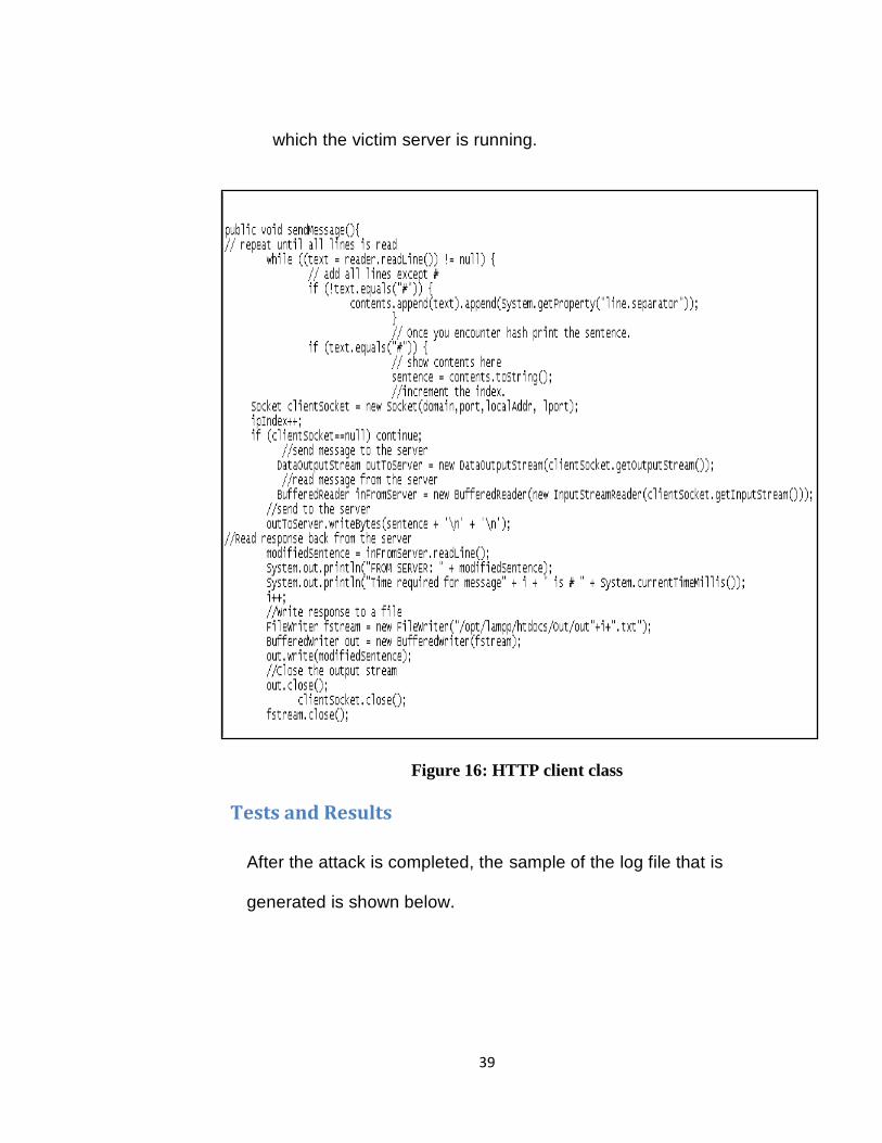
39
which the victim server is running.
Figure 16: HTTP client class
Tests and Results
After the attack is completed, the sample of the log file that is
generated is shown below.

40
Figure 17: HTTP torture test log files
The above file is used to show the output in a graphical format. The
graph is plotted using Google Chart API [32].

41
Figure 18: Graphical generation code
Figure 19: Graphical output

42
The above graph is plotted with the number of messages sent
against time taken to receive a response back from the server.
The user can see the output of the attacks in the form of log files
or the graph shown above or he can also check the server logs,
shown in Figure 20.
Figure 20: Apache server log
7.2.1.2 HTTP Slow DoS Attack
This attack is performed using an open source HTTP DoS
attack program called Slowloris [26]. It is a low bandwidth,
poisonous HTTP Client which keeps HTTP connections half
open [26]. The connections are kept alive by sending HTTP
headers at regular intervals [26]. This worm is successful in

43
making the web server completely unreachable. It is particularly
effective against servers that support multithreading [26]. This
worm has been written in Perl and requires a Perl interpreter to
run the program. In our application, we have included this
attack so that we can provide the user a way to perform HTTP
DoS attack by slowly consuming a server’s bandwidth. The user
can perform this attack in our application by simply providing
the IP address and the port number of the victim’s server.
Once the attack starts, the server stops responding to valid
requests within a few minutes. While the attack is in progress,
log files are not generated. The benefit of this feature is that
even though the web server is down no one can debug the log
files to find the root cause of the downtime. Once the attack is
complete all the errors are logged by the server.
The steps followed to run this attack are:
Figure 21: Slow DoS attack script
Tests and Results Before running the attack, we can use Nmap to check the open ports

44
and services running on the ports. Executing the command “nmap
localhost” on the command line gives us the output shown below. The
output below shows that HTTP service is running on port 80 and the
current state is open.
Figure 22: Nmap port scan before the attack
The output after running the attack is shown in the screenshot in Figure 23.

45
Figure 23: Slowloris output
While the attack is running, the server stops responding to the valid
requests. If we execute the command “nmap localhost” again after a
few minutes, we see the following output, which shows that port 80 is
filtered.
Figure 24: Nmap port scan after the attack

46
Using Hping3 we can confirm that the port is filtered. If the port is
filtered, there is 100% packet loss.
Figure 25: hping3 output after the attack
When we ping the server using Nmap
(nmap –sP –PT 80 127.0.0.1), we see that the server is actually down.
Figure 26: Output after pinging the server using Nmap
Output from the server log file is shown below:

47
Figure 27: Apache server log
7.2.2 SIP Protocol DoS Attack
A SIP DoS attack can be performed by sending malformed packets
or by flooding the server with “Register” or “Invite” messages [34].
Our application is designed to perform SIP torture testing by using
PROTOS Test-Suite: c07-sip [22]. The reason for including this in
our tool is that SIP is becoming increasingly popular among vendors
such as Cisco, Microsoft, etc. In our application we are using this to
perform a DoS attack against a SIP server. The PROTOS test suite
has exposed vulnerabilities against many servers and at times it has
been successful in launching a DoS attack [22]. During testing,
invalid INVITE messages are sent to the SIP server in order to
stress the SIP parser and thereby evaluate the robustness of the

48
server. SIP protocol, like HTTP protocol, is more prone to attacks,
which make it more suitable to include it in our tool. The test suite is
designed is to exploit INVITE messages because the SIP entity
types must support the INVITE method. The fact that the user agent
and proxy entity types accept any incoming requests without any
prior session setup exposes an important vulnerability [22]. The
numerous header-fields in the INVITE method make it more
susceptible to attacks. The attack uses the following steps [22]:
1. Send the INVITE test-cases to default SIP port 5060 over UDP.
2. Send the CANCEL request.
3. Send ACK for the teardown.
4. Send a valid INVITE.
5. Send a CANCEL request again for the valid INVITE.
6. Send ACK for the valid INVITE teardown.
After each INVITE message a session tear down request is sent
(CANCEL, ACK) because as it is an automated test there is no
manual intervention to reject the incoming call.

49
Figure 28: SIP torture test UI
We have included this suite in our application as shown below.
Figure 29: SIP torture test code
Once the attack starts, thousands of invalid SIP requests are sent to
the SIP server. The server sends responses back to each message
[22]. The server response is stored in the log file. The contents of
the log file are displayed below.

50
Figure 30: SIP torture test log file
7.2.3 TCP/IP Protocol Attack
In our application, we have covered 20 TCP/IP DoS attacks. The
attacks are performed by flooding the server with continuous
requests. For the implementation of these attacks we have used
the Nmap and Hping tools. These tools help create malicious
packets that can be constantly sent to the server. The user only
needs to provide the IP address of the victim’s machine.
These kinds of attacks are done for firewall testing. Our tool can
currently perform the attacks shown in the table below.

51
Table 3: TCP attacks list
Below we will discuss some of these attacks and their
implementations.
SYN FLOOD
This type of an attack is carried out by sending many SYN
requests to the server, thereby overloading the server. The
excessive requests result in the server not being able to
respond to all of the requests. These half open connections
cause denial of service for legitimate requests. If the server is
Attacks IP Record Route attack
IP Strict Source Route attack
IP Timestamp attack
TCP Timestamp attack
XMAS attack
Ping Flood attack
SYN Flood attack
Ping Of Death attack
IP Unknown Protocol attack
Port scan attack
Spoofing attack
SIP Broadcast attack
SIP Multicast attack
LAND attack
WINUKE attack
IP Sweep Scan attack
Loose Source Route attack
Network Performance
Open Port Scan

52
flooded to its limit, then there exists a possibility of the server
crashing. To perform this attack we use the flags provided in
hping3. The script used to perform this attack is given below:
sudo -u root -S hping3 -I eth1 -a 10.0.2.15 -S 10.0.2.16 -
p 80 -i u1000 < password"
PING OF DEATH (POD)
A regular TCP/IP packet has a maximum size limit of 65536
bytes [23]. Packet sizes above the maximum size limit are
dropped. However, an IP packet can be broken down into
smaller parts by “fragmentation” [23]. POD attack sends a
single packet larger than the permissible size by breaking it into
smaller fragments which add up to be greater than the size limit
[23]. Systems can crash while receiving such packets. The
following command is used to perform this attack:
ping –l 65510 10.10.20.101
LOCAL AREA DENIAL ATTACK (LAND)
The attack is performed during a TCP “handshake” by sending
a spoofed packet. The packet is “spoofed” to have the same
IP address for both source and destination [39]. This can
cause a machine to think it is receiving a message from itself,
thereby slowing the performance or in some cases crashing
the system. This type of attack has been found to affect the

53
Windows 95, NT and XP systems [39]. The command given
below is used to perform this attack where $domain is the IP
address of the machine.
sudo -u root -S hping3 -S -a $domain -p 21 $domain -i
u1000 < password
SMURF ATTACK
A Smurf attack uses an Internet Control Message Protocol
(ICMP) echo request to flood the victim’s network [24]. An
ICMP echo request is carried out by sending an echo packet to
the intended machine. The machine replies to this request by
sending an ICMP echo reply. This confirms that the machine is
connected to the network. An ICMP echo packet, when sent to
an IP broadcast address on the network, will be distributed to
all the machines within the network [24]. The Smurf attack is
performed by sending an ICMP echo request to an IP
broadcast address with a source IP address of the intended
victim. Hence the victim will receive multiple ICMP echo
replies, thereby creating network congestion [24]. The
following command is used to perform this attack:
ping -t 100 -s 10000 -f $domain -i 2
WINNUKE ATTACK
WinNuke is a type of DoS attack which affects Windows

54
machines [33]. This attack is generally performed on port 139
and it sends out-of-band (OOB) data to the IP address of any
Windows machine [33]. If the Windows machine fails to
handle this data, it can either crash the system or cause loss
of connectivity. The way this attack is performed in our tool is
by using nemesis software as shown below:
for {set i 1} {$i<=100000} {incr i} {
puts [exec nemesis tcp -fU -u 890 -x 16788 -y 139 -d eth1 -D
10.0.2.15]
}
-f – sets TCP URG flag
-u - urgent pointer
-x – source port
-y- destination port
PORT SCAN ATTACK
Port Scan is a type of attack used to find ways to break into a
system. It involves sending messages to each port at a time
and determining the state of the port based on the response
received. In our application, we perform this attack by using
Nmap and Hping. The following script is run to perform this
attack.

55
Figure 31: Port scan attack file
Tests and Results
Here we see the results of some of the TCP/IP DoS attacks:
Figure 32: IP record route output

56
Figure 33: ICMP timestamp option attack output
Figure 34: ICMP Unknown Protocol attack output
Figure 35: IP broadcast attack output

57
Figure 36: IP multicast attack output
Figure 37: SYN flood attack output
These output log files show the statistics that provide information
such as packets transmitted, packets received, packet loss, and
roundtrip time in milliseconds. These files can be used to study the
58
firewall testing rules. These tests can be run at different times to
compare the results.
7.3 APPLICATIONS
PenTestPro is designed to be deployed as a stand-alone
application or as a Software-as-a-Service (SaaS). A company can
ensure the privacy and security of its resources by deploying the
application inside its own private network for in-house testing. The
application provides a web portal for the user to select attacks and
enter the appropriate parameters for those attacks. Another benefit
is that this application simplifies the process of penetration testing
for academic research and activities.
8. AREAS OF IMPROVEMENT
Pen Test Pro can be used currently only via a web portal, but in the future it
can be converted to a web service where SOAP or REST calls can be made
for accessing the attack modules via the program.
Pen Test Pro is designed to perform attacks based on HTTP, SIP, and
TCP/IP protocols. In an effort to expand the range and ability of the
application, we need to incorporate other protocol-based attacks as well as
cloud-based attacks.
Graphical output analysis can be enhanced to provide information such as
severity analysis and priority ranking.

59
In comparison to the professional tools available, PenTestPro currently does
not support enhancements such as a comprehensive attack database or
attack mitigation strategies.
9. CONCLUSION
Penetration testing is a very effective method to analyze the strength of a
system’s security. By providing an automated way to perform the protocol
based attacks, we have developed an application which could be leveraged
by organizations or individuals seeking to harness the power of penetration
testing. The application is successful in achieving its goal for providing
comprehensive testing and analysis in a user-friendly and easy manner.

60
10. REFERENCES
[1] Core Security Technologies, http://www.coresecurity.com/content/intro-pen-test
[2] Penetration Testing Guide, http://www.penetration-testing.com/
[3] Red Teaming: The Art of Ethical Hacking Red Teaming,
http://www.sans.org/reading_room/whitepapers/auditing/red-teaming-art-ethical-
hacking_1272
[4] Pentesting, http://www.c2networksecurity.com/pentesting.html
[5] Discussion on Penetration testing- Tech Forum,
http://techrepublic.com.com/5208-6230-
0.html?forumID=102&threadID=206215&start=0
[6] Manual Vs Automated Penetration testing,
http://www.coresecurity.com/content/manual-penetration-testing-vs-automated-
penetration-testing
[7] Web application security: automated scanning versus manual penetration
testing,ftp://ftp.software.ibm.com/software/rational/web/whitepapers/r_wp_autosca
n.pdf
[8] Security Compliance,http://oa.mo.gov/itsd/cio/architecture/domains/security/CC-
SecurityTesting020206.pdf
[9] Dr. Mark Stamp (2009), Information Security Principles and Practices. Wiley-
Interscience.
[10] The 7 Layers of the OSI Model,
http://www.webopedia.com/quick_ref/OSI_Layers.asp

61
[11] Understanding Application Layer Protocols,
http://www.informit.com/articles/article.aspx?p=169578
[12] HTTP 1.1 Header Definitions, http://www.w3.org/Protocols/rfc2616/rfc2616-
sec14.html
[13] Hyper Text Transfer Protocol, http://www.ietf.org/rfc/rfc2616.txt
[14] Hyper Text Transfer Protocol HTTP 1.0,
http://ftp.ics.uci.edu/pub/ietf/http/rfc1945.html#GET
[15] HTTP 1.1 Status Code Definitions,
http://www.w3.org/Protocols/rfc2616/rfc2616-sec10.html
[16] HTTP 1.1 Response, http://www.w3.org/Protocols/rfc2616/rfc2616-
sec6.html
[17] RFC 3261SIP: Session Initiation Protocol, http://tools.ietf.org/html/rfc3261
[18] CERT/CC Denial of Service,
http://www.cert.org/tech_tips/denial_of_service.html
[19] Ulf Lamping, Richard Sharpe, Ed Warnicke, (2004-2008). Wireshark
User's Guide 31757 for Wireshark 1.2
[20] Hping- Active Network Security Tool, http://www.hping.org/
[21] Hping- Network Security Tool, http://wiki.hping.org/
[22] Protos Test Suite,
https://www.ee.oulu.fi/research/ouspg/PROTOS_Test-Suite_c07-sip
[23] Ping of Death,
http://www.iss.net/security_center/advice/Intrusions/2000012/default.htm

62
[24] CERT Advisory Smurf Denial of Service Attack,
http://www.cert.org/advisories/CA-1998-01.html
[25] Nmap- Free Security for Network Exploration & Security Audits,
http://nmap.org/
[26] Slowloris HTTP DoS, http://ha.ckers.org/slowloris/
[27] 2005 Computer crime survey, http://www.digitalriver.com/v2.0-
img/operations/naievigi/site/media/pdf/FBIccs2005.pdf
[28] CERT,
http://www.uscert.gov/cas/body/bulletins/SB2004_windowsOS.html#508_co
ntent
[29] Tony Howlett (2004), Open Source Security tools. Prentice Hall
[30] Tech Republic, http://www.techrepublic.com/article/evaluating-the-real-
cost-of-an-enterprise-firewall/5033712
[31] Quick Hping, http://scottlinux.com/?p=1167
[32] Live Chart Playground- Google Chart Tools/Image Charts (aka Chart
API), http://code.google.com/apis/chart/docs/chart_playground.html
[33] WinNuke Denial of Service Attack, http://www.physnet.uni-
hamburg.de/physnet/security/vulnerability/winnuke.html
[34] SIP Security,
http://download.securelogix.com/library/SIP_Security030105.pdf
[35] S.S Nagamuthu Krishnan (2010), Defending Denial of Service: State
Overload Attacks, http://www.ijana.in/papers/9.12.pdf

63
[36] Tcl –hping network security tool, http://wiki.hping.org/27
[37] hping3, http://www.pentestit.com/tag/hping3-20051105/
[38] Transmission Control Protocol, http://tools.ietf.org/html/rfc5681
[39] LAND Attack, http://www.physnet.uni-
hamburg.de/physnet/security/vulnerability/land.html
Copyright © 2022 FDOKUMEN


![Testing Testing [Read-Only] - Czone - East Sussex](https://static.fdokumen.com/doc/165x107/6327b2a26d480576770d6757/testing-testing-read-only-czone-east-sussex.jpg)