IS 9187-2 (1980): Deflection Coil Units Used with TV Picture ...
8
Disclosure to Promote the Right To Information Whereas the Parliament of India has set out to provide a practical regime of right to information for citizens to secure access to information under the control of public authorities, in order to promote transparency and accountability in the working of every public authority, and whereas the attached publication of the Bureau of Indian Standards is of particular interest to the public, particularly disadvantaged communities and those engaged in the pursuit of education and knowledge, the attached public safety standard is made available to promote the timely dissemination of this information in an accurate manner to the public. इंटरनेट मानक “!ान $ एक न’ भारत का +नम-ण” Satyanarayan Gangaram Pitroda “Invent a New India Using Knowledge” “प0रा1 को छोड न’ 5 तरफ” Jawaharlal Nehru “Step Out From the Old to the New” “जान1 का अ+धकार, जी1 का अ+धकार” Mazdoor Kisan Shakti Sangathan “The Right to Information, The Right to Live” “!ान एक ऐसा खजाना > जो कभी च0राया नहB जा सकता ह ै” Bhartṛhari—Nītiśatakam “Knowledge is such a treasure which cannot be stolen” IS 9187-2 (1980): Deflection Coil Units Used with TV Picture Tubes, Part 2: Type DCU I S for 470 mm, 510 mm, 590 mm and 610 mm TV Picture Tubes [LITD 5: Semiconductor and Other Electronic Components and Devices]
-
Upload
khangminh22 -
Category
Documents
-
view
1 -
download
0
Transcript of IS 9187-2 (1980): Deflection Coil Units Used with TV Picture ...

Disclosure to Promote the Right To Information
Whereas the Parliament of India has set out to provide a practical regime of right to information for citizens to secure access to information under the control of public authorities, in order to promote transparency and accountability in the working of every public authority, and whereas the attached publication of the Bureau of Indian Standards is of particular interest to the public, particularly disadvantaged communities and those engaged in the pursuit of education and knowledge, the attached public safety standard is made available to promote the timely dissemination of this information in an accurate manner to the public.
इंटरनेट मानक
“!ान $ एक न' भारत का +नम-ण”Satyanarayan Gangaram Pitroda
“Invent a New India Using Knowledge”
“प0रा1 को छोड न' 5 तरफ”Jawaharlal Nehru
“Step Out From the Old to the New”
“जान1 का अ+धकार, जी1 का अ+धकार”Mazdoor Kisan Shakti Sangathan
“The Right to Information, The Right to Live”
“!ान एक ऐसा खजाना > जो कभी च0राया नहB जा सकता है”Bhartṛhari—Nītiśatakam
“Knowledge is such a treasure which cannot be stolen”
“Invent a New India Using Knowledge”
है”ह”ह
IS 9187-2 (1980): Deflection Coil Units Used with TVPicture Tubes, Part 2: Type DCU I S for 470 mm, 510 mm, 590mm and 610 mm TV Picture Tubes [LITD 5: Semiconductor andOther Electronic Components and Devices]


UDC 621.397.331.24 : 621.318.1.042.12
Indian Standard
[sl 1 I
SPECIFICATION FOR DEFLECTION COIL U-NITS USED WITH TV PICTU-RE TUBES
PART II TYPE DCU IS FOR 470 mm, 510 mm, 590 mm AND 610 mm TV PICTURE TUBES
0. General - This standard shall be read in conjunction with IS: 9187 (Part I)-1979 ‘Specification for deflection coil units used with TV picture tubes: Part I General requirements and tests’.
1. Type ~Designation - This deflection coil unit shall be designated as ‘deflection coil unit type DCU 1 S’.
DCU means deflection coil unit 1 represents TV picture tubes of sizes 470 mm, 510 mm, 590 mm and 610 mm, and
S denotes solid state circuitry.
2. Application - The deflection coil unit type DCU 1 S is meant for use with 470 mm, 510 mm, 590 mn and 610 mm, 110” to 114” black and white picture tube in conjunction with:
a) line output transformer used with TV picture tubes, type LOT 1 S for 470 mm, 510 mm, 590 mm ant 610 mm TV picture tubes [see Indian Standard Specification for line output transformer used with TV picture tubes, type LOT IS for 470 mm, 510 mm, 590 mm and 610 mm TV picture tubes (under preparation)]
b) linearity control unit used with TV picture tubes, type LCU 1 S for 470 mm, 510 mm, 590 mm ant 610 mm TV picture tubes [see Indian Standard Specification for linearity control unit used with TV picture tubes, typf LCU IS for 470 mm, 510 mm, 590 mm and 610 mm TV picture tubes (under preparation)]
3. Description -The saddle-shaped line deflection coils shall be mounted on moulded case so tha the deflection centre shall be well within the conical part of the picture tube. The field deflection coil: shall be wound on a ferrite yoke ring which is flared so that the frame and line deflection centres coincide The relative positions of the frame and line deflection coils are so adjusted that their fluxes are at righ, angle to each other. The unit shall meet the self-extinguishing and non-dripping requirements of lndiar Standard ‘Safety requirements for mains operated electronic and related apparatus for household ant similar general use’ (under preparation).
4. Outline and Dimensions - The outline and the dimensions shall be according to Fig. 1.
Magnet positions (I), (2) and (3) as shown above
All dimensions in millimetres.
FIG. 1 OUTLINE AND DIMENSIONS
5. Mounting - The deflection unit shall be mounted as far forward as possible on the neck of the picturl tube, so that it touches the cone. To orient the rester correctly, the unit may be rotated by hand on thm neck of the picture tube with which it shall make a slip fit. A screw-tightened clamping ring shall permi it to be locked, both axially and radially, in the desired position.
0 July 1980, ISI
INDIAN STANDARDS INSTITUTION MANAK BHAVAN, 9 BAHADUR SHAH ZAFAR MARG
NEW DELHI 110002
IS : 9187 (Part II) - 1980
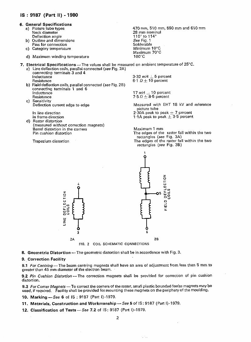
6. General Specifications a) Picture tube types 470 mm, 510 mm, 590 mm and 610 mm
Neck diameter 28 mm nominal Deflection angle 110” to 114”
b) Outline and dimensions See Fig. 1 Pins for connection Solderable
c) Category temperature Minimum 10°C Maximum 70°C
d) Maximum winding temperature 1oo”c
7. Electrical SDecifications - The values shall Abe measured on ambient temperature of 25°C. 4
b)
c)
d)
Line deflection coils, parallel connected (see Fig. 2A) connecting terminals 3 and 4 Inductance Resistance Field deflection coils, parallel connected (see Fig. 2B) connecting terminals 1 and 6 Inductance Resistance Sensitivity Deflection current edge to edge
In line direction In frame direction Raster distortion (measured without correction magnets) Barrel distortion in the corners Pin cushion distortion
Trapezium distortion
2A
3.32 mH & 5 percent 6.1 Q & IO percent
17 mH f 10 percent 7.5 Q & 8.5 percent
Measured with EHT 18 kV and reference picture tube
2.30A peak to peak 5 7 percent l.lA peak to peak f 3.5 percent
Maximum 1 mm The edges of the raster fall within the two
rectangles (see Fig. 3A) The edges of the raster fall within the two
rectangles (see Fig. 3B)
6
2B FIG. 2 COIL SCHEMATIC CONNECTIONS
8. Geometric Distortion -The geometric distortion shall be in accordance with Fig. 3.
9. Correction Facility
9.1 For Centring- The beam centring magnets shall have an area of adjustment from less than 5 mm to greater than 45 mm diameter of the electron beam.
9.2 Pin Cushion Distortion - The correction magnets shall be provided for correction of pin cushion distortion.
9.3 For Corner Magnets - To correct the corners of the raster, small plastic bounded ferrite magnets may be used, if required. Facility shall be provided for mounting these magnets on the periphery of the moulding.
IO. Marking - See 6 of IS : 9187 (Part I)-1979.
11, Materials, Construction and Workmanship -See 5 of IS: 9187 (Part I)-1 979.
12. Classification of Tests-see 7.2 of IS: 9187 (Part I)-1979.
2

IS : 9187 (Part II) - 1980
c
3A All dimensions in millimetres. 30
FIG. 3 GEOMETRIC DISTORTION
12.1 General Conditions for Tests - See 7.1 of IS : 9187 (Part I)-1 979.
12.2 The test schedule and the requirements shall be in accordance with Table 1.
SI No.
(1) i) AN
a)
b)
cl
4
e)
f 1
9)
h)
j)
k)
Test
(2)
Samples
Visual examination
Dimensions
TABLE 1 TEST SCHEDULE AND REQUIREMENTS
Continuity of winding 7.4.2
Operating current 7.4.1
DC resistance 7.4.3
Inductance 7.4.4
Voltage-proof 7.4.7
Insulation resistance
Deflection sensitivity (with accelerating voltage)
7.4.8 -
7.4.5 -
Distortion (pin cushion, barrel effect and perpendicularity/trapezium)
7.4.8 -
ii) First Group
a) Soldering
,I ) Visual examination
2) Continuity of winding
b) Robustness of terminations
1) Visual examination
2) Continuity of winding
c) Bump
7.6
7.3.1
7.4.2
7.7
7.3.1
7.4.2
7.8
1) Visual examination 7.3.1
2) Continuity of winding 7.4.2
Clause Ref of IS: 9187
(Part I)-1979
(3) -
7.3.1
7.3.2
Condition of Test
(4) -
-
-
-
-
-
-
-
-
-
-
-
1 000 bumps for 10 g
-
-
Requirements
(5)
The workmanship, condition and finish shall be satisfactory. The marking shall be legible.
The dimensions shall conform to the dimensions shown in Fig. 1.
Each winding shall be continuous.
The operating current shall be in accordance with 7(c).
The dc resistance shall be in accordance with 7(a) and 7(b).
The inductance shall be in accor- dance with 7(a) and 7(b).
There shall be no breakdown or flashover at 2 kV ac.
1 000 M Q Min at 500 V dc.
The peak to peak current flowing through the line deflection coils as well as frame deflection coils shall be in accordance with 7(c).
The picture outline distortion shall be as shown in Fig. 3.
-
There shall be no damage.
Each winding shall be continuous.
There shall be no damage.
Each winding shall be continuous.
There shall be no damage.
Each winding shall be continuous.
(Continued)
3

IS : 9187 (Part II) - 1980
TABLE 1 TEST SCHEDULE AND REQUIREMENTS-Contd
SI Test Clause Ref No. of IS: 9187
(Part I) -1979
(1) (2) (3)
d) Vibration 7.9
1) Visual examination 7.3.1
2) Continuity of winding 7.4.2
3) DC resistance 7.4.3
4) Inductance 7.4.4
5) Insulation resistance 7.4.8
0) Voltage-proof 7.4.7
e) Shock 7.14
1)
2)
3)
4)
5)
0)
Visual examination 7.3.1
Continuity of winding 7.4.2
DC resistance 7.4.3
inductance 7.4.4
Insulation resistance 7.4.8
Voltage-proof 7.4.7
f) Acceleration
1) Visual examination
2) Continuity of winding
3) DC resistance
4) Inductance
5) Insulation resistance
0) Voltage- proof
7.15
7.3.1
7.4.2
7.4.3
7.4.4
7.4.8
7.4.7
g) Climatic 7.10
1) Dry heat 7.10.2
i) Insulation resistance 7.4.8
Condition of Test
Requirements
(4)
10 to 55Hz. duration 6 hours
(5)
-
- There shall be no damage.
-
-
-
30 gi gdurrstion
-
-
-
-
-
-
20 g
-
- Each winding shall be continuous.
-
-
-
-
-
At Ma-x category temp (70°C or
100°C)
- 1 000 M Q at 500 V dc.
Each winding shall be continuous.
DC resistance shall be in accordance with 7(a) and 7(b).
Inductance shall be in accordance with 7(a) and 7(b).
1 000 MQ, Min at 500 V dc.
There shall be no breakdown nor flashover at 2 kV ac.
-
There shall be no damage.
Each winding shall be continuous.
DC resistance shall be in accordance with 7(a) and 7(b).
Inductance shall be in accordance with 7(a) and 7(b).
1 000 M Q, Min at 500 V dc.
There shall be no breakdown or flashover at 2 kV ac.
There shall be no damage.
DC resistance shall be in accordance with 7(a) and 7(b).
Inductance shall be in accordance with 7(-a) and 7(b).
1 000 M Q, Min at 500 V dc.
There shall be no breakdown or flashover at 2 kV dc.
Note - The dry heat test shall be carried out at maximum temperature 70°C by loading the deflection coil units with the appropriate current and voltage or at maximum temperature 100°C on no load.
ii) Visual examination 7.3.1
iii) Insulation resistance 7.4.8
2) Damp heat (accelerated) first cycle 7.10.3
i) Visual examination 7.3.1
ii) Insulation resistance 7.4.8
3) Cold 7.10.4
i) Visual examination 7.3.1
ii) Continuity of winding 7.4.2
iii) Voltage- proof 7.4.7
- There shall be no damage.
- 1 000 M 9 at 500 V dc.
-
- There shall be no damage.
- 1 000 M Q at 500 V dc.
+lo”c
- There shall be no damage.
- Each winding shall be continuous.
There shall be no -breakdown or flashover at 2 kV.
(Continued)
4

IS : 9187 (Part II) - 1980
TABLE 1 TEST SCHEDULE AND REQUIREMENTS-Cc~ntd
SI No.
(1)
4)
5)
Test Clause Ref of-IS: 9387
(Part I) -1979
Condition of -Test
(2) (3) (4)
Air pressure (low) 7.10.5 60 kPa
Damp heat (accelerated) remaining cycle
i) Visual examination
ii) Continuity of winding
iii) DC resistance
7.10.6
7.3.1
7.4.2
7.4.3
iv) Inductance 7.4.4
v) Insulation resistance
vi) Voltage- proof’
7.4.8
7.4.7
-
-
-
-
-
-
-
-
-
-
-
-
-
-
-
-
-
iii) Second Group
a) Damp heat (long-term exposure)
1) Visual examination
2) Continuity of winding
3) DC resistance
7.11
7.3.1
7.4.2
7.4.3
4) Inductance 7.4.4
5) Insulation resistance
6) Voltage-proof
7.4.8
7.4.7
iv) Third Group
a) Endurance (electrical)
1) Visual examination
2) Continuity of winding
3) DC resistance
4) Inductance
7.1~6
7.3.1
7.4.2
7.4.3
7.4.4
5) Insulation resistance 7.4.8
6) Voltage-proof 7.4.7
b) Flammability 7.17
v) Fourth Group
a) Mould growth
1) Visual examination
~2) Continuity of winding
7.12
7.3.1
7.4.2
vi) Fifth Group
a) Temperature-rise 7.5
vii) Sixth Group
a) Salt mist
1) Visual examination
2) Continuity of winding
7.13
7.3.1
7.4.2
Requirements
(5)
There shall be no breakdown or failure of mechanical deterioration.
There shall be no damage.
Each winding shall be continuous.
DC resistance shall be in accordance with 7(a) and 7(b).
Inductance shall be in accordance with 7(a) and 7(b).
1 000 MQ, Min at 500 V dc.
There shall be no breakdown or flashover at 2 kV ac.
-
There shall be no damage.
Each winding shall be continuous.
DC resistance shall be in accordance with 7(a) and 7(b).
Inductance shall be in accordance with 7(a) and 7(b).
1 000 MQ, Min at 500 V dc.
There shall be no breakdown or flashover at 2 kV ac.
-
There shall be no damage.
Each winding shall be continuous.
DC resistance shall be in accordance with 7(a) and 7(b).
Inductance shall be in accordance with 7(a) and 7(b).
1 000 M Q, Min at 500 V dc.
There shall be no breakdown or flashover at 2 kV ac.
Burning particles shall not detach from the components.
There shall be no damage.
Each winding shall be continuous.
The temperature-rise shall not exceed 30°C.
There shall be no damage.
Each winding shall be continuous.
5 Sree Saraswaty Press Ltd., (Under W. B. Govt.‘s
Management) Calcutta, India.