FAN COIL THERMOSTAT HE-FT01 USER MANUAL V1.0
18
FAN COIL THERMOSTAT HE-FT01 USER MANUAL V1.0
-
Upload
khangminh22 -
Category
Documents
-
view
0 -
download
0
Transcript of FAN COIL THERMOSTAT HE-FT01 USER MANUAL V1.0

FAN COIL THERMOSTAT HE-FT01
USER MANUAL V1.0
Table of ContentOverview.........................................................................................................................................................................3
Technical Specifications...................................................................................................................................................3
Disassembly.....................................................................................................................................................................6
Touch Panel Operation....................................................................................................................................................6
Climate Control Modes....................................................................................................................................................7
Heating & Cooling.......................................................................................................................................................7
Heating.......................................................................................................................................................................7
Cooling.......................................................................................................................................................................7
Ventilation..................................................................................................................................................................7
Fan Speed Modes............................................................................................................................................................7
Operating Modes.............................................................................................................................................................8
COM - Comfort Mode.................................................................................................................................................8
TIME - Temperature Schedule Mode (Auto)...............................................................................................................8
ECO - Energy Saving Mode.........................................................................................................................................9
OFF – Operating modes disabled................................................................................................................................9
Child Lock (LOC)...............................................................................................................................................................9
Factory Reset (RES)..........................................................................................................................................................9
Settings Menu.................................................................................................................................................................9
Parameter List..........................................................................................................................................................10
Time Configuration...................................................................................................................................................11
Temperature Configuration......................................................................................................................................11
Display Brightness....................................................................................................................................................11
Touch Sensitivity......................................................................................................................................................12
Power and Energy Consumption..............................................................................................................................12
Hardware & Firmware Versions...............................................................................................................................12
Z-Wave Network......................................................................................................................................................12
Adding to a Z-Wave network...............................................................................................................................13
Removal from a Z-Wave network........................................................................................................................13
Security...............................................................................................................................................................13
SmartStart...........................................................................................................................................................14
Firmware OTA Update.........................................................................................................................................14
Associations.........................................................................................................................................................14
Z-Wave Plus V2 Specifications.............................................................................................................................15
Thermostat Settings Using Z-Wave Protocol (Gateway)......................................................................................15
Factory default parameters.................................................................................................................................16
Warranty (2-Year)..........................................................................................................................................................18
2

OverviewThis is the user manual for the HELTUN HE-FT01 Advanced Programmable Thermostat for Fan Coil Heating/CoolingSystems. The HE-FT01 can be flush mounted over standard round or square electrical junction boxes. It is designedto maintain a constant room temperature using internal air temperature sensor.
It is recommended for control of air conditioning/heating systems such as: split/multi-split systems, chillers and fan coilunit systems, central air conditioning systems, multi-zone VRF/VRV air conditioning systems, etc. The fan speed iscontrolled by three relay outputs. Two more relay outputs control cooling and heating valves. The HE-FT01 has twoindependent inputs for relay channels which allow it to control fans and valves with different power sources or to userelay outputs as dry contacts. Each relay can carry a load of up to 5A.
The HE-FT01 has an LCD screen with auto-sensing or manually adjustable brightness control, six sensitive capacitivetouch-control buttons, and internal sensors for air temperature and humidity. The HE-FT01 is also equipped with lightsensor and software energy consumption logic.
The HE-FT01 integrates a Z-Wave 700 platform module allowing it to be used with Z-Wave home automationsystems. The HE-FT01 supports Z-Wave ‘S0’ and ‘S2’ security protocols, SmartStart technology, and can beconnected (“associated”) to 50 other Z-Wave devices, such as relays, switchers, etc.
You can select one of four operation modes (COM, TIME, ECO, OFF) either manually, or by using a Z-Wavecontroller/gateway. The HE-FT01 operates in four Climate Modes: Heating & Cooling, Heating only, Cooling only,Ventilation, and has six levels for fan speed control: Low, Medium, High, Auto Medium, Auto High, Off.
The display has a user-friendly interface, showing: air temperature, humidity level, user set point, operating mode,climate mode, fan speed, time, weekday and Z-Wave network status. Display brightness adjusts to ambient lightconditions automatically making it always easy to read.
Technical Specifications Front frame (on wall) dimensions: 89mm (H) х 89mm (W) х 9mm (D) Rear electronics package dimensions: 53mm (H) х 53mm (W) х 28mm (D) Materials: Tempered glass display/body, Flame retardant plastic 5 frame colors: White, Gloss Black, Matte Black, Silver, Chrome 6 glass colors: White, Black, Yellow, Green, Red, Blue LCD: 73mm x 42mm (3.3 inch), black with white segments 6 capacitive-touch buttons 5 relays with resistive load up to 5A each
o 2 relays for cooling and heating valveso 3 relays for fan speed
2 independent relay inputs (dry contact) Relay switching with HELTUN Advanced Zero-Cross Technology Relays lifetime: 100.000 switches Internal ambient light sensor Internal temperature sensor
o Measurement range: –30°C to +80°Co Accuracy: ±0.5°C
Internal humidity sensoro Measurement range: 0% to 80%RHo Accuracy: ±3.0%RH
Software energy consumption logic Operating temperature: 0°С to +50°С Power supply: 85-265VAC 50Hz/60Hz, 24-48VDC Power consumption: 1W IP class: IP21 Z-Wave Plus V2 SDK: V7.11 Z-Wave module: ZGM130S Requires mounting to flush electrical junction box:
round or square type – min. depth 40mm
3
Functions & Features Options for Inclusion/Exclusion to/from Z-Wave network
o Non-Secureo S0 Secureo S2 Unauthorized, S2 Authorized with Key
Association control of 50 devices from network 4 operational modes with individual temperature set points:
o COM – Comfort Mode o ECO – Energy saving Mode o TIME – Schedule Modeo OFF – Idle
Four climate modes:o Heating & Cooling,o Heating only,o Cooling only,o Ventilation only
Six Fan Speed control modes:o Low speedo Medium speedo High speedo Auto Medium speedo Auto High speedo Off
Four Time Schedules for 7 days of the week:o Morning o Day o Evening o Night
Periodic measurements from:o Internal temperature sensoro Internal humidity sensoro Internal ambient light sensoro Energy consumption logic
Calibration of Internal Room Air Temperature Sensor Temperature set intervals: 4.0°C to 37.0°C HELTUN Advanced Zero-Cross relay switching technology Temperature hysteresis selection range: 0.2°C to 10.0°C Temperature measurement: Celsius (°C) or Fahrenheit (°F) Time format: 24 or 12 hours (AM/PM) LCD brightness:
o Automatic adjustment (depending on ambient light)o Manual adjustment (15 levels).
LCD standby mode (different brightness for active and inactive states) LCD backlight blinking function (for easy identification among other Z-Wave devices) Child lock mode (touch buttons lockout mode) Power consumption software logic Factory reset function SmartStart technology for quick addition to Z-Wave networks OTA (Over The Air) encrypted firmware update
4
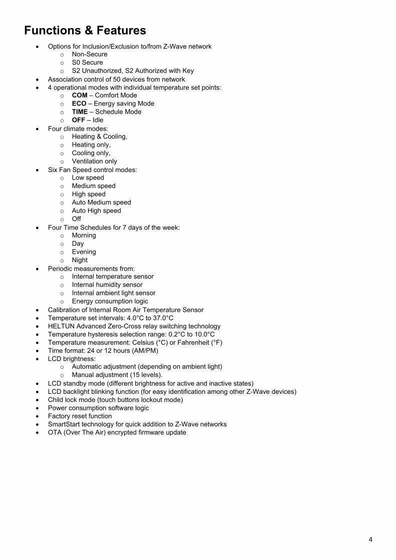
InstallationHELTUN recommends the HE-FT01 thermostat be installed by a licensed electrician in a mannerthat conforms to local regulations and building codes. Provide these instructions to the licensedelectrician who is installing the HE-FT01.
WARNING: Electrical power must be switched off during installation.
1. Placement of the HE-FT01 is of utmost importance for proper operation and must be away fromsunlight and sources of direct heat. We recommend installing the HE-FT01 approximately 1.5meters above the floor.
2. Remove the display unit and backplate of the HE-FT01 from the packaging.
3. FIRST ENSURE THE POWER IS OFF at the main circuit breaker, and then test the wires with aprobe or multimeter to verify. Insert the power wires to the HE-FT01 “POWER” terminal byinserting a small Phillips-head screwdriver in the slot beneath each terminal to open. Follow theconnection diagram and instructions below:
Power wires: connect Line & Neutral wires to L & N terminals labeled “POWER” Fan Speed: connect the required power source for Fan (Relays 1, 2 and 3 outputs) to terminal IN-1-3. Heating/Cooling valves: connect the required power source for Heating/Cooling valves
(Relays 4 and 5 outputs) to terminal IN-4-5. Loads: Connect the loads to relays output terminals:
OUT-1, OUT-2, OUT-3, OUT-4, OUT-5: OUT-1 for the Fan low speedOUT-2 for the Fan medium speedOUT-3 for the Fan high speedOUT-4 for the heating valve OUT-5 for the cooling valve
4. Make sure the HE-FT01 backplate is oriented on the wall with the word “TOP”pointed upwards. Then secure the backplate onto the electrical junction boxusing the four screws provided (do not overtighten). Once the backplate issecured onto the wall, assemble the HE-FT01 display unit onto the backplate byfirst carefully aligning the two top snap connectors, and then gently pushing theentire display unit until it ‘snaps’ into position all the way around.
5. Next, switch ON the main power at the circuit breaker. The HE-FT01 will start upshowing the original default factory settings.
6. Remove the clear protective film from the display by pulling on the top right-handtab.
5
Figure 1: Connection diagram for 1-valve system Figure 2: Connection diagram for 2-valve system
Disassembly 1. To disassemble, ENSURE POWER IS SWITCHED OFF at the main circuit breaker AND THE LCD SCREEN IS
BLANK.2. To remove the HE-FT01 display unit, grasp firmly at the bottom and pull backwards while tilting outwards until all
tabs disconnect.3. Remove screws from backplate and disconnect the wires by inserting a small Phillips-head screwdriver into the slot
beneath each wire and turning counter-clockwise to release.
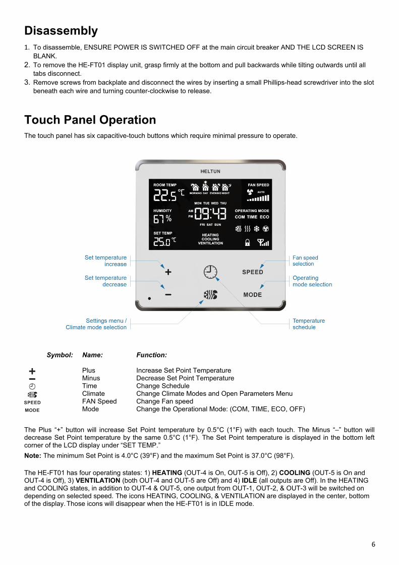
Touch Panel OperationThe touch panel has six capacitive-touch buttons which require minimal pressure to operate.
Symbol: Name:
PlusMinusTimeClimateFAN Speed Mode
Function:
Increase Set Point Temperature Decrease Set Point Temperature Change ScheduleChange Climate Modes and Open Parameters MenuChange Fan speedChange the Operational Mode: (COM, TIME, ECO, OFF)
The Plus “+” button will increase Set Point temperature by 0.5°C (1°F) with each touch. The Minus “–” button willdecrease Set Point temperature by the same 0.5°C (1°F). The Set Point temperature is displayed in the bottom leftcorner of the LCD display under “SET TEMP.”
Note: The minimum Set Point is 4.0°C (39°F) and the maximum Set Point is 37.0°C (98°F).
The HE-FT01 has four operating states: 1) HEATING (OUT-4 is On, OUT-5 is Off), 2) COOLING (OUT-5 is On and OUT-4 is Off), 3) VENTILATION (both OUT-4 and OUT-5 are Off) and 4) IDLE (all outputs are Off). In the HEATING and COOLING states, in addition to OUT-4 & OUT-5, one output from OUT-1, OUT-2, & OUT-3 will be switched on depending on selected speed. The icons HEATING, COOLING, & VENTILATION are displayed in the center, bottom of the display. Those icons will disappear when the HE-FT01 is in IDLE mode.
6
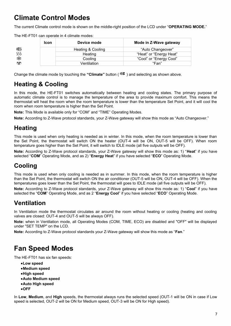
Climate Control ModesThe current Climate control mode is shown on the middle-right position of the LCD under “OPERATING MODE.”
The HE-FT01 can operate in 4 climate modes:
Icon Device mode Mode in Z-Wave gateway
Heating & Cooling “Auto Changeover”Heating “Heat” or “Energy Heat”Cooling “Cool” or “Energy Cool”
Ventilation “Fan”
Change the climate mode by touching the “Climate” button ( ) and selecting as shown above.
Heating & CoolingIn this mode, the HE-FT01 switches automatically between heating and cooling states. The primary purpose ofautomatic climate control is to manage the temperature of the area to provide maximum comfort. This means thethermostat will heat the room when the room temperature is lower than the temperature Set Point, and it will cool theroom when room temperature is higher than the Set Point.
Note: This Mode is available only for “COM” and “TIME” Operating Modes.
Note: According to Z-Wave protocol standards, your Z-Wave gateway will show this mode as “Auto Changeover.”
HeatingThis mode is used when only heating is needed as in winter. In this mode, when the room temperature is lower thanthe Set Point, the thermostat will switch ON the heater (OUT-4 will be ON, OUT-5 will be OFF). When roomtemperature goes higher than the Set Point, it will switch to IDLE mode (all five outputs will be OFF).
Note: According to Z-Wave protocol standards, your Z-Wave gateway will show this mode as: 1) “Heat” if you haveselected “COM” Operating Mode, and as 2) “Energy Heat” if you have selected “ECO” Operating Mode.
CoolingThis mode is used when only cooling is needed as in summer. In this mode, when the room temperature is higherthan the Set Point, the thermostat will switch ON the air conditioner (OUT-5 will be ON, OUT-4 will be OFF). When thetemperatures goes lower than the Set Point, the thermostat will goes to IDLE mode (all five outputs will be OFF).
Note: According to Z-Wave protocol standards, your Z-Wave gateway will show this mode as: 1) “Cool” if you haveselected the “COM” Operating Mode, and as 2 “Energy Cool” if you have selected “ECO” Operating Mode.
VentilationIn Ventilation mode the thermostat circulates air around the room without heating or cooling (heating and coolingvalves are closed: OUT-4 and OUT-5 will be always OFF).
Note: when in Ventilation mode, all Operating Modes (COM, TIME, ECO) are disabled and "OFF" will be displayedunder "SET TEMP" on the LCD.
Note: According to Z-Wave protocol standards your Z-Wave gateway will show this mode as “Fan.”
Fan Speed ModesThe HE-FT01 has six fan speeds:
Low speedMedium speedHigh speedAuto Medium speedAuto High speedOFF
In Low, Medium, and High speeds, the thermostat always runs the selected speed (OUT-1 will be ON in case if Lowspeed is selected, OUT-2 will be ON for Medium speed, OUT-3 will be ON for High speed).
7

At Auto Medium speed, the thermostat will run at Low speed if the Set Point and room temperatures difference isless than 1.0°C, and Medium speed if the Set Point and ambient temperatures difference is higher 1.0C.
At Auto High speed mode, the thermostat will run at Low speed if the Set Point and room temperatures difference isless than 1.0°C. It will run Medium speed if the Set Point and room temperatures difference is higher than 1.0°C butless then 2.0°C. And it will run on High speed if the Set Point and room temperatures difference is higher than 2.0°C.If the Fan Speed selected is OFF, the thermostat will go to IDLE mode (all outputs will be Off).
Note: depending on speed level, only one output from the group OUT-1, OUT-2, or OUT-3 will be ON.
Operating ModesThe HE-FT01 thermostat has Four Operating Modes as follows:
COM – Comfort Mode
TIME – Time Mode (enables different scheduled temperature Set Points per time and day)
ECO – Economy Mode (for power efficient & energy savings)
OFF – Operating modes disabled
You may change Modes by touching the “MODE” button (bottom right of LCD) until the desired Mode is reached. Each Operating Mode has individual temperature Set Points for each Climate Mode (Heating & Cooling Modes). TheHE-FT01 will operate automatically depending on the current Set Point indicated under the “SET TEMP” label on theLCD. To change the Set Point value, choose the desired Operating Mode (COM, TIME or ECO), choose the ClimateMode (“Heating”, “Cooling” or “Heating & Cooling”) and press the Plus “+” button to increase, or Minus “–” button todecrease, the corresponded Set Point value. You may alternatively control Set Points for each Operating and ClimateMode through your Z-Wave gateway software.
COM - Comfort ModeThis mode is recommended for maximum comfort. Under this Operating Mode there are three different Climate controlmodes: “Heating”, “Cooling” and “Heating & Cooling.” And each Climate Mode has its own individual Set Point. Choose the desired climate mode and adjust the temperature Set Point for each mode separately.
Note: In your Z-Wave gateway you will see three Set Points corresponding to different climate modes: “Auto Changeover” in Z-Wave corresponds to “Heating & Cooling” climate mode in the HE-FT01, “Heat” corresponds to “Heating” climate mode, and “Cool” corresponds to “Cooling” climate mode.
Note: “Ventilation” Climate Mode will disable (Switch Off) all Operating Modes including COM.
TIME - Temperature Schedule Mode (Auto)The Temperature Schedule (TIME) Mode can adjust hometemperatures automatically to align with your personal habits, savingenergy while you are away, and maintaining a comfortable temperaturewhile you are active at home.
The HE-FT01 can have different Schedules for Morning, Daytime,Evening and Night. For example, the “Morning” Schedule could be set to25.0°C (77°F) starting at 7:00. The “Day” Schedule could then be set to11.0°C (or 52°F) at 9:00 when everyone has gone to work or school,and so on. Here are recommended Scheduled Set Points for heatingduring the work week – you may wish to change these on weekends depending on your family’s schedule (seeexample below):
ScheduleMode
SetTime
Set Point Temperature
Morning 6:00 24.0°C (75°F)Day 9:00 20.0°C (68°F)
Evening 18:00 23.0°C (73°F)Night 23:00 18.0°C (64°F)
To set up the time and temperature for each Schedule press and hold the Clock “ ” button for three seconds. The display will then change to the Time menu.
8
To set up the start time for each Schedule, choose the Schedule by pressing the Clock “ ” button then adjust the timeby pressing the “SPEED” button to increase, or “MODE” button to decrease. Press the Clock “ ” button again toadvance to the next schedule and set the time for all four: Morning, Day, Evening & Night.
To choose the temperature Set Points for each Schedule, choose the day of the week by pressing the “Climate”button ( ), then choose the Schedule by pressing the Clock “ ” button and adjust the temperature Set Point up ordown by pressing the Plus “+” or Minus “–” buttons. Do this action for each day of the week.
Note: All four times (Morning, Day, Evening, & Night) are the same for all seven days of the week.
Note: TIME mode will only work properly if the correct current time and date have been set. The time can beautomatically corrected from your Z-Wave gateway if the Parameter 01 value is set to 1. Or it can be set manually inParameters 03, 04, and 05 in the Settings Menu (see below).
Note: When in TIME mode, the temperature Set Point (under the label on the LCD: SET TEMP) will be automaticallychanged depending on the Schedule. At any time, the Set Point can be adjusted up or down manually but it will be ineffect only until the next Schedule.
Note: Under TIME mode, the Set Points for all climate modes are the same.
Note: In your Z-Wave gateway this mode will be shown as “Auto”. It is impossible to change the TIME Mode SetPoints through a Z-Wave gateway. If you change the Operating Mode to “Auto” through your Z-Wave gateway, theClimate Mode, “Heating & Cooling,” will be selected on the HE-FT01 according to the value of Parameter 41(1=”Heating & Cooling,” 2=”Heating,” & 3=”Cooling”).
ECO - Energy Saving ModeThis Mode can be used if lower temperatures and energy consumption is desired. It can also be used at night or whenaway the property for a length of time. Under this Operating Mode there are two different Climate control modes: “Heating” and “Cooling”. Each Climate Mode has its individual Set Point. Choose the desired climate mode and adjust the temperature set point for each mode separately.
Note: In your Z-Wave gateway you will see two Set Points corresponding to different climate modes: “Energy Save Heating” in the Z-Wave gateway corresponds to “Heating” climate mode in the HE-FT01, “Energy Save Cooling” corresponds to “Cooling” the HE-FT01 climate mode.
Note: “Ventilation” Climate Mode will disable (Switch Off) all Operating Modes including ECO.
OFF – Operating modes disabled
In this operating mode only Ventilation climate mode can operate. If “Heating”, “Cooling” or “Heating & Cooling”climate modes are selected the device goes to IDLE state.
Child Lock (LOC)The Child Lock feature allows you to disable the HE-FT01 touch buttons temporarily. To activate the Child Lock Mode,press and hold the “SPEED” button for five seconds until the Lock Icon ( ) appears in the bottom right corner of thedisplay. To deactivate the Child Lock, press the “SPEED” button until the Lock Icon ( ) disappears.
Factory Reset (RES)By pressing and holding the “MODE” button for 6 seconds, the HE-FT01 will enter Factory Reset Mode, displaying“REs” in the left bottom corner, “y” and “n” in the center. Press the Plus (+) button to revert to factory settings, or the“SPEED” button to cancel. The factory reset will change all the Parameters to their original factory default values andwill also Exclude the device from any Z-Wave network.
Note: Please use Factory Reset only when the primary network controller is missing or otherwise inoperable.
Settings MenuTo enter the Settings Menu, press and hold the “Climate” button ( ) for three seconds. The abbreviatedParameter Name will be displayed in the top left corner of the LCD. The left center will display the ParameterNumber. And the bottom left corner will display the Parameter Value.
9
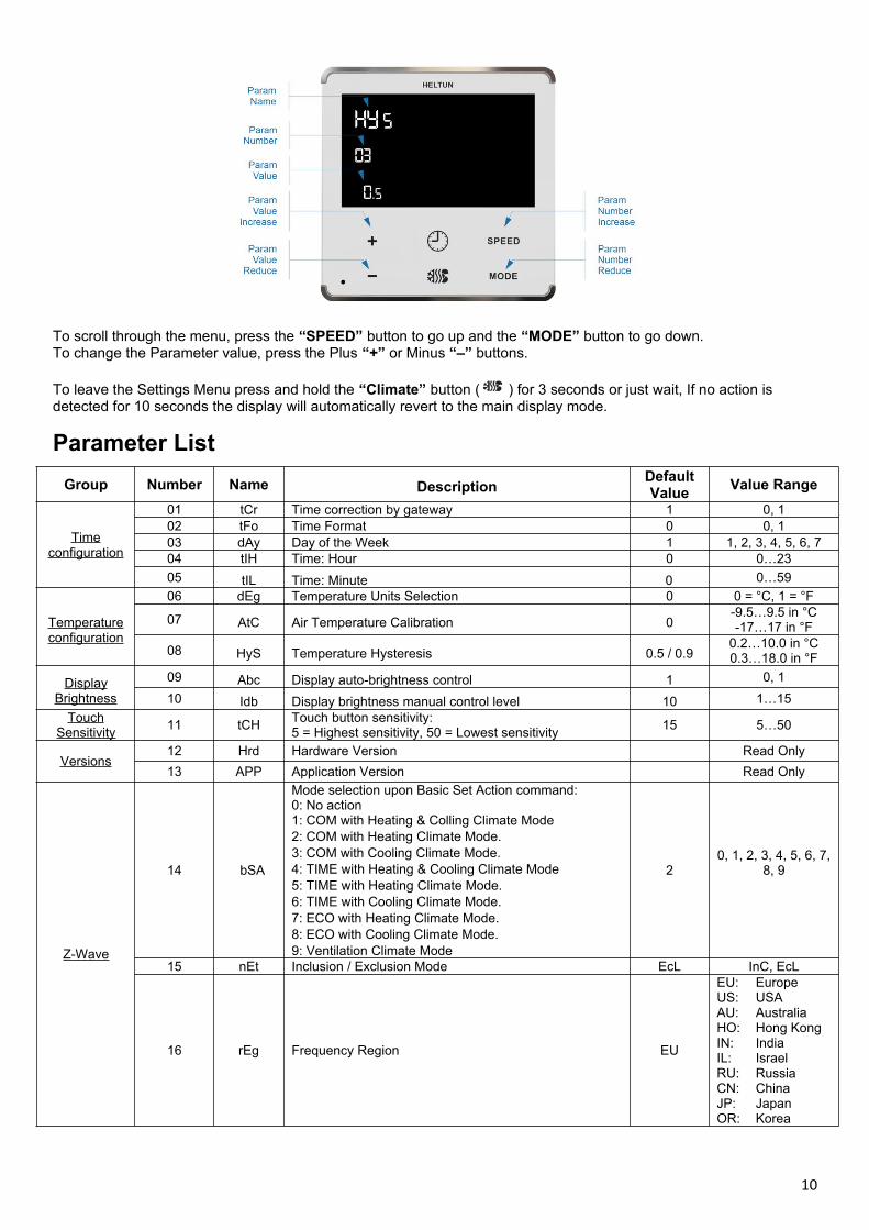
To scroll through the menu, press the “SPEED” button to go up and the “MODE” button to go down.To change the Parameter value, press the Plus “+” or Minus “–” buttons.
To leave the Settings Menu press and hold the “Climate” button ( ) for 3 seconds or just wait, If no action is detected for 10 seconds the display will automatically revert to the main display mode.
Parameter List
Group Number Name DescriptionDefaultValue
Value Range
Timeconfiguration
01 tCr Time correction by gateway 1 0, 102 tFo Time Format 0 0, 103 dAy Day of the Week 1 1, 2, 3, 4, 5, 6, 704 tIH Time: Hour 0 0…23
05 tIL Time: Minute 0 0…59
Temperatureconfiguration
06 dEg Temperature Units Selection 0 0 = °C, 1 = °F
07 AtC Air Temperature Calibration 0-9.5…9.5 in °C-17…17 in °F
08 HyS Temperature Hysteresis 0.5 / 0.90.2…10.0 in °C0.3…18.0 in °F
DisplayBrightness
09 Abc Display auto-brightness control 1 0, 1
10 Idb Display brightness manual control level 10 1…15
TouchSensitivity
11 tCHTouch button sensitivity:5 = Highest sensitivity, 50 = Lowest sensitivity
15 5…50
Versions12 Hrd Hardware Version Read Only
13 APP Application Version Read Only
Z-Wave
14 bSA
Mode selection upon Basic Set Action command:0: No action1: COM with Heating & Colling Climate Mode 2: COM with Heating Climate Mode. 3: COM with Cooling Climate Mode. 4: TIME with Heating & Cooling Climate Mode 5: TIME with Heating Climate Mode. 6: TIME with Cooling Climate Mode. 7: ECO with Heating Climate Mode. 8: ECO with Cooling Climate Mode.9: Ventilation Climate Mode
20, 1, 2, 3, 4, 5, 6, 7,
8, 9
15 nEt Inclusion / Exclusion Mode EcL InC, EcL
16 rEg Frequency Region EU
EU: EuropeUS: USAAU: AustraliaHO: Hong KongIN: IndiaIL: IsraelRU: RussiaCN: ChinaJP: JapanOR: Korea
10
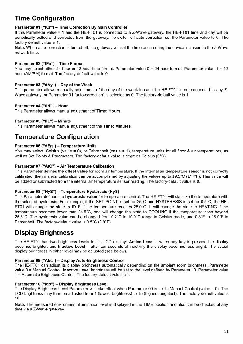
Time ConfigurationParameter 01 (“tCr”) – Time Correction By Main ControllerIf this Parameter value = 1 and the HE-FT01 is connected to a Z-Wave gateway, the HE-FT01 time and day will beperiodically polled and corrected from the gateway. To switch off auto-correction set the Parameter value to 0. Thefactory default value is 1.Note. When auto-correction is turned off, the gateway will set the time once during the device inclusion to the Z-Wavenetwork time. Parameter 02 (“tFo”) – Time FormatYou may select either 24-hour or 12-hour time format. Parameter value 0 = 24 hour format. Parameter value 1 = 12hour (AM/PM) format. The factory-default value is 0. Parameter 03 (“dAy”) – Day of the WeekThis parameter allows manually adjustment of the day of the week in case the HE-FT01 is not connected to any Z-Wave gateway, or Parameter 01 (auto-correction) is selected as 0. The factory-default value is 1. Parameter 04 (“tIH”) – HourThis Parameter allows manual adjustment of Time: Hours.
Parameter 05 (“tIL”) – MinuteThis Parameter allows manual adjustment of the Time: Minutes.
Temperature ConfigurationParameter 06 (“dEg”) – Temperature UnitsYou may select: Celsius (value = 0), or Fahrenheit (value = 1), temperature units for all floor & air temperatures, aswell as Set Points & Parameters. The factory-default value is degrees Celsius (0°C).
Parameter 07 (“AtC”) – Air Temperature CalibrationThis Parameter defines the offset value for room air temperature. If the internal air temperature sensor is not correctlycalibrated, then manual calibration can be accomplished by adjusting the values up to ±9.5°C (±17°F). This value willbe added or subtracted from the internal air temperature sensor reading. The factory-default value is 0.
Parameter 08 (“HyS”) – Temperature Hysteresis (HyS)This Parameter defines the hysteresis value for temperature control. The HE-FT01 will stabilize the temperature withthe selected hysteresis. For example, if the SET POINT is set for 25°C and HYSTERESIS is set for 0.5°C, the HE-FT01 will change the state to IDLE if the temperature reaches 25.0°C. It will change the state to HEATING if thetemperature becomes lower than 24.5°C, and will change the state to COOLING if the temperature rises beyond25.5°C. The hysteresis value can be changed from 0.2°C to 10.0°C range in Celsius mode, and 0.3°F to 18.0°F inFahrenheit. The factory-default value is 0.5°C (0.9°F).
Display BrightnessThe HE-FT01 has two brightness levels for its LCD display: Active Level – when any key is pressed the displaybecomes brighter, and Inactive Level – after ten seconds of inactivity the display becomes less bright. The actualdisplay brightness in either level may be adjusted (see below).
Parameter 09 (“Abc”) – Display Auto-Brightness ControlThe HE-FT01 can adjust its display brightness automatically depending on the ambient room brightness. Parametervalue 0 = Manual Control: Inactive Level brightness will be set to the level defined by Parameter 10. Parameter value1 = Automatic Brightness Control. The factory-default value is 1.
Parameter 10 (“ldb”) – Display Brightness LevelThe Display Brightness Level Parameter will take effect when Parameter 09 is set to Manual Control (value = 0). TheLCD brightness may then be adjusted from 1 (lowest brightness) to 15 (highest brightest). The factory default value is10.
Note: The measured environment illumination level is displayed in the TIME position and also can be checked at anytime via a Z-Wave gateway.
11

Touch SensitivityParameter 11 (“tCH”) – Touch Sensor Sensitivity ThresholdParameter 11 allows the device Touch Sensor Sensitivity Threshold to be adjusted from level 5 (very sensitive) to 50(minimal sensitivity). The factory-default value is 15.
Note: Setting the sensitivity too high can lead to false touch detection. We recommend not changing this Parameterunless there is a need to do so.
Power and Energy ConsumptionThe HE-FT01 monitors the Load Active Power in real time and the Total Energy Consumption through Software energy consumption logic. Data is periodically sent to the main Z-Wave controller according to Parameter 32.
Total Energy Consumption is the electrical power being used by your climate control system in real time during use.Power usage is calculated by the software using the values that were manually set when configuring Parameters 36-40, multiplied by the time measured when the HE-FT01 is active in each mode. Using your climate systemspecifications (see your owner’s manual), set the load in Watts for: Fan low speed in Parameters 36, Fan mediumspeed in Parameter 37, and Fan high speed in Parameter 38. Set the cooling power in Watts in Parameter 39, andheating power in Parameter 40.
Resetting cumulative consumption memoryThe HE-FT01 allows you to erase stored consumption data through the Z-Wave network as follows:1. Make sure the HE-FT01 has power.2. Include it into Z-Wave gateway/network3. Reset memory consumption data using Reset Command in COMMAND_CLASS_METER (see controller manual). Note: Turning the device main power off/on will not erase the consumption data as it is stored in non-volatile memory.
Hardware & Firmware VersionsParameter 12 (“Hrd”) – Hardware VersionThis Parameter allows you to manually check the hardware version of the HE-FT01 directly from the device.
Note: This parameter is read-only.
Parameter 13 (“APP”) – Firmware VersionThis Parameter allows you to manually check the Firmware Version directly from the device. Display informationfollows this format: Major Version - displayed at the Hours position, Minor Version - displayed at the Minutes position.Software Build - displayed at the bottom left corner at the “SET TEMP” position.
Note: This parameter in read-only.
Z-Wave NetworkThe HE-FT01 may be operated in any Z-Wave network with other Z-Wave certified devices from other manufacturers. The HELTUN HE-FT01 will act as a ‘repeater’ for other devices regardless of manufacturer or brand to increase the reliability of the overall network.
Parameter 14 (“bSA”) – Basic Set ActionThis Parameter defines which Operating Mode the HE-FT01 reverts to if the Basic Set command is received. If theBasic Set command value is 0 (OFF state) the HE-FT01 will go to OFF mode and switch the operating state to IDLE. Ifthe Basic Set command value is 0xFF (ON state) the HE-FT01 will change the Mode to the corresponding Parametervalue (as follows).
0: No action1: COM with Heating & Cooling Climate Mode 2: COM with Heating Climate Mode. 3: COM with Cooling Climate Mode. 4: TIME with Heating & Cooling Climate Mode. 5: TIME with Heating Climate Mode. 6: TIME with Cooling Climate Mode. 7: ECO with Heating Climate Mode. 8: ECO with Cooling Climate Mode.9: Ventilation Climate Mode The factory-default value is 2.
12
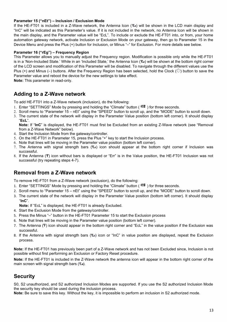
Parameter 15 (“nEt”) – Inclusion / Exclusion ModeIf the HE-FT01 is included in a Z-Wave network, the Antenna Icon ( ) will be shown in the LCD main display and“InC” will be indicated as this Parameter’s value. If it is not included in the network, no Antenna Icon will be shown inthe main display, and the Parameter value will be “EcL”. To include or exclude the HE-FT01 into, or from, your homeautomation gateway network, activate Inclusion or Exclusion Mode on your gateway, then go to Parameter 15 in theDevice Menu and press the Plus (+) button for Inclusion, or Minus “–” for Exclusion. For more details see below.
Parameter 16 (“rEg”) – Frequency RegionThis Parameter allows you to manually adjust the Frequency region. Modification is possible only while the HE-FT01is in a ‘Non-Included State.’ While in an ‘Included State,’ the Antenna Icon ( ) will be shown at the bottom right cornerof the LCD screen and modification of this Parameter will be disabled. To navigate through the different values use thePlus (+) and Minus (–) buttons. After the Frequency Region has been selected, hold the Clock ( ) button to save theParameter value and reboot the device for the new settings to take effect. Note: This parameter in read-only.
Adding to a Z-Wave network
To add HE-FT01 into a Z-Wave network (inclusion), do the following:1. Enter “SETTINGS” Mode by pressing and holding the “Climate” button ( ) for three seconds.2. Scroll menu to “Parameter 15 – nEt” using the “SPEED” button to scroll up, and the “MODE” button to scroll down.3. The current state of the network will display in the Parameter Value position (bottom left corner). It should display
“EcL”. Note: If “InC” is displayed, the HE-FT01 must first be Excluded from an existing Z-Wave network (see “Removalfrom a Z-Wave Network” below).
4. Start the Inclusion Mode from the gateway/controller.5. On the HE-FT01 in Parameter 15, press the Plus “+” key to start the Inclusion process.6. Note that lines will be moving in the Parameter value position (bottom left corner).7. The Antenna with signal strength bars ( ) icon should appear at the bottom right corner if Inclusion was
successful.8. If the Antenna ( ) icon without bars is displayed or “Err” is in the Value position, the HE-FT01 Inclusion was not
successful (try repeating steps 4-7).
Removal from a Z-Wave network
To remove HE-FT01 from a Z-Wave network (exclusion), do the following:1. Enter “SETTINGS” Mode by pressing and holding the “Climate” button ( ) for three seconds.2. Scroll menu to “Parameter 15 – nEt” using the “SPEED” button to scroll up, and the “MODE” button to scroll down.3. The current state of the network will display in the Parameter Value position (bottom left corner). It should display
“InC”. Note: If “EcL” is displayed, the HE-FT01 is already Excluded.
4. Start the Exclusion Mode from the gateway/controller.5. Press the Minus “–” button in the HE-FT01 Parameter 15 to start the Exclusion process6. Note that lines will be moving in the Parameter value position (bottom left corner).7. The Antenna ( ) icon should appear in the bottom right corner and “EcL” in the value position if the Exclusion was
successful.8. If the Antenna with signal strength bars ( ) icon or “InC” in value position are displayed, repeat the Exclusion
process.
Note: If the HE-FT01 has previously been part of a Z-Wave network and has not been Excluded since, Inclusion is notpossible without first performing an Exclusion or Factory Reset procedure.
Note: If the HE-FT01 is included in the Z-Wave network the antenna icon will appear in the bottom right corner of themain screen with signal strength bars ( ).
Security
S0, S2 unauthorized, and S2 authorized Inclusion Modes are supported. If you use the S2 authorized Inclusion Modethe security key should be used during the inclusion process. Note: Be sure to save this key. Without the key, it is impossible to perform an inclusion in S2 authorized mode.
13

SmartStart
SmartStart-enabled products can be added to a Z-Wave networkby scanning the Z-Wave QR Code shown on the product withgateways/controllers that allow for SmartStart inclusion. In thiscase, no further action will be required and the SmartStart productwill be added automatically within ten minutes of being turned on inthe vicinity of a network.
To add the HE-FT01 to a Z-Wave network using SmartStart:1. Set the main controller in Security S2 Authenticated “Add Mode”2. Input the HE-FT01 DSK code to the controller3. Power on the device.4. Wait for the Inclusion process to complete.5. A successful “Add” will be confirmed by display of the Antenna
with signal strength bars ( ) icon in the bottom right corner ofthe main screen.
Note: The device DSK and QR code are printed on the HE-FT01 back panel plus on the manual included in the HE-FT01 packaging.
Firmware OTA Update
To wirelessly update the HE-FT01 firmware, follow these steps:1. Check the current firmware version in the settings Parameter 132. Start the process from the Z-Wave gateway/controller3. Download the firmware that corresponds to the HE-FT01.4. Set the main controller in Firmware OTA (“over-the-air”) Update Mode (see gateway/controller manual).5. As soon as Firmware update begins, “LOAd” text will be displayed on the screen (this will take a few minutes).6. When the Firmware has updated, “UPd” will display on the screen for three seconds and the HE-FT01 will reboot.7. When the update has completed, the HE-FT01 will return to normal operation.8. If desired, verify the update was successful by checking the firmware version in Parameter 13 of the Settings
Mode.
Associations
Association enables the HE-FT01 to control other Z-Wave devices over the network. An Association Groups mayinclude up to 50 other devices from different brands and/or manufacturers (10 devices on each group except group 1).The HE-FT01 has six association groups:
1st Association Group – “Lifeline”: reports the state of the device and is used to communicate with the Z-Wavegateway. The group supports one Node.
Note: It is not recommended to modify this group.
2nd Association Group – “Fan Low Speed (OUT-1)” is used to turn the associated devices on/off reflecting OUT-1operation. The group supports one Node.
3rd Association Group – “Fan Medium Speed (OUT-2)” is used to turn the associated devices on/off reflectingOUT-2 operation. The group supports one Node.
4th Association Group – “Fan High Speed (OUT-3)” is used to turn the associated devices on/off reflecting OUT-3operation. The group supports one Node.
5th Association Group – “Heater (OUT-4)” is used to turn the associated devices on/off reflecting OUT-4 operation.The group supports one Nodes.
6th Association Group – “Cooler (OUT-5)” is used to turn the associated devices on/off reflecting OUT-5 operation.The group supports one Node.
Note: Through Groups 2-6 the HE-FT01 sends Basic Set command with value 0 (Off) when the relay goes to OFFstate and sends 255 (On) when the relay goes to ON state.
14
Z-Wave Plus V2 Specifications
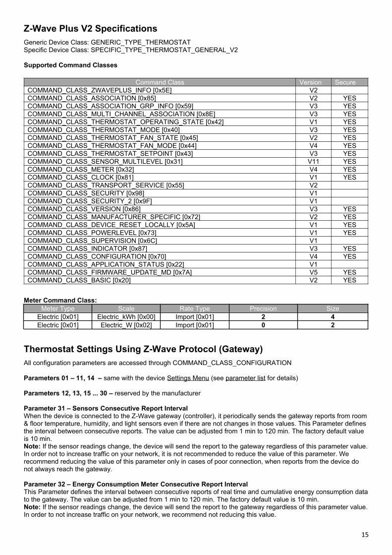
Generic Device Class: GENERIC_TYPE_THERMOSTATSpecific Device Class: SPECIFIC_TYPE_THERMOSTAT_GENERAL_V2
Supported Command Classes
Command Class Version SecureCOMMAND_CLASS_ZWAVEPLUS_INFO [0x5E] V2COMMAND_CLASS_ASSOCIATION [0x85] V2 YESCOMMAND_CLASS_ASSOCIATION_GRP_INFO [0x59] V3 YESCOMMAND_CLASS_MULTI_CHANNEL_ASSOCIATION [0x8E] V3 YESCOMMAND_CLASS_THERMOSTAT_OPERATING_STATE [0x42] V1 YESCOMMAND_CLASS_THERMOSTAT_MODE [0x40] V3 YESCOMMAND_CLASS_THERMOSTAT_FAN_STATE [0x45] V2 YESCOMMAND_CLASS_THERMOSTAT_FAN_MODE [0x44] V4 YESCOMMAND_CLASS_THERMOSTAT_SETPOINT [0x43] V3 YESCOMMAND_CLASS_SENSOR_MULTILEVEL [0x31] V11 YESCOMMAND_CLASS_METER [0x32] V4 YESCOMMAND_CLASS_CLOCK [0x81] V1 YESCOMMAND_CLASS_TRANSPORT_SERVICE [0x55] V2COMMAND_CLASS_SECURITY [0x98] V1COMMAND_CLASS_SECURITY_2 [0x9F] V1COMMAND_CLASS_VERSION [0x86] V3 YESCOMMAND_CLASS_MANUFACTURER_SPECIFIC [0x72] V2 YESCOMMAND_CLASS_DEVICE_RESET_LOCALLY [0x5A] V1 YESCOMMAND_CLASS_POWERLEVEL [0x73] V1 YESCOMMAND_CLASS_SUPERVISION [0x6C] V1COMMAND_CLASS_INDICATOR [0x87] V3 YESCOMMAND_CLASS_CONFIGURATION [0x70] V4 YESCOMMAND_CLASS_APPLICATION_STATUS [0x22] V1COMMAND_CLASS_FIRMWARE_UPDATE_MD [0x7A] V5 YESCOMMAND_CLASS_BASIC [0x20] V2 YES
Meter Command Class:Meter Type Scale Rate Type Precision Size
Electric [0x01] Electric_kWh [0x00] Import [0x01] 2 4Electric [0x01] Electric_W [0x02] Import [0x01] 0 2
Thermostat Settings Using Z-Wave Protocol (Gateway)
All configuration parameters are accessed through COMMAND_CLASS_CONFIGURATION
Parameters 01 – 11, 14 – same with the device Settings Menu (see parameter list for details)
Parameters 12, 13, 15 ... 30 – reserved by the manufacturer
Parameter 31 – Sensors Consecutive Report IntervalWhen the device is connected to the Z-Wave gateway (controller), it periodically sends the gateway reports from room& floor temperature, humidity, and light sensors even if there are not changes in those values. This Parameter defines the interval between consecutive reports. The value can be adjusted from 1 min to 120 min. The factory default value is 10 min.Note: If the sensor readings change, the device will send the report to the gateway regardless of this parameter value.In order not to increase traffic on your network, it is not recommended to reduce the value of this parameter. We recommend reducing the value of this parameter only in cases of poor connection, when reports from the device do not always reach the gateway.
Parameter 32 – Energy Consumption Meter Consecutive Report IntervalThis Parameter defines the interval between consecutive reports of real time and cumulative energy consumption datato the gateway. The value can be adjusted from 1 min to 120 min. The factory default value is 10 min.Note: If the sensor readings change, the device will send the report to the gateway regardless of this parameter value.In order to not increase traffic on your network, we recommend not reducing this value.
15
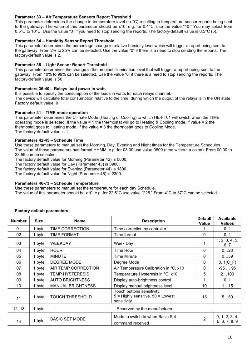
Parameter 33 – Air Temperature Sensors Report ThresholdThis parameter determines the change in temperature level (in °C) resulting in temperature sensor reports being sentto the gateway. The value of this parameter should be x10, e.g. for 0.4°C, use the value “40.” You may select from0.5°C to 10°C. Use the value “0” if you need to stop sending the reports. The factory-default value is 0.5°C (5).
Parameter 34 – Humidity Sensor Report ThresholdThis parameter determines the percentage change in relative humidity level which will trigger a report being sent to the gateway. From 2% to 25% can be selected. Use the value “0” if there is a need to stop sending the reports. The factory-default value is 2.
Parameter 35 – Light Sensor Report ThresholdThis parameter determines the change in the ambient illumination level that will trigger a report being sent to the gateway. From 10% to 99% can be selected. Use the value “0” if there is a need to stop sending the reports. The factory-default value is 50.
Parameters 36-40 – Relays load power in watt.It is possible to specify the consumption of the loads in watts for each relays channel.The device will calculate total consumption relative to the time, during which the output of the relays is in the ON state.Factory default value: 0
Parameter 41 – TIME mode operationThis parameter determines the Climate Mode (Heating or Cooling) to which HE-FT01 will switch when the TIME operating mode is selected. If the value = 1 the thermostat will go to Heating & Cooling mode, if value = 2 the thermostat goes to Heating mode, if the value = 3 the thermostat goes to Cooling Mode. The factory default value is 1.
Parameters 42-45 – Schedule TimeUse these parameters to manual set the Morning, Day, Evening and Night times for the Temperature Schedules.The value of these parameters has format HHMM, e.g. for 08:00 use value 0800 (time without a colon). From 00:00 to23:59 can be selected. The factory default value for Morning (Parameter 42) is 0600.The factory default value for Day (Parameter 43) is 0900.The factory default value for Evening (Parameter 44) is 1800.The factory default value for Night (Parameter 45) is 2300.
Parameters 46-73 – Schedule TemperatureUse these parameters to manual set the temperature for each day Schedule.The value of this parameter should be x10, e.g. for 22.5°C use value “225.” From 4°C to 37°C can be selected.
Factory default parameters
Number Size Name DescriptionDefaultValue
AvailableValues
01 1 byte TIME CORRECTION Time correction by controller 1 0, 1
02 1 byte TIME FORMAT Time format 0 0, 1
03 1 byte WEEKDAY Week Day 11, 2, 3, 4, 5,
6, 704 1 byte HOUR Time Hour 0 0…23
05 1 byte MINUTE Time Minute 0 0…59
06 1 byte DEGREE MODE Degree Mode 0 0, 1(C_F)
07 1 byte AIR TEMP CORRECTION Air Temperature Calibration in °C, x10 0 -95 … 95
08 1 byte TEMP HYSTERESIS Temperature Hysteresis in °C, x10 5 2…100
09 1 byte AUTO BRIGHTNESS Display auto-brightness control 1 0, 1
10 1 byte MANUAL BRIGHTNESS Display manual brightness level 10 1…15
11 1 byte TOUCH THRESHOLDTouch buttons sensitivity.5 = Highly sensitive. 50 = Lowest sensitivity
15 5…50
12, 13 1 byte Reserved by the manufacturer
14 1 byte BASIC SET MODEMode to switch to when Basic Set
command received2
0, 1, 2, 3, 4,5, 6, 7, 8, 9
16
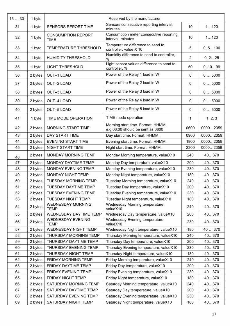
15 … 30 1 byte Reserved by the manufacturer
31 1 byte SENSORS REPORT TIMESensors consecutive reporting interval, minutes
10 1…120
32 1 byteCONSUMPTION REPORT TIME
Consumption meter consecutive reporting interval, minutes 10 1…120
33 1 byte TEMPERATURE THRESHOLDTemperature difference to send to controller, value X 10 5 0, 5…100
34 1 byte HUMIDITY THRESHOLDHumidity difference to send to controller, % 2 0, 2…25
35 1 byte LIGHT THRESHOLDLight sensor values difference to send to controller, % 50 0, 10…99
36 2 bytes OUT–1 LOAD Power of the Relay 1 load in W 0 0 … 5000
37 2 bytes OUT–2 LOAD Power of the Relay 2 load in W 0 0 … 5000
38 2 bytes OUT–3 LOAD Power of the Relay 3 load in W 0 0 … 5000
39 2 bytes OUT–4 LOAD Power of the Relay 4 load in W 0 0 … 5000
40 2 bytes OUT–5 LOAD Power of the Relay 5 load in W 0 0 … 5000
41 1 byte TIME MODE OPERATION TIME mode operation 1 1, 2, 3
42 2 bytes MORNING START TIMEMorning start time. Format: HHMM.e.g.08:00 should be sent as 0800 0600 0000…2359
43 2 bytes DAY START TIME Day start time. Format: HHMM. 0900 0000…2359
44 2 bytes EVENING START TIME Evening start time. Format: HHMM. 1800 0000…2359
45 2 bytes NIGHT START TIME Night start time. Format: HHMM. 2300 0000…2359
462 bytes MONDAY MORNING TEMP Monday Morning temperature, valueX10 240 40…370
47 2 bytes MONDAY DAYTIME TEMP Monday Day temperature, valueX10 200 40…370
48 2 bytes MONDAY EVENING TEMP Monday Evening temperature, valueX10 230 40…370
49 2 bytes MONDAY NIGHT TEMP Monday Night temperature, valueX10 180 40…370
50 2 bytes TUESDAY MORNING TEMP Tuesday Morning temperature, valueX10 240 40…370
51 2 bytes TUESDAY DAYTIME TEMP Tuesday Day temperature, valueX10 200 40…370
52 2 bytes TUESDAY EVENING TEMP Tuesday Evening temperature, valueX10 230 40…370
53 2 bytes TUESDAY NIGHT TEMP Tuesday Night temperature, valueX10 180 40…370
54 2 bytesWEDNESDAY MORNING TEMP
Wednesday Morning temperature, valueX10
240 40…370
55 2 bytes WEDNESDAY DAYTIME TEMP Wednesday Day temperature, valueX10 200 40…370
56 2 bytesWEDNESDAY EVENING TEMP
Wednesday Evening temperature, valueX10
230 40…370
57 2 bytes WEDNESDAY NIGHT TEMP Wednesday Night temperature, valueX10 180 40 … 370
58 2 bytes THURSDAY MORNING TEMP Thursday Morning temperature, valueX10 240 40…370
59 2 bytes THURSDAY DAYTIME TEMP Thursday Day temperature, valueX10 200 40…370
60 2 bytes THURSDAY EVENING TEMP Thursday Evening temperature, valueX10 230 40…370
61 2 bytes THURSDAY NIGHT TEMP Thursday Night temperature, valueX10 180 40…370
62 2 bytes FRIDAY MORNING TEMP Friday Morning temperature, valueX10 240 40…370
63 2 bytes FRIDAY DAYTIME TEMP Friday Day temperature, valueX10 200 40…370
64 2 bytes FRIDAY EVENING TEMP Friday Evening temperature, valueX10 230 40…370
65 2 bytes FRIDAY NIGHT TEMP Friday Night temperature, valueX10 180 40…370
66 2 bytes SATURDAY MORNING TEMP Saturday Morning temperature, valueX10 240 40…370
67 2 bytes SATURDAY DAYTIME TEMP Saturday Day temperature, valueX10 200 40…370
68 2 bytes SATURDAY EVENING TEMP Saturday Evening temperature, valueX10 230 40…370
69 2 bytes SATURDAY NIGHT TEMP Saturday Night temperature, valueX10 180 40…370
17

70 2 bytes SUNDAY MORNING TEMP Sunday Morning temperature, valueX10 240 40…370
71 2 bytes SUNDAY DAYTIME TEMP Sunday Day temperature, valueX10 200 40…370
72 2 bytes SUNDAY EVENING TEMP Sunday Evening temperature, valueX10 230 40…370
73 2 bytes SUNDAY NIGHT TEMP Sunday Night temperature, valueX10 180 40…370
Warranty (2-Year)HELTUN warrants this product to be free from defects in the workmanship or materials, under normal use and service,for a period of two (2) years from the date of purchase by the consumer. If at any time during the warranty period theproduct is determined to be defective or malfunctions, HELTUN will repair or replace it (at HELTUN’s option).If the product is defective, (i) return it, with a bill of sale or other dated proof of purchase, to the place from which youpurchased it; or (ii) contact HELTUN Customer Care at [email protected]. HELTUN Customer Care will make thedetermination whether the product should be returned or whether a replacement product can be sent to you.
THIS WARRANTY DOES NOT COVER REMOVAL OR REINSATLLATION COSTS. THIS WARRANTY SHALL NOTAPPLY IF IT IS SHOWN BY HELTUN THAT THE DEFECT OR MALFUNCTION WAS CAUSED BY DAMAGEWHICH OCCURRED WHILE THE PRODUCT WAS IN THE POSSESSION OF A CONSUMER. THIS WARRANTYSHALL NOT OBLIGATE HELTUN FOR ANY LABOR COSTS AND SHALL NOT APPLY TO DEFECTS INWORKMANSHIP OR MATERIALS FURNISHED BY YOUR INSTALLER AS CONTRASTED TO DEFECTS IN THEPRODUCT ITSELF. IMPLIED WARRANTIES OF MERCHANTABILITY OF FITNESS FOR A PARTICULARPURPOSE SHALL BE LIMITED IN DURATION TO THE AFORESAID TWO YEAR PERIOD. HELTUN'S LIABILITYFOR INCIDENTAL OR CONSEQUENTIAL DAMAGES, OTHER THAN DAMAGES FOR PERSONAL INJURIES,RESULTING FROM ANY BREACH OF THE AFORESAID IMPLIED WARRANTIES OR THE ABOVE LIMITEDWARRANTY IS EXPRESSLY EXCLUDED. THIS LIMITED WARRANTY IS VOID IF DEFECT(S) RESULT FROMFAILURE TO HAVE THIS PRODUCT INSTALLED BY A QUALIFIED HEATING AND AIR CONDITIONINGCONTRACTOR. IF THE LIMITED WARRANTY IS VOID DUE TO FAILURE TO USE A QUALIFIED CONTRACTOR,ALL DISCLAIMERS OF IMPLIED WARRANTIES SHALL BE EFFECTIVE UPON INSTALLATION.
HELTUN, INC. A USA DELAWARE CORPORATION.2/5 ARMENAKYAN STR., YEREVAN, 0047, ARMENIA
WWW.HELTUN.COM [email protected]
18