VIVINT ELEMENT THERMOSTAT USER GUIDE
50
VIVINT ELEMENT THERMOSTAT USER GUIDE
-
Upload
khangminh22 -
Category
Documents
-
view
1 -
download
0
Transcript of VIVINT ELEMENT THERMOSTAT USER GUIDE

RTCOA logo sheet7aug07
VIVINT ELEMENT THERMOSTAT USER GUIDE

CT200 INSTALLATION GUIDE
Table Of Contents
Getting Started 3Interior View 5Installation Location 6
Wiring 7Mounting Plate 9Prepare Wires 10Connecting Wires 11Power Supply 12
Setup 14Include device to a Z-Wave network 15Power Supply 15
Wiring Diagrams 17Detailed Wire Diagram 18Step By Step Wiring Diagrams 19Wire Reference Table 23
2

Radio Thermostat
Getting Started
3

Getting StartedVivint Element CT200 Installation Guide
Tools NeededSmall Phillips screwdriver
Drill with ¼" bit (6 mm)
To avoid electrical shock and to prevent damage to the furnace, air condi-tioner, and thermostat, disconnect the power supply before installing or servicing the thermostat or any part of the system This can be done at the circuit breaker for both the furnance and air conditioner
• Do not reconnect electricity until work is complete • Do not short (jumper) across electric terminals at the control on the
furnace or air conditioner to test the system This can damage the thermostat
• Your thermostat is a precise instrument Handle it with care • All wiring must conform to local codes and ordinances • This thermostat is designed for use with 4AA alkaline batteries and/or 24-
volt AC C wire (or a 12- 24 AC or DC source) or millivolt gas systems Each thermostat relay load should be limited to 1 0 amp; higher amperage can cause damage to the thermostat
! CAUTION
4

Getting StartedVivint Element CT200 Installation Guide
Interior View
Unit Back and Mounting Plate
Unit Front
Wire terminals
Screen
Up Button
Down ButtonBottom Edge Light
Side Button
5

Getting StartedVivint Element CT200 Installation Guide
Installation LocationTo avoid having to move your wiring to a new location, mount the thermostat in place of the old thermostat
• Install the thermostat on an inside wall of an often-used room, about 5 ft. (1.5m) above the floor.
• Do not install where there are unusual heating conditions, such as: in direct sunlight; near a lamp, radio, television, radiator register, fireplace; near hot water pipes in the wall; or near a stove on the other side of a wall
• Do not locate in unusual cooling conditions, such as: on a wall separating an unheated room; or in a draft from a stairwell, door, or window
• Do not locate in a damp area This can lead to corrosion that will shorten the thermostat’s life
• Do not locate where air circulation is poor, such as: a corner, an alcove, or behind an open door
• Do not install the thermostat until all construction and painting is complete
• This thermostat does not require leveling
6

Radio Thermostat
Wiring
7

WiringVivint Element CT200 Installation Guide
1. Switch off electricity to the heating and cooling systems. This can be done at the circuit breaker
2 Remove the cover from the existing thermostat Check for locking screws on the side or front that must be loosened first.
3. Attach provided labels to each wire for identification. Refer to the lettered terminal where the wires attach; do not use the color of the wires
4 Disconnect wires from the existing thermostat, and wind them around a pencil to keep them from falling back inside the wall
5 Loosen all mounting screws on the old thermostat and remove it from the wall
C
G
W
G
W
C
G
W
4
• Read instructions carefully before removing any wiring from an existing thermostat
• Label all wires before disconnecting them form the existing thermostat
! CAUTION
C
W
RH
GY
Preperation
8

WiringVivint Element CT200 Installation Guide
C
W
RH
GY
Attaching the Mounting Plate to the wall1 Carefully pull the labeled wires through the center hole in the
mounting plate 2 Position thermostat for best appearance to cover the hole in the
wall 3 Mark first and drill a ¼ in. (6mm) hole at each screw location.4 If you are mounting the Thermostat to sheet rock or if you are
using the old mounting holes, use the plastic anchors provided 5 Attach the Thermostat to the wall with the screws provided
9

WiringVivint Element CT200 Installation Guide
Prepare WiresMake sure your wires are labeled. If necessary, find the “other end” connection for each wire on your heating or air conditioning equipment and note the label there
1 Fan out wires so that they are aligned with their terminals 2 Do not bunch wires in front of the mounting plate Feed any slack
back into the wall
Follow these guidelines for safe and secure wire connections:
• Use at least 2 6 in of wire for each of your connections to the Thermostat
• If you do not have enough wire, splice additional wire to allow enough slack
• Terminals accept wires from 16-22 awg • Remove 1/8 in insulation from the tip of each wire • Take care not to damage the labels for each wire
! CAUTION
Do not allow wires to touch each other or other parts on the thermostat
If you have both RH and RC connections, you must set the RC/
RH Switch to OPEN If you do not have both connections, set the switch to CLOSED
CW
RHG
Y
10

WiringVivint Element CT200 Installation Guide
Connecting Your WiresReference the Detailed Wire Diagram on page 23 to identify your wiring diagram and set-up information If necessary, contact customer support for help 1 Connect a labeled wire only to a matching lettered terminal 2 Press the lever next to the terminal letter, then insert the wire in
the terminal well 3 Make sure to insert the wire into the terminal well as far as it will
go, then release the lever The wire should be secure and not pull free easily
The Thermostat can be externally powered with a power source rated from 12V to 24V, AC or DC, at 100ma or greater If used, connect to the C and RH terminals (no polarity)
The 24VAC “C” wire is the other side of the 24VAC heating transformer and can be found where the other thermostat wires connect at the wall or at the furnace Do not use the common or ground side of the line voltage
The Thermostat runs on 4 AA alkaline batteries, the C wire (if available), or both batteries and the C-wire If you do not have a C wire, you can run a new wire from the HVAC or use a standard 12-24V [AC or DC] wall transformer
The C-wire is optional but preferred for all installations
CW
RHG
Y
Example of 5 Wire Heat/Cool System
11

WiringVivint Element CT200 Installation Guide
Battery Installation
Power Supply While the thermostat can run without batteries on C-wire power, you should install batteries as well to provide power to the unit during outages See the Thermostat Battery Cautions 1 Install four (4) AA alkaline batteries following the marked polarity
in the battery compartments. Insert the battery negative end first against the spring, then push the positive end in
2 With all the wires connected and the unit attached to the wall, it is time to turn the AC power back on Reconnect the power at the breaker you used to switch it off. The Thermostat will power-up in the OFF mode
3 Your Thermostat is not yet configured to operate your HVAC system You must now connect your thermostat to a Z-Wave Network and configure the HVAC and Heat Source settings.
12

WiringVivint Element CT200 Installation Guide
• Always use new Alkaline batteries • Do not use rechargeable batteries of any type They will not operate the
thermostat properly and may lead to damage • Do not mix old and new batteries • Do not mix battery types, for example Lithium with Alkaline • Do not dispose of batteries in fire. Batteries may explode or leak.• Always replace the batteries as soon as the “Low Batt” warning flashes. The
thermostat is a battery-powered device; you should replace the batteries before they run out, as failure to replace batteries can result in excessive heating or cooling of your house
• Always replace the batteries once a year, even if the “Low Batt” indicator does not flash. Replacing the batteries also helps to prevent leakage that can corrode and damage the thermostat
• If you are leaving your home for a month or more, you should replace the batteries as a precaution against battery failure in your absence
• Failing to replace the batteries when necessary could cause the thermostat to lose power or malfunction If the thermostat loses power, then the thermostat will not control the temperature, which could result in your HVAC system not functioning as you intended and lead to possible damage from excessive heating or cooling
• If the thermostat batteries fail with the heat OFF, this can result in NO HEAT and possible frozen or broken pipes and water damage
• If the thermostat batteries fail with the cool OFF, this can result in NO COOL and could cause possible damage or excessive temperatures
! THERMOSTAT BATTERY CAUTIONS
13

Vivint Element CT200 User Guide
3 Setup
14

SetupVivint Element CT200 Installation Guide
You must add the Thermostat to a Z-Wave network This unit cannot operate without a network connection
Include the Thermostat to a Z-Wave® NetworkThe Vivint Element Thermostat is a Z-Wave® compliant thermostat It has an onboard radio that can be added to an existing Z-Wave® network This device can be used on a network with products from different vendors.1 Set your primary controller
to INCLUDE mode to add the thermostat as a node on your network (see your specific controller’s User Manual for detailed instructions)
2 The Thermostat main screen shows a welcome message Press the SIDE button to continue
3 Press the SIDE button to initiate the inclusion process This initiates the network connection process • If inclusion fails, the screen says
“Failed”. Press the SIDE button to try adding again
4 When the Thermostat has been successfully included to a Z-Wave network, the screen displays a confirmation check mark. Press the SIDE button to continue You can now configure the thermostat to work with your HVAC system
5 Your primary controller indicates that the thermostat was successfully added to its network (see your specific controller’s User Manual for details)
Exclude from a Z-Wave NetworkThe Vivint Element can be excluded from the Z-Wave network process similar to the inclusion process Set your primary controller to EXCLUDE
CONNECTWITH SKY
2
3
NEXT
4
15

Setup
3
Vivint Element CT200 Installation Guide
Z-Wave and Power SupplyThe Thermostat’s node type is fixed when it is included to the Z-Wave network; if the C-Wire is not connected and is only battery-powered when including to the network, the Thermostat will remain a frequent listening routing slave (FLiRS) node until it is removed from the network
When your thermostat is running on battery power, the Z-Wave radio will turn off to help conserve battery life. The Thermostat Z-Wave radio module supports Z-Wave beaming, which allows other devices in the network to wake up the Z-Wave module and accept commands and then go back to sleep
When your thermostat is running on C-Wire power, the Z-Wave radio will stay on and actively help route messages within the Z-Wave network. The thermostat’s node type is fixed when it is included to the Z-Wave network; if the C-Wire is present and powered when including to the network, the thermostat will remain an always-listening node until it is removed from the network
16

Radio Thermostat
Wiring Diagrams
17

Wiring Diagrams
4
Vivint Element CT200 Installation Guide
RY
GC B O
R G
C B O YnWnYnWn R GC
C W R
HVAC
C W R G W R GC Y
GC RHW Y
RC
HVACHVAC
HVAC
HVACHVAC
HVAC
C W R C W R G C W Y R G C W Y RH RC GWIRES
WIRES WIRES
Multi-stage Heat Pumpw/ Multi-stage Aux Heat
C Wn Yn R GWIRES
Multi-stage CoolMulti-stage Heat
3 Wire Heat 4 Wire Heat 5 Wire Heat/Cool 6 Wire Heat/Cool
C B or O Y R G C B or O AUXn Yn R G
WIRES WIRES WIRES
Go to Page 19 Go to Page 19 Go to Page 19 Go to Page 20
Go to Page 20 Go to Page 21 Go to Page 21oror
4 Wire Heat Pumpw/o Aux Heat
Detailed Wiring Diagrams
18

Wiring DiagramsVivint Element CT200 Installation Guide
Step-By-Step Wiring Diagrams
3 Wire Heat GAS MILLIVOLT or 24VAC System 1 Connect the R (or RH) wire to the
RH terminal This connects the heat power
2 Connect the W wire to the W terminal This connects the heat
3 If available, connect the C wire to the C terminal
4. Go to “Connect Your Wires” on page 9.
4 Wire Heat1 Connect the R (or RH) wire to the
RH terminal This connects the heat power
2 Connect the W wire to the W terminal This connects the heat
3 Connect the G wire to the G terminal This connects the fan
4 If available, connect the C wire to the C terminal 5. Go to “Connect Your Wires” on page 9.
5 Wire Heat/Cool1 Connect the W wire to the W
terminal This connects the heat 2 Connect the Y wire to the Y
terminal This connects the cooling compressor
3 Connect the RH or R wire to the RH terminal This connects the power
4 Connect the G wire to the G terminal This connects the fan 5 If available, connect the C wire to the C terminal 6. Go to “Connect Your Wires” on page 9.
POWER
HVAC SYSTEM
THERMOSTAT
C B O W Y Y2 RH RC G AW2
W RC
POWER
HVAC SYSTEM
THERMOSTAT
C B O W Y Y2 RH RC G AW2
W RC G
POWER
HVAC SYSTEM
THERMOSTAT TERMINALS
C B O W Y Y2 RH RC G AW2
W RC GY
19

Wiring Diagrams
4
Vivint Element CT200 Installation Guide
6 Wire Heat/Cool1 Connect the W wire to the W
terminal This connects the heat 2 Connect the Y wire to the Y
terminal This connects to the cooling compressor
3 Disconnect the RC and RH terminals by removing the Jumper Wire
4 Connect the RH wire to the RH terminal and the RC wire to the RC terminal This connects power
5 Connect the G wire to the G terminal This connects the fan 6 If available, connect the C wire to the C terminal 7. Go to “Connect Your Wires” on page 9.
Multi-stage Heat & Multi-Stage CoolThe CT200 can handle up to 2 stages of HEAT and 2 stages of COOL 1 Connect the W and W2 wires to
the W and W2 terminals This connects the stages of HEAT
2 Connect the Y and Y2 wires to the Y and Y2 terminals This connects the stages of COOL
3 Connect the RH or R wire to the RH terminal This connects the power
4 Connect the G wire to the G terminal This connects the fan 5 If available, connect the C wire to the C terminal 6. Go to “Connect Your Wires” on page 9.
POWER
HVAC SYSTEM
THERMOSTAT TERMINALS
C B O W Y Y2 RH RC G AW2
W GY RH RCC
*RC and RH disconnected
POWER
HVAC SYSTEM
THERMOSTAT TERMINALS
C B O W Y Y2 RH RC G AW2
W GY Y2 RC W2
20

Wiring DiagramsVivint Element CT200 Installation Guide
4 Wire Heat Pump (heat/cool) without Auxiliary Heat1 Connect the O wire to the O
terminal or the B wire to the B terminal This connects the change-over valve If you have both O and B, connect only the O wire to the O terminal and DO NOT connect B to B terminal (see the Wire Reference Table on page 23 for Trane terminal labels)
2 Connect the Y wire to the Y terminal This connects the compressor
3 Connect the R wire to the RH terminal This connects the power 4 Connect the G wire to the G terminal This connects the fan 5 If available, connect the C wire to the C terminal 6. Go to “Connect Your Wires” on page 9.
Multi-stage Heat Pump with Multi-Stage Aux HeatThe CT200 can handle up to 2 stages of Pump compression and 2 stages of AUX heat 1 Connect O wire to the O terminal
or the B wire to the B terminal This connects the change-over valve If you have both O and B, connect only the O wire to the O terminal and DO NOT connect B to B terminal (see Wire Reference Table on page X for Trane terminal labels )
2 Connect the AUX 1 and AUX 2 wires to the AUX 1 and AUX 2 terminals This connects the auxiliary heat
3 Connect the Y and Y2 wires to the Y and Y2 terminals This connects the compressor
4 Connect the R wire to RH terminal This connects the power 5 Connect the G wire to the G terminal This connects the fan 6 If available, connect the C wire to the C terminal 7. Go to “Connect Your Wires” on page 9.
POWER
HVAC SYSTEM
THERMOSTAT TERMINALS
C B O W Y Y2 RH RC G AW2
B GO Y RC
or
or
POWER
HVAC SYSTEM
THERMOSTAT TERMINALS
C B O W Y Y2 RH RC G AW2
B GO Y RC
or
or
Y2AUX2AUX1
21

Wiring Diagrams
4
Vivint Element CT200 Installation Guide
Accessory Wiring
Zoned Hot Water HeatFor Solenoid or Motor valves, connect the wires based on the diagrams to the correct terminal on the CT200 When controlling a hydronic heating system, configure the thermostat as HVAC Type = Normal with Heat Type = Gas • USE ONLY IN HEAT MODE • The CT200 must be powered by 24v ac The third wire on your valve may be called 6, Y, or G (see the Wire Reference Table on page 23
CT200RH AW
MOTOR VALVE
RHW A
CT200RH AW
SOLENOID VALVE
RHA W
22
Wiring DiagramsVivint Element CT200 Installation Guide
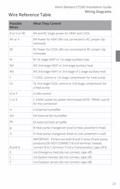
Wire Reference Table
Possible Wires
What They Control
R or V or VR RH and RC Single power for HEAT and COOL
RH or 4 RH Power for HEAT (RH not connected to RC jumper clip removed)
RC RC Power for COOL (RH not connected to RC jumper clip removed)
W W 1st stage HEAT or 1st stage auxiliary heat
W2 W2 2nd stage HEAT or 2nd stage auxiliary heat
W3 W3 3rd stage HEAT or 2nd stage of 2 stage auxiliary heat
Y Y COOL control or 1st stage compression for heat pump
Y2 Y2 2nd stage COOL control or 2nd stage compression for a heat pump
G or F G FAN control
C or X C 24VAC power (to power thermostat) NOTE: TRANE uses B for this connection
H H External Humidifier
DH DH External De-Humidifier
EX EX external fresh air baffle
B B Heat pump changeover (cool to heat, powered in heat)
O O Heat pump changeover (heat to cool, powered in cool)
B and O
IMPORTANT: If there are both B and O wires (Trane pump products) DO NOT CONNECT B to B terminal Instead, connect B to C terminal. If not a Trane product, tape off B.
E n/a Emergency heat (do not connect, tape off)
L n/a System monitor (do not connect, tape off)
T n/a Outdoor sensor (do not connect, tape off)
23

Wiring Diagrams
4
Vivint Element CT200 Installation Guide
Lennox Heat Pump
V or VR or R RH Power for HEAT
M or Y Y COOL control
Y or W or W2 W2 2nd stage HEAT
F or G G Fan control
R or O O
X or X2 or C C
Trane Products [American Standard]
B C 24VAC power (to power thermostat)
X2 Emergency heat. Do not connect, tape off.
Zoned Hot Water
2 wire
R RH
W W
Motor Driven Valves
3 Wire
R or 5 RH (power)
W or 4 W (heat ON)
Y or G or 6 (the 3rd wire) A (heat OFF)
Solenoid Valves
3 Wire
R RH (power)
W A (heat ON)
Y or G (the 3rd wire) W (heat OFF)
24

Section TitleChapter
Radio Thermostat
CT200OPERATION GUIDE
Table Of Contents
Product Overview 26Home Screen 27Outside Temp Screen 28Fan Timer ScreenSettings ScreenCompressor Protection 29
Customization 30Units 31Humidity Display Info 32Installer Equipment 35 HVAC and Heat Settings 36
Other Device Information 39Low Battery Warning Network DisconnectedFactory Reset 40
Z-Wave Reference 41
25

Vivint Element CT200 User Guide
5 Product Overview
26

Vivint Element CT200 Operation GuideProduct Overview
Home Screen
7069
Mode
Target Temp
Room Temp
This is the default screen on the Thermostat Anytime the unit wakes from sleep (or senses you approaching, if the sensor is enabled), the screen lights up and displays the system’s mode (top), the target temperature (center), and the current room temperature (bottom)
When in Heat mode, the light bar at the bottom of the unit glows red. When in Cool mode, it glows blue. When the unit is off, the light bar does not glow When the system is actively heating or cooling, the colored glow flickers.
Adjusting Temperature
• To temporarily change the target temperature, press up/down The system will meet the target temperature until the next program period starts or you change the system mode
• Press the side button once to change modes
Navigating the Vivint Element screens• Use the UP and DOWN buttons to move the cursor on the screen • Use the SIDE button to make a selection or scroll through options • To go back to a previous screen, highlight the arrow at the top of
the screen and press the SIDE button • Wait 10 seconds for the device to sleep, then press any button to
wake it again
27

Vivint Element CT200 Operation GuideProduct Overview
5
Outside Temp ScreenThis screen displays the outside temperature and inside humidity (in %)
To see this screen, press the SIDE button twice
Fan Timer ScreenThis screen enables you to change fan operation (auto/on/15 min/30 min/1 hr)
To see this screen, press the SIDE button twice
Settings ScreenThis screen enables you to adjust the Thermostat’s settings, such as display units (°F or °C), target humidity levels, how the display activates, see information about the Thermostat, and adjust installation settings
To see this screen, from the Home screen, press and hold the SIDE button for three (3) seconds
72
83
10
30
FAN
User
SETTINGS
Installer
Done
28

Vivint Element CT200 Operation GuideProduct Overview
Z-Wave and Thermostat ProgramsThe Thermostat must be included on a Z-Wave network in order to operate Use your Z-Wave application to adjust the heating and cooling programs that the Thermostat uses to run your system You can temporarily override target temperatures and change system modes from the thermostat, but you must use the Z-Wave application to make permanent changes to programs
Compressor ProtectionThe Thermostat has a minimum cycle time of four (4) minutes to protect your compressor from excessive wear from responding to thermostat changes The Home screen shows an hour glass and the message “Please Wait”. The compressor will not come on until the four-minute delay is over
29

Vivint Element CT200 User Guide
6 Customization
30

CustomizationVivint Element CT200 Operation Guide
The Settings screen provides access to many features and settings of the Thermostat Features you can control on the Settings screen are ºF / ºC display, humidity targets, display behavior, information about the Thermostat, and installer settings The following pages provide detailed information about each of these settings
UnitsThe Thermostat can display either Fahrenheit or Celsius temperature units The Thermostat can display room temperatures in a range from 28°F to 99°F (-2°C to 37°C) with increments of 0 5° (F or C) 1 From the Home screen, press and hold the SIDE button for three
(3) seconds 2 Press DOWN to highlight User, then press the SIDE button 3 Using the UP or DOWN buttons, select an option, then press the
SIDE button to confirm.
HumidityThis screen is only available if your system includes humidity controlling equipment 1 From the Home screen, press and hold the SIDE button for three
(3) seconds 2 Press DOWN to highlight Humidity, then press the SIDE button
The current Humidity Target Level percentage displays 3 Press UP or DOWN to set a new target humidity percentage, then
press the SIDE button to confirm.
DisplayThe Thermostat display can operate in one of two modes: Approach or Button Tap Approach means that the device’s display will automatically turn on when it senses you approach within 4 (four) feet of the unit Button Tap means that you will have to press one of the buttons on the unit to wake the display 1 From the Home screen, press and hold the SIDE button for three
(3) seconds 2 Press DOWN to highlight Display, then press the SIDE button The
current Display On behavior has a check mark next to it 3 Press UP or DOWN to select a behavior, then press the SIDE
button to confirm.
31

Customization
6
Vivint Element CT200 Operation Guide
InfoInformation about the Thermostat device includes:Power: The power supply the unit is currently using (batteries,
C-wire, and/or transformer) Battery: How much battery power is currently left, if batteries
are installed in the unit Heating: The heating setting the system is currently using Active Relays: The wires currently being used by the system Network: Whether or not the unit is currently connected to a
Z-Wave network Software: The current software and firmware versions the unit is
using 1 From the Home screen, press and hold the SIDE button for three
(3) seconds 2 Press DOWN to highlight Info, then press the SIDE button
Information about the Thermostat displays 3 Press UP or DOWN to scroll through the available information
InstallerInstaller settings control the following Thermostat functions:
EQUIPMENT: heating, cooling, humidity control, and fan behavior
COMFORT: swing, differential, and other settings
NETWORK: the Thermostat’s connection to a Z-Wave Network
TESTING: the Thermostat’s connection to your equipment
RESET: resetting the Thermostat’s software to factory default
! WARNINGBe sure to turn the thermostat operating mode to OFF before changing HVAC setup
32

CustomizationVivint Element CT200 Operation Guide
COMFORTComfort settings enable you to control:Calibration: Offsets the unit’s temperature displayCycling: This feature enables you to set the acceptable variance in
temperature between the Thermostat’s setting and the current room temperature before the heating or cooling system will turn on The Cycling range can be from 0 5 to 4 0F ( 25 to 2C) For example, if Cycling is set to 2 0°F and the Thermostat is set to 70°F target temperature, the heat cycle will start when the room temperature drops to 68°F Similarly, the cooling system will start when the room temperature increases to 72°F The HVAC runs until the room reaches the target temperature, and then shuts off.
Staging: Used for multiple stage systems only Staging is the number of degrees between the room temperature and the target temperature at which the next stage in multi-stage systems will engage to bring the room temperature back to the target The default is 2°F The programmable range is 2°F to 6°F (1°- 3°C)
Calibration1 From the Home screen, press and hold the SIDE button for three
(3) seconds 2 Press DOWN to highlight Installer, then press the SIDE button 3 Press DOWN to highlight Comfort, then press the SIDE button 4 Press DOWN to highlight Calibration, then press the SIDE button
The current temperature offset displays.5 Press UP or DOWN to change the value, then press the SIDE
button to confirm.
Cycling1 From the Home screen, press and hold the SIDE button for three
(3) seconds 2 Press DOWN to highlight Installer, then press the SIDE button 3 Press DOWN to highlight Comfort, then press the SIDE button 4 Press DOWN to highlight Cycling, then press the SIDE button The
current cycling value displays 5 Press UP or DOWN to change the value, then press the SIDE
button to confirm.33

Customization
6
Vivint Element CT200 Operation Guide
Staging1 From the Home screen, press and hold the SIDE button for three
(3) seconds 2 Press DOWN to highlight Installer, then press the SIDE button 3 Press DOWN to highlight Comfort, then press the SIDE button 4 Press DOWN to highlight Staging, then press the SIDE button The
current staging value displays 5 Press UP or DOWN to change the value, then press the SIDE
button to confirm.
NetworkNetwork settings enable you to add and remove the Thermostat to a Z-Wave Network, and to reset the network connection Before starting this procedure, go to your Vivint panel and prepare it for new devices Once it is ready, add the Thermostat to the network 1 From the Home screen, press and hold the SIDE button for three
(3) seconds 2 Press DOWN to highlight Installer, then press the SIDE button 3 Press DOWN to highlight Network, then press the SIDE button 4 Press DOWN to highlight "Connect", then press the SIDE button
The current networking status displays
Installer: Comfort Cont.
34

CustomizationVivint Element CT200 Operation Guide
Selecting HVAC & Heat Types1 From the Thermostat’s Home
screen, press and hold the SIDE button for 3 seconds The Settings menu opens
2 Highlight Installer, then press the SIDE button The Install Settings menu opens
3 Highlight Equipment, then press the SIDE button The Equipment menu opens
4 Highlight Heating, then press the SIDE button The Heating menu opens
5 Under Heating Type, press the SIDE button until your heating type is displayed: Forced Air, Heat Pump, Hydronic, or Radiator
6 Under Fuel, press the SIDE button until your heating fuel is displayed: Natural Gas, Propane, Fuel Oil, or Geothermal and Electric For Heat Pump systems, this field is labeled Aux Fuel
7 Under Stages, press the SIDE button until your system’s heating stage type is displayed: 1 (single), 2 (dual), 1 + Auxiliary, or 2 + Auxiliary For Heat Pump systems, this field is labeled Aux. Stages.
Note: Auxiliary stages are only available if you select Heat Pump as the heating type
Selecting Heat Pump Settings1 From the Thermostat's Home
screen, press and hold the SIDE button for 3 seconds The Setting menu opens
2 Highlight Installer, then press the SIDE button The Install Settings menu opens
3 Highlight Equipment, then press the SIDE button The Equipment menu opens
4 Highlight Heat Pump, then press the SIDE button The Heat Pump menu opens
5 Highlight Wire, then select the letter corresponding to the terminal the Heat Pump is connected to: O or B
6 Under Stages, press the SIDE button until your system's heating stage type is displayed: 1 (single), or 2 (dual)
HEATING
TYPE
FUEL
Forced Air
Natural Gas
1STAGES
Heat Types
Equipment
35

Customization
6
Vivint Element CT200 Operation Guide
Selecting Cooling Type
1 From the Thermostat’s Home screen, press and hold the SIDE button for 3 seconds The Settings menu opens
2 Highlight Installer, then press the SIDE button The Install Settings menu opens
3 Highlight Equipment, then press the SIDE button The Equipment menu opens
4 Highlight Cooling, the press the SIDE button The Cooling menu opens
5 Under Type, press the SIDE button until your Cooling type is displayed: Air Conditioning, Heat Pump, or Evaporate
6 Under Stages, press the SIDE button until the number of stages your system uses is displayed: 1(single) or 2 (dual)
Selecting Humidity Settings
1 From the Thermostat’s Home screen, press and hold the SIDE button for 3 seconds The Settings menu opens
2 Highlight Installer, then press the SIDE button The Install Settings menu opens
3 Highlight Equipment, then press the SIDE button The Equipment menu opens
4 Highlight Humidity, the press the SIDE button The Humidity menu opens
5 Under Type, press the SIDE button until the type of humidity system you have is displayed: None, Humidifier, Dehumidifier, or Air Conditioner
6 Under Activation, press the SIDE button until the method your humidity system uses is displayed: W(ith) Heating, W(ith) Cooling, or Independent
7 Under Fan, press the SIDE button until the fan option your humidity system uses is displayed: Active or Inactive
COOLING
TYPE
Air Con.
1STAGES
Cooling
HUMIDITY
TYPE
ACTIVATION
None
W/ Heating
ActiveFAN
Here are the Humidity values:
Humidity Typeo Noneo Humidi�ero Dehumid.o Air Con.
Activationo W/ Heatingo W/ Coolingo Independent
Fano Activeo Inactive
Humidity36

CustomizationVivint Element CT200 Operation Guide
Test InstallationIf you have a heat pump, leave the Thermostat in Off mode for 4 (four) minutes before checking Cool
Do not operate AC if the outside temp is below 65°F
To Check HeatThe heating and cooling tests run for up to 30 minutes You can stop a test at any time by selecting the arrow and pressing the SIDE button 1 From the Thermostat’s Home
screen, press and hold the SIDE button for 3 seconds The Settings menu opens
2 Highlight Installer, then press the SIDE button The Install Settings menu opens
3 Highlight Testing, then press the SIDE button The Testing menu opens
4 Highlight Heating, then press the SIDE button The Heat Test menu opens
5 Highlight START, then press the SIDE button The Ther-mostat screen displays the following:• HEAT TIME: how long the
test has been running in minutes and seconds
• ACTIVE: the wires the system is using to com-municate with the heating system (example: W, G)
• CHANGE: the amount of temperature change caused during the test (example: +3 4°)
6 Wait for the test to end, or highlight the back arrow and press the SIDE button
A test of a successfully functioning heating system will show a rise in the temperature, as well as the proper wires indicated as being active If the temperature appears to drop, or the wrong wires are indicated as being active, the test indicates a problem with the Thermostat installation Check the wire connections and run the heating test again
HEAT TEST
STOP
HEAT TIME: 18:24
ACTIVE: W, G
CHANGE: +3.4°
37

Customization
6
Vivint Element CT200 Operation Guide
To Check Cool1 From the Thermostat’s Home
screen, press and hold the SIDE button for 3 seconds The Settings menu opens
2 Highlight Installer, then press the SIDE button The Install Settings menu opens
3 Highlight Testing, then press the SIDE button The Testing menu opens
4 Highlight Cooling, then press the SIDE button The Cool Test menu opens
5 Highlight START, then press the SIDE button The Thermostat screen displays the following:• COOL TIME: how long the
test has been running in minutes and seconds
• ACTIVE: the wires the system is using to com-municate with the cooling system (example: Y, G)
• CHANGE: the amount of temperature change caused during the test (example: -2 6°)
6 Wait for the test to end, or highlight the back arrow and press the SIDE button
A test of a successfully functioning cooling system will show a drop in the temperature, as well as the proper wires indicated as being active If the temperature appears to rise, or the wrong wires are indicated as being active, the test indicates a problem with the Thermostat installation Check the wire connections and run the cooling test again
COOL TEST
STOP
COOL TIME: 19:59
ACTIVE: Y, G
CHANGE: -2.6°
38

CustomizationVivint Element CT200 Operation Guide
Other Device Information
Low Battery WarningThe Thermostat displays this screen when the batteries are running low on charge and should be replaced This screen will only display once per day the first time the screen wakes 1 Press the SIDE button to dismiss this
warning 2 Turn the thermostat mode to OFF (from
heat or cool) 3 Replace the batteries 4 Turn the thermostat mode back on to HEAT or COOL Your settings will be retained and the thermostat will automatically reconnect to the Z-Wave Network
Network DisconnectedThe Thermostat displays this screen when it has lost its connection to the Z-Wave Network This screen will only display once per day the first time the screen wakes. 1 Press the SIDE button to dismiss this
warning 2 Go to the Home > Installer > Network
menu, and follow the procedure to include the Thermostat to the Z-Wave Network
Firmware UpdatingThe Thermostat displays this screen when it is updating its firmware.Wait until the firmware update is complete (about 15 minutes) and this screen is no longer displayed before attempting to use the Thermostat
NETWORKDISCONNECTED
OK
Updating
39

Customization
6
Vivint Element CT200 Operation Guide
Factory ResetUse this procedure only in the event that the network primary controller is missing or otherwise inoperable 1 From the Home screen, press and hold the SIDE button for three
(3) seconds 2 Press DOWN to highlight Installer, then press the SIDE button 3 Press DOWN to highlight Reset,
then press the SIDE button 4 Press DOWN to highlight Reset,
then press the SIDE button 5. To confirm that you want to
reset the device to factory defaults, press DOWN to highlight Reset, then press the SIDE button
The device resets itself and reboots You will need to connect the device to your Z-Wave Network and specify your system’s equipment and settings See the Installation Guide Setup section
Reset
RESET
Are you sure?
40

Section TitleChapter
Radio Thermostat
CT200OPERATION GUIDE
Z-WAVE® REFERENCE
41

Z-Wave®
7
Vivint Element CT200 Operation Guide
Z-Wave® ReferenceThe Thermostat can work in the same network with any other certified Z-Wave device, regardless of manufacturer/vendor. See your specific Z-Wave® controller’s User Manual for detailed instructions on operating your thermostat through the network
Behavior Note: When power is first applied to this device it will broadcast a Hail message followed by a Node Information frame This behavior is to maintain backwards compatibility with older controllers that work with this line of devices
Z-Wave Lifeline
The following commands can be sent to lifeline:• Command Class Sensor Multilevel - Sensor Multilevel Report• Command Class Basic - Basic Report • Command Class Thermostat Mode - Thermostat Mode Report • Command Class Thermostat Operating State - Thermostat Operat-
ing State Report• Command Class Thermostat Fan Mode - Thermostat Fan Mode
Report • Command Class Thermostat Fan State - Thermostat Fan State
Report• Command Class Thermostat Setpoint - Thermostat Setpoint Report• Command Class Multichannel - Multi Channel Command Encap-
sulate
These can be accessed via an Association Group Info Command List Get for group 1 (lifeline)
42

Z-Wave®
Vivint Element CT200 Operation Guide
Advanced Z-Wave® InformationThe Thermostat supports compliant mapping of the Z-Wave® BASIC_COMMAND_CLASS to the CT thermostat “Energy Saving” and “Comfort Mode” as follows: • Basic Set (Value = 0x00) = Set Energy Saving Mode • Basic Set (Value = 0x01-0x63 & 0xFF) = Set Comfort ModeEnergy Savings applies a 4° F setback to the existing set point temperature to comply with EPA recommendations for energy savings
Anti-theftThe Anti-Theft Command Class disables a subset of supported/controlled command classes in the thermostat if the thermostat is being excluded from and included to a Z-Wave network (This thermostat supports version 2 of the Anti-Theft Command Class ) This command class is typically used when installing a thermostat in a public location, such as a hotel room or conference center The command class allows the user to lock the thermostat to the actual Z-Wave network and to render it useless if it is removed from the local network without being unlocked Another application would be to protect service-provider-owned products from leaving the service providers network before they are paid for
Disabled Commands With Engaged Anti-Theft protection
Basic Command Clock Command
Indicator Command Manufacturer Specific Command
Multilevel Sensor Command Thermostat Mode Command
Thermostat Operating State Command Thermostat Fan Mode Command
Thermostat Fan State Command Thermostat Setpoint Command
Version Command Configuration Command
Battery Command Association Command
Anti-theft Command
Multi Channel Command (Only supported if a humidity sensor is present )
43

Z-Wave®
7
Vivint Element CT200 Operation Guide
Configuration ParametersThis device supports the following Configuration Parameters:
Name Set/Get Default Values
1 Temp Reporting Threshold Set/Get 2 0 to 4
2 HVAC Settings Get Only N/A see below
3 Utility Lock Enable/Disable Set Only 0 0 to 127
4 C- Wire/Battery Status Get Only N/A 0 or 1
5 Humidity Reporting Threshold Set/Get 2 0 to 3
6 Auxiliary/Emergency Set/Get 0 0 or 1
7 Thermostat Swing Temp Set/Get 2 1 to 8
8 Thermostat Diff Temp Set/Get 4 4 to 12
9 Thermostat Recovery Mode Set/Get 2 1 or 2
10 Temp Reporting Filter Set/Get see below
11 Simple UI Mode Enable/Disable Set/Get 1 0 or 1
12 Multicast Enable/Disable Set/Get 0 0 or 1
13 Main Display Selection Set/Get 1 1 or 2
14 Save Energy Mode Type Set/Get 2 1 to 255
15 Fan Timer Set/Get 0 0 to 60
16 Humidity Control Activation Set/Get 1 0 or 0
17 Temperature Calibration Set/Get 0 -6 to 6
18 Display Units Set/Get 0 0 or 1
44

Z-Wave®
Vivint Element CT200 Operation Guide
1. Temperature Reporting Threshold (8-bit)This value determines the reporting threshold when association reporting is enabled Unsupported values are ignored
Value 0 1 2 3 4
Treshhold Disabled Disabled 0 5°F 1 0°F 1 5°F
2. HVAC Settings (32-bit)Byte 1 = HVAC Setup: Normal (0x01) or Heat Pump (0x02)Byte 2 = Aux Setup (Gas (0x01) or Electric (0x02)) & Number of
Auxiliary Stages (Heat Pump)/Number of Heat Stages (Normal)
Byte 3 = Number of Heat Pump Stages Byte 4 = Number of Cool Stages
3. Utility Lock (8-bit)If set to 0, the utility lock is disabled All other values (1-255) enable the utility lock
4. C-Wire/Battery Status (8-bit)If 0x01, the thermostat is powered by a C-wire If 0x02, the thermostat is powered by batteries
5. Humidity Reporting Threshold (8-bit)This value determines the reporting threshold when association reporting is enabled Unsupported values are ignored
6. Auxiliary/Emergency (8-bit)If set to 0, auxiliary / emergency heat is disabled All other values (1-255) enable auxiliary / emergency heat This can only be enabled when the thermostat is set to Heat Pump mode
7. Thermostat Swing TempThe thermostat swing temperature is in units of 0 5 degrees Fahrenheit A value of 0x01 is 0 5F and 0x02 is 1 0F The supported values may vary from thermostat to thermostat but typically the allowed values are 0 5F (0x01) to 4 0F (0x08)
Configuration Parameters Cont.
45

Z-Wave®
7
Vivint Element CT200 Operation Guide
8. Thermostat Diff TempThe thermostat differential temperature is in units of 0.5 degrees Fahrenheit. A value of 0x04 is 2.0F and 0x06 is 3.0F. The differential temperature must be an integer value Non-integer values, such as 1 5F (0x03), should not be used The supported values may vary from thermostat to thermostat but typically, the allowed values are 2 0F (0x04) to 6 0F (0x0C)
9. Thermostat Recovery ModeThe Thermostat Recovery Mode can be either fast (0x01) or economy (0x02)
10. Temp Reporting Filter (16-bit)Set Command Definition
7 6 5 4 3 2 1 0
Command Class = COMMAND_CLASS_CONFIGURATION
Command = CONFIGURATION_SET
Parameter = 0x0A
Default RESERVED Size = 0x04
Precision (0x00) Scale Bound Size (0x01)
Temperature Filter Lower Bound
Precision (0x00) Scale Bound Size (0x01)
Temperature Filter Upper Bound
• Parameter (8-bit) The parameter is set to 10 (0x0A) for the temperature reporting filter.
• Default (1-bit) If the default bit is set, the upper bound is zero (0) and the lower bound is 124. This disables the filter.
• Size (3-bit) The Size field must be set to 4 (100b).
• Precision (3-bits) The precision field describes the precision of the temperature filter value. The filter must be zero (0x00).
Configuration Parameters Cont.
46

Z-Wave®
Vivint Element CT200 Operation Guide
• Scale (2-bits) The scale field indicates the temperature scale used: 0 indicates Celsius and 1 indicates Fahrenheit
• Bound Size (3-bits) The size field indicates the number of bytes used for the temperature filter value. This field must be one (0x01).
• Temperature Filter Lower Bound (8-bit) The thermostat will report ambient temperature changes for temperature values less than the lower bound. This field must be between 0F and 124F By default, this value is 124F (report all temperature changes)
• Temperature Filter Upper Bound (8-bit) The thermostat will report ambient temperature changes for temperature values greater than the upper bound. This field must be between 0F and 124F By default, this value is 0F (report all temperature changes)
Thermostat Reporting Filter Report Command Definition
7 6 5 4 3 2 1 0
Command Class = COMMAND_CLASS_CONFIGURATION
Command = CONFIGURATION_SET
Parameter = 0x0A
Precision (0x00) Scale Bound Size (0x01)
Temperature Filter Lower Bound
Temperature Filter Upper Bound• Parameter (8-bit)
The parameter is set to 10 (0x0A) for the temperature reporting filter.
• Temperature Filter Lower Bound (8-bit) The thermostat will report ambient temperature changes for temperature values less than the lower bound. This field must be between 0F and 124F By default, this value is 124F (report all temperature changes)
• Temperature Filter Upper Bound (8-bit)
Configuration Parameters Cont.
47

Customization
6
Vivint Element CT200 Operation Guide
The thermostat will report ambient temperature changes for temperature values greater than the upper bound. This field must be between 0F and 124F By default, this value is 0F (report all temperature changes)
11. Simple UI Mode Enable / Disable If set to 0, Simple UI mode is disabled If set to 1, Simple UI mode
is enabled
12. Multicast Enable/Disable (8-bit) If set to 0, Multicast is disabled If set to 1, Multicast is enabled
13. Main Display Selection This configuration Param on the CT110 sets what information is
displayed in the main thermostat display area (the largest central numbers on the display) The default values is to display the Temperature (0x01) on the main numbers
14. Save Energy Mode Type This configuration value is used to read/write what behavior Save
Energy Mode causes in the thermostat when the thermostat enters Save Energy Mode
15. Fan Timer This configuration is used to activate the fan with an automatic
shut-off timer.
16. Humidity Activation This parameter is a pass-through All the logic is handled by the
thermostat based on the A terminal assignment
17. Temperature Calibration This configuration is used to set the temperature offset of the
thermostat The valid values are from -6 to 6 Note: although the thermostat UI can set calibrations in intervals of 0 5°F, this parameter can only accept whole numbers
18. Display Units This configuration is used to set units used by the device to
display temperature
Configuration Parameters Cont.
48

FCC Warning Changes or modifications to this unit not expressly approved by the party responsible for compliance could void the user’s authority to operate the equipment
NOTE: This equipment has been tested and found to comply with the limits for a Class B digital device, pursuant to Part 15 of the FCC Rules These limits are designed to provide reasonable protection against harmful interference in a residential installation This equipment generates, uses and can radiate radio frequency energy and, if not installed and used in accordance with the instructions, may cause harmful interference to radio communications
However, there is no guarantee that interference will not occur in a particular installation If this equipment does cause harmful interference to radio or television reception (which can be determined by turning the equipment off and on), try to correct the interference by following these suggestions:• Reorient or relocate the receiving antenna • Increase the separation between the equipment and receiver • Connect the equipment to an outlet on a circuit different from
that to which the receiver is connected • Consult the dealer or an experienced radio/TV technician for help
Radio Thermostat

© 2016 Radio Thermostat Company of America All rights reserved
Statement Of Use
100% Compatible with all popular residential HVAC systems: 24VAC single stage and two stage conventional heating systems (gas, oil, electric), heat pumps with up to two stages of heat and up to two stages of auxiliary heat (electric or fossil), zoned forced air and zoned hot water (2 or 3 wire), millivolt systems (with a 12-24V AC or DC source), one or two stage cooling, and hybrid systems Do not use this thermostat with with line voltage heating systems
RTCOA logo sheet7aug07