User Guide User Guide
11
User Guide User Guide Oedometer Apparatus SL250 Impact Test Equipment Ltd www.impact-test.co.uk & www.impact-test.com
-
Upload
khangminh22 -
Category
Documents
-
view
1 -
download
0
Transcript of User Guide User Guide

User Guide
User Guide
Oedometer Apparatus
SL250
Impact Test Equipment Ltd www.impact-test.co.uk & www.impact-test.com

Impact Test Equipment Ltd. Building 21 Stevenston Ind. Est.
Stevenston Ayrshire
KA20 3LR
T: 01294 602626 F: 01294 461168
Test Equipment Web Site www.impact-test.co.uk
Test Sieves & Accessories Web Site
www.impact-test.com

CONTENTS
Equipment ....................................................................................................................1 Introduction...................................................................................................................1 Description....................................................................................................................2 Consolidation Cell.........................................................................................................2 Setting Up.....................................................................................................................3 Images..........................................................................................................................4 Sample Preparation ......................................................................................................8 Test Procedures ...........................................................................................................8 Coefficient of Consolidation ..........................................................................................9
Equipment
The equipment comprises the following:- 1. Loading system 2. Operating Manual with assembly instructions & test procedure Fixed Ring Consolidation Cells, weights and dial gauge are not included and must be purchased separately.
Introduction The apparatus meets the requirements of BS1377. Maximum Loading: 8800kPa (based on a 50mm sample at 11:1 ratio) 20kg/sq.cm (based on 75mm sample at 9:1 ratio) The main purpose of consolidation is to obtain soil data which are used in predicting the rate and the amount of settlement of structures. The two most important properties furnished by a consolidation test are the compression index (Cc) which indicates the magnitude of compression and the coefficient of consolidation which indicates the rate of compression under a load increment. The data from a laboratory consolidation test make it possible to plot a stress versus strain curve, which gives useful information about the stress history of soil. The Terzaghi theory of consolidation is used for extrapolating laboratory consolidation test results, in order to predict the settlement of structures in the field.
- 1 -
Description The main unit (1) is an aluminium casting having three holes in the base, two in the back portion and one in the front, for fixing the entire unit on a table. The lever (6) is also of aluminium having a counter-balance weight (2) and a ring on the counter balance shaft for fine adjustment. Ball bearings are used in the lever system to minimum friction. A dial gauge bracket (3) is fitted to the main body, the height of which can be adjusted as per requirement. Dial gauge (4) is available separately. The front portion of the main body carries a lever supporting screw jack (5) to support the lever while adding weights (8) to the hanger (7) and also while placing the subsequent increments of loads on the lever, so that the loads can be applied instantly and without any disturbance. For numbering refer to images on page 4 onwards.
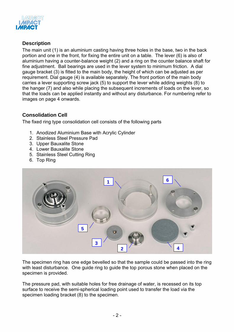
Consolidation Cell The fixed ring type consolidation cell consists of the following parts
1. Anodized Aluminium Base with Acrylic Cylinder 2. Stainless Steel Pressure Pad 3. Upper Bauxalite Stone 4. Lower Bauxalite Stone 5. Stainless Steel Cutting Ring 6. Top Ring
6 1
5
32 4
The specimen ring has one edge bevelled so that the sample could be passed into the ring with least disturbance. One guide ring to guide the top porous stone when placed on the specimen is provided. The pressure pad, with suitable holes for free drainage of water, is recessed on its top surface to receive the semi-spherical loading point used to transfer the load via the specimen loading bracket (8) to the specimen.
- 2 -
A recess is provided for the bottom porous stones. Two equally spaced studs hold down the water jacket on the channel base with a rubber ring between the base and the Perspex water jacket. Both top and bottom porous stones are sufficiently thick from a strength consideration and have a high permeability as compared to that of the soil being tested. A dial gauge (4) is required for measuring the change in thickness of the specimen.
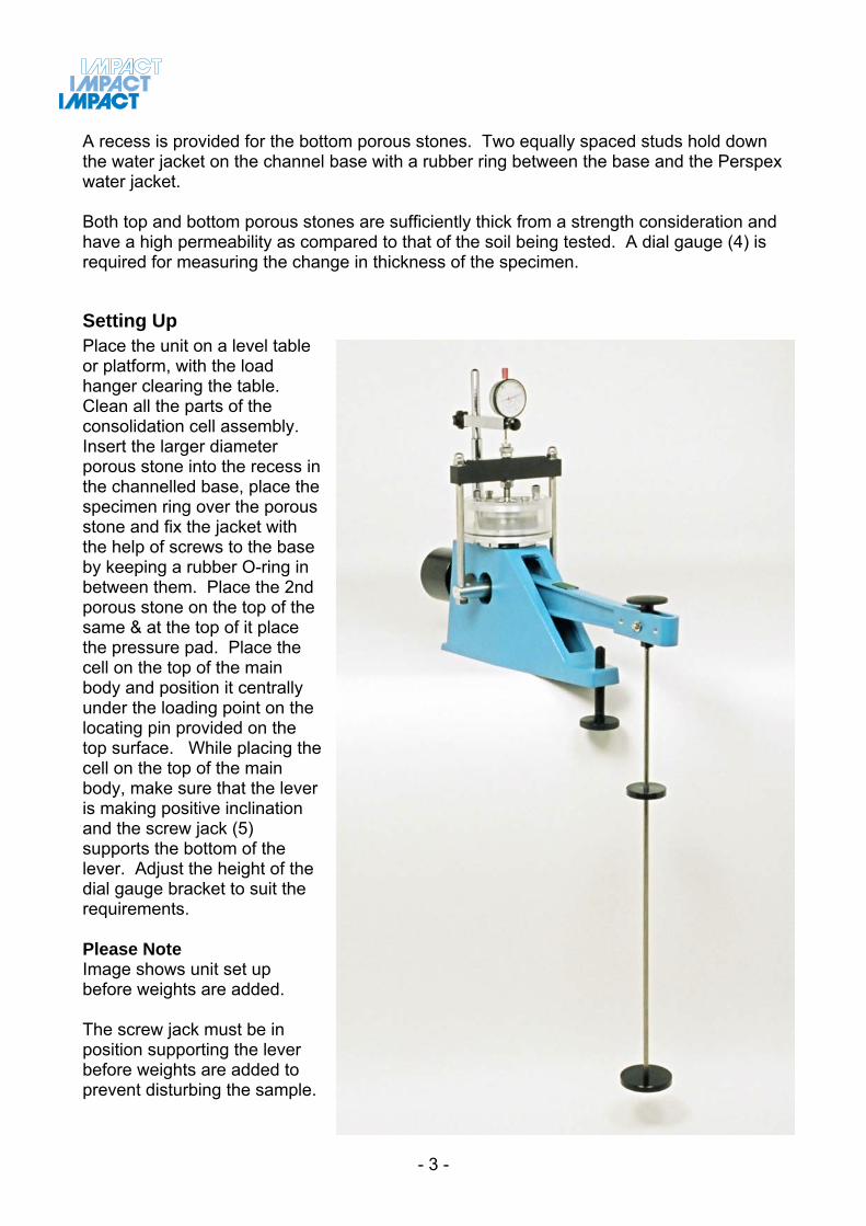
Setting Up Place the unit on a level table or platform, with the load hanger clearing the table. Clean all the parts of the consolidation cell assembly. Insert the larger diameter porous stone into the recess in the channelled base, place the specimen ring over the porous stone and fix the jacket with the help of screws to the base by keeping a rubber O-ring in between them. Place the 2nd porous stone on the top of the same & at the top of it place the pressure pad. Place the cell on the top of the main body and position it centrally under the loading point on the locating pin provided on the top surface. While placing the cell on the top of the main body, make sure that the lever is making positive inclination and the screw jack (5) supports the bottom of the lever. Adjust the height of the dial gauge bracket to suit the requirements. Please Note Image shows unit set up before weights are added. The screw jack must be in position supporting the lever before weights are added to prevent disturbing the sample.
- 3 -

Images The following images show how the apparatus should be set up. Part numbering is referred to under Description & Setting Up.
(2) Counter-Balance Weight & Ring
Mounting holes
(1) Main Unit
(3) Dial Gauge Bracket
- 4 -

(4) Dial Gauge (not supplied)
(5) Screw Jack
- 5 -
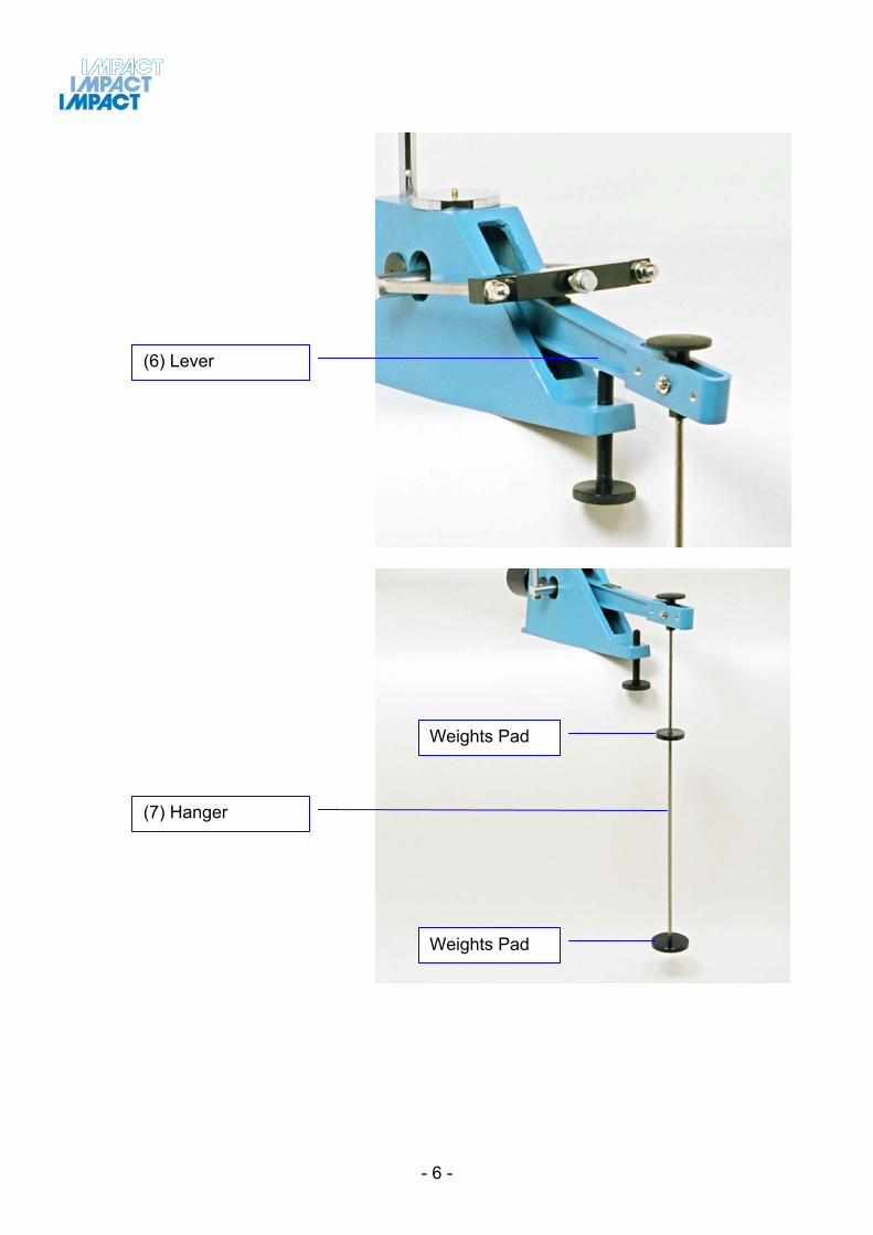
(6) Lever
Weights Pad
(7) Hanger
Weights Pad
- 6 -
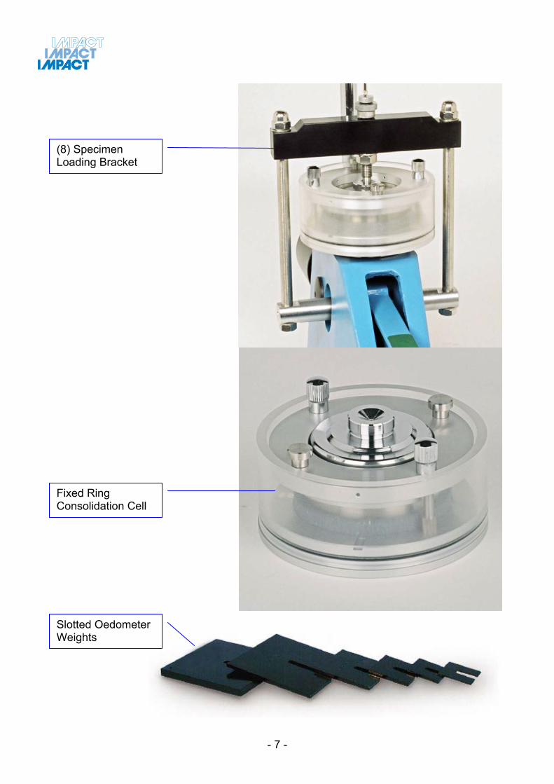
(8) Specimen Loading Bracket
Fixed Ring Consolidation Cell
Slotted Oedometer Weights
- 7 -
Sample Preparation Specimen I) FROM UNDISTURBED SOIL SAMPLES:- The specimen ring shall be cleaned and weighed empty. If desired about 25mm or more shall be cut off and rejected from one and of the undisturbed soil sample. The specimen shall be cut off either from the undisturbed tube sample or from block sample, the latter generally being more representative of the field conditions. In either case the specimen ring should be generally inserted into the sample by pressing with hands and carefully removing the material around the ring. The soil specimen so cut shall project as far as 12mm long either side of the ring. It should be trimmed flush with the top and bottom of the ring. Any voids in the specimen caused due to removal of gravel or lime-stone pieces shall be filled back by pressing lightly the loose soils in the voids, care being taken to see that the permeability of the specimen is not affected. The specimen ring shall be wiped clean of any soil sticking to the outside and weighed again with the soil. The whole process should be quick to ensure minimum loss of moisture. Three representative samples from the soil trimmings shall be taken for moisture content estimation in accordance with any of the standard methods. Organic soils, such as peat and those soils that are easily disturbed may be transferred from the sampling tube to the specimen ring provided their sizes have been suitably selected. Specimen II) FROM REPRESENTATIVE SOIL SAMPLES:- In cases where it is required to use disturbed soil samples, the soil sample shall be compacted to the desired density, at the desired water content, in a larger container. The required specimens for test are prepared as specified above from this compacted sample. Note - While preparing the specimen, attempt shall be made to have the soil strata oriented in the same direction in the consolidation apparatus as they are in the field.
Test Procedures The filter papers which are placed in between the specimen and the porous stones shall be saturated. All surfaces of the consolidometer which are to be enclosed shall be moistened. The porous stones shall be saturated by boiling in distilled water for at least 15 minutes. Assemble the apparatus as described under “Setting Up”. For saturation, remove the top loading pad of the cell assembly and pour water at the top of the porous stone to fill the Perspex water jacket just above the level of specimen. (While subsequently applying the first nominal load of 0.1kg./sq.cm. or 0.05kg/sq.cm., saturate the specimen such that the loading point is always in contact with the loading pad. This load will be neglected in the calculation for subsequent load increments). When the apparatus has been set up and the dial gauge arranged to record vertical movements, a small load of the order of 0.1kg/sq.cm. (except in the case of very soft remoulded soil) is applied for several hours to “seat” the various parts of the equipment. Following this, the first real increment of the load
- 8 -
- 9 -
of 0.25kg/sq.cm. is placed on the sample. The reading on the dial gauge is carefully noted just before the load is applied, and at various time intervals after load application, when the soil compresses during the expulsion of pore water. Because the deformation is initially very rapid and decreases with time, readings are made more frequently just after load application. With many soils the dial gauge moves so rapidly at first that it is advisable to decide before the test at what times the gauge is to be read. Sometimes it will be found convenient to use more than one stop-watches one of which is stopped at the instant the dial gauge moves past a predetermined point on the scale of compression. From the time and the compression readings, a plot of settlement or compression versus time can be prepared on a natural, square root, or logarithmic scale of time depending upon the technique to be employed to evaluate the coefficient of consolidation of the soil.
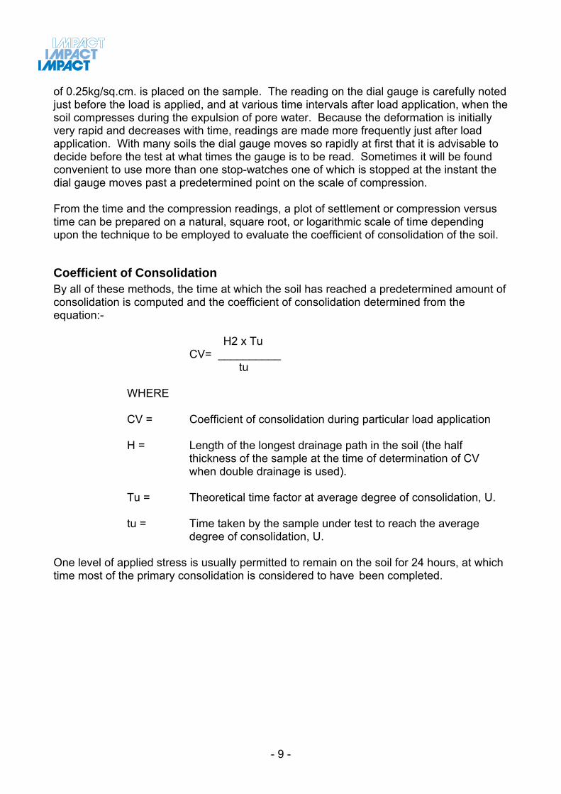
Coefficient of Consolidation By all of these methods, the time at which the soil has reached a predetermined amount of consolidation is computed and the coefficient of consolidation determined from the equation:-
H2 x Tu CV= __________ tu WHERE CV = Coefficient of consolidation during particular load application H = Length of the longest drainage path in the soil (the half
thickness of the sample at the time of determination of CV when double drainage is used).
Tu = Theoretical time factor at average degree of consolidation, U. tu = Time taken by the sample under test to reach the average
degree of consolidation, U.
One level of applied stress is usually permitted to remain on the soil for 24 hours, at which time most of the primary consolidation is considered to have been completed.