
User Guide - NET
887
www. EXFO .com User Guide 88000 Series Power Blazer HIGH-SPEED MULTISERVICE TEST MODULE
-
Upload
khangminh22 -
Category
Documents
-
view
1 -
download
0
Transcript of User Guide - NET

www.EXFO.com
User Guide
88000 SeriesPower Blazer
HIGH-SPEED MULTISERVICE TEST MODULE

ii 88000 Series
Copyright © 2014–2019 EXFO Inc. All rights reserved. No part of this publication may be reproduced, stored in a retrieval system or transmitted in any form, be it electronically, mechanically, or by any other means such as photocopying, recording or otherwise, without the prior written permission of EXFO Inc. (EXFO).
Information provided by EXFO is believed to be accurate and reliable. However, no responsibility is assumed by EXFO for its use nor for any infringements of patents or other rights of third parties that may result from its use. No license is granted by implication or otherwise under any patent rights of EXFO.
EXFO’s Commerce And Government Entities (CAGE) code under the North Atlantic Treaty Organization (NATO) is 0L8C3.
The information contained in this publication is subject to change without notice.
Trademarks
EXFO’s trademarks have been identified as such. However, the presence or absence of such identification does not affect the legal status of any trademark.
Units of Measurement
Units of measurement in this publication conform to SI standards and practices.
Patents
Dual Test Set/Bi-Directional testing is protected by US patent 9,432,206 and equivalents in other countries.
Feature(s) of this product is/are protected by one or more of: US design patent D798,171 and equivalent(s) in other countries.
October 31, 2019Document version: 13.0.0.1

Contents
Regulatory Information .......................................................................................................... x
1 Introducing the High-Speed Multiservice Test Module .............................. 1Features ..................................................................................................................................1Technical Specifications ...........................................................................................................2Conventions ............................................................................................................................3
2 Safety Information ....................................................................................... 5Additional Laser Safety Information .......................................................................................7Installation Instruction Warnings ............................................................................................8
3 Getting Started .......................................................................................... 11Inserting and Removing Test Modules .................................................................................11Inserting and Removing Transceiver System .........................................................................12Turning On the Unit ..............................................................................................................18Starting the Module Application ...........................................................................................18
4 Physical Interfaces and LEDs ..................................................................... 19Port Availability per Module ..................................................................................................25Transceivers ..........................................................................................................................29RJ45 ......................................................................................................................................29BNC ......................................................................................................................................30SMB ......................................................................................................................................30LEDs ......................................................................................................................................30
5 Graphical User Interface Overview ............................................................ 31Main Application Window ...................................................................................................31Main Window .......................................................................................................................31Navigation Buttons ...............................................................................................................32Status Bar ..........................................................................................................................32Title Bar ...............................................................................................................................35Global Indicator ...................................................................................................................36Test Control .........................................................................................................................38Test Menu ............................................................................................................................38Application Buttons ...........................................................................................................39Zoomed-In/Zoomed-Out Views ............................................................................................43Arrow Buttons .....................................................................................................................43Keyboard Usage ...................................................................................................................44
Power Blazer iii

6 Test Setup - Test Applications ....................................................................47iOptics ..................................................................................................................................49iSAM .....................................................................................................................................50Multi-Channel OTN ...............................................................................................................51FlexO BERT ............................................................................................................................52OTN BERT ..............................................................................................................................53OTN-SONET/SDH BERT ..........................................................................................................56SONET/SDH BERT ..................................................................................................................59DSn/PDH BERT ......................................................................................................................62SONET/SDH - DSn/PDH BERT ................................................................................................64NI/CSU Emulation ................................................................................................................67EtherSAM (Y.1564) ................................................................................................................68RFC 2544 ..............................................................................................................................70RFC 6349 ..............................................................................................................................72FlexE BERT .............................................................................................................................73EtherBERT .............................................................................................................................74Traffic Gen & Mon ................................................................................................................76Smart Loopback ....................................................................................................................78Through Mode ......................................................................................................................80TCP Throughput ....................................................................................................................81Carrier Ethernet OAM ..........................................................................................................82Cable Test .............................................................................................................................841588 PTP ...............................................................................................................................85SyncE ....................................................................................................................................86Wander .................................................................................................................................87FC BERT ................................................................................................................................88CPRI/OBSAI BERT ..................................................................................................................89eCPRI BERT ...........................................................................................................................91
7 Selecting and Starting a Test .....................................................................93Intelligent Apps ....................................................................................................................93Transport Test Applications ...................................................................................................97Ethernet Test Applications ....................................................................................................99Sync Test Applications .........................................................................................................101Fibre Channel Test Application ............................................................................................103Wireless Test Application ....................................................................................................105
iv 88000 Series

8 Test Setup - Test Configurator, Timer, and System ................................ 107Test Configurator Overview .................................................................................................112Modify Structure Button ....................................................................................................119Signal Auto-Detect ............................................................................................................1471588 PTP ............................................................................................................................148BERT and Unframed BERT ..................................................................................................155Cable Test ..........................................................................................................................162CFP/OSFP/QSFP/SFP ............................................................................................................164Clients - Profile ..................................................................................................................166Clock ..................................................................................................................................167Device Under Test (iOptics) ................................................................................................175eCPRI Flow - Profile ............................................................................................................179EtherBERT, FC BERT, BERT (eCPRI, CPRI/OBSAI, and FlexE), and Unframed BERT .................183EtherSAM - Burst ...............................................................................................................191EtherSAM - Global .............................................................................................................193EtherSAM - L2CP ................................................................................................................198EtherSAM - Ramp ..............................................................................................................204External Reference .............................................................................................................206Fibre Channel .....................................................................................................................207FlexE Group .......................................................................................................................210FlexO/OTN ..........................................................................................................................213Frequency ...........................................................................................................................214FTFL/PT and PT ...................................................................................................................217GFP-F/GFP-T ........................................................................................................................222Interface ............................................................................................................................223Labels ................................................................................................................................238Link OAM ...........................................................................................................................240Local Details (iSAM) ...........................................................................................................242MAC/IP/UDP .......................................................................................................................247Network .............................................................................................................................264Network Details (iSAM) ......................................................................................................269ODU Channels - Global ......................................................................................................279Remote Details (iSAM) .......................................................................................................287RFC 2544 - Global ..............................................................................................................291RFC 2544 - Subtests ...........................................................................................................294RFC 6349 ...........................................................................................................................303S-OAM and MPLS-TP OAM .................................................................................................306Services - Global ................................................................................................................316Services - L2CP ...................................................................................................................319Services - Profile .................................................................................................................320Signal ................................................................................................................................327Signal - Signal Configuration (DSn/PDH) ............................................................................333
Power Blazer v
Signal - Signal Configuration (OTN) ...................................................................................341Signal - Signal Configuration (SONET/SDH) ........................................................................345Smart Loopback .................................................................................................................349Streams - Global ................................................................................................................351Streams - Profile ................................................................................................................353SyncE .................................................................................................................................361System ...............................................................................................................................363Transceiver System (TA/TA4) ...............................................................................................364TCP Throughput .................................................................................................................365Test Sequence (iOptics) ......................................................................................................367Timer .................................................................................................................................368Traces (OTN) ......................................................................................................................370Traces (SONET/SDH) ...........................................................................................................374Traces/PT (FlexO) ................................................................................................................376Wander ..............................................................................................................................382
9 Test Results ................................................................................................385Alarms/Errors Overview .......................................................................................................388Analysis - MTIE/TDEV .........................................................................................................477Analysis - Time Error / Time Interval Error ..........................................................................479FEC Statistics ......................................................................................................................481FTFL/PT and PT ...................................................................................................................482GFP-F/GFP-T ........................................................................................................................484Graph (RFC 2544) ..............................................................................................................487Labels ................................................................................................................................488Link OAM ...........................................................................................................................489Logger ...............................................................................................................................493Messages ...........................................................................................................................496MPLS .................................................................................................................................498OTL-SDT ..............................................................................................................................499Performance Monitoring ....................................................................................................501PTP Stats ............................................................................................................................508Quality Level (1588 PTP) ....................................................................................................510Quality Level (SyncE) ..........................................................................................................512S-OAM and MPLS-TP OAM .................................................................................................514SDT (Multi-Channel OTN) ...................................................................................................519Service Configuration - Burst .............................................................................................521Service Configuration - L2CP ..............................................................................................522Service Configuration - Ramp ............................................................................................524Service Performance ..........................................................................................................526Streams - Frame Loss / Out-of-Sequence ............................................................................528Streams - Jitter ...................................................................................................................528
vi 88000 Series

Streams - Latency ..............................................................................................................529Streams - Throughput / Customer Frame Throughput ........................................................530Summary / Client Summary ...............................................................................................531Summary (1588 PTP) ..........................................................................................................540Summary (Cable Test) ........................................................................................................545Summary (EtherSAM) ........................................................................................................551Summary (FC BERT) ............................................................................................................554Summary (FlexE BERT) ........................................................................................................557Summary (FlexO BERT) .......................................................................................................559Summary (iOptics) .............................................................................................................561Summary (iSAM) ................................................................................................................563Summary (Link OAM) .........................................................................................................567Summary (Multi-Channel OTN) ..........................................................................................569Summary (NI/CSU Emulation) ............................................................................................571Summary (RFC 2544) .........................................................................................................572Summary (RFC 6349) .........................................................................................................575Summary (S-OAM and MPLS-TP OAM) ...............................................................................578Summary (SyncE) ...............................................................................................................583Summary (TCP Throughput) ...............................................................................................586Summary (Traffic Gen & Mon) ...........................................................................................589Summary (Wander) ............................................................................................................591Traces (OTN) .......................................................................................................................595Traces (SONET/SDH) ...........................................................................................................597Traces/PT (FlexO) ................................................................................................................598Traffic - Ethernet ................................................................................................................600Traffic - Flow Control .........................................................................................................603Traffic - Graph ....................................................................................................................605Traffic - OAM, S-OAM, and MPLS-TP OAM .........................................................................606Window Sweep ..................................................................................................................608WIS ....................................................................................................................................609
Power Blazer vii

10 Test Functions ..........................................................................................61140/100/200/400G Advanced - CFP4/CFP8/OSFP/QSFP+/QSFP28/QSFP56-DD Control ..........61440/100/200/400G Advanced - Lanes Mapping & Skew ......................................................618200/400G Advanced - Pre-Emphasis/RX EQ ........................................................................623200/400G Advanced - PAM-4 Histogram ...........................................................................625APS ....................................................................................................................................626BFD (Bidirectional Forwarding Detection) ..........................................................................629Client Offset ......................................................................................................................631FDL - Bit-Oriented Message ................................................................................................634FDL - Performance Report Message ...................................................................................638FEAC ..................................................................................................................................641Filters .................................................................................................................................645FlexE Advanced ..................................................................................................................649GMP ..................................................................................................................................651OH BERT ...........................................................................................................................652OH - GFP-F/GFP-T ...............................................................................................................655OH - OTN ...........................................................................................................................660OH - SONET/SDH ................................................................................................................666Packet Capture ...................................................................................................................680Ping & Trace Route .............................................................................................................686Pointer Adjustment ............................................................................................................691RTD ....................................................................................................................................701RTD/RTT (CPRI/OBSAI Framed L2) .......................................................................................704S-OAM Link Trace ...............................................................................................................707Signaling Bits .....................................................................................................................709Spare Bits ...........................................................................................................................711Traffic Scan ........................................................................................................................713
11 Test Control ...............................................................................................717Discover Remote Button ....................................................................................................718Inject Button .......................................................................................................................723Laser Button ......................................................................................................................723Lpbk Tool Button (Loopback Tool) ......................................................................................724Report Button ....................................................................................................................731Reset Button ......................................................................................................................736Save/Load Button ...............................................................................................................737Start/Stop|TX Button .........................................................................................................741
12 Power Failure Recovery ............................................................................743Enabling Power Failure Recovery .........................................................................................744When Using the Test Timer .................................................................................................745
viii 88000 Series

13 Maintenance ............................................................................................. 747Cleaning LC/MPO-n Connectors ..........................................................................................748Battery Safety Information .................................................................................................748Recalibrating the Unit .........................................................................................................749Recycling and Disposal .......................................................................................................750
14 Troubleshooting ....................................................................................... 751Solving Common Problems .................................................................................................751Contacting the Technical Support Group ............................................................................752Transportation ....................................................................................................................752
15 Warranty ................................................................................................... 753General Information ...........................................................................................................753Liability ...............................................................................................................................754Exclusions ...........................................................................................................................755Certification ........................................................................................................................755Service and Repairs .............................................................................................................756EXFO Service Centers Worldwide ........................................................................................757
A Specifications ........................................................................................... 759
B Glossary .................................................................................................... 761Acronym List .......................................................................................................................76110G Ethernet Client ............................................................................................................7781588 PTP .............................................................................................................................781CPRI ...................................................................................................................................787Ethernet Cables .................................................................................................................792G.709 Optical Transport Network (OTN) ............................................................................794Generic Framing Procedure (GFP) ......................................................................................811MPLS Labels ........................................................................................................................823OBSAI ................................................................................................................................824SONET/DSn/SDH/PDH ..........................................................................................................829SyncE ..................................................................................................................................839Unicast/Multicast Addresses for Ethernet OAM ..................................................................841VLAN ID and Priority ...........................................................................................................842
C Remote ToolBox ....................................................................................... 843Overview .............................................................................................................................843Remote ToolBox Installation ................................................................................................845Starting and Using the Remote ToolBox Application ..........................................................846Applications for... ...............................................................................................................848
Index .............................................................................................................. 849
Power Blazer ix

Regulatory Information
x 88000 Series
Regulatory Information
Electromagnetic Interference and Compatibility Regulatory Information
For Electromagnetic Interference and Compatibility Regulatory information on your product, refer to the user documentation of your platform.
European Declaration of Conformity
The full text of the EU declaration of conformity is available at the following Internet address: www.exfo.com/en/resources/legal-documentation.
Laser
Your instrument is a Class 1 laser product in compliance with standards IEC 60825-1: 2007/2014 and 21 CFR 1040.10, except for deviations pursuant to Laser Notice No. 42, dated December 18, 1989.

1 Introducing the High-Speed Multiservice Test Module
Turnkey field-test solution for deploying, validating, and troubleshooting networks up to 400G.
Features
FeaturesModel
8870/8880 88200NGE 88260 88400NGE/88460
Intelligent Apps.
iOptics X X X X
iSAM X X X -
Transport Multi-Channel OTN - X - -
FlexO BERT - - - X
OTN BERT X X X -
SONET/SDH BERT X X X -
OTN-SONET/SDH BERT X X X -
DSn/PDH BERT X - - -
SONET/SDH - DSn/PDH BERT X - X -
NI/CSU X - - -
Ethernet EtherSAM (Y.1564) X X X -
RFC 6349 X X X -
RFC 2544 X X X X
FlexE BERT - - - X
EtherBERT X X X X
Traffic Gen & Mon X X X -
Smart Loopback X X X X
Through Mode X X X -
TCP Throughput X X - -
Carrier Ethernet OAM X X X -
Cable Test X - - -
Power Blazer 1

Introducing the High-Speed Multiservice Test ModuleTechnical Specifications
Technical SpecificationsTo obtain this product’s technical specifications, visit the EXFO Web site at www.exfo.com.
Packet Sync 1588 PTP X X X -
SyncE X X X -
Wander 8880 - - -
Fibre Channel FC BERT X X X -
Wireless CPRI/OBSAI BERT X X X -
eCPRI BERT X X X -
FeaturesModel
8870/8880 88200NGE 88260 88400NGE/88460
2 88000 Series

Introducing the High-Speed Multiservice Test ModuleConventions
ConventionsBefore using the product described in this guide, you should understand the following conventions:
WARNINGIndicates a potentially hazardous situation which, if not avoided, could result in death or serious injury. Do not proceed unless you understand and meet the required conditions.
CAUTIONIndicates a potentially hazardous situation which, if not avoided, may result in minor or moderate injury. Do not proceed unless you understand and meet the required conditions.
CAUTIONIndicates a potentially hazardous situation which, if not avoided, may result in component damage. Do not proceed unless you understand and meet the required conditions.
IMPORTANTRefers to information about this product you should not overlook.
Power Blazer 3


2 Safety Information WARNING
Do not install or terminate fibers while a light source is active. Never look directly into a live fiber and ensure that your eyes are protected at all times.
WARNINGThe use of controls, adjustments and procedures, namely for operation and maintenance, other than those specified herein may result in hazardous radiation exposure or impair the protection provided by this unit.
WARNINGIf the equipment is used in a manner not specified by the manufacturer, the protection provided by the equipment may be impaired.
WARNINGUse only accessories designed for your unit and approved by EXFO. For a complete list of accessories available for your unit, refer to its technical specifications or contact EXFO.
Power Blazer 5

Safety Information
IMPORTANTRefer to the documentation provided by the manufacturers of any accessories used with your EXFO product. It may contain environmental and/or operating conditions limiting their use.
IMPORTANTWhen you see the following symbol on your unit , make sure that you refer to the instructions provided in your user documentation. Ensure that you understand and meet the required conditions before using your product.
IMPORTANTWhen you see the following symbol on your unit , it indicates that the unit is equipped with a laser source, or that it can be used with instruments equipped with a laser source. These instruments include, but are not limited to, modules and external optical units.
IMPORTANTOther safety instructions relevant for your product are located throughout this documentation, depending on the action to perform. Make sure to read them carefully when they apply to your situation.
6 88000 Series

Safety InformationAdditional Laser Safety Information
Additional Laser Safety Information This product employs Class 1 Laser transceivers.
Note: Refer to the platform user guide for additional test equipment safety information and ratings.
WARNINGWhen the LASER LED is on or flashing, the module is transmitting an optical signal on the transceiver ports.
Power Blazer 7

Safety InformationInstallation Instruction Warnings
Installation Instruction Warnings
CAUTIONWhen you use the unit outdoors, ensure that it is protected from liquids, dust, direct sunlight, precipitation, and full wind pressure.
CAUTIONExcept for the dual Bantam connector and the RJ-48C port, all telecom (electrical) interfaces are SELV (Safety Extra Low Voltage) circuitry intended for intra-building use only.
CAUTIONFor the dual Bantam connector and the RJ-48C ports, use only No. 26 AWG or larger telecommunication line cord to reduce the risk of fire.
CAUTIONNo user serviceable parts are contained inside. Contact the manufacturer regarding service of this equipment.
IMPORTANTAll wiring and installation must be in accordance with local building and electrical codes acceptable to the authorities in the countries where the equipment is installed and used.
WARNINGUse only accessories designed for your unit and approved by EXFO.
8 88000 Series

Safety InformationInstallation Instruction Warnings
CAUTIONElectrostatic Discharge (ESD) Sensitive Equipment:
Plug-in modules can be damaged by static electrical discharge. To minimize the risk of damage, dissipate static electricity by touching a grounded unpainted metal object
before removing, inserting, or handling the module.
before connecting or disconnecting cables to/from the module.
before inserting or removing a transceiver to/from the module.
Power Blazer 9

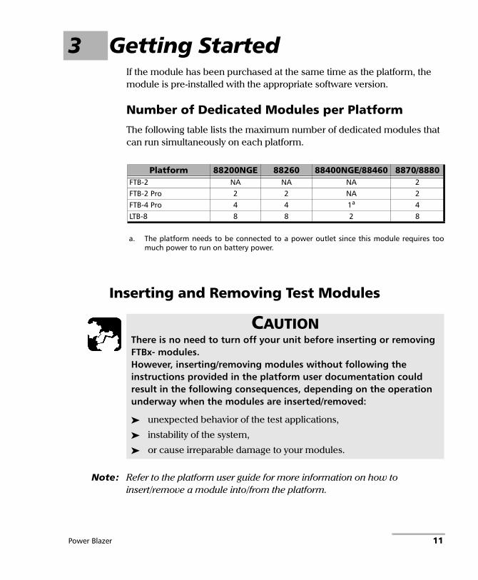
3 Getting Started If the module has been purchased at the same time as the platform, the module is pre-installed with the appropriate software version.
Number of Dedicated Modules per Platform
The following table lists the maximum number of dedicated modules that can run simultaneously on each platform.
Inserting and Removing Test Modules
Note: Refer to the platform user guide for more information on how to insert/remove a module into/from the platform.
Platform 88200NGE 88260 88400NGE/88460 8870/8880 FTB-2 NA NA NA 2FTB-2 Pro 2 2 NA 2FTB-4 Pro 4 4 1a
a. The platform needs to be connected to a power outlet since this module requires toomuch power to run on battery power.
4LTB-8 8 8 2 8
CAUTIONThere is no need to turn off your unit before inserting or removing FTBx- modules. However, inserting/removing modules without following the instructions provided in the platform user documentation could result in the following consequences, depending on the operation underway when the modules are inserted/removed:
unexpected behavior of the test applications,
instability of the system,
or cause irreparable damage to your modules.
Power Blazer 11

Getting StartedInserting and Removing Transceiver System
Inserting and Removing Transceiver System
FTBx-88260
The following procedure describes insertion and removal of transceiver system for FTBx-88260 modules.
To insert a transceiver system into the FTBx-88260 module:
1. Position the FTB-x-88260 module so that its faceplate is facing you.
2. Remove the FILLER (protective cover) from the FTBx-88260.
Turn the retaining screw counterclockwise until it is loose.
Hold the FILLER by the handle and/or the retaining screw and pull it out.
CAUTIONThere is no need to turn off your unit before inserting or removing transceiver systems.However, inserting/removing transceiver systems without following the instructions provided in this user documentation could result in the following consequences, depending on the operation underway when the transceiver systems are inserted/removed:
unexpected behavior of the test applications,
instability of the system,
or cause irreparable damage to your transceiver systems.
Screw
Handle
12 88000 Series

Getting StartedInserting and Removing Transceiver System
3. Remove the transceiver system from its packaging:
3a. Pull the battery insulator tab to activate the battery.
3b. Turn the retaining screw counterclockwise until it is loose.
3c. Hold the transceiver system by the handle and/or the retaining screw (NOT by the connectors) and pull it out. Don‘t throw away the transceiver system packaging, it is recommended to insert the transceiver system into its packaging when carrying it outside the FTBx-88260 module.
4. Insert the transceiver system into the FTBx-88260 module:
4a. Take the transceiver system and place it so that the connector pins are at the back as shown below.
The identification sticker and the protruding edges are on the left side.
4b. Insert the protruding edges of the transceiver system into the grooves of the receptacle’s module port.
Screw
Handle
Protruding edges
Grooves
Power Blazer 13

Getting StartedInserting and Removing Transceiver System
4c. Push the transceiver system all the way to the back of the receptacle by pressing firmly on the left edge of the transceiver system until it is fully inserted.
4d. Turn the retaining screw clockwise until it is tightened.
This will secure the transceiver system into its “seated” position.
To remove a transceiver system from the FTBx-88260 module:
1. Position the FTB-x-88260 module so that its faceplate is facing you.
2. Turn the retaining screw counterclockwise until it is loose.
3. Hold the transceiver system by the handle and/or the retaining screw (NOT by the connectors) and pull it out.
4. Cover the empty FTBx-88260’s receptacle with the supplied FILLER.
CAUTIONPulling out a transceiver system by its connectors could seriously damage both the transceiver system and connectors. Always pull out a transceiver system by its retaining screw, and/or the handle.
CAUTIONFailure to reinstall the FILLER over an empty receptacle will result in ventilation problems.
Press onthe edge
Screw
Screw
Handle
14 88000 Series

Getting StartedInserting and Removing Transceiver System
FTBx-88460
The following procedures describe the insertion and removal of a transceiver system for FTBx-88460 modules.
To insert a transceiver system into the FTBx-88460 module:
1. Position the FTBx-88460 module so that its faceplate is facing you. When the FTBx-88460 module is already inserted into an FTB-4 Pro platform, position the FTB-4 Pro so that its display is facing down and the module is oriented as shown in the following picture.
2. Remove the FILLER (protective cover) from the FTBx-88460.
Turn the two retaining screws counterclockwise until they are loose.
Hold the FILLER by the retaining screws and pull it out.
3. Remove the transceiver system from its packaging:
3a. Turn the two retaining screws counterclockwise until they are loose.
3b. Hold the transceiver system by the handle (NOT by the connectors) and pull it out. Do not throw away the transceiver system packaging. It is recommended to insert the transceiver system into its packaging when removing it from the FTBx-88460 module.
Screw
Handle Screw
Screw
Power Blazer 15

Getting StartedInserting and Removing Transceiver System
4. Insert the transceiver system into the FTBx-88460 module:
4a. Take the transceiver system and place it so that the handle is on the right side as shown.
4b. Insert the protruding edges of the transceiver system into the grooves of the receptacle’s module port.
4c. Push the transceiver system all the way to the back of the receptacle by pressing firmly only on the handle of the transceiver system until it is fully inserted.
Note: It is very important to push on the handle only to properly align the transceiver system within the FTBx-88460 module ensuring good electrical contact.
4d. Turn the two retaining screws clockwise until they are tightened. This will secure the transceiver system into its “seated” position.
Right protruding edgeRight groove
Handle
Screw
Screw
16 88000 Series

Getting StartedInserting and Removing Transceiver System
To remove a transceiver system from the FTBx-88460 module:
1. Position the FTBx-88460 module so that its faceplate is facing you.
2. Turn the two retaining screws counterclockwise until they are loose.
3. Hold the transceiver system by the handle (NOT by the connectors) and pull it out.
4. Cover the empty FTBx-88460’s receptacle with the supplied FILLER.
CAUTIONPulling out a transceiver system by its connectors could seriously damage both the transceiver system and connectors. Always pull out a transceiver system by its handle.
CAUTIONFailure to reinstall the FILLER over an empty receptacle will result in ventilation problems.
Handle
Screw
Screw
Power Blazer 17

Getting StartedTurning On the Unit
Turning On the Unit Turn on the platform. Refer to the platform user guide for more information.
Starting the Module Application The module can be configured and controlled by starting the application(s) as described in the following table:
To start the application:
From ToolBox X tap the desired application button.
Note: Refer to the respective user guides for more information on iORF, OpticalRF, and BBU-Emulation applications.
Module Application Comment88200NGE88400NGE88460
Power Blazer
88260 Power Blazer iORF OpticalRF
Only one application can run at once per module. Furthermore, only one instance of the iORF or OpticalRF application can run on the associated platform.
8880 8870a
a. Only the OpticalRF application is available on RTU-2.
Power Blazer iORFb OpticalRFb BBU-Emulationb
b. Not supported on FTB-2 and LTB-8.
Only one application can run at once per module. Furthermore, only one instance of the iORF, OpticalRF, or BBU-Emulation application can run on the associated platform.
18 88000 Series

4 Physical Interfaces and LEDsThis section describes all connectors (ports) and LEDs available on the 88000 Series.
FTBx-88200NGE
FTBx-88260 and Transceiver Systems
Note: The FTBx-88260 module with TA-SFP28 transceiver systems are shown below as examples for connector location purposes.
CAUTIONTo prevent exceeding the maximum input/output power level, please refer to this product’s technical specifications at www.exfo.com.
CFP41 QSFP1 EXT LCK REF OUT SFP+1 1. Laser radiation emitted from this port when LASER LED is on.
1. Laser radiation emitted from this port when LASER LED is on.
Port A Port B FTBx-88260
Port A11 TA-SFP28 Port A21 Port B11 Port B21
Power Blazer 19

Physical Interfaces and LEDs
TA-SFP28
TA-QSFP28
TA-CFP4
TA-SYNC
1. Laser radiation emitted from this port when LASER LED is on.
Port 11: SFP28 Port 21: SFP28
1. Laser radiation emitted from this port when LASER LED is on.
Port 11: QSFP28 Port 21: QSFP28
1. Laser radiation emitted from this port when LASER LED is on.
Port 11: CFP4 REF OUT
ANTENNA EXT CLK 1 PPS
20 88000 Series

Physical Interfaces and LEDs
FTBx-88400NGE
QSFP281
1. Laser radiation emitted from this port when LASER LED is on.
EXT CLK REF OUT CFP81 SFP561 SFP281
Power Blazer 21
Physical Interfaces and LEDs
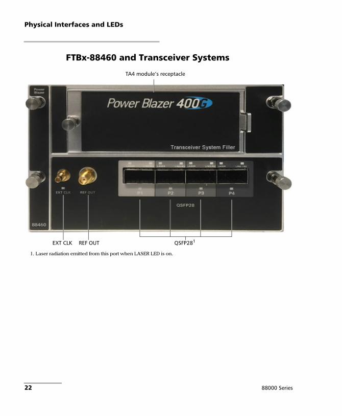
FTBx-88460 and Transceiver Systems
QSFP281
1. Laser radiation emitted from this port when LASER LED is on.
EXT CLK REF OUT
TA4 module‘s receptacle
22 88000 Series

Physical Interfaces and LEDs
TA4-CFP8
TA4-OSFP
TA4-QSFP-DD
1. Laser radiation emitted from this port when LASER LED is on.
CFP81
OSFP1 1. Laser radiation emitted from this port when LASER LED is on.
QSFP56-DD1 1. Laser radiation emitted from this port when LASER LED is on.
Power Blazer 23

Physical Interfaces and LEDs
FTBx-8870/8880
SFP+1
P2
1. Laser radiation emitted from this port when LASER LED is on.
SFP+1
P1RJ45P1
RJ48C BANTAM BNCTX/RX2
BNCRX
DUPLEX
LINK/ACT
LINK/RX
LASER BNCEXT CLK
24 88000 Series

Physical Interfaces and LEDsPort Availability per Module
Port Availability per Module
88200NGE
The following table shows the list of available ports as well as a description and the signals supported on the module.
Port Labelled Description Supported Signal(s)
SFP+ Optical IN/OUT port SFP/SFP+ transceiver
Ethernet 100/1000 Mbit/s, 10 Gbit/s optical Ethernet 10/100/1000 Mbit/s electrical (using active copper SFP)Fibre Channel 1X, 2X, 4X, 8X, 10X, 16X eCPRI 10 Gbit/sCPRI 1.2, 2.4, 3.1, 4.9, 6.1, 9.8, 10.1 Gbit/s OBSAI 1.5, 3.1, 6.1 Gbit/s OC-1/STM-0, OC-3/STM-1, OC-12/STM-4, OC-48/STM-16, OC-192/STM-64OTU1, OTU2, OTU1e, OTU2e, OTU1f, OTU2f.
CFP4 Optical IN/OUT port CFP4 transceivera
a. Only OTU4 (4 Lanes) and 100GE (4 Lanes) are supported.
Ethernet 100 Gbit/s OTU4
QSFP (QSFP+ or QSFP28)
Optical IN/OUT port QSFP+ transceiverb
b. Only parallel interfaces are supported.
Ethernet 40 Gbit/s OTU3e2, OTU3e1, OTU3
Optical IN/OUT port QSFP28 transceivera
Ethernet 100 Gbit/s OTU4
REF OUT Electrical port SMA for eye diagram clock signal generation
EXT CLK Electrical port SMB for external clock synchronization
DS1/1.5M, E1/2M, 2MHz, 1PPSc
c. Available for Dual Test Set - One-Way Latency measurement mode.
Power Blazer 25

Physical Interfaces and LEDsPort Availability per Module
88260 and Transceiver Systems
The following table shows the list of transceiver system supported on each port of the FTBx-88260 module.
The following table shows the list of port as well as a description and the signals supported on each transceiver system.
Port Labelled Description Supported Transceiver System
A Transceiver system left port TA-SFP28, TA-QSFP28, TA-CFP4, TA-Sync
B Transceiver system right port TA-SFP28, TA-QSFP28, TA-CFP4, TA-Sync
Transceiver System Description Port
Labelleda
a. The ports are listed/referred as follows in the GUI: Port, FTBx-88260‘s port (A or B), transceiver systemport (1 or 2), and connector type; for example Port A1 - SFP28.
Supported Signal(s)
TA-SFP28 Dual SFP28 supporting SFP/SFP+/SFP28 transceivers
1 Ethernet 100/1000 Mbit/s, 10 Gbit/s, 25 Gbit/s optical Ethernet 10/100/1000 Mbit/s electrical (using active copper SFP)Fibre Channel 1X, 2X, 4X, 8X, 10X, 16X, 32XeCPRI 10 Gbit/s, 25 Gbit/s CPRI 1.2, 2.4, 3.1, 4.9, 6.1, 9.8, 10.1 Gbit/s OBSAI 1.5, 3.1, 6.1 Gbit/s OC-1/STM-0, OC-3/STM-1, OC-12/STM-4, OC-48/STM-16, OC-192/STM-64OTU1, OTU2, OTU1e, OTU2e, OTU1f, OTU2f
2
TA-QSFP28 Dual QSFP28 supporting QSFP+/QSFP28 transceivers
1 QSFP+:Ethernet 40 Gbit/s OTU3e2, OTU3e1, OTU3
QSFP28:Ethernet 100 Gbit/sOTU4
2
TA-CFP4 CFP4 1 Ethernet 100 Gbit/sOTU4
REF OUT (SMA) REF OUT Electrical port for eye diagram clock signal generation
TA-SYNC EXT CLK (SMB) EXT CLK IN: 2 MHz OUT: 2 MHz
1PPS (SMB) 1 PPS IN: 1PPSb
b. Used for Dual Test Set - One-Way Latency measurement mode.
ANTENNA (SMA) ANTENNA Future use
26 88000 Series

Physical Interfaces and LEDsPort Availability per Module
88400NGE / 88460 and Transceiver Systems
The following table shows the list of available ports as well as a description and the signals supported on the module.
The following table shows the list of transceiver system supported on the 88460 module as well as a description and the signals supported.
Port Labelled Description Supported Signal(s) 88400NGE 88460a
a. Without TA4 transceiver systems.
SFP28b
b. Future use.
Optical IN/OUT port SFP28 transceiver
Ethernet 100/1000 Mbit/s, 10 Gbit/s, 25 Gbit/s optical
X -
SFP56b Optical IN/OUT port SFP56 transceiver
Ethernet 50 Gbit/s X -
QSFP28 (P1, P2, P3, P4)
Optical IN/OUT port QSFP28 transceiver
Ethernet 40 Gbit/sb, 100 Gbit/s 100G FlexO-1-RS
X X
CFP8 Optical IN/OUT port CFP8 transceiver
Ethernet 400 Gbit/s X -
REF OUT Electrical port SMA for eye diagram clock signal generation
X X
EXT CLKb Electrical port SMB for external clock synchronization
DS1/1.5M, E1/2M, 2MHz, 1PPS X X
Transceiver System Description Supported Signal(s)
TA4-CFP8 Optical IN/OUT port CFP8 transceiver
400 Gbit/s Ethernet
TA4-OSFP Optical IN/OUT port OSFP transceiver
400 Gbit/s Ethernet
TA4-QSFP-DD Optical IN/OUT port QSFP56-DD/QSFP56 transceiver
400 Gbit/s Ethernet (QSFP56-DD) 200 Gbit/s Ethernet (QSFP56)
Power Blazer 27

Physical Interfaces and LEDsPort Availability per Module
8870/8880
The following table shows the list of available ports as well as a description and the signals supported for each module.
Connector Labelled Description and supported signal(s)Module
8870 8880Bantam BANTAM
TX/RX2 RX
TX and RX: DS1/1.5M, E1/2MRX2: DS1/1.5M
- X
Clock IN/OUT: DS1/1.5M, E1/2M, 2 MHz
BNC BNC TX/RX2
TX: E1/2M, E3/34M, DS3/45M, STS-1e/STM-0e/52M, E4/140M, STS-3e/STM-1e/155MRX2: DS3, 2 MHz, 10 MHz
- X
Clock OUT: DS1/1.5M, E1/2M, 2 MHz
BNCRX
E1/2M, E3/34M, DS3/45M, STS-1e/STM-0e/52M, E4/140M, STS-3e/STM-1e/155Mk, 1PPS
- X
Clock IN: DS1/1.5M, E1/2M, 2 MHz, 10 MHz, 1 PPS
BNCEXT CLK
Clock IN: DS1/1.5M, E1/2M, 2 MHz, 1 PPS X -
RJ45 RJ45 P1 Ethernet 10/100/1000 Mbit/s electrical X X
RJ48C RJ48C DS1/1.5M, E1/2M X X
1PPS, 2 MHz, 10 MHz - X
Clock IN: DS1/1.5M, E1/2M, 2 MHz - X
Clock OUT: DS1/1.5M, E1/2M, 2 MHz - X
SFP/SFP+ SFP+ P1 or
SFP+ P2
Ethernet 100 Mbit/s, 1000 Mbit/s,10 Gbit/s LAN/WAN opticalOC-1/STM-0, OC-3/STM-1, OC-12/STM-4, OC-48/STM-16, OC-192/STM-64a
OTU1, OTU2, OTU1e, OTU2e, OTU1f, OTU2feCPRI 10 Gbit/sCPRI 1.2, 2.4, 3.1, 4.9, 6.1, 9.8, 10.1 Gbit/sOBSAI 1.5, 3.1, 6.1 Gbit/s Fibre Channel 1X, 2X, 4X, 8X, 10X
a. Port SFP+ P2 is used with OC-192/STM-64 in Decoupled (TX≠RX) mode.
X X
SFP+ P2 Ethernet 10/100/1000 Mbit/s electrical (using active copper SFP)b
b. Available as a second port when the test application requires two ports.
X X
28 88000 Series

Physical Interfaces and LEDsTransceivers
Transceivers Carefully connect optical fibre cables to the transceiver IN and OUT ports. To ensure good signal quality, make sure that the optical fibre connector is fully inserted into the optical connector port.
Note: Do not replace the transceiver while the test is running to avoid distorting results. First stop the test, replace the transceiver, select the connector type (refer to Modify Structure Button on page 119), and then restart the test.
RJ45 The electrical port is RJ45 for category 5 unshielded twisted pair (UTP). Refer to Ethernet Cables on page 792 for cable specifications.
CAUTIONTo prevent exceeding the maximum input power level please use an attenuator when a loopback configuration is used.
CAUTIONBefore inserting an optical module into the interface receptacle, inspect the receptacle to make sure nothing is inside.
WARNINGUse only EXFO supported transceivers. Refer to www.exfo.com for the list of supported transceivers. Using non-supported transceivers can affect the performance and accuracy of the test.
Power Blazer 29

Physical Interfaces and LEDsBNC
BNC Connector type is BNC for coaxial 75-ohm cable connection. An adapter cable (BNC to Bantam) is required for Bantam external clock connection (not supplied).
SMB The connector type is SMB for coaxial 75-ohm cable connection. An adapter cable (SMB to Bantam) is required for Bantam connection (not supplied).
LEDs LASER red LED is on when the module is emitting an optical laser
signal.
LINK/RX green LED is on when the link is up, off when the link is down, and flashing when frames are transmitted and/or received.
DUPLEX green LED is on for Full Duplex mode, off for Half Duplex mode, and flashing when collisions are detected.
Port blue LED is on when this port is selected for the test, and flashing when this port is selected for clock input.
30 88000 Series

5 Graphical User Interface Overview
This chapter describes the Power Blazer Series graphical user interface.
Main Application Window The following main application window is displayed when the Power Blazer application is started.
Main WindowThe main window is used to setup a test and to view the test status and results.
MainWindow
Test Control
Test Menu
Application Buttons
Status Bar
Global Indicator
Title Bar
Power Blazer 31

Graphical User Interface OverviewNavigation Buttons
Navigation ButtonsNavigation buttons appear when there is not enough room on one page to display all available test applications. The left and right arrow buttons allow respectively accessing the previous or next window. The buttons in between the left and right arrow buttons allow directly selecting the window for the type of test application listed.
Status Bar The status bar displays the following information.
Icon and/or text Description Test Application
Test icon Icon representing the active test application. All
P1, P2, P3, P4 Port identification number: Port x All
A1, A2, B1, B2
Port identification number composed of the port of the FTBx-88260 module (A or B) and the transceiver system port (1 or 2)
All
TX/RX, TX, RX Indicates the direction of the signal per port. Transport, Wander (DS1/E1)
Interface/ Signal
The interface or signal rate per port: 1GE Optical, 40G, OTU1, OTU2, OTU3, etc.
All
(BTS) or (RRH)
BTS: Emulation mode is Base Station RRH: Emulation mode is Remote Radio Head
CPRI/OBSAI BERT
LINK Green arrow: Link up. Red arrow: Link down. Gray arrow: Awaiting incoming data to provide a status.
All CPRI/OBSAI BERT
FlexO status and size
Indicates the FlexO group status and its size: Green arrow: FlexO Group Up. Red arrow: FlexO Group Down.
FlexO BERT
32 88000 Series

Graphical User Interface OverviewStatus Bar
PTP For G.8265.1: Green arrow: Signaling requests granted.Red arrow: Request denied, session canceled, or no reply.Gray arrow: Pending, inactive, or link down.
For G.8275.1: Green arrow: Announce, Sync, and Follow-up are received according with their respective interval. Red arrow: Announce, Sync, or Follow-up are not received. Gray arrow: Pending.
Refer to Negotiation Status on page 541 for more information.
1588 PTP
ESMC Green arrow: ESMC valid information frame received.Red arrow: No ESMC valid information frames received. Gray arrow: Pending state.Refer to ESMC Monitoring on page 361 for more information.
SyncE, Wander
Power level The received optical signal status:Green with “Power”: Power level in rangea.Yellow: Power level out-of-rangeb.Red with “LOS”: Loss of signalb.Red with “Power”: Power level is close to damage.Gray: The operational range value is either not available or not supplied by the transceiver.
All except Cable Test
Laser ONb. The laser icon is not displayed when the laser is offa. The laser icon is only displayed for optical interfaces. The laser is ON by default when the test is created. The laser control is not affected when turning off the laser by generating a LOS for example. Refer to Laser Button on page 723.
All
The status of the received signal pattern per port: Green: Pattern is synchronized. Red: Loss of pattern. Gray: Test is not running (EtherBERT test or EoOTN client) or the No Pattern Analysis (Live) check box is selected.
TransportEtherBERTFibre ChannelWireless
Connection established between two testing units in Dual Test Set (DTS), EXFO|Worx Interop, or in Loop Up mode.
Ethernet
Connection not established between two testing units in Dual Test Set (DTS), EXFO|Worx Interop, or in Loop Up mode.
Ethernet
Remote unit is busy (locked) in EXFO|Worx Interop operation mode. Ethernet
Icon and/or text Description Test Application
Power Blazer 33
Graphical User Interface OverviewStatus Bar
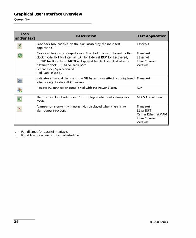
Loopback Tool enabled on the port unused by the main test application.
Ethernet
Clock synchronization signal clock. The clock icon is followed by the clock mode: INT for Internal, EXT for External RCV for Recovered, or BKP for Backplane. AUTO is displayed for dual port test when a different clock is used on each port. Green: Clock Synchronized. Red: Loss of clock.
Transport EthernetFibre ChannelWireless
Indicates a manual change in the OH bytes transmitted. Not displayed when using the default OH values.
Transport
Remote PC connection established with the Power Blazer. N/A
The test is in loopback mode. Not displayed when not in loopback mode.
NI-CSU Emulation
Alarm/error is currently injected. Not displayed when there is no alarm/error injection.
TransportEtherBERTCarrier Ethernet OAMFibre ChannelWireless
a. For all lanes for parallel interface.b. For at least one lane for parallel interface.
Icon and/or text Description Test Application
34 88000 Series

Graphical User Interface OverviewTitle Bar
The following status are also displayed:
Battery/AC icons, available on FTB platforms, indicate the battery level and if the platform is connected to an AC power source. Refer to the platform user guide for more information.
Date and Time indicate the current date and time.
Title Bar The Title Bar displays the module’s slot number in brackets, the software application name and the minimize, maximize, and close buttons.
Power Blazer 35

Graphical User Interface OverviewGlobal Indicator
Global IndicatorThe global indicator area displays the global pass/fail verdict, global alarm, and the test duration.
The global indicator area can be maximized for distant viewing. Tap anywhere within the global indicator area to display a maximized view. Tap again to exit the maximized view.
GlobalAlarm
Test Timer
Global indicator area
History
Current
Timer
GlobalVerdict
36 88000 Series

Graphical User Interface OverviewGlobal Indicator
Global Verdict
Reports the global test verdict status when supported by the test application and enabled (when applicable).
Global Alarm
Indicates the current and history alarm/error status of the test.
Verdict Description
PASS PASS is displayed with a green background when all result values meet the configured threshold criteria.
FAIL FAIL is displayed with a red background when any result value does not meet the configured threshold criteria or when a specific alarm is detected (refer to each test application for additional information).
“--” “--” is displayed with a gray background when at least one of the following conditions is met:
- Pass/Fail verdict is not enabled - there is no defined criterion- the test has not run yet.
Background color
Alarm/ Error Text displayed Description
Gray Current -- No test result available.
History
Green Current No Alarm No alarm/error has occurred in the last second.
History No alarm/error has occurred during the test.
Red Current Alarms or the name of the alarm. An alarm/error occurred in the last second.
History
Amber History No current alarm/error but at least one alarm/error has occurred during the test.
Power Blazer 37

Graphical User Interface OverviewTest Control
Test Timer
The test timer without the timer icon indicates the time elapsed since the beginning of the test. No timer action is active. The test timer format is “day hour:minute:second”.
Timer
The timer icon with Armed indicates that a start time is active.
The timer icon with the Test Timer indicates that a duration and/or a stop time is active.
Test Control
Note: Refer to Test Control on page 717 for more information.
Test Menu The test menu displays the following buttons:
Setup allows configuring the selected test. Refer to Test Setup - Test Configurator, Timer, and System on page 107 for more information.
Results allows viewing test results. Refer to Test Results on page 385 for more information.
Functions allows configuring additional test functions (refer to Test Functions on page 611).
38 88000 Series

Graphical User Interface OverviewApplication Buttons
Application Buttons Help (?) displays the help information related to the content of the
active main window. It is also possible to navigate through the remainder of the help information.
Exit (x) closes the application.
About (i) mainly displays the product version details and technical support information.
Module Details button displays the module details such as its ID, Serial Number, Software Product Version, etc.
View Licence Agreement button displays the details of the product licence agreement.
What’s new link allows displaying the details of the new features introduced with this software release as well as the platform inventory.
Software Options button displays the list of software options.
Note: For information on how to install and activate software options, refer to the platform User Guide. The Power Blazer application must be restarted once a new software option is installed in order to activate it.
Software Option Description
10electrical Ethernet 10Base-T electrical interface
10G_LAN Ethernet 10G LAN optical interface
10G_WAN Ethernet 10G WAN optical interface
100electrical Ethernet 100Base-TX electrical interface
100GE Ethernet 100G
100optical Ethernet 100Base-FX optical interface
155M 155 Mbit/s (SONET/SDH)
1588PTP 1588 Precision Time Protocol Test Application
200GE Ethernet 200G
2488M 2.488 Gbit/s (SONET/SDH)
Power Blazer 39

Graphical User Interface OverviewApplication Buttons
25GE Ethernet 25G
40GE Ethernet 40G
400GE Ethernet 400G
52M 52 Mbit/s (SONET/SDH)
622M 622 Mbit/s (SONET/SDH)
9953M 9.953 Gbit/s (SONET/SDH)
ADV-FILTERS Advanced filtering
CABLE_TEST Cable Test Application
CPRI CPRI 2.4576 Gbit/s and 3.072 Gbit/s
CPRI-1.2G CPRI 1.2288 Gbit/s
CPRI-4.9G CPRI 4.9152 Gbit/s
CPRI-6.1G CPRI 6.144 Gbit/s
CPRI-9.8G CPRI 9.8304 Gbit/s
CPRI-10.1G CPRI 10.1376 Gbit/s
CPRI-ALU-BBUe Alcatel-Lucent BBUe over CPRI
CPRI-AUTODETECT CPRI Mapping Auto-Detect
CPRI-Spectrum RF Spectrum Analysis over CPRI
DP-CPRI Dual Port CPRI
DP_40-100GE Dual Port at 40/100GE
DP-eCPRI Dual Port eCPRI
DS1-FDL DS1/1.5M Facility Data Link
DS3-FEAC DS3/45M Far-End Alarm and Control
DS3-G747 ITU-T Recommendation G.747
DSn Digital Signal
DTS-NAT NAT traversal for DTS applications
DUAL-PORT Dual Port Test
DUALRX Dual RX
eCPRI-10G eCPRI over 10GE
eCPRI-25G eCPRI over 25GE
EoE Ethernet over Ethernet Encapsulation (10GE)
EoE_40-100GE Ethernet over Ethernet Encapsulation (40/100GE)
Software Option Description
40 88000 Series

Graphical User Interface OverviewApplication Buttons
EoOTN Ethernet over Optical Transport Network
ETH-CAPTURE Ethernet Frame Capture
ETH-OAM Carrier Ethernet OAM test application
ETH-THRU Through Mode Test Application
FC-1X Fibre Channel 1X
FC-2X Fibre Channel 2X
FC-4X Fibre Channel 4X
FC-8X Fibre Channel 8X
FC-10X Fibre Channel 10X
FC-16X Fibre Channel 16X
FC-32X Fibre Channel 32X
FlexE-100G 100G FlexE Group
FlexE-200G 200G FlexE Group
FlexE-300G 300G FlexE Group
FlexE-400G 400G FlexE Group
FlexE-HiRateClient FlexE Clients at 150G and above
FlexE-LoRateClient FlexE Clients at 100G and below
FlexO-400G 400G FlexO Group
G82751 ITU-T G.8275.1 Profile
GCC-BERT OTN Overhead BERT and Synchronization validation
GigE_Electrical Ethernet 1000Base-T electrical interface
GigE_Optical Ethernet 1000Base-X optical interface
iOptics Intelligent Pluggable Optic Test Application
iORF Intelligent OpticalRF Application
IPv6 Internet Protocol Version 6 (IPv6) (up to 10GE)
IPv6_40-100GE Internet Protocol Version 6 (IPv6) (40/100GE)
iSAM Intelligent Service Activation Methodology
L2-Transparency L2CP Handling Test in EtherSAM
LINK-OAM Link OAM
MPLS MPLS Encapsulation (up to 10GE)
MPLS_40-100GE MPLS Encapsulation (40/100GE)
Software Option Description
Power Blazer 41

Graphical User Interface OverviewApplication Buttons
MULTI-CH-OTN Multi-Channel OTN Test Application
NI-CSU NI/CSU Emulation
OBSAI OBSAI 3.072 Gbit/s
OBSAI-1.5G OBSAI 1.536 Gbit/s
OBSAI-6.1G OBSAI 6.144 Gbit/s
ODU0 OTN ODU0
ODUflex OTN ODUflex
ODUflex-HiRate ODUflex client at 146.7G and above
ODUMUX ODU Multiplexing Payload Type 20 and 21
OTN-INTR-THRU OTN Intrusive Through Mode
OTN-MIX-MAPPING Mix-Mapping capability for Multi-Channel OTN
OTU1 Optical Transport Unit-1 (2.7 Gbit/s)
OTU2 Optical Transport Unit-2 (10.7 Gbit/s)
OTU2-1e-2e Optical Transport Unit-2 Overclocked (11.049/11.096 Gbit/s)
OTU2-1f-2f Optical Transport Unit-2 Overclocked (11.270/11.317 Gbit/s)
OTU3 Optical Transport Unit-3 (43.018 Gbit/s)
OTU3-e1-e2 Optical Transport Unit-3 Overclocked (44.571/44.583 Gbit/s)
OTU4 Optical Transport Unit-4 (111.81 Gbit/s)
PBBTE Provider Backbone Bridge Encapsulation (10GE)
PBBTE_40-100GE Provider Backbone Bridge Encapsulation (40/100GE)
PDH Plesiochronous Digital Hierarchy
PIM Passive Intermodulation Analysis
RF-PWR-MASK Radio Frequency Power Alarming Mask
RFC2544_200-400GE RFC 2544 test application (200/400GE)
RFC6349 RFC 6349 test application (up to 10GE)
RFC6349_40-100GE RFC 6349 test application (40/100GE)
RFC6349-EXFOWorx EXFO|Worx Interop Operation Mode
SDH Synchronous Digital Hierarchy
SONET Synchronous Optical Network
SONETSDH-INTR-THRU SONET/SDH Intrusive Through Mode
TCM Tandem Connection Monitoring STS/AU and VT/TU (SONET/SDH)
Software Option Description
42 88000 Series

Graphical User Interface OverviewZoomed-In/Zoomed-Out Views
Zoomed-In/Zoomed-Out Views Some configuration and result blocks give access to zoomed views allowing more detailed configurations/results.
The block title contains the magnifier (+) icon when a zoomed view is available.
To zoom-in, tap the magnifier (+) icon or anywhere on the block.
To zoom-out, tap on the magnifier (-) icon or anywhere on the block title.
Arrow Buttons
TCP-THPUT TCP Throughput Test Application
TRAFFIC-SCAN Traffic Scan
TST-OAM Test Over Service OAM
TunableOptics Tunable Wavelength Support for SFP+
SyncE Synchronous Ethernet Test Application
Wander Time Error / Wander Test Application
Software Option Description
Moves to the top of the list.
Moves one page up.
Moves one line up.
Moves one line down.
Moves one page down.
Moves to the end of the list.
Power Blazer 43

Graphical User Interface OverviewKeyboard Usage
Keyboard Usage The GUI pops up different keyboards to modify data. Following are the usual keyboard keys:
Left arrow moves the cursor one position to the left.
Right arrow moves the cursor one position to the right.
Up arrow increases the value by one.
Down arrow decreases the value by one.
Del deletes the value at the cursor position.
Back deletes the value preceding the cursor position.
OK completes data entry.
Cancel closes the keyboard and discards the keyboard entry.
Previous... allows the selection of previously configured values. This button is only available for certain fields like IP Address, MAC Address, etc.
Note: For certain text fields, the GUI pops up or uses the unit’s on-screen keyboard. Refer to the platform user guide for more information on how to use it.
For full keyboard, the Back, Del, Shift, and Space bar keys have the same functionality as a regular PC keyboard.
44 88000 Series

Graphical User Interface OverviewKeyboard Usage
For multiplexing keyboard, tap on all mapped signals that have to be added/removed to/from the test path.
A mapped signal with an orange background color is part of the test path.
A mapped signal with a gray background color is not part of the test path.
Power Blazer 45

Graphical User Interface OverviewKeyboard Usage
The Trace message keyboard allows entering alphanumerical characters (ITU T.50) required for J0/J1/J2/TTI Trace fields. Tap the Control Characters button to access these characters.
ITU T.50 Characters
b7 to b1 Character Description b7 to b1 Character Description
000 0000 NUL Null 001 0000 DLE Data Link Escape
000 0001 SOH Start Of Heading 001 0001 DC1 Device Control 1
000 0010 STX Start of Text 001 0010 DC2 Device Control 2
000 0011 ETX End of Text 001 0011 DC3 Device Control 3
000 0100 EOT End Of Transmission 001 0100 DC4 Device Control 4
000 0101 ENQ Enquiry 001 0101 NAK Negative Acknowledge
000 0110 ACK Acknowledge 001 0110 SYN Synchronous idle
000 0111 BEL Bell 001 0111 ETB End of Transmission Block
000 1000 BS Backspace 001 1000 CAN Cancel
000 1001 HT Horizontal Tabulation 001 1001 EM End of Medium
000 1010 LF Line Feed 001 1010 SUB Substitute character
000 1011 VT Vertical Tabulation 001 1011 ESC Escape
000 1100 FF Form Feed 001 1100 IS4 Information Separator 4
000 1101 CR Carriage Return 001 1101 IS3 Information Separator 3
000 1110 SO Shift-Out 001 1110 IS2 Information Separator 2
000 1111 SI Shift-In 001 1111 IS1 Information Separator 1
46 88000 Series

6 Test Setup - Test Applications The Power Blazer offers the following test applications.
Type ApplicationAvailable on
Page8870/8880 88200NGE 88260 88400NGE/88460
Intelligent Apps iOptics X X X X 49
iSAM X X X - 50
Transport OTN BERT X X X X 53
Multi-Channel OTN - X - - 51
FlexO BERT - - - X 52
SONET/SDH BERT X X X - 59
OTN-SONET/SDH BERT X X X - 56
DSn/PDH BERT X - - - 62
SONET/SDH - DSn/PDH BERT X - X - 64
NI/CSU Emulation X - - - 67
Ethernet EtherSAM (Y.1564) X X X - 68
RFC 6349 X X X - 72
RFC 2544 X X X X 70
FlexE BERT - - - X 73
EtherBERT X X X X 74
Traffic Gen & Mon X X X - 76
Smart Loopback X X X X 78
Through Mode X X X - 80
TCP Throughput X X - - 81
Carrier Ethernet OAM X X X - 82
Cable Test X - - - 84
Sync 1588 PTP X X X - 85
SyncE X X X - 86
Wander 8880 - - - 87
Fibre Channel FC BERT X X X - 88
Power Blazer 47
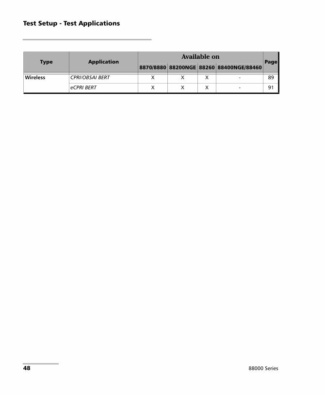
Test Setup - Test Applications
Wireless CPRI/OBSAI BERT X X X - 89
eCPRI BERT X X X - 91
Type ApplicationAvailable on
Page8870/8880 88200NGE 88260 88400NGE/88460
48 88000 Series

Test Setup - Test ApplicationsiOptics
iOptics iOptics test application provides a quick assessment of the proper operation of an optical transceiver before using it in a network or test environment. The validation is done by running sub-tests in addition to monitoring transceiver power consumption and temperature. Result and verdict are reported for each sub-test and monitoring task. Transceiver’s manufacturing information is also automatically collected.
A fiber loopback patch cord is required to perform the test with applicable attenuation included to protect the optical device. Bidirectional (single fiber) transceivers are not supported since the iOptics test requires a loopback.
Typical iOptics test application:
Supported Interfaces/Rates: 40G/100G/400G/OTU3/OTU3e1/OTU3e2/OTU4 parallel interfaces and all serial interfaces up to 25GE/OTU2f (refer to Rate on page 176 for more information).
EXFO Unit
Power Blazer 49

Test Setup - Test ApplicationsiSAM
iSAM iSAM is a simplified version of EtherSAM that is centered around addressing turn-up of E-Line circuits (EVC). The objective of the test is to validate Carrier Ethernet-based services key performance indicators defined in MEF: Frame Delay (FD), Inter-Frame Delay Variation (IFDV), and Frame Loss Ratio (FLR). In addition the RFC 6349 subtest can be enabled to validate that the Ethernet service is able to properly carry TCP traffic.
The iSAM test has to be executed in conjunction with a remote unit. The remote unit can be either in loopback configuration for unidirectional testing or in EtherSAM Dual Test Set mode for bidirectional testing.
The Dual Test Set test allows bi-directional testing between two compatible units providing independent results for each test direction. The results from local-to-remote and remote-to-local are available on the local testing unit.
Typical iSAM test applications:
Supported Interfaces/Rates: 10M to 100G.
Networkunder test
(EVC)Local Unit Remote Unit
EXFO Unit EXFO Unit
Manual or Remote
Loopback
Networkunder test
(EVC)Local Unit Remote Unit
EXFO Unit EXFO Unit
EtherSAM(DTS)
50 88000 Series
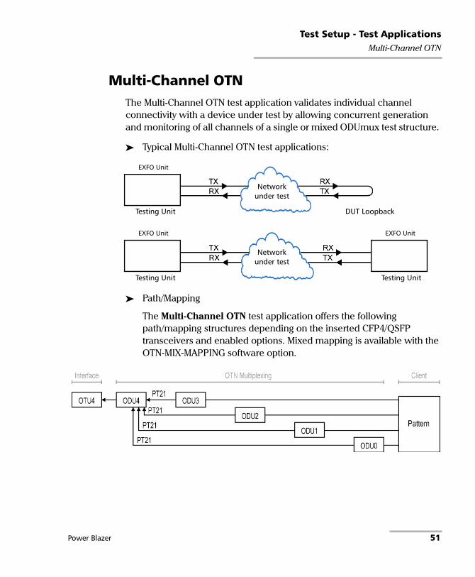
Test Setup - Test ApplicationsMulti-Channel OTN
Multi-Channel OTN The Multi-Channel OTN test application validates individual channel connectivity with a device under test by allowing concurrent generation and monitoring of all channels of a single or mixed ODUmux test structure.
Typical Multi-Channel OTN test applications:
Path/Mapping
The Multi-Channel OTN test application offers the following path/mapping structures depending on the inserted CFP4/QSFP transceivers and enabled options. Mixed mapping is available with the OTN-MIX-MAPPING software option.
Networkunder test
Testing Unit DUT Loopback
EXFO Unit
Networkunder test
Testing Unit Testing Unit
EXFO Unit EXFO Unit
Power Blazer 51

Test Setup - Test ApplicationsFlexO BERT
FlexO BERT FlexO is an adaptation layer which provides a flexible, modular mechanism to support different line rates with beyond 100G signals. A set of n 100Gbit/s Instances are bonded together to carry an OTUCn, with each FlexO Instance carrying an OTUC slice. The current implementation of FlexO is fixed to 4 x 100G PHYs.
Typical FlexO BERT test applications:
Supported Interfaces/Rates: 100G.
Networkunder test
Testing Unit
Power Blazer
Networkunder test
Testing Unit
Power Blazer
Testing Unit
Power Blazer
52 88000 Series

Test Setup - Test ApplicationsOTN BERT
OTN BERT Allows OTN (framed and unframed), OTN multiplexing, and EoOTN traffic generation with specific test pattern for Bit Error Rate analysis.
Typical OTN BERT test applications:
Path/Mapping
The OTN BERT test application offers the following path/mapping structures depending on the inserted transceiver and enabled options.
Up to OTU4 for 88200NGE/88260 and up to OTU2f for 8870/8880.
Networkunder test
Testing Unit DUT Loopback
EXFO Unit
Networkunder test
Testing Unit Testing Unit
EXFO Unit EXFO Unit
Testing Unit
EXFO Unit
Networkunder test
Networkunder test
Power Blazer 53

Test Setup - Test ApplicationsOTN BERT
54 88000 Series

Test Setup - Test ApplicationsOTN BERT
OTU4 for 88200NGE/890/890NGE
OTU4 for 88260
Power Blazer 55

Test Setup - Test ApplicationsOTN-SONET/SDH BERT
OTN-SONET/SDH BERT Allows the validation of the SONET/SDH embedded in OTN transport protocol by performing a BERT test to check the traffic or payload stability over a network facility.
Typical OTN-SONET/SDH BERT test applications:
Networkunder test
Testing Unit DUT Loopback
EXFO Unit
Networkunder test
Testing Unit Testing Unit
EXFO Unit EXFO Unit
Testing Unit
EXFO Unit
Networkunder test
Networkunder test
56 88000 Series

Test Setup - Test ApplicationsOTN-SONET/SDH BERT
Path/Mapping
The OTN-SONET/SDH BERT test application offers the following path/mapping structures depending on the module, inserted transceiver, and enabled options.
For OTN-SONET BERT: up to OTU4 for 88200NGE, up to OTU3 for 88260, and up to OTU2 for 8870/8880.
Power Blazer 57

Test Setup - Test ApplicationsOTN-SONET/SDH BERT
For OTN-SDH BERT: up to OTU4 for 88200NGE, up to OTU3 for 88260, and up to OTU2 for 8870/8880.
58 88000 Series

Test Setup - Test ApplicationsSONET/SDH BERT
SONET/SDH BERT Allows the validation of the SONET or SDH transport protocol by performing a BERT test to check the traffic or payload stability over a network facility.
Typical SONET/SDH BERT test applications:
Networkunder test
Testing Unit DUT Loopback
EXFO Unit
Networkunder test
Testing Unit Testing Unit
EXFO Unit EXFO Unit
Testing Unit
EXFO Unit
Networkunder test
Networkunder test
Power Blazer 59

Test Setup - Test ApplicationsSONET/SDH BERT
Path/Mapping
The SONET/SDH BERT test application offers the following path/mapping structures depending on the inserted transceiver, and enabled options.
For SONET BERT
60 88000 Series

Test Setup - Test ApplicationsSONET/SDH BERT
For SDH BERT
Power Blazer 61
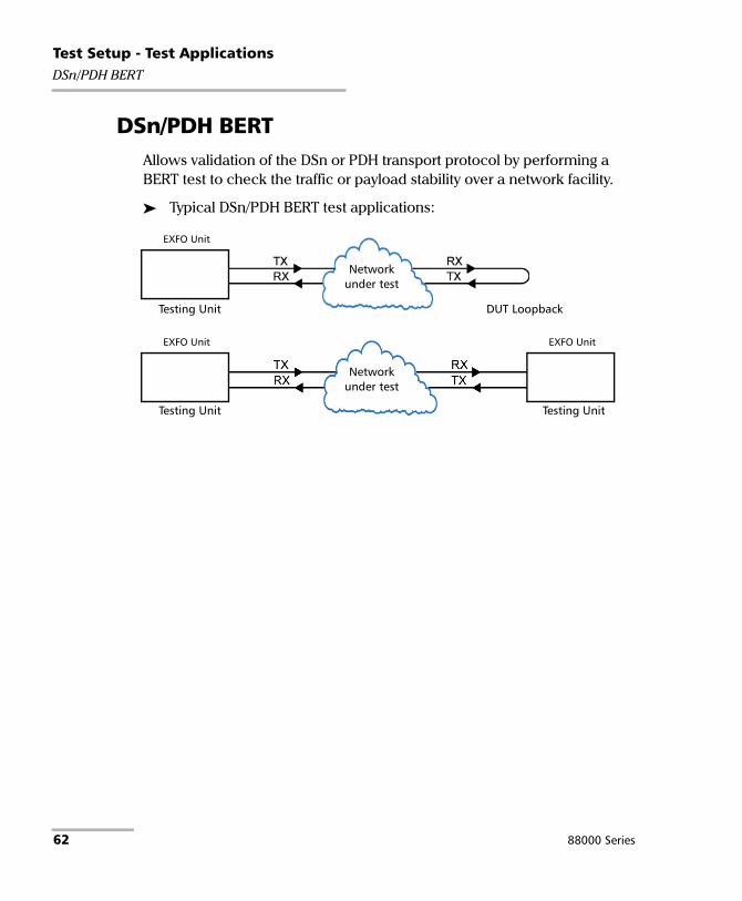
Test Setup - Test ApplicationsDSn/PDH BERT
DSn/PDH BERT Allows validation of the DSn or PDH transport protocol by performing a BERT test to check the traffic or payload stability over a network facility.
Typical DSn/PDH BERT test applications:
Networkunder test
Testing Unit DUT Loopback
EXFO Unit
Networkunder test
Testing Unit Testing Unit
EXFO Unit EXFO Unit
62 88000 Series
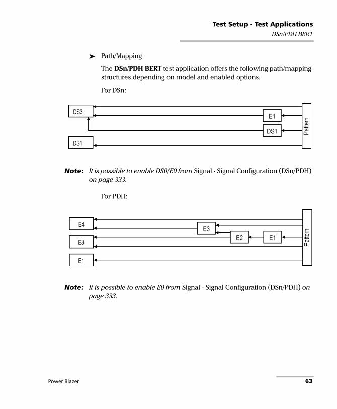
Test Setup - Test ApplicationsDSn/PDH BERT
Path/Mapping
The DSn/PDH BERT test application offers the following path/mapping structures depending on model and enabled options.
For DSn:
Note: It is possible to enable DS0/E0 from Signal - Signal Configuration (DSn/PDH) on page 333.
For PDH:
Note: It is possible to enable E0 from Signal - Signal Configuration (DSn/PDH) on page 333.
Power Blazer 63

Test Setup - Test ApplicationsSONET/SDH - DSn/PDH BERT
SONET/SDH - DSn/PDH BERT Allows validation of the DSn or PDH embedded in SONET or SDH transport protocol by performing a BERT test to check the traffic or payload stability over a network facility.
Typical SONET/SDH - DSn/PDH BERT test applications:
Networkunder test
Testing Unit DUT Loopback
EXFO Unit
Networkunder test
Testing Unit Testing Unit
EXFO Unit EXFO Unit
Testing Unit
EXFO Unit
Networkunder test
Networkunder test
64 88000 Series

Test Setup - Test ApplicationsSONET/SDH - DSn/PDH BERT
Path/Mapping
The SONET/SDH - DSn/PDH BERT test application offers the following path/mapping structures depending on the model and enabled options.
For SONET:
Power Blazer 65

Test Setup - Test ApplicationsSONET/SDH - DSn/PDH BERT
For SDH:
66 88000 Series

Test Setup - Test ApplicationsNI/CSU Emulation
NI/CSU Emulation Allows DS1 testing in NI/CSU (Network Interface/Customer Service Unit) emulation mode.
Typical NI/CSU Emulation test applications:
Networkunder test
Test Head NI/CSU Emulation
EXFO Unit
Networkunder test
Testing Unit NI/CSU Emulation
EXFO Unit
DSn/PDH BERT
EXFO Unit
Power Blazer 67

Test Setup - Test ApplicationsEtherSAM (Y.1564)
EtherSAM (Y.1564) EtherSAM can simulate all types of services that will run on the network and simultaneously qualify all key SLA parameters for each of these services. Moreover, it validates the QoS mechanisms provisioned in the network to prioritize the different service types, resulting in more accurate validation and much faster deployment and troubleshooting.
The EtherSAM (Y.1564) test, in single port configuration, has to be executed in conjunction with a remote unit. The remote unit can be either in loopback configuration for unidirectional testing or in EtherSAM Dual Test Set mode for bidirectional testing.
The Dual Test Set test allows bi-directional testing between two compatible units providing independent results for each test direction. The results from local-to-remote and remote-to-local are available on the local testing unit.
The Dual Port topology allows simultaneous and bidirectional traffic generation and analysis at 100 percent wire-speed at any packet size.
68 88000 Series

Test Setup - Test ApplicationsEtherSAM (Y.1564)
Typical EtherSAM (Y.1564) test applications:
Supported Interfaces/Rates: 10M to 10G LAN/WAN, 40G and 100G. Dual Port topology is only available for rates up to 10G WAN.
Networkunder test
Testing Unit Loopback Unit
EXFO Unit EXFO Unit
Networkunder test
Testing Unit Remote Unit
EXFO Unit EXFO Unit
Networkunder test
Testing Unit
EXFO Unit
Power Blazer 69
Test Setup - Test ApplicationsRFC 2544
RFC 2544 RFC 2544 allows Ethernet Throughput, Back-to-Back, Frame Loss, and Latency performance testing in accordance with RFC 2544 specifications.
The RFC 2544 test, in single port configuration, has to be executed in conjunction with a remote unit. The remote unit can be either in loopback configuration for unidirectional testing or in RFC 2544 Dual Test Set mode for bidirectional testing.
The Dual Test Set test allows bi-directional testing between two compatible units providing independent results for each test direction. The results from local-to-remote and remote-to-local are available on the local testing unit.
The Dual Port topology allows simultaneous and bidirectional traffic generation and analysis at 100 percent wire-speed at any packet size.
70 88000 Series

Test Setup - Test ApplicationsRFC 2544
Typical RFC 2544 test applications:
Supported Interfaces/Rates: 10M to 400G. Dual Port topology is only available for rates up to 10G WAN.
Networkunder test
Testing Unit Loopback Unit
EXFO Unit EXFO Unit
Networkunder test
Testing Unit Remote Unit
EXFO Unit EXFO Unit
Networkunder test
Testing Unit
EXFO Unit
Power Blazer 71

Test Setup - Test ApplicationsRFC 6349
RFC 6349 RFC 6349 is used to confirm that the Ethernet service is able to properly carry TCP traffic.
The RFC 6349 test has to be executed in conjunction with a remote compatible unit in RFC 6349 Dual Test Set or EXFO|Worx Interop
operation mode allowing bidirectional testing. The test provides independent results for each test direction. The results from local-to-remote and remote-to-local are available on the local testing unit.
Typical RFC 6349 test application:
Supported Interfaces/Rates: 10M to 10G LAN, 40G, and 100G.
EVC
Testing Unit Remote Unit
EXFO UnitEXFO Unit
including BV Units
72 88000 Series

Test Setup - Test ApplicationsFlexE BERT
FlexE BERT The Flex Ethernet (FlexE) supports up to four 100GBASE-R PHYs supporting multiple Ethernet MAC operating at a rate of 10, 25, 50, 100, 150, and 200, 250, 300, 350, and 400 Gbit/s.
Typical FlexE BERT test applications:
Supported Interfaces/Rates:100G.
Networkunder test
Testing Unit
Power Blazer
Networkunder test
Testing Unit
Power Blazer
Testing Unit
Power Blazer
Power Blazer 73

Test Setup - Test ApplicationsEtherBERT
EtherBERT Allows Ethernet Layer 1 up to Layer 4 and Unframed Layer 1 traffic generation with specific test pattern for Bit Error Rate analysis.
Typical EtherBERT test applications:
Networkunder test
Testing Unit Loopback Unit
EXFO Unit EXFO Unit
Networkunder test
Testing Unit Testing Unit
EXFO Unit EXFO Unit
Networkunder test
Testing Unit
EXFO Unit
Networkunder test
Testing Unit
EXFO Unit
Testing Units
EXFO Unit
74 88000 Series

Test Setup - Test ApplicationsEtherBERT
Supported Interfaces/Rates: 10M to 400G. Dual Port topology is available for either rates up to 10G WAN or 40/100G.
Networkunder test
Testing Unit
EXFO Unit
Loopback Units
EXFO Unit
Power Blazer 75

Test Setup - Test ApplicationsTraffic Gen & Mon
Traffic Gen & Mon Allows Ethernet traffic generation and analysis of up to 16 streams.
Typical Traffic Gen & Mon test applications:
Networkunder test
Testing Unit Loopback Unit
EXFO Unit EXFO Unit
Networkunder test
Testing Unit Testing Unit
EXFO Unit EXFO Unit
Networkunder test
Testing Unit
EXFO Unit
Networkunder test
Testing Unit
EXFO Unit
Testing Units
EXFO Unit
76 88000 Series

Test Setup - Test ApplicationsTraffic Gen & Mon
Supported Interfaces/Rates: 10M to 100G. Dual Port topology is only available for rates up to 10G WAN.
Networkunder test
Testing Unit
EXFO Unit
Loopback Units
EXFO Unit
Power Blazer 77

Test Setup - Test ApplicationsSmart Loopback
Smart Loopback Allows transmitting back the received Ethernet stream of data while interchanging the source and destination MAC addresses, IP addresses, and/or UDP/TCP ports. However in Transparent (Pseudo-Physical) mode the Smart Loopback operates as a physical loopback by transmitting all received frames unaltered and without discrimination.
The Smart Loopback test can be created locally (refer to Ethernet Test Applications on page 99) or remotely using either an EXFO unit (refer to Discover Remote Button on page 718) or a Third-Party device (see Third-Party Remote Loopback on page 79).
Typical Smart Loopback test application:
Supported Interfaces/Rates: 10M to 400G.
Networkunder test
Testing Unit Smart Loopback Unit
EXFO Unit EXFO Unit
78 88000 Series

Test Setup - Test ApplicationsSmart Loopback
Third-Party Remote Loopback
The Third-party Remote Loopback feature provides the capability to be discovered and react to loop-up and loop-down commands from a third party device. This feature is used for unidirectional testing, where the test stream is transmitted from the third party device to a remote EXFO device. The looped back test stream is received and analyzed by the third-party device.
The third-party loopback supports three levels of messages:
Layer 2: Only MAC addresses are swapped.
Layer 3: MAC and IP addresses are swapped.
Layer 4: MAC and IP addresses are swapped along with the UDP port.
To emulate a third-party remote device, the loopback mode is set in the function of the layer of loop messages received. The loop messages are:
Layer 2: Ethernet
Layer 3: IP
Layer 4: UDP/TCP
On receipt of the third-party loop-up command as per requested layer, the loopback mode is set and initiated on the unit.
Supported Interfaces/Rates: 10M to 100G.
Power Blazer 79

Test Setup - Test ApplicationsThrough Mode
Through Mode The Through Mode test application allows traffic to pass through the unit using two electrical or optical ports for in-service troubleshooting of live traffic between the carrier/service provider network and the customer’s network.
Typical Through Mode test application:
Supported Interfaces/Rates: 10M to 10GE LAN and 100GE; 10/100/1000M electrical is supported when using an active copper SFP and the RJ45 port.
Testing Unitin Through Mode
Network Ethernet Network Ethernet
EXFO Unit
80 88000 Series

Test Setup - Test ApplicationsTCP Throughput
TCP Throughput The objective of this test is to find the TCP throughput based on the successfully transported bytes over the test time. Two units running a TCP Throughput test are required. One unit will act as the source (Local) and the other one as the destination (Remote).
The local unit starts sending TCP segments using the Initial Window Size defined. The window size is adjusted following the TCP algorithm. The window size is incremented until the Maximum Window Size or congestion is reached. However, the window size will be reduced when congestion occurs, then incremented again as described above when the congestion is cleared. TCP Throughput and windows size statistics will be gathered throughout the test.
Typical TCP Throughput test application:
Supported Interfaces/Rates: 10M to 1G.
Networkunder test
Local Testing Unit Remote Unit
EXFO Unit EXFO Unit
Power Blazer 81

Test Setup - Test ApplicationsCarrier Ethernet OAM
Carrier Ethernet OAM The Carrier Ethernet OAM test application supports the following tests: Ethernet OAM (S-OAM), MPLS-TP OAM, and Link OAM.
Ethernet OAM and MPLS TP OAM
The Ethernet Service OAM tests are divided into two main categories:
Performance Monitoring measures parameters such as frame delay, frame loss, and synthetic loss (Y.1731/MEF).
Connectivity Fault Management provides the capability for detecting, verifying, and isolating connectivity failure (Y.1731/802.1ag/MEF).
Typical Ethernet OAM and MPLS TP OAM test applications:
Supported Interfaces/Rates: 10M to 10G LAN/WAN.
MIP EXFO Unit Peer MEP
Local MEP
MIP EXFO Unit
Local MEP
EXFO Unit
Smart Loopback with S-OAM Responder enabled.
82 88000 Series
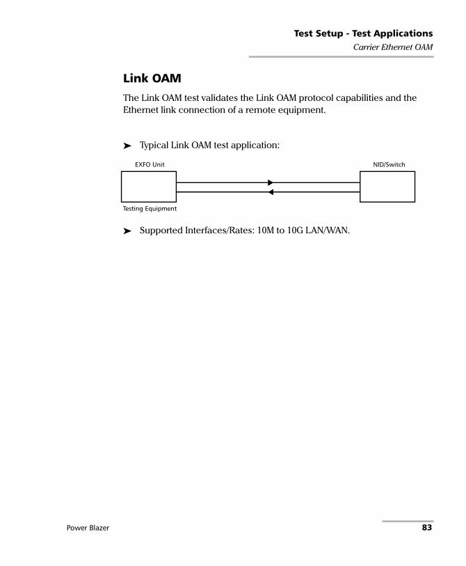
Test Setup - Test ApplicationsCarrier Ethernet OAM
Link OAM
The Link OAM test validates the Link OAM protocol capabilities and the Ethernet link connection of a remote equipment.
Typical Link OAM test application:
Supported Interfaces/Rates: 10M to 10G LAN/WAN.
EXFO Unit NID/Switch
Testing Equipment
Power Blazer 83

Test Setup - Test ApplicationsCable Test
Cable Test The cable test application is used to diagnose un-shielded twisted pairs (UTP) cables (up to Category 6e/Class E).
Cable test can be performed everywhere in the network where an electrical 10/100/1000 Mbit/s Ethernet interface is available for testing. Only the pairs used by the Ethernet signal will be tested. For 10 Base-T, and 100 Base-TX, pair 2 and 3 will be tested; for 1000 Base-T, all pairs will be tested. However, if the Ethernet signal is unknown, all four pairs will be tested.
Even if a link up is not required when testing with a far end equipment, it is preferable to have the far end equipment powered up to maximize the cable test results.
Supported Ethernet cable categories are: Category 3/Class C, Category 4, Category 5, Category 5e/Class D, and Category 6e/Class E.
Note: Cable test result is reliable for cable length of 10 meters to 120 meters (32.81 feet to 393.7 feet).
Typical Cable Test applications:
Supported Interfaces/Rates: 10M to 1000M Electrical.
Testing Unit Far end equipment
EXFO Unit
UTP cable
Testing UnitUnplugged cable
EXFO Unit
UTP cable
84 88000 Series

Test Setup - Test Applications1588 PTP
1588 PTP The 1588 PTP (Precision Time Protocol) test application handles the 1588 PTP communication with the Grand Master (GM) clock, collects statistics related to packets, and monitors the clock Quality Level.
Typical 1588 PTP test application:
Supported Interfaces/Rates: 10M to 10G LAN.
Networkunder test
Testing Unit GM Clock
EXFO Unit Grand Master Clock Source
Power Blazer 85

Test Setup - Test ApplicationsSyncE
SyncE The Synchronous Ethernet (SyncE) test application provides elementary test primitives to interactively validate the clock management functions of a SyncE capable network equipment.
Typical SyncE test applications:
Supported Interfaces/Rates: 100M to 10G LAN.
Networkunder test
Testing Unit Network Equipment
EXFO Unit EEC
EXFO Unit
Networkunder test
Testing Unit
EXFO Unit
Testing Unit
86 88000 Series
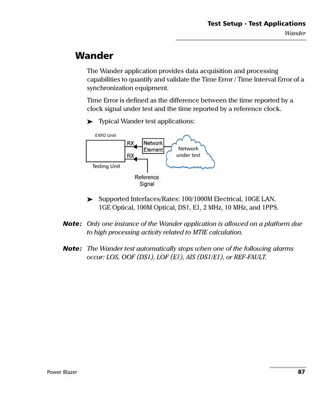
Test Setup - Test ApplicationsWander
Wander The Wander application provides data acquisition and processing capabilities to quantify and validate the Time Error / Time Interval Error of a synchronization equipment.
Time Error is defined as the difference between the time reported by a clock signal under test and the time reported by a reference clock.
Typical Wander test applications:
Supported Interfaces/Rates: 100/1000M Electrical, 10GE LAN, 1GE Optical, 100M Optical, DS1, E1, 2 MHz, 10 MHz, and 1PPS.
Note: Only one instance of the Wander application is allowed on a platform due to high processing activity related to MTIE calculation.
Note: The Wander test automatically stops when one of the following alarms occur: LOS, OOF (DS1), LOF (E1), AIS (DS1/E1), or REF-FAULT.
Networkunder test
Testing Unit
EXFO Unit
Power Blazer 87

Test Setup - Test ApplicationsFC BERT
FC BERT The FC BERT (Fibre Channel BERT) application provides full wire-speed traffic generation at the FC-2 layer allowing BER testing for link integrity measurements, latency, buffer-to-buffer credit measurements for optimization as well as login capabilities.
Typical Fibre Channel BERT test applications:
Supported Interfaces/Rates: 1X, 2X, 4X, 8X, 10X, 16X, 32X.
Networkunder test
Testing Unit DUT Loopback
EXFO Unit
Networkunder test
Testing Unit Testing Unit
EXFO Unit EXFO Unit
88 88000 Series

Test Setup - Test ApplicationsCPRI/OBSAI BERT
CPRI/OBSAI BERT The CPRI/OBSAI BERT test application offers the capability to test the fronthaul and dark fiber for Unframed rates and Framed L2 protocol, round trip delay, and Service Disruption Time measurements.
The Common Public Radio Interface (CPRI) is an industry cooperation aimed at defining a publicly available specification for the key internal interface of radio base stations between the Radio Equipment Control (REC) and the Radio Equipment (RE). In the industry the CPRI REC and RE are mainly known as Base Station (BTS) and Remote Radio Head (RRH) respectively.
The Open Base Station Architecture Initiative (OBSAI) separates a traditional radio base station configuration into a Base Transceiver Station (BTS) and a Remote Radio Head (RRH). The BTS processes the digital baseband radio information and performs the control of the RRH. The RRH converts the digital radio information into radio frequency signals transported over the air interface (antenna).
Power Blazer 89

Test Setup - Test ApplicationsCPRI/OBSAI BERT
Typical CPRI/OBSAI BERT test applications:
Note: A RRH is typically not capable to perform a loopback of the traffic so BERT test monitoring is not applicable. The BERT test is more common when testing between two test units.
Additional CPRI BERT test application:
Supported Interfaces/Rates: CPRI: 1.2, 2.4, 3.1, 4.9, 6.1, 9.8, and 10.1 Gbit/sOBSAI: 1.5, 3.1, and 6.1 Gbit/s.
Networkunder test
Testing Unit Testing Unit
EXFO Unit
Unframed, Framed L2
EXFO Unit
Networkunder test
Testing Unit Physical Loopback
EXFO Unit
Unframed
Networkunder test
Base Station (BTS)
EXFO Unit
Framed L2
RRH or EXFO Unit
Networkunder test
Testing Unit
EXFO Unit
Testing Units
EXFO Unit
90 88000 Series

Test Setup - Test ApplicationseCPRI BERT
eCPRI BERT The eCPRI BERT test application allows the generation and analysis of Framed eCPRI flow using eCPRI messages carried over Ethernet (L2) or Ethernet/IP/UDP (L3/L4) allowing measurements of bit errors/pattern loss based on a PRBS test pattern as well as quality of service metrics such as One-Way or Round-Trip Latency, Jitter, Frame Loss, Out-of-Sequence, and Throughput. It also supports a configurable test pattern when an unframed signal is used to determine the presence of Bit Error or Pattern Loss on a fiber link used to carry eCPRI signals.
Typical eCPRI BERT test applications:
Networkunder test
Testing Unit Testing Unit
EXFO Unit
Unframed, Framed L2
EXFO Unit
Networkunder test
Testing Unit Physical Loopback
EXFO Unit
Unframed
Networkunder test
Testing Unit
EXFO Unit
Framed L2
Testing Units
EXFO Unit
Power Blazer 91
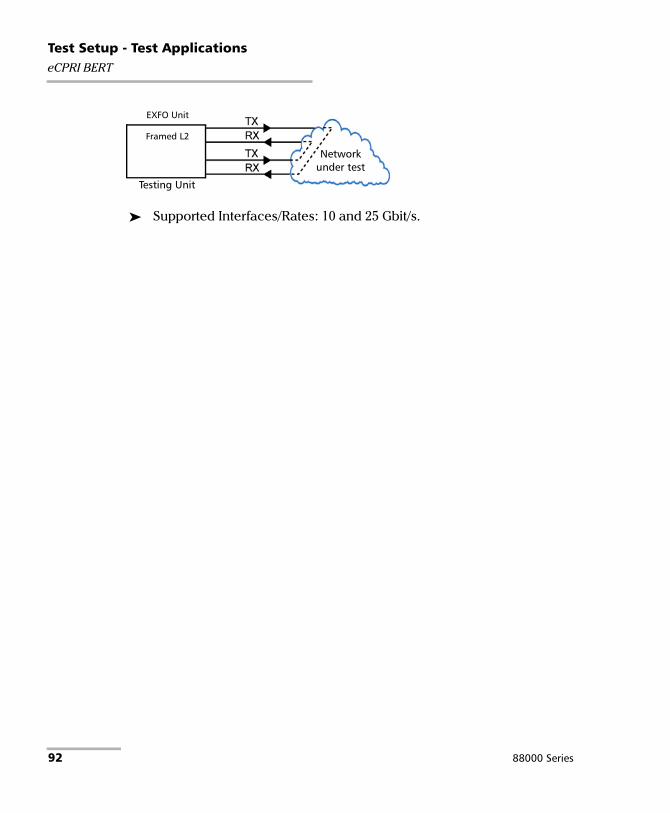
Test Setup - Test ApplicationseCPRI BERT
Supported Interfaces/Rates: 10 and 25 Gbit/s.
Networkunder test
Testing Unit
EXFO Unit
Framed L2
92 88000 Series

7 Selecting and Starting a Test A test can be created either by selecting the test from the Test Applications tab or by loading a previously saved configuration (refer to Save/Load Button on page 737 for more information).
Intelligent Apps
iOptics
To select, configure, and start iOptics:
1. From the test menu, tap Setup.
2. From the Test Applications tab, under Intelligent Apps, tap the iOptics icon.
3. From the Test Configurator tab select the interface/port and its rate.
3a. From the Optical Device Under Test block, tap the desired port icon.
3b. Once the transceiver is correctly detected , select its rate.
3c. From the Test Sequence block, select the test parameters and thresholds (refer to Test Sequence (iOptics) on page 367).
Note: The iOptics test application uses Internal timing for clock synchronization.
Test Sequence Block
Optical DeviceUnder Test Block
Power Blazer 93

Selecting and Starting a TestIntelligent Apps
4. Ensure the laser is ON and tap the Start button from the right navigation bar to start the test (refer to Start/Stop|TX Button on page 741). The Summary result page will be automatically displayed when the test is started. For additional results refer to Test Results on page 385. The test automatically stops when the transceiver is invalid or missing.
5. When the test ends automatically or is manually stopped, the generate report pop-up is displayed by default. If required, tap Yes to generate a report of the test results and statistics (refer to Report Button on page 731 for more information).
94 88000 Series

Selecting and Starting a TestIntelligent Apps
iSAM
To select, configure, and start iSAM:
1. From the test menu, tap Setup.
2. From the Test Applications tab, under Intelligent Apps, tap the iSAM icon.
3. From the Test Configurator tab configure the interface structure and its parameters.
3a. From the Local block, either select the basic port parameters or click on More for all settings (refer to Local Details (iSAM) on page 242). Ensure that the link is up and the power level for optical interface (when supported) is adequate in the status bar before proceeding to the next step (refer to Status Bar on page 32).
For CFP/QSFP interface rates, check for the optical validation check mark indicating that the transceiver matches the configured interface/rate (refer to Physical Interface Port - Test Configurator Overview on page 112).
Remote Operation Mode
Remote BlockLocal Block
Network Block
Power Blazer 95

Selecting and Starting a TestIntelligent Apps
3b. From the Network block, either select the basic test parameters or click on More for all settings (refer to Network Details (iSAM) on page 269). The total bandwidth and the estimated test duration are displayed.
3c. Select the remote operation mode; DTS is automatically selected when the RFC 6349 Test is enabled:
3d. From the Remote block, either select the basic remote parameters or click on More for all settings (refer to Remote Details (iSAM) on page 287).
Note: The iSAM test application uses Internal timing for clock synchronization.
4. Tap the Start button from the right navigation bar to start the test (refer to Start/Stop|TX Button on page 741). If the connection with the remote module is not established with either DTS or Remote Loopback mode, the automatic remote connection process is performed before starting the test. The Summary result page will be automatically displayed when the test is started from any Setup configuration page. For additional results refer to Test Results on page 385.
5. When the test ends automatically or is manually stopped, the generate report pop-up is displayed by default. If required, tap Yes to generate a report of the test results and statistics (refer to Report Button on page 731 for more information).
DTS (Dual Test Set) The remote device is automatically set in EtherSAM when the connection/overtake is successfully established. Remote LoopbackThe remote device is automatically set in Smart Loopback when the connection/overtake is successfully established. Manual LoopbackThe remote device is a physical loopback or has to be manually set in loopback.
96 88000 Series

Selecting and Starting a TestTransport Test Applications
Transport Test Applications To select, configure, and start a Transport test:
1. From the test menu, tap Setup.
2. From the Test Applications tab, under Transport, tap a test icon.
3. From the Test Configurator tab configure the signal structure and its parameters.
3a. Tap the Modify Structure button to set the basic structure of the test such as the interface/rate, connector, etc. (refer to Modify Structure Button on page 119).
3b. For CFP/QSFP interface, check for the optical validation check mark indicating that the transceiver matches the configured interface/rate (refer to Physical Interface Port - Test Configurator Overview on page 112).
3c. Tap the interface block to configure the signal parameters (refer to page 107).
3d. For an embedded signal, tap the protocol block to configure the signal (refer to page 107).
Modify Structure
Protocol Block
Test Block
Clock Block
Interface Block
PhysicalInterface Port
Power Blazer 97

Selecting and Starting a TestTransport Test Applications
3e. Tap the test block to configure the specific test settings (refer to page 107). Not available with NI/CSU Emulation test application.
3f. Tap the clock block to configure the clock synchronization (refer to Clock on page 167).
4. Tap the Timer tab to automatically start and/or stop the test at a given time or for a specific duration (refer to Timer on page 368).
5. For additional test configurations refer to Test Functions on page 611.
6. Tap the Start button from the right navigation bar to start the test. (refer to Start/Stop|TX Button on page 741). The Summary result page will be automatically displayed when the test is started from any Setup configuration page. For additional results, refer to Test Results on page 385.
7. Tap the Stop button to stop the test. By default the generate report pop-up is displayed. If required, tap Yes to generate a report of the test results and statistics (refer to Report Button on page 731).
98 88000 Series

Selecting and Starting a TestEthernet Test Applications
Ethernet Test ApplicationsTo select, configure, and start an Ethernet test:
1. From the test menu, tap Setup.
2. From the Test Applications tab, under Ethernet, tap a test icon.
3. From the Test Configurator tab configure the interface structure and its parameters.
3a. Tap the Modify Structure button to set the basic structure of the test such as the interface/rate, connector, etc. (refer to Modify Structure Button on page 119).
3b. For CFP/QSFP interface, check for the optical validation check mark indicating that the transceiver matches the configured interface/rate (refer to Physical Interface Port - Test Configurator Overview on page 112).
3c. Tap the interface block to configure the interface parameters (refer to page 107). For Dual Port topology, there is an interface block for each port. Ensure that the link is up and the power level (when supported) is present in the status bar before proceeding to the next step (refer to Status Bar on page 32).
Modify Structure
Protocol Block
Test Block
Clock Block
Interface Block
PhysicalInterface Port
Power Blazer 99

Selecting and Starting a TestEthernet Test Applications
3d. Tap the protocol block1 to configure the frame structure and its parameters (refer to page 109). For RFC 2544, EtherBERT, and Traffic Gen & Mon in Dual Port topology, there is a protocol block for each port.
3e. Tap the test block2 to configure the specific test settings (refer to page 109).
3f. Tap the clock block3 to configure the clock synchronization (refer to Clock on page 167).
4. Tap the Timer tab to automatically start and/or stop the test at a given time or for a specific duration (refer to Timer on page 368).
5. For additional test configurations refer to Test Functions on page 611.
6. Tap the Start button from the right navigation bar to start the test (refer to Start/Stop|TX Button on page 741). The Summary result page will be automatically displayed when the test is started from any Setup configuration page. For additional results refer to Test Results on page 385.
7. Depending on the test, when the test ends automatically or is manually stopped, the generate report pop-up is displayed by default. If required, tap Yes to generate a report of the test results and statistics (refer to Report Button on page 731 for more information).
1. Not available with Smart Loopback, Through Mode, TCP Throughput, Carrier Ethernet OAM, and Cable Test.
2. Not available with Traffic Gen & Mon and Through Mode.
3. Not available with Dual Port topology, 25GE test, 200/400GE test, and when using an active copper SFP. However the clock is either set to Internal or Auto (1GE electrical).
100 88000 Series

Selecting and Starting a TestSync Test Applications
Sync Test Applications To select, configure, and start a Sync test:
1. From the test menu, tap Setup.
2. From the Test Applications tab, under Sync, tap a test icon.
3. From the Test Configurator tab configure the interface structure and its parameters.
3a. Tap the Modify Structure button to set the basic structure of the test such as the interface/rate, connector, etc. (refer to Modify Structure Button on page 119).
3b. Tap the interface block to configure the interface parameters (refer to page 107; no configuration is available with Wander 10 MHz, 2 MHz, and 1PPS rates). Ensure that the link is up and the power level (when supported) is present in the status bar before proceeding to the next step (refer to Status Bar on page 32).
3c. Tap the test block to configure the specific test settings (refer to page 110).
3d. For Wander test application, tap the external reference block to configure the external reference signal (refer to External Reference on page 206).
Modify Structure
Test Block
Interface Block
PhysicalInterface Port
Physical ExternalReference Port
External Reference Block
Power Blazer 101

Selecting and Starting a TestSync Test Applications
4. Tap the Timer tab to automatically start and/or stop the test at a given time or for a specific duration (refer to Timer on page 368). Not supported with Wander test application.
5. For additional test configurations refer to Test Functions on page 611.
6. Tap the Start button from the right navigation bar to start the test (refer to Start/Stop|TX Button on page 741). The Summary result page will be automatically displayed when the test is started from any Setup configuration page. For additional results refer to Test Results on page 385.
7. Depending on the test, when the test ends automatically or manually stopped, the generate report pop-up is displayed by default. If required, tap Yes to generate a report of the test results and statistics (refer to Report Button on page 731 for more information).
102 88000 Series

Selecting and Starting a TestFibre Channel Test Application
Fibre Channel Test Application To select, configure, and start a Fibre Channel test:
1. From the test menu, tap Setup.
2. From the Test Applications tab, under Fibre Channel, tap the FC BERT test icon.
3. From the Test Configurator tab configure the interface structure and its parameters.
3a. Tap the Modify Structure button to set the basic structure of the test such as the interface/rate and connector. (refer to Modify Structure Button on page 119).
3b. Tap the interface block to configure the interface parameters (refer to page 223). Ensure that the link is up and the power level (when supported) is present in the status bar before proceeding to the next step (refer to Status Bar on page 32).
3c. Tap the protocol block to configure the frame structure and its parameters (refer to page 207).
Modify Structure
Protocol Block
Test Block
Clock Block
Interface Block
PhysicalInterface Port
Power Blazer 103

Selecting and Starting a TestFibre Channel Test Application
3d. Tap the test block to configure the specific test settings (refer to page 183).
3e. Tap the clock block to configure the clock synchronization (refer to Clock on page 167).
4. Tap the Timer tab to automatically start and/or stop the test at a given time or for a specific duration (refer to Timer on page 368).
5. Tap the Start button from the right navigation bar to start the test (refer to Start/Stop|TX Button on page 741). The Summary result page will be automatically displayed when the test is started from any Setup configuration page. For additional results refer to Test Results on page 385.
6. When the test ends automatically or is manually stopped, the generate report pop-up is displayed by default. If required, tap Yes to generate a report of the test results and statistics (refer to Report Button on page 731 for more information).
104 88000 Series

Selecting and Starting a TestWireless Test Application
Wireless Test Application To select, configure, and start a Wireless test:
1. From the test menu, tap Setup.
2. From the Test Applications tab, under Wireless, tap a test icon.
3. From the Test Configurator tab configure the interface structure and its parameters.
3a. Tap the Modify Structure button to set the basic structure of the test such as the interface/rate, connector, etc. (refer to Modify Structure Button on page 119).
3b. Tap the interface block to configure the interface parameters (refer to page 223). For Dual Port topology, there is an interface block for each port. Ensure that the power level is present in the status bar before proceeding to the next step (refer to Status Bar on page 32).
3c. For eCPRI BERT framed test, tap the protocol block to configure the frame structure and its parameters (refer to page 111). For Dual Port topology, there is a protocol block for each port.
Modify Structure
Test Block
Interface Block
PhysicalInterface Port
Clock Block
Protocol Block
Power Blazer 105
Selecting and Starting a TestWireless Test Application
3d. Tap the test block to configure the specific test settings (refer to page 183). For Dual Port topology, there is a test block for each port.
3e. For CPRI/OBSAI BERT - Framed L2 in Base Station emulation mode, tap the clock block1 to configure the clock synchronization (refer to Clock on page 167). The clock is automatically set to Recovered for Remote Radio Head emulation mode.
Note: For Unframed test the clock is set to Internal. For eCPRI BERT framed test the clock is set to either Internal or External - 1PPS (One-Way measurement mode).
4. Refer to Test Functions on page 611 for additional test configurations.
5. Tap the Timer tab to automatically start and/or stop the test at a given time or for a specific duration (refer to Timer on page 368).
6. Tap the Start button from the right navigation bar to start the test (refer to Start/Stop|TX Button on page 741). The Summary result page will be automatically displayed when the test is started from any Setup configuration page. For additional results refer to Test Results on page 385.
7. When the test ends automatically or is manually stopped, the generate report pop-up is displayed by default. If required, tap Yes to generate a report of the test results and statistics (refer to Report Button on page 731 for more information).
1. Not available in Dual Port topology. However the clock is automatically set to Internal for the Base Station and Recovered for the Remote Radio Head.
106 88000 Series

8 Test Setup - Test Configurator, Timer, and System
The Setup menu offers the following structure:
Test Configurator for Intelligent Apps test application.
Test Application Block Subtab or Pop Up Page
iOptics Device Under Test Device Under Test Details 175
Test Sequence - 367
iSAM Local Local Details 242
TA-... 364
CFP/QSFP/SFP 164
Network Network Details 269
Remote Remote Details 287
Power Blazer 107

Test Setup - Test Configurator, Timer, and System
Test Configurator for Transport test applications.
Block Subtab or Pop Up
Available with
PageOTN BERT
Multi-Channel
OTN
FlexO BERT
OTN- SONET/
SDH BERT
SONET/SDH BERT
DSn/PDH BERT
SONET/SDH -
DSn/PDH BERT
NI/CSU Emulation
Button Modify Structure X X X X X X X X 119
Signal Auto-Detect - - - - - X - X 147
Interface CFP/QSFP/SFP X X X X X - X - 164
Frequency X X X X - - - - 214
FTFL/PT and PT X X - X - - - - 217
Interface - - X - - - - - 223
Labels - - - - X - X - 238
Signal X X - X X X X X 327
TA/TA4-... X - - - - - - - 364
Traces 370 370 - 370 374 - 374 - <---
Protocol GFP-F/GFP-T X - - - - - - - 222
FlexO/OTN - - X - - - - - 213
Labels - - - X - - - - 238
Signal - - - X - - X - 345
Traces - - - X - - - - 374
Traces/PT - - X - - - - - 376
Test BERT (framed) X - X X X X X - 155
EtherBERT Xa
a. Available with EoOTN client only.
- - - - - - - 183
Global (ODU Channels) - X - - - - - - 279
PT - X - - - - - - 217
Traces - X - - - - - - 370
Unframed BERT X - - - - - - - 155
Clock Clock X X - X X X X X 167
TA-Sync X - - - - - - - 364
108 88000 Series

Test Setup - Test Configurator, Timer, and System
Test Configurator for Ethernet test applications.
Block Subtab or Pop UpTest Application
Pagea b c d e f g h i j k
Button Modify Structure X X X X X X X X X X X 131Interface CFP/QSFP/SFP X X X X X X X X X X - 164
Frequency X - X X X X X X - - - 214Interface X X X X X X X X X X X 223Network X X X - X X X X X X X 264TA/TA4-... X X X - X X X X - X - 364
Protocol FlexE Group - - - X - - - - - - - 210MAC/IP/UDP X - X - X X - - - - - 247Services - Global X - - - - - - - - - - 316Services - L2CP X - - - - - - - - - - 319Services - Profile X - - - - - - - - - - 320Streams - Global - - - - - X - - - - - 351Streams - Profile - - - - - X - - - - - 353
Test Cable Test - - - - - - - - - - X 162Clients - BERT - - - X - - - - - - - 183Clients - MAC - - - X - - - - - - - 247Clients - Profile - - - X - - - - - - - 166EtherBERT - - - - X - - - - - - 183EtherSAM - Burst X - - - - - - - - - - 191EtherSAM - Global X - - - - - - - - - - 193EtherSAM - L2CP X - - - - - - - - - - 198EtherSAM - Ramp X - - - - - - - - - - 204Link OAM - - - - - - - - - X - 240RFC 2544 - Global - - X - - - - - - - - 291RFC 2544 - Subtests - - X - - - - - - - - 294RFC 6349 - X - - - - - - - - - 303S-OAM / MPLS-TP OAM - - - - - - - - - X - 306Smart Loopback - - - - - - X - - - - 349TCP Throughput - - - - - - - - X - - 365Unframed BERT (up to 10GE) - - - - X - - - - - - 183Unframed BERT (40/100GE) - - - - X - - - - - - 155
Clock Clock X - X - X X X - X X - 167TA-SYNC X - X - X X X - X X - 364
a. EtherSAM d. FlexE BERT g. Smart Loopback j. Carrier Ethernet OAMb. RFC 6349 e. EtherBERT h. Through Mode k. Cable Testc. RFC 2544 f. Traffic Gen & Mon i. TCP Throughput
Power Blazer 109

Test Setup - Test Configurator, Timer, and System
Test Configurator for Sync test applications.
Test Configurator for Fibre Channel test application.
Block Subtab or Pop UpTest Application
Page1588 PTP SyncE Wander
Button Modify Structure X X X 141
Interface Interface X X Xa
a. No configuration available.
223
Network X X X 264
SFP X X X 164
TA-... X X - 364
Test 1588 PTP X - - 148
SyncE - X - 361
Wander - - X 382
External Reference
External Reference - - X 206
Block Subtab or Pop UpTest Application
PageFC BERT
Button Modify Structure X 143
Interface Interface X 223
SFP X 164
Protocol Fibre Channel X 207
Test FC BERT X 183
110 88000 Series

Test Setup - Test Configurator, Timer, and System
Test Configurator for Wireless test application.
Timer, see page 368.
System, see page 363.
Block Subtab or Pop UpTest Application
PageCPRI/OBSAI BERT eCPRI BERT
Button Modify Structure X X 144
Interface Interface X X 223
Network - X 264
SFP X X 164
TA-... - X 364
Protocol eCPRI Flow - MAC - X 247
eCPRI Flow - Profile - X 179
Test BERT and Unframed BERT
X X 183
Clock Clock - X 167
TA-SYNC - X 364
Power Blazer 111

Test Setup - Test Configurator, Timer, and SystemTest Configurator Overview
Test Configurator Overview The Test Configurator tab displays the interconnected blocks composing the test structure. Each block of the test structure gives an overview of its configuration/status. Availability of each block depends on the selected test application and its structure. Arrows are used to indicate the interconnection between blocks as well as the direction of the clock and data flow. Tap on a block or the More button for Intelligent Apps, to change the configuration parameters of this block.
From the Test menu, tap Setup, and the Test Configurator tab.
Intelligent Apps:
iOptics:
Device Under Test block displays and allows changing the basic interface/port settings. Tap on the More button to access more information and settings.
Test Sequence block allows changing the basic test settings.
Test Sequence Block
Device Under TestBlock
Connection
112 88000 Series
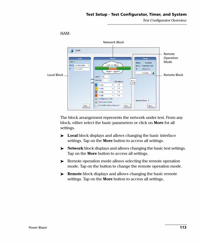
Test Setup - Test Configurator, Timer, and SystemTest Configurator Overview
iSAM:
The block arrangement represents the network under test. From any block, either select the basic parameters or click on More for all settings.
Local block displays and allows changing the basic interface settings. Tap on the More button to access all settings.
Network block displays and allows changing the basic test settings. Tap on the More button to access all settings.
Remote operation mode allows selecting the remote operation mode. Tap on the button to change the remote operation mode.
Remote block displays and allows changing the basic remote settings. Tap on the More button to access all settings.
Remote Operation Mode
Remote BlockLocal Block
Network Block
Power Blazer 113

Test Setup - Test Configurator, Timer, and SystemTest Configurator Overview
Transport Test Applications:
Ethernet Test Applications:
PhysicalInterface Port
Test Application Modify Structure
Test Block
Clock BlockPhysical Clock Port
Interface Block
Arrows
Protocol Block
TopologyPort andTransceiver System
Status
PhysicalInterface Port
Test Application Modify Structure
Protocol Block
Test Block
Clock BlockPhysical Clock Port
Interface Block
Arrows
Port andTransceiver System
Status
114 88000 Series

Test Setup - Test Configurator, Timer, and SystemTest Configurator Overview
Sync Test Applications:
Fibre Channel Test Application:
Wireless Test Application:
External Reference Block
PhysicalInterface Port
Test Application Modify Structure
Test Block
Interface Block
Arrows
Physical ExternalReference Port
Modify Structure
Protocol Block
Test Block
Clock Block
Interface Block
PhysicalInterface Port
Test Application
Arrows
PhysicalInterface Port
Test Application Modify Structure
Test Block
Interface Block
Clock Block
Arrows
Protocol Block
Power Blazer 115

Test Setup - Test Configurator, Timer, and SystemTest Configurator Overview
Test Application indicates the selected test application.
Topology, for Transport Test Applications, indicates the selected test topology.
Modify Structure button, allows the configuration of the physical port and the signal interface structure.
Port Status icon and its description for a CFP4/CFP8/OSFP/QSFP interface is only displayed when validating or if there is a problem as described in the following table. RequiredForFormatting
Transceiver System Status for a transceiver system is only displayed when there is a warning or a problem as described in the following table.
Validating transceiver.
Missing transceiver.
Invalid transceiver or mismatch with the selected signal/interface.
Valid transceiver matching the selected interface/rate. This icon is not displayed here, it is only displayed for the Physical Interface Port.
Icon Displayed Message Description
Port A/B / Port 1 - The battery for the insertion counter is low, please contact EXFO Support
The battery is low and must be replaced by an EXFO authorized service center.
Port A/B / Port 1 - The battery for the insertion counter is depleted, please contact EXFO Support
The battery is dead and must be replaced by an EXFO authorized service center.
A1/A2/B1/B2 / Port 1 - Missing TA/TA4 Transceiver System
No transceiver system detected
A1/A2/B1/B2 / Port 1 - Validating TA/TA4 Transceiver System
Validation process is on-going
A1/A2/B1/B2 / Port 1 - Invalid TA/TA4 Transceiver System
Validating process completed and incompatibility has been found
116 88000 Series

Test Setup - Test Configurator, Timer, and SystemTest Configurator Overview
Physical Interface Port indicates the physical interface port. For Dual Port topology, there is a physical interface for each port.
The status icon for a physical CFP4/CFP8/OSFP/QSFP interface is displayed as described in Port Status above.
Connection, available with iOptics, graphically represents the connection used for the test. For AOC, the cable length is also displayed.
Arrows are used to indicate the interconnection between blocks as well as the direction of the clock and data flow.
A line with an arrow on both ends indicates a bidirectional communication (TX/RX).
A line with a single arrow indicates a unidirectional communication, either TX when going out of a block or RX (or RX2) when going into a block. RX2 indicates the physical BNC TX/RX2 port.
A line going out of a block returning back to the same block, indicates a loopback communication.
Physical Clock Port indicates the direction, TX or RX, of the selected clock; not displayed when Ext Clock Out is set to None. The arrow next to the physical clock image indicates if a clock is generated (TX, arrow pointing to the left) or received (RX, arrow pointing to the right) at/from the physical EXT CLK port.
Physical External Reference Port indicates the port, signal, and direction (RX) of the selected external reference signal.
Interface Block displays an overview of the interface settings and status. Tap on the interface block to change the settings and to see detailed status. For Dual Port topology, there is an interface block for each port.
Power Blazer 117

Test Setup - Test Configurator, Timer, and SystemTest Configurator Overview
Protocol Block displays an overview of either the frame structure and its parameters for Ethernet test applications or the embedded signal for Transport test applications. This block is not present for all tests. Tap on the protocol block to change the settings and to see detailed status. For RFC 2544, EtherBERT, and Traffic Gen & Mon in Dual Port topology, there is a protocol block for each port.
Test Block displays an overview of the test settings and status. Tap on the test block to change the settings and to see detailed status.
Clock Block displays an overview of the clock settings and status. Tap on the clock area to change the settings and to see detailed status. For Dual Port topology, the clock block is not present but the clock is set to Internal.
External Reference Block displays an overview of the external reference signal settings and status. Tap on the external reference area to change the settings and to see detailed status.
118 88000 Series

Test Setup - Test Configurator, Timer, and SystemModify Structure Button
Modify Structure Button From the Test menu, tap Setup, Test Configurator, and the Modify Structure button.
For Transport Test Applications
TX/RX allows the configuration of the following parameters for either TX/RX, RX and RX2, TX, or RX depending on the selected topology.
Interface/Rate: Select the desired interface rate. Choices depend on the selected test and the rates available on the module.
Test Interface/Rate
FlexO 100G FlexO-1-RS [111.809 Gbit/s]
OTN (Parallel) OTU4 (4 Lanes) [111.81 Gbit/s] OTU3e2 (4 Lanes) [44.583 Gbit/s] OTU3e1 (4 Lanes) [44.571 Gbit/s] OTU3 (4 Lanes) [43.018 Gbit/s]
OTN (Serial) OTU2 [10.709 Gbit/s] OTU1 [2.666 Gbit/s]
SONET OC-192 [9.953 Gbit/s] OC-48 [2.488 Gbit/s] OC-12 [622.08 Mbit/s] OC-3 [155.520 Mbit/s] OC-1 [51.840 Mbit/s] STS-3e [155.520 Mbit/s] STS-1e [51.840 Mbit/s]
SDH STM-64 [9.953 Gbit/s] STM-16 [2.488 Gbit/s] STM-4 [622.080 Mbit/s] STM-1 [155.520 Mbit/s] STM-0 [51.840 Mbit/s] STM-1e [155.520 Mbit/s] STM-0e [51.840 Mbit/s]
DSn DS1 [1.544 Mbit/s] DS3 [44.736 Mbit/s]
Power Blazer 119

Test Setup - Test Configurator, Timer, and SystemModify Structure Button
Port1 - QSFP28, Port2 - QSFP28, Port3 - QSFP28, and Port4 - QSFP28 check boxes (selected by default), available with FlexO BERT, indicates the Power Blazer’s ports used for the test.
Connector allows the selection of the module’s port. For decoupled topology on 88260, TX and RX connectors are forced on the same transceiver system.
PDH E1 [2.048 Mbit/s] E3 [34.368 Mbit/s] E4 [139.264 Mbit/s]
NI/CSU Emulation DS1
Interface/RateConnectora
8870/8880 88200NGE 88260
OTU4 (4 Lanes) [111.81 Gbit/s] - Port 1 - CFP4 Port 2 - QSFPb
Port A1/A2/B1/B2 - QSFP28Port A1/B1 - CFP4
OTU3e2 (4 Lanes) [44.583 Gbit/s] OTU3e1 (4 Lanes) [44.571 Gbit/s] OTU3 (4 Lanes) [43.018 Gbit/s]
- Port 2 - QSFPb Port A1/A2/B1/B2 - QSFP28
OTU2 [10.709 Gbit/s] OTU1e [11.049 Gbit/s] OTU2e [11.096 Gbit/s] OTU1f [11.270 Gbit/s] OTU2f [11.318 Gbit/s] OC-192 [9.953 Gbit/s] STM-64 [9.953 Gbit/s]
Port 1 - SFP+c Port 1 - SFP+ Port A1/A2/B1/B2 - SFP28
OTU1 [2.666 Gbit/s] OC-48 [2.488 Gbit/s] OC-12 [622.08 Mbit/s] OC-3 [155.520 Mbit/s] OC-1 [51.840 Mbit/s] STM-16 [2.488 Gbit/s] STM-4 [622.080 Mbit/s] STM-1 [155.520 Mbit/s] STM-0 [51.840 Mbit/s]
Test Interface/Rate
120 88000 Series

Test Setup - Test Configurator, Timer, and SystemModify Structure Button
Framing
Note: For OTN BERT test application with parallel interfaces, allows the selection of the test framing type. For serial interfaces, Multi-Channel OTN, FlexO BERT, OTN BERT, and SONET/SDH BERT test applications, the Framing is set to Framed. For OTN-SONET/SDH BERT test application, the test is framed.
For parallel interfaces:
Framed (default): A single Pattern or Ethernet client applied toward the physical lanes.
STS-3e [155.520 Mbit/s] STS-1e [51.840 Mbit/s] STM-1e [155.520 Mbit/s] STM-0e [51.840 Mbit/s]
BNC - -
DS1 [1.544 Mbit/s] BantamRJ48C
- -
E1 [2.048 Mbit/s] BantamBNCRJ48C
- -
DS3 [44.736 Mbit/s] E3 [34.368 Mbit/s] E4 [139.264 Mbit/s]
BNC - -
a. Availability of connectors depend on the model. b. This port accepts QSFP+ or QSFP28 transceivers. c. Port 2 is used with OC-192/STM-64 in Decoupled (TX≠RX) mode.
Interface/RateConnectora
8870/8880 88200NGE 88260
Power Blazer 121

Test Setup - Test Configurator, Timer, and SystemModify Structure Button
4 Unframed Physical Lanes: Independent test pattern in each physical lane. Available with:OTU3 (4 Lanes) [43.018 Gbit/s],OTU3e1 (4 Lanes) [44.571 Gbit/s], OTU3e2 (4 Lanes) [44.583 Gbit/s], and OTU4 (4 Lanes) [111.81 Gbit/s]
20 Unframed Logical Lanes: Independent test pattern in each logical lane. Available with OTU4 (4 Lanes) [111.81 Gbit/s].
For 88200NGE:
122 88000 Series

Test Setup - Test Configurator, Timer, and SystemModify Structure Button
For 88260:
OTN Multiplexing - Config Mux button allows the selection of the OTN test mapping including the selection of the payload type (PT20 or PT21) when applicable. Refer to OTN BERT on page 53 and OTN-SONET/SDH BERT on page 56 for supported path/mapping.
OTN, available with FlexO BERT, indicates the OTN mapping which is OTUC4.
Power Blazer 123

Test Setup - Test Configurator, Timer, and SystemModify Structure Button
Note: For Multi-Channel OTN, ODU0 mapping is selected by default and the OTN Multiplexing field is not displayed. Refer to Modify Trib Slots/Channels on page 282 for test mapping selection and Multi-Channel OTN on page 51 for supported path/mapping.
Interface/Rate OTN MultiplexingOTU1 [2.666 Gbit/s] ODU1
ODU1/ODU0
OTU2 [10.709 Gbit/s] ODU2 ODU2/ODU1 ODU2/ODU1/ODU0ODU2/ODU0 ODU2/ODUflex
OTU1e [11.049 Gbit/s] ODU1e
OTU2e [11.096 Gbit/s] ODU2e
OTU1f [11.270 Gbit/s] ODU1f
OTU2f [11.318 Gbit/s] ODU2f
OTU3 (4 Lanes) [43.018 Gbit/s] ODU3 ODU3/ODU2ODU3/ODU2/ODU1ODU3/ODU2/ODU1/ODU0ODU3/ODU1ODU3/ODU1/ODU0ODU3/ODU0ODU3/ODUflex
OTU3e1 (4 Lanes) [44.571 Gbit/s] ODU3e1
OTU3e2 (4 Lanes) [44.583 Gbit/s] ODU3e2
124 88000 Series

Test Setup - Test Configurator, Timer, and SystemModify Structure Button
OTU4 (4 Lanes) [111.81 Gbit/s] ODU4 (default)ODU4/ODU3ODU4/ODU3/ODU2ODU4/ODU3/ODU2/ODU1ODU4/ODU3/ODU2/ODU1/ODU0ODU4/ODU3/ODU1ODU4/ODU3/ODU0ODU4/ODU2ODU4/ODU2/ODU1/ODU0ODU4/ODU2/ODU1ODU4/ODU2/ODU0ODU4/ODU2/ODUflexODU4/ODU1ODU4/ODU1/ODU0ODU4/ODU0ODU4/ODU2eODU4/ODU1eODU4/ODUflex
Interface/Rate OTN Multiplexing
Power Blazer 125

Test Setup - Test Configurator, Timer, and SystemModify Structure Button
Embedded SONET/SDH, only available with OTN-SONET/SDH BERT test application, allows the selection of the embedded SONET/SDH signal.
OTN Multiplexing Embedded SONET/SDH
ODU4/ODU3 ODU3
OC-768, STM-256
ODU4/ODU3/ODU2 ODU4/ODU2 ODU3/ODU2 ODU2
OC-192, STM-64
ODU4/ODU3/ODU2/ODU1 ODU4/ODU3/ODU1 ODU4/ODU2/ODU1 ODU4/ODU1 ODU3/ODU2/ODU1ODU3/ODU1 ODU2/ODU1ODU1
OC-48, STM-16
ODU4/ODU3/ODU2/ODU1/ODU0 ODU4/ODU3/ODU0 ODU4/ODU2/ODU1/ODU0 ODU4/ODU2/ODU0 ODU4/ODU1/ODU0 ODU4/ODU0 ODU3/ODU2/ODU1/ODU0ODU3/ODU1/ODU0ODU3/ODU0ODU2/ODU1/ODU0ODU2/ODU0ODU1/ODU0
OC-3, OC-12, STM-1, STM-4
126 88000 Series

Test Setup - Test Configurator, Timer, and SystemModify Structure Button
SONET/SDH Multiplexing - Config Mux button allows the selection of SONET/SDH multiplexing. Available with OTN-SONET/SDH BERT and SONET/SDH BERT test applications.
Interface/Rateor Embedded
SONET/SDHSONET/SDH Multiplexing
OC-768 STS-768c, STS-192c, STS-48c, STS-12c, STS-3c, STS-1
STM-256 AU-4-256c, AU-4-64c, AU-4-16c, AU-4-4c, AU-4, AU-3
OC-192 STS-192c, STS-48c, STS-12c, STS-3c, STS-1, STS-1/VT2, STS-1/VT1.5
STM-64 AU-4-64c, AU-4-16c, AU-4-4c, AU-4, AU-4/TU-3, AU-4/TU-12, AU-4/TU-11, AU-3, AU-3/TU-12, AU-3/TU-11
OC-48 STS-48c, STS-12c, STS-3c, STS-1, STS-1/VT2, STS-1/VT1.5
STM-16 AU-4-16c, AU-4-4c, AU-4, AU-4/TU-3, AU-4/TU-12, AU-4/TU-11, AU-3, AU-3/TU-12, AU-3/TU-11
OC-12 STS-12c, STS-3c, STS-1, STS-1/VT2, STS-1/VT1.5
STM-4 AU-4-4c, AU-4, AU-4/TU-3, AU-4/TU-12, AU-4/TU-11, AU-3, AU-3/TU-12, AU-3/TU-11
OC-3 STS-3c, STS-1, STS-1/VT2, STS-1/VT1.5
STM-1 AU-4, AU-4/TU-3, AU-4/TU-12, AU-4/TU-11, AU-3, AU-3/TU-12, AU-3/TU-11
OC-1 STS-1, STS-1/VT2, STS-1/VT1.5
STS-3e STS-3c, STS-1, STS-1/VT2, STS-1/VT1.5
STS-1e STS-1, STS-1/VT2, STS-1/VT1.5
STM-0 AU-3, AU-3/TU-12, AU-3/TU-11
STM-1e AU-4, AU-4/TU-3, AU-4/TU-12, AU-4/TU-11, AU-3, AU-3/TU-12, AU-3/TU-11
STM-0e AU-3, AU-3/TU-12, AU-3/TU-11
Power Blazer 127

Test Setup - Test Configurator, Timer, and SystemModify Structure Button
DSn/PDH Multiplexing, available with SONET/SDH - DSn/PDH BERT and DSn/PDH BERT test applications, allows the selection of the DSn/PDH multiplexing.
Client allows the selection of either Pattern (default) or an EoOTN (1 GbE, 10 GbE, 40 GbE, 100 GbE, or Ethernet (flex/GFP-F)) client. The client is set to Pattern for OTU1f, OTU2f, OTU3e1, OTU3e2, parallel interfaces/rates, as well as for FlexO BERT, Multi-Channel OTN, OTN-SONET/SDH BERT and SONET/SDH BERT test applications.
Interface/Rate DSn/PDH Multiplexing
DS3 None (default), DS1, E1
DS1 None
E4 None (default), E3, E3/E2/E1
E3 None (default), E2/E1
E1 None
128 88000 Series

Test Setup - Test Configurator, Timer, and SystemModify Structure Button
Topology allows the selection of the network test topology. Only Coupled (TX=RX) is available with Multi-Channel OTN and FlexO BERT.
Coupled (TX=RX) uses the same settings for both the TX and RX signals.
Decoupled (TX≠RX), supported with SONET/SDH BERT on 8870/8880/88260 module, DSn/PDH BERT, and SONET/SDH - DSn/PDH test applications, uses independent settings for TX and RX signals. However, the pattern and some other parameters are always coupled.
Through loops the RX signal to the TX port without TX overwrite capabilities.
Power Blazer 129

Test Setup - Test Configurator, Timer, and SystemModify Structure Button
Through Intrusive loops the RX signal to the TX port with TX overwrite capabilities. Only available with OTN rates.
Dual RX uses two DS1 or DS3 signals at the same time. Both RX ports are coupled at the exception of the termination mode. Only available with DS1 and DS3 signal rates.
130 88000 Series

Test Setup - Test Configurator, Timer, and SystemModify Structure Button
For Ethernet Test Applications
Note: For Dual Port topology each port is configurable individually.
Interface/Rate choices depend on the selected test and the rates available on the module. For Dual Port, both ports must be either 10GE and less, 25GE, or 40/100GE.
Test Interface/RateEtherSAM RFC 2544RFC 6349EtherBERTTraffic Gen & MonSmart Loopback
400GE (8 Lanes) [425 Gbit/s]a 400GE (4 Lanes) [425 Gbit/s]a 200GE (4 Lanes) [212.5 Gbit/s]a
100GE (4 Lanes) [103.125 Gbit/s] 40GE (4 Lanes) [41.25 Gbit/s] 25GEb 10GE WANc 10GE LAN 1GE Optical 100M Optical 10/100/1000M Electricald
a. Only available for RFC 2544, EtherBERT, and Smart Loopback. b. Only available for RFC 2544, EtherBERT, Traffic Gen & Mon, and Smart Loopback. c. Not available with RFC 6349 test application. d. Used as a second port when the test application requires two ports; Ethernet 10/100/1000 Mbit/s
electrical is supported when using an active copper SFP.
FlexE BERT 100GE (4 Lanes) [103.125 Gbit/s] Carrier Ethernet OAM 10GE WAN
10GE LAN 1GE Optical 100M Optical 10/100/1000M Electrical
Through Mode 100GE (4 Lanes) [103.125 Gbit/s] 10GE LAN 1GE Optical 100M Optical 10/100/1000M Electricale
e. Ethernet 10/100/1000 Mbit/s electrical is supported when using an active copper SFP and the RJ45 port.
TCP Throughput 1GE Optical 100M Optical 10/100/1000M Electrical
Cable Test 10/100/1000M Electrical
Power Blazer 131

Test Setup - Test Configurator, Timer, and SystemModify Structure Button
PHY Type allows selecting the transceiver PHY type:
For 100GE (4 Lanes) CFP4/QSFP: LR4/ER4 (default), SR4, CWDM4, CLR4, AOC, or Other. The PHY type when set to any except LR4/ER4, allows enabling RS-FEC (see page 223); ensure both ends of the circuit have the FEC enabled.
For 400GE (8 Lanes) QSFP-DD: Optical (default) and DAC.
Primary Port / Secondary Port, available with Through Mode test application, allows selecting the module’s ports that are respectively used as primary and secondary ports. The configuration of the network configuration parameters will be available on the Primary Port only.
Port1 - QSFP28 (selected by default), Port2 - QSFP28, Port3 - QSFP28, and Port4 - QSFP28 check boxes, available with FlexE BERT, allows selection of the Power Blazer’s ports used for FlexE PHYs.
132 88000 Series

Test Setup - Test Configurator, Timer, and SystemModify Structure Button
Connector allows the selection of the module’s port.
Interface/Rate Connectora
a. Availability of connectors depend on the model.
8870/8880 88200NGE 88260 88400NGE 88460
400GE (8 Lanes) [425 Gbit/s]
- - - Port 1 - CFP8 Port 1 - CFP8 Port 1 - QSFP56-DD
400GE (4 Lanes) [425 Gbit/s]
- - - - Port 1 - OSFP
200GE (4 Lanes) [212.5 Gbits/s]
- - - - Port 1 - QSFP56-DD
100GE (4 Lanes) [103.125 Gbit/s]
- Port 1 - CFP4Port 2 - QSFPb
b. This port accepts QSFP+ or QSFP28 transceivers.
Port A1/A2/B1/B2 - QSFP28
Port A1/B1 - CFP4
- -
40GE (4 Lanes) [41.25 Gbit/s]
- Port 2 - QSFPb Port A1/A2/B1/B2 - QSFP28
- -
25GE - - Port A1/A2/B1/B2 - SFP28
- -
10GE WAN 10GE LAN 1GE Optical 100M Optical
Port 1 - SFP+Port 2 - SFP+
Port 1 - SFP+ Port A1/A2/B1/B2 - SFP28
- -
10/100/1000M Electrical
Port 1 - RJ45 Port 2 - SFP+c, d
c. Only available as a second port when the test application requires two ports. d. Ethernet 10/100/1000M electrical is supported when using an active copper SFP.
Port 1 - SFP+d Port A1/A2/B1/B2 - SFP28 (RJ45)
- -
Power Blazer 133

Test Setup - Test Configurator, Timer, and SystemModify Structure Button
Framing, available for EtherBERT test application, allows the selection of the test framing type; otherwise the framing is set to Framed Layer 2. See Network on page 264 for more information on frame format.
The framing is not configurable and set to Framed Layer 2 for 40GE/100GE dual port topology.
Framed Layer 1: Frame of x bytes that allows connection to any interface that complies with 802.3 Ethernet PHY or DWDM fibre. Available with rate up to 10G WAN.
Framed Layer 2: Frames of x1 bytes without network layer (None) that complies with IEEE 802a Ethernet II standard.
Framed Layer 3/4 (default): Frames of x1 bytes with UDP (default) or TCP network layer that complies with IEEE 802a Ethernet II standard.
1. To set the frame length, see Frame Size on page 189 for EtherBERT (Ethernet and EoOTN) and page 293 for RFC 2544.
134 88000 Series

Test Setup - Test Configurator, Timer, and SystemModify Structure Button
Unframed (Interop) is only available with optical interface up to 25GE:
For Seed A and Seed B, available with 10G LAN and 25G, the pattern is generated by the PCS scrambler from a specific seed. The pattern is not encoded.
For PRBS31 Unscrambled, available with 10G LAN and 25G, the pattern is generated at the PCS layer. The pattern is not encoded and not scrambled.
For PRBS and User Pattern: Pattern generated by the PCS scrambler. The pattern is encoded.
Unframed is only available with optical interface up to 10G LAN:
Encoded pattern generated by the PCS scrambler.
Unframed with Sync is only available with optical interface up to 10G LAN: Pattern of a length corresponding to the number of bytes transmitted in 1 second.
Power Blazer 135

Test Setup - Test Configurator, Timer, and SystemModify Structure Button
4 Unframed XLAUI: Independent infinite length test pattern in each XLAUI lane (no blocks). Available with 40GE (4 Lanes).
4 Unframed CAUI-4: Independent infinite length test pattern in each CAUI-4 lane (no blocks). Available with 100GE (4 Lanes).
20 Unframed PCS: Independent infinite length test pattern in each PCS lane (no blocks and no lane markers). Available with 100GE (4 Lanes).
136 88000 Series

Test Setup - Test Configurator, Timer, and SystemModify Structure Button
4 Unframed 200GAUI-4: Independent infinite length test pattern in each 200GAUI-4 lane. Available with QSFP56 - 200GE (4 Lanes).
8 Unframed 200GAUI-4: Independent infinite length test pattern in each lane driving the Gearbox (no blocks). Available with QSFP56 - 200GE (4 Lanes).
Power Blazer 137

Test Setup - Test Configurator, Timer, and SystemModify Structure Button
8 Unframed 400GAUI-8: Independent infinite length test pattern in each 400GAUI-8 lane. Available with QSFP56-DD - 400GE (8 Lanes) and OSFP - 400GE (4 Lanes).
16 Unframed 400GAUI-8: Independent infinite length test pattern in each lane driving the Gearbox (no blocks). Available with QSFP56-DD - 400GE (8 Lanes) and OSFP - 400GE (4 Lanes).
138 88000 Series

Test Setup - Test Configurator, Timer, and SystemModify Structure Button
16 Unframed 400GAUI-16: Independent infinite length test pattern in each 400GAUI-16 lane (no blocks). Available with CFP8 - 400GE (8 Lanes).
Loopback Mode
Note: Only available for Smart Loopback Ethernet test application.
Transparent (Pseudo-Physical) check box when selected (cleared by default) determines that the Smart Loopback operates as a physical loopback by transmitting all received frames unaltered and without discrimination. When the check box is cleared, the Loopback mode is selectable from Loopback on page 349.
In transparent mode, the Network tab and the Ping & Trace Route functions are not available.
Note: The Transparent mode is intended to be used for point-to-point topology, not for switched or routed networks. Use the Transparent mode with caution because all received frames are looped back without discrimination.
Power Blazer 139

Test Setup - Test Configurator, Timer, and SystemModify Structure Button
Topology allows the selection of the network test topology: Single Port (default) or Dual Port.
Dual Port is only available with:
EtherSAM, RFC 2544, and Traffic Gen & Mon for rates up to 10G WAN.
EtherBERT for either rates up to 10G WAN framed/unframed or for rates 40/100G Framed Layer 2.
OAM Type
Only available for Carrier Ethernet OAM test application.
Selects the type of Carrier OAM network: Ethernet OAM (S-OAM; default), MPLS-TP OAM, or Link OAM.
S-OAM check box when selected enables S-OAM on all services. Available for rates up to 10G WAN.
140 88000 Series

Test Setup - Test Configurator, Timer, and SystemModify Structure Button
For Sync Test Applications
Interface/Rate: Select the desired interface rate. Choices depend on the selected test and the rates available on the module.
Test Interface/Rate
1588 PTPSyncE
10GE LAN 1GE Optical 100M Optical 10/100/1000M Electricala
a. The 10M rate is not available for Wander test application.
Wander 10GE LAN 1GE Optical 100M Optical 10/100/1000M Electricala DS1 [1.544 Mbit/s] E1 [2.048 Mbit/s] 10 MHz 2 MHz 1PPS
Power Blazer 141

Test Setup - Test Configurator, Timer, and SystemModify Structure Button
Connector: Allows the selection of the module’s port available for the selected interface/rate.
Interface/RateConnectora
a. Availability of connectors depend on the model.
8870/8880 88200NGE 88260
10GE LAN 1GE Optical 100M Optical
Port 1 - SFP+ Port 2 - SFP+b
b. Not available with Wander.
Port 1 - SFP+ Port A1/A2/B1/B2 - SFP28
10/100/1000M Electrical Port 1 - RJ45 Port 1 - SFP+ (RJ45)c
c. Ethernet 10/100/1000 Mbit/s electrical is supported when using an active copper SFP.
Port A1/A2/B1/B2 - SFP28 (RJ45)d
10 MHz 2 MHz 1PPS
BNC (Port labelled TX/RX2)RJ48C
- -
142 88000 Series

Test Setup - Test Configurator, Timer, and SystemModify Structure Button
For Fibre Channel Test Application
Interface/Rate choices depend on the rates available on the module.
Connector allows the selection of the module’s port available for the selected interface/rate (see above table).
Interface/RateConnectora
a. Availability of connectors depend on the model.
8870-8880 88200NGE 88260
1X2X4X8X10X
Port 1 - SFP+Port 2 - SFP+
Port 1 - SFP+ Port A1/A2/B1/B2 - SFP28
16X -
32X - -
Power Blazer 143

Test Setup - Test Configurator, Timer, and SystemModify Structure Button
For Wireless Test Application
Note: For Dual Port topology each port is configurable individually. However for eCPRI, both port interface/rate are coupled and in addition for 88260 they are forced on the same transceiver system.
Interface/Rate allows the selection of the interface rate.
Connector is the module’s port available for the selected interface/rate (see table above).
Test Interface Rate
Connectora
a. Availability of connectors depend on the model.
8870/8880 88200NGE 88260
CPRI BERT CPRI - 1.2GCPRI - 2.4G CPRI - 3.1G CPRI - 4.9G CPRI - 6.1G CPRI - 9.8G CPRI - 10.1G
Port 1 - SFP+ Port 2 - SFP+
Port 1 - SFP+ Port A1/A2/B1/B2 - SFP28
OBSAI BERT OBSAI - 1.5G OBSAI - 3.1G OBSAI - 6.1G
eCPRI BERT 10G
25G - -
144 88000 Series

Test Setup - Test Configurator, Timer, and SystemModify Structure Button
Framing
For CPRI/OBSAI:
Framed L2 (default) is mainly used to validate connectivity with the base station (REC) or remote radio head (RE) over the fiber interface.
Unframed is mainly used to validate the continuity of the dark fiber at CPRI (up to 9.8G) or OBSAI (3.1 Gbit/s) rate.
For eCPRI:
Framed Layer 2 (default) is mainly used to to validate the transport of eCPRI messages over a plain Ethernet transport network. .
Framed Layer 3/4 is mainly used to validate the transport of eCPRI messages over an Ethernet/IP/UDP transport network..
Unframed, available for single port, is mainly used to validate the presence of Bit Error or Pattern Loss on the fiber link carrying the eCPRI signal.
Vendor defines the interoperability with equipment using vendor specific overhead to generate and analyze the signal over a CPRI link: Generic (default, as per CPRI standard) or Ericsson.
Power Blazer 145

Test Setup - Test Configurator, Timer, and SystemModify Structure Button
Emulation Mode is available with CPRI/OBSAI Framed L2
Base Station (default) is used to validate the connectivity with the RRH.
For CPRI, it initiates the start-up sequence and provides synchronization with the RRH.
For OBSAI, it initiates the State Machine events and provides synchronization with the RRH.
Remote Radio Head is used to validate the communication with a base station.
For CPRI, it begins its start-up sequence when it detects a valid signal from the base station.
For OBSAI, the State Machine events depend on the Base Station signal transmission.
Topology allows the selection of the network test topology: Single Port (default) or Dual Port (available with CPRI and eCPRI Framed Layer 2/3/4 (88260 only).
146 88000 Series

Test Setup - Test Configurator, Timer, and SystemSignal Auto-Detect
Signal Auto-Detect The Signal Auto-Detect allows the detection of the DS1/DS3 interface Line Coding (DS1), Framing, and Test Pattern.
Signal Auto-Detect is only available:
with DS1 and DS3 interfaces.
when the test is stopped.
when Loopback is not activated for NI/CSU Emulation test.
Note: Test Pattern is not detected with NI/CSU Emulation test application.
During the detection process, the following messages may be displayed: Detecting, Successful, and/or Failed.
When the auto-detection is successful, the detected parameters are automatically applied as the test interface configuration.
Upon detection of specific alarms, the detection may not be possible, tap Retry to invoke the detection again.
Power Blazer 147

Test Setup - Test Configurator, Timer, and System1588 PTP
1588 PTP From the Test menu, tap Setup, Test Configurator, and the 1588 PTP test block.
PTP
Note: Refer to Status Bar on page 32 for PTP link status.
Profile
ITU G.8265.1 (default), also called Telecom Profile, is for frequency synchronization.
ITU G.8275.1, also called Telecom Profile with full timing support from the network, is for very accurate phase/time synchronization required by new mobile applications.
Domain is the PTP domain parameter used by the 1588 PTP function to communicate with the Grand Master clock: 0 to 255. However, the standard values are: 4 (default) to 23 for G.8265.1 and 24 (default) to 43 for G.8275.1.
Framing is not selectable and is set to UDP/IPv4 for G.8265.1 and Ethernet for G.8275.1.
Mode is not configurable and is set to Unicast for G.8265.1 and Multicast for G.8275.1.
Unicast implies a dedicated communication link between the master and the slave clock.
Multicast implies that a master clock send its Sync/Follow Up and Delay Response in a multicast mode.
Multicast MAC, available with ITU G.8275.1, is the multicast address used to send the delay request: 01-1B-19-00-00-00 (forwardable; default), 01-80-C2-00-00-0E (non-forwardable), or User Defined (default User Defined address is 01:1B:19:00:00:01).
148 88000 Series

Test Setup - Test Configurator, Timer, and System1588 PTP
GM IP Address1 is the IP address of the Grand Master Clock used by the 1588 PTP function to communicate with it.
Quick Ping1 button allows testing if the Grand Master IP address can be reached. A message is returned indicating if the ping attempt was Successful or Failed.
IP TOS/DS1 allows entering the Type of Service: 0x00 (default) to 0xFF.
Mechanism is not selectable and is set to Delay Req-Resp (Delay Request-Response) which specifies the mechanism used by the 1588 PTP function to communicate with the Grand Master clock. Refer to Delay Request-Response on page 781 for more information.
Delay Mode is not selectable and is set to Two-way which uses Sync/Follow Up, Delay Request, and Delay Response messages.
Connect1 button is used to initiate the Grand Master Connection process. This process is also automatically initiated when starting the test if not already initiated. The process automatically ends when stopping the test.
Negotiation Status1 is displayed during the Unicast negotiation process which is initiated when either the test is started or the Connect button is activated. See Negotiation Status on page 541 for more information.
1. Only available with Unicast mode.
Power Blazer 149

Test Setup - Test Configurator, Timer, and System1588 PTP
Message Rate
Announce determines the transmission interval of the Announce messages:
Configurable for G.8265.1: 1 msg/16s, 1 msg/8s, 1 msg/4s, 1 msg/2s (default), 1 msg/s, 2 msg/s, 4 msg/s, or 8 msg/s.
For G.8275.1, indicates the announce rate log message interval.
Sync determines the transmission interval of the Sync messages:
Configurable for G.8265.1: 1 msg/16s, 1 msg/8s, 1 msg/4s, 1 msg/2s (default), 1 msg/s, 2 msg/s, 4 msg/s, or 8 msg/s. 16 msg/s, 32 msg/s (default), 64 msg/s, or 128 msg/s
For G.8275.1, indicates the sync rate log message interval.
Delay-Request determines the transmission interval of the Delay Request messages: 1 msg/16s, 1 msg/8s, 1 msg/4s, 1 msg/2s (default), 1 msg/s, 2 msg/s, 4 msg/s, or 8 msg/s. 16 msg/s (default for G.8275.1), 32 msg/s (default for G.8265.1), 64 msg/s, or 128 msg/s. The Delay-Request message rate is limited by the Sync rate selection; the Delay-Request message rate is automatically updated to be smaller than or equal to the Sync message rate.
Service Duration (only available with Unicast mode)
Lease Duration is not configurable and is set to 300 seconds which determines the Lease Duration used between the 1588 PTP function and the Grand Master clock.
Renewal Interval is not configurable and is set to 150 seconds which determines the interval used by the 1588 PTP function to initiate the renewal of its lease with the Grand Master clock.
150 88000 Series

Test Setup - Test Configurator, Timer, and System1588 PTP
GM Info
Note: Only available when Grand Master clock information is available.
The Grand Master Information window displays the decoded clock information.
For G.8265.1 only:
Identity reports the 8-byte identification code of the Grand Master Clock.
For G.8275.1 only:
Port Identity reports the identity type of the PTP port.
GM Identity reports the clock identity of the Grand Master Clock.
Priority 1 reports the priority 1 attribute of the Grand Master Cock.
Priority 2 reports the priority 2 attribute of the Grand Master Clock.
Steps Removed reports the number of communication paths crossed between the local clock and the Grand master Clock.
Log Message Interval (Announce) reports the mean time interval between successive Announce messages.
Log Message interval (Sync) reports the mean time interval between successive Sync messages.
Power Blazer 151

Test Setup - Test Configurator, Timer, and System1588 PTP
For both G.8265.1 and G.8275.1:
Clock Class reports the description and code of the Grand Master Clock Class.
Clock Mode reports the description of the Grand Master Clock Mode: Two-step or One-step.
Clock Accuracy reports the accuracy of the clock.
Time Source reports the source of time used by the Grand Master Clock.
Code Description
0-5, 8-12, 15-51, 53-57, 59-67, 123-132, 171-186, 188-192, 194-215, 233-247, 249-254
Reserved
6 Sync to primary reference
7, 14 Holdover
13 Sync to application-specific reference
52, 58, 187, 193 Degraded
68 to 79, 81-109 (odd values), 11-122, 133-170, 216-232 Alternate PTP profiles
80-110 (even values)a
a. Refer to QL table on page 510 for the list of Quality Level values that will be used as the description.
Quality Level (QL-xxxa)
248 Default
255 Slave only
152 88000 Series

Test Setup - Test Configurator, Timer, and System1588 PTP
Alarm Timeout/Threshold
Note: The following parameters are also used to declare the Pass/Fail verdict.
Receipt Timeout defines the threshold used to declare a Loss Announce or Loss Sync message alarm: 2 to 255 messages (default is 3 messages). A message is considered lost if not received within its expected arrival time and a loss alarm is declared when the number of consecutive lost messages is greater than or equal to the defined Receipt Timeout.
IPDV Threshold defines the inter packet delay variation threshold used to raise the Unusable message alarm. The alarm is raised when IPDV is not within the configured IPDV Threshold: 0.001 to 1000ms (default is 2ms). The minimum value of 0.001 is adjusted when the Sync or Delay Req is set to 4 messages/s or less.
Quality Level
The quality level characterizes the clock quality in terms of network synchronization.
QL Mismatch Monitoring when selected (default) enables the Quality Level mismatch monitoring.
Expected QL allows, when QL Mismatch Monitoring check box is selected, the selection of the Expected Quality Level value: default value is QL-EEC2/ST3 for G.8265.1 and QL-SSU-B/ST3E for G.8275.1. Refer to page 510 for more information.
Power Blazer 153

Test Setup - Test Configurator, Timer, and System1588 PTP
Pass/Fail Verdict
Pass/Fail Verdict check box when selected (default) enables the use of the pass/fail verdict. The global pass/fail verdict is based on the following criteria: alarms (Link Down, Loss Sync, Loss Announce, Unusable (G.8265.1), and/or QL Mismatch (when QL Mismatch Monitoring is enabled)), or the test is automatically aborted (service request denied, session canceled, or no reply for G.8265.1; sync message rate changed for G.8275.1).
Restore 1588 PTP Defaults
Reverts the 1588 PTP test application to its default factory settings.
154 88000 Series

Test Setup - Test Configurator, Timer, and SystemBERT and Unframed BERT
BERT and Unframed BERT
Note: Available with Pattern client. For EtherBERT unframed test up to 25GE, refer to EtherBERT, FC BERT, BERT (eCPRI, CPRI/OBSAI, and FlexE), and Unframed BERT on page 183.
From the Test menu, tap Setup, Test Configurator, and tap on the BERT or Unframed BERT block.
Pattern
Note: RX pattern parameters and status are not available for 4 Unframed 200GAUI-4 and 8 Unframed 400GAUI-8 with either PRBS13Q or SSPRQ patterns.
The icon next to the Pattern label indicates the status of the received pattern signal. Refer to Status Bar on page 32 for more information.
TX Rate, available with ODUflex mapped to pattern, allows the selection of the transmission rate. Unit choices are %, Kbit/s, Mbit/s, and Gbit/s (default).
Coupled RX to TX check box, when selected (default), allows coupling both the TX and RX signal with the same test pattern.
For a framed test, the Coupled RX to TX check box is selected and cannot be cleared.
For an unframed test, the Coupled RX to TX check box is selectable (selected by default) when All Lanes is selected; not available with 4 Unframed 200GAUI-4 and 8 Unframed 400GAUI-8.
No Pattern Analysis (Live) check box when cleared (default), monitors the received traffic pattern. For live traffic, the No Pattern Analysis (Live) check box should be selected as the traffic is a live pattern thus there is no analysis of pattern loss, bit error, and no traffic indications. Only available with a framed test.
Power Blazer 155

Test Setup - Test Configurator, Timer, and SystemBERT and Unframed BERT
TX Pattern/RX Pattern sets respectively the TX and RX test pattern.
For OTN, SONET/SDH, FlexO BERT, and EtherBERT 40/100/200/400GE Unframed:
For DSn/PDH Interfaces:
Test Framing Pattern
OTN BERT Frameda
a. Only PRBS31 is available with ODU0/1/2/3 multiplex in OTU4.
PRBS9, PRBS15, PRBS20, PRBS23, PRBS31 (default), Null Client, and User Pattern.
Unframed PRBS9, PRBS11b, PRBS15, PRBS20b, PRBS23, PRBS31 (default), Square Wave 1 zero/onec, Square Wave 2 zeros/onesc, Square Wave 4 zeros/onesc, Square Wave 8 zeros/onesc, and Square Wave 16 zeros/onesc
b. Not available with OTU4 - 4 Unframed Physical Lanes.c. Square Wave patterns are only available when the All Lanes check box is selected. Not available with
20 Unframed Physical Lanes and OTU4 - 4 Unframed Physical Lanes.
OTN-SONET/SDH BERT,SONET/SDH BERT
Framed PRBS9, PRBS11, PRBS15, PRBS20, PRBS23, PRBS31 (default), 1111, 1100, 1010, 0000, 1in8, 1in16, 2in8, and User Pattern
FlexO BERT Framed PRBS31 and Null Client
EtherBERT Unframed PRBS9d, PRBS11d, e, PRBS15d, PRBS20d, e, PRBS23, PRBS31 (default)
d. Not available with 8 Unframed 200GAUI-4 and 16 Unframed 400GAUI-8/16. e. Not available with 100GE - 4 Unframed CAUI-4.
4 Unframed 200GAUI-4 and 8 Unframed 400GAUI-8
PRBS13Qf, PRBS31Q (default), SSPRQf
f. PRBS13Q and SSPRQ are only available for TX.
Pattern DS0, E0 DS1 DS3, E1 E3, E40000, 1010, 1100, 1111, 1in8, 1in16, 2in8 X X X X
3in24 X X X X (E3 only)
T1 DALY, 55 OCTET, Multi-Pattern - X - -
PRBS9 X X X X
156 88000 Series

Test Setup - Test Configurator, Timer, and SystemBERT and Unframed BERT
For Multi-Pattern, see Multi-Pattern Configuration on page 160.
When User Pattern is selected, enter the payload pattern hexadecimal value.
Invert check box, when selected (cleared by default), inverts the test pattern meaning that every 0 will be changed for 1 and every 1 for 0. For example, the pattern 1100 will be sent as 0011. Patterns PRBS15, PRBS23, and PRBS31 are defined inverted as per ITU standard and EXFO uses inverted patterns for Transport test applications excluding EoOTN. Not available when pattern is Multi-Pattern. Not available with 4 Unframed 200GAUI-4 and 8 Unframed 400GAUI-8 with either PRBS13Q or SSPRQ patterns.
All Lanes check box is available with an unframed test with parallel interface. When selected, it allows setting the same TX and/or RX test pattern for all lanes. When All Lanes check box is cleared (default), a different test pattern may be set for each lane. The All Lanes check box is forced selected for 4 Unframed 200GAUI-4 and 8 Unframed 400GAUI-8.
When the All Lanes check box is cleared, for an unframed test, the following pattern settings are available for each lane.
TX Pattern/RX Pattern: Select the test pattern from the list (see page 156) for each lane and direction (TX and RX).
PRBS11 Xa X X X
PRBS15 X Xa X
PRBS20, User Pattern X X X X
PRBS23 - X X Xa
PRBS31 - X X X
QRSS - Xa - -
Null Client - - - -
a. Default value.
Pattern DS0, E0 DS1 DS3, E1 E3, E4
Power Blazer 157
Test Setup - Test Configurator, Timer, and SystemBERT and Unframed BERT
Invert check box, when selected (cleared by default), inverts the test pattern meaning that every 0 will be changed for 1 and every 1 for 0. For example, the pattern 1100 will be sent as 0011.
Pattern Sync icon indicates the status of the received signal pattern. Refer to Status Bar on page 32 for more information.
Bit Error
Pass/Fail Verdict enables or disables the bit-error-rate pass/fail verdict by selecting either Bit Error Count, Bit Error Rate (default), or Disabled. Only Bit Error Rate and Disabled are available with 4 Unframed 200GAUI-4 (PRBS31Q), 8 Unframed 200GAUI-4, 8 Unframed 400GAUI-8 (PRBS31Q) and 16 Unframed 400GAUI-8/16. Not supported for 4 Unframed 200GAUI-4 and 8 Unframed 400GAUI-8 with either PRBS13Q or SSPRQ.
BER Threshold allows entering the threshold Count or Rate value that will be used to declare the pass/fail verdict. The BER Threshold applies to individual pattern for Multi-Pattern.
For Count, enter the maximum bit error count allowed before declaring a fail verdict: 0 (default) to 999999.
For Rate, enter the maximum bit error rate allowed before declaring a fail verdict: 1.0E-14 to 1.9E-01. The default value is 1.0E-12 for framed; 2.1E-5 for CLR4 unframed; 5.0E-5 for SR4, CWDM4, AOC, and Other unframed; 2.4E-4 for unframed 200/400G.
Service Disruption
The Service Disruption Time (SDT) corresponds to the duration associated to a defect that occurred in the network. For example a disruption that occurs during a network switching from the active channels to the backup channels or vice versa.
Note: The service disruption measurements are cleared when changing the criteria. Service Disruption is not available for Multi-Pattern.
158 88000 Series

Test Setup - Test Configurator, Timer, and SystemBERT and Unframed BERT
Defect allows choosing on which layer and defect the service disruption time test will be performed. Choices depend on the selected test path.
Layer Defect
Interface OTN/SONET/SDH: LOSa
DSn: LOS, BPV, EXZPDH: LOS, CV
a. Not available with QSFP transceivers.
Section/RS LOF-S/RS-LOF, B1
Line/MS AIS-L/MS-AIS, RDI-L/MS-RDI, REI-L/MS-REI, B2
STS/AU Path AIS-P/AU-AIS, LOP-P/AU-LOP, RDI-P/HP-RDI, REI-P/HP-REI, B3, UNEQ-P/HP-UNEQ, PDI-P (SONET)
VT/TU Path AIS-V/TU-AIS, LOP-V/TU-LOP, UNEQ-V/LP-UNEQ, RDI-V/LP-RDI, REI-V/LP-REI, BIP-2
DS1 AIS, OOF, RAI, Framing Bit, CRC-6
DS3 AIS, OOF, Idle, RDI, F-Bit, C-Bit, P-Bit, FEBE
E1 AIS, CRC-4, E-Bit, LOMF, TS16 AIS, LOF, FAS, RAI, RAI MF
E4, E3, E2 AIS, LOF, FAS, RAI
OTLb
b. The service disruption time measurement is available per lane for OTL defects at the exception of LOLwhich is global for all lanes. Refer to OTL-SDT on page 499 for results per lanes.
LOF, OOF, LOL, LOR, OOR, Inv. Marker, FAS
FEC FEC CORR, FEC UNCORR
OTUkc
c. Only available on the top layer.
AIS, LOF, OOF, LOM, OOM, BDI, IAE, BIAE, BIP-8, BEI, FAS, MFAS
ODUkc AIS, OCI, LCK, BDI, BIP-8, BEI, FSF, BSF, FSD, BSD
OPUkc AIS, CSF, PLMd, MSIMe, LOOMFIe, f, OOMFIe, f, OMFIe, f
d. Available when the PLM check box is selected (refer to page 221 for more information).e. Available with multiplex test only.f. Available with OPU4 only.
BERg
g. Available when the No Pattern Analysis (Live) check box (see page 155) is cleared.
Pattern Loss, Bit Error (default)
Power Blazer 159

Test Setup - Test Configurator, Timer, and SystemBERT and Unframed BERT
Note: The Service Disruption Time measurement supports a parent defect approach where the SDT measurement is triggered when the selected defect or a higher defect in the signal structure hierarchy is detected. For example, if Bit Error is selected, an OPU AIS error will trigger an SDT event.
No Defect Time (ms) represents the period without any defects before stopping SDT measurement: 0.005 ms to 2000 ms (default is 300 ms).
Disruption Monitoring check box when selected (disabled by default) enables the disruption time measurements. However, the measurement will only start if the test is already started, or when the test will be started.
Note: Clearing the Disruption Monitoring check box will stop the measurement without clearing the results. The disruption monitoring is automatically stopped without clearing results when the test is stopped. However, starting the test again while the Disruption Monitoring check box is selected will reset the results before restarting.
Pass/Fail Verdict check box when selected (cleared by default) enables service disruption pass/fail verdict and allows setting the threshold value.
SDT Threshold (ms) allows entering the SDT threshold value that will be used to declare the pass/fail verdict: 0.001 to 299999.999 ms (default is 50 ms). For EtherBERT, the minimum value is adjusted with respect to the No Traffic Time.
Multi-Pattern Configuration
Note: Only available for DSN/PDH BERT test application with DS1 signal (DS0 disabled) and when the pattern is Multi-Pattern.
This feature allows sending each pattern for a specific duration, sequentially and continuously.
160 88000 Series

Test Setup - Test Configurator, Timer, and SystemBERT and Unframed BERT
Pattern represents a sequence of patterns that will be generated: 1111, 1in8, 2in8, 3in24, and QRSS.
Enable allows enabling the generation of each pattern individually in the pattern sequence. All patterns are enabled by default. All 1’s (1111) is disabled for Unframed test.
Individual Pattern Duration specifies the transmission duration of each pattern: 15 s, 30 s, 45 s, 1 min, 2 min, 3 min (default),... up to 15 min.
Restore < Test Application > Defaults
Reverts the current test application to its default factory settings.
Power Blazer 161

Test Setup - Test Configurator, Timer, and SystemCable Test
Cable Test From the Test menu, tap Setup, Test Configurator, and the test block.
Global Options
Wiring Standard is the pin-to-pair assignment corresponding to the UTP cable used: T568A (default) or T568B.
Length Unit is the unit used for cable length and distance to fault results: Meter (default) or Feet.
PoE check box when selected (cleared by default) allows verifying that the Power Sourcing Equipment (PSE) is capable to deliver appropriate power (PoE) to the Powered Device (PD). The PoE test is performed after the cable test is executed confirming that the cable is ready to carry data and power: either the Wire Map test reported No fault, Straight pair, Crossed Pair, or Noise (link up). Only available on 8870/8880.
162 88000 Series

Test Setup - Test Configurator, Timer, and SystemCable Test
Power Class, available when PoE is enabled, selects the power class of the simulated powered device:
Pass/Fail Verdict
Pass/Fail Verdict check box when selected (default) enables the cable test pass/fail verdict and allows setting the threshold values.
Prop. Delay Threshold (ns) is the maximum time for a pulse to reach the far end: 0 to 1000 ns (default is 1000 ns for 10 Mbit/s, 556 ns for 100 Mbit/s, and 570 ns for 1 Gbit/s).
Delay Skew Threshold (ns) is the maximum time between the fastest and slowest pairs of a 1000 Base-T signal: 0 to 120 ns (default is 50 ns).
Length Threshold (m) is the maximum acceptable cable length: 0 to 120 m (0 to 394 feet) (default is 100 m (328 ft)).
PoE Loaded Voltage Thresholds (V), available when the PoE check box is selected, allows the configuration of the acceptable voltage range when a load is applied: minimum value is either 37 (default) for Class 0 to 3 or 42.5 (default) for Class 4; maximum value is 57 (default). A Pass vedict is declared when the measured voltage is within the defined range.
Restore Cable Test Defaults
Reverts the configured parameters to their default values.
Power Class Power Device
Class 0 (13.0W) - (default) Type 1
Class 1 (3.8W)
Class 2 (6.5W)
Class 3 (13.0W)
Class 4 (25.5W) Type 2
Power Blazer 163

Test Setup - Test Configurator, Timer, and SystemCFP/OSFP/QSFP/SFP
CFP/OSFP/QSFP/SFP This tab gives hardware information related to the inserted transceiver module.
From the Test menu, tap Setup, Test Configurator, tap on the interface block or on the Local block for iSAM, and on the CFP/OSFP/QSFP/SFP tab.
Port, FlexO Instance ID, and FlexE PHY Number
Note: Only available with FlexE/FlexO BERT test application.
Port allows selecting the physical port to be displayed.
FlexO Instance ID indicates the FlexO instance identifier assigned to the port.
FlexE PHY Number indicates the FlexE PHY number assigned to the port.
Parameters
The following parameters are retrieved from the transceiver:
Parameter CFP4 CFP8
QSFP+ QSFP28
QSFP56-DDOSFP
SFPSFP+SFP28
Module IDa X X X X
Vendor Name X X X X
Part Number X X X X
Serial Number X X X X
Hardware Revision X X X X
Firmware Version X X - -
Revision Compliance - - X -
164 88000 Series

Test Setup - Test Configurator, Timer, and SystemCFP/OSFP/QSFP/SFP
Connector Type X X X X
Speed X X X X
Type/Compliance Code X X X X
Wavelength - - - X
Mode X X X X
Power Class X X X X
Temperature (Actual/Max)b X X X X
Lane Ratio Type X - - -
Host Lane Signal Spec - X - -
WDM Type X X - -
Signal Code - Modulation - X - -
Signal Code - Coding - X - -
CLEI Code X X X -
a. Also displays (Tunable) for transceivers having the tunable capability. b. Displays respectively the current and the maximum temperature recorded. For iOptics this information is
available on the Summary (iOptics) page (refer to Temperature on page 562).
Parameter CFP4 CFP8
QSFP+ QSFP28
QSFP56-DDOSFP
SFPSFP+SFP28
Power Blazer 165

Test Setup - Test Configurator, Timer, and SystemClients - Profile
Clients - Profile From the Test menu, tap Setup, Test Configurator and tap on the Clients block and on the Profile tab.
Client ID and Size (Gbit/s)
Note: Only available with FlexE BERT test application.
Client ID allows selecting the client ID to be displayed.
Size (Gbit/s) indicates the size of the client ID.
Ethernet Frame
Frame Size (Bytes) allows entering the frame size. The range is from 64 to either 2000 for multiple clients or 10000 for a single client.
Shaping
TX Rate allows the selection of the transmission rate in Mbit/s or Gbit/s.
Enable TX check box when selected (default) generates streams for the selected client ID when the test is started while the TX button is enabled (refer to Start/Stop|TX Button on page 741). The Enable TX check box may also be selected or cleared while the test is running.
166 88000 Series

Test Setup - Test Configurator, Timer, and SystemClock
Clock Allows the configuration of the clock synchronization.
From the Test menu, tap Setup, Test Configurator, and tap on the clock block.
Note: A TA-Sync transceiver system is required on the 88260 module when using an external clock input or when generating an external clock out. In this case a message is displayed when there is an issue with the TA-Sync (see Transceiver System Status on page 116).
Clock Synchronization
Clock Mode allows selecting the clock source that will be used for transmission (TX).
Internal: Internal clock of the unit (STRATUM 3). The clock mode is forced to Internal for Multi-Channel OTN and for eCPRI BERT in Round-Trip or One-Way P<m> P<m> Latency mode.
Recovered: Line clock from the input port signal involved in the test. Available with Transport test applications, CPRI/OBSAI RRH, and Ethernet applications using 10G WAN. The clock mode is forced to Recovered for 1GE electrical interface using Slave local clock (see Local Clock on page 226).
External: Clock signal from the EXT CLK port. The clock mode is forced to External for eCPRI BERT in One-way Latency mode since a 1PPS clock is required.
Backplane: Clock from another module on the platform (only supported on FTB-2 and FTB-2 Pro platforms). The other module must support the backplane clock feature and must be enabled. Not available when the Backplane Clock check box is selected (see page 173). The Backplane clock cannot be shared between FTB- and FTBx- modules.
Power Blazer 167
Test Setup - Test Configurator, Timer, and SystemClock
Note: For CPRI/OBSAI Base Station single port topology, the clock is configurable to Internal or External; for CPRI/OBSAI Remote Radio Head, the clock is fixed to Recovered; for CPRI dual port topology, the clock block is not displayed and the clock mode is automatically set to Internal for the Base Station and Recovered for the Remote Radio Head.
Ext Clock In
Note: Available when the Clock Mode is set to External.
Allows setting the external clock for test synchronization.
Interface Type allows the selection of the clock interface: DS1 (default), E1, 2MHz (default when DS1 is not supported), or 1PPS. 1PPS is automatically selected in One-Way Latency measurement mode for Dual Test Set and eCPRI BERT.
Ext Clock In on a green background indicates that a valid clock is received.
LOS on a red background indicates that the received clock is not valid.
LOPPS-L, available with 1PPS, on a green background indicates that a valid clock is received.
Connector either indicates the connector type used for the clock or on 8880 allows the selection of Bantam or RJ48C when the BNC connector is used by the test application. The module connector blue LED used for Ext Clock In is flashing.
168 88000 Series

Test Setup - Test Configurator, Timer, and SystemClock
Termination mode specifies how the module is connected to the synchronization signal. The Termination mode is set to TERM for 2MHz and configurable for DS1 and E1.
For DS1:
TERM provides an input that terminates the DS1 signal.
DSX-MON provides high-input impedance and compensation for resistive loss. This setting is useful for monitoring DS1 signals at DSX monitor points, which are resistor-isolated.
BRIDGE provides high-input impedance for bridging lines that are already terminated. This setting is useful for bridging directly across copper cable pairs.
For E1:
TERM provides an input that terminates the E1 signal.
MON provides high-input impedance and compensation for resistive loss. This setting is useful for monitoring E1 signals at monitor points, which are resistor-isolated.
BRIDGE provides high-input impedance for bridging lines that are already terminated. This setting is useful for bridging directly across copper cable pairs.
Line Coding allows the selection of the interface line coding.
For DS1: AMI and B8ZS (default). For E1: AMI and HDB3 (default).
Framing: Allows the selection of the interface framing.
For DS1: SF, SLC-96, and ESF (default).For E1: PCM30 (default), PCM30 CRC-4, PCM31, and PCM31 CRC-4.
Frequency (MHz) displays the frequency of the received signal rate.
Power Blazer 169

Test Setup - Test Configurator, Timer, and SystemClock
Offset (ppm) displays the positive or negative frequency offset between the standard rate specification and the rate from the received signal. The background color is used to indicate if the received clock meets (green) or not (red) the standard rate specification.
Ext Clock Out
Note: Available when the Clock Mode is set to Internal, Recovered, or Backplane. Not available on 8870.
Allows setting the clock that will be generated.
Interface Type allows the selection of the clock interface: None (default when DS1 is not supported), DS1 (default), E1, and 2MHz (default for 88460). For eCPRI BERT the interface type is fixed to None.
Ext Clock Out on a green background indicates that a valid clock is generated on the clock port.
LOC on a red background indicates that no clock is generated on the clock port.
Connector either indicates the connector type used for the clock or on 8880 allows the selection of Bantam or RJ48C when the BNC connector is used by the test application.
LBO (Line Build Out), available with DS1 only, allows the selection of the interface Line Build Out that meets the interface requirements over the full range of cable lengths: DSX-1 (0-133 ft) (default), DSX-1 (133-266 ft), DSX-1 (266-399 ft), DSX-1 (399-533 ft), and DSX-1 (533-655 ft).
Signal Standard Rate specification
DS1 1544000 ± 8 bit/s (± 4.6 ppm)
E1 2048000 ± 10 bit/s (± 4.6 ppm)
2MHz 2048000 ± 10 bit/s (± 4.6 ppm)
170 88000 Series

Test Setup - Test Configurator, Timer, and SystemClock
Line Coding, available with DS1 and E1, allows the selection of the interface line coding.
For DS1: AMI and B8ZS (default). For E1: AMI and HDB3 (default).
Framing, available with DS1 and E1, allows the selection of the interface framing.
For DS1: SF, SLC-96, and ESF (default).For E1: PCM30 (default), PCM30 CRC-4, PCM31, and PCM31 CRC-4.
REF OUT
Source, available with CFP4 and QSFP28 transceivers, allows selecting the source clock that will be used for transmission (TX) on the REF OUT port: TX MCLK (default for CFP4), Internal 1/8, Internal 1/40, Internal 1/160 (default for QSFP28). TX MCLK is a clock derived from the inserted transceiver and its frequency is based on the setting of the CFP4/CFP8 Reference Clock (MHz) on page 73.
Power Blazer 171

Test Setup - Test Configurator, Timer, and SystemClock
Frequency (MHz) displays the frequency of the clock generated on the REF OUT port based on the test interface rate1 and divider ratio as follows:
1.For parallel interfaces, the REF OUT signal is derived from the interface lane rate.
Interface/Rate Divider Ratio
1/8a
a. Only available with CFP4 and QSFP28 transceivers. Not available for QSFP28 transceiverson FTBx-88260.
1/16 1/40a 1/160a
OC-192STM-6410G WAN
- 622.08 MHz - -
10G LAN40GE
- 644.5313 MHz - -
OTU2 - 669.3266 MHz - -
OTU1e - 690.5692 MHz - -
OTU2e - 693.4813 MHz - -
OTU1f - 704.3806 MHz - -
OTU2f - 707.3527 MHz - -
OTU3 - 672.1627 MHz - -
OTU3e1 - 696.4214 MHz - -
OTU3e2 - 696.6149 MHz - -
OTU4 3494.1 MHz - 698.8123 MHz 174.7031 MHz
100GE 3222.6 MHz - 644.5313 MHz 161.1328 MHz
172 88000 Series

Test Setup - Test Configurator, Timer, and SystemClock
Clock Out indicates the status of the clock generated on the REF OUT port as follows:
Green: a valid clock is generated.
Red: the clock is either not available (--) then not generated, or not valid but generated.
Note: The Ref Out clock port provides an eye diagram timing reference for 10G and above optical devices. This clock is provided for basic assessment. Formal qualification may require specialized external circuitry.
Backplane
Note: Only supported on FTB-2 and FTB-2 Pro platforms when the Clock Mode is set to External, Recovered, or Internal.
Backplane Clock check box when selected (cleared by default) makes available the source clock (Clock Synchronization - Clock Mode) to other modules on the platform. Other modules on the platform need to set the Clock Mode as Backplane to use this clock. The Backplane Clock should be only enabled on one module on the same platform. The Backplane clock cannot be shared between FTB- and FTBx- modules.
Backplane indicates that the background clock is generated (green) or disabled (gray).
LOC on a red background indicates, when the backplane clock is enabled, that the synchronization is not possible with the selected reference clock.
Power Blazer 173

Test Setup - Test Configurator, Timer, and SystemClock
Tributary Synchronization
Note: Only available with SONET/SDH - DSn/PDH and DSn/PDH test applications. Not supported in Through topology.
Clock Mode allows selecting the source clock that will be used for tributary transmission (TX); default is Internal. The availability of clock modes is as follows:
Internal: Internal clock of the unit (STRATUM 3).
Recovered: Line clock from the input port signal involved in the test.
External: Clock signal from the EXT CLK port.
Backplane: Clock from another module on the platform (only supported on FTB-2 and FTB-2 Pro platforms). The other module must support the backplane clock feature and must be enabled. The Backplane clock cannot be shared between FTB- and FTBx- modules.
Clock Synchronization Tributary Synchronization
Internal Internal
Recovered Internal Recovered
External Internal External
Backplane Internal Backplane
174 88000 Series

Test Setup - Test Configurator, Timer, and SystemDevice Under Test (iOptics)
Device Under Test (iOptics) From the Test menu, tap Setup, and Test Configurator.
Transceiver selection: Tap on a transceiver icon to select the interface/port. The selected transceiver is highlighted with an amber contour. The selected transceiver type and its status are displayed.
For a QSFP28 AOC (Active Optical Cable):
For a module having at least two QSFP28 ports, connect the other end of the cable to the port automatically selected and configured in transparent loopback .
For a module having only one QSFP28 port, connect the other end of the cable to the QSFP28 port of another module which must be configured in Smart Loopback with Transparent (Pseudo-Physical) mode enabled (see Loopback Mode on page 139).
For a QSFP-DD DAC (Direct Attached Copper):
Connect the other end of the cable to the QSFP-DD port of another module which must be configured in Smart Loopback with Transparent (Pseudo-Physical) mode enabled (see Loopback Mode on page 139).
Status Description
Validating the transceiver.
Transceiver correctly detected.
Incompatible transceiver detected.
Missing transceiver.
Power Blazer 175

Test Setup - Test Configurator, Timer, and SystemDevice Under Test (iOptics)
For 88260 module a message is displayed when either no transceiver systems are inserted or are all invalid:
Note: For 88260 module inserting or removing a transceiver system triggers the transceiver system detection process resulting that the default port is selected and results are cleared.
Tunable: For transceivers having tunable capability, (Tunable) is written next to the transceiver module ID.
Rate: Once the transceiver is correctly detected , select the interface rate. Rates depend on the selected port, the inserted transceiver, and the rates supported on the module.
Status Description
Invalid Transceiver System.
No Transceiver System Detected.
TransceiverRate
Transport Ethernet Fibre Channel Wireless
CFP8, QSFP56-DD
- 400GE (8 Lanes) - -
OSFP - 400GE (4 Lanes) - -
CFP4, QSFP28 OTU4 (4 Lanes) 100GE (4 Lanes) - -
QSFP+ OTU3e2 (4 Lanes) OTU3e1 (4 Lanes) OTU3 (4 Lanes)
40GE (4 Lanes) - -
SFP28 - 25GE - -
176 88000 Series

Test Setup - Test Configurator, Timer, and SystemDevice Under Test (iOptics)
Vendor Name, Part Number, Serial Number, Connector Type, Wavelength, and Mode are information retrieved from the transceiver (see page 178).
Modify button beside Wavelength, available with tunable transceivers when the TunableOptics software option is enabled, is used to configure the transceiver wavelength.
Wavelength (nm) indicates the actual wavelength value selected.
Use the scroll box and/or the -/+ buttons to select the wavelength. The minimum and maximum wavelength values are displayed.
Channel Number indicates the actual ITU channel number based on ITU Grid.
Frequency (THz) indicates the actual Frequency based on ITU Grid
Channel Spacing (GHz) indicates the difference in frequency between two adjacent channel detected from the transceiver device.
Restore Previous restores the current value present in the transceiver device.
SFP+SFP/SFP+(Port 1 only)
OTU2 OTU1e OTU2e OTU1f OTU2f OTU1 OC-192/STM-64 OC-48/STM-16 OC-12/STM-4 OC-3/STM-1 OC-1/STM-0
10GE WAN 10GE LAN 1GE Optical 100M Optical
1X2X4X8X10X16X
CPRI - 1.2GCPRI - 2.4GCPRI - 3.1GCPRI - 4.9GCPRI - 6.1GCPRI - 9.8GCPRI - 10.1G OBSAI- 1.5GOBSAI - 3.1GOBSAI - 6.1G
TransceiverRate
Transport Ethernet Fibre Channel Wireless
Power Blazer 177

Test Setup - Test Configurator, Timer, and SystemDevice Under Test (iOptics)
More gives additional transceiver system/module information and settings.
Transceiver System tab: See Transceiver System (TA/TA4) on page 364.
Device Under Test tab:
Parameters are retrieved from the transceiver (see Parameters on page 164).
Lasers OFF at Start-Up allows turning off all lasers automatically when starting the module or when switching from one test application to another. This check box is cleared by default.
178 88000 Series

Test Setup - Test Configurator, Timer, and SystemeCPRI Flow - Profile
eCPRI Flow - Profile From the Test menu, tap Setup, Test Configurator, the protocol block, and the Profile tab.
Traffic Shaping
Frame Size (Bytes)
The frame size is programmable from 64 to 16000. The minimum frame size will be adjusted according to the frame structure and components selected. The following table lists each component that may affect the minimum frame size value.
The following table lists each component that may affect the minimum frame size value.
TX Rate allows the selection of the transmission rate in percentage of utilization (100 percent by default), Mbit/s, or Gbit/s. The maximum percentage is 105 percent depending on the frame size selected.
Component Description
VLAN 4 bytes per VLAN (up to 3 VLAN)
UDP 8 bytes
Ethernet Header 14 bytes
eCPRI 8 or 12 bytes depending on the message type
IPv4 20 bytes
BERT Tag 14 bytes
BERT Minimum payload content (PRBS)
8 or 24 (depending on the Message Type or Transport layer used with the message generation)
Ethernet FCS 4 bytes
Power Blazer 179

Test Setup - Test Configurator, Timer, and SystemeCPRI Flow - Profile
QoS Measurements
Note: For Dual Port topology in One-Way P<m> P<n>, these settings are coupled.
Latency/Jitter check box, when selected (default), allows latency/jitter configuration and monitoring.
Measurement Mode:
One-Way measurement provides the delay measurement for each direction independently on a specific port. This mode requires an external 1PPS clock source (see Clock on page 167); the LOPPS-L alarm is displayed reporting its status (refer to Clock on page 397). On the 88260 module dual port topology, both ports must be on the same transceiver system since a TA-SYNC is required for the 1PPS clock.
Round-Trip Latency measurement provides the total delay measurement for both directions on a specific port.
One-Way P<m> P<n> provides the delay measurement of each direction independently between two separate ports of a single module (Dual Port test). Only available when the rate and framing parameters (Frame Format, Network Layer, and Transport Layer) are the same on both ports.
Measurement Role determines whether the eCPRI node acts as the Sender (default) or the Receiver.
Remote Status indicates whether a configuration mismatch exist between each end based on the one-way delay messages that are exchanged:
180 88000 Series

Test Setup - Test Configurator, Timer, and SystemeCPRI Flow - Profile
Measurement Rate, available with Sender measurement role, defines the number of Latency/Jitter measurements to perform per second: 1 Measurements/s.
Frame Loss/Out-of-Sequence check box, when selected (default), allows Frame Loss and Out-of-Sequence monitoring.
Remote Status Sender Receiver Description
Ready-R X X Indicates that one-way delay flows normally between sender and receiver for both request/response and remote request/request
Mismatch-R X - Indicates, for Sender measurement role, that the remote end is also configured as Sender.
Inactive-R X X Indicates that there is no one-way delay message received within 5 seconds that can be caused by: a Link Down condition, an LOPPS-L being present on the local or peer device, both ends configured as Receiver, or incompatible framing.
-- X X Indicates pending state which occurs upon starting a test or when a Link Down condition is detected.
Power Blazer 181

Test Setup - Test Configurator, Timer, and SystemeCPRI Flow - Profile
QoS Thresholds
Note: For Dual Port topology in One-Way P<m> P<n>, these settings are coupled.
Global Pass/Fail Verdict check box when selected (default) allows enabling and configuring each metrics individually, otherwise all pass/fail verdicts are disabled.
Latency check box when selected (default) enables the latency pass/fail verdict and allows setting the maximum threshold delay per direction when applicable. For One-Way Latency: 1 to 500 000 μs (default is 100 μs). For Round-Trip Latency: 1 to 1000 000 μs (default is 200 μs)
Jitter check box when selected (default) enables the jitter pass/fail verdict and allows setting the maximum threshold value per direction when applicable: 1 to 500 000 μs (default is 10 μs).
Frame Loss Rate check box when selected (default) enables the Frame Loss pass/fail verdict and allows setting the frame loss rate for the port: 0.0E-00 to 5.0E-02 (default is 1.0E-07). However entering a value of 0.0E-00 or below 1.0E-14 is treated as a pass/fail verdict based on loss count instead of rate.
Throughput check box when selected (default) enables the throughput pass/fail verdict and allows setting the minimum and maximum threshold values for the port.
182 88000 Series

Test Setup - Test Configurator, Timer, and SystemEtherBERT, FC BERT, BERT (eCPRI, CPRI/OBSAI, and FlexE), and Unframed BERT
EtherBERT, FC BERT, BERT (eCPRI, CPRI/OBSAI, and FlexE), and Unframed BERT
Note: For EtherBERT unframed test 40/100/200/400GE, refer to BERT and Unframed BERT on page 155.
From the Test menu, tap Setup, Test Configurator and tap on the EtherBERT, Clients > BERT, FC BERT, BERT, or Unframed BERT block.
LINK
Note: Available with OTN BERT test application with Ethernet client (EoOTN).
A green/red arrow is used to indicate the status of the link at the PCS level:
A green arrow indicates that the link is up.
A red arrow indicates alarms at the PCS level, the link is down.
The Local Fault Detected, Local Fault Received, Remote Fault, LOA (OTU4), Hi-BER (OTU4), LOBL1027B (OTU3), Hi-BER1027B (OTU3), and LOAML1027B (OTU3) alarms are displayed. Refer to Ethernet on page 405, Ethernet - PCS Lanes on page 410, and Transcoding on page 465 for more information.
Restore < Test Application > Defaults
Reverts the current test application to its default factory settings. Available with OTN BERT test application with Ethernet client (EoOTN), and CPRI/OBSAI BERT.
Pattern on Client ID
Selects the Client ID on which the pattern is applied. The pattern applies to a single client only. Only available with FlexE BERT test application.
Power Blazer 183

Test Setup - Test Configurator, Timer, and SystemEtherBERT, FC BERT, BERT (eCPRI, CPRI/OBSAI, and FlexE), and Unframed BERT
Pattern
Coupled RX to TX check box, when selected (default), couples both the TX and RX signal with the same test pattern. The Coupled RX to TX check box is selected and not configurable for Seed A, Seed B, and PRBS31 Unscrambled patterns as well as for CPRI/OBSAI BERT test.
No Pattern Analysis (Live) check box when cleared (default; selected by default for framed CPRI and eCPRI), monitors the incoming traffic pattern and Round-Trip Latency. For live traffic, the No Pattern Analysis (Live) check box should be selected as the traffic is a live pattern and in this case no monitoring is required. Even if this check box is not available for FC BERT, the received traffic pattern and Round-Trip Latency are monitored. See BER on page 396 for more information.
TX Pattern/RX Pattern: Select the test pattern from the list for each direction (TX and RX) if required. Choices are PRBS9, PRBS11, PRBS15, PRBS20, PRBS23, PRBS31 (default), Seed A1, Seed B1, PRBS31 Unscrambled1, CSPAT2, CJTPAT2, CRPAT2, Short CRTPAT2, Long CRTPAT2, and User Pattern. Pattern is not configurable and set to PRBS31 for eCPRI Framed Layer 2/3/4, 40/100GE dual port topology, FlexE BERT, and 200GE/400GE test.
When User Pattern is selected, enter the payload pattern hexadecimal value.
Invert check box, when selected (cleared by default), inverts the generated/expected test pattern meaning that every 0 will be changed for 1 and every 1 for 0. For example, the pattern 1100 will be sent as 0011. Patterns PRBS15, PRBS23, and PRBS31 are defined inverted as per ITU standard but EXFO uses non-inverted patterns for Ethernet test applications and EoOTN.
1. Only available for 10G LAN with Unframed (Interop) (see Framing on page 134).
2. Only available for 1G optical with Framed Layer 1 (see Framing on page 134).
184 88000 Series

Test Setup - Test Configurator, Timer, and SystemEtherBERT, FC BERT, BERT (eCPRI, CPRI/OBSAI, and FlexE), and Unframed BERT
Pattern Sync icon indicates the status of the received signal pattern. Refer to Status Bar on page 32 for more information. Not available with EtherBERT.
Bit/Pattern Error
The configuration of Bit Error is available with all patterns at the exception of Seed A and Seed B for which Pattern Error is available.
Pass/Fail Verdict enables and sets the bit/pattern error rate/count threshold prior to run the test. This allows for a simple pass/fail verdict, leaving no room for misinterpretation of the test results. To enable the pass/fail verdict, select either Bit/Pattern Error Count or Bit/Pattern Error Rate (default is Disabled).
BER Threshold allows entering the threshold Count or Rate value that will be used to declare the pass/fail verdict.
For Count, enter the maximum bit/pattern error count allowed before declaring a fail verdict: 0 (default) to 999999.
For Rate, enter the maximum bit/pattern error rate allowed before declaring a fail verdict: 1.0E-14 to 1.9E-01. The default value is 1.0E-12.
CPRI/OBSAI
Note: Available with CPRI/OBSAI BERT test application with Framed L2.
Pass/Fail Verdict check box when selected (default) enables the pass/fail verdict. A pass verdict is given when the link status is up and no CPRI/OBSAI alarm and/or error are recorded for the duration of the test.
Power Blazer 185

Test Setup - Test Configurator, Timer, and SystemEtherBERT, FC BERT, BERT (eCPRI, CPRI/OBSAI, and FlexE), and Unframed BERT
Service Disruption
Note: Not available for FC BERT, FlexE BERT, and when the No Pattern Analysis (Live) check box is selected.
No Traffic Time (ms) represents the time between two Ethernet Frames that is acceptable without raising an alarm including a Service Disruption event: 0.005 ms to 1000 ms in step of 0.005 ms (default is 50 ms). Only available with EtherBERT and eCPRI BERT.
No Defect Time (ms) represents the period without any defects before stopping SDT measurement: 0.005 ms to 2000 ms (default is 300 ms). Only available with CPRI/OBSAI.
Disruption Monitoring check box when selected (disabled by default) enables the disruption time measurements. However, the measurement will only start if the test is already started, or when the test will be started.
Note: Clearing the Disruption Monitoring check box will stop the measurement without clearing the results. The disruption monitoring is automatically stopped without clearing results when the test is stopped. However, starting the test again while the Disruption Monitoring check box is selected will reset the results before restarting.
Pass/Fail Verdict allows enabling and configuring the SDT Threshold.
SDT Threshold allows configuring the amount of time with no traffic that is accepted before failing the test: 0.005 to 299999.995 ms in step of 0.005 ms (default is 50 ms) for 10M to 10G; 0.001 to 299999.999 ms in step of 0.001 ms (default is 50 ms) for 25G to 400G. For EtherBERT and eCPRI BERT, the threshold value cannot be less than the No Traffic Time value.
186 88000 Series
Test Setup - Test Configurator, Timer, and SystemEtherBERT, FC BERT, BERT (eCPRI, CPRI/OBSAI, and FlexE), and Unframed BERT
FC Frame
Note: Only available with FC BERT.
Frame Size (Bytes) allows entering the frame size (in step of 4 bytes) for FC BERT test application: 40 to 2148 bytes (default). However the minimum frame size is 64 bytes when the Latency Tag check box is selected.
Latency Tag Insertion
Note: Only available with FC BERT.
Round trip latency measures the average round trip latency (delay) between the time the data was transmitted and received.
Latency Tag check box when selected enables latency measurements.
Pass/Fail Verdict check box when selected enables the pass/fail verdict and allows setting the Round-Trip Latency Threshold.
Round-Trip Latency Threshold (ms) allows the selection of the round trip latency: 0.015 (default) to 8000 ms.
Power Blazer 187

Test Setup - Test Configurator, Timer, and SystemEtherBERT, FC BERT, BERT (eCPRI, CPRI/OBSAI, and FlexE), and Unframed BERT
Shaping
Note: For eCPRI see eCPRI Flow - Profile on page 179.
TX Rate allows the selection of the transmission rate in percentage of utilization (100 percent by default), Mbit/s, Gbit/s, Frame/s, or IFG for Ethernet; Mbit/s or Gbit/s for FlexE; Mbit/s, Gbit/s, MB/s, or % for Fibre Channel. For Ethernet, the maximum percentage is 105 percent depending on the frame size selected.
Enable TX check box is automatically selected when starting the test allowing stream/client generation. The Enable TX check box may also be selected or cleared while the test is running. Not available for FC BERT.
188 88000 Series

Test Setup - Test Configurator, Timer, and SystemEtherBERT, FC BERT, BERT (eCPRI, CPRI/OBSAI, and FlexE), and Unframed BERT
Ethernet Frame
Note: For eCPRI see eCPRI Flow - Profile on page 179.
Frame Size (Bytes) allows entering the frame size for Ethernet test applications. The range is from 641 to 160002. EMIX is only available for rates up to 100GE.
Fixed (default)
The following table lists each component that may affect the minimum frame size values.
Note: Sending traffic with frame size >1518 in switched network may result in losing all frames.
EMIX button is available when EMIX frame size is selected. The EMIX frame sequence is repeated continuously.
1. The minimum frame size will be adjusted according to the frame structure and components selected.
2. The maximum frame size is limited to 10000 for 10/100/1000Mbps electrical interface.
Component Description
VLAN 4 bytes per VLAN (up to 3 VLAN for EtherBERT test application and only 1 VLAN for EoOTN client)
EoE Header 16 bytes
EoE VLAN 4 bytes
PBB-TE Header 18 bytes
B-VLAN 4 bytes
UDP 8 bytes
TCP 20 bytes
Ethernet Header 14 bytes
LLC and SNAP Headers 8 bytes
IPv4 20 bytes
IPv6 40 bytes
Power Blazer 189

Test Setup - Test Configurator, Timer, and SystemEtherBERT, FC BERT, BERT (eCPRI, CPRI/OBSAI, and FlexE), and Unframed BERT
Quantity allows selecting 2 to 8 frame size values.
EMIX Frame Sizes allows setting the EMIX frame sizes. The minimum frame size value is adjusted according to the frame structure and components selected as shown in the above table.
Restore Default button reverts the quantity and EMIX frame sizes to their default values.
Note: The following frame parameters are only available for OTN BERT test application with Ethernet client (EoOTN).
Source MAC Address is the module default and unique Source Media Access Control (MAC) address that is automatically given to the stream. Tap the Source MAC Address field if the stream MAC address has to be changed and enter the new MAC address.
Destination MAC Address is the destination MAC address for the stream. The default setting is the MAC address of the port. Tap the Destination MAC Address field if the stream MAC address has to be changed and enter the new MAC address.
VLAN ID check box, when selected (cleared by default), allows the configuration of the following VLAN parameters. Selecting the VLAN check box affects the Frame Size value.
VLAN ID sets the VLAN ID. Choices are 0 through 4095 (default is 2). Refer to VLAN ID and Priority on page 842 for more information.
Priority sets the VLAN user priority. Choices are 0 (default) to 7. Refer to VLAN ID and Priority on page 842 for more information.
Type indicates the supported VLAN Ethernet type which is 0x8100.
190 88000 Series

Test Setup - Test Configurator, Timer, and SystemEtherSAM - Burst
EtherSAM - Burst
Note: The Burst settings are only available for configuration when the Burst Test check box is selected (see page 193).
From the Test menu, tap Setup, Test Configurator, tap on the test block, and on the Burst tab.
Note: The burst configuration parameters are defined globally for all services but CBS, EBS, and Burst Max Rate parameters are as per each service configuration.
Burst Sequence
The graphic illustrates the configured burst sequence that contains in order, from left to right:
Refill Delay represents the pre-burst recuperation time in percentage that is equal to the remaining percentage not used by the post-burt time (Refill Delay Ratio).
Burst Frames represents the burst frame ratio in percentage that is equal to the substraction of 100 % - Burst/IR Frame Ratio.
Refill Delay represents the post-burst recuperation time in percentage that is equal to the configured Refill Delay Ratio.
CIR or CIR+EIR Frames represents the percentage of transmission at CIR or CIR+EIR rate. The CIR or CIR+EIR Frames percentage is equal to the configured Burst/IR Frame Ratio.
The “. . .” next to the burst sequence indicates that the burst sequence is repeated the number of times specified in the Number of Burst Sequence field.
Power Blazer 191

Test Setup - Test Configurator, Timer, and SystemEtherSAM - Burst
Parameters
Number of Burst Sequence is the number of times, 1 to 100 (default is 2), the burst sequence will be repeated for the CBS and EBS tests.
Refill Delay Ratio (%) is the percentage of time required to refill the CBS/EBS token buckets. The refill delay ratio is used for post-burst delay and the remaining percentage is applied to the pre-burst delay. The Refill Delay Ratio is configurable from 0 to 100 percent (50 percent is the default as well as the standard’s minimum recommended value).
Burst/IR Frame Ratio (%) is the percentage of frames transmitted at CIR rate for the CBS test and the percentage of frames transmitted at CIR+EIR rate for the EBS test. The Burst/IR Frame Ratio is configurable from 10 to 90 percent (90 percent is the default as well as the standard’s recommended percentage value).
Table
Note: Test time values are only displayed for enabled services.
Service No indicates the service number.
Service Name indicates the name of the service.
Direction, available with Dual Test Set or Dual Port topology, indicates respectively results for local (L) and remote (R) directions, or port to port directions.
CBS Test Time (s) indicates the total time required to perform all burst sequence iterations of the CBS test for this service.
EBS Test Time (s) indicates the total time required to perform all burst sequence iterations of the EBS test for this service.
Total Burst Test Time (s) indicates the total time required to perform all burst sequence iterations of both CBS and EBS tests for this service.
192 88000 Series
Test Setup - Test Configurator, Timer, and SystemEtherSAM - Global
EtherSAM - Global From the Test menu, tap Setup, Test Configurator, tap on the test block, and on the Global tab.
Dual Test Set
Dual Test Set (DTS) check box when selected (cleared by default) enables EtherSAM Dual Test Set. Once Dual Test Set is enabled, use the Discover Remote button to select a remote unit. Not available in Dual Port topology.
Note: It is also possible using the Discover Remote button to connect to a remote module and automatically enable Dual Test Set. For more details, refer to Discover Remote Button on page 718.
Disconnected indicates that there is no connection established with a remote module.
NAT LAN/WAN and WAN IP indicate presence of NAT (Network Address Translation) router. The NAT router is automatically detected and graphically displayed with LAN/WAN indication as well as the WAN IP address when the module is behind a NAT router.
Note: When there is a NAT at the Remote site, it is required to create UDP/TCP port 62819 forwarding rule on this NAT router to allow DTS communication. In addition, when there is a NAT in both directions (L->R and R->L), it is also required to create port forwarding rules on the NAT router located at the Remote side for every service defined.
Discover Remote button allows discovering remote module supporting Remote Loopback and/or Dual Test Set. For more details, see Discover Remote Button on page 718.
Power Blazer 193

Test Setup - Test Configurator, Timer, and SystemEtherSAM - Global
Subtests
Service Configuration Test verifies if the network configuration is correct for each service before starting a long term test (Service Performance Test). To test the network configuration, an L2CP Handling test, a ramp test, and/or a burst test is/are executed for each configured service.
Subtest Duration indicates the Service Configuration Test duration based on the configured Services, L2CP Handling, Ramp, and Burst settings.
L2CP Handling Test check box when selected (cleared by default) verifies that L2CP frames are handled appropriately. Only available with Dual Test Set.
Once the test is started, the configured quantity of L2CP frames for the service under test are transmitted at the configured frame rate. The test validates that the frames are received or not at the destination (remote unit). Then, based on the Expected L2CP Handling of each L2CP frame, a verdict is assessed for the service, per L2CP frame, and per direction.
The L2CP Handling test is performed when enabled for each enabled service.
194 88000 Series

Test Setup - Test Configurator, Timer, and SystemEtherSAM - Global
Ramp Test check box when selected (default):
In the first stage of the test, when CIR check box is selected (see SLA Parameters on page 325), the throughput is increased incrementally in steps until the CIR level is reached. During the first stage, the maximum Jitter, Latency, Frame Loss, and throughput are measured and are compared to the SLA thresholds to declare a pass/fail verdict.
In the second stage of the test, when the CIR+EIR check box is selected (see SLA Parameters on page 325), the throughput is increased to the CIR+EIR level to compare against expected maximum throughput threshold to declare a pass/fail verdict.
In the third stage of the test, when the Traffic Policing check box is selected (see Test Parameters on page 324), the throughput is increased one step over the CIR+EIR if selected otherwise over the CIR to compare against expected maximum throughput threshold to declare a pass/fail verdict.
The ramp test procedure is performed for each enabled service.
Power Blazer 195

Test Setup - Test Configurator, Timer, and SystemEtherSAM - Global
Burst Test check box when selected (cleared by default) verifies that the expected burst size can be transmitted at maximum burst rate with minimal loss.
CBS (Committed Burst Size) check box when selected (see SLA Parameters on page 325), verifies the performance of a committed burst size at CIR’s average TX rate.
EBS (Excess Burst Size) check box when selected (see SLA Parameters on page 325), verifies the performance of an excess burst size at CIR+EIR’s average TX rate.
The maximum Jitter, Latency, Frame Loss, and throughput are measured. For CBS, the Jitter, Latency, and Frame Loss are compared to the SLA thresholds to declare a pass/fail verdict. For EBS, the throughput is compared to the SLA thresholds to declare a pass/fail verdict.
The burst test procedure is performed for each enabled service.
Service Performance Test check box when selected (default) verifies that the SLA parameters (see SLA Parameters on page 325) are met over time by running multiple services simultaneously. The maximum Jitter, Latency, Frame Loss, and average throughput are measured and compared to the configured thresholds to declare pass/fail verdicts. The Service Performance Test is only performed for services that have their CIR check box selected.
Subtest Duration allows setting the duration time, in HH:MM:SS format, for the Service Performance Test (default is 10 minutes).
Global Test Duration Estimate indicates the total estimate duration of the test.
196 88000 Series

Test Setup - Test Configurator, Timer, and SystemEtherSAM - Global
Global Options
Per Direction Configuration check box when selected (default) specifies that the values can be configured independently for each direction (local to remote and remote to local) for Dual Test Set or for each port direction for Dual Port; for Dual Port using a different rate on each port, the check box is forced selected. When the Per Direction Configuration check box is cleared the configuration will be coupled and the values apply to both directions/ports.
Note: For Dual Test Set the Per Direction Configuration is only available when the communication with the remote module is established.
Pass/Fail Verdict check box when selected (default) enables the pass/fail verdict. A global pass/fail verdict is given for the EtherSAM test, Service Configuration, and Service performance (for each service). The pass/fail verdict is based on the following criteria: Frame Loss, Max Jitter, Round-Trip Latency, and Average RX Rate.
Latency Measurement Mode, available with Dual Test Set for rates from 10M to 10GE, allows the selection of the latency measurement mode: Round-Trip (default) or One-Way.
Synchronization with an external 1PPS clock is required to perform One-Way Latency measurement. One-Way Latency is only possible when both local and remote 1PPS signal clocks are valid. The following alarms are available with One-Way Latency measurement.
LOPPS-L and LOPPS-R (Loss Of Pulse Per Second - Local/Remote) are declared when either no pulse is received or when no pulse is received within 1 second ± 6.6 μs after the previous pulse. LOPPS-R is only monitored once the DTS connection is established.
Restore EtherSAM Defaults
Reverts the current test application to its default factory settings.
Power Blazer 197

Test Setup - Test Configurator, Timer, and SystemEtherSAM - L2CP
EtherSAM - L2CP From the Test menu, tap Setup, Test Configurator, tap on the test block, and on the L2CP tab.
Frame Rate
Defines the rate of L2CP frames to be transmitted: 1 frame/s or 10 frame/s (default).
Frame Count
Defines the quantity of each configured L2CP frame to be transmitted: 10 (default), 100, 1000 frames.
L2CP Frame Table
Lists predefined and user defined L2CP frames. Use the corresponding “...” button to edit each L2CP frame individually.
For predefined L2CP frames, only the Name and Destination MAC Address (frames having more than one allowed MAC Addresses) are configurable; the other parameters are fixed along with their L2CP type. For user defined frames, the following parameters are configurable at the exception of Type and Subtype:
Name: Up to 20 characters are allowed. Default names are the type of the L2CP frame for predefined frames and User 1/2/3/4 (01-80-C2) and User 5/6/7/8 (01-00-0C) for user defined frames.
Type: Indicates the type of the L2CP frame for predefined frames and User (01-80-C2) or User (01-00-0C) for user defined frames.
Frame Format: Ethernet II (default), LLC, or SNAP.
Frame Size: 64 bytes (default) to 1518 bytes. The frame size excludes the VLAN encapsulation.
198 88000 Series

Test Setup - Test Configurator, Timer, and SystemEtherSAM - L2CP
Destination MAC Address: For predefined L2CP frames allows selecting the Destination MAC Address for frames having more than one allowed MAC Addresses. For user defined allows selecting the Destination MAC Address from 01-80-C2-00-00-00 (default) to 01-80-C2-FF-FF-FF for User (01-80-C2) and from 01-00-0C-00-00-00 (default) to 01-00-0C-FF-FF-FF for User (01-00-0C).
LLC (available with LLC and SNAP frame formats)
SSAP: 0x00 to 0xFF (0x42 by default) for LLC frame format; fixed to 0xAA for SNAP frame format.
DSAP: 0x00 to 0xFF (0x42 by default) for LLC frame format; fixed to 0xAA for SNAP frame format.
Control: 0x00 to 0xFF (0x03 by default) for LLC frame format; fixed to 0x03 for SNAP frame format.
Note: For LLC frame format, the following concatenated values of DSAP/SSAP/Control are not valid since they are reserved for SNAP frame format: 0xAAAA03 or 0xABAB03.
OUI (available with SNAP frame format): 0x000000 (default) to 0xFFFFFF.
EtherType (available with SNAP and Ethernet II frame formats): 0x0000 to 0xFFFF for SNAP and 0x0600 to 0xFFFF (excluding 0x8100, 0x88A8, 0x9100, 0x9200, 0x9300, 0x8847, and 0x8848) for Ethernet II. Default is 0x0600.
Subtype, only available for some predefined L2CP frames, indicates the subtype for the frame.
Custom Bytes (16 bytes) 0x00000000000000000000000000000000 (default) to 0xFFFFFFFFFFFFFFFFFFFFFFFFFFFFFFFF. Only available for user defined L2CP frames.
Power Blazer 199
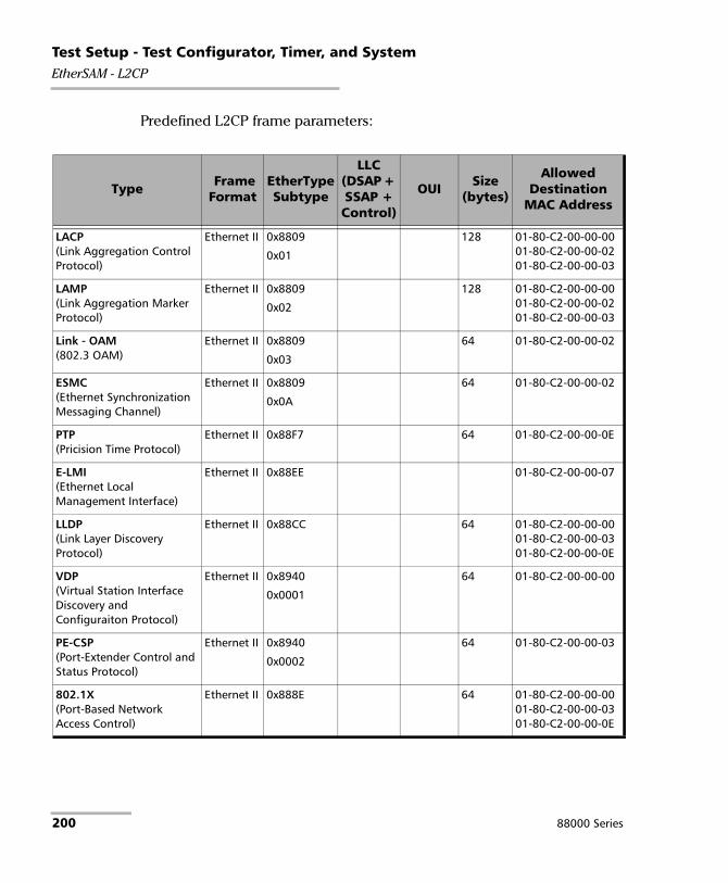
Test Setup - Test Configurator, Timer, and SystemEtherSAM - L2CP
Predefined L2CP frame parameters:
Type Frame Format
EtherType Subtype
LLC(DSAP + SSAP + Control)
OUI Size(bytes)
Allowed Destination
MAC Address
LACP (Link Aggregation Control Protocol)
Ethernet II 0x8809
0x01
128 01-80-C2-00-00-0001-80-C2-00-00-0201-80-C2-00-00-03
LAMP (Link Aggregation Marker Protocol)
Ethernet II 0x8809
0x02
128 01-80-C2-00-00-0001-80-C2-00-00-0201-80-C2-00-00-03
Link - OAM (802.3 OAM)
Ethernet II 0x8809
0x03
64 01-80-C2-00-00-02
ESMC (Ethernet Synchronization Messaging Channel)
Ethernet II 0x8809
0x0A
64 01-80-C2-00-00-02
PTP (Pricision Time Protocol)
Ethernet II 0x88F7 64 01-80-C2-00-00-0E
E-LMI (Ethernet Local Management Interface)
Ethernet II 0x88EE 01-80-C2-00-00-07
LLDP (Link Layer Discovery Protocol)
Ethernet II 0x88CC 64 01-80-C2-00-00-0001-80-C2-00-00-0301-80-C2-00-00-0E
VDP (Virtual Station Interface Discovery and Configuraiton Protocol)
Ethernet II 0x8940
0x0001
64 01-80-C2-00-00-00
PE-CSP (Port-Extender Control and Status Protocol)
Ethernet II 0x8940
0x0002
64 01-80-C2-00-00-03
802.1X (Port-Based Network Access Control)
Ethernet II 0x888E 64 01-80-C2-00-00-0001-80-C2-00-00-0301-80-C2-00-00-0E
200 88000 Series

Test Setup - Test Configurator, Timer, and SystemEtherSAM - L2CP
MAC-PAUSE (802.3 MAC Control - PAUSE)
Ethernet II 0x8808
0x0001
64 01-80-C2-00-00-01
MAC-PFC (802.3 MAC Control - Priority Flow Control)
Ethernet II 0x8808
0x0101
64 01-80-C2-00-00-01
MPMAC-Gate (802.3 Multipoint MAC Control - Gate)
Ethernet II 0x8808
0x0002
64 01-80-C2-00-00-01
MPMAC-Report (802.3 Multipoint MAC Control - Report)
Ethernet II 0x8808
0x0003
64 01-80-C2-00-00-01
MPMAC-Register-req (802.3 Multipoint MAC Control - Register-req)
Ethernet II 0x8808
0x0004
64 01-80-C2-00-00-01
MPMAC-Register (802.3 Multipoint MAC Control - Register)
Ethernet II 0x8808
0x0005
64 01-80-C2-00-00-01
MPMAC-Register-ack (802.3 Multipoint MAC Control - Register-ack)
Ethernet II 0x8808
0x0006
64 01-80-C2-00-00-01
MAC-Org-Spec-Ext (802.3 MAC Control - Organisation Specific Extensions)
Ethernet II 0x8808
0xFFFE
64 01-80-C2-00-00-01
STP (Spanning Tree Protocol)
LLC 0x424203 64 01-80-C2-00-00-0001-80-C2-00-00-08
RSTP (Rapid Spanning Tree Protocol)
LLC 0x424203 64 01-80-C2-00-00-0001-80-C2-00-00-08
MSTP (Multiple Spanning Tree Protocol)
LLC 0x424203 64 01-80-C2-00-00-0001-80-C2-00-00-08
Type Frame Format
EtherType Subtype
LLC(DSAP + SSAP + Control)
OUI Size(bytes)
Allowed Destination
MAC Address
Power Blazer 201

Test Setup - Test Configurator, Timer, and SystemEtherSAM - L2CP
SPB (Shortest Path Bridge)
LLC 0xFEFE03 64 01-80-C2-00-00-2E01-80-C2-00-00-2F
MMRP (Multiple MAC Registration Protocol)
Ethernet II 0x88F6 64 01-80-C2-00-00-20
MVRP (Multiple VLAN Registration Protocol)
Ethernet II 0x88F5 64 01-80-C2-00-00-21
01-80-C2-00-00-0D
MSRP (Multiple Stream Registration Protocol)
Ethernet II 0x22EA 64 01-80-C2-00-00-0E
MIRP (Multiple ISID Registration Protocol)
Ethernet II 0x8929 64 01-80-C2-00-00-00
CDP (Cisco Discovery Protocol)
SNAP 0x2000 0xAAAA03 0x00000C 64 01-00-0C-CC-CC-CC
VTP (VLAN Truncking Protocol)
SNAP 0x2003 0xAAAA03 0x00000C 64 01-00-0C-CC-CC-CC
PAgP (Port-Aggregation Protocol)
SNAP 0x0104 0xAAAA03 0x00000C 88 01-00-0C-CC-CC-CC
UDLD (Unidirectional Link Detection)
SNAP 0x0111 0xAAAA03 0x00000C 64 01-00-0C-CC-CC-CC
DTP (Dynamic Truncking Protocol)
SNAP 0x2004 0xAAAA03 0x00000C 64 01-00-0C-CC-CC-CC
PVST+(LLC) (Per VLAN Spanning Tree)
LLC 0x424203 64 01-00-0C-CC-CC-CD
PVST+(SNAP) (Per VLAN Spanning Tree)
SNAP 0x010B 0xAAAA03 0x00000C 68 01-00-0C-CC-CC-CD
Type Frame Format
EtherType Subtype
LLC(DSAP + SSAP + Control)
OUI Size(bytes)
Allowed Destination
MAC Address
202 88000 Series

Test Setup - Test Configurator, Timer, and SystemEtherSAM - L2CP
STP-ULFAST (Spanning Tree Protocol - Uplink Fast)
LLC 0x424203 64 01-00-0C-CD-CD-CD
VLAN-BRDSTP (VLAN Bridge Spanning Tree)
LLC 0x424203 64 01-00-0C-CD-CD-CE
ISL (Inter-Switch Link )
SNAP 0x0003 0xAAAA03 0x00000C 94 01-00-0C-00-00-00
GMRP (Generic MAC Registration Protocol)
LLC 0x424203 64 01-80-C2-00-00-20
GVRP (Generic VLAN Registration Protocol)
LLC 64 01-80-C2-00-00-21
Type Frame Format
EtherType Subtype
LLC(DSAP + SSAP + Control)
OUI Size(bytes)
Allowed Destination
MAC Address
Power Blazer 203

Test Setup - Test Configurator, Timer, and SystemEtherSAM - Ramp
EtherSAM - Ramp
Note: The Ramp tab is only available for configuration when the Ramp Test check box is selected (see page 193).
From the Test menu, tap Setup, Test Configurator, tap on the test block, and on the Ramp tab.
Note: The ramp configuration parameters are defined globally for all services but the presence of CIR+EIR, and Traffic Policing steps are as per each service configuration. CIR, CIR+EIR, and Traffic Policing steps are part of the step list as soon as they are enabled for at least one service even if that service is not enabled.
Dynamic Ramp
The graphic displays the percentage of each CIR level step in time.
Step Time
The step time is the test duration for each ramp step: 5 (default) to 60 seconds.
Ramp Duration
The ramp duration indicates the total time required to perform all the ramp steps for each service.
Add Step
Allows adding a new ramp step. Enter the CIR percentage from 1 to 99. A maximum of 7 pre CIR steps can be added in the ramp configuration.
204 88000 Series

Test Setup - Test Configurator, Timer, and SystemEtherSAM - Ramp
Delete Step
Allows deleting a step from the ramp. Select the step from the list and tap on Delete.
Defaults
Reverts the ramp configuration to its default factory settings.
Power Blazer 205

Test Setup - Test Configurator, Timer, and SystemExternal Reference
External Reference Allows the configuration of the external reference signal. Available with Wander test application.
From the Test menu, tap Setup, Test Configurator, and tap on the External Reference block.
Reference
Mode is set to External Reference.
Ext Reference In
Allow the selection of the reference signal for TE/TIE measurements.
Signal allows the selection of the reference interface: 2 MHz, 10 MHz, and 1PPS. Only 1PPS reference is available for 1PPS interface/rate test.
Ext Ref In on a green background indicates that a valid reference is received.
LOS on a red background indicates that the received signal is not valid.
Connector indicates the connector used for the external reference signal: RJ48C or BNC.
Frequency (MHz) displays the frequency of the received reference signal.
206 88000 Series

Test Setup - Test Configurator, Timer, and SystemFibre Channel
Fibre Channel From the Test menu, tap Setup, Test Configurator, and the Fibre Channel block.
World Wide Name (WWN)
The following WWN settings are only available when the Login - Enable check box is selected (see page 208).
Source allows setting the 64-bit WWN address of the local fibre channel port: 00-00-00-00-00-00-00-00 to FF-FF-FF-FF-FF-FF-FF-FF (default is 20-00-00-03-01[IEEE-MAC lsb (bits 23..0)).
Destination allows setting the 64-bit WWN address of the remote fibre channel port: 00-00-00-00-00-00-00-00 (default) to FF-FF-FF-FF-FF-FF-FF-FF. The destination WWN address is displayed and grayed-out for Point-to-Point topology after a successful login.
Buffer to Buffer Flow Control
Buffer to Buffer (BB) Flow Control, also called Flow Control Management, manages the control of data traffic between the local and remote fibre channel ports based on the network, distance, and traffic congestion.
Each remote port advertises the buffer size (BB_Credit) during the login.
Enable check box when selected allows setting or use buffers to receive frames. The Enable check box is force selected when the Login - Enable check box is selected (see page 208).
Available BB_Credit is the number of frame buffers that the remote port has available to receive frames from the local port: 1 to 65535 (default is 10). The Available BB_Credit is not editable when the Login - Enable check box is selected but its value received from the remote interface through the login process is displayed. If the login fails, the Available BB_Credit displays “–”.
Power Blazer 207

Test Setup - Test Configurator, Timer, and SystemFibre Channel
Login
After a link is established, it is possible to login to the Fibre Channel Network to send and receive data between a local and remote fibre channel port.
Enable check box when selected (default) allows pressing the Login button to start the login process.
Advertised BB_Credit is the number of frame buffers the local port has available to receive frames from the remote port: 1 to 65535 (default is 10). Advertised BB_Credit is advertised to the remote port through the Login process. Changing the Advertised BB_Credit requires to manually re-send a login using the Login button.
Login/Re-Login button allows the initiation of the Login process with the selected Advertised BB_Credit. Available when the Login - Enable check box is selected. The Login button initiates a log-in when not logged-in while the Re-Login re-initiates a log-in after changing the BB_Credit and/or WWN when already logged-in. The capability to login is available only with Framed Layer 2 (FC-2) when a successful link has been established. There are two Login processes supported by Fibre Channel: Port Login (PLOGI) and Fabric Login (FLOGI).
It is possible to skip the Login procedure and use the BB_Credit value. This is called Implicit Login and is only applicable for Point-to-Point topology. For Point-to-Point topology using implicit login, you must manually configure the Available BB_Credit value for the remote port.
Discovered Topology indicates the discovered topology.
Fabric: Ports are interconnected to a fabric switching network. A Fabric and Port login are required, and the BB_Credit value is set based on the buffer capacity of the fabric switch.
Point To Point: Direct link between two ports.
208 88000 Series

Test Setup - Test Configurator, Timer, and SystemFibre Channel
Fabric Status indicates the status of the Fabric switching network. The status is not available when the discovered topology is Point-to-Point.
Logged-in indicates that the login process has completed successfully.
Failed indicates that the login process is not completed successfully or an error has been detected.
In Progress indicates that the login process is running (not completed yet).
Logged-out (default) indicates that the system has not logged in yet or has received a valid Logout command from the remote port.
Port Status indicates the state of the port login process.
Logged-in indicates that the login process has completed successfully.
Failed indicates that the login process is not completed successfully or an error has been detected.
In Progress indicates that the login process is running (not completed yet).
Logged-out (default) indicates that the system has not logged in yet, has received a valid Logout command from the remote port, or the Fabric status is either Failed, In Progress, or Logged-out.
Power Blazer 209

Test Setup - Test Configurator, Timer, and SystemFlexE Group
FlexE Group From the Test menu, tap Setup, Test Configurator, and on the FlexE Group protocol block.
Note: Only one client is supported in the FlexE Group.
FlexE Status
Indicates the global FlexE group status: up (green arrow) or down (red arrow).
Calendar Mismatch
Indicates if the received calendar differs from the one expected using the following colors: red for mismatch; green for match; otherwise it is gray.
FlexE Group Number
Allows associating a number to the FlexE Group: 0 to 1048575.
Calendar
Allows selecting the calendar A or B that is used for mapping/demapping the FlexE clients into/from the FlexE group.
Table
Client ID indicates the client identification number.
Size indicates the size of the client in Gbit/s.
Link indicates the client link status: link up (green arrow) or link down (red arrow).
Qty of Clients indicates the number of clients assigned to the FlexE group.
210 88000 Series

Test Setup - Test Configurator, Timer, and SystemFlexE Group
Assigned Capacity (Gbit/s) indicates the sum of client size assigned to the FlexE group.
Unused Capacity (Gbit/s) indicates the client size not assigned to the FlexE group.
Modify (FlexE Calendar)
Client ID allows selecting the client ID to be displayed.
Size (Gbit/s) indicates the size of the client.
Client Assignation Status
Table
ID indicates the client identification number.
Size indicates the size of the client in Gbit/s.
Status indicates the client assignment status: Assigned or n/total (n is the number of assigned block over the total for this client).
Edit ID edits of the client identification number (1 to 65534).
Add Client adds a new client by selecting its Client ID, Size (5, 10, 25, 40, 50, 100, 150, 200, 250, 300, 350, 400 Gbit/s), and the Quantity of clients (up to 40 clients).
Delete Client removes the selected client from the FlexE group.
Delete All removes all clients from the FlexE group.
Assign/Unassign/Mode
Power Blazer 211

Test Setup - Test Configurator, Timer, and SystemFlexE Group
PHY n (Port n)
A PHY (Port) grid is presented for each enabled port displaying and allowing edition (see Assign/Unassign/Mode above) of the client assignation per slot of 5 Gbit/s.
Assigned clients are identified by their client ID number.
Unassigned clients are identified by the U letter.
Restore < Test Application > Defaults
Reverts the current test application to its default factory settings.
To assign or unassign slots:
1. Select a client from the Client Assignation Status table.
2. Select Assign or Unassign.
3. From the PHYn (Port n) slot matrix on the right, select the slot(s); slots are assign/unassign as follows according to the selected Mode:
Mode Description
Slot Assigns/unassigns a single slot.
Client Assigns/unassigns all slots for a specific client. After selecting a first slot for a client having more than one slot, subsequent tributary slots are automatically assigned/unassigned.
All Clients Assigns/unassigns all slots to/from a client and this is repeated for all clients. After selecting the first slot for a client having more than one slot, subsequent slots are automatically assigned/unassigned. This is repeated for all clients in order.
212 88000 Series
Test Setup - Test Configurator, Timer, and SystemFlexO/OTN
FlexO/OTN From the Test menu, tap Setup, Test Configurator, the FlexO-OTUCn protocol block, and FlexO/OTN tab.
Note: Only one client is supported in the FlexO Group.
FlexO
FlexO Status indicates the global FlexO group status: up (green arrow) or down (red arrow).
FlexO Group ID indicates the FlexO group ID number.
OTUCn
The OTUCn Test Signal table lists the following for each FlexO client:
Client ID indicates the client identification number.
Type indicates the ODUk container (client).
Size (Gbit/s) indicates the the ODUk client size.
Edit ID button allows editing the Client ID: 1 (default) to 40.
OTUC4/ODUC4/ODUk represents the mapping of the signal.
Payload Type indicates the payload type which is 22.
Qty of Clients indicates the quantity of clients which is 1.
Usage indicates that 80 tributary slot are used corresponding to 419 Gbit/s.
Power Blazer 213

Test Setup - Test Configurator, Timer, and SystemFrequency
Frequency
Note: The Frequency tab is only available for parallel interfaces.
From the Test menu, tap Setup, Test Configurator, tap on the interface block, and on the Frequency tab.
Port, FlexO Instance ID, and FlexE PHY Number
Note: Only available with FlexE/FlexO BERT test application.
Port allows selecting the physical port to be displayed.
FlexO Instance ID indicates the FlexO instance identifier assigned to the port.
FlexE PHY Number indicates the FlexE PHY number assigned to the port.
TX Frequency
TX Frequency (GHz) indicates the frequency (actual frequency + Frequency offset) used for transmission.
Note: Frequency offset is not available with Multi-Channel OTN and FlexE/FlexO BERT.
Offset (ppm) check box, when selected (cleared by default), allows setting the frequency offset that will be generated. Use the “+” or “-” button to respectively increment or decrement the frequency offset value based on the defined Increment/Decrement Size, or directly type the frequency offset value in the field. The range is ±120 ppm for Ethernet test applications, ±50 ppm for Transport Framed, and ±120 ppm for Transport Unframed test applications.
214 88000 Series

Test Setup - Test Configurator, Timer, and SystemFrequency
Fixed/Sweep allows selecting the frequency generation method. Only available with Ethernet interfaces when the Offset check box is cleared. Not available with FlexE BERT.
Fixed (default): uses a fixed offset frequency value for generation.
Sweep: increases and decreases repetitively the frequency to cover the defined frequency offset range using a 1 ppm step at an average rate of up to 10 ppm/sec. Starting at offset 0 the min value is reached then repetitively increases to the maximum value then decreases to minimum value.
Step Size (ppm), available with Fixed frequency, allows setting the increment/decrement value (from 0.1 to either 50 or 120 depending on the test configuration) that will be used when changing the frequency offset with the “+” or “-” button.
Range, available with sweep frequency, allows setting the range for frequency sweep generation.
Interface Frequency Offseta
a. The frequency offset range is guaranteed for a source signal at 0 ppm. In the eventthat the source signal already has an offset, then the output signal may exhibit anoffset larger than the range specified.
Nominal Frequency
OTU3 ± 50 ppm (Framed)± 120 ppm (Unframed)
43018413559 bit/s
OTU3e1 44571000000 bit/s
OTU3e2 44583000000 bit/s
OTU4 111810000000 bit/s
Power Blazer 215

Test Setup - Test Configurator, Timer, and SystemFrequency
Note: The following frequency statistics are available for each lane.
RX Frequency
Frequency (GHz) indicates the frequency of the input signal.
Offset (ppm) indicates the frequency offset between the standard rate specification and the rate at the input signal.
Note: For both Frequency and Offset the following background colors are used.
For parallel interfaces, in the Test Configurator - Interface block, LO and HI report respectively the current lowest and highest RX frequency offset values from any lane.
Max. Negative Offset (ppm) indicates the maximum negative frequency offset between the standard rate specification and the rate from the received signal.
Max. Positive Offset (ppm) indicates the maximum positive frequency offset between the standard rate specification and the rate from the received signal.
Note: Refer to Interface on page 425 for more information on standard rate specifications.
Background color Description
Green The frequency is in range.
Red The frequency is out-of-range or LOC Lane. LOC is also displayed.
Gray Pending state.
216 88000 Series
Test Setup - Test Configurator, Timer, and SystemFTFL/PT and PT
FTFL/PT and PT For OTN BERT and OTN-SONET/SDH BERT: From the Test menu tap Setup, Test Configurator, tap on the interface block, and on the FTFL/PT tab.
For Multi-Channel OTN: From the Test menu, tap Setup, Test Configurator, tap on either:
the interface block, and on the PT tab to configure the higher ODU layer.
the test block (ODU Channels), and on the PT tab to configure the lower ODU layer.
ODUx Buttons
Tap on an ODUx button to select the multiplexed level. Not available with Multi-Channel OTN lower ODU level.
Power Blazer 217

Test Setup - Test Configurator, Timer, and SystemFTFL/PT and PT
FTFL
Allows the configuration of the Forward and Backward ODU Fault Type Fault Location (FTFL) to be generated. Not available with Multi-Channel OTN.
Overwrite check box when selected generates the defined FTFL. Only available with Through Intrusive topology and applies only to the ODU top layer.
Fault Indication and Fault Indication Code allow the selection of the FTFL fault indicator message/code (byte 0 for forward, byte 128 for backward) to be generated.
Note: The Fault Indication Code field is automatically updated when the Fault Indication is changed and vice versa.
Operator Identifier allows editing the Operator Identifier to be generated (bytes 1 to 9 for forward, bytes 129 to 137 for backward; 9 characters allowed). By default no Operator Identifier is defined.
Operator Specific allows editing the Operator Specific to be generated (bytes 10 to 127 for forward, bytes 138 to 255 for backward; 118 characters allowed). By default no Operator Specific is defined.
Fault Indication Fault Indication Code (Hex)
No fault 00 (default)
Signal fail 01
Signal Degrade 02
Reserved 03a
a. Selecting Reserved will use the hexadecimal code 03 but, all codes from 03 to FFare reserved for future international standardization.
218 88000 Series

Test Setup - Test Configurator, Timer, and SystemFTFL/PT and PT
PT / Global PT
Note: Global PT, available with Muti-Channel OTN, indicates that the PT settings apply to all channels.
Note: Changing the payload type (PT) does not alter the signal structure; it only modifies the OH value that is generated.
Overwrite check box when selected generates the defined PT. Only available with Through Intrusive topology and applies only to the ODU top layer.
Payload Type and Code
Generated: Allows the selection of the payload signal type to be generated either by selecting the payload type from the list or by entering its code in hexadecimal (00 to FF).
Expected: Allows selecting the expected payload signal type.
Note: Codes not listed in the table are reserved for future standardization (Reserved For International Standardization).
Payload type Hex Code MSB1234
LSB5678
Reserved for International Standardizationa 00 0000 0000
Experimental mapping 01 0000 0001
Asynchronous CBR mapping 02 0000 0010
Bit Synchronous CBR mapping 03 0000 0011
ATM mapping 04 0000 0100
GFP mapping 05 0000 0101
Virtual Concatenation Signal 06 0000 0110
PCS Codeword Transparent Ethernet 07 0000 0111
FC-1200 into ODU2e 08 0000 1000
Power Blazer 219

Test Setup - Test Configurator, Timer, and SystemFTFL/PT and PT
GFP mapping into extended OPU2 09 0000 1001
OC-3/STM-1 into ODU0 0A 0000 1010
OC-12/STM-4 into ODU0 0B 0000 1011
FC-100 into ODU0 0C 0000 1100
FC-200 into ODU1 0D 0000 1101
FC-400 into ODUflex 0E 0000 1110
FC-800 into ODUflex 0F 0000 1111
Bit Stream with Octet Timing mapping 10 0001 0000
Bit Stream Without Octet Timing mapping 11 0001 0001
IB SDR mapping into ODUflex 12 0001 0010
IB DDR mapping into ODUflex 13 0001 0011
IB QDR mapping into ODUflex 14 0001 0100
SDI mapping into OPU0 15 0001 0101
(1.485/1.001) Gbit/s SDI mapping into OPU1 16 0001 0110
1.485 Gbit/s SDI mapping in to OPU1 17 0001 0111
(2.970/1.001) Gbit/s SDI mapping into OPUflex 18 0001 1000
2.970 Gbit/s SDI mapping into OPUflex 19 0001 1001
SBCON/ESCON mapping into OPU0 1A 0001 1010
DVB_ASI mapping into OPU0 1B 0001 1011
FC-1600 mapping into OPUflex 1C 0001 1100
FlexE Client mapping into OPUflex 1D 0001 1101
FlexE aware (partial rate) mapping into OPUflex 1E 0001 1110
FC-3200 mapping into OPUflex 1F 0001 1111
ODU Multiplex with ODTUjk 20 0010 0000
ODU Multiplex with ODTUk.ts/ODTUjk 21 0010 0001
ODU multiplex with ODTUCn.ts 22 0010 0010
25GBASE-R mapping into OPUflex 30 0011 0000
Payload type Hex Code MSB1234
LSB5678
220 88000 Series

Test Setup - Test Configurator, Timer, and SystemFTFL/PT and PT
Note: The Code field is automatically updated when the Payload Type is changed and vice versa.
OPU-PLM, when selected, enables the OPU-PLM alarm analysis.
200GBASE-R mapping into OPUflex 31 0011 0001
400GBASE-R mapping into OPUflex 32 0011 0010
Not Availableb 55 0101 0101
Reserved Codes for Proprietary Usec 80 1000 0000
NULL Test Signal mapping FD 1111 1101
PRBS Test Signal mapping FE 1111 1110
a. Selecting Reserved for International Standardization will use the hexadecimal code 00 but, all codesnot listed in the previous table at the exception of those covered in notes b and c are reserved for futurestandardization.
b. Selecting Not Available will use the hexadecimal code 55 but, 66 and FF are also Not Available payloadtypes.
c. Selecting Reserved Proprietary will use the hexadecimal code 80 but, all codes from 80 to 8F arereserved proprietary payload types.
Payload type Hex Code MSB1234
LSB5678
Power Blazer 221

Test Setup - Test Configurator, Timer, and SystemGFP-F/GFP-T
GFP-F/GFP-T
Note: Only available with Ethernet 1GbE, 10GbE, or Ethernet (flex/GFP-F) client.
From the Test menu, tap Setup, Test Configurator, and tap on the GFP-F/GFP-T block.
Note: Refer to Generic Framing Procedure (GFP) on page 811 for more information on Client Data and Client Management frames.
CDF pFCS (Client Data Frames payload Frame Check Sequence) enables the presence of the payload FCS for the client frames. This setting is only available with Ethernet (flex/GFP-F) client.
CMF pFCS (Client Management Frames payload FCS) enables the presence of the payload FCS for the management frames. The CMF pFCS check box is automatically cleared when injecting FDI or RDI alarms.
EXI (Extension Header Identifier) allows the selection of the type of GFP Extension Header. Choices are Null (0000) - (Default) and Linear (0001). EXI is only configurable with Ethernet (flex/GFP-F) client.
CID (Channel IDentifier) selects the communication channel used for the signal transmission for both Client Data and Client Management frames. Choices are from 0 (default) through 255. CID is only available when EXI is set to Linear.
The status Mismatch is displayed next to the CID value when the TX and RX CID values differ.
Delta indicates the GFP state machine synchronization parameter. Delta is set to 1.
222 88000 Series
Test Setup - Test Configurator, Timer, and SystemInterface
Interface From the Test menu, tap Setup, Test Configurator, the interface block, and the Interface tab.
Port, FlexO Instance ID, and FlexE PHY Number
Note: Only available with FlexE/FlexO BERT test application.
Port allows selecting the physical port to be displayed.
FlexO Instance ID indicates and allows changing the FlexO Instance ID (1 to 254) assigned to the port.
FlexE PHY Number indicates and allows changing the FlexE PHY number (1 to 254) assigned to the port.
LINK
An arrow is used to indicate the port link status (at the PCS level for parallel interfaces): link up (green arrow), error or link down (red arrow), or awaiting incoming data to provide a status (gray arrow).
Note: Refer to Ethernet on page 405, Fibre Channel on page 413, Ethernet - PCS on page 408, and PHY on page 448 for more information on alarms.
For 25GE framed Ethernet interface:
RS-FEC check box when selected (default) enables the use of RS-FEC.
For 100GE (4 Lanes) framed Ethernet interface:
RS-FEC check box when selected (default), enables the use of the RS-FEC; ensure both ends of the circuit have the FEC enabled. The RS-FEC check box should be selected when using a 100GBASE-SR4, 100G-CWDM4, or 100G AOC transceiver but may be cleared for testing purposes. Not available when the PHY Type is set to LR4/ER4 (see page 132).
Power Blazer 223

Test Setup - Test Configurator, Timer, and SystemInterface
For 200GE/400GE framed Ethernet interface:
RS-FEC (RX Only) check box when selected (default) enables the use of the RS-FEC in RX; when cleared, ignores RS-FEC parity symbols, detection of FEC errors, and no correction of message symbols are performed.
FEC Degraded SER check box when selected, enables the monitoring of local/remote degraded SER alarms. Only available when RS-FEC (RX Only) check box is selected.
Thresholds is available when FEC Degraded SER is enabled and allows setting the threshold values used to raise and clear the Local Degraded SER Detected alarm.
The alarm is raised when the number of symbol errors is higher than the Activate Threshold (Symbols) defined. The alarm is cleared when the number of symbol errors is lower than the Deactivate Threshold (Symbols) defined.
Interval (CW) defines the number of codewords (interval) used by the FEC decoder to count the number of symbol errors detected.
Activate Threshold (Symbols) defines the number of detected symbols required to declare the Local Degraded SER Detected alarm.
Deactivate Threshold (Symbols) defines the number of detected symbols required to clear the Local Degraded SER Detected alarm.
224 88000 Series

Test Setup - Test Configurator, Timer, and SystemInterface
For EtherBERT test application:
Remote Fault Emulation check box when selected, generates Remote Fault ordered sets when a Link Fault is received. Only available with EtherBERT, 10GE (all framing at the exception of Seed A/B and PRBS31 Unscrambled), and 40GE/100GE (Framed Layer 2 and up).
For Ethernet and Packet Sync test applications:
For optical interfaces, the Local Fault Detected, Local Fault Received, Remote Fault, LOA, Hi-BER, and/or WIS Link (10GE WAN) alarm status are displayed. Refer to Ethernet on page 405 and Ethernet - PCS Lanes on page 410 for more information.
Auto-Negotiation check box is available with 10/100/1000M Electrical and 1GE Optical interfaces. When the Auto-Negotiation check box is selected the test application indicates to the remote port which parameters to use. The Auto-Negotiation check box is automatically selected (not configurable) for 1GE Electrical interface and when using an active copper SFP.
Note: When the Auto-Negotiation check box is selected, the port Speed, Duplex, Flow Control, and Local Clock parameters can be set. Those settings are not applied immediately to the port, they are used only when the negotiation process is started and take effect only when the auto-negotiation succeeds. However current settings are applied immediately to the port when the Auto-Negotiation check box is cleared.
Power Blazer 225

Test Setup - Test Configurator, Timer, and SystemInterface
Speed, available with 10/100/1000M Electrical interface, allows the selection of the interface rate: 10M, 100M, 1GE, or Auto1. The negotiated speed will be displayed next to the Speed field selection. The 10M speed is not available with SyncE test application.
Duplex choices for 10M and 100M electrical interfaces are Full Duplex (default), Half Duplex, and Auto1. For other rates the Duplex is set to Full Duplex. Availability of choices depend on the test applications. Half Duplex is not available with an active copper SFP. The negotiated duplex will be displayed next to the Duplex field selection.
Flow Control choices are Enable TX, Enable RX, Enable RX and TX, None (default), and Auto1. When the Flow Control is set to None, pause frames received are ignored. Availability of choices depend on test applications.
Cable Mode is available with 10/100/1000M Electrical interface. Availability of choices depend on the test application.
Manual mode is selected when the Auto-Negotiation check box is cleared and allows selecting the type of cable: MDI (default) for straight through cable or MDIX for crossover cable.
Automatic mode is selected when the Auto-Negotiation check box is selected and allows the module to automatically detect the MDI or MDIX cable type.
Local Clock is only available with 1GE electrical interface and allows setting the source of the clock: Master (default), Slave2, or Auto1, 3.
1. Auto is only available when the Auto-Negotiation check box is selected.
2. Slave is the only available choice for Wander test application.
3. Not available with SyncE test application.
226 88000 Series

Test Setup - Test Configurator, Timer, and SystemInterface
For Fibre Channel test application:
PSP (Link Protocol) (Primitive Sequence Protocol) check box when selected (default) allows link management by activating the port.
For CPRI Unframed test application:
Scrambling check box when selected (default) enables the scrambler. Only available with CPRI rates 4.9152 Gbit/s and higher.
For CPRI Framed L2 test application:
Sequence indicates the last Startup Sequence State: Standby (A), L1 Sync (B), Protocol (C), L2 C&M (D), Vendor (E), Operation (F), or Passive (G). Frame Sync indicates the synchronization status: green for active, red for inactive, or gray for pending.
Protocol defines how the CPRI Startup Sequence negotiates the protocol version.
Auto can use protocol Version 1 and Version 2 during the negotiation.
Version 1 negotiates the protocol with either Scrambling disabled for all supported CPRI rates with the exception of 10.1 for which the Scrambling is enabled.
Version 2 negotiates the protocol with Scrambling enabled. Available with CPRI rates: 9.8, 6.1, and 4.9 Gbit/s.
Protocol table indicates either the last received (Version 1 or Version 2) or negotiated (Auto) protocol version. A light-red background indicates a Protocol version mismatch between the received value and the expected generated value.
Power Blazer 227

Test Setup - Test Configurator, Timer, and SystemInterface
C&M Channel defines the kind of channel that will be used by the startup sequence for negotiation. Only Disabled is available when Vendor is set to Ericsson.
Auto (default): Overhead byte #Z.66.0 can use any of the HDLC rates and Overhead byte #Z.194.0 can use any of the Ethernet Subchannel in the negotiation process.
HDLC: Only overhead byte #Z.66.0 is used with the configured HDLC Rate during the negotiation process. Ethernet #Z.194.0 byte is set to rr00 0000 as it is disabled.
Ethernet: Only overhead byte #Z.194.0 is used with the configured Ethernet Subchannel during the negotiation process. HDLC #Z.66.0 byte is set to rrrr r000 as it is disabled.
Disabled: Both HDLC Rates and Ethernet Subchannel are disabled to simulate a Passive Link. Ethernet #Z.194.0 byte is set to rr00 0000 and HDLC #Z.66.0 byte is set to rrrr r000. Only available with Base Station emulation mode.
C&M table indicates either the received (HDLC or Ethernet) or negotiated (Auto) C&M for Ethernet subchannel and HDLC rates in Mbit/s. A red background indicates either a C&M type mismatch or HDLC Rate/Ethernet subchannel mismatch compared to the generated C&M channel. An arrow is displayed indicating which C&M Channel should normally be selected as per the standard rules.
Subchannel selects the Ethernet Subchannel number: 20 to 63 where 63 is the lowest bit rate and 20 the highest.
228 88000 Series

Test Setup - Test Configurator, Timer, and SystemInterface
Rate (Mbit/s) is available with HDLC and Ethernet C&M Channel.
For HDLC: Allows the selection of the HDLC bit rate. Choices depend on the selected CPRI interface rate. HDLC Proprietary is used to exercise a case where the Base Station is aware in advance of the HDLC rate to use. The proprietary rate are not described in the standard. If an HDLC Proprietary is received during the negotiation process while the C&M Channel is set to Auto, the negotiation completes but no actual bit rate is reported as it is unknown. Similarly, if an equipment vendor uses an invalid rate (as per the CPRI Standard) during the negotiation process, this rate is reported as Unspecified (Code) where Code is a decimal value representing an invalid rate based on the configured interface rate.
For Ethernet: Indicates the bit rate corresponding to the selected Subchannel.
CPRI Rate (Gbit/s) HDLC Rate (Mbit/s)
1.2 0.240, 0.480, 0.960 (default), Proprietary
2.4 0.240, 0.480, 0.960, 1.920 (default), Proprietary
3.1 0.240, 0.480, 0.960, 1.920, 2.400 (default), Proprietary
4.9 0.240, 0.480, 0.960, 1.920, 2.400, 3.840 (default), Proprietary
6.1 0.240, 0.480, 0.960, 1.920, 2.400, 4.800 (default), Proprietary
9.8, 10.1 0.240, 0.480, 0.960, 1.920, 2.400, 7.680 (default), Proprietary
Power Blazer 229

Test Setup - Test Configurator, Timer, and SystemInterface
For OBSAI Framed L2 test application:
Sync indicates the RX State Machine status: green for FRAME_SYNC, gray for pending, or red for other states. The TX and RX State Machines are also displayed.
Force TX Idle check box when selected forces the TX State Machine to Idle state and when cleared (default) allows the TX State Machine to operate normally.
Scrambling check box when selected (default) enables the scrambler. Only available with OBSAI 6.1 Gbit/s rate.
TX Seed is the start value of the scrambler training process: 0x01 (default) to 0x7F limited to the Seed values defined in the standard.
RX Seed is the current seed value detected.
Frame Clock Burst Generation check box when selected (default) enables the generation of the frame clock burst message. Available with base station emulation mode.
230 88000 Series

Test Setup - Test Configurator, Timer, and SystemInterface
RP3 Address (OBSAI Framed L2)
Source identifies the source node of RP3 messages: 0000 to 1FFF; default is 1234. The RP3 address 1FFF corresponds to the empty message address that is dropped according to the standard.
Target identifies the peer node that is receiving the RP3 messages: 0000 (default) to 1FFF.
Peer Target indicates the RP3 Peer Target Address; indicates a mismatch when displayed in red.
Address Mismatch check box when selected, cleared by default, enables the monitoring of the mismatch between the Source and received Peer Target addresses.
RP3 Message (OBSAI Framed L2)
Type identifies the type of RP3 Data Message generated by the OBSAI node: WCDMA/FDD (00010) - (default), LTE (01110), GSM/EDGE (00100), and 802.16 (01100).
Msg Grp/Frame (N_MG) indicates the number of Message Group per Frame parameter.
Msg/Grp (M_MG) indicates the number of Message per Message Group parameter.
Idle/Grp (K_MG) indicates the number of Idle per Message Group parameter.
ESMC
Note: Available with Wander test application with SyncE rates.
Generated QL allows the selection of the QL message that will be generated. See page 512 for the list of QL message (default is QL-DNU/DUS).
Power Blazer 231

Test Setup - Test Configurator, Timer, and SystemInterface
WIS Button
Note: WIS is only available for 10GE WAN interface.
J0 Trace allows setting the J0 Trace value in 16 bytes format (default is EXFO 10GigE).
J1 Trace allows setting the J1 Trace value in 16 bytes format allowing up to 15 bytes (a CRC-7 byte will be added in front for a total of 16 bytes). Default is EXFO 10GigE.
Note: J0 and J1 values should be 7-bit T.50 suitable characters. The Padding drop list from the message keyboard allows selecting Null or Space to fill up the J0 Trace and J1 Trace up to15-byte value. The Control Characters button in the J0 Trace and J1 Trace message keyboard, allows selecting the required character. For more details on Control Characters, see page 46.
Path Signal Label (C2) byte is allocated to indicate the content of the STS SPE, including the status of the mapped payload.
C2 (Hex.) Description00 Unequipped
01 Equipped - Non-Specific
1Aa
a. Default value.
10 Gbit/s Ethernet (IEEE 802.3)
FE Test Signal, ITU-T 0.181
232 88000 Series

Test Setup - Test Configurator, Timer, and SystemInterface
Physical Interface
For parallel interfaces, the following information is displayed for each optical lane. Not supported when PHY Type is set to DAC.
Optical Lane indicates the optical lane number.
Laser indicates the status of the laser: ON with the laser pictogram (emitting an optical laser signal) or OFF.
TX Power (dBm) indicates, when supported, the transmit power level of the optical lane/laser in dBm.
Wavelength (nm) indicates, when supported, the detected wavelength.
RX Power (dBm) indicates, when supported, the current received power level of the optical laser/lane in dBm.
Green: Power level in range. Yellow: Power level out-of-range. Red: Loss of signal or power level is close to damage. Gray: Invalid operational range value or not available/supplied by the transceiver.
For parallel interfaces, in the Test Configurator - Interface block, LO and HI report respectively the current lowest and highest RX power levels from any lane.
Optical Interface Optical Lane Number40GE (4 Lanes) [41.25 Gbit/s]100GE (4 Lanes) [103.125 Gbit/s]200GE (4 Lanes) [212.5 Gbit/s] 400GE (4 Lanes) [425 Gbit/s]
0 through 3
400GE (8 Lanes) [425 Gbit/s] 0 through 7
Power Blazer 233

Test Setup - Test Configurator, Timer, and SystemInterface
Min RX Power (dBm) indicates, when supported, the minimum received power level of the optical laser/lane in dBm.
Max RX Power (dBm) indicates, when supported, the maximum received power level of the optical laser/lane in dBm.
Laser ON/OFF button, available with parallel interfaces, is used to activate the laser control per optical lane or for all lanes.
Optical lane numbers are from 0 to 3 or 0 to 7 depending on the selected interface/rate.
All Lanes check box, when selected, applies the change(s) to all optical lanes at once.
Optical Lane indicates the optical lane numbers and All which represents the setting for all optical lanes when the All Lanes check box is selected.
Laser check box, when selected, indicates that the corresponding optical laser lane is activated and emitting an optical laser signal.
Laser OFF at Start-Up check box when selected, cleared by default, automatically turns OFF the laser for serial interfaces or all lasers for parallel interfaces when starting the module or when switching from one test application to another; this applies on both ports for Dual Port topology. However the laser remains ON, on a remote module receiving a request for a DTS connection or a loopback command.
234 88000 Series

Test Setup - Test Configurator, Timer, and SystemInterface
Modify Wavelength button, available with tunable transceivers when the TunableOptics software option is enabled, is used to configure the transceiver wavelength.
Wavelength (nm) indicates the actual wavelength value selected.
Use the scroll box and/or the -/+ buttons to select the wavelength. The minimum and maximum wavelength values are displayed.
Channel Number indicates the actual ITU channel number based on ITU Grid.
Frequency (THz) indicates the actual Frequency based on ITU Grid
Channel Spacing (GHz) indicates the difference in frequency between two adjacent channel detected from the transceiver device.
Restore Previous restores the current value present in the transceiver device.
Power Range (dBm) indicates the transceiver operational RX power range.
FEC (FlexO BERT)
FEC check box when selected (default) enables the FEC in TX/RX and allows detecting, reporting, and correcting up to 15symbol errors (Correctable) per codeword. If there are over 15 symbol errors detected, they are reported as uncorrectable errors.
Power Blazer 235

Test Setup - Test Configurator, Timer, and SystemInterface
TX Frequency
Note: The following TX Frequency information applies to serial interface only, refer to TX Frequency on page 214 for parallel interfaces. Not available when using an active copper SFP.
TX Frequency (GHz) indicates the frequency (actual frequency + Frequency offset) used for transmission.
Note: Frequency offset is not available with OBSAI, CPRI in RRH emulation mode, RFC 6349 test application.
Offset (ppm) check box, when selected (cleared by default), allows setting the frequency offset that will be generated: ±120 ppm for all Sync, Fibre Channel, and Ethernet rates at the exception of 10GE WAN which is ±50 ppm; not supported for 10M electrical. Use the “+” or “-” button to respectively increment or decrement the frequency offset value based on the defined Increment/Decrement Size, or directly type the frequency offset value in the field.
Step Size (ppm) allows setting the increment/decrement value (from 0.1 to the maximum offset) that will be used when changing the frequency offset with the “+” or “-” button.
236 88000 Series
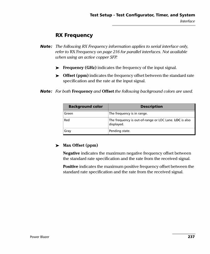
Test Setup - Test Configurator, Timer, and SystemInterface
RX Frequency
Note: The following RX Frequency information applies to serial interface only, refer to RX Frequency on page 216 for parallel interfaces. Not available when using an active copper SFP.
Frequency (GHz) indicates the frequency of the input signal.
Offset (ppm) indicates the frequency offset between the standard rate specification and the rate at the input signal.
Note: For both Frequency and Offset the following background colors are used.
Max Offset (ppm)
Negative indicates the maximum negative frequency offset between the standard rate specification and the rate from the received signal.
Positive indicates the maximum positive frequency offset between the standard rate specification and the rate from the received signal.
Background color Description
Green The frequency is in range.
Red The frequency is out-of-range or LOC Lane. LOC is also displayed.
Gray Pending state.
Power Blazer 237

Test Setup - Test Configurator, Timer, and SystemLabels
Labels For SONET/SDH BERT: From the Test menu, tap Setup, Test Configurator, the interface block, and on the Labels tab.
For OTN-SONET/SDH BERT: From the Test menu, tap Setup, Test Configurator, the protocol block, and on the Labels tab.
Note: Selecting a Label byte to be generated will automatically update the corresponding OH byte. Refer to OH - SONET/SDH on page 666 for more information.
Labels
STS/AU Path (C2): The C2 byte is allocated to indicate the content of the STS SPE / VC, including the status of the mapped payloads.
Generated: Select the C2 byte from the list. Selecting a C2 byte value will automatically update the OH C2 selection and vice versa. Refer to C2 on page 674 for more information.
PLM-P/UNEQ-P / HP-PLM/HP-UNEQ: Enables the Payload Mismatch and STS/AU UNEQ monitoring. This setting is coupled with the configuration of Traces (SONET/SDH) on page 597.
Expected: Select the expected C2 byte from the list. Refer to C2 on page 674 for more information.
238 88000 Series
Test Setup - Test Configurator, Timer, and SystemLabels
VT/TU Path (V5): The V5 byte is allocated to indicate the content of the VT/TU path, including the status of the mapped payloads.
Generated: Select the V5 byte from the list. Selecting a V5 byte value will automatically update the OH V5 selection and vice versa. Refer to V5 on page 677 for more information.
PLM-V/UNEQ-V / LP-PLM/LP-UNEQ: Enables the Payload Mismatch and VT/TU UNEQ monitoring. This setting is coupled with the configuration on the Labels on page 488.
Expected: Select the expected V5 byte from the list. Refer to V5 on page 677 for more information.
Power Blazer 239
Test Setup - Test Configurator, Timer, and SystemLink OAM
Link OAM From the test menu, tap Setup, Test Configurator, and the Link-OAM (802.3) test block.
OAM Mode
Allows the selection of the OAM mode:
Active (default) initiates the OAM discovery and send OAMPDU loopback control; doesn’t respond to variable request nor generate Link Event Notification.
Passive doesn’t initiate OAM discovery nor send OAMPDU loopback control.
OAMPDU Destination MAC Address
Indicates and allows changing the default multicast OAM PDU destination MAC address: 01:80:C2:00:00:02.
Default check box when cleared (default is selected), allows the configuration of the OAM PDU destination MAC address: 00:00:00:00:00:00 to FF:FF:FF:FF:FF:FF.
Pass/Fail Verdict
Pass/Fail Verdict check box when selected (default) enables the use of the pass/fail verdict. A global fail verdict is declared when any of the following condition is met: Link Down, any Link OAM alarm, Remote Alarms (if enabled), or Remote Loopback (if enabled).
Remote Alarms check box when selected (default) considers the following alarms to declare the pass/fail verdict: Critical Event, Dying Gasp, and Link Fault.
Remote Loopback check box when selected (default) considers successful/unsuccessful remote loopback request to declare the pass/fail verdict.
240 88000 Series

Test Setup - Test Configurator, Timer, and SystemLink OAM
OAM Discovery Status
Local reports the local OAM discovery status as follows:
Remote reports the remote OAM discovery status as follows:
Loopback
Local and Remote
Status indicates the status of the local and remote loopback: Enabled represents a Looped-Up condition and Disabled a Looped-Down condition.
Enable/Disable button allows respectively Looping-Up (Enable) or Looping-Down (Disable).
Status Description
Evaluating OAM discovery is started.
Stable OAM discovery is completed. Local OAM is satisfied with the remote OAM settings.
Unsatisfied OAM discovery cannot complete successfully.
Local OAM equipment is unsatisfied with the remote OAM settings.
Status Description
Evaluating OAM discovery is started.
Stable OAM discovery is completed. Remote OAM is satisfied with the local OAM settings.
Unsatisfied OAM discovery cannot complete successfully.
Remote OAM equipment is unsatisfied with the local OAM settings.
Power Blazer 241

Test Setup - Test Configurator, Timer, and SystemLocal Details (iSAM)
Local Details (iSAM) From the Test menu, tap Setup, Test Configurator, and the More button from the Local block.
LINK
An arrow is used to indicate the status of the test link (at the PCS level for parallel interfaces).
A green arrow indicates that the link is up.
A red arrow indicates that the link is down.
A gray arrow indicates awaiting incoming data to provide a status.
Note: For 88260, a message is displayed when there is a warning or a problem with the transceiver system as described in the following table:
Icon Displayed Message Description
Missing TA/TA4-... No transceiver system detected
Validating TA/TA4-... Validation process is on-going
Invalid TA/TA4-... Validating process completed and incompatibility has been found
242 88000 Series

Test Setup - Test Configurator, Timer, and SystemLocal Details (iSAM)
Interface/Rate or Port choices depend on the rates available on the module.
For 10GE WAN, the test uses the WIS default values for J0, J1, and C2 as defined in WIS Button on page 232.
PHY Type allows selecting the 100GE (4 Lanes) CFP4/QSFP transceiver PHY type: LR4/ER4 (default), SR4, CWDM4, CLR4, AOC, or Other. The PHY type when set to any except LR4/ER4, allows enabling RS-FEC (see page 223); ensure both ends of the circuit have the FEC enabled. Only available with 100GE (4 Lanes) framed Ethernet interface.
RS-FEC check box when selected (default), enables the use of the RS-FEC; ensure both ends of the circuit have the FEC enabled. The RS-FEC check box should be selected when using a 100GBASE-SR4, 100G-CWDM4, or 100G AOC transceiver but may be cleared for testing purposes. Not available when the PHY Type is set to LR4/ER4.
100GE (4 Lanes) [103.125 Gbit/s] 40GE (4 Lanes) [41.25 Gbit/s] 10GE LAN 1GE Optical 100M Optical 10/100/1000M Electricala
a. For 88200NGE, only possible when using an active copper SFP.
Power Blazer 243

Test Setup - Test Configurator, Timer, and SystemLocal Details (iSAM)
Connector allows the selection of the module’s port.
Auto-Negotiation check box when selected (default), indicates to the remote port which parameters to use. Only available with 10/100/1000M Electrical and 1GE Optical interfaces. For 1GE Electrical interface, the Auto-Negotiation check box is automatically selected and is not configurable.
Note: When the Auto-Negotiation check box is selected, the port Speed can be set. This setting is not applied immediately to the port, it is used only when the negotiation process is started, and takes effect only when the auto-negotiation succeeds. However, the current setting is applied immediately to the port when the Auto-Negotiation check box is cleared.
Speed, available with 10/100/1000M Electrical interface, allows the selection of the interface rate: 10M, 100M, 1GE, or Auto; Auto is only available when the Auto-Negotiation check box is selected. The negotiated speed will be displayed next to the Speed field selection.
Note: Full Duplex is used and there is no Flow Control (pause frames received are ignored).
Interface/RateConnectora
a. Availability of connectors depend on the model.
8870/8880 88200NGE 88260
100GE (4 Lanes) [103.125 Gbit/s]
- Port 1- CFP4 Port 2 - QSFP
Port A1/A2/B1/B2 - CFP4 Port A1/A2/B1/B2 - QSFP28
40GE (4 Lanes) [41.25 Gbit/s] - Port 2 - QSFP Port A1/A2/B1/B2 - QSFP28
10GE LAN Port 1 - SFP+ Port 2 - SFP+
Port 1 - SFP+ Port A1/A2/B1/B2 - SFP28
1GE Optical 100M Optical
10/100/1000M Electrical Port 1 - RJ45 Port 1 - SFP+ (RJ45)b
b. Ethernet 10/100/1000M electrical is supported when using an active copper SFP.
Port A1/A2/B1/B2 - SFP28 (RJ45)d
244 88000 Series

Test Setup - Test Configurator, Timer, and SystemLocal Details (iSAM)
Lasers OFF at Start-Up allows automatically turning off all lasers when starting the module or when switching from one test application of the same group (Ethernet or Transport) to another. This check box is cleared by default.
Wavelength (nm) indicates, when supported, the detected wavelength.
Modify button, available with tunable transceivers when the TunableOptics software option is enabled, is used to configure the transceiver wavelength.
Wavelength (nm) indicates the actual wavelength value selected.
Use the scroll box and/or the -/+ buttons to select the wavelength. The minimum and maximum wavelength values are displayed.
Channel Number indicates the actual ITU channel number based on ITU Grid.
Frequency (THz) indicates the actual Frequency based on ITU Grid
Channel Spacing (GHz) indicates the difference in frequency between two adjacent channel detected from the transceiver device.
Restore Previous restores the current value present in the transceiver device.
MAC
Address indicates the default and unique Media Access Control (MAC) address given to the Ethernet port.
Power Blazer 245

Test Setup - Test Configurator, Timer, and SystemLocal Details (iSAM)
VLAN ID/Priority check box when selected, cleared by default, enables C-VLAN with VLAN Ethernet type of 8100 and allows setting both VLAN ID and priority.
VLAN ID choices are 0 through 4095; default is 2; refer to VLAN ID and Priority on page 842 for more information.
Priority choices are 0 (default) to 7. Refer to VLAN ID and Priority on page 842 for more information.
IP
IP Version is set to IPv4.
Automatic IP (DHCP) check box, when selected (cleared by default), allows obtaining dynamically an IP address from a DHCP (Dynamic Host Configuration Protocol) server.
Note: IP Address, Subnet Mask, and Default Gateway are not available when the Automatic IP (DHCP) check box is selected.
IP Address allows entering the source IP address for the stream. The default setting is 10.10.x.y, where x and y are respectively the two least significant bytes of the port default MAC address.
Subnet Mask allows entering the Subnet Mask for the stream. The default setting is 255.255.0.0.
Default Gateway check box, when selected (cleared by default), allows entering a default Gateway IP address. When the Default Gateway check box is selected, its default address is 0.0.0.0.
Remote Discovery ID
Remote Discovery ID is used to easily identify this module in case another module is performing a discovery scan. Up to 16 alpha-numeric characters are allowed.
246 88000 Series

Test Setup - Test Configurator, Timer, and SystemMAC/IP/UDP
MAC/IP/UDP
Note: Only available with Framed Layer 2 (see Framing from the Modify Frame Structure).
From the Test menu, tap Setup, Test Configurator, and...
For RFC 2544 and EtherBERT, tap on the protocol block.
For EtherSAM, and Traffic Gen & Mon, tap on the protocol block, and on the MAC/IP/UDP tab.
For FlexE BERT, tap on the Clients block, and on the MAC tab.
For eCPRI BERT, tap on the eCPRI FLow block, and on the MAC tab.
Stream (Traffic Gen & Mon) / Service (EtherSAM) Selection
Traffic Gen & Mon supports the configuration of up to 16 different streams. EtherSAM supports the configuration of up to 10 different services.
Select the stream/service to be configured by either using the left/right arrow or by tapping over the stream/service numbers area then on a specific number.
Client ID and Size (FlexE BERT)
Client ID allows selecting the client ID to be displayed.
Size (Gbit/s) indicates the size of the client.
Couple with Interface
The Frame Format, Network Layer, and all IP and VLAN settings are coupled with the interface (see Network on page 264) when the Couple with Interface check box is selected (default). The Source MAC Address is always coupled. Not available when using Provider Encapsulation.
Power Blazer 247

Test Setup - Test Configurator, Timer, and SystemMAC/IP/UDP
Modify Frame Structure
Allows modifying the structure of the frame.
Global Option
S-OAM check box when selected enables EtherSAM over service OAM at Layer 2 on all services. The EtherSAM uses LBM and LBR messages of the S-OAM protocol to perform the test. A device having the capability to loopback LBM messages (via LBR) is required at the remote. Only available with EtherSAM for rates up to 10G WAN. Not available in Dual Test Set and Dual Port topology.
Layer Mode sets the frame layer mode for all services (available with EtherSAM for rates up to 10G WAN when the S-OAM check box is cleared):
Mixed (default) allows configuring the frame layer per service: L2, L3, or L4.
L2 Only configures all services to Layer 2 only (no IP, no MPLS).
Provider Encapsulation is available with single port EtherBERT Framed Layer 2 and Traffic Gen & Mon test applications at rates of 10GE, 40GE, and 100GE. Not supported with Dual Test Set and when Layer Mode is set to L2 Only. Choices are:
None: No encapsulation.
EoE: Ethernet over Ethernet encapsulation.
248 88000 Series

Test Setup - Test Configurator, Timer, and SystemMAC/IP/UDP
PBB-TE: Provider Backbone Bridges with Traffic Engineering encapsulation.
IP Version allows selecting IPv4 (default) or IPv6 that will be used for both the interface and all streams/services.
Framing
Note: The framing for EtherSAM in a NAT environment is limited to Ethernet II, IPv4, and UDP.
Frame Format (layer 2) allows selecting Ethernet II (default) or 802.3 SNAP as the frame format. Only Ethernet II is available with 25G/200G/400G and eCPRI.
Network Layer1 (layer 3) sets the network traffic type: IPv4 (default)/IPv62, or None.
Transport Layer1 is disabled when the Network Layer is None.
1. Not available with EtherSAM when the S-OAM check box selected. Not available when using Provider Encapsulation. Not configurable and set to None for 40GE/100GE dual port topology, or when Layer Mode is set to L2 Only.
2. IPv6 is not supported with 200G/400G and eCPRI.
Test Application Transport Layer
EtherSAM None, UDP (default), TCPa
a. Only available for 10M to 10G.
RFC 2544 eCPRI BERT
UDP
EtherBERT UDP (default), TCPa
Traffic Gen & Mon None, UDP (default), TCPa
Power Blazer 249
Test Setup - Test Configurator, Timer, and SystemMAC/IP/UDP
MPLS: The MPLS Label check box, when selected (cleared by default), enables 1 or 2 MPLS labels allowing management and test frames to be transmitted and received. Only available with EtherSAM and Traffic Gen & Mon test applications. Not available when using Provider Encapsulation. Not available with EtherSAM when the S-OAM check box is selected or when Layer Mode is set to L2 Only.
VLAN: The VLAN Tag check box when selected (cleared by default), enables up to 3 stacked VLAN; up to 2 staked VLAN when using Provider Encapsulation.
EoE: The EoE VLAN check box, when selected (cleared by default), enables the EoE VLAN tag. Available when EoE is selected as Provider Encapsulation.
PBB-TE: The B-VLAN check box, when selected (cleared by default), enables the B-VLAN tag. Available when PBB-TE is selected as Provider Encapsulation.
See VLAN on page 255 for additional VLAN settings.
Preamble/SFD
Indicates that the frame structure contains the Preamble and SFD.
EoE
Note: Available when EoE is selected as the Provider Encapsulation (see Modify Frame Structure on page 248).
Source EoE MAC Address indicates and allows changing (when the Factory Default check box is cleared) the default EoE Media Access Control (MAC) address. The default setting is 0E:01:00:xx:xx:xx..
Destination EoE MAC Address allows entering the destination EoE MAC address for the stream. The default setting is 0E:01:00:00:00:01.
250 88000 Series

Test Setup - Test Configurator, Timer, and SystemMAC/IP/UDP
EoE VLAN
Note: Only available when the EoE VLAN is enabled; refer to Modify Frame Structure on page 248.
VLAN ID choices are 0 to 4095 (default is 2); refer to VLAN ID and Priority on page 842 for more information.
Priority, VLAN user priority, choices are 0 (default) to 7. Refer to VLAN ID and Priority on page 842 for more information.
Type, VLAN Ethernet Type, choices are 0x8100, 0x88A8, 0x9100, 0xA100 (default), 0x9200, and 0x9300.
Drop Eligible:, when set to Yes (DEI = 1), the transmitted frames will be dropped first on receipt when congestion occurs under test. Drop Eligible is not available when VLAN type is 0x8100. This parameter is set to No by default.
TTL (Time To Live) choices are 0 to 255 (default is 64).
ETag (Extended Tag) choices are 0 to 255 (default is 1).
Power Blazer 251

Test Setup - Test Configurator, Timer, and SystemMAC/IP/UDP
PBB-TE
Note: Available when PBB-TE is selected as the Provider Encapsulation (see Modify Frame Structure on page 248).
Source B-MAC Address indicates and allows changing (when the Factory Default check box is cleared) the default source Backbone MAC address: 00:03:01:xx:xx:xx.
Destination B-MAC Address allows entering the destination Backbone MAC address. The default setting is 00:00:00:00:00:00.
B-VLAN (EtherType: 0x88A8) is available when PBB-TE VLAN check box is selected (see Modify Frame Structure on page 248).
VLAN ID choices are 0 through 4095 (default is 2). Rrefer to VLAN ID and Priority on page 842 for more information.
Priority choices are 0 (default) to 7. Refer to VLAN ID and Priority on page 842 for more information.
Drop Eligible:, when set to Yes (DEI = 1), the transmitted frames will be dropped first on receipt when congestion occurs under test. This parameter is set to No by default.
I-TAG (EtherType: 0x88E7)
SID (Service Instance Identifier) choices are 0 through 16777215 (default is 256).
Priority, the Priority Code Point (PCP), choices are 0 (default) to 7. Refer to VLAN ID and Priority on page 842 for more information.
Drop Eligible:, when set to Yes (DEI = 1), the transmitted frames will be dropped first on receipt when congestion occurs under test. This parameter is set to No by default.
252 88000 Series

Test Setup - Test Configurator, Timer, and SystemMAC/IP/UDP
MAC
Source MAC Address indicates the default and unique Media Access Control (MAC) address given to the Ethernet port; editable when using Provider Encapsulation.
Destination MAC Address: Enter the destination MAC address for the stream. The default setting is the source MAC address. The destination MAC Address field is not accessible when the Resolve MAC Address check box is selected.
Resolve MAC Address check box, when selected (default), sends a request to the network to retrieve the MAC address corresponding to the selected destination IP address. This setting is coupled with the Resolve MAC Address check box from IP on page 257. This check box is not available when the Network Layer is set to None (refer to Modify Frame Structure on page 248).
OAM Quick Ping button automatically starts the quick Ping utility for the stream destination MAC address and provides either a successful or failed result. The quick Ping uses 3 attempts, a delay of 1 second, and a Timeout of 5 seconds.
EtherType is set to the following values by default and is configurable from 0x0000 to 0xFFFF when the Network Layer is set to None:
0x0000 when Network Layer is set to None 0x0800 for IPv40x86DD for IPv60x8847 for MPLS0x88B7 when Network Layer is set to None with EtherBERT test0x8902 for S-OAM (available with EtherSAM) 0xAEFE for eCPRI Framed Layer 2 (no IP/UDP) and is not configurable
Power Blazer 253

Test Setup - Test Configurator, Timer, and SystemMAC/IP/UDP
Note: Depending on the Layer Mode (available with EtherSAM), some EtherType require to set the configuration parameters through the Modify Frame Structure pop-up instead of configuring its value from this field; in this case a pop-up message is displayed indicating the reason. The following EtherType are not supported for Mixed layer mode: 0x0001 to 0x05FF and 0x8870.
OUI, available when the frame format 802.3 SNAP is selected, allows the selection of the Organizationally Unique Identifier (OUI):
RFC1042 (0x000000) - (default)User Defined, available when Network Layer is set to None, allows entering the OUI value: 0x000000 (default) to 0xFFFFFF.
Note: Source/Destination Flooding and Flood Range are only available with Traffic Gen & Mon when the Network Layer is set to None (see page 249).
Source Flooding and Destination Flooding check boxes when selected (cleared by default) allows generation of frames using source/destination MAC addresses flooding as follows: The first frame is transmitted starting with the least significant bits of the source/destination MAC address covered by the range set to 0; each subsequent frame is transmitted by incrementing the least significant bits by 1; when the upper limit of the range is reached, the source/destination MAC address restarts over with the least significant bits covered by the range set to 0.
Flood Range is the range of the least significant bits used for the Source Flooding and/or Destination Flooding: 2 (1 bit), 4 (2 bits), 8 (3 bits), 16 (4 bits)... up to 16777216 (24 bits) (default).
254 88000 Series

Test Setup - Test Configurator, Timer, and SystemMAC/IP/UDP
VLAN
Note: VLAN is only available when the VLAN Tag is enabled; refer to Modify Frame Structure on page 248.
For each VLAN tag enabled (C-VLAN/S-VLAN/E-VLAN) the following parameters are configurable.
VLAN ID choices are 0 through 4095; refer to VLAN ID and Priority on page 842 for more information.
Priority, VLAN user priority, choices are 0 (default) to 7. Refer to VLAN ID and Priority on page 842 for more information.
Type, VLAN Ethernet Type, choices are 8100 (default for C-VLAN), 88A8 (default for S-VLAN), 9100 (default for E-VLAN), 9200, and 9300.
Drop Eligible:, when set to Yes (DEI = 1), the transmitted frames will be dropped first on receipt when congestion occurs under test. Drop Eligible is not available when VLAN type is 8100. This parameter is set to No by default.
Power Blazer 255

Test Setup - Test Configurator, Timer, and SystemMAC/IP/UDP
MPLS
Note: MPLS is only available when the MPLS Label is enabled; refer to Modify Frame Structure on page 248.
Label allows the selection of the MPLS TX labels: 0 to 1048575 (default is 16). Refer to for the list of MPLS labels.
COS allows the selection of the Class Of Service.
0 (000 - Low) (default)1 (001 - Low)2 (010 - Low)3 (011 - Low)4 (100 - High)5 (101 - High)6 (110 - High)7 (111 - High)
TTL allows the selection of the Time to Live value: 0 to 255 (default is 128).
S-OAM
Note: S-OAM is only available with EtherSAM when the S-OAM check box is selected; refer to Modify Frame Structure on page 248.
MEG/MD Level allows the selection of the Maintenance Entity Group Level / Maintenance Domain Level: 0 to 7 (default).
256 88000 Series

Test Setup - Test Configurator, Timer, and SystemMAC/IP/UDP
IP
For IPv4 the following configuration parameters are available.
Automatic IP (DHCP) check box, when selected (cleared by default), allows obtaining an IP address dynamically from a DHCP (Dynamic Host Configuration Protocol) server.
Source IP Address allows entering the source IP address for the stream. The default setting is 10.10.x.y, where x and y are respectively the two least significant bytes of the port default MAC address. Not available when the Automatic IP (DHCP) check box is selected.
Destination IP Address allows entering the destination IP address for the stream. The default setting is the source IP address.
For IPv6 the following configuration parameters are displayed: Source Link-Local IPv6 Address, and Source Global IPv6 Address. Tap on the IPv6 Config button to access all settings.
Link-Local IPv6 Address (LLA) is used for local communication between on-link neighbors and for Neighbor Discovery process.
Mode
Stateless Auto (default) allows automatic generation of the IPv6 address based on the MAC address.
Static allows entering the IP Address.
Address, available with Static mode, allows selecting the Link-Local IPv6 Address. The accepted range is from FE80:0000:0000:0000:0000:0000:0000:0000 to FE80:0000:0000:0000:FFFF:FFFF:FFFF:FFFF. The default address is FE80::[Interface ID], where [Interface ID] is generated from the source MAC address. When the Address field is selected for editing using virtual keyboard, the Previous IPs button appears allowing the selection of a previously configured IP address.
Power Blazer 257

Test Setup - Test Configurator, Timer, and SystemMAC/IP/UDP
Global IPv6 Address (GUA) is used to communicate with on-link neighbors and for global communication with hosts outside the subnet.
Mode
None disables the Global IPv6 Address and the Default Gateway Address.
Stateless Auto (default) allows automatic generation of the IPv6 address based on the Link-Local address interface ID and the prefix obtained from the router advertisements. If no Interface ID has been obtained for the Link Local Address, the global address will not be generated.
Static allows entering the IP address.
Address, available with Static mode, allows selecting the Global IPv6 Address. The accepted range is from 0000:0000:0000:0000::[Interface ID] to FFFF:FFFF:FFFF:FFFF::[Interface ID]. The default address is 2001:0000:0000:0000::[Interface ID], where [Interface ID] is generated from the source MAC address. When the Address field is selected for editing using virtual keyboard, the Previous IPs button appears allowing the selection of a previously configured IP address.
Interface ID Coupled, available when the Source Global IPv6 Address mode is Static, allows coupling the interface ID of the Global address to the Link-Local source address.
Enabled (default): Only the 64 bit (MSB) prefix ID in the IPv6 address is configurable, and the 64 bit (LSB) Interface ID is not configurable (read-only).
Disabled: The 64 bit (MSB) Prefix ID and 64 bit (LSB) Interface ID in the IPv6 address are configurable.
258 88000 Series

Test Setup - Test Configurator, Timer, and SystemMAC/IP/UDP
Prefix Mask, available with Static mode, allows specifying a prefix that defines the subnet. The accepted range is 0000:0000:0000:0000:0000:0000:0000:0000 to FFFF:FFFF:FFFF:FFFF:0000:0000:0000:0000. For example:
Global Address: 2001:0DB8:0001:0002:02AA:00FF:FE11:1111Prefix Mask: FFFF:FFFF:FFFF:0000:0000:0000:0000:0000 Corresponding Prefix: 2001:0DB8:0001.
Default Gateway allows the configuration of the default gateway address to forward packets outside the subnet.
Mode
Automatic (default) allows automatic selection of the default gateway.
Static allows entering the default gateway IP address.
Address, available with Static mode, allows entering the IP address of the Default Gateway. The accepted range is from 0000:0000:0000:0000:0000:0000:0000:0000 to FE80:0000:0000:0000:FFFF:FFFF:FFFF:FFFF. The default address is FE80:0000:0000:0000:0000:0000:0000:0000.
IPv6 Destination Address allows selecting the destination IP address for the stream that must start with FE80. The accepted range is from 0000:0000:0000:0000:0000:0000:0000:0001 to FFFF:FFFF:FFFF:FFFF:FFFF:FFFF:FFFF:FFFF. The default address is 2001::. When the Address field is selected for editing using virtual keyboard, the Previous IPs button appears allowing the selection of a previously configured IP address.
Power Blazer 259

Test Setup - Test Configurator, Timer, and SystemMAC/IP/UDP
The following configuration parameters are available for both IPv4 and IPv6 unless otherwise specified.
Quick Ping button automatically starts the quick Ping utility for the stream destination IP address and provides either a successful or failed result. The quick Ping uses 3 attempts, a Delay of 1 second, a Timeout of 2 seconds, and a Data Size of 32 Bytes. Refer to Ping & Trace Route on page 686 for more options.
Resolve MAC Address check box, when selected (default), sends a request to the network to retrieve the MAC address corresponding to the selected destination IP address. This setting is coupled with the Resolve MAC Address check box from MAC on page 253. The Resolve MAC address status is displayed. Possible status are:
Source IP Multiplicator check box, when selected (cleared by default), allows changing the 7 LSB (Least Significant bit) of the source IP address as specified in the range: 1-128 (default) or 0-127. Not available with eCPRI.
Subnet Mask (IPv4) allows entering the Subnet Mask for the stream. The default setting is 255.255.0.0. Not available when the Automatic IP (DHCP) check box is selected.
Default Gateway (IPv4) check box, when selected (cleared by default), allows entering a default Gateway IP address. When the Default Gateway check box is selected, its default address is 0.0.0.0. The Default Gateway address is not configurable when the Automatic IP (DHCP) check box is selected.
Status Description
-- The Resolve MAC address is not enabled.
Resolving The MAC address is being resolved.
Resolved The MAC address is resolved.
Failed The MAC address cannot be resolved.
260 88000 Series

Test Setup - Test Configurator, Timer, and SystemMAC/IP/UDP
TTL (IPv4) or HOP Limit TTL (IPv6) sets the Time To Live value: 1 to 255 (default is 128).
Flow Label (IPv6) is a number used to identify a series of related packets from a source to a destination: 0 (default) to 1048575.
IP TOS/DS (IPv4) or Traffic Class (TOS/DS) - (IPv6) allows entering either an hexadecimal value, 00 (default) to FF, or tap on the TOS/DS Config button to set each TOS or DS parameter individually. Changing the IP TOS/DS value will affect the TOS/DS Config settings and vice versa.
TOS/DS Config button allows setting the Type of Service or the Differentiated Service parameters.
TOS/DS
TOS/DS allows selecting either Type Of Service (TOS) or Differentiated Services (DS).
Binary/Hex allows displaying, once this pop-up is closed, the IP TOS/DOS value either in binary or hexadecimal.
Type Of Service (available when TOS is selected).
Precedence value: 000 (Routine) (Default)001 (Priority)010 (Immediate)011 (Flash)100 (Flash Override)101 (CRITIC/ECP)110 (Internet Control)111 (Network Control)
Delay allows the selection of the delay level: Normal (default) or Low.
Throughput allows the selection of the throughput level: Normal (default) or High.
Power Blazer 261

Test Setup - Test Configurator, Timer, and SystemMAC/IP/UDP
Reliability allows the selection of the reliability level: Normal (default) or High.
Monetary Cost allows the selection of the monetary cost level: Normal (default) or Low.
Reserved Bit allows the selection of the reserved bit value: 0 (default) or 1.
Differentiated Services (available when DS is selected).
DSCP Codepoints: 000000 (CS0) (default), 001000 (CS1), 010000 (CS2), 011000 (CS3), 100000 (CS4), 101000 (CS5), 110000 (CS6), 111000 (CS7), 001010 (AF11), 001100 (AF12), 001110 (AF13), 010010 (AF21), 010100 (AF22), 010110 (AF23), 011010 (AF31), 011100 (AF32), 011110 (AF33), 100010 (AF41), 100100 (AF42), 100110 (AF43), 101100 (VOICE-ADMIT), 101110 (EF), 110011 (51), 110110 (54), or User Defined.
User Defined Codes, available when User Defined has been selected from the DSCP codepoints, allows entering a user defined code from hexadecimal 00 (default) to 3F once the TOS/DS Config pop-up is closed.
ECN allows the selection of the Explicit Congestion Notification code: 00 (Not-ECT) (default), 01 (ECT-1), 10 (ECT 0), or 11 (CE).
UDP
Allows the selection of the source and destination UDP port number.
Source Port is configurable from 0 to 65535; the default is 49184.
Destination Port is configurable from 0 to 65535; the default is 7 (echo).
262 88000 Series

Test Setup - Test Configurator, Timer, and SystemMAC/IP/UDP
TCP
Allows the selection of the source and destination TCP port number.
Source Port is configurable from 0 to 65535; the default is 49184.
Destination Port is configurable from 0 to 65535; the default is 7 (echo).
eCPRI
Message Type is the message type to be generated: IQ Data, Bit Sequence, Real-Time Control Data, or Generic Data Transfer.
Payload
For RFC 2544 and EtherBERT, indicates that the frame structure contains a Payload.
For Traffic Gen & Mon, allows the selection of both user defined header and pattern. Payload is not configurable when the QoS Metrics Tags Insertion check box is selected (see the Global tab).
User Defined Header check box when selected (cleared by default) allows defining a 16-byte header.
Pattern allows the selection of a pattern: 00 to FF (default is CC).
FCS
Indicates that the frame structure contains an Ethernet FCS.
Power Blazer 263

Test Setup - Test Configurator, Timer, and SystemNetwork
Network From the test menu tap Setup, Test Configurator, the interface block, and the Network tab.
Note: For Through Mode test application, the Network tab is only available for the Primary Port but the configured parameters apply to both ports.
MAC
MAC Address indicates and allows changing, when the Factory Default check box is cleared, the default and unique Media Access Control (MAC) address given to the Ethernet port.
Factory Default check box, when selected (default), indicates that the factory source MAC address is used.
Frame Format (layer 2) allows selecting Ethernet II (default) or 802.3 SNAP as the frame format. Only Ethernet II is supported with eCPRI.
IP
IP Version allows the selection of either IPv4 (default) or IPv6. Only IPv4 is supported for TCP Throughput, RFC 6349, and eCPRI BERT test applications.
For IPv4 the following configuration parameters are available.
Automatic IP (DHCP) check box, when selected (cleared by default), allows obtaining an IP address dynamically from a DHCP (Dynamic Host Configuration Protocol) server.
IP Address1: Enter the IP address of the port. The default setting is 10.10.x.y, where x and y are respectively the two least significant bytes of the port default MAC address.
1. Not configurable when the Automatic IP (DHCP) check box is selected.
264 88000 Series

Test Setup - Test Configurator, Timer, and SystemNetwork
Subnet Mask1: Enter the Subnet Mask. The default setting is 255.255.000.000.
Default Gateway1 check box, when selected (cleared by default), allows entering a default Gateway IP address. When the Default Gateway check box is selected, its default address is 0.0.0.0.
For IPv6 the following configuration parameters are displayed: Link-Local IPv6 Address, Global IPv6 Address, and Default Gateway. Tap on the Config button to access all settings.
Link-Local IPv6 Address (LLA) is used for local communication between on-link neighbors and for Neighbor Discovery process.
Mode
Stateless Auto (default) allows automatic generation of the IPv6 address based on the MAC address.
Static allows entering the IP Address.
Address, available with Static mode, allows selecting the Link-Local IPv6 Address. The accepted range is from FE80:0000:0000:0000:0000:0000:0000:0000 to FE80:0000:0000:0000:FFFF:FFFF:FFFF:FFFF. The default address is FE80::[Interface ID], where [Interface ID] is generated from the source MAC address. When the Address field is selected for editing using virtual keyboard, the Previous IPs button appears allowing the selection of a previously configured IP address.
Power Blazer 265

Test Setup - Test Configurator, Timer, and SystemNetwork
Global IPv6 Address (GUA) is used to communicate with on-link neighbors and for global communication with hosts outside the subnet.
Mode
None disables the Global IPv6 Address and the Default Gateway Address.
Stateless Auto (default) allows automatic generation of the IPv6 address based on the Link-Local address interface ID and the prefix obtained from the router advertisements. If no Interface ID has been obtained for the Link Local Address, the global address will not be generated.
Static allows entering the IP address.
Address, available with Static mode, allows selecting the Global IPv6 Address. The accepted range is from 0000:0000:0000:0000::[Interface ID] to FFFF:FFFF:FFFF:FFFF::[Interface ID]. The default address is 2001:0000:0000:0000::[Interface ID], where [Interface ID] is generated from the source MAC address. When the Address field is selected for editing using virtual keyboard, the Previous IPs button appears allowing the selection of a previously configured IP address.
Interface ID Coupled, available when the Source Global IPv6 Address mode is Static, allows coupling the interface ID of the Global address to the Link-Local source address.
Enabled (default): Only the 64 bit (MSB) prefix ID in the IPv6 address is configurable, and the 64 bit (LSB) Interface ID is not configurable (read-only).
Disabled: The 64 bit (MSB) Prefix ID and 64 bit (LSB) Interface ID in the IPv6 address are configurable.
266 88000 Series

Test Setup - Test Configurator, Timer, and SystemNetwork
Prefix Mask, available with Static mode, allows specifying a prefix that defines the subnet. The accepted range is 0000:0000:0000:0000:0000:0000:0000:0000 to FFFF:FFFF:FFFF:FFFF:0000:0000:0000:0000. For example:
Global Address: 2001:0DB8:0001:0002:02AA:00FF:FE11:1111Prefix Mask: FFFF:FFFF:FFFF:0000:0000:0000:0000:0000 Corresponding Prefix: 2001:0DB8:0001.
Default Gateway allows the configuration of the default gateway address to forward packets outside the subnet.
Mode
Automatic (default) allows automatic selection of the default gateway.
Static allows entering the default gateway IP address.
Address, available with Static mode, allows entering the IP address of the Default Gateway. The accepted range is from 0000:0000:0000:0000:0000:0000:0000:0000 to FE80:0000:0000:0000:FFFF:FFFF:FFFF:FFFF. The default address is FE80:0000:0000:0000:0000:0000:0000:0000.
Power Blazer 267

Test Setup - Test Configurator, Timer, and SystemNetwork
VLAN
VLAN Tag check box, when selected (cleared by default), enables and allows setting up to 3 stacked VLANs.
For each VLAN tag enabled, C-VLAN / S-VLAN / E-VLAN, the following parameters are configurable.
VLAN ID choices are 0 through 4095; refer to VLAN ID and Priority on page 842 for more information.
Priority, VLAN user priority, choices are 0 (default) to 7. Refer to VLAN ID and Priority on page 842 for more information.
Type, VLAN Ethernet Type, choices are 0x8100 (default for C-VLAN), 0x88A8 (default for S-VLAN), 0x9100 (default for E-VLAN), 0x9200, and 0x9300.
Drop Eligible, when set to Yes (DEI = 1), the transmitted frames will be dropped first on receipt when congestion occurs under test. Drop Eligible is not available when VLAN type is 8100. This setting is set to No by default.
268 88000 Series

Test Setup - Test Configurator, Timer, and SystemNetwork Details (iSAM)
Network Details (iSAM) Either select the Layer parameter, the number of services, for each service the profile and CIR settings, or click on More for all settings.
The total bandwidth (when the Performance Test is enabled) and the estimated test duration are also displayed.
NAT LAN/WAN indicate presence of NAT (Network Address Translation) router. The NAT router is automatically detected and graphically displayed with LAN/WAN indication.
Note: When there is a NAT at the Remote site, it is required to create UDP/TCP port 62819 forwarding rule on this NAT router to allow DTS communication. In addition, when there is a NAT in both directions (L->R and R->L), it is required to create port forwarding rules on the NAT router located at the Remote side for UDP port 7.
From the Test menu, tap Setup, Test Configurator, and the More button from the Network block.
iSAM
Layer is the layer used for all services. The layer is fixed to L3/L4 when the RFC 6349 Test is enabled.
L2 (default) for Ethernet II.
L3/L4 for Ethernet II, IP (IPv4), and respectively UDP for the Configuration and Performance subtests, and TCP for RFC-6349 subtest.
Classification defines the traffic classification used in the provider network: VLAN ID, VLAN Priority, or DSCP (available with layer L3/L4).
Note: At least one check box (Configuration Test, or Performance Test, or RFC 6349 Test) has to be selected.
Power Blazer 269

Test Setup - Test Configurator, Timer, and SystemNetwork Details (iSAM)
Configuration Test check box when selected (default) verifies if the network configuration is correct for each service before starting a long term test (Performance Test).
Set the Configuration Test duration in seconds per step enabled (CIR and CIR+EIR): 5 seconds (default) to 60 seconds.
Performance Test check box when selected (default) verifies that the SLA parameters (FD, IFDV, and FLR) are met over time by running multiple services simultaneously. Results are measured and compared to the configured thresholds to declare the pass/fail verdicts. The Performance Test is only performed for services that have their CIR check box selected.
Set the Performance Test duration in hh:mm format: 1 minute to 24 hours (default is 10 minutes).
RFC 6349 Test on Service 1 check box when selected (cleared by default) verifies that the Ethernet service is able to properly carry TCP traffic; Service 1 is used to performed the RFC 6349 test. Enabling the RFC 6349 Test on Service 1 automatically set the operation mode to DTS and the layer to L3/L4; direction is bidirectional, max MTU is 1500 bytes, multiple connections as well as Path MTU Discovery are enabled.
Duration: The field next to the RFC 6349 Test on Service 1 check box is used to set the duration of the TCP Throughput phase per direction in hh:mm format: 1 minute (default) to 24 hours.
Threshold (% of ideal) allows entering the TCP Throughput as a percentage of the Ideal L4 Throughput that will be used to declare the pass/fail verdict for both directions: 0 to 100 %; default is 95 %.
270 88000 Series

Test Setup - Test Configurator, Timer, and SystemNetwork Details (iSAM)
Services
Allows the selection of the number of services: 1 (default) to 4.
The following parameters are configurable individually for each service:
Profile
Two profiles are defined by default as well as User Profile. Profiles are user definable and up to 25 profiles can be predefined (see Customizable Profiles on page 276).
Profile Parameter
Frame Type Frame Sizes VLAN Priority DSCP Performance Criteria
Priority EMIX 64, 128, 512, 1024, and 1518a
a. The minimum frame size value is adjusted according to the frame structure and components selected asshown in the table of Frame Size on page 273.
7 CS7b
b. ECN is not present and not configurable but is set to 00 (Not-ECT).
MEF Metro High
Best Effort 0 CS0b MEF Metro Low
Power Blazer 271

Test Setup - Test Configurator, Timer, and SystemNetwork Details (iSAM)
Note: At least one check box (CIR or CIR+EIR) has to be selected. Thus, clearing the CIR check box while CIR+EIR check box is cleared, will automatically select the CIR+EIR check box and vice versa.
Note: For Dual Test Set, the CIR and CIR+EIR values are the same (Symmetric) for both L->R and R->L directions.
CIR (Mbit/s) (Committed Information Rate) check box when selected (default) sets the service rate guaranteed by the SLA (default is 1 Mbit/s).
CIR+EIR (Mbit/s) check box when selected (cleared by default) sets the best effort allowed traffic for the service. The EIR (Excess Information Rate) value is equal to the CIR+EIR value minus CIR (default is 1.5 Mbit/s). The threshold value is configurable from the defined CIR value for this service to the line rate minus the total CIR from all services.
Frame Type allows the selection of the frame type and frame size(s).
Frame types choices are: Fixed and EMIX.
Fixed allows setting a single frame size.
EMIX allows setting up to 8 EMIX frame sizes. The EMIX frame sequence is repeated until the test ends. Default are 64, 128, 512, 1024, and 1518.
Quantity, available with EMIX, allows selecting the number of EMIX frame sizes: 2 to 8 frames (default is 5).
272 88000 Series

Test Setup - Test Configurator, Timer, and SystemNetwork Details (iSAM)
Frame Size
The following table lists each component that may affect the minimum frame size value.
Note: Sending traffic with frame size > 1518 in switched network may result in losing these frames.
Type Frame Size (bytes)
Fixed (default) 64a (default) to 16000b
a. The minimum value is adjusted according to the frame structure andcomponents selected as shown in the following table.
b. The maximum frame size is limited to 10000 for 10/100/1000Mbps electricalinterface.
EMIX 64a to 16000b
Component Description
C-VLAN 4 bytes
UDP 8 bytes
Ethernet Header 14 bytes
IPv4 20 bytes
Using DTS 4 bytes
Power Blazer 273

Test Setup - Test Configurator, Timer, and SystemNetwork Details (iSAM)
Classification
Allows the selection of the value for the selected classification:
Classification Value
VLAN ID 0 through 4095 (default is 2).
Refer to VLAN ID and Priority on page 842.
VLAN Priority 0 (default) to 7.
Refer to VLAN ID and Priority on page 842.
DSCP 000000 (CS0) (default), 001000 (CS1), 010000 (CS2), 011000 (CS3), 100000 (CS4), 101000 (CS5), 110000 (CS6), 111000 (CS7), 001010 (AF11), 001100 (AF12), 001110 (AF13), 010010 (AF21), 010100 (AF22), 010110 (AF23), 011010 (AF31), 011100 (AF32), 011110 (AF33), 100010 (AF41), 100100 (AF42), 100110 (AF43), 101110 (EF), 110011 (51), 110110 (54).
274 88000 Series

Test Setup - Test Configurator, Timer, and SystemNetwork Details (iSAM)
Performance Criteria
The following performance criteria are available by default:
User Performance allows the configuration of the following criteria per service: FD (Latency), IFDV (Jitter), and FLR (Frame Loss).
Note: The Performance Criteria list is user definable and up to 25 performance criteria can be created (see Customizable Performance Criteria on page 278).
Name ≤ FD (ms) ≤ IFDV (ms) ≤ FLR (%)
MEF Metro High 10 3 0.01
MEF Metro Med 20 8 0.01
MEF Metro Low 37 Disabled 0.1
MEF Regional High 25 8 0.01
MEF Regional Med 75 40 0.01
MEF Regional Low 125 Disabled 0.1
MEF Continental High 77 10 0.025
MEF Continental Med 115 40 0.025
MEF Continental Low 230 Disabled 0.1
MEF Global High 230 32 0.05
MEF Global Med 250 40 0.05
MEF Global Low 390 Disabled 0.1
Power Blazer 275
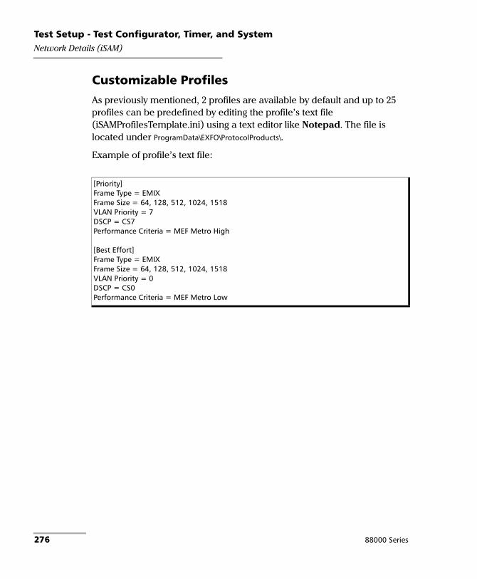
Test Setup - Test Configurator, Timer, and SystemNetwork Details (iSAM)
Customizable Profiles
As previously mentioned, 2 profiles are available by default and up to 25 profiles can be predefined by editing the profile’s text file (iSAMProfilesTemplate.ini) using a text editor like Notepad. The file is located under ProgramData\EXFO\ProtocolProducts\.
Example of profile’s text file:
[Priority]Frame Type = EMIXFrame Size = 64, 128, 512, 1024, 1518VLAN Priority = 7DSCP = CS7Performance Criteria = MEF Metro High
[Best Effort]Frame Type = EMIXFrame Size = 64, 128, 512, 1024, 1518VLAN Priority = 0DSCP = CS0Performance Criteria = MEF Metro Low
276 88000 Series

Test Setup - Test Configurator, Timer, and SystemNetwork Details (iSAM)
Each profile entry has the following parameters.
Profile Name: 1 to 16 characters. All ASCII characters from 32 to 126 decimal are supported.
Frame Type: Enter Fixed or EMIX. When the frame type is missing from a profile, EMIX is used.
Frame Size (see Frame Size on page 273 for possible values); when the frame size is missing from a profile, default value(s) is used: For Fixed: Enter a unique frame size. For EMIX: Enter 2 to 8 frame sizes with a comma between each entry.
VLAN Priority1 (optional): Enter the priority number.
DSCP1 (optional): Enter either the DSCP name or its binary value.
Performance Criteria1: Enter the name of the performance criteria. When the Performance Criteria is missing from a profile or is not available from the user profile file, the User Performance criteria is used.
When a parameter is missing from a profile, the default value of the missing parameter is used.
The value of a parameter is validated to ensure it is within the supported range; otherwise the profile entry is unsupported.
If the profile file contain more than 25 profiles, only the first 25 valid profiles are retained.
1. See Classification on page 274 for possible values.
Power Blazer 277

Test Setup - Test Configurator, Timer, and SystemNetwork Details (iSAM)
Customizable Performance Criteria
As previously mentioned, factory performance criteria are available and up to 25 performance criteria can be defined by editing the performance criteria text file (iSAMPerformanceCriteriaTemplate.ini) using a text editor like Notepad. The file is located under ProgramData\EXFO\ProtocolProducts\.
Example of performance criteria’s text file:
Each profile entry has the following parameters:
Performance Criteria Name: 1 to 16 characters. All ASCII characters from 32 to 126 decimal are supported.
Frame Delay (FD) Threshold: 0.001 ms (0.005 ms for 10M) to 8000 ms.
Inter-Frame Delay (IFDV) Threshold: 0.001 ms (0.005 ms for 10M) to 8000 ms.
Frame Loss Ratio (FLR) Threshold: 0.00 % to 5.00 %.
If the threshold value for a parameter is not defined, it is considered as disabled (as in the example above for IFDV =).
The value of a parameter is validated to ensure it is within the supported range; otherwise the performance criteria entry is unsupported.
[MEF Metro High]FD = 10IFDV = 3FLR = 0.01
[MEF Metro Med]FD = 20IFDV = 8FLR = 0.01
[MEF Metro Low]FD = 37IFDV =FLR = 0.1
278 88000 Series

Test Setup - Test Configurator, Timer, and SystemODU Channels - Global
ODU Channels - Global From the Test menu, tap Setup, Test Configurator, tap on the test block (ODU Channels), and on the Global tab.
Note: The ODU channels global configuration applies to all channels.
Pattern
The test pattern icon next to the Pattern label indicates the status of the received pattern signal. Refer to Status Bar on page 32 for more information.
No Pattern Analysis (Live) check box when cleared (default), monitors the received traffic pattern. For live traffic, the No Pattern Analysis (Live) check box should be selected as the traffic is a live pattern thus there is no analysis of pattern loss and bit error.
Pattern sets the test pattern that will be generated: PRBS31 (default) or NULL Client (0000).
Invert check box, when selected (cleared by default), inverts the test pattern meaning that every 0 will be changed for 1 and every 1 for 0. For example, the pattern 1100 will be sent as 0011.
Power Blazer 279

Test Setup - Test Configurator, Timer, and SystemODU Channels - Global
Bit Error
Pass/Fail Verdict allows enabling bit-error-rate pass/fail verdict by selecting either Bit Error Count or Bit Error Rate. The default value is Disabled.
BER Threshold allows entering the threshold Count or Rate value that will be used to declare the pass/fail verdict.
For Count, enter the maximum bit error count allowed before declaring a fail verdict: 0 (default) to 999999.
For Rate, enter the maximum bit error rate allowed before declaring a fail verdict: 1.0E-14 to 1.9E-01. The default value is 1.0E-12.
Service Disruption
The Service Disruption Time (SDT) corresponds to the duration associated to a defect that occurred in the network. For example a disruption that occurs during a network switching from the active channels to the backup channels or vice versa.
Disruption Monitoring check box when selected (disabled by default) enables the disruption time measurements. However, the measurement will only start if the test is already started, or when the test is started.
Note: Clearing the Disruption Monitoring check box will stop the measurement without clearing the results. The disruption monitoring is automatically stopped without clearing results when the test is stopped. However, starting the test again while the Disruption Monitoring check box is selected will reset the results before restarting.
Note: The service disruption measurements are cleared when changing the criteria.
280 88000 Series

Test Setup - Test Configurator, Timer, and SystemODU Channels - Global
Defect allows choosing on which layer and defect the service disruption time test will be performed. Choices depend on the selected test path.
Note: The Service Disruption Time measurement supports a parent defect approach where the SDT measurement is triggered when the selected defect or a higher defect in the signal structure hierarchy is detected.
No Defect Time (ms) represents the period without any defects before stopping SDT measurement: 0.005 ms to 2000 ms (default is 300 ms).
Pass/Fail Verdict check box when selected (cleared by default) enables service disruption pass/fail verdict and allows setting the threshold value.
SDT Threshold (ms) allows entering the SDT threshold value that will be used to declare the pass/fail verdict: 0.001 to 299999.999 ms (default is 50 ms).
Layer Defect
ODUk LOFLOM, AIS, OCI, LCK, BDI, BIP-8, BEI
OPUk AIS, CSF
Power Blazer 281

Test Setup - Test Configurator, Timer, and SystemODU Channels - Global
Channel Summary
Channel ID / Type table indicates each channel number with its ODU mapping type.
Payload Type indicates the mapped ODU payload type.
Quantity of Channels indicates the number of channels part of the test.
Unused Capacity indicates the number of tributary slot not used; either configured as background traffic or Unallocated.
Modify Trib Slots/Channels
Channel ID selects a channel number highlighting the tributary slots composing this channel. Alternatively, selecting a channel from the table on the right (TX, RX, or TX = RX tab) also selects a channel number.
Tributary Port indicates the tributary port number associated to the channel number.
Payload Type indicates the payload type for the mapped OPU.
RX, TX, or TX = RX tab (table on the right) displays the tributary slot assignments per channel for either RX, TX, or both RX and TX (TX=RX) and allows selecting tributary slots to be assigned/unassigned; see Assign/Unassign/Mode for more information.
Each tributary slot displays its number (left top corner) and channel number (middle); the channel number is replaced by B or U indicating respectively if the tributary slot carries background traffic or is configured as Unallocated.
282 88000 Series

Test Setup - Test Configurator, Timer, and SystemODU Channels - Global
The following table indicates the number of tributary slots per channel:
The table provides a status for each channel using visual indication as follows:
TX = RX check box, when selected, allows using the same tributary slot configuration for both TX and RX.
RX Structure Match is a live status indicating if the tributary slot/channel configuration is matching the received signal. Only configured channels are considered during the validation. RX Structure Match is displayed using different background colors as follows:
For... Mapped into... Tributary slot per channel
ODU3 OPU4 31
ODU2 OPU4 8
ODU1 OPU4 2
ODU0 OPU4 1
Background Color Description
White Tributary slot using background traffic (B) or Unallocated (U).
Orange Tributary slot(s) assigned for the selected channel.
Gray Tributary slot(s) assigned.
Background Color Description
Green Configured structure is matching the received signal.
Power Blazer 283

Test Setup - Test Configurator, Timer, and SystemODU Channels - Global
Channel Assignation Status
The table provides a list of each channel ID, its ODU type, and the TX/RX assignment status. TX/RX indicates either Assigned when all tributary slot are selected for this channel or the number of assigned tributary slot over the total number of tributary slots for this channel. TX/RX status must be Assigned for all channels in order to complete the tributary slots/channels configuration. Channel are sorted by their ascending ID by default, it is possible to sort ascending/descending and by Type, RX, or TX column by clicking in the desired column title.
Note: ODU0 type mapping is selected by default for all channels when the test is created. To change the ODU type mapping, use the Del Ch or Delete All button then use the Add Ch button to select an other ODU type.
Edit Ch ID button selects a new channel ID from available list.
Add Ch button allows adding new channels.
Channel ID is the channel ID to be added. Subsequent channel ID are selected then assigned, skipping channel ID already assigned, when adding more than one channel at once.
ODU Type is the ODU mapping type: ODU0, ODU1, ODU2, or ODU3. It is possible to have different ODU types when the OTN-MIX-MAPPING software option is enabled; otherwise all channels must have the same ODU type.
Quantity is the number of channel to be added.
Red Configured structure is not matching the MSI received signal or could contain an unsupported mapping (for example Unallocated).
Gray Impaired signal is preventing RX structure decoding (for example when a LOS alarm is detected).
Background Color Description
284 88000 Series

Test Setup - Test Configurator, Timer, and SystemODU Channels - Global
Del Ch button removes the selected channel.
Delete All button removes all channels.
Assign / Unassign / Mode
To assign or unassign tributary slots:
1. From the Channel Assignation Status table, select a channel.
2. Select either Assign or Unassign.
3. From the tributary slot matrix on the right, select a tributary slot; tributary slots are assigned/unassigned as follows according to the selected Mode:
Mode Description
Tributary Slot Assigns/unassigns a single tributary slot.
Channel Assigns/unassigns all tributary slots for a specific channel. After selecting a first tributary slot, subsequent tributary slots are automatically assigned/unassigned if the channel contains more than one tributary slot.
All Channels Assigns/unassigns all tributary slots to/from a channel and this is repeated for all channels. After selecting the first tributary slot, subsequent tributary slots are automatically assigned/unassigned if the channel contains more than one tributary slot. This is repeated for all channels in order.
Power Blazer 285

Test Setup - Test Configurator, Timer, and SystemODU Channels - Global
Copy RX MSI allows automatic configuration of the Channel to Trib Slot that matches the system under test configuration. A warning message is displayed when the RX test structure is either:
Unsupported: An unsupported ODU channel is received (for example Unallocated). The unsupported ODU channels are configured as background traffic.
Invalid: Impaired signal is preventing RX structure decoding (for example when a LOS alarm is detected). The RX MSI structure cannot be copied.
Restore Multi-Channel OTN Defaults
Reverts the current test application to its default factory settings.
286 88000 Series

Test Setup - Test Configurator, Timer, and SystemRemote Details (iSAM)
Remote Details (iSAM) The remote block automatically scans the remote modules for DTS and Remote Loopback modes and allows the selection of the remote module that is used to loop back the traffic via Smart Loopback or EtherSAM in Dual Test Set (DTS) mode for simultaneous bidirectional results. The number module available for remote connection is displayed. If the connection with the remote module is not manually established, the remote connection process is automatically performed when starting the test.
From the Test menu, tap Setup, Test Configurator, and the More button from the Remote block.
Note: Not available with Manual Loopback remote operation mode.
For both DTS and Remote Loopback Operation Modes
Discovered Remotes
The modules are discovered dynamically and listed with their Name, IP address, Status, Connection, and Preferred information. Name and Status are only available for remote 88000 Series, and 85100G modules. Only modules from the same subnet are automatically discovered. To access a module from a different subnet, use the Add button.
Power Blazer 287
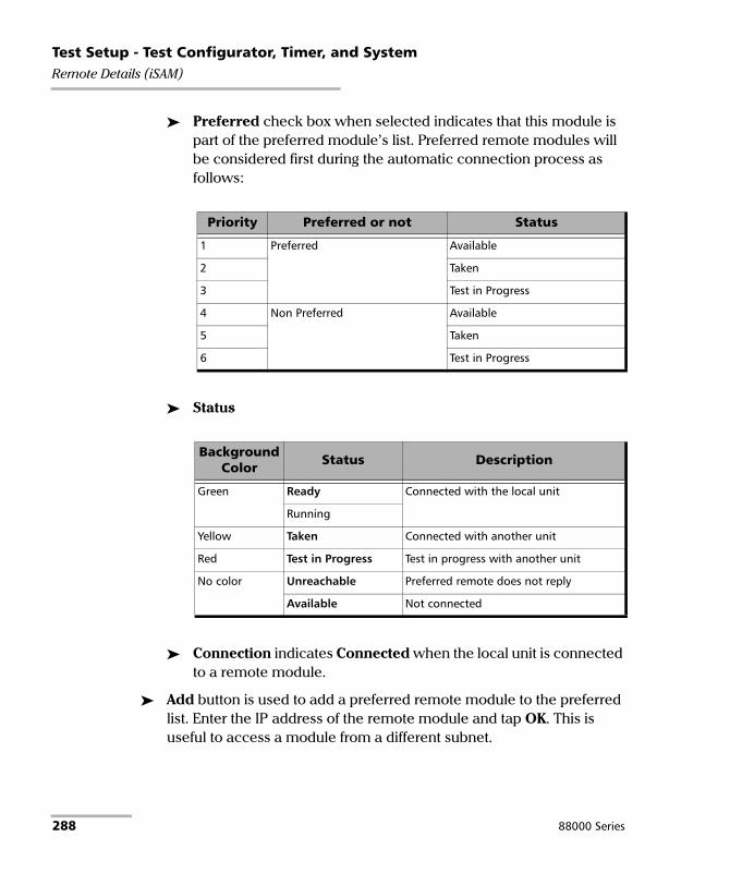
Test Setup - Test Configurator, Timer, and SystemRemote Details (iSAM)
Preferred check box when selected indicates that this module is part of the preferred module’s list. Preferred remote modules will be considered first during the automatic connection process as follows:
Status
Connection indicates Connected when the local unit is connected to a remote module.
Add button is used to add a preferred remote module to the preferred list. Enter the IP address of the remote module and tap OK. This is useful to access a module from a different subnet.
Priority Preferred or not Status
1 Preferred Available
2 Taken
3 Test in Progress
4 Non Preferred Available
5 Taken
6 Test in Progress
Background Color Status Description
Green Ready Connected with the local unit
Running
Yellow Taken Connected with another unit
Red Test in Progress Test in progress with another unit
No color Unreachable Preferred remote does not reply
Available Not connected
288 88000 Series

Test Setup - Test Configurator, Timer, and SystemRemote Details (iSAM)
For Remote Loopback Operation Mode
Loop-Up button establishes the connection with the selected remote module and sets the remote module into Smart Loopback test application.
Following a successful loop-up, the IP address of the remote module will be used as the destination IP address for the test.
Overtake button manually establishes the connection with the remote module and set the remote module into Smart Loopback test application. Available when the status is Taken or Test in Progress with another unit. A confirmation is required to overtake a module.
Loop-Down button ends the connection between the local and the remote modules.
For DTS Operation Mode
Connect button manually establishes the connection with the selected remote module and sets the remote module into DTS EtherSAM test application.
Following a successful connection, the IP address of the remote module will be used as the destination IP address for the test.
Overtake button manually establishes the connection with the remote module and set the remote module into DTS EtherSAM test application. Available when the status is Taken or Test in Progress with another unit. A confirmation is required to overtake a module.
Following a successful connection, the IP address of the remote module will be used as the destination IP address for the test.
Disconnect button, available once the connection with the remote module is established, terminates the connection with the remote module. Available when the status is Ready.
Power Blazer 289

Test Setup - Test Configurator, Timer, and SystemRemote Details (iSAM)
For Manual Loopback Operation Mode
MAC, available with layer L2, allows entering the destination MAC address of the remote.
IP, available with L3/L4, allows entering the destination IP address of the remote.
Resolved MAC address status, available with L3/L4, indicates:
Resolving when the ARP process is resolving.
Resolved when the ARP process is resolved.
Failed when the ARP process failed.
Quick Ping, available with layer L3/L4, tests if the destination IP address can be reached. A message displays if the ping attempt is Successful or Failed.
290 88000 Series

Test Setup - Test Configurator, Timer, and SystemRFC 2544 - Global
RFC 2544 - Global From the Test menu, tap Setup, Test Configurator, tap on the RFC 2544 block, and on the Global tab.
Dual Test Set
Dual Test Set (DTS) check box when selected (cleared by default) enables RFC 2544 Dual Test Set. Once Dual Test Set is enabled, use the Discover Remote button to select a remote unit. Not available in Dual Port topology.
Note: It is also possible using the Discover Remote button to connect to a remote module and automatically enable Dual Test Set. For more details, refer to Discover Remote Button on page 718.
Disconnected indicates that there is no connection established with a remote module.
Connected indicates that the connection is established with a remote module.
Discover Remote button allows discovering remote module supporting Remote Loopback and/or Dual Test Set. For more details, refer to Discover Remote Button on page 718.
Global Options
Flow Direction allows the selection of the traffic direction as follows:
TX to RX for Single Port topology.
Port #1 to Port P2, Port #2 to Port #1, and Bidirectional for Dual Port topology.
Local to Remote, Remote to Local, and Bidirectional for Dual Test Set.
Power Blazer 291

Test Setup - Test Configurator, Timer, and SystemRFC 2544 - Global
Coupled is available with Bidirectional flow direction. When the Coupled check box is:
Cleared, the decision to increase or decrease the TX Rate of the next iteration is taken independently per direction.
Selected, the decision to increase or decrease the TX Rate of the next iteration is taken commonly for both directions.
Rate Unit determines the unit used to display the rate values: %, Mbit/s, or Gbit/s.
Pass/Fail Verdict check box when selected (default) enables the use of the pass/fail verdict.
Subtests and Estimated Time
Subtests allows enabling the Throughput, Back-to-Back, Frame Loss, and Latency subtests individually.
Estimated Time (H:MM) indicates the estimated time required to complete each subtest at best conditions. The total estimated time to complete all subtests is also displayed.
Frame Distribution
Frame Distribution allows selecting either RFC 2544 (default) or User Defined distribution.
Quantity is only available when User Defined is selected and allows selecting the number of frames, from 1 to 10 (7 by default), in the distribution.
292 88000 Series

Test Setup - Test Configurator, Timer, and SystemRFC 2544 - Global
Frame Size (Bytes): For RFC 2544 distribution, gives predefined frame size distribution values. For User Defined distribution, enter up to seven frame size values.
The following table lists each component that may affect the minimum size value.
Restore RFC 2544 Defaults
Reverts the configured parameters to their default values.
Distribution Frame Size
RFC 2544 64a,128, 256, 512, 1024, 1280, and 1518
a. The minimum frame size will be adjusted according to the frame structure andcomponents selected.
User Defined 64a to 16000b
b. The maximum frame size is limited to 10000 for 10/100/1000Mbps electricalinterface.
Component Description
VLAN 4 bytes per VLAN tag (up to 3 VLAN tags)
LLC and SNAP Headers 8 bytes
IPv4 20 bytes
IPv6 40 bytes
Using DTS 4 bytes
Power Blazer 293

Test Setup - Test Configurator, Timer, and SystemRFC 2544 - Subtests
RFC 2544 - Subtests From the Test menu, tap Setup, Test Configurator, tap on the RFC 2544 block. and on the Subtests tab.
Allows the configuration of each enabled subtest.
Throughput
The objective of this test is to find the throughput of the device under test for which there is no frame loss. Starting at the specified maximum rate (Max. Rate), the rate converges towards the highest throughput without frame loss. The search is done with a halving/doubling method until a final value is reached. The test performs the number of trials defined (Trials). The throughput measurement is validated by the number of times specified (Validations) for the predefined duration (Trial Duration). The Accuracy and Acceptable Errors specify how precise the result must be. The test is performed for each defined frame size.
294 88000 Series

Test Setup - Test Configurator, Timer, and SystemRFC 2544 - Subtests
Max. Rate is the maximum rate the test should begin with, in terms of a percentage of the line rate (%), Mbit/s, or Gbit/s. For Dual Test Set Max. Rate is configurable for both local (L) and remote (R) directions. For Dual Port topology, Max. Rate is configurable for both port directions.
Trial Duration is the time for each trial in minutes:seconds: 1 second (default) to 30 minutes.
Trials is the number of times the throughput test will be generated: 1 (default) to 50 trials.
Interface Speed
Max. Rate
% Mbit/s Gbit/s
10 Mbit/s 0.0050 to 100.0000a
a. Default value.
0.00001 to 10.000a Not Applicable
100 Mbit/s 0.0050 to 100.0000a 0.0001 to 100.000a Not Applicable
1000 Mbit/s 0.0050 to 100.0000a 0.001 to 1000.00a 0.000001 to 1.000a
10G LAN 0.0050 to 100.0000a 0.01 to 10000.000a 0.00001 to 10.000a
10G WANb
b. The maximum value for 10G WAN may be lower depending on the frame size. Themaximum value will be adjusted for each frame size.
0.0005 to 92.8571a 0.01 to 9285.71a 0.00001 to 9.28571a
25G 0.0050 to 100.0000a 1.25 to 25000.00a 0.00125 to 25.00000a
40G 0.0050 to 100.0000a 2.00 to 40000.0a 0.00200 to 40.0000a
100G 0.0050 to 100.0000a 5.00 to 100000.0a 0.00500 to 100.0000a
200G 0.0050 to 100.0000a 10.0 to 200000.0a 0.0100 to 200.0000a
400G 0.0050 to 100.0000a 20.0 to 400000.0a 0.0200 to 400.0000a
Power Blazer 295
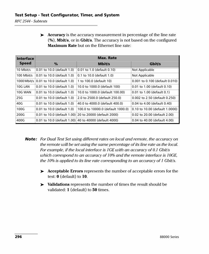
Test Setup - Test Configurator, Timer, and SystemRFC 2544 - Subtests
Accuracy is the accuracy measurement in percentage of the line rate (%), Mbit/s, or in Gbit/s. The accuracy is not based on the configured Maximum Rate but on the Ethernet line rate:
Note: For Dual Test Set using different rates on local and remote, the accuracy on the remote will be set using the same percentage of its line rate as the local. For example, if the local interface is 1GE with an accuracy of 0.1 Gbit/s which correspond to an accuracy of 10% and the remote interface is 10GE, the 10% is applied to its line rate corresponding to an accuracy of 1 Gbit/s.
Acceptable Errors represents the number of acceptable errors for the test: 0 (default) to 10.
Validations represents the number of times the result should be validated: 1 (default) to 50 times.
Interface Speed
Max. Rate
% Mbit/s Gbit/s10 Mbit/s 0.01 to 10.0 (default 1.0) 0.01 to 1.0 (default 0.10) Not Applicable
100 Mbit/s 0.01 to 10.0 (default 1.0) 0.1 to 10.0 (default 1.0) Not Applicable
1000 Mbit/s 0.01 to 10.0 (default 1.0) 1 to 100.0 (default 10) 0.001 to 0.100 (default 0.010)
10G LAN 0.01 to 10.0 (default 1.0) 10.0 to 1000.0 (default 100) 0.01 to 1.00 (default 0.10)
10G WAN 0.01 to 10.0 (default 1.0) 10.0 to 1000.0 (default 100.00) 0.01 to 1.00 (default 0.1)
25G 0.01 to 10.0 (default 1.0) 2.0 to 2500.0 (default 250.0) 0.002 to 2.50 (default 0.250)
40G 0.01 to 10.0 (default 1.0) 40.0 to 4000.0 (default 400.0) 0.04 to 4.00 (default 0.40)
100G 0.01 to 10.0 (default 1.0) 100.0 to 10000.0 (default 1000.0) 0.10 to 10.00 (default 1.0000)
200G 0.01 to 10.0 (default 1.00) 20 to 20000 (default 2000) 0.02 to 20.00 (default 2.00)
400G 0.01 to 10.0 (default 1.00) 40 to 40000 (default 4000) 0.04 to 40.00 (default 4.00)
296 88000 Series

Test Setup - Test Configurator, Timer, and SystemRFC 2544 - Subtests
Back-to-Back
The objective of this test is to find the maximum number of frames that can be sent at maximum throughput without frame loss. A burst of frames (Burst Time) is sent with minimum inter-frame gaps to the device under test and the number of forwarded frames is counted. If the count of transmitted frames is equal to the number of forwarded frames, the length of the burst is increased and the test is rerun. If the number of forwarded frames is less than the number of transmitted frames, the length of the burst is reduced and the test is rerun. The Back-to-Back value is the number of frames in the longest burst that the Device Under Test (DUT) can handle without the loss of any frames. The test performs the number of defined trials (Trials). The Accuracy and Acceptable Errors settings specify how precise that result must be. The test is performed for each defined frame size.
Burst Time is expressed in seconds: 1 (default) to 5 seconds.
Trials represents the number of times the Back-to-Back test will be generated: 1 (default) to 100 trials.
Accuracy (Frames) is the accuracy measurement value in frames: 1 (default) to 50 frames.
Acceptable Errors represents the number of acceptable errors for the test: 0 (default) to 10.
Bursts represents the number of burst that will be generated: 1 (default) to 10.
Power Blazer 297

Test Setup - Test Configurator, Timer, and SystemRFC 2544 - Subtests
Frame Loss Configuration
The objective of this test is to find the percentage of frames that are lost due to lack of resources. Starting at the specified maximum rate (Max. Rate), the test is performed for a specific frame size and for the specified duration (Trial Duration). The test is repeated by decreasing the rate by the specified granularity (Granularity), then the test is repeated again until there are two successive trials in which no frames are lost. The test is performed for the defined number of trials (Trials). The test is performed for each defined frame size.
Max. Rate is the maximum rate the test should begin with, in terms of a percentage of the line rate (%), Mbit/s, or Gbit/s. The accepted values are as shown in the Max. Rate table on page 295. For Dual Test Set, Max. Rate is configurable for both local (L) and remote (R) directions. For Dual Port topology, Max. Rate is configurable for both port directions.
Trial Duration represents the time value for each trial in minutes:seconds: 1 second to 30 minutes (default is 00:01).
Trials represents the number of times the test will be generated: 1 (default) to 50 trials.
Granularity corresponds to the percentage interval between each throughput value used for the test: 1 % to 10 % (RFC) - (default). For example, 10 % granularity means that the test will be performed for 100 %, 90 %, 80 %... of the rate value.
298 88000 Series

Test Setup - Test Configurator, Timer, and SystemRFC 2544 - Subtests
Latency Configuration
The objective of the test is to measure the time required for the frame to go through the device under test and return back to source. Starting by sending a stream of frames for the predefined duration (Trial Duration) and throughput (Max. Rate) at a particular frame size, an identifying dependent tag is included in one frame. The time at which this frame is transmitted is recorded (timestamp A). When the tagged frame comes back, the time is recorded again (timestamp B) and the Latency result is: timestamp B - timestamp A. The test is repeated for the defined number of times (Trials) and the average result is calculated. The test is performed for each defined frame size.
Trial Duration represents the time value for each trial in “minutes:seconds”: 1 second (default) to 2 minutes.
Trials represents the number of times the test will be generated: 1 (default) to 50 trials.
Copy From Throughput check box, when selected (default), uses the Throughput subtest results max rate value for each corresponding frame size. When the check box is cleared, it is possible to set the Max. Rate by tapping on the Config. per Frame Size button.
Margin %, available when Copy From Throughput check box is selected, decreases the max rate value(s) from the Throughput subtest by a value corresponding to the percentage of the line rate specified: 0 (default) to 10 percent.
Power Blazer 299

Test Setup - Test Configurator, Timer, and SystemRFC 2544 - Subtests
Measurement Mode, available with Dual Test Set, allows the selection of the latency measurement mode for rates 10M to 10GE: Round-Trip (default) or One-Way. For other rates, the measurement mode is set to Round-Trip.
Synchronization with an external 1PPS clock is required to perform One-Way Latency measurement. One-Way Latency is only possible when both the local and remote 1PPS signal clocks are valid. The following alarms are available with One-Way Latency measurement mode.
LOPPS-L and LOPPS-R (Loss Of Pulse Per Second - Local/Remote) are declared when either no pulse is received or when no pulse is received within 1 second ± 6.6 μs after the previous pulse. LOPPS-R is only monitored once the DTS connection is established.
Config. per Frame Size is available when the Copy From Throughput check box is cleared and allows setting the Max. Rate for each frame size. For Dual Test Set the Max. Rate is configurable for both local (L) and remote (R) directions. For Dual Port topology, Max Rate is configurable for both port directions.
All Frames check box when selected (cleared by default) allows entering the maximum rate that will be applied to all frame sizes.
300 88000 Series

Test Setup - Test Configurator, Timer, and SystemRFC 2544 - Subtests
Thresholds Button
Note: For Dual Test Set, thresholds are configurable for Local to Remote and Remote to Local directions at the exception of Round-Trip Latency Threshold for which the value is unique. For Dual Port topology, thresholds are configurable for both port directions.
Throughput Threshold sets the threshold1 value used to declare a pass/fail verdict for all frame sizes when applicable. The range is as follows:
Back-to-Back Threshold sets the threshold1 value in percentage of frames per burst to declare a pass/fail verdict for all frames sizes when applicable.
1. The verdict is PASS when the received/measured value is greater or equal to the threshold value.
Interface Speed
Max. Rate
% Mbit/s Gbit/s
10 Mbit/s 0.0 to 100.0a
a. Defalut value.
0.0 - 10.0a Not Applicable
100 Mbit/s 0.0 to 100.0a 0.0 - 100.0a Not Applicable
1000 Mbit/s 0.0 to 100.0a 0.0 - 1000.0a 0.0 - 1.0a
10G LAN 0.0 to 100.0a 0.0 - 10000.0a 0.0 - 10.0a
10G WANb
b. The maximum value for 10G WAN may be lower depending on the frame size. Themaximum value will be adjusted for each frame size.
0.0 to 92.857a 0.0 - 9285.7a 0.0 - 9.2857a
25G 0.0 to 100a 0.0 - 25000a 0.0 - 25a
40G 0.0 to 100.0a 0.0 - 40000.0a 0.0 - 40.0a
100G 0.0 to 100.0a 0.0 - 100000.0a 0.0 - 100.0a
200G 0.0 to 100.0a 0.0 - 200000.0a 0.0 - 200.0a
400G 0.0 to 100.0a 0.0 - 400000.0a 0.0 - 400.0a
Power Blazer 301

Test Setup - Test Configurator, Timer, and SystemRFC 2544 - Subtests
Frame Loss Threshold (%) sets the threshold1 value of frame loss for all frame sizes when applicable.
Latency Threshold / Round-Trip Latency Threshold sets the threshold value as the maximum delay in ms or μs for all frame sizes when applicable. For Dual Test Set, only available with Round-Trip Latency Measurement Mode (see Latency Configuration on page 299).
One-Way Latency Threshold, available for Dual Test Set with One-Way Latency Measurement Mode (see Latency Configuration on page 299), sets the maximum one-way latency value in millisecond, allowed for all frame sizes.
Latency Unit allows selecting either ms or μs as the reference unit for the Latency Threshold.
1. The verdict is PASS when the received/measured value is lower or equal to the threshold value.
302 88000 Series

Test Setup - Test Configurator, Timer, and SystemRFC 6349
RFC 6349 From the Test menu, tap Setup, Test Configurator, and the RFC 6349 block.
Connection
Operation Mode allows the selection of the test operation mode: Dual Test Set (DTS) or EXFO|Worx Interop.
The connection is graphically displayed with its status as follows:
Operation Mode Status Description
Dual Test Set Disconnected No connection established with a remote module.
NAT LAN/WAN, WAN IP
Connection established with a remote module.
NAT LAN/WAN and WAN IP indicate presence of NAT (Network Address Translation) router. The NAT router is automatically detected and graphically displayed with LAN/WAN indication as well as the WAN IP address when the Power Blazer is behind a NAT router.
When there is a NAT at the Remote site, it is required to create the following rules on this NAT router: 1- for UDP/TCP port 62819 to allow DTS communication.2- for the defined TCP port (see TCP Port on page 304).
EXFO|Worx Interop
Disconnected Verifier not detected (not reachable, invalid IP, or invalid TCP port).
Ready or Running
Verifier detected, either running (remote unit locked) or ready to perform a test.
The detection of NAT (Network Address Translation) router presence is automatically detected and graphically displayed. The WAN IP address is also displayed when the module is behind a NAT router.
Busy Verifier busy with another client (locked).
Power Blazer 303

Test Setup - Test Configurator, Timer, and SystemRFC 6349
Discover Remote button, available with Dual Test Set, allows discovering remote modules supporting Dual Test Set. For more details, refer to Discover Remote Button on page 718.
Direction allows the selection of the traffic direction: Local to Remote, Remote to Local, and Bidirectional (default).
Remote IP Address, available with EXFO|Worx Interop, is either the remote IP address of the verifier or the WAN IP address when the verifier is behind a NAT router.
TCP Port is the port used by the server located at the remote side: 1 to 65535 (excluding 62819 that is used for DTS connection), default is 50201. The port forwarding rule for the defined TCP port must be created on the NAT router when the remote is behind a NAT.
Parameters
Multiple Connections check box when selected (default) indicates that the applicable TCP Throughput phases are performed with multiple connections; otherwise TCP Throughput phases are performed within a single connection. For 40/100GE rate, this check box is selected and the Window Size Target per Connection can be used to set the target window.
Window Size Target per Connection, available for 40/100GE rate, selects the target window per connection: 1 MiB, 4 MiB, 8 MiB, 16 MiB (default), and 32 MiB.
CIR
The Local-to-Remote CIR and Remote-to-Local CIR represent the Committed Information Rate of the Ethernet Service under test: 1.0 Mbit/s to Line Rate. The CIR is not used to actually transmit frames at this rate but to calculate a Bandwidth Delay Product (BDP) which in turn is used to set the Max Window Size of the TCP connections.
Rate Unit determines the unit used to display the rate values: Mbit/s (default) or Gbit/s.
304 88000 Series

Test Setup - Test Configurator, Timer, and SystemRFC 6349
TOS/DS (IPv4) allows entering an hexadecimal value, 00 (default) to FF. Changing the IP TOS/DS value will affect the TOS/DS Config settings and vice versa.
MTU
Max MTU (bytes) determines the Maximum Transfer Unit (MTU) to use when the client is generating TCP traffic toward the server: from 1080 to 1500 bytes (default).
Path MTU Discovery check box when selected (default) allows performing a Packetization Layer Path MTU Discovery phase.
Window Sweep
Window Sweep check box when selected (default) allows performing the Window Sweep phase.
Duration (per step) is the duration of the Window Sweep phase per direction and per Window tested: 30 seconds (default) to 5 minutes.
TCP Throughput
Duration is the duration of the TCP Throughput phase per direction: 1 minute (default) to 30 days.
Pass/Fail Verdict check box when selected (default) enables the use of the pass/fail verdict.
Threshold (% of ideal) allows entering the TCP Throughput as a percentage of the Ideal L4 Throughput that will be used to declare the pass/fail verdict for both directions: 0 to 100 %; default is 95 %.
Restore RFC 6349 Defaults
Reverts the configured parameters to their default values.
Power Blazer 305
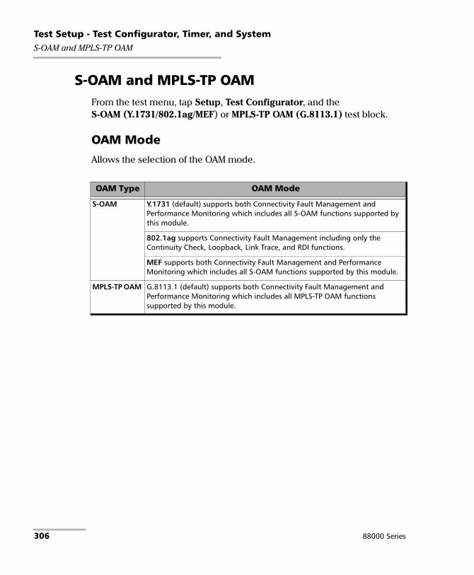
Test Setup - Test Configurator, Timer, and SystemS-OAM and MPLS-TP OAM
S-OAM and MPLS-TP OAM From the test menu, tap Setup, Test Configurator, and the S-OAM (Y.1731/802.1ag/MEF) or MPLS-TP OAM (G.8113.1) test block.
OAM Mode
Allows the selection of the OAM mode.
OAM Type OAM Mode
S-OAM Y.1731 (default) supports both Connectivity Fault Management and Performance Monitoring which includes all S-OAM functions supported by this module.
802.1ag supports Connectivity Fault Management including only the Continuity Check, Loopback, Link Trace, and RDI functions.
MEF supports both Connectivity Fault Management and Performance Monitoring which includes all S-OAM functions supported by this module.
MPLS-TP OAM G.8113.1 (default) supports both Connectivity Fault Management and Performance Monitoring which includes all MPLS-TP OAM functions supported by this module.
306 88000 Series

Test Setup - Test Configurator, Timer, and SystemS-OAM and MPLS-TP OAM
S-OAM and MPLS-TP OAM Responder
S-OAM Responder or MPLS-TP OAM Responder check box when selected (default) allows responding to LBM, LTM, DMM, LMM, and SLM valid messages (test running or not). LTM and SLM are only available with Ethernet OAM. Traffic statistics are also monitored (refer to Responder on page 607).
For S-OAM: A valid message must have its source MAC address matching the Peer MEP MAC address, destination MAC address matching either the unit port Unicast MAC address or a Multicast class 1 address, VLANs matching the unit port VLANs, and MEG/MD Level matching the local MEG/MD Level. Refer to Unicast/Multicast Addresses for Ethernet OAM on page 841 for more information.
For MPLS-TP OAM: A valid message must have its: destination MAC address matching either the unit MAC address, FF:FF:FF:FF:FF:FF, or 01:00:5E:90:00:00; VLANs matching the unit port VLANs; MPL Labels matching the local MPLS Label Stack configuration, including GAL; MEG Level matches the local MEG Level. For the Loopback function, a valid message must also have its: MEP ID of the target MEP ID TLV matching the Local MEP ID or ID Sub-Type is 0x00 (Discovery); and MEP ID and MEG ID of the requesting MEP ID TVL, if present, matching respectively the Peer MEP ID and the Local MEG ID.
Respond to... message Respond with... message
LBM LBR
LTMa
a. Only available with Ethernet OAM.
LTR
DMM DMR
LMM LMR
SLMa SLR
Power Blazer 307

Test Setup - Test Configurator, Timer, and SystemS-OAM and MPLS-TP OAM
Pass/Fail Verdict
Pass/Fail Verdict check box when selected (default) enables the use of the pass/fail verdict. A global fail verdict is declared when any of the following condition is met: Link Down alarm, Loss Continuity alarm, or any fail verdict for Frame Delay, Frame Loss, Synthetic Loss (Only applicable to Ethernet OAM), Frame Delay Failure, Frame Loss Failure, Synthetic Loss Failure (Only applicable to Ethernet OAM), Loopback Failure, or Test Failure.
Thresholds
Available with G.8113.1, Y.1731 and MEF OAM Modes when Pass/Fail verdict is enabled. The verdict is PASS when the measured value is lower or equal to the threshold value.
Frame Delay Threshold (ms) allows setting the threshold value of frame delay: 0.001 to 8000 ms (default is 50 ms).
Frame Loss Threshold (%) allows setting the threshold value of frame loss: 0.001 to 100 % (default is 10 %).
Synthetic Loss Threshold (%), available with Ethernet OAM (Y.1731 and MEF), allows setting the threshold value of Synthetic Loss: 0.001 to 100 % (default is 10 %).
308 88000 Series

Test Setup - Test Configurator, Timer, and SystemS-OAM and MPLS-TP OAM
Next HOP Router (G.8113.1)
MAC Address, available when Resolve MAC check box is cleared, allows entering the Next HOP Router MAC address: 00:00:00:00:00:00 to FF:FF:FF:FF:FF:FF, default is 01:00:5E:90:00:00. The MAC Address 01:00:5E:90:00:00 is reserved for point-to-point link and can be used when the unicast address is unknown (as per RFC-7213).
Resolve MAC check box, when selected (cleared by default), sends a request to the network to retrieve the MAC address corresponding to the selected IP address.
IP Address, available when Resolve MAC check box is selected, allows entering the Next HOP Router IP address: 0.0.0.0 to 255.255.255.255 for IPv4; default is the source IP address; ::1 to FFFF:FFFF:FFFF:FFFF:FFFF:FFFF:FFFF:FFFF for IPv6, default is 2001::.
Local Parameters
MEG ID (Y.1731 and G.8113.1), the Maintenance Entity Group Level identification, allows defining a 13-bytes MEG ID value/message to be generated (default value is EXFO MEG ID). Values should be ASCII suitable characters including the ITU T.50 Characters on page 46.
Padding allows the selection of the character (Null or Space) to used for remaining byte values.
MAID (802.1ag and MEF) is a 45 bytes Maintenance Association Identification that is divided into two parameters:
Domain ID is an optional domain identification text field (0 byte (Domain ID not present), up to 44 bytes minus the MA Name field length) set to EXFO Domain ID by default.
MA Name (Short MA Name) is a Maintenance Association Name text field set to EXFO MA Name by default. The length of the MA Name field is from 1 to either 44 bytes minus the Domain ID field length when Domain ID is present or 45 bytes when not present.
Power Blazer 309

Test Setup - Test Configurator, Timer, and SystemS-OAM and MPLS-TP OAM
MEG Level (Y.1731, MEF, and G.8113.1) is the Maintenance Entity Group Level configurable from 0 to 7 (default).
MD Level (802.1ag) is the Maintenance Domain Level and is configurable from 0 to 7 (default).
MEP ID is the Maintenance Entity Group End Point Identification configurable from 0x0001 (default) to 0x1FFF.
Peer MEP Parameters
MAC Address, available with S-OAM Mode, allows entering the unique Media Access Control (MAC) address of the peer MEP (default is 00:00:00:00:00:00).
MEP ID is the Maintenance Entity Group End Point Identification configurable from 0x0001 (default) to 0x1FFF.
OAM Quick Ping verifies the bidirectional connectivity with the peer MEP. The Successful message is reported when at least one of three attempts has been successful otherwise Failed is reported.
Continuity Check
CC Function check box when selected (default) allows transmitting and monitoring CCM frames.
The following parameters are only configurable when the CC Function check box is cleared.
Address Type, available with S-OAM Mode, defines the destination address type of the CCM frames: Unicast or Multicast (default).
Priority, available with S-OAM Mode or when VLAN is enabled (see VLAN on page 268), allows selecting the VLAN user priority: 0 to 7 (default). Refer to VLAN ID and Priority on page 842 for more information.
310 88000 Series

Test Setup - Test Configurator, Timer, and SystemS-OAM and MPLS-TP OAM
Drop Eligible, available with S-OAM Mode or when VLAN is enabled (see VLAN on page 268), is set to No (no frames will be dropped when congestion occurs) and is not configurable.
Period determines the transmission period of the CCM frame: 3.33 ms, 10 ms, 100 ms (default), 1 s, 10 s, 1 min, or 10 min.
MPLS-TP Label Stack (G.8113.1)
MPLS-TP Mode
PW (Pseudo-Wire) (default) provides an emulation of a point-to-point connection over a packet-switching network. The PW begins and ends at the LER or PE (Provider Edge).
LSP (Label Switch Path) is a path through a MPLS network, it begins and ends at LER or LSR.
Section is a segment between two adjacent LER/LSR.
Label 2 check box when selected enables the MPLS Label 2. The Label 2 check box is configurable for PW and LSP (cleared by default) and is forced cleared for Section.
Label 1 check box when selected enables the MPLS Label 1. The Label 1 check box is forced selected for PW and LSP and forced cleared for Section.
GAL check box when selected enables the Generic Associated Channel Label. The GAL check box is forced selected for LSP and Section and is configurable for PW (selected by default).
Label is configurable for Label 1 and Label 2: 16 to 1048575, default is 16. Label is not configurable for GAL and is set to 13.
TC sets the Traffic Class: 0 (default) to 7.
TTL sets the Time To Live: 1 to 255, default is 128.
Power Blazer 311

Test Setup - Test Configurator, Timer, and SystemS-OAM and MPLS-TP OAM
Test Function
Note: Test Function parameters are not configurable when the TX Enable check box is selected.
Function allows the selection of the test function to be performed.
Loopback (default) function is used to verify the bidirectional connectivity to a peer MEP (Continuous check box cleared) and to verify its capability to sustain close to line rate traffic (diagnostic test; Continuous check box selected).
Test function is used to generate a test signal and/or verify the integrity of received test signal from the peer MEP.
Frame Delay function is used to measure the round trip delay with the peer MEP.
Frame Loss function is used to measure the frame loss with the peer MEP in both directions from a single end point.
Synthetic Loss function is used to measure the frame loss with the peer MEP in both directions from a single end point using synthetic frames.
TX Enable check box when selected (cleared by default) allows transmission of frames. However the transmission will only begin when the test is started or if the test is already running. When the Continuous check box is cleared, the TX Enable check box is automatically cleared once all frames have been transmitted.
Address Type, available with S-OAM Mode, defines the destination address type of the frame: Unicast (default) or Multicast. Availability of address types depend on selected S-OAM Mode and Test Function.
Continuous check box when selected (default) specifies that the frame generation is continuous. The Continuous check box is cleared for Multicast address type.
312 88000 Series

Test Setup - Test Configurator, Timer, and SystemS-OAM and MPLS-TP OAM
Requesting MEP ID TLV (G.8113.1) check box when selected (default) determines if the Requesting MEP ID TLV is present in the LBM frame. The Requesting MEP ID TLV check box is cleared and not selectable when the Continuous check box is selected.
Priority, available with S-OAM Mode or when VLAN is enabled (see VLAN on page 268), allows selecting the VLAN user priority: 0 (default) to 7. Refer to VLAN ID and Priority on page 842 for more information.
Drop Eligible, available with S-OAM Mode or when VLAN is enabled (see VLAN on page 268), when set to Yes (DEI = 1), the transmitted frames will be dropped first on receipt when congestion occurs under test. Drop Eligible is only configurable with Unicast address type, otherwise is set to No (Default). Drop Eligible is set to No for Frame Delay, Frame Loss, and Synthetic Loss functions.
Period determines the transmission period of frames which is set to 100 ms. Period is not applicable for Multicast address type or when the Continuous check box is selected.
TX Rate (%) is the transmission rate of the LBM frame: 0.0001 to 95 % for 10M, 99.5 % for 100M, 99.95 % for 1G, 99.995 % for 10G LAN, and 92.8521 % for 10G WAN. Only available with Loopback test function when the Continuous check box is selected.
Power Blazer 313

Test Setup - Test Configurator, Timer, and SystemS-OAM and MPLS-TP OAM
Frame Size allows entering the frame size. The frame size range for Ethernet II frame format is as follows:
S-OAM Mode: 64 to 15181. The minimum frame size is adjusted according to the frame structure and parameters selected. For Frame Loss function, the frame size is not configurable and set to the minimum value.
MPLS-TP OAM Mode: Minimum and maximum values are as follows. The minimum frame size is adjusted according to the frame structure and parameters selected.
The following table lists each parameter that may affect the minimum and maximum1 frame size value.
1. For the Loopback function the maximum frame size is 16000 bytes for all rates at the exception of 10/100/1000 Mbps electrical interface which is 10000 bytes.
Test FunctionMPLS-TP Mode
PW LSP Section
Loopback 68a to 160001
a. Add 4 bytes when the GAL check box is selected.
72 to 160001 68 to 160001
Test 68 to 1522 68 to 1522 64 to 1518
Frame Delay 68ab to 1522
b. Add 2 bytes when Test ID is selected as TLV Type.
72b to 1522 68b to 1518
Frame Lossc
c. The frame size is not configurable and set to the minimum value.
68 68 64
Parameter Number of bytes to be added Apply to
802.3 SNAP 8 bytes Y.1731, MEF, G.8113.1VLAN 4 bytes per VLAN (up to 3 VLAN)
314 88000 Series

Test Setup - Test Configurator, Timer, and SystemS-OAM and MPLS-TP OAM
Note: Sending traffic with frame size >1518 in switched network may result in losing all frames.
Frame Count is the quantity of frames to be transmitted: 1 to 1000 at the exception of Frame Loss function which is 2 to 1000 (default is 10); set to 1 for Loopback function with Multicast address type; not applicable when the Continuous check box is selected at the exception of Synthetic Loss function.
TLV Type defines the TLV Type included in the frame: Data (Default), Test (Loopback (Y.1731 and G.8113.1) and Test functions), and Test ID (Frame Delay function); is set to Test for the Test function; set to Data for Synthetic Loss function; not available for Frame Loss function.
Payload, available with Data TLV Type, defines the repeating byte pattern used to fill the payload of the Data TLV: 0x00 to 0xFF (default is 0xCC).
Test Pattern, available with Test TLV Type, defines the test pattern used to fill the Test TLV: PRBS31 (default), NULL.
Test ID, available with Test ID TLV or Synthetic Loss function, defines the test ID: 0x00000000 to 0xFFFFFFFF (default is 0x00000001).
Restore Carrier Ethernet OAM Defaults
Reverts the Carrier Ethernet OAM test application to its default factory settings.
Label 2 4 bytes G.8113.1
Continuous 18 bytes for Data TLV Type21 bytes for Test TLV Type
Requesting MEP ID TLV 56 bytes
Parameter Number of bytes to be added Apply to
Power Blazer 315

Test Setup - Test Configurator, Timer, and SystemServices - Global
Services - Global From the Test menu, tap Setup, Test Configurator, tap on the services block, the Global tab, and on the General button.
General Button
The following parameters are displayed and configurable per service.
Check boxes:
The first check box (top-left) allows enabling sequentially service(s) within the limit of the link capacity when the Service Performance Test is enabled or enabling all services when the Service Performance Test is disabled.
The check boxes next to the service numbers allow enabling each service individually.
When the Service Performance Test is enabled, up to 10 services can be enabled one after the other, as long as the Total TX Rate (bandwidth) is not reached (Committed). For example, if the first service is using the full bandwidth available, then no other service can be enabled. If the first enabled service uses half bandwidth, then at least another service can be enabled using up to half bandwidth. Thus, to enable a second service, first set the CIR value within the non-used bandwidth (Available), then enable it.
When the Service Performance Test is disabled, up to 10 services can be enabled one after the other; the total TX rate is not limited.
Service Name indicates the name of each service. Tap on the Service Name button to modify the name of each service. See Services - Profile on page 320 for more information.
Direction, available with Dual Test Set or Dual Port topology, indicates respectively results for local (L) and remote (R) directions, or for both port directions.
316 88000 Series

Test Setup - Test Configurator, Timer, and SystemServices - Global
Frame Size indicates the frame size of each service. Tap on the Frame Size button to modify the frame size of each service.
Framing indicates the framing of each service. Tap on the Framing button to modify the Frame Format, Network Layer, Transport Layer, VLAN, S-OAM MEG/MD Level, and MPLS when applicable (see Modify Frame Structure from the MAC/IP/UDP on page 247).
VLAN (ID/Priority) indicates the ID and Priority of each VLAN level for each service. Tap on the VLAN button to modify the VLAN settings (see VLAN from the MAC/IP/UDP on page 247).
Addressing indicates the source and destination IP or MAC addresses for each services. Tap on the Addressing button to modify the addressing (see MAC and IP from the MAC/IP/UDP on page 247).
Batch button allows bulk configuration for services addressing. Select the check box of each configuration parameter that needs to be copied and set its parameters. From Apply To, select all services the copy applies to and tap on the Copy From to proceed.
SLA Button
The SLA parameters are displayed and configurable per service. Click on the desired column button to access the configuration settings.
See General Button on page 316 for more information on check boxes, Direction, and Service Name.
See SLA Parameters on page 325 for more information on CIR, CIR+EIR, CBS, EBS, Max Jitter, Max Latency, and Frame Loss Rate.
Power Blazer 317

Test Setup - Test Configurator, Timer, and SystemServices - Global
Total TX Rate
Note: Only available when the Service Performance Test check box is selected (see EtherSAM - Global on page 193). For Dual Test Set, the total TX rates are displayed for both Local and Remote directions.
Committed displays the total enabled TX rate (bandwidth) that will be generated by the selected service(s).
Available displays the total TX rate (bandwidth) available for traffic generation.
Global Options
Rate Unit choices are % (default), Mbit/s, and Gbit/s.
Copy Service Button
Copy Service button allows copying the services configuration to one or several services.
Copy Service allow selecting the services number from which the configuration will be copied from.
To the following Services allows selecting all services that will inherit the configuration from the selected service. An orange background represents a selected service. A service that is already enabled cannot be selected for copy.
Copy allows confirming the service configuration copy for all selected services.
318 88000 Series

Test Setup - Test Configurator, Timer, and SystemServices - L2CP
Services - L2CP The EtherSAM test application supports the configuration of up to 10 different services individually. All parameters are configurable per service.
From the Test menu, tap Setup, Test Configurator, tap on the services block, and on the L2CP tab.
Service Selection and L2CP Handling Test
Service Name indicates the name to the selected service. Select the service to be configured by either using the left/right arrow or by tapping over the service numbers area then tapping on a specific service number. An orange background indicates the selected service while a green background indicates the services that are enabled.
L2CP Handling Test check box when selected (default) enables the L2CP Handling test for the selected service.
Table
The following parameters are displayed and/or configurable per service.
Check boxes:
The first check box (top-left) allows enabling/disabling all L2CP frames at once.
The check box in front of each L2CP name allows enabling/disabling each L2CP frame individually; enabled by default for predefined frames and disabled for user defined frames.
Name indicates the name of each L2CP frame.
Destination MAC address indicates the L2CP frame destination MAC address.
Expected L2CP Handling selects the expected L2CP handling for each L2CP frame: Pass Through (default) or Discard/Peer.
Power Blazer 319
Test Setup - Test Configurator, Timer, and SystemServices - Profile
Services - Profile The EtherSAM test application supports the configuration of up to 10 different services individually. All parameters are configurable per service.
From the Test menu, tap Setup, Test Configurator, tap on the services block, and on the Profile tab.
Service Selection and Activation
Select the service to be configured by either using the left/right arrow or by tapping over the service numbers area then tapping on a specific service number. An orange background indicates the selected service while a green background indicates the services that are enabled.
Service associates a name to the selected service number. Up to 16 characters are allowed. Default service names are Service 1 to Service 10.
Enable check box when selected (cleared by default) enables the selected service. However, the service will be generated only when the test is started. For Dual Test Set, services can only be enabled once the connection with the remote unit is established.
When the Service Performance Test is enabled, up to 10 services can be enabled one after the other, as long as the Total TX Rate (bandwidth) is not reached (Committed). For example, if the first service is using the full bandwidth available, then no other service can be enabled. If the first enabled service uses half bandwidth, then at least another service can be enabled using up to half bandwidth. Thus, to enable a second service, first set the CIR value within the non-used bandwidth (Available), then enable it.
When the Service Performance Test is disabled, up to 10 services can be enabled one after the other; the total TX rate is not limited.
320 88000 Series

Test Setup - Test Configurator, Timer, and SystemServices - Profile
Total TX Rate
Note: Only available when the Service Performance Test check box is selected (see EtherSAM - Global on page 193).
Indicates the total transmit rate of all services enabled for transmission. Unit selection is available from the SLA Parameters on page 325.
Profile
Profile button allows selecting the emulation profile. The selected service profile icon, name, and configuration (when applicable) is displayed next to the Profile button.
Select the emulation profile: Voice, Video, or Data (default).
Voice
Voice Codec choices are VoIP G.711 (default), VoIP G.723.1, and VoIP G.729.
Number of Calls allows the selection of the equivalent number of calls that will be generated for the selected stream (default is 1).
CIR indicates the committed information rate in Mbps based on the number of calls selected.
Video
Video Codec choices are SDTV (MPEG-2) - (default), HDTV (MPEG-2), and HDTV (MPEG-4). Only SDTV (MPEG-2) is available with the 10 Mbps interface.
Number of Channels is the equivalent number of channels that will be generated for the selected service (default is 1).
CIR indicates the committed information rate in Mbps based on the number of channels selected.
Power Blazer 321
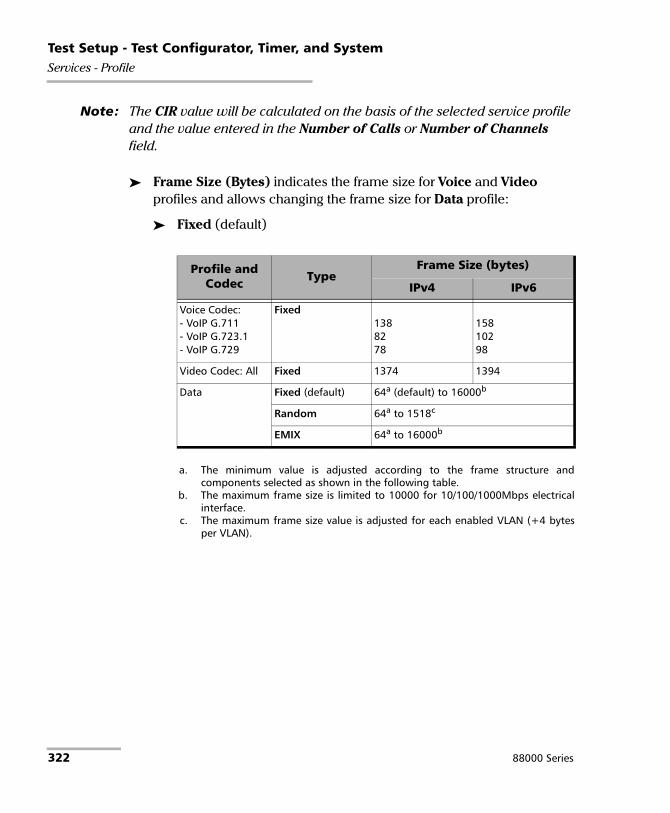
Test Setup - Test Configurator, Timer, and SystemServices - Profile
Note: The CIR value will be calculated on the basis of the selected service profile and the value entered in the Number of Calls or Number of Channels field.
Frame Size (Bytes) indicates the frame size for Voice and Video profiles and allows changing the frame size for Data profile:
Fixed (default)
Profile and Codec Type
Frame Size (bytes)
IPv4 IPv6
Voice Codec:- VoIP G.711- VoIP G.723.1- VoIP G.729
Fixed1388278
15810298
Video Codec: All Fixed 1374 1394
Data Fixed (default) 64a (default) to 16000b
a. The minimum value is adjusted according to the frame structure andcomponents selected as shown in the following table.
b. The maximum frame size is limited to 10000 for 10/100/1000Mbps electricalinterface.
Random 64a to 1518c
c. The maximum frame size value is adjusted for each enabled VLAN (+4 bytesper VLAN).
EMIX 64a to 16000b
322 88000 Series

Test Setup - Test Configurator, Timer, and SystemServices - Profile
The following table lists each component that may affect the minimum frame size value.
Note: Sending traffic with frame size > 1518 in switched network may results in losing theses frames.
EMIX button is available when EMIX frame size is selected. The EMIX frame sequence is repeated continuously.
Quantity allows selecting 2 to 8 frame size values.
EMIX Frame Sizes allows setting the EMIX frame sizes. The minimum frame size value is adjusted according to the frame structure and components selected as shown in the above table.
Restore Default button reverts the quantity and EMIX frame sizes to their default values.
Component Description
VLAN 4 bytes per VLAN (up to 2 VLAN)
MPLS 4 bytes per label (up to two labels)
UDP 8 bytes
TCP 20 bytes
Ethernet Header 14 bytes
LLC and SNAP Headers 8 bytes
IPv4 20 bytes
IPv6 40 bytes
Using DTS 4 bytes
Power Blazer 323

Test Setup - Test Configurator, Timer, and SystemServices - Profile
Test Parameters
Note: Unit selection is available from the SLA Parameters on page 325.
For Dual Test Set, parameters are configurable for both local (L) and remote (R) directions.
For Dual Port topology, parameters are configurable for both port directions.
Traffic Policing check box when selected (default) allows stressing the rate limiting of the network by sending traffic at higher rate than committed by the SLA.
Burst Max Rate allows setting the rate that is used for the CBS and EBS burst tests. Only available when the Burst Test is enabled (see EtherSAM - Global on page 193).
Note: Changing a criteria value (CIR, CIR+EIR, Ramp Traffic Policing, or Burst Max Rate) may affect the other criteria values in order to comply to the following rules:CIR CIR+EIR Ramp Traffic Policing Rate Line RateCIR CIR+EIR Burst Max Rate Line RateHowever, make sure that the criteria values comply to the following rule with an adequate margin, as per ITU-T Y.1564 standard, for a burst test to be valid:CIR CIR+EIR Burst Max Rate Line Rate
324 88000 Series

Test Setup - Test Configurator, Timer, and SystemServices - Profile
SLA Parameters
The Service-Level Agreement (SLA) parameters allow enabling and defining the pass/fail verdict thresholds for the service.
For Dual Test Set, parameters are configurable for both local (L) and remote (R) directions at the exception of Max Round-Trip Latency for which the value is unique.
For Dual Port topology, parameters are configurable for both port directions.
Information Rate
Unit choices are % (default), Mbit/s, or Gbit/s. This unit is also used for Total TX Rate and for Test Parameters (Traffic Policing and Burst Max Rate).
Note: At least one check box (CIR or CIR+EIR) has to be selected. Thus, clearing the CIR check box while CIR+EIR check box is cleared, will automatically select the CIR+EIR check box and vice versa.
CIR (Committed Information Rate) check box when selected (default) sets the service rate guaranteed by the SLA. The threshold value is configurable from 0.00011 to 100 percent (default is 50 percent). CIR and preceding steps are not performed for services that have the CIR check box cleared.
CIR+EIR check box when selected (cleared by default) sets the best effort allowed traffic for the service. The EIR (Excess Information Rate) value is equal to the CIR+EIR value minus CIR. The threshold value is configurable from 0.00011 to 100 percent (default is 75 percent).
Burst Size settings are only available when the Burst Test is enabled (see EtherSAM - Global on page 193).
Burst Size unit choices are Bytes (default) or ms.
1. The minimum rate is 1Mbit/s when the Frame Size is Random.
Power Blazer 325

Test Setup - Test Configurator, Timer, and SystemServices - Profile
CBS check box when selected (default) sets the maximum committed burst size to which services’ frames will be sent and be CIR-compliant (default is 12144 bytes). The CBS minimum and maximum values are affected by the CIR, Burst Max Rate, and Frame Size values. CBS is only available when CIR check box is selected.
EBS check box when selected (cleared by default) sets the maximum excess burst size to which services’ frames will be sent and be CIR+EIR compliant (default is 12144 bytes). The EBS minimum and maximum values are affected by the CIR+EIR, Burst Max Rate, and Frame Size values. EBS is only available when CIR+EIR check box is selected.
Performance Criteria
Max Jitter (ms) allows setting the maximum jitter value in millisecond, allowed for the service.
Max Round-Trip Latency (ms) allows setting the maximum round-trip latency value in millisecond allowed for the service. For Dual Test Set, only available with Round-Trip Latency Measurement Mode (see Global Options on page 197). Not available in Dual Port topology.
Max Latency, available for Dual Test Set with One-Way Latency Measurement Mode (see Global Options on page 197) and Dual Port topology, allows setting the maximum one-way latency allowed for the service.
Frame Loss Rate allows setting the maximum rate of Frame Loss allowed for the service.
Note: For Dual Test Set, the Frame Loss Rate is changed to percentage when the remote module does not support exponential notation. In this case a Frame Loss Rate Threshold lower than 1.0E-06 (0.0001 %) is considered as 0 %.
326 88000 Series

Test Setup - Test Configurator, Timer, and SystemSignal
Signal From the Test menu, tap Setup, Test Configurator, the interface block, and the Signal tab.
Physical Interface - Optical
Note: For electrical interface, see Physical Interface - Electrical on page 329.
Optical Lane indicates the optical lane number for parallel interfaces.
Laser1 indicates the status of the laser: ON with the laser pictogram (emitting an optical laser signal) or OFF.
TX Power (dBm)1 indicates, when supported, the transmit power level of the optical lane/laser in dBm.
Wavelength (nm)1 indicates, when supported, the detected lane/laser wavelength.
RX Power (dBm)1 indicates, when supported, the current received power level of the optical lane/laser in dBm.
Green: Power level in range. Yellow: Power level out-of-range. Red: Loss of signal or power level is close to damage. Gray: Invalid operational range value or not available/supplied by the transceiver.
Optical Interface Optical Lane Number
OTU3 (4 Lanes) [43.018 Gbit/s]OTU3e1 (4 Lanes) [44.571 Gbit/s]OTU3e2 (4 Lanes) [44.583 Gbit/s]OTU4 (4 Lanes) [111.81 Gbit/s]
0 through 3
1. Displayed for each optical lane for parallel interfaces.
Power Blazer 327

Test Setup - Test Configurator, Timer, and SystemSignal
Min RX Power (dBm)1 indicates, when supported, the minimum received power level of the optical lane/laser in dBm.
Max RX Power (dBm)1 indicates, when supported, the maximum received power level of the optical lane/laser in dBm.
Laser ON/OFF button is used for parallel interfaces to activate the laser control per optical lane or for all lanes.
Optical lane numbers are from 0 to 3 or 0 to 7 depending on the selected interface/rate.
All Lanes check box, when selected, applies the change(s) to all optical lanes at once.
Optical Lane indicates the optical lane numbers and All which represents the setting for all optical lanes when the All Lanes check box is selected.
Laser check box, when selected, indicates that the corresponding optical laser lane is activated and emitting an optical laser signal.
Lasers OFF at Start-Up check box when selected automatically turns OFF the laser for serial interfaces or all lasers for parallel interfaces when starting the Power Blazer or when switching from one test application to another. However the laser remains ON, on a remote module receiving a request for a DTS connection or a loopback command. This check box is cleared by default.
Power Range (dBm) indicates the transceiver operational RX power range.
1. Displayed for each optical lane for parallel interfaces.
328 88000 Series

Test Setup - Test Configurator, Timer, and SystemSignal
Physical Interface - Electrical
Note: The following settings are available with electrical signal and their availability depend on the signal itself and its mapping. For optical interface, see Physical Interface - Optical on page 327.
LBO (Line Build Out): The LBO allows meeting the interface requirements over the full range of cable lengths.
Line Coding
Signal LBO
DS1 Preamplification values: DSX-1 (0-133 ft)a, DSX-1 (133-266 ft), DSX-1 (266-399 ft), DSX-1 (399-533 ft), DSX-1 (533-655 ft), Cable simulation (CSU Emulation mode) values: CSU (0.0 dB), CSU (-7.5 dB), CSU (-15.0 dB), CSU (-22.5 dB).
a. Default value
DS3 0 to 225 ft rangea, 225 to 450 ft range, and Cable Simulation 900 ft.
E1/E3/E4 Not available
STS-1e/STM-0e 0 to 225 ft rangea, 225 to 450 ft range, and Cable Simulation 900 ft).
STS-3e/STM-1e 0 to 225 ft range.
Signal Line Coding
DS1 AMI and B8ZSa
a. Default value.
DS3 B3ZS
E1 AMI and HDB3a
E3 HDB3
E4 CMI
STS-1e/STM-0e B3ZS
STS-3e/STM-1e CMI
Power Blazer 329

Test Setup - Test Configurator, Timer, and SystemSignal
RX Termination
Power indicates the received signal level in dBdsx for DSn or dBm for PDH and SONET/SDH.
Amplitude indicates the received signal amplitude as well as its MIN, and MAX received values.
TX Frequency
Note: The following TX Frequency information applies to serial interface only, refer to TX Frequency on page 214 for parallel interfaces.
TX Frequency (GHz) indicates the frequency (actual frequency + Frequency offset) used for transmission.
Offset (ppm) check box, when selected (cleared by default), allows setting the frequency offset that will be generated. Use the “+” or “-” button to respectively increment or decrement the frequency offset value based on the defined Increment/Decrement Size, or directly type the frequency offset value in the field. Possible offsets are:
Signal Termination
DS1/E1 Terma, Mon, and Bridge.
a. Default value.
DS3/E3/E4/STS-1e/STM-0e/STS-3e/STM-1e Terma, and Mon
Interface Frequency Offseta Nominal Frequency
DS1 ±140 ppm 1544000 bit/s
E1 ± 70 ppm 2048000 bit/s
330 88000 Series

Test Setup - Test Configurator, Timer, and SystemSignal
Note: Frequency offset is not available when Through mode is selected.
Step Size (ppm) allows setting the increment/decrement value (from 0.1 to the maximum offset) that will be used when changing the frequency offset with the “+” or “-” button.
RX Frequency
Note: The following RX Frequency information applies to serial interface only, refer to RX Frequency on page 216 for parallel interfaces.
E3 ± 50 ppm 34368000 bit/s
DS3 44736000 bit/s
STS-1e/STM-0e 51840000 bit/s
E4 139264000 bit/s
STS-3e/STM-1e 155520000 bit/s
OC-1/STM-0 ± 50 ppm 51840000 bit/s
OC-3/STM-1 155520000 bit/s
OC-12/STM-4 622080000 bit/s
OC-48/STM-16 2488320000 bit/s
OC-192/STM-64 9953280000 bit/s
OTU1 ± 50 ppm 2666057143 bit/s
OTU2 ± 50 ppm (Framed)± 120 ppm (Unframed)
10709225316 bit/s
OTU1e ± 120 ppm 11049107143 bit/s
OTU2e 11095727848 bit/s
OTU1f 11270089286 bit/s
OTU2f 11317642405 bit/s
a. The frequency offset range is guaranteed for a source signal at 0 ppm. In the eventthat the source signal already has an offset, then the output signal may exhibit anoffset larger than the range specified.
Interface Frequency Offseta Nominal Frequency
Power Blazer 331

Test Setup - Test Configurator, Timer, and SystemSignal
Frequency (GHz) indicates the frequency of the input signal.
Offset (ppm) indicates the frequency offset between the standard rate specification and the rate at the input signal.
Note: For both Frequency and Offset the following background colors are used:
Max. Negative Offset (ppm) indicates the maximum negative frequency offset between the standard rate specification and the rate from the received signal.
Max. Positive Offset (ppm) indicates the maximum positive frequency offset between the standard rate specification and the rate from the received signal.
Note: Refer to Interface on page 425 for more information on standard rate specifications.
Signal Configuration
For OTN, refer to Signal - Signal Configuration (OTN) on page 341 for more information.
For SONET/SDH, refer to Signal - Signal Configuration (SONET/SDH) on page 345 for more information.
For DSn/PDH, refer to Signal - Signal Configuration (DSn/PDH) on page 333 for more information.
Background color DescriptionGreen The frequency is in range.
Red The frequency is out-of-range or LOC Lane. LOC is also displayed.
Gray Pending state.
332 88000 Series
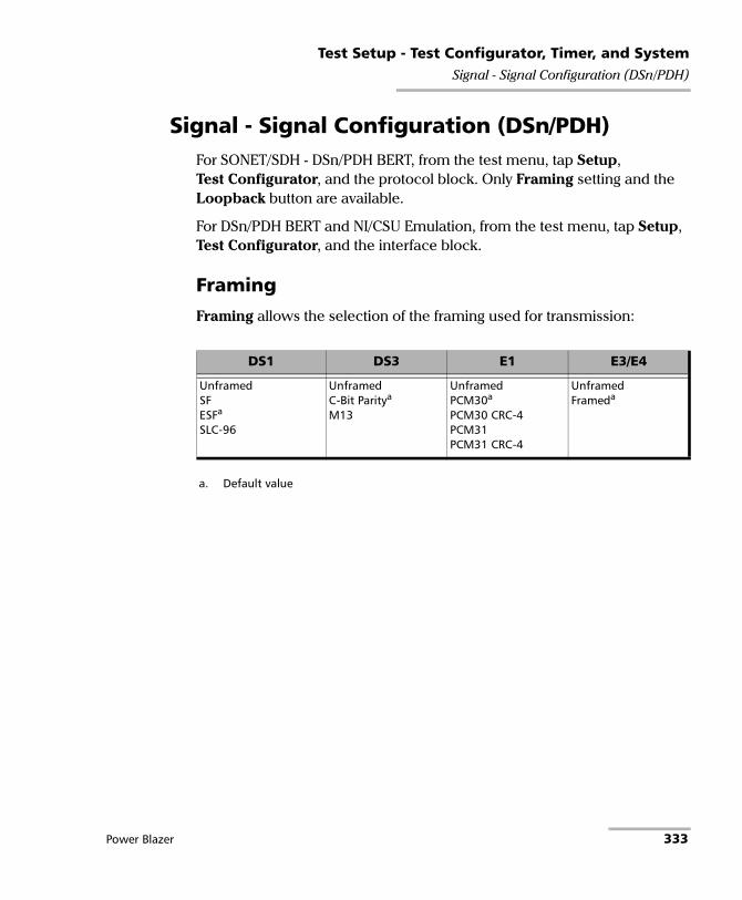
Test Setup - Test Configurator, Timer, and SystemSignal - Signal Configuration (DSn/PDH)
Signal - Signal Configuration (DSn/PDH) For SONET/SDH - DSn/PDH BERT, from the test menu, tap Setup, Test Configurator, and the protocol block. Only Framing setting and the Loopback button are available.
For DSn/PDH BERT and NI/CSU Emulation, from the test menu, tap Setup, Test Configurator, and the interface block.
Framing
Framing allows the selection of the framing used for transmission:
DS1 DS3 E1 E3/E4
UnframedSFESFa
SLC-96
a. Default value
UnframedC-Bit Paritya
M13
UnframedPCM30a
PCM30 CRC-4PCM31PCM31 CRC-4
UnframedFrameda
Power Blazer 333
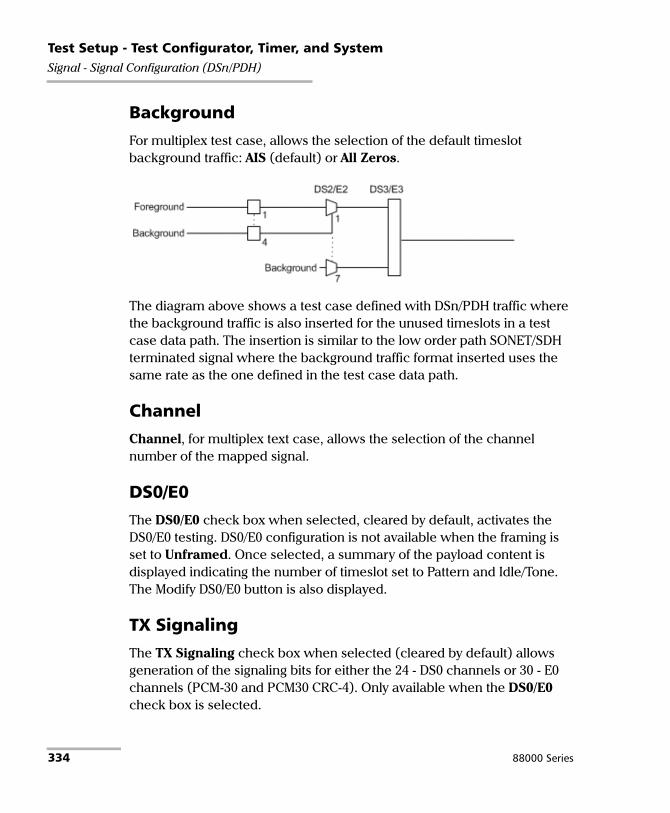
Test Setup - Test Configurator, Timer, and SystemSignal - Signal Configuration (DSn/PDH)
Background
For multiplex test case, allows the selection of the default timeslot background traffic: AIS (default) or All Zeros.
The diagram above shows a test case defined with DSn/PDH traffic where the background traffic is also inserted for the unused timeslots in a test case data path. The insertion is similar to the low order path SONET/SDH terminated signal where the background traffic format inserted uses the same rate as the one defined in the test case data path.
Channel
Channel, for multiplex text case, allows the selection of the channel number of the mapped signal.
DS0/E0
The DS0/E0 check box when selected, cleared by default, activates the DS0/E0 testing. DS0/E0 configuration is not available when the framing is set to Unframed. Once selected, a summary of the payload content is displayed indicating the number of timeslot set to Pattern and Idle/Tone. The Modify DS0/E0 button is also displayed.
TX Signaling
The TX Signaling check box when selected (cleared by default) allows generation of the signaling bits for either the 24 - DS0 channels or 30 - E0 channels (PCM-30 and PCM30 CRC-4). Only available when the DS0/E0 check box is selected.
334 88000 Series

Test Setup - Test Configurator, Timer, and SystemSignal - Signal Configuration (DSn/PDH)
Modify DS0/E0
Modify DS0/E0 button is only available when the DS0/E0 check box is selected.
Note: For DS0, the framing structure has 24 timeslots. For E0, the framing structures PCM-30 and PCM30 CRC-4 have 30 channel timeslots (1 to 15 and 17 to 31) while PCM-31 and PCM-31 CRC-4 have 31 channel timeslots (1 to 31).
DS0/E0 Size sets the channel timeslot data rate for the pattern payload content to either 56K or 64K (default); forced to respectively 56K for DS0 and 64K for E0 when TX Signaling is enabled. A timeslot data rate of 56 Kbit/s uses 7 bits while 64 Kbit/s uses 8 bits to carry the payload information.
Zero Code Suppression allows the selection of the Zero Code Suppression (ZCS) method used to replace the all-zero bytes of the Idle and Tone payload contents. The ZCS mechanism is a global parameter meaning that all channel timeslots configured with Tone/Idle data, use the same ZCS method. Choices are:
ZCS Description Available with
Nonea
a. Default value.
No Zero Code Suppression DS0 and E0
Jammed Bit 8 Every 8th (LSB) bit is forced to 1. DS0 and E0
GTE Bit 8 of an all zero channel byte is replaced by 1, except in signaling frames where bit 7 is forced to 1.
DS0
Bell Bit 7 of an all zero channel byte is replaced by 1.
DS0
Power Blazer 335

Test Setup - Test Configurator, Timer, and SystemSignal - Signal Configuration (DSn/PDH)
Note: Bit 8 is the Least-Significant Bit (LSB) and bit 1 is the Most-Significant Bit (MSB).
Payload Content and Set All
Payload Content allows the selection of the payload content that will be applied to all TX timeslots when tapping the Set All button: Pattern, Idle, or Tone.
TX
Tap once or several times on each timeslot until the desired payload content appears: Pattern (default), Idle, or Tone. For E0, timeslots 0 and 16 (PCM30 and PCM30 CRC4) are not configurable; timeslot 0 generates the FAS/NFAS framing; timeslot 16 generates a static MFAS frame when TX Signaling is disabled and generates a frame with Signaling capability when TX Signaling is enabled.
Note: For Pattern, the pattern used is the one selected from Pattern on page 155.
Tone (Hz) allows the selection of a tone for digital milliwatt testing. The signal output power, when converted to analog, is 0 dBm. Choices are 1000 Hz and 1004 Hz (default). The selected Tone applies to all timeslots set to Tone.
Idle uses the Idle code byte from the Idle field. Choices are 00 to FF. The selected Idle code applies to all timeslots set to Idle. The default setting is 7F.
Note: The timeslots set to Idle or Tone can be changed from Idle to Tone and vice versa even when the test is running; the Idle and Tone values can also be changed.
Binary allows either displaying the Idle code values in binary (when selected) or in hexadecimal (default).
336 88000 Series

Test Setup - Test Configurator, Timer, and SystemSignal - Signal Configuration (DSn/PDH)
RX
Apply Channel TX to RX, available for decoupled test, allows applying the RX payload content based on the TX settings. None will be used when TX is set to either Idle or Tone. For E0 the timeslots 0 and 16 (PCM30 and PCM30 CRC4) are not configurable. Timeslot 0 processes the FAS/NFAS while timeslot 16 processes the Signaling frame.
Note: The RX timeslot selection is only configurable in a Decoupled topology when the Apply Channel TX to RX check box is cleared. A warning is displayed when the number of Pattern timeslot does not match between TX and RX. This is to ensure pattern continuity between the TX and RX interface in a MUX/DEMUX test even if used through a cross-connect device.
Select the payload content by tapping once or several times on each timeslot until the desired content appears.
Pattern (default) uses the pattern from the received signal.
None does not use the pattern.
Loopback button
The Loopback feature generates a code that is interpreted by the DUT. The DUT interprets the command and implements the loopback.
Select the type of loopback that will be used to overwrite the traffic that will be generated. Choices are listed in the following table in addition with 10 predefined Loop Codes (see Modify Loop Codes button on page 338).
Loopback TypeCommand
Loop-Up Loop-Down
CSU (10000/100) 10000 (default) 100
NIU FAC1 (1100/1110) 1100 1110
Power Blazer 337

Test Setup - Test Configurator, Timer, and SystemSignal - Signal Configuration (DSn/PDH)
Loop-Up injects the selected loop up code. The loop code will be generated continuously for a maximum of 10 seconds or until the loopback is confirmed. After 10 seconds, if the loopback has failed, a Loop-Down command is sent. A pop-up window appears indicating the loop code injection progress and result. The text box next to the Loop-Up button indicates the selected loop up code.
Loop-Down injects the selected loop down code. The loop code will be generated continuously for a maximum of 10 seconds or until the loopback is confirmed. After 10 seconds, if the loopback has failed, a Loop-Down command is sent. A pop-up window appears indicating the loop code injection progress and result. The text box next to the Loop-Down button indicates the selected loop down code.
Modify Loop Codes button
Allows the configuration of 10 DS1 loop code pairs. Configure each loop code name, Loop-Up and Loop-Down values.
The name field allows up to 16 characters long. Loop-Up and Loop-Down range is from 3 to 16 bits (000 to 1111111111111111). The default DS1 loop codes correspond to the DS1 In-Band loop codes (Loop-Up=10000, and Loop-Down=100).
NIU FAC2 (11000/11100) 11000 11100
NIU FAC3 (100000/100) 100000 100
Loopback TypeCommand
Loop-Up Loop-Down
338 88000 Series
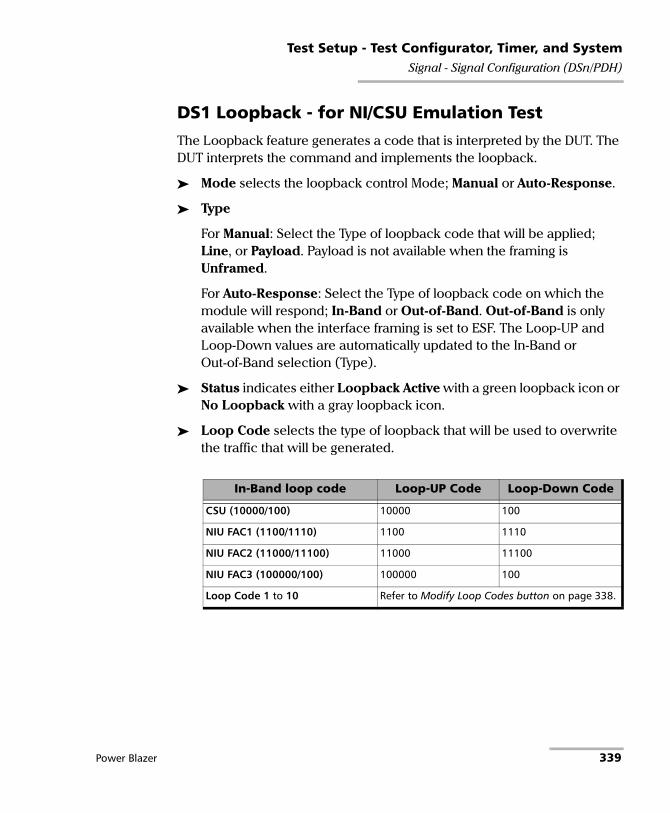
Test Setup - Test Configurator, Timer, and SystemSignal - Signal Configuration (DSn/PDH)
DS1 Loopback - for NI/CSU Emulation Test
The Loopback feature generates a code that is interpreted by the DUT. The DUT interprets the command and implements the loopback.
Mode selects the loopback control Mode; Manual or Auto-Response.
Type
For Manual: Select the Type of loopback code that will be applied; Line, or Payload. Payload is not available when the framing is Unframed.
For Auto-Response: Select the Type of loopback code on which the module will respond; In-Band or Out-of-Band. Out-of-Band is only available when the interface framing is set to ESF. The Loop-UP and Loop-Down values are automatically updated to the In-Band or Out-of-Band selection (Type).
Status indicates either Loopback Active with a green loopback icon or No Loopback with a gray loopback icon.
Loop Code selects the type of loopback that will be used to overwrite the traffic that will be generated.
In-Band loop code Loop-UP Code Loop-Down Code
CSU (10000/100) 10000 100
NIU FAC1 (1100/1110) 1100 1110
NIU FAC2 (11000/11100) 11000 11100
NIU FAC3 (100000/100) 100000 100
Loop Code 1 to 10 Refer to Modify Loop Codes button on page 338.
Power Blazer 339

Test Setup - Test Configurator, Timer, and SystemSignal - Signal Configuration (DSn/PDH)
Force Release / Activate / Release
Force Release button, available with Auto-Response mode, allows releasing a loopback condition initiated from the network. Only available when a loopback is active.
Activate button, available with Manual mode when no loopback is active, allows sending a loopback condition.
Release button, available with Manual mode when a loopback is active, allows releasing the loopback condition.
Loop-Up indicates the selected loop up code.
Loop-Down indicates the selected loop down code.
Modify Loop Codes button: See Modify Loop Codes button on page 338 for more information.
Out-of-Band loop code Loop-UP Code Loop-Down Code
Line 00001110 11111111 00111000 11111111
Payload 00010100 11111111 00110010 11111111
Reserved For Network Use 00010010 11111111 00100100 11111111
ISDN Line (NT2) 00101110 11111111 00100100 11111111
CI/CSU Line(NT1) 00100000 11111111 00100100 11111111
340 88000 Series

Test Setup - Test Configurator, Timer, and SystemSignal - Signal Configuration (OTN)
Signal - Signal Configuration (OTN)
Note: The following signal configuration parameters are available from the interface block.
From the Test menu, tap Setup, Test Configurator, the interface block, and on the Signal tab.
OTU3, OTU3e1, OTU3e2, OTU2, OTU2f, OTU1f, OTU2e, OTU1e, or OTU1
Note: At least one of the two check boxes, FEC or Scrambler, must be selected in order to prevent potential alarms caused by a lack of bit transition on the optical signal. For example to disable FEC, first select the Scrambler check box then clear the FEC check box.
FEC check box when selected (default) enables the FEC in TX/RX and allows detecting, reporting, and correcting up to 8 symbol errors (Correctable) per codeword. If there are over 8 symbol errors detected, they are reported as uncorrectable errors.
FEC-CORR Alarming check box when cleared (selected by default) does not report the FEC-CORR error status (current/history), seconds, and does not affect the global test verdict. Only available when FEC is enabled.
Scrambler check box when selected (default) provides enough “0” and “1” transitions on the optical signal for clock recovery.
Note: When the Scrambler check box is cleared, the receiver circuitry is forced to operate in a condition which is outside of the specified OTN operating conditions, potentially causing alarms/errors. This configuration can be used for special analysis in a lab environment.
Power Blazer 341

Test Setup - Test Configurator, Timer, and SystemSignal - Signal Configuration (OTN)
ODU3, ODU3e1, ODU3e2, ODU2, ODU2f, ODU1f, ODU2e, ODU1e,ODU1, ODU0, or ODUflex. Only the higher ODU layer is available with Multi-Channel OTN.
OPU Tributary Port1, available for each OPU level of a mapped signal, indicates the OPU tributary port used for the test. Tap the Modify Trib Slots/Port button to change the OPU tributary port.
OPU Tributary Slots1, available for each OPU level of a mapped signal, indicates the OPU tributary slots used for the test. Tap the Modify Trib Slots/Port button to change the OPU tributary slots.
TCM indicates each Tandem Connection enabled; No TCM indicates that no TCM is enabled. To enable TCM, tap the Config TCM1 button.
Background Traffic, available for a multiplex signal, is used to generate traffic on the timeslots that are not part of the foreground test traffic. Choices are Unallocated (available with PT21 only), AIS, Null Client, and PRBS31 (default). The background traffic is configurable for each mux type when the multiplex signal contains both PT20 and PT21 mux types.
1. Not available with Multi-Channel OTN.
Higher Layer Tributary Background Traffica
a. Uses the selected AIS, Null Client, or PRBS31 background traffic unless Unallocated is selected whichcorresponds to undefined traffic.
ODU4 ODU3, ODU2, ODU1, ODU0, ODU2e, ODU1e, ODUflex 1.25 Gbit/sb or Unallocated
b. Per tributary slot.
ODU3 ODU2 Fixed structure: ODU2Non fixed structure: ODU1
ODU1 ODU1
ODU0, ODUflex 1.25 Gbit/sb or Unallocated
ODU2 ODU1 ODU1
ODU0, ODUflex 1.25 Gbit/sb or Unallocated
ODU1 ODU0 ODU0
342 88000 Series

Test Setup - Test Configurator, Timer, and SystemSignal - Signal Configuration (OTN)
Modify Tributary Slots/Port1
The payload type 20 or 21 is indicated for each mapped OPU level.
Fixed Structure check box when selected (default) for OPU3, the selection of a tributary slot will automatically select four tributary slots from the same column, which constitute the foreground traffic. When the Fixed Structure check box is cleared, select the four tributary slots individually.
1. Not available with Multi-Channel OTN.
For... Mapped into... Tributary slot selection
ODU3 OPU4 31
ODU2eODU1e
OPU4 8
ODU2 OPU4OPU3
8 4 (PT20), 8 (PT21)
ODU1 OPU4OPU3OPU2
2 1 (PT20), 2 (PT21) 1 (PT20), 2 (PT21)
ODU0 OPU4OPU3OPU2OPU1
1 1 1 1
ODUflex OPU4OPU3 OPU2
up to 80 up to 32 up to 8
ODUflex/GFP-F OPU4OPU3OPU2
up to 8 up to 8 up to 8
Power Blazer 343
Test Setup - Test Configurator, Timer, and SystemSignal - Signal Configuration (OTN)
Tributary Port, configurable when the Fixed Structure check box is cleared, allows selecting the Tributary Port number that will be associated to the selected tributary slots. When the Fixed Structure check box is selected, the Tributary Port is automatically assigned to either the selected slot number or for OPU3 to the first slot number in the column.
Nominal Bit Rate (Gbit/s) available with ODUflex and ODUflex/GFP-F indicates the TX frequency based on the number of tributary slots selected. Note that for ODUflex with pattern Client, the Nominal Bit Rate may be affected by the TX Rate when not set to 100 % (see TX Rate on page 155).
Number of Trib Slots indicates the number of tributary slots selected.
Note: Tributary slots must be selected starting with the higher layer down to the lower and all required tributary slots must be selected to access the next level. Clear All, Select All, and Default buttons may be used to facilitate the selection.
Config TCM
Allows enabling each TCM level (1 to 6) individually. All ODUx of a mapped signal are also available. All TCM check boxes are cleared by default (disabled). Refer to Traces (OTN) on page 370 for more information. Not available with Multi-Channel OTN.
344 88000 Series

Test Setup - Test Configurator, Timer, and SystemSignal - Signal Configuration (SONET/SDH)
Signal - Signal Configuration (SONET/SDH) For OTN-SONET/SDH BERT, from the Test menu, tap Setup, Test Configurator, the protocol block, and the Signal tab.
For SONET/SDH BERT, from the Test menu, tap Setup, Test Configurator, the interface block, and the Signal tab.
OC/STM Signal
Synchronization Status Message (S1): Bits 5 through 8 of the S1 byte are used to convey synchronization status of the NE. Not available with Through topology.
Bits 5 to 8
Description
SONET SDH0000a
a. Default message.
Synchronized - Traceability Unknown (STU) Quality Unknown
0001 Stratum 1 Traceable (ST1) Reserved
0010 Reserved ITU G.811 (PRC)
0011 Reserved Reserved
0100 Transit Node Clock Traceable (TNC) SSU-A
0101 Reserved Reserved
0110 Reserved Reserved
0111 Stratum 2 Traceable (ST2) Reserved
1000 Reserved SSU-B
1001 Reserved Reserved
1010 Stratum 3 Traceable (ST3) Reserved
1011 Reserved ITU-T G.813 Option I (SEC)
1100 SONET Minimum Clock Traceable (SMC) Reserved
1101 Stratum 3E Traceable (ST3E) Reserved
1110 Provisionable by the Network Operator (PNO) Reserved
1111 Don’t Use for Synchronization (DUS) Do not use for synchronization
Power Blazer 345

Test Setup - Test Configurator, Timer, and SystemSignal - Signal Configuration (SONET/SDH)
REI-L/MS-REI Computation Method (OC-192/STM-64 only): Allows selecting the default method used to calculate the REI-L/MS-REI error for OC-192 and STM-64 signals. Choices are M1 Only and both M0 and M1. The default setting is M1 only.
STS/AU and VT/TU Mappings
Timeslot/Number
Timeslot (SONET) allows the selection of the STS timeslot number. Refer to SONET Numbering Convention on page 833 for more information.
Number (SDH) allows the selection of the AU channel number. Refer to SDH Numbering Convention on page 834 for more information.
TCM check box when selected (cleared by default) allows Tandem Connection Monitoring (TCM).
TC-UNEQ-P / TC-UNEQ-V / HPTC-UNEQ / LPTC-UNEQ check boxes when selected (cleared by default) allows the monitoring of the corresponding Tandem Connection - Unequipped alarm. Only available when the TCM check box is selected.
Overwrite Fixed Stuff (STS-1 only) check box when selected (default) fills up the bytes of the STS-1 SPE’s columns 30 and 59 with the selected pattern from the tab BERT and Unframed BERT on page 155.
Background allows the selection of the high order path background traffic: AIS, Equipped (PRBS23) - (default), or Unequipped.
346 88000 Series

Test Setup - Test Configurator, Timer, and SystemSignal - Signal Configuration (SONET/SDH)
STS/AU Path (SONET/SDH HOP):
The following diagram shows a test case data path that is terminated right after SONET/SDH high order path. High order background traffic is automatically adapted to the rate (STS-1, AU-3, or AU-4) signal level for the paths that are not defined in the test case. In the situation where the traffic pattern is replaced by GFP the background traffic remains the same for the STS-1/AU-3/AU-4 that are not involved in the test case data path. In the situation where contiguous concatenation or virtual concatenation is used, the background traffic continues to be applied on the remaining timeslots not involved in the test case data path.
Power Blazer 347

Test Setup - Test Configurator, Timer, and SystemSignal - Signal Configuration (SONET/SDH)
VT/TU Path (SONET/SDH LOP)
The following diagram shows a test case data path that is terminated at the SONET/SDH low order path. The remaining STS-1 or AU-3 timeslot not involved in the test case are filled with background traffic of STS-1 or AU-3 level depending on the interface being SONET or SDH. At the low order path level, the data path not involved in the data path defined in the test case are filled with a background traffic equivalent to the VT Group (VTG) or Tributary Unit Group (TUG) type defined by the traffic selected in the data path. Further, the remaining VTG or TUG within the high order path, selected in the test case, are respectively filled with traffic of equivalent rate for SONET and SDH data paths.
348 88000 Series

Test Setup - Test Configurator, Timer, and SystemSmart Loopback
Smart Loopback
Note: The Smart Loopback block is only displayed when the Transparent (Pseudo-Physical) check box is cleared (see Loopback Mode on page 139).
From the Test menu, tap Setup, Test Configurator, and the Smart Loopback block.
Loopback
Mode determines at which layer the Smart Loopback address/port swapping operation will be.
Ethernet swaps the MAC addresses of received packets having their Destination MAC address matching the MAC address of the loopback port.
Ethernet (All Unicast) swaps the MAC addresses of received packets having Unicast Destination MAC address.
IP, for Ethernet Layer 3 and 4, swaps the MAC and IP addresses of received packets having their Destination IP address matching the IP address of the loopback port. For Ethernet Layer 2, swaps the MAC addresses for packets having their Destination MAC address matching the MAC address of the loopback port.
UDP/TCP (default), for Ethernet Layer 4, swaps the UDP or TCP ports and the MAC and IP addresses of received packets having their Destination IP address matching the IP address of the loopback port. For Ethernet Layer 3, swaps the MAC and IP addresses for packets having their Destination IP address matching the IP address of the loopback port. For Ethernet Layer 2, swaps the MAC addresses for packets having their Destination MAC address matching the MAC address of the loopback port.
Matching & Swapping indicates the Loopback parameters that will be used based on the Loopback Mode selected.
Power Blazer 349

Test Setup - Test Configurator, Timer, and SystemSmart Loopback
S-OAM Responder
The S-OAM Responder check box when selected (default) allows responding to LBM, LTM, DMM, LMM, and SLM valid messages (test running or not). Traffic statistics are also monitored (refer to Responder on page 607).
Respond to... message Respond with... message
LBM LBR
LTM LTR
DMM DMR
LMM LMR
SLM SLR
350 88000 Series

Test Setup - Test Configurator, Timer, and SystemStreams - Global
Streams - Global From the Test menu, tap Setup, Test Configurator, the protocol block, and the Global tab.
The following parameters are displayed and configurable per stream.
Check boxes:
The first check box (top-left) allows enabling stream(s) sequentially within the limit of the link capacity.
The check boxes next to the stream numbers allow enabling each stream individually within the limit of the link capacity.
Stream Name1 indicates the name of each stream. Tap on the Stream Name button to modify the name of each stream.
Frame Size1 indicates the frame size of each stream. Tap on the Frame Size button to modify the frame size of each stream.
TX Rate1 indicates the transmission rate for each stream. Tap on the TX Rate button to modify the transmission rate (see page 357).
Framing indicates the framing of each service. Tap on the Framing button to modify the Frame Format, Network Layer, Transport Layer, VLAN, and MPLS when applicable (see Modify Frame Structure from the MAC/IP/UDP on page 247).
VLAN indicates the ID and Priority of each VLAN level for each stream. Tap on the VLAN button to modify the VLAN settings (see VLAN from the MAC/IP/UDP tab).
1. See the Profile tab for more information.
Power Blazer 351

Test Setup - Test Configurator, Timer, and SystemStreams - Global
Addressing MAC/IP indicates the source and destination MAC/IP addresses for each stream. Tap on the Addressing MAC/IP button to modify the customer addressing (see MAC and IP from the MAC/IP/UDP tab). When using Provider Encapsulation, the source and destination addresses displayed are respectively EoE MAC for EoE and B-MAC for PBB-TE.
Batch button allows bulk configuration for stream addressing. Select the check box of each configuration parameter that needs to be copied and set its parameters. From Apply To, select all streams the copy applies to and tap on the Copy From to proceed.
The following parameters are global for all streams.
Total TX Rate indicates the percentage of the total line utilization which is the TX rate sum of all enabled streams.
Link Capacity indicates the total rate available for traffic generation.
Global Options:
Rate Unit choices are % (default), Mbit/s, Gbit/s, frame/s, and IFG.
QoS Metrics Tags Insertion check box when selected (default) automatically adds a stream analysis tag containing Jitter, Latency, Throughput, and sequence tags in all frames that is generated.
Copy Stream button allows copying the stream configuration to one or several streams.
Select the stream number the configuration will be copied from.
From To the following Streams, select all streams that will inherit the configuration from the selected stream. An orange background represents a selected stream. A stream that is already enabled (Enable TX) cannot be selected for copy.
Tap Copy to confirm the stream configuration for all selected streams.
Restore Default button reverts the current test application to its default factory settings.
352 88000 Series

Test Setup - Test Configurator, Timer, and SystemStreams - Profile
Streams - Profile The Traffic Gen & Mon test application supports the configuration of up to 16 different streams individually.
From the Test menu, tap Setup, Test Configurator, the protocol block, and the Profile tab.
Note: All parameters are configurable per stream.
Stream Selection and Activation
Select the stream to be configured by either using the left/right arrow or by tapping over the stream numbers area then tapping on a specific stream number. An orange background indicates the selected stream while a green background indicates the streams that are enabled.
Stream associates a name to the selected stream number. Default stream names are Stream 1 to Stream n.
Enable check box when selected (cleared by default) enables the selected stream. However, the stream will be generated only when the test is started while the global Enable TX check box is selected from the Global tab.
Power Blazer 353

Test Setup - Test Configurator, Timer, and SystemStreams - Profile
Profile
Profile button allows the selection and configuration of either Voice, Video, or Data (default) emulation profile. The selected profile icon and its Codec for Voice and Video are displayed next to the Profile button. Only Data is available when using Provider Encapsulation.
Voice when selected allows the configuration of the following parameters.
Voice Codec allows the selection of the codec used by the voice profile: VoIP G.711 (default), VoIP G.723.1, or VoIP G.729.
Number of Calls allows the selection of the number of calls that will be generated for the selected stream. The minimum and default value is 1 for 10M to 1G, 5 for 10G, and 10 for 40G and 100G.
Rate indicates the rate corresponding to the selected codec and the number of calls.
Video when selected allows the configuration of the following parameters.
Video Codec allows the selection of the codec used by the video profile: SDTV (MPEG-2) - (default), HDTV (MPEG-2), or HDTV (MPEG-4).
Number of Channels allows the selection of the number of channels (1 by default) that will be generated for the selected stream.
Rate indicates the rate corresponding to the selected coded and the number of channels.
354 88000 Series

Test Setup - Test Configurator, Timer, and SystemStreams - Profile
Frame Size (Bytes) for Data profile is selectable: Fixed (default), Random, or Sweep. The Frame Size is forced to Fixed for Voice and Video profiles. Only Fixed frame size is available when using Provider Encapsulation.
For Fixed type, the frame size is as follow.
For Random type, the frame size range is from 64 to 1518 bytes. However, the minimum frame size will be adjusted according to the frame structure and components selected. The following table lists each component that may affect the minimum frame size value. The maximum frame size value is also adjusted for VLAN (+4 bytes per VLAN).
Profile Codec Frame Size
IPv4 IPv6
Voice VoIP G.711 138 158
VoIP G.723.1 82 102
VoIP G.729 78 98
Video All codec 1374 1394
Data - Programmable from 64a to 16000b
a. The minimum frame size will be adjusted according to the frame structure andcomponents selected. The following table lists each component that mayaffect the minimum frame size value.
b. The maximum frame size is limited to 10000 for 10/100/1000Mbps electricalinterface.
Power Blazer 355

Test Setup - Test Configurator, Timer, and SystemStreams - Profile
For Sweep type, the first frame is generated starting with the minimum number of bytes defined, then each subsequent frame is incremented by 1 byte until the maximum number of bytes is reached and start over with minimum. The frame size range is from 64 to either 10000 bytes for electrical interfaces or 16000 bytes for optical interfaces; default is 1518 bytes. However, the minimum frame size will be adjusted according to the frame structure and components selected. The following table lists each component that may affect the minimum frame size value.
The following table lists each component that may affect the minimum frame size value.
Component Description
VLAN 4 bytes per VLAN (up to 2 VLAN)
MPLS 4 bytes per label (up to two labels)
EoE Header 16 bytes
EoE VLAN 4 bytes
PBB-TE Header 18 bytes
B-VLAN 4 bytes
LLC and SNAP Headers 8 bytes
UDP 8 bytes
Ethernet Header 14 bytes
IPv4 20 bytes
IPv6 40 bytes
356 88000 Series

Test Setup - Test Configurator, Timer, and SystemStreams - Profile
Shaping
TX Mode allows the selection of the transmission mode for the selected stream when Data profile is selected. The TX Mode is forced to Continuous for Voice and Video profiles and when using Provider Encapsulation.
TX Rate / Max TX Rate indicates the transmission rate for Voice and Video profiles, and allows entering the transmission rate for Data profile. The available stream transmission rate will be calculated according to the selected TX Mode. The default setting is 100 percent for all interfaces at the exception of 10Gig-E WAN which is 92.8571 percent (depending on the frame format).
Unit choices are: % (default), Mbit/s, Gbit/s, frame/s, IFG. However frame/s and IFG are not available for Random and Sweep frame sizes.
Continuous (default) transfers the selected frame continuously according to the selected percentage of bandwidth.
n-Frame transfers the selected number of frames.
Burst transfers the selected frame at maximum bandwidth for the selected Burst Duty Cycle over the Period.
n-Burst transfers the selected number of Burst.
Ramp transfers the selected bandwidth in a stair shape according to the selected step time, number of steps, and maximum bandwidth.
n-Ramp transfers the selected number of Ramp.
Power Blazer 357

Test Setup - Test Configurator, Timer, and SystemStreams - Profile
Customer Frame TX Rate, available when using Provider Encapsulation, indicates the customer frame TX rate based on the TX Rate defined.
Frame Count is only available with n-Frame Transmit Mode. Enter the frame count number: 1 (default) to 267857142857.
Shaping button
For Burst and n-Burst TX modes.
Burst Duty Cycle (%) represents the burst duration within the burst period: 1 to 100 percent (default is 50 percent).
Period represents the burst pattern duration: 1 to 8000 milliseconds (default is 1000 ms). Unit choices are ms (default) and s.
Burst Count, available with n-Burst TX Mode, represents the number of times the burst will be repeated: 1 (default) to 255.
For Ramp and n-Ramp TX modes.
Ramp Nb. of Steps represents the number of steps within the ramp: 2 to 100 (default is 10).
Step Time represents the duration of each step: 100 to 8000 milliseconds (default is 1000 ms). Unit choices are ms (default) and s.
Ramp Cycle Count, available with n-Ramp TX mode only, represents the number of times the ramp will be repeated: 1 (default) to 255.
358 88000 Series

Test Setup - Test Configurator, Timer, and SystemStreams - Profile
Total TX Rate indicates the percentage of the total line utilization which is the sum of all TX rate enabled streams.
Note: The Individual stream can be enabled/disabled even when the test is started and running. The streams can be enabled one after the other, up to 16, as long as the maximum rate is not reached. For example, if the first stream is using the full rate available, then no other stream can be enabled. However, if the first enabled stream uses half rate, then at least another stream can be enabled using up to half rate. Thus, to enable a second stream, first set the TX rate value within the non-used rate, then enable it. A stream cannot be enabled if its MAC address is not valid (it can be either not resolved or wrongly entered).
Link Capacity indicates the total rate available for traffic generation.
QoS Metrics
Note: QoS Metrics settings apply to all streams.
Global Pass/Fail Verdict check box when selected (default) enables the pass/fail verdict for all streams.
Global Thresholds Type button
Throughput allows selecting if the verdict is based on the Current Throughput (default) or Average Throughput.
Frame Loss allows selecting if the verdict is based on a frame loss Count (default) or Rate.
Out-of-Sequence allows selecting if the verdict is based on an Out-of-Sequence Count (default) or Rate.
Throughput (%) check box when selected enables the throughput pass/fail verdict and allows setting the minimum and maximum threshold values.
Power Blazer 359

Test Setup - Test Configurator, Timer, and SystemStreams - Profile
Customer Frame Throughput. available when using Provider Encapsulation, displays the calculated customer frame throughput minimum and maximum thresholds based on the throughput values.
Frame Loss Count/Rate check box when selected enables the Frame Loss pass/fail verdict and allows setting the threshold of frame that are lost.
For Count, enter the maximum count of frame that are lost before declaring a fail verdict: 0 (default) to 9999999999.
For Rate, enter the maximum rate of frame that are lost before declaring a fail verdict: 1.0E-14 (default) to 1.0E00.
Out-of-Sequence Count/Rate check box when selected enables the Out-of-Sequence pass/fail verdict and allows setting the threshold of frames that are Out-of-Sequence.
For Count, enter the maximum count of frames that are Out-of-Sequence before declaring a fail verdict: 0 (default) to 9999999999.
For Rate, enter the maximum rate of frames that are Out-of-Sequence before declaring a fail verdict: 1.0E-14 (default) to 1.0E00.
Jitter (ms) check box when selected enables the Jitter verdict and allows setting the maximum Jitter in ms before declaring a fail verdict.
Latency (ms) check box when selected enables the Latency verdict and allows setting the maximum Latency in ms before declaring a fail verdict.
360 88000 Series

Test Setup - Test Configurator, Timer, and SystemSyncE
SyncE From the Test menu, tap Setup, Test Configurator, and the SyncE test block.
ESMC Monitoring
ESMC (Ethernet Synchronization Message Channel) is a live value monitored even when the test is not started.
An arrow next to the ESMC label indicates that ESMC valid information frames are received or not.
A green arrow indicates that at least one ESMC valid information frame, containing a valid FCS, was received within a second in the last 5-second interval.
A red arrow indicates that no ESMC valid information frames were received for more than 5 seconds.
A gray arrow indicates awaiting incoming data to provide a status.
Received QL indicates the last Quality Level received. The Received QL is a live value monitored even when the test is not started.
QL Mismatch Monitoring check box when selected (default) enables the Quality Level mismatch monitoring. The quality level characterizes the clock quality in terms of network synchronization.
Expected QL available when the QL Mismatch Monitoring check box is selected, allows the selection of the Expected Quality Level value. See page 512 for more information.
Power Blazer 361

Test Setup - Test Configurator, Timer, and SystemSyncE
Pass/Fail Verdict check box when selected (default) enables the use of the pass/fail verdict. The global pass/fail verdict is based on the following criteria: ESMC Rate Threshold (when enabled), QL Mismatch Monitoring (when enabled), ESMC Loss, or Link Down.
ESMC Rate Threshold check box when selected (default) enables the ESMC rate threshold monitoring which will declare a Fail verdict when the ESMC frame rate is outside the range of 0.8 to 10.2 frames/s.
ESMC Generation
Generated QL
The Generated QL check box when selected (default) enables the generation of the selected QL message.
The Generated QL field allows the selection of the QL message that will be generated. See page 512 for the list of QL message (default is QL-EEC2/ST3).
Note: For 1GE Electrical interface using Local Clock set to Slave, the Generated QL is not configurable and is set to QL-DNU/DUS with its check box selected.
QL Rate (frame/s) defines the frame rate at which the ESMC transmit the QL message value: 1 (default), 5, or 10 frames per second. For 1GE Electrical interface using Local Clock set to Slave, the QL Rate is not configurable and is set to 1 frame/s.
Restore SyncE Defaults
Reverts the SyncE test application to its default factory settings.
362 88000 Series

Test Setup - Test Configurator, Timer, and SystemSystem
System From the Test menu, tap Setup, and System.
Factory Default
Restore Default button restores the factory default settings for all test applications.
Restore Default at Start-Up check box when cleared (default), reloads the last configuration settings when the application is launched; when selected, the factory settings are restored.
Remote Control
User Information allows a user to leave a message to other users connected on the same module. Up to 80 characters are allowed.
Time Zone allows the selection of the time zone source.
Local (default) uses and displays the time from the 88000 Series module or from the PC for a Remote ToolBox session.
Test Equipment, available for a Remote ToolBox session, uses and displays the time from the 88000 Series module.
Power Blazer 363
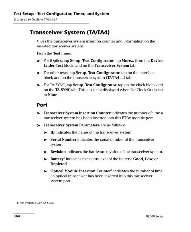
Test Setup - Test Configurator, Timer, and SystemTransceiver System (TA/TA4)
Transceiver System (TA/TA4) Gives the transceiver system insertion counter and information on the inserted transceiver system.
From the Test menu:
For iOptics, tap Setup, Test Configurator, tap More... from the Device Under Test block, and on the Transceiver System tab.
For other tests, tap Setup, Test Configurator, tap on the interface block and on the transceiver system (TA/TA4-...) tab.
For TA-SYNC, tap Setup, Test Configurator, tap on the clock block and on the TA-SYNC tab. This tab is not displayed when Ext Clock Out is set to None.
Port
Transceiver System Insertion Counter indicates the number of time a transceiver system has been inserted into this FTBx module port.
Transceiver System Parameters are as follows:
ID indicates the name of the transceiver system.
Serial Number indicates the serial number of the transceiver system.
Revision indicates the hardware revision of the transceiver system.
Battery1 indicates the status level of the battery: Good, Low, or Depleted.
Optical Module Insertion Counter1 indicates the number of time an optical transceiver has been inserted into this transceiver system port.
1. Not available with TA-SYNC.
364 88000 Series

Test Setup - Test Configurator, Timer, and SystemTCP Throughput
TCP Throughput From the Test menu, tap Setup, Test Configurator, and tap on the test block.
TCP Mode
Since two units are required to perform a TCP Throughput test, one unit must be the source (Local) unit and the other one the destination (Remote). Set the TCP Mode on both units: Local (default) or Remote.
TCP Connection Configuration
Remote IP Address, available with Local TCP mode, allows entering the IP address of the remote unit.
Quick Ping button automatically starts the quick Ping utility for the remote IP address and provides either a successful or failed result. The quick Ping uses 3 attempts, a Delay of 1 second, a Timeout of 2 seconds, and a Data Size of 32 Bytes. Refer to Ping & Trace Route on page 686 for more options.
Accept Connection from IP, available with Remote TCP mode, allows entering the IP address of the local unit. The IP address 0.0.0.0 (default) listens to any TCP stream.
IP TOS/DS, available with Local TCP mode, is configurable from 0x00 (default) to 0xFF.
TCP Port, available with Local and Remote TCP modes, allows the selection of the TCP port number: 0 to 65535 (default is 50201). For the local unit, the specified TCP port will be used for the TCP initialization algorithm with the remote unit. The following TCP segments sent by the local unit will use the TCP port number replied by the remote unit.
Power Blazer 365

Test Setup - Test Configurator, Timer, and SystemTCP Throughput
TCP Throughput Configuration
Note: TCP Throughput Configuration is only available on the local unit.
Initial Window Size1 is the window size that is used when the test is started: 1024 Bytes to 65536 KBytes (default is 2 KBytes). The Initial Window Size value must be between the Minimum Window Size and the Maximum Window Size values.
Minimum Window Size1 is the minimum window size used for the test: 1024 Bytes to 65536 KBytes (default is 1 KBytes).
Maximum Window Size1 is the maximum window size used for the test: 1024 Bytes to 65536 KBytes (default is 64 MBytes).
Rate Unit allows selecting the unit that will be used to set the Throughput Pass/Fail Verdict Threshold and throughput results: % (default) or MBit/s.
Throughput Pass/Fail Verdict check box when selected (default) enables the throughput verdict.
Threshold allows setting the pass/fail verdict threshold value: 0 to 100 % (default).
Restore TCP Throughput Defaults
Reverts the TCP Throughput test application to its default factory settings.
1. The entered value will be rounded to the closest multiple of 1024 Bytes. Unit choices are Bytes, KBytes (default), and MBytes.
366 88000 Series

Test Setup - Test Configurator, Timer, and SystemTest Sequence (iOptics)
Test Sequence (iOptics) From the Test menu, tap Setup, and Test Configurator.
Power Threshold (W)1 indicates the power consumption threshold based on the power level/class detected including uncertainty from the selected transceiver to declare the pass/fail verdict. Not available on 8870 and 8880 modules.
Power Consumption Pass/Fail Verdict1 check box when selected (default) enables the power consumption pass/fail verdict based on the Power Threshold (W) value. In the case where a vendor optical devices overcome the Power Class they are assigned to, clear this check box to avoid reporting a fail verdict.
Temp. Threshold (oC)1 allows selecting the temperature threshold to declare the pass/fail verdict: 0 to 75 oC (default is 70 oC).
TX Power Range (dBm)1 indicates, when supported, the optical device TX operational range to declare the pass/fail verdict.
RX Power Range (dBm)1 indicates the optical device RX operational range to declare the pass/fail verdict.
BERT Duration is the time duration of the bit error test: 1 minute (default), 2, 3, 4, 5, or 30 minutes.
BERT Threshold indicates the bit error test threshold (set to 0) to declare the pass/fail verdict.
Skew Threshold (Bits), available with parallel interfaces, indicates the skew threshold that is automatically set based on the rate to declare the pass/fail verdict.
1. Not available when PHY Type is set to DAC.
Power Blazer 367

Test Setup - Test Configurator, Timer, and SystemTimer
Timer Allows starting and/or stopping automatically the test at a given time or for a specific duration.
From the Test menu, tap Setup, and Timer.
Timer
Note: For RFC 2544 and RFC 6349, only Start Time and the ARM button are available.
Duration: Selects the test duration based on the test start time. The test start time can be either the time the user starts the test or the time the test is automatically started when the start time is enabled. The Duration check box has to be selected to be included in the test timer. Choices are 15 minutes (default), 1, 2, 4, 6, 12, 24, 72 hours, 7 days, and User Defined.
When User Defined is selected, the field next to it becomes available to enter the test duration using the format: dd:hh:mm:ss.
Note: Duration cannot be enabled while stop time is enabled. When the test is started while duration is enabled, the stop time is calculated and the Stop Time field is updated to indicate the time the test will stop.
Start Time selects the time the test will automatically start. The Start Time check box has to be selected to be included in the test timer.
Note: A valid start time has to be subsequent to the current time.
368 88000 Series

Test Setup - Test Configurator, Timer, and SystemTimer
Stop Time selects the time the test will automatically stop. The Stop Time check box has to be selected to be included in the test timer.
Note: A valid stop time has to be subsequent to the current time or to the start time, when enabled. The stop time must not exceed 30 days based on the start time. The stop time cannot be enabled while Duration is enabled.
ARM button, available when the Start Time check box is selected (cleared by default), enables the start test timer. Not available while the test is running. It is not possible to start the test case when the start time is armed.
Note: An icon is displayed in the global test status area indicating that the timer is enabled. Armed is displayed when the test start time is armed while the test is not started. Refer to Global Indicator on page 36 for more information.
Power Blazer 369

Test Setup - Test Configurator, Timer, and SystemTraces (OTN)
Traces (OTN) For OTN BERT and OTN-SONET/SDH BERT: From the Test menu tap Setup, Test Configurator, tap on the interface block, and on the Traces tab.
For Multi-Channel OTN: From the Test menu, tap Setup, Test Configurator, tap on either:
the interface block, and on the Traces tab to configure the higher ODU layer.
the test block (ODU Channels), and on the Traces tab to configure the lower ODU layer. Traces settings apply to all channels unless otherwise indicated.
OTUx, ODUx, and TCM Buttons
Tap on either OTUx or an ODUx button. For ODUx when TCM is enabled (see Modify TCM on page 344), tap on a TCMx button to select a TCM level. TCM is not available with Multi-Channel OTN.
SM/PM/TCM TTI Traces
Note: The TTI Traces are configurable for SM (OTUx), PM (ODUx), and TCM (ODUx when TCM is enabled; see Modify TCM on page 344).
Overwrite check box when selected generates the defined messages. Only available with Through Intrusive topology and applies only to the OTU and ODU top layers.
Generated Message
Allows editing the SAPI, DAPI and Operator Specific messages to be generated.
370 88000 Series

Test Setup - Test Configurator, Timer, and SystemTraces (OTN)
Expected Message
Allows editing the expected SAPI, and DAPI messages. The expected message settings are coupled with the Expected Message from Traces (OTN) on page 595. For Multi-Channel OTN lower ODU layer, expected traces apply to all channels but may be overwritten individually per channel from Traces (OTN) on page 595; In this case the icon appears next to the expected message indicating that at least one channel uses a different message.
SAPI (Source Access Point Identifier) corresponds to the TTI bytes 0 to 15. A maximum of 161 characters is allowed. NULL (all 0’s) characters are automatically appended to the message for bytes that are not defined. The expected SAPI message is available when the SAPI OTU/ODU-TIM check box is selected.
1. For Multi-Channel OTN lower ODU layer, a maximum of 13 characters are allowed since the channel number is automatically appended to the message.
TTI Traces
Default Messagea
a. The default message contains a NULL (all 0’s) character preceding it. NULL (all 0’s)characters are automatically appended to the message for bytes that are notdefined.
OTN BERTOTN-SONET/SDH BERT
Multi-Channel OTN (higher ODU layer)
Multi-Channel OTN (lower ODU layer)
SM EXFO OTU SAPI EXFO OTU SAPI
PM EXFO ODU SAPI XFO ODU SAPIb
b. The channel number is automatically appended to the generated/expectedmessage.
TCM EXFO TCMi SAPI
Power Blazer 371

Test Setup - Test Configurator, Timer, and SystemTraces (OTN)
DAPI (Destination Access point Identifier) corresponds to the TTI bytes 16 to 31. A maximum of 161 characters is allowed. NULL (all 0’s) characters are automatically appended to the message for bytes that are not defined. The expected DAPI message is available when the DAPI OTU/ODU-TIM check box is selected.
Operator Specific corresponds to the TTI bytes 32 to 63. A maximum of 32 characters are allowed. NULL (all 0’s) characters are automatically appended to the message for bytes that are not defined.
TTI Traces
Default Messagea
a. The default message contains a NULL (all 0’s) character preceding it. NULL (all 0’s)characters are automatically appended to the message for bytes that are notdefined.
OTN BERTOTN-SONET/SDH BERT Multi-Channel OTN
SM EXFO OTU DAPI EXFO OTU DAPI
PM EXFO ODU DAPI XFO ODU DAPIb
b. The channel number is automatically appended to the message.
TCM EXFO TCMi DAPI
TTI Traces Default Messagea
a. NULL (all 0’s) characters are automatically appended to the message for bytes thatare not defined.
OTN BERTOTN-SONET/SDH BERT Multi-Channel OTN
SM EXFO OTU OPERATOR SPECIFIC EXFO OTU OPERATOR SPECIFIC
PM EXFO ODU OPERATOR SPECIFIC XFO ODU OPERATOR SPECIFIC
TCM EXFO TCMi OPERATOR SPECIFIC
372 88000 Series
Test Setup - Test Configurator, Timer, and SystemTraces (OTN)
SAPI OTU/ODU/TCM-TIM check box, when selected (cleared by default), allows editing the expected Source Access Point Identifier (SAPI) and also enables OTU/ODU/TCM-TIM alarm monitoring.
DAPI OTU/ODU/TCM-TIM check box, when selected (cleared by default), allows editing the expected Destination Access Point Identifier (SAPI) and also enables the OTU/ODU/TCM-TIM alarm monitoring.
Power Blazer 373

Test Setup - Test Configurator, Timer, and SystemTraces (SONET/SDH)
Traces (SONET/SDH) For SONET/SDH BERT: From the Test menu, tap Setup, Test Configurator, the interface block, and on the Traces tab.
For OTN-SONET/SDH BERT: From the Test menu, tap Setup, Test Configurator, the protocol block, and on the Traces tab.
Note: Selecting a Trace byte to be generated will automatically update the corresponding OH byte. Refer to OH - SONET/SDH on page 666 for more information.
Traces
Section/RS (J0), STS/AU/TU-3 Path (J1), and VT/TU Path (J2)
Format: Allows the selections of the J0/J1/J2 format: 1 Byte (default), 16 Bytes, or 64 Bytes format.
Generated: When the 16 bytes or 64 bytes format is selected, enter the J0/J1/J2 trace value/message to be generated.
Default values/messages
Format(bytes) Traces J0/J1/J2
1 01a
a. Hexadecimal value. Refer to OH - SONET/SDH on page 666 to change this value.
J0/J1/J2
16 EXFO SONET/SDH J0/J1/J2
64 EXFO SONET/SDH Analyzer Section/RS trace test message J0
EXFO SONET/SDH Analyzer high order path trace test message J1 (STS/AU)
EXFO SONET/SDH Analyzer low order path trace test message J1 (TU-3)/J2
374 88000 Series
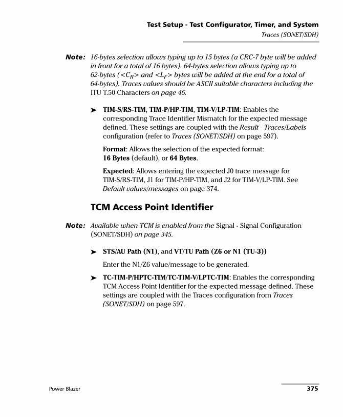
Test Setup - Test Configurator, Timer, and SystemTraces (SONET/SDH)
Note: 16-bytes selection allows typing up to 15 bytes (a CRC-7 byte will be added in front for a total of 16 bytes). 64-bytes selection allows typing up to 62-bytes (<CR> and <LF> bytes will be added at the end for a total of 64-bytes). Traces values should be ASCII suitable characters including the ITU T.50 Characters on page 46.
TIM-S/RS-TIM, TIM-P/HP-TIM, TIM-V/LP-TIM: Enables the corresponding Trace Identifier Mismatch for the expected message defined. These settings are coupled with the Result - Traces/Labels configuration (refer to Traces (SONET/SDH) on page 597).
Format: Allows the selection of the expected format: 16 Bytes (default), or 64 Bytes.
Expected: Allows entering the expected J0 trace message for TIM-S/RS-TIM, J1 for TIM-P/HP-TIM, and J2 for TIM-V/LP-TIM. See Default values/messages on page 374.
TCM Access Point Identifier
Note: Available when TCM is enabled from the Signal - Signal Configuration (SONET/SDH) on page 345.
STS/AU Path (N1), and VT/TU Path (Z6 or N1 (TU-3))
Enter the N1/Z6 value/message to be generated.
TC-TIM-P/HPTC-TIM/TC-TIM-V/LPTC-TIM: Enables the corresponding TCM Access Point Identifier for the expected message defined. These settings are coupled with the Traces configuration from Traces (SONET/SDH) on page 597.
Power Blazer 375

Test Setup - Test Configurator, Timer, and SystemTraces/PT (FlexO)
Traces/PT (FlexO) From the Test menu, tap Setup, Test Configurator, the FlexO-OTUCn protocol block, and the Traces/PT tab.
OTUCn, ODUCn, and ODUk Buttons
Tap on either the OTU or an ODU button.
SM/PM TTI Traces
Note: The TTI Traces are configurable for SM (OTUCn) and PM (ODUCn and ODUk).
Generated Message
Allows editing the SAPI, DAPI, and Operator Specific messages to be generated.
Expected Message
Allows editing the expected SAPI, and DAPI messages. The expected message settings are coupled with the Expected Message from Traces/PT (FlexO) on page 598.
376 88000 Series

Test Setup - Test Configurator, Timer, and SystemTraces/PT (FlexO)
SAPI (Source Access Point Identifier) corresponds to the TTI bytes 0 to 15. A maximum of 161 characters is allowed. NULL (all 0’s) characters are automatically appended to the message for bytes that are not defined. The expected SAPI message is available when the SAPI OTU/ODU-TIM check box is selected.
DAPI (Destination Access point Identifier) corresponds to the TTI bytes 16 to 31. A maximum of 161 characters is allowed. NULL (all 0’s) characters are automatically appended to the message for bytes that are not defined. The expected DAPI message is available when the DAPI OTU/ODU-TIM check box is selected.
1. For lower ODU layer, a maximum of 13 characters are allowed since the channel number is automatically appended to the message.
TTI Traces Default Messagea
a. The default message contains a NULL (all 0’s) character preceding it. NULL (all 0’s)characters are automatically appended to the message for bytes that are notdefined.
SM EXFO OTU SAPI
PM XFO ODU SAPIb
b. For ODUk, the client ID is automatically appended to the generated/expectedmessage.
TTI Traces Default Messagea
a. The default message contains a NULL (all 0’s) character preceding it. NULL (all 0’s)characters are automatically appended to the message for bytes that are notdefined.
SM EXFO OTU DAPI
PM XFO ODU DAPIb
b. For ODUk, the client ID is automatically appended to the message.
Power Blazer 377

Test Setup - Test Configurator, Timer, and SystemTraces/PT (FlexO)
Operator Specific corresponds to the TTI bytes 32 to 63. A maximum of 32 characters are allowed. NULL (all 0’s) characters are automatically appended to the message for bytes that are not defined.
SAPI OTU/ODU-TIM check box, when selected (cleared by default), allows editing the expected Source Access Point Identifier (SAPI) and also enables OTU/ODU-TIM alarm monitoring.
DAPI OTU/ODU-TIM check box, when selected (cleared by default), allows editing the expected Destination Access Point Identifier (SAPI) and also enables the OTU/ODU-TIM alarm monitoring.
TTI Traces Default Messagea
a. NULL (all 0’s) characters are automatically appended to the message for bytes thatare not defined.
SM EXFO OTU OPERATOR SPECIFIC
PM XFO ODU OPERATOR SPECIFIC
378 88000 Series

Test Setup - Test Configurator, Timer, and SystemTraces/PT (FlexO)
PT / Global PT
Note: Global PT indicates that the PT settings apply to all Client ID.
Note: Changing the payload type (PT) does not alter the signal structure; it only modifies the OH value that is generated.
Payload Type and Code
Generated: Allows the selection of the payload signal type to be generated either by selecting the payload type from the list or by entering its code in hexadecimal (00 to FF).
Expected: Allows selecting the expected payload signal type.
Note: Codes not listed in the table are reserved for future standardization (Reserved For International Standardization).
Payload type Hex Code MSB1234
LSB5678
Reserved for International Standardizationa 00 0000 0000
Experimental mapping 01 0000 0001
Asynchronous CBR mapping 02 0000 0010
Bit Synchronous CBR mapping 03 0000 0011
ATM mapping 04 0000 0100
GFP mapping 05 0000 0101
Virtual Concatenation Signal 06 0000 0110
PCS Codeword Transparent Ethernet 07 0000 0111
FC-1200 into ODU2e 08 0000 1000
GFP mapping into extended OPU2 09 0000 1001
OC-3/STM-1 into ODU0 0A 0000 1010
OC-12/STM-4 into ODU0 0B 0000 1011
FC-100 into ODU0 0C 0000 1100
FC-200 into ODU1 0D 0000 1101
FC-400 into ODUflex 0E 0000 1110
FC-800 into ODUflex 0F 0000 1111
Power Blazer 379

Test Setup - Test Configurator, Timer, and SystemTraces/PT (FlexO)
Bit Stream with Octet Timing mapping 10 0001 0000
Bit Stream Without Octet Timing mapping 11 0001 0001
IB SDR mapping into ODUflex 12 0001 0010
IB DDR mapping into ODUflex 13 0001 0011
IB QDR mapping into ODUflex 14 0001 0100
SDI mapping into OPU0 15 0001 0101
(1.485/1.001) Gbit/s SDI mapping into OPU1 16 0001 0110
1.485 Gbit/s SDI mapping in to OPU1 17 0001 0111
(2.970/1.001) Gbit/s SDI mapping into OPUflex 18 0001 1000
2.970 Gbit/s SDI mapping into OPUflex 19 0001 1001
SBCON/ESCON mapping into OPU0 1A 0001 1010
DVB_ASI mapping into OPU0 1B 0001 1011
FC-1600 mapping into OPUflex 1C 0001 1100
FlexE Client mapping into OPUflex 1D 0001 1101
FlexE aware (partial rate) mapping into OPUflex 1E 0001 1110
FC-3200 mapping into OPUflex 1F 0001 1111
ODU Multiplex with ODTUjk 20 0010 0000
ODU Multiplex with ODTUk.ts/ODTUjk 21 0010 0001
ODU multiplex with ODTUCn.ts 22 0010 0010
25GBASE-R mapping into OPUflex 30 0011 0000
200GBASE-R mapping into OPUflex 31 0011 0001
400GBASE-R mapping into OPUflex 32 0011 0010
Not Availableb 55 0101 0101
Reserved Codes for Proprietary Usec 80 1000 0000
NULL Test Signal mapping FD 1111 1101
PRBS Test Signal mapping FE 1111 1110
a. Selecting Reserved for International Standardization will use the hexadecimal code 00 but, all codesnot listed in the previous table at the exception of those covered in notes b and c are reserved for futurestandardization.
b. Selecting Not Available will use the hexadecimal code 55 but, 66 and FF are also Not Available payloadtypes.
c. Selecting Reserved Proprietary will use the hexadecimal code 80 but, all codes from 80 to 8F arereserved proprietary payload types.
Payload type Hex Code MSB1234
LSB5678
380 88000 Series

Test Setup - Test Configurator, Timer, and SystemTraces/PT (FlexO)
Note: The Code field is automatically updated when the Payload Type is changed and vice versa.
OPU-PLM, when selected, enables the OPU-PLM alarm analysis.
Power Blazer 381

Test Setup - Test Configurator, Timer, and SystemWander
Wander From the Test menu, tap Setup, Test Configurator, and the Wander test block.
Test
Sampling Rate is the time error measurement sampling rate: 30 samples/s (default), 20 samples/s, 10 samples/s, 5 samples/s, and 1 sample/s. Only 1 sample/s is supported with 1PPS rate.
Maximum Test Duration displays the maximum test duration based on the selected sampling rate.
Mask selects the MTIE/TDEV ITU mask for Time Error / Time Interval Error pass/fail validation: None (default), or one of the following:
Mask MTIE TDEV
G.811- Primary Reference Clock (PRC) X X
G.812- Type I Node Clock (SSU) - Constant Temperature X X
G.812- Type I Node Clock (SSU) - Variable Temperature X -
G.812- Type II and III Node Clock (SSU) - Constant Temperature X X
G.813- Option 1 SDH Equipment Clock (SEC) - Constant Temperature X X
G.813- Option 1 SDH Equipment Clock (SEC) - Variable Temperature X -
G.813- Option 2 SDH Equipment Clock (SEC) - Constant Temperature X X
G.823- Primary Reference Clock (PRC) X X
G.823- Synchronization Supply Unit (SSU) X X
G.823- SDH Equipment Clock (SEC) X X
G.823- PDH Synchronization Interface X X
G.824- 1544 kbit/s Reference Interface X X
G.824- 1544 kbit/s Reference Interface for Option 2 SEC - X
G.8261- CES Case 1 - 2048 kbit/s (MRTIE) X -
G.8261- CES Case 1 - 1544 kbit/s X -
G.8261- CES Case 2A - 2048 kbit/s (MRTIE) X -
G.8261- EEC Option 1 - SyncE Interface X X
G.8261- EEC Option 2 - SyncE Interface - X
382 88000 Series

Test Setup - Test Configurator, Timer, and SystemWander
cTE Averaging Period (s) defines the averaging period used to calculate the constant Time Error (cTE) value over a specific period of time: Elapse time (default), 100 s, 500 s, 1000 s, 10000 s.
dTEH Observation Period (s) defines the observation period used for qualifying the Time Error after High-Pass filtering 0.1 Hz: 100 s, 500 s, 1000 s, 10000 s (default).
Cable Delay Compensation (ns), available for time error measurements, allows manual compensation of external cable delay asymmetry: -1000 ns to 1000 ns (0 ns by default).
The cable delay asymmetry is caused by the difference between the length of the cable feeding the reference signal and the one feeding the signal under test. For example to compensate for a cable delay of -39 ns, enter this measured value as the Cable Delay Compensation: -39 - (-39) = 0 ns.
Duration check box, when selected (cleared by default), allows selecting/entering the test duration: 15 minutes, 1/2/4/6/12/24/72 hours, or User Defined (1 second up to 30 days depending on the selected Sampling Rate).
Note: Once the test completes (after the duration is reached or when manually stopped), MTIE calculation may take some time depending on the test duration and sampling rate used.
G.8261.1- PEC-Slave Frequency Case 3 X -
G.8262- EEC Option 1- SyncE - Constant Temperature X X
G.8262- EEC Option 1- SyncE - Variable Temperature X -
G.8262- EEC Option 2- SyncE - Constant Temperature X X
G.8263- PEC-Slave Frequency - Constant Temperature X -
G.8263- PEC-Slave Frequency - Variable Temperature X -
G.8271.1- Dynamic Time Error X -
Mask MTIE TDEV
Power Blazer 383

Test Setup - Test Configurator, Timer, and SystemWander
Verdict
The following pass/fail verdict are available and configurable when applicable.
MAX Absolute TE (ns) check box when selected, allows selecting the maximum absolute time error threshold value: 50 ns to 2000 ns (default is 1100 ns). Only available with 1PPS.
Max dTEH pk-pk (ns) check box when selected, allows selecting the maximum dynamic time error (after High-Pass filtering 0.1 Hz) peak-to-peak threshold value: 20 ns to 400 ns (default is 200 ns). Only available with 1PPS.
Max cTE (ns) check box when selected, allows selecting the maximum constant time error threshold value: 15 ns to 600 ns (default is 600 ns). Only available with 1PPS.
Note: MTIE and TDEV thresholds are disabled when the Mask selection is set to None.
MTIE check box when selected (default) reports the Maximum Time Interval Error (MTIE) verdict.
TDEV check box when selected (default) reports the Time Deviation (TDEV) verdict.
Restore Wander Defaults
Reverts the Wander test application to its default factory settings.
384 88000 Series

9 Test Results The Test Results menu offers the following structure:
Intelligent Apps test applications
Transport test applications
TabTest Application
PageiOptics iSAM
Logger X X 493
Summary 561 563 <---
Tab
Available with
PageOTN BERT
Multi-Channel
OTN
FlexO BERT
OTN- SONET/SDH
BERT
SONET/SDH BERT
DSn/PDH BERT
NI/CSU Emulation
Alarms/Errors X - X X X X - 391
FTFL/PT or PT X X - X - - - 482
GFP-F/GFP-T X - - - - - - 484
Labels - - - X X - - 488
Logger X X X X X X X 493
OTL-SDT X - - X - - - 499
Performance Monitoring
X - - X X X - 501
SDT - X - - - - 519
Summary 531 569 559 531 531 531 571 <---
Traces 595 595 - 595 / 597 597 - - <---
Traces/PT - - X - - - - 598
Traffic - Ethernet
X - - - - - - 600
Power Blazer 385

Test Results
Ethernet test applications
Tab - SubtabTest Application
Pagea
a. EtherSAM
b
b. RFC 6349
c
c. RFC 2544
d
d. FlexE BERT
e
e. EtherBERT
f
f. Traffic Gen & Mon
g
g. Smart Loopback
h
h. Through Mode
i
i. TCP Throughput
j
j. Carrier Ethernet OAM
k
k. Cable Test
Alarms/Errors X X X X X X X X X X - 391FEC Statistics - - X - X - X - - - - 481Graph - - X - - - - - - - - 487Link OAM - - - - - - - - - X - 489Logger X X X X X X - X X X - 493S-OAM / MPLS-TP OAM - - - - - - - - - X - 514Service Configuration - Burst X - - - - - - - - - - 521Service Configuration - L2CP X - - - - - - - - - - 522Service Configuration - Ramp X - - - - - - - - - - 524Service Performance X - - - - - - - - - - 526Streams - Customer Frame Throughput - - - - - X - - - - - 530Streams - Frame Loss / Out-of-Sequence - - - - - X - - - - - 528Streams - Jitter - - - - - X - - - - - 528Streams - Latency - - - - - X - - - - - 529Streams - MPLS - - - - - X - - - - - 498Streams - Throughput - - - - - X - - - - - 530Summary 551 575 572 557 531 589 531 531 586 567
578545 <---
Traffic - Ethernet X X X X X X X X X - - 600Traffic - Flow Control - X X - - X - X X - - 603Traffic - Graph - - - - - X - X - - - 605Traffic - MPLS - - - - - - - X - - - 498Traffic - S-OAM / MPLS-TP OAM - - - - - - X - - X - 606Window Sweep - X - - - - - - - - - 608WIS X - X - X X X - - X - 609
386 88000 Series

Test Results
Sync test applications
Fibre Channel test application
Wireless Test Application
TabTest Application
Page1588 PTP SyncE Wander
Alarms/Errors X X X 391
Analysis - MTIE/TDEV - - X 477
Analysis - Time Error - - X 479
Logger X X X 493
PTP Stats X - - 508
Quality Level (1588 PTP) X - - 510
Quality Level (SyncE) - X - 512
Summary 540 583 591 <---
Traffic - Ethernet X X - 600
TabTest Application
PageFibre Channel BERT
Alarms/Errors X 391
Logger X 493
Summary X 554
TabTest Application
PageCPRI/OBSAI BERTeCPRI BERT
CPRI OBSAI Alarms/Errors Xa
a. Only available for Framed L2.
Xa X 391
Logger X X X 493
Messages - X Xa 496
Summary X X X 531
Traffic - Ethernet - - Xa 600
Power Blazer 387

Test ResultsAlarms/Errors Overview
Alarms/Errors OverviewCurrent and history alarms/errors are displayed using different background colors as defined in the following table.
Seconds gives the total number of seconds in which one or more alarm/error occurred.
Count gives the number of occurrences of a specific error. The count is displayed using integer value; exponential value (for example: 1.00000E10) is used when the count is bigger than the field display capacity.
Rate calculates and displays the error rate. The rate is expressed using the exponential format with two decimal digits (example: 1.23E-04).
Note: When an alarms/errors group displays a magnifying icon, tapping on it gives more information on alarm/error like Second, Count, and Rate.
Background color
Alarm/ Error Description
Gray Current No test result available.
History
Green Current No alarm/error has occurred in the last second.
History No alarm/error has occurred during the test.
Red Current An alarm/error occurred in the last second.
History
Amber History At least one alarm/error has occurred during the test.
388 88000 Series

Test ResultsAlarms/Errors Overview
Pass/Fail Verdict
Note: The verdict is not displayed when disabled or unavailable.
The Pass/Fail verdict is represented by the following icons:
Statistic Values
Current indicates the average measurements in the last second.
Last indicates the result of the last measurement.
Minimum indicates the minimum value recorded.
Maximum indicates the maximum value recorded.
Average indicates the average value.
Port Buttons
For Dual Port topology the port buttons allows displaying the alarms/errors for each port individually.
Channel
Available with Multi-Channel OTN, allows the selection of the channel number.
Icon Verdict Description
PASS Result value meet the configured threshold criterion.
FAIL Result value does not meet the configured threshold criterion.
Power Blazer 389

Test ResultsAlarms/Errors Overview
Port, FlexE PHY Number, Client ID, and Size (Gbit/s)
Note: Only available with FlexE BERT test application.
Port allows selecting the physical port number to be displayed.
FlexE PHY Number indicates the FlexE PHY number assigned to the port.
Client ID allows selecting the client ID to be displayed.
Size (Gbit/s) indicates the size of the client ID.
Port, Client ID, and FlexO Instance ID
Note: Only available with FlexO BERT test application.
Port allows selecting the physical port number to be displayed.
Client ID indicates the client ID.
FlexO Instance ID indicates the FlexO PHY identifier assigned to the port.
390 88000 Series

Test ResultsAlarms/Errors Overview
Alarms/Errors
From the Test menu, tap Results, and the Alarms/Errors tab. Depending on the test structure, the Alarms/Errors page may be split in different tabs such as OTN, GFP-T/GFP-F, PHY, Group, Client, and Ethernet; tap on the desired tab when required.
Alarms/errors blocks containing the magnifier (+) icon in its title, opens a zoomed view giving more details like alarms/errors for each lane (parallel interface), errors in seconds, count, and rate.
When there is not enough room on the page to display the error in seconds, count, and rate, the error is displayed in Seconds per default. To select another unit, tap on the unit’s button and select either Seconds (default), Count, or Rate.
Total, available with certain errors (parallel interface), indicates the total of all lanes when Count or Rate unit is selected.
The following table lists the availability of alarms/errors per layer for TX and RX.
LayerAlarms/Errors
PageTX/RX RX only
BER Pattern Loss No Traffic, Client Frequency 396
Bit Error, Pattern Error Mismatch ‘0’, Mismatch ‘1’, Frame Loss, Out-of-Seq.
CLOCK - LOC, LOPPS-L, LOPPS-R 397
CPRI LOF, R-LOS, R-LOF, RAI, SDI Link Down 398
FAS -
DS1 AIS. OOF, RAI - 399
CRC-6, Framing Bit -
DS3 AIS, Idle, OOF, RDI - 400
CP-BIT, FEBE, F-Bit, P-Bit -
E1 AIS, LOF, RAI, LOMF, RAI MF, TS16 AIS - 401
FAS CRC-4, E-Bit
Power Blazer 391

Test ResultsAlarms/Errors Overview
E2E3E4
AIS, LOF, RAI - 402 403404
FAS -
Ethernet Link Down, Remote Fault, Local Faulta Hi-BER, Local Fault Det., Local Fault Rcd., Client Frequency, No Traffic (FlexE, see page 396)
405
Block, FCS, Symbol Alignment, False Carrier, Idle, Jabber, Oversize, Runt, Undersize
Ethernet - PCS
L Deg SER Rcd, R Deg SER LOA, Inv. Mapping, L Deg SER Det 408
66B Block, FEC-UNCOR-CW, FEC-COR-CW -
Ethernet - PCS (Lanes)
- LOBL, LOAML, Exc. Skew 410
Block, Inv. Marker, PCS BIP-8, FEC-SYMBa Pre-FEC-SYMB, Pre-FEC-Bit
FEC (FlexO) FEC-COR-CW, FEC-UNCOR-CW, FEC-SYMBa Pre-FEC-SYMB 412
FEC (OTN) FEC-CORR-BIT, FEC-CORR-CW, FEC-CORR-SYM, FEC-STRESS, FEC-UNCORR-CW
FEC-UNCORR-BIT, FEC-UNCORR-SYM
413
FEC Lanes - FEC-LOAML, Pre-FEC-SYMB 452
Fibre Channel
- Link Down, Local Fault Detected, Local Fault Received, Remote Fault, LOCWS
413
FCS,
RS-FEC Layer: FEC-COR-CW, FEC-UNCOR-CW, FEC-SYMBa
Symbol, Block, Oversize, Undersize, 66B Block, Pre-FEC-SYMB
FlexE Group - FlexE Group Down, Inconsistent Calendar, Illegal Client, Calendar Mismatch
415
FlexO Group LOM, OOM, GIDM, IIDM, MAPM, RPF Group Down, Exc. Instance Skew 415
MFAS, OH CRC -
FOIC1.4 - LOA, LOAML, Exc. Skew 418
Inv. Marker -
GFP LFD, DCI, FDI, RDI, LOCS, LOCCS, User-Defined CMF
EXM, UPM, Reserved CMF 419
cHEC-CORR, cHEC-UNCORR, tHEC-CORR, tHEC-UNCORR, eHEC-CORR, eHEC-UNCORR, SB-CORR (Post), SB-CORR (Pre), SB-UNCORR, 10B_ERR, pFCS
-
LayerAlarms/Errors
PageTX/RX RX only
392 88000 Series

Test ResultsAlarms/Errors Overview
GMP (ODTU4.1 -GMP)
- OOS 424
- Cm-CRC-8, CnD-CRC-5
GMP (ODTUC4.80 - GMP)
- OOS 424
- Cm-CRC-6, CnD-CRC-9
Interface LOS LOC Lane, Frequency, LOC 425
BPV, EXZ, CV, K30.7, 66B Block, Sync Header
IP/UDP/TCP - IP Chksum, UDP Chksum, TCP Chksum
428
MPLS-TP OAM
RDI, AIS, LCK, C-LOS, C-FDI, C-RDI, C-DCIa Loss Continuity, Mismerge, Unexp MEG Lvl, Unexp MEP, Unexp Period
453
OBSAI LOF Link Down, RP3 Address Mismatch 429
FAS CRC
ODUCn AIS, LCK, BDI TIM 435
BEI, BIP-8 -
ODUk (ODUflex)
LOFLOM, AIS, OCI, LCK, BDI TIM 430
BEI, BIP-8 -
ODUx LOFLOM, AIS, OCI, LCK, BDI, FSF, BSF, FSD, BSD
TIM 430
BEI, BIP-8 -
ODUx-TCM BDI, BIAE, IAE, LTC TIM 433
BEI, BIP-8 -
OPUCn LOOMFI, MSIM, OOMFI PLM 439
OMFI -
OPUk (OPUflex)
AIS, CSF PLM 437
OMFI -
OPUx AIS, CSF, LOOMFI, MSIM, OOMFI PLM 437
OMFI -
OTL LOF, LOL, LOR, OOF, OOR Exc. Skew 440
FAS, Inv. Marker -
OTUx AIS, BDI, BIAE, IAE, LOF, LOM, OOF, OOM TIM 441
FAS, MFAS, BIP-8, BEI -
LayerAlarms/Errors
PageTX/RX RX only
Power Blazer 393

Test ResultsAlarms/Errors Overview
OTUC Frame LOFLOM, OOF - 446
FAS, MFAS -
OTUCn AIS, BDI, BIAE, IAE TIM 446
BIP-8, BEI -
PHY (Ethernet)
Link Down Hi-BER 448
PHYs Loss of OH Frame Lock, Loss of OH MF Lock, Remote PHY Fault
Loss of PHY Number Lock, Excessive PHY Skew, FlexE Group Number Mismatch
449
OH CRC -
PTP - Loss Sync, Loss Announce, Unusable, Domain Mismatch, QL Mismatch
450
QoS Metrics - Frame Loss, Out-of-Seq. 451
Reference Signal
- REF-FAULT 451
RS-FEC (for Fibre Channel, see page 413)
- FEC-LOA, FEC-LOAML 452
For 88260 (25GE): Inv-CW-Marker, FEC-COR-CW, FEC-UNCOR-CW, FEC-SYMBa
For 88260 (25GE): Pre-FEC-SYMB
For 88260 (100GE): Inv-CW-Marker, FEC-COR-CW, FEC-UNCOR-CW, Pre-FEC-SYMB
For 88200NGE: FEC-COR-CW, FEC-UNCOR-CW, Pre-FEC-SYMB
S-OAM RDI, AIS, LCK, C-LOS, C-FDI, C-RDI, C-DCIa Loss Continuity, Mismerge, Unexp MEG Lvl, Unexp MEP, Unexp Period
453
Section/Line /RS/MS
LOF-S/RS-LOF, SEF/RS-OOF, AIS-L/MS-AIS, RDI-L/MS-RDI
TIM-S/RS-TIM 457
FAS-S/RS-FAS, B1, B2, REI-L/MS-REI -
STS-x / AU-x AIS-P/AU-AIS, LOP-P/AU-LOP, UNEQ-P/HP-UNEQ, PDI-P, RDI-P/HP-RDI, ERDI-PCD/ERDI-CD, ERDI-PPD/ERDI-PD, ERDI-PSD/ERDI-SD
TIM-P/HP-TIM, PLM-P/HP-PLM 459
B3, REI-P/HP-REI -
SyncE - ESMC Loss, QL Mismatch 461
LayerAlarms/Errors
PageTX/RX RX only
394 88000 Series
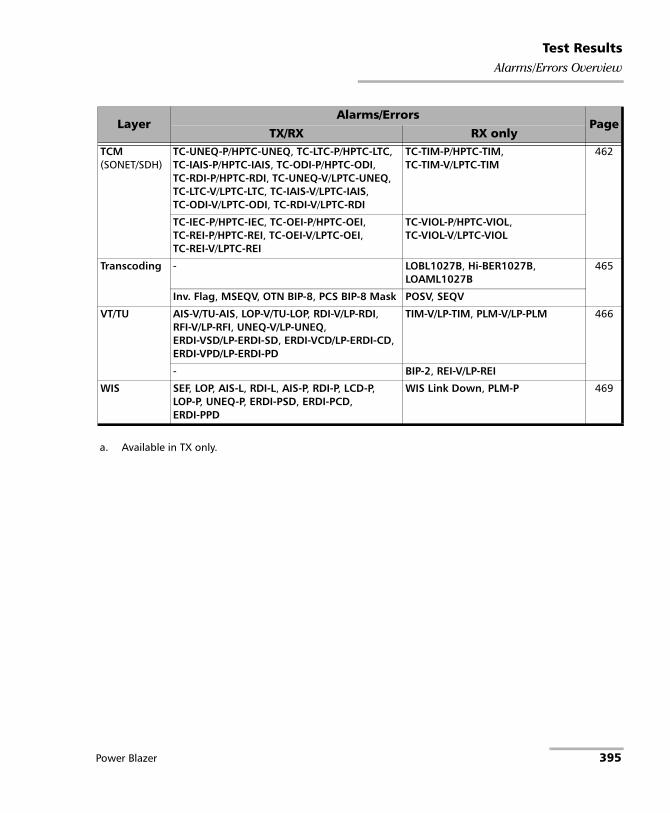
Test ResultsAlarms/Errors Overview
TCM(SONET/SDH)
TC-UNEQ-P/HPTC-UNEQ, TC-LTC-P/HPTC-LTC, TC-IAIS-P/HPTC-IAIS, TC-ODI-P/HPTC-ODI, TC-RDI-P/HPTC-RDI, TC-UNEQ-V/LPTC-UNEQ, TC-LTC-V/LPTC-LTC, TC-IAIS-V/LPTC-IAIS, TC-ODI-V/LPTC-ODI, TC-RDI-V/LPTC-RDI
TC-TIM-P/HPTC-TIM, TC-TIM-V/LPTC-TIM
462
TC-IEC-P/HPTC-IEC, TC-OEI-P/HPTC-OEI, TC-REI-P/HPTC-REI, TC-OEI-V/LPTC-OEI, TC-REI-V/LPTC-REI
TC-VIOL-P/HPTC-VIOL, TC-VIOL-V/LPTC-VIOL
Transcoding - LOBL1027B, Hi-BER1027B, LOAML1027B
465
Inv. Flag, MSEQV, OTN BIP-8, PCS BIP-8 Mask POSV, SEQV
VT/TU AIS-V/TU-AIS, LOP-V/TU-LOP, RDI-V/LP-RDI, RFI-V/LP-RFI, UNEQ-V/LP-UNEQ, ERDI-VSD/LP-ERDI-SD, ERDI-VCD/LP-ERDI-CD, ERDI-VPD/LP-ERDI-PD
TIM-V/LP-TIM, PLM-V/LP-PLM 466
- BIP-2, REI-V/LP-REI
WIS SEF, LOP, AIS-L, RDI-L, AIS-P, RDI-P, LCD-P, LOP-P, UNEQ-P, ERDI-PSD, ERDI-PCD, ERDI-PPD
WIS Link Down, PLM-P 469
a. Available in TX only.
LayerAlarms/Errors
PageTX/RX RX only
Power Blazer 395

Test ResultsAlarms/Errors Overview
BER
Alarms
No Traffic (Available with EtherBERT or OTN BERT with EoOTN client)
RX: Ethernet: No pattern traffic has been received in the last second. Fibre Channel: No traffic is being transmitted when Login Management fails; a pop up displays No Data is being transmitted on Port(s) <port number>. The Login process has failed.
Pattern Loss
RX: Ethernet: More than 20 percent of bit errors are received or the reference sequence can be unambiguously identified as out of phase. However, for OTU4 - 4 Unframed Physical Lanes and 100GE - 4 Unframed CAUI-4, bit error rate is greater than 2.5x10⁻³. Fibre Channel: bit error is detected on four consecutive words.
Client Frequency (Available for ODUflex with Pattern client)
RX: The received client signal rate doesn’t meet the nominal bit rate configured ± 100 ppm (refer to Nominal Bit Rate on page 344).
Errors
Bit Error
RX: There are logic errors in the bit stream (i.e., zeros that should be ones and vice versa). Only the count and rate values are reported for unframed test 40GE/OTU3 and up.
Pattern Error
RX: Indicates a block mismatch. Available with Seed A or Seed B pattern.
396 88000 Series
Test ResultsAlarms/Errors Overview
Mismatch ‘0’ (Available with EtherBERT and OTN BERT with EoOTN client; not available with 100GE - 4 Unframed CAUI-4 and OTU4 - 4 Unframed Physical Lanes on 88200NGE.)
RX: There is a bit error on a binary ‘0’ (for example ones that should be zeros) found in the test pattern only.
Mismatch ‘1’ (Available with EtherBERT and OTN BERT with EoOTN client; not available with 100GE - 4 Unframed CAUI-4 and OTU4 - 4 Unframed Physical Lanes on 88200NGE.)
RX: There is a bit error on a binary ‘1’ (for example zeros that should be ones) found in the test pattern only.
Clock
LOC (Loss Of Clock)
RX: The module is unable to synchronize with the selected Clock Mode. No valid clock is generated/extracted to/from the EXT CLK port.
LOPPS-L and LOPPS-R (Loss Of Pulse Per Second - Local/Remote) are only available in One-Way Latency measurement mode for Dual Test Set and eCPRI BERT (LOPPS-L).
RX: Either no pulse is received or no pulse is received within 1 second ± 6.6 μs after the previous pulse. LOPPS-R is only monitored once the DTS connection is established.
Power Blazer 397

Test ResultsAlarms/Errors Overview
CPRI
Note: CPRI alarms/errors are only available for Framed L2.
Alarms
Link Down
RX: Indicates that the start-up sequence is not in F (Operation) or G (Passive) link state.
LOF (Loss Of Frame)
RX: The hyperframe alignment cannot be achieved or is lost.
R-LOS (Remote - Loss Of Signal)
RX: Bit 3 of the Z.130.0 byte is set to 1.
R-LOF (Remote - Loss Of Frame)
RX: Bit 4 of the Z.130.0 byte is set to 1.
RAI (Remote Alarm Indication)
RX: Bit 1 of the Z.130.0 byte is set to 1.
SDI (Service Access Point Defect Indication)
RX: Bit 2 of the Z.130.0 byte is set to 1.
Errors
FAS (Frame Alignment Signal)
RX: For rates up to 9.8G, error detected in the start of hyperframe (byte different of K28.5 while not in LOF). For rate 10.1G, error detected in the sync control word of hyperframe (byte different of /S/ while not in LOF).
398 88000 Series

Test ResultsAlarms/Errors Overview
DS1
Note: For Wander test application only AIS and OOF alarms are supported.
Alarms
AIS (Alarm Indication Signal)
RX: An unframed all-ones signal is received.
OOF (Out-OF-Frame)
RX: Four consecutive frame bit errors are detected.
RAI (Yellow) (Remote Alarm Indication)
RX:
SF framing: Bit 2 in each timeslot contains “0”.
ESF framing: Eight “ones” followed by eight “zeros” pattern is received continuously in the data link (FDL).
Errors
Framing Bit
RX: An incorrect value appeared in a bit position reserved for framing.
CRC-6 (Cyclical Redundancy Check) is only available with ESF framing.
RX: One or more bit errors have been detected in a block of data through cyclical redundancy check.
Power Blazer 399

Test ResultsAlarms/Errors Overview
DS3
Alarms
AIS (Alarm Indication Signal)
RX: The M-frame contains zeros (0) for C-bits, ones (1) for X-bits, 1010... repeating sequence with a one (1) immediately following any of the control bit positions for the information bits.
Idle (DS3 Idle)
RX: Subframe 3 of the M-frame contains zeros (0) for the three C-bits, ones (1) for X-bits, 1100... repeating sequence with the first two bits following each control bit set to 11 for the information bits.
OOF (Out-OF-Frame)
RX: Four consecutive frame bit errors are detected.
RDI (Remote Defect Indicator)
RX: Both X-bits of the M-Frame are set to “0”.
Errors
CP-Bit (Control-Bit)
RX: The three C-bits reserved to control bit stuffing are different of “111” and “000”.
F-Bit (Framing-Bit)
RX: The frame alignment pattern received is different of “1001”.
P-Bit (Parity-Bit)
RX: The P-Bits does not match the parity of all the information bits following the first X-Bit of the previous DS3 frame.
FEBE (Far-End Block Error)
RX: The three FEBE bits reserved for framing or parity error detection contain the “000” pattern.
400 88000 Series

Test ResultsAlarms/Errors Overview
E1
Note: For Wander test application only AIS and LOF alarms are supported.
Alarms
Note: Only AIS is available when the framing is set to Unframed.
AIS (Alarm Indication Signal)
RX: Two or less ZEROs are received in each of two consecutive double frame periods (512 bits).
LOF (Loss Of Frame)
RX: Three consecutive incorrect frame alignment signals is received.
RAI (Yellow) (Remote Alarm Indication)
RX: Bit 3 in timeslot 0 is set to “1”.
TS16 AIS (TimeSlot 16 Alarm Indication Signal)
RX: Three or less ZEROs are received in each Timeslot 16 of two consecutive multiframes.
LOMF (Loss Of MultiFrame)
RX: Two consecutive multiframes alignment signals (bits 1 through 4 of TS16 of frame 0) is received with an error.
RAI MF (Remote Alarm Indication Multi-Frame)
RX: Bit 6 of timeslot 16 of frame 0 is set to “1”.
Power Blazer 401

Test ResultsAlarms/Errors Overview
Errors
FAS (Frame Alignment Signal) is only available with PCM30 CRC-4 or PCM31 CRC-4 framing.
RX: Bits 2 to 8 of the frame containing the FAS differ from 0011011.
CRC-4 (Cyclical Redundancy Check)
RX: One or more bit errors are detected in a block of data through cyclical redundancy check.
E-Bit (CRC-4 Error Signal) is only available with PCM30 CRC-4 or PCM31 CRC-4 framing.
RX: Bit 1 of sub-multiframe (SMF) II in frame 13 and/or 15 is set to 0 indicating a sub-multiframe error.
E2
Alarms
Note: Only AIS is available when the framing is set to Unframed.
AIS (Alarm Indication Signal)
RX: An unframed all-ones signal is received.
LOF (Loss Of Frame)
RX: Four consecutive incorrect frame alignment signals is received.
RAI (Remote Alarm Indication)
RX: Bit 11 of a framed E2 is set to “1”.
Errors
FAS (Frame Alignment Signal)
RX: Bits 1 to 10 of the first frame differ from 1111010000.
402 88000 Series

Test ResultsAlarms/Errors Overview
E3
Alarms
Note: Only AIS is available when the framing is set to Unframed.
AIS (Alarm Indication Signal)
RX: An unframed all-ones signal is received.
LOF (Loss Of Frame)
RX: Four consecutive incorrect frame alignment signals is received.
RAI (Remote Alarm Indication)
RX: Bit 11 of a framed E3 is set to “1”.
Errors
FAS (Frame Alignment Signal)
RX: Bits 1 to 10 of the first frame differ from 1111010000.
Power Blazer 403

Test ResultsAlarms/Errors Overview
E4
Alarms
Note: Only AIS is available when the framing is set to Unframed.
AIS (Alarm Indication Signal)
RX: An unframed all-ones signal is received.
LOF (Loss Of Frame)
RX: Four consecutive incorrect frame alignment signals is received.
RAI (Remote Alarm Indication)
RX: Bit 13 of a framed E4 is set to “1”.
Errors
FAS (Frame Alignment Signal)
RX: Bits 1 to 12 of the first frame differ from 111110100000.
404 88000 Series

Test ResultsAlarms/Errors Overview
Ethernet
Note: Available with EtherBERT, Wander, and OTN BERT with EoOTN client. For Wander test application only Link Down alarm is supported.
Alarms
Note: For LOA, Inv. Mapping, L Deg SER Det, L Deg SER Rcd, and R Deg SER alarms see Ethernet - PCS on page 408.
Link Down
RX: For 10/25/40/100/200/400G: There is a local or a remote fault condition. For 100/1000 Mbit/s: No bits/clock sync (PMA/PMD Link down), including LOS. For 10 Mbit/s: No data or no Normal Link Pulse (NLP) are received.
Local Fault Det1 (Local Fault Detected)
RX: At least one of the following events is detected: Loss of bit synchronization, Loss of Block synchronization, Link down, or High BER.
Local Fault Rcd1 (Local Fault Received)
RX: The received data path contains the Local Fault signal.
Remote Fault1
RX: The received data path contains the Remote Fault status.
Hi-BER (High-Bit Error Ratio) - (Available with 25/40/100GE interface, and EoOTN 100 GbE client).
RX: The bit error ratio is > 10-4 on a fixed time period; 2 ms for 25G, 1250 μs for 40G, and 500 μs for 100G.
1. Available with Ethernet 10/25/40/100/200/400 Gbit/s interface, Ethernet (flex/GFP-F) client, and EoOTN 10/40/100 GbE client. Remote Fault is also available with EoOTN 1GbE client.
Power Blazer 405

Test ResultsAlarms/Errors Overview
Client Frequency (available with EoOTN 1GbE client)
RX: The received client signal rate doesn’t meet the standard rate specification of 1250000000 ± 150000 bps (± 120 ppm).
Errors
Symbol1
RX/TX: Invalid code-group is detected/generated in the code.
Idle1
RX: An error is detected between the end of a frame and the beginning of the next frame.
False Carrier1
RX: Data is being received with invalid start of frame.
Block (available with Ethernet 10G LAN/WAN interface)
RX: Error block received in frames.
Alignment (available with 10/100 Mbit/s interface)
RX: Frames without an integral number of octets in length are received.
FCS (Frame Check Sequence)
RX: Frames with an invalid FCS are received.
Jabber
RX: Frames larger than 1518 bytes2 with an invalid FCS are received; 1534 bytes3 for EoE; 1536 bytes4 for PBB-TE.
1. Available with Ethernet 100/1000 Mbit/s interface, and EoOTN 1GbE client.
2. Add 4 bytes to this value for each VLAN layer enabled.
3. Add 4 bytes to this value for each VLAN layer enabled in the encapsulated Ethernet payload and 4 bytes for EoE VLAN when enabled.
4. Add 4 bytes to this value for each VLAN layer enabled in the encapsulated Ethernet payload and 4 bytes for B-VLAN when enabled.
406 88000 Series

Test ResultsAlarms/Errors Overview
Oversize (available when the Oversize Monitoring check box is selected.)
RX: Frames larger than 1518 bytes2 with a valid FCS; 1534 bytes3 for EoE; 1536 bytes4 for PBB-TE.
Runt
RX: Frames smaller than 64 bytes with an invalid FCS; 80 bytes for EoE; 82 bytes for PBB-TE.
Undersize
RX: Frames smaller than 64 bytes with a valid FCS; 80 bytes for EoE; 82 bytes for PBB-TE.
Oversize Monitoring check box, when selected (cleared by default), allows monitoring the Oversize frame errors.
The following errors are only available with Half Duplex mode (only for electrical interface at speeds of 10 Mbit/s and 100 Mbit/s).
Collision
RX: Indicates the number of collisions on the link.
Late Coll.
RX: Indicates the number of collisions that have occurred after a 64 bytes transmission.
Exc. Coll.
RX: Indicates the number of frames that were sent 16 times unsuccessfully due to consecutive collisions.
Power Blazer 407

Test ResultsAlarms/Errors Overview
Ethernet - PCS
Note: Available with parallel interfaces only: 40/100/200/400 Gbit/s Ethernet and OTN with 40/100GbE Ethernet client. Available under the PCS sub tab for Through Mode test providing alarms/errors for both ports.
Alarms
LOA (Loss Of Alignment)
RX: Two or more logical lanes have the same logical lane marker value, or one or more logical lane marker recovery processes are in the OOR state, or if the differential delay between two logical lanes exceeds the configured alarm threshold compensable delay.
Inv. Mapping (Invalid Mapping) - (Available with 40/100G)
RX: Indicates errors in the mapping attributed to either a mapping value appearing more than once or a non valid mapping value (out of range).
The following alarms are available with 200/400G when FEC Degraded SER is enabled:
L Deg SER Det (Local Degraded SER Detected)
RX: Local FEC degraded SER condition is detected.
L Deg SER Rcd (Local Degraded SER Received)
RX: Local degraded SER signal is detected.
R Deg SER (Remote Degraded SER)
RX: Remote degraded SER signal is detected.
408 88000 Series

Test ResultsAlarms/Errors Overview
Errors
The following errors are available with 200/400G:
66B Block
RX: Invalid 64b/66b block code are received. An invalid 64b/66b block is declared when the synchronization field has a value of 00 or 11.
FEC-UNCOR-CW (Available when RS-FEC is enabled)
RX: FEC uncorrectable codeword error is detected on the Ethernet signal.
FEC-COR-CW (Available when RS-FEC is enabled)
RX: FEC correctable codeword error is detected on the Ethernet signal. The FEC-COR-CW does not raise an error, only the count and rate values are reported.
Power Blazer 409

Test ResultsAlarms/Errors Overview
Ethernet - PCS Lanes
Note: Available with parallel interfaces only: 40/100/200/400 Gbit/s Ethernet and OTN with 40/100 GbE Ethernet client. Available under the PCS sub tab for Through Mode test providing alarms/errors for both ports.
Skew Alarm Threshold (bits), available with Ethernet test application, allows setting the threshold value that will be used to declare a skew alarm. Not available at 100G when the RS-FEC check box is selected.
Default restore the default skew alarm threshold value.
Alarms
Note: For LOA and Inv. Mapping alarms see Ethernet - PCS on page 408.
LOBL (Loss of Block Lock)
RX: In lock mode, 65 invalid sync fields (00 or 11) within a 1024 sync window are received. A PCS Lane Lock alarm is cleared when receiving 64 consecutive valid 66b sync field (01 or 10) in a row. Available with 40/100G.
LOAML (Loss of Alignment Marker Lock)
RX: In lock mode, four consecutive marker values are received that do not match the alignment marker that the lane is currently locked to. The LOAML alarm is cleared when the PCS Lane is declared Lock and two valid alignment markers 16384 blocks (66b) apart are received.
Rate Range Default Value
400G200G
0 to 10550 4781
100G 0 to 2047 928
40G 0 to 4095 1856
410 88000 Series

Test ResultsAlarms/Errors Overview
Exc. Skew (Excessive Skew)
RX: The skew exceeds the defined threshold (see Skew Alarm Threshold (bits) on page 82).
Errors
Block is available with Ethernet test applications and 100 GbE over OTU4. Injection is not available when RS-FEC is enabled.
RX: Invalid 64b/66b block code are received. An invalid 64b/66b block is declared when the synchronization field has a value of 00 or 11.
Inv. Marker (Invalid Marker): Injection is not available when RS-FEC is enabled.
RX: There are errors in the 66-bit block alignment marker.
PCS BIP-8
RX: There are PCS lane bit-interleave parity error. A routine even-parity check is performed over all bits of a PCS lane, from and including the previous alignment marker, but not including the current alignment marker.
PCS BIP-8 Mask is available with 40GbE over OTU3 test.
RX: At the OTN ingress, the calculated 8-bit error mask contains at least one bit set to “1”.
OTN BIP-8 is available with 40GbE over OTU3 test
RX: Indicates for each lane that at the OTN egress, the calculated 8-bit error contains at least one bit set to “1”.
Power Blazer 411

Test ResultsAlarms/Errors Overview
Pre-FEC-SYMB (Available with 200/400G when RS-FEC (RX Only) is enabled)
RX: FEC symbol errors are detected. The Pre-FEC-SYMB does not raise an error, only the count and rate values are reported. Receiving uncorrectable codeword may affect the Pre-FEC-SYMB error rate.
Pre-FEC-Bit (Available with 200/400G when RS-FEC (RX Only) is enabled)
RX: Indicates the number of bits corrected by the FEC. Receiving uncorrectable codeword may affect the Pre-FEC-Bit error rate.
FEC (FlexO)
Error
FEC-COR-CW (FEC Correctable Codeword)
RX: FEC Codeword that contains errors and were corrected.
FEC-UNCOR-CW (FEC Uncorrectable Codeword)
RX: FEC Codeword that contains errors and were not corrected.
Pre-FEC-SYMB (Pre-FEC Symbol)
RX: FEC symbol errors are corrected and counted once for each 10-bit symbol.
412 88000 Series

Test ResultsAlarms/Errors Overview
FEC (OTN)
Error
FEC-CORR-CW/SYM/BIT (FEC Correctable Codeword/Symbol/Bit)
RX: FEC Codeword/Symbol/Bit that contains errors and were corrected.
FEC-UNCORR-CW/SYM/BIT (FEC Uncorrectable Codeword/Symbol/Bit)
RX: FEC Codeword/Symbol/Bit that contains errors and were not corrected.
Fibre Channel
Alarms
Link Down
RX: The Fibre Channel connection is down meaning that there is a local or a remote fault condition.
Local Fault Detected (FC 10X)
RX: Indicates that at least one of the following events is detected: LOS, Loss of bit synchronization, Loss of Block synchronization, Link down, or High BER (High BER is true when the bit error ratio > 10-4 on a fixed 125 μs time period).
Local Fault Received (FC 10X)
RX: Indicates that the received data path contains the Local Fault signal.
Remote Fault (FC 10X)
RX: Indicates that a Remote Fault event is detected.
LOCWS (FC 32X)
RX: Indicates that the codeword_sync is false.
Power Blazer 413
Test ResultsAlarms/Errors Overview
Error
Symbol (FC 1X/2X/4X/8X)
RX: Invalid code-group is detected in the code.
Block (FC 10X/16X)
RX: The number of frames received with an errored block condition.
66B Block (FC 32X)
RX: The number of frames received with an errored block condition; excluding frames in LOCWS.
FEC-CORR-CW (FC 32X)
RX: FEC codeword that contains errors and were corrected; excluding frames in LOCWS.
FEC-UNCOR-CW (FC 32X)
RX: FEC codeword that contains error and were not corrected; excluding frames in LOCWS.
Pre-FEC-SYMB (Pre-FEC Symbol; FC 32X)
RX: FEC symbol errors are corrected and counted once for each 10-bit symbol; excluding frames in LOCWS.
FCS (Frame Check Sequence)
RX/TX: Frames with an invalid FCS are received/generated.
Oversize
RX: The number of received FL-2 frames larger than 2148 bytes with a valid FCS.
Undersize
RX: FL-2 frames smaller than 36 bytes with a valid FCS.
414 88000 Series

Test ResultsAlarms/Errors Overview
FlexE Group
Note: Available with FlexE BERT.
Alarms
FlexE Group Down
RX: At least one PHY link of the group is down or any of the FlexE group alarm is present.
Inconsistent Calendar
RX: Inconsistency among the PHY maps, PHY numbers, or FlexE group numbers received on the different PHYs.
Illegal Client
RX: FlexE client size on the received calendar is not supported.
Calendar Mismatch
RX: Received calendar is different of the one transmitted.
Power Blazer 415
Test ResultsAlarms/Errors Overview
FlexO - Group
Note: Available with FlexO BERT.
Alarms
Group Down
RX: At least one instance of the group is in LOS, at least one OTUC is in LOFLOM, or any FlexO Group alarm at the exception of Remote PHY Fault.
LOM (Loss Of Multiframe)
RX: OOM is present for at least 3 ms.
OOM (Out-Of-Multiframe)
RX: MFAS are in error for at least 5 consecutive FlexO frames.
GIDM (Group ID Mismatch)
RX: Received GID of any of the group member PHYs, with good CRC, does not match the expected GID parameter.
IIDM (Instance ID Mismatch)
RX: Received IID, with good CRC, does not match the expected IID parameter.
MAPM (MAP Mismatch)
RX: MAPM is declared when the received MAP value (with good CRC) does not match the value of the transmitted MAP, any values of the received IID does not have the corresponding bit set in the transmitted MAP, or the received IID values are not unique.
416 88000 Series

Test ResultsAlarms/Errors Overview
RPF (Remote PHY Fault)
RX: The RPF bit is set in the OH.
Excessive Instance Skew
RX: The current skew is above the configured Instance Skew Alarm threshold. The Excessive Instance Skew condition corresponds to a Loss of lane alignment defect (LOL) as mentioned in the standard.
Errors
MFAS (Multiframe Alignment Signal)
RX: Received OH MFAS does not match the expected MFAS value.
OH CRC
RX: OH received with an invalid CRC.
Power Blazer 417

Test ResultsAlarms/Errors Overview
FOICx.y
Note: Available with FlexO BERT.
Skew Alarm Threshold (bits), coupled for all ports in the FlexO group, allows setting the threshold value that will be used to declare a skew alarm: 0 to 1000 ns (180 ns by default).
Default restore the default skew alarm threshold value.
Alarms
LOA (Loss Of Alignment)
RX: Two or more logical lanes have the same logical lane marker value, or one or more logical lane marker recovery processes are in the OOR state, or if the differential delay between two logical lanes exceeds the configured alarm threshold compensable delay.
LOAML (Loss of Alignment Marker Lock)
RX: In lock mode, five consecutive marker values are received that do not match the alignment marker that the lane is currently locked to. The LOAML alarm is cleared when FOIC Lane is declared Lock and two valid alignment markers are received.
Exc. Skew (Excessive Skew)
RX: The skew exceeds the defined threshold (see Skew Alarm Threshold (bits) on page 82).
Errors
Inv. Marker (Invalid Marker)
RX: There are errors in the 66-bit block alignment marker.
418 88000 Series

Test ResultsAlarms/Errors Overview
GFP (Generic Framing Procedure)
Note: Available from the GFP-F/GFP-T sub-tab.
Alarms
GFP-LFD (GFP - Loss of Frame Delineation)
RX: Indicates that the GFP engine is out of synchronization.
TX: Generates a sufficient number of cHEC uncorrectable errors to avoid synchronization.
GFP-EXM (GFP - Extension Header Mismatch)
RX: The EXM alarm is declared when the EXI received is different from the expected EXI (refer to EXI on page 222) without uncorrectable cHEC, tHEC, eHEC, and no pFCS errors.
GFP-UPM (GFP - User Payload Mismatch)
RX: The UPM alarm is declared when the UPI received is different from the expected Client Data UPI without uncorrectable cHEC, tHEC, eHEC, and no pFCS errors. The GFP-F/GFP-T on page 222 displays the expected UPI value based on the test structure. Refer to page 818 for more information on UPI values.
GFP-DCI (GFP - Defect Clear Indication)
RX: The DCI alarm is declared when CMF frame is received with an UPI set to “0000 0011”.
TX: Generates a client DCI by setting the UPI field to “0000 0011”.
Power Blazer 419

Test ResultsAlarms/Errors Overview
GFP-FDI (GFP - Forward Defect Indication) is available with GFP-F.
RX: The FDI alarm is declared when CMF frame is received with an UPI set to “0000 0100”.
TX: Generates a client FDI by setting the UPI field to “0000 0100”. Note that the configuration of the CMF pFCS check box (see GFP-F/GFP-T on page 222) is temporarily cleared and the UPI value changed when the GFP-FDI alarm is selected. The CMF pFCS check box state and the UPI value returns to their previous state/value when another alarm (other than GFP-FDI or GFP-RDI) is selected.
GFP-RDI (GFP - Reverse Defect Indication) is available with GFP-F.
RX: The RDI alarm is declared when CMF frame is received with an UPI set to “0000 0101”.
TX: Generates a client RDI by setting the UPI field to “0000 0101”. Note that the configuration of the CMF pFCS check box (see GFP-F/GFP-T on page 222) is temporarily cleared and the UPI value changed when the GFP-RDI alarm is selected. The CMF pFCS check box state and the UPI value returns to their previous state/value when another alarm (other than GFP-FDI or GFP-RDI) is selected.
GFP-LOCS (GFP - CSF-Loss of Client Signal)
RX: LOCS is declared when CMF frame is received while UPI is set to “0000 0001”.
TX: Generates a LOCS by setting the UPI field to “0000 0001”.
GFP-LOCCS (CSF-Loss of Client Character Synchronization)
RX: LOCCS is declared when CMP frame is received with an UPI set to “0000 0010”.
TX: Generates a LOCCS by setting the UPI field to “0000 0010”.
420 88000 Series

Test ResultsAlarms/Errors Overview
GFP-Reserved CMF (Client Management Frame) is available when the Reserved CMF Monitoring check box is selected.
RX: CMF alarms other than the ones described above.
Reserved CMF Monitoring check box, when selected, allows monitoring the GFP-Reserved CMF alarms.
GFP-UserDefined CMF
TX: Generates a CMF (Client Management Frame) with a user defined UPI.
Errors
GFP-cHEC-CORR (GFP - core Header Error Check - Correctable)
RX: Indicates that only one bit error has been detected on Core header (PLI and cHEC).
TX: Generates a “Walking 1” pattern to hit all applicable bits covered by the cHEC and PLI.
GFP-cHEC-UNCORR (GFP - core Header Error Check - Uncorrectable)
RX: Indicates that two or more bit errors have been detected on Core header (cHEC and PLI).
TX: Generates a “Walking 11” pattern to hit all consecutive 2 bits applicable to the bits covered by the cHEC and PLI.
GFP-tHEC-CORR (GFP - type Header Error Check - Correctable)
RX: Indicates that only one bit error has been detected in the Type header (tHEC, PTI, PFI, EXI, and UPI).
TX (requires client data frame generation): Generates a “Walking 1” pattern to hit all applicable bits covered by the tHEC, PTI, PFI, EXI, and UPI.
Power Blazer 421

Test ResultsAlarms/Errors Overview
GFP-tHEC-UNCORR (GFP - type Header Error Check - Uncorrectable)
RX: Indicates that two or more bit errors have been detected in the Type header (tHEC, PTI, PFI, EXI, and UPI).
TX (requires client data frame generation): Generates a “Walking 11” pattern to hit all consecutive 2 bits applicable to the bits covered by the tHEC, PTI, PFI, EXI and UPI.
GFP-eHEC-CORR (GFP - extension Header Error Check - Correctable) is only available with GFP-F when EXI is set to Linear.
RX: Indicates that only one bit error has been detected in the Extension header (eHEC, CID and Spare).
TX (requires client data frame generation): Generates a “Walking 1” pattern to hit all applicable bits covered by the eHEC, CID and Spare.
GFP-eHEC-UNCORR (GFP - extension Header Error Check - Uncorrectable) is only available with GFP-F when EXI is set to Linear.
RX: Indicates that two or more bit errors have been detected in the Extension header (eHEC, CID and Spare).
TX (requires client data frame generation): Generates a “Walking 11” pattern to hit all consecutive 2 bits applicable to the bits covered by the eHEC, CID and Spare.
GFP-SB-CORR (GFP - Superblock Correctable) is available with GFP-T.
RX: Indicates that bit error has been detected in the CRC-16 word of the superblock. A received SB Correctable (Pre) error counts as one error while SB Correctable (Post) counts as two errors.
TX:
GFP-SB-CORR (Pre) generates a “Walking 1” pattern to include a single bit error in the CRC-16 word of the superblock. GFP-SB-CORR (Post) generates in the payload of the superblock, a “Walking 1” pattern to include two separate errors in one superblock separated by 43 bits.
422 88000 Series

Test ResultsAlarms/Errors Overview
GFP-SB-UNCORR (GFP - Superblock Uncorrectable) is available with GFP-T.
RX: Indicates that two or more bit errors have been detected in the CRC-16 word of the superblock. Note that if two errors are spaced by exactly 43 bits, they will not be reported as uncorrectable.
TX: Generates a “Walking 11” pattern to include two consecutive errors in the CRC-16 word of the superblock.
GFP-10B_ERR (GFP - 10B_Error) is available with GFP-T.
RX: Indicates that a10B_ERR code has been detected in the payload of the superblock.
TX: Generates a 10B_ERR code over the payload of the superblock as defined in ITU G.7041.
GFP-pFCS (GFP - payload Frame Check Sequence)
RX: Indicates that at least one bit error has been detected in the payload.
TX (requires client data frame generation): Generates a “Walking 1” pattern to hit all 32 bits of the pFCS only. Only available with Ethernet (flex/GFP-F) client when the CDF pFCS check box is selected (refer to GFP-F/GFP-T on page 222).
Power Blazer 423

Test ResultsAlarms/Errors Overview
GMP and ODTU4.x - GMP (Generic Mapping Procedure)
Note: GMP is only available with EoOTN client (ODU0 with PT21). GMP is displayed under ODUx alarms/errors group. GMP is labelled as ODTU4.1 - GMP with Multi-Channel OTN and ODTUC4.80 - GMP with FlexO BERT.
Alarms
OOS (Generic Mapping Procedure - Out Of Synchronization).
RX: Indicates that the GMP RX cannot synchronize with the GMP TX.
Errors
Cm-CRC-8
RX: There is a Cm-CRC-8 mismatch between the received value and the locally computed value.
CnD-CRC-5
RX: There is a CnD-CRC-5 mismatch between the received value and the locally computed value.
Cm-CRC-6
RX: There is a Cm-CRC-6 mismatch between the received value and the locally computed value.
CnD-CRC-9
RX: There is a CnD-CRC-9 mismatch between the received value and the locally computed value.
424 88000 Series

Test ResultsAlarms/Errors Overview
Interface
Alarms
LOS (Loss Of Signal)
RX: Absence of an input signal or an all-zeros pattern is received. Available for each Optical Lane for parallel interfaces. Not supported when PHY Type is set to DAC.
For CPRI Framed L2:
For rates up to 9.8G: Absence of an input signal or at least 16 8B/10B code violations occur in one hyperframe.
For rate 10.1G: Absence of an input signal or the hi_ber variable is set to true.
For Wander 1PPS interface: Either no pulse is received or no pulse is received within 1 second ±100 ms after the previous pulse.
LOC Lane (Loss Of Clock Lane) is available for each Physical Lane for parallel interfaces.
RX: The unit is unable to lock on the Physical/CAUI/CAUI-4/XLAUI/200GAUI-4/400GAUI-8/16 link interface.
Frequency (available for each Physical Lane for parallel interfaces) Not available when using an active copper SFP.
RX: The received signal frequency meets the standard specifications (green) or not (red).
For Ethernet 100/1000M Electrical, 100M Optical, 1GE Optical, 10GE LAN/WAN, 25GE, or Fibre Channel 1X/2X/4X/8X/10X/16X/32X interface/rate, the frequency range is ± 100 ppm. Not supported for 10M electrical.
Power Blazer 425

Test ResultsAlarms/Errors Overview
For parallel interfaces:
For serial interfaces:
Rate Optic Type Frequency40GE 4x10G 10.3125 Gbit/s ± 100 ppm
OTU3 4x10G 10.7546 Gbit/s ± 20 ppm
OTU3e1 4x10G 11.1427 Gbit/s ± 20 ppm
OTU3e2 4x10G 11.1458 Gbit/s ± 20 ppm
100GE 4x25G 25.78125 Gbit/s ± 100 ppm
100G FlexO-1-RS 4x28G 27.952 Gbit/s ± 20 ppm
200GE 4x50G 26.5625 Gbit/s ± 100 ppm
400GE 8x50G 26.5625 Gbit/s ± 100 ppm
OTU4 4x25G 27.952 Gbit/s ± 20 ppm
Interface Standard Rate SpecificationDS1 1544000 ±36.6 ppm
E1 2048000 ±54.6 ppm
E3 34368000 ±24.6 ppm
DS3 44736000 ±24.6 ppm
STS-1e/STM-0e, OC-1/STM-0 51840000 ±20 ppm
E4 139264000 ±19.6 ppm
STS-3e/STM-1e, OC-3/STM-1 155520000 ±20 ppm
OC-12/STM-4 622080000 ±20 ppm
OC-48/STM-16 2488320000 ±20 ppm
OTU1 2666057143 ±20 ppm
OC-192/STM-64 9953280000 ±20 ppm
OTU2 10709225316 ±20 ppm
OTU1e 11049107143 ±100 ppm
OTU2e 11095727848 ±100 ppm
OTU1f 11270089286 ±100 ppm
OTU2f 11317642405 ±100 ppm
426 88000 Series

Test ResultsAlarms/Errors Overview
Error
BPV (Bipolar Violation) for DS1, DS3, and STS-1e: Pulses of the same consecutive polarity were detected, in violation with the bipolar signal format.
CV (Code Violation)
For E1, E3, E4, STM-0e, STM-1e, and STS-3e: Pulses of the same consecutive polarity were detected, in violation with the bipolar signal format.
For CPRI (up to 9.8G) /OBSAI: Invalid 10B code word received.
66B Block, for CPRI 10.1G, indicates sync header violations or /E character is received.
K30.7, for CPRI (up to 9.8G)/OBSAI Framed L2, code word with Error_Propagation /V ordered_set received.
Sync Header, for CPRI 10.1G indicates sync header violations.
EXZ (Excessive Zeros)
For DS1 with AMI Line Coding, more than 15 consecutive bit periods with no pulses have been received.
For DS1 with B8ZS Line Coding, more than 7 consecutive bit periods with no pulses have been received.
For DS3, more than 2 consecutive bit periods with no pulses have been received.
Power Blazer 427

Test ResultsAlarms/Errors Overview
IP/UDP/TCP
Errors
IP Chksum (IP Checksum)
RX: The IP datagrams received have invalid IP header checksum. Only available for IPv4.
UDP Chksum (UDP Checksum)
RX: The UDP segments received have invalid UDP checksum.
TCP Chksum (TCP Checksum)
RX: The TCP segments received have invalid TCP checksum.
428 88000 Series

Test ResultsAlarms/Errors Overview
OBSAI
Note: OBSAI alarms/errors are only available for Framed L2.
Alarms
Link Down
RX: Indicates that the RX state machine is not FRAME_SYNC.
LOF (Loss Of Frame)
RX: The RX state machine is in either WAIT_FOR_K28.7_IDLES or SCR_CAP state.
RP3 Address Mismatch available when Address Mismatch is enabled (refer to page 231)
RX: Indicates that the RP3 Target Address does not match the local RP3 Source Address.
Errors
FAS (Frame Alignment Signal)
RX: Error detected in message group terminating character (byte different of K28.5) or master frame terminating character (byte different of K28.7).
CRC (Cyclic Redundancy Check)
RX: Indicates a message received with an invalid CRC.
Power Blazer 429

Test ResultsAlarms/Errors Overview
ODUx and ODUk (ODUflex)
Note: For OPUx and OPUk (OPUflex) alarms see page 437. For GMP alarms/errors see page 424.
Alarms
AIS (Alarm Indication Signal)
RX: The STAT information in the PM byte 3, bits 6 to 8 is “111” for at least 3 consecutive frames.
TX: Generates an all "1"s pattern in the entire ODUk signal, excluding the frame alignment overhead (FA OH), OTUk overhead (OTUk OH) and ODUk FTFL.
BDI (Backward Defect indication)
RX: The BDI bit in the PM overhead field (byte 3, bit 5) is “1” for at least 5 consecutive frames.
TX: Generates a “1” in the BDI (byte 3, bit 5) of the PM overhead field continuously.
BSD (Backward Signal Degrade)
RX: The FTFL byte 128 is “00000010”.
TX: Generates a “00000010” pattern in the FTFL Byte 128 continuously.
BSF (Backward Signal Fail)
RX: The FTFL byte 128 is “00000001”.
TX: Generates a “00000001” pattern in the FTFL Byte 128 continuously.
FSD (Forward Signal Degrade)
RX: The FTFL byte 0 is “00000010”
TX: Generates a “00000010” pattern in the FTFL Byte 0 continuously.
430 88000 Series

Test ResultsAlarms/Errors Overview
FSF (Forward Signal Fail)
RX: The FTFL byte 0 is “00000001”.
TX: Generates a “00000001” pattern in the FTFL Byte 0 continuously.
LCK (Lock)
RX: STAT information in the PM byte 3, bits 6 to 8 is “101” for at least 3 consecutive frames.
TX: Generates a repeating "01010101" pattern in the entire ODUk signal, excluding the frame alignment overhead (FA OH) and OTUk overhead (OTUk OH).
LOFLOM (Loss of Frame Loss Of Multiframe) is only available for mapped ODU client signal (designated as LO in the standard).
RX: OOF is present for at least 3 ms.
TX: Generates error continuously in FAS and MFAS of a multiplexed test case.
OCI (Open Connection Indication)
RX: STAT information in the PM byte 3, bits 6 to 8 is “110” for at least 3 consecutive frames.
TX: Generates a repeating "01100110" pattern in the entire ODUk signal, excluding the frame alignment overhead (FA OH) and OTUk overhead (OTUk OH).
TIM (Trace Identification Mismatch)
RX: The received SAPI and/or DAPI do not math the expected SAPI and/or DAPI. This alarm is only available when the SAPI ODU-TIM and/or DAPI ODU-TIM check boxes are selected from PT / Global PT on page 219.
Power Blazer 431

Test ResultsAlarms/Errors Overview
Errors
BIP-8 (Bit Interleave Parity-8)
RX: There is a PM BIP-8 mismatch between the received value and locally computed value (0 to 8).
BEI (Backward Error Indication)
RX: Interleaved block in error detected by the corresponding ODU path monitoring sink using the BIP-8 code.
ODU BEI bits (1234) BIP violations ODU BEI bits
(1234) BIP violations
0000 0 0101 5
0001 1 0110 6
0010 2 0111 7
0011 3 1000 8
0100 4 1001 to 1111 0
432 88000 Series

Test ResultsAlarms/Errors Overview
ODUx-TCM
Alarms
BDI (Backward Defect Indication)
RX: The BDI bit in the TCM overhead field Byte 3, bit 5 is “1” for at least 5 consecutive frames.
TX: Generates a "1" in the BDI bit of the TCM overhead field (byte 3, bit 5) continuously.
BIAE (Backward Incoming Alignment Error)
RX: The BEI/BIAE bits in the TCM overhead field Byte 3, bits 1 to 4 are “1011” for at least 3 consecutive frames.
TX: Generates "1011" in the BEI/BIAE bits of the TCM overhead (byte 3, bits 1 to 4) continuously.
IAE (Incoming Alignment Error)
RX: The STAT information in the TCM is “010” for at least 3 consecutive frames.
TX: Generates "1" in the IAE bit of the TCM overhead (byte 3, bit 6) continuously.
LTC (Loss of Tandem Connection)
RX: The STAT information in the TCM Byte 3, bits 6, 7, and 8 are “000” for at least 3 consecutive frames.
TX: Generates "000" in the STAT field of TCM overhead (byte 3, bits 6 to 8) continuously.
TIM (Trace Identification Mismatch)
RX: The SAPI and/or DAPI do not math the expected SAPI and/or DAPI. This alarm is only available when the Enable TIM SAPI and/or DAPI check boxes are selected from PT / Global PT on page 219.
Power Blazer 433
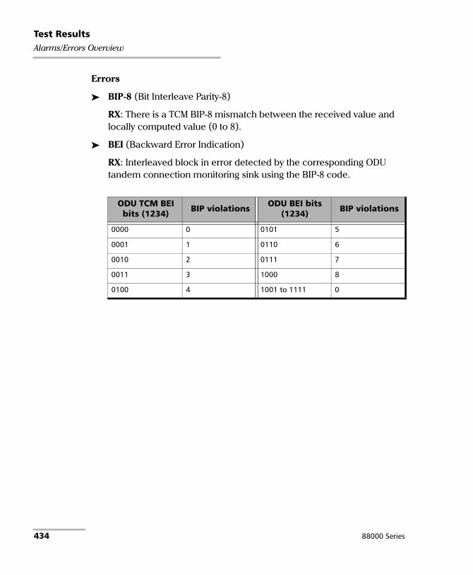
Test ResultsAlarms/Errors Overview
Errors
BIP-8 (Bit Interleave Parity-8)
RX: There is a TCM BIP-8 mismatch between the received value and locally computed value (0 to 8).
BEI (Backward Error Indication)
RX: Interleaved block in error detected by the corresponding ODU tandem connection monitoring sink using the BIP-8 code.
ODU TCM BEI bits (1234) BIP violations ODU BEI bits
(1234) BIP violations
0000 0 0101 5
0001 1 0110 6
0010 2 0111 7
0011 3 1000 8
0100 4 1001 to 1111 0
434 88000 Series

Test ResultsAlarms/Errors Overview
ODUCn
Note: For OPUCn alarms/errors see page 439.
Alarms
AIS (Alarm Indication Signal)
RX: The STAT information in the PM byte 3, bits 6 to 8 of ODUC #1 is “111” for at least 15 consecutive frames.
TX: Generates an all "1"s pattern in the entire ODUC signal, excluding the frame alignment overhead (FA OH), and OTUC overhead (OTUC OH).
LCK (Lock)
RX: STAT information in the PM byte 3, bits 6 to 8 of ODUC #1 is “101” for at least 15 consecutive frames.
TX: Generates a repeating "01010101" pattern in the entire ODUC signal, excluding the frame alignment overhead (FA OH) and OTUC overhead (OTUC OH).
BDI (Backward Defect indication)
RX: The BDI bit in the PM overhead field (byte 3, bit 5) of ODUC #1 is “1” for at least 15 consecutive frames.
TX: Generates a “1” in the BDI (byte 3, bit 5) of the PM overhead field of the ODUC #1 continuously.
TIM (Trace Identification Mismatch)
RX: The received SAPI and/or DAPI do not math the expected SAPI and/or DAPI. This alarm is only available when the SAPI ODU-TIM and/or DAPI ODU-TIM check boxes are selected from PT / Global PT on page 379.
Power Blazer 435
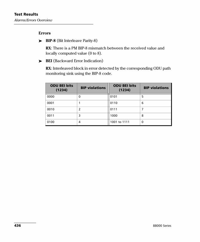
Test ResultsAlarms/Errors Overview
Errors
BIP-8 (Bit Interleave Parity-8)
RX: There is a PM BIP-8 mismatch between the received value and locally computed value (0 to 8).
BEI (Backward Error Indication)
RX: Interleaved block in error detected by the corresponding ODU path monitoring sink using the BIP-8 code.
ODU BEI bits (1234) BIP violations ODU BEI bits
(1234) BIP violations
0000 0 0101 5
0001 1 0110 6
0010 2 0111 7
0011 3 1000 8
0100 4 1001 to 1111 0
436 88000 Series

Test ResultsAlarms/Errors Overview
OPUx and OPUk (OPUflex)
Note: OPUx is displayed under ODUx alarms/errors group. OPUk (OPUflex) is displayed under ODUk alarms/errors group.
Alarms
AIS (Alarm Indication Signal) is only available on the OPU client signal (designated as LO in the standard).
RX: A PRBS11 pattern is received indicating a failure of the client signal.
TX: Generates a PRBS11 pattern.
CSF (Client Signal Fail) is only available on the OPU client signal (designated as LO in the standard).
RX: Bit 1 of the OPUk PSI[2] byte is set to “1” indicating a failure of the client signal mapped into the OPUk of the OTN signal.
TX: Sets the bit 1 of the OPUk PSI[2] byte to “1”.
LOOMFI (Loss of OPU Multi-Frame Identifier) is only available for OPU4 of a mapped signal.
RX: OOMFI is present for at least 3 ms.
MSIM (Multiplex Structure Identifier Mismatch) is available for the high oder path of a multiplexed test case only.
RX: The RX Payload Structure Identifier (PSI) information do not match the expected HO Multiplex Structure Identifier defined.
TX: Corrupts the content of the PSIFor PT20: Bytes 2 and 3 for ODU0 in ODU1, bytes 2 to 5 for ODU1 in ODU2, and bytes 2 to 17 for ODU2 in ODU3. Not applicable for ODU4.For PT21: Bytes 2 to 9 for ODU1 in ODU2, bytes 2 to 33 for ODU2 in ODU3, and bytes 2 to 81 for ODU3 in ODU4. Not applicable for ODU0.
Power Blazer 437

Test ResultsAlarms/Errors Overview
OOMFI (Out of OPU Multi-Frame Identifier) is only available for OPU4 of a mapped signal.
RX: OPU Multi-frame Identifier number are in error for at least 5 consecutive OTU frames.
PLM (Payload Mismatch) is available when OPU-PLM check box is selected.
RX: The Payload Structure Identifier (PSI) field does not match the expected PT for at least 3 consecutive frames.
MSIM Monitoring check box when selected (default) monitors the MSIM alarm.
Errors
OMFI (OPU Multi-Frame Identifier) is only available for OPU4 of a mapped signal.
RX: Invalid OMFI word sequence detected.
438 88000 Series

Test ResultsAlarms/Errors Overview
OPUCn
Note: OPUCn is displayed under ODUCn alarms/errors group.
Alarms
MSIM (Multiplex Structure Identifier Mismatch)
RX: The RX Payload Structure Identifier (PSI) information does not match the expected HO Multiplex Structure Identifier defined.
TX: Corrupts the content of the PSI bytes associated to the ODUk.
LOOMFI (Loss of OPU Multi-Frame Identifier)
RX: OOMFI is present for at least 3 ms.
OOMFI (Out of OPU Multi-Frame Identifier)
RX: OPU Multi-frame Identifier number are in error for at least 5 consecutive OTUC frames.
PLM (Payload Mismatch) is available when the OPU-PLM check box is selected.
RX: The Payload Structure Identifier (PSI) field does not match the expected PT for at least 3 consecutive frames.
MSIM Monitoring check box when selected (default) monitors the MSIM alarm.
Errors
OMFI (OPU Multi-Frame Identifier)
RX: Invalid OMFI word sequence detected.
Power Blazer 439

Test ResultsAlarms/Errors Overview
OTL
Alarms
LOL (Loss of Lane Alignment)
RX: Multilane alignment process is in the out-of-alignment (OLA) state for 3 ms.
LOF (Loss of Frame)
RX: OOF is present for at least 3 ms.
OOF (Out-Of-Frame)
RX: Any byte of the FAS (bytes 3, 4, and 5) is in error for at least 5 consecutive frames.
LOR (Loss Of Recovery)
RX: When OOR persists at least 3 ms.
OOR (Out-Of-Recovery)
RX: While in In-recovery (IR) state, in five consecutive 16320 byte periods each of the received logical lane marker (LLM) is different from the accepted LLM value.
Exc. Skew (Excessive Skew)
RX: The skew exceeds the defined threshold (see Skew Alarm Threshold (bits) on page 622).
Errors
FAS (Frame Alignment Signal)
RX: The FAS bits are in error.
Inv. Marker (Invalid Marker)
RX: Errors are detected in the 66-bit block alignment marker.
440 88000 Series

Test ResultsAlarms/Errors Overview
OTUx
Note: Available for OTU4, OTU3, OTU3e1, OTU3e2, OTU2, OTU2f, OTU1f, OTU2e, OTU1e, and OTU1.
Alarms
AIS (Alarm Indication Signal) available with serial interfaces only.
RX: Polynomial number 11 (PN-11) is over all OTU frame bits including FAS and MFAS for at least 3 consecutive 8192 bit-interval.
TX: Generates polynomial number 11 (PN-11) over all OTU frame bits including FAS and MFAS continuously.
BDI (Backward Defect Indication)
RX: The BDI bit in the SM overhead field (byte 3, bit 5) is “1” for at least 5 consecutive OTU frames.
TX: Generates “1” for the BDI bit in the SM overhead field (byte 3, bit 5) continuously.
BIAE (Backward Incoming Alignment Error)
RX: The BEI/BIAE bits in the SM overhead field (byte 3, bits 1 to 4) are “1011” for at least 3 consecutive frames.
TX: Generates “1011” for the BEI/BIAE bits in the SM overhead field (byte 3, bits 1 to 4) continuously.
IAE (Incoming Alignment Error)
RX: The IAE bit in the SM overhead field (byte 3, bit 6) is “1” for at least 5 consecutive OTU frames.
TX: Generates “1” for the IAE bit in the SM overhead field (byte 3, bit 6) continuously.
Power Blazer 441

Test ResultsAlarms/Errors Overview
LOF (Loss of Frame)
RX: OOF is present for at least 3 ms.
TX: Generates error in all FAS bits continuously.
LOM (Loss Of Multiframe)
RX: OOM is present for at least 3 ms
TX: Generates error in MFAS bits continuously.
OOF (Out-Of-Frame)
RX: FAS (bytes 3, 4, and 5) are in error for at least 5 consecutive OTU frames.
TX: Generates error in all FAS bits for 5 consecutive OTU frames.
OOM (Out-Of-Multiframe)
RX: MFAS are in error for at least 5 consecutive OTU frames.
TX: Generates error in multiframe number for 5 consecutive OTU frames.
TIM (Trace Identifier Mismatch)
RX: Expected SM SAPI and/or SM DAPI do not match the received SM SAPI and/or DAPI for at least 3 consecutive TTI. This alarm is only available when the Enable TIM SAPI OTU-TIM and/or DAPI OTU-TIM check boxes are selected from page 375.
442 88000 Series

Test ResultsAlarms/Errors Overview
Errors
BEI (Backward Error Indication)
RX: SM BEI errors are received from the DUT (value 0 to 8).
BIP-8 (Bit Interleave Parity-8)
RX: There is a SM BIP-8 mismatch between the received value and locally computed value (0 to 8).
FAS (Frame Alignment Signal)
RX: The FAS bits are in error.
FEC-CORR (Forward Error Correction - Correctable)
RX: Statistics on codewords (CW; default), symbols (SYMB), or bits (BIT) corrected by the FEC.
TX:
FEC-CORR-CW (Forward Error Correction - Correctable - Codeword): Generates 8 symbols (bytes) containing 8 bits in error each, in each codeword.
FEC-CORR-SYM (Forward Error Correction - Correctable - Symbol): Generates 1 symbol (byte) containing 8 bits in error.
FEC-CORR-BIT (Forward Error Correction - Correctable - Bit): Generates 1 symbol (byte) containing 1bit in error.
OTU BEI bits (1234) BIP violations ODUk BEI bits
(1234) BIP violations
0000 0 0101 5
0001 1 0110 6
0010 2 0111 7
0011 3 1000 8
0100 4 1001 to 1111 0
Power Blazer 443

Test ResultsAlarms/Errors Overview
FEC-UNCORR (FEC - Uncorrectable)
RX: Statistics on the detected codewords (CW) having uncorrectable errors.
TX: FEC-UNCORR-CW (Forward Error Correction - Uncorrectable - Codeword) generates 16 symbol (bytes) containing 8 bits in error each, in each codeword.
FEC-STRESS (Forward Error Correction - Stress)
TX: Generates correctable errors composed of a random number of symbol errors (less or equal to 8) containing a random number of bits distributed all over the OTU frame.
MFAS (Multiframe Alignment Signal)
RX: The MFAS bits are in error.
444 88000 Series

Test ResultsAlarms/Errors Overview
OTUC Frame
Note: Available with FlexO BERT.
Alarms
LOFLOM (Loss of Frame Loss Of Multiframe)
RX: OOF is present for at least 3 ms.
TX: Generates error continuously in FAS and MFAS.
OOF (Out-Of-Frame)
RX: FAS (bytes 3, 4, and 5) are in error for at least 5 consecutive OTUC frames or MFAS does not match the expected value for at least 5 consecutive OTUC frames.
TX: Generates error in all FAS bits for 5 consecutive OTUC frames.
Errors
FAS (Frame Alignment Signal)
RX: Received FAS does not match the expected value.
MFAS (Multiframe Alignment Signal)
RX: Received MFAS does not match the expected value.
Power Blazer 445

Test ResultsAlarms/Errors Overview
OTUCn
Note: Available with FlexO BERT.
Alarms
AIS (Alarm Indication Signal)
RX: The STAT bits in the SM overhead field (byte 3, bits 6 to 8) of the OTUC #1 are “111” for at least 15 consecutive frames.
TX: Generates all ones over each OTUC of the signal excluding the OH framing (FAS and MFAS).
IAE (Incoming Alignment Error)
RX: The STAT bits in the SM overhead field (byte 3, bits 6 to 8) of the OTUC #1 are “010” for at least 15 consecutive frames.
TX: Generates “010” for the STAT bits in the SM overhead field (byte 3, bit 6 to 8) of the OTUC #1 continuously.
BDI (Backward Defect Indication)
RX: The BDI bit in the SM overhead field (byte 3, bit 5) of the OTUC #1 is “1” for at least 15 consecutive frames.
TX: Generates “1” for the BDI bit in the SM overhead field (byte 3, bit 5) of the OTC #1 continuously.
BIAE (Backward Incoming Alignment Error)
RX: The BEI/BIAE bits in the SM overhead field (byte 3, bits 1 to 4) are “1011” for at least 3 consecutive frames.
TX: Generates “1011” for the BEI/BIAE bits in the SM overhead field (byte 3, bits 1 to 4) of OTUC continuously.
446 88000 Series

Test ResultsAlarms/Errors Overview
TIM (Trace Identifier Mismatch)
RX: Expected SM SAPI and/or SM DAPI do not match the received SM SAPI and/or DAPI for at least 3 consecutive TTI. This alarm is only available when the Enable TIM SAPI OTU-TIM and/or DAPI OTU-TIM check boxes are selected from page 376.
Errors
BIP-8 (Bit Interleave Parity-8)
RX: There is a SM BIP-8 mismatch between the received value and locally computed value (0 to 8).
BEI (Backward Error Indication)
RX: SM BEI errors are received from the DUT (value 0 to 8).
OTU BEI bits (1234) BIP violations ODUk BEI bits
(1234) BIP violations
0000 0 0101 5
0001 1 0110 6
0010 2 0111 7
0011 3 1000 8
0100 4 1001 to 1111 0
Power Blazer 447

Test ResultsAlarms/Errors Overview
PHY
Note: Available with FlexE BERT from the Alarms/Errors PHY tab.
Alarms
Link Down
RX: There are alarms at the PCS level.
Hi-BER (High-Bit Error Ratio)
RX: The bit error ratio is > 10-4 on a fixed time period; 500 μs for 100G.
448 88000 Series

Test ResultsAlarms/Errors Overview
PHYs
Note: Available with FlexE BERT from the Alarms/Errors Group tab.
Alarms
Loss of OH Frame Lock
RX: The received SH control block or the “O” code doesn’t match the expected position for 5 occurrences.
Loss of OH MF Lock
RX: The OMF bit changes from 0 to 1 or 1 to 0 in consecutive OH frames with good CRC.
Loss of PHY Number Lock
RX: The received PHY number value is different than the locked one for two consecutive OH frames with good CRC. A PHY number lock condition occurs when the same PHY number value is received in two consecutive OH frames with good CRC.
Remote PHY Fault
RX: The RPF bit is set in the OH.
Excessive PHY Skew
RX: The skew is above the configured PHY Skew Alarm threshold.
FlexE Group Number Mismatch
RX: The received FlexE group number is different of the one configured. Not applicable when the group number is set to 0.
Error
OH CRC
RX: OH received with an invalid CRC.
Power Blazer 449

Test ResultsAlarms/Errors Overview
PTP
Alarms
Loss Sync
RX: The Slave Clock does not receive packet timing signal messages (Sync, Follow Up, Delay Resp) within their expected arrival time for a duration exceeding the configured Receipt Timeout (refer to Alarm Timeout/Threshold on page 153).
Loss Announce
RX: The Slave Clock does not receive Announce messages within their expected arrival time for a duration exceeding the configured Receipt Timeout (refer to Alarm Timeout/Threshold on page 153).
Unusable (G.8265.1)
RX: Either the maximum Sync IPDV value or the maximum Delay Req IPDV value in the last second exceeds the configured IPDV Threshold (refer to Alarm Timeout/Threshold on page 153).
Domain Mismatch (G.8275.1)
RX: None of the received Domain values match the configured value (refer to page 148).
QL Mismatch
RX: The received QL value does not match the Expected QL (refer to page 153 or page 510). The QL Mismatch alarm is only reported when at least one Announce message has already been received (Last QL Received) and that the QL Mismatch Monitoring check box is selected.
450 88000 Series

Test ResultsAlarms/Errors Overview
QoS Metrics
Note: Available with Traffic Gen & Mon and eCPRI BERT test applications.
Errors
Frame Loss
RX: A sequence number is missing in the received frames.
Out-of-Seq. (Out-of-Sequence)
RX: The received frame sequence number is either smaller than the expected frame sequence number or is a duplicate number.
Reference Signal
Alarms
REF-FAULT
RX: An impairment is detected on the reference signal. When an impairment is detected on the reference signal the test automatically stops.
Power Blazer 451

Test ResultsAlarms/Errors Overview
RS-FEC
Note: Available with 25/100GE rate when RS-FEC is enabled.
Alarms
FEC-LOA (FEC-Loss Of Alignment)
RX: Deskew process is not complete meaning that not all lanes are synchronized (Alignment Marker locked) and aligned.
FEC-LOAML (FEC-Loss Of Alignment Marker Lock)
RX: The location of the alignment marker payload sequence for a given lane on the PMA service interface is not detected.
Error
Inv-CW-Marker (Invalid Codeword Marker)
RX: The received Codeword marker is invalid.
FEC-COR-CW (FEC Correctable Codeword)
RX: FEC Codeword that contains errors and were corrected.
FEC-UNCOR-CW (FEC Uncorrectable Codeword)
RX: FEC Codeword that contains errors and were not corrected.
Pre-FEC-SYMB (Pre-FEC Symbol)
RX: For 25GE, FEC symbol errors are corrected and counted once for each 10-bit symbol.
RX: For 100GE, FEC symbol errors are corrected and counted once for each 10-bit symbol.
452 88000 Series

Test ResultsAlarms/Errors Overview
S-OAM and MPLS-TP OAM
Alarms
Note: The following alarms are available when the CC Function check box is selected (refer to page 310).
Loss Continuity
RX: No CCM frames with same or lower MEG/MD Level were received from the peer MEP within an interval equal to 3.5 times the configured CCM transmission period. The alarm is cleared when at least 3 CCM frames with same or lower MEG/MD Level from the peer MEP are received within an interval equal to 3.5 times the configured CCM transmission period.
Mismerge
RX: A CCM frame was received from the peer MEP with same MEG/MD Level but with incorrect MEG ID/MAID value or format. The MAID, composed of a Domain ID and a Short MA Name strings, is incorrect if one or both strings are not as expected. The alarm is cleared when no CCM frames with same MEG/MD Level but with incorrect MEG ID/MAID value or format are received within an interval equal to 3.5 times the configured CCM transmission period.
Unexp MEG/MD Lvl (Unexpected MEG/MD Level)
RX: A CCM frames was received from the peer MEP with lower MEG/MD Level. The alarm is cleared when no CCM frames with lower MEG/MD Level are received within an interval equal to 3.5 times the configured CCM transmission period.
Power Blazer 453

Test ResultsAlarms/Errors Overview
Unexp MEP (Unexpected MEP)
RX: A CCM frame was received from the peer MEP with same MEG/MD Level, correct MEG ID/MAID, and correct source MAC Address (corresponds to the peer MEP) but with unexpected MEP ID. The alarm is cleared when no CCM frames with same MEG/MD Level, correct MEG ID/MAID, correct source MAC Address (corresponds to the peer MEP) but with an unexpected MEP ID are received within an interval equal to 3.5 times the configured CCM transmission period.
Unexp Period (Unexpected Period)
RX: A CCM frame is received from the peer MEP with same MEG/MD Level, correct MEG ID/MAID, and correct MEP ID but with a period field value different than the one configured. The alarm is cleared when no CCM frames with same MEG/MD Level, correct MEG ID/MAID, and correct MEP ID but with incorrect period field value are received within an interval equal to 3.5 times the configured CCM transmission period.
RDI (Remote Defect Indication)
RX: The RDI flag bit of a valid CCM frames is set to 1. A valid CCM frame has its source MAC address matching the Peer MEP MAC address, the destination MAC address matching either the unit port Unicast MAC address or a Multicast class 1 address (refer to page 841), and VLANs matching the unit port VLANs.
TX: The RDI flag bit of transmitted CCM frames is set to 1.
454 88000 Series
Test ResultsAlarms/Errors Overview
Note: The following alarms are available with G.8113.1, Y.1731 and MEF modes.
AIS (Alarm Indication Signal)
RX: A valid AIS frame is received. A valid frame has its destination MAC address matching either the unit port Unicast MAC address or a Multicast class 1 address (refer to page 841), VLANs matching the unit port VLANs, and MEG level matching the local MEG level. The alarm is cleared when during an interval equal to 3.5 times the AIS transmission period indicated in the last received AIS frame, no AIS frames are received.
LCK (Locked)
RX: An valid LCK frame is received. A valid frame has its destination MAC address matching either the unit port Unicast MAC address or a Multicast class 1 address (refer to page 841), VLANs matching the unit port VLANs, and MEG level matching the local MEG level. The alarm is cleared when during an interval equal to 3.5 times the LCK transmission period indicated in the last received LCK frame, no LCK frames are received.
C-LOS (Client Signal Fail - Loss Of Signal)
RX: A CSF frame is received with CSF type equal to 000. The alarm is cleared when no CSF (C-LOS) frames are received during an interval equal to 3.5 times the CSF transmission period indicated in the last received CSF (C-LOS) frame, or when a CSF frame is received with Client Defect Clear Indication (C-DCI) information (CSF Type 011).
TX: Generates a CSF frame with CSF type equal to 000.
Power Blazer 455

Test ResultsAlarms/Errors Overview
C-FDI (Client Signal Fail - Forward Defect Indication)
RX: A CSF frame is received with CSF type equal to 001.The alarm is cleared when no CSF (C-FDI) frames are received during an interval equal to 3.5 times the CSF transmission period indicated in the last received CSF (C-FDI) frame, or when a CSF frame is received with Client Defect Clear Indication (C-DCI) information (CSF Type 011).
TX: Generates a CSF frame with CSF type equal to 001.
C-RDI (Client Signal Fail - Remote Defect Indication)
RX: A CSF frame is received with CSF type equal to 010. The alarm is cleared when no CSF (C-RDI) frames are received during an interval equal to 3.5 times the CSF transmission period indicated in the last received CSF (C-RDI) frame, or when a CSF frame is received with Client Defect Clear Indication (C-DCI) information (CSF Type 011).
TX: Generates a CSF frame with CSF type equal to 010.
C-DCI (Client Signal Fail - Defect Clear Indication)
TX: Generates a CSF frame with CSF type equal to 011.
456 88000 Series
Test ResultsAlarms/Errors Overview
Section/Line / RS/MS
Alarms
LOF-S (Loss Of Frame - Section) - SONET RS-LOF (Regeneration Section - Loss Of Frame) - SDH
RX: A SEF (SONET)/RS-OOF (SDH) defect on the incoming optical signal persists for at least 3 milliseconds.
TX: Generates non-valid framing bytes (A1 and A2).
SEF (Severely Errored Framing) - SONET. RS-OOF (Regeneration Section - Out-Of-Frame) - SDH.
RX: A minimum of four consecutive errored framing patterns are received.
TX: Generates four consecutive errored framing patterns.
TIM-S (Trace Identifier Mismatch - Section) - SONET RS-TIM (Regeneration Section - Trace Identifier Mismatch) - SDH
RX: The received J0 Trace doesn’t match the expected message value. Only available when Enable TIM-S/RS-TIM check box is selected (refer to Traces (SONET/SDH) on page 374).
AIS-L (Alarm Indication Signal - Line) - SONET MS-AIS (Multiplex Section - Alarm Indication Signal) - SDH
RX: Bits 6, 7 and 8 of the K2 byte contain the “111” pattern in five consecutive frames.
TX: Generates a SONET/SDH signal that contains a valid Section Overhead (SOH) / Regenerator Section Overthead (RSOH) and an all-ones pattern on the SPE.
Power Blazer 457

Test ResultsAlarms/Errors Overview
RDI-L (Remote Defect Indication - Line) - SONET MS-RDI (Multiplex Section - Remote Defect Indication) - SDH
RX: Bits 6, 7, and 8 of the K2 byte contain the “110” pattern in five consecutive frames.
TX: Generates a “110” pattern for the bits 6, 7 and 8 of the K2 byte.
Errors
FAS-S (Frame Alignment Signal - Section) - SONET RS-FAS (Regeneration Section - Frame Alignment Signal) - SDH
RX: At least one A1 or A2 byte of the FAS word is in error.
B1 (BIP-8, Bit-Interleave Parity - 8 bits)
RX: Indicates a Section (SONET) / Regeneration Section (SDH) parity error by performing a routine even-parity check over all frames of the previous STS-n/STM-n signal (located in the first STS-1/STM-1 of an STS-n/STM-n signal).
B2 (BIP-8, Bit-Interleave Parity - 8 bits)
RX:
SONET: Indicates a Line parity error by performing an even-parity check over all bits of the LOH and SPE of the previous frame (located in every STS-1 of an STS-n signal).
SDH: Indicates a Multiplex Section parity error by performing an even-parity check over all bits (except those in the RSOH bytes) of the previous frame of a STM-N signal.
REI-L (Remote Error Indicator - Line) - SONET MS-REI (Multiplex Section - Remote Error Indicator) - SDH
RX: The M0, M1, or the combination of both M0 and M1 bytes indicate that one or more BIP violations have been detected. Refer to M0 or M1/Z2 (SONET) on page 670 for more information. For OC-192, also refer to REI-L Computation Method on page 346.
458 88000 Series

Test ResultsAlarms/Errors Overview
STS-x/AU-x
Alarms
AIS-P (Alarm Indication Signal - Path) - SONET AU-AIS (Administrative Unit - Alarm Indication Signal) - SDH
RX: The H1 and H2 bytes contain an all-ones pattern in three consecutive frames or more.
TX: Generates an all-ones pattern over H1, H2, H3, and SPE.
LOP-P (Loss Of Pointer - Path) - SONET AU-LOP (Administrative Unit - Loss Of Pointer) - SDH
RX: A valid pointer is not found in N consecutive frames (where 8 N 10), or that N consecutive NDFs (“1001” pattern) are detected (non-concatenated payloads).
TX: Generates a non-valid pointer.
UNEQ-P (Unequipped - Path) - SONET HP-UNEQ (HP - Unequipped) - SDH
RX: The C2 byte contains “00 H” in five consecutive frames. Only available when PLM-P/UNEQ-P / HP-PLM/HP-UNEQ is enabled (refer to Labels on page 238).
TX: Generates an all-zeros pattern over POH and SPE.
H4-LOM (H4 - Loss Of Multiframe)
RX: For VT/TU structured optical frames, the system loss track of the H4 byte multiframe indicator sequence.
TX: Generates a wrong H4 byte multiframe indicator sequence.
TIM-P (Trace Identifier Mismatch - Path) - SONET HP-TIM (HP - Trace Identifier Mismatch) - SDH
RX: J1 Trace doesn’t match the expected message value. Only available when TIM-P/HP-TIM is enabled (refer to Traces (SONET/SDH) on page 374).
Power Blazer 459

Test ResultsAlarms/Errors Overview
PLM-P (Payload Label Mismatch - Path) - SONET HP-PLM (HP - Payload Label Mismatch) - SDH
RX: Five consecutive frames have mismatched STS/VC signal labels (C2 byte). Only available when PLM-P/UNEQ-P / HP-PLM/HP-UNEQ is enabled (refer to Labels on page 238).
PDI-P (Payload Defect Indication - Path) - SONET
RX: For VT-structured STS-1 SPE, there is a LOP-V, AIS-V, DS3 AIS, DS3 LOS, or DS3 OOF defect on any VT or DS3 payload that it embeds into the STS SPE that it is originating. For non-VT-structured STS-1 or STS-Nc SPE, the C2 byte contains the hexadecimal FC code.
TX: For VT-structured STS-1 SPE, generates a VT-structured STS-1 SPE with payload defect. For non-VT-structured STS-1 or STS-Nc SPE, inserts the hexadecimal FC code in the C2 byte.
RDI-P (Remote Defect Indication - Path) - SONET HP-RDI (High Order Path - Remote Defect Indication) - SDH
RX: Bits 5, 6, and 7 of the G1 byte contain the “100” or “111” pattern in five consecutive frames.
TX: Generates a “100” pattern for bits 5, 6 and 7 of the G1 byte.
ERDI-PCD (Enhanced RDI - Path Connectivity Defect) - SONET ERDI-CD (Enhanced RDI - Path Connectivity Defect) - SDH
RX: Bits 5, 6 and 7 of the G1 byte contain the “110” pattern in five consecutive frames.
TX: Generates a “110” pattern for bits 5, 6 and 7 of the G1 byte.
ERDI-PPD (Enhanced RDI - Path Payload Defect) - SONET ERDI-PD (Enhanced RDI - Payload Defect) - SDH
RX: Bits 5, 6 and 7 of the G1 byte contain the “010” pattern in five consecutive frames.
TX: Generates a “010” pattern for bits 5, 6 and 7 of the G1 byte.
460 88000 Series

Test ResultsAlarms/Errors Overview
ERDI-PSD (Enhanced RDI - Path Server Defect) - SONET ERDI-SD (Enhanced RDI - Server Defect) - SDH
RX: Bits 5, 6 and 7 of the G1 byte contain the “101” pattern in five consecutive frames.
TX: Generates a “101” pattern for bits 5, 6 and 7 of the G1 byte.
Errors
B3 (BIP-8, Bit-Interleave Parity - 8 bits)
RX: Indicates a high order path parity error by performing an even-parity check over all bits of the previous SPE (SONET) / VC-N (SDH).
REI-P (Remote Error Indicator - Path) - SONET HP-REI (HP - Remote Error Indicator) - SDH
RX: Bits 1 through 4 of the G1 byte contain one pattern from the following binary range: “0001” through “1000” (1 to 8) (located in every STS-1/STM-1 of an STS-n/STM-n signal.
SyncE
Note: For Wander test application only ESMC Loss alarm is supported.
Alarms
ESMC Loss
RX: No ESMC valid information frames were received for more than 5 seconds.
QL Mismatch (available when the QL Mismatch Monitoring check box is selected)
RX: The received QL value does not match the Expected QL (refer to page 361 or page 512).
Power Blazer 461

Test ResultsAlarms/Errors Overview
TCM (SONET/SDH)
Note: TCM is displayed for rates up to OC-192/STM-64 under the STS-x/AU-x or VT/TU alarms/errors group when TCM is enabled.
Alarms
TC-UNEQ-P / HPTC-UNEQ (Unequipped)
RX/TX: An all “0”s pattern is received/generated in the higher order path signal label byte (C2), the TCM byte (N1) and the path trace byte (J1), and a valid BIP-8 bytes (B3).
TC-UNEQ-V / LPTC-UNEQ (Unequipped)(LPTC - Unequipped)
RX/TX: An all “0”s pattern is received/generated in the lower order path signal label (bit 5, 6, 7 of byte V5), the TCM byte (Z6/N2) and the path trace byte (J2), and a valid BIP-2 (bits 1, 2 of V5 byte).
TC-LTC-P / TC-LTC-V / HPTC-LTC / LPTC-LTC (Loss of Tandem Connection)
RX/TX: A wrong FAS multiframe is received/generated.
TC-IAIS-P / HPTC-IAIS (Incoming Alarm Indication Signal)
RX/TX: Bits 1 through 4 of the N1 byte are set to “1110”.
TC-IAIS-V / LPTC-IAIS (Incoming Alarm Indication Signal)
RX/TX: Bit 4 of the Z6/N2 byte is set to “1”.
TC-ODI-P / TC-ODI-V / HPTC-ODI / LPTC-ODI (Outgoing Defect Indication)
RX/TX:
SONET: Bit 7 of the N1/Z6 byte frame 74 is set to “1”.
SDH: Bit 7 of the N1/N2 byte multiframe 74 is set to “1”.
462 88000 Series

Test ResultsAlarms/Errors Overview
TC-TIM-P / TC-TIM-V / HPTC-TIM / LPTC-TIM (Trace Identifier Mismatch)
RX: The received message differs from the defined expected message. The TC-TIM is also declared when receiving invalid ASCII characters or when errors are detected with CRC-7.
TC-RDI-P / TC-RDI-V / HPTC-RDI / LPTC-RDI (Remote Defect Indication)
RX/TX:
SONET: The TC-RDI is declared when bit 8 of the N1/Z6 byte frame 73 is set to “1”.
SDH: The TC-RDI is declared when bit 8 of the N1/N2 byte multiframe 73 is set to “1”.
Errors
TC-VIOL-P / HPTC-VIOL (Violations)
RX: TC-VIOL indicates the number of B3 parity violation within the tandem connection for STS-1 SPE/VC-3 and above.
TC-VIOL-V / LPTC-VIOL (Violations)
RX: TC-VIOL indicates the number of violation within the tandem connection for VT6 SPE/VC-2 and below.
Power Blazer 463

Test ResultsAlarms/Errors Overview
TC-IEC-P / HPTC-IEC (Incoming Error Count)
RX: The TC-IEC indicates the number of B3 parity violations detected at the TC Source for STS-1 SPE/VC-3 and above (bits 1 to 4 of the N1 byte).
TC-OEI-P / TC-OEI-V / HPTC-OEI / LPTC-OEI (Outgoing Error Indication)
RX: Indicates errored blocks of the outgoing VTn/VC-n (bit 6 of the N1 or Z6/N2 byte).
TX: Bit 6 of the N1 or Z6/N2 byte is set to 1.
TC-REI-P / TC-REI-V / HPTC-REI / LPTC-REI (Remote Error Indication)
RX: Indicates errored blocks caused within the Tandem Connection (bit 5 of the N1 or Z6/N2 byte).
TX: Bit 5 of N1 or Z6/N2 byte is set to 1.
Number of BIP-8 violations
Bit Number of BIP-8 violations
Bit
1 2 3 4 1 2 3 4
0 0 0 0 0 8 1 0 0 0
1 0 0 0 1 0 1 0 0 1
2 0 0 1 0 0 1 0 1 0
3 0 0 1 1 0 1 0 1 1
4 0 1 0 0 0 1 1 0 0
5 0 1 0 1 0 1 1 0 1
6 0 1 1 0 0 (IAIS) 1 1 1 0
7 0 1 1 1 0 1 1 1 1
464 88000 Series

Test ResultsAlarms/Errors Overview
Transcoding
Note: Only available with OTU3 BERT test application with 40 GbE client.
Alarms
LOBL1027B (Loss of Block Lock 1027 Blocks)
RX: Sixteen 1027-bit blocks with invalid 3-bit patterns are received before sixty-four valid blocks.
Hi-BER1027B (High-Bit Error Ratio 1027 Blocks)
RX: The bit error ratio is > 10-4 on a fixed 250 μs time period.
LOAML1027B (Loss of Alignment Marker Lock 1027 Blocks)
RX: In lock mode, four consecutive marker values are received that do not match the alignment marker that the lane is currently locked to. The LOAML alarm is cleared when the PCS Lane is declared Lock and two valid alignment markers 16384 blocks (66b) apart are received.
Errors
Inv. Flag (Invalid Flag)
RX: A 1027-bit block with invalid 3-bit pattern is received.
POSV (POS Violation)
RX: Two or more POS (Position Field) have the same POS values or they are not in ascending order.
SEQV (Sequence Violation)
RX: Unexpected sequence is detected.
MSEQV (Marker Sequence Violation)
RX: Unexpected marker sequence is detected.
Power Blazer 465

Test ResultsAlarms/Errors Overview
VT/TU
Alarms
AIS-V (Alarm Indication Signal - VT) - SONET TU-AIS (Tributary Unit - Alarm Indication Signal) - SDH
RX: V1 and V2 bytes for the VT/TU path contain an all-ones pattern in three (SONET) / five (SDH) consecutive superframes.
TX: Generates an all-ones pattern for the V1 and V2 bytes of the VT/TU path and payload.
LOP-V (Loss Of Pointer - VT) - SONET TU-LOP (Tributary Unit - Loss Of Pointer) - SDH
RX: A valid pointer is not found in N consecutive superframes (where 8 N 10), or if N consecutive NDFs (“1001” pattern).
TX: Generates a non-valid pointer.
RDI-V (Remote Defect Indication - VT) - SONET LP-RDI (Tributary Unit - Remote Defect Indication) - SDH
RX: Bit 8 of the V5 byte contains “1” in five consecutive VT/TU superframes while bits 6 and 7 of the Z7 (SONET) / K4 (SDH) byte contain the “00” or “11” pattern.
TX: Generates “1” for the bit 8 of the V5 byte and a “00” pattern for bits 6 and 7 of the Z7 (SONET) / K4 (SDH) byte.
RFI-V (Remote Failure Indication - VT) - SONET LP-RFI (LOP - Remote Failure Indication) - SDH, available with VC-11 only.
RX: Bit 4 of the V5 byte contains “1” in five consecutive superframes.
TX: Generates “1” for the bit 4 of the V5 byte.
466 88000 Series

Test ResultsAlarms/Errors Overview
TIM-V (Trace Identifier Mismatch - VT) - SONETLP-TIM (LOP - Trace Identifier Mismatch) - SDH
RX:
SONET: The J2 Trace doesn’t match the expected message value. Only available when the TIM-V check box is selected (refer to page Traces (SONET/SDH) on page 374).
SDH: None of the sampled LP trace strings match the expected message value. Only available when the LP-TIM check box is selected (refer to page Traces (SONET/SDH) on page 374).
PLM-V (Payload Label Mismatch - VT) - SONET LP-PLM (LOP - Payload Label Mismatch) - SDH
RX: Five consecutive superframes with mismatched VT/LP Signal (bits 5 through 7 of the V5 byte are “000”, “001” or “111”). Only available when the PLM-V/UNEQ-V / LP-PLM/LP-UNEQ check box is selected (refer to page Labels on page 238).
UNEQ-V (Unequipped - VT) - SONET LP-UNEQ (LOP - Unequipped) - SDH
RX: Bit 5 through 7 of the V5 byte contain “000” for five consecutive superframes. Only available when the PLM-V/UNEQ-V / LP-PLM/LP-UNEQ check box is selected (refer to page Labels on page 238).
TX: Generates samples of unequipped VT/LP signal label (bits 5 through 7 of V5 byte are set to “000”).
ERDI-VSD (Enhanced RDI - VT Server Defect) - SONET LP-ERDI-SD (LOP - Enhanced RDI - Server Defect) - SDH
RX: Bits 5, 6, and 7 of the Z7 (SONET) / K4 (SDH) byte contain the “101” pattern, and bit 8 of the V5 byte contain “1”, in five consecutive VT/LP superframes.
TX: Generates a “101” pattern for bits 5, 6, and 7 of the Z7 (SONET) / K4 (SDH) byte, and “1” for bit 8 of the V5 byte.
Power Blazer 467

Test ResultsAlarms/Errors Overview
ERDI-VCD (Enhanced RDI - VT Connectivity Defect) - SONET LP-ERDI-CD (LOP - Enhanced RDI - Connectivity Defect) - SDH
RX: Bits 5, 6, and 7 of the Z7 (SONET) / K4 (SDH) byte contain the “110” pattern, and bit 8 of the V5 byte contain “1”, in five consecutive VT/LP superframes.
TX: Generates a “110” pattern for bits 5, 6, and 7 of the Z7 (SONET) / K4 (SDH) byte, and “1” for bit 8 of the V5 byte.
ERDI-VPD (Enhanced RDI - VT Path Payload Defect) - SONETLP-ERDI-PD (LOP - Enhanced RDI - Path Payload Defect) - SDH
RX: Bits 5, 6, and 7 of the Z7 (SONET) / K4 (SDH) byte contain the “010” pattern, and bit 8 of the V5 byte contain “0”, in five consecutive VT/LP superframes.
TX: Generates a “010” pattern for bits 5, 6, and 7 of the Z7 (SONET) / K4 (SDH) byte, and “0” for bit 8 of the V5 byte.
Errors
BIP-2 (Bit-Interleave Parity - 2 bits)
RX:
SONET: The BIP-2 error indicates a parity error by performing a routine even-parity check over all VT1.5 bytes of the previous frame of a composite signal (VT1.5/VT2/VT6).
SDH: The BIP-2 error indicates a Low Order Path parity error by performing a routine even-parity check over all bytes of the previous VC frame.
REI-V (Remote Error Indicator - VT) - SONET LP-REI (Low Order Path - Remote Error Indicator) - SDH
RX: REI is declared when bit 3 of the V5 byte is set to “1”.
468 88000 Series

Test ResultsAlarms/Errors Overview
WIS
Note: Available under the WIS sub tab for 10G WAN interface only.
Alarms
WIS Link Down
RX: At least one of the following errors is present: AIS-P, LOF, PLM-P, SEF, LOP, or AIS-L.
SEF (Severely Errored Framing)
RX: A minimum of four consecutive errored framing patterns.
TX: Generates more than four consecutive errored framing patterns.
LOF (Loss Of Frame)
RX: A Severely Error Framing (SEF) defect on the incoming SONET signal persists for at least 3 milliseconds.
TX: Generates a non-valid framing pattern.
AIS-L (Alarm Indication Signal - Line)
RX: Bits 6, 7 and 8 of the K2 byte contain the “111" pattern in five consecutive frames.
TX: Generates a “111” pattern for the bits 6, 7 and 8 of the K2 byte.
RDI-L (Remote Defect Indication - Line)
RX: Bits 6, 7, and 8 of the K2 byte contain the “110" pattern in five consecutive frames.
TX: Generates a “110” pattern for the bits 6, 7 and 8 of the K2 byte.
Power Blazer 469

Test ResultsAlarms/Errors Overview
AIS-P (Alarm Indication Signal - Path)
RX: The H1 and H2 bytes for a STS path contain an all-ones pattern in three consecutive frames or more.
TX: Generates an all-ones pattern for H1 and H2 bytes.
RDI-P (Remote Defect Indication - Path)
RX: Bits 5, 6 and 7 of the G1 byte contain the “100" or “111" pattern in ten consecutive frames.
TX: Generates a “100” pattern for bits 5, 6 and 7 of the G1 byte.
LCD-P (Loss of Code-Group Delineation - Path)
RX: The signal synchronization has been lost and the valid code-groups are no longer being delineated from the received payload stream being passed to the PCS.
TX: Generates a PCS link down.
LOP-P (Loss Of Pointer - Path)
RX: For non-concatenated payloads, a valid pointer is not found in N consecutive frames (where 8 = N = 10), or N consecutive NDFs ("1001" pattern) are detected.
TX: Generates a non-valid pointer.
PLM-P (Payload Label Mismatch - Path)
RX: Five consecutive frames have mismatched STS signal labels.
UNEQ-P (Unequipped - Path)
RX: The C2 byte contains “00 H" in five consecutive frames.
TX: Generates samples of unequipped STS signal labels (C2 is set to “00 H”).
470 88000 Series
Test ResultsAlarms/Errors Overview
ERDI-PSD (Enhanced RDI - Path Server Defect)
RX: Bits 5, 6 and 7 of the G1 byte contain the “101” pattern in five to ten consecutive frames.
TX: Generates a “101” pattern for bits 5, 6 and 7 of the G1 byte.
ERDI-PCD (Enhanced RDI - Path Connectivity Defect)
RX: Bits 5, 6 and 7 of the G1 byte contain the “110” pattern in five to ten consecutive frames.
TX: Generates a “110” pattern for bits 5, 6 and 7 of the G1 byte.
ERDI-PPD (Enhanced RDI - Path Payload Defect)
RX: Bits 5, 6 and 7 of the G1 byte contain the “010” pattern in five to ten consecutive frames.
TX: Generates a “010” pattern for bits 5, 6 and 7 of the G1 byte.
PLM-P/UNEQ-P (Payload Label Mismatch - Path / Unequipped - Path) check box when selected (cleared by default) enables the Signal Label Mismatch for the expected message defined as well as UNEQ-P monitoring.
Power Blazer 471

Test ResultsAlarms/Errors Overview
Errors
B1 (BIP-8, Bit-Interleave Parity - 8 bits)
RX: Indicates a Section parity error by performing a routine even-parity check over all Section bits of the previous frame of a composite signal (located in the first STS-1 of an STS-n signal).
B2 (BIP-1536, Bit-Interleave Parity - 1536 bits)
RX: Indicates a Line parity error by performing a routine even-parity check over all Line bits of the LOH and STS-1 frame capacity of the previous frame of a composite signal (located in every STS-1 of an STS-n signal).
B3 (BIP-8, Bit-Interleave Parity - 8 bits)
RX: Indicates a Path parity error by performing a routine even-parity check over all Path bits of the previous SPE excluding the LOH and SOH.
REI-L (Remote Error Indicator - Line)
RX: Bits 5 through 8 of the M0 byte contain one pattern from the following binary range: “0001" through “1000" (1 to 8) (located in the first STS-1 of an STS-n signal).
REI-P (Remote Error Indicator - Path)
RX: Bits 1 through 4 of the G1 byte contain one pattern from the following binary range: “0001" through “1000" (1 to 8) (located in every STS-1 of an STS-n signal).
472 88000 Series

Test ResultsAlarms/Errors Overview
Inject Button
Layer: Allows selecting on which layer is the alarm/error to be generated. Choices depend on the test application and its interface. For Multi-Channel OTN using mix-mapping, ODUk and OPUk represent ODU and OPU levels of the selected channel(s).
The port selection available with Dual Port topology, allows selecting the port used for alarm/error injection.
Channel, available with Multi-Channel OTN, allows selecting the channel number that will be used for injection. The All button selects all defined channels.
Type: Allows selecting the type of injection, either Alarms or Errors.
Defect: Allows the selection of the alarm/error defect to be generated. Choices depend on the selected Layer and Type. Refer to Alarms/Errors on page 391 for more information.
Mode and Rate/Amount
Note: Only Manual mode is available with 100GE - 4 Unframed CAUI-4 and OTU4 - 4 Unframed Physical Lanes on 88220NGE; the amount is fixed to 1; Pattern Loss injection is not possible.
Open/Close pop-up buttonSelected Alarm/Errorand status
Power Blazer 473

Test ResultsAlarms/Errors Overview
Manual allows entering the amount of error to be generated: 1 (default) through 50 or 100 (depends on the selected error).
Rate allows the selection of the error injection rate. The rate must be within the minimum and maximum values specified.
Max Rate generates the error to its theoretical maximum rate.
Period, for GFP layer, allows setting the alarm period associated with the client management frames: 10 ms to 1200 ms (default is 100 ms).
User-Defined UPI available with GFP layer, allows entering the Client Management Frame UPI value when GFP-User-Defined CMF alarm is selected.
Lane, available with parallel interfaces, allows selecting the physical lane that will be used for injection. Available for Interface, OTL, FEC (FlexO), FOICx.y, and PCS layers only.
The following settings are available with FlexE:
FlexE allows selecting the PHY, Group, or Client level used for injection.
Client ID allows selecting the client ID used for injection.
PHY allows selecting the PHY number that will be used for injection.
The following settings are available with FlexO:
Category allows selecting either PHY, FlexO, OTN, or Client Payload level used for injection.
Port available for FlexO PHY level allows selecting the physical port number.
UPI Description for PTI = 100
0000 0000 and 1111 1111 Reserved
0000 0001 Client Signal Fail (Loss of Client Signal)
0000 0010 Client Signal Fail (Loss of Client Character Synchronization)
0000 0011 through 1111 1110 Reserved for future use
474 88000 Series
Test ResultsAlarms/Errors Overview
Client ID indicates the client ID used for injection.
Instance available at FlexO level allows enabling the FlexO instance number(s) used for injection.
OTUC available at OTN level allows enabling the OTUC number(s) used for injection.
The following settings are available with Carrier Ethernet OAM:
Address Type defines the destination address type of the frame: Unicast or Multicast (default).
Priority1 allows selecting the VLAN user priority: 0 (default) to 7. Refer to VLAN ID and Priority on page 842 for more information.
Drop Eligible1 is set to No (no frames will be dropped when congestion occurs) and is not configurable.
MEG Level (Y.1731 and MEF) is the Maintenance Entity Group Level configurable from 0 to 7 (default).
MD Level (802.1ag) is the Maintenance Domain Level and is configurable from 0 to 7 (default).
Period determines the transmission period of frames: 1 s (default) and 1 min. Not available with C-DCI.
Amount, only available with C-DCI alarm, is set to 1.
Note: The RDI alarm is available when the CC Function is enabled and is using the parameters from the CC Function (refer to page 310).
1. Available when VLAN is enabled (see VLAN on page 268).
Power Blazer 475

Test ResultsAlarms/Errors Overview
Inject button
For Manual mode: Manually generates the selected errors according to the defect and the amount selected.
For Rate and Max Rate: Generates respectively the selected error at the rate specified or at its theoretical maximum rate.
Note: The selected alarm/error as well as its injection mode and status are displayed next to the Inject button.
The open/close pop-up button allows respectively expanding (up arrow) or collapsing (down arrow) a pop-up for setting the alarm/error injection parameters.
476 88000 Series

Test ResultsAnalysis - MTIE/TDEV
Analysis - MTIE/TDEV From the Test menu, tap Results, Analysis, and the MTIE/TDEV tab.
Graph
Graphically displays the MTIE/TDEV values in function of the observation interval. The MTIE and TDEV masks are also displayed when supported by the selected standard.
MTIE values and mask are displayed in pink.
TDEV values and mask are displayed in blue.
Mask
Allows the selection of an ITU mask used to validate MTIE/TDEV statistics (refer to Mask on page 382).
Remove Offset
Remove Offset check box when selected, subtracts the estimated frequency offset from the Time Error/Time Interval Error data used to calculate the MTIE/TDEV. It is preferable to set this setting before starting the test since changing this setting while the test is running will require some time for MTIE/TDEV recalculation.
MTIE
The MTIE check box when selected (default) reports MTIE values on the graph. The MTIE pass/fail verdict is displayed when enabled.
TDEV
The TDEV check box when selected (default) reports TDEV values on the graph. The TDEV pass/fail verdict is displayed when enabled.
Power Blazer 477

Test ResultsAnalysis - MTIE/TDEV
Cursor
The Cursor check box when selected (default), allows the selection of a specific observation interval value and returns the MTIE/TDEV values and the corresponding mask when enabled.
Arrow buttons: Use the left and/or right arrow buttons to move the cursor position on the graph.
Obs. Interval (s) indicates the observation interval value at the cursor position on the graph.
MTIE (ns) indicates the MTIE value and the corresponding mask at the cursor position on the graph.
TDEV (ns) indicates the TDEV value and the corresponding maskat the cursor position on the graph.
478 88000 Series

Test ResultsAnalysis - Time Error / Time Interval Error
Analysis - Time Error / Time Interval Error From the Test menu, tap Results, Analysis, and the Time Error / Time Interval Error tab.
Graph
Graphically displays the time error values as a function of time.
Note: A refresh is required to update the graph (see Refresh below).
Note: It is possible to zoom/un-zoom on time error (Y axis): Using the touch screen, use the pinch-to-zoom to zoom/un-zoom. Using a mouse, click and drag (highest to lowest value to zoom and lowest to highest value to un-zoom).
Offset
Remove Offset check box when selected, displays a second TE/TIE trace on which the frequency offset has been removed.
Freq. Offset (ppm) indicates an estimated frequency offset of the signal under test since the beginning of the test.
Zoom
Allows zooming to a desired time region (X axis).
Time (Start/End) allows selecting the starting and ending time for the zoom.
Display full range on Test Stop check box when selected (default) displays the full test duration on the Time axis when the test stops.
Refresh
Refreshes the page with the latest setting and collected data.
Power Blazer 479

Test ResultsAnalysis - Time Error / Time Interval Error
Save TE/TIE Data
Saves the TE/TIE data into CSV file format.
Folder Path allows the selection of the file destination drive and folder. Use the Browse button to change the file location. The default file location is:Users\<User>\Documents\88000-PowerBlazer\Wander
File Name allows the selection of the file name. The default file name is Wander followed by the date and time.
Save: Press Save to save the file.
Close: Press Close once the save is completed.
480 88000 Series

Test ResultsFEC Statistics
FEC Statistics
Note: Only available with 200/400G interfaces.
From the Test menu tap Results and the FEC Statistics tab.
Symbol Error per Correctable Codeword
Number of Symbols indicates the number of symbols corrected in a codeword: 1 to 15.
Codeword Count: corrected codeword count for each Number of Symbols category.
%: the number of correctable codeword for each number of symbols category divided by the total count of correctable codeword. A bar graph is displayed in background as a relative way to compare the percentage of correctable codeword count per number of symbols category.
Other Statistics
Error-free Codeword indicates error-free codeword count. The percentage value correspond to the number of error-free codeword count divided by the codeword count (all categories i.e. correctable, uncorrectable, and error-free).
Uncorrectable Codeword indicates uncorrectable codeword count. The percentage value correspond to the number of uncorrectable codeword count divided by the codeword count (all categories i.e. correctable, uncorrectable, and error-free).
Power Blazer 481
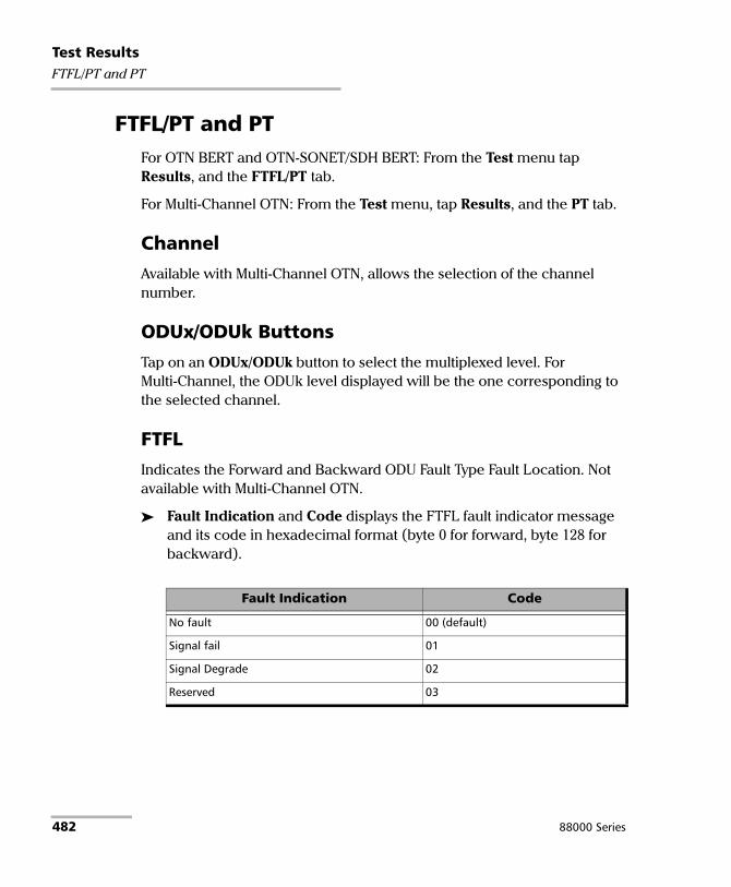
Test ResultsFTFL/PT and PT
FTFL/PT and PT For OTN BERT and OTN-SONET/SDH BERT: From the Test menu tap Results, and the FTFL/PT tab.
For Multi-Channel OTN: From the Test menu, tap Results, and the PT tab.
Channel
Available with Multi-Channel OTN, allows the selection of the channel number.
ODUx/ODUk Buttons
Tap on an ODUx/ODUk button to select the multiplexed level. For Multi-Channel, the ODUk level displayed will be the one corresponding to the selected channel.
FTFL
Indicates the Forward and Backward ODU Fault Type Fault Location. Not available with Multi-Channel OTN.
Fault Indication and Code displays the FTFL fault indicator message and its code in hexadecimal format (byte 0 for forward, byte 128 for backward).
Fault Indication Code
No fault 00 (default)
Signal fail 01
Signal Degrade 02
Reserved 03
482 88000 Series

Test ResultsFTFL/PT and PT
Operator Identifier displays the received operator identifier (bytes 1 to 9 for forward, byte 129 to 137 for backward).
Operator Specific displays the received operator specific (bytes 10 to 127 for forward, byte 138 to 255 for backward).
PT (Payload Type)
Payload Type and Code
Received displays the received payload signal type and its code in hexadecimal format.
Expected allows selecting the expected payload signal type either by selecting the payload from the list or by typing its hexadecimal code.
Note: Refer to PT / Global PT on page 219 for the list.
OPU-PLM1, when selected, enables the OPU-PLM alarm analysis.
Copy RX/Global Copy RX2 uses the received payload type as the expected payload type. For Multi-Channel OTN lower ODU layer, use the arrow button next to the Copy RX or Global Copy RX to switch from one button to the other; Global Copy RX uses the current channel received payload type as the expected payload type for all channels while Copy RX only affects the selected channel.
1. For Multi-Channel OTN lower ODU layer, the OPU-PLM check box is only configurable from the test setup.
2. Only available for Multi-Channel OTN lower ODU layer.
Power Blazer 483

Test ResultsGFP-F/GFP-T
GFP-F/GFP-T
Note: This tab is only available with OTN BERT test application with 1GbE, 10GbE, or Ethernet (flex/GFP-F) client.
From the Test menu, tap Results, and the GFP-F/GFP-T tab.
Transport Layer
Bandwidth Usage (%) indicates the transmitted/received transport layer bandwidth in the last second, excluding the Idle bytes.
Mapping Efficiency (%) indicates the transmitted/received transport layer mapping efficiency (Client Payload Bytes divided by Client Data Bytes multiplied by 100) in the last second.
Frame Type
Note: For Ethernet (flex/GFP-F) client with EXI set to Linear, the RX count/rate is configurable to either RX (default) or RX CID Filtered by tapping on the table RX label. RX CID Filtered only includes frames that match the expected CID (refer to CID on page 17).
Client Data indicates the transmitted/received client data frames without uncorrectable cHEC, tHEC, and eHEC errors. Possible rate units are Frames (default), Bytes, or Payload Bytes per second.
Client Management indicates the transmitted/received client management frames without uncorrectable cHEC, tHEC, and eHEC, and pFCS errors. Possible rate units are Frames (default), or Bytes per second.
Idle indicates the transmitted/received idle frames. Possible rate units are Frames (default), or Bytes per second.
484 88000 Series

Test ResultsGFP-F/GFP-T
Reserved PTI indicates the received client data and management frames with a payload type identifier different of 000 and 100 without uncorrectable cHEC, tHEC, and eHEC, and pFCS errors. Possible rate units are Frames (default), or Bytes per second.
Reserved PLI indicates the number of reserved control frames (PLI=1, 2, or 3 while in Synchronization state) received.
Invalid indicates the number of received frames corresponding to at least one of the following conditions:
EXI=0000 while PFI=1 and PLI <8EXI=0001 while PFI=0 and PLI <8EXI=0001 while PFI=1 and PLI<12
Discarded indicates the number of received frames with uncorrectable tHEC, eHEC errors, or Invalid Frames.
Total indicates the received frames including Idle, Client Data, Client Management, and frames with a reserved PTI. Possible rate units are Frames (default), or Bytes per second.
RX Mismatch
PFI (Payload Frame Check Sequence Identifier) indicates the number of frames with PFI field not matching the expected PFI.
EXI (Extension Header Identifier) indicates the number of frames with EXI field not matching the expected EXI.
UPI (User Payload Identifier) indicates the number of frames UPI field not matching the expected UPI.
CID (Channel IDentifier), only available when EXI is et to Linear, indicates the number of frames CID field not matching the expected CID.
Note: For expected values, refer to GFP-F/GFP-T on page 222 for more information.
Power Blazer 485

Test ResultsGFP-F/GFP-T
Superblock
Note: Superblock is only available with GFP-T.
Valid indicates the transmitted/received superblocks without any uncorrectable error.
Invalid indicates the transmitted/received superblocks with uncorrectable error.
Total indicates the total transmitted/received valid and invalid superblocks.
486 88000 Series

Test ResultsGraph (RFC 2544)
Graph (RFC 2544) Displays the graph showing the Throughput, Back-to-Back, Frame Loss, and Latency measurements. For Dual Test Set the graph shows results from Local to Remote and Remote to Local using distinctive colors. For Dual Port topology the graph shows results of both port directions.
From the Test menu, tap Results, and the Graphs tab.
All button allows viewing the graphs of all subtests simultaneously.
Throughput, Back-to-Back, Frame Loss, and Latency buttons allow viewing an enlarged graph view of the selected subtest.
Displayed Results allows selecting the displayed results mode, either Minimum, Maximum (default), Average, or Current.
Step, available with Frame Loss, allows selecting the result step (100 percent by default) to be displayed.
The X axis shows the frame sizes while the Y axis shows the subtest results.
Frame Size (Bytes) and Step (%), available with Frame Loss, allows selecting either Frame Size (default) or Step as the X axis criterion.
Power Blazer 487

Test ResultsLabels
Labels From the Test menu, tap Results, and Labels.
Note: Selecting a Label byte to be generated will automatically update the corresponding OH byte. Refer to OH - SONET/SDH on page 666 for more information.
Labels
STS/AU Path (C2): The C2 byte is allocated to indicate the content of the STS SPE / VC, including the status of the mapped payloads.
Received: Displays the received C2 byte. Refer to C2 on page 674 for more information.
PLM-P/UNEQ-P / HP-PLM/HP-UNEQ: Enables the Payload Mismatch and STS/AU UNEQ monitoring. This setting is coupled with the configuration of Labels on page 238.
Expected: Select the expected C2 byte from the list. Refer to C2 on page 674 for more information.
VT/TU Path (V5): The V5 byte is allocated to indicate the content of the VT/TU path, including the status of the mapped payloads.
Received: Displays the received V5 byte. Refer to V5 on page 677 for more information.
PLM-V/UNEQ-V / LP-PLM/LP-UNEQ: Enables the Payload Mismatch and VT/TU UNEQ monitoring. This setting is coupled with the configuration of Labels on page 238.
Expected: Select the expected V5 byte from the list. Refer to V5 on page 677 for more information.
488 88000 Series

Test ResultsLink OAM
Link OAM From the Test menu, tap Results, and the Link OAM tab.
Remote MAC Address
Indicates the remote OAM link partner MAC address.
Remote OAM Information
OAM Version indicates the protocol version supported by the DTE.
Revision indicates the revision of the Information TLV.
Multiplexer Action reports the Multiplexer Action:
Forward indicates that the device is forwarding non-OAMPDUs to the lower sublayer.
Discard indicates that the device is discarding non-OAMPDUs.
Parser Action reports the Parser Action:
Forward indicates that the device is forwarding non-OAMPDUs to the higher sublayer.
Loopback indicates that the device is looping back non-OAMPDUs to the lower sublayer.
Discard indicates that the device is discarding non-OAMPDUs.
OAM Mode reports the OAM mode:
Active indicates that the DTE is configured in Active mode.
Passive indicates that the DTE is configured in Passive mode.
OUI reports the 24-bit IEEE Organizationally Unique Identifier field identifying the vendor.
Maximum OAMPDU Size reports the maximum OAMPDU size in bytes, supported by the DTE.
Power Blazer 489

Test ResultsLink OAM
Vendor Specific Information reports the 32-bit Vendor Specific Information field identifying the vendor’s product model and version.
Unidirectional reports unidirectional support capability:
Supported indicates that the DTE is capable of sending OAMPDUs when the receive path is non-operational.
Unsupported indicates that the DTE is not capable of sending OAMPDUs when the receive path is non-operational.
Remote Loopback reports OAM remote loopback support capability:
Supported indicates that the DTE is capable of OAM remote loopback mode.
Unsupported indicates that the DTE is not capable of OAM remote loopback mode.
Variable Retrieval reports variable retrieval capability:
Supported indicates that the DTE supports sending Variable Response OAMPDUs.
Unsupported indicates that the DTE does not support sending Variable Response OAMPDUs.
Link Events reports link event capability:
Supported indicates that the DTE supports interpreting Link Events.
Unsupported indicates that the DTE does not support interpreting Link Events.
490 88000 Series

Test ResultsLink OAM
Remote Error Event Statistics
Date Stamp1 indicates the date the last Event Notification OAMPDU frame was received.
Time Stamp1 indicates the time the last Event Notification OAMPDU event was received by the test equipment.
Window
Threshold
Error Count
1. Date Stamp and Time Stamp parameters differ from the 802.3 standard definitions.
Symbol Period Errored symbol Window in second
Frame Errored frame event Window in second
Frame Period Errored frame period Window - duration period in number of 64 bytes frames
Frame Seconds Errored frame seconds summary Window
Symbol Period Errored symbol threshold in second
Frame Errored frame event threshold in second
Frame Period Errored frame period threshold in second
Frame Seconds Errored frame seconds summary threshold in second
Symbol Period The number of symbol errors in Window
Frame The number of frame event errors in Window
Frame Period The number of frame period errors in Window
Frame Seconds The number of frame seconds summary errors in Window
Power Blazer 491
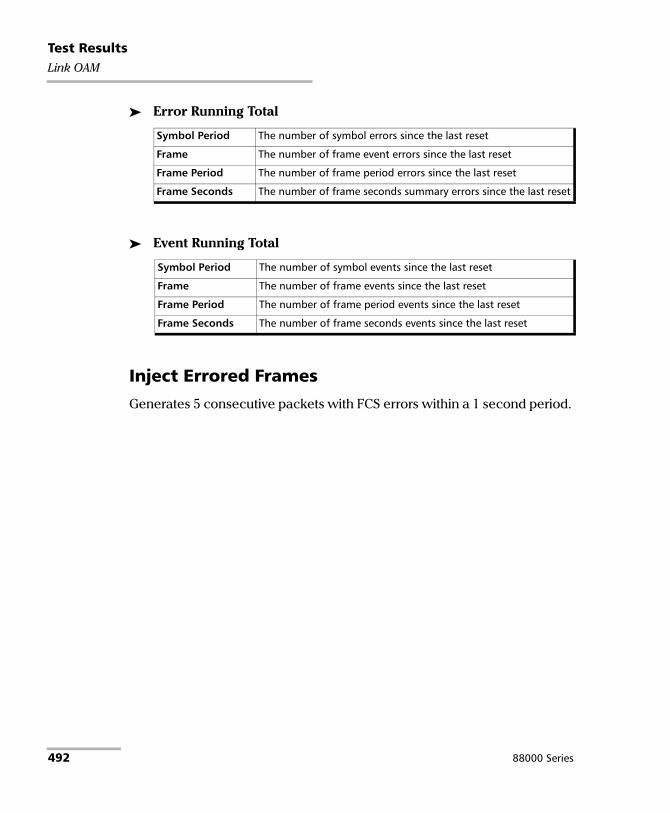
Test ResultsLink OAM
Error Running Total
Event Running Total
Inject Errored Frames
Generates 5 consecutive packets with FCS errors within a 1 second period.
Symbol Period The number of symbol errors since the last reset
Frame The number of frame event errors since the last reset
Frame Period The number of frame period errors since the last reset
Frame Seconds The number of frame seconds summary errors since the last reset
Symbol Period The number of symbol events since the last reset
Frame The number of frame events since the last reset
Frame Period The number of frame period events since the last reset
Frame Seconds The number of frame seconds events since the last reset
492 88000 Series

Test ResultsLogger
Logger The Logger page displays color-coded events and pass/fail verdict.
From the Test menu, tap Results, and the Logger tab.
Sort By
Select the sorting order of the event logger entries:
ID (default) displays the event logger entries in numeric ascending order based on the ID column of the event logger table.
Event displays the event Logger entries in alphanumeric ascending order based on the Event column of the event logger table.
Time Mode
Relative displays the time/duration fields based on the time elapse since the beginning of the test or since the last test reset. The format of the time is Dd HH:MM:SS.
Absolute (default) displays the time/duration fields based on the date and time the event occurred/ended. The time format depends on the platform time settings.
For 24 hours, the time format is MM/DD HH:MM:SS.
For 12 hours, the time format is MM/DD HH:MM:SS <AM or PM>.
Closure Format
Duration (default): Indicates the number of seconds within which the event occurred. Test events like Test Started and Test Stopped will have no duration.
End Time: Indicates at what time the event has been completed or cleared.
Power Blazer 493

Test ResultsLogger
Save to CSV
Allows saving the logger content to a CSV file format.
Table
The logger table provides the following event logger information.
ID: Indicates the event identification number. The events are sequentially numbered.
Start Time: Indicates when the event has been started or detected.
Event: Provides the event type and threshold crossing information.
Duration or End Time, depending on the Closure Format selected, indicates either the duration or at what time the event has been completed or cleared.
Details: Provides contextual information including the pass/fail verdict.
The following table displays the nature of information reported by type of event:
Note: The Logger table can display up to 5000 event entries. Once the Logger table reports 5000 event entries, a log full indicator appears and no further entries are possible. However, the events in the Pending state will be updated if the test is still running.
Type of Event Nature of Information
Test Started Start Date
Test Stopped Pass/Fail Verdict
Alarm Events Count value
Error Events Current Count and Total Count
SDT Events Service Disruption Time
Threshold Crossing Event Value at the end of the test
494 88000 Series

Test ResultsLogger
The Event Logger information will be cleared when:
the test is reset or started.
stopping the current test and.
the unit is restarted.
Note: An entry event remains in the Pending state as long as the event is not completed and it is highlighted on a yellow background color.
Note: The Threshold Crossing events are displayed in red text color.
Power Blazer 495

Test ResultsMessages
Messages From the Test menu, tap Results, and the Messages tab.
Note: For Dual Port topology select the port to be displayed.
Message Type
For OBSAI: The count of each OBSAI message type is reported.
Message Type TX Count RX Count
Control - X
Measurement - X
WCDMA/FDD X X
WCDMA/TDD - X
GSM/EDGE X X
TETRA - X
CDMA2000 - X
WLAN - X
Loopback - X
Frame Clock Burst X (BTS only) X (RRH only)
Ethernet - X
RTT Message X X
802.16 X X
Virtual HW Reset - X
LTE X X
Generic Packet - X
Multi-hop RTT Message - X
Others - X
496 88000 Series

Test ResultsMessages
For eCPRI: The count of each eCPRI message type is reported.
RX Frame Clock Burst Details
When a valid Frame Clock Burst (FCB) message is received, its SFN and c1 values are reported. Only available with OBSAI.
SFN (System Frame Number): The master frame number received with an FCB message.
c1: Arrival time of the FCB message Reference Point 1 (RP1) versus master frame start.
Message Type TX Count RX Count Loss Count OOS Count
IQ Data X X X X
Bit Sequence X X X X
Real-Time Control Data X X X X
Generic Data Transfer X X X X
Remote Memory Access - X - -
One-Way Delay Measurement X X - -
Remote Reset - X - -
Event Indication - X - -
Reserved - X - -
Vendor Specific - X - -
Total X X X X
Power Blazer 497

Test ResultsMPLS
MPLS For Traffic Gen and Mon, from the test menu, tap Results, Streams, and the MPLS tab.
For Though Mode, from the test menu, tap Results, Traffic, and the MPLS tab.
Note: For Dual Port topology select the port to be displayed.
Label 1 and Label 2
The number of MPLS frames transmitted (TX) and received (RX) are displayed for both Label 1 and Label 2 for each Stream. Not available for Through Mode test application.
Total TX/RX MPLS
Line Utilization indicates the percentage of MPLS line rate utilization in TX and RX.
Ethernet BW (%) (Ethernet Bandwidth) indicates the MPLS data rate in TX and RX.
Frame Rate (frames/s) indicates the number of transmitted (TX) and received (RX) MPLS frames.
Frame Count indicates the count of transmitted (TX) and received (RX) MPLS EtherType (0x8847 or 0x8848) frames regardless if FCS is good or not.
498 88000 Series

Test ResultsOTL-SDT
OTL-SDT
Note: Only available for parallel interfaces when an OTL defect, at the exception of LOL, is selected for Service Disruption Time (refer to Service Disruption on page 158).
From the Test menu, tap Results, and the OTL-SDT tab.
Service Disruption
Note: Service Disruption results are only available when Disruption Monitoring is enabled (refer to BERT and Unframed BERT on page 155).
Service Disruption is the time during which there is a disruption of service due to the absence of traffic or to the detection of defects per lane.
Disruption Time
Defect indicates on which layer and defect the service disruption time test is performed.
Lane indicates the lane number.
Longest (ms) indicates the longest measured disruption time per lane.
Shortest (ms) indicates the shortest measured disruption time per lane.
Last (ms) indicates the length of the last measured disruption time per lane.
Average (ms) indicates the average duration of all measured disruption times per lane.
Total (ms) indicates the total duration of all measured disruption times per lane.
Count indicates the number of disruption events detected since the beginning of the SDT test per lane.
Power Blazer 499

Test ResultsOTL-SDT
Longest Disruption indicates the longest measured disruption time.
Lanes with Disruption indicates the number of lanes with service disruption.
Note: When a disruption event is equal to or longer than the test period which is fixed to 5 minutes, then the measured disruption time is equal to the test period.
500 88000 Series
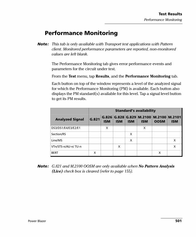
Test ResultsPerformance Monitoring
Performance Monitoring
Note: This tab is only available with Transport test applications with Pattern client. Monitored performance parameters are reported, non-monitored values are left blank.
The Performance Monitoring tab gives error performance events and parameters for the circuit under test.
From the Test menu, tap Results, and the Performance Monitoring tab.
Each button on top of the window represents a level of the analyzed signal for which the Performance Monitoring (PM) is available. Each button also displays the PM standard(s) available for this level. Tap a signal level button to get its PM results.
Note: G.821 and M.2100 OOSM are only available when No Pattern Analysis (Live) check box is cleared (refer to page 155).
Standard’s availability
Analyzed Signal G.821 G.826 ISM
G.828 ISM
G.829 ISM
M.2100 ISM
M.2100 OOSM
M.2101 ISM
DS3/DS1/E4/E3/E2/E1 X X
Section/RS X
Line/MS X X
VTn/STS-n/AU-n/ TU-n X X
BERT X X
Power Blazer 501

Test ResultsPerformance Monitoring
Near-End
EFS (Error Free Second) (G.821, G.826, G.828, and G.829): Gives the number of seconds within which no error occurred.
EC (Error Count) (G.821 only): Gives the number of bit errors.
EB (Errored Block) (G.826, G.828, and G.829): Gives the count of blocks in which one or more bits are in error.
ES (Errored Second)
For G.821, and M.2100 OOSM: Gives the number of seconds within which one or more bit error occurred, or during which Loss Of Signal (LOS) or AIS is detected.
For G.826, G.828, G.829, M.2100 ISM, and M.2101: Gives the number of seconds within which one or more anomalies (FAS (DSn/PDH), EB, etc.) occurred, or at least one defect occurred.
SES (Severely Errored Second)
For G.821, and M.2100 OOSM: Gives the number of seconds within which a bit error ratio is 10-3, or during which one defect (LOS/AIS) is detected.
For G.826, G.828, G.829 and M.2101: Gives the number of seconds within which anomalies (FAS (DSn/PDH), EB, etc.) are X percent or at least one defect occurred. X=30 percent for DSn/PDH signals; see the following table for SONET/SDH signals SES threshold.
OC-1STS-1eSTM-0STM-0e
OC-3STS-3eSTM-1STM-1e
OC-12STM-4
OC-48STM-16
OC-192STM-64
OC-768STM-256
Path 30 % 30 % 30 % 30 % 30 % 30 %
Line/MS 15 % 15 % 25 % 30 % 30 % 30 %
Section/RS 10 % 30 % 30 % 30 % 30 % 30 %
502 88000 Series

Test ResultsPerformance Monitoring
For M.2100 ISM: Gives the count of the seconds within which anomalies (frame bit errors, CRC block errors, etc.) are Y or at least one defect occurred. Y depends on the type of DSn/PDH signal as described in the following table.
BBE (Background Block Error) (G.826, G.828, G.829, and M.2101): Gives the count of Errored Block not occurring as part of a SES.
Signal SES Threshold
DS1 (SF) 8 frame bit errors (Near-End)
DS1 (ESF) 320 CRC-6 block errors (Near-End) 320 CRC-6 block errors (Far-End, if FDL enabled)
E1 (Framed without CRC-4) 28 frame bit errors (Near-End)
E1 (Framed with CRC-4) 805 CRC-4 block errors (Near-End) 805 E-bit errors (Far-End)
DS3 (M13) 2444 P-bit errors (Near-End) or 5 F-bit errors (Near-End)
DS3 (C-bit Parity) 2444 P-bit errors (Near-End) or 5 F-bit errors (Near-End) 2444 FEBE errors (Far-End)
E2 (Framed) 41 frame bit errors (Near-End)
E3 (Framed) 52 frame bit errors (Near-End)
E4 (Framed) 69 frame bit errors (Near-End)
Power Blazer 503

Test ResultsPerformance Monitoring
UAS (Unavailable Second): Gives the count of the seconds corresponding to the periods of unavailable time that begins at the onset of 10 consecutive SES events, including these 10 seconds. A period of available time shall begin at the onset of 10 consecutive non-SES events, including these 10 seconds.
ESR (Errored Second Ratio) (G.821, G.826, G.828, and G.829): Gives the ratio of the number of ES in available time (AS) during a fixed measurement interval.
ESR = ES ÷ AS
SESR (Severely Errored Second Ratio) (G.821, G.826, G.828, and G.829): Gives the ratio of the number of SES in available time (AS) during a fixed measurement interval.
SESR = SES ÷ AS
BBER (Background Block Error Ratio) (G.826, G.828, G.829, and M.2101): Gives the ratio of BBE in available time (AS) to total blocks in available time during a fixed measurement interval. The count of total blocks excludes all blocks during SESs.
DM (Degraded Minutes) (G.821 only): A Degraded Minute is the number of minutes in which the estimated error rate exceeds 10-6 but does not exceed 10-3. DM is determined by collecting all of the Available Seconds, removing any SES grouping the result in 60-second long groups and counting a 60-second long group as degraded if the cumulative errors during the seconds present in the group exceed 10-6.
504 88000 Series

Test ResultsPerformance Monitoring
SEP (Severely Errored Period) (G.828 only): A sequence between 3 to 9 consecutive SES. The sequence is terminated by a second which is not a SES.
SEPI (Severely Errored Period Intensity) (G.828 only): Gives the count of SEP events in available time, divided by the total available time in seconds.
Far-End
EFS (Error Free Second): Gives the count of the seconds within which no error occurred or when a defect is detected on the near-end.
EC (Error Count) (G.821 only): Gives the number of bit errors.
EB (Errored Block) (G.826, G.828, and G.829): Gives the count of blocks in which one or more bits are in error.
ES (Errored Second): For G.826, G.828, G.829, M.2100 ISM, and M.2101: Gives the count of the seconds within which one or more anomalies (FAS (DSn/PDH), EB, etc.) occurred or at least one defect occurred.
SES (Severely Errored Second)
For G.826, G.828, G.829 and M.2101: Gives the number of seconds within which anomalies (FAS (DSn/PDH), EB, etc.) are X percent or at least one defect occurred. X=30 percent for DSn/PDH signals; see the following table for SONET/SDH signals SES threshold.
OC-1STS-1eSTM-0STM-0e
OC-3STS-3eSTM-1STM-1e
OC-12STM-4
OC-48STM-16
OC-192STM-64
OC-768STM-256
Path 30 % 30 % 30 % 30 % 30 % 30 %
Line/MS 15 % 15 % 25 % 30 % 30 % 30 %
Section/RS 10 % 30 % 30 % 30 % 30 % 30 %
Power Blazer 505

Test ResultsPerformance Monitoring
For M.2100 ISM: Gives the count of the seconds within which anomalies (frame bit errors, CRC block errors, etc.) are Y or at least one defect occurred. Y depends on the type of DSn/PDH signal as described in the following table.
BBE (Background Block Error) (G.828 and G.829 Line): Gives the count of Errored Blocks not occurring as part of an SES.
Signal SES Threshold
DS1 (SF) 8 frame bit errors (Near-End)
DS1 (ESF) 320 CRC-6 block errors (Near-End) 320 CRC-6 block errors (Far-End, if FDL enabled)
E1 (Framed without CRC-4) 28 frame bit errors (Near-End)
E1 (Framed with CRC-4) 805 CRC-4 block errors (Near-End) 805 E-bit errors (Far-End)
DS3 (M13) 2444 P-bit errors (Near-End) or 5 F-bit errors (Near-End)
DS3 (C-bit Parity) 2444 P-bit errors (Near-End) or 5 F-bit errors (Near-End) 2444 FEBE errors (Far-End)
E2 (Framed) 41 frame bit errors (Near-End)
E3 (Framed) 52 frame bit errors (Near-End)
E4 (Framed) 69 frame bit errors (Near-End)
506 88000 Series

Test ResultsPerformance Monitoring
UAS (Unavailable Second): Gives the count of the seconds corresponding to the period of unavailable time that begins at the onset of 10 consecutive SES events, including these 10 seconds. A period of available time shall begin at the onset of 10 consecutive non-SES events, including these 10 seconds.
ESR (Errored Second Ratio): Gives the ratio of the number of ES in available time to total seconds in available time during a fixed measurement interval.
ESR = ES ÷ AS
SESR (Severely Errored Second Ratio): Gives the ratio of the number of SES in available time to total seconds in available time during a fixed measurement interval.
SESR = SES ÷ AS
BBER (Background Block Error Ratio): Gives the ratio of BBE in available time to total blocks in available time during a fixed measurement interval. The count of total blocks excludes all blocks during SESs.
Power Blazer 507

Test ResultsPTP Stats
PTP Stats From the Test menu, tap Results, and the PTP Stats tab.
TX/RX PTP Message Count/Rate
Gives the transmitted/received count and average rate for each PTP message, and the total count for all messages.
Note: In the case where messages are lost while the Receipt Timeout is set to a large value (slow communication), the last valid recorded rate value will be preceded with < to indicate that the reception rate is not stable. This applies to Delay Resp, Announce, Sync, and Follow UP.
Note: When the rate is above 150 messages/s, > 150 is displayed.
TX RX
Signaling Announce Reqa Signaling Sync Reqa Signaling Delay Resp Reqa Delay Req
a. The rate value corresponds to an average rate because these messages are onlytransmitted/received when negotiating or renewing the lease with the Grand Masterclock. If the connection with the Grand Master Clock was already established when thetest is started, the 0 value is displayed. However, the value becomes available with thenext lease renewal which happens every 150 seconds. Only available with G.8265.1profile.
Signaling Announce Granta Signaling Sync Granta Signaling Delay Resp Granta Delay Resp Sync Follow Up Announce
508 88000 Series

Test ResultsPTP Stats
IPDV
Inter Packet Delay Variation (IPDV) is available for Sync and Delay Req messages and is measured for all valid in-sequence messages (see Delay Measurement on page 544). Current, Average, Minimum, Maximum, and Standard Deviation measurement values are displayed. The Standard Derivation is the measure of the dispersion of messages from its mean. When a value is below 1μ second, < 1μs is displayed. The pass/fail verdict is also displayed beside the maximum value when enabled.
Power Blazer 509

Test ResultsQuality Level (1588 PTP)
Quality Level (1588 PTP) The quality level characterizes the clock quality in terms of network synchronization.
From the Test menu, tap Results, and the Quality Level tab.
Last QL Received indicates the last Quality Level value received. The pass/fail verdict is also displayed when both QL Mismatch Monitoring and Pass/Fail Verdict check boxes are selected.
Last Change indicates the date and time of the Last QL has changed.
QL Mismatch Monitoring when selected (default) enables the Quality Level mismatch monitoring.
Expected QL allows the selection of the Expected Quality Level value. Available when the QL Mismatch Monitoring check box is selected.
Profile ITU
Quality Level value
PTP Clock Class Description
G.8275.1 QL-PRC/PRS 6, 7, 135, 140 Primary Reference Clock Traceable (G.811)
QL-SSU-A/ST2 150 Type I or V slave clock (G.812)Traceable to Stratum 2 (G.812 Type II)
QL-SSU-B/ST3E (default)
160 Type VI slave clock (G.812)Traceable to Stratum 3E (G.812 Type III)
510 88000 Series

Test ResultsQuality Level (1588 PTP)
Count gives the count for each QL code (PTP Clock Class) included in the announce message received.
Other includes all clock class codes (0 to 255) included in the announce message received other than the QL codes (see table above). Refer to page 543 for the complete list.
Total indicates the total count of all QL code messages received.
G.8265.1 QL-PRS (default) 80 Primary Reference Source Traceable (G.811)
QL-STU/UNK 82 Synchronized - Traceability Unknown
QL-PRC 84 Primary Reference Clock Traceable (G.811)
QL-ST2 86 Traceable to Stratum 2 (G.812 Type II)
QL-INV3 88 Quality Level Invalid 3
QL-SSU-A/TNC 90 Type I or V slave clock (G.812)Traceable to Transit Node Clock (G.812 Type V)
QL-INV5 92 Quality Level Invalid 5
QL-INV6 94 Quality Level Invalid 6
QL-SSU-B 96 Type VI slave clock (G.812)
QL-INV9 98 Quality Level Invalid 9
QL-ST3E 100 Traceable to Stratum 3E (G.812 Type III)
QL-EEC2/ST3 102 Ethernet Equipment Clock Option 2Traceable to Stratum 3 (G.812 Type IV)
QL-EEC1/SEC 104 Ethernet Equipment Clock Option 1Synchronous Equipment Clock (G.813 or G.8262, Option 1)
QL-SMC 106 Traceable to SONET Minimum Clock (G.813 or G.8262, Option 2)
QL-PROV 108 Provisionable by the Network Operator (PNO)
QL-DNU/DUS 110 Do Not UseDo Not Use for Synchronization
Profile ITU
Quality Level value
PTP Clock Class Description
Power Blazer 511

Test ResultsQuality Level (SyncE)
Quality Level (SyncE) The quality level characterizes the clock quality in terms of network synchronization.
From the Test menu, tap Results, and the Quality Level tab.
Generated QL indicates the Quality Level value that is generated.
Last Change indicates the date and time of the Generated Quality Level value has changed. For 1GE Electrical interface using Local Clock set to Slave, the Last Change is not available.
Last QL Received indicates the last Quality Level value received. The pass/fail verdict is also displayed when both QL Mismatch Monitoring and Pass/Fail Verdict check boxes are selected.
Last Change indicates the date and time of the Last QL Received has changed.
QL Mismatch Monitoring when selected (default), enables the Quality Level mismatch monitoring.
Expected QL allows the selection of the Expected Quality Level value. Available when the QL Mismatch Monitoring check box is selected.
Quality Level value SSM Description
QL-STU/UNK 0 Synchronized - Traceability Unknown
QL-PRS 1 Primary Reference Source Traceable (G.811)
QL-PRC 2 Primary Reference Clock Traceable (G.811)
QL-INV3 3 Quality Level Invalid 3
QL-SSU-A/TNC 4 Type I or V slave clock (G.812)Traceable to Transit Node Clock (G.812 Type V)
QL-INV5 5 Quality Level Invalid 5
QL-INV6 6 Quality Level Invalid 6
QL-ST2 7 Traceable to Stratum 2 (G.812 Type II)
512 88000 Series
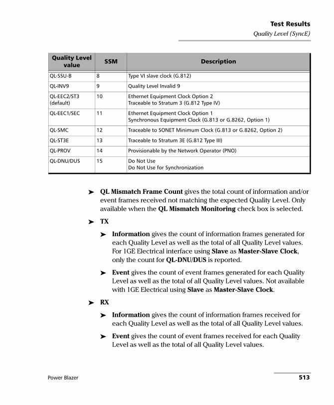
Test ResultsQuality Level (SyncE)
QL Mismatch Frame Count gives the total count of information and/or event frames received not matching the expected Quality Level. Only available when the QL Mismatch Monitoring check box is selected.
TX
Information gives the count of information frames generated for each Quality Level as well as the total of all Quality Level values. For 1GE Electrical interface using Slave as Master-Slave Clock, only the count for QL-DNU/DUS is reported.
Event gives the count of event frames generated for each Quality Level as well as the total of all Quality Level values. Not available with 1GE Electrical using Slave as Master-Slave Clock.
RX
Information gives the count of information frames received for each Quality Level as well as the total of all Quality Level values.
Event gives the count of event frames received for each Quality Level as well as the total of all Quality Level values.
QL-SSU-B 8 Type VI slave clock (G.812)
QL-INV9 9 Quality Level Invalid 9
QL-EEC2/ST3 (default)
10 Ethernet Equipment Clock Option 2Traceable to Stratum 3 (G.812 Type IV)
QL-EEC1/SEC 11 Ethernet Equipment Clock Option 1Synchronous Equipment Clock (G.813 or G.8262, Option 1)
QL-SMC 12 Traceable to SONET Minimum Clock (G.813 or G.8262, Option 2)
QL-ST3E 13 Traceable to Stratum 3E (G.812 Type III)
QL-PROV 14 Provisionable by the Network Operator (PNO)
QL-DNU/DUS 15 Do Not UseDo Not Use for Synchronization
Quality Level value SSM Description
Power Blazer 513

Test ResultsS-OAM and MPLS-TP OAM
S-OAM and MPLS-TP OAM From the Test menu, tap Results, and the S-OAM or MPLS-TP OAM tab.
Loopback
Status displays the status of the test function (refer to page 581).
TX LBM indicates the count of transmitted LBM frames.
RX LBR indicates the count of valid LBR frames received. A valid frame for S-OAM has its source MAC address matching the Peer MEP MAC address, destination MAC address matching the unit port MAC address, and VLANs matching the unit port VLANs. A valid frame for MPLS-TP OAM has its destination MAC address matching either the unit MAC address, FF:FF:FF:FF:FF:FF, or 01:00:5E:90:00:00; VLANs matching the unit port VLANs; and MPLS Labels matching the local MPLS Label Stack configuration.
LBR Timeout
For connectivity verification (Continuous check box cleared), indicates the count of LBR Timeout event which occurs if a reply (LBR frame with matching Transaction ID) to a transmitted LBM frame is not received within 5 seconds.
For diagnostic test (Continuous check box selected), indicates the difference between the transmitted LBM frames and the received LBR frames.
Invalid LBR
For connectivity verification (Continuous check box cleared), indicates the count of LBR frames received from the peer MEP with incorrect MEG/MD Level or with an unexpected Transaction ID.
For diagnostic test (Continuous check box is selected), indicates the count of LBR frames received from the peer MEP with incorrect MEG/MD Level.
514 88000 Series

Test ResultsS-OAM and MPLS-TP OAM
Invalid Payload indicates the count of received LBR frames having either a TLV type different than the one transmitted, Bit error or wrong data value detected in the data payload of a Data TLV, Bit error, Pattern Loss, or Pattern Type mismatch of a Test TLV.
Successful indicates the count of received LBR frames having no errors.
Failed indicates the count of LBR frames declared as invalid.
Test
Status displays the status of the test function (refer to page 581).
TX TST indicates the count of transmitted TST frames.
RX TST indicates the count of valid TST frames received. A valid frame for S-OAM has its source MAC address matching the Peer MEP MAC address; destination MAC address matching either the unit port Unicast MAC address or a Multicast class 1 address1; and VLANs matching the unit port VLANs. A valid frame for MPLS-TP OAM has its destination MAC address matching either the unit MAC address, FF:FF:FF:FF:FF:FF, or 01:00:5E:90:00:00; VLANs matching the unit port VLANs; and MPLS Labels matching the local MPLS Label Stack configuration.
Invalid TST indicates the count of TST frames received from the peer MEP with incorrect MEG/MD level.
Invalid Payload indicates the count of received TST frames having either an unsupported pattern type, or bit error / pattern loss detected in the payload.
Successful indicates the count of received TST frames having no errors.
Failed indicates the count of TST frames declared as invalid.
1. Refer to Unicast/Multicast Addresses for Ethernet OAM on page 841 for more information.
Power Blazer 515

Test ResultsS-OAM and MPLS-TP OAM
Frame Delay
Status displays the status of the test function (refer to page 581).
TX DMM indicates the count of transmitted DMM frames.
RX DMR indicates the count of valid DMR frames received. A valid frame for S-OAM has its source MAC address matching the Peer MEP MAC address; destination MAC address matching the unit port MAC address; and VLANs matching the unit port VLANs. A valid frame for MPLS-TP OAM has its destination MAC address matching either the unit MAC address, FF:FF:FF:FF:FF:FF, or 01:00:5E:90:00:00; VLANs matching the unit port VLANs; and MPLS Labels matching the local MPLS Label Stack configuration..
Invalid DMR indicates the count of received DMR frames from the peer MEP having an incorrect MEG/MD Level, an incorrect Test ID (when applicable), or with a valid MEG/MD Level and valid Test ID (when applicable) but with a Frame Delay outside the 0.001 to 8000.000 ms range.
Delay (ms): Current indicates the average of frame delay measured in the last second. Minimum, Maximum, and Average indicates respectively the minimum, maximum, and average frame delays measured since the beginning of the test.
Successful indicates the count of received DMR frames having no errors.
Failed indicates the count of DMR frames declared as invalid.
516 88000 Series

Test ResultsS-OAM and MPLS-TP OAM
Frame Loss
Status displays the status of the test function (refer to page 581).
TX LMM indicates the count of transmitted LMM frames.
RX LMR indicates the count of valid LMR frames received. A valid frame for S-OAM has its source MAC address matching the Peer MEP MAC address; destination MAC address matching the unit port MAC address; and VLANs matching the unit port VLANs. A valid frame for MPLS-TP OAM has its destination MAC address matching either the unit MAC address, FF:FF:FF:FF:FF:FF, or 01:00:5E:90:00:00; VLANs matching the unit port VLANs; and MPLS Labels matching the local MPLS Label Stack configuration.
Invalid LMR indicates the count of LMR frames received from the peer MEP with incorrect MEG/MD level.
Frame Loss is calculated (count and %) for both Near-End and Far-End over all valid LMR frames received.
Successful indicates the count of received LMR frames having no errors.
Failed indicates the count of LMR frames declared as invalid.
Power Blazer 517

Test ResultsS-OAM and MPLS-TP OAM
Synthetic Loss
Note: Only available with Ethernet OAM.
Status displays the status of the test function (refer to page 581).
TX SLM indicates the count of transmitted SLM frames.
RX SLR indicates the count of valid SLR frames received. A valid frame has its source MAC address matching the Peer MEP MAC address; destination MAC address matching the unit port MAC address; and VLANs matching the unit port VLANs.
Invalid SLR indicates the count of SLR frames received from the peer MEP with incorrect MEG/MD level, incorrect source MEP ID, or incorrect Test ID.
Synthetic Loss is calculated (count and %) for both Near-End and Far-End over all frames received and is updated after each Synthetic Loss measurement period (after receiving the defined Frame Count, refer to page 315).
Successful indicates the count of received SLR frames having no errors.
Failed indicates the count of SLR frames declared as invalid.
518 88000 Series

Test ResultsSDT (Multi-Channel OTN)
SDT (Multi-Channel OTN) From the Test menu, tap Results and the SDT tab.
Note: The SDT tab is only available when Disruption Monitoring is enabled (refer to ODU Channels - Global on page 279).
Service Disruption is the time during which there is a disruption of service due to the absence of traffic or to the detection of defects per channel.
Channels with Disruption indicates the number of channels with service disruption.
Channels Monitored indicates the number of channels monitored.
Channels Above Threshold, available when pass/fail verdict is enabled, indicates the number of channels with a disruption time above the defined threshold.
Longest Disruption indicates the duration of the longest measured disruption time and the channel number on which it occurred. The Pass/Fail verdict when enabled, is displayed next to duration value.
Last Disruption indicates the duration of the last measured disruption time and the channel number on witch it occurred.
SDT Threshold (ms), available when pass/fail verdict is enabled, allows entering the SDT threshold value that will be used to declare the pass/fail verdict: 0.001 to 299999.999 ms (default is 50 ms).
The following statistics are presented per channel:
Channel indicates the channel number.
Longest (ms) indicates the longest measured disruption time.
Shortest (ms) indicates the shortest measured disruption time.
Last (ms) indicates the duration of the last measured disruption time.
Average (ms) indicates the average duration of all measured disruption times.
Power Blazer 519

Test ResultsSDT (Multi-Channel OTN)
Total (ms) indicates the total duration of all measured disruption times.
Count indicates the number of disruption events detected since the beginning of the test.
PASS FAIL, available when pass/fail verdict is enabled, indicates the SDT pass/fail verdict.
Time Mode selects the format used to display the disruption time.
Relative displays SDT events based on the time elapsed since the beginning of the test.
Absolute (default) displays SDT events based on date and time.
Units selects the unit used to display SDT statistics: μs, ms (default), s, or min.
Time Stamp displays the time or date/time for each SDT channel; this apply to Longest and Last disruption time statistics. Choices are None (default), Time, and Date/Time. An extra line is added for each channel to display the time, and two lines to display the time and date.
Note: When a disruption event is equal to or longer than the test period which is fixed to 5 minutes, then the measured disruption time is equal to the test period.
520 88000 Series

Test ResultsService Configuration - Burst
Service Configuration - Burst From the Test menu, tap Results, Service Configuration, and the Burst tab.
Service Name and Selection
Service Name indicates the name of the selected service.
Select the service to be displayed by either using the left/right arrow or by tapping over the service numbers area then tapping on a specific service number. An orange background indicates the selected service while a green background indicates the services that are enabled.
Committed/Excess
Committed - Burst test is the CBS subtest.
Excess - Burst test is the EBS subtest.
Direction, available with Dual Test Set or Dual Port topology, indicates respectively results for local (L) and remote (R) directions, or for both port directions.
Burst Size indicates the size in bytes of the burst used for each subtest.
SLA Verified indicates the committed SLA parameters that are used to declare the pass/fail verdict. See Summary (EtherSAM) on page 551 for more information on Frame Loss, Max Jitter, Round-Trip Latency, Max Latency, and Max RX Rate.
Informational parameters are for information purpose only, they are not included in the test pass/fail verdict. See Summary (EtherSAM) on page 551 for more information on Frame Loss Rate, Max Jitter, Max Latency, and Round-Trip Latency.
Average RX Rate indicates the measured average utilization throughput for the CBS subtest.
Power Blazer 521

Test ResultsService Configuration - L2CP
Service Configuration - L2CP From the Test menu, tap Results, Service Configuration, and the L2CP tab.
Service Name and Selection
Service Name indicates the name of the selected service.
Select the service to be displayed by either using the left/right arrow or by tapping over the service numbers area then tapping on a specific service number. An orange background indicates the selected service while a green background indicates the services that are enabled.
L2CP Statistics per Service
Name indicates the name of each L2CP frame.
Dest. MAC indicates the L2CP frame destination MAC address.
Expected L2CP Handling indicates the expected L2CP handling: Pass Through or Discard/Peer.
Direction indicates respectively results for local (L) and remote (R) directions.
TX Frames indicates the count of L2CP frames transmitted per direction.
RX Frames indicates the count of L2CP frames received per direction.
522 88000 Series

Test ResultsService Configuration - L2CP
The L2CP frame verdict is as follows per direction:
L2CP service verdict is as follows per direction:
L2CP global verdict is as follows:
Verdict Description
PASS If the Expected L2CP Handling is Pass Through and the L2CP TX frames have been received at destination with a maximum of 1 frame lost.
If the Expected L2CP Handling is Peer/Discard and none of the transmitted L2CP frames have been received at destination.
FAIL If the Expected L2CP Handling is Pass Through and none or some but not all (more than 1 frame lost) of the transmitted L2CP frames have been received at destination.
If the Expected L2CP Handling is Peer/Discard and at least one of the transmitted L2CP frames have been received at destination.
Verdict Description
PASS All L2CP frame verdicts (same direction) are pass.
FAIL At least one L2CP verdict (same direction) is fail.
Verdict Description
PASS All L2CP service verdicts are pass.
FAIL At least one L2CP service verdict is fail.
Power Blazer 523

Test ResultsService Configuration - Ramp
Service Configuration - Ramp From the Test menu, tap Results, Service Configuration, and the Ramp tab.
Service Name and Selection
Service Name indicates the name of the selected service. Select the service to be displayed by either using the left/right arrow or by tapping over the service numbers area then tapping on a specific service number. An orange background indicates the selected service while a green background indicates the services that are enabled.
Committed/Excess Steps
Committed Steps indicate the pre CIR and CIR steps specified in the ramp configuration.
Excess Steps indicate the CIR+EIR and Traffic Policing steps specified in the ramp configuration.
Direction, available with Dual Test Set or Dual Port topology, indicates respectively results for local (L) and remote (R) directions, or for both port directions.
TX Rate indicates the transmission rate for each step.
SLA Verified indicates the committed SLA parameters that are used to declare the pass/fail verdict. See Summary (EtherSAM) on page 551 for more information on Frame Loss Rate, Max Jitter, Round-Trip Latency, and Max RX Rate.
524 88000 Series
Test ResultsService Configuration - Ramp
Informational parameters are for information purpose only, they are not included in the test pass/fail verdict. See Summary (EtherSAM) on page 551 for more information on Frame Loss, Max Jitter, and Round-Trip Latency.
Average RX Rate indicates the measured average utilization throughput for each step.
Power Blazer 525

Test ResultsService Performance
Service Performance From the Test menu, tap Results, and the Service Performance tab.
Service Name and Selection
Service Name indicates the name of the selected service.
Select the service to be displayed by either using the left/right arrow or by tapping over the service numbers area then tapping on a specific service number. An orange background indicates the selected service while a green background indicates the services that are enabled.
SLA Parameters
The configured CIR, Max Jitter, Frame Loss Rate and Max Latency/Max Round-Trip Latency SLA parameters are displayed. Refer to Services - Profile on page 320 for more information. For Dual Test Set or Dual Port topology, parameters are displayed respectively for both local (L) and remote (R) directions, or for both port directions.
Metrics
Current, Average, Minimum, Maximum, and Estimate (Jitter) measured values for each metric are reported. Direction, available with Dual Test Set or Dual Port topology indicates respectively results for local (L) and remote (R) directions, both port directions, and Round-Trip for Latency when in Round-Trip Latency Measurement Mode (see Global Options on page 197). For Dual Test Set, results for remote to local are obtained at the end of each step.
RX Rate indicates the measured utilization throughput.
Jitter (ms) indicates the measured delay variation.
Latency (ms) indicates the measured round-trip latency (delay).
Note: For the Current value, 0 is displayed when no RX rate has been measured in the last second.
526 88000 Series

Test ResultsService Performance
Note: Delay variation measurements smaller than 1 μs will be discarded, not used for the sampling process, and < 0.001 is displayed as the minimum value. For the Current value, Not measurable is displayed when no delay has been measured in the last second..
Errors
For Dual Test Set, errors are reported for both local (L) and remote (R) directions. For Dual Port topology, errors are reported for both port directions.
Frame Loss indicates that a sequence number is missing in the received frames. The pass/fail verdict when enabled reports only the verdict when it is fail. Seconds, Count, and Rate values are reported.
Out-of-Sequence indicates that the received frame sequence number is either smaller than the expected frame sequence number or is a duplicate number. The Out-Of-Sequence will not be considered in the global verdict. Seconds, Count, and Rate values are reported.
RX Frame Count
The RX Frame Count indicates the number of frames received matching the selected service ID. For Dual Test Set, the count is reported for both local (L) and remote (R) directions. For Dual Port topology, the count is reported for both port directions.
Power Blazer 527

Test ResultsStreams - Frame Loss / Out-of-Sequence
Streams - Frame Loss / Out-of-Sequence From the Test menu, tap Results, Streams, and the Frame Loss / Out-Of-Sequence tab.
Note: For Dual Port topology select the port to be displayed.
Stream indicates the stream identification number.
Thresholds button allows setting the pass/fail thresholds (refer to QoS Metrics on page 359).
Frame Loss: See QoS Metrics on page 451.
Out-Of-Sequence: See QoS Metrics on page 451.
Streams - Jitter From the Test menu, tap Results, Streams, and the Jitter tab.
Note: For Dual Port topology select the port to be displayed.
Stream: Indicates the stream identification number.
Jitter (ms) is measured for each stream on all valid frames (in-sequence frames, valid Jitter tag, and no FCS error) received. Current, Average, Minimum, Maximum, and Estimate delay values are reported.
Note: Delay variation measurements smaller than 1 μs will be discarded, not used for the sampling process, and < 0.001 will be displayed as the minimum value. For the Current value, Not measurable is displayed when no delay has been measured in the last second.
Thresholds button allows setting the pass/fail thresholds (refer to QoS Metrics on page 359).
528 88000 Series

Test ResultsStreams - Latency
Streams - Latency From the Test menu, tap Results, Streams, and the Latency tab.
Note: For Dual Port topology select the port to be displayed.
Stream: Indicates the stream identification number.
Latency (ms) is measured for each stream on all valid frames (valid Latency tag, expected originator identifier value, and no FCS error) received. Current, Average, Minimum, and Maximum round-trip latency (delay) are reported.
Note: Latency statistics are only available in loopback test topology.
Note: Delay measurements smaller than 1 μs will be discarded, not used for the sampling process, and < 0.001 will be displayed. For the Current value, Not measurable is displayed when no delay has been measured in the last second.
Thresholds button allows setting the pass/fail thresholds (refer to QoS Metrics on page 359).
Power Blazer 529

Test ResultsStreams - Throughput / Customer Frame Throughput
Streams - Throughput / Customer Frame Throughput
From the Test menu, tap Results, Streams, and the Throughput or the Customer Frame Throughput tab.
Note: For Dual Port topology select the port to be displayed.
Stream indicates the stream identification number.
TX Rate indicates the transmitted throughput rate.
RX Rate is measured for each stream on all valid frames (valid Throughput tag with no FCS error). Current, Average, Minimum, and Maximum throughput results are reported. Refer to Unit on page 352 for unit selection.
Note: A Current value of 0 indicates that no RX rate has been measured in the last second.
Total indicates the total TX and current measured RX throughput of all valid frames (valid Throughput tag with no FCS error).
Thresholds button allows setting the pass/fail thresholds (refer to QoS Metrics on page 359). Not available on Customer Frame Throughput tab.
530 88000 Series

Test ResultsSummary / Client Summary
Summary / Client Summary
Note: Available with Transport, and Ethernet (EtherBERT, Through Mode, Smart Loopback, FlexE BERT (Client Summary)), and Wireless test applications. For other test applications see the corresponding test summary page.
From the Test menu, tap Results, and the Summary tab; additionally for FlexE BERT, type the magnifying icon of the Client ID.
For Dual Port topology, depending on the application, results may be displayed either globally or for each port individually. In this case select the port to be displayed or Global for a brief test summary of both ports.
Client ID and Size (Gbit/s) are available with FlexE BERT.
Client ID allows selecting the client ID to be displayed.
Size (Gbit/s) indicates the size of the client ID.
Test Status displays the current status of the test. The global test pass/fail verdict is displayed next to the Test Status field when enabled.
Test Status Description
-- Idle state, the test is not running or results are not available.
In Progress The test is running.
Completed The test is completed, stopped at the planned time, or manually stopped when there is no set timer.
Aborted The test is interrupted; stopped before the set timer.
LOPPS-L: For eCPRI BERT in One-Way Latency mode, the test is interrupted due to a failure of synchronization with the 1PPS clock (LOPPS-L). Not Ready-R: For eCPRI BERT, the test is interrupted because the Measurement Role of the peer is either Mismatch-R or Inactive-R. Check the eCPRI Flow at each end of the eCPRI circuit to determine the fault.
Power Blazer 531

Test ResultsSummary / Client Summary
Start Time indicates the date and time the test was started. The date and time is reset every time the test is restarted or reset.
Test Recovery, when displayed, indicates that the test has automatically recovered from a power failure. The number of occurrences is also displayed next to the Test Recovery field. Refer to Power Failure Recovery on page 743.
Logger Full, when displayed, indicates that the logger is full. Refer to Logger on page 493.
Interface
Note: Only available with CPRI/OBSAI Unframed test application.
Alarms
LOS indicates that there is no input signal.
Errors
CV (Code Violation) indicates that invalid 10B code word are received.
BER and Multi-Pattern BER
Note: See BER on page 396 for a description of each alarm/error.
Note: For Multi-Pattern, alarms/errors are available for each pattern. An arrow in front of a specific pattern indicates the pattern that is currently generated/analyzed. All represents the sum of alarms/errors as well as the consolidated rate for all patterns.
Receiving Live Traffic - RX Pattern Analysis Disabled when displayed, indicates that the No Pattern Analysis (Live) check box is selected and in this case no other information/statistics are available.
BER Threshold is available when Pass/Fail Verdict is enabled1. For Multi-Channel OTN, this setting is global and applies to all Channels.
532 88000 Series

Test ResultsSummary / Client Summary
Restart Sequence button, available with multi-pattern, clears results and restarts the multi-pattern sequence with the first enabled pattern in the list. This is the only way to restart the multi-pattern sequence and to allow synchronization between two test sets.
For back-to-back testing using two test sets, create a multi-pattern test on both units, tap the Restart Sequence button on each unit within 5 seconds apart. Once synchronized, start the test on each unit.
Bit/Pattern Error Rate/Count graphically displays a meter representing either the bit/pattern error rate or the bit/pattern error count depending on the Pass/Fail Verdict selection1.
When the verdict is enabled1, the values under the threshold are presented in green while the values above are in red.
When the verdict is disabled, the bit/pattern error rate is displayed in blue.
The arrow pointer indicates the current received bit/pattern error rate/count.
The Pass/Fail verdict is displayed just on top of the meter when enabled1.
Bit/Pattern Error, Amount/Rate, and Inject: The bit/pattern error injection and settings are coupled with the Inject Button on page 473. For Transport test applications, not available in Through modes or with Multi-Pattern.
Service Disruption
Note: Service Disruption results are only available with Transport, CPRI/OBSAI, eCPRI BERT, and EtherBERT test applications when Disruption Monitoring is enabled (refer to BERT and Unframed BERT on page 155 or
1. Refer to BERT and Unframed BERT on page 155 or EtherBERT, FC BERT, BERT (eCPRI, CPRI/OBSAI, and FlexE), and Unframed BERT on page 183.
Power Blazer 533

Test ResultsSummary / Client Summary
EtherBERT, FC BERT, BERT (eCPRI, CPRI/OBSAI, and FlexE), and Unframed BERT on page 183). When Service Disruption is disabled, the message Service disruption monitoring disabled is displayed.
Service Disruption is the time during which there is a disruption of service due to the detection of defects.
Disruption Time
Note: For OTL defects, at the exception of LOL, the disruption time is displayed for the lane having the longest disruption time. See OTL-SDT on page 499 for results per lanes.
Longest (ms) indicates the longest measured disruption time.
Shortest (ms) indicates the shortest measured disruption time.
Last (ms) indicates the length of the last measured disruption time.
Average (ms) indicates the average duration of all measured disruption times.
Total (ms) indicates the total duration of all measured disruption times.
Defect, available with Transport test applications, indicates on which layer and defect the service disruption time test is performed. For OTL defect (parallel interface) also indicates within parenthesis the lane number having the longest disruption time.
Disruption Count: Indicates the number of disruption events detected since the beginning of the SDT test.
Note: When a disruption event is equal to or longer than the test period which is fixed to 5 minutes, then the measured disruption time is equal to the test period.
534 88000 Series
Test ResultsSummary / Client Summary
SDT Threshold (ms) allows entering the SDT threshold value that will be used to declare the pass/fail verdict: 0.005 to 299999.995 ms in step of 0.005 ms (default is 50 ms) for 10M to 10G; 0.001 to 299999.999 ms in step of 0.001 ms (default is 50 ms) for 25G to 400G. This setting is only accessible when Pass/Fail Verdict is enabled and is coupled with the SDT Threshold set from the test setup (refer to page 160).
GFP Frames
GFP Frames are available for OTN BERT with Ethernet 1 GbE, 10 GbE or Ethernet (flex/GFP-F) client (see GFP-F/GFP-T on page 484).
Traffic / Traffic Ethernet
Note: The Traffic statistics are available for Smart Loopback , Through Mode, and OTN BERT (with EoOTN client) test applications. See Traffic - Ethernet on page 600 for more information.
CPRI
Note: Available with CPRI Framed L2.
Sequence indicates the last Sequence State parameter: Standby (A), L1 Sync (B), Protocol (C), L2 C&M (D), Vendor (E), Operation (F), and Passive (G). The pass/fail verdict is also displayed when enabled.
Frame Sync indicates that the startup sequence synchronization status as per L1 Sync Status parameter: active (green) or inactive (red).
Protocol indicates either the last received (Version 1 or Version 2) or negotiated (Auto) protocol version. A red background indicates a Protocol version mismatch.
C&M indicates either the received (HDLC or Ethernet) or negotiated (Auto) C&M for Ethernet subchannel and HDLC rates in Mbit/s. A red background indicates either a C&M type mismatch or HDLC
Power Blazer 535

Test ResultsSummary / Client Summary
Rate/Ethernet subchannel mismatch. An arrow is displayed indicating which C&M Channel, Ethernet or HDLC, is selected following the negotiation process.
Code Word (CW) for rates up to 9.8G indicates the transmitted and received Code Word count.
66B Block for rate 10.1G indicates the transmitted and received 66B Block count.
Hyperframe indicates the transmitted and received hyperframe count.
L1 Reset, available when Remote Radio Head emulation mode is selected, indicates the number of times a request to reset the RRH interface was received.
OBSAI
Note: Available with OBSAI Framed L2.
Sync indicates the RX State Machine status: green for FRAME_SYNC, red for other states, or gray for pending. The TX and RX State Machines are also displayed.
The pass/fail verdict is displayed when enabled.
Code Word reports the count of code words transmitted and received.
Message Group reports the count of message groups transmitted and received.
Frame reports the count of frames transmitted and received.
RP3 Peer Target Address indicates the RP3 Peer Target Address; indicates a mismatch when displayed in red.
536 88000 Series

Test ResultsSummary / Client Summary
RX Frequency
Note: RX Frequency is available for Through Mode test application on both portsfor rates up to 10G LAN. Not available for a port using an active copper SFP.
Frequency (GHz) indicates the frequency of the input signal.
Offset (ppm) indicates the frequency offset between the standard rate specification and the rate at the input signal.
Note: For both Frequency and Offset the following background colors are used.
QoS Metrics (eCPRI BERT)
Note: QoS Metrics results are only available when at least one QoS Measurements criterion is enabled (refer to QoS Measurements on page 180), otherwise the QoS Metrics Monitoring Disabled message is displayed.
Displays a summary of the QoS metrics and verdict when enabled. When there is no mention of Current or Maximum, the values reported are the current ones.
The following detailed QoS Metrics are available by clicking on the QoS Metrics magnifying icon:
Port direction buttons are available for dual port topology in One-Way P<m> P<n> measurement mode.
Background color Description
Green The frequency is in range.
Red The frequency is out-of-range or LOC Lane. LOC is also displayed.
Gray Pending state.
Power Blazer 537

Test ResultsSummary / Client Summary
Local/Remote direction buttons are available for single/dual port topology in One-Way measurement mode.
Note: Throughput (including RX Frame Count, TX Rate, and TX Frame Count), Jitter, Latency, and Frame Loos/Out-of-Sequence are available when enabled (see QoS Thresholds) but their availability depend on the selected measurement mode, measurement role, and direction.
Throughput, Jitter, and Latency meters display respectively the measured Throughput, Jitter, and Latency.
Note: The green region defined by the configured threshold corresponds to a PASS verdict while the red regions corresponds to a FAIL verdict. The Pass/Fail verdict is only displayed when enabled (see QoS Thresholds on page 182).
Jitter is the delay variation measured1 on all valid frames2 received. Current, Average, Minimum, Maximum, and Estimate delay values are reported in μs per direction when applicable.
Latency is measured1 on all valid frames2 received. Current, Average, Minimum, and Maximum latency (delay) are reported.
For One-Way and One-Way P<m> P<n> measurement modes, indicates the measured one-way latency (delay) in μs per direction when applicable (available on the sender side).
For Round-Trip measurement mode, indicates the measured round-trip latency (delay) in μs (available on the sender side).
Throughput is the RX rate value measured on all valid frames (no FCS and UDP Checksum errors). Current, Average, Minimum, and Maximum throughput results are reported. A Current value of 0 indicates that no throughput has been measured in the last second.
1. Measurements smaller than 1 μs will be discarded, not used for the sampling process, and < 0.001 will be displayed as the minimum value. For the Current value, Not measurable is displayed when no delay has been measured in the last second.
2. Frames with One-Way Delay (OWD) messages and no FCS and UDP Checksum errors.
538 88000 Series

Test ResultsSummary / Client Summary
RX Frame Count indicates the number of frame received matching the stream.
TX Rate indicates the transmitted throughput rate.
TX Frame Count indicates the number of transmitted frames matching the stream.
Thresholds allows configuring the QoS thresholds:
Latency check box when selected (default) enables the latency pass/fail verdict and allows setting the maximum threshold delay per direction when applicable. For One-Way Latency: 1 to 500 000 μs (default is 100 μs). For Round-Trip Latency: 1 to 1000 000 μs (default is 200 μs)
Jitter check box when selected (default) enables the jitter pass/fail verdict and allows setting the maximum threshold value per direction when applicable: 1 to 500 000 μs (default is 10 μs).
Frame Loss Rate check box when selected (default) enables the Frame Loss pass/fail verdict and allows setting the frame loss rate for the port: 0.0E-00 to 5.0E-02 (default is 1.0E-07). However entering a value of 0.0E-00 or below 1.0E-14 is treated as a pass/fail verdict based on loss count instead of rate.
Throughput check box when selected (default) enables the throughput pass/fail verdict and allows setting the minimum and maximum threshold values for the port.
Frame Loss: See QoS Metrics on page 451. When testing with protection switching, it is recommended to use Generic Data Transfer as the Message Type (refer to eCPRI on page 263).
Out-of-Sequence: See QoS Metrics on page 451.
Power Blazer 539
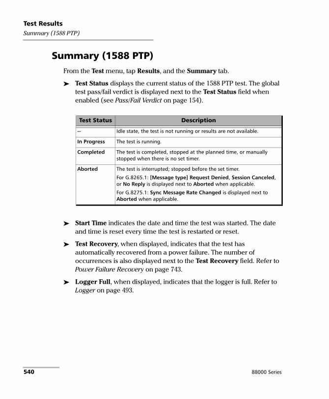
Test ResultsSummary (1588 PTP)
Summary (1588 PTP) From the Test menu, tap Results, and the Summary tab.
Test Status displays the current status of the 1588 PTP test. The global test pass/fail verdict is displayed next to the Test Status field when enabled (see Pass/Fail Verdict on page 154).
Start Time indicates the date and time the test was started. The date and time is reset every time the test is restarted or reset.
Test Recovery, when displayed, indicates that the test has automatically recovered from a power failure. The number of occurrences is also displayed next to the Test Recovery field. Refer to Power Failure Recovery on page 743.
Logger Full, when displayed, indicates that the logger is full. Refer to Logger on page 493.
Test Status Description
-- Idle state, the test is not running or results are not available.
In Progress The test is running.
Completed The test is completed, stopped at the planned time, or manually stopped when there is no set timer.
Aborted The test is interrupted; stopped before the set timer.
For G.8265.1: [Message type] Request Denied, Session Canceled, or No Reply is displayed next to Aborted when applicable.
For G.8275.1: Sync Message Rate Changed is displayed next to Aborted when applicable.
540 88000 Series

Test ResultsSummary (1588 PTP)
Negotiation Status
The status of the PTP Negotiation is displayed while in Unicast negotiation (available with G.8265.1 profile).
Negotiation Status Description Background
Colora
a. The gray background color is also used for a Link Down.
Request Granted All the Signaling request types have been granted. Green
[Message type] Request Denied
The Signaling grant message has not been granted. Red
Session Canceled The Grand Master has canceled the Unicast session. Red
No Reply No message is received from the Grand Master following transmission of 3 Signaling requests for a message type.
Make sure that both IP address and Domain (refer to 1588 PTP on page 148) of the Grand Master Clock are valid as well as the IP address of the unit’s port used to connect on the network (refer to Network on page 264).
Red
Pending Unicast negotiation has started and no message has been received from the Grand Master.
Gray
Inactive The Unicast negotiation is not active. Gray
Power Blazer 541

Test ResultsSummary (1588 PTP)
GM Info
Note: Only available when Grand Master clock information is available.
The Grand Master Information window displays the decoded clock information.
For G.8265.1 only:
Identity reports the 8-byte identification code of the Grand Master Clock.
For G.8275.1 only:
Port Identity reports the identity type of the PTP port.
GM Identity reports the clock identity of the Grand Master Clock.
Priority 1 reports the priority 1 attribute of the Grand Master Cock.
Priority 2 reports the priority 2 attribute of the Grand Master Clock.
Steps Removed reports the number of communication paths crossed between the local clock and the Grand master Clock.
Log Message Interval (Announce) reports the mean time interval between successive Announce messages.
Log Message interval (Sync) reports the mean time interval between successive Sync messages.
542 88000 Series
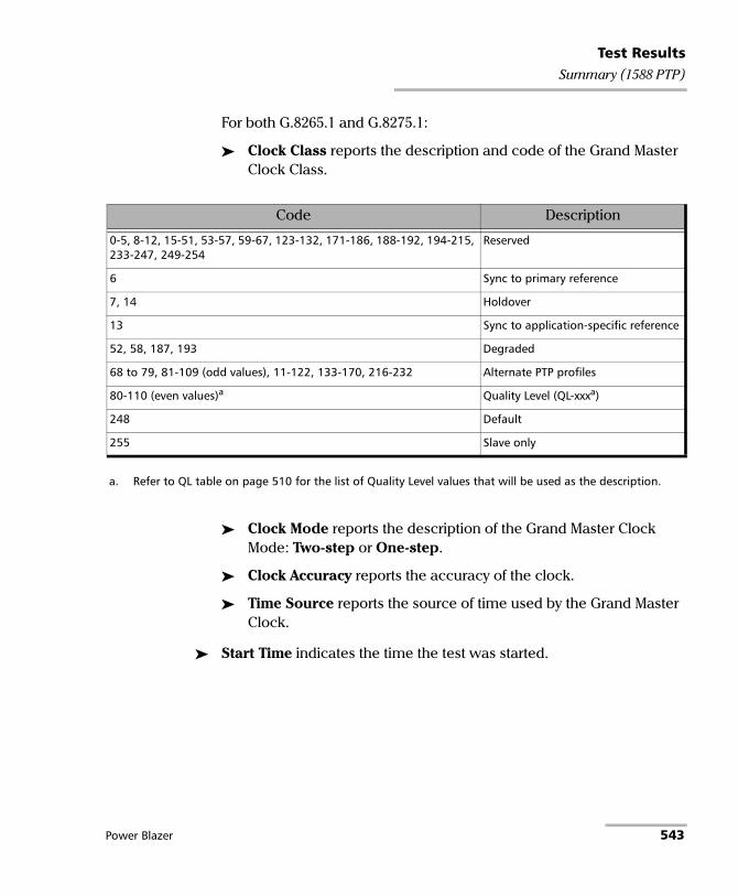
Test ResultsSummary (1588 PTP)
For both G.8265.1 and G.8275.1:
Clock Class reports the description and code of the Grand Master Clock Class.
Clock Mode reports the description of the Grand Master Clock Mode: Two-step or One-step.
Clock Accuracy reports the accuracy of the clock.
Time Source reports the source of time used by the Grand Master Clock.
Start Time indicates the time the test was started.
Code Description
0-5, 8-12, 15-51, 53-57, 59-67, 123-132, 171-186, 188-192, 194-215, 233-247, 249-254
Reserved
6 Sync to primary reference
7, 14 Holdover
13 Sync to application-specific reference
52, 58, 187, 193 Degraded
68 to 79, 81-109 (odd values), 11-122, 133-170, 216-232 Alternate PTP profiles
80-110 (even values)a
a. Refer to QL table on page 510 for the list of Quality Level values that will be used as the description.
Quality Level (QL-xxxa)
248 Default
255 Slave only
Power Blazer 543

Test ResultsSummary (1588 PTP)
Delay Measurement
Sync IPDV meter displays the average of the inter packet delay variation of consecutive Sync messages in the last second. The value and the pass/fail verdict is also displayed when enabled.
Delay Req IPDV meter displays the average of the inter packet delay variation of consecutive Delay Req messages in the last second. The value and the pass/fail verdict is also displayed when enabled.
Note: When a value is below 1μ second, “< 1μs” is displayed.
Note: When the Pass/Fail verdict is enabled, the green region is delimited from 0 to the IPDV Threshold (refer to Alarm Timeout/Threshold on page 153) corresponding to a PASS verdict. The red region beyond the threshold corresponds to a FAIL verdict. There is neither green nor red region when the Pass/Fail verdict is disabled.
Quality Level
Last QL Received indicates the last Quality Level received. The pass/fail verdict is also displayed when both QL Mismatch Monitoring and Pass/Fail Verdict check boxes are selected.
Last Change indicates the date and time of the Last QL change.
Total PTP Messages
Gives respectively the total count of transmitted (TX) and received (RX) PTP messages.
544 88000 Series

Test ResultsSummary (Cable Test)
Summary (Cable Test) From the Test menu, tap Results, and the Summary tab.
Test Status
Test Status indicates the progress of the cable test as follows:
Idle (test has not started)
In Progress
Completed
The Pass/Fail verdict is displayed next to the Test Status field, when enabled, based on the following criteria: The worst pair’s Wire Map, Prop. Delay, Delay Skew, and Length.
Start Time
Indicates the date and time the test was started. The date and time is reset every time the test is restarted or reset.
Cable
Note: When no value is available, “--” is displayed.
Wire Map indicates the Wire Map result for the pair having the worst Wire Map. The distance to fault is also displayed when a fault is identified. The Pass/Fail verdict is also displayed, when enabled.
Prop. Delay (ns) indicates the propagation delay value for the pair having the longest propagation delay. The Pass/Fail verdict is also displayed when enabled.
Power Blazer 545

Test ResultsSummary (Cable Test)
Delay Skew (ns) indicates the delay skew value for the pair having the worst delay skew. The Pass/Fail verdict is also displayed when enabled. The Delay Skew result is only available for 1000 Base-T interface when the link is up.
Length (m/ft) indicates the length for the pair having the worst cable length value. The Pass/Fail verdict is also displayed when enabled.
Pairs
Note: When no value is available, “--” is displayed.
Pair indicates the pair number.
Pins indicates the pair’s pin numbers and color of each wire corresponding to the selected wiring standard.
W-BL White-Blue
BL Blue
W-O White-Orange
O Orange
W-G White-Green
G Green
W-BR White-Brown
BR Brown
546 88000 Series

Test ResultsSummary (Cable Test)
Wire Map Test Result gives the wire map test result for each pair. When the link is up: The wire map result for each pair is given as seen by the module to get a link up. This means that the wire map result may not correspond to the type of cable tested depending on the cable(s) used and/or the configuration of the cable mode (MDI, MDIX, or auto-detection) on both the module and the far end equipment. For example, two crossed pair cables end to end used between the module and a far end equipment may give a straight pair (MDI) wire map result.
Note: For 1 Gbit/s, both MDI and MDIX can be reported simultaneously since crossed pairs detection is performed independently for pairs A-B and C-D.
MDI Straight pair.
MDIX Crossed pair.
MDI (-) For 1 Gbit/s, straight pair with swapped wires within pair.
MDIX (-) For 1 Gbit/s, crossed pair with pair A swapped with pair B and/or pair C swapped with pair D.
Noise Excessive noise on a pair most likely caused by a link partner running in 10/100 Mbit/s forced mode. In this case, no propagation delay or length is reported and there is no comparison with any threshold.
Power Blazer 547

Test ResultsSummary (Cable Test)
When the link is down:
If the determined Wire Map is either MDI, MDIX, MDI (-), MDIX (-), or Noise (Link up), the test is declared as PASS. If the determined Wire Map is either Short, Short-between-pair, Open, Noise (Link down), or Unknown, the test is declared as FAIL.
Note: Refer to Ethernet Cables on page 792 for cable pinout.
Distance To Fault (m/ft) gives the distance to fault from the near end for each pair, unless the problem is due to excessive noise. Noise may be due to electrical noise causing communication error.
Prop. Delay (ns) indicates the propagation delay of a signal through each pair.
Length (m/ft) indicates the cable length of each pair.
Short Short-circuit between Tip and Ring wires of a pair or Tip or ring wire of a pair is connected with an alien wire grounded.
Open No cable plugged in, remote end open, or either one or two wires of a pair are not connected.
Short-between-pairs Short between one or two wires of a pair with one or two wires of another pair. Short between more than two pairs, including one or two wires for each pair.
Noise Excessive noise on a pair most likely caused by a link partner running in 10/100 Mbit/s forced mode. In this case, no distance is reported and there is no comparison with any threshold.
Unknown No fault has been identified but the link is down. To maximize the cable test result, it is preferable to have the far end equipment powered up.
548 88000 Series

Test ResultsSummary (Cable Test)
PoE
Note: Only available on 8870/8880.
Detection/Classification
Power Presence indicates on which cable pairs (refer to Wiring Standard on page 162) the power is received and the polarity of each pair. Result is presented as follows:
PSE Type indicates the detected PSE type.
Granted Power Class indicates the power class provided by the PSE:
The Pass/Fail verdict is also displayed when enabled.
Power Presence Description
Pos: <pair>; Neg: <pair> PSE applies power on 2 pairs.
Pos: <pair>,<pair>; Neg: <pair>,<pair> PSE applies power on all pairs.
No power detected No power over Ethernet was detected.
Granted power Class Description
0 Class 0 (13.0W)
1 Class 1 (3.8W)
2 Class 2 (6.5W)
3 Class 3 (13.0W)
4 Class 4 (25.5W)
None The PSE denied power.
Power Blazer 549

Test ResultsSummary (Cable Test)
Operation
Note: The following results are only reported when the classification succeeded.
Unloaded Voltage (V) indicates the measured voltage when no load is applied. A value less then 5 is reported as <5.0 and a value greater than 59 is reported as >59.0.
Loaded Voltage (V) indicates the measured voltage by applying a load corresponding to the configured power class. A value less then 5 is reported as <5.0 and a value greater than 59 is reported as >59.0. The Pass/Fail verdict is also displayed when enabled.
Current (mA) indicates the current which is calculated based on the measured Loaded Voltage and the applied load.
Power (W) indicates the power in watt which is calculated based on the measured Loaded Voltage and Current.
550 88000 Series

Test ResultsSummary (EtherSAM)
Summary (EtherSAM) From the Test menu, tap Results, and the Summary tab.
Note: For Dual Test Set, only Start Time is displayed on the remote module.
Service Configuration/Performance Test Status indicates the actual test status as follows:
Start Time indicates the date and time the test was started. The date and time is reset every time the test is restarted.
Remote unit in use and locked for Dual Test Set indicates that this module is used for Dual Test Set as the remote module.
Test Status Description“--” Test has not started.
Disabled Test/subtests is/are disabled.
Running Test/subtest is currently running.
Data Transfer Test/subtest is running but no test traffic is being transmitted.
Completed, <Verdict> Test/subtest has completed with the test pass/fail verdict. A fail verdict is declared when a Link Down or LOS is detected, or when any SLA parameter fails.
Aborted, <reason> Test/subtest has been aborted either manually (Stop) or automatically from an alarm and the reason why the test has been aborted is also displayed as follows: Link down alarm, LOS alarm, Timeout during execution, DTS connection failed, Loss of remote connection (DTS), LOPPS-L Alarma, LOPPS-R Alarma, LOPPS-L / LOPPS-R Alarma, Unresolved addresses, No test enabled, No L2CP Frame Enabled, Invalid Burst Configuration, CIR disabled for all services, Excessive Refill Timeb, Stopped, NAT detection failed, Missing DTS-NAT SW option
a. Available for Dual Test Set in One-Way Latency measurement mode. b. An excessive refill occurs when the pre-burst and/or post-burst duration last for
more than 2 seconds.
Power Blazer 551

Test ResultsSummary (EtherSAM)
Remote unit in Dual Test Set Mode indicates that this module is set as remote but the DTS Connection is not established.
Service Configuration/Performance Test: Tap Service Configuration Test or Service Performance Test button to view the result summary of the corresponding test.
Service indicates the service’s number and name. For Service Configuration Test, the number/name is highlighted in red per service when VLAN mismatch occurred; in Dual Test Set or Dual Port topology, the direction is also highlighted; in Dual Test Set, the R -> L direction label is gray when VLAN Preservation is not supported by the remote module.
Direction, available with Dual Test Set or Dual Port topology, indicates respectively results for both local (L) and remote (R) directions, or both port directions.
L2CP, available when both L2CP Handling Test and pass/fail verdict are enabled, indicates the L2CP handling test pass/fail verdict.
Service Performance Test column displays the pass/fail verdict icon indicating if the service complies to the configured SLA parameters.
Service Configuration Test column displays the pass/fail verdict icon indicating if the service complies to the configured SLA parameters.
552 88000 Series

Test ResultsSummary (EtherSAM)
Committed
Frame Loss Rate indicates the rate of frames that are lost. The reported value is the maximum rate of Frame Loss from all burst sequences and ramp steps excluding the CIR+EIR, EBS, and Traffic Policing steps. Frame Loss is displayed as a percentage value when the remote module does not support exponential notation.
Max. Jitter (ms) indicates the maximum measured delay variation.
Max Latency (ms) indicates the maximum measured round-trip latency (delay). For Dual Test Set the local to remote and remote to local values are reported for One-Way Latency Measurement Mode while a single round-trip value is reported for Round-Trip Latency Measurement Mode (see Global Options on page 197).
Avg RX Rate, for Service Performance Test, indicates the measured average utilization throughput.
Excess
Max RX Rate, for Service Configuration Test, indicates the measured maximum utilization throughput.
VLAN Preservation indicates if any VLAN mismatch occurred during any step of a Ramp or Burst tests as follows:
Grey: Undefined Green: No Mismatch detected Red: Mismatch detected
Power Blazer 553

Test ResultsSummary (FC BERT)
Summary (FC BERT) From the Test menu, tap Results, and the Summary tab.
Test Status indicates the actual test status as follows:
“--”: The test is not running or results are not available.
In Progress: The test is running.
Completed: The test is completed, stopped at the planned time, or manually stopped when there is no set timer.
Once the test is stopped, the test pass/fail verdict is displayed next to the Status field when enabled. The verdict is Pass when all verdicts are Pass, the verdict is Fail as soon as one of the verdict is Fail. Refer to Bit/Pattern Error on page 185 and Latency Tag Insertion on page 187 for more information.
Start Time indicates the date and time the test was started. The date and time is reset every time the test is restarted or reset.
Test Recovery, when displayed, indicates that the test has automatically recovered from a power failure. The number of occurrences is also displayed next to the Test Recovery field. Refer to Power Failure Recovery on page 743.
Logger Full, when displayed, indicates that the logger is full. Refer to Logger on page 493.
554 88000 Series

Test ResultsSummary (FC BERT)
BER
Note: See BER on page 396 for a description of each alarm/error.
BER Threshold is available when Pass/Fail Verdict is enabled (refer to page 185).
Bit Error Rate/Count graphically displays a meter representing either the bit error rate or the bit error count depending on the Pass/Fail Verdict selection (refer to page 185).
When the verdict is enabled, the values under the threshold are presented in green while the values above are in red.
When the verdict is disabled, the bit error rate is displayed in blue.
The arrow pointer indicates the current received bit error rate/count.
The Pass/Fail verdict is displayed just on top of the meter when enabled.
Bit Error and Rate/Amount
Manual allows entering the amount of manual error to be generated: 1 (default) through 50.
Rate allows the selection of the injection rate for the selected error.
Max Rate generates the selected error to its theoretical maximum rate.
Inject generates, if the test is running, the amount of bit error configured.
Power Blazer 555

Test ResultsSummary (FC BERT)
Round-Trip Latency
Round Trip Latency (ms) is measured for each local and remote port.
Current, Average, Minimum, and Maximum indicates respectively the current, average, minimum, and the maximum round trip latency from the local to the remote port in the last one second. The pass/fail verdict is also displayed for the maximum round trip latency.
Samples indicates the number of samples used for the round trip latency.
Estimated BB_Credit indicates the estimated number of packets that can be transmitted on the optical line at the same time.
Round-Trip Latency Threshold (ms) sets the round trip latency threshold: 0.015 to 8000 ms (default is 15). This setting is only available when both Latency Tags and Pass/Fail Verdict check boxes are selected (refer to Latency Tag Insertion on page 187).
Traffic
Line Utilization (%) indicates the current percentage of the transmitting/receiving line rate utilization.
Frame Rate (frame/s) indicates the current transmitted/received number of frames (including frame with error and aborted frames) in frame per second.
Byte Count indicates the total number of transmitted/received bytes including the frame delimiters.
Frame Count indicates the total number of transmitted/received frames including link service control frames.
556 88000 Series

Test ResultsSummary (FlexE BERT)
Summary (FlexE BERT) From the Test menu, tap Results, and the Summary tab.
Status indicates the actual test status as follows:
“--”: The test is not running or results are not available.
In Progress: The test is running.
Completed: The test is completed, stopped at the planned time, or manually stopped when there is no set timer.
Start Time indicates the date and time the test was started. The date and time is reset every time the test is restarted or reset.
Test Recovery, when displayed, indicates that the test has automatically recovered from a power failure. The number of occurrences is also displayed next to the Test Recovery field. Refer to Power Failure Recovery on page 743.
Logger Full, when displayed, indicates that the logger is full. Refer to Logger on page 493.
FlexE Group
Indicates respectively for each PHY, its number, port number, link status and skew (refer to page 649). For FlexE group global alarms, refer to FlexE Group on page 415.
Power Blazer 557

Test ResultsSummary (FlexE BERT)
Pattern FlexE Client and FlexE Clients
The Pass/Fail verdict is displayed when enabled. The Pattern FlexE Client verdict is declared if any Bit Error, Pattern Loss, Ethernet alarm, or FCS error occurs. A FlexE Client verdict is declared if any Ethernet alarm or FCS error occurs.
Client ID indicates the client identification number and allows displaying the client’s summary page for the Client ID associated to the pattern (refer to Summary / Client Summary on page 531).
Size indicates the rate of the client in Gbit/s.
Link Alarm indicates respectively, from left to right, the history and current client link status (Link Down).
TX Rate indicates the client transmitted rate in Gbit/s.
RX Rate indicates the client received rate in Gbit/s.
RX Frame Count indicates the total number of received valid and invalid frames.
Bit Error Rate indicates the bit error rate.
Bit Error Count indicates the bit error count.
558 88000 Series
Test ResultsSummary (FlexO BERT)
Summary (FlexO BERT) From the Test menu, tap Results, and the Summary tab.
Client ID indicates the client ID.
Type indicates the client ODUk type.
Status indicates the actual test status as follows:
“--”: The test is not running or results are not available.
In Progress: The test is running.
Completed: The test is completed, stopped at the planned time, or manually stopped when there is no set timer.
Start Time indicates the date and time the test was started. The date and time is reset every time the test is restarted or reset.
Test Recovery, when displayed, indicates that the test has automatically recovered from a power failure. The number of occurrences is also displayed next to the Test Recovery field. Refer to Power Failure Recovery on page 743.
Logger Full, when displayed, indicates that the logger is full. Refer to Logger on page 493.
FlexO-OTUCn
Displays for each instance, its number, port number, skew, FlexO alarms (see FlexO - Group on page 416), and OTUCn alarms (see OTUCn on page 446).
Power Blazer 559
Test ResultsSummary (FlexO BERT)
BER
Note: See BER on page 396 for a description of each alarm/error.
Receiving Live Traffic - RX Pattern Analysis Disabled when displayed, indicates that the No Pattern Analysis (Live) check box is selected and in this case no other information/statistics are available.
BER Threshold is available when Pass/Fail Verdict is enabled1. This setting is global and applies to all Client ID.
Bit/Pattern Error Rate/Count graphically displays a meter representing either the bit/pattern error rate or the bit/pattern error count depending on the Pass/Fail Verdict selection1.
When the verdict is enabled1, the values under the threshold are presented in green while the values above are in red.
When the verdict is disabled, the bit/pattern error rate is displayed in blue.
The arrow pointer indicates the current received bit/pattern error rate/count.
The Pass/Fail verdict is displayed just on top of the meter when enabled1.
Bit/Pattern Error, Amount/Rate, and Inject: The bit/pattern error injection and settings are coupled with the Inject Button on page 473.
1. Refer to BERT and Unframed BERT on page 155.
560 88000 Series

Test ResultsSummary (iOptics)
Summary (iOptics) From the Test menu, tap Results, and the Summary tab.
Start Time indicates the date and time the test was started. The date and time reset every time the test is restarted.
When necessary for power consumption monitoring the Calibrating progress message is displayed. If at any point during this process or during a sub-test execution an unexpected condition is detected, an abort message is displayed as follows:
Sub-Test Sequence
The progress status and pass/fail verdict are displayed for each sub-test sequence as follows:
I/O Interface Quick Check:
Validates the operation of the MDIO/I2C interface by sending specific commands to the transceiver.
Validates the information provided by a status pin and stimulates a control pin of the transceiver.
Test Status DescriptionAborted, <reason> Sub-test sequence has been aborted and a reason is displayed:
Missing Transceiver System, Invalid Transceiver System, Missing Device Under Test, Invalid Device Under Test, Link Down, Laser Off, LOS, Device under Test Ovrld (overload), Device Pulled, Failed, or User Stopped.
Test Status Description“--” Sub-test is not running or results are not available.
Running <details> Sub-test is running and progress details are displayed.
Completed, Pass/Fail Sub-test is completed with Pass or Fail verdict.
Aborted, Fail Sub-test sequence has been aborted with a fail verdict.
Power Blazer 561

Test ResultsSummary (iOptics)
Optical TX Power Test (dBm) reports the minimum and maximum optical TX power values; in-range values are displayed in green while out-of-range are in red. Not available with QSFP28 AOC.
Optical RX Power Test (dBm) reports the minimum and maximum optical RX power values; in-range values are displayed in green while out-of-range are in red.
Bit Error Test reports the bit error count; count value smaller or equal to the BER threshold is displayed in green while bigger value is in red.
Excessive Skew Test reports the highest skew value monitored during the sub-test; a value smaller than the threshold is displayed in green while a value crossing the threshold is in red. Only available for parallel interfaces with the exception of transceivers using RS-FEC (100GBASE-SR4, 100GBASE-SR4 AOC, 100GE-CWDM4, 100GE-CLR4).
Monitoring
Power Consumption graphically displays a meter representing the transceiver power consumption in Watt. Not available on 8870 and 8880 modules.
The Current (A) and Power (W) values (Actual and Maximum) for 3.3V source are displayed.
Temperature graphically displays a meter representing the transceiver temperature in oC.
The current (Actual) and maximum temperature values are also displayed.
Note: The green region is delimited from 0 to the Threshold corresponding to a PASS verdict. The red region beyond the threshold corresponds to a FAIL verdict.
562 88000 Series

Test ResultsSummary (iSAM)
Summary (iSAM) From the Test menu, tap Results, and the Summary tab.
Start Time indicates the date and time the test was started. The date and time is reset every time the test is restarted.
Configuration/Performance Results and RFC 6349 Results buttons are used to respectively display summary results for Service Configuration Test and Service Performance Test, or RFC 6349 Test when results don’t fit on one page.
Service Configuration Test and Service Performance Test
The actual test status is displayed as follows:
Test Status Description“--” Test has not started.
Disabled Test/subtests is/are disabled.
Running Test/subtest is currently running.
Data Transfer Test/subtest is running but no test traffic is being transmitted.
Completed, <Verdict> Test/subtest has completed with the test pass/fail verdict. A fail verdict is declared when a Link Down or LOS is detected, or when any SLA parameter fails.
Aborted, <reason> Test/subtest has been aborted either manually (Stop) or automatically from an alarm and the reason why the test has been aborted is also displayed as follows: Link down alarm, LOS alarm, Timeout during execution, DTS connection failed, Loss of remote connection (DTS), Unresolved addresses, Stopped, NAT detection failed, Missing DTS-NAT SW option
Power Blazer 563

Test ResultsSummary (iSAM)
For Dual Test Set the following values are reported for both local to remote (L->R) and remote to local (R->L).
Service indicates the service’s number and name.
The pass/fail verdict icon is displayed next to the service name indicating if the service complies to the configured SLA parameters.
TX CIR (Mbit/s) indicates the transmitted Committed Information Rate.
FD (ms) (RTT1) (Latency) indicates the maximum measured round-trip latency (Frame Delay). The pass/fail verdict is also displayed.
IFDV (ms) (Jitter) indicates the maximum measured Inter Frame Delay Variation. The pass/fail verdict is also displayed.
FLR (%) (Frame Loss) indicates the maximum percentage of frames that are lost (Frame Loss Ratio) from the CIR step. The pass/fail verdict is also displayed.
RX Rate (Mbit/s) indicates either the measured maximum utilization throughput for Service Configuration Test or the measured average utilization throughput for Service Performance Test. The pass/fail verdict is also displayed.
Total RX Rate, available for Service Performance Test, indicates the average utilization throughput for all services (both directions are displayed for Dual Test Set).
1. RTT is only displayed for Dual Test Set.
564 88000 Series

Test ResultsSummary (iSAM)
RFC 6349 Test
Test Status indicates the actual test status as follows:
MTU (bytes) is the validated Maximum Transfer Unit.
Minimum RTT (ms) is the minimum time between the first bit of a segment sent and the last bit of the corresponding acknowledge.
TCP Throughput
Service indicates the service’s number and name. The pass/fail verdict icon is displayed next to the service name. A fail verdict is declared if any of the following conditions occurs: Link Down, LOS, TCP Throughput verdict failed, or an abort condition (Timeout, DTS connection lost, unresolved address, user stopped, configuration synchronization error, invalid MTU).
L->R and R->L indicates respectively the direction from local to remote and remote to local.
Test Status Description“--” Test has not started.
In Progress The test is running.
Completed, <Verdict> Test has completed and the test pass/fail verdict is displayed when enabled. A fail verdict is declared if any of the following conditions occurs: Link Down, LOS, TCP Throughput verdict failed, or an abort condition (Timeout, DTS connection lost, unresolved address, user stopped, configuration synchronization error, invalid MTU).
Aborted, <reason> Test has been aborted either manually (Stop) or automatically from an alarm and the reason is displayed as follows: Link down alarm, LOS alarm, Timeout during execution, DTS connection failed, Invalid Configuration, Unresolved addresses, Invalid MTU, User Stopped, TCP Timeout, TCP Connection failed, NAT detection failed, Missing DTS-NAT SW option
Power Blazer 565

Test ResultsSummary (iSAM)
Window indicates the total Max Window (1 KiB = 1024 bytes) followed by the number of connections and KiB per connection in parenthesis as follows: (n conn.@ n KiB).
Ideal L4 indicates the ideal TCP throughput metric.
Actual L4 indicates the average of actual TCP Throughput metric. The pass/fail verdict icon is displayed next to the this metric. A value greater or equal to the defined threshold gives a pass verdict.
TCP Efficiency (%) indicates the TCP Efficiency metric based on transmitted and retransmitted bytes.
Buffer Delay (%) indicates the Buffer Delay percentage metric which represents the increase in RTT during a TCP Throughput test versus the Minimum RTT.
566 88000 Series

Test ResultsSummary (Link OAM)
Summary (Link OAM) From the Test menu, tap Results, and the Summary tab.
Test Status displays the current status of the Link OAM test. The global test pass/fail verdict is displayed next to the Test Status when enabled (see Pass/Fail Verdict on page 362).
Start Time Indicates the date and time the test was started. The date and time is reset every time the test is restarted or reset.
Test Recovery, when displayed, indicates that the test has automatically recovered from a power failure. The number of occurrences is also displayed next to the Test Recovery field. Refer to Power Failure Recovery on page 743.
Logger Full, when displayed, indicates that the logger is full. Refer to Logger on page 493.
Alarms
Link OAM indicates that no OAM Information PDUs were received for 5 seconds.
Critical Event: Indicates that the OAM link partner has sent a critical event notification (bit 2 of the Flags field is set to 1).
Test Status Description
-- The test is not running or results are not available.
In Progress The test is running.
Completed The test is completed, stopped at the planned time, or manually stopped when there is no set timer.
Aborted The test is interrupted; stopped before the set timer.
Power Blazer 567

Test ResultsSummary (Link OAM)
Dying Gasp: Indicates that the OAM link partner has sent an unrecoverable local failure notification (bit 1 of the Flags field is set to 1).
Link Fault: Indicates that the OAM link partner has sent a link fault notification (bit 0 of the Flags field is set to 1).
Loopback
Local indicates the Status of the local loopback (Enabled or Disabled) and allows enabling or disabling it.
Remote1 indicates the Status of the remote loopback (Enabled or Disabled), the number of Successful remote loopback requests, the number of Fail remote loopback requests, and allows enabling or disabling it.
OAMPDU Frame Count
Indicates the number of transmitted and received OAMPDU frames of the following types:
Information
Loopback Control
Event Notification (received only)
Total indicates the total number of transmitted and received OAMPDU frames.
1. Statistics are influenced by both the protocol (Parser Action is set to “01”) and physical loopback. The Fail and Successful counters will be affected by successive enable/disable loopback requests when sending a loopback request to a remote module running Link OAM test since it does not provide physical loopback.
568 88000 Series

Test ResultsSummary (Multi-Channel OTN)
Summary (Multi-Channel OTN) From the Test menu, tap Results, and the Summary tab.
Status indicates the actual test status as follows.
“--”: The test is not running or results are not available.
In Progress: The test is running.
Completed: The test is completed, stopped at the planned time, or manually stopped when there is no set timer.
Start Time indicates the date and time the test was started. The date and time is reset every time the test is restarted or reset.
Test Recovery, when displayed, indicates that the test has automatically recovered from a power failure. The number of occurrences is also displayed next to the Test Recovery field. Refer to Power Failure Recovery on page 743.
Logger Full, when displayed, indicates that the logger is full. Refer to Logger on page 493.
Alarms/Errors, Traces, and Payload Type
The results displayed are for the first channel by default. Tap on one of the button described on the next page to select the results to be displayed. The selected button has an amber background.
When a channel button is selected:
The channel number is displayed indicating the selected channel.
A channel selector becomes available when zooming a result block allowing to select a specific channel.
Power Blazer 569

Test ResultsSummary (Multi-Channel OTN)
Interface / OTL / OTU4, ODU4, and Channel Buttons
Note: Refer to Alarms/Errors on page 391 for more information on alarms/errors and alarms/errors injection.
Interface / OTL / OTU4 displays alarms/errors for Interface (see page 425), Clock (see page 397), OTL (see page 440), and OTU4 (see page 441) as well as the received SM TTI Traces (see page 595).
ODU4 displays alarms/error at ODU4 (see page 430) and OPU4 (see page 437) levels as well as the received PM TTI Traces (see page 595) and received Payload Type (see page 482).
1, 2, up to 80, depending on the OTN multiplexing, displays alarms/error for a specific channel including: ODUx (see page 430), OPUx (see page 437), ODTU4.1 - GMP (see page 424), BERT (see page 532), SDT (see page 533), received PM TTI Traces (see page 595), and received Payload Type (see page 482).
Buttons use different background colors representing current and history alarms/errors. An orange background indicates the selected button.
Background color Alarm/ Errora
a. History background color is presented on the left side of the button while Current background color iscovering the rest of the button.
Description
Gray Current No test result available.
History
Green Current No alarm/error has occurred in the last second.
History No alarm/error has occurred during the test.
Red Current An alarm/error occurred in the last second.
History
Amber History At least one alarm/error has occurred during the test.
570 88000 Series

Test ResultsSummary (NI/CSU Emulation)
Summary (NI/CSU Emulation) From the Test menu, tap Results, and the Summary tab.
Status
Status indicates the progress of the test as follows:
Idle (test has not started)
In Progress
Completed
The Pass/Fail verdict is displayed next to the Test Status field, when enabled, based on the following criteria: The worst pair’s Wire Map, Prop. Delay, Delay Skew, and Length.
Start Time
Indicates the date and time the test was started. The date and time is reset every time the test is restarted or reset.
Auto-Response/Manual Loopback Status
Indicates the status of the loopback:
Loopback Active
No Loopback.
Interface
See Interface on page 425 for more information on Interface alarms/errors.
DS1
See DS1 on page 399 for more information on DS1 alarms/errors.
Power Blazer 571

Test ResultsSummary (RFC 2544)
Summary (RFC 2544) From the Test menu, tap Results, and the Summary tab.
Start Time indicates the date and time the test was started. The date and time is reset every time the test is restarted or reset. For Dual Test Set, this is the only information available on the remote module.
Test Recovery, when displayed, indicates that the test has automatically recovered from a power failure. The number of occurrences is also displayed next to the Test Recovery field. Refer to Power Failure Recovery on page 743.
Logger Full, when displayed, indicates that the logger is full. Refer to Logger on page 493.
Remote unit in use and locked for Dual Test Set indicates that this module is used for Dual Test Set as the remote module.
Remote unit in Dual Test Set Mode indicates that this module is set as remote but the DTS Connection is not established.
572 88000 Series

Test ResultsSummary (RFC 2544)
Throughput, Back-to-Back, Frame Loss, and Latency Subtests
Throughput, Back-to-Back, Frame Loss, and Latency
For each subtest, its status (-- (Idle), In Progress, Completed, or Aborted - (reason)) and duration are displayed.
TX Frames1 and RX Frames1 display the transmitted and received frame counts of the subtest in progress. For Dual Test Set, frame counts are available for both local (L) and remote (R) directions. For Dual Port topology, frame counts are available for both port directions.
Trial #1 displays the current trial iteration of the subtest in progress when applicable.
Val. #1 displays the current validation iteration of the subtest in progress when applicable.
Step1 displays the current step of the subtest in progress when applicable.
Displayed Results: Select the displayed result mode: Current, Minimum (default), Maximum, or Average.
Throughput/Back-to-Back/Frame Loss/Latency table.
Each frame size used for the test is displayed with its subtest statistics. Statistics values are displayed based on the Displayed Results setting.
“--” indicates that the result is not available because the test has not run yet. While testing, one of the following messages is displayed for each frame size: Initializing, Learning, Testing, Waiting, Not measurable, Aborted, Link is Down, or MAC not resolved.
Dir. (Direction), available with Dual Test Set or Dual Port topology, indicates respectively results for both local (L) and remote (R) directions, or for both port directions.
1. Only displayed once the test is started.
Power Blazer 573
Test ResultsSummary (RFC 2544)
Unit: Select the subtest result unit:
For Throughput: Mbit/s, Gbit/s, frame/s, and %. For Back-to-Back: Mbit/s, Gbit/s, frame/burst, and %. Frame Loss: %. Latency: ms, and μs.
Layer: For Throughput and Back-to-Back subtests, select the subtest layers used to calculate the throughput.
All (default): Layer 1,2,3 contains the Idle, Preamble, Start of Frame Delimiter, MAC address, IP address, and data.
Ethernet: Layer 2,3 contains the MAC layer, IP layer, and data.
IP: Layer 3 contains the IP layer, and data.
Step: For Frame Loss subtest, selects the step (%) of the testing rate to be displayed.
Mode: For Latency subtest, selects the propagation time mode.
Cut Through (default) allows the calculation of the propagation time of a bit (Bit Latency).
S. & F. (Store and Forward) allows the calculation of the propagation time of a frame (Frame Latency).
574 88000 Series

Test ResultsSummary (RFC 6349)
Summary (RFC 6349) From the Test menu, tap Results, and the Summary tab.
Status indicates the actual test status as follows:
Start Time indicates the date and time the test was started. The date and time is reset every time the test is restarted or reset. This is the only information available on the remote module.
Test Recovery, when displayed, indicates that the test has automatically recovered from a power failure. The number of occurrences is also displayed next to the Test Recovery field. Refer to Power Failure Recovery on page 743.
Test Status Description“--” Test has not started.
In Progress The test is running.
Completed, <Verdict> Test has completed and the test pass/fail verdict is displayed when enabled. A fail verdict is declared if any of the following conditions occurs: Link Down, LOS, TCP Throughput verdict failed, or any abort condition.
Aborted, <reason> Test has been aborted either manually (Stop) or automatically due to an abort condition, and the reason is displayed as follows: Link Down Alarm, LOS Alarm, DTS Connection failed, No Communication with Remote, Remote is busy, Unexpected response from Remote, Timeout during execution, Invalid Configuration, Unresolved addresses, Invalid MTU, User stopped, TCP Timeout, TCP Connection failed, NAT detection failed, Missing DTS-NAT SW option
Power Blazer 575

Test ResultsSummary (RFC 6349)
Logger Full1, when displayed, indicates that the logger is full. Refer to Logger on page 493.
Remote unit in use and locked for Dual Test Set2 indicates that this module is used for Dual Test Set as the remote module.
Remote unit in Dual Test Set Mode2 indicates that this module is set as remote but the DTS Connection is not established.
MTU (bytes) is the validated Maximum Transfer Unit.
Minimum RTT (ms) is the minimum time between the first bit of a segment sent and the last bit of the corresponding acknowledge.
Window Sweep
L->R and R->L indicates respectively the direction from local to remote and remote to local.
Actual L4 indicates for each step the average TCP throughput metric.
TCP Throughput
L->R and R->L indicates respectively the direction from local to remote and remote to local.
Window indicates the total Max Window in KiB (1 KiB = 1024 bytes) followed by the number of connections and KiB per connection in parenthesis as follows: (n conn. @ n KiB).
Ideal L4 indicates the ideal TCP throughput metric.
Actual L4 indicates the average of actual TCP Throughput metric. The pass/fail verdict icon is displayed next to the this metric when enabled. A value greater or equal to the defined threshold gives a pass verdict.
TCP Efficiency (%) indicates the TCP Efficiency metric based on transmitted and retransmitted bytes.
1. Displayed on local module only.
2. Displayed on Remote module only.
576 88000 Series

Test ResultsSummary (RFC 6349)
Buffer Delay (%) indicates the Buffer Delay percentage metric which represents the increase in RTT during a TCP Throughput test versus the Minimum RTT.
TCP Throughput Threshold (% of ideal) allows entering the TCP Throughput as a percentage of the defined CIR that will be used to declare the pass/fail verdict for both directions: 0 to 100 %; default is 95 %. The calculated throughput based on the selected threshold is displayed for both directions.
Power Blazer 577

Test ResultsSummary (S-OAM and MPLS-TP OAM)
Summary (S-OAM and MPLS-TP OAM) From the Test menu, tap Results, and the Summary tab.
Test Status displays the current status of the S-OAM / MPLS-TP OAM test. The global test pass/fail verdict is displayed next to the Test Status when enabled (see Pass/Fail Verdict on page 362).
Start Time Indicates the date and time the test was started. The date and time is reset every time the test is restarted or reset.
Test Recovery, when displayed, indicates that the test has automatically recovered from a power failure. The number of occurrences is also displayed next to the Test Recovery field. Refer to Power Failure Recovery on page 743.
Logger Full, when displayed, indicates that the logger is full. Refer to Logger on page 493.
Test Status Description
-- The test is not running or results are not available.
In Progress The test is running.
Completed The test is completed, stopped at the planned time, or manually stopped when there is no set timer.
Aborted The test is interrupted; stopped before the set timer.
578 88000 Series

Test ResultsSummary (S-OAM and MPLS-TP OAM)
Continuity Check (Peer MEP)
Status displays the status of the continuity check with the peer MEP.
TX CCM indicates the count of transmitted CCM frames.
RX CCM indicates the count of valid CCM frames received. A valid frame for S-OAM has its source MAC address matching the Peer MEP MAC address; destination MAC address matching either the unit port Unicast MAC address or a Multicast class 1 address (refer to 841); and VLANs matching the unit port VLANs. A valid frame for MPLS-TP OAM has its destination MAC address matching either the unit MAC address, FF:FF:FF:FF:FF:FF, or 01:00:5E:90:00:00; VLANs matching the unit port VLANs; and MPL Labels matching the local MPLS Label Stack configuration.
Status Description
Loss Continuity Loss of Continuity alarm is active.
Mismerge Mismerge alarm is active.
Unexpected MEG Level Unexpected MEG Level alarm is active.
Unexpected MEP Unexpected MEP alarm is active.
Unexpected Period Unexpected Period alarm is active.
Unexpected MD Level Unexpected MD Level alarm is active.
Receiving CCMs CCM frames from the peer MEP are received without alarms.
Power Blazer 579

Test ResultsSummary (S-OAM and MPLS-TP OAM)
CCM indicates the content of the last received CCM frame including MEG ID (Y.1731 and G.8113.1), Domain ID (802.1ag and MEF), MA Name (802.1ag and MEF), MEG Level (Y.1731, MEF, and G.8113.1), MD Level (802.1ag), MEP ID, and Period.
For unsupported Domain ID, MA Name, and MEG ID, the Unexpected Format message is displayed.
Supported Format
Domain ID 1 (No Maintenance Domain Name present)
4 (Character String)
MA Name 2 (Character String)
MEG ID 32 (ICC based format)
33 (CC and ICC based format)
580 88000 Series

Test ResultsSummary (S-OAM and MPLS-TP OAM)
Loopback / Test / Frame Delay / Frame Loss / Synthetic Loss
Note: Either Loopback, Test, Frame Delay, Frame Loss, or Synthetic Loss (available with Ethernet OAM) statistics are displayed according with the selected test function (refer to Test Function on page 312).
Status displays the status of the test function.
For Loopback, Frame Delay, Frame Loss, and Synthetic Loss (available with Ethernet OAM) functions:
For Test function:
Status Description
Idle No Results (function did not run yet).
In Progress Test is in progress. Frames are being transmitted and monitored.
Completed Test is completed:
The test with continuous transmission is manually stopped and replies have been received or timed out.
The test with continuous transmission is automatically stopped by a test timer and replies have been received or timed out.
All frames of the test with non-continuous transmission have been transmitted and replies have been received or timed out.
Aborted Test is aborted. The test with non-continuous transmission is stopped before all the frames are transmitted.
Status Description
Idle No Results (function did not run yet).
In Progress Test is in progress. RX TST frames are being monitored.
Completed Test is completed. The test is stopped or function is disabled after being In Progress state.
Power Blazer 581

Test ResultsSummary (S-OAM and MPLS-TP OAM)
RX Line Utilization meter and value, available with Loopback function, indicate the line rate utilization percentage (only LBR frames are considered) received in the last second.
TST RX Rate meter and value, available with Test function, indicate the quantity of TST frames received in the last second.
Frame Delay meter and value, available with Frame Delay function, indicate the average of the measured frame delays in the last second.
Frame Loss Ratio meter, available with Frame Loss function, indicates for both Near-End and Far-End the last measured frame loss ratio in the last second.
Synthetic Loss Ratio meter, available with Synthetic Loss function which is available with Ethernet OAM, indicates for both Near-End and Far-End the last measured Synthetic Loss ratio in the last second.
Note: Refer to S-OAM and MPLS-TP OAM on page 514 for more alarms/errors/statistics information.
Summary
Refer to S-OAM and MPLS-TP OAM on page 514 for more information on alarms.
Thresholds
Refer to Thresholds on page 308 for more information.
582 88000 Series

Test ResultsSummary (SyncE)
Summary (SyncE) From the Test menu, tap Results, and the Summary tab.
Test Status displays the current status of the SyncE test. The global test pass/fail verdict is displayed next to the Test Status when enabled (see Pass/Fail Verdict on page 362).
Start Time indicates the time the test was started.
Test Recovery, when displayed, indicates that the test has automatically recovered from a power failure. The number of occurrences is also displayed next to the Test Recovery field. Refer to Power Failure Recovery on page 743.
Logger Full, when displayed, indicates that the logger is full. Refer to Logger on page 493.
Test Status Description
-- The test is not running or results are not available.
In Progress The test is running.
Completed The test is completed, stopped at the planned time, or manually stopped when there is no set timer.
Aborted The test is interrupted; stopped before the set timer.
Power Blazer 583

Test ResultsSummary (SyncE)
ESMC
Indicates the current (meter and value), average, minimum, and maximum ESMC frame rate (including information and event frames) received in frame/s. A fail verdict is also displayed beside the minimum and/or maximum values when the ESMC frame rate is outside the range while the Pass/Fail Verdict is enabled.
ESMC RX Rate meter displays the current ESMC frame rate (including information and event frames) in frame/s averaged over the last 11 frames received. The pass/fail verdict is also displayed when enabled.
Note: When the Pass/Fail Verdict and ESMC Rate Threshold check boxes are selected (see page 362), the green region is delimited from 0.8 to 10.2 frames/s corresponding to a PASS verdict. The red regions above and beyond the threshold correspond to a FAIL verdict. There is neither green nor red region when the Pass/Fail verdict is disabled.
584 88000 Series

Test ResultsSummary (SyncE)
RX
Last QL Message indicates the last Quality Level value received. The pass/fail verdict is also displayed when both QL Mismatch Monitoring and Pass/Fail Verdict check boxes are selected.
Last Change indicates the date and time of the Last QL Message has changed.
Information/Event Count gives respectively the count of information and event frames generated for all Quality Level values.
QL Mismatch Frame Count gives the total count of information and/or event frames received not matching the expected Quality Level. Only available when the QL Mismatch Monitoring check box is selected.
Frequency/Offset indicates respectively the frequency and the offset between the standard rate specification and the rate of the input signal.
Max. (-/+) Offset (ppm) indicates respectively the minium and maximum offset between the standard rate specification and the largest/smallest rate recorded from the received signal.
TX
QL Message indicates the Quality Level value that is generated.
Last Change indicates the date and time of the QL Message value has changed. For 1GE Electrical interface using Local Clock set to Slave, the Last Change is not available.
Information/Event Count gives respectively the count of information and event frames generated for all Quality Level values. Event Count is not available with 1GE Electrical interface using remote local clock.
Power Blazer 585

Test ResultsSummary (TCP Throughput)
Summary (TCP Throughput) From the Test menu, tap Results, and the Summary tab.
Test Status indicates the actual test status as follows:
Start Time indicates the date and time the test was started. The date and time is reset every time the test is restarted or reset.
Test Recovery, when displayed, indicates that the test has automatically recovered from a power failure. The number of occurrences is also displayed next to the Test Recovery field. Refer to Power Failure Recovery on page 743.
Logger Full, when displayed, indicates that the logger is full. Refer to Logger on page 493.
Test Status Description“--” The test is not running or results are not available.
In Progress The test is running.
Completed The test is completed, stopped at the planned time, or manually stopped when there is no set timer.
Aborted - <Reason> The test is interrupted; stopped before the set timer. Possible <Reason> are: TCP Session Closed or Remote IP Not Found.
586 88000 Series

Test ResultsSummary (TCP Throughput)
TCP Throughput
TCP Connection Status indicates the actual TCP connection status.
Transmitted Frames indicates the total of frames transmitted by the local unit excluding the re-transmitted frames.
Re-transmitted Frames indicates the total of frames that have been re-transmitted by the local unit.
Efficiency (%) indicates the percentage of bytes that were not retransmitted.
Window Size Unit allows selecting the unit used for Window Size: Bytes, KBytes, or MBytes (default).
Throughput Threshold allows setting the pass/fail verdict threshold value: 0 to 100 % (default). This setting is available when the Throughput Pass/Fail Verdict check box is selected (refer to TCP Throughput on page 365).
Throughput meter displays the last second TCP Throughput measurement.
Test Status Description“--” The test is not running or results are not available.
In Progress The TCP initialization algorithm is in progress.
Waiting Indicates on the remote unit that the test is started but the TCP initialization algorithm is not initiated by the local unit.
Established The TCP session has been successfully established between the local and remote units.
Closed The session is closed. Either no TCP initialization algorithm has been received, the remote unit has received and completed the request to close the TCP session, or no data has been received at the remote unit for 30 seconds.
Closing The TCP protocol is closing down the connection.
Remote IP not found The local unit didn’t received an answer to the ARP request sent to the IP address of the remote unit.
Power Blazer 587

Test ResultsSummary (TCP Throughput)
TCP Throughput displays respectively the last, minimum, maximum, and average TCP Throughput measurement.
Window Size displays respectively the last, minimum, and maximum TCP window size.
Round Trip Latency (ms) displays respectively the last, minimum, maximum, and average round trip time gathered from the TCP Throughput test.
Ethernet Traffic
Note: See Traffic - Ethernet on page 600 for more information.
588 88000 Series

Test ResultsSummary (Traffic Gen & Mon)
Summary (Traffic Gen & Mon) From the Test menu, tap Results, and the Summary tab.
Note: For Dual Port topology select the port to be displayed.
Test Status indicates the actual test status as follows. The global test pass/fail verdict is displayed next to the Test Status when enabled (see QoS Metrics on page 359).
“--”: The test is not running or results are not available.
In Progress: The test is running.
Completed: The test is completed, stopped at the planned time, or manually stopped when there is no set timer.
Start Time indicates the date and time the test was started. The date and time is reset every time the test is restarted or reset.
Test Recovery, when displayed, indicates that the test has automatically recovered from a power failure. The number of occurrences is also displayed next to the Test Recovery field. Refer to Power Failure Recovery on page 743.
Logger Full, when displayed, indicates that the logger is full. Refer to Logger on page 493.
Stream
The following statistics are available for each stream.
Current Throughput: See Streams - Throughput / Customer Frame Throughput on page 530.
Frame Loss Rate: See Streams - Frame Loss / Out-of-Sequence on page 528.
Jitter: See Streams - Jitter on page 528.
Latency: See Streams - Latency on page 529.
Power Blazer 589

Test ResultsSummary (Traffic Gen & Mon)
Out-of-Sequence: See Streams - Frame Loss / Out-of-Sequence on page 528.
Stream indicates the stream number and provides stream detailed statistics when tapping on its button.
The following statistics are displayed for the selected stream.
Stream Selection: Select a stream by either using the left/right arrow or by tapping over the stream numbers area then tapping on a specific stream number. An orange background indicates the selected stream.
Throughput, Jitter, and Latency meters display respectively the measured Throughput, Jitter, and Latency for the selected stream.
Note: The green region defined by the configured threshold corresponds to a PASS verdict while the red regions corresponds to a FAIL verdict. The Pass/Fail verdict is only displayed when enabled (see QoS Metrics on page 359).
Jitter: See Streams - Jitter on page 528.
Latency: See Streams - Latency on page 529.
RX Rate: See Streams - Throughput / Customer Frame Throughput on page 530.
RX Frame Count indicates the number of frame received matching the selected stream.
TX Rate: See Streams - Throughput / Customer Frame Throughput on page 530.
TX Frame Count indicates the number of transmitted frames matching the selected stream.
Frame Loss and Out-of-Sequence: See Streams - Frame Loss / Out-of-Sequence on page 528.
590 88000 Series

Test ResultsSummary (Wander)
Summary (Wander) From the Test menu, tap Results, and the Summary tab.
Test Status displays the current status of the Wander test. The global test pass/fail verdict is displayed next to the Test Status when enabled (see Pass/Fail Verdict on page 362).
Start Time indicates the time the test was started.
Test Recovery, when displayed, indicates that the test has automatically recovered from a power failure. The number of occurrences is also displayed next to the Test Recovery field. Refer to Power Failure Recovery on page 743.
Logger Full, when displayed, indicates that the logger is full. Refer to Logger on page 493.
Test Status Description
-- The test is not running or results are not available.
In Progress The test is running.
Completed The test is completed, stopped at the planned time, or manually stopped when there is no set timer.
Aborted Test has been aborted either manually (Stop) or automatically from an alarm.
Power Blazer 591

Test ResultsSummary (Wander)
Time Error Statistics
Note: The following statistics are collected using 0.1 Hz Low-Pass filtering. The following statistics are available with 1PPS signal.
TE (ns) indicates the last time error value collected in the last second.
Max TE (ns) indicates the maximum time error value collected since the beginning of the test.
Min TE (ns) indicates the minimum time error value collected since the beginning of the test.
Max Absolute TE (ns) indicates the maximum absolute time error value collected since the beginning of the test. The pass/fail verdict is also displayed when enabled.
Note: The following statistics are collected using 0.1 Hz High-Pass filtering.
dTEH pk-pk (ns) indicates the dynamic time error peak-to-peak over a defined observation period (refer to dTEH Observation Period on page 383). The values are updated every second.
Max dTEH pk-pk (ns) indicates maximum dynamic time error peak-to-peak since the beginning of the test. The pass/fail verdict is also displayed when enabled.
592 88000 Series

Test ResultsSummary (Wander)
Note: The following statistics are collected without any filtering.
cTE (ns) indicates the constant time error which is an average value of time error over the defined period as follows (refer to cTE Averaging Period on page 383):
since the beginning of the test when the cTE Average Period is set to Elapse Time.
for the averaging period defined when the cTE Average Period is set to a value other than the Elapse Time. The first value is only available after the initial average period has elapsed, the value is then updated every second.
Max cTE (ns) indicates the maximum cTE value collected since the beginning of the test. The pass/fail verdict is also displayed when enabled.
MTIE and TDEV pass/fail verdict icons are displayed when enabled.
Time Interval Error Statistics
The following statistics are not available with 1PPS rate.
TIE (ns) is the Time Interval Error value collected in the last second.
Max TIE (ns) is the Maximum Time Interval Error value collected since the beginning of the test.
Min TIE (ns) is the Minimum Time Interval Error value collected since the beginning of the test.
Max TIE pk-pk (ns) is the maximum Time Interval Error peak-to-peak since the beginning of the test.
Power Blazer 593

Test ResultsSummary (Wander)
Graph
Dynamically displays the graph of either TE or TIE values as a function of time. The dynamic view is a sliding window displaying the last 27000 samples collected.
Zooming the graph:
Using the touch screen: Tap two points on the graph and drag them to enlarge the view.
Using a mouse: click and drag the region to be zoomed.
Settings
Sampling Rate indicates the sampling rate value.
TE/TIE Scale allows the selection of the Y-axis scale: Auto (default), 800 μs, 200 μs, 2 μs, 400 ns, 100 ns.
Number of samples indicates the number of samples collected since the beginning of the test.
594 88000 Series

Test ResultsTraces (OTN)
Traces (OTN) From the Test menu, tap Results, Traces, and the OTN sub-tab.
Channel available with Multi-Channel OTN allows the selection of the channel number for ODUk level.
OTUx, ODUx, ODUk, and TCM Buttons
Tap on either an OTU or ODU button. For ODUx when TCM is enabled (see Modify TCM on page 344), tap on a TCMx button to select a TCM level. TCM is not available with Multi-Channel OTN.
SM/PM TTI Traces
Received Message
SAPI indicates the received TTI (Trail Trace Identifier) Source Access Point Identifier.
DAPI indicates the received TTI Destination Access Point Identifier.
Operator Specific indicates the received TTI Operator Identifier.
Expected Message
Note: The TTI Traces are configurable for SM (OTUx), PM (ODUx), and TCM (ODUx when TCM is enabled; refer to Modify TCM on page 344). The following settings are coupled with the Expected Message from Traces (OTN) on page 370.
SAPI allows editing the expected Source Access point Identifier (TTI bytes 0 to 15). Available when the SAPI OTU/ODU-TIM check box is selected.
DAPI allows editing the expected Destination Access point Identifier (TTI bytes 16 to 31). Available when the DAPI OTU/ODU-TIM check box is selected.
Power Blazer 595

Test ResultsTraces (OTN)
SAPI OTU/ODU-TIM check box1, when selected (cleared by default), allows editing the expected Source Access Point Identifier (SAPI) and also enables OTU/ODU-TIM alarm monitoring.
DAPI OTU/ODU-TIM check box1, when selected (cleared by default), allows editing the expected Destination Access Point Identifier (SAPI) and also enables the OTU/ODU/TCM-TIM alarm monitoring.
Copy RX/Global Copy RX2 uses the received SAPI/DAPI message as the expected SAPI/DAPI. For Multi-Channel OTN lower ODU layer, use the arrow button next to the Copy RX or Global Copy RX to switch from one button to the other. Global Copy RX uses the current channel received SAPI/DAPI message as the expected SAPI/DAPI for all channels while Copy RX only affects the selected channel.
1. For Multi-Channel OTN lower ODU layer, the SAPI and DAPI ODU-TIM check boxes are only configurable from the test setup.
2. Only available for the lower ODU layer for Multi-Channel OTN and FlexO BERT.
596 88000 Series

Test ResultsTraces (SONET/SDH)
Traces (SONET/SDH) From the Test menu, tap Results, Traces, and the SONET/SDH sub-tab.
Note: Selecting a Trace byte to be generated will automatically update the corresponding OH byte. Refer to OH - SONET/SDH on page 666 for more information.
Traces
Section/RS (J0), and STS/AU/TU-3 Path (J1), and VT/TU Path (J2)
Displays the received J0/J1/J2 value in 16 or 64-bytes format. The <crc7> represents the CRC-7 for a 16-bytes format. The last two bytes of a 64-bytes format, <CR> and <LF>, represent respectively a carriage return and a line feed.
TIM-S/RS-TIM, TIM-P/HP-TIM, TIM-V/LP-TIM: Enables the corresponding Trace Identifier Mismatch for the expected message defined. These settings are coupled with the Traces configuration from Traces (SONET/SDH) on page 374.
Copy RX allows using the received TIM message as the expected one.
TCM Access Point Identifier
Note: Available when TCM is enabled (refer to page 345).
STS/AU Path (N1), and VT/TU Path (Z6 or N1 (TU-3))
Displays the received N1/Z6 value.
TC-TIM-P/HPTC-TIM/TC-TIM-V/LPTC-TIM: Enables the corresponding TCM Access Point Identifier for the expected message defined. These settings are coupled with the Traces configuration from Traces (SONET/SDH) on page 374.
Copy RX allows using the received TIM message as the expected one.
Power Blazer 597

Test ResultsTraces/PT (FlexO)
Traces/PT (FlexO) From the Test menu, tap Results, and Traces/PT.
Client ID available with FlexO BERT indicates the client ID for ODUk level.
OTUCn, ODUCn, and ODUk Buttons
Tap on either an OTU or ODU button.
SM/PM TTI Traces
Received Message
SAPI indicates the received TTI (Trail Trace Identifier) Source Access Point Identifier.
DAPI indicates the received TTI Destination Access Point Identifier.
Operator Specific indicates the received TTI Operator Identifier.
Expected Message
Note: The TTI Traces are configurable for SM (OTUx), PM (ODUx), and PM (ODUk). The following settings are coupled with the Expected Message from Traces/PT (FlexO) on page 376.
SAPI allows editing the expected Source Access point Identifier (TTI bytes 0 to 15). Available when the SAPI OTU/ODU-TIM check box is selected.
DAPI allows editing the expected Destination Access point Identifier (TTI bytes 16 to 31). Available when the DAPI OTU/ODU-TIM check box is selected.
598 88000 Series

Test ResultsTraces/PT (FlexO)
SAPI OTU/ODU-TIM check box1, when selected (cleared by default), enables OTU/ODU-TIM alarm monitoring and allows editing the expected Source Access Point Identifier (SAPI).
DAPI OTU/ODU-TIM check box1, when selected (cleared by default), enables the OTU/ODU/TCM-TIM alarm monitoring and allows editing the expected Destination Access Point Identifier (SAPI).
Copy RX/Global Copy RX2 uses the received SAPI/DAPI message as the expected SAPI/DAPI. For lower ODU layer, use the arrow button next to the Copy RX or Global Copy RX to switch from one button to the other. However since there is only one client, both Global Copy RX and Copy RX use the received SAPI/DAPI message as the expected SAPI/DAPI.
PT (Payload Type)
Payload Type and Code
Received displays the received payload signal type and its code in hexadecimal format.
Expected allows selecting the expected payload signal type either by selecting the payload from the list or by typing its hexadecimal code.
Note: Refer to PT / Global PT on page 379 for the list.
OPU-PLM1, when selected, enables the OPU-PLM alarm analysis.
Copy RX uses the received payload type as the expected payload type.
1. For the lower ODU layer these check boxes are only configurable from the test setup.
2. Global Copy RX is only available for the lower ODU layer.
Power Blazer 599

Test ResultsTraffic - Ethernet
Traffic - Ethernet From the Test menu, tap Results, Traffic, and when applicable the Ethernet tab.
Note: For Through Mode test application, the traffic statistics are displayed for both port directions.
Note: For Dual Port topology select the port to be displayed.
Client ID and Size (Gbit/s)
Note: Only available with FlexE BERT test application.
Client ID allows selecting the client ID to be displayed.
Size (Gbit/s) indicates the size of the client ID.
Traffic
Line Utilization (%) indicates the current percentage of the transmitting/receiving line rate utilization.
Ethernet BW (Mbit/s) indicates the current transmitting/receiving data rate expressed in Mbit/s.
Frame Rate (frame/s) indicates the current transmitted/received number of frames (including bad frames, Broadcast frames and Multicast frames) in frame per second.
Frame Count indicates the total number of transmitted/received valid and invalid frames.
600 88000 Series

Test ResultsTraffic - Ethernet
Frame Type
Displays the TX and RX count of the following frame types.
Multicast indicates the number of multicast frames transmitted/received without FCS errors. Broadcast frames are not counted as multicast frames.
Broadcast indicates the number of broadcast frames transmitted/received without FCS errors.
Unicast indicates the number of unicast frames transmitted/received without FCS errors.
Non-Unicast indicates the number of multicast and broadcast frames transmitted/received without FCS errors.
Total indicates the total number of all frames transmitted/received without FCS error.
Frame Size
Displays the RX count of each received frame size (valid and invalid), and the percentage (%) ratio of each received frame size based on the total count of frames. The percentage (%) ratio is not available for Through Mode test application.
< 64/80/82: frames with less than 64 bytes; 80 bytes for EoE; 82 bytes for PBB-TE.
64/80/82: frames equal to 64 bytes; 80 bytes for EoE; 82 bytes for PBB-TE.
65/81/83 - 127: frames from 65 to 127 bytes; 81 to 127 bytes for EoE; 83 to 127 bytes for PBB-TE.
128 - 255: frames from 128 to 255 bytes.
256 - 511: frames from 256 to 511 bytes.
512 - 1023: frames from 512 to 1023 bytes.
Power Blazer 601

Test ResultsTraffic - Ethernet
1024 - 1518/1534/1536:
1024 - 1518: frames from 1024 to 1518 (no VLAN), 1522 (1 VLAN tag), 1526 (2 VLAN tags), or 1530 (3 VLAN tags) bytes.
1024 - 1534: for EoE, frames from 1024 to 1534; add 4 bytes to 1534 for each VLAN layer enabled in the encapsulated Ethernet payload and 4 bytes for EoE VLAN when enabled.
1024 - 1536: for PBB-TE, frames from 1024 to 1536; add 4 bytes to 1536 for each VLAN layer enabled in the encapsulated Ethernet payload and 4 bytes for B-VLAN when enabled.
> 1518/1534/1536:
> 1518: frames with more than 1518 (no VLAN), 1522 (1 VLAN tag), 1526 (2 VLAN tags), or 1530 (3 VLAN tags) bytes.
> 1534: for EoE: frame with more than 1534; add 4 bytes to 1534 for each VLAN layer enabled in the encapsulated Ethernet payload and 4 bytes for EoE VLAN when enabled.
> 1536: for PBB-TE, frame with more than 1536; add 4 bytes to 1536 for each VLAN layer enabled in the encapsulated Ethernet payload and 4 bytes for B-VLAN when enabled.
Total indicates the total count of all received frames (valid and invalid).
602 88000 Series

Test ResultsTraffic - Flow Control
Traffic - Flow Control
Note: Not available with 200/400GE.
From the Test menu, tap Results, Traffic, and the Flow Control tab.
Note: For Dual Port topology select the port to be displayed.
Frame Count - RX
Pause Frames indicates the number of received valid flow-control frames. Frames that have a type/length field equal to 0x8808 will be counted as a pause frame.
Abort Frame indicates the number of received pause frames with a Quanta equal to zero; cancelling the pause frames.
Total Frame indicates the total number of pause time received from the link partner.
Pause Time
Indicates respectively the total, last, maximum, and minimum pause time received from the link partner in Quanta (default) or Microsecond (μs).
Power Blazer 603
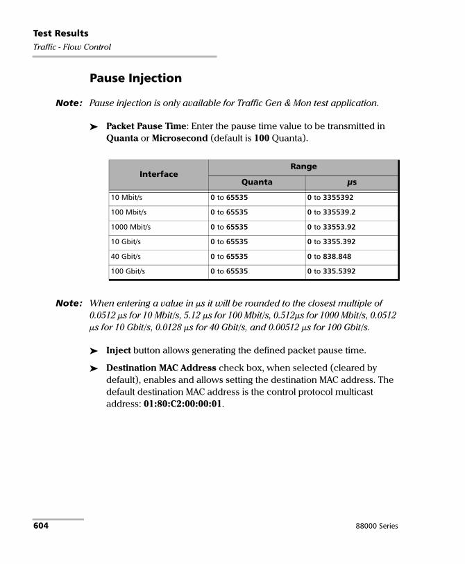
Test ResultsTraffic - Flow Control
Pause Injection
Note: Pause injection is only available for Traffic Gen & Mon test application.
Packet Pause Time: Enter the pause time value to be transmitted in Quanta or Microsecond (default is 100 Quanta).
Note: When entering a value in μs it will be rounded to the closest multiple of 0.0512 μs for 10 Mbit/s, 5.12 μs for 100 Mbit/s, 0.512μs for 1000 Mbit/s, 0.0512 μs for 10 Gbit/s, 0.0128 μs for 40 Gbit/s, and 0.00512 μs for 100 Gbit/s.
Inject button allows generating the defined packet pause time.
Destination MAC Address check box, when selected (cleared by default), enables and allows setting the destination MAC address. The default destination MAC address is the control protocol multicast address: 01:80:C2:00:00:01.
InterfaceRange
Quanta μs
10 Mbit/s 0 to 65535 0 to 3355392
100 Mbit/s 0 to 65535 0 to 335539.2
1000 Mbit/s 0 to 65535 0 to 33553.92
10 Gbit/s 0 to 65535 0 to 3355.392
40 Gbit/s 0 to 65535 0 to 838.848
100 Gbit/s 0 to 65535 0 to 335.5392
604 88000 Series
Test ResultsTraffic - Graph
Traffic - Graph From the Test menu, tap Results, Traffic, and the Graph tab.
Note: For Dual Port topology select the port to be displayed.
The graph displays the received line utilization. The X axis shows the time in seconds while the Y axis shows the percentage utilization.
Power Blazer 605

Test ResultsTraffic - OAM, S-OAM, and MPLS-TP OAM
Traffic - OAM, S-OAM, and MPLS-TP OAM From the Test menu, tap Results, Traffic, and the OAM, S-OAM, or MPLS-TP OAM tab.
Traffic Monitoring
Note: Only available with Carrier Ethernet OAM test application.
In TX, reports counts of CCM, LBM, LTM, DMM, LMM, SLM, TST, AIS, LCK, and CSF frames transmitted. LTM and SLM are only available with Ethernet OAM. Total count is reported as well as unicast and/or multicast frame counts when applicable.
In RX, reports counts of CCM, LBR, LTR, DMR, LMR, SLR, TST AIS, LCK, and CSF frames (LTR and SLR are only available with Ethernet OAM) received regardless of the sender as long as the following criteria are met:
S-OAM: The destination MAC address matches either the local MEP Unicast MAC address or a Multicast class 1 or class 2 address; and the VLANs matches the unit port VLANs. Refer to Unicast/Multicast Addresses for Ethernet OAM on page 841 for more information.
MPLS-TP OAM: The destination MAC address matches either the unit MAC address, FF:FF:FF:FF:FF:FF, or 01:00:5E:90:00:00; the VLANs matches the unit port VLANs; and MPL Labels matches the local MPLS Label Stack configuration. For AIS, LCK, and CSF, valid messages must also have the MEG Level matching the Local MEG Level.
Total count is reported as well as unicast and/or multicast frame counts when applicable.
606 88000 Series

Test ResultsTraffic - OAM, S-OAM, and MPLS-TP OAM
Responder
Note: Available when the S-OAM Responder or MPLS-TP OAM Responder check box is selected (refer to S-OAM and MPLS-TP OAM Responder on page 307).
For Carrier Ethernet OAM test application:
In TX, reports counts of LBR, LTR, DMR, LMR, and SLR total frames transmitted. LTR and SLR are only available with Ethernet OAM.
In RX, reports counts of valid LBM, LTM, DMM, LMM, and SLM unicast, multicast, and total frames received. LTM and SLM are only available with Ethernet OAM. A valid messages must have its:
S-OAM: source MAC address matching the Peer MEP MAC address; destination MAC address matching either the unit port Unicast MAC address or a Multicast class 1 or class 2 address; VLANs matching the unit port VLANs, and MEG/MD Level matching the local MEG/MD Level. Refer to Unicast/Multicast Addresses for Ethernet OAM on page 841 for more information.
MPLS-TP OAM: destination MAC address matching either the unit MAC address, FF:FF:FF:FF:FF:FF, or 01:00:5E:90:00:00; VLANs matching the unit port VLANs; and MPL Labels matching the local MPLS Label Stack configuration.
For Smart Loopback test application:
In TX, reports counts of LBR, LTR, DMR, LMR, and SLR total frames transmitted.
In RX, reports counts of valid LBM, LTM, DMM, LMM, and SLM total frames received. A valid messages must have its destination MAC address matching either the unit port Unicast MAC address or a Multicast class 1 or class 2 address. Refer to Unicast/Multicast Addresses for Ethernet OAM on page 841 for more information.
Power Blazer 607

Test ResultsWindow Sweep
Window Sweep Displays the graph showing the Ideal L4 and Actual L TCP Throughput measured for each Window Sweep step. The number of connections and KiB per connection is also displayed in parenthesis as follows: (n conn.@ n KiB)
From the Test menu, tap Results, and the Window Sweep tab.
608 88000 Series

Test ResultsWIS
WIS From the Test menu, tap Results, and the WIS tab.
Traces/Label
J0 Trace displays the J0 Trace value in 16-bytes format.
J1 Trace displays the J1 Trace value in 16-bytes format.
Path Signal Label (C2) displays the content of the STS SPE including the status of the mapped payload.
Power Blazer 609


10 Test Functions The Test Functions menu offers the following structure:
Transport Test Applications
Tab - Sub Tab
Available with
PageOTN BERT
Multi-Channel
OTN
OTN- SONET/
SDH BERT
SONET/SDH BERT
DSn/PDH BERT
SONET/SDH - DSn/PDH BERT
NI/CSU Emulation
40/100G Advanced - CFP4/QSFP Control X X X - - - - 614
40/100G Advanced - Lanes Mapping & Skew
X - X - - - - 618
APS - - X X - X - 626
Client Offset X - - - - - - 631
FDL - Bit-Oriented Message - - - - X - X 634
FDL - Performance Report Message - - - - X - X 638
FEAC - - - - X - - 641
GMP X X X - - - - 651
OH BERT X - X - - - - 652
OH (GFP-F/GFP-T) X - - - - - - 655
OH (OTN) X - X - - - - 660
OH (SONET/SDH) - - X Xa
a. The sub tab is not displayed.
- X - 666
Pointer Adjustment - - X X - X - 691
RTD X - X X X X - 701
Signaling Bits - - - - X X - 709
Spare Bits - - - - X X - 711
Power Blazer 611

Test Functions
Ethernet Test Applications
Tab - Sub TabTest Application
Pagea
a. EtherSAM
b
b. RFC 6349
c
c. RFC 2544
d
d. FlexE BERT
e
e. EtherBERT
f
f. Traffic Gen & Mon
g
g. Smart Loopback
h
h. Through Mode
i
i. TCP Throughput
j
j. Carrier Ethernet OAM
k
k. Cable Test
40/100/200/400G Advanced - CFP4/QSFP/QSFP56-DD Control
X X X X X X X - - - - 614
40/100/200/400G Advanced - Lanes Mapping & Skew
X X X - X X X - - - - 618
200/400G Advanced - Pre-Emphasis/RX EQ - - X - X - X - - - - 623
200/400G Advanced - PAM-4 Histogram - - X - X - X - - - - 625
BFD (Bidirectional Forwarding Detection) - - - - - X - - - - - 629
Filters - - - - X X - X - X - 645
FlexE Advanced - - - X - - - - - - - 649
Packet Capture - - - - X X - X - X - 680
Ping & Trace Route X X X - X X X - X X X 686
S-OAM Link Trace - - - - - - - - - X - 707
Traffic Scan - - - - - X - - - - - 713
612 88000 Series

Test Functions
Sync Test Applications
Wireless Test Application
TabTest Application
Page1588 PTP SyncE
Filters X X 645
Packet Capture X X 680
Ping & Trace Route X X 686
Tab Framing
Test Application
PageCPRI/OBSAI BERTeCPRI BERT
CPRI OBSAI
Filters Framed Layer 2/3/4 - - Xa
a. Only supported in single port topology.
645
Packet Capture Framed Layer 2/3/4 - - Xa 680
Ping & Trace Route Framed Layer 2/3/4 - - X 686
RTD Unframed X X - 701
Framed L2 X - - 704
RTT Framed L2 - X - 704
Power Blazer 613

Test Functions40/100/200/400G Advanced - CFP4/CFP8/OSFP/QSFP+/QSFP28/QSFP56-DD Control
40/100/200/400G Advanced - CFP4/CFP8/OSFP/QSFP+/QSFP28/QSFP56-DD Control
From the Test menu, tap Functions, 40/100/200/400G Advanced, and the CFP4/CFP8/OSFP/QSFP+/QSFP28/QSFP56-DD Control tab.
Port and FlexE PHY Number
Note: Only available with FlexE BERT test application.
Port allows selecting the physical port number to be displayed.
FlexE PHY Number indicates the FlexE PHY number assigned to the port.
CFP4/CFP8 Reference Clock (MHz)
Allows selecting the reference clock that will be used by the transceiver.
CFP4/CFP8/OSFP/QSFP+/QSFP28/QSFP56-DD Power Class
Indicates the power class of the inserted transceiver module.
Interface/Rate 1/160 Host Lane Rate(default - recommended) 1/40 Host Lane Rate
OTU4 174.7031 MHz 698.8123 MHz
100GE 161.1328 MHz 644.5313 MHz
400GE 156.25 MHz 625.0 MHz
614 88000 Series

Test Functions40/100/200/400G Advanced - CFP4/CFP8/OSFP/QSFP+/QSFP28/QSFP56-DD Control
CFP4/CFP8/OSFP/QSFP+/QSFP28/QSFP56-DD Control Pins
Allows the following transceiver control pin settings. Refer to the CFP MSA standard for more information.
Note: To apply any control, first select its check box then clear it; the control is applied only when the selected check box is cleared.
TX Disable1 check box (cleared by default).
Module Low Power Mode2 check box (cleared by default).
Module Reset check box (cleared by default).
Module Power Shutdown check box (cleared by default).
CFP4/CFP8/OSFP/QSFP+/QSFP28/QSFP56-DD Status Pins
Gives the following transceiver’s pin status (refer to the CFP/QSFP MSA standard for more information):
1. Not supported with OSFP/QSFP+/QSFP28/QSFP56/QSFP56-DD.
2. Not supported with QSFP56-DD.
Transceiver Pin status
CFP4CFP8
Module Absent, RX Loss of Signal, Global Alarm
OSFPQSFP+/QSFP28/QSFP56-DD/QSFP56
Module Absent
Power Blazer 615

Test Functions40/100/200/400G Advanced - CFP4/CFP8/OSFP/QSFP+/QSFP28/QSFP56-DD Control
CFP4/CFP8/OSFP/QSFP+/QSFP28/QSFP56-DD MDIO/I2C Access Interface
MDIO/I2C - Bulk Read
Page Select, available for QSFP I2C, allows selecting the I2C address page: 0x00 (default) to 0xFF.
MDIO/I2C Start Address allows selecting the MDIO/I2C start address: 0x0000 (default) to 0xFFFF (MDIO)/0x00FF (I2C).
MDIO/I2C End Address allows selecting the MDIO/I2C end address: 0x0000 to 0xFFFF; default is 0x00FF.
Bulk Read button reads and displays the data based on the specified MDIO range (MDIO/I2C Start Address to MDIO/I2C End Address).
Save to CSV button allows saving the read MDIO/I2C’s addresses and data to a CSV file.
Note: The bulk read size is limited to 1024 addresses.
MDIO/I2C - Bulk Write
Bulk Write button allows configuring and writing MDIO/I2C data values for up to 20 addresses.
Page Select, available for I2C, allows selecting the I2C address page: 0x00 (default) to 0xFF.
Address and Data allows defining up to 20 MDIO/I2C addresses and their data values: 0x0000 (default) to 0xFFFF for MDIO and 0x00 (default) to 0xFF for I2C.
Bulk Write button writes the MDIO/I2C data values for each MDIO/I2C address defined.
Default button resets the MDIO/I2C page select, addresses, and data values to their default values.
616 88000 Series

Test Functions40/100/200/400G Advanced - CFP4/CFP8/OSFP/QSFP+/QSFP28/QSFP56-DD Control
MDIO/I2C - Read/Write
MDIO/I2C Address allows selecting the MDIO/I2C address: 0x0000 (default) to 0xFFFF (MDIO)/0x00FF (I2C).
MDIO/I2C Data allows either selecting (write) or reading the MDIO/I2C data: 0x0000 (default) to 0xFFFF (MDIO)/0x00FF (I2C).
Read button reads the data of the specified MDIO/I2C Address.
Write button writes the specified MDIO/I2C DATA value to the specified MDIO/I2C Address.
CFP4/CFP8 TX Status
Indicates the transceiver transmission status for each optical lane.
Power Blazer 617
Test Functions40/100/200/400G Advanced - Lanes Mapping & Skew
40/100/200/400G Advanced - Lanes Mapping & Skew
Note: Only available with parallel interfaces. Not available at 100G when the RS-FEC check box is selected.
From the Test menu, tap Functions, 40/100/200/400G Advanced, and the Lanes Mapping & Skew tab.
TX
PCS/Logical Lane, for Ethernet test applications, indicates the PCS (Ethernet test applications) or Logical (Transport Test applications) lane markers. To change the PCS/Logical lane order, see Default/Random/Manual Mapping on page 620.
Skew (Bits) indicates the TX relative delay in bit time for each PCS/Logical lane. To change the skew values, see Reset/Manual Skew on page 621.
Lane / Physical Lane
For 400GE (4/8 Lanes), indicates the 400GAUI-8 Lane numbers.
For 200GE (4 Lanes), indicates the 200GAUI-4 Lane numbers.
For 100GE (4 Lanes), indicates the CAUI-4 Lane numbers.
For OTU4 (4 Lanes), indicates the OTL4.4 Physical Lane numbers.
618 88000 Series

Test Functions40/100/200/400G Advanced - Lanes Mapping & Skew
RX
Skew (bits) indicates the delay in bit time between the earliest PCS/Logical lane and the current lane for the one to zero transition of the alignment marker sync bits. The received skew accuracy is ±100 bits.
PCS/Logical Lane indicates received PCS/Logical Lane markers.
Note: If a PCS/Logical Lane marker is detected more than once, a red background is used to highlight all occurrences of this PCS/Logical Lane marker. Duplicate is also displayed on a red background.
PCS/Logical Lane
Allows ordering the PCS/Logical Lane markers in either Ascending (1,2,3...) or Coupled to RX.
Alarms
For a description of each alarm, refer to OTL on page 440 for Transport and Ethernet - PCS Lanes on page 410 for Ethernet.
Errors
For a description of each error, refer to OTL on page 440 for Transport and Ethernet - PCS Lanes on page 410 for Ethernet.
The error values are displayed in seconds by default. Tapping on the unit allows selecting either Seconds, Count, or Rate.
Total indicates the total of all lanes when Count or Rate unit is selected.
Power Blazer 619

Test Functions40/100/200/400G Advanced - Lanes Mapping & Skew
Default/Random/Manual Mapping
Allows changing the PCS/Logical lane mapping that will be used for the test. Not available with 100 GbE client in OTU4.
Default Mapping sets the TX mapping to the default numerical order value which corresponds to the ascending PCS/Logical lane order.
Random Mapping sets the TX mapping in a random order. Each time the button is tapped, random alignment markers are assigned to each PCS/Logical lane.
Manual Mapping allows setting the TX mapping manually.
PCS/Logical Lane/Lane Marker and Assigned Status: The PCS/Logical Lane/Lane Marker buttons allow assigning the corresponding Lane Marker to the selected PCS/Logical or xGAUI-y/CAUI/XLAUI/Physical Lane mapping (the one pointed by the arrow). The Assigned Status column displays a check mark next to the assigned PCS/Logical Lanes. Range is from 0 to 15 for 400G, 0 to 7 for 200G, 0 to 19 for OTU4/100G, and 0 to 3 for OTU3/OTU3e1/OTU3e2/40G.
PCS/Logical Lane and xGAUI-y/CAUI/XLAUI/Physical Lane columns indicate the target PCS/Logical to xGAUI-y/CAUI/XLAUI/Physical mapping.
Clear All clears the PCS/Logical to xGAUI-y/CAUI /XLAUI/Physical Lane assignments.
OK accepts the new PCS/Logical to xGAUI-y/CAUI/XLAUI/Physical lane mapping. All target PCS/Logical Lane fields must contain an assignation, including duplicates, to give access to the OK button.
Note: A PCS/Logical Lane marker can be assigned more than once. If this is the case, a red background is used to highlight all occurrences of this PCS/Logical Lane marker.
620 88000 Series

Test Functions40/100/200/400G Advanced - Lanes Mapping & Skew
Reset/Manual Skew
Allows the selection of a relative delay in bit time that will be introduced for each PCS/Logical lane. Not available with 100 GbE client in OTU4.
Reset Skew sets all TX skew (bit time) values to 0.
Manual Skew allows setting the skew value for each PCS/Logical lane manually.
All Lanes, when selected, applies the change(s) to all PCS/Logical Lane at once.
Skew Inc/Dec Size (bits) allows setting the increment/decrement value that will be used when changing the TX Skew (bits) values using the “+” and “-” buttons. Range is from 0 to 10550 for 200/400G, 0 to 2047 for 100G/OTU4 and 0 to 4095 for 40G/OTU3/OTU3e1/OTU3e2.
PCS/Logical Lane indicates the PCS/Logical Lane numbers and All which represents the value for all PCS/Logical Lane when the All Lanes check box is selected.
Skew (bits) allows setting the skew value for each lane. Enter directly the skew value in the field or use the “+” and “-” buttons to respectively increment or decrement the skew value using the defined Skew Inc/Dec Size value. Tapping and holding the “+” or “-” button allows reaching the desired value faster using the defined Skew Inc/Dec Size value. Range is from 0 to 10550 for 200/400G, 0 to 2047 for 100G/OTU4 and 0 to 4095 for 40G/OTU3/OTU3e1/OTU3e2.
Power Blazer 621

Test Functions40/100/200/400G Advanced - Lanes Mapping & Skew
Laser ON/OFF
Allows activating the laser control per optical lane or for all lanes.
Optical lane numbers are from 0 to 3 or 0 to 7 depending on the selected interface/rate.
All Lanes check box, when selected, applies the change(s) to all optical lanes at once.
Optical Lane indicates the optical lane numbers and All which represents the setting for all optical lanes when the All Lanes check box is selected.
Laser check box, when selected, indicates that the corresponding optical laser lane is activated and emitting an optical laser signal.
Skew Alarm Threshold (bits)
Allows setting the threshold value that will be used to declare a skew alarm (see Ex. Skew on page 440).
Default button restores the default alarm threshold value.
622 88000 Series

Test Functions200/400G Advanced - Pre-Emphasis/RX EQ
200/400G Advanced - Pre-Emphasis/RX EQ
Note: Only available when using OSFP/QSFP56/QSFP56-DD transceiver on FTBx-88460 module.
From the Test menu, tap Functions, 200/400G Advanced, and the Pre-Emphasis/RX EQ tab.
TX
PAM-4 Lane indicates the lane numbers.
Pre Cursor is configurable from -1000 to 1000.
Main Cursor is configurable from -1000 to 1000.
Post Cursor is configurable from -1000 to 1000.
Lower Eye is configurable from 500 to 1500.
Upper Eye is configurable from 1500 to 2500.
Swing is configurable from 60% to 120% in step of 10%.
Restore TX Defaults: Reverts the TX pre-emphasis to their default values.
RX
CTLE allows selecting the continuous time linear equalization: 0 to 9.0 dB (64 possible values).
DSP Mode allows selecting the digital signal processor mode:
DSP Mode Description
FFE+SLC Feed-Forward Equalizer + PAM-4 Slicer
FFE+DFE Feed-Forward Equalizer + Decision Feedback Equalizer
Power Blazer 623

Test Functions200/400G Advanced - Pre-Emphasis/RX EQ
VGA Tracking check box when selected (default) enables the tracking of the voltage gain amplifier.
Restore RX Defaults reverts the RX CTLE, DSP Mode, and VGA Tracking to their default values.
TX/RX
Gray Encoding check box when selected (default) enables the gray encoding.
FFE+DFE+RC Feed-Forward Equalizer + Decision Feedback Equalizer + PAM-4 Reflection Canceller
FFE+SLC+LDEQ Feed-Forward Equalizer + PAM-4 Slicer +PAM-4 Level Dependent Equalizer
FFE+SLC+RC Feed-Forward Equalizer + PAM-4 Slicer + PAM-4 Reflection Canceller
FFE+SLC+RC+LDEQ Feed-Forward Equalizer + PAM-4 Slicer + PAM-4 Reflection Canceller + PAM-4 Level Dependent Equalizer
DSP Mode Description
624 88000 Series

Test Functions200/400G Advanced - PAM-4 Histogram
200/400G Advanced - PAM-4 Histogram
Note: Only available when using OSFP/QSFP56/QSFP56-DD transceiver on FTBx-88460 module.
From the Test menu, tap Functions, 200/400G Advanced, and the PAM-4 Histogram tab.
The PAM-4 Histogram graph displays for the selected lane the number of hits at each 160 amplitude levels (PAM-4 Symbol 0 to PAM-4 Symbol 3) once the acquire process is completed.
Scale
Allows selecting the scale for the histogram hits (Y-axis): Linear (default) or Log (logarithmic).
PAM-4 Lane
Allows selecting the PAM-4 lane that will be used for the histogram acquisition. The lane displayed on an amber background indicates the selected lane while the ones on a green background indicate that valid histograms have been acquired.
Acquire
Enables the PAM-4 histogram acquisition process for the selected lane. The green LED is on when the acquisition is enabled.
To acquire the PAM-4 histogram for other lane(s), select another lane either by tapping on its number or using the arrow while the acquisition is still enabled. Repeat for all required lanes.
Note: Reactivating the acquisition clears all previously acquired histograms.
Power Blazer 625

Test FunctionsAPS
APS From the Test menu, tap Functions, and the APS tab.
TX/RX
Switching Mode, available for both TX and RX, selects the switching mode: Linear (default) or Ring.
K1
Request: Bits 1 through 4 of the K1 byte.
Bits 1 to 4
Request
Linear mode Ring mode0000 No Requesta
a. Default value.
No Request (default)a
0001 Do Not Revert Reverse Request - Ring
0010 Reverse Request Reverse Request - Span
0011 Unused Exerciser - Ring
0100 Exerciser Exerciser - Span
0101 Unused Wait-to-Restore
0110 Wait-to-Restore Manual Switch - Ring
0111 Unused Manual Switch - Span
1000 Manual Switch Signal Degrade - Ring
1001 Unused Signal Degrade - Span
1010 Signal Degrade - Low Priority Signal Degrade (Protection)
1011 Signal Degrade - High Priority Signal Fail - Ring
1100 Signal Fail - Low Priority Signal Fail - Span
1101 Signal Fail - High Priority Force Switch - Ring
1110 Force Switch Force Switch -Span
1111 Lockout of Protection Lockout of Protection - Span/SF - P
626 88000 Series

Test FunctionsAPS
Channel (Linear switching mode) or Destination Node ID (Ring switching mode): Bits 5 through 8 of the K1 byte.
K2
Protected Channel (Linear switching mode) orSource Node ID (Ring switching mode): Bits 1 through 4 of the K2 byte.
Bits 5 to 8
Channel ID(Linear mode)
Destination Node ID(Ring mode)
Bits 5 to 8
Channel ID(Linear mode)
Destination Node ID(Ring mode)
0000 0 - Nulla
a. Default value.
0a 1000 8 8
0001 1 1 1001 9 9
0010 2 2 1010 10 10
0011 3 3 1011 11 11
0100 4 4 1100 12 12
0101 5 5 1101 13 13
0110 6 6 1110 14 14
0111 7 7 1111 15 - Extra Traffic 15
Bits 1 to 4
Protected Channel(Linear mode)
Source Node ID(Ring mode)
Bits 1 to 4
Protected Channel(Linear mode)
Source Node ID(Ring mode)
0000 0 - Nulla
a. Default value.
0a 1000 8 8
0001 1 1 1001 9 9
0010 2 2 1010 10 10
0011 3 3 1011 11 11
0100 4 4 1100 12 12
0101 5 5 1101 13 13
0110 6 6 1110 14 14
0111 7 7 1111 15 - Extra Traffic 15
Power Blazer 627

Test FunctionsAPS
Architecture (Linear switching mode) or Bridge Request (Ring switching mode):Bit 5 of the K2 byte. The default setting is 1+1 for Linear switching mode and Short Path Request for Ring switching mode.
Operation Mode: Bits 6 through 8 of the K2 byte.
Bit 5 Architecture(Linear mode)
Bridge Request(Ring mode)
0 1+1a
a. Default value.
Short Patha
1 1:n Long Path
Bits 6 to 8 Linear mode Ring mode000 Reserveda
a. Default value.
Idlea
001 Reserved Bridged
010 Reserved Bridged and Switched
011 Reserved Extra Traffic - Protection
100 Unidirectional Reserved
101 Bidirectional Reserved
110 RDI-Lb/MS-RDIc
b. Operation mode for SONET.c. Operation mode for SDH.
RDI-Lb/MS-RDIc
111 AIS-Lb/MS-AISc AIS-Lb/MS-AISc
628 88000 Series

Test FunctionsBFD (Bidirectional Forwarding Detection)
BFD (Bidirectional Forwarding Detection)
Note: Only available with IPv4 Network Layer (refer to IP on page 264) in single port topology for rates up to 100G.
From the Test menu, tap Functions, and the BFD tab.
Bidirectional Forwarding Detection
Local IP Address displays the configured interface Source IP Address (refer to IP on page 264).
Remote IP Address allows configuring the destination IP Address.
IP TOS/DS allows entering the type of service: 00 (default) to FF.
Desired Min TX Interval defines the minimum interval the local module would like to use when transmitting BFD control packets: 100 ms (default) to 1 s.
Required Min RX Interval defines the minimum interval between received BFD control packets the local module requires: 100 ms (default) to 1 s.
Detect Multiplier is a value that is multiplied by the negotiated transmit interval giving the detection time for the receiving system. Choices are 1 to 255 (3 by default).
Session State indicates the local session state: Down, Init, Up.
Diagnostic indicates the reason of the last local session state change.
Connect starts/stops the BFD process.
Statistics
Packets Transmitted indicates the number of sent BFD control packets.
Packets Received indicates the number of received BFD control packets.
Power Blazer 629

Test FunctionsBFD (Bidirectional Forwarding Detection)
Neighbor Status
Session State reports the remote session state: Admin Down, Down, Init, or Up.
Diagnostic reports the reason of the remote last session state change.
Desired Min TX Interval reports the remote desired minimum TX interval.
Required Min RX Interval reports the remote required minimum RX interval.
Detect Multiplier reports the remote Detect Multiplier value.
630 88000 Series

Test FunctionsClient Offset
Client Offset
Note: Available with OTN BERT test application with 1GbE client and Pattern client with ODUflex multiplexing.
From the Test menu, tap Functions, and the Client Offset tab.
TX Frequency
Note: TX Frequency is not available in Through / Through Intrusive topology.
Frequency (GHz) indicates the frequency (nominal frequency + port frequency offset + client frequency offset) used for transmission.
Offset (ppm) check box, when selected (cleared by default), allows setting the client frequency offset that will be generated. Use the “+” or “-” button to respectively increment or decrement the client frequency offset value based on the defined Increment/Decrement Size, or directly type the frequency offset value in the field.
Increment/Decrement Size (ppm) allows setting the increment/decrement value (from 0.1 to either 115) that will be used when changing the frequency offset using the “+” or “-” button.
Client Nominal Frequency Offseta
a. The Client frequency offset range is guaranteed for a clock source signal at 0 ppmoffset. In the event that the clock source signal already has an offset, the output signalmay exhibit an offset larger than the range specified. For example, if the clock sourcesignal has an offset of +20 ppm (configured on the Signal interface), the Clientfrequency offset could be up to 135 ppm (115 ppm + 20 ppm).
1GbE 1250000000 bps ± 115 ppm
Pattern in ODUflex Nominal bit rate configured (refer to Nominal Bit Rate on page 344).
± 115 ppmb
b. The Client offset function does not allow the generation of a signal with a rate above100 % of the TX rate. For example, if the TX Rate is set to 100 %, the allowed offsetrange will be -115 ppm to 0 ppm.
Power Blazer 631

Test FunctionsClient Offset
RX Frequency
Frequency (GHz) indicates the frequency of the input signal.
Offset (ppm) indicates the frequency offset between the standard rate specification and the rate at the input signal.
Note: For both Frequency and Offset a background color is used to indicate if the received client signal rate meets the standard rate specifications. Not available with Pattern in ODUflex when the Frequency Offset Analysis check box is cleared.
Max. Negative Offset (ppm) indicates the maximum negative frequency offset between the standard rate specification and the rate from the received signal.
Client Measurement range
1GbE 1250000000 ±120 ppm
Pattern in ODUflex Expected Frequency ±120 ppm (see page 633)
Background color Description
Green The frequency is in range.
Red The frequency is out-of-range or there is a LOC Lane condition. LOC is also displayed.
Gray Pending state.
Client Standard Rate Specification
1GbE 1250000000 ±12500 bps (±100 ppm)
Pattern in ODUflex Expected Frequency ±100 ppm(see page 633)
632 88000 Series

Test FunctionsClient Offset
Max. Positive Offset (ppm) indicates the maximum positive frequency offset between the standard rate specification and the rate from the received signal.
Note: The following parameters are only available with ODUflex mapped to pattern.
Frequency Offset Analysis check box, when selected, enables the frequency offset measurements. This setting is enabled by default for Coupled topology, and disabled for Through / Through Intrusive topology.
Expected Frequency (GHz) is available when the Frequency Offset Analysis check box is selected.
For Coupled topology, the frequency is set to the configured TX Rate (refer to page 155).
For Through / Through Intrusive topology, enter the expected frequency in GHz.
Power Blazer 633

Test FunctionsFDL - Bit-Oriented Message
FDL - Bit-Oriented Message Allows setting and configuring the Bit-Oriented Messages (BOM) of the Extended Super-Frame (ESF).
Note: FDL is only available for DS1 interface with ESF framing. For Dual RX test, FDL is only available for the DS1 TX/RX port 1.
From the Test menu, tap Functions, FDL, and the Bit-Oriented Message tab.
Generated Messages
Priority
Codeword: The Bit-Oriented Message codewords are priority messages sent over the Data-Link. These messages are mostly used for networking operation and maintenance. A Bit-Oriented Message consists of 8 consecutive ones followed by a byte starting and ending by zeros.
Injects generates the selected codeword priority message.
Command/Response
Amount allows the selection of the number of message to be generated. Choices are 1 to 15. The default value is 10.
Inject manually generates the selected amount of messages.
Codeword PatternRAI 00000000 11111111
Loopback Retention and Acknowledge 00101010 11111111
RAI-CI 00111110 11111111
634 88000 Series

Test FunctionsFDL - Bit-Oriented Message
Codeword
Command/Response Codeword Pattern Command/Response
Codeword Pattern
Line Loopback Activate 00001110 11111111 Protection Switch Line 22 01101100 11111111Line Loopback Deactivate 00111000 11111111 Protection Switch Line 23 01101110 11111111Payload Loopback Activate 00010100 11111111 Protection Switch Line 24 01110000 11111111Payload Loopback Deactivate 00110010 11111111 Protection Switch Line 25 01110010 11111111Reserved for Network Use 00010010 11111111a
a. Loopback Activate.
Protection Switch Line 26 01110100 11111111Universal Loopback (Deactivate)
00100100 11111111 Protection Switch Line 27 01110110 11111111
ISDN Line Loopback (NT2) 00101110 11111111 Protection Switch Acknowledge 00011000 11111111CI/CSU Line Loopback (NT1) 00100000 11111111 Protection Switch Release 00100110 11111111For network use 00011100 11111111b
b. Indication of NT1 power off.
Do Not use for Synchronization 00110000 11111111Protection Switch Line 1 b 01000010 11111111 Stratum 2 Traceable 00001100 11111111Protection Switch Line 2 01000100 11111111 SONET Minimum Clock
Traceable00100010 11111111
Protection Switch Line 3 01000110 11111111 Stratum 4 Traceable 00101000 11111111Protection Switch Line 4 01001000 11111111 Stratum 1 Traceable 00000100 11111111Protection Switch Line 5 01001010 11111111 Synchronization Traceability
Unknown00001000 11111111
Protection Switch Line 6 01001100 11111111 Stratum 3 Traceable 00010000 11111111Protection Switch Line 7 01001110 11111111 Reserved for Network
Synchronization01000000 11111111
Protection Switch Line 8 01010000 11111111 Transmit Node Clock (TNC) 01111000 11111111Protection Switch Line 9 01010010 11111111 Stratum 3E Traceable 01111100 11111111Protection Switch Line 10 01010100 11111111 Under study for maintenance 00101100 11111111Protection Switch Line 11 01010110 11111111 Under study for maintenance 00110100 11111111Protection Switch Line 12 01011000 11111111 Reserved for network use 00010110 11111111Protection Switch Line 13 01011010 11111111 Reserved for network use 00011010 11111111Protection Switch Line 14 01011100 11111111 Reserved for network use 00011110 11111111Protection Switch Line 15 01011110 11111111 Reserved for network use 00111010 11111111Protection Switch Line 16 01100000 11111111 Reserved for customer 00000110 11111111Protection Switch Line 17 01100010 11111111 Reserved for customer 00001010 11111111Protection Switch Line 18 01100100 11111111 Reserved for customer 00000010 11111111Protection Switch Line 19 01100110 11111111 Reserved for customer 00110110 11111111Protection Switch Line 20 01101000 11111111 Reserved for customer 00111100 11111111Protection Switch Line 21 01101010 11111111 Reserved for customer 01111010 11111111
Power Blazer 635

Test FunctionsFDL - Bit-Oriented Message
Receive Messages
Link Activity indicates the activity of the following parameters during the last second of measurement.
Idle indicates that only idle codes have been detected in the last second.
Priority indicates that at least one valid priority message has been detected in the last second.
C/R (Command/Response) indicates that a least one valid command and response has been detected in the last second.
Unassigned indicates that at least one unassigned message has been detected in the last second. Therefore, since an unassigned message is part of a Command/Response codewords, the Command/Response LED will also be red.
PRM indicates that at least one PRM has been detected in the last second.
Priority: The Bit-Oriented Messages are priority messages send over the Data-Link. These messages are mostly used for networking operation and maintenance. A Bit-Oriented Message consists of 8 consecutive 1s followed by a byte starting and ending by zeros.
Current indicates the priority message detected in the last second. If no priority message has been detected, “--” is displayed.
Previous indicates the last priority message detected excluding the current message. If no priority message has been detected since the beginning of the test, “--” is displayed.
Note: See Priority on page 634 for the list of possible priority codeword messages.
636 88000 Series

Test FunctionsFDL - Bit-Oriented Message
Command/Response
Current indicates the command/response message detected in the last second. If no priority message has been detected, “--” is displayed.
Previous indicates the last command/response message detected excluding the current message. If no command/response message has been detected since the beginning of the test, “--” is displayed.
Note: See Command/Response on page 634 for the list of possible Command/Response codeword messages.
Power Blazer 637

Test FunctionsFDL - Performance Report Message
FDL - Performance Report Message
Note: FDL PRM is only available for DS1 interface with ESF framing. For Dual RX test, FDL is only available for the DS1 TX/RX port 1. For NI/CSU Emulation, only available in the RX direction.
From the Test menu, tap Results, tap the FDL, and Performance Report Message tab.
Generated Messages
Circuit allows the selection of the circuit type: CI to Network (default) or Network to CI.
ANSI T1-403 check box when selected allows the generation of a compliant ANSI T1.403 PRM Message.
Injection
Single sends the selected PRM Message(s) manually.
Continuous generates the selected PRM Message(s) continuously.
Event Count indicates the number of PRM messages sent.
PRM Bit Events allows the activation of the following PRM bit events. All PRM bit events are disabled by default.
G1: CRC = 1G2: 1 < CRC 5G3: 5 < CRC 10G4: 10 < CRC 100G5: 100 < CRC 319G6: CRC 320SE: Severely errored framing 1
FE: Frame sync. bit error 1LV: Line code violation event 1LB: Payload loopback activatedSL: Slip 1R Bit (Reserved - Default value is 0)U1: BitU2: Bit
638 88000 Series
Test FunctionsFDL - Performance Report Message
Received Messages
Event Counts lists received PRM bit event counts.See PRM Bit Events below.
Report Content lists received performance information. See Performance Information below.
Circuit indicates the selected circuit type: CI to Network or Network to CI.
Valid Event Count indicates the number of valid PRM messages received.
Link Activity, see page 636 for more information.
PRM Bit Events table, available when the Event Counts button is selected, reports the count of the detected valid PRM bit events.
G1: CRC = 1G2: 1 < CRC 5G3: 5 < CRC 10G4: 10 < CRC 100G5: 100 < CRC 319G6: CRC 320
SE: Severely errored framing 1FE: Frame sync. bit error 1LV: Line Code Violation 1LB: Payload loopback activatedSL: Slip 1
Power Blazer 639

Test FunctionsFDL - Performance Report Message
Performance Information table, available when the Report Content button is selected, reports the time t0, t0-1, t0-2, and t0-3 for each PRM.
Time
T0 represents the valid PRM message received in the last second of measurement (bytes 5 and 6).
T0-1 represents the message one PRM ago (bytes 7 and 8).
T0-2 represents the message two PRM ago (bytes 9 and 10).
T0-3 represents the message three PRM ago (bytes 11 and 12).
PRM
G3: 5 < CRC Error Event 10LV: Line Code Violation Event 1G4: 10 < CRC Error Event 100U1: Under study for synchronizationU2: Under study for synchronizationG5: 100 < CRC Error Event 319SL: Controlled Slip Event 1G6: CRC Error Event 320FE: Frame Sync. Bit Error Event 1SE: Severely-Errored Framing Event 1LB: Payload Loopback ActivatedG1: CRC Error Event = 1R: ReservedG2: 1 < CRC Error Event 5Nm and Nl: One-second report modulo 4 counter.
640 88000 Series

Test FunctionsFEAC
FEAC The Far-End Alarm and Control signal (FEAC) provides Communication Channel capability over a DS3 in a network applications using C-bit Parity configuration (see page 333).
From the test menu, tap Functions, and the FEAC tab.
Generated Messages
Allows configuring and sending alarms/status information and control signals (loopback commands) to other network elements.
Alarm/Status and Unassigned
Codeword allows the selection of the codeword alarm/status to be generated either manually or continuously.
The FEAC message format is a 16 bit codeword (0xxxxxx0 11111111) with the rightmost bit transmitted first. The 0xxxxxx0 represents the message codeword.
Mode is the alarm/status injection mode: Manual or Continuous.
CodewordDS3 Equipment Failure SA (00110010) Single DS1 LOS (00111100) User Defined (00100000)
DS3 Loss of Signal (LOS) (00011100) DS1 Equipment Failure NSA (00000110)
User Defined (00100010)
DS3 Out-of-Frame (00000000) User Defined (00000010) User Defined (00101000)
DS3 AIS Received (00101100) User Defined (00000100) User Defined (00101110)
DS3 Idle Signal Received (00110100) User Defined (00001000) User Defined (00110000)
DS3 Equipment Failure NSA (00011110) User Defined (00001100) User Defined (00111110)
DS3 NUI Loop Up (00010010) User Defined (00010000) User Defined (01000000)
DS3 NUI Loop Down (00100100) User Defined (00010100) User Defined (01111010)
Common Equipment Failure NSA (00111010) User Defined (00010110) User Defined (01111100)
Multiple DS1 LOS (00101010) User Defined (00011000) User Defined (01111110)
DS1 Equipment Failure SA (00001010) User Defined (00011010)
Power Blazer 641

Test FunctionsFEAC
Amount is the amount of codeword to be generated: 1 to15 (default is 10).
Inject generates error(s) according to the Codeword and mode selected.
Loopback Commands
Control
Codeword is the loopack control codeword to be generated: Line Loopback Activate (00001110) - (Default) or Line Loopback Deactivate (00111000).
Amount is the number of Control Codeword to be generated: 1 to 15 (default is 10).
Channel
Codeword is the channel codeword to be generated.
Amount is the number of Channel Codeword to be generated: 1 to 15 (Default is 10).
Inject generates the defined loopback command.
Channel CodewordDS3 Line (00110110) DS1 Line-No10 (01010100) DS1 Line-No20 (01101000)
DS1 Line-No1 (01000010) DS1 Line-No11 (01010110) DS1 Line-No21 (01101010)
DS1 Line-No2 (01000100) DS1 Line-No12 (01011000) DS1 Line-No22 (01101100)
DS1 Line-No3 (01000110) DS1 Line-No13 (01011010) DS1 Line-No23 (01101110)
DS1 Line-No4 (01001000) DS1 Line-No14 (01011100) DS1 Line-No24 (01110000)
DS1 Line-No5 (01001010) DS1 Line-No15 (01011110) DS1 Line-No25 (01110010)
DS1 Line-No6 (01001100) DS1 Line-No16 (01100000) DS1 Line-No26 (01110100)
DS1 Line-No7 (01001110) DS1 Line-No17 (01100010) DS1 Line-No27 (01110110)
DS1 Line-No8 (01010000) DS1 Line-No18 (01100100) DS1 Line-No28 (01111000)
DS1 Line-No9 (01010010) DS1 Line-No19 (01100110) DS1 Line-All (00100110)
642 88000 Series

Test FunctionsFEAC
Received Messages
Displays current and previous alarms/status and loopback commands as well as the link activity for the received DS3 signal.
Link Activity
None (All 1’s): An all ones pattern (11111111 11111111) has been detected in the last second.
Alarm/Status: An Alarm/Status codeword has been detected in the last second. An Alarm/Status is only detected when receiving at least 10 consecutive occurrences of a specific codeword.
Loopback: A Loopback command message has been detected in the last second. A valid loopback command is detected only when receiving 10 consecutive occurrences of a specific Loopback Command immediately followed by 10 occurrences of a specific Channel Codeword.
Unassigned: An unassigned message has been detected in the last second. An Unassigned message is only detected when receiving at least 10 consecutive occurrences of a specific unassigned codeword. An Alarm/Status codeword is also reported since Unassigned is part of the Alarm/Status group.
Alarm/Status and Unassigned displays the current and previously received Codeword messages.
Current indicates the last valid message, if any, received in the last second of measurment.
Previous indicates the message, if any, that was received just before the current measurement.
Power Blazer 643

Test FunctionsFEAC
Loopback Commands
Current displays the valid message received in the last second of measurement. A valid message is detected only when receiving 10 consecutive occurrences of a specific Loopback Command immediately followed by 10 occurrences of a specific Channel Codeword.
Previous displays the last valid message received excluding the actual Current message.
644 88000 Series

Test FunctionsFilters
Filters Allows gathering statistics according to the programmed filters. Filters provide the capability to analyze a specific stream’s behavior in order to monitor a single protocol’s behavior, perform SLA verification, or precisely troubleshoot unwanted behavior. Up to 10 filters having up to four operands each can be defined and enabled.
Note: Not available with eCPRI dual port topology.
From the Test menu, tap Functions, and the Filters tab.
Note: For Dual Port topology select the port to be displayed.
Filters
Allows the selection of the filter number (1 to 10). The filter criteria, if defined, will be displayed. A filter used (enabled) for data capture will not be configurable and the message Filter in use for data capture is displayed.
Enable
Once the filter is configured, select the Enable check box to enable the current filter. However, if the filter configuration contains errors, it will not be possible to enable it. A filter can be enabled or disabled even when the test is running. It is not possible to modify or disable a filter that is already in use for capture until either another filter or Interface (see Capture Source on page 680) is assigned to capture.
Enabled Time
Indicates the time during which the filter is enabled.
Power Blazer 645

Test FunctionsFilters
Assign to Capture
Note: Only available when the ETH-CAPTURE software option is enabled. Refer to Software Option on page 39 for more information.
Assigns the selected filter for packet capture. See Packet Capture on page 680.
Filter Configuration
Note: Multiple filter criteria is only available when the ADV-FILTERS option is enabled; otherwise only one criterion is possible. Refer to Software Option on page 39 for more information.
The filter configuration section allows configuring the filter criteria for the selected filter. The configuration is only possible when the Enable check box is cleared.
“(“ and “)“, the open and close parenthesis controls the precedence of operands when more than two operands are used. Only one level of parenthesis is supported. When no parenthesis are used, a logical AND has precedence over a logical OR.
Not check box when selected, adds the logical negation (not equal) operator for the operand filter defined at its right.
646 88000 Series

Test FunctionsFilters
Filter specifies the filter to be used (None by default).
Value is the value associated to the selected filter.
Category Filter
Ethernet MAC Destination Address, MAC Source Address, EtherTypea, C-VLAN ID, S-VLAN ID, E-VLAN ID, C-VLAN Priority, S-VLAN Priority, E-VLAN Priority, Frame Format
a. Applies only to the last EtherType occurrence when VLAN is used.
IPv4 IPv4 Destination Address, IPv4 Source Address, IPv4 TOS, IPv4 Precedence, IPv4 Protocol, IPv4 DiffServ
IPv6b
b. Available when the corresponding software option is enabled (refer topage 39).
IPv6 Destination Address, IPv6 Source Address, IPv6 Flow Label, IPv6 Next Headerc, IPv6 Traffic Class, IPv6 Precedence, IPv6 DiffServ
c. Applies only to the last next header occurrence when extension headers areused.
Higher Layer TCP Destination Portd, TCP Source Portd, UDP Destination Port, UDP Source Port
d. Available with 10M to 10G interface rates only.
MPLSb MPLS Label 1, MPLS Label 2, MPLS COS 1, MPLS COS 2
Power Blazer 647
Test FunctionsFilters
Mask allows masking the defined filter value. A bit mask of 1 indicates that the corresponding bit in the value is compared for the match. A bit mask of 0 indicates that the corresponding bit in the value is ignored.
For binary values, enter the mask value in binary format.For decimal values, enter the mask value in hexadecimal format.For IP address field, enter the mask in decimal format.For MAC address, enter the mask value in hexadecimal format.
Oper. specifies the logical operator (AND or OR) used between two operands.
Filter Statistics
Indicates throughput statistics of the frame matching the configured filter’s criteria.
Line Utilization gives the percentage of line rate utilization.
Ethernet BW (Bandwidth) gives the receiving data rate expressed in Mbit/s.
Frame Rate gives the receiving number of frames (including bad frames) in frame/s.
Frame Count indicates the number of frame matching the configured filter’s criteria.
Error Count indicates respectively the number of frames matching the configured filter’s criteria having IP Checksum, UDP Checksum, TCP Checksum, FCS, Jabber, Oversize, Runt, or Undersize errors. Refer to Ethernet on page 405 and IP/UDP/TCP on page 428 for more information on errors.
648 88000 Series

Test FunctionsFlexE Advanced
FlexE Advanced From the Test menu, tap Functions, and the FlexE Advanced tab.
TX
PHY indicates the TX PHY number assigned to the port.
Skew (ns) indicates the TX relative delay in nanoseconds for each PHY. To change the skew values, see Reset/Manual Skew on page 650.
Port
Indicates the module‘s port number.
RX
Skew (ns) indicates the delay in nanoseconds between the earliest PHY and the current PHY for the one to zero transition of the alignment marker sync bits. The received skew accuracy is ±100 bits.
PHY indicates the received PHY number.
Alarms/Errors
For a description of each alarm/error, refer to PHYs on page 449.
The error values are displayed in seconds by default. Tapping on the unit allows selecting either Seconds, Count, or Rate.
Power Blazer 649

Test FunctionsFlexE Advanced
Reset/Manual Skew
Allows the selection of a relative delay in nanoseconds that will be introduced for each PHY.
Reset Skew sets all TX skew (ns) values to 0.
Manual Skew allows setting the skew value for each PHY manually.
PHY TX Skew
PHY/Port indicates the PHY/Port numbers and All which represents the value for all PHY/Port when the All PHY check box is selected.
Skew (ns) allows setting the skew value for each PHY. Enter directly the skew value in the field or use the “+” and “-” buttons to respectively increment or decrement the skew value using the defined Skew Inc/Dec Size value. Tapping and holding the “+” or “-” button allows reaching the desired value faster using the defined Skew Inc/Dec Size value. Range is from 0 to 1000 ns.
All PHY, when selected, applies the change(s) to all PHYs at once.
Skew Inc/Dec Size (ns) allows setting the increment/decrement value that will be used when changing the Skew (ns) values using the “+” and “-” buttons. Range is from 0 to 1000 ns.
PHY Skew Alarm Threshold (ns)
Allows setting the threshold value that will be used to declare a skew alarm: 50 ns to 1000 ns, default is 300 ns (see Excessive PHY Skew on page 449).
Default button restores the default PHY skew alarm threshold value.
650 88000 Series

Test FunctionsGMP
GMP
Note: Available with Transport test applications with either payload type 21 (PT21) or one of the following clients: 1GbE, 40GbE, 100GbE, Ethernet (flex/GFP-F), or SONET/SDH (through ODU0).
From the Test menu, tap Functions, and the GMP tab.
Channel available with Multi-Channel OTN allows the selection of the channel number.
Generic Mapping Procedure
TX Cm indicates the minimum and maximum Cm value transmitted during the test.
TX CnD indicates the minimum and maximum CnD value transmitted during the test.
RX Cm indicates the minimum and maximum Cm value captured during the test.
RX CnD indicates the minimum and maximum CnD value captured during the test.
Power Blazer 651

Test FunctionsOH BERT
OH BERT The OH BERT validates the integrity of some overhead bytes on the top layer of an OTN test signal. The OH bytes are bundled as group for test purposes.
From the Test menu, tap Functions, and the OH BERT tab.
Note: Only supported with Coupled topology.
OH BERT
The OH BERT check box when selected (cleared by default), enabled the OH BERT/SYNC generation and monitoring.
Mode
Allows selecting the test operating mode:
BERT (default) is a typical BER test that is executed on the selected group of OH bytes, a PRBS15 test pattern is mapped in each individual OH group for BER evaluation.
SYNC is a special test which validates that the content of each selected OH group is carried by the same OTUk frame throughout its transfer over the network.
Invert PRBS15 Pattern
Invert PRBS15 Pattern check box, when selected (cleared by default), inverts the test pattern meaning that every 0 will be changed for 1 and every 1 for 0. For example, the pattern 1100 will be sent as 0011. Available with BERT mode only.
652 88000 Series

Test FunctionsOH BERT
OTUx and ODUx
Overhead group check boxes:
Layer Overhead Group Number of Bytes
OH Bytes Coordinate
Row Column
OTU GCC0 2 1 11,12
RES 2 1 13,14
ODU GCC1 2 4 1, 2
GCC2 2 4 3, 4
APS/PCC 4 4 5-8
PM&TCM 1 2 3
TCM ACT 1 2 4
FTFLa
a. Only configurable when the test is not running. Once enabled, the FTFL configurationand alarm generation and monitoring in the main test are not available for the top ODUlayer.
1 2 14
EXP 2 3 13, 14
RES 8 24
1,29-14
TCM1b
b. Only configurable when not enabled in the test and when the test is not running.
3 3 7, 8, 9
TCM2b 3 3 4, 5, 6
TCM3b 3 3 1, 2, 3
TCM4b 3 2 11, 12, 13
TCM5b 3 2 8, 9, 10
TCM6b 3 2 5, 6, 7
Power Blazer 653
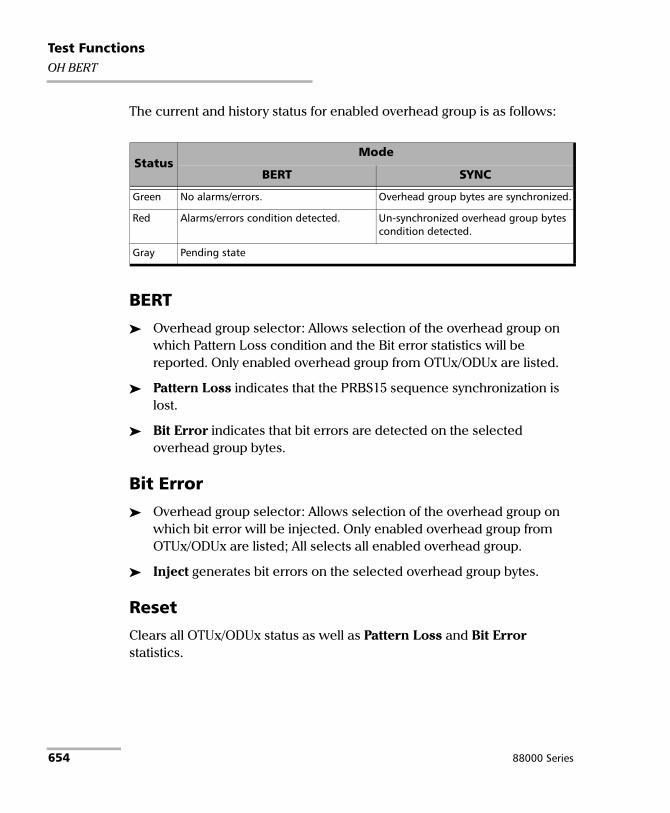
Test FunctionsOH BERT
The current and history status for enabled overhead group is as follows:
BERT
Overhead group selector: Allows selection of the overhead group on which Pattern Loss condition and the Bit error statistics will be reported. Only enabled overhead group from OTUx/ODUx are listed.
Pattern Loss indicates that the PRBS15 sequence synchronization is lost.
Bit Error indicates that bit errors are detected on the selected overhead group bytes.
Bit Error
Overhead group selector: Allows selection of the overhead group on which bit error will be injected. Only enabled overhead group from OTUx/ODUx are listed; All selects all enabled overhead group.
Inject generates bit errors on the selected overhead group bytes.
Reset
Clears all OTUx/ODUx status as well as Pattern Loss and Bit Error statistics.
StatusMode
BERT SYNC
Green No alarms/errors. Overhead group bytes are synchronized.
Red Alarms/errors condition detected. Un-synchronized overhead group bytes condition detected.
Gray Pending state
654 88000 Series

Test FunctionsOH - GFP-F/GFP-T
OH - GFP-F/GFP-T
Note: Available with OTN BERT test application with 1GbE (GFP-T), 10GbE (GFP-F), or Ethernet (flex/GFP-F) client.
From the Test menu, tap Functions, OH tab, and GFP-F/GFP-T sub tab.
Core Header
PLI and cHEC are not configurable.
Type Header
The following settings are available for Client Data and Client Management frame types.
PTI (Payload Type Identifier) allows overwriting the Payload Type Identifier.
PFI (Payload Frame Check Sequence Identifier) allows overwriting the Payload FCS Indicator.
PTI Description000 Client Data Frame
100 Client Management Frame
001, 010, 011, 101, 110, and 111 Reserved
PFI Description0 FCS Absent
1 FCS Present
Power Blazer 655

Test FunctionsOH - GFP-F/GFP-T
EXI (Extension Header Identifier) allows overwriting the Extension Header Identifier.
UPI (User Payload Identifier) allows overwriting the User Payload Identifier.
EXI Description0000 Null Extension Header
0001 Linear Frame
0010 Ring Frame
0011 to 1111 Reserved
UPI Description for PTI = 000
Description for PTI = 100
0000 00001111 1111
Reserved and not available Reserved
0000 0001 Frame-Mapped Ethernet Client Signal Fail (Loss of Client Signal)
0000 0010 Mapped PPP Frame Client Signal Fail (Loss of Character Synchronization)
0000 0011 Transparent Fibre Channel Client Defect Clear Indication (DCI)
0000 0100 Transparent FICON Client Forward Defect Indication (FDI)
0000 0101 Transparent ESCON Client Reverse Defect Indication (RDI)
0000 0110 Transparent GbE
0000 0111 Reserved for future use
0000 1000 Frame-Mapped Multiple Access Protocol over SDH (MAPOS)
0000 1001 Transparent DVB ASI
0000 1010 Framed-Mapped IEEE 802.17 Resilient Packet Ring
0000 1011 Frame-Mapped Fibre Channel FC-BBW
0000 1100 Asynchronous Transparent Fibre Channel
0000 1101 Framed MPLS Unicast
0000 1110 Framed MPLS Multicast
0000 1111 Framed IS-IS
0001 0000 Framed IPv4
0001 0001 Framed IPv6
656 88000 Series

Test FunctionsOH - GFP-F/GFP-T
Extension Header: CID and Spare are only available when EXI is set to Linear (refer to EXI on page 222) and are available for Client Data and Client Management frame types.
CID (Channel IDentifier) allows overwriting the communication channel used for the signal transmission set from CID on page 222. Choices are from 00000000 through 11111111 (0 to 255). The default setting is 00000000.
Spare allows setting the extension header Spare field. Choices are from 00000000 through 11111111 (0 to 255).
Default all OH
Returns all TX overhead bytes to their factory default values.
0001 0010 Framed DVD-ASI
0001 0011 Framed 64B/66B Ethernet
0001 0100 Framed 64B/66B Ethernet Ordered Set
0001 0101 through 1110 1111
Reserved for future standardization
1111 0000 through 1111 1110
Reserved for proprietary use
0000 0110 through 1101 1111
Reserved for future use
1110 0000 through 1111 1110
Reserved for proprietary use
UPI Description for PTI = 000
Description for PTI = 100
Power Blazer 657

Test FunctionsOH - GFP-F/GFP-T
RX
Note: The following Core Header, Type Header, and Extension Header parameters are available for Client Data, Client Management, and Reserved PTI frames. The details of the selected OH field is displayed in the OH Details section on the bottom-right of the screen.
Core Header
PLI (Payload Length Indicator) indicates the number of octets in the GFP payload area.
cHEC (Core Header Error Control) indicates the CRC-16 error control code that protects the integrity of the contents of the core header by enabling both single-bit error correction and Multi-bit error detection.
Type Header: See Type Header on page 655 for PTI, PFI, EXI, and UPI possible values.
PTI (Payload Type Identifier) indicates the type of GFP client frame.
PFI (Payload Frame Check Sequence Indicator) displays the Payload FCS Indicator.
EXI (Extension Header Identifier) indicates the Extension Header Identifier.
UPI (User Payload Identifier) indicates the User Payload Identifier.
tHEC (Type Header Error Control) indicates the CRC-16 error control code that protects the integrity of the contents of the type field by enabling both single-bit error correction and multi-bit error detection.
658 88000 Series

Test FunctionsOH - GFP-F/GFP-T
Extension Header: CID, Spare, and eHEC are only available when EXI is set to Linear (refer to EXI on page 222).
CID (Channel IDentifier) indicates the communication channel used by the signal. Possible values are 00000000 through 11111111 (0 to 255).
Spare indicates the extension header Spare field. Possible values are 00000000 through 11111111 (0 to 255).
eHEC (Type Header Error Control) indicates the CRC-16 error control code that protects the integrity of the contents of the extension header by enabling both single-bit error correction (optional) and multi-bit error detection.
OH Details
Displays the details of the selected OH byte. The first column indicates the selected OH byte. The second column indicates respectively from top to bottom the bit numbers used, the byte value in binary, and the interpretation of the byte when applicable.
Power Blazer 659

Test FunctionsOH - OTN
OH - OTN For OTN BERT, from the Test menu, tap Functions, and the OH tab.
For OTN-SONET/SDH BERT, from the Test menu, tap Functions, OH, and the OTN sub tab.
Allows respectively modifying the overhead information to be transmitted or viewing the overhead information received.
OTUx/ODUx and ODUx Buttons
Tap on either the OTUx/ODUx or the ODUx button to select the OH level.
Default OTN OH
Returns all TX overhead bytes to their factory default values.
TX/RX
Overhead bytes are organized using rows and columns structure as per G.709 standard.
Row 1
OA1 and OA2, columns 1-6, OTU FAS: All the Frame Alignment Signal OA1 bytes and OA2 bytes are individually configurable from 00 to FF. The default values are F6 for all OA1 bytes and 28 for all OA2 bytes.
MFAS, column 7, OTU MFAS: The Multi-Frame Alignment Signal byte is not configurable.
SM, columns 8-10, OTU OH: The Section Monitoring contains the following bytes.
The first SM byte (column 8) contains the TTI multiframe byte that is only configurable from Traces (OTN) on page 370.
The second SM byte (column 9) contains the BIP-8 byte that is automatically generated for each frame. This byte is not configurable.
660 88000 Series

Test FunctionsOH - OTN
The third SM byte (column 10) contains the following sub-fields. This byte is configurable from 00 (default) to FF.
GCC0, columns 11-12, OTU OH: The two General Communication Channel-0 bytes are configurable from 00 (default) to FF. Not configurable when GCC0 check box is selected from OH BERT on page 652.
RES, columns 13-14, OTU OH: The two Reserved (RES) bytes are configurable from 00 (default) to FF.
JC4 or RES1
JC4, column 15, OPU OH: Bits 1-3 set to all-0s, and bits 4-8 are controlled by GMP function. This byte is not configurable.
RES, column 15, OPU OH: The Reserved (RES) byte is configurable from 00 (default) to FF.
JC1 or JC1
JC1, column 16, OPU OH: Controlled by GMP function. This byte is not configurable.
JC, column 16, OPU OH: Bits 1-6, Reserved (RES), are configurable from binary 000000 (default) to 111111.Bits 7-8, Justification Control (JC), are configurable from binary 00 (default) to 11. Not available with ODU mux. Changing the JC value will corrupt the payload.
Bit 1-4 Bit 5 Bit 6 Bit 7-8
BEI/BIAE BDI IAE RES
1. Depending on the test MUX/Mapping.
Power Blazer 661

Test FunctionsOH - OTN
Row 2
RES, columns 1-2, ODU OH: The two Reserved (RES) bytes are configurable from 00 (default for each byte) to FF.
PM & TCM, column 3, ODU OH: The Path Monitoring and Tandem Connection Monitoring byte is configurable from 00 (default) to FF.
TCM ACT, column 4, ODU OH: The Tandem Connection Monitoring Activation is configurable from 00 (default) to FF.
TCM6/TCM5/TCM4, column 5-13, ODU OH: The Tandem Connection Monitoring overhead contains the following bytes.
The first TCMi byte contains the TTI multiframe byte and is only configurable from Traces (OTN) on page 370.
The second TCMi byte contains the BIP-8 byte and is automatically generated for each frame. This byte is not configurable.
The third TCMi byte contains the following sub-fields. This byte is configurable from 00 to FF. The default value is 00 when TCMi is disabled, and 01 when enabled.
FTFL, column 14, ODU OH: The Fault Type Fault Location multiframe byte is only configurable from FTFL/PT and PT on page 217.
JC5 or RES1
JC5, column 15, OPU OH: Bits 1-3 set to all-0s, and bits 4-8 are controlled by GMP function. This byte is not configurable.
RES, column 15, OPU OH: The Reserved (RES) byte is configurable from 00 (default) to FF.
Bit 1-4 Bit 5 Bit 6-8
BEI/BIAE BDI STAT
1. Depending on the test MUX/Mapping.
662 88000 Series

Test FunctionsOH - OTN
JC2 or JC1
JC2, column 16, OPU OH: Controlled by GMP function. This byte is not configurable.
JC, column 16, OPU OH: Bits 1-6, Reserved (RES), are configurable from binary 000000 (default) to 111111.Bits 7-8, Justification Control (JC), are configurable from binary 00 (default) to 11. Not available with ODU mux. Changing the JC value will corrupt the payload.
Row 3
TCM3/TCM2/TCM1, columns 1-9, ODU OH: See TCM6/TCM5/TCM4 on page 662 for more information.
PM, column 10-12, ODU OH: The Path Monitoring overhead contains the following bytes.
The first PM byte (column 10) contains the TTI byte that is not configurable.
The second PM byte (column 11) contains the BIP-8 byte and is automatically generated for each frame. This byte is not configurable.
The third PM byte (column 12) contains the following sub-fields. This byte is configurable from 00 to FF. The default value is 01.
EXP, column 13-14, ODU OH: The two Experimental overhead bytes are configurable form 00 (default for each byte) to FF.
1. Depending on the test MUX/Mapping.
Bit 1-4 Bit 5 Bit 6-8
BEI BDI STAT
Power Blazer 663

Test FunctionsOH - OTN
JC6 or RES1
JC6, column 15, OPU OH: Bits 1-3 set to all-0s, and bits 4-8 are controlled by GMP function. This byte is not configurable.
RES, column 15, ODU OH: The Reserved (RES) bytes are configurable from 00 (default) to FF.
JC3 or JC1
JC3, column 16, OPU OH: Controlled by GMP function. This byte is not configurable.
JC, column 16, OPU OH: Bits 1-6, Reserved (RES), are configurable from binary 000000 (default) to 111111.Bits 7-8, Justification Control (JC), are configurable from binary 00 (default) to 11. Not available with ODU mux. Changing the JC value will corrupt the payload.
Row 4
GCC1, column 1-2, ODU OH: The two General Communication Channel-1 bytes are configurable from 00 (default for each byte) to FF. Not configurable when GCC1 check box is selected from OH BERT on page 652.
GCC2, column 3-4, ODU OH: The two General Communication Channel-2 bytes are configurable from 00 (default for each byte) to FF. Not configurable when GCC2 check box is selected from OH BERT on page 652.
APS/PCC, column 5-8, ODU OH: The Automatic Protection Switching / Protection Communication Channel overhead bytes are defined in the ITU-T G.709 standard. These bytes are configurable from 00 (default) to FF.
RES, column 9-14, ODU OH: The six Reserved (RES) bytes are configurable from 00 (default for each byte) to FF.
1. Depending on the test MUX/Mapping.
664 88000 Series

Test FunctionsOH - OTN
PSI, column 15, OPU/ODU OH: Tap the PSI field to configure (TX) or display (RX) the Payload Structure Identifier.
TX: Select any TX byte from the list and its content is displayed below the list. Tap the Edit button to change its value.
RX: Select any RX byte from the list and its content is displayed below the list.
Foreground Signal Label: This is a legend representing the status of the MSI for each PSI#, either MSI TX (black), Expected MSI RX (green), or MSI Mismatch (red).
The Link TX/RX Scrolling check box when selected (cleared by default), allows synchronizing both TX and RX table allowing to see the same TX and RX PSI byte numbers when scrolling from either TX or RX table.
OMFI or NJO
OMFI, column 16, OPU OH: OPU Multi-Frame Identifier is only available for OPU4 of a mapped signal. This byte is not configurable.
NJO, column 16, ODU OH: The Negative Justification Opportunity byte is not configurable. Available either for non-concatenated signal or on the LO of a concatenated signal.
RX
RX OH Byte Details displays the content of the selected OH RX byte. Tap on any OH RX byte to see its content
Legend TX/RX indicates the path level for all OH bytes.
Power Blazer 665

Test FunctionsOH - SONET/SDH
OH - SONET/SDH The SONET/SDH OH page allows modifying (TX) the overhead information to be transmitted and viewing (RX) the overhead information received.
For SONET/SDH BERT, from the Test menu, tap Functions, and the OH tab.
For OTN-SONET/SDH BERT, from the Test menu, tap Functions, OH, and the SONET/SDH sub tab.
Tap on any overhead byte in TX to modify its value.
Tap on any overhead byte in RX to see its detailed content/value.
Note: A byte in TX that has no value displayed or is grayed out, is not configurable from the OH tab.
TX and RX Buttons (SDH)
Tap on the TX or RX button to respectively access the overhead bytes in transmission or receive mode.
STS-1 Timeslot/STM-1 Channel
Allows selecting the timeslot number for the Transport OH bytes. The STS/AU/TU-3 overhead bytes are always for the timeslot selected in the test configuration. Furthermore when modifying the Transport OH bytes H1 SS bits, the modification applies to all timeslots when the test topology is Coupled. Choices are 1 (default) to 192 (SONET) / 64 (SDH) depending on the OC-N/STM-N interface selected.
666 88000 Series

Test FunctionsOH - SONET/SDH
Transport OH - Section/RS
A1 and A2: Framing. The value should be hexadecimal F6 for A1 and 28 for A2. They must appear in every STS-1/STM-1 frame of a composite signal.
SONET: Provide frame alignment of each STS-1 frame within a composite signal (STS-1 to STS-n).
SDH: Indicate the beginning of the STM-N frame.
J0/Z0
J0: The J0 (Trace) byte is used to trace the origin of an STS-1/STM-1 frame as it travels across the SONET/SDH network. This byte is only defined for the first STS-1/STM-1 frame of a composite signal. Available when the Trace format is set to 1 Byte (refer to Traces (SONET/SDH) on page 374).
Z0: Growth.
SONET: The Z0 byte was used to uniquely identify the STS in question. This byte has to be defined in every STS-1 to STS-n frame of a composite signal. This byte is only defined for the STS-1 #2 to STS-1 #N of a OC-N signal.
SDH: These bytes are reserved for future international standardization. They are located at positions S[1,6N+2] to S[1,7N] of an STM-N signal (N > 1).
B1: BIP-8 (Bit-Interleaved Parity) byte provides section error monitoring. This byte is only defined for the first STS-1/STM-1 frame of a composite signal. The byte is calculated by performing a routine even-parity check over all bits of the previous STS-N/STM-N frame of a composite signal.
E1: Orderwire. Provides a 64 Kbit/s voice channel for communication between two STEs (Section Terminating Equipment). This byte is only defined for the first STS-1/STM-1 frame of a composite signal.
Power Blazer 667

Test FunctionsOH - SONET/SDH
F1: User/User Channel. This byte is reserved for user purposes. This byte is only defined for the first STS-1/STM-1 frame of a composite signal.
D1, D2, and D3: Data Communications Channel (DCC). Provides a 192 Kbit/s data communication between two STEs for operation functions such as OAM&P. These bytes are only defined for the first STS-1/STM-1 frame of a composite signal.
Transport OH - Line/MS
H1 and H2: Pointer.
SONET: H1 and H2 bytes are combined to form a pointer indicating where the path overhead begins within each SPE.
SDH: H1 and H2 bytes are combined to form a pointer indicating where the VC (Virtual Container) frame begins within each SPE.
Bits 5 and 6 of the H1 byte represent the SS bits and are configurable as follows:
H3: Pointer Action. H3 is an extra byte used to compensate for the SPE timing variation. The H1 and H2 pointer tell the receiver when the H3 pointer is used.
SONET: This byte must be defined in every STS-1 to STS-n frame of a composite signal.
SDH: This byte must be defined in every STM-1 of an STM-N signal in the event of negative justification, otherwise it is not defined.
SS Bits Description
00 SONET
01 Undefined
10 SDH
11 Undefined
668 88000 Series

Test FunctionsOH - SONET/SDH
B2: BIP-8
SONET: The BIP-8 (Bit-Interleaved Parity) byte provides line error monitoring. This byte is only defined for the first STS-1/STM-1 frame of a composite signal. The byte is calculated by performing a routine even-parity check over all bits of the LOH and the STS-1 frame capacity of the previous frame of a composite signal (STS-1 to STS-n). Note that the SOH is not used to calculate the parity check.
SDH: The MS BIP-N*24 (Bit-Interleaved Parity) byte provides line error monitoring. The byte is calculated by performing a routine even-parity check over all bits of the MSOH and the STM-N frame of the previous STM-N frame. Note that the RSOH is not used to calculate the parity check.
K1 and K2: Automatic Protection Switching (APS): The K1 and K2 bytes communicate APS between two LTE. These bytes are only defined for the first STS-1/STM-1 frame of a composite signal.
D4 through D12: Data Communications Channel (DCC): The D4 through D12 bytes provide a 576 Kbit/s data communications channel between two LTEs for administration, monitoring and other communications. These bytes are only defined for the first STS-1/STM-1 frame of a composite signal.
S1/Z1 (SONET)
S1: Synchronization Status: The S1 byte is used to carry the synchronization status of the SONET device. This byte is only defined for the first STS-1/STM-1 frame of a composite signal.
Z1: Growth. This byte is located in the second STS-1 through STS-n frame of a composite signal (STS-1 #2, STS-1 #3, up to STS-1 #N of a OC-N (N>3) signal).
S1 (SDH): Synchronization Status. Bits 5 to 8 of the S1 byte are used to carry the synchronization messages of the SDH device. This byte is only defined for the first STS-1/STM-1 frame of a composite signal.
Power Blazer 669

Test FunctionsOH - SONET/SDH
M0 or M1/Z2 (SONET)
M0: REI-L: The M1 byte is used for line Remote Error Indication (REI-L)
For STS-1e and OC-1: The M0 byte located in the STS-1 indicates BIP violations.
For OC-192: The M0 bytes located in the STS-1 #4 indicates BIP violations when combined with the M1 byte (see M1 byte below for more information).
M1: REI-L. The M1 byte is used for line Remote Error Indication (REI-L).
For STS-3e and OC-3: The M1 byte located in the STS-1 #3 indicates BIP violations.
M0, bits234 5678 Indicates
000 0000 0 BIP violation
000 0001 1 BIP violation
: :
000 1000 8 BIP violations
000 1001 to 1111 1111
0 BIP violation
M1, bits 234 5678 Indicates
000 0000 0 BIP violation
000 0001 1 BIP violation
: :
001 1000 24 BIP violations
001 1001 to 1111 1111
0 BIP violation
670 88000 Series

Test FunctionsOH - SONET/SDH
For OC-12: The M1 byte located in the STS-1 #7 indicates BIP violations.
For OC-48: The M1 byte located in the STS-1 #7 indicates BIP violations.
For OC-192: Either the M1 byte located in the STS-1 #7, or the combination of the M0 and M1 bytes indicates BIP violations (refer to REI-L Computation Method on page 346).
For M1 Only computation method:
M1, bits 234 5678 Indicates
000 0000 0 BIP violation
000 0001 1 BIP violation
: :
110 0000 96 BIP violations
110 0001 to 1111 1111
0 BIP violation
M1 Indicates
0000 0000 0 BIP violation
0000 0001 1 BIP violation
: :
1111 1111 255 BIP violations
M1 Indicates
0000 0000 0 BIP violation
0000 0001 1 BIP violation
: :
1111 1111 255 BIP violations
Power Blazer 671

Test FunctionsOH - SONET/SDH
For M0 and M1 computation method:
Z2: Growth. Available with OC-3, OC-12, and OC-48 signal, this byte is located in STS-1 #1 up to STS-1 #48 except for timeslots used by M0 and M1.
Undefined “--” for all other timeslots not covered by M0, M1, and Z2.
M0 or M1 (SDH)
M0: MS-REI. STM-1 channel #1 of a STM-0e and STM-0 signal; channel #2 of an STM-64 signal.
M1:MS-REI. STM-1 channel #1 of a STM-1e and STM-1 signal; channel #3 of an STM-N signal (N>1).
Undefined “--” for all other channels not covered by M0, and M1.
E2: Orderwire. Provides a 64 Kbit/s voice channel for communication between LTEs. This byte is only defined for the first STS-1/STM-1 frame of a composite signal.
M0Located in STS-1 #4
M1Located in STS-1 #7 Indicates
0000 0000 0000 0000 0 BIP violation
0000 0000 0000 0001 1 BIP violation
: : :
0000 0110 0000 0000 1536 BIP violations
0000 0110 to 1111 1111
0000 0001 to 1111 1111
0 BIP violation
672 88000 Series

Test FunctionsOH - SONET/SDH
STS/AU/TU-3
J1: Trace. Available when the Trace format is set to 1 Byte (refer to Traces (SONET/SDH) on page 374).
SONET: The J1 Trace byte provides a 16 or 64 byte fixed string to verify connection between path transmitting equipment and path receiving equipment.
SDH: The higher-order (AU)/low-order (TU) VC-N path trace byte provides a 64 byte fixed string to verify connection between path transmitting equipment and path receiving equipment.
B3: BIP-8. The BIP-8 (Bit-Interleaved Parity) byte provides path error monitoring. The byte is calculated by performing a even-parity check over all bits of the previous SPE.
Power Blazer 673

Test FunctionsOH - SONET/SDH
C2: Signal Label. Entering a C2 byte value will automatically update the Path Signal Label (C2) selection and vice versa. Refer to STS/AU Path (C2) on page 238 for more information.
C2 (Hex.)
Description
SONET SDH00a
a. These values cannot be selected as Expected Path Signal Label.
Unequipped UNEQ or supervisory-UNEQ
01 Equipped - Non-Specific RES (Equipped - Non-Specific)
02 Floating VT Mode (Default) TUG Structure
03 Locked VT Mode Locked TU-n
04 Async Mapping for DS3 Async Mapping of 34M/45M in C-3
05 Mapping under development Experimental Mapping
12 Async Mapping for 140M (DS4NA) Async Mapping of 140M in C-4
13 Mapping for ATM ATM Mapping
14 Mapping for DQDB MAN DQDB
15 Async Mapping for FDDI FDDI [3]-[11] Mapping
16 Mapping of HDLC over SONET Mapping of HDLC/PPP
17 SDL with self-sync scrambler RES (SDL self-synch scrambler)
18 Mapping of HDLC/LAPS Mapping of HDLC/LAPS
19 SDL with a set-reset scrambler RES (SDL set-reset scrambler)
1A 10 Gbit/s Ethernet (IEEE 802.3) 10 Gbit/s Ethernet (IEEE 802.3)
1B GFP GFP
1C Not supported Mapping 10 Gbit/s FC
20 Not supported Async Mapping of ODUk
CF RES (Obsolete HDLC/PPP framed) RES (obsolete HDLC/PPP framed)
E1a toFCa
STS-1 w/1 VTx PD, STS-1 w/2 VTx PD, ... STS-1 w/28 VTx or STS-n/nc PD
Not supported
FE Test Signal, ITU-T 0.181 Test Signal, ITU-T 0.181
FFa STS SPE AIS (TCM) VC-AIS (TCM)
674 88000 Series

Test FunctionsOH - SONET/SDH
G1: Path Status. The G1 byte provides a method to communicate the far-end path status back to the path originating equipment.
REI:
RDI/ERDI:
F2: User Channel. The User Channel provides a 64 Kbit/s channel for communication between two PTEs. This byte is only defined for the first STS-1/STM-1 frame of a composite signal.
H4: Multiframe Indicator. The H4 byte provides a multiframe phase indication of a VT/TU payload.
Bits 1 to 4 of G1 Description
0000 No error
0001 1 error
0010 2 errors
: :
1000 8 errors
1001 to 1111 No error
Bits 5, 6, 7 of G1 Description
000, 001, 011 No defect
100, 111 RDI
010 ERDI-PD
101 ERDI-SD
110 ERDI-CD
Power Blazer 675

Test FunctionsOH - SONET/SDH
Z3 and Z4:
SONET only: Growth.
F3:
SDH only: User Channel. The Path User Channel provides a channel for communication purposes between path elements and is payload dependent.
K3:
SDH only: Automatic Protection Switching (APS). Bits 1 to 4 of the K3 byte are used for APS signaling. K3 bits 5 to 8 are reserved for future use.
N1:
SONET: The N1 byte (formerly referred to as the Z5 byte) is allocated for Tandem Connection Maintenance (TCM) and the Path Data Channel.
SDH: (Network operator byte) The N1 byte is allocated to provide a Higher-Order Tandem Connection Monitoring (HO-TCM) function.
676 88000 Series

Test FunctionsOH - SONET/SDH
VT/TU
V5 VT/TU Path Overhead
The V5 byte is allocated to indicate the content of the VT/TU path, including the status of the mapped payloads. It provides the same functions for VT/VC paths that the B3, C2, and G1 bytes provide for STS/STM paths.
BIP-2 is not configurable.
REI, RFI, and RDI: Choices are 0 (disabled), and 1 (enabled).
Signal Label
Bits 5, 6, 7 of V5
Description
SONET SDH
000a
a. These bytes cannot be selected in receive mode.
Unequipped Unequipped or supervisory-unequipped
001 Reserved (Equipped - Non-specific)
010 Asynchronous
011 Bit Synchronous
100 Byte Synchronous
101 Extended Signal Label
110 Test Signal, ITU-T 0.181 specific mapping
111a VT SPE AIS (TCM) VC-AIS (TCM)
Power Blazer 677

Test FunctionsOH - SONET/SDH
If the signal label in V5 (bits 5, 6, and 7) is 101 the contents of the extended signal label is valid and contains in a 32 bit multiframe as shown below. See Z7/K4 Structure shown below.
Z7/K4 Structure
J2 Trace. Available when the Trace format is set to 1 Byte (refer to Traces (SONET/SDH) on page 374).
SONET: VT Path Trace: The J2 Trace byte provides a 16 or 64 bytes fixed string allowing the receiving VT PTE to verify its continued connection to the intended transmitting VT PTE.
SDH: Path Trace: The J2 byte is used to repetitively transmit a Lower-Order Access Path Identifier so that a path receiving terminal can verify its continued connection to the intended transmitter.
Z6/N2
Z6 (SONET): VT Tandem Connection Monitoring or VT Path Growth. The Z6 byte is allocated for future growth.
N2 (SDH): (Network operator byte) Tandem Connection Monitoring for the VC2, VC-12, and VC-11 level.
678 88000 Series

Test FunctionsOH - SONET/SDH
Z7 /K4 : Extended signal label
Default all OH
Returns all TX overhead bytes to their factory default values.
BitsDescription
Z7 (SONET) K4 (SDH)
1 Extended signal label. Bits 12 to 19 of the 32 bit frame multiframe (see Z7/K4 Structure on page 678) contain the extended signal label.
2 Virtual concatenation. Bits 1 to 5 of the 32 bit frame multiframe (see Z7/K4 Structure on page 678) contain the LO virtual concatenation frame count while bits 6 to 11 contain the LO virtual concatenation sequence indicator.
3 - 4 unassigned and reserved for APS signaling for protection at the lower order path level.
5 - 7 These bits in combination with bit 8 of V5 are allocated for RDI -V/ERDI-V signal
Optional use.
8 unassigned and reserved for a lower order path data link.
Power Blazer 679

Test FunctionsPacket Capture
Packet Capture Capture is used to analyze all or filtered data traffic and save complete or truncated frames into a buffer. It allows observing network truncated data precisely, or understanding errors and unwanted behavior.
Note: Not available with 200/400G and eCPRI dual port topology.
From the Test menu, tap Functions, and the Packet Capture tab.
Note: For Dual Port topology select the port to be displayed.
Capture Source
Specifies what kind of data to be captured.
Interface captures all received frames and saves them in the capture buffer.
Filter x captures only frames that match the selected filter and saves them in the capture buffer. Select the filter number from the list. Only enabled filters are available, see Filters on page 645.
The selected filter will be reserved for data capture and will not be available for filter configuration.
680 88000 Series

Test FunctionsPacket Capture
Frame Length
Specifies the length of the frame that will be saved in the capture buffer.
Complete captures the entire frames.
Truncated captures only the first specified number of bytes per frame. Use either the Bytes field to manually enter the number of bytes per frame or tap on the Truncation Calculator button for automatic bytes per frame calculation.
Bytes allows the selection of the number of bytes that will be saved in the capture buffer for each frame captured: 14 (default) to 1536 bytes.
Truncation Calculator allows determining easily at what byte to truncate the frame captured by selecting the desired frame header components.
Header Layer specifies the header layer level: Layer 2 (Ethernet), Layer 3 (IP), or Layer 4 (TCP/UDP).
IP Version specifies the IP version: IPv4 or IPv6.
Encapsulation parameters are optional and not selected by default.
VLAN check box, when selected, enables VLAN and allows selecting the number of VLANs: 1, 2, or 3.
MPLS check box, when selected, enables MPLS and allows selecting the number of labels: 1 or 2.
EoE check box, when selected, enables EoE
PBB-TE check box, when selected, enables PBB-TE.
Additional Payload (bytes) allows selecting optionally the number of additional payload bytes (1 to 1400 bytes).
Total Number of Bytes indicates the number of bytes for the selected frame parameters. This value will be used as the truncated frame length (Truncated field).
Power Blazer 681

Test FunctionsPacket Capture
Trigger
Trigger Type defines the trigger source criterion that will be used to automatically start/stop the capture when a received frame matches the filter and the trigger criteria.
Manual automatically starts the frame capture when the Capture button is on (green LED) and the test is started (refer to Start/Stop|TX Button on page 741).
On Error starts the frame capture when the selected error occurs.
FCSJabberOversize (Available when Oversize Monitoring is enabled)RuntUndersizeIP ChecksumUDP ChecksumTCP ChecksumAny Type (Any of the above errors).
Field Match starts the frame capture when the configured field match is encountered. User the Configuration button to select the field match criteria (see Filter Configuration from the Filters tab).
Cfg. Status indicates the status of the configured field match configuration: Valid or Invalid. A valid status is required to be able to start the capture.
682 88000 Series

Test FunctionsPacket Capture
Trigger Position selects the triggered frame position within the buffer.
Post-Trigger for a trigger frame located at the beginning of the buffer. The buffer will contain the triggered frame with the following frames.
Mid-Trigger for a trigger frame located at the middle of the buffer. The buffer will contain the triggered frame with the preceding and following frames.
Pre-Trigger for a trigger frame located at the end of the buffer. The buffer will contain the triggered frame with the preceding frames.
Status and Controls
Capture Status indicates the status of the data capture:
“--”: The capture is not started and has not run yet.
Armed...: The capture is started but waiting for the trigger event.
Capturing...: The capture is in progress. For Post-Trigger and Mid-Trigger mode, the trigger event has been captured and the buffer is filling up.
Completed: The capture is completed.
Frame Count indicates the number of frames captured that matches the selected filter criteria. However, for Mid-trigger and Pre-Trigger, the frame counter will only be available when the capture is completed.
Buffer Usage indicates the percentage of the buffer capacity used.
Triggered Error is available when trigger on error is selected and indicates the error that activated the trigger.
Power Blazer 683
Test FunctionsPacket Capture
Triggered Frame - Details gives details on the triggered frame.
The triggered frame corresponds to the first received frame that matches the filter and the trigger settings.
Frame Number indicates the triggered frame position in the buffer.
The framing MAC/IP/UDP/TCP source and destination addresses are displayed in a table.
Capture button allows starting/stopping the data capture. The test must be running (refer to Start/Stop|TX Button on page 741) in order to start capturing and recording data into the buffer. The Capture button is not available when the trigger on field match is selected while its trigger parameters are not valid.
No data will be recorded in the buffer if no frame matches the filter and the trigger criteria during the data capture.
The data capture stops automatically once the buffer is full. The maximum buffer capacity is 64 KBytes or a maximum of 2078 frames for rates up to 10GE and 512 KBytes or a maximum of 8192 frames for rates 40GE and 100GE.
When the capture stops or is manually stopped, the following message is displayed: Capture completed. Press Export to save captured data (the test must be stopped). To avoid losing the captured data, the data must be exported and saved into a file before restarting the test or creating a new test.
684 88000 Series

Test FunctionsPacket Capture
Export button, available when the test application is stopped, allows exporting the data captured into a .pcap file format and viewing the file using Wireshark.
Save In: Allows selecting the folder to save the capture file.
The capture file is saved in the following folder by default:Users\<User>\Documents\88000-PowerBlazer\CaptureData
View File After Generation: Allows displaying the report once it is generated using the Wireshark application. The View File After Generation check box is not selected by default.
Generate & Save
Allows generating and saving the capture data. The name of the captured file is automatically selected and contains the date and time of the capture. Capture file bigger than 100Mbytes will be split into multiple files.
Tapping on the Cancel button stops the capture generation. The captured data already processed will be saved.
Note: The export process may take several minutes.
Once generated, the capture file will be automatically opened in Wireshark when the View File After Generation check box is selected.
The capture file report may also be manually opened within Wireshark typically using Windows Explorer.
Power Blazer 685

Test FunctionsPing & Trace Route
Ping & Trace Route From the Test menu, tap Functions, and the Ping & Trace Route tab.
Note: For Dual Port topology select the port to be displayed.
Source IP Address
Displays or allows the selection of either the interface source IP address or a stream IP address depending on the test and its configuration. Refer to IP on page 264, MAC/IP/UDP on page 247, or Smart Loopback on page 349.
Destination IP Address
Enter the Destination IP Address of the network device to be detected. The destination IP address is configurable only with IPv4 Network Layer (refer to Modify Structure Button on page 119). The accepted range for IPv4 is 0.0.0.0 (default) to 255.255.255.255.
The default setting for IPv6 is 2001:0000:0000:0000:0000:0000:0000:0000 or is set automatically to the IP address of the target module from the Remote Loopback mode. The destination IP address is configured only when Ethernet/IPv6/UDP is selected. The IPv6 Address can either be the Link-Local IPv6 Address or the Global IPv6 Address. The acceptable range for IPv6 is from 000:0000:0000:0000:0000:0000:0000:0001 to FFFF:FFFF:FFFF:FFFF:FFFF:FFFF:FFFF:FFFF.
Stream
Stream is available with EtherSAM and Traffic Gen & Mon and allows selecting a stream/service to use its source and destination IP addresses for the Ping and Trace Route tests.
686 88000 Series

Test FunctionsPing & Trace Route
Use Stream
Use Stream, available with test application using stream/services, allows using the source and destination IP of the defined or selected stream/services.
Ping
Data Size (Bytes): Enter the data size that will be sent to the network device to be detected. Choices are 0 to 1452 bytes; 32 bytes by default.
TTL for IPv4 and Hop Limit (TTL) for IPv6: Enter the maximum number of hops the packet can go through. Choices are 1 to 255; 128 by default.
IP TOS/DS for IPv4 and Traffic Class (TOS/DS) for IPv6: Enter the type of service. Choices are 00 (default) to FF.
Flow Label (IPv6) value acceptable range is from 0 (default) to 1048575.
Timeout (ms): Enter the maximum time allowed between an ICMP echo and response. Choices are 200 ms to 10000 s; 4000 ms by default.
Delay (ms): Enter the delay between each attempt (PING). Choices are 100 to 10000 ms; 1000 ms by default.
Attempts: Select n-Attempts to specify the number of ping requests to send following a ping activation or select Continuous to ping continuously until manually stopped. If n-Attempts is selected, enter the number of ping attempts from 1 to 100. The default setting is n-Attempts with 4 attempts.
Ping button starts the ping tool with the specified settings.
Power Blazer 687

Test FunctionsPing & Trace Route
Trace Route
Max Hop Count: Enter the maximum network device the packet is allowed to go through. Choices are 1 to 255; 128 by default.
Timeout (ms): Enter the maximum time allowed between an ICMP echo and response at each hop. Choices are 200 ms to 10000 ms; 4000 ms by default.
Trace Route button starts the trace route tool with the specified settings.
Results
To succeed, a ping command shall be acknowledged by the network device within a given delay (Timeout). Typically a ping command can fail for the following reasons:
The IP address is unavailable or unknown.
The time allowed to perform the ping command is too short.
The remote device is not supporting ICMP messaging.
To succeed, a trace route command shall be acknowledged by the network device within a given delay (Timeout). Typically a trace route command can fail for the following reasons:
The IP address is unavailable or unknown.
The time allowed to perform the trace route command is too short.
The remote device is not supporting ICMP messaging.
The ping and trace route results are displayed with the following columns:
No.: Indicates the attempt number.
688 88000 Series

Test FunctionsPing & Trace Route
Status: Indicates the status of the attempt as follows:
Status Description
Successful Valid ICMP echo reply received.
User Aborted When a user has manually stopped the ping/trace route function before the end of attempts.
Time Out When an ICMP echo reply was not received within the defined timeout.
Destination Invalid With reserved IP addresses:
For IPv4: 0.0.0.0, 127.0.0.0, and all addresses above 240.0.0.0 (Class E and above).
For IPv6: 0::/8 (reserved/unspecified), 0::1/128 (Loopback), FF00::/8 (Multicast).
TTL Expired (ping test)
When the number of TTL was insufficient to reach the destination host.
Hop Reached (trace route test)
When a Time Exceeded message is received from a host while executing the trace route function.
Destination Unreachable
For IPv4: When the IP address is unreachable (no default gateway for an IP address, not in the same subnet, or an ICMP Unreachable message is received).
For IPv6: When the IP address is unreachable (no default gateway for an IP address, not in the same subnet, or address resolution failed or an ICMP Destination Unreachable message is received).
Data Corrupted Parameter problem message is received or data corruption is found for IPv4.
Discarded Congestion has been detected and the request cannot be transmitted.
Packet Too Big Packet Too Big message is received in response to a packet that the router cannot forward because the packet is larger than the MTU of the outgoing link. It is only applicable for the IPv6 version.
Undefined For any other errors in ping/trace route that do not fall into one of the above description.
Power Blazer 689

Test FunctionsPing & Trace Route
Replied Details
For ping, indicates the IP address of the replier, the buffer size of the ICMP echo response, the time of response in milliseconds, and the TTL of the ICMP echo response.
For trace route, indicates the IP address of the replier, and the time of response in milliseconds.
Statistics
Packets Transmitted indicates the number of sent packets.
Packets Received indicates the number of received packets.
The following statistics are only available for the ping test.
Percentage Lost (%) indicates the percentage of packets lost.
Min Round Trip Time (ms) indicates the minimum time recorded for a ping request to be answered.
Max Round Trip Time (ms) indicates the maximum time recorded for a ping request to be answered.
Avg. Round Trip Time (ms) indicates the average time required for a ping request to be answered.
690 88000 Series

Test FunctionsPointer Adjustment
Pointer Adjustment From the Test menu, tap Functions, and the Pointer Adjustment tab.
TX Pointer Adjustment
Note: Only available in Coupled topology.
The pointer adjustment supports two modes of operation: Manual and Sequence. Both modes offer the generation of pointer events even when the test is not started.
TX Pointer Adjustment - Manual Button
Step
Value
For STS/AU: Select the number of positive (Increment) or negative (Decrement) pointer adjustments to include into the STS-n (SONET) or AU-n (SDH): 1 (default) to 1000. For multiple pointer adjustments, the pointer adjustment rate is 1 adjustment at every 4 frames.
For VT/TU: Select the number of positive (Increment) or negative (Decrement) pointer adjustment to include into the VTn (SONET) or TU-n (SDH): 1 (default) to 1000. For multiple pointer adjustments, the pointer adjustment rate is 1 adjustment at every 4 multiframes.
Increment button sends the positive pointer adjustment defined.
Decrement button sends the negative pointer adjustment defined.
Pointer Value indicates the current pointer value.
Power Blazer 691

Test FunctionsPointer Adjustment
Jump
New Pointer allows selecting a new pointer value:
For STS/AU: 0 (default) to 782
For VT/TU:
Inject button sends the new pointer value.
New Data Flag (NDF) check box when selected inserts a New Data Flag with the pointer adjustment when the Inject button is tapped.
For STS/AU: When NDF is enabled, bits 1 to 4 of the pointer word (H1 and H2 bytes) are set to 1001 when executing a pointer jump.
For VT/TU: When NDF is enabled, bits 1 to 4 of the pointer word (V1 and V2 bytes) are set to 1001 when executing a pointer jump.
Path RangeVT1.5 0 to 103
VT2 0 to 139
TU-3 0 to 764
TU-11 0 to 103
TU-12 0 to 139
692 88000 Series

Test FunctionsPointer Adjustment
TX Pointer Adjustment - Sequence Button
Note: The pointer sequence is only supported on one test layer; either on VT/TU layer or on STS/AU when the test doesn’t contain VT/TU mapping. The field next to the Sequence operation mode button indicates the path level used for the sequence pointer adjustment.
Sequence: T.105-03/GR-253 allows the selection of the pointer sequence pattern based on the T.105-03/GR-253 standard.
Pointer Sequence Pattern Available withSingle pointers of opposite polarity AU-x, TU-3, TU-11, TU-12
Regular pointers plus one double pointer AU-x, TU-3, TU-11, TU-12
Regular pointers with one missing pointer AU-x, TU-3, TU-11, TU-12
Double pointers of opposite polarity AU-x, TU-3, TU-11, TU-12
Single pointer adjustment STS-x, VT1.5, VT2, AU-x, TU-3, TU-11, TU-12
Burst pointer adjustment STS-x, VT1.5, VT2, AU-x, TU-3, TU-11, TU-12
Phase transient STS-x, VT1.5, VT2, AU-x, TU-3, TU-11, TU-12
Periodic pointer adjustment 87-3 pattern STS-x, AU-x, TU-3
Periodic 87-3 with Add STS-x, AU-x, TU-3
Periodic 87-3 with Cancel STS-x, AU-x, TU-3
Periodic pointer adjustment continuous STS-x, VT1.5, VT2, AU-x, TU-3, TU-11, TU-12
Periodic pointer adjustment continuous with Add STS-x, VT1.5, VT2, AU-x, TU-3, TU-11, TU-12
Periodic pointer adjustment continuous with Cancel STS-x, VT1.5, VT2, AU-x, TU-3, TU-11, TU-12
Periodic pointer adjustment 26-1 pattern VT1.5, TU-11
Periodic 26-1 with Add VT1.5, TU-11
Periodic 26-1 with Cancel VT1.5, TU-11
Power Blazer 693

Test FunctionsPointer Adjustment
Initialization / Cool Down / Sequence
The following time line examples show the initialization, cool down, and the pointer sequence according to the selected sequence and parameters.
Example 1: Periodic 87-3 with Cancel
Example 2: Regular pointers plus one double pointer
Legend:
Description
When located at the end (right) of the sequence, indicates a continuous repetition of the pointer sequence.
When located within the sequence, indicates a repetition of pointers.
Regular pointer event or sequence.
Cancel event.
Special event like an extra cancel event (for example in Periodic 87-3 with Cancel) or a missing event from the Regular pointers with one missing pointer sequence.
Special event like add, double pointer, etc.
Indicates that the sequence is periodic with special event.
694 88000 Series

Test FunctionsPointer Adjustment
T1 to T6 are configurable duration parameters. The range of the duration parameters as well as their availability versus pointer sequence are described in the following table.
Pointer Sequence Pattern Parameter Duration rangeSingle pointers of opposite polarity T1 10 to 30 s (default 10 s)
Regular pointers plus one double pointer T2 AU/TU-3: 7.5 ms to 30 s (default 0.333 s)TU-11/12: 0.2 s to 30 s (default 0.75 s)
T3 AU/TU-3: 0.5 msTU-11/12: 2 ms
Regular pointers with one missing pointer T2 AU/TU-3: 7.5 ms to 30 s (default 0.333 s)TU-11/12: 0.2 s to 30 s (default 0.75 s)
Double pointers of opposite polarity T1 10 to 30 s (default 10 s)
T3 STS-x/AU-x/TU-3: 0.5 ms to 1 s (default 0.5 ms)VT-x/TU-11/12: 2 ms to 1 s (default 2 ms)
Single pointer adjustment T6 30 to 60 s (default 30 s)
Burst pointer adjustment T4 STS-x/AU-x/TU-3: 0.5 msVT-x/TU-11/12: 2ms
T6 30 to 60 s (default 30 s)
Phase transient T6 30 to 60 s (default 30 s)
Periodic pointer adjustment 87-3 pattern T5 7.5 ms to 10 s (default 0.333 s)
Periodic 87-3 with Add T4 0.5 ms
T5 7.5 ms to 10 s (default 0.333 s)
Periodic 87-3 with Cancel T5 7.5 ms to 10 s (default 0.333 s)
Periodic pointer adjustment continuous T5 STS-x/AU-x/TU-3: 7.5 ms to 10 s (default 0.333 s)VT-x/TU-11/12: 0.2 s to 10s (default 1 s)
Periodic pointer adjustment continuous with Add
T4 STS-x/AU-x/TU-3: 0.5 msVT-x/TU-11/12: 2 ms
T5 STS-x/AU-x/TU-3: 7.5 ms to 10 s (default 0.333 s)VT-x/TU-11/12: 0.2 s to 10 s (default 1 s)
Periodic pointer adjustment continuous with Cancel
T5 STS-x/AU-x/TU-3: 7.5 ms to 10 s (default 0.333 s)VT-x/TU-11/12: 0.2 s to 10 s (default 1 s)
Periodic pointer adjustment 26-1 pattern T5 0.2 s to 10 s (default 1 s)
Periodic 26-1 with Add T4 2 ms
T5 0.2 s to 10 s (default 1 s)
Periodic 26-1 with Cancel T5 0.2 s to 10 s (default 1 s)
Power Blazer 695

Test FunctionsPointer Adjustment
T1 (s) represents the interval between two pointer events.
Example of Single pointer of opposite polarity sequence.
T2 (s) represents the interval between successions of pointer events.
Example of Regular pointers with one missing pointer sequence.
T3 (ms) represents the interval between back to back pointer events.
Example of Regular pointers plus one double pointer sequence.
696 88000 Series

Test FunctionsPointer Adjustment
T4 (ms) represents the interval between back to back pointer events in periodic pointer sequence.
Example of Burst pointer adjustment sequence.
T5 (s) represents the interval between successions of pointer events in a Periodic pointer sequence.
Example of Periodic 87-3 with Cancel sequence.
T6 (s) represents the interval between successions of pointer events.
Example of Phase transient sequence.
Power Blazer 697

Test FunctionsPointer Adjustment
Increment/Decrement allows determining if the pointer sequence will increment (positive) or decrement (negative) the pointer values.
Periodic check box when selected, generates the pointer sequence continuously. The pointer sequence is generated only once when the Periodic check box is cleared. The capability to clear the Periodic check box is only available for the following pointer sequences:
Single pointers of opposite polarity
Regular pointers plus one double pointer
Regular pointers with one missing pointer
Double pointers of opposite polarity
Init-Cool check box when selected, generates pointer action with three phases: initialization, Cool-down, and pointer sequence. Only the pointer sequence is generated when the Init-Cool check box is cleared.
Status indicates the pointer event activity status.
Initialization indicates that the pointer sequence test is started and is running the initialization phase.
Cool-down indicates that the pointer sequence test is started and is running the cool down phase.
Sequence indicates that the pointer sequence test is started and is running the sequence phase; this phase runs until the Sequence is turn off.
Static pointer indicates that the pointer sequence is not started. The signal generator transmits a fix pointer value.
Pointer Value indicates the current pointer value. Available even if the test is not started or if the sequence is not enabled.
698 88000 Series

Test FunctionsPointer Adjustment
Sequence button when enabled, generates pointer events on a regular basis. The initialization and cool down sequence are described below for each pointer sequence pattern.
Pointer Sequence Pattern Initialization Cool downSingle pointers of opposite polarity Basic sequenceab
Duration 60 sec
a. The basic sequence corresponds to the pointer event pattern defined in the standard without any Add orextra Cancel event.
b. Only available when the Periodic check box is selected.
Basic sequenceab
Duration = 30 sec
Regular pointers plus one double pointer Add sequenceDuration 60 sec
Add sequenceDuration = 30 sec
Regular pointers with one missing pointer Cancel sequenceDuration 60 sec
Cancel sequenceDuration = 30 sec
Double pointers of opposite polarity Basic sequenceab
Duration 60 secBasic sequenceab
Duration = 30 sec
Single pointer adjustment One pointer event per secondDuration = 60 sec
No pointer eventDuration = 30 secBurst pointer adjustment
Phase transient
Periodic pointer adjustment 87-3 pattern Basic sequencea
Duration 60 secBasic sequencea
Duration = 30 sec
Periodic 87-3 with Add Add sequenceDuration = 30 sec
Periodic 87-3 with Cancel Cancel sequenceDuration = 30 sec
Periodic pointer adjustment continuous Basic sequencea
Duration = 60 secBasic sequencea
Duration = 30 sec
Periodic pointer adjustment continuous with Add Add sequenceDuration = 30 sec
Periodic pointer adjustment continuous with Cancel Cancel sequenceDuration = 30 sec
Periodic pointer adjustment 26-1 pattern Basic sequencea
Duration 60 secBasic sequencea
Duration = 30 sec
Periodic 26-1 with Add Add sequenceDuration = 30 sec
Periodic 26-1 with Cancel Cancel sequenceDuration = 30 sec
Power Blazer 699

Test FunctionsPointer Adjustment
RX Pointer Adjustment
Pointer Value
For STS/AU: Displays the value for the pointer, H1 and H2, indicating the offset in bytes between the pointer and the first byte of the STS-n (SONET) or AU-n (SDH).
For VT/TU: Displays the value of the pointer, V1 and V2, indicating the offset in bytes between the pointer and the first byte of the VTn (SONET) or TU-n (SDH) of the high order path. However, TU-3 considered a low order path, uses the H1, H2, H3 bytes for its location.
Cumulative Offset indicates the difference between the pointer increment and the pointer decrement. A pointer jump will reset this value to 0.
Ptr. Incr. (Pointer Increment) gives statistics on positive pointer adjustment detected.
Ptr. Decr. (Pointer Decrement) gives statistics on negative pointer adjustment detected.
NDF (New Data Flag) gives statistics on pointer jumps containing a New Data Flag.
For STS/AU: Bits 1 to 4 of the pointer word (H1 and H2) detected are 1001.
For VT/TU: Bits 1 to 4 of the pointer word (V1 and V2) detected are 1001.
No NDF (No New Data Flag) gives statistics on normal pointer jumps containing no NDF.
For STS/AU: Bit 1 to 4 of the pointer word (H1 and H2) detected are 0110.
For VT/TU: Bit 1 to 4 of the pointer word (V1 and V2) detected are 0110.
700 88000 Series

Test FunctionsRTD
RTD
Note: Available with Pattern client. Not available in Decoupled, Through, or Through Intrusive mode.
Round Trip Delay (RTD) measurements are needed to quantify the time it takes for a signal to cross the network and come back. Usually, transport delay is due to two factors: long configured paths and transit times through the network elements along the path. Therefore, RTD measurements are significant in systems that require two-way interactive communication, such as voice telephony, or data systems where the round-trip time directly affects the throughput rate.
From the Test menu, tap Functions, and the RTD tab.
Note: To do a Round Trip Delay test, the remote NE should be configured to provide a loopback.
Note: Be aware that RTD requires error free operation conditions to provide reliable results. Therefore, RTD results could be affected by error injection or error introduced by the network.
Mode
Allows the selection of the round trip delay test mode. Choices are Single (default) and Continuous.
Single allows testing the round trip delay once.
Continuous allows testing the round trip delay continuously in a repetitive manner (one RTD measurement every 2 seconds).
Power Blazer 701

Test FunctionsRTD
Measure Delay Button
Allows enabling the round trip delay measurement.
For Single mode, the test is performed once and stops (the Measure Delay button turns off by itself). The Measure Delay button is only available when the test is running.
For Continuous mode, the test is performed continuously until the RTD test or the test case itself is stopped. However, the measurement will only start if the test is running or when it will be started. The Measure Delay button turns off by itself when the auto-calibration fails.
Note: The Round Trip Delay (RTD) auto-calibration generates some bit errors when turning on the RTD measurement while the test is running or when starting the test while the Measure Delay button is enabled. A far end testing equipment will detect those bit errors.
Status
Indicates the test status of the RTD test. The status is only available when the test case is running.
Ready indicates that the last calibration sequence has been successful and the test is now ready to perform RTD measurement.
Running indicates that the RTD test is running.
Cancelled indicates that the RTD test has been stopped before its completion.
Calibration Failed indicates that the test calibration failed due to at least one of the following conditions:
Internal errors.
Presence of high number of bit errors.
Therefore the RTD statistics becomes unavailable since the test does not allow RTD testing.
702 88000 Series

Test FunctionsRTD
Disabled: Indicates that the RTD feature is disabled.
--: Indicates that the RTD measurement is not ready.
Reset
Resets the RTD results and measurement counts.
Delay
Indicates the time required for a bit to travel from the transmitter back to its receiver after crossing a far-end loopback.
Last indicates the result of the last Round Trip Delay measurement.
Minimum indicates the minimum Round Trip Delay recorded.
Maximum indicates the maximum Round Trip Delay recorded.
Average indicates the average Round Trip Delay value.
Unit measurement selections are ms (default) and μs.
Count
Indicates the total number of successful and failed measurements.
Successful: A measurement is declared successful when the RTD is smaller or equal to 2 seconds.
Failed: A measurement is declared failed when the RTD is > 2 seconds.
Power Blazer 703

Test FunctionsRTD/RTT (CPRI/OBSAI Framed L2)
RTD/RTT (CPRI/OBSAI Framed L2)
Note: Only available with CPRI/OBSAI Framed L2 in Base Station emulation mode.
Round Trip Delay (RTD for CPRI) and Round Trip Time (RTT for OBSAI) measurements are needed to quantify the time it takes for a signal to cross the remote radio head and come back.
Note: Be aware that RTD/RTT requires error free operation conditions to provide reliable results. Therefore, RTD/RTT results could be affected by error injection or error introduced by the network.
From the Test menu, tap Functions, and the RTD/RTT tab.
Note: For Dual Port topology select the port to be displayed.
RTD RTT
704 88000 Series

Test FunctionsRTD/RTT (CPRI/OBSAI Framed L2)
Round Trip Delay (CPRI)
Indicates the time required for a bit to travel from one point to another.
Delay T14 indicates the round trip delay measurement from the Base Station going through the Remote Radio Head (including Toffset) and back to the Base Station. The Delay T14 appearing on the diagram corresponds to the average value.
Cable Delay indicates the cable delay measured from the Base Station to the Remote Radio Head (RRH) or vice-versa assuming that the cabling in both directions are the same. The Cable Delay appearing on the diagram corresponds to the average value.
Last indicates the result of the last delay measurement.
Minimum indicates the minimum delay recorded.
Maximum indicates the maximum delay recorded.
Average indicates the average delay value.
Unit measurement selections are μs (default) and ns.
Toffset allows the configuration of the internal delay introduced by the electronic components in the Radio Equipment (RE): 0 μs (default) to 66.67 μs.
Note: A warning icon appears next to the Toffset value when this value is larger than the Delay T14 value measured indicating that the Toffset configured value maybe invalid thus corrupting the Cable Delay values reported.
Power Blazer 705

Test FunctionsRTD/RTT (CPRI/OBSAI Framed L2)
Round Trip Time (OBSAI)
Indicates the time required for a bit to travel from one point to another.
RTT indicates the round trip time measurement from the Base Station going through the Remote Radio Head (including Delay 1,2) and back to the Base Station. The RTT appearing on the diagram corresponds to the average value.
Propagation Delay indicates the propagation delay measured from the Base Station to the Remote Radio Head (RRH) or vice-versa assuming that the cabling in both directions are in the same cable bundle. The Propagation Delay appearing on the diagram corresponds to the average value.
Last indicates the result of the last time/delay measurement.
Minimum indicates the minimum time/delay recorded.
Maximum indicates the maximum time/delay recorded.
Average indicates the average time/delay value.
Unit measurement selections are μs (default) and ns.
Delay 1,2 reports the internal delay introduced by the electronic components in the Remote Radio Head (RRH).
706 88000 Series

Test FunctionsS-OAM Link Trace
S-OAM Link Trace From the Test menu, tap Functions, and the S-OAM Link Trace tab.
Link Trace
Priority1 allows selecting the VLAN user priority: 0 (default) to 7. Refer to VLAN ID and Priority on page 842 for more information.
Drop Eligible1 is set to No (no frames will be dropped when congestion occurs) and is not configurable.
TTL sets the Time To Live value: 1 to 255 (default is 128).
Link Trace button when ON (OFF by default) starts the link trace process. The Link Trace button turn OFF automatically once the link trace process is completed.
Result
The table reports the following information for each valid LTR frames received in response to the last LTM frame sent: TTL, MEP/MIP MAC Address, Forward, and Term MEP.
Last Link Trace Status displays the last link trace status.
TX LTM indicates the count of transmitted LTM frames.
1. Available when VLAN is enabled (see VLAN on page 268).
Status Description
Pending No Results
Successful Last Link Trace was successful
Failed – LTR Timeout Last Link Trace failed due to a LTR Timeout
Failed – Invalid LTR Last Link Trace failed due to an Invalid LTR
Power Blazer 707

Test FunctionsS-OAM Link Trace
RX LTR indicates the count of received LTR frames having their destination MAC address matching the unit port MAC address, and VLANs matching the unit port VLANs.
LTR Timeout indicates the count of LTR Timeout event which occurs if a reply (LTR) from the Peer MEP is not received within 5 seconds.
Invalid LTR indicates the count of LTR frames received with incorrect MEG/MD Level or Transaction ID.
708 88000 Series

Test FunctionsSignaling Bits
Signaling Bits Allows generation and monitoring of the signaling bits. Only available for DSn/PDH BERT framed test with DS0/E0 enabled.
From the Test menu, tap Functions and the Signaling Bits tab.
Note: Two signaling bits (AB) are available for SF or SLC-96 framing while four signaling bits (ABCD) are available for ESF.
TX Signaling
Note: Only available when TX Signaling is enabled (refer to TX Signaling on page 334). For E0 the TX signaling always displays the ABCD bits.
Signaling Mode, available with DS0, is configurable to 2/4/16 States for ESF or 2/4 States for SF/ SLC-96; default is 4 States.
Channel/AB/ABCD table: Allows the configuration of signaling bits of either the 24 - DS0 channels or 30 - E0 channels.
Note: Channel numbers for E0 refer to telephone channel numbers. Timeslots 1 to 15 and 17 to 31 are assigned to telephone channels numbered from 1 to 30 as per G.704.
Signaling Mode 2-States 4-States 16-States
Framing SF/SLC-96 ESF SF/SLC-96 ESF ESF
Signaling Bits 0011a
a. Default value.
00001111a
00to11a
0000010110101111a
0000to1111a
Power Blazer 709

Test FunctionsSignaling Bits
RX Signaling
Channel/AB/ABCD table: The monitoring of signaling bits of either the 24 - DS0 channels or 30 - E0 channels is performed when the test is running.
710 88000 Series

Test FunctionsSpare Bits
Spare Bits
Note: Spare Bits are not available when the framing is set to Unframed.
From the Test menu, tap Functions, tap the Spare Bits tab.
TX
Tap a spare bits field to set its value.
Note: All spare bits are reserved for national use and should be set to 1 when not used.
E4
G.751 Bit 14, 15, 16: Choices are 000 to 111 (default).
E3
G.751 Bit 12: Choices are 0 and 1 (default).
E1
Si0 is located in the bit 1 of the frame containing the frame alignment signal (FAS). Choices are 0 and 1 (default).
Si1 is located in the bit 1 of the frame not containing the frame alignment signal (FAS). Choices are 0 and 1 (default).
Sa4 to Sa8 are located in bit 4 to 8 of frame number 1, 3, 5, and 7 of sub-multiframe 1 and 2. Choices are 0 and 1 (default) or 0000 to 1111 (default) depending on the selected framing.
TS16 Frame 0 Bit 5, 7, 8 are located in bit 5, 7, and 8 from Timeslot 16 of frame 0 of a E1 signal. Choices are 000 to 111 (default).
Power Blazer 711

Test FunctionsSpare Bits
RX
E4
G.751 Bit 14, 15, 16 are reserved for national use.
E3
G.751 Bit 12 is reserved for national use.
E2
G.742 Bit 12 represents Bit 12 from Timeslot 1, 2, 3, and 4 respectively.
E1
Si0 is located in the bit 1 of the frame containing the frame alignment signal (FAS).
Si1 is located in the bit 1 of the frame not containing the frame alignment signal (FAS).
Sa4 to Sa8 are located in bit 4 to 8 of frame number 1, 3, 5, and 7 of sub-multiframe 1 and 2. Possible values are either 0 and 1 or 0000 to 1111 depending on the framing.
TS16 Frame 0 Bit 5, 7, 8 are located in bit 5, 7, and 8 from Timeslot 16 of frame 0 of a E1 signal.
712 88000 Series

Test FunctionsTraffic Scan
Traffic Scan The traffic scan tool provides the capability to discover and monitor VLAN traffic flows on the network.
Note: Not available with dual port test and when Provider Encapsulation is used.
From the Test menu, tap Functions, and the Traffic Scan tab.
Level
Allows the selection of the criteria that will be used to filter the incoming VLAN traffic flows. The default setting is All. Choices are:
Level Description
All Monitors untagged frames and up to 3 levels of stacked VLAN frames
Untagged Monitors untagged frames only (no VLAN)
C-VLAN Discovers/monitors only frames where the outer VLAN is a C-VLAN(TPID of 0x8100)
S-VLAN Discovers/monitors only frames where the outer VLAN is a S-VLAN(TPID of 0x8100, 0x88A8, 0x9100, 0x9200, or 0x9300)
E-VLAN Discovers/monitors only frames where the outer VLAN is a E-VLAN(TPID of 0x8100, 0x88A8, 0x9100, 0x9200, or 0x9300)
Power Blazer 713

Test FunctionsTraffic Scan
Rate Layer
Allows the selection of the rate unit used for Link Rate and Rate statistics.
Line Utilization is used to express the real line rate including the Preamble, SFD, and IFG.
Ethernet BW (Bandwidth) is used to express the Ethernet bandwidth rate excluding the Preamble, SFD, and IFG.
Discovered
Indicates the number of different traffic flows monitored based on the scan criteria.
Link Rate (Mbit/s)
Indicates the network link rate based on the received frames with a valid FCS regardless if the frame matches or not the traffic flows, and regardless if the traffic flow was ignored due to the limit reached (see Limit Reached). The rate is expressed either in Line Utilization or Ethernet Bandwidth depending on the Rate Layer selected.
Limit Reached
Up to 128 different traffic flows can be monitored, the Limit Reached text appears with a red background next to the Discovered field when the limit is reached.
Scan
Starts/stops the traffic scan test.
714 88000 Series

Test FunctionsTraffic Scan
Monitored Frames Table
Statistics are gathered for each different traffic flow matching the scan criteria. Each different monitored traffic flow creates a separate entry in the scan table. When the limit is reached, new traffic flows are not considered in the table but the existing traffic flows are still monitored.
The level of VLAN (untagged, E-VLAN, S-VLAN, C-VLAN), and values of VLAN ID, Priority, and TPID are used to identify a traffic flow. Any difference in one of these values will create a separated entry in the table. PBB-TE frames are ignored.
Note: Scan statistics are cleared when restarting the scan.
E-VLAN / S-VLAN / C-VLAN
ID indicates the VLAN ID of the received traffic flow.
Priority indicates the VLAN Priority of the received traffic flow.
Note: The TPID indicating the Tag Protocol Identifier of the received traffic flow is reported in the test report.
Statistics
Frame Count indicates for each traffic flow, the number of frames matching the selected scan criteria.
Total indicates the total number of frames matching the selected scan criteria.
Rate (Mbit/s) indicates for each traffic flow, the rate of frames matching the selected scan criteria. The rate is expressed either in Line Utilization or Ethernet Bandwidth (see Rate Layer).
Total indicates the total rate of frames matching the selected scan criteria.
Power Blazer 715


11 Test Control This chapter describes the test control buttons available on the right navigation bar of the application.
Button For more information, see:
Discover Remote Discover Remote Button on page 718
Inject Inject Button on page 723
Laser Laser Button on page 723
Lpbk Tool Lpbk Tool Button (Loopback Tool) on page 724
Report Report Button on page 731
Reset Reset Button on page 736
Save/Load Save/Load Button on page 737
Start/Stop|TX Start/Stop|TX Button on page 741
Power Blazer 717

Test ControlDiscover Remote Button
Discover Remote Button The Discover Remote function allows performing Ethernet tests in conjunction with a second test set (unit) by either scanning and connecting to any available EXFO Datacom remote unit or connecting to a third party remote device in loopback mode. The remote unit is used to loop back the traffic; for an EXFO unit it could be via Smart Loopback or Dual Test Set (DTS) for simultaneous bidirectional RFC 2544, RFC 6349, or EtherSAM results.
Note: Only available with single-port EtherSAM, EtherBERT, RFC 2544, RFC 6349, and Traffic Gen & Mon test applications.
Remote Module Type
Allows selecting the loopback type for EtherSAM, EtherBERT, RFC 2544, and Traffic Gen & Mon test applications. For other test applications, this setting is forced to EXFO.
EXFO (default), see Remote Modules Discovery (EXFO)
Third-Party Loopback, see Remote Modules Discovery (3rd Party Loopback) on page 721
Remote Modules Discovery (EXFO)
Target defines how to perform the scan to discover remote units.
Subnet indicates to perform the scan based on the current subnet.
Specific IP indicates to perform the scan for a specific remote unit IP address. Enter the IP address of the target unit.
Quick Ping tests if the destination IP address can be reached. A message displays if the ping attempt is Successful or Failed.
Scan button scans the subnet or a specific IP (see Target) to discover remote EXFO compatible unit(s).
718 88000 Series

Test ControlDiscover Remote Button
The discovered units are listed in the table with their IP Address, Remote ID, Capabilities, and Status information. Remote ID, Capabilities, and Status are only available for remote 88000 Series, and 85100G units.
Capabilities indicates the loopback capabilities of the remote unit using the following test application icons: Smart Loopback, RFC 2544, RFC 6349, and/or EtherSAM.
Status indicates the status of the remote unit.
Status Description
Idle-<test application>a
a. Possible test applications: EtherSAM, RFC 2544, RFC 6349, EtherBERT,Traffic Gen & Mon, Smart Loopback, Through Mode, TCP Throughput,Carrier Ethernet OAM, Cable Test, 1588 PTP, SyncE or eCPRI.
The specified test application is selected but not running.
Busy-<test application>b
b. Possible test applications: EtherSAM, RFC 2544, RFC 6349, EtherBERT,Traffic Gen & Mon, Smart Loopback, TCP Throughput, Carrier Ethernet OAM,1588 PTP, SyncE or eCPRI.
The specified test application is running.
Not Responding No response from the specified IP address (only possible when Target is set to Specific IP).
Power Blazer 719

Test ControlDiscover Remote Button
Loop Up and Loop Down buttons (Not available with RFC 6349 test application)
Loop Up establishes the connection with the selected remote unit and sets the remote unit into Smart Loopback test application.
If a remote unit is in any busy status, a user confirmation is required to proceed with the Loop Up command.
Following a successful loop up, the IP address of the remote unit will be used as the destination IP address for the test.
Once the connection is established with the remote unit, the local unit can be set for EtherSAM, RFC 2544, EtherBERT, or Traffic Gen & Mon testing.
Loop Down ends the connection between the local and the remote units.
Connect and Disconnect buttons are only available with RFC 2544, RFC 6349, and EtherSAM test applications.
Connect establishes the connection with the selected remote unit and sets the remote unit into either DTS RFC 2544, DTS RFC 6349, or DTS EtherSAM test application, depending on the active test on the local unit.
If a remote unit is in any busy status, a user confirmation is required to proceed with the Loop Up command.
Following a successful connection, the IP address of the remote unit will be used as the destination IP address for the test.
Disconnect ends the connection between the local and the remote units.
720 88000 Series

Test ControlDiscover Remote Button
Remote Modules Discovery (3rd Party Loopback)
User Stream Destination from Test Application check box when selected (default), it uses the stream destination configuration parameters from the test application to communicate with the third-party loopback unit. Only available with single-stream test applications.
Loop Layer allows selecting the layer of loop messages: L2: Ethernet, L3: IP, or L4: UDP/TCP.
Destination MAC Address1 allows specifying the stream destination MAC address.
Destination IP Address1 (L3/4), allows specifying the stream destination IP address.
Quick Ping tests if the destination IP address can be reached. A message displays if the ping attempt is Successful or Failed.
Destination Port1 (L4) allows selecting the stream destination UDP port.
Remote Module ID indicates the unit ID of the remote unit.
Remote Status indicates the status of the remote unit.
1. Not configurable when the User Stream Destination from Test Application check box is selected.
Power Blazer 721

Test ControlDiscover Remote Button
Loop UP/Down
Loop Up establishes the connection with the selected remote unit and loopback mode is set and initiated on the remote unit.
Following a successful loop up, the MAC and IP addresses of the remote unit will be used as the destination addresses for the test.
Once the connection is established with the remote unit, the local unit can be set for EtherSAM, RFC 2544, EtherBERT, or Traffic Gen & Mon testing.
A message is displayed if the remote cannot be reached.
Loop Down ends the connection between the local and the remote units.
Local Module Identification
Module ID is used to easily identify this unit in case another unit is performing a discovery scan. Up to 16 alpha-numeric characters are allowed.
722 88000 Series

Test ControlInject Button
Inject Button Injects alarms/errors based on settings from the Inject Button on page 473.
Laser Button The Laser button enables or disables the laser for optical interfaces. For Dual Port topology, enables or disables the laser for both optical interfaces (ports). However, when an active copper SFP is used on a port, the laser is always on for this port.
Laser Button Border Color Description
Black Laser is off.
Red Laser is on.
Power Blazer 723

Test ControlLpbk Tool Button (Loopback Tool)
Lpbk Tool Button (Loopback Tool) The Loopback Tool provides the capability of looping back the Ethernet frames/packets that are received on the loopback tool port.
Pressing the Lpbk Tool button opens the Loopback Tool pop-up and powers up the port unused by the main test application (it does not start looping back the frames yet). The Loopback Tool starts looping back the Ethernet frames/packets that are received when pressing on the Loopback button from the Loopback Tool tab.
Note: The Lpbk Tool button is available when the main test application is any single port Ethernet test application (up to 10G rate) with the exception of Through mode. Not available on 88200NGE.
Note: The Loopback Tool is independent from the main test Start/Stop, Reset and Test Timer.
Note: Enabling/disabling the Laser control affects both the main test application and the Loopback Tool when applicable (if both test and tool are using an optical port).
724 88000 Series

Test ControlLpbk Tool Button (Loopback Tool)
Loopback Tool tab
The Loopback Tool tab allows the configuration of the loopback parameters and displays the traffic statistics as well as the S-OAM Responder statistics.
Press the Lpbk Tool button and select the Loopback Tool tab.
Status: The status field displays the current status of the Loopback test.
-- (Idle): Loopback Tool is not looping back frames and results are not available.
In Progress: Loopback Tool is looping back frames.
Completed: Loopback Tool is not looping back frames but results are available. The test Status indicates Completed when the loopback tool has been stopped.
Start Time: The time when the Loopback Tool was started.
Transparent (Pseudo-Physical) check box when selected (cleared by default), determines that the Loopback tool operates as a physical loopback by transmitting all received frames unaltered and without discrimination.
In transparent mode, the Network tab and the S-OAM Responder statistics are not available.
Note: The Transparent mode is intended to be used for point-to-point topology, not for switched or routed networks. Use the Transparent mode with caution because all received frames are looped back without discrimination.
Power Blazer 725

Test ControlLpbk Tool Button (Loopback Tool)
Loopback Mode determines at which layer the address/port swapping is limited.
Ethernet swaps the MAC addresses of received packets having their Destination MAC address matching the MAC address of the loopback port.
Ethernet (All Unicast) swaps the MAC addresses of received packets having Unicast Destination MAC address.
IP, for Ethernet Layer 3 and 4, swaps the MAC and IP addresses of received packets having their Destination IP address matching the IP address of the loopback port. For Ethernet Layer 2, swaps the MAC addresses for packets having their Destination MAC address matching the MAC address of the loopback port.
UDP/TCP (default), for Ethernet Layer 4, swaps the UDP or TCP ports and the MAC and IP addresses of received packets having their Destination IP address matching the IP address of the loopback port. For Ethernet Layer 3, swaps the MAC and IP addresses for packets having their Destination IP address matching the IP address of the loopback port. For Ethernet Layer 2, swaps the MAC addresses for packets having their Destination MAC address matching the MAC address of the loopback port.
Traffic
Line Utilization (%) indicates the current percentage of the transmitting/receiving line rate utilization.
Ethernet BW (Mbit/s) indicates the current transmitting/receiving data rate expressed in Mbit/s.
Frame Rate (frame/s) indicates the current transmitted/received number of frames (including bad frames, Broadcast frames and Multicast frames) in frame per second.
Frame Count indicates the total number of transmitted/received valid and invalid frames.
726 88000 Series
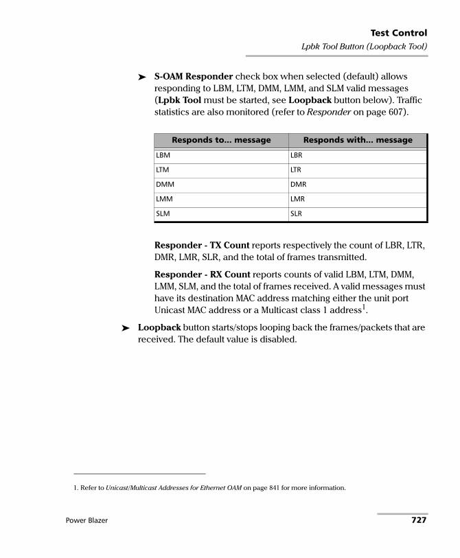
Test ControlLpbk Tool Button (Loopback Tool)
S-OAM Responder check box when selected (default) allows responding to LBM, LTM, DMM, LMM, and SLM valid messages (Lpbk Tool must be started, see Loopback button below). Traffic statistics are also monitored (refer to Responder on page 607).
Responder - TX Count reports respectively the count of LBR, LTR, DMR, LMR, SLR, and the total of frames transmitted.
Responder - RX Count reports counts of valid LBM, LTM, DMM, LMM, SLM, and the total of frames received. A valid messages must have its destination MAC address matching either the unit port Unicast MAC address or a Multicast class 1 address1.
Loopback button starts/stops looping back the frames/packets that are received. The default value is disabled.
Responds to... message Responds with... message
LBM LBR
LTM LTR
DMM DMR
LMM LMR
SLM SLR
1. Refer to Unicast/Multicast Addresses for Ethernet OAM on page 841 for more information.
Power Blazer 727

Test ControlLpbk Tool Button (Loopback Tool)
Interface Tab
Physical Interface
Interface/Rate allows the selection of the loopback tool interface rate: 10/100/1000M Electrical (default), 100M Optical, 1GE Optical, or 10GE LAN.
Connector displays the unused module’s port (on the same transceiver system when applicable) for the selected interface/rate. Ethernet 10/100/1000M electrical is supported on optical connector when using an active copper SFP.
Clock Mode: Displays the clock mode
Internal: Internal clock of the unit (STRATUM 3).
Recovered: Line clock from the input port signal involved in the tool.
Wavelength (nm) indicates, when supported, the detected wavelength.
Modify button, available with tunable transceivers when the TunableOptics software option is enabled, is used to configure the transceiver wavelength.
Wavelength (nm) indicates the actual wavelength value selected.
Use the scroll box and/or the -/+ buttons to select the wavelength. The minimum and maximum wavelength values are displayed.
Channel Number indicates the actual ITU channel number based on ITU Grid.
Frequency (THz) indicates the actual Frequency based on ITU Grid
Channel Spacing (GHz) indicates the difference in frequency between two adjacent channel detected from the transceiver device.
Restore Previous restores the current value present in the transceiver device.
728 88000 Series
Test ControlLpbk Tool Button (Loopback Tool)
RX Power (dBm) indicates the current received power level of the optical laser in dBm.
Green: Power level in range.Yellow: Power level out-of-range.Red: Loss of signal or power level is close to damage.Gray: Invalid operational range value or not supported by the optical transceiver.
Power Range (dBm) indicates, when supported, the received power level range of the optical laser in dBm.
RX Frequency (MHz/GHz) indicates the frequency of the input signal. When no frequency reading is possible, “--” is displayed. Not available when using an active copper SFP.
LINK
Auto-Negotiation check box when selected, enables the link auto-negotiation and allows setting the port Speed, Duplex, Flow Control, and Local Clock parameters. Those settings are not applied immediately to the port, they are used only when the negotiation process is started and take effect only when the auto-negotiation succeeds. However current settings are applied immediately to the port when the Auto-Negotiation check box is cleared. The Auto-Negotiation check box is automatically selected for 1GE Electrical interface and is not configurable. Available with 10/100/1000M Electrical interface.
Speed, available with 10/100/1000M Electrical interface, allows the selection of the interface rate: 10M, 100M, 1GE, or Auto1. The negotiated speed will be displayed next to the Speed field selection.
Duplex choices for 10M and 100M electrical interfaces are Full Duplex (default), Half Duplex, and Auto1. For other rates the Duplex is set to Full Duplex. The negotiated duplex will be displayed next to the Duplex field selection.
1. Auto is only available when the Auto-Negotiation check box is selected.
Power Blazer 729

Test ControlLpbk Tool Button (Loopback Tool)
Flow Control choices are TX, RX, RX and TX, None (default), and Auto1. When the Flow Control is set to None, pause frames received are ignored.
Cable Mode is available with 10/100/1000M Electrical interface.
Manual mode is selected when the Auto-Negotiation check box is cleared and allows selecting the type of cable: MDI (default) for straight through cable or MDIX for crossover cable.
Automatic mode is selected when the Auto-Negotiation check box is selected and allows detecting automatically the MDI or MDIX cable type.
Local Clock is only available with 1GE electrical interface and allows setting the provenance of the clock: Master (default), or Slave, or Auto1.
Network tab
Refer to Network on page 264 for more information.
SFP/SFP+ tab
Refer to CFP/OSFP/QSFP/SFP on page 164 for more information.
1. Auto is only available when the Auto-Negotiation check box is selected.
730 88000 Series

Test ControlReport Button
Report Button The report contains all information about the current test including its setup and results.
Note: Nothing prevents the configuration and alarm/error injection setup while the test has been stopped; thus, the report should be saved/printed before changing any test parameters to avoid printing discrepancy between the configuration and results.
The Report button is available when the test is running or stopped, but the report generation is only possible when the test is stopped. It is possible to save, open, import, export, and delete test report(s).
File Location
Public Documents: Users\Public\Documents\88000-PowerBlazer\Reports
My Documents: Users\<User>\Documents\88000-PowerBlazer\Reports
Others, use Browse to select a specific file location that will be displayed under Others.
Removable Drives is only available when there is a removable disk/key connected to the platform USB port.
Power Blazer 731
Test ControlReport Button
Config/Save Tab
The Config/Save tab allows configuring the report parameters and generating/saving the report.
Tap the Report button and the Config/Save tab.
Job Information parameters, not mandatory, are used to identify the source of the report. Enter the following job information if required: Job ID, Contractor Name, Customer Name, Operator Name, Circuit ID, and Comment. Up to 30 characters are allowed for each parameter at the exception of Comment for which 256 characters are allowed.
Note: When the EXFO Connect Server check box is selected in EXFO Connect Client, the Opeator Name is not editable but can be selected from the EXFO Connect operator list using the Change button.
Restore Default reverts all Job Information parameters back to the default values.
Report Headlines and Content parameters are used to identify the report and are not mandatory. Up to 30 characters are allowed for each parameter.
Report Header could be the company name.
Report Title could be the name of the product, name of test, test number, etc.
Optional Content allows choosing the optional content that can be part of the report:
All (default) includes all optional content to the report.
None excluded all optional content from the report.
Custom allows selecting the optional content to be part of the report.
Choose Content, available when the Optional Content is set to Custom, allows selecting what will be part of the custom content.
732 88000 Series

Test ControlReport Button
Save Report
Auto-Generate File Name check box, when selected (default), automatically generates the report file name which contains the name of the test, the date (YY.MM.DD), and time (HH.MM.SS). Clear the Auto-Generate File Name check box to enter a specific file name.
File Name is the name of the report to be generated.
Save To is the file location where the report file will be saved (see File Location on page 731).
Display Report after Saving check box when selected (default) automatically displays the report once it is generated.
Note: Once generated, the report can be opened from the Open Tab on page 734.
Turn on Report Generation Prompt check box when selected (default) displays a pop-up every time a test case is stopped or completed to ask if a report generation is desired.
Format is the file format for the report: PDF (default) and HTML.
Logo check box when selected (default) allows including a logo to the report. Select the logo picture that will be displayed on the report.
To select another logo, first add a new logo by either copying the logo picture file to the following folder or by using the Import/Export (see page 735) then select the new logo from the list. Documents\88000-PowerBlazer\Reports\Images
Supported picture file formats are jpg, gif, bmp, and png.
Save Report button generates and saves the report on the selected media (Save to).
Power Blazer 733

Test ControlReport Button
Open Tab
Report files can be opened from this page.
Tap the Report button and the Open tab.
To open a saved report:
1. Select the file location (see File Location on page 731).
2. Select the report file from the list.
3. Tap the Open button.
734 88000 Series
Test ControlReport Button
Import/Export Tab
Allows transferring and deleting report files from an external USB media. Also allows importing images that can used as the Logo for reports.
Tap the Report button and select the Import/Export tab.
To import/export a report or image:
1. Select either Report or Image as File Type.
2. Select the file location (see File Location on page 731).
3. From the Copy To drop list, select where the file(s) will be copied.
4. Select the file(s) to be copied by selecting its corresponding check box or tap the (Un)Select All button to select or unselect all files in the list.
5. Tap the Copy button.
6. A confirmation is displayed, tap OK.
To delete a report or image:
1. Select either Report or Image as File Type.
2. Select the file location (see File Location on page 731).
3. Select the file(s) to be deleted by selecting its corresponding check box or tap the (Un)Select All button to select or unselect all files.
4. Tap the Delete button.
5. Tap YES to confirm the deletion.
Power Blazer 735

Test ControlReset Button
Reset Button Tap the Reset button to clear results, statistics, and logger content. The Reset button is only available when the test is running.
Note: The Reset button is not available for EtherSAM, RFC 2544, RFC 6349, Cable Test, and Smart Loopback test applications.
736 88000 Series

Test ControlSave/Load Button
Save/Load Button The Save/Load button allows saving, loading, importing, exporting, and deleting configuration file(s).
Note: Save/Load is only possible when the test is stopped.
File location
My Documents offers two file locations: use Favorites for most commonly used configuration files or Configurations for others.
Users\<User>\Documents\88000-PowerBlazer\ConfigurationUsers\<User>\Documents\88000-PowerBlazer\Configuration\Favorites
Public Documents offers two file locations: use Favorites for most commonly used configuration files or Configurations for others.
Users\Public\Documents\88000-PowerBlazer\ConfigurationUsers\Public\Documents\88000-PowerBlazer\Configuration\Favorites
Others offers two file locations: use Factory Defined for factory defined configuration files or select Browse to create a user defined file location.
Removable Drives is only available when there is a removable disk/key connected to the platform USB port.
Power Blazer 737

Test ControlSave/Load Button
Save/Load Tab
Tap the Save/Load button and the Save/Load tab.
The save function stores the configuration of the module including all test settings to a file.
To save a configuration:
1. Select the file location (see File location on page 737).
2. Tap on the Save button.
3. Type the name of the configuration file to be saved and a description (Config Summary) if needed.
4. Select the Add to Favorites check box to save the configuration file in the Favorites list.
5. Tap OK.
The load function opens and applies the test configuration from a previously saved configuration file.
To load a configuration:
1. Select the file location (see File location on page 737).
2. Select the file from the list.
3. Select or clear the Overwrite report settings check box as required. The Overwrite report settings check box when selected (default) replaces the current report settings by those from the configuration that is loaded.
4. Tap the Load button.
Note: Configuration file has a limited backward compatibility. (Typically the backward compatibility period is one year or three software releases.)
738 88000 Series

Test ControlSave/Load Button
To rename a configuration file:
1. Select the file location (see File location on page 737).
2. Select the file from the list.
3. Tap the Rename button.
4. Change the name of the configuration file.
5. Select the Add to Favorites check box to save the configuration file in the Favorites list.
6. Tap OK.
To delete a configuration file:
1. Select the file location (see File location on page 737).
2. Select the file from the list.
3. Tap the Delete button.
4. Tap Yes to confirm the deletion.
To add a configuration file to the Favorites list:
1. Select Configuration from either My Documents or Public Documents.
2. Select the file from the list.
3. Tap the Add to Favorites button. The file will be moved into the Configurations folder of its corresponding location (either My Documents or Public Documents).
To remove a configuration file from the Favorites list:
1. Select Favorites from either My Documents or Public Documents.
2. Select the file from the list.
3. Tap the Remove from Favorites button. The file will be moved into the Configurations folder of its corresponding location (either My Documents or Public Documents).
Power Blazer 739
Test ControlSave/Load Button
Import/Export Tab Configuration files can be transferred to and from an external USB media as well as deleted.
Tap the Save/Load button and the Import/Export tab.
To import/export a test configuration:
1. Select the source file location (see File location on page 737).
2. From the Copy To drop list, select a destination file location.
3. Select the file(s) to be copied by selecting its corresponding check box or tap the (Un)Select All button to select or unselect all files in the list.
4. Tap the Copy button.
5. A confirmation is displayed, tap OK.
To delete a test configuration:
1. Select the file location (see File location on page 737).
2. Select the file(s) to be deleted by selecting its corresponding check box or tap the (Un)Select All button to select or unselect all files in the list.
3. Tap the Delete button.
4. Tap YES to confirm the deletion.
740 88000 Series

Test ControlStart/Stop|TX Button
Start/Stop|TX Button The Start/Stop|TX button allows starting or stopping manually any test as well as enabling traffic generation.
To start the test:
Tap the Start button to start the test. Start is available when the test is not running.
To stop the test:
Tap the Stop button to stop the test; the traffic generation also stops if it was enabled (TX button). Stop is available when the test is running.
By default, a message is displayed when the test stops asking to generate a report. To disable this feature, see Turn on Report Generation on page 733. Nothing prevents the configuration and alarm/error injection setup while the test has been stopped; thus, if a report is required, it should be saved before changing any test parameters to avoid discrepancy between the configuration and results. See Report Button on page 731 to generate and save a report.
To enable traffic generation:
Tap the TX button to enable traffic generation; the test is also started if it was not running.
Note: While the test is running the TX button is available to enable/disable traffic generation.
Test Application Descripton
Traffic Gen & Mon Enables traffic generation for all enabled streams.
Some conditions, such as ARP not resolved, link down, etc., may prevent the stream to be transmitted.
FlexE BERT Enables traffic generation for all enabled clients (refer to Enable TX from Clients - Profile on page 166).
eCPRI BERT Enables traffic generation.
Power Blazer 741


12 Power Failure RecoveryThe automatic power failure recovery is used to select, configure, and restart1 the test that was running before the power failure; a test that was not running will be selected and configured but not started. To provide this level of protection, the configuration of the current test is automatically saved; the logger, injections, and configuration are periodically saved.
A power failure occurs when the AC power is down (LTB-8 and FTB) while the unit’s battery (FTB) has not sufficient power to keep the unit running. Pressing the platform power button for 5 seconds performs a power down reset and is also considered as a power failure condition. The Windows Hibernate or Sleep mode is also considered as a power failure condition.
When the power returns, the automatic power failure recovery restarts the platform, the module application, then selects, configures, and starts the test if it was running before the power failure.
Note: If the automatic power failure recovery is not used, restarting the module after a power failure automatically selects, configures, and starts the test if it was running before the power failure.
1. Not applicable for iSAM, EtherSAM, RFC 2544, RFC 6349, TCP Throughput, and Cable Test applications; these tests must be started manually.
Power Blazer 743

Power Failure RecoveryEnabling Power Failure Recovery
Enabling Power Failure RecoveryTo enable the automatic power failure recovery:
1. Enable launching the application when starting the platform (refer to the platform user guide for more information):
From ToolBox X, tap on the System Settings button, the Startup Applications button, and select the corresponding module’s check box.
2. moduleEnable the platform automatic power on feature (refer to the platform user guide for more information):
2a. From ToolBox X, tap on the System Settings button and the ToolBox X button.
2b. Select the Power on the unit when AC outlet is connected or after power outage check box.
3. Make sure that Windows does not require a user name and password. The platform is set to require user name and password by default. To disable Windows user name and password:
3a. From ToolBox X, tap on the System Settings button and the Automatic Logon button.
3b. Clear the User must enter a user name and password to use this computer check box and enter the password to confirm.
Note: The power failure recovery is not used when the application closes normally.
744 88000 Series
Power Failure RecoveryWhen Using the Test Timer
When Using the Test Timer Refer to Timer on page 368 for more information on test timer.
The test that was running will be re-created and started after a power failure if conditions described above are met in addition with the following test time conditions:
The start time has not expired during the power failure.
The stop time or the duration has not expired during the power failure.
Power Blazer 745


13 Maintenance To help ensure long, trouble-free operation:
Always inspect fiber-optic connectors before using them and clean them if necessary.
Keep the unit free of dust.
Clean the unit casing and front panel with a cloth slightly dampened with water.
Store unit at room temperature in a clean and dry area. Keep the unit out of direct sunlight.
Avoid high humidity or significant temperature fluctuations.
Avoid unnecessary shocks and vibrations.
If any liquids are spilled on or into the unit, turn off the power immediately, disconnect from any external power source, remove the batteries and let the unit dry completely.
WARNINGThe use of controls, adjustments and procedures, namely for operation and maintenance, other than those specified herein may result in hazardous radiation exposure or impair the protection provided by this unit.
Power Blazer 747

MaintenanceCleaning LC/MPO-n Connectors
Cleaning LC/MPO-n ConnectorsUnder normal circumstances the cleaning of the LC/MPO-n connector is not required. However if the connector shows signs of debris or contamination, cleaning may be required.
To clean a LC/MPO-n connector
1. Use a clean dry air (CDA) or a air gun to blow out the dust or contamination.
2. Re-inspect the connector. For MPO-n optical connector, re-inspect the connector under magnification to make sure that it is clean.
3. If the connector is still not clean, use a commercial cleaner recommended by the transceiver manufacturer.
Note: Refer to the transceiver manufacturer for more detailed cleaning recommendations and instructions.
Battery Safety Information The TA/TA4-... transceiver systems contain a battery for the insertion counter. If the battery status is low, contact your nearest authorized EXFO service center for its replacement.
WARNINGDo not throw batteries into fire or water and do not short-circuit the batteries’ electrical contacts. Do not disassemble.
748 88000 Series

MaintenanceRecalibrating the Unit
Recalibrating the Unit EXFO manufacturing and service center calibrations are based on the ISO/IEC 17025 standard (General Requirements for the Competence of Testing and Calibration Laboratories). This standard states that calibration documents must not contain a calibration interval and that the user is responsible for determining the re-calibration date according to the actual use of the instrument.
The validity of specifications depends on operating conditions. For example, the calibration validity period can be longer or shorter depending on the intensity of use, environmental conditions and unit maintenance, as well as the specific requirements for your application. All of these elements must be taken into consideration when determining the appropriate calibration interval of this particular EXFO unit.
Under normal use, the recommended interval for your module is: 2 years.
For newly delivered units, EXFO has determined that the storage of this product for up to six months between calibration and shipment does not affect its performance (EXFO Policy PL-03).
Power Blazer 749
MaintenanceRecycling and Disposal
To help you with calibration follow-up, EXFO provides a special calibration label that complies with the ISO/IEC 17025 standard and indicates the unit calibration date and provides space to indicate the due date. Unless you have already established a specific calibration interval based on your own empirical data and requirements, EXFO would recommend that the next calibration date be established according to the following equation:
Next calibration date = Date of first usage (if less than six months after the calibration date) + Recommended calibration period (2 years)
To ensure that your unit conforms to the published specifications, calibration may be carried out at an EXFO service center or, depending on the product, at one of EXFO’s certified service centers. Calibrations at EXFO are performed using standards traceable to national metrology institutes.
Note: You may have purchased a FlexCare plan that covers calibrations. See the Service and Repairs section of this user documentation for more information on how to contact the service centers and to see if your plan qualifies.
Recycling and Disposal
For complete recycling/disposal information, visit the EXFO Web site at www.exfo.com/recycle.
This symbol on the product means that you should recycle or dispose of your product (including electric and electronic accessories) properly, in accordance with local regulations. Do not dispose of it in ordinary garbage receptacles.
750 88000 Series

14 Troubleshooting Solving Common Problems
Before calling EXFO’s technical support, please read the following common problems that can occur and their respective solution.
Problem Possible Cause Solution
Optical Laser LED is off and the connector is not generating the signal.
The Laser On option is disabled. Ensure that the Laser button is enabled (On).
There is a configuration mismatch between the inserted transceiver and the rate selected for the test case.
Ensure that the transceiver is supporting the rate used for the test case.
The transceiver is not compatible with the module.
Ensure to use a compatible transceiver. Refer to Modify Structure Button on page 119 and Specifications on page 759.
Unable to edit the Operator Name in Generate Report page.
This is the expected behavior when the EXFO Connect Server check box is selected in EXFO Connect Client, since the Operator Name is selected from the EXFO Connect operator name list.
To edit the Operator Name: - Clear the EXFO Connect Server check box from EXFO Connect Client. - Close and restart the module application.
Transceiver System (TA4) not detected.
TA4 is not inserted properly. Remove the TA4 from the 88460 module, and carefully follow the insertion procedure described on page 15.
Power Blazer 751

TroubleshootingContacting the Technical Support Group
Contacting the Technical Support GroupTo obtain after-sales service or technical support for this product, contact EXFO at one of the following numbers. The Technical Support Group is available to take your calls from Monday to Friday, 8:00 a.m. to 7:00 p.m. (Eastern Time in North America).
For detailed information about technical support, and for a list of other worldwide locations, visit the EXFO Web site at www.exfo.com.
If you have comments or suggestions about this user documentation, you can send them to [email protected].
To accelerate the process, please have information such as the name and the serial number (see the product identification label), as well as a description of your problem, close at hand.
TransportationMaintain a temperature range within specifications when transporting the unit. Transportation damage can occur from improper handling. The following steps are recommended to minimize the possibility of damage:
Pack the unit in its original packing material when shipping.
Avoid high humidity or large temperature fluctuations.
Keep the unit out of direct sunlight.
Avoid unnecessary shocks and vibrations.
Technical Support Group400 Godin AvenueQuebec (Quebec) G1M 2K2CANADA
1 866 683-0155 (USA and Canada)Tel.: 1 418 683-5498Fax: 1 418 [email protected]
752 88000 Series

15 WarrantyGeneral Information
EXFO Inc. (EXFO) warrants this equipment against defects in material and workmanship for a period of one year from the date of original shipment. EXFO also warrants that this equipment will meet applicable specifications under normal use.
During the warranty period, EXFO will, at its discretion, repair, replace, or issue credit for any defective product, as well as verify and adjust the product free of charge should the equipment need to be repaired or if the original calibration is erroneous. If the equipment is sent back for verification of calibration during the warranty period and found to meet all published specifications, EXFO will charge standard calibration fees.
THIS WARRANTY IS IN LIEU OF ALL OTHER WARRANTIES EXPRESSED, IMPLIED, OR STATUTORY, INCLUDING, BUT NOT LIMITED TO, THE IMPLIED WARRANTIES OF MERCHANTABILITY AND FITNESS FOR A PARTICULAR PURPOSE. IN NO EVENT SHALL EXFO BE LIABLE FOR SPECIAL, INCIDENTAL, OR CONSEQUENTIAL DAMAGES.
IMPORTANTThe warranty can become null and void if:
unit has been tampered with, repaired, or worked upon by unauthorized individuals or non-EXFO personnel.
warranty sticker has been removed.
case screws, other than those specified in this guide, have been removed.
case has been opened, other than as explained in this guide.
unit serial number has been altered, erased, or removed.
unit has been misused, neglected, or damaged by accident.
Power Blazer 753

WarrantyLiability
LiabilityEXFO shall not be liable for damages resulting from the use of the product, nor shall be responsible for any failure in the performance of other items to which the product is connected or the operation of any system of which the product may be a part.
EXFO shall not be liable for damages resulting from improper usage or unauthorized modification of the product, its accompanying accessories and software.
754 88000 Series

WarrantyExclusions
ExclusionsEXFO reserves the right to make changes in the design or construction of any of its products at any time without incurring obligation to make any changes whatsoever on units purchased. Accessories, including but not limited to fuses, pilot lamps, batteries and universal interfaces (EUI) used with EXFO products are not covered by this warranty.
This warranty excludes failure resulting from: improper use or installation, normal wear and tear, accident, abuse, neglect, fire, water, lightning or other acts of nature, causes external to the product or other factors beyond the control of EXFO.
CertificationEXFO certifies that this equipment met its published specifications at the time of shipment from the factory.
IMPORTANTIn the case of products equipped with optical connectors, EXFO will charge a fee for replacing connectors that were damaged due to misuse or bad cleaning.
Power Blazer 755
WarrantyService and Repairs
Service and RepairsEXFO commits to providing product service and repair for five years following the date of purchase.
To send any equipment for service or repair:
1. Call one of EXFO’s authorized service centers (see EXFO Service Centers Worldwide on page 757). Support personnel will determine if the equipment requires service, repair, or calibration.
2. If equipment must be returned to EXFO or an authorized service center, support personnel will issue a Return Merchandise Authorization (RMA) number and provide an address for return.
3. If possible, back up your data before sending the unit for repair.
4. Pack the equipment in its original shipping material. Be sure to include a statement or report fully detailing the defect and the conditions under which it was observed.
5. Return the equipment, prepaid, to the address given to you by support personnel. Be sure to write the RMA number on the shipping slip. EXFO will refuse and return any package that does not bear an RMA number.
Note: A test setup fee will apply to any returned unit that, after test, is found to meet the applicable specifications.
After repair, the equipment will be returned with a repair report. If the equipment is not under warranty, you will be invoiced for the cost appearing on this report. EXFO will pay return-to-customer shipping costs for equipment under warranty. Shipping insurance is at your expense.
Routine recalibration is not included in any of the warranty plans. Since calibrations/verifications are not covered by the basic or extended warranties, you may elect to purchase FlexCare Calibration/Verification Packages for a definite period of time. Contact an authorized service center (see EXFO Service Centers Worldwide on page 757).
756 88000 Series

WarrantyEXFO Service Centers Worldwide
EXFO Service Centers WorldwideIf your product requires servicing, contact your nearest authorized service center.
To view EXFO's network of partner-operated Certified Service Centers nearest you, please consult EXFO's corporate website for the complete list of service partners: http://www.exfo.com/support/services/instrument-services/exfo-service-centers.
EXFO Headquarters Service Center400 Godin AvenueQuebec (Quebec) G1M 2K2CANADA
1 866 683-0155 (USA and Canada)Tel.: 1 418 683-5498Fax: 1 418 [email protected]
EXFO Europe Service CenterWinchester House, School LaneChandlers Ford, Hampshire S053 4DGENGLAND
Tel.: +44 2380 246800Fax: +44 2380 [email protected]
EXFO Telecom Equipment(Shenzhen) Ltd.3rd Floor, Building C,FuNing Hi-Tech Industrial Park, No. 71-3, Xintian Avenue, Fuhai, Bao’An District, Shenzhen, China, 518103
Tel: +86 (755) 2955 3100Fax: +86 (755) 2955 [email protected]
Power Blazer 757


A Specifications IMPORTANT
The following general specifications can change without notice. The information presented in this section is provided as a reference only. To obtain this product’s most recent technical specifications, visit the EXFO Web site at www.exfo.com.
CAUTIONThe operation and storage temperatures, as well as the altitude, and humidity of some modules may differ from those specified for your platform. In this case, always ensure that you comply with the most restrictive conditions (either from this section or in the platformuser guide).
Power Blazer 759

Specifications
General Specifications
Transceiver System
Specification 8870/8880/ 88200NGE 88260 88400NGE 88460
Temperature Operating: 0 °C to 40 °C (32 °F to 104 °F)Storing: -40 °C to 70 °C (-40 °F to 158 °F)
Relative humidity 0 % to 95 %, non-condensing
Maximum operation altitude
5000 m (16000 ft)
Pollution degree 3
Measurement category
Not rated for measurement categories II, III, or IV
Specification TA-QSFP28 TA4-CFP8 TA4-QSFP-DD Temperature Operating: 0 °C to 40 °C (32 °F to 104 °F)
Storing: -40 °C to 70 °C (-40 °F to 158 °F)
Relative humidity 0 % to 95 %, non-condensing
Maximum operation altitude 5000 m (16000 ft)
Pollution degree 3
Measurement category Not rated for measurement categories II, III, or IV
760 88000 Series

B GlossaryAcronym List
A
B
10B_ERR 10B_Error
200GAUI-4 200 Gbit/s Attachment Unit Interface - 4 physical lanes
400GAUI-16 400 Gbit/s Attachment Unit Interface - 16 physical lanes
400GAUI-8 400 Gbit/s Attachment Unit Interface - 8 physical lanes
? Help
AC Alternating Current
ACH Associated Channel Header
ACT Activity
AIS Alarm Indication Signal
AMI Alternate Mark Inversion
AOC Active Optical Cable
APS Automatic Protection Switching
ATM Asynchronous Transfer Mode
AU-n Administrative Unit-n
AUI Attachment Unit Interface
B-VLAN Backbone Virtual Local Area Network
B8ZS Bipolar with 8 Zero Substitution
BB Buffer to Buffer
BBE Background Block Error
BBER Background Block Error Ratio
BDI Backward Defect Indication
Power Blazer 761

GlossaryAcronym List
C
BDP Bandwidth Delay Product
BEI Backward Error Indication
BER Bit Error Rate
BERT Bit Error Rate Test
BIAE Backward Incoming Alignment Error
BIP Bit-Interleaved Parity
bit/s Bit per second
BSD Backward Signal Degrade
BSF Backward Signal Fail
C Current
C-DCI Client - Defect Clear Indication
C-FDI Client - Forward Defect Indication
C-LOS Client - Loss Of Signal
C-RDI Client - Remote Defect Indication
C-VLAN Client/Customer Virtual Local Area Network
CAUI 100 Gbit/s Attachment Unit Interface
CAGE Commerce And Government Entities
CBR Constant Bit Rate
CBS Committed Burst Size
CC Continuity Check
CCM Continuity Check Message
CE Congestion Encountered
CD Connectivity Defect
CDF Client Data Frames
CE European Conformity
cHEC core Header Error Check
762 88000 Series

GlossaryAcronym List
D
CID Channel IDentifier
CIR Committed Information Rate
CLK Clock
CMF Client Management Frames
CORR Correctable
COS Class Of Service
CPRI Common Public Radio Interface
CRC Cyclic Redundancy Check
CRC-4 Cyclic Redundancy Check on 4 bits
CRITIC Critical
CSF Client Signal Fail
CSV Comma Separated Value
cTE constant Time Error
CTLE Continuous Time Linear Equalization
CV Code Violation
CW Code Word
DA Destination MAC Address
DAC Direct Attached Copper
DAPI Destination Access Point Identifier
dBm Decibel - milliwatts
DCC Data Communications Channel
DCI Defect Clear Indication
DFE Decision Feedback Equalizer
DM Degraded Minutes
DMM Delay Measurement Message
DMR Delay Measurement Reply
Power Blazer 763

GlossaryAcronym List
E
DS0 Digital Signal-level 0 (64 Kbit/s)
DS1 Digital Signal-level 1 (1.544 Mbit/s)
DS3 Digital Signal-level 3 (44.736 Mbit/s)
DSn Digital Signal-level n
DSP Digital signal processor
DST Destination
DTE Data Terminal Equipment
dTEH dynamic Time Error High
DUS Don’t Use for Synchronization
DUT Device Under Test
E-VLAN Extended Virtual Local Area Network
E0 European standard for digital transmission-level 0 (64 Kbit/s).
E1 European standard for digital transmission-level 1 (2.048 Mbit/s).
E2 European standard for digital transmission-level 2 (8.448 Mbit/s).
E3 European standard for digital transmission-level 3 (34.368 Mbit/s).
E4 European standard for digital transmission-level 4 (139.264 Mbit/s).
EB Errored Block
EBS Excess Burst Size
EC Error Count
ECN Explicit Congestion Notification
ECT ECN Capable Transport
EEC Ethernet Equipment Clock
EFS Error Free Second
eHEC extension Header Error Check
EIR Excess Information Rate
EoE Ethernet over Ethernet
764 88000 Series

GlossaryAcronym List
F
EoOTN Ethernet over OTN
ERDI Enhanced RDI
ES Errored Second
ESMC Ethernet Synchronization Message Channel
ESF Extended Superframe
ESR Errored Second Ratio
ETag Extended Tag
EUI EXFO Universal Interfaces
EXI Extension Header Identifier
EXM Extension Header Mismatch
EXT CLK External Clock
FAS Frame Alignment Signal
FC Fibre Channel
FCC Federal Communications Commission
FCB Frame Clock Burst
FCS Frame Check Sequence
FD Frame Delay
FDI Forward Defect Indication
FEC Forward Error Correction
FEC-UNCOR-CW
FEC Uncorrectable Codeword
FEC-COR-CW FEC Correctable Codeword
FEC-SYMB FEC Symbol
FFE Feed-Forward Equalizer
FlexE Flex Ethernet
FlexO Flexible Optical Transport Network
Power Blazer 765

GlossaryAcronym List
G
H
FLOGI Fabric Login
FLR Frame Loss Ratio
FOIC FlexO Interface
fps Frame Per Second
FSD Forward Signal Degrade
FSF Forward Signal Fail
GAL Generic Associated Channel Label
GE Gigabit Ethernet
Gbit/s Gigabit per second
GCC General Communication Channel
GFP Generic Framing Procedure
GFP-F GFP - Framed
GFP-T GFP - Transparent
GHz Giga Hertz
GIDM Group ID Mismatch
GM Grand Master
GMP Generic Mapping Procedure
GMP OOS GMP Out of Synchronization
GUA Global IPv6 Address
GUI Graphical User Interface
H History
HDB3 High Density Bipolar 3 Code
HDMI High Definition Multimedia Interface
766 88000 Series

GlossaryAcronym List
I
J
HDTV High Definition Television
Hi-BER High-Bit Error Ratio
Hi-BER1027B High-Bit Error Ratio 1027 Blocks
HP- High Order Path -
Hz Hertz
IAE Incoming Alignment Error
IAIS Incoming Alarm Indication Signal
ID Identification
IEC International Electrotechnical Commission
IEC Incoming Error Count
IEEE Institute of Electrical & Electronics Engineers
IFDV Inter-Frame Delay Variation
IIDM Instance ID Mismatch
IN Input
IP Internet Protocol
IPDV Inter Packet Delay Variation
IPTV Internet Protocol Television
IPG Interframe Gap
IPv4 Internet Protocol version 4
IPv6 Internet Protocol version 6
ISM In-Service Monitoring
JC Justification Control
Power Blazer 767

GlossaryAcronym List
L
-L Line
L Deg SER Det Local Degraded SER Detected
L Deg SER Rcd Local Degraded SER Received
L2CP Layer 2 Control Protocol
LAN Local Area Network
LBM Loopback Message
LBR Loopback Reply
LCD Loss of Code-Group Delineation
LCK Locked
LED Light-Emitting Diode
LER Label Edge Router
lb Pound
LBO Line Build Out
LDEQ PAM-4 Level Dependent Equalizer
LFD Loss of Frame Delineation
LLA Link-Local IPv6 Address
LLC Logical Link Control
LLM Logical Lane Marker
LMM Loss Measurement Message
LMR Loss Measurement Reply
LOA Loss Of Alignment
LOAML Loss of Alignment Marker Lock
LOAML1027B Loss of Alignment Marker Lock 1027 Blocks
LOBL Loss of Block Lock
LOBL1027B Loss of Block Lock 1027 Blocks
LOC Loss Of Clock
LOC Lane Loss Of Clock Lane
768 88000 Series

GlossaryAcronym List
M
LOCS CSF Loss of Client Signal - Client Signal Fail
LOCCS CSF Loss of Client Character Synchronization - Client Signal Fail
LOCWS Loss of CW Synchronization
LOF Loss Of Frame
LOFLOM Loss of Frame Loss Of Multiframe
LOL Loss of Lane Alignment
LOM Loss Of Multiframe
LOOMFI Loss of OPU Multi-Frame Identifier
LOPPS-L Loss Of Pulse Per Second - Local
LOPPS-R Loss Of Pulse Per Second - Remote
LOP Loss Of Pointer
LOR Loss Of Recovery
LOS Loss Of Signal
LSB Least-Significant Bit
LSP Label Switch Path
LSR Label Switching Router
LSS Loss of Sequence Synchronization
LTC Loss of Tandem Connection
LTM Link Trace Message
LTR Link Trace Reply
m Minute
m Meter
MA Maintenance Association
MAC Media Access Control
MAID Maintenance Association Identification
MAPM MAP Mismatch
Power Blazer 769

GlossaryAcronym List
N
Mbit/s Megabit per second
MD Maintenance Domain
MDI Media Dependant Interface (straight through Ethernet cable)
MDIO Management Data Input/Output
MDIX Media Dependant Interface Crossover (crossover Ethernet cable)
ME Maintenance Entity
MEG ME Group
MEG ID MEG Identification
MEP MEG End Point
MFAS Multiframe Alignment Signal
MHz Megahertz
MIP MEG Intermediate Point
MPD Mean Path Delay
MPLS Multiprotocol Label Switching
MS Multiplex Section
MSA Multisource Agreement
MSB Most-Significant Bit
MSEQV Marker Sequence Violation
msg/s Message per second
MSIM Multiplex Structure Identifier Mismatch
MTIE Maximum Time Interval Error
MTU Maximum Transfer Unit
NAT Network Address Translation
NATO North Atlantic Treaty Organization
nAUI 200GAUI-4, 400GAUI-8/16, CAUI, or XLAUI
NDF New Data Flag
770 88000 Series

GlossaryAcronym List
O
NE Network Element
NID Network Interface Device
NJO Negative Justification Opportunity
nm Nanometer
OAM Operation, Administration, and Maintenance
OBSAI Open Base Station Architecture Initiative
OC- Optical Carrier-
OCI Open Connection Indication
ODI Outgoing Defect Indication
ODU Optical Data Unit
OEI Outgoing Error Indication
OH Overhead
OLA Out-of-Lane-Alignment
OMFI OPU Multi-Frame Identifier
OOMFI Out of OPU Multi-Frame Identifier
OOF Out-Of-Frame
OOM Out-Of-Multiframe
OOR Out-Of-Recovery
OOS Generic Mapping Procedure Out Of Synchronization
OOS Out-Of-Sequence
OOSM Out-Of-Service Monitoring
OPU Optical Payload Unit
OTL Optical channel Transport Lane
OTN Optical Transport Network
OTU Optical Transport Unit
Power Blazer 771

GlossaryAcronym List
P
OUI Organizationally Unique Identifier
OUT OUTput
-P Path
PBB-TE Provider Backbone Bridges with Traffic Engineering
PC Personal Computer
PCD Path Connectivity Defect
PCP Priority Code Point
PCS Physical Coding Sublayer
PD Payload Defect
PDI Payload Defect Indication
PDU Protocol Data Unit
PE Provider Edge
pFCS payload Frame Check Sequence
PFI Payload Frame Check Sequence Identifier
PHY Physical Layer Device
PLI Payload Length Indicator
PLM Payload Label Mismatch
PLOGI Port Login
PM Performance Monitoring
PNO Provisionable by the Network Operator
POS Position Field
POSV Position Field Violation
PPD Path Payload Defect
ppm or PPM parts per million
PRBS Pseudo Random Bit Sequence
PRS Primary Reference Source/Clock
772 88000 Series

GlossaryAcronym List
Q
R
PRC Primary Reference Source/Clock
PSD Path Server Defect
PSI Payload Structure Identifier
PTI Payload Type Identifier
PTP Precision Time Protocol
Ptr. Incr. Pointer Increment
Ptr. Decr. Pointer Decrement
PTSF Packet Timing Signal Fail
PW Pseudo-Wire
QL Quality Level
QoS Quality of Service
QSFP Quad Small Form Factor Pluggable
R Deg SER Remote Degraded SER
RC PAM-4 Reflection Canceller
RDI Reverse Defect Indication
RDI Remote Defect Indication
REI Remote Error Indicator
RES Reserved
RFI Remote Failure Indication
RMA Return Merchandise Authorization
RPF Remote PHY Fault
RPn Reference Point n
RS- Regenerator Section
Power Blazer 773

GlossaryAcronym List
S
RTD Round Trip Delay
RTT Round Trip Time
RX Receive
s second
-S Section
S-OAM Service - OAM
S-VLAN Service Virtual Local Area Network
SA Source MAC Address
SAPI Source Access Point Identifier
SB Superblock
SD Server Defect
SDH Synchronous Digital Hierarchy
SDT Service Disruption Time
SDTV Standard Digital Television
SEF Severely Errored Framing
SEP Severely Errored Period
SEQV Sequence Violation
SES Severely Errored Second
SESR Severely Errored Second Ratio
SF Superframe
SFN System Frame Number
SFP Small Form Factor Pluggable
SI International System
SID Service Instance Identifier
SLA Service-Level Agreement
SLC PAM-4 Slicer
774 88000 Series

GlossaryAcronym List
T
SLM Synthetic Loss Message
SLR Synthetic Loss Reply
SM Section Monitoring
SMA Sub-Miniature A Connector
SMC SONET Minimum Clock Traceable
SNAP Sub Network Access Point
SOF Start Of Frame
SONET Synchronous Transport Signal
SP Service Provider
SPE Synchronous Payload Envelope
SR4 Short Reach (4 Lanes)
SRC Source
SSM Synchronization Status Messaging
ST1 Stratum 1 Traceable
ST2 Stratum 2 Traceable
ST3 Stratum 3 Traceable
ST3E Stratum 3E Traceable
STM Synchronous Transport Module
STS Synchronous Transport Signal
STU Synchronized - Traceability Unknown
SYMB Symbol
SW Software
TC Traffic Class
TCM Tandem Connection Monitoring
TCP Transport Control Protocol
TDEV Time Deviation
Power Blazer 775

GlossaryAcronym List
U
TE Time Error
tHEC type Header Error Check
THz Terahertz
TIE Time Interval Error
TIM Trace Identifier Mismatch
TLV Type, Length, and Value
TNC Transit Node Clock Traceable
TOS Type Of Service
TST Test PDU
TTI Trail Trace Identifier
TTL Time To Live
TU Tributary Unit
TUG Tributary Unit Group
TX Transmit
UAS Unavailable Second
UDP User Data Protocol
UNCORR Uncorrectable
UNEQ Unequipped
UPI User Payload Identifier
UPM User Payload Mismatch
μs microsecond
USA United States of America
UTP Unshielded Twisted Pairs
776 88000 Series

GlossaryAcronym List
V
W
X
V VT
VC Virtual Container
VGA Voltage Gain Amplifier
VIOL Violation
VLAN Virtual Local Area Network
VoIP Voice over Internet Protocol
VT Virtual Tributary
VTG VT Group
WAN Wide Area Network
WIS WAN Interface Sublayer
WWN World Wide Name
XLAUI 40 Gbit/s Attachment Unit Interface
Power Blazer 777

Glossary10G Ethernet Client
10G Ethernet Client The OTN Overclocked technology provides the capability to transparently transport 10G base-R Ethernet signals into OPU2 as specified in ITU-T. Two optical rates are provided:
11.0957 Gbits/s, +/- 100 ppm, designated OTU2e
11.0491 Gbits/s, +/- 100 ppm, designated OTU1e
The OTU2e uses the mapping scheme of CBR10G into OPU2 as defined in G.709. The client signal, 10GE LAN and the OPU fixed stuff bytes are accommodated into an OPU-like signal designated OPU2e. This signal is then wrapped in an ODU2e and then in an OTU2e signal.
The OTU1e uses the mapping scheme of CBR2G5 into OPU1 as defined in G.709. The client signal, 10GE LAN is accommodated into an OPU-like signal designated OPU1e (note that the fixed stuff bytes are not left free) this is why the 10GE signal can be transported at a lower rate than OTU2e. This signal is then wrapped in an ODU1e and then in an OTU1e signal.
The transparent transport of the 10G base-R means that the full 10G Ethernet data rate i.e. 10.3125 Gbit/s is transported over OTN. This means that the following information is transported:
PCS 64B/66B coded information
IPG (inter-frame filler), MAC FCS, Preamble and SFD (start of frame delimiter) and Ordered Sets (Remote Fault indication)
The OTN clocking is derived from the Ethernet client signal which is +/- 100 ppm, this is outside the clock tolerance allocated by the G.709 standard which translates in unspecified jitter performance thus limiting the application to Point to Point data path.
778 88000 Series

Glossary10G Ethernet Client
The following figure presents a typical network application.
Power Blazer 779

Glossary10G Ethernet Client
The following figure presents a typical test application.
The Ethernet layer provides the equivalent functionality of the BERT Framed Layer 2 Test application supported on EXFO’s Datacom product family with the particularity that there is no Ethernet Physical port as such. The Ethernet frame has its Ethertype field set to 0x88B7.
780 88000 Series

Glossary1588 PTP
1588 PTP The goal of the IEEE 1588 Precision Time Protocol (PTP) is to provide Network Synchronization using a packet based distribution mechanism.
Depending on the system application the Network Synchronization may require phase and frequency synchronization. 1588 PTP has the capability to deliver both by allowing a Client clock to track a Master clock in phase (time of day) and in frequency.
The protocol is based on exchange of time stamps between the Master clock and the Client clock. Two methods have been defined in the 1588 PTP standard:
Delay Request-Response mechanism uses message Sync, Delay Request, Delay Response, and Follow Up (if required).
Power Blazer 781

Glossary1588 PTP
Peer Delay mechanism uses message Pdelay Request, Pdelay Response, and if required Pdelay Response Follow Up. This mechanism is restricted to topologies where each peer-to-peer port communicates PTP messages with, at most, one other such port. Peer Delay is not supported by the Telecom Profile.
In order to minimize traffic on the network, PTP can operate in different modes:
Two-way operation uses Sync/Follow Up, Delay Request, and Delay Response messages.
One-way operation uses only the Sync/Follow Up messages. This mode of operation is used to synchronize a Client clock in frequency only. The Master clock and Client clock phases are not aligned.
Two-step clock mode uses the optional Follow Up message to carry the T1 time stamp.
One-step clock mode uses the Sync message to carry the T1 time stamp; no Follow Up message is transmitted by the Master clock, therefore less traffic on the network.
Client clock synchronization is achieved with a 2-part process:
Part 1: Path delay measurement using bidirectional messages
Mean path delay measurement (MPD) = ((T2-T1) + (T4-T3)) / 2
Part 2: Clock phase offset correction
Offset = (T2-T1) - MPD
The offset information is used by the Client clock to adjust the frequency of its oscillator in order to keep the phase offset close to zero.
782 88000 Series

Glossary1588 PTP
The 1588 PTP supports the following Master/Client communication; however Unicast is used for the Telocom Profile.
Multicast: A Master clock sends its Sync/Follow Up and Delay Response in a multicast mode. A Client can collect information from many Master clocks and select the Master clock that is best suited for its application.
Unicast: A dedicated communication link is established between the Master and the Client clock. This mode of operation requires a negotiation which is initiated by the Client clock.
The 1588 PTP messages can be mapped on the following protocols; however UDP IPv4 is used for the Telecom Profile.
UDP/IPv4
UDP/IPv6
Ethernet
1588 PTP Profiles
The purpose of a PTP profile is to allow organizations to specify particular selections of attribute values and optional features of PTP that, when using the same transport protocol, inter-work and achieve a performance that meets the requirements of a given application.
Power Blazer 783

Glossary1588 PTP
Telecom Profile G.8265.1
The Telecom Profile G.8265.1 is designed for frequency synchronization in Telecom network applications. The main attributes of this profile are:
Unicast communication with the Grand Master
UDP/IPv4 network layer
With the Telecom Profile, the Client Clock initiates the communication to the Master Clock by making a request for service that consists of sending Signaling messages containing a REQUEST UNICAST TRANSMISSION TLV to the IP address of the Master Clock.
If the Master Clock has sufficient capacity to handle the Client Clock request, it responds with a signaling message containing a GRANT UNICAST TRANSMISSION TLV.
The REQUEST UNICAST TRANSMISSION TLV contains several parameters:
messageType is the type of service being requested: Announce, Sync, or Delay Response.
durationField is the duration of the requested service: 300 seconds by default and configurable from 60 to 1000 seconds.
logInterMessagePeriod: transmission rate of the requested messages.
If the Master Clock denies the request, e.g. because it has no remaining capacity, it will send back a GRANT UNICAST TRANSMISSION TLV with the durationField set to zero.
In the event of being denied service by a Master Clock, or receiving no response to the service request, a Client Clock should wait a minimum of one second before issuing a new Unicast request to that Master Clock.
As Unicast service is only granted for a limited time, the Client Clock must re-request service periodically, before the expiration of the current grant. The Client Clock should reissue the request sufficiently far in advance of the expiration to allow the request to be repeated at least twice if no grant is received. This parameter is called Unicast renewal interval.
784 88000 Series

Glossary1588 PTP
The following diagram shows the sequence of message exchange between a Client Clock and a Master Clock. First, the Client request Unicast Announce message service. When this is granted and the first Announce message is received, the Client can check the QL value conveyed in the clockClass field of the message. From there the Client Clock can request service for Sync and Delay Request messages. Service requests are reissued at the end of the Announce duration interval to ensure continuity of service.
Power Blazer 785

Glossary1588 PTP
Telecom Profile G.8275.1
The Telecom Profile G.8275.1 is designed for time/phase synchronization in telecom network applications. The main attribute of this profile are:
Full timing support from the network, i.e. all network nodes are boundary clocks
Slave clocks synchronize with its respective upstream Boundary Clock
1588 messages are mapped on Ethernet Multicast
A very important distinction that has to be made compared with G.8265.1 is the mandatory use of Boundary Clocks with G.8275.1. With G.8265.1, network nodes such as Ethernet Switches or Routers were not required to be PTP aware. With G.8275.1, all network nodes needs to be PTP aware. This means that regular Ethernet Switches or Routers cannot be used. Switches/Routers are required to include the Boundary Clock functionality.
786 88000 Series

GlossaryCPRI
CPRI
Overview
Traditional mobile installations are bulky (use thick coaxial cables) and require a lot of power to operate (there is a huge power loss in the coaxial cabling which often requires the use of Tower Mounted Amplifiers) as outlined in the following figure.
Pressures on the Mobile Network Operators (MNO) to reduce their capital, operational cost, and increase coverage are at the heart of a revolution in the mobile network. To address the situation, a concept of decomposition of the radio base station has been developed where the radio basic functions and its ability to transmit and receive radio modulated signals are separated. In such a distributed environment a protocol is required to maintain synchronization and management capabilities as well as transporting the user traffic between the simplified Base Transceiver Station (BTS) and its Remote Radio Head (RRH).
Power Blazer 787
GlossaryCPRI
This protocol called Common Public Radio Interface (CPRI) separates a traditional radio base station configuration into two separate elements: Radio Equipment Control (REC) and the Radio Equipment (RE). The REC processes the baseband radio digital information and performs the control of the Radio Equipment. The RE converts the digital radio information into radio frequency signals transported over the air interface (antenna). The REC and RE are interconnected by a point-to-point link. This link carries the CPRI protocol and is known in the industry as the fronthaul as opposed to the backhaul that is the WAN bringing the network traffic to the base station.
The CPRI link can be extended over several kilometers as it uses fiber optics, in fact it can be deployed up to 40 km although most field installations at the moment of this writing are below 10 km.
The CPRI standard covers the physical and data link layers only. This specific focus provides additional development freedom to the various vendors to implement proprietary functions at upper layers.
788 88000 Series

GlossaryCPRI
Functional Description
As mentioned earlier, CPRI remotely locates the RE from the REC. This means that the RE must be controlled, managed and synchronized from the REC in addition to transporting the User information (Voice and user application data) and all that on the same digital link. As such, CPRI is composed of 3 communication flows multiplexed into a single serial signal transmitted in the same optical fiber as illustrated in the following figure.
An electrical link is also available from CPRI but it is typically used for base station shelf interconnection. Since a state machine drives the link parameters (rates, protocol, and C&M channel) alignment, a BTS (defined as Master in the standard) and RRH (defined as Slave in the standard) interfaces are defined where the Master initiates the negotiation procedure necessary to achieve this alignment.
Synchronization: Provides precise frequency and frame timing alignment from BTS to RRH to ensure accurate frequency and timing of the RF signal transmission and reception on the Air Interface. In essence, it provides the reference frequency for the RE.
Control & Management (C&M): Management of the link between the REC and RE as well as control over radio functions such as alarms and power.
User: Also known as IQ Data, represents the voice and data information that is exchanged by end-User Equipment (UE)
Power Blazer 789

GlossaryCPRI
CPRI Model
The CPRI Model revolves around the 3 communication flows described above. CPRI defines only the Layer 1 and Layer 2 associated to these communication flows as outlined in the following figure.
The User Data Plane contains mostly voice/data traffic in the form of IQ Data samples. IQ Data digitally encodes the change in amplitude/phase of a user device modulated signal sampled at the RE antenna.
The Control & Management Plane maintains the CPRI link itself and provides the facility to manage the operation of the RE radio functions. It is done through the L1 Inband Protocol which provides a bit oriented channel defined to support link specific alarms (R-LOS, R-LOF, …). Also, the Ethernet/HDLC channel offer two OAM&P channel alternatives which are respectively high and low bandwidth with rates configurable based on the CPRI line interface rate. These carry proprietary information between the REC and RE. Some Vendor Specific overhead is also available.
Finally, the Synchronization flow ensures frequency stability and offers the overhead necessary for frame alignment between the REC and RE to ensure hitless channel or frequency hopping. All these flows are time division multiplexed onto one optical fiber for CPRI field deployments such as Distributed Antenna Systems (DAS).
790 88000 Series

GlossaryCPRI
Physical Interface
CPRI offers 8 options in terms of interface rates. Rates below 10G uses 8B/10B line coding as per CPRI V6.0 while rates above 10G use 64B/66B coding. Depending on the rates used, scrambling is optional. Depending on the CPRI signal structure (Framed or Unframed) the scrambling is either manually configured or negotiated.
Option Rate Line Coding Protocol Version (Scrambling)
1 614.4 Mbit/s 8B/10B Version 1: No scrambling
2 1.2288 Gbit/s
3 2.4576 Gbit/s
4 3.0720 Gbit/s
5 4.9152 Gbit/s Version 1: No scrambling
Version 2: Scrambling
(Scrambling is optional)6 6.1444 Gbit/s
7 9.8304 Gbit/s
8 10.1376 Gbit/s 64B/66B Version 1: Scrambling
Power Blazer 791

GlossaryEthernet Cables
Ethernet Cables Minimum Category 3 cable is required for 10Base-T connection while Category 5 cable is required for 100Base-TX and 1000Base-T connections.
Maximum cable length (between two nodes) for 10Base-T, 100Base-TX, or 1000Base-T connection is 328 feet (100 meters).
Straight Through Cable (10/100 Mbit/s)
An Unshielded Twisted Pair (UTP) straight through cable is required to connect a 10Base-T/100Base-TX module port to a layer 1 or 2 device (ex: HUB, switch).
Crossover Cable (10/100 Mbit/s)
An Unshielded Twisted Pair (UTP) crossover cable is required to connect the 10Base-T/100Base-TX module port to a layer 3 device (ex: router).
792 88000 Series
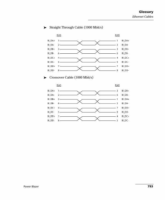
GlossaryEthernet Cables
Straight Through Cable (1000 Mbit/s)
Crossover Cable (1000 Mbit/s)
Power Blazer 793

GlossaryG.709 Optical Transport Network (OTN)
G.709 Optical Transport Network (OTN)
Overview
The optical transport network (OTN) combines the benefits of SONET/SDH technology with the bandwidth expansion capabilities offered by dense wavelength-division multiplexing (DWDM) technology.
The OTN consists of the following layers:
Optical Transport Section (OTS)
Optical Multiplex Section (OMS)
Optical Channel (OCh)
Optical channel Transport Lane (OTL)
Optical Transport Unit (OTU)
Optical Data Unit (ODU)
Optical Channel Payload Unit (OPU)
794 88000 Series

GlossaryG.709 Optical Transport Network (OTN)
Each of these layers and their functions are distributed along the network and activated when they reach their termination points, which are illustrated in the following figure.
OTN Layer Termination Points
The termination of the OTS, OMS and OCh layers is performed at the optical level of the OTN. It is at the termination of the OTU layer that further functionality can be added. This layer is the digital layer—also known as the “digital wrapper”—and offers specific overhead to manage the OTN’s digital functions. The OTU also introduces a new dimension to optical networking by adding forward error correction (FEC) to the network elements, allowing operators to limit the number of required regenerators used in the network which, in turn, lowers its cost.
FEC allows an increase in the optical link budget by providing a new method to correct errors, thereby reducing the impact of network noise and other optical phenomena experienced by the client signal traveling through the network.
The OTU also encapsulates two additional layers—the ODU and the OPU—which provide access to the payload (SONET, SDH, etc.). These layers are normally terminated at the same location.
Power Blazer 795

GlossaryG.709 Optical Transport Network (OTN)
The OTU, ODU (including the ODU tandem connection) and OPU layers can all be analyzed and monitored. As per ITU G.709, current test solutions offer these possibilities using the following line rates:
OTU1 (255/238 x 2.488 320 Gbit/s ≈ 2.666057143 Gbit/s) also referred to as 2.7 Gbit/s
OTU2 (255/237 x 9.953280 Gbit/s ≈ 10.709225316 Gbit/s) also referred to as 10.7 Gbit/s
OTU3 (255/236 x 39.813120 Gbit/s ≈ 43.018413559 Gbit/s) also referred as to 43 Gbit/s
OTU4 (255/227 x 99. 532 800 Gbit/s ≈ 111.809973568 Gbit/s) also referred to as 112 Gbit/s.
The following non standard rates are also defined:
OTU1e (255/238 × 10.3125 Gbit/s ≈ 11.0491071429 Gbit/s)
OTU2e (255/237 × 10.3125 Gbit/s ≈ 11.0957278481 Gbit/s)
OTU3e1 (255/236 x 4 x 10.3125 Gbit/s ≈ 44.570974576 Gbit/s)
OTU3e2 (243/217 x 16 x 2.488320 Gbit/s ≈ 44.583355576 Gbit/s)
The following non standard rates are not covered by the ITU standard but they are the equivalent function associated to Fiber Channel rates:
OTU1f (255/238 × 10.51875 Gbit/s ≈ 11.2700892857143 Gbit/s)
OTU2f (255/237 × 10.51875 Gbit/s ≈ 11.3176424050633 Gbit/s)
Each line rate is adapted to service different client signals:
OC-48/STM-16 is transported via OTU1
OC-192/STM-64 is transported via OTU2
OC-768/STM-256 is transported via OTU3
Null Client (All 0s) is transported via OTUk (k = 1, 2, 1e, 2e, 1f, 2f, 3, 3e1, 3e2, 4)
PRBS31 is transported via OTUk (k = 1, 2, 1e, 2e, 1f, 2f, 3, 3e1, 3e2, 4)
796 88000 Series

GlossaryG.709 Optical Transport Network (OTN)
In order to map client signals via ITU G.709, they are encapsulated using the structure illustrated in the following figure.
Basic OTN Transport Structure
Power Blazer 797

GlossaryG.709 Optical Transport Network (OTN)
As depicted above, to create an OTU frame, a client signal rate is first adapted at the OPU layer. The adaptation consists of adjusting the client signal rate to the OPU rate. Its overhead contains information to support the adaptation of the client signal. Once adapted, the OPU is mapped into the ODU. The ODU maps the OPU and adds the overhead necessary to ensure end-to-end supervision and tandem connection monitoring (up to six levels). Finally, the ODU is mapped into an OTU, which provides framing as well as section monitoring and FEC.
Following the OTN structure presented in figure Basic OTN Transport Structure on page 797, OTUks (k = 1, 2, 3) are transported using the OCh; each unit is assigned a specific wavelength of the ITU grid. Several channels can be mapped into the OMS and then transported via the OTS layer. The OCh, OMS and OTS layers each have their own overhead for management purposes at the optical level. The overhead of these optical layers is transported outside of the ITU grid in an out-of-band channel called the optical supervisory channel (OSC).
When the OTU frame structure is complete (OPU, ODU and OTU), ITU G.709 provides OAM&P functions that are supported by the overhead.
798 88000 Series
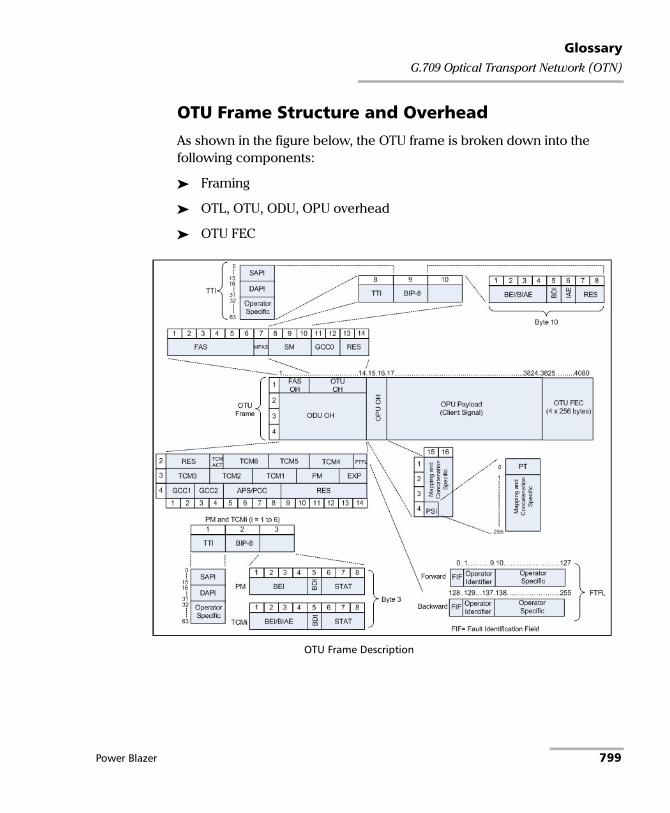
GlossaryG.709 Optical Transport Network (OTN)
OTU Frame Structure and Overhead
As shown in the figure below, the OTU frame is broken down into the following components:
Framing
OTL, OTU, ODU, OPU overhead
OTU FEC
OTU Frame Description
Power Blazer 799

GlossaryG.709 Optical Transport Network (OTN)
Framing
The OTU framing is divided into two portions: FAS and MFAS.
The frame alignment signal (FAS) uses the first six bytes and, similarly to SONET/SDH, it is used to provide framing for the entire signal. In order to provide enough 1/0 transitions for synchronization, scrambling is used over the entire OTU frame, except for the FAS bytes.
The multiframe alignment signal (MFAS) byte is used to extend command and management functions over several frames. The MFAS counts from 0 to 255, providing a 256 multiframe structure.
Overhead
Each portion of the OTU frame has its own specific overhead functions. They are displayed in figure OTU Frame Description on page 799, and are briefly described below. Further details can be found about these overhead fields in the ITU G.709 standard.
Optical channel Transport Lane (OTL)
The Optical channel Transport Lane (OTL) is an adaptation layer whose purpose is to re-use the modules developed for Ethernet 40GBASE-R and 100GBASE-LR4. These modules have a four-lane WDM interface to and from a transmit/receive pair of G.652 optical fibers, and connect to the host board via a 4-lane (OTL3.4) or 10-lane (OTL4.10) electrical interface.
The OTL layer is responsible for mapping the serial OTU signal onto a parallel path designated lanes. In the case of OTU4 the signal is distributed over 20 logical lanes and for OTU3 the signal is distributed over 4 logical lanes.
800 88000 Series

GlossaryG.709 Optical Transport Network (OTN)
Optical Transport Unit (OTU)
The OTU overhead is comprised of the SM, GCC0 and RES bytes.
The section monitoring (SM) bytes are used for the trail trace identifier (TTI), parity (BIP-8) and the backward error indicator (BEI), or backward incoming alignment error (BIAE), backward defect indicator (BDI), and incoming alignment error (IAE). The TTI is distributed over the multiframe and is 64 bytes in length. It is repeated four times over the multiframe.
General communication channel 0 (GCC0) is a clear channel used for transmission of information between OTU termination points.
The reserved (RES) bytes are currently undefined in the standard.
Power Blazer 801
GlossaryG.709 Optical Transport Network (OTN)
Optical Data Unit (ODU)
The ODU overhead is broken into several fields: RES, PM, TCMi, TCM ACT, FTFL, EXP, GCC1/GCC2 and APS/PCC.
The reserved (RES) bytes are undefined and are set aside for future applications.
The path monitoring (PM) field is similar to the SM field described above. It contains the TTI, BIP-8, BEI, BDI and Status (STAT) field.
There are six tandem connection monitoring (TCMi) fields, which contain the BEI/BIAE, BDI and STAT fields. The STAT field is used in the PM and TCMi fields to provide an indication of the presence or absence of maintenance signals.
The tandem connection monitoring activation/deactivation (TCM ACT) field is currently undefined in the standards.
The fault type and fault location reporting communication channel (FTFL) is a message spread over a 256-byte multiframe that provides the ability to send forward and backward path-level fault indications.
The experimental (EXP) field is a field that is not subject to standards and is available for network operator applications.
General communication channels 1 and 2 (GCC1/GCC2) fields are very similar to the GCC0 field except that each channel is available in the ODU.
The automatic protection switching and protection communication channel (APS/PCC) supports up to eight levels of nested APS/PCC signals, which are associated to a dedicated-connection monitoring level depending on the value of the multiframe.
802 88000 Series

GlossaryG.709 Optical Transport Network (OTN)
Optical Payload Unit (OPU)
The primary overhead field associated to the OPU is the Payload Structure Identifier (PSI). This is a 256 bytes multi-frame where its first byte is defined as the Payload Type (PT). The remaining 255 bytes are currently reserved.
The other fields in the OPU overhead are dependent on the mapping and concatenation capabilities associated to the OPU. For an asynchronous mapping (the client signal and OPU clock are different) Justification Control (JC) bytes are available to compensate for clock rate differences, two methods are supported Asynchronous Mapping Procedure (AMP) and Generic Mapping Procedure (GMP). For a purely Bit-Synchronous Mapping Procedure (BMP) (client source and OPU clock are the same), the JC bytes become reserved (set to 0). Concatenation bytes are also available as described in ITU G.709.
Power Blazer 803

GlossaryG.709 Optical Transport Network (OTN)
Tandem Connection Monitoring (TCM)
TCM enables the user and its signal carriers to monitor the quality of the traffic that is transported between segments or connections in the network. SONET/SDH allowed a single level of TCM to be configured, while ITU G.709 allows six levels of tandem connection monitoring to be configured. The assignment of monitored connections is currently a manual process that involves an understanding between the different parties. There are various types of monitored connection topologies: cascaded, nested and overlapping. Examples of these topologies are provided in the following figure.
Tandem Connection Monitoring
804 88000 Series

GlossaryG.709 Optical Transport Network (OTN)
Each of the six TCMi fields in the ODU overhead is assigned to a monitored connection. There can be from zero to six connections that can be configured for each connection. In the figure Tandem Connection Monitoring on page 804, there are three different connections that are actually monitored. Carrier C, due to its location, can monitor three TCM levels as the ODU passes through its portion of the network.
In addition to monitoring maintenance signals, using the STAT field associated with each TCM level, the TCM connection also monitors the BIP-8 and BEI errors for each connection level. Maintenance signals are used to advertise upstream maintenance conditions affecting the traffic and errors provide an indication of the quality of service offered at each segment of the network, which provides a valuable tool for the user and carrier to isolate faulty sections of the network.
Forward Error Correction (FEC)
The ITU G.709 standard supports forward error correction (FEC) in the OTU frame and is the last part added to the frame before the frame is scrambled. FEC provides a method to significantly reduce the number of transmitted errors due to noise, as well as other optical phenomena that occur at high transmission speeds. This enables providers to support longer spans in between optical repeaters.
An OTU frame is divided into four rows. Each row is broken down into 16 sub-rows comprised of 255 bytes each, as shown in figure Forward Error Correction on page 806. A sub-row is composed of interleaved bytes. The interleave is executed so that the first sub-row contains the first overhead (OH) byte, the first payload byte and the first FEC byte, and so on for the remaining sub-rows of each row in the frame. The first FEC byte starts at position 240 for all sub-rows.
Power Blazer 805

GlossaryG.709 Optical Transport Network (OTN)
The FEC uses a Reed-Solomon RS (255/239) coding technique. This means that 239 bytes are required to compute a 16-byte parity check. The FEC can correct up to eight (bytes) errors per sub-row (codeword) or detect up to 16 byte errors without correcting any. Combined with the byte interleave capability included in ITU G.709 implementation, the FEC is more resilient in regards to error burst, where up to 128 consecutive bytes can be corrected per OTU frame row.
Forward Error Correction
806 88000 Series

GlossaryG.709 Optical Transport Network (OTN)
ODU Multiplexing
The ODU multiplexer is a function that allows the multiplexing of ODU tributary signals into higher OTN signal rates. The G.709 standard supports 2 types of ODU multiplexer which can be classified as follows:
Legacy architecture is based on multi-stage architecture to bring an ODUk client to a higher OTN interface rate. This multiplexer is identified by Payload Type 20 (PT 20).
New architecture uses a single stage architecture to bring an ODUk client to any higher OTN interface rate. This method supports the ODUflex client signal. The multiplexer is identified by Payload Type 21 (PT 21).
Note: Refer to the OTN BERT on page 53or OTN-SONET/SDH BERT on page 56 for the ODU multiplexing capabilities.
The multiplexing strategy is based on the concept of tributary slots, which is similar in concept to the SONET timeslot. The multiplexing of 4 ODU1 in one ODU2 is made by distributing the ODU1 structure in a repetitive sequence of 4 ODU2 Tributary slots, a similar strategy is used for ODU3 multiplexing where the repetitive sequence is made of 16 ODU3 tributary slots, refer to G.709 standard for detailed information.
Power Blazer 807

GlossaryG.709 Optical Transport Network (OTN)
The main attributes of the ODU multiplexer functionality are as follows:
The Asynchronous Mapping Procedure (AMP) is used for multiplexing the tributary signals; this method uses a modified Justification Control mechanism which has 2 positive Justification Control bytes and one negative Justification Control byte.
The new multiplex method also supports the Generic Mapping Procedure as the Justification Control mechanism is still using the OPU OH JC bytes.
The Multiplex Structure Identifier (MSI) provides information that is specific to each type of multiplexer provided.
Can handle multiplex signals with frequency offset of +/- 20 ppm on every layer for the legacy architecture while the new architecture (using GMP) can handle frequency offset of +/-100 ppm.
808 88000 Series
GlossaryG.709 Optical Transport Network (OTN)
ODUflex
ODUflex provides the capability to carry client payload of variable size with a container size of 1.244 Gbit/s granularity. An ODUflex (L) signal can be transported once multiplexed in an ODUk (H) signal, the multiplexer in this case handles tributary slots of 1.244 Gbit/s and has a Payload Type 21. The ODUflex function can be used to transport 2 signal categories mapped in ODTUk.ts using GMP:
Ethernet in ODUflex over GFP-F signal
The Ethernet packets are mapped in GFP-F as specified in G.7041, the packets are processed as follows:
The Start of Frame Delineation bytes are terminated
Inter Frame Gaps bytes are terminated
PCS coding is terminated
GFP overhead bytes added
Since the PCS coding is terminated, it is not possible to transport the Ethernet Link status transparently but it is accommodated by the Forward Defect Indication (FDI) and Remote Defect Indication (RDI) alarms over GFP. The RDI is used to carry the Remote Fault alarm while the FDI is used to carry the Local Fault.
GFP-F provides rate adaptation between the incoming Ethernet signal and the outgoing OPUflex transport signal. This brings the fact that GMP is operated at a fixed Cm value close to the maximum server capacity.
CBR over ODUflex signal
ODUflex can transport Constant Bit Rate signal (bulk filled Test pattern) as Client of the ODUflex CBR function. This CBR function needs a Pattern generator that can operate at a data rate specified by the user, the range of the available data rates is qualified by the Bandwidth management function.
Power Blazer 809

GlossaryG.709 Optical Transport Network (OTN)
OTN Signal Rates
Rate Signal
2.666057143 Gbit/s OTU1
10.709225316 Gbit/s OTU2
11.0491 Gbit/s OTU1e
11.0957 Gbit/s OTU2e
11.2701 Gbit/s OTU1f
11.3176 Gbit/s OTU2f
43.018413559 Gbit/s OTU3
44.571 Gbit/s OTU3e1
44.583 Gbit/s OTU3e2
111.81 OTU4
810 88000 Series

GlossaryGeneric Framing Procedure (GFP)
Generic Framing Procedure (GFP) Generic framing procedure (GFP), defined in ITU recommendation G.7041/Y.1303, is a framing mechanism to transport packet-based client signals, such as Ethernet, Fibre Channel, ESCON, FICON, over fixed-data-rate optical channels. As such, GFP provides a single, flexible mechanism to map these client signals into SONET/SDH and OTN networks, as shown in figure below.
Client Signal Mapping over GFP
Prior to the introduction of GFP, several methods had been used to transport packet services over SONET/SDH networks. The first method was Asynchronous Transfer Mode (ATM) Adaptation Layer 5 (AAL 5) over SONET/SDH. ATM is a very efficient switching and multiplexing technology, whose transfer rates scale with SONET/SDH rates. However, ATM does not make the most efficient use of bandwidth because the payload data is separated into groups of 48 bytes, called cells, with an additional 5-byte header of software overhead. It became immediately apparent that almost 10 % of the bandwidth would be lost. In addition, certain types of data required even more ATM overhead.
Power Blazer 811

GlossaryGeneric Framing Procedure (GFP)
Other methods have focused on using point-to-point protocol (PPP). The IP traffic coming to an Ethernet port is encapsulated over a PPP link and multiple ports can be encapsulated over multilink PPP (ML-PPP) links. By using an HDLC framing, the PPP traffic is transported over the SONET/SDH payload. These methods have been standardized within the IETF through the following Requests for Comments (RFC): RFC 1662, RFC 1990 and RFC 2615. The ITU-T expanded this work by specifying the use of LAPS (very similar protocol to PPP/HDLC) and specifying IP over LAPS in X.85/Y.1321 and Ethernet over LAPS in X.86/Y1323. All these methods for encapsulating traffic suffer from the weaknesses of HDLC framing; i.e., limited protection from frame corruption and the introduction of variable packet sizes because of its trailer.
GFP has been standardized to better optimize the transport of Ethernet and other data services over SONET/SDH networks, taking into account both the pros and cons of ATM and PPP/HDLC and leveraging two new emerging SONET/SDH capabilities, VCAT and LCAS, that will be discussed later in this document.
812 88000 Series

GlossaryGeneric Framing Procedure (GFP)
GFP Mapping
Two types of mapping are currently available for GFP: framed-mapped (GFP-F) and transparent-mapped (GFP-T), whose mappings keep the same basic frame structure, as will be shown in the next sections. The decision on which mode to use is dependent on the underlying service to be transported.
Frame-Mapped GFP (GFP-F): mapping mechanism in which one client signal frame is received and mapped in its entirety into one GFP frame. Therefore, with this adaptation mode, the GFP-F frame size is variable as it is directly related to the incoming client payload. In fact, with GFP-F, the entire client frame must be buffered in order to determine its length. GFP-F is usually used to support Layer 2 frames like Ethernet MAC that are tolerant to some latency. The ITU G.7041 defines the following frame-mapped user payloads supported through GFP-F:
Frame-Mapped Ethernet
Frame-Mapped PPP
Frame-Mapped Multiple Access Protocol over SDH (MAPOS)
Frame-Mapped IEEE 802.17 Resilient Packet Ring
Frame-Mapped Fibre Channel FC-BBW
Transparent-Mapped GFP (GFP-T): mapping mechanism that facilitates the transport of 8B/10B block-coded client signals like Gigabit Ethernet (GbE), Fibre Channel, ESCON, FICON, and DVB-ASI. With GFP-T, individual characters of a client signal are decoded from the client signal and then mapped into fixed-size GFP frames (64B/65B coded superblocks). This approach avoids the buffering of an entire client frame before it can be mapped into a GFP frame, which reduces latency and in turn makes it ideally suited for SAN applications that require very low transmission latency.
Power Blazer 813
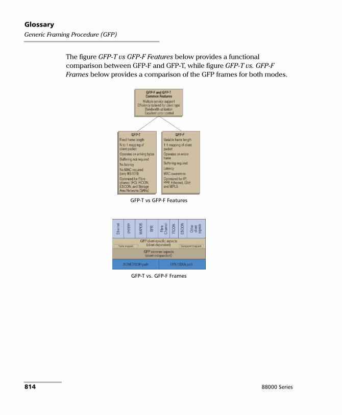
GlossaryGeneric Framing Procedure (GFP)
The figure GFP-T vs GFP-F Features below provides a functional comparison between GFP-F and GFP-T, while figure GFP-T vs. GFP-F Frames below provides a comparison of the GFP frames for both modes.
GFP-T vs GFP-F Features
GFP-T vs. GFP-F Frames
814 88000 Series

GlossaryGeneric Framing Procedure (GFP)
Functionally, GFP consists of both common and client-specific aspects. Common GFP aspects apply to all GFP-adapted traffic (i.e., both GFP-F and GFP-T) and cover functions such as packet data unit (PDU) delineation, data link synchronization and scrambling, client PDU multiplexing, and client-independent performance monitoring. Client-specific aspects of GFP cover issues such as mapping of the client PDU into the GFP payload, client-specific performance monitoring, as well as operations, administration, and maintenance (OA&M). This is illustrated in figure Client Signal Mapping over GFP on page 811.
GFP Frame Structure
As illustrated in figure below, Two basic GFP frame types have been defined: GFP client frames and GFP control frames. GFP client frames are categorized into two types: client data frames (CDFs) and client management frames (CMFs). CDFs are used to transport the client data, while CMFs are used to transport information associated with the management of the client signal or GFP connection.
As for GFP control frames, at this time, only one category has been defined by the standard so far; i.e., GFP idle frames.
GFP Frames Types
Power Blazer 815

GlossaryGeneric Framing Procedure (GFP)
The GFP generic frame structure is presented in figure below.
GFP Generic Frame Structure
Each GFP frame type consists of three main components: the core header, the payload header, and the payload information field.
The core and payload headers form the GFP header, whereas the payload information field represents the customer traffic carrying the data services. The payload header carries information about the payload type (i.e., Ethernet, Fibre Channel, etc.) that it is carrying, while the core header carries information about the size of the GFP frame itself.
Each header contains a header error correction (HEC) calculation, allowing for the correction of single errors; that is, any errors that occur in the core header or in the payload header can potentially be corrected by the HEC, through the network element. This creates a very robust mapping scheme, which ensures that GFP frames can get transported across a network without customer traffic loss.
816 88000 Series

GlossaryGeneric Framing Procedure (GFP)
Core Header
The GFP core header consists of a two-octet length field, specifying the length of the GFP frame's payload area in octets, and a two-octet field containing a CRC-16 error-check code.
Payload Length Indicator (PLI): The PLI is a two-byte field indicating the size in bytes of the GFP payload area. It indicates the beginning of the next GFP frame in the incoming bit-stream as an offset from the last byte in the current GFP core header. PLI values in the range of 0 to 3 are reserved for GFP internal use and are referred to as GFP control frames. All other frames are referred to as GFP client frames.
Core HEC (cHEC): The cHEC is a two-byte field containing a cyclic redundancy check (CRC-16) sequence that protects the integrity of the core header. The cHEC sequence is computed over the core header bytes using standard CRC-16. The CRC-16 enables both single-bit error correction and multibit error detection.
Payload Header
The payload header is a variable-length area, 4 to 64 octets long, intended to support data-link management procedures specific to the transported client signal. The payload header contains two mandatory fields, the Type field and Type Header Error Correction (tHEC) field. The payload header also supports an additional variable number of subfields referred to, as a group, as the extension header.
Payload Type Identifier (PTI): A three-bit subfield that identifies the type of GFP client frame. The following table lists the currently defined user frames.
PTI Description
000 Client Data Frame
100 Client Management Frame
Others Reserved
Power Blazer 817

GlossaryGeneric Framing Procedure (GFP)
Payload FCS Indicator (PFI): A one-bit subfield indicating the presence (1) or absence (0) of the payload FCS field. The following table lists the currently defined PFI values.
Extension Header Identifier (EXI): A four-bit subfield identifying the type of GFP extension header. Three kinds of extension headers are currently defined:
User Payload Identifier (UPI): An eight-bit field identifying the type of payload conveyed in the GFP payload information field:
PFI Description
0 FCS Absent
1 FCS Present
EXI Description Function
0000 Null Extension Header
Indicates that no extension header is present.
0001 Linear Extension Header
A two-octet extension header that supports sharing of the GFP payload across multiple clients in a point-to-point configuration. The linear extension header consists of an eight-bit channel ID (CID) field, used to indicate one of 256 communication channels (i.e. clients) at a GFP termination point, and an eight-bit spare field reserved for future use.
0010 Ring Extension Header
The use of this field is under consideration. Similar to linear, the current proposal being considered is to allow the sharing of the GFP payload across multiple clients;
however, this would only apply to ring configurations.
0011 to 1111
Reserved
UPI Client Data Client Management
0000 00001111 1111
Reserved and not available Reserved
0000 0001 Mapped Ethernet Frame Client Signal Fail (Loss of Client Signal)
818 88000 Series

GlossaryGeneric Framing Procedure (GFP)
0000 0010 Mapped PPP Frame Client Signal Fail (Loss of Character Synchronization)
0000 0011 Transparent Fibre Channel Client Defect Clear Indication (DCI)
0000 0100 Transparent FICON Client Forward Defect Indication (FDI)
0000 0101 Transparent ESCON Client Reverse Defect Indication (RDI)
0000 0110 Transparent GbE
0000 0111 Reserved for future use
0000 1000 Frame-Mapped IEEE 802.17
Resilient Packet Ring
0000 1011 Frame-Mapped Fibre Channel FC-BBW
0000 1100 Asynchronous Transparent Fibre Channel
0000 1101 Framed MPLS Unicast
0000 1110 Framed MPLS Multicast
0000 1111 Framed IS-IS
0001 0000 Framed IPv4
0001 0001 Framed IPv6
0001 0010 Framed DVD-ASI
0001 0011 Framed 64B/66B Ethernet
0001 0100 Framed 64B/66B Ethernet Ordered Set
0001 0101 through 1110 1111
Reserved for future standardization
1111 0000 through 1111 1110
Reserved for proprietary use
0000 0110 through 1101 1111
Reserved for future use
1110 0000 through 1111 1110
Reserved for proprietary use
UPI Client Data Client Management
Power Blazer 819

GlossaryGeneric Framing Procedure (GFP)
Type HEC (tHEC) Field: A two-octet field that contains a CRC-16 sequence to protect the integrity of the type field. The tHEC sequence is computed over the core header bytes using standard CRC-16. As with the cHEC, CRC-16 enables both single-bit error correction and multibit error detection.
Channel Identifier (CID): A one-byte field that is only available when the EXI field is configured to Linear. The CID byte is used to indicate one of 256 communication channels at a GFP termination point.
Spare: A one-byte field that is only available when the EXI field is configured to Linear. This field is reserved for future use.
Extension HEC (eHEC): A two-byte field that contains a CRC-16 check sequence that protects the integrity of the contents of the extension. CRC-16 enables both single-bit correction and multibit error detection.
The figure below explains how (in GFP-F) the transmitter encapsulates one entire frame of the client data.
GFP-F vs. GFP-T Frame Structure
820 88000 Series

GlossaryGeneric Framing Procedure (GFP)
Payload Information Field
The payload area (also referred to as payload information field) contains the framed client signal. This variable-length field may include from 0 to 65,535 – X octets, where X is the size of the payload header (including the extension header, if present) and the payload FCS field (if present).
Figure GFP-T vs. GFP-F Frames on page 814 shows the GFP-T and GFP-F frame structures. As shown, Both GFP-T and GFP-F frame types share a common core header, payload header, and payload FCS (optional), and they differ in the way in which the client is mapped into this payload area.
Payload FCS (pFCS)
This is an optional four-octet-long frame-check sequence. It contains a CRC-32 check sequence that is designed to validate the entire content of the payload area. The FCS field presence is signalled by the PFI bit located in the Type field of the payload header. The FCS does not correct any errors; it just indicates the presence of error(s).
In GFP-F, the transmitter encapsulates one entire frame of the client data into one GFP frame. In this case, the basic frame structure of a GFP client frame is used, including the required payload header.
In GFP-T, however, rather than buffering an entire client-data frame, the individual characters of the client signal are demapped from the client block codes and then mapped into periodic fixed-length GFP frames. The transparent GFP client frame uses the same structure as the frame-mapped GFP, including the required payload header.
Power Blazer 821

GlossaryGeneric Framing Procedure (GFP)
GFP Summary
GFP has been standardized to better optimize the transport of Ethernet and other data services over SONET, taking into account both the pros and cons of ATM and PPP/HDLC framing mechanisms. As described in this section, GFP represents a robust mapping mechanism that allows for the mapping of multiple client-data types into SONET/SDH payload (SPEs). This technology has been embraced by network equipment and service providers as it provides an efficient way of providing interoperable data-services transport over the existing SONET/SDH install base. The versatility provided by GFP allows SONET/SDH networks to offer transport services for a multiple of services, as shown in figure below.
Multiservice SONET/SDH Network
822 88000 Series

GlossaryMPLS Labels
MPLS Labels The MPLS labels are listed in the following table.
Label Description
0 IPv4 explicit null
1 Router alert
2 IPv6 explicit null
3 Implicit null
14 OAM alert
4 to 13, and 15 Unassigned
16 to 1048575 Label ID
Power Blazer 823

GlossaryOBSAI
OBSAI
Overview
Traditional mobile installations are bulky (use thick coaxial cables) and require a lot of power to operate (there is a huge power loss in the coaxial cabling which often requires the use of Tower Mounted Amplifiers) as outlined in the following figure.
Pressures on the Mobile Network Operators (MNO) to reduce their capital, operational cost, and increase coverage are at the heart of a revolution in the mobile network. To address the situation, a concept of decomposition of the radio base station has been developed where the radio basic functions and its ability to transmit and receive radio modulated signals are separated. In such a distributed environment, a protocol is required to maintain synchronization and management capabilities as well as transporting the user traffic between the simplified Base Transceiver Station (BTS) and its Remote Radio Head (RRH).
824 88000 Series

GlossaryOBSAI
This protocol called Open Base Station Architecture Initiative (OBSAI) separates a traditional radio base station configuration into two separate elements: Base Transceiver Station (BTS) and Remote Radio Head (RRH). The BTS processes the digital baseband radio information and performs the control of the RRH. The RRH converts the digital radio information into radio frequency signals transported over the air interface (antenna). The BTS and RRH are interconnected by a point-to-point link. This link carries the OBSAI protocol and is known in the industry as the fronthaul as opposed to the backhaul that is the WAN bringing the network traffic to the base station.
The OBSAI link can be extended over several kilometers as it uses fiber optics. In fact it can be deployed up to 40 km although most field installations at the moment of this writing are below 10 km.
The OBSAI BTS System Reference Document defines multiple Reference Points. The Reference Point 3 Specification mainly defines the physical to the application layers providing an opportunity for larger interoperability between vendors. However, field experience suggests that the interoperability is pretty much limited to the physical and data link layers.
Power Blazer 825

GlossaryOBSAI
OBSAI RP3-01 System Architecture
OBSAI remotely locates the RRH from the BTS. This means that the RRH must be controlled, managed and synchronized from the BTS in addition to transporting the User information (Voice and user application data) and all that on the same digital link, the RP3-01. As such, an OBSAI interface is composed of 3 communication flows sent in the same optical fiber in the form of continuous messages as illustrated in the following diagram.
The OBSAI link parameter alignment setup is driven by two paired TX and RX state machines; one pair located on the BTS acts as a Master and the other located at the RRH acts as a Slave. The Master initiates the negotiation procedure necessary to achieve this alignment.
Data: User Data Messages (IQ Data) which represents the voice and data information that is exchanged by End-User Equipment
Control: Call Processing/OAM&P messages (Generic Ctrl and RP3 Ethernet messages)
Synchronization: Frame synchronization messages
826 88000 Series

GlossaryOBSAI
OBSAI Protocol Stack
The OBSAI RP3 Protocol Stack revolves around the 4 layers: Physical Layer, Data Link Layer, Transport Layer and Application Layer as outlined in the following diagram.
Power Blazer 827

GlossaryOBSAI
Application Layer: Provides message sampling and mapping based on payload type (ex: WCDMA/FDD, LTE, GSM/EDGE and 802.16 also known as Wi-Max).
Transport Layer: End-to-End delivery message including routing based on RP3 Address defined in the messages.
Data Link Layer:
Message framing and link synchronization.
Scrambling/Descrambling (6.144G only).
Physical Layer:
8B/10B Coding/Decoding (or 10B/8B Coding).
Create serial bit stream.
Transmit/Receive bit stream on the interface..
Physical Interface
OBSAI offers 4 rates based on a multiple of 768 Mbit/s. All OBSAI rates use 8B/10B line coding. Scrambling is mandatory for the 6.1Gbit/s rate. When using OBSAI with Framed L2, the line rate and scrambling are normally negotiated following the operation of the TX and RX state machines at the BTS and RRH nodes.
Multiple (i) Rate Line Coding Scrambling
1x 768 Mbit/s 8B/10B None
2x 1.536 Gbit/s
4x 3.072 Gbit/s
8x 6.144 Gbit/s Configurable (enabled by default)
828 88000 Series

GlossarySONET/DSn/SDH/PDH
SONET/DSn/SDH/PDH
SONET/DSn/SDH/PDH Nomenclature
The GUI will used the International or European nomenclature based on the SONET and SDH software options installed on the module.
Signal Rates
Software option Nomenclature
SONET only International
SDH only European
SONET and SDH International
Rate SONET/DSnSDH/PDH
International European
1.544 Mbit/s DS1 - 1.5M
2.048 Mbit/s - E1 2M
8.448 Mbit/s - E2 8M
34.368 Mbit/s - E3 34M
44.736 Mbit/s DS3 - 45M
51.84 Mbit/s OC-1 STM-0 52M
139.264 Mbit/s - E4 140M
155.52 Mbit/s OC-3 STM-1 STM-1
622.08 Mbit/s OC-12 STM-4 STM-4
2.48832 Gbit/s OC-48 STM-16 STM-16
9.95328 Gbit/s OC-192 STM-64 STM-64
39.81312 Gbit/s OC-768 STM-256 STM-256
Power Blazer 829

GlossarySONET/DSn/SDH/PDH
SONET/SDH High and Low Order Path Nomenclature
Path Type SDH SONET
High Order AU-3 STS-1
AU-4 STS-3c
AU-4-4c STS-12c
AU-4-16c STS-48c
AU-4-64c STS-192c
AU-4-256c STS-768c
Low Order TUG-3 -
TUG-2 VTG
TU-11 VT1.5
TU-12 VT2
TU-3 -
830 88000 Series

GlossarySONET/DSn/SDH/PDH
SONET/SDH Alarms and Errors Nomenclature
Layer SONET SDH
Physical BPV/CV CV
Section / Regenerator Section LOF-S RS-LOF
SEF RS-OOF
TIM-S RS-TIM
FAS-S RS-FAS
B1 B1
Line / Multiplex Section AIS-L MS-AIS
RDI-L MS-RDI
B2 B2
REI-L MS-REI
High Order Path AIS-P AU-AIS
LOP-P AU-LOP
H4-LOM H4-LOM
PDI-P -
RDI-P HP-RDI
ERDI-PCD ERDI-CD
ERDI-PPD ERDI-PD
ERDI-PSD ERDI-SD
PLM-P HP-PLM
UNEQ-P HP-UNEQ
TIM-P HP-TIM
B3 B3
REI-P HP-REI
Power Blazer 831

GlossarySONET/DSn/SDH/PDH
Low Order Path AIS-V TU-AIS
LOP-V TU-LOP
RDI-V LP-RDI
ERDI-VCD ERDI-CD
ERDI-VPD ERDI-PD
ERDI-VSD ERDI-SD
RFI-V LP-RFI
UNEQ-V LP-UNEQ
TIM-V LP-TIM
PLM-V LP-PLM
BIP-2 BIP-2
REI-V LP-REI
Layer SONET SDH
832 88000 Series

GlossarySONET/DSn/SDH/PDH
SONET Numbering Convention
The module supports the Timeslot (default) and hierarchical two-level numbering conventions as per GR-253.
Hierarchical Notation:
The module supports numbering SONET high order path STS-1s and STS-3c using the two-level “STS-3#,STS-1#”convention in an OC-N. For example: STS-1 [2,3].
Power Blazer 833

GlossarySONET/DSn/SDH/PDH
The module supports numbering SONET low order path using the two-level “VTGroup#,VT#” convention for numbering VTs within an STS-1. For example: VT1.5 [1,3], VT2 [3,2], VT6 [6,1].
The module supports numbering SONET high order path STS-nc within an OC-N using the two-level “STS-3#,STS-1#”. For example: STS-12c [5,1].
SDH Numbering Convention
As per ITU G.707, the high order paths are defined using a 2 to 5 level convention E,D,C,B,A depending on the rate of the STM-n used.
E: the AUG-64 are numbered 1 to 4
D: the AUG-16 are numbered 1 to 4
C: the AUG-4 are numbered 1 to 4
B: the AUG-1 are numbered 1 to 4
A: the AU-3 are numbered 1 to 3
834 88000 Series

GlossarySONET/DSn/SDH/PDH
Naming is as follows for each of the following rates:
[E,D,C,B,A] for STM-256
[D,C,B,A] for STM-64
[C,B,A] for STM-16
[B,A] for STM-4
[0] for AU-4 in STM-1
[A] for AU-3 in STM-1
[A] for the AU-3 in STM-0e, A=0.
Power Blazer 835

GlossarySONET/DSn/SDH/PDH
The low order paths are defined using a 2 or 3 level convention K,L,M depending on the rate of the AU-4 or AU-3 used to multiplex the low order signals.
K: the TUG-3 are numbered 1 to 3
L: the TUG-2 are numbered within the TUG-3 0 or from 1 to 7
M: the TU-2, TU-12, TU-11 are numbered within the TUG-2 1, 1 to 3, 1 to 4 respectively
Examples for AU-4 (3 level convention)
TU-3: [K,0,0]TU-2: [K,L,0]TU-12:[K,L,M] where M = 1 to 3TU-11:[K,L,M] where M = 1 to 4
Example for AU-3 (2 level convention)
TU-2: [L,0]TU-12: [L,M] M is numbered 1 to 3TU-11: [L,M] M is numbered 1 to 4
836 88000 Series

GlossarySONET/DSn/SDH/PDH
The GUI Grid indicates the TUG-2 [x] and TUG-3 [x] values.
Power Blazer 837

GlossarySONET/DSn/SDH/PDH
DSn/PDH Numbering Convention
The DS1 numbering in DS3 shall be numbered with respect to the DS2 muxing [DS2,DS1]. For example a DS3 has 7 DS2 and a DS2 has 4 DS1, so an example would be for a DS1 number [3,2]. The DS3 shall have a single number to represent its position. That is [1] all the time whether it is used in an STS-1 or it is the DS3 electrical interface.
The PDH do not have special grouping of the E1, E2, E3 or E4. This means that the PDH has a single number. For example E1 number 2 shall be number [2].
The E1 in DS3 via G.747 numbering uses the naming [DS2,E1]. However in the grid the label shall adapt itself to DS2 [x] or 6.3M [x] (where x = 1 to 7) with respect to the interface standard used: European or International.
838 88000 Series

GlossarySyncE
SyncE Synchronous Ethernet or SyncE enables a traceable network timing reference frequency to be distributed node-by-node across a chain of Ethernet devices (SyncE compliant devices only). The network timing reference is typically hierarchically traceable to a Primary Reference Source/Clock (PRS/PRC) in a unidirectional flow. Any node in the chain not compliant to SyncE automatically terminates the synchronization propagation but this does not impact the flow of traffic.
The Physical Layer carries the clock frequency and the Data Link layer carries the Quality Level (QL) associated to the transported frequency via Synchronization Status Messaging (SSM) embedded in the Ethernet Synchronization Message Channel (ESMC). The QL is transported via Information and Event PDUs typically transmitted at a rate of 1 frame per second but this rate can vary between 1 to 10 messages per second to respect the slow protocol rules. The Information PDU is used as heart-beat for the channel while one Event PDU is transmitted asynchronously to the Information PDU upon change of the QL value. Following this change, the Information PDU is also adjusted to match the new QL.
Power Blazer 839

GlossarySyncE
In order for an Ethernet interface to be considered Synchronous Ethernet compliant it needs to be upgraded as shown in the following diagram. In addition to supporting the ESMC channel, this upgrade consists in allowing the recovered clock from the CDR to be propagated to a function called the Ethernet Equipment Clock (EEC).
The EEC is present in a network element (NE) to determine which port should be used to distribute the frequency to other port(s) in the NE as well as what QL value to transmit over the ESMC to other network element in the network synchronization chain. The actual selection decision is based on the QL value received from the various port(s) in the NE. If none are valid the EEC is equipped with a better oscillator than a standard Ethernet interface to provide synchronization (Holdover mode). Typically the highest QL value is selected among the nominated sources within the network element.
840 88000 Series

GlossaryUnicast/Multicast Addresses for Ethernet OAM
Unicast/Multicast Addresses for Ethernet OAM Unicast or multicast address can be used for most of S-OAM functions.
Unicast addresses a unique destination address of the MEP.
Multicast Class 1 addresses all MEPs in the MEG. The address value is 01-80-C2-00-00-3x, where x represents the MEG/MD Level.
Multicast Class 2 addresses all MIPs and MEPs in the MEG. The address value is 01-80-C2-00-00-3y, where y represents the MEG/MD Level + 8.
The following table specifies which address type is used for each frame type.
Frame Type Unicast
Multicast Frame Type Unicast
Multicast
Class 1 Class 2 Class 1 Class 2
CCM X X LMM X X
LBM X X LMR X
LBR X SLM X X
LTM X SLR X
LTR X AIS X X
TST X X CSF X X
DMM X X LCK X X
DMR X
Power Blazer 841

GlossaryVLAN ID and Priority
VLAN ID and PrioritySpecial VID values (IEEE Std 802.1Q-1998)
VLAN Priority
ID Description
0 The null VLAN ID. Indicates that the tag header contains only user priority information; no VLAN identifier is present in the frame. This VID value must not be configured as a PVID, configured in any Filtering Database entry, or used in any Management operation.
1 The default PVID value used for classifying frames on ingress through a Bridge Port. The PVID value can be changed on a per-Port basis.
4095 Reserved for implementation use. This VID value shall not be configured as a PVID, configured in any Filtering Database entry, used in any Management operation, or transmitted in a tag header.
0 000 - Low Priority 4 100 - High Priority
1 001 - Low Priority 5 101 - High Priority
2 010 - Low Priority 6 110 - High Priority
3 011 - Low Priority 7 111 - High Priority
842 88000 Series

C Remote ToolBox Overview
The Remote ToolBox application allows remotely controlling a module installed on a platform using a remote PC. Remote users are connected to the platform using an Ethernet connection.
Note: The remote control feature has to be enabled for the module on its specific slot on the platform. Refer to the Controlling Modules Remotely section from the platform user guide for more information.
The Remote ToolBox allows starting one or several module application(s). Once a module application is started, the application is independent and does not require the Remote ToolBox anymore. Thus, the Remote ToolBox application can be closed or can be disconnected from the platform using the Disconnect button without affecting the running remote module applications.
Power Blazer 843

Remote ToolBoxOverview
A remote module application offers the same level of control as if the module is locally controlled with the following behaviors.
Multi-user behaviors:
Up to five connections including the local and/or remote sessions are allowed per module. Beyond five connections, the performance to service the connections may decrease.
Each user is able to individually navigate through the module application without affecting the other users. However, any changes to the operation of the test (Start, Stop, Reset, etc.) or to any test parameter will be applied to all users.
File location behaviors:
The save, load, report, and data capture functions are associated with the location of the session initiated; for Remote ToolBox it will be on the local PC. The files are not duplicated on the platform platform.
The Save/Load configurations are saved in the following folder:Document\88000-PowerBlazer\Configuration
The Reports are saved in the following folder:Document\88000-PowerBlazer\Reports
If a report is being generated, no user will be able to start the test case until the report generation is completed.
The Data Capture files are saved in the following folder:Document\88000-PowerBlazer\CaptureData
If a capture file is being generated, all users will be able to stop the capture but only the user that initiates the capture will be able to see the captured data file after generation.
844 88000 Series

Remote ToolBoxRemote ToolBox Installation
Remote ToolBox Installation
Requirements
The following system requirements must be met before installing the Remote ToolBox software.
10 or 10/100 Mbit/s network interface card.
Windows XP/Vista/7/8/10 operating system.
Note: Some Windows applications such as PDF reader, Excel, etc. may be required to open the generated reports.
Installation
Download the Remote ToolBox application from EXFO STORE at www.exfo.com. Run the Setup.exe application and follow the on-screen instructions to complete the installation.
A shortcut of the EXFO Remote ToolBox will be created on the PC desktop.
Power Blazer 845

Remote ToolBoxStarting and Using the Remote ToolBox Application
Starting and Using the Remote ToolBox Application
Start the Remote ToolBox application, either by using the desktop EXFO Remote ToolBox shortcut, or by clicking on the EXFO Remote ToolBox application from All Programs - EXFO.
File Menu
The File-Exit menu allows quitting the Remote ToolBox application.
Help Menu
The Help menu displays the help information about the Remote ToolBox application.
Server Address or Host Name
Allows entering the platform IP address or the Host Name. The IP address format is IPv4 (xxx.xxx.xxx.xxx) where xxx are values from 0 to 255. For example: 192.168.1.1.
To find the IP address of the platform, refer to the platform user guide.
Connect/Disconnect Button
Connect establishes the connection with the platform specified by the selected IP address or the Host Name.
Disconnect, closes the connection with the selected platform allowing to establish a connection with another platform.
846 88000 Series

Remote ToolBoxStarting and Using the Remote ToolBox Application
Modules
Once connected to the platform, lists the modules installed on the platform regardless of the remote control feature being enabled or not. The following information is displayed for each module.
Type displays the module’s icon.
Slot indicates the platform slot number where the module is inserted.
Module indicates the name of the module.
Description displays the description given to the module. Refer to the platform user guide for more information.
Serial Number indicates the serial number of the module.
Remote Control indicates if the remote control feature is enabled for this module. Refer to the Controlling Modules Remotely section from the platform user guide for more information.
Standalone indicates if the standalone feature is possible for this module. Refer to the Controlling Modules Remotely section from platform platform user guide for more information.
Version indicates the software version of the module application.
Power Blazer 847

Remote ToolBoxApplications for...
Applications for...
Note: The application icon is only available if the selected module has its Remote Control enabled and is only displayed if the module is supported by the Remote ToolBox application.
Click on the icon to start the application.
The application is automatically started when the same version of the application is installed on the local PC.
The application is downloaded from the platform and installed on the local PC when either the application is not installed or the versions are different. Once installed, the application is automatically started. While downloading the application, the Cancel button allows cancelling the download and the installation process.
Note: Multiple versions of a module application may be installed on the same PC. Use the Windows - Control Panel - Add/Remove tool to remove non-required versions from the PC.
848 88000 Series

Index
Index
10B_ERR .................................................... 4231588 PTP ..................................... 85, 148, 38216 Unframed 400GAUI-16......................... 13916 Unframed 400GAUI-8........................... 13820 Unframed Logical Lanes ............... 122, 12320 Unframed PCS ...................................... 136200GAUI-4 Lane ........................................ 6184 Unframed 200GAUI-4............................. 1374 Unframed Physical Lanes........................ 1224 Unframed XLAUI .................................... 136400GAUI-8 Lane ........................................ 61866 Block .................................................... 40966B Block .................................. 414, 427, 5368 Unframed 200GAUI-4............................. 1378 Unframed 400GAUI-8............................. 138802.1ag..................................................... 306
AA1 ............................................................. 667A2 ............................................................. 667Abort Frame .............................................. 603About button .............................................. 39Absolute.................................................... 493Accept Connection from IP........................ 365Acceptable Errors .............................. 296, 297Accuracy.................................................... 296Accuracy (Frames) ..................................... 297Acquire...................................................... 625Acronym.................................................... 761Activate ..................................................... 340Activate Threshold (Symbols) .................... 224Actual L4 ........................................... 566, 576Add Ch...................................................... 284Add Client ................................................. 211Add Step ................................................... 204Additional Payload .................................... 681Address ..... 245, 257, 258, 259, 265, 266, 267
Power Blazer
Address Mismatch ............................. 231, 429Address Type ............................. 310, 312, 475Addressing ................................................ 317Advertised BB_Credit ................................. 208after-sales service ...................................... 752AIS.... 399, 400, 401, 402, 403, 404, 430, 435,
437, 441, 446, 455, 606AIS-L .................................................. 457, 469AIS-P.................................................. 459, 470AIS-V ......................................................... 466Alarm Timeout/Threshold .......................... 153Alarm/Status.............................................. 643Alarms ....................................................... 619Alarms background color .................. 388, 570Alarms/Errors ............................................. 649Alarms/Status and Unassigned .................. 641Alignment.................................................. 406All .............................................................. 487All Channels............................................... 285All Clients .................................................. 212All Lanes .................................................... 157All PHY....................................................... 650Amount ............................................. 475, 642Analysis - Time Error .................................. 479Analysis - Time Interval Error ..................... 479Announce .................................................. 150ANSI TI-403 ............................................... 638Application buttons..................................... 39Applications for... ...................................... 848Apply Channel TX to RX............................. 337APS............................................................ 626APS/PCC..................................................... 664Architecture............................................... 628ARM .......................................................... 369Arrow buttons ............................................. 43Arrows....................................................... 117Assign........................................................ 285Assign to Capture ...................................... 646Assigned Capacity ..................................... 211
849
Index
Attempts ................................................... 687AU Path (C2) ..................................... 238, 488AU Path (J1) .............................................. 597AU Path (N1) ..................................... 375, 597AU-AIS....................................................... 459AU-LOP...................................................... 459Auto.................................................. 227, 228Automatic ................................. 226, 259, 267Automatic IP (DHCP) ................. 246, 257, 264Auto-Negotiation ...................... 225, 244, 729Auto-Response Loopback Status ............... 571AU-x .......................................................... 459Available ................................................... 318Available BB_Credit ................................... 207Average..................................................... 389Average RX Rate........................................ 521Average TX Rate ........................................ 525Avg RX Rate .............................................. 553Avg. Round Trip Time................................ 690
BB1.............................................. 458, 472, 667B2.............................................. 458, 472, 669B3.............................................. 461, 472, 673Background....................................... 334, 346Background Traffic .................................... 342Backplane.................................. 167, 173, 174Backplane Clock ........................................ 173Back-to-Back ..................................... 297, 573Back-to-Back button.................................. 487Bandwidth Usage...................................... 484Base Station .............................................. 146Batch button ..................................... 317, 352Battery ...................................................... 364battery
safety................................................... 748Battery/AC Icons .......................................... 35BBE.................................................... 503, 506BBER.................................................. 504, 507BDI ............................ 430, 433, 435, 441, 446BEI............................. 432, 434, 436, 443, 447
Bell ............................................................ 335BER ............................................................ 396BER Threshold.................... 158, 185, 280, 555BERT .................................................. 155, 183BERT Duration ........................................... 367BERT Threshold.......................................... 367BFD............................................................ 629BIAE........................................... 433, 441, 446Bidirectional .............................................. 291Binary ........................................................ 336Binary/Hex ................................................. 261BIP-2.......................................................... 468BIP-8.......................... 432, 434, 436, 443, 447Bit Error ..................... 158, 185, 280, 396, 555Bit Error Count .......................... 533, 558, 560Bit Error Rate ............................. 533, 558, 560Bit Error Test.............................................. 562Bit-Oriented Message ................................ 634Block.......................................... 406, 411, 414BPV............................................................ 427BRIDGE ...................................................... 169Bridge Request .......................................... 628Broadcast .................................................. 601BSD............................................................ 430BSF ............................................................ 430Buffer Delay....................................... 566, 577Buffer to Buffer Flow Control .................... 207Buffer Usage.............................................. 683Bulk Read .................................................. 616Bulk Write.................................................. 616Burst.................................................. 357, 521Burst Count ............................................... 358Burst Duty Cycle ........................................ 358Burst Frames.............................................. 191Burst Max Rate .......................................... 324Burst Sequence.......................................... 191Burst Size........................................... 325, 521Burst Test .................................................. 196Burst Time ................................................. 297Burst/IR Frame Ratio .................................. 192Bursts ........................................................ 297Burt ........................................................... 191
850 88000 Series

Index
Busy .......................................................... 303B-VLAN...................................................... 252
CC/R............................................................. 636C&M.................................................. 228, 535C&M Channel ............................................ 228c1 .............................................................. 497C2 ..................................................... 238, 674cable ......................................................... 792Cable Delay ............................................... 705Cable Delay Compensation (ns) ................. 383Cable Mode....................................... 226, 730Cable Test............................................ 84, 162Calendar.................................................... 210Calendar Mismatch ........................... 210, 415Calibration Failed ...................................... 702Cancelled................................................... 702Capture button ......................................... 684Capture Source.......................................... 680Capture Status .......................................... 683Carrier Ethernet OAM.................................. 82Category.................................................... 474CAUI-4 Lane .............................................. 618caution
of personal hazard................................... 3of product hazard.................................... 3
CBS.................................................... 196, 326CBS Test Time............................................ 192CC Function............................................... 310C-CDI......................................................... 456CCM .................................................. 580, 606CDF pFCS................................................... 222C-FDI ......................................................... 456Cfg. Status ................................................ 682CFP ............................................................ 164CFP4 ...................................................... 19, 25CFP4 Control ............................................. 614CFP4 Control Pins ...................................... 615CFP4 MDIO/I2C Access Interface................ 616CFP4 Power Class ...................................... 614
CFP4 Reference Clock................................. 614CFP4 Status Pins ........................................ 615CFP4 TX Status........................................... 617CFP8 ...................................................... 23, 27CFP8 Control.............................................. 614CFP8 Control Pins ...................................... 615CFP8 MDIO/I2C Access Interface ................ 616CFP8 Power Class....................................... 614CFP8 Reference Clock................................. 614CFP8 Status Pins ........................................ 615CFP8 TX Status........................................... 617Channel ..................... 285, 334, 623, 627, 642Channel Assignation Status ....................... 284Channel ID......................................... 282, 284channel identifier....................................... 820Channel Number ............... 177, 235, 245, 728Channel Spacing................ 177, 235, 245, 728Channels Monitored .................................. 519cHEC.......................................................... 658cHEC-CORR ................................................ 421cHEC-UNCORR ........................................... 421CID .................................... 222, 485, 657, 659CIR..................................... 272, 304, 321, 325CIR or CIR+EIR Frames............................... 191CIR+EIR ............................................. 272, 325Circuit................................................ 638, 639Classification ..................................... 269, 274cleaning
front panel........................................... 747Cleaning Optical Connectors ..................... 748Client ................................................. 128, 212Client Assignation Status ........................... 211Client Data................................................. 484Client Frequency ................................ 396, 406Client ID.... 166, 210, 211, 213, 247, 390, 474,
475, 531, 558, 559, 598, 600Client Management ................................... 484Client Offset .............................................. 631Client Summary ......................................... 531Clock ......................................... 167, 206, 397Clock Accuracy .................................. 152, 543Clock block ................................................ 118
Power Blazer 851

Index
Clock Class ........................................ 152, 543Clock Mode ............... 152, 167, 174, 543, 728Clock Out .................................................. 173Clock Synchronization ............................... 167C-LOS ........................................................ 455Cm CRC-8 .................................................. 424CMF........................................................... 421CMF pFCS.................................................. 222CnD CRC-5................................................. 424Code.................................................. 483, 599Code Word................................................ 536Codeword ......................... 481, 634, 641, 642Collision .................................................... 407Command/Response.................................. 637Committed ................................................ 318Committed - Burst Test ............................. 521Committed Steps ...................................... 524Complete .................................................. 681Config TCM ............................................... 344Config/Save ............................................... 732Configuration/Performance Results ........... 563Connect..................................... 149, 289, 720Connect button......................................... 846Connected......................................... 193, 291Connection................................................ 303Connector 120, 133, 142, 143, 144, 168, 206,
244, 728Continuity Check ....................................... 310Continuity Check (Peer MEP) ..................... 579Continuous................................ 312, 357, 701Control ...................................................... 642conventions, safety ....................................... 3Copy.......................................................... 318Copy From Throughput ............................. 299Copy RX ............................ 483, 596, 597, 599Copy Service.............................................. 318Copy Services button................................. 318Copy Stream button.................................. 352Core Header .............................................. 655core header ............................................... 817Count ................................................ 388, 703Couple with Interface................................ 247
Coupled............................................. 129, 292Coupled RX to TX .............................. 155, 184CP-bit ........................................................ 400CPRI ........... 185, 186, 398, 429, 535, 536, 787CPRI/OBSAI BERT.......................................... 89CRC............................................................ 429CRC-4 ........................................................ 402CRC-6 ........................................................ 399C-RDI ......................................................... 456Critical Event ............................................. 567CSF .................................................... 437, 606cTE (ns)...................................................... 593cTE Averaging Period (s) ............................ 383CTLE .......................................................... 623Cumulative Offset...................................... 700Current .............................................. 389, 550Current Throughput .................................. 589Custom Bytes............................................. 199Customer Frame TX Rate ........................... 358customer service........................................ 756Cut Through .............................................. 574CV ..................................................... 427, 532
DD1 ............................................................. 668D2 ............................................................. 668D3 ............................................................. 668D4 through D12 ........................................ 669DAPI .................................. 372, 377, 595, 598DAPI ODU-TIM................... 373, 378, 596, 599DAPI OTU-TIM.................... 373, 378, 596, 599DAPI TCM-TIM ................................... 373, 378Data Size ................................................... 687Date and Time ............................................. 35Date Stamp ............................................... 491DCI ............................................................ 419Deactivate Threshold (Symbols)................. 224Decoupled ................................................. 129Default ...................................................... 616Default all OH.................................... 657, 679Default Gateway........ 246, 259, 260, 265, 267
852 88000 Series

Index
Default Mapping ....................................... 620Default OTN OH ........................................ 660Defaults..................................................... 205Defect ....................... 159, 281, 473, 499, 534Del Ch ....................................................... 285Delay ......................................... 261, 687, 703Delay (ms) ................................................. 516Delay 1,2 ................................................... 706Delay Measurement .................................. 544Delay Mode............................................... 149Delay Req IPDV.......................................... 544Delay Skew................................................ 546Delay Skew Threshold ............................... 163Delay T14 .................................................. 705Delay-Request ........................................... 150Delete All........................................... 211, 285Delete Client.............................................. 211Delete Step................................................ 205Delta ......................................................... 222Dest. MAC ................................................. 522Destination................................................ 207Destination B-MAC Address ...................... 252Destination EoE MAC Address................... 250Destination Flooding ................................. 254Destination IP Address .............. 257, 686, 721Destination MAC Address. 190, 199, 253, 604,
721Destination MAC address .......................... 319Destination Node ID .................................. 627Destination Port ........................ 262, 263, 721Details ....................................................... 494Detection/Classification ............................. 549Device Under Test block ............................ 112Differentiated Services............................... 262Direction .. 192, 304, 316, 521, 522, 524, 552,
565, 573, 576Disabled ............................................ 228, 703Discarded .................................................. 485Disconnect ........................................ 289, 720Disconnect button..................................... 846Disconnected............................. 193, 291, 303Discover Remote........................ 193, 291, 304
Discovered Topology ................................. 208Displayed Results ............................... 487, 573Disruption Count ....................................... 534Disruption Monitoring............... 160, 186, 280Disruption Time ................................. 499, 534Distance To Fault ....................................... 548DM ............................................................ 504DMM ......................................... 606, 607, 727DMR .................................................. 607, 727Domain...................................................... 148Domain ID ................................................. 309Domain Mismatch ..................................... 450Drop Eligible .... 251, 252, 255, 268, 311, 313,
475, 707DS0 check box ........................................... 334DS0/E0 Size................................................ 335DS1.................................................... 399, 571DS3............................................................ 400DSCP Codepoints....................................... 262DSn/PDH BERT ............................................. 62DSn/PDH Multiplexing ............................... 128DSP Mode.................................................. 623DSX-MON .................................................. 169dTEH Observation Period (s) ...................... 383dTEH pk-pk (ns) ......................................... 592Dual RX...................................................... 130Dual Test Set.............................. 193, 291, 303DUPLEX........................................................ 30Duplex ....................................................... 226Duration ............................ 305, 368, 383, 493Dying Gasp ................................................ 568Dynamic Ramp .......................................... 204
EE0 check box ............................................. 334E1 ...................................................... 401, 667E2 ...................................................... 402, 672E3 .............................................................. 403E4 .............................................................. 404EB ...................................................... 502, 505E-bit........................................................... 402
Power Blazer 853
Index
EBS.................................................... 196, 326EBS Test Time ............................................ 192EC...................................................... 502, 505ECN ........................................................... 262eCPRI BERT .................................................. 91Edit Ch ID .................................................. 284Edit ID ............................................... 211, 213Efficiency................................................... 587EFS ............................................................ 505eHEC ......................................................... 659eHEC-CORR................................................ 422eHEC-UNCORR........................................... 422Embedded SONET/SDH.............................. 126EMIX ......................................... 189, 272, 323EMIX Frame Sizes .............................. 190, 323Emulation Mode........................................ 146Enable ....................................... 320, 353, 645Enable TX .......................................... 166, 188Enabled Time ............................................ 645Encapsulation............................................ 681End Time ................................................... 493EoE.................................................... 250, 681EoE VLAN .................................................. 251equipment returns .................................... 756ERDI-CD..................................................... 460ERDI-PCD........................................... 460, 471ERDI-PD..................................................... 460ERDI-PPD ........................................... 460, 471ERDI-PSD ........................................... 461, 471ERDI-SD ..................................................... 461ERDI-VCD .................................................. 468ERDI-VPD................................................... 468ERDI-VSD................................................... 467Error Count ....................................... 491, 648Error Running Total ................................... 492Error-free Codeword ................................. 481Errors ........................................................ 619Errors background color.................... 388, 570ES...................................................... 502, 505ESD ............................................................... 9ESF ............................................................ 502ESMC................................................. 361, 584
ESMC Generation .............................. 231, 362ESMC Loss ................................................. 461ESMC Monitoring ...................................... 361ESMC Rate Threshold................................. 362ESMC RX Rate............................................ 584ESR .................................................... 504, 507Estimated BB_Credit .................................. 556Estimated Time.......................................... 292ETag .......................................................... 251EtherBERT .................................... 74, 166, 183Ethernet .................... 228, 349, 405, 410, 726
Traffic .................................................. 600Ethernet - PCS ........................................... 408Ethernet (All Unicast)......................... 349, 726Ethernet BW ...................... 498, 600, 648, 726Ethernet Frame.................................. 166, 189Ethernet OAM ........................................... 140Ethernet Traffic.......................................... 588EtherSAM .................................................... 68EtherType .......................................... 199, 253
0x88A8 ................................................ 2520x88E7................................................. 252
Event ................................................. 494, 513Event Count....................................... 585, 638Event Counts ............................................. 639Event Running Total .................................. 492Exc. Coll. .................................................... 407Exc. Skew................................... 411, 418, 440Excess - Burst Test...................................... 521Excess Steps............................................... 524Excessive Instance Skew ............................ 417Excessive PHY Skew ................................... 449Excessive Skew Test ................................... 562EXFO|Worx Interop ................................... 303EXI..................................... 222, 485, 656, 658Exit button .................................................. 39EXM........................................................... 419EXP............................................................ 663Expected.................... 219, 375, 379, 483, 599Expected Frequency................................... 633Expected L2CP Handling .................... 319, 522Expected Message ............................. 371, 376
854 88000 Series

Index
Expected QL ...................... 153, 361, 510, 512EXT CLK ......................... 19, 21, 22, 25, 27, 30Ext Clock In ............................................... 168Extension Header ...................................... 657extension header identifier........................ 818extension HEC ........................................... 820External ............................................. 167, 174External Reference block ........................... 118EXZ............................................................ 427
FF1 .............................................................. 668F2 .............................................................. 675F3 .............................................................. 676Fabric ........................................................ 208Fabric Status.............................................. 209Factory Default.................................. 264, 363FAIL ..................................................... 37, 389False Carrier............................................... 406Far-End...................................................... 505FAS.... 398, 402, 403, 404, 429, 440, 443, 445FAS-S......................................................... 458Fault Indication ................................. 218, 482Fault Indication Code ................................ 218F-bit........................................................... 400FC BERT ............................................... 88, 183FC Frame ................................................... 187FCS ............................................ 263, 406, 414FD...................................................... 275, 564FDI............................................................. 420FEAC.......................................................... 641FEBE .......................................................... 400FEC ............................................ 235, 341, 805FEC (FlexO) ................................................ 412FEC (OTN) .................................................. 413FEC (RX Only) ............................................ 224FEC Statistics ............................................. 481FEC-COR-CW ............................. 409, 412, 452FEC-CORR .................................................. 443FEC-CORR Alarming................................... 341FEC-CORR-BIT ............................................ 443
FEC-CORR-CW.................................... 413, 443FEC-CORR-SYMB ........................................ 443FEC-LOA..................................................... 452FEC-LOAML................................................ 452FEC-STRESS-CW ......................................... 444FEC-UNCOR-CW................. 409, 412, 414, 452FEC-UNCORR.............................................. 444FEC-UNCORR-CW............................... 413, 444Fibre Channel .................................... 207, 413Field Match................................................ 682File............................................................. 846Filter .......................................................... 647
Mask .................................................... 648Operator .............................................. 648Value.................................................... 647
Filter Configuration ................................... 646Filter x........................................................ 680Filters................................................. 645, 649Fixed.......................................... 215, 272, 355Fixed Structure .......................................... 343FlexE .......................................................... 474FlexE Group ............................... 210, 415, 416FlexE Group Down............................. 415, 416FlexE Group Number ................................. 210FlexE Group Number Mismatch ................. 449FlexE Instance ID................................ 164, 214FlexE PHY Number ..... 164, 214, 223, 390, 614FlexE Status ............................................... 210FlexO BERT................................................... 52FlexO Group ID .......................................... 213FlexO Instance ID ............................... 223, 390FlexO Status............................................... 213FlexO-OUTCn ............................................. 213Flood Range .............................................. 254Flow Control...................................... 226, 730
Traffic .................................................. 603Flow Direction ........................................... 291Flow Label ................................................. 261FLR..................................................... 275, 564FOIC1.4...................................................... 418Force Release ............................................. 340Force TX Idle.............................................. 230
Power Blazer 855

Index
Foreground Signal Label............................ 665Format .............................................. 374, 375Frame........................................................ 536Frame Clock Burst Generation ................... 230Frame Count ... 315, 358, 498, 556, 600, 648,
683, 726Frame Count - RX ...................................... 603Frame Delay .............................. 312, 516, 582Frame Delay Threshold .............................. 308Frame Distribution .................................... 292Frame Format............................ 198, 249, 264Frame Loss ... 312, 359, 360, 451, 517, 527,
528, 553, 564, 573Frame Loss / Out-of-Sequence
Stream................................................. 528Frame Loss button..................................... 487Frame Loss Configuration.......................... 298Frame Loss Rate ................ 182, 326, 539, 589Frame Loss Ratio ....................................... 582Frame Loss Threshold ................................ 308Frame Number .......................................... 684Frame Rate ................ 498, 556, 600, 648, 726Frame Size .... 166, 179, 187, 189, 198, 273,
293, 314, 317, 322, 351, 355, 487,601
Frame Sync................................................ 535Frame Type................................ 272, 484, 601Framed...................................................... 121Framed L2 ................................................. 145Framed Layer 1.......................................... 134Framed Layer 2.................................. 134, 145Framed Layer 3/4....................................... 145frame-mapped GFP ................................... 813Framing.... 121, 134, 145, 148, 169, 171, 317,
333, 351Framing Bit................................................ 399Freq. Offset ............................................... 479Frequency. 169, 172, 177, 206, 214, 216, 235,
237, 245, 332, 425, 537, 632, 728Frequency Offset Analysis.......................... 633Frequency/Offset ....................................... 585front panel, cleaning................................. 747
FSD............................................................ 430FSF............................................................. 431FTFL ................................................... 218, 662FTFL/PT....................................................... 482Function .................................................... 312Functions..................................................... 38
GG.709 OTN................................................. 794G.742 Bit 12 .............................................. 712G.751 Bit 12 ...................................... 711, 712G.751 Bit 14, 15, 16 .......................... 711, 712G.8113.1 ................................................... 306G1 ............................................................. 675GAL ........................................................... 311GCC BERT .................................................. 652GCC0 ......................................................... 661GCC1 ......................................................... 664GCC2 ......................................................... 664Generate & Save ........................................ 685Generated ......................................... 238, 374Generated Message........................... 370, 376Generated Messages ................. 634, 638, 641Generated QL ............................ 231, 362, 512Generic Framing Procedure ....................... 811GFP.................................................... 419, 811GFP frame structure................................... 815GFP mapping............................................. 813GFP-10B_ERR ............................................. 423GFP-cHEC-CORR......................................... 421GFP-cHEC-UNCORR .................................... 421GFP-DCI ..................................................... 419GFP-eHEC-CORR......................................... 422GFP-eHEC-UNCORR.................................... 422GFP-EXM ................................................... 419GFP-F ................................................. 222, 484GFP-F/GFP-T ............................................... 655GFP-FDI...................................................... 420GFP-LFD ..................................................... 419GFP-LOCCS ................................................ 420GFP-LOCS................................................... 420
856 88000 Series
Index
GFP-pFCS................................................... 423GFP-RDI ..................................................... 420GFP-Reserved CMF..................................... 421GFP-SB-CORR............................................. 422GFP-SB-CORR (Post) ................................... 422GFP-SB-CORR (Pre)..................................... 422GFP-SB-UNCORR........................................ 423GFP-T......................................................... 222GFP-tHEC-CORR......................................... 421GFP-tHEC-UNCORR .................................... 422GFP-UPM................................................... 419GFP-UserDefined CMF ............................... 421Global
EtherSAM ............................................ 193RFC 2544 ............................................. 291Services................................................ 316Streams ............................................... 351
Global alarm................................................ 37Global Copy RX ......................... 483, 596, 599Global indicator........................................... 36Global IPv6 Address........................... 258, 266Global Options .................. 197, 291, 318, 352Global Pass/Fail Verdict ..................... 182, 359Global Test Duration Estimate................... 196Global Thresholds Type ............................. 359Global Verdict ............................................. 37GM Info............................................. 151, 542GM IP Address........................................... 149GMP .................................................. 424, 651Granted Power Class ................................. 549Granularity ................................................ 298Graph
RFC 2544 ............................................. 487Traffic .................................................. 605
Gray Encoding........................................... 624GTE ........................................................... 335
HH1 ............................................................. 668H2 ............................................................. 668H3 ............................................................. 668
H4 ............................................................. 675H4-LOM..................................................... 459HDLC ......................................................... 228Header Layer.............................................. 681Help........................................................... 846Help button ................................................. 39Hi-BER................................................ 405, 448Hi-BER1027B.............................................. 465HOP Limit TTL ............................................ 261Host Name................................................. 846HP-PLM...................................................... 460HP-PLM/HP-UNEQ ...................................... 488HP-RDI ....................................................... 460HP-REI........................................................ 461HPTC-IAIS................................................... 462HPTC-IEC.................................................... 464HPTC-LTC ................................................... 462HPTC-ODI................................................... 462HPTC-OEI ................................................... 464HPTC-RDI ................................................... 463HPTC-REI.................................................... 464HPTC-TIM........................................... 463, 597HPTC-UNEQ ....................................... 346, 462HPTC-VIOL ................................................. 463HP-TIM....................................... 375, 459, 597HP-UNEQ ................................................... 459Hyperframe................................................ 536
II/O Interface Quick Check .......................... 561I2C - Bulk Read .......................................... 616I2C - Bulk Write ......................................... 616I2C Address ............................................... 617I2C Data .................................................... 617I2C End Address ........................................ 616I2C Start Address ....................................... 616IAE............................................. 433, 441, 446ID....................................................... 364, 494Ideal L4.............................................. 566, 576identification label..................................... 752Identity .............................................. 151, 542
Power Blazer 857

Index
Idle............................ 336, 400, 406, 484, 636Idle/Grp (K_MG) ........................................ 231IFDV .................................................. 275, 564Illegal Client .............................................. 415Import/Export tab...................................... 740Inconsistent Calendar................................ 415Increment/Decrement Size......................... 631Information............................................... 513Information Count .................................... 585Information Rate ....................................... 325Informational .................................... 521, 525Initial Window Size.................................... 366Inject ......................... 555, 604, 634, 642, 692Inject button ..................................... 473, 476Injection .................................................... 638Injects........................................................ 634inserting a module ...................................... 11Inserting and Removing Transceiver System 12
FTBx-88260............................................ 12FTBx-88460............................................ 15
Interface.... 175, 223, 242, 367, 425, 571, 680Interface block .......................................... 117Interface ID Coupled ......................... 258, 266Interface Type ................................... 168, 170Interface/Rate... 119, 131, 141, 143, 144, 243,
728Internal ..................................... 167, 174, 728Internal 1/160............................................ 171Internal 1/40.............................................. 171Internal 1/8................................................ 171Interval (CW) ............................................. 224Inv. Flag .................................................... 465Inv. Mapping............................................. 408Inv. Marker................................ 411, 418, 440Invalid ............................................... 485, 486Invalid DMR............................................... 516Invalid LBR................................................. 514Invalid LMR ............................................... 517Invalid LTR................................................. 708Invalid Payload .......................................... 515Invalid SLR................................................. 518Invalid TST................................................. 515
Inv-CW-Marker .......................................... 452Invert................................. 157, 158, 184, 279Invert PRBS15 Pattern................................ 652iOptics ......................................................... 49IP ....................................... 257, 290, 349, 726IP Address.................................. 246, 264, 309IP Checksum .............................................. 428IP TOS/DS................... 149, 261, 365, 629, 687IP Version .................................. 246, 249, 264IP/UDP/TCP................................................. 428IPDV .......................................................... 509IPDV Threshold .......................................... 153IPv4 ................................................... 257, 264IPv6 ................................................... 257, 265IPv6 Destination Address ........................... 259iSAM............................................................ 50I-TAG ......................................................... 252ITU G.8275.1 ............................................. 148
JJ0............................................................... 667J0 Trace ............................................. 232, 609J1............................................................... 673J1 Trace ............................................. 232, 609J2............................................................... 678Jabber........................................................ 406jammed bit 8............................................. 335JC .............................................. 661, 663, 664JC1 ............................................................ 661JC2 ............................................................ 663JC3 ............................................................ 664JC4 ............................................................ 661JC5 ............................................................ 662JC6 ............................................................ 664Jitter .................. 360, 526, 528, 538, 564, 589
Streams................................................ 528Job Information......................................... 732
KK1...................................................... 626, 669K2...................................................... 627, 669
858 88000 Series

Index
K3.............................................................. 676K30.7......................................................... 427K4.............................................................. 679Keyboard usage........................................... 44
LL Deg SER Det............................................ 408L Deg SER Rcd ........................................... 408L1 Reset..................................................... 536L2 .............................................................. 269L2 Only...................................................... 248L2CP .................................................. 522, 552
EtherSAM ............................................ 198Services................................................ 319
L2CP Handling Test............................ 194, 319L3/L4 ......................................................... 269Label ................................................. 311, 609Label 1 .............................................. 311, 498Label 2 .............................................. 311, 498label, identification ................................... 752Labels ................................................ 238, 488Lane .......................................................... 474Lanes Mapping & Skew ............................. 618Lanes with Disruption ....................... 500, 519LASER .......................................................... 30Laser.................................................. 233, 327Laser OFF at Start-Up ........ 178, 234, 245, 328Laser On .................................................... 751Laser ON/OFF............................. 234, 328, 622Last ........................................................... 389Last Change .............................. 510, 544, 585Last Disruption .......................................... 519Last Link Trace Status ................................ 707Last QL Message........................................ 585Last QL Received........................ 510, 512, 544Late Coll. ................................................... 407Latency...... 360, 526, 529, 538, 564, 573, 589
Streams ............................................... 529Latency button .......................................... 487Latency Configuration ............................... 299Latency Measurement Mode ..................... 197
Latency Tag ............................................... 187Latency Tag Insertion................................. 187Layer.......................................... 269, 473, 574Layer Mode................................................ 248LBM ........................................... 606, 607, 727LBO.................................................... 170, 329LBR .................................................... 607, 727LBR Timeout .............................................. 514LCD-P......................................................... 470LCK .................................... 431, 435, 455, 606Lease Duration........................................... 150LED .............................................................. 30
Blue........................................................ 30Legend TX/RX ............................................ 665Length ............................................... 546, 548Length Threshold....................................... 163Length Unit ............................................... 162LFD ............................................................ 419Line............................................................ 457Line Coding ............................... 169, 171, 329Line Utilization........... 498, 556, 600, 648, 726LINK........................................... 183, 223, 242Link............................................................ 210Link Activity ............................... 636, 639, 643Link Alarm ................................................. 558Link Capacity ............................................. 352Link Down ................. 398, 405, 413, 429, 448Link Events ................................................ 490Link Fault ................................................... 568Link OAM........................................... 240, 567Link Trace .................................................. 707Link TX/RX Scrolling ................................... 665LINK/RX........................................................ 30Link-Local IPv6 Address...................... 257, 265LLC ............................................................ 199LLC Control................................................ 199LLC DSAP ................................................... 199LLC SSAP.................................................... 199LMM.......................................... 606, 607, 727LMR ................................................... 607, 727Loaded Voltage ......................................... 550LOAML............................................... 410, 418
Power Blazer 859

Index
LOAML1027B ............................................ 465LOBL1027B................................................ 465LOC ................................................... 173, 397LOC Lane ................................................... 425Local.......................................................... 363Local block ................................................ 113Local Clock ........................................ 226, 730Local Fault Det .......................................... 405Local Fault Detected.................................. 413Local Fault Rcd .......................................... 405Local Fault Received .................................. 413Local Module Identification....................... 722Local Parameters ....................................... 309Local to Remote ........................................ 291LOCCS ....................................................... 420LOCS ......................................................... 420LOCWS ...................................................... 413LOF... 398, 401, 402, 403, 404, 429, 440, 442,
469LOFLOM ............................................ 431, 445LOF-S......................................................... 457Logger....................................................... 493Logger Full 532, 540, 554, 557, 559, 567, 569,
572, 576, 578, 583, 586, 589, 591Logical Lane .............................. 618, 619, 649Login......................................................... 208Logo.......................................................... 733LOL............................................................ 440LOM .................................................. 416, 442LOMF......................................................... 401Longest Disruption............................ 500, 519LOOMFI ............................................. 437, 439Loop Down ....................................... 720, 722Loop Layer................................................. 721Loop UP............................................. 720, 722Loop UP/Down .......................................... 722Loopback .......... 312, 337, 349, 514, 643, 727Loopback Commands........................ 642, 644Loopback Mode ................................ 139, 726Loop-Down ............................... 289, 338, 340Loop-Up .................................... 289, 338, 340LOP-P ................................................ 459, 470
LOPPS-L ............................................. 197, 397LOPPS-R ............................................. 197, 397LOP-V ........................................................ 466LOR............................................................ 440LOS.................................................... 425, 532Loss Announce .......................................... 450Loss Continuity .......................................... 453Loss of OH Frame Lock .............................. 449Loss of OH MF Lock ................................... 449Loss of PHY Number Lock .......................... 449Loss Sync ................................................... 450Lower Eye .................................................. 623LP-ERDI-CD ................................................ 468LP-ERDI-PD................................................. 468LP-ERDI-SD................................................. 467LP-PLM............................................... 239, 467LP-PLM/LP-UNEQ........................................ 488LP-RDI........................................................ 466LP-REI ........................................................ 468LP-RFI......................................................... 466LPTC- ......................................................... 464LPTC-IAIS ................................................... 462LPTC-LTC.................................................... 462LPTC-ODI ................................................... 462LPTC-OEI .................................................... 464LPTC-RDI .................................................... 463LPTC-TIM ................................... 375, 463, 597LPTC-UNEQ ........................................ 346, 462LPTC-VIOL .................................................. 463LP-TIM ....................................... 375, 467, 597LP-UNEQ............................................ 239, 467LSP............................................................. 311LTC ............................................................ 433LTM ........................................... 606, 607, 727LTR .................................................... 607, 727LTR Timeout............................................... 708
MM0..................................................... 670, 672M1..................................................... 670, 672MA Name .................................................. 309
860 88000 Series

Index
MAC.......................................................... 290MAC Address............................. 264, 309, 310MAC/IP/UDP............................................... 247MAID......................................................... 309Main Cursor .............................................. 623maintenance
front panel........................................... 747general information............................. 747
Manual.............................. 226, 474, 555, 682Manual Loopback Status ........................... 571Manual Mapping....................................... 620Manual Skew..................................... 621, 650Mapping Efficiency.................................... 484Margin ...................................................... 299Mask ................................................. 382, 477
Filter .................................................... 648Matching & Swapping............................... 349Max Absolute TE (ns)................................. 592Max cTE (ns) .............................................. 593Max dTEH pk-pk (ns) ................................. 592Max Hop Count......................................... 688Max Jitter .................................................. 326Max Latency ...................................... 326, 553Max Rate ........................................... 474, 555Max Round Trip Time ................................ 690Max Round-Trip Latency............................ 326Max RX Power ................................... 234, 328Max RX Rate.............................................. 553Max TE (ns)................................................ 592Max TIE (ns)............................................... 593Max TIE pk-pk (ns)..................................... 593Max TX Rate .............................................. 357Max. (-/+) Offset ....................................... 585Max. Jitter ................................................. 553Max. Negative Offset................. 216, 332, 632Max. Offset ............................................... 237Max. Positive Offset................... 216, 332, 633Max. Rate .......................................... 295, 298Maximum.................................................. 389Maximum OAMPDU Size ........................... 489Maximum test duration............................. 382Maximum Window Size............................. 366
MD Level............................................ 310, 475MDIO - Bulk Read ...................................... 616MDIO - Bulk Write ..................................... 616MDIO Address ........................................... 617MDIO Data ................................................ 617MDIO End Address .................................... 616MDIO Start Address ................................... 616Measure Delay button ............................... 702Mechanism................................................ 149MEF ........................................................... 306MEG ID ...................................................... 309MEG Level.......................................... 310, 475MEP ID....................................................... 310Message Group ......................................... 536Message Rate ............................................ 150Message Type ............................ 263, 496, 497Messages................................................... 496Metrics ...................................................... 526MFAS................................. 417, 444, 445, 660Mid-Trigger ............................................... 683Min Round Trip Time ................................. 690Min RX Power.................................... 234, 328Min TE (ns) ................................................ 592Min TIE (ns) ............................................... 593Minimum................................................... 389Minimum RTT .................................... 565, 576Minimum Window Size ............................. 366Mismatch .................................................. 222Mismatch ’0’ ............................................. 397Mismatch ’1’ ............................................. 397Mismerge .................................................. 453Mixed ........................................................ 248Mode......... 148, 206, 285, 349, 473, 641, 701Modify............................................... 211, 245Modify DS0................................................ 335Modify E0 .................................................. 335Modify Frame Structure............................. 248Modify Loop Codes............................ 338, 340Modify Structure ....................................... 116
Ethernet Test Applications ................... 131Packet Sync Test Applications ...... 141, 143
Power Blazer 861

Index
Transport Test Applications ................. 119Wireless Test Applications.................... 144
Modify Structure button ........................... 119Modify Trib Slots/Channels........................ 282Modify Trib Slots/Port................................ 343Modify Wavelength................... 177, 235, 728module
insertion ................................................ 11removal ................................................. 11
Modules .................................................... 847MON ......................................................... 169Monetary Cost........................................... 262MPLS ................................................. 256, 498MPLS Label ................................................ 250MPLS-TP Label Stack.................................. 311MPLS-TP Mode .......................................... 311MPLS-TP OAM ........... 140, 306, 453, 489, 514
Traffic .................................................. 606MPLS-TP OAM Responder.......................... 307MS............................................................. 457MS-AIS ...................................................... 457MSEQ Violation ......................................... 465Msg Grp/Frame (N_MG) ............................ 231Msg/Grp (M_MG) ...................................... 231MSIM ................................................ 437, 439MSIM Monitoring.............................. 438, 439MS-RDI ...................................................... 458MS-REI....................................................... 458MS-REI Computation Method ................... 346MTIE.......................................................... 478MTIE/TDEV................................................. 477MTU .................................................. 565, 576Multicast ................................................... 601Multicast MAC .......................................... 148Multi-Channel OTN...................................... 51Multipexer Action...................................... 489Multiple Connections ................................ 304
NN1 ............................................................. 676N2 ............................................................. 678
Name......................................... 198, 319, 522n-Burst....................................................... 357NDF ........................................................... 700Near-End ................................................... 502Negative .................................................... 237Negotiation Status............................. 149, 541Network .................................................... 264Network block ........................................... 113Network Details ................................. 269, 287Network Layer ........................................... 249New Data Flag ........................................... 692New Pointer............................................... 692Next HOP Router........................................ 309n-Frame ..................................................... 357NI/CSU Emulation ........................................ 67NJ0 ............................................................ 665No Defect Time.......................... 160, 186, 281No NDF...................................................... 700No Pattern Analysis (Live) .......... 155, 184, 279No Traffic................................................... 396No Traffic Time .......................................... 186Nominal Bit Rate........................................ 344None ................................................. 335, 337None (All 1’s)............................................. 643Non-Unicast............................................... 601n-Ramp...................................................... 357Number ..................................................... 346Number of Burst Sequence........................ 192Number of Calls................................. 321, 354Number of Channels.......................... 321, 354Number of samples ................................... 594Number of Symbols................................... 481Number of Trib Slots ................................. 344
OOA1........................................................... 660OA2........................................................... 660OAM Mode................................ 240, 306, 489OAM Quick Ping ................................ 253, 310OAM Type ................................................. 140OAM Version ............................................. 489
862 88000 Series

Index
Obs. Interval.............................................. 478OBSAI ........................................................ 824OCI ............................................................ 431ODU .......................................................... 802ODU Channels ........................................... 279ODU Multiplexing...................................... 807ODU Type .................................................. 284ODU0 ........................................................ 342ODUCn ...................................................... 435ODUflex..................................................... 809ODUx......................................................... 430ODUx-TCM ................................................ 433Offset ... 170, 214, 216, 236, 237, 330, 332,
537, 631, 632OH BERT .................................................... 652OH CRC ............................................. 417, 449OH Details ................................................. 659OMFI ......................................... 438, 439, 665On Error .................................................... 682One-step ........................................... 152, 543One-Way Latency Threshold ...................... 302OOF........................... 399, 400, 440, 442, 445OOM ................................................. 416, 442OOMFI............................................... 438, 439OOR .......................................................... 440OOS........................................................... 424Operation.................................................. 550Operation Mode................................ 303, 628Operator
Filter .................................................... 648Operator Identifier ............................ 218, 483Operator Specific ... 218, 372, 378, 483, 595,
598Optical Lane ...................................... 233, 327Optical Module Insertion Counter ............. 364Optical RX Power Test ............................... 562Optical TX Power Test ............................... 562OPU........................................................... 803OPU Tributary Port .................................... 342OPU Tributary Slots ................................... 342OPUCn....................................................... 439OPU-PLM........................... 221, 381, 483, 599
OPUx ......................................................... 437OSFP .......................................................... 164OSFP Control ............................................. 614OTL .................................................... 440, 800OTL4.4 Physical Lane ................................. 618OTL-SDT..................................................... 499OTN ........................................................... 660OTN BERT .................................................... 53OTN BIP-8 .................................................. 411OTN Multiplexing....................................... 123OTN Traces/PT............................................ 376OTN-SONET/SDH BERT ................................. 56OTU ........................................................... 801OTU frame structure .................................. 799OTU overhead............................................ 799OTU1 ......................................................... 341OTU1e ....................................................... 341OTU1f ........................................................ 341OTU2 ......................................................... 341OTU2e ....................................................... 341OTU2f ........................................................ 341OTU3 ......................................................... 341OTU3e1 ..................................................... 341OTU3e2 ..................................................... 341OTUC Frame .............................................. 445OTUCn ....................................................... 446OTUx.......................................................... 441OUI ............................................ 199, 254, 489Out-of-Seq................................................. 451Out-of-Sequence ....... 359, 360, 527, 528, 590Oversize............................................. 407, 414Oversize Monitoring .................................. 407Overtake .................................................... 289Overwrite........................................... 218, 219Overwrite Fixed Stuff ................................. 346
PPacket Capture .......................................... 680Packet Pause Time ..................................... 604Packets Received................................ 629, 690Packets Transmitted........................... 629, 690
Power Blazer 863

Index
Page Select................................................ 616Pair............................................................ 546PAM-4 Histogram...................................... 625PAM-4 Lane............................................... 625Parameters ................................................ 192Parser Action ............................................. 489PASS.................................................... 37, 389Pass/Fail Verdict .... 154, 158, 160, 163, 185,
186, 187, 197, 280, 281, 292, 305,308, 362
FAIL ..................................................... 389PASS .................................................... 389
Path Signal Label (C2) ....................... 232, 609Path/Mapping
DSn/PDH BERT........................................ 63OTN BERT......................................... 51, 53OTN-SONET/SDH BERT ........................... 57SONET/SDH - DSn/PDH BERT .................. 65SONET/SDH BERT ................................... 60
Pattern .............................. 155, 184, 279, 337Pattern Error.............................. 185, 396, 533Pattern Error Count ................................... 533Pattern Error Rate...................................... 533Pattern Loss............................................... 396Pattern on Client ID................................... 183Pattern Sync ...................................... 158, 185Pause Frames ............................................ 603Payload ............................................. 263, 315Payload Content........................................ 336payload FCS............................................... 821payload FCS indicator................................ 818payload header ......................................... 817payload information field.......................... 821Payload Type ..... 213, 219, 282, 379, 483, 599payload type identifier .............................. 817PBB-TE....................................... 250, 252, 681P-bit .......................................................... 400PCS BIP-8................................................... 411PCS BIP-8 Mask.......................................... 411PCS Lane ................................... 618, 619, 649PCS Lanes .................................................. 410PDI-P ......................................................... 460
Peer MEP Parameters................................. 310Peer Target RP3 Address ............................ 231Per Direction Configuration ....................... 197Percentage Lost ......................................... 690Performance Criteria.......................... 275, 326Performance Information .......................... 640Performance Monitoring ........................... 501Performance Report Message .................... 638Performance Test....................................... 270Period ........................ 311, 313, 358, 474, 475pFCS .......................................................... 423PFI ............................................. 485, 655, 658PHY............................................ 448, 474, 649PHY n (Port n)............................................ 212PHY Skew Alarm Threshold........................ 650PHY TX Skew ............................................. 650PHY Type ........................................... 132, 243PHY/Port .................................................... 650PHYs .......................................................... 449Physical clock port ..................................... 117Physical Connection................................... 117Physical Interface
Electrical .............................................. 329Optical ................................................. 327
Physical interface port ............................... 117Ping & Trace Route .................................... 686Ping button ............................................... 687Pins............................................................ 546PLI ............................................................. 658PLM ................................................... 438, 439PLM-P ................................................ 460, 470PLM-P/UNEQ-P................................... 471, 488PLM-V................................................ 239, 467PLM-V/UNEQ-V .......................................... 488PM............................................................. 663PM & TCM ................................................. 662PM TTI Traces..................... 370, 376, 595, 598PoE .................................................... 162, 549PoE Loaded Voltage Thresholds................. 163Point To Point............................................ 208Pointer Adjustment ................................... 691Pointer Value ..................................... 691, 700
864 88000 Series

Index
Port ........... 164, 214, 223, 390, 474, 614, 649Port #1 to Port #2 .................................... 291Port #2 to Port #1 .................................... 291Port A.......................................................... 19Port A1........................................................ 19Port A2.................................................. 19, 20Port B .......................................................... 19Port B1 ........................................................ 19Port B2 ........................................................ 19Port Status ................................................ 209Port1 - QSFP28 .................................. 120, 132Port2 - QSFP28 .................................. 120, 132Port3 - QSFP28 .................................. 120, 132Port4 - QSFP28 .................................. 120, 132POS Violation ............................................ 465Positive...................................................... 237Post Cursor................................................ 623Post-Trigger............................................... 683Power........................................................ 550Power Class ............................................... 163Power Consumption.................................. 562Power Presence ......................................... 549Power Range ............................. 235, 328, 729Power Threshold ....................................... 367Pre Cursor ................................................. 623Preamble/SFD ............................................ 250Precedence ................................................ 261Pre-Emphasis/RX EQ .................................. 623Pre-FEC-Bit................................................. 412Pre-FEC-SYMB............................ 412, 414, 452Prefix Mask........................................ 259, 267Pre-Trigger ................................................ 683Primary Port / Secondary Port.................... 132Priority .... 190, 246, 251, 252, 255, 268, 310,
313, 475, 634, 636, 707PRM................................................... 636, 640PRM Bit Events .................................. 638, 639product
identification label............................... 752specifications ................................... 2, 759
Profile ........................................ 148, 271, 321eCPRI.................................................... 179Services ................................................ 320Streams................................................ 353
Profile button ............................................ 354Prop. Delay ........................................ 545, 548Prop. Delay Threshold................................ 163Propagation Delay ..................................... 706Protected Channel ..................................... 627Protocol ............................................. 227, 535Protocol block ........................................... 118PSE Type .................................................... 549PSI ............................................................. 665PSP (Link Protocol)..................................... 227PTI ..................................................... 655, 658PTP ............................................................ 450PTP Message.............................................. 508PTP Stats.................................................... 508Ptr. Decr. ................................................... 700Ptr. Incr...................................................... 700PW............................................................. 311
QQL Message ............................................... 585QL Mismatch ..................................... 450, 461QL Mismatch Frame Count ................ 513, 585QL Mismatch Monitoring... 153, 361, 510, 512QL Rate...................................................... 362QoS Metrics ....................................... 359, 451QoS Metrics Tags Insertion ........................ 352QSFP .................................. 19, 21, 22, 25, 164QSFP Control ............................................. 614QSFP Control Pins ...................................... 615QSFP MDIO/I2C Access Interface................ 616QSFP Power Class ...................................... 614QSFP Status Pins ........................................ 615QSFP28 ........................................................ 27QSFP56-DD .................................................. 23Qty of Clients..................................... 210, 213Quality Level ...................... 153, 510, 512, 544
Power Blazer 865

Index
Quantity ............................................ 284, 292Quick Ping......................... 149, 260, 365, 721
RR Deg SER.................................................. 408RAI .................... 398, 399, 401, 402, 403, 404RAI MF ...................................................... 401Ramp......................................................... 357
EtherSAM ............................................ 204Service Configuration .......................... 524
Ramp Cycle Count ..................................... 358Ramp Duration.......................................... 204Ramp Nb. of Steps .................................... 358Ramp Test ................................................. 195Random .................................................... 355Random Mapping ..................................... 620Range........................................................ 215Rate........................... 229, 354, 388, 474, 555Rate Unit ................... 292, 304, 318, 352, 366rates .................................................. 810, 829RDI ............................................ 400, 420, 454RDI-L ................................................. 458, 469RDI-P ................................................. 460, 470RDI-V......................................................... 466Read.......................................................... 617Ready ................................................ 303, 702Receipt Timeout ........................................ 153Receive Messages .............................. 636, 643Received ............................................ 483, 599Received QL............................................... 361Receiving Live Traffic ......................... 532, 560Recovered.......................................... 167, 174REF OUT .............................. 19, 21, 22, 25, 27Reference .................................................. 206Reference Signal........................................ 451REF-FAULT ................................................. 451Refill .......................................................... 191Refill Delay ................................................ 191Refill Delay Ratio ....................................... 192Refresh ...................................................... 479regulatory information...................................x
REI-L .................................................. 458, 472REI-L Computation Method ....................... 346REI-P .................................................. 461, 472REI-V.......................................................... 468Relative...................................................... 493Release ...................................................... 340Reliability................................................... 262Re-Login .................................................... 208Remote block ............................................ 113Remote Control ......................................... 363Remote Fault ..................................... 405, 413Remote Fault Emulation ............................ 225Remote IP Address............................. 304, 365Remote Loopback...................................... 490Remote Module ID..................................... 721Remote Module Type................................. 718Remote Modules Discovery................ 718, 721Remote PHY Fault ...................................... 449Remote Radio Head ................................... 146Remote Status ................................... 180, 721Remote to Local......................................... 291Remote ToolBox ........................................ 843
Installation........................................... 845Starting and using ............................... 846
Remote unit in DTS Mode.......... 552, 572, 576Remote unit in use and locked for DTS..... 551,
572, 576Remove Offset ........................................... 479removing a module ..................................... 11Renewal Interval ........................................ 150Replied Details ........................................... 690Report Content.......................................... 639Request ..................................................... 626Requesting MEP ID TLV.............................. 313RES ............................................ 661, 662, 664Reserved Bit ............................................... 262Reserved CMF ............................................ 421Reserved PLI............................................... 485Reserved PTI .............................................. 485Reset.......................................................... 703Reset button.............................................. 736Reset Skew ........................................ 621, 650
866 88000 Series

Index
Resolve MAC ............................................. 309Resolve MAC Address ................ 253, 260, 290Responder ................................................. 607Restore 1588 PTP Defaults................. 154, 384Restore Cable Test Defaults ....................... 163Restore Carrier EThernet OAM Defaults..... 315Restore Default.......................... 190, 323, 363Restore Default at Start-Up ....................... 363Restore EtherBERT Defaults ....................... 183Restore EtherSAM Defaults........................ 197Restore FlexE BERT Defaults....................... 212Restore Multi-Channel OTN Defaults ......... 286Restore OTN BERT Defaults........................ 183Restore Previous ................ 177, 235, 245, 728Restore RFC 2544 Defaults ........................ 293Restore RFC 6349 Defaults ........................ 305Restore RX Defaults ................................... 624Restore SyncE Defaults .............................. 362Restore TCP Throughput Defaults.............. 366Restore Test Application Defaults .............. 161Restore TX Defaults ................................... 623Results................................................. 38, 688Re-transmitted Frames .............................. 587return merchandise authorization (RMA) .. 756Revision..................................................... 489RFC 2544..................................................... 70
Global.................................................. 291RFC 6349............................................. 72, 303RFC 6349 Results ....................................... 563RFC 6349 Test on Service 1........................ 270RFI-V.......................................................... 466R-LOF......................................................... 398R-LOS ........................................................ 398Round Trip Delay....................... 704, 705, 706Round Trip Latency.................................... 588Round Trip Time........................................ 704Round-Trip Latency ................................... 556Round-Trip Latency Threshold ........... 187, 556RP3 Address .............................................. 231RP3 Address Mismatch .............................. 429RP3 Peer Target Address............................ 536RPF ............................................................ 417
RS .............................................................. 457RS (J0)........................................................ 597RS-FAS ....................................................... 458RS-FEC ....................................... 223, 243, 452RS-FEC (RX Only)........................................ 224RS-LOF ....................................................... 457RS-OOF ...................................................... 457RS-TIM....................................... 375, 457, 597RTD.................................................... 701, 704RTT ............................................ 564, 704, 706Running..................................................... 702Runt........................................................... 407RX.............................................................. 282RX button.................................................. 666RX CCM ..................................................... 579RX Cm ....................................................... 651RX CnD ...................................................... 651RX DMR ..................................................... 516RX Frame Clock Burst Details ..................... 497RX Frame Count................................. 527, 558RX Frames.......................................... 522, 573RX Frequency............. 216, 237, 331, 537, 632RX LBR ....................................................... 514RX Line Utilization ..................................... 582RX LMR...................................................... 517RX LTR ....................................................... 708RX Mismatch ............................................. 485RX OH Byte Details..................................... 665RX Pattern ......................................... 156, 157RX Pointer Adjustment .............................. 700RX Power ................................... 233, 327, 729RX Power Range ........................................ 367RX Rate...................... 526, 530, 538, 558, 564RX Seed ..................................................... 230RX Signaling .............................................. 710RX SLR ....................................................... 518RX Structure Match ................................... 283RX Termination.......................................... 330RX TST ....................................................... 515
Power Blazer 867
Index
SS. & F......................................................... 574S1...................................................... 345, 669Sa4.................................................... 711, 712Sa5.................................................... 711, 712Sa6.................................................... 711, 712Sa7.................................................... 711, 712Sa8.................................................... 711, 712safety
battery................................................. 748caution .................................................... 3conventions ............................................. 3warning ................................................... 3
Sampling Rate ................................... 382, 594SAPI................................... 371, 377, 595, 598SAPI ODU-TIM ................... 373, 378, 596, 599SAPI OTU-TIM.................... 373, 378, 596, 599SAPI TCM-TIM.................................... 373, 378Save TE Data ............................................. 480Save TIE Data............................................. 480Save to CSV............................................... 616Save/Load button ...................................... 737Save/Load tab............................................ 738SB-CORR.................................................... 422SB-CORR (Post) .......................................... 422SB-CORR (Pre)............................................ 422SB-UNCORR ............................................... 423Scale.......................................................... 625Scrambler .................................................. 341Scrambling ........................................ 227, 230SDI ............................................................ 398SDT Threshold ........... 160, 186, 281, 519, 535Secondary Port .......................................... 132Seconds..................................................... 388Section .............................................. 311, 457Section (J0)................................................ 597SEF .................................................... 457, 469SEP ............................................................ 505SEPI ........................................................... 505SEQ Violation ............................................ 465Sequence........................................... 227, 535
Serial Number............................................ 364Server Address........................................... 846Service ............................... 320, 552, 564, 565service and repairs..................................... 756service centers ........................................... 757Service Configuration
Ramp ................................................... 524Service Configuration Test ......... 194, 270, 552Service Configuration Test button ............. 552Service Configuration Test Status ...... 551, 563Service Disruption...... 158, 280, 499, 519, 533Service Duration ........................................ 150Service Name............................. 192, 316, 319Service Name and Selection .... 521, 522, 524,
526Service No ................................................. 192Service Performance .................................. 526Service Performance Test ................... 196, 552Service Performance Test button ............... 552Service Performance Test Status ........ 551, 563Service Selection........................................ 247Services...................................................... 271SES .................................................... 502, 505SESR .................................................. 504, 507Set All ........................................................ 336Setup........................................................... 38SFN............................................................ 497SFP ............................................................ 164SFP+................................................ 19, 21, 25SFP28 .......................................................... 27SFP56 .......................................................... 27Shaping ............................................. 166, 357Shaping button ......................................... 358shipping to EXFO....................................... 756Si0 ..................................................... 711, 712Si1 ..................................................... 711, 712SID............................................................. 252Signal ................................................ 206, 327Signal Auto-Detect .................................... 147
868 88000 Series

Index
Signal Configuration ................................. 332DSn/PDH .............................................. 333OTN ..................................................... 341SONET/SDH.......................................... 345
signal rates........................................ 810, 829Signaling Bits ............................................ 709Signaling Mode ......................................... 709Single ........................................................ 701Size ................................... 210, 211, 213, 558Size (Gbit/s) ....... 166, 211, 247, 390, 531, 600Skew ................................. 618, 619, 649, 650Skew Alarm Threshold....... 410, 418, 622, 650Skew Inc/Dec Size ...................................... 650Skew Threshold ......................................... 367SLA button ................................................ 317SLA Parameters ................................. 325, 526SLA Verified....................................... 521, 524SLM........................................... 606, 607, 727Slot............................................................ 212SLR .................................................... 607, 727SM............................................................. 660SM TTI Traces .................... 370, 376, 595, 598Smart Loopback .................................. 78, 349SMB............................................................. 30S-OAM............... 248, 256, 306, 453, 489, 514
Traffic .................................................. 606S-OAM Link Trace ...................................... 707S-OAM Responder ..................... 307, 350, 727Software options......................................... 39SONET/SDH................................................ 666SONET/SDH - DSn/PDH BERT ........................ 64SONET/SDH BERT ......................................... 59SONET/SDH Multiplexing ........................... 127Sort By....................................................... 493Source ............................................... 171, 207Source B-MAC Address.............................. 252Source EoE MAC Address .......................... 250Source Flooding ........................................ 254Source IP Address.............................. 257, 686Source IP Multiplicator .............................. 260Source MAC Address ......................... 190, 253Source Node ID ......................................... 627
Source Port........................................ 262, 263Source RP3 Address ................................... 231Spare ......................................... 657, 659, 820Spare Bits .................................................. 711Special VID values...................................... 842Specific IP .................................................. 718specifications, product .......................... 2, 759Speed ........................................ 226, 244, 729Start button............................................... 741Start Time. 368, 532, 540, 543, 545, 551, 554,
557, 559, 561, 563, 567, 569, 571,572, 575, 578, 583, 586, 589, 591,725
Stateless Auto.................... 257, 258, 265, 266Static ................................. 257, 259, 265, 267Status .... 211, 557, 559, 569, 571, 575, 579,
581, 689, 702, 725Status Bar .................................................... 32
Alarm/Error Injection.............................. 34Busy ....................................................... 33Clock synchronization ............................ 34Connected ............................................. 33Disconnected ......................................... 33ESMC ............................................... 32, 33Interface/Signal ...................................... 32Laser ...................................................... 33LINK ....................................................... 32Loopback ............................................... 34Loopback mode ..................................... 34OH ......................................................... 34P1, P2..................................................... 32P1, P2, P3, P4......................................... 32Pattern ................................................... 33Power level............................................. 33Remote PC connection ........................... 34Test icon ................................................ 32TX/RX, TX, RX ......................................... 32
Step................................... 487, 573, 574, 691Step SIze.................................................... 331Step Size............................................ 215, 236Step Time .......................................... 204, 358STM-1 Channel .......................................... 666
Power Blazer 869

Index
Stop button............................................... 741Stop Time.................................................. 369storage requirements ................................ 747Stream ...... 353, 528, 529, 530, 537, 590, 686Stream Name ............................................ 351Stream Selection ....................................... 247Stream Selection and Activation................ 353STS Path (C2)..................................... 238, 488STS Path (J1).............................................. 597STS Path (N1) .................................... 375, 597STS-1 Timeslot........................................... 666STS-x ......................................................... 459Subchannel ............................................... 228Subnet ...................................................... 718Subnet Mask ............................. 246, 260, 265Subtest Duration ............................... 194, 196Subtests ............................................ 194, 292
RFC 2544 ............................................. 294Subtests EtherSAM
Service Configuration Test ................... 270Subtype..................................................... 199Summary........................... 531, 557, 559, 569
1588 PTP.............................................. 540Cable Test ............................................ 545EtherSAM ............................................ 551FC BERT................................................ 554iSAM............................................ 561, 563MPLS-TP OAM.............................. 567, 578NI/CSU Emulation ................................ 571RFC 2544 ............................................. 572RFC 6349 ............................................. 575S-OAM......................................... 567, 578SyncE ........................................... 583, 591TCP Throughput................................... 586Traffic Gen & Mon ............................... 589
Superblock ................................................ 486Sweep ............................................... 215, 356Swing........................................................ 623Switching Mode ........................................ 626Symbol .............................................. 406, 414symbols, safety.............................................. 3Sync .......................................... 150, 230, 536
Sync Header............................................... 427Sync IPDV .................................................. 544SyncE........................................... 86, 361, 461Synchronization Status Message (S1) ........ 345Synthetic Loss.................................... 312, 518Synthetic Loss Ratio................................... 582Synthetic Loss Threshold ........................... 308System............................................... 107, 363
TT0 .............................................................. 640T0-1........................................................... 640T0-2........................................................... 640T0-3........................................................... 640TA4-CFP8 ..................................................... 23TA4-OSFP..................................................... 23TA4-QSFP-DD............................................... 23Target........................................................ 718Target RP3 Address.................................... 231TC.............................................................. 311TC-IAIS-P.................................................... 462TC-IAIS-V ................................................... 462TC-IEC-P..................................................... 464TC-LTC-P .................................................... 462TC-LTC-V.................................................... 462TCM........................... 342, 344, 346, 462, 804TCM Access Point Identifier ....................... 375TCM ACT.................................................... 662TCM TTI Traces................................... 370, 376TCM1......................................................... 663TCM2......................................................... 663TCM3......................................................... 663TCM4......................................................... 662TCM5......................................................... 662TCM6......................................................... 662TC-ODI-P.................................................... 462TC-ODI-V.................................................... 462TC-OEI-P .................................................... 464TC-OEI-V .................................................... 464TCP .................................................... 263, 349TCP Checksum ........................................... 428
870 88000 Series

Index
TCP Connection Configuration .................. 365TCP Connection Status .............................. 587TCP Efficiency .................................... 566, 576TCP Mode.................................................. 365TCP Port ............................................ 304, 365TCP Throughput .................. 81, 365, 576, 588TCP Throughput Configuration ................. 366TCP Throughput Threshold (% of ideal) ..... 577TC-RDI-P .................................................... 463TC-RDI-V.................................................... 463TC-REI-P..................................................... 464TC-REI-V .................................................... 464TC-TIM....................................................... 375TC-TIM-P............................................ 463, 597TC-TIM-V ........................................... 463, 597TC-UNEQ-P ........................................ 346, 462TC-UNEQ-V........................................ 346, 462TC-VIOL-P .................................................. 463TC-VIOL-V.................................................. 463TDEV ......................................................... 478TE (ns) ....................................................... 592TE Scale ..................................................... 594technical specifications.......................... 2, 759technical support ...................................... 752Temp. Threshold........................................ 367Temperature.............................................. 562temperature for storage............................ 747TERM......................................................... 169Termination............................................... 169Test ................................................... 312, 515Test Applications ......................................... 47Test Block .................................................. 118Test Configurator ...................................... 107
Ethernet Test Applications ................... 114Fibre Channel Test Application ............ 115Intelligent Apps ................................... 112Overview.............................................. 112Packet Sync Test Applications .............. 115Transport Test Applications ................. 114Wireless Test Applications.................... 115
Test Control................................................. 38Test Equipment ......................................... 363
Test Function ............................................. 312Test ID ....................................................... 315Test Menu.................................................... 38Test Parameters ......................................... 324Test Pattern ............................................... 315Test Recovery.... 532, 540, 554, 557, 559, 567,
569, 572, 575, 578, 583, 586, 589,591
Test Sequence block .................................. 112Test Setup.................................................... 47Test Status .... 531, 540, 545, 554, 565, 567,
578, 583, 586, 589, 591Test Timer.................................................... 38tHEC .......................................................... 658tHEC-CORR ................................................ 421tHEC-UNCORR............................................ 422Threshold........................................... 366, 491Threshold (% of ideal)........................ 270, 305Thresholds ................. 224, 308, 528, 529, 530Through..................................................... 129Through Intrusive ...................................... 130Through Mode............................................. 80Throughput ....... 182, 261, 294, 359, 539, 573
Streams................................................ 530Throughput button ................................... 487Throughput meter ..................................... 587Throughput Pass/Fail Verdict ..................... 366Throughput Threshold............................... 587TIE (ns)....................................................... 593TIE Scale .................................................... 594TIM............................ 431, 433, 435, 442, 447Time .................................................. 494, 640Time Error.................................................. 479Time Interval Error ..................................... 479Time Mode ........................................ 493, 520Time Source....................................... 152, 543Time Stamp ....................................... 491, 520Time Zone.................................................. 363Timeout ............................................. 687, 688Timer ........................................... 38, 107, 368Timeslot..................................................... 346TIM-P ......................................... 375, 459, 597
Power Blazer 871

Index
TIM-S......................................... 375, 457, 597TIM-V ........................................ 375, 467, 597Title Bar ....................................................... 35TLV Type.................................................... 315To the following Services .......................... 318Toffset....................................................... 705Tone.......................................................... 336Topology ........................... 116, 129, 140, 146TOS/DS .............................................. 261, 305TOS/DS Config........................................... 261Total.................................................. 485, 486Total Burst Test Time................................. 192Total Frame ............................................... 603Total Number of Bytes............................... 681Total PTP Messages ................................... 544Total TX Rate ..................... 318, 321, 352, 359Total TX/RX MPLS ...................................... 498Trace Route ............................................... 688Traces........................................................ 609
OTN ............................. 370, 519, 595, 598SONET/SDH.................................. 374, 597
Traffic................................................ 556, 600Traffic Class (TOS/DS) ................................ 261Traffic Ethernet ......................................... 535Traffic Gen & Mon....................................... 76Traffic Monitoring ..................................... 606Traffic Policing........................................... 324Traffic Scan ............................................... 713Transceiver System Insertion Counter........ 364Transceiver System Parameters.................. 364Transcoding .............................................. 465Transmitted Frames................................... 587Transparent ....................................... 139, 725Transparent (Pseudo-Physical) ........... 139, 725transparent-mapped GFP .......................... 813Transport Layer ................................. 249, 484transportation requirements ............. 747, 752Trial ........................................................... 573Trial Duration ............................ 295, 298, 299Trials ................................. 295, 297, 298, 299Tributary Port .................................... 282, 344Tributary Slot ............................................ 285
Tributary Synchronization.......................... 174Trigger Position ......................................... 683Trigger Type .............................................. 682Triggered Error .......................................... 683Triggered Frame - Details........................... 684Truncated .................................................. 681Truncation Calculator ................................ 681TS16 AIS .................................................... 401TS16 Frame 0 Bit 5, 7, 8 .................... 711, 712TST ............................................................ 606TST RX Rate ............................................... 582TTI Traces
DAPI ODU-TIM ............................. 373, 378DAPI OTU-TIM.............................. 373, 378DAPI TCM-TIM.............................. 373, 378PM ............................................... 370, 376SAPI ODU-TIM.............................. 373, 378SAPI OTU-TIM............................... 373, 378SAPI TCM-TIM .............................. 373, 378SM ............................................... 370, 376TCM ............................................. 370, 376
TTL............................. 251, 261, 311, 687, 707TU.............................................................. 466TU Path...................................................... 348TU Path (N1) .............................................. 375TU Path (V5) ...................................... 239, 488TU Path (Z6 or N1 (TU-3)) .................. 375, 597TU-AIS ....................................................... 466TU-LOP ...................................................... 466Two-step ........................................... 152, 543TX.............................................................. 282TX = RX..................................................... 282TX button .......................................... 666, 741TX CCM ..................................................... 579TX CIR........................................................ 564TX Cm........................................................ 651TX CnD ...................................................... 651TX DMM .................................................... 516TX Enable .................................................. 312TX Frames.......................................... 522, 573TX Frequency ..................... 214, 236, 330, 631TX LBM ...................................................... 514
872 88000 Series

Index
TX LMM..................................................... 517TX LTM ...................................................... 707TX MCLK.................................................... 171TX Mode.................................................... 357TX Pattern ................................. 156, 157, 279TX Pattern/RX Pattern................................ 184TX Poniter Adjustment .............................. 691TX Power........................................... 233, 327TX Power Range ........................................ 367TX Rate .... 155, 166, 179, 188, 313, 351, 357,
524, 530, 539, 558TX Seed ..................................................... 230TX Signaling ...................................... 334, 709TX SLM...................................................... 518TX to RX .................................................... 291TX TST ....................................................... 515Type . 190, 198, 213, 231, 251, 255, 268, 473,
559Type Header .............................................. 655type HEC field............................................ 820Type Of Service.......................................... 261
UUAS ................................................... 504, 507UDP................................................... 262, 349UDP Checksum .......................................... 428UDP/TCP .................................................... 726Unassign ................................................... 285Unassigned........................................ 636, 643Uncorrectable Codeword .......................... 481Undersize .......................................... 407, 414UNEQ-P ............................................. 459, 470UNEQ-V............................................. 239, 467Unexp MEP................................................ 454Unexp Period............................................. 454Unexp. MD Lvl ........................................... 453Unexp. MEG Lvl ......................................... 453Unframed.......................................... 135, 145Unframed (Interop) ................................... 135Unframed BERT ......................... 155, 166, 183Unframed with Sync.................................. 135
Unicast ...................................................... 601Unidirectional ............................................ 490Unit ........................................................... 574Unloaded Voltage...................................... 550Unusable ................................................... 450Unused Capacity........................................ 211UPI..................................................... 485, 656UPM .......................................................... 419Upper Eye .................................................. 623Usage ........................................................ 213Use Stream ................................................ 687User Defined Codes ................................... 262User Defined UPI........................................ 474User Information ....................................... 363user payload identifier............................... 818User Performance ...................................... 275User Stream Destination from Test Application
721UserDefined CMF....................................... 421
VV5.............................................................. 677Val. ............................................................ 573Valid .......................................................... 486Valid Event Count...................................... 639Validations ................................................ 296Value ......................................................... 691
Filter..................................................... 647Variable Retrieval....................................... 490Vendor ...................................................... 145Vendor Specific Information...................... 490Verdict......................................................... 37
-- ............................................................ 37FAIL................................................ 37, 389PASS .............................................. 37, 389
Version 1 ................................................... 227Version 2 ................................................... 227VGA Tracking............................................. 624VID ............................................................ 842Video......................................................... 354Video Codec ...................................... 321, 354
Power Blazer 873

Index
View File After Generation ........................ 685VLAN................................................. 255, 351VLAN (ID/Priority) ...................................... 317VLAN ID............. 190, 246, 251, 252, 255, 268VLAN ID/Priority......................................... 246VLAN Priority ............................................. 842VLAN Tag .......................................... 250, 268Voice ......................................................... 354Voice Codec ...................................... 321, 354VT.............................................................. 466VT Path...................................................... 348VT Path (V5) ...................................... 239, 488VT Path (Z6) ...................................... 375, 597
WWander ....................................................... 87warranty
certification ......................................... 755exclusions ............................................ 755general ................................................ 753liability................................................. 754null and void........................................ 753
Wavelength....... 177, 233, 235, 245, 327, 728Window .................................................... 491Window (KiB) .................................... 566, 576Window Size ............................................. 588Window Size Target per Connection ......... 304Window Sweep ................................. 576, 608Windows Size Unit .................................... 587Wire Map .................................................. 545Wire Map Test Result................................. 547Wiring Standard........................................ 162WIS ................................................... 469, 609WIS button................................................ 232WIS Link Down.......................................... 469World Wide Name..................................... 207Write ......................................................... 617
YY.1731....................................................... 306
ZZ0.............................................................. 667Z1.............................................................. 669Z2.............................................................. 672Z3.............................................................. 676Z4.............................................................. 676Z5.............................................................. 676Z6.............................................................. 678Z7.............................................................. 679Zero Code Suppression.............................. 335
874 88000 Series


www.EXFO.com ꞏ [email protected]
P/N: 1076375
CORPORATE HEADQUARTERS 400 Godin Avenue Quebec (Quebec) G1M 2K2 CANADATel.: 1 418 683-0211 ꞏ Fax: 1 418 683-2170
TOLL-FREE (USA and Canada) 1 800 663-3936
© 2019 EXFO Inc. All rights reserved.Printed in Canada (2019-10)