69-0939 - Honeywell/36 Programmable Thermostat - ownerIQ
32
Seven Day Programmable Heat and/or Cool Low Voltage (20 to 30 Vac) Thermostat and Wallplate Model CT3600 OWNER’S GUIDE Honeywell/36 Programmable Thermostat Para pedir estas instrucciones en español, llame al 1-800-468-1502 por 69-0939S. Pour obtenir ce mode d’emploi en français, composer le 1-800-468-1502 pour 69-0939F. 69-0939-1
-
Upload
khangminh22 -
Category
Documents
-
view
0 -
download
0
Transcript of 69-0939 - Honeywell/36 Programmable Thermostat - ownerIQ

1 69-0939—1
Seven DayProgrammable Heat and/or Cool
Low Voltage (20 to 30 Vac) Thermostat and WallplateModel CT3600
OWNER’S GUIDE
Honeywell/36Programmable Thermostat
Para pedir estas instrucciones en español,llame al 1-800-468-1502 por 69-0939S.
Pour obtenir ce mode d’emploi en français,composer le 1-800-468-1502 pour 69-0939F. 69-0939-1

2 69-0939—1
Total Comfort Temperature Management withSmart Response Control
Congratulations! You made a smart choice when you purchased your new Honeywell Thermo-stat. It’s the smart thermostat that:• Keeps you comfortable by automatically calculating exactly when the furnace or air condition-
ing should go on to have the house at the desired comfort temperature by the time you wakeup or return home.
• Saves the maximum amount of energy and money by remembering to automatically adjustthe temperature when you leave home or go to sleep.
• Provides the ultimate in comfort and convenience. It comes already programmed, so it’s yourchoice—use the preprogrammed schedule or set your own.
We invite you to spend a few minutes reading this manual. You’ll find it answers many of thequestions that will arise as you become familiar and comfortable with your Honeywell thermostat,the state of the art in home comfort controls.
3 69-0939—1
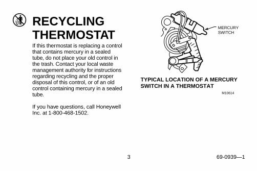
RECYCLINGTHERMOSTATIf this thermostat is replacing a controlthat contains mercury in a sealedtube, do not place your old control inthe trash. Contact your local wastemanagement authority for instructionsregarding recycling and the properdisposal of this control, or of an oldcontrol containing mercury in a sealedtube.
If you have questions, call HoneywellInc. at 1-800-468-1502.
M10614
MERCURYSWITCH
TYPICAL LOCATION OF A MERCURY SWITCH IN A THERMOSTAT

4 69-0939—1
TABLE OF CONTENTSStep 1. Prepare for Installation ................................................................. 5Step 2. Remove Old Thermostat ............................................................... 6Step 3. Mount Thermostat Wallplate ......................................................... 8Step 4 Wire Wallplate Terminals ............................................................... 9Step 5. Install the Batteries ....................................................................... 13Step 6. Set Fan Operation Switch ............................................................. 14Step 7. Mount the Thermostat ................................................................... 15Step 8. Customizing Thermostat ............................................................... 15Step 9. Programming ................................................................................. 20Step 10. Operating Your Thermostat ......................................................... 24Step 11. Setting the Fan and System Switches ....................................... 27Troubleshooting Guide .............................................................................. 28Limited One-Year Warranty ....................................................................... 31

5 69-0939—1
STEP 1. PREPARE FOR INSTALLATION❑ Check the compatibility chart to make sure this thermostat is compatible with your system. If
not, return to retailer. For specialty thermostat information, call Honeywell CustomerAssistance, toll-free 1-800-468-1502.
Compatibility Chart.
▲▲1
▲▲1
▲▲1
Not compatible with any 120/240 volt circuit.
Compatible with 2-wire Honeywell and Taco zone valves. Not compatible with 3-wire zonevalves or 2-wire White Rodgers no. 1361 zone valves.
System Type
Compatiblewith
CT3600
Gas—Standing Pilot YesGas—Electronic Ignition YesGas-Fired Boilers YesGas—Millivolt NoOil-Fired Boilers YesOil-Fired Furnace YesElectric Furnace Yes
System Type
Compatiblewith
CT3600
Electric Air Conditioning YesBaseboard Electric
(120/240 line volt)No
Single Stage Heat Pump YesMultistage Heat
Pumps/MultistageEquipment
No

6 69-0939—1
STEP 2. REMOVE OLD THERMOSTAT❑ Test to make certain that your heating and
cooling systems are working properly. Ifeither does not work, contact your localheating/air conditioning dealer. To avoidcompressor damage, do not operate thecooling system when outdoor temperatureis below 50°F (10°C).
❑ Turn off power to system at the furnace, orat the fuse/circuit breaker panel.
❑ Carefully unpack your new thermostat andwallplate; save package of screws,instructions and receipt.
❑ Remove the cover from the old thermo-stat. If it does not snap off when pulledfirmly from the bottom, check for a screwused to lock on the cover.
❑ Loosen screws holding thermostat tosubbase, wallplate or wall, and lift away.
❑ Disconnect wires from old thermostat orsubbase. As you disconnect each wire,attach theenclosedlabels withthe oldterminaldesignation.If there areonly twowires, they do not need to be labeled.Wrap wires around pencil to keep themfrom falling back into the wall, as shown.
WIRES THROUGHWALL OPENING
M5136

7 69-0939—1
Replacing a clock thermostat that hasC or C1 clock terminals?If you are replacing a HoneywellChronotherm® Clock Thermostat, you mayfind one or two wires that go to the C or C1clock terminals on the Chronotherm® wiringwallplate. Do not allow them to touch, or youcan damage your transformer. Disconnect thewires and wrap them separately usingelectrical tape; do not wrap them together.Place the wires where they will not interferewith the operation of the new thermostat.Record the colors and terminal designationlabels of the remaining wires.
Six or more wires?If there are six or more wires (excluding clockwires attached to terminals), you most likelyhave a variation of a multistage heat pump orother multistage system. The thermostat is
not compatible with such systems so returnthe product to the place of purchase. If youwould like information about which program-mable thermostats will work with yoursystem, call Honeywell Customer AssistanceCenter at 1-800-468-1502.
Three thermostat wires?If you have three wires for a heating onlysystem and can operate the fan using the fanON switch, this thermostat will work with yoursystem. However, some hot water (zoned)heating systems have three thermostat wires.The thermostat will work only if you install anisolating relay on these systems. For details,call Honeywell Customer Assistance Centerat 1-800-468-1502.

8 69-0939—1
STEP 3. MOUNT THERMOSTAT WALLPLATE
WIRES THROUGH WALL
WALL
MOUNTING HOLES
M15044
MOUNTING SCREWS
WALLANCHORS(2)
❑ Position wallplate on wall. Level thewallplate for appearance if desired. Use apencil to mark the two mounting holes thatbest fit the application.
❑ Remove wallplate from wall, and drill3/16 inch holes in wall (if drywall) asmarked. For firmer material such asplaster or wood, drill 7/32 inch holes.Gently tap anchors (provided) into drilledholes until flush with the wall.
❑ Reposition wallplate over holes, pullingwires through wiring opening. Looselyinsert two mounting screws into holes.
❑ Level for appearance only; thermostatfunctions properly even when not level.Tighten mounting screws.

9 69-0939—1
STEP 4. WIRE WALLPLATE TERMINALSNOTE: All wiring must comply with local
codes and ordinances. If unsureabout household wiring procedures,call your local heating/air condition-ing contractor.
Refer to the labels you placed on wires whenyou removed your old thermostat.
❑ Match the letter of your old thermostatwire with the terminal of the correspond-ing letter on your new thermostat. Refer toillustrations on pages 10, 11, and 12.
Be sure to remove the factory-installedjumper connecting terminals R and Rc whenwires are connected to both the R and Rcterminals.
❑ Loosen the terminal screws and slip eachwire beneath its matching terminal. Eitherstraight or wraparound wiring connectionsare acceptable (see illustration). Tightenterminals.
❑ Plug the hole in the wall with insulation tohelp prevent drafts from adverselyaffecting thermostat operation.
M4826
FOR WRAPAROUNDINSERTION STRIP7/16 IN. (11 MM).
FOR STRAIGHTINSERTION STRIP5/16 IN. (8 MM).

10 69-0939—1
M10617
THERMOSTAT
1 POWER SUPPLY. PROVIDE DISCONNECT MEANS AND OVERLOAD PROTECTION AS REQUIRED.
1
4-WIRE HEAT/COOL (JUMPER INTACT)
HEATINGRELAY ORVALVE COIL
COOLINGCONTACTORCOIL
FANRELAY
B
R
RC O W Y
G
M10616
THERMOSTAT
1 POWER SUPPLY. PROVIDE DISCONNECT MEANS AND OVERLOAD PROTECTION AS REQUIRED.
1
HEATINGRELAY ORVALVE COIL
B
R
RC O W Y
G
2-WIRE HEAT-ONLY (JUMPER INTACT)

11 69-0939—1
M10618
THERMOSTAT
1 POWER SUPPLY. PROVIDE DISCONNECT MEANS AND OVERLOAD PROTECTION AS REQUIRED.
1
3-WIRE HEAT ONLY WITH FAN(JUMPER INTACT)
HEATINGRELAY ORVALVE COIL
FANRELAY
B
R
RC O W Y
G
M12739
THERMOSTAT
4-WIRE SINGLE-STAGE HEAT PUMP(JUMPER INTACT)
B
R
RC O W Y
G
POWER SUPPLY. PROVIDE DISCONNECT MEANSAND OVERLOAD PROTECTION AS REQUIRED.
USE EITHER O OR B FOR HEAT PUMP CHANGEOVER.
1
2
2
2
1
COMPRESSORCONTACTOR
COOL CHANGEOVERVALVE
HEAT CHANGEOVERVALVE
FANRELAY

12 69-0939—1
M10619
THERMOSTAT
1 POWER SUPPLY. PROVIDE DISCONNECT MEANS AND OVERLOAD PROTECTION AS REQUIRED.
1 1
5-WIRE HEAT/COOL (JUMPER REMOVED)
HEATINGRELAY ORVALVE COIL
COOLINGCONTACTORCOIL
FANRELAY
B
R
RC O W Y
G
M10620
HEATRELAY
COMPRESSORCONTACTOR
COOLDAMPER
1 POWER SUPPLY. PROVIDE DISCONNECT MEANS AND OVERLOAD PROTECTION AS REQUIRED.
CAN BE USED FOR CHANGEOVER VALVE ON SINGLE-STAGE HEAT PUMP SYSTEMS.
2
22
1
5-WIRE HEAT/COOL WITH DAMPER (JUMPER INTACT)
B
R
RC O W Y
G
FANRELAY
HEATDAMPER
13 69-0939—1
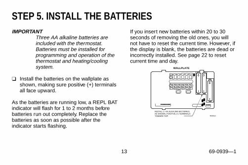
STEP 5. INSTALL THE BATTERIESIMPORTANT
Three AA alkaline batteries areincluded with the thermostat.Batteries must be installed forprogramming and operation of thethermostat and heating/coolingsystem.
❑ Install the batteries on the wallplate asshown, making sure positive (+) terminalsall face upward.
As the batteries are running low, a REPL BATindicator will flash for 1 to 2 months beforebatteries run out completely. Replace thebatteries as soon as possible after theindicator starts flashing.
If you insert new batteries within 20 to 30seconds of removing the old ones, you willnot have to reset the current time. However, ifthe display is blank, the batteries are dead orincorrectly installed. See page 22 to resetcurrent time and day.
M10622
INSTALL 3 AA ALKALINE BATTERIES AS SHOWN, POSITIVE (+) TERMINALS TOWARD TOP.
WALLPLATE
B
R RC O W Y G
14 69-0939—1
IMPORTANTAlthough the thermostat has a lowbattery indicator, replace thebatteries once a year to preventleakage and to prevent thethermostat and heating/coolingsystem from shutting down due tolack of battery power.
As a precaution when leaving home forlonger than a month, change batteries beforeyou leave to prevent system from shuttingdown due to lack of battery power.
Use fresh alkaline batteries; nonalkalinebatteries do not last as long, and may leak,causing damage to the thermostat or the wallsurface. We recommend Energizer®batteries.
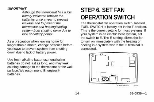
STEP 6. SET FANOPERATION SWITCHThe thermostat fan operation switch, labeledFUEL SWITCH is factory set in the F position.This is the correct setting for most systems. Ifyour system is an electric heat system, setthe switch to E. The E setting allows the fanto turn on immediately with the heating orcooling in a system where the G terminal isconnected.
M12676FUEL SWITCH
15 69-0939—1
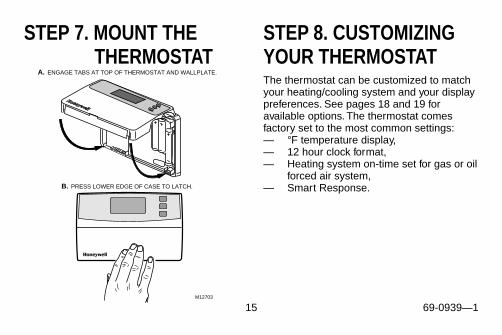
STEP 7. MOUNT THETHERMOSTAT
M12703
B. PRESS LOWER EDGE OF CASE TO LATCH.
A. ENGAGE TABS AT TOP OF THERMOSTAT AND WALLPLATE.
STEP 8. CUSTOMIZINGYOUR THERMOSTATThe thermostat can be customized to matchyour heating/cooling system and your displaypreferences. See pages 18 and 19 foravailable options. The thermostat comesfactory set to the most common settings:— °F temperature display,— 12 hour clock format,— Heating system on-time set for gas or oil
forced air system,— Smart Response.
16 69-0939—1
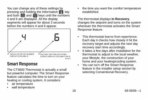
M12672
INSTALLER SETUP NUMBER DISPLAY (COLUMN 2)
FACTORY SETTING OR OTHER CHOICE DISPLAY (COLUMN 3 OR 5)
You can change any of these settings bypressing and holding the Information keyand both and keys until the numbers4 and 6 are displayed. All the displaysegments will appear for about 3 secondsbefore the numbers 4 and 6 appear.
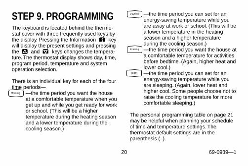
• the time you want the comfort temperatureestablished.
The thermostat displays In Recovery ,changes the setpoint and turns on the systemwhenever the thermostat activates the SmartResponse feature.
• This thermostat learns from experience.Each day it checks how closely it hit therecovery target and adjusts the next dayrecovery start time accordingly.
• It takes a few days after installation for thethermostat to adjust to the local weather,your lifestyle, the construction of yourhome and your heating/cooling system.
• You can turn off the Smart Responsefeature in the installer setup section byselecting Conventional Recovery.
Smart ResponseThe CT3600 Thermostat is actually a smallbut powerful computer. The Smart Responsefeature calculates the time to turn on yourheating or cooling system. It considers:• air temperature• wall temperature

17 69-0939—1
System Operating in Energy Savings Mode
Recovery Begins
Recovery Continues
System Operatingin Comfort Mode
ENERGYSAVINGSPERIOD
RECOVERY FROM ENERGY SAVINGS
5:305:00 6:00 6:30
COMFORTPERIOD
TIME
THERMOSTAT USES THE SAME SCHEME TO RETURN TO LOWER COMFORT TEMPERATURE DURING THE COOLING SEASON.
M12738
62°F
64°F
66°F
68°F
Heat
System
MonIn
RoomAM
RecoveryNight
Heat
SystemMorningMon
RoomAM
Heat
Heat
System
MonIn
RoomAM
RecoveryNight
Heat
System
Mon
RoomAM
Night
Heat
IF In Recovery IS DISPLAYED, PRESS TO SEE THE COMFORT SETPOINT.1
1
TE
MP
ER
AT
UR
ESmart Response

18 69-0939—1
The following table shows the numbers that will be displayed and what your choices are.
NumberDisplayed
(Press Time ▲ key Factory-Setting
Other Choices (Press ▲ or ▼ key to change) Actual
Select to change) Display Description Display Description Setting
Heatingcycle ratea
4 6 Gas or oil forced airheating system
1, 3 or 9 1—radiant floor heator gravity steamsystem
3—hot water systemor high efficiencyfurnace
9—electric heatsystem
SmartResponsecontrolb
13 0 Smart Responsecontrol is activated(system starts earlyso your house is atyour programmedtemperature at yourprogrammed time)
1 Conventional recovery(system starts at yourprogrammed time)

19 69-0939—1
a Be sure to change the heating cycle rate to 3 when using a high efficiency furnace such as a90% or greater AFUE (Average Fuel Utilization Efficiency) unit.
b Refer to Smart Response control section for more information.
IMPORTANTPress to exit the customizing feature. The thermostat has saved your changes,but you must set the current day and time for the thermostat to use the settings. Refer tothe Setting Current Day and Time portion of the Programming section forinstructions.
RunProgram
NumberDisplayed
(Press Time ▲ key Factory-Setting
Other Choices (Press ▲ or ▼ key to change) Actual
Select to change) Display Description Display Description Setting
Tempera-ture format
14 0 Temperature isdisplayed in °F
1 Temperature isdisplayed in °C
Clockformat
16 0 Time is displayed in12-hour format
1 Time is displayed in 24-hour (military time)format
Factorysetfunction
37 0 Do not change — — —
20 69-0939—1
STEP 9. PROGRAMMINGThe keyboard is located behind the thermo-stat cover with three frequently used keys bythe display. Pressing the Information keywill display the present settings and pressingthe and keys changes the tempera-ture. The thermostat display shows day, time,program period, temperature and systemoperation selection.
There is an individual key for each of the fourtime periods—
—the time period you want the houseat a comfortable temperature when youget up and while you get ready for workor school. (This will be a highertemperature during the heating seasonand a lower temperature during thecooling season.)
—the time period you can set for anenergy-saving temperature while youare away at work or school. (This will bea lower temperature in the heatingseason and a higher temperatureduring the cooling season.)—the time period you want the house ata comfortable temperature for activitiesbefore bedtime. (Again, higher heat andlower cool.)—the time period you can set for anenergy-saving temperature while youare sleeping. (Again, lower heat andhigher cool. Some people choose not toraise the cooling temperature for morecomfortable sleeping.)
The personal programming table on page 21may be helpful when planning your scheduleof time and temperature settings. Thethermostat default settings are in theparenthesis ( ).
Morning
Daytime
Evening
Night

21 69-0939—1
Personal Programming Table
Period Default SettingSunday(Sun)
Monday(Mon)
Tuesday(Tue)
Wednesday(Wed)
Thursday(Thu)
Friday(Fri)
Saturday(Sat)
Morning Time (6:00 AM)
Heata (70°F/21°C)
Coolb (78°F/25.5°C)Daytime Time (8:00 AM)
Heata (62°F/16.5°C)
Coolb (85°F/29.5°C)Evening Time (6:00 PM)
Heata (70°F/21°C)
Coolb (78°F/25.5°C)Night Time (10:00 PM)
Heata (62°F/16.5°C)
Coolb (82°F/28°C)a Your heating setpoints cannot be set higher than 90°F (32°C) or lower than 40°F (4.5°C).b Your cooling setpoints cannot be set higher than 99°F (35°C) or lower than 45°F (7°C).

22 69-0939—1
Setting the Current Day and TimePress and release then untilthe current day is displayed. (Sun = Sunday,Mon = Monday, Tue = Tuesday, Wed =Wednesday, Thu = Thursday, Fri = Friday, Sat= Saturday.)
NOTE: On initial power up, 1:00 pm flasheson the display until you press a key.
Press until the current time is displayed.
(Tapping the will advance the time inone hour increments.)
NOTE: If the current time is Daylight SavingsTime, press until DST isdisplayed.
Press .
IMPORTANTAlways press the keys with yourfingertip or similar blunt tool. Sharpinstruments like pens and pencilpoints can damage the touchpad.
Programming the First DayStart by programming the Morning time andtemperature for any one day:
Press and release then until
the desired day is displayed. Press
keys until the desired Morning time isdisplayed. (The program times are in fifteenminute intervals. Example: 8:00, 8:15, 8:30.)Press or key until the desiredMorning temperature is displayed.
Set CurrentDay/Time
Day
Time
Set CurrentDay/Time
DaylightTime
RunProgram
Morning Day
Time

23 69-0939—1
(The setpoint temperature range is 40 to 90°F(7 to 31°C) for heating and 45 to 99°F (9 to37°C) for cooling.) Press to switch toyour other system temperature setpoint.
NOTE: The program times are the same forboth heating and cooling.
Press or until the other desiredtemperature setpoint is displayed. Press
, or and repeat theabove steps for programming the rest of theday. The first day is now programmed.
IMPORTANTRepeat all the above steps for eachday of the week that has a differentprogram than your first day. Referto Copying a Day section to copyany program day to another.
Press when all the days areprogrammed.
Copying a Day
NOTE: Your thermostat must be in theprogram mode to use the copyfeature.
Press then to select the dayto be copied if different from the daydisplayed. Press then untilthe day to be copied to is displayed. Press
.
NOTE: "donE" will be displayed for twoseconds and then the normalprogram display will be shown.
Repeat the above steps for all the desireddays then press .
RunProgram
Daytime Evening Night
Heat/CoolSettings
RunProgram
Day
DayCopy
Copy
Morning

24 69-0939—1
Clearing Program Period
NOTE: Your thermostat must be in theprogram mode to use the clearfeature.
Press , , or .Press until the desired day isdisplayed. Press and hold , or
until the start time and temperaturesetting is cleared (approximately3 seconds).
NOTE: Morning cannot be cleared.
Repeat the above steps for all the periods tobe cleared then press .
Morning Daytime Evening Night
Daytime Evening
Night
Day
STEP 10. OPERATINGYOUR THERMOSTATSetting Temporary TemperaturesChanging Temperature Setting Until The NextProgram PeriodPress or key until the desiredtemperature setpoint is displayed.
NOTE: Your temporary temperature settingis displayed for approximately3 seconds. The setting is canceledwhen the next period starts or when
is pressed.RunProgram
RunProgram
25 69-0939—1
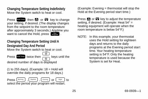
Changing Temperature Setting IndefinitelyMove the System switch to heat or cool.
Press then or key to changeyour setting, if desired. (The display changesfrom the setpoint to the room temperatureafter approximately 3 seconds.) Anytime youwant to cancel the Hold, press .
Changing Temperature Setting Until ADesignated Day And PeriodMove the System switch to heat or cool.
Press twice then keys until the
desired number of days is displayed
(1 to 255 days). (Example: 18 = Hold willoverride the daily programs for 18 days.)
Press , , or toselect the period your program will restart.
(Example: Evening = thermostat will stop theHold at the Evening period start time.)
Press or key to adjust the temperaturesetting, if desired. (Example: Heat 54° =heating equipment will operate when theroom temperature is below 54°F.)
NOTE: In this example, your thermostatuses the Hold setting for eighteendays and returns to the dailyprograms at the Evening period starttime. Your heating temperaturesetting is 54°F. Only the heatingtemperature is used because theSystem is set for Heat.
Hold Temp
RunProgram
Morning Daytime Evening Night
Time
Hold Temp

26 69-0939—1
IMPORTANTIf the Hold needs to be canceledbefore the designated time, press
to return to your program.
Using Daylight Savings Time FeatureThis feature allows you to change in and outof Daylight Savings Time with a key press.When is pressed in the fall, the timewill go back one hour. In the spring, the timewill go ahead one hour and the display willshow DST. See Setting the Current Day andTime section for initial setting instructions.
NOTE: Pressing more than oncewithin a five minute period will scrollyou through various time options(Example: one hour earlier or laterwith or without DST). Pressing
six times in a five minuteperiod will return you to your originalsettings.
Using Usage FeaturePress once to display the minutesthat the heating or cooling system has beenoperating for the current day. Press asecond time, within 10 seconds, to displaythe system operating time for the previousday (midnight to midnight). Press athird time, within 10 seconds, to display thesystem operating time since the last time theusage function was cleared.
NOTE: Press for 3 seconds to clearthe usage function.
RunProgram
DaylightTime
DaylightTime
DaylightTime
Usage
Usage
Usage
Usage
27 69-0939—1
Fan
On Auto
Fan
On Auto
System
Heat Off Cool
System
Heat Off Cool
System
Heat Off Cool
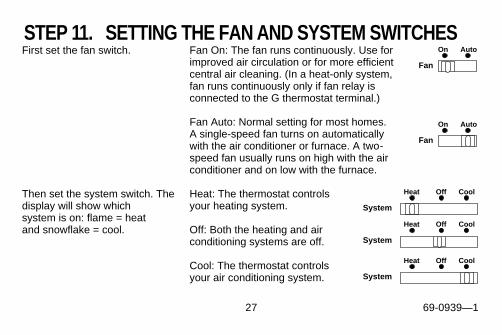
STEP 11. SETTING THE FAN AND SYSTEM SWITCHESFirst set the fan switch. Fan On: The fan runs continuously. Use for
improved air circulation or for more efficientcentral air cleaning. (In a heat-only system,fan runs continuously only if fan relay isconnected to the G thermostat terminal.)
Fan Auto: Normal setting for most homes.A single-speed fan turns on automaticallywith the air conditioner or furnace. A two-speed fan usually runs on high with the airconditioner and on low with the furnace.
Then set the system switch. Thedisplay will show which
Heat: The thermostat controlsyour heating system.
system is on: flame = heat and snowflake = cool. Off: Both the heating and air
conditioning systems are off.
Cool: The thermostat controlsyour air conditioning system.

28 69-0939—1
TROUBLESHOOTING GUIDEI F … THEN…
Display will not come on.
• Check that the batteries are installed correctly and fresh.• Check if the thermostat is mounted and latched on the wallplate—mount and latch the
thermostat on the wallplate.
Temperature settingswill not change(Example: cannot setthe heating higher orthe cooling lower).
• Check that the temperature setpoints are:— heating: 40 to 90°F (4.5 to 32°C)— cooling: 45 to 99°F (7 to 35°C).
Heating will not come on.
• Check that heat setpoint is above room temperature.• Check if the circuit breaker is tripped—reset the circuit breaker.• Check if the system switch at the equipment is in the Off position—set to On position.• Wait five minutes for the system to respond.• Set system switch to Heat.
29 69-0939—1
I F … THEN…
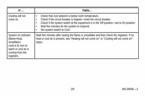
Cooling will not come on.
• Check that cool setpoint is below room temperature.• Check if the circuit breaker is tripped—reset the circuit breaker.• Check if the system switch at the equipment is in the Off position—set to On position.• Wait five minutes for the system to respond.• Set system switch to Cool.
System on indicator(flame=heat,snowflake=cool) is lit, but nowarm or cool air iscoming from theregisters.
Wait five minutes after seeing the flame or snowflake and then check the registers. If noheat or cool air is present, see "Heating will not come on" or "Cooling will not come on"steps.
30 69-0939—1
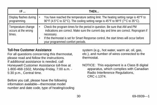
Toll-free Customer AssistanceFor all questions concerning this thermostat,please read and follow the instructions.If additional assistance is needed, callHoneywell Customer Assistance toll-free at1-800-468-1502, Monday-Friday, 7:00 a.m. -5:30 p.m., Central time.
Before you call, please have the followinginformation available—thermostat modelnumber and date code, type of heating/cooling
system (e.g., hot water, warm air, oil, gas,etc.), and number of wires connected to thethermostat.
NOTICE: This equipment is a Class B digitalapparatus, which complies with CanadianRadio Interference Regulations,CRC c.1374.
I F … THEN…
Display flashes duringprogramming.
• You have reached the temperature setting limit. The heating setting range is 40°F to90°F (4.5°C to 32°C). The cooling setting range is 45°F to 99°F (7°C to 35°C).
Temperature changeoccurs at the wrongtimes.
• Check the program times for the period in question. Be sure that AM and PM indications are correct. Make sure the current day and time are correct. Reprogram ifnecessary.
• If the thermostat is set for Smart Response control, the start times will occur beforeyour programmed comfort periods.
31 69-0939—1
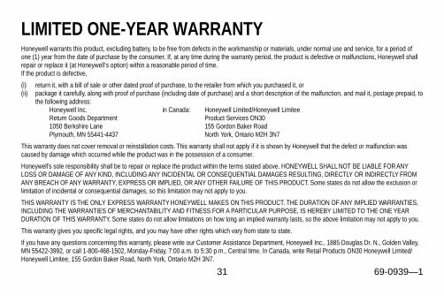
LIMITED ONE-YEAR WARRANTYHoneywell warrants this product, excluding battery, to be free from defects in the workmanship or materials, under normal use and service, for a period ofone (1) year from the date of purchase by the consumer. If, at any time during the warranty period, the product is defective or malfunctions, Honeywell shallrepair or replace it (at Honeywell’s option) within a reasonable period of time.If the product is defective,
(i) return it, with a bill of sale or other dated proof of purchase, to the retailer from which you purchased it, or(ii) package it carefully, along with proof of purchase (including date of purchase) and a short description of the malfunction, and mail it, postage prepaid, to
the following address:Honeywell Inc. in Canada: Honeywell Limited/Honeywell LimiteeReturn Goods Department Product Services ON301050 Berkshire Lane 155 Gordon Baker RoadPlymouth, MN 55441-4437 North York, Ontario M2H 3N7
This warranty does not cover removal or reinstallation costs. This warranty shall not apply if it is shown by Honeywell that the defect or malfunction wascaused by damage which occurred while the product was in the possession of a consumer.
Honeywell’s sole responsibility shall be to repair or replace the product within the terms stated above. HONEYWELL SHALL NOT BE LIABLE FOR ANYLOSS OR DAMAGE OF ANY KIND, INCLUDING ANY INCIDENTAL OR CONSEQUENTIAL DAMAGES RESULTING, DIRECTLY OR INDIRECTLY FROMANY BREACH OF ANY WARRANTY, EXPRESS OR IMPLIED, OR ANY OTHER FAILURE OF THIS PRODUCT. Some states do not allow the exclusion orlimitation of incidental or consequential damages, so this limitation may not apply to you.
THIS WARRANTY IS THE ONLY EXPRESS WARRANTY HONEYWELL MAKES ON THIS PRODUCT. THE DURATION OF ANY IMPLIED WARRANTIES,INCLUDING THE WARRANTIES OF MERCHANTABILITY AND FITNESS FOR A PARTICULAR PURPOSE, IS HEREBY LIMITED TO THE ONE YEARDURATION OF THIS WARRANTY. Some states do not allow limitations on how long an implied warranty lasts, so the above limitation may not apply to you.
This warranty gives you specific legal rights, and you may have other rights which vary from state to state.
If you have any questions concerning this warranty, please write our Customer Assistance Department, Honeywell Inc., 1885 Douglas Dr. N., Golden Valley,MN 55422-3992, or call 1-800-468-1502, Monday-Friday, 7:00 a.m. to 5:30 p.m., Central time. In Canada, write Retail Products ON30 Honeywell Limited/Honeywell Limitee, 155 Gordon Baker Road, North York, Ontario M2H 3N7.

32 69-0939—169-0939—1 Rev. 11-97 J.H.Copyright © 1997 Honeywell Inc. All Rights Reserved ® U.S. Registered Trademark
Home and Building ControlHoneywell Limited-Honeywell Limitée155 Gordon Baker RoadNorth York, OntarioM2H 3N7
Home and Building ControlHoneywell Inc.Honeywell PlazaP.O. Box 524Minneapolis, MN 55408-0524
Printed in U.S.A. on recycled paper containing at least 10% post-consumer paper fibers.