PRINT HEAD KIT - Honeywell Process Solutions
16
PRINT HEAD KIT 46190156-501 DPR180 Issue : 1 (11/96) EN CK193
-
Upload
khangminh22 -
Category
Documents
-
view
0 -
download
0
Transcript of PRINT HEAD KIT - Honeywell Process Solutions

PRINT HEAD KIT46190156-501
DPR180
Issue : 1 (11/96) EN CK193

1. Please use an antistatic ground strap to avoid possible electrostatic damage to the printed circuit boards.
1. Isolate the recorder from the mains supply.
2. Open the recorder door and remove the chart cassette from the chassis.
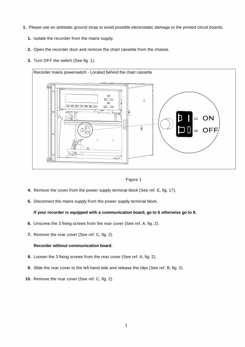
3. Turn OFF the switch (See fig. 1).
Recorder mains powerswitch - Located behind the chart cassette
Figure 1
4. Remove the cover from the power supply terminal block (See ref. E, fig. 17).
5. Disconnect the mains supply from the power supply terminal block.
If your recorder is equipped with a communication board, go to 6 otherwise go to 8.
6. Unscrew the 3 fixing screws from the rear cover (See ref. A, fig. 2).
7. Remove the rear cover (See ref. C, fig. 2).
Recorder without communication board.
8. Loosen the 3 fixing screws from the rear cover (See ref. A, fig. 2).
9. Slide the rear cover to the left hand side and release the clips (See ref. B, fig. 2).
10. Remove the rear cover (See ref. C, fig. 2).
1

A
B
C
Figure 2
2
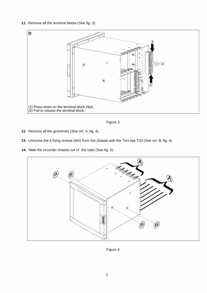
11. Remove all the terminal blocks (See fig. 3).
D
��������
(1) Press down on the terminal block clips.(2) Pull to release the terminal block.
Figure 3
12. Remove all the grommets (See ref. A, fig. 4).
13. Unscrew the 4 fixing screws (M4) from the chassis with the Torx key T20 (See ref. B, fig. 4).
14. Slide the recorder chassis out of the case (See fig. 5).
Figure 4
3
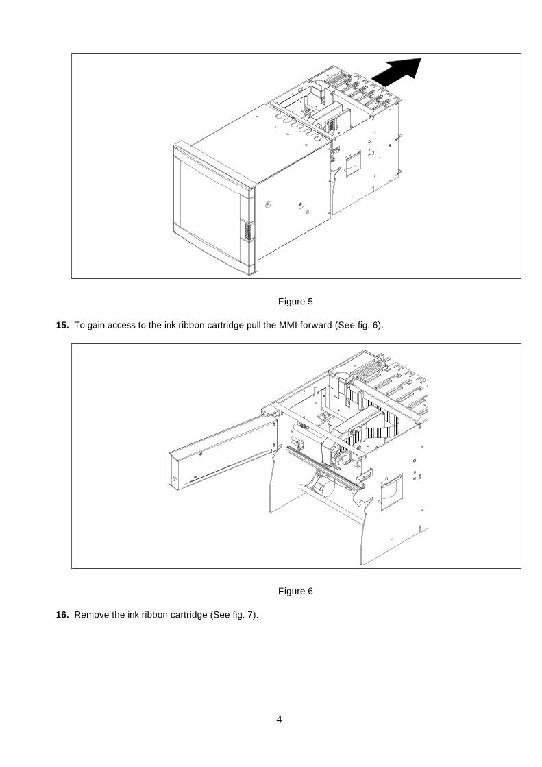
Figure 5
15. To gain access to the ink ribbon cartridge pull the MMI forward (See fig. 6).
���
���
�����
�����
�����
�����
�����
�����
���
���
���
���
���
���
���
���
����
����
�
Figure 6
16. Remove the ink ribbon cartridge (See fig. 7).
4

�������������
�������������
�������������
�������������
�������������
�������������
�������������
�������������
�������������
�������������
�������������
�������������
�������������
�������������
�������������
�������������
�������������
�������������
�������������
Figure 7
17. Remove the flat cable clamp (See ref. B, fig. 8)
18. Disconnect the two flat cables from the CPU board (See ref. A, fig. 8).
�����
�����
�����
��������
��������
��������
��������
��������
��������
��������
��������
��������
��������
�����
�����
�����
�����
�����
�����
�����
�����
�����
����
����
����
����
����
���
���
���
���
���
���
���
�
Figure 8
19. To release the print head, unscrew the two fixing screws (See fig. 9).
20. Remove the old print head.
5

Figure 9
21. To fit the new print head slide the flat cable into the print carriage side plate (See ref. C, fig. 8).
22. Secure the new print head by tightening the fixing screws (See fig. 9).
CAUTIONEnsure the flat cables do not rub against the right hand side of the printer chassis.The flat cables must be adjusted in length to make sure that they lye flat against the printer carriage sideplate when the printer carriage is fully to the right.
23. Reconnect the two flat cables from the print head carriage to the CPU board (See fig. 10).Ensure the connectors are located correctly.
6

Figure 10
24. Refit the flat cable clamp, do not tighten the fixing screws.
NOTE: The length of flat cables must be adjusted before tightening the cable clamp.
25. Move the print carriage fully to the left and right hand sides of the printer chassis.
26. Ensure the flat cables take up correctly.I.E. are not under tension when the carriage is moved fully to the right.
CAUTIONThe flat cables must not be compressed by the printer carriage when again the carriage is fully to the right.
27. Tighten the flat cable clamp screws.
28. Reinstall the chart cassette (without paper).
7

29. The print head height must now be adjusted.
30. Use a feeler gauge to set the height of the print head to 0.6 mm/0.023 inch between the print head and thetop roller of the chart cassette (See fig. 11).
NOTE:The print gap is adjusted by releasing the print head fixing screws and moving the print head up or down onthe printer carriage assembly, until the correct distance is obtained. The print head fixing screws must thenbe tightened to lock the print head in position.
Figure 11
31. Ensure the print head is in the vertical position, if incorrect readjust and lock the print head back in positionensuring the correct print gap (See point 30).
32. Move the carriage fully to the left (See fig. 12).
8

Figure 12
33. Use the setting support on the left side to adjust the height to 0.6 mm/0.023 inch between the print headand the top roller of the chart cassette.
34. Lock the left side setting support screw (See fig. 13).
Figure 13
35. Slide the carriage fully to the right (See fig. 14).
9

Figure 14
36. Use the setting support on the right side to adjust the height to 0.6 mm/0.023 inch between the print headand the top roller of the chart cassette.
37. Lock the right side setting support screw (See fig. 15).
Figure 15
38. Repeat steps 33 to 37 until the print gap is exactly 0.6 mm/0.023 inch.
39. Fit chart paper into the chart cassette.
10
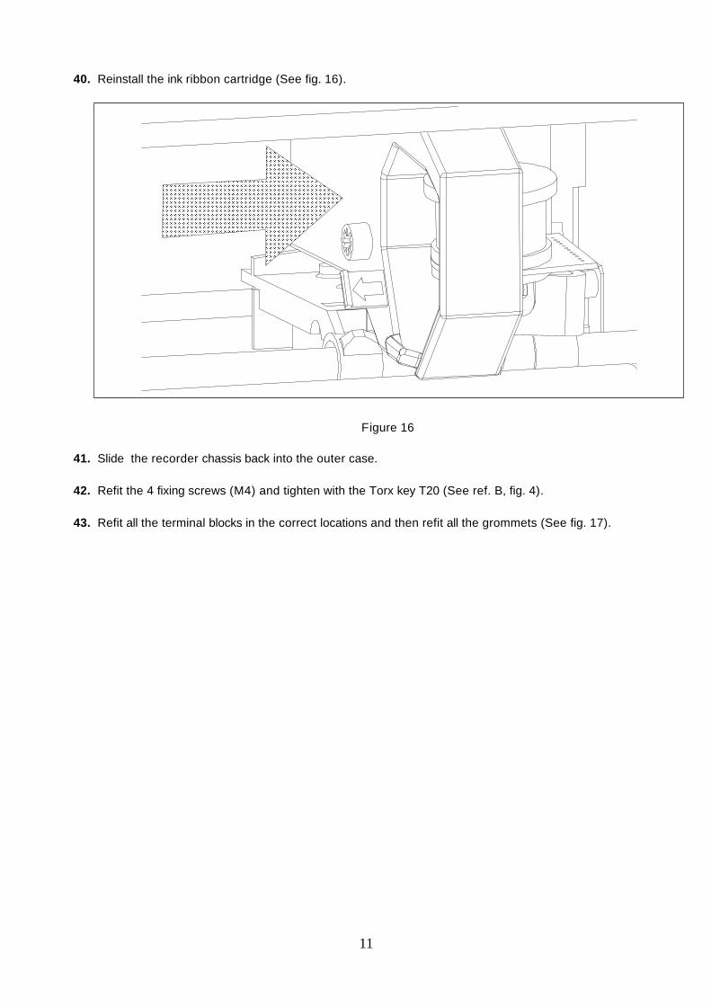
40. Reinstall the ink ribbon cartridge (See fig. 16).
��������������
��������������
��������������
��������������
��������������
��������������
��������������
��������������
��������������
��������������
��������������
��������������
��������������
��������������
��������������
��������������
��������������
��������������
��������������
��������������
Figure 16
41. Slide the recorder chassis back into the outer case.
42. Refit the 4 fixing screws (M4) and tighten with the Torx key T20 (See ref. B, fig. 4).
43. Refit all the terminal blocks in the correct locations and then refit all the grommets (See fig. 17).
11

Figure 17 Location of the terminal blocks
44. Refit the rear cover.
45. Reconnect the mains power supply to the terminal block.
46. Refit the power supply terminal cover (See ref. E, fig. 17).
47. Turn ON the switch (See fig. 1).
48. Refit the chart cassette.
49. Switch ON the mains supply.
12

50. Procedure for print head color calibration
0% CHART
DEFINITION: Chart certification to show the current 0% chart position at 0% print carriage position.This is a mechanical adjustment.
HOW TO USE/EXECUTE IT: The message (channel nb) CAL 0%" with a flashing number. This numbercorresponds to the present adjustment (= step motor).To move to the right, increase this number or to the left, decrease the number.(You may use a negative number).
You can change the distance value by pressing the[] keys.The recorder accepts the value by pressing ENTER.You can leave the 0% chart service by pressing SET UP.
NOTE: When you press ENTER, the head moves and prints the new 0% chart calibration.
100% CHART
DEFINITION: Chart certification to show the current 100% chart position at 100% print carriage position.This is a mechanical adjustment.
HOW TO USE/EXECUTE IT: The message (channel nb) CAL 100%" with a flashing number. This numbercorresponds to the present adjustment (= step motor).To move to the right, increase this number or to the left, decrease the number.(You may use a negative number.)
You can change the distance value by pressing the[] keys.The recorder accepts the value by pressing ENTER.You can leave the 100% chart service by pressing SET UP. When you press ENTER, the head moves andprints the new 100% chart calibration.
13
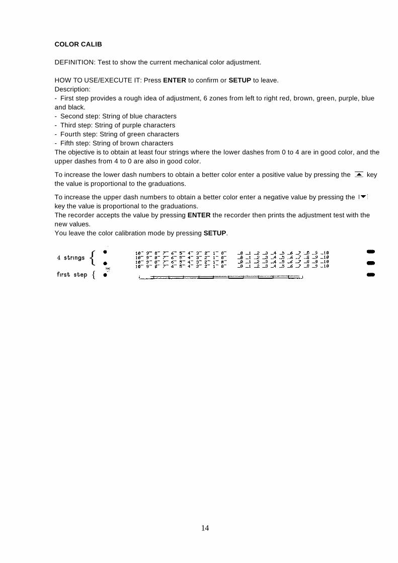
COLOR CALIB
DEFINITION: Test to show the current mechanical color adjustment.
HOW TO USE/EXECUTE IT: Press ENTER to confirm or SETUP to leave.Description:- First step provides a rough idea of adjustment, 6 zones from left to right red, brown, green, purple, blueand black.- Second step: String of blue characters- Third step: String of purple characters- Fourth step: String of green characters- Fifth step: String of brown charactersThe objective is to obtain at least four strings where the lower dashes from 0 to 4 are in good color, and theupper dashes from 4 to 0 are also in good color.
To increase the lower dash numbers to obtain a better color enter a positive value by pressing the[ keythe value is proportional to the graduations.
To increase the upper dash numbers to obtain a better color enter a negative value by pressing the]key the value is proportional to the graduations.The recorder accepts the value by pressing ENTER the recorder then prints the adjustment test with thenew values.You leave the color calibration mode by pressing SETUP.
14